Silver Peak WAN Optimization Appliances
468
Silver Peak WAN Optimization Appliances Appliance Manager Operator’s Guide Release 4.4 March 2012 PN 200030-001 Rev K
-
Upload
khangminh22 -
Category
Documents
-
view
3 -
download
0
Transcript of Silver Peak WAN Optimization Appliances

Silver PeakWAN Optimization Appliances
Appliance Manager Operator’s Guide
Release 4.4
March 2012
PN 200030-001 Rev K

Silver Peak Appliance Manager Operator’s Guide
ii PN 200030-001 Rev K
Silver Peak Appliance Manager Operator’s Guide
Document PN 200030-001 Rev K
Date: March 2012
Copyright © 2012 Silver Peak Systems, Inc. All rights reserved. Information in this document is subject to change at any time. Use of this documentation is restricted as specified in the End User License Agreement. No part of this documentation can be reproduced, except as noted in the End User License Agreement, in whole or in part, without the written consent of Silver Peak Systems, Inc.
Trademark Notification
Silver Peak SystemsTM, the Silver Peak logo, Network MemoryTM, and Silver Peak NX-SeriesTM are trademarks of Silver Peak Systems, Inc. All trademark rights reserved. All other brand or product names are trademarks or registered trademarks of their respective companies or organizations.
Warranties and Disclaimers
THIS DOCUMENTATION IS PROVIDED “AS IS” WITHOUT WARRANTY OF ANY KIND, EITHER EXPRESSED OR IMPLIED, INCLUDING, BUT NOT LIMITED TO, THE IMPLIED WARRANTIES OF MERCHANTABILITY, FITNESS FOR A PARTICULAR PURPOSE, OR NON-INFRINGEMENT. SILVER PEAK SYSTEMS, INC. ASSUMES NO RESPONSIBILITY FOR ERRORS OR OMISSIONS IN THIS DOCUMENTATION OR OTHER DOCUMENTS WHICH ARE REFERENCED BY OR LINKED TO THIS DOCUMENTATION. REFERENCES TO CORPORATIONS, THEIR SERVICES AND PRODUCTS, ARE PROVIDED “AS IS” WITHOUT WARRANTY OF ANY KIND, EITHER EXPRESSED OR IMPLIED. IN NO EVENT SHALL SILVER PEAK SYSTEMS, INC. BE LIABLE FOR ANY SPECIAL, INCIDENTAL, INDIRECT OR CONSEQUENTIAL DAMAGES OF ANY KIND, OR ANY DAMAGES WHATSOEVER, INCLUDING, WITHOUT LIMITATION, THOSE RESULTING FROM LOSS OF USE, DATA OR PROFITS, WHETHER OR NOT ADVISED OF THE POSSIBILITY OF DAMAGE, AND ON ANY THEORY OF LIABILITY, ARISING OUT OF OR IN CONNECTION WITH THE USE OF THIS DOCUMENTATION. THIS DOCUMENTATION MAY INCLUDE TECHNICAL OR OTHER INACCURACIES OR TYPOGRAPHICAL ERRORS. CHANGES ARE PERIODICALLY ADDED TO THE INFORMATION HEREIN; THESE CHANGES WILL BE INCORPORATED IN NEW EDITIONS OF THE DOCUMENTATION. SILVER PEAK SYSTEMS, INC. MAY MAKE IMPROVEMENTS AND/OR CHANGES IN THE PRODUCT(S) AND/OR THE PROGRAM(S) DESCRIBED IN THIS DOCUMENTATION AT ANY TIME.
Silver Peak Systems, Inc.4500 Great America Parkway, Suite 100Santa Clara, CA 95054
1.877.210.7325 (toll-free in USA)+ 1.408.935.1850
www.silver-peak.com/support

PN 200030-001 Rev K i
Preface . . . . . . . . . . . . . . . . . . . . . . . . . . . . . . . . . . . . . . . . . . . . . . . . . . . . . . . . . . . . . . . . . vii
Who Should Read This Manual?. . . . . . . . . . . . . . . . . . . . . . . . . . . . . . . . . . . . . . . . . . . . . . . . . . . .vii
Manual Organization . . . . . . . . . . . . . . . . . . . . . . . . . . . . . . . . . . . . . . . . . . . . . . . . . . . . . . . . . . . . .vii
Related Publications . . . . . . . . . . . . . . . . . . . . . . . . . . . . . . . . . . . . . . . . . . . . . . . . . . . . . . . . . . . . . ix
Technical Support . . . . . . . . . . . . . . . . . . . . . . . . . . . . . . . . . . . . . . . . . . . . . . . . . . . . . . . . . . . . . . . x
Chapter 1 Overview . . . . . . . . . . . . . . . . . . . . . . . . . . . . . . . . . . . . . . . . . . . . . . . . . . . . . . 1
Overview of the Silver Peak Appliances . . . . . . . . . . . . . . . . . . . . . . . . . . . . . . . . . . . . . . . . . . . . . . 2Benefits . . . . . . . . . . . . . . . . . . . . . . . . . . . . . . . . . . . . . . . . . . . . . . . . . . . . . . . . . . . . . . . . . . . . . 2Components . . . . . . . . . . . . . . . . . . . . . . . . . . . . . . . . . . . . . . . . . . . . . . . . . . . . . . . . . . . . . . . . . 3Features . . . . . . . . . . . . . . . . . . . . . . . . . . . . . . . . . . . . . . . . . . . . . . . . . . . . . . . . . . . . . . . . . . . . 9
Typical Network Deployments . . . . . . . . . . . . . . . . . . . . . . . . . . . . . . . . . . . . . . . . . . . . . . . . . . . . . 12In-Line Deployments . . . . . . . . . . . . . . . . . . . . . . . . . . . . . . . . . . . . . . . . . . . . . . . . . . . . . . . . . . 12Out-of-Path Deployments (Router Mode) . . . . . . . . . . . . . . . . . . . . . . . . . . . . . . . . . . . . . . . . . . 17
Chapter 2 Installing the Appliance . . . . . . . . . . . . . . . . . . . . . . . . . . . . . . . . . . . . . . . . 25
Before You Begin . . . . . . . . . . . . . . . . . . . . . . . . . . . . . . . . . . . . . . . . . . . . . . . . . . . . . . . . . . . . . . 26Summary of Installation Tasks . . . . . . . . . . . . . . . . . . . . . . . . . . . . . . . . . . . . . . . . . . . . . . . . . . 26Site Preparation . . . . . . . . . . . . . . . . . . . . . . . . . . . . . . . . . . . . . . . . . . . . . . . . . . . . . . . . . . . . . 26
Installing the Appliance into the Network. . . . . . . . . . . . . . . . . . . . . . . . . . . . . . . . . . . . . . . . . . . . . 30
Cabling for Configuration Management. . . . . . . . . . . . . . . . . . . . . . . . . . . . . . . . . . . . . . . . . . . . . . 32
Running the Initial Configuration Wizard . . . . . . . . . . . . . . . . . . . . . . . . . . . . . . . . . . . . . . . . . . . . . 35
Chapter 3 The Appliance Manager . . . . . . . . . . . . . . . . . . . . . . . . . . . . . . . . . . . . . . . . 37
Accessing the Appliance Manager . . . . . . . . . . . . . . . . . . . . . . . . . . . . . . . . . . . . . . . . . . . . . . . . . 38
Guided Tour of the Appliance Manager . . . . . . . . . . . . . . . . . . . . . . . . . . . . . . . . . . . . . . . . . . . . . 40The Appliance Manager Home Page . . . . . . . . . . . . . . . . . . . . . . . . . . . . . . . . . . . . . . . . . . . . . 40Banners. . . . . . . . . . . . . . . . . . . . . . . . . . . . . . . . . . . . . . . . . . . . . . . . . . . . . . . . . . . . . . . . . . . . 42Menu Structure . . . . . . . . . . . . . . . . . . . . . . . . . . . . . . . . . . . . . . . . . . . . . . . . . . . . . . . . . . . . . . 42Managing Tabular Data. . . . . . . . . . . . . . . . . . . . . . . . . . . . . . . . . . . . . . . . . . . . . . . . . . . . . . . . 49Netmask Notations . . . . . . . . . . . . . . . . . . . . . . . . . . . . . . . . . . . . . . . . . . . . . . . . . . . . . . . . . . . 50Date and Time Conventions . . . . . . . . . . . . . . . . . . . . . . . . . . . . . . . . . . . . . . . . . . . . . . . . . . . . 52Secure Access Methods . . . . . . . . . . . . . . . . . . . . . . . . . . . . . . . . . . . . . . . . . . . . . . . . . . . . . . . 52Guidelines for Creating Passwords. . . . . . . . . . . . . . . . . . . . . . . . . . . . . . . . . . . . . . . . . . . . . . . 52Object Names . . . . . . . . . . . . . . . . . . . . . . . . . . . . . . . . . . . . . . . . . . . . . . . . . . . . . . . . . . . . . . . 52Saving Your Configuration . . . . . . . . . . . . . . . . . . . . . . . . . . . . . . . . . . . . . . . . . . . . . . . . . . . . . 53Definition Help. . . . . . . . . . . . . . . . . . . . . . . . . . . . . . . . . . . . . . . . . . . . . . . . . . . . . . . . . . . . . . . 53
Chapter 4 Configuring Host Settings . . . . . . . . . . . . . . . . . . . . . . . . . . . . . . . . . . . . . 55
Overview . . . . . . . . . . . . . . . . . . . . . . . . . . . . . . . . . . . . . . . . . . . . . . . . . . . . . . . . . . . . . . . . . . . . . 56
Configuring System Settings and Max System Bandwidth . . . . . . . . . . . . . . . . . . . . . . . . . . . . . . . 56
Selecting a System Deployment . . . . . . . . . . . . . . . . . . . . . . . . . . . . . . . . . . . . . . . . . . . . . . . . . . . 58Sorting Through the Deployment Options. . . . . . . . . . . . . . . . . . . . . . . . . . . . . . . . . . . . . . . . . . 60Configuring Gigabit Etherchannel Bonding . . . . . . . . . . . . . . . . . . . . . . . . . . . . . . . . . . . . . . . . . 61
Setting the Date and Time. . . . . . . . . . . . . . . . . . . . . . . . . . . . . . . . . . . . . . . . . . . . . . . . . . . . . . . . 62
Configuring Network Parameters . . . . . . . . . . . . . . . . . . . . . . . . . . . . . . . . . . . . . . . . . . . . . . . . . . 65Modifying the Physical Interface Parameters . . . . . . . . . . . . . . . . . . . . . . . . . . . . . . . . . . . . . . . 66Configuring IP Routes . . . . . . . . . . . . . . . . . . . . . . . . . . . . . . . . . . . . . . . . . . . . . . . . . . . . . . . . . 69Routing Management Traffic. . . . . . . . . . . . . . . . . . . . . . . . . . . . . . . . . . . . . . . . . . . . . . . . . . . . 70Routing LAN–side Traffic to the Next Hop . . . . . . . . . . . . . . . . . . . . . . . . . . . . . . . . . . . . . . . . . 73Adding Domain Name Servers . . . . . . . . . . . . . . . . . . . . . . . . . . . . . . . . . . . . . . . . . . . . . . . . . . 75
Configuring Flow Exports for NetFlow. . . . . . . . . . . . . . . . . . . . . . . . . . . . . . . . . . . . . . . . . . . . . . . 76

Silver Peak Appliance Manager Operator’s Guide
ii PN 200030-001 Rev K
Chapter 5 Creating Tunnels . . . . . . . . . . . . . . . . . . . . . . . . . . . . . . . . . . . . . . . . . . . . . . 77
Overview . . . . . . . . . . . . . . . . . . . . . . . . . . . . . . . . . . . . . . . . . . . . . . . . . . . . . . . . . . . . . . . . . . . . . 78How Policies Affect Tunnel Traffic . . . . . . . . . . . . . . . . . . . . . . . . . . . . . . . . . . . . . . . . . . . . . . . 78Tunnel Characteristics . . . . . . . . . . . . . . . . . . . . . . . . . . . . . . . . . . . . . . . . . . . . . . . . . . . . . . . . 78
Letting the Auto-Tunnel Feature Do the Work for You . . . . . . . . . . . . . . . . . . . . . . . . . . . . . . . . . . 79
Manually Creating a Traffic-Carrying Tunnel. . . . . . . . . . . . . . . . . . . . . . . . . . . . . . . . . . . . . . . . . . 80
Editing a Tunnel . . . . . . . . . . . . . . . . . . . . . . . . . . . . . . . . . . . . . . . . . . . . . . . . . . . . . . . . . . . . . . . 85
Deleting a Tunnel . . . . . . . . . . . . . . . . . . . . . . . . . . . . . . . . . . . . . . . . . . . . . . . . . . . . . . . . . . . . . . 87
Tunnel Compatibility Mode . . . . . . . . . . . . . . . . . . . . . . . . . . . . . . . . . . . . . . . . . . . . . . . . . . . . . . . 88
Chapter 6 Theory of Operations . . . . . . . . . . . . . . . . . . . . . . . . . . . . . . . . . . . . . . . . . . 89
Processing Traffic Flows . . . . . . . . . . . . . . . . . . . . . . . . . . . . . . . . . . . . . . . . . . . . . . . . . . . . . . . . . 90What Maps and Policies Do . . . . . . . . . . . . . . . . . . . . . . . . . . . . . . . . . . . . . . . . . . . . . . . . . . . . 90Default Behaviors . . . . . . . . . . . . . . . . . . . . . . . . . . . . . . . . . . . . . . . . . . . . . . . . . . . . . . . . . . . . 91
Understanding MATCH Criteria. . . . . . . . . . . . . . . . . . . . . . . . . . . . . . . . . . . . . . . . . . . . . . . . . . . . 92Configuring MATCH Criteria in a Map or Policy . . . . . . . . . . . . . . . . . . . . . . . . . . . . . . . . . . . . . 93Using ACLs to Summarize MATCH Criteria . . . . . . . . . . . . . . . . . . . . . . . . . . . . . . . . . . . . . . . . 94Specifying Applications and Protocols in MATCH Criteria . . . . . . . . . . . . . . . . . . . . . . . . . . . . . 95
Using ACLs (Access Control Lists) . . . . . . . . . . . . . . . . . . . . . . . . . . . . . . . . . . . . . . . . . . . . . . . . . 98Creating an Access Control List (ACL) . . . . . . . . . . . . . . . . . . . . . . . . . . . . . . . . . . . . . . . . . . . . 99Modifying an ACL Rule . . . . . . . . . . . . . . . . . . . . . . . . . . . . . . . . . . . . . . . . . . . . . . . . . . . . . . . 102Removing an ACL Rule. . . . . . . . . . . . . . . . . . . . . . . . . . . . . . . . . . . . . . . . . . . . . . . . . . . . . . . 103Removing an ACL . . . . . . . . . . . . . . . . . . . . . . . . . . . . . . . . . . . . . . . . . . . . . . . . . . . . . . . . . . . 104
How Policies and ACLs Filter Traffic . . . . . . . . . . . . . . . . . . . . . . . . . . . . . . . . . . . . . . . . . . . . . . . 108
Managing Applications and Application Groups . . . . . . . . . . . . . . . . . . . . . . . . . . . . . . . . . . . . . . 110Built-in Applications. . . . . . . . . . . . . . . . . . . . . . . . . . . . . . . . . . . . . . . . . . . . . . . . . . . . . . . . . . 110Defining Custom Applications . . . . . . . . . . . . . . . . . . . . . . . . . . . . . . . . . . . . . . . . . . . . . . . . . . 117Creating and Using Application Groups . . . . . . . . . . . . . . . . . . . . . . . . . . . . . . . . . . . . . . . . . . 121
Chapter 7 Route Policy . . . . . . . . . . . . . . . . . . . . . . . . . . . . . . . . . . . . . . . . . . . . . . . . . 127
Introduction . . . . . . . . . . . . . . . . . . . . . . . . . . . . . . . . . . . . . . . . . . . . . . . . . . . . . . . . . . . . . . . . . . 128
How Auto-Optimization Works in TCP. . . . . . . . . . . . . . . . . . . . . . . . . . . . . . . . . . . . . . . . . . . . . . 129Handshaking for TCP Auto-Optimization in Bridge Mode . . . . . . . . . . . . . . . . . . . . . . . . . . . . . 129Handshaking for TCP Auto-Optimization in Router Mode. . . . . . . . . . . . . . . . . . . . . . . . . . . . . 130Automatically Resetting TCP Connections . . . . . . . . . . . . . . . . . . . . . . . . . . . . . . . . . . . . . . . . 131
How Auto Optimization Works in Non-TCP. . . . . . . . . . . . . . . . . . . . . . . . . . . . . . . . . . . . . . . . . . 132
Where the Route Policy Can Direct Flows . . . . . . . . . . . . . . . . . . . . . . . . . . . . . . . . . . . . . . . . . . 133Flow directed to a tunnel . . . . . . . . . . . . . . . . . . . . . . . . . . . . . . . . . . . . . . . . . . . . . . . . . . . . . . 133Flow designated as auto-optimized. . . . . . . . . . . . . . . . . . . . . . . . . . . . . . . . . . . . . . . . . . . . . . 134Flow designated as shaped pass-through traffic. . . . . . . . . . . . . . . . . . . . . . . . . . . . . . . . . . . . 135Flow designated as unshaped pass-through traffic. . . . . . . . . . . . . . . . . . . . . . . . . . . . . . . . . . 136Flow dropped . . . . . . . . . . . . . . . . . . . . . . . . . . . . . . . . . . . . . . . . . . . . . . . . . . . . . . . . . . . . . . 137Continue option used in Tunnel Down Action . . . . . . . . . . . . . . . . . . . . . . . . . . . . . . . . . . . . . . 138
Route Policy Page Organization . . . . . . . . . . . . . . . . . . . . . . . . . . . . . . . . . . . . . . . . . . . . . . . . . . 139
Managing the Route Policy . . . . . . . . . . . . . . . . . . . . . . . . . . . . . . . . . . . . . . . . . . . . . . . . . . . . . . 140Adding an Entry to a Map . . . . . . . . . . . . . . . . . . . . . . . . . . . . . . . . . . . . . . . . . . . . . . . . . . . . . 140Editing an Entry. . . . . . . . . . . . . . . . . . . . . . . . . . . . . . . . . . . . . . . . . . . . . . . . . . . . . . . . . . . . . 142Deleting an Entry. . . . . . . . . . . . . . . . . . . . . . . . . . . . . . . . . . . . . . . . . . . . . . . . . . . . . . . . . . . . 143Adding a New Route Map . . . . . . . . . . . . . . . . . . . . . . . . . . . . . . . . . . . . . . . . . . . . . . . . . . . . . 143Deleting a Map . . . . . . . . . . . . . . . . . . . . . . . . . . . . . . . . . . . . . . . . . . . . . . . . . . . . . . . . . . . . . 146Activating a New Policy. . . . . . . . . . . . . . . . . . . . . . . . . . . . . . . . . . . . . . . . . . . . . . . . . . . . . . . 146
Chapter 8 Bandwidth Management & QoS Policy . . . . . . . . . . . . . . . . . . . . . . . . . 147
Overview . . . . . . . . . . . . . . . . . . . . . . . . . . . . . . . . . . . . . . . . . . . . . . . . . . . . . . . . . . . . . . . . . . . . 148
How the QoS Policy Affects Flows . . . . . . . . . . . . . . . . . . . . . . . . . . . . . . . . . . . . . . . . . . . . . . . . 148

PN 200030-001 Rev K iii
Flow directed to a tunnel . . . . . . . . . . . . . . . . . . . . . . . . . . . . . . . . . . . . . . . . . . . . . . . . . . . . . . 149Flow designated as pass-through shaped traffic. . . . . . . . . . . . . . . . . . . . . . . . . . . . . . . . . . . . 150Flow designated as unshaped pass-through traffic. . . . . . . . . . . . . . . . . . . . . . . . . . . . . . . . . . 151
Best Practices for Bandwidth Management. . . . . . . . . . . . . . . . . . . . . . . . . . . . . . . . . . . . . . . . . . 152Summary of Bandwidth Assessment and Management Tasks. . . . . . . . . . . . . . . . . . . . . . . . . 152Guidelines for Configuring Minimum and Maximum Bandwidth Values . . . . . . . . . . . . . . . . . . 153Which Appliance Manager Pages to Use . . . . . . . . . . . . . . . . . . . . . . . . . . . . . . . . . . . . . . . . . 155
Configuring Maximum System Bandwidth. . . . . . . . . . . . . . . . . . . . . . . . . . . . . . . . . . . . . . . . . . . 1562-Port Configurations . . . . . . . . . . . . . . . . . . . . . . . . . . . . . . . . . . . . . . . . . . . . . . . . . . . . . . . . 1564-Port Configurations . . . . . . . . . . . . . . . . . . . . . . . . . . . . . . . . . . . . . . . . . . . . . . . . . . . . . . . . 156
How Tunnel Auto BW Works. . . . . . . . . . . . . . . . . . . . . . . . . . . . . . . . . . . . . . . . . . . . . . . . . . . . . 157
Configuring Pass-Through Traffic Bandwidths . . . . . . . . . . . . . . . . . . . . . . . . . . . . . . . . . . . . . . . 158
Configuring Traffic Classes . . . . . . . . . . . . . . . . . . . . . . . . . . . . . . . . . . . . . . . . . . . . . . . . . . . . . . 159Traffic Class Components. . . . . . . . . . . . . . . . . . . . . . . . . . . . . . . . . . . . . . . . . . . . . . . . . . . . . 160
Handling and Marking Packets . . . . . . . . . . . . . . . . . . . . . . . . . . . . . . . . . . . . . . . . . . . . . . . . . . . 162Applying DSCP Markings to Optimized Traffic . . . . . . . . . . . . . . . . . . . . . . . . . . . . . . . . . . . . . 162Applying DSCP Markings to Shaped and Unshaped Pass-through Traffic. . . . . . . . . . . . . . . . 165Definitions of DSCP Markings. . . . . . . . . . . . . . . . . . . . . . . . . . . . . . . . . . . . . . . . . . . . . . . . . . 167
QoS Policy Page Organization . . . . . . . . . . . . . . . . . . . . . . . . . . . . . . . . . . . . . . . . . . . . . . . . . . . 169
Managing the QoS Policy . . . . . . . . . . . . . . . . . . . . . . . . . . . . . . . . . . . . . . . . . . . . . . . . . . . . . . . 170Adding an Entry to a Map . . . . . . . . . . . . . . . . . . . . . . . . . . . . . . . . . . . . . . . . . . . . . . . . . . . . . 170Editing an Entry. . . . . . . . . . . . . . . . . . . . . . . . . . . . . . . . . . . . . . . . . . . . . . . . . . . . . . . . . . . . . 172Deleting an Entry. . . . . . . . . . . . . . . . . . . . . . . . . . . . . . . . . . . . . . . . . . . . . . . . . . . . . . . . . . . . 173Adding a New QoS Map . . . . . . . . . . . . . . . . . . . . . . . . . . . . . . . . . . . . . . . . . . . . . . . . . . . . . . 174Deleting a Map . . . . . . . . . . . . . . . . . . . . . . . . . . . . . . . . . . . . . . . . . . . . . . . . . . . . . . . . . . . . . 176Activating a New Policy. . . . . . . . . . . . . . . . . . . . . . . . . . . . . . . . . . . . . . . . . . . . . . . . . . . . . . . 177
Chapter 9 Optimization Policy. . . . . . . . . . . . . . . . . . . . . . . . . . . . . . . . . . . . . . . . . . . 179
Introduction . . . . . . . . . . . . . . . . . . . . . . . . . . . . . . . . . . . . . . . . . . . . . . . . . . . . . . . . . . . . . . . . . . 180Network Memory . . . . . . . . . . . . . . . . . . . . . . . . . . . . . . . . . . . . . . . . . . . . . . . . . . . . . . . . . . . . 180Payload Compression . . . . . . . . . . . . . . . . . . . . . . . . . . . . . . . . . . . . . . . . . . . . . . . . . . . . . . . . 181TCP Acceleration . . . . . . . . . . . . . . . . . . . . . . . . . . . . . . . . . . . . . . . . . . . . . . . . . . . . . . . . . . . 181CIFS Acceleration . . . . . . . . . . . . . . . . . . . . . . . . . . . . . . . . . . . . . . . . . . . . . . . . . . . . . . . . . . . 181
Making the Best Use of Optimizations. . . . . . . . . . . . . . . . . . . . . . . . . . . . . . . . . . . . . . . . . . . . . . 182
When the Appliance Can Apply the Optimization Policy . . . . . . . . . . . . . . . . . . . . . . . . . . . . . . . . 183
Optimization Policy Page Organization . . . . . . . . . . . . . . . . . . . . . . . . . . . . . . . . . . . . . . . . . . . . . 184
Managing the Optimization Policy . . . . . . . . . . . . . . . . . . . . . . . . . . . . . . . . . . . . . . . . . . . . . . . . . 185Adding an Entry to a Map . . . . . . . . . . . . . . . . . . . . . . . . . . . . . . . . . . . . . . . . . . . . . . . . . . . . . 185Editing an Entry. . . . . . . . . . . . . . . . . . . . . . . . . . . . . . . . . . . . . . . . . . . . . . . . . . . . . . . . . . . . . 187Deleting an Entry. . . . . . . . . . . . . . . . . . . . . . . . . . . . . . . . . . . . . . . . . . . . . . . . . . . . . . . . . . . . 188Adding a New Optimization Map. . . . . . . . . . . . . . . . . . . . . . . . . . . . . . . . . . . . . . . . . . . . . . . . 188Deleting a Map . . . . . . . . . . . . . . . . . . . . . . . . . . . . . . . . . . . . . . . . . . . . . . . . . . . . . . . . . . . . . 191Activating a New Policy. . . . . . . . . . . . . . . . . . . . . . . . . . . . . . . . . . . . . . . . . . . . . . . . . . . . . . . 192
Chapter 10 Using Flow Redirection to Address TCP Asymmetry . . . . . . . . . . . 193
Introduction . . . . . . . . . . . . . . . . . . . . . . . . . . . . . . . . . . . . . . . . . . . . . . . . . . . . . . . . . . . . . . . . . . 194Asymmetrical Networks and Flows . . . . . . . . . . . . . . . . . . . . . . . . . . . . . . . . . . . . . . . . . . . . . . 194Removing Asymmetry with Flow Redirection . . . . . . . . . . . . . . . . . . . . . . . . . . . . . . . . . . . . . . 194Redirection for WAN-initiated Traffic. . . . . . . . . . . . . . . . . . . . . . . . . . . . . . . . . . . . . . . . . . . . . 195Avoiding Asymmetry in LAN-initiated Traffic . . . . . . . . . . . . . . . . . . . . . . . . . . . . . . . . . . . . . . . 196
Configuring Flow Redirection . . . . . . . . . . . . . . . . . . . . . . . . . . . . . . . . . . . . . . . . . . . . . . . . . . . . 197Example #1: Simple Cluster with Two Physically Connected Peers. . . . . . . . . . . . . . . . . . . . . 198
Flow Reporting . . . . . . . . . . . . . . . . . . . . . . . . . . . . . . . . . . . . . . . . . . . . . . . . . . . . . . . . . . . . . . . 202
Chapter 11 Configuring and Managing VLANs . . . . . . . . . . . . . . . . . . . . . . . . . . . . 203
Introduction . . . . . . . . . . . . . . . . . . . . . . . . . . . . . . . . . . . . . . . . . . . . . . . . . . . . . . . . . . . . . . . . . . 204

Silver Peak Appliance Manager Operator’s Guide
iv PN 200030-001 Rev K
Configuring a VLAN IP Interface . . . . . . . . . . . . . . . . . . . . . . . . . . . . . . . . . . . . . . . . . . . . . . . . . . 205
Setting VLAN Tags in Outgoing WAN–side Packets. . . . . . . . . . . . . . . . . . . . . . . . . . . . . . . . . . . 2062-Port Bridge . . . . . . . . . . . . . . . . . . . . . . . . . . . . . . . . . . . . . . . . . . . . . . . . . . . . . . . . . . . . . . . 207Standard 4-Port Bridge . . . . . . . . . . . . . . . . . . . . . . . . . . . . . . . . . . . . . . . . . . . . . . . . . . . . . . . 208Flat 4-Port Bridge . . . . . . . . . . . . . . . . . . . . . . . . . . . . . . . . . . . . . . . . . . . . . . . . . . . . . . . . . . . 209Bonded 4-Port Bridge . . . . . . . . . . . . . . . . . . . . . . . . . . . . . . . . . . . . . . . . . . . . . . . . . . . . . . . . 210
Chapter 12 Monitoring Traffic . . . . . . . . . . . . . . . . . . . . . . . . . . . . . . . . . . . . . . . . . . . 211
Overview . . . . . . . . . . . . . . . . . . . . . . . . . . . . . . . . . . . . . . . . . . . . . . . . . . . . . . . . . . . . . . . . . . . . 212
About Viewing Statistics . . . . . . . . . . . . . . . . . . . . . . . . . . . . . . . . . . . . . . . . . . . . . . . . . . . . . . . . 214Understanding Traffic Direction. . . . . . . . . . . . . . . . . . . . . . . . . . . . . . . . . . . . . . . . . . . . . . . . . 214Viewing Counters Since Last Reboot . . . . . . . . . . . . . . . . . . . . . . . . . . . . . . . . . . . . . . . . . . . . 214Clearing Counters Non-Destructively . . . . . . . . . . . . . . . . . . . . . . . . . . . . . . . . . . . . . . . . . . . . 215Exporting Statistical Data . . . . . . . . . . . . . . . . . . . . . . . . . . . . . . . . . . . . . . . . . . . . . . . . . . . . . 216
Viewing Application Statistics . . . . . . . . . . . . . . . . . . . . . . . . . . . . . . . . . . . . . . . . . . . . . . . . . . . . 217What Data Displays. . . . . . . . . . . . . . . . . . . . . . . . . . . . . . . . . . . . . . . . . . . . . . . . . . . . . . . . . . 218
Viewing Current Flows. . . . . . . . . . . . . . . . . . . . . . . . . . . . . . . . . . . . . . . . . . . . . . . . . . . . . . . . . . 219Selecting Filters. . . . . . . . . . . . . . . . . . . . . . . . . . . . . . . . . . . . . . . . . . . . . . . . . . . . . . . . . . . . . 220Customizing Which Columns Display . . . . . . . . . . . . . . . . . . . . . . . . . . . . . . . . . . . . . . . . . . . . 221Current Flow Details . . . . . . . . . . . . . . . . . . . . . . . . . . . . . . . . . . . . . . . . . . . . . . . . . . . . . . . . . 226Resetting Flows to Improve Performance . . . . . . . . . . . . . . . . . . . . . . . . . . . . . . . . . . . . . . . . . 233
Viewing Tunnel QoS Statistics . . . . . . . . . . . . . . . . . . . . . . . . . . . . . . . . . . . . . . . . . . . . . . . . . . . 234
Viewing Tunnel Statistics . . . . . . . . . . . . . . . . . . . . . . . . . . . . . . . . . . . . . . . . . . . . . . . . . . . . . . . 236LAN/WAN Statistics . . . . . . . . . . . . . . . . . . . . . . . . . . . . . . . . . . . . . . . . . . . . . . . . . . . . . . . . . 238Flows / Latency / Packet Correction Statistics . . . . . . . . . . . . . . . . . . . . . . . . . . . . . . . . . . . . . 239
Viewing Reduction Statistics . . . . . . . . . . . . . . . . . . . . . . . . . . . . . . . . . . . . . . . . . . . . . . . . . . . . . 241
Viewing Bandwidth Statistics. . . . . . . . . . . . . . . . . . . . . . . . . . . . . . . . . . . . . . . . . . . . . . . . . . . . . 243
Viewing Flow Counts . . . . . . . . . . . . . . . . . . . . . . . . . . . . . . . . . . . . . . . . . . . . . . . . . . . . . . . . . . . 245
Viewing Latency Statistics. . . . . . . . . . . . . . . . . . . . . . . . . . . . . . . . . . . . . . . . . . . . . . . . . . . . . . . 247
Viewing Network Integrity Statistics. . . . . . . . . . . . . . . . . . . . . . . . . . . . . . . . . . . . . . . . . . . . . . . . 248
Viewing Dynamic Charts . . . . . . . . . . . . . . . . . . . . . . . . . . . . . . . . . . . . . . . . . . . . . . . . . . . . . . . . 250Bandwidth . . . . . . . . . . . . . . . . . . . . . . . . . . . . . . . . . . . . . . . . . . . . . . . . . . . . . . . . . . . . . . . . . 252Reduction . . . . . . . . . . . . . . . . . . . . . . . . . . . . . . . . . . . . . . . . . . . . . . . . . . . . . . . . . . . . . . . . . 253Packets Per Second . . . . . . . . . . . . . . . . . . . . . . . . . . . . . . . . . . . . . . . . . . . . . . . . . . . . . . . . . 254Flow Counts . . . . . . . . . . . . . . . . . . . . . . . . . . . . . . . . . . . . . . . . . . . . . . . . . . . . . . . . . . . . . . . 255Latency . . . . . . . . . . . . . . . . . . . . . . . . . . . . . . . . . . . . . . . . . . . . . . . . . . . . . . . . . . . . . . . . . . . 256Loss. . . . . . . . . . . . . . . . . . . . . . . . . . . . . . . . . . . . . . . . . . . . . . . . . . . . . . . . . . . . . . . . . . . . . . 257Out-of-Order Packets . . . . . . . . . . . . . . . . . . . . . . . . . . . . . . . . . . . . . . . . . . . . . . . . . . . . . . . . 258
Viewing a Summary of All Reports . . . . . . . . . . . . . . . . . . . . . . . . . . . . . . . . . . . . . . . . . . . . . . . . 259
Viewing Flow Redirection Statistics. . . . . . . . . . . . . . . . . . . . . . . . . . . . . . . . . . . . . . . . . . . . . . . . 260
Viewing NetFlow Statistics . . . . . . . . . . . . . . . . . . . . . . . . . . . . . . . . . . . . . . . . . . . . . . . . . . . . . . 262
Viewing Interface Statistics . . . . . . . . . . . . . . . . . . . . . . . . . . . . . . . . . . . . . . . . . . . . . . . . . . . . . . 263
Viewing Bridge Mode Statistics . . . . . . . . . . . . . . . . . . . . . . . . . . . . . . . . . . . . . . . . . . . . . . . . . . . 265 . . . . . . . . . . . . . . . . . . . . . . . . . . . . . . . . . . . . . . . . . . . . . . . . . . . . . . . . . . . . . . . . . . . . . . . . . 265
Viewing IP Routes . . . . . . . . . . . . . . . . . . . . . . . . . . . . . . . . . . . . . . . . . . . . . . . . . . . . . . . . . . . . . 266
Chapter 13 Administration Tasks . . . . . . . . . . . . . . . . . . . . . . . . . . . . . . . . . . . . . . . . 267
Configuring Log Settings . . . . . . . . . . . . . . . . . . . . . . . . . . . . . . . . . . . . . . . . . . . . . . . . . . . . . . . . 268Configuring Local Logging . . . . . . . . . . . . . . . . . . . . . . . . . . . . . . . . . . . . . . . . . . . . . . . . . . . . 270Configuring Remote Logging . . . . . . . . . . . . . . . . . . . . . . . . . . . . . . . . . . . . . . . . . . . . . . . . . . 271
Understanding the Events Log . . . . . . . . . . . . . . . . . . . . . . . . . . . . . . . . . . . . . . . . . . . . . . . . . . . 273
Viewing a Log of All Alarms. . . . . . . . . . . . . . . . . . . . . . . . . . . . . . . . . . . . . . . . . . . . . . . . . . . . . . 274
Viewing the Audit Log . . . . . . . . . . . . . . . . . . . . . . . . . . . . . . . . . . . . . . . . . . . . . . . . . . . . . . . . . . 275
Managing Debug Files . . . . . . . . . . . . . . . . . . . . . . . . . . . . . . . . . . . . . . . . . . . . . . . . . . . . . . . . . 276Types of Debug Files . . . . . . . . . . . . . . . . . . . . . . . . . . . . . . . . . . . . . . . . . . . . . . . . . . . . . . . . 276

PN 200030-001 Rev K v
Saving Files to a Remote Server . . . . . . . . . . . . . . . . . . . . . . . . . . . . . . . . . . . . . . . . . . . . . . . 278Deleting Log Files . . . . . . . . . . . . . . . . . . . . . . . . . . . . . . . . . . . . . . . . . . . . . . . . . . . . . . . . . . . 282
Pre-Positioning Data for Enhanced Acceleration Benefits . . . . . . . . . . . . . . . . . . . . . . . . . . . . . . 283
Configuring SNMP. . . . . . . . . . . . . . . . . . . . . . . . . . . . . . . . . . . . . . . . . . . . . . . . . . . . . . . . . . . . . 285Loading SNMP MIBs. . . . . . . . . . . . . . . . . . . . . . . . . . . . . . . . . . . . . . . . . . . . . . . . . . . . . . . . . 285Configuring SNMP Settings . . . . . . . . . . . . . . . . . . . . . . . . . . . . . . . . . . . . . . . . . . . . . . . . . . . 286
Managing User Accounts . . . . . . . . . . . . . . . . . . . . . . . . . . . . . . . . . . . . . . . . . . . . . . . . . . . . . . . 290Guidelines for Creating Passwords. . . . . . . . . . . . . . . . . . . . . . . . . . . . . . . . . . . . . . . . . . . . . . 290Accessing User Accounts . . . . . . . . . . . . . . . . . . . . . . . . . . . . . . . . . . . . . . . . . . . . . . . . . . . . . 291Creating a User Account . . . . . . . . . . . . . . . . . . . . . . . . . . . . . . . . . . . . . . . . . . . . . . . . . . . . . . 292Modifying a User Account . . . . . . . . . . . . . . . . . . . . . . . . . . . . . . . . . . . . . . . . . . . . . . . . . . . . . 293Deleting a User Account . . . . . . . . . . . . . . . . . . . . . . . . . . . . . . . . . . . . . . . . . . . . . . . . . . . . . . 294
Configuring Authentication, RADIUS, and TACACS+ . . . . . . . . . . . . . . . . . . . . . . . . . . . . . . . . . . 295Authentication and Authorization . . . . . . . . . . . . . . . . . . . . . . . . . . . . . . . . . . . . . . . . . . . . . . . 295Session Idle Time-out . . . . . . . . . . . . . . . . . . . . . . . . . . . . . . . . . . . . . . . . . . . . . . . . . . . . . . . . 296Configuring for RADIUS . . . . . . . . . . . . . . . . . . . . . . . . . . . . . . . . . . . . . . . . . . . . . . . . . . . . . . 297Configuring for TACACS+. . . . . . . . . . . . . . . . . . . . . . . . . . . . . . . . . . . . . . . . . . . . . . . . . . . . . 304
Configuring Banners . . . . . . . . . . . . . . . . . . . . . . . . . . . . . . . . . . . . . . . . . . . . . . . . . . . . . . . . . . . 312
Configuring Settings for Web Protocols and Web Users. . . . . . . . . . . . . . . . . . . . . . . . . . . . . . . . 313
Initial Configuration Wizard . . . . . . . . . . . . . . . . . . . . . . . . . . . . . . . . . . . . . . . . . . . . . . . . . . . . . . 314
Support . . . . . . . . . . . . . . . . . . . . . . . . . . . . . . . . . . . . . . . . . . . . . . . . . . . . . . . . . . . . . . . . . . . . . 316
Chapter 14 System Maintenance . . . . . . . . . . . . . . . . . . . . . . . . . . . . . . . . . . . . . . . . 317
Viewing System Information . . . . . . . . . . . . . . . . . . . . . . . . . . . . . . . . . . . . . . . . . . . . . . . . . . . . . 318
Upgrading the Appliance Manager Software. . . . . . . . . . . . . . . . . . . . . . . . . . . . . . . . . . . . . . . . . 320Overview . . . . . . . . . . . . . . . . . . . . . . . . . . . . . . . . . . . . . . . . . . . . . . . . . . . . . . . . . . . . . . . . . . 320Installing a New Software Image into a Partition. . . . . . . . . . . . . . . . . . . . . . . . . . . . . . . . . . . . 323Installing the Software Image from the Local Disk . . . . . . . . . . . . . . . . . . . . . . . . . . . . . . . . . . 324Installing the Software Image from a URL . . . . . . . . . . . . . . . . . . . . . . . . . . . . . . . . . . . . . . . . 325Installing the Software Image from an SCP Server. . . . . . . . . . . . . . . . . . . . . . . . . . . . . . . . . . 326Installing the Software Image from an FTP Server . . . . . . . . . . . . . . . . . . . . . . . . . . . . . . . . . . 328Switching to the Other Software Load. . . . . . . . . . . . . . . . . . . . . . . . . . . . . . . . . . . . . . . . . . . . 330
Managing the Appliance Configuration File. . . . . . . . . . . . . . . . . . . . . . . . . . . . . . . . . . . . . . . . . . 331Viewing the Appliance Configuration File . . . . . . . . . . . . . . . . . . . . . . . . . . . . . . . . . . . . . . . . . 331Saving the Appliance Configuration File . . . . . . . . . . . . . . . . . . . . . . . . . . . . . . . . . . . . . . . . . . 334Downloading the Appliance Configuration File . . . . . . . . . . . . . . . . . . . . . . . . . . . . . . . . . . . . . 339
Testing Network Connectivity . . . . . . . . . . . . . . . . . . . . . . . . . . . . . . . . . . . . . . . . . . . . . . . . . . . . 345Using ping . . . . . . . . . . . . . . . . . . . . . . . . . . . . . . . . . . . . . . . . . . . . . . . . . . . . . . . . . . . . . . . . . 348Using traceroute . . . . . . . . . . . . . . . . . . . . . . . . . . . . . . . . . . . . . . . . . . . . . . . . . . . . . . . . . . . . 350Using tcpdump . . . . . . . . . . . . . . . . . . . . . . . . . . . . . . . . . . . . . . . . . . . . . . . . . . . . . . . . . . . . . 352
Erasing Network Memory . . . . . . . . . . . . . . . . . . . . . . . . . . . . . . . . . . . . . . . . . . . . . . . . . . . . . . . 358
Restarting the Appliance . . . . . . . . . . . . . . . . . . . . . . . . . . . . . . . . . . . . . . . . . . . . . . . . . . . . . . . . 359
Chapter 15 Monitoring Alarms . . . . . . . . . . . . . . . . . . . . . . . . . . . . . . . . . . . . . . . . . . 361
Understanding Alarms. . . . . . . . . . . . . . . . . . . . . . . . . . . . . . . . . . . . . . . . . . . . . . . . . . . . . . . . . . 362Categories of Alarms. . . . . . . . . . . . . . . . . . . . . . . . . . . . . . . . . . . . . . . . . . . . . . . . . . . . . . . . . 362Types of Alarms . . . . . . . . . . . . . . . . . . . . . . . . . . . . . . . . . . . . . . . . . . . . . . . . . . . . . . . . . . . . 363
Viewing Current Alarms. . . . . . . . . . . . . . . . . . . . . . . . . . . . . . . . . . . . . . . . . . . . . . . . . . . . . . . . . 370
Handling Current Alarms . . . . . . . . . . . . . . . . . . . . . . . . . . . . . . . . . . . . . . . . . . . . . . . . . . . . . . . . 372Acknowledging Alarms . . . . . . . . . . . . . . . . . . . . . . . . . . . . . . . . . . . . . . . . . . . . . . . . . . . . . . . 372Clearing Alarms. . . . . . . . . . . . . . . . . . . . . . . . . . . . . . . . . . . . . . . . . . . . . . . . . . . . . . . . . . . . . 372
Appendix A Specifications, Compliance, and Regulatory Statements. . . . . . . 373
Model Specifications . . . . . . . . . . . . . . . . . . . . . . . . . . . . . . . . . . . . . . . . . . . . . . . . . . . . . . . . . . . 374Model-specific Specifications . . . . . . . . . . . . . . . . . . . . . . . . . . . . . . . . . . . . . . . . . . . . . . . . . . 374Fiber Specifications. . . . . . . . . . . . . . . . . . . . . . . . . . . . . . . . . . . . . . . . . . . . . . . . . . . . . . . . . . 379

Silver Peak Appliance Manager Operator’s Guide
vi PN 200030-001 Rev K
NX-Series Specifications. . . . . . . . . . . . . . . . . . . . . . . . . . . . . . . . . . . . . . . . . . . . . . . . . . . . . . 379
Warning Statements . . . . . . . . . . . . . . . . . . . . . . . . . . . . . . . . . . . . . . . . . . . . . . . . . . . . . . . . . . . 380Class 1 Laser Product. . . . . . . . . . . . . . . . . . . . . . . . . . . . . . . . . . . . . . . . . . . . . . . . . . . . . . . . 380
Compliance Statements . . . . . . . . . . . . . . . . . . . . . . . . . . . . . . . . . . . . . . . . . . . . . . . . . . . . . . . . 381FCC Compliance Statement . . . . . . . . . . . . . . . . . . . . . . . . . . . . . . . . . . . . . . . . . . . . . . . . . . . 381ICES-003 statement . . . . . . . . . . . . . . . . . . . . . . . . . . . . . . . . . . . . . . . . . . . . . . . . . . . . . . . . . 381Requirements for Rack-Mount Equipment . . . . . . . . . . . . . . . . . . . . . . . . . . . . . . . . . . . . . . . . 381Requirements for Knurled Thumb Screws . . . . . . . . . . . . . . . . . . . . . . . . . . . . . . . . . . . . . . . . 382
What Ports the NX and the GMS Use . . . . . . . . . . . . . . . . . . . . . . . . . . . . . . . . . . . . . . . . . . . . . . 383
Appliance Views . . . . . . . . . . . . . . . . . . . . . . . . . . . . . . . . . . . . . . . . . . . . . . . . . . . . . . . . . . . . . . 387
Appendix B Power Cords & Cable Pinouts . . . . . . . . . . . . . . . . . . . . . . . . . . . . . . . 431
Power Cords by Country . . . . . . . . . . . . . . . . . . . . . . . . . . . . . . . . . . . . . . . . . . . . . . . . . . . . . . . . 432
Fiber Connectors. . . . . . . . . . . . . . . . . . . . . . . . . . . . . . . . . . . . . . . . . . . . . . . . . . . . . . . . . . . . . . 435
Cable Pinouts . . . . . . . . . . . . . . . . . . . . . . . . . . . . . . . . . . . . . . . . . . . . . . . . . . . . . . . . . . . . . . . . 436
Configuring DB-9 Console Access to the Appliance . . . . . . . . . . . . . . . . . . . . . . . . . . . . . . . . . . . 437
Appendix C Glossary. . . . . . . . . . . . . . . . . . . . . . . . . . . . . . . . . . . . . . . . . . . . . . . . . . . 439
Index . . . . . . . . . . . . . . . . . . . . . . . . . . . . . . . . . . . . . . . . . . . . . . . . . . . . . . . . . . . . . . . . . 447

PN 200030-001 Rev K vii
Preface
The Silver Peak NX, VX, or VRX Series appliances enable branch office infrastructure centralization by delivering applications across a WAN with LAN-like performance.
Who Should Read This Manual?Anyone who wishes to install the NX, VX, or VRX Series appliances should read this manual. Users should have some background in Windows terminology, Web browser operation, and a knowledge of where to find the TCP/IP and subnet mask information for their system.
Manual OrganizationThis section outlines the chapters and summarizes their content.
Chapter 1, “Overview,” provides an overview of the Silver Peak appliances and the Appliance Manager graphical user interface. It also explains the basic concepts and core functionality, along with providing a summary of typical network deployments.
Chapter 2, “Installing the Appliance,” describes the basics of installing your Silver Peak appliance to prepare for in-line deployment (Bridge mode) and out-of-path deployment (Router mode). It describes the preparations you need to make, how to use a web browser to run the initial configuration wizard, how to add the appliance into the network, and how to verify connectivity.
Chapter 3, “The Appliance Manager,” explains how to access the Appliance Manager through your browser. It also familiarizes you with the task-related and graphical conventions used throughout the interface screens.
Chapter 4, “Configuring Host Settings,” describes how to configure or modify the existing appliance system parameters, including the WAN bandwidth at the far side of the router. Additionally, it describes how to set the date and time, add DNS servers, work with the routing table, modify network interface parameters, configure gigabit ethernetchannel bonding, and set up export to NetFlow collectors.
Chapter 5, “Creating Tunnels,” describes the relationship among tunnels, Access Control Lists (ACLs), and policies, as they relate to directing and processing traffic for acceleration. It describes how to create custom applications that you can use in ACLs. It describes auto-tunnels, as well as prescribes best practices and procedures for those who prefer to manually create an Up and Active tunnel.
Chapter 6, “Theory of Operations,” describes how the Silver Peak appliance optimizes traffic by allowing you to define flows with MATCH criteria and direct flows with policy maps. It also describes techniques for streamlining your network management by using Access Control Lists (ACLs), user-defined applications, and application groups.
Chapter 7, “Route Policy,” focuses on the SET actions that are specific to the Route policy. Where applicable, they also provide context relative to the Optimization and QoS policies. It also explains how Auto Optimization works, enabling you to get up and running after only configuring a tunnel.

Silver Peak Appliance Manager Operator’s Guide Manual Organization
viii PN 200030-001 Rev K
Chapter 8, “Bandwidth Management & QoS Policy,” describes the QoS Policy’s SET actions. It also explains how to configure traffic classes for optimized and pass-through traffic, along with providing best practices guidelines for effectively managing bandwidth.
Chapter 9, “Optimization Policy,” describes how the appliance optimizes tunnelized traffic — improving the performance of applications across the WAN.
Chapter 10, “Using Flow Redirection to Address TCP Asymmetry,” describes how flow redirection enables Silver Peak appliances to optimize asymmetrically routed flows by redirecting packets between appliances.
Chapter 11, “Configuring and Managing VLANs,” describes how to configure and manage VLANs when the appliance is in Bridge mode.
Chapter 12, “Monitoring Traffic,” describes how to view realtime statistics for applications, current flows, QoS, tunnels, data reduction, bandwidth optimization, flow counts, latency, flow redirection, NetFlow, interfaces, and bridge mode. Generally, this includes the last hour’s worth of collected data.
Chapter 13, “Administration Tasks,” describes administrative tasks such as configuring log settings, viewing event and alarm logs, managing debug files, pre-positioning file server data into Network Memory, configuring SNMP, managing user accounts (as well as their authorization and authentication), configuring settings for web protocols and web users, re-accessing the initial configuration wizard, and contacting Silver Peak Support.
Chapter 14, “System Maintenance,” describes tasks related to maintaining the hardware, software, and database. This includes tasks such as managing the software images and the configuration files, testing network connectivity, managing the hard disks, erasing Network Memory, and restarting the appliance.
Chapter 15, “Monitoring Alarms,” describes alarms categories and definitions. It also describes how to view and handle alarm notifications.
Appendix A, “Specifications, Compliance, and Regulatory Statements,” lists model specification, warning statements, compliance statements, TCP/IP port usage, and provides annotated diagrams of each hardware model’s interfaces, LEDs, and disk layout.
Appendix B, “Power Cords & Cable Pinouts,” lists and illustrates power cords by country.
Appendix C, “Glossary,” provides definitions of terms related to WAN acceleration technology and equipment.

Related Publications Preface
PN 200030-001 Rev K ix
Related Publications
Refer to the following related publications for more information:
Document Part Number
Manuals Silver Peak Network Deployment Guide 200059-001
Silver Peak Command Line Interface Reference Guide 200063-001
Silver Peak Global Management System User’s Guide 200095-001
Silver Peak Field Replaceable Unit Guide 200535-001
Mount Instructions
Desk / Wall Mount Instructions: NX-1700 200461-001
Rack Mount Instructions: ear mount - NX-1700 200450-001
Rack Mount Instructions: 1-RU without rails 200260-001
Rack Mount Instructions: 1-RU with rails 200259-001
Rack Mount Instructions: 1-RU with rails [newer model] 200562-001
Rack Mount Instructions: 2-RU with rails – NX-3600 200371-001
Rack Mount Instructions: 2_RU with rails – NX-10700/9700/8700/7700/5700/3700/2700/GX-1100
200486-001
Rack Mount Instructions: 2_RU with rails [newer model] – NX-10700/9700/8700/7700/5700/3700/2700/GX-1100
200554-001
Rack Mount Instructions: 3-RU with rails 200258-001
Rack Mount Instructions: 3-RU with rails – NX-9610/8600/7600/5600
200282-001
Rack Mount Instructions: 3-RU with rails [newer model] – NX-9610/8600/7600/5600
200588-001
Quick Start Guides
GX-1000 Appliance Quick Start Guide 200080-001
GX-1100 Appliance Quick Start Guide 200532-001
NX Series Appliances Quick Start Guide 200257-001
Quick Start Guide – VXOA Virtual Appliance – Bridge Mode – VMware vSphere/vSphere Hypervisor
200568-001
Quick Start Guide – VXOA Virtual Appliance – Router Mode – VMware vSphere/vSphere Hypervisor
200567-001
Quick Start Guide – VX-1000 Virtual Appliance with Microsoft Hyper-V Hypervisor
200548-001
Quick Start Guide – GX-V Virtual GMS Server – VMware vSphere/vSphere Hypervisor
200471-001
Quick Start Guide – GX-V Virtual GMS Server – Microsoft Hyper-V Hypervisor
200561-001
Quick Start Guide – GX-V Virtual GMS Server – Citirx Xen Hypervisor
200569-001
Silver Peak Appliance Manager Operator’s Guide Technical Support
x PN 200030-001 Rev K
Release Notes provide information on new software features, system bugs, and software compatibility.
All user documentation is also available for download from the Support section of http://www.silver-peak.com.
Technical SupportFor product and technical support, contact Silver Peak Systems at any of the following:
• 1.877.210.7325 (toll-free in USA)
• +1.408.935.1850
• www.silver-peak.com
We’re dedicated to continually improving the usability of our products and documentation. If you have suggestions or feedback for our documentation, please send an e-mail to [email protected].
For usability suggestions, questions, or issues, please send an e-mail to [email protected].
System Requirements
VXOA Host System Requirements 200566-001
GX-V Host System Requirements 200476-001
Release Notes Check www.silver-peak.com/support for the latest version.
Document Part Number

PN 200030-001 Rev K 1
C H A P T E R 1
Overview
This chapter describes the structure, components, and features of the Silver Peak NX Series appliances, as well as the VX and VRX virtual appliances. It acquaints you with basic concepts and core functionality. It also provides a basic overview of in-line (Bridge mode) and out-of-path (Router mode) deployments.
In This Chapter Overview of the Silver Peak Appliances See page 2.
Typical Network Deployments See page 12.

Silver Peak Appliance Manager Operator’s Guide Overview of the Silver Peak Appliances
2 PN 200030-001 Rev K
Overview of the Silver Peak AppliancesAlong with their VX and VRX virtual counterparts, Silver Peak’s WAN optimization appliances reduce IT costs and enhance enterprise-wide data security and regulatory compliance by enabling the centralization of branch office servers and storage. In addition, they improve the performance and reliability of backup, replication, and recovery across a Wide Area Network (WAN).
Silver Peak appliances leverage Local Instance Networking (LIN) to achieve secure, scalable application delivery and significantly improved performance over existing application acceleration approaches. Local Instance Networking effectively localizes information in each office while retaining control where it belongs — centrally. Deployment of Silver Peak appliances requires absolutely no client, server, or application reconfiguration.
This section describes features and benefits, along with providing an overview of hardware and software components. The VX and VRX virtual appliances provide the same functionality.
Benefits
Security
Silver Peak appliances are the only WAN acceleration appliances with 128-bit encrypted disk drives to protect data stored on the device. IPsec encryption protects data sent between appliances. Hardware acceleration ensures that data security is achieved with little or no impact on application performance.
Resilience
Redundant hardware protects against disk drive and power failures. Additionally, fail-to-wire network interfaces mechanically isolate the appliance in the event of hardware, software, or power failures.
Scalability
Network Memory™ provides a common data store across all locations, preventing storage repetition and ensuring efficient usage of appliance CPU and disk space.
High Availability Deployment
To maximize uptime, you can deploy NX appliances redundantly in 1+1 or N+1 configurations, with failover and load balancing.
Easy to Manage
The intuitive, web-based Appliance Manager Graphical User Interface (WebUI) simplifies network monitoring, policy provisioning, and device management. Powerful wizards simplify configuration. The WebUI is available via HTTP and HTTPS.
A full-featured CLI is available over the DB-9 console port (RS-232 serial port) or via SSH. For the port pinout, see “Cable Pinouts” on page 436 in Appendix B. Also see “Related Publications” on page ix.
Larger deployments can easily be managed using Silver Peak’s GX-1000 or GX-1100 appliance, running the Global Management System (GMS).
Easy Deployment
The Auto-Tunnel feature automatically creates tunnels between Silver Peak appliances that have network connectivity and active flows. By default, the auto-optimization route policy is in effect for automatically created tunnels. IP Auto-Optimization provides for optimization of bilateral IP (TCP and non-TCP) traffic without the use of explicit route maps.
You can deploy Silver Peak appliances in-line (in Bridge mode) between an Ethernet LAN switch and a WAN router, or out-of-path (in Router mode) using Policy-based-routing redirection, Web Cache Communications Protocol (WCCP), or Virtual Router Redundancy Protocol (VRRP).

Overview of the Silver Peak Appliances Chapter 1 Overview
PN 200030-001 Rev K 3
Multiple appliances can be clustered for increased scalability. Typical deployment takes less than 30 minutes per appliance.
Components
Silver Peak’s NX Series hardware appliances and VX (and VRX) Series virtual appliances enable organizations to centralize branch office server and storage infrastructure on a broad basis, reducing IT costs and enhancing enterprise-wide data security and compliance.
Silver Peak appliances are deployed in each office of a distributed enterprise network and typically sit “behind” the Wide Area Network (WAN) router. The appliances support a variety of different installation modes and robust fallback mechanisms, making them a perfect fit for all enterprise situations.
Hardware Appliances
The NX Series includes the following models, designed to fit seamlessly into any enterprise network and to accommodate a wide range of enterprise office environments:
NX-1700
• A 1-RU appliance that supports 4 Mbps of WAN bandwidth and 500 GB of secure local data storage.
• The NX-1700 is ideal for branch or remote offices.
NX-2500
• A 1-RU appliance that supports 2 Mbps of WAN bandwidth and 250 GB of secure local data storage.
• The NX-2500 is ideal for branch or remote offices.
NX-2600
• A 1-RU appliance that supports 4 Mbps of WAN bandwidth and includes 250 GB of secure local data storage.
• The NX-2600 is ideal for branch or remote offices.
NX-2610
• A 1-RU appliance that supports 8 Mbps of WAN bandwidth and includes 500 GB of secure local data storage.
• The NX-2610 is ideal for branch or remote offices.

Silver Peak Appliance Manager Operator’s Guide Overview of the Silver Peak Appliances
4 PN 200030-001 Rev K
NX-2700
• A 2-RU appliance that supports 10 Mbps of WAN bandwidth and 1 TB of secure local data storage.
• The NX-2700 is ideal for branch or remote offices.
NX-3500
• A 2-RU appliance that supports 10 Mbps of WAN bandwidth and 500 GB of secure local data storage.
• The NX-3500 is ideal for mid-size offices or corporate data centers.
NX-3600
• A 2-RU appliance that supports 20 Mbps of WAN bandwidth and 1 TB of secure local data storage.
• 4 LAN/WAN data ports
• The NX-3600 is for mid-size offices or corporate data centers.
NX-3700
• A 2-RU appliance that supports 20 Mbps of WAN bandwidth and 1 TB of secure local data storage.
• The NX-3700 is ideal for mid-size offices or corporate data centers.
NX-5500 / NX-5504
• A 3-RU appliance that supports 50 Mbps of WAN bandwidth and 2 TB of secure local data storage.
• The NX-5500 brings application acceleration to medium and large offices.
x

Overview of the Silver Peak Appliances Chapter 1 Overview
PN 200030-001 Rev K 5
NX-5600
• A 3-RU appliance that supports 50 Mbps of WAN bandwidth and 2 TB of secure local data storage.
• The NX-5600 brings application acceleration to medium and large offices.
NX-5700
• A 2-RU appliance that supports 50 Mbps of WAN bandwidth and 4 TB of secure local data storage.
• The NX-5700 brings application acceleration to medium and large offices.
NX-7500 / NX-7504
• A 3-RU appliance that supports 155 Mbps of WAN bandwidth and 2 TB of secure local data storage.
• The NX-7500 is intended for deployment in larger data centers.
NX-7600
• A 3-RU appliance that supports 155 Mbps of WAN bandwidth and 3 TB of secure local data storage.
• The NX-7600 is intended for deployment in larger data centers.
NX-7700
• A 2-RU appliance that supports 155 Mbps of WAN bandwidth and 5 TB of secure local data storage.
• The NX-7700 is ideal for deployment in larger data centers.

Silver Peak Appliance Manager Operator’s Guide Overview of the Silver Peak Appliances
6 PN 200030-001 Rev K
NX-8504
• A 3-RU appliance that supports 500 Mbps of WAN bandwidth and 7 TB of secure local data storage.
• The NX-8500 is intended for deployment in larger data facilities, such as regional hubs, multinational data centers, and disaster recovery locations.
NX-8600
• A 3-RU appliance that supports 500 Mbps of WAN bandwidth and 8 TB of secure local data storage.
• The NX-8600 is intended for deployment in larger data facilities, such as regional hubs, multinational data centers, and disaster recovery locations.
NX-8700
• A 2-RU appliance that supports 622 Mbps of WAN bandwidth and 5 TB of secure local data storage, enhanced by 4 x 64GB SSDs.
• The NX-8700 is intended for deployment in larger data facilities, such as regional hubs, multinational data centers, and disaster recovery locations.
NX-9610
• A 3-RU appliance that supports 1 Gbps of WAN bandwidth and 8 TB of secure local data storage.
• The NX-9610 is intended for deployment in larger data facilities, such as regional hubs, multinational data centers, and disaster recovery locations.
NX-9700
• A 2-RU appliance that supports 1 Gbps of WAN bandwidth and 5 TB of secure local data storage, enhanced by 4 x 64GB SSDs.
• The NX-9700 is intended for deployment in larger data facilities, such as regional hubs, multinational data centers, and disaster recovery locations.

Overview of the Silver Peak Appliances Chapter 1 Overview
PN 200030-001 Rev K 7
Virtual Appliances
Silver Peak’s VX and VRX virtual appliances are software versions of the company’s winning NX appliances. They support all of Silver Peak’s realtime Network Acceleration, Network Integrity, and Network Memory™ features to overcome common WAN bandwidth, latency, and quality challenges.
By running on industry-standard appliances, the virtual appliances leverage all the benefits of server virtualization, which include ease of deployment, reduced hardware costs, mobility, and high availability.
The VX Series include the VX-1000, VX-2000, VX-3000, and VX-5000.
With industry leading capacity and built-in support for all popular Storage Area Network (SAN) and Network Attached Storage (NAS) replication applications, Silver Peak VRX appliances meet the requirements of today’s most demanding data center-to-data center initiatives, including data replication, data migration, and disaster recovery.
See Silver Peak’s website for a list of supported hypervisors.
NX-10700
• A 2-RU appliance that supports 2.5 Gbps of WAN bandwidth and 1.6 TB of secure local data storage, in 16 x 100GB SSDs.
• The NX-10700 is intended for deployment in larger data facilities, such as regional hubs, multinational data centers, and disaster recovery locations.

Silver Peak Appliance Manager Operator’s Guide Overview of the Silver Peak Appliances
8 PN 200030-001 Rev K
Software Component
The Appliance Manager features intuitive and powerful graphing tools to monitor your network’s performance, application load, and to generate key ROI (Return On Investment) metrics.
The web-based Appliance Manager GUI is available via HTTP/HTTPS and features powerful wizards to simplify common appliance configuration tasks.

Overview of the Silver Peak Appliances Chapter 1 Overview
PN 200030-001 Rev K 9
Features
The Silver Peak solution is fully transparent to clients, servers, networking equipment, and applications. Absolutely no client, server, or application reconfiguration is necessary. Once you deploy the appliances in a network, enterprise-wide benefits are realized immediately, with continued gains over time as content repetition increases.
This section describes features in terms of the following categories:
Network MemoryTM See page 9.
Network Integrity See page 9.
Network Acceleration See page 9.
Management See page 10.
In-Line and Out-of-Path Deployments See page 11.
Network MemoryTM
All Silver Peak appliances are equipped with Network Memory™ technology — the cornerstone of the Silver Peak solution. With Network Memory, each appliance uses advanced fingerprinting algorithms to examine all incoming and outgoing WAN traffic. Network Memory™ localizes information and transmits only modifications between locations while retaining the control where it belongs — centrally.
Silver Peak appliances support state-of-the-art IP header compression, cross-flow payload compression, packet acceleration, and packet coalescing.
Network Integrity
Silver Peak ensures network integrity by using QoS management, Forward Error Correction, and Packet Order Correction.
Quality of Service Management
QoS management consists of packet classification into application flows, application-to-traffic-class mapping, and queuing and service disciplines. You can configure multiple traffic maps, each defining a mapping of applications to traffic classes. Only one traffic map can be active at any given time. Additionally, the user can also configure the priority of each traffic class for a given tunnel, and for pass-through traffic.
Forward Error Correction & Packet Order Correction
When Adaptive Forward Error Correction (FEC) is enabled, the appliance introduces a parity packet, which helps detect and correct single-packet loss within a stream of packets, reducing the need for retransmissions. Silver Peak dynamically adjusts how often this parity packet is introduced in response to changing link conditions. This maximizes error correction while minimizing overhead.
To avoid retransmissions that occur when packets arrive out of order, Silver Peak NX appliances use Packet Order Correction (POC) to resequence packets on the far end of a WAN link, as needed.
Network Acceleration
Silver Peak mitigates the impacts of latency across the WAN by using various TCP acceleration techniques, like adjustable window sizing and selective acknowledgements, as well as CIFS acceleration techniques, such as read-aheads and write-behinds. These tools help to overcome inherent chattiness that can otherwise hamper application performance across a WAN.

Silver Peak Appliance Manager Operator’s Guide Overview of the Silver Peak Appliances
10 PN 200030-001 Rev K
Management
Silver Peak provides a variety of ways for you to access and configure the appliances, as well as review statistics and events across a Silver Peak network.
System Access
Silver Peak supports four methods:
Appliance Manager Graphical User Interface (WebUI): The Silver Peak Appliance can be managed through the Appliance Manager. The Appliance Manager is implemented as a Java applet that can be downloaded directly from the appliance using a Web browser.
Command Line Interface (CLI): You can manage the Silver Peak Appliance through the CLI. You can access the full-featured CLI either locally, through the RS-232 serial (console) port, or remotely, through a Secure Shell (SSH) connection.
Global Management System (GMS): This is a comprehensive platform for deployment, management, and monitoring of a Silver Peak-enabled WAN. In addition to centralizing the administration of the Silver Peak appliances, GMS provides detailed visibility into all aspects of application delivery across a distributed enterprise, including application behavior, WAN performance, Quality of Service (QoS) policies, and bandwidth utilization.
SNMP: The appliances work with standard and proprietary SNMPv2c traps.
Monitoring Statistics
The Appliance Manager retains up to three days’ worth of statistics related to applications, tunnels, interfaces, and flows:
Legacy charts offer export capability.
New, dynamic charts feature full pan and zoom capabilities.
User Access Management
User Access Management controls and monitors access to the Silver Peak Appliance. User Access Management consists of:
User Authentication: Supports local password protection and centralized authentication using RADIUS and/or TACACS+.
Access Privilege Control: Two levels of privileges are supported – administration and monitoring. Monitoring privileges provide the user with read access to the configuration database, statistics, etc. Administration privileges include add, change, and delete, as well as monitoring privileges.
Access Audit: This feature provides a mechanism to track access to the system. It also tracks unauthorized attempts to access the system.
Software Image Management
Image management is responsible for the loading and activation of system-bootable images. You can store downloadable images in one of two specified partitions, as well as specify which partition to boot from the next time the appliance restarts.
Configuration Database Backup and Restore
This feature provides the capabilities to upload and download configuration data. Whereas you can store multiple configuration files in the appliance, only one of the configuration files is active at any given time.
Logging/Debugging
All alarms and events are logged to the local disk. Optionally, you can configure Access Manager to send events of a that meet a specified minimum severity level to a remote syslog server.
Overview of the Silver Peak Appliances Chapter 1 Overview
PN 200030-001 Rev K 11
Fault Management
Fault management is responsible for detection, isolation, and correcting faults in the Silver Peak Appliance. Fault Management provides the following:
• Generating an event to raise or clear an alarm condition
• The ability to acknowledge/un-acknowledge alarms
• The ability for the user to clear an alarm (applies to clearable alarm types only)
• An Active alarm table that holds existing outstanding fault conditions
• A log file that holds all alarms and events generated by the appliance
In-Line and Out-of-Path Deployments
Silver Peak appliances can be installed in the data path (in-line; bridge mode) between an L2/L3 switch and the edge WAN router, with fail-to-wire in case of failure.
Fail-to-wire network interfaces mechanically isolate the appliances from the network in the event of a hardware, software, or power failure. This ensures that all traffic bypasses the failed appliance and maximizes up-time.
Alternatively, Silver Peak appliances can be installed out-of-path (router mode) to the WAN router. In an out-of-path deployment, policy-based routing (PBR), VRRP, or WCCP redirect the traffic to the Silver Peak appliance for processing.
The next sections outlines typical network deployments.
Silver Peak Appliance Manager Operator’s Guide Typical Network Deployments
12 PN 200030-001 Rev K
Typical Network DeploymentsThis section provides an overview of the supported in-line and out-of-path deployments, complete with diagram and summary.
For detailed configuration information, see the Silver Peak Network Deployment Guide.
For a discussion of Flow Redirection in both Bridge and Router modes, see “Using Flow Redirection to Address TCP Asymmetry” on page 193.
In-Line Deployments
Silver Peak supports these typical in-line deployments:
1 Bridge Mode - Two Ports See page 12.
2 Bridge Mode - Four Ports See page 14.
Bridge Mode - Two Ports
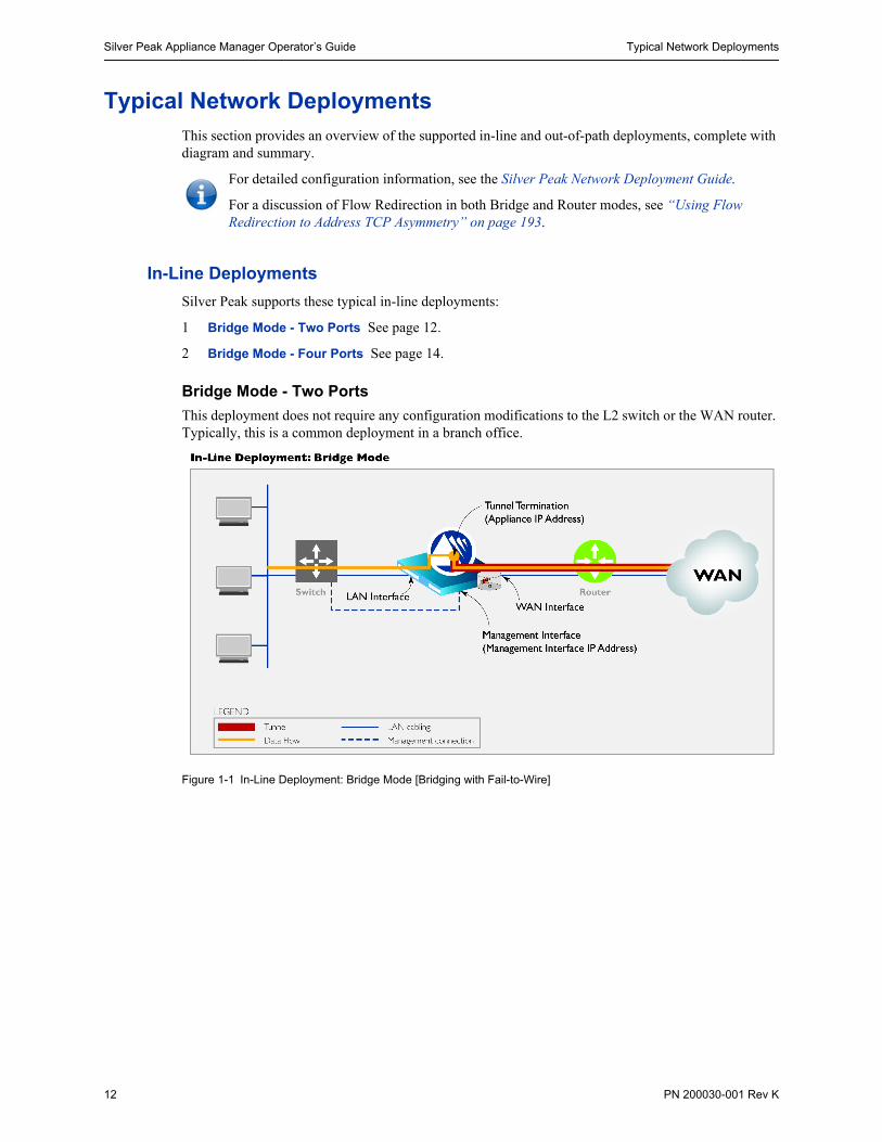
This deployment does not require any configuration modifications to the L2 switch or the WAN router. Typically, this is a common deployment in a branch office.
Figure 1-1 In-Line Deployment: Bridge Mode [Bridging with Fail-to-Wire]

Typical Network Deployments Chapter 1 Overview
PN 200030-001 Rev K 13
Summary
Appliance Placement Appliance placed in-line between Ethernet LAN switch and WAN router
• Appliance LAN interface connects to Ethernet LAN switch
• Appliance WAN interface connects to WAN router
Fail-Safe Behavior Fails-to-Wire: The appliance behaves as a crossover cable between the Ethernet LAN switch and the WAN router in any failure scenario (hardware, software, power).
IMPORTANT: Ensure that the Ethernet LAN’s switch and the WAN router have compatible Ethernet interface physical configuration settings (speed and duplex settings). This is to ensure that traffic flows correctly if the Silver-Peak appliance “Fails-to-wire”.
IP Addresses This deployment model requires two IP addresses (on the same or separate subnets)
• Silver Peak Appliance IP address (to originate and terminate tunnel)
• Silver Peak Management IP Address (for appliance configuration and management)
• Although it’s not a requirement, it’s considered a best practice to use different subnets for the mgmt0 and the Appliance IP.

Silver Peak Appliance Manager Operator’s Guide Typical Network Deployments
14 PN 200030-001 Rev K
Bridge Mode - Four Ports
This deployment does not require any configuration modifications to the L2 switch or the WAN router. Typically, this is a common deployment in a branch office.
Figure 1-2 In-Line Deployment: Bridge Mode [Bridging with Fail-to-Wire]
Silver Peak appliances support the four-port configurations for both pass-through and tunnelized traffic, as shown next.

Typical Network Deployments Chapter 1 Overview
PN 200030-001 Rev K 15
Pass-through Traffic Summary
The following 4-port topologies are supported for pass-though traffic:
Appliance Placement Appliance placed in-line between Ethernet LAN switch and WAN router
• Appliance LAN interface(s) connects to Ethernet LAN switch(es)
• Appliance WAN interface(s) connects to WAN router(s)
Fail-Safe Behavior Fails-to-Wire: The appliance behaves as a crossover cable between the Ethernet LAN switch and the WAN router in any failure scenario (hardware, software, power).
• LAN0 maps to WAN0• LAN1 maps to WAN1• No crossover of traffic in the appliance
IMPORTANT: Ensure that the Ethernet LAN’s switch and the WAN router have compatible Ethernet interface physical configuration settings (speed and duplex settings). This is to ensure that traffic flows correctly if the Silver-Peak appliance “Fails-to-wire”.
IP Addresses This deployment model requires two IP addresses (on the same or separate subnets)
• Silver Peak Appliance IP address (to originate and terminate tunnel)
• Silver Peak Management IP Address (for appliance configuration and management)
• Although it’s not a requirement, it’s considered a best practice to use different subnets for the mgmt0 and the Appliance IP.
Link Propogation Default is Enable. When an interface goes down, it forces the interface that’s paired with it to fail. For example, if LAN1 goes down, it forces WAN1 to fail.

Silver Peak Appliance Manager Operator’s Guide Typical Network Deployments
16 PN 200030-001 Rev K
Tunnelized Traffic Summary
The appliances’ WAN next-hops can be configured Active/Active or Active/Backup.
The following 4-port topologies are supported for tunnelized traffic:
Appliance Placement Appliance placed in-line between Ethernet LAN switch and WAN router
• Appliance LAN interface(s) connects to Ethernet LAN switch(es)
• Appliance WAN interface(s) connects to WAN router(s)
Fail-Safe Behavior Fails-to-Wire: The appliance behaves as a crossover cable between the Ethernet LAN switch and the WAN router in any failure scenario (hardware, software, power).
IMPORTANT: Ensure that the Ethernet LAN’s switch and the WAN router have compatible Ethernet interface physical configuration settings (speed and duplex settings). This is to ensure that traffic flows correctly if the Silver-Peak appliance “Fails-to-wire”.
IP Addresses This deployment model requires two IP addresses (on the same or separate subnets)
• Silver Peak Appliance IP address (to originate and terminate tunnel)
• Silver Peak Management IP Address (for appliance configuration and management)
• Although it’s not a requirement, it’s considered a best practice to use different subnets for the mgmt0 and the Appliance IP.
Link Propogation Default is Enable. When an interface goes down, it forces the interface that’s paired with it to fail. For example, if LAN1 goes down, it forces WAN1 to fail.

Typical Network Deployments Chapter 1 Overview
PN 200030-001 Rev K 17
Out-of-Path Deployments (Router Mode)
Silver Peak supports these typical out-of-path deployments:
1 Out-of-Path with Policy-Based-Routing (PBR Redirection) See page 18.
2 Out-of-Path with Web Cache Communications Protocol (WCCP) See page 19.
3 Out-of-Path with VRRP Peering to WAN Router See page 20.
4 Out-of-Path with Policy-Based-Routing (PBR) and VRRP Redundant Silver Peak Appliances See page 21.
5 Out-of-Path with Web Cache Communications Protocol (WCCP) Redundant Silver Peak Appliances See page 22.

Silver Peak Appliance Manager Operator’s Guide Typical Network Deployments
18 PN 200030-001 Rev K
Out-of-Path with Policy-Based-Routing (PBR Redirection)
Figure 1-3 Out-of-Path Deployment with Policy-Based Routing (PBR): Router Mode [Spare Router Port Available]
Summary
Appliance Placement Attached to available router interface:
• Appliance WAN interface connects to available WAN interface
• Do not connect LAN interface
Failure Method Fails-Open:
• The appliance behaves as unconnected port in all failure cases (hardware, software, power)
• The WAN router sees the link to the appliance go down, Policy-Based-Routing fails, unicast routing forwards traffic normally.
IP Addresses This deployment model requires two IP addresses (on the same or separate subnets):
• Silver Peak Appliance IP Address (to originate and terminate tunnel)
• Silver Peak Management IP Address (for appliance configuration and management)
• Although it’s not a requirement, it’s considered a best practice to use different subnets for the mgmt0 and the Appliance IP.
Configure PBR on WAN router
• Direct traffic from LAN (subnet/interface) destined for WAN to Silver Peak appliance
• Do NOT enable this PBR on the interface to which the Silver Peak appliance connects

Typical Network Deployments Chapter 1 Overview
PN 200030-001 Rev K 19
Out-of-Path with Web Cache Communications Protocol (WCCP)
Figure 1-4 Out-of-Path Deployment: Silver Peak Appliance peered with an L3 router using WCCP
Summary
Appliance Placement Appliance attached in network, reachable by WAN router
• Appliance WAN interface connects to network
• Do not connect LAN interface
Fail-Safe Behavior WCCP recognizes failed appliance
• Appliance removed from WCCP Service Groups
• WAN router resumes forwarding traffic normally according to its routing tables
• Capable of load blalncing across multiple Silver Peak appliances
IP Addresses This deployment model requires two IP addresses (on the same or separate subnets)
• Silver Peak Appliance IP Address (to originate and terminate tunnels)
• Silver Peak Management IP Address (for appliance configuration and management)
• Although it’s not a requirement, it’s considered a best practice to use different subnets for the mgmt0 and the Appliance IP.
Configure WCCP on the Silver Peak appliance and the WAN router
• Configure two WCCP Service Groups on the Silver Peak appliance (one for TCP and one for UDP)
• Configure two WCCP Service Groups on the WAN router (one for TCP and one for UDP)

Silver Peak Appliance Manager Operator’s Guide Typical Network Deployments
20 PN 200030-001 Rev K
Out-of-Path with VRRP Peering to WAN Router
Figure 1-5 Out-of-Path Deployment: Silver Peak Appliance peered with an L3 router using Virtual Router Redundancy Protocol (VRRP)
Summary
Appliance Placement Appliance shares LAN segment with existing equipment
• Appliance WAN interface connects to Ethernet LAN switch
• Do not connect LAN interface
Failure Method Fails -Open:
• The appliance behaves as an unconnected port in all failure cases (hardware, software, power)
• WAN router assumes Virtual IP Address and forwards traffic normally
IP Addresses This deployment model requires three IP addresses:
• Silver Peak Appliance IP Address (to originate and terminate tunnel)
• Silver Peak Management IP Address (for appliance configuration and management)
• Although it’s not a requirement, it’s considered a best practice to use different subnets for the mgmt0 and the Appliance IP.
• Virtual IP Address (VIP) shared by Silver Peak appliance and the WAN router
The VIP must be the default gateway for the clients and servers on the LAN subnet. NOTE: Typically, this would be the current default gateway, to avoid client reconfigurations.
The Silver Peak appliance must share the default gateway VIP with WAN router using VRRP.
• The Silver Peak appliance must be configured with higher priority and preemption to ensure VRRP reverts to the appliance.
Typical Network Deployments Chapter 1 Overview
PN 200030-001 Rev K 21
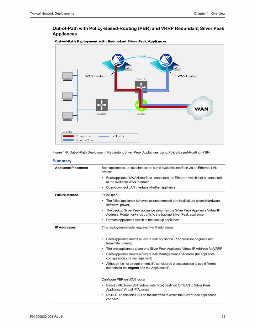
Out-of-Path with Policy-Based-Routing (PBR) and VRRP Redundant Silver Peak Appliances
Figure 1-6 Out-of-Path Deployment: Redundant Silver Peak Appliances using Policy-Based-Routing (PBR)
Summary
Appliance Placement Both appliances are attached to the same available interface via an Ethernet LAN switch:
• Each appliance’s WAN interface connects to the Ethernet switch that is connected to the available WAN interface
• Do not connect LAN interface of either appliance
Failure Method Fails Open:
• The failed appliance behaves as unconnected port in all failure cases (hardware, software, power)
• The backup Silver Peak appliance assumes the Silver Peak Appliance Virtual IP Address. Router forwards traffic to the backup Silver Peak appliance.
• Remote appliances switch to the backup appliance
IP Addresses This deployment model requires five IP addresses:
• Each appliance needs a Silver Peak Appliance IP Address (to originate and terminate tunnels)
• The two appliances share one Silver Peak Appliance Virtual IP Address for VRRP
• Each appliance needs a Silver Peak Management IP Address (for appliance configuration and management)
• Although it’s not a requirement, it’s considered a best practice to use different subnets for the mgmt0 and the Appliance IP.
Configure PBR on WAN router
• Direct traffic from LAN (subnet/interface) destined for WAN to Silver Peak Appliances’ Virtual IP Address
• Do NOT enable this PBR on the interface to which the Silver Peak appliances connect

Silver Peak Appliance Manager Operator’s Guide Typical Network Deployments
22 PN 200030-001 Rev K
Out-of-Path with Web Cache Communications Protocol (WCCP) Redundant Silver Peak Appliances
Figure 1-7 Out-of-Path Deployment: Redundant Silver Peak Appliances peered with an L3 router using WCCP

Typical Network Deployments Chapter 1 Overview
PN 200030-001 Rev K 23
Summary
Appliance Placement Both appliances are attached in network, reachable by WAN router
• Each appliance’s WAN interface connects to network
• Do not connect LAN interface of either appliance
Fail-Safe Behavior WCCP recognizes the failed appliance
• Failed appliance is removed from WCCP Service Groups
• WCCP forwards all traffic to the backup Silver Peak appliance
• Remote appliances switch to the backup appliance
IP Addresses This deployment model requires four IP addresses:
• Each appliance needs a Silver Peak Appliance IP Address (to originate and terminate tunnels)
• Each appliance needs a Silver Peak Management IP Address (for appliance configuration and management)
• Although it’s not a requirement, it’s considered a best practice to use different subnets for the mgmt0 and the Appliance IP.
Configure WCCP on the Silver Peak Appliances and the WAN router
• Configure two WCCP Service Groups on each Silver Peak appliance (one for TCP and one for UDP)
• Configure two WCCP Service Groups on the WAN router (one for TCP and one for UDP)

Silver Peak Appliance Manager Operator’s Guide Typical Network Deployments
24 PN 200030-001 Rev K

PN 200030-001 Rev K 25
C H A P T E R 2
Installing the Appliance
This chapter describes the procedures for installing your Silver Peak appliance. It describes the preparations you need to make, how to install the appliance in a rack, how to access and run the configuration wizard, and how to verify connectivity.
In This Chapter Before You Begin See page 26.
Installing the Appliance into the Network See page 30.
Cabling for Configuration Management See page 32.
Running the Initial Configuration Wizard See page 35.
CAUTION Disconnect AC power before servicing.

Silver Peak Appliance Manager Operator’s Guide Before You Begin
26 PN 200030-001 Rev K
Before You Begin
Summary of Installation Tasks
The following table summarizes the tasks, and points you to the appropriate section of this chapter.
Site Preparation
These preparations ensure quick and smooth installation.
1 Inspect the package contents and verify them against the packing list.
2 Decide on the appliance’s location in the network topology.
For a brief overview of network deployments, see “Typical Network Deployments” on page 12 in Chapter 1, “Overview.”
For detailed deployment scenarios, see the Silver Peak NX Series Appliances Network Deployment Guide.
Task Notes For detailed instructions, see...
1 Review the specifications and prepare the site
Ensure that the physical environment supports the product requirements. Also, make sure that you have all the equipment and network information needed for initial configuration.
Appendix A “Specifications, Compliance, and Regulatory Statements”.
“Site Preparation” on page 26.
2 Rack mount the appliance -- ... rack mount instruction part numbers in next section
3 Connect the power Connect the power cords and check the power LED.
Do NOT turn the power on yet.a
4 Cable the appliance into the network, based on the chosen deployment
Cable the interface ports and verify LED behavior.
“Installing the Appliance into the Network” on page 30.
Appendix A “Specifications, Compliance, and Regulatory Statements”.
5 Turn the power on After each appliance powers up, it goes into Bypass (Fail-to-Wire) mode.
“Installing the Appliance into the Network” on page 30.
6 Connect the management cables
Instructions detail how to connect to the appliance.
“Cabling for Configuration Management” on page 32.
7 Access and run the GUI-based configuration wizard
Configure the appliance for either Bridge mode or a Router mode, based on the selected deployment.
For detailed procedures for each deployment, see Silver Peak NX Series Appliances Network Deployment Guide.
a. Some appliances power up automatically, and therefore are not subject to this step.

Before You Begin Chapter 2 Installing the Appliance
PN 200030-001 Rev K 27
3 Survey the physical site.
You should make note of the following for the physical installation of the appliance:
This appliance...
requires... in a ... Part Number of instructionsa
a. Newest version and/or part number is always downloadable from the Support page of the Silver Peak website. In some cases, a newer rail set is superceding an earlier model; either pair will work.
NX-1700 1 Rack Unit (1 RU) 2-post Telco Rack, or 4-post Server Rack, or rack mount kit for wall or under-desk installation
PN 200450-001
PN 200461-001
NX-2500 1 Rack Unit (1 RU) 2-post Telco Rack out of production
NX-2600 1 Rack Unit (1 RU) 4-post Server Rack PN 200259-001PN 200562-001
NX-2610 1 Rack Unit (1 RU) 4-post Server Rack PN 200259-001PN 200562-001
NX-2700 2 Rack Units (2 RU) 4-post Server Rack PN 200486-001PN 200554-001
NX-3500 2 Rack Units (2 RU) 2-post Telco rack or 4-post Server Rack
PN 200260-001
NX-3600 2 Rack Units (2 RU) 2-post Telco rack or 4-post Server Rack
PN 200371-001
NX-3700 2 Rack Units (2 RU) 4-post Server Rack PN 200486-001PN 200554-001
NX-5500 3 Rack Units (3 RU) 4-post Server Rack PN 200258-001
NX-5504 3 Rack Units (3 RU) 4-post Server Rack PN 200258-001
NX-5600 3 Rack Units (3 RU) 4-post Server Rack PN 200282-001
NX-5700 2 Rack Units (2 RU) 4-post Server Rack PN 200486-001PN 200554-001
NX-7500 3 Rack Units (3 RU) 4-post Server Rack PN 200258-001
NX-7504 3 Rack Units (3 RU) 4-post Server Rack PN 200258-001
NX-7600 3 Rack Units (3 RU) 4-post Server Rack PN 200282-001PN 200588-001
NX-7700 2 Rack Units (2 RU) 4-post Server Rack PN 200486-001PN 200554-001
NX-8504 3 Rack Units (3 RU) 4-post Server Rack PN 200258-001
NX-8600 3 Rack Units (3 RU) 4-post Server Rack PN 200282-001PN 200588-001
NX-8700 2 Rack Units (2 RU) 4-post Server Rack PN 200486-001PN 200554-001
NX-9610 3 Rack Units (3 RU) 4-post Server Rack PN 200282-001PN 200588-001
NX-9700 2 Rack Units (2 RU) 4-post Server Rack PN 200486-001PN 200554-001
NX-10700 2 Rack Units (2 RU) 4-post Server Rack PN 200486-001PN 200554-001

Silver Peak Appliance Manager Operator’s Guide Before You Begin
28 PN 200030-001 Rev K
• Ensure that sufficient power is available. Supply circuits should be protected by a minimum 15A, maximum 20A circuit breaker.
• On the network devices that will provide the WAN, LAN, and management connections to the appliance, identify the 10/100/1000 Ethernet ports, and determine their speed and duplex settings.
• Verify that the ambient temperature does not exceed 35o C (95o F).
• Make sure you have a standard Phillips screwdriver for installing the brackets and rails.
CAUTION IT (Information Technology) Power System: To ensure safe operation of this equipment, connect only to an AC power source that contains a protective earthing (PE) conductor. IT power systems do not provide adequate grounding and are not recommended.
CAUTION Silver Peak NX Appliances contain embedded hard disk drives. Accordingly, securely rack mount the appliance to stabilize it against excessive vibration.

Before You Begin Chapter 2 Installing the Appliance
PN 200030-001 Rev K 29
4 Collect all the data needed for system configuration.
You will need the following information on hand to complete the initial turn up of your Silver Peak appliance. If in doubt, ask your Network Administrator for help.
The next section describes how to install the appliance into the network.
What the initial configuration wizard requires...
Your information... Definition
Host name for Appliance A name you give the appliance that makes it easy for you to remember.
Appliance Mode Bridge: in-line deployment
Router: out-of-path deployment
Administrator password When you create a user name, ensure that the first character of the name is alphabetical (a-z or A-Z). The remaining characters must include one of the following:
• alphabetical (upper or lower case)• numerical• dash (-)• underscore (_)• dot (.)
mgmt0 IP Address/Netmask This is the management interface. It’s the name of the actual physical interface. Labeled as such on the appliance.
mgmt0 Next-hop IP Address The default gateway IP address.
Depending on the network topology, this may or may not be the same as the wan0 Next-hop IP Address.
If you’re unsure, contact your network administrator.
Appliance IP1 Address / Netmask The IP address assigned to the Silver Peak Appliance
Appliance IP2 Address/ Netmask For use in a dual-home router configuration.
wan0 Next-hop IP Address IP address of WAN edge router connected to appliance’s WAN interface cable.
LAN Interface speed[Bridge mode only]
The mode (auto, full duplex, half duplex) and the speed (10, 100, 1000 Mbps) of each of the Ethernet interfaces connected to the appliance.
By default, the Silver Peak appliance supports auto-sense. If the network device connected to the appliance supports auto-sense, both sides should be configured as auto. Otherwise, both sides need to be configured with the same mode and speed.
LAN Interface duplex mode[Bridge mode only]
WAN Interface speed
WAN Interface duplex mode
MGMT (mgmt0) Interface speed
MGMT (mgmt0) Interface duplex mode
lan0 Next-hop IP
[Bridge mode only; optional]
If your LAN has multiple subnets, you can enter this information for one of the subnets.

Silver Peak Appliance Manager Operator’s Guide Installing the Appliance into the Network
30 PN 200030-001 Rev K
Installing the Appliance into the NetworkThis section describes how to install the appliance into your network and verify connectivity before you run the initial configuration wizard from within a browser.
Tip For a brief overview of network deployments, see “Typical Network Deployments” on page 12. For detailed in-line and out-of-path deployment scenarios and configuration instructions, see the Silver Peak NX Series Appliances Network Deployment Guide.
To install the Silver Peak Appliance into the network
1 Identify the lan0, wan0, and mgmt0 ports on the back of the appliance. Connect the supplied network cables from the appliance to the identified network equipment ports.
• Silver Peak follows the convention of using a blue (straight-through) cable for the mgmt0 interface, a red (crossover) cable for the wan0 interface, and a yellow (straight-through) cable for the lan0 interface.
Bridge Mode
Router Mode

Installing the Appliance into the Network Chapter 2 Installing the Appliance
PN 200030-001 Rev K 31
• In most cases, the WAN crossover cable is appropriate. If you have difficulty verifying connectivity in the next step, then switch to a WAN straight-through cable (not supplied).
• All four copper RJ-45 Gigabit Ethernet interfaces (lan0, wan0, mgmt0, and mgmt1) in the Silver Peak appliance support auto MDI/MDI-X and are auto-sensing.
• For fiber interfaces, consult these tables:
2 Verify connectivity between network devices.
This applies to Bridge mode (in-line deployment) only.
a Ping a host on the remote (WAN) side of the Silver Peak appliance from a host on the local (LAN) side of the appliance.
b If you are not able to verify connectivity, check the cabling. Do not proceed to the next step if connectivity still cannot be verified.
1 Gbps Fiber Interfaces
NX-9610 / NX-9700
10 Gbps Fiber Interfaces
NX-8700 / NX-9610 / NX-9700
lan / wana
Fiber Supportlan / wana
Fail-to-Closetlan0 / twan0
Fiber Supporttlan0 / twan0 Fail-to-Close
• 4 interfaces• LC connectors• Support multi-mode 50μ fiber /
62.5μ fiber
NX-9610 — no• 2 interfaces• LC connectors• Support multi-mode 50μ fiber
noNX-9700 — yes
a. This can be for lan0/wan0 or lan1/wan1.
NX-10700 : 1 Gbps Fiber Interfaces
tlan0 / twan0 / tlan1 / twan1
• 4 interfaces• LC connectors
• Support multi-mode 50μ fiber• Fail-to-close — no

Silver Peak Appliance Manager Operator’s Guide Cabling for Configuration Management
32 PN 200030-001 Rev K
Cabling for Configuration ManagementThis section describes how to cable your laptop to the appliance for initial configuration.
After you power up the appliance, you need to establish a management connection and then perform the initial configuration by accessing the wizard in the browser-based graphical user interface (GUI).
Silver Peak assigns the mgmt1 ethernet interface a default IP address of 169.254.0.1 and a subnet mask of /16 (the same as 255.255.0.0).
Both RJ-45 Gigabit Ethernet interfaces (mgmt0 and mgmt1) on the NX Series appliances support MDI/MDI-X and auto-negotiation.
1 Identify the mgmt0 and mgmt1 interfaces on the rear of the appliance.
2 Using the supplied blue straight-through cable, connect the appliance’s mgmt0 interface to the identified network equipment interface.
3 Using the supplied red crossover cable, connect the appliance’s mgmt1 interface to your PC.
4 Check the state of the various management interface port LEDs, per the following charts.

Cabling for Configuration Management Chapter 2 Installing the Appliance
PN 200030-001 Rev K 33
mgmt0 & mgmt1
Not connected 10 Mbps 100 Mbps 1000 Mbps Auto
NX-1700
Speed = solid
--
Link/Activity: blinking = traffic
NX-2500
Speed = solid
--
Link/Activity: blinking = traffic
NX-2600 NX-2610NX-3600
Speed = solid
--
Link/Activity: blinking = traffic
NX-3500
[blinking only]
NX-5500NX-5504NX-7500NX-7504NX-8504
Link = solid
--
Activity: blinking = traffic
Link: ON for 1000 Mbps and 100 Mbps only.
(All full duplex)
NX-5600 NX-7600NX-8600NX-9610
Speed = solid
--
Link/Activity: blinking = traffic
Link/Activity Speed
Link/Activity Speed
Link/Activity Speed
Link/Activity Speed
Speed Link/Activity
Speed Link/Activity
Speed Link/Activity
Speed Link/Activity
Link/Activity Speed
Link/Activity Speed
Link/Activity Speed
Link/Activity Speed
Link/Activity Speed
Link Activity Link Activity Link Activity Link Activity
Link/Activity Speed
Link/Activity Speed
Link/Activity Speed
Link/Activity Speed
Link/Activity Speed

Silver Peak Appliance Manager Operator’s Guide Cabling for Configuration Management
34 PN 200030-001 Rev K
NX-2700NX-3700NX-5700NX-7700NX-8700NX-9700NX-10700
Speed = solid
--
Link/Activity:solid = linkblinking = traffic
mgmt0 & mgmt1
Not connected 10 Mbps 100 Mbps 1000 Mbps Auto
Link/Activity Speed
Link/Activity Speed
Link/Activity Speed
Link/Activity Speed
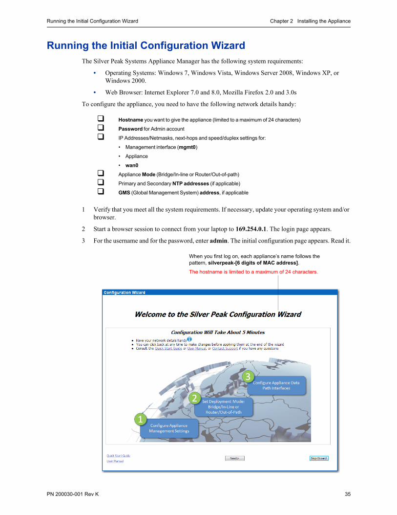
Running the Initial Configuration Wizard Chapter 2 Installing the Appliance
PN 200030-001 Rev K 35
Running the Initial Configuration WizardThe Silver Peak Systems Appliance Manager has the following system requirements:
• Operating Systems: Windows 7, Windows Vista, Windows Server 2008, Windows XP, or Windows 2000.
• Web Browser: Internet Explorer 7.0 and 8.0, Mozilla Firefox 2.0 and 3.0s
To configure the appliance, you need to have the following network details handy:
1 Verify that you meet all the system requirements. If necessary, update your operating system and/or browser.
2 Start a browser session to connect from your laptop to 169.254.0.1. The login page appears.
3 For the username and for the password, enter admin. The initial configuration page appears. Read it.
Hostname you want to give the appliance (limited to a maximum of 24 characters)
Password for Admin account
IP Addresses/Netmasks, next-hops and speed/duplex settings for:
• Management interface (mgmt0)
• Appliance
• wan0
Appliance Mode (Bridge/In-line or Router/Out-of-path)
Primary and Secondary NTP addresses (if applicable)
GMS (Global Management System) address, if applicable
When you first log on, each appliance’s name follows the pattern, silverpeak-[6 digits of MAC address].
The hostname is limited to a maximum of 24 characters.

Silver Peak Appliance Manager Operator’s Guide Running the Initial Configuration Wizard
36 PN 200030-001 Rev K
Note If you want to access this page in the future, just go to the Administration menu, and select Initial Config Wizard.
4 Click Next, and continue through the wizard.
5 Complete the fields, and click Apply. When the appliance asks permission to reboot, allow it.
Tip If you need a reference, see the detailed instructions for the specific scenarios in the Silver Peak NX Series Appliances Network Deployment Guide.

PN 200030-001 Rev K 37
C H A P T E R 3
The Appliance Manager
This chapter describes the structure, content, and features of the Appliance Manager. It also familiarizes you with elements, hierarchy, and conventions employed by the Appliance Manager’s interface.
In This Chapter Accessing the Appliance Manager See page 38.
Guided Tour of the Appliance Manager See page 40.

Silver Peak Appliance Manager Operator’s Guide Accessing the Appliance Manager
38 PN 200030-001 Rev K
Accessing the Appliance ManagerThe Silver Peak Systems Appliance Manager has the following system requirements:
• Operating Systems: Windows XP, Windows 2000, or Windows Vista
• Web Browsers: Internet Explorer, Mozilla Firefox
Verify that you meet all the system requirements. If necessary, update your operating system and/or browser.
1 In the browser, enter http://<mgmt0 IP Address>/ to access the Appliance Manager. This is the address you configured on the first page of the initial configuration wizard.
Note The default web setting allows for both http and https, so you can use either at this stage.
A security alert pop-up window displays.
Note If a message displays telling you that the page cannot be displayed, you may be trying to access the appliance across a firewall. In that case, it may be necessary to open TCP ports 80 and 443 to/from the management IP address.
2 Click OK to proceed. Another Security Alert window displays.
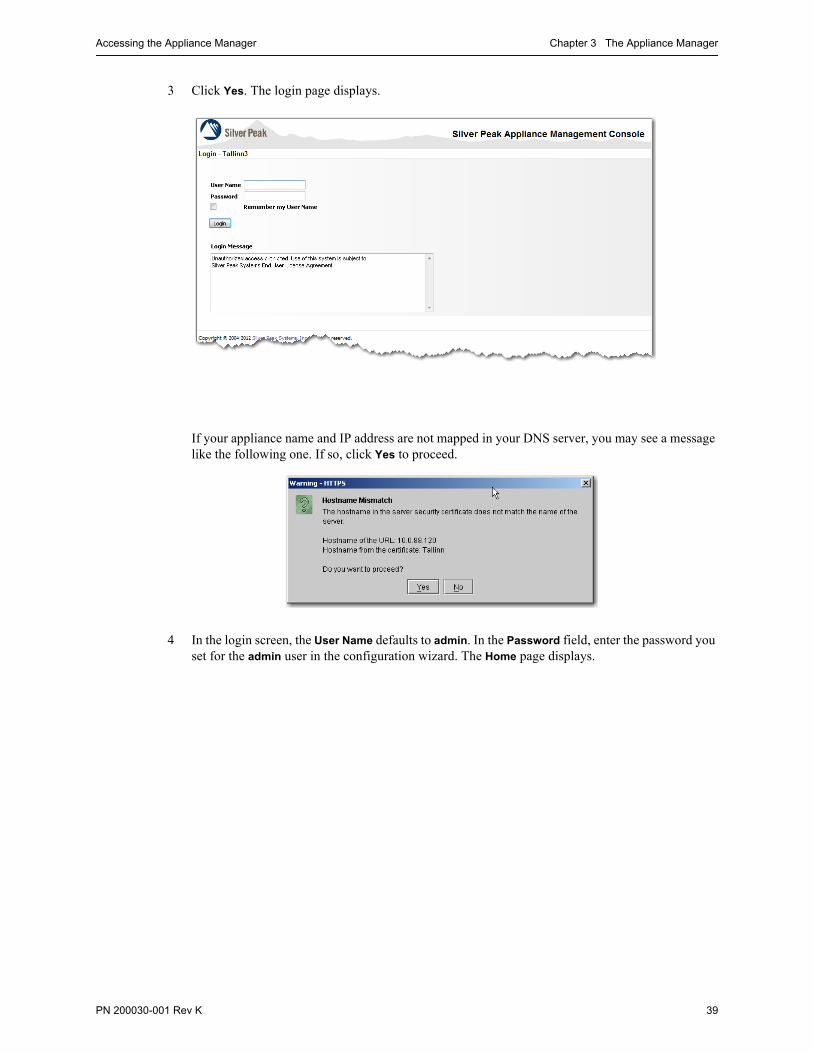
Accessing the Appliance Manager Chapter 3 The Appliance Manager
PN 200030-001 Rev K 39
3 Click Yes. The login page displays.
If your appliance name and IP address are not mapped in your DNS server, you may see a message like the following one. If so, click Yes to proceed.
4 In the login screen, the User Name defaults to admin. In the Password field, enter the password you set for the admin user in the configuration wizard. The Home page displays.

Silver Peak Appliance Manager Operator’s Guide Guided Tour of the Appliance Manager
40 PN 200030-001 Rev K
Guided Tour of the Appliance ManagerThis section describes navigational and screen elements that are common throughout the user interface. It also describes common operations such as selecting and deleting items from a table, sorting columns, and refreshing screens:
• The Appliance Manager Home Page See page 40.
• Banners See page 42.
• Menu Structure See page 42.
• Managing Tabular Data See page 49.
• Netmask Notations See page 50.
• Date and Time Conventions See page 52.
• Secure Access Methods See page 52.
• Guidelines for Creating Passwords See page 52.
• Object Names See page 52.
• Saving Your Configuration See page 53.
• Definition Help See page 53.
The Appliance Manager Home Page
The Appliance Manager Home - Summary page displays the last hour’s worth of statistics for bandwidth, applications, latency, loss, and top 10 flows.

Guided Tour of the Appliance Manager Chapter 3 The Appliance Manager
PN 200030-001 Rev K 41
Additionally, the home page provides links to the main pages from which each abbreviated chart derives.
For more information, see Chapter 12, “Monitoring Traffic.”
→ Monitoring > Bandwidth → Monitoring > Applications
→ Monitoring > Latency
→ Monitoring > Loss
→ Configuration > Tunnels > [individual tunnel > FEC]
For more information, see Chapter 5, “Creating Tunnels.”
→ Monitoring > Current Flows
→ Alarms > Current Alarms > [ Recommended Action link ]For more information, see Chapter 15, “Monitoring Alarms.”
Each counts uncleared alarms

Silver Peak Appliance Manager Operator’s Guide Guided Tour of the Appliance Manager
42 PN 200030-001 Rev K
Banners
The banner is common to all of the Appliance Manager pages:
Menu Structure
This section lists each main menu with its submenus, and describes its contents.
Configuration Menus
These menus are for configurations related to host settings, networking, applications, and deployments.
User Name of the person who is logged in
Click to log off the appliance
The appliance’s Hostname, followed by the mgmt0 IP address (Normal state).
However, when an appliance is in hardware Bypass, the state is noted after the Hostname, and the text is red.
The name of the page you’re viewing. Correlates to menu - submenu pairs.
Mouse over a menu to access drop-down submenus
Menu bar
Date, time, and time zone configured for this appliance, as well as software version number
Table 3-1 Configuration Menus
Menu Name Description
System Configure basic system parameters.
Identifies the appliance’s hostname, ID, location, and contact person. Here you specify the following:
• whether or not to encrypt data on the appliance hard drives• whether or not to put the appliance in System Bypass• whether the deployment is in-line (Bridge Mode) or out-of-path (Router Mode), along
with IP addresses for the appliance(s) and next-hop(s)• if in Bridge mode, whether to propogate the link down• if using a 4-port appliance, whether or not to use etherchannel bonding• the maximum WAN bandwidth.
For more information, see Chapter 4, “Configuring Host Settings.”

Guided Tour of the Appliance Manager Chapter 3 The Appliance Manager
PN 200030-001 Rev K 43
Date/Time Configure date and time.
Specifies time zone, and whether time is set manually or via one of the user-specified NTP servers.
For more information, see Chapter 4, “Configuring Host Settings.”
Tunnels Configure tunnels.
Specifies all tunnels, their states and endpoints, their minimum and maximum bandwidths (configured and current), whether or not IPsec is enabled, and how long the tunnel has been up.
When modifying a tunnel, you can also access and change the default values for MTU, mode (gre / udp), FEC, reorder wait, and traffic classes.
For more information, see Chapter 5, “Creating Tunnels.”
Pass-through Configure pass-through traffic.
Specifies the minimum and maximum bandwidth for the pass-through traffic. Includes a table for managing bandwidth and queuing by traffic class.
For more information, see Chapter 8, “Bandwidth Management & QoS Policy.”
Access Lists Configure access control lists.
Each ACL consists of one or more rules. Rules specify MATCH criteria that you can associate with Route, QoS, and Optimization policies [maps]. ACLs are convenient when you want to name a set of MATCH criteria and/or reuse them in multiple rules or maps.
For more information, see Chapter 6, “Theory of Operations.”
Route Policy Configure route map(s) and specify one map to be the active route policy.
Route maps associate MATCH criteria, or an existing ACL, with the following SET actions:
• tunnel• tunnel down action [what to do when the associated tunnel goes down]
For more information, see Chapter 7, “Route Policy.”
QoS Policy Configure QoS map(s) and specify one map to be the active QoS policy.
QoS maps associate MATCH criteria, or an existing ACL, with SET actions. QoS actions tell the appliance how to handle values found in the LAN and WAN ToS (Type of Service) fields.
For more information, see Chapter 8, “Bandwidth Management & QoS Policy.”
Optimization Policy Configure optimization map(s) and specify one map to be the active optimization policy.
Optimization maps associate MATCH criteria, or an existing ACL, with any combination of the following SET actions:
• Network Memory• payload compression• TCP acceleration• CIFS acceleration
For more information, see Chapter 9, “Optimization Policy.”
Table 3-1 Configuration Menus (Continued)
Menu Name Description

Silver Peak Appliance Manager Operator’s Guide Guided Tour of the Appliance Manager
44 PN 200030-001 Rev K
Networking Configure various networking parameters.
Interfaces: Identifies the specifics of the two management (mgmt0, mgmt1) and two network (lan0, wan0) interfaces. Allows the user to choose whether to statically set IP addresses or to use DHCP.
A 4-port appliance includes two additional interfaces — lan1 and wan1.
VLAN: When the appliance is in Bridge mode, specifies the configuration for VLANs. This enables tagging of packets and use of VLANs as discriminators in policy and/or ACL MATCH criteria.
IP Routes: Specifies or provides information about the following:
• Static routes and the default gateway control how management traffic is routed out of the appliance.
• Specifies next-hop address(es) for LAN-side networks that are not directly connected to a Bridge-mode (in-line) appliance.
DNS: Specifies up to three Domain Name Servers, along with any user-specified domains.
VRRP: For high availability, allows you to configure traffic redirection, with or without redundancy, by configuring VRRP (Virtual Router Redundancy Protocol) on a common virtual interface.
WCCP: For high availability, allows you to configure traffic redirection, with or without redundancy, by configuring WCCP (Web Cache Communications Protocol).
Flow Redirection: Ensures that you don’t have asymmetrical TCP flows between peer appliances.
NetFlow: For collecting and sending traffic flow data to a centralized NetFlow collector.
For more information, see Chapter 4, “Configuring Host Settings.”
For detailed deployment procedures, see the Silver Peak NX Series Appliances Network Deployment Guide.
Application Configure custom applications or application groups.
Built-in: Lists the standard applications included, by name and port number(s).
User Defined: For configuring custom applications, based on any combination of port, port ranges, IP address, DSCP, or VLAN.
Groups: Lets you create and name sets of applications. You can use these in the Application field of any ACL’s or policy’s MATCH criteria.
For more information, see Chapter 6, “Theory of Operations.”
Table 3-1 Configuration Menus (Continued)
Menu Name Description

Guided Tour of the Appliance Manager Chapter 3 The Appliance Manager
PN 200030-001 Rev K 45
Monitoring Menus
These reports are realtime in nature and thereby more suitable for use in troubleshooting. Each graph provides for access to the raw data via the Table View button.
Table 3-2 Monitoring Menus
Menu Name Description
Applications Monitor real-time application statistics for individual tunnel, pass-through shaped, or pass-through unshaped traffic.
Provides the choice of a pie chart or a table to display application statistics for the WAN or LAN side. The pie chart displays the percentage of traffic for the top 10 applications. The table expands the data to include all available applications.
You can view the statistics accrued since the last reboot or since resetting the counter to zero.
For more information, see “Viewing Application Statistics” on page 217.
Current Flows Monitor current flows, based on multiple selectable criteria.
Retrieves a listing of up to 100 realtime connections based on selectable filter criteria. These include end points, ports, route, and application.
For more information, see “Viewing Current Flows” on page 219.
QoS Monitor tunnel-specific QoS statistics.
Selectable for all tunnels or for individual tunnels, specifies the total number of bytes and packets transmitted and received, based on traffic class and/or WAN QoS [DSCP] marking. Also provides granular information about types of packets, as in dropped, invalid, duplicate, etc.
You can view the statistics accrued since the last reboot or since resetting the counter to zero.
For more information, see “Viewing Tunnel QoS Statistics” on page 234.
Tunnels Monitor tunnel statistics.
LAN/WAN Statistics: Specifies the total number of bytes and packets transmitted and received, as well as invalid, lost, and duplicate packets.
Flows/Latency/Packet Correction Statistics: Provides data about accelerated and non-accelerated TCP flow, round-trip latency (minimum, maximum, and average), packet loss before and after applying Forward Error Correction, and out-of-order packets before and after Packet Order Correction.
You can view the statistics accrued since the last reboot or since resetting the counter to zero.
For more information, see “Viewing Tunnel Statistics” on page 236.
Reduction Monitor the reduction of (data) bytes.
Selectable for optimized traffic or for individual tunnels, displays the total number of bytes (and packets) received, processed, and transmitted by a tunnel in the outbound (LAN-to-WAN) and inbound (WAN-to-LAN) direction.
For more information, see “Viewing Reduction Statistics” on page 241.
Bandwidth Monitor bandwidth usage.
Selectable for all tunnels or for individual tunnels, compares the traffic’s bandwidth usage on the LAN and WAN.
For more information, see “Viewing Bandwidth Statistics” on page 243.
Flow Counts Monitor flow counts.
For all optimized traffic or on an individual tunnel basis, provides realtime data for the various TCP and non-TCP flows.
For more information, see “Viewing Flow Counts” on page 224.

Silver Peak Appliance Manager Operator’s Guide Guided Tour of the Appliance Manager
46 PN 200030-001 Rev K
Latency View latency data.
On a per-tunnel basis, provides data about round-trip latency (minimum, maximum, and average).
For more information, see “Viewing Latency Statistics” on page 247.
Network Integrity Monitor packet loss and out-of-order packets.
On a per-tunnel basis, displays
• packet loss (minimum, maximum, and average) before /after Forward Error Correction• out-of-order packets (minimum, maximum, and average) before /after Packet Order
Correction
For more information, see “Viewing Network Integrity Statistics” on page 248.
Dynamic Charts Monitor traffic by selecting chart focus, traffic type, direction, and time span.
Dynamic charts feature spark lines, as well as selectable (and modifiable) time ranges for any data collected in the last 72 hours.
Overall, it includes bandwidth, reduction, packets per second, and flow counts. Specific to single tunnels, it includes latency, loss, and out-of-order packets.
For more information, see “Viewing Dynamic Charts” on page 250.
All Reports Summarizes the legacy charts for the selected time period.
This summary page includes charts/graphs for (top 10) applications, reduction, bandwidth, flows (+/- TCP), latency, packet loss (Forward Error Correction), and out-of-order packets (Packet Order Correction). You can export this page as an image in PDF or PNG format.
For more information, see “Viewing a Summary of All Reports” on page 259.
Flow Redirection Monitor how many flows were redirected to maintain TCP symmetry.
Between an appliance and its peer (if one exists), displays how many flows, packets, and bytes were redirected to ensure that flows are not asymmetrical.
You can view the statistics accrued since the last reboot or since resetting the counter to zero.
For more information, see “Viewing Flow Redirection Statistics” on page 260.
NetFlow Monitor the number of records sent to the NetFlow collector(s).
Displays the number of control packets sent and received between this appliance and the other peers in the cluster. Also displays how much traffic was redirected to and from the other peers.
For more information, see “Viewing NetFlow Statistics” on page 262.
Interfaces Monitor network LAN/WAN interface statistics.
For the physical lan0, wan0, mgmt0, and mgmt1 interfaces, specifies the number of bytes, as well as the number of packets discarded, errors encountered, packets overrun, frames sent, carriers used, and multicast packets.
For a 4-port appliance, data also accrues for the lan1 and wan1 interfaces.
You can view the statistics accrued since the last reboot or since resetting the counter to zero.
For more information, see “Viewing Interface Statistics” on page 263.
Table 3-2 Monitoring Menus (Continued)
Menu Name Description

Guided Tour of the Appliance Manager Chapter 3 The Appliance Manager
PN 200030-001 Rev K 47
Administration Menus
These menus are related to managing various appliance administrative functions.
Bridges Monitor the interfaces used and link health in bridge mode.
In bridge mode deployments, this screen provides details that help explain the amount of traffic and state of the interfaces in a bridged topology.
You can view the statistics accrued since the last reboot or since resetting the counter to zero.
For more information, see “Viewing Bridge Mode Statistics” on page 265.
IP Routes Monitor next-hop reachability.
You can view the statistics accrued since the last reboot or since resetting the counter to zero.
For more information, see “Viewing IP Routes” on page 266.
Table 3-2 Monitoring Menus (Continued)
Menu Name Description
Table 3-3 Administration Menus
Menu Name Description
Logging Configure logging thresholds and view event and alarm logs.
Log Settings: For configuring system logging thresholds. Allows you to set parameters related to the local log, including specifying a minimum severity level logged and how often to start a new log file, based on frequency or size. Also, you can designate a remote log server with its own severity threshold.
Event Log Viewer: Displays timestamped messages for all system-level activity.
Alarm Log Viewer: Displays timestamped messages for all alarm activity.
Audit Log Viewer: Displays timestamped configuration changes and system actions made by the user.
For more information, see the following:
• “Configuring Log Settings” on page 268• “Understanding the Events Log” on page 273• “Viewing a Log of All Alarms” on page 274.• “Viewing the Audit Log” on page 275.
Debug Files Manage file system.
Provides user data disk information, and lets you manage the following collections of generated files:
• Log• Debug Dump• Snapshot• TCP Dump Result• Tech Support
For more information, see “Managing Debug Files” on page 276.
Pre-position Enable an appliance to place received FTP content into Network Memory.
Allows you to pre-position—or push—files from a file server (FTP client) to the appliance (FTP server). The end result is that the file data is prepopulated into Network Memory.
For more information, see “Pre-Positioning Data for Enhanced Acceleration Benefits” on page 283.
SNMP Configure SNMP trap destinations.
You can specify which hosts receive SNMP traps.
For more information, see “Configuring SNMP” on page 285.

Silver Peak Appliance Manager Operator’s Guide Guided Tour of the Appliance Manager
48 PN 200030-001 Rev K
Maintenance Menus
These menus are related to maintaining the appliance software, databases, disks, Network Memory, and system restarts.
User Management Manage users and their access.
Users: Lists all local users — enabled or not. Lets you assign or change user names, groups, and passwords.
Banners: For configuring a Login Message and/or Message Of The Day.
Authentication: For configuring authentication methods and authorization information.
RADIUS: For configuring RADIUS settings and servers.
TACACS+: For configuring TACACS+ settings and servers.
For more information, see “Managing User Accounts” on page 290.
Web Configure web server access settings.
For configuring web protocol settings (http, https), and web user settings (inactivity time-out, maximum number of user sessions).
For more information, see “Configuring Settings for Web Protocols and Web Users” on page 313.
Initial Config Wizard Provides access to the Initial Config Wizard.
For more information, see “Initial Configuration Wizard” on page 314.
Support Provides information that Technical Support requires when you contact them, along with the contact info.
For more information, see “Support” on page 316.
Table 3-3 Administration Menus (Continued)
Menu Name Description
Table 3-4 Maintenance Menus
Menu Name Description
System Information Lists appliance-specific system information.
Includes hostname, appliance ID, model, system status, uptime, date/time, software version, serial number, mode, appliance IP address, and whether or not disk encryption is enabled.
For more information, see “Viewing System Information” on page 318.
Software Upgrade Upgrade, install, and manage software images.
For loading software images into the two partitions by installing them from a local hard disk, a URL, an SCP (Secure Copy) server, or an FTP server. Also lets you select which partition will be active at the next reboot of the appliance.
For more information, see “Upgrading the Appliance Manager Software” on page 320.
Configuration Management
Manage configuration files.
Allows you to save or load an appliance configuration file, view a saved configuration, revert to a saved file, activate a file, rename a file, or delete a file.
For more information, see “Managing the Appliance Configuration File” on page 331.
Disk Management Manage disk.
Provides read-only RAID information, and provides a table that lists each disk, its status, size, and serial number.
For more information, see the Field Replaceable Unit Guide.

Guided Tour of the Appliance Manager Chapter 3 The Appliance Manager
PN 200030-001 Rev K 49
Alarm Menu
Managing Tabular Data
By default, a table sorts on the first column. Additionally, the Appliance Manager allows you to select any column for sort by clicking on its heading. The selected column’s heading displays an arrow to the right.
Network Connectivity Test network connectivity.
Provides access to three tests — ping, traceroute, and tcpdump.
For more information, see “Testing Network Connectivity” on page 345.
Erase Network Memory Clears Network Memory without rebooting the appliance.
For more information, see “Erasing Network Memory” on page 358.
Restart System Restart system with options.
Allows you to select from the following:
• Reboot the appliance• Reboot the appliance and erase Network MemoryTM
• Shutdown the appliance until the power is turned on again
For more information, see “Restarting the Appliance” on page 359.
Table 3-4 Maintenance Menus (Continued)
Menu Name Description
Table 3-5 Alarm Menu
Menu Name Description
[Current] Alarms View current alarms.
Lists all critical, major, minor, and warning alarms.
For more information, see Chapter 15, “Monitoring Alarms.”
The triangle indicates which column is being used to sort. To reverse the order, click the triangle.

Silver Peak Appliance Manager Operator’s Guide Guided Tour of the Appliance Manager
50 PN 200030-001 Rev K
Netmask Notations
When designating netmasks, the Appliance Manager uses the slash notation (/) for netmasks or bitmasks.
The following table shows the relationship between the / (“slash”) notation, the byte notation, and the corresponding binary numbers (with a dot every eight digits) for the 32-bit addresses. Also included is a count of how many Class A/B/C networks the larger networks encompass.
/ notation, also known as the “slash” notation
/ Notation Binary Byte Notation # Class
/0 00000000.00000000.00000000.00000000 0.0.0.0 256 A
/1 10000000.00000000.00000000.00000000 128.0.0.0 128 A
/2 11000000.00000000.00000000.00000000 192.0.0.0 64 A
/3 11100000.00000000.00000000.00000000 224.0.0.0 32 A
/4 11110000.00000000.00000000.00000000 240.0.0.0 16 A
/5 11111000.00000000.00000000.00000000 248.0.0.0 8 A
/6 11111100.00000000.00000000.00000000 252.0.0.0 4 A
/7 11111110.00000000.00000000.00000000 254.0.0.0 2 A
/8 11111111.00000000.00000000.00000000 255.0.0.0 1 A
/9 11111111.10000000.00000000.00000000 255.128.0.0 128 B
/10 11111111.11000000.00000000.00000000 255.192.0.0 64 B
/11 11111111.11100000.00000000.00000000 255.224.0.0 32 B
/12 11111111.11110000.00000000.00000000 255.240.0.0 16 B
/13 11111111.11111000.00000000.00000000 255.248.0.0 8 B
/14 11111111.11111100.00000000.00000000 255.252.0.0 4 B
/15 11111111.11111110.00000000.00000000 255.254.0.0 2 B
/16 11111111.11111111.00000000.00000000 255.255.0.0 1 B
/17 11111111.11111111.10000000.00000000 255.255.128.0 128 C
/18 11111111.11111111.11000000.00000000 255.255.192.0 64 C
/19 11111111.11111111.11100000.00000000 255.255.224.0 32 C
/20 11111111.11111111.11110000.00000000 255.255.240.0 16 C
/21 11111111.11111111.11111000.00000000 255.255.248.0 8 C
/22 11111111.11111111.11111100.00000000 255.255.252.0 4 C

Guided Tour of the Appliance Manager Chapter 3 The Appliance Manager
PN 200030-001 Rev K 51
/23 11111111.11111111.11111110.00000000 255.255.254.0 2 C
/24 11111111.11111111.11111111.00000000 255.255.255.0 1 C
/25 11111111.11111111.11111111.10000000 255.255.255.128
/26 11111111.11111111.11111111.11000000 255.255.255.192
/27 11111111.11111111.11111111.11100000 255.255.255.224
/28 11111111.11111111.11111111.11110000 255.255.255.240
/29 11111111.11111111.11111111.11111000 255.255.255.248
/30 11111111.11111111.11111111.11111100 255.255.255.252
/31 11111111.11111111.11111111.11111110 255.255.255.254
/32 11111111.11111111.11111111.11111111 255.255.255.255
/ Notation Binary Byte Notation # Class
Silver Peak Appliance Manager Operator’s Guide Guided Tour of the Appliance Manager
52 PN 200030-001 Rev K
Date and Time Conventions
The Appliance Manager uses these conventions across all application modules:
• If the screen shows data related to today’s date, then only the time is shown.
• If the data is from a past or future date, then both the time and date are included.
• The timestamp is based on the 24-hour (military) clock.
Times shown are based on the local time zone.
Secure Access Methods
By default, the Silver Peak appliance ships preconfigured for web access over http with Secure Sockets Layer (SSL) encryption. In other words, the URL begins with https://. To change the configuration, see the Administration - Web page.
Guidelines for Creating Passwords
Passwords should be a minimum of 8 characters.
There should be at least one lower case letter and one upper case letter.
There should be at least one digit.
There should be at least one special character
Consecutive letters in the password should not be dictionary words.
Object Names
When you create a name for an object, such as a tunnel, access control list, or a route map, you can use one of the following types of characters:
alphabetical (upper or lower case)
numerical
dash (-)
underscore (_)
dot (.)
Note However, the dot (.) cannot be used in a hostname.

Guided Tour of the Appliance Manager Chapter 3 The Appliance Manager
PN 200030-001 Rev K 53
Saving Your Configuration
As you Apply page settings, the Appliance Manager applies the values to the running configuration file. As long as the Save Changes button — located in the upper right part of the page — has a red background, you have not permanently saved the edits.
After you click Save Changes, the button reverts to a light background until you make more changes.
You can keep applying your changes as you work across multiple pages and then save the running configuration when you’re done.
There are a few items, however, that are not part of, or don’t affect, the configuration file. These include:
• log files (alarms, events, troubleshooting) and their display
• software partitions (and, hence, upgrade or install operations)
• system restarts
So, for those, you won’t see a reminder to save the configuration, either on screen or in this document.
Definition Help
When you see the icon near a term or field, roll the mouse over it for definition Help.
No unsaved changes...Indicates unsaved changes...
Roll mouse over icon for Help

Silver Peak Appliance Manager Operator’s Guide Guided Tour of the Appliance Manager
54 PN 200030-001 Rev K

PN 200030-001 Rev K 55
C H A P T E R 4
Configuring Host Settings
This chapter describes how to configure or modify appliance system parameters, including the WAN bandwidth available to the appliance. Additionally, it describes how to set the date and time, add DNS servers, work with the routing tables, modify network interface parameters, and configure export to NetFlow collectors.
In This Chapter Overview See page 56.
Configuring System Settings and Max System Bandwidth See page 56.
Selecting a System Deployment See page 58.
Configuring Network Parameters See page 65.
Configuring Flow Exports for NetFlow See page 76.

Silver Peak Appliance Manager Operator’s Guide Overview
56 PN 200030-001 Rev K
OverviewWhen you first installed the appliance and logged in via the browser, you were presented with the Initial Configuration Wizard. What you configured depends on whether you selected Bridge mode (for in-line deployment) or Router mode (for out-of-path deployment). Then, typically, you move on to using the Appliance Manager.
The basic parameters that you can and/or need to configure now include:
• Configuring System Settings and Max System Bandwidth See page 56.
• Selecting a System Deployment See page 58.
• Configuring Network Parameters See page 65.
• Configuring Flow Exports for NetFlow See page 76.
Configuring System Settings and Max System BandwidthWhen you access the Configuration - System page, you can do all of the following:
• Add contact information, such as the appliance owner’s name, address, phone number, and/or e-mail address
• Add a user-friendly note about the appliance’s location, whether it be a street address or a company’s department
• Enable Auto Tunnel, which automatically creates tunnels between Silver Peak appliances that have network connectivity and active flows. By default, auto-optimization of IP traffic is in effect for automatically created tunnels.
• Enable Auto Reset TCP Flows for resetting TCP flows that are not accelerated but are in the tunnel. Consider your environment carefully before implementing.
• Choose not to encrypt data on the appliance hard drive(s), contrary to the default selection
• Change modes: Bridge, for in-line deployment, or Router, for out-of-path deployment. After changing the mode, you must reboot the appliance for the change to take effect.
• Choose to propagate a down link, or not. Propagate Link Down forces the WAN interface to go down when the corresponding LAN interface goes down, or vice versa. By default, this option is enabled.
• View and/or modify the total bandwidth configured for the WAN interface
• Select System Bypass to put the appliance into hardware bypass mode.
• Configure etherchannel bonding, to bond pairs of Ethernet ports (lan0 + lan1, wan0 + wan1) into a single port with one IP address. For more information, see “Configuring Gigabit Etherchannel Bonding” on page 61.

Configuring System Settings and Max System Bandwidth Chapter 4 Configuring Host Settings
PN 200030-001 Rev K 57
The Hostname and Appliance ID fields display what you entered when you first connected to the appliance and were taken to the initial configuration wizard. The same is true for the mode (Router or Bridge) you selected (lower down this page).
You can modify those entries here, except for the Hostname. The only way to change that within the GUI is to go to the Administration menu and select Initial Config Wizard. The appliance must reboot for the change to take effect.
The WAN Bandwidth section refers to the bandwidth at the router’s WAN interface.
For guidance, refer back to “Best Practices for Bandwidth Management” on page 152.
Encrypting hard disk data is the appliance default.
The default value for wan0, shown in the Max Bandwidth field, is different for each appliance model. To maintain the best traffic flow, refer to the section, “Best Practices for Bandwidth Management” on page 152.
When you select System Bypass, the appliance mechanically isolates itself from the network, allowing traffic to flow without intervention.
When you deselect System Bypass, the appliance again allows traffic to be directed to tunnels for optimization.
Propagate Link Down forces the WAN interface to go down when the corresponding LAN interface goes down, or vice versa. Checked by default.
For 4-port devices, enables gigabit etherchannel bonding.
The NX-9700, NX-9610, and NX-8700 run at either 1G (by default) or 10G. The NX-10700 runs at 10G. To run at 10G, you must cable the appropriate interfaces, select its 10 Gigabit checkbox, and reboot.
Notice that in the WebUI, its interfaces are labeled twan0 and tlan0.
For resetting TCP flows that are not accelerated but are in the tunnel. See “How Auto-Optimization Works in TCP” on page 129.

Silver Peak Appliance Manager Operator’s Guide Selecting a System Deployment
58 PN 200030-001 Rev K
Selecting a System DeploymentAlong with a view of the deployment options, this section addresses the following:
Sorting Through the Deployment Options See page 60.
Configuring Gigabit Etherchannel Bonding See page 61.
Changing deployment mode requires a reboot.
BRIDGE MODE
This screen appears when you click Advanced after choosing Bridge.
Bridge 2-port
• Most common bridge mode deployment
• The appliance is in-line between a single WAN router and a single WAN-side switch.
Bridge Standard 4-port
• Most common 4-port bridge configuration
• 2 routers / 2 subnets / 1 appliance
• 2 ISPs or 2 services (MPLS, IPsec VPN, MetroEthernet, etc.) or both
• Tunnel packets are sourced with a single IP address (Appliance IP1)
Bridge Flat 4-port
• Less common 4-port bridge configuration
• 2 routers / 1 subnet / 1 appliance
• 2 ISPs or 2 services (MPLS, IPsec VPN, MetroEthernet, etc.) or both
Bridge 4-port Bonding
• Increased throughput on a very high-end appliance and/or interface-level redundancy
• “Super” version of Bridge 2-port
• Uses 2 ports from same WAN router

Selecting a System Deployment Chapter 4 Configuring Host Settings
PN 200030-001 Rev K 59
ROUTER MODE
This screen appears when you click Advanced after choosing Router.
Router Standard
• Most common one-armed configuration
• Single subnet / single router
Router Dual Homed
• For flow redirection on the WAN side
• 2 routers / 2 subnets / 1 appliance
• 2 ISPs or 2 services (MPLS, IPsec VPN, MetroEthernet, etc.) or both
• Can set up 2 instances of either WCCP or Policy-Based Routing
• Tunnel packets are sourced with a single IP address (Appliance IP1)
ROUTER BONDING MODE
This screen appears when you click Advanced after choosing Router and Bonding.
Using 4-port appliances for more throughput
[1 Gbps + 1 Gbps = 2 Gbps]
Router Standard Bonding
• Increased throughput on a very high-end appliance and/or interface-level redundancy
• “Super” version of Router Standard
• Uses 2 ports at same WAN router
RouterDual Homed Bonding
• Increased throughput on a very high-end appliance and/or interface-level redundancy
• “Super” version of Router Dual Homed
• Uses 2 ports at each WAN router
• Tunnel packets are sourced with a single IP address (Appliance IP1)

Silver Peak Appliance Manager Operator’s Guide Selecting a System Deployment
60 PN 200030-001 Rev K
Sorting Through the Deployment Options

Selecting a System Deployment Chapter 4 Configuring Host Settings
PN 200030-001 Rev K 61

Silver Peak Appliance Manager Operator’s Guide Selecting a System Deployment
62 PN 200030-001 Rev K
Configuring Gigabit Etherchannel Bonding
When using a four-port Silver Peak appliance, you can bond pairs of Ethernet ports into a single port with one IP address. This feature provides the capability to carry 2 Gbps in and out of an NX Series appliance when both ports are in service.
When you configure bonding, the following is true:
• lan0 plus lan1 bond to form blan0, which uses the lan0 IP address.
• wan0 plus wan1 bond to form bwan0, which uses the wan0 IP address.
• The appliances use flow-based load balancing across the links.
• This configuration provides failover in case one link goes down.
• You can view the statistics on the Monitoring - Interfaces page. If you’re using bonding, you’ll see statistics for blan0 and bwan0, as well as for the interfaces that comprise them (lan0, lan1, wan0, and wan1).
• If a WCCP or VRRP deployment already exists, then you must reconfigure the deployment on the bonding interface. In other words, if you previously configured on wan0, then after bonding you must reconfigure on bwan0.
Rollback to non-bonding mode returns the intact, non-bonded configuration.
• Enabling/disabling bonding requires an appliance reboot.
To configure etherchannel bonding
To enable bonding, you need to configure both the appliance and the router for bonding.
1 Access the Configuration - System page, and select one of the three available bonding modes:
a To select the Bridge mode bonding option for 4-port Bonding, click Bonding and Bridge.
b To view and select from both Router mode bonding options, click Bonding, Router, and Advanced. Choose from Standard Bonding or Dual Homed Bonding, and click OK.
2 Click Apply. The Confirm Dialog box appears.
3 Click Reboot. The appliance reboots.
4 Now, configure the Cisco router. Following is an example of the commands, where angle brackets indicate variables:
config tinterface range <g1/0/6-7>channel-group <1> mode on
show etherchannelshow interface port-channel <1>

Setting the Date and Time Chapter 4 Configuring Host Settings
PN 200030-001 Rev K 63
Setting the Date and TimeYou need to set the system date and time by either entering it manually or assigning an NTP server to the appliance. If you decide to use an NTP server, you must first manually set the date and time to be close to accurate, before pointing to NTP.
1 From the Configuration menu, select Date/Time.
2 At the Time Zone field, use the drop-down menu to select your appliance’s time zone.
To set the date and time manually
1 In the Date/Time Setting section, click Manually.
2 From the Time Zone field, select the appliance’s local time zone.
3 In the Date field, enter the date in the format YYYY/MM/DD, that is Year/Month/Date.
4 In the Time field, enter the time based on a 24-hour clock, using the format HH/MM/SS, that is Hour/Minute/Second.
5 Click Apply.
• If this button is red, click it to save your changes. • If this button is greyed out, you have no unsaved changes.
This opens a calendar when clicked.

Silver Peak Appliance Manager Operator’s Guide Setting the Date and Time
64 PN 200030-001 Rev K
To add an NTP server
1 In the Date/Time Setting area, click NTP Time Synchronization.
2 From the Time Zone field, select the appliance’s local time zone.
3 In the NTP Servers section, do the following:
a Enter the IP address for an NTP server of your choice.
b From the Version field, select 3 or 4, as appropriate.
4 If you want, you can enter two additional NTP servers. The Appliance Manager selects from the servers in the order listed.
• If Server 1 is unavailable, it tries Server 2.
• If both Server 1 and Server 2 are unavailable, it tries Server 3.
5 Click Apply.
6 Click Save Changes.

Setting the Date and Time Chapter 4 Configuring Host Settings
PN 200030-001 Rev K 65
To edit an NTP server
1 In the NTP Servers section, edit the server’s IP address and/or select a different version number.
2 Click Apply.
3 Click Save Changes.
To remove an NTP server
In this example, we remove Server 1 from the list and observe the results.
1 In the NTP Servers area, do the following:
a In the Server field, cut or delete the IP address you want to remove.
b In the Version field, select the blank space from the drop-down menu.
2 Click Apply. The remaining server(s) move up the list to keep the sequence unbroken.
3 Click Save Changes.

Silver Peak Appliance Manager Operator’s Guide Configuring Network Parameters
66 PN 200030-001 Rev K
Configuring Network ParametersThis section discusses the networking-related menus found under the Configuration > Networking menu.
These menus are discussed in the following sections:
Modifying the Physical Interface Parameters See page 66.
Configuring IP Routes See page 69.
Routing Management Traffic See page 70.
Routing LAN–side Traffic to the Next Hop See page 73.
Adding Domain Name Servers See page 75.
High availability — as configured with VRRP and WCCP — are covered separately, and in depth, in the Silver Peak NX Series Appliances Network Deployment Guide.
Networking-related menus include:
• Interfaces - lists the appliance’s physical interfaces.
• VLAN - for creating a VLAN interface
• IP Routes - provides the default gateway for the management interfaces, the WAN next-hop address(es) for optimized traffic, and the next-hop address(es) for LAN-side networks that are not directly connected to a Bridge-mode (in-line) appliance.
• DNS - for the Domain Name Server (DNS)

Configuring Network Parameters Chapter 4 Configuring Host Settings
PN 200030-001 Rev K 67
Modifying the Physical Interface Parameters
This section describes how to modify the interface parameters, such as speed, duplex, and MTU (Maximum Transmission Unit).
Here you can choose whether you want to statically set the IP addresses (recommended) or whether you want to use DHCP (Dynamic Host Configuration Protocol). Using DHCP automatically retrieves the IP address from the DHCP server and displays it in the table.
WARNING DHCP can dynamically assign a new IP address to the appliance. This may result in traffic loss because previously configured tunnel endpoints would now be incorrect. If you elect to use DHCP, allocate the appliance’s IP address manually in the DHCP server. This prevents the possibility of lost traffic due to the DHCP server dynamically changing the IP address.
To access the Configuration - Interfaces page
Go to the menu and select Configuration > Networking > Interfaces.
At first, the interface values displayed result from the data entered during the initial installation.
Admin denotes the state you specify for the interface.
Status is the interface’s actual state at the moment.
This screen shows a 4-port NX appliance in Bridge mode, the in-path deployment scenario. Because the appliance “bridges” the wan0 and lan0 interfaces with the Appliance IP address, no separate wan0 and lan0 IP addresses display. The same applies to the wan1 and lan1 interfaces.
In Router mode (for out-of-path deployments), no cable connects to the LAN port. Therefore, although the mgmt0, mgmt1, and wan0 interfaces have IP addresses, the lan0 interface does not.
Speed and Duplex default to Auto.
If DHCP is not configured, the IP addresses are static.

Silver Peak Appliance Manager Operator’s Guide Configuring Network Parameters
68 PN 200030-001 Rev K
When you click an interface’s Name, the page displays the Configure interface [interface name] area.
If an interface has no assigned IP address, then the field is blank.
In Bridge (in-line) mode, no IP addresses display for lan0 and wan0.
In Router (out-of-path) mode, no IP address displays for lan0. Also the wan0 IP address is the same as the Appliance IP address.
Interface name displays here

Configuring Network Parameters Chapter 4 Configuring Host Settings
PN 200030-001 Rev K 69
To configure or edit an interface
1 In the Interfaces table, click any hyperlinked interface Name. The Configuration - Interfaces area displays. This example displays the edit area for the wan0 interface.
2 Edit the interface parameters, as needed.
3 Click Apply, and click Save Changes.
For wan0 (and lan0), the only parameters you can edit on this page are Speed and Duplex.
Tip To change wan0’s IP address (which is the same as the Appliance IP
Address), you need to access the Configuration - System page.

Silver Peak Appliance Manager Operator’s Guide Configuring Network Parameters
70 PN 200030-001 Rev K
Configuring IP Routes
The Configuration - IP Routes page is the locus for information about:
• the default gateways for management interfaces
• WAN next-hop address(es) for optimized traffic, and
• next-hop address(es) for LAN–side networks that are not directly connected to a Bridge-mode (in-line) appliance.
LAN Route(s) provide next-hop address(es) for LAN-side networks that are not directly connected to a bridge-mode appliance.
Redundant (backup) LAN routes can be created by specifying another next-hop with a higher metric value.
Examples:
To specify 1.1.1.2 as a backup next-hop for 1.1.1.1, the table would contain:
• default 1.1.1.1 10• default 1.1.1.2 20
For more information, see “Routing LAN–side Traffic to the Next Hop” on page 73.
Management Route(s) provide the default gateway(s) for the management interfaces.
This is a routing table.
For more information, see “Routing Management Traffic” on page 70.
WAN Next-hop(s) provide next-hop address(es) for optimized traffic.
When two WAN next-hops are configured Active/Active in 4-port bridge mode:
• LAN0 ingress traffic is routed to the first WAN next-hop• LAN1 Ingress traffic is routed to the second WAN next-hop
When two WAN next-hops are configured Active/Active in dual-homed router mode:
• WAN0 ingress traffic is routed to the first WAN next-hop• LAN0 Ingress traffic is routed to the second WAN next-hop
To edit WAN next-hops, go to the Configuration - System page.
In Bridge mode, this would be, bvi0, for bridge virtual interface.

Configuring Network Parameters Chapter 4 Configuring Host Settings
PN 200030-001 Rev K 71
Routing Management Traffic
Static routes on the Configuration - IP Route page control how management traffic is routed out of the appliance.
The IP Routes table shows the configured static routes, as well as the system’s dynamically created routes. These dynamic routes are automatically added by the appliance, as a result of configuring the appliance’s management interfaces.
Dynamic routes cannot be deleted or added by the user.
This section describes the following:
To add a new static management route See page 70.
To configure a new Next-hop IP Address for a management interface See page 71.
To remove a management route from the routing table See page 72.
To add a new static management route
1 To add a static route, click Add.
The Add Static Management Route area appears.
2 In the Add Static Management Route area, enter the values for the Destination IP, Netmask, and the associated Next-hop IP. And select either mgmt0 or mgmt1.
3 Click Apply. The new static route displays in the table.
4 Click Save Changes.

Silver Peak Appliance Manager Operator’s Guide Configuring Network Parameters
72 PN 200030-001 Rev K
To configure a new Next-hop IP Address for a management interface
1 Click Set Default Gateway.
The Set Default Gateway area appears.
2 In the Next-hop IP field, edit the IP address for the next router hop and select the management interface.
3 Click Apply.
4 Click Save Changes.
In the routing table, the new Next-hop IP address replaces the old one.

Configuring Network Parameters Chapter 4 Configuring Host Settings
PN 200030-001 Rev K 73
To remove a management route from the routing table
1 Select the route in the routing table. The Appliance Manager greys out routes that you cannot delete.
2 Click Remove Selected. The Appliance Manager asks you to confirm this action.
3 Click OK.
4 Click Save Changes. The Appliance Manager permanently deletes the route.

Silver Peak Appliance Manager Operator’s Guide Configuring Network Parameters
74 PN 200030-001 Rev K
Routing LAN–side Traffic to the Next Hop
This section of the Configuration - IP Routes page provides next-hop address(es) for LAN–side networks that are not directly connected to a Bridge-mode (in-line) appliance.
This is only applicable when the appliance is in Bridge mode. That is, it’s an in-line deployment.
This section describes the following:
To add a LAN–side route See page 73.
To add a default LAN–side gateway See page 74.
To remove a LAN route from the LAN table See page 74.
A note about datapath connectivity See page 74.
To add a LAN–side route
1 In the LAN area, click Add. The Add LAN Route area appears below it.
2 In the Destination IP Netmask field, enter the traffic’s desired destination and subnet mask.
3 In the Next-hop IP field, enter the IP address of the nearest router to which you want to direct the traffic.
4 If you’re creating a redundant (backup) LAN route, specify a higher metric value for the backup route.
5 Click Apply.

Configuring Network Parameters Chapter 4 Configuring Host Settings
PN 200030-001 Rev K 75
To add a default LAN–side gateway
1 In the LAN area, click Add Default Gateway. The Add Default Gateway area appears below it.
2 In the Next-hop IP field, enter the IP address of the nearest router to which you want to direct the traffic.
3 If you’re creating a redundant (backup) LAN gateway, specify a higher metric value for the backup.
4 Click Apply.
To remove a LAN route from the LAN table
1 Select the route in the routing table. The Appliance Manager greys out routes that you cannot delete.
2 Click Remove Selected. The Appliance Manager asks you to confirm this action.
3 Click OK.
4 Click Save Changes. The Appliance Manager permanently deletes the route.
A note about datapath connectivity
If there is either a LAN Next-Hop Unreachable or WAN Next-Hop Unreachable alarm after upgrading to Version 2.4.3.1, resolve the alarm(s) immediately by configuring the gateway(s) to respond to ICMP pings from the Silver Peak NX Appliance IP Address.

Silver Peak Appliance Manager Operator’s Guide Configuring Network Parameters
76 PN 200030-001 Rev K
Adding Domain Name Servers
A Domain Name Server (DNS) keeps a table of the IP addresses associated with domain names. It allows you to reference locations by domain name, such as silver-peak.com, instead of using the routable IP address.
On the Configuration - DNS page, you can configure up to three DNS servers.
Finally, save the changes.
To add a domain name, enter it in the Domain Name field and click Add.
The domain name then displays in the field to the right.
Enter the IP Address of the Primary DNS IP address, and click Apply. Entering additional ones, in case the first one fails, is optional.

Configuring Flow Exports for NetFlow Chapter 4 Configuring Host Settings
PN 200030-001 Rev K 77
Configuring Flow Exports for NetFlowOn the Configuration - NetFlow page, you can configure your appliance to export statistical data to NetFlow collectors.
The appliance exports flows against two virtual interfaces — sp_lan and sp_wan — that accumulate the total of LAN–side and WAN–side traffic regardless of physical interface.
These interfaces appear in SNMP and are therefore “discoverable” by NetFlow collectors.
To add a NetFlow collector
1 Select Configuration > Networking > NetFlow. The Configuration - NetFlow page appears.
2 To enable flow exporting, select Flow Exporting Enabled.
3 Accept or change the default value (in minutes) for Active Flow Timeout. The range is 1 to 30 minutes.
4 From Traffic Type, select the interface(s) you want. The default is WAN Tx.
5 In the Collector 1 IP field, enter the IP address of the device to which you’re exporting the NetFlow statistics. The default Collector Port is 2055.
If you want to add a second collector, you can.
6 Click Apply.
7 Click Save Changes.
To delete a NetFlow collector
1 Delete the specific IP address(es) from the Collector [1 or 2] IP field.
2 Click Apply.
3 Click Save Changes.

Silver Peak Appliance Manager Operator’s Guide Configuring Flow Exports for NetFlow
78 PN 200030-001 Rev K

PN 200030-001 Rev K 77
C H A P T E R 5
Creating Tunnels
The appliance only optimizes traffic that the Route Policy directs to a tunnel. This chapter describes auto-tunnels, as well as how to manually create and manage tunnels.
Additionally, it addresses tunnel compatibility mode, which enables two nodes with mismatched software versions to keep the tunnel up and offer basic services.
The discussion of creating tunnels for high availability with VRRP and WCCP is beyond the scope of this document. For those specifics, see the Silver Peak Appliances Network Deployment Guide.
In This Chapter Overview See page 78.
Letting the Auto-Tunnel Feature Do the Work for You See page 79.
Editing a Tunnel See page 85.
Deleting a Tunnel See page 87.
Tunnel Compatibility Mode See page 88.

Silver Peak Appliance Manager Operator’s Guide Overview
78 PN 200030-001 Rev K
OverviewSilver Peak Systems appliances are interconnected by tunnels. With this mechanism, Silver Peak uses proprietary techniques to optimize IP traffic flows and enhance application performance.
Whatever your deployment, when a Silver Peak appliance receives a packet, three separate policies — Route, QoS, and Optimization — use MATCH criteria to delineate flows and apply SET actions.
How Policies Affect Tunnel Traffic
The Route Policy’s MATCH criteria and SET actions determine if a flow is directed to a specific tunnel. If it is, then:
The appliance encapsulates the flow’s packets, according to the tunnel configuration. The default is GRE. The other options are UDP or IPsec.
The tunnel may be shaped to a specified maximum bandwidth to avoid overrunning downstream bottlenecks.
• The bandwidth shaping is configured on the Configuration - Tunnels page, and the QoS Policy assigns the traffic class.
• The QoS Policy honors or changes the DSCP markings to request appropriate per-packet treatment by the network.
The Optimization Policy applies optimization, compression, and acceleration techniques to enhance application performance.
By default, every appliance has a default route map entry, in the last Priority position. The default’s SET action is [auto optimized], which means that IP traffic — both TCP and non-TCP — will be auto-optimized when placed in a specific tunnel:
If the auto-tunnel feature is enabled, then the software automatically creates tunnels between Silver Peak appliances that have network connectivity and active flows.
If the auto-tunnel feature is disabled, then you must do one of the following. Either:
• enable the auto-tunnel feature on the Configuration - System page, or
• manually create the tunnel on the Configuration - Tunnels page. You can only build from the local appliance to a remote one, so ensure that you build a tunnel from each to the other.
Tunnel Characteristics
Each Silver Peak tunnel:
Is bidirectional (or consists of a pair of unidirectional tunnels). The tunnel does not become operational until connectivity is established in both directions.
Is specified by a source IP address and destination IP address, owned by the two terminating Silver Peak appliances.
Can have the terminating appliances automatically negotiate for maximum bandwidth. Or, you can set it manually.
By default, uses the Generic Routing Encapsulation (GRE) protocol to interconnect Silver Peak appliances.
Runs a keepalive protocol so that a tunnel failure can be detected rapidly and appropriate recovery actions initiated.

Letting the Auto-Tunnel Feature Do the Work for You Chapter 5 Creating Tunnels
PN 200030-001 Rev K 79
Letting the Auto-Tunnel Feature Do the Work for YouIf you want the auto-tunnel feature to automatically build tunnels for you, it must be enabled for each appliance involved.
To verify the state of the auto-tunnel feature
1 From the Configuration menu, select System. The Configuration - System page appears.
2 To enable the feature, click the check box.
3 Verify that the remote appliance has the same auto-tunnel configuration.
Now, once bilateral traffic begins to flow, the Appliance Manager constructs a default, bilateral tunnel.
And with auto-optimization enabled, the appliance now automatically optimizes IP flows.
Disabled
Enabled

Silver Peak Appliance Manager Operator’s Guide Manually Creating a Traffic-Carrying Tunnel
80 PN 200030-001 Rev K
Manually Creating a Traffic-Carrying TunnelIf this is the appliance’s first tunnel, Silver Peak recommends that you put the local and remote appliances in System Bypass until you’ve created the tunnel(s) and tuned the policies — Route, QoS, and Optimization — for the local and remote appliances. Then, when you’re done, take the appliances out of System Bypass.
This serves a number of purposes:
• It keeps things “quiet” until you’re done. Specifically because tunnels default to Admin Up.
• It tests Fail To Wire.
This step is recommended, but not required.
To put the appliance in System Bypass when creating the first tunnel
1 From the Configuration menu, select System. The Configuration - System page appears.
2 Before creating the first tunnel, select System Bypass and click Apply.
3 Repeat for the appliance at the remote end.

Manually Creating a Traffic-Carrying Tunnel Chapter 5 Creating Tunnels
PN 200030-001 Rev K 81
To create a traffic-carrying tunnel
Follow this procedure.
Step 1 Create the tunnel
1 On the Configuration menu, click Tunnels. The Configuration - Tunnels page appears.
2 Click Add. On the lower half of the page, the Add Tunnel area appears.

Silver Peak Appliance Manager Operator’s Guide Manually Creating a Traffic-Carrying Tunnel
82 PN 200030-001 Rev K
a In the Name field, assign a locally significant name. Silver Peak recommends using the naming convention of SiteA-to-SiteB. There’s a 32-character limit.
The valid character set for names (tunnel, acl, etc.) includes:
• the alphabet (both upper and lower case)
• numbers
• hyphen (-)
• underscore (_), and
• dot (.)
• Spaces are not supported.
b In the MTU field, accept the default of 1500.
c In the Local IP field, the Appliance Manager prefills the IP address for the local appliance. This coincides with the address for the wan0 interface.
d In the Remote IP field, enter the Appliance IP address that belongs to the remote appliance.
e Leave the Auto Max BW checked, as is. This setting enables the appliances to negotiate the maximum tunnel bandwidth.
For more information about this feature, see “How Tunnel Auto BW Works” on page 157.
In the Min BW field, Silver Peak recommends that you always use the default value, 32 kbps.
For more information about prudently setting bandwidths, see Chapter 8, “Bandwidth Management & QoS Policy.”
f If you want to enable IPsec, select ipsec from the Mode list. Remember that you’ll need to enable this at both ends of the tunnel. In most cases, you’ll leave this unchanged, opting for the default GRE tunnel.
For IPsec, the Appliance Manager autogenerates a pre-shared key. However, if you want to enter your own string, a field becomes available for that when you go to modify the tunnel.

Manually Creating a Traffic-Carrying Tunnel Chapter 5 Creating Tunnels
PN 200030-001 Rev K 83
3 Click Apply. The new tunnel displays in the table.
4 Click Save Changes.
Step 2 Configure the tunnel at the remote appliance
Login to the Appliance Manager of the remote Silver Peak appliance (at BranchA), and repeat Step 1.
Step 3 [Suggested] Create the entries you need for the policies — Route, QoS, and Optimization.
Entries are comprised of MATCH criteria paired with policy-specific SET actions:
MATCH criteria are described in Chapter 6, “Theory of Operations.”
Specific SET actions are described in each of the policy chapters:
• Chapter 7, “Route Policy”
• Chapter 8, “Bandwidth Management & QoS Policy”
• Chapter 9, “Optimization Policy”
Note The Route Policy’s default entry auto-optimizes all IP traffic through a tunnel it automatically determines is appropriate. Because of this, you need only add Route Policy entries for pass-through or dropped traffic. You don’t need to add entries in the Optimization Policy or QoS Policy. For more information, see Chapter 7, “Route Policy.”
After you click Apply, the new tunnel displays here. To view or edit the details, click the tunnel’s name.
...the Status display changes from down to down - in progress to up - active.
Both the Max BW and Min BW columns show the configured bandwidth followed by the current bandwidth — (cfg/cur).
In the Max BW column, AUTO/50000 means that the tunnel is set to auto-negotiate the value and is currently at 50,000 kbps.

Silver Peak Appliance Manager Operator’s Guide Manually Creating a Traffic-Carrying Tunnel
84 PN 200030-001 Rev K
Step 4 At each end, verify the status of the tunnel.
You can check the status at each site by looking for the tunnel listing the Configuration - Tunnels page.
Possible states for tunnels are as follows:
The modifier, – idle, can be added to any tunnel state (for example, up – active - idle). Idle means that there has been no traffic in either direction on the tunnel for five minutes, and that as a result, the periodic sending of keepalives has been reduced to once a minute.
Tunnel State Description
down • The tunnel is down. This can be because the tunnel administrative setting is down, or the tunnel can’t communicate with the appliance at the other end. Possible causes are:
- Lack of end-to-end connectivity / routability (test with iperf)
- Intermediate firewall dropping packets (open firewall)
- Intermediate QoS policy (be packets are being starved. Change control packet DSCP marking)
- Mismatched tunnel mode (gre / ipsec / udp)
- IPsec is misconfigured: (1) enabled on one side (see show int tunnel configured), or (2) mismatched pre-shared key
down – in progress The tunnel is down. Meanwhile, the appliance is exchanging control information with the appliance at the other end, trying to bring up the tunnel.
down – misconfigured The two appliances are configured with the same System ID (see show system).
up – active The tunnel is up and active. Traffic destined for this tunnel will be forwarded to the remote appliance.
up – active - idle The tunnel is up and active but has not had recent activity in the past five minutes, and has slowed the rate of issuing keepalive packets.
up – degraded The tunnel is up, but degraded due to excess WAN latency. This happens when the tunnel control packet round-trip time (RTT) exceeds the configured thresholds.
For more information about specific alarm text, see “Types of Alarms” on page 363.
up – reduced functionality The tunnel is up and active, but the two endpoint appliances are running mismatched software releases that give no performance benefit.
unknown The tunnel status is unknown. This can be because the appliance is unable to retrieve the current tunnel status. Try again later.

Editing a Tunnel Chapter 5 Creating Tunnels
PN 200030-001 Rev K 85
Editing a TunnelYou can edit a tunnel according to the following procedure.
1 From the Configuration page, select Tunnels. The Configuration - Tunnels page appears.
2 To edit a tunnel, click its name. The tunnel’s details appear under two links — Setting and Traffic
Class.
When you set FEC to auto, it adjusts dynamically based on network conditions, with the upper limit being capped by the Ratio value you choose.

Silver Peak Appliance Manager Operator’s Guide Editing a Tunnel
86 PN 200030-001 Rev K
Setting includes some parameters that weren’t visible when you created the tunnel: Pre Shared Key, FEC, and Reorder Wait:
• Reorder Wait: Sets the maximum time the appliance holds an out-of-order packet when attempting to reorder.
The 100ms default value should be adequate for most situations.
Set to zero to disable Packet Order Correction.
• FEC: Enable Forward Error Correction to reconstruct lost packets (as reported by the far-end appliance).
The auto setting dynamically adjusts the FEC setting based on network conditions. When set to auto, the value selected in the Ratio field becomes the upper limit, or “cap”, for adjustments.
Note A FEC ratio of 1:2 is very aggressive and should only be utilized with great care in networks with extremely high loss (10% or greater).
Note that FEC may introduce out-of-order packets if the reorder wait time is not set high enough.
• Pre-Shared Key: When left blank, a preshared key will be generated by the appliance.
For information about the Traffic Class tab, see Chapter 8, “Bandwidth Management & QoS Policy.”
3 After making your edits, click Apply.
4 Click Save Changes.

Deleting a Tunnel Chapter 5 Creating Tunnels
PN 200030-001 Rev K 87
Deleting a Tunnel
To delete a tunnel
1 On the Configuration - Tunnels page, click the check box to the left of the tunnel you want to delete.
2 Click Remove Selected. A confirmation message appears.
3 Click OK.
4 Click Save Changes.

Silver Peak Appliance Manager Operator’s Guide Tunnel Compatibility Mode
88 PN 200030-001 Rev K
Tunnel Compatibility ModeTunnel Compatibility Mode enables two nodes with mismatched software versions to keep the tunnel up and offer some basic services. Check the Release Notes to verify software version compatibility.
Any tunnel with reduced functionality is highlighted in orange and labeled as such on the Configuration
- Tunnels page.
The Appliance Manager indicates reduced functionality on the following additional pages:
Alarms - Current Alarms This alarm is, Tunnel software version mismatch.
Monitoring - Current Flows
Monitoring - Current Flow Detail
Preserved Functionalities Disabled Optimizations
Tunnel encapsulation (including IPsec, if applicable)
QoS shaping and marking
Forward Error Correction [FEC]
Packet Order Correction [POC]
packet coalescing
statistics gathering
network path behavior
Network Memory
Payload Compression
TCP Acceleration
CIFS Acceleration
SSF Acceleration

PN 200030-001 Rev K 89
C H A P T E R 6
Theory of Operations
This chapter describes how the Silver Peak appliance optimizes traffic by allowing you to define flows with MATCH criteria and to direct flows with policy maps.
It also describes techniques for streamlining your network management by using Access Control Lists (ACLs), user-defined applications, and application groups.
In This Chapter Processing Traffic Flows See page 90.
Understanding MATCH Criteria See page 92.
Using ACLs (Access Control Lists) See page 98.
How Policies and ACLs Filter Traffic See page 108.
Managing Applications and Application Groups See page 110.

Silver Peak Appliance Manager Operator’s Guide Processing Traffic Flows
90 PN 200030-001 Rev K
Processing Traffic FlowsSilver Peak appliances are interconnected by tunnels, which transport optimized traffic flows.
Policies control how the appliance filters LAN-side packets into flows — and whether an individual flow is ultimately:
• directed to a tunnel, shaped, and optimized
• processed as shaped, pass-through (unoptimized) traffic
• processed as unshaped, pass-through (unoptimized) traffic
• continued to the next applicable Route Policy entry if a tunnel goes down, or
• dropped.
The Appliance Manager has separate policies for routing, optimization, and QoS functions. You can create multiple versions (maps) in each policy, but only the activated map is applied.
Maps use prioritized rules, known as entries, to sort traffic. Entries pair MATCH criteria—which define and delineate a flow—with SET action(s) that are specific to the policy type. MATCH criteria are based on the 5-tuple, along with some additional criteria:
• A basic 5-tuple is defined by a combination of protocol, source IP, destination IP, source port, and destination port.
• To save work, you can single out many applications by name, instead of citing a combination of protocol paired with source and/or destination port(s).
• MATCH criteria also let you filter on an incoming flow’s DSCP markings
• If you’ve configured any VLANs in Appliance Manager, then you can also discriminately MATCH based on those VLAN tags. Otherwise, all traffic is optimized according to existing policies, independent of VLANs.
What Maps and Policies Do
Policies prescribe how the appliance handles the LAN packets it receives. The Appliance Manager provides three kinds of policies that act independently of each other on any given flow. These are the Route policy, the QoS policy, and the Optimization policy. Each addresses a specific set of questions.
A Route policy asks:
• What traffic do I want to optimize?
• What traffic do I want to send to the WAN without optimization (pass-through traffic)?
• Do I want to shape all pass-through traffic or not?
• What traffic do I want to drop?
• How do I route traffic if a tunnel goes down?
A QoS policy asks:
• How do I want to prioritize traffic?
• For a flow directed to Tunnel_A, what traffic class should it be assigned?
• For a flow designated as shaped, pass-through traffic, what pass-through traffic classes should it be assigned?
• How should the DSCP markings be treated? Trust the incoming LAN-to-WAN marking or re-mark for the LAN or WAN?

Processing Traffic Flows Chapter 6 Theory of Operations
PN 200030-001 Rev K 91
An Optimization policy asks:
• What optimization techniques do I want to apply to a given flow?
• Are there any flows that don’t need all available optimization techniques?
Within each of the three policies, you can have multiple maps — with only one map being active at any given time. Each map can have multiple entries.
Let’s say the traffic mix you see during after-hours network maintenance tasks differs significantly from what you see during regular business hours. To address that, you can create a separate, customized Route map for each scenario. Obviously, only one of these maps can be active at any time — so, the map you activate is the policy.
Default Behaviors
When you first configure the appliance, there are three policies. There is one active map in each of the three policies. Each map has one fixed default entry, listed as follows:
• By default, the Route map automatically optimizes all IP (TCP and non-TCP) flows.
• The QoS map puts all traffic in the default traffic class and trusts the existing DSCP markings.
• The Optimization map applies all optimizations — Network Memory, payload compression, TCP acceleration, and CIFS acceleration — to tunnelized flows.
Typically, you’ll only make additional Route map entries when you choose to treat some of the traffic differently. For example, you might decide to route, but not optimize, VoIP calls.
No matter how many entries you add to a map, the default entry always has the last priority. Therefore, if the LAN traffic doesn’t meet any user-prescribed MATCH criteria, ultimately the default entry’s SET actions apply.
The next section delves into MATCH criteria, followed by discussions of how ACLs and Application Groups can simplify your workload.
Subsequently, the next three chapters discuss the SET actions for each policy.

Silver Peak Appliance Manager Operator’s Guide Understanding MATCH Criteria
92 PN 200030-001 Rev K
Understanding MATCH CriteriaWithin a policy, the appliance searches sequentially for the first match, and when it finds it, the appliance performs the associated SET action(s). If no user-configured entries match, then it applies the default entry’s MATCH criteria and SET action.
Following are the SET actions available for each policy. The default value is highlighted in blue:
The Appliance Manager lets you modify an active entry’s MATCH criteria and/or SET actions while the entry is in use.
The rest of this section describes the basic building blocks of filtering traffic into flows:
• Configuring MATCH Criteria in a Map or Policy See page 93.
• Using ACLs to Summarize MATCH Criteria See page 94.
• Specifying Applications and Protocols in MATCH Criteria See page 95.
Policy Parameters for SET actions Options For more information, see...
Route Tunnel • [a specific tunnel]
• Auto optimized
• Pass-through shaped
• Pass-through unshaped
• Drop
Chapter 7, “Route Policy”
Tunnel Down Action • Pass-through shaped
• Pass-through unshaped
• Drop
• Continue
QoS Traffic Class • specific to the tunnel’s configuration. Default is the tunnel’s Traffic Class 1.
• based on pass-through configuration. Default is Traffic Class 1.
Chapter 8, “Bandwidth Management & QoS Policy”
LAN QoS trust-lan(plus other DSCP markings)
WAN QoS trust-lan(plus other DSCP markings)
Optimization Network Memory
Payload Compression
TCP Acceleration
CIFS Acceleration
Default = Balanced
Default = ON
Default = ON
Default = ON
Chapter 9, “Optimization Policy”

Understanding MATCH Criteria Chapter 6 Theory of Operations
PN 200030-001 Rev K 93
Configuring MATCH Criteria in a Map or Policy
Whereas each type of policy has different SET actions available, the options available for MATCH criteria are universal across all maps — Route, QoS, and Optimization.
All MATCH criteria include the following parameters:
• Priority
• Protocol
• Source IP Address and Netmask
• Destination IP and Netmask
• Application
• Source and Destination Ports
• DSCP
• VLAN [if VLAN tag is configured on the Configuration - VLAN page]
The default value for every MATCH statement field is “any”.
The following screen shows how the MATCH criteria display on the Configuration - QoS Policy page. The structure is the same on the Route and Optimization policy configuration pages.
Incoming LAN traffic can only match one entry per policy. Therefore, best practice is to prioritize entries from most restrictive matches to the least restrictive.
Highlight of the MATCH criteria fields. Which ones you use, or are accessible, is a function of how you’re trying to delineate flows within traffic.
Notice that between the Priority and Protocol columns, there’s an ACL column. For more information, see “Using ACLs to Summarize MATCH Criteria” on page 94.
Entries are assigned Priority in intervals of 10 (ten), making it easy to insert another entry later.
Also, you can reorder an entry’s Priority by editing the number.
There is no implicit connection between map names or priorities across different policies. In fact, the default map for each policy is named, map1.

Silver Peak Appliance Manager Operator’s Guide Understanding MATCH Criteria
94 PN 200030-001 Rev K
Using ACLs to Summarize MATCH Criteria
Sometimes, you might want to use the same MATCH criteria in different maps. With the Appliance Manager, you can create “reusable” MATCH criteria in the form of an ACL (Access Control List). An ACL has one or more prioritized rules.
ACLs are only applied when explicitly included in a policy.
Each ACL is available from the drop-down list on any policy’s Configuration page. Here, we specify the ACL, Branch_to_HQ_Day, as the MATCH criteria for this Route Policy entry.
This ACL, named Branch_to_HQ_Day, has three prioritized, user-configured rules.
If you use an ACL to specify MATCH criteria, then only its name displays on the policy’s Configuration page.
Clicking the hyperlink takes you to the Configuration - Access Lists page (above), where you can view the details of its MATCH criteria.
These links return you to the Policy page of your choice.

Understanding MATCH Criteria Chapter 6 Theory of Operations
PN 200030-001 Rev K 95
Specifying Applications and Protocols in MATCH Criteria
Applications are pairings of protocol with a source and/or destination port. In the Appliance Manager, to filter traffic by application, the Protocol you choose determines:
• if you must select an application by name, or use its default, any
If you select ip from the Protocol field: See page 95.
• if you must specify the source and destination portsIf you select tcp or udp from the Protocol field: See page 96.
• if the protocol name is all that’s requiredIf you select any other protocol (that is, not ip, tcp, or udp) from the Protocol field: See page 97.
You may specify any of the protocols in the following table. All protocols not shown in bold text require only the Protocol name in the MATCH criteria. Most of the time, you’ll use ip, tcp, or udp:
The following examples show the MATCH criteria fields in an ACL. These are identical to the MATCH criteria in policies.
If you select ip from the Protocol field:
To include all traffic types, use the default value, any.
To restrict traffic to a built-in application, a user-defined application, or a user-defined application group, select from the Application drop-down menu.
To create a user-defined application, see “Defining Custom Applications” on page 117.
To create an application group, see “Creating and Using Application Groups” on page 121.
ip ah etherip idpr-cmtp ip-mobility iso-ip pim vrrp
tcp egp fc idrp ipip iso-tp4 rdp 1-255
udp eigrp gre igmp ipip4 l2tp rsvp
encap icmp igp ipx-in-ip mhrp sctp
esp idpr ip-comp irtp ospf tlsp
...then you can select a specific Application; the default is any.The Appliance Manager filters for the application’s source or destination port.
The Src:Dst Port field is not applicable/available.

Silver Peak Appliance Manager Operator’s Guide Understanding MATCH Criteria
96 PN 200030-001 Rev K
If you select tcp or udp from the Protocol field:
...then you must specify a Source Port and a Destination Port.
The Application field is not applicable/available.
Src:Dst Port Means to match on...
0:0 any source port and any destination port
0:100 any source port and only destination port 100
100:0 only source port 100 and any destination port
100:100 only source port 100 and only destination port 100
This last case (100:100) is not OR. The only way to match on 100 for either source or destination port is to use two different MATCH entries (0:100, 100:0).

Understanding MATCH Criteria Chapter 6 Theory of Operations
PN 200030-001 Rev K 97
If you select any other protocol (that is, not ip, tcp, or udp) from the Protocol field:
The Application field is not applicable/available.
The Src:Dst Port field is not applicable/available.

Silver Peak Appliance Manager Operator’s Guide Using ACLs (Access Control Lists)
98 PN 200030-001 Rev K
Using ACLs (Access Control Lists)Access Control Lists are useful for creating reusable MATCH criteria. In other words, you can use the same ACL as a MATCH condition in more than one policy — Route, QoS, or Optimization.
The following example shows an appliance with three ACLs, all of which are in use by a Route Map named map1. One ACL is expanded to show the details:
Silver Peak ACLs have the following characteristics:
An Access Control List (ACL) consists of one or more ordered access control rules.
Rules process sequentially, based on the unique priority number assigned during creation.
You can reorder a rule by changing its priority.
Each access control rule is composed of two parts:
• The first portion specifies the filter based on source IP address, destination IP address, and application (or a pairing of protocol with source and destination port numbers). The rule applies to a particular packet only if the packet matches all conditions.
• The second portion specifies the action: either Permit or Deny.
• Deny prevents further processing of the flow by that ACL, specifically. The appliance then proceeds on to the next entry in the policy.
• Permit allows the matching traffic flow to proceed on to the policy entry’s associated SET action(s). The default is Permit.
For more information, see “How Policies and ACLs Filter Traffic” on page 108.
When you first create the ACL, it is not active and has no effect on the system. An ACL becomes active when it’s associated with SET actions in a policy entry.
When creating ACL rules, list the Deny statements first. Also, it’s best to prioritize less restrictive rules ahead of more restrictive rules.
You cannot remove an ACL if a policy is using it.
aa
ACL’s name
ACL rules
This page shows you if any map is using this ACL. However, it doesn’t tell you whether or not that map is currently active. For that information, you need to check the specific policy’s page.
When there is more than one ACL, each displays as a collapsed list until you click on the to expand it.
The Priority uniquely identifies the rule and also specifies the order of the rule within the ACL.

Using ACLs (Access Control Lists) Chapter 6 Theory of Operations
PN 200030-001 Rev K 99
Creating an Access Control List (ACL)
To create an ACL
1 From the Configuration menu, click Access Lists. The Configuration - Access Lists page appears.
2 Click New ACL.The new ACL area appears.
By default:
3 In the ACL Name field, enter a locally significant name for the ACL.
4 For each ACL rule, the Appliance Manager automatically assigns Priority in increments of ten, beginning with 10. This gives you room to insert additional rules later, without having to reprioritize everything. There’s no need to change the number now.
Note If you’re using Silver Peak’s Global Management System (GMS), your ACL will begin with 1010, instead of 10.
If you don’t specify the... then the rule matches...
application name any application
source/destination port number any value
DSCP value any value

Silver Peak Appliance Manager Operator’s Guide Using ACLs (Access Control Lists)
100 PN 200030-001 Rev K
5 In specifying a type of traffic, the Protocol you choose determines whether you are limited to using the Application field, the Src:Dst Port field, or if you’re restricted from using either one.
6 In the Source Network and Destination Network fields, use the slash notation to specify the IP address and netmask.
For example, to stipulate an IP address of 172.50.2.0 with a netmask of 255.255.255.0, enter 172.50.2.0/24.
To view a table listing the notations, see “Netmask Notations” on page 50.
7 From the DSCP field, select the desired option. The default value is any.
8 From the Action field, select either Permit or Deny. If traffic satisfies the MATCH criteria, then:
• Deny prevents further processing of the flow by that ACL, specifically. The appliance then proceeds on to the next entry in the policy — Route, QoS, or Optimization.
For an explanatory diagram, see “Scenario #3 — Traffic matches ACL with Deny” on page 109.
• Permit allows the matching traffic flow to proceed on to the policy entry’s associated SET action(s).
The default value is Permit.
For illustrated detail, see “How Policies and ACLs Filter Traffic” on page 108.
If you select this from the Protocol field... then...
ip ...you can select a built-in or custom application from the Application field.
To select a user-customized application that hasn’t been created yet (evidenced by its not being in the drop-down menu), refer to “Defining Custom Applications” on page 117.
tcp ...you must specify a source port and a destination port in the Src:Dst Port field.
For a review of formats and limitations, see “If you select tcp or udp from the Protocol field:” on page 96.
udp
anything else • The Application field is not applicable/available.
• The Src:Dst Port field is not applicable/available.

Using ACLs (Access Control Lists) Chapter 6 Theory of Operations
PN 200030-001 Rev K 101
9 Click Apply. You’ve now created your first Access Control List, containing one rule.
10 Click Save Changes.
To add an additional rule to the same ACL, click Add, and repeat Steps 3 through 9.
If you’re adding a new rule, the word, new, displays at the beginning of the line. This distinguishes it from a rule you’re modifying. In that case, a check box precedes the line’s contents, instead.
Be aware that if you assign a priority number that already exists, the new rule overwrites the old one.

Silver Peak Appliance Manager Operator’s Guide Using ACLs (Access Control Lists)
102 PN 200030-001 Rev K
Modifying an ACL Rule
You can modify ACLs (and policies) without deactivating the policy. Changes do not affect existing connections or flows, which become “stale”. Changes only affect new connections.
Note You can see a list of existing flows by going to the Monitoring menu and selecting Current
Flows. Any flows that have become stale (because of a change in an ACL or policy) display with a pink background. For an example, see “Viewing Current Flows” on page 219.
To modify an ACL Rule
1 In the Priority column, click the number of the rule you want to modify.
2 Make the desired edits.
3 Click Apply.
4 Click Save Changes.
Clicking the rule’s Priority makes all fields editable.
This ACL, Branch_to_HQ_Day, is expanded to display all its rules.
The route map, map 1, uses this ACL. However, it doesn’t tell you whether or not that map is currently activated as a policy. For that information, you need to check the specific policy’s page.

Using ACLs (Access Control Lists) Chapter 6 Theory of Operations
PN 200030-001 Rev K 103
Removing an ACL Rule
You can remove ACL rules without deactivating the policy. Changes do not affect existing connections or flows. That is, connections will not reset if they no longer satisfy the MATCH criteria. Changes only affect new connections.
To remove an ACL Rule
1 In the leftmost column, click the check box(es) of the ACL rule(s) you want to remove.
2 Click Remove Selected. A warning appears, asking you to confirm the deletion(s).
3 Click OK.
4 Click Save Changes.
When a check box is selected, a green check mark displays.
Removing an ACL rule does not cause any renumbering of the remaining rules.

Silver Peak Appliance Manager Operator’s Guide Using ACLs (Access Control Lists)
104 PN 200030-001 Rev K
Removing an ACL
You cannot remove an ACL if it’s associated with any map. To delete an ACL, first remove it from the associated map(s). Following is such an example.
To remove an ACL associated with a map
In this example, we’ll remove the ACL, Engineering_Traffic.
1 On the Configuration - Access Lists page, examine the ACL you want to remove.
2 To access the page where the QoS maps are, click QoS Policy.
This ACL is associated with the Q0S Map, map1. Notice that there’s no way to select the ACL for removal. You have to dissociate it from the QoS map first.
The Appliance Manager provides links so you can move between the Configuration - Access Lists page and each of the policy configuration pages.
When you click on QoS Policy and arrive at the Configuration - QoS Policy page, the QoS Policy link is absent (obviously) — replaced by the Access Lists link.

Using ACLs (Access Control Lists) Chapter 6 Theory of Operations
PN 200030-001 Rev K 105
The Configuration - QoS Policy page appears.
3 Click Remove Selected. You’ll be prompted for confirmation.
Click the check box for the entry that contains the ACL. The buttons change state.

Silver Peak Appliance Manager Operator’s Guide Using ACLs (Access Control Lists)
106 PN 200030-001 Rev K
4 Click OK. The revised policy displays, with the ACL removed.
5 Return to the Configuration - Access Lists page, and expand the ACL.
6 Click Remove ACL. To confirm when prompted, click OK.
To return to the Configuration - Access Lists page, click Access Lists.

Using ACLs (Access Control Lists) Chapter 6 Theory of Operations
PN 200030-001 Rev K 107
Appliance Manager removes the ACL.
7 Click Save Changes.

Silver Peak Appliance Manager Operator’s Guide How Policies and ACLs Filter Traffic
108 PN 200030-001 Rev K
How Policies and ACLs Filter TrafficThe following three scenarios illustrate how policies and ACLs interact to isolate flows:
• Scenario #1 — Policy with no ACLs in MATCH Criteria See page 108.
• Scenario #2 — Traffic matches ACL with Permit See page 108.
• Scenario #3 — Traffic matches ACL with Deny See page 109.
It’s important to remember that ACLs are only applied when called out for use in a policy’s MATCH criteria.
Scenario #1 — Policy with no ACLs in MATCH Criteria
Scenario #2 — Traffic matches ACL with Permit
a The traffic comes to entry 30 in the policy, where ACL-1 defines the MATCH criteria. ACL-1 has three rules.
b The traffic doesn’t match ACL Rule 10, but it does match ACL Rule 20.
c ACL Rule 20 has a Permit action, so the appliance applies the SET actions for Policy entry 30.
Here, the traffic doesn’t fit the MATCH criteria of the first two entries, but it does match the third (Priority = 30).
The policy applies the SET Actions for entry 30.

How Policies and ACLs Filter Traffic Chapter 6 Theory of Operations
PN 200030-001 Rev K 109
Scenario #3 — Traffic matches ACL with Deny
a The traffic arrives at entry 30 in the policy, where ACL-2 is the MATCH criteria. ACL-2 has three rules.
b The traffic doesn’t match ACL Rule 10, but it does match ACL Rule 20.
c ACL Rule 20 has a Deny action, so it prevents further processing of that ACL. Traffic looks for a match with the next policy entry.
d No other user-configured policy entries fit, so the Default entry processes the traffic.

Silver Peak Appliance Manager Operator’s Guide Managing Applications and Application Groups
110 PN 200030-001 Rev K
Managing Applications and Application GroupsThe Appliance Manager provides you with many ways to define and organize the applications you use. These include the following:
• Built-in Applications See page 110.
• Defining Custom Applications See page 117.
• Creating and Using Application Groups See page 121.
Built-in Applications
Silver Peak appliances have a long list of built-in applications. For the latest information regarding default port numbers, see http://www.iana.org/assignments/port-numbers.
Name TCP Port Number(s)
UDP Port Number(s)
Description and Inclusions
3par 5781–5783, 5785 5781–5783, 5785 3PAR
aol 5191–5193 -- America Online [AOL]
aol_im 4443, 5190 -- AOL/ICQ Instant Messenger
AOL/ICQ Image Transfer
aspera 33001 33001 Aspera
avamar 7778, 27000, 28001–28002, 29000
-- EMC Avamar[override ms_zone 29000]
backweb -- 370 Backweb is a generic, background downloading tool that software vendors can incorporate into their product to download data (for example, product updates) to the user's PC.
bit_torrent 6881–6999 -- BitTorrent
bluearc 32963 -- HDS BlueArc
celerra 5085, 8888 -- EMC Celerra Replicator
8888 replication
5085 session management
centera 3218, 3682 3218 EMC Centera
3218 data
3682 management
cifs_smb 139, 445 -- Microsoft’s Common Internet File System/Server Message Block protocol
cisco_skinny 2000 2000 Cisco Skinny (SCCP) Control
(override MeterFlow DPI failure)
citrix 1494, 2512–2513, 2598
1604 • TCP 1494 is MeterFlow matched• UPD 1604 is MeterFlow matched
Citrix
Citrix - ICA WinFrame Server
commvault 8400–8403 8400–8403 CommVault
cuseeme 7648–7649 7648–7652, 24032
Cu-SeeMe Videoconferencing
cvs 2401 -- CVS [Concurrent Versions System]

Managing Applications and Application Groups Chapter 6 Theory of Operations
PN 200030-001 Rev K 111
datadomain 4126 4126 EMC Data Domain
ddm 446–447 446–447 Distributed Data Management (DB)
ddm_ssl 448 448 DDM over SSL
dns 53 53 Domain Name Services
Domain Name Service (DNS) over TCP (RFC 793)
doom 666 -- DOOM Game - Id Software
doubletake 1100, 1106, 6320, 6325
1100, 1105, 6320 NSI Double-Take
1100 old data
6320 new data
echo 7 7 Echo Protocol (RFC 863)
edonkey 4661–4662 4665 eDonkey2000 Server
fcip 3225–3228 -- FCIP [FCIP iana port 3225 only]
filenet 32768–32771 32768–32771 FileNet TMS Transfer Management System
FileNet RPCRemote Procedure Call
FileNet NCHNetwork Clearinghouse
FileNet RMIRemote Method Invocation
ftp 20–21 -- File Transfer Protocol - Control Port (RFC 959)
File Transfer Protocol - Data Port (RFC 959)
ftps 989–990 -- Secure FTP Data Port (FTP Data Port over SSL)
Secure FTP Control Port (FTP Control Port over SSL)
gnutella 6346–6347 6346–6347 Gnutella Server
Gnutella Router
h_323 1720 1718–1719 H.323 Videoconferencing Call Signaling & Control
hadoop 8020–8021, 9000–9001, 50010, 50020, 50030, 50060, 50070, 50075, 50090, 50100, 50105, 50470, 500475
-- Hadoop ports for http web mgmt and IPC communication among servers
hostname 101 -- NIC Internet Hostname Server Protocol (RFC 953)
http 80, 591, 8008, 8080
-- WWW Hypertext Transfer Protocol (HTTP - RFC 1945, 2068, 2069, 2109, 2145)
HTTP Alternate (see Port 80 for HTTP)
https 443 -- Secure HTTP (HTTP over SSL)
ibm_db2 523, 3700-3701 -- IBM DB2 Administration Server
IBM-DB2 Connection Service
IBM-DB2 Interrupt Connection Service
ifcp 3420 3420 iFCP (Internet Fibre Channel Protocol)
Name TCP Port Number(s)
UDP Port Number(s)
Description and Inclusions

Silver Peak Appliance Manager Operator’s Guide Managing Applications and Application Groups
112 PN 200030-001 Rev K
imap 143, 220 -- 143 IMAP2 and IMAP4
220 IMAP3
Internet Message Access Protocol (IMAP)
Internet Message Access Protocol (IMAP) (v2 - RFC 1064, v4 - RFC 1730)
Internet Message Access Protocol (IMAP) (v3 - RFC 1203)
imap4s 585, 993 -- Secure IMAPv4 (IMAPv4 over SSL)
585 secure IMAP (IMAP4-SSL)
993 IMAP4 over SSL (IMAPS)
ipsec -- -- A collection of IP security measures that comprise an optional tunneling protocol for IPv6; IP protocol AH and ESP
irc 194 194 Internet Relay Chat Protocol (RFC 1459)
irc_ssl 994 994 Secure IRC Chat (IRC Chat over SSL)
isakmp -- 500 Internet Security Association and Key Management Protocol (ISAKMP)
iscsi 860, 3260 860, 3260 860 iSCSI system port
3260 used for iSCSI connections
isns 3205 3205 internet Storage Name Service (associated with iSCSI)
ivisit -- 9943, 9945, 56768 iVisit - Internet Video CHAT
kazaa 1214 1214 Kazaa-Morpheus-Grokster P2P File Sharing
Kazaa P2P File Sharing - File Download
kerberos -- 88 Kerberos
l2tp -- 1701 Layer 2 Tunneling Protocol
ldap 389 389 Lightweight Directory Access Protocol (LDAP over TCP - RFC 1777)
ldaps 636 636 Secure LDAP (LDAP over SSL)
lotus_cc_mail 3264 3264 Lotus cc:Mail
lotus_notes 1352 1352 Lotus NOTES
matip 350–351 -- MATIP (RFC 2351)
ms_exchange 135 -- Microsoft Exchange Server (detected from ms_rpc)
ms_media 1755 -- Microsoft Media Player
Microsoft Media Streaming Payload
ms_messenger 1863, 6891–6901 1863, 6901, 7001 MSN Messenger
MSN Messenger File Transfer
MSN Messenger Voice
ms_odbc -- -- Microsoft Open DataBase Connectivity (detected from Oracle)
ms_ole -- -- Microsoft Object Linking and Embedding (detected from Oracle)
ms_rpc 135 -- Microsoft Remote Procedure Call
ms_sql 1433–1434 -- 1433 Microsoft SQL Server
1434 Microsoft SQL Monitor
Name TCP Port Number(s)
UDP Port Number(s)
Description and Inclusions

Managing Applications and Application Groups Chapter 6 Theory of Operations
PN 200030-001 Rev K 113
ms_terminal_services 3389 -- Microsoft Terminal Services
Microsoft Terminal Server
ms_zone 6073, 28800–28999, 29001–29100, 47624
-- • 29000 overridden by avamar
MSN Zone
MSN Zone DirectX 7.0 Control
MSN Zone DirectX 8.0 Control
nameserver -- 42 Name Server
ndmp 10000 10000 Network Data Management Protocol (used by SnapVault and others)
netbios 137 137 Network Basic Input/Output System
NetBIOS-over-TCP/UDP - Datagram Service (RFC 1001, 1002)
NetBIOS-over-TCP/UDP - Name Service, WINS (RFC 1001, 1002)
NetBIOS-over-TCP/UDP - Session Service (RFC 1001, 1002)
nfs 2049 2049 Sun Network File System
nntp 119 -- Network News Transfer Protocol (NNTP - RFC 977)
nntps 563 -- Secure NNTP (NNTP over SSL) or TLS [Transport Layer Security]
novell 524 524 Novell NCP [Netware Core Protocol]
ntp -- 123 Network Time synchronization Protocol -- protocol providing time across a network with precise clocks; implemented over TCP and UDP
openwindows 2000 2000 Open Windows
oracle 1521, 1525–1527, 1529, 1571, 1575, 1600, 1610, 1620, 1754, 1808–1809, 2481–2484
2481–2484 Oracle Co-Author Database
Oracle Enterprise Manager
Oracle Names Database
Oracle Remote Database
Oracle Server
Oracle TNS Server
Oracle VP
pcanywhere 5631 5632 pcANYWHERE
pcANYWHERE - Data
pcmail 158 -- PCMail
PCMail Server (RFC 1056)
pcoip 4172, 50002 4172, 50002 PCoIP (PC-over-IP — VMware)
peoplesoft -- -- PeopleSoft enterprise application software[detected from Oracle]
pop 109-110 110 Post Office Protocol
Post Office Protocol - Version 2 (RFC 937)
Post Office Protocol - Version 3 (RFC 1725)
pop3s 995 995 Secure POP3 Mail (POP3 Mail over SSL)
pptp 1723 -- Microsoft Point-to-Point Tunneling Protocol (PPTP)
Name TCP Port Number(s)
UDP Port Number(s)
Description and Inclusions

Silver Peak Appliance Manager Operator’s Guide Managing Applications and Application Groups
114 PN 200030-001 Rev K
printer 515 -- Printer Spooler
quake 26000 26000 Quake
Quake-II
recoverpoint 5020, 5040 5020, 5040 EMC Recover Point
rlogin 513 -- BSD RLOGIN (remote login a la telnet)
routing 179, 201 -- 179 BGP Border Gateway Protocol
201 RTM Routing Table Messaging Protocol
• Includes IP protocols for:
EGP Exterior Gateway Protocol
OSPF Open Shortest Path First
IGP Interior Gateway Protocol
IGRP Interior Gateway Routing Protocol
EIRGP Enhanced Interior Gateway Routing Protocol
rtcp -- 5005 Real Time Transport Control Protocol
rtsp 554, 8554 -- Real Time Stream Control Protocol (RTSP - RFC 2326)
sap 3200, 330–3388, 3390–3399, 3600–3681, 3683–3699
-- Service Advertising Protocol (a NetWare protocol)
SAP R/3
[3682 overridden by centera]
sgcp -- 440 Simple Gateway Control Protocol
sgmp 153, 160 153, 160 Signaling Gateway Monitoring Protocol
shell 514 -- RCMD, RSH (Remote execution; like exec, but automatic)
silverpeak_comm 4164 4164 Silver Peak Communication Protocol
[Redirection cluster (should never be seen in current flows); added for completeness]
silverpeak_gms 3011–3020 -- Silver Peak GMS (Global Management System)
silverpeak_internal 4321 -- Reconcile (valid for 3.X; gone with 4.X)
silverpeak_peer -- 4163 UDP tunnels (should never see in current flows); added for completeness
silverpeak_tcpperf 2153–2154 -- Silver Peak tcpperf (default tcpperf server ports)
sip -- 5060 Session Initiated Protocol, or Session Initiation Protocol, an application-layer control protocol; a signaling protocol for Internet Telephony
sip_tls 5061 -- SIP over Transport Layer Security
smtp 25 -- Simple Mail Transfer Protocol (SMTP - RFC 821)
smtps 465 -- Secure SMTP (SMTP over SSL)
snapmirror 10565–10569 -- NetApp SnapMirror
• async uses 10566• sync and semi-sync use 10565–10569
snmp 161-162 161-162 Simple Network Management Protocol (RFC 1902, 1905)
Simple Network Management Protocol - Traps (RFC 1902, 1905)
Name TCP Port Number(s)
UDP Port Number(s)
Description and Inclusions

Managing Applications and Application Groups Chapter 6 Theory of Operations
PN 200030-001 Rev K 115
You can also define custom applications, by associating an application name with a protocol and a port number. These user-defined applications are accessible alongside built-in applications and application groups.
sql 118, 150, 156 118, 150 • all iana
SQL (Structured Query Language)
118 SQL Services
150 Oracle SQL*NET
156 SQL Service
srdf 1748 -- EMC SRDF
• overrride Oracle (iana 1748 for Oracle)
ssh 22 -- SSH (Secure Shell) Remote Login Protocol
sshell 614 -- Secure shell (shell over SSL)
sun_rpc 111, 2049 111, 2049 Sun Remote Procedure Call (RFC 1831)
sybase 1498, 2638 -- Sybase SQL Anywhere (v6.0)
Sybase SQL Anywhere (v5.x & older)
syslog -- 514 Syslog
t_120 1503 -- T.120 Whiteboarding
tacacs 49, 65 -- Login Host Protocol (TACACS)
TACACS - Default Server Port (RFC 1492)
telnet 23 -- Telnet (RFC 854)
telnets 992 -- Secure TELNET (TELNET over SSL)
tftp -- 69 Small, simple FTP used primarily in booting diskless systems
timbuktu 407, 1417–1420 407, 1419 Timbuktu
time 37 37 Time Protocol (RFC 868)
uucp 540 -- UUCP (Unix-to-Unix copy protocol) over TCP
UUCP Path Service (RFC 915)
vnc 5500, 5800, 5900 -- VNC
• match on 1 VNC display only (ignore 5801/5901 ...)• iana for 5900• 5500 for server-initiated connection• 5800 for Java VNC viewer on web browser
vplex 11000 EMC VPLEX
vvr 4145, 8199, 8989 4145 Veritas Volume Replicator (VVR iana port 4145)
xwindows 6000–6063 -- X Window (x11) System
yahoo_games 11999 -- Yahoo Games
yahoo_im 5000–5001, 5050, 5100–5101
5000–5010, 5055 Yahoo Instant Messenger
Yahoo Instant Messenger file transfer
Yahoo Instant Messenger voice
Yahoo Instant Messenger webcam
Name TCP Port Number(s)
UDP Port Number(s)
Description and Inclusions

Silver Peak Appliance Manager Operator’s Guide Managing Applications and Application Groups
116 PN 200030-001 Rev K
To view the list of built-in applications
In the menu bar, click Configuration > Application > Built-in to access the Configuration - Built-in
Application page.
When you create MATCH criteria in policies or ACLs, you have access to these applications via a drop-down list.

Managing Applications and Application Groups Chapter 6 Theory of Operations
PN 200030-001 Rev K 117
Defining Custom Applications
By default, the Appliance Manager already lists over 100 built-in applications.
When you want to differentiate traffic that is not already included in the built-in applications list, you can create custom applications, using the following parameters:
• priority
• protocol
• source IP address, subnet, and port
• destination IP address, subnet, and port
• DSCP
• VLAN
Once you’ve created and named an application, you can access it in the Match Criteria when configuring any of the traffic maps (Route, Optimization, QoS) or the Access [Control] Lists (ACLs).
Note When creating a custom application on one appliance, you must create the same application on each corresponding device so that there is reporting symmetry. Doing so ensures that if an application has a name on one appliance, it isn’t listed as unassigned application on another, paired appliance.
To create a user-defined application
1 In the menu bar, click Configuration > Application > User-Defined to access the Configuration -
User-Defined Applications page.

Silver Peak Appliance Manager Operator’s Guide Managing Applications and Application Groups
118 PN 200030-001 Rev K
2 Click Add. A set of editable fields appears.
a Accept or modify the Priority number:
• For the first entry, the Priority field defaults to 10. By default, adding a rule/application increments the last Priority by 10.
• The range is from 1 to 50000 (no commas).
• The numbers are unique across all applications.
• If there is any overlap in the matching criteria within the custom applications, then the lower Priority number prevails for that criteria.
b In the blank Application field, enter a name for your application.
• Application names cannot be modified.
• To rename an application, you must delete the existing one and create a new one.
c From the Protocol drop-down menu, select the protocol.
• You can create an application that uses the same port with tcp and with udp. In that case, use the option, tcp/udp.
• If you select tcp, udp, or tcp/udp, then you can access the Port field. If you don’t select one of those three specific protocols, then the Port field(s) are unavailable.
d In the DSCP field, accept the default, any, or select another option from the drop-down menu.
e If you want, specify a VLAN tag. For more information about VLANs, see Chapter 11, “Configuring and Managing VLANs.”

Managing Applications and Application Groups Chapter 6 Theory of Operations
PN 200030-001 Rev K 119
f Enter Source and/or Destination information:
• An IP address can specify a subnet. For example: 10.0.0.10/24.
• An IP address can specify a range. For example: 10.0.0.20-30.
• To specify any IP address, use 0.0.0.0/0.
• Ports are available only for the protocols tcp, udp, and tcp/udp.
• Specify either a single port, or a range of ports. For example: 1234–1250.
Note When it comes to flow and application statistics reports, user-defined applications are always checked before built-in applications.
Ports are unique. If a port or a range includes a built-in port, then the custom application is the one that lays claim to it.
If two distinctly named user-defined applications have a port number in common, then report results will be skewed, depending on the priority assigned to the custom applications. A port is only counted once.
• To specify any port, use 0.
• Separate multiple items with any of the following: a line break, a comma, or a single space.
3 Click Apply.
4 Click Save Changes.
If you want to edit an entry later, just click on the hyperlink in the Priority column.
In this example, the user-defined application’s port range of 20–90 overrides claim to the following built-in ports:
• dns 53• ftp 20–21• http 80• kerberos 88• nameserver 42• smtp 25• ssh 22• tacacs 49, 65• telnet 23• time 37

Silver Peak Appliance Manager Operator’s Guide Managing Applications and Application Groups
120 PN 200030-001 Rev K
To remove a user-defined application from the database
The Configuration - User-Defined Application page doesn’t provide direct information about whether or not a custom application is in use. If you try to delete an application that an ACL and/or a policy is using, Appliance Manager provides the following message:
In that case, you’ll need to either remove the ACL or edit the ACL to remove (or change) that application.
Once the application has no associations, you can delete it from the table on the Configuration -
User-Defined Application page.
1 For the entry you want to remove, click its check box. If you want to remove more than one application, you can select all their check boxes. A green check mark displays.
2 Click Remove Selected. A confirmation message appears.
3 Click OK.
If the application were associated with a policy or ACL, Appliance Manager would display that message now.
4 Click Save Changes.
WARNING: Clicking on the application name makes the line editable and displays different buttons from those shown here. To back out of that situation, just click Cancel.

Managing Applications and Application Groups Chapter 6 Theory of Operations
PN 200030-001 Rev K 121
Creating and Using Application Groups
If your ACLs or policy maps contain MATCH conditions that involve multiple applications, you can simplify the MATCH criteria with application groups. Application groups are identifiers that you can create to represent a list of applications.
For example, an application group, encrypted, might include SSH, HTTPS, and SFTP.
Application groups have the following properties:
• Any application can belong to multiple groups.
• You can modify an application group even when it’s used by an ACL or policy map.
• You can only remove an application group if it is not associated with an ACL or map.
To create an Application Group
When creating an application group on one appliance, you must create the same application group on each corresponding device so that there is reporting symmetry.
1 In the menu bar, click Configuration > Application > Groups to access the Configuration -
Application Groups page.
2 Click Add. The Add New Application Group area appears.

Silver Peak Appliance Manager Operator’s Guide Managing Applications and Application Groups
122 PN 200030-001 Rev K
3 In the Group Name field, enter a descriptive name.
4 From the Available list, select the built-in and/or user-defined applications you want and click Add.
• To select multiple adjacent applications, drag across the names you want to select.
• To select nonadjacent applications, select a single cell, and then hold down the CTRL key while you click other cells that you want to select.
The applications move to the Selected list.
5 Click Apply. The Add New Application Group area disappears, and the new group displays in the table.
6 Click Save Changes.
To remove any or all applications from the group, select the applications and click Remove.
User-defined applications appear at the top of the list.

Managing Applications and Application Groups Chapter 6 Theory of Operations
PN 200030-001 Rev K 123
To modify an Application Group
For any group you create, you can add applications or remove them — as needed — even if the group is specified in an ACL or policy.
1 In the menu bar, click Configuration > Application > Groups to access the Configuration -
Application Groups page.
2 In the Group Name column, click the name of the group you want to modify. The Modify Application
Group area displays.
3 Do one of the following:
• To add an application to the group, go to the Available list, select the built-in and/or user-defined applications you want, and click Add.
• To remove an application from the group, go to the Selected list, select the built-in and/or user-defined applications you want, and click Remove.
To select multiple adjacent applications, drag across the names you want to select.
To select nonadjacent applications, select a single cell, and then hold down the CTRL key while you click other cells that you want to select.
4 Click Apply. The Modify Application Group area disappears, and the modified results display in the table.
5 Click Save Changes.

Silver Peak Appliance Manager Operator’s Guide Managing Applications and Application Groups
124 PN 200030-001 Rev K
To remove an Application Group from the database
The Configuration - Application Groups page doesn’t tell you whether or not an application group is in use. When you try to remove any application, the Appliance Manager first asks you to confirm:
If you try to delete a group that an ACL and/or a policy is using, the Appliance Manager tells you which policy is using the application group and tells you that you must change that policy entry:
In that case, you’ll need to either remove the ACL or edit the ACL to replace the group with another group or application.
Once the application group has no associations, you can delete it from the table on the Configuration -
Application Groups page.
1 In the menu bar, click Configuration > Application > Groups to access the Configuration -
Application Groups page.

Managing Applications and Application Groups Chapter 6 Theory of Operations
PN 200030-001 Rev K 125
2 For the entry you want to remove, select its check box. If you want to remove more than one group, select their check boxes. A selected check box displays a green check mark.
3 Click Remove Selected. A confirmation message appears.
4 Click OK.
If the group were associated with a policy or ACL, Appliance Manager would display that message now.
5 Click Save Changes.
The next three chapters describe each of the policies — Route, QoS, and Optimization — in terms of their SET actions and how to best utilize them.
WARNING: Clicking on the group name makes the line editable and displays different buttons from those shown here. To back out of that situation, just click Cancel.

Silver Peak Appliance Manager Operator’s Guide Managing Applications and Application Groups
126 PN 200030-001 Rev K

PN 200030-001 Rev K 127
C H A P T E R 7
Route Policy
This chapter describes the Route Policy.
Because MATCH criteria work the same way across all policies, the discussions focus on the SET actions that are specific to the Route policy. Where applicable, they also provide context relative to the Optimization and QoS policies.
You can manually configure explicit Route Policy entries, or you can choose to use auto-optimization for all your TCP traffic.
In This Chapter Introduction See page 128.
How Auto-Optimization Works in TCP See page 129.
How Auto Optimization Works in Non-TCP See page 132.
Route Policy Page Organization See page 139.
Managing the Route Policy See page 140.

Silver Peak Appliance Manager Operator’s Guide Introduction
128 PN 200030-001 Rev K
IntroductionThe Route Policy determines where to direct traffic and flows. A Route Policy asks:
• What traffic do I want to optimize?
• What traffic do I want to send to the WAN without optimization (pass-through traffic)?
• Do I want to shape all pass-through traffic or not?
• What traffic do I want to drop?
• How do I route traffic if a tunnel goes down?
Auto-optimization simplifies configurations in complex or simple networks by reducing or removing the need to create Route Policy entries. By default, the Route Policy auto-optimizes all IP traffic without the explicit use of route maps. Specifically, this means that TCP and non-TCP flows are automatically directed to the appropriate tunnel, shaped, and optimized.
You can, if you choose, modify the default entry’s SET action of auto-optimized.
As in all policies, the Route Policy consists of entries that pair MATCH criteria with SET actions. Each MATCH criteria delineates a flow. In the Route Policy, the SET actions determine whether an individual flow is ultimately:
• auto-optimized
• directed to a specific tunnel, shaped, and optimized
• processed as shaped, pass-through (unoptimized) traffic
• processed as unshaped, pass-through (unoptimized) traffic, or
• dropped.
Auto-optimization operates via different mechanisms for TCP versus non-TCP traffic. Because both mechanisms ultimately require an exchange of packets between two appliances, unidirectional IP traffic will not trigger auto-optimization.

How Auto-Optimization Works in TCP Chapter 7 Route Policy
PN 200030-001 Rev K 129
How Auto-Optimization Works in TCPIn the context of TCP traffic, auto-optimization begins with the sending of TCP control packets that—in the process of handshaking—determine which tunnel to use as they open the connection.
Basic TCP handshaking consists of three ordered steps:
1 The client sends a SYN packet to the server, as “hello”.
2 The server receives the SYN packet and acknowledges it by sending a SYN/ACK packet .
3 The client receives the SYN/ACK packet. The connection is established. The client then sends an ACK packet, along with the data, known as a TCP flow.
During this process, the appliances interact with the control packets to set up auto optimization.
Handshaking for TCP Auto-Optimization in Bridge Mode
Beginning at the top and progressing to the bottom, this diagram summarizes the sequence of activities during handshaking in Bridge mode.

Silver Peak Appliance Manager Operator’s Guide How Auto-Optimization Works in TCP
130 PN 200030-001 Rev K
Handshaking for TCP Auto-Optimization in Router Mode
Beginning at the top and progressing to the bottom, this diagram summarizes the sequence of activities during handshaking in Router mode.

How Auto-Optimization Works in TCP Chapter 7 Route Policy
PN 200030-001 Rev K 131
Automatically Resetting TCP Connections
Silver Peak’s Network Acceleration optimizations require that the Silver Peak appliances are present for the TCP syn/syn-ack exchange.
In the event of a network or appliance failure, it’s possible that the appliances won’t see the syn/syn-ack exchange and therefore Network Acceleration features will not be enabled for some flows.
Automatic TCP Connection Reset ensures full optimization in such cases by automatically resetting TCP flows that are not accelerated but are in the tunnel.
Use this feature with caution because resetting flows in most production environments may be undesirable. The typical user case for this feature is replication environments where Network Acceleration is a key requirement to maintaining production Service Level Agreements (SLAs).
By default, this feature — called Auto Reset TCP Flows — is disabled.
Default = disabled

Silver Peak Appliance Manager Operator’s Guide How Auto Optimization Works in Non-TCP
132 PN 200030-001 Rev K
How Auto Optimization Works in Non-TCPNon-TCP auto-optimization requires that at least 12 packets are transmitted in each direction to auto-optimize the flow.
As a corollary, unidirectional non-TCP traffic will not trigger auto-optimization.

Where the Route Policy Can Direct Flows Chapter 7 Route Policy
PN 200030-001 Rev K 133
Where the Route Policy Can Direct FlowsThe Route Policy’s SET actions determine:
• where the appliance directs the traffic, and
• how traffic is treated if a tunnel is down.
These actions correlate with what you choose for the options in Tunnel and Tunnel Down Action. The following diagrams illustrate the consequences for each:
• Flow directed to a tunnel See page 133.
• Flow designated as auto-optimized See page 134.
• Flow designated as shaped pass-through traffic See page 135.
• Flow designated as unshaped pass-through traffic See page 136.
• Flow dropped See page 137.
• Continue option used in Tunnel Down Action See page 138.
Flow directed to a tunnel
The most important thing to remember is that the only way to optimize traffic is to direct flows to tunnels, either by specifying the tunnel or selecting auto-optimization.
This diagram shows how the appliance processes a flow assigned to a tunnel by the Route Policy. The QoS and Optimization policies are shown only in the interest of providing a broader context for interested users.
1 First, the Route Policy checks traffic incoming from the LAN against the MATCH criteria in its prioritized entries. Entries 10 and 20 don’t match the traffic, but Entry 30 does.
2 The policy applies the entry’s SET actions to the identified flow. In this case, it sends the flow to Tunnel A. Once any traffic matches an entry, no subsequent entries are examined.

Silver Peak Appliance Manager Operator’s Guide Where the Route Policy Can Direct Flows
134 PN 200030-001 Rev K
3 Before the flow reaches Tunnel A, the QoS Policy checks against its entries and
• applies the DSCP marking specified for LAN QoS, and
• tells the flow which of Tunnel A’s traffic classes to use. All traffic classes for optimized flows are tunnel-specific. That is, they’re part of the tunnel’s configuration.
4 The appliance places the flow in Traffic Class #1 and passes the flow to the Optimization Policy.
Only flows directed to tunnels are subject to the Optimization Policy.
5 After optimization, the QoS Policy applies the rest of the SET action, which is to apply the DSCP markings for the WAN QoS.
6 The appliance queues the optimized flow to exit the physical WAN interface.
Flow designated as auto-optimized
When a Route Policy entry has a SET action of auto optimized — as is the case with the default entry — the appliance first employs a TCP handshaking procedure to determine the appropriate tunnel (if there’s more than one configured) and establish a connection. The appliance then sends TCP flows through the appropriate tunnel, and any non-TCP traffic is sent as pass-through-shaped.
1 The Route Policy checks traffic incoming from the LAN against the MATCH criteria in its prioritized entries. No user-configured entries match the traffic, so the Default entry applies.

Where the Route Policy Can Direct Flows Chapter 7 Route Policy
PN 200030-001 Rev K 135
2 The Default entry tells the appliance to process the flow as auto-optimized traffic. In this case, it means it sends TCP flows to Tunnel A, and processes non-TCP flows as pass-through-shaped:
a Before the TCP flow reaches Tunnel A, the QoS Policy checks against its entries and
• applies the DSCP marking specified for LAN QoS, and
• tells the flow which of Tunnel A’s traffic classes to use. All traffic classes for optimized flows are tunnel-specific. That is, they’re part of the tunnel’s configuration.
b The appliance places the flow in Traffic Class #1 and passes the flow to the Optimization Policy.
Only flows directed to tunnels are subject to the Optimization Policy.
c After optimization, the QoS Policy applies the rest of the SET action, which is to apply the DSCP markings for the WAN QoS.
At the same time, it processes non-TCP flows as shaped, pass-through traffic:
d Based on the configuration for pass-through traffic, the QoS Policy checks against its entries and
• ignores the DSCP marking specified for LAN QoS, and
• tells the flow which traffic class to use. For shaped, pass-through traffic, the appliance references the Configuration – Pass-through page.
e After shaping, the QoS Policy applies the rest of the SET action, which is to apply the DSCP markings for the WAN QoS.
3 The appliance queues the flows to exit the physical WAN interface.
Flow designated as shaped pass-through traffic
Flows tagged by the Route Policy as shaped, pass-through traffic follow this path:
1 The Route Policy checks traffic incoming from the LAN against the MATCH criteria in its prioritized entries. No user-configured entries match the traffic, so the Default entry applies.
2 The Default entry tells the appliance to process the flow as shaped, pass-through traffic.

Silver Peak Appliance Manager Operator’s Guide Where the Route Policy Can Direct Flows
136 PN 200030-001 Rev K
3 Then, the QoS Policy checks against its entries and
• ignores the DSCP marking specified for LAN QoS, and
• tells the flow which traffic class to use. For shaped, pass-through traffic, the appliance references the Configuration – Pass-through page.
4 After shaping, the QoS Policy applies the rest of the SET action, which is to apply the DSCP markings for the WAN QoS.
5 The appliance queues the flow to exit the physical WAN interface.
Flow designated as unshaped pass-through traffic
Flows marked by the Route Policy as unshaped, pass-through traffic follow this path:
1 The Route Policy checks traffic incoming from the LAN against the MATCH criteria in its prioritized entries. The first three entries don’t match the traffic, but Entry 40 does.
2 The policy applies the entry’s SET actions to the identified flow. In this case, the flow is to be processed as unshaped, pass-through traffic. Once any traffic matches an entry, no subsequent entries are examined.
3 Then, the QoS Policy checks against its entries and only applies the DSCP marking specified for WAN QoS.
4 The appliance queues the flow to exit the physical WAN interface.

Where the Route Policy Can Direct Flows Chapter 7 Route Policy
PN 200030-001 Rev K 137
Flow dropped
Flows that have a SET action of drop follow this path:
1 First, the Route Policy checks traffic incoming from the LAN against the MATCH criteria in its prioritized entries. Entries 10 and 20 don’t match the traffic, but Entry 30 does.
2 With a SET action of drop, the appliance stops all processing on the flow.

Silver Peak Appliance Manager Operator’s Guide Where the Route Policy Can Direct Flows
138 PN 200030-001 Rev K
Continue option used in Tunnel Down Action
The Continue option in the Tunnel Down Action field enables the appliance to read ensuing entries in the Route Policy in the event that the tunnel used in a previous entry goes down.
Flows that have a Tunnel Down SET action of Continue follow this path:(We’ve simplified this last diagram, skipping over the sequenced application of Optimization and QoS Policies. To refresh your memory, see “Flow directed to a tunnel” on page 133.)
1 First, the Route Policy checks traffic incoming from the LAN against the MATCH criteria in its prioritized entries. Entries 10 and 20 don’t match the traffic, but Entry 30 does.
2 The policy applies the entry’s SET actions to the identified flow. In this case, it sends the flow to Tunnel A. Once any traffic matches an entry, no subsequent entries are examined.
3 Tunnel A goes down, and the Route Policy refers back to the policy entry’s Tunnel Down Action. The action prescribed is to continue to the next applicable MATCH criteria, which is Entry 50, putting all traffic into Tunnel B.
This configuration provides redundancy for high availability environments:
• If Tunnel A is subsequently restored, the Route Policy directs new flows matching Entry 30 to Tunnel A.
• Flows that were continued from Entry 30 to Entry 50 (and Tunnel B) persist until complete.

Route Policy Page Organization Chapter 7 Route Policy
PN 200030-001 Rev K 139
Route Policy Page OrganizationThe following shows the SET actions for the appliance, sphqnx01:
This Route Policy has three maps — gms_RouteMap, gms_RouteMap_alt, and map1.
By definition, the active map is the policy and always displays at the top of the list when there is more than one map. Here, it’s gms_RouteMap_alt.
To switch to another Route Policy, select from the drop-down menu and click Activate. Any change governs all new flows.
The following options are available when configuring the Tunnel:
• auto optimized
• the name of any tunnel from the Configuration - Tunnels page
• pass-through [shaped]
• pass-through-unshaped, and
• drop
No matter how many entries you add, the default entry in any policy (or map) is always the last line. In the case of a Route Policy, the default is auto optimized.
The last column is only accessible if the Tunnel entry is a specific tunnel.
Tunnel Down Action has the following options:
• pass-through [shaped]
• pass-through-unshaped
• drop, and
• continue

Silver Peak Appliance Manager Operator’s Guide Managing the Route Policy
140 PN 200030-001 Rev K
Managing the Route PolicyThis section discusses procedures for managing the Route Policy. It includes:
Adding an Entry to a Map See page 140.
Editing an Entry See page 142.
Deleting an Entry See page 143.
Adding a New Route Map See page 143.
Deleting a Map See page 146.
Activating a New Policy See page 146.
Adding an Entry to a Map
This section describes how to add an entry to a route map.
To add an entry to a map
1 From the Configuration menu, select Route Policy. The Configuration – Route Policy page appears. If this is the first time you’re accessing the page, only the default entry appears.
The default Route Policy is always map1...
...and it’s active.
The Route Policy has a default entry that isn’t numbered. It always occupies the last priority position, In reality, its assigned value is 65535.
You can modify the default entry’s Action. The options are:
• auto-optimization• pass-through [shaped]• pass-through-unshaped• drop
If traffic matches no user-configured entries, then the default entry:
• auto-optimizes all TCP traffic, and • sends non-TCP traffic to the WAN as shaped pass-through traffic.
This refers only to entries made by a user. The default entry isn’t part of the count.

Managing the Route Policy Chapter 7 Route Policy
PN 200030-001 Rev K 141
2 Click Add. A new entry appears, with editable fields.
As described in Chapter 6, “Theory of Operations,” do one of the following:
• Complete the individual fields belonging to the Match Criteria, or
• From the ACL column, select the name of an existing Access Control List.
3 Make your selection from the Tunnel field.
4 If you select a tunnel, then you must select an option from the Tunnel Down Action field. The available options include: pass-through [shaped], pass-through-unshaped, and drop.
5 Click Apply.
6 Click Save Changes.
If you need to review the list of existing ACLs, click Access Lists. The Configuration – Access Lists page displays.
After you’ve reviewed the entries, you can return to this page by clicking Route Policy in the same location on that page.
To complete the tuple elements individually, complete these fields.
To use an existing ACL, select its name from the ACL column’s drop-down menu. Once you do, the other fields in the Match Criteria area are inaccessible.
Tunnel names display without square brackets
This column is only accessible if the Tunnel entry is a specific tunnel.

Silver Peak Appliance Manager Operator’s Guide Managing the Route Policy
142 PN 200030-001 Rev K
Editing an Entry
You can edit an active entry at any time. Changes to a route map entry affect new connections only.
If you’ve added additional route maps, you can also edit their entries.
To edit an entry
1 From the Configuration menu, select Route Policy. The Configuration – Route Policy page appears.
2 To edit an entry, click that entry’s Priority number. The fields become editable.
3 Make the desired changes.
4 Click Apply.
5 Click Save Changes.

Managing the Route Policy Chapter 7 Route Policy
PN 200030-001 Rev K 143
Deleting an Entry
The procedure for deleting an entry is the same across all maps, lists, and policies.
To delete an entry
1 In the leftmost column of the policy, click the check box(es) for the entries you want to delete.
A green check displays inside, and the Remove Selected button becomes accessible.
2 Click Remove Selected.
3 Click Save Changes.
Adding a New Route Map
You can always add another Route map, whether or not you choose to activate it immediately.
To add a new map
1 In the Configuration – Route Policy page, click New Route Map.

Silver Peak Appliance Manager Operator’s Guide Managing the Route Policy
144 PN 200030-001 Rev K
The new section displays above the active map.
2 In the Route Map Name field, enter a new map name.
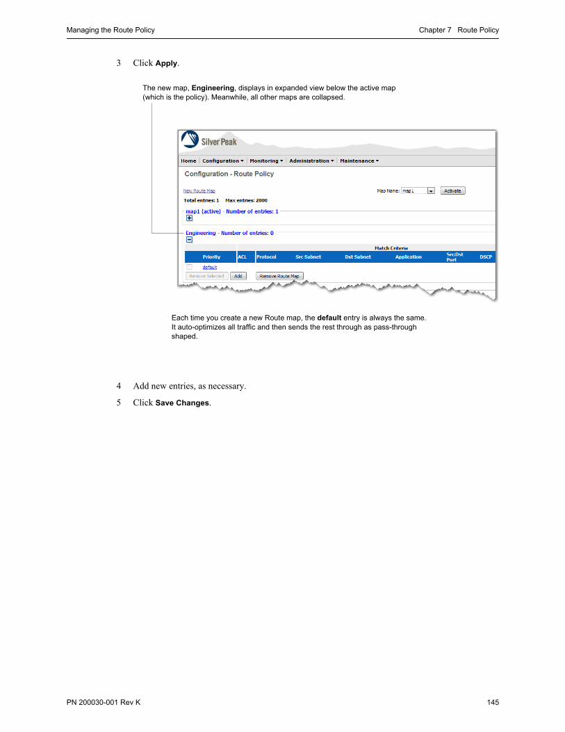
Managing the Route Policy Chapter 7 Route Policy
PN 200030-001 Rev K 145
3 Click Apply.
4 Add new entries, as necessary.
5 Click Save Changes.
The new map, Engineering, displays in expanded view below the active map (which is the policy). Meanwhile, all other maps are collapsed.
Each time you create a new Route map, the default entry is always the same. It auto-optimizes all traffic and then sends the rest through as pass-through shaped.

Silver Peak Appliance Manager Operator’s Guide Managing the Route Policy
146 PN 200030-001 Rev K
Deleting a Map
You can only delete an inactive map.
To delete a map
1 Under the map’s name, click the to expand the inactive map you want to delete.
2 Click Remove Route Map. A window appears, requesting confirmation.
3 Click OK.
4 Click Save Changes.
Activating a New Policy
Activating a new Route map deactivates the old one. All new traffic matches against the new Route Policy.
To activate a new policy
1 From the Map Names field, select the map you want to activate.
2 Click Activate. The old map deactivates and the new one activates, beginning with all new flows.
3 Click Save Changes.

PN 200030-001 Rev K 147
C H A P T E R 8
Bandwidth Management & QoS Policy
This chapter describes the QoS Policy’s SET actions. It also explains how to configure traffic classes for optimized and pass-through traffic, along with providing best practices guidelines for effectively managing bandwidth.
In This Chapter Overview See page 148.
How the QoS Policy Affects Flows See page 148.
Best Practices for Bandwidth Management See page 152.
Configuring Maximum System Bandwidth See page 156.
How Tunnel Auto BW Works See page 157.
Configuring Pass-Through Traffic Bandwidths See page 158.
Configuring Traffic Classes See page 159.
Handling and Marking Packets See page 162.
QoS Policy Page Organization See page 169.
Managing the QoS Policy See page 170.
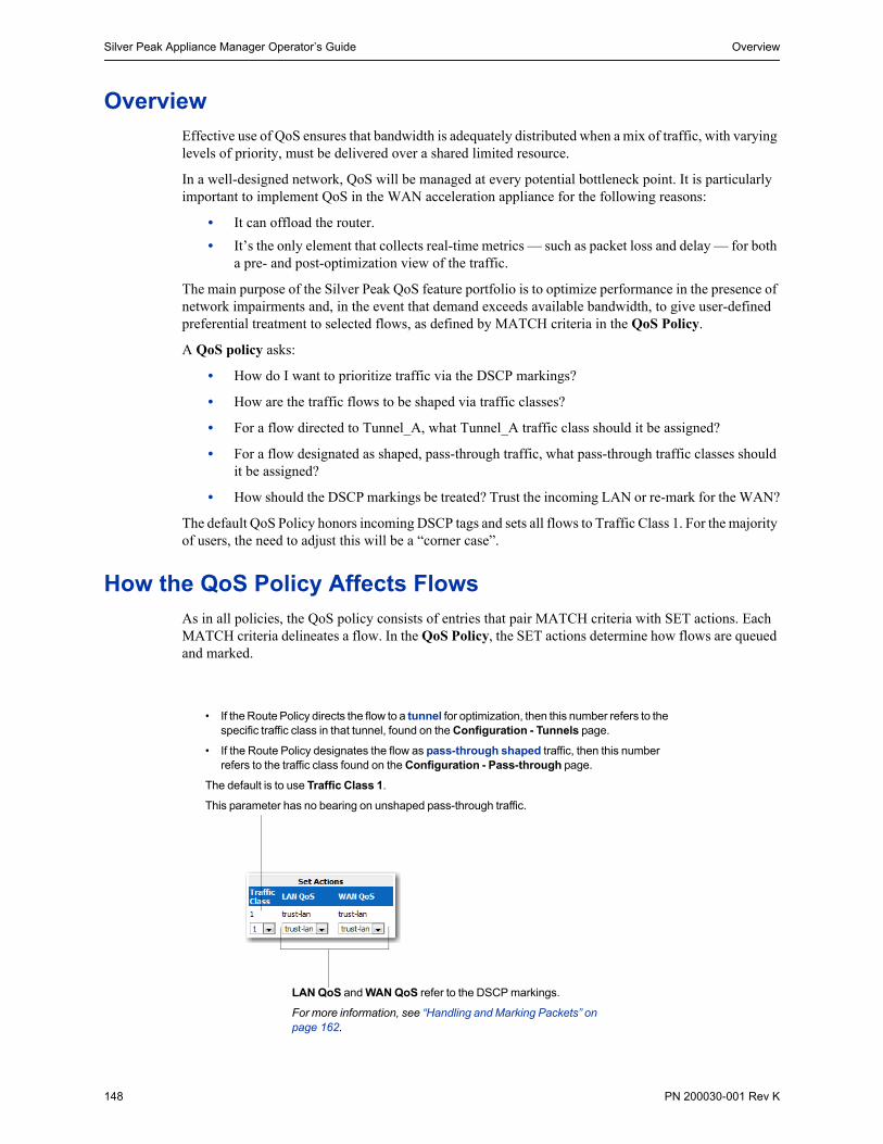
Silver Peak Appliance Manager Operator’s Guide Overview
148 PN 200030-001 Rev K
OverviewEffective use of QoS ensures that bandwidth is adequately distributed when a mix of traffic, with varying levels of priority, must be delivered over a shared limited resource.
In a well-designed network, QoS will be managed at every potential bottleneck point. It is particularly important to implement QoS in the WAN acceleration appliance for the following reasons:
• It can offload the router.
• It’s the only element that collects real-time metrics — such as packet loss and delay — for both a pre- and post-optimization view of the traffic.
The main purpose of the Silver Peak QoS feature portfolio is to optimize performance in the presence of network impairments and, in the event that demand exceeds available bandwidth, to give user-defined preferential treatment to selected flows, as defined by MATCH criteria in the QoS Policy.
A QoS policy asks:
• How do I want to prioritize traffic via the DSCP markings?
• How are the traffic flows to be shaped via traffic classes?
• For a flow directed to Tunnel_A, what Tunnel_A traffic class should it be assigned?
• For a flow designated as shaped, pass-through traffic, what pass-through traffic classes should it be assigned?
• How should the DSCP markings be treated? Trust the incoming LAN or re-mark for the WAN?
The default QoS Policy honors incoming DSCP tags and sets all flows to Traffic Class 1. For the majority of users, the need to adjust this will be a “corner case”.
How the QoS Policy Affects Flows As in all policies, the QoS policy consists of entries that pair MATCH criteria with SET actions. Each MATCH criteria delineates a flow. In the QoS Policy, the SET actions determine how flows are queued and marked.
• If the Route Policy directs the flow to a tunnel for optimization, then this number refers to the specific traffic class in that tunnel, found on the Configuration - Tunnels page.
• If the Route Policy designates the flow as pass-through shaped traffic, then this number refers to the traffic class found on the Configuration - Pass-through page.
The default is to use Traffic Class 1.
This parameter has no bearing on unshaped pass-through traffic.
LAN QoS and WAN QoS refer to the DSCP markings.
For more information, see “Handling and Marking Packets” on page 162.

How the QoS Policy Affects Flows Chapter 8 Bandwidth Management & QoS Policy
PN 200030-001 Rev K 149
The QoS Policy’s SET actions determine two things:
• what traffic class a shaped flow — whether optimized or pass-through — is assigned
• how to handle DSCP markings for all flows leaving the appliance’s WAN interface, whether the marking is for over-the-WAN or for the LAN on the remote side.
The following diagrams illustrate the consequences for each:
• Flow directed to a tunnel See page 149.
• Flow designated as pass-through shaped traffic See page 150.
• Flow designated as unshaped pass-through traffic See page 151.
Flow directed to a tunnel
This diagram shows how the appliance applies QoS to a flow that’s been directed to a tunnel.
1 First, the Route Policy checks traffic incoming from the LAN against the MATCH criteria in its prioritized entries. Entries 10 and 20 don’t match the traffic, but Entry 30 does.
2 The policy applies the entry’s SET actions to the identified flow. In this case, it sends the flow to Tunnel A. Once any traffic matches an entry, no subsequent entries are examined.
3 Before the flow reaches Tunnel A, the QoS Policy checks against its entries and
• applies the DSCP marking specified for LAN QoS, and
• tells the flow which of Tunnel A’s traffic classes to use. All traffic classes for optimized flows are tunnel-specific. That is, they’re part of the tunnel’s configuration.
4 The appliance places the flow in Traffic Class #1 and passes the flow to the Optimization Policy.
5 After optimization, the QoS Policy applies the DSCP markings for the WAN QoS.
6 The optimized flow exits the physical WAN interface.
Handling of DSCP markings is further explained in “Applying DSCP Markings to Optimized Traffic” on page 162.

Silver Peak Appliance Manager Operator’s Guide How the QoS Policy Affects Flows
150 PN 200030-001 Rev K
Flow designated as pass-through shaped traffic
Flows tagged by the Route Policy as pass-through shaped traffic follow this path:
1 The Route Policy checks traffic incoming from the LAN against the MATCH criteria in its prioritized entries. No user-configured entries match the traffic, so the Default entry applies.
2 The Default entry tells the appliance to process the flow as pass-through shaped traffic.
3 Then, the QoS Policy checks against its entries and
• ignores the DSCP marking specified for LAN QoS (because packets are not encapsulated), and
• tells the flow which traffic class to use. For shaped, pass-through traffic, the appliance references the Configuration – Pass-through page.
4 After shaping, the QoS Policy applies the rest of the SET action, which is to apply the DSCP markings for the WAN QoS.
5 The flow exits the physical WAN interface.
Handling of DSCP markings is further explained in “Applying DSCP Markings to Shaped and Unshaped Pass-through Traffic” on page 165.

How the QoS Policy Affects Flows Chapter 8 Bandwidth Management & QoS Policy
PN 200030-001 Rev K 151
Flow designated as unshaped pass-through traffic
Flows marked by the Route Policy as unshaped, pass-through traffic follow this path:
1 The Route Policy checks traffic incoming from the LAN against the MATCH criteria in its prioritized entries. The first three entries don’t match the traffic, but Entry 40 does.
2 The policy applies the entry’s SET actions to the identified flow. In this case, the flow is to be processed as unshaped, pass-through traffic. Once any traffic matches an entry, no subsequent entries are examined.
3 Because the traffic is set to pass-through unshaped, it is not encapsulated. The QoS Policy checks against its entries and only applies the DSCP marking specified for WAN QoS.
4 The flow exits the physical WAN interface.
Handling of DSCP markings is further explained in “Applying DSCP Markings to Shaped and Unshaped Pass-through Traffic” on page 165.

Silver Peak Appliance Manager Operator’s Guide Best Practices for Bandwidth Management
152 PN 200030-001 Rev K
Best Practices for Bandwidth ManagementCongestion is unlikely on either of the LAN segments to which the Silver Peak device connects directly, since these are typically operating at 100Mbps or 1000Mbps.
In a typical deployment, congestion is most likely to arise at the near-end WAN interface.
With wise bandwidth management and QoS, the Silver Peak appliance can guarantee shaping and prioritization for all traffic. For smooth network operation, it’s wisest to consider your overall bandwidth allocation in advance and then to revisit it each time you add, edit, or remove a tunnel.
This section describes the following:
• Summary of Bandwidth Assessment and Management Tasks See page 152.
• Guidelines for Configuring Minimum and Maximum Bandwidth Values See page 153.
• Which Appliance Manager Pages to Use See page 155.
Summary of Bandwidth Assessment and Management Tasks
The following table summarizes the tasks when configuring multiple tunnels for an appliance and/or more than one traffic class per entity.
Task Notes For detailed instructions, see...
1 Configure the maximum system bandwidth, based on the bandwidth of the WAN link.
Because of where network congestion typically occurs, you want to ensure that the appliance doesn’t deliver more than the WAN can manage.
“Configuring Maximum System Bandwidth” on page 156.
2 Let the appliance negotiate tunnel maximum bandwidth(s)
When Auto BW is active (as it is by default), the appliance negotiates maximum bandwidth for each tunnel.
“How Tunnel Auto BW Works” on page 157.
3 Configure the tunnel minimum bandwidth
“Which Appliance Manager Pages to Use” on page 155.
4 Configure traffic classes for tunnels.
Each tunnel’s default traffic class is number 1.
You can configure up to 10 traffic classes per tunnel.
“Configuring Traffic Classes” on page 159.
5 Set the configuration for pass-through shaped traffic
Configure:
• minimum and maximum bandwidth values for the traffic as a whole
• traffic classes
“Configuring Pass-Through Traffic Bandwidths” on page 158.
“Configuring Traffic Classes” on page 159.
6 Review your configuration Make sure that you haven’t over- or undersubscribed the link.
“Guidelines for Configuring Minimum and Maximum Bandwidth Values” on page 153.

Best Practices for Bandwidth Management Chapter 8 Bandwidth Management & QoS Policy
PN 200030-001 Rev K 153
Guidelines for Configuring Minimum and Maximum Bandwidth Values
This sample worksheet provides an overall picture of the items and relationships you need to consider.
Guidelines for Maximum Bandwidth Values
• All tunnels and pass-through traffic can have a Max(imum) Bandwidth equal to the WAN Bandwidth.
• For all tunnels and pass-through traffic, each of their traffic classes can have a max(imum) bandwidth equal to the WAN Bandwidth.
Appropriately configuring the Minimum Bandwidth values is the most critical aspect.
See “Rules of Thumb” on page 154.

Silver Peak Appliance Manager Operator’s Guide Best Practices for Bandwidth Management
154 PN 200030-001 Rev K
Guidelines for Minimum Bandwidth Values
If you oversubscribe the system bandwidth, the appliance defaults to allotting minimum bandwidths based on ratio. In that case, you won’t get your expected minimum. In fact, if the ratio is too large, the smaller tunnel may not get any bandwidth at all.
Rules of Thumb
• The minimum pass-through bandwidth plus the sum of all minimum tunnel bandwidths should not exceed the value of the WAN Bandwidth.
• Within a tunnel, the sum of traffic class minimum bandwidths should not exceed the tunnel’s minimum bandwidth.
• For (shaped) pass-through traffic, the sum of traffic class minimum bandwidths should not exceed the pass-through minimum bandwidth.
• For traffic classes, minimum bandwidth allocation is based on Priority. This becomes critical when you oversubscribe.
Following this sequence prevents bottlenecks and helps keep traffic flowing smoothly to/from the WAN.
Tip When you set a traffic class Minimum Bandwidth to zero, you are explicitly not guaranteeing any bandwidth for that class.
By default, a tunnel’s Minimum Bandwidth is set to 32 kbps.
When the sum of all minimum bandwidths (pass-through and tunnels) exceeds the maximum system bandwidth, the appliance defaults to allocating by ratio — in this case, 30:1. As a result, if both tunnels were active, Tunnel #2 would receive less than 30 Kbps. As the ratio increases, the situation becomes even more critical.

Best Practices for Bandwidth Management Chapter 8 Bandwidth Management & QoS Policy
PN 200030-001 Rev K 155
Which Appliance Manager Pages to Use
The worksheet information originates from three Configuration menu pages. Highlighted areas show where the necessary data is, positionally.
C
A
On the Configuration - Tunnels page, click on a tunnel name to see its details:
• The Setting tab displays the tunnel Min and Max Bandwidths.
• The Traffic Class tab [shown here] has hyperlinks to individual traffic classes for their min/max bandwidth values.
The Configuration - Pass-through [shaped] page is home to the overall Min and Max Pass-through values, as well as the traffic class values.
Go to the Configuration - System page to enter the bandwidth at the router’s WAN interface in the WAN Bandwidth field.
As a best practice, this ensures that the appliance doesn’t contribute to congestion.
A
B
C
B
B

Silver Peak Appliance Manager Operator’s Guide Configuring Maximum System Bandwidth
156 PN 200030-001 Rev K
Configuring Maximum System BandwidthTo make sure that the appliance doesn’t send more traffic than the router’s WAN interface can manage, enter the router’s WAN Bandwidth in the Configuration - System page.
2-Port Configurations
When using wan0 and lan0, make sure that this value is not greater than the WAN interface. In other words, don’t oversubscribe.
4-Port Configurations
When using a 4-port configuration (that is, with lan0, lan1, wan0, and wan1) with two WAN next-hops, use these rules of thumb:
• If the ISPs are configured Active/Active, then use the sum of the two routers’ WAN bandwidths.
• If the ISPs are configure Active/Standby, then use the larger of the two routers’ WAN bandwidth values.
The WAN Bandwidth section refers to the bandwidth at the router’s WAN interface.
For guidance, refer back to “Best Practices for Bandwidth Management” on page 152.
The default value varies with appliance model. To maintain the best traffic flow, refer to the section, “How Tunnel Auto BW Works” on page 157.

How Tunnel Auto BW Works Chapter 8 Bandwidth Management & QoS Policy
PN 200030-001 Rev K 157
How Tunnel Auto BW WorksEach model of NX Series appliance has a specific maximum system bandwidth. That is, the amount of bandwidth it can support for optimized traffic at the WAN interface. With all features enabled, the amount of WAN transmit traffic that each appliance optimally manages is as follows:
By default, all tunnels are set to automatically negotiate tunnel bandwidth to the lowest common value. The following illustrations show this negotiation from the perspective of an NX-8500 with multiple tunnels. The maximum values assume that all options are enabled.
After negotiating bandwidth for all four tunnels, 138 Mbps (500 minus 362) are left over for shaped pass-through traffic.
NX Series Appliance WAN Capacity (all features)
(all options enabled)
NX-2500 2 Mbps
NX-1700 / NX-2600 4 Mbps
NX-2610 8 Mbps
NX-2700 / NX-3500 10 Mbps
NX-3600 / NX-3690 / NX-3700 20 Mbps
NX-5500 / NX-5504 / NX-5600 / NX-5700 50 Mbps
NX-7500 / NX-7504 / NX-7600 / NX-7700 155 Mbps
NX-8504 / NX-8600 500 Mbps
NX-8700 622 Mpbs
NX-9610 / NX-9700 1 Gbps
NX-10700 2.5 Gbps

Silver Peak Appliance Manager Operator’s Guide Configuring Pass-Through Traffic Bandwidths
158 PN 200030-001 Rev K
Configuring Pass-Through Traffic BandwidthsOn the Configuration - Pass-through page, you can configure QoS Bandwidth and Queuing.
To configure bandwidth limits for pass-through traffic
1 Access the Configuration - Pass-through page.
2 Under Traffic Bandwidth, configure the Min(imum) Bandwidth and Max(imum) Bandwidth.
These are absolute values for the upper and lower bandwidth limits, in kilobits per second.
Priority determines which traffic class gets serviced first. Multiple classes can have the same priority number. The lower the number, the higher the priority.
Specify Minimum and Maximum Bandwidths here.
For more information, see:
• “Guidelines for Configuring Minimum and Maximum Bandwidth Values” on page 153.
• “Configuring Pass-Through Traffic Bandwidths” on page 158.
Bandwidth Queuing
Maximum value (in milliseconds) for how long packets of this traffic class can queue up before exiting the appliance at the WAN interface. Packets that are queued longer than this maximum value will be dropped.
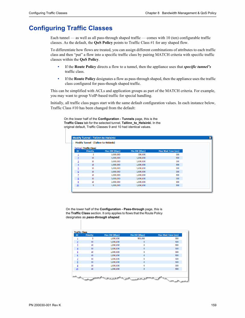
Configuring Traffic Classes Chapter 8 Bandwidth Management & QoS Policy
PN 200030-001 Rev K 159
Configuring Traffic ClassesEach tunnel — as well as all pass-through shaped traffic — comes with 10 (ten) configurable traffic classes. As the default, the QoS Policy points to Traffic Class #1 for any shaped flow.
To differentiate how flows are treated, you can assign different combinations of attributes to each traffic class and then “put” a flow into a specific traffic class by pairing MATCH criteria with specific traffic classes within the QoS Policy.
• If the Route Policy directs a flow to a tunnel, then the appliance uses that specific tunnel’s traffic class.
• If the Route Policy designates a flow as pass-through shaped, then the appliance uses the traffic class configured for pass-though shaped traffic.
This can be simplified with ACLs and application groups as part of the MATCH criteria. For example, you may want to group VoIP-based traffic for special handling.
Initially, all traffic class pages start with the same default configuration values. In each instance below, Traffic Class #10 has been changed from the default:
On the lower half of the Configuration - Tunnels page, this is the Traffic Class tab for the selected tunnel, Tallinn_to_Helsinki. In the original default, Traffic Classes 9 and 10 had identical values.
On the lower half of the Configuration - Pass-through page, this is the Traffic Class section. It only applies to flows that the Route Policy designates as pass-through shaped.

Silver Peak Appliance Manager Operator’s Guide Configuring Traffic Classes
160 PN 200030-001 Rev K
Practically speaking, you’ll likely define the same 10 traffic classes across all traffic — optimized and pass-through. What will vary are the Max Wait Time, and the bandwidth settings, based on the size of each tunnel.
If your appliance only has one tunnel, then you don’t need to make any changes to either the tunnel or (shaped) pass-through traffic classes. However, once you configure an additional traffic class or add another tunnel, or both, best practice dictates that you review the values to ensure that you don’t run the risk of squeezing out any traffic by over- or under-subscribing bandwidth. To review a model for doing this, see “Summary of Bandwidth Assessment and Management Tasks” on page 152.
The Max Wait Time feature makes it easy to precisely configure QoS queue depths by using a maximum allowable queue wait time, in milliseconds.
Tip For real-time applications that are most sensitive to delay and jitter (for example, voice), we recommend that you set Max Wait Time = 100 ms.
Traffic Class Components
Traffic classes are sets of parameters for bandwidth and queuing.
These items are Bandwidth-related:
• Priority• Maximum bandwidth (Kbps)• Minimum bandwidth (Kbps)
To set Queue limits, configure:
• Maximum Wait Time (milliseconds)
It’s important to understand that this QoS mechanism only has an effect at congestion points.
The parameter, Max Wait Time, allows precise setting of allowable queue latency.

Configuring Traffic Classes Chapter 8 Bandwidth Management & QoS Policy
PN 200030-001 Rev K 161
To edit a traffic class
1 To access the traffic classes, do one of the following:
a For a tunnel, go to the Configuration - Tunnels page and in the Tunnels table, click on a tunnel’s Name. When the details display, click Traffic Class.
b For pass-through shaped traffic, go to the Configuration - Pass-through page.
2 To permanently save edits, first click Apply and then click Save Changes.
For precise queue length, use Max Wait Time to control latency.
These are absolute values for the upper and lower bandwidth limits, in kilobits per second. The sum of these ten Min BW values should never exceed the Min BW value configured for the tunnel in the Setting tab.
Priority determines which traffic class gets serviced first. Multiple classes can have the same priority number. The lower the number, the higher the priority.
These 10 traffic classes are specific to the tunnel, Tallinn_to_Helsinki.
To access and edit the Bandwidth and Queuing, click the desired ID.

Silver Peak Appliance Manager Operator’s Guide Handling and Marking Packets
162 PN 200030-001 Rev K
Handling and Marking PacketsAll flows that are not explicitly dropped by the Route Policy are subject to DSCP marking by the QoS Policy. DSCP markings enforce end-to-end QoS policies throughout a network.
As with all policies, the appliance searches sequentially through the policy for the first MATCH criteria that applies. If no user-created entries match, then ultimately the default entry applies. For the QoS Policy, the default DSCP values for LAN QoS and WAN QoS are trust-lan.
The appliance encapsulates optimized traffic. This process adds an IP outer header to packets for travel across the WAN. However, because pass-through traffic doesn’t receive this additional header, its handling is different. The following two sections provide illustrated examples:
• Applying DSCP Markings to Optimized Traffic See page 162.
• Applying DSCP Markings to Shaped and Unshaped Pass-through Traffic See page 165.
• Definitions of DSCP Markings See page 167.
Applying DSCP Markings to Optimized Traffic
This section illustrates and explains how the appliance applies the QoS Policy to optimized traffic in the following scenarios:
• LAN and WAN set to trust-lan See page 162.
• LAN setting changed, WAN is trust-lan See page 163.
• LAN is trust-lan, WAN setting changed See page 163.
• LAN setting changed, WAN setting changed See page 164.
LAN and WAN set to trust-lan
1 The source appliance receives the packet from the LAN with a DSCP marking of be (best effort).
2 Based on MATCH criteria, the QoS Policy applies the LAN QoS setting of trust-lan, leaving the LAN DSCP markings as be (best effort). As the packet is encapsulated, this is now part of the IP inner header.
3 Since the WAN QoS is trust-lan, the appliance also sets the WAN QoS bits to be in the encapsulating IP outer header.

Handling and Marking Packets Chapter 8 Bandwidth Management & QoS Policy
PN 200030-001 Rev K 163
4 When the packet reaches the destination appliance, the appliance de-encapsulates the packet, and the packet traverses the LAN with the DSCP markings set to be.
LAN setting changed, WAN is trust-lan
1 The source appliance receives the packet from the LAN. It has a DSCP marking of be (best effort).
2 Based on MATCH criteria, the QoS Policy changes the LAN QoS setting to ef (express forwarding). As the packet is encapsulated, this is now part of the IP inner header.
3 Since the policy’s WAN QoS is trust-lan, the appliance refers back to the original DSCP markings and sets the WAN QoS bits to be in the encapsulating IP outer header.
4 When the packet reaches the destination appliance, the appliance de-encapsulates the packet, and the packet traverses the LAN with the DSCP markings set to ef.
LAN is trust-lan, WAN setting changed
1 The source appliance receives the packet from the LAN.
2 Based on MATCH criteria, the QoS Policy applies the LAN QoS setting of trust-lan, leaving the LAN DSCP markings as be (best effort). As the packet is encapsulated, this is now part of the IP inner header.
3 Since the policy’s WAN QoS action is cs5 (class selector 5), the appliance sets the bits to cs5 in the encapsulating IP outer header.

Silver Peak Appliance Manager Operator’s Guide Handling and Marking Packets
164 PN 200030-001 Rev K
4 When the packet reaches the destination appliance, the appliance de-encapsulates the packet, and the packet traverses the LAN with the DSCP markings set to be.
LAN setting changed, WAN setting changed
1 The source appliance receives the packet from the LAN. It has a DSCP marking of be (best effort).
2 Based on MATCH criteria, the QoS Policy changes the LAN QoS setting to ef. As the packet is encapsulated, this is now part of the IP inner header.
3 Since the policy’s WAN QoS action is cs5, the appliance sets the bits to cs5 in the encapsulating IP outer header.
4 When the packet reaches the destination appliance, the appliance de-encapsulates the packet, and the packet traverses the LAN with the DSCP markings set to ef.

Handling and Marking Packets Chapter 8 Bandwidth Management & QoS Policy
PN 200030-001 Rev K 165
Applying DSCP Markings to Shaped and Unshaped Pass-through Traffic
The appliance applies the QoS Policy’s DSCP markings to all pass-through flows — whether shaped or unshaped — in the same way:
• If there is a match, the appliance applies the WAN QoS setting to the packet (in the IP ToS/DSCP field).
• If there is a LAN QoS setting in the policy match, it is ignored.
• If there is a trust-lan setting in the policy match, it is ignored.
To summarize, all pass-through traffic is trust-lan unless it’s modified by the WAN QoS setting. When that’s the case, the packet retains the modified QoS setting as it travels through the WAN to the destination appliance.
The following three examples illustrate how the QoS Policy’s LAN QoS and WAN QoS settings affect a matched flow’s DSCP markings:
• LAN and WAN set to trust-lan See page 165.
• LAN setting changed, WAN is trust-lan See page 166.
• LAN is trust-lan, WAN setting changed See page 166.
LAN and WAN set to trust-lan
1 Because it’s pass-through traffic, the appliance ignores the LAN QoS setting.
2 Since the WAN QoS is trust-lan, the appliance sets the WAN QoS bits to be (best effort).
3 When the packet reaches the destination appliance, it retains the be setting as the LAN receives it.

Silver Peak Appliance Manager Operator’s Guide Handling and Marking Packets
166 PN 200030-001 Rev K
LAN setting changed, WAN is trust-lan
1 Because it’s pass-through traffic, the appliance ignores the new LAN QoS setting.
2 Since the WAN QoS is trust-lan, the appliance sets the WAN QoS bits to be (best effort).
3 When the packet reaches the destination appliance, it retains the be setting as the LAN receives it.
LAN is trust-lan, WAN setting changed
1 Because it’s pass-through traffic, the appliance ignores the LAN QoS setting.
2 The appliance sets the WAN QoS bits to cs5.
3 When the packet reaches the destination appliance, it retains the cs5 setting as the LAN receives it.

Handling and Marking Packets Chapter 8 Bandwidth Management & QoS Policy
PN 200030-001 Rev K 167
LAN setting changed, WAN setting changed
1 Because it’s pass-through traffic, the appliance ignores the LAN QoS setting.
2 The appliance sets the WAN QoS bits to cs5.
3 When the packet reaches the destination appliance, it retains the cs5 setting as the LAN receives it.
Definitions of DSCP Markings
Following is a list of definitions for the available Differentiated Services Code Point (DSCP) markings, which use a 6-bit value to indicate Per-Hop Behavior (PHB):
DSCP Marking Per-Hop Behavior Group Codepoint Number
be Best Effort 000000 DSCP 0
af11 Assured Forwarding 11 001010 DSCP 10
af12 Assured Forwarding 12 001100 DSCP 12
af13 Assured Forwarding 13 001110 DSCP 14
af21 Assured Forwarding 21 010010 DSCP 18
af22 Assured Forwarding 22 010100 DSCP 20
af23 Assured Forwarding 23 010110 DSCP 22
af31 Assured Forwarding 31 011010 DSCP 26
af32 Assured Forwarding 32 011100 DSCP 28
af33 Assured Forwarding 33 011110 DSCP 30
af41 Assured Forwarding 41 100010 DSCP 34
af42 Assured Forwarding 42 100100 DSCP 36
af43 Assured Forwarding 43 100110 DSCP 38
cs1 Class Selector 1 (precedence 1) 001000 CS1
cs2 Class Selector 2 (precedence 2) 010000 CS2
cs3 Class Selector 3 (precedence 3) 011000 CS3
cs4 Class Selector 4 (precedence 4) 100000 CS4
cs5 Class Selector 5 (precedence 5) 101000 CS5

Silver Peak Appliance Manager Operator’s Guide Handling and Marking Packets
168 PN 200030-001 Rev K
cs6 Class Selector 6 (precedence 6) 110000 CS6
cs7 Class Selector 7 (precedence 7) 111000 CS7
ef Expedited Forwarding 101110 DSCP 46
DSCP Marking Per-Hop Behavior Group Codepoint Number

QoS Policy Page Organization Chapter 8 Bandwidth Management & QoS Policy
PN 200030-001 Rev K 169
QoS Policy Page OrganizationThe following shows the SET actions for the appliance, spdcnx01.
This QoS Policy has three maps — gms_QoSMap, gms_QoSMap_alt, and map1. Here, gms_QoSMap_alt is active and therefore it’s the policy.
To activate another QoS Policy, select a map from the drop-down menu and click Activate. Any change governs all new flows.
The QoS Policy doesn’t apply DSCP markings for LAN QoS if the flows are pass-through shaped or unshaped.
When there are multiple maps, they display below the active map, or policy.
You can only change a map’s name when it’s inactive.
Every policy — Route, Optimization, or QoS — starts with an active default map named, map1. Here, map1 is inactive.
However, since they’re different types of policies, the fact that they have the same name does not indicate (or cause) a relationship among them.

Silver Peak Appliance Manager Operator’s Guide Managing the QoS Policy
170 PN 200030-001 Rev K
Managing the QoS PolicyThis section discusses procedures for managing the QoS Policy. It includes:
Adding an Entry to a Map See page 170.
Editing an Entry See page 172.
Deleting an Entry See page 173.
Adding a New QoS Map See page 174.
Deleting a Map See page 176.
Activating a New Policy See page 177.
Adding an Entry to a Map
When you create a new entry in the QoS Policy, the Appliance Manager defaults to directing all flows to Traffic Class #1 and trusting the DSCP markings the packets had when arriving from the LAN.
To add an entry to a map
1 From the Configuration menu, select QoS Policy. The Configuration – QoS Policy page appears. If this is the first time you’re accessing the page, only the default entry appears.
The default QoS Policy is always map1...
...and it is active.
The QoS Policy has a default entry that isn’t numbered. It always occupies the last priority position, In reality, its assigned value is 65535.
If traffic doesn’t match any user-configured entries, then the policy applies the default entry.

Managing the QoS Policy Chapter 8 Bandwidth Management & QoS Policy
PN 200030-001 Rev K 171
2 Click Add. A new entry appears, with editable fields.
As described in Chapter 6, “Theory of Operations,” do one of the following:
• Complete the individual fields belonging to the Match Criteria, or
• From the ACL column, select the name of an existing Access Control List.
3 Edit the SET actions as desired.
By default, the appliance:
• trusts and propagates the DSCP markings that the packets had on arrival from the LAN.
• directs flows going to a tunnel to the tunnel’s Traffic Class #1.
• directs pass-through shaped flows to Traffic Class #1, as defined on the Configuration -
Pass-through page.
4 Click Apply.
5 Click Save Changes.
If you need to review the list of existing ACLs, click Access Lists. The Configuration – Access Lists page displays.
After you’ve reviewed the entries, you can return to this page by clicking QoS Policy in the same location on that page.
To complete the tuple elements individually, complete these fields.
To use an existing ACL, select its name from the ACL column’s drop-down menu. Once you do, the other fields in the Match Criteria area are inaccessible.

Silver Peak Appliance Manager Operator’s Guide Managing the QoS Policy
172 PN 200030-001 Rev K
Editing an Entry
You can edit an active entry without having to “deactivate” it first. Changes to an QoS map entry affect new connections only.
If you’ve added additional QoS maps, you can also edit their entries.
The default entry (always the last one in a policy) cannot be edited.
To edit an entry
1 From the Configuration menu, select QoS Policy. The Configuration – QoS Policy page appears.
2 To edit an entry, click that entry’s Priority number. The fields become editable.
3 Make the desired changes.
4 Click Apply.
5 Click Save Changes.
BulkData is a user-defined application group.
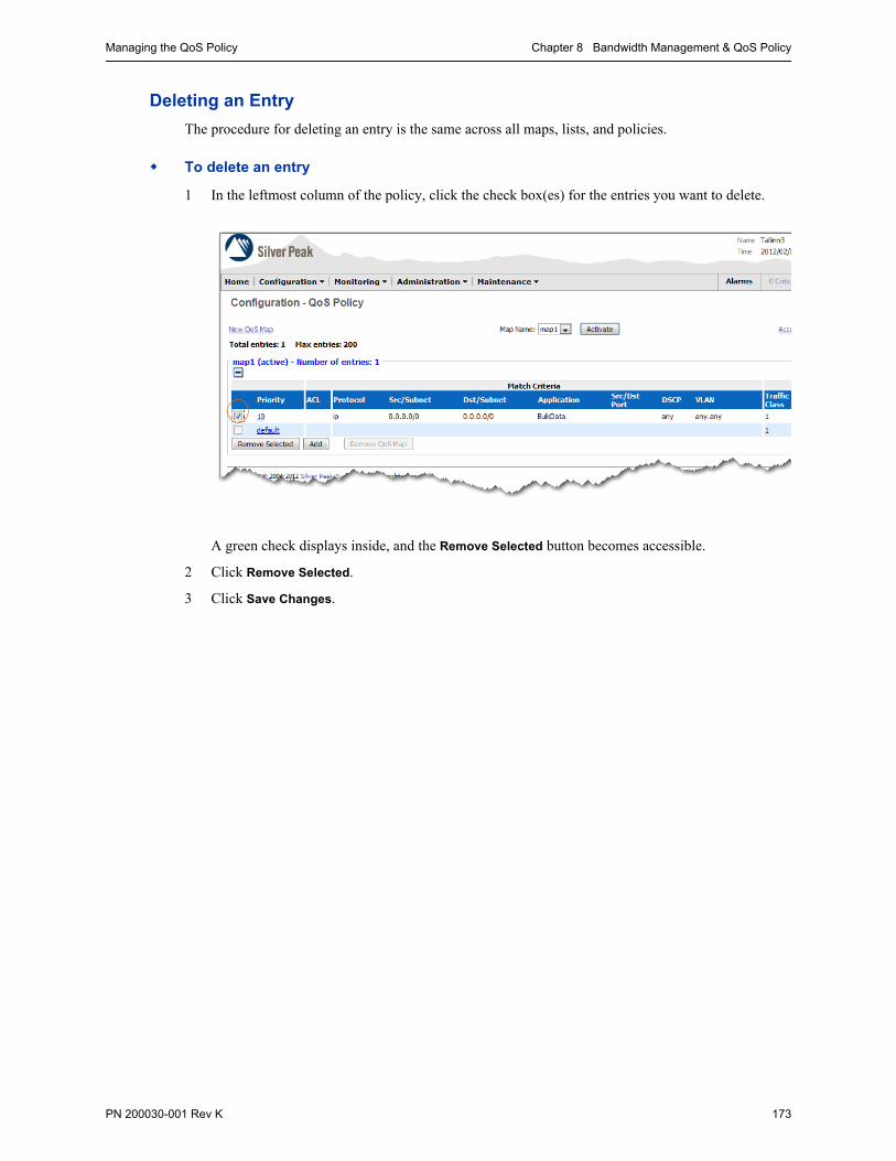
Managing the QoS Policy Chapter 8 Bandwidth Management & QoS Policy
PN 200030-001 Rev K 173
Deleting an Entry
The procedure for deleting an entry is the same across all maps, lists, and policies.
To delete an entry
1 In the leftmost column of the policy, click the check box(es) for the entries you want to delete.
A green check displays inside, and the Remove Selected button becomes accessible.
2 Click Remove Selected.
3 Click Save Changes.

Silver Peak Appliance Manager Operator’s Guide Managing the QoS Policy
174 PN 200030-001 Rev K
Adding a New QoS Map
You can always add another QoS map, whether or not you choose to activate it immediately.
To add a new map
1 In the Configuration – QoS Policy page, click New QoS Map.
The new section displays above the active map.

Managing the QoS Policy Chapter 8 Bandwidth Management & QoS Policy
PN 200030-001 Rev K 175
2 In the QoS Map Name field, enter a new map name.
3 Click Apply.
4 Add new entries, as necessary.
5 Click Save Changes.
The new map, Financial, displays in expanded view below the active map (which is the policy). Meanwhile, all other maps are collapsed.
Each time you create a new QoS map, the default entry is always the same.

Silver Peak Appliance Manager Operator’s Guide Managing the QoS Policy
176 PN 200030-001 Rev K
Deleting a Map
You can only delete an inactive map. That is, a map that’s not in use as the policy.
If the map you want to delete is active, first see “Activating a New Policy” on page 177.
To delete a map
1 Under the map’s name, click the to expand the inactive map you want to delete.
2 Click Remove QoS Map. A window appears, requesting confirmation.
3 Click OK.
4 Click Save Changes.

Managing the QoS Policy Chapter 8 Bandwidth Management & QoS Policy
PN 200030-001 Rev K 177
Activating a New Policy
Activating a new QoS map deactivates the old one. All new traffic matches against the new QoS Policy.
To activate a new policy
1 From the Map Names field, select the map you want to activate.
2 Click Activate. The old map deactivates and the new one activates, beginning with all new flows.
3 Click Save Changes.

Silver Peak Appliance Manager Operator’s Guide Managing the QoS Policy
178 PN 200030-001 Rev K

PN 200030-001 Rev K 179
C H A P T E R 9
Optimization Policy
This chapter describes how the appliance optimizes tunnelized traffic — improving the performance of applications across the WAN.
In This Chapter Introduction See page 180.
Making the Best Use of Optimizations See page 182.
When the Appliance Can Apply the Optimization Policy See page 183.
Optimization Policy Page Organization See page 184.
Managing the Optimization Policy See page 185.

Silver Peak Appliance Manager Operator’s Guide Introduction
180 PN 200030-001 Rev K
IntroductionThe Optimization Policy uses optimization techniques to improve the performance of applications across the WAN. It asks:
• What optimization techniques do I want to apply to a given flow?
• Are there any flows that don’t need optimization?
Note If a flow is not directed to a tunnel, it’s not subject to the Optimization Policy.
The Optimization Policy’s SET actions include:
• Network Memory See page 180.
• Payload Compression See page 181.
• TCP Acceleration See page 181.
• CIFS Acceleration See page 181.
Network Memory
All Silver Peak appliances are equipped with Network Memory™ technology. Network Memory is used to inspect all inbound and outbound WAN traffic in real-time, storing a single local instance of data on each appliance.
Before sending information across the WAN, Silver Peak appliances compare real-time traffic streams to patterns stored using Network Memory. If a match exists, a short reference pointer is sent to the remote Silver Peak appliance, instructing it to deliver the traffic pattern from its local instance. Repetitive data is never sent across the WAN.
If content is modified, the Silver Peak appliance detects the change at the byte level and updates the network’s “memory”. Only the modifications are sent across the WAN. These are combined with original content by Silver Peak appliances at the destination location.
Benefit scenarios
The following scenarios exemplify the benefits of Network Memory.
File Server Even when the file is not identical to the version that was previously downloaded, significant performance improvements are realized by transporting only the incremental changes across the WAN.
Web If a web application is generating dynamic pages (for example, using HTTP), only delta information is transferred. For example, a SharePoint table with many rows updates by just transmitting the delta for the row, rather than the whole page.
Video streaming and Video On Demand If several employees in an office chose to watch the same video (for example, a distance learning module or a taped CEO address), Network Memory eliminates the need to send multiple copies across the WAN. This has the same advantage if they all are watching the video simultaneously, or at different times.
Software patch distribution and upgrades If several employees in an office need to download the same software patch, Network Memory eliminates the need to send multiple copies across the WAN.
Remote backups Once the first backup is completed, future “full” backups are effectively reduced to “incremental backups” as far as WAN traffic is concerned.

Introduction Chapter 9 Optimization Policy
PN 200030-001 Rev K 181
Available Settings
You can configure Network Memory on a per-flow (or per-application or per-ACL) basis.
There are four available Network Memory settings:
Payload Compression
Compression reduces the bandwidth consumed by traffic traversing the WAN. Payload compression uses algorithms to identify relatively short byte sequences that are repeated frequently over time. These sequences are then replaced with shorter segments of code to reduce the size of transmitted data. Simple algorithms can find repeated bytes within a single packet; more sophisticated algorithms can find duplication across packets and even across flows.
Header compression provides additional bandwidth gains by reducing packet header information using specialized compression algorithms. It’s always enabled and not user-configurable.
Silver Peak appliances include state of the art, cross-flow data compression and header compression as part of a broader Local Instance Networking solution. Information gleaned from the compression of one flow can be applied to other flows.
Payload compression is used in conjunction with Network Memory to provide compression on “first pass” data.
TCP Acceleration
TCP acceleration uses techniques such as selective acknowledgement, window scaling, and message segment size adjustment to compensate for poor performance on high latency links.
CIFS Acceleration
Silver Peak appliances provide enhancements to accelerate CIFS—including read-aheads, write-behinds, and metadata caching. This reduces the impact of latency on data transfers using this protocol.
Maximize Reduction Optimizes for maximum data reduction at the potential cost of slightly lower throughput and/or some increase in latency. It is appropriate for bulk data transfers such as file transfers and FTP where bandwidth savings are the primary concern.
Minimize Latency Ensures that Network Memory processing adds no latency. This may come at the cost of lower data reduction. It is appropriate for extremely latency-sensitive interactive or transactional traffic. It is also appropriate for WAN bandwidth saving is not a primary objective, and instead it is desirable to fully utilize the WAN pipe to increase LAN–side throughput.
Balanced This is the default setting. It dynamically balances latency and data reduction objectives and is the best choice for most traffic types.
Disabled No Network Memory is performed.

Silver Peak Appliance Manager Operator’s Guide Making the Best Use of Optimizations
182 PN 200030-001 Rev K
Making the Best Use of OptimizationsBy default, the Optimization Policy’s default entry applies all four user-selectable optimizations — Network Memory, payload compression, TCP acceleration, and CIFS acceleration.
In general, leaving all optimizations defaulted to ON is the best practice. However, there are scenarios where it makes sense to change these defaults. For example:
1 For real-time calls using VoIP, configure the optimizations as follows:
Network Memory – OFF
Payload Compression – OFF
TCP Acceleration – ON
CIFS Acceleration – ON
2 For end-to-end encrypted traffic (that’s encrypted on a per-session basis), configure the optimizations as follows:
Network Memory – OFF
Payload Compression – OFF
TCP Acceleration – ON
CIFS Acceleration – ON
3 If there’s a VoIP element in a videocast (from one source to multiple, individual users), then configure the optimizations as follows:
Network Memory – Minimize Latency
Payload Compression – ON
TCP Acceleration – ON
CIFS Acceleration – ON
Usually, the only reasons to turn off TCP Acceleration and/or CIFS Acceleration are for:
• debugging
• testing the impacts of various acceleration techniques.

When the Appliance Can Apply the Optimization Policy Chapter 9 Optimization Policy
PN 200030-001 Rev K 183
When the Appliance Can Apply the Optimization PolicyThis diagram shows how the appliance processes a flow assigned to a tunnel.
1 First, the Route Policy checks traffic incoming from the LAN against the MATCH criteria in its prioritized entries. Entries 10 and 20 don’t match the traffic, but Entry 30 does.
2 The policy applies the entry’s SET actions to the identified flow. In this case, it sends the flow to Tunnel A. Once any traffic matches an entry, no subsequent entries are examined.
3 Before the flow reaches Tunnel A, the QoS Policy checks against its entries and
• applies the DSCP marking specified for LAN QoS, and
• tells the flow which of Tunnel A’s traffic classes to use. All traffic classes for optimized flows are tunnel-specific. That is, they’re part of the tunnel’s configuration.
4 The appliance places the flow in Traffic Class #1 and passes the flow to the Optimization Policy.
Only flows directed to tunnels are subject to the Optimization Policy.
5 After optimization, the QoS Policy applies the rest of the SET action, which is to apply the DSCP markings for the WAN QoS.
6 The appliance queues the optimized flow to exit the physical WAN interface.

Silver Peak Appliance Manager Operator’s Guide Optimization Policy Page Organization
184 PN 200030-001 Rev K
Optimization Policy Page OrganizationThe following shows the SET actions within an Optimization Policy on a Silver Peak NX appliance.
The Optimization Policy is applied to any flow that matches the Route Policy entries..
This Optimization Policy has one map — map1. It’s active and therefore it is the Optimization Policy that will be applied to all tunneled data flows.
Every policy — Route, Optimization, or QoS — has an active default map with this name. However, since they’re different types of policies, the fact that they have the same name does not indicate (or cause) a relationship among them.
To activate another Optimization Policy, select a map from the drop-down menu and click Activate. Any change governs all new flows.
Here, VoIP is a user-created application group that includes h_323 and cisco_skinny.
Those details aren’t apparent on this screen, but you could see them by selecting Configuration > Application > Groups from the main menu bar.
Notice that for the application group, VoIP, Network Memory is disabled.
When there are multiple maps, they list under the active map, or policy. Here, there are none.
You can only change a map’s name when it’s inactive.

Managing the Optimization Policy Chapter 9 Optimization Policy
PN 200030-001 Rev K 185
Managing the Optimization PolicyThis section discusses procedures for managing the Optimization Policy. It includes:
Adding an Entry to a Map See page 185.
Editing an Entry See page 187.
Deleting an Entry See page 188.
Adding a New Optimization Map See page 188.
Deleting a Map See page 191.
Activating a New Policy See page 192.
Adding an Entry to a Map
When you create a new entry in the Optimization Policy, the Appliance Manager defaults to leaving all four optimizations ON, until you change it.
To add an entry to a map
1 From the Configuration menu, select Optimization Policy. The Configuration – Optimization Policy page appears. If this is the first time you’re accessing the page, only the default entry appears.
The default Optimization Policy is always map1...
...and it is active.
The Optimization Policy has a default entry that isn’t numbered. It always occupies the last priority position, In reality, its assigned value is 65535.
If traffic doesn’t match any user-configured entries, then the default entry applies all optimizations to all flows that the Route Policy is directing to a tunnel.

Silver Peak Appliance Manager Operator’s Guide Managing the Optimization Policy
186 PN 200030-001 Rev K
2 Click Add. A new entry appears, with editable fields.
As described in Chapter 6, “Theory of Operations,” do one of the following:
• Complete the individual fields belonging to the Match Criteria, or
• From the ACL column, select the name of an existing Access Control List.
3 By default, all optimizations are ON. If you want to turn any off, click the green check mark to uncheck the option.
4 Click Apply.
5 Click Save Changes.
If you need to review the list of existing ACLs, click Access Lists. The Configuration – Access Lists page displays.
After you’ve reviewed the entries, you can return to this page by clicking Optimization Policy in the same location on that page.
To complete the tuple elements individually, complete these fields.
To use an existing ACL, select its name from the ACL column’s drop-down menu. Once you do, the other fields in the Match Criteria area are inaccessible.
To review when you might want to turn any of the optimizations off, see “Making the Best Use of Optimizations” on page 182.

Managing the Optimization Policy Chapter 9 Optimization Policy
PN 200030-001 Rev K 187
Editing an Entry
You can edit an active entry without having to “deactivate” it first. Changes to an Optimization map entry affect new connections only.
If you’ve added additional Optimization maps, you can also edit their entries.
The default entry (always the last one in a policy) cannot be edited.
To edit an entry
1 From the Configuration menu, select Optimization Policy. The Configuration – Optimization Policy page appears.
2 To edit an entry, click that entry’s Priority number. The fields become editable.
3 Make the desired changes.
4 Click Apply.
5 Click Save Changes.

Silver Peak Appliance Manager Operator’s Guide Managing the Optimization Policy
188 PN 200030-001 Rev K
Deleting an Entry
The procedure for deleting an entry is the same across all maps, lists, and policies.
To delete an entry
1 In the leftmost column of the policy, click the check box(es) for the entries you want to delete.
A green check displays inside, and the Remove Selected button becomes accessible.
2 Click Remove Selected.
3 Click Save Changes.
Adding a New Optimization Map
You can always add another Optimization map, whether or not you choose to activate it immediately.
To add a new map
1 In the Configuration – Optimization Policy page, click New Optimization Map.

Managing the Optimization Policy Chapter 9 Optimization Policy
PN 200030-001 Rev K 189
The new section displays above the active map.
2 In the Optimization Map Name field, enter a new map name.

Silver Peak Appliance Manager Operator’s Guide Managing the Optimization Policy
190 PN 200030-001 Rev K
3 Click Apply.
4 Add new entries, as necessary.
5 Click Save Changes.
The new map, Broadcast, displays in expanded view below the active map (which is the policy). Meanwhile, all other maps are collapsed.
Each time you create a new Optimization map, the default entry is always the same. It applies all optimizations to flows directed to tunnels.

Managing the Optimization Policy Chapter 9 Optimization Policy
PN 200030-001 Rev K 191
Deleting a Map
You can only delete an inactive map. That is, a map that’s not in use as the policy.
To delete a map
1 Under the map’s name, click the to expand the inactive map you want to delete.
2 Click Remove Optimization Map. A window appears, requesting confirmation.
3 Click OK.
4 Click Save Changes.

Silver Peak Appliance Manager Operator’s Guide Managing the Optimization Policy
192 PN 200030-001 Rev K
Activating a New Policy
Activating a new Optimization map deactivates the old one. All new traffic matches against the new Optimization Policy.
To activate a new policy
1 From the Map Names field, select the map you want to activate.
2 Click Activate. The old map deactivates and the new one activates, beginning with all new flows.
3 Click Save Changes.

PN 200030-001 Rev K 193
C H A P T E R 1 0
Using Flow Redirection to Address TCP Asymmetry
This chapter describes how Flow Redirection allows Silver Peak appliances to optimize asymmetrically routed flows by redirecting packets between appliances.
The flow redirection feature is implemented solely in software, and is available in both bridge and router modes.
In This Chapter Introduction See page 194.
Configuring Flow Redirection See page 197.
Flow Reporting See page 202.

Silver Peak Appliance Manager Operator’s Guide Introduction
194 PN 200030-001 Rev K
IntroductionA network is asymmetric when a client request and its server response don’t use the same path through the network. This asymmetric network configuration is common for:
• Financial institutions, which virtualize geographically separate data centers for load balancing and redundancy.
• Businesses that have multiple ISP paths across a customer network.
Asymmetrical Networks and Flows
The following diagram shows a sample asymmetric network. In this example, each server appliance sees only one direction of the traffic flow.
For TCP flows to be optimized, both directions must travel through the same client and server appliances.
Removing Asymmetry with Flow Redirection
Flow redirection removes the asymmetry locally by merging the traffic of an asymmetric flow into a single appliance. An appliance that handles both directions of traffic for a flow can then optimize the flow properly. Specifically, this sets the stage for TCP acceleration and CIFS acceleration.
With flow redirection, the appliance that receives the first packet — that is, the TCP SYN packet — owns the flow and eventually receives all of that flow’s traffic. To be able to redirect, appliances are configured into clusters, whereby they communicate with each other and keep track of flows. Any given appliance can own multiple flows and redirect others, depending on whether or not the appliance received the initial TCP SYN packet.
1. The client initiates traffic to the server and sends it through SP1.
2. The traffic traverses the server appliance, SP2.
4. SP3 only sees the traffic returning to the client.
3. The server receives traffic from SP2 but returns it via SP3.
5. The client receives the return traffic from SP3.

Introduction Chapter 10 Using Flow Redirection to Address TCP Asymmetry
PN 200030-001 Rev K 195
The client request — in the form of an initiating SYN packet — may be received from the WAN side or the LAN side. This results in two possible scenarios for evading asymmetry:
• Redirection for WAN-initiated Traffic See page 195.
• Avoiding Asymmetry in LAN-initiated Traffic See page 196.
The assumptions is that flow redirection happens across a LAN environment. Redirection across a WAN is not supported.
Redirection for WAN-initiated Traffic
In this scenario, the WAN initiates the flow. All traffic returned from the server is redirected to the appliance that first received traffic from the WAN.

Silver Peak Appliance Manager Operator’s Guide Introduction
196 PN 200030-001 Rev K
Avoiding Asymmetry in LAN-initiated Traffic
In this scenario, the LAN initiates the flow.
The default behavior is that all traffic returned from the WAN is always returned to the appliance that first received the traffic from the LAN, regardless of the route policy at the remote appliance.

Configuring Flow Redirection Chapter 10 Using Flow Redirection to Address TCP Asymmetry
PN 200030-001 Rev K 197
Configuring Flow RedirectionIf you have one path from the client to the server and a different path from the server to the client, you need to enable flow redirection and configure the appliances to communicate with each other.
Flow redirection moves packet traffic between appliances that belong to a cluster:
• A cluster may contain just one appliance (in which no redirection occurs), or several appliances (in which redirection may occur between different pairs).
• All the appliances in a cluster are equal peers.
• You can have up to 32 peers in a cluster.
• The Silver Peak Communication Protocol (SPCP) formalizes the peer-to-peer communications in an appliance cluster. SPCP is both a discovery and control protocol. By default, SPCP uses mgmt1 to communicate between appliances.
• This must be a Layer 2 connection. In other words, you want a switch — not a router — between any two peers.
For each peer appliance in a cluster, the process of configuring flow redirection uses three of the Appliance Manager’s pages:
• The Configuration - Interfaces page, for configuring the mgmt1 IP address.
• The Configuration - IP Route page, for configuring the necessary static route(s).
• The Configuration - Flow Redirection page, for enabling flow redirection, selecting the management interface, and identifying the peers in the cluster.
Note IMPORTANT — When configuring for flow redirection, the mgmt1 interfaces need to be in a separate subnet from the mgmt0 interfaces.
Tip Typically, you’ll use the mgmt1 interface. However, when the LAN–side is greater than 1 Gbps and your Silver Peak appliance has a 10-Gbps interface, then you may consider using a 10-Gbps interface for flow direction. In that case, contact Support for assistance.
Following is the complete example:
Example #1: Simple Cluster with Two Physically Connected Peers See page 198.
Because of their physical proximity, a crossover cable connects two peers’ mgmt1 interfaces.

Silver Peak Appliance Manager Operator’s Guide Configuring Flow Redirection
198 PN 200030-001 Rev K
Example #1: Simple Cluster with Two Physically Connected Peers
When you want to cluster two appliances that are in the same subnet (with Layer 2 connectivity), and they’re located in the same room, you can physically cable the two mgmt1 interfaces together, in lieu of setting up an IP static route.
Instead of physically cabling the appliances, you also have the option of connecting the mgmt1 interfaces via the local area network.
Note IMPORTANT — When configuring for flow redirection, the mgmt1 interfaces need to be in a separate subnet from the mgmt0 interfaces.
To configure this scenario
1 Using a crossover cable, physically connect one appliance’s mgmt1 port to the other appliance’s mgmt1 port.
2 From SP1’s Configuration menu, select Networking and then Interfaces. The Configuration -
Interfaces page appears.
The mgmt1 interface shipped with a default IP address, to make initial configuration easy. You don’t need this any longer, so we’ll reconfigure it to use as a cluster interface for flow redirection.

Configuring Flow Redirection Chapter 10 Using Flow Redirection to Address TCP Asymmetry
PN 200030-001 Rev K 199
a Click mgmt1. The Configure interface mgmt1 area appears.
b Configure SP1 to have the mgmt1 IP address, 10.10.10.1/24.
c Click Apply. The new mgmt1 IP address appears in the table.
To complete the appliance’s configuration, you’ll enable flow redirection and specify the other peer in the cluster.

Silver Peak Appliance Manager Operator’s Guide Configuring Flow Redirection
200 PN 200030-001 Rev K
3 From the Configuration menu, select Networking > Flow Redirection. The Configuration - Flow
Redirection page appears.
In the Settings area:
a Click Enable.
b Verify that the default Interface is mgmt1.
c Click Apply.
4 In the Peers area, click Add. The Add Peer area appears.

Configuring Flow Redirection Chapter 10 Using Flow Redirection to Address TCP Asymmetry
PN 200030-001 Rev K 201
a Enter the mgmt1 IP address for the appliance, SP2. Here, it’s 10.10.10.2.
b Click Apply. The Peers table appears, displaying the SP2’s mgmt1 interface IP address.
5 Click Save Changes.
Now, repeat the entire procedure for the other appliance. When that’s complete, both cluster interfaces are able to communicate with each other and the State changes to OK.
• State is either Unreachable or OK
• Flow Redirection is either Disabled or Enabled
When you click Enable and Apply, it enables all the peers that are associated with this appliance. To verify, manually refresh the screen and then view State in the table below.

Silver Peak Appliance Manager Operator’s Guide Flow Reporting
202 PN 200030-001 Rev K
Flow ReportingFor flow redirection, the appliance handles flow reporting as follows:
The reporting mechanism of locally owned flows is unchanged.
When a peer redirects a flow, it does no per-flow reporting. Rather, that traffic’s statistics are maintained by the owner of the flow. That is, the peer appliance to which the flow is redirected.
On the Monitoring - Current Flows page, a flow’s Details link has a field named, Flow Redirected
From which displays which peer appliance IP is redirecting the flow to this appliance. This field only has an entry if the appliance owns the flow.
For more information, see “Viewing Current Flows” on page 219.
The Monitoring - Flow Redirection page lists the mgmt1 IP address for each peer in the cluster. It also displays statistics for the control packet, number of current flows redirected to/from the appliance, and a cumulative tally of the packets and bytes redirected to/from peers.
For more information, see “Viewing Flow Redirection Statistics” on page 260.

PN 200030-001 Rev K 203
C H A P T E R 1 1
Configuring and Managing VLANs
This chapter describes how to configure and manage VLANs. This applies only when the appliance is in Bridge mode.
In This Chapter Introduction See page 204.
Configuring a VLAN IP Interface See page 205.
Setting VLAN Tags in Outgoing WAN–side Packets See page 206.

Silver Peak Appliance Manager Operator’s Guide Introduction
204 PN 200030-001 Rev K
IntroductionThe NX appliances provide full support for deployments on 802.1q trunked links.
By default, in a tagged environment (that is, an environment with VLANs), the NX appliance behaves as follows:
• optimizes all traffic according to existing Route policies, independent of VLAN
• delivers LAN-side packets untagged
You need to create a VLAN IP interface(s) on the appliance if you want to do any of the following:
• deliver tagged LAN-side packets. Any exploded LAN-side packets destined to VLANs for which the NX appliance has an interface will be tagged.
For more information, see “Configuring a VLAN IP Interface” on page 205.
• (optionally) set VLAN tags in outgoing WAN-side packets
For more information, see “Setting VLAN Tags in Outgoing WAN–side Packets” on page 206.
• (optionally) use VLAN tags as discriminators in MATCH criteria for Route/QoS/Optimization maps or Access Lists
For more information, see “Configuring MATCH Criteria in a Map or Policy” on page 93.
• view VLAN information for Monitoring - Current Flows
For more information, see “Current Flow Details” on page 226.

Configuring a VLAN IP Interface Chapter 11 Configuring and Managing VLANs
PN 200030-001 Rev K 205
Configuring a VLAN IP InterfaceYou can only create a VLAN IP interface if the appliance is in Bridge mode.
To configure a VLAN IP interface
1 On the Configuration - System page, verify that the appliance is in Bridge mode. There are 4 possible deployments.
2 From the Configuration menu, select Networking > VLAN. The Configuration - VLAN page appears.
3 Click Add and complete the fields.
For example, in the standard 4-port configuration below:
4 Click Apply. Now all LAN-side packets destined for subnets in the new VLAN will be tagged.
These are the router (WAN-side) next-hops.
If deployed in bonded 4-port bridge mode, then this is labeled, bwan0 Next-hop IP.
IP address of the WAN router in this VLAN.
IP address of the Silver Peak appliance in this VLAN.
In Bridge mode, bvi0 is the logical interface corresponding to lan0.

Silver Peak Appliance Manager Operator’s Guide Setting VLAN Tags in Outgoing WAN–side Packets
206 PN 200030-001 Rev K
Setting VLAN Tags in Outgoing WAN–side PacketsThis is an optional task.
To set VLAN tags in outgoing WAN-side tunnel traffic
1 Select Configuration > Networking > IP Routes.
2 Choose which bvi interface to set as the system next-hop. You can only choose one.
If you tag the “native” VLAN, add a static route on the WAN-side router directing all incoming traffic destined for the Silver Peak appliance IP to one of the VLAN IP interfaces.
The following pages display VLAN configuration in the context of the possible bridge deployments.
Shown for each bridge deployment are the Configuration - System page, the Configuration - VLAN page, and the Configuration - IP Routes page.
The deployments covered here are as follows:
2-Port Bridge See page 207.
Standard 4-Port Bridge See page 208.
Flat 4-Port Bridge See page 209.
Bonded 4-Port Bridge See page 210.

Setting VLAN Tags in Outgoing WAN–side Packets Chapter 11 Configuring and Managing VLANs
PN 200030-001 Rev K 207
2-Port Bridge
This is the most common of the Bridge deployments.
Note If the “native” VLAN is tagged, add a static route on the WAN-side router directing all incoming traffic destined for the Silver Peak appliance IP to one of the VLAN IP interfaces.
Selecting this line ensures that packets destined for the WAN are tagged with VLAN 411.
A 2-port bridge deployment has:
• 1 WAN–side router next-hop• 1 subnet
Any VLAN deployed here has:
• a bvi0 (logical bridge) interface• 1 WAN–side router next-hop• 1 subnet
Configuration - System page

Silver Peak Appliance Manager Operator’s Guide Setting VLAN Tags in Outgoing WAN–side Packets
208 PN 200030-001 Rev K
Standard 4-Port Bridge
This is also known as dual bridge mode.
Note If the “native” VLAN is tagged, add a static route on the WAN-side router directing all incoming traffic destined for the Silver Peak appliance IP to one of the VLAN IP interfaces.
By default, the interfaces display as active. You can, however, set one selected WAN interface to backup.
A standard 4-port bridge deployment has:
• 2 WAN–side router next-hops• 2 subnets
Tunnel packets will be sourced with a single IP address (Appliance IP1 address)
Any VLAN deployed here has:
• bvi0 and bvi1 (logical bridge) interfaces
• 2 WAN–side router next-hops• 2 subnets
Configuration - System page
Select the desired interface from the drop-down list.

Setting VLAN Tags in Outgoing WAN–side Packets Chapter 11 Configuring and Managing VLANs
PN 200030-001 Rev K 209
Flat 4-Port Bridge
Note If the “native” VLAN is tagged, add a static route on the WAN-side router directing all incoming traffic destined for the Silver Peak appliance IP to one of the VLAN IP interfaces.
Since this is the native VLAN, packets exiting to the WAN are not tagged.
By default, the interfaces display as active / active. You can, however, set either bvi0 to backup.
A flat 4-port bridge deployment has:
• 2 WAN–side router next-hops• 1 subnet
Any VLAN deployed here has:
• a bvi0 (logical bridge) interface• 2 WAN–side router next-hops• 1 subnet
Configuration - System page

Silver Peak Appliance Manager Operator’s Guide Setting VLAN Tags in Outgoing WAN–side Packets
210 PN 200030-001 Rev K
Bonded 4-Port Bridge
Essentially, this is like the 2-port bridge, but with twice the bandwidth.
Note If the “native” VLAN is tagged, add a static route on the WAN-side router directing all incoming traffic destined for the Silver Peak appliance IP to one of the VLAN IP interfaces.
Here, the user has chosen to change the default selection of native VLAN to VLAN 600 instead. Packets leaving for the WAN will be tagged accordingly.
A bonded 4-port bridge deployment has:
• 1 WAN–side router next-hops• 1 subnet
Any VLAN deployed here has:
• a bvi0 (logical bridge) interface• 1 WAN–side router next-hop• 1 subnet
Configuration - System page

PN 200030-001 Rev K 211
C H A P T E R 1 2
Monitoring Traffic
This chapter describes how to view traffic and application statistics. The Appliance Manager retains these statistics for 72 hours.
Additionally, counters provide numbers since the last reboot for tunnels, tunnel QoS, and interfaces.
In This Chapter Overview See page 212.
About Viewing Statistics See page 214.
Viewing Application Statistics See page 217.
Viewing Current Flows See page 219.
Viewing Tunnel QoS Statistics See page 234.
Viewing Tunnel Statistics See page 236.
Viewing Reduction Statistics See page 241.
Viewing Bandwidth Statistics See page 243.
Viewing Flow Counts See page 245.
Viewing Latency Statistics See page 247.
Viewing Network Integrity Statistics See page 248.
Viewing Dynamic Charts See page 250.
Viewing a Summary of All Reports See page 259.
Viewing Flow Redirection Statistics See page 260.
Viewing NetFlow Statistics See page 262.
Viewing Interface Statistics See page 263.
Viewing Bridge Mode Statistics See page 265.
Viewing IP Routes See page 266.

Silver Peak Appliance Manager Operator’s Guide Overview
212 PN 200030-001 Rev K
OverviewWith the Monitoring menus, the Appliance Manager displays statistics for tunnels, the physical network interfaces, applications, and connections:
• The Appliance Manager collects data every second, and retains it for 72 hours.
• Realtime stats display with a 6-second lag.
Tip The Global Management System (GMS) collects and stores appliance data for longer periods of time. The programmable maximum depends upon the granularity of the data desired. For example, minute statistics are retained for less time than hourly or daily statistics.
The various menus are as follows:
Viewing Application Statistics See page 217.
Application statistics summarize the percentage of traffic that can be accounted for, individually, by the “Top 10” applications. “Other” is the eleventh category, and aggregates all remaining applications.
Viewing Current Flows See page 219.
You can view a listing of 200 realtime connections, based on selectable filter criteria. These include end points, ports, traffic path, applications, protocol, Top Talkers, number of flows, and number of (mega)bytes. Additionally, you can customize which data columns display and view a flow’s details.
Viewing Tunnel QoS Statistics See page 234.
This is essentially a more detailed view of the tunnel statistics (see next bullet). You can view the total number of bytes and packets transmitted and received, based on traffic class and/or WAN QoS [DSCP markings], for all tunnels or any individual tunnel. It also provides more granular information about types of packets, such as dropped, invalid, duplicate, etc.
Tunnel QoS statistics display the data accumulated since the last reboot. Additionally, you have the option of non-destructively clearing the counters to zero and viewing the delta values.
Viewing Tunnel Statistics See page 236.
Tunnel statistics specify the number of bytes and/or packets received, processed, and transmitted by a tunnel in both the outbound (LAN-to-WAN) and inbound (WAN-to-LAN) directions. They tally control packets, as well as accelerated versus non-accelerated traffic flow, round-trip latency, and packet loss before and after forward error correction. The Appliance Manager reports all these statistics as raw data.
Tunnel statistics display the data accumulated since the last reboot. Additionally, you have the option of non-destructively clearing the counters to zero and viewing the delta values.
Viewing Reduction Statistics See page 241.
Reduction statistics specify the number of bytes and/or packets received, processed, and transmitted by a tunnel in both the outbound (LAN-to-WAN) and inbound (WAN-to-LAN) directions.
Viewing Bandwidth Statistics See page 243.
Bandwidth statistics summarize the overall inbound and outbound bandwidth improvements afforded by the Silver Peak appliance.
Viewing Flow Counts See page 245.
This summarizes the number of TCP flows versus non-TCP flows. Within the TCP flows, it distinguishes between accelerated and non-accelerated flows.
Overview Chapter 12 Monitoring Traffic
PN 200030-001 Rev K 213
Viewing Latency Statistics See page 247.
Latency statistics summarize the round-trip time of data in a Silver Peak tunnel.
Viewing Network Integrity Statistics See page 248.
These statistics summarize the number of lost and/or out-of-order packets, before and after enabling Forward Error Correction (FEC) and Packet Order Correction, respectively.
Viewing Dynamic Charts See page 250.
These new charts feature pan and zoom capability for bandwidth, reduction, packets per second, flow counts, latency, loss, and out-of-order packets. You can review data from the last 72 hours.
Currently, the Dynamic Charts don’t support data export. However, that functionality is available in the legacy charts.
Viewing a Summary of All Reports See page 259.
This summary page includes charts and graphs for (top 10) applications, reduction, bandwidth, flows (+/- TCP), latency, packet loss (Forward Error Correction), and out-of-order packets (Packet Order Correction). You can export this page as an image in PDF or PNG format.
Viewing Flow Redirection Statistics See page 260.
This shows the statistics collected, specific to the process when you allow two (or more) NX appliances to exchange flow ownership information and then redirect packets to the owner.
Viewing NetFlow Statistics See page 262.
This displays how many NetFlow statistics the appliance exported to the collector(s). Stats are defined in terms of number of flows, and number of datagrams (packets) required to export those flows.
Viewing Interface Statistics See page 263.
Interface statistics display generic performance data for the actual physical LAN, WAN, and management interfaces (primary and secondary).
Interface statistics display the data accumulated since the last reboot. Additionally, you have the option of non-destructively clearing the counters to zero and viewing the delta values.
Viewing Bridge Mode Statistics See page 265.
This summarizes the data traffic traversing all the LAN and WAN interfaces, in a redundant bridge mode deployment.
Viewing IP Routes See page 266.
This summarizes the next-hop reachability of the IP addresses, along with listing the source (WAN or LAN), state, uptime, WAN configured role, and WAN current role.
Before discussing individual reports, the next section describes the basics of viewing reports.

Silver Peak Appliance Manager Operator’s Guide About Viewing Statistics
214 PN 200030-001 Rev K
About Viewing StatisticsThis section discusses methods for viewing additional details about report charts and graphs. It includes:
• Understanding Traffic Direction See page 214.
• Viewing Counters Since Last Reboot See page 214.
• Clearing Counters Non-Destructively See page 215.
• Exporting Statistical Data See page 216.
Understanding Traffic Direction
In Appliance Manager, statistics and reports either reference the direction of the flow or the point(s) where the data is collected:
LAN-to-WAN refers to traffic exiting the LAN, destined for the WAN. This flow is also referred to as outbound traffic.
WAN-to-LAN refers to traffic coming from the WAN, destined for the LAN. This flow is also referred to as inbound traffic.
Tip Here’s a helpful mnemonic for remembering the difference:
- Rx is “Receive fRom”, so LAN Rx is “receive from LAN”- Tx is “Transmit To”, so LAN Tx is “transmit to LAN”
Viewing Counters Since Last Reboot
By default, the statistics that display in the following reports have accumulated since the last reboot: Applications, Tunnel QoS, Tunnels, Flow Redirection, NetFlow, and Interfaces.
To verify this, note that Actual Stats button is selected.

About Viewing Statistics Chapter 12 Monitoring Traffic
PN 200030-001 Rev K 215
Clearing Counters Non-Destructively
To non-destructively set the counters to zero, click Delta Stats. To update the statistics, you can manually refresh the page whenever you want. Or, you can select from one of the preconfigured auto-refresh intervals in the same menu.
To restore the values since the last reboot, click Actual Stats.
To zero out counters non-destructively, select Delta Stats.
If you set the Refresh menu to manually, click the browser’s refresh icon as needed for a cumulative update.
Select table’s display units: Bytes, MBytes, Pkts, or KPkts

Silver Peak Appliance Manager Operator’s Guide About Viewing Statistics
216 PN 200030-001 Rev K
Exporting Statistical Data
Most legacy reports provide access to the raw statistical data with a Table View button. If they do, the Export button saves the statistics tables to a .csv file.
You can export statistics for the following reports. Only the QoS pages doesn’t have a table view:
To export a .csv file
1 In the report, click Table View. The table appears.
2 Click Export and either Open or Save the file, as needed.
Image
[PDF or PNG]
Table View
[to CSV]
Applications no
Current Flows no
QoS [Tunnel] no Export options
Tunnels no Export options
Reduction
Bandwidth
Flow Counts
Latency
Network Integrity
Forward Error Correction
Packet Order Correction
Dynamic Charts no Export options
All Reports no
Flow Redirection
no Export options
NetFlow
Interfaces
Bridges
IP Routes

Viewing Application Statistics Chapter 12 Monitoring Traffic
PN 200030-001 Rev K 217
Viewing Application StatisticsThe Monitoring - Application Stats page summarizes the percentage of traffic that can be accounted for, individually, by the “Top 10” applications.
The reports answer the following questions:
For any given tunnel, what 10 applications account for the majority of all traffic?
What application accounts for the largest percentage of my tunnel or pass-through (shaped, unshaped) traffic?
Which applications account for more than n% of my bandwidth?
When comparing the WAN- and LAN-side traffic, how are the application distributions different?
Based on bytes, what is the ratio of LAN-to-WAN or WAN-to-LAN traffic for any given application?
To view the Application Statistics report
On the Monitoring menu, select Applications. Initially, the chart defaults to the Last 60 Minutes of LAN-to-WAN traffic for optimized traffic.
No matter which Direction you choose, the LAN chart is on the left and the WAN chart is on the right.
The LAN slices are arranged by increasing/decreasing size. The sequence and color assigned to an application in the LAN pie chart are continued in the WAN chart. So, the WAN slices maintain the same order by application, not by size. This allows for direct visual comparison.
Table lists data for all applications
Choose the time interval:
• Current Hour• Last 60 Minutes• Last 4 Hours• Current Day• Wednesday• Tuesday• Monday
Choose the traffic direction: LAN to WAN [default] or WAN to LAN
The earliest day only contains data that begins 72 hours back from now, so it won’t be a full day’s worth of data.

Silver Peak Appliance Manager Operator’s Guide Viewing Application Statistics
218 PN 200030-001 Rev K
What Data Displays
The Monitoring - Applications report displays the following statistics for each listed application.
What is the difference between other and unassigned in the Applications stats pie chart?
The pie chart shows the top ten applications and, possibly, other.
unassigned means the sum of traffic (bytes) for which the appliance could not determine the application.
other means the sum of traffic other than the top nine.
If you don’t have more than ten applications, you won’t see other.
Table 12-1 Traffic Direction: LAN to WAN
Column Definition
LAN Traffic (%) Percentage of LAN traffic that this application comprises
WAN Traffic (%) Percentage of WAN traffic that this application comprises
LAN Rx Bytes Number of bytes received from the LAN side
WAN Tx Bytes Number of bytes transmitted to the WAN side
Ratio (X) [Bytes received from LAN] / [Bytes transmitted to WAN]
Reduction (%)
Table 12-2 Traffic Direction: WAN to LAN
Column Definition
LAN Traffic (%) Percentage of LAN traffic that this application comprises
WAN Traffic (%) Percentage of WAN traffic that this application comprises
LAN Tx Bytes Number of bytes transmitted to the LAN side
WAN Rx Bytes Number of bytes received from the WAN side
Ratio (X) [Bytes transmitted to LAN] / [Bytes received from WAN]
Reduction (%)
[Bytes received from LAN] – [Bytes transmitted to WAN]
Bytes received from LAN
[Bytes transmitted to LAN] – [Bytes received from WAN]
Bytes transmitted to LAN
Viewing Current Flows Chapter 12 Monitoring Traffic
PN 200030-001 Rev K 219
Viewing Current FlowsThe Monitoring - Current Flows page retrieves a listing of up to 200 realtime connections based on selectable filter criteria.
• These include end points, ports, traffic path, applications, protocol, Top Talkers, number of flows, and number of (mega)bytes.
• This page provides the ability to filter before waiting on flows to populate. No flows populate until you click Apply.
• When you first filter and click Apply to generate a list of flows, the page displays a default set of parameter columns, along with individual links to flow details.
• You can customize the Current Flows columns so that you can choose which of the many columns you want to view onscreen.
It answers questions like:
What flows is the Silver Peak appliance optimizing?
Which flows are the Top Talkers, that is, which flows are generating the most traffic?
Which CIFS flows are being accelerated? Or could be?
Which CIFS flows have SMB signing enabled on the server?
Which TCP flows are being accelerated? Or could be?
Is any TCP flow asymmetric?
Are SSL flows deduped?
What’s the performance improvement on a “per flow” basis?
What SET actions are the Route, QoS, and Optimization policies applying to the flow?
Is any tunnelized traffic experiencing reduced functionality as a result of two nodes having mismatched software versions?

Silver Peak Appliance Manager Operator’s Guide Viewing Current Flows
220 PN 200030-001 Rev K
Selecting Filters
Select from the following Traffic types
This field’s options include built-in applications, custom applications, and user-created application groups.
Enter specific addresses and/or use zeroes (in the octet) as wildcards. The page lists flows that have either endpoint.
The content of the Op (Operation) and Value fields vary with the Filter selected.With some filters, a Duration field also appears.
When you select a LAN or WAN option, the filter defaults to the ten Top Talker flows. These are the flows consuming the most bandwidth, in bytes. You can filter for a maximum of 200 flows.
You can also filter for flows relative to a specific number of bytes (default), with Equal, Greater Than, or Less Than. For example, to filter on:
• 1000 bytes, enter 1000• 200 megabytes, enter 200m or 200M (no space)• 45.3 gigabytes, enter 45.3g or 45.3G (no space)• 7 terabytes, enter 7t or 7T (no space)
Filter on a protocol to either isolate it (Equal) or exclude it (Not Equal).
Tip Customize the results columns to show the data that you’re filtering. For more detail, see “To customize the screen display” on page 222.
Protocol-Specific
Relative Bandwidth
Most Bandwidth Consumed (Top Talkers)
List up to 200 matches.

Viewing Current Flows Chapter 12 Monitoring Traffic
PN 200030-001 Rev K 221
Customizing Which Columns Display
Following are some customization guidelines:
The first time you click Apply, a default set of columns displays results. This includes:
The items in green always display, whether or not you customize your screen display.
Customizations persist for the specific user during a given browser session. If you log out and in during the same browser session, your customizations persevere. If you quit the browser and subsequently restart it, the screen display automatically resets to the default.
You can view as many of the possible columns as you want. You may have to scroll, though.
When you Export the data from a given screen, only the data belonging to the displayed columns is included in the .csv file.
Customize and Export functions are accessible to all users.
IP1 Protocol
Port 1 L/W Ratio (X)
IP2 W/L Ratio (X)
Port 2 SMB Signed
Tx Action Up Time
Application Details
This screen shows the default set of columns.
To specify which columns display or not, click Customize.

Silver Peak Appliance Manager Operator’s Guide Viewing Current Flows
222 PN 200030-001 Rev K
To customize the screen display
1 To access the Current Flow Customize Dialog box, click Customize.
2 To make your selections, check/uncheck boxes as needed.
3 Click OK. The screen refreshes with the new columns.
To reset to the default display
1 To access the Current Flow Customize Dialog box, click Customize.
2 Click Reset Default. The screen display resets.
This is the default set. Greyed-out boxes cannot be unchecked.

Viewing Current Flows Chapter 12 Monitoring Traffic
PN 200030-001 Rev K 223
To customize and review a Current Flows report
1 From the Monitoring menu, select Current Flows. Initially, the page defaults to all endpoints with All
Traffic and All Applications and no additional filtering.
• When you enter a specific endpoint, the page returns connections that have that endpoint.
• Entering 0 in any IP address’s octet position acts as a wild card for that position. 0 in the Port field is also a wild card.
• The two IP address (and port) fields are independent of each other. In other words, you can filter on two separate endpoints.
Select the kind of traffic you want.
Choose from all built-in and user-defined applications or application groups, or choose All Applications.
The filter defaults to 100 matches. You can specify up to 200.
• The Filter By selection determines the options in Op and Value.
• A fourth parameter, Duration, appears when appropriate.
Field Description
IP Address1 (2) / Port1 (2) An endpoint(s) on which you want to filter:
• When you enter a specific endpoint, the page returns connections that have that endpoint.
• Entering 0 in any IP address’s octet position acts as a wild card for that position. 0 in the Port field is also a wild card.
• The two IP address (and port) fields are independent of each other. In other words, you can filter on two separate endpoints.
Traffic Select the type of traffic connections you want to retrieve:
• All Traffic – all optimized and pass-through traffic.• Optimized – the sum of all optimized traffic. That is, all tunnelized
traffic.• pass-through – all unoptimized, shaped traffic. • pass-through-unshaped – all unoptimized, unshaped traffic. • [a named Tunnel] – that specific tunnel’s optimized traffic.
Application Select which standard or user-defined application (or application group) to use as a filter criteria. The default value is All Applications.

Silver Peak Appliance Manager Operator’s Guide Viewing Current Flows
224 PN 200030-001 Rev K
a If you keep the default values and click Apply, the page retrieves a default of 100 of the total current flows.
b To further refine the results (before or after clicking Apply), select options from the Filter drop-down list and fields.
A pink background indicates that the SET action(s) for this flow were changed after the flow began. Therefore, this is now a stale connection.
Here, the Appliance Manager retrieved 100 out of 498 flows.
An orange background indicates that the tunnelized flow is experiencing reduced functionality as a result of two nodes having mismatched software versions. This tunnel compatibility mode offers some basic benefits, but not the full set of optimizations. For the list, see “Tunnel Compatibility Mode” on page 88.

Viewing Current Flows Chapter 12 Monitoring Traffic
PN 200030-001 Rev K 225
2 Click Apply. The results display.
.
Flows that use TCP protocol have selectable (dark edged) check boxes and can be reset, if you have admin privileges. You can select them individually, or click Select All.
• To revert to default filter values, click Clear Filter.
• To refresh the results list, click Apply.
Resets all flows you’ve selected in the result display.Note: This button is greyed out because the user is logged on with the more limited monitor privileges or because no flows are selected.
Resets all TCP flows in the appliance, whether or not they’re displayed in the list of matches. This is a service-affecting step.
Clicking the icon in the Details column displays a detailed flow report. However, if the flow has already terminated or timed out, no report displays.
Defaults to 100 matched flows. The maximum is 200.

Silver Peak Appliance Manager Operator’s Guide Viewing Current Flows
226 PN 200030-001 Rev K
Current Flow Details
Following is an example of a Monitoring - Current Flows page, with customized columns, followed by the results of clicking Details for the first flow listed.
Clicking the icon in the Details column displays a detailed flow report. However, if the flow has already terminated or timed out, no report displays, and you get an error message..
• The (added) green highlighting shows which fields always display as columns.
• The (added) yellow highlighting shows which fields you can include in the screen display, by using the Customize button.

Viewing Current Flows Chapter 12 Monitoring Traffic
PN 200030-001 Rev K 227
If a flow is not fully optimized because of a software version mismatch between nodes, then the Details page annotates this reduced functionality.

Silver Peak Appliance Manager Operator’s Guide Viewing Current Flows
228 PN 200030-001 Rev K
In the following definitions table, the red rows correspond to information that is only available in the Current Flows Details page. The rest are available by default.
Field Definition
Route Information
Map Name The name of the Route Policy.
Priority in Map The number of the entry in the Route Policy that the flow matches.
Endpoint IP1 (or IP2) IP Address of one end of the flow. This will either be the specific address you filtered for or the other end of a connection to it.
Port1 (or Port2) Number of the port the application is using. A value of 0 means “any port”.
Configured Tx Action The SET action configured in the Route Policy’s Tunnel field.
Tx Action How the traffic is actually being transmitted.
Rx Action By what path or method the appliance is receiving this flow’s traffic.
Application Name of the application to which that flow’s traffic belongs.
Protocol The Protocol options include the following:
• tcp — unaccelerated TCP• udp — UDP• tcp [accel] — accelerated TCP• cifs [accel] — this CIFS flow is on the client side• cifs [server] — this CIFS flow is on the server side, so disregard. CIFS only
displays as “accelerated” on the client-side appliance, not on the server side.• cifs — when we don’t know whether a CIFS connection is client-side or
server-side (for example, in a hairpinned connection).• other ip protocols — like icmp, etc.
Using Stale Map Entry Whether or not the flow is using a policy entry that has been edited or deleted since the flow began.
Flow Direction Whether the flow is LAN to WAN, or WAN to LAN.
Flow Redirected From The IP address of the appliance that’s redirecting this flow to this appliance.
Auto-opt Status Whether it matched a specific Route Policy or was Auto Optimized.
Auto-opt Transit Mode The IP addresses of the hops between this appliance and the other end of the connection.
LAN-side VLAN Whether or not the flow is part of a VLAN configured in Appliance Manager..
Optimization Information
Map Name The name of the Optimization Policy.
Priority in Map The number of the entry in the Optimization Policy that the flow matches.
TCP Accelerated Configured
Whether or not TCP acceleration is configured in the Optimization Policy.
TCP Accelerated Status Whether the flow is TCP accelerated [Yes] or not [No].
For a list of error codes, see “Error Reasons for TCP Acceleration Failure” on page 230.
TCP Asymmetric When the answer is YES, the Silver Peak appliance is able to intercept connection establishment in only one direction. As a result, this flow is not accelerated. When this happens, it indicates that there is asymmetric routing in the network.
CIFS Accelerated Configured
Whether or not CIFS acceleration is configured in the Optimization Policy. [Yes/No]

Viewing Current Flows Chapter 12 Monitoring Traffic
PN 200030-001 Rev K 229
CIFS Accelerated Status Whether or not CIFS is being accelerated or not. [Yes/No]
SMB signed Specifies whether or not the CIFS traffic is SMB-signed by the server:
• Yes means it was signed. If that’s the case, then the appliance was unable to accelerate any CIFS traffic.
• No means it wasn’t signed. If that’s the case, then server requirements did not preclude CIFS acceleration.
• Overridden means that SMB signing is ON and the appliance overrode it.
SSL Accelerated Status If a certificate has been appropriately installed via the GMS, then SSL traffic can be deduplicated. For a list of error codes, see “Error Reasons for SSL Acceleration Failure” on page 232.
Network Memory There are four Network Memory settings:
• Maximize Reduction — optimizes for maximum data reduction at the potential cost of slightly lower throughput and/or some increase in latency. It is appropriate for bulk data transfers such as file transfers and FTP where bandwidth savings are the primary concern.
• Minimize Latency — ensures that no latency is added by Network Memory processing. This may come at the cost of lower data reduction. It is appropriate for extremely latency-sensitive interactive or transactional traffic. It is also appropriate if WAN bandwidth saving is not a primary objective, and instead it is desirable to fully utilize the WAN pipe to increase LAN–side throughput.
• Balanced — This is the default setting. It dynamically balances latency and data reduction objectives and is the best choice for most traffic types.
• Disabled — No Network Memory is performed.
Payload Whether or not payload compression is turned on.
Using Stale Map Entry Whether or not the flow is using a Route Policy entry that has been edited or deleted since the flow began.
Stats Information
LAN to WAN Ratio (X) For the outbound traffic, a ratio of the LAN Rx Bytes divided by the WAN Tx Bytes.
When this ratio is less than 1.0, it’s attributable to a fixed overhead (for WAN transmission) being applied to traffic that either is not compressible or consists of few packets.
WAN to LAN Ratio (X) For the inbound traffic, a ratio of the WAN Rx Bytes divided by the LAN Tx Bytes.
LAN to WAN Reduction The percentage by which outbound traffic is reduced in size.
WAN to LAN Reduction The percentage of optimization in the WAN-to-LAN direction.
LAN Rx Bytes Total number of bytes received from the LAN [outbound traffic]
WAN Tx Bytes Total number of bytes sent to the WAN [outbound traffic]
LAN Tx Bytes Total number of bytes sent to the LAN [inbound traffic]
WAN Rx Bytes Total number of bytes received from the WAN [inbound traffic]
Flow Up Time The length of time that there has been a connection between the endpoints.
Flow ID A unique number that the appliance assigns to the flow.
TCP Flow Context Silver Peak uses this for debugging purposes.
QoS Information
Map Name The name of the QoS Policy.
Field Definition (Continued)

Silver Peak Appliance Manager Operator’s Guide Viewing Current Flows
230 PN 200030-001 Rev K
Error Reasons for TCP Acceleration Failure
Following is a list of possible errors, along with a brief description.
Priority in Map The number of the entry in the QoS Policy that the flow matches.
Traffic Class The number of the traffic class assigned by the QoS to the flow, based on the MATCH conditions satisfied:
• If the traffic is tunnelized, the traffic class is tunnel-specific.
• If the traffic is pass-through (shaped), the traffic class is based on the pass-through (shaped) configuration.
LAN DSCP The LAN DSCP marking that the QoS policy assigned to the flow, based on the MATCH conditions satisfied.
WAN DSCP The WAN DSCP marking that the QoS policy assigned to the flow, based on the MATCH conditions satisfied.
Using Stale Map Entry Whether or not the flow is using a policy entry that has been edited or deleted since the flow began.
Error Reason Description
unknown cause This is only OK when traffic is unidirectional, WAN to LAN.
disabled in Optimization Map TCP Acceleration disabled in the Optimization Map
IP briefly blacklisted TG1 ----- Site1 <------------> Site2 ----- Firewall ------- TG2
If someone doesn’t reply to our SYN, we blacklist the address.
1. The firewall drops the packet because the SYN was modified while enroute to the remote destination. For example, Site 1 sends SYN to Site 2, which modifies it.
2. Site1’s keep alive times out.
3. TG1 tries making a connection a second time.
4. Site1 blacklists this connection from entering TCP acceleration so the firewall after Site2 will let it through to TG2.
5. RESULT: TCP unacclerated by Site1.
keep alive failure • A keep alive failure triggers the blacklisting of an IP address.• If a TCP connection was accelerated once, and a second connection
attempt fails, the appliance won’t blacklist the Destination IP.
connection reset by peer This happens when you try to go to a port that no one is listening on. We send a SYN; and the Destination IP sends a RESET (which means it can’t accept the connection, for whatever reason).
retransmission timeout Keep sending packet but get no acknowledgement from the remote site.
SYN packet fragmented Very rare. It’s a small packet; breaks into pieces.
system flow limit reached Every NX/VX model has a specific max limit of connections.
This system limit is the sum of ingoing + outgoing connections.
first packet not a SYN • Can only accelerate TCP if the flow starts with a SYN.
Usually happens after an established connection is redirected. For example:- WCCP failure between router and SP- in Bridge mode and SP reboots
Field Definition (Continued)

Viewing Current Flows Chapter 12 Monitoring Traffic
PN 200030-001 Rev K 231
tandem SP appliance involved LAN-A -------> SP1-----SP2----- WAN -----SP3-----SP4 -----LAN-B
When you have a couple of in-line Silver Peak appliances:
1. SP1 receives traffic from LAN-A and marks the SYN packet.
2. SP2 receives the packet and sees that SP1 has altered it, beginning the TCP acceleration. Therefore, SP2 leaves the SYN packet [the flow] alone.
no remote appliance detected No Silver Peak appliance detected for intentional or accidental reasons:
• intentional [Opt map: TCP accel OFF; Route Map config’d to Send P-T]
• accidental [SP has failed-to-wire; bad routing]
terminated by user Connection terminated by user.
disabled to allow debug Acceleration is turned off because someone from Silver Peak is logged on in debug mode.
stale flow 1. A valid connection [with SYN, SYN-ACK, ACK, data] exists.
2. Then, the application terminates the connection, but then the same connection restarts when it shouldn’t. Not enough time elapsed for everything to die.
out of TCP memory • Not enough memory to create another connection.• Should NEVER happen. If it does, contact Customer Support.
connection to be deleted A connection was created and now it’s marked to be deleted.
Route Map set to drop packets A user configured this.
Route Map set to pass-through A user configured this.
tunnel down Can’t accelerate a connection if the tunnel is down.
remote appliance dropped out of accel There was established communication with the Silver Peak appliance, but for some reason the appliance dropped out of the connection.
asymmetric flow The flow’s outgoing path and incoming path are not the same.
TCP state mismatch Something’s wrong and the connection automatically resets.
TCP auto-optimization failed TCP auto-optimization failed.
software version mismatch The error is the result of a specific software version mismatch.
partner flows not eligible Partner flows are helper flows that are created when the transmit and receive paths of a TCP flow terminate on separate Silver Peak appliances. Partner flows are not eligible for TCP acceleration.
client advertised zero MSS The client wants to establish the connection, but the window size is zero, so it cannot transport data.
Error Reason Description (Continued)

Silver Peak Appliance Manager Operator’s Guide Viewing Current Flows
232 PN 200030-001 Rev K
Error Reasons for SSL Acceleration Failure
Following is a list of the reasons you may receive a failure message for SSL acceleration. The first requirement for successful acceleration is using the Global Management System (GMS) to install the SSL certificate into the appliance(s).
Error Reason Description
error processing certificate Certificate processing error
error processing client hello1 Unsupported client SSL protocol version or options
error processing client hello2 Unsupported client SSL protocol version or options
error processing client hello3 Error processing client hello
error processing server hello Error processing server hello
invalid certificate SSL certificate is invalid
invalid cipher Unsupported or invalid cipher algorithm
invalid client proto version Unsupported client protocol version
invalid handshake condition SSL handshake failure
invalid key SSL private key is invalid
memory flow control SSL maximum memory limit reached
miscellaneous error Miscellaneous errors
missing active session SSL proxy session cache is out of sync with that of client or server
missing certificate SSL certificate is missing
missing key SSL private key is missing
missing pending session SSL proxy session cache is out of sync with that of client or server
missing resume session Cannot resume SSL-specific optimization because SSL proxy was not present for prior session
no ipsec on tunnel IPsec is not configured on the tunnel and IPsec override is off
ssl disabled SSL-specific optimization is disabled
unsupported server protocol Unsupported server SSL protocol version

Viewing Current Flows Chapter 12 Monitoring Traffic
PN 200030-001 Rev K 233
Resetting Flows to Improve Performance
In the list of (up to 200) results, you can look for the flows that aren’t being accelerated, but could be. Generally, this means flows that use TCP protocol and are not TCP-accelerated:
• This includes tunnelized TCP traffic that is not TCP-accelerated. TCP connections are not accelerated if they already exist when the tunnel comes up or when the appliance reboots.
• Pass-through connections are neither tunnelized nor accelerated if they already exist when a new tunnel is added and/or when an ACL is added or edited.
Unaccelerated TCP flows can be reset to allow them to reconnect at a later time. It is assumed that the connection end-points will re-establish the flows. When these flows are reconnected, the appliance recognizes them as new and accelerates them. Note that the time it takes to reset a flow may vary, depending on the traffic activity.
CAUTION Resetting a flow interrupts service for that flow. The appliance cannot restore the connection on its own; it relies on the end points to re-establish the flow. Use it only if service interruption can be tolerated for a given flow.
Tip For information about configuring the appliance to automatically reset TCP flows, see “Automatically Resetting TCP Connections” on page 131.
The arrows show traffic that could be TCP-accelerated.
Accessible (not dimmed) check boxes indicate that resetting the flows would terminate the flows and then reestablish them with TCP acceleration, if the flow would now fit the Route Policy’s MATCH criteria for a tunnel.
If a TCP flow is accelerated, then that’s noted here, in square brackets [].

Silver Peak Appliance Manager Operator’s Guide Viewing Tunnel QoS Statistics
234 PN 200030-001 Rev K
Viewing Tunnel QoS StatisticsThe Monitoring - Tunnel QoS page summarizes optimized traffic on the basis of traffic class and/or WAN DSCP markings.
It answers the questions:
How many dropped and/or out-of-order packets are seen on the appliance on a Traffic Class or DSCP basis?
Is QoS working correctly?
Are there problems in the network related to insufficient re-order wait times?
To view a Tunnel QoS Statistics report
1 From the Monitoring menu, select QoS. Initially, the chart defaults to all Traffic Classes and all DSCP markings for the first tunnel listed alphabetically. In other words, the results are not filtered.
2 Select the Refresh interval.
3 Select Actual Stats or Delta Stats.
4 Select options from the Tunnel, Traffic Class, and DSCP drop-down menus.
5 Click Apply. The tunnel QoS statistics update.
Choose an individual tunnel.
You can choose all traffic classes, or any one from 1 through 10. The default is All.
You can choose all DSCP markings, or any one individually. The default is all.

Viewing Tunnel QoS Statistics Chapter 12 Monitoring Traffic
PN 200030-001 Rev K 235
When you select a tunnel from the table, the Appliance Manager provides two detailed reports:
• QoS Statistics on Traffic Class
• QoS Statistics on DSCP
The QoS Statistics on Traffic Class area displays the following information:
The QoS Statistics on DSCP area displays the following information:
Field Definition
LAN Rx Bytes Number of bytes received from the LAN
LAN Rx Pkts Number of packets received from the LAN
LAN Tx Bytes Number of bytes sent to the LAN
LAN Tx Pkts Number of packets sent to the LAN
Lan Rx Dropped Pkts Number of packets received from the LAN that were dropped
QoS Class Total Bytes Exceeded Number of packets that exceeded the byte queue limit for a traffic class
QoS Class Total Pkts Exceeded Number of packets that exceeded the packet queue limit for a traffic class
QoS Class Per-Flow Bytes Exceeded Number of packets that exceeded the bytes-per-flow queue limit for a traffic class
QoS Class Per-Flow Pkts Exceeded Number of packets that exceeded the packets-per-flow queue limit for a traffic class
QoS Class Queue Time Exceeded Number of packets that exceeded the maximum queue wait time for a traffic class
Field Definition
WAN Tx Bytes Number of bytes sent to the WAN
WAN Tx Pkts Number of packets sent to the WAN
WAN Rx Bytes Number of bytes received from the WAN
WAN Rx Pkts Number of packets received from the WAN

Silver Peak Appliance Manager Operator’s Guide Viewing Tunnel Statistics
236 PN 200030-001 Rev K
Viewing Tunnel StatisticsThe Monitoring - Tunnels page summarizes the overall inbound and outbound traffic statistics for the tunnels since the last reboot. The Tunnels table condenses the total LAN and WAN counters.
When you select a tunnel from the table, the Appliance Manager provides the following detailed report:
The Appliance Manager reports all realtime tunnel statistics as raw data.
Name Description
LAN/WAN Statistics • Specifies the number of bytes and packets received, processed, and transmitted by a Silver Peak tunnel in both the outbound (LAN-to-WAN) and inbound (WAN-to-LAN) directions.
• Statistics are separated for inbound and outbound traffic.
Flows/Latency/Packet Correction Statistics
• Specifies packets by TCP flow versus non-TCP flow. Packets in a TCP flow are further sorted by whether or not they’re accelerated.
• Displays round trip latency time in milliseconds (minimum, maximum, and average).• Displays how many received packets were lost before and after Forward Error Correction
(FEC).• Displays how many received packets were out-of-order before and after Packet Order
Correction (POC).• Statistics represent combined, bi-directional data.
When you choose manually, click the browser’s Refresh icon to view up-to-the-minute data.
The default display unit is Bytes. If you want, you can choose MBytes, Pkts [packets], or KPkts instead. If you select a specific tunnel and then change the units, the page refreshes to display the table only.
OUTBOUND traffic (Transmit LAN to WAN)
INBOUND traffic (Receive WAN to LAN)
For detail, click a tunnel name.
LAN Rx - WAN TxLAN Rx
WAN Rx - LAN TxWAN Rx
How long the tunnel has been up
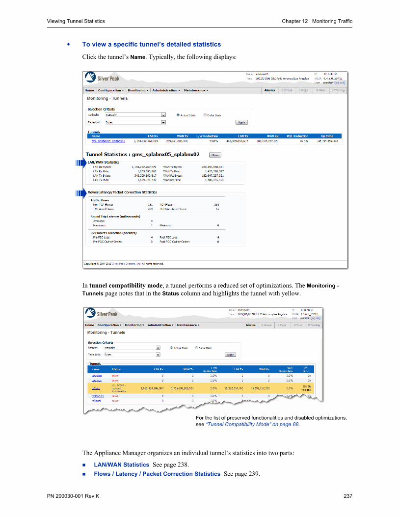
Viewing Tunnel Statistics Chapter 12 Monitoring Traffic
PN 200030-001 Rev K 237
To view a specific tunnel’s detailed statistics
Click the tunnel’s Name. Typically, the following displays:
In tunnel compatibility mode, a tunnel performs a reduced set of optimizations. The Monitoring -
Tunnels page notes that in the Status column and highlights the tunnel with yellow.
The Appliance Manager organizes an individual tunnel’s statistics into two parts:
LAN/WAN Statistics See page 238.
Flows / Latency / Packet Correction Statistics See page 239.
For the list of preserved functionalities and disabled optimizations, see “Tunnel Compatibility Mode” on page 88.
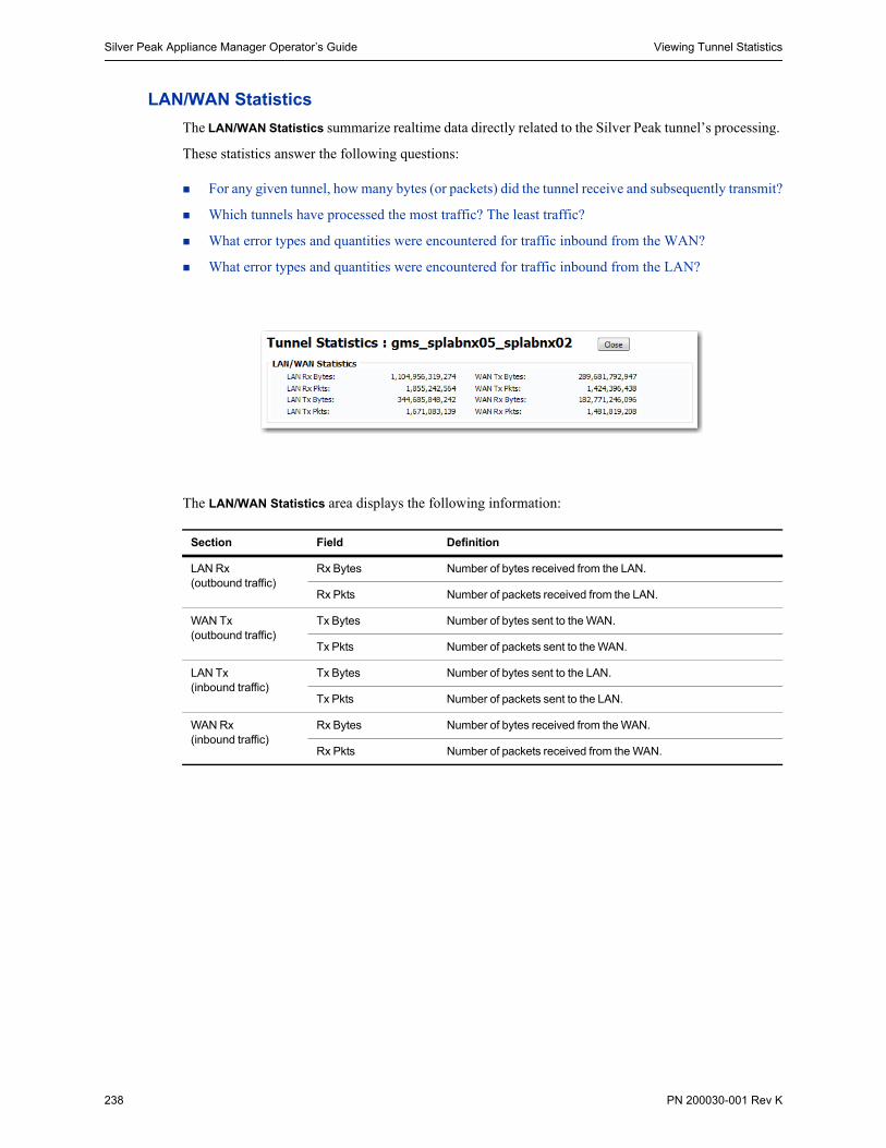
Silver Peak Appliance Manager Operator’s Guide Viewing Tunnel Statistics
238 PN 200030-001 Rev K
LAN/WAN Statistics
The LAN/WAN Statistics summarize realtime data directly related to the Silver Peak tunnel’s processing.
These statistics answer the following questions:
For any given tunnel, how many bytes (or packets) did the tunnel receive and subsequently transmit?
Which tunnels have processed the most traffic? The least traffic?
What error types and quantities were encountered for traffic inbound from the WAN?
What error types and quantities were encountered for traffic inbound from the LAN?
The LAN/WAN Statistics area displays the following information:
Section Field Definition
LAN Rx (outbound traffic)
Rx Bytes Number of bytes received from the LAN.
Rx Pkts Number of packets received from the LAN.
WAN Tx(outbound traffic)
Tx Bytes Number of bytes sent to the WAN.
Tx Pkts Number of packets sent to the WAN.
LAN Tx(inbound traffic)
Tx Bytes Number of bytes sent to the LAN.
Tx Pkts Number of packets sent to the LAN.
WAN Rx(inbound traffic)
Rx Bytes Number of bytes received from the WAN.
Rx Pkts Number of packets received from the WAN.

Viewing Tunnel Statistics Chapter 12 Monitoring Traffic
PN 200030-001 Rev K 239
Flows / Latency / Packet Correction Statistics
The Flows / Latency / Packet Correction Statistics area includes other general statistics. It answers the questions:
How many of the traffic flows are based on TCP and how many are not?
How much of the TCP flow was accelerated?
What is the minimum, average, and peak latency in milliseconds?
How many packets were lost before Forward Error Correction (FEC), and how many were lost after?
How many out-of-order packets were there before and after Packet Order Correction?
TCP Flow / Latency / Packet Loss Statistics area displays the following statistics:
Section Field Definition
Traffic Flows Non-TCP Flows Number of flows that are not TCP-based.
TCP Flows Number of flows that are TCP-based.
TCP Accel Flows Number of TCP flows that are accelerated. Since CIFS acceleration is a subset of TCP acceleration, they are included herein.
TCP Non-Accel Flow Number of TCP flows that are not accelerated.
Round Trip Latency Average Length of the average round trip latency, in milliseconds.
Maximum Length of the peak round trip latency, in milliseconds.
Minimum Length of the shortest round trip latency, in milliseconds.
Rx Packet Correction Pre FEC Loss Number of packets lost before Forward Error Correction (FEC).
Post FEC Loss Number of packets lost after Forward Error Correction (FEC).
Pre POC Out-of-Order Number of out-of-order packets before Packet Order Correction (POC).
Post POC Out-of-Order Number of out-of-order packets after Packet Order Correction (POC).

Silver Peak Appliance Manager Operator’s Guide Viewing Tunnel Statistics
240 PN 200030-001 Rev K
Enabling Forward Error Correction (FEC) can sometimes result in the creation of additional Out-of-Order
Packets (OOP). After enabling FEC, look for OOP and adjust if necessary, as follows:
1 Go to Monitoring > Network Integrity > Packet Order Correction.
2 If out-of-order packets exist, then you’ll need to try another Reorder Wait time for the tunnel in question.
3 Go to Configuration > Tunnels, and select the tunnel in question.
4 At first, set the Reorder Wait time to 10ms, and save the configuration.
5 Return to Monitoring > Network Integrity > Packet Order Correction to see if the out-of-order packets have been eliminated.
6 If there are still out-of-order packets, then go back to the tunnel configuration and increase the Reorder Wait time.
7 Repeat Steps 5 and 6 until there are no more out-of-order packets.
Tip To view these same tunnel statistics for preselected time intervals, go to the Reporting menu and select from the following: Flow Counts, Latency, or Network Integrity.
For more information, see “Viewing Flow Counts” on page 224, “Viewing Latency” on page 226, or “Viewing Network Integrity” on page 227.

Viewing Reduction Statistics Chapter 12 Monitoring Traffic
PN 200030-001 Rev K 241
Viewing Reduction StatisticsThe Monitoring - Reduction page summarizes the reduction of (data) bytes afforded by the Silver Peak appliance over selectable time periods.
The Reduction report answers the following questions:
How much data is traveling in real-time?
How much data was sent and received for each minute in the current hour, the last 60 minutes, or three days ago?
What is the ratio of LAN to WAN (or WAN to LAN) traffic at any point in time?
This Realtime line chart shows the raw LAN and WAN data, in bytes, for optimized traffic, every second. Data accrues at the right side of the chart.
The green line shows the ratio of the two. In the LAN to WAN direction, the ratio is calculated from:[LAN value] / [WAN value].
This table displays the raw data presented in the chart. If you wanted to view the data in terms of packets, this is where you would need to look.
Date and time of first data point.

Silver Peak Appliance Manager Operator’s Guide Viewing Reduction Statistics
242 PN 200030-001 Rev K
To view a Reduction report
1 From the Monitoring menu, select Reduction. Initially, the chart defaults to real-time LAN-to-WAN traffic for the first tunnel, as listed alphabetically.
2 In the Filter Selection section:
a Select the Traffic type. Options in the drop-down menu include:
• All Traffic
• Optimized – the sum of all optimized traffic. That is, all tunnelized traffic.
• individual tunnel name(s), listed alphabetically
• pass-through for shaped, unoptimized traffic
• pass-through-unshaped for unshaped, unoptimized traffic
b Select the Direction of the traffic. Options in the drop-down menu include:
• LAN to WAN [default]
• WAN to LAN
c Select the time Period. Options in the drop-down menu include:
• Realtime [default]
• Current Hour
• Last 60 Minutes
• Last 4 Hours
• Current Day
• Sunday [Yesterday, by name]
• [Day before yesterday, by name]
• [Two days before yesterday, by name]
3 Click Apply to update and display the chart.
4 To view minute-by-minute data displayed as a table, click Table View.

Viewing Bandwidth Statistics Chapter 12 Monitoring Traffic
PN 200030-001 Rev K 243
Viewing Bandwidth StatisticsThe Monitoring - Bandwidth page summarizes the inbound and outbound bandwidth improvements afforded by the Silver Peak appliance over three selectable time periods: realtime (every second), and minute by minute over the current hour or the last 60 minutes.
The Bandwidth report answers the following questions:
How much has the bandwidth been optimized?
At what rate was the data sent and received in each time interval?
What is the ratio of LAN to WAN traffic at any point in time?
This Realtime view shows the actual data rates — and the ratio of rates — for a single tunnel. The direction of traffic is LAN to WAN. The chart adds a data point every second, after an initial 6-second delay.
With the Realtime chart, you can individually select/deselect which lines to display.

Silver Peak Appliance Manager Operator’s Guide Viewing Bandwidth Statistics
244 PN 200030-001 Rev K
To view a Bandwidth optimization report
1 From the Monitoring menu, select Bandwidth. Initially, the chart defaults to second-by-second, realtime, optimized, LAN-to-WAN traffic.
2 In the Filter Selection section:
a Select the Traffic type. Options in the drop-down menu include:
• All Traffic
• Optimized – the sum of all optimized traffic. That is, all tunnelized traffic.
• individual tunnel name(s), listed alphabetically
• pass-through for shaped, unoptimized traffic
• pass-through-unshaped for unshaped, unoptimized traffic
b Select the Direction of the traffic. Options in the drop-down menu include:
• LAN to WAN [default]
• WAN to LAN
c Select the time Period. The options range from Realtime to 72 hours ago (specified by day of the week).
3 Click Apply to update and display the chart.
4 To view minute-by-minute data displayed as a table, click Table View.
This Last 4 Hours view shows the actual data rates — and the ratio of rates — for all optimized traffic over. The direction of traffic is LAN to WAN.
The column used for sorting displays as a lighter shade.

Viewing Flow Counts Chapter 12 Monitoring Traffic
PN 200030-001 Rev K 245
Viewing Flow CountsThe Monitoring - Flow Counts page summarizes the number of TCP flows versus non-TCP flows. Within the TCP flows, its bar charts separate out how many flows were accelerated and how many were not. Since CIFS acceleration is a subset of TCP acceleration, that data is incorporated generically in the accelerated TCP flow data.
This report answers the following questions:
How much of my traffic is TCP-based?
How much of my TCP traffic is accelerated?
This bar chart displays the values for optimized traffic, minute by minute, over the last 60 minutes. You can also choose to view data for a specific tunnel.
By definition, flows are considered bi-directional.
Here, Table View displays all 4 traffic flows:
• Non-TCP flows• TCP flows• TCP accelerated flows• TCP non-accelerated flows
When the statistics were sampled
To export this table as a .csv (comma-separated values) file that you can open as an Excel spreadsheet, click Export. A dialog box asks if you want to open or save the file.
This bar chart displays the values for all traffic, minute by minute, over the last 60 minutes.

Silver Peak Appliance Manager Operator’s Guide Viewing Flow Counts
246 PN 200030-001 Rev K
To view a Flow report
1 From the Monitoring menu, select Flow Counts. The chart defaults to realtime optimized traffic. In the Filter Selection section:
a Select the Traffic type. Options in the drop-down menu include:
• All Traffic
• Optimized – the sum of all optimized traffic. That is, all tunnelized traffic.
• individual tunnel name(s), listed alphabetically
• pass-through for shaped, unoptimized traffic
• pass-through-unshaped for unshaped, unoptimized traffic
b Select the time Period. The options range from Realtime to 72 hours ago (specified by day of the week)
2 Click Apply to update and display the chart.
3 To view the table, click Table View. The table charts four items:
Field Definition
Non TCP Flows Number of flows that are not TCP-based.
TCP Flows Number of flows that are TCP-based.
TCP Accel Flows Number of TCP flows that are accelerated. Since CIFS acceleration is a subset of TCP acceleration, they are included.
TCP Non-Accel Flows Number of flows that are not TCP-accelerated.

Viewing Latency Statistics Chapter 12 Monitoring Traffic
PN 200030-001 Rev K 247
Viewing Latency StatisticsThe Monitoring - Latency page summarizes the round-trip time of data in a Silver Peak tunnel during three selectable time periods: realtime (every 6 seconds), and minute by minute over the current hour or the last 60 minutes. It answers the following questions:
How long does it take my data to get to the other end of the Silver Peak tunnel?
What were the peak, average, and minimum time intervals?
To view the Latency report
1 From the Monitoring menu, select Latency.
2 From the Traffic menu, select the name of the individual tunnel.
3 From the Period menu, select the time interval.
4 Click Apply to update and display the chart.
To view the data displayed as a table, click Table View.
Every second, this line chart plots round-trip latency for tunnel gms_sphqnx01_spdcnx01.
The above chart and table to the right show the latency data for Monday.

Silver Peak Appliance Manager Operator’s Guide Viewing Network Integrity Statistics
248 PN 200030-001 Rev K
Viewing Network Integrity StatisticsThe Monitoring - Network Integrity page summarizes the following statistics by tunnel:
• the number of packets lost before and after enabling Forward Error Correction (FEC)
• the number of out-of-order packets before and after enabling Packet Order Correction (POC).
The bar charts show data for three selectable time periods: realtime (every 6 seconds), and minute by minute over the current hour or the last 60 minutes.
It answers the following questions:
How many errors were there before and after turning on Forward Error Correction?
How many out-or-order packets were there before/after turning on Packet Order Correction?
For any given minute, what was the percent loss?
For tunnel gms_sphqnx01_spdcnx01, this chart displays percent of packets lost:
• before and after enabling Forward Error Correction on tunnel (upper chart), and• before and after enabling Packet Order Correction on tunnel (lower chart)
To export this table as a .csv (comma-separated values) file that you can save or open as an Excel spreadsheet, click Export.
Tables for FEC and POC are separate, as shown below.

Viewing Network Integrity Statistics Chapter 12 Monitoring Traffic
PN 200030-001 Rev K 249
To view the hourly Forward Error Correction statistics
1 From the Monitoring menu, select Network Integrity.
2 From the Tunnel menu, select the name of the individual tunnel.
3 Select the time Period.
4 Click Apply to display the chart.
5 To view the data displayed as a table, click FEC Table View or POC Table View, as desired.
In the FEC Table View, the Appliance Manager charts the following items:
Tip If you enable FEC and see an increase in out-of-order packets in this Monitoring report, it indicates that you need to go back to the Configuration - Tunnels page and increase the Reorder
Wait time from the default of 100ms assigned at tunnel creation.
In the POC Table View, the Appliance Manager charts the following items:
Field Definition
Pre-FEC Loss (%) Percentage of packets received from the WAN having errors before FEC was applied
Post FEC Loss (%) Percentage of packets received from the WAN having errors after FEC was applied
Pre-FEC Pkts Loss Number of error packets before Forward Error Correction (FEC) applied
Post-FEC Pkts Loss Number of error packets after Forward Error Correction (FEC) applied
WAN Rx Pkts Total number of WAN packets received
Field Definition
Pre-POC OOO (%) Percentage of out-of-order packets received from the WAN before applying POC
Post-POC OOO (%) Percentage of out-of-order packets received from the WAN after applying POC
Pre-POC OOO Pkts Number of error packets before applying Packet Order Correction (POC)
Post-POC OOO Pkts Number of error packets after applying Packet Order Correction (POC)
Pre-FEC Pkts Loss Number of error packets before Forward Error Correction (FEC) applied
WAN Rx Pkts Total number of WAN packets received

Silver Peak Appliance Manager Operator’s Guide Viewing Dynamic Charts
250 PN 200030-001 Rev K
Viewing Dynamic ChartsThese dynamic charts feature spark lines, as well as selectable (and modifiable) time ranges for any data collected in the last 72 hours.
Dynamic charts exist for the following:
Bandwidth See page 252.
Reduction See page 253.
Packets Per Second See page 254.
Flow Counts See page 255.
Latency See page 256.
Loss See page 257.
Out-of-Order Packets See page 258.
Tip Currently, the Dynamic Charts don’t support data export or tables. However, that functionality is available in the legacy charts.
The Dynamic Charts consist of filters, a main chart display, and a time selection area.
FILTER SELECTION
1
1
2
3

Viewing Dynamic Charts Chapter 12 Monitoring Traffic
PN 200030-001 Rev K 251
CHART DISPLAY — Legend / X-axis / Y-axis
Click color to select/deselect parameter
To cycle through magnitude of units (TB, GB, MB, KB), click on any value.
To zoom in... click, drag, and release. The chart updates to show the new range.
NOTE: When editing a pie chart, you can also toggle between WAN and LAN views.
2
The Y-axis height is calibrated to the maximum Y value attained, by the parameters shown, in the last 72 hours, as seen in the spark line below it.
The Y-axis calibration may change if you hide a parameter that consistently has the higher values. You can not manually zoom to change the Y-axis.
TIME SELECTION
To change the time frame, you can also
• drag the slider to change its position
• change the slider’s size — click and drag an edge
Spark lines showing the activity
Displays the slider’s range. You can also set it.
When you select, one endpoint is always NOW.
3

Silver Peak Appliance Manager Operator’s Guide Viewing Dynamic Charts
252 PN 200030-001 Rev K
Bandwidth
The Bandwidth dynamic chart summarizes the inbound and outbound bandwidth improvements afforded by the Silver Peak appliance.
The Bandwidth chart answers the following questions:
How much has the bandwidth been optimized?
At what rate was the data sent and/or received in each time interval?

Viewing Dynamic Charts Chapter 12 Monitoring Traffic
PN 200030-001 Rev K 253
Reduction
The Reduction dynamic chart summarizes the reduction of (data) bytes afforded by the Silver Peak appliance over selectable time periods.
The Reduction report answers the following questions:
How much data is traveling in real-time?
How much data was sent and received for each minute in the current hour, the last 60 minutes, or three days ago?
What is the ratio of LAN to WAN (or WAN to LAN) traffic at any point in time?

Silver Peak Appliance Manager Operator’s Guide Viewing Dynamic Charts
254 PN 200030-001 Rev K
Packets Per Second
The Packets Pert Second dynamic chart summarizes the throughput in terms of data packets (as opposed to megabits) per second.
The Packets Pert Second chart answers the following questions:
What is the distribution of data in packets?
At what rate was the data sent and received in each time interval?
What is the ratio of LAN to WAN traffic at any point in time?

Viewing Dynamic Charts Chapter 12 Monitoring Traffic
PN 200030-001 Rev K 255
Flow Counts
The Flow Counts dynamic chart summarizes the number of TCP flows versus non-TCP flows.
• The TCP flows are separated out into accelerated and non-accelerated.
• Since CIFS acceleration is a subset of TCP acceleration, that data is incorporated generically in the accelerated TCP flow data.
This report answers the following questions:
How much of my traffic is TCP-based?
How much of my TCP traffic is accelerated?
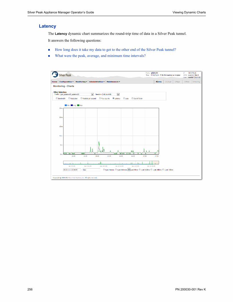
Silver Peak Appliance Manager Operator’s Guide Viewing Dynamic Charts
256 PN 200030-001 Rev K
Latency
The Latency dynamic chart summarizes the round-trip time of data in a Silver Peak tunnel.
It answers the following questions:
How long does it take my data to get to the other end of the Silver Peak tunnel?
What were the peak, average, and minimum time intervals?

Viewing Dynamic Charts Chapter 12 Monitoring Traffic
PN 200030-001 Rev K 257
Loss
The Loss dynamic chart summarizes, by tunnel, the number of packets lost before and after enabling Forward Error Correction (FEC).
It answers the following questions:
How many errors were there before and after turning on Forward Error Correction?
For any given minute, what was the percent loss?

Silver Peak Appliance Manager Operator’s Guide Viewing Dynamic Charts
258 PN 200030-001 Rev K
Out-of-Order Packets
The Out of Order Packets dynamic chart summarizes, by tunnel, the number of packets lost before and after enabling Packet Order Correction (POC).
It answers the following questions:
How many errors were there before and after turning on Packet Order Correction?
For any given minute, what was the percentage of out-of-order packets?

Viewing a Summary of All Reports Chapter 12 Monitoring Traffic
PN 200030-001 Rev K 259
Viewing a Summary of All ReportsThis summary page includes charts and graphs for (top 10) applications, reduction, bandwidth, flows (+/- TCP), latency, packet loss (Forward Error Correction), and out-of-order packets (Packet Order Correction). You can export this page as an image in PDF or PNG format.
The default time period is the Last 60 Minutes.
There are no results for these 3 reports because they are specific to named tunnels, and this report filtered for optimized traffic.

Silver Peak Appliance Manager Operator’s Guide Viewing Flow Redirection Statistics
260 PN 200030-001 Rev K
Viewing Flow Redirection StatisticsThe Monitoring - Flow Redirection page displays the number of control packets sent and received between this appliance and the other peer(s) in the cluster, as well as how much traffic was redirected to and from the other peer(s).
It answers the following questions:
What are the mgmt1 IP addresses of the other peers in this cluster?
How many control packets were exchanged between this appliance and each of its peers?
How many redirected flows does this appliance currently own?
How many flows is this appliance currently redirecting to peers?
In total, how many packets/bytes have been redirected to/from any given peer?
A Sampling of Results
When you choose manually, click the browser’s Refresh icon to view up-to-the-minute data.
For each mgmt1 IP address in the cluster, the Stats area summarizes the control packets that keep open the connection to a peer appliance.
These numbers are cumulative for all redirected flows, whether they’re active or terminated.
The Flows columns list current flows only.
This appliance owns all the Flows Redirected From.

Viewing Flow Redirection Statistics Chapter 12 Monitoring Traffic
PN 200030-001 Rev K 261
The Monitoring - Flow Redirection page displays the following statistics:
Across all other reported statistics, only the owner of a flow reports a flow’s traffic statistics.
Section Field Definition
Stats Peer IP The mgmt1 IP address of a peer appliance in the same cluster as this appliance.
Hello Control packets used to keep open the TCP connection between two peers’ mgmt1 cluster interfaces.
Redirection Requests to redirect flows
Tx Msgs The number of messages transmitted.
Tx Bytes The size of the transmitted messages, in bytes.
Rx Msgs The number of messages received.
Rx Bytes The size of the received messages, in bytes.
Flows Redirected From
Peer The mgmt1 IP address of a peer appliance in the same cluster as this appliance.
Flows The number of current flows redirected from the peer to this appliance.
Pkts To date, the total number of packets redirected from the peer to this appliance.
Bytes To date, the total number of bytes redirected from the peer to this appliance.
Flows Redirected To Peer The mgmt1 IP address of a peer appliance in the same cluster as this appliance.
Flows The number of current flows redirected to the peer by this appliance.
Pkts To date, the total number of packets redirected to the peer by this appliance.
Bytes To date, the total number of bytes redirected to the peer by this appliance.

Silver Peak Appliance Manager Operator’s Guide Viewing NetFlow Statistics
262 PN 200030-001 Rev K
Viewing NetFlow StatisticsThe Monitoring - NetFlow page displays the how many records were exported to the NetFlow collectors.
It answers the following questions:
How many flows were required to export the records to NetFlow?
How many packets were required export these flows?
A Sampling of Results

Viewing Interface Statistics Chapter 12 Monitoring Traffic
PN 200030-001 Rev K 263
Viewing Interface StatisticsThe Monitoring - Interfaces page displays generic performance data for the actual physical LAN, WAN, and management interfaces (primary and secondary). It answers the following questions:
How many bytes or packets is the appliance transmitting or receiving?
How many errors exist?
What types of errors exist?
To view the Interface Statistics
From the Monitoring menu, select Interfaces. The page displays the actual statistics accumulated for wan0, lan0, mgmt0, and mgmt1 since the appliance’s last reboot.
If Refresh is set to manually, use the browser’s refresh to view up-to-the minute data.
When the appliance is in Bridge mode, there are lan0 interface statistics. When the appliance is in Router mode, there are not.
Management connection to LAN Management connection to PC
blan0 and bwan0 are visible when gigabit etherchannel bonding is configured.
For more information, see “Configuring Gigabit Etherchannel Bonding” on page 61.

Silver Peak Appliance Manager Operator’s Guide Viewing Interface Statistics
264 PN 200030-001 Rev K
The Monitoring - Interfaces page displays the following statistics:
Network Receive Statistics
Network Transmit Statistics
Field Definition
Rx Bytes Number of bytes received inbound from the WAN side
Rx Pkts Number of packets received inbound from the WAN side, including all packets that were either discarded, contained errors, arrived too quickly for the hardware to receive, or were frame or mcast packets,
Rx Discard Pkts Number of input packets selected to be discarded even though no errors are found.
Rx Error Pkts Number of input packets that contained errors.
Rx Overrun Pkts Number of times the receiver hardware was unable to hand a received packet to a hardware buffer because the rate exceeded the receiver's ability to handle the data.
Rx MCast Pkts Number of multicast packets received.
Rx Frame Pkts Number of packets received incorrectly having a CRC error and a non-integer number of octets. On a LAN, this is usually the result of collisions or a malfunctioning Ethernet device.
Field Definition
Tx Bytes Number of bytes transmitted outbound toward the WAN side
Tx Pkts Number of packets transmitted outbound toward the WAN side, including all packets that were either discarded, contained errors, were overrun, had collisions, or were dropped because the interface detection link is lost.
Tx Discard Pkts Number of output packets selected to be discarded even though no errors are found.
Tx Error Pkts Number of outbound packets that could not be transmitted because of errors.
Tx Overrun Pkts Number of times the transmitter hardware was unable to hand a transmitted packet to a hardware buffer because the rate exceeded the transmitter's ability to handle the data.
Tx Carrier Pkts Number of packets dropped because the interface detection link is lost.
Tx Collision Pkts Number of output collisions detected on this interface.

Viewing Bridge Mode Statistics Chapter 12 Monitoring Traffic
PN 200030-001 Rev K 265
Viewing Bridge Mode StatisticsThe Monitoring - Bridges page displays data traffic traversing all the LAN and WAN interfaces.
It answers the following questions:
Is the appliance receiving/sending on all interfaces?
Is the link up?
Ingress for pass-through traffic
Egress for pass-through traffic

Silver Peak Appliance Manager Operator’s Guide Viewing IP Routes
266 PN 200030-001 Rev K
Viewing IP RoutesThe Monitoring - IP Routes page displays next-hop reachability.
It answers the following questions:
Is the appliance receiving/sending on all interfaces?
Is the link up?
Sampling of Results
The Monitoring - IP Routes page displays the following statistics:
A note about datapath connectivity
If there is either a LAN Next-Hop Unreachable or WAN Next-Hop Unreachable alarm after upgrading to Version 2.4.3.1, resolve the alarm(s) immediately by configuring the gateway(s) to respond to ICMP pings from the Silver Peak NX Appliance IP Address.
Field Definition
Next-hop IP IP address of the router to which the Silver Peak appliance sends datapath traffic
Interface The logical port associated with the Next-hop IP
Source Direction of the next-hop router, relative to the appliance
State There are four possible states:
• Initializing• Reachable • Unreachable• Test disabled [when appliance is in Bypass mode]
Uptime How long the next-hop router has been reachable
WAN Configured Role Whether the next-hop router is Active or Backup. When Active, it’s delivering tunnelized packets.
WAN Current Role Actual WAN role. The options are Active, Backup, Down, and N/A [not applicable].

PN 200030-001 Rev K 267
C H A P T E R 1 3
Administration Tasks
This chapter describes how to perform various administration-related tasks.
In This Chapter Configuring Log Settings See page 268.
Understanding the Events Log See page 273.
Viewing a Log of All Alarms See page 274.
Viewing the Audit Log See page 275.
Managing Debug Files See page 276.
Pre-Positioning Data for Enhanced Acceleration Benefits See page 283.
Configuring SNMP See page 285.
Managing User Accounts See page 290.
Configuring Authentication, RADIUS, and TACACS+ See page 295.
Configuring Banners See page 312.
Configuring Settings for Web Protocols and Web Users See page 313.
Initial Configuration Wizard See page 314.
Support See page 316.
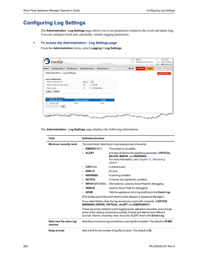
Silver Peak Appliance Manager Operator’s Guide Configuring Log Settings
268 PN 200030-001 Rev K
Configuring Log SettingsThe Administration - Log Settings page allows you to set parameters related to the event and alarm logs. You can configure local and, optionally, remote logging parameters.
To access the Administration - Log Settings page
From the Administration menu, select Logging > Log Settings.
The Administration - Log Settings page displays the following information:
Field Definition/Content
Minimum severity level The event level, listed here in decreasing order of severity:
• EMERGENCY The system is unusable.
• ALERT Includes all alarms the appliance generates: CRITICAL, MAJOR, MINOR, and WARNING. For more information, see Chapter 15, “Monitoring Alarms.”
• CRITICAL A critical event
• ERROR An error
• WARNING A warning condition
• NOTICE A normal, but significant, condition
• INFORMATIONAL Informational. Used by Silver Peak for debugging.
• DEBUG Used by Silver Peak for debugging
• NONE Tells the appliance not to log anything to the Event Log.
[The bolded part of the level name is what displays in Appliance Manager.]
If you select Notice, then the log records any event with a severity of NOTICE, WARNING, ERROR, CRITICAL, ALERT, and EMERGENCY.
These are purely related to event logging levels, not alarm severities, even though some of the naming conventions overlap. Events and alarms have different sources. Alarms, once they clear, list as the ALERT level in the Event Log.
Start new file when log reaches
Specifies a maximum log size before a new log file is created. The default is 50 MB.
Keep at most Sets a limit for the number of log files to store. The default is 30.

Configuring Log Settings Chapter 13 Administration Tasks
PN 200030-001 Rev K 269
Apply all changes or edits to the running configuration, but not the stored configuration. To add the changes to the stored configuration, be sure to click Save Changes.
Undo changes if you haven’t clicked Apply.
Remote Log Receivers These allow you to forward logs of all events at a given severity level and higher to a remote syslog server.
IP Address The IP address of the remote syslog server.
Minimum Severity The lowest severity level of all logged events to be forwarded.
Displays the Add Remote Receiver area, where you can enter the remote syslog server’s IP address and choose the Minimum Severity level of events to report.
Removes the IP address of the remote syslog server from the destination list.
Adds the IP address of the remote syslog server to the destination list of forwarded logged events.
Applies the changes made to the IP address and/or severity level in the Modify Remote Receiver area.
Field Definition/Content (Continued)

Silver Peak Appliance Manager Operator’s Guide Configuring Log Settings
270 PN 200030-001 Rev K
Configuring Local Logging
You can configure log severity levels and rotation parameters on the Administration - Log Settings page.
To save changes to the running configuration, click Apply.
Then, Save the changes to make them part of the stored configuration.
Select a Minimum severity level from the drop-down list.
• Silver Peak recommends that you select NOTICE, which is the default.
• If you select NONE, then no events are logged.
For severity definitions, see “Categories of Alarms” on page 362.
Choose when to begin a new log, based on maximum log size in megabytes.
The default maximum log size is 50 MB, which means that the current log continues until it reaches that size. Of course, you can change the value.
Enter the number of log files to retain. The default value is 30: the current log plus 29 archives.
Click to display the Add Remote Receiver fields.
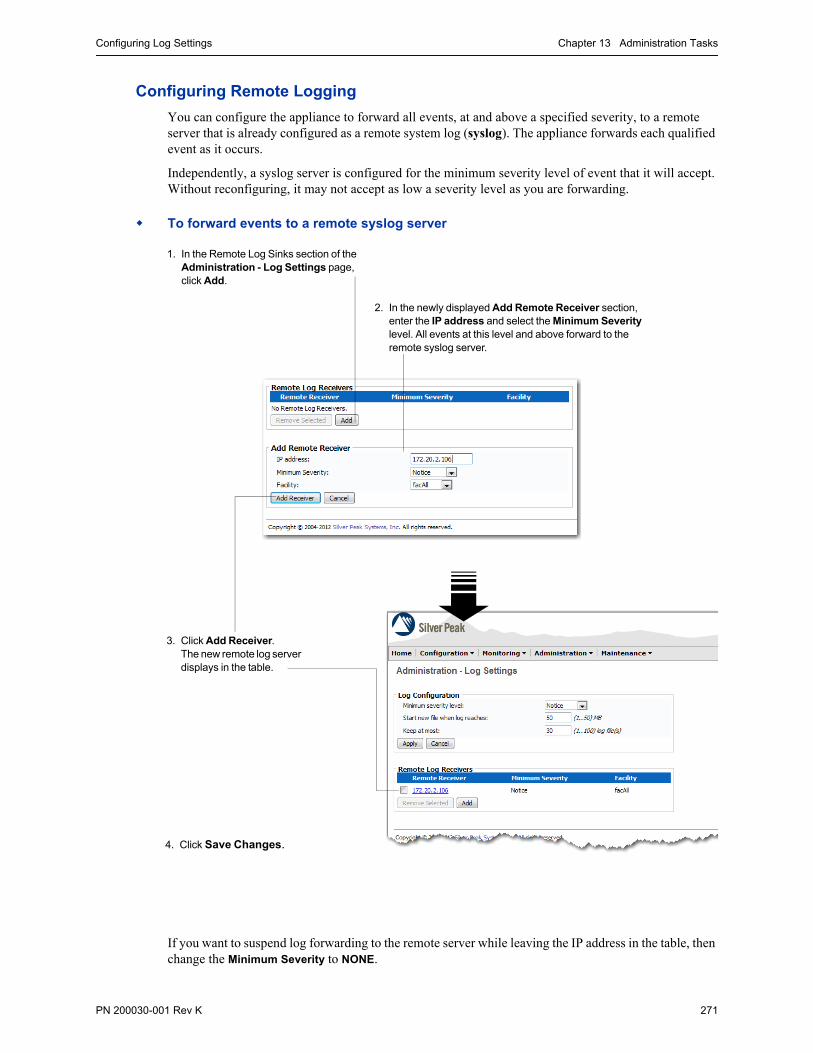
Configuring Log Settings Chapter 13 Administration Tasks
PN 200030-001 Rev K 271
Configuring Remote Logging
You can configure the appliance to forward all events, at and above a specified severity, to a remote server that is already configured as a remote system log (syslog). The appliance forwards each qualified event as it occurs.
Independently, a syslog server is configured for the minimum severity level of event that it will accept. Without reconfiguring, it may not accept as low a severity level as you are forwarding.
To forward events to a remote syslog server
If you want to suspend log forwarding to the remote server while leaving the IP address in the table, then change the Minimum Severity to NONE.
1. In the Remote Log Sinks section of the Administration - Log Settings page, click Add.
2. In the newly displayed Add Remote Receiver section, enter the IP address and select the Minimum Severity level. All events at this level and above forward to the remote syslog server.
3. Click Add Receiver. The new remote log server displays in the table.
4. Click Save Changes.

Silver Peak Appliance Manager Operator’s Guide Configuring Log Settings
272 PN 200030-001 Rev K
To modify a remote receiver’s Minimum Severity
You cannot modify an existing server’s IP address. Instead, you must delete the old one and add a new one.
1 In the Remote Log Receivers area, click the IP address of the receiver you want to modify. The Modify Remote Receiver (IP address) appears.
2 From the Minimum Severity drop-down menu, select the option you want.
3 Click Modify Receiver.
4 Click Save Changes.
To remove a syslog server from the Remote Receiver list
1 Select the server in the table.
2 Click Remove Selected. The table clears the syslog server entry.
3 To save changes to the running configuration, click Apply.
4 Save the changes to the database.

Understanding the Events Log Chapter 13 Administration Tasks
PN 200030-001 Rev K 273
Understanding the Events LogThe event log, which you access by selecting Administration > Logging > Event Log Viewer, contains timestamped messages for all system-level activity. It’s a locally saved, read-only log:
You can configure the generic log settings on the Administration - Log Settings page. This includes specifying:
• The minimum severity level logged
• Whether time intervals or log size determine when a new log begins
• The maximum number of log files to keep, including the current log
• To what other remote servers to send logged events
For more information, see “Configuring Log Settings” on page 268.
Go to first page Go to last page
Previous page Next page
Select how many alarmsper page

Silver Peak Appliance Manager Operator’s Guide Viewing a Log of All Alarms
274 PN 200030-001 Rev K
Viewing a Log of All AlarmsThe Administration - Alarm Log Viewer page displays all alarms—current and historical. It contains timestamped messages each time an alarm is raised or cleared. It is a locally saved read-only log.
To access the alarm log, select Administration > Logging > Alarm Log Viewer.
You can configure the generic log settings on the Administration - Log Settings page. This includes specifying:
• The minimum severity level logged
• Whether time intervals or log size determine when a new log begins
• The maximum number of log files to keep, including the current log
• To what other remote servers to send logged events
For more information, see “Configuring Log Settings” on page 268.
Go to first page Go to last page
Previous page Next page
Select how many alarmsper page

Viewing the Audit Log Chapter 13 Administration Tasks
PN 200030-001 Rev K 275
Viewing the Audit LogThe Administration - Audit Log Viewer page lists all configuration changes (create, modify, delete) and all system actions such as login/logout made by any users (Command Line Interface [CLI], Appliance Manager, and/or Global Management System [GMS]).
To access this page, select Administration > Logging > View Audit Log.
This log is only available to users with the Admin privilege level.
username@IP(/gms of GMS user)
Additional parameters (context dependent)
create /modify /delete /
action
succeeded / failed /requested
Appliance Hostname
SYSTEM /INTERFACE /ALARM /CONFIG-DB

Silver Peak Appliance Manager Operator’s Guide Managing Debug Files
276 PN 200030-001 Rev K
Managing Debug FilesThis chapter describes how to manage the system files – log files, debug dump files, stat reports, and tcpdump results. It also describes how to archive them by saving them to an SCP (Secure Copy) or FTP (File Transfer Protocol) Server.
Types of Debug Files See page 276.
Saving Files to a Remote Server See page 278.
Deleting Log Files See page 282.
Types of Debug Files
The appliance automatically creates and stores a number of non-configuration data files as a result of normal events, traffic monitoring, system crashes, and testing.
• The Appliance Manager’s Administration - Debug Files page lists these files and provides a way for you to save them to another location for storage or additional handling.
• With the exception of the [Log] files, you cannot view these files on the Appliance Manager.
• To free up memory in the appliance, you can delete the files.
Specifically, these five file types are as follows:
Log The raw event log data, viewable on the Administration - Event Log Viewer page. This includes historical alarms, not current ones. To access this page, select Administration > Logging > Event Log Viewer.
By default, a new file begins when the file reaches 50 MB. However, you can change the rotation criteria on the Administration - Log Settings page. To access this page, select Administration > Logging > Log Settings.
Debug Dump Created as a result of any system failure.
Can also be created on demand by clicking the Generate button next to the System & Debug Information File field.
Transfer these files to Silver Peak’s Customer Support for evaluation.
Snapshot Created as a result of any system failure.
Contains the same information as Debug Dump, and then includes additional information needed by the engineering team.
Transfer these files to Silver Peak’s Customer Support for evaluation.
TCP Dump Result User-named data file generated by running using the Command Line Interface (CLI).
Transfer these files to Silver Peak’s Customer Support for evaluation.
Show Tech Can also be created on demand by clicking the Generate button next to the Tech Support File field.
Transfer these files to Silver Peak’s Customer Support for evaluation.

Managing Debug Files Chapter 13 Administration Tasks
PN 200030-001 Rev K 277
Shows the data disk space used and available, in bytes and as a percentage
To save a file to the local disk or an SCP or FTP remote server, click on the filename itself.
Debug Dump
The file name format is tunbug-[Hostname]-[YYYYMMDD-HHMMSS].tgz
TCP Dump Result
User-named file generated by running tcpdump in the Command Line Interface (CLI).
Show Tech
Generated when you execute the Tech Support File. The file name format is [Hostname]-[YYYYMMDD-HHMMSS].txt.gz
Snapshot
The file name format is [Hostname]-[sysd|statsd|soapd|snmpd|...]-[YYYYMMDD-HHMMSS].tar.gz
To generate the Show Tech file.
To manually generate Debug Dump file.
Log
As a new log file is created, the earlier files increment. For example, the file messages will eventually be renamed messages.3.gz.

Silver Peak Appliance Manager Operator’s Guide Managing Debug Files
278 PN 200030-001 Rev K
Saving Files to a Remote Server
The Application Manager lets you copy non-configuration files from the appliance to a remote server.
When you click to select the method, you can only edit the required fields.
The fields and options have the following definitions:
Click to return to the main Administration - Debug Files page
Field or Option Definition/Content
File Name (A read-only field) The name of the file you’ve chosen to save.
Save to Server with:
Local File For saving the software image file to your local PC.
SCP (Secure Copy) For saving the software image file to a remote Secure Copy server.
FTP (File Transfer Protocol) For saving the software image file to a remote File Transfer Protocol (FTP) server.
Remote Server Address Use either the server IP address or the server name (if it’s mapped to a local host table or a DNS server).
Remote User Name The name of the user that server expects
Remote Password The password of the user that the server expects
Remote Full PathRemote Relative Path
The type of path requested depends on which method you choose:
• If using the SCP server, enter the full path to the server.• (Optional) If using the FTP server, enter the relative path to the server.
Destination File Name (Optional) If you want to rename the file, you can do so here.
Status If the read-only value is Ready, you may proceed with transferring the file to a remote server.

Managing Debug Files Chapter 13 Administration Tasks
PN 200030-001 Rev K 279
To save a log file to a local PC
1 Go to the Administration - Debug Files page.
2 In the File Management area, click the type of log you want to save: Log, Debug Dump, Snapshot, Stat Report, or TCP Dump Result.
3 In the table, click on the file name of the file you want to save.
The Administration - Debug Files - Save File page appears.
4 Click Local File.
5 Click Save. A security warning box displays.
6 Click Save.
7 When the Save As dialog box appears, navigate to the directory you want, accept or change the file name, and click Save.
Last Save Status The status at the end of the previous save operation.
Transfer Start Time What time the file transfer began
Transfer End Time What time the file transfer ended
Saves the selected file/image to the remote server
Allows you to cancel a file transfer that is in progress
Field or Option Definition/Content (Continued)

Silver Peak Appliance Manager Operator’s Guide Managing Debug Files
280 PN 200030-001 Rev K
To save a log file to an SCP Server
1 Go to the Administration - Debug Files page.
2 In the File Management area, click the type of log you want to save: Log, Debug Dump, Snapshot, Stat Report, or TCP Dump Result.
3 In the table, click on the file name of the file you want to save.
The Administration - Debug Files - Save File page appears.
4 Click SCP (Secure Copy).
5 Enter the data necessary to save the file to the SCP server.
Here, we’ll use the example of saving the file, alerts, to the following location:
scp <UserName>@170.2.2.65:/home/<UserName>/work/logs/alerts
a For the Remote Server Address field, enter either:
• the server IP address, as in 170.2.2.65, or
• the server name, if it’s mapped to a local host table or a DNS server
b Enter the Remote User Name and Remote Password for the Secure Copy (SCP) server.
c For the Remote Full Path field, enter the full path.
A full pathname includes the drive (if required), starting or root directory, all attached subdirectories and ends with the file or object name. Begin the path with a forward slash (/).
d If you want to rename the file, enter the new file name in the Destination File Name field. If you leave the field blank, the Appliance Manager saves the file with its existing file name.
6 Click Save. The Appliance Manager displays the progress.

Managing Debug Files Chapter 13 Administration Tasks
PN 200030-001 Rev K 281
To save a log file to an FTP Server
1 Go to the Administration - Debug Files page.
2 In the File Management area, click the type of log you want to save: Log, Debug Dump, Snapshot, Stat Report, or TCP Dump Result.
3 In the table, click on the file name of the file you want to save. The Administration - File System -
Save File page appears.
4 Click File Transfer to Protocol (FTP).
5 Enter the data necessary to save the file to the FTP server.
Here, we’ll use the example of saving the file, alerts, to Andrew’s directories on an FTP server. In the process, we’ll rename the file to alerts_SP41-NX-8600:
a For the Remote Server Address field, enter either:
• the server IP address, as in 170.2.2.65, or
• the server name, if it’s mapped to a local host table or a DNS server
b Enter the Remote User Name and Remote Password for the FTP server.
c For the Remote Relative Path field, enter the relative path.
A relative path is a path relative to the current working directory. Its first character can be anything but the pathname separator (here, a forward slash).
For example, if the ftp login directory is /home/<UserName>/, then the relative path would begin at the next subdirectory, as in, work/logs. It is not necessary to begin or end the relative path with a forward slash (/).
d If you want to rename the file, enter the new file name in the Destination File Name field. If you leave the field blank, the Appliance Manager saves the file with its existing file name.
6 Click Save. The Appliance Manager displays the progress.
If you want to rename the original file, enter it in this field. If you leave it blank, the file saves with its existing name.
For FTP, no slash necessary before or after the directory name
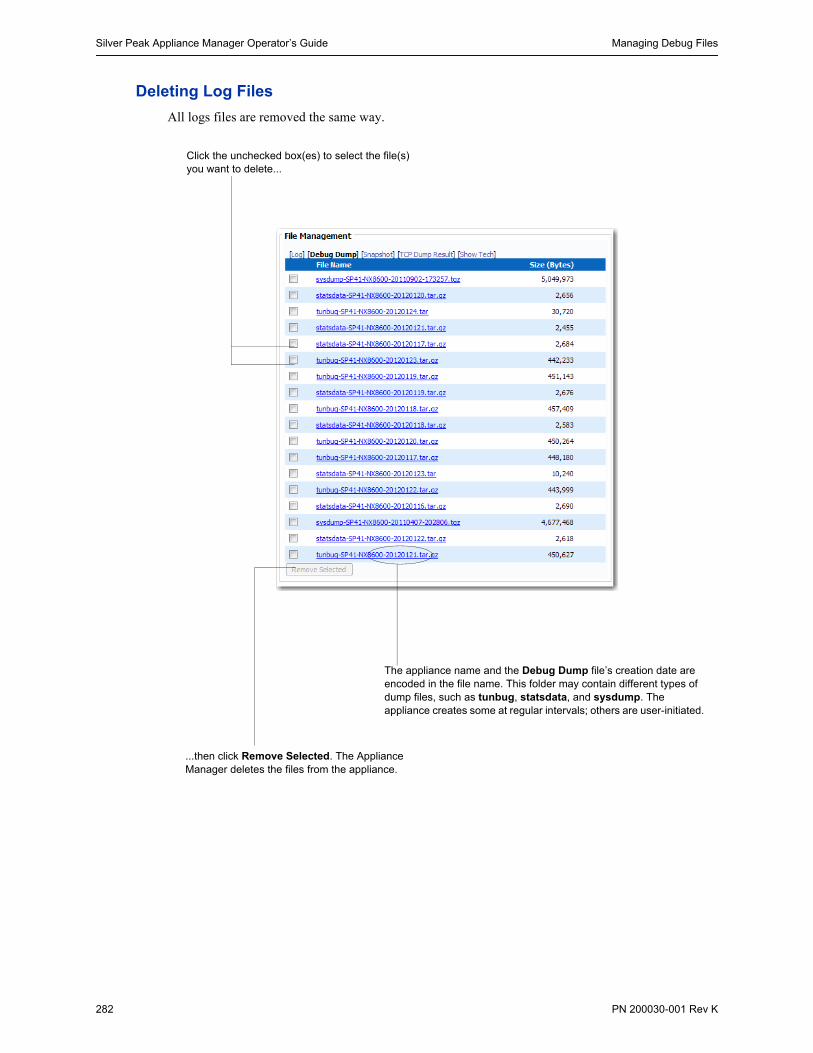
Silver Peak Appliance Manager Operator’s Guide Managing Debug Files
282 PN 200030-001 Rev K
Deleting Log Files
All logs files are removed the same way.
Click the unchecked box(es) to select the file(s) you want to delete...
...then click Remove Selected. The Appliance Manager deletes the files from the appliance.
The appliance name and the Debug Dump file’s creation date are encoded in the file name. This folder may contain different types of dump files, such as tunbug, statsdata, and sysdump. The appliance creates some at regular intervals; others are user-initiated.

Pre-Positioning Data for Enhanced Acceleration Benefits Chapter 13 Administration Tasks
PN 200030-001 Rev K 283
Pre-Positioning Data for Enhanced Acceleration BenefitsThis section describes how to use the appliances’ FTP server capability to pre-position data and enable all users to get the benefit of second-pass network performance.
The Appliance Manager allows you to pre-position data into Network Memory so that users can get the benefits of second-pass data without having to wait for Network Memory to populate.
With the Administration - Pre-position page, you can enable FTP server capability on each branch’s NX appliance:
Once you enable pre-positioning on the appliance, administrators can then FTP files or directories to the appliances which will, in turn, “warm” Network Memory.
Subsequently, any user who requests data that was pre-positioned will immediately enjoy the acceleration benefits of the stored local instances.
It’s important to make sure that the relevant tunnels are admin-ed up before FTP transfer.
If the Administrator desires, (s)he can set up a script process for prepositioning jobs that need to run automatically on an ongoing basis.
There is no down side to leaving this feature enabled by default.
In this scenario, the file server at the data center is the FTP client, with multiple directories under /dir/home.

Silver Peak Appliance Manager Operator’s Guide Pre-Positioning Data for Enhanced Acceleration Benefits
284 PN 200030-001 Rev K
To configure a branch or remote appliance to pre-position data
1 From the Administration menu, select Pre-position.
a Select the Server Enable check box. This enables the appliance to act as an FTP server.
b To exempt the FTP client from needing to use an existing account on the appliance, select Anonymous Access Enable.
c Enter the maximum number of clients that may access the appliance simultaneously. The default value is 5. The range is 1 to 10.
2 Click Apply.
3 Click Save Changes.

Configuring SNMP Chapter 13 Administration Tasks
PN 200030-001 Rev K 285
Configuring SNMPThis section describes the following about Simple Network Management Protocol (SNMP):
Loading SNMP MIBs See page 285.
Configuring SNMP Settings See page 286.
Loading SNMP MIBs
When you took delivery of your appliance, the package also contained a CD with the Standard and the Silver Peak proprietary MIBs (Management Information Base) files, for loading into whatever MIBs browser you’re using:
• You can choose to install the Standard MIBs, the Silver Peak proprietary MIBs, or both.
• The Standard list and the Silver Peak file list share the same first three files. These are highlighted in green below.
• Because there are dependencies, you must load the files in a list in a specific sequence.
• If you choose to load both the Standard and the Silver Peak MIBs, load either list completely and then append the non-common files from the remaining list.
List of Silver Peak MIBs
Load these files in the following order:
1 SNMPv2-SMI.txt
2 SNMPv2-TC.txt
3 SNMPv2-CONF.txt
4 SILVERPEAK-SMI.txt
5 SILVERPEAK-TC.txt
6 SILVERPEAK-PRODUCTS-MIB.txt
7 SILVERPEAK-MGMT-MIB.txt
List of Standard SMIBs
Load these files in the following order:
1 SNMPv2-SMI.txt
2 SNMPv2-TC.txt
3 SNMPv2-CONF.txt
4 RFC1155-SMI.txt
5 RFC1213-MIB.txt
6 SNMPv2-MIB.txt
7 SNMP-FRAMEWORK-MIB.txt
8 SNMP-MPD-MIB.txt
9 SNMP-TARGET-MIB.txt
10 SNMP-NOTIFICATION-MIB.txt
11 SNMP-USER-BASED-SM-MIB.txt
12 SNMP-VIEW-BASED-ACM-MIB.txt

Silver Peak Appliance Manager Operator’s Guide Configuring SNMP
286 PN 200030-001 Rev K
Configuring SNMP Settings
This section describes the following SNMP-related procedures:
To add a trap receiver See page 287.
To modify a trap receiver See page 288.
To remove a trap receiver See page 288.
To add an SNMP v3 user See page 289.
On the Administration - SNMP page, you can configure the Appliance Manager for SNMP:
• The Silver Peak appliance is implemented as a host that supports data in the Management Information Base (MIB) II, as described in RFC 1213, for cold start traps and warm start traps.
• The appliance issues a MIB-II trap during reset—that is, when loading a new image, recovering from a crash, or rebooting.
• You can specify trap receivers—that is, the IP address destinations.
• The appliances send traps every time an alarm is raised or cleared. The traps contain additional information about the alarm including severity, sequence number, a text-based description of the alarm, and the time the alarm was created. Please see SILVERPEAK-MGMT-MIB.TXT in the MIBS directory of the documentation distribution for additional information.
This area and the one below it are generic — an all that’s needed for SNMP v1 and SNMP v2c.
This area is manages trap receivers, that is, IP address destinations.
For additional security, you can enable admin (only) for SNMP v3, which requires authentication between the SNMP server and the user. Additionally, you can encrypt and an optional encryption component.

Configuring SNMP Chapter 13 Administration Tasks
PN 200030-001 Rev K 287
To add a trap receiver
1 Click Add. The Add Trap Receiver area appears.
a In the Trap Receiver IP field, enter the IP address where you want the traps sent.
b In the Community field, enter the same community string that is configured on the agent.
c From the Trap Type field, select either v1 (RFC 1157) or v2c (RFC 1901) standards.
In SNMP v1 (RFC 1157) and v2c (RFC 1901) standards, authentication is based on a community string (text string) that represents an unencrypted username without a password.
d The Enable Trap Receiver box is checked by default.
2 Click Apply. The new host displays in the table.
The new trap receiver appears in the table.
3 Click Save Changes.
Unless you change the setting, the server is enabled by default.

Silver Peak Appliance Manager Operator’s Guide Configuring SNMP
288 PN 200030-001 Rev K
To modify a trap receiver
You can modify a trap receiver’s Community and Trap Type, as well as enable or disable the host.
You cannot modify a Trap Receiver IP. Rather, you must delete the host and add a new one.
1 In the Trap Receivers table, click the desired Host IP address.
The Modify Trap Receiver area appears, specific to that IP address.
2 Do one of the following, as needed:
a Select the server and click Enable Server. The value in the Enabled column changes from false to true.
b Select the server and click Disable Server. The value in the Enabled column changes from true to false.
To remove a trap receiver
1 In the Trap Receivers table, select the desired server(s).
2 Click Remove Selected.
A dialog window displays, requesting confirmation.
3 Click OK. The Appliance Manager removes the selected hosts.
The default value for Community is public. However, you can edit this text string, as needed.

Configuring SNMP Chapter 13 Administration Tasks
PN 200030-001 Rev K 289
To add an SNMP v3 user
Only the user, admin, can be configured to be an SNMP v3 user.
Any user with admin privileges (capability) can configure the SNMP v3 privileges for admin, the user.
1 Select Enable User.
If you’d prefer, you can configure and save the authorization and privacy settings without enabling the user until a later date.
2 In the Auth Information area:
a From the Type box, select either the SHA-1 or MD5 hash algorithm.
b Indicate whether the password you’ll enter is plain text or encrypted.
• If you’re entering a plain text password, leave the Password Encrypted check box deselected.
• If you’re entering an encrypted password, select the Password Encrypted check box.
c Enter the password.
3 If you leave the Private Information area unchanged and blank, the appliance uses the default privacy algorithm (AES-128) and the same password that’s specified for authentication. If you want to use the DES hash algorithm and/or a different password, then, in the Private Information area:
a From the Type box, select either the DES or AES-128 hash algorithm.
b Indicate whether the password you’ll enter is plain text or encrypted.
• If you’re entering a plain text password, leave the Password Encrypted check box deselected.
• If you’re entering an encrypted password, select the Password Encrypted check box.
c Enter the password.
4 Click Apply.
5 Save the changes.
Authentication between the user and the server acting as the SNMP agent is bilateral and required for SNMP v3. You can use either the MD5 or SHA-1 hash algorithm.
Using DES or AES-128 for privacy is optional. If you don’t specify a password, it uses the same privacy password (encrypted or plain text) that you specified for authentication.
• When entering a plain text password, leave Password Encrypted deselected.• When entering an encrypted password, select Password Encrypted.

Silver Peak Appliance Manager Operator’s Guide Managing User Accounts
290 PN 200030-001 Rev K
Managing User AccountsThis section provides information about using the Administration - Users page for creating, deleting, and editing user accounts.
Guidelines for Creating Passwords See page 290.
Accessing User Accounts See page 291.
Creating a User Account See page 292.
Modifying a User Account See page 293.
Deleting a User Account See page 294.
When you first install the Silver Peak appliance, admin and monitor are the only users: admin has all privileges and monitor has a limited subset.
However, you can add an additional layer of security by setting up authentication and authorization with the use of RADIUS and TACACS+. For more information, see “Configuring Authentication, RADIUS, and TACACS+” on page 295.
Guidelines for Creating Passwords
Passwords should be a minimum of 8 characters.
There should be at least one lower case letter and one upper case letter.
There should be at least one digit.
There should be at least one special character
Consecutive letters in the password should not be dictionary words.

Managing User Accounts Chapter 13 Administration Tasks
PN 200030-001 Rev K 291
Accessing User Accounts
The Silver Peak appliances’ built-in user database supports user names, groups, and passwords.
The two user groups are admin and monitor. You must associate each User Name with one or the other. Neither group can be modified or deleted.
• The monitor group supports reading and monitoring of all data, in addition to performing all actions. This is equivalent to the Command Line Interface’s (CLI) enable mode privileges.
• The admin group supports full privileges, along with permission to add, modify, and delete. This is equivalent to the CLI’s configuration mode privileges.
To access the Users page
From the Administration menu, select User Management > Users. The Administration - Users page displays.
The table lists all users known to this appliance, whether or not their accounts are enabled.
• The users, admin and monitor, CANNOT be deleted or disabled. Their check boxes are inaccessible.
• You can, however, change each one’s password.
The Active Sessions section lists all users who are logged in to the appliance. In order, these logins originate from the following locations:
• RS-232 serial port (console)• Appliance Manager• Global Management System (GMS)

Silver Peak Appliance Manager Operator’s Guide Managing User Accounts
292 PN 200030-001 Rev K
Creating a User Account
To create a new user account, you must be logged in with admin group privileges.
To create a new user account
1 On the Administration - Users page, click Add. The Add New User area displays.
2 In the User Name field, enter a new user name.
3 In the Capability field, select admin or monitor from the drop-down menu.
• The monitor group supports reading and monitoring of all data, in addition to performing all actions. This is equivalent to the Command Line Interface’s (CLI) enable mode privileges.
• The admin group supports full privileges, along with permission to add, modify, and delete. This is equivalent to the CLI’s configuration mode privileges.
4 In the Password field, enter a password; the appliance has no constraints. Reenter the same sequence in the Confirm Password field.
5 Click Apply. The new user displays in the User Accounts table. By default, each new user is enabled.
If you want to disable a user, you must modify the account.
6 To permanently save the edits, first click Apply and then Save Changes.
New user added to the table

Managing User Accounts Chapter 13 Administration Tasks
PN 200030-001 Rev K 293
Modifying a User Account
To edit a user account, you must be logged in with admin group privileges.
When editing an account, you can:
• change the user’s password (you can change your own if you have admin privileges.)
• enable or disable a user account
• remove a user account
You cannot:
• modify a user’s name
• increase or decrease the user’s level of privileges
To accomplish that, you must add a new name and delete the old name. The order in which you do it is not important.
You also cannot have more than one user with the same User Name.
To edit a user account
1 In the User Accounts table, click the user’s name.
2 To change the password:
a Click the Change Password box.
b In the Old Password fields, enter the existing password.
c Then enter the new password in the New Password and Confirm Password fields.
3 To disable a user account, clear the Enabled User check box.
4 To permanently save the edits, first click Apply and then click Save Changes. The table updates its information.
We’ll modify the account, Carlton.
The name of the selected account displays in the header.

Silver Peak Appliance Manager Operator’s Guide Managing User Accounts
294 PN 200030-001 Rev K
Deleting a User Account
To delete a user account, you must have logged in with admin group privileges.
To delete a user account
1 In the User Accounts table, click the check box to the left of the user’s name.
2 Click Remove Selected, which is now accessible.
A dialog box appears, asking you to confirm the deletion(s).
3 Click OK. The table updates its information.
4 To permanently save the edits, click Save Changes.
We’ll delete the account, Chris.

Configuring Authentication, RADIUS, and TACACS+ Chapter 13 Administration Tasks
PN 200030-001 Rev K 295
Configuring Authentication, RADIUS, and TACACS+This sections discusses the following:
Authentication and Authorization See page 295.
Session Idle Time-out See page 296.
Configuring for RADIUS See page 297.
Configuring for TACACS+ See page 304.
The Silver Peak NX appliances support user authentication and authorization before providing access rights.
• Authentication is the process of validating that the end user, or a device, is who they claim to be.
• Authorization is the action of determining what a user is allowed to do. Generally, authentication precedes authorization.
The configuration specified for authentication and authorization applies globally to all users accessing that appliance.
Additionally, if a logged-in user is inactive for an interval that exceeds the inactivity time-out, the appliance returns them to the Login page. You can change the value on the Administration - Web page.
Authentication and Authorization
To provide authentication and authorization services, Silver Peak appliances:
• support a built-in user database
• can be linked to a RADIUS (Remote Address Dial-In User Service) server
• can be linked to a TACACS+ (Terminal Access Controller Access Control System) server.
Both RADIUS and TACACS+ are client/server protocols.
Appliance-based User Database
The built-in user database supports user names, groups, and passwords.
The two user groups are admin and monitor. You must associate each User Name with one or the other. Neither group can be modified or deleted.
• The monitor group supports reading and monitoring of all data, in addition to performing all actions. This is equivalent to the Command Line Interface’s (CLI) enable mode privileges.
• The admin group supports full privileges, along with permission to add, modify, and delete. This is equivalent to the CLI’s configuration mode privileges.
RADIUS
RADIUS uses UDP as its transport. With RADIUS, the authentication and authorization functions are coupled together. RADIUS authentication requests must be accompanied by a shared secret. The shared secret must be the same as defined in the RADIUS setup. Please see your RADIUS documentation for details.
TACACS+
TACACS+ uses TCP for its transport. TACACS+ provides separated authentication, authorization, and accounting services. Transactions between the TACACS+ client and TACACS+ servers are also authenticated through the use of a shared secret. Please see your TACACS+ documentation for details.

Silver Peak Appliance Manager Operator’s Guide Configuring Authentication, RADIUS, and TACACS+
296 PN 200030-001 Rev K
To configure the authentication and authorization methods for all users of the appliance
From the Administration menu, select User Management > Authentication. The page displays.
Session Idle Time-out
The session idle time-out is the amount of time a user must be inactive before the Silver Peak appliance forces the user to login all over again. You can set this on the Administration - Web page; the default is 30 minutes.
Authentication Method List:
These settings tell the appliance to attempt authentication in the order shown. If you don’t require a different second or third method, then reuse the first method in those fields.
For example, if you only want to use the Local appliance’s database for authentication, then enter Local for the First Method and select None for the second and third methods. [This is the default setting.].
No matter how many methods you choose, at least one of them must be Local.
Local Only: It maps all remote users to the Default User.
Remote First: This is the default behavior. If the local user name is valid, then it maps the authenticated user to the local user. If the User Name is not valid locally, it uses the Default User.
Remote Only: If the local user name is valid, it maps only to a remote authenticated user. If the local user name is not valid, it attempts no further mapping.
Here, you define the Default User (referred to by the Map Order task) as either admin or monitor.
Authorization Information:
Use this section when authenticating users via RADIUS or TACACS+.
The Silver Peak appliance has a database of user names and passwords. Similarly, when you use RADIUS or TACACS+, those servers also have their own database of user names and passwords. The question then becomes how to “map” the local user information to the server’s variant of the same data, and to determine whether the appliance or the server has the “last word”.
The authorization policy, here, determines how the remote user mapping behaves.
Default User:
Map Order:

Configuring Authentication, RADIUS, and TACACS+ Chapter 13 Administration Tasks
PN 200030-001 Rev K 297
Configuring for RADIUS
If you want to use RADIUS as one of your authentication methods, make you first go to the Administration - Authentication page and configure RADIUS as one of the methods.
On this page, there are two places where you can potentially enter a Server Key — under General
Settings and in the fields that appear when you add a new RADIUS server:
• If all (or a majority) of your servers have the same Server Key (also known as, shared secret), then enter that value in the Server Key field located in the General Settings section of this page. Then, when you’re adding an individual server that has that same key, you can leave the specific server’s Server Key fields blank. The software defers to the value in General Settings.
• If the server you’re adding has a different Server Key, then enter that value to the information in the Add RADIUS Server section. An specifically added server key always outranks a General
Settings Server Key value.
1 From the Administration window, select User Management > RADIUS. The Administration - RADIUS page appears.
2 Configure the General Settings, which apply to all RADIUS servers in your list. You can have a maximum of two RADIUS servers:
a In the Server Key field, enter the shared secret that was defined when setting up the RADIUS server.
b In the Confirm Server Key field, re-enter the same text string.
c If you wish, change the Timeout value. The default is 3 seconds.
d In the Retries field, specify how many retries to allow the user before locking them out.
e Click Apply.

Silver Peak Appliance Manager Operator’s Guide Configuring Authentication, RADIUS, and TACACS+
298 PN 200030-001 Rev K
3 Click Add. The Add RADIUS Server area appears.
a In the Server IP field, enter the IP address for the RADIUS server.
b In the Server Key field, do one of the following:
• Leave it blank if this server’s key is the same as the entry you made for Server Key in the General Settings section above, or
• Assign a individual key, different from the one you entered in General Settings. Note that it must be the string that matches the one assigned to this RADIUS server.
c In the Timeout field, the default time period is 3 seconds. You can select from the range between 1 and 15 seconds.
d In the Retries field, enter how many retries to allow the user before locking them out. The default is 1 retry.
4 Click Apply. The server appears in the RADIUS Servers table.
5 Click Save Changes.
Refer to your RADIUS documentation for additional details.

Configuring Authentication, RADIUS, and TACACS+ Chapter 13 Administration Tasks
PN 200030-001 Rev K 299
DEMO 13.1 Integrating the NX appliance into an existing RADIUS network.
Before you begin, obtain the RADIUS shared/secret key from your network administrator. In the NX screens, we call this same item the Server Key.
First, we configure the RADIUS server. In this example, we’re using Cisco IOS. And, we’ll configure the NX appliance to use RADIUS.
Configuring the RADIUS Server
1 Login to your RADIUS server.
2 In the left column, select Network Configuration.
a In the AAA Servers section, make sure that you have a server with the AAA Server Type of RADIUS.
b If you haven’t added a RADIUS server, do it now. For assistance, see your network administrator.
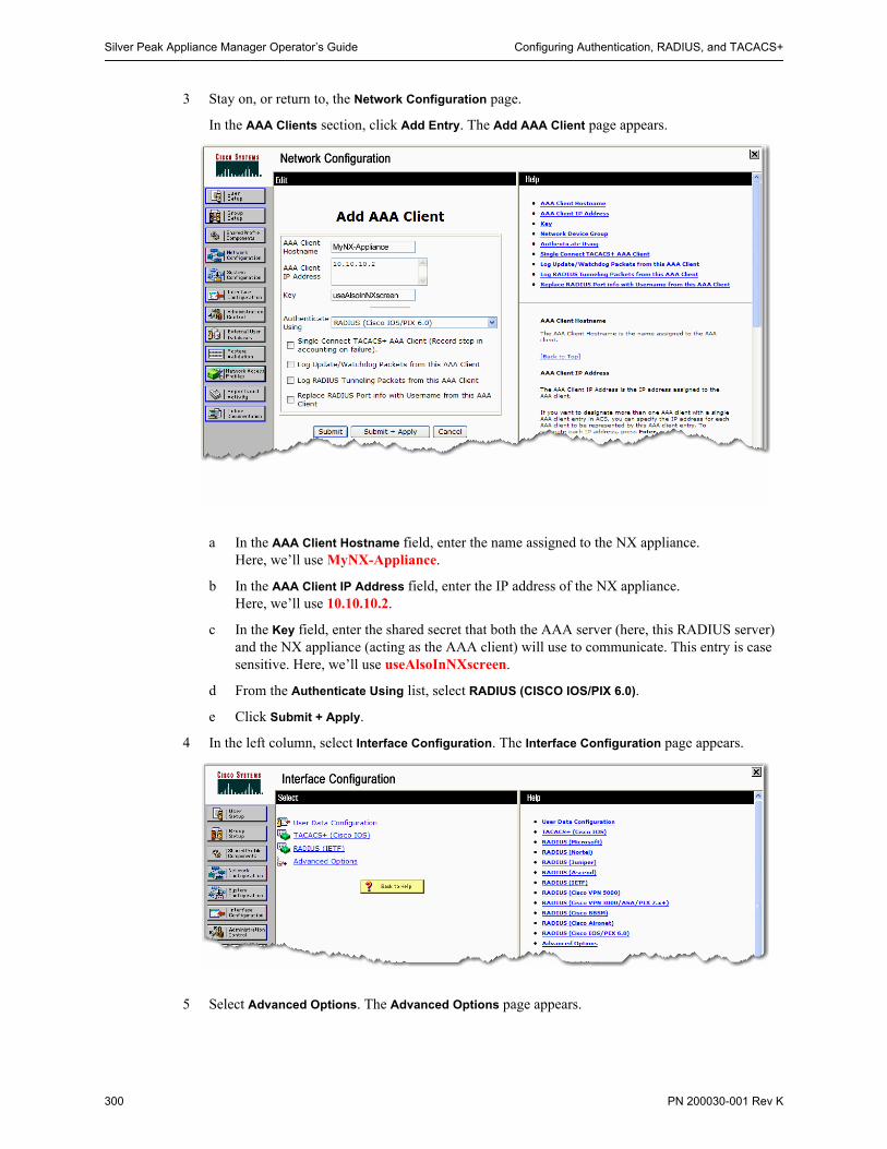
Silver Peak Appliance Manager Operator’s Guide Configuring Authentication, RADIUS, and TACACS+
300 PN 200030-001 Rev K
3 Stay on, or return to, the Network Configuration page.
In the AAA Clients section, click Add Entry. The Add AAA Client page appears.
a In the AAA Client Hostname field, enter the name assigned to the NX appliance. Here, we’ll use MyNX-Appliance.
b In the AAA Client IP Address field, enter the IP address of the NX appliance.Here, we’ll use 10.10.10.2.
c In the Key field, enter the shared secret that both the AAA server (here, this RADIUS server) and the NX appliance (acting as the AAA client) will use to communicate. This entry is case sensitive. Here, we’ll use useAlsoInNXscreen.
d From the Authenticate Using list, select RADIUS (CISCO IOS/PIX 6.0).
e Click Submit + Apply.
4 In the left column, select Interface Configuration. The Interface Configuration page appears.
5 Select Advanced Options. The Advanced Options page appears.
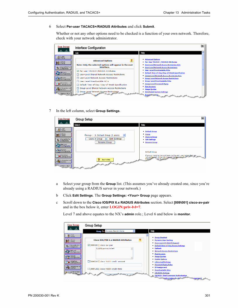
Configuring Authentication, RADIUS, and TACACS+ Chapter 13 Administration Tasks
PN 200030-001 Rev K 301
6 Select Per-user TACACS+/RADIUS Attributes and click Submit.
Whether or not any other options need to be checked is a function of your own network. Therefore, check with your network administrator.
7 In the left column, select Group Settings.
a Select your group from the Group list. (This assumes you’ve already created one, since you’re already using a RADIUS server in your network.)
b Click Edit Settings. The Group Settings: <Your> Group page appears.
c Scroll down to the Cisco IOS/PIX 6.x RADIUS Attributes section. Select [009\001] cisco-av-pair and in the box below it, enter LOGIN:priv-lvl=7.
Level 7 and above equates to the NX’s admin role.; Level 6 and below is monitor.

Silver Peak Appliance Manager Operator’s Guide Configuring Authentication, RADIUS, and TACACS+
302 PN 200030-001 Rev K
d Scroll down to the IETF RADIUS Attributes section. Select [006] Service-Type and from the drop-down list, select NAS Prompt.
e Click Submit and Restart.
Note IMPORTANT: After making any modifications to the current ACS configuration, you must restart all ACS services for the modifications to take effect.
To do this, go to System Configuration, click Service Control, and then click Restart.
Configuring the NX Appliance for RADIUS
To configure RADIUS for the NX appliance, you must have admin privileges.
1 From the Administration menu, select User Management > RADIUS. The Administration - RADIUS page appears.
2 In the RADIUS Servers area, click Add.

Configuring Authentication, RADIUS, and TACACS+ Chapter 13 Administration Tasks
PN 200030-001 Rev K 303
a In the Server IP field, enter the RADIUS server IP address.
b In the Server Key field, enter the RADIUS server’s shared key. This is the same string entered in the Cisco Secure ACS RADIUS Network Configuration page for this NX appliance, known there as the AAA client. That key was useAlsoInNXscreen, so we’ll enter it here.
Reenter the same key in the Confirm Server Key field.
c Accept the defaults for the Timeout and Retries fields.
d Make sure that the Enabled checkbox is selected.
3 Click Apply.
4 Save the changes.
Now, anyone logging in to the NX appliance is subject to authentication and authorization by the RADIUS server.

Silver Peak Appliance Manager Operator’s Guide Configuring Authentication, RADIUS, and TACACS+
304 PN 200030-001 Rev K
Configuring for TACACS+
1 From the Administration window, select User Management > TACACS+. The Administration -
TACACS+ page appears.
2 Configure the General Settings , which apply to all TACACS+ servers in your list:
a In the Server Key field, enter the shared secret that was defined when setting up the TACACS+ server.
b In the Confirm Server Key field, re-enter the same text string.
c If you wish, change the Timeout value.
d In the Retries field, specify how many retries to allow the user before locking them out.
e Click Apply.
3 Click Add. The Add TACACS+ Server area appears.

Configuring Authentication, RADIUS, and TACACS+ Chapter 13 Administration Tasks
PN 200030-001 Rev K 305
a In the Server IP field, enter the IP address for the TACACS+ server.
b From the Authentication Type field, select either pap or ascii, as appropriate.
c In the Server Key field, enter the password [shared secret] that was set up for the TACACS+ server.
d In the Confirm Server Key field, re-enter the same text string.
e In the Timeout field, select a timeout period between 1 and 15 seconds.
f In the Retries field, enter how many retries to allow the user before locking them out.
4 Click Apply. The server appears in the TACACS+ Servers table.
5 Click Save Changes.
Refer to your TACACS+ documentation for additional details.
DEMO 13.2 Configuring a TACACS+ server for authenticating NX appliance users.
In this example, we’ll configure an AAA server running TACACS+ on Cisco Secure ACS software. Then, we’ll configure an NX appliance to be an AAA client to that AAA server and discuss the possible error messages.
Tip If you’re adding the NX appliance to a network already being served by TACACS+, then just skip ahead to Step 5.
1 Install the Cisco Secure ACS (Access Control Server) software. Select everything and accept the defaults.
2 If you don’t already have it, install the latest Java Runtime Environment (JRE) from java.sun.com.
Configuring the TACACS+ Server
3 In a web browser, enter http://<tacacs-server-ip>:2002. The user interface for ACS appears.
4 Select Administration Control.
a Create the user, admin, with the password, admin.
b Under Administrator Privileges, click Grant All.
c Click Submit.
5 Select Interface Configuration.
a Click TACACS+ (Cisco IOS).
b Define a new service, silverpeak, with protocol, ip.

Silver Peak Appliance Manager Operator’s Guide Configuring Authentication, RADIUS, and TACACS+
306 PN 200030-001 Rev K
c Enable configuration for User, Group, or both. In reality, you only need to configure one—either the user or the group.
d Scroll down and click Submit.
6 Select Group Setup. The Group Setup page appears.
a From the Group drop-down menu, select the desired group and click Edit Settings. The Group
Settings : <Group Name> page appears.
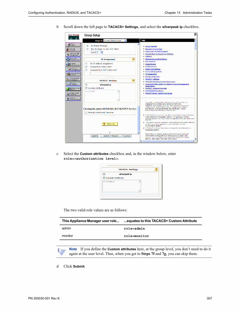
Configuring Authentication, RADIUS, and TACACS+ Chapter 13 Administration Tasks
PN 200030-001 Rev K 307
b Scroll down the left page to TACACS+ Settings, and select the silverpeak ip checkbox.
c Select the Custom attributes checkbox and, in the window below, enter role=<authorization level>.
The two valid role values are as follows:
Note If you define the Custom attributes here, at the group level, you don’t need to do it again at the user level. Thus, when you get to Steps 7f and 7g, you can skip them.
d Click Submit.
This Appliance Manager user role... ...equates to this TACACS+ Custom Attribute
admin role=admin
monitor role=monitor

Silver Peak Appliance Manager Operator’s Guide Configuring Authentication, RADIUS, and TACACS+
308 PN 200030-001 Rev K
7 Select User Setup.
a Create a user, and set a password.
b In the User Setup section, from the Password Authentication field, select ACS Internal
Database.
c Under Advanced TACACS+ Settings, for TACACS+ Enable Password, select Use CiscoSecure
PAP Password.
Remember this. You’ll need to know it later when you configure the NX appliance.
d Also, for the TACACS+ Outbound Password, enter the same password you set in Step 7a.
e Select the silverpeak ip checkbox.

Configuring Authentication, RADIUS, and TACACS+ Chapter 13 Administration Tasks
PN 200030-001 Rev K 309
f If you didn’t already do this at the group level, then select the Custom attributes checkbox and, in the window below, enter role=<authorization level>.
The two valid role values are as follows:
g Click Submit.
8 Select Network Configuration.
a In the AAA Servers section, click the AAA server name, tacacs. The AAA Server Setup For
tacacs page appears.
b If the Key field is blank, then enter a string of your choosing. This key, here, is for the AAA server to use in contacting the ACS server. It is not the key shared and used with the NX appliance(s). For our purposes here, we don’t care what this password is.
c In the AAA Server Type field, select TACACS+.
d Click Submit + Apply.
This Appliance Manager user role... ...equates to this TACACS+ Custom Attribute
admin role=admin
monitor role=monitor

Silver Peak Appliance Manager Operator’s Guide Configuring Authentication, RADIUS, and TACACS+
310 PN 200030-001 Rev K
9 Select Network Configuration again.
a In the AAA Clients section, click Add Entry. The Add AAA Client page appears.
b In the AAA Client Hostname field, enter the name assigned to the NX appliance. Here, we’ll use MyNX-Appliance.
c In the AAA Client IP Address field, enter the IP address of the NX appliance.Here, we’ll use 172.10.10.223.
d In the Key field, enter the shared secret that both the AAA server (here, this TACACS+ server) and the NX appliance (acting as the AAA client) will use to communicate. This entry is case sensitive. Here, we’ll use morph.
e From the Authenticate Using list, select TACACS+ (Cisco IOS).
f Click Submit + Apply.
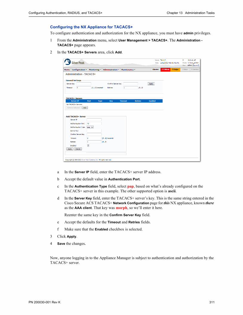
Configuring Authentication, RADIUS, and TACACS+ Chapter 13 Administration Tasks
PN 200030-001 Rev K 311
Configuring the NX Appliance for TACACS+
To configure authentication and authorization for the NX appliance, you must have admin privileges.
1 From the Administration menu, select User Management > TACACS+. The Administration -
TACACS+ page appears.
2 In the TACACS+ Servers area, click Add.
a In the Server IP field, enter the TACACS+ server IP address.
b Accept the default value in Authentication Port.
c In the Authentication Type field, select pap, based on what’s already configured on the TACACS+ server in this example. The other supported option is ascii.
d In the Server Key field, enter the TACACS+ server’s key. This is the same string entered in the Cisco Secure ACS TACACS+ Network Configuration page for this NX appliance, known there as the AAA client. That key was morph, so we’ll enter it here.
Reenter the same key in the Confirm Server Key field.
e Accept the defaults for the Timeout and Retries fields.
f Make sure that the Enabled checkbox is selected.
3 Click Apply.
4 Save the changes.
Now, anyone logging in to the Appliance Manager is subject to authentication and authorization by the TACACS+ server.

Silver Peak Appliance Manager Operator’s Guide Configuring Banners
312 PN 200030-001 Rev K
Configuring BannersWith the Appliance Manager, you can configure two different types of banners:
The Login Message appears on the Login page.
The Message of the Day appears on the Home page after you log in.
You can configure either, neither, or both.
Enter whatever text you want, and click Apply.
If you leave the field blank, no text displays.

Configuring Settings for Web Protocols and Web Users Chapter 13 Administration Tasks
PN 200030-001 Rev K 313
Configuring Settings for Web Protocols and Web UsersThis section describes how to configure the web protocol settings and web user settings.
Using the Appliance Manager, you can configure the following on the Administration - Web page:
• whether to enable HTTP, HTTPS, or both protocols
• how long you can go without using the Application Manager before it times out and you’re forced to log on again
• the maximum number of simultaneous user sessions allowed on an appliance
Apply the changes, and then click Save Changes to save them to the configuration.
Select the web protocol from these three buttons
Maximum number of minutes without timeout is 60 (one hour)
Maximum number of simultaneous user sessions is 50. The default value is 10.
Click Cancel to clear any changes you may have applied, but not saved.

Silver Peak Appliance Manager Operator’s Guide Initial Configuration Wizard
314 PN 200030-001 Rev K
Initial Configuration WizardYou can return to the Administration - Initial Configuration Wizard page to change appliance addressing information.
1 From the Administration Menu, select Initial Config Wizard.
2 Click Next>, as needed, to continue through the wizard.
The first page tells you what information you’ll need, outlines the steps you’ll be taking, and provides links to targeted user documentation and customer support.
Clicking Skip Wizard takes you out of the wizard and into the Home Page, without saving any configuration information. This is not recommended unless Support advises you to do so.
After you finish configuring, you can also see the results of this field’s entry on the Configuration - IP Routes page. To access it, go to Configuration > Network > IP Routes.

Initial Configuration Wizard Chapter 13 Administration Tasks
PN 200030-001 Rev K 315
3 When you reach the page where you select the deployment mode (bridge/in-line or route/out-of-path), you also have the option of finishing by applying the management settings only.
Choose that option when you have more advanced deployment modes — such as dual-homed router mode, 4-port bridge — which require configuration outside of the wizard.
4 No matter which deployment you select, the last page summarizes the configuration.
5 Click Apply. The last page of the wizard appears.
6 Complete the fields, and click Apply. When the appliance asks permission to reboot, allow it.

Silver Peak Appliance Manager Operator’s Guide Support
316 PN 200030-001 Rev K
SupportThe Administration - Support page lists the appliance-specific information you need when calling Technical Support. It also tells you how to contact Support via web, e-mail, and phone.

PN 200030-001 Rev K 317
C H A P T E R 1 4
System Maintenance
This chapter describes how to perform various system maintenance tasks.
Note Although Disk Management is part of the Maintenance menu, the topic is covered in the Silver Peak Field Replaceable Unit Guide.
In This Chapter Viewing System Information See page 318.
Upgrading the Appliance Manager Software See page 320.
Managing the Appliance Configuration File See page 331.
Testing Network Connectivity See page 345.
Erasing Network Memory See page 358.
Restarting the Appliance See page 359.

Silver Peak Appliance Manager Operator’s Guide Viewing System Information
318 PN 200030-001 Rev K
Viewing System InformationThe Maintenance - System Information page displays system information specific to this appliance.
The Maintenance - System Information page summarizes the following information:
Field Definition/Content
Hostname The name assigned to the appliance when using the initial configuration wizard. To edit it later, you can use the Command Line Interface (CLI) and the hostname command. The hostname is limited to a maximum of 24 characters.
Appliance ID A network-wide unique number between 1 and 65534, assigned automatically during initial configuration.
Model The appliance’s model number. For example, NX-7600 or NX-5600.
System Status The options are Normal and Bypass.
• When the status is Normal, traffic goes through tunnels, as configured.• Bypass refers to hardware bypass. If there is a major problem with the appliance
hardware, software, or power, all traffic goes through the appliance without any processing. Additionally, you can manually put the appliance into Bypass as an aid to troubleshooting.
To see how the GUI otherwise highlights system status, see “Banners” on page 42.
Uptime The time elapsed since the last reboot. For example, 3d 3h 28m 28s means “3 days, 3 hours, 28 minutes, and 28 seconds”.
Date/Time The local date and time at the appliance’s location, specified by time zone.
Release The currently running software version of the Appliance Manager.
Serial Number The serial number of the appliance hardware.
Mode Whether the appliance is configured for Bridge (in-line) or Router (out-of-path) mode.
Appliance IP The IP address of this Silver Peak appliance

Viewing System Information Chapter 14 System Maintenance
PN 200030-001 Rev K 319
Disk Encryption Yes means that Network Memory is encrypted; No means that it’s not. Selecting either enforces the choice from that moment until you change it, in which case you’d have some network memory encrypted and some not. Although we don’t recommend that you do this, the Appliance Manager manages both seamlessly.
Auto Tunnel Whether or not the appliance is configured to create tunnels if there is network connectivity and active flows with other peers. The default is no.
TCP Auto Reset Flows Whether or not the appliance is configured to automatically reset unaccelerated TCP flows so that they accelerate. This is a service-disrupting option.
The default is no.
Field Definition/Content (Continued)

Silver Peak Appliance Manager Operator’s Guide Upgrading the Appliance Manager Software
320 PN 200030-001 Rev K
Upgrading the Appliance Manager SoftwareThis section consists of the following topics:
Overview See page 320.
Installing a New Software Image into a Partition See page 323.
Installing the Software Image from the Local Disk See page 324.
Installing the Software Image from a URL See page 325.
Installing the Software Image from an SCP Server See page 326.
Installing the Software Image from an FTP Server See page 328.
Switching to the Other Software Load See page 330.
Overview
The Appliance Manager provides multiple options for managing appliance software. You can:
• Store two software images on the appliance
• Select which software version to run from the installed images
• Set up to switch to the other partition at the next reboot
• Install a software image from a local file, URL, Secure Copy (SCP) server, or a File Transfer Protocol (FTP) server, and install it into the appliance’s inactive partition.
• Choose to reboot and begin running a newly installed software image either immediately, or at the next reboot.
When appliances within a network are operating at different software release level, the higher numbered software release determines interoperability. For more information, see “Tunnel Compatibility Mode” on page 88, and check the Release Notes to verify software version compatibility.

Upgrading the Appliance Manager Software Chapter 14 System Maintenance
PN 200030-001 Rev K 321
A software image always installs automatically into the inactive partition, no matter what the selection is. For all these software management tasks, use the Maintenance - Software Upgrade page.
The fields have the following definitions:
When you select a file source, only the appropriate fields display.
This section displays the download progress and results.
For details, see “Switching to the Other Software Load” on page 330.
To execute the Install Options choice you made with the radio buttons.
Reboots from the partition that has yes in the Next Boot column
Choose what, if anything, you want the Appliance Manager to do after installing the new software image into the inactive partition.
Field Definition/Content
Partition ID The number of the partition
Active The partition is active if the appliance booted from that partition; in that case, the value of the field is yes. If the partition contains the inactive image, or software, then the value is no.
Next Boot Yes specifies the partition that the appliance accesses at the next reboot.

Silver Peak Appliance Manager Operator’s Guide Upgrading the Appliance Manager Software
322 PN 200030-001 Rev K
Release The VXOA release number, in the following format:
MM.mm.Mn.PP_<internal number> <date>
• MM Major release version (0-99) • mm Minor release version (0-99) • Mn Maintenance release version (0-99) • PP Patch release version (0-99) • <internal number> Silver Peak’s internal engineering build number
Tells the appliance to point to the other image for the next reboot. The inactive image’s Next Boot value changes from no to yes.
Reboots the appliance now, from the partition that has yes in the Next Boot column.
Install Options:
Install Downloads and installs the image file into the inactive partition.
Install and set nextboot partition
Downloads and installs the image file into the inactive partition. Then, designates the appliance to boot from this partition at the next reboot.
Install and reboot Downloads the image, installs it into the inactive partition, and reboots the appliance. While the appliance reboots, it goes into the hardware bypass state, allowing all traffic to pass through the appliance without intervention. Once the reboot is complete, the appliance returns to its previous state (not in hardware bypass state). Finally, the appliance requires you to log in again.
[Local File] When you select this item, you can Browse to the image file’s location on your local hard drive.
[URL] When you select this item, enter the image location address. The entry must begin with http://
[SCP (Secure Copy)] When you choose to download the image from a Secure Copy server, the following fields highlight to indicate that they need entries: Remote Server Address, Remote User Name, Remote Password, Remote Full Path, and Source File Name.
FTP (File TransferProtocol)
When you choose to download the image from a File Transfer Protocol (FTP) server, the following fields highlight to indicate that they need entries: Remote Server Address, Remote User Name, Remote Password, Remote Relative Path (optional), and Source File Name.
Lets you find and select the image file when you’ve placed it on your local hard drive.
Executes the Install Options choice you made with the radio buttons.
Remote Server Address Use either the server IP address or the server name (if it’s mapped to a local host table or a DNS server).
Remote User Name The name of the user that the server expects
Remote Password The password of the user that the server expects
Remote [Full/Relative] Path
• If using the SCP server, enter the full path to the server.• If using the FTP server, enter the relative path to the server.
Source File Name The name of the software image file, ending with the suffix, .zip.
Status If the read-only value is Ready, you may proceed with the download, installation, and reboot.
Last Install Status The status at the end of the previous download.
Field Definition/Content (Continued)

Upgrading the Appliance Manager Software Chapter 14 System Maintenance
PN 200030-001 Rev K 323
Note Software upgrade files end with .img or .zip.
Installing a New Software Image into a Partition
When you install a new software image, the Appliance Manager automatically downloads it into the inactive partition. Depending on the option you choose, you can install the software image and:
• Store it there indefinitely
• Set it as the image to use at the next reboot
• Reboot immediately to begin running the newly installed software.
While the Silver Peak appliance reboots, it goes into the hardware bypass state, allowing all traffic to pass through the appliance without intervention. Once the reboot is complete, the appliance comes out of the hardware bypass state and requires you to log in again.
Since some traffic may drop while the appliance goes into and out of the hardware bypass state, Silver Peak suggests that you perform upgrades when traffic volume is lower, preferably after hours.
Tip Best practices recommend that before upgrading (or switching to the other partition), you preserve a copy of the running configuration file by saving it to a server. For this, use the Maintenance - Configuration Management page’s Save Configuration link.
Tip Best practices also recommend scheduling a maintenance window to best accommodate the appliance reboot when installing an image.
CAUTION The database schema may change with software image upgrades. Because the database is in the same partition as its associated software version, going “backwards” is not an issue. However, be aware that configuration changes made since you last ran the earlier version will be lost. To verify the feasibility, consult first with Silver Peak Customer Support.
Install Start Time The time the installation began
Install End Time The time the installation was complete
Allows you to cancel a download in progress, but not an installation once it has begun.
Field Definition/Content (Continued)

Silver Peak Appliance Manager Operator’s Guide Upgrading the Appliance Manager Software
324 PN 200030-001 Rev K
Installing the Software Image from the Local Disk
To install the software image from your computer’s hard disk
1 On the Maintenance - Software Upgrade page, click Local File.
2 To use your computer’s directory structure to access the file, click Browse and navigate to the image file.
3 From the Install Options, select one of the following:
• Install – to install the image into the inactive partition
• Install and set next boot partition – to install the image into the inactive partition and designate it as the partition to be used during the next boot
• Install and Reboot. – to install the image into the inactive partition, switch to that partition, and then reboot to begin running it immediately. While the Silver Peak appliance reboots, it goes into the hardware bypass state, allowing all traffic to pass through the appliance without intervention. Once the reboot is complete, the appliance comes out of the hardware bypass state and requires you to log in again.
4 Click Install. The browser reports your progress during download and installation.

Upgrading the Appliance Manager Software Chapter 14 System Maintenance
PN 200030-001 Rev K 325
Installing the Software Image from a URL
To install the software image from a URL
1 On the Maintenance - Software Upgrade page, click URL. The source-specific fields appear.
2 From the Install Options, select one of the following:
• Install – to install the image into the inactive partition
• Install and set next boot partition – to install the image into the inactive partition and designate it as the partition to be used during the next boot
• Install and Reboot. – to install the image into the inactive partition, switch to that partition, and then reboot to begin running it immediately. While the Silver Peak appliance reboots, it goes into the hardware bypass state, allowing all traffic to pass through the appliance without intervention. Once the reboot is complete, the appliance comes out of the hardware bypass state and requires you to log in again.
3 In the field, enter the URL (ending with the filename) after http:// . For example: http://server/directory/image-4.4.8.0_39715.img.
4 Click Install. The browser reports your progress during download and installation.

Silver Peak Appliance Manager Operator’s Guide Upgrading the Appliance Manager Software
326 PN 200030-001 Rev K
Installing the Software Image from an SCP Server
To install the software image from an SCP server
1 Access the Maintenance - Software Upgrade page.
2 From the Install Options, select one of the following:
• Install – to install the image into the inactive partition
• Install and set next boot partition – to install the image into the inactive partition and designate it as the partition to be used during the next boot
• Install and Reboot. – to install the image into the inactive partition, switch to that partition, and then reboot to begin running it immediately. While the Silver Peak appliance reboots, it goes into the hardware bypass state, allowing all traffic to pass through the appliance without intervention. Once the reboot is complete, the appliance comes out of the hardware bypass state and requires you to log in again.
3 Click SCP (Secure Copy). The appropriate fields display.

Upgrading the Appliance Manager Software Chapter 14 System Maintenance
PN 200030-001 Rev K 327
4 Enter the data necessary to download the file from the SCP server.
Here, we’ll use the example of downloading the file, image-4.8.8.0_39715.img, from the following location:
scp <UserName>@10.10.10.11:/home/<UserName>/SWimages/image-4.8.8.0_39715.img
a For the Remote Server Address field, enter either:
• the server IP address, as in 10.10.10.11, or
• the server name, if it’s mapped to a local host table or a DNS server
b Enter the Remote User Name and Remote Password for the Secure Copy (SCP) server.
c For your Remote Full Path field, enter the full path, without the file name.
A full pathname includes the drive (if required), starting or root directory, and all attached subdirectories.
d In the Source File Name, enter the image’s filename. This is an .img file.
5 Click Install. The browser reports your progress during download and installation.

Silver Peak Appliance Manager Operator’s Guide Upgrading the Appliance Manager Software
328 PN 200030-001 Rev K
Installing the Software Image from an FTP Server
To install the software image from an FTP server
1 On the Maintenance - Software Upgrade page, click FTP (File Transfer Protocol).
2 From the Install Options, select one of the following:
• Install – to install the image into the inactive partition
• Install and set next boot partition – to install the image into the inactive partition and designate it as the partition to be used during the next boot
• Install and Reboot. – to install the image into the inactive partition, switch to that partition, and then reboot to begin running it immediately. While the Silver Peak appliance reboots, it goes into the hardware bypass state, allowing all traffic to pass through the appliance without intervention. Once the reboot is complete, the appliance comes out of the hardware bypass state and requires you to log in again.
3 Enter the data necessary to download the file from the FTP server.
Here, we’ll use the example of downloading the file, image-4.8.8.0_39715.img, from Vince’s directories on an FTP server:

Upgrading the Appliance Manager Software Chapter 14 System Maintenance
PN 200030-001 Rev K 329
a For the Remote Server Address field, enter either:
• the server IP address, as in 10.10.10.11, or
• the server name, if it’s mapped to a local host table or a DNS server
b Enter the Remote User Name and Remote Password for the FTP server.
c [Optional] For your Remote Relative Path field, enter the relative path.
A relative path is a path relative to the current working directory. Its first character can be anything but the pathname separator (here, a forward slash).
For example, if the ftp login directory is /home/<UserName>/, then the relative path would begin at the next subdirectory, as in, /SWimages.
d In the Source File Name, enter the image’s filename. This is an .img file.
4 Click Install. The browser reports your progress during download and installation.

Silver Peak Appliance Manager Operator’s Guide Upgrading the Appliance Manager Software
330 PN 200030-001 Rev K
Switching to the Other Software Load
You can specify that you want to switch to the other, inactive partition for the next reboot:
To select the partition now, for a later reboot, click Switch Boot Partition. The inactive image’s Next
Boot value changes from no to yes.
To select the partition now and reboot immediately, click Reboot.
In this example, the user clicked Switch Boot Partition. As a result, Partition 2, which is not currently active, has yes in the Next Boot column.

Managing the Appliance Configuration File Chapter 14 System Maintenance
PN 200030-001 Rev K 331
Managing the Appliance Configuration FileThis section consists of the following topics:
Viewing the Appliance Configuration File See page 331.
Saving the Appliance Configuration File See page 334.
Downloading the Appliance Configuration File See page 339.
To protect the Appliance Manager database against loss or corruption, you can store a backup of the configuration database file, either locally on the appliance or on a local hard drive, an SCP (Secure Copy) server, or an FTP (File Transfer Protocol) server.
You can also restore or load a configuration database file from a local disk, SCP server, FTP server, or web-based location (URL).
The Appliance Manager provides multiple options for managing the active and inactive configuration files. Functionally, the Appliance Manager’s Maintenance - Configuration Management page is divided into four distinct areas:
Viewing the Appliance Configuration File
This section consists of the following topics:
To view the last saved version of a configuration file See page 332.
To view the running configuration file See page 333.
For copying a saved configuration file (active or inactive) to/from the local disk or a remote location:
• Save Configuration copies the file from the appliance to the local disk or to a remote server.
• Load Configuration copies the file to the appliance from the local disk, a website’s URL or a remote server.
Displays the status of any configuration file that you’re saving to, or downloading from, another location.
For managing the running configuration file. That is, an active file with unsaved changes.
For removing or activating an inactive configuration file that’s stored on the appliance.
To view the contents of a configuration file, click its name and a separate window opens.

Silver Peak Appliance Manager Operator’s Guide Managing the Appliance Configuration File
332 PN 200030-001 Rev K
To view the last saved version of a configuration file
1 Go to the Maintenance - Configuration Management page.
2 In the Configuration Files table at the top of the page, click on the name of the file you want to view. A separate window opens.
The content display does not change after you open the file. This view of the saved configuration is static.
To view the text files that display the Command Line Interface (CLI) commands underlying the configuration, click the file name itself. The contents open in a separate window.
IMPORTANT: You can only save this text file to your computer’s local hard disk.
To apply this configuration to another appliance, you must first open an SSH shell to the target appliance and then copy and paste these configuration commands into the shell.
Browser’s menu...

Managing the Appliance Configuration File Chapter 14 System Maintenance
PN 200030-001 Rev K 333
To view the running configuration file
If you’ve made configuration changes but haven’t saved them yet, then that information displays after the file name.
1 Go to the Maintenance - Configuration Management page.
2 In the Configuration Files table at the top of the page, click on the name of the file you want to view. A separate window opens.
Indicates unsaved changes in the configuration file

Silver Peak Appliance Manager Operator’s Guide Managing the Appliance Configuration File
334 PN 200030-001 Rev K
Saving the Appliance Configuration File
The Appliance Manager supports saving a configuration file to three destinations external to the appliance, as follows:
To save the configuration file to a local disk See page 336.
To save the configuration file to an SCP Server See page 337.
To save the configuration file to an FTP Server See page 338.
When you click to select the method, the appropriate fields appear.
Also, you can rename a file when saving it to the local disk, but you cannot rename it in the process of saving it to an SCP or FTP server.
The fields and options in the Save Configuration area have the following definitions:
Field or Option Definition/Content
Save the selected configuration file
This drop-down menu allows you to select any active or inactive that’s saved on the appliance. These are the same files that appear in the Configuration Files table at the top of the page.
[Local File] For saving the configuration file to your computer’s local hard disk.
[SCP (Secure Copy)] For saving the configuration file to a remote Secure Copy server.
[FTP (File Transfer Protocol)]
For saving the configuration file to a remote File Transfer Protocol (FTP) server.
Remote Server Address Enter either the server IP address, or the server name (if it’s mapped to a local host table or a DNS server).

Managing the Appliance Configuration File Chapter 14 System Maintenance
PN 200030-001 Rev K 335
Remote User Name The name of the user that server expects
Remote Password The password of the user that the server expects
Remote Full Path When using the SCP server, enter the full path to the server.
Initial slashes are required for full path; end slashes are not required at all.
Remote Relative Path (Optional) When using the FTP server, enter the relative path to the server. Relative paths do not require initial or end slashes.
Destination File Name (Optional) If you want to rename the file, do it in this field.
Status If the read-only value is Ready, you may proceed with transferring the file to a remote server.
Last Save Status The status at the end of the previous download.
Transfer Start Time What time the file transfer began
Transfer End Time What time the file transfer ended
Saves the selected file/image to the remote server
Allows you to cancel a file transfer that is in progress.
Field or Option Definition/Content (Continued)

Silver Peak Appliance Manager Operator’s Guide Managing the Appliance Configuration File
336 PN 200030-001 Rev K
To save the configuration file to a local disk
1 Go to the Maintenance - Configuration Management page, and select the file you want to save.
2 Click Save Configuration, if its fields aren’t already visible.
3 Click Local File. The relevant fields appear.
4 From the menu following Save the selected configuration file, select the file you want to save.
5 Click Save. A dialog box appears, prompting you for confirmation.
6 Click Save. A Save As dialog box appears.
7 Browse to the target directory, rename the file if you wish, and click Save. A Windows-based progress bar displays as the (renamed) file saves to the computer’s local disk.
If no progress bar displays, you’re probably trying to save a running configuration file. Save your changes and then try again.
You can access any of the appliance’s saved active or inactive configuration files from this menu.

Managing the Appliance Configuration File Chapter 14 System Maintenance
PN 200030-001 Rev K 337
To save the configuration file to an SCP Server
1 Go to the Maintenance - Configuration Management page. The Save Configuration area displays by default.
2 Select the file you want to save.
3 Click SCP (Secure Copy). The relevant fields appear.
4 Enter the data necessary to save the file to the SCP server.
Here, we’ll use the example of saving the file, initial, to the following location:
scp <UserName>@180.6.7.243:/home/<UserName>/work/image/initial
a For the Remote Server Address field, enter either:
• the server IP address, as in 180.6.7.243, or
• the server name, if it’s mapped to a local host table or a DNS server
b Enter the Remote User Name and Remote Password for the Secure Copy (SCP) server.
c For your Remote Full Path field, enter the full path. A full pathname includes the drive (if required), starting or root directory, and all attached subdirectories.
A full pathname requires an initial slash; no end slashes are required.
d In the Destination File Name, enter the image’s filename. You can use the existing file name, or save with a new file name.
5 Click Save. The Appliance Manager displays the progress.
You can access any of the appliance’s saved active or inactive configuration files from this menu.
You can save with either the existing, or a new, destination filename.
You can begin the pathname with or without an initial slash (/).

Silver Peak Appliance Manager Operator’s Guide Managing the Appliance Configuration File
338 PN 200030-001 Rev K
To save the configuration file to an FTP Server
1 Go to the Maintenance - Configuration Management page. The Save Configuration area displays by default.
2 Select the file you want to save.
3 Click File Transfer Protocol (FTP) to Server. The appropriate fields display.
4 Enter the data necessary to save the file to the FTP server.
Here, we’ll use the example of saving the file, initial, to Roger’s directories on an FTP server:
a For the Remote Server Address field, enter either:
• the server IP address, as in 180.6.7.243, or
• the server name, if it’s mapped to a local host table or a DNS server, as in <myserver>
b Enter the Remote User Name and Remote Password for the FTP server.
c For your Remote Relative Path field, enter the relative path and the file name.
A relative path is a path relative to the current working directory. Its first character can be anything but the pathname separator (here, a forward slash).
For example, if the ftp login directory is /home/<UserName>/, then the relative path would begin at the next subdirectory, as in, work/image/. The end slash isn’t required, but is accepted.
5 Click Save. The Appliance Manager displays the progress.
You can access any of the appliance’s saved active or inactive configuration files from this menu.
You can save with either the existing, or a new, destination file name. Here, we’ve renamed the file, initial, to last_1.5_backup.
No slash necessary before the directory name.

Managing the Appliance Configuration File Chapter 14 System Maintenance
PN 200030-001 Rev K 339
Downloading the Appliance Configuration File
The Appliance Manager supports downloading a configuration file from four sources external to the appliance, as follows:
To load the configuration file from a local disk See page 341.
To load the configuration file from a URL See page 342.
To load the configuration file from an SCP Server See page 343.
To load the configuration file from an FTP Server See page 344.
When you click to select the method, the appropriate fields appear.
The fields and options in the Load Configuration area have the following definitions:
Field or Option Definition/Content
Destination File Name What name you want the configuration file to be assigned on the appliance.
[Local File] For saving the configuration file to your computer’s local hard disk.
[URL] The web address to which you want to save the file. When you select this item, enter the image location address. The entry must begin with http://
[SCP (Secure Copy)] For saving the configuration file from a remote Secure Copy server.
[FTP (File Transfer Protocol)]
For saving the configuration file from a remote File Transfer Protocol (FTP) server.
Remote Server Address Use either the server IP address or the server name (if it’s mapped to a local host table or a DNS server).

Silver Peak Appliance Manager Operator’s Guide Managing the Appliance Configuration File
340 PN 200030-001 Rev K
Remote User Name The name of the user that server expects
Remote Password The password of the user that the server expects
Remote [Full/Relative] Path
The type of path requested depends on which method you choose:
• If using the SCP server, enter the full path to the server.• If using the FTP server, enter the relative path to the server.
Full paths require initial slashes; end slashes are not required at all. Relative paths do not require initial or end slashes.
Status If the read-only value is Ready, you may proceed with transferring the file to a remote server.
Last Upgrade Status The status at the end of the previous download.
Transfer Start Time What time the file transfer began
Transfer End Time What time the file transfer ended
Loads the selected file/image from the remote location
Allows you to cancel a file transfer that is in progress.
Field or Option Definition/Content (Continued)

Managing the Appliance Configuration File Chapter 14 System Maintenance
PN 200030-001 Rev K 341
To load the configuration file from a local disk
1 Go to the Maintenance - Configuration Management page.
2 Click Load Configuration. The Local File fields display by default.
3 If you want the file that you’re restoring to have a different file name on the appliance, enter a new name in the Destination File Name field.
4 Click Browse. A Choose file dialog box appears.
5 Select your file from its directory and click Open. The filename and path appear in the Configuration
file field.
6 Click Load. The Appliance Manager saves the file to the appliance and lists it at the top of the page, under Configuration Files.
If you want the file you’re downloading to the appliance to have a new name, enter it here.

Silver Peak Appliance Manager Operator’s Guide Managing the Appliance Configuration File
342 PN 200030-001 Rev K
To load the configuration file from a URL
1 Go to the Maintenance - Configuration Management page.
2 Click Load Configuration, and click URL.
3 If you want to save the file with a different filename, enter the new name in the Destination File
Name field.
4 In the field, enter the complete URL after http://
5 If you want to save the file with a new name, enter the new name in the Destination File Name field.
6 Click Load. The Appliance Manager reports your progress during the download and lists it at the top of the page, under Configuration Files.
If you want to rename the file you’re downloading to the appliance, enter it here.

Managing the Appliance Configuration File Chapter 14 System Maintenance
PN 200030-001 Rev K 343
To load the configuration file from an SCP Server
1 Go to the Maintenance - Configuration Management page, and click Load Configuration.
2 Click SCP (Secure Copy). The appropriate fields appear.
3 Enter the data necessary to save the file from the SCP server to the appliance.
Here, we’ll use the example of renaming and restoring the file, testfile, from the following location:
scp <UserName>@180.6.7.243:/home/<UserName>/work/configfiles/testfile
a For the Remote Server Address field, enter either:
• the server IP address, as in 180.6.7.243, or
• the server name, if it’s mapped to a local host table or a DNS server
b Enter the Remote User Name and Remote Password for the Secure Copy (SCP) server.
c For your Remote Full Path field, enter the full path and the file name.
A full pathname includes the drive (if required), starting or root directory, all attached subdirectories and ends with the file or object name.
A full pathname requires an initial slash; no end slashes are required.
d In the Destination File Name field, enter the existing file name or rename the file.
4 Click Load. The Appliance Manager displays the progress.
If you want to rename the file during the download, enter the new file name here.

Silver Peak Appliance Manager Operator’s Guide Managing the Appliance Configuration File
344 PN 200030-001 Rev K
To load the configuration file from an FTP Server
1 Go to the Maintenance - Configuration Management page, and click Load Configuration.
2 Click FTP (File Transfer Protocol). The appropriate fields appear.
3 Enter the data necessary to save the file from the FTP server.
Here, we’ll use the example of loading the file, testfile, from Roger’s directory on an FTP server. In the process, we’ll rename it to newfilename:
a For the Remote Server Address field, enter either:
• the server IP address, as in 180.6.7.243, or
• the server name, if it’s mapped to a local host table or a DNS server, as in <myserver>
b Enter the Remote User Name and Remote Password for the FTP server.
c For your Remote Relative Path field, enter the relative path.
A relative path is a path relative to the current working directory. Its first character can be anything but the pathname separator (here, a forward slash).
For example, if the ftp login directory is /home/<UserName>/, then the relative path would begin at the next subdirectory, as in, work/configfiles. The end slash isn’t required, but is accepted.
d In the Destination File Name field, enter the existing file name or rename the file.
4 Click Load. The Appliance Manager reports your progress during the download and lists it at the top of the page, under Configuration Files.
No slash before the directory name
If you want to rename the file during the download, enter the new file name here.

Testing Network Connectivity Chapter 14 System Maintenance
PN 200030-001 Rev K 345
Testing Network ConnectivityThe Appliance Manager enables you to test network connectivity, using three commands: ping, traceroute, and tcpdump.
• There can only be one connectivity test session per appliance at any time, regardless of which command you’re using.
• Click Stop to terminate a test.
• If a user logs on to an appliance while a testing session is in progress, only the Abort button is accessible to them. Otherwise, that button is not visible.
To run a Network Connectivity test
1 From the Maintenance menu, select Network Connectivity. The Maintenance - Network Connectivity page appears.
After a test has begun, this area displays its status and start/end times.
• The ping and traceroute tests provide an IP/Hostname field.
• The tcpdump test displays a File Name field instead, and automatically enters a name in the format, tcpdump_<hostname>. After running a tcpdump test, you can locate the captured results on the Administration - Debug Files page, via the TCP Dump Result link. You can download the resulting file to your PC for viewing and analyzing via Wireshark® or Ethereal®.
When a test begins, Start changes to Stop. Use as needed.
To view the arguments that the selected command can take
Abort allows a user with admin privileges to terminate another user’s connectivity test session. It’s available whenever there’s a session in progress.

Silver Peak Appliance Manager Operator’s Guide Testing Network Connectivity
346 PN 200030-001 Rev K
2 Complete the fields as follows:
a From the Type field, click to select the test you want.
b If the IP / Hostname field is present, enter the IP address or hostname of the destination device. If the File Name field displays, its field is populated by a default name.
c In the Option field, enter the command option you want. For example, for ping, you could enter -c 3 to stop after sending three ECHO_REQUEST packets. For available arguments, click Help.
Options for each command are listed after these steps.
3 Click Start. The Network Connectivity Result area displays intermediate results every few seconds.
To stop the test and see the complete results, click Stop. For example:
ping

Testing Network Connectivity Chapter 14 System Maintenance
PN 200030-001 Rev K 347
traceroute
tcpdump
The Option field populates with -n by default. This flag results in tcpdump not trying to resolve IP addresses, so that the process doesn’t try to perform a DNS lookup on every new IP address it encounters.
Access this file on the Administration - Debug Files page, under the TCP Dump Result link.

Silver Peak Appliance Manager Operator’s Guide Testing Network Connectivity
348 PN 200030-001 Rev K
Using ping
Use the ping command to send Internet Control Message Protocol (ICMP) echo requests to a specified host.
By default, the ping command uses the mgmt0 interface. If you want to ping out of datapath interfaces, use the -I option with the local appliance IP address. For example:
The following ping options are supported:
ping -I <local appliance IP> — sends the ping out a datapath interface
Option Explanation
-A Adaptive ping. Interpacket interval adapts to round-trip time, so that effectively not more than one (or more, if preload is set) unanswered probes present in the network. Minimal interval is 200 msec if not super-user. On networks with low rtt this mode is essentially equivalent to flood mode.
-b Allow pinging a broadcast address.
-B Do not allow ping to change source address of probes. The address is bound to one selected when ping starts.
-c count: Stop after sending count ECHO_REQUEST packets. With deadline option, ping waits for count ECHO_REPLY packets, until the time- out expires.
-d Set the SO_DEBUG option on the socket being used. Essentially, this socket option is not used by Linux kernel.
-F flow label: Allocate and set 20 bit flow label on echo request packets. (Only ping6). If value is zero, kernel allocates random flow label.
-i interval: Wait interval seconds between sending each packet. The default is to wait for one second between each packet normally, or not to wait in flood mode. Only super-user may set interval to values less 0.2 seconds.
-I interface address: Set source address to specified interface address. Argument may be numeric IP address or name of device. When pinging IPv6 link-local address this option is required.
-l preload: If preload is specified, ping sends that many packets not waiting for reply. Only the super-user may select preload more than 3.
-L Suppress loopback of multicast packets. This flag only applies if the ping destination is a multicast address.
-M MTU discovery hint: Select Path MTU Discovery strategy. hint may be either do (prohibit fragmentation, even local one), want (do PMTU discovery, fragment locally when packet size is large), or dont (do not set DF flag).
-n Numeric output only. No attempt will be made to lookup symbolic names for host addresses.

Testing Network Connectivity Chapter 14 System Maintenance
PN 200030-001 Rev K 349
When you click the Help button, the following displays in the Network Connectivity Result area.
Usage: ping [-LRUbdfnqrvVaA] [-c count] [-i interval] [-w deadline] [-p pattern] [-s packetsize] [-t ttl] [-I interface or address] [-M mtu discovery hint] [-S sndbuf] [ -T timestamp option ] [ -Q tos ] [hop1 ...] destination
-p pattern: You may specify up to 16 “pad” bytes to fill out the packet you send. This is useful for diagnosing data-dependent problems in a network. For example, -p ff will cause the sent packet to be filled with all ones.
-Q tos: Set Quality of Service -related bits in ICMP datagrams. tos can be either decimal or hex number.
Traditionally (RFC1349), these have been interpreted as: 0 for reserved (currently being redefined as congestion control), 1-4 for Type of Service and 5-7 for Precedence.
Possible settings for Type of Service are: minimal cost: 0x02, reliability: 0x04, throughput: 0x08, low delay: 0x10.
Multiple TOS bits should not be set simultaneously.
Possible settings for special Precedence range from priority (0x20) to net control (0xe0). You must be root (CAP_NET_ADMIN capability) to use Critical or higher precedence value. You cannot set bit 0x01 (reserved) unless ECN has been enabled in the kernel.
In RFC2474, these fields has been redefined as 8-bit Differentiated Services (DS), consisting of: bits 0-1 of separate data (ECN will be used, here), and bits 2-7 of Differentiated Services Codepoint (DSCP).
-q Quiet output. Nothing is displayed except the summary lines at startup time and when finished.
-R Record route. Includes the RECORD_ROUTE option in the ECHO_REQUEST packet and displays the route buffer on returned packets. Note that the IP header is only large enough for nine such routes. Many hosts ignore or discard this option.
-r Bypass the normal routing tables and send directly to a host on an attached interface. If the host is not on a directly attached network, an error is returned. This option can be used to ping a local host through an interface that has no route through it provided the option -I is also used.
-s packetsize: Specifies the number of data bytes to be sent. The default is 56, which translates into 64 ICMP data bytes when combined with the 8 bytes of ICMP header data.
-S sndbuf: Set socket sndbuf. If not specified, it is selected to buffer not more than one packet.
-t ttl Set the IP Time to Live.
-T timestamp option: Set special IP timestamp options. timestamp option may be either tsonly (only timestamps), tsandaddr (timestamps and addresses) or tsprespec host1 [host2 [host3 [host4]]] (timestamp prespecified hops).
-U Print full user-to-user latency (the old behavior). Normally ping prints network round trip time, which can be different f.e. due to DNS failures.
-v Verbose output.
-V Show version and exit.
-w deadline: Specify a timeout, in seconds, before ping exits regardless of how many packets have been sent or received. In this case ping does not stop after count packet are sent, it waits either for deadline expire or until count probes are answered or for some error notification from network.
Option Explanation (Continued)

Silver Peak Appliance Manager Operator’s Guide Testing Network Connectivity
350 PN 200030-001 Rev K
Using traceroute
Use the traceroute command to trace the route that packets take to a destination.
The following traceroute options are supported:
Option Explanation
-d Enable socket level debugging.
-f Set the initial time-to-live used in the first outgoing probe packet.
-F Set the “don’t fragment” bit.
-g Specify a loose source route gateway (8 maximum).
-i Specify a network interface to obtain the source IP address for outgoing probe packets. This is normally only useful on a multi-homed host. (See the -s flag for another way to do this.)
-I Use ICMP ECHO instead of UDP datagrams.
-m Set the max time-to-live (max number of hops) used in outgoing probe packets. The default is 30 hops (the same default used for TCP connections).
-n Print hop addresses numerically rather than symbolically and numerically (saves a nameserver address-to-name lookup for each gateway found on the path).
-p Set the base UDP port number used in probes (default is 33434). Traceroute hopes that nothing is listening on UDP ports base to base + nhops - 1 at the destination host (so an ICMP PORT_UNREACHABLE message will be returned to terminate the route tracing). If something is listening on a port in the default range, this option can be used to pick an unused port range.
-q nqueries
-r Bypass the normal routing tables and send directly to a host on an attached network. If the host is not on a directly-attached network, an error is returned. This option can be used to ping a local host through an interface that has no route through it (for example, after the interface was dropped by routed (8C)).
-s Use the following IP address (which usually is given as an IP number, not a hostname) as the source address in outgoing probe packets. On multi-homed hosts (those with more than one IP address), this option can be used to force the source address to be something other than the IP address of the interface the probe packet is sent on. If the IP address is not one of this machine’s interface addresses, an error is returned and nothing is sent. (See the -i flag for another way to do this.)
-t Set the type-of-service in probe packets to the following value (default zero). The value must be a decimal integer in the range 0 to 255. This option can be used to see if different types-of-service result in different paths. (If you are not running 4.4bsd, this may be academic since the normal network services like telnet and ftp don’t let you control the TOS). Not all values of TOS are legal or meaningful - see the IP spec for definitions. Useful values are probably â-t 16â (low delay) and â-t 8â (high throughput). If TOS value is changed by intermediate routers, (TOS=<value>!) will be printed once: value is the decimal value of the changed TOS byte.
-v Verbose output. Received ICMP packets other than TIME_EXCEEDED and UNREACHABLEs are listed.
-w Set the time (in seconds) to wait for a response to a probe (default 5 sec.).

Testing Network Connectivity Chapter 14 System Maintenance
PN 200030-001 Rev K 351
When you click the Help button, the following displays in the Network Connectivity Result area.
Version 1.4a12Usage: traceroute [-dFInrvx] [-g gateway] [-i iface] [-f first_ttl][-m max_ttl] [ -p port] [-q nqueries] [-s src_addr] [-t tos][-w waittime] [-z pausemsecs] host [packetlen]
-x Toggle ip checksums. Normally, this prevents traceroute from calculating ip checksums. In some cases, the operating system can overwrite parts of the outgoing packet but not recalculate the checksum (so in some cases the default is to not calculate checksums and using -x causes them to be calculated). Note that checksums are usually required for the last hop when using ICMP ECHO probes (-I). So they are always calculated when using ICMP.
-z Set the time (in milliseconds) to pause between probes (default 0). Some systems such as Solaris and routers such as Ciscos rate limit icmp messages. A good value to use with this is 500 (e.g. 1/2 second).
Option Explanation (Continued)

Silver Peak Appliance Manager Operator’s Guide Testing Network Connectivity
352 PN 200030-001 Rev K
Using tcpdump
Use the tcpdump command to display packets on a network.
For example, to capture 100 packets on the wan0 interface, use the command, -n -i wan0 -c 100.
The following tcpdump options are supported:
Option Explanation
-A Print each packet (minus its link level header) in ASCII. Handy for capturing web pages.
-c Exit after receiving count packets.
-C Before writing a raw packet to a savefile, check whether the file is currently larger than file_size and, if so, close the current savefile and open a new one. Savefiles after the first savefile will have the name specified with the -w flag, with a number after it, starting at 1 and continuing upward. The units of file_size are millions of bytes (1,000,000 bytes, not 1,048,576 bytes).
-d Dump the compiled packet-matching code in a human readable form to standard output and stop.
-dd Dump packet-matching code as a C program fragment.
-ddd Dump packet-matching code as decimal numbers (preceded with a count).
-D Print the list of the network interfaces available on the system and on which tcpdump can capture packets. For each network interface, a number and an interface name, possibly followed by a text description of the interface, is printed. The interface name or the number can be supplied to the -i flag to specify an interface on which to capture.
This can be useful on systems that don’t have a command to list them (e.g., Windows systems, or UNIX systems lacking ifconfig -a); the number can be useful on Windows 2000 and later systems, where the interface name is a somewhat complex string.
The -D flag will not be supported if tcpdump was built with an older version of libpcap that lacks the pcap_findalldevs() function.
-e Print the link-level header on each dump line.

Testing Network Connectivity Chapter 14 System Maintenance
PN 200030-001 Rev K 353
-E Use spi@ipaddr algo:secret for decrypting IPsec ESP packets that are addressed to addr and contain Security Parameter Index value spi. This combination may be repeated with comma or newline separation.
Note that setting the secret for IPv4 ESP packets is supported at this time.
Algorithms may be des-cbc, 3des-cbc, blowfish-cbc, rc3-cbc, cast128-cbc, or none. The default is des-cbc. The ability to decrypt packets is only present if tcpdump was compiled with cryptography enabled.
secret is the ASCII text for ESP secret key. If preceded by 0x, then a hex value will be read.
The option assumes RFC2406 ESP, not RFC1827 ESP. The option is only for debugging purposes, and the use of this option with a true ‘secret’ key is discouraged. By presenting IPsec secret key onto command line you make it visible to others, via ps(1) and other occasions.
In addition to the above syntax, the syntax file name may be used to have tcpdump read the provided file in. The file is opened upon receiving the first ESP packet, so any special permissions that tcpdump may have been given should already have been given up.
-f Print ‘foreign’ IPv4 addresses numerically rather than symbolically (this option is intended to get around serious brain damage in Sun’s NIS server â usually it hangs forever translating non-local internet numbers).
The test for ‘foreign’ IPv4 addresses is done using the IPv4 address and netmask of the interface on which capture is being done. If that address or netmask are not available either because the interface on which capture is being done has no address or netmask or because the capture is being done on the Linux “any” interface, which can capture on more than one interface, this option will not work correctly.
-F Use file as input for the filter expression. An additional expression given on the command line is ignored.
-i Listen on interface. If unspecified, tcpdump searches the system interface list for the lowest numbered, configured up interface (excluding loopback). Ties are broken by choosing the earliest match.
On Linux systems with 2.2 or later kernels, an interface argument of “any” can be used to capture packets from all interfaces. Note that captures on the “any” device will not be done in promiscuous mode.
If the -D flag is supported, an interface number as printed by that flag can be used as the interface argument.
-l Make stdout line buffered. Useful if you want to see the data while capturing it. For example,tcpdump -l | tee dat or tcpdump -l > dat & tail -f dat
-L List the known data link types for the interface and exit.
-m Load SMI MIB module definitions from file module. This option can be used several times to load several MIB modules into tcp-dump.
-M Use secret as a shared secret for validating the digests found in TCP segments with the TCP-MD5 option (RFC 2385), if present.
-n Don’t convert host addresses to names. This can be used to avoid DNS lookups.
-nn Don’t convert protocol and port numbers etc. to names either.
-N Don’t print domain name qualification of host names. For example, if you give this flag then tcpdump will print nic instead of nic.ddn.mil.
Option Explanation (Continued)

Silver Peak Appliance Manager Operator’s Guide Testing Network Connectivity
354 PN 200030-001 Rev K
-O Do not run the packet-matching code optimizer. This is useful only if you suspect a bug in the optimizer.
-p Don’t put the interface into promiscuous mode. Note that the interface might be in promiscuous mode for some other reason; hence, -p cannot be used as an abbreviation for ‘ether host {local-hw-addr} or ether broadcast’.
-q Quick output. Print less protocol information so output lines are shorter.
-R Assume ESP/AH packets to be based on old specification (RFC1825 to RFC1829). If specified, tcpdump will not print replay prevention field. Since there is no protocol version field in ESP/AH specification, tcpdump cannot deduce the version of ESP/AH protocol.
-r Read packets from file (which was created with the -w option). Standard input is used if file is ‘’-’’.
-S Print absolute, rather than relative, TCP sequence numbers.
-s Snarf snaplen bytes of data from each packet rather than the default of 68 (with SunOS’s NIT, the minimum is actually 96). 68 bytes is adequate for IP, ICMP, TCP and UDP but may truncate protocol information from name server and NFS packets.Packets truncated because of a limited snapshot are indicated in the output with [|proto], where proto is the name of the protocol level at which the truncation has occurred.
Note that taking larger snapshots both increases the amount of time it takes to process packets and, effectively, decreases the amount of packet buffering. This may cause packets to be lost. You should limit snaplen to the smallest number that will capture the protocol information you’re interested in. Setting snaplen to 0 means use the required length to catch whole packets.
-t Don’t print a timestamp on each dump line.
-tt Print an unformatted timestamp on each dump line.
-ttt Print a delta (in micro-seconds) between current and previous line on each dump line.
-tttt Print a timestamp in default format proceeded by date on each dump line.
-T Force packets selected by “expression” to be interpreted the specified type. Currently known types are:
aodv Ad-hoc On-demand Distance Vector protocolcnfp Cisco NetFlow protocolrpc Remote Procedure Callrtp Real-Time Applications protocolrtcp Real-Time Applications control protocolsnmp Simple Network Management Protocoltftp Trivial File Transfer Protocolvat Visual Audio Tool)wb distributed White Board
-u Print undecoded NFS handles.
-U Make output saved via the -w option “packet-buffered”; that is, as each packet is saved, it will be written to the output file, rather than being written only when the output buffer fills.
The -U flag will not be supported if tcpdump was built with an older version of libpcap that lacks the pcap_dump_flush() function.
-v When parsing and printing, produce (slightly more) verbose output. For example, the time to live, identification, total length and options in an IP packet are printed. Also enables additional packet integrity checks such as verifying the IP and ICMP header checksum.
When writing to a file with the -w option, report, every 10 seconds, the number of packets captured.
Option Explanation (Continued)

Testing Network Connectivity Chapter 14 System Maintenance
PN 200030-001 Rev K 355
When you click the Help button, the following displays in the Network Connectivity Result area.
tcpdump version 3.8libpcap version 0.8.3Usage: tcpdump [-aAdDeflLnNOpqRStuUvxX] [-c count] [ -C file_size ]
[ -E algo:secret ] [ -F file ] [ -i interface ] [ -M secret ][ -r file ] [ -s snaplen ] [ -T type ] [ -w file ] [ -W filecount ][ -y datalinktype ] [ -Z user ][ expression ]
-vv Even more verbose output. For example, additional fields are printed from NFS reply packets, and SMB packets are fully decoded.
-vvv Even more verbose output. For example, telnet SB... SE options are printed in full. With -X Telnet options are printed in hex as well.
-w Write the raw packets to file rather than parsing and printing them out. They can later be printed with the -r option. Standard output is used if file is “-”.
-W Used in conjunction with the -C option, this will limit the number of files created to the specified number, and begin overwriting files from the beginning, thus creating a ‘rotating’ buffer. In addition, it will name the files with enough leading 0s to support the maximum number of files, allowing them to sort correctly.
-x Print each packet (minus its link level header) in hex. The smaller of the entire packet or snaplen bytes will be printed. Note that this is the entire link-layer packet, so for link layers that pad (e.g. Ethernet), the padding bytes will also be printed when the higher layer packet is shorter than the required padding.
-xx Print each packet, including its link level header, in hex.
-X Print each packet (minus its link level header) in hex and ASCII. This is very handy for analyzing new protocols.
-XX Print each packet, including its link level header, in hex and ASCII.
-y Set the data link type to use while capturing packets to datalinktype.
-Z Drops privileges (if root) and changes user ID to user and the group ID to the primary group of user.
This behavior can also be enabled by default at compile time.
Option Explanation (Continued)

Silver Peak Appliance Manager Operator’s Guide Testing Network Connectivity
356 PN 200030-001 Rev K
To retrieve tcpdump results
1 From the Administration menu, select Debug Files. The Administration - Debug Files page appears.
2 In the File Management area, click TCP Dump Result. Any saved tcpdump files display.

Testing Network Connectivity Chapter 14 System Maintenance
PN 200030-001 Rev K 357
3 To access the tcpdump file, click on its name link. The Administration - Debug Files - Save File page appears.
4 Select whether you want to save the file to your PC, an SCP server, or an FTP server, and click Save.
5 Complete the fields for the method you’ve chosen.
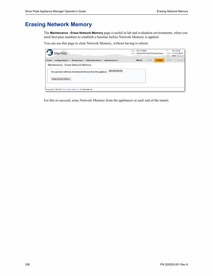
Silver Peak Appliance Manager Operator’s Guide Erasing Network Memory
358 PN 200030-001 Rev K
Erasing Network MemoryThe Maintenance - Erase Network Memory page is useful in lab and evaluation environments, when you need first-pass numbers to establish a baseline before Network Memory is applied.
You can use this page to clear Network Memory, without having to reboot.
For this to succeed, erase Network Memory from the appliances at each end of the tunnel.
mmmm

Restarting the Appliance Chapter 14 System Maintenance
PN 200030-001 Rev K 359
Restarting the ApplianceThis section describes the types of reboots available for restarting the appliance, the possible reasons for choosing a particular method, and the consequences of each.
The Silver Peak appliance supports four different types of reboot, appropriate to your various circumstances and needs at the time.
Regardless of the reboot type, while it’s rebooting, the appliance goes into:
• the hardware bypass state if the appliance is deployed in-line (Bridge mode), or
• the open-port state if the appliance is deployed out-of-path (Router mode).
This allows traffic to pass, but without the benefits of compression, acceleration, or Network Memory™.
To restart the appliance
1 From Maintenance menu, select Restart System.
2 Click the type of reboot you want. The appliance asks you to confirm your decision.
3 Click Yes. The appliance reboots.
Restart Type What it does... You might need to use it if...
Reboot Reboots the appliance gracefully. This is your typical, “vanilla” restart.
• You’re changing the deployment mode and other configuration parameters that require a reboot.
Reboot Clean Reboots the appliance and cleans out the Network Memory™.
• You need to restart the appliance with clean Network Memory™ data.
Shutdown Shuts down the appliance and turns the power off. To restart, you’ll need to go to the appliance and physically turn the power on with the power switch.
• You’re decommissioning the appliance. • You need to physically move the appliance to
another location. • You need to recable the appliance for another type
of deployment

Silver Peak Appliance Manager Operator’s Guide Restarting the Appliance
360 PN 200030-001 Rev K

PN 200030-001 Rev K 361
C H A P T E R 1 5
Monitoring Alarms
This chapter describes alarm categories and definitions. It also describes how to view and handle alarm notifications.
In This Chapter Understanding Alarms See page 362.
Types of Alarms See page 363.
Handling Current Alarms See page 372.

Silver Peak Appliance Manager Operator’s Guide Understanding Alarms
362 PN 200030-001 Rev K
Understanding AlarmsThis section defines the four alarm severity categories and provides tables of all Silver Peak appliance alarms. It also describes the difference between viewing current alarms and reviewing a history of alarms.
The Alarms - Current Alarms page lists currently existing alarm conditions for the appliance. Each entry represents one current condition that may require human intervention. Because alarms are conditions, they may come and go without management involvement.
Whereas merely acknowledging most alarms does not clear them, some alarm conditions are set up to be self-clearing when you acknowledge them. For example, if you remove a hard disk drive, it generates an alarm; once you’ve replaced it and it has finished rebuilding itself, the alarm clears itself.
Categories of Alarms
The Appliance Manager categorizes alarms at four preconfigured severity levels: Critical, Major, Minor, and Warning.
Critical and Major alarms are both service-affecting. Critical alarms require immediate attention, and reflect conditions that affect an appliance or the loss of a broad category of service.
Major alarms, while also service-affecting, are less severe than Critical alarms. They reflect conditions which should be addressed in the next 24 hours. An example would be an unexpected traffic class error.
Minor alarms are not service-affecting, and you can address them at your convenience. An example of a minor alarm would be a user not having changed their account’s default password, or a degraded disk.
Warnings are also not service-affecting, and warn you of conditions that may become problems over time. For example, a software version mismatch.
An alarm, whether acknowledged or unacknowledged, is only accessible via the Alarms - Current Alarms page until it clears.

Understanding Alarms Chapter 15 Monitoring Alarms
PN 200030-001 Rev K 363
Types of Alarms
The appliance can raise alarms based on problems with tunnels, traffic class, and equipment.
Although Appliance Manager doesn’t display Alarm Type ID (Hex) codes, the data is available for applications that can do their own filtering, such as SNMP:
Table 15-1 Silver Peak Appliance Alarms
Subsystem Alarm Type ID (Hex)
Alarm Severity
Alarm Text
Tunnel 0010000 CRITICAL Connecting to a non-VX-X is not supported
RESOLUTION: VX-Xpress appliance can only peer with another VX-Xpress appliance. Create a tunnel to another VX-Xpress appliance.
00010003 CRITICAL Tunnel keepalive version mismatch
RESOLUTION: Tunnel peers are running incompatible software versions.
• Normal during a software upgrade.
Run the same or compatible software releases among the tunnel peers.
00010001 CRITICAL Tunnel state is Down
RESOLUTION: Cannot reach tunnel peer.
• Check tunnel configuration [Admin state, Source IP/Dest IP, IPsec]
• Check network connectivity.
00010007 MAJOR Duplicate license detected in peer (only applies to virtual appliance)
RESOLUTION: Install unique license on all virtual appliances. To check and/or change license:
• In GMS: Initial Configuration page at Configuration > System (Single Appliance)
• In WebUI: Configuration - System page
00010000 MAJOR Tunnel remote ID is misconfigured
RESOLUTION: System ID is not unique.
• Virtual Appliance: Was the same license key used?
• Physical Appliance: Change System ID in the rare case of a duplicate ID (CLI command: system id < >)
00010005 MINOR Tunnel software version mismatch
RESOLUTION: Tunnel are not running the same release of software. They will function, but with reduced functionality.
• Normal during an upgrade.
• Run the same software version to eliminate the alarm and fully optimize.
Software 00040003 CRITICAL The licensing for this virtual appliance has expired.[For VX series only]a
RESOLUTION: Enter a new license.

Silver Peak Appliance Manager Operator’s Guide Understanding Alarms
364 PN 200030-001 Rev K
00040004 CRITICAL There is no license installed on this virtual appliance. [For VX series only]a
RESOLUTION: Enter a valid license.
0004000a CRITICAL Virtual appliance license expires in 15 days. Upon expiry, traffic will no longer be optimized and may be disrupted. Please enter new license key to avoid disruption.
RESOLUTION: Enter a new license.
0004000c CRITICAL Invalid virtual appliance license. Traffic is not being optimized and may be disrupted. Please enter a valid license key.
RESOLUTION: Enter a valid license. Traffic will not be optimized until this is resolved.
00040005 MAJOR A disk self-test has been run on the appliance.
RESOLUTION: Reboot the appliance. Traffic will not be optimized until this is performed.
00040002 MAJOR Significant change in time of day has occurred, and might compromise statistics. Please contact TAC.
RESOLUTION: Appliance statistics could be missing for a substantial period of time. Contact Customer Service.
00040001 MAJOR System is low on resources
RESOLUTION: Contact Customer Service.
0004000b MAJOR Virtual appliance license expires in 45 days. Upon expiry, traffic will no longer be optimized and may be disrupted. Please enter new license key to avoid disruption.
RESOLUTION: Enter a new license.
00040007 WARNING The SSL certificate is not yet valid.
RESOLUTION: The SSL certificate has a future start date. It will correct itself when the future date becomes current. Otherwise, install a certificate that is current.
00040008 WARNING The SSL certificate has expired.
RESOLUTION: Reinstall a valid SSL certificate that is current.
00040009 WARNING The NTP server is unreachable.
RESOLUTION: Check the appliance’s NTP server IP and version configuration:
• Can the appliance reach the NTP server?
• Is UDP port 123 open between the appliance’s mgmt0 IP and the NTP server?
00040006 WARNING The SSL private key is invalid.
RESOLUTION: The key is not an RSA standard key that meets the minimum requirement of 1024 bits. Regenerate a key that meets this minimum requirement.
Table 15-1 Silver Peak Appliance Alarms (Continued)
Subsystem Alarm Type ID (Hex)
Alarm Severity
Alarm Text

Understanding Alarms Chapter 15 Monitoring Alarms
PN 200030-001 Rev K 365
Equipment 00030007 CRITICAL Encryption card hardware failure
RESOLUTION: Contact Customer Service.
00030007 CRITICAL Fan failure detected
RESOLUTION: Contact Customer Service.
00030024 CRITICAL Insufficient configured memory size for this virtual appliance
RESOLUTION: Assign more memory to the virtual machine, and restart the appliance. Traffic will not be optimized until this is resolved.
00030025 CRITICAL Insufficient configured processor count for this virtual appliance
RESOLUTION: Assign more processors to the virtual machine, and restart the appliance. Traffic will not be optimized until this is resolved.
00030026 CRITICAL Insufficient configured disk storage for this virtual appliance
RESOLUTION: Assign more storage to the virtual machine, and restart the appliance. Traffic will not be optimized until this is resolved.
00030005 CRITICAL LAN/WAN fail-to-wire card failure
RESOLUTION: Contact Customer Service.
00030021 CRITICAL NIC interface failure
RESOLUTION: Contact Customer Service.
00030004 CRITICAL System is in Bypass mode
RESOLUTION: Normal with factory default configuration, during reboot, and if user has put the appliance in Bypass mode. Contact Customer Service if the condition persists.
0003001d MAJOR Bonding members have different speed/duplex
RESOLUTION: Check interface speed/duplex settings and negotiated values on wan0/wan1 and lan0/lan1 etherchannel groups.
0003001c MAJOR [Flow redirection] cluster peer is down
RESOLUTION:
• Check flow redirection configuration on all applicable appliances.
• Check L3/L4 connectivity between the peers. • Open TCP and UDP ports 4164 between the cluster peer IPs
if they are blocked.
00030017 MAJOR Disk removed by operator
RESOLUTION: Normal during disk replacement. Use WebUI or GMS for inserting disk. Contact Customer Service if insertion fails.
00030001 MAJOR Disk is failed
RESOLUTION: Contact Customer Service to replace disk.
Table 15-1 Silver Peak Appliance Alarms (Continued)
Subsystem Alarm Type ID (Hex)
Alarm Severity
Alarm Text

Silver Peak Appliance Manager Operator’s Guide Understanding Alarms
366 PN 200030-001 Rev K
Equipment (cont.)
00030015 MAJOR Disk is not in service
RESOLUTION:
• Check to see if the disk is properly seated.• Contact Customer service for further assistance.
0003000b MAJOR Interface is half duplex
RESOLUTION: Check speed/duplex settings on the router/switch port.
0003000c MAJOR Interface speed is 10 Mbps
RESOLUTION:
• Check speed/duplex settings.• Use a 100/1000 Mbps port on the router/switch.
00030022 MAJOR LAN next-hop unreachableb
RESOLUTION: Check appliance configuration:
• LAN–side next-hop IP• Appliance IP / netmask• VLAN IP / netmask • VLAN ID
0003001a MAJOR LAN/WAN interface has been shut down due to link propagation of paired interface
RESOLUTION: Check cables and connectivity. For example, if lan0 is shut down, check why wan0 is down. Applicable only to in-line (bridge) mode.
00030018 MAJOR LAN/WAN interfaces have different admin states
RESOLUTION: Check interface admin configuration for lan0/wan0 (and lan1/wan1). Applicable only to in-line (bridge) mode.
00030019 MAJOR LAN/WAN interfaces have different link carrier states
RESOLUTION: Check interfaces’ configured speed settings and current values for lan0/wan0 (and lan1/wan1). Applicable only to in-line (bridge) mode.
0003000a MAJOR Management interface link down
RESOLUTION:
• Check cables.• Check interface admin status on the router.
00030009 MAJOR Network interface link down
RESOLUTION: Is the system in Bypass mode?
• Check cables.• Check interface admin status on the router.
00030020 MAJOR Power supply not connected, not powered, or failed
RESOLUTION:
• Connect to a power outlet.• Check power cable connectivity.
Table 15-1 Silver Peak Appliance Alarms (Continued)
Subsystem Alarm Type ID (Hex)
Alarm Severity
Alarm Text
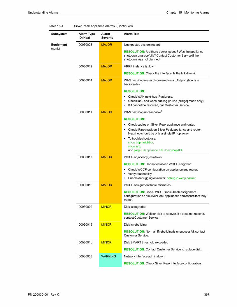
Understanding Alarms Chapter 15 Monitoring Alarms
PN 200030-001 Rev K 367
Equipment (cont.)
00030023 MAJOR Unexpected system restart
RESOLUTION: Are there power issues? Was the appliance shutdown ungracefully? Contact Customer Service if the shutdown was not planned.
00030012 MAJOR VRRP instance is down
RESOLUTION: Check the interface. Is the link down?
00030014 MAJOR WAN next-hop router discovered on a LAN port (box is in backwards)
RESOLUTION:
• Check WAN next-hop IP address.• Check lan0 and wan0 cabling (in-line [bridge] mode only).• If it cannot be resolved, call Customer Service.
00030011 MAJOR WAN next-hop unreachableb
RESOLUTION:
• Check cables on Silver Peak appliance and router.
• Check IP/netmask on Silver Peak appliance and router. Next-hop should be only a single IP hop away.
• To troubleshoot, use:show cdp neighbor, show arp, and ping -I <appliance IP> <next-hop IP>.
0003001e MAJOR WCCP adjacency(ies) down
RESOLUTION: Cannot establish WCCP neighbor:
• Check WCCP configuration on appliance and router.• Verify reachability.• Enable debugging on router: debug ip wccp packet
0003001f MAJOR WCCP assignment table mismatch
RESOLUTION: Check WCCP mask/hash assignment configuration on all Silver Peak appliances and ensure that they match.
00030002 MINOR Disk is degraded
RESOLUTION: Wait for disk to recover. If it does not recover, contact Customer Service.
00030016 MINOR Disk is rebuilding
RESOLUTION: Normal. If rebuilding is unsuccessful, contact Customer Service.
0003001b MINOR Disk SMART threshold exceeded
RESOLUTION: Contact Customer Service to replace disk.
00030008 WARNING Network interface admin down
RESOLUTION: Check Silver Peak interface configuration.
Table 15-1 Silver Peak Appliance Alarms (Continued)
Subsystem Alarm Type ID (Hex)
Alarm Severity
Alarm Text

Silver Peak Appliance Manager Operator’s Guide Understanding Alarms
368 PN 200030-001 Rev K
Equipment (cont.)
00030013 WARNING VRRP state changed from Master to Backup
RESOLUTION: VRRP state has changed from Master to Backup.
• Check VRRP Master for uptime.• Check VRRP Master for connectivity.
Threshold Crossing Alerts (TCAs)
00050001 WARNING The average WAN–side transmit throughput of X Mbps over the last minute [exceeded, fell below] the threshold of Y Mbps
RESOLUTION: User configured. Check bandwidth reports for tunnel bandwidth.
00050002 WARNING The average LAN–side receive throughput of X Mbps over the last minute [exceeded, fell below] the threshold of Y Mbps
RESOLUTION: User configured. Check bandwidth reports.
00050003 WARNING The total number of X optimized flows at the end of the last minute [exceeded, fell below] the threshold of Y
RESOLUTION: User configured. Check flow and real-time connection reports.
00050004 WARNING The total number of X flows at the end of the last minute [exceeded, fell below] the threshold of Y
RESOLUTION: User configured. Check flow and real-time connection reports.
00050005 WARNING The file system utilization of X% at the end of the last minute [exceeded, fell below] the threshold of Y
RESOLUTION: Contact Customer Service.
00050006 WARNING The peak latency of X during the last minute [exceeded, fell below] the threshold of Y
RESOLUTION: User configured.
• Check Latency Reports. If latency is too high, check routing between the appliances and QoS policy on upstream routers.
• Check tunnel DSCP marking. If latency persists, contact ISP and Silver Peak Customer Service.
00050007 WARNING The average pre-FEC loss of X% over the last minute [exceeded, fell below] the threshold of Y%
RESOLUTION: User configured.
• Check Loss Reports. • Check for loss between Silver Peak appliances (interface
counters on upstream routers). • Use network bandwidth measurement tools such as iperf to
measure loss. • Contact ISP (Internet Service Provider).
Table 15-1 Silver Peak Appliance Alarms (Continued)
Subsystem Alarm Type ID (Hex)
Alarm Severity
Alarm Text

Understanding Alarms Chapter 15 Monitoring Alarms
PN 200030-001 Rev K 369
00050008 WARNING The average post-FEC loss of X% over the last minute [exceeded, fell below] the threshold of Y%
RESOLUTION: User configured.
• Check Loss Reports. • Check for loss between Silver Peak appliances (interface
counters on upstream routers). • Use network bandwidth measurement tools such as iperf to
measure loss. • Enable/Adjust Silver Peak Forward Error Correction (FEC).• Contact ISP (Internet Service Provider).
00050009 WARNING The average pre-POC out-of-order packets of X% over the last minute [exceeded, fell below] the threshold of Y%
RESOLUTION: User configured.
• Check Out-of-Order Packets Reports.
Normal in a network with multiple paths and different QoS queues.
Normal in a dual-homed router or 4-port in-line [bridge] configuration.
• Contact Customer Service if out-of-order packets are not 100% corrected.
0005000a WARNING The average post-POC out-of-order packets of X% over the last minute [exceeded, fell below] the threshold of Y%
RESOLUTION: User configured.
• Check Out-of-Order Packets Reports.
Normal in a network with multiple paths and different QoS queues.
Normal in a dual-homed router or 4-port in-ling [bridge] configuration.
• Contact Customer Service if out-of-order packets are not 100% corrected.
0005000b WARNING The average tunnel utilization of X% over the last minute [exceeded, fell below] the threshold of Y%
RESOLUTION: User configured.
Check bandwidth reports for tunnel bandwidth utilization.
0005000c WARNING The average tunnel reduction of X% over the last minute [exceeded, fell below] the threshold of Y%
RESOLUTION: User configured.
• Check bandwidth reports for deduplication.• Check if the traffic is pre-compressed or encrypted.
a. The VX appliances are a family of virtual appliances, comprised of the VX-n000 software, an appropriately paired hypervisor and server, and a valid software license.
b. If there is either a LAN Next-Hop Unreachable or WAN Next-Hop Unreachable alarm after upgrading to Version 2.4.3.1, resolve the alarm(s) immediately by configuring the gateway(s) to respond to ICMP pings from the Silver Peak appliance IP Address.
Table 15-1 Silver Peak Appliance Alarms (Continued)
Subsystem Alarm Type ID (Hex)
Alarm Severity
Alarm Text

Silver Peak Appliance Manager Operator’s Guide Viewing Current Alarms
370 PN 200030-001 Rev K
Viewing Current AlarmsThe alarm summary appears in the banner. You can view current alarms as follows:
To view the Alarms - Current Alarms page, click anywhere in this area.
This appliance is in System Bypass.
To disable System Bypass:
1. Go to the Configuration - System page
2. Click to deselect System Bypass
3. Click Apply.
...and the Alarms - Current Alarms page displays.
Click the link to access the necessary screen.

Viewing Current Alarms Chapter 15 Monitoring Alarms
PN 200030-001 Rev K 371
The Alarm - Current Alarms page displays the following information:
Field Definition/Content
Applies any changes or edits to the running configuration.
Seq No. The sequential number of the alarm, based on the time the alarm raised.
Date/Time The local date and time at the appliance’s location, specified by a 24-hour clock.
Type The type of alarm:
• Tunnel A tunnel-based alarm• TC A traffic class-based alarm• EQU An equipment-based alarm• SW A code- or software-based alarm
Severity The severity of the alarm, listed here in decreasing order of severity:
• Critical A critical alarm, such as “Tunnel Down”• Major A major alarm, such as “Disk out of Service”• Minor A minor alarm, such as “Disk Degraded”• Warning A warning, such as “Software Process Restart”• Info For Silver Peak debugging purposes.
These are purely related to alarms severities, not event logging levels, even though some of the naming conventions overlap. Events and alarms have different sources. Alarms, once they clear, list as the ALERT level in the Alarms - Log Viewer page.
Source Refers to the particular subsystem or equipment that is causing the alarm. For example, we can raise the tunnel-based alarm, “Tunnel Down”, where the source would refer to a particular tunnel.
Description A brief description of the alarm.
Recommended Action Describes what action to take and, when appropriate, provides a link to the page where you need to do it.
Clear Check boxes with a black border are user-clearable.
To clear the alarm, click the Clear box, and click Apply. Once cleared, the row is removed and the content is viewable in the read-only page, Alarms - Log Viewer.
Ack Select Yes to acknowledge the alarm; Select No to remove acknowledgement.

Silver Peak Appliance Manager Operator’s Guide Handling Current Alarms
372 PN 200030-001 Rev K
Handling Current AlarmsOn the Alarms - Current Alarms page, you can:
• Acknowledge alarms
• Clear alarms, if they are clearable
Acknowledging Alarms
Acknowledge or unacknowledge alarms as follows:
Clearing Alarms
Most Silver Peak appliance alarms cannot be cleared by the user. Instead, the appliance generally corrects the alarm condition and clears the alarm by itself.
Clear alarms as follows:
• To acknowledge an individual alarm, select the Ack column. Click Apply.
• To unacknowledge an alarm, deselect the Ack column. Click Apply.
You can only access the check boxes in the Clear column that have shading. To clear an alarm, click its box. Then click Apply.

PN 200030-001 Rev K 373
A P P E N D I X A
Specifications, Compliance, and Regulatory Statements
This appendix contains specifications, as well as compliance and regulatory statements.
In This Appendix Model Specifications See page 374.
Warning Statements See page 380.
Compliance Statements See page 381.
What Ports the NX and the GMS Use See page 383.
Appliance Views See page 387.

Silver Peak Appliance Manager Operator’s Guide Model Specifications
374 PN 200030-001 Rev K
Model SpecificationsThis section includes general and model-specific specifications for the Silver Peak appliances:
Model-specific Specifications See page 374.
Fiber Specifications See page 379.
NX-Series Specifications See page 379.
Note To verify the most current VXOA host system requirements, refer to the Quick Start Guides listed in the User Documentation section of http://www.silver-peak.com/Support.
Note To see which hypervisors Silver Peak’s VXOA software currently supports, refer to the Quick Start Guides listed in the User Documentation section of http://www.silver-peak.com/Support.
Model-specific Specifications
NX-1700 NX-1700 DC NX-2500
Capacity WAN Capacity(All Features)
4 Mbps 4 Mbps 2 Mbps
Local Data Store 500 GB 500 GB 250 GB
Connectivity LAN/WAN Ethernet
4 x 10/100/1000 LAN WAN
2 x 10/100/1000 LAN WAN
2 x 10/100/1000 LAN WAN
Management 2 x 10/100/1000; RS-232 serial port
2 x 10/100/1000; RS-232 serial port
2 x 10/100/1000; RS-232 serial port
Power Requirement 100–240VAC 47–63Hz, 90 W / 307 BTU
-31VDC to -72VDC, 86 W / 295 BTU
100–240VAC 50-60Hz, 120 W / 410 BTU
Power Supplies Single Single Single
Dimensions and Weight
Height 1.8 in. (45 mm) 1 RU 1.8 in. (45 mm) 1 RU 1.7 in. (43 mm) 1 RU
Width 17.5 in. (445 mm) 17.5 in. (445 mm) 16.8 in. (427 mm)
Depth 8.2 in. (209 mm) 8.2 in. (209 mm) 14.0 in. (356 mm)
Weight 8.5 lbs (3.9 kg) 8.5 lbs (3.9 kg) 14 lbs (6.4 kg)

Model Specifications Appendix A Specifications, Compliance, and Regulatory Statements
PN 200030-001 Rev K 375
NX-2600 NX-2610 NX-2700
Capacity WAN Capacity(All Features)
4 Mbps 8 Mbps 10 Mbps
Local Data Store 250 GB 500 GB 1 TB
Connectivity LAN/WAN Ethernet
2 x 10/100/1000 LAN WAN
4 x 10/100/1000 LAN WAN
4 x 10/100/1000 LAN WAN
Management 2 x 10/100/1000; RS-232 serial port
2 x 10/100/1000; RS-232 serial port
2 x 10/100/1000; RS-232 serial port
Power Requirement 100–240VAC 50-60Hz, 145 W / 496 BTU
100–240VAC 50-60Hz, 165 W / 563 BTU
100–240VAC 47-63Hz, 285 W / 973 BTU
Power Supplies Single Single 1+1 redundant
Dimensions and Weight
Height 1.7 in. (43.5 mm) 1 RU 1.7 in. (43.5 mm) 1 RU 3.5 in. (89 mm) 2 RU
Width 16.9 in. (430 mm) 16.9 in. (430 mm) 16.9 in. (430 mm)
Depth 22.4 in. (569 mm) 22.4 in. (569 mm) 26 in. (660 mm)
Weight 22.0 lbs (10.0 kg) 24.2 lbs (11.0 kg) 40.5 lbs (18.4 kg)
NX-3500 NX-3600 NX-3700
Capacity WAN Capacity(All Features)
10 Mbps 20 Mbps 20 Mbps
Local Data Store 500 GB 1 TB 1 TB
Connectivity LAN/WAN Ethernet
2 x 10/100/1000 LAN WAN
4 x 10/100/1000 LAN WAN
4 x 10/100/1000 LAN WAN
Management 2 x 10/100/1000; RS-232 serial port
2 x 10/100/1000; RS-232 serial port
2 x 10/100/1000; RS-232 serial port
Power Requirement 100–240VAC 50-60Hz, 150 W / 512 BTU
100–240VAC 47-63Hz, 250 W / 853 BTU
100–240VAC 47-63Hz, 305 W / 1041 BTU
Power Supplies 1+1 redundant 1+1 redundant 1+1 redundant
Dimensions and Weight
Height 3.5 in. (89 mm) 2 RU 3.5 in. (89 mm) 2 RU 3.5 in. (89 mm) 2 RU
Width 17.9 in. (455 mm) 17.0 in. (432 mm) 16.9 in. (430 mm)
Depth 22.3 in. (566 mm) 26.0 in. (661 mm) 26 in. (660 mm)
Weight 34 lbs (15.4 kg) 41.0 lbs (18.6 kg) 40.5 lbs (18.4 kg)

Silver Peak Appliance Manager Operator’s Guide Model Specifications
376 PN 200030-001 Rev K
NX-5500 NX-5504 NX-5600
Capacity WAN Capacity(All Features)
50 Mbps 50 Mbps 50 Mbps
Local Data Store 2 TB 2 TB 2 TB
Connectivity LAN/WAN Ethernet
2 x 10/100/1000 LAN WAN
4 x 10/100/1000 LAN WAN
4 x 10/100/1000 LAN WAN
Management 2 x 10/100/1000; RS-232 serial port
2 x 10/100/1000; RS-232 serial port
2 x 10/100/1000; RS-232 serial port
Power Requirement 100–240VAC 50-60Hz, 400 W / 1366 BTU
100–240VAC 50-60Hz, 400 W / 1366 BTU
100–240VAC 50-60Hz, 440 W / 1501 BTU
Power Supplies 2+1 redundant 2+1 redundant 2+1 redundant
Dimensions and Weight
Height 5.2 in. (132 mm) 3 RU 5.2 in. (132 mm) 3 RU 5.2 in. (132 mm) 3 RU
Width 17.7 in. (450 mm) 17.7 in. (450 mm) 17 in. (432 mm)
Depth 25.5 in. (647 mm) 25.5 in. (647 mm) 26 in. (659 mm)
Weight 65 lbs (29.5 kg) 65 lbs (29.5 kg) 62 lbs (28.1 kg)
NX-5700
Capacity WAN Capacity(All Features)
50 Mbps
Local Data Store 4 TB
Connectivity LAN/WAN Ethernet
4 x 10/100/1000 LAN WAN
Management 2 x 10/100/1000; RS-232 serial port
Power Requirement 100–240VAC 47-63Hz, 345 W / 1178 BTU
Power Supplies 1+1 redundant
Dimensions and Weight
Height 3.5 in. (89 mm) 2 RU
Width 16.9 in. (430 mm)
Depth 26 in. (660 mm)
Weight 43 lbs (19.6 kg)

Model Specifications Appendix A Specifications, Compliance, and Regulatory Statements
PN 200030-001 Rev K 377
NX-7500 NX-7504 NX-7600
Capacity WAN Capacity(All Features)
155 Mbps 155 Mbps 155 Mbps
Local Data Store 2 TB 2 TB 3 TB
Connectivity LAN/WAN Ethernet
2 x 10/100/1000 LAN WAN
4 x 10/100/1000 LAN WAN
4 x 10/100/1000 LAN WAN
Management 2 x 10/100/1000; RS-232 serial port
2 x 10/100/1000; RS-232 serial port
2 x 10/100/1000; RS-232 serial port
Power Requirement 100–240VAC 50-60Hz, 400 W / 1366 BTU
100–240VAC 50-60Hz, 400 W / 1366 BTU
100–240VAC 50-60Hz, 580 W / 1979 BTU
Power Supplies 2+1 redundant 2+1 redundant 2+1 redundant
Dimensions and Weight
Height 5.2 in. (132 mm) 3 RU 5.2 in. (132 mm) 3 RU 5.2 in. (132 mm) 3 RU
Width 17.7 in. (450 mm) 17.7 in. (450 mm) 17 in. (432 mm)
Depth 25.5 in. (647 mm) 25.5 in. (647 mm) 26 in. (659 mm)
Weight 65 lbs (29.5 kg) 65 lbs (29.5 kg) 68 lbs (30.8 kg)
NX-7700
Capacity WAN Capacity(All Features)
155 Mbps
Local Data Store 5 TB
Connectivity LAN/WAN Ethernet
4 x 10/100/1000 LAN WAN
Management 2 x 10/100/1000; RS-232 serial port
Power Requirement 100–240VAC 47-63Hz, 475 W / 1621 BTU
Power Supplies 1+1 redundant
Dimensions and Weight
Height 3.5 in. (89 mm) 2 RU
Width 16.9 in. (430 mm)
Depth 26 in. (660 mm)
Weight 44 lbs (20 kg)

Silver Peak Appliance Manager Operator’s Guide Model Specifications
378 PN 200030-001 Rev K
NX-8504 NX-8600 NX-8700
Capacity WAN Capacity(All Features)
500 Mbps 500 Mbps 622 Mbps
Local Data Store 8 TB 8 TB 5 TB + 4 x 64GB SSD
Connectivity LAN/WAN Ethernet
4 x 10/100/1000 LAN WAN
4 x 10/100/1000 LAN WAN
4 x 10/100/1000 LAN WAN; 2 x 10 Gbps fiber LAN WAN
Management 2 x 10/100/1000; RS-232 serial port
2 x 10/100/1000; RS-232 serial port
2 x 10/100/1000; RS-232 serial port
Power Requirement 100–240VAC 50-60Hz, 530 W / 1809 BTU
100–240VAC 50-60Hz, 650 W / 2218 BTU
100-240VAC 47–63Hz, 520 W / 1775 BTU
Power Supplies 2+1 redundant 2+1 redundant 1+1 redundant
Dimensions and Weight
Height 5.2 in. (132 mm) 3 RU 5.2 in. (132 mm) 3 RU 3.5 in. (89 mm) 2 RU
Width 17.7 in. (450 mm) 17 in. (432 mm) 16.9 in. (430 mm)
Depth 25.5 in. (647 mm) 26 in. (659 mm) 26 in. (660 mm)
Weight 71 lbs (32.2 kg) 75 lbs (34.0 kg) 46.5 lbs (21.2 kg)
NX-9610 NX-9700 NX-10700
Capacity WAN Capacity(All Features)
1 Gbps 1 Gbps 2.5 Gbps
Local Data Store 8 TB 5 TB + 4 x 64GB SSD 16 x 100GB SSD
Connectivity LAN/WAN Ethernet
4 x 1 Gbps fiber LAN WANa;2 x 10 Gbps fiber LAN WANb
4 x 1 Gbps fiber LAN WAN;2 x 10 Gbps fiber LAN WAN
4 x 10 Gbps fiber LAN WAN
Management 2 x 10/100/1000; RS-232 serial port
2 x 10/100/1000; RS-232 serial port
2 x 10/100/1000; RS-232 serial port
Power Requirement 100–240VAC 50-60Hz, 682 W / 2327 BTU
100-240VAC 47–63Hz, 600 W / 2048 BTU
100-240VAC 47–63Hz, 600 W / 2048 BTU
Power Supplies 2+1 redundant 1+1 redundant 1+1 redundant
Dimensions and Weight
Height 5.2 in. (132 mm) 3 RU 3.5 in. (89 mm) 2 RU 3.5 in. (89 mm) 2 RU
Width 17 in. (432 mm) 16.9 in. (430 mm) 16.9 in. (430 mm)
Depth 26 in. (659 mm) 26 in. (660 mm) 26 in. (660 mm)
Weight 75.5 lbs (34.5 kg) 47 lbs (21.2 kg) 46.5 lbs (21.1 kg)
a. The connectors are LC and support both multi-mode 50 micron fiber and multi-mode 62.5 micro fiber.
b. The connectors are LC and support multi-mode 50 micron fiber.

Model Specifications Appendix A Specifications, Compliance, and Regulatory Statements
PN 200030-001 Rev K 379
Fiber Specifications
NX-Series Specifications
1 Gbps Fiber Interfaces
NX-9610 / NX-9700
10 Gbps Fiber Interfaces
NX-8700 / NX-9610 / NX-9700
lan / wana
Fiber Support
a. This can be for lan0/wan0 or lan1/wan1.
lan / wana Fail-to-Close
tlan0 / twan0Fiber Support
tlan0 / twan0 Fail-to-Close
• 4 interfaces• LC connectors• Support multi-mode 50μ fiber /
62.5μ fiber
NX-9610 — no• 2 interfaces• LC connectors• Support multi-mode 50μ fiber
no
NX-9700 — yes
NX-10700 : 10 Gbps Fiber Interfaces
tlan0 / twan0 / tlan1 / twan1
• 2 interfaces• LC connectors
• Support multi-mode 50μ fiber• Fail-to-close — no
Environmental Temperature (Operating) 10°C to 40°C (50°F to 104°F)
Temperature (Storage) -40°C to 65°C (-40°F to 149°F)
Humidity 8% to 90% relative humidity, non-condensing
Regulatory EMC FCC Part 15 Class A, EN 55022 Class A, EN 61000-3-2/3-3, EN 55024
Safety UL/cUL 60950, EN 60950

Silver Peak Appliance Manager Operator’s Guide Warning Statements
380 PN 200030-001 Rev K
Warning Statements
Class 1 Laser Product
NX-8700
NX-9600
NX-9700

Compliance Statements Appendix A Specifications, Compliance, and Regulatory Statements
PN 200030-001 Rev K 381
Compliance StatementsThis section includes the following required compliance statements:
FCC Compliance Statement See page 381.
ICES-003 statement See page 381.
Requirements for Rack-Mount Equipment See page 381.
Requirements for Knurled Thumb Screws See page 382.
FCC Compliance Statement
This equipment has been tested and found to comply with the limits for a Class A digital device, pursuant to Part 15 of the FCC Rules. These limits are designed to provide reasonable protection against harmful interference when the equipment is operated in a commercial environment. This equipment generates, uses, and can radiate radio frequency energy and, if not installed and used in accordance with the instruction manual, may cause harmful interference to radio communications. Operation of this equipment in a residential area is likely to cause harmful interference in which case the user will be required to correct the interference at his own expense.
ICES-003 statement
The Class A digital apparatus complies with Canadian ICES-003.
Cet appareil numérique de la classe A est conforme á la norme NMB-003 du Canada.
Requirements for Rack-Mount Equipment
Observe the following requirements for all rack-mount equipment:
1 Elevated Operating Ambient Temperature – If installed in a closed or multi-unit rack assembly, the operating ambient temperature of the rack environment may be greater than room ambient. Therefore, consideration should be given to installing the equipment in an environment compatible with the maximum ambient temperature (Tma) specified by the manufacturer.
2 Reduced Air Flow – Installation of the equipment in a rack should be such that the amount of air flow required for safe operation of the equipment is not compromised.
3 Mechanical Loading – Mounting of the equipment in the rack should be such that a hazardous condition is not achieved due to uneven mechanical loading.
4 Circuit Overloading – Consideration should be given to the connection of the equipment to the supply circuit and the effect that overloading of the circuits might have on overcurrent protection and supply wiring.
Appropriate consideration of equipment nameplate ratings should be used when addressing this concern.
5 Reliable Earthing – Reliable earthing of rack-mounted equipment should be maintained. Particular attention should be given to supply connections other than direct connections to the branch circuit (for example, use of power strips).

Silver Peak Appliance Manager Operator’s Guide Compliance Statements
382 PN 200030-001 Rev K
Requirements for Knurled Thumb Screws
Thumbscrews should be tightened with a tool after both initial installation and subsequent access to the panel.

What Ports the NX and the GMS Use Appendix A Specifications, Compliance, and Regulatory Statements
PN 200030-001 Rev K 383
What Ports the NX and the GMS UseFollowing are lists of ports that are used by the appliances and by the Global Management System (GMS). These are the ports used for “listening”.
If you intend to use a port, make sure that it is open in the firewall(s).
List of ports used by the GMS
Following is the list of ports used by the GMS. All are part of the management plane.
It is mandatory for certain ports to be open. Opening other ports is optional (opt.), depending on your network, applications, and chosen deployment.
Must open port?
TCP UDP Port Application Direction relative to the GMS
Comments
yes x 22 SSH bidirectional SNMP trap receivers
yes x 443 HTTPS bi-directional communications between the GMS and a physical or virtual appliance (NX or VX)
opt. x 21 FTP outgoing for GMS backup
This is the default port. If you’ve configured a different port, then you also need to configure the firewall with that port number.
opt. x 22 SCP outgoing for GMS backup
This is the default port. If you’ve configured a different port, then you also need to configure the firewall with that port number.
opt. x 49 TACACS+ outgoing user authentication and authorization
opt. x x 53 DNS outgoing domain name services
opt. x 80 HTTP outgoing If the appliance’s web configuration is for HTTP only, then you must open this port.
opt. x 123 NTP outgoing synchronizes clocks
opt. x 162 SNMP outgoing SNMP trap receivers
opt. x 1812 RADIUS outgoing user authentication and authorization
opt. x 2055 Netflow outgoing Netflow collector

Silver Peak Appliance Manager Operator’s Guide What Ports the NX and the GMS Use
384 PN 200030-001 Rev K
List of ports used by the NX
Data Plane
This is for packets that traverse the optimization path. For creating tunnels, at least one of the first three applications — GRE, IPsec, or UDP — is required.
Management Plane
It is mandatory for certain ports to be open. Opening other ports is optional (opt.), depending on your network, applications, and chosen deployment.
Diagrams of TCP/IP Port Use
See the following two pages.
Application Ports and Protocols Use
GRE Protocol 47 If tunnel mode is GRE
IPsec Protocol ESP 50; UDP port 500 (for IKE key exchange)
If tunnel mode is IPsec
UDP UDP Port 4163 If tunnel mode is UDP
WCCP UDP Port 2048 For WCCP redirection
Flow redirection TCP Port 4164 and UDP Port 4164 If flow direction is enabled and clustered via routers
iperf TCP Port 5001 and UDP Port 5001 For testing link integrity outside the tunnel.
Must open port ?
TCP UDP Port Application Direction relative to the appliance
Used for ...
yes x 22 SSH and SCP bidirectional • configuration backup• software upgrades
yes x 80 HTTP bidirectional communication with NX clients and with GMS
yes x 443 HTTPS bidrectional communication with NX clients
opt. x 20 [data channel]
21 [control channel]
FTP bidirectional • configuration backup• software upgrades
opt. x 49 TACACS+ outgoing user authentication and authorization
opt. x x 53 DNS outgoing domain name services
opt. x 123 NTP outgoing synchronizes clocks
opt. x 1812 RADIUS outgoing user authentication and authorization
opt. x 162 SNMP outgoing SNMP trap receivers
opt. x 2055 Netflow outgoing Netflow collector

What Ports the NX and the GMS Use Appendix A Specifications, Compliance, and Regulatory Statements
PN 200030-001 Rev K 385

Silver Peak Appliance Manager Operator’s Guide What Ports the NX and the GMS Use
386 PN 200030-001 Rev K

Appliance Views Appendix A Specifications, Compliance, and Regulatory Statements
PN 200030-001 Rev K 387
Appliance ViewsThis section includes each NX appliance model and provides information about its physical characteristics and layout.
NX-1700 AC See page 388.
NX-1700 DC See page 390.
NX-2500 See page 391.
NX-2600 / NX-2610 See page 392.
NX-2700 See page 394.
NX-3500 See page 396.
NX-3600 See page 398.
NX-3700 See page 400.
NX-5500 / NX-5504 See page 402.
NX-5600 See page 404.
NX-5700 See page 406.
NX-7500 / NX-7504 See page 408.
NX-7600 See page 410.
NX-7700 See page 412.
NX-8504 See page 414.
NX-8600 See page 416.
NX-8700 See page 418.
NX-9610 See page 422.
NX-9700 See page 424.
NX-10700 See page 428.

Silver Peak Appliance Manager Operator’s Guide Appliance Views
388 PN 200030-001 Rev K
NX-1700 AC
There are a couple of different physical chassis for AC current. The functional distinction is only in whether the physical interfaces are on the front panel or the rear panel.
Option #1 – NX-1700 AC with Interfaces on Rear Panel
NX-1700 Hard Disks Power Supplies
Quantity 1 1
User authorized to replace? no no
Hot swappable? -- --
Power LED
Power switch
When you toggle the Power switch, verify that the Power LED illuminates green.
NX-1700 (AC) — Front View
parallel port
console[serial port]
VGA port auxiliary port
management interfaces[mgmt0 / mgmt1]
network interfaces[lan0 / wan0 / lan1 / wan1]
NX-1700
power supply LED
NX-1700 (AC) — Rear View

Appliance Views Appendix A Specifications, Compliance, and Regulatory Statements
PN 200030-001 Rev K 389
Option #2 – NX-1700 AC with Interfaces on Front Panel
Power LED
console[serial port]
auxiliary port
management interfaces[mgmt0 / mgmt1]
network interfaces[lan0 / wan0 / lan1 / wan1]
NX-1700
NX-1700 (AC) — Front View
Power switch
Power plug
NX-1700 (AC) — Rear View
NX-1700
mgmt0 & mgmt1 lan0 / wan0 / lan1 / wan1
Not connected
10 Mbps 100 Mbps 1000 Mbps
Link/Activity: blinking = traffic
--
Speed = solid
Link/Activity Speed
Link/Activity Speed
Link/Activity Speed
Link/Activity Speed
Link/Activity Speed

Silver Peak Appliance Manager Operator’s Guide Appliance Views
390 PN 200030-001 Rev K
NX-1700 DC
NX-1700 DC Hard Disks Power Supplies
Quantity 1 1
User authorized to replace? no no
Hot swappable? -- --
Power LED
Power switch
When you toggle the Power switch, verify that the Power LED illuminates green.
NX-1700 (DC) — Front View
parallel port
console[serial port]
VGA port auxiliary port
management interfaces[mgmt0 / mgmt1]
network interfaces[lan0 / wan0 / lan1 / wan1]
power supply LED
DC terminal connector (DC)
side view
NX-1700 (DC) — Rear View
a Connect one wire from the NX-1700’s 0V terminal to the DC source 0V terminal.
b Connect the second wire from the NX-1700’s –48V terminal to the DC source –48V terminal.
NX-1700
mgmt0 & mgmt1 lan0 / wan0 / lan1 / wan1
Not connected
10 Mbps 100 Mbps 1000 Mbps
Link/Activity: blinking = traffic
--
Speed = solid
Link/Activity Speed
Link/Activity Speed
Link/Activity Speed
Link/Activity Speed
Link/Activity Speed

Appliance Views Appendix A Specifications, Compliance, and Regulatory Statements
PN 200030-001 Rev K 391
NX-2500
NX-2500 Hard Disks Power Supplies
Quantity 1 1
User authorized to replace? no no
Hot swappable? -- --
Partial View of Front Panel
Power LEDPower switch
On the upper right front panel, verify that the Power LED illuminates green.
NX-2500 — Front View
NOTE: Depending on the hardware revision of your appliance, the MGMT0 and MGMT1 interfaces may be positionally reversed. All instructions refer to the name of the port, not the position.
NX-2500 — Partial Rear Views
Use the cables supplied, as follows:
• Blue (straight-through) cable for the MGMT0 interface
• Red (crossover) cable for the WAN0 interface, and
• Yellow (straight-through) for the LAN0 interface.
A female DB-9 serial cable connects locally from the serial port to a laptop (null modem cable) or remotely to a terminal server (see your terminal server documentation for specifics).
An Ethernet cable connects locally from the MGMT1 port to a laptop.
(MGMT1 position may vary)
NX-2500
mgmt0 & mgmt1
Not connected
10 Mbps 100 Mbps 1000 Mbps
Speed = solid
---
Link/Activity: blinking = traffic
Speed Link/Activity
Speed Link/Activity
Speed Link/Activity
Speed Link/Activity

Silver Peak Appliance Manager Operator’s Guide Appliance Views
392 PN 200030-001 Rev K
NX-2600 / NX-2610
NX-2600 NX-2610
Hard Disks Power Supplies Hard Disks Power Supplies
Quantity 1 1 2 1
User authorized to replace? no no yes no
Hot swappable? -- -- no --
Power LED [blue]
Power switch
On the front panel, verify that the Power LED illuminates blue.
NX-2600 and NX-2610 — Front Views
Not usedAlarm MuteSystem Reset
mgmt0 mgmt1Hard Disk Driveactivity
NX-2600 — Disk Layout
User replacement NOT authorized
NX-2610
NX-2600 — Rear View
NX-2610

Appliance Views Appendix A Specifications, Compliance, and Regulatory Statements
PN 200030-001 Rev K 393
NX-2600 NX-2610
mgmt0 & mgmt1
Not connected 10 Mbps 100 Mbps 1000 Mbps Auto
Speed = solid
--
Link/Activity: blinking = traffic
Link/Activity Speed
Link/Activity Speed
Link/Activity Speed
Link/Activity Speed
Link/Activity Speed

Silver Peak Appliance Manager Operator’s Guide Appliance Views
394 PN 200030-001 Rev K
NX-2700
NX-2700 Hard Disks Power Supplies
Quantity 2 2
User authorized to replace? yes yes
Hot swappable? yes yes
Power button
[plugging the power cords in automatically powers up the appliance]
Power LED [blue = ON]
System reset
Alarm mute
Illuminates red when a power supply is disconnected or off
NX-2700 — Front View
NX-2700 — Disk Layout

Appliance Views Appendix A Specifications, Compliance, and Regulatory Statements
PN 200030-001 Rev K 395
.
Each power cord socket has a corresponding green LED to its left. When a socket receives power, its LED illuminates green.
NX-2700 — Rear View
NX-2700mgmt0 & mgmt1
Not connected 10 Mbps 100 Mbps 1000 Mbps
Speed = solid
--
Link/Activity:solid = linkblinking = traffic
NX-2700 Network interfaces
Link/Activity:solid green = link goodblinking green = traffic
system bypass mode
Ports 0 + 2 – solid greenPorts 1 + 3 – OFF
slave portsnot in system bypass
Ports 0 + 2 – OFFPorts 1 + 3 – solid green
Link/Activity Speed
Link/Activity Speed
Link/Activity Speed
Link/Activity Speed
Link/Activity
lan0 wan0 lan1 wan1
Link/Activity
Link/Activity
Link/Activity
lan0 wan0 lan1 wan1
lan0 wan0 lan1 wan1

Silver Peak Appliance Manager Operator’s Guide Appliance Views
396 PN 200030-001 Rev K
NX-3500
NX-3500 Hard Disks Power Supplies
Quantity 2 2
User authorized to replace? yes yes
Hot swappable? no yes
POWER: Solid green = Power On
HARD DISK ACTIVITY: Flashing Green = Active
STATUS: Solid Green = GoodSolid Yellow = Alarm
NX-3500 — Front Views
Disks are here, behind cover
[two more Power LEDs on rear panel]
Disk 0
Disk 1
NX-3500 — Disk Layout

Appliance Views Appendix A Specifications, Compliance, and Regulatory Statements
PN 200030-001 Rev K 397
.
NX-3500 — Rear View
Power cord sockets
Each power supply has a green LED. When a socket receives power, its LED illuminates.
Power rocker switch
NX-3500
mgmt0 & mgmt1
Not connected
10 Mbps 100 Mbps 1000 Mbps
[blinking only]

Silver Peak Appliance Manager Operator’s Guide Appliance Views
398 PN 200030-001 Rev K
NX-3600
NX-3600 Hard Disks Power Supplies
Quantity 2 2
User authorized to replace? yes yes
Hot swappable? no yes
Disk 0 Disk 1These two slots house the hard disks you can remove and replace.
NX-3600 — Front View & Disk Layout
NX-3600 — Rear View

Appliance Views Appendix A Specifications, Compliance, and Regulatory Statements
PN 200030-001 Rev K 399
.
NX-3600mgmt0 & mgmt1
Not connected 10 Mbps 100 Mbps 1000 Mbps Auto
Speed = solid
--
Link/Activity: blinking = traffic
Link/Activity Speed
Link/Activity Speed
Link/Activity Speed
Link/Activity Speed
Link/Activity Speed

Silver Peak Appliance Manager Operator’s Guide Appliance Views
400 PN 200030-001 Rev K
NX-3700
NX-3700 Hard Disks Power Supplies
Quantity 2 2
User authorized to replace? yes yes
Hot swappable? yes yes
Power button
[plugging the power cords in automatically powers up the appliance]
Power LED [blue = ON]
System reset
Alarm mute
Illuminates red when a power supply is disconnected or off
NX-3700 — Front View
NX-3700 — Disk Layout

Appliance Views Appendix A Specifications, Compliance, and Regulatory Statements
PN 200030-001 Rev K 401
.
Each power cord socket has a corresponding green LED to its left. When a socket receives power, its LED illuminates green.
NX-3700 — Rear View
NX-3700mgmt0 & mgmt1
Not connected 10 Mbps 100 Mbps 1000 Mbps
Speed = solid
--
Link/Activity:solid = linkblinking = traffic
NX-3700 Network interfaces
Link/Activity:solid green = link goodblinking green = traffic
system bypass mode
Ports 0 + 2 – solid greenPorts 1 + 3 – OFF
slave portsnot in system bypass
Ports 0 + 2 – OFFPorts 1 + 3 – solid green
Link/Activity Speed
Link/Activity Speed
Link/Activity Speed
Link/Activity Speed
Link/Activity
lan0 wan0 lan1 wan1
Link/Activity
Link/Activity
Link/Activity
lan0 wan0 lan1 wan1
lan0 wan0 lan1 wan1

Silver Peak Appliance Manager Operator’s Guide Appliance Views
402 PN 200030-001 Rev K
NX-5500 / NX-5504
.
NX-5500 / NX-5504 Hard Disks Power Supplies
Quantity 8 2
User authorized to replace? yes yes
Hot swappable? yes yes
!
Power Button
System Reset
Power Indicator
mgmt0
Overheat
Power Fail
Mute Switch(Alarm) *
LED Color Condition Description
HDD Amber Blink HDD Activity
Off No Activity
Power Green On System On
Off System Off
mgmt0 [interface]
Green On Linked
Blink mgmt0 Activity
Off Disconnected
Overheat Red On System Overheat
Off System Normal
System Alert/Power Failure
Red On 1 or more PWR modules failure
Off System Normal
HDD
NX-5500 / NX-5504 — Front View
NX-5500 / NX-5504 — Disk Layout

Appliance Views Appendix A Specifications, Compliance, and Regulatory Statements
PN 200030-001 Rev K 403
The NX-5500 has two network interface ports (lan0, wan0), whereas the NX-5504 has four (lan0, wan0, lan1, wan1).
NX-5500 / NX-5504 — Rear View
Each power cord socket has a corresponding green Power LED to its right. When a socket receives power, its LED illuminates.
For redundancy, plug in all power cords, preferably to different sources.
If all power cords are not connected, an audible alarm sounds. To silence, make sure to plug in all power sources.
mgmt0 & mgmt1
Not connected
10 Mbps 100 Mbps 1000 Mbps Auto
NX-5500NX-5504
Link = solid
--
Activity: blinking = traffic
Link: ON for 1000 Mbps and 100 Mbps only.
(All full duplex)
Link Activity Link Activity Link Activity Link Activity

Silver Peak Appliance Manager Operator’s Guide Appliance Views
404 PN 200030-001 Rev K
NX-5600
NX-5600 Hard Disks Power Supplies
Quantity 8 3
User authorized to replace? yes yes
Hot swappable? yes yes
Power LED [blue = ON]
NX-5600 — Front Views
Not usedAlarm MuteSystem Reset
mgmt0 mgmt1Hard Disk Drive activity[Yellow = busy]
NX-5600 — Front Views
NX-5600 — Rear View

Appliance Views Appendix A Specifications, Compliance, and Regulatory Statements
PN 200030-001 Rev K 405
.
mgmt0 & mgmt1
Not connected
10 Mbps 100 Mbps 1000 Mbps Auto
NX-5600
Speed = solid
--
Link/Activity: blinking = traffic
Link/Activity Speed
Link/Activity Speed
Link/Activity Speed
Link/Activity Speed
Link/Activity Speed

Silver Peak Appliance Manager Operator’s Guide Appliance Views
406 PN 200030-001 Rev K
NX-5700
NX-5700 Hard Disks Power Supplies
Quantity 8 2
User authorized to replace? yes yes
Hot swappable? yes yes
Power button
[plugging the power cords in automatically powers up the appliance]
Power LED [blue = ON]
System reset
Alarm mute
Illuminates red when a power supply is disconnected or off
NX-5700 — Front View
NX-5700 — Disk Layout

Appliance Views Appendix A Specifications, Compliance, and Regulatory Statements
PN 200030-001 Rev K 407
.
Each power cord socket has a corresponding green LED to its left. When a socket receives power, its LED illuminates green.
NX-5700 — Rear View
NX-5700mgmt0 & mgmt1
Not connected 10 Mbps 100 Mbps 1000 Mbps
Speed = solid
--
Link/Activity:solid = linkblinking = traffic
NX-5700 Network interfaces
Link/Activity:solid green = link goodblinking green = traffic
system bypass mode
Ports 0 + 2 – solid greenPorts 1 + 3 – OFF
slave portsnot in system bypass
Ports 0 + 2 – OFFPorts 1 + 3 – solid green
Link/Activity Speed
Link/Activity Speed
Link/Activity Speed
Link/Activity Speed
Link/Activity
lan0 wan0 lan1 wan1
Link/Activity
Link/Activity
Link/Activity
lan0 wan0 lan1 wan1
lan0 wan0 lan1 wan1

Silver Peak Appliance Manager Operator’s Guide Appliance Views
408 PN 200030-001 Rev K
NX-7500 / NX-7504
NX-7500 / NX-7504 Hard Disks Power Supplies
Quantity 8 3
User authorized to replace? yes yes
Hot swappable? yes yes
!
Power Button
System Reset
Power Indicator
mgmt0
Overheat
Power Fail
Mute Switch(Alarm) *
LED Color Condition Description
HDD Amber Blink HDD Activity
Off No Activity
Power Green On System On
Off System Off
mgmt0 [interface]
Green On Linked
Blink mgmt0 Activity
Off Disconnected
Overheat Red On System Overheat
Off System Normal
System Alert/Power Failure
Red On 1 or more PWR modules failure
Off System Normal
HDD
NX-7500 and NX-7504 — Front Views
NX-7500 and NX-7504 — Disk Layout

Appliance Views Appendix A Specifications, Compliance, and Regulatory Statements
PN 200030-001 Rev K 409
NX-7500 and NX-7504 — Rear View
Each power cord socket has a corresponding green Power LED to its right. When a socket receives power, its LED illuminates.
For redundancy, plug in all power cords, preferably to different sources.
If all power cords are not connected, an audible alarm sounds. To silence, make sure to plug in all power sources.
mgmt0 & mgmt1
Not connected
10 Mbps 100 Mbps 1000 Mbps Auto
NX-7500NX-7504
Link = solid
--
Activity: blinking = traffic
Link: ON for 1000 Mbps and 100 Mbps only.
(All full duplex)
Link Activity Link Activity Link Activity Link Activity
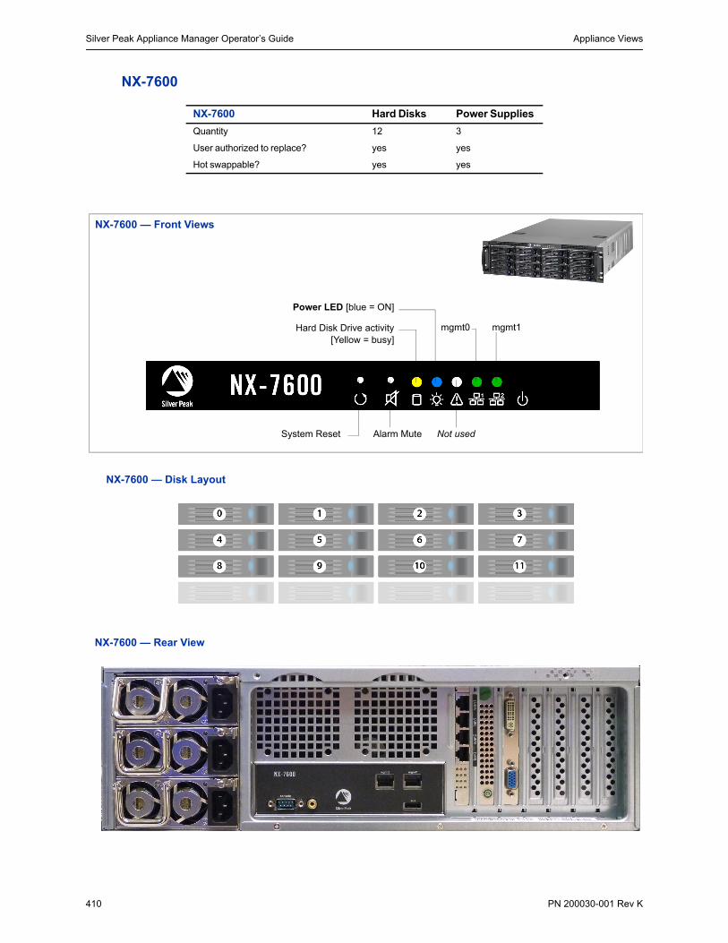
Silver Peak Appliance Manager Operator’s Guide Appliance Views
410 PN 200030-001 Rev K
NX-7600
NX-7600 Hard Disks Power Supplies
Quantity 12 3
User authorized to replace? yes yes
Hot swappable? yes yes
Power LED [blue = ON]
NX-7600 — Front Views
Not usedAlarm MuteSystem Reset
mgmt0 mgmt1Hard Disk Drive activity[Yellow = busy]
NX-7600 — Disk Layout
NX-7600 — Rear View

Appliance Views Appendix A Specifications, Compliance, and Regulatory Statements
PN 200030-001 Rev K 411
mgmt0 & mgmt1
Not connected
10 Mbps 100 Mbps 1000 Mbps Auto
NX-7600
Speed = solid
--
Link/Activity: blinking = traffic
Link/Activity Speed
Link/Activity Speed
Link/Activity Speed
Link/Activity Speed
Link/Activity Speed
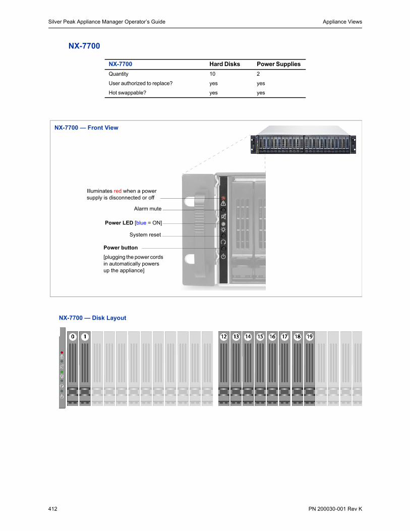
Silver Peak Appliance Manager Operator’s Guide Appliance Views
412 PN 200030-001 Rev K
NX-7700
NX-7700 Hard Disks Power Supplies
Quantity 10 2
User authorized to replace? yes yes
Hot swappable? yes yes
Power button
[plugging the power cords in automatically powers up the appliance]
Power LED [blue = ON]
System reset
Alarm mute
Illuminates red when a power supply is disconnected or off
NX-7700 — Front View
NX-7700 — Disk Layout
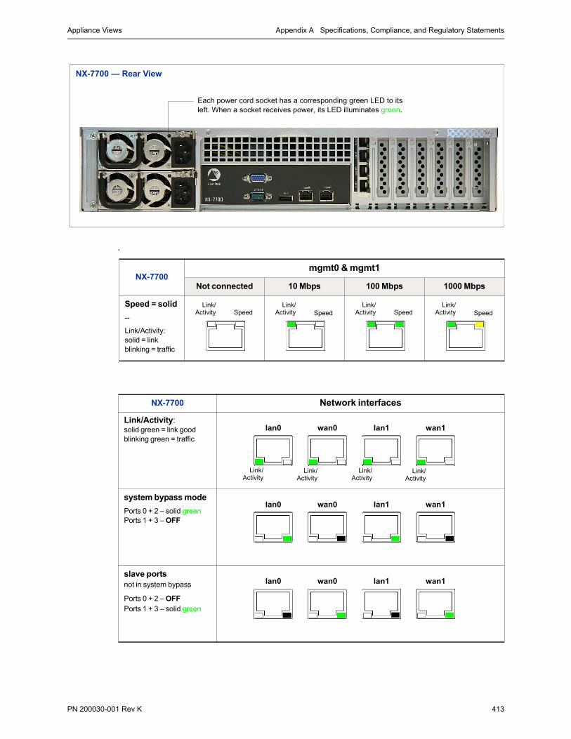
Appliance Views Appendix A Specifications, Compliance, and Regulatory Statements
PN 200030-001 Rev K 413
.
Each power cord socket has a corresponding green LED to its left. When a socket receives power, its LED illuminates green.
NX-7700 — Rear View
NX-7700mgmt0 & mgmt1
Not connected 10 Mbps 100 Mbps 1000 Mbps
Speed = solid
--
Link/Activity:solid = linkblinking = traffic
NX-7700 Network interfaces
Link/Activity:solid green = link goodblinking green = traffic
system bypass mode
Ports 0 + 2 – solid greenPorts 1 + 3 – OFF
slave portsnot in system bypass
Ports 0 + 2 – OFFPorts 1 + 3 – solid green
Link/Activity Speed
Link/Activity Speed
Link/Activity Speed
Link/Activity Speed
Link/Activity
lan0 wan0 lan1 wan1
Link/Activity
Link/Activity
Link/Activity
lan0 wan0 lan1 wan1
lan0 wan0 lan1 wan1
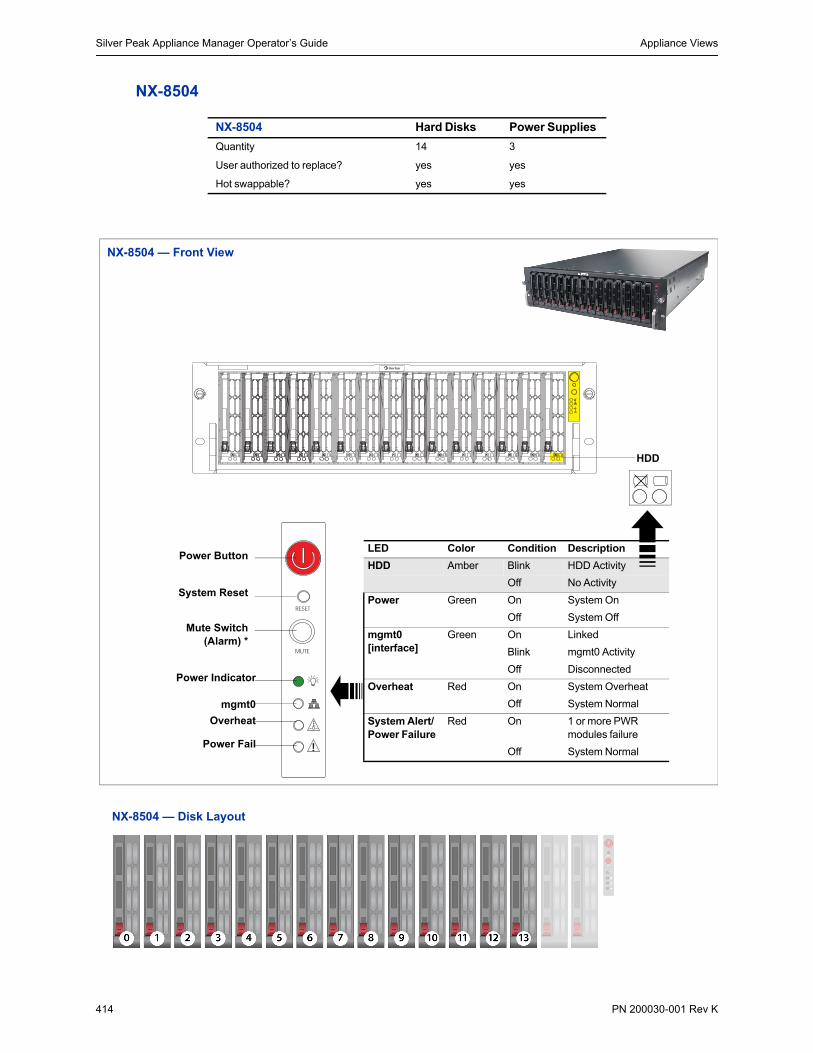
Silver Peak Appliance Manager Operator’s Guide Appliance Views
414 PN 200030-001 Rev K
NX-8504
NX-8504 Hard Disks Power Supplies
Quantity 14 3
User authorized to replace? yes yes
Hot swappable? yes yes
!
Power Button
System Reset
Power Indicator
mgmt0
Overheat
Power Fail
Mute Switch(Alarm) *
LED Color Condition Description
HDD Amber Blink HDD Activity
Off No Activity
Power Green On System On
Off System Off
mgmt0 [interface]
Green On Linked
Blink mgmt0 Activity
Off Disconnected
Overheat Red On System Overheat
Off System Normal
System Alert/Power Failure
Red On 1 or more PWR modules failure
Off System Normal
HDD
NX-8504 — Front View
NX-8504 — Disk Layout

Appliance Views Appendix A Specifications, Compliance, and Regulatory Statements
PN 200030-001 Rev K 415
NX-8504 — Rear View
Each power cord socket has a corresponding green Power LED to its right. When a socket receives power, its LED illuminates.
For redundancy, plug in all power cords, preferably to different sources.
If all power cords are not connected, an audible alarm sounds. To silence, make sure to plug in all power sources.
mgmt0 & mgmt1
Not connected
10 Mbps 100 Mbps 1000 Mbps Auto
NX-8504
Link = solid
--
Activity: blinking = traffic
Link: ON for 1000 Mbps and 100 Mbps only.
(All full duplex)
Link Activity Link Activity Link Activity Link Activity

Silver Peak Appliance Manager Operator’s Guide Appliance Views
416 PN 200030-001 Rev K
NX-8600
NX-8600 Hard Disks Power Supplies
Quantity 16 3
User authorized to replace? yes yes
Hot swappable? yes yes
Power LED [blue = ON]
NX-8600 — Front View
Not usedAlarm MuteSystem Reset
mgmt0 mgmt1Hard Disk Drive activity[Yellow = busy]
NX-8600 — Disk Layout
NX-8600 — Rear View

Appliance Views Appendix A Specifications, Compliance, and Regulatory Statements
PN 200030-001 Rev K 417
mgmt0 & mgmt1
Not connected
10 Mbps 100 Mbps 1000 Mbps Auto
NX-8600
Speed = solid
--
Link/Activity: blinking = traffic
Link/Activity Speed
Link/Activity Speed
Link/Activity Speed
Link/Activity Speed
Link/Activity Speed

Silver Peak Appliance Manager Operator’s Guide Appliance Views
418 PN 200030-001 Rev K
NX-8700
NX-8700 Hard Disks Power Supplies
Quantity 14 2
User authorized to replace? yes yes
Hot swappable? yes yes
NX-8700 — Front View
Power supply warning LED[red = 1 PS down or missing]
Alarm mute
Power LED [blue = on]
System reset
Power switch
blue = disk onNO LIGHT = OFF
DISK LEDs:green = disk activityred = error [no access to drive]
Solid-state disks
SATA hard disk drives
SATA hard disk drives
Note that the NX-9700 and NX-8700 appliances contain a mix of SATA hard disk drives and SSDs (solid-state drives).
NX-8700 — Disk Layout
The two NX-8700s differ only in the placement of the solid state drives.

Appliance Views Appendix A Specifications, Compliance, and Regulatory Statements
PN 200030-001 Rev K 419
Management interfaces
SATA hard disk drives
SATA hard disk drives
Note that the NX-9700 and NX-8700 appliances contain a mix of SATA hard disk drives and SSDs (solid-state drives).
Solid-state disks
NX-8700v — Disk Layout
auxiliary port
console [serial port]
VGA portPower Supply LEDsgreen = power on
management interfaces
copper network interfaces
10 Gbps fiber network interfaces
NX-8700 — Rear View
NX-8700mgmt0 & mgmt1
Not connected 10 Mbps 100 Mbps 1000 Mbps
Link/Activity:solid = linkblinking = traffic
--
Speed = solid
Link/Activity Speed
Link/Activity Speed
Link/Activity Speed
Link/Activity Speed

Silver Peak Appliance Manager Operator’s Guide Appliance Views
420 PN 200030-001 Rev K
Network interfaces
10 Gbps fiber interfaces
You have the option to separately order LR (Long Range) 10 Gbps Fiber Interfaces to replace the default SR (Short Reach) modules in the NX-8700 appliance.
Silver Peak supports different module combinations. For example, you may have an SR (Short Reach) interface for the LAN side and an LR (or long range) for the WAN.
These modules are hot-swappable.
NX-8700 Network interfaces
Link/Activity:solid green = link goodblinking green = traffic
system bypass mode
Ports 0 + 2 – solid greenPorts 1 + 3 – OFF
slave portsnot in system bypass
Ports 0 + 2 – OFFPorts 1 + 3 – solid green
NX-8700 tlan0 / twan0
all LEDs are green
Link = solid
Activity = blinking
Link/Activity
lan0 wan0 lan1 wan1
Link/Activity
Link/Activity
Link/Activity
lan0 wan0 lan1 wan1
lan0 wan0 lan1 wan1
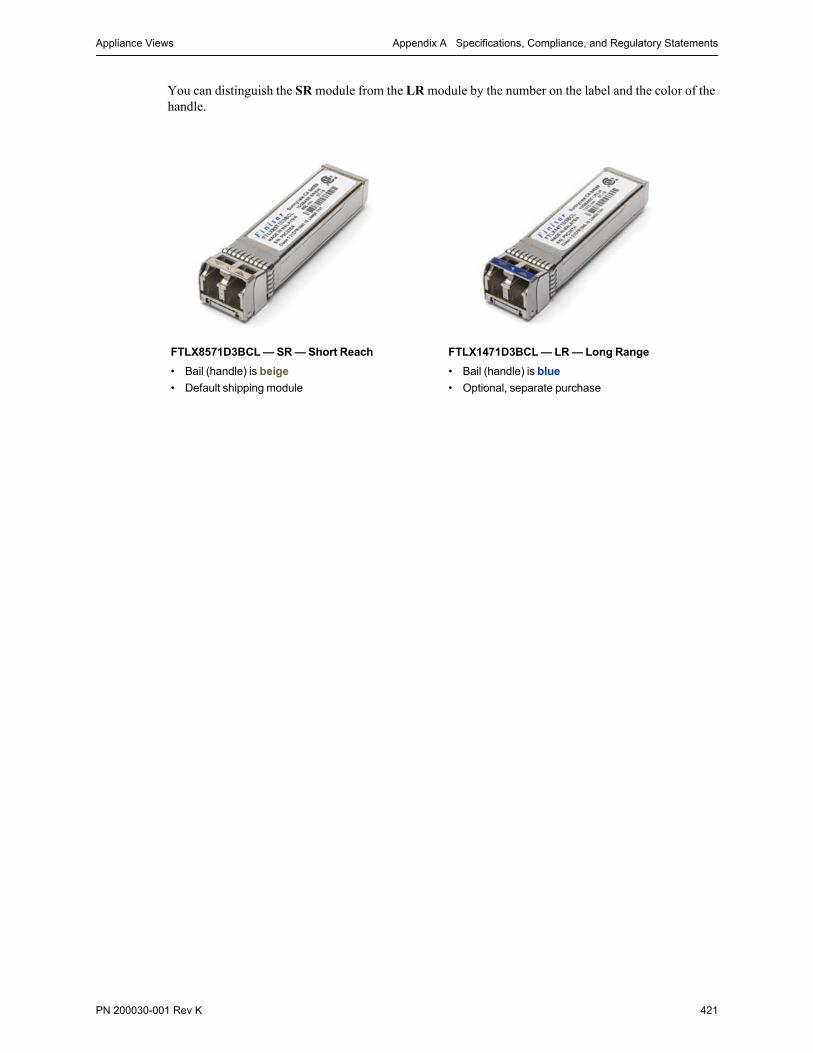
Appliance Views Appendix A Specifications, Compliance, and Regulatory Statements
PN 200030-001 Rev K 421
You can distinguish the SR module from the LR module by the number on the label and the color of the handle.
FTLX8571D3BCL — SR — Short Reach
• Bail (handle) is beige
• Default shipping module
FTLX1471D3BCL — LR — Long Range
• Bail (handle) is blue
• Optional, separate purchase

Silver Peak Appliance Manager Operator’s Guide Appliance Views
422 PN 200030-001 Rev K
NX-9610
NX-9610 Hard Disks Power Supplies
Quantity 16 3
User authorized to replace? yes yes
Hot swappable? yes yes
Power LED [blue = ON]
NX-9610 — Front Views
Not usedAlarm MuteSystem Reset
mgmt0 mgmt1Hard Disk Drive activity[Yellow = busy]
NX-9610 — Disk Layout
NX-9610 — Rear View 10 Gbps fiber network interfaces
1 Gbps fiber network interfaces

Appliance Views Appendix A Specifications, Compliance, and Regulatory Statements
PN 200030-001 Rev K 423
mgmt0 & mgmt1
Not connected
10 Mbps 100 Mbps 1000 Mbps Auto
NX-9610
Speed = solid
--
Link/Activity: blinking = traffic
Link/Activity Speed
Link/Activity Speed
Link/Activity Speed
Link/Activity Speed
Link/Activity Speed
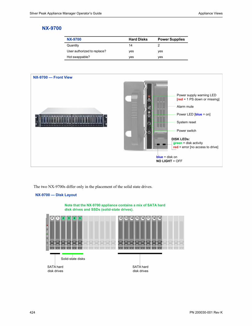
Silver Peak Appliance Manager Operator’s Guide Appliance Views
424 PN 200030-001 Rev K
NX-9700
NX-9700 Hard Disks Power Supplies
Quantity 14 2
User authorized to replace? yes yes
Hot swappable? yes yes
NX-9700 — Front View
Power supply warning LED[red = 1 PS down or missing]
Alarm mute
Power LED [blue = on]
System reset
Power switch
blue = disk onNO LIGHT = OFF
DISK LEDs:green = disk activityred = error [no access to drive]
Solid-state disks
SATA hard disk drives
SATA hard disk drives
Note that the NX-9700 appliance contains a mix of SATA hard disk drives and SSDs (solid-state drives).
NX-9700 — Disk Layout
The two NX-9700s differ only in the placement of the solid state drives.

Appliance Views Appendix A Specifications, Compliance, and Regulatory Statements
PN 200030-001 Rev K 425
Management interfaces
SATA hard disk drives
SATA hard disk drives
Note that the NX-9700 and NX-8700 appliances contain a mix of SATA hard disk drives and SSDs (solid-state drives).
Solid-state disks
NX-9700v — Disk Layout
auxiliary port
console [serial port]
VGA portPower Supply LEDsgreen = power on
management interfaces
1 Gbps fiber network interfaces
10 Gbps fiber network interfaces
NX-9700 — Rear View
NX-9700mgmt0 & mgmt1
Not connected 10 Mbps 100 Mbps 1000 Mbps
Link/Activity:solid = linkblinking = traffic
--
Speed = solid
Link/Activity Speed
Link/Activity Speed
Link/Activity Speed
Link/Activity Speed

Silver Peak Appliance Manager Operator’s Guide Appliance Views
426 PN 200030-001 Rev K
1 Gbps fiber interfaces
10 Gbps fiber interfaces
You have the option to separately order LR (Long Range) 10 Gbps Fiber Interfaces to replace the default SR (Short Reach) modules in the NX-9700 appliance.
Silver Peak supports different module combinations. For example, you may have an SR (Short Reach) interface for the LAN side and an LR (or long range) for the WAN.
These modules are hot-swappable.
NX-9700 lan0 / wan0 / lan1 / wan1
all LEDs are solid
NX-9700 tlan0 / twan0
all LEDs are green
Link = solid
Activity = blinking

Appliance Views Appendix A Specifications, Compliance, and Regulatory Statements
PN 200030-001 Rev K 427
You can distinguish the SR module from the LR module by the number on the label and the color of the handle.
FTLX8571D3BCL — SR — Short Reach
• Bail (handle) is beige
• Default shipping module
FTLX1471D3BCL — LR — Long Range
• Bail (handle) is blue
• Optional, separate purchase

Silver Peak Appliance Manager Operator’s Guide Appliance Views
428 PN 200030-001 Rev K
NX-10700
NX-10700 Hard Disks Power Supplies
Quantity 18 2
User authorized to replace? yes yes
Hot swappable? yes yes
NX-10700 — Front View
Power supply warning LED[red = 1 PS down or missing]
Alarm mute
Power LED [blue = on]
System reset
Power switch
blue = disk onNO LIGHT = OFF
DISK LEDs:green = disk activityred = error [no access to drive]
Solid-state disks
SATA hard disk drives
Note that the NX-10700 appliance contains a mix of SATA hard disk drives and SSDs (solid-state drives).
NX-10700 — Disk Layout

Appliance Views Appendix A Specifications, Compliance, and Regulatory Statements
PN 200030-001 Rev K 429
Management interfaces
10 Gbps fiber interfaces
You have the option to separately order LR (Long Range) 10 Gbps Fiber Interfaces to replace the default SR (Short Reach) modules in the NX-10700 appliance.
Silver Peak supports different module combinations. For example, you may have an SR (Short Reach) interface for the LAN side and an LR (or long range) for the WAN.
These modules are hot-swappable.
auxiliary port
console [serial port]
VGA portPower Supply LEDsgreen = power on
management interfaces
10 Gbps fiber network interfaces
NX-10700 — Rear View
NX-10700mgmt0 & mgmt1
Not connected 10 Mbps 100 Mbps 1000 Mbps
Link/Activity:solid = linkblinking = traffic
--
Speed = solid
NX-10700 tlan0 / twan0
all LEDs are green
Link = solid
Activity = blinking
Link/Activity Speed
Link/Activity Speed
Link/Activity Speed
Link/Activity Speed

Silver Peak Appliance Manager Operator’s Guide Appliance Views
430 PN 200030-001 Rev K
You can distinguish the SR module from the LR module by the number on the label and the color of the handle.
FTLX8571D3BCL — SR — Short Reach
• Bail (handle) is beige
• Default shipping module
FTLX1471D3BCL — LR — Long Range
• Bail (handle) is blue
• Optional, separate purchase

PN 200030-001 Rev K 431
A P P E N D I X B
Power Cords & Cable Pinouts
This appendix lists and illustrates power cords, by country, and cable pinouts.
In This Appendix Power Cords by Country See page 432.
Fiber Connectors See page 435.
Cable Pinouts See page 436.
Configuring DB-9 Console Access to the Appliance See page 437.

Silver Peak Appliance Manager Operator’s Guide Power Cords by Country
432 PN 200030-001 Rev K
Power Cords by CountryThis section includes country-specific power cord plug and receptacle specifications for the Silver Peak appliances.
Table 2-1 Power Cord Specifics by Country
COUNTRY APPROVALS POWER CORD P/N
Rating PLUG RECEPTACLE
Argentina IRAM 9000.098 10A / 250V IRM 2073: 1982 Argentina Plug
IEC-60320_C13
Australia SAA 8530.098 10A / 250V AS 3112, Australia Plug IEC-60320_C13
China CCC 8590.098 10A / 250V GB2099, China Plug IEC-60320_C13
Continental Europe VDE, KEMA, CEVEC, NEMKO, DEMKO, SETI, OVE, SEV
8500.098 10A / 250V CEE 7/7 Europe Plug “Schuko” CE
IEC-60320_C13
Denmark DEMKO 8540.098 10A / 250V SRAF 1962/DB 16/87, Danish Plug
IEC-60320_C13
India / South Africa SABS, VDE 8580.098 10A / 250V BS 546, Indian Plug IEC-60320_C13
Israel SII 8560.098 10A / 250V SI32, Israeli Plug IEC-60320_C13
Italy IMQ 8550.098 10A / 250V CEU -23-16m, Italian Plug
IEC-60320_C13
Japan PSE 2000.098 10A / 125V JIS 8303, Japanese Plug
IEC-60320_C13
Korea KETI 8704.098 10A / 250V KSC 8305, Korean Plug IEC-60320_C13
North America UL, CSA 2500.072 10A / 125V NEMA 5-15P IEC-60320_C13
Switzerland SEV 8520.098 10A / 250V SEV 1011, Swiss Plug IEC-60320_C13
United Kingdom / Ireland
BSI 9650.098 10A / 250V BS 1363, U.K. Plug IEC-60320_C13
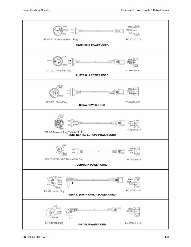
Power Cords by Country Appendix B Power Cords & Cable Pinouts
PN 200030-001 Rev K 433
ARGENTINA POWER CORD
AUSTRALIA POWER CORD
CHINA POWER CORD
CONTINENTAL EUROPE POWER CORD
DENMARK POWER CORD
INDIA & SOUTH AFRICA POWER CORD
ISRAEL POWER CORD

Silver Peak Appliance Manager Operator’s Guide Power Cords by Country
434 PN 200030-001 Rev K
ITALY POWER CORD
JAPAN POWER CORD
KOREA POWER CORD
NORTH AMERICA POWER CORD
SWITZERLAND POWER CORD
UNITED KINGDOM & IRELAND POWER CORD

Fiber Connectors Appendix B Power Cords & Cable Pinouts
PN 200030-001 Rev K 435
Fiber ConnectorsFiber modules accept the following fiber cable:
multimode duplex Fibre Channel optic LC/LC patch cable

Silver Peak Appliance Manager Operator’s Guide Cable Pinouts
436 PN 200030-001 Rev K
Cable PinoutsFollowing is the pinout for the console (RS-232 serial) port, which uses a null modem cable.

Configuring DB-9 Console Access to the Appliance Appendix B Power Cords & Cable Pinouts
PN 200030-001 Rev K 437
Configuring DB-9 Console Access to the ApplianceFor console port access, the appropriate settings are as follows:
Bits per second 9600
Data bits 8
Parity none
Stop bits 1
Flow control none

Silver Peak Appliance Manager Operator’s Guide Configuring DB-9 Console Access to the Appliance
438 PN 200030-001 Rev K

PN 200030-001 Rev K 439
A P P E N D I X C
Glossary
802.1q encapsulation. Also known as VLAN tagging. An IEEE standard (and process) which allows multiple bridged networks to transparently share the same physical network link without leakage of information between networks and, in common usage, the name of the encapsulation protocol used to implement this mechanism over Ethernet networks.
ACL. Access Control List.
ARP. Address Resolution Protocol. An IP protocol for finding a host’s link layer (hardware) address when only its Internet Layer or some other Network Layer address is known.
asymmetric routing. When new writes can be made without having to wait for the secondary or remote storage site to also finish its writes.
asynchronous replication. A type of disk storage replication, where write is considered complete as soon as local storage acknowledges it. Remote storage is updated, but probably with a small lag. Performance is greatly increased, but in case of losing a local storage, the remote storage is not guaranteed to have the current copy of data and most recent data may be lost.
authentication. The process of validating the claimed identity of an end user or a device wuch as a host, server, switch, router, etc.
authorization. The act of granting access rights to a user, groups of users, system, or program.
auto discovery. Within the NX Series appliances, the ability of an appliance to discover and register with the Global Management System (GMS) server when first deployed.
auto-negotiation. The process by which terminating devices automatically negotiate for maximum bandwidth.
bandwidth. A rate of data transfer, throughput, or bit rate, measured in bits per second.
bit. A binary digit, taking a logical value of either "1" or "0" (also referred to as "true" or "false" respectively). It is also a unit of measurement, the information capacity of one binary digit.
blan0. When configuring for gigabit etherchannel bonding, lan0 plus lan1 bond to form blan0, which uses the lan0 IP address.
Bridge mode. In-line deployment of an appliance, placing it between an Ethernet LAN switch and a WAN edge router.

Silver Peak Appliance Manager Operator’s Guide
440 PN 200030-001 Rev K
bwan0. When configuring for gigabit etherchannel bonding, wan0 plus wan1 bond to form the virtual interface, bwan0, which uses the wan0 IP address.
bypass. Refers to hardware bypass. If there is a major problem with the appliance hardware, software, or power, all traffic goes through the appliance without any processing. Additionally, you can manually put the appliance into Bypass as an aid to troubleshooting.
chattiness. A common problem with naively designed application protocols is that they are too “chatty”. That is, they imply too many “round-trip” cycles.
CIFS. Common Internet File System. CIFS is the remote file system access protocol used by Windows servers and clients to share files across the network. Some specific capabilities of CIFS include file access, record locking, read/write privileges, change notification, server name resolution, request batching, and server authentication
CIFS acceleration. A set of techniques for mitigating the impacts of latency across the WAN. They include read-aheads and write-behinds to pipeline CIFS requests and the respective acknowledgements. This dramatically minimizes roundtrip delays when using CIFS over a WAN.
CLI. See Command Line Interface.
client. An application or system that accesses a remote service on another computer system, known as a server, by way of a network.
Command Line Interface. A method of configuring the appliance by typing in commands via the local serial interface or remote SSH session. [Peribit]
CoS. Class of Service (CoS) is a way of managing traffic in a network by grouping similar types of traffic (for example, e-mail, streaming video, voice, large document file transfer) together and treating each type as a class with its own level of service priority. Unlike Quality of Service (QoS) traffic management, Class of Service technologies do not guarantee a level of service in terms of bandwidth and delivery time; they offer a "best-effort." On the other hand, CoS technology is simpler to manage and more scalable as a network grows in structure and traffic volume. One can think of CoS as "coarsely-grained" traffic control and QoS as "finely-grained" traffic control.
crossflow compression. A technique that applies compression across various flows of traffic.
data streaming. The transfer of data at a steady high-speed rate sufficient to support such applications as high-definition television (HDTV) or the continuous backup copying to a storage medium of the data flow within a computer. Data streaming requires some combination of bandwidth sufficiency and, for real-time human perception of the data, the ability to make sure that enough data is being continuously received without any noticeable time lag.
datagram. An independent, self-contained message sent over the network whose arrival, arrival time, and content are not guaranteed.
default gateway. A gateway is a router on a computer network, serving as an access point to another network.
DHCP. Dynamic Host Configuration Protocol. A TCP/IP protocol that enables PCs and workstations to automatically get temporary or permanent IP addresses (out of a pool) from centrally administered servers.
DNS. Domain Naming System or Domain Name Server. It serves as the "phone book" for the Internet by translating human-friendly computer hostnames into IP addresses.

Appendix C Glossary
PN 200030-001 Rev K 441
DSCP. Differentiated Services Code Point. A 6-bit value that encoudes Per-Hop Behavior (PHB) into the 8-bit Differentiated Services (DS) field of the IP packet header. The DS field is the same as the TOS (Type of Service) field.
domain. The main purpose of a domain name is to provide a recognizable names to mostly numerically addressed Internet resources. This abstraction allows any resource (for example, website) to be moved to a different physical location in the address topology of the network, globally or locally in an intranet, in effect changing the IP address.
failover. The capability to switch over automatically to a redundant or standby computer server, system, or network upon the failure or abnormal termination of the previously active server, system, or network. Failover happens without human intervention and generally without warning, unlike switchover.
FEC. Forward Error Correction. When Adaptive Forward Error Correction (FEC) is enabled, the appliance introduces a parity packet, which helps detect and correct single-packet loss within a stream of packets, reducing the need for retransmissions. Silver Peak dynamically adjusts how often this parity packet is introduced in response to changing link conditions. This maximizes error correction while minimizing overhead.
flow. In a packet switching network, packet flow or traffic flow is a sequence of packets from a source computer to a destination, which may be another host, a multicast group, or a broadcast domain. As packets traverse successive communication links towards their destination, the packets from one flow (for example, A1, A2, A3) will be intermingled with packets from other flows also traversing the network to form a multiplexed stream (for example, A1, B7, C9, A2, C10, A3). This represents a form of statistical multiplexing because the link is shared as required.
FTP. File Transfer Protocol. A network protocol used to exchange and manipulate files over a TCP computer network, such as the Internet. An FTP client may connect to an FTP server to manipulate files on that server.
full duplex. Bidirectional, simultaneous two-way communications.
gateway. Also called protocol converters, can operate at any layer of the OSI model. The job of a gateway is much more complex than that of a router or switch. Typically, a gateway must convert one protocol stack into another.
GMS. Global Management System.
GRE. Generic Routing Encapsulation. Tunneling protocol developed by Cisco that can encapsulate a wide variety of protocol packet types inside IP tunnels, creating a virtual point-to-point link to Cisco routers at remote points over an IP internetwork.
GUI. Graphical User Interface.
half duplex. A circuit designed for data transmission in both directions, but not at the same time.
hardware bypass. If there is a major problem with the appliance hardware, software, or power, all traffic goes through the appliance without any processing. Additionally, you can manually put the appliance into Bypass as an aid to troubleshooting.
header compression. This technique can provide additional bandwidth gains by reducing packet header information using specialized compression algorithms.
high availability. For maximizing uptime, deploying NX appliances redundantly in 1+1 or N+1 configurations, with failover and load balancing.

Silver Peak Appliance Manager Operator’s Guide
442 PN 200030-001 Rev K
host. In computer networking, a network host, Internet host or host is a computer connected to the Internet. A network host can host information as well as client and/or server software.
host address. The host address, or more properly the host id portion of an IP address is the portion of the address used to identify hosts (which can be any device requiring a Network Interface Card, such a personal computer or networked printer) on the network.
HTTP. HyperText Transfer Protocol. The protocol web browsers use to communicated with web servers.
HTTPS. HyperText Transfer Protocol Secure. A combination of the HyperText Transfer Protocol and a cryptographic protocol, for accessing a secure web server.
ICMP. Internet Control Message Protocol. An internet protocol used by networked computers’ operating systems to manage errors and generate control messages.
Internet. A global network of interconnected computers, enabling users to share information along multiple channels.
IP. Internet Protocol. Network layer protocol in the TCP/IP stack that enables a connectionless internetwork service.
IP Address. An Internet Protocol (IP) address is a numerical identification and logical address that is assigned to devices participating in a computer network utilizing the Internet Protocol for communication between its nodes.
IPsec. Internet Protocol Security Protocol.
IP VPN. Internet Virtual Private Network.
LAN. Local Area Network.
LAN Rx. Traffic received from the LAN.
LAN Tx. Traffic transmitted to the LAN.
latency. A time delay between the moment something is initiated, and the moment one of its effects begins or becomes detectable. Network latency is the time it takes for information to go from a sender to a receiver and back.
load balancing. A technique to spread work between two or more computers, network links, CPUs, hard drives, or other resources, in order to get optimal resource utilization, maximize throughput, and minimize response time. Using multiple components with load balancing, instead of a single component, may increase reliability through redundancy. The balancing service is usually provided by a dedicated program or hardware device.
lossy. A WAN prone to dropped and out-of-order packets. This is most common on shared networks, like MPLS and Internet VPNs.
MAPI. Messaging Application Programming Interface. A Microsoft Windows program interface that enables you to send e-mail from within a Windows application and attach the document you are working on to the e-mail note. Applications that take advantage of MAPI include word processors, spreadsheets, and graphics applications.
MIB. Management Information Base. A type of database for managing devices in a communications network.

Appendix C Glossary
PN 200030-001 Rev K 443
Microsoft Exchange. Messaging and groupware software for Windows from Microsoft. The Exchange server is an Internet-compliant messaging system that runs under Windows systems and can be accessed by web browsers, the Windows In-box, Exchange client or Outlook. The Exchange server also stores files for sharing.
MPLS. MultiProtocol Label Switching is an IETF initiative that integrates Layer 2 information into Layer 3 (IP) packets.
MTU. Maximum Transmission Unit. The largest size packet that a device can transmit on a network.
Network Acceleration. Addresses high WAN latency and TCP chattiness. This is achieved using standard TCP acceleration techniques, such as adjustable windows and selective acknowledgements.
Network Integrity. Protects traffic from collateral congestion in a shared service provider network by mitigating the impact of dropped and out-of-order packets.
Network Memory™. Addresses limited bandwidth. This technology uses advanced fingerprinting algorithms to examine all incoming and outgoing WAN traffic. Network Memory localizes information and transmits only modifications between locations.
NFS. Network File System. The file sharing protocol in a UNIX network.
OOO. Out-of-Order [packets]
out-of-path. Same as Router mode. In an out-of-path deployment, policy-based routing (PBR), VRRP, or WCCP redirect the traffic to the Silver Peak appliance for processing.
packet coalescing. When packets are small, packet headers consume substantial bandwidth in comparison to the amount of end-user data transferred. Packet coalescing combines multiple user packets traveling between the same two sites into a single coalesced packet. Used in conjunction with header compression, this amortizes a single header over multiple packets thus decreasing overhead, and therefore bandwidth requirements. Packet coalescing is particularly beneficial for web applications, VoIP, and interactive applications, like Citrix.
pass-through traffic. Traffic that is sent to the WAN without being optimized.
payload compression. Uses algorithms to identify relatively short byte sequences that are repeated frequently over time. These sequences are then replaced with shorter segments of code to reduce the size of transmitted data. Simple algorithms can find repeated bytes within a single packet; more sophisticated algorithms can find duplication across packets and even across flows
PBR. Policy-based routing is a technique used to make routing decisions based on policies set by the network administrator.
Propagate Link Down. Forces the WAN interface to go down when the corresponding LAN interface goes down, or vice versa. By default, this option is enabled on the Configuration - System page.
ping. A programs used to test whether a particular network destination is online, by sending an Internet Control Message Protocol (ICMP) echo request and waiting for a response. [Peribit]
POC. Packet Order Correction. To avoid retransmissions that occur when packets arrive out of order, Silver Peak NX appliances use Packet Order Correction (POC) to resequence packets on the far end of a WAN link, as needed.
QoS. Quality of Service is the ability to provide different priority to different applications, users, or data flows, or to guarantee a certain level of performance to a data flow. QoS involves several functions: 1) classification of packets into traffic classes based on characteristics such as source, destination addresses,

Silver Peak Appliance Manager Operator’s Guide
444 PN 200030-001 Rev K
and/or applications and 2) queuing and service mechanisms that are used to apply service policies based on these classifications, including bandwidth allocation.
RADIUS. Remote Authentication Dial In User Service (RADIUS) is a networking protocol that provides centralized Authentication, Authorization and Accounting (AAA) management for computers to connect and use a network service. It is a client/server protocol that uses UDP as transport.
Router mode. Out-of-path deployment, where data traffic is redirected by using policy-based routing (PBR), Web Cache Coordination Protocol (WCCP), or Virtual Router Redundancy Protocol (VRRP).
RTT. Round-trip time. the time it takes to send a packet to a remote host and receive a response; used to measure delay on a network at a given time. [Peribit]
SMB. Server Message Block. An application-level network protocol mainly used to provide shared access to files, printers, serial ports, and miscellaneous communications between nodes on a network.
SMB2. Server Message Block, version 2.
SMTP. Simple Mail Transfer Protocol. A de facto standard for electronic mail (e-mail) transmissions across the Internet.
SNMP. Simple Network Management Protocol. A standard TCP/IP protocol for network management. Network administrators use SNMP to monitor network devices, performance, and security, and to manage configurations and collect statistics.
SSL. Secure Socket Layer. These are cryptographic protocols that provide secure communications for such things web browsing, email, and other data transfers over the internet.
subnet. A portion of a network that shares a common address component. On TCP/IP networks, subnets are defined as all devices whose IP addresses have the same prefix. For example, all devices with IP addresses that start with 100.100.100. would be part of the same subnet. Dividing a network into subnets is useful for both security and performance reasons. IP networks are divided using a subnet mask.
switch. A network device that filters and forwards frames based on the destination address of each frame. The switch operates at Layer-2 (data link layer) of the Open System Interconnection (OSI) model.
TACACS+. Terminal Access Controller Access-Control System Plus is a protocol which provides access control for routers, network access servers and other networked computing devices via one or more centralized servers. TACACS+ provides separate authentication, authorization and accounting services. It uses TCP for its transport. Transactions between the TACACS+ client and TACACS+ servers are also authenticated through the use of a shared secret.
TCP. Transmission Control Protocol. The error-correcting Transport layer (Layer-4) in the TCP/IP protocol suite. It ensures that all data arrive at the other end accurately and completely intact.
TCP acceleration. A set of techniques for mitigating the impacts of latency across the WAN. They include adjustable window sizing and selective acknowledgements.
TCP/IP. Transmission Control Protocol/Internet Protocol. A protocol suite for communication between computers, used as a standard for transmitting data over networks and as the basis for standard Internet protocols.
Telnet. A terminal emulation protocol used on the Internet and TCP/IP-based networks. A Telnet program allows a user at a terminal or PC to log in to a remote computer and run a program and execute other Unix commands.
throughput. The average rate of successful message delivery over a communication channel.

Appendix C Glossary
PN 200030-001 Rev K 445
tunneling. Encapsulating one type of network protocol (called the payload protocol) within a different delivery protocol. Reasons to use tunneling include carrying a payload over an incompatible delivery network, or to provide a secure path through an untrusted network.
UDP. User Datagram Protocol. Part of the TCP/IP protocol suite, it was created to provide a way for applications to access the connectionless features of IP. UDP provides for exchange of datagrams without acknowledgements or guaranteed delivery.
VLAN. Virtual Local Area Network. A means by which LAN users on different physical LAN segments are afforded priority access privileges across the LAN backbone so that they appear to be on the same physical segment of an enterprise-level logical LAN.
VLAN tag. See 802.1q encapsulation.
VoIP. Voice-Over-Internet-Protocol. A protocol optimized for the transmission of voice through the Internet or other packet-switched networks.
VRRP. Virtual Router Redundancy Protocol is a standard redundancy protocol designed to increase the availability of servicing hosts on the same subnet.
WAN. Wide Area Network
WAN Rx. Traffic received from the WAN.
WAN Tx. Traffic transmitted to the WAN.
WCCP. Web Cache Communications Protocol. A Cisco-developed content-routing protocol that provides a mechanism to redirect traffic flows in real-time. It has built-in load balancing, scaling, fault tolerance, and service-assurance (failsafe) mechanisms.
X.11. An application redirect protocol; a distributed window system that is based on the client/server model.

Silver Peak Appliance Manager Operator’s Guide
446 PN 200030-001 Rev K

Index
PN 200030-001 Rev K 447
Index
Numerics
10G interfaces 57
1G interfaces 57
802.1q trunked linksSee VLANs
A
Access Control Lists 98–107application groups in 121
as reusable MATCH criteria 94
characteristics of 98
creating 99–101
how they filter traffic 108–109
modifying an ACL rule 102
removing an ACL 104–107
removing an ACL rule 103
ACLsSee Access Control Lists
Alarm Log Viewer 274
alarmsclearing 362
current 362
viewing 370–371
handling of 372
list of types and text 363–369
severity levels 362
appliance configuration fileSee configuration file
Appliance Manageraccessing 38
Home - Summary page 40–42
log in 39
menu structure
Administration menus 47–48
Alarm menus 49
Configuration menus 42–44
Maintenance menus 48
Monitoring menus 45–47
system requirements 38
tables, managing 49
application groupscreating 121–122
modifying 123
properties of 121
removing from the database 124
using in MATCH criteria 121
applicationsbuilt-in
list of 110–115
viewing 116
custom, defining and creating 117–120
statistics 217–218
asymmetric networks or flowsSee flow redirection
Audit Log 275
authentication and authorization 10, 295, 296
authorization 295for SNMP v3 user 289
Auto Optimization 56, 127, 128non-TCP initiation 132
SET actions diagram 134
TCP, Bridge mode handshaking 129
TCP, Router mode handshaking 130
Auto Reset TCP Flows 56, 57, 131
Auto Tunnel 56, 78, 79
B
bandwidthdynamic chart 252
statistics 212, 243–244, 252
bandwidth managementauto bandwidth 157
best practices 152–155
Configuration pages for 155
configuring minimum and maximum values 153–154
maximum system bandwidth, determining 156
for multiple tunnels 152
multiple traffic classes 152
for pass-through traffic 158
bandwidth shaping 78See also Configuration - Tunnels
page
banners
login message 312
Message of the Day 312
bitmasks 50
blan0 See etherchannel bonding
bridge mode2-port bridge 12, 58
4-port 14–16
4-port bonding 58
4-port, flat 58
4-port, standard 58
statistics 213
bwan0 See etherchannel bonding
bypassSee System Bypass
C
cabling 32
CIFS Acceleration 181, 182disabled in Tunnel Compatibility
Mode 88
cluster interface 198, 201
configurationcabling 32
Initial Configuration Wizard 35–36, 314–315
saving the running configuration 53
system settings 56, 57
configuration filedownloading 339, 340
from a URL 342
from an FTP server 344
from an SCP server 343
fron a local disk 341
saving 334, 335
to a local disk 336
to an FTP server 338
to an SCP server 337
viewing
last saved version 332
the running config file 333
current flows

Silver Peak Appliance Manager Operator’s Guide
448 PN 200030-001 Rev K
customizing which columns display 221, 222
details of 225, 226–230
filter for specific results 223–225
orange background 224
pink background 224
reduced tunnel functionality 224
resetting for improved performance 233
resetting the default display 222
selecting filters 220
stale connection 224
statistics 212, 219–233
unaccelerated TCP 233
See also flows
D
datapath connectivity 74, 266
date and timeconventions 52
Debug Dump 276, 277
debug filesDebug Dump 276, 277
deleting 282
Log 276, 277
saving to
a local PC 279
a remote server 278
an FTP server 281
an SCP server 280
Show Tech 276, 277
Snapshot 276, 277
TCP Dump Result 276, 277
types of 276
See also logs
debugging 182
deploymentInitial Configuration Wizard
314–315
deployment options 11, 58–60in-line
Bridge mode - four ports 14–16
Bridge mode - two ports 12
out-of-path 17–23
out-of-path with Policy-Based Routing (PBR) Redirection 18
out-of-path with Policy-Based-Routing (PBR) and VRRP redundant Silver Peak appliances 21
out-of-path with VRRP peering to WAN router 20
out-of-path with Web Cache Communications Protocol (WCCP) 19
out-of-path with Web Cache Communications Protocol (WCCP) redundant Silver Peak appliances 22
DNS server, adding 75
DSCP markings 148, 149apply to
pass-through traffic 165–167
applying to
optimized traffic 162–164
definitions list 167–168
dynamic charts 250–258
E
encapsulation 78
encryptionfor SNMP v3 user 289
hard disk 319
etherchannel bonding 56configuring 61
gigabit, for 4-port devices 57, 61
Ethernet portsSee etherchannel bonding
Events Log 273
F
FECSee Forward Error Correction
field definitions 53
flow counts 240dynamic chart 255
statistics 212, 245–246, 255
TCP and non-TCP 239
See also current flows
flow exports, for NetFlow 76
flow redirectionasymmetric networks and flows 194
configuration example 197–201
for LAN-initiated traffic 196
for removing asymmetry 194
reporting 202
statistics 213, 260–261
for WAN-initiated traffic 195
flows, processing of 90
Forward Error Correctiondynamic chart 257
statistics 213, 239, 240, 248–249, 257
in Tunnel Compatibility Mode 88
FTP server capability in appliance 283
H
hardware bypass modeSee System Bypass
hardware componentsNX-1700 3NX-2500 3NX-2600 3NX-2610 3NX-2700 4NX-3500 4NX-3600 4NX-3700 4NX-5500 4NX-5600 5NX-5700 5NX-7500 5NX-7600 5NX-7700 5NX-8500 6NX-8600 6NX-8700 6NX-9610 6NX-9700 6NX-10700 7
hardware installation tasks 26
help icons 53
Hostnamemodifying 57
See also Initial Config Wizard
I
inbound traffic 214, 238
Initial Configuration Wizard 35–36, 314–315
interfaces1G and 10G 57
configuring from table 68
manually configuring for DHCP 66
statistics 213, 263–264
IP routesdatapath connectivity 74
removing a LAN route from the routing table 74
static routes for management traffic 70

Index
PN 200030-001 Rev K 449
statistics 213, 266
unreachable 74
IP routes, configuringdefault gateways for management
interfaces 69
default LAN-side gateway 74
next-hop address(es) for LAN-side networks 69, 73
WAN next-hop address(es) 69
L
latency 240dynamic chart 256
statistics 213, 239, 247
LEDsSee also power, connecting and
verifying
verifying connectivity 32
log settingsconfiguring parameters for event
and alarm logs 268
local logging 270
minimum severity level 268, 272
remote syslog server 271
login message banner 312
logsAlarm Log Viewer 274
Audit Log 275
deleting files 282
Event Log Viewer 273
lossdynamic chart 257
M
management interface, configuringnext-hop IP address 71
static routes 70
management methods 10
management routeremoving from the routing table 72
MATCH criteria 128, 1345-tuple 90
application groups in 121
basis of 90
configuring 93
how they filter traffic 108–109
specifying applications and protocols in 95–97
understanding 92–97
using ACLs to summarize 94
Max System Bandwidthconfiguring 56
See also bandwidth management, best practices
Message of the Day 312
MIBs, list of standard and proprietary 285
minimum severity level 268modifying the remote receiver 272
N
naming objects 52
NetFlowconfiguring flow exports for 76
statistics 213, 262
netmask notation 50table of 50
Network Accelerationdescription of 9
network connectivity, testing 345–347See also ping, traceroute, and
tcpdump
Network Integrity 240description of 9statistics 213, 248–249
Network Memory 182available settings 181
benefit scenarios 180
definition 180
description of 9disabled in Tunnel Compatibility
Mode 88
erasing 358
hard disk encryption 319
pre-positioning data into 283, 284
See also Optimization policies
networking parametersrelated menus 65
next-hops, list of 213, 266
NTP server, configuring 63–64
NX-10700configuring 10G 57
NX-8700configuring 1G or 10G 57
NX-9610configuring 1G or 10G 57
NX-9700configuring 1G or 10G 57
O
CIFS AccelerationSee also Optimization policies 181
Optimization policies 90, 91, 134, 135, 180–192activating a new policy 192
adding a new Optimization map 188–190
adding an entry to a map 185–186
Configuration page organization 184
default behaviors 91
deleting an entry 188
deleting an inactive map 191
editing an active entry 187
when the appliance can apply them 184
Payload CompressionSee also Optimization policies 181
TCP AccelerationSee also Optimization policies 181
optimized traffic flowsprocessing of 90
outbound traffic 214, 238
Out-of-Order Packets (OOP)dynamic chart 258
See Packet Order Correction
P
packet coalescingin Tunnel Compatibility Mode 88
Packet Order Correctionstatistics 213, 239, 240, 248–249
in Tunnel Compatibility Mode 88
packets per seconddynamic chart 254
pass-through trafficapplying DSCP markings 165–167
configuring bandwidth limits 158
passwordfor SNMP v3 user 289
guidelines for creating 52
guidelines for user accounts 290
Payload Compression 181, 182disabled 88
ping 346, 348–349
POCSee Packet Order Correction
power, connecting and verifying 387–430
pre-positioning data 283, 284

Silver Peak Appliance Manager Operator’s Guide
450 PN 200030-001 Rev K
Propagate Link Down 56, 57
Q
QoS policies 90, 147–177activating a new policy 177
adding a new QoS map 174–175
adding an entry to a map 170–171
Configuration page organization 169
default behavior 148
default behaviors 91
deleting an entry 173
deleting an inactive map 176
editing an entry 172
effective use of 148
QoS shaping and marking 88
QoS statisticstunnel 212, 234–235
R
RADIUS 295configuration 297–298
example, integrating NX appliance into network 299–303
reboot clean 359
rebooting the appliance 359
reductiondynamic chart 253
statistics 212, 241–242, 253
Reorder Wait Time 240
restarting the appliance 359
Route policies 90, 127–146activating a new policy 146
adding a new Route map 143–145
adding an entry to a map 140–141
auto optimization 128–132
Configuration page organization 139
default behaviors 91
deleting an entry 143
deleting an inactive map 146
editing an active entry 142
where to direct flows 133–138
router modedual-homed 59
dual-homed bonding 59
Out-of-Path with Policy-Based Routing (PBR) redirection 18
Out-of-Path with Policy-Based-Routing (PBR)
and VRRP redundant Silver Peak appliances 21
Out-of-Path with VRRP peering to WAN router 20
Out-of-Path with Web Cache Communications Protocol (WCCP) 19
Out-of-Path with Web Cache Communications Protocol (WCCP) redundant Silver Peak appliances 22
standard 59
standard bonding 59
running configuration 53
S
Save 125
server virtualization 7session idle time-out 296
SET actions 90, 91, 92, 93, 98, 100, 108in Optimization policies 180, 182,
184
in QoS policies 148–151, 169
in Route policies 128, 133–138, 139
Show Tech 276, 277
shutdown 359
site preparation 26–29
slash notation 50
Snapshot 276, 277
SNMPadding an SNMP v3 user 289
configuring SNMP settings 286
loading SNMP MIBs 285
trap receiver
adding 287
modifying 288
removing 288
software managementinstalling a software image
from a URL 325
from an FTP server 328, 329
from an SCP server 326, 327
from the local disk 324
into a partition 323
options 320–323
switching partitions 330
software versionlisted 318
statisticIP routes 266
statisticsabout viewing 214–216
applications 217–218
bandwidth 212, 243–244, 252
bridge mode 213
counters
clearing non-destructively 215
view since reboot 214
current flows 212, 219–233
Delta Stats 215
flow counts 212, 245–246, 255
flow redirection 213, 260–261
Forward Error Correction 213, 248–249, 257
interfaces 213, 263–264
IP routes 213
latency 213, 247
NetFlow 213, 262
Network Integrity 213, 248–249
Packet Order Correction 213, 248–249
reduction 212, 241–242, 253
refreshing 215
tunnel 236–240
tunnel QoS 212, 234–235
Support, contacting 316
syslog serverSee log settings
System Bypass 56, 57, 80, 318
system configuration settingsdate and time 62
NTP server, configuring 63–64
system deploymentSee deployment
system information, displayed 318
system requirements for Appliance Manager 38
system settingsconfigure 56, 57
T
TACACS+ 295configuration 304–305
example, configuring server to authenticate NX appliance users 305–311
TCP Acceleration 181, 182disabled 88
TCP flowsSee flow counts
asymmetric

Index
PN 200030-001 Rev K 451
See flow redirection
tcpdump 276, 277, 347, 352–355retrieving results 356–357
Technical Support, contacting 316
timestamp 52
tlan0 57
traceroute 347, 350–351
trafficdirection of flows 214
inbound 214
outbound 214
processing flows with policies 90
traffic classesconfiguring for tunnels and
pass-through traffic 159–161
defaults 148
for optimized flows 149
shaped pass-through traffic 150
tunnels 149
tunnelcharacteristics 78
deleting a 87
diagram of directing flows to 133–134
editing a 85, 86
encapsulation 88
manually creating a 80–84
parameters
FEC 85, 86, 88
POC 88
Pre Shared Key 86
Reorder Wait 86
QoS shaping and marking 88
QoS statistics 212, 234–235
reduced functionality, indicating 88
states, list of 84
statistics 236–240
traffic
how Route Policies affect 78
Tunnel Compatibility Mode 88
disabled optimizations 88
preserved functionalities 88
U
uptime, of appliance 318
user access management 10
user accountsaccessing 291
admin and monitor privileges 292
authentication and authorization 295, 296
built-in user database 291, 295
creating 292
deleting 294
modifying 293
password guidelines 290
session idle time-out 296
V
virtual appliances 3, 7VLANs 204–210
configuring a VLAN IP interface 205
in Current Flows Details 228
setting tags in outgoing WAN-side packets 206
2-port Bridge 207
4-port Bridge 208
bonded 4-port Bridge 210
flat 4-port Bridge 209
tags 90
why create a VLAN IP interface 204
VX appliances 3, 7
W
WAN interfacemodifying total bandwidth 56, 57
webprotocol settings 313
user settings 313

Silver Peak Appliance Manager Operator’s Guide
452 PN 200030-001 Rev K

PN 200030-001 Rev K 453

Silver Peak Systems, Inc.4500 Great America Parkway, Suite 100Santa Clara, CA 95054
1.877.210.7325+1.408.935.1850
www.silver-peak.com