Tos en otorrinolaringología: Revisión actualizada del enfoque ...
Upload
khangminh22Category
view
1download
0
Cisco Systems, Inc. www.cisco.com
1
Cisco SD-WAN vManage How-Tos
Cisco Systems, Inc. www.cisco.com
2
THE SPECIFICATIONS AND INFORMATION REGARDING THE PRODUCTS IN THIS MANUAL ARE SUBJECT TO CHANGE WITHOUT NOTICE. ALL STATEMENTS, INFORMATION, AND RECOMMENDATIONS IN THIS MANUAL ARE BELIEVED TO BE ACCURATE BUT ARE PRESENTED WITHOUT WARRANTY OF ANY KIND, EXPRESS OR IMPLIED. USERS MUST TAKE FULL RESPONSIBILITY FOR THEIR APPLICATION OF ANY PRODUCTS.
THE SOFTWARE LICENSE AND LIMITED WARRANTY FOR THE ACCOMPANYING PRODUCT ARE SET FORTH IN THE INFORMATION PACKET THAT SHIPPED WITH THE PRODUCT AND ARE INCORPORATED HEREIN BY THIS REFERENCE. IF YOU ARE UNABLE TO LOCATE THE SOFTWARE LICENSE OR LIMITED WARRANTY, CONTACT YOUR CISCO REPRESENTATIVE FOR A COPY.
The Cisco implementation of TCP header compression is an adaptation of a program developed by the University of California, Berkeley (UCB) as part of UCB's public domain version of the UNIX operating system. All rights reserved. Copyright © 1981, Regents of the University of California.
NOTWITHSTANDING ANY OTHER WARRANTY HEREIN, ALL DOCUMENT FILES AND SOFTWARE OF THESE SUPPLIERS ARE PROVIDED “AS IS" WITH ALL FAULTS. CISCO AND THE ABOVE-NAMED SUPPLIERS DISCLAIM ALL WARRANTIES, EXPRESSED OR IMPLIED, INCLUDING, WITHOUT LIMITATION, THOSE OF MERCHANTABILITY, FITNESS FOR A PARTICULAR PURPOSE AND NONINFRINGEMENT OR ARISING FROM A COURSE OF DEALING, USAGE, OR TRADE PRACTICE.
IN NO EVENT SHALL CISCO OR ITS SUPPLIERS BE LIABLE FOR ANY INDIRECT, SPECIAL, CONSEQUENTIAL, OR INCIDENTAL DAMAGES, INCLUDING, WITHOUT LIMITATION, LOST PROFITS OR LOSS OR DAMAGE TO DATA ARISING OUT OF THE USE OR INABILITY TO USE THIS MANUAL, EVEN IF CISCO OR ITS SUPPLIERS HAVE BEEN ADVISED OF THE POSSIBILITY OF SUCH DAMAGES.
Any Internet Protocol (IP) addresses and phone numbers used in this document are not intended to be actual addresses and phone numbers. Any examples, command display output, network topology diagrams, and other figures included in the document are shown for illustrative purposes only. Any use of actual IP addresses or phone numbers in illustrative content is unintentional and coincidental.
All printed copies and duplicate soft copies of this document are considered uncontrolled. See the current online version for the latest version.
Cisco has more than 200 offices worldwide. Addresses and phone numbers are listed on the Cisco website at www.cisco.com/go/offices.
Cisco and the Cisco logo are trademarks or registered trademarks of Cisco and/or its affiliates in the U.S. and other countries. To view a list of Cisco trademarks, go to this URL: www.cisco.com/go/trademarks. Third-party trademarks mentioned are the property of their respective owners. The use of the word partner does not imply a partnership relationship between Cisco and any other company. (1721R)

Cisco SD-WAN vManage How-Tos Configuration
3
CONFIGURATION ..................................................................................................................................................... 8
ADD A VBOND ORCHESTRATOR ...................................................................................................................................... 8 ADD A VMANAGE NMS TO A VMANAGE CLUSTER .............................................................................................................. 9 ADD A VSMART CONTROLLER ........................................................................................................................................ 10 ADD, DELETE, OR EDIT A TENANT ................................................................................................................................... 11 ADD OR DELETE AN IMAGE IN THE VMANAGE SOFTWARE REPOSITORY ................................................................................... 13 ATTACH DEVICES TO A DEVICE CONFIGURATION TEMPLATE ................................................................................................. 15 CHANGE CONFIGURATION MODES ................................................................................................................................. 17 CHANGE THE IP ADDRESS OF THE VMANAGE NMS ............................................................................................................ 18 CHECK USER ACCOUNTS AND PERMISSIONS ...................................................................................................................... 19 CONFIGURE CERTIFICATE AUTHORIZATION SETTINGS FOR CONTROLLER DEVICES ....................................................................... 22 CONFIGURE CERTIFICATE AUTHORIZATION SETTINGS FOR VEDGE CLOUD ROUTERS ................................................................... 24 CONFIGURE DEVICES FROM VMANAGE NMS .................................................................................................................... 25 CONFIGURE GEOGRAPHIC COORDINATES FOR A DEVICE ...................................................................................................... 28 CONFIGURE ORGANIZATION NAME ................................................................................................................................ 29 CONFIGURE OR CANCEL A VMANAGE SERVER MAINTENANCE WINDOW ................................................................................. 30 CONFIGURE POLICIES ................................................................................................................................................... 31 CONFIGURE THE DNS NAME OR IP ADDRESS OF THE VBOND ORCHESTRATOR ......................................................................... 64 CONFIGURE THE VMANAGE NMS STATISTICS DATABASE .................................................................................................... 65 CONFIGURE VMANAGE NMS FOR ZSCALER ...................................................................................................................... 66 COPY A CONFIGURATION TEMPLATE ............................................................................................................................... 66 COPY ROUTER CONFIGURATION ..................................................................................................................................... 67 CREATE A DEVICE CONFIGURATION TEMPLATE .................................................................................................................. 68 CREATE A TEMPLATE VARIABLES SPREADSHEET ................................................................................................................. 72 CREATE CONFIGURATION TEMPLATES FOR A VBOND ORCHESTRATOR ..................................................................................... 75 CREATE CONFIGURATION TEMPLATES FOR A VEDGE ROUTER ................................................................................................ 80 CREATE CONFIGURATION TEMPLATES FOR A VMANAGE NMS .............................................................................................. 86 CREATE CONFIGURATION TEMPLATES FOR A VSMART CONTROLLER ....................................................................................... 91 DELETE A SOFTWARE IMAGE FROM A DEVICE .................................................................................................................... 96 DELETE CONFIGURATION TEMPLATES .............................................................................................................................. 97 DETERMINE CHANGES TO A CONFIGURATION TEMPLATE ..................................................................................................... 98 DETERMINE WHY A DEVICE REJECTS A TEMPLATE .............................................................................................................. 99 EDIT A CLI DEVICE CONFIGURATION TEMPLATE ............................................................................................................... 100 EDIT A CONFIGURATION TEMPLATE .............................................................................................................................. 101 EDIT CONTROLLER LOGIN CREDENTIALS ......................................................................................................................... 102 ENABLE AND CONFIGURE CLOUD ONRAMP FOR SAAS ...................................................................................................... 103 ENABLE DATA STREAM COLLECTION FROM A WAN EDGE ROUTER ...................................................................................... 107 ENABLE TIMEOUT VALUE FOR A VMANAGE CLIENT SESSION ............................................................................................... 108 ENABLE VANALYTICS PLATFORM .................................................................................................................................. 109 ENFORCE SOFTWARE VERSION ON A WAN EDGE ROUTER ................................................................................................. 110
Cisco SD-WAN vManage How-Tos Configuration
4
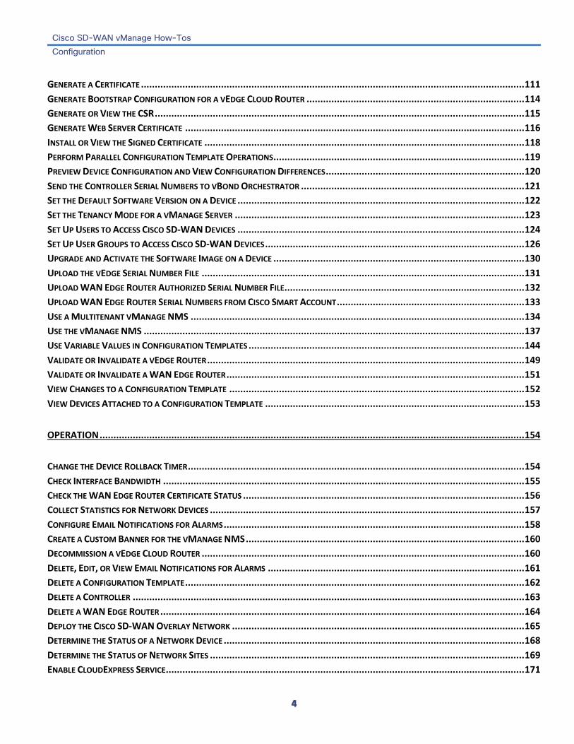
GENERATE A CERTIFICATE ........................................................................................................................................... 111 GENERATE BOOTSTRAP CONFIGURATION FOR A VEDGE CLOUD ROUTER ............................................................................... 114 GENERATE OR VIEW THE CSR ...................................................................................................................................... 115 GENERATE WEB SERVER CERTIFICATE ........................................................................................................................... 116 INSTALL OR VIEW THE SIGNED CERTIFICATE .................................................................................................................... 118 PERFORM PARALLEL CONFIGURATION TEMPLATE OPERATIONS ........................................................................................... 119 PREVIEW DEVICE CONFIGURATION AND VIEW CONFIGURATION DIFFERENCES ........................................................................ 120 SEND THE CONTROLLER SERIAL NUMBERS TO VBOND ORCHESTRATOR ................................................................................. 121 SET THE DEFAULT SOFTWARE VERSION ON A DEVICE ........................................................................................................ 122 SET THE TENANCY MODE FOR A VMANAGE SERVER ......................................................................................................... 123 SET UP USERS TO ACCESS CISCO SD-WAN DEVICES ........................................................................................................ 124 SET UP USER GROUPS TO ACCESS CISCO SD-WAN DEVICES .............................................................................................. 126 UPGRADE AND ACTIVATE THE SOFTWARE IMAGE ON A DEVICE ........................................................................................... 130 UPLOAD THE VEDGE SERIAL NUMBER FILE ..................................................................................................................... 131 UPLOAD WAN EDGE ROUTER AUTHORIZED SERIAL NUMBER FILE ....................................................................................... 132 UPLOAD WAN EDGE ROUTER SERIAL NUMBERS FROM CISCO SMART ACCOUNT .................................................................... 133 USE A MULTITENANT VMANAGE NMS ......................................................................................................................... 134 USE THE VMANAGE NMS .......................................................................................................................................... 137 USE VARIABLE VALUES IN CONFIGURATION TEMPLATES .................................................................................................... 144 VALIDATE OR INVALIDATE A VEDGE ROUTER ................................................................................................................... 149 VALIDATE OR INVALIDATE A WAN EDGE ROUTER ............................................................................................................ 151 VIEW CHANGES TO A CONFIGURATION TEMPLATE ........................................................................................................... 152 VIEW DEVICES ATTACHED TO A CONFIGURATION TEMPLATE .............................................................................................. 153
OPERATION .......................................................................................................................................................... 154
CHANGE THE DEVICE ROLLBACK TIMER .......................................................................................................................... 154 CHECK INTERFACE BANDWIDTH ................................................................................................................................... 155 CHECK THE WAN EDGE ROUTER CERTIFICATE STATUS ...................................................................................................... 156 COLLECT STATISTICS FOR NETWORK DEVICES .................................................................................................................. 157 CONFIGURE EMAIL NOTIFICATIONS FOR ALARMS ............................................................................................................. 158 CREATE A CUSTOM BANNER FOR THE VMANAGE NMS ..................................................................................................... 160 DECOMMISSION A VEDGE CLOUD ROUTER ..................................................................................................................... 160 DELETE, EDIT, OR VIEW EMAIL NOTIFICATIONS FOR ALARMS ............................................................................................. 161 DELETE A CONFIGURATION TEMPLATE ........................................................................................................................... 162 DELETE A CONTROLLER .............................................................................................................................................. 163 DELETE A WAN EDGE ROUTER .................................................................................................................................... 164 DEPLOY THE CISCO SD-WAN OVERLAY NETWORK .......................................................................................................... 165 DETERMINE THE STATUS OF A NETWORK DEVICE ............................................................................................................. 168 DETERMINE THE STATUS OF NETWORK SITES .................................................................................................................. 169 ENABLE CLOUDEXPRESS SERVICE .................................................................................................................................. 171

Cisco SD-WAN vManage How-Tos Configuration
5
ENABLE REVERSE PROXY ............................................................................................................................................ 172 ESTABLISH AN SSH SESSION TO A DEVICE ....................................................................................................................... 175 EXPORT ALARM DATA IN CSV FORMAT ......................................................................................................................... 176 EXPORT AUDIT LOG DATA IN CSV FORMAT .................................................................................................................... 177 EXPORT DEVICE DATA IN CSV FORMAT ......................................................................................................................... 178 EXPORT EVENT DATA IN CSV FORMAT .......................................................................................................................... 179 EXPORT ROOT CERTIFICATE ......................................................................................................................................... 180 HOW TO LOAD A CUSTOM VMANAGE APPLICATION SERVER LOGO ...................................................................................... 181 LOG IN TO A CISCO SD-WAN DEVICE ........................................................................................................................... 183 MIGRATE A CONTROLLER'S VIRTUAL MACHINE USING VMOTION ........................................................................................ 185 REBOOT A DEVICE ..................................................................................................................................................... 189 REBOOT A DEVICE OR VIEW ACTIVE DEVICES .................................................................................................................. 190 REDISCOVER THE NETWORK ........................................................................................................................................ 191 REMOVE A VEDGE ROUTER'S SERIAL NUMBER FROM THE VMANAGE NMS ........................................................................... 192 REMOVE A VMANAGE NMS FROM A VMANAGE CLUSTER ................................................................................................. 194 REPLACE A VEDGE ROUTER ......................................................................................................................................... 195 RESET AN INTERFACE ................................................................................................................................................. 197 RESET THE RSA KEY PAIR ........................................................................................................................................... 198 RESTORE THE VMANAGE NMS .................................................................................................................................... 199 SET ACL LOG FILTERS ................................................................................................................................................ 213 SET ALARM FILTERS .................................................................................................................................................. 214 SET AUDIT LOG FILTERS ............................................................................................................................................. 215 SET EVENT FILTERS .................................................................................................................................................... 216 SET MAP FILTERS ..................................................................................................................................................... 217 SET THE TIME INTERVAL TO COLLECT DEVICE STATISTICS .................................................................................................... 218 SET VMANAGE LOGIN CREDENTIALS ............................................................................................................................. 219 STAGE A WAN EDGE ROUTER ..................................................................................................................................... 219 SYNCHRONIZE DEVICE DATA ....................................................................................................................................... 221 VIEW ACL LOGS ....................................................................................................................................................... 222 VIEW ALL INTERFACES ............................................................................................................................................... 223 VIEW APPLICATION PERFORMANCE WITH CLOUD ONRAMP FOR SAAS ................................................................................. 225 VIEW ARP TABLE ENTRIES .......................................................................................................................................... 226 VIEW AUDIT LOGS .................................................................................................................................................... 227 VIEW A CONFIGURATION TEMPLATE ............................................................................................................................. 228 VIEW BFD SESSION INFORMATION ............................................................................................................................... 229 VIEW BGP INFORMATION .......................................................................................................................................... 230 VIEW CELLULAR INTERFACE INFORMATION ..................................................................................................................... 232 VIEW CERTIFICATE .................................................................................................................................................... 234 VIEW CFLOWD INFORMATION ..................................................................................................................................... 235 VIEW CLOUD ONRAMP CLOUD CONNECTIVITY ................................................................................................................ 237 VIEW CONFIGURATION TEMPLATES .............................................................................................................................. 239

Cisco SD-WAN vManage How-Tos Configuration
6
VIEW CONTROL CONNECTIONS .................................................................................................................................... 240 VIEW CSR ............................................................................................................................................................... 243 VIEW DATA CONNECTIONS ......................................................................................................................................... 244 VIEW DATA POLICIES ................................................................................................................................................. 245 VIEW DEVICES CONNECTED TO A VMANAGE NMS ........................................................................................................... 247 VIEW DEVICE INFORMATION ....................................................................................................................................... 248 VIEW DHCP SERVER AND INTERFACE INFORMATION ........................................................................................................ 250 VIEW DPI INFORMATION ........................................................................................................................................... 252 VIEW INTERFACE MTU INFORMATION .......................................................................................................................... 254 VIEW LINK INFORMATION .......................................................................................................................................... 255 VIEW LOG OF CERTIFICATE ACTIVITIES ........................................................................................................................... 256 VIEW LOG OF SOFTWARE UPGRADE ACTIVITIES ............................................................................................................... 257 VIEW LOG OF CONFIGURATION TEMPLATE ACTIVITIES ...................................................................................................... 258 VIEW MANAGEMENT INTERFACES ................................................................................................................................ 259 VIEW MULTICAST INFORMATION ................................................................................................................................. 260 VIEW NETWORK PERFORMANCE WITH VANALYTICS PLATFORM .......................................................................................... 262 VIEW OMP INFORMATION ......................................................................................................................................... 264 VIEW OMP STATUS .................................................................................................................................................. 266 VIEW OSPF INFORMATION ......................................................................................................................................... 268 VIEW PIM INFORMATION .......................................................................................................................................... 270 VIEW ROUTE, FIB, AND MFIB TABLES .......................................................................................................................... 271 VIEW ROUTER CONFIGURATION ................................................................................................................................... 273 VIEW SERVICES RUNNING ON A VMANAGE NMS ............................................................................................................ 274 VIEW SOFTWARE VERSIONS INSTALLED ON A DEVICE ........................................................................................................ 275 VIEW STATUS OF DEVICE BRINGUP ............................................................................................................................... 276 VIEW SUMMARY INFORMATION ABOUT TENANTS IN A VMANAGE SERVER ............................................................................ 277 VIEW THE STATUS OF A VBOND ORCHESTRATOR ............................................................................................................. 278 VIEW THE STATUS OF A VEDGE ROUTER ......................................................................................................................... 279 VIEW THE STATUS OF A VSMART CONTROLLER ................................................................................................................ 280 VIEW TUNNEL LATENCY STATISTICS .............................................................................................................................. 281 VIEW TUNNEL LOSS STATISTICS ................................................................................................................................... 282 VIEW VRRP INFORMATION ........................................................................................................................................ 283 VIEW WAN INTERFACES ............................................................................................................................................ 284
TROUBLESHOOTING ............................................................................................................................................. 286
CAPTURE PACKETS TO A FILE ....................................................................................................................................... 286 CHECK APPLICATION-AWARE ROUTING TRAFFIC .............................................................................................................. 287 COLLECT DEVICE DATA TO SEND TO CUSTOMER SUPPORT ................................................................................................. 288 MONITOR ALARMS ................................................................................................................................................... 289 MONITOR EVENT NOTIFICATIONS ................................................................................................................................ 293

Cisco SD-WAN vManage How-Tos Configuration
7
MONITOR TCP OPTIMIZATION .................................................................................................................................... 298 PING A CISCO SD-WAN DEVICE .................................................................................................................................. 300 RUN A TRACEROUTE .................................................................................................................................................. 302 RUN A TRACEROUTE IN RELEASES 17.1 AND EARLIER ........................................................................................................ 302 SIMULATE FLOWS ..................................................................................................................................................... 304 TROUBLESHOOT CELLULAR INTERFACES ......................................................................................................................... 307 TROUBLESHOOT DEVICE BRINGUP ................................................................................................................................ 312 TROUBLESHOOT WIFI CONNNECTIONS .......................................................................................................................... 313 USE SNMP TRAPS .................................................................................................................................................... 317 USE SYSLOG MESSAGES ............................................................................................................................................. 320 VIEW TUNNEL HEALTH ............................................................................................................................................... 355
18.4 HOW-TOS ..................................................................................................................................................... 356
ADD, DELETE, OR EDIT A TENANT ................................................................................................................................. 356 ADD A TENANT TO A VMANAGE SERVER ........................................................................................................................ 356 DELETE A TENANT FROM A VMANAGE SERVER ................................................................................................................ 356 EDIT A TENANT ........................................................................................................................................................ 356 USE A MULTITENANT VMANAGE NMS ......................................................................................................................... 358 VMANAGE MULTITENANT DASHBOARD ......................................................................................................................... 358 PLACE THE VMANAGE NMS INTO MULTITENANT MODE ................................................................................................... 358 ADD TENANTS ......................................................................................................................................................... 358 VIEW A SUMMARY OF TENANT STATUS ......................................................................................................................... 359 VIEW DETAILED TENANT STATUS ................................................................................................................................. 359 MODIFY A TENANT ................................................................................................................................................... 360 DELETE A TENANT ..................................................................................................................................................... 360

Cisco SD-WAN vManage How-Tos Configuration
8
Configuration Add a vBond Orchestrator
To add a vBond orchestrator to the overlay network:
1. In vManage NMS, select the Configuration ► Devices screen.
2. In the Controllers tab, click the Add Controller drop-down and select vBond.
3. In the Add vBond window:
a. Enter the management IP address of the vBond controller.
b. Enter the username and password to access the vBond orchestrator.
c. Select the Generate CSR checkbox to allow the certificate-generation process to occur automatically.
d. Click Add.
4. Repeat Steps 1 and 2 to add additional vBond orchestrators.
The new vBond orchestrator is added to the list of controllers in the Controllers screen.
Release Information Introduced in vManage NMS in Release 15.2.
Additional Information Add a vSmart Controller Edit Controller Details Enable Reverse Proxy

Cisco SD-WAN vManage How-Tos Configuration
9
Add a vManage NMS to a vManage Cluster To add a new vManage NMS to a vManage cluster:
1. In vManage NMS, select the Administration ► Cluster Management screen.
2. In the Service Configuration tab, click the Add vManage button. The Add vManage screen opens.
3. Enter the IP address of the vManage NMS you are adding to the cluster.
Note: It is strongly recommended that the IP addresses of all members of the vManage cluster be in the same subnet.
3. Specify the username and password for the new vManage server.
4. Select the services to run on the vManage server. You can select from the services listed below. Note that the Application Server field is not editable. The vManage Application Server is the local vManage HTTP web server.
• Statistics Database—Stores all real-time statistics from all Cisco SD-WAN devices in the network.
• Configuration Database—Stores all the device and feature templates and configurations for all Cisco SD-WAN devices in the network.
• Messaging Server—Distributes messages and shares state among all vManage NMS cluster members.
5. Click Add. The vManage NMS that you just added then reboots before joining the cluster.
In a cluster, it is recommended that you run at least three instances of each service.
Note: The members of a vManage cluster rely on timestamps to synchronize data and to track device uptime. For this time-dependent data to remain accurate, you cannot change the clock time on any one of the vManage servers of the cluster after you create the cluster.
Release Information Introduced in vManage NMS in Release 16.2.
Additional Information Create a vManage Cluster Remove a vManage NMS from a vManage Cluster

Cisco SD-WAN vManage How-Tos Configuration
10
Add a vSmart Controller To add a vSmart controller to the overlay network:
1. In vManage NMS, select the Configuration ► Devices screen.
2. In the Controllers tab, click the Add Controller drop-down and select vSmart.
3. In the Add vSmart window:
a. Enter the IP address in VPN 0 that is used to reach the vSmart controller.
b. Enter the username and password to access the vSmart controller.
c. Select the protocol to use for control-plane connections. The default is DTLS.
d. If you select TLS, enter the port number to use for TLS connections. The default is 23456.
e. Select the Generate CSR checkbox to allow the certificate-generation process to occur automatically.
f. Click Add.
4. Repeat Steps 1 and 2 to add additional vSmart controllers. The vManage NMS can support up to 20 vSmart controllers in the network.
The new vSmart controller is added to the list of controllers in the Controllers screen.
Release Information Introduced in vManage NMS in Release 15.2.
Additional Information Add a vBond Orchestrator Edit Controller Details Enable Reverse Proxy

Cisco SD-WAN vManage How-Tos Configuration
11
Add, Delete, or Edit a Tenant You can add, delete, or edit a tenant in a vManage server.
Add a Tenant to a vManage Server 1. In vManage NMS, select the Administration ► Tenant Management screen.
2. In the left pane, click the Add Tenant button.
3. In the Add Tenant window:
a. Enter a name for the tenant. It can be up to 128 characters and can contain only alphanumeric characters.
b. Enter a description for the tenant. It can be up to 256 characters and can contain only alphanumeric characters.
c. Enter the name of the organization. The name is case-sensitive. It is the name in the certificates for all Cisco SD-WAN network devices, and it must be identical on all devices in the overlay network.
d. In the URL subdomain field, enter the domain name for the tenant. The domain name must include the provider's domain name. You must also configure this same domain name when you enable multitenancy mode, in vManage Administration ► Settings ► Tenancy Mode.
e. Click Save.
4. The Create Tenant screen is displayed, and the Status column shows In progress. To view status messages related to the creation of the tenant, click the > to the left of the status column. After about 1 minute, the Status column changes to Success, and the tenant table shows the tenant's system IP address.
Delete a Tenant from a vManage Server 1. In vManage NMS, select the Administration ► Tenant Management screen.
2. In the left pane, click the name of the tenant.
3. In the right pane, click the Trash icon to the right of the tenant's name.
4. In the Delete Tenant popup, enter your vManage password and click Save.
Edit a Tenant 1. In vManage NMS, select the Administration ► Tenant Management screen.
2. In the left pane, click the name of the tenant.
3. In the right pane, click the Pencil icon to the right of the tenant's name.
4. In the Edit Tenant popup, modify the tenant's name, description, or domain name.
5. Click Save.

Cisco SD-WAN vManage How-Tos Configuration
12
Release Information Introduced in vManage NMS in Release 17.2.
Additional Information Multitenant Dashboard Use a Multitenant vManage NMS View Summary Information About all Tenants in a vManage Server

Cisco SD-WAN vManage How-Tos Configuration
13
Add or Delete an Image in the vManage Software Repository You can add or delete a software image from the vManage software repository.
Add Software Images to the Repository Before you can upgrade the software on a vEdge router, vSmart controller, or vManage NMS to a new software version, you need to add the software image to the vManage software repository. The repository allows you to store software images on the local vManage server and on a remote file server.
The vManage software repository allows you to store images in three ways:
• On the local vManage server, to be downloaded over a control plane connection—Here, the software images are stored on the local vManage server, and they are downloaded to the Cisco SD-WAN devices over a control plane connection. The receiving device generally throttles the amount of data traffic it can receive over a control plane connection, so for large files, the vManage server might not be able to monitor the software installation on the device even though it is proceeding correctly.
• On the local vManage server, to be downloaded over an out-of-band connection—Here, the software images are stored on the local vManage server, and they are downloaded to the Cisco SD-WAN devices over an out-of-band management connection. For this method to work, you specify the IP address of the out-of-band management interface when you copy the images to the software repository. This method is recommended when the software image files are large, because it bypasses any throttling that the device might perform and so the vManage server is able to monitor the software installation.
• On a remote server—Here, the software images remain on a remote file server that is reachable through an FTP or HTTP URL. As part of the software upgrade process, the vManage server sends this URL to the Cisco SD-WAN device, which then establishes a connection to the file server over which to download the software images.
1. In vManage NMS, select the Maintenance ► Software Repository screen.
2. Click Add New Software.
3. Select the location to store the software image:
a. To store the software image on the local vManage server and have it be downloaded to Cisco SD-WAN devices over a control plane connection, select vManage. The Upload Software to vManage dialog box opens.
i. Drag and drop the software image file to the dialog box, or click Browse to select the software image from a directory on the local vManage server.
ii. Click Upload to add the image to the software repository. The Software Repository tables displays the added software image, and it is available for installing on the devices.
b. To store the software image on a remote server, select Remote Server. The Location of Software on Remote Server dialog box opens.
i. In the Version box, enter the version number of the software image.
ii. In the URL box, enter the FTP or HTTP URL of the software image.
iii. Click Add to add the image to the software repository. The Software Repository tables displays the added software image, and it is available for installing on the devices.

Cisco SD-WAN vManage How-Tos Configuration
14
c. To store the image on a remote vManage server and have it be downloaded to Cisco SD-WAN devices over an out-of-band management connection, select Remote Server - vManage. The Upload Software to Remote Server - vManage dialog box opens.
i. In the vManage Hostname box, enter the IP address of an interface on the vManage server that is in a management VPN (typically, VPN 512).
ii. Drag and drop the software image file to the dialog box, or click Browse to select the software image from a directory on the local vManage server.
iii. Click Upload to add the image to the software repository. The Software Repository tables displays the added software image, and it is available for installing on the devices.
Delete a Software Image from the Repository 1. In vManage NMS, select the Maintenance ► Software Repository screen.
2. In the software repository table, select the software image.
3. In the More actions icon to the right of the line, click Delete.
If a software image is being download to a router, you cannot delete the image until the download process completes.
Release Information Introduced in vManage NMS in Release 15.2.
Additional Information Delete a Software Image from a Device Upgrade and Activate the Software Image on a Device View Log of Software Upgrade Activities

Cisco SD-WAN vManage How-Tos Configuration
15
Attach Devices to a Device Configuration Template To attach one or more devices to a device configuration template:
1. In vManage NMS, select the Configuration ► Templates screen.
2. In the Device tab, select a template.
3. Click the More Actions icon to the right of the row and click Attach Devices. The Attach Devices dialog box opens with the Select Devices tab selected
4. In the Available Devices column on the left, select a group and search for one or more devices, select a device from the list, or click Select All.
5. Click the arrow pointing right to move the device to the Selected Devices column on the right.
6. Click Attach.
7. If the template contains variables, enter the missing variable values for each device you selected in one of the following ways:
• Enter the values manually for each device either in the table column or by clicking the More Actions icon to the right of the row and clicking Edit Device Template. When you are using optional rows, if you do not want to include the parameter for the specific device, do not specify a value.
• Click Import File in the upper right corner of the screen to upload a CSV file that lists all the variables and defines each variable's value for each device.
7. Click Update
8. Click Next. If any devices have the same system IP address, a pop-up or an error message is displayed when you click Next. Modify the system IP addresses so that there are no duplicates, and click Save. Then click Next again.
9. In the left pane, select the device, to preview the configuration that is ready to be pushed to the device. The right pane displays the device's configuration and the Config Preview tab in the upper right corner is selected. Click the Config Diff tab to view the differences between this configuration and the configuration currently running on the device, if applicable. Click the Back button to edit the variable values entered in the previous screen.
10. If you are attaching a vEdge router, click Configure Device Rollback Timer located at the bottom of the left pane, to configure the time interval at which the device rolls back to its previous configuration if the router loses its control connection to the overlay network. The Configure Device Rollback Time dialog box is displayed.
a. From the Devices drop-down, select a device.
b. To enable the rollback timer, in the Set Rollback slider beneath the Devices drop-down, drag the slider to the left to enable the rollback timer. When you do this, the slider changes in color from gray to green.
c. To disable the rollback timer, click the Enable Rollback slider. When you disable the timer, the Password field pops up. Enter the password that you used to log in to the vManage NMS.
d. In the Device Rollback Time slider, drag the slider to the desired value. The default time is 5 minutes. You can configure a time from 6 to 15 minutes.
e. To exclude a device from the rollback timer setting, click Add Exception and select the devices to exclude.

Cisco SD-WAN vManage How-Tos Configuration
16
f. The table at the bottom of the Configure Device Rollback Time dialog box lists all the devices to which you are attaching the template and their rollback time. To delete a configured rollback time, click the Trash icon to right right of the device name.
g. Click Save.
11. Click Configure Devices to push the configuration to the devices. The Status column displays whether the configuration was successfully pushed. Click the right angle bracket to the left of the row to display details of the push operation.
Release Information Introduced in vManage NMS in Release 16.2.
Additional Information Create a Device Configuration Template Perform Parallel Configuration Template Operations View Devices Attached to a Configuration Template

Cisco SD-WAN vManage How-Tos Configuration
17
Change Configuration Modes You can toggle any device in the overlay network from vManage mode to CLI mode.
To toggle a WAN Edge router from vManage mode to CLI mode:
1. In vManage NMS, select the Configuration ► Devices screen.
2. In WAN Edge List tab, select a router.
3. Click the Change Mode drop-down and select CLI mode.
An SSH window opens. To log in to the device, enter a username and password. You can then issue CLI commands to configure or monitor the device.
To toggle a controller device from vManage mode to CLI mode:
1. In vManage NMS, select the Configuration ► Devices screen.
2. In the Controllers tab, select a controller.
3. Click the Change Mode drop-down.
4. Select CLI mode and then select the device type. The Change Mode CLI window opens.
5. From the vManage mode pane, select the device and click the right arrow to move the device to the CLI mode pane.
6. Click Update to CLI Mode.
An SSH window opens. To log in to the device, enter a username and password. You can then issue CLI commands to configure or monitor the device.
Release Information Introduced in vManage NMS in Release 15.2.

Cisco SD-WAN vManage How-Tos Configuration
18
Change the IP Address of the vManage NMS It is recommended that you configure the IP address of the vManage server statically, in its configuration file. Configure this IP address on a non-tunnel interface in VPN 0. It is also recommended that you do not configure DHCP in VPN 512.
When you start a vManage NMS for the first time, the default IP address of the vManage server is shown as "localhost". Before you can add a new vManage NMS to a cluster, you must change "localhost" to an IP address:
1. In vManage NMS, select the Administration ► Cluster Management screen.
2. In the Service Configuration tab, click the Add vManage button. The Edit vManage screen opens.
3. From the vManage IP Address drop-down list, select an IP address to assign to the vManage server.
4. Specify a username and password for the vManage server.
5. Click Update.
The vManage server automatically reboots and displays the Cluster Management screen.
Release Information Introduced in vManage NMS in Release 16.2.
Additional Information Add a vManage NMS to a vManage Cluster Create a vManage Cluster Remove a vManage NMS from a vManage Cluster

Cisco SD-WAN vManage How-Tos Configuration
19
Check User Accounts and Permissions You can check which users have accounts to log in to the vManage NMS and what permissions these users have. You can also check which users are logged in to a Cisco SD-WAN device.
Check vManage User Accounts 1. In vManage NMS, select the Administration ► Manage Users screen.
2. In the menu bar, click Users. All users who have accounts on the vManage NMS are listed.
3. In the left pane, click the user name. The right pane then shows the features for which the user has read or write permission.
Check User Account Permissions 1. In vManage NMS, select the Administration ► Manage Users screen.
2. In the menu bar, click User Groups.
3. To edit user account information, click the More Actions icon to the right of a table row.

Cisco SD-WAN vManage How-Tos Configuration
20
Check which Users Are Logged in To a Device 1. In vManage NMS, select the Monitor ► Network screen.
2. From the Device Groups drop-down list in the left pane, select the device group to which the device belongs. A list of all the devices in the group is displayed in the left pane.
3. Choose the options in the Sort by drop-down to sort the device list by status, hostname, system IP, site ID, or device type.
4. Select the device from the left pane.
5. In the right pane, click the Real Time toggle button.
6. From the drop-down list at the top of the right pane, select Users.

Cisco SD-WAN vManage How-Tos Configuration
21
Release Information Introduced in vManage NMS in Release 15.2.
Additional Information See the Configuring User Access and Authentication article for your software release. Set up User Accounts to Access Cisco SD-WAN Devices

Cisco SD-WAN vManage How-Tos Configuration
22
Configure Certificate Authorization Settings for Controller Devices Signed certificates are used to authenticate devices in the overlay network. Once authenticated, devices can establish secure sessions between each other. It is from the vManage NMS that you generate these certificates and install them on the controller devices—vManage NMSs, vBond orchestrators, and vSmart controllers. You can use certificates signed by Symantec, or you can use enterprise root certificates.
The controller certification authorization settings establish how the certification generation for all controller devices will be done. They do not generate the certificates.
You need to select the certificate-generation method only once. The method you select is automatically used each time you add a device to the overlay network.
Have Symantec Automatically Process Certificates To have the Symantec signing server automatically generate, sign, and install certificates on each controller device:
1. In vManage NMS, select the Administration ► Settings screen.
2. Click the Edit button to the right of the Controller Certificate Authorization bar.
3. Click Symantec Automated (Recommended). This is the recommended method for handling controller signed certificates.
4. Enter the first and last name of the requestor of the certificate.
5. Enter the email address of the requestor of the certificate. This address is required because the signed certificate and a confirmation email are sent to the requestor via email; they are also made available though the customer portal.
6. Specify the validity period for the certificate. It can be 1, 2, or 3 years.
7. Enter a challenge phrase.The challenge phrase is your certificate password and is required when you renew or revoke a certificate.
8. Confirm your challenge phrase.
9. In the Certificate Retrieve Interval field, specify how often the vManage server checks if the Symantec signing server has sent the certificate.
10. Click Save.
Manually Install Symantec Certificates To manually install certificates that the Symantec signing server has generated and signed:
1. In vManage NMS, select the Administration ► Settings screen.
2. Click the Edit button to the right of the Controller Certificate Authorization bar.
3. Click Symantec Manual.
4. Click Save.

Cisco SD-WAN vManage How-Tos Configuration
23
Use Enterprise Root Certificates You can install enterprise root certificates on vBond orchestrator, vManage NMS, and vSmart controller devices.
To view this information, issue the show certificate signing-request decoded command on a controller device, and check the output in the Subject line.
To use enterprise root certificates:
1. In vManage NMS, select the Administration ► Settings screen.
2. Click the Edit button to the right of the Controller Certificate Authorization bar.
3. Click Enterprise Root Certificate.
4. In the Certificate box, either paste the certificate, or click Select a file and upload a file that contains the enterprise root certificate.
5. To change one or more of the default CSR properties:
a. Click Set CSR Properties.
b. Enter the domain name to include in the CSR. This domain name is appended to the certificate number (CN).
c. Enter the organizational unit (OU) to include in the CSR.
d. Enter the organization (O) to include in the CSR.
e. Enter the city (L), state (ST), and two-letter country code (C) to include in the CSR.
f. Enter the email address (emailAddress) of the certificate requestor.
g. Specify the validity period for the certificate. It can be 1, 2, or 3 years.
6. Click Import & Save.
Release Information Introduced in vManage NMS in Release 15.2. In Release 18.2, add support for enterprise root certificates.
Additional Information Export a Root Certificate show certificate signing-request

Cisco SD-WAN vManage How-Tos Configuration
24
Configure Certificate Authorization Settings for vEdge Cloud Routers Certificates are used to authenticate vEdge Cloud routers in the overlay network. Once authentication is complete, WAN Edge Cloud routers can establish secure sessions with other devices in the overlay network.
By default, vEdge Cloud certification authorization is automated. This is the recommended setting.
If you use third-party certificate authorization, configure certificate authorization to be manual:
1. In vManage NMS, select the Administration ► Settings screen.
2. Click the Edit button to the right of the vEdge Cloud Certificate Authorization bar.
3. In the vEdge Cloud field, click Manual (Enterprise CA).
4. Click Save.
Release Information Introduced in vManage NMS in Release 17.1.
Cisco SD-WAN vManage How-Tos Configuration
25
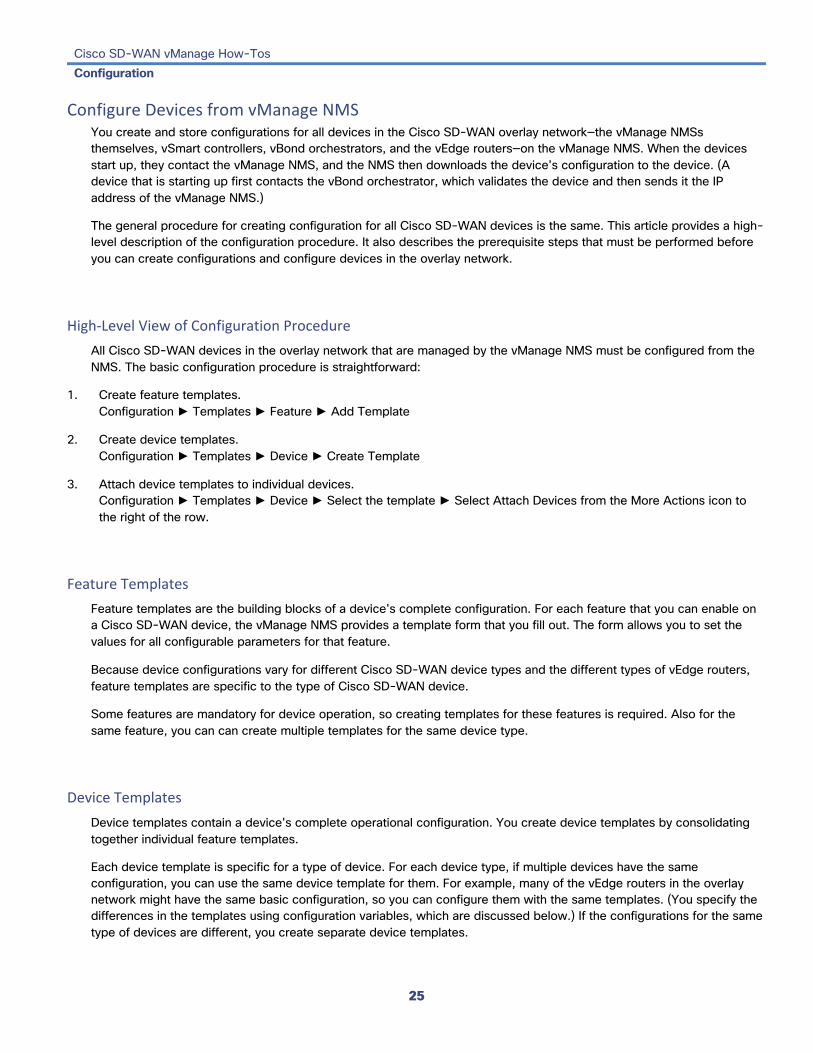
Configure Devices from vManage NMS You create and store configurations for all devices in the Cisco SD-WAN overlay network—the vManage NMSs themselves, vSmart controllers, vBond orchestrators, and the vEdge routers—on the vManage NMS. When the devices start up, they contact the vManage NMS, and the NMS then downloads the device's configuration to the device. (A device that is starting up first contacts the vBond orchestrator, which validates the device and then sends it the IP address of the vManage NMS.)
The general procedure for creating configuration for all Cisco SD-WAN devices is the same. This article provides a high-level description of the configuration procedure. It also describes the prerequisite steps that must be performed before you can create configurations and configure devices in the overlay network.
High-Level View of Configuration Procedure All Cisco SD-WAN devices in the overlay network that are managed by the vManage NMS must be configured from the NMS. The basic configuration procedure is straightforward:
1. Create feature templates. Configuration ► Templates ► Feature ► Add Template
2. Create device templates. Configuration ► Templates ► Device ► Create Template
3. Attach device templates to individual devices. Configuration ► Templates ► Device ► Select the template ► Select Attach Devices from the More Actions icon to the right of the row.
Feature Templates Feature templates are the building blocks of a device's complete configuration. For each feature that you can enable on a Cisco SD-WAN device, the vManage NMS provides a template form that you fill out. The form allows you to set the values for all configurable parameters for that feature.
Because device configurations vary for different Cisco SD-WAN device types and the different types of vEdge routers, feature templates are specific to the type of Cisco SD-WAN device.
Some features are mandatory for device operation, so creating templates for these features is required. Also for the same feature, you can can create multiple templates for the same device type.
Device Templates Device templates contain a device's complete operational configuration. You create device templates by consolidating together individual feature templates.
Each device template is specific for a type of device. For each device type, if multiple devices have the same configuration, you can use the same device template for them. For example, many of the vEdge routers in the overlay network might have the same basic configuration, so you can configure them with the same templates. (You specify the differences in the templates using configuration variables, which are discussed below.) If the configurations for the same type of devices are different, you create separate device templates.

Cisco SD-WAN vManage How-Tos Configuration
26
You can also create a device template by entering a CLI text-style configuration directly on the vManage NMS. Typically, you upload a text file containing the configuration text (or cut the configuration text from a text file and paste it into the vManage NMS). You can also directly type the configuration text into the vManage NMS.
Attach Templates To Devices To configure a device on the overlay network, you attach a device template to the device. You can attach only one device template to a device, so the template—whether you created it by consolidating individual feature templates or by entering a CLI text-style configuration—must contain the device's complete configuration. You cannot mix and match feature templates and CLI-style configurations.
You can attach the same templates to multiple devices, and you can do so simultaneously, in a single operation.
If the device being configured is present and operational on the network, the configuration is sent to the device immediately and takes effect immediately. If the device has not yet joined the network, the pushing of the configuration to the device is scheduled. When the device joins the network, the vManage NMS pushes the configuration immediately after it learns that the device is present in the network.
Template Variables Within a feature template, some configuration commands and command options are identical across all device types. Others—such as a device's system IP address, its geographic latitude and longitude, the timezone, and the overlay network site identifier—are variable, changing from device to device. When you attach the device template to a device, you are prompted to enter actual values for these command variables. You can do this either manually, by typing the values for each variable and for each device, or you can upload an Excel file in CSV format that contains the values for each device.
Configuration Prerequisites
Security Prerequisites Before you can configure any device in the Cisco SD-WAN overlay network, that device must be validated and authenticated so that the vManage NMSs, vSmart controllers, and vBond orchestrators recognize it as being allowed in the overlay network.
To validate and authenticate the controllers in the overlay network—the vManage NMSs, vSmart controllers, and vBond orchestrators—a signed certificate must be installed on these devices, as described in the article Generate a Certificate .
To validate and authenticate the vEdge routers, you receive a vEdge authorized serial number file from Cisco SD-WAN, which lists the serial and chassis numbers for all the vEdge routers allowed in your network. Then, you upload the vEdge serial number file to the vManage NMS.

Cisco SD-WAN vManage How-Tos Configuration
27
Variables Spreadsheet The feature templates that you create will most likely contain variables. To have the vManage NMS populate the variables with actual values when you attach a device template to a device, create an Excel file that lists the variable values for each device and save the file in CSV format.
In the spreadsheet, the header row contains the variable name and each row after that corresponds to a device, defining the values of the variables. The first three columns in the spreadsheet must be (in the order listed below):
• csv-deviceId—Serial number of the device (used to uniquely identify the device). For vEdge routers, you receive the serial numbers in the vEdge authorized serial number file sent to you from Cisco SD-WAN. For other devices, the serial number is included in the signed certificate you receive from Symantec or from your root CA.
• csv-deviceIP—System IP address of the device (used to populate the system ip address command).
• csv-host-name—Hostname of the device (used to populate the system hostname command).
You can create a single spreadsheet for all devices in the overlay network—vSmart controllers, vBond orchestrators, and vEdge routers. You do not need to specify values for all variables for all devices.
Release Information Introduced in vManage NMS in Release 15.3.
Additional Information Configure a Policy Create a Template Variables Spreadsheet Create Configuration Templates for a vBond Orchestrator Create Configuration Templates for a vEdge Router Create Configuration Templates for a vSmart Controller

Cisco SD-WAN vManage How-Tos Configuration
28
Configure Geographic Coordinates for a Device To configure the geographic coordinates for a device, use the vManage Configuration ► Templates ► System feature template.
If the Cisco SD-WAN device is not attached to a configuration template, you can configure the latitude and longitude directly on the device:
1. In vManage NMS, select the Tools ► SSH Terminal screen.
2. Select the device from the left pane. The SSH Terminal screen opens in the right pane.
3. Enter the username and password to log in to the device.
4. Determine whether the device is attached to a configuration template: # show system status Check the values in the vManaged and Configuration template output fields. For example: ... Personality: vedge Model name: vedge-cloud Services: None vManaged: false Commit pending: false Configuration template: None If the vManaged field is false, the device is not attached to a configuration template, and the Configuration template field says None. For such a device, you can configure the GPS coordinates directly from the CLI. If the vManaged field is true, the device's configuration has been downloaded by the vManage server, and the Configuration template field shows the name of the configuration template. For such a device, you cannot configure the GPS coordinates directly from the CLI. If you attempt to do so, the validate or commit command fails, with the following message: Aborted: 'system is-vmanaged': This device is being managed by the vManage. Configuration through the CLI is not allowed.
5. Enter configuration mode: # config (config)#
6. Configure the latitude and longitude on the device: (config)# system gps-location latitude degrees.minutes.seconds (config-system)# gps-location longitude degrees.minutes.seconds
7. Save the configuration: (config-system)# commit (config-system)#
Release Information Introduced in vManage NMS in Release 15.2.
Additional Information Set Map Filters View Device Information View Link Information

Cisco SD-WAN vManage How-Tos Configuration
29
Configure Organization Name You must configure the name of your organization before you can generate a CSR. The organization name is included in the CSR.
To configure the name of your organization:
1. In vManage NMS, select the Administration ► Settings screen.
2. Click the Edit button to the right of the Organization Name bar.
3. In the Organization Name field, enter the name of your organization. The organization name must be identical to the name that is configured on the vBond orchestrator.
4. In the Confirm Organization Name field, re-enter and confirm your organization name.
5. Click Save.
Note that once the control connections are up and running, the organization name bar is not editable.
Release Information Introduced in vManage NMS in Release 15.2.

Cisco SD-WAN vManage How-Tos Configuration
30
Configure or Cancel a vManage Server Maintenance Window You can set or cancel the start and end times and the duration of the maintenance window for the vManage server.
Configure a Maintenance Window 1. In vManage NMS, select the Administration ► Settings screen.
2. Click the Edit button to the right of the Maintenance Window bar.
3. Click the Start date and time drop-down, and select the date and time when the maintenance window will start.
4. Click the End date and time drop-down, and select the date and time when the maintenance window will end.
5. Click Save. The start and end times and the duration of the maintenance window are displayed in the Maintenance Window bar.
Two days before the start of the window, the vManage Dashboard displays a maintenance window alert notification.
Cancel a Maintenance Window 1. In vManage NMS, select the Administration ► Settings screen.
2. Click the Edit button to the right of the Maintenance Window bar.
3. Click Cancel maintenance window.
Release Information Introduced in vManage NMS in Release 17.2. In Release 18.2, add ability to cancel a maintenance window.

Cisco SD-WAN vManage How-Tos Configuration
31
Configure Policies Policy is used to influence the flow of data traffic among the vEdge routers in the overlay network. The Cisco SD-WAN overlay network separates policy into two functional groups:
• Centralized policy, which is coordinated by the vSmart controllers. Centralized policy affects the flow of both control plane traffic, which are route and TLOC updates carried by OMP that the vSmart controllers use to determine the topology and status of the overlay network, and data plane traffic, which is the data traffic that moves between vEdge routers in the network. The vSmart controllers distributed centralized data policy to the vEdge routers affected by that policy.
• Localized policy, which runs on vEdge routers. Localized policy affects the flow of traffic through the router and at the local site where the vEdge router is located. They include traditional access lists (ACLs) and routing policies that are associated with BGP or OSPF as well as policies that effect mirroring, policing, and QoS on router interfaces.
You create and store policy configurations on the vManage NMS. As vSmart controllers and vEdge routers join the overlay network, the vManage NMS pushes the policy configurations to the devices.
To simplify the configuration of centralized policy, the vManage NMS provides a policy configuration wizard that walks you through the configuration process and that pushes the policy to any active vSmart controllers in the overlay network.
For localized policy, you use a CLI-style interface on the vManage NMS to configure the policy components. Then, you associate the policy with an interface or with a routing protocol in a feature configuration templates.
In vManage NMS, you perform device configuration and policy configuration, for the most part, independently of each other. (You configure Cisco SD-WAN network devices using the templates in the Configuration ►Templates screens, while you configure policy in the Configuration ► Policies screens.) This design separates the tasks required to have a device become operational in the overlay network from the tasks required to control the flow of route and TLOC information and data traffic throughout the network.
The sections below describe how to configure policies from a vManage NMS running Release 17.2 or later.
Configure Centralized Policy To configure centralized policies, use the vManage policy configuration wizard. The wizard consists of four sequential screens that guide you through the process of creating and editing policy components:
• Create Applications or Groups of Interest—Create lists that group together related items and that you call in the match or action components of a policy.
• Configure Topology—Create the network structure to which the policy applies.
• Configure Traffic Rules—Create the match and action conditions of a policy.
• Apply Policies to Sites and VPNs—Associate policy with sites and VPNs in the overlay network.
In the first three policy configuration wizard screens, you are creating policy components or blocks. In the last screen, you are applying policy blocks to sites and VPNs in the overlay network.
For a centralized policy to take effect, you must activate the policy.
This section describes how to start the policy configuration wizard and explains the four policy configuration wizard screens.

Cisco SD-WAN vManage How-Tos Configuration
32
Start the Policy Configuration Wizard To start the policy configuration wizard:
1. In vManage NMS, select the Configure ► Policies screen. When you first open this screen, the Centralized Policy tab is selected by default.
2. Click Add Policy.
The policy configuration wizard opens, and the Create Applications or Groups of Interest screen is displayed.
Create Applications or Groups of Interest To create lists of applications or groups to use in centralized policy:
1. Start the policy configuration wizard as explained above.
2. Create new lists , as described in the following table:
1. List Type Policy Usage Procedure
Application Application-aware routing policy
1. In the left bar, click Application.
2. Click New Application List.
3. Enter a name for the list.
4. Click either the Application or Application Family button.
5. From the Select drop-down, select the desired applications or application families.
6. Click Add.
Two application lists are preconfigured. You cannot edit or delete these lists.
7. Google_Apps—Includes Google applications, such as gmail, Google maps, and YouTube. To display a full list of Google applications, click the list in the Entries column.
8. Microsoft_Apps—Includes Microsoft applications, such as Excel, Skype, and Xbox. To display a full list of Microsoft applications, click the list in the Entries column.
Color Centralized control policy 9. In the left bar, click Color.
10. Click New Color List.
11. Enter a name for the list.
12. From the Select Color drop-down, select the desired colors.
13. Click Add.
Cisco SD-WAN vManage How-Tos Configuration
33
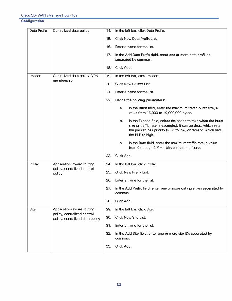
Data Prefix Centralized data policy 14. In the left bar, click Data Prefix.
15. Click New Data Prefix List.
16. Enter a name for the list.
17. In the Add Data Prefix field, enter one or more data prefixes separated by commas.
18. Click Add.
Policer Centralized data policy, VPN membership
19. In the left bar, click Policer.
20. Click New Policer List.
21. Enter a name for the list.
22. Define the policing parameters:
a. In the Burst field, enter the maximum traffic burst size, a value from 15,000 to 10,000,000 bytes.
b. In the Exceed field, select the action to take when the burst size or traffic rate is exceeded. It can be drop, which sets the packet loss priority (PLP) to low, or remark, which sets the PLP to high.
c. In the Rate field, enter the maximum traffic rate, a value from 0 through 2 64 – 1 bits per second (bps).
23. Click Add.
Prefix Application-aware routing policy, centralized control policy
24. In the left bar, click Prefix.
25. Click New Prefix List.
26. Enter a name for the list.
27. In the Add Prefix field, enter one or more data prefixes separated by commas.
28. Click Add.
Site Application-aware routing policy, centralized control policy, centralized data policy
29. In the left bar, click Site.
30. Click New Site List.
31. Enter a name for the list.
32. In the Add Site field, enter one or more site IDs separated by commas.
33. Click Add.

Cisco SD-WAN vManage How-Tos Configuration
34
SLA Class Application-aware routing policy
34. In the left bar, click SLA Class.
35. Click New SLA Class List.
36. Enter a name for the list.
37. Define the SLA class parameters:
a. In the Loss field, enter the maximum packet loss on the connection, a value from 0 through 100 percent.
b. In the Latency field, enter the maximum packet latency on the connection, a value from 0 through 1,000 milliseconds.
c. In the Jitter field, enter the maximum jitter on the connection, a value from 1 through 1,000 milliseconds.
38. Click Add.
TLOC Centralized control policy, centralized data policy
39. In the left bar, click TLOC.
40. Click New TLOC List. The TLOC List popup displays.
41. Enter a name for the list.
42. In the TLOC IP field, enter the system IP address for the TLOC.
43. In the Color field, select the TLOC's color.
44. In the Encap field, select the encapsulation type.
45. In the Preference field, optionally select a preference to associate with the TLOC.
46. Click Add TLOC to add another TLOC to the list.
47. Click Save.
VPN Application-aware routing policy, centralized control policy, centralized data policy
48. In the left bar, click VPN.
49. Click New VPN List.
50. Enter a name for the list.
51. In the Add VPN field, enter one or more VPN IDs separated by commas.
52. Click Add.
4. Click Next to move to Configure Topology in the wizard. When you first open this screen, the Topology tab is selected by default.
Configure the Network Topology To configure the network topology or a VPN membership to use in centralized policy:

Cisco SD-WAN vManage How-Tos Configuration
35
1. If you are already in the policy configuration wizard, skip to Step 4. Otherwise, in vManage NMS, select the Configure ► Policies screen. When you first open this screen, the Centralized Policy tab is selected by default.
2. Click Add Policy. The policy configuration wizard opens, and the Create Applications or Groups of Interest screen is displayed
3. Click Next. The Network Topology screen opens, and in the Topology bar, the Topology tab is selected by default.
4. Create a network topology, as described in the following table:
Network Topology Description Procedure Hub and Spoke
Policy for a topology with one or more central hub sites and with spokes connected to a hub
1. In the Add Topology drop-down, select Hub and Spoke.
2. Enter a name for the hub-and-spoke policy.
3. Enter a description for the policy.
4. In the VPN List field, select the VPN list for the policy.
5. In the left pane, click Add Hub and Spoke. A hub-and-spoke policy component containing the text string My Hub-and-Spoke is added in the left pane.
6. Double-click the My Hub-and-Spoke text string, and enter a name for the policy component.
7. In the right pane, add hub sites to the network topology:
a. Click Add Hub Sites.
b. In the Site List Field, select a site list for the policy component.
c. Click Add.
d. Repeat Steps 7a, 7b, and 7c to add more hub sites to the policy component.
8. In the right pane, add spoke sites to the network topology:
a. Click Add Spoke Sites.
b. In the Site List Field, select a site list for the policy component.
c. Click Add.
d. Repeat Steps 8a, 8b, and 8c to add more spoke sites to the policy component.
9. Repeat Steps 5 through 8 to add more components to the hub-and-spoke policy.
10. Click Save Hub and Spoke Policy.

Cisco SD-WAN vManage How-Tos Configuration
36
Mesh Partial-mesh or full-mesh region
11. In the Add Topology drop-down, select Mesh.
12. Enter a name for the mesh region policy component.
13. Enter a description for the mesh region policy component.
14. In the VPN List field, select the VPN list for the policy.
15. Click New Mesh Region.
16. In the Mesh Region Name field, enter a name for the individual mesh region.
17. In the Site List field, select one or more sites to include in the mesh region.
18. Repeat Steps 5 through 7 to add more mesh regions to the policy.
19. Click Save Mesh Region.
Cisco SD-WAN vManage How-Tos Configuration
37
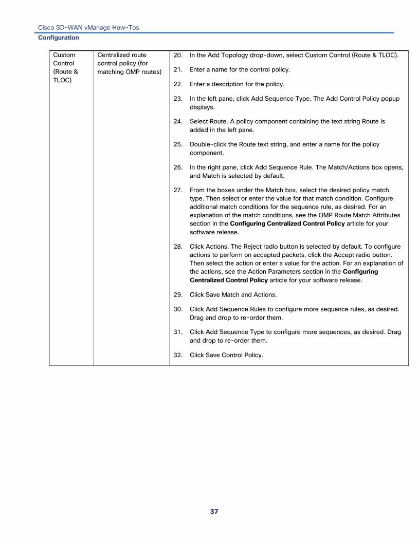
Custom Control (Route & TLOC)
Centralized route control policy (for matching OMP routes)
20. In the Add Topology drop-down, select Custom Control (Route & TLOC).
21. Enter a name for the control policy.
22. Enter a description for the policy.
23. In the left pane, click Add Sequence Type. The Add Control Policy popup displays.
24. Select Route. A policy component containing the text string Route is added in the left pane.
25. Double-click the Route text string, and enter a name for the policy component.
26. In the right pane, click Add Sequence Rule. The Match/Actions box opens, and Match is selected by default.
27. From the boxes under the Match box, select the desired policy match type. Then select or enter the value for that match condition. Configure additional match conditions for the sequence rule, as desired. For an explanation of the match conditions, see the OMP Route Match Attributes section in the Configuring Centralized Control Policy article for your software release.
28. Click Actions. The Reject radio button is selected by default. To configure actions to perform on accepted packets, click the Accept radio button. Then select the action or enter a value for the action. For an explanation of the actions, see the Action Parameters section in the Configuring Centralized Control Policy article for your software release.
29. Click Save Match and Actions.
30. Click Add Sequence Rules to configure more sequence rules, as desired. Drag and drop to re-order them.
31. Click Add Sequence Type to configure more sequences, as desired. Drag and drop to re-order them.
32. Click Save Control Policy.

Cisco SD-WAN vManage How-Tos Configuration
38
Centralized TLOC control policy (for matching TLOC routes)
33. In the Add Topology drop-down, select Custom Control (Route & TLOC).
34. Enter a name for the control policy.
35. Enter a description for the policy.
36. In the left pane, click Add Sequence Type. The Add Control Policy popup displays.
37. Select TLOC. A policy component containing the text string TLOC is added in the left pane.
38. Double-click the TLOC text string, and enter a name for the policy component.
39. In the right pane, click Add Sequence Rule. The Match/Actions box opens, and Match is selected by default.
40. From the boxes under the Match box, select the desired policy match type. Then select or enter the value for that match condition. Configure additional match conditions for the sequence rule, as desired. For an explanation of the match conditions, see the OMP TLOC Match Attributes section in the Configuring Centralized Control Policy article for your software release.
41. Click Actions. The Reject radio button is selected by default. To configure actions to perform on accepted packets, click the Accept radio button. Then select the action or enter a value for the action. For an explanation of the actions, see the Action Parameters section in the Configuring Centralized Control Policy article for your software release.
42. Click Save Match and Actions.
43. Click Add Sequence Rules to configure more sequence rules, as desired. Drag and drop to re-order them.
44. Click Add Sequence Type to configure more sequences, as desired. Drag and drop to re-order them.
45. Click Save Control Policy.
5. To use an existing topology:
a. In the Add Topology drop-down, click Import Existing Topology. The Import Existing Topology popup displays.
b. Select the type of topology.
c. In the Policy drop-down, select the name of the topology.
d. Click Import.
6. To create a VPN membership policy, in the Topology bar, click VPN Membership. Then:
a. Click Add VPN Membership Policy. The Update VPN Membership Policy popup displays.
b. Enter a name and description for the VPN membership policy.

Cisco SD-WAN vManage How-Tos Configuration
39
c. In the Site List field, select the site list.
d. In the VPN Lists field, select the VPN list.
e. Click Add List to add another VPN to the VPN membership.
f. Click Save
7. Click Next to move to Configure Traffic Rules in the wizard. When you first open this screen, the Application-Aware Routing tab is selected by default.
Configure Traffic Rules To create the match and action rules to apply to traffic affected by the policy:
1. If you are already in the policy configuration wizard, skip this procedure. Otherwise, in vManage NMS, select the Configure ► Policies screen. When you first open this screen, the Centralized Policy tab is selected by default.
2. Click Add Policy. The policy configuration wizard opens, and the Create Applications or Groups of Interest screen is displayed
3. Click Next. The Network Topology screen opens, and in the Topology bar, the Topology tab is selected by default.
4. Click Next. The Configure Traffic Rules screen opens, and in the Application-Aware Routing bar, the Application-Aware Routing tab is selected by default.
You can configure traffic rules for the following types of routing policy:
• Application-Aware Routing—To create an application-aware routing policy
• Traffic Data—To create a centralized data policy
• Cflowd—To create a policy for traffic flow monitoring with cflowd
Create an Application-Aware Routing Policy To configure traffic rules for application-aware routing policy:
1. In the Application-Aware Routing bar, select the Application-Aware Routing tab.
2. Click the Add Policy drop-down.
3. Select Create New, and in the left pane, click Sequence Type. A policy sequence containing the text string App Route is added in the left pane.
4. Double-click the App Route text string, and enter a name for the policy sequence.The name you type is displayed both in the Sequence Type list in the left pane and in the right pane.
5. In the right pane, click Sequence Rule. The Match/Action box opens, and Match is selected by default. The available policy match conditions are listed below the box.
6. To select one or more Match conditions, click its box and set the values as described in the following table:
Match Condition Procedure

Cisco SD-WAN vManage How-Tos Configuration
40
None (match all packets) Do not specify any match conditions.
Applications/Application Family List
1. In the Match conditions, click Applications/Application Family List.
2. In the drop-down, select the application family.
3. To create an application list:
a. Click New Application List.
b. Enter a name for the list.
c. Click the Application button to create a list of individual applications. Click the Application Family button to create a list of related applications.
d. In the Select Application drop-down, select the desired applications or application families.
e. Click Save.
Destination Data Prefix 4. In the Match conditions, click Destination Data Prefix.
5. To match a list of destination prefixes, select the list from the drop-down.
6. To match an individual destination prefix, type the prefix in the Destination box.
Destination Port 7. In the Match conditions, click Destination Port.
8. In the Destination field, enter the port number. Specify a single port number, a list of port numbers (with numbers separated by a space), or a range of port numbers (with the two numbers separated with a hyphen [-]).
DNS Application List (to enable split DNS)
9. In the Match conditions, click DNS Application List.
10. In the drop-down, select the application family.
DNS (to enable split DNS) 11. In the Match conditions, click DNS.
12. In the drop-down, select Request to process DNS requests for the DNS applications, and select Response to process DNS responses for the applications.
DSCP 13. In the Match conditions, click DSCP.
14. In the DSCP field, type the DSCP value, a number from 0 through 63.
PLP 15. In the Match conditions, click PLP.
16. In the PLP drop-down, select Low or High. To set the PLP to high, apply a policer that includes the exceed remark option.
Protocol 17. In the Match conditions, click Protocol.
18. In the Protocol field, type the Internet Protocol number, a number from 0 through 255.

Cisco SD-WAN vManage How-Tos Configuration
41
Source Data Prefix 19. In the Match conditions, click Source Data Prefix.
20. To match a list of source prefixes, select the list from the drop-down.
21. To match an individual source prefix, type the prefix in the Source box.
Source Port 22. In the Match conditions, click Source Port.
23. In the Source field, enter the port number. Specify a single port number, a list of port numbers (with numbers separated by a space), or a range of port numbers (with the two numbers separated with a hyphen [-]).
7. To select actions to take on matching data traffic, click the Actions box. The available policy actions are listed below the box.
8. Set the policy action as described in the following table:
Match Condition
Description Procedure Backup SLA Preferred Color
When no tunnel matches the SLA, direct the data traffic to a specific tunnel. Data traffic is sent out the configured tunnel if that tunnel interface is available. If that tunnel interface is not available, traffic is sent out another available tunnel. You can specify one or more colors. The backup SLA preferred color is a loose matching, not a strict matching.
Counter Count matching data packets.
Log Place a sampled set of packets that match the SLA class rule into system logging (syslog) files. In addition to logging the packet headers, a syslog message is generated the first time a packet header is logged and then every 5 minutes thereafter, as long as the flow is active.
SLA Class List For the SLA class, all matching data traffic is directed to a tunnel whose performance matches the SLA parameters defined in the class. The software first tries to send the traffic through a tunnel that matches the SLA. If a single tunnel matches the SLA, data traffic is sent through that tunnel. If two or more tunnels match, traffic is distributed among them. If no tunnel matches the SLA, data traffic is sent through one of the available tunnels.
9. Click Save Match and Actions.
10. Create additional sequence rules as desired. Drag and drop to re-arrange them.
11. Create additional sequence types as desired. Drag and drop to re-arrange them.
12. Click Save Application-Aware Routing Policy.
Click Next to move to Apply Policies to Sites and VPNs in the wizard.
Create a Traffic Data Policy To configure traffic rules for centralized data policy:
1. In the Application-Aware Routing bar, select the Traffic Data tab.
2. Click the Add Policy drop-down.
3. Select Create New. The Add Data Policy popup opens.
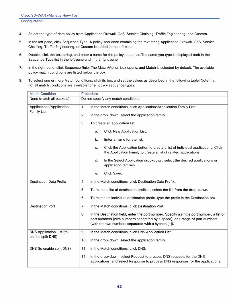
Cisco SD-WAN vManage How-Tos Configuration
42
4. Select the type of data policy from Application Firewall, QoS, Service Chaining, Traffic Engineering, and Custom.
5. In the left pane, click Sequence Type. A policy sequence containing the text string Application Firewall, QoS, Service Chaining, Traffic Engineering, or Custom is added in the left pane.
6. Double-click the text string, and enter a name for the policy sequence.The name you type is displayed both in the Sequence Type list in the left pane and in the right pane.
7. In the right pane, click Sequence Rule. The Match/Action box opens, and Match is selected by default. The available policy match conditions are listed below the box.
8. To select one or more Match conditions, click its box and set the values as described in the following table. Note that not all match conditions are available for all policy sequence types.
Match Condition Procedure None (match all packets) Do not specify any match conditions.
Applications/Application Family List
1. In the Match conditions, click Applications/Application Family List.
2. In the drop-down, select the application family.
3. To create an application list:
a. Click New Application List.
b. Enter a name for the list.
c. Click the Application button to create a list of individual applications. Click the Application Family to create a list of related applications.
d. In the Select Application drop-down, select the desired applications or application families.
e. Click Save.
Destination Data Prefix 4. In the Match conditions, click Destination Data Prefix.
5. To match a list of destination prefixes, select the list from the drop-down.
6. To match an individual destination prefix, type the prefix in the Destination box.
Destination Port 7. In the Match conditions, click Destination Port.
8. In the Destination field, enter the port number. Specify a single port number, a list of port numbers (with numbers separated by a space), or a range of port numbers (with the two numbers separated with a hyphen [-]).
DNS Application List (to enable split DNS)
9. In the Match conditions, click DNS Application List.
10. In the drop-down, select the application family.
DNS (to enable split DNS) 11. In the Match conditions, click DNS.
12. In the drop-down, select Request to process DNS requests for the DNS applications, and select Response to process DNS responses for the applications.

Cisco SD-WAN vManage How-Tos Configuration
43
DSCP 13. In the Match conditions, click DSCP.
14. In the DSCP field, type the DSCP value, a number from 0 through 63.
Packet Length 15. In the Match conditions, click Packet Length.
16. In the Packet Length field, type the length, a value from 0 through 65535.
PLP 17. In the Match conditions, click PLP.
18. In the PLP drop-down, select Low or High. To set the PLP to high, apply a policer that includes the exceed remark option.
Protocol 19. In the Match conditions, click Protocol.
20. In the Protocol field, type the Internet Protocol number, a number from 0 through 255.
Source Data Prefix 21. In the Match conditions, click Source Data Prefix.
22. To match a list of source prefixes, select the list from the drop-down.
23. To match an individual source prefix, type the prefix in the Source box.
Source Port 24. In the Match conditions, click Source Port.
25. In the Source field, enter the port number. Specify a single port number, a list of port numbers (with numbers separated by a space), or a range of port numbers (with the two numbers separated with a hyphen [-]).
TCP 26. In the Match conditions, click TCP.
27. In the TCP field, syn is the only option available.
9. To select actions to take on matching data traffic, click the Actions box.
10. To drop matching traffic, click the Drop button.
11. To accept matching traffic, click the Accept button. The available policy actions are listed to the right of the button.
12. Set the policy action as described in the following table:
Match Condition Description Procedure Counter Count matching data packets. 1. In the Action conditions,
click Counter.
2. In the Counter Name field, enter the name of the file in which to store packet counters.

Cisco SD-WAN vManage How-Tos Configuration
44
DSCP Assign a DSCP value to matching data packets. 3. In the Action conditions, click DSCP.
4. In the DSCP field, type the DSCP value, a number from 0 through 63.
Forwarding Class
Assign a forwarding class to matching data packets. 5. In the Match conditions, click Forwarding Class.
6. In the Forwarding Class field, type the class value, which can be up to 32 characters long.
Log Place a sampled set of packets that match the SLA class rule into system logging (syslog) files. In addition to logging the packet headers, a syslog message is generated the first time a packet header is logged and then every 5 minutes thereafter, as long as the flow is active.
7. In the Action conditions, click Log to enable logging.
Policer Apply a policer to matching data packets. 8. In the Match conditions, click Policer.
9. In the Policer drop-down field, select the name of a policer.
13. Click Save Match and Actions.
14. Create additional sequence rules as desired. Drag and drop to re-arrange them.
15. Create additional sequence types as desired. Drag and drop to re-arrange them.
16. Click Save Data Policy.
Click Next to move to Apply Policies to Sites and VPNs in the wizard.
Create a Cflowd Policy To configure traffic rules for cflowd policy:
1. In the Application-Aware Routing bar, select the Cflowd tab.
2. Click the Add Policy drop-down.
3. Select Create New. The Add Cflowd Policy popup opens.
4. Configure timer parameters for the cflowd template:
a. In the Active Flow Timeout field, specify how long to collect a set of flows on which traffic is actively flowing, a value from 30 through 3,600 seconds. The default is 600 seconds (10 minutes).

Cisco SD-WAN vManage How-Tos Configuration
45
b. In the Inactive Flow Timeout field, specify how long to wait to send a set of sampled flows to a collector for a flow on which no traffic is flowing, a value from 1 through 3,600 seconds. The default is 60 seconds (1 minute).
c. In the Flow Refresh Interval field, specify how often to send the cflowd template record fields to the collector, a value from 60 through 86,400 seconds (1 minute through 1 day). The default is 90 seconds.
d. In the Sampling Interval field, specify how many packets to wait before creating a new flow, a value from 1 through 65,536 seconds. While you can configure any integer value, the software rounds the value down to the nearest power of 2.
5. Click Add New Collector, and configure the location of the cflowd collector. You can configure up to four collectors.
a. In the VPN ID field, enter the number of the VPN in which the collector is located.
b. In the IP Address field, enter the IP address of the collector.
c. In the Port Number field, enter the collector port number. The default port is 4739.
d. In the Transport Protocol drop-down, select the transport type to use to reach the collector, either TCP or UDP.
e. In the Source Interface field, enter the name of the interface to use to send flows to the collector. It can be either a Gigabit Ethernet, a 10-Gigabit Ethernet interface ( ge ), or a loopback interface ( loopback number ).
6. Click Save Cflowd Policy.
Click Next to move to Apply Policies to Sites and VPNs in the wizard.
Apply Policies to Sites and VPNs In the last screen of the policy configuration wizard, you associate the policy blocks that you created on the previous three screens with VPNs and with sites in the overlay network.
To apply a policy block to sites and VPNs in the overlay network:
1. If you are already in the policy configuration wizard, skip to Step 6. Otherwise, in vManage NMS, select the Configure ► Policies screen. When you first open this screen, the Centralized Policy tab is selected by default.
2. Click Add Policy. The policy configuration wizard opens, and the Create Applications or Groups of Interest screen is displayed
3. Click Next. The Network Topology screen opens, and in the Topology bar, the Topology tab is selected by default.
4. Click Next. The Configure Traffic Rules screen opens, and in the Application-Aware Routing bar, the Application-Aware Routing tab is selected by default.
5. Click Next. The Apply Policies to Sites and VPNs screen opens.
6. In the Policy Name field, enter a name for the policy. This field is mandatory and can contain only uppercase and lowercase letters, the digits 0 through 9, hyphens (–), and underscores (_). It cannot contain spaces or any other characters.
7. In the Policy Description field, enter a description of the policy. It can contain up to 2048 characters. This field is mandatory, and it can contain any characters and spaces.

Cisco SD-WAN vManage How-Tos Configuration
46
8. From the Topology bar, select the type of policy block. The table then lists policies that you have created for that type of policy block.
9. Associate the policy with VPNs and sites. The choice of VPNs and sites depends on the type of policy block:
a. For a Topology policy block, click Add New Site List and VPN List or Add New Site. Some topology blocks might have no Add buttons. Select one or more site lists, and select one or more VPN lists. Click Add.
b. For an Application-Aware Routing policy block, click Add New Site List and VPN list. Select one or more site lists, and select one or more VPN lists. Click Add.
c. For a Traffic Data policy block, click Add New Site List and VPN List. Select the direction for applying the policy (From Tunnel, From Service, or All), select one or more site lists, and select one or more VPN lists. Click Add.
d. For a cflowd policy block, click Add New Site List. Select one or more site lists, Click Add.
10. Click Preview to view the configured policy. The policy is displayed in CLI format.
11. Click Save Policy. The Configuration ► Policies screen opens, and the policies table includes the newly created policy.
Activate a Centralized Policy Activating a centralized policy sends that policy to all connected vSmart controllers. To activate a centralized policy:
1. In vManage NMS, select the Configure ► Policies screen. When you first open this screen, the Centralized Policy tab is selected by default.
2. Select a policy.
3. Click the More Actions icon to the right of the row, and click Activate. The Activate Policy popup opens. It lists the IP addresses of the reachable vSmart controllers to which the policy is to be applied.
4. Click Activate.

Cisco SD-WAN vManage How-Tos Configuration
47
Configure Localized Policy To configure localized policy, also called a route policy:
• Create the localized policy.
• Apply the policy in a device configuration template.
Create a Localized Policy To create a localized policy, also called a route policy:
1. In vManage NMS, select the Configure ► Policies screen. When you first open this screen, the Centralized Policy tab is selected by default.
2. Click Localized Policy.
3. Click Add CLI Policy. The Add CLI Policy screen opens.
4. In the Name field, enter a name for the policy. This field is mandatory and can contain only uppercase and lowercase letters, the digits 0 through 9, hyphens (–), and underscores (_). It cannot contain spaces or any other characters.
5. In the Description field, enter a description for the route policy. It can contain up to 2048 characters. This field is mandatory, and it can contain any characters and spaces.
6. Enter the policy configuration in CLI format.
7. Click Create Variable to create a variable to use in the configuration.
8. Click Select a File to import a file containing policy configuration commands.
9. Click Add. The Configuration ► Policies screen opens, and the policies table includes the newly created policy.
Apply a Localized Policy You apply a localized control policy in a device configuration template:
1. In vManage NMS, select the Configuration ► Templates screen.
2. If you are creating a new device template:
a. In the Device tab, click Create Template.
b. From the Create Template drop-down, select From Feature Template.
c. From the Device Model drop-down, select one of the vEdge devices.
d. In the Template Name field, enter a name for the device template. This field is mandatory and can contain only uppercase and lowercase letters, the digits 0 through 9, hyphens (–), and underscores (_). It cannot contain spaces or any other characters.
e. In the Description field, enter a description for the device template. This field is mandatory, and it can contain any characters and spaces.

Cisco SD-WAN vManage How-Tos Configuration
48
f. Continue with Step 4.
3. If you are editing an existing device template:
a. In the Device tab, click the More Actions icon to the right of the desired template, and click the pencil icon.
b. Click the Additional Templates tab. The screen scrolls to the Additional Templates section.
c. From the Policy drop-down, select the name of a policy that you have configured.
4. Click the Additional Templates tab located directly beneath the Description field. The screen scrolls to the Additional Templates section.
5. From the Policy drop-down, select the name of the policy you configured in the above procedure.
6. To apply a route policy to BGP:
a. Scroll to the Service VPN section.
b. In the Service VPN drop-down, type the service VPN number (a VPN number other than 0 or 512).
c. From Additional VPN Templates, select BGP.
d. From the BGP drop-down, click Create Template or View Template.
e. Select the Neighbor tab, click the plus sign (+), and click More.
f. In Address Family, change the scope to Device Specific. Then, Click On to enable Address Family, Click On to enable Route Policy In, and specify the name of a route policy to apply to prefixes received from the neighbor, or click On to enable Route Policy Out, and specify the name of a route policy to apply to prefixes sent to the neighbor. This name is one that you configured with a policy route-policy command.
g. Click Save to save the neighbor configuration, and then click Save to save the BGP configuration.
7. To apply a route policy to routes coming from all OSPF neighbors:
a. Scroll to the Service VPN section.
b. In the Service VPN drop-down, type the service VPN number (a VPN number other than 0 or 512).
c. From Additional VPN Templates, select OSPF.
d. Click Create Template or View Template.
e. Select the Advanced tab.
f. In Policy Name, specify the name of a route policy to apply to incoming routes. This name is one that you configured with a policy route-policy command.
g. Click Save.
8. To apply a route policy before redistributing routes into OSPF:
a. Scroll to the Service VPN section.
b. In the Service VPN drop-down, type the service VPN number (a VPN number other than 0 or 512).
c. From Additional VPN Templates, select OSPF.

Cisco SD-WAN vManage How-Tos Configuration
49
d. Click Create Template or View Template.
e. Select the Redistribute tab, click the plus sign (+), and select the protocol from which to redistribute routes into OSPF.
f. Specify the name of a route policy to apply to the routes being redistributed. This name is one that you configured with a policy route-policy command.
g. Click Save.
9. Click Save (for a new template) or Update (for an existing template).
View a Policy To view a centralized or localized policy:
1. In vManage NMS, select the Configure ► Policies screen. When you first open this screen, the Centralized Policy tab is selected by default.
2. In the Centralized Policy or Localized Policy tab, select a policy.
3. To view the policy, click the More Actions icon to the right of the row, and click View. For a centralized policy whose type field is UI Policy Builder, the policy blocks are displayed. For a policy whose type is CLI, the policy's CLI configuration is displayed.
4. If the centralized policy type field is UI Policy Builder, to display the policy in CLI format, click the More Actions icon to the right of the row, and click Preview.
Copy a Policy To copy a centralized policy:
1. In vManage NMS, select the Configure ► Policies screen. When you first open this screen, the Centralized Policy tab is selected by default.
2. In the Centralized Policy or Localized Policy tab, select a policy whose type field is UI Policy Builder
3. To view the policy, click the More Actions icon to the right of the row, and click Copy. The Policy Copy popup opens.
4. Enter the name of the new policy and a description of the policy.
5. Click Copy. The copied policy is then listed in the policy table.
Edit a Policy To edit a centralized or localized policy.
1. In vManage NMS, select the Configure ► Policies screen. When you first open this screen, the Centralized Policy tab is selected by default.
2. In the Centralized Policy or Localized Policy tab, select a policy.

Cisco SD-WAN vManage How-Tos Configuration
50
3. Click the More Actions icon to the right of the row, and click Edit.
Delete a Policy To delete a centralized or localized policy.
1. In vManage NMS, select the Configure ► Policies screen. When you first open this screen, the Centralized Policy tab is selected by default.
2. In the Centralized Policy or Localized Policy tab, select a policy.
3. To delete the policy, click the More Actions icon to the right of the row, and click Delete.
4. Click OK to confirm deletion of the policy.
Modify, Copy, or Delete a List in a Centralized Policy To modify a list from the Configure ► Policies screen:
1. In the Title bar, click the Custom Options drop-down.
2. Select Lists. The Define List screen opens.
3. In the left pane, select the type of list.
4. In the lists table, select the desired list.
5. To edit the list, click the Pencil icon to the right of the list.
6. To copy the list, click the Duplicate icon to the right of the list.
7. To delete the list, click the Trash icon to the right of the list.
To modify a list from within the policy configuration wizard:
1. In vManage NMS, select the Configure ► Policies screen. When you first open this screen, the Centralized Policy tab is selected by default.
2. Click Add Policy. The policy configuration wizard opens, and the Create Applications or Groups of Interest screen is displayed.
3. In the left pane, select the type of list.
4. In the lists table, select the desired list.
5. To edit the list, click the Pencil icon to the right of the list.
6. To copy the list, click the Duplicate icon to the right of the list.
7. To delete the list, click the Trash icon to the right of the list.

Cisco SD-WAN vManage How-Tos Configuration
51
Modify, Copy, or Delete a Topology or VPN Membership Block in a Centralized Policy To modify a network topology or VPN membership from the Configure ► Policies screen:
1. In the Title bar, click the Custom Options drop-down.
2. Select Topology. The Topology screen displays.
3. In the Topology bar, select either the Topology or VPN Membership tab.
4. Select the desired topology or VPN membership.
5. To edit the item, click the Pencil icon to the right of the item.
6. To copy the item, click the Duplicate icon to the right of the item.
7. To delete the item, click the Trash icon to the right of the item.
To modify a topology or VPN membership from within the policy configuration wizard:
1. In vManage NMS, select the Configure ► Policies screen. When you first open this screen, the Centralized Policy tab is selected by default.
2. Click Add Policy. The policy configuration wizard opens, and the Create Applications or Groups of Interest screen is displayed.
3. Click Next. The Network Topology screen opens, and in the Topology bar, the Topology tab is selected by default.
4. Select the desired topology or VPN membership.
5. To edit the item, click the Pencil icon to the right of the item.
6. To copy the item, click the Duplicate icon to the right of the item.
7. To delete the item, click the Trash icon to the right of the item.
Modify, Copy, or Delete a Traffic Rule in a Centralized Policy To modify a network topology or VPN membership from the Configure ► Policies screen:
1. In the Title bar, click the Custom Options drop-down.
2. Select Traffic Policy. The Traffic Policy screen opens.
3. In the Application-Aware Routing bar, select either the Application-Aware Routing, Traffic Data, or Cflowd tab.
4. Select the desired traffic policy component.
5. To edit the item, click the Pencil icon to the right of the item.
6. To copy the item, click the Duplicate icon to the right of the item.
7. To delete the item, click the Trash icon to the right of the item.
To modify a traffic rule from within the policy configuration wizard:

Cisco SD-WAN vManage How-Tos Configuration
52
1. In vManage NMS, select the Configure ► Policies screen. When you first open this screen, the Centralized Policy tab is selected by default.
2. Click Add Policy. The policy configuration wizard opens, and the Create Applications or Groups of Interest screen is displayed.
3. Click Next. The Network Topology screen opens, and in the Topology bar, the Topology tab is selected by default.
4. Click Next. The Traffic Rules screen opens, and in the Application-Aware Routing bar, the Application-Aware Routing tab is selected by default.
5. Select the desired traffic policy type—Application-Aware Routing, Traffic Data, or Cflowd. The policy blocks for that traffic type are listed in the table.
6. To edit the item, click the Pencil icon to the right of the item.
7. To copy the item, click the Duplicate icon to the right of the item.
8. To delete the item, click the Trash icon to the right of the item.
Configure Policies in Release 17.1 This section describes how to configure policies from a vManage NMS running Release 17.1./p>
Create an Application-Aware Routing Policy To configure application-aware routing policy in vManage NMS, perform the following steps:
1. Configure lists to group related items, to be called in the application-aware routing policy.
2. Configure the application-aware routing policy policy.
3. Apply the policy.
Configure Lists 1. In vManage NMS, select the Configuration ► Policies screen.
2. In the Policies title bar, click the Centralized Policy/Localized Policy drop-down. When you first open the Policy Screen, Centralized Policy is selected by default.
3. Click Define Lists, located in the upper right corner of the screen.
4. In the left pane, select the type of list. For application-aware routing policy, you can use Application, Data Prefix, Prefix, SLA Class, and VPN lists.
5. To create a new list, click New List. To modify an existing list, click the More Actions icon to the right of the desired list, and click the pencil icon.
6. In the List Name field, enter a name for the list. This field is mandatory and can contain only uppercase and lowercase letters, the digits 0 through 9, hyphens (–), and underscores (_). It cannot contain spaces or any other characters.

Cisco SD-WAN vManage How-Tos Configuration
53
7. In the field below the List Name field, enter the desired values for the list. For some lists you type the desired values, and for others you select from a drop-down.
8. Click Add (for a new list) or Save (for an existing list).
Configure an Application-Aware Routing Policy 1. In vManage NMS, select the Configuration ► Policies screen.
2. In the Policy title bar, click the Centralized Policy/Localized Policy drop-down. When you first open the Policy Screen, Centralized Policy is selected by default.
3. In the Policy bar, click Traffic.
4. To create a new application-aware routing policy, click Add App Route Policy. To modify an existing policy, click the More Actions icon to the right of the desired policy, and click the pencil icon.
5. If data traffic does not match any of the conditions in one of the sequences, it is dropped by default. If you want nonmatching routes to be accepted, click the pencil icon in the Default Action, click Accept, and click Save Match And Actions.
6. To create a match–action sequence for data traffic:
a. Click Sequence Type.
b. To create a match–action rule, click Sequence Rule. The Match button is selected by default.
c. Click the desired Match button, and enter the desired values in Match Conditions. For some conditions, you type the desired values, and for others you select from a drop-down.
d. Click the Actions button.
e. Click the desired action, and enter the desired values for Actions.
f. Click Save Match and Actions.
g. Create additional Sequence Rules or Sequence Types, as needed.
7. To rename a Sequence Type, double-click its name in the right pane, and type the new name. The name also changes in the right pane.
8. To re-order sequence rules and types, drag and drop them them.
9. Click Save.
You can also configure an application aware routing policy directly from the Configuration ► Policies screen:
1. Click Assemble Full Policy.
2. In the Policy Name field, enter a name for the policy. This field is mandatory and can contain only uppercase and lowercase letters, the digits 0 through 9, hyphens (–), and underscores (_). It cannot contain spaces or any other characters.
3. In the Policy Description field, enter a description for the route policy. This field is mandatory, and it can contain any characters and spaces.
4. Click Data in the bar located directly below the Policy Description field.

Cisco SD-WAN vManage How-Tos Configuration
54
5. In the left pane, click Add App Route Policy, and follow Steps 6, 7, and 8 above.
Apply an Application-Aware Routing Policy 1. In vManage NMS, select the Configuration ► Policies screen.
2. Click Assemble Full Policy.
3. In the Policy Name field, enter a name for the policy. This field is mandatory and can contain only uppercase and lowercase letters, the digits 0 through 9, hyphens (–), and underscores (_). It cannot contain spaces or any other characters.
4. In the Policy Description field, enter a description for the route policy. This field is mandatory, and it can contain any characters and spaces.
5. Click App Route Policy in the bar located directly below the Policy Description field.
6. In the left pane, select a data policy. The right pane displays the New Site List and VPN List box.
7. Click New Site List and VPN List.
8. Click the Select Site List field, and select a site list.
9. Click the Select VPN List field, and select a VPN list.
10. Click Add.
11. To add additional components to the application-aware routing policy, repeat Steps 6 through 10.
12. Click Save.
Create a Centralized Data Policy To configure a centralized data policy in vManage NMS, perform the following steps:
1. Configure lists to group related items, to be called in the centralized data policy.
2. Configure the centralized data policy.
3. Apply the policy.
Configure Lists 1. In vManage NMS, select the Configuration ► Policies screen.
2. In the Policies title bar, click the Centralized Policy/Localized Policy drop-down. When you first open the Policy Screen, Centralized Policy is selected by default.
3. Click Define Lists, located in the upper right corner of the screen.
4. In the left pane, select the type of list. For centralized data policy, you can use Application, Prefix, Site, TLOC, and VPN lists.
Cisco SD-WAN vManage How-Tos Configuration
55
5. To create a new list, click New List. To modify an existing list, click the More Actions icon to the right of the desired list, and click the pencil icon.
6. In the List Name field, enter a name for the list. This field is mandatory and can contain only uppercase and lowercase letters, the digits 0 through 9, hyphens (–), and underscores (_). It cannot contain spaces or any other characters.
7. In the field below the List Name field, enter the desired values for the list. For some lists you type the desired values, and for others you select from a drop-down.
8. Click Add (for a new list) or Save (for an existing list).
Configure a Centralized Data Policy 1. In vManage NMS, select the Configuration ► Policies screen.
2. In the Policies title bar, click the Centralized Policy/Localized Policy drop-down. When you first open the Policy Screen, Centralized Policy is selected by default.
3. In the Policy bar, click Traffic.
4. To create a new centralized data policy, click Add Data Policy. To modify an existing policy, click the More Actions icon to the right of the desired policy, and click the pencil icon.
5. If data traffic does not match any of the conditions in one of the sequences, it is dropped by default. If you want nonmatching routes to be accepted, click the pencil icon in the Default Action, click Accept, and click Save Match And Actions.
6. To create a match–action sequence for data traffic:
a. Click Sequence Type.
b. In the Add Data Policy dialog box, select Application Firewall, QoS, Service Chaining, Traffic Engineering, or Custom.
c. To create a match–action rule, click Sequence Rule. The Match button is selected by default.
d. Click the desired Match button, and enter the desired values in Match Conditions. For some conditions, you type the desired values, and for others you select from a drop-down.
e. Click the Actions button. The default action is Reject. To accept matching packets, click the Accept radio button. Then click the desired action, and enter the desired values for Actions.
f. Click Save Match and Actions.
g. Create additional Sequence Rules or Sequence Types, as needed.
7. To rename a Sequence Type, double-click its name in the right pane, and type the new name. The name also changes in the right pane.
8. To re-order sequence rules and types, drag and drop them them.
9. Click Save.
You can also configure a centralized data policy directly from the Configuration ► Policies screen:
1. Click Assemble Full Policy.

Cisco SD-WAN vManage How-Tos Configuration
56
2. In the Policy Name field, enter a name for the policy. This field is mandatory and can contain only uppercase and lowercase letters, the digits 0 through 9, hyphens (–), and underscores (_). It cannot contain spaces or any other characters.
3. In the Policy Description field, enter a description for the route policy. This field is mandatory, and it can contain any characters and spaces.
4. Click Data in the bar located directly below the Policy Description field.
5. In the left pane, click Add Data Policy, and follow Steps 6, 7, and 8 above.
Apply a Centralized Data Policy 1. In vManage NMS, select the Configuration ► Policies screen.
2. Click Assemble Full Policy.
3. In the Policy Name field, enter a name for the policy. This field is mandatory and can contain only uppercase and lowercase letters, the digits 0 through 9, hyphens (–), and underscores (_). It cannot contain spaces or any other characters.
4. In the Policy Description field, enter a description for the route policy. This field is mandatory, and it can contain any characters and spaces.
5. Click Data in the bar located directly below the Policy Description field.
6. In the left pane, select a data policy. The right pane displays the New Site List and VPN List box.
7. Click New Site List and VPN List.
8. Click the From Tunnel, From Service, or All radio button to configure which traffic the centralized data policy applies to.
9. Click the Select Site List field, and select a site list.
10. Click the Select VPN List field, and select a VPN list.
11. Click Add.
12. To add additional components to the centralized data policy, repeat Steps 6 through 11.
13. Click Save.
Create a Centralized Control Policy To configure a centralized control policy in vManage NMS, perform the following steps:
1. Configure lists to group related items to be called in the centralized control policy.
2. Configure the centralized control policy.
3. Apply the policy.

Cisco SD-WAN vManage How-Tos Configuration
57
Configure Lists 1. In vManage NMS, select the Configuration ► Policies screen.
2. In the Policies title bar, click the Centralized Policy/Localized Policy drop-down. When you first open the Policy Screen, Centralized Policy is selected by default.
3. Click Define Lists, located in the upper right corner of the screen.
4. In the left pane, select the type of list. For centralized control policy, you can use Prefix, Site, TLOC, and VPN lists.
5. To create a new list, click New List. To modify an existing list, click the More Actions icon to the right of the desired list, and click the pencil icon.
6. In the List Name field, enter a name for the list. This field is mandatory and can contain only uppercase and lowercase letters, the digits 0 through 9, hyphens (–), and underscores (_). It cannot contain spaces or any other characters.
7. In the field below the List Name field, enter the desired values for the list. For some lists you type the desired values, and for others you select from a drop-down.
8. Click Add (for a new list) or Save (for an existing list).
Configure a Centralized Control Policy 1. In vManage NMS, select the Configuration ► Policies screen.
2. In the Policy title bar, click the Centralized Policy/Localized Policy drop-down. When you first open the Policy Screen, Centralized Policy is selected by default.
3. In the Policy bar, click Control.
4. To create a new centralized control policy, click Add Control Policy. To modify an existing policy, click the More Actions icon to the right of the desired policy, and click the pencil icon.
5. If a route does not match any of the conditions in one of the sequences, it is rejected by default. If you want nonmatching routes to be accepted, click the pencil icon in the Default Action, click Accept, and click Save Match And Actions.
6. To create a match–action sequence for routes or TLOCs:
a. Click Sequence Type.
b. In the Add Control Policy dialog box, select Route or TLOC.
c. To create a match–action rule, click Sequence Rule. The Match button is selected by default.
d. Click the desired Match button, and enter the desired values in Match Conditions. For some conditions, you type the desired values, and for others you select from a drop-down.
e. Click the Actions button. The default action is Reject. To accept matching packets, click the Accept radio button. Then click the desired action, and enter the desired values for Actions.
f. Click Save Match and Actions.
g. Create additional Sequence Rules or Sequence Types, as needed.

Cisco SD-WAN vManage How-Tos Configuration
58
7. To rename a Sequence Type, double-click its name in the right pane, and type the new name. The name also changes in the right pane.
8. To re-order sequence rules and types, drag and drop them them.
9. Click Save.
You can also configure a centralized control policy directly from the Configuration ► Policies screen:
1. Click Assemble Full Policy.
2. In the Policy Name field, enter a name for the policy. This field is mandatory and can contain only uppercase and lowercase letters, the digits 0 through 9, hyphens (–), and underscores (_). It cannot contain spaces or any other characters.
3. In the Policy Description field, enter a description for the route policy. This field is mandatory, and it can contain any characters and spaces.
4. Click Control in the bar located directly below the Policy Description field.
5. In the left pane, click Add Control Policy, and follow Steps 6, 7, and 8 above.
Apply a Centralized Control Policy 1. In vManage NMS, select the Configuration ► Policies screen.
2. Click Assemble Full Policy.
3. In the Policy Name field, enter a name for the policy. This field is mandatory and can contain only uppercase and lowercase letters, the digits 0 through 9, hyphens (–), and underscores (_). It cannot contain spaces or any other characters.
4. In the Policy Description field, enter a description for the route policy. This field is mandatory, and it can contain any characters and spaces.
5. Click Control in the bar located directly below the Policy Description field.
6. In the left pane, select a control policy. The right pane displays the New Site List box.
7. Click New Site List.
8. Click the Inbound Site List or Outbound Site List field, select a site list, and click Add.
9. To add additional components to the centralized control policy, repeat Steps 6 through 8.
10. Click Save.
Configure vEdge Policies Localized policies that you configure on vEdge routers affect the flow of traffic through the router and at the local site where the vEdge router is situated. Configuring vEdge policies is done in three steps:
1. Define the policy configuration.

Cisco SD-WAN vManage How-Tos Configuration
59
2. Reference the policy in the appropriate feature template.
3. Apply the policy to the router by attaching the configuration template to the router.
For ease of policy management, you should configure all required vEdge policies in a single policy "bucket" on the vManage NMS.
Define a vEdge Policy To configure a vEdge policy:
1. In vManage NMS, select the Configuration ► Policy screen.
2. From the Policy title bar, select vEdge.
3. Click Add Policy.
4. Enter a name and description of the policy. This name is used only on this screen in the vManage NMS. To avoid confusion, we refer to it as the "vManage policy name."
5. Enter the policy configuration using CLI-style text directly on the vManage NMS. Enter all the policy components for all the types of policies required on your overlay network for all the routers in the network. Ensure that all policies and policy lists are identified by unique names. Click Select a File to upload a text file containing the configuration text. You can also enter the configuration directly into the CLI Configuration box, either by cutting and pasting or by typing directly.
6. To convert an actual configuration value to a variable, select the value and click Create Variable. Enter the variable name, and click Create Variable. You can also type the variable name directly, in the format {{ variable-name }}; for example, {{hostname}}. This feature is available in Releases 16.2 and later.
7. Click Add.
Reference vEdge Policies in Feature Templates To include a vEdge policy in a router's feature template:
1. In vManage NMS, select the Configuration ► Templates screen.
2. From the Templates title bar, select Feature.
3. Click Add Template.
4. In the left pane, select one or more router models. You can create a single feature template for features that are available on more than one vEdge model. You must create separate feature templates for software features that are available only on one or a subset of router models.
5. To configure BGP or OSPF policy on a vEdge router, in the right pane, select the BGP or OSPF template. You can redistribute routes learned from other protocols into BGP and OSPF.
a. Click Redistribute.
b. Click the plus sign (+) to add a policy.
c. From Protocol, select the protocol from which to redistribute routes into BGP or OSPF.

Cisco SD-WAN vManage How-Tos Configuration
60
d. From Route Policy, type the name of the specific policy specified with a route policy command in the configuration that you placed in the vManage policy. For example, for a policy named "redistribute-connected" (configured with route policy redistribute-connected command), type the route policy name "redistribute-connected".
6. To configure policies that affect traffic flow on a router's interface, select the VPN-vEdge-Interface template:
a. Click ACL.
b. To associate an ACL with the interface, under Ingress ACL or Egress ACL (or both), click the On button. Then type the name of the specific ACL (configured with the policy access-list command) in the corresponding Access list box.
c. To configuring policing on the interface, under Ingress policer or Egress policer (or both), click the On button. Then type the name of the specific ACL that invokes the policer (a policy configured with a policy access-list command) in the corresponding Access list box.
d. To associate a QoS map with the interface, under QoS map, type the name of the specific ACL that invokes the QoS map (a policy configured with the policy access-list command).
e. To associate a rewrite rule with the interface, under Rewrite rule, type the name of the specific ACL that invokes the rewrite rule (a policy configured with the policy rewrite-rule command).
7. Click Save.
Apply Policy to Routers To apply policy to vEdge routers, you include the feature templates in configuration templates, and then attach the configuration template to the routers. See Configure a vEdge Router .
Configure Policies in Releases 16.3 and Earlier This section describes how to configure policies from a vManage NMS running Release 16.3, 16.2, 16.1, 15.4, or 15.3.
Configure a Centralized vSmart Policy For vSmart policies, you create a policy configuration that contains the complete centralized policy definition for the vSmart controllers. Then, you activate this configuration on all the vSmart controllers. If your overlay network has more than one vSmart controller, the activation operation occurs simultaneously on all the controllers.
You can activate only one vSmart policy configuration at a time. If you later activate a different policy, the existing one is overwritten.
You can create additional centralized vSmart policy configurations so that they are available if you need to quickly change centralized policies, for example, during a network attack of some type.
To configure a centralized vSmart policy:
1. In vManage NMS, select the Configuration ► Policy screen.
Cisco SD-WAN vManage How-Tos Configuration
61
2. From the Policy title bar, select vSmart.
3. From the row beneath the title bar, select Add Policy.
4. Enter a name and description of the policy.
5. Enter the policy configuration using CLI-style text directly on the vManage NMS. Click Select a file to upload a text file containing the configuration text. You can also enter the configuration directly into the CLI Configuration box, either by cutting and pasting or by typing directly. For information about the policy CLI configuration syntax, see the Policy Overview article your software release.
6. Click Add.
7. To create additional policies, repeat Steps 3 through 6.
Activate a Centralized vSmart Policy If your overlay network has more than one vSmart controllers, the centralized vSmart policies on all the controllers must be identical. When you activate a vSmart policy, the vSmart NMS pushes it to all reachable vSmart controllers. More specifically, when you activate the policy, the vSmart NMS pushes both the policy portion of the configuration and the currently attached configuration template to each vSmart controller.
To activate a centralized vSmart policy:
1. In vManage NMS, select the Configuration ► Policy screen.
2. From the Policy title bar, select vSmart.
3. Select the vSmart policy from the list.
4. Click the More Actions icon to the right of the row, and select Activate.
5. Click Activate. If your network has more than one vSmart controller, the policy is activated on them all simultaneously.
Configure vEdge Policies Localized policies that you configure on vEdge routers affect the flow of traffic through the router and at the local site where the vEdge router is situated. Configuring vEdge policies is done in three steps:
1. Define the policy configuration.
2. Reference the policy in the appropriate feature template.
3. Apply the policy to the router by attaching the configuration template to the router.
For ease of policy management, you should configure all required vEdge policies in a single policy "bucket" on the vManage NMS.
Define a vEdge Policy To configure a vEdge policy:

Cisco SD-WAN vManage How-Tos Configuration
62
1. In vManage NMS, select the Configuration ► Policy screen.
2. From the Policy title bar, select vEdge.
3. Click Add Policy.
4. Enter a name and description of the policy. This name is used only on this screen in the vManage NMS. To avoid confusion, we refer to it as the "vManage policy name."
5. Enter the policy configuration using CLI-style text directly on the vManage NMS. Enter all the policy components for all the types of policies required on your overlay network for all the routers in the network. Ensure that all policies and policy lists are identified by unique names. Click Select a File to upload a text file containing the configuration text. You can also enter the configuration directly into the CLI Configuration box, either by cutting and pasting or by typing directly.
6. To convert an actual configuration value to a variable, select the value and click Create Variable. Enter the variable name, and click Create Variable. You can also type the variable name directly, in the format {{ variable-name }}; for example, {{hostname}}. This feature is available in Releases 16.2 and later.
7. Click Add.
Reference vEdge Policies in Feature Templates To include a vEdge policy in a router's feature template:
1. In vManage NMS, select the Configuration ► Templates screen.
2. From the Templates title bar, select Feature.
3. Click Add Template.
4. In the left pane, select one or more router models. You can create a single feature template for features that are available on more than one vEdge model. You must create separate feature templates for software features that are available only on one or a subset of router models.
5. To configure BGP or OSPF policy on a vEdge router, in the right pane, select the BGP or OSPF template. You can redistribute routes learned from other protocols into BGP and OSPF.
a. Click Redistribute.
b. Click the plus sign (+) to add a policy.
c. From Protocol, select the protocol from which to redistribute routes into BGP or OSPF.
d. From Route Policy, type the name of the specific policy specified with a route policy command in the configuration that you placed in the vManage policy. For example, for a policy named "redistribute-connected" (configured with route policy redistribute-connected command), type the route policy name "redistribute-connected".
6. To configure policies that affect traffic flow on a router's interface, select the VPN-vEdge-Interface template:
a. Click ACL.

Cisco SD-WAN vManage How-Tos Configuration
63
b. To associate an ACL with the interface, under Ingress ACL or Egress ACL (or both), click the On button. Then type the name of the specific ACL (configured with the policy access-list command) in the corresponding Access list box.
c. To configuring policing on the interface, under Ingress policer or Egress policer (or both), click the On button. Then type the name of the specific ACL that invokes the policer (a policy configured with a policy access-list command) in the corresponding Access list box.
d. To associate a QoS map with the interface, under QoS map, type the name of the specific ACL that invokes the QoS map (a policy configured with the policy access-list command).
e. To associate a rewrite rule with the interface, under Rewrite rule, type the name of the specific ACL that invokes the rewrite rule (a policy configured with the policy rewrite-rule command).
7. Click Save.
Apply Policy to Routers To apply policy to vEdge routers, you include the feature templates in configuration templates, and then attach the configuration template to the routers. See Configure a vEdge Router .
Release Information Introduced in vManage NMS in Release 15.3. In Release 17.2, add policy configuration wizard.
Additional Information Configure a vEdge Router Configuring Application-Aware Routing Configuring Centralized Control Policy Configuring Centralized Data Policy Configuring Cflowd Traffic Flow Monitoring Configuring Localized Control Policy Understand How To Configure Devices from the vManage NMS

Cisco SD-WAN vManage How-Tos Configuration
64
Configure the DNS Name or IP Address of the vBond Orchestrator To configure the DNS name or IP address of the vBond orchestrator:
1. In vManage NMS, select the Administration ► Settings screen.
2. Click the Edit button to the right of the vBond bar.
3. In the vBond DNS/IP Address: Port field, enter the DNS name that points to the vBond orchestrator or the IP address of the vBond orchestrator and the port number to use to connect to it.
4. Click Save.
Release Information Introduced in vManage NMS in Release 15.2.

Cisco SD-WAN vManage How-Tos Configuration
65
Configure the vManage NMS Statistics Database To configure the statistics database, which stores all real-time statistics from the local vManage NMS:
1. In vManage NMS, select the Administration ► Settings screen.
2. In the Statistics Database Configuration tab, click Edit. The Statistics Database Configuration screen opens, and the Statistics Database Configuration bar shows the maximum space available for the database.
3. For each Statistics Type field, assign an the amount of storage to allocate, in gigabytes (GB). The total value of all fields cannot exceed the maximum available space.
4. Click Save.
To view the amount of space available and utilized for the statistics database on the local vManage NMS:
1. In vManage NMS, select the Administration ► Settings screen.
2. In the Statistics Database Configuration tab, click Edit. The Statistics Database Configuration screen opens. The top of the screen specifies the maximum space available for the database. The table on this screen shows, for each statistics type, the disk space currently being utilized.
3. Click Close.
Release Information Introduced in vManage NMS in Release 16.2.

Cisco SD-WAN vManage How-Tos Configuration
66
Configure vManage NMS for Zscaler
Configure vManage NMS for Zscaler
Copy a Configuration Template If you are creating feature templates that are similar to each other, you can make a copy of an existing feature template and then modify it.
You cannot copy device templates.
To copy a feature template:
1. In vManage NMS, select the Configuration ► Templates screen.
2. From the Templates title bar, select Feature.
3. From the templates table, select the desired template.
4. Click the More Actions icon to the right of the row, and select Copy.
5. Enter a new template name and description. These fields are mandatory. You cannot use any special characters in template names.
6. Click Copy.
Release Information Introduced in vManage NMS in Release 15.3.
Additional Information Create a Device Configuration Template

Cisco SD-WAN vManage How-Tos Configuration
67
Copy Router Configuration When you are replacing one router at a site with another router, you copy the old router's configuration to the new router. Then you remove the old router from the network and add the new one.
To copy the configuration from the old router to the new router:
1. In vManage NMS, select the Configuration ► Certificates screen.
2. Select the new vEdge router and mark it as invalid.
3. In the Configuration ► Devices screen, in the WAN Edge List tab, select the old router.
4. Click the More Actions icon to the right of the row and click Copy Configuration.
5. In the Copy Configuration window, select the new router.
6. Click Update to confirm the copy of the configuration.
After you have copied the configuration to the new router, you can add the new router to the network. First, delete the old router from the network, as described below. Then add the new router to the network:
1. In the Configuration ► Certificates screen, mark the new router as valid.
2. Click Send to Controller.
Release Information Introduced in vManage NMS in Release 15.4.
Additional Information View Router Configuration

Cisco SD-WAN vManage How-Tos Configuration
68
Create a Device Configuration Template Device templates define a device's complete operational configuration. A device template consists of a number of feature templates. Each feature template defines the configuration for a particular software feature. Some feature templates are mandatory, indicated with an asterisk (*), and some are optional. Each mandatory feature template, and some of the optional ones too, have a factory-default template. For software features that have a factory-default template, you can use either the factory-default template (named Factory_Default_ feature-name _Template) or you can create a custom feature template.
Create a Device Template from Feature Templates To create a device template:
1. In vManage NMS, select the Configuration ► Templates screen.
2. In the Device tab, click the Create Template drop-down and select From Feature Template.
3. From the Device Model drop-down, select the type of device for which you are creating the template. vManage NMS displays all the feature templates for that device type. The required feature templates are indicated with an asterisk (*), and the remaining templates are optional. The factory-default template for each feature is selected by default.
4. In the Template Name field, enter a name for the device template. This field is mandatory and can contain only uppercase and lowercase letters, the digits 0 through 9, hyphens (-), and underscores (_). It cannot contain spaces or any other characters.
5. In the Description field, enter a description for the device template. This field is mandatory, and it can contain any characters and spaces.
6. To view the factory-default configuration for a feature template, select the desired feature template and click View Template. Click Cancel to return to the Configuration Template screen.
7. To create a custom template for a feature, select the desired factory-default feature template and click Create Template. The template form is displayed. The top of the form contains fields for naming the template, and the bottom contains fields for defining feature parameters.
8. In the Template Name field, enter a name for the feature template. This field is mandatory and can contain only uppercase and lowercase letters, the digits 0 through 9, hyphens (-), and underscores (_). It cannot contain spaces or any other characters.
9. In the Description field, enter a description for the feature template. This field is mandatory, and it can contain any characters and spaces.
10. For each field, enter the desired value. You may need to click a tab or the plus sign (+) to display additional fields.
11. When you first open a feature template, for each parameter that has a default value, the scope is set to Default (indicated by a check mark), and the default setting or value is shown. To change the default or to enter a value, click the scope drop-down to the left of the parameter field and select one of the following:
Parameter Scope Scope Description

Cisco SD-WAN vManage How-Tos Configuration
69
Device Specific (indicated by a host icon)
Use a device-specific value for the parameter. For device-specific parameters, you cannot enter a value in the feature template. You enter the value when you attach a Cisco SD-WAN device to a device template .
When you click Device Specific, the Enter Key box opens. This box displays a key, which is a unique string that identifies the parameter in a CSV file that you create. This file is an Excel spreadsheet that contains one column for each key. The header row contains the key names (one key per column), and each row after that corresponds to a device and defines the values of the keys for that device. You upload the CSV file when you attach a Cisco SD-WAN device to a device template. For more information, see Use Variable Values in Configuration Templates .
To change the default key, type a new string and move the cursor out of the Enter Key box.
Examples of device-specific parameters are system IP address, hostname, GPS location, and site ID.
Global (indicated by a globe icon)
Enter a value for the parameter, and apply that value to all devices.
Examples of parameters that you might apply globally to a group of devices are DNS server, syslog server, and interface MTUs.
12. For some groups of parameters, you can mark the entire group as device-specific. To do this, click the Mark as Optional Row box. These parameters are then grayed out so that you cannot enter a value for them in the feature template. You enter the value or values when you attach a Cisco SD-WAN device to a device template.
13. Click Save.
14. Repeat Steps 7 through 13 to create a custom template for each additional software feature. For details on creating specific feature templates, see the templates listed in Available Feature Templates.
15. Click Create. The new configuration template is displayed in the Device Template table. The Feature Templates column shows the number of feature templates that are included in the device template, and the Type column shows "Feature" to indicate that the device template was created from a collection of feature templates.
Another way to create device templates from feature templates is to first create one or more custom feature templates and then create device templates. You can create multiple feature templates for the same feature. For a list of feature templates, see Available Feature Templates .
1. In vManage NMS, select the Configuration ► Templates screen.
2. From the Templates title bar, select Feature.
3. Click the Add Template button.
4. In the left pane, from Select Devices, select the type of device for which you are creating a template. You can create a single feature template for features that are available on multiple device types. You must, however, create separate feature templates for software features that are available only on the device type you are configuring.
5. In the right pane, select the feature template. The template form is displayed. The top of the form contains fields for naming the template, and the bottom contains fields for defining required parameters. If the feature has optional parameters, the bottom of the template form shows a plus sign (+) after the required parameters.
6. In the Template Name field, enter a name for the feature template. This field is mandatory and can contain only uppercase and lowercase letters, the digits 0 through 9, hyphens (-), and underscores (_). It cannot contain spaces or any other characters.
7. In the Description field, enter a description for the feature template. This field is mandatory, and it can contain any characters and spaces.

Cisco SD-WAN vManage How-Tos Configuration
70
8. For each required parameter, choose the desired value, and if applicable, select the scope of the parameter. Select the scope from the drop-down menu to the left of each parameter's value box
9. Click the plus sign (+) below the required parameters to set the values of optional parameters.
10. Click Save.
11. Repeat Steps 2 to 9 for each additional feature template you wish to create.
12. From the Templates title bar, select Device.
13. Click the Create Template drop-down and select From Feature Template.
14. From the Device Model drop-down, select the type of device for which you are creating the device template. vManage NMS displays the feature templates for the device type you selected. The required feature templates are indicated with an asterisk (*). The remaining templates are optional.
15. In the Template Name field, enter a name for the device template. This field is mandatory and can contain only uppercase and lowercase letters, the digits 0 through 9, hyphens (-), and underscores (_). It cannot contain spaces or any other characters.
16. In the Description field, enter a description for the device template. This field is mandatory, and it can contain any characters and spaces.
17. To view the factory-default configuration for a feature template, select the desired feature template and click View Template. Click Cancel to return to the Configuration Template screen.
18. To use the factory-default configuration, click Create to create the device template. The new device template is displayed in the Device Template table. The Feature Templates column shows the number of feature templates that are included in the device template, and the Type column shows "Feature" to indicate that the device template was created from a collection of feature templates.
19. To modify the factory-default configuration, select the feature template for which you do not wish to use the factory-default template. From the drop-down list of available feature templates, select a feature template that you created.
20. Repeat Step 18 for each factory-default feature template you wish to modify.
21. Click Create. The new configuration template is displayed in the Device Template table. The Feature Templates column shows the number of feature templates that are included in the device template, and the Type column shows "Feature" to indicate that the device template was created from a collection of feature templates.
Create a Device Template from the CLI To create a device template by entering a CLI text-style configuration directly on the vManage NMS:
1. In vManage NMS, select the Configuration ► Templates screen.
2. In the Device tab, click the Create Template drop-down and select CLI Template.
3. From the Device Type drop-down, select the type of device for which you are creating the template.
4. In the Template Name field, enter a name for the device template. This field is mandatory and can contain only uppercase and lowercase letters, the digits 0 through 9, hyphens (–), and underscores (_). It cannot contain spaces or any other characters.

Cisco SD-WAN vManage How-Tos Configuration
71
5. In the Description field, enter a description for the device template. This field is mandatory, and it can contain any characters and spaces.
6. In the CLI Configuration box, enter the configuration either by typing it, cutting and pasting it, or uploading a file.
7. To convert an actual configuration value to a variable, select the value and click Create Variable. Enter the variable name, and click Create Variable. You can also type the variable name directly, in the format {{ variable-name }}; for example, {{hostname}}.
8. Click Add. The new device template is displayed in the Device Template table. The Feature Templates column shows the number of feature templates that are included in the device template, and the Type column shows "CLI" to indicate that the device template was created from CLI text.
Release Information Introduced in vManage NMS in Release 15.3.
Additional Information Change the Device Rollback Timer Copy a Configuration Template Edit a Configuration Template Preview Device Configuration Use Variable Values in Configuration Templates View a Configuration Template
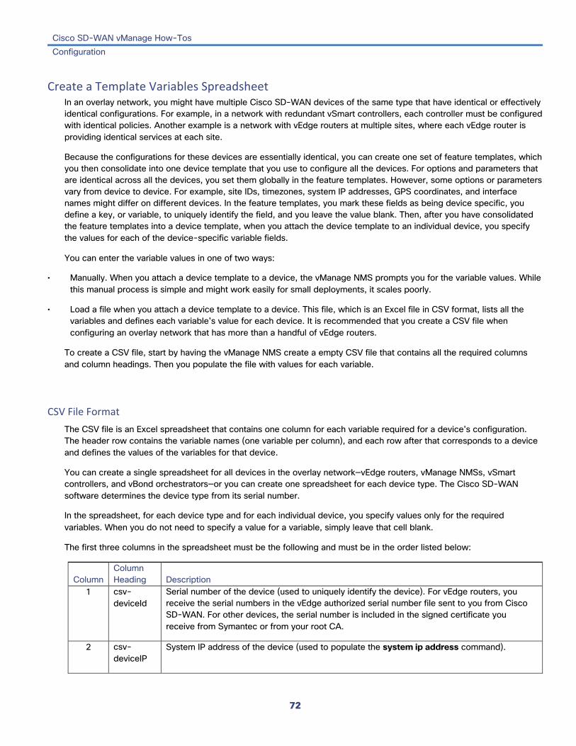
Cisco SD-WAN vManage How-Tos Configuration
72
Create a Template Variables Spreadsheet In an overlay network, you might have multiple Cisco SD-WAN devices of the same type that have identical or effectively identical configurations. For example, in a network with redundant vSmart controllers, each controller must be configured with identical policies. Another example is a network with vEdge routers at multiple sites, where each vEdge router is providing identical services at each site.
Because the configurations for these devices are essentially identical, you can create one set of feature templates, which you then consolidate into one device template that you use to configure all the devices. For options and parameters that are identical across all the devices, you set them globally in the feature templates. However, some options or parameters vary from device to device. For example, site IDs, timezones, system IP addresses, GPS coordinates, and interface names might differ on different devices. In the feature templates, you mark these fields as being device specific, you define a key, or variable, to uniquely identify the field, and you leave the value blank. Then, after you have consolidated the feature templates into a device template, when you attach the device template to an individual device, you specify the values for each of the device-specific variable fields.
You can enter the variable values in one of two ways:
• Manually. When you attach a device template to a device, the vManage NMS prompts you for the variable values. While this manual process is simple and might work easily for small deployments, it scales poorly.
• Load a file when you attach a device template to a device. This file, which is an Excel file in CSV format, lists all the variables and defines each variable's value for each device. It is recommended that you create a CSV file when configuring an overlay network that has more than a handful of vEdge routers.
To create a CSV file, start by having the vManage NMS create a empty CSV file that contains all the required columns and column headings. Then you populate the file with values for each variable.
CSV File Format The CSV file is an Excel spreadsheet that contains one column for each variable required for a device's configuration. The header row contains the variable names (one variable per column), and each row after that corresponds to a device and defines the values of the variables for that device.
You can create a single spreadsheet for all devices in the overlay network—vEdge routers, vManage NMSs, vSmart controllers, and vBond orchestrators—or you can create one spreadsheet for each device type. The Cisco SD-WAN software determines the device type from its serial number.
In the spreadsheet, for each device type and for each individual device, you specify values only for the required variables. When you do not need to specify a value for a variable, simply leave that cell blank.
The first three columns in the spreadsheet must be the following and must be in the order listed below:
Column Column Heading Description
1 csv-deviceId
Serial number of the device (used to uniquely identify the device). For vEdge routers, you receive the serial numbers in the vEdge authorized serial number file sent to you from Cisco SD-WAN. For other devices, the serial number is included in the signed certificate you receive from Symantec or from your root CA.
2 csv-deviceIP
System IP address of the device (used to populate the system ip address command).

Cisco SD-WAN vManage How-Tos Configuration
73
3 csv-host-name
Hostname of the device (used to populate the system hostname command).
The headings for the remaining columns must be unique variable keys that are defined in the Enter Key box of a feature template. These remaining columns can be in any order.
Create an Empty CSV File An easy way to get the correct text strings for the column headings is to have the vManage NMS create an empty CSV file. Note that this generated CSV is not completely empty. Rather, it contains one row for each Cisco SD-WAN device type. What it provides you, though, is the column headings required for each of the variables in the device configuration.
To have the vManage NMS create an empty CSV file, which contains columns and column headings for all the variables required by all the feature templates contained in the device template:
1. In the Configuration ► Templates screen, click the Feature tab.
2. Click Add Template.
3. Create the required feature templates for one vEdge router, one vSmart controller, one vManage NMS, and one vBond controller. For information about creating the feature templates, see the Device Configuration How-To articles. In each feature template:
a. For fields that have default values, verify that you want to use that value for all devices. If you do not want to use the default, change the scope to Global or Device specific.
b. For fields that apply to all devices, select the Global icon next to the field and set the desired global values.
c. For fields that are device specific, select the Device-specific icon next to the field and leave the field blank.
4. For each Cisco SD-WAN device type, create a device template. For information about creating device templates, see the Device Configuration How-To articles.
5. In the Configuration ► Templates screen, click the Device tab.
6. In the Template List view, select the desired device template.
7. Click the More Actions icon to the right of the row and click Export CSV.
8. Repeat Steps 6 and 7 for each device type.
Edit the exported CSV file, adding at a minimum the device serial number, device system IP address, and device hostname for each device in the overlay network. Then add values for desired device-specific variables for each device. Note that variable names cannot contain forward slashes (/) or backwards slashes (\).
If desired, you can combine the CSV files into a single file.
To use the device-specific variable values in the CSV file, import the file when you are attaching a device template to the Cisco SD-WAN device. During the attachment process, click Import file to load the Excel file. If vManage NMS detects duplicate system IP addresses for devices in the overlay network, it displays a warning message or a pop-up window. You must correct the system IP addresses to remove any duplicates before you can continue the process of attaching device templates to Cisco SD-WAN devices.

Cisco SD-WAN vManage How-Tos Configuration
74
Manually Enter Template Variables If any fields in a feature template contain device-specific values, when you attach a device template to a device, the vManage NMS prompts you for the values of these variables. In test or POC networks, or if you are deploying a small network, you can simply enter the values manually instead of creating and importing a template variables spreadsheet and then attach the template to the device
1. In the Configuration ► Templates screen, click the Device tab.
2. In the Template List, select the desired device template.
3. Click the More Actions icon to the right of the row and click Attach Devices. The Attach Devices dialog box opens with the Select Devices tab selected
4. In the Available Devices column on the left, select a group and search for one or more devices, select a device from the list, or click Select All.
5. Click the arrow pointing right to move the device to the Selected Devices column on the right.
6. Click Attach.
7. If the template contains variables, enter the missing variable values. Note that variable names cannot contain forward slashes (/) or backwards slashes (\). Once you provide values for all variables, the Status column to the right of each device row changes to green.
8. Click Next. If any devices have the same system IP address, a pop-up or an error message is displayed when you click Next. Modify the system IP addresses so that there are no duplicates, and click Save. Then click Next again.
9. In the left pane, select the device to preview the configuration that is ready to be pushed to the device. The right pane displays the device's configuration and the Config Preview tab in the upper right corner is selected. Click the Config Diff tab to preview the differences between this configuration and the configuration currently running on the device, if applicable. Click the Back button to edit the variable values entered in the previous screen.
10. Click Configure Devices to push the configuration to the devices. The Status column displays whether the configuration was successfully pushed. Click the right angle bracket to the left of the row to display details of the push operation.
Release Information Introduced in vManage NMS in Release 15.3. In Release 15.4, add ability to export CSV file without having to first attach devices. In Release 17.2, have vManage NMS check for duplicate system IP addresses.
Additional Information Configure Devices from vManage NMS Create Configuration Templates for a vBond Orchestrator Create Configuration Templates for a vEdge Router Create Configuration Templates for a vManage NMS Create Configuration Templates for a vSmart Controller

Cisco SD-WAN vManage How-Tos Configuration
75
Create Configuration Templates for a vBond Orchestrator This article describes how to configure vBond orchestrators that are being managed by a vManage NMS. These devices must be configured from the vManage NMS. If you configure them directly from the CLI on the router, the vManage NMS overwrites the configuration with the one stored on the NMS system.
Configuration Prerequisites
Security Prerequisites Before you can configure vBond orchestrators in the Cisco SD-WAN overlay network, you must have generated a certificate for the vBond orchestrator, and the certificate must already be installed on the device. See Generate a Certificate .
Variables Spreadsheet The feature templates that you create will most likely contain variables. To have the vManage NMS populate the variables with actual values when you attach a device template to a device, either enter the values manually or click Import File in the upper right corner to load an Excel file in CSV format that contains the variables values.
In the spreadsheet, the header row contains the variable name and each row after that corresponds to a device, defining the values of the variables. The first three columns in the spreadsheet must be (in the order listed below):
• csv-deviceId—Serial number of the device (used to uniquely identify the device). For vEdge routers, you receive the serial numbers in the vEdge authorized serial number file sent to you from Cisco SD-WAN. For other devices, the serial number is included in the signed certificate you receive from Symantec or from your root CA.
• csv-deviceIP—System IP address of the device (used to populate the system ip address command).
• csv-host-name—Hostname of the device (used to populate the system hostname command).
You can create a single spreadsheet for all devices in the overlay network—vEdge routers, vSmart controllers, and vBond orchestrators. You do not need to specify values for all variables for all devices.
Feature Templates for vBond Orchestrators The following features are mandatory for vBond orchestrator operation, and so creating a feature template for each of them is required:
Feature Template Name Authentication, Authorization, and Accounting (AAA) AAA
Security Security
System-wide parameters System
Transport VPN (VPN 0) VPN, with the VPN ID set to 0

Cisco SD-WAN vManage How-Tos Configuration
76
Management VPN (for out-of-band management traffic) VPN, with the VPN ID set to 512
The following templates are provided for other vBond orchestrator features:
Feature Template Name Archive of the router's running configuration Archive
Banner text displayed before and after login Banner
Interfaces VPN and VPN-Interface-Ethernet
SNMP SNMP
System message logging Logging
Create Feature Templates Feature templates are the building blocks of a vBond orchestrator's complete configuration. For each feature that you can enable on a vBond orchestrator, the vManage NMS provides a template form that you fill out with the desired parameters for that feature.
You must create feature templates for the mandatory vBond orchestrator features.
You can create multiple templates for the same feature.
To create vBond feature templates:
1. In vManage NMS, select the Configuration ► Templates screen.
2. From the Templates title bar, select Feature.
3. Click Add Template.
4. In the left pane, from Select Devices, select vEdge Cloud. (For Releases 15.4 and earlier, select vBond Software.) In Releases 16.1 and later, you must create a vBond-only templates, that define only orchestrator functionality. These templates must not contain any vEdge functionality.
5. In the right pane, select the template. The template form is displayed. The top of the form contains fields for naming the template, and the bottom contains fields for defining required parameters applicable to that template. Optional parameters are generally grayed out. A plus sign (+) is displayed to the right when you can add multiple entries for the same parameter.
6. Enter a template name and description. These fields are mandatory. You cannot use any special characters in template names.
7. For each required parameter, choose the desired value, and if applicable, select the scope of the parameter. Select the scope from the drop-down menu to the left of each parameter's value box:
Parameter Scope Scope Description

Cisco SD-WAN vManage How-Tos Configuration
77
Default Use the default value for the parameter.
If the parameter is already configured on a device, the configured value is not modified.
If the parameter is not yet configured on a device and if it has a default value, that default value is configured on the device. Examples of parameters that have default values are the various timers for routing protocol hello intervals.
Device specific
Use a device-specific value for the parameter.
When you attach the device template to the router, you must enter the value for the parameter. You can type the values manually, or you can upload an Excel file in CSV format that contains the parameter's value.
Examples of device-specific parameters are system IP address, hostname, GPS location, and site ID.
Global Enter a value for the parameter, and apply that value to all devices.
Examples of parameters that you might apply globally to a group of devices are DNS server, syslog server, and interface MTUs.
8. Click the plus sign (+) below the required parameters to set the values for additional parameters, if applicable.
9. Click Create.
10. Create feature templates for each of the required features listed in the previous section.
a. In the System template, in the top portion, configure all desired parameters except for Controller Groups, Maximum Controllers, and Maximum OMP Sessions. These parameters are specific to vEdge routers and have no meaning for a vBond orchestrator. In the Advanced Options portion, in vBond Only and Local vBond, click On. These two parameters are what instantiate the vBond orchestrator.
b. Create two VPN templates, one for VPN 0 (the VPN that connects to the Internet or other public transport network) and one for VPN 512 (the VPN that handles out-of-band management traffic).
c. Create AAA and Security templates.
11. Create feature templates for each optional feature that you want to enable on vBond orchestrators:
a. Create Archive and Banner templates
b. Create one VPN-Interface-Ethernet template for each additional Ethernet interface you want to configure on the vBond orchestrator. Do not create any tunnel interfaces, or tunnels of any kind, for vBond orchestrators.
Create Device Templates Device templates contain all or large portions of a device's complete operational configuration. You create device templates by consolidating together individual feature templates. You can also create them by entering a CLI text-style configuration directly on the vManage NMS. You can use both styles of device templates when configuring a vBond orchestrator.
To create vBond device templates from feature templates:

Cisco SD-WAN vManage How-Tos Configuration
78
1. In vManage NMS, select the Configuration ► Templates screen.
2. From the Templates title bar, select Device.
3. Click Create Template, and from the drop-down list, select From Feature Templates.
4. From the Device Model drop-down, select vEdge Cloud. (For Releases 15.4 and earlier, select vBond Software.)
5. Enter a name and description for the vBond device template. These fields are mandatory. You cannot use any special characters in template names.
6. From the bar beneath the template name and description, select the desired group of templates.
7. In each section, select the desired template. All required templates are marked with an asterisk (*). Initially, the drop-down list for each template lists the default feature template
a. For each required and optional template, select the feature template from the drop-down list. These templates are the ones that you previously created (see Create Feature Templates above). Do not select a BFD or an OMP template for vBond orchestrators.
b. For additional templates, click the plus (+) sign next to the template name, and select the feature template from the drop-down list.
8. Click Create. The new device template is listed in the Templates table. The Feature Templates column shows the number of feature templates that are included in the device template, and the Type column shows "Feature" to indicate that the device template was created from a collection of feature templates.
To create device templates by entering a CLI text-style configuration directly on the vManage NMS:
1. In vManage NMS, select the Configuration ► Templates screen.
2. From the Templates title bar, select Device.
3. Click Create Template, and from the drop-down list, select CLI Template.
4. In the Add Device CLI Template box, enter a template name and description, and select vBond Software.
5. Enter the configuration in the CLI Configuration box, either by typing it, cutting and pasting it, or uploading a file.
6. To convert an actual configuration value to a variable, select the value and click Create Variable. Enter the variable name, and click Create Variable. You can also type the variable name directly, in the format {{ variable-name }}; for example, {{hostname}}.
7. Click Add. The right pane on the screen lists the new device template. The Feature Templates column shows the number of feature templates that are included in the device template, and the Type column shows "CLI" to indicate that the device template was created from CLI text.
Attach Device Templates To vBond Orchestrators To configure a vBond orchestrator, you attach one device template to the orchestrator. You can attach the same template to multiple vBond orchestrators simultaneously.
To attach a device template to vBond orchestrators:
1. In vManage NMS, select the Configuration ► Templates screen.

Cisco SD-WAN vManage How-Tos Configuration
79
2. From the Templates title bar, select Device.
3. In the right pane, select the desired device template.
4. Click the More Actions icon to the right of the row, and select Attach Devices.
5. In the Attach Devices box, select the desired vBond orchestrators from the Available Devices list, and click the right-pointing arrow to move them to the Selected Devices box. You can select one or more orchestrators. Click Select All to choose all listed orchestrators.
6. Click Attach.
7. If the device template contains variables, either enter the values manually or click Import file in the upper right corner to load an Excel file in CSV format that contains the variable values.
8. Click Next.
9. To send the configuration in the device template to the vBond orchestrators, click Configure Devices.
Release Information Introduced in vManage NMS in Release 15.3. Procedure revised in Release 16.1.
Additional Information Add the vBond Orchestrator to the Overlay Network Configure Devices from vManage NMS Create Configuration Templates for a vEdge Router Create Configuration Templates for a vManage NMS Create Configuration Templates for a vSmart Controller Generate a Certificate

Cisco SD-WAN vManage How-Tos Configuration
80
Create Configuration Templates for a vEdge Router This article describes how to configure vEdge routers that are being managed by a vManage NMS. These routers must be configured from the vManage NMS. If you configure these routers directly from the CLI on the router, the vManage NMS overwrites the configuration with the one stored on the NMS system.
Security Prerequisites Before you can configure the vEdge routers in the Cisco SD-WAN overlay network, the devices must be validated and authenticated so that the vManage NMSs, vSmart controllers, and vBond orchestrators recognize them as being allowed in the overlay network.
To validate and authenticate the vEdge routers, you receive a vEdge authorized serial number file from Cisco SD-WAN, which lists the serial and chassis numbers for all the vEdge routers allowed in your network. Then, you upload the vEdge serial number file to the vManage NMS.
Variables Spreadsheet The feature templates that you create will most likely contain variables. To have the vManage NMS populate the variables with actual values when you attach a device template to a device, either enter the values manually or click Import File in the upper right corner to load an Excel file in CSV format that contains the variables values.
In the spreadsheet, the header row contains the variable name and each row after that corresponds to a device, defining the values of the variables. The first three columns in the spreadsheet must be (in the order listed below):
• csv-deviceId—Serial number of the device (used to uniquely identify the device). For vEdge routers, you receive the serial numbers in the vEdge authorized serial number file sent to you Cisco SD-WAN. For other devices, the serial number is included in the signed certificate you receive from Symantec or from your root CA.
• csv-deviceIP—System IP address of the device (used to populate the system ip address command).
• csv-host-name—Hostname of the device (used to populate the system hostname command).
You can create a single spreadsheet for all devices in the overlay network—vEdge routers, vSmart controllers, and vBond orchestrators. You do not need to specify values for all variables for all devices.
Feature Templates for vEdge Routers The following features are mandatory for vEdge router operation, and so creating a feature template for each of them is required:
Feature Template Name Authentication, Authorization, and Accounting (AAA) AAA
Bidirectional Forwarding Detection (BFD) BFD
Overlay Management Protocol (OMP) OMP
Security Security
System-wide parameters System

Cisco SD-WAN vManage How-Tos Configuration
81
Transport VPN (VPN 0) VPN, with the VPN ID set to 0
Management VPN (for out-of-band management traffic) VPN, with the VPN ID set to 512
The following templates are provided for other vEdge router features:
Feature Template Name Archive of the router's running configuration Archive
Banners display before and login and Banner
BGP BGP
Bridging Bridge
Bridging interfaces VPN-Interface-Bridge
Cellular profiles and interfaces (in Releases 16.3 and later) Cellular-Profile and VPN-Interface-Cellular
DHCP server DHCP-Server
Ethernet interfaces VPN-Interface-Ethernet
GRE interfaces VPN-Interface-GRE
IGMP IGMP
Message logging Logging
IP multicast Multicast
NAT pool interfaces VPN-Interface-Natpool
Network Time Protocol NTP
OSPF OSPF
PPP interfaces VPN-Interface-PPP and VPN-Interface-PPP-Ethernet
Protocol-Independent Multicast PIM
SNMP SNMP
WLAN WiFi Radio (in Releases 16.3 and later) WiFi Radio
WLAN WiFi SSID (in Release 16.3 and later) WiFi SSID
Create Feature Templates Feature templates are the building blocks of a vEdge router's complete configuration. For each feature that you can enable on a vEdge router, the vManage NMS provides a template form that you fill out with the desired parameters for that feature.
You must create feature templates for the mandatory vEdge router features.
You can create multiple templates for the same feature.

Cisco SD-WAN vManage How-Tos Configuration
82
To create vEdge feature templates:
1. In vManage NMS, select the Configuration ► Templates screen.
2. From the Templates title bar, select Feature.
3. Click Add Template.
4. In the left pane, select one or more router models. You can create a single feature template for features that are available on more than one vEdge model. You must, however, create separate feature templates for software features that are available only on one or a subset of router models.
5. In the right pane, select the template. The template form is displayed. The top of the form contains fields for naming the template, and the bottom contains fields for defining required parameters applicable to that template. Optional parameters are generally grayed out. A plus sign (+) is displayed to the right when you can add multiple entries for the same parameter.
6. Enter a template name and description. These fields are mandatory. You cannot use any special characters in template names.
7. For each required parameter, choose the desired value, and if applicable, select the scope of the parameter. Select the scope from the drop-down menu to the left of each parameter's value box:
Parameter Scope Scope Description
Default Use the default value for the parameter.
If the parameter is already configured on a device, the configured value is not modified. (Because vEdge routers are shipped with a factory-default configuration, some parameters are preconfigured on new routers.)
If the parameter is not yet configured on a device and if it has a default value, that default value is configured on the device. Examples of parameters that have default values are the various timers for routing protocol hello intervals.
Device specific
Use a device-specific value for the parameter.
When you attach the device template to the router, you must enter the value for the parameter. You can type the values manually, or you can upload an Excel file in CSV format that contains the parameter's value.
Examples of device-specific parameters are system IP address, hostname, GPS location, and site ID.
Global Enter a value for the parameter, and apply that value to all devices.
Examples of parameters that you might apply globally to a group of devices are DNS server, syslog server, and interface MTUs.
8. Click the plus sign (+) below the required parameters to set the values for additional parameters, if applicable.
9. Click Create.
10. Create feature templates for each of the required features listed in the previous section.

Cisco SD-WAN vManage How-Tos Configuration
83
For the transport VPN, use the template called VPN-vEdge and in the VPN Template section, set the VPN to 0, with a scope of Global. For the management VPN, use the template called VPN-vEdge and in the VPN Template section, set the VPN to 512, with a scope of Global.
11. Create feature templates for each optional feature that you want to enable on vEdge routers.
Create Device Templates Device templates contain all or large portions of a device's complete operational configuration. You create device templates by consolidating together individual feature templates. You can also create them by entering a CLI text-style configuration directly on the vManage NMS. You can use both styles of device templates when configuring a vEdge router.
To create vEdge device templates from feature templates:
1. In vManage NMS, select the Configuration ► Templates screen.
2. From the Templates title bar, select Device.
3. Click Create Template, and from the drop-down list, select From Feature Templates.
4. From the Device Model drop-down, select the router model. You create separate device templates for each vEdge router model in the overlay network.
5. Enter a name and description for the vEdge router device template. These fields are mandatory. You cannot use any special characters in template names.
6. Complete the Required Templates section. All required templates are marked with an asterisk.
a. For each required template, select the feature template from the drop-down list. These templates are the ones that you previously created (see Create Feature Templates above). After you select a template, the circle next to the template name turns green and displays a green check mark.
b. For templates that have Sub-Templates, click the plus (+) sign or the Sub-Templates title to display a list of sub-templates. As you select a sub-template, the name of the sub-template along with a drop-down is displayed. If the sub-template is mandatory, its name is marked with an asterisk.
c. Select the desired sub-template.
7. Complete the Optional Templates section, if required. To do so:
a. Click Optional Templates to add optional feature templates to the device template.
b. Select the template to add.
c. Click the template name and select a specific feature template.
8. Click Create. The new device template is listed in the Templates table. The Feature Templates column shows the number of feature templates that are included in the device template, and the Type column shows "Feature" to indicate that the device template was created from a collection of feature templates.
To create device templates by entering a CLI text-style configuration directly on the vManage NMS:

Cisco SD-WAN vManage How-Tos Configuration
84
1. In vManage NMS, select the Configuration ► Templates screen.
2. From the Templates title bar, select Device.
3. Click Create Template, and from the drop-down list, select CLI Template.
4. In the Add Device CLI Template box, enter a template name and description, and select the router model.
5. Enter the configuration in the CLI Configuration box, either by typing it, cutting and pasting it, or uploading a file.
6. To convert an actual configuration value to a variable, select the value and click Create Variable. Enter the variable name, and click Create Variable. You can also type the variable name directly, in the format {{ variable-name }}; for example, {{hostname}}.
7. Click Add. The right pane on the screen lists the new device template. The Feature Templates column shows the number of feature templates that are included in the device template, and the Type column shows "CLI" to indicate that the device template was created from CLI text.
Attach Device Templates To Routers To configure a vEdge router, you attach one device template to a vEdge router. You can attach the same template to multiple vEdge routers simultaneously.
To attach a device template to vEdge routers:
1. In vManage NMS, select the Configuration ► Templates screen.
2. From the Templates title bar, select Device.
3. In the right pane, select the desired device template.
4. Click the More Actions icon to the right of the row, and select Attach Devices.
5. In the Attach Devices box, select the desired vEdge routers from the Available Devices list, and click the right-pointing arrow to move them to the Selected Devices box. The Attach Devices box lists only the routers whose router model matches the model in the device template. You can select one or more router. Click Select All to choose all listed routers.
6. Click Attach.
7. If the device template contains variables, either enter the values manually or click Import file in the upper right corner to load an Excel file in CSV format that contains the variable values.
8. Click Next.
9. To send the configuration in the device template to the vEdge routers, click Configure Device.
Release Information Introduced in vManage NMS in Release 15.3.

Cisco SD-WAN vManage How-Tos Configuration
85
Additional Information Create Configuration Templates for a vBond Orchestrator Create Configuration Templates for a vManage NMS Create Configuration Templates for a vSmart Controller Configure Devices from vManage NMS Upload the vEdge Serial Number File

Cisco SD-WAN vManage How-Tos Configuration
86
Create Configuration Templates for a vManage NMS You should create configuration templates for the vManage NMS.
Security Prerequisites Before you can configure a vManage NMS in the Cisco SD-WAN overlay network, you must have generated a certificate for it, and the certificate must already be installed on the device. See Generate a Certificate .
Variables Spreadsheet The feature templates that you create will most likely contain variables. To have the vManage NMS populate the variables with actual values when you attach a device template to a device, either enter the values manually or click Import File in the upper right corner to load an Excel file in CSV format that contains the variables values.
In the spreadsheet, the header row contains the variable name and each row after that corresponds to a device, defining the values of the variables. The first three columns in the spreadsheet must be (in order):
• csv-deviceId—Serial number of the device (used to uniquely identify the device). For vEdge routers, you receive the serial numbers in the vEdge authorized serial number file sent to you from Cisco SD-WAN. For other devices, the serial number is included in the signed certificate you receive from Symantec or from your root CA.
• csv-deviceIP—System IP address of the device (used to populate the system ip address command).
• csv-host-name—Hostname of the device (used to populate the system hostname command).
You can create a single spreadsheet for all devices in the overlay network—vManage NMSs, vEdge routers, vSmart controllers, and vBond orchestrators. You do not need to specify values for all variables for all devices.
Feature Templates for vManage NMSs The following features are mandatory for vManage NMS operation, so you must create a feature template for each of them:
Feature Template Name Authentication, Authorization, and Accounting (AAA) AAA
Security Security
System-wide parameters System
Transport VPN (VPN 0) VPN, with the VPN ID set to 0
Management VPN (for out-of-band management traffic) VPN, with the VPN ID set to 512
The following additional templates are provided for other vManage NMS features:
Feature Template Name Archive of the router's running configuration Archive
Banners display before and login and Banner
Interfaces VPN and VPN-Interface-Ethernet

Cisco SD-WAN vManage How-Tos Configuration
87
Network Time Protocol NTP
SNMP SNMP
System message logging Logging
Create Feature Templates Feature templates are the building blocks of a vManage NMS's complete configuration. For each feature that you can enable on a vManage NMS, the vManage NMS provides a template form that you fill out with the desired parameters for that feature.
You must create feature templates for the mandatory vManage NMS features.
You can create multiple templates for the same feature.
To create vManage feature templates:
1. In vManage NMS, select the Configuration ► Templates screen.
2. From the Templates title bar, select Feature.
3. Click Add Template.
4. In the left pane, from Select Devices, select vManage. You can create a single feature template for features that are available on both the vManage NMS and other devices. You must, however, create separate feature templates for software features that are available only on the vManage NMS.
5. In the right pane, select the template. The template form is displayed. The top of the form contains fields for naming the template, and the bottom contains fields for defining parameters applicable to that template. Optional parameters are generally grayed out. A plus (+) sign is displayed to the right when you can add multiple entries for the same parameter.
6. Enter a template name and description. These fields are mandatory. You cannot use any special characters in template names.
7. For each required parameter, choose the desired value, and if applicable, select the scope of the parameter. Select the scope from the drop-down menu to the left of each parameter field:
Parameter Scope Scope Description
Default Use the default value for the parameter.
If the parameter is already configured on a device, it is over-written by the default value.
If the parameter is not yet configured on a device and if it has a default value, that default value is configured on the device. Examples of parameters that have default values are timers.

Cisco SD-WAN vManage How-Tos Configuration
88
Device specific
Use a device-specific value for the parameter.
When you attach the device template to the vManage NMS, you must enter the value for the parameter. You can type the values manually, or you can upload an Excel file in CSV format that contains the parameter's value.
Examples of device-specific parameters are system IP address, hostname, GPS location, and site ID.
Global Enter a value for the parameter, and apply that value to all devices.
Examples of parameters that you might apply globally to a group of devices are DNS server, syslog server, and interface MTUs.
8. Click the plus sign (+) below the required parameters to set values for additional parameters, if applicable.
9. Click Create.
10. Create feature templates for each of the required features listed in the previous section.
a. For the transport VPN, use the template called VPN-vManage and in the VPN Template section, set the VPN to 0, with a scope of Global.
b. For the management VPN, use the template called VPN-vManage and in the VPN Template section, set the VPN to 512, with a scope of Global.
11. Create any additional feature templates for each optional feature that you want to enable on the vManage NMS.
Create Device Templates Device templates contain a device's complete operational configuration. You create device templates by consolidating together individual feature templates. You can also create them by entering a CLI text-style configuration directly on the vManage NMS.
You can attach only one device template to configure a vManage NMS, so it must contain, at a minimum, all the required portions of the vManage configuration. If it does not, the vManage NMS returns an error message. If you attach a second device template to the vManage NMS, it overwrites the first one.
To create device templates from feature templates:
1. In vManage NMS, select the Configuration ► Templates screen.
2. From the Templates title bar, select Device.
3. Click Create Template, and from the drop-down list select From Feature Templates.
4. From the Device Model drop-down, select vManage.
5. Enter a name and description for the vManage device template. These fields are mandatory. You cannot use any special characters in template names.
6. Complete the Required Templates section. All required templates are marked with an asterisk.

Cisco SD-WAN vManage How-Tos Configuration
89
a. For each required template, select the feature template from the drop-down list. These templates are the ones that you previously created (see Create Feature Templates above). After you select a template, the circle next to the template name turns green and displays a green check mark.
b. For templates that have Sub-Templates, click the plus (+) sign or the Sub-Templates title to display a list of sub-templates. As you select a sub-template, the name of the sub-template along with a drop-down is displayed. If the sub-template is mandatory, its name is marked with an asterisk.
c. Select the desired sub-template.
7. Complete the Optional Templates section, if required. To do so:
a. Click Optional Templates to add optional feature templates to the device template.
b. Select the template to add.
c. Click the template name and select a specific feature template.
8. Click Create. The new device template is listed in the Templates table. The Feature Templates column shows the number of feature templates that are included in the device template, and the Type column shows "Feature" to indicate that the device template was created from a collection of feature templates.
To create device templates by entering a CLI text-style configuration directly on the vManage NMS:
1. In vManage NMS, select the Configuration ► Templates screen.
2. From the Templates title bar, select Device.
3. Click Create Template, and from the drop-down list, select CLI Template.
4. In the Add Device CLI Template box, enter a template name and description, and select vManage.
5. Enter the configuration in the CLI Configuration box, either by typing it, cutting and pasting it, or uploading a file.
6. To convert an actual configuration value to a variable, select the value and click Create Variable. Enter the variable name, and click Create Variable. You can also type the variable name directly, in the format {{ variable-name }}; for example, {{hostname}}.
7. Click Add. The new device template is listed in the Templates table. The Feature Templates column shows the number of feature templates that are included in the device template, and the Type column shows "CLI" to indicate that the device template was created from CLI text.
Attach a Device Template to a vManage NMS To configure a vManage NMS, you attach one device template to the device.
To attach a device template to a vManage NMS:
1. In vManage NMS, select the Configuration ► Templates screen.
2. From the Templates title bar, select Device.
3. In the right pane, select the desired device template.
4. Click the More Actions icon to the right of the row, and select Attach Devices.

Cisco SD-WAN vManage How-Tos Configuration
90
5. In the Attach Devices box, select the desired vManage NMS from the Available Devices list, and click the right-pointing arrow to move them to the Selected Devices box. You can select one or more controllers. Click Select All to choose all listed controllers.
6. Click Attach.
7. If the device template contains variables, either enter the values manually or click Import file in the upper right corner to load an Excel file in CSV format that contains the variable values.
8. Click Next.
9. To preview the configuration that is about to be sent to the vManage NMS, in the left pane, click the device. The configuration is displayed in the right pane, in the Device Configuration Preview window.
10. To send the configuration in the device template to the vManage NMS, click Configure Devices.
Release Information Introduced in vManage NMS in Release 15.3.
Additional Information Create Configuration Templates for a vBond Orchestrator Create Configuration Templates for a vEdge Router Create Configuration Templates for a vSmart Controller Configure Devices from vManage NMS Generate a Certificate

Cisco SD-WAN vManage How-Tos Configuration
91
Create Configuration Templates for a vSmart Controller For vSmart controllers that are being managed by a vManage NMS, you must configure them from the vManage NMS. If you configure them directly from the CLI on the vSmart controller, the vManage NMS overwrites the configuration with the one stored on the NMS system.
Configuration Prerequisites
Security Prerequisites Before you can configure vSmart controllers in the Cisco SD-WAN overlay network, you must have generated a certificate for the vSmart controller, and the certificate must already be installed on the device. See Generate a Certificate .
Variables Spreadsheet The feature templates that you create will most likely contain variables. To have the vManage NMS populate the variables with actual values when you attach a device template to a device, either enter the values manually or click Import File in the upper right corner to load an Excel file in CSV format that contains the variables values.
In the spreadsheet, the header row contains the variable name and each row after that corresponds to a device, defining the values of the variables. The first three columns in the spreadsheet must be (in order):
• csv-deviceId—Serial number of the device (used to uniquely identify the device). For vEdge routers, you receive the serial numbers in the vEdge authorized serial number file sent to you from Cisco SD-WAN. For other devices, the serial number is included in the signed certificate you receive from Symantec or from your root CA.
• csv-deviceIP—System IP address of the device (used to populate the system ip address command).
• csv-host-name—Hostname of the device (used to populate the system hostname command).
You can create a single spreadsheet for all devices in the overlay network—vEdge routers, vSmart controllers, and vBond orchestrators. You do not need to specify values for all variables for all devices.
Feature Templates for vSmart Controllers The following features are mandatory for vSmart controller operation, so you must create a feature template for each of them:
Feature Template Name Authentication, Authorization, and Accounting (AAA) AAA
Overlay Management Protocol (OMP) OMP
Security Security
System-wide parameters System

Cisco SD-WAN vManage How-Tos Configuration
92
Transport VPN (VPN 0) VPN with the VPN ID set to 0
Management VPN (for out-of-band management traffic) VPN with the VPN ID set to 512
The following additional templates are provided for other vSmart controller features:
Feature Template Name Archive of the router's running configuration Archive
Banners display before and login and Banner
Interfaces VPN-Interface
Network Time Protocol NTP
SNMP SNMP
System message logging Logging
Create Feature Templates Feature templates are the building blocks of a vSmart controller's complete configuration. For each feature that you can enable on a vSmart controller, the vManage NMS provides a template form that you fill out with the desired parameters for that feature.
You must create feature templates for the mandatory vSmart controller features.
You can create multiple templates for the same feature.
To create vSmart feature templates:
1. In vManage NMS, select the Configuration ► Templates screen.
2. From the Templates title bar, select Feature.
3. Click Add Template.
4. In the left pane, from Select Devices, select vSmart. You can create a single feature template for features that are available on both vSmart controllers and other devices. You must, however, create separate feature templates for software features that are available only on vSmart controllers.
5. In the right pane, select the template. The template form is displayed. The top of the form contains fields for naming the template, and the bottom contains fields for defining parameters applicable to that template. Optional parameters are generally grayed out. A plus sign (+) is displayed to the right when you can add multiple entries for the same parameter.
6. Enter a template name and description. These fields are mandatory. You cannot use any special characters in template names.
7. For each required parameter, choose the desired value, and if applicable, select the scope of the parameter. Select the scope from the drop-down menu to the left of each parameter field:
Parameter Scope Scope Description

Cisco SD-WAN vManage How-Tos Configuration
93
Default Use the default value for the parameter.
If the parameter is already configured on a device, the configured value is not modified.
If the parameter is not yet configured on a device and if it has a default value, that default value is configured on the device. Examples of parameters that have default values are timers.
Device specific
Use a device-specific value for the parameter.
When you attach the device template to the vSmart controller, you must enter the value for the parameter. You can type the values manually, or you can upload an Excel file in CSV format that contains the parameter's value.
Examples of device-specific parameters are system IP address, hostname, GPS location, and site ID.
Global Enter a value for the parameter, and apply that value to all devices.
Examples of parameters that you might apply globally to a group of devices are DNS server, syslog server, and interface MTUs.
8. Click the plus sign (+) below the required parameters to set values for additional parameters, if applicable.
9. Click Create.
10. Create feature templates for each of the required features listed in the previous section. For the transport VPN, use the template called VPN-vSmart and in the VPN Template section, set the VPN to 0, with a scope of Global. For the management VPN, use the template called VPN-vSmart and in the VPN Template section, set the VPN to 512, with a scope of Global.
11. Create any additional feature templates for each optional feature that you want to enable on vSmart controllers.
Create Device Templates Device templates contain a device's complete operational configuration. You create device templates by consolidating together individual feature templates. You can also create them by entering a CLI text-style configuration directly on the vManage NMS.
You can attach only one device template to configure a vSmart controller, so it must contain, at a minimum, all the required portions of the vSmart configuration. If it does not, the vManage NMS returns an error message. If you attach a second device template to the vSmart controller, it overwrites the first one.
To create device templates from feature templates:
1. In vManage NMS, select the Configuration ► Templates screen.
2. From the Templates title bar, select Device.
3. Click Create Template, and from the drop-down list select From Feature Templates.
4. From the Device Model drop-down, select vSmart.
5. Enter a name and description for the vSmart device template. These fields are mandatory. You cannot use any special characters in template names.

Cisco SD-WAN vManage How-Tos Configuration
94
6. Complete the Required Templates section. All required templates are marked with an asterisk.
a. For each required template, select the feature template from the drop-down list. These templates are the ones that you previously created (see Create Feature Templates above). After you select a template, the circle next to the template name turns green and displays a green check mark.
b. For templates that have Sub-Templates, click the plus (+) sign or the Sub-Templates title to display a list of sub-templates. As you select a sub-template, the name of the sub-template along with a drop-down is displayed. If the sub-template is mandatory, its name is marked with an asterisk.
c. Select the desired sub-template.
7. Complete the Optional Templates section, if required. To do so:
a. Click Optional Templates to add optional feature templates to the device template.
b. Select the template to add.
c. Click the template name and select a specific feature template.
8. Click Create. The new device template is listed in the Templates table. The Feature Templates column shows the number of feature templates that are included in the device template, and the Type column shows "Feature" to indicate that the device template was created from a collection of feature templates.
To create device templates by entering a CLI text-style configuration directly on the vManage NMS:
1. In vManage NMS, select the Configuration ► Templates screen.
2. From the Templates title bar, select Device.
3. Click Create Template, and from the drop-down list, select CLI Template.
4. In the Add Device CLI Template box, enter a template name and description, and select vSmart.
5. Enter the configuration in the CLI Configuration box, either by typing it, cutting and pasting it, or uploading a file.
6. To convert an actual configuration value to a variable, select the value and click Create Variable. Enter the variable name, and click Create Variable. You can also type the variable name directly, in the format {{ variable-name }}; for example, {{hostname}}.
7. Click Add. The right pane on the screen lists the new device template. The Feature Templates column shows the number of feature templates that are included in the device template, and the Type column shows "CLI" to indicate that the device template was created from CLI text.
Attach a Device Template To vSmart Controllers To configure a vSmart controller, you attach one device template to the controller. You can attach the same template to multiple vSmart controllers simultaneously.
To attach a device template to vSmart controllers:
1. In vManage NMS, select the Configuration ► Templates screen.
2. From the Templates title bar, select Device.

Cisco SD-WAN vManage How-Tos Configuration
95
3. In the right pane, select the desired device template.
4. Click the More Actions icon to the right of the row, and select Attach Devices.
5. In the Attach Devices box, select the desired vSmart controllers from the Available Devices list, and click the right-pointing arrow to move them to the Selected Devices box. You can select one or more controllers. Click Select All to choose all listed controllers.
6. Click Attach.
7. If the device template contains variables, either enter the values manually or click Import file in the upper right corner to load an Excel file in CSV format that contains the variable values.
8. Click Next.
9. To preview the configuration that is about to be sent to the vSmart controller, in the left pane, click the device. The configuration is displayed in the right pane, in the Device Configuration Preview window.
10. To send the configuration in the device template to the vSmart controllers, click Configure Devices.
Release Information Introduced in vManage NMS in Release 15.3.
Additional Information Add a vSmart Controller Configure Devices from vManage NMS Create Configuration Templates for a vBond Orchestrator Create Configuration Templates for a vEdge Router Create Configuration Templates for a vManage NMS Generate a Certificate

Cisco SD-WAN vManage How-Tos Configuration
96
Delete a Software Image from a Device To delete a software image from a device, use the vManage Maintenance ► Software Upgrade screen.
1. In the title bar, click the WAN Edge, Controller, or vManage tab.
2. Select one or more devices from which to delete a software image.
3. Click the Delete Available Software button. The Delete Available Software dialog box opens.
4. Select the software version to delete.
5. Click Delete.
Release Information Introduced in vManage NMS in Release 15.2.
Additional Information Upgrade and Activate the Software Image on a Device
Cisco SD-WAN vManage How-Tos Configuration
97
Delete Configuration Templates You can delete feature templates if they are not being used in any device templates that are attached to devices.
You can delete device templates if no devices are attached to them.
Delete a Feature Template You can delete feature templates if they are not being used in any device templates that are attached to devices.
1. In vManage NMS, select the Configuration ► Templates screen.
2. From the Templates title bar, select Feature. In the templates table, the Device Templates column indicates how many device configuration templates are using a particular feature template. The Devices Attached column indicates how many devices are attached, via a device configuration template, to the feature template.
3. If the template is not being used in a device template, select it.
4. Click the More Actions icon to the right of the row, and select Delete.
5. Click OK to confirm deletion of the template.
Delete a Device Template You can delete device templates if no devices are attached to them.
1. In vManage NMS, select the Configuration ► Templates screen.
2. From the Templates title bar, select Device. In the templates table, the Devices Attached column indicates how many devices are attached to the device template.
3. If no devices are attached to the template, select it.
4. Click the More Actions icon to the right of the row, and select Delete.
5. Click OK to confirm deletion of the template.
Release Information Introduced in vManage in Release 15.3.
Additional Information Copy Configuration Templates Create Configuration Templates for a vBond Orchestrator Create Configuration Templates for a vEdge Router Create Configuration Templates for a vSmart Controller Configure Devices from vManage NMS

Cisco SD-WAN vManage How-Tos Configuration
98
Determine Changes to a Configuration Template When you push a new configuration template to a device, you can view changes between the old and the new templates. To view changes made to a configuration template:
1. In vManage NMS, select the Monitor ► Audit Log screen.
2. Select a row from the audit log table. The Message column of the audit log row contains a message indicating that the template is successfully attached to the device.
3. Click the More Actions icon to the right of the row, and click CLI Diff.
The CLI Diff popup window opens, with the Config Diff tab selected by default. This window displays a side-by-side view of the differences between the old configuration that was on the device and the changes made to the configuration. To view the changes inline, click the Inline Diff button located to the right of the window.
To view the updated configuration on the device, click the Configuration tab located to the left of the window.
Release Information Introduced in vManage NMS in Release 17.2.

Cisco SD-WAN vManage How-Tos Configuration
99
Determine Why a Device Rejects a Template When you attach a template to a device using the Configuration ► Templates screen, the device might reject the template. One reason that this may occur is because the device template contains incorrect variable values. When a device rejects a template, it reverts to the previous configuration.
To determine why the device rejected the template:
1. In vManage NMS, select the Configuration ► Devices screen.
2. In the right pane, locate the device. The Status column indicates why the device rejected the template.
Release Information Introduced in vManage NMS in Release 16.2.
Additional Information Device Configuration

Cisco SD-WAN vManage How-Tos Configuration
100
Edit a CLI Device Configuration Template In vManage NMS, you can edit a CLI device configuration template.
1. In vManage NMS, select the Configuration ► Templates screen.
2. In the Device tab, select a template.
3. Click the More Actions icon to the right of the row and click Edit.
4. In the Device CLI Template window, edit the template.
5. Click Update.
Release Information Introduced in vManage NMS in Release 15.3.
Additional Information Create a Device Configuration Template Change the Device Rollback Timer

Cisco SD-WAN vManage How-Tos Configuration
101
Edit a Configuration Template You can edit a device or feature configuration template.
1. In vManage NMS, select the Configuration ► Templates screen.
2. In the Device or Feature tab, select a template.
3. Click the More Actions icon to the right of the row and click Edit.
You cannot change the name of a device or feature template when that template is attached to a device.
Note: You can edit templates simultaneously from one or more vManage servers. For simultaneous template edit operations, the following rules apply:
• You cannot edit the same device or feature template simultaneously.
• When you are editing a device template, all other feature templates attached to that device template are locked and you cannot perform any edit operations on them.
• When you are editing a feature template that is attached to a device template, that device template as well as all other feature templates attached to it are locked and you cannot perform any edit operations on them.
Release Information Introduced in vManage NMS in Release 15.2.
Additional Information Create a Device Configuration Template View a Configuration Template

Cisco SD-WAN vManage How-Tos Configuration
102
Edit Controller Login Credentials To edit the IP address and login credentials of a controller device:
1. In vManage NMS, select the Configuration ► Devices screen.
2. In the Controllers tab, select the controller.
3. Click the More Actions icon to the right of the row and click Edit.
4. In the Edit window, edit the IP address and the login credentials.
5. Click Save.
Release Information Introduced in vManage NMS in Release 15.2.
Additional Information Add a vBond Orchestrator Add a vSmart Controller

Cisco SD-WAN vManage How-Tos Configuration
103
Enable and Configure Cloud OnRamp for SaaS Cloud OnRamp for SaaS (formerly called CloudExpress service) optimizes the performance of Software as a Service (SaaS) cloud applications based on network loss and latency. Cloud OnRamp for SaaS provides clear visibility of the performance of individual applications and automatically chooses the best path for each one.
Cloud OnRamp for SaaS calculates a value called the Cisco SD-WAN Quality of Experience (vQoE). The vQoE value weighs loss and latency using a formula customized for each application. For example, email applications tolerate latency better than video applications, and video applications tolerate loss better than email applications. The vQoE value ranges from zero to ten, with zero being the worst quality and ten being the best. Cloud OnRamp for SaaSe computes vQoE values for applications and paths, and then assigns applications to the paths that best match their vQoE value. Cloud OnRamp for SaaS periodically recalculates vQoE values for paths to ensure ongoing optimal application performance.
CloudExpress Requirements You can enable Cloud OnRamp for SaaS in your Cisco SD-WAN overlay network on sites with Direct Internet Access (DIA) and on DIA sites that access the internet through a secure web gateway such as Zscaler or iboss. You can also enable Cloud OnRamp for SaaS on client sites that access the internet through another site in the overlay network, called a gateway site. Gateway sites can include regional data centers or carrier-neutral facilities. When you enable Cloud OnRamp for SaaS on a client site that accesses the internet through a gateway, you also enable Cloud OnRamp for SaaS on the gateway site.
All Cisco SD-WAN devices configured for Cloud OnRamp for SaaS must meet these requirements:
• The devices must run vManage 16.3 or higher.
• The devices must run in vManage mode.
• You must configure a DNS server address in VPN 0.
• You must configure local exit interfaces in VPN 0:
– If the local interface list contains only physical interfaces, you must enable NAT on those interfaces. You can use normal default IP routes for next hops.
– If the local interface list contains only GRE interfaces, you do not need to enable NAT on those interfaces. You can add default routes to the IP address of the GRE tunnel to the destination.
Cloud OnRamp for SaaS runs on IPv4 only. It does not support IPv6.
Enable Cloud OnRamp for SaaS 1. In vManage NMS, select the Administration ► Settings screen.
2. Click the Edit button to the right of the CloudExpress bar.
3. In the Enable CloudExpress field, click Enabled.
4. Click Save.

Cisco SD-WAN vManage How-Tos Configuration
104
Configure Cloud OnRamp for SaaS
Add Applications 1. In vManage NMS, select the Configuration ► CloudExpress screen, or click the CloudExpress icon in the title bar. The
CloudExpress Dashboard screen opens.
2. From the Manage CloudExpress drop-down, located to the right of the title bar, select Applications to add applications to the CloudExpress configuration.
3. Click the Add Applications and VPN button. The Add Applications & VPN popup window displays.
4. In the Applications field, select an application.
5. In the VPN field, enter the service VPN in which that application runs. You can enter any VPN other than 0 and 512.
6. Click Add.
7. Repeat Steps 3 through 6 for each application you want to add.
8. Click Save Changes.
Configure Client Sites and Gateways To configure Cloud OnRamp for SaaS on client sites that access the internet through gateways, you must configure Cloud OnRamp for SaaS both on the client sites and on the gateway sites:
1. In vManage NMS, select the Configuration ► CloudExpress screen, or click the CloudExpress icon in the title bar. The CloudExpress Dashboard screen opens.
2. From the Manage CloudExpress drop-down, located to the right of the title bar, select Client Sites.
3. In the Manage Sites screen, click the Attach Sites button. The Attach Sites screen displays all sites in the overlay network with available sites highlighted. For a site to be available, all devices at that site must be running in vManage mode.
4. In the Available Sites pane, select a client site to attach and click the right arrow. To remove a site, select it in the Selected Sites pane and click the left arrow.
5. Click Attach. vManage NMS pushes the feature template configuration to the devices. The Task View window displays a Validation Success message.
6. Select Configuration ► CloudExpress to return to the CloudExpress Dashboard screen.
7. From the Manage CloudExpress drop-down, located to the right of the title bar, select Gateways.
8. In the Manage Gateways screen, click the Attach Gateways button. The Attach Gateways popup window displays all sites in your overlay network with available sites highlighted. For a site to be available, all devices at that site must be running in vManage mode.
9. In the Available Sites pane, select a gateway site to attach and click the right arrow. To remove a site, select it in the Selected Sites pane and click the left arrow.
10. If you do not specify interfaces for Cloud OnRamp for SaaS to use, the system selects a NAT-enabled physical interface from VPN 0. To specify GRE interfaces for Cloud OnRamp for SaaS service to use:

Cisco SD-WAN vManage How-Tos Configuration
105
a. Click the link Add interfaces to selected sites (optional), located in the bottom right corner of the window.
b. In the Select Interfaces drop-down, select GRE interfaces to add.
c. Click Save Changes.
11. Click Attach. vManage NMS pushes the feature template configuration to the devices. The Task View window displays a Validation Success message.
12. To return to the CloudExpress Dashboard, Select Configuration ► CloudExpress.
Configure DIA Sites 1. In vManage NMS, select the Configuration ► CloudExpress screen, or click the CloudExpress icon in the title bar. The
CloudExpress Dashboard screen opens.
2. From the Manage CloudExpress drop-down, located to the right of the title bar, select Direct Internet Access (DIA) Sites.
3. In the Manage DIA screen, click Attach DIA Sites. The Attach DIA Sites popup window displays all sites in your overlay network with available sites highlighted. For a site to be available, all devices at that site must be running in vManage mode.
4. In the Available Sites pane, select a site to attach and click the right arrow. To remove a site, select it in the Selected Sites pane and click the left arrow.
5. If you do not specify interfaces for Cloud OnRamp for SaaS to use, the system will select a NAT-enabled physical interface from VPN 0. If you would like to specify GRE interfaces for Cloud OnRamp for SaaS to use:
a. Click the link, Add interfaces to selected sites (optional), located in the bottom right corner of the window.
b. In the Select Interfaces drop-down, select GRE interfaces to add.
c. Click Save Changes.
6. Click Attach. vManage NMS pushes the feature template configuration to the devices. The Task View window displays a Validation Success message.
7. To return to the CloudExpress Dashboard, Select Configuration ► CloudExpress.
You have now completed configuring the Cloud OnRamp for SaaS. To return to the CloudExpress Dashboard, select the Configuration ► CloudExpress screen, or click the CloudExpress icon in the title bar.
Supported Applications Cloud OnRamp for SaaS supports the following enterprise applications:
• Amazon Web Service (AWS)
• Box
• Concur
• Dropbox

Cisco SD-WAN vManage How-Tos Configuration
106
• Google Apps
• GoToMeeting
• Intuit
• Microsoft Office 365
• Oracle
• Salesforce
• SugarCRM
• Zendesk
• Zoho CRM
Release Information Introduced in vManage NMS in Release 16.3.
Additional Information CloudExpress Service View Application Performance with CloudExpress Service
Cisco SD-WAN vManage How-Tos Configuration
107
Enable Data Stream Collection from a WAN Edge Router To collect data streams from a WAN Edge router in the overlay network, use the vManage Administration ► Settings screen.
By default, collecting streams of data from a network device is not enabled.
1. Click the Edit button to the right of the Data Stream bar.
2. In the Data Stream field, click Enabled.
3. In the Hostname field, enter the name of the host to collect the data. It is recommended that this host be one that is used for out-of-band management and that is located in the management VPN.
4. In the VPN field, enter the number of the VPN in which the host is located. It is recommended that this be the management VPN, which is typically VPN 512.
5. Click Save.
Release Information Introduced in vManage NMS in Release 17.2.

Cisco SD-WAN vManage How-Tos Configuration
108
Enable Timeout Value for a vManage Client Session To set how long a vManage client session is inactive before a user is logged out, use the vManage Administration ► Settings screen.
By default, a user's session to a vManage client remains established indefinitely and never times out.
1. Click the Edit button to the right of the Client Session Timeout bar.
2. In the Session Timeout field, click Enabled.
3. In the Timeout field, enter the timeout value, in minutes. This value can be from 10 to 180 minutes.
4. Click Save.
The client session timeout value applies to all vManage servers in a vManage cluster.
Release Information Introduced in vManage NMS in Release 17.1.

Cisco SD-WAN vManage How-Tos Configuration
109
Enable vAnalytics Platform To enable the vAnalytics platform, use the vManage Administration ► Settings screen:
1. Click the Edit button to the right of the vAnalytics bar.
2. In the Enable vAnalytics field, click Enabled.
3. Click Save.
Release Information Introduced in vManage NMS in Release 16.3.

Cisco SD-WAN vManage How-Tos Configuration
110
Enforce Software Version on a WAN Edge Router If you are using the Cisco SD-WAN ZTP hosted service, and wish to enforce a version of the Cisco software to run on a WAN Edge router when it first joins the overlay network, use the vManage Administration ► Settings screen.
1. Ensure that the software image for the desired WAN Edge router is present in the vManage software image repository:
a. In vManage NMS, select the Maintenance ► Software Upgrade screen.
b. In the Device List drop-down, click Repository. The Software Repository screen opens and displays a table of software images. If the desired software image is present in the repository, continue with Step 2.
c. If you need to add a software image, click Add New Software.
d. Select the location from which to download the software images, either vManage or Remote Server.
e. Select both an x86-based and a MIPS-based software image. Both images must be present in the repository.
f. Click Upload or Add to play the image in the repository.
2. In the Administration ► Settings screen, click the Edit button to the right of the Enforce Software Version (ZTP) bar.
3. In the Enforce Software Version field, click Enabled.
4. From the Software Version drop-down, select the version of the software to enforce on vEdge routers when they join the network.
5. Click Save.
If you enable this feature on the vManage NMS, any WAN Edge router joining the network is configured with the version of the software specified in the Enforce Software Version field regardless of whether the router was running a higher or lower version of the vManage software.
Release Information Introduced in vManage NMS in Release 15.2.

Cisco SD-WAN vManage How-Tos Configuration
111
Generate a Certificate Each vSmart controller and vBond orchestrator in the overlay network must have a signed certificate installed before it can operate in the overlay network. The signed certificate can be provided by Symantec or by an enterprise root CA. A certificate signing request (CSR) must be generated, and then the signed certificate must be received, installed on the device, and sent to the vBond orchestrator to allow the device to join the overlay network.
If the certificate is provided by Symantec, when you install a device from the vManage NMS, the NMS can automatically generate the CSR, retrieve the generated certificate, install it on the device, and send it to the vBond orchestrator. Or you can choose to manually generate the certificate . However, this is not recommended only because the automatic process requires only a single step.
If the certificate is provided by an enterprise root CA, you must manually generate and install the certificate from the vManage NMS. See Manually Generate a Certificate below.
Select the Certificate-Generation Method 1. In vManage NMS, select the Administration ► Settings screen.
2. Click the Edit button to the right of the Certificate Authorization bar.
3. In Certificate Signing by Symantec, select Automated to have the Symantec signing server automatically generate, sign, and install certificates on each controller device. If not, select Manual.
4. Enter the first and last name of the requestor of the certificate.
5. Enter the email address of the requestor of the certificate. If you selected Manual in Step 1, the signed certificate and a confirmation email are sent to the requestor via email and are also made available though the customer portal.
6. Specify the validity period for the certificate.
7. Click the Edit Challenge Phrase checkbox to enter a challenge phrase. The challenge phrase is your certificate password and is required when you renew or revoke a certificate.
8. Confirm your challenge phrase.
9. In the Certificate Retrieve Interval field, specify how often the vManage server checks if the Symantec signing server has sent the certificate.
10. Click Save.
You need to select the certificate-generation method only once. The method you select is automatically used each time you add a device to the overlay network.
Automatically Generate a Certificate 1. In vManage NMS, select the Configuration ► Devices screen.
2. Click Add Controller, and add a vBond orchestrator or vSmart controller to the overlay network.
3. Complete the fields in the Add vSmart or Add vBond window. Ensure that the Generate CSR checkbox is selected.
4. Click Add.

Cisco SD-WAN vManage How-Tos Configuration
112
The vManage NMS sends the CSR to Symantec. It periodically checks with Symantec, and when the signed certificate is ready, the NMS retrieves it. Then, the vManage NMS installs the signed certificate on the device and sends it to the vBond orchestrator.
By default, the vManage NMS checks with Symantec once per hour. This interval allows time for Symantec to verify your device and network information with the Customer Support team. You can shorten this time period in the Certificate Authorization section of the Administration ► Settings screen.
To view the progress of the certificate-generation process, select the Configuration ► Devices screen, and then select the device. The workflow bar at the bottom of the screen shows the progress of the four steps in the process. A check mark in a green circle indicates that a step is complete, and a check mark in a gray circle indicates that a step has not yet been completed.
Manually Generate a Certificate 1. In vManage NMS, select the Configuration ► Devices screen. Click the Controllers tab.
2. Click Add Controller to add a vBond orchestrator or vSmart controller to the overlay network.
3. If you are generating a certificate for a vBond orchestrator, in the Add vBond window:
a. Enter the management IP address of the vBond controller.
b. Enter the username and password to access the vBond orchestrator.
c. Ensure that the Generate CSR checkbox is not selected.
d. Click Add.
4. If you are generating a certificate for a vSmart controller, in the Add vSmart window:
a. Enter the system IP address of the vSmart controller.
b. Enter the username and password to access the vSmart controller.
c. Select the protocol to use for control-plane connections. The default is DTLS.
d. If you select TLS, enter the port number to use for TLS connections. The default is 23456.
e. Ensure that the Generate CSR checkbox is not selected.
f. Click Add.
5. Select the Configuration ► Certificates screen. Click the Controllers tab, and select the device. In the workflow bar at the bottom of the screen, the check mark next to Add Device is green, indicating that the device has been added, but the remaining three check marks are gray, indicating that these three operations still need to be performed before the device becomes operational in the overlay network. In the More Actions icon to the right side of the row, select Generate CSR. Either cut and paste the CSR or download it to the local browser window. The downloaded CSR is in a file with a name in the format hostname .csr or ip-address .csr. In the workflow bar at the bottom of the screen, the check mark next to Generate CSR changes from gray to green.
6. If you are using an enterprise root CA, have the certificate signed and continue to the next step. If you want Symantec to sign the certificate, go to the Symantec website, enroll, and paste the CSR or upload the CSR

Cisco SD-WAN vManage How-Tos Configuration
113
file. (Click Certificate, and read the Symantec certificate instructions.) Symantec sends an email to the email address you specified in the Certificate Authorization fields acknowledging the receipt of your CSR, and it sends an email to the Customer Support team asking them to approve the signing request. When Symantec receives approval from, it signs the certificate and sends an email to you indicating that the signed certificate is ready to be retrieved. Retrieve the signed certificate from the Symantec website.
7. In the Configuration ► Certificates screen, select the device, and select Install Certificate. Either cut and paste the certificate text or select the certificate file. Click Install. In the workflow bar at the bottom of the screen, the check mark next to Upload Certificate changes from gray to green.
8. Click the Send to vBond button in the top left corner of the screen. In the workflow bar at the bottom of the screen, the check mark next to Update vBond changes from gray to green. The device is now operational.
Release Information Introduced in vManage NMS in Release 15.2.
Additional Information View CSR View Certificate

Cisco SD-WAN vManage How-Tos Configuration
114
Generate Bootstrap Configuration for a vEdge Cloud Router To generate and download a bootstrap configuration for one or more vEdge Cloud routers, use the vManage Configuration ► Devices screen.
For vEdge Cloud routers, you need to generate a bootstrap configuration file that you use when you create vEdge cloud VM instances.
1. In the WAN Edge List tab, click the Export Bootstrap Configuration button.
2. In the Export Bootstrap Configuration window, in the Bootstrap Configuration field, click Cloud-Init or Encoded String, depending the Hypervisor you are using to bring up the vEdge Cloud router.
3. Select the devices to configure from the Available Devices pane, or click Select All to select all devices.
4. Click the right arrow to move the devices to the Selected Devices pane.
5. Click Generate Configuration. The configurations are downloaded to the vManage NMS.
6. Provision the vEdge Cloud router instance in AWS, KVM, or ESXi with the boostrap configuration. By default, ge0/0 is the device's tunnel interface and is a DHCP client. To use an interface other than ge0/0 as the tunnel interface or to use a static IP as the IP address, reconfigure the device through the CLI. For more information about configuring interfaces, see Configure Network Interfaces .
After you provision the vEdge Cloud router instance, vManage NMS installs a certificate on the device and the device's token changes to a serial number. After the device's control connections to vManage NMS come up, any templates attached to the device are automatically pushed to the device.
Release Information Introduced in vManage NMS in Release 17.1.

Cisco SD-WAN vManage How-Tos Configuration
115
Generate or View the CSR To generate or view the Certificate Signing Request (CSR), use the vManage Configuration ► Certificates screen.
Generate the CSR 1. In the Controllers tab, select a device.
2. Click the More Actions icon to the right of the row and click Generate CSR.
3. In the Generate CSR window, click Download to download the file to your local PC (that is, to the PC you are using to connect to the vManage NMS).
4. Repeat Steps 1 to 4 for each controller for which you are generating a CSR.
View the CSR 1. In the WAN Edge List or Controllers tab, select a device.
2. Click the More Actions icon to the right of the row, and click View CSR to view the certificate signing request (CSR).
Release Information Introduced in vManage NMS in Release 15.2.
Additional Information Configure Certificate Authorization Settings for Controller Devices Configure Certificate Authorization Settings for vEdge Cloud Routers Install a Signed Certificate

Cisco SD-WAN vManage How-Tos Configuration
116
Generate Web Server Certificate To generate a web server certificate, use the vManage Administration ► Settings screen.
To establish a secure connection between your web browser and the vManage server using authentication certificates, you must generate a CSR to create a certificate, have it signed by a root CA, and then install it. To do so:
1. Click the CSR button to the right of the Web Server Certificate bar.
2. In the Common Name field, enter the domain name or IP address of the vManage server. For example, the fully-qualified domain name of vManage could be vmanage.org.local.
3. In the Organizational Unit field, enter the unit name within your organization, for example, Network Engineering.
4. In the Organization field, enter the exact name of your organization as specified by your root CA.
5. In the City field, enter the name of the city where your organization is located, for example, San Jose.
6. In the State field, enter the state in which your city is located, for example, California.
7. In the 2-Letter Country Code field, enter the two-letter code for the country in which your state is located. For example, the two-letter country code for the United States of America is US.
8. From the Validity drop-down, select the validity period for the certificate.
9. Click Generate to generate the CSR.
10. Send the CSR to Symantec or a root CA for signing.
11. When you receive the signed certificate, click the Certificate button to the right of the Web Server Certificate bar to install the new certificate. The View box displays the current certificate on the vManage server.
12. Copy and paste the new certificate in the box. Or click the Import button, click Select a File to download the new certificate file, and click Import.
13. Once the certificate is installed, reboot the vManage server.
Below is an example of a certificate generated with the above configuration. Note that the certificate is truncated in this example.

Cisco SD-WAN vManage How-Tos Configuration
117
View Web Server Certificate Expiration Date When you establish a secure connection between your web browser and the vManage server using authentication certificates, you configure the time period for which the certification is valid (in Step 8 in the previous section). At the end of this time period, the certificate expires. The Web Server Certificate bar shows the expiration date and time.
Starting 60 days before the certificate expires, the vManage Dashboard displays a notification indicating that the certificate is about to expire. This notification is then redisplayed 30, 15, and 7 days before the expiration date, and then daily.
Release Information Introduced in vManage NMS in Release 15.2.
Cisco SD-WAN vManage How-Tos Configuration
118
Install or View the Signed Certificate To install a signed certificate on a WAN Edge router, use the vManage Configuration ► Certificates screen.
If in Administration ► Settings ► Certificate Signing by Symantec, you selected the Manual option for the certificate-generation process, use the Install Certificate button to manually install certificates on the controller devices.
After Symantec or your enterprise root CA has signed the certificates, they return the files containing the individual signed certificates. Place them on a server in your local network. Then install them on each controller:
1. In the Controllers tab, click the Install Certificate button.
2. In the Install Certificate window, select a file, or copy and paste the certificate text.
3. Click Install to install the certificate on the device. The certificate contains information that identifies the controller, so you do not need to select the device on which to install the certificate.
4. Repeat Steps 1 to 3 to install additional certificates.
View the Certificate 1. In the Controllers tab, select a device.
2. Click the More Actions icon to the right of the row and click View Certificate.
Release Information Introduced in vManage NMS in Release 15.2.

Cisco SD-WAN vManage How-Tos Configuration
119
Perform Parallel Configuration Template Operations On Cisco SD-WAN devices in the overlay network, you can perform the same operations, in parallel, from one or more vManage servers. You can perform the following template operations in parallel in the vManage Configuration ► Templates screen:
• Attach devices to a device template
• Detach devices from a device template
• Change the variable values for a device template that has devices attached to it
For template operations, the following rules apply:
• When a device template is already attached to a device, you can modify one of its feature templates. Then when you click Update ► Configure Devices, all other template operations—including attach devices, detach devices, and edit device values—are locked on all vManage servers until the update operation completes. This means that a user on another vManage server cannot perform any template operations until the update completes.
• You can perform the attach and detach device template operations on different devices, from one or more vManage servers, at the same time. However, if any one of these operations is in progress on one vManage server, you cannot edit any feature templates on any of the servers until the attach or detach operation completes.
Release Information Introduced in vManage NMS in Release 16.3.
Additional Information Attach Devices to a Device Configuration Template Use Variable Values in Configuration Templates

Cisco SD-WAN vManage How-Tos Configuration
120
Preview Device Configuration and View Configuration Differences For a device configuration that you have created from the CLI:
1. In vManage NMS, select the Configuration ► Templates screen.
2. In the Device tab, select a device template.
3. Click the More Actions icon to the right of the row and click Change Device Values. The right pane displays the device's configuration, and the Config Preview tab in the upper right corner is selected.
4. In the left pane, click the name of a device.
5. Click the Config Diff tab to view the differences between this configuration and the configuration currently running on the device, if applicable. Click the Back button to edit the variable values entered in the previous screen.
6. Click Configure Devices to push the configuration to the devices. The Status column displays whether the configuration was successfully pushed. Click the right angle bracket to the left of the row to display details of the push operation.
Release Information Introduced in vManage NMS in Release 17.2.
Additional Information Create a Device Template Edit a CLI Device Template

Cisco SD-WAN vManage How-Tos Configuration
121
Send the Controller Serial Numbers to vBond Orchestrator To send the serial numbers of the controller devices to the vBond orchestrator, use the vManage Configuration ► Certificates screen.
To determine which controllers in the overlay network are valid, the vBond orchestrator keeps a list of the controller serial numbers. The vManage NMS learns these serial numbers during the certificate-generation process.
To send the controller serial numbers to the vBond orchestrator:
1. In the Controllers tab, check the certificate status bar at the bottom of the screen. If the Send to Controllers check mark is green, all serial numbers have already been sent to the vBond orchestrator. If it is grey, you can send one or more serial numbers to the vBond orchestrator.
2. Click the Send to vBond button in the Controllers tab. A controller's serial number is sent only once to the vBond orchestrator. If all serial numbers have been sent, when you click the Send to vBond button, an error message is displayed. To resend a controller's serial number, you must first select the device and then select Invalid in the Validity column.
After the serial numbers have been sent, click the Tasks icon in the vManage toolbar to display a log of the file download and other recent activities.
Release Information Introduced in vManage NMS in Release 15.2.
Additional Information Check the WAN Edge Router Certificate Status

Cisco SD-WAN vManage How-Tos Configuration
122
Set the Default Software Version on a Device To set a software image to be the default image on a device, use the vManage Maintenance ► Software Upgrade screen.
Performing this operation overwrites the factory-default software image, replacing it with an image of your choosing. It is recommended that you set a software image to be the default only after verifying that the software is operating as desired on the device and in your network.
To set a software image to be the default image on a device:
1. In the title bar, click the vEdge, Controller, or vManage tab.
2. Select one or more devices on which you wish to change the default software image.
3. Click the Set Default Version button. The Set Default Version dialog box opens.
4. From the Version drop-down, select the software image to use as the default.
5. Click Set Default.
Release Information Introduced in vManage NMS in Release 16.2.
Additional Information Upgrade and Activate the Software Image on a Device

Cisco SD-WAN vManage How-Tos Configuration
123
Set the Tenancy Mode for a vManage Server To place the vManage server in multitenant mode so that you can manage the overlay networks of multiple tenants, use the vManage Administration ► Settings screen.
By default, the vManage server is in single tenant mode, which enables it to manage a single overlay network.
1. Click the Edit button to the right of the Tenancy Mode bar.
2. In the Tenancy field, click Multitenant.
3. In the Domain field, enter the domain name for the service provider.
4. Click Save. The vManage server reboots and comes back up in multitenant mode.
Note: After you place a vManage server into multitenant mode, you cannot convert it back to single-tenant mode.
To configure tenants, go to the Administration ► Tenant Management screen.
Release Information Introduced in vManage NMS in Release 17.2.

Cisco SD-WAN vManage How-Tos Configuration
124
Set Up Users to Access Cisco SD-WAN Devices You can add, delete, or edit users from the vManage NMS.
Only a user logged in as the admin user or a user who has Manage Users write permission can add, edit, or delete users from the vManage NMS.
Add a User To perform operations on a Cisco SD-WAN device, you configure usernames and passwords for users who are allowed to access the Cisco SD-WAN device. The Cisco SD-WAN software provides one standard username, admin , and you can also create custom usernames, as needed.
To add a user:
1. In vManage NMS, select the Administration ► Manage Users screen.
2. In the Users tab, click Add User.
3. In the Add User popup window, enter the full name, username, and password for the user. Note that uppercase characters are not allowed in usernames.
4. From the User Groups drop-down list, select the groups that the user will be a member of.
5. Click Add. The user is then listed in the user table.
Delete a User 1. In vManage NMS, select the Administration ► Manage Users screen.
2. In the Users tab, select the user you wish to delete.
3. Click the More Actions icon to the right of the column and click Delete.
4. Click OK to confirm deletion of the user.
Edit User Details 1. In vManage NMS, select the Administration ► Manage Users screen.
2. In the Users tab, select the user whose details you wish to edit.
3. Click the More Actions icon to the right of the column and click Edit.
4. Edit login details, and add or remove the user from user groups.
5. Click Update.
Change User Password 1. In vManage NMS, select the Administration ► Manage Users screen.
2. In the Users tab, select the user whose password you wish to change.
3. Click the More Actions icon to the right of the column and click Change Password.
4. Enter, and then confirm, the new password. Note that the user, if logged in, is logged out.

Cisco SD-WAN vManage How-Tos Configuration
125
5. Click Done.
You can not use Exclamation Mark (!) as a character in the password for vManage users.
Release Information Introduced in vManage NMS in Release 15.2.
Additional Information Add, Delete, or Edit User Groups

Cisco SD-WAN vManage How-Tos Configuration
126
Set Up User Groups to Access Cisco SD-WAN Devices You can add, delete, or edit user groups from the vManage NMS.
Only a user logged in as the admin user or a user who has Manage Users write permission can add, edit, or delete user groups from the vManage NMS.
Add a User Group Users are placed in groups, which define the specific configuration and operational commands that the users are authorized to view and modify. A single user can be in one or more groups. There are three standard user groups, and you can also create custom user groups, as needed:
• basic—Includes users who have permission to view interface and system information.
• netadmin—Includes the admin user, by default, who can perform all operations on the vManage NMS. You can add other users to this group.
• operator—Includes users who have permission only to view information.
To add a user group:
1. In vManage NMS, select the Administration ► Manage Users screen.
2. In the User Groups tab, click Add User Group.
3. In the Add User Group popup window, enter the user group name and select the desired read and write permissions for each feature. Note that uppercase characters are not allowed in user group names.
4. Click OK. The user group is then listed in the left pane.
Each user group can have read or write permission for the features listed below. Write permission includes read permission.
Note: All user groups, regardless of the read or write permissions selected, can view the information displayed in the vManage Dashboard screen.
Feature Read Permission Write Permission Alarms Set alarm filters and view alarms generated
on the devices on the Monitor ► Alarms screen.
No additional permissions.
Audit Log Set audit log filters and view a log of all activities on the devices on the Monitor ► Audit Log screen.
No additional permissions.

Cisco SD-WAN vManage How-Tos Configuration
127
Certificates View a list of vEdge routers in the overlay network on the Configuration ► Certificates ► vEdge List screen.
View a CSR and certificate on the Configuration ► Certificates ► Controllers screen.
Validate and invalidate a vEdge router, stage a vEdge router, and send the serial number of valid controller devices to the vBond orchestrator on the Configuration ► Certificates ► vEdge List screen.
Generate a CSR, install a signed certificate, reset the RSA key pair, and invalidate a controller device on the Configuration ► Certificates ► Controllers screen.
Cluster View information about services running on a vManage NMS, a list of devices connected to a vManage NMS, and the services that are available and running on all the vManage NMSs in the cluster on the Administration ► Cluster Management screen.
Change the IP address of the current vManage NMS, add a vManage NMS to the cluster, configure the statistics database, edit a vManage NMS, and remove a vManage NMS from the cluster on the Administration ► Cluster Management screen.
Device Inventory
View a vEdge router's running and local configuration, a log of template activities, and the status of attaching configuration templates to vEdge routers on the Configuration ► Devices ► vEdge List screen.
View the running and local configuration of a controller device, a log of template activities, and the status of attaching configuration templates to controller devices on the Configuration ► Devices ► Controllers screen.
Upload the vEdge router authorized serial number file to the vManage NMS, toggle a vEdge router from vManage configuration mode to CLI mode, copy a vEdge router's configuration, and delete a vEdge router from the network on the Configuration ► Devices ► vEdge List screen.
Add and delete controller devices from the overlay network, and edit the IP address and login credentials of a controller device on the Configuration ► Devices ► Controllers screen.
Device Monitoring
View the geographic location of the Cisco SD-WAN devices on the Monitor ► Geography screen.
View events that have occurred on Cisco SD-WAN devices on the Monitor ► Events screen.
View a list of Cisco SD-WAN devices in the network, device status summary, DPI and cflowd flow information, TLOC loss, latency, and jitter information, control and tunnel connections, system status, and events on the Monitor ► Network screen (only if System is selected).
Ping a device, run a traceroute, and analyze the traffic path for an IP packet on the Monitor ► Network ► Troubleshooting screen (only if System is selected).
Device Reboot
View a list of devices on which the reboot operation can be performed on the Maintenance ► Device Reboot screen.
Reboot one or more Cisco SD-WAN device on the Maintenance ► Device Reboot screen.
Interface View information about interfaces on a device on the Monitor ► Network ► Interface screen (only is Device Monitoring is selected).
Edit Chart Options to select the type of data to display, and edit the time period for which to display data on the Monitor ► Network ► Interface screen (only if Device Monitoring is selected).

Cisco SD-WAN vManage How-Tos Configuration
128
Manage Users View users and user groups on the Administration ► Manage Users screen.
Add, edit, and delete users and user groups from the vManage NMS, and edit user group privileges on the Administration ► Manage Users screen.
Policy View common policies for all vSmart controllers or vEdge routers in the network on the Configuration ► Policy screen (only if Policy Configuration and Policy Deploy are selected).
Create, edit, and delete common policies for all vSmart controllers or vEdge routers in the network on the Configuration ► Policy screen (only if Policy Configuration and Policy Deploy are selected).
Policy Configuration
View list of policies created and details about them on the Configuration ► Policy screen (only if Policy is selected).
Create, edit, and delete common policies for all vSmart controllers and vEdge routers in the network on the Configuration ► Policy screen (only if Policy is selected).
Policy Deploy View the current status of the vSmart controllers to which a policy is being applied on the Configuration ► Policy screen (only if Policy is selected).
Activate and deactivate common policies for all vSmart controllers in the network on the Configuration ► Policy screen (only if Policy is selected).
Routing View real-time routing information for a device on the Monitor ► Network ► Real-Time screen (only if Device Monitoring is selected).
Add command filters to speed up the display of information on the Monitor ► Network ► Real-Time screen (only if Device Monitoring is selected).
Settings View the organization name, vBond DNS/IP address, certificate authorization settings, software version enforced on a vEdge router, custom banner on the vManage login screen, and the current settings for collecting statistics on the Administration ► Settings screen.
Edit the organization name, vBond DNS/IP address, certificate authorization settings, software version enforced on a vEdge router, custom banner on the vManage login screen, current settings for collecting statistics, generate a Certificate Signing Request (CSR) for a web server certificate, and install a certificate on the Administration ► Settings screen.
Software Upgrade
View a list of Cisco SD-WAN devices on which software upgrade can be performed and the current software version running on a device on the Maintenance ► Software Upgrade screen.
Upload new software images on Cisco SD-WAN devices, upgrade, activate, and delete a software image on a device, and set a software image to be the default image on a Cisco SD-WAN device on the Maintenance ► Software Upgrade screen.
System View system-wide parameters configured using vManage templates on the Configuration ► Templates ► System screen (only if Device Monitoring is selected).
Configure system-wide parameters using vManage templates on the Configuration ► Templates ► System screen (only if Device Monitoring is selected).
Template Configuration
View feature and device templates on the Configuration ► Templates screen.
Create, edit, delete, and copy a feature or device template on the Configuration ► Templates screen.
Template Deploy
View devices attached to a device template on the Configuration ► Templates screen.
Attach a device to a device template on the Configuration ► Templates screen.
Cisco SD-WAN vManage How-Tos Configuration
129
Tools Use the Admin Tech command to collect system status information for a device on the Tools ► Operational Commands screen.
Use the Admin Tech command to collect system status information for a device, and use the Interface Reset command to shut down and then restart an interface on a device in a single operation on the Tools ► Operational Commands screen.
Rediscover the network to locate new devices and synchronize them with the vManage NMS on the Tools ► Rediscover Network screen.
Establish an SSH session to a Cisco SD-WAN device and issue CLI commands on the Tools ► SSH Terminal screen.
Delete a User Group 1. In vManage NMS, select the Administration ► Manage Users screen.
2. In the User Groups tab, click the name of the user group you wish to delete. Note that you cannot delete any of the three standard user groups—basic, netadmin, and operator.
3. Click the Trash icon.
4. Click OK to confirm deletion of the user group.
Edit User Group Privileges 1. In vManage NMS, select the Administration ► Manage Users screen.
2. In the User Groups tab, select the name of the user group whose privileges you wish to edit. Note that you cannot edit privileges for the three standard user groups—basic, netadmin, and operator.
3. Click the Edit button located directly above the privilege level table, and edit privileges as needed.
4. Click Save.
If an admin user changes the privileges of a user by changing their group, and if that user is currently logged in to the device, the user is logged out and must log back in again.
Release Information Introduced in vManage NMS in Release 15.2.
Additional Information Add, Delete, or Edit Users

Cisco SD-WAN vManage How-Tos Configuration
130
Upgrade and Activate the Software Image on a Device To upgrade and activate the software image on a device, use the vManage Maintenance ► Software Upgrade screen.
Upgrade a Software Image To upgrade the software image on a device:
1. In the title bar, click the WAN Edge, Controller, or vManage tab.
2. Select one or more devices on which to upgrade the software image.
3. Click the Upgrade button. The Software Upgrade dialog box opens.
4. Select the software version to install on the device. If the software is located on a Remote Server, select the VPN in which the software image is located.
5. To automatically activate the new software version and reboot the device, select the Activate and Reboot checkbox.
6. Click Upgrade. A progress bar indicates the status of the software upgrade. If the control connection to the vManage NMS does not come up within the configured time limit, vManage NMS automatically reverts the device to the previously running software image. The configured time limit for all Cisco SD-WAN devices to come up after a software upgrade is 5 minutes, except for vEdge 100 routers, which have a default time of 12 minutes.
Note: If you upgrade the vEdge software to a version higher than that running on a controller device, a warning message is displayed that software incompatibilities might occur. It is recommended that you upgrade the controller software first, before upgrading the vEdge software.
Activate a New Software Image If you did not select the Activate and Reboot checkbox when upgrading the software image, the device continues to use the existing configuration. To activate the new software image:
1. In the title bar, click the vEdge, Controller, or vManage tab.
2. Select one or more devices on which to activate the new software image.
3. Click the Activate button. The Activate Software dialog box opens.
4. Select the software version to activate on the device.
5. Click Activate. vManage NMS reboots the device and activates the new software image.
If the control connection to the vManage NMS does not come up within the configured time limit, vManage NMS automatically reverts the device to the previously running software image. The configured time limit for all Cisco SD-WAN devices to come up after a software upgrade is 5 minutes, except for the vEdge 100 routers, which have a default time of 12 minutes.
Release Information Introduced in vManage NMS in Release 15.2.
Additional Information Add or Delete an Image in the vManage Software Repository

Cisco SD-WAN vManage How-Tos Configuration
131
Upload the vEdge Serial Number File The vEdge authorized serial number file lists the serial and chassis numbers for all the vEdge routers allowed in the network. You receive a file containing this information from Cisco SD-WAN. You upload this file to the vManage NMS and then send the serial and chassis numbers to the vSmart controller. A vSmart controller validates and authenticates only those vEdge routers with matching serial numbers.
Upload the vEdge Serial Number File to the vManage NMS 1. In vManage NMS, select the Configuration ► Devices screen.
2. From the Devices title bar, select vEdge List.
3. Click Upload vEdge List.
4. From the Upload vEdge dialog box, select the file to upload.
5. To upload the vEdge serial number file to the vManage NMS only, click Upload. To upload the file to the vManage NMS and also send it to the controller devices in the network, click Validate the uploaded vEdge list and send to controllers, and then click Upload.
Send the vEdge Serial Number File to the Controllers If you did not send the vEdge serial number file to the controllers when you uploaded the file to the vManage NMS, as described in the previous section, send it manually:
1. In vManage NMS, select the Configuration ► Certificates screen.
2. From the Certificates title bar, select vEdge List.
3. Click Send to Controller. vManage NMS displays the Push vEdge List screen showing the status of the push operation.
Release Information Introduced in vManage NMS in Release 15.2.
Additional Information Stage a vEdge Router

Cisco SD-WAN vManage How-Tos Configuration
132
Upload WAN Edge Router Authorized Serial Number File To upload the WAN edge router authorized serial number file to the vManage NMS and then download it to all the controllers in the overlay network, use the vManage Configuration ► Devices screen.
The WAN Edge router authorized serial number file contains the chassis and serial numbers of all valid vEdge routers in the overlay network. You receive this file from Cisco SD-WAN. Then, from the vManage NMS, you send it to the controllers in the network. This file is required to allow the Cisco SD-WAN overlay network components to validate and authenticate each other and thus to allow the overlay network to become operational.
1. In the WAN Edge List tab, click Upload WAN Edge List.
2. In the Upload WAN Edge List window:
a. Click Choose File and select the WAN edge router authorized serial number file you received from Cisco SD-WAN.
b. To automatically validate the routers and send their chassis and serial numbers to the controllers, ensure that the checkbox Validate the Uploaded WAN Edge List and Send to Controllers is selected. (It is selected by default.) If you do not select this option, you must individually validate each router in Configuration ► Certificates ► WAN Edge List.
c. Click Upload.
A list of routers in the network is displayed in the router table, with details about each router.
Release Information Introduced in vManage NMS in Release 15.2.
Additional Information Upload WAN Edge Router Serial Numbers from Cisco Smart Account

Cisco SD-WAN vManage How-Tos Configuration
133
Upload WAN Edge Router Serial Numbers from Cisco Smart Account To upload the WAN edge router authorized serial numbers from a Cisco Smart account to the vManage NMS and then download it to all the controllers in the overlay network, use the vManage Configuration ► Devices screen.
1. In the WAN Edge List tab, click Sync Device.
2. In the Sync Smart Account window:
a. Enter the username and password for your Smart account..
b. To automatically validate the routers and send their chassis and serial numbers to the controllers, ensure that the checkbox Validate the Uploaded WAN Edge List and Send to Controllers is selected. (It is selected by default.) If you do not select this option, you must individually validate each router in Configuration ► Certificates ► WAN Edge List.
c. Click Upload.
A list of routers in the network is displayed in the router table, with details about each router.
Release Information Introduced in vManage NMS in Release 18.2.
Additional Information Upload WAN Edge Router Authorized Serial Number File
Cisco SD-WAN vManage How-Tos Configuration
134
Use a Multitenant vManage NMS A service provider can manage multiple customers, called tenants, from a single vManage NMS that is running in multitenant mode. All tenants share a single vBond orchestrator. All tenants share the service provider's domain name, with each tenant having a subdomain name to identify the tenant. For example, the service provider fruit.com might manage the tenants mango (mango.fruit.com) and plum (plum.fruit.com). For each tenant, you configure one or more vSmart controllers and vEdge routers the same way that you configure these devices on a single-tenant vManage NMS.
To create a multitenant vManage NMS, you must start with a new vManage server. You cannot migrate an existing single-tenant vManage server to a multitenant vManage server, even if you invalidate or delete all devices from the existing server.
By default, a vManage NMS is in single-tenant mode. After you place a vManage NMS server into multitenant mode, you cannot convert it back to single-tenant mode.
vManage Multitenant Dashboard After you have placed a vManage NMS server into multitenant mode, when you log in to the vManage NMS, you see the vManage multitenant dashboard. This dashboard is also called the provider dashboard. It provides a quick summary of the overall health of all the tenants that the service provide is managing with this vManage server.
To return the the provider dashboard from other vManage screens, click Provider Name in the Top Bar.
Place the vManage NMS into Multitenant Mode By default, a vManage NMS is in single-tenant mode. To place the vManage NMS into multitenant mode:
1. Log in to the vManage NMS, at the URL https:// system-ip-address :8443/, as a user with "admin" credentials.
2. In vManage NMS, select Administration ► Settings.
3. In the Tenancy Mode bar, click the Edit button to the right.
4. In the Tenancy field, click Multitenant.
5. In the Domain field, enter the domain name for the service provider.
6. Click Save. The vManage server reboots and comes back up in multitenant mode.
Add Tenants 1. In vManage NMS, select Administration ► Tenant Management.
2. In the left pane, click the Add Tenant button.
3. In the Add Tenant window:
a. Enter a name for the tenant. It can be up to 128 characters and can contain only alphanumeric characters.
b. Enter a description for the tenant. It can be up to 256 characters and can contain only alphanumeric characters.
c. Enter the name of the organization. The name is case-sensitive. It is the name in the certificates for all Cisco SD-WAN network devices, and it must be identical on all devices in the overlay network.

Cisco SD-WAN vManage How-Tos Configuration
135
d. In the URL subdomain field, enter the domain name for the tenant. The domain name must include the provider's domain name. You must also configure this same domain name when you enable multitenancy mode, in vManage Administration ► Settings ► Tenancy Mode.
e. Click Save.
4. The Create Tenant screen is displayed, and the Status column shows In progress. To view status messages related to the creation of the tenant, click the > to the left of the status column. After about 1 minute, the Status column changes to Success, and the tenant table shows the tenant's system IP address.
If you add another tenant immediately after adding the first one, vManage NMS adds them sequentially, not in parallel. The processing required to create the second tenant does not start until the creation of the first tenant completes.
View a Summary of Tenant Status The provider dashboard displays a summary of the status of all tenants that are being managed by the vManage server. The provider dashboard is displayed when you log in to a multitenant vManage NMS. To return the the provider dashboard from other vManage screens in vManage NMS, click Provider Name in the Top Bar.
This dashboard shows the following:
• Number of service provider vBond orchestrators and vManage NMSs.
• Number of certificates that are about to expire or that are invalid.
• Number of tenants and information about all their control status, site health, vEdge health, and vSmart status.
• List of individual tenants, with information about each tenant's control status, site health, vEdge health, and vSmart status.
To display tenant-specific status summary information, click the tenant name in the list on the lower part of the screen. A window opens on the right side of the screen that provides additional information about the tenant's status. To close this window, click the tenant name.
View Detailed Tenant Status If you select a tenant from the Provider Name drop-down in the Top Bar, the tenant dashboard for selected tenant is displayed. It contains the following components, which are the same components present on a single-tenant vManage dashboard:
• Device pane—Displays all control connections from the vManage NMS to the vSmart controllers and vEdge routers in the tenant's overlay network. It also displays the status of the vManage NMSs in the network.
• Reboot pane—Displays the total number of reboots in the last 24 hours for all devices in the network, including soft and cold reboots and reboots that occurred as a result of power-cycling a device.
• Control Status pane—Displays whether vSmart and vEdge devices are connected to the required number of vSmart controllers.
• Site Health View pane—Displays the state of a site's data connections.
• Transport Interface Distribution pane—Displays interface usage in the last 24 hours for all vEdge interfaces in VPN 0.

Cisco SD-WAN vManage How-Tos Configuration
136
• vEdge Inventory pane—Displays counts of authorized, deployed, and staged vEdge routers.
• vEdge Health pane—Displays an aggregated view for each router state and a count of how many vEdge routers are in that state.
• Transport Health pane—Displays the aggregated average loss, latency, and jitter for all links.
• Top Applications pane—Displays DPI and cflowd flow information for traffic transiting vEdge routers in the overlay network.
• Application-Aware Routing pane—Displays the 10 worst tunnels based on criteria you specify from the Type drop-down list, including loss, latency, and jitter.
Modify a Tenant 1. In vManage NMS, select Administration ► Tenant Management.
2. In the left pane, click the name of the tenant.
3. In the right pane, click the Pencil icon to the right of the tenant's name.
4. In the Edit Tenant popup, modify the tenant's name, description, or domain name.
5. Click Save.
Delete a Tenant 1. In vManage NMS, select Administration ► Tenant Management.
2. In the left pane, click the name of the tenant.
3. In the right pane, click the Trash icon to the right of the tenant's name.
4. In the Delete Tenant popup, enter your vManage password and click Save.
Release Information Introduced in vManage NMS in Release 17.2.
Additional Information Create a MultitenantvManage NMS Use the vManage NMS

Cisco SD-WAN vManage How-Tos Configuration
137
Use the vManage NMS The vManage NMS is a centralized network management system that provides a GUI interface to easily monitor, configure, and maintain all Cisco SD-WAN devices and links in the overlay network. The vManage NMS software runs on a server in the network.
Browser Support You can access the vManage NMS using the Chrome and Firefox browsers.
You can access the vManage NMS from VPN 0 (the WAN transport VPN) and from VPN 512 (the management VPN).
vManage Dashboard When you log in to the vManage NMS, the dashboard provides a quick summary of the network.
Here, at a glance, you can view the health of the entire network including the operational state of any device, total number of reboots and crashes, and the state of all controller certificates. This visibility into the network eases the task of managing the devices.
vManage Menu As shown in the above figure, the menu is located to the left of the Dashboard screen. The following table lists each menu and submenu item and provides a brief description.
Menu Item
Description
Dashboard
Dashboard
Monitor, at a glance, the health of the Cisco SD-WAN overlay network.
Multitenant Dashboard
For a multitenant vManage NMS, monitor the overall health of all tenants being managed.
Monitor
Geography
A map view of the entire network and displays the geographic location of the devices in the network.
Network
An inventory of all Cisco SD-WAN devices in the network along with detailed information on each device.
Alarms
Details on alarms generated by all Cisco SD-WAN devices in the network.
Cisco SD-WAN vManage How-Tos Configuration
138
Events
Details on events generated by all Cisco SD-WAN devices in the network.
Audit Log
An audit log of all activities on Cisco SD-WAN devices.
ACL Log
System log messages related to access lists (ACLs) configured on a vEdge router.
Configuration
Devices
Add or delete devices from the overlay network.
Certificates
Manage certificates and authenticate Cisco SD-WAN devices in the overlay network.
Templates
Create configuration templates for a set of Cisco SD-WAN devices.
Policy
Create common policies for a set of vSmart controllers.
CloudExpress
Optimize access to cloud applications from Direct Internet Access (DIA) nodes in the overlay network.
Cloud OnRamp
Create virtual private cloud (VPC) instances for hosting vEdge Cloud routers in the public internet.
Tools
SSH Terminal
Establish an SSH session to a Cisco SD-WAN device.
Rediscover Network
Locate new devices in the overlay network and synchronize them with the vManage NMS.
Operational Commands
Run two or more operational commands as a single command.
Maintenance
Software Upgrade
Download new software images and upgrade the software image running on Cisco SD-WAN devices.
Device Reboot

Cisco SD-WAN vManage How-Tos Configuration
139
Reboot one or more Cisco SD-WAN devices.
Administration
Settings
Configure organization name and certificate authorization settings.
Manage Users
Add, edit, or delete users and user groups from the vManage NMS.
Cluster Management
Create and manage a vManage NMS cluster.
Tenant Management
For a multitenant vManage, create and manage tenants.
vAnalytics
vAnalytics
View, at a glance, the performance and availability of the Cisco SD-WAN overlay network, including metrics for carriers, tunnels, and applications.
Bringing Up the Cisco SD-WAN Overlay Network The following table lists the tasks for bringing up the Cisco SD-WAN overlay network using the vManage NMS.
Bringup Task Step-by-Step Procedure Step 1: Start the vManage NMS.
1. On the hypervisor, create a VM instance.
2. Boot the vManage NMS server, start the VM, and enter login information.
3. In vManage ► Administration ► Settings, configure certificate authorization settings. Select Automated to allow the certificate-generation process to occur automatically when a CSR is generated for a controller device.
4. In vManage ► Certificates, generate the CSR.
5. Check for a confirmation email from Symantec that your request has been received.
6. Check for an email from Symantec that Cisco SD-WAN has approved your request and the certificate is signed.
7. In vManage ► Configuration ► Devices, check that the certificate has been installed.

Cisco SD-WAN vManage How-Tos Configuration
140
Step 2: Start the vBond orchestrator.
8. On the hypervisor, create a VM instance.
9. B oot the vBond server and start the VM.
10. In vManage ► Configuration ► Devices ► Controller, add the vBond orchestrator and generate the CSR.
11. Check for a confirmation email from Symantec that your request has been received.
12. Check for an email from Symantec that Cisco SD-WAN has approved your request and the certificate is signed.
13. In vManage ► Configuration ► Devices, check that the certificate has been installed.
14. In vManage ► Configuration ► Templates:
a. Create a configuration template for the vBond orchestrator.
b. Attach the template to the vBond orchestrator.
15. In vManage ► Dashboard, verify that the vBond orchestrator is operational.
Step 3: Start the vSmart controller.
16. On the hypervisor, create a VM instance.
17. Boot the vSmart server and start the VM.
18. In vManage ► Configuration ► Devices ► Controller, add the vSmart controller and generate the CSR.
19. Check for a confirmation email from Symantec that your request has been received.
20. Check for an email from Symantec that Cisco SD-WAN has approved your request and the certificate is signed.
21. In vManage ► Configuration ► Devices, check that the certificate has been installed.
22. In vManage ► Configuration ► Templates:
a. Create a configuration template for the vSmart controller.
b. Attach the template to the vSmart controller.
23. In vManage ► Dashboard, verify that the vSmart controller is operational.

Cisco SD-WAN vManage How-Tos Configuration
141
Step 4: Configure the vEdge router.
24. In vManage ► Configuration ► Devices ► vEdge List, upload the vEdge authorized serial number file.
25. In vManage ► Configuration ► Certificates ► vEdge List, check that the router's chassis and serial number are in the vEdge list.
26. In vManage ► Configuration ► Certificates ► vEdge List, authorize each router by marking it Valid in the Validity column.
27. In vManage ► Configuration ► Certificates ► vEdge List, send the vEdge list to the controller devices.
28. In vManage ► Configuration ► Templates:
a. Create a configuration template for the vEdge router.
b. Attach the template to the vEdge router.
Step 5: Connect AC power and boot a hardware vEdge router.
29. Connect AC power to the vEdge router.
30. If needed, flip the On/Off switch on the rear of the router to the ON position.
31. In vManage ► Dashboard or in vManage ► Monitor ► Network ► Device Dashboard, verify that the vEdge router is operational.
Using vManage NMS on Different Servers Starting in Release 16.3, on vEdge routers you can perform the same operations, in parallel, from one or more vManage servers. You can perform the following operations in parallel:
• Upgrade the software image on a device (Maintenance ► Software Upgrade screen)
• Activate a software image on a device (Maintenance ► Software Upgrade screen)
• Delete a software image from a device (Maintenance ► Software Upgrade screen)
• Set a software image to be the default image on a device (Maintenance ► Software Upgrade screen)
• Reboot a device (Maintenance ► Device Reboot screen)
• Manage templates (Configuration ► Templates screen):
– Attach devices to a device template
– Detach devices from a device template
– Change the variable values for a device template that has devices attached to it
For template operations, the following rules apply:
• When a device template is already attached to a device, you can modify one of its feature templates. Then when you click Update ► Configure Devices, all other template operations—including attach devices, detach devices, and edit device values—are locked on all vManage servers until the update operation completes. This means that a user on another vManage server cannot perform any template operations until the update completes.

Cisco SD-WAN vManage How-Tos Configuration
142
• You can perform the attach and detach device template operations on different devices, from one or more vManage servers, at the same time. However, if any one of these operations is in progress on one vManage server, you cannot edit any feature templates on any of the servers until the attach or detach operation completes.
RESTful API for vManage NMS The vManage NMS supports a RESTful (Representational State Transfer) API, which provides calls for retrieving real-time and static information about the Cisco SD-WAN overlay network and the devices in the network and for uploading device configuration templates and other configuration-related information. Using the RESTful API, you can design a custom portal for interacting with the vManage NMS.
The vManage API documentation is provided as part of the vManage software, at the URL https:// vmanage-ip-address /apidocs. (More accurately, the full URL includes the vManage port number, https:// vmanage-ip-address :8443/apidocs.) vmanage-ip-address is the IP address of the vManage server.
API calls are provided for the following categories of operations:
• Certificate Management
• Configuration
• Device and Device Inventory
• Monitoring
• Real-Time Monitoring
• Troubleshooting Tools

Cisco SD-WAN vManage How-Tos Configuration
143
For each group of API calls, click Show/Hide to list the individual calls and the URL for each call. Each call shows its response class, required parameters, and response messages (status codes).
To display the request URL for each API call and the format of the response body, click the Try It Out button. The request URL consists of the vManage NMS's URL, followed by /dataservice. For example, https://10.0.1.32:8443/dataservice/device/interface/statistics/ge0/0?deviceId=172.16.255.11
Below are a few examples of the URLs to use for API calls:
Requested Information API Call List all network devices dataservice/device
Health status of hardware device components, such as CPU, memory, fan, and power
dataservice/device/hardware/environment?deviceId= system-ip-address
Status of a device's transport interfaces dataservice/device/interface?deviceId= system-ip-address &port-type=transport
Interface statistics, errors, and packet drops dataservice/device/interface?deviceId= system-ip-address
DTLS/TLS control connection status dataservice/device/control/connections?deviceId= system-ip-address
OMP peering dataservice/device/omp/peers?deviceId= system-ip-address
BGP peering on the service side dataservice/device/bgp/neighbors?deviceId= system-ip-address

Cisco SD-WAN vManage How-Tos Configuration
144
Use Variable Values in Configuration Templates An overlay network might have multiple Cisco SD-WAN devices of the same type that have nearly identical configurations. This situation most commonly occurs with vEdge routers, when the routers located in multiple stores or branch locations provide identical services, but each individual router has its own hostname, IP address, GPS location, and other site-specific properties, such as BGP neighbors. This situation also occurs in a network with redundant controller devices, such as vSmart controllers, which must all be configured with identical policies, and vManage NMSs. Again, each controller has its own individual parameters, such as hostname and IP address.
To simplify the configuration process for these devices, you can create a single configuration template that contains both static configuration values and variable values. The static values are common across all the devices, and the variable values apply only to an individual device. You provide the actual values for the variables when you attach the individual device to the device configuration template.
You can configure a variable value for a parameter in a feature configuration template in two ways:
• Select the parameter scope to be Device Specific—For an individual configuration parameter, select Device Specific to mark the parameter as a variable. Each variable must be identified by a unique text string, which is called a key . When you select Device Specific, an Enter Key box opens and displays the default key. You can use the default key, or you can change it by typing a new string and then moving the cursor out of the Enter Key box.
• Mark a group of related parameters as optional—For some features in some feature configuration templates, you can mark the entire feature as optional. To do this, you click Mark as Optional Row in a section of a feature configuration template. The variable parameters are then grayed out, and you cannot configure values for them in the feature configuration template.
You enter the device-specific values for the variables when you attach the device to the configuration, in one of the following ways:
• From a file—When you are attaching a template to a device, you load a file to the vManage NMS. This is an Excel file in CSV format that lists all the variables and defines the variable's value for each device.
• Manually—When you attach a device template to a device, the vManage NMS prompts you for the values for each of device-specific parameters, and you type in the value for each parameter.
Use a File for Variable Parameters To load device-specific variable values from a file, you create a template variables file. This is an Excel file in CSV format that lists all the variables in your devices' configurations and defines the values for each variable. You create this file offline and then import it into the vManage server when you attach a device configuration to one or more devices in the overlay network.
It is recommended that you create a template variables CSV file when your overlay network has more than a small number of vEdge routers.
CSV File Format The CSV file is an Excel spreadsheet that contains one column for each variable required for a device's configuration. The header row contains the variable names (one variable per column), and each row after that corresponds to a device and defines the values of the variables for that device.
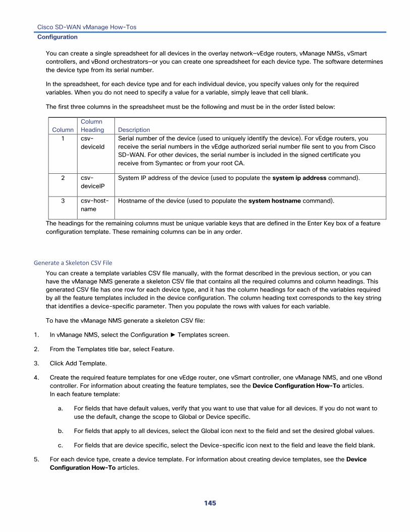
Cisco SD-WAN vManage How-Tos Configuration
145
You can create a single spreadsheet for all devices in the overlay network—vEdge routers, vManage NMSs, vSmart controllers, and vBond orchestrators—or you can create one spreadsheet for each device type. The software determines the device type from its serial number.
In the spreadsheet, for each device type and for each individual device, you specify values only for the required variables. When you do not need to specify a value for a variable, simply leave that cell blank.
The first three columns in the spreadsheet must be the following and must be in the order listed below:
Column Column Heading Description
1 csv-deviceId
Serial number of the device (used to uniquely identify the device). For vEdge routers, you receive the serial numbers in the vEdge authorized serial number file sent to you from Cisco SD-WAN. For other devices, the serial number is included in the signed certificate you receive from Symantec or from your root CA.
2 csv-deviceIP
System IP address of the device (used to populate the system ip address command).
3 csv-host-name
Hostname of the device (used to populate the system hostname command).
The headings for the remaining columns must be unique variable keys that are defined in the Enter Key box of a feature configuration template. These remaining columns can be in any order.
Generate a Skeleton CSV File You can create a template variables CSV file manually, with the format described in the previous section, or you can have the vManage NMS generate a skeleton CSV file that contains all the required columns and column headings. This generated CSV file has one row for each device type, and it has the column headings for each of the variables required by all the feature templates included in the device configuration. The column heading text corresponds to the key string that identifies a device-specific parameter. Then you populate the rows with values for each variable.
To have the vManage NMS generate a skeleton CSV file:
1. In vManage NMS, select the Configuration ► Templates screen.
2. From the Templates title bar, select Feature.
3. Click Add Template.
4. Create the required feature templates for one vEdge router, one vSmart controller, one vManage NMS, and one vBond controller. For information about creating the feature templates, see the Device Configuration How-To articles. In each feature template:
a. For fields that have default values, verify that you want to use that value for all devices. If you do not want to use the default, change the scope to Global or Device specific.
b. For fields that apply to all devices, select the Global icon next to the field and set the desired global values.
c. For fields that are device specific, select the Device-specific icon next to the field and leave the field blank.
5. For each device type, create a device template. For information about creating device templates, see the Device Configuration How-To articles.

Cisco SD-WAN vManage How-Tos Configuration
146
6. In the Configuration ► Templates screen, click the Device tab.
7. In the Template List table, select the desired device template.
8. Click the More Actions icon to the right of the row and click Export CSV.
9. Repeat Steps 7 and 8 for each device template.
Edit the exported CSV file, adding at a minimum the device serial number, device system IP address, and device hostname for each device in the overlay network. Then add values for desired device-specific variables for each device. Note that variable names cannot contain forward slashes (/) or backwards slashes (\).
If desired, you can combine the CSV files into a single file.
Import a CSV File To use the device-specific variable values in the CSV file, import the file when you are attaching a device template to the Cisco SD-WAN device:
1. In vManage NMS, select the Configuration ► Templates screen.
2. From the Templates title bar, select Device.
3. For the desired template, click the More Actions icon to the right of the row, and Select Attach Devices.
4. In the Attach Devices popup, select the desired devices in the Available Devices box and click the arrow to move them to the Selected Devices box.
5. Click Attach.
6. Click the Up arrow on the right side of the screen. The Upload CSV File box displays.
7. Choose the CSV file to upload, and click Upload.
During the attachment process, click Import file to load the Excel file. If vManage NMS detects duplicate system IP addresses for devices in the overlay network, it displays a warning message or a pop-up window. You must correct the system IP addresses to remove any duplicates before you can continue the process of attaching device templates to Cisco SD-WAN devices.
Manually Enter Values for Device-Specific Variables and for Optional Rows For parameters in a feature template that you configure as device-specific, when you attach a device template to a device, the vManage NMS prompts you for the values to use for these parameters. Entering device-specific values in this manner is useful in test or POC networks, or if you are deploying a small network. This method generally does not scale well for larger networks.
For situations when the configuration for many devices is identical except for a few parameters, in the feature configuration template, you can specify that the parameter be an optional row in the configuration. By selecting optional row, the feature template automatically marks the parameters as device-specific, and these parameters are grayed out so that you cannot set them in the template. You do not have to individually mark the parameters as device specific. Then, when you attach a device template to a device, the vManage NMS prompts you for the values to use for these parameters. Using optional rows to enter device-specific values is useful when a group of many vEdge routers provide

Cisco SD-WAN vManage How-Tos Configuration
147
identical services at their branch or site, but individual routers have their own hostname, IP address, GPS location, and other site or store properties, such as BGP neighbors.
Optional rows are available for some parameters in some feature configuration templates. To treat a parameter or set of parameters as an optional row, click the Mark as Optional Row box. For these types of parameters, the feature configuration template has a table listing all the configured parameters. The Optional column indicates which are optional rows,
To manually enter values for device-specific variables or for variables in optional rows when you attach the template to a device:
1. In vManage NMS, select the Configuration ► Templates screen.
2. From the Templates title bar, click the Device tab.
3. In the Template List, select the desired device template.
4. Click the More Actions icon to the right of the row and click Attach Devices. The Attach Devices dialog box opens.
5. In the Available Devices column on the left, select a group and search for one or more devices, select a device from the list, or click Select All.
6. Click the arrow pointing right to move the device to the Selected Devices column on the right.
7. Click Attach.
8. In the Chassis Number List, select the desired device.
9. Click the More Actions icon to the right of the row and click Edit Device Template. The Update Device Template dialog box opens.
10. Enter values for the optional parameters. When you are using optional rows, if you do not want to include the parameter for the specific device, do not specify a value.
11. Click Update.
12. Click Next. If any devices have the same system IP address, a pop-up or an error message is displayed when you click Next. Modify the system IP addresses so that there are no duplicates, and click Save. Then click Next again.
13. In the left pane, select the device. The right pane displays the device's configuration and the Config Preview tab in the upper right corner is selected. Click the Config Diff tab to preview the differences between this configuration and the configuration currently running on the device, if applicable. Click the Back button to edit the variable values entered in the previous screen.
14. Click Configure Devices to push the configuration to the devices. The Status column displays whether the configuration was successfully pushed. Click the right angle bracket to the left of the row to display details of the push operation.
Release Information Introduced in vManage NMS in Release 15.3. In Release 15.4, add ability to export CSV file without having to first attach devices. In Release 17.2, have vManage NMS check for duplicate system IP addresses. In Release 18.2, add optional rows.

Cisco SD-WAN vManage How-Tos Configuration
148
Additional Information Configure Devices from vManage NMS Create Configuration Templates for a vBond Orchestrator Create Configuration Templates for a vEdge Router Create Configuration Templates for a vManage NMS Create Configuration Templates for a vSmart Controller Perform Parallel Configuration Template Operations

Cisco SD-WAN vManage How-Tos Configuration
149
Validate or Invalidate a vEdge Router In vManage NMS, you can validate, invalidate, or stage a vEdge router. Validation authorizes a router to be operational in the network, so that the router can establish operational connections with the vSmart controller and the vManage NMS. Staging allows you to provision and test a router before it is validated and joins the actual production network.
Determine if a vEdge Router is in Valid State To determine the validity of a vEdge router:
1. In vManage NMS, select the Configuration ► Certificates screen.
2. From the list of routers, locate the desired router. Use the search box if necessary.
3. Check the router's state in the Validity column. A router can be in one of the following states: • Valid—shown in green • Staging—shown in yellow • Invalid—shown in red
Validate a vEdge Router When you add vEdge routers to the network using the Configuration ► Devices screen, you can automatically validate the routers and send their chassis and serial numbers to the controller devices by clicking the checkbox Validate the uploaded vEdge List and send to controllers.
If you do not select this option, you must individually validate each router and send their chassis and serial numbers to the controller devices:
1. In vManage NMS, select the Configuration ► Certificates screen.
2. From the Devices title bar, select vEdge List.
3. From the list of routers, select the vEdge router to validate.

Cisco SD-WAN vManage How-Tos Configuration
150
4. In the Validate column, click Valid.
5. Click OK to confirm the move to the valid state.
6. Repeat Steps 3 to 5 for each router you wish to validate.
7. Click the Send to Controller button in the upper left corner of the screen to send the chassis and serial numbers of the validated vEdge routers to the controller devices in the network.
Invalidate a vEdge Router 1. In vManage NMS, select the Configuration ► Certificates screen.
2. From the Devices title bar, select vEdge List.
3. From the list of routers, select the vEdge router to invalidate.
4. In the Validate column, click Invalid.
5. Click OK to confirm the move to the invalid state.
6. Repeat Steps 3 to 5 for each router you wish to invalidate.
7. Click the Send to Controller button in the upper left corner of the screen to send the chassis and serial numbers of the validated vEdge routers to the controller devices in the network.
Release Information Introduced in vManage NMS in Release 15.2.
Additional Information Add the vEdge Routers Stage a vEdge Router

Cisco SD-WAN vManage How-Tos Configuration
151
Validate or Invalidate a WAN Edge Router To validate or invalidate a WAN Edge router, use the vManage Configuration ► Certificates screen.
In vManage NMS, you can validate, invalidate, or stage a WAN Edge router. Validation authorizes a router to be operational in the network, so that the router can establish operational connections with the vSmart controller and the vManage NMS. Staging allows you to provision and test a router before it is validated and joins the actual production network.
Validate a WAN Edge Router When you add vEdge and WAN routers to the network using the Configuration ► Devices screen, you can automatically validate the routers and send their chassis and serial numbers to the controller devices by clicking the checkbox Validate the uploaded WAN Edge List and send to controllers. If you do not select this option, you must individually validate each router and send their chassis and serial numbers to the controller devices. To do so:
1. In the WAN Edge List tab, select the router to validate.
2. In the Validate column, click Valid.
3. Click OK to confirm the move to the valid state.
4. Repeat Steps 1 to 3 for each router you wish to validate.
5. Click the Send to Controllers button in the upper left corner of the screen to send the chassis and serial numbers of the validated routers to the controller devices in the network. vManage NMS displays the Push WAN Edge List screen showing the status of the push operation.
Invalidate a WAN Edge Router 1. In the WAN Edge List tab, select the router to invalidate.
2. In the Validate column, click Invalid.
3. Click OK to confirm the move to the invalid state.
4. Repeat Steps 1 to 3 for each router you wish to invalidate.
5. Click the Send to Controllers button in the upper left corner of the screen to send the chassis and serial numbers of the validated routers to the controller devices in the network. vManage NMS displays the Push WAN Edge List screen showing the status of the push operation.
Release Information Introduced in vManage NMS in Release 15.2.
Additional Information Check the WAN Edge Router Certificate Status Stage a WAN Edge Router

Cisco SD-WAN vManage How-Tos Configuration
152
View Changes to a Configuration Template When you push a template configuration to a device, you can view changes between the old and the new configuration template. To view changes made to a configuration template, use the vManage Monitor ► Audit Log screen.
1. Select the audit log row from the table. The Message column of the audit log row will contain a message to the effect that the template is successfully attached to the device.
2. Click the More Actions icon to the right of the row and click CLI Diff.
The CLI Diff popup window opens, with the Config Diff tab selected by default. This window displays a side-by-side view of the differences between the configuration that was on the device and the changes made to the configuration. To view the changes inline, click the Inline Diff button located to the right of the window.
To view the updated configuration on the device, click the Configuration tab located to the left of the window.
Release Information Introduced in vManage NMS in Release 15.2.
Additional Information Export Audit Log Data in CSV Format Set Audit Log Filters View Audit Logs

Cisco SD-WAN vManage How-Tos Configuration
153
View Devices Attached to a Configuration Template You can view devices attached to a feature or a device configuration template.
View Devices Attached to a Feature Template 1. In vManage NMS, select the Configuration ► Templates screen.
2. In the Feature tab, select a template.
3. Click the More Actions icon to the right of the row and click Show Attached Device Templates. The View Attached Device Templates popup window opens, displaying the names of the device templates to which the feature template is attached.
View Devices Attached to a Device Template For a device template that you created from feature templates:
1. In vManage NMS, select the Configuration ► Templates screen.
2. In the Device tab, select a template.
3. Click the More Actions icon to the right of the row and click Attach Devices.
4. In the Attach Devices window, click the Attached Devices tab.
5. For a device template that you created from a CLI template:
6. In the Device tab, select a template.
7. Click the More Actions icon to the right of the row and click Show Attached Devices.
Release Information Introduced in vManage NMS in Release 15.2.
Additional Information Attach Devices to a Device Configuration Template Create a Device Configuration Template

Cisco SD-WAN vManage How-Tos Operation
154
Operation Change the Device Rollback Timer
By default, when you attach a vEdge router to a device configuration template, if the router is unable to successfully start after 5 minutes, it returns to, or rolls back to, the previous configuration For a configuration that you have created from the CLI, you can change the device's rollback timer:
1. In vManage NMS, select the Configuration ► Templates screen.
2. In the Device tab, select a device template.
3. Click the More Actions icon to the right of the row and click Change Device Values. The right pane displays the device's configuration, and the Config Preview tab in the upper right corner is selected.
4. In the left pane, click the name of a device.
5. Click Configure Device Rollback Timer located at the bottom of the left pane. The Configure Device Rollback Time dialog box is displayed.
6. From the Devices drop-down, select a device.
7. To enable the rollback timer, in the Set Rollback slider beneath the Devices drop-down, drag the slider to the left to enable the rollback timer. When you do this, the slider changes in color from gray to green.
8. To disable the rollback timer, click the Enable Rollback slider. When you disable the timer, the Password field pops up. Enter the password that you used to log in to the vManage NMS.
9. In the Device Rollback Time slider, drag the slider to the desired value. The default time is 5 minutes. You can configure a time from 6 to 15 minutes.
10. To exclude a device from the rollback timer setting, click Add Exception and select the devices to exclude.
11. The table at the bottom of the Configure Device Rollback Time dialog box lists all the devices to which you are attaching the template and their rollback time. To delete a configured rollback time, click the Trash icon to right right of the device name.
12. Click Save.
13. Click Configure Devices to push the configuration to the devices. The Status column displays whether the configuration was successfully pushed. Click the right angle bracket to the left of the row to display details of the push operation.
Release Information Introduced in vManage NMS in Release 17.2.
Additional Information Attach Devices to a Device Configuration Template

Cisco SD-WAN vManage How-Tos Operation
155
Check Interface Bandwidth To run a speed test to check the actual bandwidth of a circuit from one device to another:
1. In the vManage Administration ► Settings screen, ensure that Data Stream is enabled.
2. From the Monitor ► Network screen, select the device.
3. Click Troubleshooting in the left pane.
4. From the Connectivity pane, click Speed Test.
5. In the Source Circuit drop-down, select the color of tunnel interface on the local device.
6. In the Destination Device drop-down, select the remote device by the device's name and system IP address.
7. In the Destination Circuit drop-down, select the color of the tunnel interface on the remote device.
8. Click Start Test. The speed test sends a single packet from the source to the destination and receives the acknowledgement from the destination.
The middle part of the right pane reports the results of the speed test. The clock reports the circuit's speed based on the round-trip time. The download speed shows the speed from the source to the destination, and the upload speed shows the speed from the destination to the source, both in Mbps. The configured downstream and upstream bandwidths for the circuit are also displayed.
When a speed test completes, the test results are added to the table at the lower part of the right pane.
Release Information Introduced in vManage NMS in Release 18.2.
Additional Information See the Configuring Network Interfaces article for your software release.

Cisco SD-WAN vManage How-Tos Operation
156
Check the WAN Edge Router Certificate Status To check the certificate status of a WAN Edge router, use the vManage Configuration ► Certificates screen.
In the WAN Edge List tab, check the Validate column. The status can be one of the following:
• Valid (shown in green)—The router's certificate is valid.
• Staging (shown in yellow)—The router is in the staging state.
• Invalid (shown in red)—The router's certificate is not valid.
Release Information Introduced in vManage NMS in Release 15.2.
Additional Information Stage a WAN Edge Router Validate or Invalidate a WAN Edge Router

Cisco SD-WAN vManage How-Tos Operation
157
Collect Statistics for Network Devices To enable or disable the collection of statistics for devices in the overlay network, use the vManage Administration ► Settings screen:
1. Click the Edit button to the right of the Statistics Settings bar. By default, all statistics collection settings are enabled for all Cisco SD-WAN devices.
2. To set statistics collection parameters for all devices in the network, click Disable All for the parameter you wish to disable statistics collection for. To return to the saved settings during an edit operation, click Reset. To return the saved settings to the factory-default settings, click Restore Factory Default
3. To set statistics collection parameters for individual devices in the network, click Custom to select devices on which to enable or disable statistics collection. The Select Devices popup screen opens listing the hostname and device IP of all devices in the network. Select one or more devices from the Enabled Devices column on the left and click the arrow pointing right to move the device to the Disabled Devices column on the right. To move devices from the Disabled Devices to the Enabled Devices column, select one or more devices and click the arrow pointing left. To select all devices in the Select Devices popup screen, click the Select All checkbox in either window. Click Done when all selections are made.
4. Click Save.
Release Information Introduced in vManage NMS in Release 16.2.
Cisco SD-WAN vManage How-Tos Operation
158
Configure Email Notifications for Alarms To configure the vManage NMS to send email notifications when an alarm is generated on a device in the overlay network:
1. Enable email notifications for alarms in the Administration ► Settings screen.
2. Send email notifications when alarms occur in the Monitor ► Alarms screen.
The email message that is sent contains the hostname, system IP address, alarm name, and alarm severity.
Enable Email Notifications To enable email notifications, configure the SMTP and email recipient parameters:
1. In vManage NMS, select the Administration ► Settings screen.
2. Click the Edit button to the right of the Email Notifications bar.
3. In the Enable Email Notifications field, click Enabled.
4. Select the security level for sending the email notifications. The security level can be none, SSL, or TLS.
5. In the SMTP Server field, enter the name or IP address of the SMTP server to receive the email notifications.
6. In the SMTP port field, enter the SMTP port number. For no security, the default port is 25; for SSL it is 465; and for TLS it is 587.
7. In the From Address field, enter the full email address to include as the sender in email notifications.
8. In the Reply To address, enter the full email address to include in the Reply-To field of the email. This address can be a noreply address, such as [email protected].
9. To enable SMTP authentication to the SMTP server, click Use SMTP Authentication. Enter the username and password to use for SMTP authentication. The default user email suffix is appended to the username. The password that you type is hidden.
10. Click Save.
Send Email Notifications To send email notifications when alarms occur:
1. In vManage NMS, select the Monitor ► Alarms screen.
2. Click Email Notifications located to the right of the title bar. A list of configured notifications is displayed in the email notifications table.
3. Click Add Email Notification.
4. In the Name field, enter a name for the email notification. The name can be up to 128 characters and can contain only alphanumeric characters.

Cisco SD-WAN vManage How-Tos Operation
159
5. In the Severity drop-down, select one or more alarm severity levels, from Critical, Major, Medium, and Minor.
6. In the Alarm Name drop-down, select one or more alarms. The alarms generated for each severity level are listed in the section Alarms Generated on vManage NMS, below.
7. In Account Details, enter the email addresses to receive email notifications:
a. Click Add New Email List.
b. In the Email List popup, click Add Email.
c. Enter the email address of a user.
d. Add additional email addresses as desired.
e. Click Save.
8. In the Email Threshold field, set the maximum number of emails to be sent per minute. The number can be a value from 1 through 30. The default is 5.
9. Click the Webhook box to trigger an HTTP callback when an alarm notification event occurs:
a. Enter the username and password to authenticate the webhook server.
b. Enter the URL of the webhook server.
10. Select the routers to which the alarm notification applies, either All Devices or a custom list. If you select Custom, a device list is displayed:
a. In the Available Devices table on the left, select one or more devices.
b. Click the right-point arrow to move the devices to the Selected Devices table on the right.
11. Click Add.
Release Information Introduced in vManage NMS in Release 18.3.
Additional Information Delete, Edit, or View Alarm Email Notifications

Cisco SD-WAN vManage How-Tos Operation
160
Create a Custom Banner for the vManage NMS To create a custom banner that is displayed after you log in to the vManage NMS, use the vManage Administration ► Settings screen:
1. Click the Edit button to the right of the Banner bar.
2. In the Enable Banner field, click Enabled.
3. In the Banner Info text box, enter the text string for the login banner or click Select a File to download a file that contains the text string.
4. Click Save.
Release Information Introduced in vManage NMS in Release 16.1.
Decommission a vEdge Cloud Router To decommission a vEdge Cloud router:
1. In vManage NMS, select the Configuration ► Devices screen.
2. In the WAN Edge List tab, select a vEdge Cloud router.
3. Click the More Actions icon to the right of the row and click Decommission WAN Edge.
4. Click OK to confirm the decommissioning of the router.
Decommissioning a vEdge Cloud router removes the device's serial number from vManage NMS and generates a new token for the device. To do so:
Release Information Introduced in vManage NMS in Release 17.1.
Additional Information Delete a WAN Edge Router

Cisco SD-WAN vManage How-Tos Operation
161
Delete, Edit, or View Email Notifications for Alarms You can delete, edit or view an email notification about an alarm generated on a device in the overlay network.
Delete an Email Notification 1. In vManage NMS, select the Monitor ► Alarms screen.
2. Click Email Notifications located to the right of the title bar.
3. For the desired email notification, click the Trash Bin icon to the right of the row.
4. In the confirmation popup, click OK.
Edit an Email Notification 1. In vManage NMS, select the Monitor ► Alarms screen.
2. Click Email Notifications located to the right of the title bar.
3. For the desired email notification, click the Pencil icon to the right of the row.
4. When you are done editing the notification, click Update.
View an Email Notification 1. In vManage NMS, select the Monitor ► Alarms screen.
2. Click Email Notifications located to the right of the title bar.
3. For the desired email notification, click the View icon to the right of the row.
4. When you are done viewing the notification, click OK.
Release Information Introduced in vManage NMS in Release 18.3.
Additional Information Configure Alarm Email Notifications

Cisco SD-WAN vManage How-Tos Operation
162
Delete a Configuration Template You can delete a device or feature configuration template.
1. In vManage NMS, select the Configuration ► Templates screen.
2. In the Device or Feature tab, select a template.
3. Click the More Actions icon to the right of the row and click Delete.
4. Click OK to confirm deletion of the template.
Release Information Introduced in vManage NMS in Release 15.2.
Additional Information Create a Device Configuration Template Edit a Configuration Template View a Configuration Template
Cisco SD-WAN vManage How-Tos Operation
163
Delete a Controller To delete a controller from the overlay network:
1. In vManage NMS, select the Configuration ► Devices screen.
2. In the Controllers tab, select the controller.
3. Click the More Actions icon to the right of the row and click Invalidate.
4. Click OK to confirm the removal of the device and all its control connections.
Release Information Introduced in vManage NMS in Release 15.2.
Additional Information Add a vBond Orchestrator Add a vSmart Controller

Cisco SD-WAN vManage How-Tos Operation
164
Delete a WAN Edge Router To delete a WAN Edge router from the overlay network:
1. In vManage NMS, in the Configuration ► Certificates screen, mark the WAN Edge router as invalid.
2. In the Configuration ► Devices screen, in the WAN Edge List tab, select the router.
3. Click the More Actions icon to the right of the row and click Delete WAN Edge.
4. Click OK to confirm deletion of the device.
5. In the Configuration ► Certificates screen, click Send to Controller.
Deleting a router removes its serial and chassis numbers from the WAN edge router serial number list and permanently removes the router's configuration from the vManage NMS.
Release Information Introduced in vManage NMS in Release 16.3.
Additional Information Decommission a vEdge Cloud Router

Cisco SD-WAN vManage How-Tos Operation
165
Deploy the Cisco SD-WAN Overlay Network In a general sense, what you do to bring up the Cisco SD-WAN overlay network is what you would do to bring up any network: you plan out the network, create device configurations, and then deploy the network hardware and software components. These components include all the Cisco SD-WAN devices, all the traditional routers that participate in the overlay network, and all the network devices that provide shared services across the overlay network, such as firewalls, load balancers, and IDP systems.
The table below summarizes the steps for the user portion of the overlay network bringup. The details of each step are provided in the articles listed in the Procedure column. While you can bring up the devices in any order, it is recommended that you deploy them in the order listed below, which is the functional order in which the devices verify and authenticate themselves.
Step Workflow Procedure 1
Plan out your overlay network. See Components of the Cisco SD-WAN Solution .
2
On paper, create device configurations that implement the desired architecture and functionality. See the Software documentation for your software release.
3
Download the software images from the Software Download portal.

Cisco SD-WAN vManage How-Tos Operation
166
4
Deploy the vManage NMS in the data center:
1. Create a vManage VM instance, either on an ESXi or a KVM hypervisor.
2. Create either a minimal or a full configuration for each vManage NMS.
3. Configure certificate settings and generate a certificate for the vManage NMS.
4. Create a vManage cluster .
5
Deploy the vBond orchestrator :
5. Create a vBond VM instance, either on an ESXi or a KVM hypervisor.
6. Create a minimal configuration for the vBond orchestrator.
7. Add the vBond orchestrator to the overlay network.
8. Create a full configuration for the vBond orchestrator.
6
Deploy the vSmart controller in the data center:
9. Create a vSmart VM instance, either on an ESXi or a KVM hypervisor.
10. Create a minimal configuration for the vSmart controller.
11. Add the vSmart controller to the overlay network.
12. Create a full configuration for the vSmart controller.

Cisco SD-WAN vManage How-Tos Operation
167
7
Deploy the vEdge routers in the overlay network:
13. For software vEdge Cloud routers, create a VM instance, either on an AWS server, or on an ESXi or a KVM hypervisor.
14. For software vEdge Cloud routers, send a certificate signing request to Symantec and then install the signed certificate on the router.
15. From the vManage NMS, send the serial numbers of all vEdge routers to the vSmart controllers and vBond orchestrators in the overlay network.
16. Create a full configuration for the vEdge routers.
Release Information Introduced in vManage NMS in Release 15.3. vEdge Cloud router added in Release 16.1.

Cisco SD-WAN vManage How-Tos Operation
168
Determine the Status of a Network Device To determine the status of a network device from vManage NMS:
1. In vManage NMS, select the Monitor ► Network screen.
2. Locate the device using the Sort options drop-down and the Search box. Or scroll through the list of devices in the device table.
3. Select the device by clicking its hostname.
The screen changes and the left pane lists the information categories about the device. In the right pane, the System Status category is selected, which displays status information about the device.
Release Information Introduced in vManage NMS in Release 15.2. In Release 17.2, display status for controller devices.
Additional Information View Control Connections

Cisco SD-WAN vManage How-Tos Operation
169
Determine the Status of Network Sites A site is a particular physical location within the overlay network, such as a branch office, a data center, or a campus. Each site is identified by a unique integer, called a site ID. Each device at a site is identified by the same site ID.
To determine the status of network sites:
1. In vManage NMS, select the Dashboard screen.
2. Locate the Site Health View pane, which displays the state of a site's data connections. When a site has multiple vEdge routers, this pane displays the state for the entire site, not for individual devices. The Site Health View pane displays three states:
• Full WAN Connectivity—Total number of sites where all BFD sessions on all vEdge routers are in the up state.
• Partial WAN Connectivity—Total number of sites where a TLOC or a tunnel is in the down state. These sites still have limited data plane connectivity.
• No WAN Connectivity—Total number of sites where all BFD sessions on all vEdge routers are in the down state. These sites have no data plane connectivity.
3. Click a row to display a popup window with detailed information on each site, node, or tunnel.
4. Click the More Actions icon to the right of each table row to access the Device Dashboard or Real Time view in the Monitor ► Network screen or the Tools ► SSH Terminal screen.
Release Information Introduced in vManage NMS in Release 15.2.

Cisco SD-WAN vManage How-Tos Operation
170
Additional Information View Control Connections

Cisco SD-WAN vManage How-Tos Operation
171
Enable CloudExpress Service To enable CloudExpress service, use the vManage Administration ► Settings screen:
1. Click the Edit button to the right of the CloudExpress bar.
2. In the Enable CloudExpress field, click Enabled.
3. Click Save.
Release Information Introduced in vManage NMS in Release 16.3.

Cisco SD-WAN vManage How-Tos Operation
172
Enable Reverse Proxy In a standard overlay network, vEdge routers initiate direct connections to the Cisco SD-WAN controllers—the vManage NMSs and vSmart controllers—over which they exchange control plane information. Because vEdge routers are typically located in branch sites and hence access the controllers over the internet, the result is that vManage NMSs and vSmart controllers have connections directly to the internet. If, for security or other reasons, you do not want these devices to have direct internet connections, you can insert a reverse proxy between the controllers and the vEdge routers. The reverse proxy acts as an intermediary to pass control traffic between the controllers and the vEdge routers. So instead of communicating directly with the vManage NMSs and the vSmart controllers, the vEdge routers communicate directly with the intermediate proxy device, and the proxy device relays the traffic to and from the vManage and vSmart controller devices.
The following figure illustrates a reverse proxy inserted between a vEdge router and the vSmart and vManage controllers.
The figure shows a network architecture that comprises two areas, one with no internet access and a second with internet access. The vSmart controllers and vManage NMSs are located in the area with no access to the Internet, and the reverse proxy device, along with the vBond orchestrator, are located in the area with internet access. All communication between the branch routers and the vSmart and vManage devices goes through the reverse proxy intermediary, and all communication between the routers and the vBond orchestrator occurs directly over a public internet connection, which is the standard overlay network behavior. The solid green lines in the figure illustrate these connections. Control plane traffic, indicated by the dashed blue lines, flows directly between the vSmart, vManage, and vBond devices.
For reverse proxy to work, you map the private IP address and port number of the vSmart controller and vManage NMS to a proxy IP address and port number. The private IP address is the IP address of the device's transport interface in VPN 0. The default TLS private port number is 23456. The proxy IP address and port number are values that you select and configure on the reverse proxy device.
The vManage pushes the private IP addresses and port numbers and their proxy mappings to the vBond orchestrator. When a vEdge router joins the overlay network and requests the IP addresses of the overlay network controller devices,
Cisco SD-WAN vManage How-Tos Operation
173
the vBond orchestrator sends the mapped proxy addresses and port numbers of all registered controllers. Thus, the vEdge router connects to the reverse proxy instead of to the controllers directly.
To enable reverse proxy in the overlay network:
1. Enable the reverse proxy functionality on the vManage NMS.
2. Provision certificates on the proxy.
3. Configure reverse proxy on vManage and vSmart controllers, defining the mapping between private IP addresses and port numbers and proxy IP addresses and port numbers.
4. On vManage and vSmart controllers, configure the control transport protocol to be TLS.
Enable Reverse Proxy Functionality To enable reverse proxy functionality in the overlay network:
1. In vManage NMS, select the Administration ► Settings screen.
2. In the Reverse Proxy bar, click Edit.
3. Click Enabled.
4. Click Save.
Provision Certificates on the Proxy For reverse proxy to work, the reverse proxy device and the vEdge routers must authenticate each other.
On the reverse proxy device you must provision a certificate that is signed by the same CA with which the controller's certificate is signed.
On the reverse proxy, you also need to provision the vManage certificate bundle exported form the vManage NMS. This certificate is used by the reverse proxy to verify the vEdge routers. To do this:
1. In vManage NMS, select the Configuration ► Certificates screen.
2. Click Controllers in the top bar.
3. Click Export Root Certificate in the top bar.
Configure Reverse Proxy on Controllers To configure reverse proxy on individual vManage NMS and vSmart controller devices:
1. In vManage NMS select the Configuration ► Devices screen.
2. Click the Controllers tab.
3. For the desired device, click the More Actions icon to the right of the row, and click Add Reverse Proxy. The Add Reverse Proxy popup is displayed.

Cisco SD-WAN vManage How-Tos Operation
174
4. Click Add Reverse Proxy.
5. Configure the private IP address and port number for the device. The private IP address is the IP address of the transport interface in VPN 0. The default port number is 12346. This is the port used to establish the connections that handle control and traffic in the overlay network.
6. Configure the proxy IP address and port number for the device, to create the mapping between the private and public IP addresses and port numbers.
7. If the vManage NMS or vSmart controller has multiple cores, repeat Steps 5 and 6 for each core.
8. Click Add.
9. In the Security feature configuration template for the vManage NMS and the vSmart controller, set the transport protocol to be TLS.
To display a device's private and proxy (public) IP addresses and port numbers, in the vManage Monitor ► Network screen, select the device, click Real Time, and select the Control Connections command. To display these IP address and pot numbers in the CLI, issue the show control local-properties command.
To verify the mapping between the private and proxy IP addresses and port numbers, issue the show orchestrator reverse-proxy-mapping command on the vBond orchestrator.
In the output of the show control connections command on a vEdge router, if the Proxy column value is Yes, the Peer Public IP and Peer Public Port fields show the proxy IP address and port number, respectively, and the output indicates that the connection is the controller device is through the proxy.
Have vEdge Router Generate Certificate After you configure reverse proxy on the overlay network controllers, any vEdge router that joins the overlay network or that is already operating in the overlay network requires a signed certificate to establish a secure connection to the proxy device. The process for generating the signed certificate is initiated automatically by the vEdge router as soon as it learns that reverse proxy is enabled in the network, and the vEdge router receives a signed certificate that it uses to establish a secure connection to the reverse proxy device.
To view the signed certificate, issue the show certificate reverse-proxy command on the vEdge router.
Release Information Introduced in vManage NMS in Release 18.2.

Cisco SD-WAN vManage How-Tos Operation
175
Establish an SSH Session to a Device To establish an SSH session to a device in the network, use the vManage Tools ► SSH Terminal screen.
From an SSH session, you can issue CLI commands on the device.
1. From the left pane, select the device on which to collect statistics:
a. Select the device group to which the device belongs.
b. If needed, sort the device list by its status, hostname, system IP, site ID, or device type.
c. Click on the device to select it.
2. Enter the username and password to log in to the device.
You can now issue CLI commands to monitor or configure the device.
Release Information Introduced in vManage NMS in Release 15.2.

Cisco SD-WAN vManage How-Tos Operation
176
Export Alarm Data in CSV Format To export data for all alarms to a file in CSV format, use the vManage Monitor ► Alarms screen.
Click the Export icon. This icon, which is a downward-pointing arrow, is located to the right of the Search box below the Alarms Histogram.
vManage NMS downloads all data from the alarms table to an Excel file in CSV format. The file is downloaded to your brower's default download location.
Release Information Introduced in vManage NMS in Release 15.2.
Additional Information Monitor Alarms Set Alarm Filters

Cisco SD-WAN vManage How-Tos Operation
177
Export Audit Log Data in CSV Format To export data for all audit logs to a file in CSV format, use the vManage Monitor ► Audit Log screen.
Click the Export icon. This icon, which is a downward-pointing arrow, is located to the right of the filter criteria.
vManage NMS downloads all data from the events table to an Excel file in CSV format. The file is downloaded to your brower's default download location.
Release Information Introduced in vManage NMS in Release 15.2.
Additional Information Set Audit Log Filters View Audit Logs
Cisco SD-WAN vManage How-Tos Operation
178
Export Device Data in CSV Format To export data for all devices to a file in CSV format, use the vManage Maintenance ► Software Upgrade screen.
Click the Export icon. This icon, which is a downward-pointing arrow, is located to the right of the filter criteria both in the WAN Edge List and in the Controllers tab.
vManage NMS downloads all data from the device table to an Excel file in CSV format. The file is downloaded to your brower's default download location.
Release Information Introduced in vManage NMS in Release 16.3
Cisco SD-WAN vManage How-Tos Operation
179
Export Event Data in CSV Format To export data for all events to a file in CSV format, use the vManage Monitor ► Events screen.
Click the Export icon. This icon, which is a downward-pointing arrow, is located to the right of the Search box below the Events Histogram.
vManage NMS downloads all data from the events table to an Excel file in CSV format. The file is downloaded to your brower's default download location.
Release Information Introduced in vManage NMS in Release 15.2.
Additional Information Check Events Set Event Filters

Cisco SD-WAN vManage How-Tos Operation
180
Export Root Certificate To export a root certificate, use the vManage Configuration ► Certificates screen.
1. In the Controllers tab, click the Export Root Certificate button.
2. In the Export Root Certificate window, click Download to export the root certificate to a file.
3. Click Close.
Release Information Introduced in vManage NMS in Release 18.2.
Additional Information Configure Certificate Authorization Settings for Controller Devices

Cisco SD-WAN vManage How-Tos Operation
181
How to Load a Custom vManage Application Server Logo To change the vManage web application server logo and load a new custom logo, use the request nms application-server update-logo command.
The logo image is located in the upper left corner of all vManage web application server screens. You can load two files, a larger version, which is displayed on wider browser screens, and a smaller version, which is displayed when the screen size narrows. Both files must be PNG files located on the local device, and both must be 1 MB or smaller in size. For best resolution, it is recommended that the image for the large logo be 180 x 33 pixels, and for the small logo 30 x 33 pixels.

Cisco SD-WAN vManage How-Tos Operation
182
Locate a Cisco SD-WAN Device From the vManage NMS, you can quickly locate a Cisco SD-WAN device in the overlay network using the Monitor ► Geography or the Monitor ► Network screen.
Use the Geography Screen 1. In vManage NMS, select the Monitor ► Geography screen.
2. Use the Filter button to display only the device type you are trying to locate.
3. Hover over the device icon to display basic information about the device, including the site ID where the device is located. To display detailed information about the device, click the device icon.
Use the Monitor Screen 1. In vManage NMS, select the Monitor ► Network screen.
2. Locate the device using the Sort options drop-down and the Search box. Or scroll through the list of devices in the device table.
3. To get detailed information about the device, select it by clicking its system IP address.
Release Information Introduced in vManage NMS in Release 15.2.

Cisco SD-WAN vManage How-Tos Operation
183
Log In to a Cisco SD-WAN Device This article describes how to log in to a Cisco SD-WAN device.
Log In to a Device for the First Time When you first deploy a Cisco SD-WAN overlay network, log in to the vBond orchestrator, vManage NMS, and vSmart controller to manually create the device's initial configuration. For information, see the articles in the Cisco SD-WAN Overlay Network Bringup section that describe how to create the initial configurations for the vBond , vSmart , and vManage devices.
vEdge routers are shipped with a default factory configuration. If you choose to modify this configuration manually, log in through the router's console port, as described below.
Log In to the vManage Web Application Server The vManage NMS runs as a web application server through which you log in to a running vManage NMS.
In an overlay network with a single vManage NMS, to log in to the NMS, use HTTPS and specify the IP address of the NMS. Enter a URL in the format https:// ip-address :8443, where 8443 is the port number used by the vManage NMS. On the login page, enter a valid username and password, and then click Log In. You have five chances to enter the correct password. After the fifth incorrect attempt, you are locked out of the device, and you must wait 15 minutes before attempting to log in again.
In an overlay network that has a cluster of vManage NMSs, the cluster allows you to log in to one of the vManage NMSs that is operating in the role of a web application server. (For information about configuring roles in vManage clusters, see Create a vManage Cluster .) Use HTTPS, specifying the IP address of one of the vManage NMSs, in the format https:// ip-address :8443. The cluster software load-balances login sessions among the individual vManage NMSs that are acting as web application servers. You cannot control which of the individual vManage NMSs you log in to.
With a vManage cluster, if you enter invalid login credentials, it might take some time for you to see an invalid login error message, and the amount of time increases as the size of the cluster increases. This delay happens because each vManage NMS attempts sequentially to validate the credentials. If none of the NMSs validates you, only then do you see an invalid login error message.
To determine which vManage NMS you are logged in to, look in the vManage toolbar, which is located at the top of the every screen. The penultimate button shows the name of the NMS you are logged in to. To display more information about this particular NMS server, enter the name of the NMS in the Search filter of the Monitor ► Network screen.
Establish an SSH Session to a Cisco SD-WAN Device 1. In vManage NMS, select the Tools ► SSH Terminal screen.
2. From the left pane, select the device on which to collect statistics:
a. Select the device group to which the device belongs.
b. If needed, sort the device list by its status, hostname, system IP, site ID, or device type.
c. Click on the device to select it.

Cisco SD-WAN vManage How-Tos Operation
184
3. Enter the username and password to log in to the device.
You can now issue CLI commands to monitor or configure the device.
You can also establish an SSH session directly to the Cisco SD-WAN device.
You have five chances to enter the correct password. After the fifth incorrect attempt, you are locked out of the device, and you must wait 15 minutes before attempting to log in again.
Log In to a vEdge Router through a Console Port For hardware vEdge routers, you can connect the router to a management console through the router's console port. For information, see the planning and installation articles for your hardware router model.
Release Information Introduced in vManage NMS in Release 15.2.
Additional Information Cisco SD-WAN Overlay Network Bringup See the vEdge Router Default Configuration article for your router model.
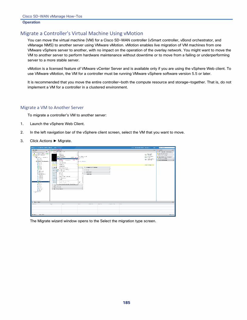
Cisco SD-WAN vManage How-Tos Operation
185
Migrate a Controller's Virtual Machine Using vMotion You can move the virtual machine (VM) for a Cisco SD-WAN controller (vSmart controller, vBond orchestrator, and vManage NMS) to another server using VMware vMotion. vMotion enables live migration of VM machines from one VMware vSphere server to another, with no impact on the operation of the overlay network. You might want to move the VM to another server to perform hardware maintenance without downtime or to move from a failing or underperforming server to a more stable server.
vMotion is a licensed feature of VMware vCenter Server and is available only if you are using the vSphere Web client. To use VMware vMotion, the VM for a controller must be running VMware vSphere software version 5.5 or later.
It is recommended that you move the entire controller—both the compute resource and storage—together. That is, do not implement a VM for a controller in a clustered environment.
Migrate a VM to Another Server To migrate a controller's VM to another server:
1. Launch the vSphere Web Client.
2. In the left navigation bar of the vSphere client screen, select the VM that you want to move.
3. Click Actions ► Migrate.
The Migrate wizard window opens to the Select the migration type screen.

Cisco SD-WAN vManage How-Tos Operation
186
4. Select Change both compute resource and storage ► Select compute resource first. Then click Next.
The Select compute resource screen opens.
5. Select the compute resource that is the destination for your VM migration, and click Next.
The Select storage screen opens.

Cisco SD-WAN vManage How-Tos Operation
187
6. Select the storage that is the destination for your VM migration, and click Next.
The Select network screen opens.
7. Select the network that is the destination for your VM migration, and click Next.
The Select vMotion priority screen opens.

Cisco SD-WAN vManage How-Tos Operation
188
8. Choose a priority for allocation of CPU resources and click Next.
The Ready to complete screen opens.
9. Verify the information for the migration and click Finish.
The VM is migrated to the new server.
Additional Information Create vManage NMS VM Instance Create vBond or vSmart VM Instance Restore the vManage NMS

Cisco SD-WAN vManage How-Tos Operation
189
Reboot a Device From the vManage NMS, you can easily reboot one or more devices in the overlay network. To do so:
1. In vManage NMS, select the Maintenance ► Device Reboot screen.
2. In Device List view, select one or more devices.
3. Click the Reboot button directly beneath the Device Reboot title bar.
Release Information Introduced in vManage NMS in Release 15.2.

Cisco SD-WAN vManage How-Tos Operation
190
Reboot a Device or View Active Devices To reboot one or more devices or to view a list of active devices in the overlay network, use the vManage Maintenance ► Device Reboot screen:
Reboot a Device 1. In Device List view, select one or more devices.
2. Click the Reboot button directly beneath the Device Reboot title bar.
View Active Devices To view a list of devices on which the reboot operation has been performed:
1. Click the Tasks icon located in the vManage toolbar. vManage NMS displays a list of all running tasks along with the total number of successes and failures.
2. Click a row to see details of a task. vManage NMS opens a status window displaying the status of the task and details of the device on which the task was performed.
Release Information Introduced in vManage NMS in Release 15.2.

Cisco SD-WAN vManage How-Tos Operation
191
Rediscover the Network To locate new devices in the overlay network, use the vManage Tools ► Rediscover Network screen.
Click the Rediscover button located directly beneath the title bar. vManage NMS rediscovers every device and link and displays updated information about the network.
Release Information Introduced in vManage NMS in Release 15.2.
Additional Information Synchronize Device Data

Cisco SD-WAN vManage How-Tos Operation
192
Remove a vEdge Router's Serial Number from the vManage NMS When you return a vEdge router to Cisco SD-WAN via an RMA process, you want to delete the serial number of that router from the vManage NMS. You may also want to delete a serial number that has been erroneously entered into the vManage NMS.
When you delete a router's serial number, all information about that router, including its configuration, is removed from the vManage NMS. This means that if you are replacing a vEdge router, you should first copy the configuration from the RMA'd router to the new router and install the new router, before you remove the RMA'd router's serial number from the vManage NMS.
Before You Begin If you are replacing an RMA'd router with a new router, ensure that you have copied the configuration from the failed to the new router.
Remove a Router's Serial Number from the vManage NMS To remove a vEdge router's serial number from the vManage NMS:
1. In vManage NMS, select the Configuration ► Certificates screen.
2. From the list of vEdge routers, locate the desired router.
3. In the Validate column, click Invalid.
4. Click OK to confirm the move to the invalid state.
5. Select the Configuration ► Devices screen.
6. From the list of vEdge routers, locate the desired router.
7. Click the More Actions icon to the right of the row, and select Delete vEdge.
8. Click OK to confirm deletion of the device from the network.
9. Select the Configuration ► Certificates screen.
10. Click Send to Controllers to send the updated vEdge router chassis and serial numbers to the vBond orchestrators and vSmart controllers in the network.
Release Information Introduced in vManage NMS in Release 15.4.

Cisco SD-WAN vManage How-Tos Operation
193
Additional Information Replace a vEdge Router Validate or Invalidate a vEdge Router See the Return Hardware article for your hardware platform.

Cisco SD-WAN vManage How-Tos Operation
194
Remove a vManage NMS from a vManage Cluster To remove a vManage NMS from a vManage cluster, use the vManage Administration ► Cluster Management screen:
1. In the Service Configuration tab, for a vManage NMS, click the More Actions icon to the right of its row and click Remove. The Remove vManage dialog box opens.
2. Enter the username and password to confirm removal of the device from the network.
3. Click Remove.
The vManage NMS is removed from the cluster, the device is invalidated, and the certificates for that device are deleted. The remaining members in the cluster re-balance the NMS services.
Release Information Introduced in vManage NMS in Release 16.2.

Cisco SD-WAN vManage How-Tos Operation
195
Replace a vEdge Router This article describes how to replace a vEdge router at a particular location. You might do this when a vEdge router has failed completely or when a component in a router, such as one of the power supplies, has failed, and you want to replace the entire router.
At a high level, to replace one vEdge router with another, you simply copy the configuration from the router you are removing to the new router and then put the new router into the network.
Before you can replace the vEdge router in the vManage NMS, the NMS must have learned the chassis number and serial number of the replacement vEdge router.
• If the replacement vEdge router is a router that you have previously received, such as a router that part of your spares inventory, the vManage NMS will have already learned the router's chassis and serial number when you previously uploaded the serial number file to the NMS.
• If you initiated an RMA process and have received a new router as a replacement, you need to upload the updated version of the authorized vEdge serial number file to the NMS.
You perform the procedure for replacing the failed router from the vManage NMS, by doing the following:
1. Copy the configuration from the failed router to the replacement router.
2. Invalidate the failed router. Invalidating a router deactivates its certificate and thus removes it from the overlay network.
3. Validate the replacement router, to activate its certificate.
Because the new router is a complete replacement for the failed router, its configuration is identical to that of the failed router. (Remember, though, that each router has a unique chassis number and a unique serial number in its certificate.) After you copy the configuration from the failed router to the replacement, both routers have the same configurations, including the same IP address. Because two routers with the same IP address cannot be present in the network at the same time, one router must be in valid state on the vManage NMS and the other must be in invalid state—or both routers must be in invalid state.
Before You Begin Ensure that you have uploaded the vEdge serial number file to the vManage NMS.
Copy the Configuration from the Failed to the Replacement Router From the vManage NMS, you copy the configuration from the failed vEdge router to the replacement router.
The vEdge router that you are copying the configuration from can be a device that is active in the overlay network (that is, it is in a valid state) or it can be one that is inactive (that is, it is in invalid state). For example, if you are replacing a router in which one of the two power supplies has failed, the router might still be active in the network, but if you are replacing one that has failed completely, you might have already marked it as invalid to remove it from the network.
The vEdge router that you are copying the configuration to must be in invalid state.
To view the state of a vEdge router or to change the validity state, see Validate or Invalidate a vEdge Router .
To copy the configuration from the failed router to the replacement router:
1. In vManage NMS, select the Configuration ► Devices screen.
2. From the list of vEdge routers, locate the failed router.

Cisco SD-WAN vManage How-Tos Operation
196
3. Click the More Actions icon to the right of the row and click Copy Configuration.
4. In the Copy Configuration window, select the replacement router.
5. Click Update.
Removed the Failed Router To remove the failed vEdge router from the overlay network:
1. In vManage NMS, select the Configuration ► Certificates screen.
2. From the list of vEdge routers, locate the failed router.
3. In the Validate column, click Invalid.
4. Click OK to confirm invalidation of the device.
5. Click Send to Controllers.
Add the Replacement Router To add the replacement vEdge router into the overlay network:
1. In vManage NMS, select the Configuration ► Certificates screen.
2. From the list of vEdge routers, locate the replacement router.
3. In the Validate column, click Valid.
4. Click OK to confirm validation of the device.
5. Click Send to Controllers.
If you attempt to validate a router that has the same IP address as another router in the network, an error message is displayed, and the validation process is terminated.
Release Information Introduced in vManage NMS in Release 15.4.
Additional Information Validate or Invalidate a vEdge Router See the Return Hardware article for your hardware platform.
Cisco SD-WAN vManage How-Tos Operation
197
Reset an Interface You can reset an interface on a device, issuing a shutdown command followed by a no shutdown command, in a single operation from the vManage NMS, without having to modify the device's configuration.
To reset an interface:
1. In vManage NMS, select the Tools ► Operational Commands screen.
2. In the right pane, click the device.
3. Click the More Actions icon to the right of the row.
4. From the drop-down list of commands, select Interface Reset.
5. From the Interface Reset box, select the desired interface.
6. Click Reset.
CLI equivalent : request interface-reset
Release Information Introduced in vManage NMS in Release 15.3.
Additional Information See the Configuring Network Interfaces article for your software release.

Cisco SD-WAN vManage How-Tos Operation
198
Reset the RSA Key Pair To reset the RSA key pair, use the vManage Configuration ► Certificates screen.
1. In the Controllers tab, select a device.
2. Click the More Actions icon to the right of the row and click Reset RSA.
3. Click OK to confirm resetting of the device's RSA key and to generate a new CSR with new public/private keys.
Release Information Introduced in vManage NMS in Release 15.2.

Cisco SD-WAN vManage How-Tos Operation
199
Restore the vManage NMS This article describes how to restore the vManage NMS in case the server on which the vManage NMS virtual machine (VM) is running fails. This article provides procedures for restoring a vManage NMS using two different VMware interfaces, vSphere Client and vSphere Web Client.
Note: If you are creating a new vManage NMS as part of an initial network bringup, see Bringup Sequence of Events and Create vManage NMS VM Instance .
The vManage NMS database is the repository for the overlay network device configurations, events, alarms, and monitoring information. The vManage NMS database is stored on a separate virtual hard disk on the vManage NMS server; specifically, it is stored on hard disk 2. Hard disk 1 contains the Cisco SD-WAN operating system software.
We recommend that you set up periodic crash-consistent backups of the vManage NMS database. (In a crash-consistent backup, all the VM's data are captured at exactly the same time.) Then, if the vManage NMS server fails, you simply create a new vManage NMS instance and attach the vManage NMS database backup to that instance.
The procedures in this article each encompass both of the following scenarios:
• If you have a backup of the vManage NMS database, you create a new vManage NMS and attach the disk that contains your backup database.
• If you do not have a backup of the vManage database, you create a new vManage NMS and create a new virtual hard disk for the database.
Restore vManage NMS Using vSphere Client 1. Create a vManage VM instance. See Launch vSphere Client and Create a vManage VM Instance, in Create a vManage
VM Instance .
2. In the left navigation bar of the vSphere Client screen, select the vManage VM instance you just created, and click Edit virtual machine settings.
3. The vManage - Virtual Machine Properties screen is displayed.

Cisco SD-WAN vManage How-Tos Operation
200
4. Click Add to add a new virtual disk, and click OK.
The Add Hardware window opens with the Select a Disk screen displayed. If you have a backup of the vManage NMS database, complete Step 4. If you do not have a backup database, skip to Step 5.
4. If you have a backup of the vManage NMS database, complete the following steps:
a. In the Select a disk screen, select Use an existing virtual disk, and click Next.
The Select Existing Disk screen is displayed.

Cisco SD-WAN vManage How-Tos Operation
201
b. Click Browse.
The Browse Datastores window opens and displays the datastores on the server
c. Navigate to the location of your backup database, and click OK.

Cisco SD-WAN vManage How-Tos Operation
202
d. In the Select Existing Disk screen, click Next.
The Advanced Options screen is displayed. Skip Step 5 and proceed to Step 6.
5. If you do not have an existing vManage NMS database, you must create a new virtual disk for the vManage database:
a. In the Select a Disk screen, select Create a new virtual disk and click Next.
The Create a Disk screen is displayed.

Cisco SD-WAN vManage How-Tos Operation
203
e. Enter a disk capacity for the vManage database of 100 GB, and click Next.
The Advanced Options screen is displayed.
6. In the Advanced Options screen, select IDE for the virtual device node, and click Next.
The Ready to Complete screen is displayed.

Cisco SD-WAN vManage How-Tos Operation
204
7. Click Finish.
The data volume is added to the vManage NMS.
8. To verify that the new disk has been created, in the vManage Virtual Machine Properties screen, select the Hardware tab. Hard disk 2—the virtual disk that stores the vManage database—is shown in the hardware list.

Cisco SD-WAN vManage How-Tos Operation
205
9. In the left navigation bar of the vSphere Client, select the vManage VM instance you just created, and click Power on the virtual machine.
The vManage virtual machine is powered on.
10. Select the Console tab to connect to the vManage console. The vManage console is displayed.
11. At the vManage login prompt, log in with the default username, which is admin , and the default password, which is admin . The system prompts you to select the storage device to use.

Cisco SD-WAN vManage How-Tos Operation
206
13. Select the appropriate storage device.
14. In response to the question Would you like to format x ? :
– If you attached an existing disk with a backup of the vManage database, type n .
– If you created a new virtual disk for the vManage database, type y .
15. Configure the vManage NMS. See vManage NMS Initial Configuration .
16. Generate a certificate for the new vManage NMS. See Generate vManage Certificate .
17. Add the serial number of the new vManage NMS to all the vBond orchestrators in the overlay network, as described later in this article.
Restore vManage NMS Using vSphere Web Client 1. Create a vManage VM instance. See Launch vSphere Client and Create a vManage VM Instance, in Create a vManage
VM Instance .
2. Log in to the vSphere Web Client.
3. Select the VM instance for your vManage NMS.
4. Click the Manage tab, and click Edit. The Edit Settings screen is displayed with the Virtual Hardware tab selected.

Cisco SD-WAN vManage How-Tos Operation
207
5. If you have a backup of the vManage NMS database, attach it to the new vManage VM. If you do not have a backup database, skip to step 6 and create a new virtual disk for the database.
a. In the New device field at the bottom of the screen, click Select. A pop-up menu opens.
b. From the pop-up menu, select Existing Hard Disk. The Select File window is displayed.
c. In the Select File window, under Datastores, navigate to and select the appropriate.vmdk file, and click OK.
6. If you do not have an existing vManage NMS database, create a new virtual disk for the vManage NMS database:
a. In the New device field at the bottom of the screen, click Select. A pop-up menu opens.

Cisco SD-WAN vManage How-Tos Operation
208
b. From the pop-up menu, select New Hard Disk.

Cisco SD-WAN vManage How-Tos Operation
209
c. In the New Hard Disk field, enter a size for the new virtual disk of 100 GB.
d. Click OK.
7. From the New Hard Disk section, under Virtual Device Node, select IDE 1, and click OK.

Cisco SD-WAN vManage How-Tos Operation
210
7. From the vSphere Web Client Navigator, select the datacenter that is hosting the VM and then select Open Console from the menu. The vManage console is displayed.
8. At the vManage login prompt, log in with the default username, which is admin , and the default password, which is admin . The system prompts you to select the storage device to use.
9. Select the appropriate storage device:
11. In response to the question Would you like to format x ? :

Cisco SD-WAN vManage How-Tos Operation
211
– If you attached an existing disk with a backup of the vManage database, type n.
– If you created a new virtual disk for the vManage database, type y to reformat the disk .
12. Configure the vManage NMS. See vManage NMS Initial Configuration .
13. Generate a certificate for the new vManage NMS. See Generate vManage Certificate .
14. Add the serial number of the new vManage NMS to all the vBond orchestrators in the overlay network, as described below.
Add vManage NMS Serial Number to vBond Orchestrators When you generate a certificate for a new vManage NMS with a new database, the serial number from the certificate is automatically sent to the vBond orchestrators. However, when you create a new vManage NMS and attach an existing database, you must manually send the new serial number to each vBond orchestrator to overwrite the serial number of the previous vManage NMS.
If you have the management IP address for the vBond orchestrator, you can use vManage NMS to send the serial number to each vBond orchestrator. Otherwise, you must use the CLI.
If you have the management IP address for the vBond orchestrator:
1. In vManage NMS, select the Configuration ► Devices screen.
2. From the Devices title bar, select Controllers.
3. Select the vBond orchestrator.
4. Click the More Actions icon to the right of the row and select Edit.
5. Enter the management IP address, username, and password for the vBond orchestrator.
6. Click Save.
7. Select the Configuration ► Certificates screen.
8. From the Certificates title bar, select Controllers.
9. Click Send to vBond to send the new vManage NMS certificate to the vBond orchestrator.
If you do not have the management IP address for the vBond orchestrator:
1. Find the serial number for the new vManage NMS:
a. In vManage NMS, select the Configuration ► Certificates screen.

Cisco SD-WAN vManage How-Tos Operation
212
b. From the Certificates title bar, select Controllers.
c. Select the vManage NMS and make a note of the serial number that is displayed in the Certificate Serial column.
2. Select the Tools ► SSH Terminal screen.
3. Select the vBond orchestrator.
4. Enter the username and password for the vBond orchestrator and click Login.
5. Enter the following command to send the certificate serial number for the new vManage NMS to the vBond orchestrator, where number is the serial number that you noted in Step 1: vBond# request vsmart add serial-num number
Additional Information Bringup Sequence of Events Deploy the vManage NMS

Cisco SD-WAN vManage How-Tos Operation
213
Set ACL Log Filters To set filters for searching ACL Logs, use the vManage Monitor ► ACL Log screen.
1. Click the Filter drop-down menu.
2. In the VPN drop-down, select the entity for which you are collecting ACL logs. You can select only one VPN.
3. Click Search to search for logs that match the filter.
vManage NMS displays a log of activities in table format.
Release Information Introduced in vManage NMS in Release 15.2.
Additional Information View ACL Logs

Cisco SD-WAN vManage How-Tos Operation
214
Set Alarm Filters To set filters for searching alarms generated by one or more Cisco SD-WAN devices, use the vManage Monitor ► Alarms screen.
1. Click the Filter drop-down menu.
2. In the Severity drop-down, select the alarm severity level. You can specify more than one severity level.
3. In the Active drop-down, select active, cleared, or both types of alarm. Active alarms are alarms that are currently on the device but have not been acknowledged.
4. CIick the Alarm Name drop-down, select the name of the alarm. You can specify more than one alarm name.
5. Click Search to search for alarms that match the filter.
vManage NMS displays the alarms both in table and graphical format.
Release Information Introduced in vManage NMS in Release 15.2.
Additional Information Check Alarms Export Alarm Data in CSV Format

Cisco SD-WAN vManage How-Tos Operation
215
Set Audit Log Filters To set filters for searching audit logs, use the vManage Monitor ► Audit Log screen.
1. Click the Filter drop-down menu.
2. In the Module drop-down, select the entity for which you are collecting audit logs. You can select more than one entity.
3. Click Search to search for logs that match the filter.
vManage NMS displays a log of activities both in table and graphical format.
vManage NMS displays a log of activities in table format.
Release Information Introduced in vManage NMS in Release 15.2.
Additional Information Export Audit Log Data in CSV Format View Audit Logs

Cisco SD-WAN vManage How-Tos Operation
216
Set Event Filters To set filters for searching events generated on one or more Cisco SD-WAN devices, use the vManage Monitor ► Events screen.
1. Click the Filter drop-down menu.
2. In the Severity drop-down, select the event severity level. Events generated by Cisco SD-WAN devices are collected by vManage NMS and classified as:
• Critical—indicates that action needs to be taken immediately.
• Major—indicates that the problem needs to be looked into but is not critical enough to bring down the network.
• Minor—is informational only.
You can specify more than one severity level.
3. In the Component drop-down, select the configuration component that caused the event. You can select more than one configuration component.
4. In the System IP drop-down, select the system IP of the devices for which to view generated events.
5. In the Event Name drop-down, select the event name for which to view generated events. You can select more than one event name.
6. Click Search to search events that match the filter.
vManage NMS displays the events both in table and graphical format.
Release Information Introduced in vManage NMS in Release 15.2.
Additional Information Export Event Data in CSV Format Monitor Event Notifications

Cisco SD-WAN vManage How-Tos Operation
217
Set Map Filters To select the devices and links you want to display on the map, use the Monitor ► Geography screen.
1. Click the Filter button to display a pull-down menu.
2. Select the device group from the pull-down menu which includes all configured device groups. By default, the group "All" is selected and displays all Cisco SD-WAN devices in the overlay network. The group "No Groups" includes the devices that are not part of a device group. If all devices are in a group, the "No Groups" group is not displayed.
3. Select the Cisco SD-WAN devices to display on the map. By default, the map displays all device types including vEdge, vEdge-vBond, vSmart, and vManage.
4. Select the state of control and data links. By default, the map displays all control and data connections.
5. Close the Filter box by moving the cursor outside the box.
The map is dynamically updated to reflect your selections. Also, as you make the device group, device type, and link selections, the tabs next to the Filter button are updated.
Release Information Introduced in vManage NMS in Release 15.2.
Additional Information Configure Geographic Coordinates for a Device View Device Information View Link Information

Cisco SD-WAN vManage How-Tos Operation
218
Set the Time Interval to Collect Device Statistics To set the time interval at which vManage NMS should collect statistics for devices in the overlay network, use the Administration ► Settings screen:
1. Click the Edit button to the right of the Statistics Configuration bar. By default, statistics is collected for all Cisco SD-WAN devices every 30 minutes.
2. Click the up or down arrow in the Collection Interval drop-down to change the frequency at which to collect device statistics. The minimum time you can specify is 5 minutes and the maximum is 180 minutes.
3. Click Save.
Release Information Introduced in vManage NMS in Release 17.1.
Cisco SD-WAN vManage How-Tos Operation
219
Set vManage Login Credentials To set the login credentials for a vManage NMS, use the vManage Administration ► Cluster Management screen:
1. In the Service Configuration tab, for a vManage NMS, click the More Actions icon to the right of its row and click Edit. The Edit vManage screen opens.
2. In the vManage IP Address box, select the IP address to edit.
3. Enter the username and password, and edit the cluster services provided by that vManage NMS.
4. Click Update.
Release Information Introduced in vManage NMS in Release 16.2.
Stage a WAN Edge Router To stage a WAN Edge router, use the vManage Configuration ► Certificates screen.
When you initially bring up and configure a WAN Edge router, you can place it in staging state using the vManage NMS. When the router is in this state, you can configure the router, and you can test that the router is able to establish operational connections with the vSmart controller and the vManage NMS. When a WAN Edge router is in staging state, the vSmart controller learns about the router and learns routes from the router, but it does not advertise these routes to any of the other WAN Edge routers in the network. Staging state allows you to provision and test WAN Edge routers without disturbing the operation of the existing network. During the staging state, OMP does not send any routes, data policies, or TLOCs to the WAN Edge router.
After you physically place the WAN Edge router at its production site, you change the router's state from staging to valid. It is only at this point that the router joins the actual production network.
Before You Begin Ensure that you have uploaded the vEdge serial number file to the vManage NMS.

Cisco SD-WAN vManage How-Tos Operation
220
Stage a WAN Edge Router 1. In vManage NMS, select the Configuration ► Certificates screen.
2. In the WAN Edge List tab, select the router to stage.
3. In the Validate column, click Staging.
4. Click OK to confirm the move to the staging state.
5. Click Send to Controllers in the upper left corner of the screen to sync the WAN edge authorized serial number file with the controllers. vManage NMS displays the Push vEdge List screen showing the status of the push operation.
Unstage a WAN Edge Router 1. In vManage NMS, select the Configuration ► Certificates screen.
2. In the WAN Edge List tab, select the router to stage.
3. In the Validate column, click Valid.
4. Click OK to confirm the move to the valid state.
5. Click Send to Controllers in the upper left corner of the screen to sync the WAN Edge authorized serial number file with the controllers.
Release Information Introduced in vManage NMS in Release 15.3.
Additional Information Upload the vEdge Serial Number File

Cisco SD-WAN vManage How-Tos Operation
221
Synchronize Device Data To synchronize the data on a specific device with the vManage NMS, use the vManage Tools ► Rediscover Network screen.
1. From the Device Groups drop-down list, select the device group to which the device belongs. The device table lists all the devices in the selected group.
2. Select the device.
3. Click the Rediscover button.
4. In the Rediscover Network window, click Rediscover to confirm re-synchronization of the device data.
Release Information Introduced in vManage NMS in Release 15.3.
Additional Information Rediscover the Network

Cisco SD-WAN vManage How-Tos Operation
222
View ACL Logs To view logs for access lists (ACLs) configured on a WAN Edge router, use the vManage Monitor ► ACL Log screen.
Routers collect ACL logs every 10 minutes.
Release Information Introduced in vManage NMS in Release 15.2.
Additional Information Set ACL Log Filters

Cisco SD-WAN vManage How-Tos Operation
223
View All Interfaces Interfaces on vEdge routers handle control traffic (in VPN 0), data traffic (in VPNs other than 0 and 512), and out-of-band management traffic (in VPN 512). Interfaces on vSmart controller and vManage NMSs handle control and management traffic.
To view interface information on a vEdge router:
In Releases 16.2 and later
1. In vManage NMS, select the Monitor ► Network screen.
2. Locate the device using the Sort options drop-down and the Search box. Or scroll through the list of devices in the device table.
3. Select the device by clicking its system IP address.
4. In the screen that opens, select Interface in the left pane.
In Releases 16.1 and earlier
1. In vManage NMS, select the Monitor ► Network screen.
2. From the Device Groups drop-down list in the left pane, select the device group to which the vEdge router belongs.
3. Choose the options in the Sort by drop-down to sort the device list by status, hostname, system IP, site ID, or personality.
4. Select the device.
5. In the right pane, click the Real Time toggle button.
6. Perform one of the procedures below to view specific interface information.
View Interface Status From the command drop-down located in the right pane, select Interface.
CLI equivalent : show interface
View Interface Statistics 1. From the command drop-down located in the right pane, select Interface.
2. In Chart Options, select the statistics to display.
3. Beneath each graph, select the data interfaces for which to display statistics.
CLI equivalent : show interface statistics

Cisco SD-WAN vManage How-Tos Operation
224
Release Information Introduced in vManage NMS in Release 15.2.
Additional Information See the Configuring Interfaces article for your software release.
Cisco SD-WAN vManage How-Tos Operation
225
View Application Performance with Cloud OnRamp for SaaS Cloud OnRamp for SaaS (formerly called CloudExpress service) calculates a value called the Quality of Experience (vQoE). The vQoE value weighs loss and latency using a formula customized for each application. For example, email applications tolerate latency better than video applications, and video applications tolerate loss better than email applications. The vQoE value ranges from zero to ten, with zero being the worst quality and ten being the best. Cloud OnRamp for SaaS computes vQoE values for applications and paths, and then assigns applications to the paths that best match their vQoE value. Cloud OnRamp for SaaS periodically recalculates vQoE values for paths to ensure ongoing optimal application performance.
View Application Performance Information In vManage NMS, select the Configuration ► CloudExpress screen, or click the CloudExpress icon in the title bar. The CloudExpress Dashboard displays the performance of each cloud application in a separate pane.
Each application pane displays the number of vEdge routers accessing the application and the quality of the connection:
• The bottom status bar displays green for devices experience good quality.
• The middle status bar displays yellow for devices experiencing average quality.
• The top status bar displays red for devices experiencing bad quality.
The number to the right of each status bar indicates how many devices are experiencing that quality of connection.
View Application Details 1. In vManage NMS, select the Configuration ► CloudExpress screen, or click the CloudExpress icon in the title bar. The
CloudExpress Dashboard displays each cloud application in a separate pane.
2. Click in an application's pane. vManage NMS displays a list of sites accessing the application.
3. Click a graph icon in the vQoE Score column to display vQoE history for that site:
– Click a predefined or custom time period for which to display data.
– Hover over a point on the chart to display vQoE details for that point in time.
Release Information Introduced in vManage NMS in Release 16.3.
Additional Information Enable and Configure Cloud OnRamp for SaaS

Cisco SD-WAN vManage How-Tos Operation
226
View ARP Table Entries The Address Resolution Protocol (ARP) is used to resolve network layer addresses, such as IPv4 addresses) into link layer addresses (such as Ethernet, or MAC, addresses). The mappings between network and physical addresses are stored in an ARP table.
To display the entries in the ARP table:
In Releases 16.2 and later
1. In vManage NMS, select the Monitor ► Network screen.
2. Locate the device using the Sort options drop-down and the Search box. Or scroll through the list of devices in the device table.
3. Select the device by clicking its system IP address.
4. In the screen that opens, select Real Time in the left pane.
5. From the command drop-down located in the right pane, select ARP.
In Releases 16.2 and later
1. In vManage NMS, select the Monitor ► Network screen.
2. From the Device Groups drop-down list in the left pane, select the device group to which the device belongs.
3. Choose the options in the Sort by drop-down to sort the device list by status, hostname, system IP, site ID, or personality.
4. Select the device.
5. In the right pane, click the Real Time toggle button.
6. From the command drop-down located in the right pane, select ARP.
CLI equivalent : show arp
Release Information Introduced in vManage NMS in Release 15.2.
Additional Information See the Configuring Interfaces article for your software release.

Cisco SD-WAN vManage How-Tos Operation
227
View Audit Logs To display a log of all activities on Cisco SD-WAN devices, use the vManage Monitor ► Audit Log screen.
View Audit Log Details To view detailed information about any audit log:
1. Select the audit log row from the table.
2. Click the More Actions icon to the right of the row and click Audit Log Details.
The Audit Log Details popup window opens, displaying details of the audit log.
Release Information Introduced in vManage NMS in Release 15.2.
Additional Information Export Audit Log Data in CSV Format Set Audit Log Filters

Cisco SD-WAN vManage How-Tos Operation
228
View a Configuration Template You can view a device or feature configuration template.
1. In vManage NMS, select the Configuration ► Templates screen.
2. In the Device or Feature tab, select a template.
3. Click the More Actions icon to the right of the row and click View.
Release Information Introduced in vManage NMS in Release 15.2.
Additional Information Create a Device Configuration Template Edit a Configuration Template

Cisco SD-WAN vManage How-Tos Operation
229
View BFD Session Information BFD sessions between vEdge routers start automatically when the routers come up in the network. BFD which runs on secure IPsec connections between the routers, is used to detect connection failures between the routers.
To view BFD information on a vEdge router:
In Releases 16.2 and later
1. In vManage NMS, select the Monitor ► Network screen.
2. Locate the vEdge router using the Sort options drop-down and the Search box. Or scroll through the list of devices in the device table.
3. Select the vEdge router by clicking its system IP address.
4. In the screen that opens, select Real Time in the left pane.
5. Perform one of the procedures below to view specific BFD information.
In Releases 16.1 and earlier
1. In vManage NMS, select the Monitor ► Network screen.
2. From the Device Groups drop-down list in the left pane, select the device group to which the device belongs.
3. Choose the options in the Sort by drop-down to sort the device list by status, hostname, system IP, site ID, or personality.
4. Select the vEdge router from the left pane.
5. In the right pane, click the Real Time toggle button.
6. Perform one of the procedures below to view specific BFD information.
View Real-Time BFD Sessions From the command drop-down located in the right pane, select BFD Sessions.
CLI equivalent : show bfd sessions
View BFD Session History From the command drop-down located in the right pane, select BFD History.
CLI equivalent : show bfd history
Release Information Introduced in vManage NMS in Release 15.2.
Additional Information See the Configuring High-Availability Parameters article for your software release.

Cisco SD-WAN vManage How-Tos Operation
230
View BGP Information You can configure the Border Gateway Protocol (BGP) on vEdge routers to enable routing on the service side (site-local side) of the router, thus providing reachability to networks at the routers' local sites.
To view BGP information on a vEdge router:
In Releases 16.2 and later
1. In vManage NMS, select the Monitor ► Network screen.
2. Locate the vEdge router using the Sort options drop-down and the Search box. Or scroll through the list of devices in the device table.
3. Select the vEdge router by clicking its system IP address.
4. In the screen that opens, select Real Time in the left pane.
5. Perform one of the procedures below to view specific BGP information.
In Releases 16.1 and earlier
1. In vManage NMS, select the Monitor ► Network screen.
2. From the Device Groups drop-down list in the left pane, select the device group to which the device belongs.
3. Choose the options in the Sort by drop-down to sort the device list by status, hostname, system IP, site ID, or personality.
4. Select the device from the left pane.
5. In the right pane, click the Real Time toggle button.
6. Perform one of the procedures below to view specific BGP information.
View BGP Connection Status From the command drop-down located in the right pane, select BGP Summary.
CLI equivalent : show bgp summary
View BGP Neighbors From the command drop-down located in the right pane, select BGP Neighbors.
CLI equivalent : show bgp neighbor
View Routes Learned by BGP From the command drop-down located in the right pane, select BGP Routes.
CLI equivalent : show bgp routes

Cisco SD-WAN vManage How-Tos Operation
231
Release Information Introduced in vManage NMS in Release 15.2.
Additional Information See the Configuring Unicast Overlay Routing article for your software release.

Cisco SD-WAN vManage How-Tos Operation
232
View Cellular Interface Information You can view cellular interface information on a vEdge 100 router. To do so:
In Releases 16.2 and later
1. In vManage NMS, select the Monitor ► Network screen.
2. Locate the device using the Sort options drop-down and the Search box. Or scroll through the list of devices in the device table.
3. Select the device by clicking its system IP address.
4. In the screen that opens, select Real Time in the left pane.
5. Perform one of the procedures below to view specific cellular interface information.
In Release 16.1 and later
1. In vManage NMS, select the Monitor ► Network screen.
2. From the Device Groups drop-down list in the left pane, select the device group to which the vEdge router belongs.
3. Choose the options in the Sort by drop-down to sort the device list by status, hostname, system IP, site ID, or personality.
4. Select the device from the left pane.
5. In the right pane, click the Real Time toggle button.
6. Perform one of the procedures below to view specific cellular interface information.
View Cellular Modem Information and Status From the command drop-down located in the right pane, select Cellular Modem.
CLI equivalent : show cellular modem
View Cellular Network Information From the command drop-down located in the right pane, select Cellular Network.
CLI equivalent : show cellular network
View Cellular Profiles From the command drop-down located in the right pane, select Cellular Profiles.
CLI equivalent : show cellular profiles

Cisco SD-WAN vManage How-Tos Operation
233
View Cellular Radio Frequency Information From the command drop-down located in the right pane, select Cellular Radio.
CLI equivalent : show cellular radio
View Cellular Session Information From the command drop-down located in the right pane, select Cellular Sessions.
CLI equivalent : show cellular sessions
View Cellular Status From the command drop-down located in the right pane, select Cellular Status.
CLI equivalent : show cellular status
Release Information Introduced in vManage NMS in Release 16.1.
Additional Information See the Configuring Interfaces article for your software release.

Cisco SD-WAN vManage How-Tos Operation
234
View Certificate Signed certificates are used to authenticate Cisco SD-WAN devices in the overlay network. To view the contents of a signed certificate using the vManage NMS:
1. In vManage NMS, select the Configuration ► Certificates screen.
2. From the Certificates title bar, select Controllers.
3. Select the device whose certificate you wish to view.
4. Click the More Actions icon to the right of the row, and select View Certificate to view the installed certificate.
Release Information Introduced in vManage NMS in Release 15.2.
Additional Information Generate a Certificate Security Certificates

Cisco SD-WAN vManage How-Tos Operation
235
View Cflowd Information Cflowd monitors traffic flowing through vEdge routers in the overlay network and exports flow information to a collector, where it can be processed by an IPFIX analyzer. For a traffic flow, cflowd periodically sends template reports to flow collector. These reports contain information about the flow and data extracted from the IP headers of the packets in the flow.
To configure cflowd on a vEdge router, you use centralized data policy to define a cflowd template, which specifies the location of a cflowd collector and timers that control flow collection.
To view cflowd flow information for a vEdge router:
In Releases 16.2 and later
1. In vManage NMS, select the Monitor ► Network screen.
2. Locate the vEdge router using the Sort options drop-down and the Search box. Or scroll through the list of devices in the device table.
3. Select the vEdge router by clicking its system IP address.
4. In the screen that opens, select Real Time in the left pane.
5. Perform one of the procedures below to view specific cflowd information.
In Releases 16.1 and earlier
1. In vManage NMS, select the Monitor ► Network screen.
2. From the Device Groups drop-down list in the left pane, select the device group to which the device belongs.
3. Choose one option in the Sort by drop-down to sort the device list by status, hostname, system IP, site ID, or device type.
4. Select the device from the left pane.
5. In the right pane, click the Real Time toggle button.
6. Perform one of the procedures below to view specific cflowd information.
View the Cflowd Template From the command drop-down located in the right pane, select Cflowd Template.
CLI equivalent : show app cflowd template
View Cflowd Collector Information From the command drop-down located in the right pane, select Cflowd Collector.
CLI equivalent : show app cflowd collector

Cisco SD-WAN vManage How-Tos Operation
236
View Cflowd Flows From the command drop-down located in the right pane, select Cflowd Flows.
CLI equivalents : show app cflowd flows , show app cflowd flow-count
View Cflowd Collector Information From the command drop-down located in the right pane, select Cflowd Statistics.
CLI equivalent : show app cflowd statistics
Release Information Introduced in vManage NMS in Release 15.2.
Additional Information See the Configuring Cflowd Traffic Flow Monitoring article for your software release. cflowd-template

Cisco SD-WAN vManage How-Tos Operation
237
View Cloud OnRamp Cloud Connectivity In vManage NMS, you can view the host and gateway virtual private cloud (VPC) instances that have been configured with the Cloud OnRamp service. You can also map and unmap host VPCs, and add and delete gateway VPCs.
Display Host VPCs 1. In vManage NMS, select the Configuration ► Cloud OnRamp screen.
2. In the Cloud OnRamp Dashboard, click the pane for the desired VPC. The Host VPCs/Gateway VPCs screen opens, and Host VPCs is selected by default. In the bar below this, Mapped Host VPCs is selected by default, and the table on the screen lists the mapping between host and gateway VPCs, the state of the gateway VPC, and the VPN ID.
3. To list unmapped host VPCs, click Unmapped Host VPCs. Then click Discover Host VPCs.
4. To display the gateway VPCs, click Gateway VPCs.
Display Gateway VPCs 1. In vManage NMS, select the Configuration ► Cloud OnRamp screen.
2. In the Cloud OnRamp Dashboard, click the pane for the desired VPC. The Host VPCs/Gateway VPCs screen opens, and Host VPCs is selected by default.
3. Click Gateway VPCs.
The table at the bottom of the screen lists the gateway VPCs.
Map Host VPCs to a Gateway VPC 1. In vManage NMS, select the Configuration ► Cloud OnRamp screen.
2. In the Cloud OnRamp Dashboard, click the pane for the desired VPC. The Host VPCs/Gateway VPCs screen opens.
3. Click Unmapped Host VPCs.
4. Click Discover Host VPCs.
5. From the list of discovered host VPCs, select the desired host VPCs
6. Click Map VPCs. The Map Host VPCs popup opens.
7. In the Gateway VPC drop-down, select the desired gateway VPC.
8. In the VPN drop-down, select the VPN in the overlay network in which to place the mapping.
9. Click Map VPCs.

Cisco SD-WAN vManage How-Tos Operation
238
Unmap Host VPCs 1. In vManage NMS, select the Configuration ► Cloud OnRamp screen.
2. In the Cloud OnRamp Dashboard, click the pane for the desired VPC. The Host VPCs/Gateway VPCs screen opens.
3. Click Mapped Host VPCs.
4. From the list of VPCs, select the desired host VPCs.
5. Click Unmap VPCs.
6. Click OK to confirm the unmapping.
Add a Gateway VPC 1. In vManage NMS, select the Configuration ► Cloud OnRamp screen.
2. In the Cloud OnRamp Dashboard, click the pane for the desired VPC. The Host VPCs/Gateway VPCs screen opens, and Host VPCs is selected by default.
3. Click Gateway VPCs.
4. Click Add Gateway VPC.
Delete a Gateway VPC 1. In vManage NMS, select the Configuration ► Cloud OnRamp screen.
2. In the Cloud OnRamp Dashboard, click the pane for the desired VPC. The Host VPCs/Gateway VPCs screen opens, and Host VPCs is selected by default.
3. Click Mapped Host VPCs.
4. Select the desired host VPC, and click Unmap VPCs.
5. Click OK to confirm the unmapping.
6. Click Gateway VPCs.
7. Click the Trash icon to the left of the row for the gateway VPC.
8. Click OK to confirm.
Release Information Introduced in vManage NMS in Release 17.2.
Additional Information See the Configuring Cloud OnRamp Service for your software release.
Cisco SD-WAN vManage How-Tos Operation
239
View Configuration Templates You can view the components of feature and device templates. In view mode, you cannot modify the templates in any way.
View a Feature Template 1. In vManage NMS, select the Configuration ► Templates screen.
2. From the Templates title bar, select Feature.
3. Select the desired template.
4. Click the More Actions icon to the right of the row, and select View.
View a Device Template 1. In vManage NMS, select the Configuration ► Templates screen.
2. From the Templates title bar, select Device.
3. Select the desired template.
4. Click the More Actions icon to the right of the row, and select View.
Release Information Introduced in vManage NMS in Release 15.3.
Additional Information Create Configuration Templates for a vBond Orchestrator Create Configuration Templates for a vEdge Router Create Configuration Templates for a vSmart Controller Configure Devices from vManage NMS

Cisco SD-WAN vManage How-Tos Operation
240
View Control Connections Each vSmart controller establishes and maintains a control plane connection with each vEdge router in the overlay network. In a network with multiple vSmart controllers, a single vSmart controller may have connections only to a subset of the vEdge routers, for load-balancing purposes. The control connection, which runs as a DTLS tunnel, is established after device authentication succeeds. The DTLS connection between a vSmart controller and a vEdge router is a permanent connection.
View Summary of Control Connections 1. In vManage NMS, select the Dashboard screen.
2. Locate the Control Status pane which displays whether vSmart and vEdge devices are connected to the required number of vSmart controllers. Each vSmart controller must connect to all other vSmart controllers in the network. Each vEdge router must connect to the configured maximum number of vSmart controllers. The Control Status pane shows three counts:
• Control Up—Total number of devices with the required number of operational control plane connections to a vSmart controller.
• Partial—Total number of devices with some, but not all, operational control plane connections to vSmart controllers.
• Control Down—Total number of devices with no control plane connection to a vSmart controller.
3. For more details, click the More Actions icon to the right of each table row to access the Device Dashboard or Device Details view in the Monitor ► Network screen.
4. Click any row to display a table with details about the devices, including status, hostname, system IP, total number of control connections, site ID, device model, device type, and how long the device has been operational.

Cisco SD-WAN vManage How-Tos Operation
241
View Control Connections for a Single Device 1. In vManage NMS, select the Monitor ► Network screen.
2. Locate the device using the Sort options drop-down and the Search box. Or scroll through the list of devices in the device table.
3. Select the device by clicking its system IP address. If you select a controller device—a vBond orchestrator, a vManage NMS, or a Smart controller—the Control Connections screen opens by default.
4. If you select a vEdge router, click Control Connections in the left pane. The right pane displays information about all control connections that the device has with other controller devices in the network.
The upper part of the right pane contains the following elements:
• Expected and actual number of connections.
• Control connection data in graphical format. If the device has multiple interfaces, vManage NMS displays a graphical topology of all control connections for each color.
The lower part of the right pane contains the following elements:
• Filter criteria.
• Control connections data in tabular format. By default, the first six control connections are selected. The graphical display in the upper part of the right pane plots information for the selected control connections.
– Click the arrow to the left to view the control connections for that TLOC color.
– Click the checkbox to the left to select and deselect control connections. You can select and display information for a maximum of six control connections at one time.

Cisco SD-WAN vManage How-Tos Operation
242
View Control Connections in Real Time For vEdge routers, you can view real-time information about its control connections:
1. From the Monitor ► Network screen, select the device. The device must be a vEdge router.
2. Click Troubleshooting in the left pane.
3. From the Connectivity pane, click Control Connections.
The control plane connection information is updated automatically, every 15 seconds.
The upper part of the right pane on the Control Connections screen shows figures illustrates the operational control plane tunnels between the vEdge router and vManage and vSmart controllers.
The lower part of the lower pane contains a table that shows details for each of the control plane tunnels, including the remote device's IP address and the status of the tunnel end points, including the reason for the failure of an end point.
Release Information Introduced in vManage NMS in Release 15.2. In Release 17.2.2, add Monitor ► Network ► Troubleshooting ► Connectivity ► Control Connections for viewing real-time control connection information.
Additional Information View Data Connections

Cisco SD-WAN vManage How-Tos Operation
243
View CSR Signed certificates are used to authenticate each vSmart controller and vBond orchestrator before it can become operational in the overlay network. To do so, you must first generate a Certificate Signing Request (CSR) for the server where the certificate will be installed.
To view the contents of a CSR from the vManage NMS:
1. In vManage NMS, select the Configuration ► Certificates screen.
2. From the Certificates title bar, select Controllers.
3. Select the device whose CSR you wish to view.
4. Click the More Actions icon to the right of the column, and select View CSR.
Release Information Introduced in vManage NMS in Release 15.2.
Additional Information Generate CSR Security Certificates

Cisco SD-WAN vManage How-Tos Operation
244
View Data Connections Each vEdge router establishes and maintains a data plane connection with each vEdge router that it exchanges data traffic with. Data plane traffic travels within secure Internet Security (IPsec) connections.
To view all data connections for a single device:
1. In vManage NMS, select the Monitor ► Network screen.
2. From the Device Groups drop-down list in the left pane, select the device group to which the device belongs. A list of all the devices in the group is displayed in the left pane.
3. Choose the options in the Sort by drop-down to sort the device list by status, hostname, system IP, site ID, or device type.
4. Select the device from the left pane. The Device Dashboard screen opens, displaying the number of data connections that are:
• Down—Non-operational connections with other vEdge routers in the network.
• Init—Connections that are reachable but not up yet.
• Up—Operational connections with other vEdge routers in the network.
To view all control connections that the device has with other controller devices in the network, click Control Connections.
Release Information Introduced in vManage NMS in Release 15.2.
Additional Information View Control Connections

Cisco SD-WAN vManage How-Tos Operation
245
View Data Policies Centralized data policy is configured and applied on the vSmart controller, and then it is carried in OMP updates to the vEdge routers in the site-list that the policy is applied to. Centralized data policy examines fields in the headers of data packets, looking at the source and destination addresses and ports, and the protocol and DSCP values, and for matching packets, it can modify the next hop in a variety of ways or apply a policer to the packets. The policy match operation and any resultant actions are performed on the vEdge router as it transmits or receives data traffic.
Localized data policy, also called access lists (ACLs), is configured directly on a local vEdge router and affects data traffic being transmitted between the routers on the overlay network.
To view ACL information on a vEdge router:
In Releases 16.2 and later
1. In vManage NMS, select the Monitor ► Network screen.
2. Locate the vEdge router using the Sort options drop-down and the Search box. Or scroll through the list of devices in the device table.
3. Select the vEdge router by clicking its system IP address.
4. In the screen that opens, select Real Time in the left pane.
5. Perform one of the procedures below to view specific BFD information.
In Releases 16.1 and earlier
1. In vManage NMS, select the Monitor ► Network screen.
2. From the Device Groups drop-down list in the left pane, select the device group to which the vEdge router belongs.
3. Choose the options in the Sort by drop-down to sort the device list by status, hostname, system IP, site ID, or personality.
4. Select the vEdge router from the left pane.
5. In the right pane, click the Real Time toggle button.
6. Perform one of the procedures below to view specific BFD information.
View Names of Configured ACLs From the command drop-down located in the right pane, select Policy access list names.
CLI equivalent : show policy access-list-names
View Interfaces to Which ACLs Are Applied From the command drop-down located in the right pane, select Policy access list associations.
CLI equivalent : show policy access-list-associations
View Count of Packets Affected by ACLs From the command drop-down located in the right pane, select Policy access list counters.
CLI equivalent : show policy access-list-counters

Cisco SD-WAN vManage How-Tos Operation
246
Release Information Introduced in vManage NMS in Release 15.2.
Additional Information See the Policy Framework Basics , Centralized Data Policy , Configuring Centralized Data Policy , Localized Data Policy , and Configuring Localized Data Policy articles for your software release.

Cisco SD-WAN vManage How-Tos Operation
247
View Devices Connected to a vManage NMS To view a list of devices connected to a vManage NMS, use the vManage Administration ► Cluster Management screen:
1. In the Service Configuration tab, click on the hostname of the vManage server. The IP Address screen opens with the vManage Details tab selected.
2. Click the Connected Device tab to view a detailed list of all devices connected to the vManage NMS.
Alternatively:
• In the Service Configuration tab, for a vManage NMS, click the More Actions icon to the right of its row.
• Click Device Connected.
Release Information Introduced in vManage NMS in Release 16.2.

Cisco SD-WAN vManage How-Tos Operation
248
View Device Information You can display basic or detailed information for a router in the overlay network.
Display Basic Information 1. In vManage NMS, select the Monitor ► Geography screen.
2. Hover over the device icon.
A hover box displays the system IP, hostname, site ID, device type, and device status. To display detailed information for a device, double-click the device icon to open the View More Details hover box. Click Device Dashboard, Device Details, SSH Terminal, or Links to get further details for the device.
Display Detailed Information 1. In vManage NMS, select the Monitor ► Network screen.
2. Select the device:
a. From the Device Groups drop-down list, select the device group to which the device belongs. The device table lists all the devices in the selected group.
b. Select the device by clicking its hostname. The left pane lists the information categories about the device. In the right pane, the System Status category is selected, which displays status information about the device.
To select a different device, either click the Select Device drop-down located at the top of the left pane, or click Network in the title bar and then select a device by clicking its hostname.
After you select a device by clicking its hostname, the screen changes and displays the following elements:
• Select Device bar—A horizontal bar that includes these elements:
– Select Device drop-down
– Device name
– Device IP address
– Device site location
– Device model
– More Info drop-down
• Left pane—A vertical pane that lists the categories of information you can display about the device:
– Application—DPI and cflowd flow information.
– Interface—Interface status and statistics.
– TCP Optimization—Statistics related to find-tuning the processing of TCP data traffic.
– WAN—TLOC and tunnel status and statistics.
Cisco SD-WAN vManage How-Tos Operation
249
– Control Connections—Status and statistics for control connections.
– System Status—Reboot and crash information, hardware component status, and CPU and memory usage.
– Events—Latest syslog events.
– ACL Logs—Logging files for access lists (ACLs).
– Troubleshooting—Ping and traceroute traffic connectivity tools.
– Real Time—Real-time device information for feature-specific operational commands.
• Right pane—Displays information about the selected category.
Click an information category in the left pane. The right pane displays detailed information for the selected category.
Release Information Introduced in vManage NMS in Release 15.2.
Additional Information Configure Geographic Coordinates for a Device Set Map Filters View Link Information

Cisco SD-WAN vManage How-Tos Operation
250
View DHCP Server and Interface Information When you configure a tunnel interface on a vEdge router, a number of services are enabled by default on that interface, including DHCP. A vEdge router can act as a DHCP server for the service-side network to which it is connected, assigning IP addresses to hosts in the service-side network. It can also act as a DHCP helper, forwarding requests for IP addresses from devices in the service-side network to a DHCP server that is in a different subnet on the service side of the vEdge router.
To view DHCP server and interface information:
In Releases 16.2 and later
1. In vManage NMS, select the Monitor ► Network screen.
2. Locate the device using the Sort options drop-down and the Search box. Or scroll through the list of devices in the device table.
3. Select the device by clicking its system IP address.
4. In the screen that opens, select Real Time in the left pane.
5. Perform one of the procedures below to view specific DHCP server and interface information.
In Releases 16.1 and earlier
1. In vManage NMS, select the Monitor ► Network screen.
2. From the Device Groups drop-down list in the left pane, select the device group to which the device belongs.
3. Choose the options in the Sort by drop-down to sort the device list by status, hostname, system IP, site ID, or personality.
4. Select the device.
5. In the right pane, click the Real Time toggle button.
6. Perform one of the procedure below to view specific DHCP server and interface information.
View Enabled DHCP Server Functionality To display information about the DHCP server functionality that is enabled on the vEdge router, select DHCP Servers from the command drop-down located in the right pane.
CLI equivalent : show dhcp server
View DHCP Interface Information To display information about the interfaces on which DHCP is enabled on a vEdge router or vSmart controller, select DHCP Interfaces from the command drop-down located in the right pane.
CLI equivalent : show dhcp interface

Cisco SD-WAN vManage How-Tos Operation
251
Release Information Introduced in vManage NMS in Release 15.2. Display of DHCP interfaces added in Release 15.4.
Additional Information See the Configuring Interfaces article for your software release.

Cisco SD-WAN vManage How-Tos Operation
252
View DPI Information vEdge routers can be configured to perform deep-packet inspection (DPI). DPI monitors the applications in use by devices in all the VPNs and on the subnetworks to which they are connected.
View Top Applications in Use in the Network To view the top applications in use, select the vManage Dashboard screen. The Top Applications pane, on the lower left, lists the top applications.
To list top applications by VPN, select a VPN from the Filter drop-down list.
To list top applications in a larger pop-up window:
1. Click the full-screen button to the right of the Filter drop-down list.
2. In the Filter drop-down list, select the desired VPN, and then click Search.
3. Click Chart to list the applications.
4. Click Details to display more information about the applications.
5. Click the X in the upper right corner to close the window and return to the Dashboard screen.
View DPI Information for a Device To view DPI information for a vEdge router:
In Releases 16.2 and later
1. In vManage NMS, select the Monitor ► Network screen.
2. Locate the device using the Sort options drop-down and the Search box. Or scroll through the list of devices in the device table.
3. Select the device by clicking its system IP address.
4. In the screen that opens, select Application–DPI in the left pane. The upper part of the right pane displays DPI flow information for the device in graphical format. The lower part of the right pane lists all application families sorted by usage. By default, the top six application families are selected.
5. In the DPI flow graph legend located to the right of the graph, select an application family to display information for just that flow. To select an application family not listed in the graph legend, click the checkbox to the left of the application family in the table below. You can select and display information for a maximum of six application families at one time.
6. Click the Total Network Traffic checkbox to display flow information as a proportion of total network traffic.
7. Click an application family in the table below to display applications within the family.
8. Click an application to display the source IP addresses of the devices accessing the application. The Traffic per TLOC pie chart next to the graph displays traffic distribution per TLOC (color).

Cisco SD-WAN vManage How-Tos Operation
253
To return to the list of application families, click Applications–DPI in the title bar or click the Back button in the browser.
In Releases 16.1 and earlier
1. In vManage NMS, select the Monitor ► Network screen.
2. From the Device Groups drop-down list in the left pane, select the device group to which the device belongs.
3. Choose an option in the Sort by drop-down to sort the device list by status, hostname, system IP, site ID, or personality.
4. Select the device from the left pane.
5. In the right pane, click the Real Time toggle button.
6. From the drop-down list at the top of the right pane, select App DPI Applications, App DPI Supported Application, or App DPI Flows.
CLI equivalents : show app dpi applications , show app dpi supported-applications , show app dpi flows .
Release Information Introduced in vManage NMS in Release 15.2.
Additional Information See the Configuring Centralized Data Policy article for your software release. app-visibility

Cisco SD-WAN vManage How-Tos Operation
254
View Interface MTU Information To display interface information:
In Releases 16.2 and later
1. In vManage NMS, select the Monitor ► Network screen.
2. Locate the device using the Sort options drop-down and the Search box. Or scroll through the list of devices in the device table.
3. Select the device by clicking its system IP address.
4. In the screen that opens, select Real Time in the left pane.
5. From the command drop-down located in the right pane, select Interface Detail.
In Releases 16.1 and earlier
1. In vManage NMS, select the Monitor ► Network screen.
2. From the Device Groups drop-down list in the left pane, select the device group to which the device belongs.
3. Choose one option in the Sort by drop-down to sort the device list by status, hostname, system IP, site ID, or device type.
4. Select the device from the left pane.
5. In the right pane, click the Real Time toggle button.
6. From the command drop-down located in the right pane, select Interface.
CLI equivalent : show interface
Release Information Introduced in vManage NMS in Release 15.2.
Additional Information See the Configuring Interfaces article for your software release. clear-dont-fragment mtu pmtu
Cisco SD-WAN vManage How-Tos Operation
255
View Link Information To see control and data connections for a device, use the Monitor ► Geography screen.
By default, control and data connections are not displayed on the map.
1. Double-click the device icon to open a hover box with details about the device.
2. Click Links.
Note the following:
• An active control connection between two devices is displayed on the map as a thin blue line. Multiple active connections between devices are displayed by a bold blue line. A control connection that is down is displayed on the map as a dotted red line. Multiple control connections that are down are displayed by a bold dotted red line. If you hover over the line, a hover box tells you if the connection is up or down.
• An active data connection between two devices is displayed on the map as a thin green line. Multiple active data connections are displayed by a bold green line. A data connection that is down is displayed on the map as a dotted red line. Multiple data connections that are down are displayed by a bold dotted red line. If you hover over the line, a hover box tells you if the connection is up or down.
• An active consolidated control and data connection between two devices is displayed on the map as a thick grey line.
Release Information Introduced in vManage NMS in Release 15.2.
Additional Information Configure Geographic Coordinates for a Device Set Map Filters View Device Information

Cisco SD-WAN vManage How-Tos Operation
256
View Log of Certificate Activities To view the status of certificate-related activities, use the vManage Configuration ► Certificates screen.
1. Click the Tasks icon located in the vManage toolbar. vManage NMS displays a list of all running tasks along with the total number of successes and failures.
2. Click a row to see details of a task. vManage NMS opens a status window displaying the status of the task and details of the device on which the task was performed.
Release Information Introduced in vManage NMS in Release 15.2.

Cisco SD-WAN vManage How-Tos Operation
257
View Log of Software Upgrade Activities To view the status of software upgrades and a log of related activities, use the vManage Maintenance ► Software Upgrade screen.
1. Click the Tasks icon located in the vManage toolbar. vManage NMS displays a list of all running tasks along with the total number of successes and failures.
2. Click a row to see details of a task. vManage NMS opens a status window displaying the status of the task and details of the device on which the task was performed.
Release Information Introduced in vManage NMS in Release 15.4.
Additional Information Delete a Software Image from a Device Upgrade and Activate the Software Image on a Device Set the Default Software Version on a Device

Cisco SD-WAN vManage How-Tos Operation
258
View Log of Configuration Template Activities To view a log of activities related to creation of configuration templates and the status of attaching configuration templates to devices:
1. In vManage NMS, select the Configuration ► Devices screen.
2. In the WAN Edge List or Controllers tab, select the device.
3. Click the More Actions icon to the right of the row and click Template Log.
Release Information Introduced in vManage NMS in Release 15.2.
Additional Information Attach Devices to a Device Configuration Template Create a Device Configuration Template

Cisco SD-WAN vManage How-Tos Operation
259
View Management Interfaces VPN 512 is commonly used for out-of-band management traffic.
To display information about the interfaces in VPN 512 on a vEdge router:
In Releases 16.2 and later
1. In vManage NMS, select the Monitor ► Network screen.
2. Locate the vEdge router using the Sort options drop-down and the Search box. Or scroll through the list of devices in the device table.
3. Select the vEdge router by clicking its system IP address.
4. In the screen that opens, select Real Time in the left pane.
5. From the command drop-down located in the right pane, select Interface Detail.
6. In the Search box, type 512 .
In Releases 16.1 and earlier
1. In vManage NMS, select the Monitor ► Network screen.
2. From the Device Groups drop-down list in the left pane, select the device group to which the vEdge router belongs.
3. Choose the options in the Sort by drop-down to sort the device list by status, hostname, system IP, site ID, or personality.
4. Select the vEdge router.
5. In the right pane, click the Real Time toggle button.
6. From the drop-down list in the right pane, select Interface.
7. In the Search box in the right pane, type 512 .
CLI equivalent : show interface vpn 512
Release Information Introduced in vManage NMS in Release 15.2.
Additional Information See the Configuring Interfaces article for your software release.

Cisco SD-WAN vManage How-Tos Operation
260
View Multicast Information vEdge routers can participate in a multicast overlay network.
To view multicast information on a vEdge router:
In Releases 16.2 and later
1. In vManage NMS, select the Monitor ► Network screen.
2. Locate the vEdge router using the Sort options drop-down and the Search box. Or scroll through the list of devices in the device table.
3. Select the vEdge router by clicking its system IP address.
4. In the screen that opens, select Real Time in the left pane.
5. Perform one of the procedures below to view specific multicast information.
In Releases 16.1 and earlier
1. In vManage NMS, select the Monitor ► Network screen.
2. From the Device Groups drop-down list in the left pane, select the device group to which the device belongs.
3. Choose the options in the Sort by drop-down to sort the device list by status, hostname, system IP, site ID, or personality.
4. Select the device from the left pane.
5. In the right pane, click the Real Time toggle button.
6. Perform one of the procedures below to view specific multicast information.
View Topology Information about the Multicast Domain From the command drop-down located in the right pane, select Multicast Topolocy.
CLI equivalent : show multicast topology
View Peers That Support Multicast From the command drop-down located in the right pane, select OMP Multicast Advertised Autodiscover or OMP Multicast Received Autodiscover.
CLI equivalent: show omp multicast multicast-auto-discover
View Information about IPsec Tunnels between Multicast Peers From the command drop-down located in the right pane, select Multicast Tunnels.

Cisco SD-WAN vManage How-Tos Operation
261
CLI equivalent : show multicast tunnel
View Multicast Reverse-Path Forwarding Information From the command drop-down located in the right pane, select Multicast RPF.
CLI equivalent : show multicast rpf
View Multicast Replicators From the command drop-down located in the right pane, select Multicast Replicators
CLI equivalent: show multicast replicator
View Multicast Routes That OMP Has Learned from PIM Join Messages From the command drop-down located in the right pane, select OMP Multicast Advertised Routes or OMP Multicast Received Routes.
CLI equivalent: show omp multicast-routes
Additional Information See the Configuring Multicast Overlay Routing article for your software release.

Cisco SD-WAN vManage How-Tos Operation
262
View Network Performance with vAnalytics Platform vAnalytics platform provides graphical representations of the performance of your entire overlay network over time, and lets you drill down to the characteristics of a single carrier, tunnel, or application at a particular time.
The vAnalytics dashboard serves as an interactive overview of your network and an entrance point for more details. The dashboard displays information for the last 24 hours. When you drill down, you can select different time periods for which to display data.
vAnalytics platform displays application performance with the Quality of Experience (vQoE) value. This value ranges from zero to ten, with zero being the worst performance and ten being the best. vAnalytics platform calculates vQoE based on latency, loss, and jitter, customizing the calculation for each application.
You can access information in vAnalytics platform in three main ways:
• Click screen elements to display additional charts or graphs.
• Hover over screen elements to open hover boxes with additional details.
• Download PDF files to use in reports or other documentation.
Enable vAnalytics Platform 1. In vManage NMS, select Administration ► Settings.
2. In the vAnalytics bar, click Edit.
3. Select Enabled, then enter your SSO username and password.
4. Click Save.
5. Ensure that the vManage server is able to reach a DNS server so that the vManage server canresolve the public domain address for the vAnalytics cluster, which is located in the cloud. In vManage NMS, select the Configure ► Templates screen, and in the vManage template for VPN 0, select the DNS tab and configure the address of a primary DNS server and, optionally, a secondary DNS server. From the CLI, use the vpn 0 dns configuration command.
Open vAnalytics Platform In vManage NMS, click vAnalytics in the menu. The vAnalytics dashboard opens in a new tab.
View Network Availability The Network Availability pane displays a summary of downtime by vEdge router and by circuit.
• Click the vEdge section for details about downtime at individual sites.
• Click the Circuit section for information about downtime on different circuits.
You can also access this information by selecting Network Availability in the vAnalytics menu.

Cisco SD-WAN vManage How-Tos Operation
263
View Carrier Performance The Carrier Performance box displays a geographical map with circles representing the carriers in your overlay network.
• Select Latency, Loss, or Jitter to change the data displayed.
• Click a carrier's circle for more information about that carrier's performance.
You can also access this information by selecting Network Health ► Carrier in the vAnalytics menu.
View Tunnel Performance The Tunnel Performance box displays a graph of tunnel performance, with one line representing each tunnel in your overlay network.
• Select Latency, Loss, or Jitter to change the data displayed.
• Click a point on any line for more information about the tunnel's performance at that point in time.
You can also access this information by selecting Network Health ► Tunnel in the vAnalytics menu.
View Application Performance The Application Performance pane displays least performing applications, applications consuming the most bandwidth, and anomalous behavior by application family.
The Least Performing Applications box displays applications with the lowest performance. Select vQoE, latency, loss, or jitter to change the data displayed. Click an application for more information about that application's performance.
The Applications Consuming Most Bandwidth box displays circles of different sizes representing each application. Larger circles show applications that consume more bandwidth than smaller circles. Click a circle for information about the bandwidth utilization of that application.
The Anomalous Application Families box displays application families experiencing performance that deviates from their baseline. Click an application family for more information about its anomalies.
You can also access this information by selecting Applications in the vAnalytics menu.
Release Information Introduced in vManage NMS in Release 16.3.

Cisco SD-WAN vManage How-Tos Operation
264
View OMP Information The Cisco SD-WAN Overlay Management Protocol (OMP) is responsible for establishing and maintaining the Cisco SD-WAN overlay network control plane. OMP orchestrates communication among devices in the overlay network, distributes service-level routing information and related location mappes, distributes data plane security parameters, and manages the centralized control and distribution of routing policy.
To view OMP information on a device:
In Releases 16.2 and later
1. In vManage NMS, select the Monitor ► Network screen.
2. Locate the device using the Sort options drop-down and the Search box. Or scroll through the list of devices in the device table.
3. Select the device by clicking its system IP address.
4. In the screen that opens, select Real Time in the left pane.
5. Perform one of the procedures below to view specific OMP information.
In Releases 16.1 and earlier
1. In vManage NMS, select the Monitor ► Network screen.
2. From the Device Groups drop-down list in the left pane, select the device group to which the device belongs.
3. Choose the options in the Sort by drop-down to sort the device list by status, hostname, system IP, site ID, or personality.
4. Select the device from the left pane.
5. In the right pane, click the Real Time toggle button.
6. Perform one of the procedures below to view specific OMP information.
View OMP Peers From the command drop-down located in the right pane, select OMP Peers.
CLI equivalent : show omp peers
View Information about the OMP Sessions Running between vSmart and vEdge Devices From the command drop-down located in the right pane, select OMP Summary.
CLI equivalent : show omp summary
Cisco SD-WAN vManage How-Tos Operation
265
View OMP Routes From the command drop-down located in the right pane, select OMP Received Routes or OMP Advertised Routes.
CLI equivalent : show omp routes
View OMP TLOCs From the command drop-down located in the right pane, select OMP Received TLOCs or OMP Advertised TLOCs.
CLI equivalent : show omp tlocs
Release Information Introduced in vManage NMS in Release 15.2.
Additional Information See the Configuring Unicast Overlay Routing article for your software release.

Cisco SD-WAN vManage How-Tos Operation
266
View OMP Status The Cisco SD-WAN Overlay Management Protocol (OMP) is the protocol responsible for establishing and maintaining the Cisco SD-WAN control plane. It provides the following services:
• Orchestration of overlay network communication, including connectivity among network sites, service chaining, and VPN topologies
• Distribution of service-level routing information and related location mappings
• Distribution of data plane security parameters
• Central control and distribution of routing policy
To view OMP information on a device:
In Releases 16.2 and later
1. In vManage NMS, select the Monitor ► Monitor screen.
2. Locate the device using the Sort options drop-down and the Search box. Or scroll through the list of devices in the device table.
3. Select the device by clicking its system IP address.
4. In the screen that opens, select Real Time in the left pane.
5. Perform one of the procedures below to view specific OMP information.
In Releases 16.1 and earlier
1. In vManage NMS, select the Monitor ► Network screen.
2. From the Device Groups drop-down list in the left pane, select the device group to which the device belongs.
3. Choose an option in the Sort by drop-down to sort the device list by status, hostname, system IP, site ID, or device type.
4. Select the device from the left pane.
5. In the right pane, click the Real Time toggle button.
6. Perform one of the procedures below to view specific OMP information.
View OMP Summary Information From the command drop-down located in the right pane, select OMP Summary.
CLI equivalent : show omp summary
View OMP Peering Sessions From the command drop-down located in the right pane, select OMP Peers.
CLI equivalent : show omp peers

Cisco SD-WAN vManage How-Tos Operation
267
Release Information Introduced in vManage NMS in Release 15.2.
Additional Information See the Configuring OMP article for your software release. omp

Cisco SD-WAN vManage How-Tos Operation
268
View OSPF Information You can configure the Open Shortest Path First (OSPF) protocol on vEdge routers to enable routing on the service side (site-local side) of the router, thus providing reachability to networks at the routers' local sites.
To view OSPF information on a vEdge router:
In Releases 16.2 and later
1. In vManage NMS, select the Monitor ► Network screen.
2. Locate the vEdge router using the Sort options drop-down and the Search box. Or scroll through the list of devices in the device table.
3. Select the vEdge router by clicking its system IP address.
4. In the screen that opens, select Real Time in the left pane.
5. Perform one of the procedures below to view specific OSPF information.
In Releases 16.1 and earlier
1. In vManage NMS, select the Monitor ► Network screen.
2. From the Device Groups drop-down list in the left pane, select the device group to which the device belongs.
3. Choose the options in the Sort by drop-down to sort the device list by status, hostname, system IP, site ID, or personality.
4. Select the device from the left pane.
5. In the right pane, click the Real Time toggle button.
6. Perform one of the procedures below to view specific OSPF information.
View Interfaces Running OSPF From the command drop-down located in the right pane, select OSPF Interfaces.
CLI equivalent : show ospf interface
View OSPF Neighbors From the command drop-down located in the right pane, select OSPF Neighbors.
CLI equivalent : show ospf neighbor
View Routes Learned from OSPF From the command drop-down located in the right pane, select OSPF Routes.

Cisco SD-WAN vManage How-Tos Operation
269
CLI equivalent : show ospf routes
View a Summary of the OSPF Link-State Database Entries From the command drop-down located in the right pane, select OSPF Database Summary.
CLI equivalent : show ospf database-summary
View the OSPF Link-State Database Entries From the command drop-down located in the right pane, select OSPF Database.
CLI equivalent : show ospf database
View OSPF External Routes From the command drop-down located in the right pane, select OSPF External Database. External routes are OSPF routes that are not within the OSPF AS (domain).
View OSPF Processes From the command drop-down located in the right pane, select OSPF Processes.
CLI equivalent : show ospf process
Release Information Introduced in vManage NMS in Release 15.2.
Additional Information See the Configuring Unicast Overlay Routing article for your software release.

Cisco SD-WAN vManage How-Tos Operation
270
View PIM Information vEdge routers that participate in a multicast overlay network must be running PIM.
To view PIM information on a vEdge router:
In Releases 16.2 and later
1. In vManage NMS, select the Monitor ► Network screen.
2. Locate the vEdge router using the Sort options drop-down and the Search box. Or scroll through the list of devices in the device table.
3. Select the vEdge router by clicking its system IP address.
4. In the screen that opens, select Real Time in the left pane.
5. Perform one of the procedures below to view specific PIM information.
In Releases 16.1 and earlier
1. In vManage NMS, select the Monitor ► Network screen.
2. From the Device Groups drop-down list in the left pane, select the device group to which the device belongs.
3. Choose the options in the Sort by drop-down to sort the device list by status, hostname, system IP, site ID, or personality.
4. Select the device from the left pane.
5. In the right pane, click the Real Time toggle button.
6. Perform one of the procedures below to view specific PIM information.
View Interfaces Running PIM From the command drop-down located in the right pane, select PIM Interfaces.
CLI equivalent : show pim interface
View PIM Neighbors From the command drop-down located in the right pane, select PIM Neighbors.
CLI equivalent : show pim neighbor
View PIM-Related Statistics From the command drop-down located in the right pane, select PIM Statistics.
CLI equivalent : show pim statistics
Additional Information See the Configuring Multicast Overlay Routing article for your software release.

Cisco SD-WAN vManage How-Tos Operation
271
View Route, FIB, and MFIB Tables vEdge routers maintaing unicast and multicast route tables, and a forwarding table.
To view PIM information on a vEdge router:
In Releases 16.2 and later
1. In vManage NMS, select the Monitor ► Network screen.
2. Locate the vEdge router using the Sort options drop-down and the Search box. Or scroll through the list of devices in the device table.
3. Select the vEdge router by clicking its system IP address.
4. In the screen that opens, select Real Time in the left pane.
5. Perform one of the procedures below to view specific route or forwarding table information.
In Releases 16.1 and earlier
1. In vManage NMS, select the Monitor ► Network screen.
2. From the Device Groups drop-down list in the left pane, select the device group to which the device belongs.
3. Choose the options in the Sort by drop-down to sort the device list by status, hostname, system IP, site ID, or personality.
4. Select the device from the left pane.
5. In the right pane, click the Real Time toggle button.
6. Perform one of the procedures below to view specific route or forwarding table information.
View IP Route Table Entries From the command drop-down located in the right pane, select IP Routes.
CLI equivalent : show ip routes
View Forwarding Table Entries From the command drop-down located in the right pane, select IP FIB.
CLI equivalent : show ip fib
View a Summary of Active Entries in the Multicast FIB From the command drop-down located in the right pane, select IP MFIB Summary.
CLI equivalent : show ip mfib summary

Cisco SD-WAN vManage How-Tos Operation
272
View Outgoing Interfaces from the Multicast FIB From the command drop-down located in the right pane, select IP MFIB OIL.
CLI equivalent : show ip mfib oil
View Statistics for Active Entries in the Multicast FIB From the command drop-down located in the right pane, select IP MFIB Statistics.
CLI equivalent : show ip mfib stats
Additional Information See the Configuring Multicast Overlay Routing article for your software release.

Cisco SD-WAN vManage How-Tos Operation
273
View Router Configuration You can view the running or stored configuration on a router in CLI-style format.
View a Router's Running Configuration To view a device's running configuration in CLI-style format:
1. In vManage NMS, select the Configuration ► Devices screen.
2. From the Devices title bar, select WAN Edge List or Controllers.
3. Select the device.
4. Click the More Actions icon to the right of the row, and select Running Configuration.
View the Configuration Stored on the vManage NMS To view a device's stored configuration in CLI-style format:
1. In vManage NMS, select the Configuration ► Devices screen.
2. From the Devices title bar, select WAN Edge List or Controllers.
3. Select the device.
4. Click the More Actions icon to the right of the row, and select Local Configuration.
Release Information Introduced in vManage NMS in Release 15.3.
Additional Information Copy Router Configuration

Cisco SD-WAN vManage How-Tos Operation
274
View Services Running on a vManage NMS To view detailed information about the services running on a vManage NMS, use the vManage Administration ► Cluster Management screen:
1. In the Service Configuration tab, click on the hostname of the vManage server. The IP Address screen opens, with the vManage Details tab selected. This screen displays the process IDs of all the vManage services that are enabled on the vManage NMS.
2. Click Cluster Management in the breadcrumb in the title bar to return to the Cluster Management screen.
Release Information Introduced in vManage NMS in Release 16.2.

Cisco SD-WAN vManage How-Tos Operation
275
View Software Versions Installed on a Device You can list information about all software images installed on a device. To do so:
In Releases 16.2 and later
1. In vManage NMS, select the Monitor ► Network screen.
2. Locate the device using the Sort options drop-down and the Search box. Or scroll through the list of devices in the device table.
3. Select the device by clicking its system IP address.
4. In the screen that opens, select Real Time in the left pane.
5. From the command drop-down located in the right pane, select Software Versions.
In Releases 16.1 and earlier
1. In vManage NMS, select the Monitor ► Network screen.
2. From the Device Groups drop-down list in the left pane, select the device group to which the device belongs.
3. Choose the options in the Sort by drop-down to sort the device list by status, hostname, system IP, site ID, or device model.
4. Select the device from the left pane.
5. In the right pane, click the Real Time toggle button.
6. From the drop-down list, located in the right pane and to the left of the Real Time toggle button, select Software Versions.
CLI equivalent : show software
Release Information Introduced in vManage NMS in Release 15.4.
Additional Information Software Installation and Upgrade

Cisco SD-WAN vManage How-Tos Operation
276
View Status of Device Bringup To view the status of the operations involved in bringing a router or controller up in the overlay network:
1. In vManage NMS, select the Configuration ► Devices screen.
2. In the WAN Edge List or Controllers tab, select the device.
3. Click the More Actions icon to the right of the row and click Device Bring Up.
Release Information Introduced in vManage NMS in Release 18.2

Cisco SD-WAN vManage How-Tos Operation
277
View Summary Information about Tenants in a vManage Server To view summary information about tenants in a vManage server, use the vManage Administration ► Tenant Management screen.
View a Single Tenant To view summary information about a single tenant:
1. In the center of the top bar, click the provider name.
2. In the table of tenants, click the tenant name. The summary information displays to the right of the name.
3. To hide the summary information, click the tenant name a second time.
To view the vManage dashboard for a single tenant:
1. In the center of the top bar, click Select Tenant to the right of the provider name.
2. Select the tenant name from the drop-down.
View All Tenants To view summary information about all tenants, click the provider name in the center of the top bar.
Release Information Introduced in vManage NMS in Release 17.2.

Cisco SD-WAN vManage How-Tos Operation
278
View the Status of a vBond Orchestrator From the vManage NMS, you can view the status of a vBond orchestrator in the overlay network using the Dashboard, Monitor ► Geography, or the Monitor ► Network screen.
Use the Dashboard Screen 1. In vManage NMS, select the Dashboard screen.
2. Click the Up or Down arrow in the vBond device pane located in the top of the screen. The vBond popup window opens.
3. Check the Status or Reachability column for the vBond orchestrator.
Use the Geography Screen 1. In vManage NMS, select the Monitor ► Geography screen.
2. Use the Filter button to locate the vBond orchestrators in the network.
3. Click the vBond icon to check its status.
Use the Network Screen 1. In vManage NMS, select the Monitor ► Network screen.
2. Locate the vBond orchestrator using the Sort options drop-down and the Search box. Or scroll through the list of devices in the device table.
3. Select the vBond orchestrator by clicking its system IP address. The Control Connections screen opens by default and displays information about all control connections that the device has with other controller devices in the network.
Release Information Introduced in vManage NMS in Release 15.2.
Additional Information Add a vBond Orchestrator Configure a vBond Orchestrator

Cisco SD-WAN vManage How-Tos Operation
279
View the Status of a vEdge Router From the vManage NMS, you can view the status of a vEdge router in the overlay network using the Dashboard, Monitor ► Geography, or the Monitor ► Network screen.
Use the Dashboard Screen 1. In vManage NMS, select the Dashboard screen.
2. Click the Up or Down arrow in the vEdge device pane located in the top of the screen. The vEdge popup window opens.
3. Check the Status or Reachability column for the vEdge router.
Use the Geography Screen 1. In vManage NMS, select the Monitor ► Geography screen.
2. Use the Filter button to locate the router in the network.
3. Click the router icon to check its status.
Use the Network Screen 1. In vManage NMS, select the Monitor ► Network screen.
2. Locate the vEdge router using the Sort options drop-down and the Search box. Or scroll through the list of devices in the device table.
3. Select the vEdge router by clicking its system IP address. The System Status screen opens by default.
Release Information Introduced in vManage NMS in Release 15.2.
Additional Information Add vEdge Routers Validate or Invalidate a vEdge Router

Cisco SD-WAN vManage How-Tos Operation
280
View the Status of a vSmart Controller From the vManage NMS, you can view the status of a vSmart controller in the overlay network using the Dashboard, Monitor ► Geography, or the Monitor ► Network screen.
Use the Dashboard Screen 1. In vManage NMS, select the Dashboard screen.
2. Click the Up or Down arrow in the vSmart device pane located in the top left corner of the screen. The vSmart popup window opens.
3. Check the Status or Reachability column for the vSmart controller.
Use the Geography Screen 1. In vManage NMS, select the Monitor ► Geography screen.
2. Use the Filter button to locate the vSmart controller in the network.
3. Click the vSmart icon to check its status.
Use the Network Screen 1. In vManage NMS, select the Monitor ► Network screen.
2. Locate the vSmart controller using the Sort options drop-down and the Search box. Or scroll through the list of devices in the device table.
3. Select the vSmart controller by clicking its system IP address. The Control Connections screen opens by default and displays information about all control connections that the device has with other controller devices in the network.
Release Information Introduced in vManage NMS in Release 15.2.
Additional Information Add a vSmart Controller Configure a vSmart Controller

Cisco SD-WAN vManage How-Tos Operation
281
View Tunnel Latency Statistics From the vManage NMS, you can display average packet latency information for application-aware routing using the Dashboard or the Monitor ► Network screen.
Use the Dashboard Screen 1. In vManage NMS, select the Dashboard screen.
2. Locate the Application-Aware Routing pane on the bottom right of the screen.
Use the Network Screen 1. In vManage NMS, select the Monitor ► Network screen.
2. Locate the device using the Sort options drop-down and the Search box. Or scroll through the list of devices in the device table.
3. Select the device by clicking its system IP address.
4. In the screen that opens, select WAN–Tunnel in the left pane.
CLI equivalent : show app-route statistics
Release Information Introduced in vManage NMS in Release 15.3.
Additional Information See the Application-Aware Routing article for your software release. app-route-policy

Cisco SD-WAN vManage How-Tos Operation
282
View Tunnel Loss Statistics You can display traffic loss information for a vEdge router's IPsec tunnels and for application-aware-routing.
Display Data Plane Tunnel Loss Statistics To display information about the packets successfully and unsuccessfully transmitted and received on the data plane tunnels that originate on a vEdge router:
In Releases 16.2 and later
1. In vManage NMS, select the Monitor ► Network screen.
2. Locate the vEdge router using the Sort options drop-down and the Search box. Or scroll through the list of devices in the device table.
3. Select the vEdge router by clicking its system IP address.
4. In the screen that opens, select Real Time in the left pane.
5. From the command drop-down located in the right pane, select Tunnel Statistics.
In Releases 16.1 and earlier
1. In vManage NMS, select the Monitor ► Network screen.
2. From the Device Groups drop-down list in the left pane, select the device group to which the device belongs.
3. Choose one option in the Sort by drop-down to sort the device list by status, hostname, system IP, site ID, or device type.
4. Select the router from the left pane.
5. In the right pane, click the Real Time toggle button.
6. From the drop-down list at the top of the right pane, select Tunnel Statistics.
CLI equivalent : show tunnel statistic
Display Traffic Loss for Application-Aware Routing To display average packet loss information for application-aware routing, go to the Application-Aware Routing pane located on the bottom right of the vManage Dashboard screen.
CLI equivalent : show app-route statistics
Release Information Introduced in vManage NMS in Release 15.3.
Additional Information See the Application-Aware Routing and Configuring Security Parameters article for your software release. app-route-policy ipsec

Cisco SD-WAN vManage How-Tos Operation
283
View VRRP Information To display information about VRRP on a vEdge router:
In Releases 16.2 and later
1. In vManage NMS, select the Monitor ► Network screen.
2. Locate the vEdge router using the Sort options drop-down and the Search box. Or scroll through the list of devices in the device table.
3. Select the vEdge router by clicking its system IP address.
4. In the screen that opens, select Real Time in the left pane.
5. From the command drop-down located in the right pane, select VRRP Information.
In Releases 16.1 and earlier
1. In vManage NMS, select the Monitor ► Network screen.
2. From the Device Groups drop-down list in the left pane, select the device group to which the device belongs.
3. Choose one option in the Sort by drop-down to sort the device list by status, hostname, system IP, site ID, or device type.
4. Select the vEdge router from the left pane.
5. In the right pane, click the Real Time toggle button.
6. From the drop-down list at the top of the right pane, select VRRP.
CLI equivalent : show vrrp
Release Information Introduced in vManage NMS in Release 15.2.
Additional Information See the Configuring Interfaces article for your software release.

Cisco SD-WAN vManage How-Tos Operation
284
View WAN Interfaces Transport interfaces in VPN 0 connect to a WAN network of some kind, such as the Internet, a Metro Ethernet network, or an MPLS network.
To display information about WAN interfaces on a device:
In Releases 16.2 and later
1. In vManage NMS, select the Monitor ► Network screen.
2. Locate the device using the Sort options drop-down and the Search box. Or scroll through the list of devices in the device table.
3. Select the device by clicking its system IP address.
4. In the screen that opens, select Real Time in the left pane.
5. From the command drop-down located in the right pane, select Control WAN Interface Information.
In Releases 16.1 and earlier
1. In vManage NMS, select the Monitor ► Network screen.
2. From the Device Groups drop-down list in the left pane, select the device group to which the device belongs.
3. Choose the options in the Sort by drop-down to sort the device list by status, hostname, system IP, site ID, or personality.
4. Select the device.
5. In the right pane, click the Real Time toggle button.
6. From the drop-down list in the right pane, select Control WAN interface.
Alternate Method:
1. In vManage NMS, select the Monitor ► Network screen.
2. From the Device Groups drop-down list in the left pane, select the device group to which the device belongs.
3. Choose the options in the Sort by drop-down to sort the device list by status, hostname, system IP, site ID, or personality.
4. Select the device.
5. In the right pane, select Interface.
6. In the Search box in the right pane, type transport .
CLI equivalent : show interface
Release Information Introduced in vManage NMS in Release 15.2.

Cisco SD-WAN vManage How-Tos Operation
285
Additional Information See the Configuring Interfaces article for your software release.

Cisco SD-WAN vManage How-Tos Troubleshooting
286
Troubleshooting Capture Packets to a File
To capture control plane and data plane packets in real time, similar to a UNIX tcpdump operation, and to save these packets to a file (available on vEdge routers only):
1. In vManage NMS, select the Monitor ► Network screen.
2. Select the device:
a. From the Device Groups drop-down list, select the device group to which the device belongs. The device table lists all the devices in the selected group.
b. Select the device by clicking its hostname. The left pane lists the information categories about the device.
3. Click Troubleshooting in the left pane.
4. From the Traffic pane, click App Packet Capture.
5. From the VPN drop-down, select the VPN in which to capture packets.
6. From the Interface drop-down, select the interface over which to capture packets.
7. Optionally, click Traffic Filter to filter the packets to capture based on values in their IP headers. Enter values for one or more of these fields:
a. In Source IP, enter the packets' source IP address.
b. In Source Port, enter the packets' source port number.
c. In Protocol, enter the packets' protocol number
d. In Destination IP, enter the packets' destination IP address.
e. In Destination Port, enter the packets' destination port number.
8. Click Start. The packet capture begins, and displays its progress:
a. Packet Capture in Progress—Packet capture stops after 5 minutes, after the file of collected packets reaches 5 MB, or when you click the Stop button.
b. Preparing file to download—vManage NMS creates a file in libpcap format (a.pcap file).
c. File ready, click to download the file—Click the download icon to download the generated file.
Release Information Introduced in vManage NMS in Release 18.2.
Additional Information tcpdump

Cisco SD-WAN vManage How-Tos Troubleshooting
287
Check Application-Aware Routing Traffic To display statistics about data traffic characteristics for all a data plane tunnel:
1. In vManage NMS, select the Monitor ► Network screen.
2. Locate a vEdge router using the Sort options drop-down and the Search box, or scroll through the list of devices in the device table.
3. Select the router by clicking its hostname. The screen changes, and the left pane lists the categories of information you can display about the router.
4. Click Troubleshooting in the left pane.
5. From the Traffic pane, click App Route Visualization.
6. From the Remote Device drop-down, select a destination vEdge router.
7. Click Go.
The lower part of the screen displays:
• Chart Options bar—Located directly under the device name, this bar includes the Chart Options drop-down and time periods. Click Chart Options to select the type of statistics to display, either loss percentage, or latency and jitter. Click a predefined or custom time period for which to display data.
• Application-aware routing statistics in graphical format for all tunnels between the two routers. The top graphs display either loss statistics or latency and jitter statistics. The bottom graphs display the number of packets received and transmitted on the data plane tunnel. By default, statistics for the first six tunnels are displayed.
• Application-aware routing graph legend—Lists all data plane tunnels between the two routers. Each tunnel end point is identified by router name and TLOC color. By default, statistics for the first six tunnels are selected. Click the tunnel name to select and deselect a data plane tunnel.
Release Information Introduced in vManage NMS in Release 17.2.
Additional Information show app-route stats
Cisco SD-WAN vManage How-Tos Troubleshooting
288
Collect Device Data To Send to Customer Support To collect system status data for a device in a single tar file, to aid in troubleshooting and diagnostics, use the vManage Tools ► Operational Commands screen.
When you are troubleshooting a problem on a Cisco SD-WAN device or in the overlay network, you can collect the status information from the device. vManage places this information in a single tar file, which contains the output of various commands and the content of various files on the local device. Generally, you send this file to customer support so that they can aid in debugging the problem.
1. In the right pane, click the device.
2. Click the More Actions icon to the right of the row.
3. From the drop-down list of commands, select Admin Tech. The Generate admin-tech File popup window opens.
4. If desired, limit the contents of the Admin Tech tar file:
a. The Include Logs checkbox is selected by default. Deselect this checkbox to omit any log files from the compressed tar file. Log files are stored in the /var/log/directory on the local device.
b. Select the Include Cores checkbox to include any core files. Core files are stored in the /var/crash directory on the local device.
c. Select the Include Tech checkbox to include any files related to device processes (daemons) and operations. These files are stored in the /var/tech directory on the local device.
5. Click Generate. A tar file is created which contains the contents of various files on the local device. This file has a name similar to 20150709-032523-admin-tech.tar.gz, where the numeric fields are the date and time.
6. When the admin-tech operation completes, the Admin-tech ready popup displays. Click Download to download the admin-tech file to your local computer. To download the admin-tech file at a later time, in the top bar, click Show Admin Tech List. Locate the desired file in the list, and click the download icon.
7. Send the admin-tech.tar.gz file to your customer support contact.
CLI equivalent : request admin-tech
Release Information Introduced in vManage NMS in Release 15.3. In Release 16.3, add ability to limit contents of Admin Tech tar file.

Cisco SD-WAN vManage How-Tos Troubleshooting
289
Monitor Alarms When something of interest happens on an individual device in the overlay network, the device reports the event in the following ways:
• Send a notification to the vManage NMS. The vManage NMS filters the event notifications and correlates related events, and it consolidates major and critical events into alarms.
• Send an SNMP trap to the configured trap target. For each SNMP trap that a device generates, the device also generates a corresponding notification message.
• Generate a system logging (syslog) message and place it in a syslog file in the /var/log directory on the local device and, if configured, on a remote device.
You can view alarms from the vManage Dashboard, by clicking the Alarm Bell icon in the top bar. In the Alarm Bell, the alarms are grouped into Active or Cleared. You can also view alarms from the vManage Monitor ► Alarms screen. You can view the individual events from the vManage Monitor ► Events screen.
You can also collect alarm information using the vManage REST APIs.
The following table explains the differences between alarms and events:
Alarms Events Device source vManage NMS vEdge routers and vSmart controllers
Type of information Global and device-specific
Per device
Ways of extracting alarm information
REST and bulk APIs Netconf, notifications, REST bulk APIs, SNMP traps, syslog messages
It is recommended that you use alarms rather than events and notifications. The vManage NMS aggressively filters and aggregates events and notifications to provide you with a comprehensive and clear view of the events that are occurring. Manually gathering, filtering, and aggregating events on an individual device provides information only about that device.
View Alarms You can view alarms using either the alarm bell icon or the Alarms screen.
Use the Alarm Bell Icon 1. In the vManage NMS screens, select the alarm bell icon located to the right of the vManage toolbar. vManage NMS
displays the total number of active and cleared alarms, as well as a list of all active alarms.
2. To see a list of all cleared alarms, click the Cleared Alarms tab.
3. To view details about an alarm, click the alarm to display the Alarm Details screen.
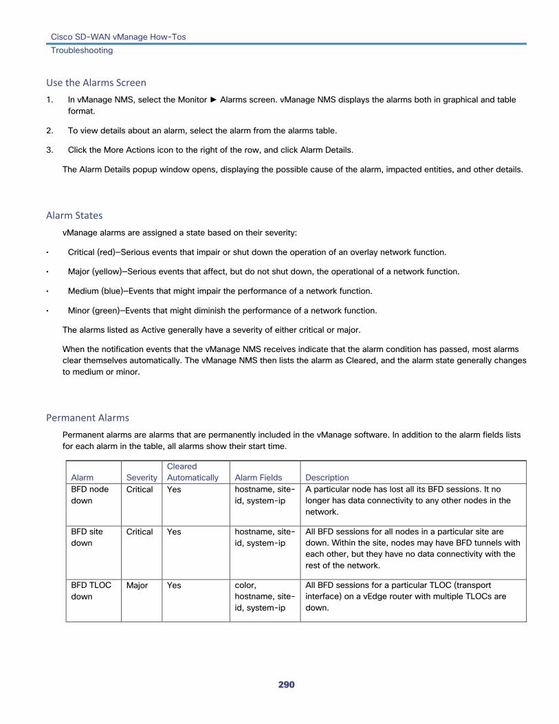
Cisco SD-WAN vManage How-Tos Troubleshooting
290
Use the Alarms Screen 1. In vManage NMS, select the Monitor ► Alarms screen. vManage NMS displays the alarms both in graphical and table
format.
2. To view details about an alarm, select the alarm from the alarms table.
3. Click the More Actions icon to the right of the row, and click Alarm Details.
The Alarm Details popup window opens, displaying the possible cause of the alarm, impacted entities, and other details.
Alarm States vManage alarms are assigned a state based on their severity:
• Critical (red)—Serious events that impair or shut down the operation of an overlay network function.
• Major (yellow)—Serious events that affect, but do not shut down, the operational of a network function.
• Medium (blue)—Events that might impair the performance of a network function.
• Minor (green)—Events that might diminish the performance of a network function.
The alarms listed as Active generally have a severity of either critical or major.
When the notification events that the vManage NMS receives indicate that the alarm condition has passed, most alarms clear themselves automatically. The vManage NMS then lists the alarm as Cleared, and the alarm state generally changes to medium or minor.
Permanent Alarms Permanent alarms are alarms that are permanently included in the vManage software. In addition to the alarm fields lists for each alarm in the table, all alarms show their start time.
Alarm Severity Cleared Automatically Alarm Fields Description
BFD node down
Critical Yes hostname, site-id, system-ip
A particular node has lost all its BFD sessions. It no longer has data connectivity to any other nodes in the network.
BFD site down
Critical Yes hostname, site-id, system-ip
All BFD sessions for all nodes in a particular site are down. Within the site, nodes may have BFD tunnels with each other, but they have no data connectivity with the rest of the network.
BFD TLOC down
Major Yes color, hostname, site-id, system-ip
All BFD sessions for a particular TLOC (transport interface) on a vEdge router with multiple TLOCs are down.

Cisco SD-WAN vManage How-Tos Troubleshooting
291
BGP router down
Critical Yes hostname, router-id, system-ip,vpn-id
All BGP peering sessions from a particular BGP router to all its BGP peers on other vEdge routers are down.
Control all vSmarts down
Critical Yes hostname, site-id, system-ip
All control connections for all vSmart controllers in the network are down. This is a catastrophic event, because the entire control plane is down.
Control node down (vEdge)
Critical Yes hostname, site-id, system-ip
A vEdge router has lost all its control connections and no longer has control plane connectivity to any other node in the network.
Control site down
Critical Yes hostname, site-id, system-ip
All control connections for all nodes in a particular site are down. Within the site, nodes may have control connections with each other, but they have no control plane with the rest of the network.
Control TLOC down
Major Yes color, hostname, site-id, system-ip
All control connections for a particular TLOC (transport interface) on a vEdge router with multiple TLOCs are down.
Control vSmart down
Critical Yes hostname, site-id, system-ip
A vSmart control has lost all its control connections and no longer has control plane connectivity to any other node in the network.
OMP all vSmarts down
Critical Yes hostname, site-id, system-ip
All OMP sessions for all vSmart controllers in the network are down. This is a catastrophic event, because the entire control plane is down. You will receive no information from OMP.
OMP node down
Critical Yes hostname, site-id, system-ip
A vEdge router or vSmart controller has lost all its control connections and no longer has control plane connectivity to any other node in the network, and it will receive no information from OMP.
OMP site down
Critical Yes hostname, site-id, system-ip
All control connections for all nodes in a particular site are down. Within the site, nodes may have control connections with each other, but they have no control plane with the rest of the network, and they will receive no information from OMP.
OSPF router down
Critical Yes hostname, router-id, system-ip,vpn-id
All OSPF peering sessions from a particular OSPF router to all its OSPF peers on other vEdge routers are down.
Alarm Fields Alarm messages can contain the following fields:
Field Description

Cisco SD-WAN vManage How-Tos Troubleshooting
292
acknowledged Whether the alarm has been viewed and acknowledged. This field allows the vManage NMS to distinguish between alarms that have already been reported and those that have not yet been addressed. To acknowledge an alarm, use the following API post call:
https:// vmanage-ip-address :8443/dataservice/alarms/markviewed
Specify the data as:
{“uuid”: [< uuids of alarms to acknowledge >]}
active Whether the alarm is still active. For alarms that are automatically cleared, when a network element recovers, the alarm is marked as "active":false.
cleared_time Time when alarm was cleared. This field is present of for alarms whose "active" field is false.
devices List of system IP addresses or router IDs of the affected devices.
entry_time Time when the alarm was raised, in milliseconds, expressed in UNIX time.
message Short message that describes the alarm.
possible_causes Possible causes for the event.
rule_name_display Name of the alarm. Use this name when querying for alarms of a particular type.
severity Severity of the alarm: critical, major, medium, minor.
severity_number Integer value for the severity: 1 (critical), 2 (major), 3 (medium), 4 (minor)
uuid Unique identifier for the alarm
values Set of values for all the affected devices. These values, which are different for each alarm, are in addition to those shown in the "devices" field.
values_short_display Subset of the values field that provides a summary of the affected network devices.
Release Information Introduced in vManage NMS in Release 16.2. In Release 17.1, update list of alarms.
Additional Information Monitor Event Notifications Use SNMP Traps Use Syslog Messages vManage REST APIs

Cisco SD-WAN vManage How-Tos Troubleshooting
293
Monitor Event Notifications When something of interest happens on an individual device in the overlay network, the device reports the event in the following ways:
• Send a notification to the vManage NMS. The vManage NMS filters the event notifications and correlates related events, and it consolidates major and critical events into alarms.
• Send an SNMP trap to the configured trap target. For each SNMP trap that a device generates, the device also generates a corresponding notification message.
• Generate a system logging (syslog) message and place it in a syslog file in the /var/log directory on the local device and, if configured, on a remote device.
Notifications are messages that the device sends to the vManage NMS server.
View Event Notifications For each SNMP trap that an overlay network device generate, the device generates a notification message.
To display detailed information about events generated by devices:
1. In vManage NMS, select the Monitor ► Events screen. vManage NMS displays the events both in graphical and table format.
2. To view detailed information about any event generated on a device, select the event row from the table.
3. Click the More Actions icon to the right of the row, and click Device Details.
The Device Details popup window opens, displaying the hostname of the device originating the event and other details.
From the CLI, use the show notification stream viptela command. Here is an example of the command output. The first line of the output shows the time when the message was generated (the SNMP eventTime). The time is shown in UTC format. not in the device's local time. The second line of the notification contains a description of the event, and the third line indicates the severity level.
vEdge# show notification stream viptela notification eventTime 2015-04-17T14:39:41.687272+00:00 bfd-state-change severity-level major host-name vEdge system-ip 1.1.4.2 src-ip 192.168.1.4 dst-ip 108.200.52.250 proto ipsec src-port 12346 dst-port 12406 local-system-ip 1.1.4.2 local-color default remote-system-ip 1.1.9.1 remote-color default new-state down ! ! notification eventTime 2015-04-17T15:12:20.435831+00:00 tunnel-ipsec-rekey
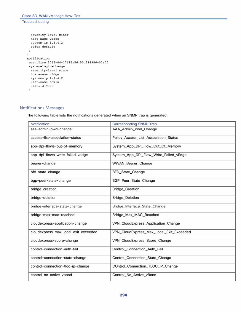
Cisco SD-WAN vManage How-Tos Troubleshooting
294
severity-level minor host-name vEdge system-ip 1.1.4.2 color default ! ! notification eventTime 2015-04-17T16:56:50.314986+00:00 system-login-change severity-level minor host-name vEdge system-ip 1.1.4.2 user-name admin user-id 9890 !
Notifications Messages The following table lists the notifications generated when an SNMP trap is generated.
Notification Corresponding SNMP Trap aaa-admin-pwd-change AAA_Admin_Pwd_Change
access-list-association-status Policy_Access_List_Association_Status
app-dpi-flows-out-of-memory System_App_DPI_Flow_Out_Of_Memory
app-dpi-flows-write-failed-vedge System_App_DPI_Flow_Write_Failed_vEdge
bearer-change WWAN_Bearer_Change
bfd-state-change BFD_State_Change
bgp-peer-state-change BGP_Peer_State_Change
bridge-creation Bridge_Creation
bridge-deletion Bridge_Deletion
bridge-interface-state-change Bridge_Interface_State_Change
bridge-max-mac-reached Bridge_Max_MAC_Reached
cloudexpress-application-change VPN_CloudExpress_Application_Change
cloudexpress-max-local-exit-exceeded VPN_CloudExpress_Max_Local_Exit_Exceeded
cloudexpress-score-change VPN_CloudExpress_Score_Change
control-connection-auth-fail Control_Connection_Auth_Fail
control-connection-state-change Control_Connection_State_Change
control-connection-tloc-ip-change COntrol_Connection_TLOC_IP_Change
control-no-active-vbond Control_No_Active_vBond

Cisco SD-WAN vManage How-Tos Troubleshooting
295
control-no-active-vsmart Control_No_Active_vSmart
control-vbond-state-change Control_vBond_State_Change
control-vedge-list-request Control_vEdge_List_Request
data-policy-association-status Policy_Data_Policy_Association_Status
device-template-attached-during-ztp Security_Device_Template_Attached_During_ZTP
device-template-missing Security_Device_Template_Missing
dhcp-address-assigned DHCP_Address_Assigned
dhcp-address-released DHCP_Address_Released
dhcp-address-renewed DHCP_Address_Renewed
dhcp-request-rejected DHCP_Request_Rejected
dhcp-server-state-change DHCP_Server_State_Change
disk-usage Disk_Usage (Disk usage on the device exceed the predefined threshold of 60%)
domain-id-change Domain_ID_Change
domain-state-change WWAN_ Domain_State_Change
emmc-fault HW_EMMC_Fault
fan-fault HW_Fan_Fault
fantray-fault HW_FanTray_Fault
fib-update VPN_FIB_Update
flash-fault HW_Flash_Fault
interface-admin-state-change Interface_Admin_State_Change
interface-bw VPN_If_BW_Update
interface-pcs-fault-detected Interface_PCS_Fault_Detected
interface-state-change Interface_State_Change
memory-usage Memory_Usage
omp-data-policy Data_Policy
omp-number-of-vsmarts-change OMP_Number_of_vSmarts_Change
omp-peer-state-change OMP_Peer_State_Change
omp-policy OMP_Policy
omp-state-change OMP_State_Change

Cisco SD-WAN vManage How-Tos Troubleshooting
296
omp-tloc-state-change OMP_TLOC_State_Change
org-name-change Org_Name_Change
ospf-interface-state-change OSPF_Interface_State_Change
ospf-neighbor-state-change OSPF_Neighbor_State_Change
pem-fault HW_PEM_Fault
pem-state-change PEM_State_Change
pim-fault HW_PIM_Fault
pim-interface-state-change PIM_Interface_State_Change
pim-neighbor-state-change PIM_Neighbor_State_Change
pim-state-change HW_PIM_State_Change
pim-tunnel-change PIM_Tunnel_Change
pim-tunnel-state-change PIM_Tunnel_State_Change
process-down Process_Down
process-restart Process_Restart
pseudo-commit-status System_Pseudo_Commit_Status
reg-state-change WWAN_Reg_State_Change
route-install-fail Route_Install_Fail
sd-card-fault HW_SDCard_Fault
security-certificate-expired Security_Certificate_Expired
security-certificate-installed Security_Certificate_Installed
security-clear-installed-certificate Security_Clear_Installed_Certificate
security-new-csr-generated Security_New_CSR_Generated
security-root-cert-chain-installed Security_Root_Cert_Chain_Installed
security-root-cert-chain-uninstalled Security_Root_Cert_Chain_Uninstalled
security-vedge-entry-added Security_vEdge_Entry_Added
security-vedge-entry-removed Security_vEdge_Entry_Removed
security-vedge-serial-file-uploaded Security_vEdge_Serial_File_Uploaded
security-vsmart-serial-file-uploaded Security_vSmart_Serial_File_Uploaded
service-gre-state-update Security_Service_GRE_State_Update

Cisco SD-WAN vManage How-Tos Troubleshooting
297
sfp-state-change SFP_State_Change
sfp-support-state SFP_Support_State
sim-state-change WWAN_SIM_State_Change
site-id-change Site_ID_Change
sla-change SLA_Change
sla-violation Policy_SLA_Violation
sla-violation-pkt-drop Policy_SLA_Violation_Pkt_Drop
system-aaa-login-fail System_AAA_Login_Fail
system-commit System_Commit
system-ip-change System_IP_Change
system-login-change System_Login_Change
system-logout-change System_Logout_Change
system-reboot-aborted System_Reboot_Aborted
system-reboot-complete System_Reboot_Complete
system-reboot-issued Reboot_Issued
system-software-install-status Software_Install_Status
tempsensor-fault HW_TempSensor_Fault
tempsensor-state HQ_TempSensor_State
tunnel-install-fail Tunnel_Install_Fail
tunnel-ipsec-manual-rekey Tunnel_IPSec_Manual_Rekey
tunnel-ipsec-rekey Tunnel_IPSec_Rekey
usb-state-change USB_State_Change
vbond-reject-vedge-connection Security_Reject_vEdge_Connection
vmanage-connection-preference-changed Security_vManage_Connection_Preference_Changed
vrrp-group-state-change VRRP_Group_State_Change
Additional Information Monitor Alarms Use SNMP Traps Use Syslog Messages

Cisco SD-WAN vManage How-Tos Troubleshooting
298
Monitor TCP Optimization If TCP optimization is enabled on a vEdge router, you can view information about how the optimization is affecting the processing and throughput of TCP data traffic on the router:
1. In vManage NMS, select the Monitor ► Network screen.
2. Locate the vEdge router using the Sort options drop-down and the Search box. Or scroll through the list of devices in the device table.
3. Select the vEdge router by clicking its hostname. The screen changes and the left pane lists the categories of information you can display about the device.
4. Click TCP Optimization–WAN Throughput in the left pane. The right pane displays the WAN throughput, in megabits per second (Mbps).
The upper part of the right pane contains the following elements:
• Chart Options bar—Located directly under the device name, this bar includes the Chart Options drop-down and time periods. Click Chart Options to select the type of data to display. Click a predefined or custom time period for which to display data.
• Average optimized throughput information, in graphical format.
• WAN graph legend—Identifies non-optimized and TCP-optimized packet throughput.
The lower part of the right pane shows the hourly average throughput and the total optimized throughput, both in megabits per second.
View TCP Flows Click TCP Optimization–Flows in the left pane to display information about TCP-optimized traffic flows. The upper part of the right pane contains the following elements:
• Chart Options bar—Located directly under the device name, this bar includes the Chart Options drop-down and time periods. Click Chart Options to select the type of data to display. Click a predefined or custom time period for which to display data.
• Average optimized throughput information in graphical format.
• Flows graph legend—Identifies non-optimized and TCP optimized packet throughput.
The lower part of the right pane contains the following elements:
• Set perspective—Select the flow direction.
• Filter criteria.
• Flow table that lists the flow destination, usage, and percentage of total traffic for all TCP-optimized flows. By default, the first six flows are selected. Click the checkbox to the left to select and deselect flows to display. The graphical display in the upper part of the right pane plots information for the selected flows.

Cisco SD-WAN vManage How-Tos Troubleshooting
299
View TCP Top Talkers Click TCP Optimization–Top Talkers in the left pane to display information about the tunnels over which the most TCP-optimized traffic is flowing. The upper part of the right pane contains the following elements:
• Chart Options bar—Located directly under the device name, this bar includes the Chart Options drop-down and time periods. Click Chart Options to select the type of data to display. Click a predefined or custom time period for which to display data.
• TCP-optimized traffic volume per tunnel, in bar graph format.
The lower part of the right pane contains the following elements:
• Filter criteria.
• Flow table that lists information about each of the tunnels.
Release Information Introduced in vManage NMS in Release 17.2.
Additional Information See the Configuring TCP Optimization article for your software release.

Cisco SD-WAN vManage How-Tos Troubleshooting
300
Ping a Cisco SD-WAN Device To verify that a device is reachable on the network, ping the device to send ICMP ECHO_REQUEST packets to it:
1. In vManage NMS, select the Monitor ► Network screen.
2. Locate the device using the Sort options drop-down and the Search box. Or scroll through the list of devices in the device table.
3. Select the device by clicking its hostname. The screen changes and the left pane lists the categories of information you can display about the device.
4. Click Troubleshooting in the left pane.
5. From the Connectivity pane, click Ping.
6. In the Destination IP field, enter the IP address of the device to ping.
7. In the VPN drop-down, select the VPN to use to reach the device.
8. In the Source/Interface drop-down, select the interface to use to send the ping packets.
9. In the Probes field, select the protocol type to use to send the ping packets.
10. In the Source Port field, enter the number of the source port.
11. In the Destination Port field, enter the number of the destination port.
12. In the Type of Service field, enter the value for the type of service (ToS) field to include in the ping packets.
13. In the Time to Live field, enter the round-trip time for sending this ping packet and receiving a response, in milliseconds.
14. Click the Don't Fragment slider to set the Don't Fragment bit in the ping packets.
15. Click Advanced Options to specify additional parameters:
a. In the Count field, enter the number of ping requests to send. The range is 1 through 30. The default is 5.
b. In the Payload Size field, enter the size of the packet to send. The default is 64 bytes, which comprises 56 bytes of data and 8 bytes of ICMP header. The range for data is 56 through 65507 bytes.
c. Click the Rapid slider to send five ping requests in rapid succession and to display statistics only for packets transmitted and received, and for the percentage of packets lost.
16. Click Ping.
Ping a Cisco SD-WAN Device in Releases 17.1 and Earlier To verify that a network device is reachable on the network, ping the device to send ICMP ECHO_REQUEST packets to it:
1. In vManage NMS, select the Monitor ► Network screen.
2. Locate the device using the Sort options drop-down and the Search box. Or scroll through the list of devices in the device table.

Cisco SD-WAN vManage How-Tos Troubleshooting
301
3. Select the device by clicking its system IP address. The screen changes and displays a left and right pane.
4. Click Troubleshooting in the left pane. When you first click Troubleshooting, the Connectivity Tools tab and the Ping button are selected in the right pane.
4. In the Destination IP field, enter the IP address of the device to ping.
5. In the VPN drop-down, select the VPN to use to reach the device.
6. In the Source/Interface drop-down, select the interface or IP address to use to send the ping packets.
7. Click Advanced Options to specify additional parameters:
a. In the Count field, enter the number of ping requests to send. The range is 1 through 30. The default is 5.
b. In the Size field, enter the size of the packet to send. The default is 64 bytes, which comprises 56 bytes of data and 8 bytes of ICMP header. The range for data is 56 through 65507 bytes.
c. Click the Rapid checkbox to send 5 ping requests in rapid succession and to display statistics only for packets transmitted and received, and the percentage of packets lost.
Release Information Introduced in vManage NMS in Release 16.2. In Release 17.2, modify design of ping troubleshooting screen.
Additional Information ping tools nping

Cisco SD-WAN vManage How-Tos Troubleshooting
302
Run a Traceroute To display the path that packets take to reach a host or IP address on the network:
1. In vManage NMS, select the Monitor ► Network screen.
2. Locate the device using the Sort options drop-down and the Search box. Or scroll through the list of devices in the device table.
3. Select the device by clicking its hostname. The screen changes and the left pane lists the categories of information you can display about the device.
4. Click Troubleshooting in the left pane.
5. From the Connectivity pane, click Trace Route.
6. In the Destination IP field, enter the IP address of a device on the network.
7. In the VPN drop-down, select the VPN to use to reach the device.
8. In the Source/Interface drop-down, select the interface to use to send traceroute probe packets.
9. Click Advanced Options:
a. In the Size field, enter the size of the traceroute probe packets, in bytes.
10. Click Start to trigger a traceroute to the requested destination.
The lower part of the right pane displays:
• Output—Raw output of the path the traceroute probe packets take to reach the destination.
• Graphical depiction of the path the traceroute probe packets take to reach the destination.
Run a Traceroute in Releases 17.1 and Earlier To display the path that packets take to reach a host or IP address on the network:
1. In vManage NMS, select the Monitor ► Network screen.
2. Locate the device using the Sort options drop-down and the Search box. Or scroll through the list of devices in the device table.
3. Select the device by clicking its system IP address. The screen changes and displays a left and right pane.
4. Click Troubleshooting in the left pane. When you first click Troubleshooting, the Connectivity Tools tab and the Ping button are selected in the right pane.
5. Click the Traceroute button.

Cisco SD-WAN vManage How-Tos Troubleshooting
303
5. In the Destination IP field, enter the hostname or IP address of a device on the network.
6. In the VPN drop-down, select the VPN to use to reach the device.
7. In the Source/Interface field, select the interface to use to send traceroute probe packets.
8. Click Advanced Options:
a. In the Size field, enter the size of the traceroute probe packets, in bytes.
9. Click Start to trigger a traceroute to the requested destination.
The lower part of the right pane displays:
• Output—Raw output of the path the traceroute probe packets take to reach the destination.
• Graphical depiction of the path the traceroute probe packets take to reach the destination.
Release Information Introduced in vManage NMS in Release 16.2. In Release 17.2, modify design of traceroute troubleshooting screen.
Additional Information traceroute

Cisco SD-WAN vManage How-Tos Troubleshooting
304
Simulate Flows To display the next-hop information for an IP packet (available on vEdge routers only):
1. In vManage NMS, select the Monitor ► Network screen.
2. Locate the vEdge router using the Sort options drop-down and the Search box. Or scroll through the list of devices in the device table.
3. Select the vEdge router by clicking its hostname. The screen changes and the left pane lists the categories of information you can display about the device.
4. Click Troubleshooting in the left pane.
5. From the Traffic pane, click Simulate Flows.
6. To specify the data traffic path, select values or enter data in the required fields and optional fields. On the screen, required fields are indicated with an asterisk (*). The required fields are: • VPN—VPN in which the data tunnel is located. • Source Interface—Interface from which the cflowd flow originates. • Source IP—IP address from which the cflowd flow originates. • Destination IP—Destination IP address of the cflowd flow. • Protocol (under Advanced Options)—Number of the protocol being used to transmit the cflowd flow. The optional fields are: • Application—Application running on the router. • Source Port (under Advanced Options)—Port from which the cflowd flow originates. • Destination Port (under Advanced Options)—Destination port of the cflowd flow. • DSCP (under Advanced Options)—DSCP value in the cflowd packets.
7. Click Advanced Options:
a. In the Path toggle field, select whether the data traffic path information comes from the service side of the router or from the tunnel side.
b. Select values or enter data in the required fields (marked with an asterisk [*]) and optional fields. The required fields are: • Protocol—Number of the protocol being used to transmit the cflowd flow. The optional fields are: • Source Port—Port from which the cflowd flow originates. • Destination Port—Destination port of the cflowd flow. • DSCP—DSCP value in the cflowd packets.
c. Check the All Paths checkbox to display all possible paths for a packet.
8. Click Simulate to determine the next hop that a packet with the specified headers would take.
Simulate Flows in Releases 17.1 and Earlier To display the next-hop information for an IP packet (available on vEdge routers only):
1. In vManage NMS, select the Monitor ► Network screen.

Cisco SD-WAN vManage How-Tos Troubleshooting
305
2. Locate the vEdge router using the Sort options drop-down and the Search box. Or scroll through the list of devices in the device table.
3. Select the vEdge router by clicking its hostname. The screen changes and displays a left and right pane.
4. Click Troubleshooting in the left pane. When you first click Troubleshooting, the Connectivity Tools tab and the Ping button are selected in the right pane.
5. Click the Traffic Analysis tab.
5. To specify the data traffic path, select values or enter data in the required fields (marked with an asterisk [*]) and optional fields. The required fields are: • VPN—VPN in which the data tunnel is located. • Source Interface—Interface from which the cflowd flow originates. • Source IP—IP address from which the cflowd flow originates. • Destination—Destination IP address of the cflowd flow. • Protocol (under Advanced Options)—Number of the protocol being used to transmit the cflowd flow. The optional fields are: • Application—Application running on the router. • Source Port—Port from which the cflowd flow originates. • Destination Port—Destination port of the cflowd flow. • DSCP—DSCP value in the cflowd packets.
6. Click Advanced Options:
a. In the Path toggle field, select whether the data traffic path information comes from the service side of the router or from the tunnel side.
b. Check the All Paths checkbox to display all possible paths for a packet.
7. Click Simulate to determine the next hop that a packet with the specified headers would take.

Cisco SD-WAN vManage How-Tos Troubleshooting
306
Release Information Introduced in vManage NMS in Release 16.2. In Release 17.2, modify design of flow simulation screen.
Additional Information See the Application-Aware Routing article for your software release.

Cisco SD-WAN vManage How-Tos Troubleshooting
307
Troubleshoot Cellular Interfaces This article describes how to monitor the status of cellular interfaces in vEdge routers and how to troubleshoot problems for these interfaces.
Monitor Cellular Interfaces You can verify signal strength and service availability using either vManage NMS or the LED on the vEdge router. You can view the last-seen error message for cellular interfaces from vManage NMS.
Verify Signal Strength Using vManage NMS To check signal strength and service availability of a cellular connection from vManage NMS:
1. In vManage NMS, select the Monitor ► Network screen.
2. From the Device Groups drop-down list in the left pane, select the device group to which the router belongs.
3. Choose the options in the Sort by drop-down to sort the device list by status, hostname, system IP, site ID, or personality.
4. Select the vEdge router.
5. In the screen that opens, select Real Time in the left pane.
6. From the command drop-down located in the right pane, select Cellular Status. The value for Signal Strength should be Excellent. If signal strength is Good, Fair, Poor, or No Signal, see Insufficient Radio Signal Strength , below.
CLI equivalent: show cellular status
7. From the command drop-down located in the right pane, select Cellular Radio. This screen shows the values for the different cellular signals. If signal strength is Good, Fair, Poor, or No Signal, see Insufficient Radio Signal Strength , below..
CLI equivalent: show cellular status
Verify Radio Signal Strength Using the Router's LED To check signal strength and service availability of a cellular connection from the vEdge router, look at the WWAN Signal Strength LED. This LED is lon the front of the vEdge 100m and vEdge 100wm routers, and it is labeled with a wireless icon.
The following table explains the LED color and associated status:
Color Signal Strength State Description
Off — — LTE interface disabled (that is, admin status is down) or not configured
Green Excellent Solid LTE interface enabled and in dormant mode (no data being received or transmitted)

Cisco SD-WAN vManage How-Tos Troubleshooting
308
Blinking LTE interface enabled and in active mode (data being received and transmitted)
Yellow Good Solid LTE interface enabled and in dormant mode (no data being received or transmitted)
Blinking LTE interface enabled and in active mode (data being received and transmitted)
Orange Poor Solid LTE interface enabled and in dormant mode (no data being received or transmitted)
Blinking LTE interface enabled and in active mode (data are being received and transmitted)
Red Critical Issue Solid LTE interface enabled but faulty; issues include no connectivity with the base transceiver station (BTS) and no signal
View Error Messages for Cellular Interfaces To view the last-seen error for cellular interfaces from vManage NMS:
1. In vManage NMS, select the Monitor ► Network screen.
2. Select the device from the left pane.
3. IIn the screen that opens, select Real Time in the left pane.
4. From the command drop-down located in the right pane, select Cellular Status. The output displayed includes a column for Last Seen Error.
CLI equivalent: show cellular status
Resolve Problems with Cellular Interfaces This section describes the most common issues and error messages that occur with cellular connections from the vEdge router to the cellular network, and the steps to resolve them.
Insufficient Radio Signal Strength Problem Statement
The cellular module in the vEdge router cannot detect a radio signal from the service provider network.
Identify the Problem
• The signal strength displayed in the vManage Cellular Status screen or with the show cellular status CLI command, or in the Cellular Radio screen or with the show cellular radio command is no signal, poor, or good. It should be excellent. The following table lists the ranges of signal strengths:
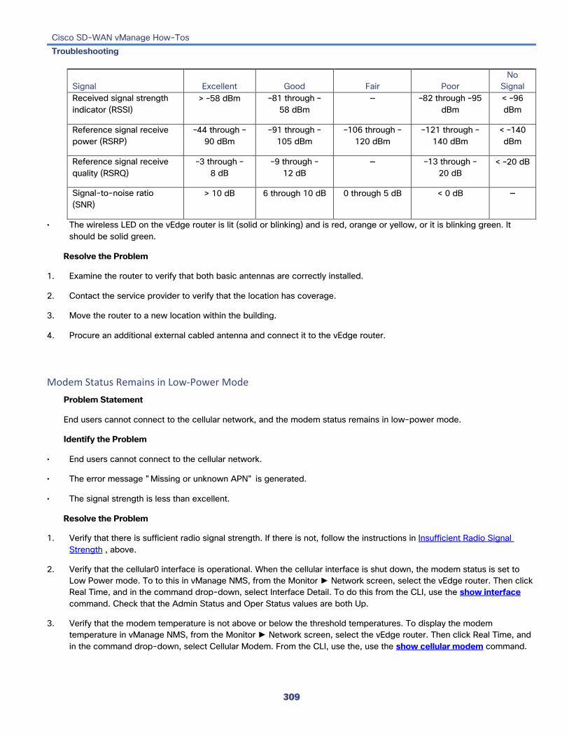
Cisco SD-WAN vManage How-Tos Troubleshooting
309
Signal Excellent Good Fair Poor No
Signal Received signal strength indicator (RSSI)
> –58 dBm –81 through –58 dBm
— –82 through –95 dBm
< –96 dBm
Reference signal receive power (RSRP)
–44 through –90 dBm
–91 through –105 dBm
–106 through –120 dBm
–121 through –140 dBm
< –140 dBm
Reference signal receive quality (RSRQ)
–3 through –8 dB
–9 through –12 dB
— –13 through –20 dB
< –20 dB
Signal-to-noise ratio (SNR)
> 10 dB 6 through 10 dB 0 through 5 dB < 0 dB —
• The wireless LED on the vEdge router is lit (solid or blinking) and is red, orange or yellow, or it is blinking green. It should be solid green.
Resolve the Problem
1. Examine the router to verify that both basic antennas are correctly installed.
2. Contact the service provider to verify that the location has coverage.
3. Move the router to a new location within the building.
4. Procure an additional external cabled antenna and connect it to the vEdge router.
Modem Status Remains in Low-Power Mode Problem Statement
End users cannot connect to the cellular network, and the modem status remains in low-power mode.
Identify the Problem
• End users cannot connect to the cellular network.
• The error message "Missing or unknown APN" is generated.
• The signal strength is less than excellent.
Resolve the Problem
1. Verify that there is sufficient radio signal strength. If there is not, follow the instructions in Insufficient Radio Signal Strength , above.
2. Verify that the cellular0 interface is operational. When the cellular interface is shut down, the modem status is set to Low Power mode. To to this in vManage NMS, from the Monitor ► Network screen, select the vEdge router. Then click Real Time, and in the command drop-down, select Interface Detail. To do this from the CLI, use the show interface command. Check that the Admin Status and Oper Status values are both Up.
3. Verify that the modem temperature is not above or below the threshold temperatures. To display the modem temperature in vManage NMS, from the Monitor ► Network screen, select the vEdge router. Then click Real Time, and in the command drop-down, select Cellular Modem. From the CLI, use the, use the show cellular modem command.
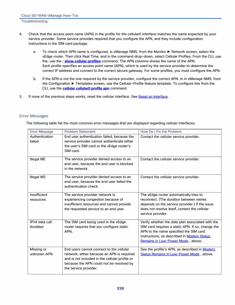
Cisco SD-WAN vManage How-Tos Troubleshooting
310
4. Check that the access point name (APN) in the profile for the cellular0 interface matches the name expected by your service provider. Some service provides required that you configure the APN, and they include configuration instructions in the SIM card package.
a. To check which APN name is configured, in vManage NMS, from the Monitor ► Network screen, select the vEdge router. Then click Real Time, and in the command drop-down, select Cellular Profiles. From the CLI, use the, use the ; show cellular profiles command. The APN columns shows the name of the APN. Each profile specifies an access point name (APN), which is used by the service provider to determine the correct IP address and connect to the correct secure gateway. For some profiles, you must configure the APN.
b. If the APN is not the one required by the service provider, configure the correct APN. In in vManage NMS, from the Configuration ► Templates screen, use the Cellular-Profile feature template. To configure this from the CLI, use the cellular cellular0 profile apn command.
5. If none of the previous steps works, reset the cellular interface. See Reset an Interface .
Error Messages The following table list the most common error messages that are displayed regarding cellular interfaces:
Error Message Problem Statement How Do I Fix the Problem Authentication failed
End user authentication failed, because the service provider cannot authenticate either the user's SIM card or the vEdge router's SIM card.
Contact the cellular service provider.
Illegal ME The service provider denied access to an end user, because the end user is blocked in the network.
Contact the cellular service provider.
Illegal MS The service provider denied access to an end user, because the end user failed the authentication check.
Contact the cellular service provider.
Insufficient resources
The service provider network is experiencing congestion because of insufficient resources and cannot provide the requested service to an end user.
The vEdge router automatically tries to reconnect. (The duration between retries depends on the service provider.) If the issue does not resolve itself, contact the cellular service provider.
IPV4 data call throttled
The SIM card being used in the vEdge router requires that you configure static APN.
Verify whether the data plan associated with the SIM card requires a static APN. If so, change the APN to the name specified the SIM card instructions, as described in Modem Status Remains in Low-Power Mode , above.
Missing or unknown APN
End users cannot connect to the cellular network, either because an APN is required and is not included in the cellular profile or because the APN could not be resolved by the service provider.
See the profile's APN, as described in Modem Status Remains in Low-Power Mode , above.

Cisco SD-WAN vManage How-Tos Troubleshooting
311
MS has no subscription for this service
The service provided denied access to an end user, because the end user has no subscription.
Contact the cellular service provider.
Network failure The service provider network is experiencing difficulties.
The vEdge router automatically tries to reconnect. (The duration between retries depends on the service provider.) If the issue does not resolve itself, contact the cellular service provider.
Network is temporarily out of resources
The service provider network is experiencing congestion because of insufficient resources and cannot provide the requested service to an end user.
The vEdge router automatically tries to reconnect. (The duration between retries depends on the service provider.) If the issue does not resolve itself, contact the cellular service provider.
Operator has barred the UE
The service provided denied access to an end user, because the operator has barred the end user.
Contact the cellular service provider.
Requested service option not subscribed
The SIM card being used in the vEdge router requires that you configure a static APN entry.
Verify whether the data plan associated with the SIM card requires a static APN. If so, change the APN to the name specified the SIM card instructions, as described in Modem Status Remains in Low-Power Mode , above.
Service not supported by the PLMN
The Public Land Mobile Network (PLMN) does not support data service.
Contact the cellular service provider.
Operational Commands clear cellular errors clear cellular session statistics show cellular modem show cellular network show cellular profiles show cellular radio show cellular sessions show cellular status show interface
Release Information Introduced in vManage NMS in Release 16.1.
Additional Information Collect Device Data To Send To Customer Support See the Configuring Interfaces and Configuring Cellular Interfaces articles for your software release. vEdge 100m router Front and Rear Panel Components vEdge 100wm router Front and Rear Panel Components

Cisco SD-WAN vManage How-Tos Troubleshooting
312
Troubleshoot Device Bringup To verify the status of the bringup of a vEdge router:
1. In vManage NMS, select the Monitor ► Network screen.
2. Locate the device using the Sort options drop-down and the Search box. Or scroll through the list of devices in the device table.
3. Select the device by clicking its hostname. The screen changes and the left pane lists the categories of information you can display about the device.
4. Click Troubleshooting in the left pane.
5. From the Connectivity pane, click Device Bringup.
The Device Bringup screen opens and displays:
• Troubleshooting drop-down—Located to the right of the Select Device drop-down. Click an option to view troubleshooting information. To close the drop-down, click the Troubleshooting button again.
• Device bringup state—Indicated by one of the following states:
– Green check mark—Indicates that the device has successfully established control-plane connections with the controller devices in the network and is up and running.
– Gray check mark—Indicates that ZTP was disabled in the Administration ► Settings screen when the device initially came up. You see this state for the Software Image Update box only.
– Red check mark—Indicates that the device failed to establish control-plane connections with the controller devices in the network and is not up and running.
– Yellow exclamation point—Indicates that vManage NMS could not determine the reason for the device bringup failure.
Release Information Introduced in vManage NMS in Release 17.2.

Cisco SD-WAN vManage How-Tos Troubleshooting
313
Troubleshoot WiFi Connnections This article describes how to check for connection problems between a WiFi client and a WiFi network that is provided by a vEdge 100wm router. This article also describes how to resolve these problems.
Check for WiFi Connection Problems If a WiFi client is unable to connect to a WiFi network when a vEdge 100wm router is providing the WiFi network, follow these steps to determine the source of the problem. To perform each step, use a method appropriate for the WiFi client.
1. Verify that the WiFi client can locate the service identifier (SSID) advertised by the vEdge router. If the client cannot find the SSID, see SSID Not Located , below.
2. Verify that the WiFi client can connect to the SSID advertised by the vEdge router. If the client cannot connect to the SSID, see SSID Connection Fails , below.
3. Verify that the WiFi client has been assigned an IP address. If the client cannot obtain an IP address, see Missing IP Address , below.
4. Verify that the WiFi client can access the Internet. If the client cannot connect to the Internet, see Internet Connection Failure , below.
5. If the WiFi client connection is slow or if you notice frequent disconnects, see WiFi Speed Is Slow , below.
Resolve Problems with WiFi Connections This section describes the most common issues that occur with WiFi connections between a WiFi client and a vEdge router, and it describes steps to resolve the issues.
SSID Not Located Problem Statement
The WiFi client cannot locate the SSID advertised by the vEdge 100wm router.
Resolve the Problem
1. Ensure that the basic service set identifier (BSSID) address for the SSID is valid:
a. In vManage NMS, select the Monitor ► Network screen.
b. Locate the vEdge 100wm router using the Sort options drop-down and the Search box. Or scroll through the list of devices in the device table.
c. Select the vEdge 100wm router by clicking its hostname.
d. From the left pane, select WiFi. The right pane displays information about WiFI configuration on the vEdge router.
e. In the right pane, locate the SSID. Check that the BSSID for this SSID does not have a value of 00:00:00:00:00:00.

Cisco SD-WAN vManage How-Tos Troubleshooting
314
f. If the BSSID is 00:00:00:00:00:00, the WLAN (VAP) interface for this SSID may be misconfigured. Ensure that the WLAN interface has been added to a bridge during the configuration process. — To view the device's running configuration in vManage NMS, from the Configuration ► Devices screen, select the vEdge 100wm router. Then click the More Actions icon to the right of the row, and click Running Configuration. To view the device's running configuration from the CLI, use the show running-config command. — To add the WLAN interface to a bridge, in vManage NMS, from the Configuration ► Templates screen, use the Bridge feature template. To do this from the CLI, see Configuring WLAN Interfaces .
2. Eliminate static channels. A static channel is one where you explicitly configure the radio channel rather than allowing the router to automatically select the best radio channel. A slow static channel may appear to be an unreachable SSID.
a. View the current SSID channel setting for the vEdge router. To do this in vManage NMS, from the Monitor ► Network screen, select the vEdge 100wm router. Then click Real Time, and in the command drop-down, select WLAN Clients or WLAN Radios. From the CLI, use the show wlan clients or show wlan radios command.
b. If the channel is set to a specific number, change the value to "auto". To do this in vManage NMS, from the Configuration ► Templates screen, use the WiFi Radio feature template. From the CLI, use the wlan channel auto command.
3. Ensure that the WiFi client is using the same radio band as the vEdge 100wm router, either 2.4 GHz (for IEEE 802.11b/g/n) or 5 GHz(for IEEE802.11a/n/ac):
a. Check which radio band the WiFi client supports.
b. Check the vEdge 100wm router’s Select Radio setting. To do this in vManage NMS, from the Monitor ► Network screen, select the vEdge 100wm router. Then click Real Time, and in the command drop-down, select WLAN Radios. From the CLI, use the show wlan radios command.
c. If the vEdge 100wm router and WiFi client radio band settings do not match, either change the WiFi client's radio band or change the settings on the vEdge 100wm router so that they match. To do this in vManage NMS, from the Configuration ► Templates screen, use the WiFi Radio feature template. From the CLI, use the wlan command.
SSID Connection Fails Problem Statement
The WiFi client can locate the SSID advertised by the vEdge 100wm router but cannot connect to it.
Resolve the Problem
1. If you configure passwords locally on the vEdge 100wm router, ensure that the WiFi client's password matches the SSID's password.
2. If you are using a RADIUS server, ensure that the RADIUS server is reachable and that the WiFi client's username and password match the RADIUS configuration:
a. To verify that the RADIUS server is reachable from the router, ping the server. To do this in vManage NMS, see Ping a Device . From the CLI, use the ping command.
b. Check for matching passwords on the RADIUS server and WiFi client.

Cisco SD-WAN vManage How-Tos Troubleshooting
315
3. Ensure that you do not exceed the maximum number of clients for this SSID:
a. Verify the number of used clients and the maximum number of clients:
• In vManage NMS, from the Monitor ► Network screen, select the vEdge 100wm router. From the left pane, select WiFi. In the right pane, locate the SSID. Check the No. of Clients field. If the used/maximum values are equal, no more clients can connect to this SSID.
• From the CLI, use the show wlan interfaces detail command.
b. If needed, increase the Max Clients setting for your SSID. To do this in vManage NMS, from the Configuration ► Templates screen, use the WiFi SSID feature template. From the CLI, use the max-clients command.
4. Ensure that the WiFi client supports WPA2 management security:
a. Check your Management Security setting. To do this in vManage NMS, from the Monitor ► Network screen, select the vEdge 100wm router. Then click Real Time, and in the command drop-down, select WLAN Interfaces. From the CLI, use the show wlan interfaces command. If the management security value is set to "required," the WiFi client must support WPA2 security.
b. If necessary, change the Management Security setting for your SSID to "optional" or "none." To do this in vManage NMS, from the Configuration ► Templates screen, use the WiFi SSID feature template. From the CLI, use the mgmt-security command.
Missing IP Address Problem Statement
The WiFi client can connect to the SSID, but cannot obtain an IP address.
Resolve the Problem
Ensure that a DHCP server is reachable and has an available IP address in its address pool:
1. If the vEdge 100wm router is acting as a DHCP helper (DHCP relay agent), ping the DHCP server to ensure that it is reachable from the router. To do this in vManage NMS, see Ping a Cisco SD-WAN Device . From the CLI, use the ping command.
2. If you are using a remote DHCP server, check that the remote DHCP server has an available IP address in its address pool.
3. If the vEdge 100wm router is acting as the local DHCP server:
a. View the number of addresses being used. In vManage NMS, from the Monitor ► Network screen, select the vEdge 100wm router. Then click Real Time, and in the command drop-down, select DHCP Servers. From the CLI, use the show dhcp server command.
b. Compute the number of IP addresses in the pool based on the configured DHCP address pool size and the number of addresses excluded from the DHCP address pool. To view these values in vManage NMS, from the Configuration ► Devices screen, select the vEdge router. Then click the More Actions icon to the right of the row, and click Running Configuration. To view them from the CLI, use the show running-config command.
c. If necessary, increase the range of addresses in the router's DHCP address pool. To do this in vManage NMS, from the Configuration ► Templates screen, use the DHCP-Server feature template. From the CLI, use the address-pool command.

Cisco SD-WAN vManage How-Tos Troubleshooting
316
Internet Connection Failure Problem Statement
The WiFi client is connected to the SSID and has an IP address, but it cannot connect to the Internet.
Resolve the Problem
Ensure that the WiFi client has received the correct default gateway and DNS settings from the DHCP server:
1. If the DHCP server is remote, check the settings on the server.
2. If the vEdge 100wm router is the DHCP server, ensure that the default gateway and DNS server settings are the same as those on the WiFi client. To view the settings in vManage NMS, from the Monitor ► Network screen, select the vEdge 100wm router. Then click Real Time, and in the command drop-down, select DHCP Interfaces. From the CLI, use the show dhcp interface command.
WiFi Speed Is Slow Problem Statement
The WiFi client can connect to the Internet, but the connection speed is slow.
Resolve the Problem
Allow the vEdge 100wm router to choose the best WiFi channel:
1. View the current SSID channel setting for the vEdge 100wm router. To do this in vManage NMS, from the Monitor ► Network screen, select the vEdge 100wm router. Then click Real Time, and in the command drop-down, select WLAN Clients or WLAN Radios. From the CLI, use the show wlan clients or show wlan radios command.
2. If the channel is set to a specific number, change the value to "auto". To do this in vManage NMS, from the Configuration ► Templates screen, use the WiFi Radio feature template. From the CLI, use the wlan channel auto command.
Operational Commands show dhcp interface show dhcp server show running-config show wlan clients show wlan interfaces show wlan radios
Release Information Introduced in vManage NMS in Release 16.3
Additional Information Configuring WLAN Interfaces

Cisco SD-WAN vManage How-Tos Troubleshooting
317
Use SNMP Traps When something of interest happens on an individual device in the overlay network, the device reports the event in the following ways:
• Send a notification to the vManage NMS. The vManage NMS filters the event notifications and correlates related events, and it consolidates major and critical events into alarms.
• Send an SNMP trap to the configured trap target. For each SNMP trap that a device generates, the device also generates a corresponding notification message.
• Generate a system logging (syslog) message and place it in a syslog file in the /var/log directory on the local device and, if configured, on a remote device.
SNMP traps are asynchronous notifications that a Cisco SD-WAN device sends to an SNMP management server. Traps notify the management server of events, whether normal or significant, that occur on the Cisco SD-WAN device. By default, SNMP traps are not sent to an SNMP server. Note that for SNMPv3, the PDU type for notifications ie either SNMPv2c inform (InformRequest-PDU) or trap (Trapv2-PDU).
Configure SNMP Traps To configure SNMP traps, you define the traps themselves and you configure the SNMP server that is to receive the traps. To configure these from vManage NMS, use the SNMP feature configuration template.
From the CLI, to configure groups of traps to be collected on a Cisco SD-WAN device, use the trap group command:
(config-snmp)# trap group group-name (config-group)# trap-type level severity
The group-name is a name of your choosing. A single trap group can contain multiple trap types. In the configuration, specify one trap type per line, and each trap type can have one, two, or three severity levels. See the configuration example below for an illustration of the configuration process.
The trap-type can be one of those listed in the table below. The severity can be critical , major , or minor .
From the CLI to configure the SNMP server to receive the traps, use the trap target command:
(config-snmp)# trap target vpn vpn-id ipv4-address udp-port (config-target)# group-name name (config-target)# community-name community-name (config-target)# source-interface interface-name
For each SNMP server, specify the identifier of VPN where the server is located, the server's IPv4 address, and the UDP port on the server to connect to. When configuring the trap server's address, you must use an IPv4 address. You cannot use an IPv6 address.
In the group-name command, associate a previously configured trap group with the server. The traps in that group are sent to the SNMP server.
In the community-name command, associate a previously configure SNMP community with the SNMP server.
In the source-interface command, configure the interface to use to send traps to the SNMP server that is receiving the trap information. This interface cannot be a subinterface.

Cisco SD-WAN vManage How-Tos Troubleshooting
318
SNMP Traps The following table lists the SNMP traps by severity level. For each SNMP trap that a Cisco SD-WAN device generate, the device generates a notification message.
Trap Type
Critical Major Minor
all All critical traps listed below.
All major traps listed below. All minor traps listed below.
app-route
SLA_Change
bfd BFD_State_Change
bridge Bridge_Interface_State_Change Bridge_Creation Bridge_Deletion Max_MAC_Reached
control No_Active_vBond No_Active_vSmart
Connection_Auth_Fail Connection_State_Change Connection_TLOC_IP_Change vBond_State_Change
Control_vEdge_List_Request
dhcp Server_State_Change Address_Assigned Address_Released Address_Renewed Request_Rejected
hardware EMMC_Fault Fan_Fault FanTray_Fault Flash_Fault PEM_Fault PEM_State_Change PIM_Fault PIM_State_Change SDCard_Fault SFP_State_Change TempSensor_Fault TempSensor_State USB_State_Change
SFP_Support_State
omp Data_Policy Number_of_vSmarts_Change Peer_State_Change Policy State_Change TLOC_State_Change
policy Access_List_Association_Status Data_Policy_Association_Status SLA_Violation_Pkt_Drop
SLA_Violation

Cisco SD-WAN vManage How-Tos Troubleshooting
319
routing BGP_Peer_State_Change OSPF_Interface_State_Change OSPF_Neighbor_State_Change PIM_Interface_State_Change PIM_Neighbor_State_Change PIM_TUnnel_Change PIM_Tunnel_State_Change
security Certificate_Expired Clear_Installed_Certificate Device_Template_Missing Reject_vEdge_COnnection Root_Cert_Chain_Uninstalled vEdge_Entry_Added vEdge_Entry_Removed vEdge_Serial_File_Uploaded vSmart_Entry_Added vSmart_Entry_Removed vSmart_Serial_File_Uploaded
Certificate_Installed Device_Template_Attached_During_ZTP New_CSR_Generated Root_Cert_Chain_Installed Service_GRE_State_Update Tunnel_IPSec_Manual_Rekey Tunnel_IPSec_Rekey vManage_Connection_Preference_Changed
system AAA_Admin_Pwd_Change AAA_Login_Fail App_DPI_Flow_Out_Of_Memory APP_DPI_Flow_Write_Failed_vEdge Disk_Usage Memory_Usage Process_Down Process_Restart Pseudo_Commit_Status Reboot_Aborted Reboot_Complete
Domain_ID_Change Org_Name_Change Reboot_Issued Site_ID_Change Software_Install_Status System_Commit System_IP_Change System_Login_Change System_Logout_Change
vpn CloudExpress_Max_Local_Exit_Exceeded CloudExpress_Score_Change If_BW_Update Interface_Admin_State_Change Interface_PCS_Fault_Detected Interface_State_Change VRRP_Group_State_Change
CloudExpress_Application_Change FIB_Update Route_Install_Fail Tunnel_Install_Fail
wwan Bearer_Change Domain_State_Change Reg_State_Change SIM_State_Change
Additional Information Monitor Alarms Monitor Event Notifications Use Syslog Messages

Cisco SD-WAN vManage How-Tos Troubleshooting
320
Use Syslog Messages When something of interest happens on an individual device in the overlay network, the device reports the event in the following ways:
• Send a notification to the vManage NMS. The vManage NMS filters the event notifications and correlates related events, and it consolidates major and critical events into alarms.
• Send an SNMP trap to the configured trap target. For each SNMP trap that a device generates, the device also generates a corresponding notification message.
• Generate a system logging (syslog) message and place it in a syslog file in the /var/log directory on the local device and, if configured, on a remote device.
On SD-WAN devices, you can log event notification system log (syslog) messages to files on the local device or on a remote host, or both. On the local device, syslog files are placed in the /var/log directory.
Configure System Logging Logging syslog messages with a priority level of "information," to the local device's hard disk, is enabled by default. Log files are placed in the local /var/log directory. By default, log files are 10 MB in size, and up to 10 files are stored. After 10 files have been created, the oldest one is discarded to create a file for newer syslog messages.
To modify the default syslog parameters from vManage NMS, use the Logging feature template. From the CLI, include the logging disk or logging server command in the device configuration.
Display Syslog Logging Information In vManage NMS, to display the contents of a device's syslog files:
1. In the Administration ► Settings screen, ensure that Data Stream is enabled.
2. From the Monitor ► Network screen, select the vEdge router.
3. Click Troubleshooting in the left pane.
4. From the Logs pane, click Debug Log.
5. In the Log Files field, select the name of the log file. The lower part of the screen displays the log information.
To display the contents of a syslog file from the CLI, use the show log command. For example:
vEdge# show log auth.log tail 10 ==> /var/log/auth.log <== auth.info: Nov 14 14:33:35 vedge sshd[2570]: Accepted publickey for admin from 10.0.1.1 port 39966 ssh2: RSA SHA256:pkFQ5wE//DmiA0d0JU1rOt91CMTVGkscm9wLSYQrI1s auth.info: Nov 14 14:39:42 vedge sshd[2578]: Received disconnect from 10.0.1.1 port 39966:11: disconnected by user auth.info: Nov 14 14:39:42 vedge sshd[2578]: Disconnected from 10.0.1.1 port 39966 auth.info: Nov 16 10:51:45 vedge sshd[6106]: Accepted publickey for admin from 10.0.1.1 port 40012 ssh2: RSA SHA256:pkFQ5wE//DmiA0d0JU1rOt91CMTVGkscm9wLSYQrI1s auth.info: Nov 16 11:21:55 vedge sshd[6108]: Received disconnect from 10.0.1.1 port 40012:11: disconnected by user auth.info: Nov 16 11:21:55 vedge sshd[6108]: Disconnected from 10.0.1.1 port 40012

Cisco SD-WAN vManage How-Tos Troubleshooting
321
auth.info: Nov 17 12:59:52 vedge sshd[15889]: Accepted publickey for admin from 10.0.1.1 port 40038 ssh2: RSA SHA256:pkFQ5wE//DmiA0d0JU1rOt91CMTVGkscm9wLSYQrI1s auth.info: Nov 17 13:45:13 vedge sshd[15894]: Received disconnect from 10.0.1.1 port 40038:11: disconnected by user auth.info: Nov 17 13:45:13 vedge sshd[15894]: Disconnected from 10.0.1.1 port 40038 auth.info: Nov 17 14:47:31 vedge sshd[30883]: Accepted publickey for admin from 10.0.1.1 port 40040 ssh2: RSA SHA256:pkFQ5wE//DmiA0d0JU1rOt91CMTVGkscm9wLSYQrI1s
To display the configured system logging settings for a device, use the show logging command from the CLI. For example:
vEdge# show logging System logging to in vpn 0 is disabled Priority for host logging is set to: info System logging to disk is enabled Priority for disk logging is set to: info File name for disk logging is set to: /var/log/vsyslog File size for disk logging is set to: 10 MB File recycle count for disk logging is set to: 10 Syslog facility is set to: local7
System Log Files Syslog messages at or above the default or configured priority value are recorded in a number of files in the /var/log directory on the local device. These files include the following:
• auth.log—Login, logout, and superuser access events, and usage of authorization systems.
• kern.log—Kernel messages.
• messages—Consolidated log file that contains syslog messages from all sources.
• vconfd—All configuration-related syslog messages.
• vdebug—All debug messages for modules whose debugging is turned on and all syslog messages above the configured priority value. Debug logging supports various levels of logging based on the module. Different modules implement the logging levels differently. For example, the system manager (sysmgr) has two logging levels (on and off), while the chassis manager (chmgr) has four different logging levels (off, low, normal, and high). You cannot send debug messages to a remote host. To enable debugging, use the debug operational command.
• vsyslog—All syslog messages from Cisco SD-WAN processes (daemons) above the configured priority value. The default priority value is "informational" (severity level 6), so by default, all "notice", "warning", "error", "critical", "alert", and "emergency" syslog messages (severity levels 5 through 0, respectively) are saved.
The Cisco SD-WAN software does not use the following standard LINUX files, which are present in /var/log, for logging: cron.log, debug, lpr.log, mail.log, and syslog.
The writing of messages to syslog files is not rate-limited. This means that if many syslog messages are generated in a short amount of time, the overflow messages are buffered and placed in a queue until they can be written to a syslog file. The overflow messages are not dropped.
For repeating syslog messages—identical messages that occur multiple times in succession—only one copy of the message is placed in the syslog file. The message is annotated to indicate the number of times that the message occurred.

Cisco SD-WAN vManage How-Tos Troubleshooting
322
The maximum length of a syslog message is 1024 bytes. Longer messages are truncated.
Syslog messages related to AAA authentication and Netconf CLI access and usage are placed in the auth.log and messages files. Each time a vManage NMS logs in to a vEdge router to retrieve statistics and status information and to push files to the router, the router generates AAA and Netconf log messages. So, over time, these messages can fill the log files. To prevent these messages from filling the log files, you can disable the logging of AAA and Netconf syslog messages:
(config)# system aaa logs (config-logs)# audit-disable (config-logs)# netconf-disable
Syslog Message Format Syslog message generated by the Cisco SD-WAN software have the following format:
facility.source date - source - module - level - MessageID: text-of-syslog-message
Here is an example of a syslog message. In the file, this message is on a single line. This message has the facility name of local7, which is the name used for all Cisco SD-WAN processes, and a priority of "info".
local7.info: Apr 3 13:40:31 vsmart SYSMGR[221]: %Viptela-vsmart-sysmgrd-6-INFO-1400002: Notification : 4/3/2017 20:40:31 system-login-change severity-level:minor host-name:"vm1" system-ip:172.16.255.11 user-name:"admin" user-id:162
Syslog Message Acronyms The following Cisco SD-WAN-specific acronyms are used in syslog messages and in the explanations of the messages:
Acronym Meaning confd CLI configuration process
FTM Forwarding table manager
FP Forwarding process
RTM Route table manager
TTM Tunnel table manager
Syslog Messages The tables below list the syslog messages generated by Cisco SD-WAN devices. The messages are grouped based on the software module that generates them. The software modules are typically processes (daemons) that run on the Cisco SD-WAN device.
All syslog messages are generated on all Cisco SD-WAN devices unless otherwise indicated.
Each syslog message has a corresponding number. The tables list all syslog messages and their number even if the messages are defined in the header files but are not currently used in the operating software. For these messages, the Message Format, Description, and Action fields are empty.

Cisco SD-WAN vManage How-Tos Troubleshooting
323
In these tables, the Action field indicates the recommended action you should take in response to the syslog message:
• A—Automatically open a ticket in your organization's support team.
• AE—Automatically open a support ticket and escalate the ticket
• E—Send email to the appropriate team within your organization.
CFGMGR: Configuration Manager Process Priority: Informational
Message Number Message Format Description Action
CFGMGR_SYSLOG_END 399999 Terminating cfgmgr
Configuration manager is stopping
E
CFGMGR_SYSLOG_SPEED_DUPLEX_NOT_SUPPORTED 300003 — Interface does not support duplex mode
E
CFGMGR_SYSLOG_SPURIOUS_TIMER 300002 — Internal error A
CFGMGR_SYSLOG_IF_STATE 300004 — Interface state reported by configuration manager
E
CFGMGR_SYSLOG_START 300001 Starting cfgmgr
Configuration manager is starting
E
CFLOWD: Cflowd Traffic Flow Monitoring Process Priority: Informational
Message Number Message Format Description Action CFLOWD_SYSLOG_MSG 2200002 Received information about vpn_id
%ld, vpn_id Cflowd detected a VPN change
E
Priority: Notice
Message Number Message Format Description Action CFLOWD_SYSLOG_END 2299999 Terminating module
cflowd because of sysmgr abort
Cflowd module going down at request of sysmgr
E
CFLOWD_SYSLOG_END 2299999 Terminating module cflowd with error code %d
Cflowd initialization failed and cflowd is about to go down, or cflowd module is going down
A
CFLOWD_SYSLOG_START 2200001 Starting module cflowd Cflowd module is starting E

Cisco SD-WAN vManage How-Tos Troubleshooting
324
CHMGR: Chassis Manager The chassis manager process runs only on hardware vEdge routers.
Priority: Informational
Message Number Message Format Description Action CHMGR_CHASSIS_INFO 100009 Chassis-Type %s
max-modules %d Informational message indicating chassis type and maximum number of modules (PIMs + fixed) supported by chassis
E
CHMGR_FAN_SPEED_HIGH 100003 — Fan speed is high E
CHMGR_FAN_SPEED_NORMAL 100004 — Fan speed is normal E
CHMGR_FANTRAY_INSERTED 100052 Fantray %d inserted Fan tray inserted (on vEdge 2000 only) E
CHMGR_FANTRAY_REMOVED 100053 Fantray %d removed Fan tray removed (on vEdge 2000 only)
E
CHMGR_MODULE_INSERTED 100007 Module %d inserted - port type: %s, num_ports: %s
PIM module inserted E
CHMGR_MODULE_REMOVED 100008 Module %d removed PIM module removed E
CHMGR_PIM_OK 100057 — PIM module status is normal E
CHMGR_PORT_INSERTED 100005 Port %s inserted in module %d
SFP inserted E
CHMGR_PORT_REMOVED 100006 Port %s removed from module %d
SFP removed E
CHMGR_SIGTERM 100024 Received sigterm, exiting gracefully
Debug-level message indicating that chassis manager is going down
E
CHMGR_SYSLOG_START 100001 Starting chassis manager
Chassis manager process is starting E
CHMGR_USB_INSERTED 100058 USB media inserted in slot %d
USB media inserted E
CHMGR_USB_REMOVED 100059 USB media removed from slot %d
USB media removed E
Priority: Notice
Message Number Message Format Description Action CHMGR_EMMC_OK 100039 eMMC read successful EMMC read was successful E
CHMGR_FAN_OK 100041 Fan Tray %d Fan %d fault cleared, ftrayid, id
Fan fault cleared E

Cisco SD-WAN vManage How-Tos Troubleshooting
325
CHMGR_FANTRAY_OPER 100055 Fan tray '%d' up, ftrayid Fan tray detected A
CHMGR_FLASH_OK 100037 Flash memory status read successful
Flash read successful E
CHMGR_PEM_OK 100043 Power supply '%d' fault cleared
Power supply fault cleared E
CHMGR_PEM_OPER 100045 Power supply '%d' up Power supply inserted or detected
E
CHMGR_SDCARD_OK 100047 SD card read successful SD card read successful E
CHMGR_SFP_UNSUPPORTED 10060 SFP %s is not supported SFP is not supported E
CHMGR_SHORT_RESET_REQUEST 100018 — Chassis manager received a request to reboot the router
E
CHMGR_TEMP_GREEN 100030 %s temperature (%d degrees C) is below yellow threshold (%d degrees C)
Temperature sensor reading below yellow threshold
E
CHMGR_TEMP_OK 100027 %s temperature sensor fault cleared
Temperature sensor read successful after a previous failed attempt
E
Priority: Warning
Message Number Message Format Description Action CHMGR_HOTSWAP_DIFF_MOD 100051 Hot-Insertion of a module
of different type requires reboot. Module %d will remain down,
PIM module of a different type was inserted in the slot; it was detected, but will remain down until the next reboot
E
Priority: Error
Message Number Message Format Description Action CHMGR_CONFD_DATACB_REGISTER_FAILED 100023 Failed to register data
cb Internal error registering a data callback function with confd
AE
CHMGR_CONFD_REPLY_FAILED 100022 Failed to send oper data reply - %s (%d)
Internal error occurred when processing chassis manager–related configuration of show command
A
CHMGR_EEPROM_READ_FAILED 100011 Failed to read module %d eeprom on chassis %s, module, chassis-name
Failed to read details of inserted PIM
AE

Cisco SD-WAN vManage How-Tos Troubleshooting
326
CHMGR_EEPROM_VERSION_ERROR 100012 Unsupported eeprom format version for module %d
EEPROM version of PIM module is supported; module will not be recognized
AE
CHMGR_EMMC_FAULT 100038 eMMC fault detected Error occurred reading EMMC information
A
CHMGR_FAN_FAULT 100040 Fan Tray %d Fan %d fault detected, ftrayid, id
Fan fault detected A
CHMGR_FANTRAY_DOWN 100054 Fan tray '%d' not present, ftrayid id
Fan tray not detected A
CHMGR_FLASH_FAULT 100036 Flash memory status fault
Internal error reading flash
AE
CHMGR_GET_HWADDR_FAILED 100010 Failed to get macaddr for %s, p_ifname
Internal error resulting from failure to obtain an interface's MAC address
A
CHMGR_GET_IFFLAG_FAILED 100016 Failed to get ifflags for %s err %d, p_port->kernel_name, errno
Interface initialization failure; interface may remain down, or device may reboot
A
CHMGR_IFFLAGS_SET_FAIL 100050 — Setting an interface flag failed
E
CHMGR_IF_GSO_OFF_FAILED 100025 — Setting interface options failed
E
CHMGR_PEM_DOWN 100044 Power supply '%d' down or not present
Power supply removed or not detected
A
CHMGR_PEM_FAULT 100042 Power supply '%d' fault detected
Power supply fault detected
AE
CHMGR_PIM_FAULT 100056 PIM %d power fault PIM power fault detected
AE
CHMGR_PIM_FAULT 100056 PIM %d power fault cleared
PIM power fault cleared A
CHMGR_SDCARD_FAULT 100046 SD card fault detected (no present or unreadable)
SD card fault detected A
CHMGR_SET_IFFLAG_FAILED 100017 Failed to set ifflags to %x for %s err %d
Interface initialization failure; interface may remain down, or device may reboot
A

Cisco SD-WAN vManage How-Tos Troubleshooting
327
CHMGR_SHORT_RESET_CLEAR_FAILED 100019 — Clearing a reboot request failed.
A
CHMGR_SHORT_RESET_FAILED 100020 — Request to reset the router by rebooting failed
A
CHMGR_SPURIOUS_TIMER 100035 Spurious timer ignored what = %#x arg = %p
Internal error A
CHMGR_SYSOUT_OF_RESOURCES 100049 Timer add failed. Out of resources
Interal error; if fatal, device may reboot to recover
A
CHMGR_UNKNOWN_MODULE_TYPE 100013 Invalid module-type %x in module-slot %d on chassis %s,
Unrecognized PIM module type in slot
AE
CHMGR_UNSUPPORTED_MODULE_TYPE 100014 Module-Type %s not supported in slot %d on chassis %s
PIM module is not supported in slot in which it is inserted
A
Priority: Critical
Message Number Message Format Description Action CHMGR_IF_RENAME_FAILED 100015 Unable to rename %s to %s Interface initialization failed;
interface may remain down or the device may reboot
A
CHMGR_TEMP_FAULT 100026 %s temperature sensor fault detected. Unable to read temperature
Failed to read from a temperature sensor; possible temperature sensor failure
A
CHMGR_TEMP_RED 100028 %s temperature (%d degrees C) is above red threshold (%d degrees C).
Temperature sensor reading above red threshold
AE
CHMGR_TEMP_YELLOW 100029 %s temperature (%d degrees C) is above yellow threshold (%d degrees C),
Temperature sensor reading above yellow threshold
A
Priority: Alert
Message Number Message Format Description Action CHMGR_CONFD_INIT_FAILED 100021 Initialization failed.
vconfd_module_init returned %d Chassis manager failed to initialize and start
AE
CVMX: Internal Cavium Driver Process
Priority: Informational
Message Number Message Format Description Action CVMX_SYSLOG_END 999999 Terminating Cavium drivers Internal Cavium drivers ending E

Cisco SD-WAN vManage How-Tos Troubleshooting
328
CVMX_SYSLOG_START 900001 Starting Cavium drivers Internal Cavium drivers starting E
CXP: Cloud onRamp for SaaS Process Priority: Informational
Message Number Message Format Description Action CXP_SYSLOG_END 2799999 Terminating Cloud onRamp process Cloud onRamp for SaaS ending E
CXP_SYSLOG_START 2700001 Starting Cloud onRamp process Cloud onRamp for SaaS starting E
CONTAINER: Containers Priority: Informational
Message Number Message Format Description Action CONTAINER_SYSLOG_END 2699999 Terminating container process Container process ending E
CONTAINER_SYSLOG_START 2600001 Starting container process Container process starting E
DBGD: Debug Process Priority: Informational
Message Number Message Format Description Action DBGD_SYSLOG_END 2900001 Terminating debug process Debug process ending E
DBGD_SYSLOG_START 2999999 Starting debug process Debug process starting E
DHCPC: DHCP Client The DHCP client process runs only on vEdge routers.
Priority: Informational
Message Number Message Format Description Action DHCP_SYSLOG_CLEAR_INTERFACE 1300006 Clearing dhcp state for
interface %s, DHCP client cleared DHCP state for interface
E
DHCP_SYSLOG_DISCOVER_TIMEOUT 1300005 No response for dhcp discover packets for interface %s,
DHCP discovery failure
E
DHCP_SYSLOG_END 1300001 Terminating syslog process
Syslog process ending E

Cisco SD-WAN vManage How-Tos Troubleshooting
329
DHCP_SYSLOG_IP_ADDR_ASSIGNED 1300002 Assigned address %s to interface %s
DHCP client assigned address to interface
E
DHCP_SYSLOG_IP_ADDR_RELEASED 1300003 Released address for interface %s
DHCP client released address
E
DHCP_SYSLOG_IP_ADDR_RENEWED 1300010 Renewed address %s for interface %s
DHCP client address renewed
E
DHCP_SYSLOG_IP_ADDR_REQUEST_RENEW 1300004 Requesting renew [50%%] for interface %s address %s/%d
DHCP client renewal request at 50% of lease expiration time
E
DHCP_SYSLOG_IP_ADDR_REQUEST_RENEW 1300004 Requesting renew [85%%] for interface %s address %s/%d
DHCP client renewal request at 85% of lease expiration time
E
DHCP_SYSLOG_IP_ADDR_REQUEST_RENEW 1300004 Requesting renew [100%%] for interface %s address %s/%d
DHCP client renewal request at 100% of lease expiration time
E
DHCP_SYSLOG_START 1399999 Starting syslog process
Syslog paroces starting
E
Priority: Critical
Message Number Message Format Description Action DHCP_SYSLOG_IP_ADDR_CONFLICT 1300007 Interface %s IP Address
%s conflict with interface %s,
DHCP client detected IP address conflict with another interface
E
DHCP: DHCP Server The DHCP server process runs only on vEdge routers.
Priority: Informational
Message Number Message Format Description Action DHCP_SYSLOG_CLEAR_SERVER_BINDINGS 1300008 Clearing dhcp server bindings
for interface %s, vpn %ld, DHCP server cleared bindings for interface
E
DHCP_SYSLOG_CLEAR_SERVER_BINDINGS 1300008 Clearing dhcp server binding for interface %s, vpn %ld, mac addr %x:%x:%x:%x:%x:%x,
DHCP server cleared bindings for interface
E
FPMD: Forwarding Policy Manager Process Priority: Informational

Cisco SD-WAN vManage How-Tos Troubleshooting
330
Message Number Message Format Description Action FPMD_SYSLOG_ACL_PROGRAM_SUCCESS 1100005 Successfully
reprogrammed access list - %s
Access list successfully created
E
FPMD_SYSLOG_END 1199999 Terminating fpmd Forwarding policy manager process is ending
E
FPMD_SYSLOG_POLICY_PROGRAM_SUCCESS 1100004 Successfully reprogrammed policy %s - %s
Policy created successfully
E
FPMD_SYSLOG_START 1100001 Starting fpmd Forwarding policy manager process is starting
E
Priority: Alert
Message Number Message Format Description Action FPMD_SYSLOG_ACL_PROGRAM_FAILED 1100003 Failed to allocate memory for
access list %s. Continuing without the access
Access list could not be created
A
FPMD_SYSLOG_POLICY_PROGRAM_FAILED 1100002 Failed to allocate memory for policy %s - %s. Continuing without the policy
Policy could not be created
A
FTMD: Forwarding Table Management Process The forwarding table management process runs only on vEdge routers.
Priority: Informational
Message Number Message Format Description Action FTMD_SLA_CLASS_ADD 1000020 SLA Class %s added at index
%d: loss = %d%%, latency = %d ms
SLA class added E
FTMD_SYSLOG_BFD_STATE 1000009 record with discriminator %u invalid
BFD state is invalid E
FTMD_SYSLOG_BFD_STATE 1000009 BFD Session %s.%u->%s.%u %s:%u->%s:%u %s %s %s %d
BFD state changed E

Cisco SD-WAN vManage How-Tos Troubleshooting
331
FTMD_SYSLOG_DBGD_STATE 1000036 Connection to DBGD came up
Connection to DBGD went down
DBGD FTM: Initialized message queue
DBGD FTM oper %d vpn %u sip %s:%u dip %s %u
DBGD FTM: oper %d vpn %lu localc %d remote %d remoteip %s
Messages related to the FTM debugging process
E
FTMD_SYSLOG_DPI_FLOW_OOM 1000024 Out-of-memory status for DPI flows: %s
Memory status for DPI flows
E
FTMD_SYSLOG_DPI_WRITE_OFF 1000032 Turning off writing DPI records to disk
DPI records are no longer being written to disk
E
FTMD_SYSLOG_END 1999999 Terminating FTM process Forwarding table management process ending
E
FTMD_SYSLOG_FIB_GROW 1000012 Growing FIB6 memory to accommodate larger tables):
IPv6 forwarding table size is being increased
E
FTMD_SYSLOG_FIB_GROW 1000012 Growing FIB memory to accommodate larger tables):
IPv4 forwarding table size is being increased
E
FTMD_SYSLOG_IF_STATE 1000001 VPN %lu Interface %s %s, FTM detected interface state change
E
FTMD_SYSLOG_LR_ADD 1000027 LR: Adding Iface %s as LR Last-resort interface is being added
E
FTMD_SYSLOG_LR_ADD 1000027 LR: Iface %s has become an LR
Interface has become a last-resort interface
E
FTMD_SYSLOG_LR_DEL 1000028 LR: Found iface %s while looking for iface %s
Last-resort interface found while looking for another interface
E
FTMD_SYSLOG_LR_DEL 1000028 LR: iface %s has become non-LR. Hence set OPER UP on that interface
Last-resort interface has become an active interface
E
FTMD_SYSLOG_LR_DEL 1000028 LR: Iface %s has become a non-LR
LR: Removing Iface %s as LR
Messages related to an interface that is no longer a last-resort interface
E

Cisco SD-WAN vManage How-Tos Troubleshooting
332
FTMD_SYSLOG_LR_DOWN 1000030 LR: At least one bfd session of non-LR is active
LR: At least one non-LR's bfd session in Up
LF bfd session = SIP: %s DIP:%s SPORT:%u DPORT:%u PROTO:%u is Up for at least &u interval msecs
LR: Bringing LR's wan if Down in %u msecs
LR: Bringing LR's wan if Down right away
LR: Cleared LR down_in-progress
Messages related to shutting down an interface of last resort
E
FTMD_SYSLOG_LR_UP 1000029 LR: All bfd sessions gone down. Setting LR %s's OPER state to UP
Last-resort interface's status set to Up because no other circuits on the router are active
E
FTMD_SYSLOG_LR_UP 1000029 LR: Bring LR's wan if up immediately as no other circuit's bfd sessions are up
Last-resort interface activated because no other circuits on the router are active
E
FTMD_SYSLOG_LR_UP 1000029 LR: Starting hold up timer immediately !!
Hold timer for last-resort interface activated because no other circuits on the router are active
E
FTMD_SYSLOG_NAT_FLOW_ADD 1000039 NAT flow add: Private %s, Public %s
FTM detected the addition of a NAT flow with the specified private and public IP addresses
E
FTMD_SYSLOG_NAT_FLOW_DELETE 1000040 NAT flow delete: Private %s, Public %s
FTM detected the deletion of a NAT flow with the specified private and public IP addresses
E
FTMD_SYSLOG_PIM_DOWN 1000017 — FTM detected that PIM ended
E
FTMD_SYSLOG_PIM_UP 1000018 — FTM detected that PIM started
E
FTMD_SYSLOG_ROUTE_ADD_FAIL 1000004 Route Add for prefix %s Failed. Reason %s
FTM failed to add a route received from the RTM
E

Cisco SD-WAN vManage How-Tos Troubleshooting
333
FTMD_SYSLOG_ROUTE_VERIFY 1000033 Successfully verified RIB and FIB routes on the vEdge
FTM verified the routes in the router's RIB and FIB
E
FTMD_SYSLOG_ROUTE_VERIFY_FAIL 1000034 — RIB and FIB router verification failed
E
FTMD_SYSLOG_SIGTERM 1000005 Received Cleanup signal. Exiting gracefully
FTM received termination signal from sysmgr and is about to go down
E
FTMD_SYSLOG_START 1000001 Starting FTM process Forwarding table management process starting
E
FTMD_SYSLOG_TCPD_STATE 1000035 Sent tcp_opt_disable successfully for vpn %ld
Disabling of TCP options was successful on the interface
E
FTMD_SYSLOG_TUNNEL_ADD_FAIL 1000015 Tunnel Add to TLOC %s.%s Failed. Reason %s
Failed to add new TLOC; reported by TTM
E
FTMD_SYSLOG_WWAN_STATE 1000025 Bring %s last resort circuit Up or down status of circuit of last resort
E
FTMD_SYSLOG_WWAN_STATE 1000025 Connection to WWAN came up Circuit of last resort came up
E
FTMD_SYSLOG_WWAN_STATE 1000025 Connection to WWAN went down
Circuit of last resort went down
E
Priority: Notice
Message Number Message Format Description Action FTMD_SLA_CLASS_DEL 1000022 Sla class %s at index %d
removed: loss = %d%%, latency = %d ms, jitter = %d ms
SLA class deleted A
FTMD_SLA_CLASS_MOD 1000021 Sla class %s at index %d modified: loss = %d%%, latency = %d ms, jitter = %d ms
SLA class changed A
FTMD_SLA_CLASS_VIOLATION 1000023 [%lu] SLA class violation application %s %2:%u._%s:&u protocol: %d dscp: %d %s, status - %s
SLA class violation for application in specified VPN, with specified source address and port, destination address and port, protocol, DSCP, and reason
A
FTMD_SYSLOG_DOT1X_HOST 1000031 Host %s denied access on interface %s in single host mode
An 802.1X interface in single-host mode is denying access, because it has already granted access to a client
E
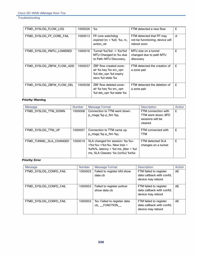
Cisco SD-WAN vManage How-Tos Troubleshooting
334
FTMD_SYSLOG_FLOW_LOG 1000026 %s FTM detected a new flow E
FTMD_SYSLOG_FP_CORE_FAIL 1000013 FP core watchdog expired (rc = %d). %s, rc, action_str
FTM detected that FP may not be functioning; device will reboot soon
A
FTMD_SYSLOG_PMTU_LOWERED 1000016 Tunnel %s/%d -> %s/%d MTU Changed to %u due to Path-MTU Discovery,
MTU size on a tunnel changed due to path MTU discovery
E
FTMD_SYSLOG_ZBFW_FLOW_ADD 1000037 ZBF flow created zone-air %s key %s src_vpn %d dst_vpn %d expiry secs %d state %s
FTM detected the creation of a zone pair
E
FTMD_SYSLOG_ZBFW_FLOW_DEL 1000038 ZBF flow deleted zone-air %s key %s src_vpn %d dst_vpn %d state %s
FTM detected the deletion of a zone pair
E
Priority: Warning
Message Number Message Format Description Action FTMD_SYSLOG_TTM_DOWN 1000008 Connection to TTM went down.
p_msgq %p p_ftm %p, FTM connection with TTM went down; BFD sessions will be cleared
E
FTMD_SYSLOG_TTM_UP 1000007 Connection to TTM came up. p_msgq %p p_ftm %p,
FTM connected with TTM
E
FTMD_TUNNEL_SLA_CHANGED 1000019 SLA changed for session: %s.%u->%s:%u->%s:%u. New loss = %d%%, latency = %d ms, jitter = %d ms, SLA Classes: %s (ox%x) %s%s
FTM detected SLA changes on a tunnel
E
Priority: Error
Message Number Message Format Description Action FTMD_SYSLOG_CONFD_FAIL 1000003 Failed to register bfd show
data cb FTM failed to register data callback wtih confd; device may reboot
AE
FTMD_SYSLOG_CONFD_FAIL 1000003 Failed to register policer show data cb
FTM failed to register data callback with confd; device may reboot
AE
FTMD_SYSLOG_CONFD_FAIL 1000003 %s: Failed to register data cb, __FUNCTION__
FTM failed to register data callback with confd; device may reboot
AE

Cisco SD-WAN vManage How-Tos Troubleshooting
335
FTMD_SYSLOG_CONFD_FAIL 1000003 %s: Failed to send oper data reply - %s (%d) : %s,
FTM failed to respond correctly to confd; some show commands may not work
A
FTMD_SYSLOG_FP_COREDUMP 1000011 FP Core %d Died. Core file recorded at %s,
FTM detected an FP crash; device will reboot soon
AE
FTMD_SYSLOG_IFADD_FAIL 1000014 Failed to add interface %s in vpn %lu. Out of forwarding interface records
Interface not added because of insufficient forwarding interface database records
A
FTMD_SYSLOG_IFADD_FAIL 1000014 Failed to add interface %s in vpn %lu. Out of snmp interface indices
Interface not added because of insufficient SNMP interface indices
A
FTMD_SYSLOG_INIT_FAIL 1000002 vconf_module_init returned %d
FTM failed to start with confd
A
FTMD_SYSLOG_LR_DEL 1000028 LR: LR is not enabled...while we are trying to remove iface %s as last resort
Interface being removed is not configured as a last-resort interface
A
FTMD_SYSLOG_LR_DEL 1000028 LR: Unable to remove iface %s as LR
Interface is no longer a last-resort interface so it cannot be deleted
A
FTMD_SYSLOG_RTM_DECODE_FAIL 1000006 Bad RTM Msg: Msg-Type %u Msg-Len %u len: %u decoded-len %u,
Could not process route or interface change message from RTM
A
FTMP_SYSLOG_SPURIOUS_TIMER 1000010 Spurious timer ignored what = %#x arg = %p,
Internal error A
GPS: Global Positioning System Priority: Informational
Message Number Message Format Description Action GPS_SYSLOG_END 2599999 Terminating GPS GPS process is ending E
GPS_SYSLOG_GGA_FIX 2500002 GGA %d:%d:%d lat=%f lon=%f alt=%f sat=%d hdop %f fix%d
GPS fix information E
GPS_SYSLOG_GSA_FIX 2500004 GSA %s pdop=%.2f hdop=%.2f vdop=%.2f
GPS satellite and dilution of precision (DOP) information
E
GPS_SYSLOG_PSTOP 2500005 Polling disabled
Stopping polling timers
Messages related to polling for GPS information
E

Cisco SD-WAN vManage How-Tos Troubleshooting
336
GPS_SYSLOG_RMC_FIX 2500003 RMC %s %d %d lat=%f lon=%f speed %f course=%s status valid
Essential minimum GPS information
E
GPS_SYSLOG_START 2500001 Starting GPS GPS process is starting E
IGMP: Internet Group Management Protocol Priority: Informational
Message Number Message Format Description Action IGMP_SYSLOG_END 1800001 Terminating IGMP IGMP process is ending E
IGMP_SYSLOG_START 1899999 Starting IGMP IGMP process is starting E
LIBBSS: UNIX BSS Library Unused Messages
Message Number Message Format Description Action LIBBSS_SYSLOG_END 1699999 Terminating libbss UNIX BSS library process is ending E
LIBBSS_SYSLOG_START 1600001 Starting libbss UNIX BSS library process is starting E
LIBCHMGR: Chassis Manager Library Process Unused Messages
Message Number Message Format Description Action LIBCHMGR_SYSLOG_END 1599999 Terminating
libchmrg Chassis manager library process is ending
E
LIBCHMGR_SYSLOG_START 1500001 Starting libchmgr Chassis manager libryary process is starting
E
MSGQ: Message Queue Process Ununsed Messages
Message Number Message Format Description Action MSGQ_SYSLOG_END 899999 Terminating msgq Message queue process is ending E
MSGQ_SYSLOG_START 800001 Starting msgq Message queue process is starting E

Cisco SD-WAN vManage How-Tos Troubleshooting
337
OMP: Overlay Management Protocol Priority: Informational or Other
Message Number Message Format Description Action OMP_NUMBER_OF_VSMARTS 400005 Number of vSmarts
connected: %u Number of vSmart controllers to which device is connected (on vEdge routers only)
E
OMP_PEER_STATE_CHANGE 400002 %s peer %s state changed to %s,
OMP peer stated changed to up or down
E
OMP_POLICY_CHANGE 400007 Using policy from peer %s,
Forwarding policy received from vSmart controller (on vEdge routers only)
E
OMP_STATE_CHANGE 400003 Operational state changed to %s,
OMP internal operational state changed
E
OMP_TLOC_STATE_CHANGE 400004 TLOC %s state changed to %s for address-family: %s,
TLOC state changed E
Priority: Notice
Message Number Message Format Description Action OMP_SYSLOG_END 400006 Terminating OMP process is stopping E
OMP_SYSLOG_START 400001 Starting OMP process is starting E
PIM: Protocol-Independent Multicast Process Priority: Informational
Message Number Message Format Description Action IGMP_SYSLOG_END 1900001 Terminating PIM process is ending E
IGMP_SYSLOG_START 1999999 Starting PIM process is starting E
Priority: Notice
Message Number Message Format Description Action PIM_SYSLOG_IF_STATE_CHANGE 1900003 VPN %lu Interface
%s %s In specified VPN, interface state changed to up or down
E
PIM_SYSLOG_NBR_STATE_CHANGE 1900002 Neighbor %s state changed to up
PIM neighbor came up E
PIM_SYSLOG_TUNNEL_STATE_CHANGE 1900004 Tunnel %s state changed to %s
Tunnel used for PIM when down or came up
E
Priority: Error
Message Number Message Format Description Action

Cisco SD-WAN vManage How-Tos Troubleshooting
338
PIM_SYSLOG_NBR_STATE_CHANGE 1900002 Neighbor %s stated changed to down
PIM neighbor went down
E
POLICY: Policy Process Unused Messages
Message Number Message Format Description Action POLICY_SYSLOG_END 799999 Terminating policy Policy process is ending E
POLICY_SYSLOG_START 700001 Starting policy Policy process is starting E
RESOLV: Resolver Process Unused Messages
Message Number Message Format Description Action RESOLV_SYSLOG_END 2000001 Terminating resolver Resolver process is ending E
RESOLV_SYSLOG_START 2099999 Starting resolver Resolver process is starting E
SNMP Listener Process Unused Messages
Message Number Message Format Description Action SNMP_SYSLOG_END 2100001 Terminating SNMP listener SNMP listener process is ending E
SNMP_SYSLOG_START 2199999 Starting SNMP listener SNMP listener process is starting E
SYSMGR: System Manager Process The system manager process (daemon) spawns, monitors, and terminates all the processes in the system, and it collects and logs vital system information, such as memory and CPU status.
Priority: Informational
Message Number Message Format Description Action SYSMGR_CONFD_PHASE1_INFO 200041 Generated authorized keys
on %s, p_sysmgr->cfg.my_personality
Generated authorized keys for SSH-based login between vManage server and Cisco SD-WAN device
E
SYSMGR_CONFD_PHASE2_SUCCESS 200007 Confd Phase2 Up Successful device bringup
E

Cisco SD-WAN vManage How-Tos Troubleshooting
339
SYSMGR_DAEMON_START 200017 Started daemon %s @ pid %d in vpn %lu,
System manager started process in VPN
E
SYSMGR_DAEMON_UP 200011 Daemon %s @ pid %d came up in vpn %lu (%d %d)
Daemon started by system manager came up as expected
E
SYSMGR_SIGTERM 200001 Received sigterm, stopping all daemons except confd
System manager received termination signal and will initiate termination of all processes
E
SYSMGR_VPN_DESTROY 200022 vpn %lu destroy. lookup returned %p
Stopping all processes in VPN
E
Priority: Notice
Message Number Message Format Description Action SYSMGR_CLOCK_SET 200025 System clock set to
%s System clock set by user
E
SYSMGR_CONFD_CDB_NOT_INITED 200031 Confd db initialization not complete. Deleting cdb and starting afresh.
First-time initialization of configuration database
E
SYSMGR_CONFD_PHASE1_INFO 200041 Install successfully completed from %s to %s
Failed to read installation ID; will fall back to default
E
SYSMGR_CORE_FILE_COMPRESSED 200045 — Core file was compressed
E
SYSMGR_DAEMON_EXIT_NORMAL 200021 — A process terminated normally
E
SYSMGR_DAEMON_RESTARTED 200043 — A process restarted E
SYSMGR_DISK_ALERT_OFF 200036 Disk usage is below 60%%.
Disk usage is below threshold
E
SYSMGR_MEMORY_ALERT_OFF 200058 System memory usage is below 50%
System memory usage is below 50%
E
SYSMGR_MISC 200065 — Miscellaneous message
E
SYSMGR_REBOOT 200038 System going down for a reboot.. (%s), reason
System manager initiating a device reboot, possibly because of a process failure
E
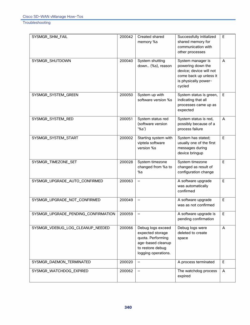
Cisco SD-WAN vManage How-Tos Troubleshooting
340
SYSMGR_SHM_FAIL 200042 Created shared memory %s
Successfully initialized shared memory for communication with other processes
E
SYSMGR_SHUTDOWN 200040 System shutting down.. (%s), reason
System manager is powering down the device; device will not come back up unless it is physically power-cycled
A
SYSMGR_SYSTEM_GREEN 200050 System up with software version %s
System status is green, indicating that all processes came up as expected
E
SYSMGR_SYSTEM_RED 200051 System status red (software version '%s')
System status is red, possibly because of a process failure
A
SYSMGR_SYSTEM_START 200002 Starting system with viptela software version %s
System has stated; usually one of the first messages during device bringup
E
SYSMGR_TIMEZONE_SET 200028 System timezone changed from %s to %s
System timezone changed as result of configuration change
E
SYSMGR_UPGRADE_AUTO_CONFIRMED 200063 — A software upgrade was automatically confirmed
E
SYSMGR_UPGRADE_NOT_CONFIRMED 200049 — A software upgrade was as not confirmed
E
SYSMGR_UPGRADE_PENDING_CONFIRMATION 200059 — A software upgrade is pending confirmation
E
SYSMGR_VDEBUG_LOG_CLEANUP_NEEDED 200066 Debug logs exceed expected storage quota. Performing age-based cleanup to restore debug logging operations.
Debug logs were deleted to create space
A
SYSMGR_DAEMON_TERMINATED 200020 — A process terminated E
SYSMGR_WATCHDOG_EXPIRED 200062 — The watchdog process expired
A

Cisco SD-WAN vManage How-Tos Troubleshooting
341

Cisco SD-WAN vManage How-Tos Troubleshooting
342
Priority: Warning
Message Number Message Format Description Action SYSMGR_CORE_FILE_DELETED 200044 — Core file was
deleted A
SYSMGR_DAEMON_RESTART_ABORTED 200060 — The restarting of a process was aborted
A
SYSMGR_DAEMON_STOP 200018 Stopping daemon %s @ pid %d. Sending signal %d
System manager stopped a daemon
E
SYSMGR_DISK_ALERT_ORANGE 200054 Disk usage is above 75%%. Please clean up unnecessary files.
Disk usage is above 75%
E
SYSMGR_DISK_ALERT_YELLOW 200035 Disk usage is above 60%%. Please clean up unnecessary files.
Disk usage is above 60%
E
SYSMGR_FILE_DELETED 200064 Deleted file %s (size %lu MB) to recover disk space
File deleted to free up disk space
A
SYSMGR_MEMORY_ALERT_ORANGE 200056 System memory usage is above 75%%
System memory usage is above 75%
E
SYSMGR_MEMORY_ALERT_YELLOW 200057 System memory usage is above 60%%
System memory usage is above 60%
E
Priority: Error
Message Number Message Format Description Action SYSMGR_BAUD_RATE_SET 200046 Console baud rate
changed to '%d', baud_rate
Console baud rate changed
E
SYSMGR_BAUD_RATE_SET_FAIL 200047 Failed to set console baud rate in OS to '%d'
Failed to set user-specified console baud rate in Linus
A
SYSMGR_BAUD_RATE_SET_FAIL 200047 Failed to set console baud rate in U-boot to '%d'
Failed to set user-specified console baud rate in Uboot
A
SYSMGR_CLOCK_SET_FAIL 200026 Cannot set system clock to %s
Failed to set system clock to time specified by user
A
SYSMGR_CONFD_CDB_INIT_OPEN_FAIL 200030 Failed to open cdb init file (%s)
Failed to open the configuration database
A
SYSMGR_DAEMON_EXIT_FAIL 200023 — A process could not terminate
A

Cisco SD-WAN vManage How-Tos Troubleshooting
343
SYSMGR_CONFD_DATACB_REGISTER_FAIL 200010 Failed to register data cb
Failed to register data callback function with confd; device may reboot
A
SYSMGR_CONFD_CDB_DEL_FAIL 200032 Failed to remove cbd directory '%s'
Failed to reinitialize configuration database to recover from failure
AE
SYSMGR_CONFD_FORK_FAILURE 200003 Cannot move confd to phase2 (err %s)
Failed to move confd to Phase 2; device will reboot soon
A
SYSMGR_CONFD_PHASE1_FAILURE 200005 Failed to generate archive keys
Failed to generate keys required for archiving configuration
E
SYSMGR_CONFD_PHASE1_FAILURE 200005 Failed to generate authorized keys on %s, p_sysmgr->cfg.my_personality
Failed to generate keys required for SSH-based login between vManage server and Cisco SD-WAN device
E
SYSMGR_CONFD_PHASE1_FAILURE 200005 Failed to generate SSH keys for archive
Failed to generate SSH keys
E
SYSMGR_CONFD_PHASE1_FAILURE 200005 Failed to get install id from file, using 00_00
Failed to read previous system version
A
SYSMGR_CONFD_PHASE1_FAILURE 200005 Failed to get previous version, using 0.0
Failed to read system version
A
SYSMGR_CONFD_PHASE1_FAILURE 200005 Failed to transition confd to phase1. Re-initializing CDB..
Confd module failed to move to Phase 1, indicating a possible configuration database failure; device will reboot soon
A
SYSMGR_CONFD_PHASE1_FAILURE 200005 Verified that archive keys exist
Verified that configuration archive keys exist
A
SYSMGR_CONFD_PHASE2_FAILURE 200006 Failed to get current version, using 0.0
Failed to read system version file
A
SYSMGR_CONFD_PHASE2_FAILURE 200006 Failed to open %s, version_file
Failed to open system version file
A
SYSMGR_CONFD_PHASE2_FAILURE 200006 Failed to read %s, version_file
Failed to read system version file
A

Cisco SD-WAN vManage How-Tos Troubleshooting
344
SYSMGR_CONFD_PHASE2_FAILURE 200006 Failed to transition confd to phase2
Confd module failed to move to Phase 2, indicating a possible configuration database failure; device will reboot soon
A
SYSMGR_CONFD_REPLY_FAIL 200009 Failed to send oper data reply - %s (%d)
Failed to reply to confd; some show commands may not work
A
SYSMGR_CONFD_SETPGID_FAILURE 200004 setpgid(0,0) failed: %d Process group failed to start
A
SYSMGR_DAEMON_DOWN 200012 Daemon %s [%u] went down in vpn %lu,
Process started by system manager went down
A
SYSMGR_DAEMON_EXECV_FAILURE 200016 execv %s failed Internal failure occurred while starting a process
A
SYSMGR_DAEMON_FORK_FAILURE 200014 Cannot start daemon %s: %s
Internal failure occurred while starting a process
A
SYSMGR_DAEMON_INACTIVE 200033 Daemon %s[%lu] @ pid %d died. Rebooting device..
System manager detected a process failure and is about to reboot the device
A
SYSMGR_DAEMON_MSGQ_FAILURE 200013 Could not start msgq to daemon %s. err %d
Failed to establish message queue with process; device may reboot soon
A
SYSMGR_DAEMON_MSGQ_FAILURE 200013 Could not start msgq to quagga daemon %s. err %d
Failed to establish message queue with routing process; device may reboot soon
A
SYSMGR_DAEMON_SETAFFINITY_FAILURE 200061 — The scheduling of a process failed
E
SYSMGR_DAEMON_SETPGID_FAILURE 200015 setpgid(0,0) failed Internal failure setting process group of a process
A

Cisco SD-WAN vManage How-Tos Troubleshooting
345
SYSMGR_DAEMON_STOPPED 200019 Daemon %s @ pid %u terminated - %s
Daemon started by system manager terminated; device may reboot soon (except for vBond orchestrator)
A
SYSMGR_RTC_CLOCK_SET_FAIL 200027 Cannot set hardware clock to %s - %s (errno
Failed to update hardware clock to system time specified by user
A
SYSMGR_SHM_FAIL 200042 Failed to close shared memory %s with an error %d
Failed to completely and properly close the shared memory for communication with other processes
E
SYSMGR_SHM_FAIL 200042 Failed to map shared memory %s
Failed to initialize shared memory for communication with other processes
E
SYSMGR_SHM_FAIL 200042 Failed to open shared memory %s with an error %d
Failed to open shared memory for communication with other processes
E
SYSMGR_SHM_FAIL 200042 Failed to truncate shared memory %s with an error %d
Failed to initialize shared memory for communication with other processes
E
SYSMGR_SHM_FAIL 200042 Failed to unmap shared memory %s
Failed to completely and properly close shared memory for communication with other processes
E
SYSMGR_SWITCHBACK_FAILED 200053 Software upgrade to version %s failed because of %s
Software upgrade failed
A
SYSMGR_TIMEZONE_SET_FAIL 200029 Failed to set system timezone to %s (rc = %d)
Failed to set system timezone to timezone specified by user
A
SYSMGR_TRACE_ERROR 200024 — A trace error occurred A

Cisco SD-WAN vManage How-Tos Troubleshooting
346
Priority: Critical
Message Number Message Format Description Action SYSMGR_CONFD_INIT_FAIL 200008 Sysmgr child in charge of
migrating confd/ncs to phase2 exited with error code %d
System manager detected a confd process failure; device may reboot
AE
SYSMGR_DISK_ALERT_RED 200034 Disk usage is above 90%% (critically high). Please clean up unnecessary files.
Disk usage is above 90% AE
SYSMGR_MEMORY_ALERT_RED 200055 System memory usage is above 90%% (critically high)
System memory usage is above 90%
AE
SYSMGR_REBOOT_HALTED 200039 Reboot (reason: %s) aborted..too many reboots
System manager stopped short of rebooting the device because it detected too many reboots in a short period of time
AE
SYSMGR_UPGRADE_FAILED 200052 Software upgrade to version %s failed because of reason
Software upgrade failed AE
TCPD: TCP Options Process
Priority: Informational
Message Number Message Format Description Action TCPD_MSGQ_SERVER 2800002 Server Exception: %s Proxy server did not accept connection E
TCPD_PROXY 2800004 Enabled TCP_OPT for vpn %lu: %s:%u
%s
Starting sysmgr_app object
tcpd<->ftmd channel established
tcpd<->ftmd = Will try connecting
Messages related to starting a proxy E
TCPD_PROXY 2800004 tcpd error counters -%s Count of TCP option errors E
TCPD_SYSLOG_END 2800001 Terminating TCP options TCP options process ending E
TCPD_SYSLOG_START 2899999 Starting TCP options TCP options process starting E

Cisco SD-WAN vManage How-Tos Troubleshooting
347
TCPD_SYSMGR_APP 2800003 %s Exception: %s
%s - Sysmgr app::connect -Exception - %s
Messages related to the connection between the system manager and the TCP proxy process
E
Priority: Debug
Message Number Message Format Description Action TCPD_SYSMGR_APP 2800003 %s - Registering for
send_hello-msg
%s: Sending following register msg
Sending msg of length %u
%s - Sysmgr app::connect
%s - Write %u bytes
%s - Wrote register msg %u
Messages related to the connection between the system manager and the TCP proxy process
E
TRACKER: Interface Tracker Process Priority: Informational
Message Number Message Format Description Action TRACKER_SYSLOG_CONN_DOWN 1700003 Connection to %s %s
Down Connection to interface is down
E
TRACKER_SYSLOG_CONN_UP 1700002 Connection to %s %s Up Connection to interface is up E
TRACKER_SYSLOG_END 1700001 Terminating Interface tracker process is ending
E
TRACKER_SYSLOG_START 1799999 Starting Interface tracker process is starting
E
VCONFD: Cisco SD-WAN Configuration Process Priority: Informational
Message Number Message Format Description Action VCONFD_SYSLOG_END 1400001 Terminating Configuration process is ending E

Cisco SD-WAN vManage How-Tos Troubleshooting
348
TRACKER_SYSLOG_NOTIFICATION 1400002 Notification: %d/%d?%d %d:%d:%d %s severity level: %s hostname: %s system-ip %s process name: %s process id: %s reason: %s
Configuration at specified date and time for a process, with reason
E
TRACKER_SYSLOG_NOTIFICATION 1400002 Notification: %d/%d?%d %d:%d:%d %s severity level: %s hostname: %s system-ip %s status: %s install id: %s message %s
Configuration at specified date and time, with specified status (minor, major)
E
TRACKER_SYSLOG_NOTIFICATION 1400002 Notification: %d/%d?%d %d:%d:%d %s severity level: %s hostname: %s system-ip %s reason: %s
Configuration at specified date and time, with reason
E
TRACKER_SYSLOG_NOTIFICATION 1400002 Notification: %d/%d?%d %d:%d:%d %s severity level: %s hostname: %s system-ip %s reboot reason: %s
Configuration at specified date and time, with reboot reason
E
TRACKER_SYSLOG_NOTIFICATION 1400002 Notification: %d/%d?%d %d:%d:%d %s severity level: %s hostname: %s system-ip %s username: %s remote host: %s
Configuration at specified date and time, for username and remote host
E

Cisco SD-WAN vManage How-Tos Troubleshooting
349
TRACKER_SYSLOG_NOTIFICATION 1400002 Notification: %d/%d?%d %d:%d:%d %s severity level: %s hostname: %s system-ip %s vpn id: %s if name: %s mac addr: %s ip-addr:%s
Configuration at specified date and time, for VPN, interface, MAC address, and IP address
E
VCONFD_SYSLOG_START 1499999 Starting Configuration process is starting E
VDAEMON: Cisco SD-WAN Software Process Priority: Informational
Message Number Message Format Description Action VDAEMON_SYSLOG_DOMAIN_ID_CHANGE 500006 System Domain-ID
changed from '%d' to '%d', System domain ID changed
E
VDAEMON_SYSLOG_END 599999 — Process ending E
VDAEMON_SYSLOG_ORG_NAME_CHANGE 500008 System Organization-Name changed from '%s' to '%s'
System organization name changed
E
VDAEMON_SYSLOG_PEER_STATE 500003 Peer %s Public-TLOC %s Color %u %s,
Peer state changed to up or down
E
VDAEMON_SYSLOG_SITE_ID_CHANGE 500005 System Site-ID changed from '%d' to '%d'
System site ID changed
E
VDAEMON_SYSLOG_START 500001 — Process starting E
VDAEMON_SYSLOG_SYSTEM_IP_CHANGE 500007 System-IP changed from '%s' to '%s'
System IP address changed
E
Priority: Error
Message Number Message Format Description Action
VDAEMON_BOARD_ID_CHALLENGE_FAILED 500002 — Board ID could not be verified E
VDAEMON_BOARD_ID_INIT_FAILED 500001 — Board initialization failed because board ID could not be verified
E
VDAEMON_SYSLOG_CERT_STORE_FAIL 500009 Certificate store init failed
Certificate not stored AE
VDAEMON_SYSLOG_PEER_AUTH_FAIL 500004 Peer %s Public-TLOC %s Color %u %s
Authentication with a vdaemon peer failed
E

Cisco SD-WAN vManage How-Tos Troubleshooting
350
VDAEMON_SYSLOG_PEER_STATE 500003 Failed to read system host name
Internal error reading system hostname; device will not register with vManage server or ZTP will fail
A
VRRP: Virtual Router Redundancy Protocol The VRRP process runs only on vEdge routers.
Priority: Informational
Message Number Message Format Description Action VRRPD_STATE_CHANGE 600002 Group %d, interface %s, vpn %lu state
changed to %s VRRP interface state change
E
VRRPD_SYSLOG_END 699999 Terminating VRRPD VRRP process is ending E
VRRPD_SYSLOG_START 600001 Starting VRRPD VRRP process is starting
E
WLAN: Wireless LAN Process The wireless LAN process runs only on vEdge routers.
Priority: Informational
Message Number Message Format Description Action WLAN_SYSLOG_END 2300001 Terminating wlan WLAN process is ending E
WLAN_SYSLOG_START 2399999 Starting wlan WLAN process is starting E
WWAND: Cellular Process The wireless WAN process runs only on vEdge routers.
Priority: Informational
Message Number Message Format Description Action WWAN_SYSLOG_ADMIN_DWL 2400010 Cellular%d interface is
set for deletion Cellular interface is about to be deleted
E
WWAN_SYSLOG_ADMIN_DOWN 2400009 Cellular%d interface is set to admin down
Cellular interface is administratively Down
E
WWAN_SYSLOG_ADMIN_UP 2400008 Cellular%d interface is set to admin up
Cellular interface is administratively Up
E

Cisco SD-WAN vManage How-Tos Troubleshooting
351
WWAN_SYSLOG_CONNECT 2400002 Connected to Cellular%d modem
Connection to cellular modem established
E
WWAN_SYSLOG_CONNECT_DATA 2400006 — — E
WWAN_SYSLOG_DATA_MONITOR 2400032 Info: %lld bytes left
Info: exceeded by %lld bytes
Information about amount of data remaining in billing cycle
E
WWAN_SYSLOG_DATA_SESSION 2400019 Data session started successfully
Data session on cellular interface started successfully
E
WWAN_SYSLOG_DATA_SESSION_BEARER 2400028 Data bearer changed to %s (%lx)
Data carrier changed E
WWAN_SYSLOG_DATA_SESSION_DISCONNECT 2400023 Data session disconnect: restarting session
Data session was disconnected and is restarting
E
WWAN_SYSLOG_DATA_SESSION_DISC_REASON 2400024 Data session disconnect reason: %s
Reason data session was disconnected
E
WWAN_SYSLOG_DATA_SESSION_DISC_VERB 2400025 Data session disconnect reason verbose: %s
More information about why data session disconnected
E
WWAN_SYSLOG_DATA_SESSION_DOMAIN 2400026 Packet-switched domain state change to %s: registration: %s ran: %s if: %s
Packet-switched domain changed
E
WWAN_SYSLOG_DATA_SESSION_DORMANCY 2400029 Dormancy state changed to %s
Session dormancy state changed
E
WWAN_SYSLOG_DATA_SESSION_NETWORK 2400027 Network registration changed to %s: domain: %s ran: %s if: %s
Network registration changed
E
WWAN_SYSLOG_DATA_SESSION_START 2400018 Starting data session on Cellular%e
Data session on cellular interface is starting
E
WWAN_SYSLOG_DATA_SESSION_STATE 2400020 Data session state changed to %s
Data session status E
WWAN_SYSLOG_DATA_SESSION_STOP 2400022 Data session stopped successfully
Data session stopped E
WWAN_SYSLOG_DISCONNECT 2400003 Disconnected LTE modem %d
Disconnection from LTE modem
E
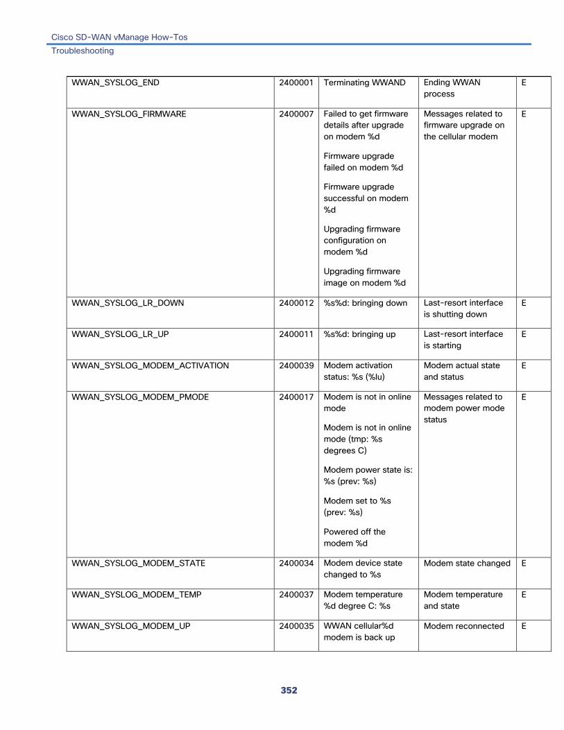
Cisco SD-WAN vManage How-Tos Troubleshooting
352
WWAN_SYSLOG_END 2400001 Terminating WWAND Ending WWAN process
E
WWAN_SYSLOG_FIRMWARE 2400007 Failed to get firmware details after upgrade on modem %d
Firmware upgrade failed on modem %d
Firmware upgrade successful on modem %d
Upgrading firmware configuration on modem %d
Upgrading firmware image on modem %d
Messages related to firmware upgrade on the cellular modem
E
WWAN_SYSLOG_LR_DOWN 2400012 %s%d: bringing down Last-resort interface is shutting down
E
WWAN_SYSLOG_LR_UP 2400011 %s%d: bringing up Last-resort interface is starting
E
WWAN_SYSLOG_MODEM_ACTIVATION 2400039 Modem activation status: %s (%lu)
Modem actual state and status
E
WWAN_SYSLOG_MODEM_PMODE 2400017 Modem is not in online mode
Modem is not in online mode (tmp: %s degrees C)
Modem power state is: %s (prev: %s)
Modem set to %s (prev: %s)
Powered off the modem %d
Messages related to modem power mode status
E
WWAN_SYSLOG_MODEM_STATE 2400034 Modem device state changed to %s
Modem state changed E
WWAN_SYSLOG_MODEM_TEMP 2400037 Modem temperature %d degree C: %s
Modem temperature and state
E
WWAN_SYSLOG_MODEM_UP 2400035 WWAN cellular%d modem is back up
Modem reconnected E

Cisco SD-WAN vManage How-Tos Troubleshooting
353
WWAN_SYSLOG_OMA_DM_DONE 2400041 Modem OMA DM configuration completed
Modem OMA-DM configuration finished
E
WWAN_SYSLOG_OPER_DOWN 2400014 Cellular%d set if down Cellular interface is operationally Down
E
WWAN_SYSLOG_OPER_UP 2400013 Cellular%d set if up Cellular interface is operationally Up
E
WWAN_SYSLOG_PROFILE_CHECK 2400030 Profile %lu with PDP: %s APN: %s Auth: %s User: %s
Cellular profile information
E
WWAN_SYSLOG_REBOOT 2400040 Cellular%d modem mode updated: rebooting; %s reason
Reason why celluar modem rebooted
E
WWAN_SYSLOG_SDK_DOWN 2400005 SDK got terminated: %s
Connection to software development kit terminated
E
WWAN_SYSLOG_SDK_UP 2400004 Connected to Cellular%d sdk process
Connection to cellular software development kit established
E
WWAN_SYSLOG_SIM_STATUS 2400033 SIM status changed to: %s
SIM status changed E
WWAN_SYSLOG_START 2499999 Starting WWAND Starting WWAN process
E
WWAN_SYSLOG_TRACK_GW_UP 2400015 Cellular%d gateway %s is reachable
Cellular gateway is reachable
E

Cisco SD-WAN vManage How-Tos Troubleshooting
354
Priority: Error
Message Number Message Format Description Action WWAN_SYSLOG_AUTO_PROFILE_MISS 2400031 Manually configure
APN profile for the data connection
Data session could not start because required APN could not be located
E
WWAN_SYSLOG_MODEM_DOWN 2400036 WWAN cellular%d modem went down
Modem is disconnected E
WWAN_SYSLOG_MODEM_RESET 2400038 Failed to recover Cellular %d modem
Connection to modem could not be reestablished
E
WWAN_SYSLOG_TRACK_GW_DOWN 2400016 Cellular%d gateway %s is not reachable
Cellular gateway is not reachable
E
Additional Information Monitor Alarms Monitor Event Notifications Use SNMP Traps

Cisco SD-WAN vManage How-Tos Troubleshooting
355
View Tunnel Health To view statistics about data traffic traffic jitter, loss, and latency and other interface characteristics for all operational data plane tunnels:
1. In vManage NMS, select the Monitor ► Network screen.
2. Locate the device using the Sort options drop-down and the Search box. Or scroll through the list of devices in the device table.
3. Select the device by clicking its hostname. The screen changes and the left pane lists the categories of information you can display about the device.
4. Click Troubleshooting in the left pane.
5. From the Traffic pane, click Tunnel Health.
6. From the Local Circuit drop-down, select the TLOC color for the tunnel source.
7. From the Remote Device drop-down, select a remote device. Each remote device is listed by hostname and system IP address.
8. From the Remote Circuit drop-down, select the TLOC color for the tunnel destination.
9. Click Go.
The lower part of the screen displays:
• Chart Options bar—Located directly under the device name, this bar includes the Chart Options drop-down and time periods. Click Chart Options to select the type of data to display—either Loss Percentage, Latency/Jitter, or Octets. Click a predefined or custom time period for which to display data.
• Statistics for selected data traffic in graphical format for both directions of the selected tunnel. Hover over the points in the graph to display detailed statistics for an individual time period.
• Graph legend—Color-coded names that identify the tunnels whose data is displayed in the graph. Each tunnel name is identified by the local hostname and its tunnel color, following by the remote hostname and its tunnel color. In the legend, select a tunnel to display data traffic statistics for just that tunnel.
Release Information Introduced in vManage NMS in Release 17.2.
Additional Information show app-route stats

Cisco SD-WAN vManage How-Tos 18.4 How-Tos
356
18.4 How-Tos Add, Delete, or Edit a Tenant
You can add, delete, or edit a tenant in a vManage server.
Starting with Release 18.4, in single-tenant mode, you can manage up to 10,000 devices. In multitenant mode, you can manage up to 500 tenants and up to a total of 10,000 tenants.
Add a Tenant to a vManage Server 1. In vManage NMS, select the Administration ► Tenant Management screen.
2. In the left pane, click the Add Tenant button.
3. In the Add Tenant window:
a. Enter a name for the tenant. It can be up to 128 characters and can contain only alphanumeric characters.
b. Enter a description for the tenant. It can be up to 256 characters and can contain only alphanumeric characters.
c. Enter the name of the organization. The name is case-sensitive. It is the name in the certificates for all Cisco SD-WAN network devices, and it must be identical on all devices in the overlay network.
d. In the URL subdomain field, enter the domain name for the tenant. The domain name must include the provider's domain name. You must also configure this same domain name when you enable multitenancy mode, in vManage Administration ► Settings ► Tenancy Mode.
e. Click Save.
4. The Create Tenant screen is displayed, and the Status column shows In progress. To view status messages related to the creation of the tenant, click the > to the left of the status column. After about 1 minute, the Status column changes to Success, and the tenant table shows the tenant's system IP address.
Delete a Tenant from a vManage Server 1. In vManage NMS, select the Administration ► Tenant Management screen.
2. In the left pane, click the name of the tenant.
3. In the right pane, click the Trash icon to the right of the tenant's name.
4. In the Delete Tenant popup, enter your vManage password and click Save.
Edit a Tenant 1. In vManage NMS, select the Administration ► Tenant Management screen.
2. In the left pane, click the name of the tenant.

Cisco SD-WAN vManage How-Tos 18.4 How-Tos
357
3. In the right pane, click the Pencil icon to the right of the tenant's name.
4. In the Edit Tenant popup, modify the tenant's name, description, or domain name.
5. Click Save.
Release Information Introduced in vManage NMS in Release 17.2.
Additional Information Multitenant Dashboard Use a Multitenant vManage NMS View Summary Information About all Tenants in a vManage Server

Cisco SD-WAN vManage How-Tos 18.4 How-Tos
358
Use a Multitenant vManage NMS A service provider can manage multiple customers, called tenants, from a single vManage NMS that is running in multitenant mode. All tenants share a single vBond orchestrator. All tenants share the service provider's domain name, with each tenant having a subdomain name to identify the tenant. For example, the service provider fruit.com might manage the tenants mango (mango.fruit.com) and plum (plum.fruit.com). For each tenant, you configure one or more vSmart controllers and vEdge routers the same way that you configure these devices on a single-tenant vManage NMS.
In multitenant mode, you can manage up to 500 tenants and up to a total of 10,000 devices. In single-tenant ode you can manage up to 10,000 devices.
To create a multitenant vManage NMS, you must start with a new vManage server. You cannot migrate an existing single-tenant vManage server to a multitenant vManage server, even if you invalidate or delete all devices from the existing server.
By default, a vManage NMS is in single-tenant mode. After you place a vManage NMS server into multitenant mode, you cannot convert it back to single-tenant mode.
vManage Multitenant Dashboard After you have placed a vManage NMS server into multitenant mode, when you log in to the vManage NMS, you see the vManage multitenant dashboard. This dashboard is also called the provider dashboard. It provides a quick summary of the overall health of all the tenants that the service provide is managing with this vManage server.
To return the the provider dashboard from other vManage screens, click Provider Name in the Top Bar.
Place the vManage NMS into Multitenant Mode By default, a vManage NMS is in single-tenant mode. To place the vManage NMS into multitenant mode:
1. Log in to the vManage NMS, at the URL https:// system-ip-address :8443/, as a user with "admin" credentials.
2. In vManage NMS, select Administration ► Settings.
3. In the Tenancy Mode bar, click the Edit button to the right.
4. In the Tenancy field, click Multitenant.
5. In the Domain field, enter the domain name for the service provider.
6. Click Save. The vManage server reboots and comes back up in multitenant mode.
Add Tenants 1. In vManage NMS, select Administration ► Tenant Management.
2. In the left pane, click the Add Tenant button.
3. In the Add Tenant window:
a. Enter a name for the tenant. It can be up to 128 characters and can contain only alphanumeric characters.

Cisco SD-WAN vManage How-Tos 18.4 How-Tos
359
b. Enter a description for the tenant. It can be up to 256 characters and can contain only alphanumeric characters.
c. Enter the name of the organization. The name is case-sensitive. It is the name in the certificates for all Cisco SD-WAN network devices, and it must be identical on all devices in the overlay network.
d. In the URL subdomain field, enter the domain name for the tenant. The domain name must include the provider's domain name. You must also configure this same domain name when you enable multitenancy mode, in vManage Administration ► Settings ► Tenancy Mode.
e. Click Save.
4. The Create Tenant screen is displayed, and the Status column shows In progress. To view status messages related to the creation of the tenant, click the > to the left of the status column. After about 1 minute, the Status column changes to Success, and the tenant table shows the tenant's system IP address.
If you add another tenant immediately after adding the first one, vManage NMS adds them sequentially, not in parallel. The processing required to create the second tenant does not start until the creation of the first tenant completes.
View a Summary of Tenant Status The provider dashboard displays a summary of the status of all tenants that are being managed by the vManage server. The provider dashboard is displayed when you log in to a multitenant vManage NMS. To return the the provider dashboard from other vManage screens in vManage NMS, click Provider Name in the Top Bar.
This dashboard shows the following:
• Number of service provider vBond orchestrators and vManage NMSs.
• Number of certificates that are about to expire or that are invalid.
• Number of tenants and information about all their control status, site health, vEdge health, and vSmart status.
• List of individual tenants, with information about each tenant's control status, site health, vEdge health, and vSmart status.
To display tenant-specific status summary information, click the tenant name in the list on the lower part of the screen. A window opens on the right side of the screen that provides additional information about the tenant's status. To close this window, click the tenant name.
View Detailed Tenant Status If you select a tenant from the Provider Name drop-down in the Top Bar, the tenant dashboard for selected tenant is displayed. It contains the following components, which are the same components present on a single-tenant vManage dashboard:
• Device pane—Displays all control connections from the vManage NMS to the vSmart controllers and vEdge routers in the tenant's overlay network. It also displays the status of the vManage NMSs in the network.
• Reboot pane—Displays the total number of reboots in the last 24 hours for all devices in the network, including soft and cold reboots and reboots that occurred as a result of power-cycling a device.
Cisco SD-WAN vManage How-Tos 18.4 How-Tos
360
• Control Status pane—Displays whether vSmart and vEdge devices are connected to the required number of vSmart controllers.
• Site Health View pane—Displays the state of a site's data connections.
• Transport Interface Distribution pane—Displays interface usage in the last 24 hours for all vEdge interfaces in VPN 0.
• vEdge Inventory pane—Displays counts of authorized, deployed, and staged vEdge routers.
• vEdge Health pane—Displays an aggregated view for each router state and a count of how many vEdge routers are in that state.
• Transport Health pane—Displays the aggregated average loss, latency, and jitter for all links.
• Top Applications pane—Displays DPI and cflowd flow information for traffic transiting vEdge routers in the overlay network.
• Application-Aware Routing pane—Displays the 10 worst tunnels based on criteria you specify from the Type drop-down list, including loss, latency, and jitter.
Modify a Tenant 1. In vManage NMS, select Administration ► Tenant Management.
2. In the left pane, click the name of the tenant.
3. In the right pane, click the Pencil icon to the right of the tenant's name.
4. In the Edit Tenant popup, modify the tenant's name, description, or domain name.
5. Click Save.
Delete a Tenant 1. In vManage NMS, select Administration ► Tenant Management.
2. In the left pane, click the name of the tenant.
3. In the right pane, click the Trash icon to the right of the tenant's name.
4. In the Delete Tenant popup, enter your vManage password and click Save.
Release Information Introduced in vManage NMS in Release 17.2.
Additional Information Create a MultitenantvManage NMS Use the vManage NMS
Copyright © 2022 FDOKUMEN