HP01A-TOS HP02A-TOS
12
Operation Manual HP01A-TOS HP02A-TOS High Voltage Test Probe This product is a probe used by connecting to a Kikusui TOS series withstanding volt- age tester or a TOS93 series electrical safety analyzer (hereafter referred to as the tester). It used to generate test voltages. Its convenient shape allows faster connec- tion to the device under test (DUT). To prevent potential electric shocks while performing tasks close to a high-voltage area 1 such as the DUT, always wear rubber gloves for electrical work when perform- ing withstand voltage tests with the test probe. Safety Precautions DANGER To prevent electric shock that may result in serious injury or death, never touch the following items: • Never touch the contact pin of the test probe. • Never touch the DUT during testing. WARNING Observe the following instructions to minimize the potential for electric shock that may result in serious injury or death. • Never perform testing when leaning on your elbows at the test bench or in other areas. • Do not fasten the slide lever of the test probe such that the contact pin is exposed. • Keep the probe cables neat and free of tangles. Never drape the high voltage cable over any part of your body. • Generate test voltages only when performing actual tests. • Operate the product without wearing rubber gloves for electrical work. This product is designed to be used in combination with a Kikusui tester. Carefully read the warnings and precautions given in the Tester Operation Manual before attempting to use it. Indicates an imminently hazardous situation which, if ignored, will result in death or serious injury. Indicates a potentially hazardous situation which, if ignored, could result in death or serious injury. Indicates a potentially hazardous situation which, if ignored, may result in slight injury or damage to the product or other property. DANGER WARNING CAUTION Part No. Z1-000-652, IA000787 Dec 2018
-
Upload
khangminh22 -
Category
Documents
-
view
0 -
download
0
Transcript of HP01A-TOS HP02A-TOS

Operation ManualHP01A-TOS HP02A-TOSHigh Voltage Test Probe
Part No. Z1-000-652, IA000787Dec 2018
This product is a probe used by connecting to a Kikusui TOS series withstanding volt-age tester or a TOS93 series electrical safety analyzer (hereafter referred to as the tester). It used to generate test voltages. Its convenient shape allows faster connec-tion to the device under test (DUT).To prevent potential electric shocks while performing tasks close to a high-voltage area1 such as the DUT, always wear rubber gloves for electrical work when perform-ing withstand voltage tests with the test probe.
Safety Precautions
DANGERTo prevent electric shock that may result in serious injury or death, never touch the following items:
• Never touch the contact pin of the test probe.• Never touch the DUT during testing.
WARNINGObserve the following instructions to minimize the potential for electric shock that may result in serious injury or death.
• Never perform testing when leaning on your elbows at the test bench or in other areas.• Do not fasten the slide lever of the test probe such that the contact pin is exposed.• Keep the probe cables neat and free of tangles. Never drape the high voltage
cable over any part of your body.• Generate test voltages only when performing actual tests.• Operate the product without wearing rubber gloves for electrical work.
This product is designed to be used in combination with a Kikusui tester. Carefully read the warnings and precautions given in the Tester Operation Manual before attempting to use it.
Indicates an imminently hazardous situation which, if ignored, will result in death or serious injury.Indicates a potentially hazardous situation which, if ignored, could result in death or serious injury.Indicates a potentially hazardous situation which, if ignored, may result in slight injury or damage to the product or other property.
DANGER
WARNING
CAUTION

WARNINGThe test probe uses a dangerously high voltage capable of causing electric shocks resulting in death unless handled correctly. To prevent accidents, handle the probe with extreme care, abiding by all instructions given below.Ensure the safety of test environments.
• Insulate the DUT and other high-voltage areas1 with an electrical insulation rubber plate or sheet to prevent electric shock even if the operator contacts the DUT or other high-voltage areas. If electrical insulation rubber plates or sheets are not available, contact your Kikusui distributor or agent.
• Implement measures so that only authorized operators can approach high-volt-age areas1.
Never touch the contact pin. Contact will result in electric shock.• High voltage is delivered to the contact pin.
Never touch the contact pin.• The DUT is also charged to high test volt-
ages during testing. Never touch high-volt-age areas1.
• Never expose the contact pin except when testing.
• Never touch the red area around the contact pin; this area is also capable of inflicting electric shock.
Modification may cause electric shock.• Never fasten the slide lever to the grip such that the contact pin is exposed.• Do not lock start switch 1 and/or start switch 2 to the on state.• Do not fasten the high voltage cable to the high voltage terminal of the Tester. If
the cable catches against an object, it may be disconnected from the Tester.Do not operate the probe with a single hand.
For safety reasons, this test probe is designed to be operated using both hands. Never attempt to operate the probe using only one hand.
Be sure to connect the remote control cable.To prevent electric shock, never perform testing using the Tester START (TEST) switch without the remote control cable.
Never use the test probe with Testers from other manufacturers.The test probe is designed specifically for use with a KIKUSUI Tester. It cannot be used with testers from other manufacturers, even if the connector appears to be compatible.
Never use the product at voltages above 4 kV ac rms or 5 kV dc.The rated maximum voltage2 of the probe is 4 kV ac rms or 5 kV dc. Use at higher voltages may result in electric shock.
Handle the test probe attentively. Do not swing it around.Do not yank the test probe cable or drape it over any part of your body.
2 HP01A-TOS/HP02A-TOS

To Supervisor in Charge of Operations• Use of the test probe involves unavoidable electrical shock hazards. Take appro-
priate measures to ensure maximum safety in the test environment at the DUT, at the test bench, and in nearby areas.
• If the operator does not read the language used for this manual, translate the manual into an appropriate language.
• Ensure that the operator understands the information in this manual before start-ing operations.
• Keep this manual near the product to allow for easy reference by the operator when necessary.
About ManualsIntended readersThese manuals are intended for users of this product and their instructors. The man-uals assume that the reader has knowledge about electric safety testing.
TrademarksCompany names and product names used in this manual are generally trademarks or registered trademarks of the respective companies.
CopyrightReproduction and reprinting of this operation manual, whole or partially, without our permission is prohibited. Both unit specifications and manual contents are subject tochange without notice. © Copyright 2018 Kikusui Electronics Corporation
HP01A-TOS/HP02A-TOS 3
Contents
Safety Precautions . . . . . . . . . . . . . . . . . . . . . . . . . . . . . . . . . . . . . . . . . . . 1
To Supervisor in Charge of Operations . . . . . . . . . . . . . . . . . . . . . . . . . . . 3
About Manuals . . . . . . . . . . . . . . . . . . . . . . . . . . . . . . . . . . . . . . . . . . . . . . 3
Inspection Before Starting . . . . . . . . . . . . . . . . . . . . . . . . . . . . . . . . . . . . . 5
Stop Use in the Event of Failures. . . . . . . . . . . . . . . . . . . . . . . . . . . . . . . . 5
Component Names and Functions. . . . . . . . . . . . . . . . . . . . . . . . . . . . . . . 6
Connecting to the Tester . . . . . . . . . . . . . . . . . . . . . . . . . . . . . . . . . . . . . . 7
Starting and Stopping Tests. . . . . . . . . . . . . . . . . . . . . . . . . . . . . . . . . . . . 8
Test Procedure. . . . . . . . . . . . . . . . . . . . . . . . . . . . . . . . . . . . . . . . . . . . . . 8
Maintenance. . . . . . . . . . . . . . . . . . . . . . . . . . . . . . . . . . . . . . . . . . . . . . . 10
Specifications . . . . . . . . . . . . . . . . . . . . . . . . . . . . . . . . . . . . . . . . . . . . . . 10
Glossary . . . . . . . . . . . . . . . . . . . . . . . . . . . . . . . . . . . . . . . . . . . . . . . . . . 11
4 HP01A-TOS/HP02A-TOS

Inspection Before StartingAlways inspect and confirm the following items before beginning an actual test:* If any abnormality or failure is found in the “Inspection Before Starting,” immediately stop using the test probe and contact your Kikusui distributor or agent for repairs.
Stop Use in the Event of FailuresIf any of the following conditions arises, the test probe is defective. To minimize haz-ards, immediately turn off the POWER switch of the Tester and stop using the test probe.
• The H.V ON LED does not light.• The on/off status of the H.V ON LED of the test probe is inconsistent with that of
the DANGER (TEST ON or H.V ON) lamp on the Tester.• The H.V ON LED remains lit even when start switch 1 or 2 is turned off.• The H.V ON LED remains lit even when the contact pin is retracted into the red
area.
Item Description of Inspection
Remote control cable Chack for broken sheathing and loose or cracked connectors.
High voltage cable and LOW test lead
Check for broken sheathing and loose or cracked connectors. Use a tester to confirm electrical continuity.
Grip and slide lever Confirm that the slide lever moves smoothly.
Start switches 1 and 2 Confirm that they operate smoothly when pressed.
Contact pin Check for any signs of damage.
Warning label Check for illegibility or peeling.
WARNING • Implement measures so that no one can use the test probe until it has been repaired.
• To minimize potential hazards, always contact your Kiku-sui distributor or agent for repairs.
HP01A-TOS/HP02A-TOS 5
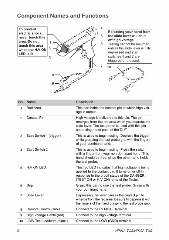
Component Names and Functions
No. Name Description
1 Red Area This part holds the contact pin to which high volt-age is output.
2 Contact Pin High voltage is delivered to this pin. The pin emerges from the red area when you depress the slide lever. The test probe is used with this pin contacting a test point of the DUT.
3 Start Switch 1 (trigger) This is used to begin testing. Depress the trigger while grasping the test probe grip with the fingers of your dominant hand.
4 Start Switch 2 This is used to begin testing. Press the switch with a finger from your non-dominant hand. This hand should be free, since the other hand holds the test probe.
5 H.V ON LED This red LED indicates that high voltage is being applied to the contact pin. It turns on or off in response to the on/off status of the DANGER (TEST ON or H.V ON) lamp of the Tester.
6 Grip Grasp this part to use the test probe. Grasp with your dominant hand.
7 Slide Lever Depressing this lever causes the contact pin to emerge from the red area. Be sure to depress it with the fingers of the hand grasping the test probe grip.
8 Remote Control Cable Connect to the REMOTE terminal.
9 High Voltage Cable (red) Connect to the high voltage terminal.
10 LOW Test Leadwire (black) Connect to the LOW (GND) terminal
5
6
7
12
3
4
9
8
10
6 HP01A-TOS/HP02A-TOS

Connecting to the Tester
1 Turn off the POWER switch of the Tester.
2 Connect the LOW test leadwire to the LOW (GND) terminal of the Tester.When using a TOS series withstanding voltage tester, attach a cable lock guard.When using a TOS93 series electrical safety analyzer, lift the cable lock, con-nect the test leadwire, and then lower the cable lock.
3 Connect the remote control cable to the REMOTE terminal of the Tester.
4 Connect the high voltage cable to the high voltage terminal of the Tester.
Cable Lock
The cable lock guard is not used.
Insert the tester-side end of the test leadwire fixture into the terminal and fasten securely.
■TOS93 series electrical safety analyzer
■TOS series withstanding voltage testerREMOTE Terminal
Remote Control Cable
High Voltage Cable (red)
High Voltage TerminalLOW (GND) Terminal
LOW Test Leadwire (black)
REMOTE Terminal
Connect via a DIN adapter cable (DD-5P/9P)depending on the model.
Connect via a DIN adapter cable
Remote Control Cable
High Voltage Cable (red)
LOW Test Leadwire (black)
LOW (GND) Terminal
High Voltage Terminal
HP01A-TOS/HP02A-TOS 7
Starting and Stopping Tests
Test Procedure
1 Configure the required test conditions for the Tester by referring to the operation manual.
2 Connect the test probe to the Tester (p.7).
3 Connect the alligator clip of the LOW test leadwire to the case (conductive part) of the DUT.
4 Hold the grip of the test probe with your dominant hand.Do not depress the slider lever yet! Place your non-dominant hand near start switch 2 and prepare to press the switch. Do not press start switch 2 yet!
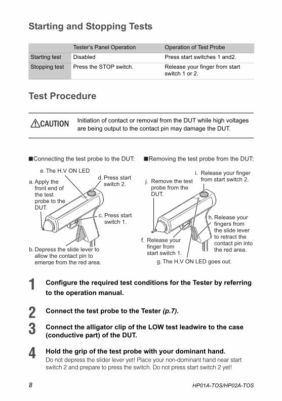
Tester’s Panel Operation Operation of Test Probe
Starting test Disabled Press start switches 1 and2.
Stopping test Press the STOP switch. Release your finger from start switch 1 or 2.
CAUTION Initiation of contact or removal from the DUT while high voltages are being output to the contact pin may damage the DUT.
Connecting the test probe to the DUT: Removing the test probe from the DUT:
a. Apply the front end of the test probe to the DUT.
b. Depress the slide lever to allow the contact pin to emerge from the red area.
e. The H.V ON LED d. Press start
switch 2.
c. Press start switch 1.
f. Release your finger from start switch 1.
j. Remove the test probe from the DUT.
i. Release your finger from start switch 2.
h. Release your fingers from the slide lever to retract the contact pin into the red area.
g. The H.V ON LED goes out.
8 HP01A-TOS/HP02A-TOS

5 Apply the front-end (red area) of the test probe to the test point of the DUT (a).
6 Depress the slide lever to allow the contact pin to emerge from the front end of the test probe (b).Be careful to avoid triggering start switch 1 prematurely.
7 Depress and hold down start switch 1 with a finger of your domi-nant hand (the hand holding the test probe grip) (c).
8 Press start switch 2 with a finger of your non-dominant hand (d).This causes the H.V ON LED to light up; the test voltage is output to the con-tact pin (e). Do not remove the contact pin from the DUT during testing.
9 When testing is complete (or is stopped), lift your finger from start switch 1 (f).Do not release your fingers from the slide lever or remove the test probe from the DUT.
10 Confirm that the H.V ON LED is not lit (g).
11 Release your fingers from the slide lever to retract the contact pin into the red area (h).
12 Release the finger of your non-dominant hand from start switch 2 ( i ).
13 Remove the test probe from the DUT ( j ).
14 Disconnect the alligator clip of the LOW test leadwire from the DUT.
This completes one testing cycle. The test setup returns to the status of step 2. Repeat the procedure for the next DUT, starting with step 3. After completing all tests, turn off the POWER switch of the Tester.
The current flowing through the stray capacitance between the high voltage cable of the test probe and the periphery of the cable may contribute to measurement errors. The higher the test voltage or Withstanding Voltage Tester’s current detecting sensitivity, the larger the measurement errors. If a test is performed at high current-detecting sensitivity, the current flowing through the stray capacitance may exceed the preset lower limit, depend-ing on the test voltage. This may disable lower-limit judgment.
HP01A-TOS/HP02A-TOS 9
MaintenancePeriodic inspections and maintenance are required to maintain the product’s original performance over the long term.
• Be sure to disconnect the test probe from the Tester before undertaking inspec-tions or maintenance.
• Avoid volatile solvents such as thinner and benzene, which may discolor the probe’s surface coating, erase printed characters, etc.
CleaningIf the test probe becomes soiled, moisten a piece of soft cloth with a mild, dilute detergent and gently wipe the probe.
Periodic InspectionThe remote control cable, high voltage cable, and LOW test leadwire are consum-ables. We recommend a inspection by one of our authorized service engineers once a year. To have an inspection performed, contact your Kikusui distributor or agent.
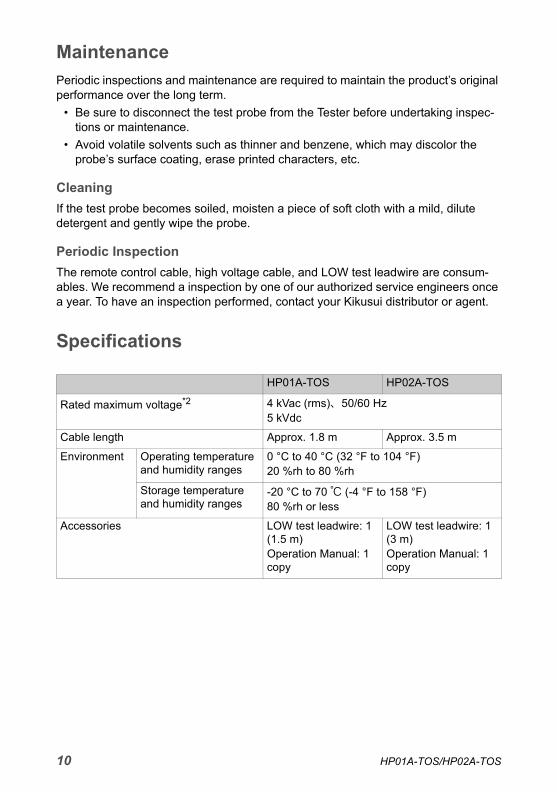
Specifications
HP01A-TOS HP02A-TOS
Rated maximum voltage*2 4 kVac (rms)、50/60 Hz5 kVdc
Cable length Approx. 1.8 m Approx. 3.5 m
Environment Operating temperature and humidity ranges
0 °C to 40 °C (32 °F to 104 °F)20 %rh to 80 %rh
Storage temperature and humidity ranges
-20 °C to 70 ℃ (-4 °F to 158 °F)80 %rh or less
Accessories LOW test leadwire: 1 (1.5 m)Operation Manual: 1 copy
LOW test leadwire: 1 (3 m)Operation Manual: 1 copy
10 HP01A-TOS/HP02A-TOS

Glossary1. high-voltage area: The high-voltage area refers to the contact pin and the
DUT (an area electrically connected to the contact pin during testing). It also includes areas where high volt-age is electrostatically or electromagnetically induced by application of high voltages.
2. Rated maximum voltage: The rated maximum voltage refers to the maximum volt-age the test probe is capable of handling within the given operating temperature and humidity ranges.
HP01A-TOS/HP02A-TOS 11

If you find any misplaced or missing pages in the manuals, they will be replaced. If the manual gets lost or soiled, a new copy can be provided for a fee. In either case, please contact your Kikusui agent or distributor. At that time, inform your agent or distributor of the “Part No.” written on the front cover of this manual.Every effort has been made to ensure the accuracy of this manual. However, if you have any questions or find any errors or omissions, please contact your Kikusui agent or distributor.After you have finished reading this manual, store it so that you can use it for reference at any time.
The newest version of the operation manual can be downloaded from Download service of Kikusui website.
KIKUSUI ELECTRONICS CORP. www.kikusui.co.jp/en1-1-3 Higashiyamata, Tsuzuki-ku, Yokohama, 224-0023, Japan
Tel: +81-45-482-6353Fax: +81-45-482-6261