tos-varnsdorf-vyrobni-program-aj.pdf - Your partner for future ...
98
Milling machine manufacturer Your partner for future machining page 2
-
Upload
khangminh22 -
Category
Documents
-
view
0 -
download
0
Transcript of tos-varnsdorf-vyrobni-program-aj.pdf - Your partner for future ...

Milling machine manufacturer
Yo u r p a r t n e r f o r f u t u r e m a c h i n i n g
page 2

Located on a site larger than 30 Football Pitches
30
Subsidiaries companies around the world
9
Number of employees
404
The company was established in 1903
1903
Machine accuracyin the order of hundreds of a millimeter
0.01
Machines sold between 1941 and 2020
19,830
Annual turnover in 2020
40.1 mil €
No
Mio
Ai

1Produc t ion programme
Content
. . . . . . . . . . . . . . . . . . . . . . . . . . . . . . . . . . . . . . . . . . . . . . . . . . . . . . . . . . . . . . . . . . . . . . . . . . . . . . . . . . . . . . . . . . . . . . . . . . . . . . . . . . . . . . . . . . . . . . . . . . . . . . . . . . . . . . . . . . . . . . . . . . . . . . . . . . . . . 2
Table-type machines
WH(Q) 10 CNC . . . . . . . . . . . . . . . . . . . . . . . . . . . . . . . . . . . . . . . . . . . . . . . . . . . . . . . . . . . . . . . . . . . . . . . . . . . . . . . . . . . . . . . . . . . . . . . . . . . . . . . . . . . . . . . . . . . . . . . . . . . . . . . . . . . . . . . . . . . . . . . . . . . . . . . . . . . . . . . . . . . . . . . . . . . . . . 6
WH(Q) 105 CNC . . . . . . . . . . . . . . . . . . . . . . . . . . . . . . . . . . . . . . . . . . . . . . . . . . . . . . . . . . . . . . . . . . . . . . . . . . . . . . . . . . . . . . . . . . . . . . . . . . . . . . . . . . . . . . . . . . . . . . . . . . . . . . . . . . . . . . . . . . . . . . . . . . . . . . . . . . . . . . . . . . . . . . . . . . . . 8
WHN 110 / 130 (Q,MC). . . . . . . . . . . . . . . . . . . . . . . . . . . . . . . . . . . . . . . . . . . . . . . . . . . . . . . . . . . . . . . . . . . . . . . . . . . . . . . . . . . . . . . . . . . . . . . . . . . . . . . . . . . . . . . . . . . . . . . . . . . . . . . . . . . . . . . . . . . . . . . . . . . . . . . . . . . . . . . . 10
WHN(Q) 13 / 15 CNC . . . . . . . . . . . . . . . . . . . . . . . . . . . . . . . . . . . . . . . . . . . . . . . . . . . . . . . . . . . . . . . . . . . . . . . . . . . . . . . . . . . . . . . . . . . . . . . . . . . . . . . . . . . . . . . . . . . . . . . . . . . . . . . . . . . . . . . . . . . . . . . . . . . . . . . . . . . . . . . . . . . 14
WHR 13 (Q) . . . . . . . . . . . . . . . . . . . . . . . . . . . . . . . . . . . . . . . . . . . . . . . . . . . . . . . . . . . . . . . . . . . . . . . . . . . . . . . . . . . . . . . . . . . . . . . . . . . . . . . . . . . . . . . . . . . . . . . . . . . . . . . . . . . . . . . . . . . . . . . . . . . . . . . . . . . . . . . . . . . . . . . . . . . . . . . . . 18
MAXIMA I / II . . . . . . . . . . . . . . . . . . . . . . . . . . . . . . . . . . . . . . . . . . . . . . . . . . . . . . . . . . . . . . . . . . . . . . . . . . . . . . . . . . . . . . . . . . . . . . . . . . . . . . . . . . . . . . . . . . . . . . . . . . . . . . . . . . . . . . . . . . . . . . . . . . . . . . . . . . . . . . . . . . . . . . . . . . . . . . . 22
Floor-type milling machines
WRD 13 (Q) . . . . . . . . . . . . . . . . . . . . . . . . . . . . . . . . . . . . . . . . . . . . . . . . . . . . . . . . . . . . . . . . . . . . . . . . . . . . . . . . . . . . . . . . . . . . . . . . . . . . . . . . . . . . . . . . . . . . . . . . . . . . . . . . . . . . . . . . . . . . . . . . . . . . . . . . . . . . . . . . . . . . . . . . . . . . . . . . . 26
GRATA . . . . . . . . . . . . . . . . . . . . . . . . . . . . . . . . . . . . . . . . . . . . . . . . . . . . . . . . . . . . . . . . . . . . . . . . . . . . . . . . . . . . . . . . . . . . . . . . . . . . . . . . . . . . . . . . . . . . . . . . . . . . . . . . . . . . . . . . . . . . . . . . . . . . . . . . . . . . . . . . . . . . . . . . . . . . . . . . . . . . . . . . . 28
WRD 130 / 150 (Q) . . . . . . . . . . . . . . . . . . . . . . . . . . . . . . . . . . . . . . . . . . . . . . . . . . . . . . . . . . . . . . . . . . . . . . . . . . . . . . . . . . . . . . . . . . . . . . . . . . . . . . . . . . . . . . . . . . . . . . . . . . . . . . . . . . . . . . . . . . . . . . . . . . . . . . . . . . . . . . . . . . . . . . 30
WRD 170 (Q) . . . . . . . . . . . . . . . . . . . . . . . . . . . . . . . . . . . . . . . . . . . . . . . . . . . . . . . . . . . . . . . . . . . . . . . . . . . . . . . . . . . . . . . . . . . . . . . . . . . . . . . . . . . . . . . . . . . . . . . . . . . . . . . . . . . . . . . . . . . . . . . . . . . . . . . . . . . . . . . . . . . . . . . . . . . . . . . 34
WRD 180 H . . . . . . . . . . . . . . . . . . . . . . . . . . . . . . . . . . . . . . . . . . . . . . . . . . . . . . . . . . . . . . . . . . . . . . . . . . . . . . . . . . . . . . . . . . . . . . . . . . . . . . . . . . . . . . . . . . . . . . . . . . . . . . . . . . . . . . . . . . . . . . . . . . . . . . . . . . . . . . . . . . . . . . . . . . . . . . . . . . 36
Machining centres
WHT 110 / 130 (C) . . . . . . . . . . . . . . . . . . . . . . . . . . . . . . . . . . . . . . . . . . . . . . . . . . . . . . . . . . . . . . . . . . . . . . . . . . . . . . . . . . . . . . . . . . . . . . . . . . . . . . . . . . . . . . . . . . . . . . . . . . . . . . . . . . . . . . . . . . . . . . . . . . . . . . . . . . . . . . . . . . . . . . . 42
Portal milling machines
WVM 2600 / 3600 T . . . . . . . . . . . . . . . . . . . . . . . . . . . . . . . . . . . . . . . . . . . . . . . . . . . . . . . . . . . . . . . . . . . . . . . . . . . . . . . . . . . . . . . . . . . . . . . . . . . . . . . . . . . . . . . . . . . . . . . . . . . . . . . . . . . . . . . . . . . . . . . . . . . . . . . . . . . . . . . . . . . . 52
Accessories
Rotating tables . . . . . . . . . . . . . . . . . . . . . . . . . . . . . . . . . . . . . . . . . . . . . . . . . . . . . . . . . . . . . . . . . . . . . . . . . . . . . . . . . . . . . . . . . . . . . . . . . . . . . . . . . . . . . . . . . . . . . . . . . . . . . . . . . . . . . . . . . . . . . . . . . . . . . . . . . . . . . . . . . . . . . . . . . . . 60
Automatic palette changer (APC) . . . . . . . . . . . . . . . . . . . . . . . . . . . . . . . . . . . . . . . . . . . . . . . . . . . . . . . . . . . . . . . . . . . . . . . . . . . . . . . . . . . . . . . . . . . . . . . . . . . . . . . . . . . . . . . . . . . . . . . . . . . . . . . . . . . . . . . . . . . . . . 62
Automatic tool changer (ATC) . . . . . . . . . . . . . . . . . . . . . . . . . . . . . . . . . . . . . . . . . . . . . . . . . . . . . . . . . . . . . . . . . . . . . . . . . . . . . . . . . . . . . . . . . . . . . . . . . . . . . . . . . . . . . . . . . . . . . . . . . . . . . . . . . . . . . . . . . . . . . . . . . . . . 64
Milling heads . . . . . . . . . . . . . . . . . . . . . . . . . . . . . . . . . . . . . . . . . . . . . . . . . . . . . . . . . . . . . . . . . . . . . . . . . . . . . . . . . . . . . . . . . . . . . . . . . . . . . . . . . . . . . . . . . . . . . . . . . . . . . . . . . . . . . . . . . . . . . . . . . . . . . . . . . . . . . . . . . . . . . . . . . . . . . . 66
Facing heads . . . . . . . . . . . . . . . . . . . . . . . . . . . . . . . . . . . . . . . . . . . . . . . . . . . . . . . . . . . . . . . . . . . . . . . . . . . . . . . . . . . . . . . . . . . . . . . . . . . . . . . . . . . . . . . . . . . . . . . . . . . . . . . . . . . . . . . . . . . . . . . . . . . . . . . . . . . . . . . . . . . . . . . . . . . . . . . 72
The operator‘s platform and machine covering . . . . . . . . . . . . . . . . . . . . . . . . . . . . . . . . . . . . . . . . . . . . . . . . . . . . . . . . . . . . . . . . . . . . . . . . . . . . . . . . . . . . . . . . . . . . . . . . . . . . . . . . . . . . . . . . . . . . . . . . 74
Control systems . . . . . . . . . . . . . . . . . . . . . . . . . . . . . . . . . . . . . . . . . . . . . . . . . . . . . . . . . . . . . . . . . . . . . . . . . . . . . . . . . . . . . . . . . . . . . . . . . . . . . . . . . . . . . . . . . . . . . . . . . . . . . . . . . . . . . . . . . . . . . . . . . . . . . . . . . . . . . . . . . . . . . . . . . . 76
Other accessories and services . . . . . . . . . . . . . . . . . . . . . . . . . . . . . . . . . . . . . . . . . . . . . . . . . . . . . . . . . . . . . . . . . . . . . . . . . . . . . . . . . . . . . . . . . . . . . . . . . . . . . . . . . . . . . . . . . . . . . . . . . . . . . . . . . . . . . . . . . . . . . . . . . . 78
Components
Headstocks . . . . . . . . . . . . . . . . . . . . . . . . . . . . . . . . . . . . . . . . . . . . . . . . . . . . . . . . . . . . . . . . . . . . . . . . . . . . . . . . . . . . . . . . . . . . . . . . . . . . . . . . . . . . . . . . . . . . . . . . . . . . . . . . . . . . . . . . . . . . . . . . . . . . . . . . . . . . . . . . . . . . . . . . . . . . . . . . . 80
Other components . . . . . . . . . . . . . . . . . . . . . . . . . . . . . . . . . . . . . . . . . . . . . . . . . . . . . . . . . . . . . . . . . . . . . . . . . . . . . . . . . . . . . . . . . . . . . . . . . . . . . . . . . . . . . . . . . . . . . . . . . . . . . . . . . . . . . . . . . . . . . . . . . . . . . . . . . . . . . . . . . . . . . 82
References
TOS Olomouc
TOS
Olom
ouc
Refe
renc
esTa
ble-
type
mac
hine
sFlo
or-ty
pe m
illin
g mac
hine
sM
achi
ning
cent
res
Port
al m
illin
g m
achi
nes
Acce
ssor
ies
Com
pone
nts

2 TOS VARNSDORF a . s .
Status screenClearly displays basic information about the machine (coordinates, program, alarms, logged in user, etc.).
DocumentationThis is an application enabling the reading and management of PDF documents (e.g. operating instructions, repair manual, etc.), including the creation of user rights and the creation of tabs and notes in documents.
CNC control systemDisplays the standard control system screen supplemented by a sidebar with a button for returning to the TOS Control default screen.
CalendarStandard calendar view – day, week, monthUser event, add, change, deleteMeeting of machine tool manufacturers – service eventCalendar reminderAll data stored in the local database
TOScontrol is a set of applications and functions for advanced machine management.For easy and intuitive operation, the system consists of a default screen with icons for each application (similar to mobile device operating systems).
The applications are clearly displayed on the machine's control panel and the operator can switch between them easily. The solution also includes, among other things, user account management. TOScontrol is part of the standard equipment of all machines.
Standard machine equipment| TOSControl system default screen.
TOS
Olom
ouc
Refe
renc
esTa
ble-
type
mac
hine
sFlo
or-ty
pe m
illin
g mac
hine
sPo
rtal
mill
ing
mac
hine
sAc
cess
orie
sCo
mpo
nent
sM
achi
ning
cent
res

3Produc t ion programme
IP cameraThe application enables control of one or more motorised cameras located on any part of the machine. Data from the camera can also be used to facilitate machine operation.
Inspection and compensationThis is metrological software integrated into the control system, which together with the touch probe allows the work-piece to be measured accurately and directly on the machine making it possible to perform the automatic compensation of errors and program debugging.
Option applications(not–included in standard equipment)
Work administrator Displays the work order view and the overview of operations directly on the machine tool control panel, which is linked to the ERP system. It is also possible to add other documents into the application, e.g., operation description, photographs, tables of NC programs.
Technology calculationA technology consultant for a selected tool that facilitates the selection and control of cutting conditions and provides optimal utilisation of the tool properties.
Predictive maintenanceExpands the machine monitor application to enable service intervention prediction to decrease maintenance costs and prolong machine operation.
Machine monitorAn integrated system for monitoring the history of machine tool use. This system displays the time axis of basic machine states, e.g., ready, production, production slowdown, error, off , etc.
Thermal compensationThis is an application that depicts a virtual model of the machine tool's thermal behaviour and comparison of previously measured thermal deformation with the current thermal conditions of the machine. Based on this comparison, the application compensates the actual thermal deformation of the machine.
Applications under preparation
TOS
Olom
ouc
Refe
renc
esTa
ble-
type
mac
hine
sFlo
or-ty
pe m
illin
g mac
hine
sPo
rtal
mill
ing
mac
hine
sAc
cess
orie
sCo
mpo
nent
sM
achi
ning
cent
res

4 TOS VARNSDORF a . s .
Horizontal table-type boring machines
Horizontal table-type WH(Q) 10 CNC, WH(Q) 105 CNC, WHN 110 / 130 (Q, MC), WHN(Q) 13 / 15 CNC, WHR 13 (Q) and MAXIMA I / II are milling and boring machines with a cross-arrangement of the beds. The machines are on top-class technical level corresponding to the needs of modern progressive technology. The machines‘ design off ers a wide choice of versions in all parameters, thus
allowing the customer to choose the optimum version. The horizontal table-type machines off er eff ective machining with a great cutting performance and high precision. They are built for demanding customers, who can apply very demanding technological procedures.
TOS
Olom
ouc
Refe
renc
esTa
ble-
type
mac
hine
sFlo
or-ty
pe m
illin
g mac
hine
sM
achi
ning
cent
res
Port
al m
illin
g m
achi
nes
Acce
ssor
ies
Com
pone
nts

5Produc t ion programme
Table-type machines
WH(Q) 10 CNC
WH(Q) 105 CNC
WHN 110 / 130 (Q, MC)
WHN(Q) 13 / 15 CNC
WHR 13 (Q)
MAXIMA I / II
TOS
Olom
ouc
Refe
renc
esTa
ble-
type
mac
hine
sFlo
or-ty
pe m
illin
g mac
hine
sM
achi
ning
cent
res
Port
al m
illin
g m
achi
nes
Acce
ssor
ies
Com
pone
nts

Table-type machines
6 TOS VARNSDORF a . s .
WH(Q) 10 CNC
TECHNICAL PARAMETERS
Headstock
Work spindle diameter mm (in) 100 (3.9370)
Spindle taper ISO 50
Work spindle speed range 1/min 10 – 2 500
Main motor power (S1 / S6 – 60%) kW (HP) 22.5 (30.6) / 34 (46.2)
Torque on spindle (S1 / S6 – 60%) Nm (ft lb) 812 (598.9) / 1 218 (898.4)
Spindle stroke W mm (in) 710 (27.9527)
Column
Headstock vertical travel Y mm (in) 1 100 (43.3070)
Table longitudinal travel Z mm (in) 940 (37.0078)
Rotational table
Table transverse travel X mm (in) 1 250 (49.2125)
Max. workpiece weight kg (lbs) 3 000 (6613)
Table clamping area mm (in) 1 000 x 1 120 (39.3700 x 44.0944)
Feeds
Range of feeds (working and rapid traverse) – X, Y, Z, W mm/min (ipm) 4 – 8 000 (0.1574 – 314.9606)
– B 1/min 0.003 – 2
Machine confi guration
• WH 10 CNC – basic version with work spindle diameter 100 mm
• WHQ 10 CNC – version with an automatic tool change
WH(Q) 10 CNC is a horizontal table-type boring machine with travelling work spindle 100 mm in diameter and maximum weight capacity of the table 3000 kg. This is the smallest machine in the TOS VARNSDORF range.The optimally dimensioned structure from grey cast-iron consists of a Fixed Column and a longitudinal bed with a cross moving Rotary Table. Thanks to a rigid structure excellently absorbing vibrations, suffi ciently dimensioned drives and accurate guides, the machine is designed for universal cutting operations of Prismatic parts,
light workpieces from cast iron, cast steel and steel including technologically demanding operations.The machine can be extended by special equipment, peripheral devices and
special technological equipment (e.g. guide supports, facing head, milling heads, chucking equipment, etc.).
TOS
Olom
ouc
Refe
renc
esTa
ble-
type
mac
hine
sFlo
or-ty
pe m
illin
g mac
hine
sM
achi
ning
cent
res
Port
al m
illin
g m
achi
nes
Acce
ssor
ies
Com
pone
nts

Walter innovations are setting standards.
Walter innovations are setting standards worldwideAs a premium manufacturer of metal cutting tools, Walter enjoys an excellent reputation among customers and users worldwide. Whether it is innovative milling bodies and indexable inserts, new drill concepts or multi-stage thread milling cutters: Walter is setting standards in turning, milling, holemaking and threading – across the industry. More than 35% of the products we sell are less than five years old. With our innovations, we are ensuring that tools from Walter will continue to rank among the best in future.
walter-tools.com
AZ_Produkt_2019_ohne100J_EN_HQ_210x297_neu.indd 1 14.01.2020 09:30:44

Table-type machines
8 TOS VARNSDORF a . s .
WH(Q) 105 CNCThe horizontal milling and boring machine WH(Q) 105 CNC is a modern, effi cient, continuously controlled milling machine. The high cutting parameters and broad comfort of technological features predestine this machine for application in very demanding technological operations. The continuous control of the X, Y, Z and W coordinates and the rotating positioning table create conditions for universal application. It can be used for effi cient milling of box-type components from multiple sizes as well as milling of moulds and other complicated workpieces.The machine can be supplemented with a series of technological devices, which greatly extend the machine‘s potentialities.
Machine confi guration
• WH 105 CNC – basic version with work spindle diameter 105 mm
• WHQ 105 CNC – version with an automatic tool change
• „N“ headstock – suitable for power milling operations
• „R“ headstock – suitable for high-performance milling operations
• „R4“ headstock – high-speed version of headstock up to 4 000 rpm
• work table with maximum load 3 tonnes or 5 tonnes
Y
W
ZX
TOS
Olom
ouc
Refe
renc
esTa
ble-
type
mac
hine
sFlo
or-ty
pe m
illin
g mac
hine
sM
achi
ning
cent
res
Port
al m
illin
g m
achi
nes
Acce
ssor
ies
Com
pone
nts

Table-type machines
9Produc t ion programme
TECHNICAL PARAMETERS
Spindle type „N“ „R“ „R4“
Work spindle diameter mm (in) 105 (4.1338)
Spindle taper ISO 50
Work spindle speed range 1/min 10 – 2 300 10 – 3 300 10 – 4 000
Main motor power (S1) kW (HP) 29 (39.4)
Max. output of main motor (S6 – 60%) kW (HP) 35 (47.6)
Torque on spindle (S1) Nm (ft lb) 1 170 (862.9) 921 (679.3)
Max. torque on spindle (S6 – 60%) Nm (ft lb) 1 462(1078.3) 1 148 (846.7)
Spindle stroke W mm (in) 630 (24.8)
Column
Headstock vertical travel Y mm (in) 1 250 (49.2125), 1 600 (62.9921)
Minimum height of spindle axis above work table mm (in) 0
Rotational table
Max. workpiece weight kg (lbs) 5 000 (11023) / 3 000 (6613)
Table clamping area mm(in)
1 400 x 1 400, 1 400 x 1 600(55.1181 x 55.1181, 55.1181 x 62.9921)
Table longitudinal travel Z mm (in) 1 250 (49.2125)
Table transverse travel X mm (in) 1 800 (70.8661) / 2 000 (78.7401)*
Feeds
Range of feeds (working and rapid traverse) – X, Y, Z mm/min (ipm) 5 – 10 000 (0.1968 – 393.7007)
– W mm/min (ipm) 5 – 8 000 (0.1968 – 314.9606)
– B 1/min 0.003 – 2
* max. workpiece weight 3 000 kg (6613 lbs)
| Customised solution for special products and series production.
TOS
Olom
ouc
Refe
renc
esTa
ble-
type
mac
hine
sFlo
or-ty
pe m
illin
g mac
hine
sM
achi
ning
cent
res
Port
al m
illin
g m
achi
nes
Acce
ssor
ies
Com
pone
nts

Table-type machines
10 TOS VARNSDORF a . s .
WHN 110/130 (Q, MC)The WHN 110 / 130 (Q, MC) milling and boring machines are powerful, effi cient representatives of the TOS VARNSDORF a.s. advanced generation, which responds to the needs of modern progressive technology.
The machines are produced in a cross arrangement of the beds, with a longitudinally adjustable stand, a traversing spindle and cross-wise adjustable rotary table.
Machine confi guration
• WHN 110 – basic version with work spindle diameter 112 mm
• WHN 130 – basic version with work spindle diameter 130 mm
• WHN 110/130 Q – version with an automatic tool change
• WHN 110/130 MC – version with an automatic palette change
• variable work table clamping area size
Y
X
Z
W
TOS
Olom
ouc
Refe
renc
esTa
ble-
type
mac
hine
sFlo
or-ty
pe m
illin
g mac
hine
sM
achi
ning
cent
res
Port
al m
illin
g m
achi
nes
Acce
ssor
ies
Com
pone
nts

Table-type machines
11Produc t ion programme
TECHNICAL PARAMETERS
Machine type WHN 110 (Q, MC) WHN 130 (Q, MC)
Headstock „N/R“ „N/R“
Work spindle diameter mm (in) 112 (4.4094) 130 (5.1181)
Spindle taper ISO 50 / ISO 50 BIG+
Work spindle speed range 1/min 10 – 3 300 10 – 3 000
Main motor power (S1) kW (HP) 41 (55.7)
Max. output of main motor (S6 – 60%) kW (HP) 46 (62.5)
Torque on spindle (S1) Nm (ft lb) 1 463 (1079.1) 1 624 (1197.8)
Max. torque on spindle (S6 – 60%) Nm (ft lb) 1 811 (1335.7) 2017 (1487.7)
Spindle stroke W mm (in) 710 (27.9527) 800 (31.4960)
Column
Headstock vertical travel Y– version with normal rotary table
– version with technological palette
mm(in)mm(in)
1 250, 1 400, 1 600(49.2125, 55.1181, 62.9921)
1 120, 1 250, 1 400(44.0944, 49.2125, 55.1181)
1 600, 2 000, 2 500(62.9921, 78.7401, 98.4251)
1 400, 1 800, 2 240(55.1181, 70.8661, 88.1889)
Minimum height of spindle axis above work table / palette mm (in) 50 (1.9685) / 0
Column longitudinal travel Zmm(in)
800, 1 000, 1 250(31.4960, 39.3700, 49.2125)
1 000, 1 250, 1 600, 2 00039.3700, 49.2125,62.9921, 78.7401
Rotational table
Max. workpiece weight kg (lbs) 8 000 (17637) 12 000 (26455.5)
Table clamping area
mm
(in)
1 250 x 1 400, 1 400 x 1 600, 1 400 x 1 800*
49.2125 x 55.1181, 55.1181 x 62.9921, 55.1181 x 70.8661*
1 600 x 1 800, 1 800 x 2 240
62.9921 x 70.8661, 70.8661 x 88.1889
Table transverse travel X
mm
(in)
1 600, 2 000, 2 500, 3 000
62.9921, 78.7401, 98.4251, 118.1102
2 000, 2 500, 3 000, 3 500, 4 000
78.7401, 98.4251, 118.1102, 137.7952, 157.4803
Automatic palette exchage
Max. workpiece weight kg (lbs) 5 000 (11023.1) 8 000 (17636.9)
Palette clamping area mm(in)
1 250 x 1 400, 1 250 x 1 60049.2125 x 55.1181, 49.2125 x 62.9921
1 600 x 1 800(62.9921 x 70.8661)
Number of Pallets in the system 2 2
Total period of automatic palette change s 85 85
Feeds
Range of feeds (working and rapid traverse) – X, Y, Z, W mm/min (ipm) 1 – 10 000 (0.0393 - 393.7007)
– B 1/min 0.003 – 2.5 0.003 – 2
* max. wokpiece weight 5 000 kg (11023.1 lbs)
TOS
Olom
ouc
Refe
renc
esTa
ble-
type
mac
hine
sFlo
or-ty
pe m
illin
g mac
hine
sM
achi
ning
cent
res
Port
al m
illin
g m
achi
nes
Acce
ssor
ies
Com
pone
nts

Table-type machines
12 TOS VARNSDORF a . s .
WHN 110 / 130 (Q, MC) – Varied use
| Drilling and millingat angles.
| Deep drilling and reaming.
| Minimisation of downtimewhen replacing a workpiece
with a palette system thatreplaces a product in only
85 seconds.
| Interpolation turning of large diameter holes.
TOS
Olom
ouc
Refe
renc
esTa
ble-
type
mac
hine
sFlo
or-ty
pe m
illin
g mac
hine
sM
achi
ning
cent
res
Port
al m
illin
g m
achi
nes
Acce
ssor
ies
Com
pone
nts

• Collision detection• Tool breakage detection• Tool wear detection• Contact detection
CoroPlus® Process Control
Monitor machining processes and automate actions
sandvik.coromant.com/processcontrol

Table-type machines
14 TOS VARNSDORF a . s .
WHN(Q) 13/15 CNC
Y
X
Z
W
Machine confi guration
• WHN 13 CNC – basic version with work spindle diameter 130 mm
• WHN 15 CNC – optional version with work spindle diameter 150 mm
• WHQ 13/15 CNC – version with an automatic tool change
• WHQ 13/15 MC – machine with a character of a machining centre (automatic tool change and automatic pallet change)
• wide range of work table designs
The horizontal milling and boring machine WHN(Q) 13/15 CNC is a universal machine designed for precise milling, line-coordinate drilling, boring and thread-cutting of box- and board-type workpieces as well as complicated workpieces from cast-iron, steel cast-iron and steel with the weight of up to 25 000 kg.WHN(Q) 13/15 CNC is the most successful machine from the company production. The fi rst model of the machine was produced in 1968. The success of this machine can be documented by the fact that more than 2724 pieces of these machines have been sold up to now.It particularly excels in the ratio between capacity and the purchasing costs. The users value the structure of the machine, which guarantees high rigidity and
reliability as well as high technical parameters and a broad range and comfort of the technological features. The machine can be supplemented with a series of options, which greatly extend the machine‘s potentialities.
TOS
Olom
ouc
Refe
renc
esTa
ble-
type
mac
hine
sFlo
or-ty
pe m
illin
g mac
hine
sM
achi
ning
cent
res
Port
al m
illin
g m
achi
nes
Acce
ssor
ies
Com
pone
nts
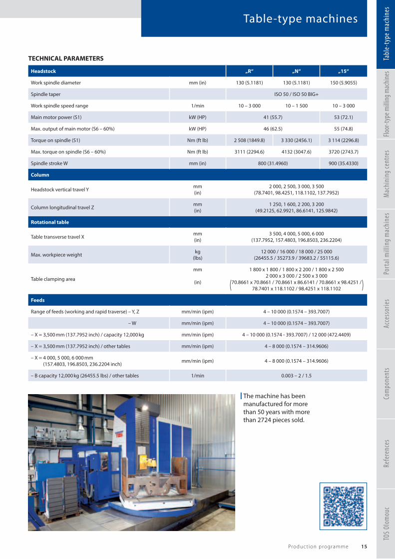
Table-type machines
15Produc t ion programme
TECHNICAL PARAMETERS
Headstock „R“ „N“ „15“
Work spindle diameter mm (in) 130 (5.1181) 130 (5.1181) 150 (5.9055)
Spindle taper ISO 50 / ISO 50 BIG+
Work spindle speed range 1/min 10 – 3 000 10 – 1 500 10 – 3 000
Main motor power (S1) kW (HP) 41 (55.7) 53 (72.1)
Max. output of main motor (S6 – 60%) kW (HP) 46 (62.5) 55 (74.8)
Torque on spindle (S1) Nm (ft lb) 2 508 (1849.8) 3 330 (2456.1) 3 114 (2296.8)
Max. torque on spindle (S6 – 60%) Nm (ft lb) 3111 (2294.6) 4132 (3047.6) 3720 (2743.7)
Spindle stroke W mm (in) 800 (31.4960) 900 (35.4330)
Column
Headstock vertical travel Y mm(in)
2 000, 2 500, 3 000, 3 500(78.7401, 98.4251, 118.1102, 137.7952)
Column longitudinal travel Z mm(in)
1 250, 1 600, 2 200, 3 200(49.2125, 62.9921, 86.6141, 125.9842)
Rotational table
Table transverse travel X mm(in)
3 500, 4 000, 5 000, 6 000(137.7952, 157.4803, 196.8503, 236.2204)
Max. workpiece weight kg(lbs)
12 000 / 16 000 / 18 000 / 25 000(26455.5 / 35273.9 / 39683.2 / 55115.6)
Table clamping area
mm
(in)
1 800 x 1 800 / 1 800 x 2 200 / 1 800 x 2 5002 000 x 3 000 / 2 500 x 3 000
70.8661 x 70.8661 / 70.8661 x 86.6141 / 70.8661 x 98.4251 / 78.7401 x 118.1102 / 98.4251 x 118.1102
Feeds
Range of feeds (working and rapid traverse) – Y, Z mm/min (ipm) 4 – 10 000 (0.1574 – 393.7007)
– W mm/min (ipm) 4 – 10 000 (0.1574 – 393.7007)
– X = 3,500 mm (137.7952 inch) / capacity 12,000 kg mm/min (ipm) 4 – 10 000 (0.1574 - 393.7007) / 12 000 (472.4409)
– X = 3,500 mm (137.7952 inch) / other tables mm/min (ipm) 4 – 8 000 (0.1574 – 314.9606)
– X = 4 000, 5 000, 6 000 mm (157.4803, 196.8503, 236.2204 inch) mm/min (ipm) 4 – 8 000 (0.1574 – 314.9606)
– B capacity 12,000 kg (26455.5 lbs) / other tables 1/min 0.003 – 2 / 1.5
| The machine has been manufactured for more than 50 years with more than 2724 pieces sold.
TOS
Olom
ouc
Refe
renc
esTa
ble-
type
mac
hine
sFlo
or-ty
pe m
illin
g mac
hine
sM
achi
ning
cent
res
Port
al m
illin
g m
achi
nes
Acce
ssor
ies
Com
pone
nts

Table-type machines
16 TOS VARNSDORF a . s .
WHN(Q) 13/15 CNC
HeadstockThe Headstock contains the Spindle drive motor and Gearbos together with the W axis drive system. The travelling work spindle is nitrided, housed with a minimum allowance in an all-nitrided hollow spindle, which is housed in a set of highly precise pre-stressed bevel bearings. The spindle speed is controlled in two mechanical rows automatically engaged by a hydraulic circuit. For more information see page 80.
Headstock CounterbalanceThe spindle weight is balanced by a counter-weight suspended on cables and conducted in the stand.
TOS
Olom
ouc
Refe
renc
esTa
ble-
type
mac
hine
sFlo
or-ty
pe m
illin
g mac
hine
sM
achi
ning
cent
res
Port
al m
illin
g m
achi
nes
Acce
ssor
ies
Com
pone
nts

Table-type machines
17Produc t ion programme
WHN(Q) 13/15 CNC
StandThe basic part of the WHN(Q) 13/15 CNC machines are made of high-quality grey cast-iron made in the Czech Republic, which forms a cast-iron skeleton. The structure and the ribbing of the frame guarantee high rigidity.
The bedWe use the GG 25 cast iron for production of the support sections because of high demands for vibration absorption in the horizontal boring machines. High rigidity of an optimally dimensioned cast-iron frame guarantees high effi ciency and productivity of the milling machine while securing top geometrical accuracy of the workpiece.
Drives of travel unitsThe travel units are driven by digitally controlled AC servo drives Siemens.To reach higher travel forces, an allowance-free gear is inserted between the servo drive and the ball screw.
Guides of adjustable groupsGuides of all linear groups are sliding. The guide surfaces are laser-hardened. Hardened steel bars on guide surfaces are installed under friction bearings and otherwise loaded areas.Matching areas are treated with a sliding material with a low friction coeffi cient. In addition, the table rails are eased by four friction units.Guides on the bed are protected against dirt by telescopic covers, guide surfaces of the column are protected by bellows covered by steel plates. The table is housed in a peripheral slide guide and a friction bearing in the centre.
Revolving attachment tableIt is equipped with a rotation sensor, which allows automatic positioning of the table with an increment of 0.001°. After reaching the target position, the table is automatically fi xed. The rotation is driven by a motor with gear to one of two sprockets, which mesh in the ring gear of the table.
TOS
Olom
ouc
Refe
renc
esTa
ble-
type
mac
hine
sFlo
or-ty
pe m
illin
g mac
hine
sM
achi
ning
cent
res
Port
al m
illin
g m
achi
nes
Acce
ssor
ies
Com
pone
nts

18 TOS VARNSDORF a . s .
The latest representative of horizontal table-type boring machines WHR 13 (Q) produce by TOS VARNSDORF. The WHR 13 (Q) has been developed from the most successful generation of table-type WHN 13 CNC machines, which have reached customers all around the world over the past few decades (more than 2670 of all versions and types of WHN 13 have been sold) and they are still popular and in high demand. The WHN 13 CNC machines have become a standard for all machines in this category through their unique properties, reliability and power parameters. The horizontal boring machine WHR 13 (Q) takes the best from its predecessor and, using the most modern technology, represents another step forward in its class.
Table-type machines
WHR 13 (Q)
Y
Z
X
BB
WW
V
Machine confi guration
• WHR 13 – basic version with work spindle diameter 130 mm
• WHR 13 Q – version with an automatic tool change
• wide range of work table designs
TOS
Olom
ouc
Refe
renc
esTa
ble-
type
mac
hine
sFlo
or-ty
pe m
illin
g mac
hine
sM
achi
ning
cent
res
Port
al m
illin
g m
achi
nes
Acce
ssor
ies
Com
pone
nts

19Produc t ion programme
Table-type machines
TECHNICAL PARAMETERS
Headstock
Work spindle diameter mm (in) 130 (5.1181)
RAM size mm (in) 320 x 400 (12.5984 x 15.7480)
Spindle taper ISO 50 / ISO 50 BIG+
Work spindle speed range 1/min 10 – 3 000
Main motor power (S1) kW (HP) 41 (55.7)
Max. output of main motor (S6 – 60%) kW (HP) 46 (62.5)
Torque on spindle (S1) Nm (ft lb) 2 542 (1874.9)
Max. torque on spindle (S6 – 60%) Nm (ft lb) 3 111 (2294.6)
Spindle stroke W mm (in) 650 (25.5905)
RAM stroke V mm (in) 700 (27.6)
Column
Headstock vertical travel Y mm(in)
2 000, 2 500, 3 000(78.7401, 98.4251, 118.1102)
Column longitudinal travel Z mm(in)
1 250, 1 600, 2 200, 3 200(49.2125, 62.9921, 86.6141, 125.9842)
Rotational table
Table transverse travel X mm(in)
3 500, 4 000, 5 000, 6 000(137.7952, 157.4803, 196.8503, 236.2204)
Max. workpiece weight kg(lbs)
12 000 / 16 000 / 18 000 / 25 000(26455.5 / 35273.9 / 39683.2 / 55115.6)
Table clamping area
mm
(in)
1 800 x 1 800 / 1 800 x 2 200 / 1 800 x 2 500 2 000 x 3 000 / 2 500 x 3 000
70.8661 x 70.8661 / 70.8661 x 86.6141 / 70.8661 x 98.4251 / 78.7401 x 118.1102 / 98.4251 x 118.1102
Feeds
Range of feeds (working and rapid traverse) – Y, Z, W, V mm/min (ipm) 5 – 10 000 (0.1574 - 393.7007)
– X = 3,500 mm (137.7952 inch) / capacity 12,000 kg mm/min (ipm) 4 – 10 000 (0.1574 – 393.7007) / 12 000 (472.4409)
– X = 3,500 mm (137.7952 inch) / other tables mm/min (ipm) 4 – 8 000 (0.1574 – 314.9606)
– X = 4 000, 5 000, 6 000 mm(157.4803, 196.8503, 236.2204 inch) mm/min (ipm) 4 – 8 000 (0.1574 – 314.9606)
– B capacity 12,000 kg (26455.5 inch) / other tables 1/min 0.003 – 2 / 1.5
| The robotic manipulator provides eff ective tool exchange in the main spindle and milling head.
TOS
Olom
ouc
Refe
renc
esTa
ble-
type
mac
hine
sFlo
or-ty
pe m
illin
g mac
hine
sM
achi
ning
cent
res
Port
al m
illin
g m
achi
nes
Acce
ssor
ies
Com
pone
nts

20 TOS VARNSDORF a . s .
Table-type machines
ColumnThe basic part of the machine frames made by TOS VARNSDORF are of high-quality grey cast-iron made in the Czech Republic, which forms a cast-iron skeleton. The structure and the ribbing of the frame guarantee high rigidity.
Drives of traverse unitsThe traverse units are driven by digitally controlled AC servo drives Siemens. To reach higher travel forces, an allowance-free gear is inserted between the servo drive and the ball screw.
The bedWe use the GG 25 cast iron for production of the support sections because of high demands for vibration absorption in the horizontal boring machines. High rigidity of an optimally dimensioned cast-iron frame guarantees high effi ciency and productivity of the milling machine while securing top geometrical accuracy of the workpiece.
WHR 13 (Q)
Automatic palette changeThe WHR 13 (Q) machine can be equipped with automatic palette change; for more information see page 62.
TOS
Olom
ouc
Refe
renc
esTa
ble-
type
mac
hine
sFlo
or-ty
pe m
illin
g mac
hine
sM
achi
ning
cent
res
Port
al m
illin
g m
achi
nes
Acce
ssor
ies
Com
pone
nts

21Produc t ion programme
Table-type machines
HeadstockThe main casing is a rigid gray iron casting of L shape which is directly integrated lines for ram. For more information see page 80 – Headstock.
Rotating attachment tableIt is equipped with a rotation sensor, which allows automatic positioning of the table with an increment of 0.001°. After reaching the target position, the table is automatically fi xed.
WHR 13 (Q)
TOS
Olom
ouc
Refe
renc
esTa
ble-
type
mac
hine
sFlo
or-ty
pe m
illin
g mac
hine
sM
achi
ning
cent
res
Port
al m
illin
g m
achi
nes
Acce
ssor
ies
Com
pone
nts

Table-type machines
22 TOS VARNSDORF a . s .
MAXIMA I / IIThe horizontal table-type boring machines MAXIMA I / II are another representative of the CNC generation of TOS VARNSDORF machines, which excel in the top level of performance parameters and a user comfort based on technically advanced concept and a broad off er of variants and user functions. The structure of the machine is based on structural groups of the WRD machines, which are arranged in a cross-mounting of the table-type machines. The MAXIMA boring machines are characterized by a modern technical design of the structure and high level of performance. The MAXIMA machines are equipped with a RAM and a work spindle. The machine can be supplemented with a series of technological devices, which greatly extend the machine‘s potentialities.
Machine confi guration
• MAXIMA I – basic version with work spindle diameter 130 mm
• MAXIMA II – optional version with work spindle diameter 150 mm or 160 mm
• version with an automatic tool change
• version with an automatic palette change
• work table with maximum load 30 tonnes or 50 tonnes
Y
W
Z
X
BB
V
TOS
Olom
ouc
Refe
renc
esTa
ble-
type
mac
hine
sFlo
or-ty
pe m
illin
g mac
hine
sM
achi
ning
cent
res
Port
al m
illin
g m
achi
nes
Acce
ssor
ies
Com
pone
nts

Table-type machines
23Produc t ion programme
TECHNICAL PARAMETERS
Machine type MAXIMA I MAXIMA II
Work spindle diameter mm (in) 130 (5.1181) 150 (5.9055) 160 (6.2992)
RAM size mm (in) 450 x 450 (17.7165 x 17.7165)
Spindle taper ISO 50 / ISO 50 BIG+
Work spindle speed range 1/min 10 – 3 000 10 – 2 500(2 800) 10 - 2 400
Main motor power (S1) kW (HP) 41 (55.7) 58 (78.9)
Max. output of main motor (S6 – 60%) kW (HP) 46 (62.5) 65 (88.4)
Torque on spondle (S1) Nm (ft lb) 2 542 (1874.9) 2 437 (1797.4)
Max. torque on spindle (S6 – 60%) Nm (ft lb) 3152 (2324.8) 3138 (2314.5)
RAM stroke V mm (in) 1 200 (47.2440)
Spindle stroke W mm (in) 700 (27.6) 800 (31.5)
Column
Headstock vertical travel Y mm (in) 2 500 – 6 000 (98.4251 – 236.2204)in steps of 500 mm
Column longitudinal travel Z mm(in)
1 500, 2 000, 2 500(59.0551, 78.7401, 98.4251)
Rotational table
Table clamping area
mm
(in)
2 000 x 2 000, 2 000 x 2 500, 2 500 x 3 000 /3 000 x 3 000, 3 000 x 3 500, 3 000 x 4 000
78.7401 x 78.7401, 78.7401 x 98.4251, 98.4251 x 118.1102 /118.1102 x 118.1102, 118.1102 x 137.7952, 118.1102 x 157.4803
Max. workpiece weight kg (lbs) 30 000 (66138.7) / 50 000 (110231.1)
Table transverse travel X mm(in)
3 000, 4 000, 5 000*, 6 000*(118.1102, 157.4803, 196.8503*, 236.2204*)
Feeds
Range of feeds (working and rapid traverse) – X, Z mm/min (ipm) 1 – 16 000 (0.0393 – 629.9212)
– Y, V mm/min (ipm) 1 – 24 000 (0.0393 – 944.8818)
– W mm/min (ipm) 1 – 12 000 (0.0393 – 472.4409)
– B 1/min 0.003 – 3
* Only for rotational tables with a load capacity of 30 tonnes (33.06 tons).
| The machine concept provides a large work space that enables the machine to apply effi cient machining.
TOS
Olom
ouc
Refe
renc
esTa
ble-
type
mac
hine
sFlo
or-ty
pe m
illin
g mac
hine
sM
achi
ning
cent
res
Port
al m
illin
g m
achi
nes
Acce
ssor
ies
Com
pone
nts

Floor-type machines
24 TOS VARNSDORF a . s .
Horizontal fl oor-type boring machines WRD 13 (Q), GRATA, WRD 130/150 (Q), WRD 170 (Q) and WRD 180 H are designed for precise line-coordinate drilling, boring, milling and thread cutting.They are particularly suitable for machining box- and board-type workpieces and complicated shapes from
cast-iron, steel cast-iron and other machinable materials, especially large as well as the largest sizes and weights. The machines are suitable for series manufacture as well as demanding technological applications. The user can extend technological potentialities of the machine by a series of additional equipment.
TOS
Olom
ouc
Refe
renc
esTa
ble-
type
mac
hine
sFlo
or-ty
pe m
illin
g mac
hine
sM
achi
ning
cent
res
Port
al m
illin
g m
achi
nes
Acce
ssor
ies
Com
pone
nts

Floor-type machines
25Produc t ion programme
WRD 13 (Q)
GRATA
WRD 130 / 150 (Q)
WRD 170 (Q)
WRD 180 H
TOS
Olom
ouc
Refe
renc
esTa
ble-
type
mac
hine
sFlo
or-ty
pe m
illin
g mac
hine
sM
achi
ning
cent
res
Port
al m
illin
g m
achi
nes
Acce
ssor
ies
Com
pone
nts

Floor-type machines
26 TOS VARNSDORF a . s .
WRD 13 (Q)The WRD 13 (Q) horizontal fl oor-type boring machine with a RAM and a work spindle is based on the original generation of CNC horizontal milling and boring machines WRD(Q) 13 CNC produced by TOS VARNSDORF a.s. The headstock and the column are identical with the WHR 13 (Q) machine. The drive in the X axis is the Master&Slave system.Three linear guides in the X axis secure perfect accuracy when machining and high speed traverse up to 21 000 mm/min.
Machine confi guration
• WRD 13 – basic version with work spindle diameter 130 mm
• WRD 13 Q – version with an automatic tool change
• machine can be equipped with an additional rotary table
TECHNICAL PARAMETERS
Headstock
Work spindle diameter mm (in) 130 (5.1181)
RAM size mm (in) 320 x 400 (12.6 x 15.7)
Spindle taper ISO 50 / ISO 50 BIG+
Work spindle speed range 1/min 10 – 3 000
Main motor power (S1 / S6 – 60%) kW (HP) 41 (55.7) / 46 (62.5)
Torque on spondle (S1 / S6 – 60%) Nm (ft lb) 2542 (1874.9) / 3 111 (2294.6)
Spindle stroke W mm (in) 650 (22.6)
RAM stroke Z mm (in) 700 (27.6)
Column
Headstock vertical travel Y mm(in)
2 000, 2 500, 3 000(78.7401, 98.4251, 118.1102)
Column longitudinal travel X mm (in) 3 000 – 20 000 (118.1102 - 787.4015)in steps of 1 000 mm
Feeds
Range of feeds (working and rapid traverse) – X mm/min (ipm) 5 – 21 000 (0.1968 – 826.7716)
– Y, Z, W mm/min (ipm) 5 – 10 000 (0.1968 – 393.7007)
TOS
Olom
ouc
Refe
renc
esTa
ble-
type
mac
hine
sFlo
or-ty
pe m
illin
g mac
hine
sM
achi
ning
cent
res
Port
al m
illin
g m
achi
nes
Acce
ssor
ies
Com
pone
nts

New, ground-breaking measuring technologies for machine tools
Machine Tool Measurementc /o m&h Inprocess Messtechnik GmbH
Am Langholz 11 | D-88289 Waldburg
Tel. +49 (0) 7529 9733 0 | Fax 49 (0) 7529 9733 7
| hexagonmi.com/MTM

Floor-type machines
28 TOS VARNSDORF a . s .
GRATA
X
Y
Z
The GRATA fl oor-type machine tools are designed for precise line-coordinate milling, drilling, boring, milling and thread cutting. They are particularly suitable for machining of box- and plate-type workpieces and complicated workpieces from cast-iron, steel cast-iron, steel and other machinable materials, mainly large as well as the largest sizes and weights.
The machines are equipped with an extensible tool-holding slide, which can be fi tted with a broad range of
additional devices that signifi cantly enhance the machine‘s potentialities.
The machines are suitable for series manufacture as well as demanding technological applications. They are continuously controlled in three basic coordinates (X, Y, Z) or other axes according to the used special equipment by the machine‘s control system.
Machine confi guration
• basic version of the machine
• machine with an automatic tool change
• headstock with an exchangeable spindle attachment
• headstock with an exchangeable miling head(see page 66)
• machine can be equipped with an additional rotary table
TOS
Olom
ouc
Refe
renc
esTa
ble-
type
mac
hine
sFlo
or-ty
pe m
illin
g mac
hine
sM
achi
ning
cent
res
Port
al m
illin
g m
achi
nes
Acce
ssor
ies
Com
pone
nts

Floor-type machines
29Produc t ion programme
TECHNICAL PARAMETERS
Headstock
Termination of RAM by an interface for application of technological accessories
RAM size mm (in) 500 x 500 (19.6850 x 19.6850)
Main motor speed range 1/min 10 – 5 000
Main motor power (at permanent operation of S1) kW (HP) 37 (50.3)
Torque on the driving shaft (S1) Nm (ft lb) 1 375 (1014.2)
RAM stroke Z mm (in) 1 500 (59.0551)
Column
Column longitudinal travel X mm (in) 5 000 – 25 000 (196.8503 – 984.2519)in steps of 2 000 mm
Headstock vertical travel Y mm(in)
1 600, 2 000, 2 500, 3 000(62.9921, 78.7401, 98.4251, 118.1102)
Feeds
Range of feeds (working and rapid traverse) – X, Y mm/min (ipm) 1 – 25 000 (0.0393 – 984.2519)
– Z mm/min (ipm) 1 – 15 000 (0.0393 – 590.5511)
| Example of crankshaft machining at a Chinese customer, customised technology was turnkey delivered with a complete set of tools and special accessories.
TOS
Olom
ouc
Refe
renc
esTa
ble-
type
mac
hine
sFlo
or-ty
pe m
illin
g mac
hine
sM
achi
ning
cent
res
Port
al m
illin
g m
achi
nes
Acce
ssor
ies
Com
pone
nts
Floor-type machines
30 TOS VARNSDORF a . s .
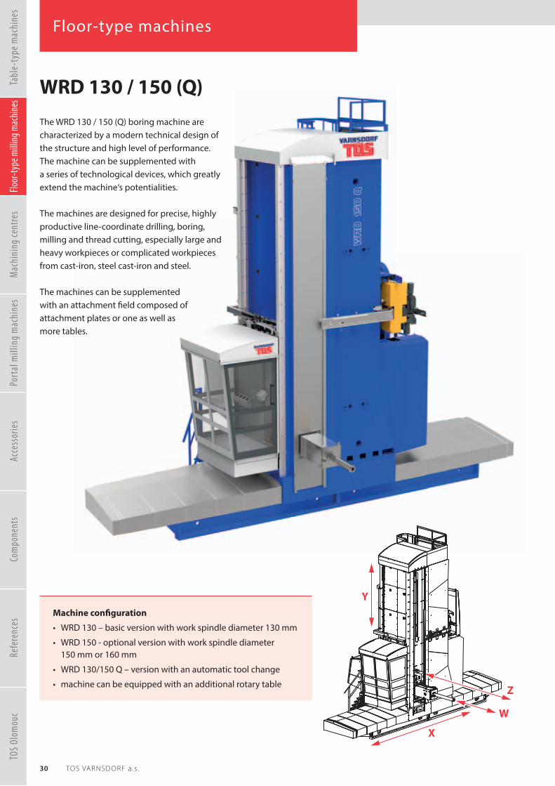
The WRD 130 / 150 (Q) boring machine are characterized by a modern technical design of the structure and high level of performance. The machine can be supplemented with a series of technological devices, which greatly extend the machine‘s potentialities.
The machines are designed for precise, highly productive line-coordinate drilling, boring, milling and thread cutting, especially large and heavy workpieces or complicated workpieces from cast-iron, steel cast-iron and steel.
The machines can be supplemented with an attachment fi eld composed of attachment plates or one as well as more tables.
WRD 130 / 150 (Q)
Y
W
Z
X
Machine confi guration
• WRD 130 – basic version with work spindle diameter 130 mm
• WRD 150 - optional version with work spindle diameter 150 mm or 160 mm
• WRD 130/150 Q – version with an automatic tool change
• machine can be equipped with an additional rotary table
TOS
Olom
ouc
Refe
renc
esTa
ble-
type
mac
hine
sFlo
or-ty
pe m
illin
g mac
hine
sM
achi
ning
cent
res
Port
al m
illin
g m
achi
nes
Acce
ssor
ies
Com
pone
nts

Floor-type machines
31Produc t ion programme
| Example of an application at a Finnish customer, where the machine was also adapted for the application of turning operations (special milling heads, extensions and carousel table).
TECHNICAL PARAMETERS
Headstock WRD 130 (Q) WRD 150 (Q)
Work spindle diameter mm(in)
130(5.1181)
150(5.9055)
160(6.2992)
RAM size mm (in) 450 x 450 (17.7165 x 17.7165)
Spindle taper ISO 50 / ISO 50 BIG+
Work spindle speed range 1/min 10 – 3 00010 – 2 500
(2 800)(10 – 1 500*)
10 – 2 400
Main motor power(at permanent operation of S1) kW (HP) 41 (55.7) 58 (78.9) 58 (78.9)
Max. output of main motor(at operation of S6-60% working hours) kW (HP) 46 (62.5) 65 (88.4) 65 (88.4)
Torque on spindle (S1)
Nm
(ft lb)
2 542
(1874.9)
2 437[2 465/4 870*]
1797.4[1818.1/3591.9*]
2 437
(1797.4)
Max. torque on spindle (S6 – 60%) Nm (ft lb) 3 152 (2324.8) 3 138 (2314.5) 3 138 (2314.5)
RAM stroke Z mm (in) 1 200 (47.2440)
Spindle stroke W mm (in) 700 (27.5590) 800 (31.4960) 800 (31.4960)
Column
Headstock vertical travel Y mm (in) 2 500 – 6 000 (98.4251 – 236.2204)in steps of 500 mm
Column longitudinal travel X mm (in) 5 000 – 27 000 (196.8503 – 1062.9921)in steps of 2 000 mm
Feeds
Range of feeds (working and rapid traverse) – X, Y, Z mm/min (ipm) 1 – 24 000 (0.0393 – 944.8818)
– W mm/min (ipm) 1 – 12 000 (0.0393 – 472.4409)
* an option suitable for drive of the facing head from the hollow spindle, Nmax=1 500 rpm, 2 465 Nm (1818.1 ft lb) on the work spindle, 4 870 Nm (3591.9 ft lb) on the hollow spindle
TOS
Olom
ouc
Refe
renc
esTa
ble-
type
mac
hine
sFlo
or-ty
pe m
illin
g mac
hine
sM
achi
ning
cent
res
Port
al m
illin
g m
achi
nes
Acce
ssor
ies
Com
pone
nts

Floor-type machines
32 TOS VARNSDORF a . s .
HeadstockThe basic body is a rigid casting from ductile iron; like other corresponding parts, they have an L shape, which creates a guiding rail for the RAM. The conception of this unit allows electro-magnetic compensation of the RAM drop during its extension in the Z axis (for more information see page 80 – Headstock).
Balancing of the headstock weight: The weight of the headstock is balanced by a telescopic cylinder from the hydropneumatic system. This system of headstock weight balancing demands minimum traverse forces, thus reducing power consumption during the machining process.
Compensation of the RAM dropping: This concept of compensating the RAM dropping is unique and patented. The concept of the whole headstock allows compensation of the slide plate drop during its extension in the Z axis. Dropping of the RAM is compensated by a special electromechanical system.
Guides of adjustable groups
Guides of all linear adjustable groups are rolling with pretensioning (guide of the headstock, the column rail, the slide plate guide), based on compact linear rolling guides.
Guides of the beds are covered by steel telescopic covers.
The guide on the column is protected by steel covers of the whole headstock movement area; on the face towards the workpiece by steel plates; on the operator‘s platform side, the whole area is covered by a fi xed covering; on the rear side by cover bellows.
ColumnThe column is designed as a rigid optimally dimensioned castings of gray iron. To column vertically moves the headstock with ram which is guided on two linear guide ways. On the column is fastened a ball screw, drive of Y-axis
and hydraulic cylinder for weight balancing of the headstock.
WRD 130 / 150 (Q)
a
ght of the headstock is balanced umatic system. This
mands wer s.
ng
heZ axis. Droppingctromechanical
TOS
Olom
ouc
Refe
renc
esTa
ble-
type
mac
hine
sFlo
or-ty
pe m
illin
g mac
hine
sM
achi
ning
cent
res
Port
al m
illin
g m
achi
nes
Acce
ssor
ies
Com
pone
nts

Floor-type machines
33Produc t ion programme
Drives of traverse units and fi xationAll 4 axes (X, Y, Z, W) are equipped with separate electric control servo drives. Transfer to straight motion of the Y, Z, W axes is achieved by ball screws with pre-tensioned nuts, movement of the X axis is provided by two electric servo motors with reducers.Prestress of pinions on outlets from reducers to the rack is achieved by engagement of drives in the „Master-Slave“ operation.
WRD 130 / 150 (Q)
| Machine handed over including the technologyof turning internal curved holes.
TOS
Olom
ouc
Refe
renc
esTa
ble-
type
mac
hine
sFlo
or-ty
pe m
illin
g mac
hine
sM
achi
ning
cent
res
Port
al m
illin
g m
achi
nes
Acce
ssor
ies
Com
pone
nts

Floor-type machines
34 TOS VARNSDORF a . s .
WRD 170 (Q)The WRD 170 (Q) machine is the largest and heaviest representative of fl oor-type machine with linear guide in the manufacturing portfolio of TOS VARNSDORF a.s. The machines are designed for precise line-coordinate drilling, boring, milling and thread cutting. WRD 170 (Q) is suitable for machining of box- and plate-type workpieces and complicated workpieces from cast-iron, steel cast-iron, steel and other machinable materials, mainly large as well as the largest sizes up to 150 tons.
The machine can be supplemented with a series of technological devices, which greatly extend the machine‘s fl exibility.
Y
W
X
Z
Machine confi guration
• WRD 170 – basic version with work spindle diameter 170 mm, optionaly 160 mm or 200 mm
• WRD 170 Q – version with an automatic tool change
• machine can be equipped with an additional rotary table
TOS
Olom
ouc
Refe
renc
esTa
ble-
type
mac
hine
sFlo
or-ty
pe m
illin
g mac
hine
sM
achi
ning
cent
res
Port
al m
illin
g m
achi
nes
Acce
ssor
ies
Com
pone
nts

Floor-type machines
35Produc t ion programme
| Example of propeller blade machining at a Russian customer, where the machine was equipped with an additional rotary table with load capacity of up to 130 tonnes (143.3 tons).
TECHNICAL PARAMETERS
Headstock
Work spindle diameter mm(in)
160(6.2992)
170(6.6929)
200(7.8740)
RAM size mm (in) 550 x 550 (21.6535 x 21.6535)
Spindle taper ISO 50 / ISO 50 BIG+
Work spindle speed range 1/min 10 – 2 200 10 - 1 800
Main motor power (at permanent operation of S1) kW (HP) 81 (110.1)
Max. output of main motor(at operation of S6-60% working hours) kW (HP) 88 (119.6)
Torque on spindle (S1) Nm (ft lb) 3 846 (2836.7)
Max. torque on spindle (S6 – 60%) Nm (ft lb) 4 800 (3540.3)
RAM stroke Z mm (in) 1 500 (59.0551)
Spindle stroke W mm (in) 1 000 (39.3700)
Column
Headstock vertical travel Y mm (in) 3 000 – 6 000 (118.1102 – 236.2204)in steps of 500 mm
Column longitudinal travel X mm (in) 5 000 – 29 000 (196.8503 – 1141.7322)in steps of 2 000 mm
Feeds
Range of feeds (working and rapid traverse) – X mm/min (ipm) 1 – 16 000 (0.0393 – 629.9212)
– Y, Z, W mm/min (ipm) 1 – 12 000 (0.0393 – 472.4409)
TOS
Olom
ouc
Refe
renc
esTa
ble-
type
mac
hine
sFlo
or-ty
pe m
illin
g mac
hine
sM
achi
ning
cent
res
Port
al m
illin
g m
achi
nes
Acce
ssor
ies
Com
pone
nts

Floor-type machines
36 TOS VARNSDORF a . s .
WRD 180 HThe largest, heaviest and most powerful, this is a representative of fully hydrostatic WRD 180 H machines. Thanks to excellent properties of hydrostatic guide, the machines are designed for the most demanding machining methods.
The WRD 180 H machines are designed for precise line-coordinate drilling, boring, milling and thread cutting. They are particularly suitable for machining of box- and plate-type workpieces and complicated workpieces from cast-iron, steel cast-iron, steel and other machinable materials, mainly large as well as the largest sizes up to 200 tons.
Y
X
WZ
Machine confi guration
• basic version with work spindle diameter 180 mm, optionaly 160 mm or 200 mm
• version with an automatic tool change
• machine can be equipped with an additional rotary table
TOS
Olom
ouc
Refe
renc
esTa
ble-
type
mac
hine
sFlo
or-ty
pe m
illin
g mac
hine
sM
achi
ning
cent
res
Port
al m
illin
g m
achi
nes
Acce
ssor
ies
Com
pone
nts

Floor-type machines
37Produc t ion programme
| Example of an application at an Indian customer, where the machine has been operating under demanding conditions for almost 5 years.
TECHNICAL PARAMETERS
Headstock
Work spindle diameter mm(in)
160(6.2992)
180(7.0866)
200(7.8740)
RAM size mm (in) 550 x 550 (21.6535 x 21.6535)
Spindle taper ISO 50 / ISO 50 BIG+
Work spindle speed range 1/min 10 – 2 200 10 – 2 200 10 – 2 000
Main motor power (at permanent operation of S1) kW (HP) 74 (100.6) 101 (137.3)
Torque on spindle (S1) Nm(ft lb)
6 820(5030.2)
11 165(8234.9)
13 927(10272)
RAM stroke Z mm (in) 1 600 (62.9921)
Spindle stroke W mm (in) 1 200 (47.2440)
Column
Headstock vertical travel Y mm (in) 3 000 – 6 000 (118.1102 – 236.2204)in steps of 500 mm
Column longitudinal travel X mm (in) 5 000 – 29 000 (196.8503 – 1141.7322)in steps of 1 000 mm
Feeds
Range of feeds (working and rapid traverse) – X, Y, Z, W mm/min (ipm) 1 – 20 000 (0.0393 – 787.4015)
TOS
Olom
ouc
Refe
renc
esTa
ble-
type
mac
hine
sFlo
or-ty
pe m
illin
g mac
hine
sM
achi
ning
cent
res
Port
al m
illin
g m
achi
nes
Acce
ssor
ies
Com
pone
nts

Floor-type machines
38 TOS VARNSDORF a . s .
Drives of Y, Z, W axes All 3 axes (Y, Z, W) are equipped with separate electric control servo drives. Traverse of the Y axis is achieved by a couple of electric servo motors. Transfer to straight motion of the W and Z axes is achieved by ball screws.The primary level of the Z and W axis drives is provided by cogwheel gears.
WRD 180 H
TOS
Olom
ouc
Refe
renc
esTa
ble-
type
mac
hine
sFlo
or-ty
pe m
illin
g mac
hine
sM
achi
ning
cent
res
Port
al m
illin
g m
achi
nes
Acce
ssor
ies
Com
pone
nts

Floor-type machines
39Produc t ion programme
WRD 180 H
HeadstockThe headstock housing is a rigid casting from high-quality grey cast iron, which is followed by other groups of the machine. The internal area of the casting has a horizontal square tunnel with precisely machined surfaces for guiding the RAM. The RAM housing is a prismatic casting from ductile cast iron with a hollow for housing the spindle in the machine‘s axis.
Balancing and compensation
Headstock compensation: By means of steel cables, which connect the headstock with a counter-weight.
Compensation of the column‘s deformation: By means of four rods passing through the rear wall of the column, which can be used for correction of the guide surfaces.
Thermal compensation: Special housing and cooling of bearings minimizes the amount of heat generated in the housing.
Compensation of deformation of the shape and incline of the RAM: Bending deformations of the RAM are prevented by four prestressing rods. The rods are pushed by hydraulic cylinders according to the RAM‘s position. The front hanger incorporates a hydraulic cylinder, which tensions cables according to the RAM‘s traverse.
Guides of adjustable groupsThe main support guide (X axis) consists of four sizeable bars inserted between the bed and the rails. Each bar incorporates 9 closed hydrostatic cells arranged in two separately powered sections. In total, the machine is carried by 36 closed cells.
Guide surfaces of the face, side and rear guides (the Y axis) are precisely ground. Guiding surfaces of the headstock housing consist of two rows of classic hydrostatic cells with separate pressure oil inlets.
Guide surfaces of the RAM (the Z axis) consist of sixteen bars lined by Biplast with hydrostatic chambers.
TOS
Olom
ouc
Refe
renc
esTa
ble-
type
mac
hine
sFlo
or-ty
pe m
illin
g mac
hine
sM
achi
ning
cent
res
Port
al m
illin
g m
achi
nes
Acce
ssor
ies
Com
pone
nts

Machining centres
40 TOS VARNSDORF a . s .
The WHT 110 (C), WHT 130 (C), machining centres create a modular kit, which can be used for assembling various versions of machines by selecting the modules and their sizes.
Basic modules: stand, table, basic headstocks with horizontal axes of spindles and special headstocks with milling heads and automatically controlled angular position of the spindle.
Supplementary modules: peripheries for automatic tool changer (ATC), automatic palette changer (APC), technological equipment and various machine coverings.
Machining centres WHT 110 (C), WHT 130 (C) are standardly equipped with complete covering, which prevents spraying of the cooling fl uid and scatter of chips.
TOS
Olom
ouc
Refe
renc
esTa
ble-
type
mac
hine
sFlo
or-ty
pe m
illin
g mac
hine
sM
achi
ning
cent
res
Port
al m
illin
g m
achi
nes
Acce
ssor
ies
Com
pone
nts

Machining centres
41Produc t ion programme
WHT 110 (C)
WHT 130 (C)
TOS
Olom
ouc
Refe
renc
esTa
ble-
type
mac
hine
sFlo
or-ty
pe m
illin
g mac
hine
sM
achi
ning
cent
res
Port
al m
illin
g m
achi
nes
Acce
ssor
ies
Com
pone
nts

Machining centres
42 TOS VARNSDORF a . s .
WHT 110 / 130 (C)The new high-performance WHT 110 / 130 is a horizontal machine tool suitable for the most demanding operations that require precise drilling, gear cutting, turning operations or milling.
WHT 110 / 130 machines may be designed as machining centres with a wide choice of accessories, e.g., automatic change of technological palettes, tools, special accessories, turning tables, and a range of other options that will satisfy the needs of the most demanding applications in areas such as the aerospace industry, power industry, mining industry, oil industry, and engineering industry.
These „multi-tasking“ machines are suitable both for single-piece and batch production.
Y
X
Z
W
BB
ools, special, and a range of other
e needs of the mostn areas such as the
industry, mining engineering industry.
hines are suitable batch production.
Machine confi guration
• WHT 110 / 130 S – so called „small“ machine version with a rotary table, rotation speed of work spindle up to 4 000 rpm
• WHT 110 / 130 L – so called „large“ machine version with a rotary table, rotation speed of work spindle up to 4 000 rpm
• WHT 110 / 130 C (S / L) – machining centre version (automatic palette and automatic special accessory change, fully covered) with work spindle revolutions up to 6,000 per minute for WHT 110, and up to 5,000 per minute for WHT 130
• WHT 110 machines are equipped with work spindle diameter 112 mm
• WHT 130 machines are equipped with work spindle diameter 130 mm
TOS
Olom
ouc
Refe
renc
esTa
ble-
type
mac
hine
sFlo
or-ty
pe m
illin
g mac
hine
sM
achi
ning
cent
res
Port
al m
illin
g m
achi
nes
Acce
ssor
ies
Com
pone
nts

Machining centres
43Produc t ion programme
2
1
3
4
5
6
7
Automatic replacement of special accessories with two storage sites and a cover plate.
8
Multiple machine utilizationThe machine can be used for milling, boring, gear cutting, turning operations, toothed gear manufacturing, and 5-axis machining.
Maximum machine automatizationAutomatic changing of the tools, special accessories, and technological palettes.
User friendlyMachine cover is adapted for easy and fast service access. Simply removable with magnet fi xed covers. The machining center is equipped with a rolling shutter along the Z axis.
Maximum machine dimensions: WHT 110: X – 3 000 mm, Y – 2 000 mm and Z – 2 500 mm(X – 118.1102 inch, Y – 78.7401 inch and Z – 98.4251 inch)WHT 130: X – 5 000 mm, Y – 3 000 mm and Z – 3 000 mm(X – 196.8503 inch, Y – 118.1102 inch and Z –118.1102 inch)
1 Linear guideways in X, Y and Z axes ensure a high accuracy and strength of the guide with a very low friction coeffi cient.
5
The basic parts of the frame (tables, palettes, longitudinal and transverse beds) are made of the highest quality grey cast iron of Czech origin.
6
High feed speeds in X, Y, Z axes: WHT 110: 25 000 mm/min and 40 000 mm/min
(984.2519 ipm and 1574.8031 ipm)WHT 130: 25 000 mm/min and 36 000 mm/min
(984.2519 ipm and 1417.3228 ipm)
7
8
Key Machine Features
Two types of central headstocks: WHT 110:4 000 rpm, 31 kW (42.1 HP), 1 205 Nm (888.8 ft lb)6 000 rpm, 31 kW (42.1 HP), 1 375 Nm (1014.1 ft lb)
WHT 130:4 000 rpm, 41 kW (55.7 HP), 3 200 Nm (2360.2 ft lb)5 000 rpm, 41 kW (55.7 HP), 1 718 Nm (1267.1 ft lb)
2
Temperature monitoring and compensation on the machine.
3
A wide choice of clamping devices. Rotary table capacity:WHT 110: up to 6 000 kg (13227.7 lbs)WHT 130: up to 20 000 kg (44092.5 lbs)
Up to 4 automatically changeable palettes.
4Carousel table:WHT 110: ∅ 1 600 mm (62.9921 inch), 400 rpmWHT 130: ∅ 2 000 mm (78.7401 inch), 250 rpm
TOS
Olom
ouc
Refe
renc
esTa
ble-
type
mac
hine
sFlo
or-ty
pe m
illin
g mac
hine
sM
achi
ning
cent
res
Port
al m
illin
g m
achi
nes
Acce
ssor
ies
Com
pone
nts

Machining centres
44 TOS VARNSDORF a . s .
TECHNICAL PARAMETERS – BASIC MACHINE PARAMETERS
Machine type WHT 110 S WHT 110 L WHT 110 SC WHT 110 LC
Headstock
Work spindle diameter mm (in) 112 (4.4094)
Spindle taper ISO 50
Work spindle speed range 1/min 10 – 4 000 10 – 6 000
Main motor power (S1) kW (HP) 31 (42.1) 31 (42.1)
Torque on spidle (S1) Nm (ft lb) 1 205 (888.8) 1 375 (1041.1)
Spindle stroke W mm (in) 650 (25.5905)
Column
Headstock vertical travel Y mm(in)
1 250(49.2125)
1 600(62.9921)
1 250(49.2125)
1 600(62.9921)
Longitudinal column adjustment Z mm(in)
1 500(59.0551)
2 500(98.4251)
1 500(59.0551)
2 500(98.4251)
Rotational table
Transverse table travel X mm(in)
1 500(59.0551)
2 500(98.4251)
1 500(59.0551)
2 500(98.4251)
Max. workpiece weight kg (lbs) 6 000 (13227.7)
Table clamping area mm(in)
1 250 x 1 250(49.2125 x 49.2125)
1 250 x 1 600(49.2125 x 62.9921)
1 250 x 1 250(49.2125 x 49.2125)
1 250 x 1 600(49.2125 x 62.9921)
Feeds
Range of feeds (working and rapid traverse) – X, Y, Z mm/min (ipm) 1 – 25 000 (0.0393 – 984.2519) 1 – 40 000 (0.0393 – 1574.8031)
– W mm/min (ipm) 1 – 20 000 (0.0393 – 787.4015)
– B 1/min 0.003 – 3
Basic machine equipment
– Chip conveyor • •
– Machine operator covering • •
– X and Z-axis covering •
– Modifi cation for the manual change of the manually adjusted miling heads •
– Remote diagnostics • •
– Complete machine enclosure (including the machine operator covering) •
– Automatic tool change ATC 40 •
– Modifi cation for the automatic change of the milling heads (UPPT) •
– CHZ tool cooling (via the external nozzles) •
Basic horizotal table type machines or centres are available in two versions – S (small) and L (large). Each version has its pre-defi ned parameters (see the table) and equipment. It is possible to only select from the range of options (e.g. milling heads, face plates, etc.).
WHT 110 (C)
TOS
Olom
ouc
Refe
renc
esTa
ble-
type
mac
hine
sFlo
or-ty
pe m
illin
g mac
hine
sM
achi
ning
cent
res
Port
al m
illin
g m
achi
nes
Acce
ssor
ies
Com
pone
nts

Machining centres
45Produc t ion programme
OPTIONAL MACHINE VERSIONS
Machine type WHT 110 WHT 110 C
Headstock
Work spindle diameter mm (in) 112 (4.4094)
Spindle taper ISO 50
Work spindle speed range 1/min 10 – 4 000 10 – 4 000 10 – 6 000
Main motor power (S1) kW (HP) 31 (42.1482)
Torque on spidle (S1) Nm (ft lb) 1 205 (888.8) 1 205 (888.8) 1 375 (1014.1)
Spindle stroke W mm (in) 650 (25.5905)
Column
Headstock vertical travel Y mm (in) 1 250, 1 600, 2 000* (49.2125, 62.9921, 78.7401*)
Longitudinal column adjustment Z mm (in) 1 500, 2 000, 2 500 (59.0551, 78.7401, 98.4251)
Rotational table
Transverse table travel X mm (in) 1 500, 2 000, 2 500, 3 000 (59.0551, 78.7401, 98.4251, 118.1102)
Max. workpiece weight kg (lbs) 6 000 (13227.7)
Table clamping area mm (in) 1 250 x 1 250, 1 250 x 1 600 (49.2125 x 49.2125, 49.2125 x 62.9921)
Turning table
Traverse table travel X mm (in) 1 500, 2 000, 2 500, 3 000 (59.0551, 78.7401, 98.4251, 118.1102)
Max. workpiece weight / max. palette load kg (lbs) 6 000 (13227.7) / 4 000 (8818.5)
Table clamping area mm (in) Ø 1 600 (62.9921)
Max. speed 1/min 400
Automatic palette change
Transverse table travel X mm (in) 1 500, 2 000, 2 500, 3 000 (59.0551, 78.7401, 98.4251, 118.1102)
Max. workpiece weight kg (lbs) 4 000 (8818.5)
Palette clamping area mm (in) 1 250 x 1 250, 1 250 x 1 600 (49.2125 x 49.2125 , 49.2125 x 62.9921)
Max. number of palettes pcs 2 to 4
Automatic tool change
Number of storage sites – chain type magazine pcs 40, 60, 80
Number of storage sites – rack type magazine pcs 100+
Max. tool diameter
– with fully loaded magazine mm (in) 125 (4.9212)
– with free neighbouring storage sites mm (in) 320 (11.8110)
Max. tool length mm (in) 500 (19.6850)
Tool change time s 8
* only for the WHT 110 horizontal boring machine
WHT 110 (C)
TOS
Olom
ouc
Refe
renc
esTa
ble-
type
mac
hine
sFlo
or-ty
pe m
illin
g mac
hine
sM
achi
ning
cent
res
Port
al m
illin
g m
achi
nes
Acce
ssor
ies
Com
pone
nts

Machining centres
46 TOS VARNSDORF a . s .
TECHNICAL PARAMETERS – BASIC MACHINE PARAMETERS
Machine type WHT 130 S WHT 130 L WHT 130 SC WHT 130 LC
Headstock
Work spindle diameter mm (in) 130 (5.1181)
Spindle taper ISO 50
Work spindle speed range 1/min 10 – 4 000 10 – 5 000
Main motor power (S1) kW (HP) 41 (55.7) 41 (55.7)
Torque on spidle (S1) Nm (ft lb) 3 200 (2360.2) 1 718 (1267.1)
Spindle stroke W mm (in) 800 (31.4960)
Column
Headstock vertical travel Y mm(in)
1 500(59.0551)
2 500(98.4251)
1 500(59.0551)
2 500(98.4251)
Longitudinal column adjustment Z mm(in)
2 000(78.7401)
3 000(118.1102)
2 000(78.7401)
3 000(118.1102)
Rotational table
Transverse table travel X mm(in)
2 000(78.7401)
4 000(157.4803)
2 000(78.7401)
4 000(157.4803)
Max. workpiece weight kg (lbs) 20 000 (44092.5)
Table clamping area mm(in)
1 800 x 1 800(70.8661 x 70.8661)
1 800 x 2 200(70.8661 x 86.6141)
1 800 x 1 800(70.8661 x 70.8661)
1 800 x 2 200(70.8661 x 86.6141)
Feeds
Range of feeds (working and rapid traverse) – X, Y, Z mm/min (ipm) 1 – 25 000 (0.0393 – 984.2519) 1 – 36 000 (0.0393 – 1417.3228)
– W mm/min (ipm) 1 – 20 000 (0.0393 – 787.4015)
– B 1/min 0.003 – 3
Basic machine equipment
– Chip conveyor • •
– Machine operator covering • •
– X and Z-axis covering •
– Modifi cation for the manual change of the manually adjusted miling heads •
– Remote diagnostics • •
– Complete machine enclosure (including the machine operator covering) •
– Automatic tool change ATC 40 •
– Modifi cation for the automatic change of the milling heads (UPPT) •
– CHZ tool cooling (via the external nozzles) •
Basic horizotal table type machines or centres are available in two versions – S (small) and L (large). Each version has its pre-defi ned parameters (see the table) and equipment. It is possible to only select from the range of options (e.g. milling heads, face plates, etc.).
WHT 130 (C)
TOS
Olom
ouc
Refe
renc
esTa
ble-
type
mac
hine
sFlo
or-ty
pe m
illin
g mac
hine
sM
achi
ning
cent
res
Port
al m
illin
g m
achi
nes
Acce
ssor
ies
Com
pone
nts

Machining centres
47Produc t ion programme
OPTIONAL MACHINE VERSIONS
Machine type WHT 130 WHT 130 C
Headstock
Work spindle diameter mm (in) 130 (5.1181)
Spindle taper ISO 50
Work spindle speed range 1/min 10 – 4 000 10 – 4 000 10 – 5 000
Main motor power (S1) kW (HP) 41 (55.7)
Torque on spidle (S1) Nm (ft lb) 3 200 (2360.2) 3 200 (2360.2) 1 718 (1267.1)
Spindle stroke W mm (in) 800 (31.4960)
Column
Headstock vertical travel Y mm (in) 1 500, 2 000, 2 500, 3 000* (59.0551, 78.7401, 98.4251, 118.1102*)
Longitudinal column adjustment Z mm (in) 1 500, 2 000, 2 500, 3 000 (59.0551, 78.7401, 98.4251, 118.1102)
Rotational table
Transverse table travel X mm (in) 2 000, 3 000, 4 000, 5 000* (78.7401, 118.1102, 157.4803, 196.8503*)
Max. workpiece weight kg (lbs) 20 000 (44092.5)
Table clamping area
mm
(in)
1 800 x 1 800, 1 800 x 2 200,1 800 x 2 500, 2 000 x 3 000, 2 500 x 3 000
70.8661 x 70.8661, 70.8661 x 86.6141, 70.8661 x 98.4251, 78.7401 x 118.1102, 98.4251 x 118.1102
Turning table
Traverse table travel X mm (in) 2 000, 3 000, 4 000, 5 000* (78.7401, 118.1102, 157.4703, 196.8503*)
Max. workpiece weight / max. palette load kg (lbs) 10 000 (22046.2)
Table clamping area mm (in) Ø 2 000 (78.7401)
Max. speed 1/min 250
Automatic palette change
Transverse table travel X mm (in) 2 000, 3 000, 4 000, 5 000* (78.7401, 118.1102, 157.4803, 196.8503*)
Max. workpiece weight kg (lbs) 16 000 (35274)
Palette clamping area mm (in) 1 600 x 1 600, 1 600 x 2 000 (62.9921 x 62.9921, 62.9921 x 78.7401)Ø 2 000 (78.7401)
Max. number of palettes pcs 2 to 4
Automatic tool change
Number of storage sites – chain type magazine pcs 40, 60, 80
Number of storage sites – rack type magazine pcs 100+
Max. tool diameter
– with fully loaded magazine mm (in) 125 (4.9212)
– with free neighbouring storage sites mm (in) 320 (12.5984)
Max. tool length mm (in) 500 (19.6850)
Tool change time s 16
* only for the WHT 130 horizontal boring machine
WHT 130 (C)
TOS
Olom
ouc
Refe
renc
esTa
ble-
type
mac
hine
sFlo
or-ty
pe m
illin
g mac
hine
sM
achi
ning
cent
res
Port
al m
illin
g m
achi
nes
Acce
ssor
ies
Com
pone
nts

Machining centres
48 TOS VARNSDORF a . s .
Machhine frameBasic heavy machine parts (tables, palettes, longitudinal and transverse
beds) are casted from grey iron. The machine column is designed as a twin-shell casting also made of grey iron with an optimised
structure. The high rigidity of the whole machine structure is ensured by joining the X and Z axes together
Machhine frameBasic heavy m
beds) area tw
CounterbalancingThe headstock weight is compensated hydromechanically (using a hydraulic cylinder) with use of a standalone hydraulic power unit.
WHT 110/130 (C)
TOS
Olom
ouc
Refe
renc
esTa
ble-
type
mac
hine
sFlo
or-ty
pe m
illin
g mac
hine
sM
achi
ning
cent
res
Port
al m
illin
g m
achi
nes
Acce
ssor
ies
Com
pone
nts

Machining centres
49Produc t ion programme
Automatic change of technological palettesConceptually, the palette change equipment is based on the automatic change of the technological palettes between the stationary stowage stations and the palette clamping base on the machine. When 2-pallet system is used, pallets are changed directly between storage stations and the machine. In case of 3 or 4-pallet system are pallets changed using a rotary manipulator.
WHT 110/130 (C)
Central headstockThe WHT 110/130 machine is equipped with a central core headstock. This solution is optimum in respect to a uniform thermal and mechanical loading of the machine frame. The spindle is driven from a standardised gear case connected to the main motor. Two mechanical spindle speed ranges are shifted electromechanically. The travelling spindle is sliding in the hollow spindle.
Machine controlsThe machine controls are located on the main control panel: It is mounted on a rotary arm that can be adjusted vertically in the operator’s position.
Chip conveyorThe chip conveyor is provided with each version of the machine as a standard part of delivery.
X, Y, Z and W axis drivesThe linear axes are driven by standalone actuators with embedded belt gears and ball screws with a large pitch. The X and Z axes are driven from the ball screws with rotating ball nuts. The Y and W axis are driven from the rotating ball screws.
Travelling group guidesAll the linear trvelling machine groups in the X, Y and Z axes are guided in
the pre-loaded compact rolling linear guideways. The travelling spindle is sliding in the hollow spindle. The table is supported on a large radial-thrust cylindrical roller
bearing with high capacity and rigidity.
X, Y, The lball srota
TTO
S Ol
omou
cRe
fere
nces
Tabl
e-ty
pe m
achi
nes
Floor
-type
mill
ing m
achi
nes
Mac
hini
ng ce
ntre
sPo
rtal
mill
ing
mac
hine
sAc
cess
orie
sCo
mpo
nent
s

Machining centres
50 TOS VARNSDORF a . s .
Optional version
Covering basic version: the bed, column and operator‘s place covers
Protective covering of the workspace: the bed, colum and operator‘s position covers and workspace protective covering that includes a removable sheet metal cab
Machine covers with the automatic tool change: bed, column, operator‘s place and automatic tool change
covers
„C“ cover: the beds, the column, the machine operator‘s station, and the workspace covering
along the X and Z axes
A complete covering of the machining centre. In addition to the covering, a chip washing option or the workspace exhaustion can be specifi ed.
Horizontal machining centre
Horizontal machine tool
WHT 110 / 130 (C)
Machine covering
TOS
Olom
ouc
Refe
renc
esTa
ble-
type
mac
hine
sFlo
or-ty
pe m
illin
g mac
hine
sM
achi
ning
cent
res
Port
al m
illin
g m
achi
nes
Acce
ssor
ies
Com
pone
nts
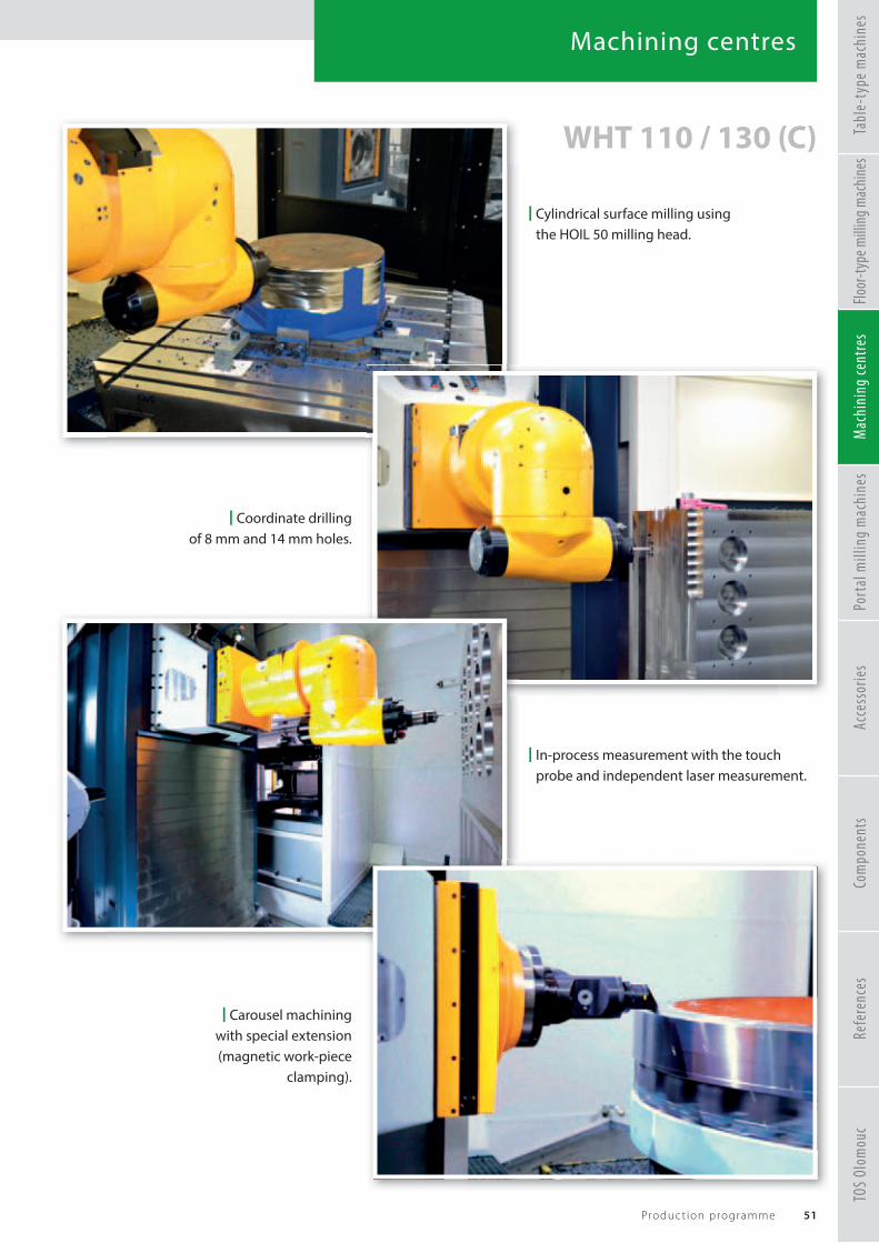
Machining centres
51Produc t ion programme
WHT 110 / 130 (C)
| Cylindrical surface milling using the HOIL 50 milling head.
| Coordinate drilling of 8 mm and 14 mm holes.
| Carousel machining with special extension (magnetic work-piece
clamping).
| In-process measurement with the touch probe and independent laser measurement.
TOS
Olom
ouc
Refe
renc
esTa
ble-
type
mac
hine
sFlo
or-ty
pe m
illin
g mac
hine
sM
achi
ning
cent
res
Port
al m
illin
g m
achi
nes
Acce
ssor
ies
Com
pone
nts

Portal milling machines
Portal milling machine WVM 2600 / 3600 T
52 TOS VARNSDORF a . s .
Vertical machining centers of the WVM 2600 / 3600 T series are designed as a unifi ed series of machines for universal machining of steel and cast iron parts especially in the general engineering segment.
Thanks to its unique construction of a solid portal with a mobile headstock (Y), a vertically traveling RAM (Z) and a sliding table (X), the machines stand out with high precision and stiff ness.
The high installed power of the machine (53 kW) is designed especially for power and productive machining.
Machines can be equipped with various types of milling heads, which are automatically installed and allow to further extend the technological possibilities of the machine. Machines can be supplemented by other types of accessories to increase machine effi ciency, such as cooling system, machine monitoring, or tool change system.
Machine control is provided from the operator platform installed on the side of one of the columns, and the machines can be equipped with a cover around the table axis (X) to minimize fl ying of chips and splashing of cutting fl uid into the environment.
| Basic machine designwithout covering.
TOS
Olom
ouc
Refe
renc
esTa
ble-
type
mac
hine
sFlo
or-ty
pe m
illin
g mac
hine
sM
achi
ning
cent
res
Port
al m
illin
g m
achi
nes
Acce
ssor
ies
Com
pone
nts

Portal milling machines
53Produc t ion programme
| Complete view of the machine.There is horizontaly moveableheadstock with traveling RAM.
| A view of the work area of the machine where the horizontal
surface is milled.
| Detail of integrated orthogonal milling head SEMPUCO.
| Detail of automatic tool change system, which changes tools to the horizontaly positioned milling head.
WVM 2600 / 3600 T
TOS
Olom
ouc
Refe
renc
esTa
ble-
type
mac
hine
sFlo
or-ty
pe m
illin
g mac
hine
sM
achi
ning
cent
res
Port
al m
illin
g m
achi
nes
Acce
ssor
ies
Com
pone
nts

Portal milling machines
54 TOS VARNSDORF a . s .
WVM 2600 / 3600 T| Basic machine design
with covering.
Machine confi guration
• machine with integrated orthogonal milling head
• machine equiped with an automatic tool change
• machine equiped with an automatic special accessory change
• wide range of work table designs
| Controlled axes schema
TOS
Olom
ouc
Refe
renc
esTa
ble-
type
mac
hine
sFlo
or-ty
pe m
illin
g mac
hine
sM
achi
ning
cent
res
Port
al m
illin
g m
achi
nes
Acce
ssor
ies
Com
pone
nts

Portal milling machines
55Produc t ion programme
TECHNICAL PARAMETERS
Headstock WVM 2600 T WVM 3600 T
Termination of RAM by an interface for application of technological accessories
RAM size mm (in) 500 x 500 (19.6850 x 19.6850)
Main motor speed range 1/min 10 – 5 000
Main motor power (S1) kW (HP) 53 (72.1)
Torque on driving shaft (S1) Nm (ft lb) 1 375 (1014.1)
Ram stroke Z mm (in) 1500 (59.0551)
Headstock horizontal transverse traverse Y mm (in) 3 200 (125.9842) 4 200 (165.3543)
– when AVTP system is applied mm (in) 4 300 (169.2913) 5 300 (208.6614)
Headstock with the integrated milling head
Spindle tool hollow ISO 50
Max. spindle speed 1/min 5 000
Max. transmitted power kW (HP) 40 (54.4)
Max. spindle torque Nm (ft lb) 1 200 (885.1)
Basic increment for positioning both dividing planes ° 1
Range of rotation in the A axis ° ±180
Range of rotation in the C axis ° ±180
Work table for WVM 2600 T
Table longitudinal traverse X mm(in)
4 000, 5 000, 6 000, 7 000, 9 000(157.4803, 196.8503, 236.2204, 275.5905, 354.3307)
Distance between the columns mm (in) 2 600 (102.3622)
Width of table clamping area mm (in) 2000 (78.7401)
Length of table clamping area mm(in)
3000(118.1102)
4000(157.4803)
5000(196.8503)
6000(236.2204)
8000(314.9606)
Max. workpiece weight tonnes (tons) 20 24 28 32 40
Size of the clamping T-slots mm (in) 28H8 (1.1023)
Spacing of the clamping T-slots mm (in) 250 (9.8425)
Work table for WVM 3600 T
Table longitudinal traverse X mm(in)
4 000, 5 000, 6 000, 7 000, 9 000, 11 000(157.4803, 196.8503, 236.2204, 275.5905, 354.3307, 433.0708)
Distance between the columns mm (in) 3 600 (141.7322)
Width of table clamping area mm (in) 3 000 (18.1102)
Length of table clamping area mm(in)
Max. workpiece weight tonnes (tons)
Size of the clamping T-slots mm (in) 28H8 (1.1023)
Spacing of the clamping T-slots mm (in) 250 (9.8425)
Travels
Range of traverse (working and rapid travel) – X, Y, Z mm/min (ipm) 1 – 25 000 (0.0393 – 984.2519)
Max. traverse forces in the X, Y, Z, W axes kN (lbf ) 20 (4496.2)
Automatic tool change
Number of storage sites – chain type magazine pcs 60
Number of storage sites – meander type magazine pcs 80, 120
Tool change time s 20
3000(118.1102)
4000(157.4803)
5000(196.8503)
6000(236.2204)
8000(314.9606)
10 000(393.7007)
20 (22) 24 (26.5) 28 (30.9) 32 (35.3) 40 (44.1) 40 (44.1)
TOS
Olom
ouc
Refe
renc
esTa
ble-
type
mac
hine
sFlo
or-ty
pe m
illin
g mac
hine
sM
achi
ning
cent
res
Port
al m
illin
g m
achi
nes
Acce
ssor
ies
Com
pone
nts

Portal milling machines
56 TOS VARNSDORF a . s .
WVM 2600 / 3600 T
X, Y, Z axis drivesDrives of all the linear axes are fi tted with separate electric re-gulating actuators. The Z axis is driven via a ball screw with pre-loaded nuts. The X and Y axes are driven via a rack and two pre-loaded pinion gears controlled by a “Master-Slave” system.
Machine frame The frame consists of a bed with a traversing table, above which a transversely housed headstock moves on the crossbeam that is attached to two vertical stands. All the frame parts are designed as rigid and optimally sized castings.
Guiding of movable groups Linearly traversing groups of the X, Y, and Z machine axes are guided using linear roller guides. Bed guideways are covered with telescopic steel covers. A crossbeam guideway is protected by folded fabric bellows.
TOS
Olom
ouc
Refe
renc
esTa
ble-
type
mac
hine
sFlo
or-ty
pe m
illin
g mac
hine
sM
achi
ning
cent
res
Port
al m
illin
g m
achi
nes
Acce
ssor
ies
Com
pone
nts

Portal milling machines
57Produc t ion programme
WVM 2600 / 3600 T
Headstock The basic body is a rigid casting of ductile cast iron, in which a horizontally traversing RAM made of cast steel is mounted. The main spindle rotation drive is transmitted from a powerful electric drive via a robust two-speed gearbox with automatic shifting.
Automatic tool change It consists of a chain tool magazine, a manipulator gui-deway on the stand, and a custom manipulator that allows the tool to be exchanged in the milling head.
BalancingRam weight is compensated hydro-mechanically (with a hydraulic cylinder) using a standalone hydraulic unit.
HeadThe bRAM a pow
AutIt cdewthe
TOS
Olom
ouc
Refe
renc
esTa
ble-
type
mac
hine
sFlo
or-ty
pe m
illin
g mac
hine
sM
achi
ning
cent
res
Port
al m
illin
g m
achi
nes
Acce
ssor
ies
Com
pone
nts

Portal milling machines
58 TOS VARNSDORF a . s .
WVM 2600 / 3600 T | The fi rst implementation of the WVM 2600 T at a Czech customer.
TOS
Olom
ouc
Refe
renc
esTa
ble-
type
mac
hine
sFlo
or-ty
pe m
illin
g mac
hine
sM
achi
ning
cent
res
Port
al m
illin
g m
achi
nes
Acce
ssor
ies
Com
pone
nts

Portal milling machines
59Produc t ion programme
WVM 2600 / 3600 T
X = 4 500 mm (177.1653 inch)Y = 3 200 mm (125.9842 inch)Z = 1 500 mm (59.0551 inch)
ATC = 60Work table = 4 000 x 2 000 mm (20 tonnes)
157.4803 x 78.7401 inch (22 tons)
TOS
Olom
ouc
Refe
renc
esTa
ble-
type
mac
hine
sFlo
or-ty
pe m
illin
g mac
hine
sM
achi
ning
cent
res
Port
al m
illin
g m
achi
nes
Acce
ssor
ies
Com
pone
nts

Accessories
60 TOS VARNSDORF a . s .
Rotating tablesThe additional work tables with horizontal adjustment are designed as special accessory for horizontal fl oor-type boring machines (the WRD series) and adaptable for machines by other manufacturers.
The additional turning tables with horizontal adjustment consist of a rigid bed on the top of which a table with horizontal attachment area rotationally housed on the rail usually travels. The CNC-controlled table is used for attachment and positioning of workpieces on the technological sites and can be multiply applied. It allows interpolation in the longitudinal axis, in the rotational axis and both axes simultaneously with other continuously controlled axes of the corresponding machine.
The rotational axis can be used classically for positioning or machining during the table‘s rotation when the main cutting motion is performed by the rotating tool attached in the work spindle of the machine.
The control of the supplementary tables and the servo drives are integrated in the CNC control, operation and
electrical equipment of the machine. The position
in the coordinates is programmed with the increment of 0.001°.
The B coordinate is driven by the „Master-Slave“ system,
which incorporates two separate servo drives and their control.
| Table control as a full-fl edged CNC axis. In this case used for machining the inner surface of curved armature.
TOS
Olom
ouc
Refe
renc
esTa
ble-
type
mac
hine
sFlo
or-ty
pe m
illin
g mac
hine
sM
achi
ning
cent
res
Port
al m
illin
g m
achi
nes
Acce
ssor
ies
Com
pone
nts

Accessories
61Produc t ion programme
TECHNICAL PARAMETERS
Additional rotating table S 5 S 10 S 20
Max. workpiece weight kg (lbs) 5 000 (11023.1) 10 000 (22046.2) 20 000 (44092.5)
Table clamping area
mm
(in)
1 000 x 1 250
(39.3700 x 49.2125)
1 250 x 1 2501 250 x 1 600
49.2125 x 49.212549.2125 x 62.9921
1 800 x 1 8001 800 x 2 2001 800 x 2 5002 500 x 2 500
70.8661 x 70.866170.8661 x 86.614170.8661 x 98.425198.4251 x 98.4251
Size of clamping T-slots mm (in) 28H8 (1.1023)
Size of table adjustment
mm
(in)
0, 1 600, 2 000
(0, 62.9921, 78.7401)
0, 1 500, 2 000, 3 000
0, 59.0551, 78.7401, 118.1102
0, 1 500, 2 000, 3 000, 4 000
0, 59.0551, 78.7401, 118.1102, 157.4803
Feed range – V mm/min(ipm)
1 – 20 000(0.0393 – 787.4015)
1 – 15 000(0.0393 – 590.5511)
Feed range – B 1/min 0.003 – 1.5
Rapid traverse – V mm/min (ipm) 30 000 (1181.1023) 24 000 (944.8818) 20 000 (787.4015)
Rapid traverse – B 1/min 7 5 3.5
Min. programmable positioning increment– in the V coordinate– in the B coordinate
mm (in)°
0,001 (0.0000393)0,001
Additional rotating table S 16 S 30 S 50 S 80
Max. workpiece weight kg (lbs) 16 000 (35274) 30 000 (66138.7) 50 000 (110231.1) 80 000 (176369.8)
Table clamping area
mm
(in)
1 800 x 2 240 2 000 x 2 500
70.8661 x 88.188978.7401 x 98.4251
2 000 x 2 0002 000 x 2 5002 500 x 3 000
78.7401 x 78.740178.7401 x 98.4251
98.4251 x 118.1102
3 000 x 3 000 3 000 x 3 5003 000 x 4 000
118.1102 x 137.7952 118.1102 x 118.1102118.1102 x 157.4803
3 500 x 3 5003 500 x 4 0004 000 x 4 0004 000 x 4 500
137.7952 x 137.7952137.7952 x 157.4803157.4803 x 157.4803157.4803 x 177.1653
Size of clamping T-slots mm (in) 28H8 (1.1023)
Size of table adjustment
mm
(in)
0, 1 400, 1 800
(0, 55.1181, 70.8661)
0, 1 300, 1 800,2 500, 3 000, 3 5000, 51.1811, 70.8661, 98.4251, 118.1102,
137.7952
0, 1 500, 2 000, 2 500, 3 000, 3 5000, 59.0551, 78.7401, 98.4251, 118.1102,
137.7952
2 000, 3 000, 4 000
78.7401, 118.1102, 157.4803
Feed range – V mm/min(ipm)
1 – 5 000(0.0393 – 196.8503)
1 – 8 000(0.0393 – 314.9606)
1 – 6 000 (0.0393 – 236.2204)
Feed range – B 1/min 0.003 – 1 0.003 – 1.5 0.002 – 1
Rapid traverse – V mm/min (ipm) 10 000 (393.7007) 15 000 (590.5511) 15 000 (590.5511) 13 700 (539.3700)
Rapid traverse – B 1/min 1.75 3 2.5 1.6
Min. programmable positioning increment– in the V coordinate– in the B coordinate
mm (in)°
0,001 (0.0000393)0,001
TOS
Olom
ouc
Refe
renc
esTa
ble-
type
mac
hine
sFlo
or-ty
pe m
illin
g mac
hine
sM
achi
ning
cent
res
Port
al m
illin
g m
achi
nes
Acce
ssor
ies
Com
pone
nts

Accessories
62 TOS VARNSDORF a . s .
Automatic palette changer (APC)The APC automatic palette changer replaces the table; it is suitable for quick replacement of the workpiece by preparation and setting of another workpiece during machining of the fi rst workpiece. This signifi cantly speeds up the machining.
The palette change equipment is based on automatic replacement of technological palettes between stationary stacking stations equipped with manipulators and the palette attachment base the on the machine. The palette is locked on the attachment base by centring pins and fi xed by disc springs, release of the palette is hydraulic.
The automatic palette changer is designed for machines WHN 110/130, WHN(Q) 13/15, WHR 13 (Q), MAXIMA I / II, WHT 110 (C) and WHT 130 (C).
TECHNICAL PARAMETERS
Type marking of the palettes P 4 P 5 P 8 P 16
Palette clamping area
mm
(in)
1 250 x 1 2501 250 x 1 600
49.2125 x 49.2125,49.2125 x 62.9921
1 250 x 1 4001 250 x 1 600
49.2125 x 49.2125,49.2125 x 62.9921
1 600 x 1 800
(62.9921 x 70.8661)
1 600 x 1 6001 600 x 2 0001 800 x 1 8001 800 x 2 2001 800 x 2 500
62.9921 x 62.992162.9921 x 78.740170.8661 x 70.866170.8661 x 86.614170.8661 x 98.4251
Max. workpiece weight kg (lbs) 4 000 (8818.5) 5 000 (11023.1) 8 000 (17637) 16 000 (35274)
Size of clamping T-slots mm (in) 22H8 (0.8661)
Size of adjustment
mm
(in)
1 500, 2 000,2 500, 3 000
59.0551, 78.7401, 98.4251, 118.1102
1 600, 2 000,2 500
62.9921, 78.7401, 98.4251
2 000, 2 500, 3 000, 3 500, 4 000
78.7401, 98.4251, 118.1102, 137.7952,
157.4803
3 000, 3 500, 4 000
118.1102, 137.7952, 157.4803
Number of palettes in the system pcs 2 – 4 2 2 – 4 2
Palette change time s 150 85 85 120
TOS
Olom
ouc
Refe
renc
esTa
ble-
type
mac
hine
sFlo
or-ty
pe m
illin
g mac
hine
sM
achi
ning
cent
res
Port
al m
illin
g m
achi
nes
Acce
ssor
ies
Com
pone
nts

THE FACTORY AUTOMATION COMPANY
FANUC offers the widest range of CNC systems in the industry from best value controllers with powerful functionality to highperformance control systems for complex machines – fast programming and easy to use. For the highest quality and short processing times. Ask us: our dedicated support team is available any time.WWW.FANUC.CZ
Highest qualityshortest processing time
CNC systems, CNC machines and Industrial robots
designed and built in Japan
NEW 30i-B Plus
series
MAD-00401-FA-General_CNC_AD.indd 1 20-05-2020 15:41:14

Accessories
64 TOS VARNSDORF a . s .
Automatic tool change (ATC)It consists of a chain meander- or rack-type magazine, a manipulator path on the column or rack and the actual manipulator equipped with a rotating two-arm hand. The tool detection is based on a coded bed in the magazine.
The equipment allows automatic change of tools for milling heads in the horizontal direction.
It is possible to choose a variable number of storage sites on customer demand.
Robot application Four-motor tilting tool manipulator
Three-motor untilting tool manipulator
Meander magazine Chain magazine Rack magazine
TOS
Olom
ouc
Refe
renc
esTa
ble-
type
mac
hine
sFlo
or-ty
pe m
illin
g mac
hine
sM
achi
ning
cent
res
Port
al m
illin
g m
achi
nes
Acce
ssor
ies
Com
pone
nts

Accessories
65Produc t ion programme
TECHNICAL PARAMETERS
TABLE-TYPE MACHINES FLOOR-TYPE MACHINES
Number of storage sites in the magazine pcs 40, 60, 80, 120
Pitch of storage sites in the magazine mm (in) 130 (5.1181)
Max. tool diameter– with fully loaded magazine– with free neighbouring storage sites
mm (in)mm (in)
125 (4.9212)320 (12.5984)
Max. diameter of a special fl at tool mm (in) 390 (15.3543)
Max. tool length mm (in) 500 (19.6850)
Max. tool weight kg (lbs) 25 (55.1)
Max. tool weight in the chain kg (lbs) 1 000 (2204.6)
Max. tool imbalance in the chain kg (lbs) 150 (330.7)
Tool change time (tool-tool) s 15 20
MACHINING CENTRES PORTAL MILLING MACHINES
WHT 110 WHT 130 WVM 2600 / 3600 T
Number of storage sitesin the magazine 40, 60, 80, 100+ 40, 60, 80, 100, 120
Pitch of storage sites in the magazine mm (in) 130 (5.1181)
Max. tool diameter– with fully loaded magazine– with free neighbouring storage sites
mm (in)mm (in)
125 (4.9212)320 (12.5984)
Max. tool length mm (in) 500 (19.6850)
Max. tool weight kg (lbs) 25 (55.1)
Max. tool weight in the chain kg (lbs) 1 000 (2204.6)
Tool change time (tool-tool) s 8 16 20
| Automatic tool change to the milling head by using a four-motor tilting manipulator.
TOS
Olom
ouc
Refe
renc
esTa
ble-
type
mac
hine
sFlo
or-ty
pe m
illin
g mac
hine
sM
achi
ning
cent
res
Port
al m
illin
g m
achi
nes
Acce
ssor
ies
Com
pone
nts

Accessories
66 TOS VARNSDORF a . s .
Milling heads
Hand-adjustable heads
FP 40 / 50The milling machine serves as an accessory to the WH(Q) 10 CNC and WHN(Q) 13 CNC machines.It is suitable for milling fl at surfaces or planing of faces. Manual attachment of the tool and the milling instrument on the machine.
• number of axes: 1• speed (min-1): 600• output (kW): 10
(HP): 13.6• moment (Nm): 1 000
(ft lb): 737.6• weight (kg): 140
(lbs): 308.6• positioning: manual
UFP 40 / 50Used as an accessory for the WH(Q) 10 CNC and WHN(Q) 13 CNC machines. It is suitable for machining variously inclined surfaces parallel with one of the machine‘s main axes. Manual attachment of the tool and the milling instrument on the machine.
• number of axes: 2• speed (min-1): 600• output (kW): 10
(HP): 13.6• moment (Nm): 1 000
(ft lb): 737.6• weight (kg): 200
(lbs): 440.9• positioning: manual
HUR 50Univeral manual milling head HUR 50 consists of three compactly joined basic parts, which can be mutually rotated to reach the required general position of the work spindle head. The adjustment angles have the increment of 0.1°on circumferential scales fi tted with nonius.For adjustment of parts of the head into 8 basic positions (4x90° in the vertical separating plane, 2x180° in the inclined separating plane).
• number of axes: 2• speed (min-1): 3 000• output (kW): 20
(HP): 27.2• moment (Nm): 1 000
(ft lb): 737.6• weight (kg): 330
(lbs): 727.5• positioning: manual
HPR 50Right-angle manual milling head HPR 50 consists of two compactly joined basic parts, which can be mutually rotated to reach the required position of the work spindle head. The adjustment angles have the increment of 0.1°on circumferential scales fi tted with nonius.
• number of axes: 1• speed (min-1): 3 000• output (kW): 25
(HP): 34• moment (Nm): 1 200
(ft lb): 885.1• weight (kg): 200
(lbs): 440.9• positioning: manual
TOS
Olom
ouc
Refe
renc
esTa
ble-
type
mac
hine
sFlo
or-ty
pe m
illin
g mac
hine
sM
achi
ning
cent
res
Port
al m
illin
g m
achi
nes
Acce
ssor
ies
Com
pone
nts

Accessories
67Produc t ion programme
Automatically positioning heads
HPI 50The head consists of two compactly connected basic parts enabling their mutual rotation to reach required general position of working spindle of the head. Moveable part of the head is in dividing area equipped with exact toothed Hirth rim, which division is in accordance with basic positioning increment in which are fi xed the moveable parts of the head. Positioning of rotation part is ensured by mechanical drive from the machine spindle and gives the possibility for positioning +,-185°.
• number of axes: 1• speed (min-1): 3 500• output (kW): 37
(HP): 50.3• moment (Nm): 1 200
(ft lb): 885.1• weight (kg): 600
(lbs): 1322.8• positioning: index 1°
00
320085.1
.8x 1°
HUI 50The HUI 50 milling head consists of three compact sections that may be swiveled against each other so as the required angular position of the head’s spindle may be set. The joint planes of both theswiveling sections of the head are provided with highly precise Hirth-toothed rims.
• number of axes: 2• speed (min-1): 3 000• output (kW): 32
(HP): 43.5• moment (Nm): 1 000
(ft lb): 737.6• weight (kg): 440
(lbs): 970• positioning: index 2.5°°
HUIL 50The universal automatically indexed milling head HUIL 50 is based on the same concept as the milling head HUI 50. However, this head design has more precise positioning and allows a signifi cantly higher speed. The head is equipped with cooling channels to ensure even cooling of the head.
• number of axes: 2• speed (min-1): 5 000• output (kW): 25
(HP): 34• moment (Nm): 1 000
(ft lb): 737.6• weight (kg): 600
(lbs): 1322.8• positioning: index 1°
HUIT 50The universal automatically indexed milling head HUIT 50 is based on the same concept as the milling head HUIL 50.However, this head design is signifi cantly more powerful and has higher torque.
• number of axes: 2• speed (min-1): 3 000• output (kW): 35
(HP): 47.6• moment (Nm): 1 400
(ft lb): 1032.6• weight (kg): 710
(lbs): 1565.3• positioning: index 1°
TOS
Olom
ouc
Refe
renc
esTa
ble-
type
mac
hine
sFlo
or-ty
pe m
illin
g mac
hine
sM
achi
ning
cent
res
Port
al m
illin
g m
achi
nes
Acce
ssor
ies
Com
pone
nts

Accessories
68 TOS VARNSDORF a . s .
Milling heads
Automatically positioning heads
HOI 50Orthogonal automatically indexed milling head HOI 50 consists of three compactly joined basic parts, which can be mutually rotated in the A and C axes. The rotational parts are positioned by a mechanical drive from the machine‘s spindle, which allows positioning ±180° in axis C and ±120° in axis A.
• number of axes: 2• speed (min-1): 3 500• output (kW): 37
(HP): 50.3• moment (Nm): 1 200
(ft lb): 885.1• weight (kg): 1 100
(lbs): 2425.1• positioning: index 1°
HUFT 50Univeral continuoiusly positioned milling head HUFT 50 is based on the same concept as the milling head HUF 50.However, this head design is signifi cantly more powerful and has higher torque. The head is equipped with cooling channels to ensure even cooling of the head.
• number of axes: 2• speed (min-1): 3 000• output (kW): 35
(HP): 47.6• moment (Nm): 1 400
(ft lb): 1032.6• weight (kg): 850
(lbs): 1873.9• positioning: index 0.001°
HOIL 50Orthogonal automatically indexed milling head HOIL 50 is based on the same concept as the milling head HOI 50.However, this head design is signifi cantly lighter, with the weight of the head reduced by more than half.
• number of axes: 2• speed (min-1): 3 500• output (kW): 25
(HP): 34• moment (Nm): 1 000
(ft lb): 737.6• weight (kg): 450
(lbs): 992.1• positioning: index 1°
HUF 50Univeral continuously positioned milling head HUF 50 consists of three compact sections that may be swiveled against each other. The angular positioning of the head is controlled through the machine spindle CNC controlled rotation. Continuous positioning is provided by servo motors which allow the rotation of Hirth-toothed rims and the subsequent step of 0,001° in both axes A and C.
• number of axes: 2• speed (min-1): 3 000• output (kW): 32
(HP): 43.5• moment (Nm): 1 000
(ft lb): 737.6• weight (kg): 610
(lbs): 1344.8• positioning: index 0.001°°
TOS
Olom
ouc
Refe
renc
esTa
ble-
type
mac
hine
sFlo
or-ty
pe m
illin
g mac
hine
sM
achi
ning
cent
res
Port
al m
illin
g m
achi
nes
Acce
ssor
ies
Com
pone
nts

Accessories
69Produc t ion programme
Milling heads
Automatically positioning heads
| Control run of the HOIT 50 milling head on the WRD 180 H machine.
HOIT 50Orthogonal automatically indexed milling head HOIT 50 is based on the same concept as the milling head HOI 50.However, this head design is signifi cantly more powerful and has higher torque. The head is designed especially for hydrostatic machines.
• number of axes: 2• speed (min-1): 2 000• output (kW): 50
(HP): 68• moment (Nm): 2 500
(ft lb): 1843.9• weight (kg): 1 100
(lbs): 2425.1• positioning: index 1°
TOS
Olom
ouc
Refe
renc
esTa
ble-
type
mac
hine
sFlo
or-ty
pe m
illin
g mac
hine
sM
achi
ning
cent
res
Port
al m
illin
g m
achi
nes
Acce
ssor
ies
Com
pone
nts

Accessories
70 TOS VARNSDORF a . s .
Milling heads
Automatically positioning – Continuously controlled heads
HPFL 50The head consists of three compactly connected basic parts, where the two parts are fi rmly connected and one part is rotable in the A axis. The movement of this part is provided from the independent servo-drives, which enable the continuous positioning in the full rotation range as well as the smooth movement of axis A during machining.
• number of axes: 1• speed (min-1): 3 000• output (kW): 20
(HP): 27.2• moment (Nm): 1 000
(ft lb): 737.6• weight (kg): 550
(lbs): 1212.5• positioning: continuous
HV / VThe head consists of three compactly joined basic parts with mutual rotation in the A and C axes. The mutual movement of these parts is provided by separate servo drives, which allow continuous positioning in full rotation range and smooth movement of both axes during machining.
• number of axes: 2• speed (min-1): 3 500• output (kW): 22
(HP): 29.9• moment (Nm): 500
(ft lb): 368.8• weight (kg): 800
(lbs): 1763.7• positioning: continuousus
| Successful testing of full-fl edged 5-axis machining with the new HPFL 50 milling head.
TOS
Olom
ouc
Refe
renc
esTa
ble-
type
mac
hine
sFlo
or-ty
pe m
illin
g mac
hine
sM
achi
ning
cent
res
Port
al m
illin
g m
achi
nes
Acce
ssor
ies
Com
pone
nts

Accessories
71Produc t ion programme
Milling heads
Head assortment
FP /
UFP
HPR
50
HU
R 50
HPI
50
HU
I 50
HU
IL 5
0
HU
IT 5
0
HU
F 50
HU
FT 5
0
HO
I 50
HO
IL 5
0
HO
IT 5
0
HPF
L 50
HV
/V
WH(Q) 10 CNC ✓ ✓
WH(Q) 105 CNC ✓ ✓
WHN 110 (Q, MC) ✓ ✓
WHN 130 (Q, MC) ✓ ✓ ✓ ✓
WHN(Q) 13/15 CNC ✓ ✓ ✓ ✓ ✓ ✓ ✓
WHR 13 Q ✓ ✓ ✓ ✓ ✓ ✓ ✓ ✓
MAXIMA I / II ✓ ✓ ✓ ✓ ✓ ✓ ✓ ✓ ✓ ✓ ✓ ✓
WRD 13 (Q) ✓ ✓ ✓ ✓ ✓ ✓ ✓ ✓
WRD 130 / 150 (Q) ✓ ✓ ✓ ✓ ✓ ✓ ✓ ✓ ✓ ✓ ✓ ✓
WRD 170 (Q) ✓ ✓ ✓ ✓ ✓ ✓ ✓ ✓ ✓ ✓ ✓ ✓ ✓
WRD 180 H ✓ ✓ ✓ ✓ ✓ ✓ ✓ ✓ ✓ ✓ ✓ ✓ ✓
GRATA ✓ ✓ ✓ ✓ ✓ ✓ ✓ ✓ ✓ ✓ ✓ ✓
WHT 110 (C) ✓ ✓ ✓ ✓ ✓ ✓
WHT 130 (C) ✓ ✓ ✓ ✓ ✓ ✓ ✓ ✓ ✓
WVM 2600/3600 T ✓ ✓ ✓
Assortment of milling heads
TOS
Olom
ouc
Refe
renc
esTa
ble-
type
mac
hine
sFlo
or-ty
pe m
illin
g mac
hine
sM
achi
ning
cent
res
Port
al m
illin
g m
achi
nes
Acce
ssor
ies
Com
pone
nts

Accessories
72 TOS VARNSDORF a . s .
Facing heads
D‘Andrea• Maximum boring diameter: 1 000 / 1 250 / 1 400 mm
39.3700 / 49.2125 / 55.1181 inch• Plate dimensions: 500 / 600 / 800 mm
39.3700 / 49.2125 / 55.1181 inch• Traverse range: 160 / 200 / 250 mm
6.2992 / 7.8740 / 9.8425 inch• Boring accuracy: 0.01 mm (0.000393 inch) • Positioning: Automatic
LD 650The facing head consists of an axially symmetrical rotational basic body fi tted with an axial hole for potential passage of the machine‘s work spindle and a slide conducted perpendicularly to the body.
• Diameter of the basic body mm (in) 650 (25.5905)• The slide‘s adjustment mm (in) 170 (6.6929)• Max. speed of the facing head 1/min 150• Range of the slide‘s working traverses mm/min (ipm) 1 – 1 000 (0.0393 – 39.3700)• Slide‘s rapid traverse mm/min (ipm) 1 000 (39.3700)• Max. diameter of face turning mm (in) 1 000 (39.3700)• Range of the boring diameters mm (in) 300 – 1 000 (11.8110 – 39.3700)
93 – 39.3700)
| Application of LD 650 facing head, which is used for turning of valve fl ange.
TOS
Olom
ouc
Refe
renc
esTa
ble-
type
mac
hine
sFlo
or-ty
pe m
illin
g mac
hine
sM
achi
ning
cent
res
Port
al m
illin
g m
achi
nes
Acce
ssor
ies
Com
pone
nts

Medium and large sized NC boring and facing heads for boring machines, machining centers, and special machinery, which are applied manually, automatically, and with palletized systems on boring machines, machining centers, and special machinery.
General featuresU-TRONIC are medium and large sized NC heads that are connected to the U axis of the NC in the machine tool for outer facing, inner facing, back-facing, cylindrical and conical boring and threading, concave and convex corner rounding through interpolation with the other axes of the machine tool.They can be applied manually or automatically and with pallet systems on boring machines, machining centers and special machines.They are constructed in 6 models from ø 360 to ø 1000 mm. All these include an internal passage for coolant. Special versions of U-TRONIC, with two slides or with counterweights for self-balancing, may be supplied upon request.Fixed toolholders may be applied to the slide, with either manual or automatic tool change.Any application on machines that do not permit the connection to an axis of the NC, may be made by managing the motor of the drive unit with a practical, simple, and economical U-CONTROL positioner with wireless REMOTE-CONTROL.
Application
connectors.
U-TRONIC
STANDARD RANGE
SPECIAL SOLUTIONS
EXTENDED
NEW PSC
HIGH SPEED HIGH TORQUE (RATIO 1 : 4)
25x25
25x25
D’ANDREA s.p.a. Via Garbagnate 71 • 20020 Lainate (MI) Italy Tel. +39 02 937532.1 • Fax +39 02 93753240 www.dandrea.com • [email protected]
U-TRONIC TPPC
16CAISO5611
TU
B 50
B 15
B 01
B 02
MR
B 02
B
MR
TU 25x2
TP
B
U TRONIC
MHD’
B 5 B50-PSC
TU-PSC
MCD’-PSC
B 15-PSC
B 01-PSC
B 02-PSC
MR-PSC
25
B 02-PSC
B50 PSC
UT 3-360 SUT 5-500 SUT 6-630 SUT 5-800 SUT 8-800 SUT 8-1000 S

Accessories
74 TOS VARNSDORF a . s .
The operator‘s platform and the machine covering
The machine covering designThe TOS VARNSDORF machines are delivered in modern designs, which satisfy the customers‘ ecological and ergonomic demands and correspond to the strictest safety standards (CE). The covering also protect key components of the machine against mechanical damage and pollution.
The operator‘s cabinTo ease the operator‘s work, the machines are equipped with moveable cabins (horizontally and vertically adjustable).
The cabins move independently of the spindle head, thus ensuring the operator‘s excellent visual contact during machining, excellent access to the workpiece during its attachment or tuning the NC programme and comfortable manual tool replacement. The operator‘s cabins are suffi ciently spacious, thus satisfying strict ergonomic demands.
TOS
Olom
ouc
Refe
renc
esTa
ble-
type
mac
hine
sFlo
or-ty
pe m
illin
g mac
hine
sM
achi
ning
cent
res
Port
al m
illin
g m
achi
nes
Acce
ssor
ies
Com
pone
nts
| Basic covers – Operator covering and machine fencing
| Partial “C” type cover
| Additional KVR cover
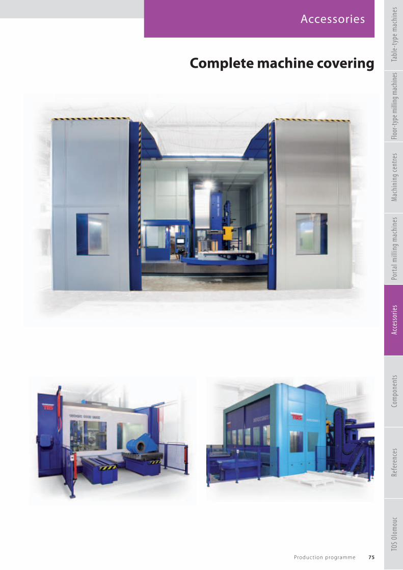
Accessories
75Produc t ion programme
TOS
Olom
ouc
Refe
renc
esTa
ble-
type
mac
hine
sFlo
or-ty
pe m
illin
g mac
hine
sM
achi
ning
cent
res
Port
al m
illin
g m
achi
nes
Acce
ssor
ies
Com
pone
nts
Complete machine covering

Accessories
76 TOS VARNSDORF a . s .
Control systemsSpecifi cations of the HEIDENHAIN TNC 640, Siemens Sinumerik 840D sl or FANUC 30i / 31i control systems correspond to demands for control of all TOS VARNSDORF a.s. machines and demands for all technological operations performed on these machines.
The control systems allow simple control of the machine in the manual as well as fully automatic mode.The control systems can also be operated by a manual wheel and control panel for automatic tool replacement.
HMOP I-Pendant
HR520 HR550HR510Heidenhain TNC 640
HT2 HUBITRONSiemens Sinumerik 840D sl
Fanuc 31i
TOS
Olom
ouc
Refe
renc
esTa
ble-
type
mac
hine
sFlo
or-ty
pe m
illin
g mac
hine
sM
achi
ning
cent
res
Port
al m
illin
g m
achi
nes
Acce
ssor
ies
Com
pone
nts

The TNC 640 and Extended Workspace CompactKeeping digital job management in view
In a fully digitalized and networked production environment, the user at the machine enjoys direct access to useful and relevant information. He can also bring his expertise to bear directly on the wider process chain. To make this possible, the TNC 640 with Extended Workspace Compact and a 24-inch widescreen offers an especially user-friendly workstation. The user can display additional applications alongside the control screen and organize his jobs fully digitally right on the control.
Angle Encoders Linear Encoders Contouring Controls Digital Readouts Length Gauges Rotary Encoders

Accessories
78 TOS VARNSDORF a . s .
Other accessories and servicesPICK UP systemSpecial technological accessories can be put aside and replaced using the PICK-UP system by means of a column for special accessories whose design (the number of storage sites, method of location, etc.) follows the customer‘s special demands.The fl oor-type machines have two versions of accessories magazine, i.e. with a swivelling or rolling opening. For the table-type machines, it is possible to choose a supplementary stand, which is attached and locked on the turning table, an additional stand, which is locked on swivelling arms on the turning table or a stand, which is located on a concrete fl oor next to the machine.
Clamping equipmentThe clamping devices are used as special technological equipment for horizontal boring machines. They are used for clamping of the workpiece.
Clamping angles: UU 800 – UU 6 000
Clamping plates: UD 2 000 – UD 5 000
Clamping cubes: UK 500 – UK 3 000
TOS
Olom
ouc
Refe
renc
esTa
ble-
type
mac
hine
sFlo
or-ty
pe m
illin
g mac
hine
sM
achi
ning
cent
res
Port
al m
illin
g m
achi
nes
Acce
ssor
ies
Com
pone
nts

Accessories
79Produc t ion programme
Spindle guide supports 340 - 650The guide support provides increased rigidity of the housing and guiding of the work spindle, thus making it usable for power machining or precise machining at large traverses within the entire range of speeds, while allowing traverse of the work spindle.
TOSwideWe also off er a system of services for permanent care of the customer. TOSwide potentialities:• visualization of the current screen of
the connected control system and its remote controlling
• reception of data from connected control system for inspection
• quick remote solution of problems (error determination) on the machine tool – transfer of interactive data on the machine‘s condition
• diagnostics of drives, measurements and indication of the machine‘s inputs/outputs• transfer of data from the service network into the customer‘s control system as a support during technological utilization
of the machine (transfer of NC programmes, tool tables and zero points) and modifi cations of the machine‘s properties (transfer of PLC programmes and machine parameters).
Tool coolingTwo tool cooling methods can be applied on the TOS VARNSDORF a. s. machines. Cooling by adjustable nozzles (CHZ) or internal axial tool cooling (CHOV). The axial cooling can be used with an inserted milling head.
ProbesAll control systems can use various types of measurement probes.
Chip conveyorIt is possible to supply the machine with a chip conveyor at customer demand. The lengh of the conveyor and the delivery height can be adjusted to the user needs..
TOS
Olom
ouc
Refe
renc
esTa
ble-
type
mac
hine
sFlo
or-ty
pe m
illin
g mac
hine
sM
achi
ning
cent
res
Port
al m
illin
g m
achi
nes
Acce
ssor
ies
Com
pone
nts

Components
80 TOS VARNSDORF a . s .
Headstocks
Headstocks for hydrostatic machines WRD H: 160, 180, 200The headstock housing is a rigid casting from high-quality grey cast iron, which is followed by other groups of the machine. The internal area of the casting has a horizontal square tunnel with precisely machined surfaces for guiding the RAM. The drive of the work spindle is derived from powerful electric regulation drive through a robust two-speed gearbox. Three mechanical speeds of the gearbox are shifted automatically. Two traverse motors are incorporated in the internal section to drive the headstock in the Y coordinate.
Headstocks for the WH machines: 10, 105, 110, 130, 13, 15 The headstocks contain complete nodes and mechanisms of the spindle housing and driving (the C axis) and traverse of the work spindle (W axis) including chucking of the tool. It is possible to connect special removable accessories on the headstock face such as guiding supports, facing heads, milling heads, etc.
The spindle is housed in precise spindle ball bearings with oblique-angled contact of increased accuracy in multiple arrangement with a prestress. The spindle weight is balanced by a counter-weight suspended on cables and conducted in the stand.
Headstocks for the WHR / WRD machines: 13, 130, 150, 160, 170, MAXIMA I / IIThe basic body is a rigid casting from ductile iron; like other corresponding parts, they have an L shape, which creates a guide for the RAM. The concept of the WHR / WRD 13 – 170 headstocks allow electro-mechanical compensation of the RAM‘s drop during its traverse in the Z axis.
The drive of the work spindle is derived from the electric regulation drive through a two-speed gearbox. The weight of the WRD 13 – 170 headstock is balanced by a hydraulic cylinder. The balancing equipment also includes pressure cylinders for the hydraulic oil and gas located on the column rails. The weight of the WHR / WRD 13 headstock is compensated by a counter-weight housed in the stand‘s hollow.
TOS
Olom
ouc
Refe
renc
esTa
ble-
type
mac
hine
sFlo
or-ty
pe m
illin
g mac
hine
sM
achi
ning
cent
res
Port
al m
illin
g m
achi
nes
Acce
ssor
ies
Com
pone
nts

Components
81Produc t ion programme
Headstocks for portal milling machines: WVM 2600 / 3600 TThe basic body is a rigid casting of ductile cast iron, which creates a guideway for the horizontally traveling RAM of cast steel. The driving shaft in the RAM is driven by a powerful electrical control drive via a robust gearbox. The two mechanical gears are engaged mechanically by an electrically controlled shifter. The drive from the gearbox to the driving shaft has a torsionally rigid coupling.The headstock also incorporates a motor with a belt drive and a ball screw for the RAM travel, end switch, measuring gauge of the RAM and a RAM stroke safety brake.The RAM is guided by the four tracks of the linear guideways. On the sides, the RAM weight is symmetrically counter-balanced by hydraulic cylinders (plungers).
Headstocks for universal milling machines: GRATA The headstock is produced with centrally conducted traveling RAM. The driving shaft speed is derived from a powerful electric drive through the robust gearbox. Two mechanical gears are automatically engaged - by an electrically controlled shifter. The drive from the transmission to the drive shaft is made through a torsional rigid coupling. The coupling includes electromechanical compensation of the RAM movements.
Headstocks for machining centres: WHT 110 (C), WHT 130 (C)Headstocks for machining centres are produced with centrally conducted spindle. This concept is optimal as regards even thermal and power load on the machine‘s frame. In machines with traveling spindle the main housing consists of a set of hollow and work spindle. The traveling work spindle is nitrided, housed with a minimum allowance in an all-nitrided hollow spindle. The hollow spindle is housed in a set of highly precise pre-stressed spindle bearings with oblique contact.
TOS
Olom
ouc
Refe
renc
esTa
ble-
type
mac
hine
sFlo
or-ty
pe m
illin
g mac
hine
sM
achi
ning
cent
res
Port
al m
illin
g m
achi
nes
Acce
ssor
ies
Com
pone
nts

Components
82 TOS VARNSDORF a . s .
Other componentsLubrication systemThe automatic loss lubrication system with a central lubrication aggregate ensures lubrication of sliding guide surfaces of adjustable groups and the ball nuts in the traverse drives. Cogwheels of the spindle drive in the headstock are lubricated by a circulating oil system.
Energy sourcesThe electrical equipment is mostly located in a four-part electric box. It includes the basic module of the control system and control of drives and traverses as well as the spindle and all supply, switch and protection elements. The equipment was produced by renowned manufacturers (Telemècanique, Merlin Gerin, Siemens).
Linear guidesThis concept ensures high accuracy and rigidity of the guides at a verly low friction coeffi cient; it allows application of high traverse speeds and guarantees long life. The individual linear guides are located in areas of the largest stress and force transmission. Thanks to the profi le rail, the carriage can capture forces in the vertical and horizontal direction. Machines with linear guides can be equipped with direct gauging integrated directly in the linear guide.
Hydraulic aggregateThe source of pressure oil for lubrication of the guide surfaces comes from a lubrication aggregate located together with the hydro-aggregate in a separate energy box
TOS
Olom
ouc
Refe
renc
esTa
ble-
type
mac
hine
sFlo
or-ty
pe m
illin
g mac
hine
sM
achi
ning
cent
res
Port
al m
illin
g m
achi
nes
Acce
ssor
ies
Com
pone
nts


Components
84 TOS VARNSDORF a . s .
GaugingAs standard, the linear axes X, Y, Z are equipped with direct measurement with closed electro-optical HEIDENHAIN gauges.
Ball screwsThe linear axes are driven by ball screws with pre-stressed nuts. Suffi cient diameters of the ball screws guarantee top-level rigidity of the drive in the individual linear axes.
Telescopic coversThe guides on the rails are protected against dirt by telescopic covers and the guide surfaces of the column are protected by bellows with covered steel plates.
Toothed shaftIf the X axis is longer than 6,000 mm, the ball screw is replaced with a tooth shaft. This concept is driven by an AC-digital servo drive and a pinion - toothed shaft gear (the master slave system).
Other components
TOS
Olom
ouc
Refe
renc
esTa
ble-
type
mac
hine
sFlo
or-ty
pe m
illin
g mac
hine
sM
achi
ning
cent
res
Port
al m
illin
g m
achi
nes
Acce
ssor
ies
Com
pone
nts


References
86 TOS VARNSDORF a . s .
WRD 130 QManoir Industries – France
X = 9 000 mm (354.3307 inch)Y = 2 500 mm (98.4251 inch)ATC = 40Table clamping surface = 1 800 x 2 200 mm (20 tonnes)
70.8661 x 86.6141 inch (22.5 tons)
WRD 170 QGE CANADA – Canada
X = 13 000 mm (511.8110 inch)Y = 4 000 mm (157.4803 inch)ATC = 80Table clamping surface = 3 000 x 3 500 mm (50 tonnes)
118.1102 x 137.7952 inch (55.1 tons)
WHT 110 LCPersa a.s. – Czech republic
X = 2 500 mmY = 1 6 00 mmZ = 2 500 mmATC = 602x clamping pallete= 1 250 x 1 600 mm (4 tonnes)
49,2125 x 62,9921 inch (4.4 tons)
TOS
Olom
ouc
Refe
renc
esTa
ble-
type
mac
hine
sFlo
or-ty
pe m
illin
g mac
hine
sM
achi
ning
cent
res
Port
al m
illin
g m
achi
nes
Acce
ssor
ies
Com
pone
nts

References
87Produc t ion programme
3x machine TOS VarnsdorfWHQ 15 CNC, WHQ 13 CNC,WHN 110 QStrojírna TYC s.r.o. – Czech Republic
WHQ 13 CNCHiecise Heavy – duty Machines Co., Ltd. – China
X = 3 500 mm (137.7952 inch)Y = 2 500 mm (98.4251 inch)Z = 1 600 mm (62.9921 inch)ATC = 60Table clamping surface = 1 800 x 2 200 mm (12 tonnes)
70.8661 x 86.6141 (13.2 tons)
WRD 150 QTecnoweld Italia srl – Italy
X = 11 000 mm (433.0708 inch)Y = 4 500 mm (177.1653 inch)ATC = 60Table clamping surface = 3 000 x 3 500 mm (50 tonnes)
118.1102 x 137.7952 inch (55.1 tons)
TOS
Olom
ouc
Refe
renc
esTa
ble-
type
mac
hine
sFlo
or-ty
pe m
illin
g mac
hine
sM
achi
ning
cent
res
Port
al m
illin
g m
achi
nes
Acce
ssor
ies
Com
pone
nts

References
88 TOS VARNSDORF a . s .
WHN 130 QFasten Group IMP. / Exp. Co., Ltd. – China
X = 3 000 mm (118.1102 inch)Y = 1 600 mm (62.9921 inch)Z = 1 000 mm (39.3700 inch)ATC = 40Table clamping surface = 1 800 x 2 240 mm (12 tonnes)
70.8661 x 88.1889 inch (13.2 tons)
WRD 130 QStrojírny Prostějov – Czech Republic
X = 9 000 mm (354.3307 inch)Y = 3 000 mm (118.1102 inch)ATC = 40
WRD 170 QJOY Global Inc. – Chile
X = 17 000 mm (669.2913 inch)Y = 6 000 mm (236.2204 inch)ATC = 80 mmTable clamping surface = 5 000 x 5 000 mm (65 tonnes)
196.8503 x 196.8503 inch (71.6 tons)
TOS
Olom
ouc
Refe
renc
esTa
ble-
type
mac
hine
sFlo
or-ty
pe m
illin
g mac
hine
sM
achi
ning
cent
res
Port
al m
illin
g m
achi
nes
Acce
ssor
ies
Com
pone
nts

References
89Produc t ion programme
WHQ 105 CNCEngcon – Poland
X = 1 800 mm (70.8661 inch)Y = 1 250 mm (49.2125 inch)Z = 1 250 mm (49.2125 inch)ATC = 40Table clamping surface = 1 400 x 1 400 mm (5 tonnes)
55.1181 x 55.1181 inch (5.5 tons)
WHQ 13 CNCFrýdlantské strojírny – Czech Republic
X = 3 500 mm (137.7952 inch)Y = 2 500 mm (98.4251 inch)Z = 1 250 mm (49.2125 inch)ATC = 40Table clamping surface = 1 800 x 2 200 mm (12 tonnes)
70.8661 x 86.6141 inch (13.2 tons)
WHT 110 LCTRIGA-MF spol. s r.o. – Czech republic
X = 2 500 mmY = 1 600 mmZ = 2 500 mmATC = 116clamping pallets2x size 1 250 x 1 250 mm (4 tonnes)
49.2125 x 49.2125 inch (4.4 tons)2x size 1 250 x 1 600 mm (4 tonnes)
49.2125 x 62.9921 inch (4.4 tons)
TOS
Olom
ouc
Refe
renc
esTa
ble-
type
mac
hine
sFlo
or-ty
pe m
illin
g mac
hine
sM
achi
ning
cent
res
Port
al m
illin
g m
achi
nes
Acce
ssor
ies
Com
pone
nts

References
90 TOS VARNSDORF a . s .
WRD 150 QS.E.P.F.A. – France
X = 8 000 mm (314.9606 inch)Y = 3 000 mm (118.1102 inch)ATC = 40Table clamping surface = 2 000 x 2 500 mm (25 tonnes)
78.7401 x 98.4251 inch (27.5 tons)
WRD 130 QFaymonville – Belgium
X = 11 000 mm (433.0708 inch)Y = 4 000 mm (157.4803 inch)ATC = 80 Milling head HOI 50
WVM 2600 TTYC Kooperace s.r.o. – Czech republic
X = 4 500 mmY = 3 200 mmZ = 1 500 mmATC = 60Table clamping area= 4 000 x 2 000 mm (20 tonnes)
157.4803 x 78.7401 inch (22 tons)
TOS
Olom
ouc
Refe
renc
esTa
ble-
type
mac
hine
sFlo
or-ty
pe m
illin
g mac
hine
sM
achi
ning
cent
res
Port
al m
illin
g m
achi
nes
Acce
ssor
ies
Com
pone
nts

References
91Produc t ion programme
WHT 110 CEngel Austria GmbH – Austria
X = 2 000 mmY = 1 6 00 mmZ = 2 000 mmATC = 80Table clamping area = 1 250 x 1 600 mm (6 tonnes)
49.2125 x 62.9921 inch (6.6 tons)
TOS
Olom
ouc
Refe
renc
esTa
ble-
type
mac
hine
sFlo
or-ty
pe m
illin
g mac
hine
sM
achi
ning
cent
res
Port
al m
illin
g m
achi
nes
Acce
ssor
ies
Com
pone
nts
WRD 150 TANDEMHydra Arc – South Africa
common axis X = 33 000 mm(1299.2125 inch)
Y = 2x 5 000 mm (196.8503 inch)2x ATC 60
WHQ 105 CNCAVL Moravia – Czech Republic
X = 1 800 mm (70.8661 inch)Y = 1 600 mm (62.9921 inch)Z = 1 250 mm (49.2125 inch)ATC = 40Table clamping surface = 1 400 x 1 600 mm (3 tonnes)
55.1181 x 62.9921 inch (3.3 tons)
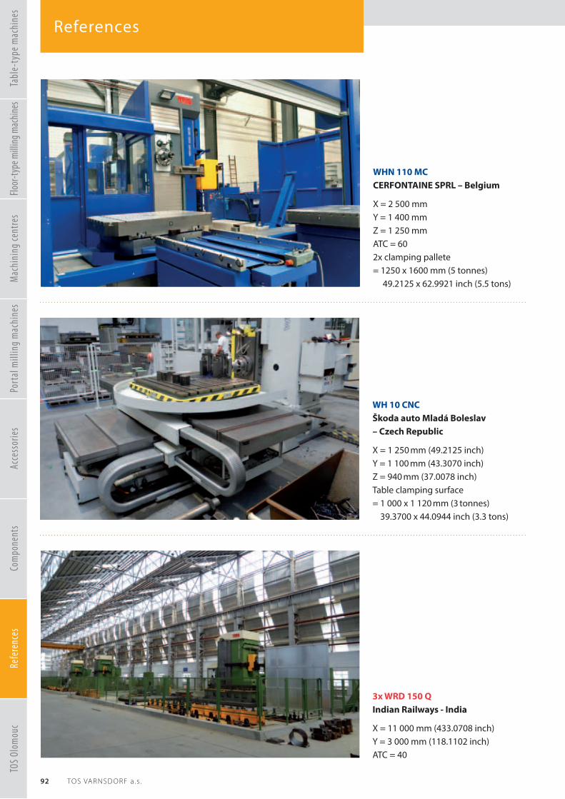
References
92 TOS VARNSDORF a . s .
3x WRD 150 QIndian Railways - India
X = 11 000 mm (433.0708 inch)Y = 3 000 mm (118.1102 inch)ATC = 40
WH 10 CNCŠkoda auto Mladá Boleslav – Czech Republic
X = 1 250 mm (49.2125 inch)Y = 1 100 mm (43.3070 inch)Z = 940 mm (37.0078 inch)Table clamping surface = 1 000 x 1 120 mm (3 tonnes)
39.3700 x 44.0944 inch (3.3 tons)
WHN 110 MCCERFONTAINE SPRL – Belgium
X = 2 500 mmY = 1 400 mmZ = 1 250 mmATC = 602x clamping pallete= 1250 x 1600 mm (5 tonnes)
49.2125 x 62.9921 inch (5.5 tons)
TOS
Olom
ouc
Refe
renc
esTa
ble-
type
mac
hine
sFlo
or-ty
pe m
illin
g mac
hine
sM
achi
ning
cent
res
Port
al m
illin
g m
achi
nes
Acce
ssor
ies
Com
pone
nts

References
93Produc t ion programme
WHN 130 MCSolar Turbines EAME s.r.o. – Czech Republic
X = 2 000 mm (78.7401 inch)Y = 2 240 mm (88.1889 inch)Z = 1 250 mm (49.2125 inch)ATC = 1202x clamping pallete 1 600 x 1 800 mm,(62.9921 x 70.8661 inch)
WHR 13 MCDOOSAN Plzeň – Czech Republic
X = 3 000 mm (118.1102 inch)Y = 2 500 mm (98.4251 inch)Z = 3 200 mm (125.9842 inch)ATC = 1202x clamping pallete 1 800 x 2 200 mm,70.8661 x 86.6141 inch
WHN 110 QKLEMENT a.s. – Czech republic
X = 3 000 mmY = 1 650 mmZ = 1 250 mmATC = 40Table clamping area= 1 400 x 1 800 mm (8 tonnes)
55.1181 x 70.8661 inch (8.8 tons)
TOS
Olom
ouc
Refe
renc
esTa
ble-
type
mac
hine
sFlo
or-ty
pe m
illin
g mac
hine
sM
achi
ning
cent
res
Port
al m
illin
g m
achi
nes
Acce
ssor
ies
Com
pone
nts

TOS Olomouc
94 TOS VARNSDORF a . s .
FNGJ 40 / 50 AThe FNGJ 40 / 50 A machine is a conventional milling machine designed for milling, drilling, boring and thread-cutting operations on workpieces of up to 350 kg in small-series manufacture, mainly in the toolrooms. It is supplied with a horizontal spindle housed in a tool-holding slide spindle head. The machine is also equipped with a vertical head and fi xed angle table. The vertical head is equipped with a manually traversed tailstock; the spindle can be tilted in the range of ± 90°. The machine is also equipped with tool cooling, a light and a safety cover of the work space.
FNGJ 40 A FNGJ 50 ATable mm (in) 800 x 400 (31.4960 x 15.7480) 900 x 500 (35.4330 x 19.6850)Working travels – longitudinal mm (in) 600 (23.6220) 700 (27.5590) – crosswise mm (in) 400 (15.7480) 500 (19.6850) – vertical mm (in) 400 (15.7480) 500 (19.6850)Tailstock travel mm (in) 80 (3.1496) 80 (3.1496)Spindle ISO 40 ISO 40Speed 1/min 50 – 4 000 50 – 4 000Motor output kW (HP) 4.0 (5.4) 4.0 (5.4)Total input of the machine kVA 22 22Built-up area mm (in) 2 070 x 2 120 (81.4960 x 83.4645) 2 170 x 2 120 (85.4330 x 83.4645)Height mm (in) 2 115 (83.2677) 2 115 (83.2677)Weight kg (lbs) 2 500 (5511.6) 2 600 (5732)
FNG 40 / 50 CNC AThe FNG 40 / 50 CNC A machine is a milling machine with continuous control in three coordinates designed for milling, drilling, boring and thread-cutting operations on workpieces of up to 350 kg. It is delivered with a vertical head and a fi xed angle table. The spindle is driven by a motor with smooth speed control. As standard the machine is equipped with tool cooling, a light and a safety semi-cabin covering of the work space.
FNG 40 CNC A FNG 50 CNC ATable mm (in) 800 x 400 (31.4960 x 15.7480) 900 x 500 (35.4330 x 19.6850)Working travels – longitudinal mm (in) 600 (23.6220) 700 (27.5590) – crosswise mm (in) 400 (15.7480) 500 (19.6850) – vertical mm (in) 400 (15.7480) 500 (19.6850)Tailstock travel mm (in) 80 (3.1496) 80 (3.1496)Spindle ISO 40 ISO 40Speed 1/min 50 – 4 000 50 – 4 000Motor output kW (HP) 5.5 (7.5) 5.5 (7.5)Total machine input kVA 20 20Built-up area mm (in) 3 623 x 2 845 (142.6377 x 112.0078) 3 623 x 2 845 (142.6377 x 112.0078)Height mm (in) 2 120 (83.4645) 2 120 (83.4645)Weight kg (lbs) 2 750 (6062.7) 2 850 (6283.2)
TOS
Olom
ouc
Refe
renc
esTa
ble-
type
mac
hine
sFlo
or-ty
pe m
illin
g mac
hine
sM
achi
ning
cent
res
Port
al m
illin
g m
achi
nes
Acce
ssor
ies
Com
pone
nts

TOS Olomouc
95Produc t ion programme
FGU 32 FGV 32Table mm (in) 360 x 1 400 (14.1732 x 55.1181) 360 x 1 400 (14.1732 x 55.1181)Working travels – longitudinal mm (in) 1 000 (39.3700) 1 000 (39.3700) – crosswise mm (in) 275 (10.8267) 300 (11.8110) – vertical mm (in) 420 (16.5354) 420 (16.5354)Tailstock travel mm (in) – 75 (2.9527)Spindle ISO 50 ISO 50Speed 1/min 31,5 – 1 400 45 – 2 000 31,5 – 1 400 45 – 2 000Motor output kW (HP) 5,5 (7.5) 5,5 (7.5)Total machine input kVA 13 13Built-up area mm (in) 2 995 x 2 000 (117.9133 x 78.7401) 2 995 x 2 000 (117.9133 x 78.7401)Height mm (in) 1 980 (77.9527) 2 100 (82.6771)Weight kg (lbs) 2 900 (6393.4) 2 860 (6305.2)
FGU 32The FGU 32 milling machine is a highly powerful milling machine with a horizontal spindle. The machine is designed for accurate and effi cient milling of fl at and box-type workpieces of up to 250 kg in single-part production as well as series manufacture. A divided transverse table allows turning of the longitudinal table around its vertical axis, thus strongly extending utility of the machine.
FGV 32The FGV 32 milling machine is a highly powerful milling machine with a vertical spindle. The spindle is housed in a titling headstock with an extensible tailstock. The machine is designed for a broad range of milling and drilling operations on workpieces of up to 250 kg in single-part production as well as series manufacture.
F2V-RThe F2V R knee-type milling machine (regulating) is designed for milling and drilling operations of workpieces of up to 200 kg in all spheres of mechanical manufacture. The headstock with spindle housed in extensible tailstock can be tilted in the longitudinal plane of the table. The machine‘s potentialities can be extended by using special equipment.
F2V-RTable mm (in) 300 x 1 300 (11.8110 x 51.1811)Working travels – longitudinal mm (in) 840 (33.0708) – crosswise mm (in) 376 (14.8031) –vertical mm (in) 420 (16.5354)Tailstock travel mm (in) 125 (4.9212)Spindle ISO 40Speed 1/min 60 – 4 000Motor output kW (HP) 3 (4.1)Total machine input kVA 12Built-up area mm (in) 2 660 x 1 730 (104.7244 x 68.1102)Height mm (in) 2 270 (89.3700)Weight kg (lbs) 1 550 (3417.2)
TOS
Olom
ouc
Refe
renc
esTa
ble-
type
mac
hine
sFlo
or-ty
pe m
illin
g mac
hine
sM
achi
ning
cent
res
Port
al m
illin
g m
achi
nes
Acce
ssor
ies
Com
pone
nts

09-2
021
WORLDWIDE
Personnel Department:Tel.: +420 412 351 123E-mail: [email protected]
TOS VARNSDORF a.s.Říční 1774407 47 VarnsdorfCzech RepublicTel.: +420 412 351 203Fax: +420 412 351 490E-mail: [email protected]
Marketing and Promotion:Tel.: +420 412 351 216E-mail: [email protected]
Service Department:Tel.: +420 412 351 230E-mail: [email protected]
Cooperation:Tel.: +420 412 351 406E-mail: [email protected]
Data and features in the present catalogue are not binding. The producer reserves the right to alter them without advance notice at any time.