System Setup and Software Installation Guide for Cisco ASR ...
78
System Setup and Software Installation Guide for Cisco ASR 9000 Series Routers, IOS XR Release 7.1.x First Published: 2020-01-29 Americas Headquarters Cisco Systems, Inc. 170 West Tasman Drive San Jose, CA 95134-1706 USA http://www.cisco.com Tel: 408 526-4000 800 553-NETS (6387) Fax: 408 527-0883
-
Upload
khangminh22 -
Category
Documents
-
view
0 -
download
0
Transcript of System Setup and Software Installation Guide for Cisco ASR ...

System Setup and Software Installation Guide for Cisco ASR 9000Series Routers, IOS XR Release 7.1.xFirst Published: 2020-01-29
Americas HeadquartersCisco Systems, Inc.170 West Tasman DriveSan Jose, CA 95134-1706USAhttp://www.cisco.comTel: 408 526-4000
800 553-NETS (6387)Fax: 408 527-0883

THE SPECIFICATIONS AND INFORMATION REGARDING THE PRODUCTS IN THIS MANUAL ARE SUBJECT TO CHANGE WITHOUT NOTICE. ALL STATEMENTS,INFORMATION, AND RECOMMENDATIONS IN THIS MANUAL ARE BELIEVED TO BE ACCURATE BUT ARE PRESENTED WITHOUT WARRANTY OF ANY KIND,EXPRESS OR IMPLIED. USERS MUST TAKE FULL RESPONSIBILITY FOR THEIR APPLICATION OF ANY PRODUCTS.
THE SOFTWARE LICENSE AND LIMITED WARRANTY FOR THE ACCOMPANYING PRODUCT ARE SET FORTH IN THE INFORMATION PACKET THAT SHIPPED WITHTHE PRODUCT AND ARE INCORPORATED HEREIN BY THIS REFERENCE. IF YOU ARE UNABLE TO LOCATE THE SOFTWARE LICENSE OR LIMITED WARRANTY,CONTACT YOUR CISCO REPRESENTATIVE FOR A COPY.
The Cisco implementation of TCP header compression is an adaptation of a program developed by the University of California, Berkeley (UCB) as part of UCB's public domain version ofthe UNIX operating system. All rights reserved. Copyright © 1981, Regents of the University of California.
NOTWITHSTANDING ANY OTHERWARRANTY HEREIN, ALL DOCUMENT FILES AND SOFTWARE OF THESE SUPPLIERS ARE PROVIDED “AS IS" WITH ALL FAULTS.CISCO AND THE ABOVE-NAMED SUPPLIERS DISCLAIM ALL WARRANTIES, EXPRESSED OR IMPLIED, INCLUDING, WITHOUT LIMITATION, THOSE OFMERCHANTABILITY, FITNESS FOR A PARTICULAR PURPOSE AND NONINFRINGEMENT OR ARISING FROM A COURSE OF DEALING, USAGE, OR TRADE PRACTICE.
IN NO EVENT SHALL CISCO OR ITS SUPPLIERS BE LIABLE FOR ANY INDIRECT, SPECIAL, CONSEQUENTIAL, OR INCIDENTAL DAMAGES, INCLUDING, WITHOUTLIMITATION, LOST PROFITS OR LOSS OR DAMAGE TO DATA ARISING OUT OF THE USE OR INABILITY TO USE THIS MANUAL, EVEN IF CISCO OR ITS SUPPLIERSHAVE BEEN ADVISED OF THE POSSIBILITY OF SUCH DAMAGES.
Any Internet Protocol (IP) addresses and phone numbers used in this document are not intended to be actual addresses and phone numbers. Any examples, command display output, networktopology diagrams, and other figures included in the document are shown for illustrative purposes only. Any use of actual IP addresses or phone numbers in illustrative content is unintentionaland coincidental.
All printed copies and duplicate soft copies of this document are considered uncontrolled. See the current online version for the latest version.
Cisco has more than 200 offices worldwide. Addresses and phone numbers are listed on the Cisco website at www.cisco.com/go/offices.
The documentation set for this product strives to use bias-free language. For purposes of this documentation set, bias-free is defined as language that does not imply discrimination based onage, disability, gender, racial identity, ethnic identity, sexual orientation, socioeconomic status, and intersectionality. Exceptions may be present in the documentation due to language thatis hardcoded in the user interfaces of the product software, language used based on standards documentation, or language that is used by a referenced third-party product.
Cisco and the Cisco logo are trademarks or registered trademarks of Cisco and/or its affiliates in the U.S. and other countries. To view a list of Cisco trademarks, go to this URL:https://www.cisco.com/c/en/us/about/legal/trademarks.html. Third-party trademarks mentioned are the property of their respective owners. The use of the word partner does not imply apartnership relationship between Cisco and any other company. (1721R)
© 2020 Cisco Systems, Inc. All rights reserved.

C O N T E N T S
Preface vP R E F A C E
Obtaining Documentation and Submitting a Service Request v
Changes to This Document v
New and Changed Feature Information 1C H A P T E R 1
New and Changed System Setup Features 1
Cisco ASR 9000 System Features 3C H A P T E R 2
Cisco ASR 9000 Product Overview 3
Virtual Machine based Routing and System Administration 4
Command Modes 5
Bring-up the Router 7C H A P T E R 3
Boot the Router 7
Boot the Router Using USB 8
Boot the Router Using iPXE 10
Setup Root User Credentials 12
Access the System Admin Console 14
Configure the Management Port 15
Perform Clock Synchronization with NTP Server 17
Perform Preliminary Checks 19C H A P T E R 4
Verify Software Version 19
Verify Active VMs 20
Verify Status of Hardware Modules 22
Verify Firmware Version 22
System Setup and Software Installation Guide for Cisco ASR 9000 Series Routers, IOS XR Release 7.1.xiii

Verify SDR Information 24
Verify Interface Status 26
Create User Profiles and Assign Privileges 27C H A P T E R 5
Create User Groups 28
Configure User Groups in XR VM 29
Create a User Group in System Admin VM 30
Create Users 32
Create a User Profile in XR VM 32
Create a User Profile in System Admin VM 34
Create Command Rules 36
Create Data Rules 38
Change Disaster-recovery Username and Password 41
Recover Password using PXE Boot 42
Perform System Upgrade and Install Feature Packages 43C H A P T E R 6
Upgrading the System 43
Upgrading Features 44
Workflow for Install Process 44
Install Packages 44
Install Prepared Packages 48
Uninstall Packages 51
Manage Automatic Dependency 55C H A P T E R 7
Update RPMs and SMUs 56
Upgrade Base Software Version 56
Downgrade an RPM 57
Customize Installation using Golden ISO 61C H A P T E R 8
Limitations 61
Golden ISO Workflow 62
Build Golden ISO 63
Build Golden ISO Using Script 64
Install Golden ISO 67
System Setup and Software Installation Guide for Cisco ASR 9000 Series Routers, IOS XR Release 7.1.xiv
Contents

Preface
This preface contains these sections:
• Obtaining Documentation and Submitting a Service Request, on page v• Changes to This Document, on page v
Obtaining Documentation and Submitting a Service RequestFor information on obtaining documentation, using the Cisco Bug Search Tool (BST), submitting a servicerequest, and gathering additional information, see What's New in Cisco Product Documentation, at:http://www.cisco.com/c/en/us/td/docs/general/whatsnew/whatsnew.html.
Subscribe to What's New in Cisco Product Documentation, which lists all new and revised Cisco technicaldocumentation as an RSS feed and delivers content directly to your desktop using a reader application. TheRSS feeds are a free service.
Changes to This DocumentThis table lists the technical changes made to this document since it was first released.
SummaryDate
Initial release of this documentJanuary 2020
System Setup and Software Installation Guide for Cisco ASR 9000 Series Routers, IOS XR Release 7.1.xv

System Setup and Software Installation Guide for Cisco ASR 9000 Series Routers, IOS XR Release 7.1.xvi
PrefaceChanges to This Document

C H A P T E R 1New and Changed Feature Information
This table summarizes the new and changed feature information for the System Setup and Software InstallationGuide for Cisco ASR 9000 Series Routers .
• New and Changed System Setup Features, on page 1
New and Changed System Setup FeaturesWhere DocumentedChanged in ReleaseDescriptionFeature
Not applicableNot applicableNo new featuresintroduced
None
System Setup and Software Installation Guide for Cisco ASR 9000 Series Routers, IOS XR Release 7.1.x1

System Setup and Software Installation Guide for Cisco ASR 9000 Series Routers, IOS XR Release 7.1.x2
New and Changed Feature InformationNew and Changed System Setup Features

C H A P T E R 2Cisco ASR 9000 System Features
The topics covered in this chapter are:
• Cisco ASR 9000 Product Overview, on page 3• Virtual Machine based Routing and System Administration, on page 4• Command Modes, on page 5
Cisco ASR 9000 Product OverviewThe Cisco ASR 9000 series routers are next-generation edge access routers that are optimized for serviceprovider applications. These routers are designed to fulfill various roles in:
• Layer 2 and Layer 3 Ethernet aggregation
• Subscriber-aware broadband aggregation
The Cisco ASR 9000 series routers meet carrier-class requirements for redundancy, availability, packaging,power, and other requirements traditional to the service provider.
The Cisco ASR 9000 series consists of the following routers:
• Cisco ASR 9001 Router (32-bit)
• Cisco ASR 9001-S Router
• Cisco ASR 9006 Router
• Cisco ASR 9010 Router
• Cisco ASR 9901 Router
• Cisco ASR 9904 Router
• Cisco ASR 9906 Router
• Cisco ASR 9910 Router
• Cisco ASR 9912 Router
• Cisco ASR 9922 Router
System Setup and Software Installation Guide for Cisco ASR 9000 Series Routers, IOS XR Release 7.1.x3

Virtual Machine based Routing and System AdministrationOn the Cisco ASR 9000 series router running 64-bit IOS XR, the routing functions and the SystemAdministration functions are run on separate virtual machines (VMs) over a Linux host operating system.The VMs simulate individual physical computing environments over a common hardware. Available hardwareresources like processor, memory, hard disk, and so on, are virtualized and allocated to individual virtualmachines by the hypervisor.
The VM topology on the Cisco ASR 9000 series router running 64-bit IOS XR is shown in this figure.
Figure 1: Virtualized IOS XR on Cisco ASR 9000 Series Router
Implementation of Virtualized IOS XR on Cisco ASR 9000 Series Router
• The hypervisor creates and manages individual VM environments.
• On every route processor (RP) there are two VMs; one for system administration (System Admin VM)and one for managing the routing functions (XR VM).
• The two VMs on each node operate on their respective planes. On each plane, the VMs are connectedto each other using a dedicated VLAN over a high-speed Control Ethernet connection.
• The System Admin VMs can detect each other's presence by auto discovery and thus maintain completesystem awareness.
To access the XR VM, connect to the XR VM console port on the RP. To access the System Admin VM, inthe XR VM CLI, execute the admin command.
In 32-bit IOS XR OS, the management interfaces are available from XR VM. In 64-bit IOS XR OS, theManagement ports on the RP/RSP are available as follows:
• MGT LAN 0 is available in XR VM.
• MGT LAN 1 is available in Admin VM.
Note
System Setup and Software Installation Guide for Cisco ASR 9000 Series Routers, IOS XR Release 7.1.x4
Cisco ASR 9000 System FeaturesVirtual Machine based Routing and System Administration
Advantages of Virtualized IOS XR on the Router
• Faster boot time—Because the System Admin functions are on a dedicated VM, the boot time isconsiderably reduced.
• Independent upgrades—Software packages can be independently installed on the System Admin VMand the XR VM, resulting in minimal system downtime.
• Self-starting VMs—Both the System Admin VM and the XR VM are automatically launched duringrouter boot-up without any user intervention. They have a default set-up that is ready for use.
• System redundancy—In spite of their interconnectivity, there is also a level of isolation between theVMs. Therefore, if a particular VM experiences any issues, it does not affect the functioning of otherVMs.
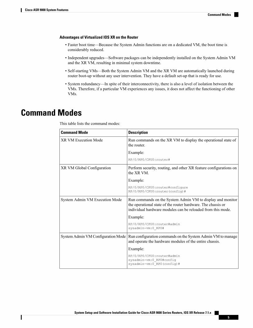
Command ModesThis table lists the command modes:
DescriptionCommand Mode
Run commands on the XR VM to display the operational state ofthe router.
Example:RP/0/RP0/CPU0:router#
XR VM Execution Mode
Perform security, routing, and other XR feature configurations onthe XR VM.
Example:RP/0/RP0/CPU0:router#configureRP/0/RP0/CPU0:router(config)#
XR VM Global Configuration
Run commands on the System Admin VM to display and monitorthe operational state of the router hardware. The chassis orindividual hardware modules can be reloaded from this mode.
Example:RP/0/RP0/CPU0:router#adminsysadmin-vm:0_RP0#
System Admin VM Execution Mode
Run configuration commands on the SystemAdmin VM tomanageand operate the hardware modules of the entire chassis.
Example:RP/0/RP0/CPU0:router#adminsysadmin-vm:0_RP0#configsysadmin-vm:0_RP0(config)#
SystemAdminVMConfigurationMode
System Setup and Software Installation Guide for Cisco ASR 9000 Series Routers, IOS XR Release 7.1.x5
Cisco ASR 9000 System FeaturesCommand Modes

System Setup and Software Installation Guide for Cisco ASR 9000 Series Routers, IOS XR Release 7.1.x6
Cisco ASR 9000 System FeaturesCommand Modes

C H A P T E R 3Bring-up the Router
After installing the hardware, boot the router. Connect to the XR console port and power on the router. Therouter completes the boot process using the pre-installed operating system (OS) image. If no image is availablewithin the router, the router can be booted using PXE boot or an external bootable USB drive.
After booting is complete, create the root username and password, and then use it to log on to the XR consoleand get the router prompt. The first user created in XR console is synchronized to the System Admin console.From the XR console, access the System Admin console to configure system administration settings.
For more information about completing the hardware installation, see Cisco ASR 9000 Series AggregationServices Router Hardware Installation Guide.
• Boot the Router, on page 7• Boot the Router Using USB, on page 8• Boot the Router Using iPXE, on page 10• Setup Root User Credentials, on page 12• Access the System Admin Console, on page 14• Configure the Management Port, on page 15• Perform Clock Synchronization with NTP Server, on page 17
Boot the RouterUse the console port on the Route Processor (RP) to connect to a new router. The console port connect to theXR console by default. If necessary, subsequent connections can be established through the management port,after it is configured.
SFP/SFP+ ports1
Service LAN port2
External USB port3
System Setup and Software Installation Guide for Cisco ASR 9000 Series Routers, IOS XR Release 7.1.x7

Management LAN ports4
Console and Auxiliary (AUX) ports5
Step 1 Connect a terminal to the console port of the RP.Step 2 Start the terminal emulation program on your workstation.
• For modular chassis RP, the console settings are baud rate 9600 bps, no parity, 2 stop bits and 8 data bits
• For fixed chassis, the console settings are baud rate 115200 bps, no parity, 2 stop bits and 8 data bits.
The baud rate is set by default and cannot be changed.
For chassis with RSP4, RP2 cards, the console settings are baud rate 9600 bps, no parity, 2 stop bits and 8 data bits. Theuser can change this baud rate. For next generation RP3, RSP5 cards, the console settings are baud rate 115200 bps, noparity, 2 stop bits and 8 data bits.
Step 3 Power on the router.
Connect the power cord to Power Entry Module (PEM) and the router boots up. The boot process details are displayedon the console screen of the terminal emulation program.
Step 4 Press Enter.
The boot process is complete when the system prompts to enter the root-system username. If the prompt does not appear,wait for a while to give the router more time to complete the initial boot procedure, then press Enter.
If the boot process fails, it may be because the preinstalled image on the router is corrupt. In this case, the routercan be booted using an external bootable USB drive.
Important
We recommended that you check the md5sum of the image after copying from source location to the serverfrom where router boots up with new version. This ensures that if md5sum mismatch is observed, you canremove the corrupted file and ensure that a working copy of the image file is available for setup to begin.
Note
What to do next
Specify the root username and password.
Boot the Router Using USBThe bootable USB drive is used to re-image the router for the purpose of system upgrade, password recoveryor boot the router in case of boot failure. The USB on router is mounted as disk 2.
Before you begin
Ensure you have completed the following prerequisites:
• You have access to a USB drive with a storage capacity that is between 8GB (min) and 32 GB (max).USB 2.0 and USB 3.0 are supported.
System Setup and Software Installation Guide for Cisco ASR 9000 Series Routers, IOS XR Release 7.1.x8
Bring-up the RouterBoot the Router Using USB

• Copy the compressed boot file from the Software Download Center to your local machine. The file namefor the compressed boot file is in the format asr9k-x64-usb_boot-<release_number>.zip.
Step 1 Create a bootable USB drive.
The content of the zipped file ("EFI" and "boot" directories) should be extracted directly into root of the USBdrive. If the unzipping application places the extracted files in a new folder, move the "EFI" and "boot" directoriesto root of the USB drive.
Note
a) Connect the USB drive to your local machine and format it with FAT32 or MS-DOS file system using the WindowsOperating System or Apple MAC Disk Utility.
b) Copy the asr9k-x64-usb_boot-<release_number>.zip compressed boot file to the USB drive.c) Verify that the copy operation is successful. To verify, compare the file size at source and destination. Additionally,
verify the MD5 checksum value.d) Extract the content of the compressed boot file by unzipping it inside the USB drive. This converts the USB drive to
a bootable drive.e) Eject the USB drive from your local machine.
Step 2 Insert the USB on the active RP, and reload or reset the power of the router.
Use this procedure only on active RP; the standby RP must either be removed from the chassis, or stopped atthe boot menu. After the active RP is installed with images from USB, boot the standby RP.
Note
Step 3 On active XR console, press CTRL-C to view BIOS menu. From the menu, select IOS-XR 64 bit Local boot using
front panel USB media.
System Setup and Software Installation Guide for Cisco ASR 9000 Series Routers, IOS XR Release 7.1.x9
Bring-up the RouterBoot the Router Using USB

If active and standby RPs are not stopped at the boot menu, the previously used boot option is used. If the system isinactive in the boot menu for 30 minutes, the system resets automatically.
Step 4 If standby RP is present and it was stopped in step 2, boot the standby RP after the active RP starts to boot. From theboot options select IOS-XR 64 bit Internal network boot from RSP/RP.
Example:Please select the operating system and the boot device:
1) IOS-XR (32 bit Classic XR)2) IOS-XR 64 bit Boot previously installed image3) IOS-XR 64 bit Mgmt Network boot using DHCP server4) IOS-XR 64 bit Mgmt Network boot using local settings (iPXE)5) IOS-XR 64 bit Internal network boot from RSP/RP6) IOS-XR 64 bit Local boot using embedded USB media7) IOS-XR 64 bit Local boot using front panel USB media
Selection [1/2/3/4/5/6/7]:
Select option 5 and proceed with the boot up. After the router boots up, specify the root username and password.
Boot the Router Using iPXEiPXE is a pre-boot execution environment that is included in the network card of the management interfacesand works at the system firmware (UEFI) level of the router. iPXE is used to re-image the system, and bootthe router in case of boot failure or in the absence of a valid bootable partition. iPXE downloads the ISOimage, proceeds with the installation of the image, and bootstraps within the new installation.
iPXE acts as a boot loader and provides the flexibility to choose the image that the system will boot based onthe Platform Identifier (PID), the Serial Number, or the management mac-address. iPXE must be defined inthe DHCP server configuration file.
PID and serial number is supported only if iPXE is invoked using the command (admin) hw-module locationall bootmedia network reload all. If iPXE is selected manually from BIOS, PID and serial number is notsupported.
Note
Cisco ASR 9901 —By default, iPXE uses the previous attempted boot method on the next reload. If theNetwork option was previously used, the iPXE register will be set to 1 (IPXE_PREF=1). To boot an CiscoASR 9901 router via DHCP on the next reload, you must set the IPXE_PREF settings to 0 (IPXE_PREF=0).
From the system admin console, enter the run chvrf 0 ssh rp0_admin /opt/cisco/calvados/bin/nvram_dump-s IPXE_PREF=0 command twice. After entering this command the first time, the host is added to the knownlist of hosts.sysadmin-vm:0_RP0# run chvrf 0 ssh rp0_admin /opt/cisco/calvados/bin/nvram_dump -s IPXE_PREF=0Sat May 2 10:39:52.740 UTC+00:00Warning: Permanently added 'rp0_admin' (ECDSA) to the list of known hosts.sysadmin-vm:0_RP0# run chvrf 0 ssh rp0_admin /opt/cisco/calvados/bin/nvram_dump -s IPXE_PREF=0Sat May 2 10:39:54.995 UTC+00:00sysadmin-vm:0_RP0# hw-module location all bootmedia network
Note
System Setup and Software Installation Guide for Cisco ASR 9000 Series Routers, IOS XR Release 7.1.x10
Bring-up the RouterBoot the Router Using iPXE

iPXE boot can be performed during the following scenarios:
• migration from 32-bit to 64-bit using migration script
• recover password
• boot-up failure with 64-bit image
Before you begin
Take a backup of configuration to a TFP or FTP path to load the configuration back after the iPXE boot.
Step 1 Login to the system admin console.
Example:sysadmin-vm:0_RSP0# hw-module location all reloadTue Mar 6 08:12:47.605 UTCReload hardware module ? [no,yes] yesresult Card graceful reload request on all acknowledged.sysadmin-vm:0_RSP0#
Step 2 If the router is unable to boot, press Ctrl +C to stop the boot process when the following information is displayed.
Use this procedure only on active RP; the standby RP must either be removed from the chassis, or stopped atthe boot menu. After the active RP is installed with images from iPXE boot, boot the standby RP.
Note
Example:
System Bootstrap, Version 10.57 [ASR9K x86 ROMMON],Copyright (c) 1994-2018 by Cisco Systems, Inc.Compiled on Mon 01/09/2017 17:15:01.98BOARD_TYPE : 0x100317Rommon : 10.57 (Primary)Board Revision : 4PCH EEPROM : 3.4IPU FPGA(PL) : 0.40.0 (Backup)IPU INIT(HW_FPD) : 0.30.0IPU FSBL(BOOT.BIN) : 1.19.0IPU LINUX(IMAGE.FPD) : 1.21.0OPTIMUS FPGA : 0.12.0OMEGA FPGA : 0.13.0ALPHA FPGA : 0.14.0CHA FPGA : 0.5.1CBC0 : Part 1=34.38, Part 2=34.38, Act Part=2Product Number : A9K-RSP880-SEChassis : ASR-9904-ACChassis Serial Number : FOX1936GBDDSlot Number : 1Pxe Mac Address LAN 0 : 70:e4:22:06:13:40Pxe Mac Address LAN 1 : 70:e4:22:06:13:41==========================================================Got EMT Mode as 3Got Boot Mode as 0Booting IOS-XR (32 bit Classic XR) - Press Ctrl-c to stop
Step 3 Choose option 4 for iPXE boot.
Example:Please select the operating system and the boot device:
1) IOS-XR (32 bit Classic XR)
System Setup and Software Installation Guide for Cisco ASR 9000 Series Routers, IOS XR Release 7.1.x11
Bring-up the RouterBoot the Router Using iPXE

2) IOS-XR 64 bit Boot previously installed image3) IOS-XR 64 bit Mgmt Network boot using DHCP server4) IOS-XR 64 bit Mgmt Network boot using local settings (iPXE)5) IOS-XR 64 bit Internal network boot from RSP/RP6) IOS-XR 64 bit Local boot using embedded USB media7) IOS-XR 64 bit Local boot using front panel USB media
Selection [1/2/3/4/5/6/7]:
Step 4 Manually update iPXE ROMMON details before booting using FTP or TFTP.
Example:iPXE>set cisco/cisco-server-url:string tftp://<path>/asr9k-mini-x64.isoiPXE>set cisco/cisco-ipv4-address:string 1.3.24.202iPXE>set cisco/cisco-netmask-address:str 255.255.0.0iPXE>set cisco/cisco-gateway-address:str 1.3.0.1
Step 5 Open the connected management port (0/1).
Example:iPXE>ifclose net0iPXE>ifclose net1iPXE>ifopen net1
where net0 and net1 represents management port0 and port1 respectively.
Step 6 Boot the required image from FTP or TFTP location.
Example:iPXE>iPXE> ifopen net0:iPXE> boot tftp://<path>/asr9k-mini-x64-<release-number>.isotftp://<path>/asr9k-mini-x64-<release-number>.iso... 0%Booting iso-image@0x83c525000(1135456256), bzImage@0x83c55f000(4526671)
.......BIOS CODE SIGN ENTRY ...
Step 7 After the active RP is up and running, boot the standby RP. From the boot options select IOS-XR 64 bit Internal
network boot from RSP/RP.
Example:
Please select the operating system and the boot device:1) IOS-XR (32 bit Classic XR)2) IOS-XR 64 bit Boot previously installed image3) IOS-XR 64 bit Mgmt Network boot using DHCP server4) IOS-XR 64 bit Mgmt Network boot using local settings (iPXE)5) IOS-XR 64 bit Internal network boot from RSP/RP6) IOS-XR 64 bit Local boot using embedded USB media7) IOS-XR 64 bit Local boot using front panel USB media
Selection [1/2/3/4/5/6/7]:
Setup Root User CredentialsWhen the router boots for the first time, the system prompts the user to configure root credentials (usernameand password). These credentials are configured as the root user on the XR (root-lr) console, the SystemAdmin VM (root-system), and as disaster-recovery credentials.
System Setup and Software Installation Guide for Cisco ASR 9000 Series Routers, IOS XR Release 7.1.x12
Bring-up the RouterSetup Root User Credentials

Before you begin
The boot process must be complete. For details on how to initiate the boot process, see Bring-up the Router,on page 7.
SUMMARY STEPS
1. Enter root-system username: username
2. Enter secret: password
3. Enter secret again: password
4. Username: username
5. Password: password
6. (Optional) show run username
DETAILED STEPS
Step 1 Enter root-system username: username
Enter the username of the root user. The character limit is 1023. In this example, the name of the root user is "root".
The specified username is mapped to the "root-lr" group on the XR console. It is alsomapped as the "root-system"user on the System Admin console.
Important
When starting the router for the first time, or after a reimage, the router does not have any user configuration. In suchcases, the router prompts you to specify the "root-system username". However, if the router has been configured previously,the router prompts you to enter the "username", as described in Step 4.
Step 2 Enter secret: password
Enter the password for the root user. The character range of the password is from 6 through 253 characters. The passwordthat you type is not displayed on the CLI for security reasons.
The root username and password must be safeguarded as it has the superuser privileges. It is used to access the completerouter configuration.
Step 3 Enter secret again: password
Reenter the password for the root user. The password is not accepted if it does not match the password that is entered inthe previous step. The password that you type is not displayed on the CLI for security reasons.
Step 4 Username: username
Enter the root-system username to login to the XR VM console.
Step 5 Password: password
Enter the password of the root user. The correct password displays the router prompt. You are now logged into the XRVM console.
Step 6 (Optional) show run username
Displays user details.
username rootgroup root-lrgroup cisco-support
System Setup and Software Installation Guide for Cisco ASR 9000 Series Routers, IOS XR Release 7.1.x13
Bring-up the RouterSetup Root User Credentials

secret 5 $1$NBg7$fHs1inKPZVvzqxMv775UE/!
What to do next
• Configure routing functions from the XR console.
• Configure system administration settings from the System Admin prompt. The System Admin promptis displayed on accessing the SystemAdmin console. For details on how to get the SystemAdmin prompt,see Access the System Admin Console, on page 14.
Access the System Admin ConsoleYou must login to the System Admin console through the XR console to perform all system administrationand hardware management setups.
SUMMARY STEPS
1. Login to the XR console as the root user.2. (Optional) Disable the login banner on console port when accessing the System Admin mode from XR
mode.3. admin4. (Optional) exit
DETAILED STEPS
Step 1 Login to the XR console as the root user.Step 2 (Optional) Disable the login banner on console port when accessing the System Admin mode from XR mode.
a) configureb) service sysadmin-login-banner disable
Example:RP/0/RSP0/CPU0:router(config)#service sysadmin-login-banner disable
Disable the login banner on console port in System Admin mode.
c) commitd) end
Step 3 admin
Example:
The login banner is enabled by default. The following example shows the command output with the login banner enabled:RP/0/RSP0/CPU0:router#admin
Mon May 22 06:57:29.350 UTC
root connected from 127.0.0.1 using console on host
System Setup and Software Installation Guide for Cisco ASR 9000 Series Routers, IOS XR Release 7.1.x14
Bring-up the RouterAccess the System Admin Console

sysadmin-vm:0_RP0# exitMon May 22 06:57:32.360 UTC
The following example shows the command output with the login banner disabled:RP/0/RP0/CPU0:router#adminThu Mar 01:07:14.509 UTCsysadmin-vm:0_RP0# exit
Step 4 (Optional) exit
Return to the XR mode from the System Admin mode.
Configure the Management PortTo use the Management port for system management and remote communication, you must configure an IPaddress and a subnet mask for the management ethernet interface. To communicate with devices on othernetworks (such as remote management stations or TFTP servers), you need to configure a default (static) routefor the router.
Before you begin
• Consult your network administrator or system planner to procure IP addresses and a subnet mask for themanagement interface.
• Physical port Ethernet 0 and Ethernet 1 on RP are the management ports. Ensure that the port is connectedto management network.
SUMMARY STEPS
1. configure2. interface MgmtEth rack/slot/port
3. ipv4 address ipv4-address subnet-mask
4. ipv4 address ipv4 virtual address subnet-mask
5. no shutdown6. exit7. router static address-family ipv4 unicast 0.0.0.0/0 default-gateway
8. Use the commit or end command.
DETAILED STEPS
Step 1 configure
Example:
RP/0/RSP0/CPU0:router# configure
Enters global configuration mode.
Step 2 interface MgmtEth rack/slot/port
System Setup and Software Installation Guide for Cisco ASR 9000 Series Routers, IOS XR Release 7.1.x15
Bring-up the RouterConfigure the Management Port

Example:RP/0/RSP0/CPU0:router(config)#interface mgmtEth 0/RP0/CPU0/0
Enters interface configuration mode for the management interface of the primary RP.
Step 3 ipv4 address ipv4-address subnet-mask
Example:RP/0/RSP0/CPU0:router(config-if)#ipv4 address 10.1.1.1/8
Assigns an IP address and a subnet mask to the interface.
Step 4 ipv4 address ipv4 virtual address subnet-mask
Example:RP/0/RSP0/CPU0:router(config-if)#ipv4 address 1.70.31.160 255.255.0.0
Assigns a virtual IP address and a subnet mask to the interface.
Step 5 no shutdown
Example:RP/0/RSP0/CPU0:router(config-if)#no shutdown
Places the interface in an "up" state.
Step 6 exit
Example:RP/0/RSP0/CPU0:router(config-if)#exit
Exits the Management interface configuration mode.
Step 7 router static address-family ipv4 unicast 0.0.0.0/0 default-gateway
Example:RP/0/RSP0/CPU0:router(config)#router static address-family ipv4 unicast 0.0.0.0/0 12.25.0.1
Specifies the IP address of the default-gateway to configure a static route; this is to be used for communications withdevices on other networks.
Step 8 Use the commit or end command.
commit —Saves the configuration changes and remains within the configuration session.
end —Prompts user to take one of these actions:
• Yes — Saves configuration changes and exits the configuration session.
• No —Exits the configuration session without committing the configuration changes.
• Cancel —Remains in the configuration session, without committing the configuration changes.
What to do next
Connect to the management port to the ethernet network. With a terminal emulation program, establish a SSHor telnet connection to the management interface port using its IP address. Before establishing a telnet session,
System Setup and Software Installation Guide for Cisco ASR 9000 Series Routers, IOS XR Release 7.1.x16
Bring-up the RouterConfigure the Management Port

use the telnet ipv4|ipv6 server max-servers command in the XR Config mode, to set number of allowabletelnet sessions to the router.
Perform Clock Synchronization with NTP ServerThere are independent system clocks for the XR console and the System Admin console. To ensure that theseclocks do not deviate from true time, they need to be synchronized with the clock of a NTP server. In thistask you will configure a NTP server for the XR console. After the XR console clock is synchronized, theSystem Admin console clock will automatically synchronize with the XR console clock.
Before you begin
Configure and connect to the management port.
SUMMARY STEPS
1. configure2. ntp server server_address
DETAILED STEPS
Step 1 configure
Example:
RP/0/RSP0/CPU0:router# configure
Enters global configuration mode.
Step 2 ntp server server_address
Example:RP/0/RSP0/CPU0:router(config)#ntp server 64.90.182.55
The XR console clock is configured to be synchronized with the specified sever.
System Setup and Software Installation Guide for Cisco ASR 9000 Series Routers, IOS XR Release 7.1.x17
Bring-up the RouterPerform Clock Synchronization with NTP Server

System Setup and Software Installation Guide for Cisco ASR 9000 Series Routers, IOS XR Release 7.1.x18
Bring-up the RouterPerform Clock Synchronization with NTP Server

C H A P T E R 4Perform Preliminary Checks
After successfully logging into the console, you must perform some preliminary checks to verify the defaultsetup. If any setup issue is detected when these checks are performed, take corrective action before makingfurther configurations. These preliminary checks are:
• Verify Software Version, on page 19• Verify Active VMs, on page 20• Verify Status of Hardware Modules, on page 22• Verify Firmware Version, on page 22• Verify SDR Information, on page 24• Verify Interface Status, on page 26
Verify Software VersionThe router is shipped with the Cisco IOS XR software pre-installed. Verify that the latest version of thesoftware is installed. If a newer version is available, perform a system upgrade. This will install the newerversion of the software and provide the latest feature set on the router.
Perform this task to verify the version of Cisco IOS XR software running on the router.
SUMMARY STEPS
1. show version
DETAILED STEPS
show version
Example:RP/0/RSP0/CPU0:router# show version
Displays the version of the various software components installed on the router. The result includes the version of CiscoIOS XR software and its various components.
System Setup and Software Installation Guide for Cisco ASR 9000 Series Routers, IOS XR Release 7.1.x19

Example
What to do next
Verify the result to ascertain whether a system upgrade or additional package installation is required. If thatis required, refer to the tasks in the chapter Perform System Upgrade and Install Feature Packages, on page43.
Verify Active VMsOn the router both the XRVM and the SystemAdmin VMmust be operational. Instances of both VMs shouldbe running on every route processor (RP). Complete this task to verify the VMs are active.
SUMMARY STEPS
1. show redundancy summary2. admin3. show vm
DETAILED STEPS
Step 1 show redundancy summary
Example:RP/0/RP0:hostname#show redundancy summaryMon Mar 9 16:32:19.276 ISTActive Node Standby Node----------- ------------0/RP0 0/RP1 (Node Ready, NSR: Not Configured)0/LC0 0/LC1 (Node Ready, NSR: Not Configured)RP/0/RP0:hostname#
Displays the readiness of the VMs.
Step 2 admin
Example:
RP/0/RSP0/CPU0:router# admin
Enters administration EXEC mode.
Step 3 show vm
Example:sysadmin-vm:0_RP0#show vm
Displays the status of the VMs running on various nodes.sysadmin-vm:0_RP0# sh vmMon Mar 9 07:52:06.173 UTC------ VMs found at location 0/RP0 ------Id : sysadmin
System Setup and Software Installation Guide for Cisco ASR 9000 Series Routers, IOS XR Release 7.1.x20
Perform Preliminary ChecksVerify Active VMs

Status : runningIP Addr: 192.0.44.1HB Interval : NALast HB Sent: NALast HB Rec : NA-------Id : default-sdrStatus : runningIP Addr: 192.0.44.4HB Interval : 0 s 500000000 nsLast HB Sent: 663743Last HB Rec : 663743-------Id : default-sdrStatus : runningIP Addr: 192.0.44.6HB Interval : 10 s 0 nsLast HB Sent: 33183Last HB Rec : 33183------------- VMs found at location 0/RP1 ------Id : sysadminStatus : runningIP Addr: 192.0.88.1HB Interval : NALast HB Sent: NALast HB Rec : NA-------Id : default-sdrStatus : runningIP Addr: 192.0.88.4HB Interval : 0 s 500000000 nsLast HB Sent: 663749Last HB Rec : 663749-------Id : default-sdrStatus : runningIP Addr: 192.0.88.6HB Interval : 10 s 0 nsLast HB Sent: 33183Last HB Rec : 33183-------sysadmin-vm:0_RP0#
In the above result:
• Id—Name of the VM. "sysadmin" represents System Admin VM; "default-sdr" represents XR VM.
• Status—Status of the VM
• IP Addr—Internal IP address of the VM
If a VM is not running on a node, in the output of the show vm command, no output is shown for that node.
What to do next
If the XR VM is not running on a node, try reloading the node. To do so, use the hw-module location node-idreload command in the mode. Also, use the show sdr command in the mode to verify that the SDR isrunning on the node.
System Setup and Software Installation Guide for Cisco ASR 9000 Series Routers, IOS XR Release 7.1.x21
Perform Preliminary ChecksVerify Active VMs
Verify Status of Hardware ModulesHardware modules include RPs, fan trays, and so on. On the router, multiple hardware modules are installed.Perform this task to verify that all hardware modules are installed correctly and are operational.
Before you begin
Ensure that all required hardware modules have been installed on the router.
SUMMARY STEPS
1. show platform
DETAILED STEPS
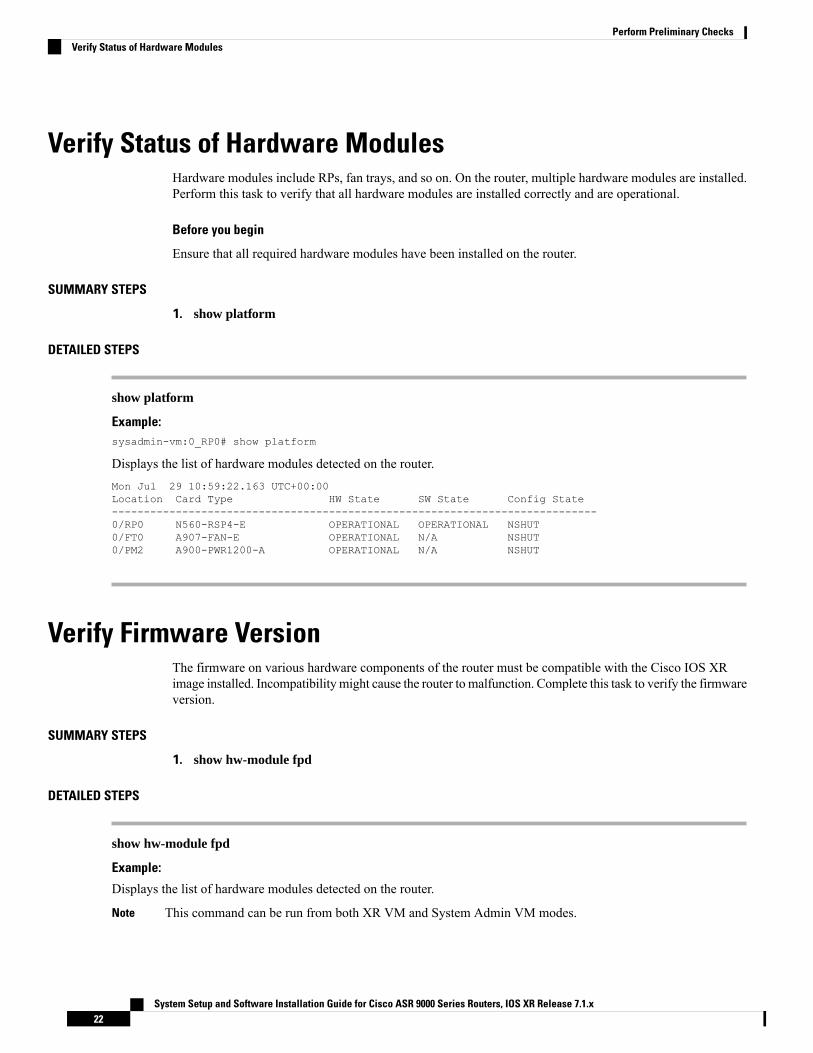
show platform
Example:sysadmin-vm:0_RP0# show platform
Displays the list of hardware modules detected on the router.Mon Jul 29 10:59:22.163 UTC+00:00Location Card Type HW State SW State Config State----------------------------------------------------------------------------0/RP0 N560-RSP4-E OPERATIONAL OPERATIONAL NSHUT0/FT0 A907-FAN-E OPERATIONAL N/A NSHUT0/PM2 A900-PWR1200-A OPERATIONAL N/A NSHUT
Verify Firmware VersionThe firmware on various hardware components of the router must be compatible with the Cisco IOS XRimage installed. Incompatibility might cause the router to malfunction. Complete this task to verify the firmwareversion.
SUMMARY STEPS
1. show hw-module fpd
DETAILED STEPS
show hw-module fpd
Example:
Displays the list of hardware modules detected on the router.
This command can be run from both XR VM and System Admin VM modes.Note
System Setup and Software Installation Guide for Cisco ASR 9000 Series Routers, IOS XR Release 7.1.x22
Perform Preliminary ChecksVerify Status of Hardware Modules

In the above output, some of the significant fields are:
• FPD Device- Name of the hardware component such as FPD, CFP, and so on.
• ATR-Attribute of the hardware component. Some of the attributes are:
• B- Backup Image
• S-Secure Image
• P-Protected Image
• Status- Upgrade status of the firmware. The different states are:
• CURRENT-The firmware version is the latest version.
• READY-The firmware of the FPD is ready for an upgrade.
• NOT READY-The firmware of the FPD is not ready for an upgrade.
• NEED UPGD-A newer firmware version is available in the installed image. It is recommended that an upgradebe performed.
• RLOAD REQ-The upgrade has been completed, and the ISO image requires a reload.
• UPGD DONE-The firmware upgrade is successful.
• UPGD FAIL- The firmware upgrade has failed.
• BACK IMG-The firmware is corrupted. Reinstall the firmware.
• UPGD SKIP-The upgrade has been skipped because the installed firmware version is higher than the oneavailable in the image.
• Running- Current version of the firmware running on the FPD.
What to do next
• Upgrade the required firmware by using the upgrade hw-module location all fpd command in theEXEC mode. For the FPD upgrade to take effect, the router needs a power cycle.
• It is recommended to upgrade all FPGAs on a given node using the upgrade hw-module fpd all location{all | node-id} command. Do not upgrade the FPGA on a node using the upgrade hw-module fpd<individual-fpd> location {all | node-id} as it may cause errors in booting the card.
• If required, turn on the auto fpd upgrade function. To do so, use the fpd auto-upgrade enable commandin the XR configuration [(config)#] mode. After it is enabled, if there are new FPD binaries present inthe image being installed on the router, FPDs are automatically upgraded during the system upgradeoperation.
System Setup and Software Installation Guide for Cisco ASR 9000 Series Routers, IOS XR Release 7.1.x23
Perform Preliminary ChecksVerify Firmware Version

Verify SDR InformationSecure domain routers (SDRs) divide a single physical system into multiple logically-separated routers. SDRsare also known as logical routers (LRs). On the router, only one SDR is supported. This SDR is termed thedefault-sdr. Every router is shipped with the default-sdr, which owns all RPs installed in the routing system.An instance of this SDR runs on line cards and route processors. Complete this task to verify the details ofthe SDR instances.
SUMMARY STEPS
1. admin2. show sdr
DETAILED STEPS
Step 1 admin
Example:
RP/0/RSP0/CPU0:router# admin
Enters administration EXEC mode.
Step 2 show sdr
Example:sysadmin-vm:0_RP0# show sdr
Displays the SDR information for every node.sysadmin-vm:0_RP0# show sdr
sdr default-sdrlocation 0/0/VM1sdr-id 2IP Address of VM 192.0.4.3MAC address of VM A4:6C:2A:2B:AA:A6VM State RUNNINGstart-time 2015-12-03T15:38:38.74514+00:00Last Reload Reason "SMU:Reboot triggered by install"Reboot Count 2location 0/1/VM1sdr-id 2IP Address of VM 192.0.8.3MAC address of VM B0:AA:77:E7:5E:DAVM State RUNNINGstart-time 2015-12-03T15:38:39.730036+00:00Last Reload Reason "SMU:Reboot triggered by install"Reboot Count 2location 0/2/VM1sdr-id 2IP Address of VM 192.0.12.3MAC address of VM B0:AA:77:E7:67:34VM State RUNNINGstart-time 2015-12-03T15:38:38.886947+00:00Last Reload Reason "SMU:Reboot triggered by install"Reboot Count 2
System Setup and Software Installation Guide for Cisco ASR 9000 Series Routers, IOS XR Release 7.1.x24
Perform Preliminary ChecksVerify SDR Information
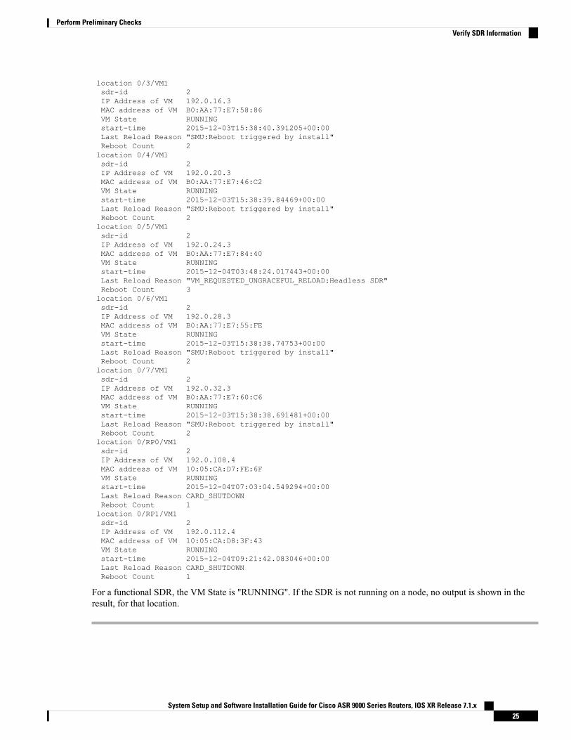
location 0/3/VM1sdr-id 2IP Address of VM 192.0.16.3MAC address of VM B0:AA:77:E7:58:86VM State RUNNINGstart-time 2015-12-03T15:38:40.391205+00:00Last Reload Reason "SMU:Reboot triggered by install"Reboot Count 2location 0/4/VM1sdr-id 2IP Address of VM 192.0.20.3MAC address of VM B0:AA:77:E7:46:C2VM State RUNNINGstart-time 2015-12-03T15:38:39.84469+00:00Last Reload Reason "SMU:Reboot triggered by install"Reboot Count 2location 0/5/VM1sdr-id 2IP Address of VM 192.0.24.3MAC address of VM B0:AA:77:E7:84:40VM State RUNNINGstart-time 2015-12-04T03:48:24.017443+00:00Last Reload Reason "VM_REQUESTED_UNGRACEFUL_RELOAD:Headless SDR"Reboot Count 3location 0/6/VM1sdr-id 2IP Address of VM 192.0.28.3MAC address of VM B0:AA:77:E7:55:FEVM State RUNNINGstart-time 2015-12-03T15:38:38.74753+00:00Last Reload Reason "SMU:Reboot triggered by install"Reboot Count 2location 0/7/VM1sdr-id 2IP Address of VM 192.0.32.3MAC address of VM B0:AA:77:E7:60:C6VM State RUNNINGstart-time 2015-12-03T15:38:38.691481+00:00Last Reload Reason "SMU:Reboot triggered by install"Reboot Count 2location 0/RP0/VM1sdr-id 2IP Address of VM 192.0.108.4MAC address of VM 10:05:CA:D7:FE:6FVM State RUNNINGstart-time 2015-12-04T07:03:04.549294+00:00Last Reload Reason CARD_SHUTDOWNReboot Count 1location 0/RP1/VM1sdr-id 2IP Address of VM 192.0.112.4MAC address of VM 10:05:CA:D8:3F:43VM State RUNNINGstart-time 2015-12-04T09:21:42.083046+00:00Last Reload Reason CARD_SHUTDOWNReboot Count 1
For a functional SDR, the VM State is "RUNNING". If the SDR is not running on a node, no output is shown in theresult, for that location.
System Setup and Software Installation Guide for Cisco ASR 9000 Series Routers, IOS XR Release 7.1.x25
Perform Preliminary ChecksVerify SDR Information

What to do next
If you find SDR is not running on a node, try reloading the node. To do that, use the hw-module locationnode-id reload command in the mode.
Verify Interface StatusAfter the router has booted, all available interfaces must be discovered by the system. If interfaces are notdiscovered, it might indicate a malfunction in the unit. Complete this task to view the number of discoveredinterfaces.
SUMMARY STEPS
1. show ipv4 interface summary
DETAILED STEPS
show ipv4 interface summary
Example:RP/0/RSP0/CPU0:router#show ipv4 interface summary
When a router is turned on for the first time, all interfaces are in the 'unassigned' state. Verify that the total number ofinterfaces displayed in the result matches with the actual number of interfaces present on the router.
In the above result:
• Assigned— An IP address is assigned to the interface.
• Unnumbered— Interface which has borrowed an IP address already configured on one of the other interfaces of therouter.
• Unassigned—No IP address is assigned to the interface.
You can also use the show interfaces brief and show interfaces summary commands in the mode to verify the interfacestatus.
System Setup and Software Installation Guide for Cisco ASR 9000 Series Routers, IOS XR Release 7.1.x26
Perform Preliminary ChecksVerify Interface Status

C H A P T E R 5Create User Profiles and Assign Privileges
To provide controlled access to the XR and System Admin configurations on the router, user profiles arecreated with assigned privileges. The privileges are specified using command rules and data rules.
The authentication, authorization, and accounting (aaa) commands are used for the creation of users, groups,command rules, and data rules. The aaa commands are also used for changing the disaster-recovery password.
You cannot configure the external AAA server and services from the SystemAdmin VM. It can be configuredonly from the XR VM.
Configure AAA authorization to restrict users from uncontrolled access. If AAA authorization is not configured,the command and data rules associated to the groups that are assigned to the user are bypassed. An IOS-XRuser can have full read-write access to the IOS-XR configuration through Network Configuration Protocol(NETCONF), google-defined Remote Procedure Calls (gRPC) or any YANG-based agents. In order to avoidgranting uncontrolled access, enable AAA authorization before setting up any configuration.
Note
If any user on XR is deleted, the local database checks whether there is a first user on System Admin VM.
• If there is a first user, no syncing occurs.
• If there is no first user, then the first user on XR (based on the order of creation) is synced to SystemAdmin VM.
• When a user is added in XR, if there is no user on System Admin mode, then the user is synced tosysadmin-vm. After the synchronization, any changes to the user on XR VM does not synchronize onthe System Admin VM.
• A user added on the System Admin VM does not synchronize with XR VM.
• Only the first user or disaster-recovery user created on System Admin VM synchronizes with the hostVM.
• Changes to credentials of first user or disaster-recovery user on System Admin VM synchronizes withthe host VM.
• The first user or disaster-recovery user deleted on System Admin VM does not synchronize with the hostVM. The host VM retains the user.
Note
System Setup and Software Installation Guide for Cisco ASR 9000 Series Routers, IOS XR Release 7.1.x27

Users are authenticated using username and password. Authenticated users are entitled to execute commandsand access data elements based on the command rules and data rules that are created and applied to usergroups. All users who are part of a user group have such access privileges to the system as defined in thecommand rules and data rules for that user group.
The workflow for creating user profile is represented in this flow chart:
Figure 2: Workflow for Creating User Profiles
The root-lr user, created for the XR VM during initial router start-up, is mapped to the root-system user forthe System Admin VM. The root-system user has superuser permissions for the System Admin VM andtherefore has no access restrictions.
Note
Use the show run aaa command in the Config mode to view existing aaa configurations.
The topics covered in this chapter are:
• Create User Groups, on page 28• Create Users , on page 32• Create Command Rules, on page 36• Create Data Rules, on page 38• Change Disaster-recovery Username and Password, on page 41• Recover Password using PXE Boot, on page 42
Create User GroupsCreate a new user group to associate command rules and data rules with it. The command rules and data rulesare enforced on all users that are part of the user group.
For extensive information about creating user groups, task groups, RADIUS and TACACS configurations,see the Configuring AAA Services chapter in the System Security Configuration Guide for Cisco ASR 9000Series Routers. For detailed information about commands, syntax and their description, see the Authentication,Authorization, and Accounting Commands chapter in the System Security Command Reference for CiscoASR 9000 Series Routers.
System Setup and Software Installation Guide for Cisco ASR 9000 Series Routers, IOS XR Release 7.1.x28
Create User Profiles and Assign PrivilegesCreate User Groups

Configure User Groups in XR VMUser groups are configured with the command parameters for a set of users, such as task groups. Entering theusergroup command accesses the user group configuration submode. Users can remove specific user groupsby using the no form of the usergroup command. Deleting a usergroup that is still referenced in the systemresults in a warning.
Before you begin
Only users associated with the WRITE:AAA task ID can configure user groups. User groups cannot inheritproperties from predefined groups, such as owner-sdr.
Note
SUMMARY STEPS
1. configure2. usergroup usergroup-name
3. description string
4. inherit usergroup usergroup-name
5. taskgroup taskgroup-name
6. Repeat Step for each task group to be associated with the user group named in Step 2.7. Use the commit or end command.
DETAILED STEPS
Step 1 configure
Example:
RP/0/RSP0/CPU0:router# configure
Enters global configuration mode.
Step 2 usergroup usergroup-name
Example:RP/0/RSP0/CPU0:router(config)# usergroup beta
Creates a name for a particular user group and enters user group configuration submode.
• Specific user groups can be removed from the system by specifying the no form of the usergroup command.
Step 3 description string
Example:RP/0/RSP0/CPU0:router(config-ug)#description this is a sample user group description
(Optional) Creates a description of the user group named in Step 2.
Step 4 inherit usergroup usergroup-name
System Setup and Software Installation Guide for Cisco ASR 9000 Series Routers, IOS XR Release 7.1.x29
Create User Profiles and Assign PrivilegesConfigure User Groups in XR VM

Example:RP/0/RSP0/CPU0:router(config-ug)#inherit usergroup sales
• Explicitly defines permissions for the user group.
Step 5 taskgroup taskgroup-name
Example:RP/0/RSP0/CPU0:router(config-ug)# taskgroup beta
Associates the user group named in Step 2 with the task group named in this step.
• The user group takes on the configuration attributes (task ID list and permissions) already defined for the enteredtask group.
Step 6 Repeat Step for each task group to be associated with the user group named in Step 2.Step 7 Use the commit or end command.
commit —Saves the configuration changes and remains within the configuration session.
end —Prompts user to take one of these actions:
• Yes — Saves configuration changes and exits the configuration session.
• No —Exits the configuration session without committing the configuration changes.
• Cancel —Remains in the configuration session, without committing the configuration changes.
Create a User Group in System Admin VMCreate a user group for the System Admin VM.
The router supports a maximum of 32 user groups.
Before you begin
Create a user profile. See the Create User section.
SUMMARY STEPS
1. admin2. config3. aaa authentication groups group group_name
4. users user_name
5. gid group_id_value
6. Use the commit or end command.
DETAILED STEPS
Step 1 admin
System Setup and Software Installation Guide for Cisco ASR 9000 Series Routers, IOS XR Release 7.1.x30
Create User Profiles and Assign PrivilegesCreate a User Group in System Admin VM

Example:
RP/0/RSP0/CPU0:router# admin
Enters administration EXEC mode.
Step 2 config
Example:sysadmin-vm:0_RP0#config
Enters mode.
Step 3 aaa authentication groups group group_name
Example:sysadmin-vm:0_RP0(config)#aaa authentication groups group gr1
Creates a new user group (if it is not already present) and enters the group configuration mode. In this example, the usergroup "gr1" is created.
By default, the user group "root-system" is created by the system at the time of root user creation. The rootuser is part of this user group. Users added to this group will get root user permissions.
Note
Step 4 users user_name
Example:sysadmin-vm:0_RP0(config-group-gr1)#users us1
Specify the name of the user that should be part of the user group.
You can specify multiple user names enclosed withing double quotes. For example, users "user1 user2 ...".
Step 5 gid group_id_value
Example:sysadmin-vm:0_RP0(config-group-gr1)#gid 50
Specify a numeric value. You can enter any 32 bit integer.
Step 6 Use the commit or end command.
commit —Saves the configuration changes and remains within the configuration session.
end —Prompts user to take one of these actions:
• Yes — Saves configuration changes and exits the configuration session.
• No —Exits the configuration session without committing the configuration changes.
• Cancel —Remains in the configuration session, without committing the configuration changes.
What to do next
• Create command rules. See Create Command Rules, on page 36.
• Create data rules. See Create Data Rules, on page 38.
System Setup and Software Installation Guide for Cisco ASR 9000 Series Routers, IOS XR Release 7.1.x31
Create User Profiles and Assign PrivilegesCreate a User Group in System Admin VM

Create UsersCreate new users for the XR VM and System Admin VM.
Users created in the System Admin VM are different from the ones created in XR VM. As a result, theusername and password of a System Admin VM user cannot be used to access the XR VM, and vice versa.
Note
XR VM and System Admin VM User Profile Synchronization
When the user profile is created for the first time in XR VM, the user name and password are synced to theSystem Admin VM if no user already exists in System Admin VM.
However, the subsequent password change or user deletion in XR VM for the synced user is not synchronizedwith the System Admin VM.
Therefore, the passwords in XR VM and System Admin VMmay not be the same. Also, the user synced withthe System Admin VM will not be deleted if the user is deleted in XR VM.
For extensive information about creating user groups, task groups, RADIUS and TACACS configurations,see the Configuring AAA Services chapter in the System Security Configuration Guide for Cisco ASR 9000Series Routers. For detailed information about commands, syntax and their description, see the Authentication,Authorization, and Accounting Commands chapter in the System Security Command Reference for CiscoASR 9000 Series Routers.
Create a User Profile in XR VMEach user is identified by a username that is unique across the administrative domain. Each user must be amember of at least one user group. Deleting a user group may orphan the users associated with that group.The AAA server authenticates orphaned users but most commands are not authorized.
For more information about AAA, and creating users, see theConfiguring AAA Services chapter in the SystemSecurity Configuration Guide for Cisco ASR 9000 Series Routers. For detailed information about relatedcommands, syntax and their description, see the Authentication, Authorization, and Accounting Commandschapter in the System Security Command Reference for Cisco ASR 9000 Series Routers.
Step 1 configure
Example:
RP/0/RSP0/CPU0:router# configure
Enters global configuration mode.
Step 2 username user-name
Example:RP/0/RSP0/CPU0:router(config)# username user1
Creates a name for a new user (or identifies a current user) and enters username configuration submode.
• The user-name argument can be only one word. Spaces and quotation marks are not allowed.
System Setup and Software Installation Guide for Cisco ASR 9000 Series Routers, IOS XR Release 7.1.x32
Create User Profiles and Assign PrivilegesCreate Users

Step 3 Do one of the following:
• password {0 | 7} password• secret {0 | 5 | 8 | 9 | 10} secret
Example:Router(config-un)# password 0 pwd1
orRouter(config-un)# secret 0 sec1
Specifies a password for the user named in Step 2.
• Use the secret command to create a secure login password for the user names specified in Step 2.
• Entering 0 following the password command specifies that an unencrypted (clear-text) password follows. Entering7 following the password command specifies that an encrypted password follows.
• For the secret command, the following values can be entered:
• 0 : specifies that a secure unencrypted (clear-text) password follows
• 5 : specifies that a secure encrypted password follows that uses MD5 hashing algorithm
• 8 : specifies that Type 8 secret that uses SHA256 hashing algorithm follows
• 9 : specifies that Type 9 secret that uses SCrypt hashing algorithm follows
The Type 8 and Type 9 secrets are supported on the IOS XR 64-bit operating system starting fromCisco IOS XR Software Release 7.0.1. Prior to this release, it was supported only on the IOS XR32-bit operating system.
Note
• 10 : specifies Type 10 secret that uses SHA512 hashing algorithm
• Type 10 secret is supported only for Cisco IOS XR 64 bit platform.
• Backward compatibility issues such as configuration loss, authentication failure, and so on, areexpected when you downgrade to lower versions that still use MD5 or SHA256 encryptionalgorithms. If there are any type 10 secrets, convert the secrets to type 5 if you are downgradingthe system from versions 7.0.1 and above to versions 6.5.3 and above. If you are downgradingthe system from versions 7.0.1 and above to versions below 6.5.3, then un-configure all usersfrom the XR-vm and sysadmin-vm before executing install activate. Backward compatibilityissue does not occur in Cisco ASR 9000 Series Routers running Cisco IOS XR 32-Bit softwarebecause Type 10 secret is not applicable to such routers.
• In a first user configuration scenario or when you reconfigure a user, the system synchronisesonly the Type 5 and Type 10 secrets from XR VM to System Admin VM and Host VM. It doesnot synchronize the Type 8 and Type 9 secrets in such scenarios.
Note
• Type 0 is the default for the password and secret commands.
• From Cisco IOS XR Software Release 7.0.1 and later, the default hashing type is 10 (SHA512) when clear textsecret is configured without choosing the type in the configuration.
Step 4 group group-name
Example:
System Setup and Software Installation Guide for Cisco ASR 9000 Series Routers, IOS XR Release 7.1.x33
Create User Profiles and Assign PrivilegesCreate a User Profile in XR VM

RP/0/RSP0/CPU0:router(config-un)# group sysadmin
Assigns the user named in Step 2 to a user group that has already been defined through the usergroup command.
• The user takes on all attributes of the user group, as defined by that user group’s association to various task groups.
• Each user must be assigned to at least one user group. A user may belong to multiple user groups.
Step 5 Repeat step 4 for each user group to be associated with the user specified in step 2.Step 6 Use the commit or end command.
commit —Saves the configuration changes and remains within the configuration session.
end —Prompts user to take one of these actions:
• Yes — Saves configuration changes and exits the configuration session.
• No —Exits the configuration session without committing the configuration changes.
• Cancel —Remains in the configuration session, without committing the configuration changes.
Create a User Profile in System Admin VMCreate new users for the SystemAdmin VM. Users are included in a user group and assigned certain privileges.The users have restricted access to the commands and configurations in the SystemAdmin VM console, basedon assigned privileges.
The router supports a maximum of 1024 user profiles.
The root-lr user of XR VM can access the System Admin VM by entering Admin command in the EXECmode. The router does not prompt you to enter any username and password. The XR VM root-lr user isprovided full access to the System Admin VM.
SUMMARY STEPS
1. admin2. config3. aaa authentication users user user_name
4. password password
5. uid user_id_value
6. gid group_id_value
7. ssh_keydir ssh_keydir
8. homedir homedir
9. Use the commit or end command.
DETAILED STEPS
Step 1 admin
Example:
System Setup and Software Installation Guide for Cisco ASR 9000 Series Routers, IOS XR Release 7.1.x34
Create User Profiles and Assign PrivilegesCreate a User Profile in System Admin VM

RP/0/RSP0/CPU0:router# admin
Enters administration EXEC mode.
Step 2 config
Example:sysadmin-vm:0_RP0#config
Enters mode.
Step 3 aaa authentication users user user_name
Example:sysadmin-vm:0_RP0(config)#aaa authentication users user us1
Creates a new user and enters user configuration mode. In the example, the user "us1" is created.
Step 4 password password
Example:sysadmin-vm:0_RP0(config-user-us1)#password pwd1
Enter the password that will be used for user authentication at the time of login into System Admin VM.
Step 5 uid user_id_value
Example:sysadmin-vm:0_RP0(config-user-us1)#uid 100
Specify a numeric value. You can enter any 32 bit integer.
Step 6 gid group_id_value
Example:sysadmin-vm:0_RP0(config-user-us1)#gid 50
Specify a numeric value. You can enter any 32 bit integer.
Step 7 ssh_keydir ssh_keydir
Example:sysadmin-vm:0_RP0(config-user-us1)#ssh_keydir dir1
Specify any alphanumeric value.
Step 8 homedir homedir
Example:sysadmin-vm:0_RP0(config-user-us1)#homedir dir2
Specify any alphanumeric value.
Step 9 Use the commit or end command.
commit —Saves the configuration changes and remains within the configuration session.
end —Prompts user to take one of these actions:
• Yes — Saves configuration changes and exits the configuration session.
System Setup and Software Installation Guide for Cisco ASR 9000 Series Routers, IOS XR Release 7.1.x35
Create User Profiles and Assign PrivilegesCreate a User Profile in System Admin VM

• No —Exits the configuration session without committing the configuration changes.
• Cancel —Remains in the configuration session, without committing the configuration changes.
What to do next
• Create user group that includes the user created in this task. See Create a User Group in System AdminVM, on page 30.
• Create command rules that apply to the user group. See Create Command Rules, on page 36.
• Create data rules that apply to the user group. See Create Data Rules, on page 38.
Create Command RulesCommand rules are rules based on which users of a user group are either permitted or denied the use of certaincommands. Command rules are associated to a user group and get applied to all users who are part of the usergroup.
A command rule is created by specifying whether an operation is permitted, or denied, on a command. Thistable lists possible operation and permission combinations:
Reject PermissionAccept PermissionOperation
Command is not displayed on the CLI when"?" is used.
Command is displayed on the CLI when"?" is used.
Read (R)
Command cannot be executed from the CLI.Command can be executed from the CLI.Execute (X)
Command is neither visible nor executablefrom the CLI.
Command is visible on the CLI and can beexecuted.
Read andexecute (RX)
By default, all permissions are set to Reject.
Each command rule is identified by a number associated with it. When multiple command rules are appliedto a user group, the command rule with a lower number takes precedence. For example, cmdrule 5 permitsread access, while cmdrule10 rejects read access. When both these command rules are applied to the sameuser group, the user in this group gets read access because cmdrule 5 takes precedence.
As an example, in this task, the command rule is created to deny read and execute permissions for the "showplatform" command.
Before you begin
Create an user group. See Create a User Group in System Admin VM, on page 30.
SUMMARY STEPS
1. admin2. config3. aaa authorization cmdrules cmdrule command_rule_number
4. command command_name
System Setup and Software Installation Guide for Cisco ASR 9000 Series Routers, IOS XR Release 7.1.x36
Create User Profiles and Assign PrivilegesCreate Command Rules

5. ops {r | x | rx}6. action {accept | accept_log | reject}7. group user_group_name
8. context connection_type
9. Use the commit or end command.
DETAILED STEPS
Step 1 admin
Example:
RP/0/RSP0/CPU0:router# admin
Enters administration EXEC mode.
Step 2 config
Example:sysadmin-vm:0_RP0#config
Enters mode.
Step 3 aaa authorization cmdrules cmdrule command_rule_number
Example:sysadmin-vm:0_RP0(config)#aaa authorization cmdrules cmdrule 1100
Specify a numeric value as the command rule number. You can enter a 32 bit integer.
Do no use numbers between 1 to 1000 because they are reserved by Cisco.Important
This command creates a new command rule (if it is not already present) and enters the command rule configuration mode.In the example, command rule "1100" is created.
By default "cmdrule 1" is created by the system when the root-system user is created. This command ruleprovides "accept" permission to "read" and "execute" operations for all commands. Therefore, the root userhas no restrictions imposed on it, unless "cmdrule 1" is modified.
Note
Step 4 command command_name
Example:sysadmin-vm:0_RP0(config-cmdrule-1100)#command "show platform"
Specify the command for which permission is to be controlled.
If you enter an asterisk '*' for command, it indicates that the command rule is applicable to all commands.
Step 5 ops {r | x | rx}
Example:sysadmin-vm:0_RP0(config-cmdrule-1100)#ops rx
Specify the operation for which permission has to be specified:
• r —Read
System Setup and Software Installation Guide for Cisco ASR 9000 Series Routers, IOS XR Release 7.1.x37
Create User Profiles and Assign PrivilegesCreate Command Rules

• x — Execute
• rx —Read and execute
Step 6 action {accept | accept_log | reject}
Example:sysadmin-vm:0_RP0(config-cmdrule-1100)#action reject
Specify whether users are permitted or denied the use of the operation.
• accept — users are permitted to perform the operation
• accept_log— users are permitted to perform the operation and every access attempt is logged.
• reject— users are restricted from performing the operation.
Step 7 group user_group_name
Example:sysadmin-vm:0_RP0(config-cmdrule-1100)#group gr1
Specify the user group on which the command rule is applied.
Step 8 context connection_type
Example:sysadmin-vm:0_RP0(config-cmdrule-1100)#context *
Specify the type of connection to which this rule applies. The connection type can be netconf (Network ConfigurationProtocol), cli (Command Line Interface), or xml (Extensible Markup Language ). It is recommended that you enter anasterisk '*'; this indicates that the command rule applies to all connection types.
Step 9 Use the commit or end command.
commit —Saves the configuration changes and remains within the configuration session.
end —Prompts user to take one of these actions:
• Yes — Saves configuration changes and exits the configuration session.
• No —Exits the configuration session without committing the configuration changes.
• Cancel —Remains in the configuration session, without committing the configuration changes.
What to do next
Create data rules. See Create Data Rules, on page 38.
Create Data RulesData rules are rules based on which users of the user group are either permitted, or denied, accessing andmodifying configuration data elements. The data rules are associated to a user group. The data rules get appliedto all users who are part of the user group.
System Setup and Software Installation Guide for Cisco ASR 9000 Series Routers, IOS XR Release 7.1.x38
Create User Profiles and Assign PrivilegesCreate Data Rules

Each data rule is identified by a number associated to it. When multiple data rules are applied to a user group,the data rule with a lower number takes precedence.
Before you begin
Create an user group. See Create a User Group in System Admin VM, on page 30.
SUMMARY STEPS
1. admin2. config3. aaa authorization datarules datarule data_rule_number
4. keypath keypath
5. ops operation
6. action {accept | accept_log | reject}7. group user_group_name
8. context connection type
9. namespace namespace
10. Use the commit or end command.
DETAILED STEPS
Step 1 admin
Example:
RP/0/RSP0/CPU0:router# admin
Enters administration EXEC mode.
Step 2 config
Example:sysadmin-vm:0_RP0#config
Enters mode.
Step 3 aaa authorization datarules datarule data_rule_number
Example:sysadmin-vm:0_RP0(config)#aaa authorization datarules datarule 1100
Specify a numeric value as the data rule number. You can enter a 32 bit integer.
Do no use numbers between 1 to 1000 because they are reserved by Cisco.Important
This command creates a new data rule (if it is not already present) and enters the data rule configuration mode. In theexample, data rule "1100" is created.
By default "datarule 1" is created by the system when the root-system user is created. This data rule provides"accept" permission to "read", "write", and "execute" operations for all configuration data. Therefore, theroot user has no restrictions imposed on it, unless "datarule 1" is modified.
Note
Step 4 keypath keypath
System Setup and Software Installation Guide for Cisco ASR 9000 Series Routers, IOS XR Release 7.1.x39
Create User Profiles and Assign PrivilegesCreate Data Rules

Example:sysadmin-vm:0_RP0(config-datarule-1100)#keypath /aaa/disaster-recovery
Specify the keypath of the data element. The keypath is an expression defining the location of the data element. If youenter an asterisk '*' for keypath , it indicates that the command rule is applicable to all configuration data.
Step 5 ops operation
Example:sysadmin-vm:0_RP0(config-datarule-1100)#ops rw
Specify the operation for which permission has to be specified. Various operations are identified by these letters:
• c—Create
• d—Delete
• u—Update
• w—Write (a combination of create, update, and delete)
• r—Read
• x—Execute
Step 6 action {accept | accept_log | reject}
Example:sysadmin-vm:0_RP0(config-datarule-1100)#action reject
Specify whether users are permitted or denied the operation.
• accept — users are permitted to perform the operation
• accept_log— users are permitted to perform the operation and every access attempt is logged
• reject— users are restricted from performing the operation
Step 7 group user_group_name
Example:sysadmin-vm:0_RP0(config-datarule-1100)#group gr1
Specify the user group on which the data rule is applied. Multiple group names can also be specified.
Step 8 context connection type
Example:sysadmin-vm:0_RP0(config-datarule-1100)#context *
Specify the type of connection to which this rule applies. The connection type can be netconf (Network ConfigurationProtocol), cli (Command Line Interface), or xml (Extensible Markup Language ). It is recommended that you enter anasterisk '*', which indicates that the command applies to all connection types.
Step 9 namespace namespace
Example:sysadmin-vm:0_RP0(config-datarule-1100)#namespace *
Enter asterisk '*' to indicate that the data rule is applicable for all namespace values.
System Setup and Software Installation Guide for Cisco ASR 9000 Series Routers, IOS XR Release 7.1.x40
Create User Profiles and Assign PrivilegesCreate Data Rules

Step 10 Use the commit or end command.
commit —Saves the configuration changes and remains within the configuration session.
end —Prompts user to take one of these actions:
• Yes — Saves configuration changes and exits the configuration session.
• No —Exits the configuration session without committing the configuration changes.
• Cancel —Remains in the configuration session, without committing the configuration changes.
Change Disaster-recovery Username and PasswordWhen you define the root-system username and password initially after starting the router, the same usernameand password gets mapped as the disaster-recovery username and password for the System Admin console.However, it can be changed.
The disaster-recovery username and password is useful in these scenarios:
• Access the system when the AAA database, which is the default source for authentication in SystemAdmin console is corrupted.
• Access the system through the management port, when, for some reason, the System Admin console isnot working.
• Create new users by accessing the System Admin console using the disaster-recovery username andpassword, when the regular username and password is forgotten.
On the router, you can configure only one disaster-recovery username and password at a time.Note
SUMMARY STEPS
1. admin2. config3. aaa disaster-recovery username username password password
4. Use the commit or end command.
DETAILED STEPS
Step 1 admin
Example:
RP/0/RSP0/CPU0:router# admin
Enters administration EXEC mode.
System Setup and Software Installation Guide for Cisco ASR 9000 Series Routers, IOS XR Release 7.1.x41
Create User Profiles and Assign PrivilegesChange Disaster-recovery Username and Password

Step 2 config
Example:sysadmin-vm:0_RP0#config
Enters mode.
Step 3 aaa disaster-recovery username username password password
Example:sysadmin-vm:0_RP0(config)#aaa disaster-recovery username us1 password pwd1
Specify the disaster-recovery username and the password. You have to select an existing user as the disaster-recoveryuser. In the example, 'us1' is selected as the disaster-recovery user and assigned the password as 'pwd1'. The passwordcan be entered as a plain text or md5 digest string.
When you need to make use of the disaster recovery username, you need to enter it as username@localhost.
Step 4 Use the commit or end command.
commit —Saves the configuration changes and remains within the configuration session.
end —Prompts user to take one of these actions:
• Yes — Saves configuration changes and exits the configuration session.
• No —Exits the configuration session without committing the configuration changes.
• Cancel —Remains in the configuration session, without committing the configuration changes.
Recover Password using PXE BootIf you are unable to login or lost your XR and System administration passwords, use the following steps tocreate new password. A lost password cannot be recovered, instead a new username and password must becreated with a non-graceful PXE boot.
Step 1 Boot the router using PXE.
PXE boot is fully intrusive. The router state, configuration and image is reset.Note
To PXE boot a router, see Boot the Router Using iPXE, on page 10.
Step 2 Reset the password.
System Setup and Software Installation Guide for Cisco ASR 9000 Series Routers, IOS XR Release 7.1.x42
Create User Profiles and Assign PrivilegesRecover Password using PXE Boot

C H A P T E R 6Perform System Upgrade and Install FeaturePackages
The system upgrade and package installation processes are executed using install commands on the router.The processes involve adding and activating the iso images (.iso) and feature packages on the router. Thesefiles are accessed from a network server and then activated on the router. If the installed package or SMUcauses any issue on the router, it can be uninstalled.
The topics covered in this chapter are:
• Upgrading the System, on page 43• Upgrading Features, on page 44• Workflow for Install Process, on page 44• Install Packages, on page 44• Install Prepared Packages, on page 48• Uninstall Packages, on page 51
Upgrading the System
If an interface on a router does not have a configuration and is brought up by performing no-shut operation,then upon router reload, the interface state changes to admin-shutdown automatically.
Note
System upgrade is done by installing a base package–Cisco IOS XR Unicast Routing Core Bundle. The filename for this bundle is . Install this ISO image using install commands. For more information about the installprocess, see Workflow for Install Process, on page 44.
Do not perform any install operations when the router is reloading.
Do not reload the router during an upgrade operation.
Caution
System Setup and Software Installation Guide for Cisco ASR 9000 Series Routers, IOS XR Release 7.1.x43

CSM Server is a web-based, server-side automation and orchestration framework. It gives service providersthe ability to simultaneously schedule and deploy SMUs and perform software upgrades across hundreds ofrouters in a scheduled manner through a simple point and click Web interface. For more information, seeCisco Software Manager.
Note
For more information on upgrading the system and the RPMs, see Manage Automatic Dependency chapter.
Upgrading FeaturesUpgrading features is the process of deploying new features and software patches on the router. Featureupgrade is done by installing package files, termed simply, packages. Software patch installation is done byinstalling Software Maintenance Upgrade (SMU) files.
Installing a package on the router installs specific features that are part of that package. Cisco IOSXR Softwareis divided into various software packages; this enables you to select the features to run on your router. Eachpackage contains components that perform a specific set of router functions, such as routing, security, and soon.
For example, the components of the routing package are split into individual RPMs, such as BGP and OSPF.BGP is a mandatory RPMwhich is a part of the base software version and hence cannot be removed. OptionalRPMs such as OSPF can be added and removed as required.
The naming convention of the package is <platform>-<pkg>-<pkg version>-<release
version>.<architecture>.rpm. Standard packages are as follows:
Package and SMU installation is performed using install commands. For more information about the installprocess, see Install Packages, on page 44.
There are separate packages and SMUs for the XR VM and the System Admin VM. They can be identifiedby their filenames.
You can alternatively perform a cross VMoperation, by activationg or deactivating the SystemAdmin packagesand SMUs from XR.
For more information on upgrading the system and the RPMs, see Cisco IOS XR Flexible PackagingConfiguration Guide.
Workflow for Install ProcessThe workflow for installation and uninstallation processes is depicted in this flowchart.
For installing a package, see Install Packages, on page 44. For uninstalling a package, see Uninstall Packages,on page 51.
Install PackagesComplete this task to upgrade the system or install a patch. The system upgrade is done using an ISO imagefile, while the patch installation is done using packages and SMUs. You can also include SMUs in an upgradeoperation along with mini ISO.
System Setup and Software Installation Guide for Cisco ASR 9000 Series Routers, IOS XR Release 7.1.x44
Perform System Upgrade and Install Feature PackagesUpgrading Features

This task is also used to install .rpm files. The .rpm file contains multiple packages and SMUs that are mergedinto a single file. The packaging format defines one RPM per component, without dependency on the cardtype.
• The System Admin package and XR package can be executed using install commands in the mode andmode. All install commands are applicable in both these modes.
• Install operation over IPv6 is not supported.
Note
The workflow for installing a package is shown in this flowchart.
Figure 3: Installing Packages Workflow
Before you begin
• Configure and connect to the management port. The installable file is accessed through the managementport. For details about configuring the management port, see Configure the Management Port, on page15.
• Copy the package to be installed either on the router's hard disk or on a network server to which therouter has access.
System Setup and Software Installation Guide for Cisco ASR 9000 Series Routers, IOS XR Release 7.1.x45
Perform System Upgrade and Install Feature PackagesInstall Packages

SUMMARY STEPS
1. Execute one of these:
• install add source <http or shttp transfer protocol>/package_path/ filename1 filename2 ...
• install add source <tftp transfer protocol>/package_path/ filename1 filename2 ...
• install add source <ftp or sftp transfer protocol>//user@server:/package_path/ filename1 filename2...
2. show install request3. show install repository4. show install inactive5. Execute one of these:
• install activate package_name
• install activate id operation_id
6. show install active7. install commit
DETAILED STEPS
Step 1 Execute one of these:
• install add source <http or shttp transfer protocol>/package_path/ filename1 filename2 ...
• install add source <tftp transfer protocol>/package_path/ filename1 filename2 ...
• install add source <ftp or sftp transfer protocol>//user@server:/package_path/ filename1 filename2 ...
Example:
or
or
A space must be provided between the package_path and filename.Note
The software files are unpacked from the package, validated, and then added to the software repository. This operationmight take time depending on the size of the files being added. The operation is performed in asynchronous mode. Theinstall add command runs in the background, and the EXEC prompt is returned as soon as possible.
The repositories for the XR VM and the System Admin VM are different. The system automatically adds arouting package to the XR VM repository and a system administration package to the System Admin VMrepository.
Note
Step 2 show install request
Example:RP/0/RSP0/CPU0:router#show install request
(Optional) Displays the operation ID of the add operation and its status. The operation ID can be later used to executethe activate command.Install operation 8 is still in progress
For system administration packages, the remaining steps must be performed from the mode. Use the admin commandto enter the mode.
System Setup and Software Installation Guide for Cisco ASR 9000 Series Routers, IOS XR Release 7.1.x46
Perform System Upgrade and Install Feature PackagesInstall Packages

Step 3 show install repository
Example:RP/0/RSP0/CPU0:router#show install repository
Displays packages that are added to the repository. Packages are displayed only after the install add operation iscomplete.
Step 4 show install inactive
Example:RP/0/RSP0/CPU0:router#show install inactive
Displays inactive packages that are present in the repository. Only inactive packages can be activated.
Step 5 Execute one of these:
• install activate package_name
• install activate id operation_id
Example:
The operation_id is that of the install add operation. This command can also be run from System Admin mode. Thepackage configurations are made active on the router. As a result, new features and software fixes take effect. Thisoperation is performed in asynchronous mode, as this is the default. The install activate command runs in the background,and the EXEC prompt is returned.
You can run the activate operation either through the synchronous mode or by selecting the sync option from the CLI.
If you use the operation ID, all packages that were added in the specified operation are activated together. For example,if 5 packages are added in operation 8, by executing install activate id 8, all 5 packages are activated together. You donot have to activate the packages individually.
Activation does not happen instantaneously, but takes some time. Upon activation completion, the system reloadsautomatically. For restart SMU activation, the SMU takes effect once the processes impacted by the SMU are restarted.
If the SMU has dependency on both XR VM and System Admin VM, perform the reload after activating the SMU inboth VMs so that they take effect simultaneously. To reload the router, use the hw-module location all reload commandfrom the mode.
Step 6 show install active
Example:RP/0/RSP0/CPU0:router#show install active
Displays packages that are active.
From the result, verify that the same image and package versions are active on all RPs and LCs.
Step 7 install commit
Example:RP/0/RSP0/CPU0:router#install commit
Commits the Host, XR, and System Admin newly active software.
On Multi-SDR mode, you can use the install commit sdr to commit just the sdr from where the CLI is beingtriggered.
Note
System Setup and Software Installation Guide for Cisco ASR 9000 Series Routers, IOS XR Release 7.1.x47
Perform System Upgrade and Install Feature PackagesInstall Packages

Installing Packages: Related Commands
PurposeRelated Commands
Displays the log information for the install process; this can be used fortroubleshooting in case of install failure.
show install log
Displays the details of the packages that have been added to the repository.Use this command to identify individual components of a package.
show install package
Makes pre-activation checks on an inactive package, to prepare it foractivation.
install prepare
Displays the list of package that have been prepared and are ready foractivation.
show install prepare
What to do next
• Ensure that you commit the upgrade using install commit.
• After performing a system upgrade, upgrade FPD by using the upgrade hw-module location all fpdall command from the mode. The progress of FPD upgrade process can be monitored using the showhw-module fpd command in the mode. Reload the router after the FPD upgrade is completed.
• Verify the installation using the install verify packages command.
• Uninstall the packages or SMUs if their installation causes any issues on the router. See Uninstall Packages,on page 51.
ISO images cannot be uninstalled. However, you can perform a system downgradeby installing an older ISO version.
Note
Install Prepared Packages• If the installable file is corrupted, the prepare process fails. This provides an early warning of the problem.If the corrupted file was activated directly, it might cause router malfunction.
• Directly activating an ISO image for system upgrade takes considerable time during which the router isnot usable. However, if the image is prepared before activation, not only does the prepare process runasynchronously, but when the prepared image is subsequently activated, the activation process too takesless time. As a result, the router downtime is reduced.
A system upgrade or feature upgrade is performed by activating the ISO image file, packages, and SMUs. Itis possible to prepare these installable files before activation. During the prepare phase, preactivation checksare made and the components of the installable files are loaded on to the router setup. The prepare processruns in the background and the router is fully usable during this time. When the prepare phase is over, all theprepared files can be activated instantaneously. The advantages of preparing before activation are:
System Setup and Software Installation Guide for Cisco ASR 9000 Series Routers, IOS XR Release 7.1.x48
Perform System Upgrade and Install Feature PackagesInstall Prepared Packages

• If the installable file is corrupted, the prepare process fails. This provides an early warning of the problem.If the corrupted file was activated directly, it might cause router malfunction.
• Directly activating an ISO image for system upgrade takes considerable time during which the router isnot usable. However, if the image is prepared before activation, not only does the prepare process runasynchronously, but when the prepared image is subsequently activated, the activation process too takesless time. As a result, the router downtime is considerably reduced.
• Performs disk-space check that is required for a successful operation. This quantifies the disk-spacedeficit, and provides you possible alternatives to free up space in the filesystem.
• Performs package compatibility check. This ensures that all the required installation packages are available.For any package compatibility check error, details of the package and version are logged.
Complete this task to upgrade the system and install packages by making use of the prepare operation.
Depending on whether you are installing a System Admin package or a XR package, execute the installcommands in the mode or mode respectively. All install commands are applicable in both these modes.System Admin install operations can be done from XR mode.
Note
SUMMARY STEPS
1. Add the required ISO image and packages to the repository.2. show install repository3. Execute one of these:
• install prepare package_name
• install prepare id operation_id
4. show install prepare5. install activate6. show install active7. install commit
DETAILED STEPS
Step 1 Add the required ISO image and packages to the repository.For details, see Install Packages, on page 44.
Step 2 show install repository
Example:RP/0/RSP0/CPU0:router#show install repository
Perform this step to verify that the required installable files are available in the repository. Packages are displayed onlyafter the "install add" operation is complete.
Step 3 Execute one of these:
• install prepare package_name
• install prepare id operation_id
System Setup and Software Installation Guide for Cisco ASR 9000 Series Routers, IOS XR Release 7.1.x49
Perform System Upgrade and Install Feature PackagesInstall Prepared Packages

Example:
The prepare process takes place. This operation is performed in asynchronous mode. The install prepare command runsin the background, and the EXEC prompt is returned as soon as possible.
If you use the operation ID, all packages that were added in the specified operation are prepared together. For example,if 5 packages are added in operation 8, by executing install prepare id 8, all 5 packages are prepared together. You donot have to prepare the packages individually.
Step 4 show install prepare
Example:RP/0/RSP0/CPU0:router#show install prepare
Displays packages that are prepared. From the result, verify that all the required packages have been prepared.
Step 5 install activate
Example:RP/0/RSP0/CPU0:router#install activate
All the packages that have been prepared are activated together to make the package configurations active on the router.
You should not specify any package name or operation ID in the CLI.Note
Activations of some SMUs require manual reload of the router. When such SMUs are activated, a warning message isdisplayed to perform reload. The components of the SMU get activated only after the reload is complete. Perform routerreload immediately after the execution of the install activate command is completed.
Step 6 show install active
Example:RP/0/RSP0/CPU0:router#show install active
Displays packages that are active.
From the result, verify that on all RPs and LCs, the same image and package versions are active.
Step 7 install commit
Example:RP/0/RSP0/CPU0:router#install commit
Installing Packages: Related Commands
PurposeRelated Commands
Displays the log information for the install process; this can be used fortroubleshooting in case of install failure.
show install log
Displays the details of the packages that have been added to the repository.Use this command to identify individual components of a package.
show install package
Clears the prepare operation and removes all the packages from theprepared state.
install prepare clean
System Setup and Software Installation Guide for Cisco ASR 9000 Series Routers, IOS XR Release 7.1.x50
Perform System Upgrade and Install Feature PackagesInstall Prepared Packages

What to do next
• After performing a system upgrade, upgrade FPD by using the upgrade hw-module location all fpdall command from the mode. The progress of FPD upgrade process can be monitored using the showhw-module fpd command in the mode. Reload the router after the FPD upgrade is completed.
• Verify the installation using the install verify packages command.
• Uninstall the packages or SMUs if their installation causes any issues on the router. See Uninstall Packages.
ISO images cannot be uninstalled. However, you can perform a system downgradeby installing an older ISO version.
Note
Uninstall PackagesComplete this task to uninstall a package. All router functionalities that are part of the uninstalled packageare deactivated. Packages that are added in the XR VM cannot be uninstalled from the System Admin VM.However, the cross VM operation allows System Admin packages to be deactivated from XR as well.
Installed ISO images cannot be uninstalled. Also, kernel SMUs that install third party SMU on host, XR VMand SystemAdmin VM, cannot be uninstalled. However, subsequent installation of ISO image or kernel SMUoverwrites the existing installation.
Note
The workflow for uninstalling a package is shown in this flowchart.
Figure 4: Uninstalling Packages Workflow
System Setup and Software Installation Guide for Cisco ASR 9000 Series Routers, IOS XR Release 7.1.x51
Perform System Upgrade and Install Feature PackagesUninstall Packages

This task uninstalls XRVMpackages. If you need to uninstall SystemAdmin packages, run the same commandsfrom the mode.
SUMMARY STEPS
1. show install active2. Execute one of these:
• install deactivate package_name
• install deactivate id operation_id
3. show install inactive4. install commit5. install remove package_name
6. show install repository
DETAILED STEPS
Step 1 show install active
Example:RP/0/RSP0/CPU0:router#show install active
Displays active packages. Only active packages can be deactivated.
Step 2 Execute one of these:
• install deactivate package_name
• install deactivate id operation_id
Example:
The operation_id is the ID from install add operation. All features and software patches associated with the package aredeactivated. You can specify multiple package names and deactivate them simultaneously.
If you use the operation ID, all packages that were added in the specified operation are deactivated together. You do nothave to deactivate the packages individually. If System admin packages were added as a part of the install add operation(of the ID used in deactivate) then those packages will also be deactivated.
Step 3 show install inactive
Example:RP/0/RSP0/CPU0:router#show install inactive
The deactivated packages are now listed as inactive packages. Only inactive packages can be removed from the repository.
Step 4 install commit
Step 5 install remove package_name
Example:
The inactive packages are removed from the repository.
Use the install remove command with the id operation-id keyword and argument to remove all packages that wereadded for the specified operation ID.
You can also use the install remove inactive all to remove all inactive packages from XR and System Admin.
System Setup and Software Installation Guide for Cisco ASR 9000 Series Routers, IOS XR Release 7.1.x52
Perform System Upgrade and Install Feature PackagesUninstall Packages

Step 6 show install repository
Example:RP/0/RSP0/CPU0:router#show install repository
Displays packages available in the repository. The package that are removed are no longer displayed in the result.
What to do next
Install required packages. .
System Setup and Software Installation Guide for Cisco ASR 9000 Series Routers, IOS XR Release 7.1.x53
Perform System Upgrade and Install Feature PackagesUninstall Packages

System Setup and Software Installation Guide for Cisco ASR 9000 Series Routers, IOS XR Release 7.1.x54
Perform System Upgrade and Install Feature PackagesUninstall Packages

C H A P T E R 7Manage Automatic Dependency
Flexible packaging supports automatic dependency management. While you update an RPM, the systemautomatically identifies all relevant dependent packages and updates them.
Figure 5: Flow for Installation (base software, RPMs and SMUs)
Until this release, you downloaded the software image and required RPMs from CCO on a network server(the repository), and used the install add and the install activate commands to add and activate the downloadedfiles on the router. Then, you manually identify relevant dependent RPMs, to add and activate them.
With automatic dependency management, you need not identify dependent RPMs to individually add andactivate them. You can execute new install command to identify and install dependent RPMs automatically.
The command install source adds and activates packages. The command install replace adds and activatespackages in a given golden ISO (GISO).
1. Cisco IOS XR Version 6.1.1 does not provide third party SMUs as part of automatic dependencymanagement (install source command). The third party SMUsmust be installed separately, and in isolationfrom other installation procedures (installation of SMUs and RPMs in IOS XR or admin containers).
Note
The rest of this chapter contains these sections:
• Update RPMs and SMUs, on page 56• Upgrade Base Software Version, on page 56• Downgrade an RPM, on page 57
System Setup and Software Installation Guide for Cisco ASR 9000 Series Routers, IOS XR Release 7.1.x55

Update RPMs and SMUsAn RPM may contain a fix for a specific defect, and you may need to update the system with that fix. Toupdate RPMs and SMUs to a newer version, use the install source command. When this command is issuedfor a particular RPM, the router communicates with the repository, and downloads and activates that RPM.If the repository contains a dependent RPM, the router identifies that dependent RPM and installs that too.
The syntax of the install source command is:
install source repository [rpm]
Four scenarios in which you can use the install source command are:
• When a package name is not specified
When no package is specified, the command updates the latest SMUs of all installed packages.
install source [repository]
• When a package name is specified
If the package name is specified, the command installs that package, updates the latest SMUs of thatpackage, along with its dependencies. If the package is already installed, only the SMUs of that packageare installed. (SMUs that are already installed are skipped.)
install source [repository] asr9k-mpls.rpm
• When a package name and version number are specified
If a particular version of package needs to be installed, the complete package name must be specified;that package is installed along with the latest SMUs of that package present in the repository.
install source [repository] asr9k-mpls-1.0.2.0-r611.x86_64.rpm
• When an SMU is specified
If an SMU is specified, that SMU is downloaded and installed, along with its dependent SMUs.
install source [repository] asr9k-mpls-1.0.2.1-r611.CSCub12345.x86_64.rpm
Upgrade Base Software VersionYou can upgrade to a newer version of the base software when it becomes available. To upgrade to the latestbase software version, use the install source command. With the upgrade of the base version, RPMs that arecurrently available on the router are also upgraded.
SMUs are not upgraded as part of this process.Note
The syntax of the install source command is:
install source repository
System Setup and Software Installation Guide for Cisco ASR 9000 Series Routers, IOS XR Release 7.1.x56
Manage Automatic DependencyUpdate RPMs and SMUs

VRF and TPA on dataport is not supported. If the server is reachable only through non-default VRF interface,the file must already be retrieved using ftp, sfp, scp, http or https protocols.
Note
Default routes (0.0.0.0/0) cannot be copied onto Linux due to TPA implementation.Note
You can use the install source command when:
• The version number is specified
The base software (.mini) is upgraded to the specified version; all installed RPMs are upgraded to thesame release version.
install source [repository] version <version> asr9k-mini-x64-<version>.iso
For example,
install source repository version 7.0.1 asr9k-mini-x64-7.0.1.iso
You can also automatically fetch the .mini file and RPMs of the required release and proceed with theupgrade.
install source repository asr9k-mini-x64-7.0.1.iso
• The version number for an RPM is specified
When performing a system upgrade, the user can choose to have an optional RPM to be of a differentrelease (from that of the base software version); that RPM can be specified.
install source repository version 7.0.1asr9k-mpls-1.0.2.0-r701.x86_64.rpm
Downgrade an RPMAn RPM can be downgraded after it is activated. RPMs are of the following types:
• Hostos RPM: The RPM contains hostos in the name.
For example:
• <platform>-sysadmin-hostos-6.5.1-r651.CSChu77777.host.arm
• <platform>-sysadmin-hostos-6.5.1-r651.CSChu77777.admin.arm
• <platform>-sysadmin-hostos-6.5.1-r651.CSChu77777.host.x86_64
• <platform>-sysadmin-hostos-6.5.1-r651.CSChu77777.admin.x86_64
• Non-hostos RPM: The RPM does not contain hostos in the name.
For example:
• <platform>-sysadmin-system-6.5.1-r651.CSCvc12346
System Setup and Software Installation Guide for Cisco ASR 9000 Series Routers, IOS XR Release 7.1.x57
Manage Automatic DependencyDowngrade an RPM

To deactivate the RPMs, perform the following steps:
• Downgrade Hostos RPM
• Scenario 1: To downgrade to version 06 from the active version 09:
1. Download the version 06 hostos RPMs, and add the RPMs.
install add source [repository]<platform>-sysadmin-hostos-6.5.1.06-r65108I.CSChu44444.host.arm<platform>-sysadmin-hostos-6.5.1.06-r65108I.CSChu44444.admin.arm<platform>-sysadmin-hostos-6.5.1.06-r65108I.CSChu44444.host.x86_64<platform>-sysadmin-hostos-6.5.1.06-r65108I.CSChu44444.admin.x86_64
2. Activate the downloaded RPMs.
install activate [repository]<platform>-sysadmin-hostos-6.5.1.06-r65108I.CSChu44444.host.arm<platform>-sysadmin-hostos-6.5.1.06-r65108I.CSChu44444.admin.arm<platform>-sysadmin-hostos-6.5.1.06-r65108I.CSChu44444.host.x86_64<platform>-sysadmin-hostos-6.5.1.06-r65108I.CSChu44444.admin.x86_64
3. Commit the configuration.
install commit
• Scenario 2: Deactivate hostos RPM by activating base RPM, consider version 09 is active:
1. Activate the base RPM.
install activate <platform>-sysadmin-hostos-6.5.1.08I-r65108I.admin.arm<platform>-sysadmin-hostos-6.5.1.08I-r65108I.host.arm<platform>-sysadmin-hostos-6.5.1.08I-r65108I.admin.x86_64<platform>-sysadmin-hostos-6.5.1.08I-r65108I.host.x86_64
For example, if RPM is the RPM installed, then is its base RPM.2. Commit the configuration.
install commit
The downgrade for third-party RPMs is similar to the hostos RPMs. To downgrade a SMU, activatethe lower version of the SMU. If only one version of SMU is present, the base RPM of the SMUmust be activated.
Hostos and third-party RPMs cannot be deactivated. Only activation of differentversions is supported.
Note
• Downgrade Non-Hostos RPM
1. Deactivate the RPM to downgrade to earlier version of RPM.
install deactivate <platform>-<rpm-name>
2. Check the active version of the RPM.
show install active
3. Commit the configuration.
System Setup and Software Installation Guide for Cisco ASR 9000 Series Routers, IOS XR Release 7.1.x58
Manage Automatic DependencyDowngrade an RPM

install commit
System Setup and Software Installation Guide for Cisco ASR 9000 Series Routers, IOS XR Release 7.1.x59
Manage Automatic DependencyDowngrade an RPM

System Setup and Software Installation Guide for Cisco ASR 9000 Series Routers, IOS XR Release 7.1.x60
Manage Automatic DependencyDowngrade an RPM

C H A P T E R 8Customize Installation using Golden ISO
Golden ISO (GISO) is a customized ISO that a user can build to suit the installation requirement. The usercan customize the installable image to include the standard base image with the basic functional components,and add additional RPMs, SMUs and configuration files based on requirement.
The ease of installation and the time taken to seamlessly install or upgrade a system plays a vital role in acloud-scale network. An installation process that is time-consuming and complex affects the resiliency andscale of the network. The GISO simplifies the installation process, automates the installation workflow, andmanages the dependencies in RPMs and SMUs automatically.
GISO is built using a build script gisobuild.py available on the github location Github location.
When a system boots with GISO, additional SMUs and RPMs in GISO are installed automatically, and therouter is pre-configured with the XR configuration in GISO. For more information about downloading andinstalling GISO, see Install Golden ISO, on page 67.
The capabilities of GISO can be used in the following scenarios:
• Migration from IOS XR 32-bit to IOS XR 64-bit
• Initial deployment of the router
• Software disaster recovery
• System upgrade from one base version to another
• System upgrade from same base version but with additional SMUs
• Install update to identify and update dependant packages
• Limitations, on page 61• Golden ISO Workflow, on page 62• Build Golden ISO, on page 63• Install Golden ISO, on page 67
LimitationsThe following are the known problems and limitations with the customized ISO:
• GISO image size more than 1.8 GB is not supported. The maximum image size for RSP880-LT-SE/TRis 1.599 GB.
System Setup and Software Installation Guide for Cisco ASR 9000 Series Routers, IOS XR Release 7.1.x61

• Building and booting GISO for asynchronous package (a package of different release than the ISO) isnot supported.
• Verifying the XR configuration is not supported in the GISO build script gisobuild.py.
• Renaming a GISO build and then installing from the renamed GISO build is not supported.
• Install operation over IPv6 is not supported.
• Migrating from IOS XR 32-bit to 64-bit OS using GISO involves the following restrictions:
• The IOS XR 32-bit to 64-bit conversion script does not support file names exceeding 48 characters.
• The IOS XR 32-bit OS has a maximum file size limit of 2 GB. Ensure that GISO does not exceedthat limit.
For more information about migration methods and system requirements, see the Migration Guidefor Cisco ASR 9000 Series Routers.
Golden ISO WorkflowThe following image shows the workflow for building and installing golden ISO.
System Setup and Software Installation Guide for Cisco ASR 9000 Series Routers, IOS XR Release 7.1.x62
Customize Installation using Golden ISOGolden ISO Workflow

Build Golden ISOThe customized ISO is built using Cisco Golden ISO (GISO) build script gisobuild.py available on theGithub location.
The GISO build script supports automatic dependency management, and provides these functionalities:
• Builds RPM database of all the packages present in package repository.
• Scans the repositories and selects the relevant Cisco RPMs that matches the input iso.
• Skips and removes third-party RPMs that are not SMUs of already existing third-party base package inmini-x.iso.
• Displays an error and exits build process if there are multiple base RPMs of same release but differentversions.
• Performs compatibility check and dependency check for all the RPMs. For example, the child RPMasr9000-mpls-te-rsvp is dependent on the parent RPM asr9000-mpls. If only the child RPM is included,the Golden ISO build fails.
System Setup and Software Installation Guide for Cisco ASR 9000 Series Routers, IOS XR Release 7.1.x63
Customize Installation using Golden ISOBuild Golden ISO
Build Golden ISO Using ScriptTo build GISO, provide the following input parameters to the script:
• Base mini-x.iso (mandatory)
• XR configuration file (optional)
• one or more Cisco-specific SMUs for host, XR and System admin (mandatory)
• one or more third-party SMUs for host, XR and System admin (mandatory)
• Label for golden ISO (optional)
• Optional RPMs
To successfully add k9sec RPM to GISO, change the permission of the file to 644 using the chmod command.chmod 644 [k9 sec rpm]
Note
To build GISO, perform the following steps:
Before you begin
• To upgrade from a release that did not support GISO to a release supporting GISO version, it is mandatoryto first upgrade to mini ISO with GISO support. For ASR 9000 series routers, upgrade to release 6.1.3or later.
• The system where GISO is built must meet the following requirements:
• System must have Python version 2.7 and later.
• System must have free disk space of minimum 3 to 4 GB.
• Verify that the Linux utilities mount, rm, cp, umount, zcat, chroot, mkisofs are present in the system.These utilities will be used by the script. Ensure privileges are available to execute all of these Linuxcommands.
• Kernel version of the systemmust be later than 3.16 or later than the version of kernel of Cisco ISO.
• Verify that a libyaml rpm supported by the Linux kernel is available to successfully import yaml
in the tool.
• User should have proper permission for security rpm(k9sec-rpm) in rpm repository, else securityrpm would be ignored for Golden ISO creation.
• The system from where the gisobuild.py script is executed must have root credentials.
Step 1 Copy the script gisobuild.py from the Github location to an offline system or external server where the GISO will bebuilt. Ensure that this system meets the pre-requisites described above in the Before You Begin section.
Step 2 Run the script gisobuild.py and provide parameters to build the golden ISO off the router.
Example:
System Setup and Software Installation Guide for Cisco ASR 9000 Series Routers, IOS XR Release 7.1.x64
Customize Installation using Golden ISOBuild Golden ISO Using Script

[directory-path]$ gisobuild.py [-h] [-i <mini-x.iso>] [-r <rpm repository>][-c <config-file>] [-l <giso label>] [-m] [-v]
The -i option is mandatory, and either or both -r or -c options must be provided.Note
The corresponding GISO and build logs are available under the specified out_directory path. The default directory is/output_gisobuild.[directory-path]$ gisobuild.py [-h] [-i asr9k-mini-x.iso] [-r <rpm repository>][-c <config-file>] [-l <giso label>] [-m] [-v]Golden ISO build process starting...
System requirements check [PASS]
Platform: asr9k Version: <version>
Info: Migration option is provided so migration tar will be generated
Scanning repository [repo]...
Building RPM Database...Total 56 RPM(s) present in the repository path provided in CLI
Following XR x86_64 rpm(s) will be used for building Golden ISO:
(+) asr9k-diags-x64-1.0.0.0-r<version>.x86_64.rpm(+) asr9k-parser-x64-2.0.0.0-r<version>.x86_64.rpm(+) asr9k-mgbl-x64-3.0.0.0-r<version>.x86_64.rpm(+) asr9k-k9sec-x64-2.2.0.0-r<version>.x86_64.rpm(+) asr9k-os-supp-64-4.0.0.1-r<version>.CSChu77777.x86_64.rpm(+) asr9k-mpls-x64-2.1.0.0-r<version>.x86_64.rpm(+) asr9k-k9sec-x64-2.2.0.1-r<version>.CSCxr33333.x86_64.rpm
------------Truncated
Skipping following rpms from repository since they are already present in base ISO:
(-) asr9k-parser-x64-2.0.0.0-r<version>.x86_64.rpm(-) asr9k-bgp-x64-1.0.0.0-r<version>.x86_64.rpm(-) asr9k-diags-x64-1.0.0.0-r<version>.x86_64.rpm
...RPM compatibility check [PASS]
Following SYSADMIN x86_64 rpm(s) will be used for building Golden ISO:
(+) asr9k-sysadmin-system-<version>-r<version>.CSCcv11111.x86_64.rpm(+) asr9k-sysadmin-shared-<version>-r<version>.CSCcv22222.x86_64.rpm(+) asr9k-sysadmin-system-<version>-r<version>.CSCcv44444.x86_64.rpm
------------Truncated
...RPM compatibility check [PASS]
Following HOST x86_64 rpm(s) will be used for building Golden ISO:
(+) asr9k-sysadmin-hostos-<version>-r<version>.CSChu77777.host.x86_64.rpm(+) cisco-klm-mifpga-0.1.p1-r0.0.CSCtp12345.host.x86_64.rpm(+) kernel-modules-3.14-r0.1.host.x86_64.rpm
...RPM compatibility check [PASS]
Building Golden ISO...Summary .....
System Setup and Software Installation Guide for Cisco ASR 9000 Series Routers, IOS XR Release 7.1.x65
Customize Installation using Golden ISOBuild Golden ISO Using Script

XR rpms:asr9k-k9sec-x64-2.2.0.0-r<version>.x86_64.rpmiosxr-infra-asr9k-64-4.0.0.2-r<version>.CSCxr11111.x86_64.rpmasr9k-mpls-te-rsvp-x64-1.2.0.0-r<version>.x86_64.rpm
HOST rpms:asr9k-sysadmin-hostos-<version>-r<version>.CSChu77777.host.x86_64.rpmcisco-klm-mifpga-0.1.p1-r0.0.CSCtp12345.host.x86_64.rpmkernel-modules-3.14-r0.1.host.x86_64.rpm
...Golden ISO creation SUCCESS.
Golden ISO Image Location: <repo>/asr9k-goldenk9-x64.iso-<version>.v1
Building Migration tar...
Migration tar creation SUCCESS.
Migration tar Location: <repo>/asr9k-goldenk9-x64-migrate_to_eXR.tar-<version>.v1
Detail logs: <repo>/Giso_build.log-2016-12-18:03:53:54.837680[03:54:53]-[router:<repo>]$ ls -ltr asr9k-goldenk9-x64*-rw-r--r-- 1 root root 1274669056 Dec 18 03:54 asr9k-goldenk9-x64.iso-<version>.v1-rw-r--r-- 1 root root 1425008640 Dec 18 03:54 asr9k-goldenk9-x64-migrate_to_x64.tar-<version>.v1
--------------Truncated
where:
• -i is the path to mini-x.iso
• -r is the path to RPM repository
• -c is the path to XR config file
• -l is the golden ISO label
• -h shows the help message
• -v is the version of the build tool gisobuild.py
• -m is to build the migration tar to migrate from IOS XR to IOS XR 64 bit
It is recommended to build GISOs with a label name.Note
The corresponding GISO and build logs are available under the specified directory in out_directory. If a directoryis not specified, the files are placed in /output_gisobuild directory.
The GISO script does not support verification of XR configuration.Note
What to do next
Install the GISO image on the router.
System Setup and Software Installation Guide for Cisco ASR 9000 Series Routers, IOS XR Release 7.1.x66
Customize Installation using Golden ISOBuild Golden ISO Using Script

Install Golden ISOGolden ISO (GISO) automatically performs the following actions:
• Installs host and system admin RPMs.
• Partitions repository and TFTP boot on RP.
• Creates software profile in system admin and XR modes.
• Installs XR RPMs. Use show install active command to see the list of RPMs.
• Applies XR configuration. Use show running-config command in XR mode to verify.
Step 1 Download GISO image to the router using one of the following options:
• PXE boot: when the router is booted, the boot mode is identified. After detecting PXE as boot mode, all availableethernet interfaces are brought up, and DHClient is run on each interface. DHClient script parses HTTP or TFTPprotocol, and GISO is downloaded to the box.
When you bring up a router using the PXE boot mode, existing configurations are removed. To recover smartlicensing configurations like Permanent License Reservation (PLR), enable these configurations after the routercomes up.Router# configureRouter(config)# license smart reservationRouter(config)# commit
The following example shows the logs from installation of GISO using PXE boot:...Fri Dec 2 19:18:03 UTC 2016: ---Starting to prepare host logical volume---...Fri Dec 02 19:18:14 UTC 2016: Skipping tp base rpm(openssh-scp-6.6p1-r0.0.host.x86_64.rpm) frominstallationFri Dec 02 19:18:14 UTC 2016: Skipping tp base rpm(kernel-modules-3.14-r0.1.host.x86_64.rpm) frominstallationFri Dec 02 19:18:15 UTC 2016: Installing asr9k-sysadmin-hostos-6.1.3-r613.CSChu77777.host.x86_64
[SUCCESS]
...
Fri Dec 2 19:18:23 UTC 2016: ---Starting to prepare calvados logical volume---
...
Fri Dec 02 19:18:48 UTC 2016: Skipping tp base rpm(openssh-scp-6.6p1-r0.0.admin.x86_64.rpm) frominstallationFri Dec 02 19:18:48 UTC 2016: Skipping tp base rpm(kernel-modules-3.14-r0.1.admin.x86_64.rpm)from installationFri Dec 02 19:18:49 UTC 2016: Installing asr9k-sysadmin-system-6.1.3-r613.CSCcv44444.x86_64
[SUCCESS]Fri Dec 02 19:18:50 UTC 2016: Installing asr9k-sysadmin-shared-6.1.3-r613.CSCcv33333.x86_64
[SUCCESS]Fri Dec 02 19:18:51 UTC 2016: Installing asr9k-sysadmin-hostos-6.1.3-r613.CSChu77777.admin.x86_64
[SUCCESS]
...
System Setup and Software Installation Guide for Cisco ASR 9000 Series Routers, IOS XR Release 7.1.x67
Customize Installation using Golden ISOInstall Golden ISO

Fri Dec 2 19:19:07 UTC 2016: ---Starting to prepare repository---Fri Dec 2 19:19:11 UTC 2016: File system creation on /test took 3 secondsFri Dec 2 19:19:11 UTC 2016: Copying /iso/host.iso to repository /iso directoryFri Dec 2 19:19:11 UTC 2016: Copy Host rpms to repositoryFri Dec 2 19:19:13 UTC 2016: Copying /iso/asr9k-sysadmin.iso to repository /iso directoryFri Dec 2 19:19:13 UTC 2016: Copy Sysadmin rpms to repositoryFri Dec 2 19:19:16 UTC 2016: Copy HostOs rpms to repositoryFri Dec 2 19:19:16 UTC 2016: Copy XR rpms to repositoryFri Dec 2 19:19:16 UTC 2016: Copy giso_info.txt to repositoryFri Dec 2 19:19:17 UTC 2016: Copying /iso/asr9k-xr.iso to repository /iso directoryFri Dec 2 19:19:21 UTC 2016: Copying all ISOs to repository took 10 seconds
...
• USB boot or Disk Boot: when the USB mode is detected during boot, and GISO is identified, the additional RPMsand XR configuration files are extracted and installed.
• System Upgrade when the system is upgraded, GISO can be installed using install add, install activate, or usinginstall replace commands.
To replace the current version and packages on the router with the version from GISO, note the changein command and format.
• In versions prior to Cisco IOS XR Release 6.3.3, 6.4.x and 6.5.1, use the install update command:install update source <source path> <Golden-ISO-name> replace
• In Cisco IOS XR Release 6.5.2 and later, use the install replace command.install replace <absolute-path-of-Golden-ISO>
Important
System Setup and Software Installation Guide for Cisco ASR 9000 Series Routers, IOS XR Release 7.1.x68
Customize Installation using Golden ISOInstall Golden ISO

To create a Bootable External USB Disk, do the following:
• Ensure that the USB Boot Disk has a minimum storage of 8GB, and that you have root/admin orappropriate permission to create bootable disk on linux machine.
a. Copy and execute usb-install script on the Linux machine to create a bootable external USB.Router#admin
sysadmin-vm:0_RSP0# run chvrf 0 ssh rp0_admin[sysadmin-vm:0_RSP0:~]$ ssh my_host[host:~]$ cd /misc/disk1/[host:~]$ ./usb-install-712-or-latest.sh asr9k-goldenk9-x64-7.0.2-dr.isso /dev/sdcEFI
Preparing USB stick for EFIparted gpt: Failed to create partition - continuing ...Create filesystem on /dev/sdc1Mounting source iso at //misc/disk1/cdtmp.CnuKnAMounting destination /dev/sdc1 at //misc/disk1/usbdev.SSBb4RCopying image to USB stickInitrd path is //misc/disk1/cdtmp.CnuKnA/boot/initrd.imgGetting boot3749342 blocksCopying bootCopying initrd.imgCopying signature.initrd.imgCopying certsCreating grub filesCopying /misc/disk1/asr9k-goldenk9-x64-7.0.2-dr.iso in USB StickUSB stick set up for EFI boot!
b. Reset the RSP/RP and plug in bootable USB to RSP/RP's front panel. The USB will get detected inROMMON. Note that when the system is in ROMMON, and if you add a front panel external USB,the USB will not be detected until the RSP/RP is reset.
Note
The options to upgrade the system are as follows:
• system upgrade from a non-GISO (image that does not support GISO) to GISO image: If a system isrunning a version1 with an image that does not support GISO, the system cannot be upgraded directly to version2of an image that supports GISO. Instead, the version1 must be upgraded to version2 mini ISO, and then toversion2 GISO.
• system upgrade in a release from version1 GISO to version2 GISO: If both the GISO images have the samebase version but different labels, install add and install activate commands does not support same version oftwo images. Instead, using install update command installs only the delta RPMs. System reload is based onrestart type of the delta RPMs.
• system upgrade across releases from version1 GISO to version2 GISO:Both the GISO images have differentbase versions. Use install add and install activate commands, or install replace command to perform thesystem upgrade. The router reloads after the upgrade with the version2 GISO image.
Step 2 Run the show install repository all command in System Admin mode to view the RPMs and base ISO for host, systemadmin and XR.sysadmin-vm:0_RP0# show install repository allAdmin repository---------------------asr9k-sysadmin-6.1.1
System Setup and Software Installation Guide for Cisco ASR 9000 Series Routers, IOS XR Release 7.1.x69
Customize Installation using Golden ISOInstall Golden ISO

asr9k-sysadmin-hostos-6.1.1-r611.CSCcv10001.admin.x86_64asr9k-sysadmin-system-6.1.1-r611.CSCcv10005.x86_64....
XR repository------------------asr9k-iosxr-mgbl-3.0.0.0-r611.x86_64asr9k-xr-6.1.1....
Host repository---------------------host-6.1.1
Step 3 Run the show install package <golden-iso> command to display the list of RPMs, and packages built in GISO.
To list RPMs in the GISO, the GISO must be present in the install repository.Note
Router#show install package asr9k-goldenk9-x64-6.1.3
Sun Dec 4 13:52:48.279 UTCThis may take a while ...
ISO Name: asr9k-goldenk9-x64-6.1.3ISO Type: bundleISO Bundled: asr9k-mini-x64-6.1.3Golden ISO Label: tempISO Contents:
ISO Name: asr9k-xr-6.1.3ISO Type: xrrpms in xr ISO:
iosxr-os-asr9k-64-5.0.0.0-r613iosxr-ce-asr9k-64-3.0.0.0-r613iosxr-infra-asr9k-64-4.0.0.0-r613iosxr-fwding-asr9k-64-4.0.0.0-r613iosxr-routing-asr9k-64-3.1.0.0-r613
...
ISO Name: asr9k-sysadmin-6.1.3ISO Type: sysadminrpms in sysadmin ISO:
asr9k-sysadmin-topo-6.1.3-r613asr9k-sysadmin-shared-6.1.3-r613asr9k-sysadmin-system-6.1.3-r613asr9k-sysadmin-hostos-6.1.3-r613.admin
...
ISO Name: host-6.1.3ISO Type: hostrpms in host ISO:
asr9k-sysadmin-hostos-6.1.3-r613.host
Golden ISO Rpms:xr rpms in golden ISO:
asr9k-k9sec-x64-2.2.0.1-r613.CSCxr33333.x86_64.rpmopenssh-scp-6.6p1.p1-r0.0.CSCtp12345.xr.x86_64.rpmopenssh-scp-6.6p1-r0.0.xr.x86_64.rpmasr9k-mpls-x64-2.1.0.0-r613.x86_64.rpmasr9k-k9sec-x64-2.2.0.0-r613.x86_64.rpm
sysadmin rpms in golden ISO:asr9k-sysadmin-system-6.1.3-r613.CSCcv11111.x86_64.rpmopenssh-scp-6.6p1-r0.0.admin.x86_64.rpmopenssh-scp-6.6p1.p1-r0.0.CSCtp12345.admin.x86_64.rpm
System Setup and Software Installation Guide for Cisco ASR 9000 Series Routers, IOS XR Release 7.1.x70
Customize Installation using Golden ISOInstall Golden ISO

host rpms in golden ISO:openssh-scp-6.6p1-r0.0.host.x86_64.rpmopenssh-scp-6.6p1.p1-r0.0.CSCtp12345.host.x86_64.rpm
The ISO, SMUs and packages in GISO are installed on the router.
System Setup and Software Installation Guide for Cisco ASR 9000 Series Routers, IOS XR Release 7.1.x71
Customize Installation using Golden ISOInstall Golden ISO

System Setup and Software Installation Guide for Cisco ASR 9000 Series Routers, IOS XR Release 7.1.x72
Customize Installation using Golden ISOInstall Golden ISO