
Cisco ONS 15454 Hardware Installation Guide
520
Cisco ONS 15454 Hardware Installation Guide First Published: 2016-11-26 Last Modified: 2020-09-24 Americas Headquarters Cisco Systems, Inc. 170 West Tasman Drive San Jose, CA 95134-1706 USA http://www.cisco.com Tel: 408 526-4000 800 553-NETS (6387) Fax: 408 527-0883
-
Upload
khangminh22 -
Category
Documents
-
view
3 -
download
0
Transcript of Cisco ONS 15454 Hardware Installation Guide
Cisco ONS 15454 Hardware Installation GuideFirst Published: 2016-11-26
Last Modified: 2020-09-24
Americas HeadquartersCisco Systems, Inc.170 West Tasman DriveSan Jose, CA 95134-1706USAhttp://www.cisco.comTel: 408 526-4000
800 553-NETS (6387)Fax: 408 527-0883

© 2019 Cisco Systems, Inc. All rights reserved.

C O N T E N T S
Preface xviiP R E F A C E
Revision History xviii
Document Objectives xxiii
Audience xxiii
Related Documentation xxiii
Document Conventions xxiii
Obtaining Optical Networking Information xxix
Where to Find Safety and Warning Information xxix
Obtaining Documentation, Obtaining Support, and Security Guidelines xxix
Overview 1C H A P T E R 1
Compliance Standards 1
Safety Labels 1
Cisco ONS 15454 ANSI 3
Cisco ONS 15454 ETSI 4
Cisco ONS 15454 M2 Shelf 4
Cisco ONS 15454 M6 Shelf 6
Preparing to Install the ONS 15454 (ANSI and ETSI), ONS 15454 M2 and ONS 15454 M6 Shelf 9C H A P T E R 2
Important Safety Recommendations 9
Required Tools and Equipment 11
Cisco Supplied Materials 11
User Supplied Materials 13
Ordering Solutions for ONS 15454 M2 and ONS 15454 M6 17
Card Slot Requirements 17
ONS 15454 17
Cisco ONS 15454 Hardware Installation Guideiii
ONS 15454 M2 20
ONS 15454 M6 21
Card Replacement 21
NTP-G305 Unpack and Inspect the ONS 15454, ONS 15454 M2, and ONS 15454 M6 Shelves 22
DLP-G676 Unpack and Verify the ONS 15454, ONS 15454 M2, and ONS 15454 M6 Shelves 22
DLP-G677 Inspect the ONS 15454, ONS 15454 M2, and ONS 15454 M6 Shelves 23
Installing the ONS 15454 M12 (ANSI and ETSI) Shelf 25C H A P T E R 3
ONS 15454 ANSI Rack Installation 26
Reversible Mounting Bracket 27
Mounting a Single Node 28
Mounting Multiple Nodes 28
ONS 15454 ANSI Bay Assembly 28
ONS 15454 ETSI Rack Installation 29
Mounting a Single Node 30
Mounting Multiple Nodes 31
NTP-G306 Install the ONS 15454 Shelf 33
DLP-G3 Reverse the Mounting Bracket to Fit a 19-inch (482.6-mm) Rack (ANSI Only) 35
DLP-G4 Install the External Brackets and Air Filter (ANSI Only) 36
DLP-G678 Mount the ONS 15454 Shelf in a Rack (One Person) 38
DLP-G679 Mount the ONS 15454 Shelf in a Rack (Two People) 39
DLP-G680 Mount Multiple ONS 15454 Shelf Assemblies in a Rack 41
DLP-G8 Install the Air Ramp 44
Front Door 47
ONS 15454 ANSI Backplane Covers 55
Lower Backplane Cover 56
Rear Cover 56
Alarm Interface Panel 58
Alarm Interface Panel Replacement 58
NTP-G3 Open and Remove the Front Door 58
DLP-G9 Open the Front Cabinet Compartment (Door) 59
DLP-G10 Remove the Front Door 60
NTP-G4 Open and Remove the FMEC Cover (ETSI Only) 62
DLP-G11 Open the FMEC Cover 63
Cisco ONS 15454 Hardware Installation Guideiv
Contents
DLP-G12 Remove the FMEC Cover 64
NTP-G5 Remove the Backplane Covers (ANSI Only) 65
DLP-G13 Remove the Lower Backplane Cover 65
DLP-G14 Remove the Backplane Sheet Metal Cover 66
ONS 15454 ETSI Front Mount Electrical Connection 67
NTP-G6 Install the MIC-A/P and MIC-T/C/P FMECs (ETSI Only) 67
Power and Ground Description 69
NTP-G7 Install the Power and Ground 69
DLP-G17 Connect Office Power to the ONS 15454 ETSI 72
DLP-G18 Connect Office Power to the ONS 15454 ANSI 73
DLP-G19 Turn On and Verify Office Power 76
Shelf Voltage and Temperature 77
NTP-G230 View Shelf Voltage and Temperature 78
Fan-Tray Assembly 78
Fan-tray Units for ONS 15454 Cards 80
Fan Speed 83
Fan Failure 83
Air Filter 84
NTP-G8 Install the Fan-Tray Assembly 84
ONS 15454 ANSI Alarm Expansion Panel 87
NTP-G9 Install the Alarm Expansion Panel (ANSI Only) 93
ONS 15454 ANSI Alarm, Timing, LAN, and Craft Pin Connections 96
Alarm Contact Connections 99
Timing Connections 100
LAN Connections 100
TL1 Craft Interface Installation 101
NTP-G10 Attach Wires to Alarm, Timing, LAN, and Craft Pin Connections 102
DLP-G20 Install Alarm Wires on the MIC-A/P (ETSI Only) 103
DLP-G21 Install Timing Wires on the MIC-C/T/P (ETSI Only) 106
DLP-G22 Install LAN Wires on the MIC-C/T/P (ETSI Only) 107
DLP-G23 Install Alarm Wires on the Backplane (ANSI Only) 108
DLP-G24 Install Timing Wires on the Backplane (ANSI Only) 111
DLP-G25 Install LAN Wires on the Backplane (ANSI Only) 112
DLP-G26 Install the TL1 Craft Interface Wires (ANSI Only) 113
Cisco ONS 15454 Hardware Installation Guidev
Contents
NTP-G11 Install an External Wire-Wrap Panel on the AEP (ANSI Only) 114
NTP-G12 Install and Close the FMEC Cover (ETSI Only) 119
NTP-G13 Install the Rear Cover (ANSI Only) 120
Typical DWDM Rack Layouts 122
NTP-G14 Install DWDM Equipment 125
DLP-G27 Install the DCU Shelf 125
DLP-G28 Install the Fiber Patch-Panel Tray 126
DLP-G29 Install the Fiber-Storage Tray 127
DLP-G371 Install the Ethernet Adapter Panel 128
DLP-G352 Install the Y-Cable Module Tray 128
DLP-G30 Install the FlexLayer Shelf 129
DLP-G31 Install the FlexLayer Modules 130
DLP-G32 Install the Y-Cable Protection Modules in the FlexLayer Shelf 131
DLP-G377 Install the Y-Cable Protection Modules in the Y-Cable Module Tray 132
NTP-G15 Install the Common Control Cards 133
DLP-G33 Install the TCC2, TCC2P, or TCC3 Card 134
DLP-G34 Install the AIC-I Card 137
DLP-G309 Install the MS-ISC-100T Card 138
Multishelf Management 139
Multishelf LAN Topologies 139
ONS 15454 Multishelf Node and Subtending Shelves 140
ONS 15454 Multishelf Node and Subtending Shelves—Upgrade 140
NTP-G301 Connect the ONS 15454 Multishelf Node and Subtending Shelves to an MS-ISC-100TCard 140
NTP-G304 Configure theMS-ISC-100T Card for a ONS 15454Multishelf Node for Non-Default Publicand Private VLAN IDs 143
NTP-G307 Perform the ONS 15454 Shelf Installation Acceptance Test 145
DLP-G35 Inspect the Shelf Installation and Connections 147
DLP-G36 Measure Voltage 148
NTP-G295 Connect the ONS 15454 Multishelf Node and Subtending Shelves to a Catalyst 2950 orCatalyst 3560 148
NTP-G296 Upgrade the ONS 15454 Multishelf with MS-ISC Card Configuration Using the Catalyst3560 150
NTP-G297 Upgrade the ONS 15454 Multishelf with Catalyst 2950 Configuration Using the Catalyst3560 152
Cisco ONS 15454 Hardware Installation Guidevi
Contents
NTP-G298 Configure a Cisco Catalyst 2950 or Catalyst 3560 (Active and Standby) for a ONS 15454Multishelf Node 154
Ethernet Adapter Panel 156
Filler and Blank Cards 158
Cable Routing and Management 159
Fiber Management 160
Fiber Management Using the Patch-Panel Trays 162
Standard and Deep Patch-Panel Trays (32-Channel) 162
40-Channel Patch-Panel Tray 163
Mesh Patch-Panel Tray 164
Install PP-Mesh 165
Install PP-Mesh on an ANSI 19" Configuration 166
Install PP-Mesh on an ANSI 23" Configuration 169
Install PP-Mesh on an ETSI Configuration 173
Fiber Management Using the Y-Cable Module Tray 175
Fiber Management Using the Fiber-Storage Tray 175
Fiber Management Using the Optional ANSI Tie-Down Bar 177
Installing the ONS 15454 M2 Shelf 179C H A P T E R 4
Installing the ONS 15454 M2 Shelf 179
ANSI Rack Installation 179
Mounting Brackets 180
Mounting a Single Node 181
ETSI Rack Installation 181
Mounting a Single Node 182
Wall Mounting the ONS 15454 M2 Shelf 182
Desktop Mounting the ONS 15454 M2 Shelf 183
Air Deflector 183
Air Plenum 183
Air Plenum Rack and Cabinet Compatibility 184
NTP-G343 Install the Air Plenum in ONS 15454 M2 Shelf 185
DLP-G763 Install Air Plenum for ONS 15454 M2 Shelf in ANSI 19-inch Configuration 187
DLP-G764 Install Air Plenum in ONS 15454 M2 Shelf for ANSI 23-inch Configuration 189
DLP-G765 Install Air Plenum for ONS 15454 M2 Shelf in ETSI Configuration 193
Cisco ONS 15454 Hardware Installation Guidevii
Contents
NTP-G266 Install the ONS 15454 M2 Shelf 196
DLP-G582 Mounting the 19-inch Brackets on the ONS 15454 M2 Shelf for ANSI RackConfiguration 199
DLP-G583 Mounting the 23-inch Brackets on the ONS 15454 M2 Shelf for ANSI RackConfiguration 200
DLP-G584 Mounting the Bracket with Air Deflectors (Front-to-Back) on the ONS 15454 M2Shelf for ANSI Rack Configuration 201
DLP-G585 Mounting the Brackets on the ONS 1545 M2 Shelf for ETSI Rack Configuration 204
DLP-G586 Mounting the Air Deflectors (Front-to-Front) on the ONS 15454 M2 Shelf for ETSIRack Configuration 205
DLP-G587 Mounting the Bracket with Air Deflectors (Front-to-Back) on the ONS 15454 M2Shelf for ETSI Rack Configuration 207
DLP-G588Mounting the Bracket with Air Deflectors (Front-to-Top) on the ONS 15454M2 Shelffor ETSI Rack Configuration 210
DLP-G589 Mount the ONS 15454 M2 Shelf on a Rack (One Person) 211
DLP-G590 Mount the ONS 15454 M2 Shelf on the Wall 213
DLP-G591 Mount the ONS 15454 M2 Shelf on the Desktop 216
Front Door 217
NTP-G269 Install the Standard Door of the ONS 15454 M2 Shelf 218
NTP-G270 Open and Remove the Standard Door of the ONS 15454 M2 Shelf 220
DLP-G594 Open the Standard Door of the ONS 15454 M2 Shelf 221
DLP-G595 Remove the Standard Door of the ONS 15454 M2 Shelf 222
NTP-G343 Install the Deep-Front Panel of the ONS 15454 M2 Shelf 224
NTP-G331 Remove the Deep-Front Panel of the ONS 15454 M2 Shelf 228
Power Modules 230
AC Power Module 231
DC Power Module 232
NTP-G267 Install the Power Module in the ONS 15454 M2 Shelf 232
DLP-G592 Install the AC Power Module in the ONS 15454 M2 Shelf 233
DLP-G593 Install the DC Power Module in the ONS 15454 M2 Shelf 235
Fan-Tray Assembly 236
Fan Speed 237
Fan Failure 237
NTP-G268 Install the Fan-Tray Assembly in the ONS 15454 M2 Shelf 237
Power and Ground Description 239
Cisco ONS 15454 Hardware Installation Guideviii
Contents
ANSI Power and Ground 240
ETSI Power and Ground 240
NTP-G271 Install the Power and Ground to the ONS 15454 M2 Shelf 241
DLP-G596 Connect Office Power (AC) to the ONS 15454 M2 Shelf 243
DLP-G597 Connect Office Power (DC) to the ONS 15454 M2 Shelf (ANSI Only) 246
DLP-G598 Connect Office Power (DC) to the ONS 15454 M2 Shelf (ETSI Only) 251
DLP-G599 Turn On and Verify AC Office Power on the ONS 15454 M2 Shelf 253
DLP-G600 Turn On and Verify DC Office Power on the ONS 15454 M2 Shelf 254
NTP-G291 Attach Wires to Timing, LAN, and Craft Pin Connections in ONS 15454 M2 256
DLP-G292 Install Timing Wires in ONS 15454 M2 - ANSI 257
DLP-G293 Install Timing Wires in ONS 15454 M2 - ETSI 259
DLP-G294 Install LAN Wires in ONS 15454 M2 263
NTP-G313 Install and Configure the TNC, TNCE, TSC, or TSCE Card 263
DLP-G604 Install the TNC, TNCE, TSC, or TSCE Card 264
DLP-G605 Provision PPM and Port for the TNC and TNCE Cards 267
DLP-G606 Configure UDC and VoIP for the TNC and TNCE Cards 268
NTP-G275 Perform the ONS 15454 M2 Shelf Installation Acceptance Test 269
DLP-G601 Inspect the ONS 15454 M2 Shelf Installation and Connections 270
DLP-G602 Measure DC Voltage on the ONS 15454 M2 Shelf 270
Filler and Blank Cards 271
Air Filter 272
Shelf Voltage and Temperature 272
Installing the ONS 15454 M6 Shelf 273C H A P T E R 5
ANSI Rack Installation 274
Reversible Mounting Bracket 275
Mounting a Single Shelf 275
Mounting Multiple Nodes 276
ETSI Rack Installation 276
Mounting a Single Node 277
Mounting Multiple Nodes 278
Air Deflector 278
Air Plenum 278
Air Plenum Rack and Cabinet Compatibility 280
Cisco ONS 15454 Hardware Installation Guideix
Contents
NTP-G344 Install the Air Plenum in ONS 15454 M6 Shelf 281
DLP-G766 Install Air Plenum for ONS 15454 M6 Shelf in ANSI 19-inch Cabinet 282
DLP-G767 Install Air Plenum in ONS 15454 M6 Shelf for ANSI 23-inch Configuration 286
DLP-G768 Install Pre-assembled Air Plenums in ANSI 23-inch Configuration 289
DLP-G769 Install Air Plenum for ONS 15454 M6 Shelf in ETSI Configuration 291
Air Flow Performance of ONS 15454 M6 295
NTP-G252 Install the ONS 15454 M6 Shelf 296
DLP-G674 Verify the ONS 15454 M6 Shelf for AC Power Module Installation 299
DLP-G675 Verify the ONS 15454 M6 Shelf for DC Power Module Installation 300
DLP-G560 Mounting the Reversible Brackets on the ONS 15454 M6 Shelf for ANSI RackConfiguration 301
DLP-G561 Mounting the Bracket with Air Deflectors (Front-to-Back) on the ONS 15454 M6 Shelffor ANSI Rack Configuration 304
DLP-G562 Mounting the Brackets on the ONS 15454 M6 Shelf for ETSI Rack Configuration 306
DLP-G563Mounting the Air Deflectors (Front-to-Front) on the ONS 15454M6 Shelf for ETSI RackConfiguration 308
DLP-G564 Mounting the Bracket with Air Deflectors (Front-to-Back) on the ONS 15454 M6 Shelffor ETSI Rack Configuration 309
DLP-G565 Mounting the Bracket with Air Deflectors (Front-to-Top) on the ONS 15454 M6 Shelffor ETSI Rack Configuration 311
DLP-G821 Mounting the Bracket with Air Deflectors (Front-to-Side) on the ONS 15454 M6 Shelffor ETSI Rack Configuration 315
DLP-G566 Mount the ONS 15454 M6 Shelf on a Rack (One Person) 317
DLP-G567 Mount the ONS 15454 M6 Shelf on a Rack (Two People) 319
DLP-G568 Mount Multiple ONS 15454 M6 Shelves on a Rack 320
Front Door 322
NTP-G258 Install the Standard Door of the ONS 15454 M6 Shelf 324
NTP-G259 Open and Remove the Standard Door of the ONS 15454 M6 Shelf 329
DLP-G576 Open the Standard Door of the ONS 15454 M6 Shelf 330
DLP-G577 Remove the Standard Door of the ONS 15454 M6 Shelf 332
NTP-G327 Install the Deep-Front Panel of the ONS 15454 M6 Shelf 334
NTP-G329 Remove the Deep-Front Panel of the ONS 15454 M6 Shelf 341
External Connection Units 345
ECU 345
ECU2 346
Cisco ONS 15454 Hardware Installation Guidex
Contents
ECU-60V 346
ECU-S 347
ECU60-S 348
Alarm Connectors 350
Passive Unit Inventory Interfaces 350
VoIP or UDC 351
MSM 351
Timing Connections 351
NTP-G253 Install the ECU or ECU-S Module 352
NTP-L68 Upgrading to ONS 15454 M6 ECU60-S Module 355
Power Modules 355
AC Power Module 355
Changing the AC Power Module 356
DC Power Module 356
Changing the DC Power Module 357
Power Filler Module 357
NTP-G524 Install the Power Modules in the ONS 15454 M6 Shelf 358
DLP-G569 Install the AC Power Module in the ONS 15454 M6 Shelf 358
DLP-G757 Replacing 15454-M6-AC With 15454-M6-AC2 Power module 361
DLP-G758 Replacing 15454-M6-AC2 With 15454-M6-AC Power module 362
DLP-G570 Install the DC Power Module in the ONS 15454 M6 Shelf 363
DLP-G737 Replacing 15454-M6-DC With 15454-M6-DC20 Power Module 366
DLP-G738 Replacing 15454-M6-DC20 With 15454-M6-DC Power Module 368
LCD Unit 369
NTP-G255 Install the LCD Module in the ONS 15454 M6 Shelf 369
Power and Ground Description 371
ANSI Power and Ground 371
ETSI Power and Ground 372
NTP-G256 Install Power and Ground to the ONS 15454 M6 Shelf 373
DLP-G571 Connect Office Power (AC) to the ONS 15454 M6 Shelf 376
DLP-G572 Connect Office Power (DC) to the ONS 15454 M6 Shelf (ANSI Only) 380
DLP-G573 Connect Office Power (DC) to the ONS 15454 M6 Shelf (ETSI Only) 384
DLP-G574 Turn On and Verify AC Office Power on the ONS 15454 M6 Shelf 388
DLP-G575 Turn On and Verify DC Office Power on the ONS 15454 M6 Shelf 389
Cisco ONS 15454 Hardware Installation Guidexi
Contents

Fan-Tray Assembly 390
Fan Speed 391
Fan Failure 391
NTP-G257 Install the Fan-Tray Assembly in the ONS 15454 M6 Shelf 391
Cable Routing and Management 393
Default Module 393
Fiber Module 393
Cable and Fiber Routing 394
NTP-G290 Install the Cable and Fiber Modules 394
DLP-G653 Remove the Fiber Module 395
DLP-G654 Install the Cable Module 396
DLP-G655 Route and Lock Cables 397
NTP-G312 Attach Wires to Alarm, Timing, LAN, and Craft Pin Connections in Cisco ONS 15454M6 400
DLP-G295 Install Alarm Wires in ONS 15454 M6 401
DLP-G296 Install Timing Wires on ONS 15454 M6 - ANSI 406
DLP-297 Install Timing Wires in ONS 15454 M6 - ETSI 407
DLP-G298 Install LAN Wires in ONS 15454 M6 409
NTP-G308 Connect the ONS 15454M6Multishelf Node and the ONS 15454M6 Subtending Shelves410
NTP-G309 Connect the ONS 15454 M6 and the ONS 15454 in a Mixed Multishelf Configuration 412
DLP-G682 Connect the ONS 15454M6 as the Node Controller in a MixedMultishelf ConfigurationUsing the Catalyst 3560 413
DLP-G729 Connect the ONS 15454M6 as the Node Controller in a MixedMultishelf Configurationwithout a Catalyst Switch 416
DLP-G683 Connect the ONS 15454 as the Node Controller in a Mixed Multishelf Configuration418
NTP-G310 Upgrade the ONS 15454 Multishelf Configuration Using the ONS 15454 M6 422
DLP-G687 Upgrade the ONS 15454 Multishelf with the Catalyst 2950 Switch Configuration 423
DLP-G688 Upgrade the ONS 15454 Multishelf with MS-ISC Card Configuration 426
NTP-G264 Perform the ONS 15454 M6 Shelf Installation Acceptance Test 428
DLP-G578 Inspect the ONS 15454 M6 Shelf Installation and Connections 430
DLP-G579 Measure DC Voltage on the ONS 15454 M6 Shelf 430
NTP-G317 Connect the ONS 15454 M6 Multishelf Node and the ONS 15454 M6 Subtending Shelveswith Simplex Controllers 431
Cisco ONS 15454 Hardware Installation Guidexii
Contents
NTP-G318 Connect the ONS 15454 M6 Multishelf Node and the ONS 15454 M6 Subtending Shelvesin a Ring Topology 433
Air Deflector 434
Filler and Blank Cards 435
Air Filter 435
Shelf Voltage and Temperature 436
Cooling Profile 436
Maintaining the ONS 15454 M12 (ANSI and ETSI), ONS 15454 M2 and ONS 15454 M6 Shelf 439C H A P T E R 6
NTP-G114 Inspect and Replace the Air Filter 439
NTP-G274 Replace the Air Filter of the ONS 15454 M2 Shelf Assembly 443
NTP-G262 Replace the Air Filter of the ONS 15454 M6 Shelf Assembly 445
NTP-G263 Replace the Air Filter of the AC Power Module in the ONS 15454 M6 Shelf Assembly448
NTP-G115 Clean Fiber Connectors 449
DLP-G261 Clean Multi Fiber-Optic Cable Connectors 450
DLP-G262 Clean Fiber Connectors with CLETOP 451
DLP-G263 Clean the Fiber Adapters 451
NTP-G40 Replace the Front Door 452
NTP-G116 Replace the Fan-Tray Assembly of the ONS 15454 Shelf Assembly 454
NTP-G272 Replace the Fan-Tray Assembly of the ONS 15454 M2 Shelf Assembly 460
NTP-G260 Replace the Fan-Tray Assembly of the ONS 15454 M6 Shelf Assembly 462
NTP-G117 Replace the ANSI Shelf Alarm Interface Panel 464
NTP-G118 Replace the ANSI Shelf Plastic Lower Backplane Cover 467
NTP-G795 Change System Mode Using LCD 468
Hardware Specifications 471A P P E N D I X A
ONS 15454 Shelf Specifications 471
Bandwidth 471
Configurations 472
Cisco Transport Controller 472
External LAN Interface 472
TL1 Craft Interface 472
Modem Interface 472
Cisco ONS 15454 Hardware Installation Guidexiii
Contents
Alarm Interface 473
EIA Interface (ANSI only) 473
BITS Interface (ANSI only) 473
System Timing 473
System Power 474
Fan Tray 474
System Environmental Specifications 474
Dimensions 475
ONS 15454 M2 Shelf Specifications 475
Bandwidth 475
Configurations 475
Cisco Transport Controller 475
External LAN Interface for EMS 476
TL1 Craft Interface 476
Modem Interface 476
Alarm Interface 476
Passive Unit Remote Inventory 476
BITS Interface 476
System Timing 476
System Power 477
Fan Tray 477
System Environmental Specifications 477
Dimensions 478
ONS 15454 M6 Shelf Specifications 478
Bandwidth 478
Configurations 478
Cisco Transport Controller 479
External LAN Interface for EMS 479
TL1 Craft Interface 479
Modem Interface 479
Alarm Interface 479
Passive Unit Remote Inventory 479
BITS Interface 479
System Timing 480
Cisco ONS 15454 Hardware Installation Guidexiv
Contents

System Power 480
AC Power Specifications 480
DC Power Specifications 480
Power Supply Modules Supported by ONS 15454 M6 ECU-S 482
Power Calculation 482
Fan Tray 483
System Environmental Specifications 483
Dimensions 483
Cisco ONS 15454 Hardware Installation Guidexv
Contents

Cisco ONS 15454 Hardware Installation Guidexvi
Contents
Preface
Unless otherwise specified, “ONS 15454” refers to both ANSI and ETSI M12 shelf assemblies.Note
The terms “Unidirectional Path Switched Ring” and “UPSR” may appear in Cisco literature. These terms donot refer to using Cisco ONS 15xxx products in a unidirectional path switched ring configuration. Rather,these terms, as well as “Path ProtectedMesh Network” and “PPMN”, refer generally to Cisco's path protectionfeature, which may be used in any topological network configuration. Cisco does not recommend using itspath protection feature in any particular topological network configuration.
Note
Due to memory limitations, TCC2/TCC2P cards are not supported as the node controller in multi-shelfconfiguration fromR10.5.2.6. Hence, it is recommended to use TCC3 card as the node controller in multi-shelfconfiguration. However, the TCC2/TCC2P cards can be used as a subtended controller and also in a stand-aloneconfiguration.
Note
This section explains the objectives, intended audience, and organization of this publication and describes theconventions that convey instructions and other information.
This section provides the following information:
• Revision History, on page xviii• Document Objectives, on page xxiii• Audience, on page xxiii• Related Documentation, on page xxiii• Document Conventions, on page xxiii• Obtaining Optical Networking Information, on page xxix• Where to Find Safety and Warning Information, on page xxix• Obtaining Documentation, Obtaining Support, and Security Guidelines, on page xxix
Cisco ONS 15454 Hardware Installation Guidexvii

Revision HistoryNotesDate
• Updated the Tools/Equipment information for EAP cable length in “NTP-G301Connect the ONS 15454Multishelf Node and Subtending Shelves to anMS-ISC-100TCard” in chapter, “Install the Cisco ONS 15454 Shelf”.
• Updated the list of supplied materials in chapters, “Install the Cisco ONS 15454 M2Shelf” and “Install the Cisco ONS 15454 M6 Shelf”.
• Updated the AC fuse rating values for the ONS 15454 M2 and ONS 15454 M6 shelfassemblies in chapters, “Install the Cisco ONS 15454M2 Shelf” and “Install the CiscoONS 15454 M6 Shelf”.
• Added a table, “Port Mapping” in the chapter, “Install the Cisco ONS 15454 Shelf”.• Added a note to explain the configuration of 48-port Catalyst switch in chapters,“Install the Cisco ONS 15454 Shelf” and “Install the Cisco ONS 15454 M6 Shelf”.
• Added a note on temporary door in chapter, “Install the Cisco ONS 15454M6 Shelf”.
June 2010
• Updated the wall mounting procedure for ONS 15454 M2 shelf in chapter, “Installthe Cisco ONS 15454 M2 Shelf”.
• Added a note in NTP-G253 in the chapter, “Install the Cisco ONS 15454 M6 Shelf”.• Updated the total maximum power consumption of ONS 15454M6 shelf in appendix“Hardware Specifications”.
August 2010
• Modified procedure, “DLP-G682Connect the ONS 15454M6 as the Node Controllerin a Mixed Multishelf Configuration” in chapter, “Install the Cisco ONS 15454 M6Shelf”.
September 2010
• Added a note in the chapter “Installing the ONS 15454 (ANSI and ETSI) Shelf”.• Added two notes and a step in “DLP-G18 Connect Office Power to the ONS 15454ANSI” of the chapter, “Installing the ONS 15454 (ANSI and ETSI) Shelf”.
• Updated step 1 in “DLP-G19 Turn On and Verify Office Power” of the chapter,“Installing the ONS 15454 (ANSI and ETSI) Shelf”.
• Added a step in the “Connect Office Power (DC) to the ONS 15454 M2 Shelf” and“Connect Office Power (DC) to the ONS 15454M6 Shelf” procedures of the chapters,“Install the Cisco ONS 15454M2 Shelf” and Install the Cisco ONS 15454M6 Shelf”respectively.
• Added a note in the “Connect Office Power (AC) to the ONS 15454 M2 Shelf” and“Connect Office Power (AC) to the ONS 15454M6 Shelf” procedures of the chapters,“Install the Cisco ONS 15454M2 Shelf” and Install the Cisco ONS 15454M6 Shelf”respectively.
October 2010
• Added Step 11 and a note to Step 9 in the procedure, “DLP-G18 Connect OfficePower to the ONS 15454 ANSI”.
• Updated Step 1 in the procedure “DLP-G19 Turn On and Verify Office Power”.• Updated Step 11 in the procedure, “DLP-G572 Connect Office Power (DC) to theONS 15454 M6 Shelf (ANSI Only)” of the chapter, “Install the Cisco ONS 15454M6 Shelf”.
November 2010
Cisco ONS 15454 Hardware Installation Guidexviii
PrefaceRevision History
NotesDate
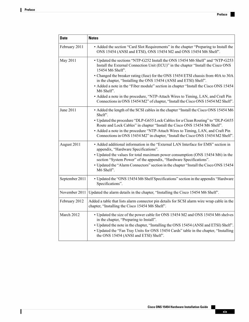
• Added the section “Card Slot Requirements” in the chapter “Preparing to Install theONS 15454 (ANSI and ETSI), ONS 15454 M2 and ONS 15454 M6 Shelf”.
February 2011
• Updated the sections “NTP-G252 Install the ONS 15454 M6 Shelf” and “NTP-G253Install the External Connection Unit (ECU)” in the chapter “Install the Cisco ONS15454 M6 Shelf”.
• Changed the breaker rating (fuse) for the ONS 15454 ETSI chassis from 40A to 30Ain the chapter, “Installing the ONS 15454 (ANSI and ETSI) Shelf”.
• Added a note in the “Fiber module” section in chapter “Install the Cisco ONS 15454M6 Shelf”.
• Added a note in the procedure, “NTP-Attach Wires to Timing, LAN, and Craft PinConnections in ONS 15454M2” of chapter, “Install the Cisco ONS 15454M2 Shelf”.
May 2011
• Added the length of the SCSI cables in the chapter “Install the Cisco ONS 15454 M6Shelf”.
• Updated the procedure “DLP-G655 Lock Cables for a Clean Routing” to “DLP-G655Route and Lock Cables” in chapter “Install the Cisco ONS 15454 M6 Shelf”.
• Added a note in the procedure “NTP-Attach Wires to Timing, LAN, and Craft PinConnections in ONS 15454M2” in chapter, “Install the Cisco ONS 15454M2 Shelf”.
June 2011
• Added additional information in the “External LAN Interface for EMS” section inappendix, “Hardware Specifications”.
• Updated the values for total maximum power consumption (ONS 15454 M6) in thesection “System Power” of the appendix, “Hardware Specifications”.
• Updated the “AlarmConnectors” section in the chapter “Install the Cisco ONS 15454M6 Shelf”.
August 2011
• Updated the “ONS 15454M6 Shelf Specifications” section in the appendix “HardwareSpecifications”.
September 2011
Updated the alarm details in the chapter, “Installing the Cisco 15454 M6 Shelf”.November 2011
Added a table that lists alarm connector pin details for SCSI alarm wire wrap cable in thechapter, “Installing the Cisco 15454 M6 Shelf”.
February 2012
• Updated the size of the power cable for ONS 15454 M2 and ONS 15454 M6 shelvesin the chapter, “Preparing to Install”.
• Updated the note in the chapter, “Installing the ONS 15454 (ANSI and ETSI) Shelf”.• Updated the “Fan Tray Units for ONS 15454 Cards” table in the chapter, “Installingthe ONS 15454 (ANSI and ETSI) Shelf”.
March 2012
Cisco ONS 15454 Hardware Installation Guidexix
PrefacePreface
NotesDate
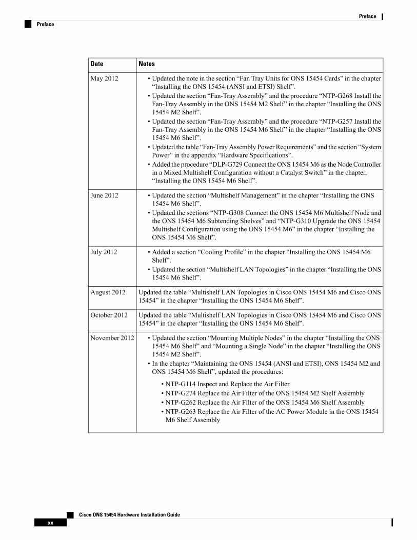
• Updated the note in the section “Fan Tray Units for ONS 15454 Cards” in the chapter“Installing the ONS 15454 (ANSI and ETSI) Shelf”.
• Updated the section “Fan-Tray Assembly” and the procedure “NTP-G268 Install theFan-Tray Assembly in the ONS 15454 M2 Shelf” in the chapter “Installing the ONS15454 M2 Shelf”.
• Updated the section “Fan-Tray Assembly” and the procedure “NTP-G257 Install theFan-Tray Assembly in the ONS 15454 M6 Shelf” in the chapter “Installing the ONS15454 M6 Shelf”.
• Updated the table “Fan-Tray Assembly Power Requirements” and the section “SystemPower” in the appendix “Hardware Specifications”.
• Added the procedure “DLP-G729 Connect the ONS 15454M6 as the Node Controllerin a Mixed Multishelf Configuration without a Catalyst Switch” in the chapter,“Installing the ONS 15454 M6 Shelf”.
May 2012
• Updated the section “Multishelf Management” in the chapter “Installing the ONS15454 M6 Shelf”.
• Updated the sections “NTP-G308 Connect the ONS 15454 M6 Multishelf Node andthe ONS 15454 M6 Subtending Shelves” and “NTP-G310 Upgrade the ONS 15454Multishelf Configuration using the ONS 15454 M6” in the chapter “Installing theONS 15454 M6 Shelf”.
June 2012
• Added a section “Cooling Profile” in the chapter “Installing the ONS 15454 M6Shelf”.
• Updated the section “Multishelf LAN Topologies” in the chapter “Installing the ONS15454 M6 Shelf”.
July 2012
Updated the table “Multishelf LAN Topologies in Cisco ONS 15454 M6 and Cisco ONS15454” in the chapter “Installing the ONS 15454 M6 Shelf”.
August 2012
Updated the table “Multishelf LAN Topologies in Cisco ONS 15454 M6 and Cisco ONS15454” in the chapter “Installing the ONS 15454 M6 Shelf”.
October 2012
• Updated the section “Mounting Multiple Nodes” in the chapter “Installing the ONS15454 M6 Shelf” and “Mounting a Single Node” in the chapter “Installing the ONS15454 M2 Shelf”.
• In the chapter “Maintaining the ONS 15454 (ANSI and ETSI), ONS 15454 M2 andONS 15454 M6 Shelf”, updated the procedures:
• NTP-G114 Inspect and Replace the Air Filter• NTP-G274 Replace the Air Filter of the ONS 15454 M2 Shelf Assembly• NTP-G262 Replace the Air Filter of the ONS 15454 M6 Shelf Assembly• NTP-G263 Replace the Air Filter of the AC Power Module in the ONS 15454M6 Shelf Assembly
November 2012
Cisco ONS 15454 Hardware Installation Guidexx
PrefacePreface
NotesDate
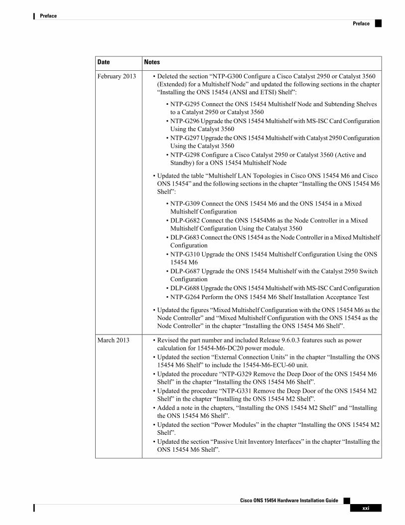
• Deleted the section “NTP-G300 Configure a Cisco Catalyst 2950 or Catalyst 3560(Extended) for a Multishelf Node” and updated the following sections in the chapter“Installing the ONS 15454 (ANSI and ETSI) Shelf”:
• NTP-G295 Connect the ONS 15454 Multishelf Node and Subtending Shelvesto a Catalyst 2950 or Catalyst 3560
• NTP-G296Upgrade the ONS 15454Multishelf withMS-ISCCard ConfigurationUsing the Catalyst 3560
• NTP-G297Upgrade the ONS 15454Multishelf with Catalyst 2950 ConfigurationUsing the Catalyst 3560
• NTP-G298 Configure a Cisco Catalyst 2950 or Catalyst 3560 (Active andStandby) for a ONS 15454 Multishelf Node
• Updated the table “Multishelf LAN Topologies in Cisco ONS 15454 M6 and CiscoONS 15454” and the following sections in the chapter “Installing the ONS 15454M6Shelf”:
• NTP-G309 Connect the ONS 15454 M6 and the ONS 15454 in a MixedMultishelf Configuration
• DLP-G682 Connect the ONS 15454M6 as the Node Controller in a MixedMultishelf Configuration Using the Catalyst 3560
• DLP-G683 Connect the ONS 15454 as the Node Controller in aMixedMultishelfConfiguration
• NTP-G310 Upgrade the ONS 15454 Multishelf Configuration Using the ONS15454 M6
• DLP-G687 Upgrade the ONS 15454 Multishelf with the Catalyst 2950 SwitchConfiguration
• DLP-G688Upgrade the ONS 15454Multishelf withMS-ISCCard Configuration• NTP-G264 Perform the ONS 15454 M6 Shelf Installation Acceptance Test
• Updated the figures “MixedMultishelf Configuration with the ONS 15454M6 as theNode Controller” and “Mixed Multishelf Configuration with the ONS 15454 as theNode Controller” in the chapter “Installing the ONS 15454 M6 Shelf”.
February 2013
• Revised the part number and included Release 9.6.0.3 features such as powercalculation for 15454-M6-DC20 power module.
• Updated the section “External Connection Units” in the chapter “Installing the ONS15454 M6 Shelf” to include the 15454-M6-ECU-60 unit.
• Updated the procedure “NTP-G329 Remove the Deep Door of the ONS 15454 M6Shelf” in the chapter “Installing the ONS 15454 M6 Shelf”.
• Updated the procedure “NTP-G331 Remove the Deep Door of the ONS 15454 M2Shelf” in the chapter “Installing the ONS 15454 M2 Shelf”.
• Added a note in the chapters, “Installing the ONS 15454 M2 Shelf” and “Installingthe ONS 15454 M6 Shelf”.
• Updated the section “Power Modules” in the chapter “Installing the ONS 15454 M2Shelf”.
• Updated the section “Passive Unit Inventory Interfaces” in the chapter “Installing theONS 15454 M6 Shelf”.
March 2013
Cisco ONS 15454 Hardware Installation Guidexxi
PrefacePreface

NotesDate
• Revised the part number and included Release 9.8 features such as AC2 powermodule.July 2013
• Added Release 10.0 feature on deep-front panel. Updated section “4.1 Front Door”.
• NTP-G343 Install the Air Plenum in ONS 15454 M2 Shelf.• DLP-G763 Install Air Plenum for ONS 15454 M2 Shelf in ANSI 19-inchConfiguration.
• DLP-G764 Install Air Plenum in ONS 15454 M2 Shelf for ANSI 23-inchConfiguration.
• DLP-G765 Install Air Plenum for ONS 15454 M2 Shelf in ETSI Configuration.
• Added Release 10.0 feature on air plenum to orient the air flow within the chassis insection “5.4 Air Plenum“.
• NTP-G344 Install the Air Plenum in ONS 15454 M6 Shelf• DLP-G766 Install Air Plenum for ONS 15454M6 Shelf in ANSI 19-inch Cabinet.• DLP-G767 Install Air Plenum in ONS 15454 M6 Shelf for ANSI 23-inchConfiguration.
• DLP-G768 Install Pre-assembled Air Plenums in ANSI 23-inch Configuration.• DLP-G769 Install Air Plenum for ONS 15454 M6 Shelf in ETSI Configuration.
November 2013
• The full length book-PDF was generated.April 2014
• Added information for the 15454-M6-DC40 power module.December 2014
• Added a note to the section, “Alarm Connectors” in the chapter “Installing the ONS15454 M6 Shelf”.
June 2015
• Updated for R10.5.2January 2016
Added the following note:
Due to memory limitations, TCC2/TCC2P cards are not supported as the node controllerin multi-shelf configuration from R10.5.2.6. Hence, it is recommended to use TCC3 cardas the node controller in multi-shelf configuration. However, the TCC2/TCC2P cards canbe used as a subtended controller and also in a stand-alone configuration.
April 2016
Updated the bandwidth specifications for ONS 15454 M6 in the appendix, “HardwareSpecifications”.
June 2016
Updated the sections, “Filler and Blank Cards” in the chapters, “Installing the ONS 15454M12 (ANSI and ETSI) Shelf”, “Installing the ONS 15454 M2 Shelf”, and “Installing theONS 15454 M6 Shelf”.
July 2016
Included R 10.6.1 features.November 2016
Added a note to "DLP-G298 Install LAN Wires in ONS 15454 M6" in the chapter,"Installing the ONS 15454 M6 Shelf".
March 2017
Updated for R10.6.2April 2017
Updated for R11.1October 2019
Cisco ONS 15454 Hardware Installation Guidexxii
PrefacePreface
Document ObjectivesThis document explains installation, turn up, provisioning, and maintenance for Cisco ONS 15454, CiscoONS M2, and Cisco ONS M6 systems. Use this document in conjunction with the appropriate publicationslisted in the Related Documentation, on page xxiii section.
AudienceTo use this publication, you should be familiar with Cisco or equivalent optical transmission hardware andcabling, telecommunications hardware and cabling, electronic circuitry and wiring practices, and preferablyhave experience as a telecommunications technician.
Related DocumentationUse the Cisco ONS 15454 Hardware Installation Guide in conjunction with the following referencedpublications:
• Cisco ONS 15454 DWDM Control Card and Node Configuration Guide
• Cisco ONS 15454 DWDM Line Card Configuration Guide
• Cisco ONS 15454 DWDM Network Configuration Guide
• Installing the Cisco ONS 15454 M2 and ONS 15454 M6 Passive Optical Modules
• Regulatory Compliance and Safety Information for Cisco ONS Products
• Electrostatic Discharge and Grounding Guide for Cisco CPT and Cisco ONS Platforms
• Installing the GBIC, SFP, SFP+, QSFP, XFP, CXP, CFP, and CPAK Optical Modules in Cisco ONSPlatforms
• Cisco ONS 15454 DWDM Troubleshooting Guide
• Cisco ONS 15454 DWDM Licensing Configuration Guide
For an update on End-of-Life and End-of-Sale notices, refer tohttp://www.cisco.com/en/US/products/hw/optical/ps2006/prod_eol_notices_list.html.
Document ConventionsThis publication uses the following conventions:
ApplicationConvention
Commands and keywords in body text.boldface
Command input that is supplied by the user.italic
Keywords or arguments that appear within square brackets are optional.[ ]
Cisco ONS 15454 Hardware Installation Guidexxiii
PrefaceDocument Objectives
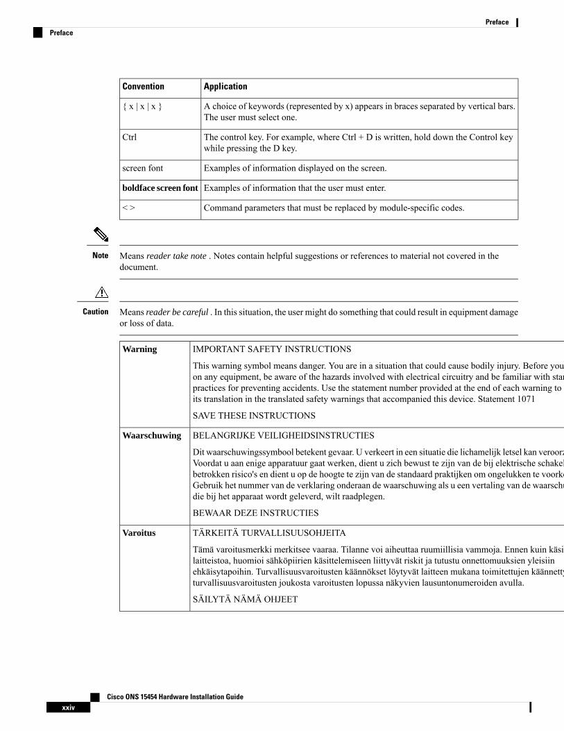
ApplicationConvention
A choice of keywords (represented by x) appears in braces separated by vertical bars.The user must select one.
{ x | x | x }
The control key. For example, where Ctrl + D is written, hold down the Control keywhile pressing the D key.
Ctrl
Examples of information displayed on the screen.screen font
Examples of information that the user must enter.boldface screen font
Command parameters that must be replaced by module-specific codes.< >
Means reader take note . Notes contain helpful suggestions or references to material not covered in thedocument.
Note
Means reader be careful . In this situation, the user might do something that could result in equipment damageor loss of data.
Caution
IMPORTANT SAFETY INSTRUCTIONS
This warning symbol means danger. You are in a situation that could cause bodily injury. Before you workon any equipment, be aware of the hazards involved with electrical circuitry and be familiar with standardpractices for preventing accidents. Use the statement number provided at the end of each warning to locateits translation in the translated safety warnings that accompanied this device. Statement 1071
SAVE THESE INSTRUCTIONS
Warning
BELANGRIJKE VEILIGHEIDSINSTRUCTIES
Dit waarschuwingssymbool betekent gevaar. U verkeert in een situatie die lichamelijk letsel kan veroorzaken.Voordat u aan enige apparatuur gaat werken, dient u zich bewust te zijn van de bij elektrische schakelingenbetrokken risico's en dient u op de hoogte te zijn van de standaard praktijken om ongelukken te voorkomen.Gebruik het nummer van de verklaring onderaan de waarschuwing als u een vertaling van de waarschuwingdie bij het apparaat wordt geleverd, wilt raadplegen.
BEWAAR DEZE INSTRUCTIES
Waarschuwing
TÄRKEITÄ TURVALLISUUSOHJEITA
Tämä varoitusmerkki merkitsee vaaraa. Tilanne voi aiheuttaa ruumiillisia vammoja. Ennen kuin käsitteletlaitteistoa, huomioi sähköpiirien käsittelemiseen liittyvät riskit ja tutustu onnettomuuksien yleisiinehkäisytapoihin. Turvallisuusvaroitusten käännökset löytyvät laitteen mukana toimitettujen käännettyjenturvallisuusvaroitusten joukosta varoitusten lopussa näkyvien lausuntonumeroiden avulla.
SÄILYTÄ NÄMÄ OHJEET
Varoitus
Cisco ONS 15454 Hardware Installation Guidexxiv
PrefacePreface
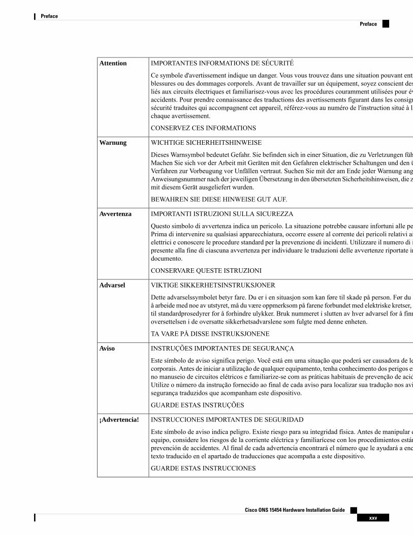
IMPORTANTES INFORMATIONS DE SÉCURITÉ
Ce symbole d'avertissement indique un danger. Vous vous trouvez dans une situation pouvant entraîner desblessures ou des dommages corporels. Avant de travailler sur un équipement, soyez conscient des dangersliés aux circuits électriques et familiarisez-vous avec les procédures couramment utilisées pour éviter lesaccidents. Pour prendre connaissance des traductions des avertissements figurant dans les consignes desécurité traduites qui accompagnent cet appareil, référez-vous au numéro de l'instruction situé à la fin dechaque avertissement.
CONSERVEZ CES INFORMATIONS
Attention
WICHTIGE SICHERHEITSHINWEISE
Dieses Warnsymbol bedeutet Gefahr. Sie befinden sich in einer Situation, die zu Verletzungen führen kann.Machen Sie sich vor der Arbeit mit Geräten mit den Gefahren elektrischer Schaltungen und den üblichenVerfahren zur Vorbeugung vor Unfällen vertraut. Suchen Sie mit der am Ende jeder Warnung angegebenenAnweisungsnummer nach der jeweiligenÜbersetzung in den übersetzten Sicherheitshinweisen, die zusammenmit diesem Gerät ausgeliefert wurden.
BEWAHREN SIE DIESE HINWEISE GUT AUF.
Warnung
IMPORTANTI ISTRUZIONI SULLA SICUREZZA
Questo simbolo di avvertenza indica un pericolo. La situazione potrebbe causare infortuni alle persone.Prima di intervenire su qualsiasi apparecchiatura, occorre essere al corrente dei pericoli relativi ai circuitielettrici e conoscere le procedure standard per la prevenzione di incidenti. Utilizzare il numero di istruzionepresente alla fine di ciascuna avvertenza per individuare le traduzioni delle avvertenze riportate in questodocumento.
CONSERVARE QUESTE ISTRUZIONI
Avvertenza
VIKTIGE SIKKERHETSINSTRUKSJONER
Dette advarselssymbolet betyr fare. Du er i en situasjon som kan føre til skade på person. Før du begynnerå arbeide med noe av utstyret, må du være oppmerksom på farene forbundet med elektriske kretser, og kjennetil standardprosedyrer for å forhindre ulykker. Bruk nummeret i slutten av hver advarsel for å finneoversettelsen i de oversatte sikkerhetsadvarslene som fulgte med denne enheten.
TA VARE PÅ DISSE INSTRUKSJONENE
Advarsel
INSTRUÇÕES IMPORTANTES DE SEGURANÇA
Este símbolo de aviso significa perigo. Você está em uma situação que poderá ser causadora de lesõescorporais. Antes de iniciar a utilização de qualquer equipamento, tenha conhecimento dos perigos envolvidosno manuseio de circuitos elétricos e familiarize-se com as práticas habituais de prevenção de acidentes.Utilize o número da instrução fornecido ao final de cada aviso para localizar sua tradução nos avisos desegurança traduzidos que acompanham este dispositivo.
GUARDE ESTAS INSTRUÇÕES
Aviso
INSTRUCCIONES IMPORTANTES DE SEGURIDAD
Este símbolo de aviso indica peligro. Existe riesgo para su integridad física. Antes de manipular cualquierequipo, considere los riesgos de la corriente eléctrica y familiarícese con los procedimientos estándar deprevención de accidentes. Al final de cada advertencia encontrará el número que le ayudará a encontrar eltexto traducido en el apartado de traducciones que acompaña a este dispositivo.
GUARDE ESTAS INSTRUCCIONES
¡Advertencia!
Cisco ONS 15454 Hardware Installation Guidexxv
PrefacePreface
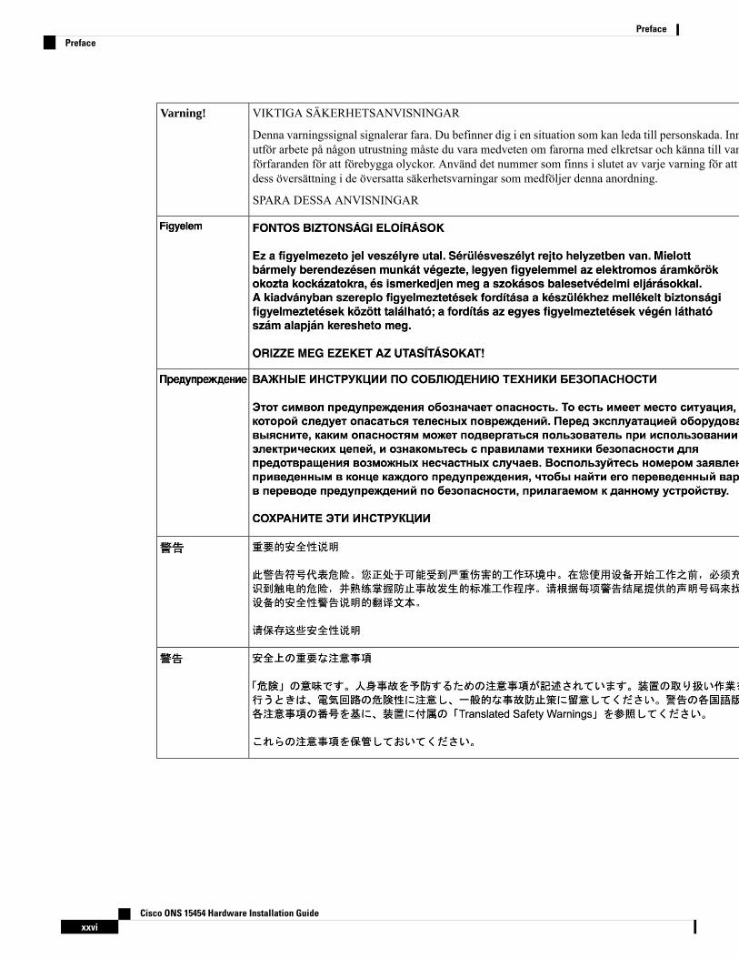
VIKTIGA SÄKERHETSANVISNINGAR
Denna varningssignal signalerar fara. Du befinner dig i en situation som kan leda till personskada. Innan duutför arbete på någon utrustning måste du vara medveten om farorna med elkretsar och känna till vanligaförfaranden för att förebygga olyckor. Använd det nummer som finns i slutet av varje varning för att hittadess översättning i de översatta säkerhetsvarningar som medföljer denna anordning.
SPARA DESSA ANVISNINGAR
Varning!
Cisco ONS 15454 Hardware Installation Guidexxvi
PrefacePreface
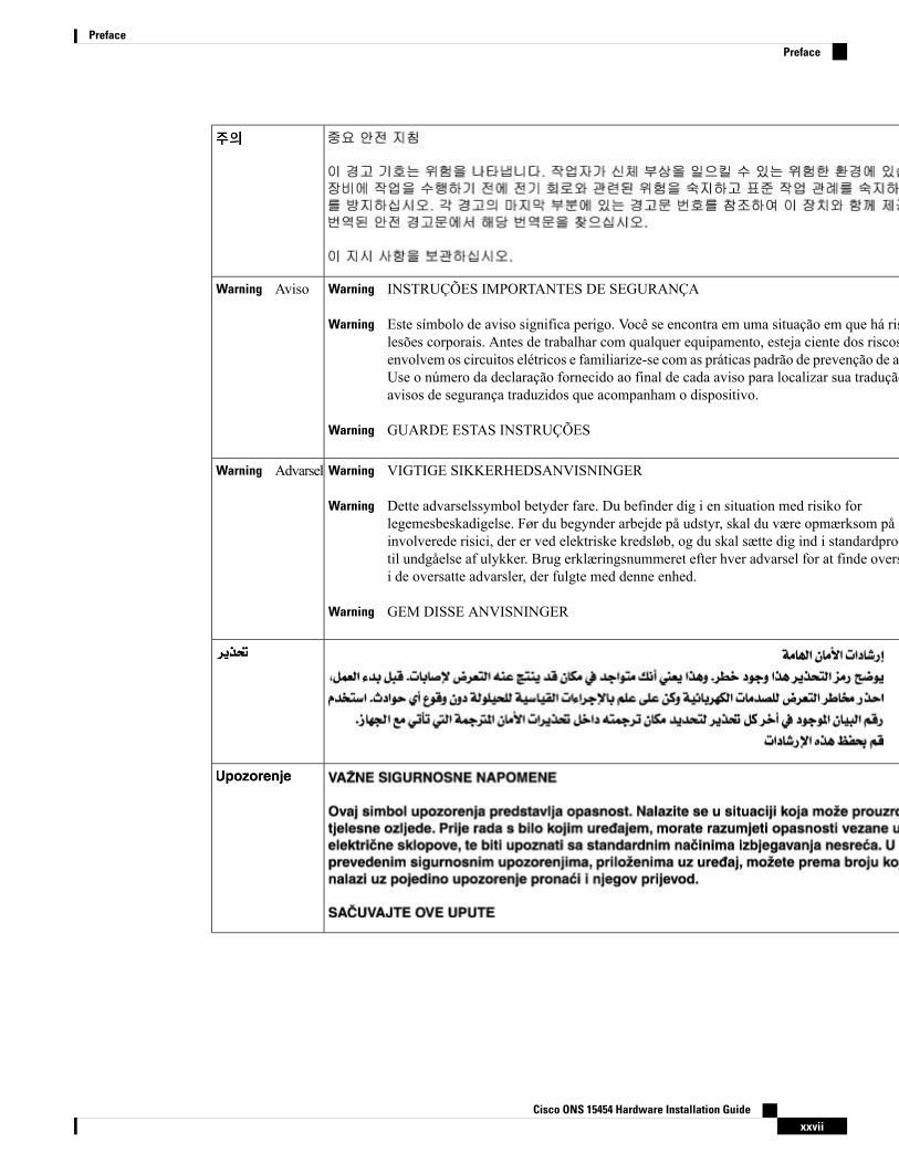
INSTRUÇÕES IMPORTANTES DE SEGURANÇAWarning
Este símbolo de aviso significa perigo. Você se encontra em uma situação em que há risco delesões corporais. Antes de trabalhar com qualquer equipamento, esteja ciente dos riscos queenvolvem os circuitos elétricos e familiarize-se com as práticas padrão de prevenção de acidentes.Use o número da declaração fornecido ao final de cada aviso para localizar sua tradução nosavisos de segurança traduzidos que acompanham o dispositivo.
Warning
GUARDE ESTAS INSTRUÇÕESWarning
AvisoWarning
VIGTIGE SIKKERHEDSANVISNINGERWarning
Dette advarselssymbol betyder fare. Du befinder dig i en situation med risiko forlegemesbeskadigelse. Før du begynder arbejde på udstyr, skal du være opmærksom på deinvolverede risici, der er ved elektriske kredsløb, og du skal sætte dig ind i standardprocedurertil undgåelse af ulykker. Brug erklæringsnummeret efter hver advarsel for at finde oversættelseni de oversatte advarsler, der fulgte med denne enhed.
Warning
GEM DISSE ANVISNINGERWarning
AdvarselWarning
Cisco ONS 15454 Hardware Installation Guidexxvii
PrefacePreface
Cisco ONS 15454 Hardware Installation Guidexxviii
PrefacePreface
Obtaining Optical Networking InformationThis section contains information that is specific to optical networking products. For information that pertainsto all of Cisco, refer to the Obtaining Documentation, Obtaining Support, and Security Guidelines, on pagexxix section.
Where to Find Safety and Warning InformationFor safety and warning information, refer to the following document that accompanied the product:
Regulatory Compliance and Safety Information for Cisco ONS Products
This publication describes the international agency compliance and safety information for the Cisco ONS15454, ONS 15454 M2, and ONS 15454 M6 system. It also includes translations of the safety warnings thatappear in the Cisco ONS 15454 system documentation.
Obtaining Documentation, Obtaining Support, and SecurityGuidelines
For information on obtaining documentation, submitting a service request, and gathering additional information,see the monthly What’s New in Cisco Product Documentation , which also lists all new and revised Ciscotechnical documentation, at:
http://www.cisco.com/en/US/docs/general/whatsnew/whatsnew.html
Subscribe to the What’s New in Cisco Product Documentation as a Really Simple Syndication (RSS) feedand set content to be delivered directly to your desktop using a reader application. The RSS feeds are a freeservice and Cisco currently supports RSS Version 2.0.
Cisco ONS 15454 Hardware Installation Guidexxix
PrefaceObtaining Optical Networking Information

Cisco ONS 15454 Hardware Installation Guidexxx
PrefaceObtaining Documentation, Obtaining Support, and Security Guidelines
C H A P T E R 1Overview
This chapter provides an overview of the Cisco ONS 15454 (ANSI and ETSI), ONS 15454 M2 and ONS15454 M6 shelf install.
Unless otherwise specified, “ONS 15454” refers to both ANSI and ETSI M12 shelf assemblies.Note
The Cisco ONS 15454 shelf assemblies are intended for use with telecommunications equipment only.Note
• Compliance Standards, on page 1• Safety Labels, on page 1• Cisco ONS 15454 ANSI, on page 3• Cisco ONS 15454 ETSI, on page 4• Cisco ONS 15454 M2 Shelf, on page 4• Cisco ONS 15454 M6 Shelf, on page 6
Compliance StandardsInstall the ONS 15454, ONS 15454M2 and ONS 15454M6 shelves in compliance with your local and nationalelectrical codes:
• United States: National Fire Protection Association (NFPA) 70; United States National Electrical Code.• Canada: Canadian Electrical Code, Part I, CSA C22.1.• Other countries: If local and national electrical codes, are not available, refer to IEC 364, Part 1 throughPart 7.
Safety LabelsCisco ONS 15454 Series chassis is classified as Hazard Level 1M as per IEC 60825-1, since it includesembedded Class 1 or Class 1M Laser sources.
The Class 1M Laser Product label is shown in the following figure.
Cisco ONS 15454 Hardware Installation Guide1
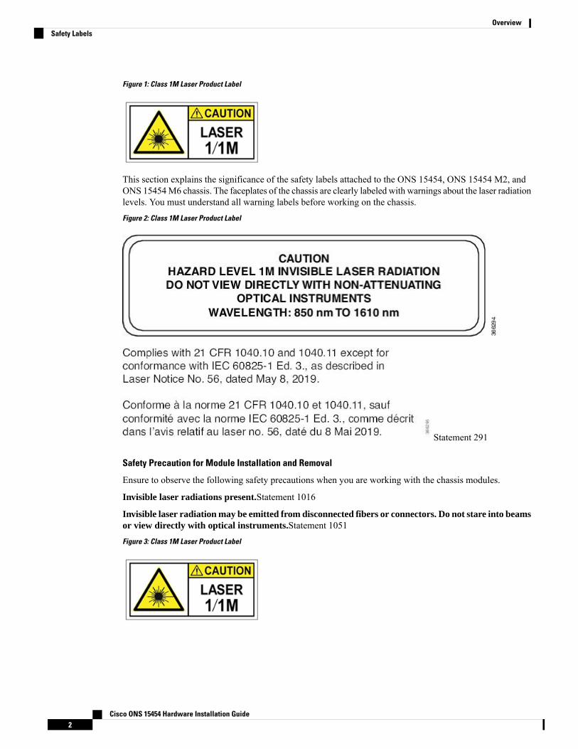
Figure 1: Class 1M Laser Product Label
This section explains the significance of the safety labels attached to the ONS 15454, ONS 15454 M2, andONS 15454M6 chassis. The faceplates of the chassis are clearly labeled with warnings about the laser radiationlevels. You must understand all warning labels before working on the chassis.
Figure 2: Class 1M Laser Product Label
Statement 291
Safety Precaution for Module Installation and Removal
Ensure to observe the following safety precautions when you are working with the chassis modules.
Invisible laser radiations present.Statement 1016
Invisible laser radiation may be emitted from disconnected fibers or connectors. Do not stare into beamsor view directly with optical instruments.Statement 1051
Figure 3: Class 1M Laser Product Label
Cisco ONS 15454 Hardware Installation Guide2
OverviewSafety Labels
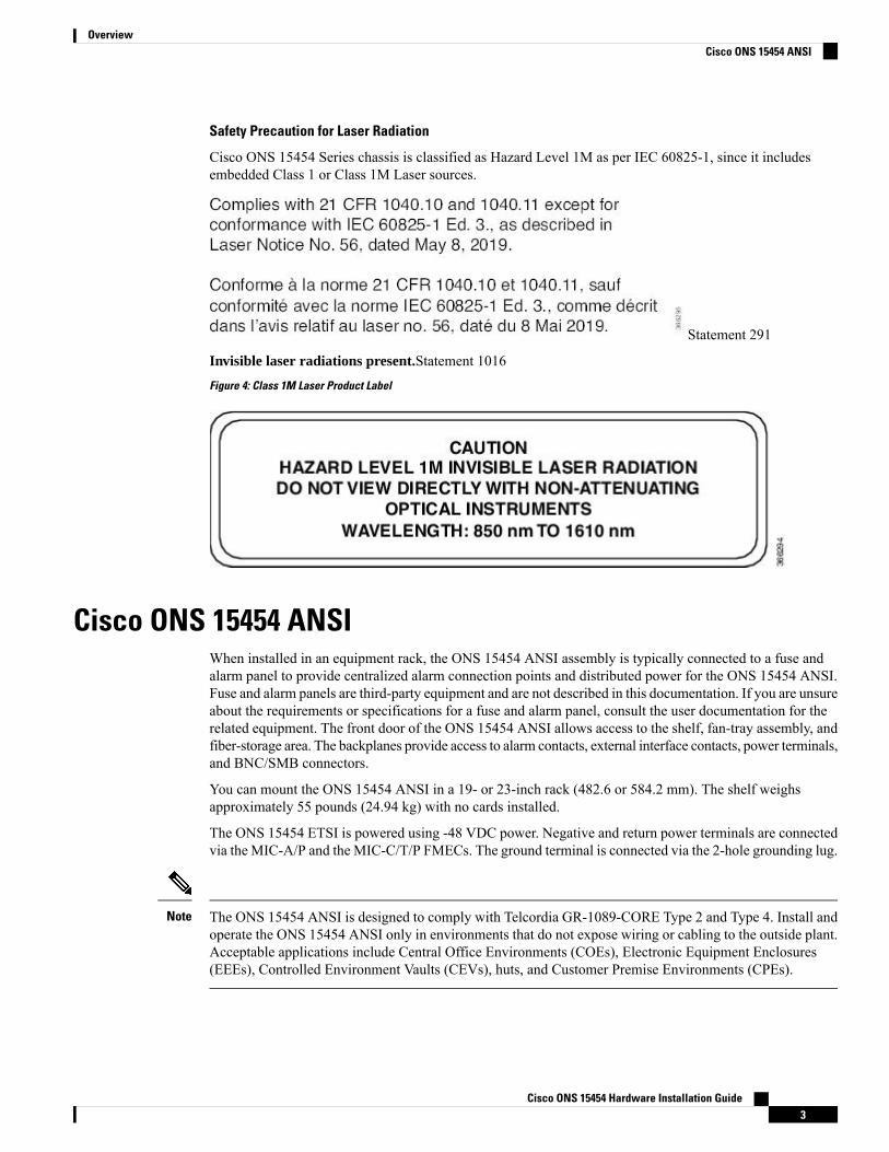
Safety Precaution for Laser Radiation
Cisco ONS 15454 Series chassis is classified as Hazard Level 1M as per IEC 60825-1, since it includesembedded Class 1 or Class 1M Laser sources.
Statement 291
Invisible laser radiations present.Statement 1016
Figure 4: Class 1M Laser Product Label
Cisco ONS 15454 ANSIWhen installed in an equipment rack, the ONS 15454 ANSI assembly is typically connected to a fuse andalarm panel to provide centralized alarm connection points and distributed power for the ONS 15454 ANSI.Fuse and alarm panels are third-party equipment and are not described in this documentation. If you are unsureabout the requirements or specifications for a fuse and alarm panel, consult the user documentation for therelated equipment. The front door of the ONS 15454 ANSI allows access to the shelf, fan-tray assembly, andfiber-storage area. The backplanes provide access to alarm contacts, external interface contacts, power terminals,and BNC/SMB connectors.
You can mount the ONS 15454 ANSI in a 19- or 23-inch rack (482.6 or 584.2 mm). The shelf weighsapproximately 55 pounds (24.94 kg) with no cards installed.
The ONS 15454 ETSI is powered using -48 VDC power. Negative and return power terminals are connectedvia the MIC-A/P and the MIC-C/T/P FMECs. The ground terminal is connected via the 2-hole grounding lug.
The ONS 15454 ANSI is designed to comply with Telcordia GR-1089-CORE Type 2 and Type 4. Install andoperate the ONS 15454 ANSI only in environments that do not expose wiring or cabling to the outside plant.Acceptable applications include Central Office Environments (COEs), Electronic Equipment Enclosures(EEEs), Controlled Environment Vaults (CEVs), huts, and Customer Premise Environments (CPEs).
Note
Cisco ONS 15454 Hardware Installation Guide3
OverviewCisco ONS 15454 ANSI
For information on hardware and software specifications for the ONS 15454 ANSI shelf, refer to the ONS15454 Shelf Specifications, on page 471.
Cisco ONS 15454 ETSIWhen installed in an equipment rack, the ONS 15454 ETSI assembly is typically connected to a fuse andalarm panel to provide centralized alarm connection points and distributed power for the ONS 15454 ETSI.Fuse and alarm panels are third-party equipment and are not described in this documentation. If you are unsureabout the requirements or specifications for a fuse and alarm panel, consult the user documentation for therelated equipment. The front door of the ONS 15454 ETSI allows access to the shelf, fan-tray assembly, andfiber-storage area. The FMEC cover at the top of the shelf allows access to power connectors, external alarmsand controls, timing input and output, and craft interface terminals.
You can mount the ONS 15454 ETSI in an ETSI rack. The shelf weighs approximately 26 kg (57 pounds)with no cards installed. The shelf includes a front door and a Front Mount Electrical Connection (FMEC)cover for added security, a fan tray module for cooling, and extensive fiber-storage space.
The ONS 15454 ETSI is powered using –48 VDC power. Negative, return, and ground power terminals areconnected via the MIC-A/P and the MIC-C/T/P FMECs.
For information on hardware and software specifications for the ONS 15454 ETSI shelf, refer to the ONS15454 Shelf Specifications, on page 471.
Cisco ONS 15454 M2 ShelfThe ONS 15454 M2 is designed to comply with Telcordia GR-1089-CORE, Issue 5. The ONS 15454 M2provides only Type 2 and Type 4 interfaces. A single ONS 15454 M2 shelf supports both ANSI and ETSIstandards.
The ONS 15454 M2 shelf has 3 horizontal card slots —Slot 1, Slot 2, and Slot 3. While Slot 2 and Slot 3house MSTP cards that provide 10 to 100 Gbps interconnections, Slot 1 accommodates the TNC, TNCE,TSC, TNCS-2, TNCS-2O, or TSCE card (timing and control card). The ONS 15454M2 system can be poweredby AC or DC power module. The ONS 15454 M2 system contains backup flash memory that supports thedatabase (DB) and image backup in the single mode operation. The ONS 15454 M2 shelf can be mounted onan ANSI or an ETSI rack using the mounting brackets or air deflectors. The air deflectors orient the air flowin a specific direction. The ONS 15454 M2 shelf can also be wall-mounted or desktop-mounted.
When installed in an equipment rack, the Cisco ONS 15454 M2 shelf is typically connected to a fuse panelto provide distributed power for the ONS 15454 M2. The fuse panel is a third-party equipment and is notdescribed in this documentation. If you are unsure about the requirements or specifications for a fuse, consultthe user documentation for the related equipment.
Install and operate the ONS 15454M2 only in environments that do not expose wiring or cabling to the outsideplant.
Two types of front doors can be attached to the Cisco ONS 15454 M2 shelf— the standard door and the deepdoor. The front door provides access to the shelf, and acts as a protective panel. The deep door providesadditional space in front of the shelf to accommodate cables that do not fit inside the standard door. The deepdoor does not have a hinge and cannot be rotated like the standard door.
You can mount the ONS 15454 M2 on a 19-inch or 23-inch ANSI rack (482.6 or 584.2 mm), or on a 600 x600-mm (23.6 x 23.6-inch) or 600 x 300-mm (23.6 x 11.8-inch) ETSI standard equipment rack. The ONS
Cisco ONS 15454 Hardware Installation Guide4
OverviewCisco ONS 15454 ETSI
15454M2 shelf can also be wall mounted or desktop mounted. The shelf weighs approximately 11.02 pounds(5 kg) with no cards installed.
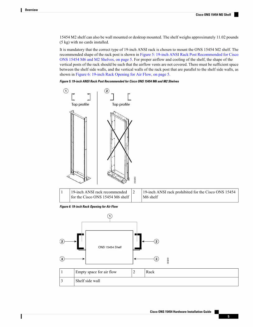
It is mandatory that the correct type of 19-inch ANSI rack is chosen to mount the ONS 15454 M2 shelf. Therecommended shape of the rack post is shown in Figure 5: 19-inch ANSI Rack Post Recommended for CiscoONS 15454 M6 and M2 Shelves, on page 5. For proper airflow and cooling of the shelf, the shape of thevertical posts of the rack should be such that the airflow vents are not covered. There must be sufficient spacebetween the shelf side walls, and the vertical walls of the rack post that are parallel to the shelf side walls, asshown in Figure 6: 19-inch Rack Opening for Air Flow, on page 5.
Figure 5: 19-inch ANSI Rack Post Recommended for Cisco ONS 15454 M6 and M2 Shelves
19-inch ANSI rack prohibited for the Cisco ONS 15454M6 shelf
219-inch ANSI rack recommendedfor the Cisco ONS 15454 M6 shelf
1
Figure 6: 19-inch Rack Opening for Air Flow
Rack2Empty space for air flow1
Shelf side wall3
Cisco ONS 15454 Hardware Installation Guide5
OverviewCisco ONS 15454 M2 Shelf
For information on hardware and software specifications for the ONS 15454 ETSI shelf, refer to the ONS15454 M2 Shelf Specifications, on page 475.
Cisco ONS 15454 M6 ShelfThe ONS 15454 M6 is designed to comply with Telcordia GR-1089-CORE, Issue 5.
The ONS 15454 M6 provides only Type 2 and Type 4 interfaces. A single ONS 15454 M6 shelf supportsboth ANSI and ETSI standards.
The ONS 15454 M6 shelf has 8 horizontal card slots numbered 1 to 8. While Slot 2 to Slot 7 house MSTPcards that provide 10 to 100 Gbps interconnections, Slot 1 and Slot 8 accommodate the TNC, TNCE, TSC,TNCS-2, TNCS-2O, or TSCE cards (timing and control cards). The ONS 15454 M6 system can be poweredby redundant AC or DC power modules. A single power module (AC or DC) can be used to power up theentire ONS 15454 M6 system. The ONS 15454 M6 system contains backup flash memory that supports thedatabase (DB) and image backup in the single mode operation.
The front door of the ONS 15454 M6 shelf allows access to the shelf, fan-tray assembly, fiber-routing area,power connectors, external alarms and controls, timing input and output, and craft interface terminals. Twotypes of front doors can be attached to the ONS 15454 M6 shelf—the standard door and the deep door. Thefront door provides access to the shelf, and acts as a protective panel. The deep door provides additional spacein front of the shelf to accommodate cables that do not fit inside the standard door. The deep door does nothave a hinge and cannot be rotated like the standard door. The fiber or cable guide used in the ONS 15454M6 shelf provides improved fiber management.
The ONS 15454 M6 is mounted on a 19-inch or 23-inch ANSI rack, or on a 600 x 600-mm or 600 x 300-mmETSI standard equipment rack. The rack mounting is done using the mounting brackets or air deflectors. Theair deflectors orient the air flow in a specific direction.
Depending on the position of the mounting bracket, the chassis may project to different distances outside therack. If the chassis projects outside the rack, the cabinet doors must be kept open (if present). The table belowdisplays the details below:
Chassis ProjectionOutside Rack (mm)
Bracket Mount PositionChassis Depth (mm)Door Type
50 mmFront mount287 mmStandard door
135 mmMid mount287 mmStandard door
100 mmFront mount337 mmDeep door
185 mmMid mount337 mmDeep door
It is mandatory that the correct type of 19-inch ANSI rack is chosen to mount the ONS 15454 M6 shelf. Therecommended shape of the rack post is shown in Figure 5: 19-inch ANSI Rack Post Recommended for CiscoONS 15454 M6 and M2 Shelves, on page 5. For proper airflow and cooling of the shelf, the shape of thevertical posts of the rack should be such that the airflow vents are not covered. There must be sufficient spacebetween the shelf side walls, and the vertical walls of the rack post that are parallel to the shelf side walls, asshown in Figure 6: 19-inch Rack Opening for Air Flow, on page 5.
When installed in an equipment rack, the Cisco ONS 15454 M6 shelf is typically connected to a fuse andalarm panel to provide centralized alarm connection points and distributed power for the ONS 15454 M6.
Cisco ONS 15454 Hardware Installation Guide6
OverviewCisco ONS 15454 M6 Shelf
Fuse and alarm panels are third-party equipment and are not described in this documentation. If you are unsureabout the requirements or specifications for a fuse and alarm panel, consult the user documentation for therelated equipment.
The shelf with preinstalled air filter weighs approximately 23.55 pounds (10.680 kg) with no cards installed.
Install and operate the ONS 15454M6 only in environments that do not expose wiring or cabling to the outsideplant.
Note
For information on hardware and software specifications for the ONS 15454 ETSI shelf, refer to the ONS15454 M6 Shelf Specifications, on page 478.
Cisco ONS 15454 Hardware Installation Guide7
OverviewCisco ONS 15454 M6 Shelf

Cisco ONS 15454 Hardware Installation Guide8
OverviewCisco ONS 15454 M6 Shelf
C H A P T E R 2Preparing to Install the ONS 15454 (ANSI andETSI), ONS 15454 M2 and ONS 15454 M6 Shelf
This chapter explains how to prepare for the ONS 15454 (ANSI and ETSI), ONS 15454 M2 and ONS 15454M6 shelf install.
Unless otherwise specified, “ONS 15454” refers to both ANSI and ETSI M12 shelf assemblies.Note
Due to memory limitations, TCC2/TCC2P cards are not supported as the node controller in multi-shelfconfiguration fromR10.5.2.6. Hence, it is recommended to use TCC3 card as the node controller in multi-shelfconfiguration. The TCC2P card can be used as a control card in a subtended shelf where the node controlleris TCC3 card on ONS 15454 chassis or TNC/TNCE/TNCS/TNCS-O/TNCS-2/TNCS-2O cards on ONS 15454M6 or NCS 20015 chassis. The TCC2P card can also be used as a node controller in a stand-alone configuration.
Note
• Important Safety Recommendations, on page 9• Required Tools and Equipment, on page 11• Ordering Solutions for ONS 15454 M2 and ONS 15454 M6, on page 17• Card Slot Requirements, on page 17• NTP-G305 Unpack and Inspect the ONS 15454, ONS 15454 M2, and ONS 15454 M6 Shelves, on page22
Important Safety Recommendations
This warning symbol means danger. You are in a situation that could cause bodily injury. Before youwork on any equipment, be aware of the hazards involved with electrical circuitry and be familiar withstandard practices for preventing accidents. To see translations of the warnings that appear in thispublication, refer to the Regulatory Compliance and Safety Information document for the appropriateCisco chassis. Statement 274
Warning
Cisco ONS 15454 Hardware Installation Guide9
Installation of the equipment must comply with local and national electrical codes. Statement 1074Warning
This equipment must be installed and maintained by service personnel as defined by AS/NZS 3260.Incorrectly connecting this equipment to a general-purpose outlet could be hazardous. Thetelecommunications lines must be disconnected 1) before unplugging the main power connector or 2)while the housing is open, or both. Statement 1043
Warning
This unit is intended for installation in restricted access areas. A restricted access area can be accessedonly through the use of a special tool, lock and key, or other means of security. Statement 1017
Warning
Ultimate disposal of this product should be handled according to all national laws and regulations.Statement 1040
Warning
A readily accessible two-poled disconnect device must be incorporated in the fixed wiring. Statement1022
Warning
The ONS 15454, ONS 15454 M2 and ONS 15454 M6 are suitable for mounting on concrete or othernoncombustible surfaces only.
Note
In this chapter, “shelf” refers to the steel enclosure that holds cards and connects power, and “node” refers tothe entire hardware and software system.
Note
Unless otherwise specified, ONS 15454, ONS 15454 M2 and ONS 15454 M6 refers to both ANSI and ETSIenvironments.
Note
The ONS 15454 M6 is suitable for installation in network telecommunication facilities where the NationalElectric Code (NEC) applies.
Note
Cisco ONS 15454 Hardware Installation Guide10
Preparing to Install the ONS 15454 (ANSI and ETSI), ONS 15454 M2 and ONS 15454 M6 ShelfImportant Safety Recommendations
Required Tools and EquipmentThe following sections describe the tools and equipment you need to install and test the ONS 15454 (ANSIand ETSI), ONS 15454 M2 or the ONS 15454 M6 shelves.
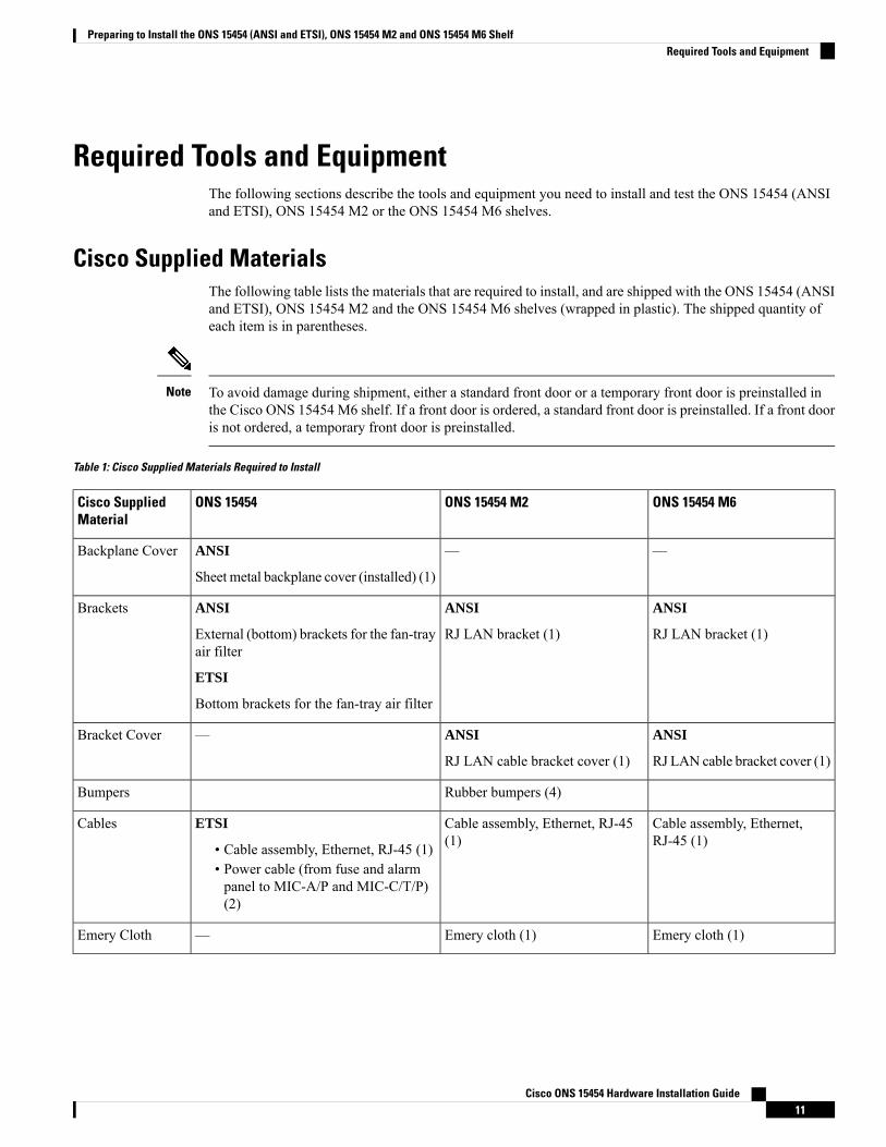
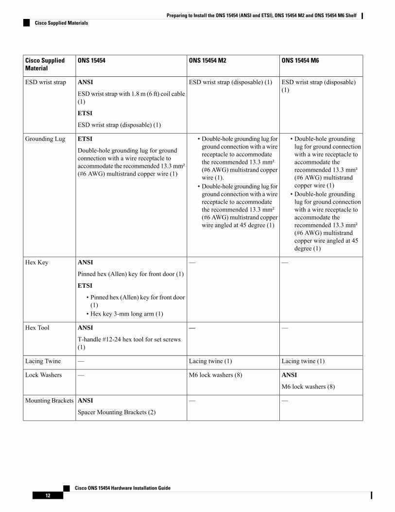
Cisco Supplied MaterialsThe following table lists the materials that are required to install, and are shipped with the ONS 15454 (ANSIand ETSI), ONS 15454 M2 and the ONS 15454 M6 shelves (wrapped in plastic). The shipped quantity ofeach item is in parentheses.
To avoid damage during shipment, either a standard front door or a temporary front door is preinstalled inthe Cisco ONS 15454 M6 shelf. If a front door is ordered, a standard front door is preinstalled. If a front dooris not ordered, a temporary front door is preinstalled.
Note
Table 1: Cisco Supplied Materials Required to Install
ONS 15454 M6ONS 15454 M2ONS 15454Cisco SuppliedMaterial
——ANSI
Sheet metal backplane cover (installed) (1)
Backplane Cover
ANSI
RJ LAN bracket (1)
ANSI
RJ LAN bracket (1)
ANSI
External (bottom) brackets for the fan-trayair filter
ETSI
Bottom brackets for the fan-tray air filter
Brackets
ANSI
RJ LAN cable bracket cover (1)
ANSI
RJ LAN cable bracket cover (1)
—Bracket Cover
Rubber bumpers (4)Bumpers
Cable assembly, Ethernet,RJ-45 (1)
Cable assembly, Ethernet, RJ-45(1)
ETSI
• Cable assembly, Ethernet, RJ-45 (1)• Power cable (from fuse and alarmpanel to MIC-A/P and MIC-C/T/P)(2)
Cables
Emery cloth (1)Emery cloth (1)—Emery Cloth
Cisco ONS 15454 Hardware Installation Guide11
Preparing to Install the ONS 15454 (ANSI and ETSI), ONS 15454 M2 and ONS 15454 M6 ShelfRequired Tools and Equipment
ONS 15454 M6ONS 15454 M2ONS 15454Cisco SuppliedMaterial
ESD wrist strap (disposable)(1)
ESD wrist strap (disposable) (1)ANSI
ESDwrist strap with 1.8 m (6 ft) coil cable(1)
ETSI
ESD wrist strap (disposable) (1)
ESD wrist strap
• Double-hole groundinglug for ground connectionwith a wire receptacle toaccommodate therecommended 13.3 mm²(#6 AWG) multistrandcopper wire (1)
• Double-hole groundinglug for ground connectionwith a wire receptacle toaccommodate therecommended 13.3 mm²(#6 AWG) multistrandcopper wire angled at 45degree (1)
• Double-hole grounding lug forground connectionwith a wirereceptacle to accommodatethe recommended 13.3 mm²(#6 AWG)multistrand copperwire (1).
• Double-hole grounding lug forground connectionwith a wirereceptacle to accommodatethe recommended 13.3 mm²(#6 AWG)multistrand copperwire angled at 45 degree (1)
ETSI
Double-hole grounding lug for groundconnection with a wire receptacle toaccommodate the recommended 13.3mm²(#6 AWG) multistrand copper wire (1)
Grounding Lug
——ANSI
Pinned hex (Allen) key for front door (1)
ETSI
• Pinned hex (Allen) key for front door(1)
• Hex key 3-mm long arm (1)
Hex Key
——ANSI
T-handle #12-24 hex tool for set screws(1)
Hex Tool
Lacing twine (1)Lacing twine (1)—Lacing Twine
ANSI
M6 lock washers (8)
M6 lock washers (8)—Lock Washers
——ANSI
Spacer Mounting Brackets (2)
Mounting Brackets
Cisco ONS 15454 Hardware Installation Guide12
Preparing to Install the ONS 15454 (ANSI and ETSI), ONS 15454 M2 and ONS 15454 M6 ShelfCisco Supplied Materials
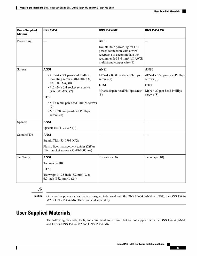
ONS 15454 M6ONS 15454 M2ONS 15454Cisco SuppliedMaterial
—ANSI
Double-hole power lug for DCpower connection with a wirereceptacle to accommodate therecommended 8.4 mm² (#8 AWG)multistrand copper wire (1)
—Power Lug
ANSI
#12-24 x 0.50 pan-head Phillipsscrews (8)
ETSI
M6.0 x 20 pan-head Phillipsscrews (8)
ANSI
#12-24 x 0.50 pan-head Phillipsscrews (8)
ETSI
M6.0 x 20 pan-head Phillips screws(8)
ANSI
• #12-24 x 3/4 pan-head Phillipsmounting screws (48-1004-XX,48-1007-XX) (8)
• #12 -24 x 3/4 socket set screws(48-1003-XX) (2)
ETSI
• M4 x 8 mm pan-head Phillips screws(2)
• M6 x 20 mm pan-head Phillipsscrews (8)
Screws
——ANSI
Spacers (50-1193-XX)(4)
Spacers
——ANSI
Standoff kit (53-0795-XX):
Plastic fiber management guides (2)Fanfilter bracket screws (53-48-0003) (6)
Standoff Kit
Tie wraps (10)Tie wraps (10)ANSI
Tie Wraps (10)
ETSI
Tie wraps 0.125-inch (3.2 mm) W x6.0-inch (152 mm) L (24)
Tie Wraps
Only use the power cables that are designed to be used with the ONS 15454 (ANSI or ETSI), the ONS 15454M2 or ONS 15454 M6. These are sold separately.
Caution
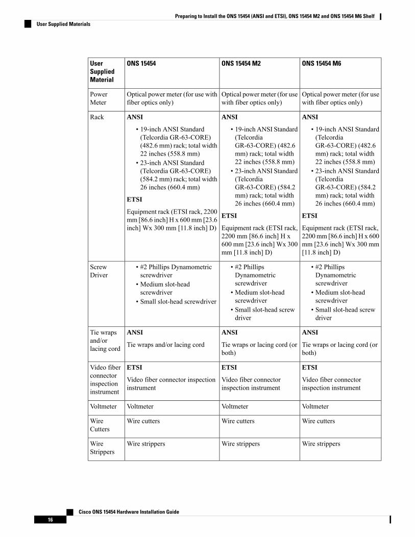
User Supplied MaterialsThe following materials, tools, and equipment are required but are not supplied with the ONS 15454 (ANSIand ETSI), ONS 15454 M2 and ONS 15454 M6.
Cisco ONS 15454 Hardware Installation Guide13
Preparing to Install the ONS 15454 (ANSI and ETSI), ONS 15454 M2 and ONS 15454 M6 ShelfUser Supplied Materials
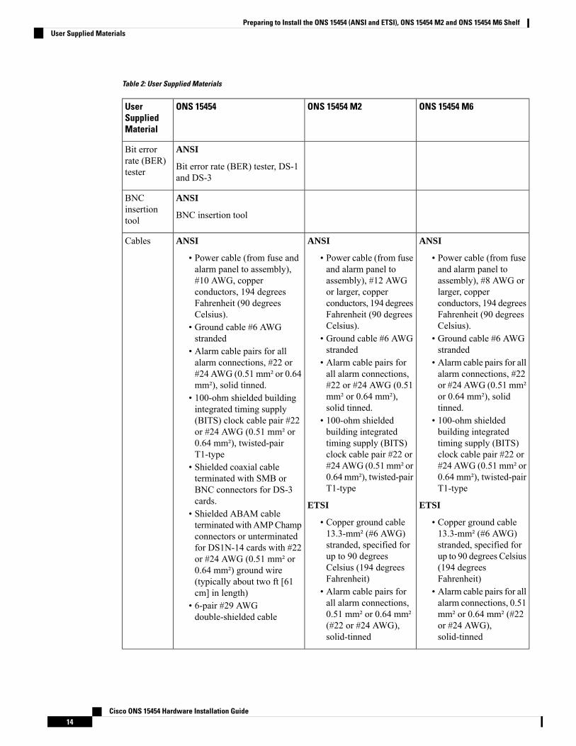
Table 2: User Supplied Materials
ONS 15454 M6ONS 15454 M2ONS 15454UserSuppliedMaterial
ANSI
Bit error rate (BER) tester, DS-1and DS-3
Bit errorrate (BER)tester
ANSI
BNC insertion tool
BNCinsertiontool
ANSI
• Power cable (from fuseand alarm panel toassembly), #8 AWG orlarger, copperconductors, 194 degreesFahrenheit (90 degreesCelsius).
• Ground cable #6 AWGstranded
• Alarm cable pairs for allalarm connections, #22or #24 AWG (0.51 mm²or 0.64 mm²), solidtinned.
• 100-ohm shieldedbuilding integratedtiming supply (BITS)clock cable pair #22 or#24 AWG (0.51 mm² or0.64 mm²), twisted-pairT1-type
ETSI
• Copper ground cable13.3-mm² (#6 AWG)stranded, specified forup to 90 degrees Celsius(194 degreesFahrenheit)
• Alarm cable pairs for allalarm connections, 0.51mm² or 0.64 mm² (#22or #24 AWG),solid-tinned
ANSI
• Power cable (from fuseand alarm panel toassembly), #12 AWGor larger, copperconductors, 194 degreesFahrenheit (90 degreesCelsius).
• Ground cable #6 AWGstranded
• Alarm cable pairs forall alarm connections,#22 or #24 AWG (0.51mm² or 0.64 mm²),solid tinned.
• 100-ohm shieldedbuilding integratedtiming supply (BITS)clock cable pair #22 or#24AWG (0.51mm² or0.64 mm²), twisted-pairT1-type
ETSI
• Copper ground cable13.3-mm² (#6 AWG)stranded, specified forup to 90 degreesCelsius (194 degreesFahrenheit)
• Alarm cable pairs forall alarm connections,0.51 mm² or 0.64 mm²(#22 or #24 AWG),solid-tinned
ANSI
• Power cable (from fuse andalarm panel to assembly),#10 AWG, copperconductors, 194 degreesFahrenheit (90 degreesCelsius).
• Ground cable #6 AWGstranded
• Alarm cable pairs for allalarm connections, #22 or#24 AWG (0.51 mm² or 0.64mm²), solid tinned.
• 100-ohm shielded buildingintegrated timing supply(BITS) clock cable pair #22or #24 AWG (0.51 mm² or0.64 mm²), twisted-pairT1-type
• Shielded coaxial cableterminated with SMB orBNC connectors for DS-3cards.
• Shielded ABAM cableterminatedwithAMPChampconnectors or unterminatedfor DS1N-14 cards with #22or #24 AWG (0.51 mm² or0.64 mm²) ground wire(typically about two ft [61cm] in length)
• 6-pair #29 AWGdouble-shielded cable
Cables
Cisco ONS 15454 Hardware Installation Guide14
Preparing to Install the ONS 15454 (ANSI and ETSI), ONS 15454 M2 and ONS 15454 M6 ShelfUser Supplied Materials
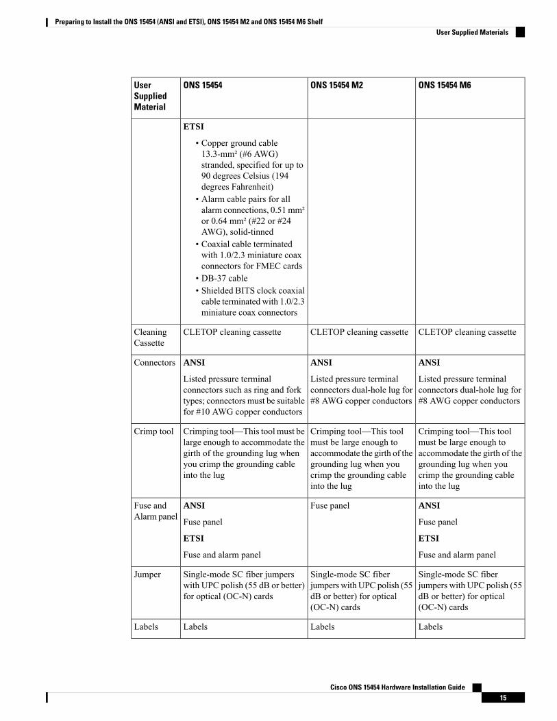
ONS 15454 M6ONS 15454 M2ONS 15454UserSuppliedMaterial
ETSI
• Copper ground cable13.3-mm² (#6 AWG)stranded, specified for up to90 degrees Celsius (194degrees Fahrenheit)
• Alarm cable pairs for allalarm connections, 0.51mm²or 0.64 mm² (#22 or #24AWG), solid-tinned
• Coaxial cable terminatedwith 1.0/2.3 miniature coaxconnectors for FMEC cards
• DB-37 cable• Shielded BITS clock coaxialcable terminated with 1.0/2.3miniature coax connectors
CLETOP cleaning cassetteCLETOP cleaning cassetteCLETOP cleaning cassetteCleaningCassette
ANSI
Listed pressure terminalconnectors dual-hole lug for#8 AWG copper conductors
ANSI
Listed pressure terminalconnectors dual-hole lug for#8 AWG copper conductors
ANSI
Listed pressure terminalconnectors such as ring and forktypes; connectors must be suitablefor #10 AWG copper conductors
Connectors
Crimping tool—This toolmust be large enough toaccommodate the girth of thegrounding lug when youcrimp the grounding cableinto the lug
Crimping tool—This toolmust be large enough toaccommodate the girth of thegrounding lug when youcrimp the grounding cableinto the lug
Crimping tool—This tool must belarge enough to accommodate thegirth of the grounding lug whenyou crimp the grounding cableinto the lug
Crimp tool
ANSI
Fuse panel
ETSI
Fuse and alarm panel
Fuse panelANSI
Fuse panel
ETSI
Fuse and alarm panel
Fuse andAlarm panel
Single-mode SC fiberjumpers with UPC polish (55dB or better) for optical(OC-N) cards
Single-mode SC fiberjumpers with UPC polish (55dB or better) for optical(OC-N) cards
Single-mode SC fiber jumperswith UPC polish (55 dB or better)for optical (OC-N) cards
Jumper
LabelsLabelsLabelsLabels
Cisco ONS 15454 Hardware Installation Guide15
Preparing to Install the ONS 15454 (ANSI and ETSI), ONS 15454 M2 and ONS 15454 M6 ShelfUser Supplied Materials
ONS 15454 M6ONS 15454 M2ONS 15454UserSuppliedMaterial
Optical power meter (for usewith fiber optics only)
Optical power meter (for usewith fiber optics only)
Optical power meter (for use withfiber optics only)
PowerMeter
ANSI
• 19-inch ANSI Standard(TelcordiaGR-63-CORE) (482.6mm) rack; total width22 inches (558.8 mm)
• 23-inch ANSI Standard(TelcordiaGR-63-CORE) (584.2mm) rack; total width26 inches (660.4 mm)
ETSI
Equipment rack (ETSI rack,2200mm [86.6 inch] H x 600mm [23.6 inch] Wx 300 mm[11.8 inch] D)
ANSI
• 19-inch ANSI Standard(TelcordiaGR-63-CORE) (482.6mm) rack; total width22 inches (558.8 mm)
• 23-inch ANSI Standard(TelcordiaGR-63-CORE) (584.2mm) rack; total width26 inches (660.4 mm)
ETSI
Equipment rack (ETSI rack,2200 mm [86.6 inch] H x600 mm [23.6 inch] Wx 300mm [11.8 inch] D)
ANSI
• 19-inch ANSI Standard(Telcordia GR-63-CORE)(482.6 mm) rack; total width22 inches (558.8 mm)
• 23-inch ANSI Standard(Telcordia GR-63-CORE)(584.2 mm) rack; total width26 inches (660.4 mm)
ETSI
Equipment rack (ETSI rack, 2200mm [86.6 inch] H x 600mm [23.6inch] Wx 300 mm [11.8 inch] D)
Rack
• #2 PhillipsDynamometricscrewdriver
• Medium slot-headscrewdriver
• Small slot-head screwdriver
• #2 PhillipsDynamometricscrewdriver
• Medium slot-headscrewdriver
• Small slot-head screwdriver
• #2 Phillips Dynamometricscrewdriver
• Medium slot-headscrewdriver
• Small slot-head screwdriver
ScrewDriver
ANSI
Tie wraps or lacing cord (orboth)
ANSI
Tie wraps or lacing cord (orboth)
ANSI
Tie wraps and/or lacing cord
Tie wrapsand/orlacing cord
ETSI
Video fiber connectorinspection instrument
ETSI
Video fiber connectorinspection instrument
ETSI
Video fiber connector inspectioninstrument
Video fiberconnectorinspectioninstrument
VoltmeterVoltmeterVoltmeterVoltmeter
Wire cuttersWire cuttersWire cuttersWireCutters
Wire strippersWire strippersWire strippersWireStrippers
Cisco ONS 15454 Hardware Installation Guide16
Preparing to Install the ONS 15454 (ANSI and ETSI), ONS 15454 M2 and ONS 15454 M6 ShelfUser Supplied Materials
ONS 15454 M6ONS 15454 M2ONS 15454UserSuppliedMaterial
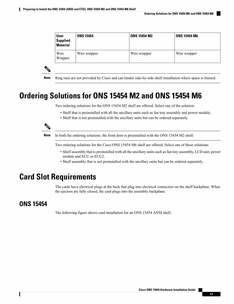
Wire wrapperWire wrapperWire wrapperWireWrapper
Ring runs are not provided by Cisco and can hinder side-by-side shelf installation where space is limited.Note
Ordering Solutions for ONS 15454 M2 and ONS 15454 M6Two ordering solutions for the ONS 15454 M2 shelf are offered. Select one of the solution:
• Shelf that is preinstalled with all the ancillary units such as fan tray assembly and power module.• Shelf that is not preinstalled with the ancillary units but can be ordered separately.
In both the ordering solutions, the front door is preinstalled with the ONS 15454 M2 shelf.Note
Two ordering solutions for the Cisco ONS 15454 M6 shelf are offered. Select one of these solutions:
• Shelf assembly that is preinstalled with all the ancillary units such as fan tray assembly, LCD unit, powermodule and ECU or ECU2.
• Shelf assembly that is not preinstalled with the ancillary units but can be ordered separately.
Card Slot RequirementsThe cards have electrical plugs at the back that plug into electrical connectors on the shelf backplane. Whenthe ejectors are fully closed, the card plugs into the assembly backplane.
ONS 15454The following figure shows card installation for an ONS 15454 ANSI shelf.
Cisco ONS 15454 Hardware Installation Guide17
Preparing to Install the ONS 15454 (ANSI and ETSI), ONS 15454 M2 and ONS 15454 M6 ShelfOrdering Solutions for ONS 15454 M2 and ONS 15454 M6
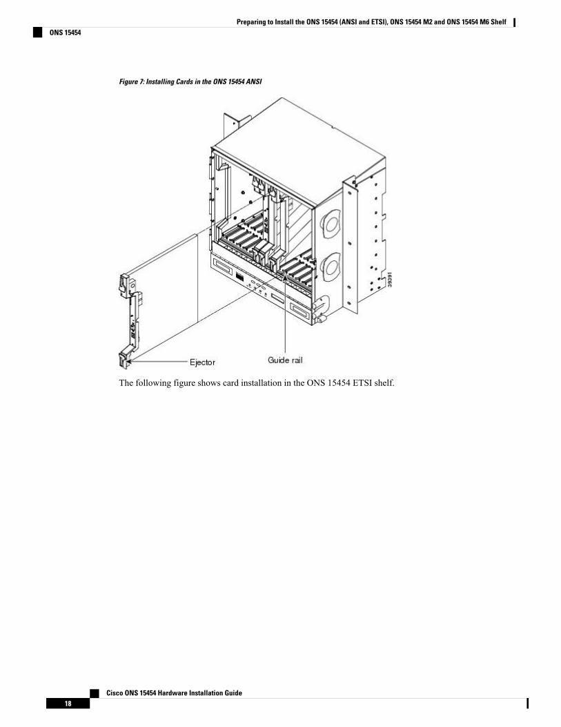
Figure 7: Installing Cards in the ONS 15454 ANSI
The following figure shows card installation in the ONS 15454 ETSI shelf.
Cisco ONS 15454 Hardware Installation Guide18
Preparing to Install the ONS 15454 (ANSI and ETSI), ONS 15454 M2 and ONS 15454 M6 ShelfONS 15454
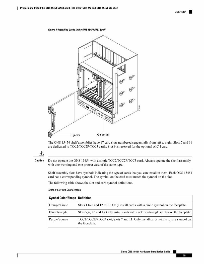
Figure 8: Installing Cards in the ONS 15454 ETSI Shelf
The ONS 15454 shelf assemblies have 17 card slots numbered sequentially from left to right. Slots 7 and 11are dedicated to TCC2/TCC2P/TCC3 cards. Slot 9 is reserved for the optional AIC-I card.
Do not operate the ONS 15454 with a single TCC2/TCC2P/TCC3 card. Always operate the shelf assemblywith one working and one protect card of the same type.
Caution
Shelf assembly slots have symbols indicating the type of cards that you can install in them. Each ONS 15454card has a corresponding symbol. The symbol on the card must match the symbol on the slot.
The following table shows the slot and card symbol definitions.
Table 3: Slot and Card Symbols
DefinitionSymbol Color/Shape
Slots 1 to 6 and 12 to 17. Only install cards with a circle symbol on the faceplate.Orange/Circle
Slots 5, 6, 12, and 13. Only install cards with circle or a triangle symbol on the faceplate.Blue/Triangle
TCC2/TCC2P/TCC3 slot, Slots 7 and 11. Only install cards with a square symbol onthe faceplate.
Purple/Square
Cisco ONS 15454 Hardware Installation Guide19
Preparing to Install the ONS 15454 (ANSI and ETSI), ONS 15454 M2 and ONS 15454 M6 ShelfONS 15454
DefinitionSymbol Color/Shape
Cross-connect (XC/XCVT/XC10G) slot, Slots 8 and 10. Only install ONS 15454 cardswith a cross symbol on the faceplate.
Cross-connect cards are not required in DWDM applications. Install aFILLER card or blank card if not using Slots 8 and 10.
Note
Green/Cross
Protection slot in 1:N protection schemes.Red/P
AIC/AIC-I slot, Slot 9. Only install cards with a diamond symbol on the faceplate.Red/Diamond
Slots 1 to 4 and 14 to 17. Only install cards with a star symbol on the faceplate.Gold/Star
(Only used with the 15454-SA-HD shelf assembly.) Slots 3 and 15. Only install ONS15454 ANSI cards with a blue hexagon symbol on the faceplate.
Blue/Hexagon
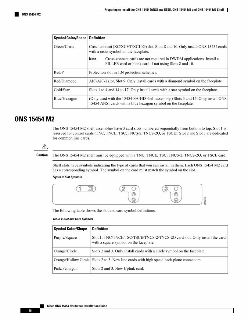
ONS 15454 M2The ONS 15454 M2 shelf assemblies have 3 card slots numbered sequentially from bottom to top. Slot 1 isreserved for control cards (TNC, TNCE, TSC, TNCS-2, TNCS-2O, or TSCE). Slot 2 and Slot 3 are dedicatedfor common line cards.
The ONS 15454 M2 shelf must be equipped with a TNC, TNCE, TSC, TNCS-2, TNCS-2O, or TSCE card.Caution
Shelf slots have symbols indicating the type of cards that you can install in them. Each ONS 15454 M2 cardhas a corresponding symbol. The symbol on the card must match the symbol on the slot.
Figure 9: Slot Symbols
The following table shows the slot and card symbol definitions.
Table 4: Slot and Card Symbols
DefinitionSymbol Color/Shape
Slot 1. TNC/TNCE/TSC/TSCE/TNCS-2/TNCS-2O card slot. Only install the cardwith a square symbol on the faceplate.
Purple/Square
Slots 2 and 3. Only install cards with a circle symbol on the faceplate.Orange/Circle
Slots 2 to 3. New line cards with high speed back plane connectors.Orange/HollowCircle
Slots 2 and 3. New Uplink card.Pink/Pentagon
Cisco ONS 15454 Hardware Installation Guide20
Preparing to Install the ONS 15454 (ANSI and ETSI), ONS 15454 M2 and ONS 15454 M6 ShelfONS 15454 M2
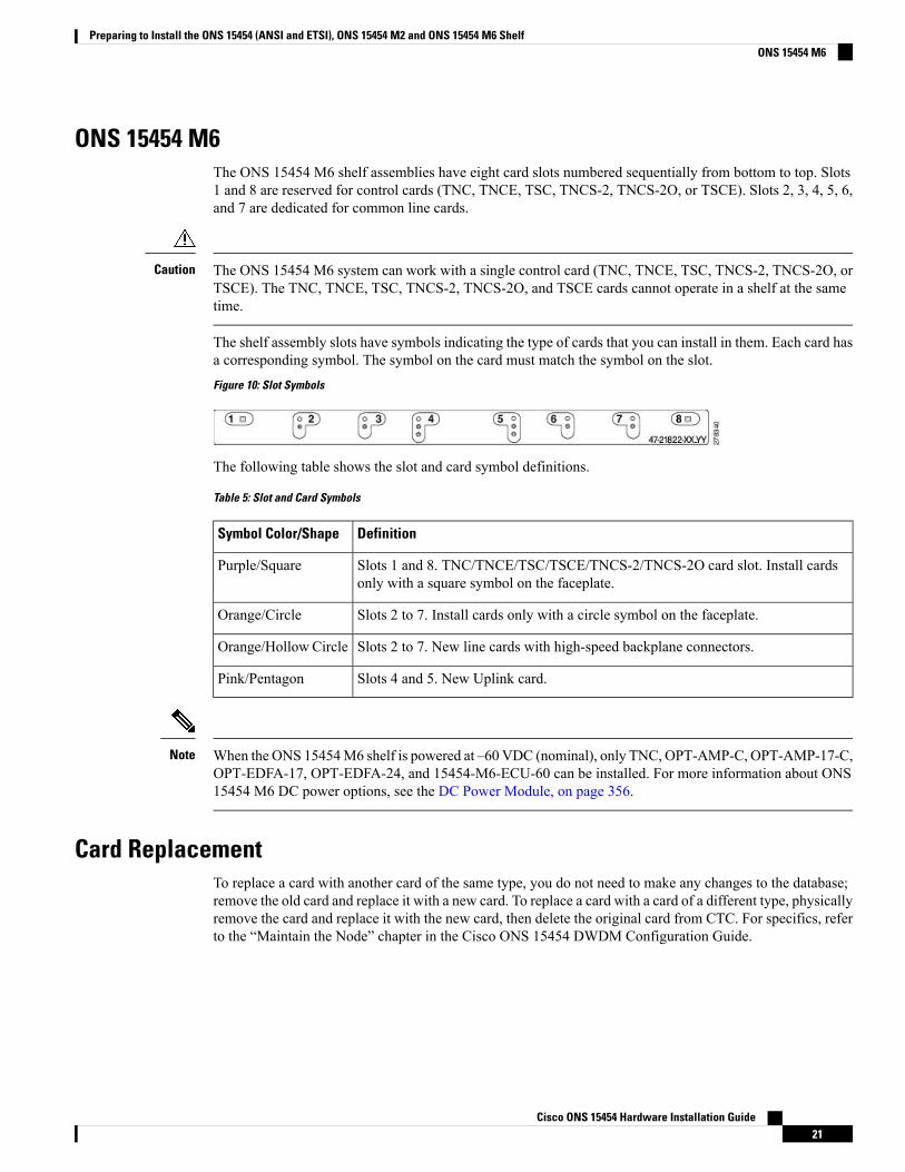
ONS 15454 M6The ONS 15454 M6 shelf assemblies have eight card slots numbered sequentially from bottom to top. Slots1 and 8 are reserved for control cards (TNC, TNCE, TSC, TNCS-2, TNCS-2O, or TSCE). Slots 2, 3, 4, 5, 6,and 7 are dedicated for common line cards.
The ONS 15454 M6 system can work with a single control card (TNC, TNCE, TSC, TNCS-2, TNCS-2O, orTSCE). The TNC, TNCE, TSC, TNCS-2, TNCS-2O, and TSCE cards cannot operate in a shelf at the sametime.
Caution
The shelf assembly slots have symbols indicating the type of cards that you can install in them. Each card hasa corresponding symbol. The symbol on the card must match the symbol on the slot.
Figure 10: Slot Symbols
The following table shows the slot and card symbol definitions.
Table 5: Slot and Card Symbols
DefinitionSymbol Color/Shape
Slots 1 and 8. TNC/TNCE/TSC/TSCE/TNCS-2/TNCS-2O card slot. Install cardsonly with a square symbol on the faceplate.
Purple/Square
Slots 2 to 7. Install cards only with a circle symbol on the faceplate.Orange/Circle
Slots 2 to 7. New line cards with high-speed backplane connectors.Orange/HollowCircle
Slots 4 and 5. New Uplink card.Pink/Pentagon
When the ONS 15454M6 shelf is powered at –60 VDC (nominal), only TNC, OPT-AMP-C, OPT-AMP-17-C,OPT-EDFA-17, OPT-EDFA-24, and 15454-M6-ECU-60 can be installed. For more information about ONS15454 M6 DC power options, see the DC Power Module, on page 356.
Note
Card ReplacementTo replace a card with another card of the same type, you do not need to make any changes to the database;remove the old card and replace it with a new card. To replace a card with a card of a different type, physicallyremove the card and replace it with the new card, then delete the original card from CTC. For specifics, referto the “Maintain the Node” chapter in the Cisco ONS 15454 DWDM Configuration Guide.
Cisco ONS 15454 Hardware Installation Guide21
Preparing to Install the ONS 15454 (ANSI and ETSI), ONS 15454 M2 and ONS 15454 M6 ShelfONS 15454 M6
Removing any active card from the shelf can result in traffic interruption. Use caution when replacing cardsand verify that only inactive or standby cards are being replaced. If the active card needs to be replaced, switchit to standby prior to removing the card from the node. For traffic switching procedures, refer to the CiscoONS 15454 DWDM Configuration Guide.
Caution
An improper removal (IMPROPRMVL) alarm is raised whenever a card pull (reseat) is performed, unlessthe card is deleted in CTC first. The alarm clears after the card replacement is complete.
Note
NTP-G305 Unpack and Inspect the ONS 15454, ONS 15454 M2,and ONS 15454 M6 Shelves
This procedure explains how to unpack the ONS 15454, ONS 15454 M2, andONS 15454 M6 shelves and verify their contents.
Purpose
Pinned hex (Allen) key for front door (ONS 15454 only)Tools/Equipment
NonePrerequisite Procedures
RequiredRequired/As Needed
OnsiteOnsite/Remote
NoneSecurity Level
Procedure
Step 1 Complete the DLP-G676 Unpack and Verify the ONS 15454, ONS 15454 M2, and ONS 15454 M6 Shelves, on page 22.
Step 2 Complete the DLP-G677 Inspect the ONS 15454, ONS 15454 M2, and ONS 15454 M6 Shelves, on page 23.Step 3 Continue with the NTP-G305 Unpack and Inspect the ONS 15454, ONS 15454 M2, and ONS 15454 M6
Shelves, on page 22.
Stop. You have completed this procedure.
DLP-G676 Unpack and Verify the ONS 15454, ONS 15454 M2, and ONS 15454M6 Shelves
This task removes the shelves from the package.Purpose
Cisco ONS 15454 Hardware Installation Guide22
Preparing to Install the ONS 15454 (ANSI and ETSI), ONS 15454 M2 and ONS 15454 M6 ShelfNTP-G305 Unpack and Inspect the ONS 15454, ONS 15454 M2, and ONS 15454 M6 Shelves
NoneTools/Equipment
NonePrerequisite Procedures
RequiredRequired/As Needed
OnsiteOnsite/Remote
NoneSecurity Level
Procedure
Step 1 When you receive the ONS 15454, ONS 15454 M2, or ONS 15454 M6 system equipment at the installationsite, open the top of the box. The Cisco Systems logo designates the top of the box.
Step 2 Remove the foam inserts from the box. The box contains the ONS 15454 shelf (wrapped in plastic) and asmaller box of items needed for installation.
Step 3 To remove the shelf, grasp both rings of the shelf removal strap and slowly lift the shelf out of the box.Step 4 Open the smaller box of installation materials, and verify that you have all items listed in the Required Tools
and Equipment, on page 11.
If the shelf and ancillary units are ordered separately, then the power modules, LCD module, ECUor ECU2 module, fan-tray assembly, and mounting brackets are shipped separately.
Note
Step 5 Return to your originating procedure (NTP).
DLP-G677 Inspect the ONS 15454, ONS 15454 M2, and ONS 15454 M6 ShelvesThis task verifies that all parts of the shelf are in good condition.Purpose
Pinned hex (Allen) key for front doorTools/Equipment
DLP-G676 Unpack and Verify the ONS 15454, ONS 15454M2, and ONS 15454M6 Shelves , on page 22
Prerequisite Procedures
RequiredRequired/As Needed
OnsiteOnsite/Remote
NoneSecurity Level
Procedure
Step 1 Open the shelf using the pinned hex key. For more information, see the DLP-G9 Open the Front CabinetCompartment (Door) , on page 59.
Step 2 Verify the following:
• The pins are not bent or broken.
Cisco ONS 15454 Hardware Installation Guide23
Preparing to Install the ONS 15454 (ANSI and ETSI), ONS 15454 M2 and ONS 15454 M6 ShelfDLP-G677 Inspect the ONS 15454, ONS 15454 M2, and ONS 15454 M6 Shelves

• The frame is not bent.
Step 3 If the pins are bent or broken, or the frame is bent, call your Cisco sales engineer for a replacement.Step 4 (ONS 15454 only) Close the front door before installing.Step 5 Return to your originating procedure (NTP).
Cisco ONS 15454 Hardware Installation Guide24
Preparing to Install the ONS 15454 (ANSI and ETSI), ONS 15454 M2 and ONS 15454 M6 ShelfDLP-G677 Inspect the ONS 15454, ONS 15454 M2, and ONS 15454 M6 Shelves

C H A P T E R 3Installing the ONS 15454 M12 (ANSI and ETSI)Shelf
This chapter explains how to install the ONS 15454 (ANSI and ETSI) shelf.
Unless otherwise specified, “ONS 15454” refers to both ANSI and ETSI M12 shelf assemblies.Note
Due to memory limitations, TCC2/TCC2P cards are not supported as the node controller in multi-shelfconfiguration fromR10.5.2.6. Hence, it is recommended to use TCC3 card as the node controller in multi-shelfconfiguration. The TCC2P card can be used as a control card in a subtended shelf where the node controlleris TCC3 card on ONS 15454 chassis or TNC/TNCE/TNCS/TNCS-O cards on ONS 15454M6 or NCS 20015chassis. The TCC2P card can also be used as a node controller in a stand-alone configuration.
Note
• ONS 15454 ANSI Rack Installation, on page 26• ONS 15454 ETSI Rack Installation , on page 29• NTP-G306 Install the ONS 15454 Shelf, on page 33• Front Door, on page 47• ONS 15454 ANSI Backplane Covers, on page 55• NTP-G3 Open and Remove the Front Door , on page 58• NTP-G4 Open and Remove the FMEC Cover (ETSI Only), on page 62• NTP-G5 Remove the Backplane Covers (ANSI Only), on page 65• ONS 15454 ETSI Front Mount Electrical Connection, on page 67• NTP-G6 Install the MIC-A/P and MIC-T/C/P FMECs (ETSI Only), on page 67• Power and Ground Description, on page 69• NTP-G7 Install the Power and Ground , on page 69• Shelf Voltage and Temperature, on page 77• NTP-G230 View Shelf Voltage and Temperature, on page 78• Fan-Tray Assembly , on page 78• NTP-G8 Install the Fan-Tray Assembly , on page 84• ONS 15454 ANSI Alarm Expansion Panel, on page 87• NTP-G9 Install the Alarm Expansion Panel (ANSI Only), on page 93• ONS 15454 ANSI Alarm, Timing, LAN, and Craft Pin Connections, on page 96
Cisco ONS 15454 Hardware Installation Guide25
• NTP-G10 Attach Wires to Alarm, Timing, LAN, and Craft Pin Connections , on page 102• NTP-G11 Install an External Wire-Wrap Panel on the AEP (ANSI Only), on page 114• NTP-G12 Install and Close the FMEC Cover (ETSI Only), on page 119• NTP-G13 Install the Rear Cover (ANSI Only), on page 120• Typical DWDM Rack Layouts, on page 122• NTP-G14 Install DWDM Equipment, on page 125• Multishelf Management, on page 139• NTP-G301 Connect the ONS 15454Multishelf Node and Subtending Shelves to anMS-ISC-100T Card,on page 140
• NTP-G304 Configure theMS-ISC-100T Card for a ONS 15454Multishelf Node for Non-Default Publicand Private VLAN IDs, on page 143
• NTP-G307 Perform the ONS 15454 Shelf Installation Acceptance Test , on page 145• NTP-G295 Connect the ONS 15454 Multishelf Node and Subtending Shelves to a Catalyst 2950 orCatalyst 3560, on page 148
• NTP-G296 Upgrade the ONS 15454 Multishelf with MS-ISC Card Configuration Using the Catalyst3560, on page 150
• NTP-G297 Upgrade the ONS 15454 Multishelf with Catalyst 2950 Configuration Using the Catalyst3560, on page 152
• NTP-G298 Configure a Cisco Catalyst 2950 or Catalyst 3560 (Active and Standby) for a ONS 15454Multishelf Node, on page 154
• Ethernet Adapter Panel, on page 156• Filler and Blank Cards, on page 158• Cable Routing and Management, on page 159
ONS 15454 ANSI Rack InstallationThe ONS 15454 ANSI shelf is mounted in a 19- or 23-in. (482.6- or 584.2-mm) equipment rack. The shelfprojects five inches (127 mm) from the front of the rack. It mounts in both Electronic Industries Alliance(EIA) standard and Telcordia-standard racks. The shelf is a total of 17 inches (431.8 mm) wide with nomounting ears attached. Ring runs are not provided by Cisco and might hinder side-by-side installation ofshelves where space is limited.
The ONS 15454 ANSI assembly measures 18.5 inches (469.9 mm) high, 19 or 23 inches (482.6 or 584.2 mm)wide (depending on which way the mounting ears are attached), and 12 inches (304.8 mm) deep. You caninstall up to four ONS 15454 ANSIs in a seven-foot (2133.6 mm) equipment rack. The ONS 15454 ANSImust have one inch (25.4 mm) of airspace below the installed shelf to allow air flow to the fan intake. If asecond ONS 15454 ANSI is installed underneath the shelf, the air ramp on top of the lower shelf provides theair spacing needed and should not be modified in any way. The following figure shows the dimensions of theONS 15454 ANSI.
A 10-Gbps-compatible shelf (15454-SA-ANSI or 15454-SA-HD) and fan-tray assembly (15454-FTA3,15454-FTA3-T, or 15454-CC-FTA) are required if ONS 15454 ANSI 10-Gbps Cross-Connect (XC10G) cardsare installed in the shelf.
Note
Cisco ONS 15454 Hardware Installation Guide26
Installing the ONS 15454 M12 (ANSI and ETSI) ShelfONS 15454 ANSI Rack Installation
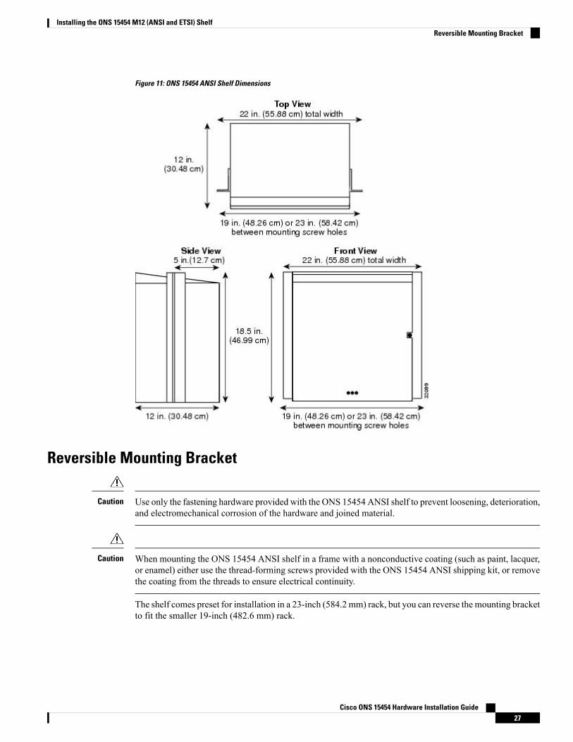
Figure 11: ONS 15454 ANSI Shelf Dimensions
Reversible Mounting Bracket
Use only the fastening hardware provided with the ONS 15454 ANSI shelf to prevent loosening, deterioration,and electromechanical corrosion of the hardware and joined material.
Caution
When mounting the ONS 15454 ANSI shelf in a frame with a nonconductive coating (such as paint, lacquer,or enamel) either use the thread-forming screws provided with the ONS 15454 ANSI shipping kit, or removethe coating from the threads to ensure electrical continuity.
Caution
The shelf comes preset for installation in a 23-inch (584.2 mm) rack, but you can reverse the mounting bracketto fit the smaller 19-inch (482.6 mm) rack.
Cisco ONS 15454 Hardware Installation Guide27
Installing the ONS 15454 M12 (ANSI and ETSI) ShelfReversible Mounting Bracket
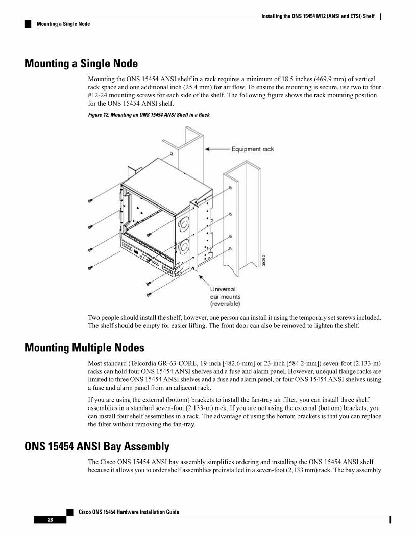
Mounting a Single NodeMounting the ONS 15454 ANSI shelf in a rack requires a minimum of 18.5 inches (469.9 mm) of verticalrack space and one additional inch (25.4 mm) for air flow. To ensure the mounting is secure, use two to four#12-24 mounting screws for each side of the shelf. The following figure shows the rack mounting positionfor the ONS 15454 ANSI shelf.
Figure 12: Mounting an ONS 15454 ANSI Shelf in a Rack
Two people should install the shelf; however, one person can install it using the temporary set screws included.The shelf should be empty for easier lifting. The front door can also be removed to lighten the shelf.
Mounting Multiple NodesMost standard (Telcordia GR-63-CORE, 19-inch [482.6-mm] or 23-inch [584.2-mm]) seven-foot (2.133-m)racks can hold four ONS 15454 ANSI shelves and a fuse and alarm panel. However, unequal flange racks arelimited to three ONS 15454 ANSI shelves and a fuse and alarm panel, or four ONS 15454 ANSI shelves usinga fuse and alarm panel from an adjacent rack.
If you are using the external (bottom) brackets to install the fan-tray air filter, you can install three shelfassemblies in a standard seven-foot (2.133-m) rack. If you are not using the external (bottom) brackets, youcan install four shelf assemblies in a rack. The advantage of using the bottom brackets is that you can replacethe filter without removing the fan-tray.
ONS 15454 ANSI Bay AssemblyThe Cisco ONS 15454 ANSI bay assembly simplifies ordering and installing the ONS 15454 ANSI shelfbecause it allows you to order shelf assemblies preinstalled in a seven-foot (2,133 mm) rack. The bay assembly
Cisco ONS 15454 Hardware Installation Guide28
Installing the ONS 15454 M12 (ANSI and ETSI) ShelfMounting a Single Node
is available in a three- or four-shelf configuration. The three-shelf configuration includes three ONS 15454ANSI shelf assemblies, a prewired fuse and alarm panel, and two fiber-storage trays. The four-shelfconfiguration includes four ONS 15454 ANSI shelf assemblies and a prewired fuse and alarm panel. You canorder optional fiber channels with either configuration. Installation procedures are included in the Unpackingand Installing the Cisco ONS 15454 Four-Shelf and Zero-Shelf Bay Assembly document that ships with thebay assembly.
ONS 15454 ETSI Rack InstallationThe ONS 15454 ETSI shelf (15454-SA-ETSI) is mounted in a 600 x 600-mm (23-inch) or 600 x 300-mm(11.8-inch) equipment cabinet/rack. The shelf projects 240 mm (9.45 inches) from the front of the rack. Itmounts in ETSI-standard racks. The shelf is a total of 435 mm (17.35 inches) wide with no mounting earsattached. Ring runs are not provided by Cisco and might hinder side-by-side installation of shelves wherespace is limited.
The ONS 15454 ETSI shelf measures 616.5 mm (24.27 inches) high, 535 mm (21.06 inches) wide, and 280mm (11.02 inches) deep. You can install up to three ONS 15454 ETSI shelves in a seven-foot (2133.6 mm)equipment rack. The ONS 15454 ETSI must have one inch (25.4 mm) of airspace below the installed shelfto allow air flow to the fan intake. If a second ONS 15454 ETSI is installed below the first shelf, an ETSI airramp unit must be assembled between the two shelves to ensure adequate air flow.
The following figure provides the dimensions of the ONS 15454 ETSI shelf.
The standard ETSI racks can hold three ONS 15454 ETSI shelf assemblies and two air ramps.Whenmountinga shelf in a partially filled rack, load the rack from the bottom to the top with the heaviest component at thebottom of the rack. If the rack is provided with stabilizing devices, install the stabilizers before mounting orservicing the unit in the rack.
Caution
The ONS 15454 ETSI must have 1 inch (25.4 mm) of airspace below the installed shelf to allow air flow tothe fan intake. The air ramp (the angled piece of sheet metal on top of the shelf) provides this spacing andshould not be modified in any way.
Caution
Cisco ONS 15454 Hardware Installation Guide29
Installing the ONS 15454 M12 (ANSI and ETSI) ShelfONS 15454 ETSI Rack Installation
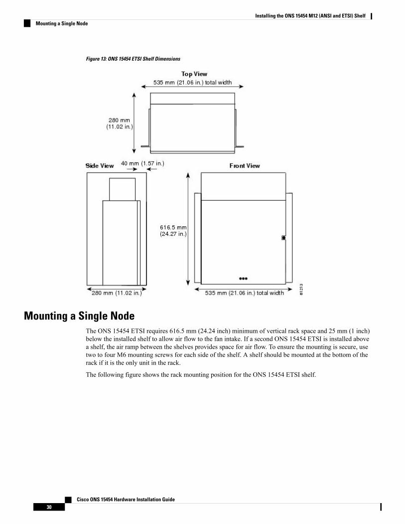
Figure 13: ONS 15454 ETSI Shelf Dimensions
Mounting a Single NodeThe ONS 15454 ETSI requires 616.5 mm (24.24 inch) minimum of vertical rack space and 25 mm (1 inch)below the installed shelf to allow air flow to the fan intake. If a second ONS 15454 ETSI is installed abovea shelf, the air ramp between the shelves provides space for air flow. To ensure the mounting is secure, usetwo to four M6 mounting screws for each side of the shelf. A shelf should be mounted at the bottom of therack if it is the only unit in the rack.
The following figure shows the rack mounting position for the ONS 15454 ETSI shelf.
Cisco ONS 15454 Hardware Installation Guide30
Installing the ONS 15454 M12 (ANSI and ETSI) ShelfMounting a Single Node
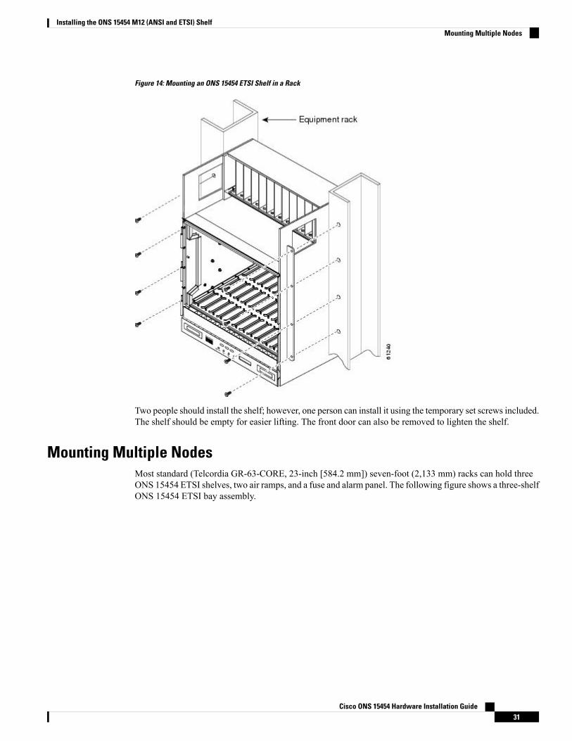
Figure 14: Mounting an ONS 15454 ETSI Shelf in a Rack
Two people should install the shelf; however, one person can install it using the temporary set screws included.The shelf should be empty for easier lifting. The front door can also be removed to lighten the shelf.
Mounting Multiple NodesMost standard (Telcordia GR-63-CORE, 23-inch [584.2 mm]) seven-foot (2,133 mm) racks can hold threeONS 15454 ETSI shelves, two air ramps, and a fuse and alarm panel. The following figure shows a three-shelfONS 15454 ETSI bay assembly.
Cisco ONS 15454 Hardware Installation Guide31
Installing the ONS 15454 M12 (ANSI and ETSI) ShelfMounting Multiple Nodes
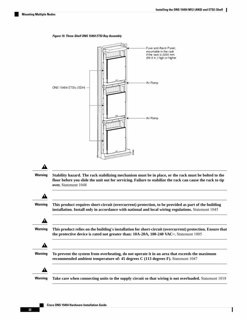
Figure 15: Three-Shelf ONS 15454 ETSI Bay Assembly
Stability hazard. The rack stabilizing mechanism must be in place, or the rack must be bolted to thefloor before you slide the unit out for servicing. Failure to stabilize the rack can cause the rack to tipover. Statement 1048
Warning
This product requires short-circuit (overcurrent) protection, to be provided as part of the buildinginstallation. Install only in accordance with national and local wiring regulations. Statement 1045
Warning
This product relies on the building's installation for short-circuit (overcurrent) protection. Ensure thatthe protective device is rated not greater than: 10A-20A, 100-240 VAC~. Statement 1005
Warning
To prevent the system from overheating, do not operate it in an area that exceeds the maximumrecommended ambient temperature of: 45 degrees C (113 degrees F). Statement 1047
Warning
Take care when connecting units to the supply circuit so that wiring is not overloaded. Statement 1018Warning
Cisco ONS 15454 Hardware Installation Guide32
Installing the ONS 15454 M12 (ANSI and ETSI) ShelfMounting Multiple Nodes
If the rack is provided with stabilizing devices, install the stabilizers before mounting or servicing theunit in the rack. Statement 1006
Warning
To prevent bodily injury when mounting or servicing this unit in a rack, you must take special precautions toensure that the system remains stable. The following guidelines are provided to ensure your safety:
• This unit should be mounted at the bottom of the rack if it is the only unit in the rack.• When mounting this unit in a partially filled rack, load the rack from the bottom to the top with
the heaviest component at the bottom of the rack.• If the rack is provided with stabilizing devices, install the stabilizers before mounting or servicing
the unit in the rack. Statement 1006
Warning
To prevent airflow restriction, allow clearance around the ventilation openings to be at least:1 inch(25.4 mm) Statement 1076
Warning
The ONS 15454 must have 1 inch (25.4 mm) of airspace below the installed shelf assembly to allow airflow to the fan intake. The air ramp (the angled piece of sheet metal on top of the shelf assembly)provides this spacing and should not be modified in any way. Statement 385
Warning
Voltages that present a shock hazard may exist on Power over Ethernet (PoE) circuits if interconnectionsare made using uninsulated exposed metal contacts, conductors, or terminals. Avoid using suchinterconnection methods, unless the exposed metal parts are located within a restricted access locationand users and service people who are authorized within the restricted access location are made awareof the hazard. A restricted access area can be accessed only through the use of a special tool, lock andkey or other means of security. Statement 1072
Warning
NTP-G306 Install the ONS 15454 ShelfThis procedure reverses the mounting bracket and mounts shelf assemblies in arack.
Purpose
Cisco ONS 15454 Hardware Installation Guide33
Installing the ONS 15454 M12 (ANSI and ETSI) ShelfNTP-G306 Install the ONS 15454 Shelf
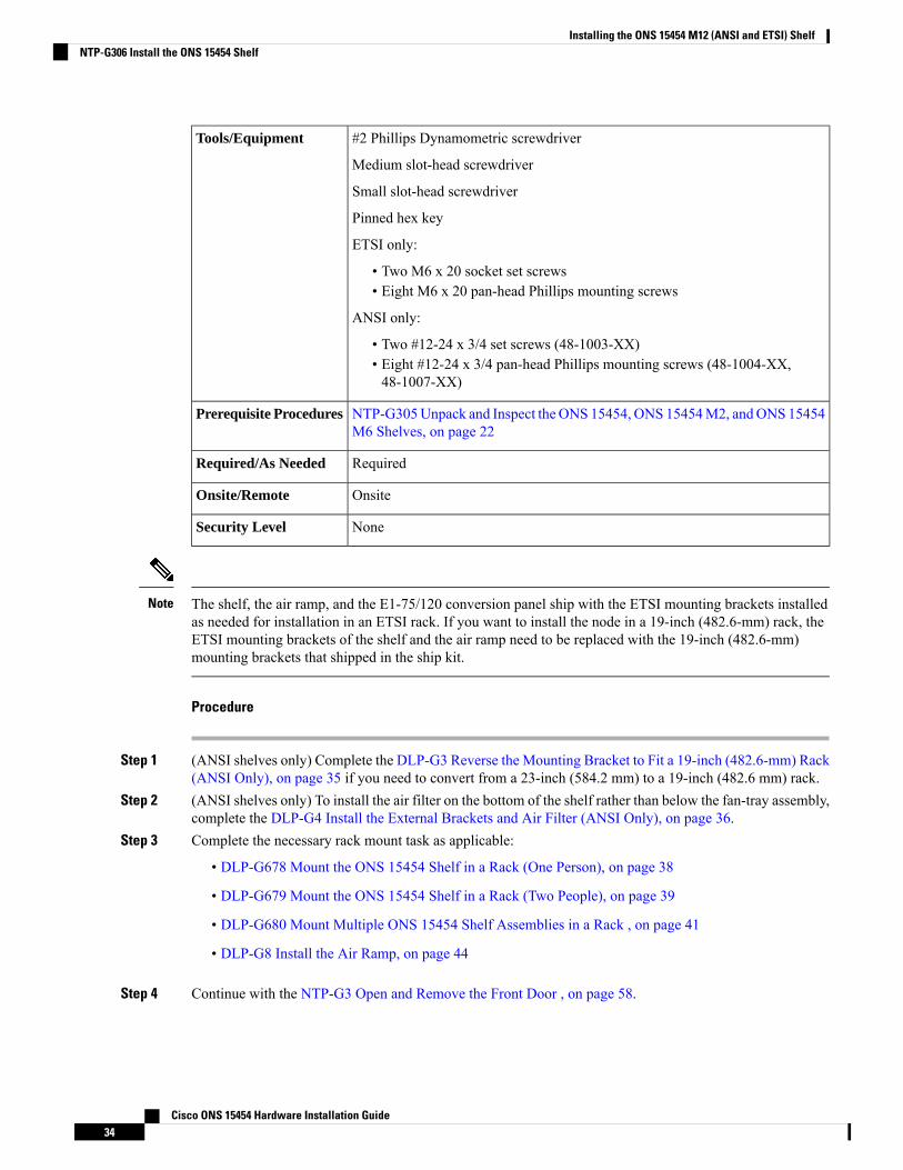
#2 Phillips Dynamometric screwdriver
Medium slot-head screwdriver
Small slot-head screwdriver
Pinned hex key
ETSI only:
• Two M6 x 20 socket set screws• Eight M6 x 20 pan-head Phillips mounting screws
ANSI only:
• Two #12-24 x 3/4 set screws (48-1003-XX)• Eight #12-24 x 3/4 pan-head Phillips mounting screws (48-1004-XX,48-1007-XX)
Tools/Equipment
NTP-G305Unpack and Inspect the ONS 15454, ONS 15454M2, andONS 15454M6 Shelves, on page 22
Prerequisite Procedures
RequiredRequired/As Needed
OnsiteOnsite/Remote
NoneSecurity Level
The shelf, the air ramp, and the E1-75/120 conversion panel ship with the ETSI mounting brackets installedas needed for installation in an ETSI rack. If you want to install the node in a 19-inch (482.6-mm) rack, theETSI mounting brackets of the shelf and the air ramp need to be replaced with the 19-inch (482.6-mm)mounting brackets that shipped in the ship kit.
Note
Procedure
Step 1 (ANSI shelves only) Complete the DLP-G3 Reverse the Mounting Bracket to Fit a 19-inch (482.6-mm) Rack(ANSI Only), on page 35 if you need to convert from a 23-inch (584.2 mm) to a 19-inch (482.6 mm) rack.
Step 2 (ANSI shelves only) To install the air filter on the bottom of the shelf rather than below the fan-tray assembly,complete the DLP-G4 Install the External Brackets and Air Filter (ANSI Only), on page 36.
Step 3 Complete the necessary rack mount task as applicable:
• DLP-G678 Mount the ONS 15454 Shelf in a Rack (One Person), on page 38
• DLP-G679 Mount the ONS 15454 Shelf in a Rack (Two People), on page 39
• DLP-G680 Mount Multiple ONS 15454 Shelf Assemblies in a Rack , on page 41
• DLP-G8 Install the Air Ramp, on page 44
Step 4 Continue with the NTP-G3 Open and Remove the Front Door , on page 58.
Cisco ONS 15454 Hardware Installation Guide34
Installing the ONS 15454 M12 (ANSI and ETSI) ShelfNTP-G306 Install the ONS 15454 Shelf
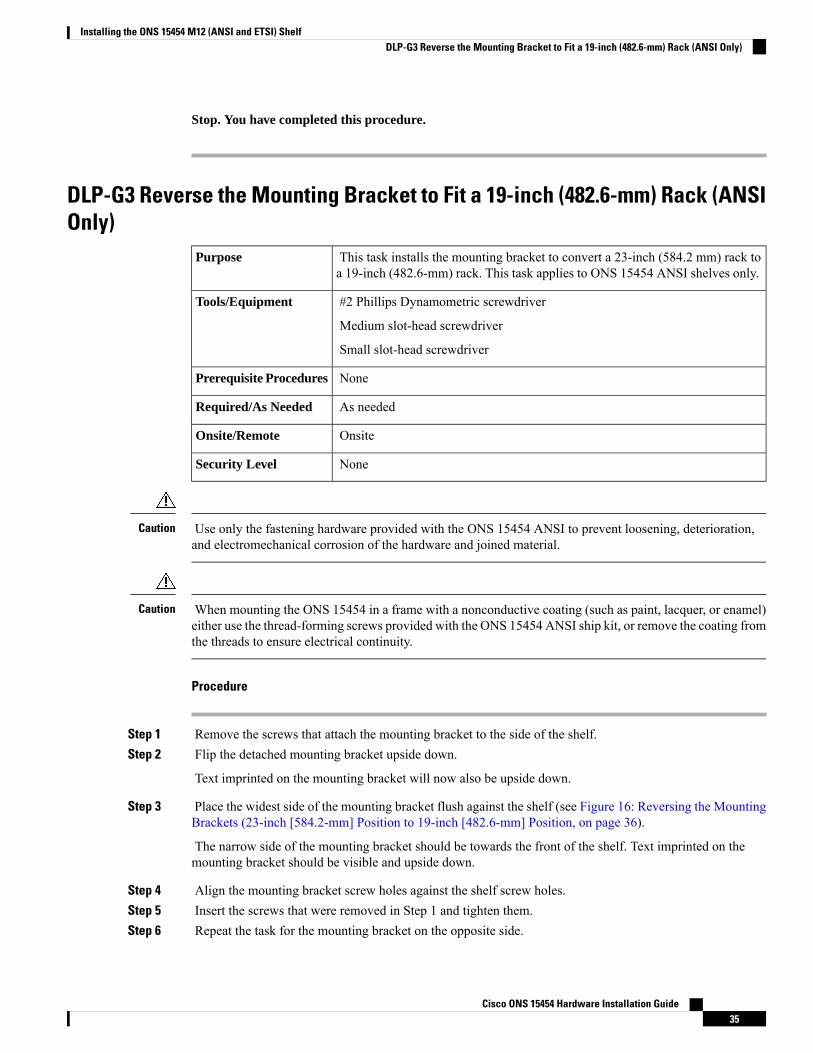
Stop. You have completed this procedure.
DLP-G3 Reverse the Mounting Bracket to Fit a 19-inch (482.6-mm) Rack (ANSIOnly)
This task installs the mounting bracket to convert a 23-inch (584.2 mm) rack toa 19-inch (482.6-mm) rack. This task applies to ONS 15454 ANSI shelves only.
Purpose
#2 Phillips Dynamometric screwdriver
Medium slot-head screwdriver
Small slot-head screwdriver
Tools/Equipment
NonePrerequisite Procedures
As neededRequired/As Needed
OnsiteOnsite/Remote
NoneSecurity Level
Use only the fastening hardware provided with the ONS 15454 ANSI to prevent loosening, deterioration,and electromechanical corrosion of the hardware and joined material.
Caution
When mounting the ONS 15454 in a frame with a nonconductive coating (such as paint, lacquer, or enamel)either use the thread-forming screws provided with the ONS 15454 ANSI ship kit, or remove the coating fromthe threads to ensure electrical continuity.
Caution
Procedure
Step 1 Remove the screws that attach the mounting bracket to the side of the shelf.Step 2 Flip the detached mounting bracket upside down.
Text imprinted on the mounting bracket will now also be upside down.
Step 3 Place the widest side of the mounting bracket flush against the shelf (see Figure 16: Reversing the MountingBrackets (23-inch [584.2-mm] Position to 19-inch [482.6-mm] Position, on page 36).
The narrow side of the mounting bracket should be towards the front of the shelf. Text imprinted on themounting bracket should be visible and upside down.
Step 4 Align the mounting bracket screw holes against the shelf screw holes.Step 5 Insert the screws that were removed in Step 1 and tighten them.Step 6 Repeat the task for the mounting bracket on the opposite side.
Cisco ONS 15454 Hardware Installation Guide35
Installing the ONS 15454 M12 (ANSI and ETSI) ShelfDLP-G3 Reverse the Mounting Bracket to Fit a 19-inch (482.6-mm) Rack (ANSI Only)
Figure 16: Reversing the Mounting Brackets (23-inch [584.2-mm] Position to 19-inch [482.6-mm] Position
Step 7 Return to your originating procedure (NTP).
DLP-G4 Install the External Brackets and Air Filter (ANSI Only)This task installs the external brackets and air filter on the bottom of the shelfrather than below the fan-tray assembly. Installing the external brackets and airfilter on the bottom of the shelf enables access to the air filter without removingthe fan-tray assembly. This task applies to the ONS 15454 ANSI shelf only.
Purpose
#2 Phillips Dynamometric screwdriver
Medium slot-head screwdriver
Small slot-head screwdriver
Tools/Equipment
DLP-G3 Reverse theMounting Bracket to Fit a 19-inch (482.6-mm) Rack (ANSIOnly), on page 35, if applicable
Prerequisite Procedures
As neededRequired/As Needed
OnsiteOnsite/Remote
NoneSecurity Level
To install the air filter inside the air ramp unit (15454E-AIR-RAMP or 15454-AIR-RAMP), use the ETSIversion of the air filter (15454-FTF2 or 15454E-FTF4).
Note
Cisco ONS 15454 Hardware Installation Guide36
Installing the ONS 15454 M12 (ANSI and ETSI) ShelfDLP-G4 Install the External Brackets and Air Filter (ANSI Only)
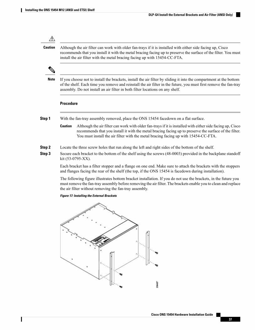
Although the air filter can work with older fan-trays if it is installed with either side facing up, Ciscorecommends that you install it with the metal bracing facing up to preserve the surface of the filter. You mustinstall the air filter with the metal bracing facing up with 15454-CC-FTA.
Caution
If you choose not to install the brackets, install the air filter by sliding it into the compartment at the bottomof the shelf. Each time you remove and reinstall the air filter in the future, you must first remove the fan-trayassembly. Do not install an air filter in both filter locations on any shelf.
Note
Procedure
Step 1 With the fan-tray assembly removed, place the ONS 15454 facedown on a flat surface.
Although the air filter can work with older fan-trays if it is installed with either side facing up, Ciscorecommends that you install it with the metal bracing facing up to preserve the surface of the filter.You must install the air filter with the metal bracing facing up with 15454-CC-FTA.
Caution
Step 2 Locate the three screw holes that run along the left and right sides of the bottom of the shelf.Step 3 Secure each bracket to the bottom of the shelf using the screws (48-0003) provided in the backplane standoff
kit (53-0795-XX).
Each bracket has a filter stopper and a flange on one end. Make sure to attach the brackets with the stoppersand flanges facing the rear of the shelf (the top, if the ONS 15454 is facedown during installation).
The following figure illustrates bottom bracket installation. If you do not use the brackets, in the future youmust remove the fan-tray assembly before removing the air filter. The brackets enable you to clean and replacethe air filter without removing the fan-tray assembly.
Figure 17: Installing the External Brackets
Cisco ONS 15454 Hardware Installation Guide37
Installing the ONS 15454 M12 (ANSI and ETSI) ShelfDLP-G4 Install the External Brackets and Air Filter (ANSI Only)
Step 4 Slide the air filter into the shelf.Step 5 Return to your originating procedure (NTP).
DLP-G678 Mount the ONS 15454 Shelf in a Rack (One Person)This task allows one person to mount the shelf in a rack.Purpose
Pinned hex key
# 2 Phillips Dynamometric screwdriver
ETSI only:
Two M6 x 20 socket set screws
Eight M6 x 20 pan-head Phillips mounting screws
ANSI only:
Two #12-24 x 3/4 set screws (48-1003-XX)
Eight #12-24 x 3/4 pan-head Phillipsmounting screws (48-1004-XX, 48-1007-XX)
Tools/Equipment
NTP-G305Unpack and Inspect the ONS 15454, ONS 15454M2, andONS 15454M6 Shelves, on page 22
Prerequisite Procedures
As neededRequired/As Needed
OnsiteOnsite/Remote
NoneSecurity Level
The ONS 15454 ETSI requires 616.5 mm (24.24 inch) minimum of vertical rack space and 25 mm (1 inch)below the installed shelf to allow air flow to the fan intake. If a second ONS 15454 ETSI is installed abovea shelf, the air ramp between the shelves provides space for air flow. To ensure that the mounting is secure,use two to four M6 mounting screws for each side of the shelf. A shelf should be mounted at the bottom ofthe rack if it is the only unit in the rack.
Note
Procedure
Step 1 Verify that the proper fuse and alarm panel has been installed in the top mounting space. If a fuse and alarmpanel is not present, you must install one according to manufacturer instructions:
• (ETSI only) Verify that the fuse rating does not exceed 30A.
• The fuse rating for ANSI chassis must not exceed 30A.
Step 2 Ensure that the shelf is set for the desired rack size (either 23 inches [584.2 mm] or 19 inches [482.6 mm]).
The following figure shows the rack-mounting position for the ONS 15454 ETSI.
Cisco ONS 15454 Hardware Installation Guide38
Installing the ONS 15454 M12 (ANSI and ETSI) ShelfDLP-G678 Mount the ONS 15454 Shelf in a Rack (One Person)
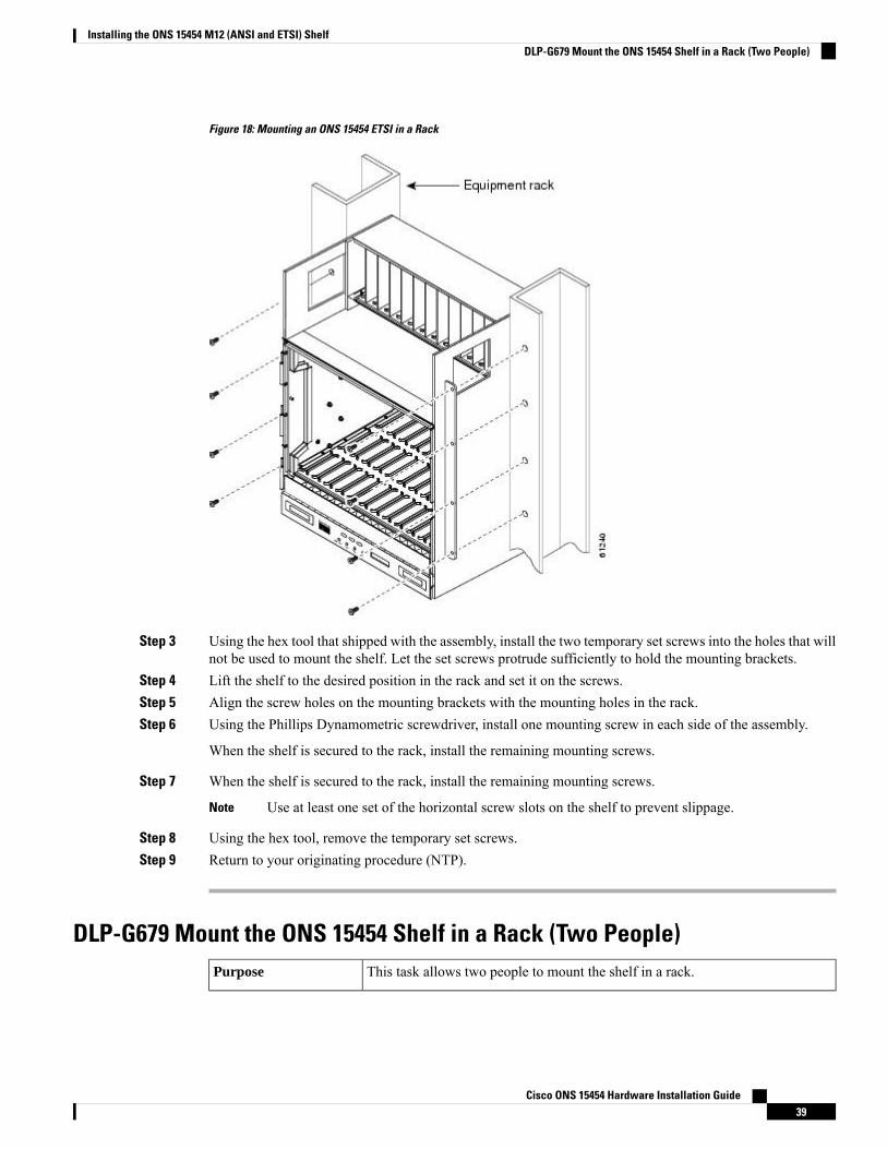
Figure 18: Mounting an ONS 15454 ETSI in a Rack
Step 3 Using the hex tool that shipped with the assembly, install the two temporary set screws into the holes that willnot be used to mount the shelf. Let the set screws protrude sufficiently to hold the mounting brackets.
Step 4 Lift the shelf to the desired position in the rack and set it on the screws.Step 5 Align the screw holes on the mounting brackets with the mounting holes in the rack.Step 6 Using the Phillips Dynamometric screwdriver, install one mounting screw in each side of the assembly.
When the shelf is secured to the rack, install the remaining mounting screws.
Step 7 When the shelf is secured to the rack, install the remaining mounting screws.
Use at least one set of the horizontal screw slots on the shelf to prevent slippage.Note
Step 8 Using the hex tool, remove the temporary set screws.Step 9 Return to your originating procedure (NTP).
DLP-G679 Mount the ONS 15454 Shelf in a Rack (Two People)This task allows two people to mount the shelf in a rack.Purpose
Cisco ONS 15454 Hardware Installation Guide39
Installing the ONS 15454 M12 (ANSI and ETSI) ShelfDLP-G679 Mount the ONS 15454 Shelf in a Rack (Two People)
Pinned hex key
# 2 Phillips Dynamometric screwdriver
ETSI only:
Two M6 x 20 socket set screws
Eight M6 x 20 pan-head Phillips mounting screws
ANSI only:
Two #12-24 x 3/4 set screws (48-1003-XX)
Eight #12-24 x 3/4 pan-head Phillipsmounting screws (48-1004-XX, 48-1007-XX)
Tools/Equipment
NTP-G305Unpack and Inspect the ONS 15454, ONS 15454M2, andONS 15454M6 Shelves, on page 22
Prerequisite Procedures
As neededRequired/As Needed
OnsiteOnsite/Remote
NoneSecurity Level
The ONS 15454 ETSI requires 616.5 mm (24.24 inch) minimum of vertical rack space and 25 mm (1 inch)below the installed shelf to allow air flow to the fan intake. If a second ONS 15454 ETSI is installed abovea shelf, the air ramp between the shelves provides space for air flow. To ensure that the mounting is secure,use two to four M6 mounting screws for each side of the shelf. A shelf should be mounted at the bottom ofthe rack if it is the only unit in the rack.
Note
The ONS 15454 ANSI must have one inch (25.4 mm) of airspace below the installed shelf to allow air flowto the fan intake. If a second ONS 15454 is installed underneath a shelf, the air ramp on top of the bottomshelf provides the desired space. However, if the ONS 15454 is installed above third-party equipment, youmust provide a minimum spacing of one inch (25.4 mm) between the third-party shelf and the bottom of theONS 15454. The third-party equipment must not vent heat upward into the ONS 15454.
Note
Procedure
Step 1 Verify that the proper fuse and alarm panel has been installed in the top mounting space. If a fuse and alarmpanel is not present, you must install one according to manufacturer’s instructions:
• (ETSI only) Verify that the fuse rating does not exceed 30A.
• The fuse rating for ANSI chassis must not exceed 30A.
Step 2 Ensure that the shelf is set for the desired rack size (either 23 inches [584.2 mm] or 19 inches [482.6 mm]).Step 3 Using the hex tool that shipped with the assembly, install the two set screws into the holes that will not be
used to mount the shelf. Let the set screws protrude sufficiently to hold the mounting brackets.
Cisco ONS 15454 Hardware Installation Guide40
Installing the ONS 15454 M12 (ANSI and ETSI) ShelfDLP-G679 Mount the ONS 15454 Shelf in a Rack (Two People)
Step 4 Lift the shelf to the desired position in the rack.Step 5 Align the screw holes on the mounting brackets with the mounting holes in the rack.Step 6 Have one person hold the shelf in place while the other person uses the Phillips Dynamometric screwdriver
to install one mounting screw in each side of the assembly.Step 7 When the shelf is secured to the rack, install the remaining mounting screws.
Use at least one set of the horizontal screw slots on the shelf to prevent slippage.Note
Step 8 Use the hex tool to remove the temporary set screws.Step 9 Return to your originating procedure (NTP).
DLP-G680 Mount Multiple ONS 15454 Shelf Assemblies in a RackThis task installs multiple shelves in a rack.Purpose
Pinned hex key
#2 Phillips Dynamometric screwdriver
ETSI only:
Two M6 x 20 socket set screws (per shelf)
Eight M6 x 20 pan-head Phillips mounting screws (per shelf)
ANSI only:
Two #12-24 x 3/4 set screws (48-1003-XX) (per shelf)
Eight #12-24 x 3/4 pan-head Phillipsmounting screws (48-1004-XX, 48-1007-XX)(per shelf)
Tools/Equipment
NTP-G305Unpack and Inspect the ONS 15454, ONS 15454M2, andONS 15454M6 Shelves, on page 22
Prerequisite Procedures
As neededRequired/As Needed
OnsiteOnsite/Remote
NoneSecurity Level
A standard ETSI rack can hold three ONS 15454 ETSI shelf assemblies and two air ramps. When mountinga shelf in a partially filled rack, load the rack from the bottom to the top with the heaviest component at thebottom of the rack. If the rack is provided with stabilizing devices, install the stabilizers before mounting orservicing the unit in the rack.
Note
Cisco ONS 15454 Hardware Installation Guide41
Installing the ONS 15454 M12 (ANSI and ETSI) ShelfDLP-G680 Mount Multiple ONS 15454 Shelf Assemblies in a Rack

The ONS 15454 ETSI requires 616.5 mm (24.24 inch) minimum of vertical rack space and 25 mm (1 inch)below the installed shelf to allow air flow to the fan intake. If a second ONS 15454 ETSI is installed abovea shelf, the air ramp between the shelves provides space for air flow.When using third-party equipment abovethe ONS 15454 ETSI, provide a minimum of 25 mm (1 inch) between the third-party unit and the bottom ofthe ONS 15454 ETSI. The third-party equipment must not vent heat upward into the ONS 15454 ETSI.
Note
The ONS 15454 ANSI must have one inch (25.4 mm) of airspace below the installed shelf to allow air flowto the fan intake. If a second ONS 15454 is installed underneath a shelf, the air ramp on top of the bottomshelf provides the desired space. However, if the ONS 15454 is installed above third-party equipment, youmust provide a minimum spacing of one inch (25.4 mm) between the third-party shelf and the bottom of theONS 15454. The third-party equipment must not vent heat upward into the ONS 15454.
Note
Procedure
Step 1 Verify that the proper fuse and alarm panel has been installed in the top mounting space. If a fuse and alarmpanel is not present, you must install one according to manufacturer’s instructions:
• (ETSI only) Verify that the fuse rating does not exceed 30A.
• The fuse rating for ANSI chassis must not exceed 30A.
Step 2 Mount the first shelf in the bottom of the rack using the DLP-G678 Mount the ONS 15454 Shelf in a Rack(One Person), on page 38 or the DLP-G679 Mount the ONS 15454 Shelf in a Rack (Two People), on page39.
The following figure shows a three-shelf ONS 15454 ETSI bay assembly.
Cisco ONS 15454 Hardware Installation Guide42
Installing the ONS 15454 M12 (ANSI and ETSI) ShelfDLP-G680 Mount Multiple ONS 15454 Shelf Assemblies in a Rack
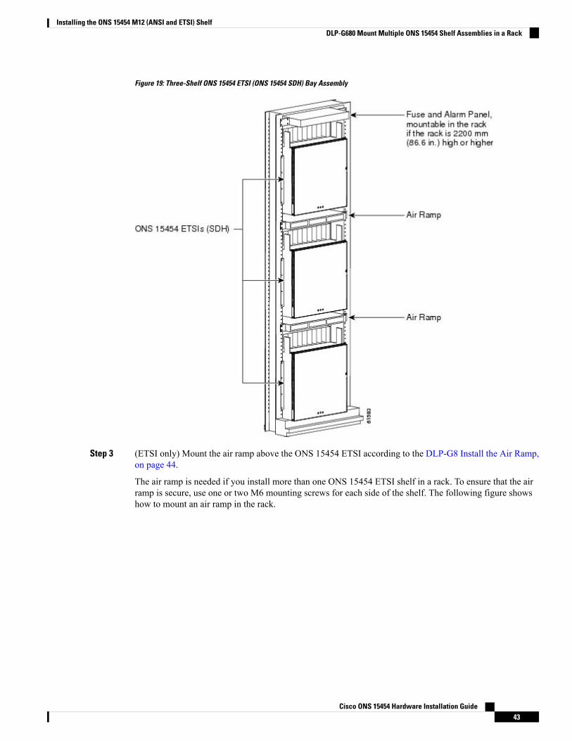
Figure 19: Three-Shelf ONS 15454 ETSI (ONS 15454 SDH) Bay Assembly
Step 3 (ETSI only) Mount the air ramp above the ONS 15454 ETSI according to the DLP-G8 Install the Air Ramp,on page 44.
The air ramp is needed if you install more than one ONS 15454 ETSI shelf in a rack. To ensure that the airramp is secure, use one or two M6 mounting screws for each side of the shelf. The following figure showshow to mount an air ramp in the rack.
Cisco ONS 15454 Hardware Installation Guide43
Installing the ONS 15454 M12 (ANSI and ETSI) ShelfDLP-G680 Mount Multiple ONS 15454 Shelf Assemblies in a Rack
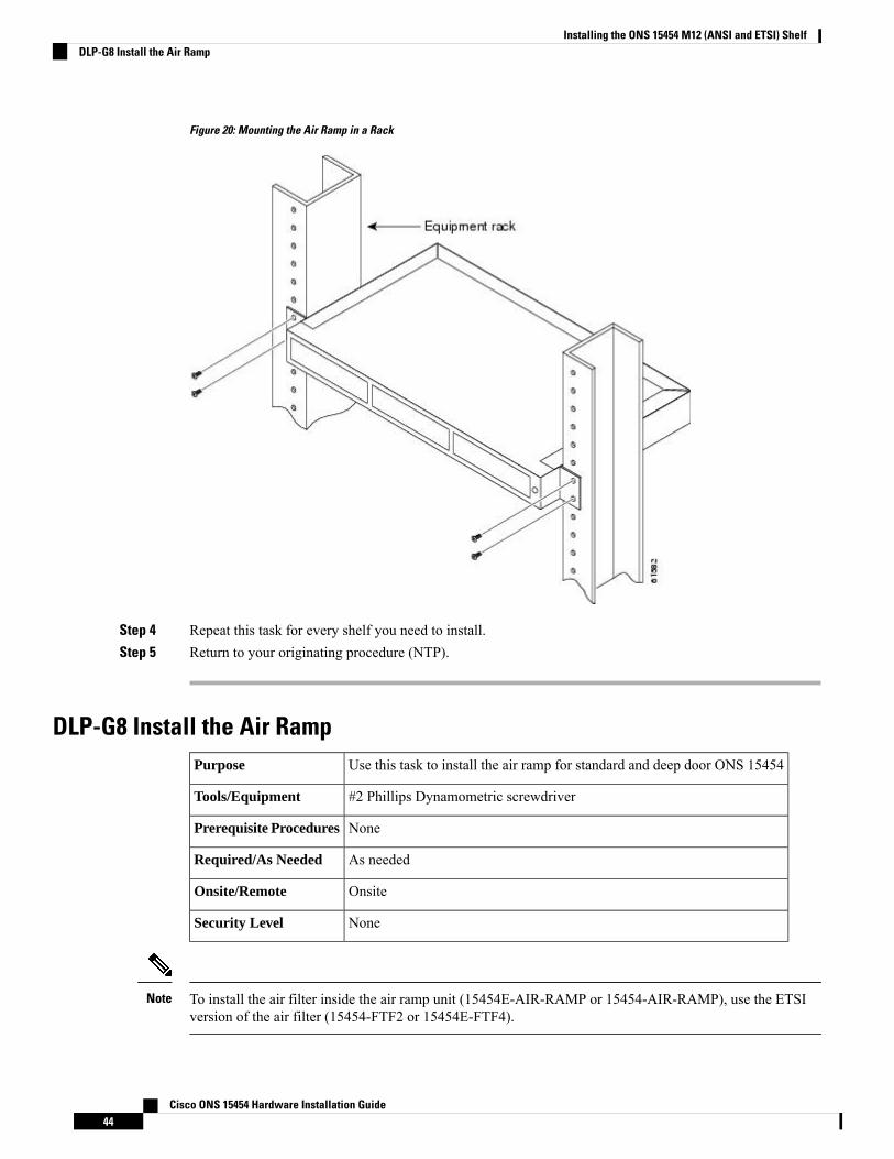
Figure 20: Mounting the Air Ramp in a Rack
Step 4 Repeat this task for every shelf you need to install.Step 5 Return to your originating procedure (NTP).
DLP-G8 Install the Air RampUse this task to install the air ramp for standard and deep door ONS 15454Purpose
#2 Phillips Dynamometric screwdriverTools/Equipment
NonePrerequisite Procedures
As neededRequired/As Needed
OnsiteOnsite/Remote
NoneSecurity Level
To install the air filter inside the air ramp unit (15454E-AIR-RAMP or 15454-AIR-RAMP), use the ETSIversion of the air filter (15454-FTF2 or 15454E-FTF4).
Note
Cisco ONS 15454 Hardware Installation Guide44
Installing the ONS 15454 M12 (ANSI and ETSI) ShelfDLP-G8 Install the Air Ramp
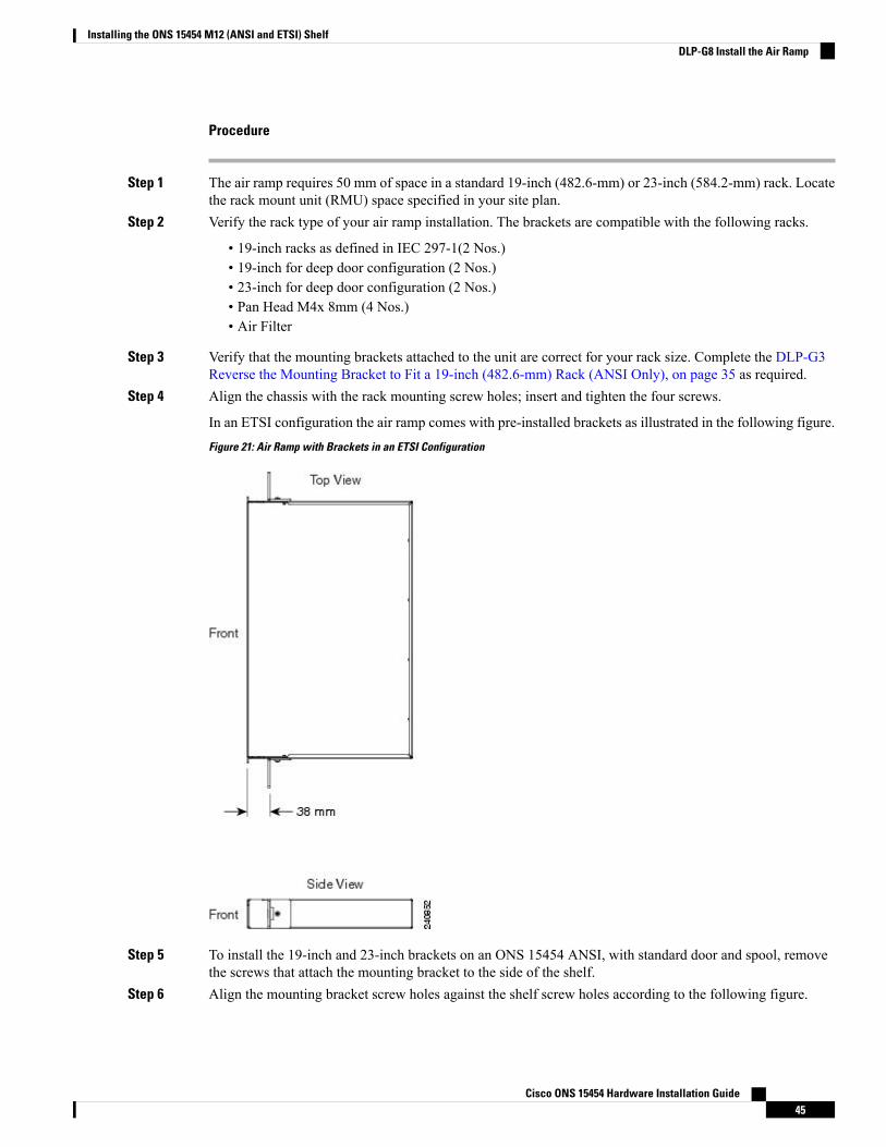
Procedure
Step 1 The air ramp requires 50 mm of space in a standard 19-inch (482.6-mm) or 23-inch (584.2-mm) rack. Locatethe rack mount unit (RMU) space specified in your site plan.
Step 2 Verify the rack type of your air ramp installation. The brackets are compatible with the following racks.
• 19-inch racks as defined in IEC 297-1(2 Nos.)• 19-inch for deep door configuration (2 Nos.)• 23-inch for deep door configuration (2 Nos.)• Pan Head M4x 8mm (4 Nos.)• Air Filter
Step 3 Verify that the mounting brackets attached to the unit are correct for your rack size. Complete the DLP-G3Reverse the Mounting Bracket to Fit a 19-inch (482.6-mm) Rack (ANSI Only), on page 35 as required.
Step 4 Align the chassis with the rack mounting screw holes; insert and tighten the four screws.
In an ETSI configuration the air ramp comes with pre-installed brackets as illustrated in the following figure.
Figure 21: Air Ramp with Brackets in an ETSI Configuration
Step 5 To install the 19-inch and 23-inch brackets on an ONS 15454 ANSI, with standard door and spool, removethe screws that attach the mounting bracket to the side of the shelf.
Step 6 Align the mounting bracket screw holes against the shelf screw holes according to the following figure.
Cisco ONS 15454 Hardware Installation Guide45
Installing the ONS 15454 M12 (ANSI and ETSI) ShelfDLP-G8 Install the Air Ramp
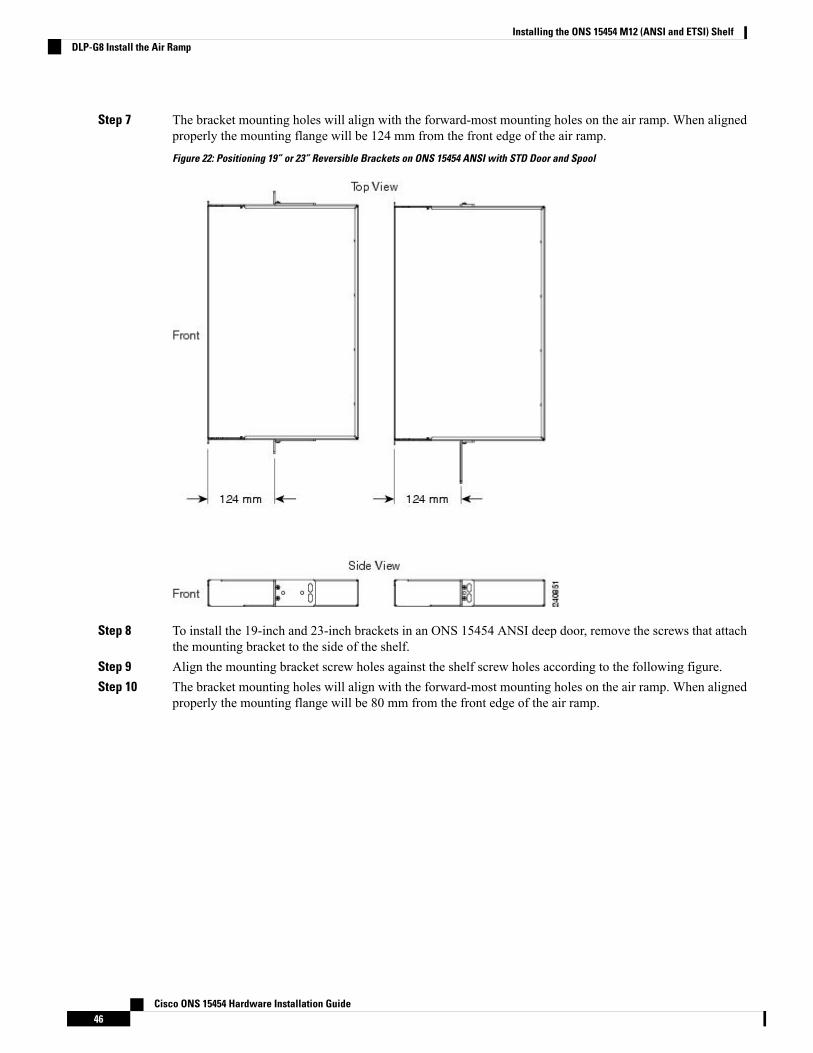
Step 7 The bracket mounting holes will align with the forward-most mounting holes on the air ramp. When alignedproperly the mounting flange will be 124 mm from the front edge of the air ramp.
Figure 22: Positioning 19” or 23” Reversible Brackets on ONS 15454 ANSI with STD Door and Spool
Step 8 To install the 19-inch and 23-inch brackets in an ONS 15454 ANSI deep door, remove the screws that attachthe mounting bracket to the side of the shelf.
Step 9 Align the mounting bracket screw holes against the shelf screw holes according to the following figure.Step 10 The bracket mounting holes will align with the forward-most mounting holes on the air ramp. When aligned
properly the mounting flange will be 80 mm from the front edge of the air ramp.
Cisco ONS 15454 Hardware Installation Guide46
Installing the ONS 15454 M12 (ANSI and ETSI) ShelfDLP-G8 Install the Air Ramp
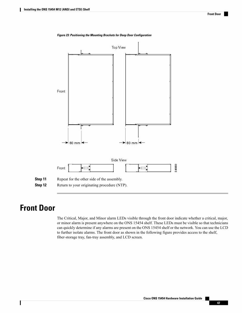
Figure 23: Positioning the Mounting Brackets for Deep Door Configuration
Step 11 Repeat for the other side of the assembly.Step 12 Return to your originating procedure (NTP).
Front DoorThe Critical, Major, and Minor alarm LEDs visible through the front door indicate whether a critical, major,or minor alarm is present anywhere on the ONS 15454 shelf. These LEDs must be visible so that technicianscan quickly determine if any alarms are present on the ONS 15454 shelf or the network. You can use the LCDto further isolate alarms. The front door as shown in the following figure provides access to the shelf,fiber-storage tray, fan-tray assembly, and LCD screen.
Cisco ONS 15454 Hardware Installation Guide47
Installing the ONS 15454 M12 (ANSI and ETSI) ShelfFront Door
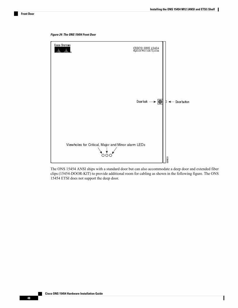
Figure 24: The ONS 15454 Front Door
The ONS 15454 ANSI ships with a standard door but can also accommodate a deep door and extended fiberclips (15454-DOOR-KIT) to provide additional room for cabling as shown in the following figure. The ONS15454 ETSI does not support the deep door.
Cisco ONS 15454 Hardware Installation Guide48
Installing the ONS 15454 M12 (ANSI and ETSI) ShelfFront Door
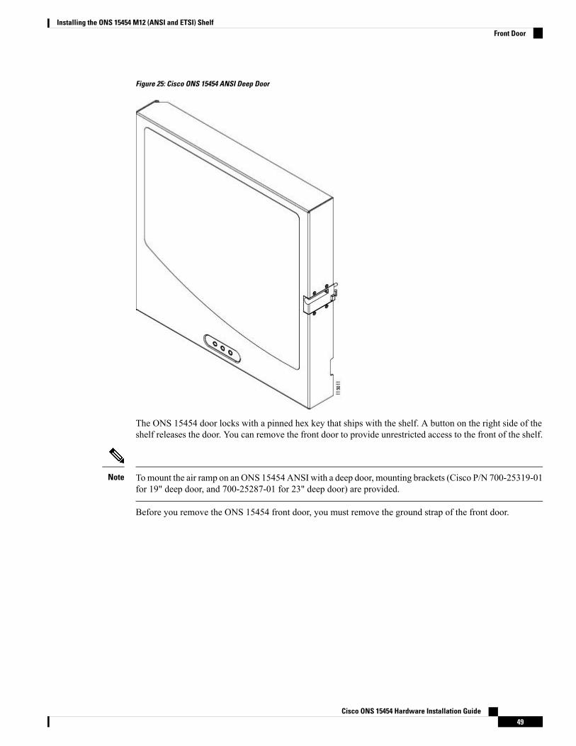
Figure 25: Cisco ONS 15454 ANSI Deep Door
The ONS 15454 door locks with a pinned hex key that ships with the shelf. A button on the right side of theshelf releases the door. You can remove the front door to provide unrestricted access to the front of the shelf.
Tomount the air ramp on an ONS 15454 ANSI with a deep door, mounting brackets (Cisco P/N 700-25319-01for 19" deep door, and 700-25287-01 for 23" deep door) are provided.
Note
Before you remove the ONS 15454 front door, you must remove the ground strap of the front door.
Cisco ONS 15454 Hardware Installation Guide49
Installing the ONS 15454 M12 (ANSI and ETSI) ShelfFront Door
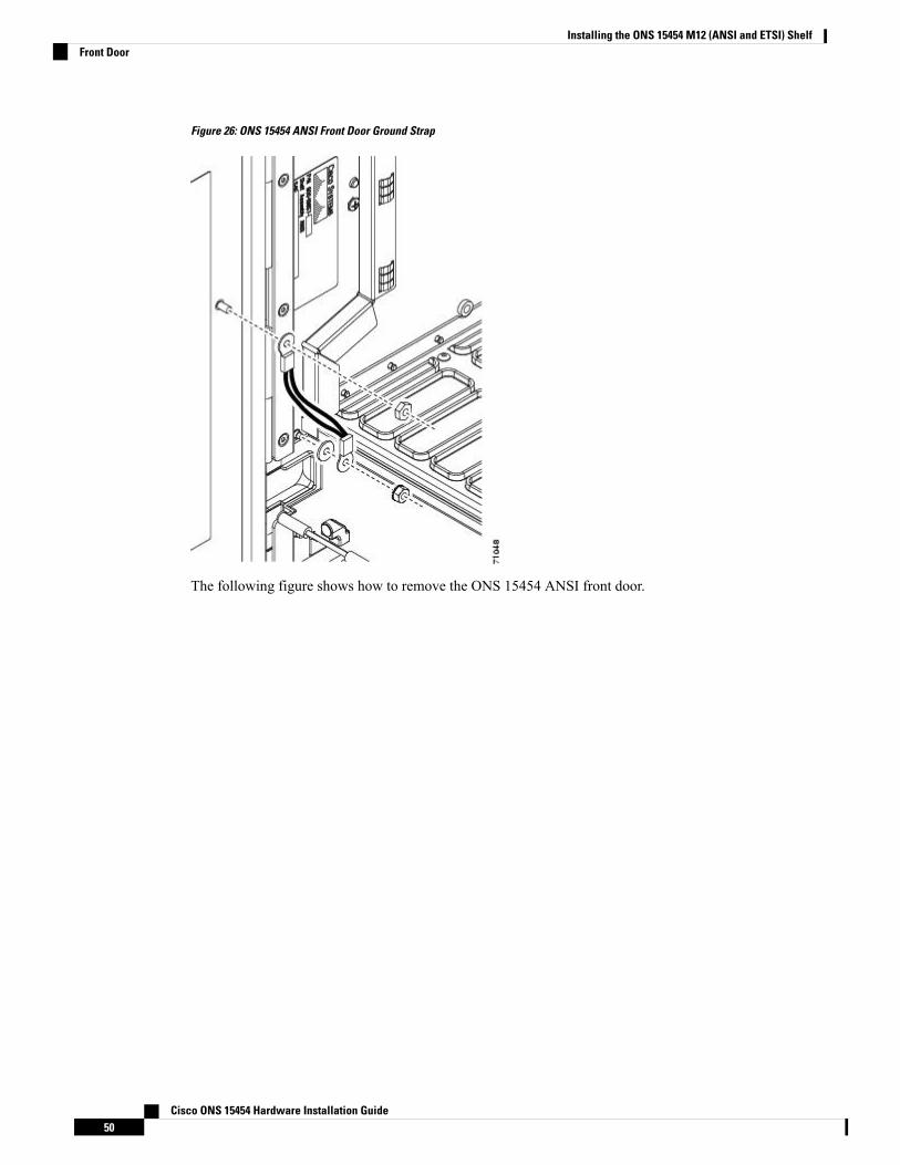
Figure 26: ONS 15454 ANSI Front Door Ground Strap
The following figure shows how to remove the ONS 15454 ANSI front door.
Cisco ONS 15454 Hardware Installation Guide50
Installing the ONS 15454 M12 (ANSI and ETSI) ShelfFront Door
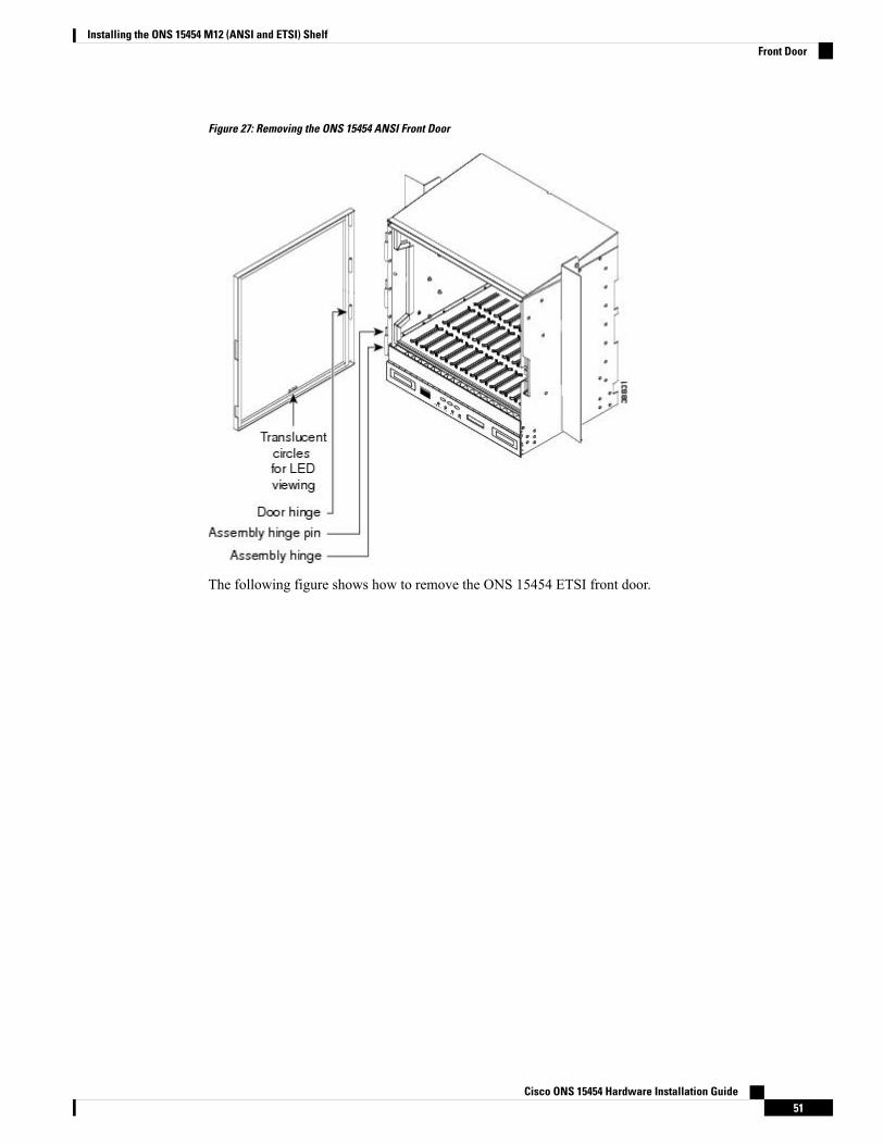
Figure 27: Removing the ONS 15454 ANSI Front Door
The following figure shows how to remove the ONS 15454 ETSI front door.
Cisco ONS 15454 Hardware Installation Guide51
Installing the ONS 15454 M12 (ANSI and ETSI) ShelfFront Door
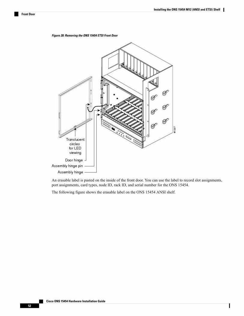
Figure 28: Removing the ONS 15454 ETSI Front Door
An erasable label is pasted on the inside of the front door. You can use the label to record slot assignments,port assignments, card types, node ID, rack ID, and serial number for the ONS 15454.
The following figure shows the erasable label on the ONS 15454 ANSI shelf.
Cisco ONS 15454 Hardware Installation Guide52
Installing the ONS 15454 M12 (ANSI and ETSI) ShelfFront Door
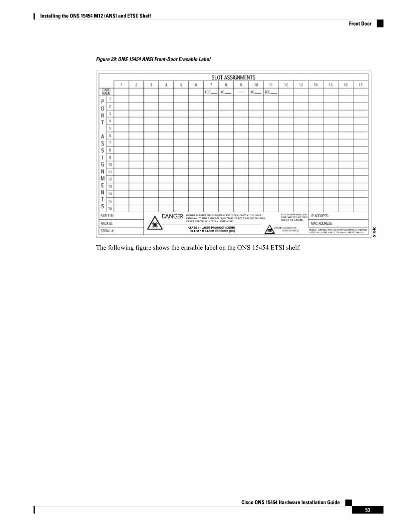
Figure 29: ONS 15454 ANSI Front-Door Erasable Label
The following figure shows the erasable label on the ONS 15454 ETSI shelf.
Cisco ONS 15454 Hardware Installation Guide53
Installing the ONS 15454 M12 (ANSI and ETSI) ShelfFront Door
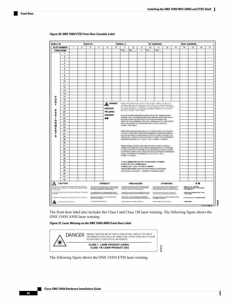
Figure 30: ONS 15454 ETSI Front-Door Erasable Label
The front door label also includes the Class I and Class 1M laser warning. The following figure shows theONS 15454 ANSI laser warning.
Figure 31: Laser Warning on the ONS 15454 ANSI Front-Door Label
The following figure shows the ONS 15454 ETSI laser warning.
Cisco ONS 15454 Hardware Installation Guide54
Installing the ONS 15454 M12 (ANSI and ETSI) ShelfFront Door
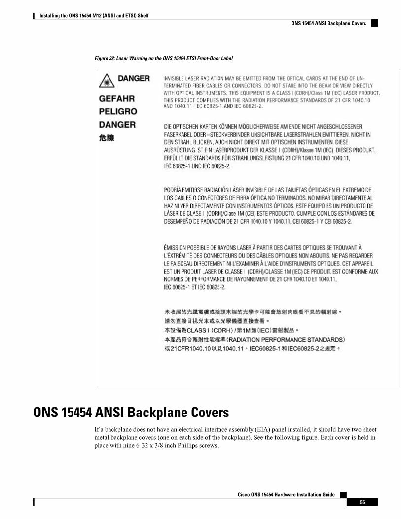
Figure 32: Laser Warning on the ONS 15454 ETSI Front-Door Label
ONS 15454 ANSI Backplane CoversIf a backplane does not have an electrical interface assembly (EIA) panel installed, it should have two sheetmetal backplane covers (one on each side of the backplane). See the following figure. Each cover is held inplace with nine 6-32 x 3/8 inch Phillips screws.
Cisco ONS 15454 Hardware Installation Guide55
Installing the ONS 15454 M12 (ANSI and ETSI) ShelfONS 15454 ANSI Backplane Covers
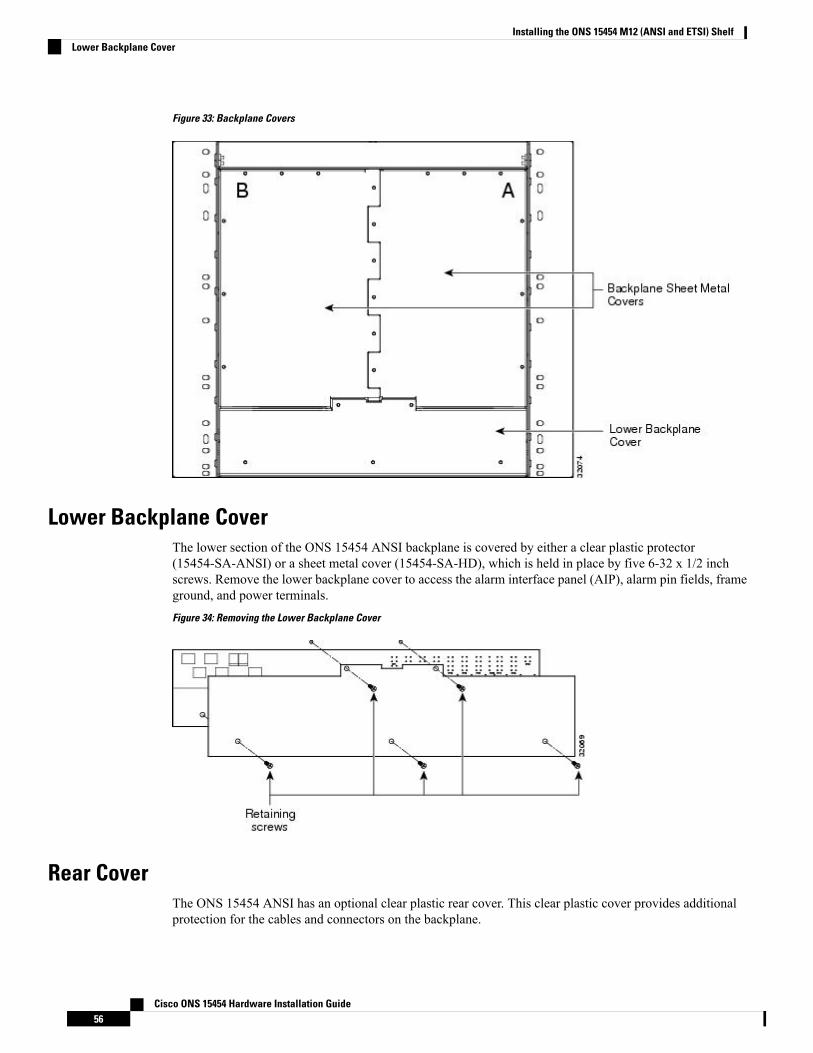
Figure 33: Backplane Covers
Lower Backplane CoverThe lower section of the ONS 15454 ANSI backplane is covered by either a clear plastic protector(15454-SA-ANSI) or a sheet metal cover (15454-SA-HD), which is held in place by five 6-32 x 1/2 inchscrews. Remove the lower backplane cover to access the alarm interface panel (AIP), alarm pin fields, frameground, and power terminals.
Figure 34: Removing the Lower Backplane Cover
Rear CoverThe ONS 15454 ANSI has an optional clear plastic rear cover. This clear plastic cover provides additionalprotection for the cables and connectors on the backplane.
Cisco ONS 15454 Hardware Installation Guide56
Installing the ONS 15454 M12 (ANSI and ETSI) ShelfLower Backplane Cover
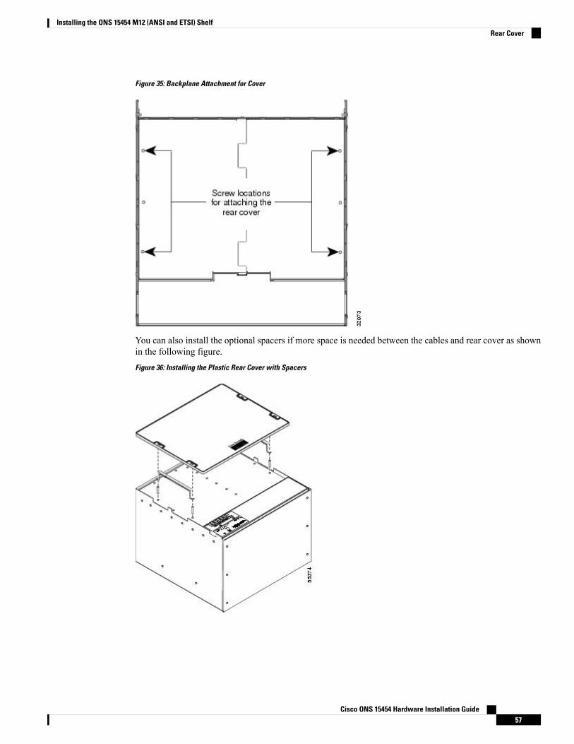
Figure 35: Backplane Attachment for Cover
You can also install the optional spacers if more space is needed between the cables and rear cover as shownin the following figure.
Figure 36: Installing the Plastic Rear Cover with Spacers
Cisco ONS 15454 Hardware Installation Guide57
Installing the ONS 15454 M12 (ANSI and ETSI) ShelfRear Cover
Alarm Interface PanelThe AIP is located above the alarm contacts on the lower section of the backplane. The AIP provides surgeprotection for the ONS 15454 ANSI. It also provides an interface from the backplane to the fan-tray assemblyand LCD. The AIP plugs into the backplane using a 96-pin DIN connector and is held in place with tworetaining screws. The panel has a nonvolatile memory chip that stores the unique node address (MAC address).The MAC address identifies the nodes that support circuits. It allows Cisco Transport Controller (CTC) todetermine circuit sources, destinations, and spans. The TCC2/TCC2P/TCC3 cards in the ONS 15454 ANSIalso use the MAC address to store the node database.
The 5-A AIP (73-7665-XX) is required when installing fan-tray assembly 15454-FTA3 or 15454-CC-FTA,which comes preinstalled on the shelf (15454-SA-ANSI or 15454-SA-HD).
Note
A blown fuse on the AIP board can cause the LCD display to go blank.Note
Alarm Interface Panel ReplacementIf the AIP fails, a MAC Fail alarm appears on the CTC Alarms menu and/or the LCD display on the fan-trayassembly goes blank. To perform an in-service replacement of the AIP, you must contact the Cisco TechnicalAssistance Center (Cisco TAC). For contact information, see the Obtaining Documentation, Obtaining Support,and Security Guidelines, on page xxix.
You can replace the AIP on an in-service system without affecting traffic (except Ethernet traffic on nodesrunning a release earlier than Software Release 4.0). The circuit repair feature allows you to repair circuitsaffected by MAC address changes on one node at a time. Circuit repair works when all nodes are running thesame software version. Each individual AIP upgrade requires an individual circuit repair; if AIPs are replacedon two nodes, the circuit repair must be performed twice. Always replace an AIP during a maintenancewindow.
Do not use a 2-A AIP with a 5-A fan-tray assembly; doing so causes a blown fuse on the AIP.Caution
Ensure that all nodes in the affected network are running the same software version before replacing the AIPand repairing circuits. If you need to upgrade nodes to the same software version, no hardware should bechanged or circuit repair performed until after the software upgrade is complete.
Note
NTP-G3 Open and Remove the Front DoorThis procedure opens and removes the front door to access the equipment.Purpose
Cisco ONS 15454 Hardware Installation Guide58
Installing the ONS 15454 M12 (ANSI and ETSI) ShelfAlarm Interface Panel
Open-end wrench
Pinned hex (Allen) key
Tools/Equipment
NTP-G306 Install the ONS 15454 Shelf, on page 33Prerequisite Procedures
RequiredRequired/As Needed
OnsiteOnsite/Remote
NoneSecurity Level
Procedure
Step 1 Complete the DLP-G9 Open the Front Cabinet Compartment (Door) , on page 59.Step 2 Complete the DLP-G10 Remove the Front Door , on page 60.Step 3 If you are using an ETSI shelf, continue with the NTP-G4 Open and Remove the FMEC Cover (ETSI Only),
on page 62. If you are using an ANSI shelf, continue with the NTP-G5 Remove the Backplane Covers (ANSIOnly), on page 65.
Stop. You have completed this procedure.
DLP-G9 Open the Front Cabinet Compartment (Door)This task opens the front door.Purpose
Pinned hex (Allen) keyTools/Equipment
NTP-G306 Install the ONS 15454 Shelf, on page 33Prerequisite Procedures
RequiredRequired/As Needed
OnsiteOnsite/Remote
NoneSecurity Level
The ONS 15454 shelf has an ESD plug input and is shipped with an ESD wrist strap. The ESD plug input islocated on the outside of the shelf on the right side. It is labeled “ESD” on the top and bottom. Always wearan ESD wrist strap and connect the strap to the ESD plug when working on the ONS 15454. For detailedinstructions on how to wear the ESD wristband, refer to the Electrostatic Discharge and Grounding Guide forCisco CPT and Cisco ONS Platforms.
Note
Procedure
Step 1 Open the front door lock.
Cisco ONS 15454 Hardware Installation Guide59
Installing the ONS 15454 M12 (ANSI and ETSI) ShelfDLP-G9 Open the Front Cabinet Compartment (Door)
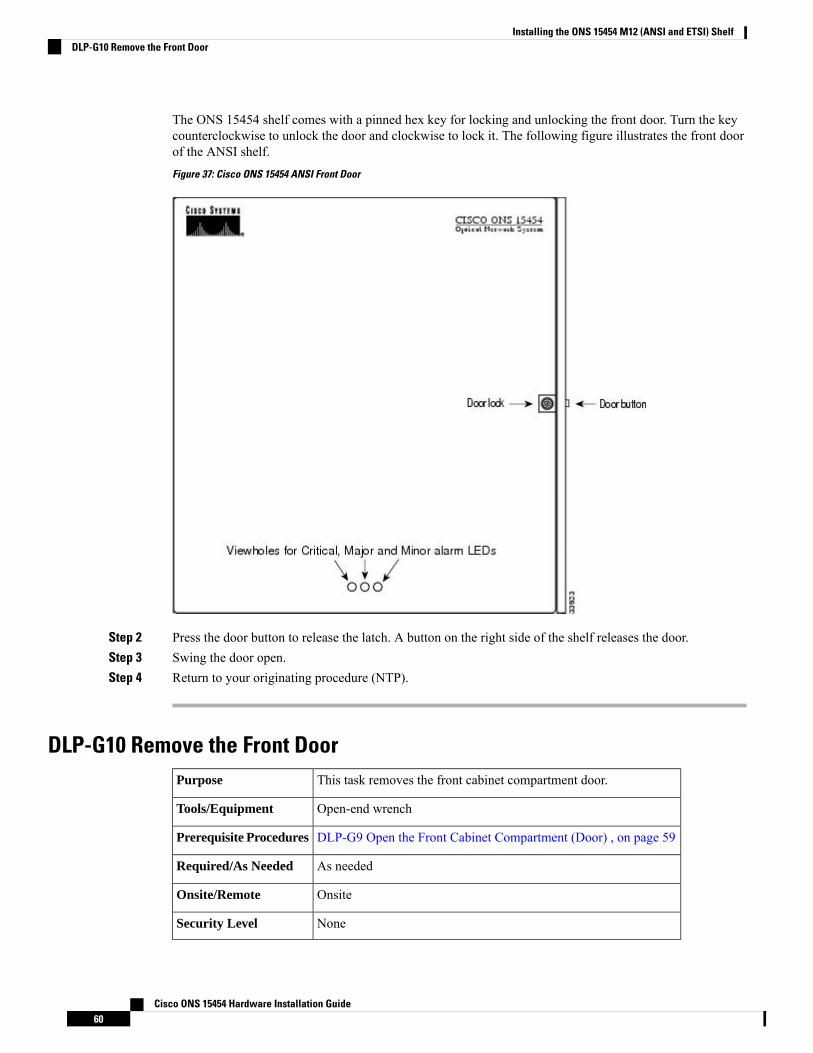
The ONS 15454 shelf comes with a pinned hex key for locking and unlocking the front door. Turn the keycounterclockwise to unlock the door and clockwise to lock it. The following figure illustrates the front doorof the ANSI shelf.
Figure 37: Cisco ONS 15454 ANSI Front Door
Step 2 Press the door button to release the latch. A button on the right side of the shelf releases the door.Step 3 Swing the door open.Step 4 Return to your originating procedure (NTP).
DLP-G10 Remove the Front DoorThis task removes the front cabinet compartment door.Purpose
Open-end wrenchTools/Equipment
DLP-G9 Open the Front Cabinet Compartment (Door) , on page 59Prerequisite Procedures
As neededRequired/As Needed
OnsiteOnsite/Remote
NoneSecurity Level
Cisco ONS 15454 Hardware Installation Guide60
Installing the ONS 15454 M12 (ANSI and ETSI) ShelfDLP-G10 Remove the Front Door
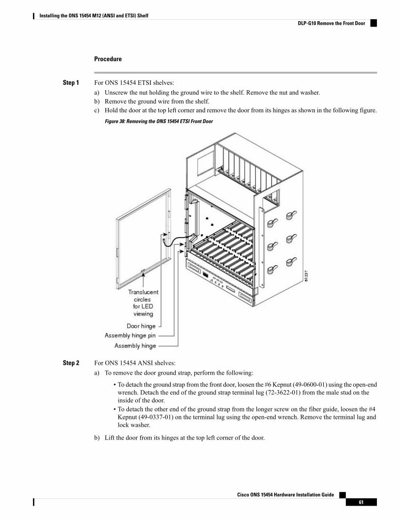
Procedure
Step 1 For ONS 15454 ETSI shelves:a) Unscrew the nut holding the ground wire to the shelf. Remove the nut and washer.b) Remove the ground wire from the shelf.c) Hold the door at the top left corner and remove the door from its hinges as shown in the following figure.
Figure 38: Removing the ONS 15454 ETSI Front Door
Step 2 For ONS 15454 ANSI shelves:a) To remove the door ground strap, perform the following:
• To detach the ground strap from the front door, loosen the #6 Kepnut (49-0600-01) using the open-endwrench. Detach the end of the ground strap terminal lug (72-3622-01) from the male stud on theinside of the door.
• To detach the other end of the ground strap from the longer screw on the fiber guide, loosen the #4Kepnut (49-0337-01) on the terminal lug using the open-end wrench. Remove the terminal lug andlock washer.
b) Lift the door from its hinges at the top left corner of the door.
Cisco ONS 15454 Hardware Installation Guide61
Installing the ONS 15454 M12 (ANSI and ETSI) ShelfDLP-G10 Remove the Front Door
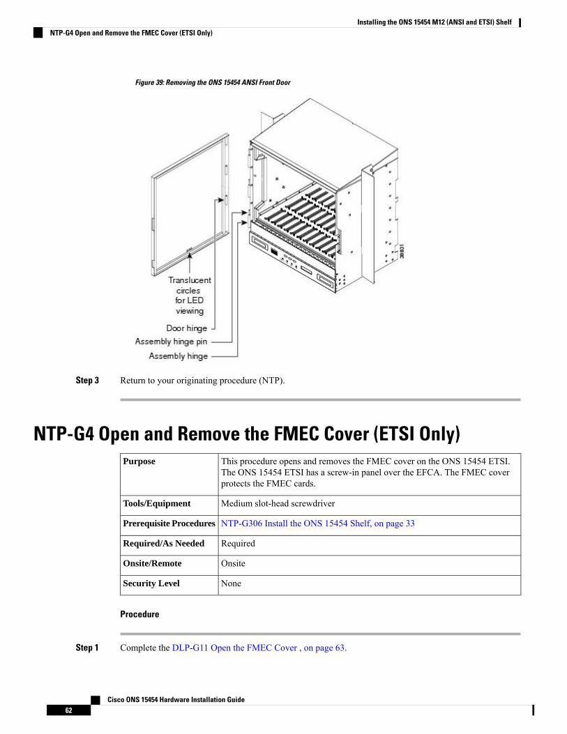
Figure 39: Removing the ONS 15454 ANSI Front Door
Step 3 Return to your originating procedure (NTP).
NTP-G4 Open and Remove the FMEC Cover (ETSI Only)This procedure opens and removes the FMEC cover on the ONS 15454 ETSI.The ONS 15454 ETSI has a screw-in panel over the EFCA. The FMEC coverprotects the FMEC cards.
Purpose
Medium slot-head screwdriverTools/Equipment
NTP-G306 Install the ONS 15454 Shelf, on page 33Prerequisite Procedures
RequiredRequired/As Needed
OnsiteOnsite/Remote
NoneSecurity Level
Procedure
Step 1 Complete the DLP-G11 Open the FMEC Cover , on page 63.
Cisco ONS 15454 Hardware Installation Guide62
Installing the ONS 15454 M12 (ANSI and ETSI) ShelfNTP-G4 Open and Remove the FMEC Cover (ETSI Only)
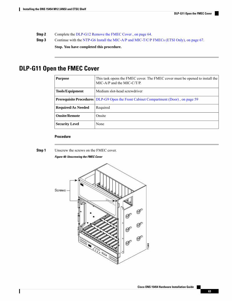
Step 2 Complete the DLP-G12 Remove the FMEC Cover , on page 64.Step 3 Continue with the NTP-G6 Install the MIC-A/P and MIC-T/C/P FMECs (ETSI Only), on page 67.
Stop. You have completed this procedure.
DLP-G11 Open the FMEC CoverThis task opens the FMEC cover. The FMEC cover must be opened to install theMIC-A/P and the MIC-C/T/P.
Purpose
Medium slot-head screwdriverTools/Equipment
DLP-G9 Open the Front Cabinet Compartment (Door) , on page 59Prerequisite Procedures
RequiredRequired/As Needed
OnsiteOnsite/Remote
NoneSecurity Level
Procedure
Step 1 Unscrew the screws on the FMEC cover.
Figure 40: Unscrewing the FMEC Cover
Cisco ONS 15454 Hardware Installation Guide63
Installing the ONS 15454 M12 (ANSI and ETSI) ShelfDLP-G11 Open the FMEC Cover
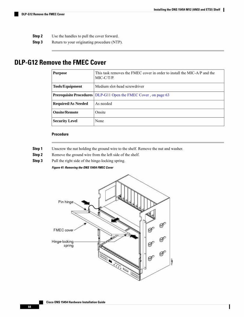
Step 2 Use the handles to pull the cover forward.Step 3 Return to your originating procedure (NTP).
DLP-G12 Remove the FMEC CoverThis task removes the FMEC cover in order to install the MIC-A/P and theMIC-C/T/P.
Purpose
Medium slot-head screwdriverTools/Equipment
DLP-G11 Open the FMEC Cover , on page 63Prerequisite Procedures
As neededRequired/As Needed
OnsiteOnsite/Remote
NoneSecurity Level
Procedure
Step 1 Unscrew the nut holding the ground wire to the shelf. Remove the nut and washer.Step 2 Remove the ground wire from the left side of the shelf.Step 3 Pull the right side of the hinge-locking spring.
Figure 41: Removing the ONS 15454 FMEC Cover
Cisco ONS 15454 Hardware Installation Guide64
Installing the ONS 15454 M12 (ANSI and ETSI) ShelfDLP-G12 Remove the FMEC Cover
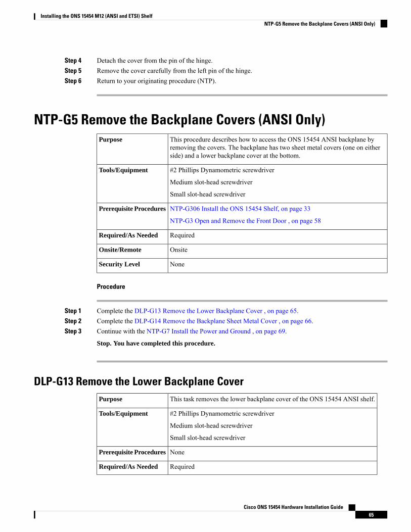
Step 4 Detach the cover from the pin of the hinge.Step 5 Remove the cover carefully from the left pin of the hinge.Step 6 Return to your originating procedure (NTP).
NTP-G5 Remove the Backplane Covers (ANSI Only)This procedure describes how to access the ONS 15454 ANSI backplane byremoving the covers. The backplane has two sheet metal covers (one on eitherside) and a lower backplane cover at the bottom.
Purpose
#2 Phillips Dynamometric screwdriver
Medium slot-head screwdriver
Small slot-head screwdriver
Tools/Equipment
NTP-G306 Install the ONS 15454 Shelf, on page 33
NTP-G3 Open and Remove the Front Door , on page 58
Prerequisite Procedures
RequiredRequired/As Needed
OnsiteOnsite/Remote
NoneSecurity Level
Procedure
Step 1 Complete the DLP-G13 Remove the Lower Backplane Cover , on page 65.Step 2 Complete the DLP-G14 Remove the Backplane Sheet Metal Cover , on page 66.Step 3 Continue with the NTP-G7 Install the Power and Ground , on page 69.
Stop. You have completed this procedure.
DLP-G13 Remove the Lower Backplane CoverThis task removes the lower backplane cover of the ONS 15454 ANSI shelf.Purpose
#2 Phillips Dynamometric screwdriver
Medium slot-head screwdriver
Small slot-head screwdriver
Tools/Equipment
NonePrerequisite Procedures
RequiredRequired/As Needed
Cisco ONS 15454 Hardware Installation Guide65
Installing the ONS 15454 M12 (ANSI and ETSI) ShelfNTP-G5 Remove the Backplane Covers (ANSI Only)
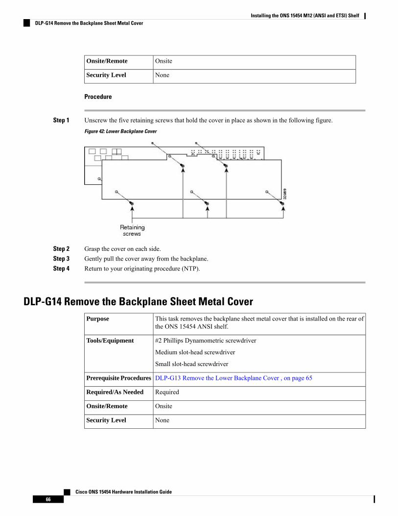
OnsiteOnsite/Remote
NoneSecurity Level
Procedure
Step 1 Unscrew the five retaining screws that hold the cover in place as shown in the following figure.
Figure 42: Lower Backplane Cover
Step 2 Grasp the cover on each side.Step 3 Gently pull the cover away from the backplane.Step 4 Return to your originating procedure (NTP).
DLP-G14 Remove the Backplane Sheet Metal CoverThis task removes the backplane sheet metal cover that is installed on the rear ofthe ONS 15454 ANSI shelf.
Purpose
#2 Phillips Dynamometric screwdriver
Medium slot-head screwdriver
Small slot-head screwdriver
Tools/Equipment
DLP-G13 Remove the Lower Backplane Cover , on page 65Prerequisite Procedures
RequiredRequired/As Needed
OnsiteOnsite/Remote
NoneSecurity Level
Cisco ONS 15454 Hardware Installation Guide66
Installing the ONS 15454 M12 (ANSI and ETSI) ShelfDLP-G14 Remove the Backplane Sheet Metal Cover
Procedure
Step 1 To remove the backplane sheet metal cover, loosen the five screws that secure it to the ONS 15454 ANSIshelf and pull it away from the shelf.
Step 2 Loosen the nine perimeter screws that hold the backplane sheet metal cover(s) in place.Step 3 Lift the panel by the bottom to remove it from the shelf.Step 4 Store the panel for later use. Attach the backplane cover(s) whenever electrical interface assemblies (EIAs)
are not installed.Step 5 Return to your originating procedure (NTP).
ONS 15454 ETSI Front Mount Electrical ConnectionThe ONS 15454 ETSI positive and negative power terminals are located on FMEC cards in the ElectricalFacility Connection Assembly (EFCA). The ground connection is the grounding receptacle on the side panelof the shelf.
The ONS 15454 ETSI EFCA at the top of the shelf has 12 FMEC slots numbered sequentially from left toright (18 to 29). Slots 18 to 22 and 25 to 29 provide electrical connections. Slots 23 and 24 host the MIC-A/PandMIC-C/T/P cards, respectively. TheMIC-A/P and theMIC-C/T/P cards also connect alarm, timing, LAN,and craft connections to the ONS 15454 ETSI.
For more information about the MIC-A/P and MIC-C/T/P cards, see the chapter “Install the Control Cards”in Cisco ONS 15454 DWDM Configuration Guide.
NTP-G6 Install the MIC-A/P and MIC-T/C/P FMECs (ETSI Only)This procedure installs the MIC-A/P and the MIC-T/C/P FMECs in the EFCA.The EFCA is located at the top of the ONS 15454 ETSI shelf. It providesconnection for installing power, external alarms, timing input and output, andcraft interface terminals.
Purpose
#2 Phillips Dynamometric screwdriver
Medium slot-head screwdriver
Small slot-head screwdriver
FMECs (the MIC-A/P and MIC-T/C/P)
Tools/Equipment
NTP-G4 Open and Remove the FMEC Cover (ETSI Only), on page 62Prerequisite Procedures
RequiredRequired/As Needed
OnsiteOnsite/Remote
NoneSecurity Level
Cisco ONS 15454 Hardware Installation Guide67
Installing the ONS 15454 M12 (ANSI and ETSI) ShelfONS 15454 ETSI Front Mount Electrical Connection
Voltage is present on the backplane when the system is operating. To reduce risk of an electric shock,keep hands and fingers out of the power supply bays and backplane areas. Statement 166
Warning
Always use the supplied ESD wristband when working with a powered ONS 15454 ETSI. For detailedinstructions on how to wear the ESD wristband, refer to the Electrostatic Discharge and Grounding Guide forCisco CPT and Cisco ONS Platforms .
Caution
The ONS 15454 ETSI EFCA has 12 FMEC slots numbered sequentially from left to right beginning with Slot18. Slots 18 to 22 and 25 to 29 provide electrical connections for the corresponding slots, so they areunnecessary in DWDM applications.
Note
Procedure
Step 1 Ensure that you are installing the FMECs in the correct slot:
• FMEC Slot 23 supports the MIC-A/P.
The MIC-A/P card provides connection for the BATTERY B input, one of the two possible redundant powersupply inputs. It also provides connection for eight alarm outputs (coming from the TCC2/TCC2P/TCC3card), sixteen alarm inputs, and four configurable alarm inputs/outputs.
• FMEC Slot 24 supports the MIC-C/T/P.
The MIC-C/T/P card provides connection for the BATTERY A input, one of the two possible redundantpower supply inputs. It also provides connection for system management serial port, system managementLAN port, and system timing inputs and outputs.
Step 2 Hold the FMEC by the faceplate.Step 3 Slide the FMEC along the guide rails into the desired FMEC slot or slots.Step 4 Push the FMEC gently into the connector. The ONS 15454 ETSI FMECs plug into electrical connectors on
the back panel of the shelf when the screws are tightened. The following figure shows FMEC installation.
Cisco ONS 15454 Hardware Installation Guide68
Installing the ONS 15454 M12 (ANSI and ETSI) ShelfNTP-G6 Install the MIC-A/P and MIC-T/C/P FMECs (ETSI Only)

Figure 43: Installing FMECs on the ONS 15454 ETSI
Step 5 Tighten the screws.Step 6 Continue with the NTP-G7 Install the Power and Ground , on page 69.
Stop. You have completed this procedure.
Power and Ground DescriptionGround the equipment according to Telcordia standards or local practices. The following sections describepower and ground for the ONS 15454 shelves.
For detailed instructions on grounding the ONS 15454 ANSI or ONS 15454 ETSI chassis, refer to theElectrostatic Discharge and Grounding Guide for Cisco CPT and Cisco ONS Platforms .
Note
NTP-G7 Install the Power and GroundThis procedure installs power feeds and grounds the ONS 15454.Purpose
Cisco ONS 15454 Hardware Installation Guide69
Installing the ONS 15454 M12 (ANSI and ETSI) ShelfPower and Ground Description
ANSI and ETSI:
• #2 Phillips Dynamometric screwdriver• Medium slot-head screwdriver• Small slot-head screwdriver• Screws• Ground cable 13.3-mm² (#6 AWG) stranded• Listed pressure terminal connectors such as ring and fork types; connectorsmust be suitable for #10 AWG copper conductors
• Wire cutters• Wire strippers• Crimp tool• Fuse panel
ANSI only:
• Power cable (from fuse and alarm panel to assembly), #10 AWG, copperconductors, 194 degrees F [90 degrees C])
• Wire wrapper
ETSI only:
• Power cable (from fuse panel to MIC-A/P and to MIC-C/T/P), shipped withthe ONS 15454 ETSI
• Two-hole grounding lug, shipped with the ONS 15454 ETSI
Tools/Equipment
NTP-G4 Open and Remove the FMEC Cover (ETSI Only), on page 62
NTP-G6 Install the MIC-A/P and MIC-T/C/P FMECs (ETSI Only), on page 67
NTP-G5 Remove the Backplane Covers (ANSI Only), on page 65
Prerequisite Procedures
RequiredRequired/As Needed
OnsiteOnsite/Remote
NoneSecurity Level
Before performing any of the following procedures, ensure that power is removed from the DC circuit.Statement 1003
Warning
This equipment is intended to be grounded. Ensure that the host is connected to earth ground duringnormal use. Statement 39
Warning
Use copper conductors only. Statement 1025Warning
Cisco ONS 15454 Hardware Installation Guide70
Installing the ONS 15454 M12 (ANSI and ETSI) ShelfNTP-G7 Install the Power and Ground
Connect the unit only to DC power source that complies with the safety extra-low voltage (SELV)requirements in IEC 60950-1 based safety standards. Statement 1033
Warning
This product requires short-circuit (overcurrent) protection, to be provided as part of the buildinginstallation. Install only in accordance with national and local wiring regulations. The short-circuit(overcurrent) protection rating must not exceed 30A. Statement 1045
Warning
A readily accessible two-poled disconnect device must be incorporated in the fixed wiring. Statement1022
Warning
This unit might have more than one power supply connection. All connections must be removed tode-energize the unit. Statement 1028
Warning
Always use the supplied ESD wristband when working with a powered ONS 15454. For detailed instructionson how to wear the ESD wristband, refer to the Electrostatic Discharge and Grounding Guide for Cisco CPTand Cisco ONS Platforms .
Caution
Procedure
Step 1 Verify that the correct fuse and alarm panel is installed in the top mounting space:
• (ETSI only) Verify that the fuse rating does not exceed 30A.
• The fuse rating for ANSI chassis must not exceed 30A.
Step 2 Depending on your type of shelf, connect the office ground to the 15454 ETSI or the 15454 ANSI chassis.For detailed instructions on grounding, refer to the Electrostatic Discharge and Grounding Guide for CiscoCPT and Cisco ONS Platforms .
Step 3 Depending on your shelf, complete the DLP-G17 Connect Office Power to the ONS 15454 ETSI , on page72 or the DLP-G18 Connect Office Power to the ONS 15454 ANSI, on page 73.
Step 4 Complete the DLP-G19 Turn On and Verify Office Power , on page 76.Step 5 Continue with the NTP-G8 Install the Fan-Tray Assembly , on page 84.
Stop. You have completed this procedure.
Cisco ONS 15454 Hardware Installation Guide71
Installing the ONS 15454 M12 (ANSI and ETSI) ShelfNTP-G7 Install the Power and Ground
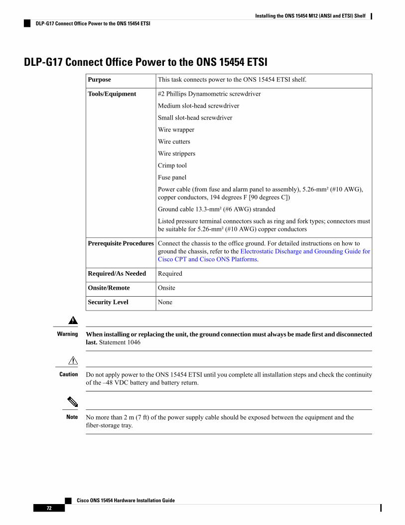
DLP-G17 Connect Office Power to the ONS 15454 ETSIThis task connects power to the ONS 15454 ETSI shelf.Purpose
#2 Phillips Dynamometric screwdriver
Medium slot-head screwdriver
Small slot-head screwdriver
Wire wrapper
Wire cutters
Wire strippers
Crimp tool
Fuse panel
Power cable (from fuse and alarm panel to assembly), 5.26-mm² (#10 AWG),copper conductors, 194 degrees F [90 degrees C])
Ground cable 13.3-mm² (#6 AWG) stranded
Listed pressure terminal connectors such as ring and fork types; connectors mustbe suitable for 5.26-mm² (#10 AWG) copper conductors
Tools/Equipment
Connect the chassis to the office ground. For detailed instructions on how toground the chassis, refer to the Electrostatic Discharge and Grounding Guide forCisco CPT and Cisco ONS Platforms.
Prerequisite Procedures
RequiredRequired/As Needed
OnsiteOnsite/Remote
NoneSecurity Level
When installing or replacing the unit, the ground connection must always be made first and disconnectedlast. Statement 1046
Warning
Do not apply power to the ONS 15454 ETSI until you complete all installation steps and check the continuityof the –48 VDC battery and battery return.
Caution
No more than 2 m (7 ft) of the power supply cable should be exposed between the equipment and thefiber-storage tray.
Note
Cisco ONS 15454 Hardware Installation Guide72
Installing the ONS 15454 M12 (ANSI and ETSI) ShelfDLP-G17 Connect Office Power to the ONS 15454 ETSI
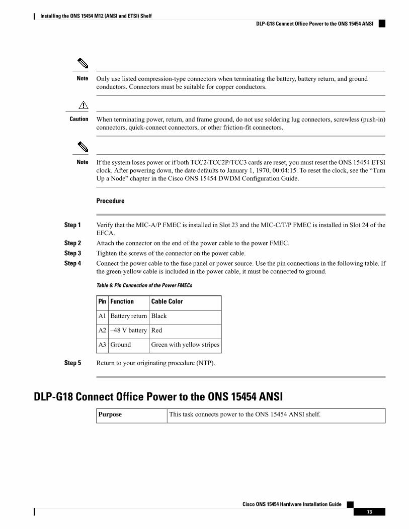
Only use listed compression-type connectors when terminating the battery, battery return, and groundconductors. Connectors must be suitable for copper conductors.
Note
When terminating power, return, and frame ground, do not use soldering lug connectors, screwless (push-in)connectors, quick-connect connectors, or other friction-fit connectors.
Caution
If the system loses power or if both TCC2/TCC2P/TCC3 cards are reset, you must reset the ONS 15454 ETSIclock. After powering down, the date defaults to January 1, 1970, 00:04:15. To reset the clock, see the “TurnUp a Node” chapter in the Cisco ONS 15454 DWDM Configuration Guide.
Note
Procedure
Step 1 Verify that the MIC-A/P FMEC is installed in Slot 23 and the MIC-C/T/P FMEC is installed in Slot 24 of theEFCA.
Step 2 Attach the connector on the end of the power cable to the power FMEC.Step 3 Tighten the screws of the connector on the power cable.Step 4 Connect the power cable to the fuse panel or power source. Use the pin connections in the following table. If
the green-yellow cable is included in the power cable, it must be connected to ground.
Table 6: Pin Connection of the Power FMECs
Cable ColorFunctionPin
BlackBattery returnA1
Red–48 V batteryA2
Green with yellow stripesGroundA3
Step 5 Return to your originating procedure (NTP).
DLP-G18 Connect Office Power to the ONS 15454 ANSIThis task connects power to the ONS 15454 ANSI shelf.Purpose
Cisco ONS 15454 Hardware Installation Guide73
Installing the ONS 15454 M12 (ANSI and ETSI) ShelfDLP-G18 Connect Office Power to the ONS 15454 ANSI
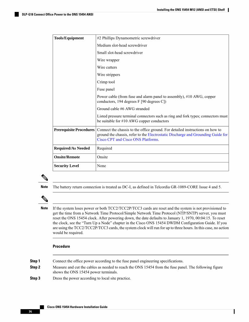
#2 Phillips Dynamometric screwdriver
Medium slot-head screwdriver
Small slot-head screwdriver
Wire wrapper
Wire cutters
Wire strippers
Crimp tool
Fuse panel
Power cable (from fuse and alarm panel to assembly), #10 AWG, copperconductors, 194 degrees F [90 degrees C])
Ground cable #6 AWG stranded
Listed pressure terminal connectors such as ring and fork types; connectors mustbe suitable for #10 AWG copper conductors
Tools/Equipment
Connect the chassis to the office ground. For detailed instructions on how toground the chassis, refer to the Electrostatic Discharge and Grounding Guide forCisco CPT and Cisco ONS Platforms.
Prerequisite Procedures
RequiredRequired/As Needed
OnsiteOnsite/Remote
NoneSecurity Level
The battery return connection is treated as DC-I, as defined in Telcordia GR-1089-CORE Issue 4 and 5.Note
If the system loses power or both TCC2/TCC2P/TCC3 cards are reset and the system is not provisioned toget the time from a Network Time Protocol/Simple Network Time Protocol (NTP/SNTP) server, you mustreset the ONS 15454 clock. After powering down, the date defaults to January 1, 1970, 00:04:15. To resetthe clock, see the “Turn Up a Node” chapter in the Cisco ONS 15454 DWDM Configuration Guide. If youare using the TCC2/TCC2P/TCC3 cards, the system clock will run for up to three hours. In this case, no actionwould be required.
Note
Procedure
Step 1 Connect the office power according to the fuse panel engineering specifications.Step 2 Measure and cut the cables as needed to reach the ONS 15454 from the fuse panel. The following figure
shows the ONS 15454 power terminals.Step 3 Dress the power according to local site practice.
Cisco ONS 15454 Hardware Installation Guide74
Installing the ONS 15454 M12 (ANSI and ETSI) ShelfDLP-G18 Connect Office Power to the ONS 15454 ANSI
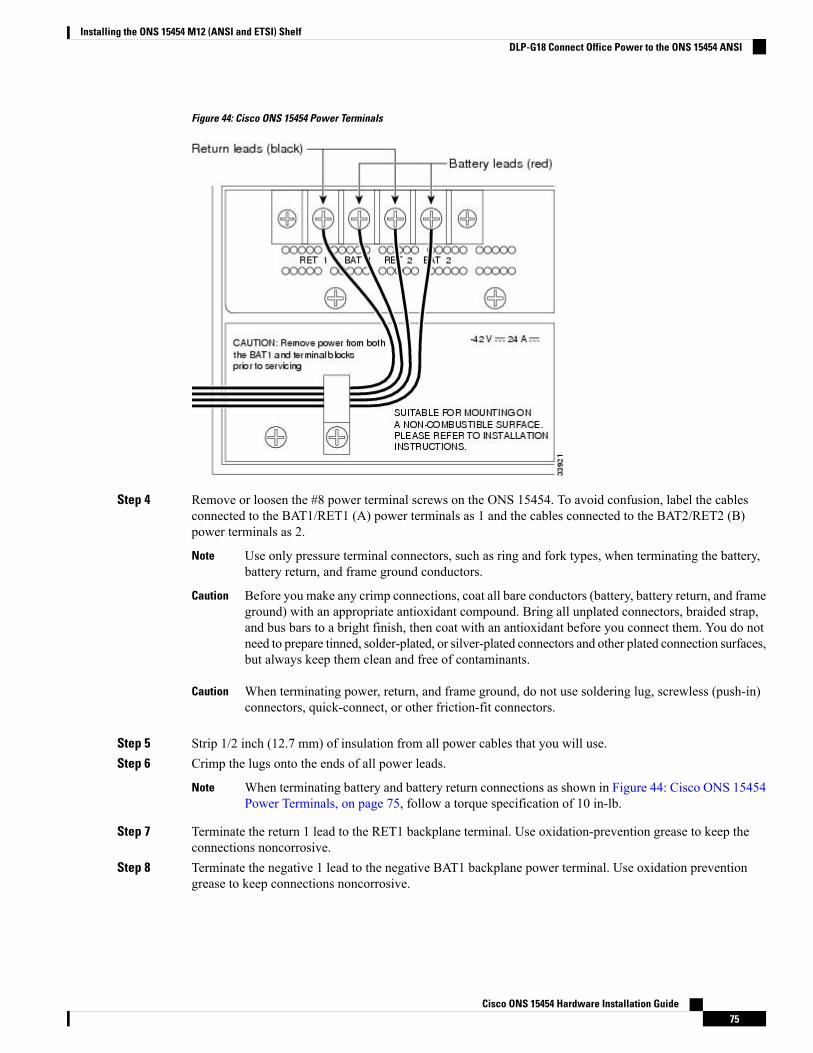
Figure 44: Cisco ONS 15454 Power Terminals
Step 4 Remove or loosen the #8 power terminal screws on the ONS 15454. To avoid confusion, label the cablesconnected to the BAT1/RET1 (A) power terminals as 1 and the cables connected to the BAT2/RET2 (B)power terminals as 2.
Use only pressure terminal connectors, such as ring and fork types, when terminating the battery,battery return, and frame ground conductors.
Note
Before you make any crimp connections, coat all bare conductors (battery, battery return, and frameground) with an appropriate antioxidant compound. Bring all unplated connectors, braided strap,and bus bars to a bright finish, then coat with an antioxidant before you connect them. You do notneed to prepare tinned, solder-plated, or silver-plated connectors and other plated connection surfaces,but always keep them clean and free of contaminants.
Caution
When terminating power, return, and frame ground, do not use soldering lug, screwless (push-in)connectors, quick-connect, or other friction-fit connectors.
Caution
Step 5 Strip 1/2 inch (12.7 mm) of insulation from all power cables that you will use.Step 6 Crimp the lugs onto the ends of all power leads.
When terminating battery and battery return connections as shown in Figure 44: Cisco ONS 15454Power Terminals, on page 75, follow a torque specification of 10 in-lb.
Note
Step 7 Terminate the return 1 lead to the RET1 backplane terminal. Use oxidation-prevention grease to keep theconnections noncorrosive.
Step 8 Terminate the negative 1 lead to the negative BAT1 backplane power terminal. Use oxidation preventiongrease to keep connections noncorrosive.
Cisco ONS 15454 Hardware Installation Guide75
Installing the ONS 15454 M12 (ANSI and ETSI) ShelfDLP-G18 Connect Office Power to the ONS 15454 ANSI
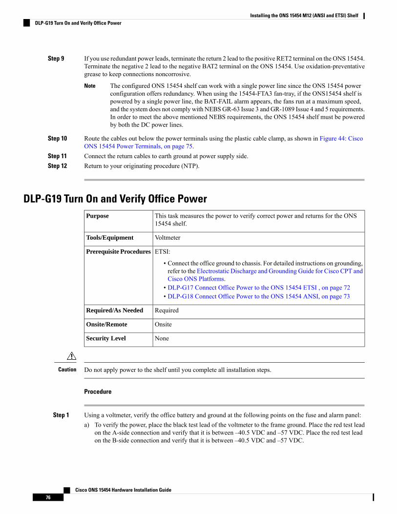
Step 9 If you use redundant power leads, terminate the return 2 lead to the positive RET2 terminal on the ONS 15454.Terminate the negative 2 lead to the negative BAT2 terminal on the ONS 15454. Use oxidation-preventativegrease to keep connections noncorrosive.
The configured ONS 15454 shelf can work with a single power line since the ONS 15454 powerconfiguration offers redundancy. When using the 15454-FTA3 fan-tray, if the ONS15454 shelf ispowered by a single power line, the BAT-FAIL alarm appears, the fans run at a maximum speed,and the system does not comply with NEBSGR-63 Issue 3 and GR-1089 Issue 4 and 5 requirements.In order to meet the above mentioned NEBS requirements, the ONS 15454 shelf must be poweredby both the DC power lines.
Note
Step 10 Route the cables out below the power terminals using the plastic cable clamp, as shown in Figure 44: CiscoONS 15454 Power Terminals, on page 75.
Step 11 Connect the return cables to earth ground at power supply side.Step 12 Return to your originating procedure (NTP).
DLP-G19 Turn On and Verify Office PowerThis task measures the power to verify correct power and returns for the ONS15454 shelf.
Purpose
VoltmeterTools/Equipment
ETSI:
• Connect the office ground to chassis. For detailed instructions on grounding,refer to the Electrostatic Discharge and Grounding Guide for Cisco CPT andCisco ONS Platforms.
• DLP-G17 Connect Office Power to the ONS 15454 ETSI , on page 72• DLP-G18 Connect Office Power to the ONS 15454 ANSI, on page 73
Prerequisite Procedures
RequiredRequired/As Needed
OnsiteOnsite/Remote
NoneSecurity Level
Do not apply power to the shelf until you complete all installation steps.Caution
Procedure
Step 1 Using a voltmeter, verify the office battery and ground at the following points on the fuse and alarm panel:a) To verify the power, place the black test lead of the voltmeter to the frame ground. Place the red test lead
on the A-side connection and verify that it is between –40.5 VDC and –57 VDC. Place the red test leadon the B-side connection and verify that it is between –40.5 VDC and –57 VDC.
Cisco ONS 15454 Hardware Installation Guide76
Installing the ONS 15454 M12 (ANSI and ETSI) ShelfDLP-G19 Turn On and Verify Office Power
The minimum and maximum voltages required to power the chassis are –40.5 VDC and –57VDC respectively. The nominal steady-state voltage is -48 VDC.
Note
b) To verify the ground, place the black test lead of the voltmeter to the frame ground. Place the red test leadon the A-side return ground and verify that no voltage is present. The voltmeter must read 0 VDC. Placethe red test lead on the B-side return ground and verify that no voltage is present. The voltmeter must read0 VDC.
Step 2 To power up the node, insert the fuse into the fuse position according to site practice. The fuse rating mustnot exceed 30A.
Step 3 At the bottom rear of the shelf, remove the cover panel to access the power connections.Step 4 Using a voltmeter, verify the ONS 15454 shelf for –48 VDC battery and ground:
a) To verify the A-side of the shelf, place the black lead of the voltmeter to the frame ground. Place the redtest lead to the BAT1 (A-side battery connection) red cable. Verify that it reads between –40.5 VDC and–57 VDC. Then place the red test lead of the voltmeter to the RET1 (A-side return ground) black cableand verify that no voltage is present.
The voltages –40.5 VDC and –57 VDC are, respectively, the minimum and maximum voltagesrequired to power the chassis.
Note
b) To verify the B-side of the shelf, place the black test lead of the voltmeter to the frame ground. Place thered test lead to the BAT2 (B-side battery connection) red cable. Verify that it reads between –40.5 VDCand –57 VDC. Then place the red test lead of the voltmeter to the RET2 (B-side return ground) blackcable and verify that no voltage is present.
Step 5 Return to your originating procedure (NTP).
Shelf Voltage and Temperature
The temperature measured by the TCC2/TCC2P/TCC3 sensors appears on the LCD screen in the ONS 15454chassis.
Note
The input voltages and temperature of the ONS 15454 chassis are displayed in the Shelf view > Provisioning>General >Voltage/Temperature pane in CTC. The voltage supplied to the shelf (in millivolts) is displayedin the Voltage area of the Voltage/Temperature pane. The temperature of the shelf (in degree Celsius) isdisplayed in the Temperature area of the pane.
The Voltage/Temperature pane retrieves the following values for the ONS 15454 chassis:
• Voltage A—Voltage of the shelf that corresponds to power supply A, in millivolts.• Voltage B—Voltage of the shelf that corresponds to power supply B, in millivolts.• Chassis Temperature—Temperature of the shelf, in degrees Celsius.
In multishelf configuration, the voltage and temperature of each shelf is displayed in the Shelf view >Provisioning > General > Voltage/Temperature pane.
Cisco ONS 15454 Hardware Installation Guide77
Installing the ONS 15454 M12 (ANSI and ETSI) ShelfShelf Voltage and Temperature
NTP-G230 View Shelf Voltage and TemperatureThis procedure displays the shelf voltage and temperature of the ONS 15454chassis in CTC.
Purpose
NoneTools/Equipment
DLP-G46 Log into CTCPrerequisiteProcedures
As NeededRequired/As Needed
RemoteOnsite/Remote
Provisioning or higherSecurity Level
The temperature measured by the TCC2/TCC2P/TCC3 sensors appears on the LCD screen in the ONS 15454chassis.
Note
Procedure
Step 1 In node view (single-node mode) or multishelf view (multishelf mode), click the Provisioning > General >Voltage/Temperature tabs. The Voltage/Temperature pane appears.
Step 2 The Voltage/Temperature pane retrieves the following values:
• Voltage A—Voltage of the shelf that corresponds to power supply A, in millivolts.• Voltage B—Voltage of the shelf that corresponds to power supply B, in millivolts.• Chassis Temperature—Temperature of the shelf in degrees Celsius.
Step 3 Click the Reset button to refresh the voltage and temperature values.
Stop. You have completed this procedure.
Fan-Tray AssemblyThe fan-tray assembly is located at the bottom of the ONS 15454 shelf. The fan-tray is a removable drawerthat holds fans and fan-control circuitry for the ONS 15454. The front door can be left in place or removedbefore installing the fan-tray assembly. After you install the fan-tray, you should only need to access it if afan failure occurs or if you need to replace or clean the fan-tray air filter. Refer to the “Maintain the Node”chapter in the Cisco ONS 15454 DWDM Configuration Guide to clean and replace the fan-tray assembly.
The front of the fan-tray assembly has an LCD screen that provides slot- and port-level information for allcard slots, including the number of Critical, Major, and Minor alarms.
Cisco ONS 15454 Hardware Installation Guide78
Installing the ONS 15454 M12 (ANSI and ETSI) ShelfNTP-G230 View Shelf Voltage and Temperature
The fan-tray assembly features an air filter at the bottom of the tray that you can install and remove by hand.Remove and visually inspect this filter every 30 days and keep spare filters in stock. Refer to the “Maintainthe Node” chapter in the Cisco ONS 15454 DWDM Configuration Guide for information about cleaning andmaintaining the fan-tray air filter. Figure 45: Position of the ONS 15454 ETSI Fan-Tray Assembly, on page80 shows the position of the ONS 15454 ETSI fan-tray assembly. (The fan-tray assembly on the ONS 15454ANSI is located in a similar position.)
Do not operate an ONS 15454 without the mandatory fan-tray air filter.Caution
Fan-tray assembly 15454E-CC-FTA (ETSI shelf)/15454-CC-FTA (ANSI shelf) is required when any of thefollowing cards are used in an ONS 15454 DWDM application: ADM-10G, GE_XP, 10GE_XP, GE_XPE,10GE_XPE, ML-MR-10, and CE-MR-10.
Caution
The 15454-FTA3-T fan-tray assembly can only be installed in ONS 15454 Release 3.1 and later shelf assemblies(15454-SA-ANSI, P/N: 800-19857; 15454-SA-HD, P/N: 800-24848). The fan-tray assembly includes a pinthat prevents it from being installed in ONS 15454 shelf assemblies released before ONS 15454 Release 3.1(15454-SA-NEBS3E, 15454-SA-NEBS3, and 15454-SA-R1). Equipment damage can result from attemptingto install the 15454-FTA3 in an incompatible shelf.
Caution
15454-CC-FTA is compatible with Software Release 2.2.2 and greater and shelf assemblies 15454-SA-HDand 15454-SA-ANSI. 15454E-CC-FTA is compatible with Software Release 4.0 and greater and shelf15454-SA-ETSI.
Note
Fan-tray assembly 15454E-CC-FTA (ETSI shelf)/15454-CC-FTA (ANSI shelf) is requiredwhen the 80-WXC-Ccard is placed near MXP or TXP units.
Note
Cisco ONS 15454 Hardware Installation Guide79
Installing the ONS 15454 M12 (ANSI and ETSI) ShelfFan-Tray Assembly
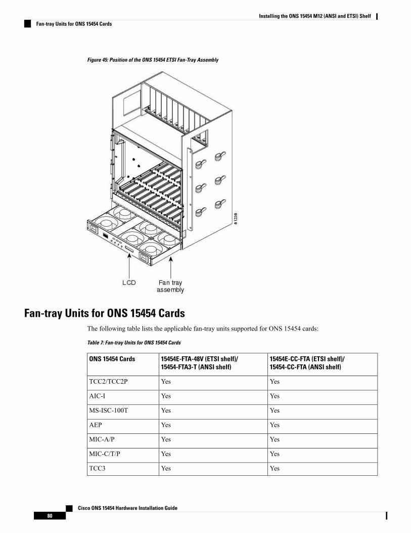
Figure 45: Position of the ONS 15454 ETSI Fan-Tray Assembly
Fan-tray Units for ONS 15454 CardsThe following table lists the applicable fan-tray units supported for ONS 15454 cards:
Table 7: Fan-tray Units for ONS 15454 Cards
15454E-CC-FTA (ETSI shelf)/15454-CC-FTA (ANSI shelf)
15454E-FTA-48V (ETSI shelf)/15454-FTA3-T (ANSI shelf)
ONS 15454 Cards
YesYesTCC2/TCC2P
YesYesAIC-I
YesYesMS-ISC-100T
YesYesAEP
YesYesMIC-A/P
YesYesMIC-C/T/P
YesYesTCC3
Cisco ONS 15454 Hardware Installation Guide80
Installing the ONS 15454 M12 (ANSI and ETSI) ShelfFan-tray Units for ONS 15454 Cards
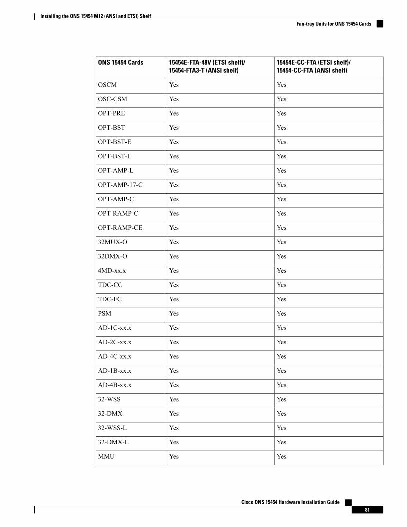
15454E-CC-FTA (ETSI shelf)/15454-CC-FTA (ANSI shelf)
15454E-FTA-48V (ETSI shelf)/15454-FTA3-T (ANSI shelf)
ONS 15454 Cards
YesYesOSCM
YesYesOSC-CSM
YesYesOPT-PRE
YesYesOPT-BST
YesYesOPT-BST-E
YesYesOPT-BST-L
YesYesOPT-AMP-L
YesYesOPT-AMP-17-C
YesYesOPT-AMP-C
YesYesOPT-RAMP-C
YesYesOPT-RAMP-CE
YesYes32MUX-O
YesYes32DMX-O
YesYes4MD-xx.x
YesYesTDC-CC
YesYesTDC-FC
YesYesPSM
YesYesAD-1C-xx.x
YesYesAD-2C-xx.x
YesYesAD-4C-xx.x
YesYesAD-1B-xx.x
YesYesAD-4B-xx.x
YesYes32-WSS
YesYes32-DMX
YesYes32-WSS-L
YesYes32-DMX-L
YesYesMMU
Cisco ONS 15454 Hardware Installation Guide81
Installing the ONS 15454 M12 (ANSI and ETSI) ShelfFan-tray Units for ONS 15454 Cards

15454E-CC-FTA (ETSI shelf)/15454-CC-FTA (ANSI shelf)
15454E-FTA-48V (ETSI shelf)/15454-FTA3-T (ANSI shelf)
ONS 15454 Cards
YesYes40-DMX-C
YesYes40-DMX-CE
YesYes40-MUX-C
YesYes40-WSS-C
YesYes40-WSS-CE
YesYes40-WXC-C
YesYes40-SMR1-C/40-SMR2-C
YesYes80-WXC-C
YesYesTXP_MR_10G
YesYesTXP_MR_2.5G
YesYesTXPP_MR_2.5G
YesYesMXP_2.5G_10G
YesYesTXP_MR_10E
YesYesMXP_2.5G_10E
YesYesMXP_MR_2.5G
YesYesMXPP_MR_2.5G
YesYesTXP_MR_10E_C
YesYesTXP_MR_10E_L
YesYesMXP_2.5G_10E_C
YesYesMXP_2.5G_10E_L
YesYesMXP_MR_10DME_C
YesYesMXP_MR_10DME_L
YesNoGE_XP/10GE_XP
YesNoADM-10G
YesNoGE_XPE/10GE_XPE
YesNoOTU2_XP
YesNo40G-MXP-C
Cisco ONS 15454 Hardware Installation Guide82
Installing the ONS 15454 M12 (ANSI and ETSI) ShelfFan-tray Units for ONS 15454 Cards
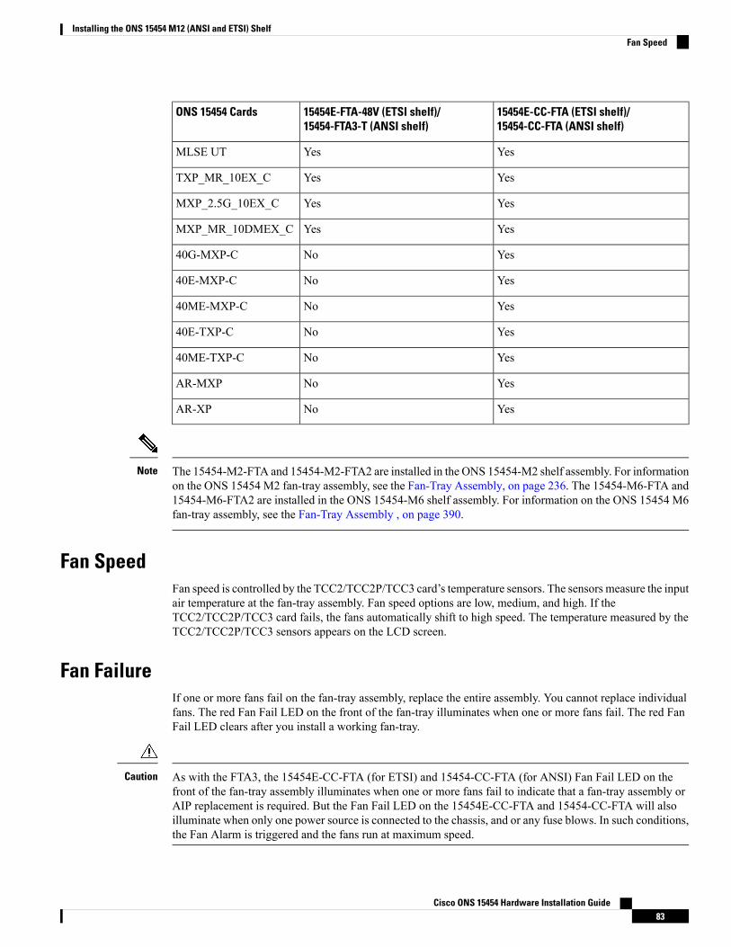
15454E-CC-FTA (ETSI shelf)/15454-CC-FTA (ANSI shelf)
15454E-FTA-48V (ETSI shelf)/15454-FTA3-T (ANSI shelf)
ONS 15454 Cards
YesYesMLSE UT
YesYesTXP_MR_10EX_C
YesYesMXP_2.5G_10EX_C
YesYesMXP_MR_10DMEX_C
YesNo40G-MXP-C
YesNo40E-MXP-C
YesNo40ME-MXP-C
YesNo40E-TXP-C
YesNo40ME-TXP-C
YesNoAR-MXP
YesNoAR-XP
The 15454-M2-FTA and 15454-M2-FTA2 are installed in the ONS 15454-M2 shelf assembly. For informationon the ONS 15454 M2 fan-tray assembly, see the Fan-Tray Assembly, on page 236. The 15454-M6-FTA and15454-M6-FTA2 are installed in the ONS 15454-M6 shelf assembly. For information on the ONS 15454 M6fan-tray assembly, see the Fan-Tray Assembly , on page 390.
Note
Fan SpeedFan speed is controlled by the TCC2/TCC2P/TCC3 card’s temperature sensors. The sensors measure the inputair temperature at the fan-tray assembly. Fan speed options are low, medium, and high. If theTCC2/TCC2P/TCC3 card fails, the fans automatically shift to high speed. The temperature measured by theTCC2/TCC2P/TCC3 sensors appears on the LCD screen.
Fan FailureIf one or more fans fail on the fan-tray assembly, replace the entire assembly. You cannot replace individualfans. The red Fan Fail LED on the front of the fan-tray illuminates when one or more fans fail. The red FanFail LED clears after you install a working fan-tray.
As with the FTA3, the 15454E-CC-FTA (for ETSI) and 15454-CC-FTA (for ANSI) Fan Fail LED on thefront of the fan-tray assembly illuminates when one or more fans fail to indicate that a fan-tray assembly orAIP replacement is required. But the Fan Fail LED on the 15454E-CC-FTA and 15454-CC-FTA will alsoilluminate when only one power source is connected to the chassis, and or any fuse blows. In such conditions,the Fan Alarm is triggered and the fans run at maximum speed.
Caution
Cisco ONS 15454 Hardware Installation Guide83
Installing the ONS 15454 M12 (ANSI and ETSI) ShelfFan Speed
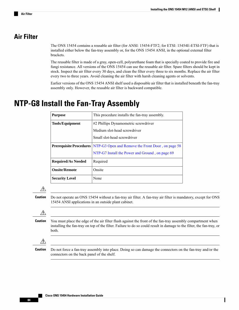
Air FilterThe ONS 15454 contains a reusable air filter (for ANSI: 15454-FTF2; for ETSI: 15454E-ETSI-FTF) that isinstalled either below the fan-tray assembly or, for the ONS 15454 ANSI, in the optional external filterbrackets.
The reusable filter is made of a gray, open-cell, polyurethane foam that is specially coated to provide fire andfungi resistance. All versions of the ONS 15454 can use the reusable air filter. Spare filters should be kept instock. Inspect the air filter every 30 days, and clean the filter every three to six months. Replace the air filterevery two to three years. Avoid cleaning the air filter with harsh cleaning agents or solvents.
Earlier versions of the ONS 15454 ANSI shelf used a disposable air filter that is installed beneath the fan-trayassembly only. However, the reusable air filter is backward compatible.
NTP-G8 Install the Fan-Tray AssemblyThis procedure installs the fan-tray assembly.Purpose
#2 Phillips Dynamometric screwdriver
Medium slot-head screwdriver
Small slot-head screwdriver
Tools/Equipment
NTP-G3 Open and Remove the Front Door , on page 58
NTP-G7 Install the Power and Ground , on page 69
Prerequisite Procedures
RequiredRequired/As Needed
OnsiteOnsite/Remote
NoneSecurity Level
Do not operate an ONS 15454 without a fan-tray air filter. A fan-tray air filter is mandatory, except for ONS15454 ANSI applications in an outside plant cabinet.
Caution
You must place the edge of the air filter flush against the front of the fan-tray assembly compartment wheninstalling the fan-tray on top of the filter. Failure to do so could result in damage to the filter, the fan-tray, orboth.
Caution
Do not force a fan-tray assembly into place. Doing so can damage the connectors on the fan-tray and/or theconnectors on the back panel of the shelf.
Caution
Cisco ONS 15454 Hardware Installation Guide84
Installing the ONS 15454 M12 (ANSI and ETSI) ShelfAir Filter

15454-CC-FTA is compatible with Software Release 2.2.2 and greater and shelf assemblies 15454-SA-HDand 15454-SA-ANSI. 15454E-CC-FTA is compatible with Software Release 4.0 and greater and shelf15454-SA-ETSI.
Note
If you install the air filter below 15454E-CC-FTA or 15454-CC-FTA, only filters with part numbers700-23193-01 and 700-23194-01 can be used in this configuration.
Caution
Error messages appear on the TCC2/TCC2P/TCC3 card, the fan-tray LED, and in Cisco Transport Controller(CTC) when the fan-tray assembly is removed from the shelf or when one fan is not working.
Note
If you are installing the ONS 15454 in an outside plant cabinet, remove the air filter to provide maximumcooling capabilities and to comply with Telcordia GR-487-CORE.
Note
To install the fan-tray assembly, it is not necessary to move any of the fiber-storage facilities.Note
If the fan-tray assembly is removed from the shelf, wait for at least 5 seconds before plugging it back into theshelf. In the event the LCD display in the fan-tray assembly appears blank, remove the unit from the shelf,wait for at least 5 seconds and reinsert the unit into the shelf.
Note
Procedure
Step 1 Install the air filter. The air filter can be installed internally between the fan-tray and shelf, or externally bymounting the air filter bracket on the bottom of the shelf. Slide the air filter into the bracket.
Although the air filter can work with older fan-trays if it is installed with either side facing up, Ciscorecommends that you install it with the metal bracing facing up to preserve the surface of the filter.You must install the air filter with the metal bracing facing up with 15454E-CC-FTA or15454-CC-FTA.
Caution
Step 2 Install the fan-tray assembly. Figure 46: Installing the Fan-Tray Assembly on the ONS 15454 ETSI, on page86 shows the fan-tray assembly location on the ONS 15454 ETSI. Figure 47: Installing the Fan-Tray Assemblyon the ONS 15454 ANSI, on page 87 shows the fan-tray assembly location on the ONS 15454 ANSI.
• For the ONS 15454 ETSI shelf, press and hold the locks on the outer edges as you slide the fan-trayassembly into the shelf.
Cisco ONS 15454 Hardware Installation Guide85
Installing the ONS 15454 M12 (ANSI and ETSI) ShelfNTP-G8 Install the Fan-Tray Assembly
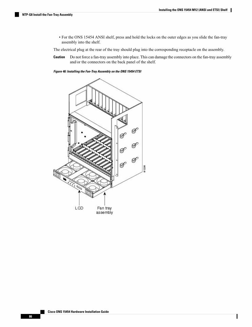
• For the ONS 15454 ANSI shelf, press and hold the locks on the outer edges as you slide the fan-trayassembly into the shelf.
The electrical plug at the rear of the tray should plug into the corresponding receptacle on the assembly.
Do not force a fan-tray assembly into place. This can damage the connectors on the fan-tray assemblyand/or the connectors on the back panel of the shelf.
Caution
Figure 46: Installing the Fan-Tray Assembly on the ONS 15454 ETSI
Cisco ONS 15454 Hardware Installation Guide86
Installing the ONS 15454 M12 (ANSI and ETSI) ShelfNTP-G8 Install the Fan-Tray Assembly
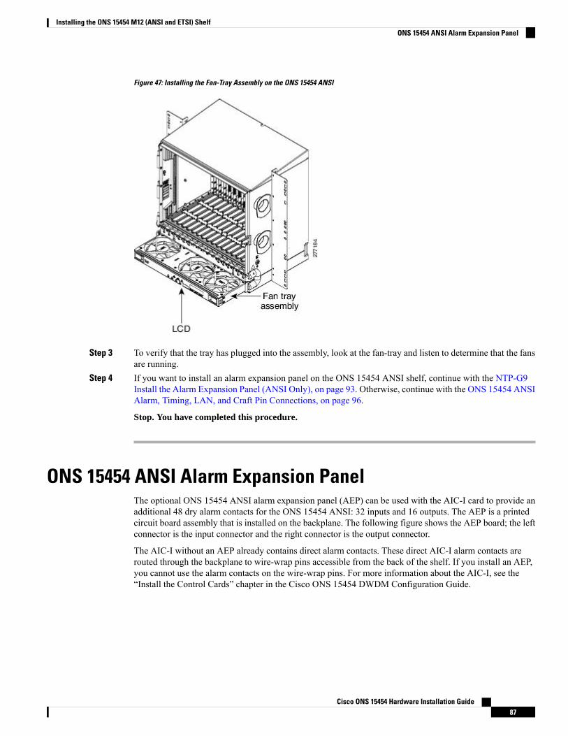
Figure 47: Installing the Fan-Tray Assembly on the ONS 15454 ANSI
Step 3 To verify that the tray has plugged into the assembly, look at the fan-tray and listen to determine that the fansare running.
Step 4 If you want to install an alarm expansion panel on the ONS 15454 ANSI shelf, continue with the NTP-G9Install the Alarm Expansion Panel (ANSI Only), on page 93. Otherwise, continue with the ONS 15454 ANSIAlarm, Timing, LAN, and Craft Pin Connections, on page 96.
Stop. You have completed this procedure.
ONS 15454 ANSI Alarm Expansion PanelThe optional ONS 15454 ANSI alarm expansion panel (AEP) can be used with the AIC-I card to provide anadditional 48 dry alarm contacts for the ONS 15454 ANSI: 32 inputs and 16 outputs. The AEP is a printedcircuit board assembly that is installed on the backplane. The following figure shows the AEP board; the leftconnector is the input connector and the right connector is the output connector.
The AIC-I without an AEP already contains direct alarm contacts. These direct AIC-I alarm contacts arerouted through the backplane to wire-wrap pins accessible from the back of the shelf. If you install an AEP,you cannot use the alarm contacts on the wire-wrap pins. For more information about the AIC-I, see the“Install the Control Cards” chapter in the Cisco ONS 15454 DWDM Configuration Guide.
Cisco ONS 15454 Hardware Installation Guide87
Installing the ONS 15454 M12 (ANSI and ETSI) ShelfONS 15454 ANSI Alarm Expansion Panel
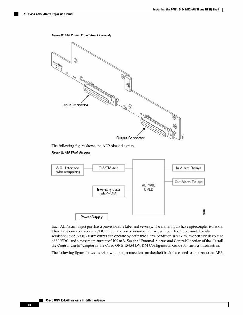
Figure 48: AEP Printed Circuit Board Assembly
The following figure shows the AEP block diagram.
Figure 49: AEP Block Diagram
Each AEP alarm input port has a provisionable label and severity. The alarm inputs have optocoupler isolation.They have one common 32-VDC output and a maximum of 2 mA per input. Each opto-metal oxidesemiconductor (MOS) alarm output can operate by definable alarm condition, a maximum open circuit voltageof 60 VDC, and a maximum current of 100mA. See the “External Alarms and Controls” section of the “Installthe Control Cards” chapter in the Cisco ONS 15454 DWDM Configuration Guide for further information.
The following figure shows the wire-wrapping connections on the shelf backplane used to connect to the AEP.
Cisco ONS 15454 Hardware Installation Guide88
Installing the ONS 15454 M12 (ANSI and ETSI) ShelfONS 15454 ANSI Alarm Expansion Panel
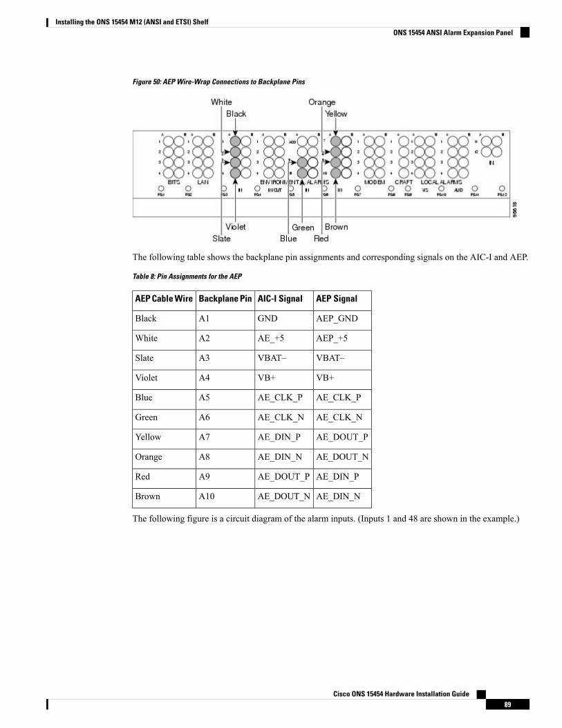
Figure 50: AEP Wire-Wrap Connections to Backplane Pins
The following table shows the backplane pin assignments and corresponding signals on the AIC-I and AEP.
Table 8: Pin Assignments for the AEP
AEP SignalAIC-I SignalBackplane PinAEP Cable Wire
AEP_GNDGNDA1Black
AEP_+5AE_+5A2White
VBAT–VBAT–A3Slate
VB+VB+A4Violet
AE_CLK_PAE_CLK_PA5Blue
AE_CLK_NAE_CLK_NA6Green
AE_DOUT_PAE_DIN_PA7Yellow
AE_DOUT_NAE_DIN_NA8Orange
AE_DIN_PAE_DOUT_PA9Red
AE_DIN_NAE_DOUT_NA10Brown
The following figure is a circuit diagram of the alarm inputs. (Inputs 1 and 48 are shown in the example.)
Cisco ONS 15454 Hardware Installation Guide89
Installing the ONS 15454 M12 (ANSI and ETSI) ShelfONS 15454 ANSI Alarm Expansion Panel
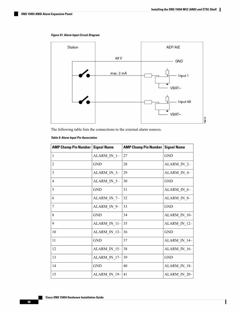
Figure 51: Alarm Input Circuit Diagram
The following table lists the connections to the external alarm sources.
Table 9: Alarm Input Pin Association
Signal NameAMP Champ Pin NumberSignal NameAMP Champ Pin Number
GND27ALARM_IN_1–1
ALARM_IN_2–28GND2
ALARM_IN_4–29ALARM_IN_3–3
GND30ALARM_IN_5–4
ALARM_IN_6–31GND5
ALARM_IN_8–32ALARM_IN_7–6
GND33ALARM_IN_9–7
ALARM_IN_10–34GND8
ALARM_IN_12–35ALARM_IN_11–9
GND36ALARM_IN_13–10
ALARM_IN_14–37GND11
ALARM_IN_16–38ALARM_IN_15–12
GND39ALARM_IN_17–13
ALARM_IN_18–40GND14
ALARM_IN_20–41ALARM_IN_19–15
Cisco ONS 15454 Hardware Installation Guide90
Installing the ONS 15454 M12 (ANSI and ETSI) ShelfONS 15454 ANSI Alarm Expansion Panel
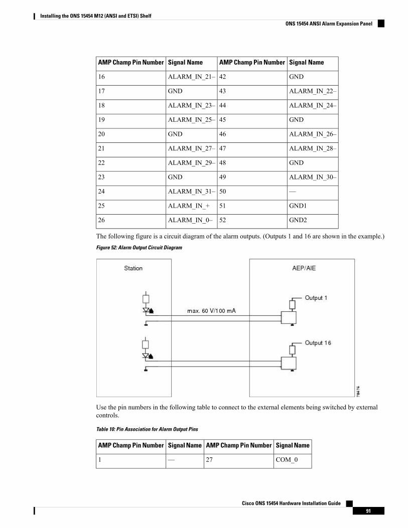
Signal NameAMP Champ Pin NumberSignal NameAMP Champ Pin Number
GND42ALARM_IN_21–16
ALARM_IN_22–43GND17
ALARM_IN_24–44ALARM_IN_23–18
GND45ALARM_IN_25–19
ALARM_IN_26–46GND20
ALARM_IN_28–47ALARM_IN_27–21
GND48ALARM_IN_29–22
ALARM_IN_30–49GND23
—50ALARM_IN_31–24
GND151ALARM_IN_+25
GND252ALARM_IN_0–26
The following figure is a circuit diagram of the alarm outputs. (Outputs 1 and 16 are shown in the example.)
Figure 52: Alarm Output Circuit Diagram
Use the pin numbers in the following table to connect to the external elements being switched by externalcontrols.
Table 10: Pin Association for Alarm Output Pins
Signal NameAMP Champ Pin NumberSignal NameAMP Champ Pin Number
COM_027—1
Cisco ONS 15454 Hardware Installation Guide91
Installing the ONS 15454 M12 (ANSI and ETSI) ShelfONS 15454 ANSI Alarm Expansion Panel
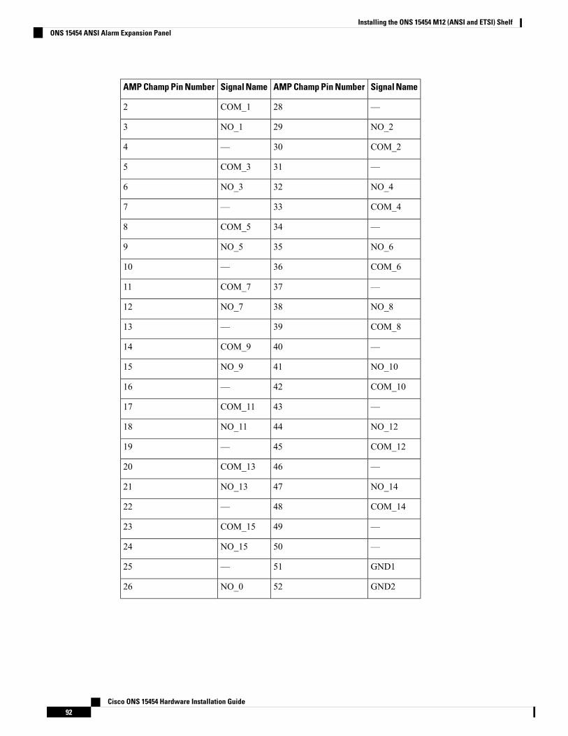
Signal NameAMP Champ Pin NumberSignal NameAMP Champ Pin Number
—28COM_12
NO_229NO_13
COM_230—4
—31COM_35
NO_432NO_36
COM_433—7
—34COM_58
NO_635NO_59
COM_636—10
—37COM_711
NO_838NO_712
COM_839—13
—40COM_914
NO_1041NO_915
COM_1042—16
—43COM_1117
NO_1244NO_1118
COM_1245—19
—46COM_1320
NO_1447NO_1321
COM_1448—22
—49COM_1523
—50NO_1524
GND151—25
GND252NO_026
Cisco ONS 15454 Hardware Installation Guide92
Installing the ONS 15454 M12 (ANSI and ETSI) ShelfONS 15454 ANSI Alarm Expansion Panel
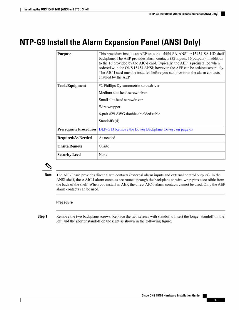
NTP-G9 Install the Alarm Expansion Panel (ANSI Only)This procedure installs an AEP onto the 15454-SA-ANSI or 15454-SA-HD shelfbackplane. The AEP provides alarm contacts (32 inputs, 16 outputs) in additionto the 16 provided by the AIC-I card. Typically, the AEP is preinstalled whenordered with the ONS 15454 ANSI; however, the AEP can be ordered separately.The AIC-I card must be installed before you can provision the alarm contactsenabled by the AEP.
Purpose
#2 Phillips Dynamometric screwdriver
Medium slot-head screwdriver
Small slot-head screwdriver
Wire wrapper
6-pair #29 AWG double-shielded cable
Standoffs (4)
Tools/Equipment
DLP-G13 Remove the Lower Backplane Cover , on page 65Prerequisite Procedures
As neededRequired/As Needed
OnsiteOnsite/Remote
NoneSecurity Level
The AIC-I card provides direct alarm contacts (external alarm inputs and external control outputs). In theANSI shelf, these AIC-I alarm contacts are routed through the backplane to wire-wrap pins accessible fromthe back of the shelf. When you install an AEP, the direct AIC-I alarm contacts cannot be used. Only the AEPalarm contacts can be used.
Note
Procedure
Step 1 Remove the two backplane screws. Replace the two screws with standoffs. Insert the longer standoff on theleft, and the shorter standoff on the right as shown in the following figure.
Cisco ONS 15454 Hardware Installation Guide93
Installing the ONS 15454 M12 (ANSI and ETSI) ShelfNTP-G9 Install the Alarm Expansion Panel (ANSI Only)
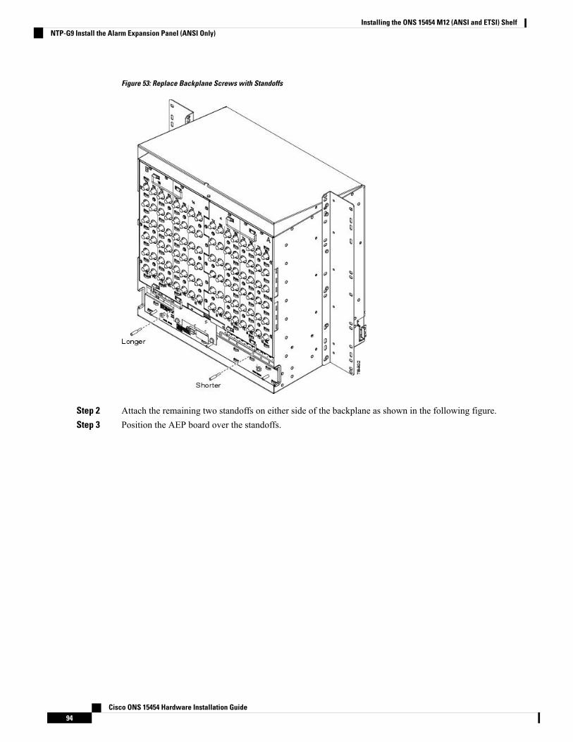
Figure 53: Replace Backplane Screws with Standoffs
Step 2 Attach the remaining two standoffs on either side of the backplane as shown in the following figure.Step 3 Position the AEP board over the standoffs.
Cisco ONS 15454 Hardware Installation Guide94
Installing the ONS 15454 M12 (ANSI and ETSI) ShelfNTP-G9 Install the Alarm Expansion Panel (ANSI Only)
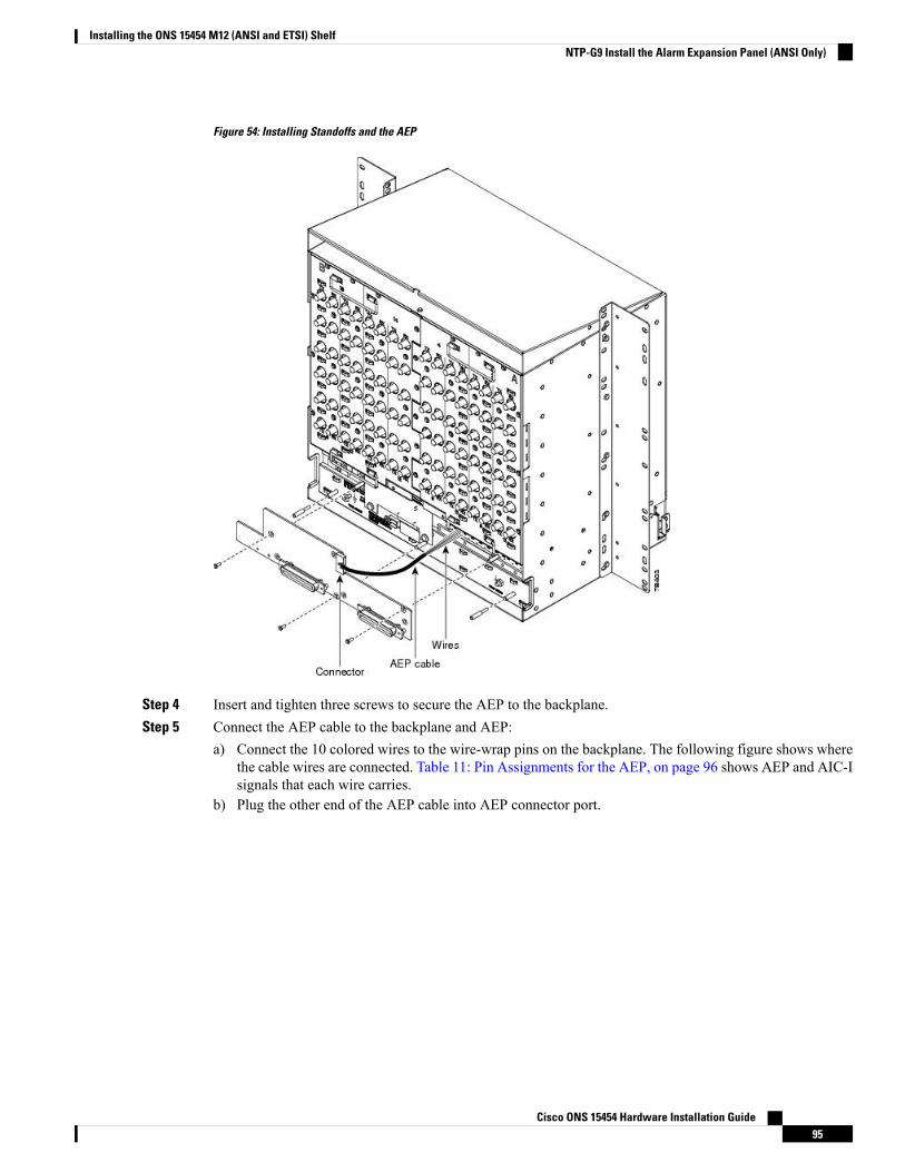
Figure 54: Installing Standoffs and the AEP
Step 4 Insert and tighten three screws to secure the AEP to the backplane.Step 5 Connect the AEP cable to the backplane and AEP:
a) Connect the 10 colored wires to the wire-wrap pins on the backplane. The following figure shows wherethe cable wires are connected. Table 11: Pin Assignments for the AEP, on page 96 shows AEP and AIC-Isignals that each wire carries.
b) Plug the other end of the AEP cable into AEP connector port.
Cisco ONS 15454 Hardware Installation Guide95
Installing the ONS 15454 M12 (ANSI and ETSI) ShelfNTP-G9 Install the Alarm Expansion Panel (ANSI Only)
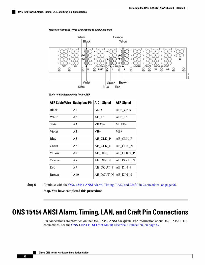
Figure 55: AEP Wire-Wrap Connections to Backplane Pins
Table 11: Pin Assignments for the AEP
AEP SignalAIC-I SignalBackplane PinAEP Cable Wire
AEP_GNDGNDA1Black
AEP_+5AE_+5A2White
VBAT–VBAT–A3Slate
VB+VB+A4Violet
AE_CLK_PAE_CLK_PA5Blue
AE_CLK_NAE_CLK_NA6Green
AE_DOUT_PAE_DIN_PA7Yellow
AE_DOUT_NAE_DIN_NA8Orange
AE_DIN_PAE_DOUT_PA9Red
AE_DIN_NAE_DOUT_NA10Brown
Step 6 Continue with the ONS 15454 ANSI Alarm, Timing, LAN, and Craft Pin Connections, on page 96.
Stop. You have completed this procedure.
ONS 15454 ANSI Alarm, Timing, LAN, and Craft Pin ConnectionsPin connections are provided on the ONS 15454 ANSI backplane. For information about ONS 15454 ETSIconnections, see the ONS 15454 ETSI Front Mount Electrical Connection, on page 67.
Cisco ONS 15454 Hardware Installation Guide96
Installing the ONS 15454 M12 (ANSI and ETSI) ShelfONS 15454 ANSI Alarm, Timing, LAN, and Craft Pin Connections

The ONS 15454 ANSI has a backplane pin field located at the bottom of the backplane. The backplane pinfield provides 0.045 inch2 (29 mm2) wire-wrap pins for enabling external alarms, timing input and output,and craft interface terminals. This section describes the backplane pin field and the pin assignments for thefield. Figure 57: ONS 15454 ANSI Backplane Pinouts, on page 99 shows the wire-wrap pins on the backplanepin field. Beneath each wire-wrap pin is a frame ground pin. Frame ground pins are labeled FG1, FG2, FG3,etc. Install the ground shield of the cables connected to the backplane to the ground pin that corresponds tothe pin field used.
The AIC-I requires a shelf running Software R3.4.0 or later. The backplane of the ANSI shelf contains awire-wrap field with pin assignment according to the layout in Figure 56: Cisco ONS 15454 Backplane Pinouts(Release 3.4 or Later), on page 98. The shelf might be an existing shelf that has been upgraded to SoftwareR3.4 or later. In this case, the backplane pin labeling appears as indicated in Figure 57: ONS 15454 ANSIBackplane Pinouts, on page 99, but you must use the pin assignments provided by the AIC-I card as shownin Figure 56: Cisco ONS 15454 Backplane Pinouts (Release 3.4 or Later), on page 98.
Note
Cisco ONS 15454 Hardware Installation Guide97
Installing the ONS 15454 M12 (ANSI and ETSI) ShelfONS 15454 ANSI Alarm, Timing, LAN, and Craft Pin Connections
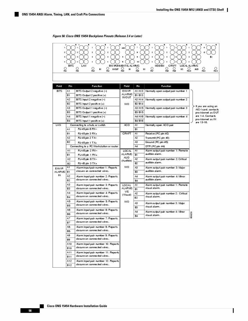
Figure 56: Cisco ONS 15454 Backplane Pinouts (Release 3.4 or Later)
Cisco ONS 15454 Hardware Installation Guide98
Installing the ONS 15454 M12 (ANSI and ETSI) ShelfONS 15454 ANSI Alarm, Timing, LAN, and Craft Pin Connections
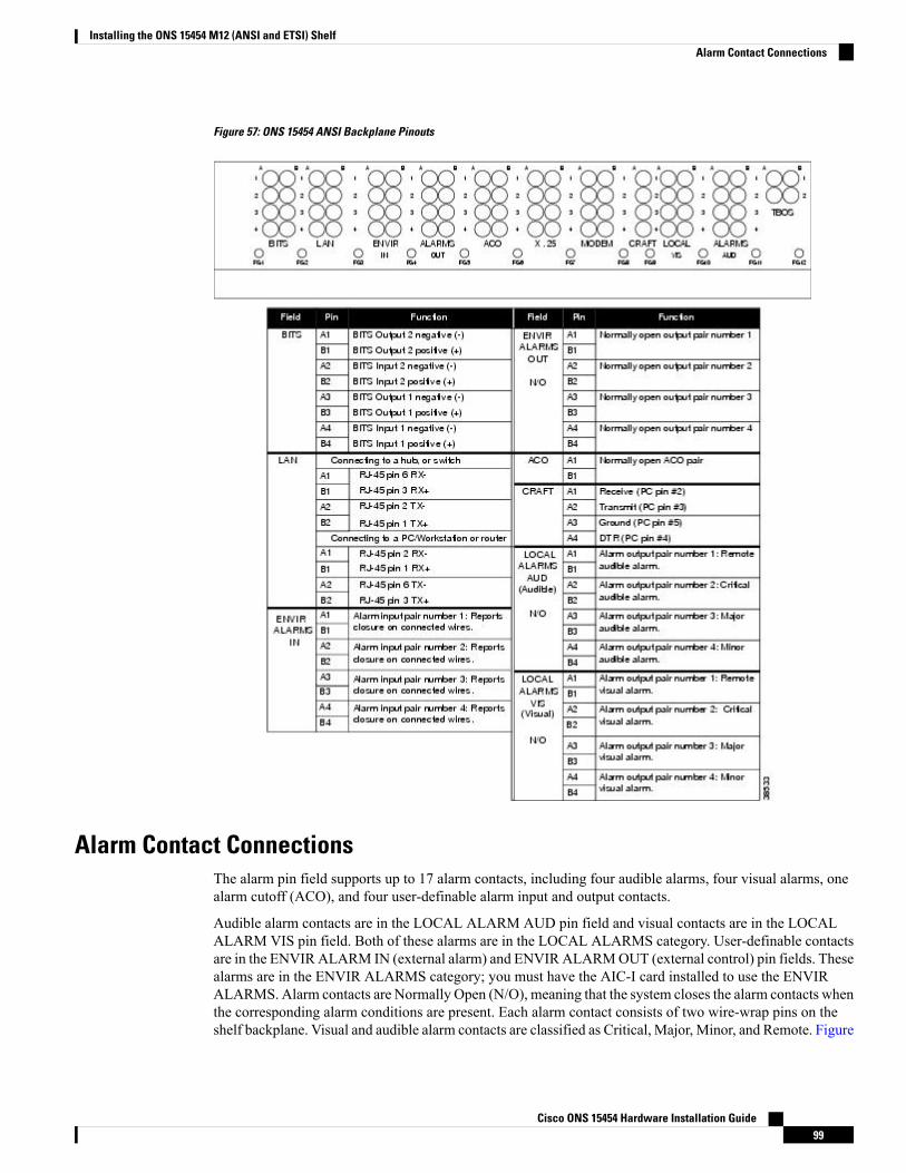
Figure 57: ONS 15454 ANSI Backplane Pinouts
Alarm Contact ConnectionsThe alarm pin field supports up to 17 alarm contacts, including four audible alarms, four visual alarms, onealarm cutoff (ACO), and four user-definable alarm input and output contacts.
Audible alarm contacts are in the LOCAL ALARM AUD pin field and visual contacts are in the LOCALALARM VIS pin field. Both of these alarms are in the LOCAL ALARMS category. User-definable contactsare in the ENVIRALARM IN (external alarm) and ENVIRALARMOUT (external control) pin fields. Thesealarms are in the ENVIR ALARMS category; you must have the AIC-I card installed to use the ENVIRALARMS. Alarm contacts are Normally Open (N/O), meaning that the system closes the alarm contacts whenthe corresponding alarm conditions are present. Each alarm contact consists of two wire-wrap pins on theshelf backplane. Visual and audible alarm contacts are classified as Critical, Major, Minor, and Remote. Figure
Cisco ONS 15454 Hardware Installation Guide99
Installing the ONS 15454 M12 (ANSI and ETSI) ShelfAlarm Contact Connections
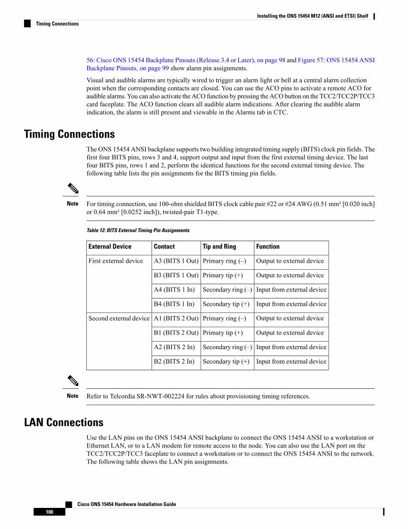
56: Cisco ONS 15454 Backplane Pinouts (Release 3.4 or Later), on page 98 and Figure 57: ONS 15454 ANSIBackplane Pinouts, on page 99 show alarm pin assignments.
Visual and audible alarms are typically wired to trigger an alarm light or bell at a central alarm collectionpoint when the corresponding contacts are closed. You can use the ACO pins to activate a remote ACO foraudible alarms. You can also activate the ACO function by pressing the ACObutton on the TCC2/TCC2P/TCC3card faceplate. The ACO function clears all audible alarm indications. After clearing the audible alarmindication, the alarm is still present and viewable in the Alarms tab in CTC.
Timing ConnectionsThe ONS 15454 ANSI backplane supports two building integrated timing supply (BITS) clock pin fields. Thefirst four BITS pins, rows 3 and 4, support output and input from the first external timing device. The lastfour BITS pins, rows 1 and 2, perform the identical functions for the second external timing device. Thefollowing table lists the pin assignments for the BITS timing pin fields.
For timing connection, use 100-ohm shielded BITS clock cable pair #22 or #24 AWG (0.51 mm² [0.020 inch]or 0.64 mm² [0.0252 inch]), twisted-pair T1-type.
Note
Table 12: BITS External Timing Pin Assignments
FunctionTip and RingContactExternal Device
Output to external devicePrimary ring (–)A3 (BITS 1 Out)First external device
Output to external devicePrimary tip (+)B3 (BITS 1 Out)
Input from external deviceSecondary ring (–)A4 (BITS 1 In)
Input from external deviceSecondary tip (+)B4 (BITS 1 In)
Output to external devicePrimary ring (–)A1 (BITS 2 Out)Second external device
Output to external devicePrimary tip (+)B1 (BITS 2 Out)
Input from external deviceSecondary ring (–)A2 (BITS 2 In)
Input from external deviceSecondary tip (+)B2 (BITS 2 In)
Refer to Telcordia SR-NWT-002224 for rules about provisioning timing references.Note
LAN ConnectionsUse the LAN pins on the ONS 15454 ANSI backplane to connect the ONS 15454 ANSI to a workstation orEthernet LAN, or to a LAN modem for remote access to the node. You can also use the LAN port on theTCC2/TCC2P/TCC3 faceplate to connect a workstation or to connect the ONS 15454 ANSI to the network.The following table shows the LAN pin assignments.
Cisco ONS 15454 Hardware Installation Guide100
Installing the ONS 15454 M12 (ANSI and ETSI) ShelfTiming Connections
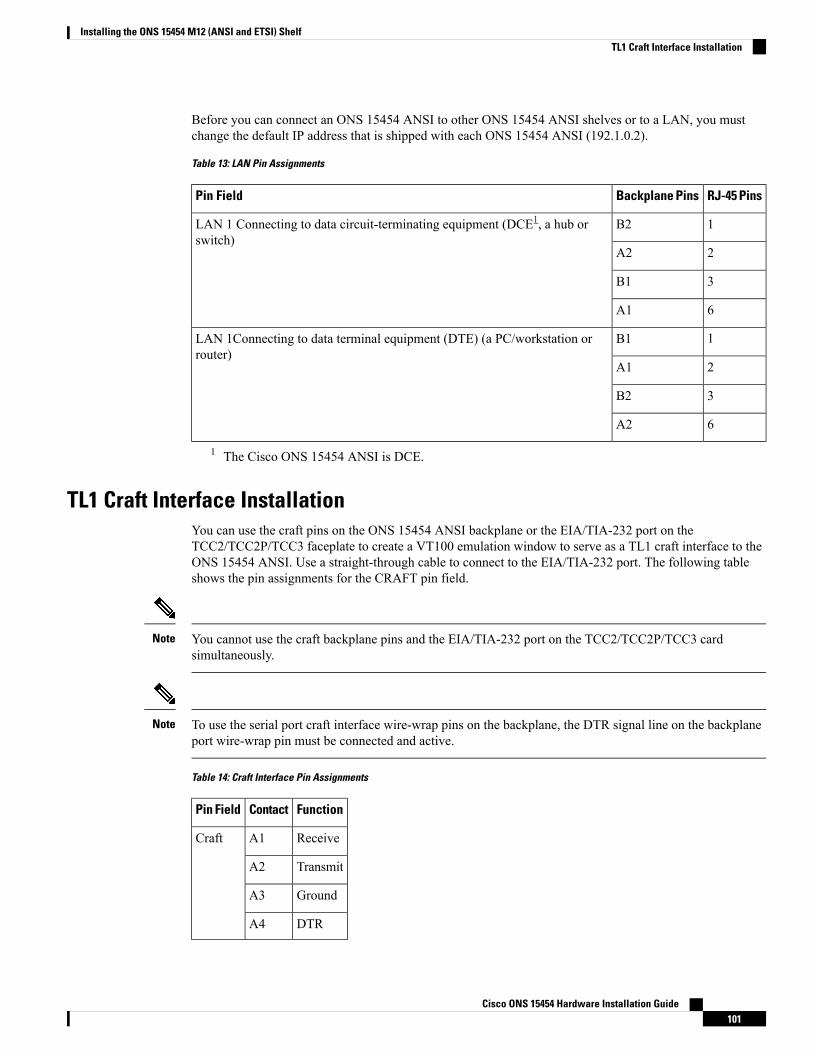
Before you can connect an ONS 15454 ANSI to other ONS 15454 ANSI shelves or to a LAN, you mustchange the default IP address that is shipped with each ONS 15454 ANSI (192.1.0.2).
Table 13: LAN Pin Assignments
RJ-45 PinsBackplane PinsPin Field
1B2LAN 1 Connecting to data circuit-terminating equipment (DCE1, a hub orswitch)
2A2
3B1
6A1
1B1LAN 1Connecting to data terminal equipment (DTE) (a PC/workstation orrouter)
2A1
3B2
6A2
1 The Cisco ONS 15454 ANSI is DCE.
TL1 Craft Interface InstallationYou can use the craft pins on the ONS 15454 ANSI backplane or the EIA/TIA-232 port on theTCC2/TCC2P/TCC3 faceplate to create a VT100 emulation window to serve as a TL1 craft interface to theONS 15454 ANSI. Use a straight-through cable to connect to the EIA/TIA-232 port. The following tableshows the pin assignments for the CRAFT pin field.
You cannot use the craft backplane pins and the EIA/TIA-232 port on the TCC2/TCC2P/TCC3 cardsimultaneously.
Note
To use the serial port craft interface wire-wrap pins on the backplane, the DTR signal line on the backplaneport wire-wrap pin must be connected and active.
Note
Table 14: Craft Interface Pin Assignments
FunctionContactPin Field
ReceiveA1Craft
TransmitA2
GroundA3
DTRA4
Cisco ONS 15454 Hardware Installation Guide101
Installing the ONS 15454 M12 (ANSI and ETSI) ShelfTL1 Craft Interface Installation
NTP-G10 Attach Wires to Alarm, Timing, LAN, and Craft PinConnections
This procedure installs alarm, timing, LAN, and craft wires on the ONS 15454shelf. These wires are attached to the mechanical interface card (MIC) FMECson the ETSI shelf and are attached to the backplane on the ANSI shelf.
Purpose
Connectors according to function
Twisted #22 or #24 AWG (0.51 mm² or 0.64 mm²) shielded wires for LAN orcraft
75-ohm coaxial cable with 1.0/2.3 miniature coax connector
0.51 mm² or 0.64 mm² (#22 or #24 AWG) alarm wires
Tools/Equipment
NTP-G6 Install the MIC-A/P and MIC-T/C/P FMECs (ETSI Only), on page 67
NTP-G5 Remove the Backplane Covers (ANSI Only), on page 65
Prerequisite Procedures
As neededRequired/As Needed
OnsiteOnsite/Remote
NoneSecurity Level
Always use the supplied ESD wristband when working with a powered ONS 15454 ETSI. For detailedinstructions on how to wear the ESD wristband, refer to the Electrostatic Discharge and Grounding Guide forCisco CPT and Cisco ONS Platforms.
Caution
Procedure
Step 1 For an ONS 15454 ETSI shelf, complete the following tasks as necessary:
• Complete the DLP-G20 Install Alarm Wires on the MIC-A/P (ETSI Only), on page 103if you want toprovision external alarms and/or controls with the AIC-I card.
• Complete the DLP-G21 Install Timing Wires on the MIC-C/T/P (ETSI Only), on page 106 if you areprovisioning external timing.
• Complete the DLP-G22 Install LAN Wires on the MIC-C/T/P (ETSI Only), on page 107 to create anexternal LAN connection. You must either install LAN wires on the MIC-C/T/P or connect a CAT-5Ethernet cable to the LAN port on the TCC2/TCC2P/TCC3 card to create an external LAN connection.
Step 2 For an ONS 15454 ANSI shelf, complete the following tasks as necessary:
• Complete the DLP-G23 Install AlarmWires on the Backplane (ANSI Only), on page 108 if you are usingan AIC-I card and are not using an AEP.
Cisco ONS 15454 Hardware Installation Guide102
Installing the ONS 15454 M12 (ANSI and ETSI) ShelfNTP-G10 Attach Wires to Alarm, Timing, LAN, and Craft Pin Connections
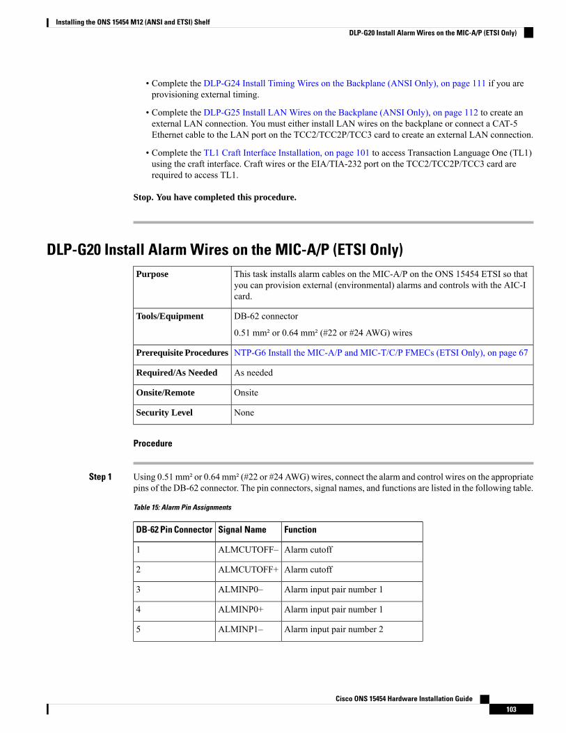
• Complete the DLP-G24 Install Timing Wires on the Backplane (ANSI Only), on page 111 if you areprovisioning external timing.
• Complete the DLP-G25 Install LAN Wires on the Backplane (ANSI Only), on page 112 to create anexternal LAN connection. You must either install LAN wires on the backplane or connect a CAT-5Ethernet cable to the LAN port on the TCC2/TCC2P/TCC3 card to create an external LAN connection.
• Complete the TL1 Craft Interface Installation, on page 101 to access Transaction Language One (TL1)using the craft interface. Craft wires or the EIA/TIA-232 port on the TCC2/TCC2P/TCC3 card arerequired to access TL1.
Stop. You have completed this procedure.
DLP-G20 Install Alarm Wires on the MIC-A/P (ETSI Only)This task installs alarm cables on the MIC-A/P on the ONS 15454 ETSI so thatyou can provision external (environmental) alarms and controls with the AIC-Icard.
Purpose
DB-62 connector
0.51 mm² or 0.64 mm² (#22 or #24 AWG) wires
Tools/Equipment
NTP-G6 Install the MIC-A/P and MIC-T/C/P FMECs (ETSI Only), on page 67Prerequisite Procedures
As neededRequired/As Needed
OnsiteOnsite/Remote
NoneSecurity Level
Procedure
Step 1 Using 0.51 mm² or 0.64 mm² (#22 or #24 AWG) wires, connect the alarm and control wires on the appropriatepins of the DB-62 connector. The pin connectors, signal names, and functions are listed in the following table.
Table 15: Alarm Pin Assignments
FunctionSignal NameDB-62 Pin Connector
Alarm cutoffALMCUTOFF–1
Alarm cutoffALMCUTOFF+2
Alarm input pair number 1ALMINP0–3
Alarm input pair number 1ALMINP0+4
Alarm input pair number 2ALMINP1–5
Cisco ONS 15454 Hardware Installation Guide103
Installing the ONS 15454 M12 (ANSI and ETSI) ShelfDLP-G20 Install Alarm Wires on the MIC-A/P (ETSI Only)

FunctionSignal NameDB-62 Pin Connector
Alarm input pair number 2ALMINP1+6
Alarm input pair number 3ALMINP2–7
Alarm input pair number 3ALMINP2+8
Alarm input pair number 4ALMINP3–9
Alarm input pair number 4ALMINP3+10
Extra alarm 0EXALM0–11
Extra alarm 0EXALM0+12
GroundFGND13
Extra alarm 1EXALM1–14
Extra alarm 1EXALM1+15
Extra alarm 2EXALM2–16
Extra alarm 2EXALM2+17
Extra alarm 3EXALM3–18
Extra alarm 3EXALM3+19
Extra alarm 4EXALM4–20
Extra alarm 4EXALM4+21
Extra alarm 5EXALM5–22
Extra alarm 5EXALM5+23
Extra alarm 6EXALM6–24
Extra alarm 6EXALM6+25
GroundFGND26
Extra alarm 7EXALM7–27
Extra alarm 7EXALM7+28
Extra alarm 8EXALM8–29
Extra alarm 8EXALM8+30
Extra alarm 9EXALM9–31
Extra alarm 9EXALM9+32
Extra alarm 10EXALM10–33
Cisco ONS 15454 Hardware Installation Guide104
Installing the ONS 15454 M12 (ANSI and ETSI) ShelfDLP-G20 Install Alarm Wires on the MIC-A/P (ETSI Only)
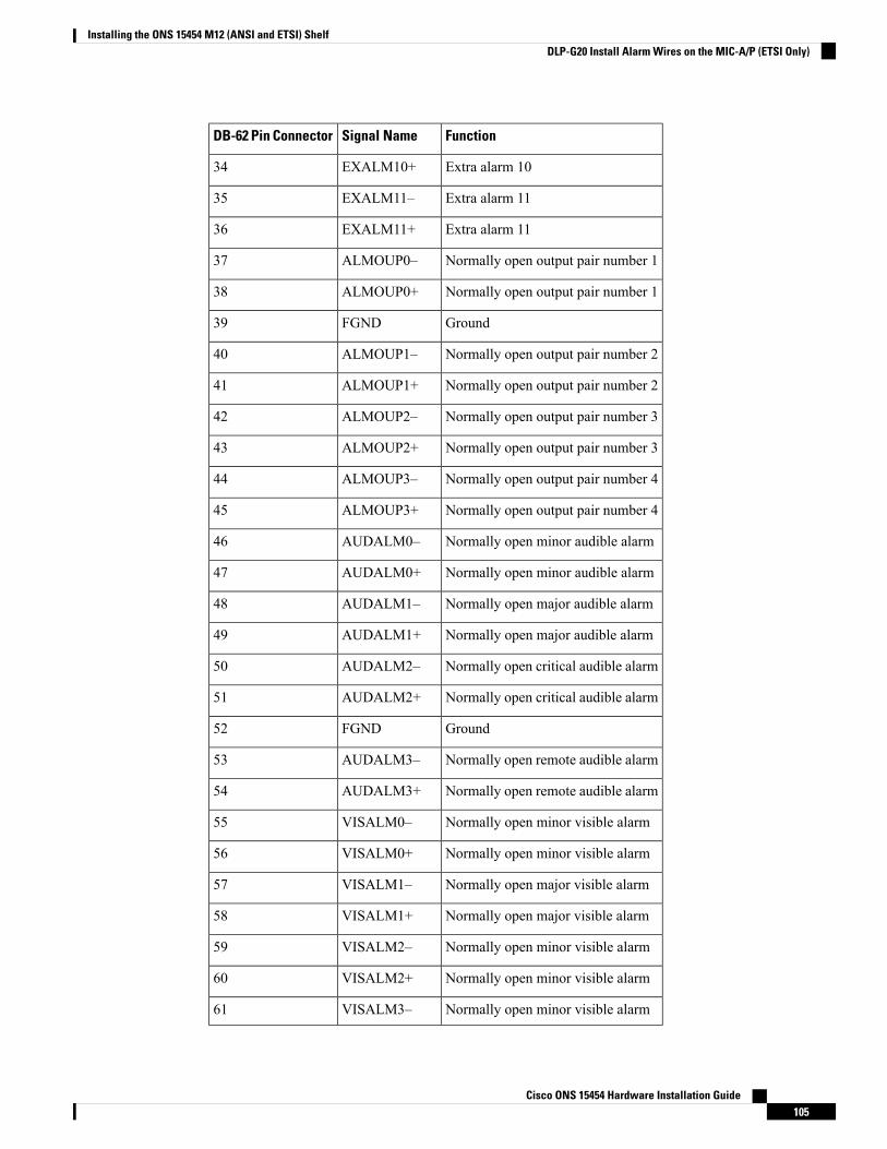
FunctionSignal NameDB-62 Pin Connector
Extra alarm 10EXALM10+34
Extra alarm 11EXALM11–35
Extra alarm 11EXALM11+36
Normally open output pair number 1ALMOUP0–37
Normally open output pair number 1ALMOUP0+38
GroundFGND39
Normally open output pair number 2ALMOUP1–40
Normally open output pair number 2ALMOUP1+41
Normally open output pair number 3ALMOUP2–42
Normally open output pair number 3ALMOUP2+43
Normally open output pair number 4ALMOUP3–44
Normally open output pair number 4ALMOUP3+45
Normally open minor audible alarmAUDALM0–46
Normally open minor audible alarmAUDALM0+47
Normally open major audible alarmAUDALM1–48
Normally open major audible alarmAUDALM1+49
Normally open critical audible alarmAUDALM2–50
Normally open critical audible alarmAUDALM2+51
GroundFGND52
Normally open remote audible alarmAUDALM3–53
Normally open remote audible alarmAUDALM3+54
Normally open minor visible alarmVISALM0–55
Normally open minor visible alarmVISALM0+56
Normally open major visible alarmVISALM1–57
Normally open major visible alarmVISALM1+58
Normally open minor visible alarmVISALM2–59
Normally open minor visible alarmVISALM2+60
Normally open minor visible alarmVISALM3–61
Cisco ONS 15454 Hardware Installation Guide105
Installing the ONS 15454 M12 (ANSI and ETSI) ShelfDLP-G20 Install Alarm Wires on the MIC-A/P (ETSI Only)
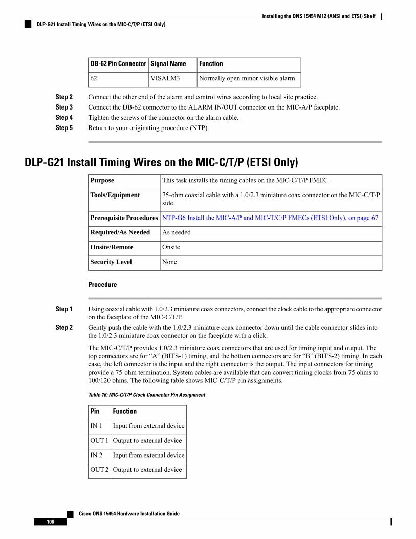
FunctionSignal NameDB-62 Pin Connector
Normally open minor visible alarmVISALM3+62
Step 2 Connect the other end of the alarm and control wires according to local site practice.Step 3 Connect the DB-62 connector to the ALARM IN/OUT connector on the MIC-A/P faceplate.Step 4 Tighten the screws of the connector on the alarm cable.Step 5 Return to your originating procedure (NTP).
DLP-G21 Install Timing Wires on the MIC-C/T/P (ETSI Only)This task installs the timing cables on the MIC-C/T/P FMEC.Purpose
75-ohm coaxial cable with a 1.0/2.3 miniature coax connector on the MIC-C/T/Pside
Tools/Equipment
NTP-G6 Install the MIC-A/P and MIC-T/C/P FMECs (ETSI Only), on page 67Prerequisite Procedures
As neededRequired/As Needed
OnsiteOnsite/Remote
NoneSecurity Level
Procedure
Step 1 Using coaxial cable with 1.0/2.3 miniature coax connectors, connect the clock cable to the appropriate connectoron the faceplate of the MIC-C/T/P.
Step 2 Gently push the cable with the 1.0/2.3 miniature coax connector down until the cable connector slides intothe 1.0/2.3 miniature coax connector on the faceplate with a click.
The MIC-C/T/P provides 1.0/2.3 miniature coax connectors that are used for timing input and output. Thetop connectors are for “A” (BITS-1) timing, and the bottom connectors are for “B” (BITS-2) timing. In eachcase, the left connector is the input and the right connector is the output. The input connectors for timingprovide a 75-ohm termination. System cables are available that can convert timing clocks from 75 ohms to100/120 ohms. The following table shows MIC-C/T/P pin assignments.
Table 16: MIC-C/T/P Clock Connector Pin Assignment
FunctionPin
Input from external deviceIN 1
Output to external deviceOUT1
Input from external deviceIN 2
Output to external deviceOUT2
Cisco ONS 15454 Hardware Installation Guide106
Installing the ONS 15454 M12 (ANSI and ETSI) ShelfDLP-G21 Install Timing Wires on the MIC-C/T/P (ETSI Only)
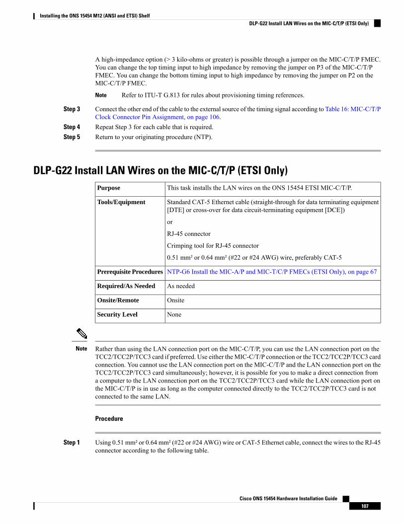
A high-impedance option (> 3 kilo-ohms or greater) is possible through a jumper on the MIC-C/T/P FMEC.You can change the top timing input to high impedance by removing the jumper on P3 of the MIC-C/T/PFMEC. You can change the bottom timing input to high impedance by removing the jumper on P2 on theMIC-C/T/P FMEC.
Refer to ITU-T G.813 for rules about provisioning timing references.Note
Step 3 Connect the other end of the cable to the external source of the timing signal according to Table 16: MIC-C/T/PClock Connector Pin Assignment, on page 106.
Step 4 Repeat Step 3 for each cable that is required.Step 5 Return to your originating procedure (NTP).
DLP-G22 Install LAN Wires on the MIC-C/T/P (ETSI Only)This task installs the LAN wires on the ONS 15454 ETSI MIC-C/T/P.Purpose
Standard CAT-5 Ethernet cable (straight-through for data terminating equipment[DTE] or cross-over for data circuit-terminating equipment [DCE])
or
RJ-45 connector
Crimping tool for RJ-45 connector
0.51 mm² or 0.64 mm² (#22 or #24 AWG) wire, preferably CAT-5
Tools/Equipment
NTP-G6 Install the MIC-A/P and MIC-T/C/P FMECs (ETSI Only), on page 67Prerequisite Procedures
As neededRequired/As Needed
OnsiteOnsite/Remote
NoneSecurity Level
Rather than using the LAN connection port on the MIC-C/T/P, you can use the LAN connection port on theTCC2/TCC2P/TCC3 card if preferred. Use either theMIC-C/T/P connection or the TCC2/TCC2P/TCC3 cardconnection. You cannot use the LAN connection port on the MIC-C/T/P and the LAN connection port on theTCC2/TCC2P/TCC3 card simultaneously; however, it is possible for you to make a direct connection froma computer to the LAN connection port on the TCC2/TCC2P/TCC3 card while the LAN connection port onthe MIC-C/T/P is in use as long as the computer connected directly to the TCC2/TCC2P/TCC3 card is notconnected to the same LAN.
Note
Procedure
Step 1 Using 0.51 mm² or 0.64 mm² (#22 or #24 AWG) wire or CAT-5 Ethernet cable, connect the wires to the RJ-45connector according to the following table.
Cisco ONS 15454 Hardware Installation Guide107
Installing the ONS 15454 M12 (ANSI and ETSI) ShelfDLP-G22 Install LAN Wires on the MIC-C/T/P (ETSI Only)
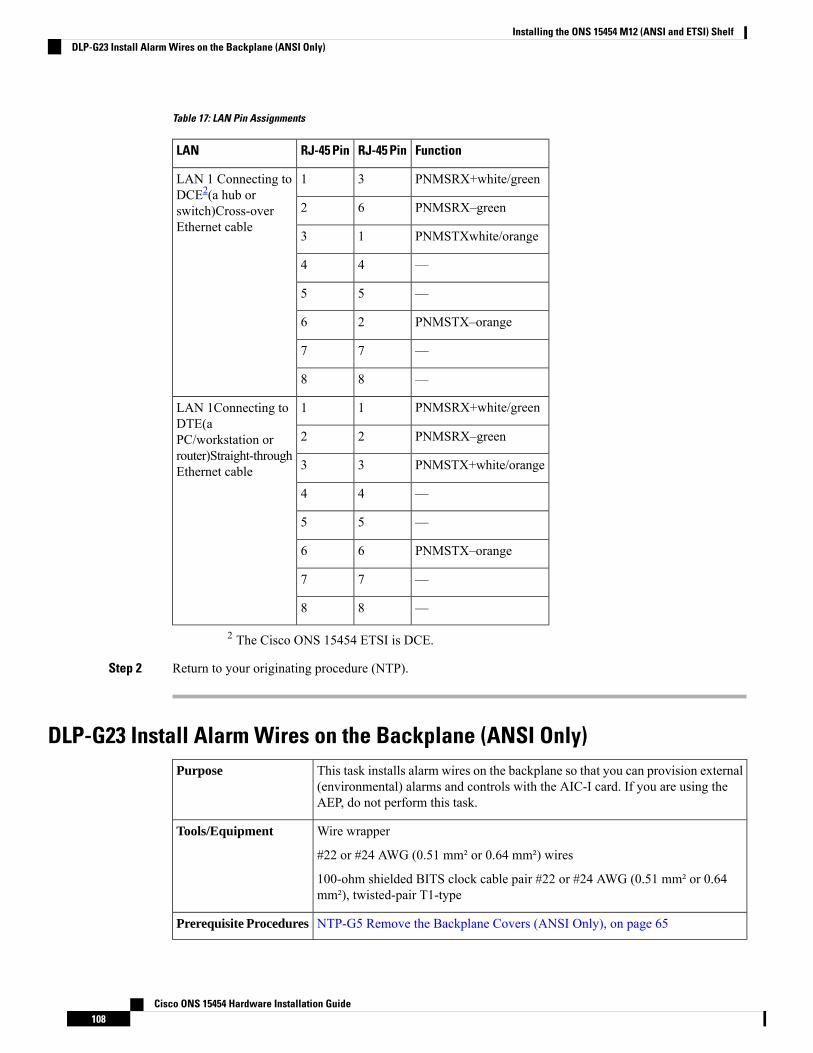
Table 17: LAN Pin Assignments
FunctionRJ-45 PinRJ-45 PinLAN
PNMSRX+white/green31LAN 1 Connecting toDCE2(a hub orswitch)Cross-overEthernet cable
PNMSRX–green62
PNMSTXwhite/orange13
—44
—55
PNMSTX–orange26
—77
—88
PNMSRX+white/green11LAN 1Connecting toDTE(aPC/workstation orrouter)Straight-throughEthernet cable
PNMSRX–green22
PNMSTX+white/orange33
—44
—55
PNMSTX–orange66
—77
—88
2 The Cisco ONS 15454 ETSI is DCE.
Step 2 Return to your originating procedure (NTP).
DLP-G23 Install Alarm Wires on the Backplane (ANSI Only)This task installs alarm wires on the backplane so that you can provision external(environmental) alarms and controls with the AIC-I card. If you are using theAEP, do not perform this task.
Purpose
Wire wrapper
#22 or #24 AWG (0.51 mm² or 0.64 mm²) wires
100-ohm shielded BITS clock cable pair #22 or #24 AWG (0.51 mm² or 0.64mm²), twisted-pair T1-type
Tools/Equipment
NTP-G5 Remove the Backplane Covers (ANSI Only), on page 65Prerequisite Procedures
Cisco ONS 15454 Hardware Installation Guide108
Installing the ONS 15454 M12 (ANSI and ETSI) ShelfDLP-G23 Install Alarm Wires on the Backplane (ANSI Only)
As neededRequired/As Needed
OnsiteOnsite/Remote
NoneSecurity Level
Procedure
Step 1 Using 100-ohm shielded BITS clock cable pair #22 or #24 AWG (0.51mm² or 0.64mm²) twisted-pair T1-typewires, wrap the alarm wires on the appropriate wire-wrap pins according to local site practice. Ground theshield of the BITS Input cable at the BITS end. For BITS Output, wrap the ground shield of the BITS cableto the frame ground pin (FG1) located below the column of BITS pins.
Cisco ONS 15454 Hardware Installation Guide109
Installing the ONS 15454 M12 (ANSI and ETSI) ShelfDLP-G23 Install Alarm Wires on the Backplane (ANSI Only)

Figure 58: Cisco ONS 15454 Backplane Pinouts (Release 3.4 or Later)
Cisco ONS 15454 Hardware Installation Guide110
Installing the ONS 15454 M12 (ANSI and ETSI) ShelfDLP-G23 Install Alarm Wires on the Backplane (ANSI Only)
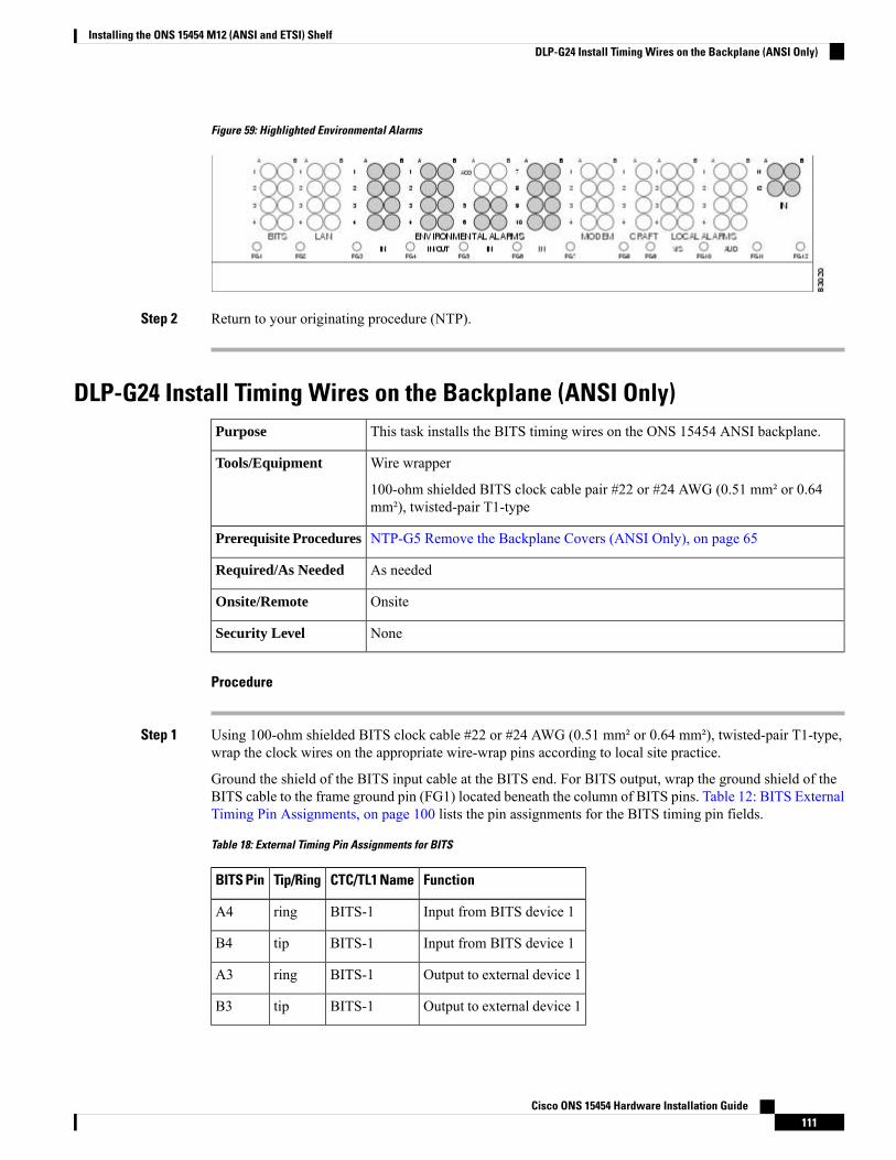
Figure 59: Highlighted Environmental Alarms
Step 2 Return to your originating procedure (NTP).
DLP-G24 Install Timing Wires on the Backplane (ANSI Only)This task installs the BITS timing wires on the ONS 15454 ANSI backplane.Purpose
Wire wrapper
100-ohm shielded BITS clock cable pair #22 or #24 AWG (0.51 mm² or 0.64mm²), twisted-pair T1-type
Tools/Equipment
NTP-G5 Remove the Backplane Covers (ANSI Only), on page 65Prerequisite Procedures
As neededRequired/As Needed
OnsiteOnsite/Remote
NoneSecurity Level
Procedure
Step 1 Using 100-ohm shielded BITS clock cable #22 or #24 AWG (0.51 mm² or 0.64 mm²), twisted-pair T1-type,wrap the clock wires on the appropriate wire-wrap pins according to local site practice.
Ground the shield of the BITS input cable at the BITS end. For BITS output, wrap the ground shield of theBITS cable to the frame ground pin (FG1) located beneath the column of BITS pins. Table 12: BITS ExternalTiming Pin Assignments, on page 100 lists the pin assignments for the BITS timing pin fields.
Table 18: External Timing Pin Assignments for BITS
FunctionCTC/TL1 NameTip/RingBITS Pin
Input from BITS device 1BITS-1ringA4
Input from BITS device 1BITS-1tipB4
Output to external device 1BITS-1ringA3
Output to external device 1BITS-1tipB3
Cisco ONS 15454 Hardware Installation Guide111
Installing the ONS 15454 M12 (ANSI and ETSI) ShelfDLP-G24 Install Timing Wires on the Backplane (ANSI Only)
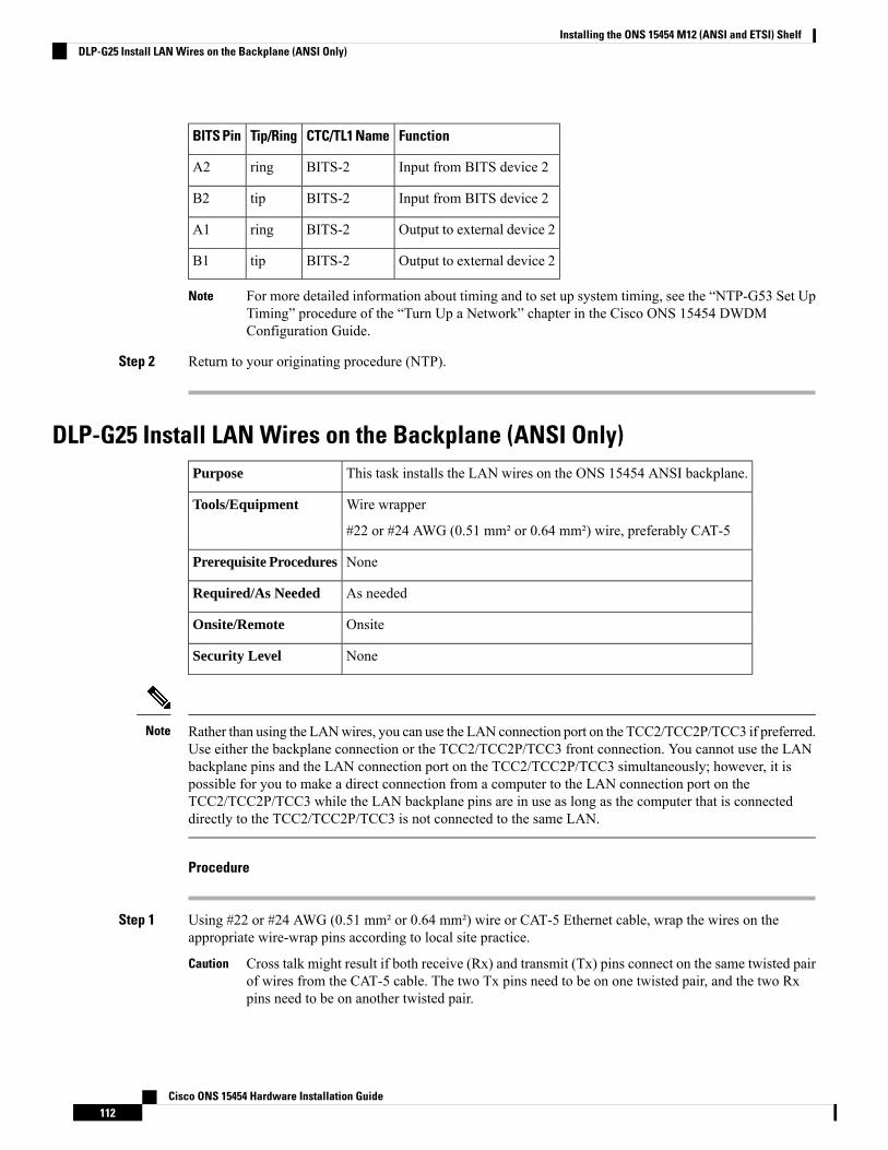
FunctionCTC/TL1 NameTip/RingBITS Pin
Input from BITS device 2BITS-2ringA2
Input from BITS device 2BITS-2tipB2
Output to external device 2BITS-2ringA1
Output to external device 2BITS-2tipB1
For more detailed information about timing and to set up system timing, see the “NTP-G53 Set UpTiming” procedure of the “Turn Up a Network” chapter in the Cisco ONS 15454 DWDMConfiguration Guide.
Note
Step 2 Return to your originating procedure (NTP).
DLP-G25 Install LAN Wires on the Backplane (ANSI Only)This task installs the LAN wires on the ONS 15454 ANSI backplane.Purpose
Wire wrapper
#22 or #24 AWG (0.51 mm² or 0.64 mm²) wire, preferably CAT-5
Tools/Equipment
NonePrerequisite Procedures
As neededRequired/As Needed
OnsiteOnsite/Remote
NoneSecurity Level
Rather than using the LANwires, you can use the LAN connection port on the TCC2/TCC2P/TCC3 if preferred.Use either the backplane connection or the TCC2/TCC2P/TCC3 front connection. You cannot use the LANbackplane pins and the LAN connection port on the TCC2/TCC2P/TCC3 simultaneously; however, it ispossible for you to make a direct connection from a computer to the LAN connection port on theTCC2/TCC2P/TCC3 while the LAN backplane pins are in use as long as the computer that is connecteddirectly to the TCC2/TCC2P/TCC3 is not connected to the same LAN.
Note
Procedure
Step 1 Using #22 or #24 AWG (0.51 mm² or 0.64 mm²) wire or CAT-5 Ethernet cable, wrap the wires on theappropriate wire-wrap pins according to local site practice.
Cross talk might result if both receive (Rx) and transmit (Tx) pins connect on the same twisted pairof wires from the CAT-5 cable. The two Tx pins need to be on one twisted pair, and the two Rxpins need to be on another twisted pair.
Caution
Cisco ONS 15454 Hardware Installation Guide112
Installing the ONS 15454 M12 (ANSI and ETSI) ShelfDLP-G25 Install LAN Wires on the Backplane (ANSI Only)
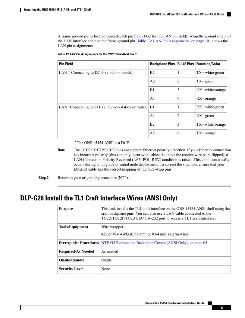
A frame ground pin is located beneath each pin field (FG2 for the LAN pin field). Wrap the ground shield ofthe LAN interface cable to the frame ground pin. Table 13: LAN Pin Assignments, on page 101 shows theLAN pin assignments.
Table 19: LAN Pin Assignments for the ONS 15454 ANSI Shelf
Function/ColorRJ-45 PinsBackplane PinsPin Field
TX+ white/green1B2LAN 1 Connecting to DCE3 (a hub or switch);
TX– green2A2
RX+white/orange3B1
RX– orange6A1
RX+ white/green1B1LAN 1Connecting to DTE (a PC/workstation or router)
RX– green2A1
TX+ white/orange3B2
TX– orange6A2
3 The ONS 15454 ANSI is a DCE.
The TCC2/TCC2P/TCC3 does not support Ethernet polarity detection. If your Ethernet connectionhas incorrect polarity (this can only occur with cables that have the receive wire pairs flipped), aLAN Connection Polarity Reversed (LAN-POL-REV) condition is raised. This condition usuallyoccurs during an upgrade or initial node deployment. To correct the situation, ensure that yourEthernet cable has the correct mapping of the wire-wrap pins.
Note
Step 2 Return to your originating procedure (NTP).
DLP-G26 Install the TL1 Craft Interface Wires (ANSI Only)This task installs the TL1 craft interface on the ONS 15454 ANSI shelf using thecraft backplane pins. You can also use a LAN cable connected to theTCC2/TCC2P/TCC3 EIA/TIA-232 port to access a TL1 craft interface.
Purpose
Wire wrapper
#22 or #24 AWG (0.51 mm² or 0.64 mm²) alarm wires
Tools/Equipment
NTP-G5 Remove the Backplane Covers (ANSI Only), on page 65Prerequisite Procedures
As neededRequired/As Needed
OnsiteOnsite/Remote
NoneSecurity Level
Cisco ONS 15454 Hardware Installation Guide113
Installing the ONS 15454 M12 (ANSI and ETSI) ShelfDLP-G26 Install the TL1 Craft Interface Wires (ANSI Only)
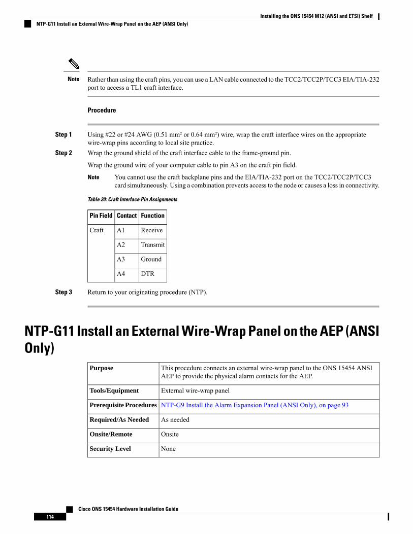
Rather than using the craft pins, you can use a LAN cable connected to the TCC2/TCC2P/TCC3EIA/TIA-232port to access a TL1 craft interface.
Note
Procedure
Step 1 Using #22 or #24 AWG (0.51 mm² or 0.64 mm²) wire, wrap the craft interface wires on the appropriatewire-wrap pins according to local site practice.
Step 2 Wrap the ground shield of the craft interface cable to the frame-ground pin.
Wrap the ground wire of your computer cable to pin A3 on the craft pin field.
You cannot use the craft backplane pins and the EIA/TIA-232 port on the TCC2/TCC2P/TCC3card simultaneously. Using a combination prevents access to the node or causes a loss in connectivity.
Note
Table 20: Craft Interface Pin Assignments
FunctionContactPin Field
ReceiveA1Craft
TransmitA2
GroundA3
DTRA4
Step 3 Return to your originating procedure (NTP).
NTP-G11 Install an External Wire-Wrap Panel on the AEP (ANSIOnly)
This procedure connects an external wire-wrap panel to the ONS 15454 ANSIAEP to provide the physical alarm contacts for the AEP.
Purpose
External wire-wrap panelTools/Equipment
NTP-G9 Install the Alarm Expansion Panel (ANSI Only), on page 93Prerequisite Procedures
As neededRequired/As Needed
OnsiteOnsite/Remote
NoneSecurity Level
Cisco ONS 15454 Hardware Installation Guide114
Installing the ONS 15454 M12 (ANSI and ETSI) ShelfNTP-G11 Install an External Wire-Wrap Panel on the AEP (ANSI Only)
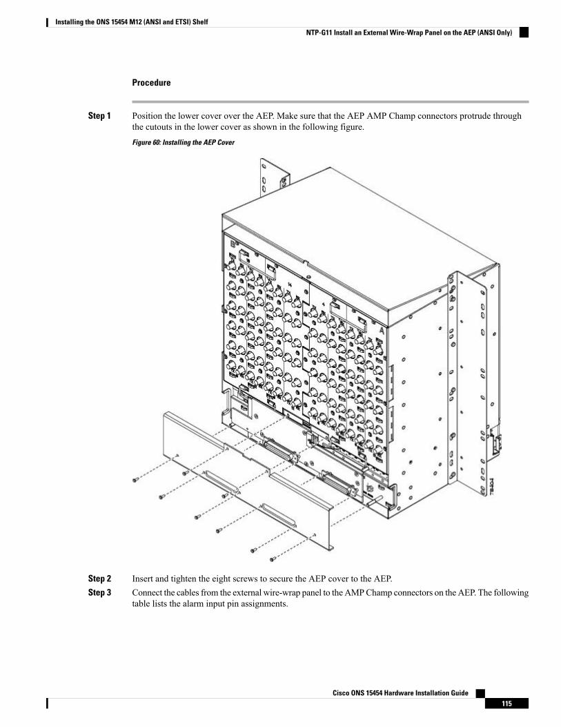
Procedure
Step 1 Position the lower cover over the AEP. Make sure that the AEP AMP Champ connectors protrude throughthe cutouts in the lower cover as shown in the following figure.
Figure 60: Installing the AEP Cover
Step 2 Insert and tighten the eight screws to secure the AEP cover to the AEP.Step 3 Connect the cables from the external wire-wrap panel to the AMPChamp connectors on the AEP. The following
table lists the alarm input pin assignments.
Cisco ONS 15454 Hardware Installation Guide115
Installing the ONS 15454 M12 (ANSI and ETSI) ShelfNTP-G11 Install an External Wire-Wrap Panel on the AEP (ANSI Only)
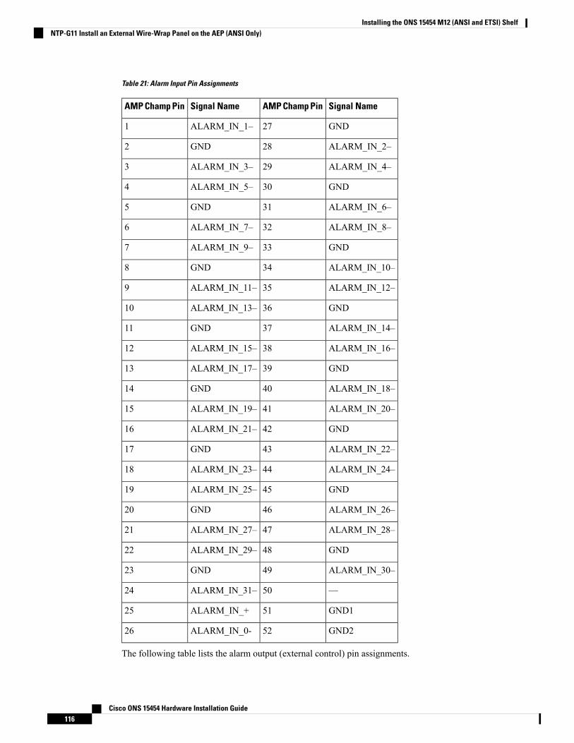
Table 21: Alarm Input Pin Assignments
Signal NameAMP Champ PinSignal NameAMP Champ Pin
GND27ALARM_IN_1–1
ALARM_IN_2–28GND2
ALARM_IN_4–29ALARM_IN_3–3
GND30ALARM_IN_5–4
ALARM_IN_6–31GND5
ALARM_IN_8–32ALARM_IN_7–6
GND33ALARM_IN_9–7
ALARM_IN_10–34GND8
ALARM_IN_12–35ALARM_IN_11–9
GND36ALARM_IN_13–10
ALARM_IN_14–37GND11
ALARM_IN_16–38ALARM_IN_15–12
GND39ALARM_IN_17–13
ALARM_IN_18–40GND14
ALARM_IN_20–41ALARM_IN_19–15
GND42ALARM_IN_21–16
ALARM_IN_22–43GND17
ALARM_IN_24–44ALARM_IN_23–18
GND45ALARM_IN_25–19
ALARM_IN_26–46GND20
ALARM_IN_28–47ALARM_IN_27–21
GND48ALARM_IN_29–22
ALARM_IN_30–49GND23
—50ALARM_IN_31–24
GND151ALARM_IN_+25
GND252ALARM_IN_0-26
The following table lists the alarm output (external control) pin assignments.
Cisco ONS 15454 Hardware Installation Guide116
Installing the ONS 15454 M12 (ANSI and ETSI) ShelfNTP-G11 Install an External Wire-Wrap Panel on the AEP (ANSI Only)
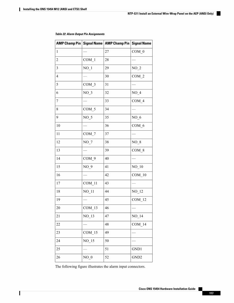
Table 22: Alarm Output Pin Assignments
Signal NameAMP Champ PinSignal NameAMP Champ Pin
COM_027—1
—28COM_12
NO_229NO_13
COM_230—4
—31COM_35
NO_432NO_36
COM_433—7
—34COM_58
NO_635NO_59
COM_636—10
—37COM_711
NO_838NO_712
COM_839—13
—40COM_914
NO_1041NO_915
COM_1042—16
—43COM_1117
NO_1244NO_1118
COM_1245—19
—46COM_1320
NO_1447NO_1321
COM_1448—22
—49COM_1523
—50NO_1524
GND151—25
GND252NO_026
The following figure illustrates the alarm input connectors.
Cisco ONS 15454 Hardware Installation Guide117
Installing the ONS 15454 M12 (ANSI and ETSI) ShelfNTP-G11 Install an External Wire-Wrap Panel on the AEP (ANSI Only)
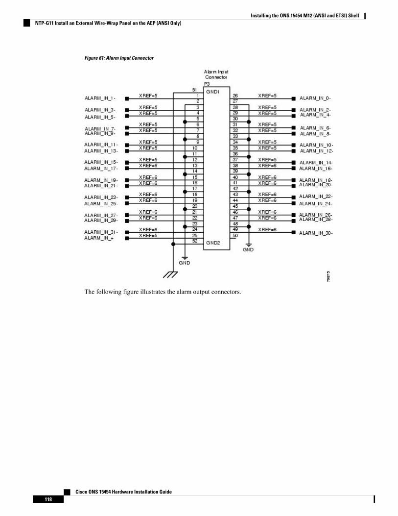
Figure 61: Alarm Input Connector
The following figure illustrates the alarm output connectors.
Cisco ONS 15454 Hardware Installation Guide118
Installing the ONS 15454 M12 (ANSI and ETSI) ShelfNTP-G11 Install an External Wire-Wrap Panel on the AEP (ANSI Only)
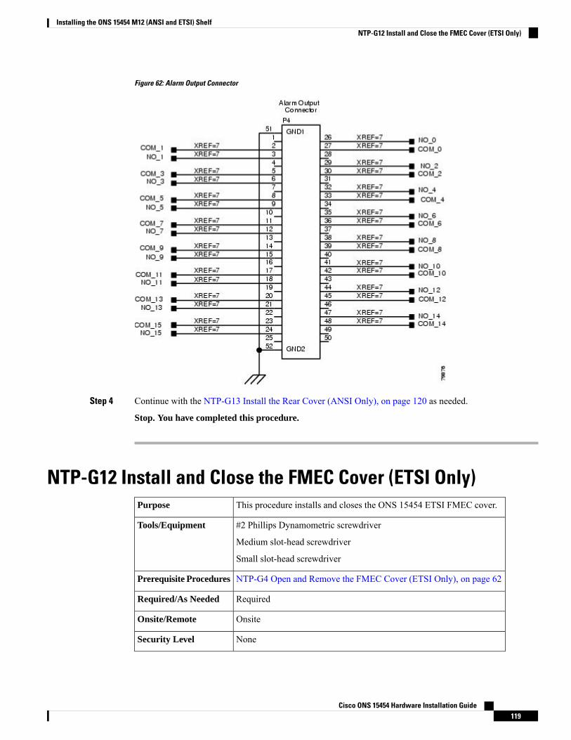
Figure 62: Alarm Output Connector
Step 4 Continue with the NTP-G13 Install the Rear Cover (ANSI Only), on page 120 as needed.
Stop. You have completed this procedure.
NTP-G12 Install and Close the FMEC Cover (ETSI Only)This procedure installs and closes the ONS 15454 ETSI FMEC cover.Purpose
#2 Phillips Dynamometric screwdriver
Medium slot-head screwdriver
Small slot-head screwdriver
Tools/Equipment
NTP-G4 Open and Remove the FMEC Cover (ETSI Only), on page 62Prerequisite Procedures
RequiredRequired/As Needed
OnsiteOnsite/Remote
NoneSecurity Level
Cisco ONS 15454 Hardware Installation Guide119
Installing the ONS 15454 M12 (ANSI and ETSI) ShelfNTP-G12 Install and Close the FMEC Cover (ETSI Only)
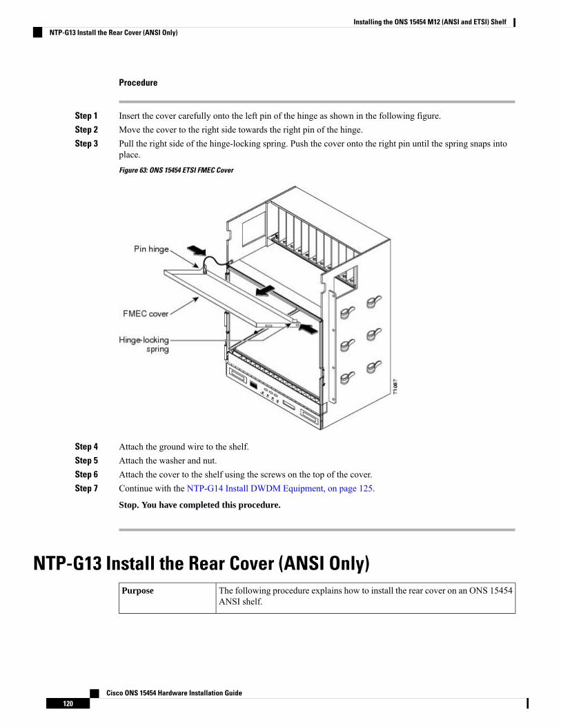
Procedure
Step 1 Insert the cover carefully onto the left pin of the hinge as shown in the following figure.Step 2 Move the cover to the right side towards the right pin of the hinge.Step 3 Pull the right side of the hinge-locking spring. Push the cover onto the right pin until the spring snaps into
place.
Figure 63: ONS 15454 ETSI FMEC Cover
Step 4 Attach the ground wire to the shelf.Step 5 Attach the washer and nut.Step 6 Attach the cover to the shelf using the screws on the top of the cover.Step 7 Continue with the NTP-G14 Install DWDM Equipment, on page 125.
Stop. You have completed this procedure.
NTP-G13 Install the Rear Cover (ANSI Only)The following procedure explains how to install the rear cover on an ONS 15454ANSI shelf.
Purpose
Cisco ONS 15454 Hardware Installation Guide120
Installing the ONS 15454 M12 (ANSI and ETSI) ShelfNTP-G13 Install the Rear Cover (ANSI Only)
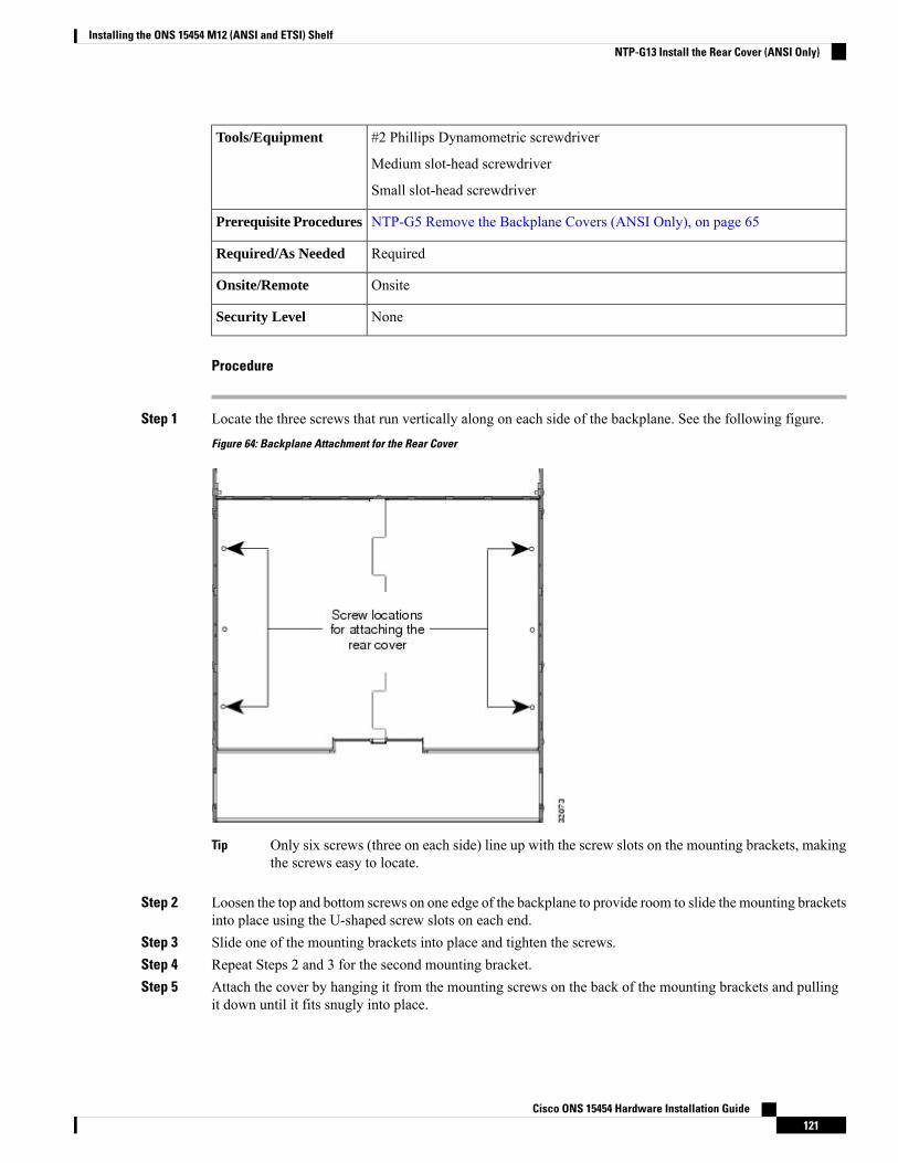
#2 Phillips Dynamometric screwdriver
Medium slot-head screwdriver
Small slot-head screwdriver
Tools/Equipment
NTP-G5 Remove the Backplane Covers (ANSI Only), on page 65Prerequisite Procedures
RequiredRequired/As Needed
OnsiteOnsite/Remote
NoneSecurity Level
Procedure
Step 1 Locate the three screws that run vertically along on each side of the backplane. See the following figure.
Figure 64: Backplane Attachment for the Rear Cover
Only six screws (three on each side) line up with the screw slots on the mounting brackets, makingthe screws easy to locate.
Tip
Step 2 Loosen the top and bottom screws on one edge of the backplane to provide room to slide the mounting bracketsinto place using the U-shaped screw slots on each end.
Step 3 Slide one of the mounting brackets into place and tighten the screws.Step 4 Repeat Steps 2 and 3 for the second mounting bracket.Step 5 Attach the cover by hanging it from the mounting screws on the back of the mounting brackets and pulling
it down until it fits snugly into place.
Cisco ONS 15454 Hardware Installation Guide121
Installing the ONS 15454 M12 (ANSI and ETSI) ShelfNTP-G13 Install the Rear Cover (ANSI Only)
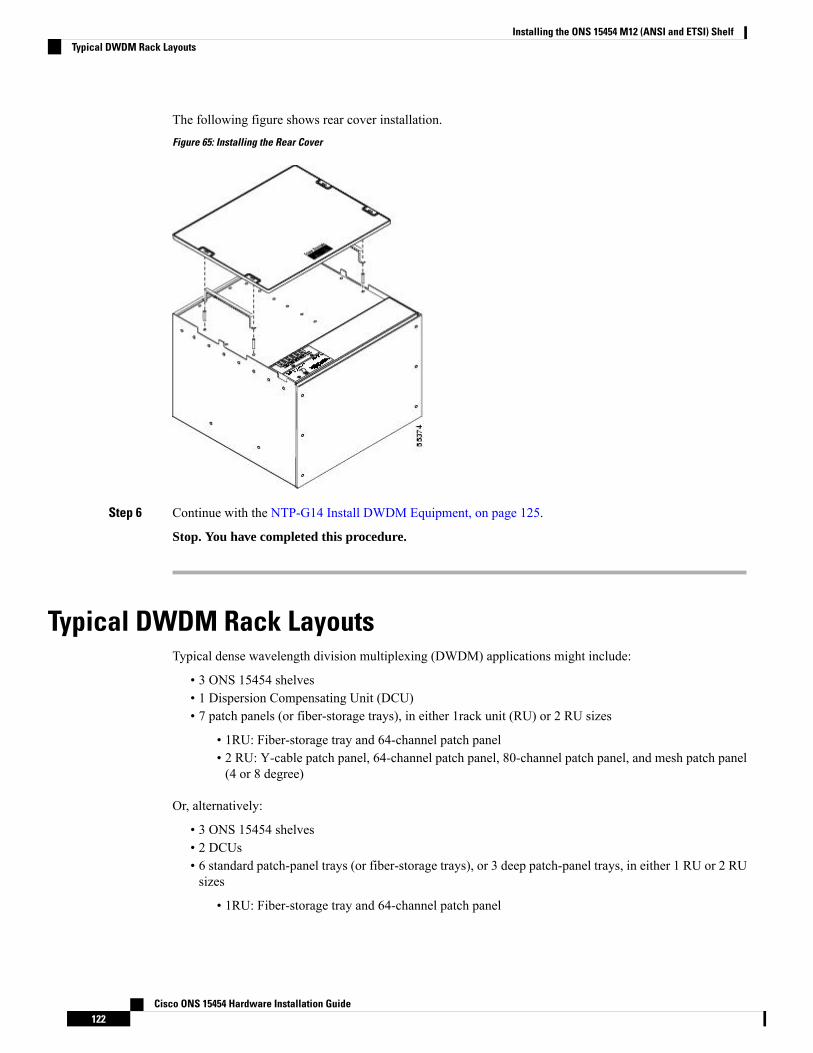
The following figure shows rear cover installation.
Figure 65: Installing the Rear Cover
Step 6 Continue with the NTP-G14 Install DWDM Equipment, on page 125.
Stop. You have completed this procedure.
Typical DWDM Rack LayoutsTypical dense wavelength division multiplexing (DWDM) applications might include:
• 3 ONS 15454 shelves• 1 Dispersion Compensating Unit (DCU)• 7 patch panels (or fiber-storage trays), in either 1rack unit (RU) or 2 RU sizes
• 1RU: Fiber-storage tray and 64-channel patch panel• 2 RU: Y-cable patch panel, 64-channel patch panel, 80-channel patch panel, and mesh patch panel(4 or 8 degree)
Or, alternatively:
• 3 ONS 15454 shelves• 2 DCUs• 6 standard patch-panel trays (or fiber-storage trays), or 3 deep patch-panel trays, in either 1 RU or 2 RUsizes
• 1RU: Fiber-storage tray and 64-channel patch panel
Cisco ONS 15454 Hardware Installation Guide122
Installing the ONS 15454 M12 (ANSI and ETSI) ShelfTypical DWDM Rack Layouts

• 2 RU: Y-cable patch panel, 64-channel patch panel, 80-channel patch panel, and mesh patch panel(4 or 8 degree)
See the following figure for a typical rack layout.
Use the rack layout generated by Cisco TransportPlanner to determine your exact shelf layout.Note
Cisco ONS 15454 Hardware Installation Guide123
Installing the ONS 15454 M12 (ANSI and ETSI) ShelfTypical DWDM Rack Layouts
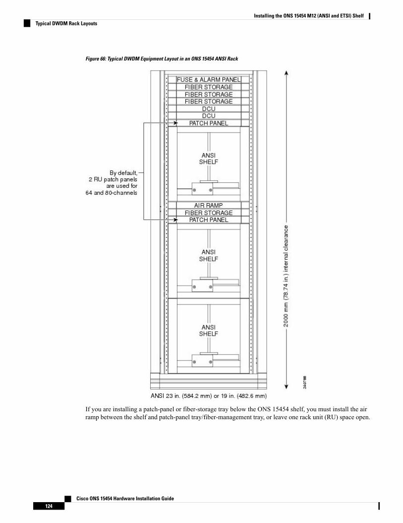
Figure 66: Typical DWDM Equipment Layout in an ONS 15454 ANSI Rack
If you are installing a patch-panel or fiber-storage tray below the ONS 15454 shelf, you must install the airramp between the shelf and patch-panel tray/fiber-management tray, or leave one rack unit (RU) space open.
Cisco ONS 15454 Hardware Installation Guide124
Installing the ONS 15454 M12 (ANSI and ETSI) ShelfTypical DWDM Rack Layouts
NTP-G14 Install DWDM EquipmentThis procedure installs the optional DWDM assemblies.Purpose
#2 Phillips Dynamometric screwdriver
Crimping tool (large enough for #10 to #14 AWG)
#14 AWG wire
Tools/Equipment
NTP-G306 Install the ONS 15454 Shelf, on page 33Prerequisite Procedures
As neededRequired/As Needed
OnsiteOnsite/Remote
NoneSecurity Level
Procedure
Step 1 Complete the DLP-G27 Install the DCU Shelf , on page 125 as needed.Step 2 Complete the DLP-G28 Install the Fiber Patch-Panel Tray, on page 126 as needed.Step 3 Complete the DLP-G29 Install the Fiber-Storage Tray, on page 127 as needed.Step 4 Complete the DLP-G371 Install the Ethernet Adapter Panel, on page 128 as needed.Step 5 Complete the DLP-G352 Install the Y-Cable Module Tray, on page 128 as needed.Step 6 Complete the DLP-G30 Install the FlexLayer Shelf, on page 129 as needed.
Procedures for installing FlexLayer hardware in this chapter require that you have a network plancalculated for your DWDM network with Cisco Transport Planner, Release 9.2. CiscoTransportPlanner is a DWDMplanning tool that is available from your Cisco account representative.Cisco TransportPlanner prepares a shelf plan for each network node and calculates the power andattenuation levels for the DWDM cards installed in the node. For information about CiscoTransportPlanner, refer to the Cisco TransportPlanner DWDM Operations Guide, Release 9.2.
Note
Step 7 Complete the DLP-G31 Install the FlexLayer Modules, on page 130 as needed.Step 8 Complete the DLP-G32 Install the Y-Cable ProtectionModules in the FlexLayer Shelf, on page 131 as needed.Step 9 Complete the DLP-G377 Install the Y-Cable Protection Modules in the Y-Cable Module Tray, on page 132
as needed.
Stop. You have completed this procedure.
DLP-G27 Install the DCU ShelfThis task installs the Dispersion Compensation Unit (DCU) chassis.Purpose
Cisco ONS 15454 Hardware Installation Guide125
Installing the ONS 15454 M12 (ANSI and ETSI) ShelfNTP-G14 Install DWDM Equipment
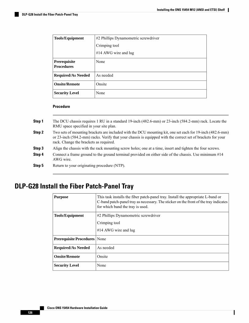
#2 Phillips Dynamometric screwdriver
Crimping tool
#14 AWG wire and lug
Tools/Equipment
NonePrerequisiteProcedures
As neededRequired/As Needed
OnsiteOnsite/Remote
NoneSecurity Level
Procedure
Step 1 The DCU chassis requires 1 RU in a standard 19-inch (482.6-mm) or 23-inch (584.2-mm) rack. Locate theRMU space specified in your site plan.
Step 2 Two sets of mounting brackets are included with the DCUmounting kit, one set each for 19-inch (482.6-mm)or 23-inch (584.2-mm) racks. Verify that your chassis is equipped with the correct set of brackets for yourrack. Change the brackets as required.
Step 3 Align the chassis with the rack mounting screw holes; one at a time, insert and tighten the four screws.Step 4 Connect a frame ground to the ground terminal provided on either side of the chassis. Use minimum #14
AWG wire.Step 5 Return to your originating procedure (NTP).
DLP-G28 Install the Fiber Patch-Panel TrayThis task installs the fiber patch-panel tray. Install the appropriate L-band orC-band patch-panel tray as necessary. The sticker on the front of the tray indicatesfor which band the tray is used.
Purpose
#2 Phillips Dynamometric screwdriver
Crimping tool
#14 AWG wire and lug
Tools/Equipment
NonePrerequisite Procedures
As neededRequired/As Needed
OnsiteOnsite/Remote
NoneSecurity Level
Cisco ONS 15454 Hardware Installation Guide126
Installing the ONS 15454 M12 (ANSI and ETSI) ShelfDLP-G28 Install the Fiber Patch-Panel Tray
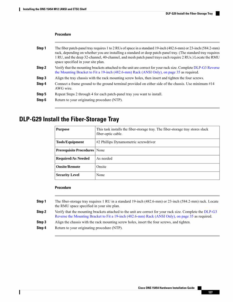
Procedure
Step 1 The fiber patch-panel tray requires 1 to 2 RUs of space in a standard 19-inch (482.6-mm) or 23-inch (584.2-mm)rack, depending on whether you are installing a standard or deep patch-panel tray. (The standard tray requires1 RU, and the deep 32-channel, 40-channel, and mesh patch panel trays each require 2 RUs.) Locate the RMUspace specified in your site plan.
Step 2 Verify that the mounting brackets attached to the unit are correct for your rack size. Complete DLP-G3 Reversethe Mounting Bracket to Fit a 19-inch (482.6-mm) Rack (ANSI Only), on page 35 as required.
Step 3 Align the tray chassis with the rack mounting screw holes, then insert and tighten the four screws.Step 4 Connect a frame ground to the ground terminal provided on either side of the chassis. Use minimum #14
AWG wire.Step 5 Repeat Steps 2 through 4 for each patch-panel tray you want to install.Step 6 Return to your originating procedure (NTP).
DLP-G29 Install the Fiber-Storage TrayThis task installs the fiber-storage tray. The fiber-storage tray stores slackfiber-optic cable.
Purpose
#2 Phillips Dynamometric screwdriverTools/Equipment
NonePrerequisite Procedures
As neededRequired/As Needed
OnsiteOnsite/Remote
NoneSecurity Level
Procedure
Step 1 The fiber-storage tray requires 1 RU in a standard 19-inch (482.6-mm) or 23-inch (584.2-mm) rack. Locatethe RMU space specified in your site plan.
Step 2 Verify that the mounting brackets attached to the unit are correct for your rack size. Complete the DLP-G3Reverse the Mounting Bracket to Fit a 19-inch (482.6-mm) Rack (ANSI Only), on page 35 as required.
Step 3 Align the chassis with the rack mounting screw holes, insert the four screws, and tighten.Step 4 Return to your originating procedure (NTP).
Cisco ONS 15454 Hardware Installation Guide127
Installing the ONS 15454 M12 (ANSI and ETSI) ShelfDLP-G29 Install the Fiber-Storage Tray
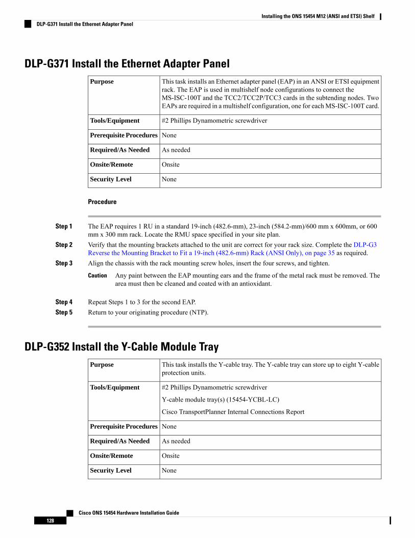
DLP-G371 Install the Ethernet Adapter PanelThis task installs an Ethernet adapter panel (EAP) in an ANSI or ETSI equipmentrack. The EAP is used in multishelf node configurations to connect theMS-ISC-100T and the TCC2/TCC2P/TCC3 cards in the subtending nodes. TwoEAPs are required in a multishelf configuration, one for eachMS-ISC-100T card.
Purpose
#2 Phillips Dynamometric screwdriverTools/Equipment
NonePrerequisite Procedures
As neededRequired/As Needed
OnsiteOnsite/Remote
NoneSecurity Level
Procedure
Step 1 The EAP requires 1 RU in a standard 19-inch (482.6-mm), 23-inch (584.2-mm)/600 mm x 600mm, or 600mm x 300 mm rack. Locate the RMU space specified in your site plan.
Step 2 Verify that the mounting brackets attached to the unit are correct for your rack size. Complete the DLP-G3Reverse the Mounting Bracket to Fit a 19-inch (482.6-mm) Rack (ANSI Only), on page 35 as required.
Step 3 Align the chassis with the rack mounting screw holes, insert the four screws, and tighten.
Any paint between the EAP mounting ears and the frame of the metal rack must be removed. Thearea must then be cleaned and coated with an antioxidant.
Caution
Step 4 Repeat Steps 1 to 3 for the second EAP.Step 5 Return to your originating procedure (NTP).
DLP-G352 Install the Y-Cable Module TrayThis task installs the Y-cable tray. The Y-cable tray can store up to eight Y-cableprotection units.
Purpose
#2 Phillips Dynamometric screwdriver
Y-cable module tray(s) (15454-YCBL-LC)
Cisco TransportPlanner Internal Connections Report
Tools/Equipment
NonePrerequisite Procedures
As neededRequired/As Needed
OnsiteOnsite/Remote
NoneSecurity Level
Cisco ONS 15454 Hardware Installation Guide128
Installing the ONS 15454 M12 (ANSI and ETSI) ShelfDLP-G371 Install the Ethernet Adapter Panel
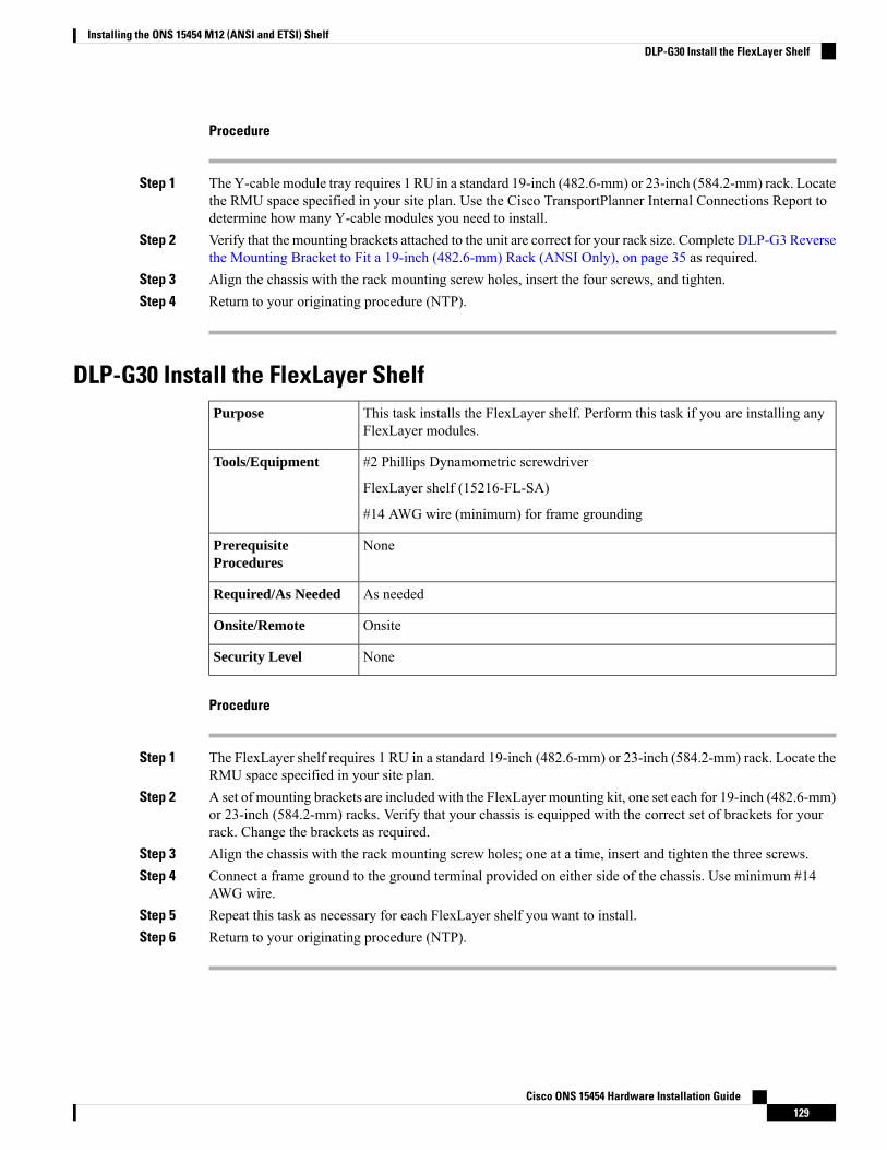
Procedure
Step 1 The Y-cable module tray requires 1 RU in a standard 19-inch (482.6-mm) or 23-inch (584.2-mm) rack. Locatethe RMU space specified in your site plan. Use the Cisco TransportPlanner Internal Connections Report todetermine how many Y-cable modules you need to install.
Step 2 Verify that the mounting brackets attached to the unit are correct for your rack size. Complete DLP-G3 Reversethe Mounting Bracket to Fit a 19-inch (482.6-mm) Rack (ANSI Only), on page 35 as required.
Step 3 Align the chassis with the rack mounting screw holes, insert the four screws, and tighten.Step 4 Return to your originating procedure (NTP).
DLP-G30 Install the FlexLayer ShelfThis task installs the FlexLayer shelf. Perform this task if you are installing anyFlexLayer modules.
Purpose
#2 Phillips Dynamometric screwdriver
FlexLayer shelf (15216-FL-SA)
#14 AWG wire (minimum) for frame grounding
Tools/Equipment
NonePrerequisiteProcedures
As neededRequired/As Needed
OnsiteOnsite/Remote
NoneSecurity Level
Procedure
Step 1 The FlexLayer shelf requires 1 RU in a standard 19-inch (482.6-mm) or 23-inch (584.2-mm) rack. Locate theRMU space specified in your site plan.
Step 2 A set of mounting brackets are included with the FlexLayer mounting kit, one set each for 19-inch (482.6-mm)or 23-inch (584.2-mm) racks. Verify that your chassis is equipped with the correct set of brackets for yourrack. Change the brackets as required.
Step 3 Align the chassis with the rack mounting screw holes; one at a time, insert and tighten the three screws.Step 4 Connect a frame ground to the ground terminal provided on either side of the chassis. Use minimum #14
AWG wire.Step 5 Repeat this task as necessary for each FlexLayer shelf you want to install.Step 6 Return to your originating procedure (NTP).
Cisco ONS 15454 Hardware Installation Guide129
Installing the ONS 15454 M12 (ANSI and ETSI) ShelfDLP-G30 Install the FlexLayer Shelf

DLP-G31 Install the FlexLayer ModulesThis task installs the FlexLayer modules in the FlexLayer shelf. You can onlyinstall two-channel FlexLayer modules.
Purpose
#2 Phillips Dynamometric screwdriver
FlexLayer modules
Tools/Equipment
NonePrerequisite Procedures
As neededRequired/As Needed
OnsiteOnsite/Remote
NoneSecurity Level
Procedure
Step 1 Determine the FlexLayer modules that you want to install in the FlexLayer shelf. The FlexLayer shelf canhouse up to four Add/Drop FlexLayer modules or four Y-cable splitter modules. The following table lists thetwo-channel FlexLayer modules and part numbers.
Table 23: ONS 15xxx Two-Channel Add/Drop FlexLayer Module Hardware Part Numbers
DescriptionPart Number
ITU-100 GHz 2 Ch, FlexMod - 1530.33 and 1531.1215216-FLB-2-31.1=
ITU-100 GHz 2 Ch, FlexMod - 1531.90 and 1532.6815216-FLB-2-32.6=
ITU-100 GHz 2 Ch, FlexMod - 1534.25 and 1535.0415216-FLB-2-35.0=
ITU-100 GHz 2 Ch, FlexMod - 1535.82 and 1536.6115216-FLB-2-36.6=
ITU-100 GHz 2 Ch, FlexMod - 1538.19 and 1538.9815216-FLB-2-38.9=
ITU-100 GHz 2 Ch, FlexMod - 1539.77 and 1540.5615216-FLB-2-40.5=
ITU-100 GHz 2 Ch, FlexMod - 1542.14 and 1542.9415216-FLB-2-42.9=
ITU-100 GHz 2 Ch, FlexMod - 1543.73 and 1544.5315216-FLB-2-44.5=
ITU-100 GHz 2 Ch, FlexMod - 1546.12 and 1546.9215216-FLB-2-46.9=
ITU-100 GHz 2 Ch, FlexMod - 1547.72 and 1548.5115216-FLB-2-48.5=
ITU-100 GHz 2 Ch, FlexMod - 1550.12 and 1550.9215216-FLB-2-50.9=
ITU-100 GHz 2 Ch, FlexMod - 1551.72 and 1552.5215216-FLB-2-52.5=
ITU-100 GHz 2 Ch, FlexMod - 1554.13 and 1554.9415216-FLB-2-54.9=
ITU-100 GHz 2 Ch, FlexMod - 1555.75 and 1556.5515216-FLB-2-56.5=
Cisco ONS 15454 Hardware Installation Guide130
Installing the ONS 15454 M12 (ANSI and ETSI) ShelfDLP-G31 Install the FlexLayer Modules

DescriptionPart Number
ITU-100 GHz 2 Ch, FlexMod - 1558.17 and 1558.9815216-FLB-2-58.9=
ITU-100 GHz 2 Ch, FlexMod - 1559.79 and 1560.6115216-FLB-2-60.6=
Step 2 Insert the appropriate module into the FlexLayer shelf.Step 3 Use a Phillips Dynamometric screwdriver to install the two accompanying screws.
The following figure shows the FlexLayer shelf and how the FlexLayer modules can be installed.
Figure 67: ONS 15xxx FlexLayer Shelf
Step 4 Repeat this task as necessary for each FlexLayer module you want to install.Step 5 Return to your originating procedure (NTP).
DLP-G32 Install the Y-Cable Protection Modules in the FlexLayer ShelfThis task installs the Y-cable protection modules in the FlexLayer shelf.Purpose
#2 Phillips Dynamometric screwdriver
Y-cable module(s): Multi-Mode Y-Cable Protection FlexModule(s)(15216-CS-MM-Y) or Single-Mode Y-Cable Protection FlexModule(s)(15216-CS-SM-Y), as appropriate
Tools/Equipment
NonePrerequisite Procedures
As neededRequired/As Needed
OnsiteOnsite/Remote
NoneSecurity Level
Cisco ONS 15454 Hardware Installation Guide131
Installing the ONS 15454 M12 (ANSI and ETSI) ShelfDLP-G32 Install the Y-Cable Protection Modules in the FlexLayer Shelf
Procedure
Step 1 According to the Cisco TransportPlanner Internal Connections Report, determine the Y-cable modules thatyou want to install in the FlexLayer shelf.
Step 2 Insert the appropriate Y-cable module into the FlexLayer shelf. Use a Phillips Dynamometric screwdriver toinstall the two accompanying screws.
Step 3 Repeat Steps 1 and 2 as necessary for each Y-cable module you want to install. The FlexLayer shelf can holdup to four Y-cable modules, and the Y-cable tray can hold up to eight Y-cable modules.
Step 4 Return to your originating procedure (NTP).
DLP-G377 Install the Y-Cable Protection Modules in the Y-Cable Module TrayThis task installs the Y-cable protection modules in the Y-cable module tray. TheY-cable module tray can hold up to eight Y-cable modules.
Purpose
#2 Phillips Dynamometric screwdriver
Y-cable modules: Multi-Mode Y-Cable Protection Module(s)(15454-YCM-MM-LC) or Single-Mode Y-Cable Protection Module(s)(15454-YCM-SM-LC), as appropriate
Cisco TransportPlanner Internal Connections Report
Tools/Equipment
NonePrerequisite Procedures
As neededRequired/As Needed
OnsiteOnsite/Remote
NoneSecurity Level
Procedure
Step 1 According to the Cisco TransportPlanner Internal Connections Report, determine which slots you will use toinstall the Y-cable modules.
Step 2 Open the drawer of the tray by pushing inward on the latches located at the left and right front of the tray.Step 3 In the tray, pull up the latches on either side of the module frame and slide the frame upward until it is fully
extended.Step 4 Line up the first Y-cable module that you want to install with the desired slot, pull the latch at the bottom of
the Y-cable module to enable the Y-cable module to slide onto the guides, and slide the module down untilit is fully installed in the slot. The following figure shows the Y-cable module that can be installed in theY-cable module tray.
Cisco ONS 15454 Hardware Installation Guide132
Installing the ONS 15454 M12 (ANSI and ETSI) ShelfDLP-G377 Install the Y-Cable Protection Modules in the Y-Cable Module Tray
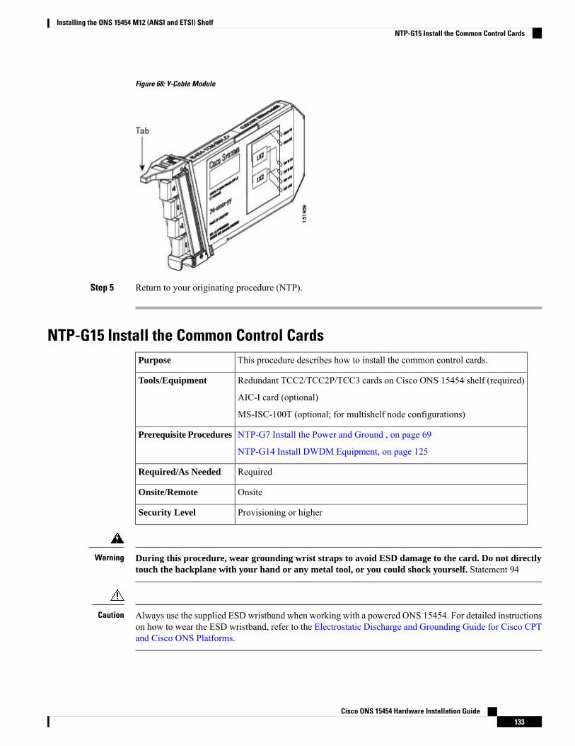
Figure 68: Y-Cable Module
Step 5 Return to your originating procedure (NTP).
NTP-G15 Install the Common Control CardsThis procedure describes how to install the common control cards.Purpose
Redundant TCC2/TCC2P/TCC3 cards on Cisco ONS 15454 shelf (required)
AIC-I card (optional)
MS-ISC-100T (optional; for multishelf node configurations)
Tools/Equipment
NTP-G7 Install the Power and Ground , on page 69
NTP-G14 Install DWDM Equipment, on page 125
Prerequisite Procedures
RequiredRequired/As Needed
OnsiteOnsite/Remote
Provisioning or higherSecurity Level
During this procedure, wear grounding wrist straps to avoid ESD damage to the card. Do not directlytouch the backplane with your hand or any metal tool, or you could shock yourself. Statement 94
Warning
Always use the supplied ESD wristband when working with a powered ONS 15454. For detailed instructionson how to wear the ESD wristband, refer to the Electrostatic Discharge and Grounding Guide for Cisco CPTand Cisco ONS Platforms.
Caution
Cisco ONS 15454 Hardware Installation Guide133
Installing the ONS 15454 M12 (ANSI and ETSI) ShelfNTP-G15 Install the Common Control Cards
If protective clips are installed on the backplane connectors of the cards, remove the clips before installingthe cards.
Note
If you install a card incorrectly, the FAIL LED flashes continuously.Note
Procedure
Step 1 (Cisco ONS 15454 only) Complete the DLP-G33 Install the TCC2, TCC2P, or TCC3 Card , on page 134.
If you install the wrong card in a slot, see the NTP-G107 Remove Permanently or Remove andReplace DWDM Cards procedure.
Note
Step 2 (Cisco ONS 15454 only) Complete the DLP-G34 Install the AIC-I Card, on page 137, if necessary.Step 3 (Cisco ONS 15454 only) Complete the DLP-G309 Install the MS-ISC-100T Card , on page 138, if necessary.
Stop. You have completed this procedure.
DLP-G33 Install the TCC2, TCC2P, or TCC3 CardThis task installs redundant TCC2/TCC2P/TCC3 cards. The first card you installin the ONS 15454 must be a TCC2/TCC2P/TCC3 card, and it must initializebefore you install any cross-connect or traffic cards. Cross-connect cards are onlyrequired in hybrid nodes.
Purpose
Two TCC2/TCC2P/TCC3 cardsTools/Equipment
NonePrerequisite Procedures
RequiredRequired/As Needed
OnsiteOnsite/Remote
NoneSecurity Level
Do not remove a TCC2/TCC2P/TCC3 card during the software transfer process, which is indicated by alternateflashing FAIL and ACT/STBY LEDs. Removing a TCC2/TCC2P/TCC3 during the software transfer processwill corrupt the system memory.
Caution
Allow each card to boot completely before installing the next card.Note
Cisco ONS 15454 Hardware Installation Guide134
Installing the ONS 15454 M12 (ANSI and ETSI) ShelfDLP-G33 Install the TCC2, TCC2P, or TCC3 Card
Procedure
Step 1 Open the latches/ejectors of the first TCC2/TCC2P/TCC3 card that you will install.Step 2 Use the latches/ejectors to firmly slide the card along the guide rails until the card plugs into the receptacle
at the back of the slot (Slot 7 or 11).
In Step 4, you will be instructed to watch the LED activity (sequence) on the front of theTCC2/TCC2P/TCC3 card. This activity begins immediately after you close the latches in Step 3.
Note
Step 3 Verify that the card is inserted correctly and close the latches/ejectors on the card.
It is possible to close the latches/ejectors when the card is not completely plugged into the backpanel of the shelf. Ensure that you cannot insert the card any farther.
Note
If you insert a card into a slot provisioned for a different card, all LEDs turn off.
Step 4 Verify the LED activity on the TCC2/TCC2P/TCC3 cards as appropriate.a) For the TCC2 card:
• All LEDs turn on briefly. The red FAIL LED and the yellow ACT/STBY LED turn on for about 15seconds. (For TCC3 card it takes around 20 to 25 seconds)
• The red FAIL LED and the green ACT/STBY LED turn on for about 40 seconds.• The red FAIL LED blinks for about 15 seconds.• The red FAIL LED turns on for about 15 seconds. All LEDs turn on for about 3 seconds beforeturning off for about 3 seconds.
• Both green PWR LEDs turn on for 10 seconds. The PWR LEDs then turn red for 2 to 3 minutesbefore going to steady green.
• While the PWR LEDs are red for two to three minutes, the ACT/STBY turn on.• The boot-up process is complete when the PWR LEDs turn green and the ACT/STBY remains on.(The ACT/STBY LED will be green if this is the first TCC2 card installed, and amber if this is thesecond TCC2 card installed.)
It might take up to four minutes for the A and B power alarms to clear.Note
Alarm LEDs might be on; disregard alarm LEDs until you are logged into CTC and can viewthe Alarms tab.
Note
If you are logged into CTC, the SFTWDOWN alarm might appear as many as two times whilethe TCC2 card initializes. The alarm should clear after the card completely boots.
Note
If the FAIL LED is on continuously, see the tip in Step 8 about the TCC2 card automatic upload.Note
b) For the TCC2P card:
• All LEDs turn on briefly. The red FAIL LED, the yellow ACT/STBY LED, the green SYNC LED,and the green ACO LED turn on for about 15 seconds.
• The red FAIL LED and the green ACT/STBY LED turn on for about 30 seconds.• The red FAIL LED blinks for about 3 seconds.• The red FAIL LED turns on for about 15 seconds.• The red FAIL LED blinks for about 10 seconds and then becomes solid.• All LEDs (including the CRIT, MAJ, MIN, REM, SYNC, and ACO LEDs) blink once and turn offfor about 5 seconds.
Cisco ONS 15454 Hardware Installation Guide135
Installing the ONS 15454 M12 (ANSI and ETSI) ShelfDLP-G33 Install the TCC2, TCC2P, or TCC3 Card
• Both green PWR LEDs turn on for 10 seconds. The PWR LEDs then turn red for 2 to 3 minutesbefore going to steady green. During this time, the ACT/STBY, MJ, and MN LEDs might turn on,followed by the SNYC LED briefly.
• The boot-up process is complete when the PWRLEDs turn green and the yellowACT/STBY remainson. (The ACT/STBY LED will be green if this is the first TCC2P card installed, and yellow if thisis the second TCC2P card installed.)
It might take up to three minutes for the A and B power alarms to clear.Note
Alarm LEDs might be on; disregard alarm LEDs until you are logged into CTC and can viewthe Alarms tab.
Note
If you are logged into CTC, the SFTWDOWN alarm might appear as many as two times whilethe TCC2P card initializes. The alarm should clear after the card completely boots.
Note
If the FAIL LED is on continuously, see the tip in Step 8 about the TCC2P card automaticupload.
Note
c) For the TCC3 card:
• All LEDs turn on briefly. The red FAIL LED, the yellow ACT/STBY LED, the green SYNC LED,and the green ACO LED turn on for about 25 seconds.
• The red FAIL LED and the green ACT/STBY LED turn on for about 15 seconds.• The red FAIL LED blinks for about 3 seconds.• The red FAIL LED turns on for about 60 seconds.• The red FAIL LED blinks for about 15 seconds and then becomes solid (the LED is turned on forabout 20 seconds).
• All LEDs (including the CRIT, MAJ, MIN, REM, SYNC, and ACO LEDs) blink once and turn offfor about 5 seconds.
• Both green PWR LEDs turn on for 10 seconds. The PWR LEDs then turn red for 2 to 3 minutesbefore going to steady green. During this time, the ACT/STBY, MJ, and MN LEDs might turn on,followed by the SNYC LED briefly.
• The boot-up process is complete when the PWRLEDs turn green and the yellowACT/STBY remainson. (The ACT/STBY LED will be green if this is the first TCC3 card installed, and yellow if this isthe second TCC3 card installed.)
It might take up to three minutes for the A and B power alarms to clear.Note
Alarm LEDs might be on; disregard alarm LEDs until you are logged into CTC and can viewthe Alarms tab.
Note
If you are logged into CTC, the SFTWDOWN alarm might appear as many as two times whilethe TCC3 card initializes. The alarm should clear after the card completely boots.
Note
If the FAIL LED is on continuously, see the tip in Step 8 about the TCC3 card automatic upload.Note
Step 5 Verify that the ACT/STBY LED is green if this is the first powered-up TCC2/TCC2P/TCC3 card installed,or yellow for standby if this is the second powered-up TCC2/TCC2P/TCC3. The IP address, temperature ofthe node, and time of day appear on the LCD. The default time and date is 12:00 AM, January 1, 1970.
Step 6 The LCD cycles through the IP address (the default is 192.1.0.2), node name, and software version. Verifythat the correct software version is shown on the LCD. The software text string indicates the node type (SDHor SONET) and software release. (For example: SDH 09.20-05L-20.10 indicates it is an SDH software load,Release 9.2. The numbers following the release number do not have any significance.)
Cisco ONS 15454 Hardware Installation Guide136
Installing the ONS 15454 M12 (ANSI and ETSI) ShelfDLP-G33 Install the TCC2, TCC2P, or TCC3 Card
Step 7 If the LCD shows the correct software version, continue with Step 8. If the LCD does not show the correctsoftware version, refer to your next level of technical support, upgrade the software, or remove theTCC2/TCC2P/TCC3 card and install a replacement card.
Refer to the release-specific software upgrade document to replace the software. To replace theTCC2/TCC2P/TCC3 card, refer to the Cisco ONS 15454 DWDM Troubleshooting Guide.
Step 8 Repeat Steps 1 through 7 for the redundant TCC2/TCC2P/TCC3 card. If both TCC2/TCC2P/TCC3 cards arealready installed, proceed to Step 9.
If you install a standby TCC2/TCC2P/TCC3 card that has a different software version than theactive TCC2/TCC2P/TCC3 card, the newly installed standby TCC2/TCC2P/TCC3 card automaticallycopies the software version from the active TCC2/TCC2P/TCC3 card. You do not need to doanything in this situation. However, the loading TCC2/TCC2P/TCC3 card does not boot up in thenormal manner.When the standby card is first inserted, the LEDs followmost of the normal boot-upsequence. However, after the red FAIL LED turns on for about 5 seconds, the FAIL LED and theACT/STBY LED begin to flash alternately for up to 30 minutes while the new software loads ontothe active TCC2/TCC2P/TCC3 card. After loading the new software, the upgradedTCC2/TCC2P/TCC3 card’s LEDs repeat the appropriate bootup sequence, and the amberACT/STBYLED turns on.
Tip
If you insert a card into a slot provisioned for a different card, all LEDs turn off.Note
Alarm LEDs might be on; disregard alarm LEDs until you are logged into CTC and can view theAlarms tab.
Note
Step 9 Return to your originating procedure (NTP).
DLP-G34 Install the AIC-I CardThis task installs the AIC-I card. The AIC-I card provides connections for externalalarms and controls (environmental alarms).
Purpose
AIC-I cardTools/Equipment
DLP-G33 Install the TCC2, TCC2P, or TCC3 Card , on page 134Prerequisite Procedures
As neededRequired/As Needed
OnsiteOnsite/Remote
NoneSecurity Level
When installing cards, allow each card to boot completely before installing the next card.Note
Procedure
Step 1 Open the latches/ejectors on the card.
Cisco ONS 15454 Hardware Installation Guide137
Installing the ONS 15454 M12 (ANSI and ETSI) ShelfDLP-G34 Install the AIC-I Card
Step 2 Use the latches/ejectors to firmly slide the card along the guide rails in Slot 9 until the card plugs into thereceptacle at the back of the slot.
Step 3 Verify that the card is inserted correctly and close the latches/ejectors on the card.
It is possible to close the latches/ejectors when the card is not completely plugged into the backplane.Ensure that you cannot insert the card any further.
Note
Step 4 Verify the following:
• The red FAIL LED blinks for up to 10 seconds.
If the red FAIL LED does not turn on, check the power.Note
• The PWR A and PWR B LEDs become red, the two INPUT/OUTPUT LEDs become amber, and theACT LED turns green for approximately 5 seconds.
• The PWRA and PWRB LEDs turn green, the INPUT/OUTPUT LEDs turn off, and the green ACT LEDremains on.
It might take up to 3 minutes for the PWR A and PWR B LEDs to update.Note
If you insert a card into a slot provisioned for a different card, no LEDs turn on.Note
If the red FAIL LED is on continuously or the LEDs act erratically, the card is not installed properly.Remove the card and repeat all the steps.
Note
Step 5 Return to your originating procedure (NTP).
DLP-G309 Install the MS-ISC-100T CardThis task installs redundant MS-ISC-100T cards. The MS-ISC-100T card isrequired for a multishelf node configuration. It provides LAN redundancy on thenode controller shelf. An alternative to using the MS-ISC-100T card is the CiscoCatalyst 2950, although Cisco recommends using the MS-ISC-100T. For moreinformation on the Catalyst 2950 installation, refer to the Catalyst 2950 productdocumentation.
Purpose
MS-ISC-100T card (2)Tools/Equipment
DLP-G33 Install the TCC2, TCC2P, or TCC3 Card , on page 134Prerequisite Procedures
As neededRequired/As Needed
OnsiteOnsite/Remote
NoneSecurity Level
When installing cards, allow each card to boot completely before installing the next card.Note
Cisco ONS 15454 Hardware Installation Guide138
Installing the ONS 15454 M12 (ANSI and ETSI) ShelfDLP-G309 Install the MS-ISC-100T Card
The MS-ISC-100T is not supported in a subtended shelf.Note
Procedure
Step 1 Open the latches/ejectors on the card.Step 2 Use the latches/ejectors to firmly slide the card along the guide rails into the appropriate slot in the node
controller shelf until the card plugs into the receptacle at the back of the slot. The card can be installed in anyslot from Slot 1 to 6 or 12 to 17. Cisco recommends that you install the MS-ISC-100T cards in Slot 6 and Slot12.
Step 3 Verify that the card is inserted correctly and close the latches/ejectors on the card.
It is possible to close the latches/ejectors when the card is not completely plugged into the backplane.Ensure that you cannot insert the card any further.
Note
Step 4 Verify the LED activity:
• The red FAIL LED blinks for 35 to 45 seconds.
• The red FAIL LED turns on for 15 to 20 seconds.
• The red FAIL LED blinks for approximately 3 minutes.
• The red FAIL LED turns on for approximately 6 minutes.
• The green ACT or ACT/STBY LED turns on. The SF LED can persist until all card ports connect totheir far end counterparts and a signal is present.
If the red FAIL LED does not turn on, check the power.Note
If you insert a card into a slot provisioned for a different card, all LEDs turn off.Note
Step 5 Repeat all the steps for the redundant MS-ISC-100T card.Step 6 Return to your originating procedure (NTP).
Multishelf ManagementThe maximum number of shelves that can be aggregated under a single IP address is 30 shelves. It isrecommended to use TCC3 card in the node controller if the number of subtended shelves exceed 12 shelves.
Multishelf LAN TopologiesThe following sections describe various multishelf LAN topologies in Cisco ONS 15454 shelves.
Cisco ONS 15454 Hardware Installation Guide139
Installing the ONS 15454 M12 (ANSI and ETSI) ShelfMultishelf Management
ONS 15454 Multishelf Node and Subtending ShelvesWhen ONS 15454 node is used as node controller, upto 29 shelves can be subtended using four 24-port CiscoCatalyst 3560 switch or two 48-port Cisco Catalyst 3560 switch. Usage of TCC3 card as the node controlleris recommended if the number of subtended shelves is more than 12 shelves. This topology supports both thenon-secure and secure mode configuration.
ONS 15454 Multishelf Node and Subtending Shelves—Upgrade
Scenario 1: When ONS 15454 is connected to MS-ISC-100T card:
When an ONS 15454 node is connected to an MS-ISC-100T card, connect Port 1 of the Cisco Catalyst 3560switch to Port 8 of theMS-ISC-100T card to upgrade the number of shelves.When you connect Cisco Catalyst3560 switch to theMS-ISC-100T card, disconnect the shelves subtended toMS-ISC-100T card and re-connectthem to Cisco Catalyst 3560 switch. Usage of TCC3 card as the node controller is recommended if the numberof subtended shelves is more than 12 shelves. This topology supports both the non-secure and secure modeconfiguration.
Scenario 2: When ONS 15454 node is connected to Cisco Catalyst 2950 switch:
When an ONS 15454 node is connected to a Cisco Catalyst 2950 switch, subtend the Cisco Catalyst 3560switch to Cisco Catalyst 2950 switch to upgrade the number of shelves. Assign VLAN ID as VLANint toPort 21 of the Cisco Catalyst 2950 switch and connect to Port 1 of the Cisco Catalyst 3560 switch. Thistopology supports both the non-secure and secure mode configuration.
ONS 15454 Multishelf Node Controller, ONS 15454 M6 and ONS 15454 Subtending Shelves
When an ONS 15454 is used as the node controller, a mix of ONS 15454 and ONS 15454 M6 shelves can besubtended through the Cisco Catalyst 3560 switch connected to the node controller or the MS-ISC-100T cardconnected to the node controller. In this topology, ONS 15454 M6 shelves can be diasy chained. Usage ofTCC3 card as the node controller is recommended if the number of subtended shelves is more than 12 shelves.This topology supports both the non-secure and secure mode configuration.
The ONS 15454 multishelf node controller cannot be converted to the subtended shelf controller using theLCD. Hence, use CTC to perform the conversion.
NTP-G301 Connect the ONS 15454 Multishelf Node andSubtending Shelves to an MS-ISC-100T Card
Use this procedure to connect a ONS 15454 multishelf node and subtendingshelves to two MS-ISC-100T cards.
Purpose
5.9 in. (0.15 m) CAT-5 LAN cable (2)
19.69 in. (0.5 m) CAT-5 LAN cable (1)
Cross-over (CAT-5) LAN cables (2 for each subtending shelf)
84 in. (2.13 m) EAP cables (2)
Tools/Equipment
Cisco ONS 15454 Hardware Installation Guide140
Installing the ONS 15454 M12 (ANSI and ETSI) ShelfONS 15454 Multishelf Node and Subtending Shelves
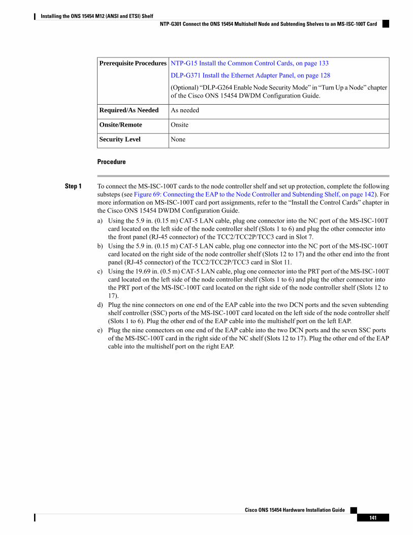
NTP-G15 Install the Common Control Cards, on page 133
DLP-G371 Install the Ethernet Adapter Panel, on page 128
(Optional) “DLP-G264 Enable Node SecurityMode” in “Turn Up aNode” chapterof the Cisco ONS 15454 DWDM Configuration Guide.
Prerequisite Procedures
As neededRequired/As Needed
OnsiteOnsite/Remote
NoneSecurity Level
Procedure
Step 1 To connect the MS-ISC-100T cards to the node controller shelf and set up protection, complete the followingsubsteps (see Figure 69: Connecting the EAP to the Node Controller and Subtending Shelf, on page 142). Formore information on MS-ISC-100T card port assignments, refer to the “Install the Control Cards” chapter inthe Cisco ONS 15454 DWDM Configuration Guide.a) Using the 5.9 in. (0.15 m) CAT-5 LAN cable, plug one connector into the NC port of the MS-ISC-100T
card located on the left side of the node controller shelf (Slots 1 to 6) and plug the other connector intothe front panel (RJ-45 connector) of the TCC2/TCC2P/TCC3 card in Slot 7.
b) Using the 5.9 in. (0.15 m) CAT-5 LAN cable, plug one connector into the NC port of the MS-ISC-100Tcard located on the right side of the node controller shelf (Slots 12 to 17) and the other end into the frontpanel (RJ-45 connector) of the TCC2/TCC2P/TCC3 card in Slot 11.
c) Using the 19.69 in. (0.5 m) CAT-5 LAN cable, plug one connector into the PRT port of the MS-ISC-100Tcard located on the left side of the node controller shelf (Slots 1 to 6) and plug the other connector intothe PRT port of the MS-ISC-100T card located on the right side of the node controller shelf (Slots 12 to17).
d) Plug the nine connectors on one end of the EAP cable into the two DCN ports and the seven subtendingshelf controller (SSC) ports of the MS-ISC-100T card located on the left side of the node controller shelf(Slots 1 to 6). Plug the other end of the EAP cable into the multishelf port on the left EAP.
e) Plug the nine connectors on one end of the EAP cable into the two DCN ports and the seven SSC portsof the MS-ISC-100T card in the right side of the NC shelf (Slots 12 to 17). Plug the other end of the EAPcable into the multishelf port on the right EAP.
Cisco ONS 15454 Hardware Installation Guide141
Installing the ONS 15454 M12 (ANSI and ETSI) ShelfNTP-G301 Connect the ONS 15454 Multishelf Node and Subtending Shelves to an MS-ISC-100T Card
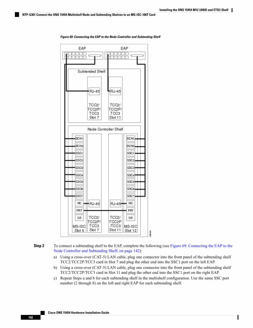
Figure 69: Connecting the EAP to the Node Controller and Subtending Shelf
Step 2 To connect a subtending shelf to the EAP, complete the following (see Figure 69: Connecting the EAP to theNode Controller and Subtending Shelf, on page 142):a) Using a cross-over (CAT-5) LAN cable, plug one connector into the front panel of the subtending shelf
TCC2/TCC2P/TCC3 card in Slot 7 and plug the other end into the SSC1 port on the left EAP.b) Using a cross-over (CAT-5) LAN cable, plug one connector into the front panel of the subtending shelf
TCC2/TCC2P/TCC3 card in Slot 11 and plug the other end into the SSC1 port on the right EAP.c) Repeat Steps a and b for each subtending shelf in the multishelf configuration. Use the same SSC port
number (2 through 8) on the left and right EAP for each subtending shelf.
Cisco ONS 15454 Hardware Installation Guide142
Installing the ONS 15454 M12 (ANSI and ETSI) ShelfNTP-G301 Connect the ONS 15454 Multishelf Node and Subtending Shelves to an MS-ISC-100T Card
Stop. You have completed this procedure.
NTP-G304 Configure the MS-ISC-100T Card for a ONS 15454Multishelf Node for Non-Default Public and Private VLAN IDs
Use this procedure to configure the MS-ISC-100T Card for a multi-shelf nodefor non-default public and private VLAN IDs.
Purpose
VoltmeterTools/Equipment
Applicable procedures in Installing the ONS 15454M12 (ANSI and ETSI) Shelf,on page 25
Prerequisite Procedures
RequiredRequired/As Needed
OnsiteOnsite/Remote
NoneSecurity Level
Procedure
Step 1 At the Cisco IOS command line interface (CLI) for the MS-ISC-100T card, enter the following spanning treecommands:
Example:
Router(config)# bridge public VLAN ID protocol rstpRouter(config)# bridge public VLAN ID forward-time 5Router(config)# bridge public VLAN ID max-age 10Router(config)# bridge private VLAN ID protocol rstpRouter(config)# bridge private VLAN ID forward-time 5Router(config)# bridge private VLAN ID max-age 10
Step 2 Enter the following commands to configure the ports DCN 1 and DCN 2:
Example:
(Router(config)# interface FastEthernet0(Router(config-if)# no ip address(Router(config-if)# no ip route-cache(Router(config-if)# bridge-group public VLAN ID
(Router(config)# interface FastEthernet1(Router(config-if)# no ip address(Router(config-if)# no ip route-cache(Router(config-if)# bridge-group public VLAN ID
Cisco ONS 15454 Hardware Installation Guide143
Installing the ONS 15454 M12 (ANSI and ETSI) ShelfNTP-G304 Configure the MS-ISC-100T Card for a ONS 15454 Multishelf Node for Non-Default Public and Private VLAN IDs

Step 3 Enter the following commands to configure ports SSC 1 through SSC 7. Replace port with the port number(2 to 8) and repeat for each port.
Example:
(Router(config)#interface FastEthernet port
(Router(config-if)# no ip address(Router(config-if)# no ip route-cache(Router(config-if)# bridge-group private VLAN ID
Step 4 Enter the following commands to configure port NC (port 9):
Example:
Router(config)# interface FastEthernet9Router(config-if) no ip address(Router(config-if) no ip route-cacheRouter(config)# interface FastEthernet9.2(Router(config-if)dot1Q public VLAN ID native(Router(config-if) no ip route-cache(Router(config-if) no snmp trap link-status(Router(config-if)bridge-group public VLAN ID
Router(config)# interface FastEthernet9.2(Router(config-if) encapsulation dot1Q private VLAN ID
(Router(config-if) no ip route-cache(Router(config-if) no snmp trap link-status(Router(config-if)bridge-group private VLAN ID
Step 5 Enter the following commands to configure port PRT (port 10):
Example:
Router(config)# interface FastEthernet10(Router(config-if)# no ip address(Router(config-if)# no ip route-cacheRouter(config)# interface FastEthernet10.1(Router(config-if)encapsulation dot1Q public VLAN ID native(Router(config-if)# no ip route-cache(Router(config-if)# no snmp trap link-status(Router(config-if)bridge-group public VLAN ID
(Router(config-if)# bridge-group public VLAN ID priority 0!Router(config)# interface FastEthernet10.2(Router(config-if)encapsulation dot1Q private VLAN ID
(Router(config-if)# no ip route-cache(Router(config-if)# no snmp trap link-status(Router(config-if)# bridge-group private VLAN ID
(Router(config-if)# bridge-group private VLAN ID priority 0Router(config)# interface FastEthernet11Router(config)# no ip addressRouter(config)# no ip route-cacheRouter(config)# shutdown
Cisco ONS 15454 Hardware Installation Guide144
Installing the ONS 15454 M12 (ANSI and ETSI) ShelfNTP-G304 Configure the MS-ISC-100T Card for a ONS 15454 Multishelf Node for Non-Default Public and Private VLAN IDs
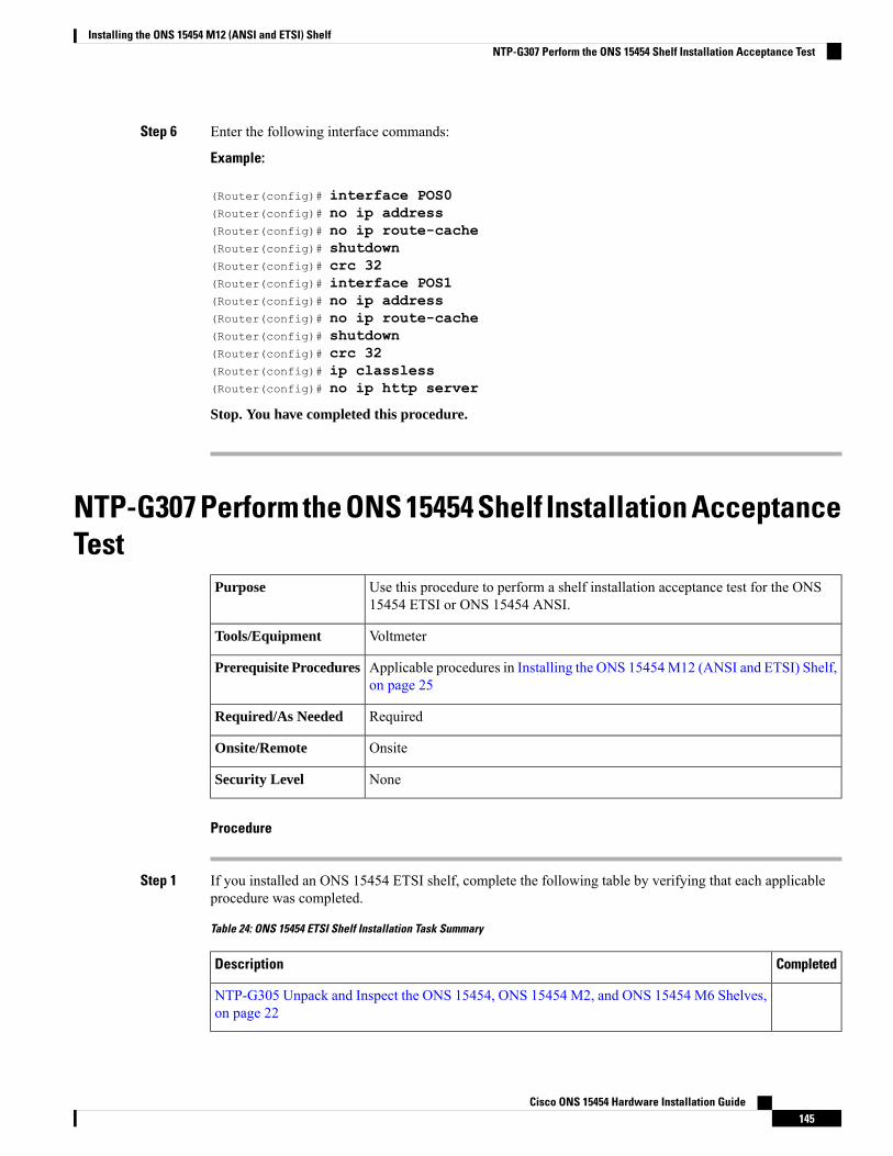
Step 6 Enter the following interface commands:
Example:
(Router(config)# interface POS0(Router(config)# no ip address(Router(config)# no ip route-cache(Router(config)# shutdown(Router(config)# crc 32(Router(config)# interface POS1(Router(config)# no ip address(Router(config)# no ip route-cache(Router(config)# shutdown(Router(config)# crc 32(Router(config)# ip classless(Router(config)# no ip http server
Stop. You have completed this procedure.
NTP-G307 Perform the ONS 15454 Shelf Installation AcceptanceTest
Use this procedure to perform a shelf installation acceptance test for the ONS15454 ETSI or ONS 15454 ANSI.
Purpose
VoltmeterTools/Equipment
Applicable procedures in Installing the ONS 15454M12 (ANSI and ETSI) Shelf,on page 25
Prerequisite Procedures
RequiredRequired/As Needed
OnsiteOnsite/Remote
NoneSecurity Level
Procedure
Step 1 If you installed an ONS 15454 ETSI shelf, complete the following table by verifying that each applicableprocedure was completed.
Table 24: ONS 15454 ETSI Shelf Installation Task Summary
CompletedDescription
NTP-G305 Unpack and Inspect the ONS 15454, ONS 15454 M2, and ONS 15454 M6 Shelves,on page 22
Cisco ONS 15454 Hardware Installation Guide145
Installing the ONS 15454 M12 (ANSI and ETSI) ShelfNTP-G307 Perform the ONS 15454 Shelf Installation Acceptance Test
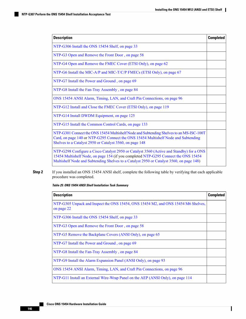
CompletedDescription
NTP-G306 Install the ONS 15454 Shelf, on page 33
NTP-G3 Open and Remove the Front Door , on page 58
NTP-G4 Open and Remove the FMEC Cover (ETSI Only), on page 62
NTP-G6 Install the MIC-A/P and MIC-T/C/P FMECs (ETSI Only), on page 67
NTP-G7 Install the Power and Ground , on page 69
NTP-G8 Install the Fan-Tray Assembly , on page 84
ONS 15454 ANSI Alarm, Timing, LAN, and Craft Pin Connections, on page 96
NTP-G12 Install and Close the FMEC Cover (ETSI Only), on page 119
NTP-G14 Install DWDM Equipment, on page 125
NTP-G15 Install the Common Control Cards, on page 133
NTP-G301Connect theONS 15454Multishelf Node and Subtending Shelves to anMS-ISC-100TCard, on page 140 or NTP-G295 Connect the ONS 15454 Multishelf Node and SubtendingShelves to a Catalyst 2950 or Catalyst 3560, on page 148
NTP-G298 Configure a Cisco Catalyst 2950 or Catalyst 3560 (Active and Standby) for a ONS15454 Multishelf Node, on page 154 (if you completed NTP-G295 Connect the ONS 15454Multishelf Node and Subtending Shelves to a Catalyst 2950 or Catalyst 3560, on page 148)
Step 2 If you installed an ONS 15454 ANSI shelf, complete the following table by verifying that each applicableprocedure was completed.
Table 25: ONS 15454 ANSI Shelf Installation Task Summary
CompletedDescription
NTP-G305 Unpack and Inspect the ONS 15454, ONS 15454 M2, and ONS 15454 M6 Shelves,on page 22
NTP-G306 Install the ONS 15454 Shelf, on page 33
NTP-G3 Open and Remove the Front Door , on page 58
NTP-G5 Remove the Backplane Covers (ANSI Only), on page 65
NTP-G7 Install the Power and Ground , on page 69
NTP-G8 Install the Fan-Tray Assembly , on page 84
NTP-G9 Install the Alarm Expansion Panel (ANSI Only), on page 93
ONS 15454 ANSI Alarm, Timing, LAN, and Craft Pin Connections, on page 96
NTP-G11 Install an External Wire-Wrap Panel on the AEP (ANSI Only), on page 114
Cisco ONS 15454 Hardware Installation Guide146
Installing the ONS 15454 M12 (ANSI and ETSI) ShelfNTP-G307 Perform the ONS 15454 Shelf Installation Acceptance Test
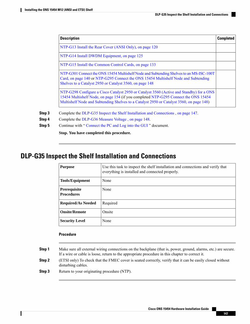
CompletedDescription
NTP-G13 Install the Rear Cover (ANSI Only), on page 120
NTP-G14 Install DWDM Equipment, on page 125
NTP-G15 Install the Common Control Cards, on page 133
NTP-G301Connect theONS 15454Multishelf Node and Subtending Shelves to anMS-ISC-100TCard, on page 140 or NTP-G295 Connect the ONS 15454 Multishelf Node and SubtendingShelves to a Catalyst 2950 or Catalyst 3560, on page 148
NTP-G298 Configure a Cisco Catalyst 2950 or Catalyst 3560 (Active and Standby) for a ONS15454 Multishelf Node, on page 154 (if you completed NTP-G295 Connect the ONS 15454Multishelf Node and Subtending Shelves to a Catalyst 2950 or Catalyst 3560, on page 148)
Step 3 Complete the DLP-G35 Inspect the Shelf Installation and Connections , on page 147.Step 4 Complete the DLP-G36 Measure Voltage , on page 148.Step 5 Continue with “ Connect the PC and Log into the GUI ” document.
Stop. You have completed this procedure.
DLP-G35 Inspect the Shelf Installation and ConnectionsUse this task to inspect the shelf installation and connections and verify thateverything is installed and connected properly.
Purpose
NoneTools/Equipment
NonePrerequisiteProcedures
RequiredRequired/As Needed
OnsiteOnsite/Remote
NoneSecurity Level
Procedure
Step 1 Make sure all external wiring connections on the backplane (that is, power, ground, alarms, etc.) are secure.If a wire or cable is loose, return to the appropriate procedure in this chapter to correct it.
Step 2 (ETSI only) To check that the FMEC cover is seated correctly, verify that it can be easily closed withoutdisturbing cables.
Step 3 Return to your originating procedure (NTP).
Cisco ONS 15454 Hardware Installation Guide147
Installing the ONS 15454 M12 (ANSI and ETSI) ShelfDLP-G35 Inspect the Shelf Installation and Connections
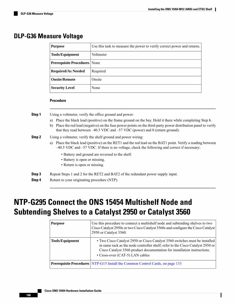
DLP-G36 Measure VoltageUse this task to measure the power to verify correct power and returns.Purpose
VoltmeterTools/Equipment
NonePrerequisite Procedures
RequiredRequired/As Needed
OnsiteOnsite/Remote
NoneSecurity Level
Procedure
Step 1 Using a voltmeter, verify the office ground and power:a) Place the black lead (positive) on the frame ground on the bay. Hold it there while completing Step b.b) Place the red lead (negative) on the fuse power points on the third-party power distribution panel to verify
that they read between –40.5 VDC and –57 VDC (power) and 0 (return ground).
Step 2 Using a voltmeter, verify the shelf ground and power wiring:a) Place the black lead (positive) on the RET1 and the red lead on the BAT1 point. Verify a reading between
–40.5 VDC and –57 VDC. If there is no voltage, check the following and correct if necessary:
• Battery and ground are reversed to the shelf.• Battery is open or missing.• Return is open or missing.
Step 3 Repeat Steps 1 and 2 for the RET2 and BAT2 of the redundant power supply input.Step 4 Return to your originating procedure (NTP).
NTP-G295 Connect the ONS 15454 Multishelf Node andSubtending Shelves to a Catalyst 2950 or Catalyst 3560
Use this procedure to connect a multishelf node and subtending shelves to twoCisco Catalyst 2950s or two Cisco Catalyst 3560s and configure the Cisco Catalyst2950 or Catalyst 3560.
Purpose
• Two Cisco Catalyst 2950 or Cisco Catalyst 3560 switches must be installedin same rack as the node controller shelf; refer to the Cisco Catalyst 2950 orCisco Catalyst 3560 product documentation for installation instructions.
• Cross-over (CAT-5) LAN cables
Tools/Equipment
NTP-G15 Install the Common Control Cards, on page 133Prerequisite Procedures
Cisco ONS 15454 Hardware Installation Guide148
Installing the ONS 15454 M12 (ANSI and ETSI) ShelfDLP-G36 Measure Voltage
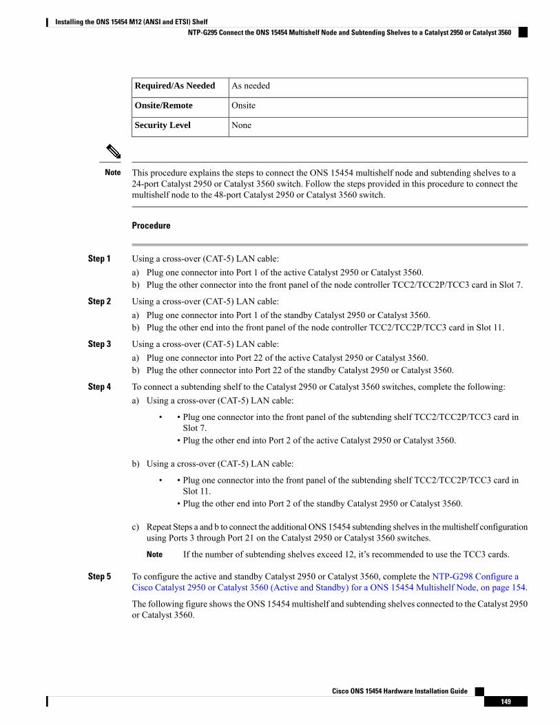
As neededRequired/As Needed
OnsiteOnsite/Remote
NoneSecurity Level
This procedure explains the steps to connect the ONS 15454 multishelf node and subtending shelves to a24-port Catalyst 2950 or Catalyst 3560 switch. Follow the steps provided in this procedure to connect themultishelf node to the 48-port Catalyst 2950 or Catalyst 3560 switch.
Note
Procedure
Step 1 Using a cross-over (CAT-5) LAN cable:a) Plug one connector into Port 1 of the active Catalyst 2950 or Catalyst 3560.b) Plug the other connector into the front panel of the node controller TCC2/TCC2P/TCC3 card in Slot 7.
Step 2 Using a cross-over (CAT-5) LAN cable:a) Plug one connector into Port 1 of the standby Catalyst 2950 or Catalyst 3560.b) Plug the other end into the front panel of the node controller TCC2/TCC2P/TCC3 card in Slot 11.
Step 3 Using a cross-over (CAT-5) LAN cable:a) Plug one connector into Port 22 of the active Catalyst 2950 or Catalyst 3560.b) Plug the other connector into Port 22 of the standby Catalyst 2950 or Catalyst 3560.
Step 4 To connect a subtending shelf to the Catalyst 2950 or Catalyst 3560 switches, complete the following:a) Using a cross-over (CAT-5) LAN cable:
• • Plug one connector into the front panel of the subtending shelf TCC2/TCC2P/TCC3 card inSlot 7.
• Plug the other end into Port 2 of the active Catalyst 2950 or Catalyst 3560.
b) Using a cross-over (CAT-5) LAN cable:
• • Plug one connector into the front panel of the subtending shelf TCC2/TCC2P/TCC3 card inSlot 11.
• Plug the other end into Port 2 of the standby Catalyst 2950 or Catalyst 3560.
c) Repeat Steps a and b to connect the additional ONS 15454 subtending shelves in themultishelf configurationusing Ports 3 through Port 21 on the Catalyst 2950 or Catalyst 3560 switches.
If the number of subtending shelves exceed 12, it’s recommended to use the TCC3 cards.Note
Step 5 To configure the active and standby Catalyst 2950 or Catalyst 3560, complete the NTP-G298 Configure aCisco Catalyst 2950 or Catalyst 3560 (Active and Standby) for a ONS 15454 Multishelf Node, on page 154.
The following figure shows the ONS 15454 multishelf and subtending shelves connected to the Catalyst 2950or Catalyst 3560.
Cisco ONS 15454 Hardware Installation Guide149
Installing the ONS 15454 M12 (ANSI and ETSI) ShelfNTP-G295 Connect the ONS 15454 Multishelf Node and Subtending Shelves to a Catalyst 2950 or Catalyst 3560
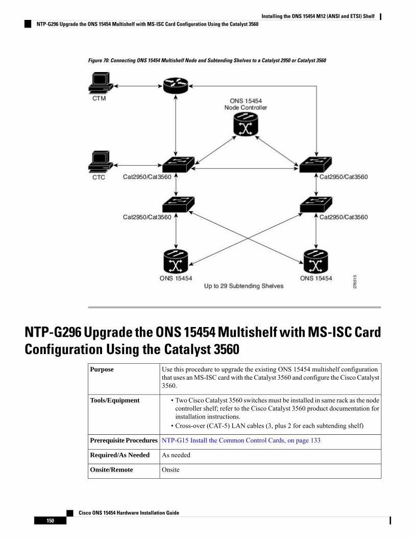
Figure 70: Connecting ONS 15454 Multishelf Node and Subtending Shelves to a Catalyst 2950 or Catalyst 3560
NTP-G296 Upgrade the ONS 15454 Multishelf with MS-ISC CardConfiguration Using the Catalyst 3560
Use this procedure to upgrade the existing ONS 15454 multishelf configurationthat uses anMS-ISC card with the Catalyst 3560 and configure the Cisco Catalyst3560.
Purpose
• Two Cisco Catalyst 3560 switches must be installed in same rack as the nodecontroller shelf; refer to the Cisco Catalyst 3560 product documentation forinstallation instructions.
• Cross-over (CAT-5) LAN cables (3, plus 2 for each subtending shelf)
Tools/Equipment
NTP-G15 Install the Common Control Cards, on page 133Prerequisite Procedures
As neededRequired/As Needed
OnsiteOnsite/Remote
Cisco ONS 15454 Hardware Installation Guide150
Installing the ONS 15454 M12 (ANSI and ETSI) ShelfNTP-G296 Upgrade the ONS 15454 Multishelf with MS-ISC Card Configuration Using the Catalyst 3560
NoneSecurity Level
Procedure
Step 1 Disconnect the ONS 15454 subtending shelf from the EAPs:a) Remove the cross-over (CAT 5) LAN cable (connecting the ONS 15454 subtending shelf) from the SSC8
port of the right EAP.b) Remove the cross-over (CAT 5) LAN cable (connecting the ONS 15454 subtending shelf) from the SSC8
port of the left EAP.
Step 2 Connect the EAPs to the Catalyst 3560:a) Using a cross-over (CAT-5) LAN cable:
• • Plug one connector to the SSC8 port of the right EAP.• Plug the other connector to Port 1 of the active Catalyst 3560.
b) Using a cross-over (CAT-5) LAN cable:
• • Plug one connector to the SSC8 port of the left EAP.• Plug the other connector to Port 1 of the standby Catalyst 3560.
Step 3 Reconnect the ONS 15454 subtending shelf disconnected in Step 1 to the Catalyst 3560 switches:a) Using a cross-over (CAT-5) LAN cable:
• • Plug one connector into the front panel of the subtending shelf TCC2/TCC2P/TCC3 card inSlot 7.
• Plug the other connector into Port 2 of the active Catalyst 3560.
b) Using a cross-over (CAT-5) LAN cable:
• • Plug one connector into the front panel of the subtending shelf TCC2/TCC2P/TCC3 card inSlot 11.
• Plug the other connector into Port 2 of the standby Catalyst 3560.
Step 4 Repeat Step 3a and 3b to connect the additional ONS 15454 subtending shelves in the multishelf configurationfrom Port 3 through Port 24 on the Catalyst 3560 switches.
Step 5 To configure the Catalyst 3560 in case of upgrade, complete the NTP-G298 Configure a Cisco Catalyst 2950or Catalyst 3560 (Active and Standby) for a ONS 15454 Multishelf Node, on page 154.
Cisco ONS 15454 Hardware Installation Guide151
Installing the ONS 15454 M12 (ANSI and ETSI) ShelfNTP-G296 Upgrade the ONS 15454 Multishelf with MS-ISC Card Configuration Using the Catalyst 3560
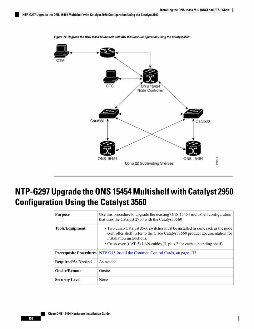
Figure 71: Upgrade the ONS 15454 Multishelf with MS-ISC Card Configuration Using the Catalyst 3560
NTP-G297 Upgrade the ONS 15454 Multishelf with Catalyst 2950Configuration Using the Catalyst 3560
Use this procedure to upgrade the existing ONS 15454 multishelf configurationthat uses the Catalyst 2950 with the Catalyst 3560
Purpose
• Two Cisco Catalyst 3560 switches must be installed in same rack as the nodecontroller shelf; refer to the Cisco Catalyst 3560 product documentation forinstallation instructions.
• Cross-over (CAT-5) LAN cables (3, plus 2 for each subtending shelf)
Tools/Equipment
NTP-G15 Install the Common Control Cards, on page 133.Prerequisite Procedures
As neededRequired/As Needed
OnsiteOnsite/Remote
NoneSecurity Level
Cisco ONS 15454 Hardware Installation Guide152
Installing the ONS 15454 M12 (ANSI and ETSI) ShelfNTP-G297 Upgrade the ONS 15454 Multishelf with Catalyst 2950 Configuration Using the Catalyst 3560

Procedure
Step 1 Disconnect the subtending shelf at Port 21 of the active and standby Catalyst 2950:a) Remove the cross-over (CAT 5) LAN cable from Port 21 of the active Catalyst 2950.b) Remove the cross-over (CAT 5) LAN cable from Port 21 of the standby Catalyst 2950.
Step 2 Connect the extended Catalyst 3560 (active and standby) to the Catalyst 2950:a) Using a cross-over (CAT-5) LAN cable:
• • Plug one connector to Port 1 of the extended Catalyst 3560 (active).• Plug the other connector to Port 21 of the active Catalyst 2950.
b) Using a cross-over (CAT-5) LAN cable:
• • Plug one connector to Port 1 of the extended Catalyst 3560 (standby).• Plug the other connector to Port 21 of the standby Catalyst 2950.
Step 3 Reconnect the ONS 15454 subtending shelf disconnected in Step 1 to the Catalyst 3560 switches:a) Using a cross-over (CAT-5) LAN cable:
• • Plug one connector into the front panel of the subtending shelf TCC2/TCC2P/TCC3 card inSlot 7.
• Plug the other connector into Port 2 of the active Catalyst 3560.
b) Using a cross-over (CAT-5) LAN cable:
• • Plug one connector into the front panel of the subtending shelf TCC2/TCC2P/TCC3 card inSlot 11.
• Plug the other connector into Port 2 of the standby Catalyst 3560.
Step 4 Repeat Step 3a and Step 3b to connect additional subtending shelves using Port 3 through Port 24 on theextended Catalysts 3560.
If the number of subtending shelves exceed four, it’s recommended to use the TCC3 cards.Note
Step 5 To configure the Catalyst 2950 in case of upgrade, complete the NTP-G298 Configure a Cisco Catalyst 2950or Catalyst 3560 (Active and Standby) for a ONS 15454 Multishelf Node, on page 154.
Step 6 To configure the Cisco Catalyst 3560, refer to the NTP-G298 Configure a Cisco Catalyst 2950 or Catalyst3560 (Active and Standby) for a ONS 15454 Multishelf Node, on page 154.
Stop. You have completed this procedure.
Cisco ONS 15454 Hardware Installation Guide153
Installing the ONS 15454 M12 (ANSI and ETSI) ShelfNTP-G297 Upgrade the ONS 15454 Multishelf with Catalyst 2950 Configuration Using the Catalyst 3560
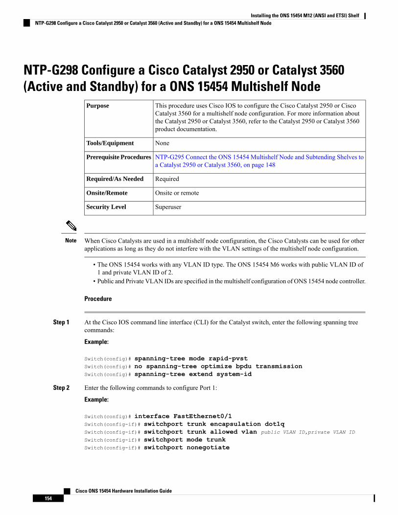
NTP-G298 Configure a Cisco Catalyst 2950 or Catalyst 3560(Active and Standby) for a ONS 15454 Multishelf Node
This procedure uses Cisco IOS to configure the Cisco Catalyst 2950 or CiscoCatalyst 3560 for a multishelf node configuration. For more information aboutthe Catalyst 2950 or Catalyst 3560, refer to the Catalyst 2950 or Catalyst 3560product documentation.
Purpose
NoneTools/Equipment
NTP-G295 Connect the ONS 15454 Multishelf Node and Subtending Shelves toa Catalyst 2950 or Catalyst 3560, on page 148
Prerequisite Procedures
RequiredRequired/As Needed
Onsite or remoteOnsite/Remote
SuperuserSecurity Level
When Cisco Catalysts are used in a multishelf node configuration, the Cisco Catalysts can be used for otherapplications as long as they do not interfere with the VLAN settings of the multishelf node configuration.
Note
• The ONS 15454 works with any VLAN ID type. The ONS 15454 M6 works with public VLAN ID of1 and private VLAN ID of 2.
• Public and Private VLAN IDs are specified in the multishelf configuration of ONS 15454 node controller.
Procedure
Step 1 At the Cisco IOS command line interface (CLI) for the Catalyst switch, enter the following spanning treecommands:
Example:
Switch(config)# spanning-tree mode rapid-pvstSwitch(config)# no spanning-tree optimize bpdu transmissionSwitch(config)# spanning-tree extend system-id
Step 2 Enter the following commands to configure Port 1:
Example:
Switch(config)# interface FastEthernet0/1Switch(config-if)# switchport trunk encapsulation dot1qSwitch(config-if)# switchport trunk allowed vlan public VLAN ID,private VLAN ID
Switch(config-if)# switchport mode trunkSwitch(config-if)# switchport nonegotiate
Cisco ONS 15454 Hardware Installation Guide154
Installing the ONS 15454 M12 (ANSI and ETSI) ShelfNTP-G298 Configure a Cisco Catalyst 2950 or Catalyst 3560 (Active and Standby) for a ONS 15454 Multishelf Node
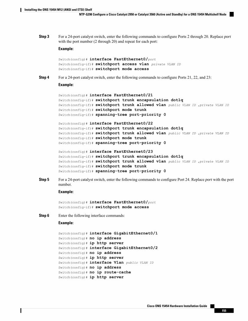
Step 3 For a 24-port catalyst switch, enter the following commands to configure Ports 2 through 20. Replace portwith the port number (2 through 20) and repeat for each port:
Example:
Switch(config)# interface FastEthernet0/portSwitch(config-if)# switchport access vlan private VLAN ID
Switch(config-if)# switchport mode access
Step 4 For a 24-port catalyst switch, enter the following commands to configure Ports 21, 22, and 23:
Example:
Switch(config)# interface FastEthernet0/21Switch(config-if)# switchport trunk encapsulation dot1qSwitch(config-if)# switchport trunk allowed vlan public VLAN ID ,private VLAN ID
Switch(config-if)# switchport mode trunkSwitch(config-if)# spanning-tree port-priority 0
Switch(config)# interface FastEthernet0/22Switch(config-if)# switchport trunk encapsulation dot1qSwitch(config-if)# switchport trunk allowed vlan public VLAN ID ,private VLAN ID
Switch(config-if)# switchport mode trunkSwitch(config-if)# spanning-tree port-priority 0
Switch(config)# interface FastEthernet0/23Switch(config-if)# switchport trunk encapsulation dot1qSwitch(config-if)# switchport trunk allowed vlan public VLAN ID ,private VLAN ID
Switch(config-if)# switchport mode trunkSwitch(config-if)# spanning-tree port-priority 0
Step 5 For a 24-port catalyst switch, enter the following commands to configure Port 24. Replace port with the portnumber.
Example:
Switch(config)# interface FastEthernet0/portSwitch(config-if)# switchport mode access
Step 6 Enter the following interface commands:
Example:
Switch(config)# interface GigabitEthernet0/1Switch(config)# no ip addressSwitch(config)# ip http serverSwitch(config)# interface GigabitEthernet0/2Switch(config)# no ip addressSwitch(config)# ip http serverSwitch(config)# interface Vlan public VLAN ID
Switch(config)# no ip addressSwitch(config)# no ip route-cacheSwitch(config)# ip http server
Cisco ONS 15454 Hardware Installation Guide155
Installing the ONS 15454 M12 (ANSI and ETSI) ShelfNTP-G298 Configure a Cisco Catalyst 2950 or Catalyst 3560 (Active and Standby) for a ONS 15454 Multishelf Node
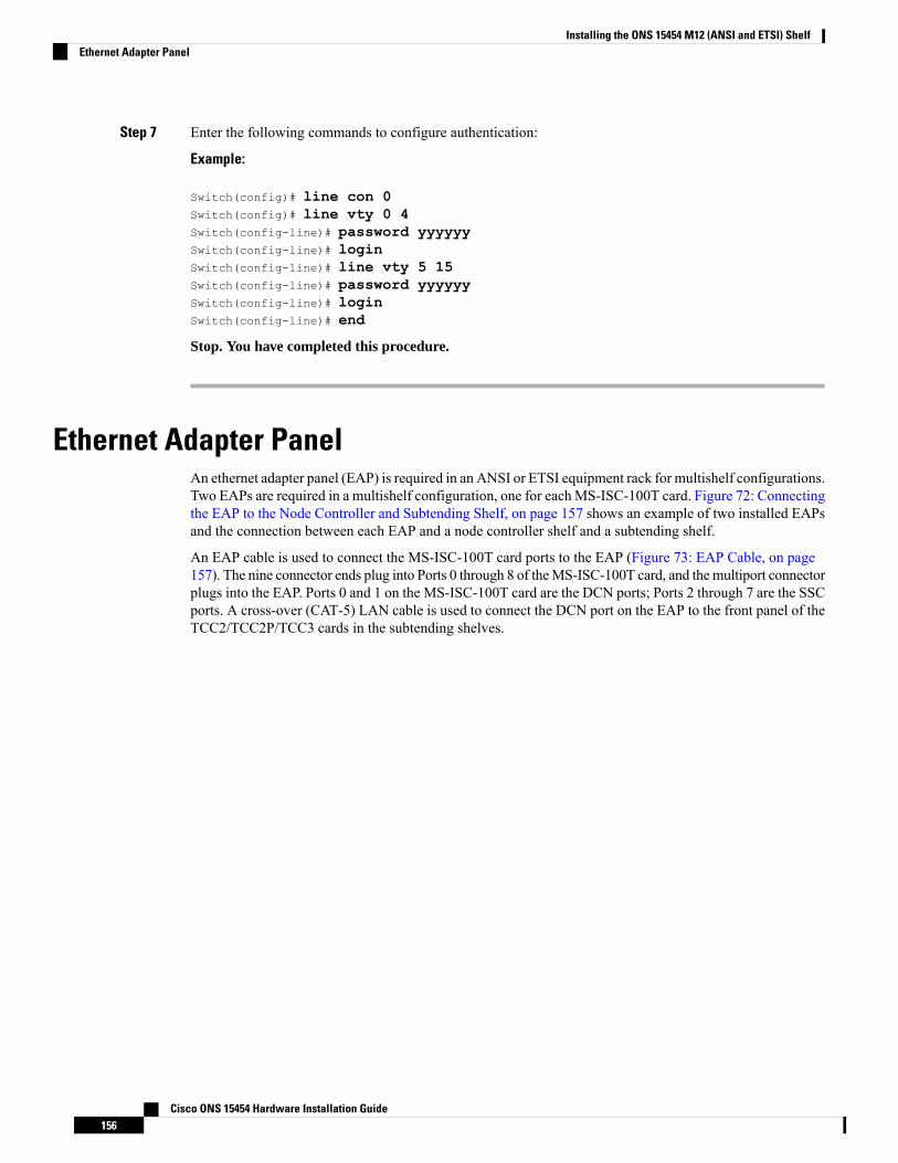
Step 7 Enter the following commands to configure authentication:
Example:
Switch(config)# line con 0Switch(config)# line vty 0 4Switch(config-line)# password yyyyyySwitch(config-line)# loginSwitch(config-line)# line vty 5 15Switch(config-line)# password yyyyyySwitch(config-line)# loginSwitch(config-line)# end
Stop. You have completed this procedure.
Ethernet Adapter PanelAn ethernet adapter panel (EAP) is required in an ANSI or ETSI equipment rack for multishelf configurations.Two EAPs are required in a multishelf configuration, one for eachMS-ISC-100T card. Figure 72: Connectingthe EAP to the Node Controller and Subtending Shelf, on page 157 shows an example of two installed EAPsand the connection between each EAP and a node controller shelf and a subtending shelf.
An EAP cable is used to connect the MS-ISC-100T card ports to the EAP (Figure 73: EAP Cable, on page157). The nine connector ends plug into Ports 0 through 8 of theMS-ISC-100T card, and themultiport connectorplugs into the EAP. Ports 0 and 1 on the MS-ISC-100T card are the DCN ports; Ports 2 through 7 are the SSCports. A cross-over (CAT-5) LAN cable is used to connect the DCN port on the EAP to the front panel of theTCC2/TCC2P/TCC3 cards in the subtending shelves.
Cisco ONS 15454 Hardware Installation Guide156
Installing the ONS 15454 M12 (ANSI and ETSI) ShelfEthernet Adapter Panel
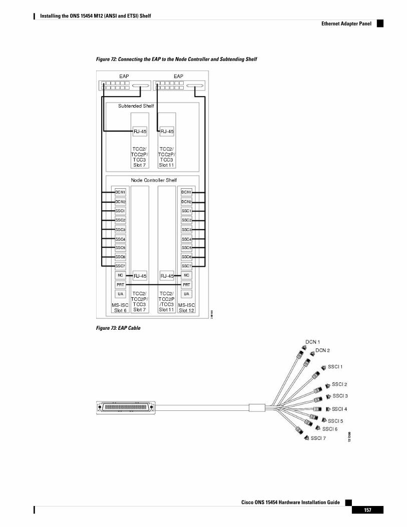
Figure 72: Connecting the EAP to the Node Controller and Subtending Shelf
Figure 73: EAP Cable
Cisco ONS 15454 Hardware Installation Guide157
Installing the ONS 15454 M12 (ANSI and ETSI) ShelfEthernet Adapter Panel
Filler and Blank CardsThe filler card (15454- FILLER) is designed to occupy empty multiservice and AIC-I slots in the Cisco ONS15454 (Slots 1 to 6, 9, and 12 to17). The filler card cannot operate in the cross-connect (XC) slots (Slots 8and 10) or TCC2/TCC2P/TCC3 slots (Slots 7 and 11). The filler card is detected by CTC.
When installed, the filler card aids in maintaining proper air flow and EMI requirements.
Do not use 15454-M-FILLER or 15454-M-T-FILLER filler cards in the Cisco ONS 15454 M12 shelf.Note
The following figure shows the card faceplate. The filler card has no card-level LED indicators.
Blank cards (15454-BLANK) can be installed in any empty slot in the shelf. CTC does not detect blank cards.
Cisco ONS 15454 Hardware Installation Guide158
Installing the ONS 15454 M12 (ANSI and ETSI) ShelfFiller and Blank Cards
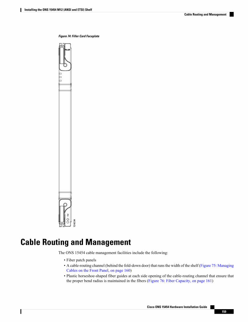
Figure 74: Filler Card Faceplate
Cable Routing and ManagementThe ONS 15454 cable management facilities include the following:
• Fiber patch panels• A cable-routing channel (behind the fold-down door) that runs the width of the shelf (Figure 75:ManagingCables on the Front Panel, on page 160)
• Plastic horseshoe-shaped fiber guides at each side opening of the cable-routing channel that ensure thatthe proper bend radius is maintained in the fibers (Figure 76: Fiber Capacity, on page 161)
Cisco ONS 15454 Hardware Installation Guide159
Installing the ONS 15454 M12 (ANSI and ETSI) ShelfCable Routing and Management
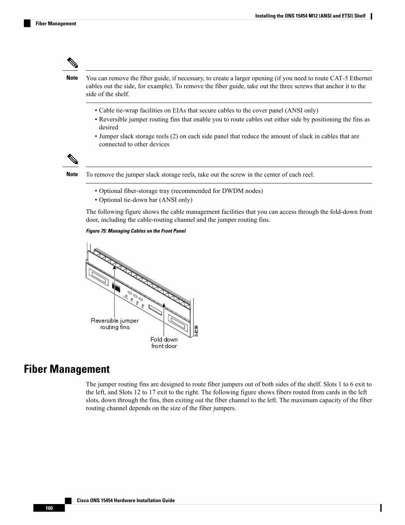
You can remove the fiber guide, if necessary, to create a larger opening (if you need to route CAT-5 Ethernetcables out the side, for example). To remove the fiber guide, take out the three screws that anchor it to theside of the shelf.
Note
• Cable tie-wrap facilities on EIAs that secure cables to the cover panel (ANSI only)• Reversible jumper routing fins that enable you to route cables out either side by positioning the fins asdesired
• Jumper slack storage reels (2) on each side panel that reduce the amount of slack in cables that areconnected to other devices
To remove the jumper slack storage reels, take out the screw in the center of each reel.Note
• Optional fiber-storage tray (recommended for DWDM nodes)• Optional tie-down bar (ANSI only)
The following figure shows the cable management facilities that you can access through the fold-down frontdoor, including the cable-routing channel and the jumper routing fins.
Figure 75: Managing Cables on the Front Panel
Fiber ManagementThe jumper routing fins are designed to route fiber jumpers out of both sides of the shelf. Slots 1 to 6 exit tothe left, and Slots 12 to 17 exit to the right. The following figure shows fibers routed from cards in the leftslots, down through the fins, then exiting out the fiber channel to the left. The maximum capacity of the fiberrouting channel depends on the size of the fiber jumpers.
Cisco ONS 15454 Hardware Installation Guide160
Installing the ONS 15454 M12 (ANSI and ETSI) ShelfFiber Management
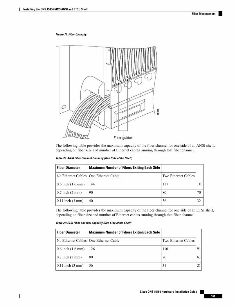
Figure 76: Fiber Capacity
The following table provides the maximum capacity of the fiber channel for one side of an ANSI shelf,depending on fiber size and number of Ethernet cables running through that fiber channel.
Table 26: ANSI Fiber Channel Capacity (One Side of the Shelf)
Maximum Number of Fibers Exiting Each SideFiber Diameter
Two Ethernet CablesOne Ethernet CableNo Ethernet Cables
1101271440.6 inch (1.6 mm)
7080900.7 inch (2 mm)
3236400.11 inch (3 mm)
The following table provides the maximum capacity of the fiber channel for one side of an ETSI shelf,depending on fiber size and number of Ethernet cables running through that fiber channel.
Table 27: ETSI Fiber Channel Capacity (One Side of the Shelf)
Maximum Number of Fibers Exiting Each SideFiber Diameter
Two Ethernet CablesOne Ethernet CableNo Ethernet Cables
941101260.6 inch (1.6 mm)
6070800.7 inch (2 mm)
2631360.11 inch (3 mm)
Cisco ONS 15454 Hardware Installation Guide161
Installing the ONS 15454 M12 (ANSI and ETSI) ShelfFiber Management
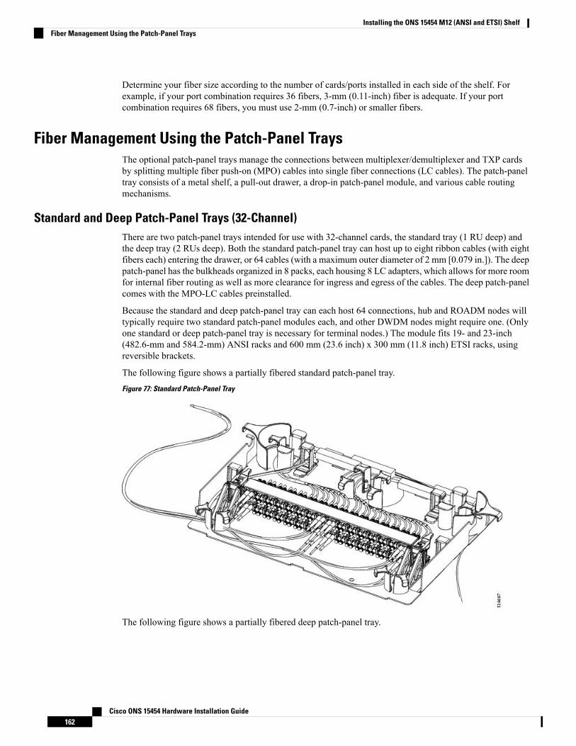
Determine your fiber size according to the number of cards/ports installed in each side of the shelf. Forexample, if your port combination requires 36 fibers, 3-mm (0.11-inch) fiber is adequate. If your portcombination requires 68 fibers, you must use 2-mm (0.7-inch) or smaller fibers.
Fiber Management Using the Patch-Panel TraysThe optional patch-panel trays manage the connections between multiplexer/demultiplexer and TXP cardsby splitting multiple fiber push-on (MPO) cables into single fiber connections (LC cables). The patch-paneltray consists of a metal shelf, a pull-out drawer, a drop-in patch-panel module, and various cable routingmechanisms.
Standard and Deep Patch-Panel Trays (32-Channel)There are two patch-panel trays intended for use with 32-channel cards, the standard tray (1 RU deep) andthe deep tray (2 RUs deep). Both the standard patch-panel tray can host up to eight ribbon cables (with eightfibers each) entering the drawer, or 64 cables (with a maximum outer diameter of 2 mm [0.079 in.]). The deeppatch-panel has the bulkheads organized in 8 packs, each housing 8 LC adapters, which allows for more roomfor internal fiber routing as well as more clearance for ingress and egress of the cables. The deep patch-panelcomes with the MPO-LC cables preinstalled.
Because the standard and deep patch-panel tray can each host 64 connections, hub and ROADM nodes willtypically require two standard patch-panel modules each, and other DWDM nodes might require one. (Onlyone standard or deep patch-panel tray is necessary for terminal nodes.) The module fits 19- and 23-inch(482.6-mm and 584.2-mm) ANSI racks and 600 mm (23.6 inch) x 300 mm (11.8 inch) ETSI racks, usingreversible brackets.
The following figure shows a partially fibered standard patch-panel tray.
Figure 77: Standard Patch-Panel Tray
The following figure shows a partially fibered deep patch-panel tray.
Cisco ONS 15454 Hardware Installation Guide162
Installing the ONS 15454 M12 (ANSI and ETSI) ShelfFiber Management Using the Patch-Panel Trays
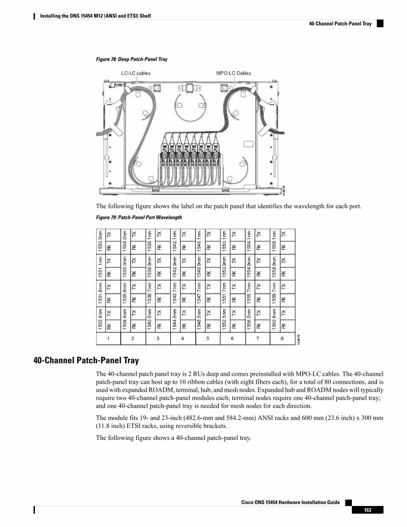
Figure 78: Deep Patch-Panel Tray
The following figure shows the label on the patch panel that identifies the wavelength for each port.
Figure 79: Patch-Panel Port Wavelength
40-Channel Patch-Panel TrayThe 40-channel patch panel tray is 2 RUs deep and comes preinstalled with MPO-LC cables. The 40-channelpatch-panel tray can host up to 10 ribbon cables (with eight fibers each), for a total of 80 connections, and isused with expanded ROADM, terminal, hub, andmesh nodes. Expanded hub and ROADMnodes will typicallyrequire two 40-channel patch-panel modules each; terminal nodes require one 40-channel patch-panel tray;and one 40-channel patch-panel tray is needed for mesh nodes for each direction.
The module fits 19- and 23-inch (482.6-mm and 584.2-mm) ANSI racks and 600 mm (23.6 inch) x 300 mm(11.8 inch) ETSI racks, using reversible brackets.
The following figure shows a 40-channel patch-panel tray.
Cisco ONS 15454 Hardware Installation Guide163
Installing the ONS 15454 M12 (ANSI and ETSI) Shelf40-Channel Patch-Panel Tray
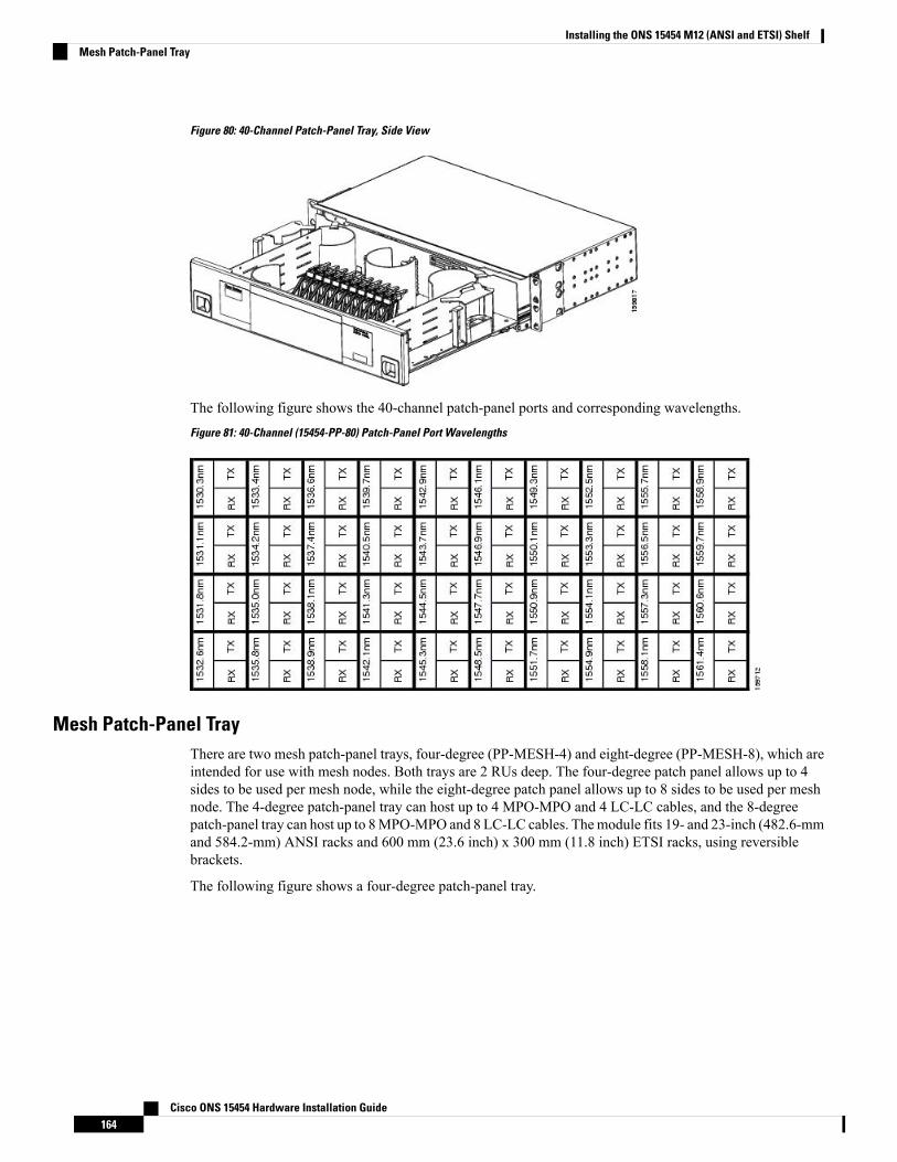
Figure 80: 40-Channel Patch-Panel Tray, Side View
The following figure shows the 40-channel patch-panel ports and corresponding wavelengths.
Figure 81: 40-Channel (15454-PP-80) Patch-Panel Port Wavelengths
Mesh Patch-Panel TrayThere are two mesh patch-panel trays, four-degree (PP-MESH-4) and eight-degree (PP-MESH-8), which areintended for use with mesh nodes. Both trays are 2 RUs deep. The four-degree patch panel allows up to 4sides to be used per mesh node, while the eight-degree patch panel allows up to 8 sides to be used per meshnode. The 4-degree patch-panel tray can host up to 4 MPO-MPO and 4 LC-LC cables, and the 8-degreepatch-panel tray can host up to 8MPO-MPO and 8 LC-LC cables. Themodule fits 19- and 23-inch (482.6-mmand 584.2-mm) ANSI racks and 600 mm (23.6 inch) x 300 mm (11.8 inch) ETSI racks, using reversiblebrackets.
The following figure shows a four-degree patch-panel tray.
Cisco ONS 15454 Hardware Installation Guide164
Installing the ONS 15454 M12 (ANSI and ETSI) ShelfMesh Patch-Panel Tray

Figure 82: Four-Degree Patch-Panel Tray
The following figure shows an eight-degree patch-panel tray.
Figure 83: Eight-Degree Patch-Panel Tray
Install PP-MeshThe PP-Mesh is an ONS 15454 unit that can be installed either above or below the DWDM generatingequipment according to the local site practice.
The PP-Mesh is a 2 rack unit (RU) high. Each package includes one set of the following brackets:
• 19-inch (482.6-mm) or 23-inch (584.2-mm) reversible (two-way) mounting brackets that can be rotatedto fit either rack size. These reversible brackets are used for EIA and IEC standard racks.
• ETSI brackets that are used for ETSI standard racks.
Cisco ONS 15454 Hardware Installation Guide165
Installing the ONS 15454 M12 (ANSI and ETSI) ShelfInstall PP-Mesh
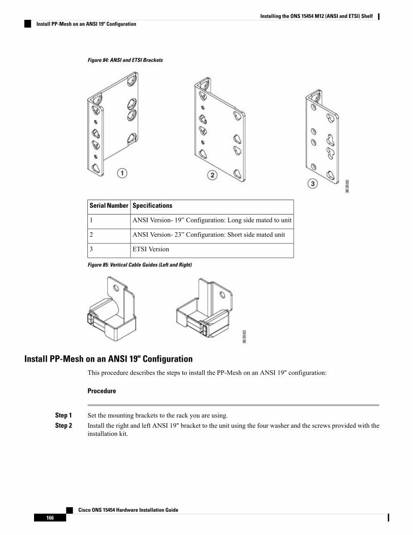
Figure 84: ANSI and ETSI Brackets
SpecificationsSerial Number
ANSI Version- 19” Configuration: Long side mated to unit1
ANSI Version- 23” Configuration: Short side mated unit2
ETSI Version3
Figure 85: Vertical Cable Guides (Left and Right)
Install PP-Mesh on an ANSI 19" ConfigurationThis procedure describes the steps to install the PP-Mesh on an ANSI 19" configuration:
Procedure
Step 1 Set the mounting brackets to the rack you are using.Step 2 Install the right and left ANSI 19" bracket to the unit using the four washer and the screws provided with the
installation kit.
Cisco ONS 15454 Hardware Installation Guide166
Installing the ONS 15454 M12 (ANSI and ETSI) ShelfInstall PP-Mesh on an ANSI 19" Configuration
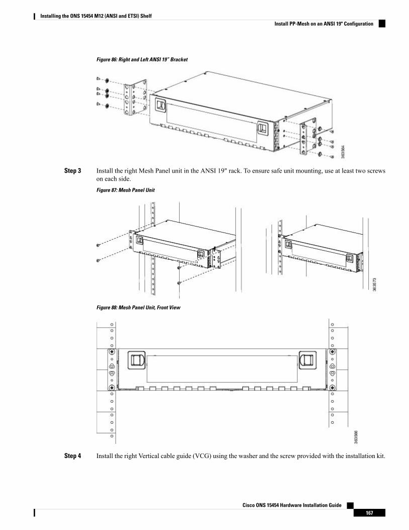
Figure 86: Right and Left ANSI 19” Bracket
Step 3 Install the right Mesh Panel unit in the ANSI 19" rack. To ensure safe unit mounting, use at least two screwson each side.
Figure 87: Mesh Panel Unit
Figure 88: Mesh Panel Unit, Front View
Step 4 Install the right Vertical cable guide (VCG) using the washer and the screw provided with the installation kit.
Cisco ONS 15454 Hardware Installation Guide167
Installing the ONS 15454 M12 (ANSI and ETSI) ShelfInstall PP-Mesh on an ANSI 19" Configuration
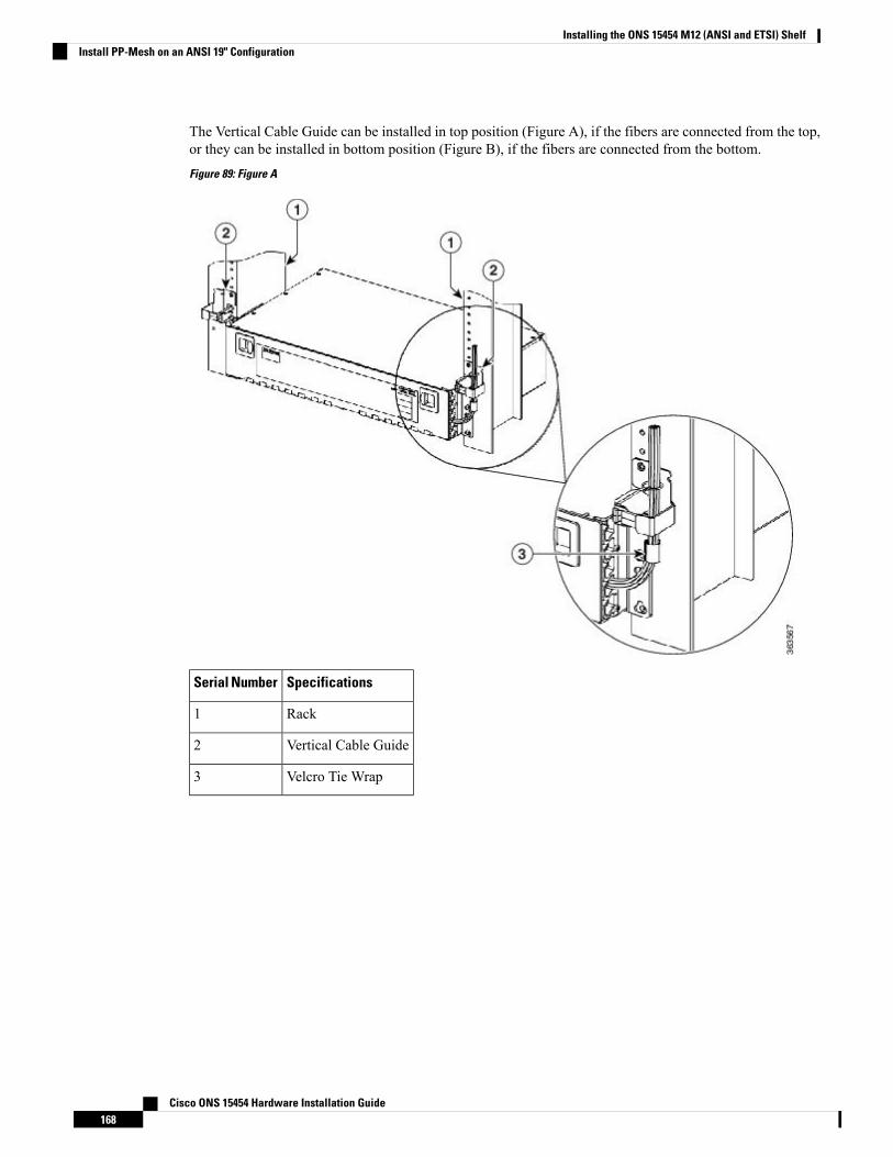
The Vertical Cable Guide can be installed in top position (Figure A), if the fibers are connected from the top,or they can be installed in bottom position (Figure B), if the fibers are connected from the bottom.
Figure 89: Figure A
SpecificationsSerial Number
Rack1
Vertical Cable Guide2
Velcro Tie Wrap3
Cisco ONS 15454 Hardware Installation Guide168
Installing the ONS 15454 M12 (ANSI and ETSI) ShelfInstall PP-Mesh on an ANSI 19" Configuration

Figure 90: Figure B
SpecificationsSerial Number
Rack1
Vertical Cable Guide2
Install PP-Mesh on an ANSI 23" ConfigurationThis procedure describes the steps to install the PP-Mesh on an ANSI 23" configuration:
Cisco ONS 15454 Hardware Installation Guide169
Installing the ONS 15454 M12 (ANSI and ETSI) ShelfInstall PP-Mesh on an ANSI 23" Configuration
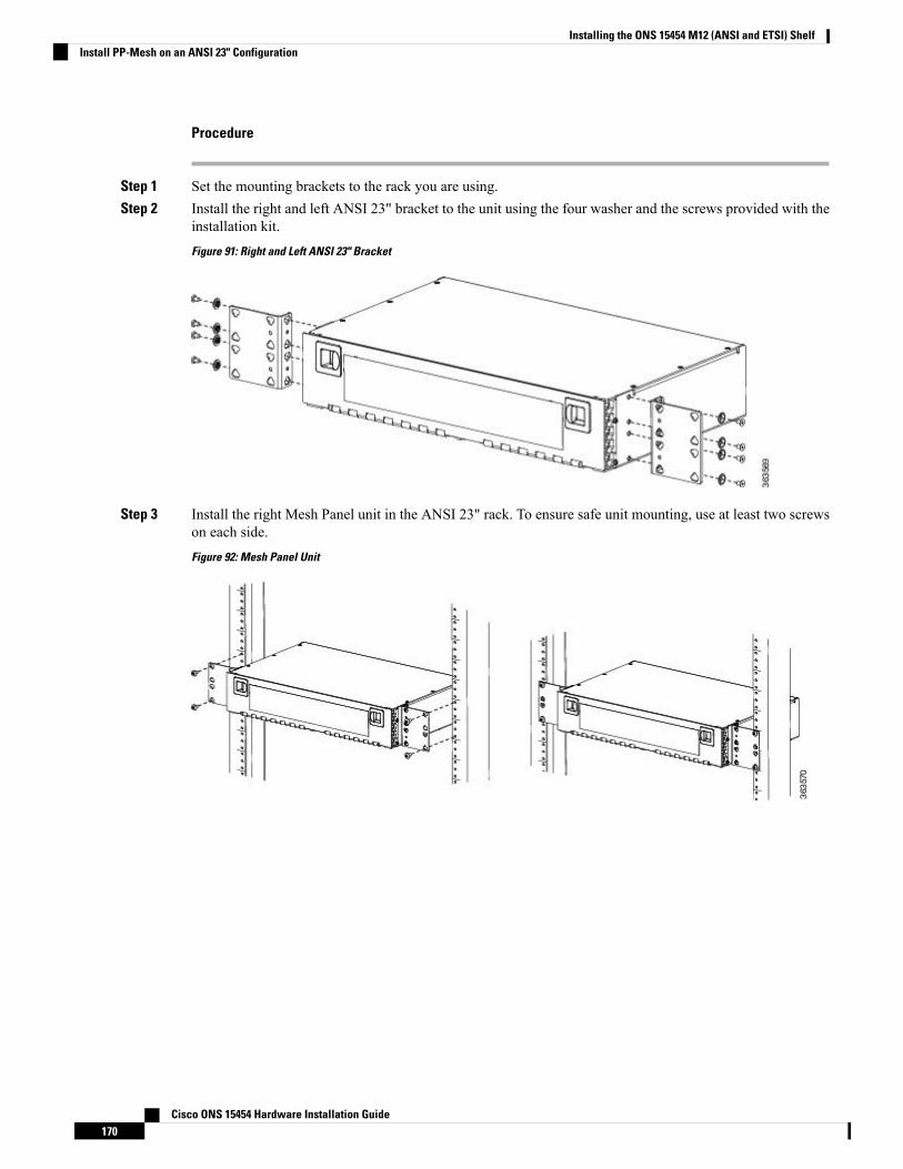
Procedure
Step 1 Set the mounting brackets to the rack you are using.Step 2 Install the right and left ANSI 23" bracket to the unit using the four washer and the screws provided with the
installation kit.
Figure 91: Right and Left ANSI 23" Bracket
Step 3 Install the right Mesh Panel unit in the ANSI 23" rack. To ensure safe unit mounting, use at least two screwson each side.
Figure 92: Mesh Panel Unit
Cisco ONS 15454 Hardware Installation Guide170
Installing the ONS 15454 M12 (ANSI and ETSI) ShelfInstall PP-Mesh on an ANSI 23" Configuration

Figure 93: Mesh Panel Unit, Front View
Step 4 Install the right Vertical cable guide (VCG) using the washer and the screw provided with the installation kit.
The Vertical Cable Guide can be installed in top position (Figure A), if the fibers are connected from the top,or they can be installed in bottom position (Figure B), if the fibers are connected from the bottom.
Figure 94: Figure A
SpecificationsSerial Number
Rack1
Cisco ONS 15454 Hardware Installation Guide171
Installing the ONS 15454 M12 (ANSI and ETSI) ShelfInstall PP-Mesh on an ANSI 23" Configuration
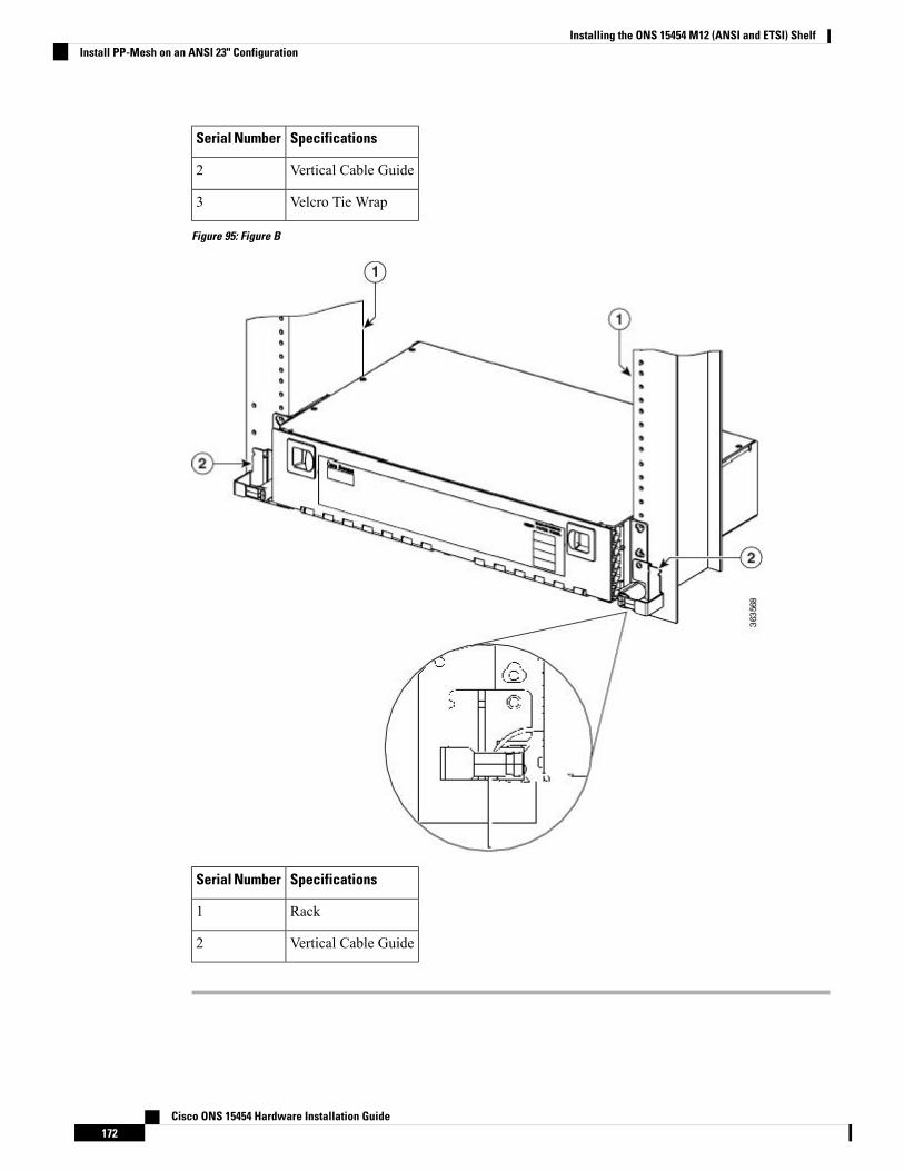
SpecificationsSerial Number
Vertical Cable Guide2
Velcro Tie Wrap3
Figure 95: Figure B
SpecificationsSerial Number
Rack1
Vertical Cable Guide2
Cisco ONS 15454 Hardware Installation Guide172
Installing the ONS 15454 M12 (ANSI and ETSI) ShelfInstall PP-Mesh on an ANSI 23" Configuration
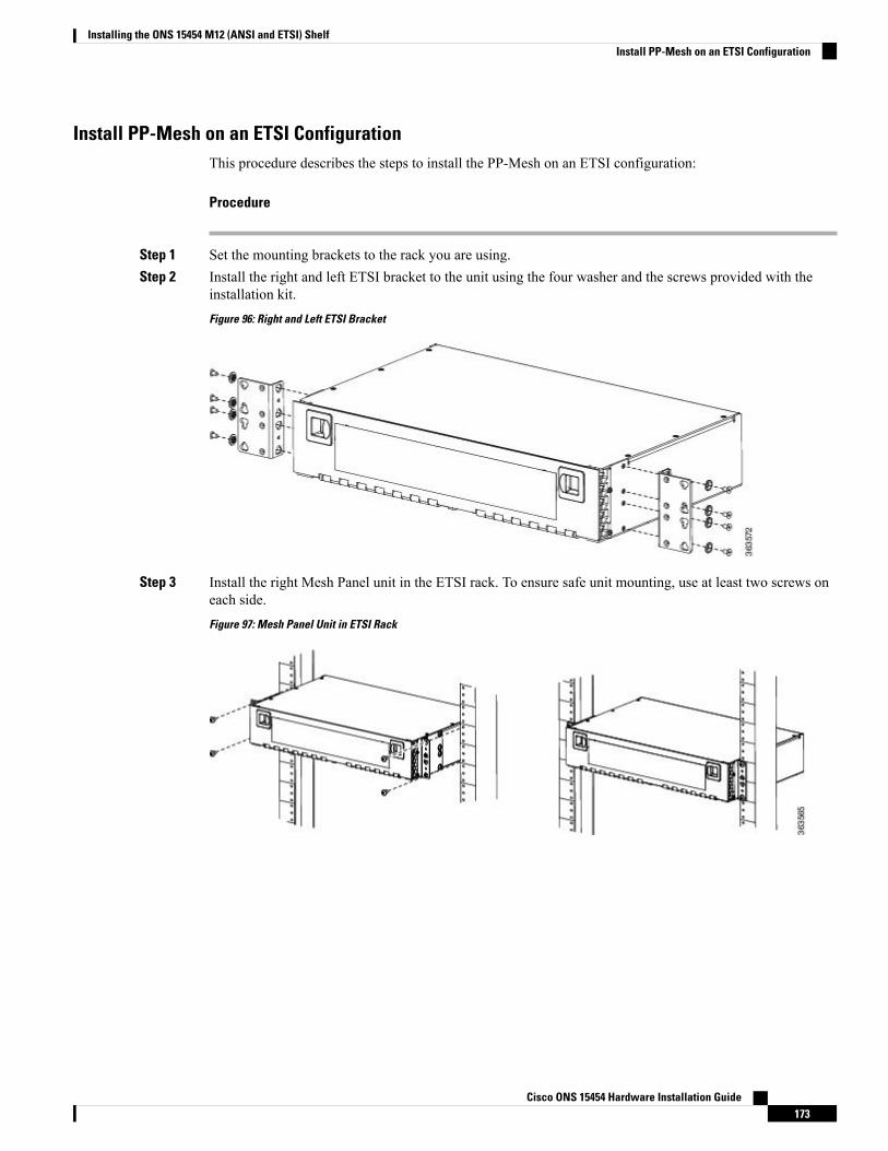
Install PP-Mesh on an ETSI ConfigurationThis procedure describes the steps to install the PP-Mesh on an ETSI configuration:
Procedure
Step 1 Set the mounting brackets to the rack you are using.Step 2 Install the right and left ETSI bracket to the unit using the four washer and the screws provided with the
installation kit.
Figure 96: Right and Left ETSI Bracket
Step 3 Install the right Mesh Panel unit in the ETSI rack. To ensure safe unit mounting, use at least two screws oneach side.
Figure 97: Mesh Panel Unit in ETSI Rack
Cisco ONS 15454 Hardware Installation Guide173
Installing the ONS 15454 M12 (ANSI and ETSI) ShelfInstall PP-Mesh on an ETSI Configuration
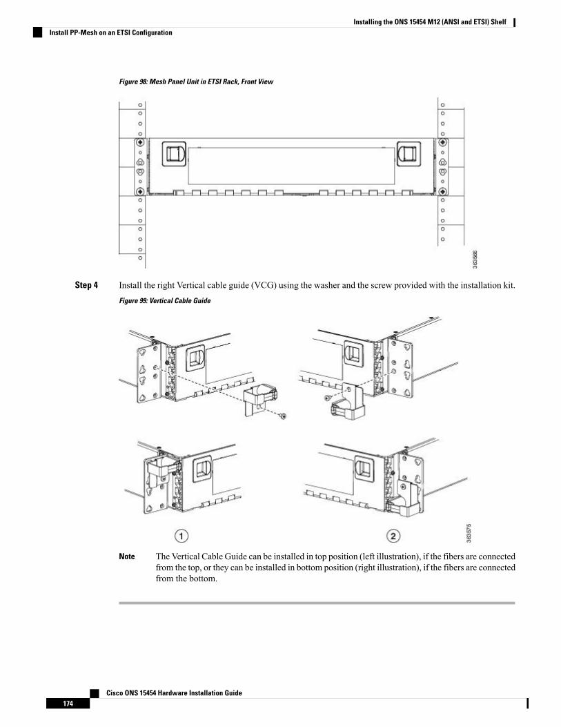
Figure 98: Mesh Panel Unit in ETSI Rack, Front View
Step 4 Install the right Vertical cable guide (VCG) using the washer and the screw provided with the installation kit.
Figure 99: Vertical Cable Guide
The Vertical Cable Guide can be installed in top position (left illustration), if the fibers are connectedfrom the top, or they can be installed in bottom position (right illustration), if the fibers are connectedfrom the bottom.
Note
Cisco ONS 15454 Hardware Installation Guide174
Installing the ONS 15454 M12 (ANSI and ETSI) ShelfInstall PP-Mesh on an ETSI Configuration
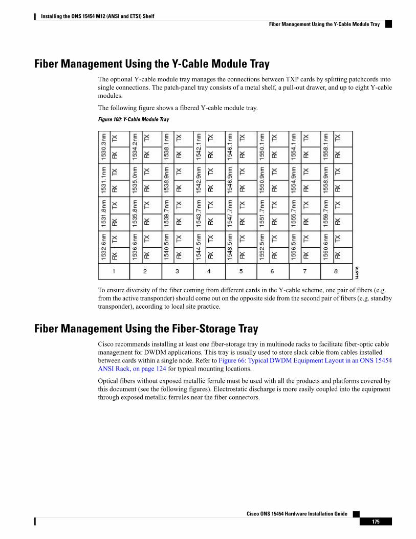
Fiber Management Using the Y-Cable Module TrayThe optional Y-cable module tray manages the connections between TXP cards by splitting patchcords intosingle connections. The patch-panel tray consists of a metal shelf, a pull-out drawer, and up to eight Y-cablemodules.
The following figure shows a fibered Y-cable module tray.
Figure 100: Y-Cable Module Tray
To ensure diversity of the fiber coming from different cards in the Y-cable scheme, one pair of fibers (e.g.from the active transponder) should come out on the opposite side from the second pair of fibers (e.g. standbytransponder), according to local site practice.
Fiber Management Using the Fiber-Storage TrayCisco recommends installing at least one fiber-storage tray in multinode racks to facilitate fiber-optic cablemanagement for DWDM applications. This tray is usually used to store slack cable from cables installedbetween cards within a single node. Refer to Figure 66: Typical DWDMEquipment Layout in an ONS 15454ANSI Rack, on page 124 for typical mounting locations.
Optical fibers without exposed metallic ferrule must be used with all the products and platforms covered bythis document (see the following figures). Electrostatic discharge is more easily coupled into the equipmentthrough exposed metallic ferrules near the fiber connectors.
Cisco ONS 15454 Hardware Installation Guide175
Installing the ONS 15454 M12 (ANSI and ETSI) ShelfFiber Management Using the Y-Cable Module Tray
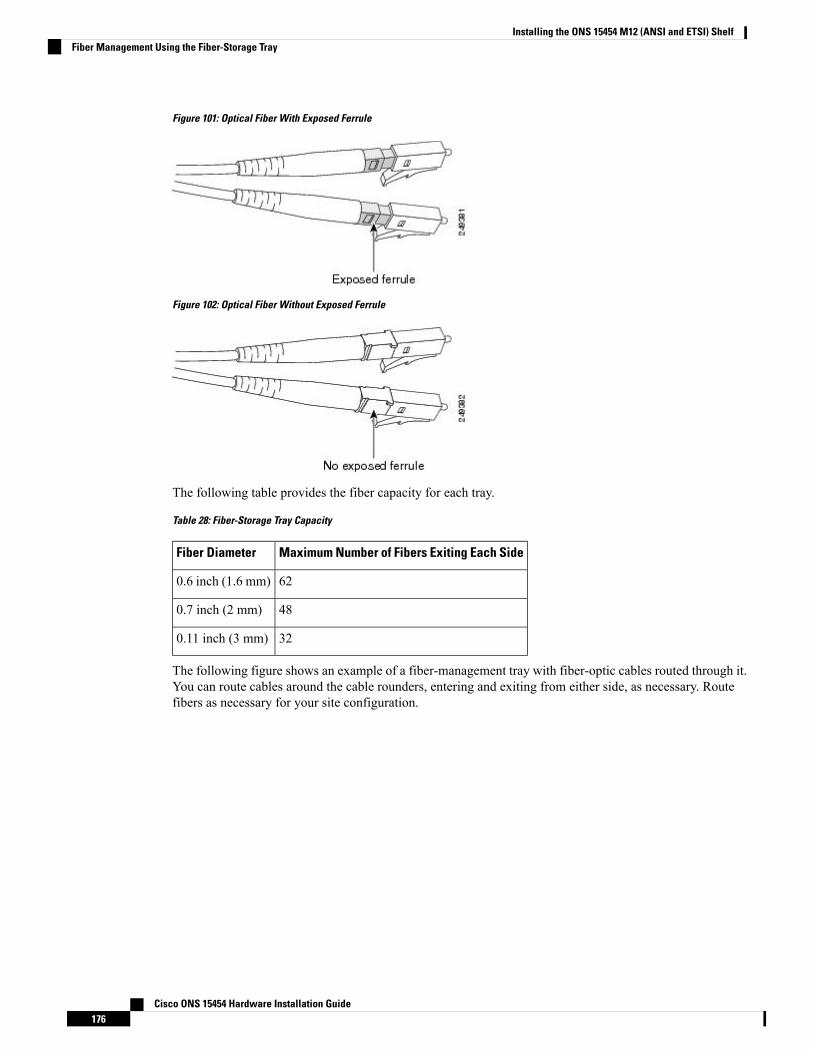
Figure 101: Optical Fiber With Exposed Ferrule
Figure 102: Optical Fiber Without Exposed Ferrule
The following table provides the fiber capacity for each tray.
Table 28: Fiber-Storage Tray Capacity
Maximum Number of Fibers Exiting Each SideFiber Diameter
620.6 inch (1.6 mm)
480.7 inch (2 mm)
320.11 inch (3 mm)
The following figure shows an example of a fiber-management tray with fiber-optic cables routed through it.You can route cables around the cable rounders, entering and exiting from either side, as necessary. Routefibers as necessary for your site configuration.
Cisco ONS 15454 Hardware Installation Guide176
Installing the ONS 15454 M12 (ANSI and ETSI) ShelfFiber Management Using the Fiber-Storage Tray
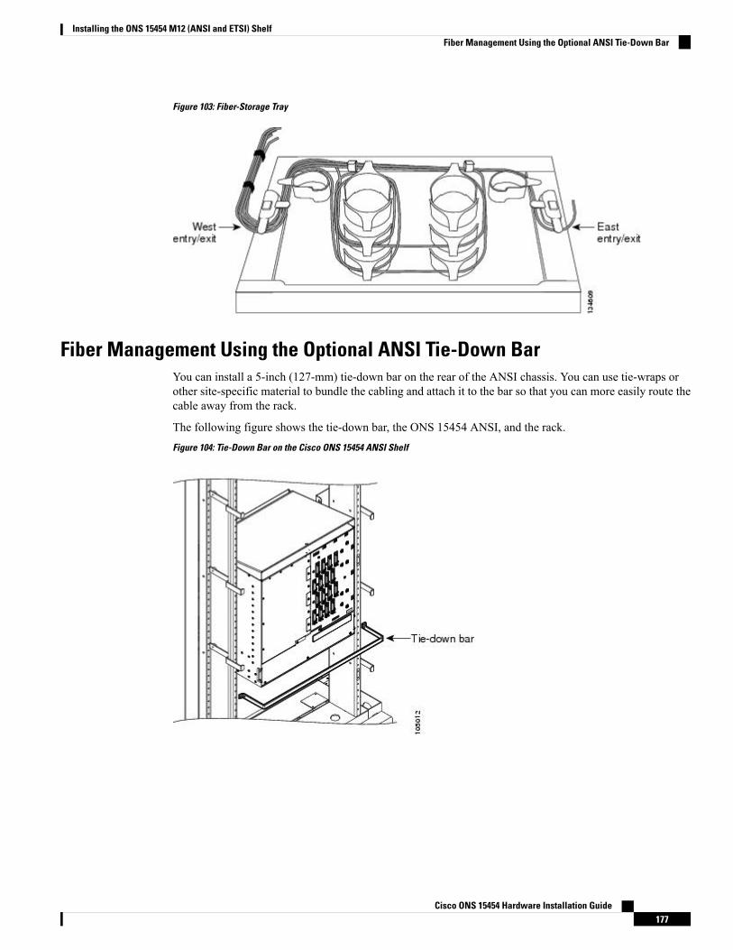
Figure 103: Fiber-Storage Tray
Fiber Management Using the Optional ANSI Tie-Down BarYou can install a 5-inch (127-mm) tie-down bar on the rear of the ANSI chassis. You can use tie-wraps orother site-specific material to bundle the cabling and attach it to the bar so that you can more easily route thecable away from the rack.
The following figure shows the tie-down bar, the ONS 15454 ANSI, and the rack.
Figure 104: Tie-Down Bar on the Cisco ONS 15454 ANSI Shelf
Cisco ONS 15454 Hardware Installation Guide177
Installing the ONS 15454 M12 (ANSI and ETSI) ShelfFiber Management Using the Optional ANSI Tie-Down Bar

Cisco ONS 15454 Hardware Installation Guide178
Installing the ONS 15454 M12 (ANSI and ETSI) ShelfFiber Management Using the Optional ANSI Tie-Down Bar

C H A P T E R 4Installing the ONS 15454 M2 Shelf
This chapter explains how to install the ONS 15454 M2 shelf.
• Installing the ONS 15454 M2 Shelf, on page 179
Installing the ONS 15454 M2 ShelfThis chapter explains how to install the ONS 15454 M2 shelf.
ANSI Rack InstallationThe ONS 15454M2 shelf is mounted on a 19-inch (482.6-mm) or 23-inch (584.2-mm) equipment rack. Makesure that the correct type of 19-inch ANSI rack is used for mounting the ONS 15454 M2 shelf as shown inFigure 5: 19-inch ANSI Rack Post Recommended for Cisco ONS 15454 M6 and M2 Shelves, on page 5.If the shelf is mounted in the front position, then it projects 1.7 inches (43.18 mm) from the front of the rack.If the shelf is mounted in the middle position, then it projects 5.1 inches (129.54 mm) from the front of therack. The shelf mounts in both Electronic Industries Alliance (EIA) standard and Telcordia-standard racks.The shelf is a total of 17.2 inches (431.8 mm) wide with nomounting ears attached. Ring runs are not providedby Cisco and might hinder side-by-side installation of shelves where space is limited.
The ONS 15454 M2 shelf measures 3.5 inches (88.9 mm) high, 19 or 23 inches (482.6 or 584.2 mm) wide(depending on which way the mounting ears are attached), and 11.1 inches (304.8 mm) deep.
The following figure shows the dimensions of the ONS 15454 M2 shelf in a 19-inch configuration withbrackets mounted in the front position.
Cisco ONS 15454 Hardware Installation Guide179
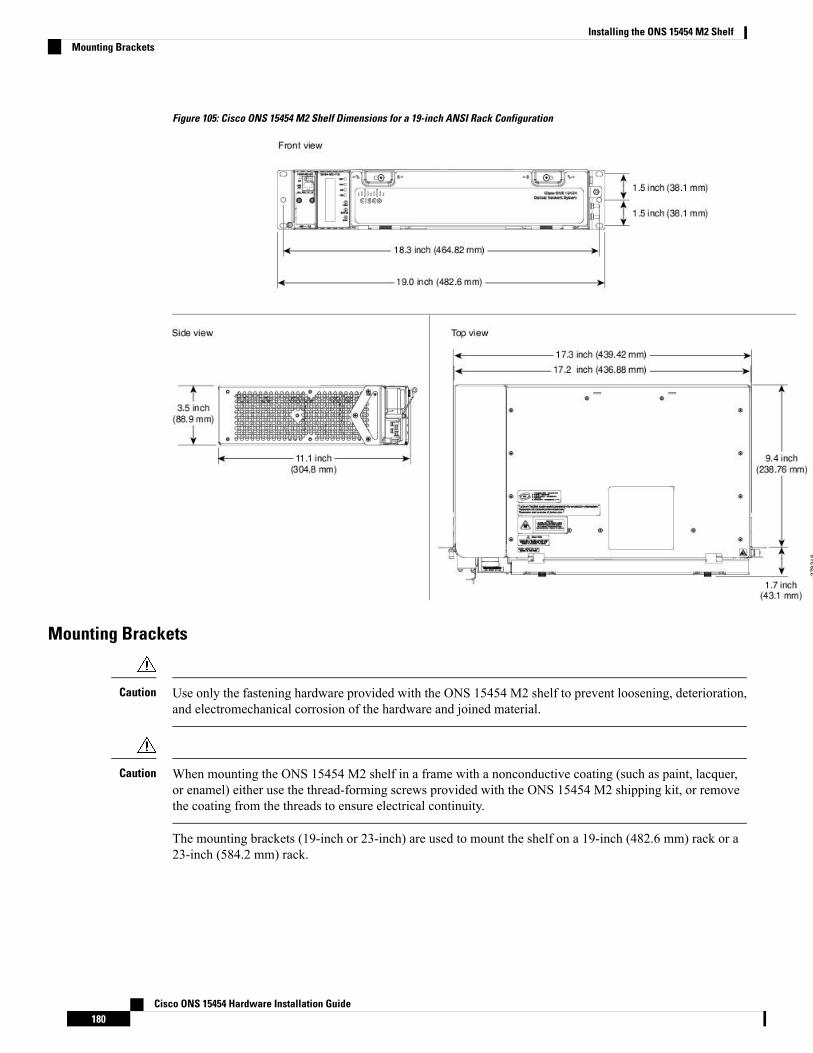
Figure 105: Cisco ONS 15454 M2 Shelf Dimensions for a 19-inch ANSI Rack Configuration
Mounting Brackets
Use only the fastening hardware provided with the ONS 15454 M2 shelf to prevent loosening, deterioration,and electromechanical corrosion of the hardware and joined material.
Caution
When mounting the ONS 15454 M2 shelf in a frame with a nonconductive coating (such as paint, lacquer,or enamel) either use the thread-forming screws provided with the ONS 15454 M2 shipping kit, or removethe coating from the threads to ensure electrical continuity.
Caution
The mounting brackets (19-inch or 23-inch) are used to mount the shelf on a 19-inch (482.6 mm) rack or a23-inch (584.2 mm) rack.
Cisco ONS 15454 Hardware Installation Guide180
Installing the ONS 15454 M2 ShelfMounting Brackets
Mounting a Single NodeMounting the ONS 15454 M2 shelf on a rack requires a minimum of 3.5 inches (88.9 mm) of vertical rackspace. To ensure the mounting is secure, use two to three #12-24 mounting screws for each side of the shelf.For an ANSI rack, the brackets can be mounted in the front or middle position. The shelf should be emptyfor easier lifting. For information on the ONS 15454 M2 shelf weight, refer to the Dimensions , on page 478.
The ONS 15454 M2 shelves can be mounted above each other without any space between the shelves. Thismethod of mounting does not restrict the air flow because the air vents are on either sides of the ONS 15454M2 shelves.
ETSI Rack InstallationThe ONS 15454 M2 shelf is mounted on a 600 x 600-mm (23.6 x 23.6-inch) or 600 x 300-mm (23.6 x11.8-inch) ETSI standard equipment rack. In an ETSI rack, the shelf can be mounted only in the front position.The shelf projects 1.7 inches from the front of the rack. The shelf is a total of 17.2 inches (431.8 mm) widewith no mounting ears attached. Cisco does not provide ring runs, which might hinder side-by-side installationof shelves where space is limited.
The ONS 15454 M2 shelf measures 88.9 mm (3.5 inches) high, 535 mm (21.06 inches) wide, and 11.1 inches(304.8 mm) deep.
The following figure provides the dimensions of the ONS 15454 M2 shelf installed on a 600 x 600-mm (23.6x 23.6-inch) ETSI standard equipment rack.
When mounting a shelf in a partially filled rack, load the rack from the bottom to the top with the heaviestcomponent at the bottom of the rack. If the rack is provided with stabilizing devices, install the stabilizersbefore mounting or servicing the unit in the rack.
Caution
Cisco ONS 15454 Hardware Installation Guide181
Installing the ONS 15454 M2 ShelfMounting a Single Node

Figure 106: ONS 15454 M2 Shelf Dimensions for an ETSI Rack Configuration
Mounting a Single NodeThe ONS 15454 M2 requires 3.5 inches (88.9 mm) minimum of vertical rack space. To ensure the mountingis secure, use two to three M6 mounting screws for each side of the shelf.
In an ETSI rack, the brackets can be mounted only in the front position.
The ONS 15454 M2 shelves can be mounted above each other without any space between the shelves. Thismethod of mounting does not restrict the air flow because the air vents are on either sides of the ONS 15454M2 shelves.
Wall Mounting the ONS 15454 M2 ShelfThe ONS 15454M2 shelf can be mounted on the wall using the wall mount brackets. The type of screws usedto mount the brackets on the wall depends on the wall-type and are not provided by Cisco.
After the ONS 15454 M2 shelf is mounted on the wall, a fire protective tray is installed on the wall mountbracket to support the shelf.
Cisco ONS 15454 Hardware Installation Guide182
Installing the ONS 15454 M2 ShelfMounting a Single Node
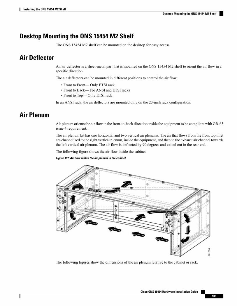
Desktop Mounting the ONS 15454 M2 ShelfThe ONS 15454 M2 shelf can be mounted on the desktop for easy access.
Air DeflectorAn air deflector is a sheet-metal part that is mounted on the ONS 15454 M2 shelf to orient the air flow in aspecific direction.
The air deflectors can be mounted in different positions to control the air flow:
• Front to Front— Only ETSI rack• Front to Back— For ANSI and ETSI racks• Front to Top— Only ETSI rack
In an ANSI rack, the air deflectors are mounted only on the 23-inch rack configuration.
Air PlenumAir plenum orients the air flow in the front-to-back direction inside the equipment to be compliant with GR-63issue 4 requirement.
The air plenum kit has one horizontal and two vertical air plenums. The air that flows from the front top inletare channelized to the right vertical plenum, inside the equipment, and then to the exhaust air channel towardsthe left vertical air plenum. The air flow is deflected by 90 degrees and exited out in the rear end.
The following figure shows the air flow inside the cabinet.
Figure 107: Air flow within the air plenum in the cabinet
The following figures show the dimensions of the air plenum relative to the cabinet or rack.
Cisco ONS 15454 Hardware Installation Guide183
Installing the ONS 15454 M2 ShelfDesktop Mounting the ONS 15454 M2 Shelf

Figure 108: Dimension of Cisco ONS 15454 M2 chassis relative to the air plenum
Figure 109: Dimension on Cisco ONS 15454 M2 relative to the air plenum
Air Plenum Rack and Cabinet CompatibilityThe table shows the compatibility of air plenum with the ANSI and ETSI racks and cabinets. The chassis canbe installed with brackets in front position only.
Table 29: Air plenum compatibility with racks and cabinets
Front-to-back air flowRack / Cabinet
Supported 1ANSI 19-inch rack
Supported 1ANSI 19-inch cabinet
SupportedANSI 23-inch rack
SupportedANSI 23-inch cabinet
Supported 1ETSI cabinet
Cisco ONS 15454 Hardware Installation Guide184
Installing the ONS 15454 M2 ShelfAir Plenum Rack and Cabinet Compatibility
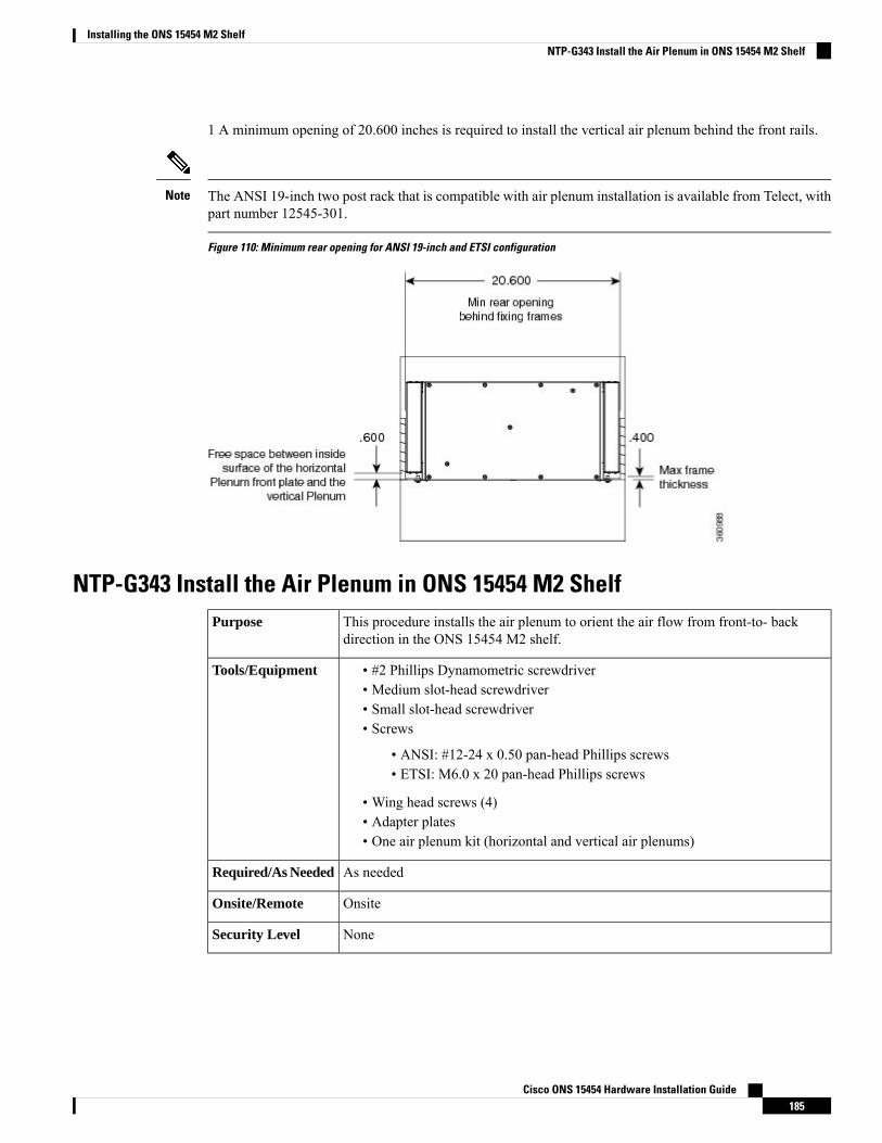
1 A minimum opening of 20.600 inches is required to install the vertical air plenum behind the front rails.
The ANSI 19-inch two post rack that is compatible with air plenum installation is available from Telect, withpart number 12545-301.
Note
Figure 110: Minimum rear opening for ANSI 19-inch and ETSI configuration
NTP-G343 Install the Air Plenum in ONS 15454 M2 ShelfThis procedure installs the air plenum to orient the air flow from front-to- backdirection in the ONS 15454 M2 shelf.
Purpose
• #2 Phillips Dynamometric screwdriver• Medium slot-head screwdriver• Small slot-head screwdriver• Screws
• ANSI: #12-24 x 0.50 pan-head Phillips screws• ETSI: M6.0 x 20 pan-head Phillips screws
• Wing head screws (4)• Adapter plates• One air plenum kit (horizontal and vertical air plenums)
Tools/Equipment
As neededRequired/As Needed
OnsiteOnsite/Remote
NoneSecurity Level
Cisco ONS 15454 Hardware Installation Guide185
Installing the ONS 15454 M2 ShelfNTP-G343 Install the Air Plenum in ONS 15454 M2 Shelf
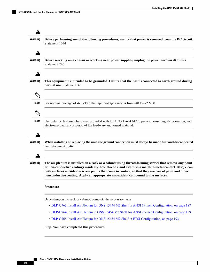
Before performing any of the following procedures, ensure that power is removed from the DC circuit.Statement 1074
Warning
Before working on a chassis or working near power supplies, unplug the power cord on AC units.Statement 246
Warning
This equipment is intended to be grounded. Ensure that the host is connected to earth ground duringnormal use. Statement 39
Warning
For nominal voltage of -60 VDC, the input voltage range is from -40 to -72 VDC.Note
Use only the fastening hardware provided with the ONS 15454 M2 to prevent loosening, deterioration, andelectromechanical corrosion of the hardware and joined material.
Note
When installing or replacing the unit, the ground connection must always be made first and disconnectedlast. Statement 1046
Warning
The air plenum is installed on a rack or a cabinet using thread-forming screws that remove any paintor non-conductive coatings inside the hole threads, and establish a metal-to-metal contact. Also, cleanboth surfaces outside the screw points that come in contact, so that they are free of paint and othernonconductive coating. Apply an appropriate antioxidant compound to the surfaces.
Warning
Procedure
Depending on the rack or cabinet, complete the necessary tasks:
• DLP-G763 Install Air Plenum for ONS 15454 M2 Shelf in ANSI 19-inch Configuration, on page 187
• DLP-G764 Install Air Plenum in ONS 15454 M2 Shelf for ANSI 23-inch Configuration, on page 189
• DLP-G765 Install Air Plenum for ONS 15454 M2 Shelf in ETSI Configuration, on page 193
Stop. You have completed this procedure.
Cisco ONS 15454 Hardware Installation Guide186
Installing the ONS 15454 M2 ShelfNTP-G343 Install the Air Plenum in ONS 15454 M2 Shelf
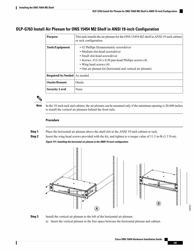
DLP-G763 Install Air Plenum for ONS 15454 M2 Shelf in ANSI 19-inch Configuration
This task installs the air plenum for the ONS 15454M2 shelf in ANSI 19-inch cabinetor rack configuration.
Purpose
• #2 Phillips Dynamometric screwdriver• Medium slot-head screwdriver• Small slot-head screwdriver• Screws: #12-24 x 0.50 pan-head Phillips screws (4)• Wing head screws (4)• One air plenum kit (horizontal and vertical air plenum)
Tools/Equipment
As neededRequired/As Needed
OnsiteOnsite/Remote
NoneSecurity Level
In the 19-inch rack and cabinet, the air plenum can be mounted only if the minimum opening is 20.600 inchesto install the vertical air plenums behind the front rails.
Note
Procedure
Step 1 Place the horizontal air plenum above the shelf slot in the ANSI 19-inch cabinet or rack.Step 2 Insert the wing head screws provided with the kit, and tighten to a torque value of 11.5 in-lb (1.3 N-m).
Figure 111: Installing the horizontal air plenum in the ANSI 19-inch configuration
Step 3 Install the vertical air plenum to the left of the horizontal air plenum:a) Insert the vertical plenum in the free space between the horizontal plenum and cabinet.
Cisco ONS 15454 Hardware Installation Guide187
Installing the ONS 15454 M2 ShelfDLP-G763 Install Air Plenum for ONS 15454 M2 Shelf in ANSI 19-inch Configuration

b) Install the wing head screws from the internal side of the horizontal plenum as shown in the followingfigure.
c) Tighten the screws to a torque value of 11.5 in-lb (1.3 N-m).
Figure 112: Installing the left vertical air plenum
Step 4 Install the vertical air plenum to the right of the horizontal air plenum. Follow step 3a to 3c.
Figure 113: Installing the right vertical air plenum
Step 5 Install the 19-inch standard brackets on both sides of the chassis in the front position. See DLP-G582Mountingthe 19-inch Brackets on the ONS 15454 M2 Shelf for ANSI Rack Configuration, on page 199.
Step 6 Install the ONS 15454 M2 empty chassis below the horizontal plenum.
Cisco ONS 15454 Hardware Installation Guide188
Installing the ONS 15454 M2 ShelfDLP-G763 Install Air Plenum for ONS 15454 M2 Shelf in ANSI 19-inch Configuration
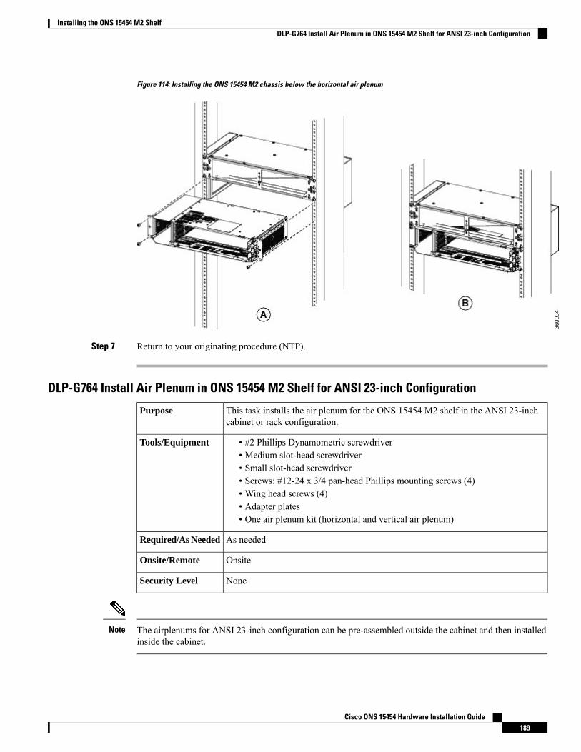
Figure 114: Installing the ONS 15454 M2 chassis below the horizontal air plenum
Step 7 Return to your originating procedure (NTP).
DLP-G764 Install Air Plenum in ONS 15454 M2 Shelf for ANSI 23-inch Configuration
This task installs the air plenum for the ONS 15454 M2 shelf in the ANSI 23-inchcabinet or rack configuration.
Purpose
• #2 Phillips Dynamometric screwdriver• Medium slot-head screwdriver• Small slot-head screwdriver• Screws: #12-24 x 3/4 pan-head Phillips mounting screws (4)• Wing head screws (4)• Adapter plates• One air plenum kit (horizontal and vertical air plenum)
Tools/Equipment
As neededRequired/As Needed
OnsiteOnsite/Remote
NoneSecurity Level
The airplenums for ANSI 23-inch configuration can be pre-assembled outside the cabinet and then installedinside the cabinet.
Note
Cisco ONS 15454 Hardware Installation Guide189
Installing the ONS 15454 M2 ShelfDLP-G764 Install Air Plenum in ONS 15454 M2 Shelf for ANSI 23-inch Configuration
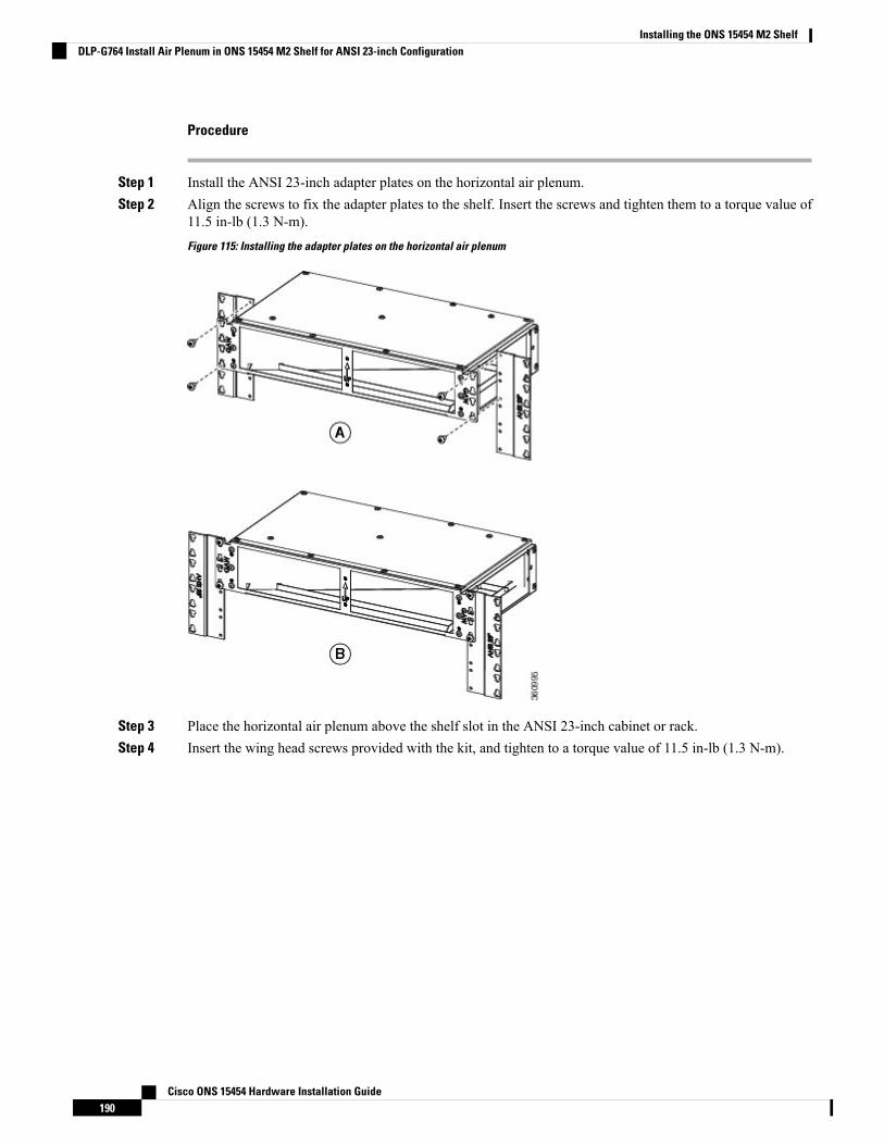
Procedure
Step 1 Install the ANSI 23-inch adapter plates on the horizontal air plenum.Step 2 Align the screws to fix the adapter plates to the shelf. Insert the screws and tighten them to a torque value of
11.5 in-lb (1.3 N-m).
Figure 115: Installing the adapter plates on the horizontal air plenum
Step 3 Place the horizontal air plenum above the shelf slot in the ANSI 23-inch cabinet or rack.Step 4 Insert the wing head screws provided with the kit, and tighten to a torque value of 11.5 in-lb (1.3 N-m).
Cisco ONS 15454 Hardware Installation Guide190
Installing the ONS 15454 M2 ShelfDLP-G764 Install Air Plenum in ONS 15454 M2 Shelf for ANSI 23-inch Configuration

Figure 116: Installing the horizontal air plenum in the ANSI 23-inch configuration
Step 5 Install the vertical air plenum to the left of the horizontal air plenum:a) Insert the vertical air plenum in the free space between the horizontal air plenum and cabinet.b) Install the wing head screws from the internal side of the horizontal plenum as shown in the following
figure.c) Tighten the screws to a torque value of 11.5 in-lb (1.3 N-m).
Figure 117: Installing the left vertical air plenum
Step 6 Install the vertical plenum to the right of the horizontal air plenum. Follow step 5a to 5c.
Cisco ONS 15454 Hardware Installation Guide191
Installing the ONS 15454 M2 ShelfDLP-G764 Install Air Plenum in ONS 15454 M2 Shelf for ANSI 23-inch Configuration
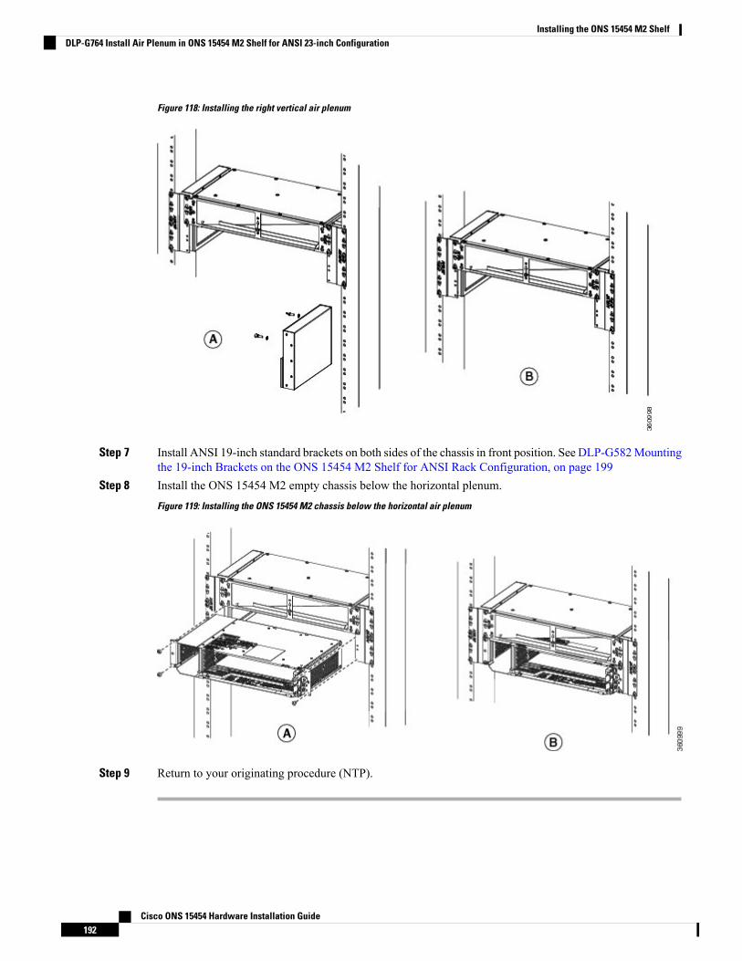
Figure 118: Installing the right vertical air plenum
Step 7 Install ANSI 19-inch standard brackets on both sides of the chassis in front position. See DLP-G582Mountingthe 19-inch Brackets on the ONS 15454 M2 Shelf for ANSI Rack Configuration, on page 199
Step 8 Install the ONS 15454 M2 empty chassis below the horizontal plenum.
Figure 119: Installing the ONS 15454 M2 chassis below the horizontal air plenum
Step 9 Return to your originating procedure (NTP).
Cisco ONS 15454 Hardware Installation Guide192
Installing the ONS 15454 M2 ShelfDLP-G764 Install Air Plenum in ONS 15454 M2 Shelf for ANSI 23-inch Configuration
DLP-G765 Install Air Plenum for ONS 15454 M2 Shelf in ETSI Configuration
This task installs the air plenum for the ONS 15454M2 shelf in the ETSI configuration.Purpose
• #2 Phillips Dynamometric screwdriver• Medium slot-head screwdriver• Small slot-head screwdriver• Screws: M6.0 x 20 pan-head Phillips screws (4)• Wing head screws (4)• Adapter plates• One air plenum kit (horizontal and vertical air plenum)
Tools/Equipment
As neededRequired/As Needed
OnsiteOnsite/Remote
NoneSecurity Level
Procedure
Step 1 Install the ETSI adapter plates on the horizontal air plenum.Step 2 Align the screws to fix the adapter plates to the horizontal air plenum. Insert the screws and tighten them to
a torque value of 11.5 in-lb (1.3 N-m) as shown in the following figure.
Cisco ONS 15454 Hardware Installation Guide193
Installing the ONS 15454 M2 ShelfDLP-G765 Install Air Plenum for ONS 15454 M2 Shelf in ETSI Configuration

Figure 120: Installing the adapter plates on the horizontal air plenum
Step 3 Place the horizontal plenum above the chassis slot in the ETSI cabinet.Step 4 Insert the wing head screws provided with the kit, and tighten to a torque value of 11.5 in-lb (1.3 N-m).
Figure 121: Installing the horizontal air plenum in the ETSI configuration
Step 5 Install the vertical air plenum to the left of the horizontal air plenum:a) Insert the vertical plenum in the free space between the horizontal plenum and cabinet.
Cisco ONS 15454 Hardware Installation Guide194
Installing the ONS 15454 M2 ShelfDLP-G765 Install Air Plenum for ONS 15454 M2 Shelf in ETSI Configuration
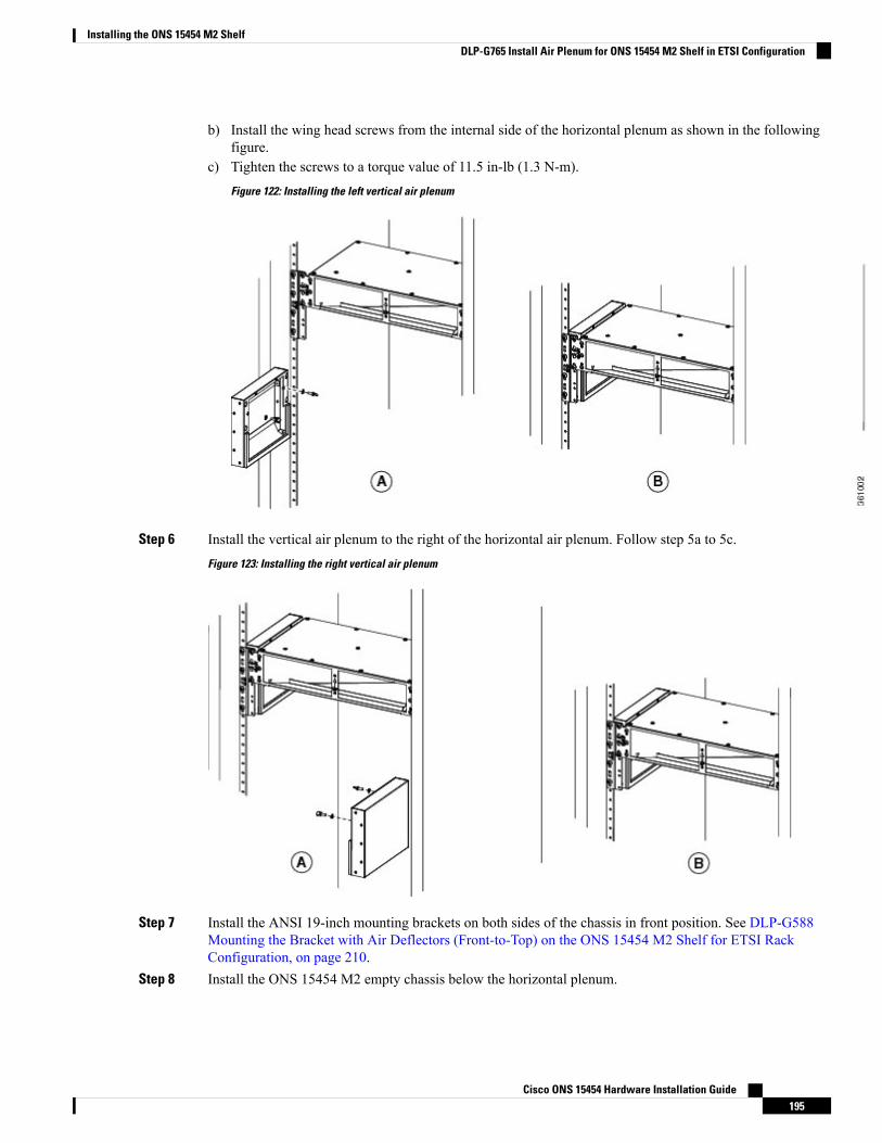
b) Install the wing head screws from the internal side of the horizontal plenum as shown in the followingfigure.
c) Tighten the screws to a torque value of 11.5 in-lb (1.3 N-m).
Figure 122: Installing the left vertical air plenum
Step 6 Install the vertical air plenum to the right of the horizontal air plenum. Follow step 5a to 5c.
Figure 123: Installing the right vertical air plenum
Step 7 Install the ANSI 19-inch mounting brackets on both sides of the chassis in front position. See DLP-G588Mounting the Bracket with Air Deflectors (Front-to-Top) on the ONS 15454 M2 Shelf for ETSI RackConfiguration, on page 210.
Step 8 Install the ONS 15454 M2 empty chassis below the horizontal plenum.
Cisco ONS 15454 Hardware Installation Guide195
Installing the ONS 15454 M2 ShelfDLP-G765 Install Air Plenum for ONS 15454 M2 Shelf in ETSI Configuration
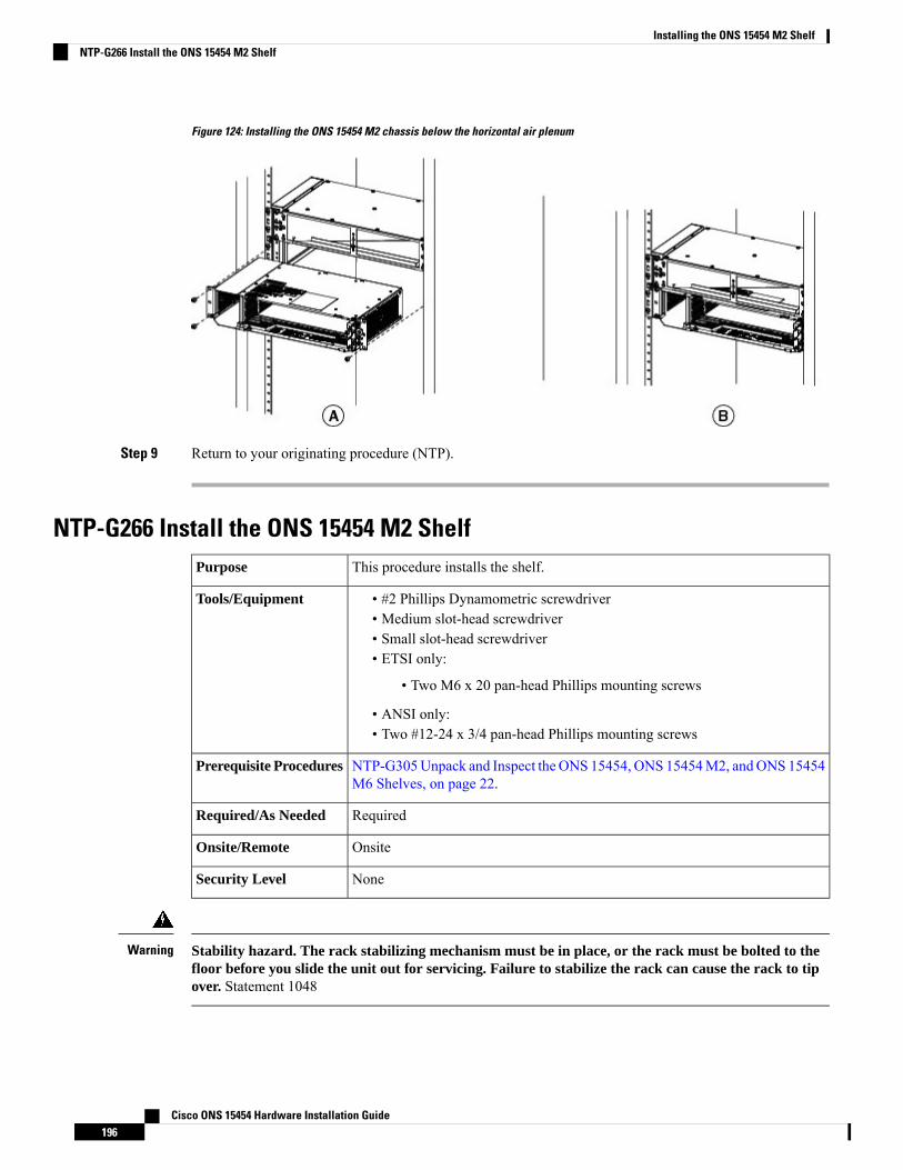
Figure 124: Installing the ONS 15454 M2 chassis below the horizontal air plenum
Step 9 Return to your originating procedure (NTP).
NTP-G266 Install the ONS 15454 M2 ShelfThis procedure installs the shelf.Purpose
• #2 Phillips Dynamometric screwdriver• Medium slot-head screwdriver• Small slot-head screwdriver• ETSI only:
• Two M6 x 20 pan-head Phillips mounting screws
• ANSI only:• Two #12-24 x 3/4 pan-head Phillips mounting screws
Tools/Equipment
NTP-G305Unpack and Inspect the ONS 15454, ONS 15454M2, andONS 15454M6 Shelves, on page 22.
Prerequisite Procedures
RequiredRequired/As Needed
OnsiteOnsite/Remote
NoneSecurity Level
Stability hazard. The rack stabilizing mechanism must be in place, or the rack must be bolted to thefloor before you slide the unit out for servicing. Failure to stabilize the rack can cause the rack to tipover. Statement 1048
Warning
Cisco ONS 15454 Hardware Installation Guide196
Installing the ONS 15454 M2 ShelfNTP-G266 Install the ONS 15454 M2 Shelf
This product requires short-circuit (overcurrent) protection, to be provided as part of the buildinginstallation. Install only in accordance with national and local wiring regulations. Statement 1045
Warning
Voltages that present a shock hazard may exist on Power over Ethernet (PoE) circuits if interconnectionsare made using uninsulated exposed metal contacts, conductors, or terminals. Avoid using suchinterconnection methods, unless the exposed metal parts are located within a restricted access locationand users and service people who are authorized within the restricted access location are made awareof the hazard. A restricted access area can be accessed only through the use of a special tool, lock andkey or other means of security. Statement 1072
Warning
This product relies on the building's installation for short-circuit (overcurrent) protection. Ensure thatthe protective device is rated not greater than: 10A-20A, 100-240 VAC~. Statement 1005
Warning
To prevent the system from overheating, do not operate it in an area that exceeds the maximumrecommended ambient temperature of: 131°F (55°C). Statement 1047
Warning
Take care when connecting units to the supply circuit so that wiring is not overloaded. Statement 1018Warning
To prevent bodily injury when mounting or servicing this unit in a rack, you must take special precautions toensure that the system remains stable. The following guidelines are provided to ensure your safety:
Warning
• This unit should be mounted at the bottom of the rack if it is the only unit in the rack.• When mounting this unit in a partially filled rack, load the rack from the bottom to the top with
the heaviest component at the bottom of the rack.• If the rack is provided with stabilizing devices, install the stabilizers before mounting or servicing
the unit in the rack. Statement 1006
To prevent airflow restriction, allow clearance around the ventilation openings to be at least:1 inch(25.4 mm) Statement 1076
Warning
Make sure that the correct type of 19-inch ANSI rack is used for mounting the ONS 15454M2 shelf as shownin Figure 5: 19-inch ANSI Rack Post Recommended for Cisco ONS 15454 M6 and M2 Shelves, on page 5.
Note
Cisco ONS 15454 Hardware Installation Guide197
Installing the ONS 15454 M2 ShelfNTP-G266 Install the ONS 15454 M2 Shelf
During installation, do not use the door to handle the chassis.Note
Remove the door from the ONS 15454 M2 shelf and reinstall it after installation of all the other modules iscomplete.
Note
Procedure
Step 1 Complete the necessary task as applicable:
• DLP-G582 Mounting the 19-inch Brackets on the ONS 15454 M2 Shelf for ANSI Rack Configuration,on page 199
• DLP-G583 Mounting the 23-inch Brackets on the ONS 15454 M2 Shelf for ANSI Rack Configuration,on page 200
• DLP-G584 Mounting the Bracket with Air Deflectors (Front-to-Back) on the ONS 15454 M2 Shelf forANSI Rack Configuration , on page 201
• DLP-G585 Mounting the Brackets on the ONS 1545 M2 Shelf for ETSI Rack Configuration, on page204
• DLP-G586 Mounting the Air Deflectors (Front-to-Front) on the ONS 15454 M2 Shelf for ETSI RackConfiguration, on page 205
• DLP-G587 Mounting the Bracket with Air Deflectors (Front-to-Back) on the ONS 15454 M2 Shelf forETSI Rack Configuration, on page 207
• DLP-G588 Mounting the Bracket with Air Deflectors (Front-to-Top) on the ONS 15454 M2 Shelf forETSI Rack Configuration, on page 210
Step 2 Complete the necessary mounting task as applicable:
• DLP-G589 Mount the ONS 15454 M2 Shelf on a Rack (One Person), on page 211.
• DLP-G590 Mount the ONS 15454 M2 Shelf on the Wall, on page 213
• DLP-G591 Mount the ONS 15454 M2 Shelf on the Desktop, on page 216
Step 3 Connect the chassis to the office ground. For detailed instructions on how to ground the chassis, refer to theElectrostatic Discharge and Grounding Guide for Cisco CPT and Cisco ONS Platforms.
Step 4 Continue with NTP-G270 Open and Remove the Standard Door of the ONS 15454 M2 Shelf, on page 220.
Stop. You have completed this procedure.
Cisco ONS 15454 Hardware Installation Guide198
Installing the ONS 15454 M2 ShelfNTP-G266 Install the ONS 15454 M2 Shelf
DLP-G582 Mounting the 19-inch Brackets on the ONS 15454 M2 Shelf for ANSI Rack Configuration
This task installs the 19-inch mounting brackets to the ONS 15454 M2 shelf forANSI rack configuration.
Purpose
• #2 Phillips Dynamometric screwdriver• Medium slot-head screwdriver• Small slot-head screwdriver
Tools/Equipment
NTP-G305Unpack and Inspect the ONS 15454, ONS 15454M2, andONS 15454M6 Shelves, on page 22.
Prerequisite Procedures
As neededRequired/As Needed
OnsiteOnsite/Remote
NoneSecurity Level
Use only the fastening hardware provided with the ONS 15454 M2 to prevent loosening, deterioration, andelectromechanical corrosion of the hardware and joined material.
Caution
When mounting the ONS 15454 M2 in a frame with a nonconductive coating (such as paint, lacquer, orenamel) either use the thread-forming screws provided with the ONS 15454M2 ship kit, or remove the coatingfrom the threads to ensure electrical continuity.
Caution
The mounting brackets can be installed in the front or the middle position of the chassis.Note
Procedure
Step 1 Place the wider side of the 19-inch mounting bracket flush against the shelf (see the following figure). Thenarrow side of the mounting bracket should be towards the front of the shelf.
Step 2 Align the mounting bracket screw holes against the shelf screw holes.Step 3 Insert the screws and tighten them to a torque value of 11.5 in-lb (1.3 N-m).Step 4 Repeat steps 1 through 3 for the mounting bracket on the opposite side.
Cisco ONS 15454 Hardware Installation Guide199
Installing the ONS 15454 M2 ShelfDLP-G582 Mounting the 19-inch Brackets on the ONS 15454 M2 Shelf for ANSI Rack Configuration
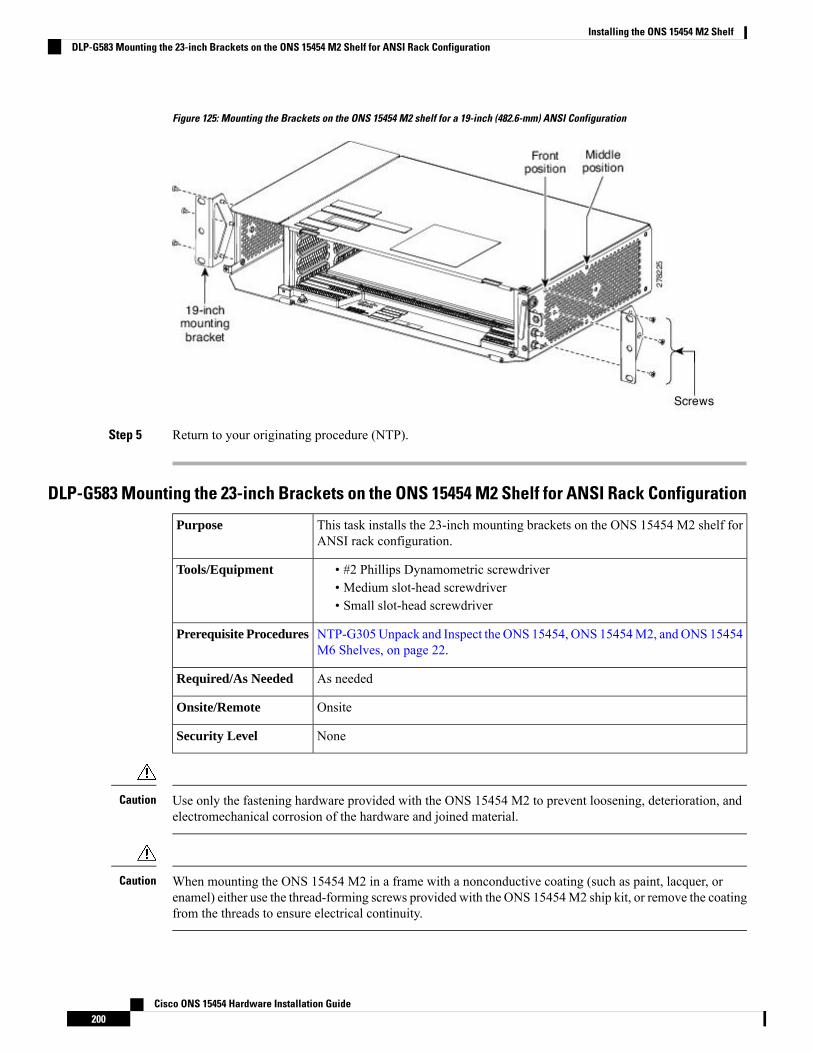
Figure 125: Mounting the Brackets on the ONS 15454 M2 shelf for a 19-inch (482.6-mm) ANSI Configuration
Step 5 Return to your originating procedure (NTP).
DLP-G583 Mounting the 23-inch Brackets on the ONS 15454 M2 Shelf for ANSI Rack Configuration
This task installs the 23-inch mounting brackets on the ONS 15454 M2 shelf forANSI rack configuration.
Purpose
• #2 Phillips Dynamometric screwdriver• Medium slot-head screwdriver• Small slot-head screwdriver
Tools/Equipment
NTP-G305Unpack and Inspect the ONS 15454, ONS 15454M2, andONS 15454M6 Shelves, on page 22.
Prerequisite Procedures
As neededRequired/As Needed
OnsiteOnsite/Remote
NoneSecurity Level
Use only the fastening hardware provided with the ONS 15454 M2 to prevent loosening, deterioration, andelectromechanical corrosion of the hardware and joined material.
Caution
When mounting the ONS 15454 M2 in a frame with a nonconductive coating (such as paint, lacquer, orenamel) either use the thread-forming screws provided with the ONS 15454M2 ship kit, or remove the coatingfrom the threads to ensure electrical continuity.
Caution
Cisco ONS 15454 Hardware Installation Guide200
Installing the ONS 15454 M2 ShelfDLP-G583 Mounting the 23-inch Brackets on the ONS 15454 M2 Shelf for ANSI Rack Configuration
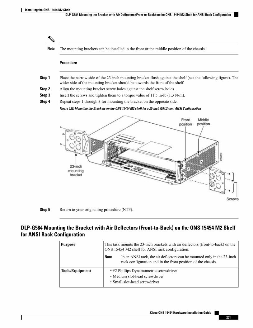
The mounting brackets can be installed in the front or the middle position of the chassis.Note
Procedure
Step 1 Place the narrow side of the 23-inch mounting bracket flush against the shelf (see the following figure). Thewider side of the mounting bracket should be towards the front of the shelf.
Step 2 Align the mounting bracket screw holes against the shelf screw holes.Step 3 Insert the screws and tighten them to a torque value of 11.5 in-lb (1.3 N-m).Step 4 Repeat steps 1 through 3 for mounting the bracket on the opposite side.
Figure 126: Mounting the Brackets on the ONS 15454 M2 shelf for a 23-inch (584.2-mm) ANSI Configuration
Step 5 Return to your originating procedure (NTP).
DLP-G584 Mounting the Bracket with Air Deflectors (Front-to-Back) on the ONS 15454 M2 Shelffor ANSI Rack Configuration
This task mounts the 23-inch brackets with air deflectors (front-to-back) on theONS 15454 M2 shelf for ANSI rack configuration.
In an ANSI rack, the air deflectors can be mounted only in the 23-inchrack configuration and in the front position of the chassis.
Note
Purpose
• #2 Phillips Dynamometric screwdriver• Medium slot-head screwdriver• Small slot-head screwdriver
Tools/Equipment
Cisco ONS 15454 Hardware Installation Guide201
Installing the ONS 15454 M2 ShelfDLP-G584 Mounting the Bracket with Air Deflectors (Front-to-Back) on the ONS 15454 M2 Shelf for ANSI Rack Configuration

NTP-G305Unpack and Inspect the ONS 15454, ONS 15454M2, andONS 15454M6 Shelves, on page 22.
Prerequisite Procedures
As neededRequired/As Needed
OnsiteOnsite/Remote
NoneSecurity Level
Use only the fastening hardware provided with the ONS 15454 M2 to prevent loosening, deterioration, andelectromechanical corrosion of the hardware and joined material.
Caution
Procedure
Step 1 Place the right front air deflector flush against the right side of the chassis as shown in Diagram 1 of Figure127:Mounting the Air Deflectors (Front-to-Back) on the ONS 15454M2 Shelf for ANSI Rack Configuration,on page 203.
Step 2 Align the screw holes on the right front air deflector with the screw holes on right side of the chassis.Step 3 Insert the screws and tighten them to a torque value of 11.5 in-lb (1.3 N-m). See Diagram 2 of Figure 127:
Mounting the Air Deflectors (Front-to-Back) on the ONS 15454 M2 Shelf for ANSI Rack Configuration, onpage 203.
Step 4 Place the left back air deflector flush against the chassis as shown in Diagram 1 of Figure 127: Mounting theAir Deflectors (Front-to-Back) on the ONS 15454 M2 Shelf for ANSI Rack Configuration, on page 203.
If the 100G-LC-C, 10x10G-LC, or CFP-LC cards are to be installed in the ONS 15454 M2 shelf,do not mount the left back deflector (exhaust air deflector). Use the standard brackets directly tomount the ONS 15454 M2 shelf.
Note
Step 5 Align the screw holes on the left back air deflector with the screw holes on the chassis.Step 6 Insert the screws and tighten them to a torque value of 11.5 in-lb (1.3 N-m). See Diagram 2 of Figure 127:
Mounting the Air Deflectors (Front-to-Back) on the ONS 15454 M2 Shelf for ANSI Rack Configuration, onpage 203.
Step 7 Place the air deflector covers on the front and rear ends of the chassis as shown in Diagram 3 of Figure 127:Mounting the Air Deflectors (Front-to-Back) on the ONS 15454 M2 Shelf for ANSI Rack Configuration, onpage 203.
Step 8 Align the screw holes on the air deflector covers with the screw holes on the chassis.Step 9 Insert the screws and tighten them to a torque value of 11.5 in-lb (1.3 N-m). See Diagram 4 of Figure 127:
Mounting the Air Deflectors (Front-to-Back) on the ONS 15454 M2 Shelf for ANSI Rack Configuration, onpage 203.
Step 10 Place the 23-inch mounting bracket flush in the front position (see Diagram 1 of Figure 128: Mounting theBrackets on the ONS 15454 M2 Shelf for ANSI Rack Configuration, on page 203) or in the middle position(see Diagram 3 of Figure 128: Mounting the Brackets on the ONS 15454 M2 Shelf for ANSI RackConfiguration, on page 203) against the right side of the chassis.
Step 11 Align the screw holes on the 23-inch mounting bracket with the screw holes on the right side of the chassis.Step 12 Insert the screws and tighten them to a torque value of 11.5 in-lb (1.3 N-m).
Cisco ONS 15454 Hardware Installation Guide202
Installing the ONS 15454 M2 ShelfDLP-G584 Mounting the Bracket with Air Deflectors (Front-to-Back) on the ONS 15454 M2 Shelf for ANSI Rack Configuration
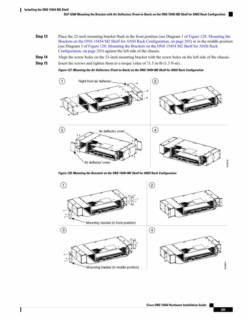
Step 13 Place the 23-inch mounting bracket flush in the front position (see Diagram 1 of Figure 128: Mounting theBrackets on the ONS 15454 M2 Shelf for ANSI Rack Configuration, on page 203) or in the middle position(see Diagram 3 of Figure 128: Mounting the Brackets on the ONS 15454 M2 Shelf for ANSI RackConfiguration, on page 203) against the left side of the chassis.
Step 14 Align the screw holes on the 23-inch mounting bracket with the screw holes on the left side of the chassis.Step 15 Insert the screws and tighten them to a torque value of 11.5 in-lb (1.3 N-m).
Figure 127: Mounting the Air Deflectors (Front-to-Back) on the ONS 15454 M2 Shelf for ANSI Rack Configuration
Figure 128: Mounting the Brackets on the ONS 15454 M2 Shelf for ANSI Rack Configuration
Cisco ONS 15454 Hardware Installation Guide203
Installing the ONS 15454 M2 ShelfDLP-G584 Mounting the Bracket with Air Deflectors (Front-to-Back) on the ONS 15454 M2 Shelf for ANSI Rack Configuration

Step 16 Return to your originating procedure (NTP).
DLP-G585 Mounting the Brackets on the ONS 1545 M2 Shelf for ETSI Rack Configuration
This task installs the mounting brackets on the ONS 15454 M2 shelf for ETSIrack configuration.
In an ETSI rack, the air deflectors can be mounted only in the frontposition of the chassis.
Note
Purpose
• #2 Phillips Dynamometric screwdriver• Medium slot-head screwdriver• Small slot-head screwdriver
Tools/Equipment
NTP-G305Unpack and Inspect the ONS 15454, ONS 15454M2, andONS 15454M6 Shelves, on page 22.
Prerequisite Procedures
As neededRequired/As Needed
OnsiteOnsite/Remote
NoneSecurity Level
Use only the fastening hardware provided with the ONS 15454 M2 to prevent loosening, deterioration, andelectromechanical corrosion of the hardware and joined material.
Caution
When mounting the ONS 15454 M2 in a frame with a nonconductive coating (such as paint, lacquer, orenamel) either use the thread-forming screws provided with the ONS 15454M2 ship kit, or remove the coatingfrom the threads to ensure electrical continuity.
Caution
Procedure
Step 1 Place the mounting bracket flush against the shelf as shown in Figure 129: Mounting the Brackets on the ONS15454 M2 Shelf for ETSI Rack Configuration, on page 205.
Step 2 Align the mounting bracket screw holes against the shelf screw holes.Step 3 Insert the screws and tighten them to a torque value of 11.5 in-lb (1.3 N-m).Step 4 Repeat steps 1 through 3 for the mounting bracket on the opposite side.
Cisco ONS 15454 Hardware Installation Guide204
Installing the ONS 15454 M2 ShelfDLP-G585 Mounting the Brackets on the ONS 1545 M2 Shelf for ETSI Rack Configuration
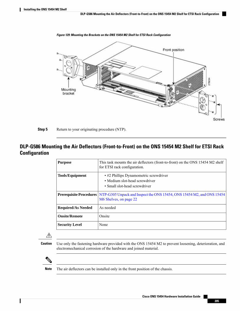
Figure 129: Mounting the Brackets on the ONS 15454 M2 Shelf for ETSI Rack Configuration
Step 5 Return to your originating procedure (NTP).
DLP-G586 Mounting the Air Deflectors (Front-to-Front) on the ONS 15454 M2 Shelf for ETSI RackConfiguration
This task mounts the air deflectors (front-to-front) on the ONS 15454 M2 shelffor ETSI rack configuration.
Purpose
• #2 Phillips Dynamometric screwdriver• Medium slot-head screwdriver• Small slot-head screwdriver
Tools/Equipment
NTP-G305Unpack and Inspect the ONS 15454, ONS 15454M2, andONS 15454M6 Shelves, on page 22
Prerequisite Procedures
As neededRequired/As Needed
OnsiteOnsite/Remote
NoneSecurity Level
Use only the fastening hardware provided with the ONS 15454 M2 to prevent loosening, deterioration, andelectromechanical corrosion of the hardware and joined material.
Caution
The air deflectors can be installed only in the front position of the chassis.Note
Cisco ONS 15454 Hardware Installation Guide205
Installing the ONS 15454 M2 ShelfDLP-G586 Mounting the Air Deflectors (Front-to-Front) on the ONS 15454 M2 Shelf for ETSI Rack Configuration

Procedure
Step 1 Place the right front air deflector flush against the right side of the chassis as shown in Diagram 1 of Figure130: Mounting the Air Deflectors (Front-to-Front) on the ONS 15454M2 Shelf for ETSI Rack Configuration,on page 207.
Step 2 Align the screw holes on the right front air deflector with the screw holes on right side of the chassis.Step 3 Insert the screws and tighten them to a torque value of 11.5 in-lb (1.3 N-m). See Diagram 1 of Figure 130:
Mounting the Air Deflectors (Front-to-Front) on the ONS 15454 M2 Shelf for ETSI Rack Configuration, onpage 207.
Step 4 Place the left front air deflector flush against the chassis as shown in Diagram 1 of Figure 130: Mounting theAir Deflectors (Front-to-Front) on the ONS 15454 M2 Shelf for ETSI Rack Configuration, on page 207.
If the 100G-LC-C, 10x10G-LC, or CFP-LC cards are to be installed in the ONS 15454 M2 shelf,do not mount the left front deflector (exhaust air deflector). Use the standard brackets directly tomount the ONS 15454 M2 shelf.
Note
Step 5 Align the screw holes on the left back air deflector with the screw holes on the chassis.Step 6 Insert the screws and tighten them to a torque value of 11.5 in-lb (1.3 N-m). See Diagram 1 of Figure 130:
Mounting the Air Deflectors (Front-to-Front) on the ONS 15454 M2 Shelf for ETSI Rack Configuration, onpage 207.
Step 7 Place the air deflector covers on the rear ends of the chassis as shown in Diagram 2 of Figure 130: Mountingthe Air Deflectors (Front-to-Front) on the ONS 15454 M2 Shelf for ETSI Rack Configuration, on page 207.
Step 8 Align the screw holes on the air deflector covers with the screw holes on the chassis.Step 9 Insert the screws and tighten them to a torque value of 11.5 in-lb (1.3 N-m).Step 10 Place the mounting bracket flush in the front position (see Diagram 3 of Figure 130: Mounting the Air
Deflectors (Front-to-Front) on the ONS 15454 M2 Shelf for ETSI Rack Configuration, on page 207) againstthe right side of the chassis.
Step 11 Align the screw holes on the mounting bracket with the screw holes on the right side of the chassis.Step 12 Insert the screws and tighten them to a torque value of 11.5 in-lb (1.3 N-m).Step 13 Place the other mounting bracket flush in the front position (see Diagram 3 of Figure 130: Mounting the Air
Deflectors (Front-to-Front) on the ONS 15454 M2 Shelf for ETSI Rack Configuration, on page 207) againstthe left side of the chassis.
Step 14 Align the screw holes on the mounting bracket with the screw holes on the left side of the chassis.Step 15 Insert the screws and tighten them to a torque value of 11.5 in-lb (1.3 N-m).
Cisco ONS 15454 Hardware Installation Guide206
Installing the ONS 15454 M2 ShelfDLP-G586 Mounting the Air Deflectors (Front-to-Front) on the ONS 15454 M2 Shelf for ETSI Rack Configuration

Figure 130: Mounting the Air Deflectors (Front-to-Front) on the ONS 15454 M2 Shelf for ETSI Rack Configuration
Step 16 Return to your originating procedure (NTP).
DLP-G587 Mounting the Bracket with Air Deflectors (Front-to-Back) on the ONS 15454 M2 Shelffor ETSI Rack Configuration
This task installs the bracket with air deflectors (front-to-back) on the ONS 15454M2 shelf for ETSI rack configuration.
Purpose
• #2 Phillips Dynamometric screwdriver• Medium slot-head screwdriver• Small slot-head screwdriver
Tools/Equipment
NTP-G305Unpack and Inspect the ONS 15454, ONS 15454M2, andONS 15454M6 Shelves, on page 22
Prerequisite Procedures
As neededRequired/As Needed
OnsiteOnsite/Remote
NoneSecurity Level
Use only the fastening hardware provided with the ONS 15454 M2 to prevent loosening, deterioration, andelectromechanical corrosion of the hardware and joined material.
Caution
The air deflectors can be installed only in the front position of the chassis.Note
Cisco ONS 15454 Hardware Installation Guide207
Installing the ONS 15454 M2 ShelfDLP-G587 Mounting the Bracket with Air Deflectors (Front-to-Back) on the ONS 15454 M2 Shelf for ETSI Rack Configuration

Procedure
Step 1 Place the right front air deflector flush against the right side of the chassis as shown in Diagram 1 of Figure131: Mounting the Air Deflectors (Front-to-Back) on the ONS 15454M2 Shelf for ETSI Rack Configuration,on page 209.
Step 2 Align the screw holes on the right front air deflector with the screw holes on right side of the chassis.Step 3 Insert the screws and tighten them to a torque value of 11.5 in-lb (1.3 N-m). See Diagram 2 of Figure 131:
Mounting the Air Deflectors (Front-to-Back) on the ONS 15454 M2 Shelf for ETSI Rack Configuration, onpage 209.
Step 4 Place the left back air deflector flush against the chassis as shown in Diagram 1 of Figure 131: Mounting theAir Deflectors (Front-to-Back) on the ONS 15454 M2 Shelf for ETSI Rack Configuration, on page 209.
If the 100G-LC-C, 10x10G-LC, or CFP-LC cards are to be installed in the ONS 15454 M2 shelf,do not mount the left back deflector (exhaust air deflector). Use the standard brackets directly tomount the ONS 15454 M2 shelf.
Note
Step 5 Align the screw holes on the left back air deflector with the screw holes on the chassis.Step 6 Insert the screws and tighten them to a torque value of 11.5 in-lb (1.3 N-m). See Diagram 2 of Figure 131:
Mounting the Air Deflectors (Front-to-Back) on the ONS 15454 M2 Shelf for ETSI Rack Configuration, onpage 209.
Step 7 Place the air deflector covers on the front and rear ends of the chassis as shown in Diagram 3 of Figure 131:Mounting the Air Deflectors (Front-to-Back) on the ONS 15454 M2 Shelf for ETSI Rack Configuration, onpage 209.
Step 8 Align the screw holes on the air deflector covers with the screw holes on the chassis.Step 9 Insert the screws and tighten them to a torque value of 11.5 in-lb (1.3 N-m). See Diagram 4 of Figure 131:
Mounting the Air Deflectors (Front-to-Back) on the ONS 15454 M2 Shelf for ETSI Rack Configuration, onpage 209.
Step 10 Place the mounting bracket flush in the front position (see Diagram 1 of Figure 132: Mounting the Bracketswith Air Deflectors (Front-to-Back) on the ONS 15454 M2 Shelf for ETSI Rack Configuration, on page 209)or in the middle position (see Diagram 3 of Figure 132: Mounting the Brackets with Air Deflectors(Front-to-Back) on the ONS 15454M2 Shelf for ETSI Rack Configuration, on page 209) against the right sideof the chassis.
Step 11 Align the screw holes on the 23-inch mounting bracket with the screw holes on the right side of the chassis.Step 12 Insert the screws and tighten them to a torque value of 11.5 in-lb (1.3 N-m).Step 13 Place the mounting bracket flush in the front position (see Diagram 1 of Figure 132: Mounting the Brackets
with Air Deflectors (Front-to-Back) on the ONS 15454 M2 Shelf for ETSI Rack Configuration, on page 209)or in the middle position (see Diagram 3 of Figure 132: Mounting the Brackets with Air Deflectors(Front-to-Back) on the ONS 15454 M2 Shelf for ETSI Rack Configuration, on page 209) against the left sideof the chassis.
Step 14 Align the screw holes on the 23-inch mounting bracket with the screw holes on the left side of the chassis.Step 15 Insert the screws and tighten them to a torque value of 11.5 in-lb (1.3 N-m).
Cisco ONS 15454 Hardware Installation Guide208
Installing the ONS 15454 M2 ShelfDLP-G587 Mounting the Bracket with Air Deflectors (Front-to-Back) on the ONS 15454 M2 Shelf for ETSI Rack Configuration
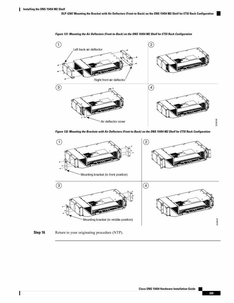
Figure 131: Mounting the Air Deflectors (Front-to-Back) on the ONS 15454 M2 Shelf for ETSI Rack Configuration
Figure 132: Mounting the Brackets with Air Deflectors (Front-to-Back) on the ONS 15454 M2 Shelf for ETSI Rack Configuration
Step 16 Return to your originating procedure (NTP).
Cisco ONS 15454 Hardware Installation Guide209
Installing the ONS 15454 M2 ShelfDLP-G587 Mounting the Bracket with Air Deflectors (Front-to-Back) on the ONS 15454 M2 Shelf for ETSI Rack Configuration

DLP-G588 Mounting the Bracket with Air Deflectors (Front-to-Top) on the ONS 15454 M2 Shelf forETSI Rack Configuration
This task installs the bracket with air deflectors (front-to-top configuration) onthe ONS 15454 M2 shelf.
Purpose
• #2 Phillips Dynamometric screwdriver• Medium slot-head screwdriver• Small slot-head screwdriver
Tools/Equipment
NTP-G305Unpack and Inspect the ONS 15454, ONS 15454M2, andONS 15454M6 Shelves, on page 22
Prerequisite Procedures
As neededRequired/As Needed
OnsiteOnsite/Remote
NoneSecurity Level
Use only the fastening hardware provided with the ONS 15454 M2 to prevent loosening, deterioration, andelectromechanical corrosion of the hardware and joined material.
Caution
The air deflectors can be installed only in the front position of the chassis.Note
Procedure
Step 1 Place the right front air deflector flush against the right side of the chassis (see Diagram 1 of Figure 133:Mounting the Bracket with Air Deflectors (Front-to-Top) on the ONS 15454 M2 Shelf for ETSI RackConfiguration, on page 211).
Step 2 Align the screw holes on the right front air deflector with the screw holes on right side of the chassis.Step 3 Insert the screws and tighten them to a torque value of 11.5 in-lb (1.3 N-m).Step 4 Place the air deflector cover on the rear end of the chassis.Step 5 Insert the screws and tighten them to a torque value of 11.5 in-lb (1.3 N-m). See Diagram 2 of Figure 133:
Mounting the Bracket with Air Deflectors (Front-to-Top) on the ONS 15454 M2 Shelf for ETSI RackConfiguration, on page 211).
Step 6 Place the mounting bracket flush against the left side of the chassis (see Diagram 2 of Figure 133: Mountingthe Bracket with Air Deflectors (Front-to-Top) on the ONS 15454 M2 Shelf for ETSI Rack Configuration,on page 211).
Step 7 Align the screw holes on the mounting bracket with the screw holes on the left side of the chassis.Step 8 Insert the screws and tighten them to a torque value of 11.5 in-lb (1.3 N-m).Step 9 Place the mounting bracket flush against the right side of the chassis (see Diagram 2 of Figure 133: Mounting
the Bracket with Air Deflectors (Front-to-Top) on the ONS 15454 M2 Shelf for ETSI Rack Configuration,on page 211).
Cisco ONS 15454 Hardware Installation Guide210
Installing the ONS 15454 M2 ShelfDLP-G588 Mounting the Bracket with Air Deflectors (Front-to-Top) on the ONS 15454 M2 Shelf for ETSI Rack Configuration
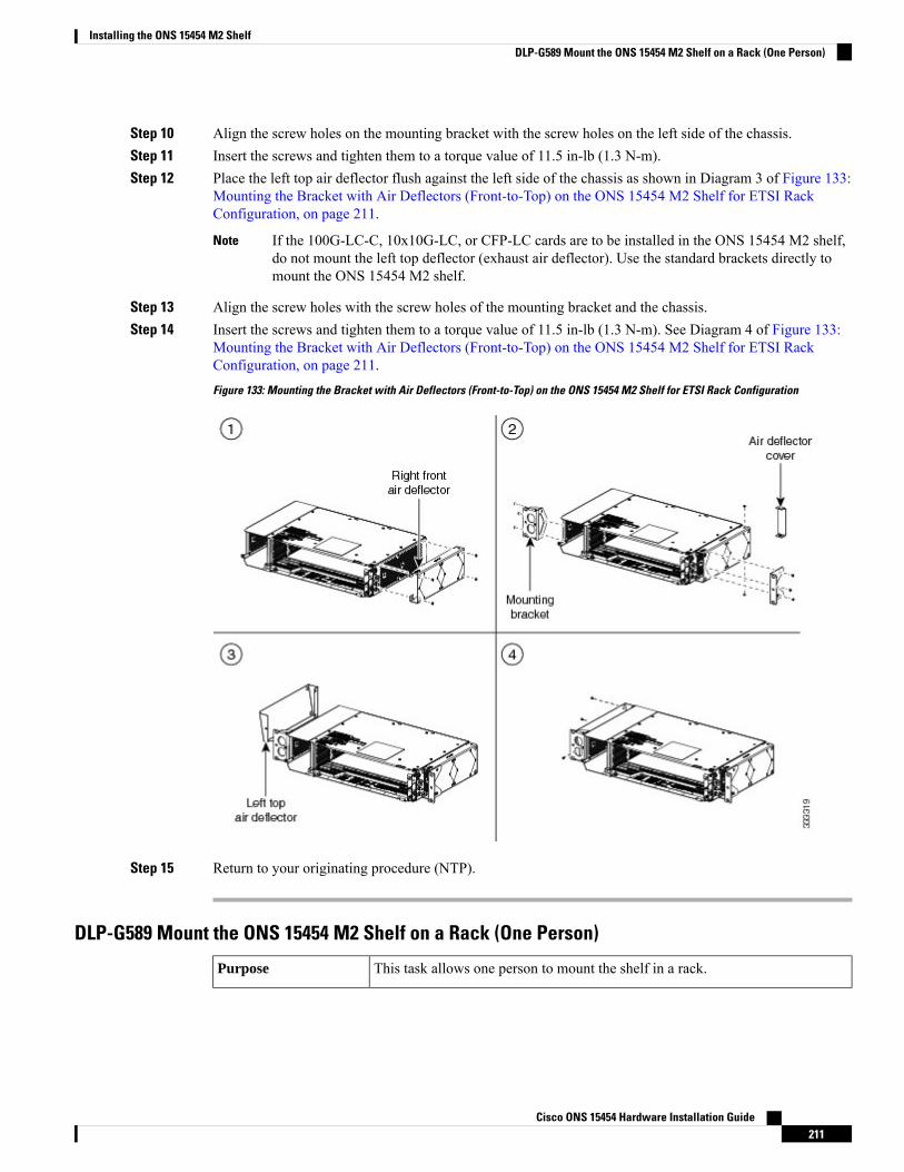
Step 10 Align the screw holes on the mounting bracket with the screw holes on the left side of the chassis.Step 11 Insert the screws and tighten them to a torque value of 11.5 in-lb (1.3 N-m).Step 12 Place the left top air deflector flush against the left side of the chassis as shown in Diagram 3 of Figure 133:
Mounting the Bracket with Air Deflectors (Front-to-Top) on the ONS 15454 M2 Shelf for ETSI RackConfiguration, on page 211.
If the 100G-LC-C, 10x10G-LC, or CFP-LC cards are to be installed in the ONS 15454 M2 shelf,do not mount the left top deflector (exhaust air deflector). Use the standard brackets directly tomount the ONS 15454 M2 shelf.
Note
Step 13 Align the screw holes with the screw holes of the mounting bracket and the chassis.Step 14 Insert the screws and tighten them to a torque value of 11.5 in-lb (1.3 N-m). See Diagram 4 of Figure 133:
Mounting the Bracket with Air Deflectors (Front-to-Top) on the ONS 15454 M2 Shelf for ETSI RackConfiguration, on page 211.
Figure 133: Mounting the Bracket with Air Deflectors (Front-to-Top) on the ONS 15454 M2 Shelf for ETSI Rack Configuration
Step 15 Return to your originating procedure (NTP).
DLP-G589 Mount the ONS 15454 M2 Shelf on a Rack (One Person)
This task allows one person to mount the shelf in a rack.Purpose
Cisco ONS 15454 Hardware Installation Guide211
Installing the ONS 15454 M2 ShelfDLP-G589 Mount the ONS 15454 M2 Shelf on a Rack (One Person)
• # 2 Phillips Dynamometric screwdriver• ANSI—Two #12-24 x 3/4 pan-head Phillips mounting screws• ETSI—Two M6 x 20 mounting screws
Tools/Equipment
NTP-G305Unpack and Inspect the ONS 15454, ONS 15454M2, andONS 15454M6 Shelves, on page 22.
Prerequisite Procedures
As neededRequired/As Needed
OnsiteOnsite/Remote
NoneSecurity Level
The ONS 15454 M2 requires a minimum of 3.5 inches (88.9 mm) of vertical rack space. To ensure that themounting is secure, use two to threeM6mounting screws on each side of the shelf. A shelf should be mountedat the bottom of the rack if it is the only unit in the rack.
Note
In an ANSI rack, the chassis can be installed in the front or the middle position. In an ETSI rack, the chassisis installed only in the front position.
Note
Procedure
Step 1 Verify that the proper fuse panel has been installed in the top mounting space. If a fuse panel is not present,you must install one according to manufacturer instructions:
• For a DC power supply, the fuse rating must not exceed 15A.• For an AC power supply, the fuse rating must not exceed 10A, 15A, or 20A. For North America, thebranch circuit protectionmust be rated 20A. The overcurrent/short circuit protectionmust be in accordancewith local and national electrical codes.
Step 2 Ensure that the shelf is mounted on the appropriate rack equipment:
• 23 inches (584.2 mm) or 19 inches (482.6 mm) for ANSI racks. The recommended 19-inch ANSI rackfor the ONS 15454 M2 shelf is shown in Figure 5: 19-inch ANSI Rack Post Recommended for CiscoONS 15454 M6 and M2 Shelves, on page 5.
• 600 x 600-mm (23.6 x 23.6-inch) or 600 x 300-mm (23.6 x 11.8-inch) for ETSI racks.
Diagram 1 of Figure 134: Mounting an ONS 15454 M2 in a Rack, on page 213 shows the ONS 15454 M2shelf mounted on an ANSI rack in the middle position using 19-inch mounting brackets
Diagram 2 of Figure 134: Mounting an ONS 15454 M2 in a Rack, on page 213 shows the ONS 15454 M2shelf mounted on an ETSI rack in the front position using mounting brackets
Cisco ONS 15454 Hardware Installation Guide212
Installing the ONS 15454 M2 ShelfDLP-G589 Mount the ONS 15454 M2 Shelf on a Rack (One Person)
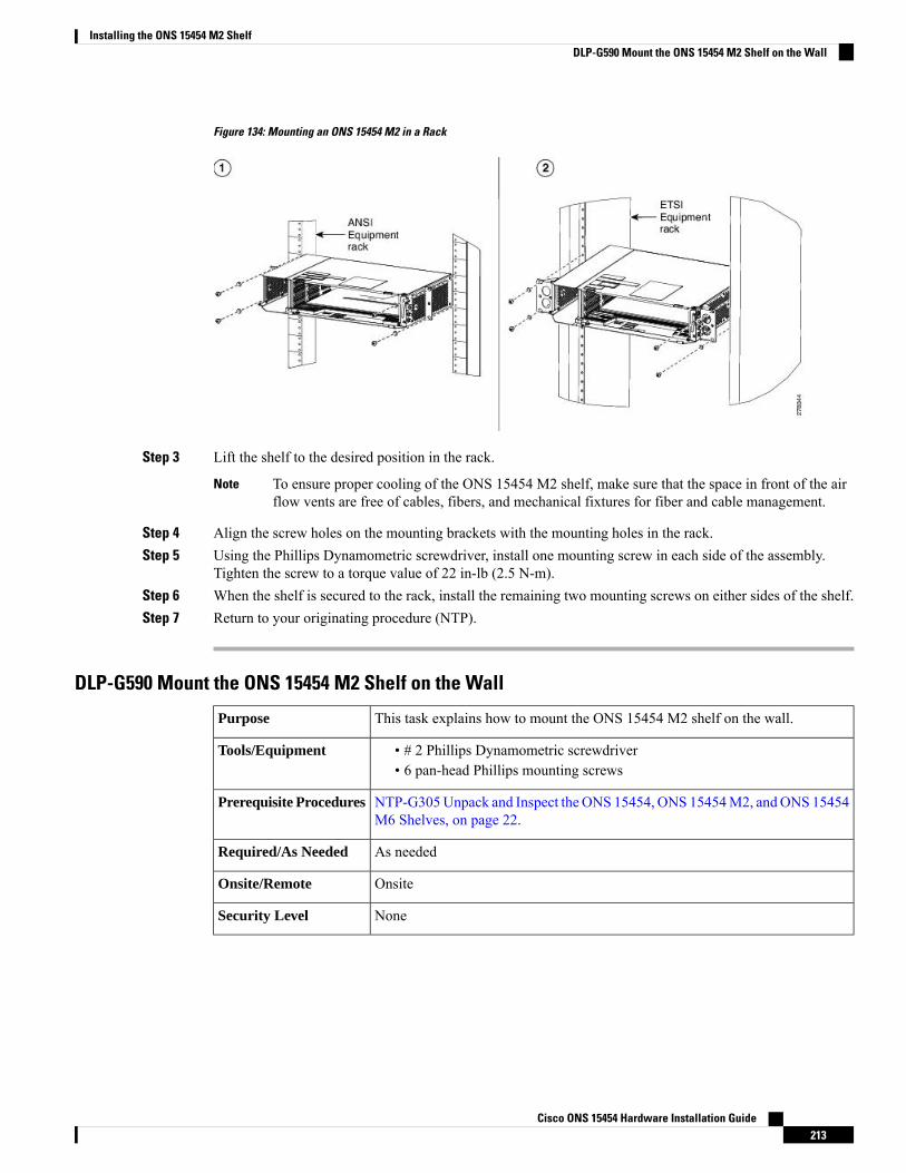
Figure 134: Mounting an ONS 15454 M2 in a Rack
Step 3 Lift the shelf to the desired position in the rack.
To ensure proper cooling of the ONS 15454 M2 shelf, make sure that the space in front of the airflow vents are free of cables, fibers, and mechanical fixtures for fiber and cable management.
Note
Step 4 Align the screw holes on the mounting brackets with the mounting holes in the rack.Step 5 Using the Phillips Dynamometric screwdriver, install one mounting screw in each side of the assembly.
Tighten the screw to a torque value of 22 in-lb (2.5 N-m).Step 6 When the shelf is secured to the rack, install the remaining two mounting screws on either sides of the shelf.Step 7 Return to your originating procedure (NTP).
DLP-G590 Mount the ONS 15454 M2 Shelf on the Wall
This task explains how to mount the ONS 15454 M2 shelf on the wall.Purpose
• # 2 Phillips Dynamometric screwdriver• 6 pan-head Phillips mounting screws
Tools/Equipment
NTP-G305Unpack and Inspect the ONS 15454, ONS 15454M2, andONS 15454M6 Shelves, on page 22.
Prerequisite Procedures
As neededRequired/As Needed
OnsiteOnsite/Remote
NoneSecurity Level
Cisco ONS 15454 Hardware Installation Guide213
Installing the ONS 15454 M2 ShelfDLP-G590 Mount the ONS 15454 M2 Shelf on the Wall

The ONS 15454 M2 requires a minimum of 20.4-inches (518.16-mm) vertical length and a minimum of25.5-inches (647.69-mm) horizontal width on the wall.Wall mount brackets are used tomount the ONS 15454M2 shelf assembly on the wall. The type of screws used to mount the brackets on the wall depends on thewall-type and are not provided by Cisco. The screws used must be able to sustain an overall weight of at least20 kg (44 lb).
Note
Procedure
Step 1 Verify that the proper fuse panel has been installed. If a fuse panel is not present, you must install one accordingto manufacturer instructions:
• For a DC power supply, the fuse rating must not exceed 15A.• For an AC power supply, the fuse rating must not exceed 10A, 15A, or 20A. For North America, thebranch circuit protectionmust be rated 20A. The overcurrent/short circuit protectionmust be in accordancewith local and national electrical codes.
Step 2 Mount the bracket on the wall as shown in Figure 135: Wall Mounting of the ONS 15454 M2 Shelf, on page215. To mount the bracket on a non-concrete wall, choose the bracket holes based on the wall structure. Atleast four screws must be used to mount the bracket on the wall.
Step 3 Align the mounting bracket screw holes against the shelf screw holes (see diagram 1 of Figure 135: WallMounting of the ONS 15454 M2 Shelf, on page 215).
Step 4 Insert the screws and tighten them to a torque value of 11.5 in-lb (1.3 N-m). See diagram 2 of Figure 135:Wall Mounting of the ONS 15454 M2 Shelf, on page 215.
Cisco ONS 15454 Hardware Installation Guide214
Installing the ONS 15454 M2 ShelfDLP-G590 Mount the ONS 15454 M2 Shelf on the Wall
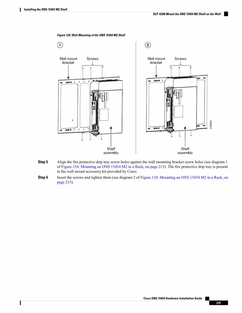
Figure 135: Wall Mounting of the ONS 15454 M2 Shelf
Step 5 Align the fire protective drip tray screw holes against the wall mounting bracket screw holes (see diagram 1of Figure 134: Mounting an ONS 15454 M2 in a Rack, on page 213). The fire protective drip tray is presentin the wall mount accessory kit provided by Cisco.
Step 6 Insert the screws and tighten them (see diagram 2 of Figure 134: Mounting an ONS 15454 M2 in a Rack, onpage 213).
Cisco ONS 15454 Hardware Installation Guide215
Installing the ONS 15454 M2 ShelfDLP-G590 Mount the ONS 15454 M2 Shelf on the Wall

Figure 136: Mounting the Fire Protective Cover
Step 7 Return to your originating procedure (NTP).
DLP-G591 Mount the ONS 15454 M2 Shelf on the Desktop
This task explains mount the shelf on the desktop.Purpose
NoneTools/Equipment
NTP-G305Unpack and Inspect the ONS 15454, ONS 15454M2, andONS 15454M6 Shelves, on page 22.
Prerequisite Procedures
As neededRequired/As Needed
OnsiteOnsite/Remote
NoneSecurity Level
Procedure
Step 1 Verify that the proper fuse panel has been installed. If a fuse panel is not present, you must install one accordingto manufacturer instructions:
• For a DC power supply, the fuse rating must not exceed 15A.
Cisco ONS 15454 Hardware Installation Guide216
Installing the ONS 15454 M2 ShelfDLP-G591 Mount the ONS 15454 M2 Shelf on the Desktop

• For an AC power supply, the fuse rating must not exceed 10A, 15A, or 20A. For North America, thebranch circuit protectionmust be rated 20A. The overcurrent/short circuit protectionmust be in accordancewith local and national electrical codes.
Step 2 Locate the rubber bumpers provided in the accessory tool kit.Step 3 Place the ONS 15454 M2 shelf upside down on a smooth, flat surface.
To ensure proper cooling of the ONS 15454 M2 shelf, make sure that the space in front of the airflow vents are free of cables, fibers, and mechanical fixtures for fiber and cable management.
Note
Step 4 Peel off the rubber bumpers from the adhesive strip and place it adhesive-side down onto all the four cornersof the surface.
Figure 137: Desktop Mounting of the ONS 15454 M2 Shelf
Step 5 Place the ONS 15454 M2 shelf on a desktop, or other flat and secure surface.Step 6 Return to your originating procedure (NTP).
Front DoorThe front door of the ONS 15454 M2 provides access to the shelf and air-filter.
There are two types of front doors that act as protective panels—standard door and deep-front panel. Thedeep-front panel provides additional space in front of the shelf to accommodate cables that do not fit insidethe standard door. The deep-front panel does not have a hinge and cannot be rotated like the standard door.
If a standard front door was ordered, the ONS 15454 M2 is shipped with a preinstalled standard door. If adeep-front panel was ordered, it is shipped in a separate package.
You can remove the door to provide unrestricted access to the front of the shelf.
An erasable label is pasted on the inside of the front door. You can use the label to record slot and portassignments, card types, node ID, rack ID, and serial number of the ONS 15454 M2 shelf.
The following figure shows the erasable label on the ONS 15454 M2 shelf.
Cisco ONS 15454 Hardware Installation Guide217
Installing the ONS 15454 M2 ShelfFront Door
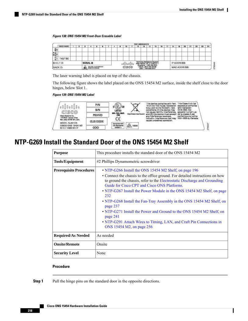
Figure 138: ONS 15454 M2 Front-Door Erasable Label
The laser warning label is placed on top of the chassis.
The following figure shows the label placed on the ONS 15454 M2 surface, inside the shelf close to the doorhinges, below Slot 1.
Figure 139: ONS 15454 M2 Label
NTP-G269 Install the Standard Door of the ONS 15454 M2 ShelfThis procedure installs the standard door of the ONS 15454 M2Purpose
#2 Phillips Dynamometric screwdriverTools/Equipment
• NTP-G266 Install the ONS 15454 M2 Shelf, on page 196• Connect the chassis to the office ground. For detailed instructions on howto ground the chassis, refer to the Electrostatic Discharge and GroundingGuide for Cisco CPT and Cisco ONS Platforms.
• NTP-G267 Install the Power Module in the ONS 15454 M2 Shelf, on page232
• NTP-G268 Install the Fan-Tray Assembly in the ONS 15454 M2 Shelf, onpage 237
• NTP-G271 Install the Power and Ground to the ONS 15454 M2 Shelf, onpage 241
• NTP-G291 Attach Wires to Timing, LAN, and Craft Pin Connections inONS 15454 M2, on page 256
Prerequisite Procedures
As neededRequired/As Needed
OnsiteOnsite/Remote
NoneSecurity Level
Procedure
Step 1 Pull the hinge pins on the standard door in the opposite directions.
Cisco ONS 15454 Hardware Installation Guide218
Installing the ONS 15454 M2 ShelfNTP-G269 Install the Standard Door of the ONS 15454 M2 Shelf
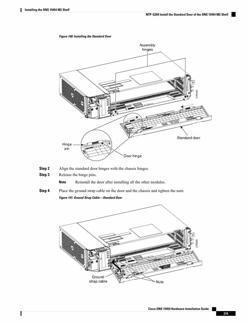
Figure 140: Installing the Standard Door
Step 2 Align the standard door hinges with the chassis hinges.Step 3 Release the hinge pins.
Reinstall the door after installing all the other modules.Note
Step 4 Place the ground strap cable on the door and the chassis and tighten the nuts.
Figure 141: Ground Strap Cable—Standard Door
Cisco ONS 15454 Hardware Installation Guide219
Installing the ONS 15454 M2 ShelfNTP-G269 Install the Standard Door of the ONS 15454 M2 Shelf
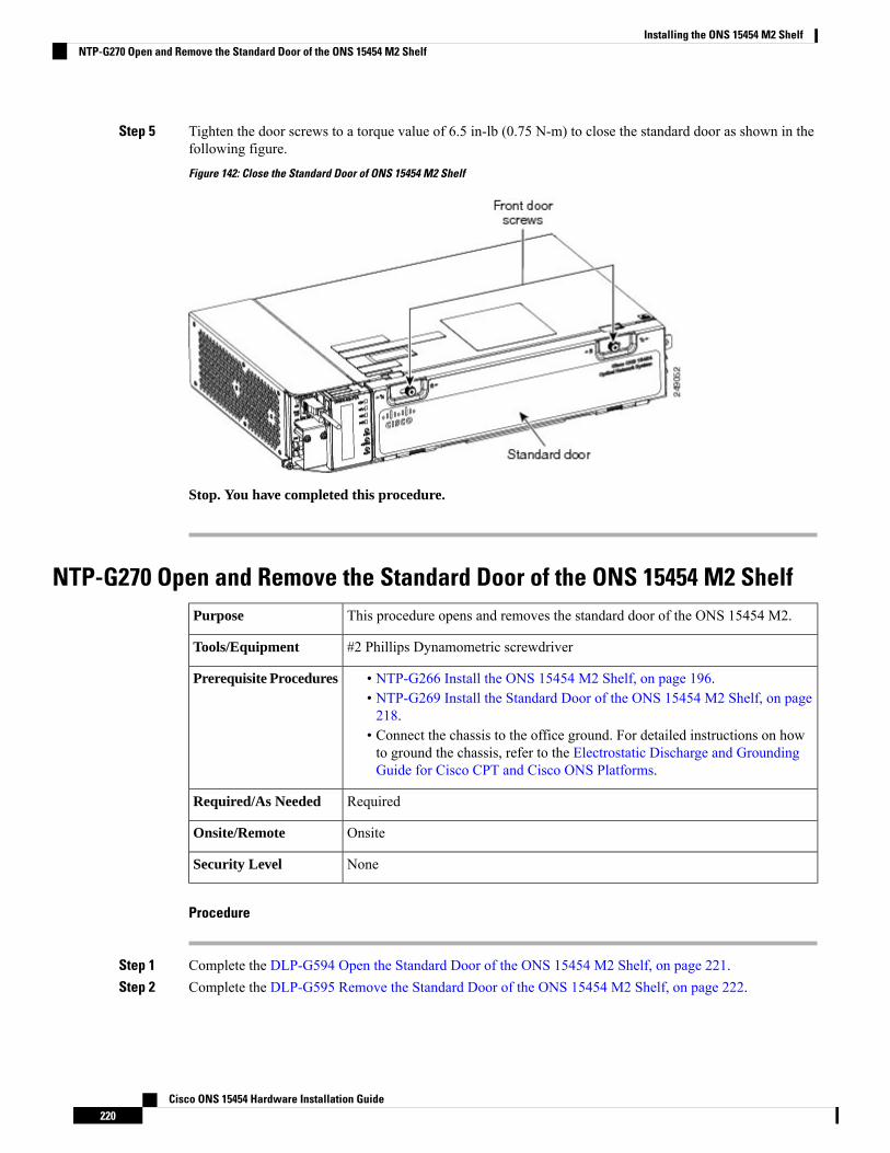
Step 5 Tighten the door screws to a torque value of 6.5 in-lb (0.75 N-m) to close the standard door as shown in thefollowing figure.
Figure 142: Close the Standard Door of ONS 15454 M2 Shelf
Stop. You have completed this procedure.
NTP-G270 Open and Remove the Standard Door of the ONS 15454 M2 ShelfThis procedure opens and removes the standard door of the ONS 15454 M2.Purpose
#2 Phillips Dynamometric screwdriverTools/Equipment
• NTP-G266 Install the ONS 15454 M2 Shelf, on page 196.• NTP-G269 Install the Standard Door of the ONS 15454 M2 Shelf, on page218.
• Connect the chassis to the office ground. For detailed instructions on howto ground the chassis, refer to the Electrostatic Discharge and GroundingGuide for Cisco CPT and Cisco ONS Platforms.
Prerequisite Procedures
RequiredRequired/As Needed
OnsiteOnsite/Remote
NoneSecurity Level
Procedure
Step 1 Complete the DLP-G594 Open the Standard Door of the ONS 15454 M2 Shelf, on page 221.Step 2 Complete the DLP-G595 Remove the Standard Door of the ONS 15454 M2 Shelf, on page 222.
Cisco ONS 15454 Hardware Installation Guide220
Installing the ONS 15454 M2 ShelfNTP-G270 Open and Remove the Standard Door of the ONS 15454 M2 Shelf
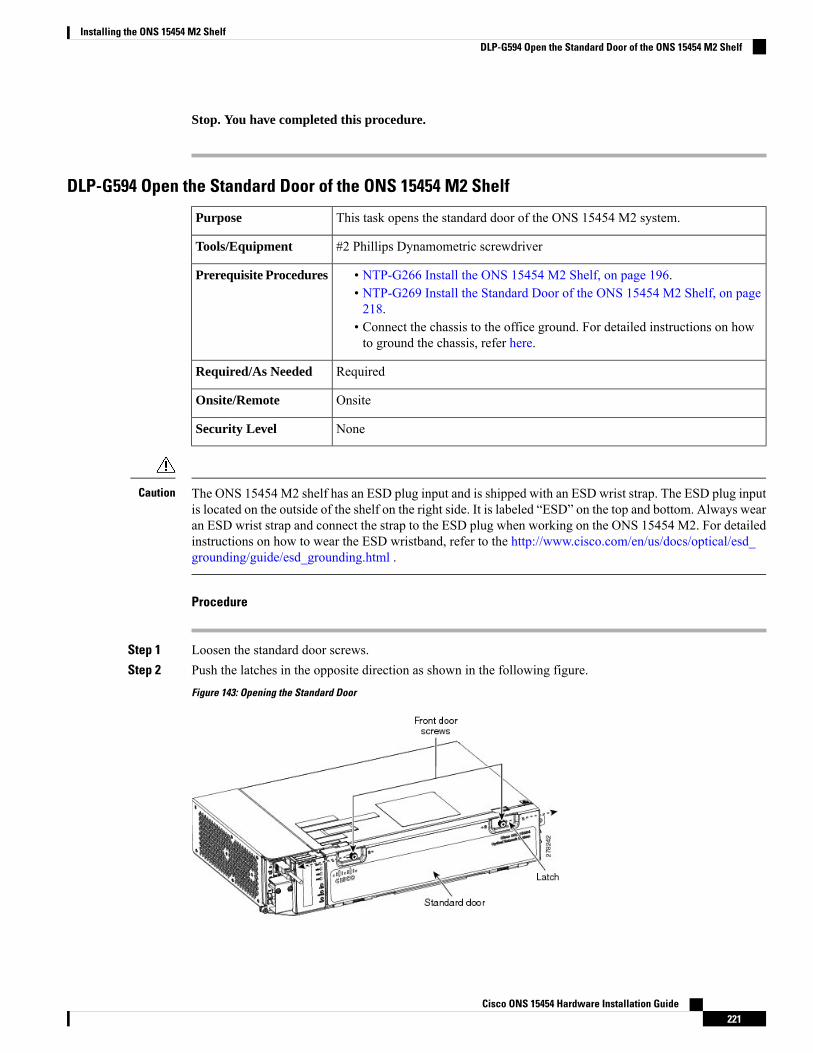
Stop. You have completed this procedure.
DLP-G594 Open the Standard Door of the ONS 15454 M2 Shelf
This task opens the standard door of the ONS 15454 M2 system.Purpose
#2 Phillips Dynamometric screwdriverTools/Equipment
• NTP-G266 Install the ONS 15454 M2 Shelf, on page 196.• NTP-G269 Install the Standard Door of the ONS 15454 M2 Shelf, on page218.
• Connect the chassis to the office ground. For detailed instructions on howto ground the chassis, refer here.
Prerequisite Procedures
RequiredRequired/As Needed
OnsiteOnsite/Remote
NoneSecurity Level
The ONS 15454 M2 shelf has an ESD plug input and is shipped with an ESD wrist strap. The ESD plug inputis located on the outside of the shelf on the right side. It is labeled “ESD” on the top and bottom. Always wearan ESD wrist strap and connect the strap to the ESD plug when working on the ONS 15454 M2. For detailedinstructions on how to wear the ESD wristband, refer to the http://www.cisco.com/en/us/docs/optical/esd_grounding/guide/esd_grounding.html .
Caution
Procedure
Step 1 Loosen the standard door screws.Step 2 Push the latches in the opposite direction as shown in the following figure.
Figure 143: Opening the Standard Door
Cisco ONS 15454 Hardware Installation Guide221
Installing the ONS 15454 M2 ShelfDLP-G594 Open the Standard Door of the ONS 15454 M2 Shelf
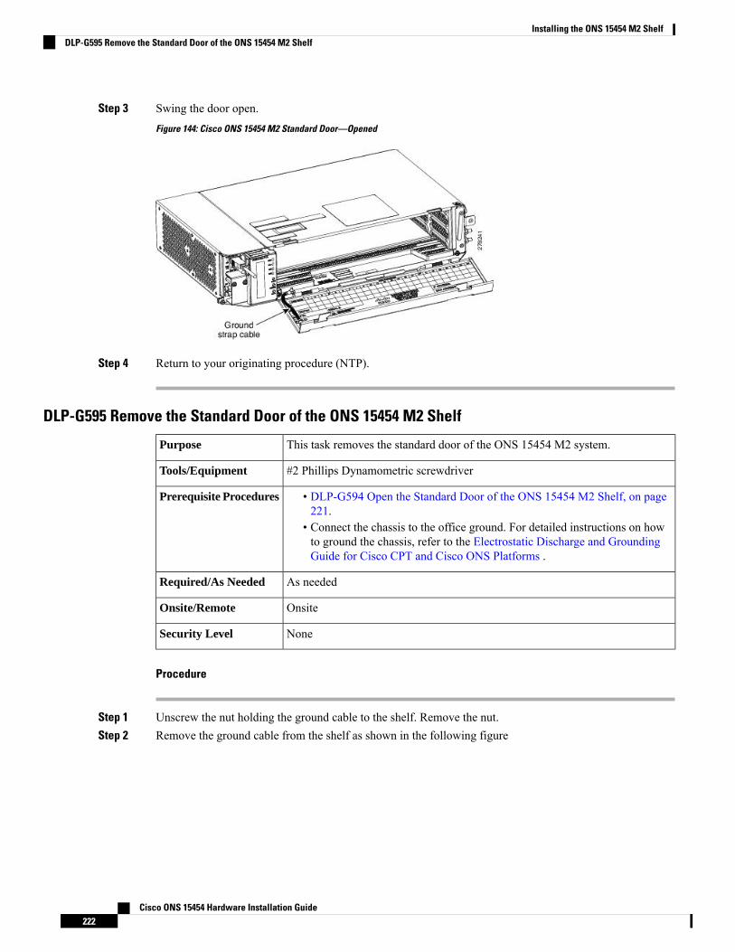
Step 3 Swing the door open.
Figure 144: Cisco ONS 15454 M2 Standard Door—Opened
Step 4 Return to your originating procedure (NTP).
DLP-G595 Remove the Standard Door of the ONS 15454 M2 Shelf
This task removes the standard door of the ONS 15454 M2 system.Purpose
#2 Phillips Dynamometric screwdriverTools/Equipment
• DLP-G594 Open the Standard Door of the ONS 15454 M2 Shelf, on page221.
• Connect the chassis to the office ground. For detailed instructions on howto ground the chassis, refer to the Electrostatic Discharge and GroundingGuide for Cisco CPT and Cisco ONS Platforms .
Prerequisite Procedures
As neededRequired/As Needed
OnsiteOnsite/Remote
NoneSecurity Level
Procedure
Step 1 Unscrew the nut holding the ground cable to the shelf. Remove the nut.Step 2 Remove the ground cable from the shelf as shown in the following figure
Cisco ONS 15454 Hardware Installation Guide222
Installing the ONS 15454 M2 ShelfDLP-G595 Remove the Standard Door of the ONS 15454 M2 Shelf
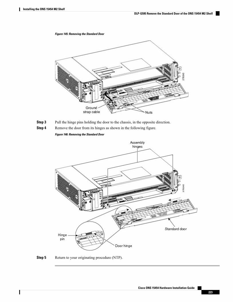
Figure 145: Removing the Standard Door
Step 3 Pull the hinge pins holding the door to the chassis, in the opposite direction.Step 4 Remove the door from its hinges as shown in the following figure.
Figure 146: Removing the Standard Door
Step 5 Return to your originating procedure (NTP).
Cisco ONS 15454 Hardware Installation Guide223
Installing the ONS 15454 M2 ShelfDLP-G595 Remove the Standard Door of the ONS 15454 M2 Shelf
NTP-G343 Install the Deep-Front Panel of the ONS 15454 M2 ShelfThis procedure installs the deep-front panel of the ONS 15454 M2 shelf.Purpose
• #2 Phillips Dynamometric screwdriver• Socket (6/32 standard) and socket wrench to tighten or loosen the groundnut
Tools/Equipment
• NTP-G266 Install the ONS 15454 M2 Shelf, on page 196• Connect the chassis to the office ground. For detailed instructions on howto ground the chassis, refer to the Electrostatic Discharge and GroundingGuide for Cisco CPT and Cisco ONS Platforms .
• NTP-G267 Install the Power Module in the ONS 15454 M2 Shelf, on page232
• NTP-G268 Install the Fan-Tray Assembly in the ONS 15454 M2 Shelf, onpage 237
• NTP-G271 Install the Power and Ground to the ONS 15454 M2 Shelf, onpage 241
• NTP-G291 Attach Wires to Timing, LAN, and Craft Pin Connections inONS 15454 M2, on page 256
Prerequisite Procedures
As neededRequired/As Needed
OnsiteOnsite/Remote
NoneSecurity Level
Use the deep front panel when ONS-SC+-10G-C pluggables are installed on ONS 15454 M2 shelf.Note
The deep-front panel does not have a hinge and cannot be rotated like a standard door. Rotating the deep frontpanel can damage the deep-front panel, shelf hinges, other devices and cables placed below the ONS 15454M2 shelf.
Caution
Procedure
Step 1 Connect the ground strap cable:a) Loosen the ground nut from the shelf (see the following figure).b) Insert the lug of the ground strap cable and tighten the nut on the shelf to a torque value of 11.5 in-lb (1.3
N-m) (see the following figure).c) Route the other end of the ground strap cable outside the shelf at an angle of 180 degrees towards the left.
Cisco ONS 15454 Hardware Installation Guide224
Installing the ONS 15454 M2 ShelfNTP-G343 Install the Deep-Front Panel of the ONS 15454 M2 Shelf
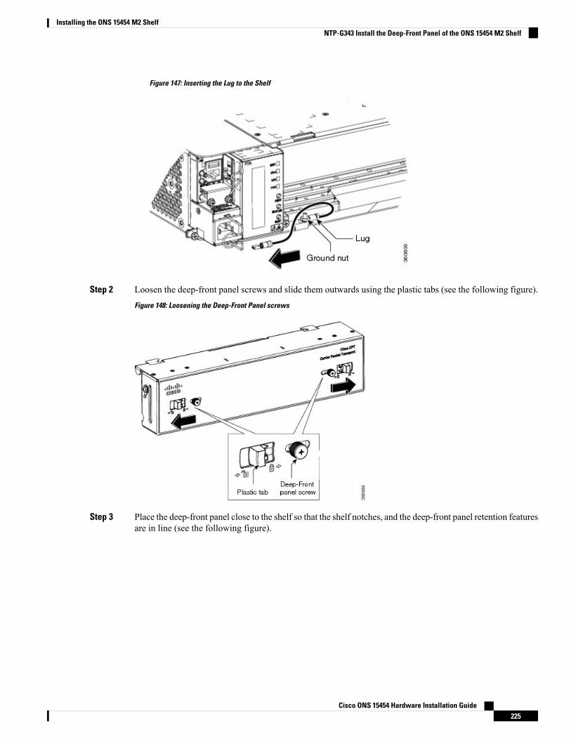
Figure 147: Inserting the Lug to the Shelf
Step 2 Loosen the deep-front panel screws and slide them outwards using the plastic tabs (see the following figure).
Figure 148: Loosening the Deep-Front Panel screws
Step 3 Place the deep-front panel close to the shelf so that the shelf notches, and the deep-front panel retention featuresare in line (see the following figure).
Cisco ONS 15454 Hardware Installation Guide225
Installing the ONS 15454 M2 ShelfNTP-G343 Install the Deep-Front Panel of the ONS 15454 M2 Shelf
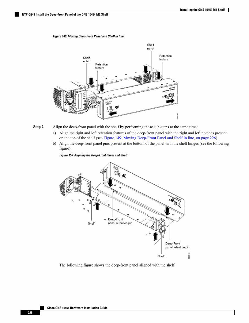
Figure 149: Moving Deep-Front Panel and Shelf in line
Step 4 Align the deep-front panel with the shelf by performing these sub-steps at the same time:a) Align the right and left retention features of the deep-front panel with the right and left notches present
on the top of the shelf (see Figure 149: Moving Deep-Front Panel and Shelf in line, on page 226).b) Align the deep-front panel pins present at the bottom of the panel with the shelf hinges (see the following
figure).
Figure 150: Aligning the Deep-Front Panel and Shelf
The following figure shows the deep-front panel aligned with the shelf.
Cisco ONS 15454 Hardware Installation Guide226
Installing the ONS 15454 M2 ShelfNTP-G343 Install the Deep-Front Panel of the ONS 15454 M2 Shelf
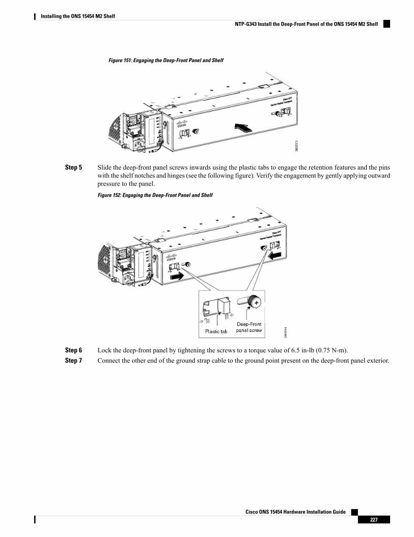
Figure 151: Engaging the Deep-Front Panel and Shelf
Step 5 Slide the deep-front panel screws inwards using the plastic tabs to engage the retention features and the pinswith the shelf notches and hinges (see the following figure). Verify the engagement by gently applying outwardpressure to the panel.
Figure 152: Engaging the Deep-Front Panel and Shelf
Step 6 Lock the deep-front panel by tightening the screws to a torque value of 6.5 in-lb (0.75 N-m).Step 7 Connect the other end of the ground strap cable to the ground point present on the deep-front panel exterior.
Cisco ONS 15454 Hardware Installation Guide227
Installing the ONS 15454 M2 ShelfNTP-G343 Install the Deep-Front Panel of the ONS 15454 M2 Shelf
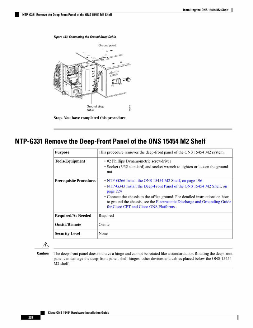
Figure 153: Connecting the Ground Strap Cable
Stop. You have completed this procedure.
NTP-G331 Remove the Deep-Front Panel of the ONS 15454 M2 ShelfThis procedure removes the deep-front panel of the ONS 15454 M2 system.Purpose
• #2 Phillips Dynamometric screwdriver• Socket (6/32 standard) and socket wrench to tighten or loosen the groundnut
Tools/Equipment
• NTP-G266 Install the ONS 15454 M2 Shelf, on page 196• NTP-G343 Install the Deep-Front Panel of the ONS 15454 M2 Shelf, onpage 224
• Connect the chassis to the office ground. For detailed instructions on howto ground the chassis, see the Electrostatic Discharge and Grounding Guidefor Cisco CPT and Cisco ONS Platforms .
Prerequisite Procedures
RequiredRequired/As Needed
OnsiteOnsite/Remote
NoneSecurity Level
The deep-front panel does not have a hinge and cannot be rotated like a standard door. Rotating the deep frontpanel can damage the deep-front panel, shelf hinges, other devices and cables placed below the ONS 15454M2 shelf.
Caution
Cisco ONS 15454 Hardware Installation Guide228
Installing the ONS 15454 M2 ShelfNTP-G331 Remove the Deep-Front Panel of the ONS 15454 M2 Shelf
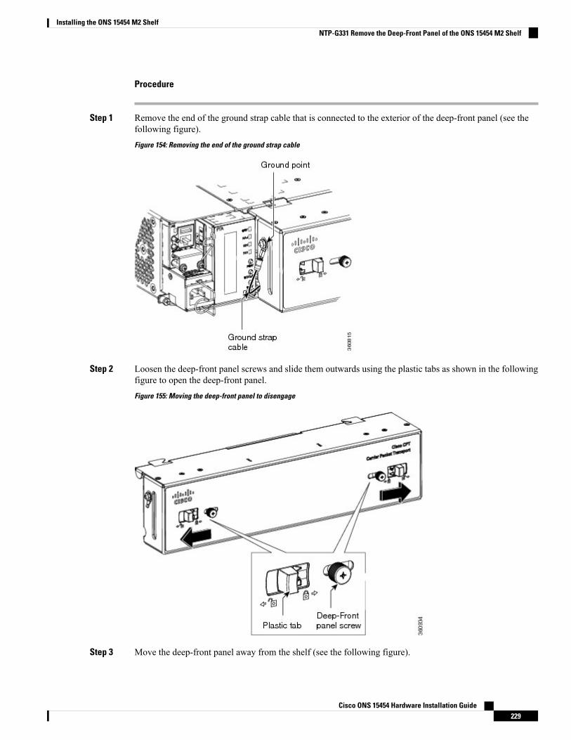
Procedure
Step 1 Remove the end of the ground strap cable that is connected to the exterior of the deep-front panel (see thefollowing figure).
Figure 154: Removing the end of the ground strap cable
Step 2 Loosen the deep-front panel screws and slide them outwards using the plastic tabs as shown in the followingfigure to open the deep-front panel.
Figure 155: Moving the deep-front panel to disengage
Step 3 Move the deep-front panel away from the shelf (see the following figure).
Cisco ONS 15454 Hardware Installation Guide229
Installing the ONS 15454 M2 ShelfNTP-G331 Remove the Deep-Front Panel of the ONS 15454 M2 Shelf
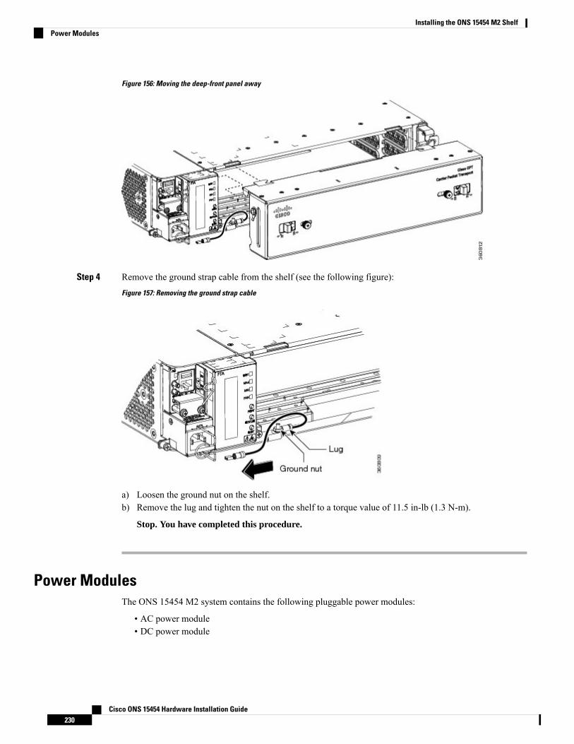
Figure 156: Moving the deep-front panel away
Step 4 Remove the ground strap cable from the shelf (see the following figure):
Figure 157: Removing the ground strap cable
a) Loosen the ground nut on the shelf.b) Remove the lug and tighten the nut on the shelf to a torque value of 11.5 in-lb (1.3 N-m).
Stop. You have completed this procedure.
Power ModulesThe ONS 15454 M2 system contains the following pluggable power modules:
• AC power module• DC power module
Cisco ONS 15454 Hardware Installation Guide230
Installing the ONS 15454 M2 ShelfPower Modules
In addition to supplying power to the ONS 15454 M2 shelf, the power modules support the followingconnections:
• LANConnection—AnEthernet port (RJ-45) that supports the elementmanager system (EMS) connection.The RJ-45 port is used to connect the EMS or the craft interface terminal to access the ONS 15454 M2shelf.
• Passive Unit Inventory Interfaces (USB port)—The passive unit inventory interfaces are used to retrieveinventory information from passive devices such as, fiber trays, FBG DCU, patch panels, passivemuxponder and demuxponder and so on. The inventory details are displayed in the Inventory tab inCTC.
• Timing Connections—The BITS-IN port receives input from third party external sources called SSU(Synchronization Supply Unit) to synchronize the timing of the ONS 15454 M2 shelf. The BITS-OUTport provides output to external devices (other Cisco or third party shelves) to synchronize the timingsignals with the ONS 15454 M6 shelf.
The ONS 15454 M2 shelf has a BITS-IN and BITS-OUT port on the power module. The BITS-IN andBITS-OUT connections are supported by:
• Wire-wrap pins and mini-BNC connectors on the AC power module.•• Mini-BNC connectors on the ETSI DC power module.• Wire-wrap pins on the ANSI DC power module.
For timing connection, use 100-ohm shielded BITS clock cable pair #22 or #24 AWG (0.51 mm² [0.020 inch]or 0.64 mm² [0.0252 inch]) twisted-pair T1-type.
Note
Refer to Telcordia SR-NWT-002224 for rules about provisioning timing references.Note
AC Power ModuleThe AC power module converts the AC input current to DC output current.
Each AC power module has:
• One AC single phase three poles (line L, Neutral N, and Protective Earth PE) input connector• One RJ-45 port for EMS connection• One USB port to support passive unit remote inventory connection• Two BITs connections (IN and OUT) for network synchronization supported by mini BNC• Two BITs connections (IN and OUT) for network synchronization supported by four wire-wrap pins
The AC power module has a single dual-color (red and green) LED on the faceplate. When the AC powerline is not connected, the LED is OFF. Green LED indicates that the AC power line is connected and thepower module is functioning properly. Red LED indicates that the AC power line is connected but an alarmis present due to secondary (48 V) fuse break. The shelf controller card controls the conditions that result intriggering the LED. The LED can be overwritten by the shelf controller card (TNC, TNCE, TSC, TNCS-2,TNCS-2O, or TSCE) in all the three states (OFF/red/green). The AC power module supports the lamp testprocedure and the LED changes its color or state. The fans in the ONS 15454 M2 shelf cool the AC moduleand guarantee proper operation across the complete operating temperature or output power range.
Cisco ONS 15454 Hardware Installation Guide231
Installing the ONS 15454 M2 ShelfAC Power Module
DC Power ModuleThe ONS 15454 M2 system can be powered by redundant DC power lines, however a single power line canpower the entire ONS 15454 M2 system. The DC power module draws the power from the batteries to turnon the ONS 15454 M2.
Each ETSI DC power module has:
• Two input battery connectors (two poles): -48V, RET for power terminals A and B.• One RJ-45 port for EMS connection• One USB port to support passive unit remote inventory connection• Two BITS connections (IN and OUT) for network synchronization that is supported by mini BNC
Each ANSI DC power module has:
• Two terminal block connectors with -48V, RET for power terminals A and B• One RJ-45 port for EMS connection• One USB port to support passive unit remote inventory connection• Two BITS connections (IN and OUT) for network synchronization supported by four wire-wrap pins
The DC power module has a single dual-color (red and green) LED on the faceplate. When the battery is notconnected, the LED is OFF. Green LED indicates that the battery is connected and the power module functionsproperly. Red LED indicates that the battery is connected but an alarm is present due to secondary fuse break(48 V). The DC power module does not support the lamp test procedure.
The fork or ring terminals used on the DC power modules are not available from Cisco, but they are availablecommercially. Ensure that the hole size of the fork terminal or ring terminal is greater than 3.5 mm and widthis less than or equal to 7 mm. The minimum acceptable cable size is #14 AWG. The fork terminal must beinsulated and UL listed.
NTP-G267 Install the Power Module in the ONS 15454 M2 ShelfThis procedure installs the power module in the ONS 15454 M2 system.Purpose
#2 Phillips screwdriverTools/Equipment
• NTP-G266 Install the ONS 15454 M2 Shelf, on page 196.• Connect the chassis to the office ground. For detailed instructions on howto ground the chassis, refer to the Electrostatic Discharge and GroundingGuide for Cisco CPT and Cisco ONS Platforms .
Prerequisite Procedures
RequiredRequired/As Needed
OnsiteOnsite/Remote
NoneSecurity Level
The plug-socket combination must be accessible at all times because it serves as the main disconnectingdevice. Statement 1019
Warning
Cisco ONS 15454 Hardware Installation Guide232
Installing the ONS 15454 M2 ShelfDC Power Module
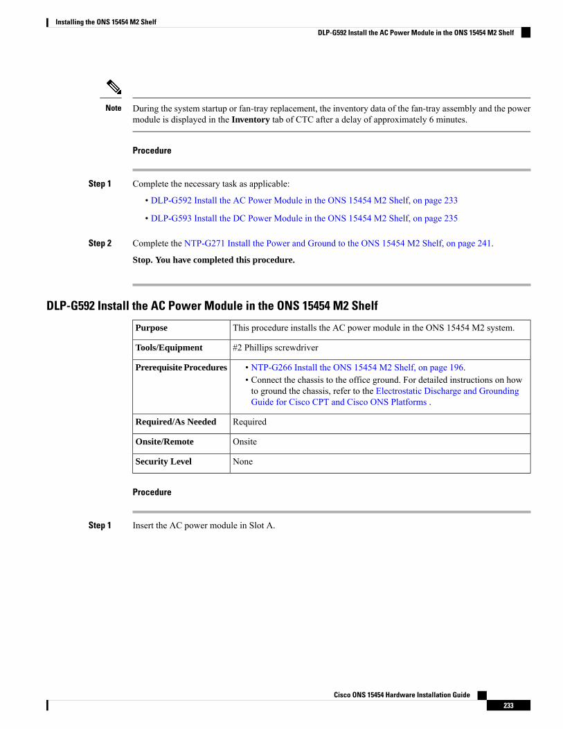
During the system startup or fan-tray replacement, the inventory data of the fan-tray assembly and the powermodule is displayed in the Inventory tab of CTC after a delay of approximately 6 minutes.
Note
Procedure
Step 1 Complete the necessary task as applicable:
• DLP-G592 Install the AC Power Module in the ONS 15454 M2 Shelf, on page 233
• DLP-G593 Install the DC Power Module in the ONS 15454 M2 Shelf, on page 235
Step 2 Complete the NTP-G271 Install the Power and Ground to the ONS 15454 M2 Shelf, on page 241.
Stop. You have completed this procedure.
DLP-G592 Install the AC Power Module in the ONS 15454 M2 Shelf
This procedure installs the AC power module in the ONS 15454 M2 system.Purpose
#2 Phillips screwdriverTools/Equipment
• NTP-G266 Install the ONS 15454 M2 Shelf, on page 196.• Connect the chassis to the office ground. For detailed instructions on howto ground the chassis, refer to the Electrostatic Discharge and GroundingGuide for Cisco CPT and Cisco ONS Platforms .
Prerequisite Procedures
RequiredRequired/As Needed
OnsiteOnsite/Remote
NoneSecurity Level
Procedure
Step 1 Insert the AC power module in Slot A.
Cisco ONS 15454 Hardware Installation Guide233
Installing the ONS 15454 M2 ShelfDLP-G592 Install the AC Power Module in the ONS 15454 M2 Shelf
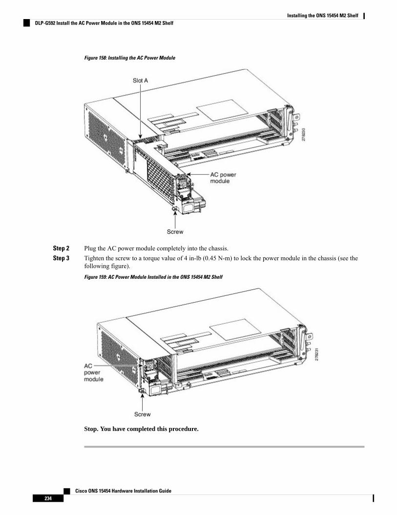
Figure 158: Installing the AC Power Module
Step 2 Plug the AC power module completely into the chassis.Step 3 Tighten the screw to a torque value of 4 in-lb (0.45 N-m) to lock the power module in the chassis (see the
following figure).
Figure 159: AC Power Module Installed in the ONS 15454 M2 Shelf
Stop. You have completed this procedure.
Cisco ONS 15454 Hardware Installation Guide234
Installing the ONS 15454 M2 ShelfDLP-G592 Install the AC Power Module in the ONS 15454 M2 Shelf

DLP-G593 Install the DC Power Module in the ONS 15454 M2 Shelf
This task installs the DC power module in the ONS 15454 M2 system.Purpose
#2 Phillips Dynamometric screwdriverTools/Equipment
• NTP-G266 Install the ONS 15454 M2 Shelf, on page 196.• Connect the chassis to the office ground. For detailed instructions on howto ground the chassis, refer to the Electrostatic Discharge and GroundingGuide for Cisco CPT and Cisco ONS Platforms .
Prerequisite Procedures
RequiredRequired/As Needed
OnsiteOnsite/Remote
NoneSecurity Level
Procedure
Step 1 Insert the DC power module in Slot A (see the following figure).
Figure 160: Installing the DC Power Module
Step 2 Plug the DC power module completely into the chassis.Step 3 Tighten the screw to a torque value of 4 in-lb (0.45 N-m) to lock the power module in the chassis (see the
following figure).
Cisco ONS 15454 Hardware Installation Guide235
Installing the ONS 15454 M2 ShelfDLP-G593 Install the DC Power Module in the ONS 15454 M2 Shelf
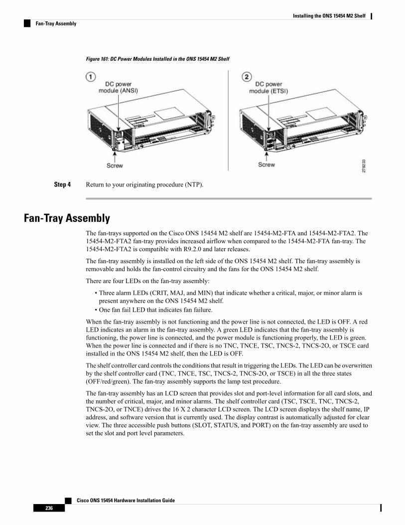
Figure 161: DC Power Modules Installed in the ONS 15454 M2 Shelf
Step 4 Return to your originating procedure (NTP).
Fan-Tray AssemblyThe fan-trays supported on the Cisco ONS 15454 M2 shelf are 15454-M2-FTA and 15454-M2-FTA2. The15454-M2-FTA2 fan-tray provides increased airflow when compared to the 15454-M2-FTA fan-tray. The15454-M2-FTA2 is compatible with R9.2.0 and later releases.
The fan-tray assembly is installed on the left side of the ONS 15454 M2 shelf. The fan-tray assembly isremovable and holds the fan-control circuitry and the fans for the ONS 15454 M2 shelf.
There are four LEDs on the fan-tray assembly:
• Three alarm LEDs (CRIT, MAJ, and MIN) that indicate whether a critical, major, or minor alarm ispresent anywhere on the ONS 15454 M2 shelf.
• One fan fail LED that indicates fan failure.
When the fan-tray assembly is not functioning and the power line is not connected, the LED is OFF. A redLED indicates an alarm in the fan-tray assembly. A green LED indicates that the fan-tray assembly isfunctioning, the power line is connected, and the power module is functioning properly, the LED is green.When the power line is connected and if there is no TNC, TNCE, TSC, TNCS-2, TNCS-2O, or TSCE cardinstalled in the ONS 15454 M2 shelf, then the LED is OFF.
The shelf controller card controls the conditions that result in triggering the LEDs. The LED can be overwrittenby the shelf controller card (TNC, TNCE, TSC, TNCS-2, TNCS-2O, or TSCE) in all the three states(OFF/red/green). The fan-tray assembly supports the lamp test procedure.
The fan-tray assembly has an LCD screen that provides slot and port-level information for all card slots, andthe number of critical, major, and minor alarms. The shelf controller card (TSC, TSCE, TNC, TNCS-2,TNCS-2O, or TNCE) drives the 16 X 2 character LCD screen. The LCD screen displays the shelf name, IPaddress, and software version that is currently used. The display contrast is automatically adjusted for clearview. The three accessible push buttons (SLOT, STATUS, and PORT) on the fan-tray assembly are used toset the slot and port level parameters.
Cisco ONS 15454 Hardware Installation Guide236
Installing the ONS 15454 M2 ShelfFan-Tray Assembly
The fan-tray assembly should be installed only after installing the power module. During the system startupor fan-tray replacement, the inventory data of the fan-tray assembly and the power module is displayed in theInventory tab of CTC after a delay of approximately 6 minutes.
Note
After you install the fan-tray, you should only access it if a fan failure occurs. To clean and replace the fan-trayassembly, see the “Maintain the Node” chapter in the Cisco ONS 15454 DWDM Configuration Guide.
If the fan-tray assembly is removed from the shelf, wait for at least 5 seconds before plugging it back into theshelf. In the event the LCD display on the fan-tray assembly appears blank, remove the unit from the shelf,wait for at least 5 seconds and reinsert the unit into the shelf.
Note
A back-up flash memory is fitted into the fan-tray assembly to support the database (DB) and image back-upin the single mode operation of the ONS 15454 M2.
Fan SpeedFan speed is controlled by the TNC, TNCE, TSC, TNCS-2, TNCS-2O, or TSCE card temperature sensors.The sensors measure the input air temperature at the fan-tray assembly. Fan speed options are low, medium,and high. If the TNC, TNCE, TSC, TNCS-2, TNCS-2O, or TSCE card fails, the fans automatically shift tohigh speed. The temperature measured by the TNC, TNCE, TSC, TNCS-2, TNCS-2O, or TSCE sensorsappears on the LCD screen.
Fan FailureIf one or more fans fail on the fan-tray assembly, replace the entire assembly. You cannot replace individualfans. The red Fan Fail LED on the front of the fan-tray illuminates when one or more fans fail. The red FanFail LED clears after you install a working fan-tray.
NTP-G268 Install the Fan-Tray Assembly in the ONS 15454 M2 ShelfThis procedure installs the 15454-M2-FTA or 15454-M2-FTA2 fan-tray assemblyin the ONS 15454 M2 system.
Purpose
Small slot-head screwdriverTools/Equipment
• NTP-G266 Install the ONS 15454 M2 Shelf, on page 196.• Connect the chassis to the office ground. For detailed instructions on howto ground the chassis, see the Electrostatic Discharge and Grounding Guidefor Cisco CPT and Cisco ONS Platforms.
• NTP-G267 Install the Power Module in the ONS 15454 M2 Shelf, on page232.
Prerequisite Procedures
RequiredRequired/As Needed
OnsiteOnsite/Remote
NoneSecurity Level
Cisco ONS 15454 Hardware Installation Guide237
Installing the ONS 15454 M2 ShelfFan Speed
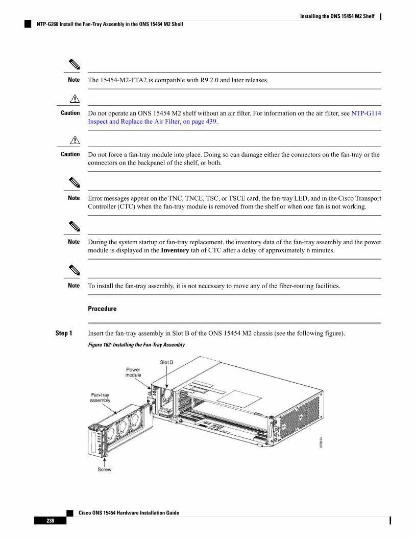
The 15454-M2-FTA2 is compatible with R9.2.0 and later releases.Note
Do not operate an ONS 15454 M2 shelf without an air filter. For information on the air filter, see NTP-G114Inspect and Replace the Air Filter, on page 439.
Caution
Do not force a fan-tray module into place. Doing so can damage either the connectors on the fan-tray or theconnectors on the backpanel of the shelf, or both.
Caution
Error messages appear on the TNC, TNCE, TSC, or TSCE card, the fan-tray LED, and in the Cisco TransportController (CTC) when the fan-tray module is removed from the shelf or when one fan is not working.
Note
During the system startup or fan-tray replacement, the inventory data of the fan-tray assembly and the powermodule is displayed in the Inventory tab of CTC after a delay of approximately 6 minutes.
Note
To install the fan-tray assembly, it is not necessary to move any of the fiber-routing facilities.Note
Procedure
Step 1 Insert the fan-tray assembly in Slot B of the ONS 15454 M2 chassis (see the following figure).
Figure 162: Installing the Fan-Tray Assembly
Cisco ONS 15454 Hardware Installation Guide238
Installing the ONS 15454 M2 ShelfNTP-G268 Install the Fan-Tray Assembly in the ONS 15454 M2 Shelf

Step 2 Push the fan-tray assembly such that the backplane connector is completely engaged (see the following figure).
Figure 163: Inserting the Fan-Tray Assembly in the ONS 15454 M2 Chassis
Step 3 Tighten the screw to a torque value of 4 in-lb (0.45 N-m) to lock the unit (see the following figure).
Figure 164: Fan-Tray Assembly Installed in the ONS 15454 M2 Shelf
Step 4 To verify that the tray has plugged into the assembly, check the fan-tray and listen to determine if the fansare running.
If the fan-tray assembly is removed from the shelf, wait for at least 5 seconds before plugging itback into the shelf. In the event the LCD display on the fan-tray assembly appears blank, removethe unit from the shelf, wait for at least 5 seconds and reinsert the unit into the shelf.
Note
Stop. You have completed this procedure.
Power and Ground DescriptionGround the equipment according to Telcordia standards or local practices.
The grounding configuration is mandatory for ANSI and ETSI chassis for both AC and DC configurations.
The following sections describe power and ground for the ONS 15454 M2 shelves.
For detailed instructions on grounding the ONS 15454 M2 chassis, see the Electrostatic Discharge andGrounding Guide for Cisco CPT and Cisco ONS Platforms.
Cisco ONS 15454 Hardware Installation Guide239
Installing the ONS 15454 M2 ShelfPower and Ground Description
ANSI Power and GroundFor AC power feed, use the power cable shipped with the ONS 15454 M2 and one ground cable. For an ACpower supply, the fuse rating must not exceed 10A, 15A, or 20A. For low input voltage ranges, 100V to127Vac, the branch circuit protection must not be rated more than 20A. The overcurrent/short circuit protectionmust be in accordance with local and national electrical codes. The voltage rating value for AC power rangesbetween 100 VAC to 240 VAC depending on the standards in various countries. This product is intended foruse on the TN and TT power systems.
The ONS 15454 M2 has redundant –48 VDC #12 single-hole lug power terminals. The terminals are labeledRET(A), RET(B), -48V(A), and -48V(B) on the power module.
To install redundant DC power feeds, use four power cables and one ground cable. For a single power feed,only two power cables (#12 AWG or larger, copper conductor, 194 degrees F [90 degrees C] minimum) andone ground cable (#6 AWG or larger) are required. Use a conductor with low impedance to ensure circuitovercurrent protection. However, the conductor must have the capability to safely conduct any faulty currentthat might be imposed. For a DC power supply, the fuse rating must not exceed 15A. The voltages –40.5 VDCand –57.6 VDC are, respectively, the minimum and maximum voltages required to power the chassis. Thenominal steady state voltage is -48 VDC.
Functionality is guaranteed at –40 VDC input voltage, as defined in Telcordia GR-1089-CORE, Issue 5.Note
We recommend the following wiring conventions, but customer conventions prevail:
• Red wire for battery connections (–48 VDC).• Black wire for battery return connections (RET).• The battery return connection is treated as DC-I, as defined in Telcordia GR-1089-CORE, Issue 3.
The ground lug must be a dual-hole type, UL Listed, CSA certified and rated to accept the #6 AWG cable.Two ground posts with two M5 nuts are provided on the ONS 15454 M2 to accommodate the dual-hole lug.
ETSI Power and GroundFor AC power feed, use the power cable shipped with the ONS 15454 M2 and one ground cable. For an ACpower supply, the fuse rating must not exceed 10A, 15A, or 20A. For low input voltage ranges, 100V to127Vac, the branch circuit protection must not be rated more than 20A.
The overcurrent/short circuit protection must be in accordance with local and national electrical codes. Thevoltage rating value for AC power ranges between 100 VAC to 240 VAC depending on the standards invarious countries. This product is intended for use on the TN and TT power systems.
The ONS 15454 M2 for ETSI has redundant –48 VDC power connectors (DSUB for DC power module) onthe DC power module. To install redundant power feeds, use the two power cables shipped with the ONS15454 M2 shelf and one ground cable. For a DC power supply, the fuse rating must not exceed 15A. Thevoltages –40.5 VDC and –57.6 VDC are, respectively, theminimum andmaximum voltages required to powerthe chassis. The nominal steady state voltage is -48 VDC.
The ground lug must be a dual-hole type, UL Listed, CSA certified and rated to accept the #6 AWG cable.Two ground posts with two M5 nuts are provided on the ONS 15454 M2 to accommodate the dual-hole lug.
Only use the power cables shipped with the ONS 15454 M2 shelf.Caution
Cisco ONS 15454 Hardware Installation Guide240
Installing the ONS 15454 M2 ShelfANSI Power and Ground
NTP-G271 Install the Power and Ground to the ONS 15454 M2 ShelfThis procedure installs power feeds and grounds the ONS 15454 M2 system.Purpose
ANSI and ETSI:
• #2 Phillips Dynamometric screwdriver• Medium slot-head screwdriver• Small slot-head screwdriver• Screws• Ground cable 13.3-mm² (#6 AWG) stranded• Listed pressure dual-holes lugs suitable for #6 AWG copper conductors• Wire cutters• Wire strippers• Crimp tool• Fuse panel
ANSI only:
• Power cable (from fuse panel to assembly), #12 AWG, copper conductors,194 degrees F [90 degrees C])
• Wire wrapper• Two-hole grounding lug, shipped with the ONS 15454 M2
ETSI only:
• Power cable (from fuse panel to power modules), shipped with the ONS15454 M2 ETSI
• Two-hole grounding lug, shipped with the ONS 15454 M2
Tools/Equipment
• NTP-G267 Install the Power Module in the ONS 15454 M2 Shelf, on page232.
• Connect the chassis to the office ground. For detailed instructions on howto ground the chassis, refer to the Electrostatic Discharge and GroundingGuide for Cisco CPT and Cisco ONS Platforms.
Prerequisite Procedures
RequiredRequired/As Needed
OnsiteOnsite/Remote
NoneSecurity Level
To ensure safety of personnel and equipment, do not connect any power cables into the power moduleuntil the module is completely installed into the chassis. Statement 389
Warning
To reduce the risk of electric shock, switch on the power only after the power cord is completely installedinto the power module. Statement 390
Warning
Cisco ONS 15454 Hardware Installation Guide241
Installing the ONS 15454 M2 ShelfNTP-G271 Install the Power and Ground to the ONS 15454 M2 Shelf
Blank faceplates (filler panels) serve three important functions: they prevent exposure to hazardousvoltages and currents inside the chassis; they contain electromagnetic interference (EMI) that mightdisrupt other equipment; and they direct the flow of cooling air through the chassis. Do not operatethe system unless all cards, power modules, and faceplates are in place. Statement 261
Warning
This equipment must be grounded. Never defeat the ground conductor or operate the equipment in theabsence of a suitably installed ground conductor. Contact the appropriate electrical inspection authorityor an electrician if you are uncertain that suitable grounding is available. Statement 1024
Warning
Never install an AC power module and a DC power module in the same chassis. Statement 1050Warning
When stranded wiring is required, use approved wiring terminations, such as closed-loop or spade-typewith upturned lugs. These terminations should be the appropriate size for the wires and should clampboth the insulation and conductor. Statement 1002
Warning
Before performing any of the following procedures, ensure that power is removed from the DC circuit.Statement 1003
Warning
Before working on a chassis or working near power supplies, unplug the power cord on AC units.Statement 246
Warning
This equipment is intended to be grounded. Ensure that the host is connected to earth ground duringnormal use. Statement 39
Warning
Use copper conductors only. Statement 1025Warning
Connect the unit only to DC power source that complies with the safety extra-low voltage (SELV)requirements in IEC 60950-1 based safety standards. Statement 1033
Warning
This product requires short-circuit (overcurrent) protection, to be provided as part of the buildinginstallation. Install only in accordance with national and local wiring regulations. Statement 1045
Warning
Cisco ONS 15454 Hardware Installation Guide242
Installing the ONS 15454 M2 ShelfNTP-G271 Install the Power and Ground to the ONS 15454 M2 Shelf
This product relies on the building's installation for short-circuit (overcurrent) protection. Ensure thatthe protective device is rated not greater than: 10A-20A, 100-240 VAC~. Statement 1005
Warning
A readily accessible two-poled disconnect device must be incorporated in the fixed wiring. Statement1022
Warning
This unit might have more than one power supply connection. All connections must be removed tode-energize the unit. Statement 1028
Warning
Always use the supplied ESD wristband when working with a powered ONS 15454. For detailed instructionson how to wear the ESD wristband, refer to the Electrostatic Discharge and Grounding Guide for Cisco CPTand Cisco ONS Platforms.
Caution
Procedure
Step 1 Verify that the correct fuse panel is installed in the top mounting space:
• For a DC power supply, the fuse rating must not exceed 15A.
• For an AC power supply, the fuse rating must not exceed 10A, 15A, or 20A. For low input voltage ranges,100V to 127Vac, the branch circuit protection must not be rated more than 20A. The overcurrent/shortcircuit protection must be in accordance with local and national electrical codes.
Step 2 Depending on the shelf and the power module installed, complete the necessary tasks:
• DLP-G596 Connect Office Power (AC) to the ONS 15454 M2 Shelf, on page 243
• DLP-G597 Connect Office Power (DC) to the ONS 15454 M2 Shelf (ANSI Only), on page 246
• DLP-G598 Connect Office Power (DC) to the ONS 15454 M2 Shelf (ETSI Only), on page 251
Step 3 Connect the office ground to the ONS 15454 M2 shelf. For detailed instructions on grounding, refer to theElectrostatic Discharge and Grounding Guide for Cisco CPT and Cisco ONS Platforms .
Step 4 Complete the DLP-G600 Turn On and Verify DC Office Power on the ONS 15454 M2 Shelf, on page 254.Step 5 Continue with the NTP-G268 Install the Fan-Tray Assembly in the ONS 15454 M2 Shelf, on page 237.
Stop. You have completed this procedure.
DLP-G596 Connect Office Power (AC) to the ONS 15454 M2 Shelf
This task connects AC power to the ONS 15454 M2 shelf.Purpose
Cisco ONS 15454 Hardware Installation Guide243
Installing the ONS 15454 M2 ShelfDLP-G596 Connect Office Power (AC) to the ONS 15454 M2 Shelf
• #2 Phillips Dynamometric screwdriver• Medium slot-head screwdriver• Small slot-head screwdriver• Wire wrapper• Wire cutters• Wire strippers• Crimp tool• Fuse panel• Ground cable 13.3-mm² (#6 AWG) stranded. The PIDs of the power cablesare listed in Table 30: PIDs for AC Power Cables, on page 246.
Tools/Equipment
• NTP-G266 Install the ONS 15454 M2 Shelf, on page 196.• Connect the chassis to the office ground. For detailed instructions on howto ground the chassis, refer to the Electrostatic Discharge and GroundingGuide for Cisco CPT and Cisco ONS Platforms .
• NTP-G270 Open and Remove the Standard Door of the ONS 15454 M2Shelf, on page 220.
• NTP-G267 Install the Power Module in the ONS 15454 M2 Shelf, on page232.
Prerequisite Procedures
RequiredRequired/As Needed
OnsiteOnsite/Remote
NoneSecurity Level
This product is intended for use on the TN and TT power systems.Note
When installing or replacing the unit, the ground connection must always be made first and disconnectedlast. Statement 1046
Warning
This equipment shall be connected to AC mains provided with a surge protective device (SPD) at theservice equipment complying with NFPA 70, the National Electrical Code (NEC). Statement 7012
Warning
The ONS 15454M2 relies on the protective devices in the building installation to protect against short circuit,overcurrent and ground faults. Ensure that the protective devices are properly rated and comply with nationaland local codes.
Caution
Not more than 7 feet (2 m) of the power supply cable should be exposed between the equipment and the fiberstorage tray.
Note
Cisco ONS 15454 Hardware Installation Guide244
Installing the ONS 15454 M2 ShelfDLP-G596 Connect Office Power (AC) to the ONS 15454 M2 Shelf
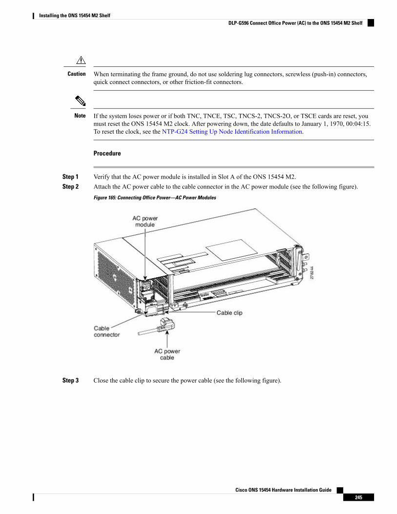
When terminating the frame ground, do not use soldering lug connectors, screwless (push-in) connectors,quick connect connectors, or other friction-fit connectors.
Caution
If the system loses power or if both TNC, TNCE, TSC, TNCS-2, TNCS-2O, or TSCE cards are reset, youmust reset the ONS 15454 M2 clock. After powering down, the date defaults to January 1, 1970, 00:04:15.To reset the clock, see the NTP-G24 Setting Up Node Identification Information.
Note
Procedure
Step 1 Verify that the AC power module is installed in Slot A of the ONS 15454 M2.Step 2 Attach the AC power cable to the cable connector in the AC power module (see the following figure).
Figure 165: Connecting Office Power—AC Power Modules
Step 3 Close the cable clip to secure the power cable (see the following figure).
Cisco ONS 15454 Hardware Installation Guide245
Installing the ONS 15454 M2 ShelfDLP-G596 Connect Office Power (AC) to the ONS 15454 M2 Shelf
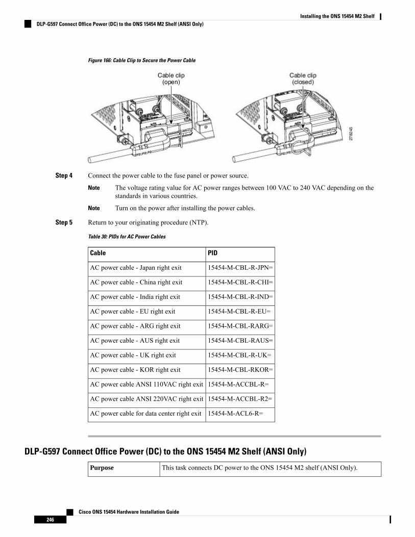
Figure 166: Cable Clip to Secure the Power Cable
Step 4 Connect the power cable to the fuse panel or power source.
The voltage rating value for AC power ranges between 100 VAC to 240 VAC depending on thestandards in various countries.
Note
Turn on the power after installing the power cables.Note
Step 5 Return to your originating procedure (NTP).
Table 30: PIDs for AC Power Cables
PIDCable
15454-M-CBL-R-JPN=AC power cable - Japan right exit
15454-M-CBL-R-CHI=AC power cable - China right exit
15454-M-CBL-R-IND=AC power cable - India right exit
15454-M-CBL-R-EU=AC power cable - EU right exit
15454-M-CBL-RARG=AC power cable - ARG right exit
15454-M-CBL-RAUS=AC power cable - AUS right exit
15454-M-CBL-R-UK=AC power cable - UK right exit
15454-M-CBL-RKOR=AC power cable - KOR right exit
15454-M-ACCBL-R=AC power cable ANSI 110VAC right exit
15454-M-ACCBL-R2=AC power cable ANSI 220VAC right exit
15454-M-ACL6-R=AC power cable for data center right exit
DLP-G597 Connect Office Power (DC) to the ONS 15454 M2 Shelf (ANSI Only)
This task connects DC power to the ONS 15454 M2 shelf (ANSI Only).Purpose
Cisco ONS 15454 Hardware Installation Guide246
Installing the ONS 15454 M2 ShelfDLP-G597 Connect Office Power (DC) to the ONS 15454 M2 Shelf (ANSI Only)
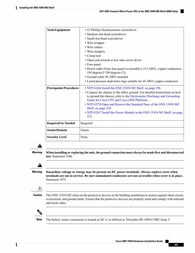
• #2 Phillips Dynamometric screwdriver• Medium slot-head screwdriver• Small slot-head screwdriver• Wire wrapper• Wire cutters• Wire strippers• Crimp tool• Open-end wrench or hex tube screw driver• Fuse panel• Power cable (from fuse panel to assembly), #12 AWG, copper conductors,194 degrees F [90 degrees C])
• Ground cable #6 AWG stranded• Listed pressure dual-holes lugs suitable for #6 AWG copper conductors
Tools/Equipment
• NTP-G266 Install the ONS 15454 M2 Shelf, on page 196.• Connect the chassis to the office ground. For detailed instructions on howto ground the chassis, refer to the Electrostatic Discharge and GroundingGuide for Cisco CPT and Cisco ONS Platforms .
• NTP-G270 Open and Remove the Standard Door of the ONS 15454 M2Shelf, on page 220.
• NTP-G267 Install the Power Module in the ONS 15454 M2 Shelf, on page232.
Prerequisite Procedures
RequiredRequired/As Needed
OnsiteOnsite/Remote
NoneSecurity Level
When installing or replacing the unit, the ground connection must always be made first and disconnectedlast. Statement 1046
Warning
Hazardous voltage or energy may be present on DC power terminals. Always replace cover whenterminals are not in service. Be sure uninsulated conductors are not accessible when cover is in place.Statement 1075
Warning
The ONS 15454M2 relies on the protective devices in the building installation to protect against short circuit,overcurrent, and ground faults. Ensure that the protective devices are properly rated and comply with nationaland local codes.
Caution
The battery return connection is treated as DC-I, as defined in Telcordia GR-1089-CORE Issue 5.Note
Cisco ONS 15454 Hardware Installation Guide247
Installing the ONS 15454 M2 ShelfDLP-G597 Connect Office Power (DC) to the ONS 15454 M2 Shelf (ANSI Only)

If the system loses power or both TNC, TNCE, TSC, TNCS-2, TNCS-2O, or TSCE cards are reset and thesystem is not provisioned to get the time from a Network Time Protocol/Simple Network Time Protocol(NTP/SNTP) server, you must reset the ONS 15454 clock. After powering down, the date defaults to January1, 1970, 00:04:15. To reset the clock, see the NTP-G24 Setting Up Node Identification Information. If youare using the TNC, TNCE, TSC, TNCS-2, TNCS-2O, or TSCE cards, the system clock will run for up to threehours. In this case, no action would be required.
Note
Procedure
Step 1 Connect the return cables of the power supply to the Earth ground located at the power supply side.Step 2 Connect the office power according to the fuse panel engineering specifications.Step 3 Measure and cut the cables as needed to reach the ONS 15454 M2 from the fuse panel.Step 4 Dress the power according to local site practice.Step 5 Strip 1/2 inch (12.7 mm) of insulation from all power cables that you will use.Step 6 Crimp the lugs onto the ends of all power leads.Step 7 Verify that the DC power module is installed in Slot A.Step 8 Remove the screws from the terminal block protective cover from the DC power module (see the following
figure).
Cisco ONS 15454 Hardware Installation Guide248
Installing the ONS 15454 M2 ShelfDLP-G597 Connect Office Power (DC) to the ONS 15454 M2 Shelf (ANSI Only)
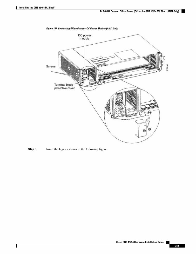
Figure 167: Connecting Office Power—DC Power Module (ANSI Only)
Step 9 Insert the lugs as shown in the following figure.
Cisco ONS 15454 Hardware Installation Guide249
Installing the ONS 15454 M2 ShelfDLP-G597 Connect Office Power (DC) to the ONS 15454 M2 Shelf (ANSI Only)
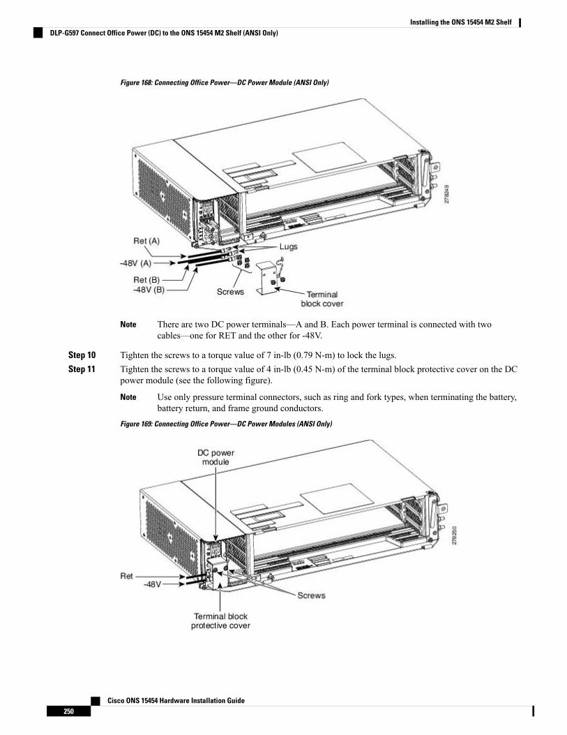
Figure 168: Connecting Office Power—DC Power Module (ANSI Only)
There are two DC power terminals—A and B. Each power terminal is connected with twocables—one for RET and the other for -48V.
Note
Step 10 Tighten the screws to a torque value of 7 in-lb (0.79 N-m) to lock the lugs.Step 11 Tighten the screws to a torque value of 4 in-lb (0.45 N-m) of the terminal block protective cover on the DC
power module (see the following figure).
Use only pressure terminal connectors, such as ring and fork types, when terminating the battery,battery return, and frame ground conductors.
Note
Figure 169: Connecting Office Power—DC Power Modules (ANSI Only)
Cisco ONS 15454 Hardware Installation Guide250
Installing the ONS 15454 M2 ShelfDLP-G597 Connect Office Power (DC) to the ONS 15454 M2 Shelf (ANSI Only)
Before you make any crimp connections, coat all bare conductors (battery, battery return, and frameground) with an appropriate antioxidant compound. Bring all unplated connectors, braided strap,and bus bars to a bright finish, then coat with an antioxidant before you connect them. You do notneed to prepare tinned, solder-plated, or silver-plated connectors and other plated connection surfaces,but always keep them clean and free of contaminants.
Caution
When terminating power, return (RET), and frame ground, do not use soldering lug, screwless(push-in) connectors, quick-connect, or other friction-fit connectors.
Caution
Step 12 Return to your originating procedure (NTP).
DLP-G598 Connect Office Power (DC) to the ONS 15454 M2 Shelf (ETSI Only)
This task connects power to the ONS 15454 M2 shelf (ETSI Only).Purpose
• #2 Phillips Dynamometric screwdriver• Medium slot-head screwdriver• Small slot-head screwdriver• Wire wrapper• Wire cutters• Wire strippers• Crimp tool• Fuse panel• Ground cable #6 AWG stranded. The PID of the DC power cable for ETSIleft exit is 15454-M2-DCCBL-LE=.
Tools/Equipment
• NTP-G266 Install the ONS 15454 M2 Shelf, on page 196.• Connect the chassis to the office ground. For detailed instructions on howto ground the chassis, refer to the Electrostatic Discharge and GroundingGuide for Cisco CPT and Cisco ONS Platforms .
• NTP-G270 Open and Remove the Standard Door of the ONS 15454 M2Shelf, on page 220.
• NTP-G267 Install the Power Module in the ONS 15454 M2 Shelf, on page232.
Prerequisite Procedures
RequiredRequired/As Needed
OnsiteOnsite/Remote
NoneSecurity Level
When installing or replacing the unit, the ground connection must always be made first and disconnectedlast. Statement 1046
Warning
Cisco ONS 15454 Hardware Installation Guide251
Installing the ONS 15454 M2 ShelfDLP-G598 Connect Office Power (DC) to the ONS 15454 M2 Shelf (ETSI Only)
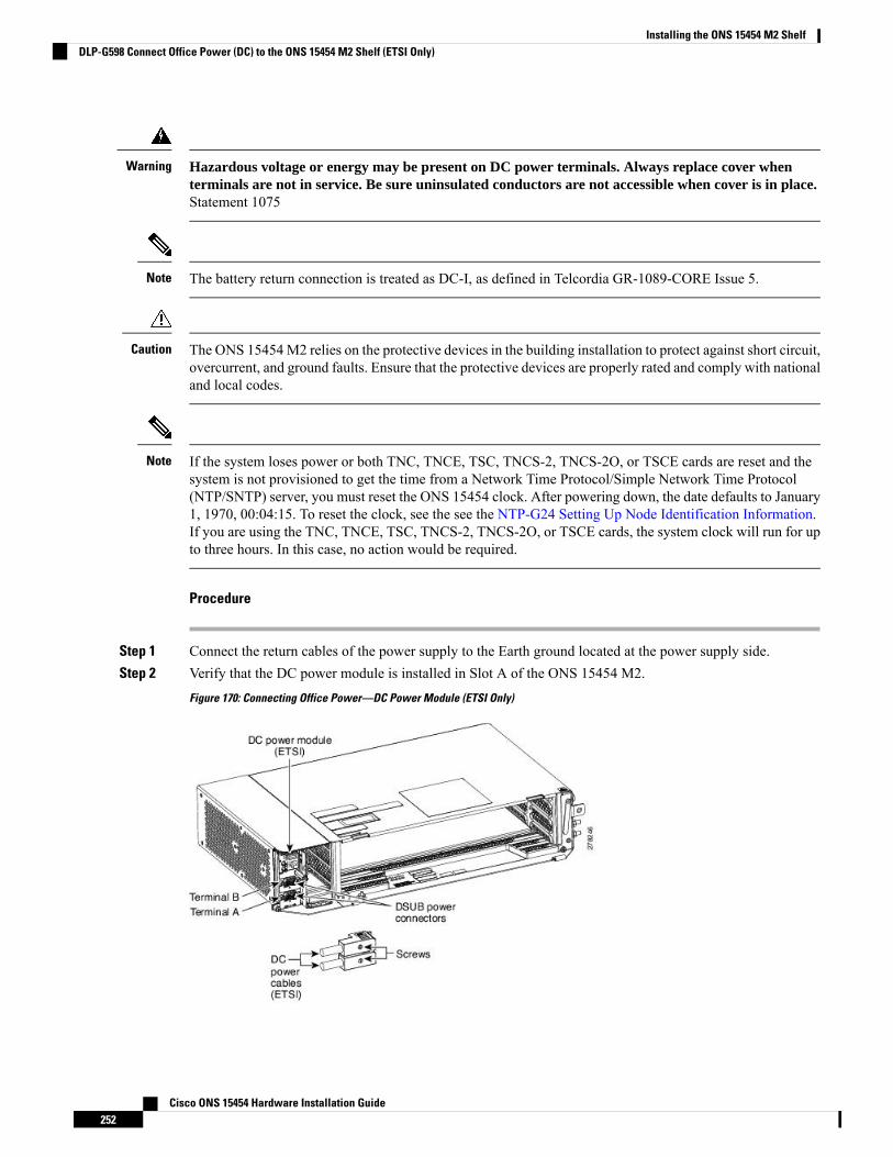
Hazardous voltage or energy may be present on DC power terminals. Always replace cover whenterminals are not in service. Be sure uninsulated conductors are not accessible when cover is in place.Statement 1075
Warning
The battery return connection is treated as DC-I, as defined in Telcordia GR-1089-CORE Issue 5.Note
The ONS 15454M2 relies on the protective devices in the building installation to protect against short circuit,overcurrent, and ground faults. Ensure that the protective devices are properly rated and comply with nationaland local codes.
Caution
If the system loses power or both TNC, TNCE, TSC, TNCS-2, TNCS-2O, or TSCE cards are reset and thesystem is not provisioned to get the time from a Network Time Protocol/Simple Network Time Protocol(NTP/SNTP) server, you must reset the ONS 15454 clock. After powering down, the date defaults to January1, 1970, 00:04:15. To reset the clock, see the see the NTP-G24 Setting Up Node Identification Information.If you are using the TNC, TNCE, TSC, TNCS-2, TNCS-2O, or TSCE cards, the system clock will run for upto three hours. In this case, no action would be required.
Note
Procedure
Step 1 Connect the return cables of the power supply to the Earth ground located at the power supply side.Step 2 Verify that the DC power module is installed in Slot A of the ONS 15454 M2.
Figure 170: Connecting Office Power—DC Power Module (ETSI Only)
Cisco ONS 15454 Hardware Installation Guide252
Installing the ONS 15454 M2 ShelfDLP-G598 Connect Office Power (DC) to the ONS 15454 M2 Shelf (ETSI Only)
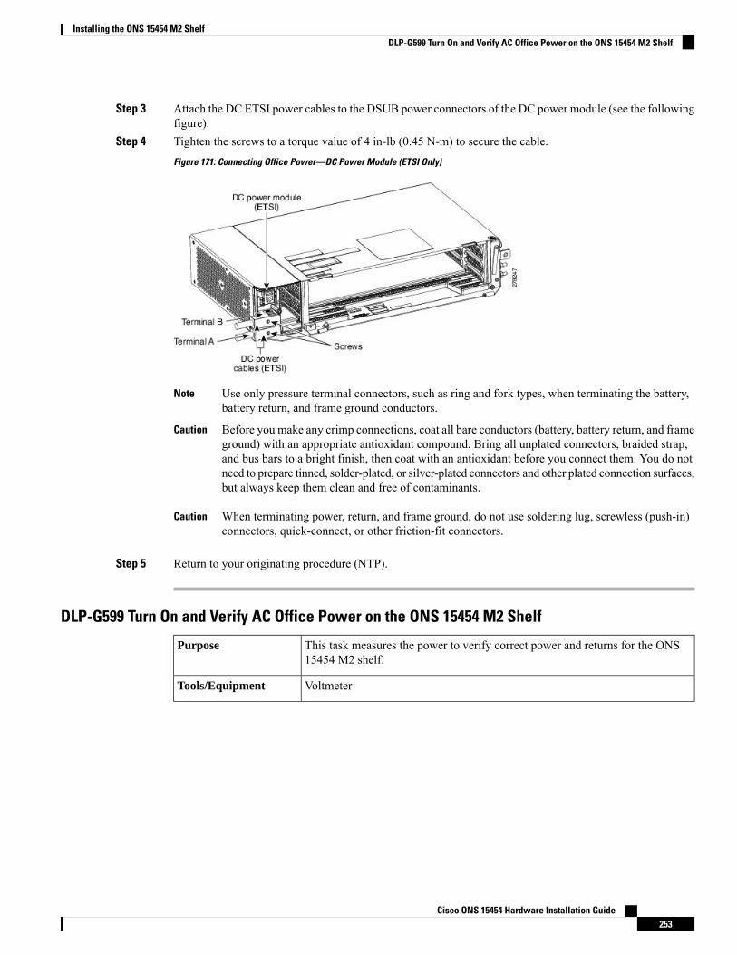
Step 3 Attach the DC ETSI power cables to the DSUB power connectors of the DC power module (see the followingfigure).
Step 4 Tighten the screws to a torque value of 4 in-lb (0.45 N-m) to secure the cable.
Figure 171: Connecting Office Power—DC Power Module (ETSI Only)
Use only pressure terminal connectors, such as ring and fork types, when terminating the battery,battery return, and frame ground conductors.
Note
Before you make any crimp connections, coat all bare conductors (battery, battery return, and frameground) with an appropriate antioxidant compound. Bring all unplated connectors, braided strap,and bus bars to a bright finish, then coat with an antioxidant before you connect them. You do notneed to prepare tinned, solder-plated, or silver-plated connectors and other plated connection surfaces,but always keep them clean and free of contaminants.
Caution
When terminating power, return, and frame ground, do not use soldering lug, screwless (push-in)connectors, quick-connect, or other friction-fit connectors.
Caution
Step 5 Return to your originating procedure (NTP).
DLP-G599 Turn On and Verify AC Office Power on the ONS 15454 M2 Shelf
This task measures the power to verify correct power and returns for the ONS15454 M2 shelf.
Purpose
VoltmeterTools/Equipment
Cisco ONS 15454 Hardware Installation Guide253
Installing the ONS 15454 M2 ShelfDLP-G599 Turn On and Verify AC Office Power on the ONS 15454 M2 Shelf
• NTP-G266 Install the ONS 15454 M2 Shelf, on page 196.• Connect the office ground to chassis. For detailed instructions on grounding,refer to the Electrostatic Discharge and Grounding Guide for Cisco CPT andCisco ONS Platforms .
• NTP-G270 Open and Remove the Standard Door of the ONS 15454 M2Shelf, on page 220.
• NTP-G267 Install the Power Module in the ONS 15454 M2 Shelf, on page232.
• DLP-G596 Connect Office Power (AC) to the ONS 15454 M2 Shelf, onpage 243
Prerequisite Procedures
RequiredRequired/As Needed
OnsiteOnsite/Remote
NoneSecurity Level
Do not apply power to the shelf until you complete all the installation steps.Caution
To ensure safety of personnel and equipment, do not connect any power cables into the power moduleuntil the module is completely installed into the chassis. Statement 389
Warning
To reduce the risk of electric shock, switch on the power only after the power cord is completely installedinto the power module. Statement 390
Warning
Procedure
Step 1 To power up the node, insert the fuse into the fuse position according to site practice. The fuse rating mustnot exceed 15A in case of AC power.
Step 2 If the ONS 15454M2 does not power up, check the voltage at the power source using a voltmeter. The voltageshould be 100 to 240 VAC +/-10 percent.
Step 3 Return to your originating procedure (NTP).
DLP-G600 Turn On and Verify DC Office Power on the ONS 15454 M2 Shelf
This task measures the power to verify correct power and returns for the ONS15454 M2 shelf.
Purpose
VoltmeterTools/Equipment
Cisco ONS 15454 Hardware Installation Guide254
Installing the ONS 15454 M2 ShelfDLP-G600 Turn On and Verify DC Office Power on the ONS 15454 M2 Shelf
• NTP-G266 Install the ONS 15454 M2 Shelf, on page 196.• Connect the office ground to chassis. For detailed instructions on grounding,refer to the Electrostatic Discharge and Grounding Guide for Cisco CPT andCisco ONS Platforms .
• NTP-G270 Open and Remove the Standard Door of the ONS 15454 M2Shelf, on page 220.
• NTP-G267 Install the Power Module in the ONS 15454 M2 Shelf, on page232.
• DLP-G597 Connect Office Power (DC) to the ONS 15454 M2 Shelf (ANSIOnly), on page 246 (or)
• DLP-G598 Connect Office Power (DC) to the ONS 15454 M2 Shelf (ETSIOnly), on page 251.
Prerequisite Procedures
RequiredRequired/As Needed
OnsiteOnsite/Remote
NoneSecurity Level
Do not apply power to the shelf until you complete all installation steps.Caution
To ensure safety of personnel and equipment, do not connect any power cables into the power moduleuntil the module is completely installed into the chassis. Statement 389
Warning
To reduce the risk of electric shock, switch on the power only after the power cord is completely installedinto the power module. Statement 390
Warning
Procedure
Step 1 Using a voltmeter, verify the office battery and ground at the following points on the fuse panel:a) To verify the power, place the black test lead of the voltmeter to the frame ground. Place the red test lead
on the A-side connection and verify that it is between –40.5 VDC and –57.6 VDC. Place the red test leadon the B-side connection and verify that it is between –40.5 VDC and –57.6 VDC.
The voltages –40.5 VDC and –57.6 VDC are, respectively, the minimum andmaximum voltagesrequired to power the chassis. The nominal steady state voltage is -48 VDC.
Note
b) To verify the ground, place the black test lead of the voltmeter to the frame ground. Place the red test leadon the A-side return ground and verify that no voltage is present. Place the red test lead on the B-sidereturn ground and verify that no voltage is present.
Step 2 To power up the node, insert the fuse into the fuse position according to site practice. The fuse rating mustnot exceed 15A.
Step 3 Using a voltmeter, verify the ONS 15454 M2 shelf for –48 VDC battery and ground:
Cisco ONS 15454 Hardware Installation Guide255
Installing the ONS 15454 M2 ShelfDLP-G600 Turn On and Verify DC Office Power on the ONS 15454 M2 Shelf
a) To verify the A-side of the shelf, place the black lead of the voltmeter to the frame ground. Place the redtest lead to the -48V (A-side battery connection) red cable. Verify that it reads between –40.5 VDC and–57.6 VDC. Then place the red test lead of the voltmeter to the RET1 (A-side return ground) black cableand verify that no voltage is present.
The voltages –40.5 VDC and –57.6 VDC are, respectively, the minimum andmaximum voltagesrequired to power the chassis.
Note
b) To verify the B-side of the shelf, place the black test lead of the voltmeter to the frame ground. Place thered test lead to the -48V (B-side battery connection) red cable. Verify that it reads between –40.5 VDCand –57.6 VDC. Then place the red test lead of the voltmeter to the RET2 (B-side return ground) blackcable and verify that no voltage is present.
To view the shelf voltage and temperature, refer to the NTP-G230 View Shelf Voltage andTemperature, on page 78.
Note
Step 4 Return to your originating procedure (NTP).
NTP-G291 Attach Wires to Timing, LAN, and Craft Pin Connections in ONS15454 M2
This procedure attaches wires to the Timing, LAN, and Craft Pin connections inthe ONS 15454 M2 shelf.
Purpose
Twisted #22 or #24 AWG (0.51 mm² or 0.64 mm²) shielded wires for LAN orcraft 75-ohm coaxial cable with DIN 1.0/2.3 miniature coax connector.
Tools/Equipment
NTP-G267 Install the Power Module in the ONS 15454 M2 Shelf, on page 232Prerequisite Procedures
As neededRequired/As Needed
OnsiteOnsite/Remote
NoneSecurity Level
Always use the supplied Electrostatic Discharge (ESD) wristband when working with a powered ONS 15454M2. For detailed instructions on how to wear the ESD wristband, refer to the Electrostatic Discharge andGrounding Guide for Cisco CPT and Cisco ONS Platforms .
Caution
To route the copper cables from the SFPs or RJ-45 ports in a ONS 15454 M2 shelf, removal of the shelf dooris mandatory.
Note
The minimum distance between the fiber LC connector and the bulk attenuator must be at least 50 cm. Thisis the minimum distance required to place the bulk attenuator outside the shelf from any port of a card.
Note
Cisco ONS 15454 Hardware Installation Guide256
Installing the ONS 15454 M2 ShelfNTP-G291 Attach Wires to Timing, LAN, and Craft Pin Connections in ONS 15454 M2
Procedure
Step 1 Complete either DLP-G292 Install TimingWires in ONS 15454M2 - ANSI, on page 257 or DLP-G293 InstallTiming Wires in ONS 15454 M2 - ETSI, on page 259 if you are provisioning external timing.
Step 2 Complete DLP-G294 Install LANWires in ONS 15454M2, on page 263 to create an external LAN connection.Youmust connect a CAT-5 Ethernet cable to the LAN port on the TNC/TNCE/TSC/TSCE/TNCS-2/TNCS-2Ocard to create an external LAN connection.
Stop. You have completed this procedure.
DLP-G292 Install Timing Wires in ONS 15454 M2 - ANSI
This task installs the timing wires in the DC-2 or AC-2 Power Module of ONS15454 M2 (ANSI).
Purpose
100-ohm wire wrap cable, wire wrap toolTools/Equipment
NonePrerequisite Procedures
As neededRequired/As Needed
OnsiteOnsite/Remote
NoneSecurity Level
Procedure
Step 1 Locate the timing BITS connectors in the DC-2 or AC-2 PowerModule, as shown in the following two figures.
Cisco ONS 15454 Hardware Installation Guide257
Installing the ONS 15454 M2 ShelfDLP-G292 Install Timing Wires in ONS 15454 M2 - ANSI
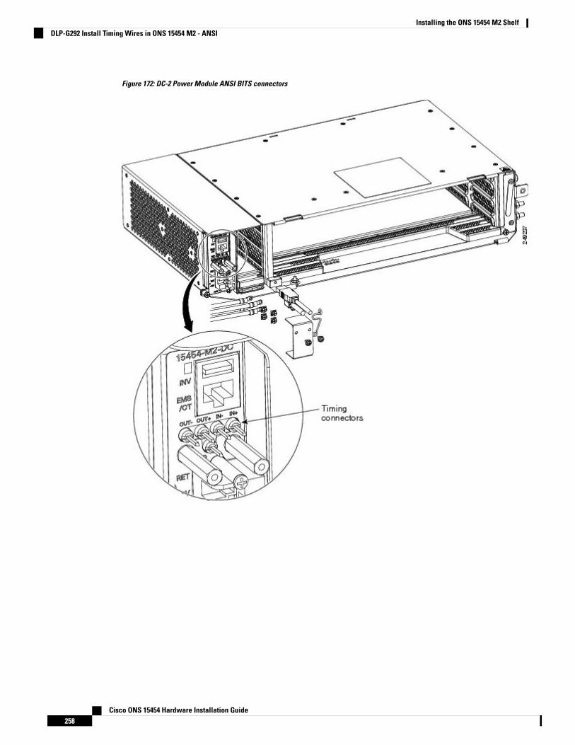
Figure 172: DC-2 Power Module ANSI BITS connectors
Cisco ONS 15454 Hardware Installation Guide258
Installing the ONS 15454 M2 ShelfDLP-G292 Install Timing Wires in ONS 15454 M2 - ANSI

Figure 173: AC-2 Power Module ANSI BITS Connectors
Step 2 Connect the wire wrap cable to the appropriate timing connector in the Power Module.Step 3 Connect the other end of the cable to the external source of the timing.
Repeat step 3 for each cable that is needed.
Step 4 Return to your originating procedure (NTP).
DLP-G293 Install Timing Wires in ONS 15454 M2 - ETSI
This task installs the timing wires in the AC-2 or DC-2E Power Module of ONS15454 M2 (ETSI).
Purpose
Cisco ONS 15454 Hardware Installation Guide259
Installing the ONS 15454 M2 ShelfDLP-G293 Install Timing Wires in ONS 15454 M2 - ETSI
75-ohm coaxial cable with a DIN 1.0/2.3 miniature coax connector. The PID forthe BITS IN/OUT cable is 15454-M-TMGCBL=.
Tools/Equipment
NonePrerequisite Procedures
As neededRequired/As Needed
OnsiteOnsite/Remote
NoneSecurity Level
Procedure
Step 1 Locate the timing BITS connectors in the DC-2E or AC-2 Power Module, as shown in the following twofigures.
Cisco ONS 15454 Hardware Installation Guide260
Installing the ONS 15454 M2 ShelfDLP-G293 Install Timing Wires in ONS 15454 M2 - ETSI
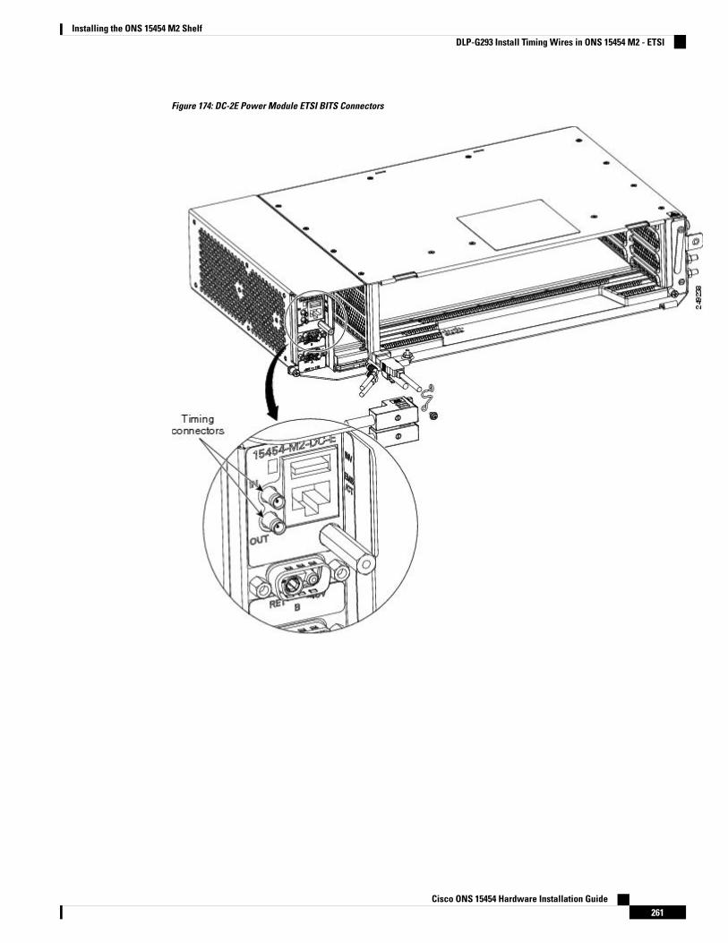
Figure 174: DC-2E Power Module ETSI BITS Connectors
Cisco ONS 15454 Hardware Installation Guide261
Installing the ONS 15454 M2 ShelfDLP-G293 Install Timing Wires in ONS 15454 M2 - ETSI
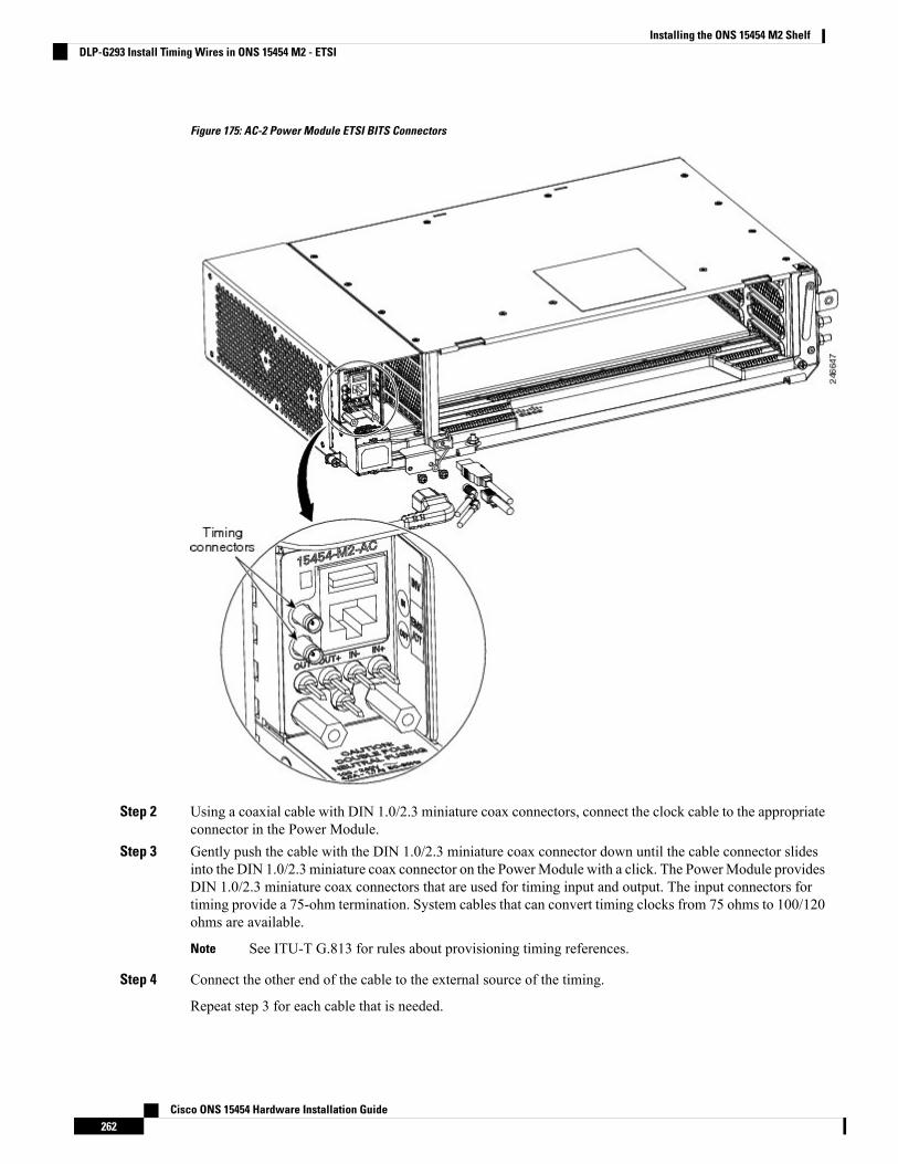
Figure 175: AC-2 Power Module ETSI BITS Connectors
Step 2 Using a coaxial cable with DIN 1.0/2.3 miniature coax connectors, connect the clock cable to the appropriateconnector in the Power Module.
Step 3 Gently push the cable with the DIN 1.0/2.3 miniature coax connector down until the cable connector slidesinto the DIN 1.0/2.3 miniature coax connector on the PowerModule with a click. The PowerModule providesDIN 1.0/2.3 miniature coax connectors that are used for timing input and output. The input connectors fortiming provide a 75-ohm termination. System cables that can convert timing clocks from 75 ohms to 100/120ohms are available.
See ITU-T G.813 for rules about provisioning timing references.Note
Step 4 Connect the other end of the cable to the external source of the timing.
Repeat step 3 for each cable that is needed.
Cisco ONS 15454 Hardware Installation Guide262
Installing the ONS 15454 M2 ShelfDLP-G293 Install Timing Wires in ONS 15454 M2 - ETSI
Step 5 Return to your originating procedure (NTP).
DLP-G294 Install LAN Wires in ONS 15454 M2
This task installs the LAN wires in ONS 15454 M2.Purpose
Standard CAT-5 Ethernet cable straight-through for data terminal equipment(DTE) or crossover for data circuit-terminating equipment (DCE) or RJ-45connector
Crimping tool for RJ-45 connector
0.51 mm² or 0.64 mm² (#22 or #24 AWG) wire, preferably standard CAT-5
Tools/Equipment
NTP-G267 Install the Power Module in the ONS 15454 M2 Shelf, on page 232Prerequisite Procedures
As neededRequired/As Needed
OnsiteOnsite/Remote
NoneSecurity Level
Procedure
Step 1 Using a 0.51 mm² or 0.64 mm² (#22 or #24 AWG) wire or a standard CAT-5 Ethernet cable, connect the wiresto the RJ-45 connector.
Step 2 Return to your originating procedure (NTP).
NTP-G313 Install and Configure the TNC, TNCE, TSC, or TSCE CardThis procedure describes how to install and configure the TNC, TNCE, TSC, orTSCE card.
Purpose
Redundant TNC/TNCE/TSC/TSCEcards onCiscoONS15454M6 shelf (required)
Stand-alone TNC/TNCE/TSC/TSCEcard onCiscoONS15454M2 shelf (required)
Tools/Equipment
NTP-G271 Install the Power and Ground to the ONS 15454 M2 Shelf, on page241
NTP-G14 Install DWDM Equipment, page 1-66
Prerequisite Procedures
RequiredRequired/As Needed
OnsiteOnsite/Remote
Provisioning or higherSecurity Level
Cisco ONS 15454 Hardware Installation Guide263
Installing the ONS 15454 M2 ShelfDLP-G294 Install LAN Wires in ONS 15454 M2
During this procedure, wear grounding wrist straps to avoid ESD damage to the card. Do not directlytouch the backplane with your hand or any metal tool, or you could shock yourself. Statement 94
Warning
Always use the supplied ESD wristband when working with a powered ONS 15454 M2 and ONS 15454 M6shelf assemblies. For detailed instructions on how to wear the ESD wristband, refer to the ElectrostaticDischarge and Grounding Guide for Cisco CPT and Cisco ONS Platforms.
Caution
If you install a card incorrectly, the FAIL LED flashes continuously.Note
Procedure
Step 1 Complete the DLP-G604 Install the TNC, TNCE, TSC, or TSCE Card, on page 264.
If you install the wrong card in a slot, see the NTP-G107 Remove Permanently or Remove andReplace DWDM Cards .
Note
Step 2 Complete the DLP-G605 Provision PPM and Port for the TNC and TNCE Cards, on page 267.Step 3 Complete the DLP-G606 Configure UDC and VoIP for the TNC and TNCE Cards, on page 268.
Stop. You have completed this procedure.
DLP-G604 Install the TNC, TNCE, TSC, or TSCE Card
(ONS 15454 M2 and ONS 15454 M6 only) This task installs redundantTNC/TNCE/TSC/TSCE/TNCS-2/TNCS-2O cards on the ONS 15454 M6 shelfand a stand-alone TNC/TNCE/TSC/TSCE/TNCs-2/TNCS-2O card on the ONS15454 M2 shelf. Install and initialize theTNC/TNCE/TSC/TSCE/TNCS-2/TNCS-2O card before installing any other linecards into the shelf assemblies. On the ONS 15454 M6 shelf, install theTNC/TNCE/TSC/TSCE/TNCS-2/TNCS-2O cards in slots 1 and 8 for redundancy.On the ONS 15454 M2 shelf, install the stand-aloneTNC/TNCE/TSC/TSCE/TNCS-2/TNCS-2O card in slot 1.
Purpose
Two TNC/TNCE/TSC/TSCE/TNCS-2/TNCS-2O cards for the ONS 15454 M6shelf and one TNC/TNCE/TSC/TSCE/TNCS-2/TNCS-2Ocard for theONS 15454M2 shelf
Tools/Equipment
NonePrerequisite Procedures
RequiredRequired/As Needed
OnsiteOnsite/Remote
Cisco ONS 15454 Hardware Installation Guide264
Installing the ONS 15454 M2 ShelfDLP-G604 Install the TNC, TNCE, TSC, or TSCE Card
NoneSecurity Level
Do not remove the TNC/TNCE/TSC/TSCE/TNCS-2/TNCS-2O cards during the software installation process,which is indicated by alternate flashing FAIL and ACT/STBY LEDs. Removing theTNC/TNCE/TSC/TSCE/TNCS-2/TNCS-2O cards during the software installation process will corrupt thesystem memory.
Caution
Allow each TNC/TNCE/TSC/TSCE/TNCS-2/TNCS-2Ocard to boot completely before installing the redundantTNC/TNCE/TSC/TSCE/TNCS-2/TNCS-2O card.
Note
On the ONS 15454 M6 shelf, install the TNC/TNCE/TSC/TSCE/TNCS-2/TNCS-2O cards in slots 1 and 8for redundancy. On the ONS 15454 M2 shelf, install the stand-aloneTNC/TNCE/TSC/TSCE/TNCS-2/TNCS-2O card in slot 1. For more information, see the Card SlotRequirements, on page 17.
Note
You cannot insert the TNC/TNCE/TSC/TSCE/TNCS-2/TNCS-2O cards in other slots due to mechanicalconstraints. To identify the card slot, match the symbol placed on the lower side of the card front panel withthe symbol in the shelf.
Note
To achieve redundancy, two TNC or TNCE cards or two TSC or TSCE cards must be installed in the ONS15454 M6 shelf. Do not install one TNC or TNCE card and a redundant TSC or TSCE card in the same shelf.
Caution
Procedure
Step 1 Open the latches/ejectors of the first TNC/TNCE/TSC/TSCE/TNCS-2/TNCS-2O card that you will install.Step 2 Use the latches/ejectors to firmly slide the card horizontally along the guide rails until the card plugs into the
receptacle at the back of the slot (slot 1 or 8 in the ONS 15454 M6 shelf and slot 1 in the ONS 15454 M2shelf).
Step 3 Verify that the card is inserted correctly, and close the latches/ejectors on the card.
If you insert a card into a slot assigned for a different card, all LEDs turn off.
Step 4 As needed, verify the LED activity on the TNC/TNCE/TSC/TSCE/TNCS-2/TNCS-2O card.
• The red FAIL LED, PWR LED turn on briefly.• The red FAIL LED turns on for about 10 seconds.• The red FAIL LED and the amber ACT/STBY LED turn on for about 30 seconds.• The red FAIL LED blinks for about 10 seconds.
Cisco ONS 15454 Hardware Installation Guide265
Installing the ONS 15454 M2 ShelfDLP-G604 Install the TNC, TNCE, TSC, or TSCE Card
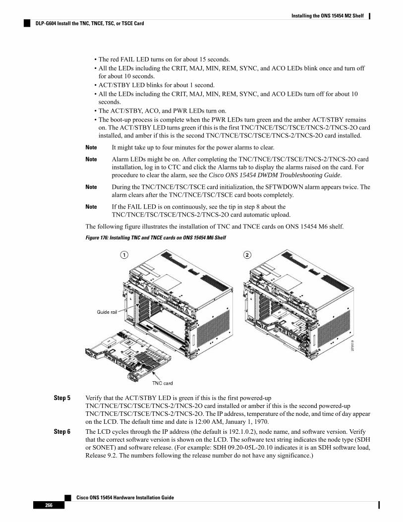
• The red FAIL LED turns on for about 15 seconds.• All the LEDs including the CRIT, MAJ, MIN, REM, SYNC, and ACO LEDs blink once and turn offfor about 10 seconds.
• ACT/STBY LED blinks for about 1 second.• All the LEDs including the CRIT, MAJ, MIN, REM, SYNC, and ACO LEDs turn off for about 10seconds.
• The ACT/STBY, ACO, and PWR LEDs turn on.• The boot-up process is complete when the PWR LEDs turn green and the amber ACT/STBY remainson. The ACT/STBY LED turns green if this is the first TNC/TNCE/TSC/TSCE/TNCS-2/TNCS-2O cardinstalled, and amber if this is the second TNC/TNCE/TSC/TSCE/TNCS-2/TNCS-2O card installed.
It might take up to four minutes for the power alarms to clear.Note
Alarm LEDs might be on. After completing the TNC/TNCE/TSC/TSCE/TNCS-2/TNCS-2O cardinstallation, log in to CTC and click the Alarms tab to display the alarms raised on the card. Forprocedure to clear the alarm, see the Cisco ONS 15454 DWDM Troubleshooting Guide.
Note
During the TNC/TNCE/TSC/TSCE card initialization, the SFTWDOWN alarm appears twice. Thealarm clears after the TNC/TNCE/TSC/TSCE card boots completely.
Note
If the FAIL LED is on continuously, see the tip in step 8 about theTNC/TNCE/TSC/TSCE/TNCS-2/TNCS-2O card automatic upload.
Note
The following figure illustrates the installation of TNC and TNCE cards on ONS 15454 M6 shelf.
Figure 176: Installing TNC and TNCE cards on ONS 15454 M6 Shelf
Step 5 Verify that the ACT/STBY LED is green if this is the first powered-upTNC/TNCE/TSC/TSCE/TNCS-2/TNCS-2O card installed or amber if this is the second powered-upTNC/TNCE/TSC/TSCE/TNCS-2/TNCS-2O. The IP address, temperature of the node, and time of day appearon the LCD. The default time and date is 12:00 AM, January 1, 1970.
Step 6 The LCD cycles through the IP address (the default is 192.1.0.2), node name, and software version. Verifythat the correct software version is shown on the LCD. The software text string indicates the node type (SDHor SONET) and software release. (For example: SDH 09.20-05L-20.10 indicates it is an SDH software load,Release 9.2. The numbers following the release number do not have any significance.)
Cisco ONS 15454 Hardware Installation Guide266
Installing the ONS 15454 M2 ShelfDLP-G604 Install the TNC, TNCE, TSC, or TSCE Card
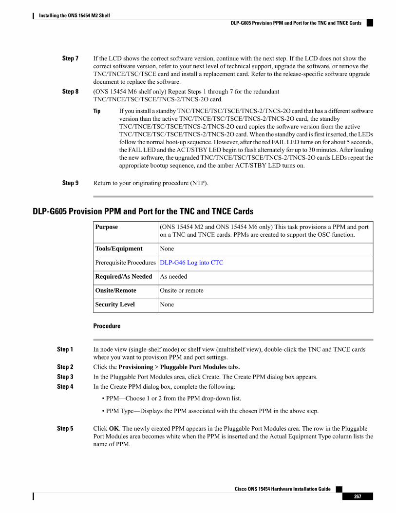
Step 7 If the LCD shows the correct software version, continue with the next step. If the LCD does not show thecorrect software version, refer to your next level of technical support, upgrade the software, or remove theTNC/TNCE/TSC/TSCE card and install a replacement card. Refer to the release-specific software upgradedocument to replace the software.
Step 8 (ONS 15454 M6 shelf only) Repeat Steps 1 through 7 for the redundantTNC/TNCE/TSC/TSCE/TNCS-2/TNCS-2O card.
If you install a standby TNC/TNCE/TSC/TSCE/TNCS-2/TNCS-2O card that has a different softwareversion than the active TNC/TNCE/TSC/TSCE/TNCS-2/TNCS-2O card, the standbyTNC/TNCE/TSC/TSCE/TNCS-2/TNCS-2O card copies the software version from the activeTNC/TNCE/TSC/TSCE/TNCS-2/TNCS-2O card.When the standby card is first inserted, the LEDsfollow the normal boot-up sequence. However, after the red FAIL LED turns on for about 5 seconds,the FAIL LED and the ACT/STBYLED begin to flash alternately for up to 30minutes. After loadingthe new software, the upgraded TNC/TNCE/TSC/TSCE/TNCS-2/TNCS-2O cards LEDs repeat theappropriate bootup sequence, and the amber ACT/STBY LED turns on.
Tip
Step 9 Return to your originating procedure (NTP).
DLP-G605 Provision PPM and Port for the TNC and TNCE Cards
(ONS 15454 M2 and ONS 15454 M6 only) This task provisions a PPM and porton a TNC and TNCE cards. PPMs are created to support the OSC function.
Purpose
NoneTools/Equipment
DLP-G46 Log into CTCPrerequisite Procedures
As neededRequired/As Needed
Onsite or remoteOnsite/Remote
NoneSecurity Level
Procedure
Step 1 In node view (single-shelf mode) or shelf view (multishelf view), double-click the TNC and TNCE cardswhere you want to provision PPM and port settings.
Step 2 Click the Provisioning > Pluggable Port Modules tabs.Step 3 In the Pluggable Port Modules area, click Create. The Create PPM dialog box appears.Step 4 In the Create PPM dialog box, complete the following:
• PPM—Choose 1 or 2 from the PPM drop-down list.
• PPM Type—Displays the PPM associated with the chosen PPM in the above step.
Step 5 Click OK. The newly created PPM appears in the Pluggable Port Modules area. The row in the PluggablePort Modules area becomes white when the PPM is inserted and the Actual Equipment Type column lists thename of PPM.
Cisco ONS 15454 Hardware Installation Guide267
Installing the ONS 15454 M2 ShelfDLP-G605 Provision PPM and Port for the TNC and TNCE Cards
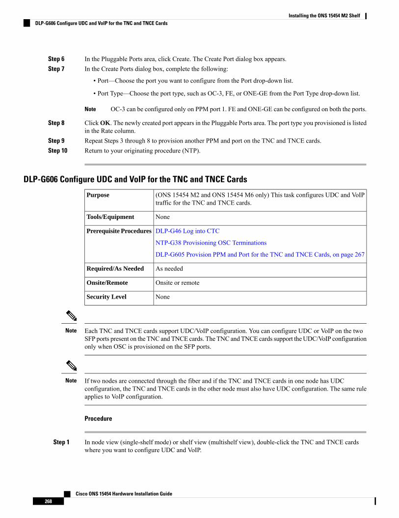
Step 6 In the Pluggable Ports area, click Create. The Create Port dialog box appears.Step 7 In the Create Ports dialog box, complete the following:
• Port—Choose the port you want to configure from the Port drop-down list.
• Port Type—Choose the port type, such as OC-3, FE, or ONE-GE from the Port Type drop-down list.
OC-3 can be configured only on PPM port 1. FE and ONE-GE can be configured on both the ports.Note
Step 8 ClickOK. The newly created port appears in the Pluggable Ports area. The port type you provisioned is listedin the Rate column.
Step 9 Repeat Steps 3 through 8 to provision another PPM and port on the TNC and TNCE cards.Step 10 Return to your originating procedure (NTP).
DLP-G606 Configure UDC and VoIP for the TNC and TNCE Cards
(ONS 15454 M2 and ONS 15454 M6 only) This task configures UDC and VoIPtraffic for the TNC and TNCE cards.
Purpose
NoneTools/Equipment
DLP-G46 Log into CTC
NTP-G38 Provisioning OSC Terminations
DLP-G605 Provision PPM and Port for the TNC and TNCE Cards, on page 267
Prerequisite Procedures
As neededRequired/As Needed
Onsite or remoteOnsite/Remote
NoneSecurity Level
Each TNC and TNCE cards support UDC/VoIP configuration. You can configure UDC or VoIP on the twoSFP ports present on the TNC and TNCE cards. The TNC and TNCE cards support the UDC/VoIP configurationonly when OSC is provisioned on the SFP ports.
Note
If two nodes are connected through the fiber and if the TNC and TNCE cards in one node has UDCconfiguration, the TNC and TNCE cards in the other node must also have UDC configuration. The same ruleapplies to VoIP configuration.
Note
Procedure
Step 1 In node view (single-shelf mode) or shelf view (multishelf view), double-click the TNC and TNCE cardswhere you want to configure UDC and VoIP.
Cisco ONS 15454 Hardware Installation Guide268
Installing the ONS 15454 M2 ShelfDLP-G606 Configure UDC and VoIP for the TNC and TNCE Cards

Step 2 Click the Provisioning > UDC / VOIP tabs.Step 3 From the Service Type drop-drop list, choose UDC or VOIP.
You can configure UDC or VoIP on only one SFP port at a time per TNC and TNCE cards. If youwant to configure UDC or VoIP on the second SFP port, choose NONE from the Service Typedrop-down list for the first port and then choose UDC or VoIP for the second port.
Note
Step 4 Click Apply.Step 5 Return to your originating procedure (NTP).
NTP-G275 Perform the ONS 15454 M2 Shelf Installation Acceptance TestUse this procedure to perform a shelf installation acceptance test for the ONS15454 M2.
Purpose
VoltmeterTools/Equipment
Applicable procedures in Installing the ONS 15454 M2 Shelf, on page 179Prerequisite Procedures
RequiredRequired/As Needed
OnsiteOnsite/Remote
NoneSecurity Level
Procedure
Step 1 If you installed an ONS 15454 M2 shelf, complete the following table by verifying that each applicableprocedure was completed.
Table 31: ONS 15454 M2 ETSI Shelf Installation Task Summary
CompletedDescription
NTP-G305 Unpack and Inspect the ONS 15454, ONS 15454 M2, and ONS 15454 M6 Shelves,on page 22
NTP-G266 Install the ONS 15454 M2 Shelf, on page 196
Connect the chassis to the office ground. For detailed instructions on how to ground the chassis,refer to the Electrostatic Discharge andGroundingGuide for Cisco CPT and CiscoONS Platforms.
NTP-G270 Open and Remove the Standard Door of the ONS 15454 M2 Shelf, on page 220
NTP-G267 Install the Power Module in the ONS 15454 M2 Shelf, on page 232
NTP-G271 Install the Power and Ground to the ONS 15454 M2 Shelf, on page 241
NTP-G268 Install the Fan-Tray Assembly in the ONS 15454 M2 Shelf, on page 237
Cisco ONS 15454 Hardware Installation Guide269
Installing the ONS 15454 M2 ShelfNTP-G275 Perform the ONS 15454 M2 Shelf Installation Acceptance Test
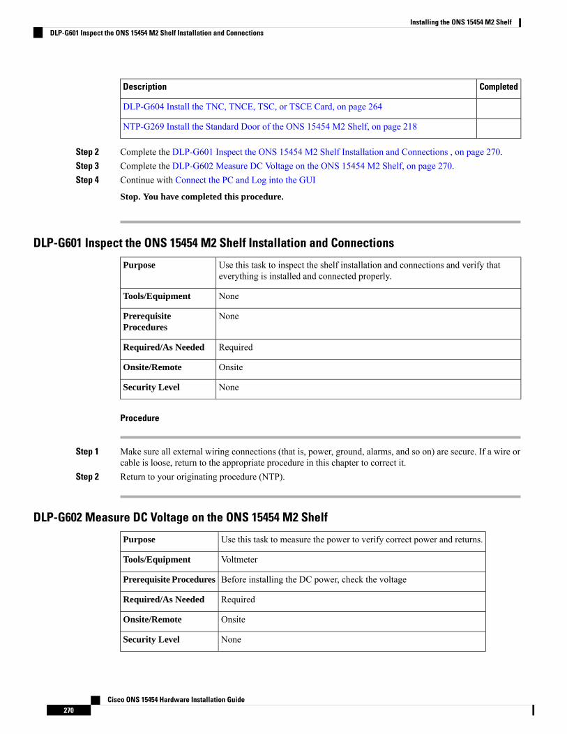
CompletedDescription
DLP-G604 Install the TNC, TNCE, TSC, or TSCE Card, on page 264
NTP-G269 Install the Standard Door of the ONS 15454 M2 Shelf, on page 218
Step 2 Complete the DLP-G601 Inspect the ONS 15454 M2 Shelf Installation and Connections , on page 270.Step 3 Complete the DLP-G602 Measure DC Voltage on the ONS 15454 M2 Shelf, on page 270.Step 4 Continue with Connect the PC and Log into the GUI
Stop. You have completed this procedure.
DLP-G601 Inspect the ONS 15454 M2 Shelf Installation and Connections
Use this task to inspect the shelf installation and connections and verify thateverything is installed and connected properly.
Purpose
NoneTools/Equipment
NonePrerequisiteProcedures
RequiredRequired/As Needed
OnsiteOnsite/Remote
NoneSecurity Level
Procedure
Step 1 Make sure all external wiring connections (that is, power, ground, alarms, and so on) are secure. If a wire orcable is loose, return to the appropriate procedure in this chapter to correct it.
Step 2 Return to your originating procedure (NTP).
DLP-G602 Measure DC Voltage on the ONS 15454 M2 Shelf
Use this task to measure the power to verify correct power and returns.Purpose
VoltmeterTools/Equipment
Before installing the DC power, check the voltagePrerequisite Procedures
RequiredRequired/As Needed
OnsiteOnsite/Remote
NoneSecurity Level
Cisco ONS 15454 Hardware Installation Guide270
Installing the ONS 15454 M2 ShelfDLP-G601 Inspect the ONS 15454 M2 Shelf Installation and Connections

Do not apply power to the shelf until you complete all the installation steps.Caution
To ensure safety of personnel and equipment, do not connect any power cables into the power moduleuntil the module is completely installed into the chassis. Statement 389
Warning
To reduce the risk of electric shock, switch on the power only after the power cord is completely installedinto the power module. Statement 390
Warning
Procedure
Step 1 Using a voltmeter, verify the office ground and power:
• Place the black lead (positive) on the frame ground on the bay.• Place the red lead (negative) on the fuse power points on the third-party power distribution panel to verifythat they read between –40.5 VDC and –57.6 VDC (power) and 0 (return ground).
Step 2 Using a voltmeter, verify the shelf ground and power wiring:
• Place the black lead (positive) on the RET1(A) and the red lead on the -48V (A) point. Verify a readingbetween –40.5 VDC and –57.6 VDC. If there is no voltage, check the following and correct if necessary:
• Battery and ground are reversed to the shelf.• Battery is open or missing.• Return is open or missing.
Step 3 Repeat the above steps for the RET2 (B) and -48V (B) of the redundant power supply input.Step 4 Return to your originating procedure (NTP).
Filler and Blank CardsFiller cards must be installed in unused and empty slots to ensure proper air flow and electromagneticinterference (EMI) requirements during the ONS 15454 M2 operation.
There are two types of card fillers:
• Line card fillers (15454-M-FILLER) that operate in slots 2 and 3.• Timing and Control Card fillers (15454-M-T-FILLER) for control cards that operate in slot 1.
CTC detects filler cards from R10.6 onwards. Figure 288: Line Card Filler—Faceplate, on page 435 showsthe line card filler. The filler cards have no card-level LED indicators.
Blank cards (15454-BLANK) can be installed in any empty slot in the shelf. CTC does not detect blank cards.
Cisco ONS 15454 Hardware Installation Guide271
Installing the ONS 15454 M2 ShelfFiller and Blank Cards
Air FilterThe ONS 15454 M2 contains a preinstalled reusable air filter (15454 M2-FTF) on the right side of the shelf.
The reusable filter is made up of a gray, open-cell, polyurethane foam that is specially coated to provide fireand fungi resistance. Spare filters should be kept in stock. Inspect the air filter every 30 days, and clean thefilter every three to six months. The air filter can be replaced without removing the fan-tray assembly. However,the fan-tray must be turned off to remove the air filter. Replace the air filter every two to three years. Avoidcleaning the air filter with harsh cleaning agents or solvents.
Do not operate an ONS 15454 M2 without the mandatory air filter.Caution
Shelf Voltage and Temperature
The temperature measured by the TNC, TNCE, TSC, or TSCE sensors appears on the LCD screen in the ONS15454 M2 chassis.
Note
The input voltages and temperature of the ONS 15454 M2 chassis are displayed in the Shelf view >Provisioning >General >Voltage/Temperature pane in CTC. The voltage supplied to the shelf (in millivolts)is displayed in the Voltage area of the Voltage/Temperature pane. The temperature of the shelf (in degreeCelsius) is displayed in the Temperature area of the pane.
The Voltage/Temperature pane retrieves the following values for the ONS 15454 M2 chassis:
• Voltage A—Voltage of the shelf that corresponds to power supply A, in millivolts.• Voltage B—Voltage of the shelf that corresponds to power supply B, in millivolts.• Chassis Temperature—Temperature of the shelf, in degrees Celsius.
In multishelf configuration, the voltage and temperature of each shelf is displayed in the Shelf view >Provisioning > General > Voltage/Temperature pane.
Cisco ONS 15454 Hardware Installation Guide272
Installing the ONS 15454 M2 ShelfAir Filter

C H A P T E R 5Installing the ONS 15454 M6 Shelf
This chapter explains how to install the ONS 15454 M6 shelf.
Unless otherwise specified, the ECU module refers to the ECU, ECU2, ECU-S, and ECU-60V units. Fordetails about the various ECU modules, see the External Connection Units, on page 345.
Note
• ANSI Rack Installation, on page 274• ETSI Rack Installation, on page 276• Air Deflector, on page 278• Air Plenum, on page 278• Air Plenum Rack and Cabinet Compatibility, on page 280• NTP-G344 Install the Air Plenum in ONS 15454 M6 Shelf, on page 281• Air Flow Performance of ONS 15454 M6, on page 295• NTP-G252 Install the ONS 15454 M6 Shelf , on page 296• Front Door, on page 322• NTP-G258 Install the Standard Door of the ONS 15454 M6 Shelf , on page 324• NTP-G259 Open and Remove the Standard Door of the ONS 15454 M6 Shelf , on page 329• NTP-G327 Install the Deep-Front Panel of the ONS 15454 M6 Shelf, on page 334• NTP-G329 Remove the Deep-Front Panel of the ONS 15454 M6 Shelf , on page 341• External Connection Units, on page 345• NTP-G253 Install the ECU or ECU-S Module, on page 352• NTP-L68 Upgrading to ONS 15454 M6 ECU60-S Module, on page 355• Power Modules, on page 355• NTP-G524 Install the Power Modules in the ONS 15454 M6 Shelf , on page 358• LCD Unit, on page 369• NTP-G255 Install the LCD Module in the ONS 15454 M6 Shelf, on page 369• Power and Ground Description, on page 371• NTP-G256 Install Power and Ground to the ONS 15454 M6 Shelf , on page 373• Fan-Tray Assembly , on page 390• NTP-G257 Install the Fan-Tray Assembly in the ONS 15454 M6 Shelf, on page 391• Cable Routing and Management, on page 393• NTP-G290 Install the Cable and Fiber Modules, on page 394
Cisco ONS 15454 Hardware Installation Guide273
• NTP-G312 Attach Wires to Alarm, Timing, LAN, and Craft Pin Connections in Cisco ONS 15454 M6,on page 400
• NTP-G308 Connect the ONS 15454 M6 Multishelf Node and the ONS 15454 M6 Subtending Shelves,on page 410
• NTP-G309 Connect the ONS 15454 M6 and the ONS 15454 in a Mixed Multishelf Configuration, onpage 412
• NTP-G310 Upgrade the ONS 15454 Multishelf Configuration Using the ONS 15454 M6 , on page 422• NTP-G264 Perform the ONS 15454 M6 Shelf Installation Acceptance Test , on page 428• NTP-G317 Connect the ONS 15454 M6 Multishelf Node and the ONS 15454 M6 Subtending Shelveswith Simplex Controllers, on page 431
• NTP-G318 Connect the ONS 15454 M6 Multishelf Node and the ONS 15454 M6 Subtending Shelvesin a Ring Topology, on page 433
• Air Deflector, on page 434• Filler and Blank Cards, on page 435• Air Filter , on page 435• Shelf Voltage and Temperature, on page 436• Cooling Profile, on page 436
ANSI Rack InstallationThe ONS 15454M6 shelf is mounted on a 19-inch (482.6-mm) or 23-inch (584.2-mm) equipment rack. Makesure that the correct type of 19-inch ANSI rack is used for mounting the ONS 15454 M6 shelf as shown inFigure 5: 19-inch ANSI Rack Post Recommended for Cisco ONS 15454 M6 and M2 Shelves, on page 5.If the shelf is mounted in the front position, then it projects 1.7 inches (43.18 mm) from the front of the rack.If the shelf is mounted in the middle position, then it projects 5.1 inches (129.54 mm) from the front of therack. The shelf mounts in both Electronic Industries Alliance (EIA) standard and Telcordia-standard racks.The shelf is a total of 17 inches (431.8 mm) wide with no mounting ears attached. Ring runs are not providedby Cisco and might hinder side-by-side installation of shelves where space is limited.
The ONS 15454M6 shelf measures 10.4 inches (264.16 mm) high, 19 or 23 inches (482.6 or 584.2 mm) wide(depending on which way the mounting ears are attached), and 11.1 inches (304.8 mm) deep. You can installup to seven ONS 15454 M6 shelves in a 7-foot (2133.6 mm) equipment rack.
The following figure shows the dimensions of the ONS 15454 M6 shelf on a 19-inch (482.6 mm) ANSI rackconfiguration with brackets mounted in the front position.
Cisco ONS 15454 Hardware Installation Guide274
Installing the ONS 15454 M6 ShelfANSI Rack Installation
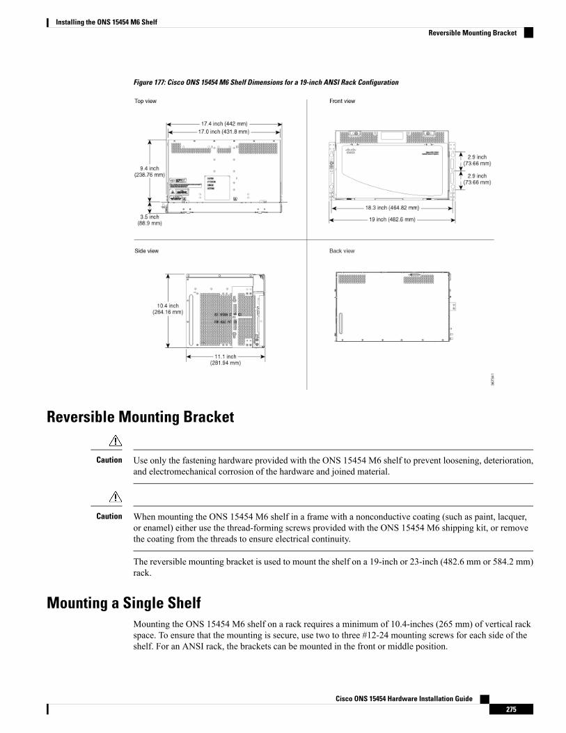
Figure 177: Cisco ONS 15454 M6 Shelf Dimensions for a 19-inch ANSI Rack Configuration
Reversible Mounting Bracket
Use only the fastening hardware provided with the ONS 15454 M6 shelf to prevent loosening, deterioration,and electromechanical corrosion of the hardware and joined material.
Caution
When mounting the ONS 15454 M6 shelf in a frame with a nonconductive coating (such as paint, lacquer,or enamel) either use the thread-forming screws provided with the ONS 15454 M6 shipping kit, or removethe coating from the threads to ensure electrical continuity.
Caution
The reversible mounting bracket is used to mount the shelf on a 19-inch or 23-inch (482.6 mm or 584.2 mm)rack.
Mounting a Single ShelfMounting the ONS 15454 M6 shelf on a rack requires a minimum of 10.4-inches (265 mm) of vertical rackspace. To ensure that the mounting is secure, use two to three #12-24 mounting screws for each side of theshelf. For an ANSI rack, the brackets can be mounted in the front or middle position.
Cisco ONS 15454 Hardware Installation Guide275
Installing the ONS 15454 M6 ShelfReversible Mounting Bracket
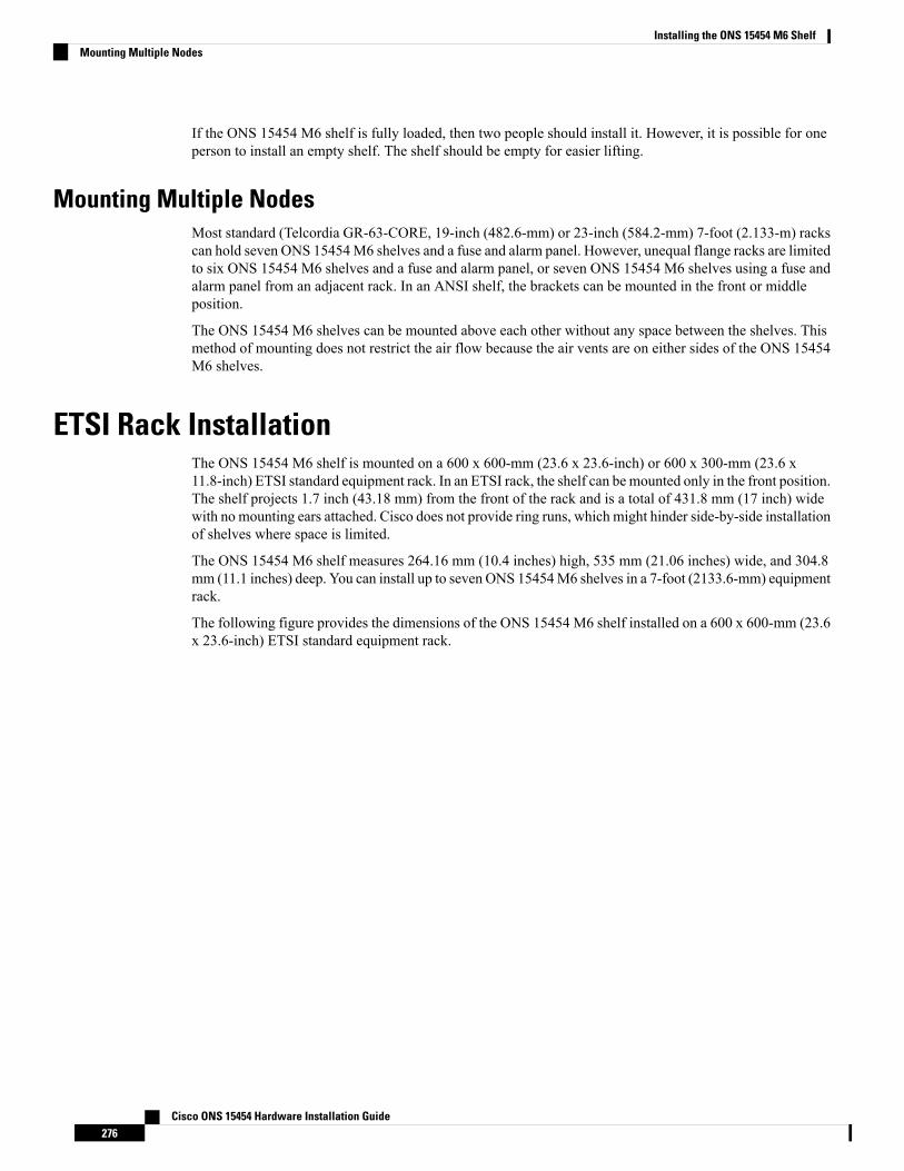
If the ONS 15454 M6 shelf is fully loaded, then two people should install it. However, it is possible for oneperson to install an empty shelf. The shelf should be empty for easier lifting.
Mounting Multiple NodesMost standard (Telcordia GR-63-CORE, 19-inch (482.6-mm) or 23-inch (584.2-mm) 7-foot (2.133-m) rackscan hold seven ONS 15454M6 shelves and a fuse and alarm panel. However, unequal flange racks are limitedto six ONS 15454 M6 shelves and a fuse and alarm panel, or seven ONS 15454 M6 shelves using a fuse andalarm panel from an adjacent rack. In an ANSI shelf, the brackets can be mounted in the front or middleposition.
The ONS 15454 M6 shelves can be mounted above each other without any space between the shelves. Thismethod of mounting does not restrict the air flow because the air vents are on either sides of the ONS 15454M6 shelves.
ETSI Rack InstallationThe ONS 15454 M6 shelf is mounted on a 600 x 600-mm (23.6 x 23.6-inch) or 600 x 300-mm (23.6 x11.8-inch) ETSI standard equipment rack. In an ETSI rack, the shelf can be mounted only in the front position.The shelf projects 1.7 inch (43.18 mm) from the front of the rack and is a total of 431.8 mm (17 inch) widewith no mounting ears attached. Cisco does not provide ring runs, which might hinder side-by-side installationof shelves where space is limited.
The ONS 15454 M6 shelf measures 264.16 mm (10.4 inches) high, 535 mm (21.06 inches) wide, and 304.8mm (11.1 inches) deep. You can install up to seven ONS 15454M6 shelves in a 7-foot (2133.6-mm) equipmentrack.
The following figure provides the dimensions of the ONS 15454 M6 shelf installed on a 600 x 600-mm (23.6x 23.6-inch) ETSI standard equipment rack.
Cisco ONS 15454 Hardware Installation Guide276
Installing the ONS 15454 M6 ShelfMounting Multiple Nodes

Figure 178: Cisco ONS 15454 M6 Shelf Dimensions for an ETSI Rack Configuration
The standard ETSI racks can hold seven ONS 15454 M6 shelves. When mounting a shelf in a partially filledrack, load the rack from the bottom to the top with the heaviest component at the bottom of the rack. If therack is provided with stabilizing devices, install the stabilizers before mounting or servicing the unit in therack.
Caution
Mounting a Single NodeTheONS 15454M6 requires 264.16mm (10.4-inches) minimum of vertical rack space. To ensure themountingis secure, use two to three M6 mounting screws for each side of the shelf. A shelf should be mounted at thebottom of the rack if it is the only unit in the rack.
In an ETSI rack, the brackets are mounted only in the front position.
If the ONS 15454 M6 shelf is fully loaded, then two people should install it. However, it is possible for oneperson to install an empty shelf. The shelf should be empty for easier lifting. For information on the ONS15454 M6 shelf weight, see the Dimensions, on page 483.
Cisco ONS 15454 Hardware Installation Guide277
Installing the ONS 15454 M6 ShelfMounting a Single Node
Mounting Multiple NodesMost standard (ETS 300 119) ETSI 600 x 600 x 2200 mm or 600 x 300 x 2200 mm racks can hold sevenONS 15454 M6 shelves, and a fuse and alarm panel. In an ETSI rack, the brackets are mounted only in thefront position.
The ONS 15454 M6 shelves can be mounted above each other without any space between the shelves. Thismethod of mounting does not restrict the air flow because the air vents are on either sides of the ONS 15454M6 shelves.
Air DeflectorAn air deflector is a sheet-metal part that is mounted on the ONS 15454 M6 shelf to orient the air flow in aspecific direction.
The air deflectors can be mounted in different positions to control the air flow:
• Front to Front— Only ETSI rack• Front to Back— For ANSI and ETSI racks• Front to Top— Only ETSI rack
In an ANSI rack, the air deflectors are mounted only on the 23-inch rack configuration.
Air PlenumAir plenum orients the air flow in the front-to-back direction inside the equipment to be compliant with GR-63issue 4 requirement.
The air plenum kit has two horizontal and two vertical air plenums. The air that flows from the front top inletand the front bottom inlet are channelized to the right vertical plenum, inside the equipment, and then to theexhaust air channel towards the left vertical air plenum. The air flow is deflected by 90 degrees and exitedout in the rear end.
The following figure shows the air flow inside the cabinet.
Cisco ONS 15454 Hardware Installation Guide278
Installing the ONS 15454 M6 ShelfMounting Multiple Nodes
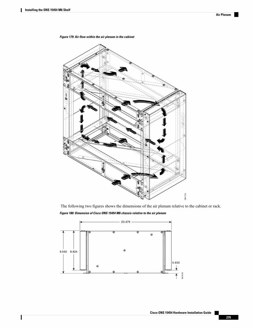
Figure 179: Air flow within the air plenum in the cabinet
The following two figures shows the dimensions of the air plenum relative to the cabinet or rack.
Figure 180: Dimension of Cisco ONS 15454 M6 chassis relative to the air plenum
Cisco ONS 15454 Hardware Installation Guide279
Installing the ONS 15454 M6 ShelfAir Plenum
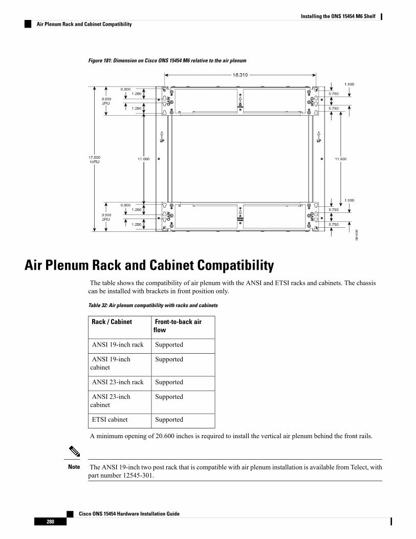
Figure 181: Dimension on Cisco ONS 15454 M6 relative to the air plenum
Air Plenum Rack and Cabinet CompatibilityThe table shows the compatibility of air plenum with the ANSI and ETSI racks and cabinets. The chassiscan be installed with brackets in front position only.
Table 32: Air plenum compatibility with racks and cabinets
Front-to-back airflow
Rack / Cabinet
SupportedANSI 19-inch rack
SupportedANSI 19-inchcabinet
SupportedANSI 23-inch rack
SupportedANSI 23-inchcabinet
SupportedETSI cabinet
A minimum opening of 20.600 inches is required to install the vertical air plenum behind the front rails.
The ANSI 19-inch two post rack that is compatible with air plenum installation is available from Telect, withpart number 12545-301.
Note
Cisco ONS 15454 Hardware Installation Guide280
Installing the ONS 15454 M6 ShelfAir Plenum Rack and Cabinet Compatibility

Figure 182: Minimum rear opening for ANSI 19-inch and ETSI configuration
NTP-G344 Install the Air Plenum in ONS 15454 M6 ShelfThis procedure installs the air plenum to orient the air flow from front-to- backdirection in the ONS 15454 M6 shelf.
Purpose
• #2 Phillips Dynamometric screwdriver• Medium slot-head screwdriver• Small slot-head screwdriver• Screws
• ANSI: #12-24 x 0.50 pan-head Phillips screws• ETSI: M6.0 x 20 pan-head Phillips screws
• Wing head screws (8)• Adapter plates• One air plenum kit (horizontal and vertical air plenums)
Tools/Equipment
As neededRequired/As Needed
OnsiteOnsite/Remote
NoneSecurity Level
Before performing any of the following procedures, ensure that power is removed from the DC circuit.Statement 1074
Warning
Before working on a chassis or working near power supplies, unplug the power cord on AC units.Statement 246
Warning
Cisco ONS 15454 Hardware Installation Guide281
Installing the ONS 15454 M6 ShelfNTP-G344 Install the Air Plenum in ONS 15454 M6 Shelf
This equipment is intended to be grounded. Ensure that the host is connected to earth ground duringnormal use. Statement 39
Warning
For nominal voltage of -60 VDC, the input voltage range is from -40 to -72 VDC.Note
Use only the fastening hardware provided with the ONS 15454 M6 to prevent loosening, deterioration, andelectromechanical corrosion of the hardware and joined material.
Note
When installing or replacing the unit, the ground connection must always be made first and disconnectedlast. Statement 1046
Warning
The air plenum is installed on a rack or a cabinet using thread-forming screws that remove any paintor non-conductive coatings inside the hole threads, and establish a metal-to-metal contact. Also, cleanboth surfaces outside the screw points that come in contact, so that they are free of paint and othernonconductive coating. Apply an appropriate antioxidant compound to the surfaces.
Warning
Procedure
Depending on the rack or cabinet, complete the necessary task:
• DLP-G766 Install Air Plenum for ONS 15454 M6 Shelf in ANSI 19-inch Cabinet, on page 282
• DLP-G767 Install Air Plenum in ONS 15454 M6 Shelf for ANSI 23-inch Configuration, on page 286
• DLP-G768 Install Pre-assembled Air Plenums in ANSI 23-inch Configuration, on page 289
• DLP-G769 Install Air Plenum for ONS 15454 M6 Shelf in ETSI Configuration, on page 291
Stop. You have completed this procedure.
DLP-G766 Install Air Plenum for ONS 15454 M6 Shelf in ANSI 19-inch CabinetThis task installs the air plenum for the ONS 15454 M6 shelf in ANSI 19-inchcabinet.
Purpose
Cisco ONS 15454 Hardware Installation Guide282
Installing the ONS 15454 M6 ShelfDLP-G766 Install Air Plenum for ONS 15454 M6 Shelf in ANSI 19-inch Cabinet
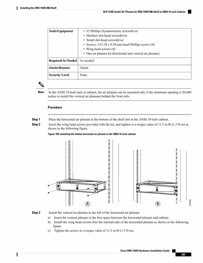
• #2 Phillips Dynamometric screwdriver• Medium slot-head screwdriver• Small slot-head screwdriver• Screws: #12-24 x 0.50 pan-head Phillips screws (8)• Wing head screws (8)• One air plenum kit (horizontal and vertical air plenum)
Tools/Equipment
As neededRequired/As Needed
OnsiteOnsite/Remote
NoneSecurity Level
In the ANSI 19-inch rack or cabinet, the air plenum can be mounted only if the minimum opening is 20.600inches to install the vertical air plenums behind the front rails.
Note
Procedure
Step 1 Place the horizontal air plenum at the bottom of the shelf slot in the ANSI 19-inch cabinet.Step 2 Insert the wing head screws provided with the kit, and tighten to a torque value of 11.5 in-lb (1.3 N-m) as
shown in the following figure.
Figure 183: Installing the bottom horizontal air plenum in the ANSI 19-inch cabinet
Step 3 Install the vertical air plenum to the left of the horizontal air plenum:a) Insert the vertical plenum in the free space between the horizontal plenum and cabinet.b) Install the wing head screws fom the internal side of the horizontal plenum as shown in the following
figure.c) Tighten the screws to a torque value of 11.5 in-lb (1.3 N-m).
Cisco ONS 15454 Hardware Installation Guide283
Installing the ONS 15454 M6 ShelfDLP-G766 Install Air Plenum for ONS 15454 M6 Shelf in ANSI 19-inch Cabinet
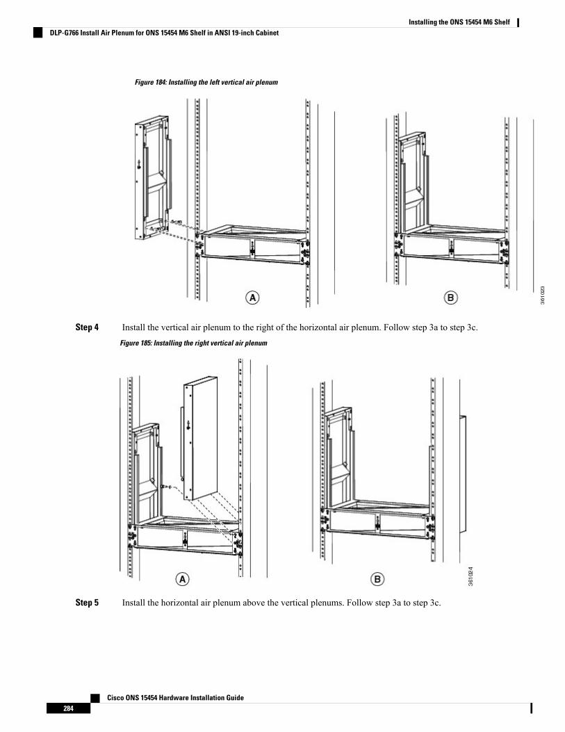
Figure 184: Installing the left vertical air plenum
Step 4 Install the vertical air plenum to the right of the horizontal air plenum. Follow step 3a to step 3c.
Figure 185: Installing the right vertical air plenum
Step 5 Install the horizontal air plenum above the vertical plenums. Follow step 3a to step 3c.
Cisco ONS 15454 Hardware Installation Guide284
Installing the ONS 15454 M6 ShelfDLP-G766 Install Air Plenum for ONS 15454 M6 Shelf in ANSI 19-inch Cabinet
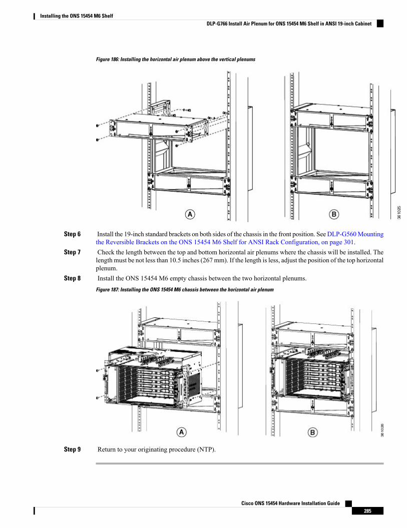
Figure 186: Installing the horizontal air plenum above the vertical plenums
Step 6 Install the 19-inch standard brackets on both sides of the chassis in the front position. See DLP-G560Mountingthe Reversible Brackets on the ONS 15454 M6 Shelf for ANSI Rack Configuration, on page 301.
Step 7 Check the length between the top and bottom horizontal air plenums where the chassis will be installed. Thelength must be not less than 10.5 inches (267 mm). If the length is less, adjust the position of the top horizontalplenum.
Step 8 Install the ONS 15454 M6 empty chassis between the two horizontal plenums.
Figure 187: Installing the ONS 15454 M6 chassis between the horizontal air plenum
Step 9 Return to your originating procedure (NTP).
Cisco ONS 15454 Hardware Installation Guide285
Installing the ONS 15454 M6 ShelfDLP-G766 Install Air Plenum for ONS 15454 M6 Shelf in ANSI 19-inch Cabinet

DLP-G767 Install Air Plenum in ONS 15454 M6 Shelf for ANSI 23-inchConfiguration
This task installs the air plenum for the ONS 15454 M6 shelf in the ANSI 23-inchcabinet or rack configuration.
Purpose
• #2 Phillips Dynamometric screwdriver• Medium slot-head screwdriver• Small slot-head screwdriver• Screws: #12-24 x 3/4 pan-head Phillips mounting screws (8)• Wing head screws (8)• Adapter plates• One air plenum kit (horizontal and vertical air plenum)
Tools/Equipment
As neededRequired/As Needed
OnsiteOnsite/Remote
NoneSecurity Level
The airplenums for ANSI 23-inch configuration can be pre-assembled outside the cabinet and then installedinside the cabinet. See DLP-G768 Install Pre-assembled Air Plenums in ANSI 23-inch Configuration, on page289
Note
Procedure
Step 1 Install the ANSI 23-inch adapter plates on the horizontal air plenum.Step 2 Align the screws to fix the adapter plates to the shelf. Insert the screws and tighten them to a torque value of
11.5 in-lb (1.3 N-m).
Figure 188: Installing the adapter plates on the horizontal air plenum
Step 3 Place the horizontal air plenum below the shelf slot in the ANSI 23-inch cabinet or rack.Step 4 Insert the wing head screws provided with the kit, and tighten to a torque value of 11.5 in-lb (1.3 N-m).
Cisco ONS 15454 Hardware Installation Guide286
Installing the ONS 15454 M6 ShelfDLP-G767 Install Air Plenum in ONS 15454 M6 Shelf for ANSI 23-inch Configuration
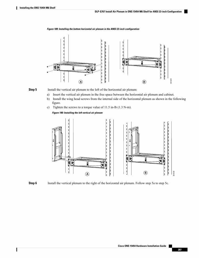
Figure 189: Installing the bottom horizontal air plenum in the ANSI 23-inch configuration
Step 5 Install the vertical air plenum to the left of the horizontal air plenum:a) Insert the vertical air plenum in the free space between the horizontal air plenum and cabinet.b) Install the wing head screws from the internal side of the horizontal plenum as shown in the following
figure.c) Tighten the screws to a torque value of 11.5 in-lb (1.3 N-m).
Figure 190: Installing the left vertical air plenum
Step 6 Install the vertical plenum to the right of the horizontal air plenum. Follow step 5a to step 5c.
Cisco ONS 15454 Hardware Installation Guide287
Installing the ONS 15454 M6 ShelfDLP-G767 Install Air Plenum in ONS 15454 M6 Shelf for ANSI 23-inch Configuration
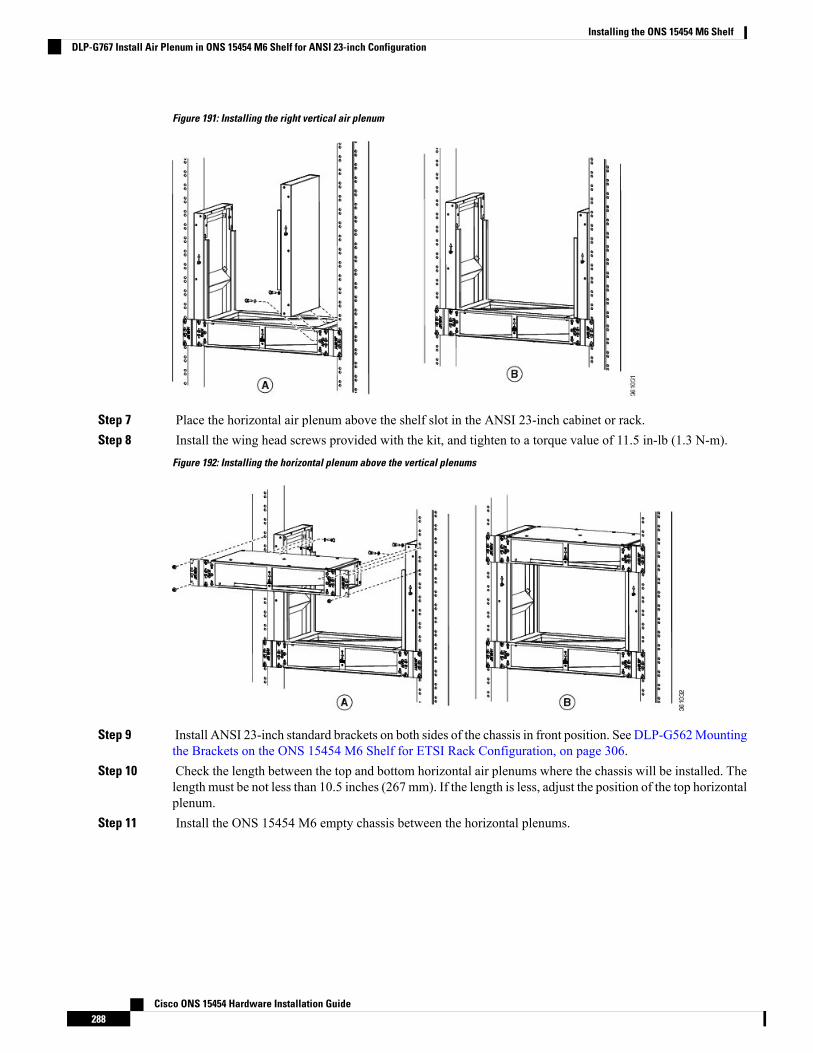
Figure 191: Installing the right vertical air plenum
Step 7 Place the horizontal air plenum above the shelf slot in the ANSI 23-inch cabinet or rack.Step 8 Install the wing head screws provided with the kit, and tighten to a torque value of 11.5 in-lb (1.3 N-m).
Figure 192: Installing the horizontal plenum above the vertical plenums
Step 9 Install ANSI 23-inch standard brackets on both sides of the chassis in front position. See DLP-G562Mountingthe Brackets on the ONS 15454 M6 Shelf for ETSI Rack Configuration, on page 306.
Step 10 Check the length between the top and bottom horizontal air plenums where the chassis will be installed. Thelength must be not less than 10.5 inches (267 mm). If the length is less, adjust the position of the top horizontalplenum.
Step 11 Install the ONS 15454 M6 empty chassis between the horizontal plenums.
Cisco ONS 15454 Hardware Installation Guide288
Installing the ONS 15454 M6 ShelfDLP-G767 Install Air Plenum in ONS 15454 M6 Shelf for ANSI 23-inch Configuration
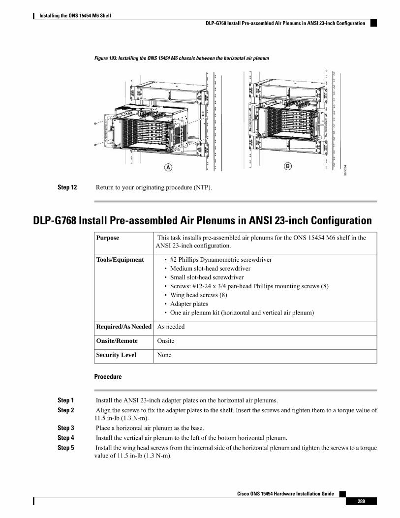
Figure 193: Installing the ONS 15454 M6 chassis between the horizontal air plenum
Step 12 Return to your originating procedure (NTP).
DLP-G768 Install Pre-assembled Air Plenums in ANSI 23-inch ConfigurationThis task installs pre-assembled air plenums for the ONS 15454 M6 shelf in theANSI 23-inch configuration.
Purpose
• #2 Phillips Dynamometric screwdriver• Medium slot-head screwdriver• Small slot-head screwdriver• Screws: #12-24 x 3/4 pan-head Phillips mounting screws (8)• Wing head screws (8)• Adapter plates• One air plenum kit (horizontal and vertical air plenum)
Tools/Equipment
As neededRequired/As Needed
OnsiteOnsite/Remote
NoneSecurity Level
Procedure
Step 1 Install the ANSI 23-inch adapter plates on the horizontal air plenums.Step 2 Align the screws to fix the adapter plates to the shelf. Insert the screws and tighten them to a torque value of
11.5 in-lb (1.3 N-m).Step 3 Place a horizontal air plenum as the base.Step 4 Install the vertical air plenum to the left of the bottom horizontal plenum.Step 5 Install the wing head screws from the internal side of the horizontal plenum and tighten the screws to a torque
value of 11.5 in-lb (1.3 N-m).
Cisco ONS 15454 Hardware Installation Guide289
Installing the ONS 15454 M6 ShelfDLP-G768 Install Pre-assembled Air Plenums in ANSI 23-inch Configuration

Step 6 Install the vertical air plenum to the right of the horizontal air plenum. Follow step 4.Step 7 Install the horizontal air plenum above the vertical air plenums. Follow step 4.
Figure 194: Pre-assembling the air plenums
Step 8 Install the ANSI 23-inch adapter plates on the horizontal air plenums.Step 9 Install the wing head screws provided with the kit, and tighten to a torque value of 11.5 in-lb (1.3 N-m).
Cisco ONS 15454 Hardware Installation Guide290
Installing the ONS 15454 M6 ShelfDLP-G768 Install Pre-assembled Air Plenums in ANSI 23-inch Configuration
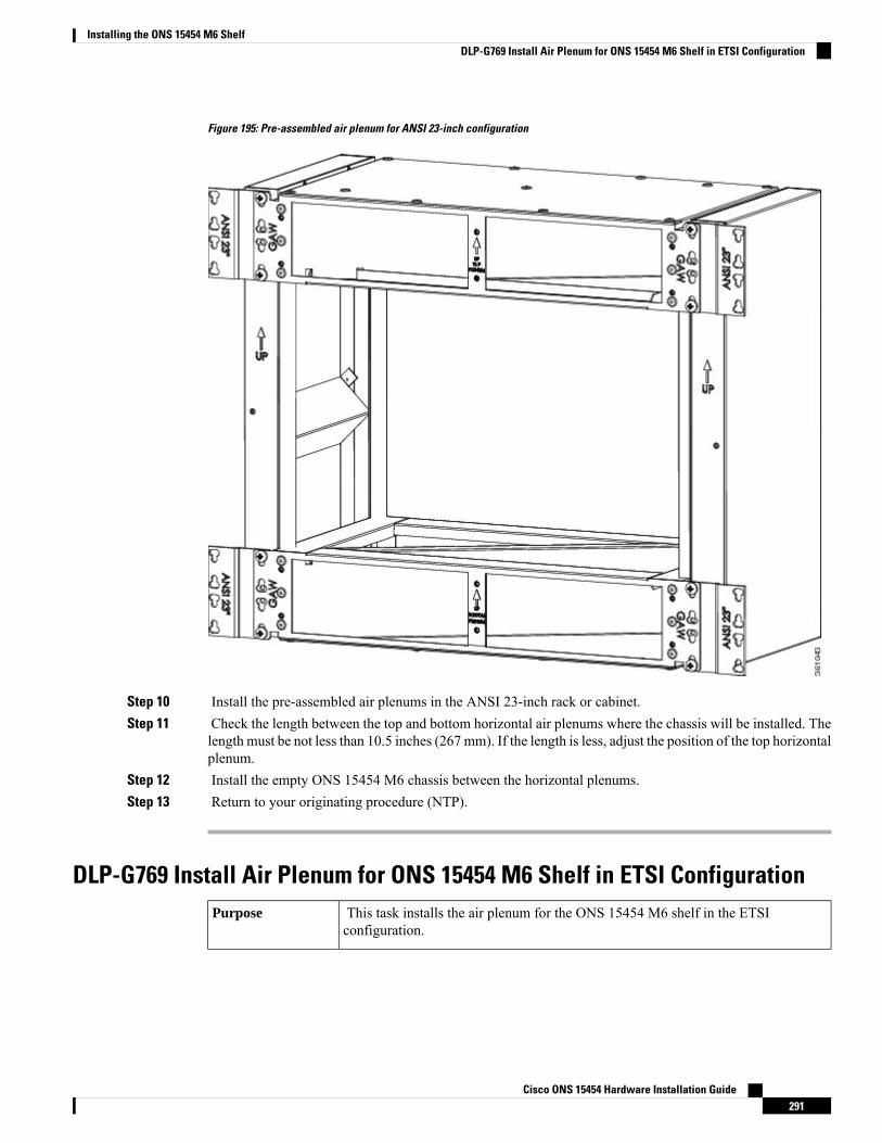
Figure 195: Pre-assembled air plenum for ANSI 23-inch configuration
Step 10 Install the pre-assembled air plenums in the ANSI 23-inch rack or cabinet.Step 11 Check the length between the top and bottom horizontal air plenums where the chassis will be installed. The
length must be not less than 10.5 inches (267 mm). If the length is less, adjust the position of the top horizontalplenum.
Step 12 Install the empty ONS 15454 M6 chassis between the horizontal plenums.Step 13 Return to your originating procedure (NTP).
DLP-G769 Install Air Plenum for ONS 15454 M6 Shelf in ETSI ConfigurationThis task installs the air plenum for the ONS 15454 M6 shelf in the ETSIconfiguration.
Purpose
Cisco ONS 15454 Hardware Installation Guide291
Installing the ONS 15454 M6 ShelfDLP-G769 Install Air Plenum for ONS 15454 M6 Shelf in ETSI Configuration

• #2 Phillips Dynamometric screwdriver• Medium slot-head screwdriver• Small slot-head screwdriver• Screws: M6.0 x 20 pan-head Phillips screws (8)• Wing head screws (8)• Adapter plates• One air plenum kit (horizontal and vertical air plenum)
Tools/Equipment
As neededRequired/As Needed
OnsiteOnsite/Remote
NoneSecurity Level
Procedure
Step 1 Install the ETSI adapter plates on the horizontal air plenums.Step 2 Align the screws to fix the adapter plates to the shelf. Insert the screws and tighten them to a torque value of
11.5 in-lb (1.3 N-m).
Figure 196: Installing the adapter plates on the horizontal air plenum
Step 3 Place the horizontal plenum below the chassis slot in the ETSI cabinet.Step 4 Install the wing head screws provided with the kit, and tighten to a torque value of 11.5 in-lb (1.3 N-m).
Cisco ONS 15454 Hardware Installation Guide292
Installing the ONS 15454 M6 ShelfDLP-G769 Install Air Plenum for ONS 15454 M6 Shelf in ETSI Configuration
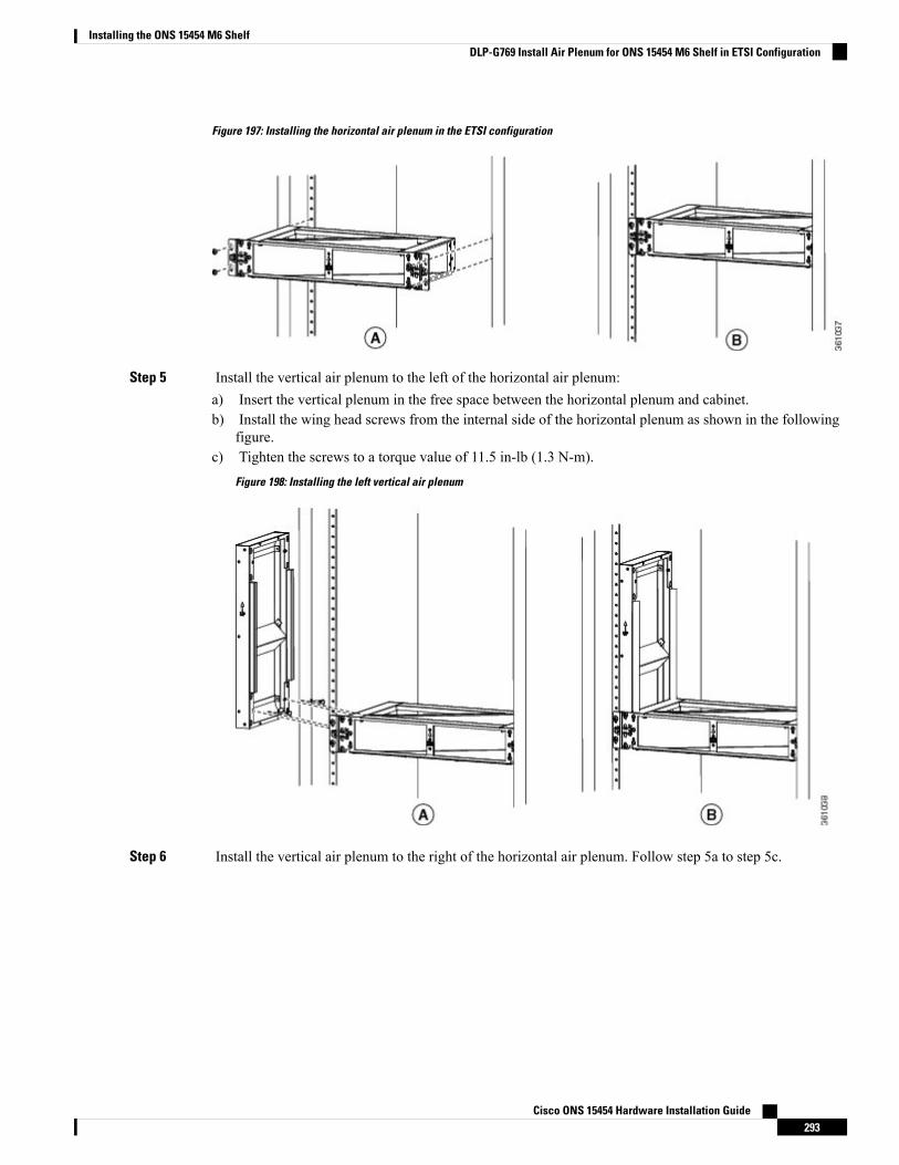
Figure 197: Installing the horizontal air plenum in the ETSI configuration
Step 5 Install the vertical air plenum to the left of the horizontal air plenum:a) Insert the vertical plenum in the free space between the horizontal plenum and cabinet.b) Install the wing head screws from the internal side of the horizontal plenum as shown in the following
figure.c) Tighten the screws to a torque value of 11.5 in-lb (1.3 N-m).
Figure 198: Installing the left vertical air plenum
Step 6 Install the vertical air plenum to the right of the horizontal air plenum. Follow step 5a to step 5c.
Cisco ONS 15454 Hardware Installation Guide293
Installing the ONS 15454 M6 ShelfDLP-G769 Install Air Plenum for ONS 15454 M6 Shelf in ETSI Configuration
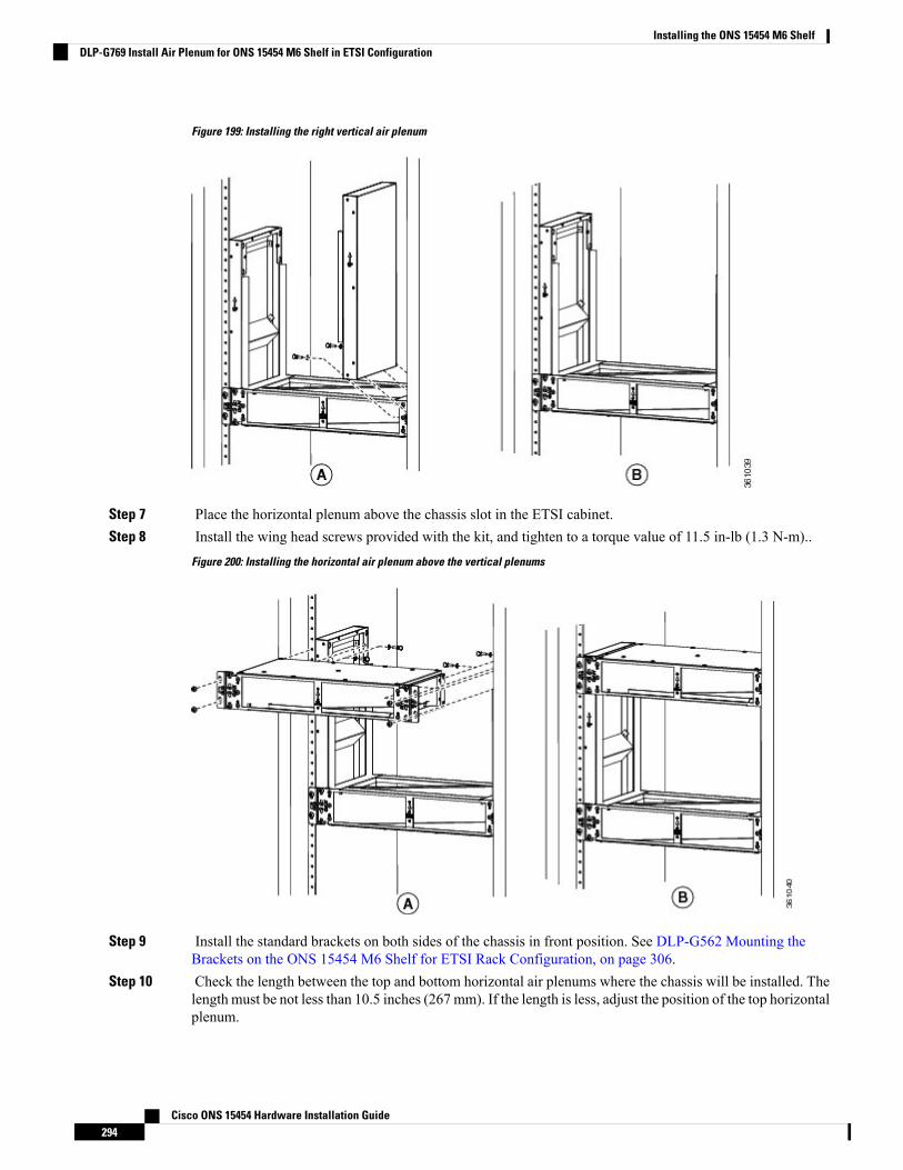
Figure 199: Installing the right vertical air plenum
Step 7 Place the horizontal plenum above the chassis slot in the ETSI cabinet.Step 8 Install the wing head screws provided with the kit, and tighten to a torque value of 11.5 in-lb (1.3 N-m)..
Figure 200: Installing the horizontal air plenum above the vertical plenums
Step 9 Install the standard brackets on both sides of the chassis in front position. See DLP-G562 Mounting theBrackets on the ONS 15454 M6 Shelf for ETSI Rack Configuration, on page 306.
Step 10 Check the length between the top and bottom horizontal air plenums where the chassis will be installed. Thelength must be not less than 10.5 inches (267 mm). If the length is less, adjust the position of the top horizontalplenum.
Cisco ONS 15454 Hardware Installation Guide294
Installing the ONS 15454 M6 ShelfDLP-G769 Install Air Plenum for ONS 15454 M6 Shelf in ETSI Configuration

Step 11 Install the ONS 15454 M6 empty chassis between the horizontal plenums.
Figure 201: Installing the ONS 15454 M6 chassis below the horizontal air plenum
Step 12 Return to your originating procedure (NTP).
Air Flow Performance of ONS 15454 M6The tables below summarizes the air flow performance of ONS 15454 M6:
Worst ControllerCard Slot (#8) Flow,CFM
Worst Line CardSlot (#7) Flow,CFM
DeflectorConfiguration
Case
13500 RPM(40°C and55°C)
9600 RPM(27°C)
13500 RPM (40°Cand 55°C)
9600 RPM(27°C)
2114.922.416No deflectorsSide to Side
106.911.28.2Inlet and OutletETSI Front to Rear
18.412.716.812.2Only InletETSI Front to Side
14.710.618.713.4Inlet and OutletANSI Front toRear
19.714.120.714.8Only InletANSI Front to Side
Bulk Chassis Flow, CFMDeflector ConfigurationCase
13500RPM9600 RPM
Cisco ONS 15454 Hardware Installation Guide295
Installing the ONS 15454 M6 ShelfAir Flow Performance of ONS 15454 M6
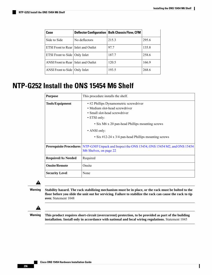
Bulk Chassis Flow, CFMDeflector ConfigurationCase
295.6215.3No deflectorsSide to Side
135.897.7Inlet and OutletETSI Front to Rear
258.6187.7Only InletETSI Front to Side
166.9120.5Inlet and OutletANSI Front to Rear
268.6193.5Only InletANSI Front to Side
NTP-G252 Install the ONS 15454 M6 ShelfThis procedure installs the shelf.Purpose
• #2 Phillips Dynamometric screwdriver• Medium slot-head screwdriver• Small slot-head screwdriver• ETSI only:
• Six M6 x 20 pan-head Phillips mounting screws
• ANSI only:
• Six #12-24 x 3/4 pan-head Phillips mounting screws
Tools/Equipment
NTP-G305Unpack and Inspect the ONS 15454, ONS 15454M2, andONS 15454M6 Shelves, on page 22
Prerequisite Procedures
RequiredRequired/As Needed
OnsiteOnsite/Remote
NoneSecurity Level
Stability hazard. The rack stabilizing mechanism must be in place, or the rack must be bolted to thefloor before you slide the unit out for servicing. Failure to stabilize the rack can cause the rack to tipover. Statement 1048
Warning
This product requires short-circuit (overcurrent) protection, to be provided as part of the buildinginstallation. Install only in accordance with national and local wiring regulations. Statement 1045
Warning
Cisco ONS 15454 Hardware Installation Guide296
Installing the ONS 15454 M6 ShelfNTP-G252 Install the ONS 15454 M6 Shelf
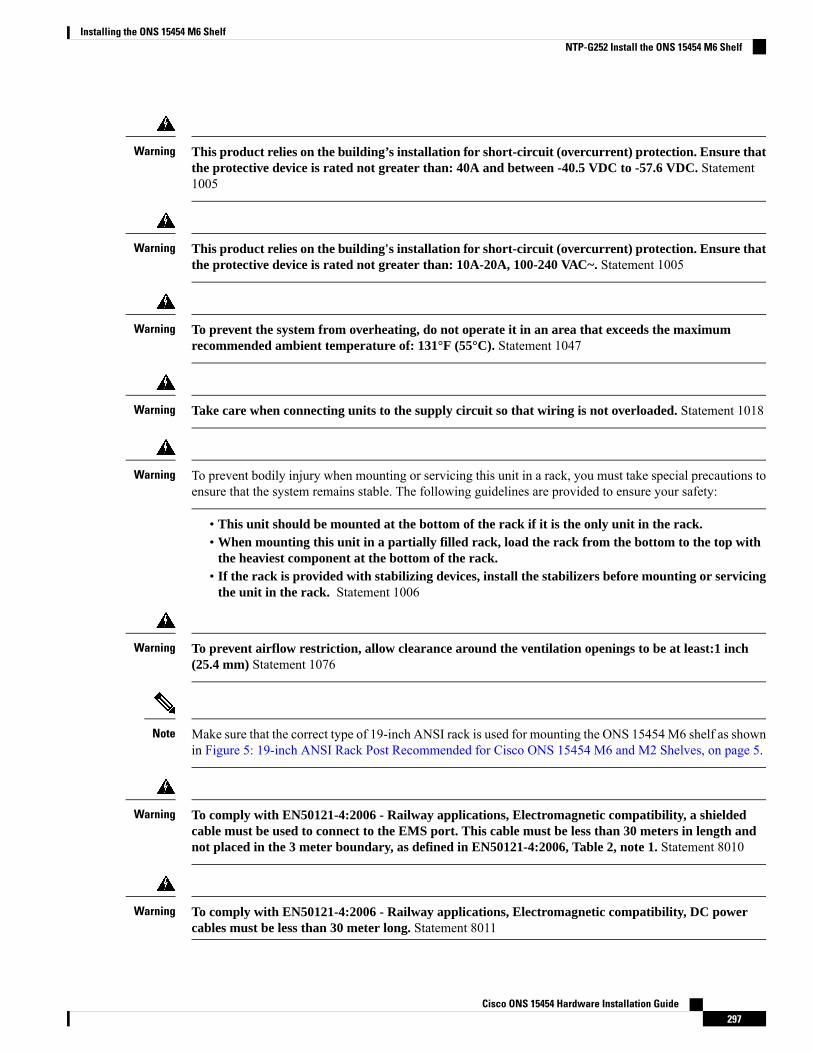
This product relies on the building’s installation for short-circuit (overcurrent) protection. Ensure thatthe protective device is rated not greater than: 40A and between -40.5 VDC to -57.6 VDC. Statement1005
Warning
This product relies on the building's installation for short-circuit (overcurrent) protection. Ensure thatthe protective device is rated not greater than: 10A-20A, 100-240 VAC~. Statement 1005
Warning
To prevent the system from overheating, do not operate it in an area that exceeds the maximumrecommended ambient temperature of: 131°F (55°C). Statement 1047
Warning
Take care when connecting units to the supply circuit so that wiring is not overloaded. Statement 1018Warning
To prevent bodily injury when mounting or servicing this unit in a rack, you must take special precautions toensure that the system remains stable. The following guidelines are provided to ensure your safety:
Warning
• This unit should be mounted at the bottom of the rack if it is the only unit in the rack.• When mounting this unit in a partially filled rack, load the rack from the bottom to the top with
the heaviest component at the bottom of the rack.• If the rack is provided with stabilizing devices, install the stabilizers before mounting or servicing
the unit in the rack. Statement 1006
To prevent airflow restriction, allow clearance around the ventilation openings to be at least:1 inch(25.4 mm) Statement 1076
Warning
Make sure that the correct type of 19-inch ANSI rack is used for mounting the ONS 15454M6 shelf as shownin Figure 5: 19-inch ANSI Rack Post Recommended for Cisco ONS 15454 M6 and M2 Shelves, on page 5.
Note
To comply with EN50121-4:2006 - Railway applications, Electromagnetic compatibility, a shieldedcable must be used to connect to the EMS port. This cable must be less than 30 meters in length andnot placed in the 3 meter boundary, as defined in EN50121-4:2006, Table 2, note 1. Statement 8010
Warning
To comply with EN50121-4:2006 - Railway applications, Electromagnetic compatibility, DC powercables must be less than 30 meter long. Statement 8011
Warning
Cisco ONS 15454 Hardware Installation Guide297
Installing the ONS 15454 M6 ShelfNTP-G252 Install the ONS 15454 M6 Shelf
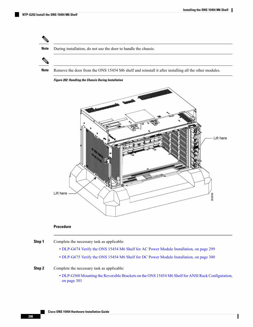
During installation, do not use the door to handle the chassis.Note
Remove the door from the ONS 15454 M6 shelf and reinstall it after installing all the other modules.Note
Figure 202: Handling the Chassis During Installation
Procedure
Step 1 Complete the necessary task as applicable:
• DLP-G674 Verify the ONS 15454 M6 Shelf for AC Power Module Installation, on page 299
• DLP-G675 Verify the ONS 15454 M6 Shelf for DC Power Module Installation, on page 300
Step 2 Complete the necessary task as applicable:
• DLP-G560Mounting the Reversible Brackets on the ONS 15454M6 Shelf for ANSI Rack Configuration,on page 301
Cisco ONS 15454 Hardware Installation Guide298
Installing the ONS 15454 M6 ShelfNTP-G252 Install the ONS 15454 M6 Shelf
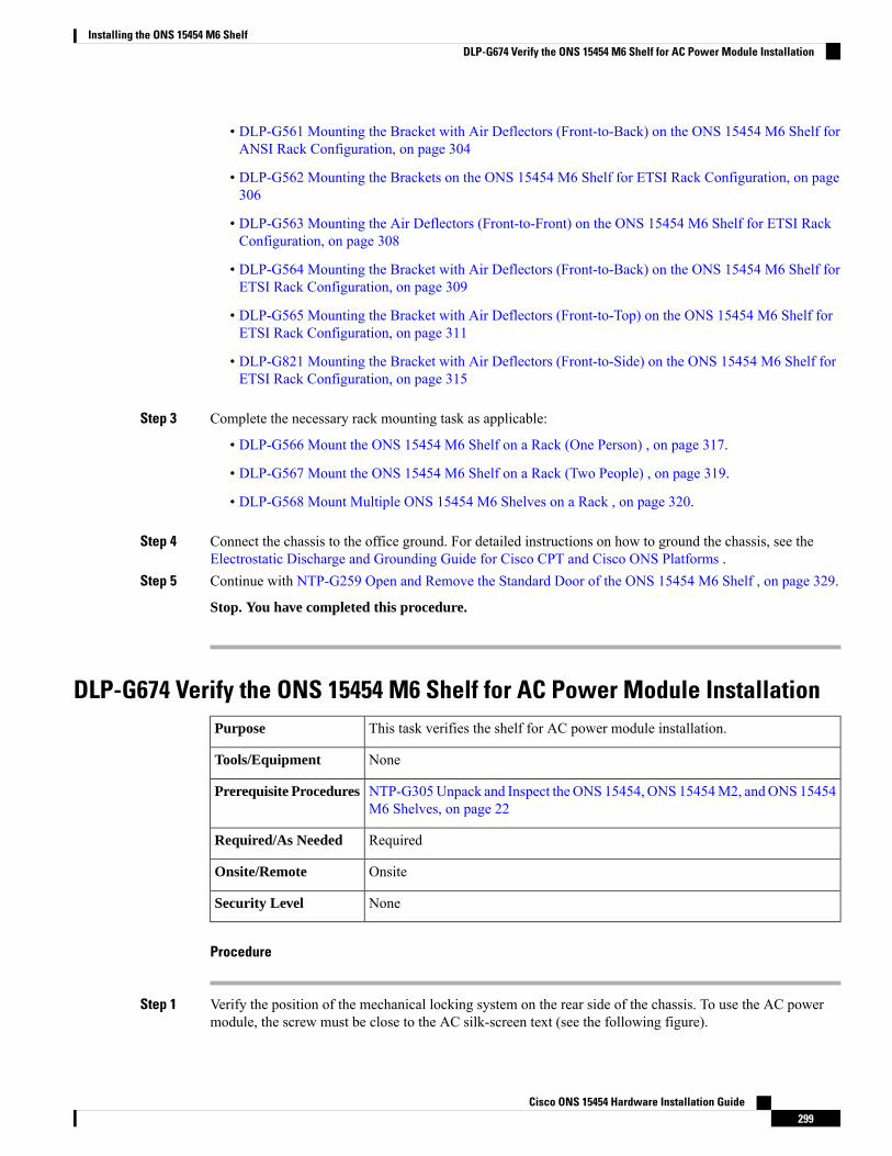
• DLP-G561 Mounting the Bracket with Air Deflectors (Front-to-Back) on the ONS 15454 M6 Shelf forANSI Rack Configuration, on page 304
• DLP-G562 Mounting the Brackets on the ONS 15454 M6 Shelf for ETSI Rack Configuration, on page306
• DLP-G563 Mounting the Air Deflectors (Front-to-Front) on the ONS 15454 M6 Shelf for ETSI RackConfiguration, on page 308
• DLP-G564 Mounting the Bracket with Air Deflectors (Front-to-Back) on the ONS 15454 M6 Shelf forETSI Rack Configuration, on page 309
• DLP-G565 Mounting the Bracket with Air Deflectors (Front-to-Top) on the ONS 15454 M6 Shelf forETSI Rack Configuration, on page 311
• DLP-G821 Mounting the Bracket with Air Deflectors (Front-to-Side) on the ONS 15454 M6 Shelf forETSI Rack Configuration, on page 315
Step 3 Complete the necessary rack mounting task as applicable:
• DLP-G566 Mount the ONS 15454 M6 Shelf on a Rack (One Person) , on page 317.
• DLP-G567 Mount the ONS 15454 M6 Shelf on a Rack (Two People) , on page 319.
• DLP-G568 Mount Multiple ONS 15454 M6 Shelves on a Rack , on page 320.
Step 4 Connect the chassis to the office ground. For detailed instructions on how to ground the chassis, see theElectrostatic Discharge and Grounding Guide for Cisco CPT and Cisco ONS Platforms .
Step 5 Continue with NTP-G259 Open and Remove the Standard Door of the ONS 15454 M6 Shelf , on page 329.
Stop. You have completed this procedure.
DLP-G674 Verify the ONS 15454 M6 Shelf for AC Power Module InstallationThis task verifies the shelf for AC power module installation.Purpose
NoneTools/Equipment
NTP-G305Unpack and Inspect the ONS 15454, ONS 15454M2, andONS 15454M6 Shelves, on page 22
Prerequisite Procedures
RequiredRequired/As Needed
OnsiteOnsite/Remote
NoneSecurity Level
Procedure
Step 1 Verify the position of the mechanical locking system on the rear side of the chassis. To use the AC powermodule, the screw must be close to the AC silk-screen text (see the following figure).
Cisco ONS 15454 Hardware Installation Guide299
Installing the ONS 15454 M6 ShelfDLP-G674 Verify the ONS 15454 M6 Shelf for AC Power Module Installation
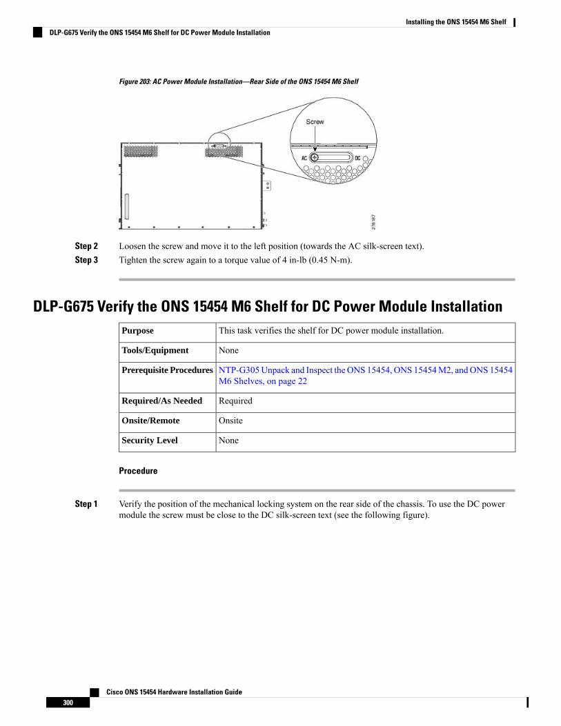
Figure 203: AC Power Module Installation—Rear Side of the ONS 15454 M6 Shelf
Step 2 Loosen the screw and move it to the left position (towards the AC silk-screen text).Step 3 Tighten the screw again to a torque value of 4 in-lb (0.45 N-m).
DLP-G675 Verify the ONS 15454 M6 Shelf for DC Power Module InstallationThis task verifies the shelf for DC power module installation.Purpose
NoneTools/Equipment
NTP-G305Unpack and Inspect the ONS 15454, ONS 15454M2, andONS 15454M6 Shelves, on page 22
Prerequisite Procedures
RequiredRequired/As Needed
OnsiteOnsite/Remote
NoneSecurity Level
Procedure
Step 1 Verify the position of the mechanical locking system on the rear side of the chassis. To use the DC powermodule the screw must be close to the DC silk-screen text (see the following figure).
Cisco ONS 15454 Hardware Installation Guide300
Installing the ONS 15454 M6 ShelfDLP-G675 Verify the ONS 15454 M6 Shelf for DC Power Module Installation
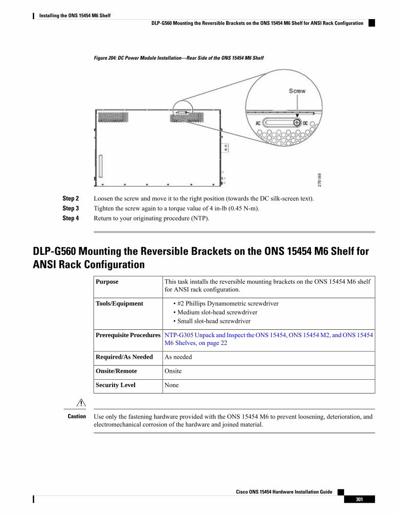
Figure 204: DC Power Module Installation—Rear Side of the ONS 15454 M6 Shelf
Step 2 Loosen the screw and move it to the right position (towards the DC silk-screen text).Step 3 Tighten the screw again to a torque value of 4 in-lb (0.45 N-m).Step 4 Return to your originating procedure (NTP).
DLP-G560 Mounting the Reversible Brackets on the ONS 15454 M6 Shelf forANSI Rack Configuration
This task installs the reversible mounting brackets on the ONS 15454 M6 shelffor ANSI rack configuration.
Purpose
• #2 Phillips Dynamometric screwdriver• Medium slot-head screwdriver• Small slot-head screwdriver
Tools/Equipment
NTP-G305Unpack and Inspect the ONS 15454, ONS 15454M2, andONS 15454M6 Shelves, on page 22
Prerequisite Procedures
As neededRequired/As Needed
OnsiteOnsite/Remote
NoneSecurity Level
Use only the fastening hardware provided with the ONS 15454 M6 to prevent loosening, deterioration, andelectromechanical corrosion of the hardware and joined material.
Caution
Cisco ONS 15454 Hardware Installation Guide301
Installing the ONS 15454 M6 ShelfDLP-G560 Mounting the Reversible Brackets on the ONS 15454 M6 Shelf for ANSI Rack Configuration
When mounting the ONS 15454 M6 in a frame with a nonconductive coating (such as paint, lacquer, orenamel) either use the thread-forming screws provided with the ONS 15454M6 ship kit, or remove the coatingfrom the threads to ensure electrical continuity.
Caution
In an ANSI rack, reversible mounting brackets (19-inch or 23-inch) are used to install the shelf. The mountingbrackets can be installed in the front or the middle position of the chassis.
Note
Procedure
Step 1 To mount the reversible brackets:
• For a 19-inch (482.6-mm) configuration, place the widest side of the mounting bracket flush against theshelf (see Figure 205: Mounting the Brackets on the ONS 15454 M6 shelf for a 19-inch (482.6-mm)ANSI Configuration, on page 303). The narrow side of the mounting bracket should be towards the frontof the shelf.
• For a 23-inch (584.2-mm) configuration, place the narrow side of the mounting bracket flush against theshelf (see Figure 206: Mounting the Brackets on the ONS 15454 M6 shelf for a 23-inch (584.2-mm)ANSI Configuration, on page 303). The widest side of the mounting bracket should be towards the frontof the shelf.
Step 2 Align the mounting bracket screw holes against the shelf screw holes.Step 3 Insert the screws and tighten them to a torque value of 11.5 in-lb (1.3 N-m).Step 4 Repeat steps 1 through 3 for the mounting bracket on the opposite side.
The following figure shows mounting the brackets for a 19-inch (482.6-mm) configuration.
Cisco ONS 15454 Hardware Installation Guide302
Installing the ONS 15454 M6 ShelfDLP-G560 Mounting the Reversible Brackets on the ONS 15454 M6 Shelf for ANSI Rack Configuration
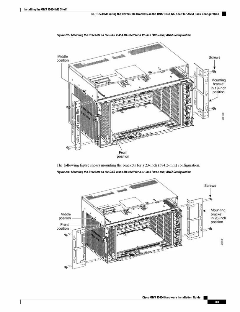
Figure 205: Mounting the Brackets on the ONS 15454 M6 shelf for a 19-inch (482.6-mm) ANSI Configuration
The following figure shows mounting the brackets for a 23-inch (584.2-mm) configuration.
Figure 206: Mounting the Brackets on the ONS 15454 M6 shelf for a 23-inch (584.2-mm) ANSI Configuration
Cisco ONS 15454 Hardware Installation Guide303
Installing the ONS 15454 M6 ShelfDLP-G560 Mounting the Reversible Brackets on the ONS 15454 M6 Shelf for ANSI Rack Configuration
Step 5 Return to your originating procedure (NTP).
DLP-G561 Mounting the Bracket with Air Deflectors (Front-to-Back) on theONS 15454 M6 Shelf for ANSI Rack Configuration
This task installs the bracket with air deflectors (front-to-back) on the ONS 15454M6 shelf for ANSI rack configuration.
In an ANSI rack, the air deflectors can be mounted only in the 23-inchrack configuration and in the front position of the chassis.
Note
Purpose
• #2 Phillips Dynamometric screwdriver• Medium slot-head screwdriver• Small slot-head screwdriver
Tools/Equipment
NTP-G305Unpack and Inspect the ONS 15454, ONS 15454M2, andONS 15454M6 Shelves, on page 22
Prerequisite Procedures
As neededRequired/As Needed
OnsiteOnsite/Remote
NoneSecurity Level
Use only the fastening hardware provided with the ONS 15454 M6 to prevent loosening, deterioration, andelectromechanical corrosion of the hardware and joined material.
Caution
Procedure
Step 1 (ANSI only) Place the right front air deflector flush against the right side of the chassis (see Diagram 1 ofFigure 207: Mounting the Air Deflectors (Front-to-Back) on the ONS 15454 M6 Shelf for the ANSI rackConfiguration, on page 305).
Step 2 Align the screw holes on the right front air deflector with the screw holes on the right side of the chassis.Step 3 Insert the screws and tighten them to a torque value of 11.5 in-lb (1.3 N-m).Step 4 Place the left back air deflector flush chassis as shown in Diagram 2 of Figure 207:Mounting the Air Deflectors
(Front-to-Back) on the ONS 15454 M6 Shelf for the ANSI rack Configuration, on page 305.
Do not mount the left back deflector (exhaust air deflector), if these cards are to be installed in the ONS 15454M6 shelf:
• 100G-LC-C, 10x10G-LC, or CFP-LC• EDRA1-26, EDRA1-35, EDRA2-26, or EDRA2-35
Use the standard brackets directly to mount the ONS 15454 M6 shelf.
Step 5 Align the screw holes on the left back air deflector with the screw holes on the left side of the chassis.
Cisco ONS 15454 Hardware Installation Guide304
Installing the ONS 15454 M6 ShelfDLP-G561 Mounting the Bracket with Air Deflectors (Front-to-Back) on the ONS 15454 M6 Shelf for ANSI Rack Configuration
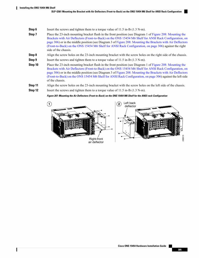
Step 6 Insert the screws and tighten them to a torque value of 11.5 in-lb (1.3 N-m).Step 7 Place the 23-inch mounting bracket flush in the front position (see Diagram 1 of Figure 208: Mounting the
Brackets with Air Deflectors (Front-to-Back) on the ONS 15454 M6 Shelf for ANSI Rack Configuration, onpage 306) or in the middle position (see Diagram 3 of Figure 208: Mounting the Brackets with Air Deflectors(Front-to-Back) on the ONS 15454 M6 Shelf for ANSI Rack Configuration, on page 306) against the rightside of the chassis.
Step 8 Align the screw holes on the 23-inch mounting bracket with the screw holes on the right side of the chassis.Step 9 Insert the screws and tighten them to a torque value of 11.5 in-lb (1.3 N-m).Step 10 Place the 23-inch mounting bracket flush in the front position (see Diagram 1 of Figure 208: Mounting the
Brackets with Air Deflectors (Front-to-Back) on the ONS 15454 M6 Shelf for ANSI Rack Configuration, onpage 306) or in the middle position (see Diagram 3 of Figure 208: Mounting the Brackets with Air Deflectors(Front-to-Back) on the ONS 15454M6 Shelf for ANSI Rack Configuration, on page 306) against the left sideof the chassis.
Step 11 Align the screw holes on the 23-inch mounting bracket with the screw holes on the left side of the chassis.Step 12 Insert the screws and tighten them to a torque value of 11.5 in-lb (1.3 N-m).
Figure 207: Mounting the Air Deflectors (Front-to-Back) on the ONS 15454 M6 Shelf for the ANSI rack Configuration
Cisco ONS 15454 Hardware Installation Guide305
Installing the ONS 15454 M6 ShelfDLP-G561 Mounting the Bracket with Air Deflectors (Front-to-Back) on the ONS 15454 M6 Shelf for ANSI Rack Configuration
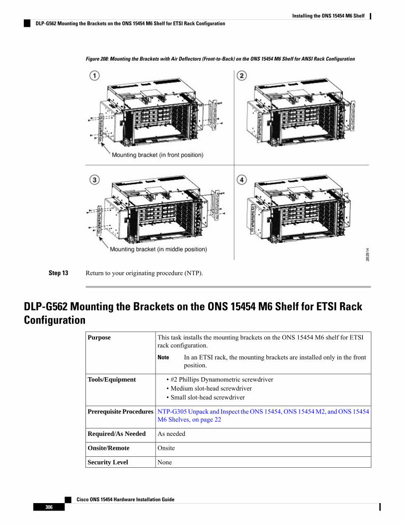
Figure 208: Mounting the Brackets with Air Deflectors (Front-to-Back) on the ONS 15454 M6 Shelf for ANSI Rack Configuration
Step 13 Return to your originating procedure (NTP).
DLP-G562 Mounting the Brackets on the ONS 15454 M6 Shelf for ETSI RackConfiguration
This task installs the mounting brackets on the ONS 15454 M6 shelf for ETSIrack configuration.
In an ETSI rack, the mounting brackets are installed only in the frontposition.
Note
Purpose
• #2 Phillips Dynamometric screwdriver• Medium slot-head screwdriver• Small slot-head screwdriver
Tools/Equipment
NTP-G305Unpack and Inspect the ONS 15454, ONS 15454M2, andONS 15454M6 Shelves, on page 22
Prerequisite Procedures
As neededRequired/As Needed
OnsiteOnsite/Remote
NoneSecurity Level
Cisco ONS 15454 Hardware Installation Guide306
Installing the ONS 15454 M6 ShelfDLP-G562 Mounting the Brackets on the ONS 15454 M6 Shelf for ETSI Rack Configuration
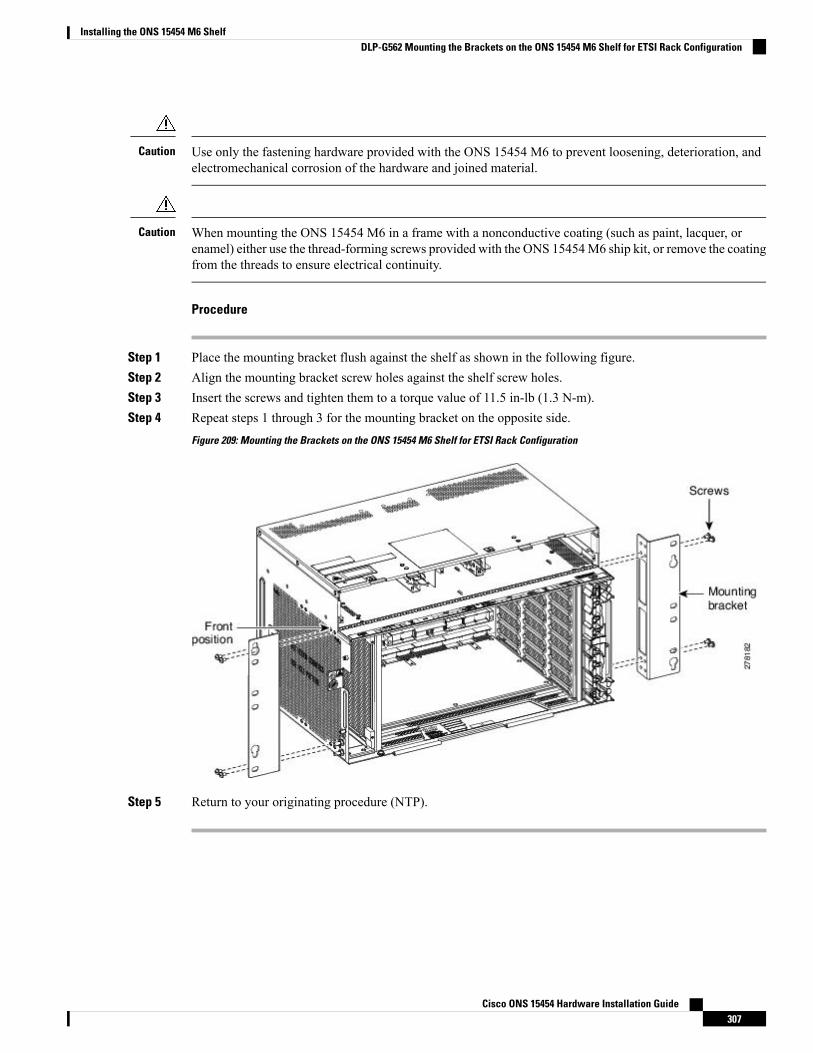
Use only the fastening hardware provided with the ONS 15454 M6 to prevent loosening, deterioration, andelectromechanical corrosion of the hardware and joined material.
Caution
When mounting the ONS 15454 M6 in a frame with a nonconductive coating (such as paint, lacquer, orenamel) either use the thread-forming screws provided with the ONS 15454M6 ship kit, or remove the coatingfrom the threads to ensure electrical continuity.
Caution
Procedure
Step 1 Place the mounting bracket flush against the shelf as shown in the following figure.Step 2 Align the mounting bracket screw holes against the shelf screw holes.Step 3 Insert the screws and tighten them to a torque value of 11.5 in-lb (1.3 N-m).Step 4 Repeat steps 1 through 3 for the mounting bracket on the opposite side.
Figure 209: Mounting the Brackets on the ONS 15454 M6 Shelf for ETSI Rack Configuration
Step 5 Return to your originating procedure (NTP).
Cisco ONS 15454 Hardware Installation Guide307
Installing the ONS 15454 M6 ShelfDLP-G562 Mounting the Brackets on the ONS 15454 M6 Shelf for ETSI Rack Configuration
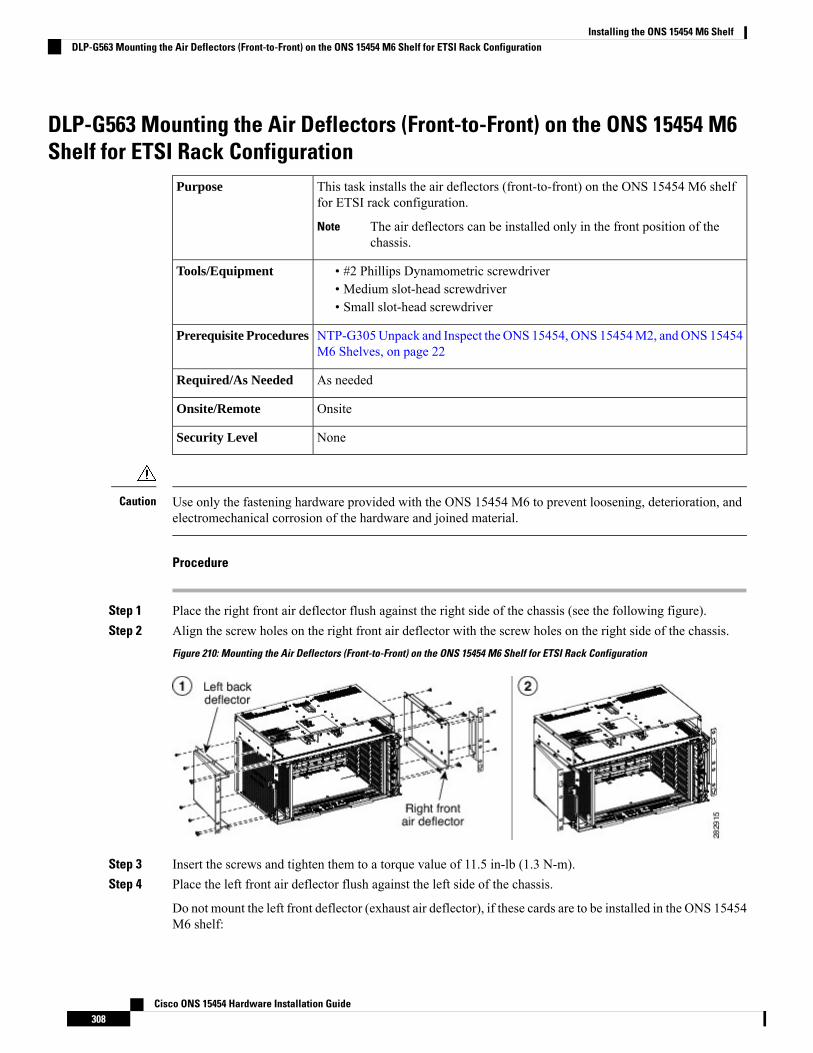
DLP-G563 Mounting the Air Deflectors (Front-to-Front) on the ONS 15454 M6Shelf for ETSI Rack Configuration
This task installs the air deflectors (front-to-front) on the ONS 15454 M6 shelffor ETSI rack configuration.
The air deflectors can be installed only in the front position of thechassis.
Note
Purpose
• #2 Phillips Dynamometric screwdriver• Medium slot-head screwdriver• Small slot-head screwdriver
Tools/Equipment
NTP-G305Unpack and Inspect the ONS 15454, ONS 15454M2, andONS 15454M6 Shelves, on page 22
Prerequisite Procedures
As neededRequired/As Needed
OnsiteOnsite/Remote
NoneSecurity Level
Use only the fastening hardware provided with the ONS 15454 M6 to prevent loosening, deterioration, andelectromechanical corrosion of the hardware and joined material.
Caution
Procedure
Step 1 Place the right front air deflector flush against the right side of the chassis (see the following figure).Step 2 Align the screw holes on the right front air deflector with the screw holes on the right side of the chassis.
Figure 210: Mounting the Air Deflectors (Front-to-Front) on the ONS 15454 M6 Shelf for ETSI Rack Configuration
Step 3 Insert the screws and tighten them to a torque value of 11.5 in-lb (1.3 N-m).Step 4 Place the left front air deflector flush against the left side of the chassis.
Do not mount the left front deflector (exhaust air deflector), if these cards are to be installed in the ONS 15454M6 shelf:
Cisco ONS 15454 Hardware Installation Guide308
Installing the ONS 15454 M6 ShelfDLP-G563 Mounting the Air Deflectors (Front-to-Front) on the ONS 15454 M6 Shelf for ETSI Rack Configuration

• 100G-LC-C, 10x10G-LC, or CFP-LC• EDRA1-26, EDRA1-35, EDRA2-26, or EDRA2-35
Use the standard brackets directly to mount the ONS 15454 M6 shelf.
Step 5 Align the screw holes on the left front air deflector with the screw holes on the left side of the chassis.Step 6 Insert the screws and tighten them to a torque value of 11.5 in-lb (1.3 N-m).Step 7 Return to your originating procedure (NTP).
DLP-G564 Mounting the Bracket with Air Deflectors (Front-to-Back) on theONS 15454 M6 Shelf for ETSI Rack Configuration
This task installs the bracket with air deflectors (front-to-back) on the ONS 15454M6 shelf for ETSI rack configuration.
The air deflectors can be installed only in the front position of thechassis.
Note
Purpose
• #2 Phillips Dynamometric screwdriver• Medium slot-head screwdriver• Small slot-head screwdriver
Tools/Equipment
NTP-G305Unpack and Inspect the ONS 15454, ONS 15454M2, andONS 15454M6 Shelves, on page 22
Prerequisite Procedures
As neededRequired/As Needed
OnsiteOnsite/Remote
NoneSecurity Level
Use only the fastening hardware provided with the ONS 15454 M6 to prevent loosening, deterioration, andelectromechanical corrosion of the hardware and joined material.
Caution
Procedure
Step 1 Place the right front air deflector flush against the right side of the chassis (see Diagram 1 of Figure 211:Mounting the Air Deflectors (Front-to-Back) on the ONS 15454 M6 Shelf for ETSI Rack Configuration, onpage 310).
Step 2 Align the screw holes on the right front air deflector with the screw holes on the right side of the chassis.Step 3 Insert the screws and tighten them to a torque value of 11.5 in-lb (1.3 N-m).Step 4 Place the left back air deflector flush against the chassis as shown in Diagram 2 of Figure 211: Mounting the
Air Deflectors (Front-to-Back) on the ONS 15454 M6 Shelf for ETSI Rack Configuration, on page 310.
Cisco ONS 15454 Hardware Installation Guide309
Installing the ONS 15454 M6 ShelfDLP-G564 Mounting the Bracket with Air Deflectors (Front-to-Back) on the ONS 15454 M6 Shelf for ETSI Rack Configuration
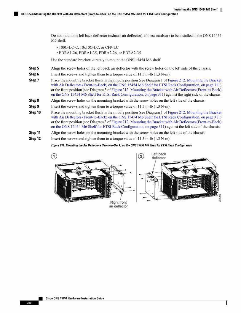
Do not mount the left back deflector (exhaust air deflector), if these cards are to be installed in the ONS 15454M6 shelf:
• 100G-LC-C, 10x10G-LC, or CFP-LC• EDRA1-26, EDRA1-35, EDRA2-26, or EDRA2-35
Use the standard brackets directly to mount the ONS 15454 M6 shelf.
Step 5 Align the screw holes of the left back air deflector with the screw holes on the left side of the chassis.Step 6 Insert the screws and tighten them to a torque value of 11.5 in-lb (1.3 N-m).Step 7 Place the mounting bracket flush in the middle position (see Diagram 1 of Figure 212: Mounting the Bracket
with Air Deflectors (Front-to-Back) on the ONS 15454 M6 Shelf for ETSI Rack Configuration, on page 311)or the front position (see Diagram 3 of Figure 212: Mounting the Bracket with Air Deflectors (Front-to-Back)on the ONS 15454 M6 Shelf for ETSI Rack Configuration, on page 311) against the right side of the chassis.
Step 8 Align the screw holes on the mounting bracket with the screw holes on the left side of the chassis.Step 9 Insert the screws and tighten them to a torque value of 11.5 in-lb (1.3 N-m).Step 10 Place the mounting bracket flush in the middle position (see Diagram 1 of Figure 212: Mounting the Bracket
with Air Deflectors (Front-to-Back) on the ONS 15454 M6 Shelf for ETSI Rack Configuration, on page 311)or the front position (see Diagram 3 of Figure 212: Mounting the Bracket with Air Deflectors (Front-to-Back)on the ONS 15454 M6 Shelf for ETSI Rack Configuration, on page 311) against the left side of the chassis.
Step 11 Align the screw holes on the mounting bracket with the screw holes on the left side of the chassis.Step 12 Insert the screws and tighten them to a torque value of 11.5 in-lb (1.3 N-m).
Figure 211: Mounting the Air Deflectors (Front-to-Back) on the ONS 15454 M6 Shelf for ETSI Rack Configuration
Cisco ONS 15454 Hardware Installation Guide310
Installing the ONS 15454 M6 ShelfDLP-G564 Mounting the Bracket with Air Deflectors (Front-to-Back) on the ONS 15454 M6 Shelf for ETSI Rack Configuration
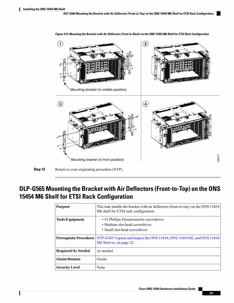
Figure 212: Mounting the Bracket with Air Deflectors (Front-to-Back) on the ONS 15454 M6 Shelf for ETSI Rack Configuration
Step 13 Return to your originating procedure (NTP).
DLP-G565 Mounting the Bracket with Air Deflectors (Front-to-Top) on the ONS15454 M6 Shelf for ETSI Rack Configuration
This task installs the bracket with air deflectors (front-to-top ) on the ONS 15454M6 shelf for ETSI rack configuration.
Purpose
• #2 Phillips Dynamometric screwdriver• Medium slot-head screwdriver• Small slot-head screwdriver
Tools/Equipment
NTP-G305Unpack and Inspect the ONS 15454, ONS 15454M2, andONS 15454M6 Shelves, on page 22
Prerequisite Procedures
As neededRequired/As Needed
OnsiteOnsite/Remote
NoneSecurity Level
Cisco ONS 15454 Hardware Installation Guide311
Installing the ONS 15454 M6 ShelfDLP-G565 Mounting the Bracket with Air Deflectors (Front-to-Top) on the ONS 15454 M6 Shelf for ETSI Rack Configuration
Use only the fastening hardware provided with the ONS 15454 M6 to prevent loosening, deterioration, andelectromechanical corrosion of the hardware and joined material.
Caution
The front-to-top air deflector configuration must be used only for the bottom most chassis in the rack.Note
Do not install a fan tray (exhaust) side deflector on a chassis that is installed above a chassis with a front-to-topair deflector configuration.
Note
The front-to-top deflector configuration can be operated at a maximum of 50C at 1800 m altitude. OnlyROADM cards can be installed for this configuration.
Note
It is recommended to maintain a space of one RU between two chassis in a rack for cable management.Note
Hot and cold aisle airflow management must be planned for the installation.Note
Procedure
Step 1 To install the mounting bracket with air deflectors (front-to-top) in the front position, perform Step 3 throughStep 11.
Step 2 To install the mounting bracket with air deflectors (front-to-top) in the middle position, perform Step 12through Step 23.
Step 3 Place the right front air deflector flush against the right side of the chassis (see Diagram 1 of Figure 213:Mounting the Bracket with Air Deflectors (Front-to-Top) on the ONS 15454 M6 Shelf for ETSI RackConfiguration- Front Position, on page 313).
Step 4 Align the screw holes on the right front air deflector with the screw holes on right side of the chassis.Step 5 Insert the screws and tighten them to a torque value of 11.5 in-lb (1.3 N-m).Step 6 Place a mounting bracket flush against the left and right side of the chassis (see Diagram 2 of Figure 213:
Mounting the Bracket with Air Deflectors (Front-to-Top) on the ONS 15454 M6 Shelf for ETSI RackConfiguration- Front Position, on page 313).
Step 7 Align the screw holes on the mounting bracket with the screw holes on the side of the chassis.Step 8 Insert the screws and tighten them to a torque value of 11.5 in-lb (1.3 N-m).Step 9 Place the left top air deflector flush against the chassis as shown in Diagram 3 of Figure 213: Mounting the
Bracket with Air Deflectors (Front-to-Top) on the ONS 15454 M6 Shelf for ETSI Rack Configuration- FrontPosition, on page 313.
Cisco ONS 15454 Hardware Installation Guide312
Installing the ONS 15454 M6 ShelfDLP-G565 Mounting the Bracket with Air Deflectors (Front-to-Top) on the ONS 15454 M6 Shelf for ETSI Rack Configuration
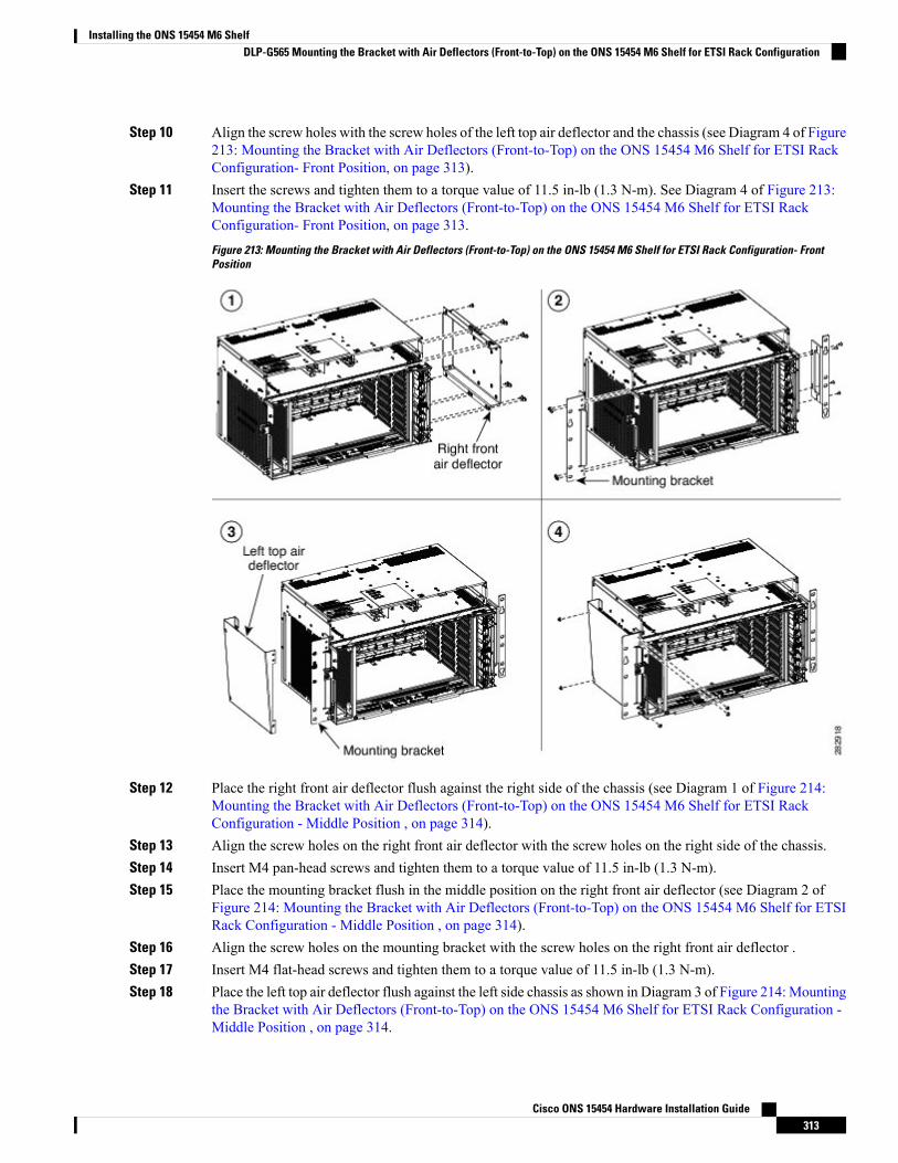
Step 10 Align the screw holes with the screw holes of the left top air deflector and the chassis (see Diagram 4 of Figure213: Mounting the Bracket with Air Deflectors (Front-to-Top) on the ONS 15454 M6 Shelf for ETSI RackConfiguration- Front Position, on page 313).
Step 11 Insert the screws and tighten them to a torque value of 11.5 in-lb (1.3 N-m). See Diagram 4 of Figure 213:Mounting the Bracket with Air Deflectors (Front-to-Top) on the ONS 15454 M6 Shelf for ETSI RackConfiguration- Front Position, on page 313.
Figure 213: Mounting the Bracket with Air Deflectors (Front-to-Top) on the ONS 15454 M6 Shelf for ETSI Rack Configuration- FrontPosition
Step 12 Place the right front air deflector flush against the right side of the chassis (see Diagram 1 of Figure 214:Mounting the Bracket with Air Deflectors (Front-to-Top) on the ONS 15454 M6 Shelf for ETSI RackConfiguration - Middle Position , on page 314).
Step 13 Align the screw holes on the right front air deflector with the screw holes on the right side of the chassis.Step 14 Insert M4 pan-head screws and tighten them to a torque value of 11.5 in-lb (1.3 N-m).Step 15 Place the mounting bracket flush in the middle position on the right front air deflector (see Diagram 2 of
Figure 214: Mounting the Bracket with Air Deflectors (Front-to-Top) on the ONS 15454 M6 Shelf for ETSIRack Configuration - Middle Position , on page 314).
Step 16 Align the screw holes on the mounting bracket with the screw holes on the right front air deflector .Step 17 Insert M4 flat-head screws and tighten them to a torque value of 11.5 in-lb (1.3 N-m).Step 18 Place the left top air deflector flush against the left side chassis as shown in Diagram 3 of Figure 214:Mounting
the Bracket with Air Deflectors (Front-to-Top) on the ONS 15454 M6 Shelf for ETSI Rack Configuration -Middle Position , on page 314.
Cisco ONS 15454 Hardware Installation Guide313
Installing the ONS 15454 M6 ShelfDLP-G565 Mounting the Bracket with Air Deflectors (Front-to-Top) on the ONS 15454 M6 Shelf for ETSI Rack Configuration
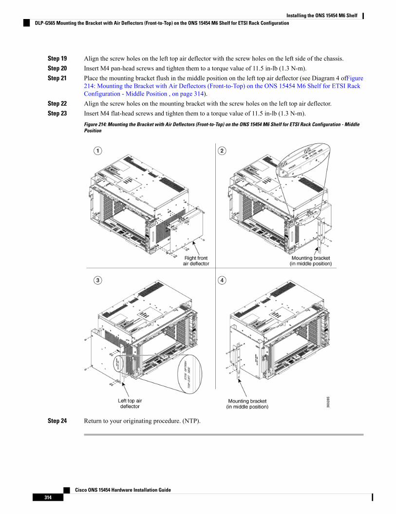
Step 19 Align the screw holes on the left top air deflector with the screw holes on the left side of the chassis.Step 20 Insert M4 pan-head screws and tighten them to a torque value of 11.5 in-lb (1.3 N-m).Step 21 Place the mounting bracket flush in the middle position on the left top air deflector (see Diagram 4 ofFigure
214: Mounting the Bracket with Air Deflectors (Front-to-Top) on the ONS 15454 M6 Shelf for ETSI RackConfiguration - Middle Position , on page 314).
Step 22 Align the screw holes on the mounting bracket with the screw holes on the left top air deflector.Step 23 Insert M4 flat-head screws and tighten them to a torque value of 11.5 in-lb (1.3 N-m).
Figure 214: Mounting the Bracket with Air Deflectors (Front-to-Top) on the ONS 15454 M6 Shelf for ETSI Rack Configuration - MiddlePosition
Step 24 Return to your originating procedure. (NTP).
Cisco ONS 15454 Hardware Installation Guide314
Installing the ONS 15454 M6 ShelfDLP-G565 Mounting the Bracket with Air Deflectors (Front-to-Top) on the ONS 15454 M6 Shelf for ETSI Rack Configuration
DLP-G821 Mounting the Bracket with Air Deflectors (Front-to-Side) on the ONS15454 M6 Shelf for ETSI Rack Configuration
This task installs the bracket with air deflectors (front-to-side) on the ONS 15454M6 shelf for ETSI rack configuration.
Purpose
• #2 Phillips Dynamometric screwdriver• Medium slot-head screwdriver• Small slot-head screwdriver
Tools/Equipment
NTP-G305Unpack and Inspect the ONS 15454, ONS 15454M2, andONS 15454M6 Shelves, on page 22
Prerequisite Procedures
As neededRequired/As Needed
OnsiteOnsite/Remote
NoneSecurity Level
Use only the fastening hardware provided with the ONS 15454 M6 to prevent loosening, deterioration, andelectromechanical corrosion of the hardware and joined material.
Caution
It is recommended to maintain a space of one RU between two chassis in a rack for cable managementNote
Hot and cold aisle airflow management must be planned for the installation.Note
Procedure
Step 1 Place the right front air deflector flush against the right side of the chassis (see diagram below).
Cisco ONS 15454 Hardware Installation Guide315
Installing the ONS 15454 M6 ShelfDLP-G821 Mounting the Bracket with Air Deflectors (Front-to-Side) on the ONS 15454 M6 Shelf for ETSI Rack Configuration
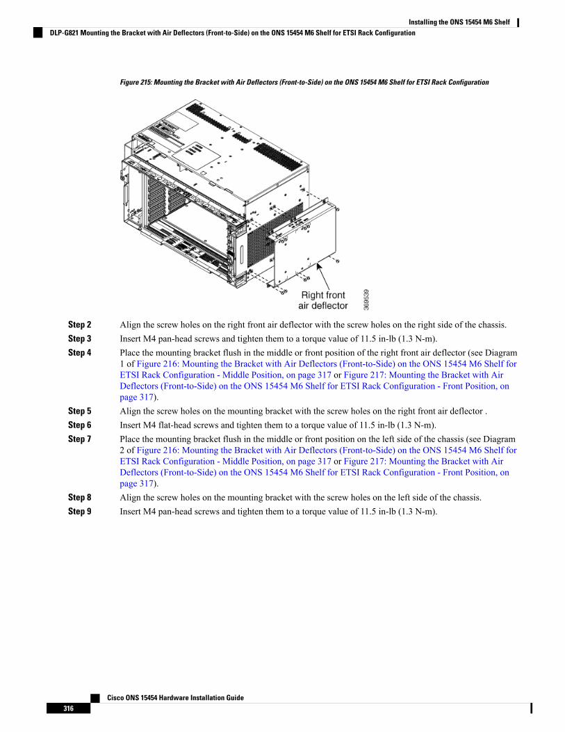
Figure 215: Mounting the Bracket with Air Deflectors (Front-to-Side) on the ONS 15454 M6 Shelf for ETSI Rack Configuration
Step 2 Align the screw holes on the right front air deflector with the screw holes on the right side of the chassis.Step 3 Insert M4 pan-head screws and tighten them to a torque value of 11.5 in-lb (1.3 N-m).Step 4 Place the mounting bracket flush in the middle or front position of the right front air deflector (see Diagram
1 of Figure 216: Mounting the Bracket with Air Deflectors (Front-to-Side) on the ONS 15454 M6 Shelf forETSI Rack Configuration - Middle Position, on page 317 or Figure 217: Mounting the Bracket with AirDeflectors (Front-to-Side) on the ONS 15454 M6 Shelf for ETSI Rack Configuration - Front Position, onpage 317).
Step 5 Align the screw holes on the mounting bracket with the screw holes on the right front air deflector .Step 6 Insert M4 flat-head screws and tighten them to a torque value of 11.5 in-lb (1.3 N-m).Step 7 Place the mounting bracket flush in the middle or front position on the left side of the chassis (see Diagram
2 of Figure 216: Mounting the Bracket with Air Deflectors (Front-to-Side) on the ONS 15454 M6 Shelf forETSI Rack Configuration - Middle Position, on page 317 or Figure 217: Mounting the Bracket with AirDeflectors (Front-to-Side) on the ONS 15454 M6 Shelf for ETSI Rack Configuration - Front Position, onpage 317).
Step 8 Align the screw holes on the mounting bracket with the screw holes on the left side of the chassis.Step 9 Insert M4 pan-head screws and tighten them to a torque value of 11.5 in-lb (1.3 N-m).
Cisco ONS 15454 Hardware Installation Guide316
Installing the ONS 15454 M6 ShelfDLP-G821 Mounting the Bracket with Air Deflectors (Front-to-Side) on the ONS 15454 M6 Shelf for ETSI Rack Configuration
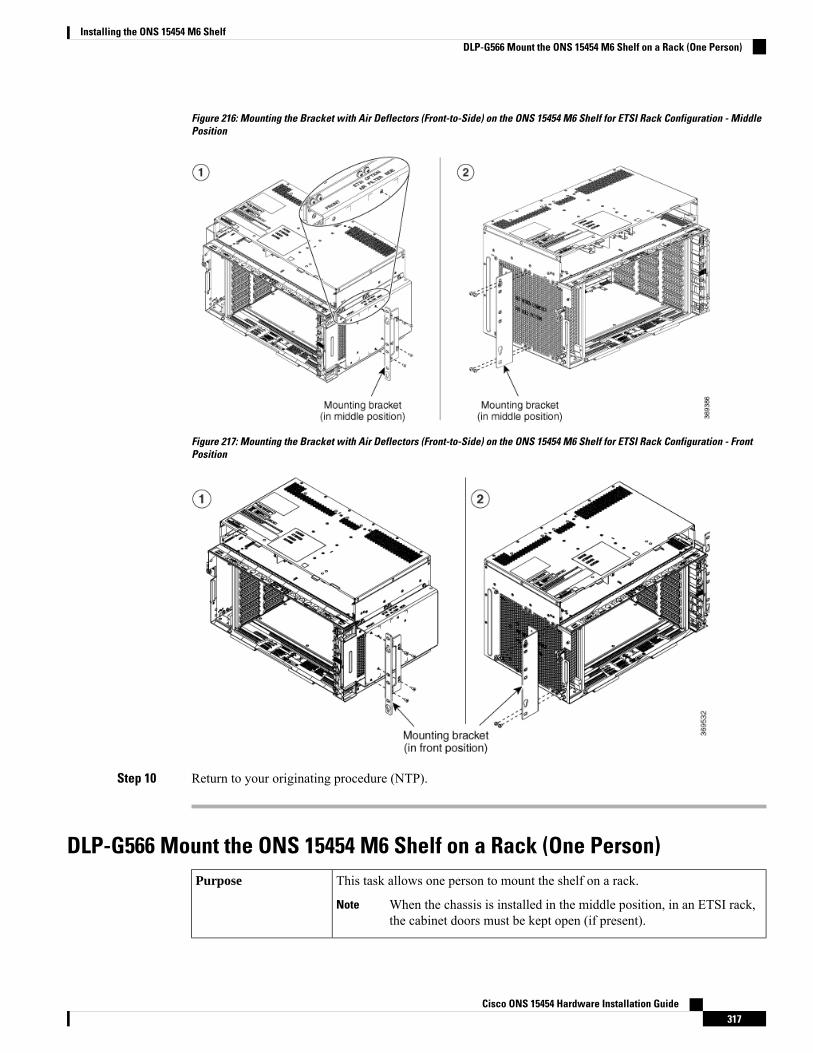
Figure 216: Mounting the Bracket with Air Deflectors (Front-to-Side) on the ONS 15454 M6 Shelf for ETSI Rack Configuration - MiddlePosition
Figure 217: Mounting the Bracket with Air Deflectors (Front-to-Side) on the ONS 15454 M6 Shelf for ETSI Rack Configuration - FrontPosition
Step 10 Return to your originating procedure (NTP).
DLP-G566 Mount the ONS 15454 M6 Shelf on a Rack (One Person)This task allows one person to mount the shelf on a rack.
When the chassis is installed in the middle position, in an ETSI rack,the cabinet doors must be kept open (if present).
Note
Purpose
Cisco ONS 15454 Hardware Installation Guide317
Installing the ONS 15454 M6 ShelfDLP-G566 Mount the ONS 15454 M6 Shelf on a Rack (One Person)
• # 2 Phillips Dynamometric screwdriver• ANSI—Six #12-24 x ¾ pan-head Phillips mounting screws• ETSI—Six M6 mounting screws
Tools/Equipment
NTP-G305Unpack and Inspect the ONS 15454, ONS 15454M2, andONS 15454M6 Shelves, on page 22
Prerequisite Procedures
As neededRequired/As Needed
OnsiteOnsite/Remote
NoneSecurity Level
The ONS 15454 M6 requires a minimum of six RU of vertical rack space. To ensure that the mounting issecure, use two to three M6 mounting screws on each side of the shelf. A shelf should be mounted at thebottom of the rack if it is the only unit in the rack.
Note
Procedure
Step 1 Verify that the proper fuse and alarm panel has been installed in the top mounting space. If a fuse and alarmpanel is not present, you must install one according to manufacturer instructions:
• For a DC power supply, the fuse rating must not exceed 40A.• For an AC power supply, the fuse rating must not exceed 10A, 15A, or 20A. For North America, thebranch circuit protectionmust be rated 20A. The overcurrent/short circuit protectionmust be in accordancewith local and national electrical codes.
Step 2 Ensure that the shelf is mounted on the appropriate rack equipment:
• 23-inches (584.2 mm) or 19-inches (482.6 mm) for ANSI racks. The recommended 19-inch ANSI rackfor the ONS 15454 M6 shelf is shown in Figure 5: 19-inch ANSI Rack Post Recommended for CiscoONS 15454 M6 and M2 Shelves, on page 5.
• 600 x 600-mm (23.6 x 23.6-inch) or 600 x 300-mm (23.6 x 11.8-inch) for ETSI racks.
Diagram 1 of Figure 218: Mounting an ONS 15454 M6 on a Rack, on page 319 shows the ONS 15454 M6shelf mounted on an ANSI rack in the middle position using 19-inch mounting brackets.
Diagram 2 of Figure 218: Mounting an ONS 15454 M6 on a Rack, on page 319 shows the ONS 15454 M6shelf mounted on an ETSI rack in the front position.
Cisco ONS 15454 Hardware Installation Guide318
Installing the ONS 15454 M6 ShelfDLP-G566 Mount the ONS 15454 M6 Shelf on a Rack (One Person)
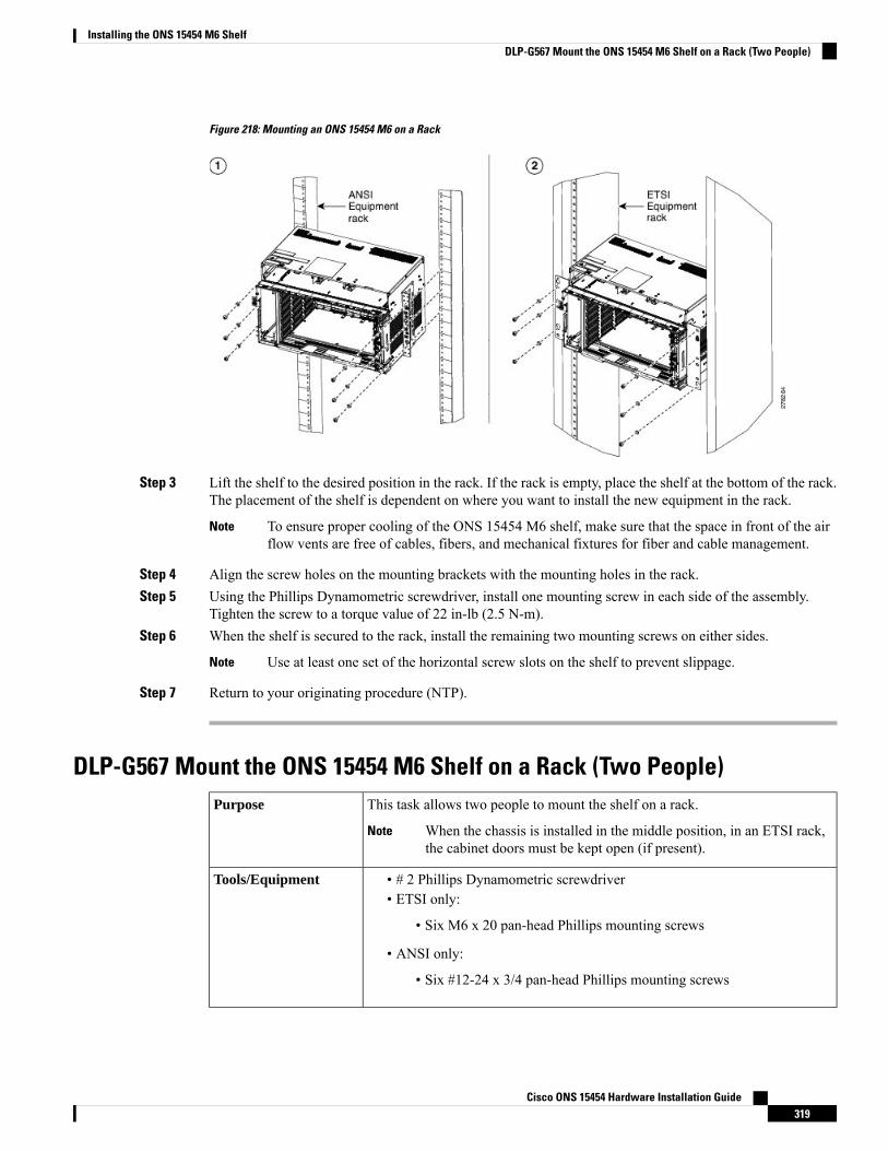
Figure 218: Mounting an ONS 15454 M6 on a Rack
Step 3 Lift the shelf to the desired position in the rack. If the rack is empty, place the shelf at the bottom of the rack.The placement of the shelf is dependent on where you want to install the new equipment in the rack.
To ensure proper cooling of the ONS 15454 M6 shelf, make sure that the space in front of the airflow vents are free of cables, fibers, and mechanical fixtures for fiber and cable management.
Note
Step 4 Align the screw holes on the mounting brackets with the mounting holes in the rack.Step 5 Using the Phillips Dynamometric screwdriver, install one mounting screw in each side of the assembly.
Tighten the screw to a torque value of 22 in-lb (2.5 N-m).Step 6 When the shelf is secured to the rack, install the remaining two mounting screws on either sides.
Use at least one set of the horizontal screw slots on the shelf to prevent slippage.Note
Step 7 Return to your originating procedure (NTP).
DLP-G567 Mount the ONS 15454 M6 Shelf on a Rack (Two People)This task allows two people to mount the shelf on a rack.
When the chassis is installed in the middle position, in an ETSI rack,the cabinet doors must be kept open (if present).
Note
Purpose
• # 2 Phillips Dynamometric screwdriver• ETSI only:
• Six M6 x 20 pan-head Phillips mounting screws
• ANSI only:
• Six #12-24 x 3/4 pan-head Phillips mounting screws
Tools/Equipment
Cisco ONS 15454 Hardware Installation Guide319
Installing the ONS 15454 M6 ShelfDLP-G567 Mount the ONS 15454 M6 Shelf on a Rack (Two People)
NTP-G305Unpack and Inspect the ONS 15454, ONS 15454M2, andONS 15454M6 Shelves, on page 22
Prerequisite Procedures
As neededRequired/As Needed
OnsiteOnsite/Remote
NoneSecurity Level
The ONS 15454 M6 requires a minimum of six RU of vertical rack space. To ensure that the mounting issecure, use two to three M6 mounting screws on each side of the shelf. A shelf should be mounted at thebottom of the rack if it is the only unit in the rack.
Note
Procedure
Step 1 Verify that the proper fuse and alarm panel has been installed in the top mounting space. If a fuse and alarmpanel is not present, you must install one as per the instructions of the manufacturer:
• For a a DC power supply, the fuse rating must not exceed 40A.• For an AC power supply, the fuse rating must not exceed 10A, 15A, or 20A. For North America, thebranch circuit protectionmust be rated 20A. The overcurrent/short circuit protectionmust be in accordancewith local and national electrical codes.
Step 2 Ensure that the shelf is mounted on the appropriate rack equipment:
• 23-inches (584.2 mm) or 19-inches (482.6 mm) for ANSI racks.• 600 x 600-mm (23.6 x 23.6-inch) or 600 x 300-mm (23.6 x 11.8-inch) for ETSI racks.
Step 3 Lift the shelf to the desired position in the rack. If the rack is empty, place the shelf at the bottom of the rack.The placement of the shelf is dependent on where you want to install the new equipment in the rack.
To ensure proper cooling of the ONS 15454 M6 shelf, make sure that the space in front of the airflow vents are free of cables, fibers, and mechanical fixtures for fiber and cable management.
Note
Step 4 Align the screw holes on the mounting brackets with the mounting holes in the rack.Step 5 Have one person hold the shelf in place while the other person uses the Phillips Dynamometric screwdriver
to install one mounting screw in each side of the assembly. Tighten the screw to a torque value of 22 in-lb(2.5 N-m).
Step 6 When the shelf is secured to the rack, install the remaining mounting screws.
Use at least one set of the horizontal screw slots on the shelf to prevent slippage.Note
Step 7 Return to your originating procedure (NTP).
DLP-G568 Mount Multiple ONS 15454 M6 Shelves on a RackThis task installs multiple shelves in a rack.Purpose
Cisco ONS 15454 Hardware Installation Guide320
Installing the ONS 15454 M6 ShelfDLP-G568 Mount Multiple ONS 15454 M6 Shelves on a Rack
• #2 Phillips Dynamometric screwdriver• ETSI only:
• Six M6 x 20 pan-head Phillips mounting screws, per shelf
• ANSI only:
• Six #12-24 x 3/4 pan-head Phillips mounting screws, per shelf
Tools/Equipment
NTP-G305Unpack and Inspect the ONS 15454, ONS 15454M2, andONS 15454M6 Shelves, on page 22
Prerequisite Procedures
As neededRequired/As Needed
OnsiteOnsite/Remote
NoneSecurity Level
A standard rack can hold six or seven ONS 15454 M6 shelves. When mounting a shelf in a partially filledrack, load the rack from the bottom to the top with the heaviest component at the bottom of the rack. If therack is provided with stabilizing devices, install the stabilizers before mounting or servicing the unit in therack.
Note
The ONS 15454 M6 requires a minimum of six RU of vertical rack space.Note
Procedure
Step 1 Verify that the proper fuse and alarm panel has been installed in the top mounting space. If a fuse and alarmpanel is not present, you must install one according to manufacturer’s instructions:
• For a DC power supply, the fuse rating must not exceed 40A.• For AC power supply, the fuse rating must not exceed 20A.
Step 2 Mount the first shelf in the bottom of the rack using the DLP-G566 Mount the ONS 15454 M6 Shelf on aRack (One Person) , on page 317 or the DLP-G567 Mount the ONS 15454 M6 Shelf on a Rack (Two People), on page 319.
Diagram 1 of Figure 219:Multiple ONS 15454M6 ShelvesMounted on the Rack, on page 322 showsmultipleONS 15454 M6 shelf assemblies mounted on the ANSI rack.
Diagram 2 of Figure 219:Multiple ONS 15454M6 ShelvesMounted on the Rack, on page 322 showsmultipleONS 15454 M6 shelf assemblies mounted on the ETSI rack.
Cisco ONS 15454 Hardware Installation Guide321
Installing the ONS 15454 M6 ShelfDLP-G568 Mount Multiple ONS 15454 M6 Shelves on a Rack
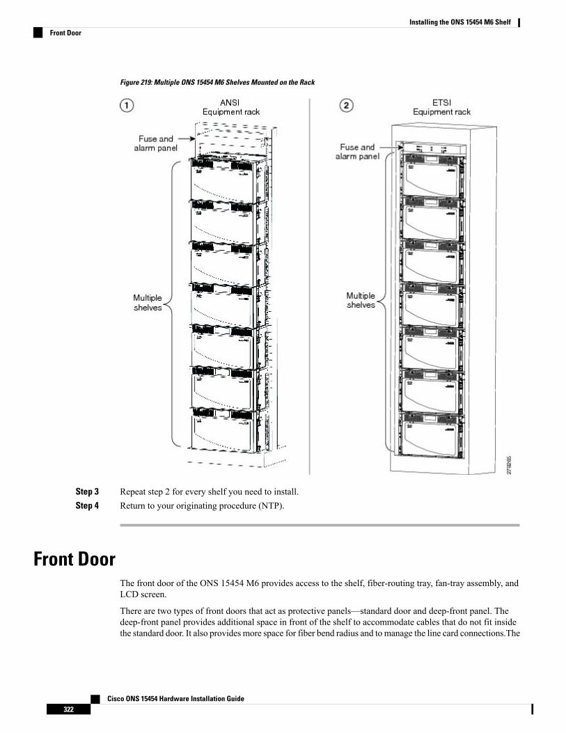
Figure 219: Multiple ONS 15454 M6 Shelves Mounted on the Rack
Step 3 Repeat step 2 for every shelf you need to install.Step 4 Return to your originating procedure (NTP).
Front DoorThe front door of the ONS 15454 M6 provides access to the shelf, fiber-routing tray, fan-tray assembly, andLCD screen.
There are two types of front doors that act as protective panels—standard door and deep-front panel. Thedeep-front panel provides additional space in front of the shelf to accommodate cables that do not fit insidethe standard door. It also provides more space for fiber bend radius and to manage the line card connections.The
Cisco ONS 15454 Hardware Installation Guide322
Installing the ONS 15454 M6 ShelfFront Door
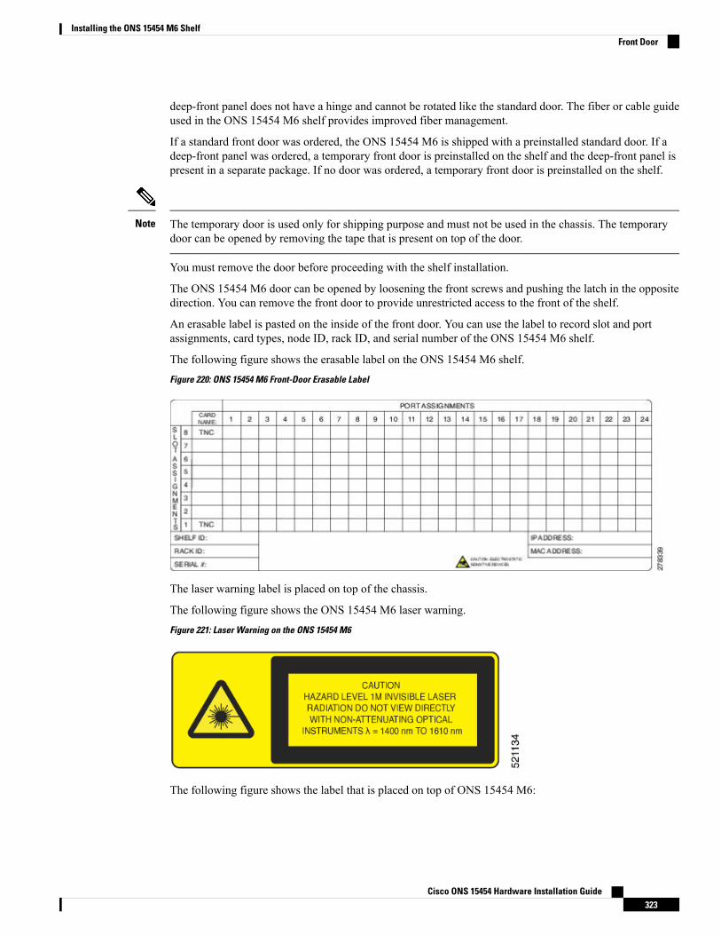
deep-front panel does not have a hinge and cannot be rotated like the standard door. The fiber or cable guideused in the ONS 15454 M6 shelf provides improved fiber management.
If a standard front door was ordered, the ONS 15454 M6 is shipped with a preinstalled standard door. If adeep-front panel was ordered, a temporary front door is preinstalled on the shelf and the deep-front panel ispresent in a separate package. If no door was ordered, a temporary front door is preinstalled on the shelf.
The temporary door is used only for shipping purpose and must not be used in the chassis. The temporarydoor can be opened by removing the tape that is present on top of the door.
Note
You must remove the door before proceeding with the shelf installation.
The ONS 15454 M6 door can be opened by loosening the front screws and pushing the latch in the oppositedirection. You can remove the front door to provide unrestricted access to the front of the shelf.
An erasable label is pasted on the inside of the front door. You can use the label to record slot and portassignments, card types, node ID, rack ID, and serial number of the ONS 15454 M6 shelf.
The following figure shows the erasable label on the ONS 15454 M6 shelf.
Figure 220: ONS 15454 M6 Front-Door Erasable Label
The laser warning label is placed on top of the chassis.
The following figure shows the ONS 15454 M6 laser warning.
Figure 221: Laser Warning on the ONS 15454 M6
The following figure shows the label that is placed on top of ONS 15454 M6:
Cisco ONS 15454 Hardware Installation Guide323
Installing the ONS 15454 M6 ShelfFront Door
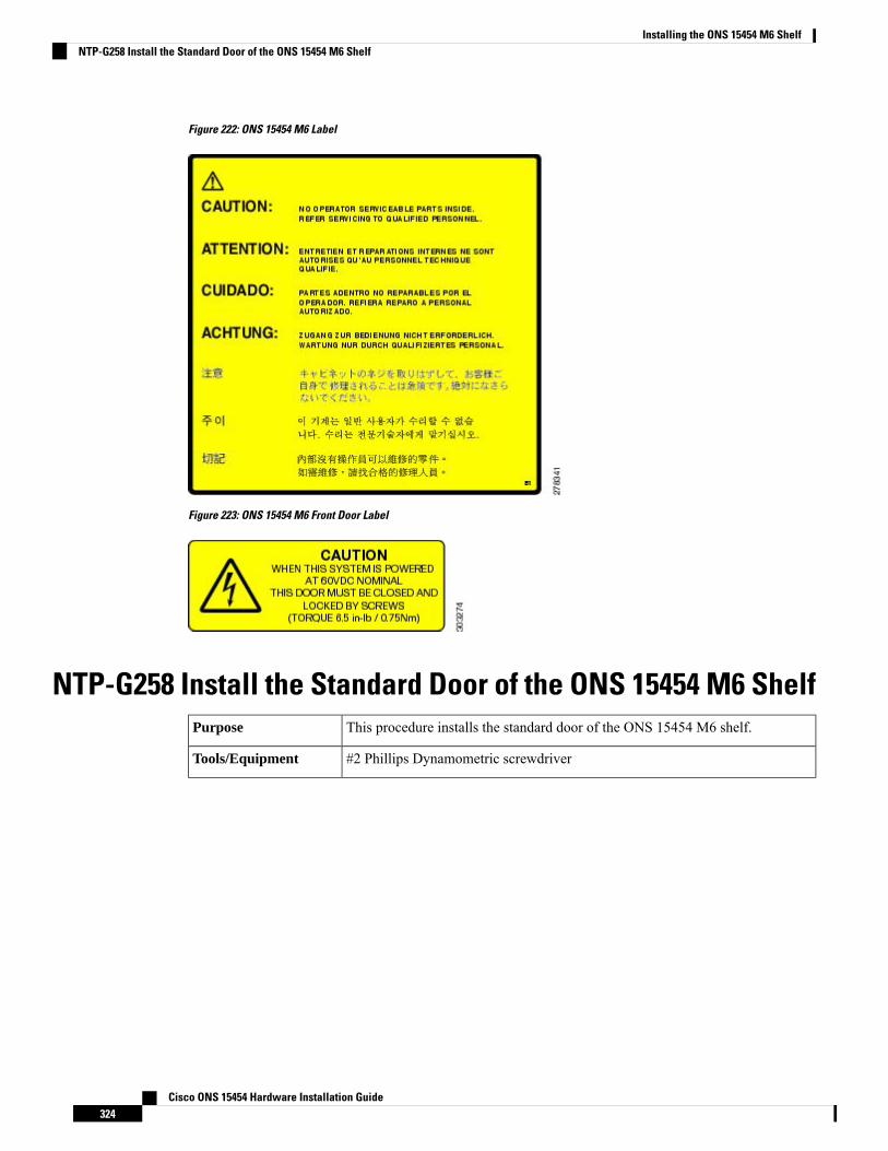
Figure 222: ONS 15454 M6 Label
Figure 223: ONS 15454 M6 Front Door Label
NTP-G258 Install the Standard Door of the ONS 15454 M6 ShelfThis procedure installs the standard door of the ONS 15454 M6 shelf.Purpose
#2 Phillips Dynamometric screwdriverTools/Equipment
Cisco ONS 15454 Hardware Installation Guide324
Installing the ONS 15454 M6 ShelfNTP-G258 Install the Standard Door of the ONS 15454 M6 Shelf

• NTP-G259 Open and Remove the Standard Door of the ONS 15454 M6Shelf , on page 329
• NTP-G252 Install the ONS 15454 M6 Shelf , on page 296• Connect the chassis to the office ground. For detailed instructions on howto ground the chassis, see the Electrostatic Discharge and Grounding Guidefor Cisco CPT and Cisco ONS Platforms.
• NTP-G253 Install the ECU or ECU-S Module, on page 352• NTP-G524 Install the Power Modules in the ONS 15454M6 Shelf , on page358
• NTP-G255 Install the LCD Module in the ONS 15454 M6 Shelf, on page369
• NTP-G256 Install Power and Ground to the ONS 15454 M6 Shelf , on page373
• NTP-G257 Install the Fan-Tray Assembly in the ONS 15454 M6 Shelf, onpage 391
• NTP-G290 Install the Cable and Fiber Modules, on page 394• NTP-G312 AttachWires to Alarm, Timing, LAN, and Craft Pin Connectionsin Cisco ONS 15454 M6, on page 400
Prerequisite Procedures
As neededRequired/As Needed
OnsiteOnsite/Remote
NoneSecurity Level
Procedure
Step 1 Pull the hinge pins on the standard door in the opposite directions (see the following figure).
Cisco ONS 15454 Hardware Installation Guide325
Installing the ONS 15454 M6 ShelfNTP-G258 Install the Standard Door of the ONS 15454 M6 Shelf
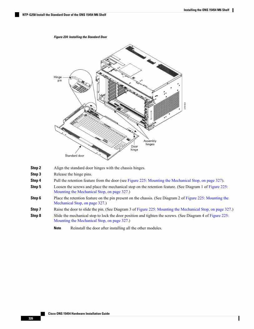
Figure 224: Installing the Standard Door
Step 2 Align the standard door hinges with the chassis hinges.Step 3 Release the hinge pins.Step 4 Pull the retention feature from the door (see Figure 225: Mounting the Mechanical Stop, on page 327).Step 5 Loosen the screws and place the mechanical stop on the retention feature. (See Diagram 1 of Figure 225:
Mounting the Mechanical Stop, on page 327.)Step 6 Place the retention feature on the pin present on the chassis. (See Diagram 2 of Figure 225: Mounting the
Mechanical Stop, on page 327.)Step 7 Raise the door to slide the pin. (See Diagram 3 of Figure 225: Mounting the Mechanical Stop, on page 327.)Step 8 Slide the mechanical stop to lock the door position and tighten the screws. (See Diagram 4 of Figure 225:
Mounting the Mechanical Stop, on page 327.)
Reinstall the door after installing all the other modules.Note
Cisco ONS 15454 Hardware Installation Guide326
Installing the ONS 15454 M6 ShelfNTP-G258 Install the Standard Door of the ONS 15454 M6 Shelf
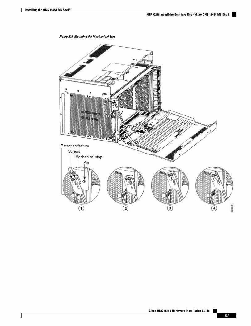
Figure 225: Mounting the Mechanical Stop
Cisco ONS 15454 Hardware Installation Guide327
Installing the ONS 15454 M6 ShelfNTP-G258 Install the Standard Door of the ONS 15454 M6 Shelf
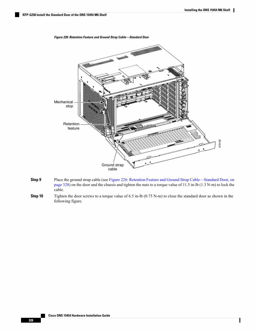
Figure 226: Retention Feature and Ground Strap Cable—Standard Door
Step 9 Place the ground strap cable (see Figure 226: Retention Feature and Ground Strap Cable—Standard Door, onpage 328) on the door and the chassis and tighten the nuts to a torque value of 11.5 in-lb (1.3 N-m) to lock thecable.
Step 10 Tighten the door screws to a torque value of 6.5 in-lb (0.75 N-m) to close the standard door as shown in thefollowing figure.
Cisco ONS 15454 Hardware Installation Guide328
Installing the ONS 15454 M6 ShelfNTP-G258 Install the Standard Door of the ONS 15454 M6 Shelf
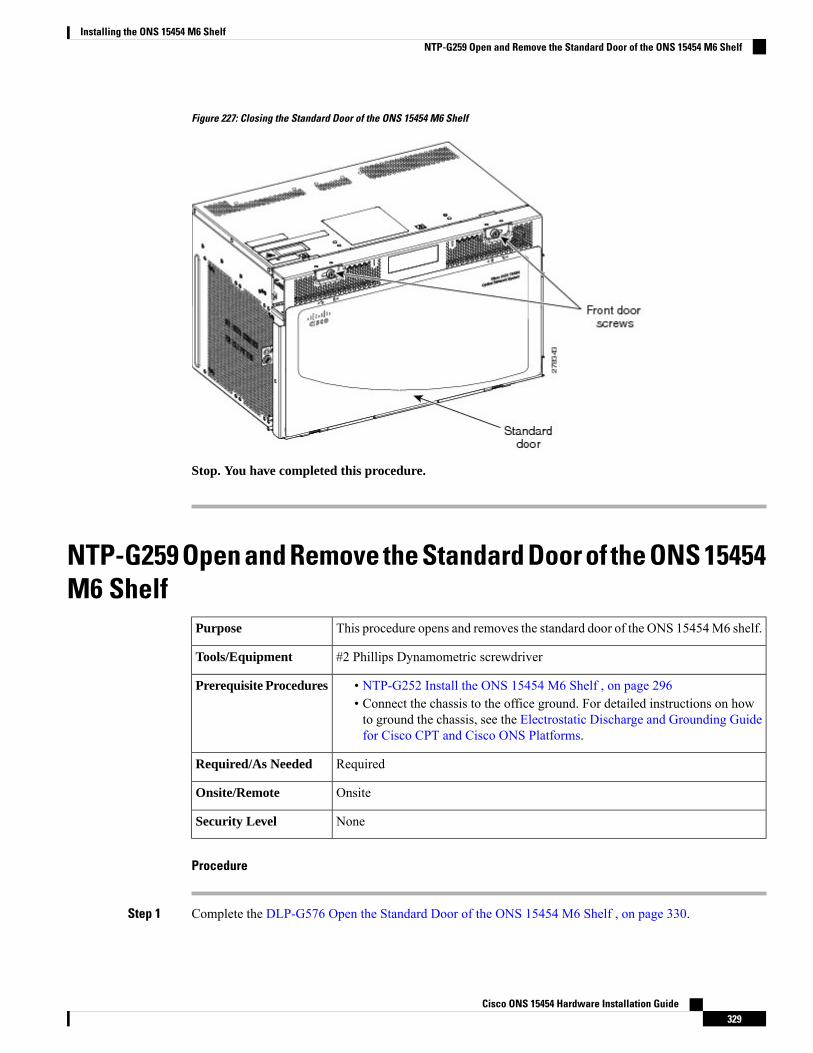
Figure 227: Closing the Standard Door of the ONS 15454 M6 Shelf
Stop. You have completed this procedure.
NTP-G259 Open and Remove the Standard Door of the ONS 15454M6 Shelf
This procedure opens and removes the standard door of the ONS 15454M6 shelf.Purpose
#2 Phillips Dynamometric screwdriverTools/Equipment
• NTP-G252 Install the ONS 15454 M6 Shelf , on page 296• Connect the chassis to the office ground. For detailed instructions on howto ground the chassis, see the Electrostatic Discharge and Grounding Guidefor Cisco CPT and Cisco ONS Platforms.
Prerequisite Procedures
RequiredRequired/As Needed
OnsiteOnsite/Remote
NoneSecurity Level
Procedure
Step 1 Complete the DLP-G576 Open the Standard Door of the ONS 15454 M6 Shelf , on page 330.
Cisco ONS 15454 Hardware Installation Guide329
Installing the ONS 15454 M6 ShelfNTP-G259 Open and Remove the Standard Door of the ONS 15454 M6 Shelf
Step 2 Complete the DLP-G577 Remove the Standard Door of the ONS 15454 M6 Shelf , on page 332.
Stop. You have completed this procedure.
DLP-G576 Open the Standard Door of the ONS 15454 M6 ShelfThis task opens the standard door of the ONS 15454 M6 shelf.Purpose
#2 Phillips Dynamometric screwdriverTools/Equipment
• NTP-G252 Install the ONS 15454 M6 Shelf , on page 296• Connect the chassis to the office ground. For detailed instructions on howto ground the chassis, see the Electrostatic Discharge and Grounding Guidefor Cisco CPT and Cisco ONS Platforms.
Prerequisite Procedures
RequiredRequired/As Needed
OnsiteOnsite/Remote
NoneSecurity Level
The ONS 15454 M6 shelf has an ESD plug input and is shipped with an ESD wrist strap. The ESD plug inputis located on the outside of the shelf on the left side. It is labeled “ESD” on the top and bottom. Always wearan ESD wrist strap and connect the strap to the ESD plug when working on the ONS 15454 M6. For detailedinstructions on how to wear the ESD wristband, see the Electrostatic Discharge and Grounding Guide forCisco CPT and Cisco ONS Platforms.
Note
Procedure
Step 1 Loosen the standard door screws to a torque value of 6.5 in-lb (0.75 N-m) (see the following figure).Step 2 Push the latches in the opposite direction as shown in the following figure.
Cisco ONS 15454 Hardware Installation Guide330
Installing the ONS 15454 M6 ShelfDLP-G576 Open the Standard Door of the ONS 15454 M6 Shelf
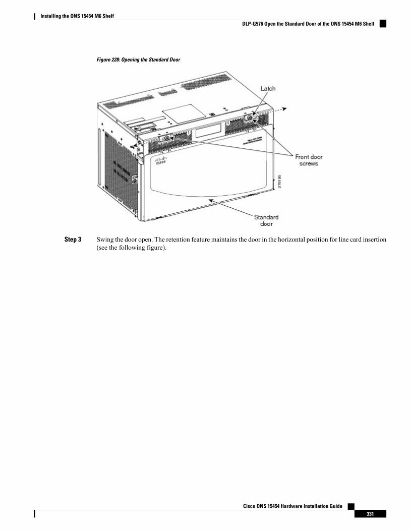
Figure 228: Opening the Standard Door
Step 3 Swing the door open. The retention feature maintains the door in the horizontal position for line card insertion(see the following figure).
Cisco ONS 15454 Hardware Installation Guide331
Installing the ONS 15454 M6 ShelfDLP-G576 Open the Standard Door of the ONS 15454 M6 Shelf
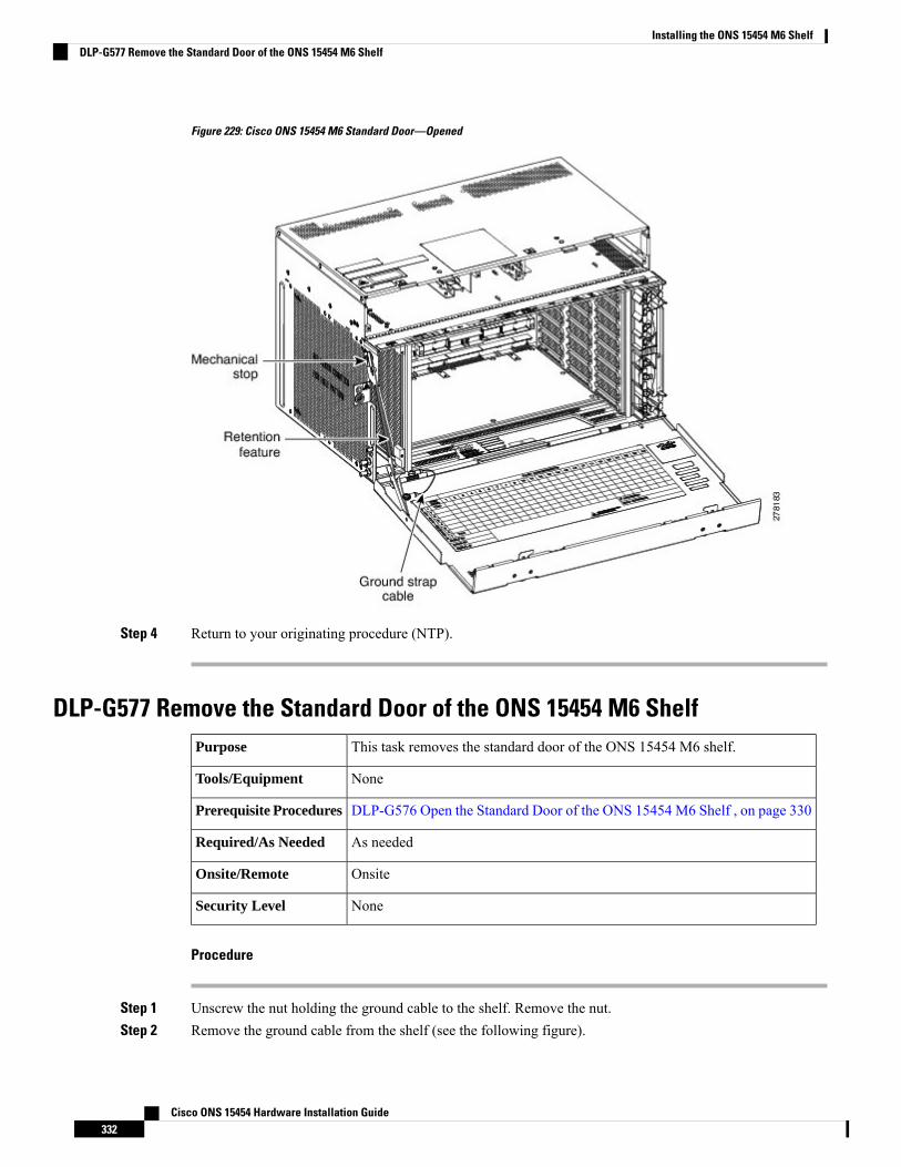
Figure 229: Cisco ONS 15454 M6 Standard Door—Opened
Step 4 Return to your originating procedure (NTP).
DLP-G577 Remove the Standard Door of the ONS 15454 M6 ShelfThis task removes the standard door of the ONS 15454 M6 shelf.Purpose
NoneTools/Equipment
DLP-G576 Open the Standard Door of the ONS 15454 M6 Shelf , on page 330Prerequisite Procedures
As neededRequired/As Needed
OnsiteOnsite/Remote
NoneSecurity Level
Procedure
Step 1 Unscrew the nut holding the ground cable to the shelf. Remove the nut.Step 2 Remove the ground cable from the shelf (see the following figure).
Cisco ONS 15454 Hardware Installation Guide332
Installing the ONS 15454 M6 ShelfDLP-G577 Remove the Standard Door of the ONS 15454 M6 Shelf
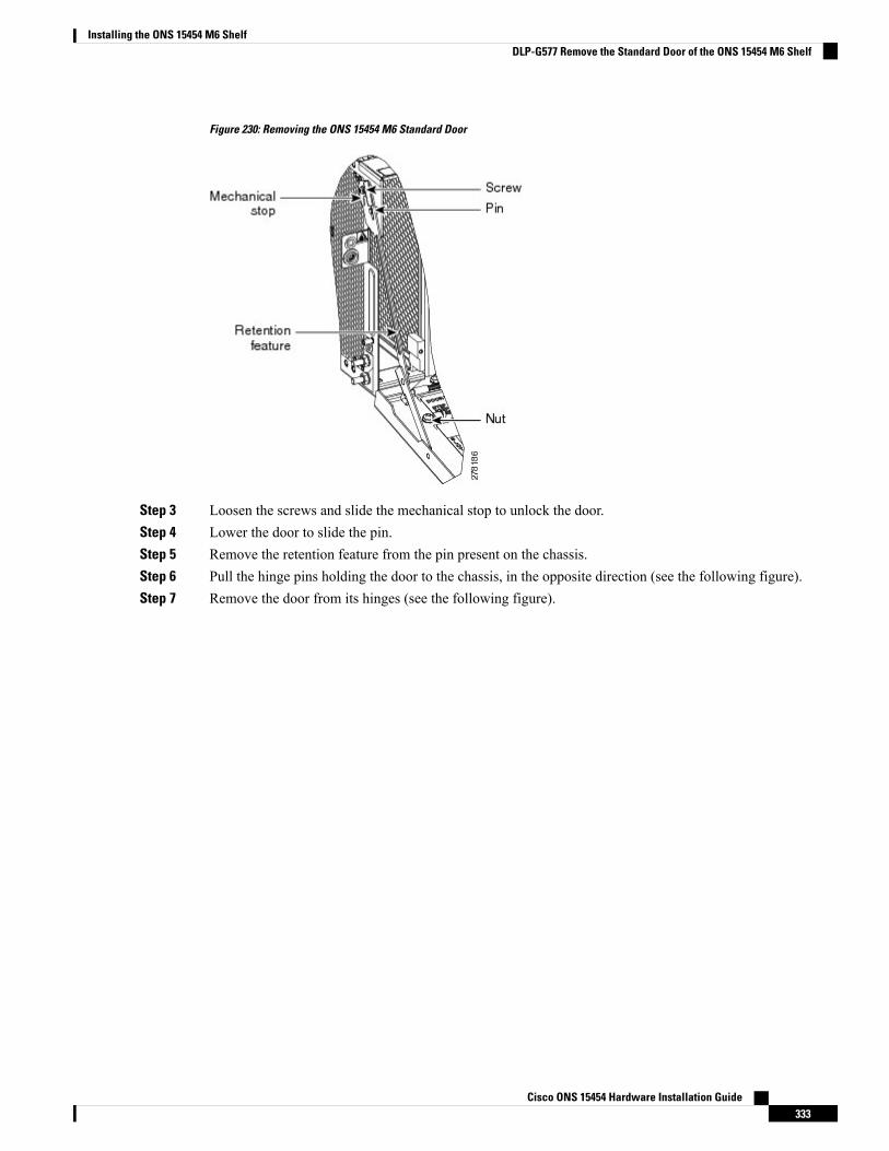
Figure 230: Removing the ONS 15454 M6 Standard Door
Step 3 Loosen the screws and slide the mechanical stop to unlock the door.Step 4 Lower the door to slide the pin.Step 5 Remove the retention feature from the pin present on the chassis.Step 6 Pull the hinge pins holding the door to the chassis, in the opposite direction (see the following figure).Step 7 Remove the door from its hinges (see the following figure).
Cisco ONS 15454 Hardware Installation Guide333
Installing the ONS 15454 M6 ShelfDLP-G577 Remove the Standard Door of the ONS 15454 M6 Shelf
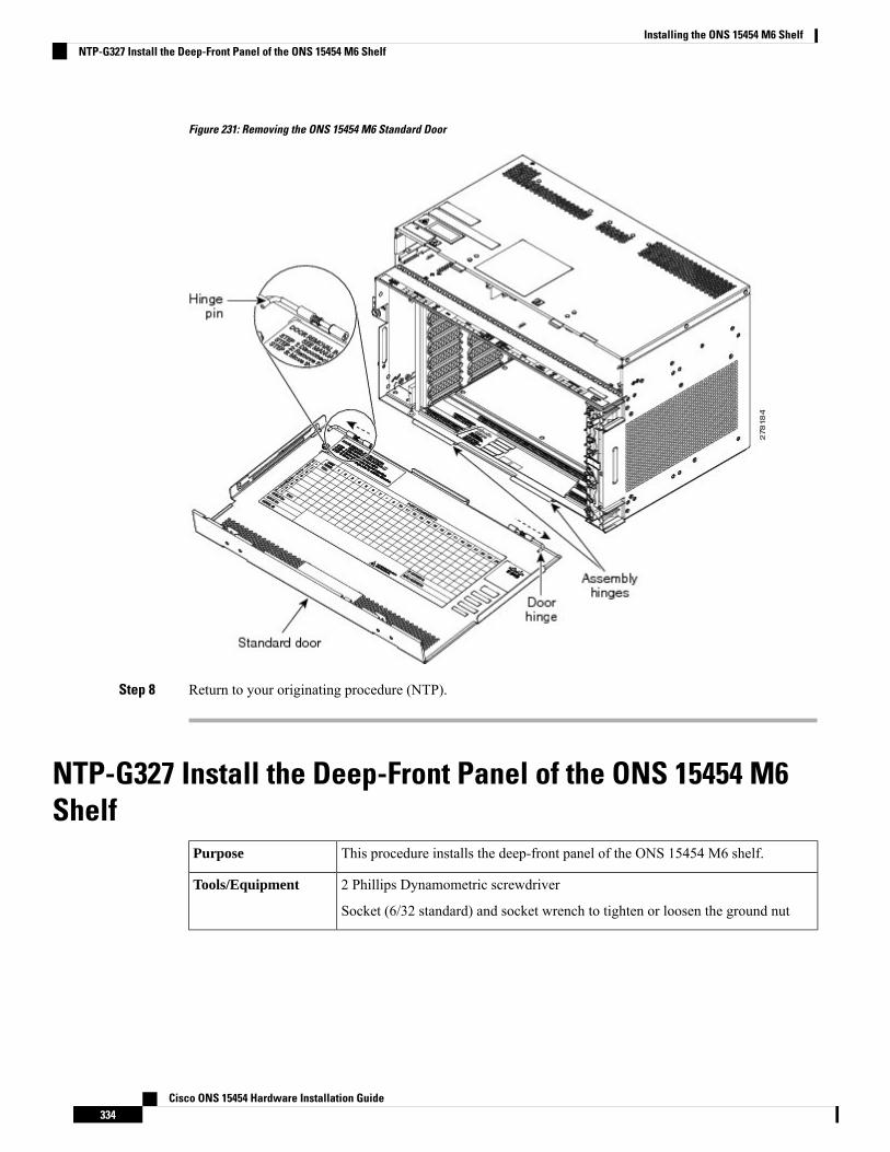
Figure 231: Removing the ONS 15454 M6 Standard Door
Step 8 Return to your originating procedure (NTP).
NTP-G327 Install the Deep-Front Panel of the ONS 15454 M6Shelf
This procedure installs the deep-front panel of the ONS 15454 M6 shelf.Purpose
2 Phillips Dynamometric screwdriver
Socket (6/32 standard) and socket wrench to tighten or loosen the ground nut
Tools/Equipment
Cisco ONS 15454 Hardware Installation Guide334
Installing the ONS 15454 M6 ShelfNTP-G327 Install the Deep-Front Panel of the ONS 15454 M6 Shelf

Remove the temporary door by removing the tape on top of the door.
• NTP-G259Open and Remove the Standard Door of the ONS 15454M6 Shelf, on page 329
• DLP-G576 Open the Standard Door of the ONS 15454 M6 Shelf , on page330
• Connect the chassis to the office ground. For detailed instructions on how toground the chassis, see the Electrostatic Discharge and Grounding Guide forCisco CPT and Cisco ONS Platforms.
• NTP-G253 Install the ECU or ECU-S Module, on page 352• NTP-G524 Install the Power Modules in the ONS 15454 M6 Shelf , on page358
• NTP-G255 Install the LCDModule in the ONS 15454M6 Shelf, on page 369• NTP-G256 Install Power and Ground to the ONS 15454 M6 Shelf , on page373
• NTP-G257 Install the Fan-Tray Assembly in the ONS 15454 M6 Shelf, onpage 391
• NTP-G290 Install the Cable and Fiber Modules, on page 394• NTP-G312 AttachWires to Alarm, Timing, LAN, and Craft Pin Connectionsin Cisco ONS 15454 M6, on page 400
PrerequisiteProcedures
As neededRequired/As Needed
OnsiteOnsite/Remote
NoneSecurity Level
Use the deep-front panel when ONS-SC+-10G-C pluggables are installed on ONS 15454 M6 shelf.Note
When the deep front-panel is installed, the total chassis depth is 12.9 inches. The deep front-panel extendsfrom the rack by 1.8 inches.
Note
The deep-front panel does not have a hinge and cannot be rotated like a standard door. Rotating the deep-frontpanel can damage the deep-front panel, shelf hinges, other devices and cables placed below the ONS 15454M6 shelf.
Caution
Procedure
Step 1 Connect the ground strap cable to the shelf:a) Loosen and remove the ground nut from the shelf.b) Insert the lug of the ground strap cable and tighten the nut on the shelf to a torque value of 11.5 in-lb (1.3
N-m). See the following figure.
Cisco ONS 15454 Hardware Installation Guide335
Installing the ONS 15454 M6 ShelfNTP-G327 Install the Deep-Front Panel of the ONS 15454 M6 Shelf
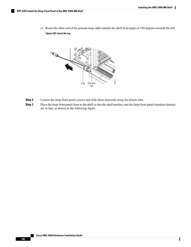
c) Route the other end of the ground strap cable outside the shelf at an angle of 180 degrees towards the left.
Figure 232: Insert the lug
Step 2 Loosen the deep-front panel screws and slide them outwards using the plastic tabs.Step 3 Place the deep-front panel close to the shelf so that the shelf notches, and the deep-front panel retention features
are in line, as shown in the following figure.
Cisco ONS 15454 Hardware Installation Guide336
Installing the ONS 15454 M6 ShelfNTP-G327 Install the Deep-Front Panel of the ONS 15454 M6 Shelf
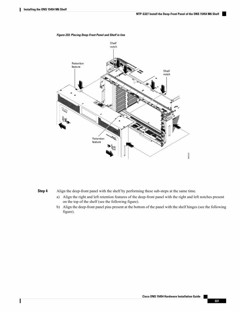
Figure 233: Placing Deep-Front Panel and Shelf in line
Step 4 Align the deep-front panel with the shelf by performing these sub-steps at the same time.a) Align the right and left retention features of the deep-front panel with the right and left notches present
on the top of the shelf (see the following figure).b) Align the deep-front panel pins present at the bottom of the panel with the shelf hinges (see the following
figure).
Cisco ONS 15454 Hardware Installation Guide337
Installing the ONS 15454 M6 ShelfNTP-G327 Install the Deep-Front Panel of the ONS 15454 M6 Shelf
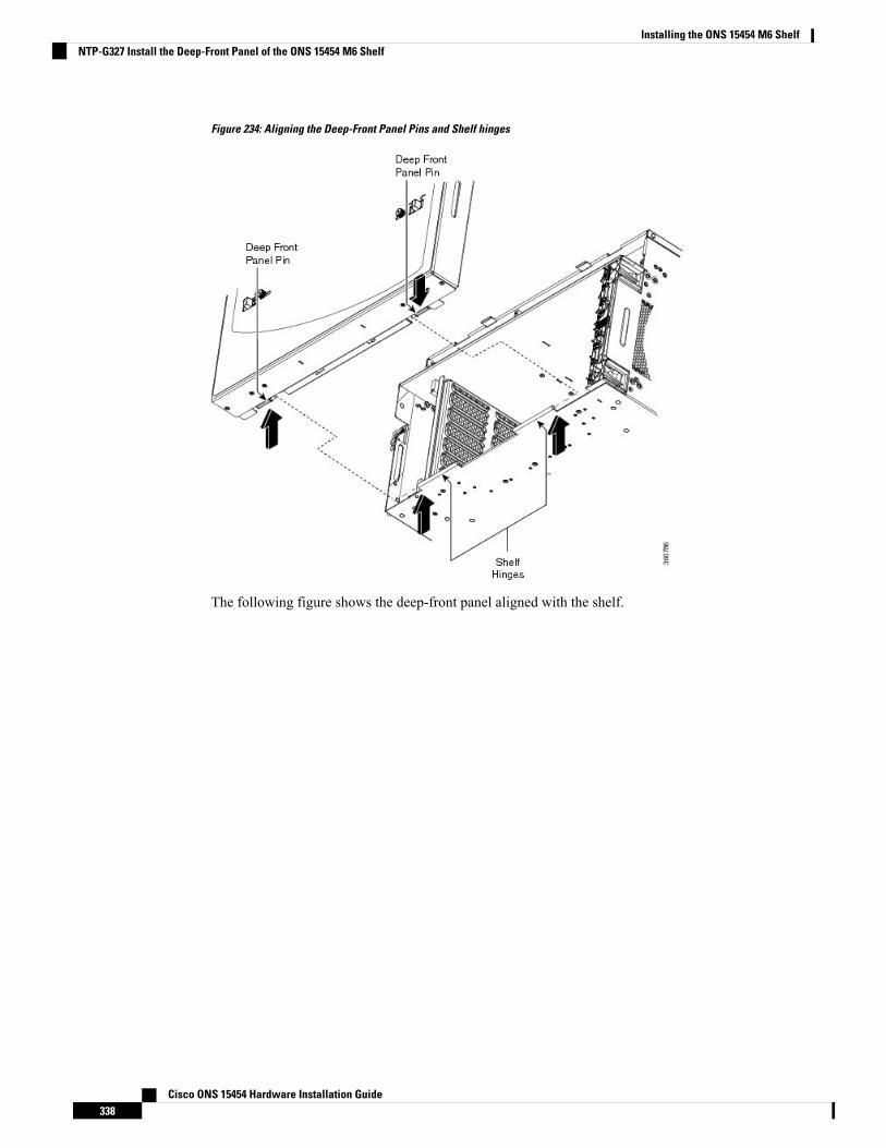
Figure 234: Aligning the Deep-Front Panel Pins and Shelf hinges
The following figure shows the deep-front panel aligned with the shelf.
Cisco ONS 15454 Hardware Installation Guide338
Installing the ONS 15454 M6 ShelfNTP-G327 Install the Deep-Front Panel of the ONS 15454 M6 Shelf
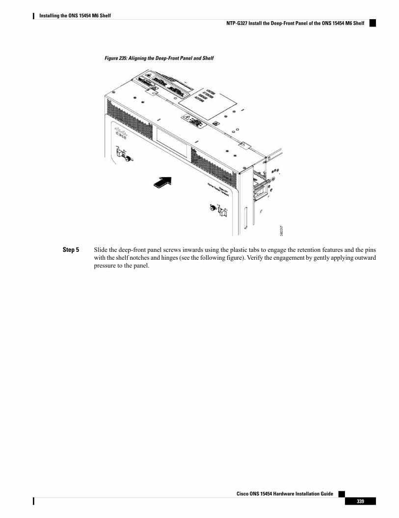
Figure 235: Aligning the Deep-Front Panel and Shelf
Step 5 Slide the deep-front panel screws inwards using the plastic tabs to engage the retention features and the pinswith the shelf notches and hinges (see the following figure). Verify the engagement by gently applying outwardpressure to the panel.
Cisco ONS 15454 Hardware Installation Guide339
Installing the ONS 15454 M6 ShelfNTP-G327 Install the Deep-Front Panel of the ONS 15454 M6 Shelf
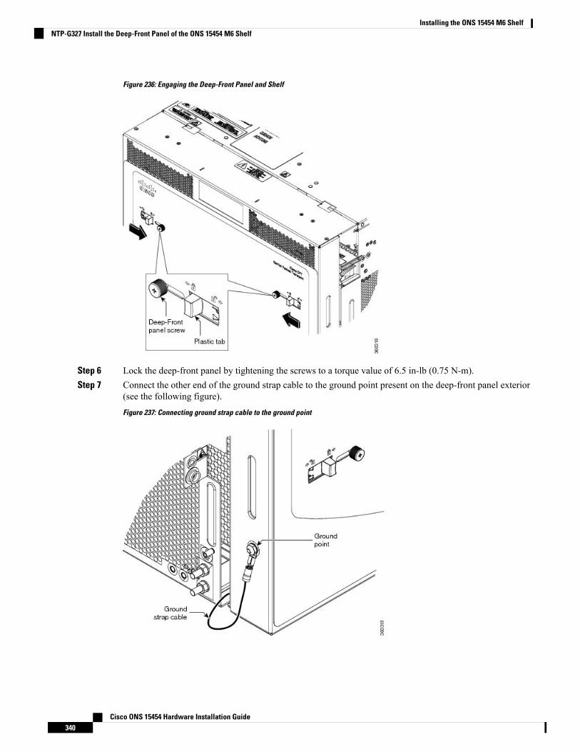
Figure 236: Engaging the Deep-Front Panel and Shelf
Step 6 Lock the deep-front panel by tightening the screws to a torque value of 6.5 in-lb (0.75 N-m).Step 7 Connect the other end of the ground strap cable to the ground point present on the deep-front panel exterior
(see the following figure).
Figure 237: Connecting ground strap cable to the ground point
Cisco ONS 15454 Hardware Installation Guide340
Installing the ONS 15454 M6 ShelfNTP-G327 Install the Deep-Front Panel of the ONS 15454 M6 Shelf
Stop. You have completed this procedure.
NTP-G329 Remove the Deep-Front Panel of the ONS 15454 M6Shelf
This procedure removes the deep-front panel of the ONS 15454 M6 system.Purpose
• #2 Phillips Dynamometric screwdriver• Socket (6/32 standard) and socket wrench to tighten or loosen the groundnut
Tools/Equipment
• NTP-G252 Install the ONS 15454 M6 Shelf , on page 296• NTP-G327 Install the Deep-Front Panel of the ONS 15454 M6 Shelf, onpage 334
• Connect the chassis to the office ground. For detailed instructions on howto ground the chassis, see the Electrostatic Discharge and Grounding Guidefor Cisco CPT and Cisco ONS Platforms.
Prerequisite Procedures
RequiredRequired/As Needed
OnsiteOnsite/Remote
NoneSecurity Level
The deep-front panel does not have a hinge and cannot be rotated like a standard door. Rotating the deep-frontpanel can damage the deep-front panel, shelf hinges, other devices and cables placed below the ONS 15454M6 shelf.
Caution
When the deep front-panel is installed, the total chassis depth is 12.9 inches. The deep front-panel extendsfrom the rack by 1.8 inches.
Note
Procedure
Step 1 Remove the end of the ground strap cable that is connected to the exterior of the deep-front panel (see thefollowing figure).
Cisco ONS 15454 Hardware Installation Guide341
Installing the ONS 15454 M6 ShelfNTP-G329 Remove the Deep-Front Panel of the ONS 15454 M6 Shelf
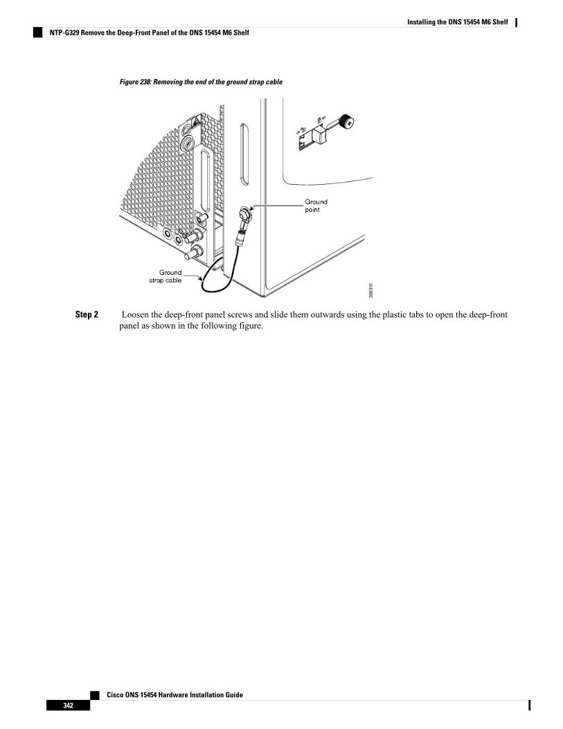
Figure 238: Removing the end of the ground strap cable
Step 2 Loosen the deep-front panel screws and slide them outwards using the plastic tabs to open the deep-frontpanel as shown in the following figure.
Cisco ONS 15454 Hardware Installation Guide342
Installing the ONS 15454 M6 ShelfNTP-G329 Remove the Deep-Front Panel of the ONS 15454 M6 Shelf
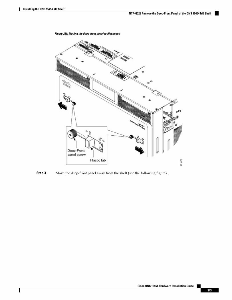
Figure 239: Moving the deep-front panel to disengage
Step 3 Move the deep-front panel away from the shelf (see the following figure).
Cisco ONS 15454 Hardware Installation Guide343
Installing the ONS 15454 M6 ShelfNTP-G329 Remove the Deep-Front Panel of the ONS 15454 M6 Shelf
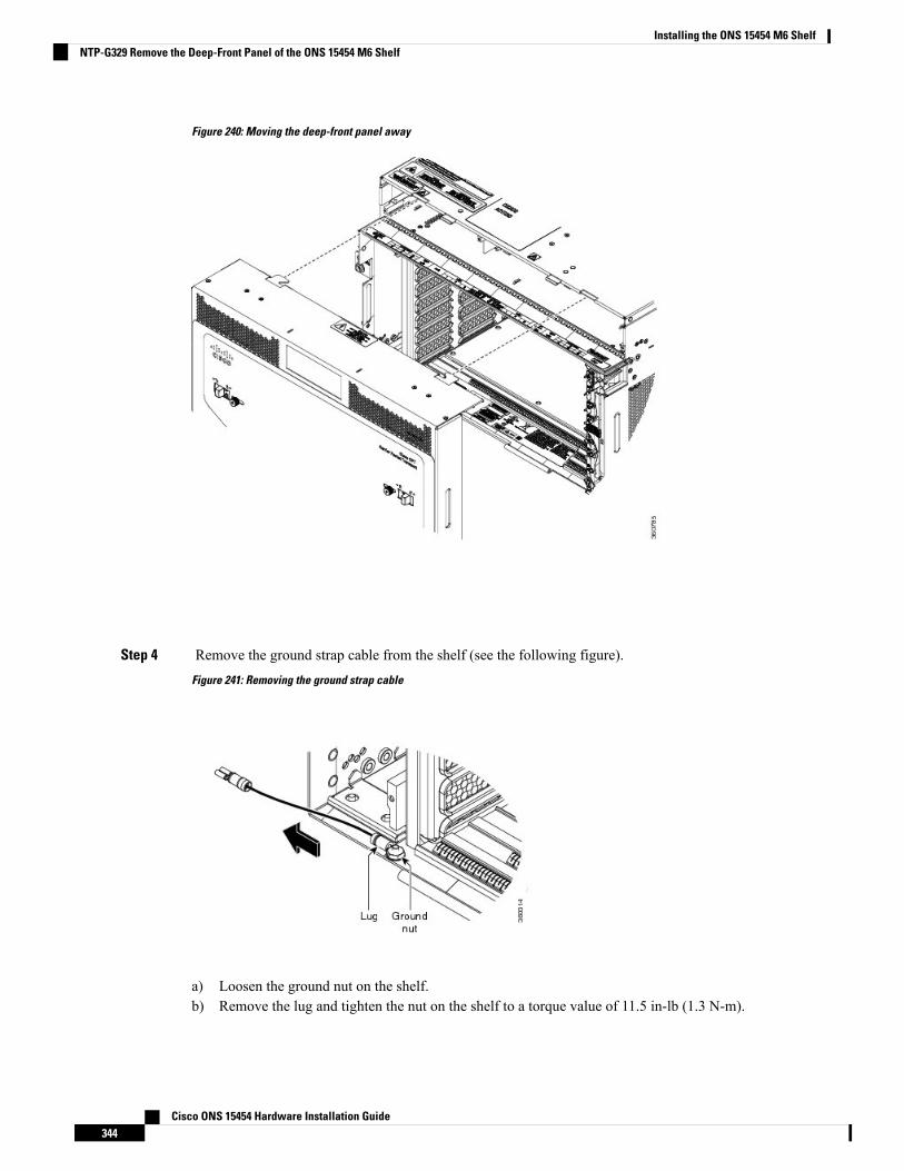
Figure 240: Moving the deep-front panel away
Step 4 Remove the ground strap cable from the shelf (see the following figure).
Figure 241: Removing the ground strap cable
a) Loosen the ground nut on the shelf.b) Remove the lug and tighten the nut on the shelf to a torque value of 11.5 in-lb (1.3 N-m).
Cisco ONS 15454 Hardware Installation Guide344
Installing the ONS 15454 M6 ShelfNTP-G329 Remove the Deep-Front Panel of the ONS 15454 M6 Shelf
Stop. You have completed this procedure.
External Connection UnitsThe external connection unit (ECU) is a replaceable module placed on top of the ONS 15454 M6 shelf. TheECU module discovers and manages the inventory of the external shelf units. It also handles the multishelfmanagement connections and timing synchronizations. There are three types of ECU modules available forthe ONS 15454 M6 shelf, namely ECU (PN: 15454-M6-ECU=), ECU2 (PN: 15454-M6-ECU2=), ECU-60V(PN: 15454-M6-ECU-60=), ECU-S, and ECU60-S.
The ECU and ECU2 modules can be interchanged on an ONS 15454 M6 shelf without any alarms.
A label, as shown in the following figure, is present on the ONS 15454 M6 shelf indicating the connectionsfor the ECU module.
Figure 242: Connector Label for ECU Module
ECUThe external connections of ONS 15454 M6 present on the ECU are:
• 12 remote inventory standard USB connections• 2 BITS-OUT connections (2 subminiature version B [SMB] connectors for ETSI and 4 wire-wrap pinsfor ANSI)
• 2 BITS-IN connections (2 SMB connectors for ETSI and 4 wire-wrap pins for ANSI)• 6 multishelf connections• 1 element management system (EMS) connection• 1 craft terminal connection• 2 VoIP or 2 user data channel (UDC) connections, or one each of VoIP and UDC connections• 1 SCSI with 26 poles for TNC and TNCE relay contact, including alarm cut-off (ACO) signal and digitalI/O (D-I/O) signals (on the left-side connector)
• 1 SCSI with 26 poles for digital I/O signals (on the right-side connector)
The following figure shows the ECU connectors.
Figure 243: Connectors on the ECU Faceplate
The ECU should not be used when the shelf is powered at –60V DC nominal input voltage.Note
Cisco ONS 15454 Hardware Installation Guide345
Installing the ONS 15454 M6 ShelfExternal Connection Units

ECU2The ECU2 is an advanced version of the ECU. The ECU2 is hardware-ready to support IEEE1588v2 PTP,time-of-day (ToD), and pulse-per-second (PPS) inputs. The external connections of ONS 15454 M6 presenton the ECU2 are:
• 12 remote inventory standard USB connections• 2 BITS-OUT connections (2 subminiature version B[SMB] connectors for ETSI and 4 wire-wrap pinsfor ANSI)
• 10 MHz IN and OUT and PPS IN and OUT (hardware-ready)• 2 BITS-IN connections (2 SMB connectors for ETSI and 4 wire-wrap pins for ANSI)• 6 multishelf connections• 1 element management system (EMS) connection• 1 craft terminal connection• 1 time-of-day (ToD) connection (hardware-ready)• 2 VoIP or 2 user data channel (UDC) connections, or one each of VoIP and UDC connections• 1 SCSI with 26 poles for TNC relay contact, including alarm cut-off (ACO) signal and digital I/O (D-I/O)signals (on the left-side connector)
• 1 SCSI with 26 poles for digital I/O signals (on the right-side connector)
The following figure shows the ECU2 connectors.
Figure 244: Connectors on ECU2 Faceplate
The ECU2 should not be used when the shelf is powered at –60 VDC nominal input voltage.Note
ECU-60VThe ECU-60V is used when the shelf is powered at –60 VDC nominal input voltage. The external connectionsof ONS 15454 M6 present on the ECU-60V are:
• 12 remote inventory standard USB connections• 2 BITS-OUT connections (2 subminiature version B [SMB] connectors for ETSI and 4 wire-wrap pinsfor ANSI)
• 10 MHz IN and OUT and PPS IN and OUT (hardware-ready)• 2 BITS-IN connections (2 SMB connectors for ETSI and 4 wire-wrap pins for ANSI)• 6 multishelf connections• 1 element management system (EMS) connection• 1 craft terminal connection• 1 time-of-day (ToD) connection (hardware-ready)• 2 user data channel (UDC) connections
The following figure shows the ECU-60V connectors.
Cisco ONS 15454 Hardware Installation Guide346
Installing the ONS 15454 M6 ShelfECU2
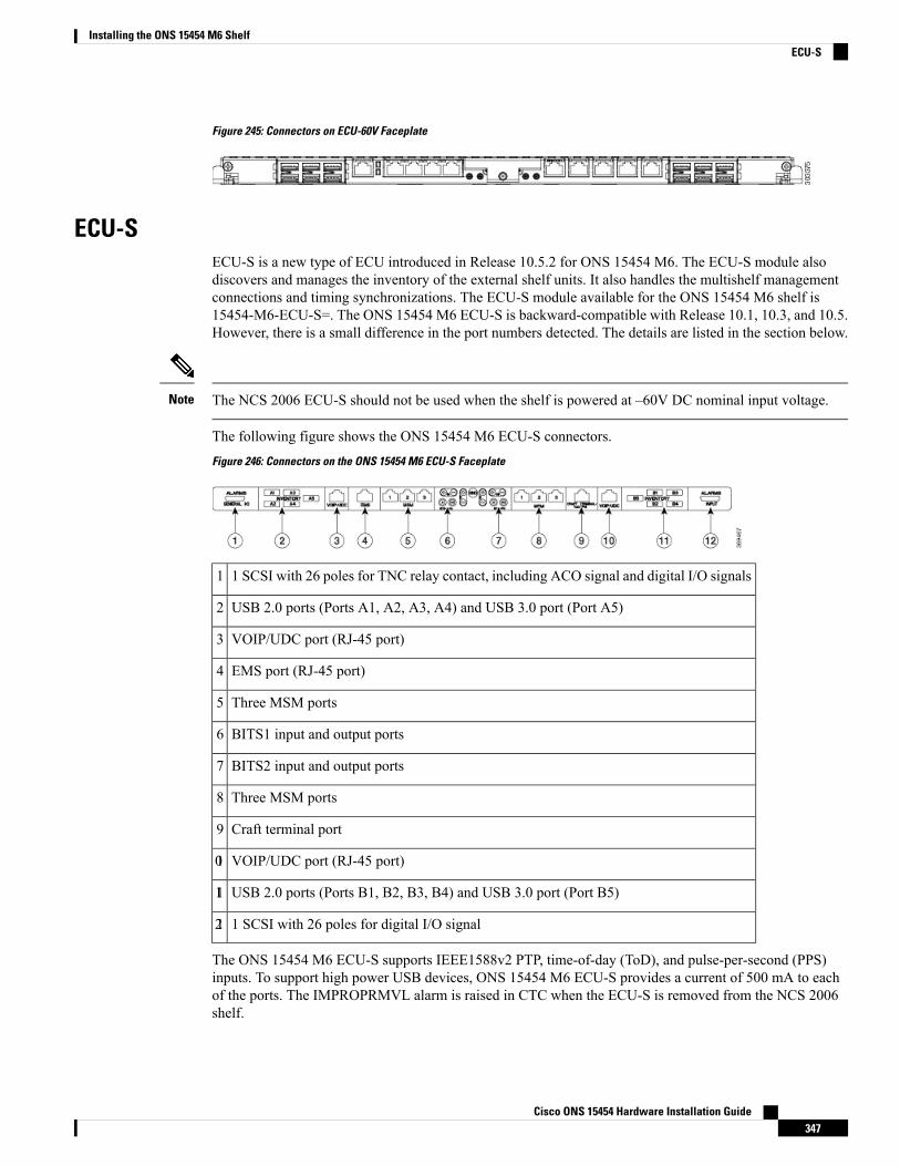
Figure 245: Connectors on ECU-60V Faceplate
ECU-SECU-S is a new type of ECU introduced in Release 10.5.2 for ONS 15454 M6. The ECU-S module alsodiscovers and manages the inventory of the external shelf units. It also handles the multishelf managementconnections and timing synchronizations. The ECU-S module available for the ONS 15454 M6 shelf is15454-M6-ECU-S=. The ONS 15454 M6 ECU-S is backward-compatible with Release 10.1, 10.3, and 10.5.However, there is a small difference in the port numbers detected. The details are listed in the section below.
The NCS 2006 ECU-S should not be used when the shelf is powered at –60V DC nominal input voltage.Note
The following figure shows the ONS 15454 M6 ECU-S connectors.
Figure 246: Connectors on the ONS 15454 M6 ECU-S Faceplate
1 SCSI with 26 poles for TNC relay contact, including ACO signal and digital I/O signals1
USB 2.0 ports (Ports A1, A2, A3, A4) and USB 3.0 port (Port A5)2
VOIP/UDC port (RJ-45 port)3
EMS port (RJ-45 port)4
Three MSM ports5
BITS1 input and output ports6
BITS2 input and output ports7
Three MSM ports8
Craft terminal port9
VOIP/UDC port (RJ-45 port)10
USB 2.0 ports (Ports B1, B2, B3, B4) and USB 3.0 port (Port B5)11
1 SCSI with 26 poles for digital I/O signal12
The ONS 15454 M6 ECU-S supports IEEE1588v2 PTP, time-of-day (ToD), and pulse-per-second (PPS)inputs. To support high power USB devices, ONS 15454 M6 ECU-S provides a current of 500 mA to eachof the ports. The IMPROPRMVL alarm is raised in CTC when the ECU-S is removed from the NCS 2006shelf.
Cisco ONS 15454 Hardware Installation Guide347
Installing the ONS 15454 M6 ShelfECU-S
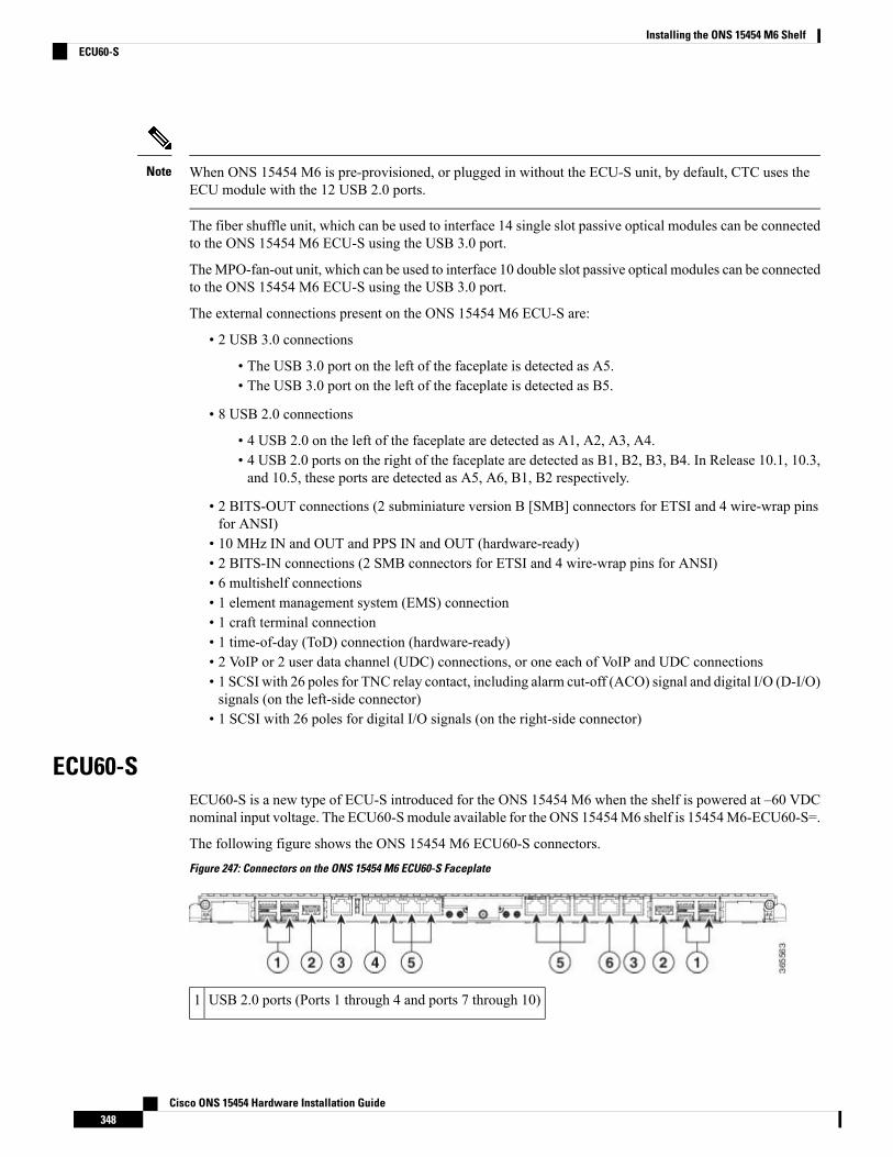
When ONS 15454 M6 is pre-provisioned, or plugged in without the ECU-S unit, by default, CTC uses theECU module with the 12 USB 2.0 ports.
Note
The fiber shuffle unit, which can be used to interface 14 single slot passive optical modules can be connectedto the ONS 15454 M6 ECU-S using the USB 3.0 port.
TheMPO-fan-out unit, which can be used to interface 10 double slot passive optical modules can be connectedto the ONS 15454 M6 ECU-S using the USB 3.0 port.
The external connections present on the ONS 15454 M6 ECU-S are:
• 2 USB 3.0 connections
• The USB 3.0 port on the left of the faceplate is detected as A5.• The USB 3.0 port on the left of the faceplate is detected as B5.
• 8 USB 2.0 connections
• 4 USB 2.0 on the left of the faceplate are detected as A1, A2, A3, A4.• 4 USB 2.0 ports on the right of the faceplate are detected as B1, B2, B3, B4. In Release 10.1, 10.3,and 10.5, these ports are detected as A5, A6, B1, B2 respectively.
• 2 BITS-OUT connections (2 subminiature version B [SMB] connectors for ETSI and 4 wire-wrap pinsfor ANSI)
• 10 MHz IN and OUT and PPS IN and OUT (hardware-ready)• 2 BITS-IN connections (2 SMB connectors for ETSI and 4 wire-wrap pins for ANSI)• 6 multishelf connections• 1 element management system (EMS) connection• 1 craft terminal connection• 1 time-of-day (ToD) connection (hardware-ready)• 2 VoIP or 2 user data channel (UDC) connections, or one each of VoIP and UDC connections• 1 SCSI with 26 poles for TNC relay contact, including alarm cut-off (ACO) signal and digital I/O (D-I/O)signals (on the left-side connector)
• 1 SCSI with 26 poles for digital I/O signals (on the right-side connector)
ECU60-SECU60-S is a new type of ECU-S introduced for the ONS 15454 M6 when the shelf is powered at –60 VDCnominal input voltage. The ECU60-Smodule available for the ONS 15454M6 shelf is 15454M6-ECU60-S=.
The following figure shows the ONS 15454 M6 ECU60-S connectors.
Figure 247: Connectors on the ONS 15454 M6 ECU60-S Faceplate
USB 2.0 ports (Ports 1 through 4 and ports 7 through 10)1
Cisco ONS 15454 Hardware Installation Guide348
Installing the ONS 15454 M6 ShelfECU60-S
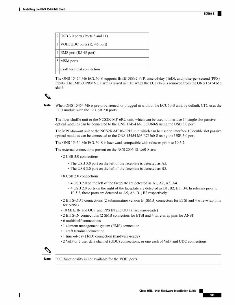
USB 3.0 ports (Ports 5 and 11)2
VOIP/UDC ports (RJ-45 port)3
EMS port (RJ-45 port)4
MSM ports5
Craft terminal connection6
The ONS 15454 M6 ECU60-S supports IEEE1588v2 PTP, time-of-day (ToD), and pulse-per-second (PPS)inputs. The IMPROPRMVL alarm is raised in CTC when the ECU60-S is removed from the ONS 15454 M6shelf.
When ONS 15454 M6 is pre-provisioned, or plugged in without the ECU60-S unit, by default, CTC uses theECU module with the 12 USB 2.0 ports.
Note
The fiber shuffle unit or the NCS2K-MF-6RU unit, which can be used to interface 14 single slot passiveoptical modules can be connected to the ONS 15454 M6 ECU60-S using the USB 3.0 port.
The MPO-fan-out unit or the NCS2K-MF10-6RU unit, which can be used to interface 10 double slot passiveoptical modules can be connected to the ONS 15454 M6 ECU60-S using the USB 3.0 port.
The ONS 15454 M6 ECU60-S is backward-compatible with releases prior to 10.5.2.
The external connections present on the NCS 2006 ECU60-S are:
• 2 USB 3.0 connections
• The USB 3.0 port on the left of the faceplate is detected as A5.• The USB 3.0 port on the left of the faceplate is detected as B5.
• 8 USB 2.0 connections
• 4 USB 2.0 on the left of the faceplate are detected as A1, A2, A3, A4.• 4 USB 2.0 ports on the right of the faceplate are detected as B1, B2, B3, B4. In releases prior to10.5.2, these ports are detected as A5, A6, B1, B2 respectively.
• 2 BITS-OUT connections (2 subminiature version B [SMB] connectors for ETSI and 4 wire-wrap pinsfor ANSI)
• 10 MHz IN and OUT and PPS IN and OUT (hardware-ready)• 2 BITS-IN connections (2 SMB connectors for ETSI and 4 wire-wrap pins for ANSI)• 6 multishelf connections• 1 element management system (EMS) connection• 1 craft terminal connection• 1 time-of-day (ToD) connection (hardware-ready)• 2 VoIP or 2 user data channel (UDC) connections, or one each of VoIP and UDC connections
POE functionality is not available for the VOIP ports.Note
Cisco ONS 15454 Hardware Installation Guide349
Installing the ONS 15454 M6 ShelfECU60-S
You can upgrade to the NCS2006 ECU60-S from an older ECU (ECU/ECU-2/ECU-S) in the ONS 15454M6 shelf. For more information, see NTP-L68 Upgrading to ONS 15454M6 ECU60-SModule, on page 355.
Alarm ConnectorsThe ECU modules, except for ECU-60V, have two SCSI alarm connectors that are used to connect ONS15454 M6 to support external alarms. The alarm connectors provide dry alarm contacts and are similar to theAIC-I card of the ONS 15454 shelf. The left alarm connector is used for TNC and TNCE relay contact,including Alarm Cut Off (ACO) signal and Digital Input/Output (D-I/O) signals. The right alarm connectoris used for Digital Input/Output (D-I/O) signals. To export alarms from the ONS 15454 M6 shelf to a thirdparty device, use the output pins of either the right alarm connector or the left alarm connector.
When external controls are not provisioned, 14 external input alarms are available. Input alarm 11 and inputalarm 12 are available on the left side connector; input alarm 13 and input alarm 14 are available on the rightside connector.
When external controls are provisioned, only 10 external input alarms are available.
In a multishelf configuration, alarms on the subtended shelves cannot be extended through the node controller.Note
ECU60-S does not support alarm connections.Note
See Table 36: SCSI Alarm Cable (15454-M-ALMCBL) and SCSI Alarm Patch Cable (15454-M-AEXPCBL)Connector Details , on page 403 and Table 37: SCSIAlarmWire-Wrap Cable (15454-M-ALMCBL2) ConnectorDetails , on page 404 for pin details of the alarm connectors.
Passive Unit Inventory InterfacesThe passive unit inventory interfaces (USB ports) are used to retrieve inventory information from passivedevices such as fiber trays, FBG DCU, patch panels, passive multiplexer or demultiplexer, and so on. Thereare 12 USB ports on the ECU modules. The inventory details are displayed in the Inventory tab in CTC.
The USB 3.0 port delivers power to the fiber shuffle unit or the MPO-fan-out unit when they are connectedto the ONS 15454 M6 2006 ECU-S.
The 12 passive inventory ports on the ECUmodules are labeled 1 to 12. However, CTC represents the passiveinventory ports as USBP_SIDE_PORT, where SIDE can be A or B, and PORT can be any value from 1 to12. For example, Port 1 on the left side of the ECU module is represented as USBP_A_1 and Port 1 on theright side of the ECU module is represented as USBP_B_ 1. The left side of the ECU module is Side A andthe right side of the ECU module is Side B.
Note
Cisco ONS 15454 Hardware Installation Guide350
Installing the ONS 15454 M6 ShelfAlarm Connectors
The 8 passive inventory USB 2.0 ports on the NCS 2006 ECU-Smodule are labeled 1 through 4 and 7 through10. The USB 3.0 port on the left of the faceplate is detected as A5. The USB 3.0 port on the left of the faceplateis detected as B5. However, CTC represents the passive inventory ports as USBP_SIDE_PORT, where SIDEcan be A or B, and PORT can be any value from 1 to 5. For example, Port 1 on the left side of the ECU-Smodule is represented as USBP_A_1 and Port 1 on the right side of the NCS 2006 ECU-Smodule is representedas USBP_B_ 1. The left side of the ONS 15454 M6 2006 ECU-S module is Side A and the right side of theONS 15454 M6 2006 ECU-S module is Side B.
Note
VoIP or UDCVoIP or UDC is an RJ45 port that can be configured to support UDC or VoIP service on an ONS 15454 M6shelf. There are two VoIP or UDC ports on the ECU modules. The VoIP or UDC port on the left side isconnected to the TNC or TNCE card in Slot 1 and the port on the right side is connected to the TNC or TNCEcard in Slot 8. The VoIP or UDC port also supports Power over Ethernet for connecting VoIP equipments.
Power over Ethernet functionality is not available on ECU-60V.Note
MSMThe multishelf management (MSM) port is an RJ-45 port that is used to connect the ONS 15454 M6 shelf toother ONS 15454 or ONS 15454 M6 shelves that are a part of the multishelf configuration. There are sixMSM ports on the ECU modules—three ports on the left side and three ports on the right side. The MSMports on the left side correspond to the TNC/TNCE/TSC/TSCE card in Slot 1, and those on the right sidecorrespond to the TNC/TNCE/TSC/TSCE card in Slot 8. Three MSM ports are used as working ports, andthe remaining three are used as standby ports.
Timing ConnectionsThe ECU modules have four Building Integrated Timing Supply (BITS) connections that support both ETSIand ANSI connections. There are two BITS-IN and two BITS-OUT connections that can either be SMBconnectors for ETSI connection or wire-wrap pins for ANSI connection, based on customer requirements.The BITS-IN ports receive input from third-party external sources called Synchronization Supply Unit (SSU)to synchronize the timing of the ONS 15454M6 shelf. The BITS-OUT ports provide output to external devices(other Cisco or third-party shelves) to synchronize the timing signals with the ONS 15454 M6 shelf.
For timing connection, use 100 ohm shielded BITS clock cable pair #22 or #24 AWG (0.51 mm² [0.020 inch]or 0.64 mm² [0.0252 inch]), twisted-pair T1-type.
Note
See Telcordia SR-NWT-002224 for rules about provisioning timing references.Note
Cisco ONS 15454 Hardware Installation Guide351
Installing the ONS 15454 M6 ShelfVoIP or UDC
NTP-G253 Install the ECU or ECU-S ModuleThis procedure installs the external connection unit modules (ECU, ECU2, ECU-S,ECU60-S, or ECU-60V) in the ONS 15454 M6 shelf.
Purpose
Small slot-head screwdriverTools/Equipment
• NTP-G252 Install the ONS 15454 M6 Shelf , on page 296.• NTP-G259 Open and Remove the Standard Door of the ONS 15454 M6Shelf , on page 329.
• Connect the chassis to the office ground. For detailed instructions on howto ground the chassis, see the Electrostatic Discharge and Grounding Guidefor Cisco CPT and Cisco ONS Platforms.
Prerequisite Procedures
RequiredRequired/As Needed
OnsiteOnsite/Remote
NoneSecurity Level
The intra-building port(s) of the equipment or subassembly is suitable for connection to intra-buildingor unexposed wiring or cabling only. The intra-building port(s) of the equipment or subassembly MUSTNOT metallically connect to interfaces that connect to the OSP or its wiring. These interfaces aredesigned for use as intra-building interfaces only (Type 2 or Type 4 ports as described in GR-1089-CORE,Issue 5) and require isolation from the exposed OSP cabling. The addition of Primary Protectors is notsufficient protection in order to connect these interfaces metallically to OSP wiring. Statement 7005
Warning
To comply with the Telcordia GR-1089 NEBS standard for electromagnetic compatibility and safety,connect the serial high-speed WAN interface ports only to intra-building or unexposed wiring or cable.The intrabuilding cable must be shielded and the shield must be grounded at both ends. Theintra-building port(s) of the equipment or subassembly must not be metallically connected to interfacesthat connect to the OSP or its wiring. These interfaces are designed for use as intra-building interfacesonly (Type 2 or Type 4 ports as described in GR-1089-CORE) and require isolation from the exposedOSP cabling. The addition of Primary Protectors is not sufficient protection in order to connect theseinterfaces metallically to OSP wiring. Statement 7003
Warning
The intra-building port(s) of the equipment or subassembly is suitable for connection to intra-buildingor unexposed wiring or cabling only. The intra-building port(s) of the equipment or subassembly MUSTNOT metallically connect to interfaces that connect to the OSP or its wiring. These interfaces aredesigned for use as intra-building interfaces only (Type 2 or Type 4 ports as described in GR-1089-CORE,Issue 5) and require isolation from the exposed OSP cabling. The addition of Primary Protectors is notsufficient protection in order to connect these interfaces metallically to OSP wiring. Statement 7018
Warning
Cisco ONS 15454 Hardware Installation Guide352
Installing the ONS 15454 M6 ShelfNTP-G253 Install the ECU or ECU-S Module

Voltages that present a shock hazard may exist on Power over Ethernet (PoE) circuits if interconnectionsare made using uninsulated exposed metal contacts, conductors, or terminals. Avoid using suchinterconnection methods, unless the exposed metal parts are located within a restricted access locationand users and service people who are authorized within the restricted access location are made awareof the hazard. A restricted access area can be accessed only through the use of a special tool, lock andkey or other means of security. Statement 1072
Warning
Always use the supplied ESDwristbandwhenworkingwith a poweredONS 15454M6. For detailed instructionson how to wear the ESD wristband, see the Electrostatic Discharge and Grounding Guide for Cisco CPT andCisco ONS Platforms.
Caution
If the USB device connected to the ECU module is not detected when the ONS 15454 M6 shelf assembly ispowered on, plug out (remove) the ECU module and insert it again.
Note
Procedure
Step 1 Insert the ECU module in the central slot of the chassis (see the following figure).Step 2 Push the ECU module such that the backplane connector is completely engaged and the faceplate of the ECU
module aligns with the edge of the chassis side wall.Step 3 Tighten the screws to a torque value of 4 in-lb (0.45 N-m).
Cisco ONS 15454 Hardware Installation Guide353
Installing the ONS 15454 M6 ShelfNTP-G253 Install the ECU or ECU-S Module
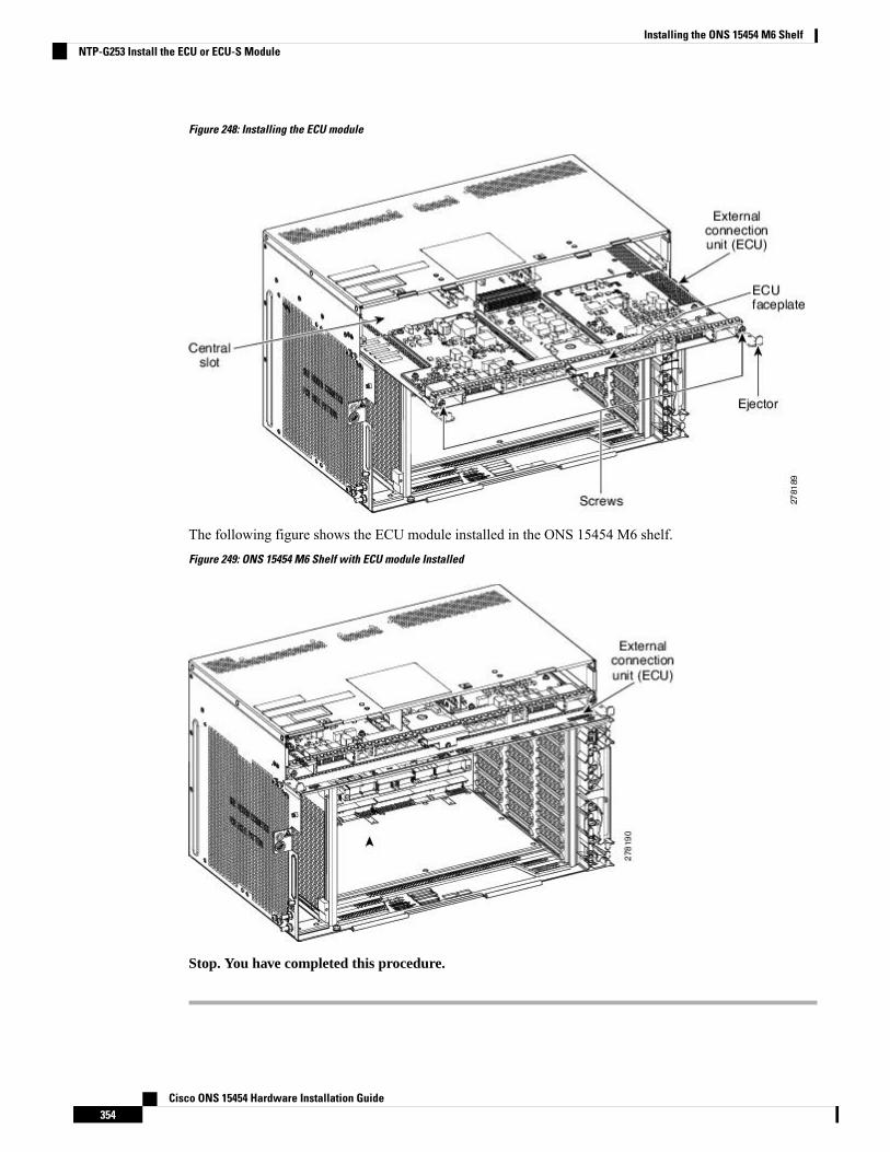
Figure 248: Installing the ECU module
The following figure shows the ECU module installed in the ONS 15454 M6 shelf.
Figure 249: ONS 15454 M6 Shelf with ECU module Installed
Stop. You have completed this procedure.
Cisco ONS 15454 Hardware Installation Guide354
Installing the ONS 15454 M6 ShelfNTP-G253 Install the ECU or ECU-S Module
NTP-L68 Upgrading to ONS 15454 M6 ECU60-S Module
Always use the supplied ESDwristbandwhenworkingwith a poweredONS 15454M6. For detailed instructionson how to wear the ESD wristband, see the Electrostatic Discharge and Grounding Guide for Cisco CPT andCisco ONS Platforms.
Caution
Do not replace the 15454-M6-DC20, or 15454-M6-DC40 power modules with the 15454-M6-DCV03 powermodule if the ONS 15454 M6 shelf is consuming more than 960 W of power. Refer to table A-4 to ascertainthe power consumption of the shelf.
Note
Procedure
Step 1 Power down the ONS 15454 M6 shelf.Step 2 Remove the 15454-M6-DC20 or 15454-M6-DC40 DC power module from the ONS 15454 M6 shelf.Step 3 Install the 15454-M6-DC V03 DC Power Module in the ONS 15454 M6 shelf as described in the DLP-G570
Install the DC Power Module in the ONS 15454 M6 Shelf, on page 363.Step 4 Remove the ECU module (ECU/ECU-2/ECU-S) from the ONS 15454 M6 shelf.Step 5 Install the ECU60-S module in the ONS 15454 M6 shelf as described in the NTP-G253 Install the ECU or
ECU-S Module, on page 352.Step 6 Power on the 15454-M6-DC V03 power module as described in the NTP-G256 Install Power and Ground to
the ONS 15454 M6 Shelf , on page 373
Stop. You have completed this procedure.
Power ModulesThe ONS 15454 M6 system contains pluggable and redundant power modules for AC and DC power. TheAC and DC power modules cannot be used simultaneously to power the ONS 15454 M6 system. Beforeinstalling the power module, verify the position of the mechanical locking system on the rear side of thechassis. To insert the AC power module, the screw must be next to the AC silk-screen text; to insert the DCpower module the screw must be next to the DC silk-screen text.
AC Power ModuleThe ONS 15454 M6 system can be powered by a single AC power module or redundant AC power modules.The supported AC power modules on the ONS 15454 M6 shelf are 15454-M6-AC and 15454-M6-AC2. TheAC power module converts the AC-input current to DC-output current.
Cisco ONS 15454 Hardware Installation Guide355
Installing the ONS 15454 M6 ShelfNTP-L68 Upgrading to ONS 15454 M6 ECU60-S Module
The AC power module supports the lamp test procedure and has fans that are directly powered by the module.The fans cool the module and guarantees proper operation across the complete operating temperature or outputpower range. These fans contain replaceable air-filters.The AC power module draws power from the powerlines to turn on the ONS 15454M6 shelf. See ACPower Specifications, on page 480 for the power specificationsof the AC power modules.
Each AC power module has one AC single-phase 3 poles (line L, Neutral N, and Protective Earth PE) inputconnector.
The AC power module has a dual color (red and green) LED on the faceplate to represent the different statesof the AC power module, which are controlled by the shelf controller card. The different states are:
• LED is OFF. Indicates that the AC power line is not connected.• LED is green. Indicates that the AC power line is functioning correctly.• LED is red. Indicates that the AC power line is connected but there is a failure due to a secondary fusebreak (48 V DC) or failure of the fan in the AC module.
However, the LED states (OFF/red/green) can be overwritten by the shelf controller card (TNC, TNCE, TSC,or TSCE).
For the 15454-M6-AC2 power module, the power consumption of the ONS-15454-M6 shelf (includingancillaries, controller cards, and line cards) is limited to 1200W. If the power consumption of the shelf exceeds1200 W, a new line card, when it is installed in the ONS-15454-M6 shelf, will not boot up. This is indicatedby the PWR-CON-LMT alarm that is raised in the Alarms tab of CTCwhen the installation or pre-provisioningof a card causes the power consumption to exceed the limit of 1200W. The 15454-M6-AC2 has a maximumcapacity of1500 W for 230 Vin and 1200 W for 110 Vin.
Changing the AC Power ModuleIt is possible to change the power modules of the ONS 15454 M6 system, from 15454-M6-AC to15454-M6-AC2, and vice-versa, without powering down the ONS 15454 M6 system. While changing thepower modules, ensure that only one power module is replaced at a time, and the other power module continuesto supply power to the shelf. However, during regular operation of the node, the ONS 15454 M6 shelf musthave either the 15454-M6-AC or 15454-M6-AC2 power module, but not both. See DLP-G757 Replacing15454-M6-ACWith 15454-M6-AC2 Power module, on page 361 and DLP-G758 Replacing 15454-M6-AC2With 15454-M6-AC Power module, on page 362 for changing the power modules.
DC Power ModuleThe ONS 15454 M6 system can be powered by redundant DC power modules or a single DC power module.The supported DC power modules on the ONS 15454 M6 shelf are 15454-M6-DC, 15454-M6-DC20, and15454-M6-DC40.
The DC power module does not support the lamp test procedure.
The DC power module draws power from the batteries to turn on the ONS 15454 M6 shelf. See DC PowerSpecifications, on page 480 for the power specifications of the DC power modules.
Each DC power module has:
• One input battery connector (three poles) —VBAT, VRET, and FGnd for ETSI installation• Terminal block connector with VBAT and VRET for ANSI installation
The DC power module has a dual color (red and green) LED on the faceplate to represent the different statesof the AC power module which are controlled by the shelf controller card. The different states are:
Cisco ONS 15454 Hardware Installation Guide356
Installing the ONS 15454 M6 ShelfChanging the AC Power Module
• LED is off when the battery is not connected• LED turns green when the battery is connected and the power module functions correctly• LED turns red when the battery is connected but there is a failure due to a secondary fuse break (48 VDC) or AC module fan failure.
When the ONS 15454 M6 shelf is powered at –60 VDC (nominal), only the TNC, OPT-AMP-C,OPT-AMP-17-C, OPT-EDFA-17, and OPT-EDFA-24, 17 SMR9 FS, 24 SMR9 FS, 34 SMR9 FS, SMR20FS, SMR20 FS CV, 12-AD-FS, 16-AD-FS, 100GS-CK-LC, andMR-MXP cards, and the 15454-M6-ECU-60can be installed.
Note
The 15454-M6-DC40 power module is required to accommodate up to four 100GS-CK-LC cards in aONS-15454-M6 shelf.
For the 15454-M6-DC20 power module, the power consumption of the ONS-15454-M6 shelf (includingancillaries, controller cards, and line cards) is limited to 960 W. A new line card will not boot up when it isinstalled in the ONS-15454-M6 shelf, if it causes the power consumption of the shelf to exceed 960 W. ThePWR-CON-LMT alarm is raised in the Alarms tab in CTC when the installation or pre-provisioning of a cardcauses the power consumption to exceed the limit of 960 W.
For the 15454-M6-DC40 power module, the power consumption of the ONS-15454-M6 shelf (includingancillaries, controller cards, and line cards) is limited to 1920 W. A new line card will not boot up when it isinstalled in the ONS-15454-M6 shelf, if it causes the power consumption of the shelf to exceed 1920 W. ThePWR-CON-LMT alarm is raised in the Alarms tab in CTC when the installation or pre-provisioning of a cardcauses the power consumption to exceed the limit of 1920 W.
The total power consumption of the shelf is calculated by the controller card and displayed in CTC in theProvisioning > Power Monitor tab. For details about power calculation, see Power Calculation, on page 482.
Note
The terminal lugs used on the DC power modules are included in the accessory kit (53-3318-01) and partnumber of the terminal lug is 32-0603-01 (4 pieces). The accessory kit is placed under the 15454-M-SHIPKIT=PID.
Changing the DC Power ModuleIt is possible to change the power modules without powering down the ONS 15454M6 system.While changingthe power modules, ensure that only one power module is replaced at a time and the other power modulecontinues to supply power to the shelf. However, during regular operation of the node, the ONS 15454 M6shelf must have 15454-M6-DC20 or 15454-M6-DC or 15454-M6-DC40 power module. See DLP-G737Replacing 15454-M6-DC With 15454-M6-DC20 Power Module, on page 366 and DLP-G738 Replacing15454-M6-DC20 With 15454-M6-DC Power Module, on page 368 for changing the power modules.
Power Filler ModuleFor redundant power supplies, two AC or DC power modules can be installed in Slot A and Slot B of theONS 15454 M6 shelf. However, only one power module can sustain the functioning of the entire ONS 15454M6 system. In that case, insert a power filler module in the empty slot.
Cisco ONS 15454 Hardware Installation Guide357
Installing the ONS 15454 M6 ShelfChanging the DC Power Module
NTP-G524 Install the Power Modules in the ONS 15454 M6 ShelfThis procedure installs the power modules in the ONS 15454 M6 system.Purpose
#2 Phillips screwdriverTools/Equipment
• NTP-G252 Install the ONS 15454 M6 Shelf , on page 296.• NTP-G259 Open and Remove the Standard Door of the ONS 15454 M6Shelf , on page 329.
• Connect the chassis to the office ground. For detailed instructions on howto ground the chassis, see the Electrostatic Discharge and Grounding Guidefor Cisco CPT and Cisco ONS Platforms.
Prerequisite Procedures
RequiredRequired/As Needed
OnsiteOnsite/Remote
NoneSecurity Level
The plug-socket combination must be accessible at all times because it serves as the main disconnectingdevice. Statement 1019
Warning
Procedure
Step 1 Complete the necessary task as applicable:
• DLP-G569 Install the AC Power Module in the ONS 15454 M6 Shelf, on page 358
• DLP-G757 Replacing 15454-M6-AC With 15454-M6-AC2 Power module, on page 361
• DLP-G758 Replacing 15454-M6-AC2 With 15454-M6-AC Power module, on page 362
• DLP-G570 Install the DC Power Module in the ONS 15454 M6 Shelf, on page 363
• DLP-G737 Replacing 15454-M6-DC With 15454-M6-DC20 Power Module, on page 366
• DLP-G738 Replacing 15454-M6-DC20 With 15454-M6-DC Power Module, on page 368
Step 2 Complete the NTP-G256 Install Power and Ground to the ONS 15454 M6 Shelf , on page 373.
Stop. You have completed this procedure.
DLP-G569 Install the AC Power Module in the ONS 15454 M6 ShelfThis task installs the 15454-M6-AC or 15454-M6-AC2 power module in the ONS15454 M6 system.
Purpose
Cisco ONS 15454 Hardware Installation Guide358
Installing the ONS 15454 M6 ShelfNTP-G524 Install the Power Modules in the ONS 15454 M6 Shelf
#2 Phillips screwdriverTools/Equipment
• NTP-G252 Install the ONS 15454 M6 Shelf , on page 296.• NTP-G259 Open and Remove the Standard Door of the ONS 15454 M6Shelf , on page 329.
• Connect the chassis to the office ground. For detailed instructions on howto ground the chassis, see the Electrostatic Discharge and Grounding Guidefor Cisco CPT and Cisco ONS Platforms.
Prerequisite Procedures
RequiredRequired/As Needed
OnsiteOnsite/Remote
NoneSecurity Level
The node can temporarily work with both 15454-M6-AC and 15454-M6-AC2 power module units installedon the ONS 15454M6 shelf. However, during regular operation, the shelf must have either the 15454-M6-ACor 15454-M6-AC2 power module, but not both.
Caution
Insert the AC power module in Slot A or Slot B, or both (see the following figure).Tip
While inserting the AC power module, apply insertion force only above the hook and not on the air filter (seethe following figure).
Note
Cisco ONS 15454 Hardware Installation Guide359
Installing the ONS 15454 M6 ShelfDLP-G569 Install the AC Power Module in the ONS 15454 M6 Shelf
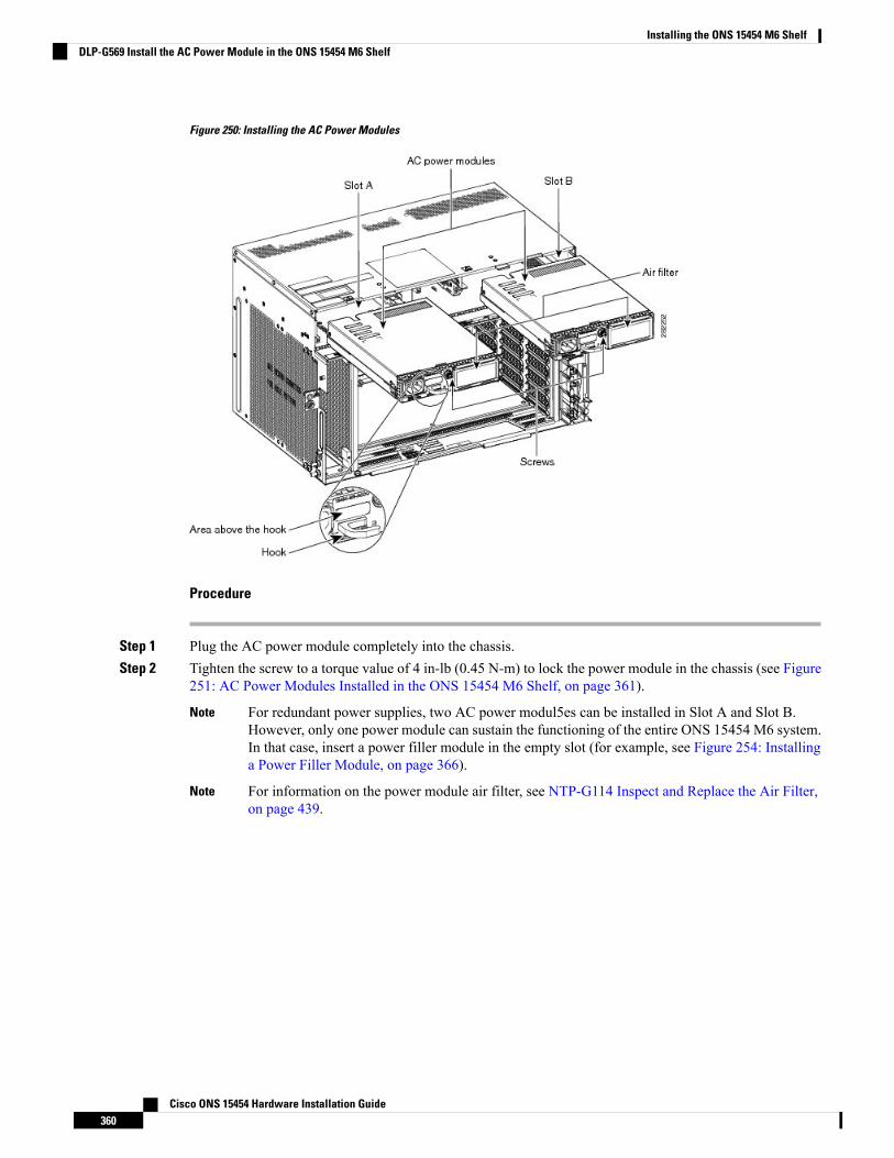
Figure 250: Installing the AC Power Modules
Procedure
Step 1 Plug the AC power module completely into the chassis.Step 2 Tighten the screw to a torque value of 4 in-lb (0.45 N-m) to lock the power module in the chassis (see Figure
251: AC Power Modules Installed in the ONS 15454 M6 Shelf, on page 361).
For redundant power supplies, two AC power modul5es can be installed in Slot A and Slot B.However, only one power module can sustain the functioning of the entire ONS 15454 M6 system.In that case, insert a power filler module in the empty slot (for example, see Figure 254: Installinga Power Filler Module, on page 366).
Note
For information on the power module air filter, see NTP-G114 Inspect and Replace the Air Filter,on page 439.
Note
Cisco ONS 15454 Hardware Installation Guide360
Installing the ONS 15454 M6 ShelfDLP-G569 Install the AC Power Module in the ONS 15454 M6 Shelf
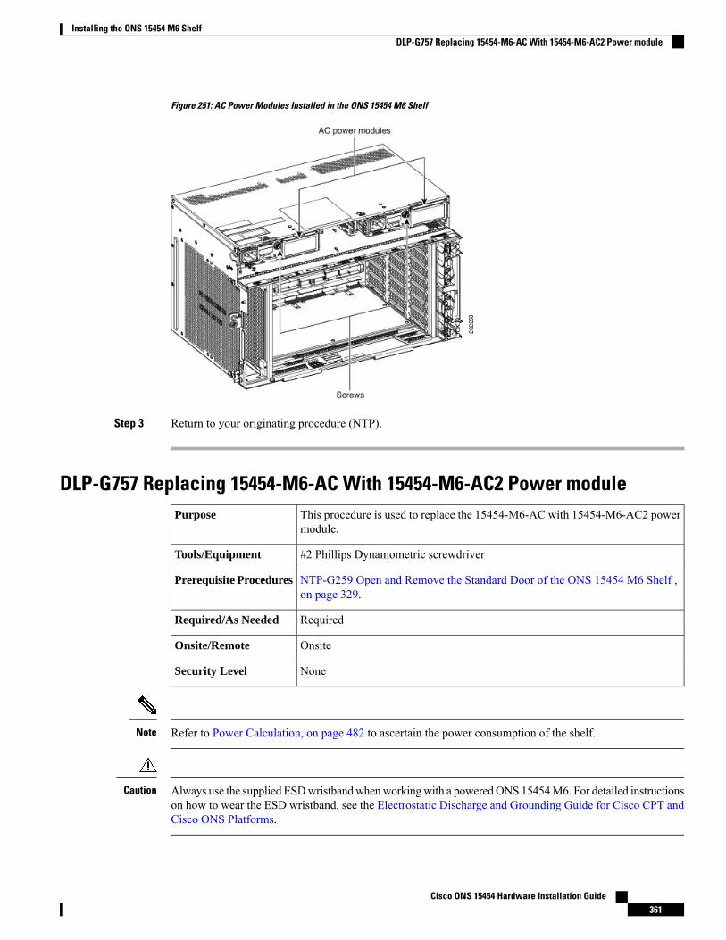
Figure 251: AC Power Modules Installed in the ONS 15454 M6 Shelf
Step 3 Return to your originating procedure (NTP).
DLP-G757 Replacing 15454-M6-AC With 15454-M6-AC2 Power moduleThis procedure is used to replace the 15454-M6-AC with 15454-M6-AC2 powermodule.
Purpose
#2 Phillips Dynamometric screwdriverTools/Equipment
NTP-G259 Open and Remove the Standard Door of the ONS 15454 M6 Shelf ,on page 329.
Prerequisite Procedures
RequiredRequired/As Needed
OnsiteOnsite/Remote
NoneSecurity Level
Refer to Power Calculation, on page 482 to ascertain the power consumption of the shelf.Note
Always use the supplied ESDwristbandwhenworkingwith a poweredONS 15454M6. For detailed instructionson how to wear the ESD wristband, see the Electrostatic Discharge and Grounding Guide for Cisco CPT andCisco ONS Platforms.
Caution
Cisco ONS 15454 Hardware Installation Guide361
Installing the ONS 15454 M6 ShelfDLP-G757 Replacing 15454-M6-AC With 15454-M6-AC2 Power module
Procedure
Step 1 Disconnect the power source and remove the power connections from the B-side power module (installed inslot B).
Step 2 Unscrew the holding screw that secures the 15454-M6-AC power module.Step 3 Pull the 15454-M6-AC power module away from the ONS 15454 M6 chassis.Step 4 Install the 15454-M6-AC2 power module as described in the DLP-G569 Install the AC Power Module in the
ONS 15454 M6 Shelf, on page 358.Step 5 Install power on the 15454-M6-AC2 power module as described in the NTP-G256 Install Power and Ground
to the ONS 15454 M6 Shelf , on page 373.
While replacing power modules, when the ONS 15454 M6 chassis is in the mixed power mode(with both 15454-M6-AC and 15454-M6-AC2 power modules installed), do not provision or installany line cards. Card provisioning and installation must be done only after both the slots have thesame type of power modules.
Note
Step 6 Perform Steps 1 to 5 for the other power module (installed in slot A).
To ensure that the controller card calculates the shelf power consumption correctly, reset the controllercard. For details about performing card reset, see the “NTP-G106 Resetting Cards Using CTC”procedure in the Cisco ONS 15454 DWDM Network Configuration Guide.
Note
Return to your originating procedure (NTP).
DLP-G758 Replacing 15454-M6-AC2 With 15454-M6-AC Power moduleThis procedure is used to replace the 15454-M6-AC2 with 15454-M6-AC powermodule.
Purpose
#2 Phillips Dynamometric screwdriverTools/Equipment
NTP-G259 Open and Remove the Standard Door of the ONS 15454 M6 Shelf ,on page 329.
Prerequisite Procedures
RequiredRequired/As Needed
OnsiteOnsite/Remote
NoneSecurity Level
When mixed power modules are present, if the power consumption is more than 900W, identify and plug outthe line cards so that Total power consumption is less than or equal to 900W.
Caution
Cisco ONS 15454 Hardware Installation Guide362
Installing the ONS 15454 M6 ShelfDLP-G758 Replacing 15454-M6-AC2 With 15454-M6-AC Power module
Always use the supplied ESDwristbandwhenworkingwith a poweredONS 15454M6. For detailed instructionson how to wear the ESD wristband, see the Electrostatic Discharge and Grounding Guide for Cisco CPT andCisco ONS Platforms.
Caution
Procedure
Step 1 Disconnect the power source and remove the power connections from the B-side power module (installed inslot B).
Step 2 Unscrew the holding screw that secures the 15454-M6-AC2 power module.Step 3 Pull the 15454-M6-AC2 power module clear from the ONS 15454 M6 chassis.Step 4 Install the 15454-M6-AC power module as described in the DLP-G569 Install the AC Power Module in the
ONS 15454 M6 Shelf, on page 358.Step 5 Install power on the 15454-M6-AC power module as described in the NTP-G256 Install Power and Ground
to the ONS 15454 M6 Shelf , on page 373.
While replacing the power modules, do not provision or install any line cards when the ONS 15454M6 chassis is in the mixed power mode (with both 15454-M6-AC and 15454-M6-AC2 powermodules installed). Card provisioning and installation must be done only after both the slots havethe same type of power modules.
Note
Step 6 Perform steps 1 to 5 for the other power module (installed in slot A).Step 7 Return to your originating procedure (NTP).
DLP-G570 Install the DC Power Module in the ONS 15454 M6 ShelfThis procedure installs the 15454-M6-DC, 15454-M6-DC20, or 15454-M6-DC40DC power module in the ONS 15454 M6 system.
Purpose
#2 Phillips Dynamometric screwdriverTools/Equipment
• NTP-G252 Install the ONS 15454 M6 Shelf , on page 296.• NTP-G259 Open and Remove the Standard Door of the ONS 15454 M6Shelf , on page 329.
• Connect the chassis to the office ground. For detailed instructions on howto ground the chassis, see the Electrostatic Discharge and Grounding Guidefor Cisco CPT and Cisco ONS Platforms.
Prerequisite Procedures
RequiredRequired/As Needed
OnsiteOnsite/Remote
NoneSecurity Level
Cisco ONS 15454 Hardware Installation Guide363
Installing the ONS 15454 M6 ShelfDLP-G570 Install the DC Power Module in the ONS 15454 M6 Shelf
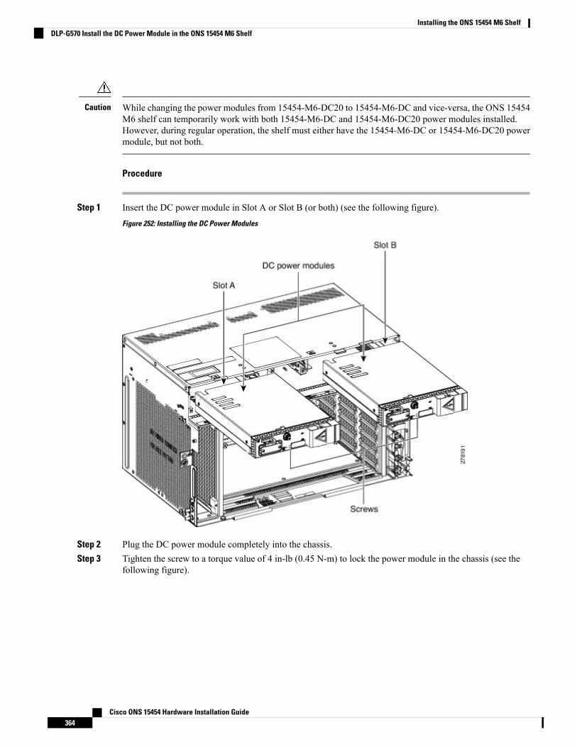
While changing the power modules from 15454-M6-DC20 to 15454-M6-DC and vice-versa, the ONS 15454M6 shelf can temporarily work with both 15454-M6-DC and 15454-M6-DC20 power modules installed.However, during regular operation, the shelf must either have the 15454-M6-DC or 15454-M6-DC20 powermodule, but not both.
Caution
Procedure
Step 1 Insert the DC power module in Slot A or Slot B (or both) (see the following figure).
Figure 252: Installing the DC Power Modules
Step 2 Plug the DC power module completely into the chassis.Step 3 Tighten the screw to a torque value of 4 in-lb (0.45 N-m) to lock the power module in the chassis (see the
following figure).
Cisco ONS 15454 Hardware Installation Guide364
Installing the ONS 15454 M6 ShelfDLP-G570 Install the DC Power Module in the ONS 15454 M6 Shelf
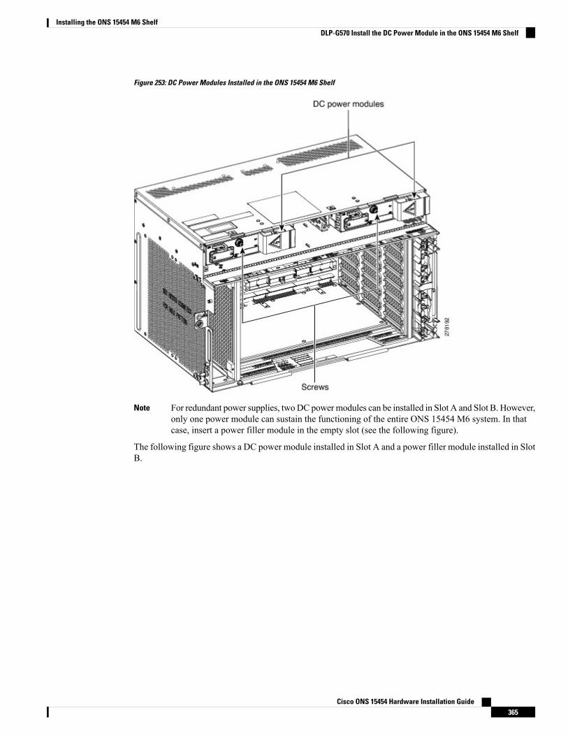
Figure 253: DC Power Modules Installed in the ONS 15454 M6 Shelf
For redundant power supplies, twoDC powermodules can be installed in Slot A and Slot B. However,only one power module can sustain the functioning of the entire ONS 15454 M6 system. In thatcase, insert a power filler module in the empty slot (see the following figure).
Note
The following figure shows a DC power module installed in Slot A and a power filler module installed in SlotB.
Cisco ONS 15454 Hardware Installation Guide365
Installing the ONS 15454 M6 ShelfDLP-G570 Install the DC Power Module in the ONS 15454 M6 Shelf
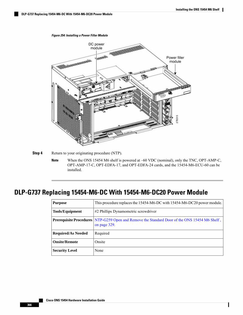
Figure 254: Installing a Power Filler Module
Step 4 Return to your originating procedure (NTP).
When the ONS 15454 M6 shelf is powered at –60 VDC (nominal), only the TNC, OPT-AMP-C,OPT-AMP-17-C, OPT-EDFA-17, and OPT-EDFA-24 cards, and the 15454-M6-ECU-60 can beinstalled.
Note
DLP-G737 Replacing 15454-M6-DC With 15454-M6-DC20 Power ModuleThis procedure replaces the 15454-M6-DCwith 15454-M6-DC20 power module.Purpose
#2 Phillips Dynamometric screwdriverTools/Equipment
NTP-G259 Open and Remove the Standard Door of the ONS 15454 M6 Shelf ,on page 329.
Prerequisite Procedures
RequiredRequired/As Needed
OnsiteOnsite/Remote
NoneSecurity Level
Cisco ONS 15454 Hardware Installation Guide366
Installing the ONS 15454 M6 ShelfDLP-G737 Replacing 15454-M6-DC With 15454-M6-DC20 Power Module
The procedure to replace the 15454-M6-DC power module with 15454-M6-DC40 power module is the sameas this procedure. The 15454-M6-DC40 power module uses 15454-M6-DCCBL2-L= and15454-M6-DCCBL2-R= cables.
Note
Do not replace the 15454-M6-DC with the 15454-M6-DC20 power module if the ONS 15454 M6 shelf isconsuming more than 960 W of power. Refer to Power Calculation, on page 482 to ascertain the powerconsumption of the shelf.
Note
While changing the power modules from 15454-M6-DC20 to 15454-M6-DC and vice-versa, the ONS 15454M6 shelf can temporarily work with both 15454-M6-DC and 15454-M6-DC20 power modules installed.However, during regular operation, the shelf must either have the 15454-M6-DC or 15454-M6-DC20 powermodule, but not both.
Caution
Always use the supplied ESDwristbandwhenworkingwith a poweredONS 15454M6. For detailed instructionson how to wear the ESD wristband, see the Electrostatic Discharge and Grounding Guide for Cisco CPT andCisco ONS Platforms .
Caution
Procedure
Step 1 Disconnect the power source opening the breaker on top of the standby power module (installed in slot B).Step 2 Unscrew the holding screw that secures the 15454-M6-DC power module.Step 3 Pull the 15454-M6-DC power module clear from the ONS 15454 M6 chassis.Step 4 Remove the power connections from the standby power module.Step 5 Install power on the 15454-M6-DC power module as described in the NTP-G256 Install Power and Ground
to the ONS 15454 M6 Shelf , on page 373.
While replacing the power modules, do not provision or install any line cards when the ONS 15454M6 chassis is in the mixed power mode. Card provisioning and installation must be done only afterboth the slots have the same type of power modules.
Note
Step 6 Install the 15454-M6-DC power module as described in the DLP-G570 Install the DC Power Module in theONS 15454 M6 Shelf, on page 363.
Step 7 Connect the power source closing the breaker on top of the standby power module (installed in slot B).Step 8 Perform the Step 1 to Step 7 for the active power module (installed in slot A) procedure.
To ensure that the controller card is calculating the shelf power consumption correctly, reset thecontroller card. For details about performing card reset, see the “NTP-G106 Reset Cards UsingCTC” procedure in the Cisco ONS 15454 DWDM Configuration Guide.If the power consumptionof the shelf is exceeding 960 W, the PWR-CON-LMT alarm is raised. Either revert to the15454-M6-DC power module or remove and deprovsion the existing line cards to reduce the load.
Note
Cisco ONS 15454 Hardware Installation Guide367
Installing the ONS 15454 M6 ShelfDLP-G737 Replacing 15454-M6-DC With 15454-M6-DC20 Power Module
Step 9 Return to your originating procedure (NTP).
DLP-G738 Replacing 15454-M6-DC20 With 15454-M6-DC Power ModuleThis procedure replaces the 15454-M6-DC20with 15454-M6-DC power module.Purpose
#2 Phillips Dynamometric screwdriverTools/Equipment
NTP-G259 Open and Remove the Standard Door of the ONS 15454 M6 Shelf ,on page 329.
Prerequisite Procedures
RequiredRequired/As Needed
OnsiteOnsite/Remote
NoneSecurity Level
The procedure to replace the 15454-M6-DC20 power module with 15454-M6-DC40 power module is thesame as this procedure. The 15454-M6-DC40 power module uses 15454-M6-DCCBL2-L= and15454-M6-DCCBL2-R= cables.
Note
While changing the power modules from 15454-M6-DC20 to 15454-M6-DC and vice-versa, the ONS 15454M6 shelf can temporarily work with both 15454-M6-DC and 15454-M6-DC20 power modules installed.However, during regular operation, the shelf must either have the 15454-M6-DC or 15454-M6-DC20 powermodule, but not both.
Caution
Always use the supplied ESDwristbandwhenworkingwith a poweredONS 15454M6. For detailed instructionson how to wear the ESD wristband, see the Electrostatic Discharge and Grounding Guide for Cisco CPT andCisco ONS Platforms .
Caution
Procedure
Step 1 Disconnect the power source and remove the power connections from the standby power module (installedin slot B).
Step 2 Unscrew the holding screw that secures the 15454-M6-DC20 power module.Step 3 Pull the 15454-M6-DC20 power module clear from the ONS 15454 M6 chassis.Step 4 Install the 15454-M6-DC power module as described in the DLP-G570 Install the DC Power Module in the
ONS 15454 M6 Shelf, on page 363.Step 5 Install power on the 15454-M6-DC power module as described in the NTP-G256 Install Power and Ground
to the ONS 15454 M6 Shelf , on page 373.
Cisco ONS 15454 Hardware Installation Guide368
Installing the ONS 15454 M6 ShelfDLP-G738 Replacing 15454-M6-DC20 With 15454-M6-DC Power Module
While replacing the power modules, do not provision or install any line cards when the ONS 15454M6 chassis is in the mixed power mode. Card provisioning and installation must be done only afterboth the slots have the same type of power modules.
Note
Step 6 Perform steps 1 to 5 for the active power module (installed in slot A).Step 7 Return to your originating procedure (NTP).
LCD UnitThe LCD unit consists of an LCD display panel, push button, and shelf-level LED indicators on the ONS15454M6 system. A backup flash memory is fitted into the LCD unit to support the database (DB) and imagebackup in the operation of the ONS 15454 M6.
The shelf controller card (TSC, TSCE, TNC, or TNCE) powers the 16 x 2 character LCD screen. The LCDscreen displays the shelf name, shelf IP address, and software version currently used. The LCD screen alsoprovides slot-level and port-level information of all card slots, including the number of critical, major, andminor alarms. The display contrast is automatically adjusted for a clearer view. The three accessible pushbuttons (SLOT, STATUS, and PORT) on the LCD unit are used to set parameters at the slot-level and port-level.There are three alarm LEDs (CRIT, MAJ, and MIN) on the LCD unit that indicate whether a critical, major,or minor alarm is present anywhere on the ONS 15454 M6 shelf. The shelf controller card controls theconditions that result in triggering the LEDs. The LEDs can be overwritten by the shelf controller card (TNC,TNCE, TSC, or TSCE) in all the three states (OFF/red/green). The LCD unit supports the lamp test procedureand the LEDs changes its color or state.
If the LCD unit is removed from the shelf, wait for at least 5 seconds before plugging it back into the shelf.In the event the LCD display appears blank, remove the unit from the shelf, wait for at least 5 seconds andreinsert the unit into the shelf.
Note
The LCD module must be present in the ONS 15454 M6 shelf to:
• Provision the ECU module, fan-tray assembly, or power modules.• Retrieve alarms from the ECU module, fan-tray assembly, or power modules.
NTP-G255 Install the LCD Module in the ONS 15454 M6 ShelfThis procedure installs the LCD module in the ONS 15454 M6 system.Purpose
Small slot-head screwdriverTools/Equipment
• NTP-G252 Install the ONS 15454 M6 Shelf , on page 296.• NTP-G259 Open and Remove the Standard Door of the ONS 15454 M6Shelf , on page 329.
• Connect the chassis to the office ground. For detailed instructions on howto ground the chassis, see the Electrostatic Discharge and Grounding Guidefor Cisco CPT and Cisco ONS Platforms .
Prerequisite Procedures
Cisco ONS 15454 Hardware Installation Guide369
Installing the ONS 15454 M6 ShelfLCD Unit
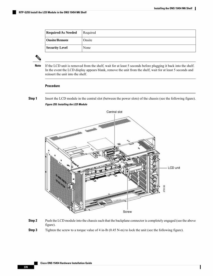
RequiredRequired/As Needed
OnsiteOnsite/Remote
NoneSecurity Level
If the LCD unit is removed from the shelf, wait for at least 5 seconds before plugging it back into the shelf.In the event the LCD display appears blank, remove the unit from the shelf, wait for at least 5 seconds andreinsert the unit into the shelf.
Note
Procedure
Step 1 Insert the LCD module in the central slot (between the power slots) of the chassis (see the following figure).
Figure 255: Installing the LCD Module
Step 2 Push the LCDmodule into the chassis such that the backplane connector is completely engaged (see the abovefigure).
Step 3 Tighten the screw to a torque value of 4 in-lb (0.45 N-m) to lock the unit (see the following figure).
Cisco ONS 15454 Hardware Installation Guide370
Installing the ONS 15454 M6 ShelfNTP-G255 Install the LCD Module in the ONS 15454 M6 Shelf

Figure 256: LCD Module Installed in the ONS 15454 M6 Shelf
Stop. You have completed this procedure.
Power and Ground DescriptionGround the equipment according to Telcordia standards or local practices. The following sections describepower and ground for the ONS 15454 M6 shelves.
For detailed instructions on grounding the ONS 15454 M6 chassis, see the Electrostatic Discharge andGrounding Guide for Cisco CPT and Cisco ONS Platforms.
Note
ANSI Power and GroundThe ONS 15454 M6 has redundant AC and DC power modules.
For redundant AC power feeds, install both the AC power modules and use the two power cables (right andleft cables) shipped with the ONS 15454 M6 and one ground cable. For an AC power supply, the fuse ratingmust not exceed 10A, 15A, or 20A. For North America, the branch circuit protection must be rated 20A. Theovercurrent/short circuit protection must be in accordance with local and national electrical codes. The voltage
Cisco ONS 15454 Hardware Installation Guide371
Installing the ONS 15454 M6 ShelfPower and Ground Description
rating value for AC power ranges between 100 VAC to 240 VAC depending on the standards in variouscountries. This product is intended for use on the TN and TT power systems.
For redundant DC power feeds, install both the DC power modules and use four power cables and one groundcable. For a single power feed, only two power cables (#8 AWG or larger, copper conductor, 194 degrees F[90 degrees C] minimum) and one ground cable (#6 AWG or larger) are required. Use a conductor with lowimpedance to ensure circuit overcurrent protection. However, the conductor must have the capability to safelyconduct any faulty current that might be imposed. For a a DC power supply, the fuse rating must not exceed40A. For operating voltages, see DC Power Specifications, on page 480.
The DC power modules have –48 VDC or –60 VDC #8 dual-hole lug power terminals for ANSI. The terminalsare labeled RET and –48 V or –60 V on the DC power modules.
When the ONS 15454 M6 shelf is powered at –60 VDC (nominal), only the TNC, OPT-AMP-C,OPT-AMP-17-C, OPT-EDFA-17, and OPT-EDFA-24 cards, and the 15454-M6-ECU-60 can be installed.
Note
We recommend the following wiring conventions, but customer conventions prevail:
• Red wire for battery connections (–48 VDC or –60 VDC).• Black wire for battery return connections (RET).• The battery return connection is treated as DC-I, as defined in Telcordia GR-1089-CORE, Issue 3.
The ground lug must be a dual-hole type, UL Listed, CSA certified and rated to accept the #6 AWG cable.Two ground posts with two M5 nuts are provided on the ONS 15454 M6 to accommodate the dual-hole lug.
Only use the power cables shipped with the ONS 15454 M6 shelf.Note
ETSI Power and GroundThe ONS 15454 M6 for ETSI has –48 VDC or –60 VDC power connectors (DSUB for DC power module)on the DC power module. For redundant DC power feeds, install both the DC power modules and use the twopower cables shipped with the ONS 15454 M6 and one ground cable. For a DC power supply, the fuse ratingmust not exceed 40A. For operating voltages, see DC Power Specifications, on page 480.
For redundant AC power feeds, install both the AC power modules and use the two power cables (right andleft cables) shipped with the ONS 15454 M6 and one ground cable. For an AC power supply, the fuse ratingmust not exceed 10A, 15A, or 20A. For North America, the branch circuit protection must be rated 20A. Theovercurrent/short circuit protection must be in accordance with local and national electrical codes. The voltagerating value for AC power ranges between 100 VAC to 240 VAC depending on the standards in variouscountries. This product is intended for use on the TN and TT power systems.
Only use the power cables shipped with the ONS 15454 M6 shelf.Caution
Cisco ONS 15454 Hardware Installation Guide372
Installing the ONS 15454 M6 ShelfETSI Power and Ground

NTP-G256 Install Power and Ground to the ONS 15454 M6 ShelfThis procedure installs power feeds and grounds the ONS 15454 M6 system.Purpose
ANSI and ETSI:
• #2 Phillips Dynamometric screwdriver• Medium slot-head screwdriver• Small slot-head screwdriver• Screws• Ground cable 13.3-mm² (#6 AWG) stranded• Listed pressure dual-holes lugs suitable for #8 AWG copper conductors• Wire cutters• Wire strippers• Crimp tool• Fuse panel
ANSI only:
• Power cable (from fuse and alarm panel to assembly), #8 AWG, copperconductors, 194 degrees F [90 degrees C])
• Wire wrapper
ETSI only:
• Power cable (from fuse panel to power modules), shipped with the ONS15454 M6
• Two-hole grounding lug, shipped with the ONS 15454 M6
Tools/Equipment
• NTP-G524 Install the Power Modules in the ONS 15454M6 Shelf , on page358.
• Connect the chassis to the office ground. For detailed instructions on howto ground the chassis, see the Electrostatic Discharge and Grounding Guidefor Cisco CPT and Cisco ONS Platforms.
Prerequisite Procedures
RequiredRequired/As Needed
OnsiteOnsite/Remote
NoneSecurity Level
To ensure safety of personnel and equipment, do not connect any power cables into the power moduleuntil the module is completely installed into the chassis. Statement 389
Warning
To reduce the risk of electric shock, switch on the power only after the power cord is completely installedinto the power module. Statement 390
Warning
Cisco ONS 15454 Hardware Installation Guide373
Installing the ONS 15454 M6 ShelfNTP-G256 Install Power and Ground to the ONS 15454 M6 Shelf
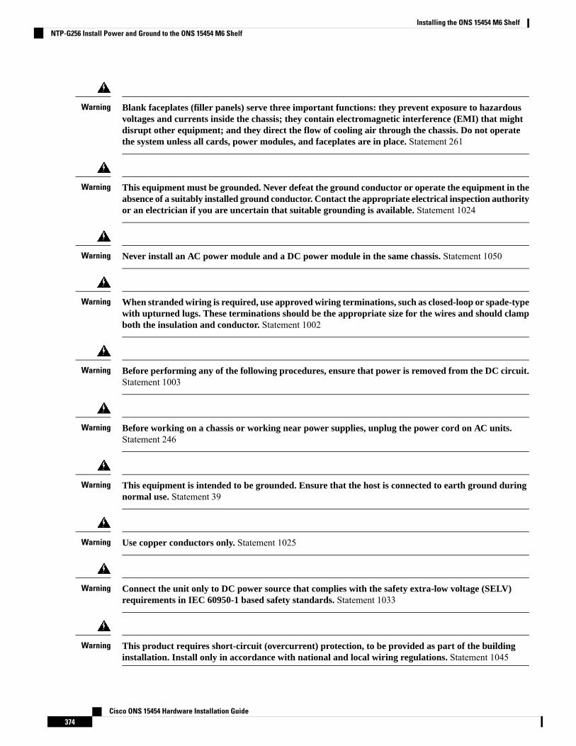
Blank faceplates (filler panels) serve three important functions: they prevent exposure to hazardousvoltages and currents inside the chassis; they contain electromagnetic interference (EMI) that mightdisrupt other equipment; and they direct the flow of cooling air through the chassis. Do not operatethe system unless all cards, power modules, and faceplates are in place. Statement 261
Warning
This equipment must be grounded. Never defeat the ground conductor or operate the equipment in theabsence of a suitably installed ground conductor. Contact the appropriate electrical inspection authorityor an electrician if you are uncertain that suitable grounding is available. Statement 1024
Warning
Never install an AC power module and a DC power module in the same chassis. Statement 1050Warning
When stranded wiring is required, use approved wiring terminations, such as closed-loop or spade-typewith upturned lugs. These terminations should be the appropriate size for the wires and should clampboth the insulation and conductor. Statement 1002
Warning
Before performing any of the following procedures, ensure that power is removed from the DC circuit.Statement 1003
Warning
Before working on a chassis or working near power supplies, unplug the power cord on AC units.Statement 246
Warning
This equipment is intended to be grounded. Ensure that the host is connected to earth ground duringnormal use. Statement 39
Warning
Use copper conductors only. Statement 1025Warning
Connect the unit only to DC power source that complies with the safety extra-low voltage (SELV)requirements in IEC 60950-1 based safety standards. Statement 1033
Warning
This product requires short-circuit (overcurrent) protection, to be provided as part of the buildinginstallation. Install only in accordance with national and local wiring regulations. Statement 1045
Warning
Cisco ONS 15454 Hardware Installation Guide374
Installing the ONS 15454 M6 ShelfNTP-G256 Install Power and Ground to the ONS 15454 M6 Shelf
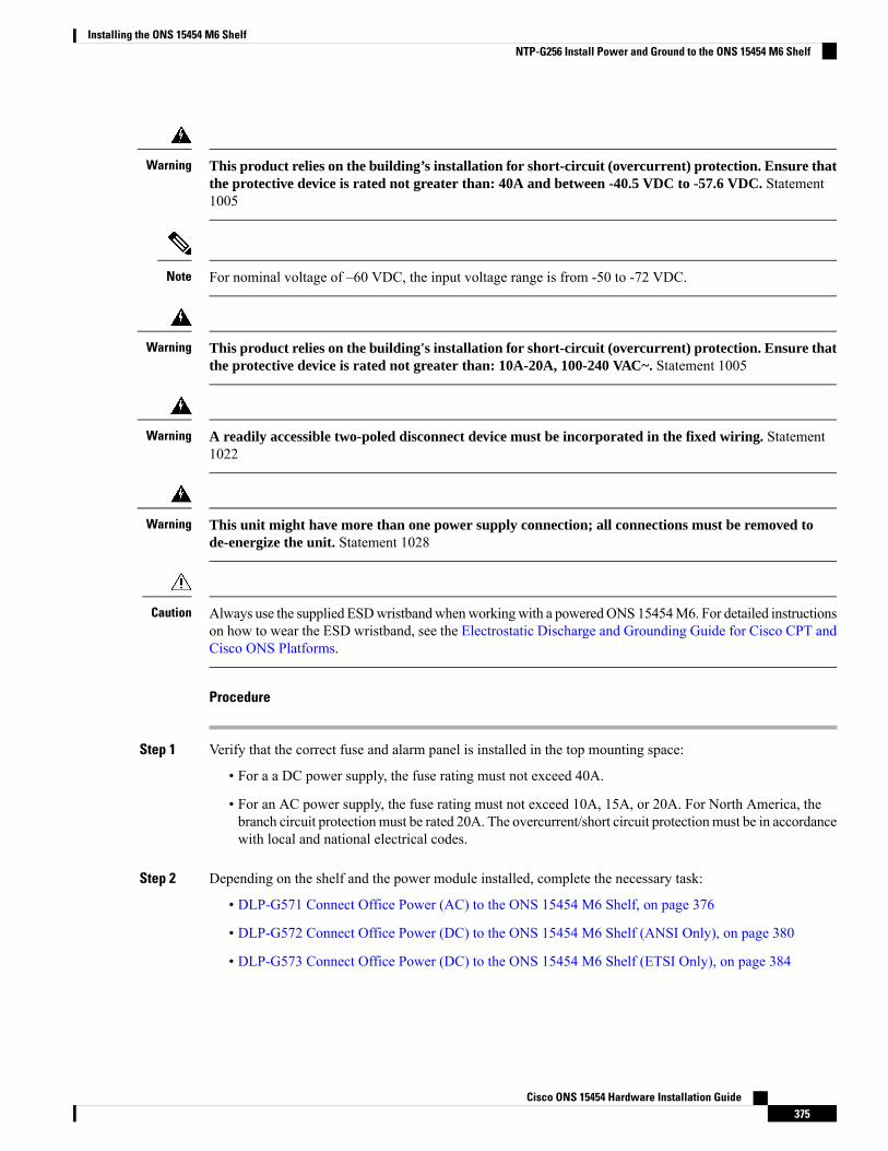
This product relies on the building’s installation for short-circuit (overcurrent) protection. Ensure thatthe protective device is rated not greater than: 40A and between -40.5 VDC to -57.6 VDC. Statement1005
Warning
For nominal voltage of –60 VDC, the input voltage range is from -50 to -72 VDC.Note
This product relies on the building's installation for short-circuit (overcurrent) protection. Ensure thatthe protective device is rated not greater than: 10A-20A, 100-240 VAC~. Statement 1005
Warning
A readily accessible two-poled disconnect device must be incorporated in the fixed wiring. Statement1022
Warning
This unit might have more than one power supply connection; all connections must be removed tode-energize the unit. Statement 1028
Warning
Always use the supplied ESDwristbandwhenworkingwith a poweredONS 15454M6. For detailed instructionson how to wear the ESD wristband, see the Electrostatic Discharge and Grounding Guide for Cisco CPT andCisco ONS Platforms.
Caution
Procedure
Step 1 Verify that the correct fuse and alarm panel is installed in the top mounting space:
• For a a DC power supply, the fuse rating must not exceed 40A.
• For an AC power supply, the fuse rating must not exceed 10A, 15A, or 20A. For North America, thebranch circuit protectionmust be rated 20A. The overcurrent/short circuit protectionmust be in accordancewith local and national electrical codes.
Step 2 Depending on the shelf and the power module installed, complete the necessary task:
• DLP-G571 Connect Office Power (AC) to the ONS 15454 M6 Shelf, on page 376
• DLP-G572 Connect Office Power (DC) to the ONS 15454 M6 Shelf (ANSI Only), on page 380
• DLP-G573 Connect Office Power (DC) to the ONS 15454 M6 Shelf (ETSI Only), on page 384
Cisco ONS 15454 Hardware Installation Guide375
Installing the ONS 15454 M6 ShelfNTP-G256 Install Power and Ground to the ONS 15454 M6 Shelf
Step 3 Connect the office ground to the ONS 15454 M6 shelf. For detailed instructions on grounding, see theElectrostatic Discharge and Grounding Guide for Cisco CPT and Cisco ONS Platforms.
Step 4 Complete the DLP-G575 Turn On and Verify DC Office Power on the ONS 15454 M6 Shelf, on page 389Step 5 Continue with the NTP-G257 Install the Fan-Tray Assembly in the ONS 15454 M6 Shelf, on page 391.
Stop. You have completed this procedure.
DLP-G571 Connect Office Power (AC) to the ONS 15454 M6 ShelfThis task connects AC power to the ONS 15454 M6 shelf.Purpose
• #2 Phillips Dynamometric screwdriver• Medium slot-head screwdriver• Small slot-head screwdriver• Wire wrapper• Wire cutters• Wire strippers• Crimp tool• Fuse panel• Ground cable 13.3-mm² (#6 AWG) stranded. The PIDs of the power cablesare listed in Table 33: PIDs for AC Power Cables, on page 379.
Tools/Equipment
• NTP-G252 Install the ONS 15454 M6 Shelf , on page 296.• NTP-G259 Open and Remove the Standard Door of the ONS 15454 M6Shelf , on page 329.
• Connect the chassis to the office ground. For detailed instructions on howto ground the chassis, see the Electrostatic Discharge and Grounding Guidefor Cisco CPT and Cisco ONS Platforms.
• NTP-G524 Install the Power Modules in the ONS 15454M6 Shelf , on page358.
Prerequisite Procedures
RequiredRequired/As Needed
OnsiteOnsite/Remote
NoneSecurity Level
This product is intended for use on the TN and TT power systems.Note
When installing or replacing the unit, the ground connection must always be made first and disconnectedlast. Statement 1046
Warning
Cisco ONS 15454 Hardware Installation Guide376
Installing the ONS 15454 M6 ShelfDLP-G571 Connect Office Power (AC) to the ONS 15454 M6 Shelf
This equipment shall be connected to AC mains provided with a surge protective device (SPD) at theservice equipment complying with NFPA 70, the National Electrical Code (NEC). Statement 7012
Warning
The ONS 15454M6 relies on the protective devices in the building installation to protect against short circuit,overcurrent and ground faults. Ensure that the protective devices are properly rated and comply with nationaland local codes.
Caution
Not more than 7 feet (2 m) of the power supply cable should be exposed between the equipment and the fiberstorage tray.
Note
When terminating the frame ground, do not use soldering lug connectors, screwless (push-in) connectors,quick connect connectors, or other friction-fit connectors.
Caution
If the system loses power or if both the TNC, TNCE, TSC, or TSCE cards are reset, you must reset the ONS15454 M6 clock. After powering down, the date defaults to January 1, 1970, 00:04:15. To reset the clock, seethe “NTP-G24 Setting Up Node Identification Information” procedure in the Cisco ONS 15454 DWDMControl Card and Node Configuration Guide.
Note
Procedure
Step 1 Verify that the AC power module is installed in Slot A or Slot B (or both) of the ONS 15454 M6.Step 2 Attach the AC power cable to the cable connector in the AC power module (see the following figure).
Cisco ONS 15454 Hardware Installation Guide377
Installing the ONS 15454 M6 ShelfDLP-G571 Connect Office Power (AC) to the ONS 15454 M6 Shelf
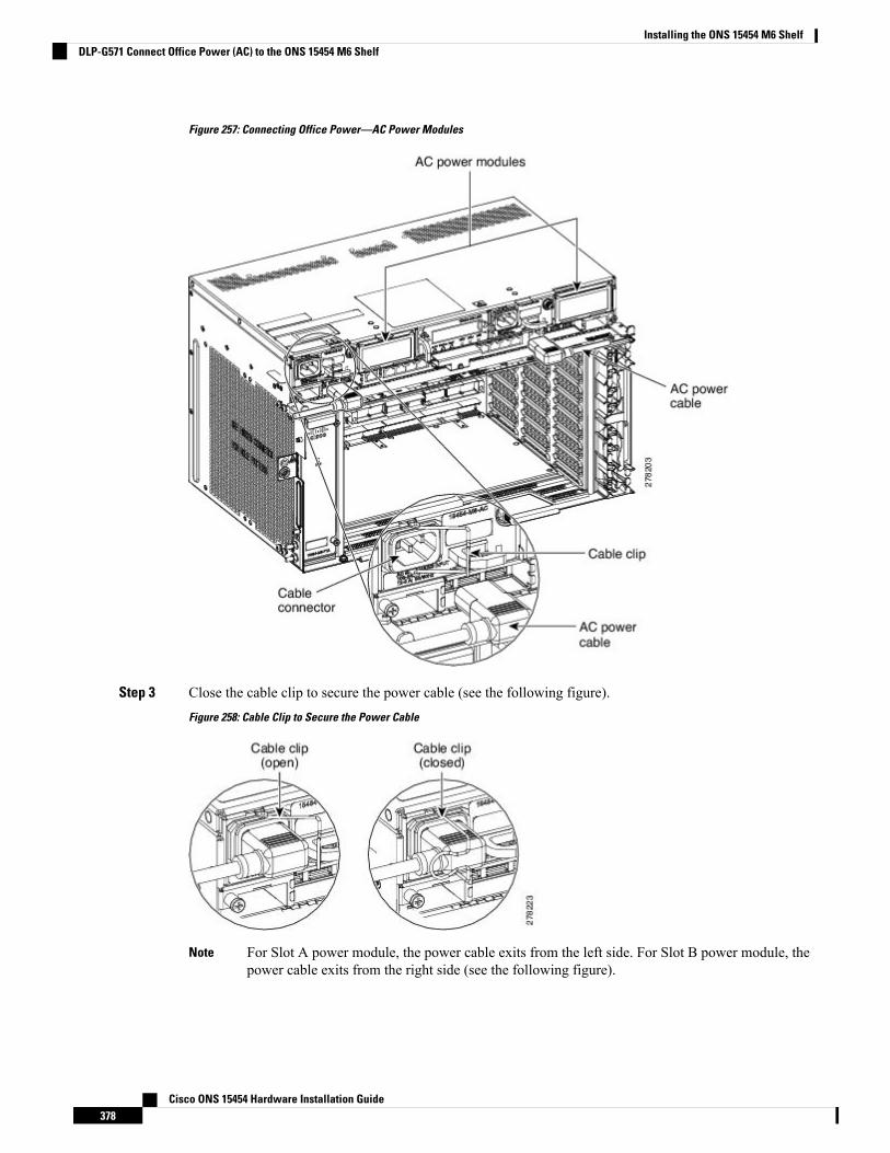
Figure 257: Connecting Office Power—AC Power Modules
Step 3 Close the cable clip to secure the power cable (see the following figure).
Figure 258: Cable Clip to Secure the Power Cable
For Slot A power module, the power cable exits from the left side. For Slot B power module, thepower cable exits from the right side (see the following figure).
Note
Cisco ONS 15454 Hardware Installation Guide378
Installing the ONS 15454 M6 ShelfDLP-G571 Connect Office Power (AC) to the ONS 15454 M6 Shelf

Figure 259: Power Cable Exit
Step 4 Connect the power cable to the fuse panel or power source.
The voltage rating value for AC power ranges between 100 VAC to 240 VAC depending on thestandards in various countries.
Note
Turn on the power after installing the power cables.Note
Step 5 Return to your originating procedure (NTP).
Table 33: PIDs for AC Power Cables
PIDCable
15454-M-CBL-L-JPN=AC power cable - Japan left exit
15454-M-CBL-R-JPN=AC power cable - Japan right exit
15454-M-CBL-L-CHI=AC power cable - China left exit
15454-M-CBL-R-CHI=AC power cable - China right exit
15454-M-CBL-L-IND=AC power cable - India left exit
15454-M-CBL-R-IND=AC power cable - India right exit
15454-M-CBL-L-EU=AC power cable - EU left exit
15454-M-CBL-R-EU=AC power cable - EU right exit
Cisco ONS 15454 Hardware Installation Guide379
Installing the ONS 15454 M6 ShelfDLP-G571 Connect Office Power (AC) to the ONS 15454 M6 Shelf
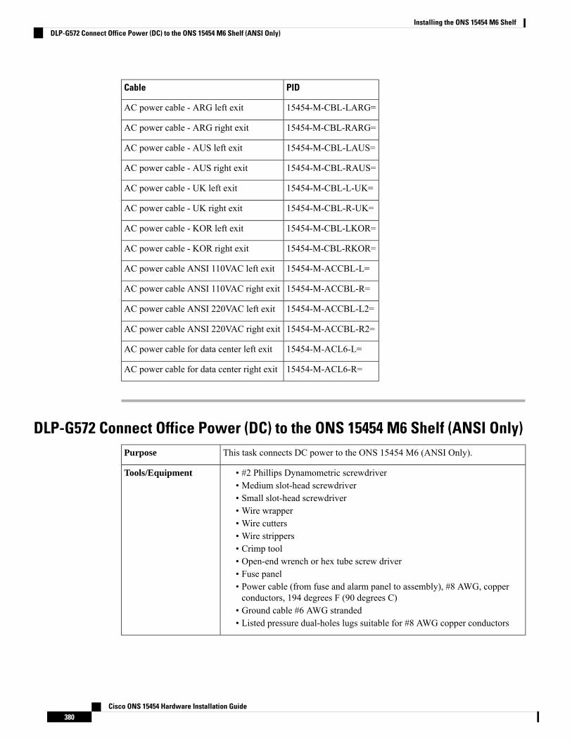
PIDCable
15454-M-CBL-LARG=AC power cable - ARG left exit
15454-M-CBL-RARG=AC power cable - ARG right exit
15454-M-CBL-LAUS=AC power cable - AUS left exit
15454-M-CBL-RAUS=AC power cable - AUS right exit
15454-M-CBL-L-UK=AC power cable - UK left exit
15454-M-CBL-R-UK=AC power cable - UK right exit
15454-M-CBL-LKOR=AC power cable - KOR left exit
15454-M-CBL-RKOR=AC power cable - KOR right exit
15454-M-ACCBL-L=AC power cable ANSI 110VAC left exit
15454-M-ACCBL-R=AC power cable ANSI 110VAC right exit
15454-M-ACCBL-L2=AC power cable ANSI 220VAC left exit
15454-M-ACCBL-R2=AC power cable ANSI 220VAC right exit
15454-M-ACL6-L=AC power cable for data center left exit
15454-M-ACL6-R=AC power cable for data center right exit
DLP-G572 Connect Office Power (DC) to the ONS 15454 M6 Shelf (ANSI Only)This task connects DC power to the ONS 15454 M6 (ANSI Only).Purpose
• #2 Phillips Dynamometric screwdriver• Medium slot-head screwdriver• Small slot-head screwdriver• Wire wrapper• Wire cutters• Wire strippers• Crimp tool• Open-end wrench or hex tube screw driver• Fuse panel• Power cable (from fuse and alarm panel to assembly), #8 AWG, copperconductors, 194 degrees F (90 degrees C)
• Ground cable #6 AWG stranded• Listed pressure dual-holes lugs suitable for #8 AWG copper conductors
Tools/Equipment
Cisco ONS 15454 Hardware Installation Guide380
Installing the ONS 15454 M6 ShelfDLP-G572 Connect Office Power (DC) to the ONS 15454 M6 Shelf (ANSI Only)

• NTP-G252 Install the ONS 15454 M6 Shelf , on page 296.• NTP-G259 Open and Remove the Standard Door of the ONS 15454 M6Shelf , on page 329.
• Connect the chassis to the office ground. For detailed instructions on howto ground the chassis, see the Electrostatic Discharge and Grounding Guidefor Cisco CPT and Cisco ONS Platforms.
• NTP-G524 Install the Power Modules in the ONS 15454M6 Shelf , on page358.
Prerequisite Procedures
RequiredRequired/As Needed
OnsiteOnsite/Remote
NoneSecurity Level
When installing or replacing the unit, the ground connection must always be made first and disconnectedlast. Statement 1046
Warning
Hazardous voltage or energy may be present on DC power terminals. Always replace cover whenterminals are not in service. Be sure uninsulated conductors are not accessible when cover is in place.Statement 1075
Warning
The ONS 15454M6 relies on the protective devices in the building installation to protect against short circuit,overcurrent, and ground faults. Ensure that the protective devices are properly rated and comply with nationaland local codes.
Caution
The battery return connection is treated as DC-I, as defined in Telcordia GR-1089-CORE Issue 5.Note
If the system loses power or both the TNC, TNCE, TSC, or TSCE cards are reset, and the system is notprovisioned to get the time from a Network Time Protocol/Simple Network Time Protocol (NTP/SNTP)server, you must reset the ONS 15454 clock. After powering down, the date defaults to January 1, 1970,00:04:15. To reset the clock, see the “NTP-G24 Setting Up Node Identification Information” procedure intheCisco ONS 15454 DWDM Control Card and Node Configuration Guide. If you are using the TNC, TNCE,TSC, or TSCE cards, the system clock will run for up to three hours. In this case, no action would be required.
Note
Procedure
Step 1 Connect the return cables of the power supply to the Earth ground located at the power supply side.
Cisco ONS 15454 Hardware Installation Guide381
Installing the ONS 15454 M6 ShelfDLP-G572 Connect Office Power (DC) to the ONS 15454 M6 Shelf (ANSI Only)
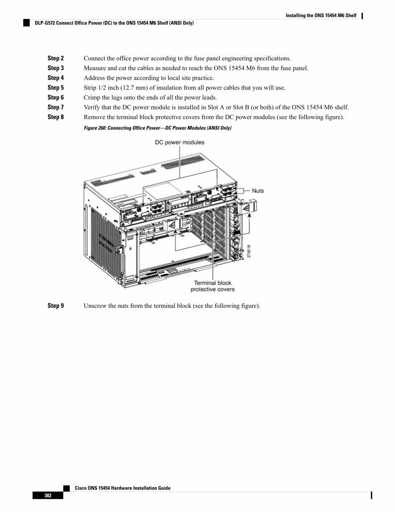
Step 2 Connect the office power according to the fuse panel engineering specifications.Step 3 Measure and cut the cables as needed to reach the ONS 15454 M6 from the fuse panel.Step 4 Address the power according to local site practice.Step 5 Strip 1/2 inch (12.7 mm) of insulation from all power cables that you will use.Step 6 Crimp the lugs onto the ends of all the power leads.Step 7 Verify that the DC power module is installed in Slot A or Slot B (or both) of the ONS 15454 M6 shelf.Step 8 Remove the terminal block protective covers from the DC power modules (see the following figure).
Figure 260: Connecting Office Power—DC Power Modules (ANSI Only)
Step 9 Unscrew the nuts from the terminal block (see the following figure).
Cisco ONS 15454 Hardware Installation Guide382
Installing the ONS 15454 M6 ShelfDLP-G572 Connect Office Power (DC) to the ONS 15454 M6 Shelf (ANSI Only)
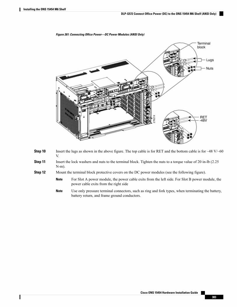
Figure 261: Connecting Office Power—DC Power Modules (ANSI Only)
Step 10 Insert the lugs as shown in the above figure. The top cable is for RET and the bottom cable is for –48 V/–60V.
Step 11 Insert the lock washers and nuts to the terminal block. Tighten the nuts to a torque value of 20 in-lb (2.25N-m).
Step 12 Mount the terminal block protective covers on the DC power modules (see the following figure).
For Slot A power module, the power cable exits from the left side. For Slot B power module, thepower cable exits from the right side
Note
Use only pressure terminal connectors, such as ring and fork types, when terminating the battery,battery return, and frame ground conductors.
Note
Cisco ONS 15454 Hardware Installation Guide383
Installing the ONS 15454 M6 ShelfDLP-G572 Connect Office Power (DC) to the ONS 15454 M6 Shelf (ANSI Only)
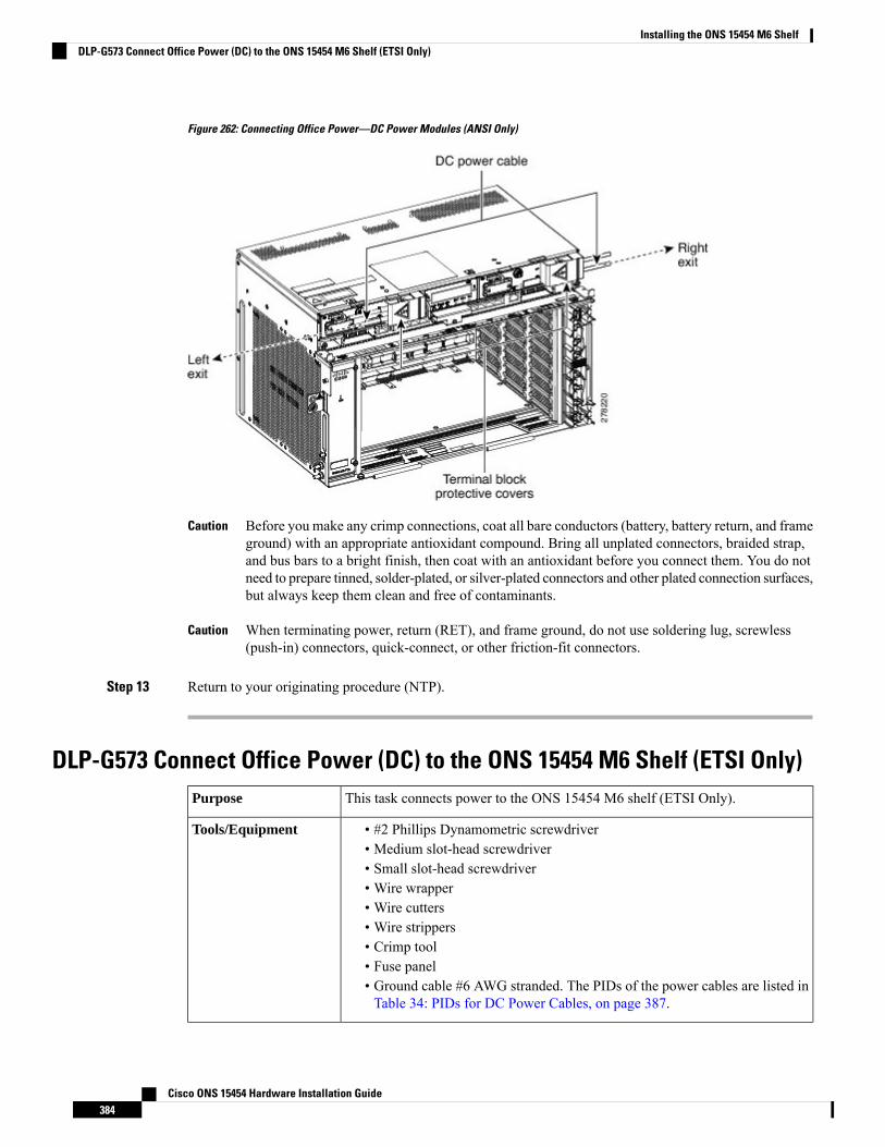
Figure 262: Connecting Office Power—DC Power Modules (ANSI Only)
Before you make any crimp connections, coat all bare conductors (battery, battery return, and frameground) with an appropriate antioxidant compound. Bring all unplated connectors, braided strap,and bus bars to a bright finish, then coat with an antioxidant before you connect them. You do notneed to prepare tinned, solder-plated, or silver-plated connectors and other plated connection surfaces,but always keep them clean and free of contaminants.
Caution
When terminating power, return (RET), and frame ground, do not use soldering lug, screwless(push-in) connectors, quick-connect, or other friction-fit connectors.
Caution
Step 13 Return to your originating procedure (NTP).
DLP-G573 Connect Office Power (DC) to the ONS 15454 M6 Shelf (ETSI Only)This task connects power to the ONS 15454 M6 shelf (ETSI Only).Purpose
• #2 Phillips Dynamometric screwdriver• Medium slot-head screwdriver• Small slot-head screwdriver• Wire wrapper• Wire cutters• Wire strippers• Crimp tool• Fuse panel• Ground cable #6 AWG stranded. The PIDs of the power cables are listed inTable 34: PIDs for DC Power Cables, on page 387.
Tools/Equipment
Cisco ONS 15454 Hardware Installation Guide384
Installing the ONS 15454 M6 ShelfDLP-G573 Connect Office Power (DC) to the ONS 15454 M6 Shelf (ETSI Only)
• NTP-G252 Install the ONS 15454 M6 Shelf , on page 296.• NTP-G259 Open and Remove the Standard Door of the ONS 15454 M6Shelf , on page 329.
• Connect the chassis to the office ground. For detailed instructions on howto ground the chassis, see the Electrostatic Discharge and Grounding Guidefor Cisco CPT and Cisco ONS Platforms.
• NTP-G524 Install the Power Modules in the ONS 15454M6 Shelf , on page358.
Prerequisite Procedures
RequiredRequired/As Needed
OnsiteOnsite/Remote
NoneSecurity Level
When installing or replacing the unit, the ground connection must always be made first and disconnectedlast. Statement 1046
Warning
Hazardous voltage or energy may be present on DC power terminals. Always replace cover whenterminals are not in service. Be sure uninsulated conductors are not accessible when cover is in place.Statement 1075
Warning
The battery return connection is treated as DC-I, as defined in Telcordia GR-1089-CORE Issue 5.Note
The ONS 15454M6 relies on the protective devices in the building installation to protect against short circuit,overcurrent, and ground faults. Ensure that the protective devices are properly rated and comply with nationaland local codes.
Caution
If the system loses power or both TNC, TNCE, TSC, or TSCE cards are reset and the system is not provisionedto get the time from a Network Time Protocol/Simple Network Time Protocol (NTP/SNTP) server, you mustreset the ONS 15454 M6 clock. After powering down, the date defaults to January 1, 1970, 00:04:15. To resetthe clock, see the “NTP-G24 Setting Up Node Identification Information” procedure in the Cisco ONS 15454DWDM Control Card and Node Configuration Guide. If you are using the TNC, TNCE, TSC, or TSCE cards,the system clock will run for up to three hours. In this case, no action would be required.
Note
Procedure
Step 1 Connect the return cables of the power supply to the Earth ground located at the power supply side.
Cisco ONS 15454 Hardware Installation Guide385
Installing the ONS 15454 M6 ShelfDLP-G573 Connect Office Power (DC) to the ONS 15454 M6 Shelf (ETSI Only)
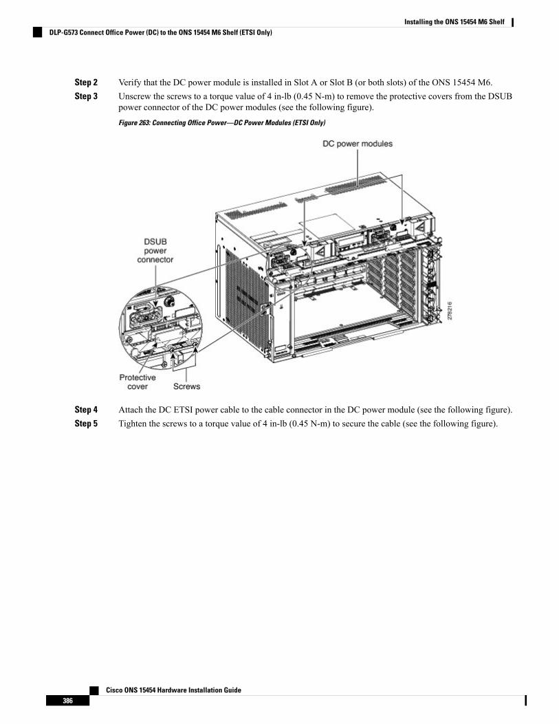
Step 2 Verify that the DC power module is installed in Slot A or Slot B (or both slots) of the ONS 15454 M6.Step 3 Unscrew the screws to a torque value of 4 in-lb (0.45 N-m) to remove the protective covers from the DSUB
power connector of the DC power modules (see the following figure).
Figure 263: Connecting Office Power—DC Power Modules (ETSI Only)
Step 4 Attach the DC ETSI power cable to the cable connector in the DC power module (see the following figure).Step 5 Tighten the screws to a torque value of 4 in-lb (0.45 N-m) to secure the cable (see the following figure).
Cisco ONS 15454 Hardware Installation Guide386
Installing the ONS 15454 M6 ShelfDLP-G573 Connect Office Power (DC) to the ONS 15454 M6 Shelf (ETSI Only)
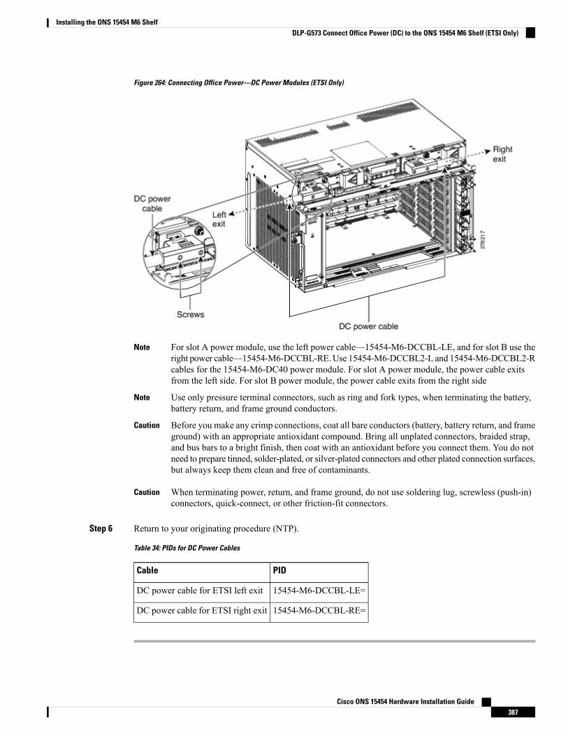
Figure 264: Connecting Office Power—DC Power Modules (ETSI Only)
For slot A power module, use the left power cable—15454-M6-DCCBL-LE, and for slot B use theright power cable—15454-M6-DCCBL-RE.Use 15454-M6-DCCBL2-L and 15454-M6-DCCBL2-Rcables for the 15454-M6-DC40 power module. For slot A power module, the power cable exitsfrom the left side. For slot B power module, the power cable exits from the right side
Note
Use only pressure terminal connectors, such as ring and fork types, when terminating the battery,battery return, and frame ground conductors.
Note
Before you make any crimp connections, coat all bare conductors (battery, battery return, and frameground) with an appropriate antioxidant compound. Bring all unplated connectors, braided strap,and bus bars to a bright finish, then coat with an antioxidant before you connect them. You do notneed to prepare tinned, solder-plated, or silver-plated connectors and other plated connection surfaces,but always keep them clean and free of contaminants.
Caution
When terminating power, return, and frame ground, do not use soldering lug, screwless (push-in)connectors, quick-connect, or other friction-fit connectors.
Caution
Step 6 Return to your originating procedure (NTP).
Table 34: PIDs for DC Power Cables
PIDCable
15454-M6-DCCBL-LE=DC power cable for ETSI left exit
15454-M6-DCCBL-RE=DC power cable for ETSI right exit
Cisco ONS 15454 Hardware Installation Guide387
Installing the ONS 15454 M6 ShelfDLP-G573 Connect Office Power (DC) to the ONS 15454 M6 Shelf (ETSI Only)
DLP-G574 Turn On and Verify AC Office Power on the ONS 15454 M6 ShelfThis task turns on and verifies AC office power on the ONS 15454 M6 shelf.Purpose
VoltmeterTools/Equipment
• NTP-G252 Install the ONS 15454 M6 Shelf , on page 296.• NTP-G259 Open and Remove the Standard Door of the ONS 15454 M6Shelf , on page 329.
• Connect the chassis to the office ground. For detailed instructions on howto ground the chassis, see the Electrostatic Discharge and Grounding Guidefor Cisco CPT and Cisco ONS Platforms.
• NTP-G524 Install the Power Modules in the ONS 15454M6 Shelf , on page358.
• DLP-G571 Connect Office Power (AC) to the ONS 15454 M6 Shelf, onpage 376
Prerequisite Procedures
RequiredRequired/As Needed
OnsiteOnsite/Remote
NoneSecurity Level
Do not apply power to the shelf until you complete all the installation steps.Caution
To ensure safety of personnel and equipment, do not connect any power cables into the power moduleuntil the module is completely installed into the chassis. Statement 389
Warning
To reduce the risk of electric shock, switch on the power only after the power cord is completely installedinto the power module. Statement 390
Warning
Procedure
Step 1 To power up the node, insert the fuse into the fuse position according to site practice. The fuse rating mustnot exceed 20A.
Step 2 If the ONS 15454M6 does not power up, check the voltage at the power source using a voltmeter. The voltageshould be 100 to 240 VAC +/-10 percent.
Step 3 Return to your originating procedure (NTP).
Cisco ONS 15454 Hardware Installation Guide388
Installing the ONS 15454 M6 ShelfDLP-G574 Turn On and Verify AC Office Power on the ONS 15454 M6 Shelf
DLP-G575 Turn On and Verify DC Office Power on the ONS 15454 M6 ShelfThis task turns on the power and verifies correct power and returns on the ONS15454 M6 shelf.
Purpose
VoltmeterTools/Equipment
• NTP-G252 Install the ONS 15454 M6 Shelf , on page 296.• NTP-G259 Open and Remove the Standard Door of the ONS 15454 M6Shelf , on page 329.
• Connect the chassis to the office ground. For detailed instructions on howto ground the chassis, see the Electrostatic Discharge and Grounding Guidefor Cisco CPT and Cisco ONS Platforms.
• NTP-G524 Install the Power Modules in the ONS 15454M6 Shelf , on page358.
• DLP-G572 Connect Office Power (DC) to the ONS 15454 M6 Shelf (ANSIOnly), on page 380
• DLP-G573 Connect Office Power (DC) to the ONS 15454 M6 Shelf (ETSIOnly), on page 384
Prerequisite Procedures
RequiredRequired/As Needed
OnsiteOnsite/Remote
NoneSecurity Level
Do not apply power to the shelf until you complete all the installation steps.Caution
To ensure safety of personnel and equipment, do not connect any power cables into the power moduleuntil the module is completely installed into the chassis. Statement 389
Warning
To reduce the risk of electric shock, switch on the power only after the power cord is completely installedinto the power module. Statement 390
Warning
Procedure
Step 1 Using a voltmeter, verify the office battery and ground at the following points on the fuse and alarm panel:a) To verify the power, place the black test lead of the voltmeter to the frame ground. Place the red test lead
on the A-side connection and verify that it is between –40.5 VDC and –72.0 VDC. Place the red test leadon the B-side connection and verify that it is between –40.5 VDC and –72.0 VDC.
Cisco ONS 15454 Hardware Installation Guide389
Installing the ONS 15454 M6 ShelfDLP-G575 Turn On and Verify DC Office Power on the ONS 15454 M6 Shelf
For nominal steady state voltage of –48 VDC, the operating voltage range for the chassis is–40.5 VDC (minimum) to –57.6 VDC (maximum).For nominal steady state voltage of –60VDC, the operating voltage range for the chassis is –50.0 VDC (minimum) to –72.0 VDC(maximum).
Note
b) To verify the ground, place the black test lead of the voltmeter to the frame ground. Place the red test leadon the A-side return ground and verify that no voltage is present. Place the red test lead on the B-sidereturn ground and verify that no voltage is present.
Step 2 To power up the node, insert the fuse into the fuse position according to site practice. The fuse rating mustnot exceed 40 A.
Step 3 Using a voltmeter, verify the ONS 15454 M6 shelf for –48 VDC or –60 VDC battery and ground:a) To verify the A-side of the shelf, place the black lead of the voltmeter to the frame ground. Place the red
test lead to the –48 V or –60 V (A-side battery connection) red cable. Verify that it reads between –40.5VDC and –72.0 VDC. Then place the red test lead of the voltmeter to the RET1 (A-side return ground)black cable and verify that no voltage is present.
For nominal steady state voltage of –48 VDC, the operating voltage range for the chassis is–40.5 VDC (minimum) to –57.6 VDC (maximum).For nominal steady state voltage of –60VDC, the operating voltage range for the chassis is –50.0 VDC (minimum) to –72.0 VDC(maximum).
Note
b) To verify the B-side of the shelf, place the black test lead of the voltmeter to the frame ground. Place thered test lead to the –48 V (B-side battery connection) red cable. Verify that it reads between –40.5 VDCand –72.0 VDC. Then place the red test lead of the voltmeter to the RET2 (B-side return ground) blackcable and verify that no voltage is present.
To view the shelf voltage and temperature, see the NTP-G230 View Shelf Voltage andTemperature, on page 78.
Note
If the ONS 15454 M6 shelf is being powered at –60 VDC nominal voltage, the door must bekept closed during regular operation.
Note
Step 4 Return to your originating procedure (NTP).
Fan-Tray AssemblyThe fan-trays supported on the ONS 15454 M6 shelf are 15454-M6-FTA and 15454-M6-FTA2. The15454-M6-FTA2 fan-tray provides increased airflow when compared to the 15454-M6-FTA fan-tray. The15454-M2-FTA2 is compatible with R9.2.0 and later releases.
The fan-tray assembly is located on the left side of the ONS 15454 M6 shelf. The fan-tray is removable andholds the fan-control circuitry and the fans for the ONS 15454 M6 shelf. It has a single dual-color LED onthe faceplate. When the fan-tray assembly is not functioning or when the power line is not connected, theLED is OFF. When the power line is connected and if there is no TNC, TNCE, TSC, or TSCE card installedin the ONS 15454 M6 shelf, then the LED is OFF. A red LED indicates an alarm in the fan-tray assembly. Agreen LED indicates that the fan-tray assembly is functioning, the power line is connected, and the powermodule is functioning properly. The shelf controller card controls the conditions that result in triggering theLEDs. The LED can be overwritten by the shelf controller card (TNC, TNCE, TSC, or TSCE) in all the threestates (OFF/red/green). The fan-tray assembly supports the lamp test procedure. After you install the fan tray,you should only access it if a fan failure occurs.
Cisco ONS 15454 Hardware Installation Guide390
Installing the ONS 15454 M6 ShelfFan-Tray Assembly
Fan SpeedThe fan speed is controlled by the TNC, TNCE, TSC, or TSCE card temperature sensors. The sensors measurethe input air temperature at the fan-tray assembly. Fan speed options are low, medium, and high. If the TNC,TNCE, TSC, or TSCE card fails, the fans automatically shift to high speed. The temperature that the TNC,TNCE, TSC, or TSCE sensors measure appear on the LCD screen.
Fan FailureIf one or more fans fail on the fan-tray assembly, replace the entire assembly. You cannot replace individualfans. The red Fan Fail LED on the front of the fan-tray illuminates when one or more fans fail. The red FanFail LED clears after you install a working fan-tray.
NTP-G257 Install the Fan-Tray Assembly in the ONS 15454 M6Shelf
This procedure installs the 15454-M6-FTA or 15454-M6-FTA2 fan-tray assemblyin the ONS 15454 M6 system.
Purpose
Small slot-head screwdriverTools/Equipment
• NTP-G252 Install the ONS 15454 M6 Shelf , on page 296.• NTP-G259 Open and Remove the Standard Door of the ONS 15454 M6Shelf , on page 329.
• Connect the chassis to the office ground. For detailed instructions on howto ground the chassis, see the Electrostatic Discharge and Grounding Guidefor Cisco CPT and Cisco ONS Platforms.
Prerequisite Procedures
RequiredRequired/As Needed
OnsiteOnsite/Remote
NoneSecurity Level
The 15454-M2-FTA2 is compatible with R9.2.0 and later releases.Note
Do not operate an ONS 15454M6without an air filter. For information on the air filter, see NTP-G114 Inspectand Replace the Air Filter, on page 439.
Caution
Do not force a fan-tray assembly into place. Doing so can damage either the connectors on the fan tray or theconnectors on the backpanel of the shelf, or both.
Caution
Cisco ONS 15454 Hardware Installation Guide391
Installing the ONS 15454 M6 ShelfFan Speed
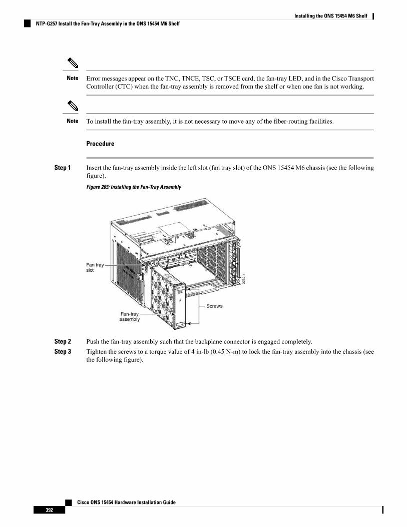
Error messages appear on the TNC, TNCE, TSC, or TSCE card, the fan-tray LED, and in the Cisco TransportController (CTC) when the fan-tray assembly is removed from the shelf or when one fan is not working.
Note
To install the fan-tray assembly, it is not necessary to move any of the fiber-routing facilities.Note
Procedure
Step 1 Insert the fan-tray assembly inside the left slot (fan tray slot) of the ONS 15454 M6 chassis (see the followingfigure).
Figure 265: Installing the Fan-Tray Assembly
Step 2 Push the fan-tray assembly such that the backplane connector is engaged completely.Step 3 Tighten the screws to a torque value of 4 in-lb (0.45 N-m) to lock the fan-tray assembly into the chassis (see
the following figure).
Cisco ONS 15454 Hardware Installation Guide392
Installing the ONS 15454 M6 ShelfNTP-G257 Install the Fan-Tray Assembly in the ONS 15454 M6 Shelf
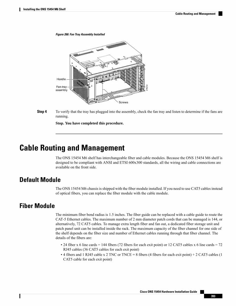
Figure 266: Fan Tray Assembly Installed
Step 4 To verify that the tray has plugged into the assembly, check the fan tray and listen to determine if the fans arerunning.
Stop. You have completed this procedure.
Cable Routing and ManagementThe ONS 15454 M6 shelf has interchangeable fiber and cable modules. Because the ONS 15454 M6 shelf isdesigned to be compliant with ANSI and ETSI 600x300 standards, all the wiring and cable connections areavailable on the front side.
Default ModuleThe ONS 15454M6 chassis is shipped with the fiber module installed. If you need to use CAT5 cables insteadof optical fibers, you can replace the fiber module with the cable module.
Fiber ModuleThe minimum fiber bend radius is 1.5 inches. The fiber guide can be replaced with a cable guide to route theCAT-5 Ethernet cables. The maximum number of 2 mm diameter patch cords that can be managed is 144, oralternatively, 72 CAT5 cables. To manage extra length fiber and fan out, a dedicated fiber storage unit andpatch panel unit can be installed inside the rack. The maximum capacity of the fiber channel for one side ofthe shelf depends on the fiber size and number of Ethernet cables running through that fiber channel. Thedetails of the fibers are:
• 24 fiber x 6 line cards = 144 fibers (72 fibers for each exit point) or 12 CAT5 cables x 6 line cards = 72RJ45 cables (36 CAT5 cables for each exit point)
• 4 fibers and 1 RJ45 cable x 2 TNC or TNCE = 8 fibers (4 fibers for each exit point) + 2 CAT5 cables (1CAT5 cable for each exit point)
Cisco ONS 15454 Hardware Installation Guide393
Installing the ONS 15454 M6 ShelfCable Routing and Management
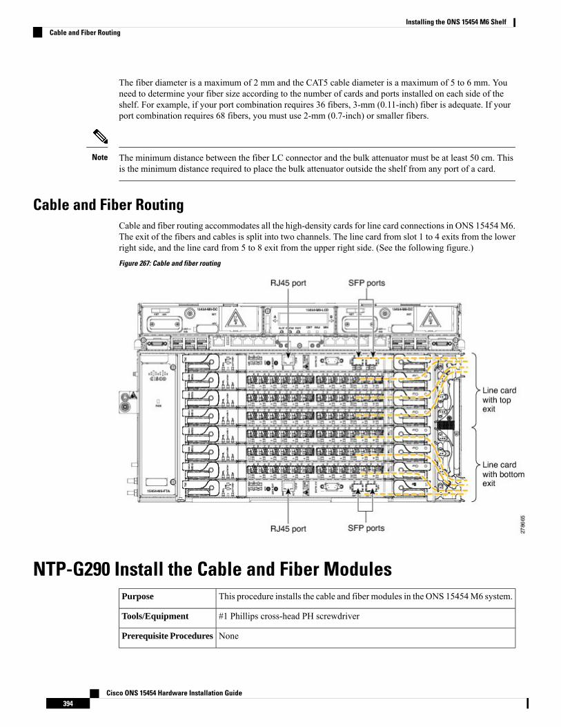
The fiber diameter is a maximum of 2 mm and the CAT5 cable diameter is a maximum of 5 to 6 mm. Youneed to determine your fiber size according to the number of cards and ports installed on each side of theshelf. For example, if your port combination requires 36 fibers, 3-mm (0.11-inch) fiber is adequate. If yourport combination requires 68 fibers, you must use 2-mm (0.7-inch) or smaller fibers.
The minimum distance between the fiber LC connector and the bulk attenuator must be at least 50 cm. Thisis the minimum distance required to place the bulk attenuator outside the shelf from any port of a card.
Note
Cable and Fiber RoutingCable and fiber routing accommodates all the high-density cards for line card connections in ONS 15454M6.The exit of the fibers and cables is split into two channels. The line card from slot 1 to 4 exits from the lowerright side, and the line card from 5 to 8 exit from the upper right side. (See the following figure.)
Figure 267: Cable and fiber routing
NTP-G290 Install the Cable and Fiber ModulesThis procedure installs the cable and fiber modules in the ONS 15454M6 system.Purpose
#1 Phillips cross-head PH screwdriverTools/Equipment
NonePrerequisite Procedures
Cisco ONS 15454 Hardware Installation Guide394
Installing the ONS 15454 M6 ShelfCable and Fiber Routing
As neededRequired/As Needed
OnsiteOnsite/Remote
NoneSecurity Level
Procedure
Step 1 Complete the DLP-G653 Remove the Fiber Module, on page 395.Step 2 Complete the DLP-G654 Install the Cable Module, on page 396.Step 3 Complete the DLP-G655 Route and Lock Cables, on page 397 .
Stop. You have completed this procedure.
DLP-G653 Remove the Fiber ModuleThis procedure removes the default fiber module in the ONS 15454 M6 system.Purpose
#1 Phillips cross-head PH screwdriverTools/Equipment
NonePrerequisite Procedures
As neededRequired/As Needed
OnsiteOnsite/Remote
NoneSecurity Level
Procedure
Step 1 Loosen the screws on the fiber module present on the right side of the ONS 15454 M6 assembly. (See thefollowing figure.)
Step 2 Loosen the screw present on the air filter locking feature of the ONS 15454 M6 shelf.Step 3 Remove the air filter locking feature by holding the air filter and gently pulling the air filter locking feature
away from the shelf.Step 4 Extract the fiber module by gently removing it from the ONS 15454 M6 shelf.
Cisco ONS 15454 Hardware Installation Guide395
Installing the ONS 15454 M6 ShelfDLP-G653 Remove the Fiber Module
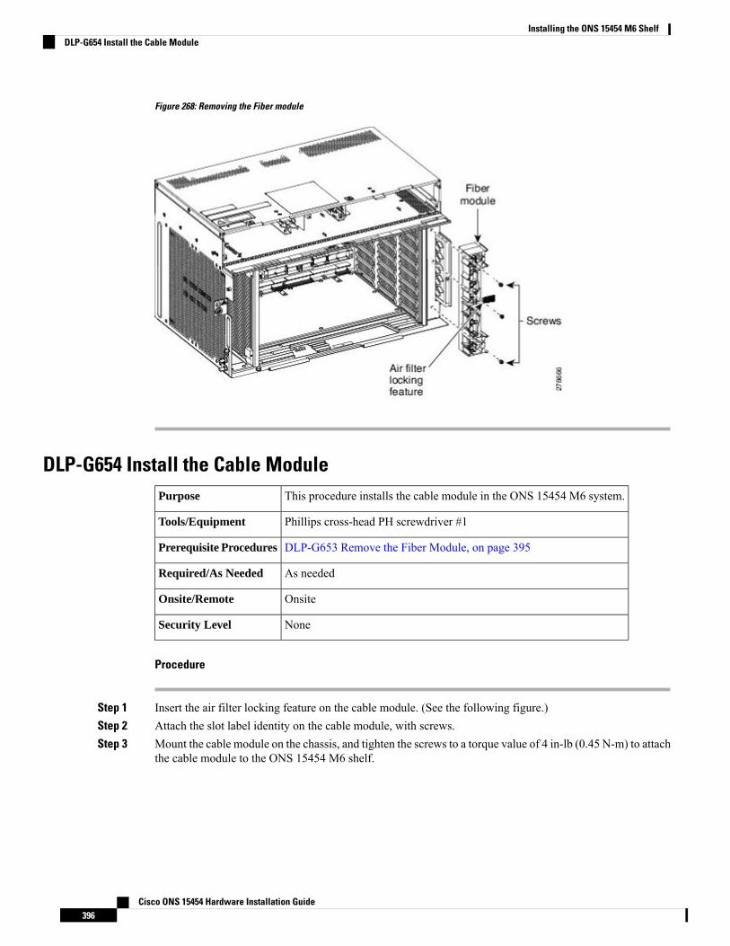
Figure 268: Removing the Fiber module
DLP-G654 Install the Cable ModuleThis procedure installs the cable module in the ONS 15454 M6 system.Purpose
Phillips cross-head PH screwdriver #1Tools/Equipment
DLP-G653 Remove the Fiber Module, on page 395Prerequisite Procedures
As neededRequired/As Needed
OnsiteOnsite/Remote
NoneSecurity Level
Procedure
Step 1 Insert the air filter locking feature on the cable module. (See the following figure.)Step 2 Attach the slot label identity on the cable module, with screws.Step 3 Mount the cable module on the chassis, and tighten the screws to a torque value of 4 in-lb (0.45 N-m) to attach
the cable module to the ONS 15454 M6 shelf.
Cisco ONS 15454 Hardware Installation Guide396
Installing the ONS 15454 M6 ShelfDLP-G654 Install the Cable Module
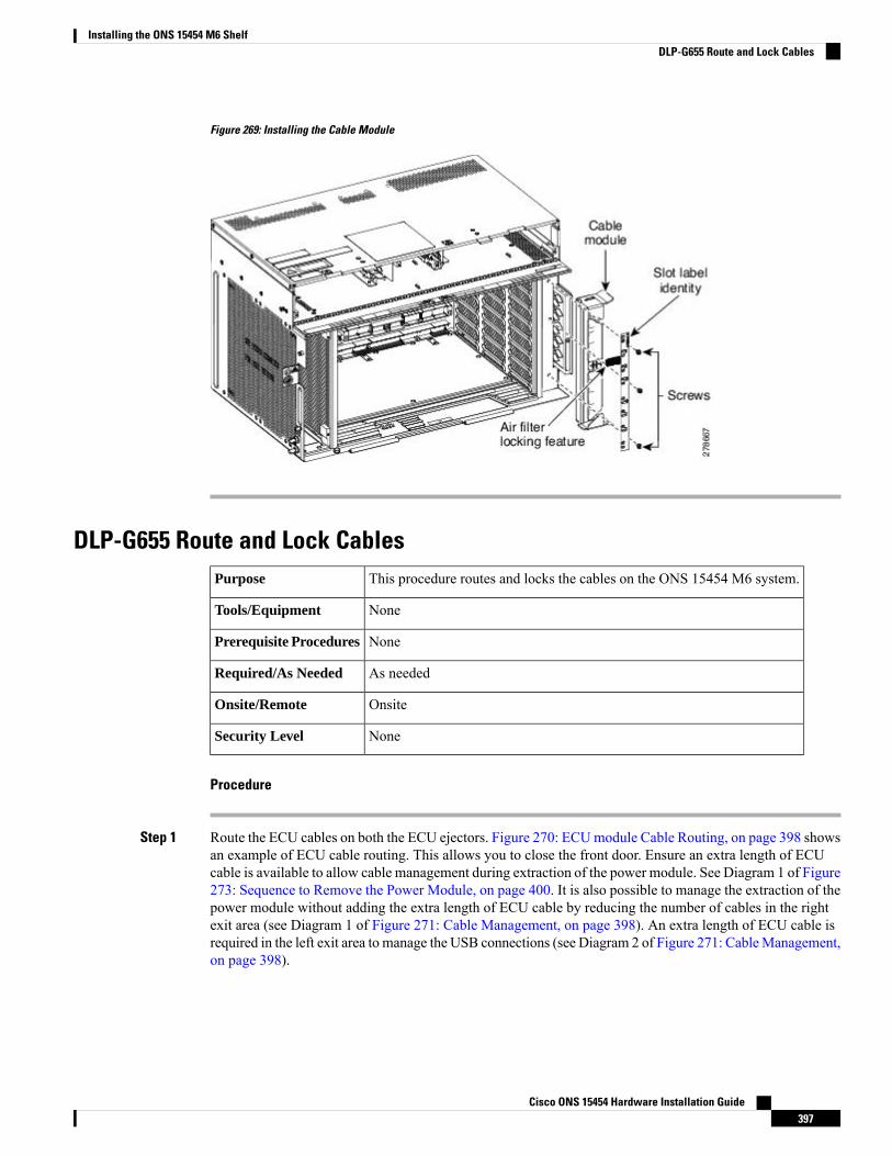
Figure 269: Installing the Cable Module
DLP-G655 Route and Lock CablesThis procedure routes and locks the cables on the ONS 15454 M6 system.Purpose
NoneTools/Equipment
NonePrerequisite Procedures
As neededRequired/As Needed
OnsiteOnsite/Remote
NoneSecurity Level
Procedure
Step 1 Route the ECU cables on both the ECU ejectors. Figure 270: ECUmodule Cable Routing, on page 398 showsan example of ECU cable routing. This allows you to close the front door. Ensure an extra length of ECUcable is available to allow cable management during extraction of the power module. See Diagram 1 of Figure273: Sequence to Remove the Power Module, on page 400. It is also possible to manage the extraction of thepower module without adding the extra length of ECU cable by reducing the number of cables in the rightexit area (see Diagram 1 of Figure 271: Cable Management, on page 398). An extra length of ECU cable isrequired in the left exit area to manage the USB connections (see Diagram 2 of Figure 271: CableManagement,on page 398).
Cisco ONS 15454 Hardware Installation Guide397
Installing the ONS 15454 M6 ShelfDLP-G655 Route and Lock Cables
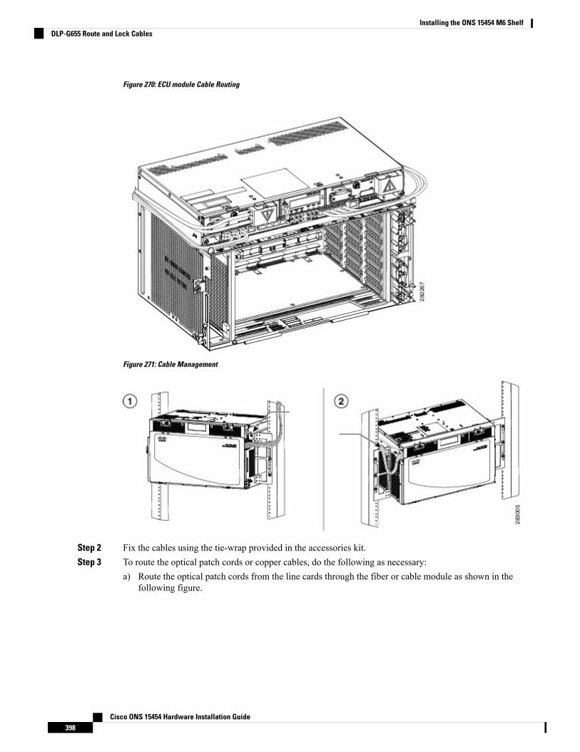
Figure 270: ECU module Cable Routing
Figure 271: Cable Management
Step 2 Fix the cables using the tie-wrap provided in the accessories kit.Step 3 To route the optical patch cords or copper cables, do the following as necessary:
a) Route the optical patch cords from the line cards through the fiber or cable module as shown in thefollowing figure.
Cisco ONS 15454 Hardware Installation Guide398
Installing the ONS 15454 M6 ShelfDLP-G655 Route and Lock Cables
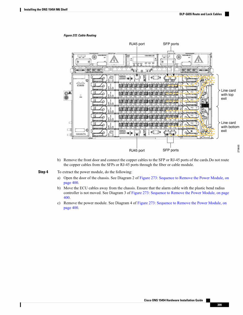
Figure 272: Cable Routing
b) Remove the front door and connect the copper cables to the SFP or RJ-45 ports of the cards.Do not routethe copper cables from the SFPs or RJ-45 ports through the fiber or cable module.
Step 4 To extract the power module, do the following:a) Open the door of the chassis. See Diagram 2 of Figure 273: Sequence to Remove the Power Module, on
page 400.b) Move the ECU cables away from the chassis. Ensure that the alarm cable with the plastic bend radius
controller is not moved. See Diagram 3 of Figure 273: Sequence to Remove the Power Module, on page400.
c) Remove the power module. See Diagram 4 of Figure 273: Sequence to Remove the Power Module, onpage 400.
Cisco ONS 15454 Hardware Installation Guide399
Installing the ONS 15454 M6 ShelfDLP-G655 Route and Lock Cables
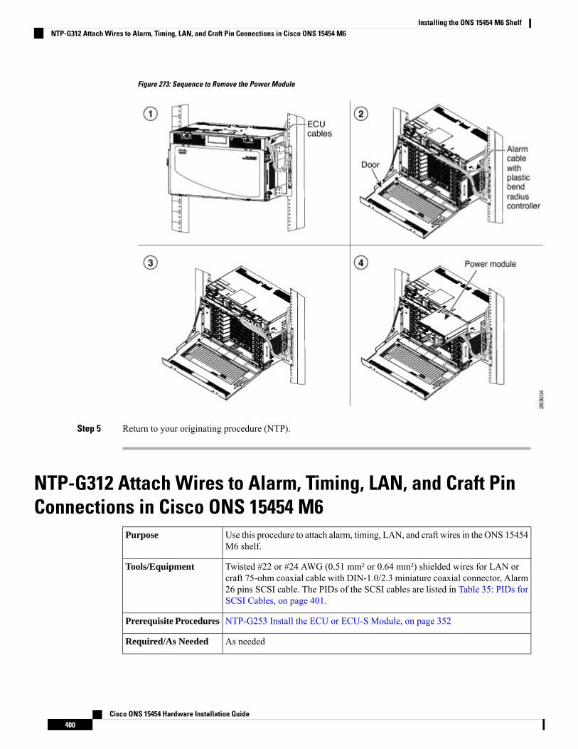
Figure 273: Sequence to Remove the Power Module
Step 5 Return to your originating procedure (NTP).
NTP-G312 Attach Wires to Alarm, Timing, LAN, and Craft PinConnections in Cisco ONS 15454 M6
Use this procedure to attach alarm, timing, LAN, and craft wires in the ONS 15454M6 shelf.
Purpose
Twisted #22 or #24 AWG (0.51 mm² or 0.64 mm²) shielded wires for LAN orcraft 75-ohm coaxial cable with DIN-1.0/2.3 miniature coaxial connector, Alarm26 pins SCSI cable. The PIDs of the SCSI cables are listed in Table 35: PIDs forSCSI Cables, on page 401.
Tools/Equipment
NTP-G253 Install the ECU or ECU-S Module, on page 352Prerequisite Procedures
As neededRequired/As Needed
Cisco ONS 15454 Hardware Installation Guide400
Installing the ONS 15454 M6 ShelfNTP-G312 Attach Wires to Alarm, Timing, LAN, and Craft Pin Connections in Cisco ONS 15454 M6
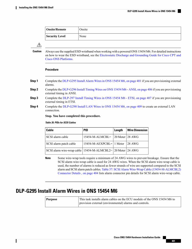
OnsiteOnsite/Remote
NoneSecurity Level
Always use the supplied ESDwristbandwhenworkingwith a poweredONS 15454M6. For detailed instructionson how to wear the ESD wristband, see the Electrostatic Discharge and Grounding Guide for Cisco CPT andCisco ONS Platforms.
Caution
Procedure
Step 1 Complete the DLP-G295 Install AlarmWires in ONS 15454M6, on page 401 if you are provisioning externalalarms.
Step 2 Complete the DLP-G296 Install TimingWires on ONS 15454M6 - ANSI, on page 406 if you are provisioningexternal timing in ANSI.
Step 3 Complete the DLP-297 Install Timing Wires in ONS 15454 M6 - ETSI, on page 407 if you are provisioningexternal timing in ETSI.
Step 4 Complete the DLP-G298 Install LAN Wires in ONS 15454 M6, on page 409 to create an external LANconnection.
Stop. You have completed this procedure.
Table 35: PIDs for SCSI Cables
Wire DimensionLengthPIDCable
28 AWG20Meter15454-M-ALMCBL=SCSI alarm cable
28 AWG1 Meter15454-M-AEXPCBL=SCSI alarm patch cable
24 AWG20Meter15454-M-ALMCBL2=SCSI alarm wire-wrap cable
Some wire-wrap tools require a minimum of 24 AWG wires to prevent breakage. Ensure that theSCSI alarm wire-wrap cable is used for 24 AWG wires. When the SCSI alarm wire-wrap cable isused, the number of alarms is reduced as fewer strands of wire are supported compared to the SCSIalarm and SCSI alarm patch cables. Table 37: SCSI AlarmWire-Wrap Cable (15454-M-ALMCBL2)Connector Details , on page 404 lists alarm connector pin details for SCSI alarm wire-wrap cable.
Note
DLP-G295 Install Alarm Wires in ONS 15454 M6This task installs alarm cables on the ECU module of the ONS 15454 M6 toprovision external (environmental) alarms and controls.
Purpose
Cisco ONS 15454 Hardware Installation Guide401
Installing the ONS 15454 M6 ShelfDLP-G295 Install Alarm Wires in ONS 15454 M6
Alarm SCSI 26-pin cable
Wire-wrap tool for ANSI BITS
Screw for the alarm cable
Tools/Equipment
NTP-G253 Install the ECU or ECU-S Module, on page 352.Prerequisite Procedures
As neededRequired/As Needed
OnsiteOnsite/Remote
NoneSecurity Level
Procedure
Step 1 Connect one end of the SCSI cable to the input alarms or input/output alarms, and the other end to the alarmsource (See Diagram 1 of Figure 274: Installing the ECU Alarm Cable—Left Exit Option, on page 403 orFigure 275: Installing the ECU Alarm Cable—Right Exit Option, on page 403). The details of the alarmconnector pins are listed in Table 36: SCSI Alarm Cable (15454-M-ALMCBL) and SCSI Alarm Patch Cable(15454-M-AEXPCBL) Connector Details , on page 403 and Table 37: SCSI Alarm Wire-Wrap Cable(15454-M-ALMCBL2) Connector Details , on page 404.
These alarms are generic signals that the operator assigns to a definite wire (color) and name throughthe Craft Terminal.
Note
Step 2 Tighten the screws of the SCSI connector to a torque value of 4 in-lb (0.45 N-m) using #2 Philips Dynamometricscrewdriver. See Diagram 2 of Figure 274: Installing the ECU Alarm Cable—Left Exit Option, on page 403or Figure 275: Installing the ECU Alarm Cable—Right Exit Option, on page 403.
Step 3 Bend the cable at an angle of 90° to exit from the left side (see Diagram 3 of Figure 274: Installing the ECUAlarm Cable—Left Exit Option, on page 403) or to exit from the right side (see Diagram 3 of Figure 275:Installing the ECU Alarm Cable—Right Exit Option, on page 403).
Step 4 Snap the cable bend controller on the cable. See Diagram 4 of Figure 274: Installing the ECU AlarmCable—Left Exit Option, on page 403 or Figure 275: Installing the ECU Alarm Cable—Right Exit Option,on page 403.
Step 5 Return to your originating procedure (NTP).
Cisco ONS 15454 Hardware Installation Guide402
Installing the ONS 15454 M6 ShelfDLP-G295 Install Alarm Wires in ONS 15454 M6
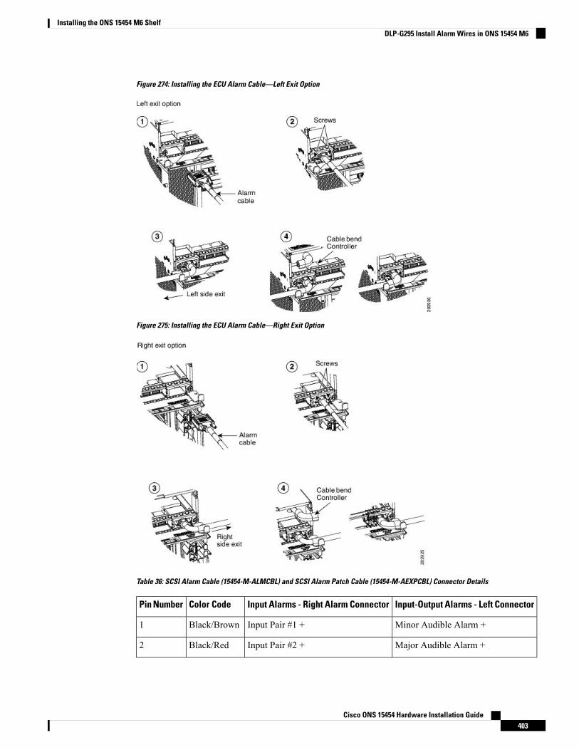
Figure 274: Installing the ECU Alarm Cable—Left Exit Option
Figure 275: Installing the ECU Alarm Cable—Right Exit Option
Table 36: SCSI Alarm Cable (15454-M-ALMCBL) and SCSI Alarm Patch Cable (15454-M-AEXPCBL) Connector Details
Input-Output Alarms - Left ConnectorInput Alarms - Right Alarm ConnectorColor CodePin Number
Minor Audible Alarm +Input Pair #1 +Black/Brown1
Major Audible Alarm +Input Pair #2 +Black/Red2
Cisco ONS 15454 Hardware Installation Guide403
Installing the ONS 15454 M6 ShelfDLP-G295 Install Alarm Wires in ONS 15454 M6
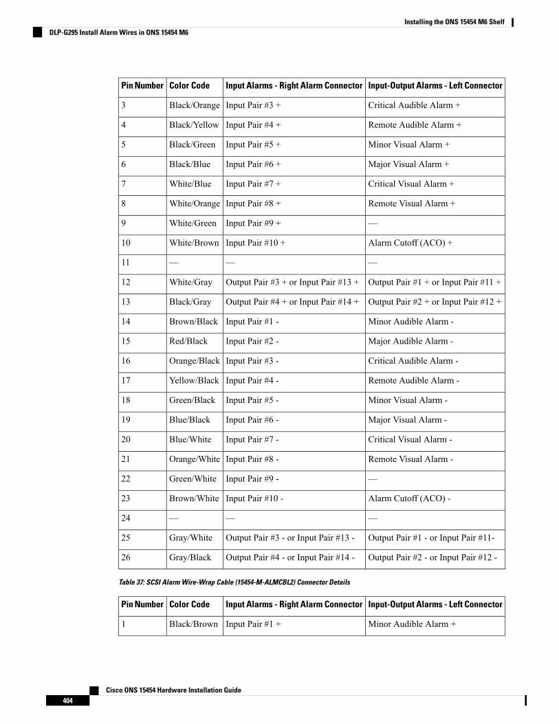
Input-Output Alarms - Left ConnectorInput Alarms - Right Alarm ConnectorColor CodePin Number
Critical Audible Alarm +Input Pair #3 +Black/Orange3
Remote Audible Alarm +Input Pair #4 +Black/Yellow4
Minor Visual Alarm +Input Pair #5 +Black/Green5
Major Visual Alarm +Input Pair #6 +Black/Blue6
Critical Visual Alarm +Input Pair #7 +White/Blue7
Remote Visual Alarm +Input Pair #8 +White/Orange8
—Input Pair #9 +White/Green9
Alarm Cutoff (ACO) +Input Pair #10 +White/Brown10
———11
Output Pair #1 + or Input Pair #11 +Output Pair #3 + or Input Pair #13 +White/Gray12
Output Pair #2 + or Input Pair #12 +Output Pair #4 + or Input Pair #14 +Black/Gray13
Minor Audible Alarm -Input Pair #1 -Brown/Black14
Major Audible Alarm -Input Pair #2 -Red/Black15
Critical Audible Alarm -Input Pair #3 -Orange/Black16
Remote Audible Alarm -Input Pair #4 -Yellow/Black17
Minor Visual Alarm -Input Pair #5 -Green/Black18
Major Visual Alarm -Input Pair #6 -Blue/Black19
Critical Visual Alarm -Input Pair #7 -Blue/White20
Remote Visual Alarm -Input Pair #8 -Orange/White21
—Input Pair #9 -Green/White22
Alarm Cutoff (ACO) -Input Pair #10 -Brown/White23
———24
Output Pair #1 - or Input Pair #11-Output Pair #3 - or Input Pair #13 -Gray/White25
Output Pair #2 - or Input Pair #12 -Output Pair #4 - or Input Pair #14 -Gray/Black26
Table 37: SCSI Alarm Wire-Wrap Cable (15454-M-ALMCBL2) Connector Details
Input-Output Alarms - Left ConnectorInput Alarms - Right Alarm ConnectorColor CodePin Number
Minor Audible Alarm +Input Pair #1 +Black/Brown1
Cisco ONS 15454 Hardware Installation Guide404
Installing the ONS 15454 M6 ShelfDLP-G295 Install Alarm Wires in ONS 15454 M6
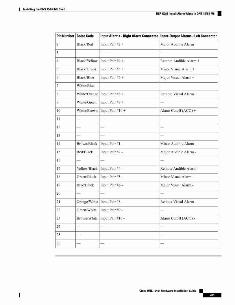
Input-Output Alarms - Left ConnectorInput Alarms - Right Alarm ConnectorColor CodePin Number
Major Audible Alarm +Input Pair #2 +Black/Red2
———3
Remote Audible Alarm +Input Pair #4 +Black/Yellow4
Minor Visual Alarm +Input Pair #5 +Black/Green5
Major Visual Alarm +Input Pair #6 +Black/Blue6
——White/Blue7
Remote Visual Alarm +Input Pair #8 +White/Orange8
—Input Pair #9 +White/Green9
Alarm Cutoff (ACO) +Input Pair #10 +White/Brown10
———11
———12
———13
Minor Audible Alarm -Input Pair #1 -Brown/Black14
Major Audible Alarm -Input Pair #2 -Red/Black15
———16
Remote Audible Alarm -Input Pair #4 -Yellow/Black17
Minor Visual Alarm -Input Pair #5 -Green/Black18
Major Visual Alarm -Input Pair #6 -Blue/Black19
———20
Remote Visual Alarm -Input Pair #8 -Orange/White21
—Input Pair #9 -Green/White22
Alarm Cutoff (ACO) -Input Pair #10 -Brown/White23
———24
———25
———26
Cisco ONS 15454 Hardware Installation Guide405
Installing the ONS 15454 M6 ShelfDLP-G295 Install Alarm Wires in ONS 15454 M6
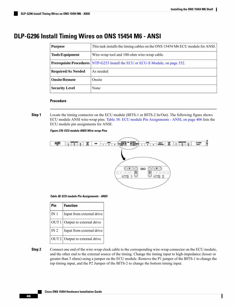
DLP-G296 Install Timing Wires on ONS 15454 M6 - ANSIThis task installs the timing cables on the ONS 15454M6 ECUmodule for ANSI.Purpose
Wire-wrap tool and 100-ohm wire-wrap cable.Tools/Equipment
NTP-G253 Install the ECU or ECU-S Module, on page 352.Prerequisite Procedures
As neededRequired/As Needed
OnsiteOnsite/Remote
NoneSecurity Level
Procedure
Step 1 Locate the timing connector on the ECU module (BITS-1 or BITS-2 In/Out). The following figure showsECU module ANSI wire-wrap pins. Table 38: ECU module Pin Assignments - ANSI, on page 406 lists theECU module pin assignments for ANSI.
Figure 276: ECU module ANSI Wire-wrap Pins
Table 38: ECU module Pin Assignments - ANSI
FunctionPin
Input from external driveIN 1
Output to external driveOUT1
Input from external driveIN 2
Output to external driveOUT2
Step 2 Connect one end of the wire-wrap clock cable to the corresponding wire-wrap connector on the ECUmodule,and the other end to the external source of the timing. Change the timing input to high-impedance (lesser orgreater than 3 ohms) using a jumper on the ECU module. Remove the P1 jumper of the BITS-1 to change thetop timing input, and the P2 Jumper of the BITS-2 to change the bottom timing input.
Cisco ONS 15454 Hardware Installation Guide406
Installing the ONS 15454 M6 ShelfDLP-G296 Install Timing Wires on ONS 15454 M6 - ANSI
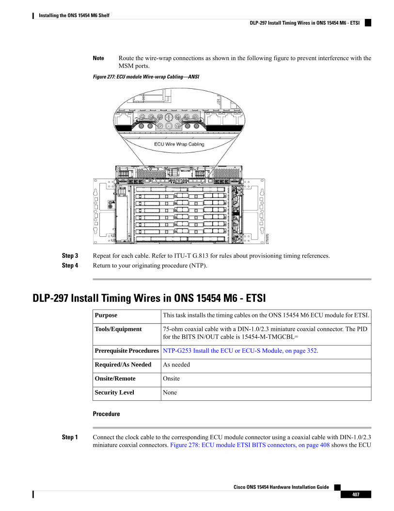
Route the wire-wrap connections as shown in the following figure to prevent interference with theMSM ports.
Note
Figure 277: ECU module Wire-wrap Cabling—ANSI
Step 3 Repeat for each cable. Refer to ITU-T G.813 for rules about provisioning timing references.Step 4 Return to your originating procedure (NTP).
DLP-297 Install Timing Wires in ONS 15454 M6 - ETSIThis task installs the timing cables on the ONS 15454M6 ECUmodule for ETSI.Purpose
75-ohm coaxial cable with a DIN-1.0/2.3 miniature coaxial connector. The PIDfor the BITS IN/OUT cable is 15454-M-TMGCBL=
Tools/Equipment
NTP-G253 Install the ECU or ECU-S Module, on page 352.Prerequisite Procedures
As neededRequired/As Needed
OnsiteOnsite/Remote
NoneSecurity Level
Procedure
Step 1 Connect the clock cable to the corresponding ECU module connector using a coaxial cable with DIN-1.0/2.3miniature coaxial connectors. Figure 278: ECU module ETSI BITS connectors, on page 408 shows the ECU
Cisco ONS 15454 Hardware Installation Guide407
Installing the ONS 15454 M6 ShelfDLP-297 Install Timing Wires in ONS 15454 M6 - ETSI
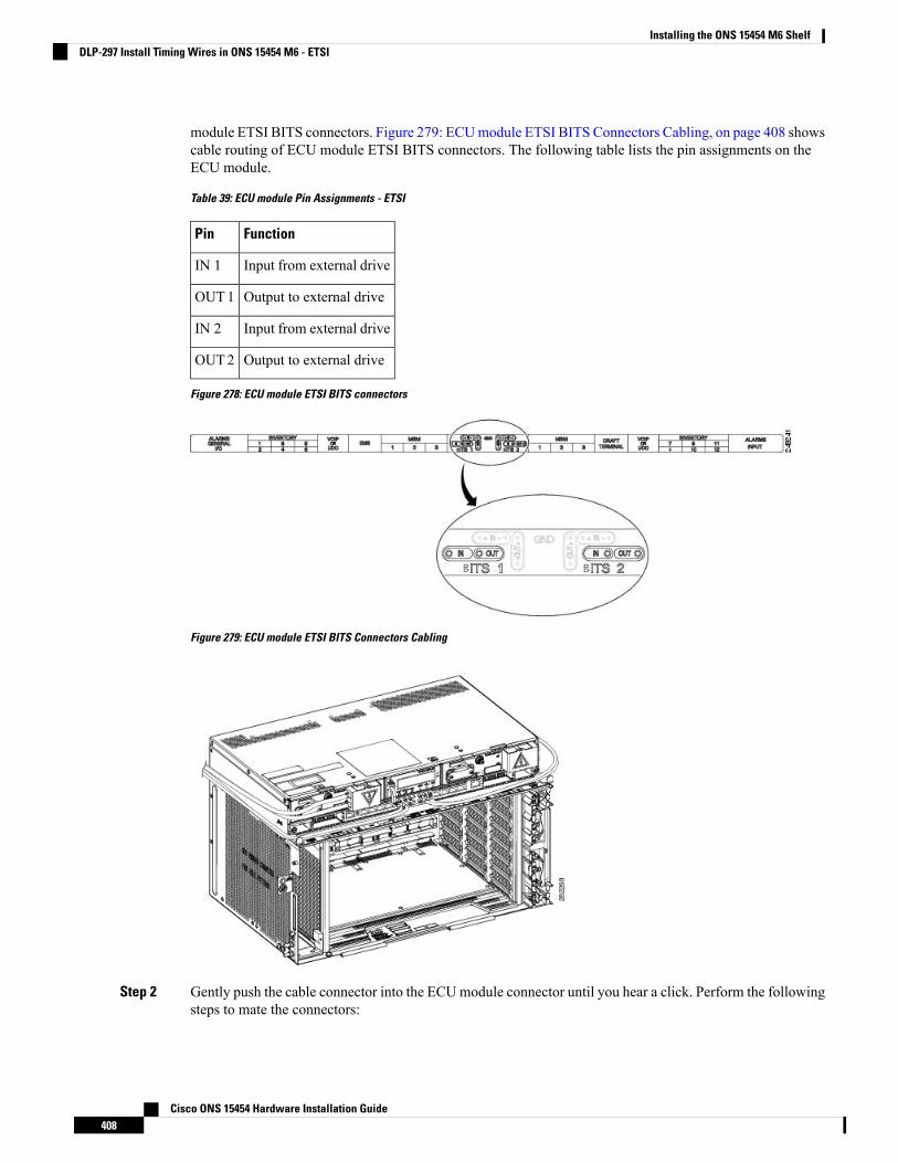
module ETSI BITS connectors. Figure 279: ECUmodule ETSI BITS Connectors Cabling, on page 408 showscable routing of ECU module ETSI BITS connectors. The following table lists the pin assignments on theECU module.
Table 39: ECU module Pin Assignments - ETSI
FunctionPin
Input from external driveIN 1
Output to external driveOUT1
Input from external driveIN 2
Output to external driveOUT2
Figure 278: ECU module ETSI BITS connectors
Figure 279: ECU module ETSI BITS Connectors Cabling
Step 2 Gently push the cable connector into the ECUmodule connector until you hear a click. Perform the followingsteps to mate the connectors:
Cisco ONS 15454 Hardware Installation Guide408
Installing the ONS 15454 M6 ShelfDLP-297 Install Timing Wires in ONS 15454 M6 - ETSI
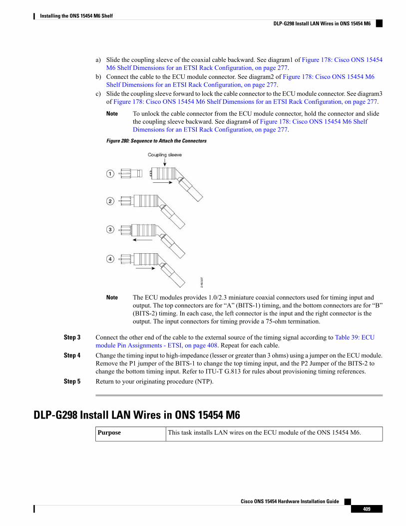
a) Slide the coupling sleeve of the coaxial cable backward. See diagram1 of Figure 178: Cisco ONS 15454M6 Shelf Dimensions for an ETSI Rack Configuration, on page 277.
b) Connect the cable to the ECU module connector. See diagram2 of Figure 178: Cisco ONS 15454 M6Shelf Dimensions for an ETSI Rack Configuration, on page 277.
c) Slide the coupling sleeve forward to lock the cable connector to the ECUmodule connector. See diagram3of Figure 178: Cisco ONS 15454 M6 Shelf Dimensions for an ETSI Rack Configuration, on page 277.
To unlock the cable connector from the ECU module connector, hold the connector and slidethe coupling sleeve backward. See diagram4 of Figure 178: Cisco ONS 15454 M6 ShelfDimensions for an ETSI Rack Configuration, on page 277.
Note
Figure 280: Sequence to Attach the Connectors
The ECU modules provides 1.0/2.3 miniature coaxial connectors used for timing input andoutput. The top connectors are for “A” (BITS-1) timing, and the bottom connectors are for “B”(BITS-2) timing. In each case, the left connector is the input and the right connector is theoutput. The input connectors for timing provide a 75-ohm termination.
Note
Step 3 Connect the other end of the cable to the external source of the timing signal according to Table 39: ECUmodule Pin Assignments - ETSI, on page 408. Repeat for each cable.
Step 4 Change the timing input to high-impedance (lesser or greater than 3 ohms) using a jumper on the ECUmodule.Remove the P1 jumper of the BITS-1 to change the top timing input, and the P2 Jumper of the BITS-2 tochange the bottom timing input. Refer to ITU-T G.813 for rules about provisioning timing references.
Step 5 Return to your originating procedure (NTP).
DLP-G298 Install LAN Wires in ONS 15454 M6This task installs LAN wires on the ECU module of the ONS 15454 M6.Purpose
Cisco ONS 15454 Hardware Installation Guide409
Installing the ONS 15454 M6 ShelfDLP-G298 Install LAN Wires in ONS 15454 M6
Standard CAT-5 Ethernet cable (straight-through for data terminating equipment[DTE] or cross-over for data circuit-terminating equipment [DCE]) or RJ-45connector Crimping tool for RJ-45 connector
0.51 mm² or 0.64 mm² (#22 or #24 AWG) wire, preferably CAT-5
Tools/Equipment
NTP-G253 Install the ECU or ECU-S Module, on page 352.Prerequisite Procedures
As neededRequired/As Needed
OnsiteOnsite/Remote
NoneSecurity Level
We recommend the use of RJ-45 port (craft terminal port or the EMS port) on the ECU module to establishLAN connectivity. The advantages of using the RJ-45 ports on the ECU module include:
• CAT-5 Ethernet cable connections can be managed better by routing the cable through the ECU modulecable exit area.
• If the TNC, TNCE, TSC, or TSCE card fails, the LAN connection is not lost during the TNC, TNCE,TSC, or TSCE card switch over.
If the ECU module is absent, you can connect a CAT-5 Ethernet cable to the LAN port on theTNC/TNCE/TSC/TSCE card to create an external LAN connection.
You can use the same procedure to connect Multishelf Management ports of several chassis in MSMconfigurations.
Note
To avoid duplexmismatch between EMS or craft terminal port and external LAN switch port, auto negotiationmust be enabled on the external LAN switch port.
Note
Procedure
Step 1 Using 0.51 mm² or 0.64 mm² (#22 or #24 AWG) wire or a standard CAT-5 Ethernet cable, connect the wiresto the RJ-45 connector.
Step 2 Return to your originating procedure (NTP).
NTP-G308 Connect the ONS 15454 M6 Multishelf Node and theONS 15454 M6 Subtending Shelves
Use this procedure to connect the ONS 15454 M6 multishelf node and the ONS15454 M6 subtending shelves.
Purpose
Cisco ONS 15454 Hardware Installation Guide410
Installing the ONS 15454 M6 ShelfNTP-G308 Connect the ONS 15454 M6 Multishelf Node and the ONS 15454 M6 Subtending Shelves
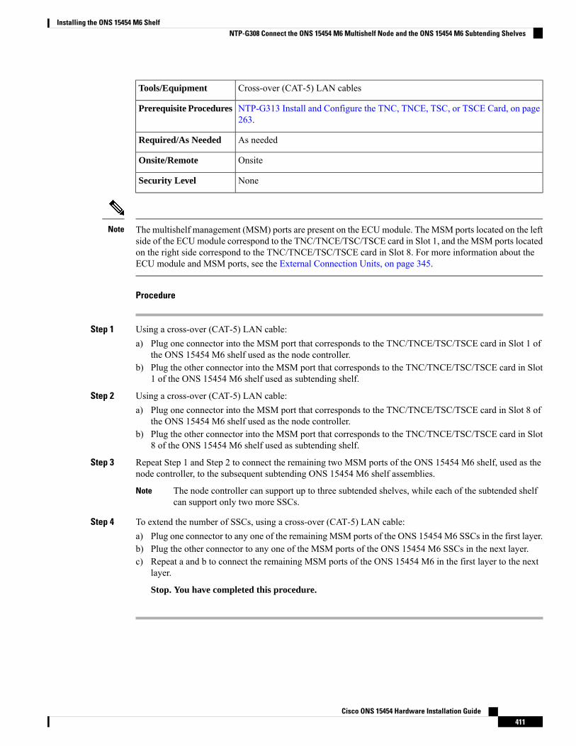
Cross-over (CAT-5) LAN cablesTools/Equipment
NTP-G313 Install and Configure the TNC, TNCE, TSC, or TSCE Card, on page263.
Prerequisite Procedures
As neededRequired/As Needed
OnsiteOnsite/Remote
NoneSecurity Level
The multishelf management (MSM) ports are present on the ECUmodule. The MSM ports located on the leftside of the ECUmodule correspond to the TNC/TNCE/TSC/TSCE card in Slot 1, and the MSM ports locatedon the right side correspond to the TNC/TNCE/TSC/TSCE card in Slot 8. For more information about theECU module and MSM ports, see the External Connection Units, on page 345.
Note
Procedure
Step 1 Using a cross-over (CAT-5) LAN cable:a) Plug one connector into the MSM port that corresponds to the TNC/TNCE/TSC/TSCE card in Slot 1 of
the ONS 15454 M6 shelf used as the node controller.b) Plug the other connector into the MSM port that corresponds to the TNC/TNCE/TSC/TSCE card in Slot
1 of the ONS 15454 M6 shelf used as subtending shelf.
Step 2 Using a cross-over (CAT-5) LAN cable:a) Plug one connector into the MSM port that corresponds to the TNC/TNCE/TSC/TSCE card in Slot 8 of
the ONS 15454 M6 shelf used as the node controller.b) Plug the other connector into the MSM port that corresponds to the TNC/TNCE/TSC/TSCE card in Slot
8 of the ONS 15454 M6 shelf used as subtending shelf.
Step 3 Repeat Step 1 and Step 2 to connect the remaining two MSM ports of the ONS 15454 M6 shelf, used as thenode controller, to the subsequent subtending ONS 15454 M6 shelf assemblies.
The node controller can support up to three subtended shelves, while each of the subtended shelfcan support only two more SSCs.
Note
Step 4 To extend the number of SSCs, using a cross-over (CAT-5) LAN cable:a) Plug one connector to any one of the remaining MSM ports of the ONS 15454 M6 SSCs in the first layer.b) Plug the other connector to any one of the MSM ports of the ONS 15454 M6 SSCs in the next layer.c) Repeat a and b to connect the remaining MSM ports of the ONS 15454 M6 in the first layer to the next
layer.
Stop. You have completed this procedure.
Cisco ONS 15454 Hardware Installation Guide411
Installing the ONS 15454 M6 ShelfNTP-G308 Connect the ONS 15454 M6 Multishelf Node and the ONS 15454 M6 Subtending Shelves
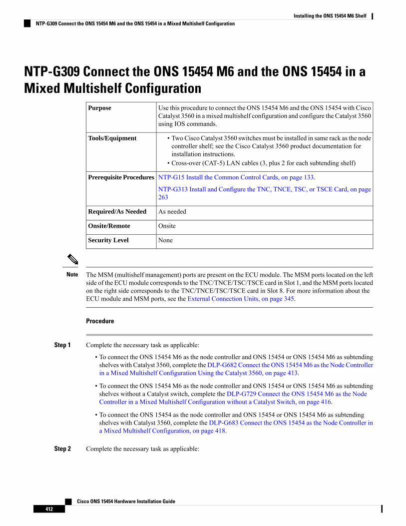
NTP-G309 Connect the ONS 15454 M6 and the ONS 15454 in aMixed Multishelf Configuration
Use this procedure to connect the ONS 15454M6 and the ONS 15454 with CiscoCatalyst 3560 in a mixedmultishelf configuration and configure the Catalyst 3560using IOS commands.
Purpose
• Two Cisco Catalyst 3560 switches must be installed in same rack as the nodecontroller shelf; see the Cisco Catalyst 3560 product documentation forinstallation instructions.
• Cross-over (CAT-5) LAN cables (3, plus 2 for each subtending shelf)
Tools/Equipment
NTP-G15 Install the Common Control Cards, on page 133.
NTP-G313 Install and Configure the TNC, TNCE, TSC, or TSCE Card, on page263
Prerequisite Procedures
As neededRequired/As Needed
OnsiteOnsite/Remote
NoneSecurity Level
The MSM (multishelf management) ports are present on the ECUmodule. The MSM ports located on the leftside of the ECUmodule corresponds to the TNC/TNCE/TSC/TSCE card in Slot 1, and theMSM ports locatedon the right side corresponds to the TNC/TNCE/TSC/TSCE card in Slot 8. For more information about theECU module and MSM ports, see the External Connection Units, on page 345.
Note
Procedure
Step 1 Complete the necessary task as applicable:
• To connect the ONS 15454 M6 as the node controller and ONS 15454 or ONS 15454 M6 as subtendingshelves with Catalyst 3560, complete the DLP-G682 Connect the ONS 15454M6 as the Node Controllerin a Mixed Multishelf Configuration Using the Catalyst 3560, on page 413.
• To connect the ONS 15454 M6 as the node controller and ONS 15454 or ONS 15454 M6 as subtendingshelves without a Catalyst switch, complete the DLP-G729 Connect the ONS 15454 M6 as the NodeController in a Mixed Multishelf Configuration without a Catalyst Switch, on page 416.
• To connect the ONS 15454 as the node controller and ONS 15454 or ONS 15454 M6 as subtendingshelves with Catalyst 3560, complete the DLP-G683 Connect the ONS 15454 as the Node Controller ina Mixed Multishelf Configuration, on page 418.
Step 2 Complete the necessary task as applicable:
Cisco ONS 15454 Hardware Installation Guide412
Installing the ONS 15454 M6 ShelfNTP-G309 Connect the ONS 15454 M6 and the ONS 15454 in a Mixed Multishelf Configuration
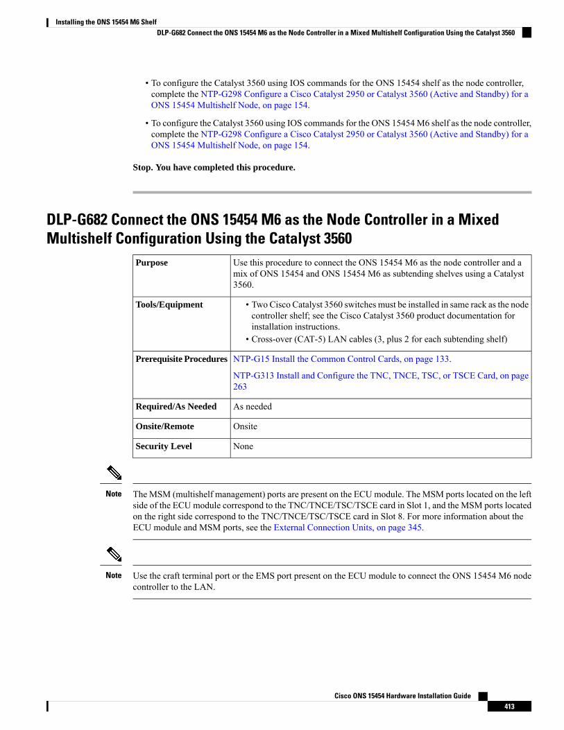
• To configure the Catalyst 3560 using IOS commands for the ONS 15454 shelf as the node controller,complete the NTP-G298 Configure a Cisco Catalyst 2950 or Catalyst 3560 (Active and Standby) for aONS 15454 Multishelf Node, on page 154.
• To configure the Catalyst 3560 using IOS commands for the ONS 15454M6 shelf as the node controller,complete the NTP-G298 Configure a Cisco Catalyst 2950 or Catalyst 3560 (Active and Standby) for aONS 15454 Multishelf Node, on page 154.
Stop. You have completed this procedure.
DLP-G682 Connect the ONS 15454 M6 as the Node Controller in a MixedMultishelf Configuration Using the Catalyst 3560
Use this procedure to connect the ONS 15454 M6 as the node controller and amix of ONS 15454 and ONS 15454 M6 as subtending shelves using a Catalyst3560.
Purpose
• Two Cisco Catalyst 3560 switches must be installed in same rack as the nodecontroller shelf; see the Cisco Catalyst 3560 product documentation forinstallation instructions.
• Cross-over (CAT-5) LAN cables (3, plus 2 for each subtending shelf)
Tools/Equipment
NTP-G15 Install the Common Control Cards, on page 133.
NTP-G313 Install and Configure the TNC, TNCE, TSC, or TSCE Card, on page263
Prerequisite Procedures
As neededRequired/As Needed
OnsiteOnsite/Remote
NoneSecurity Level
The MSM (multishelf management) ports are present on the ECUmodule. The MSM ports located on the leftside of the ECUmodule correspond to the TNC/TNCE/TSC/TSCE card in Slot 1, and the MSM ports locatedon the right side correspond to the TNC/TNCE/TSC/TSCE card in Slot 8. For more information about theECU module and MSM ports, see the External Connection Units, on page 345.
Note
Use the craft terminal port or the EMS port present on the ECU module to connect the ONS 15454 M6 nodecontroller to the LAN.
Note
Cisco ONS 15454 Hardware Installation Guide413
Installing the ONS 15454 M6 ShelfDLP-G682 Connect the ONS 15454 M6 as the Node Controller in a Mixed Multishelf Configuration Using the Catalyst 3560
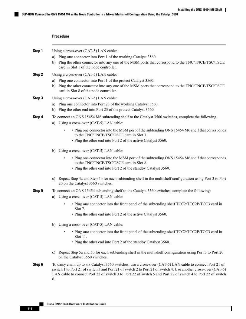
Procedure
Step 1 Using a cross-over (CAT-5) LAN cable:a) Plug one connector into Port 1 of the working Catalyst 3560.b) Plug the other connector into any one of the MSM ports that correspond to the TNC/TNCE/TSC/TSCE
card in Slot 1 of the node controller.
Step 2 Using a cross-over (CAT-5) LAN cable:a) Plug one connector into Port 1 of the protect Catalyst 3560.b) Plug the other connector into any one of the MSM ports that correspond to the TNC/TNCE/TSC/TSCE
card in Slot 8 of the node controller.
Step 3 Using a cross-over (CAT-5) LAN cable:a) Plug one connector into Port 23 of the working Catalyst 3560.b) Plug the other end into Port 23 of the protect Catalyst 3560.
Step 4 To connect an ONS 15454 M6 subtending shelf to the Catalyst 3560 switches, complete the following:a) Using a cross-over (CAT-5) LAN cable:
• • Plug one connector into the MSM port of the subtending ONS 15454M6 shelf that correspondsto the TNC/TNCE/TSC/TSCE card in Slot 1.
• Plug the other end into Port 2 of the active Catalyst 3560.
b) Using a cross-over (CAT-5) LAN cable:
• • Plug one connector into the MSM port of the subtending ONS 15454M6 shelf that correspondsto the TNC/TNCE/TSC/TSCE card in Slot 8.
• Plug the other end into Port 2 of the standby Catalyst 3560.
c) Repeat Step 4a and Step 4b for each subtending shelf in the multishelf configuration using Port 3 to Port20 on the Catalyst 3560 switches.
Step 5 To connect an ONS 15454 subtending shelf to the Catalyst 3560 switches, complete the following:a) Using a cross-over (CAT-5) LAN cable:
• • Plug one connector into the front panel of the subtending shelf TCC2/TCC2P/TCC3 card inSlot 7.
• Plug the other end into Port 2 of the active Catalyst 3560.
b) Using a cross-over (CAT-5) LAN cable:
• • Plug one connector into the front panel of the subtending shelf TCC2/TCC2P/TCC3 card inSlot 11.
• Plug the other end into Port 2 of the standby Catalyst 3560.
c) Repeat Step 5a and 5b for each subtending shelf in the multishelf configuration using Port 3 to Port 20on the Catalyst 3560 switches.
Step 6 To daisy chain up to six Catalyst 3560 switches, use a cross-over (CAT-5) LAN cable to connect Port 21 ofswitch 1 to Port 21 of switch 3 and Port 21 of switch 2 to Port 21 of switch 4. Use another cross-over (CAT-5)LAN cable to connect Port 22 of switch 3 to Port 22 of switch 5 and Port 22 of switch 4 to Port 22 of switch6.
Cisco ONS 15454 Hardware Installation Guide414
Installing the ONS 15454 M6 ShelfDLP-G682 Connect the ONS 15454 M6 as the Node Controller in a Mixed Multishelf Configuration Using the Catalyst 3560
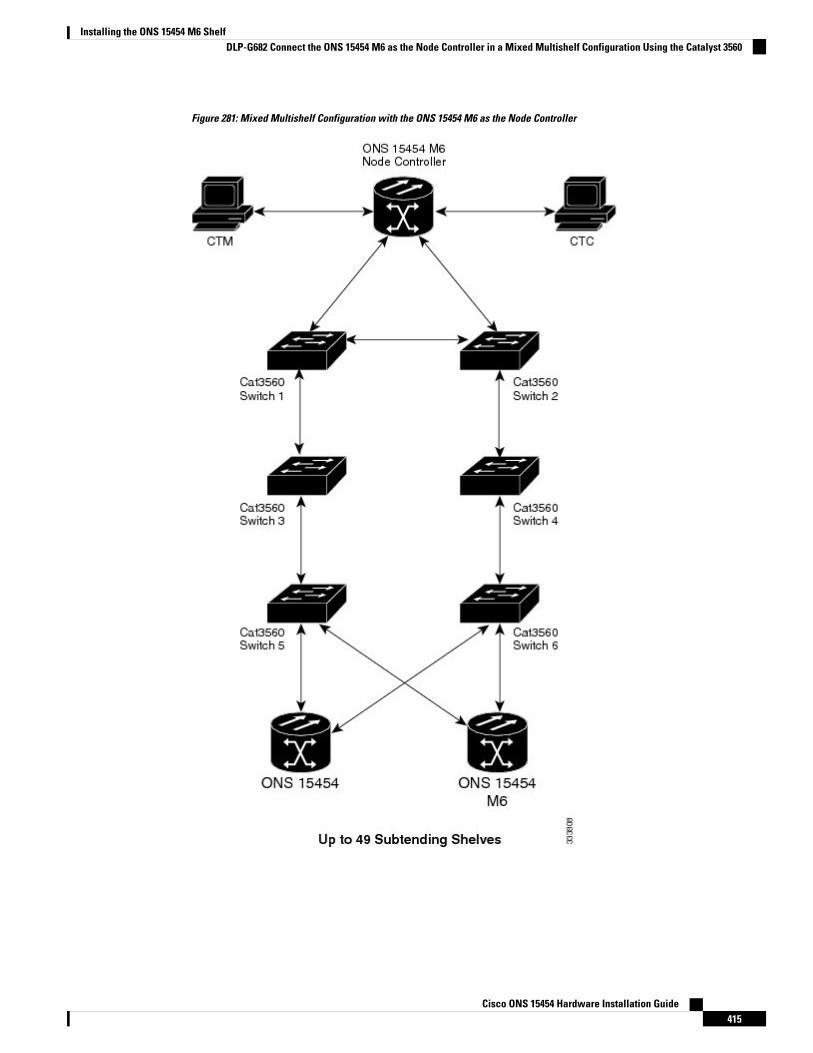
Figure 281: Mixed Multishelf Configuration with the ONS 15454 M6 as the Node Controller
Cisco ONS 15454 Hardware Installation Guide415
Installing the ONS 15454 M6 ShelfDLP-G682 Connect the ONS 15454 M6 as the Node Controller in a Mixed Multishelf Configuration Using the Catalyst 3560
In order to connect the ONS 15454 M6 subtending shelves to the ONS 15454 M6 node controllerwithout using a catalyst, follow the steps described in NTP-G308 Connect the ONS 15454 M6Multishelf Node and the ONS 15454 M6 Subtending Shelves, on page 410. To connect an ONS15454 subtending shelf to the ONS 15454 M6 node controller without using a catalyst switch,connect the MSM ports that correspond to the TNC/TNCE/TSC/TSCE cards in Slot 1 and Slot 8of the ONS 15454 M6 node controller to the ONS 15454 subtending shelf TCC2/TCC2P/TCC3cards in Slot 7 and Slot 11.
Note
Step 7 Return to your originating procedure (NTP).
DLP-G729 Connect the ONS 15454 M6 as the Node Controller in a MixedMultishelf Configuration without a Catalyst Switch
Use this procedure to connect the ONS 15454 M6 as the node controller and amix of ONS 15454 and ONS 15454 M6 as subtending shelves without using aCatalyst switch.
Purpose
• Cross-over (CAT-5) LAN cables (3, plus 2 for each subtending shelf)Tools/Equipment
NTP-G15 Install the Common Control Cards, on page 133.
NTP-G313 Install and Configure the TNC, TNCE, TSC, or TSCE Card, on page263
Prerequisite Procedures
As neededRequired/As Needed
OnsiteOnsite/Remote
NoneSecurity Level
The MSM (multishelf management) ports are present on the ECUmodule. The MSM ports located on the leftside of the ECUmodule correspond to the TNC/TNCE/TSC/TSCE card in Slot 1, and the MSM ports locatedon the right side correspond to the TNC/TNCE/TSC/TSCE card in Slot 8. For more information about theECU module and MSM ports, see the External Connection Units, on page 345.
Note
Use the craft terminal port or the EMS port present on the ECU module to connect the ONS 15454 M6 nodecontroller to the LAN.
Note
Procedure
Step 1 To connect an ONS 15454M6 subtending shelf to the ONS 15454M6 node controller, complete the following:a) Using a cross-over (CAT-5) LAN cable:
Cisco ONS 15454 Hardware Installation Guide416
Installing the ONS 15454 M6 ShelfDLP-G729 Connect the ONS 15454 M6 as the Node Controller in a Mixed Multishelf Configuration without a Catalyst Switch
• • Plug one connector into the MSM port of the subtending ONS 15454M6 shelf that correspondsto the TNC/TNCE/TSC/TSCE card in Slot 1.
• Plug the other end into the MSM port of the node controller ONS 15454 M6 shelf thatcorresponds to the TNC/TNCE/TSC/TSCE card in Slot 1.
b) Using a cross-over (CAT-5) LAN cable:
• • Plug one connector into the MSM port of the subtending ONS 15454M6 shelf that correspondsto the TNC/TNCE/TSC/TSCE card in Slot 8.
• Plug the other end into the MSM port of the node controller ONS 15454 M6 shelf thatcorresponds to the TNC/TNCE/TSC/TSCE card in Slot 1.
c) Repeat Step 1a and Step 1b to connect the remaining MSM ports on the node controller ONS 15454 M6shelf to the MSM ports on the subtending ONS 15454 M6 shelf.
Step 2 To connect an ONS 15454 subtending shelf to the ONS 15454 M6 node controller, complete the following:a) Using a cross-over (CAT-5) LAN cable:
• • Plug one connector into the front panel of the subtending shelf TCC2/TCC2P/TCC3 card inSlot 7.
• Plug the other end into the MSM port of the node controller ONS 15454 M6 shelf thatcorresponds to the TNC/TNCE/TSC/TSCE card in Slot 1.
b) Using a cross-over (CAT-5) LAN cable:
• • Plug one connector into the front panel of the subtending shelf TCC2/TCC2P/TCC3 card inSlot 11.
• Plug the other end into the MSM port of the node controller ONS 15454 M6 shelf thatcorresponds to the TNC/TNCE/TSC/TSCE card in Slot 8.
c) Repeat Step 2a and 2b for each subtending shelf in the multishelf configuration using the remainingMSMports on the node controller ONS 15454 M6 shelf.
Step 3 To connect an ONS 15454 subtending shelf to the ONS 15454 M6 subtending shelf, complete the following:a) Using a cross-over (CAT-5) LAN cable:
• • Plug one connector into the front panel of the subtending shelf TCC2/TCC2P/TCC3 card inSlot 7.
• Plug the other end into the MSM port of the subtended ONS 15454 M6 shelf that correspondsto the TNC/TNCE/TSC/TSCE card in Slot 1.
b) Using a cross-over (CAT-5) LAN cable:
• • Plug one connector into the front panel of the subtending shelf TCC2/TCC2P/TCC3 card inSlot 11.
• Plug the other end into the MSM port of the subtended ONS 15454 M6 shelf that correspondsto the TNC/TNCE/TSC/TSCE card in Slot 8.
c) Repeat Step 3a and 3b for each subtending shelf in the multishelf configuration using the remainingMSMports on the subtending ONS 15454 M6 shelf.
Cisco ONS 15454 Hardware Installation Guide417
Installing the ONS 15454 M6 ShelfDLP-G729 Connect the ONS 15454 M6 as the Node Controller in a Mixed Multishelf Configuration without a Catalyst Switch

Figure 282: Mixed Multishelf Configuration without a Catalyst Switch Using ONS 15454 M6 as the Node Controller
Step 4 Return to your originating procedure (NTP).
DLP-G683 Connect the ONS 15454 as the Node Controller in a Mixed MultishelfConfiguration
Use this procedure to connect the ONS 15454 as the node controller and a mixof ONS 15454 and ONS 15454M6 as subtending shelves using the Catalyst 3560.
Purpose
• Two Cisco Catalyst 3560 switches must be installed in same rack as the nodecontroller shelf; refer to the Cisco Catalyst 3560 product documentation forinstallation instructions.
• Cross-over (CAT-5) LAN cables
Tools/Equipment
NTP-G15 Install the Common Control Cards, on page 133.
NTP-G313 Install and Configure the TNC, TNCE, TSC, or TSCE Card, on page263
Prerequisite Procedures
Cisco ONS 15454 Hardware Installation Guide418
Installing the ONS 15454 M6 ShelfDLP-G683 Connect the ONS 15454 as the Node Controller in a Mixed Multishelf Configuration
As neededRequired/As Needed
OnsiteOnsite/Remote
NoneSecurity Level
The MSM (multishelf management) ports are present on the ECUmodule. The MSM ports located on the leftside of the ECUmodule correspond to the TNC/TNCE/TSC/TSCE card in Slot 1, and the MSM ports locatedon the right side correspond to the TNC/TNCE/TSC/TSCE card in Slot 8. For more information about theECU module and MSM ports, see the External Connection Units, on page 345.
Note
This procedure explains the steps to connect the ONS 15454 multishelf node and subtending shelves to a24-port Catalyst 2950 or Catalyst 3560 switch. Follow the steps provided in this procedure to connect themultishelf node to the 48-port Catalyst 2950 or Catalyst 3560 switch.
Note
Cisco ONS 15454 M12 subtended shelf does not support connecting to NCS multi-shelf node.Note
Procedure
Step 1 Using a cross-over (CAT-5) LAN cable:a) Plug one connector into Port 1 of the active Catalyst 3560.b) Plug the other connector into the front panel of the node controller TCC2/TCC2P/TCC3 card in Slot 7.
Step 2 Using a cross-over (CAT-5) LAN cable:a) Plug one connector into Port 1 of the standby Catalyst 3560.b) Plug the other connector into the front panel of the node controller TCC2/TCC2P/TCC3 card in Slot 11.
Step 3 Using a cross-over (CAT-5) LAN cable:a) Plug one connector into Port 23 of the active Catalyst 3560.b) Plug the other connector into Port 23 of the standby Catalyst 3560.
Use TCC3 cards in the ONS 15454 node controller while connecting it to the ONS 15454 M6subtending shelves and when there are more than 12 subtending shelves.
Note
Step 4 To connect an ONS 15454 M6 subtending shelf to the Catalyst 3560 switches, complete the following:a) Using a cross-over (CAT-5) LAN cable:
• • Plug one connector into the MSM port of the subtending ONS 15454M6 shelf that correspondsto the TNC/TNCE/TSC/TSCE card in Slot 1.
• Plug the other connector into Port 2 of the active Catalyst 3560.
b) Using a cross-over (CAT-5) LAN cable:
Cisco ONS 15454 Hardware Installation Guide419
Installing the ONS 15454 M6 ShelfDLP-G683 Connect the ONS 15454 as the Node Controller in a Mixed Multishelf Configuration

• • Plug one connector into the MSM port of the subtending ONS 15454M6 shelf that correspondsto the TNC/TNCE/TSC/TSCE card in Slot 8.
• Plug the other connector into Port 2 of the standby Catalyst 3560.
c) Repeat Steps 4a and 4b for each subtending shelf in the multishelf configuration using Port 3 to Port 20on the Catalyst 3560 switches.
Step 5 To connect an ONS 15454 subtending shelf to the Catalyst 3560 switches, complete the following:a) Using a cross-over (CAT-5) LAN cable:
• • Plug one connector into the front panel of the subtending shelf TCC2/TCC2P/TCC3 card inSlot 7.
• Plug the other connector into Port 2 of the active Catalyst 3560.
b) Using a cross-over (CAT-5) LAN cable:
• • Plug one connector into the front panel of the subtending shelf TCC2/TCC2P/TCC3 card inSlot 11.
• Plug the other connector into Port 2 of the standby Catalyst 3560.
c) Repeat Step 5a and 5b for each subtending shelf in the multishelf configuration using Port 3 to Port 20on the Catalyst 3560 switches.
Step 6 To daisy chain up to six Catalyst 3560 switches, use a cross-over (CAT-5) LAN cable to connect Port 21 ofswitch 1 to Port 21 of switch 3 and Port 21 of switch 2 to Port 21 of switch 4. Use another cross-over (CAT-5)LAN cable to connect Port 22 of switch 3 to Port 22 of switch 5 and Port 22 of switch 4 to Port 22 of switch6.
Cisco ONS 15454 Hardware Installation Guide420
Installing the ONS 15454 M6 ShelfDLP-G683 Connect the ONS 15454 as the Node Controller in a Mixed Multishelf Configuration
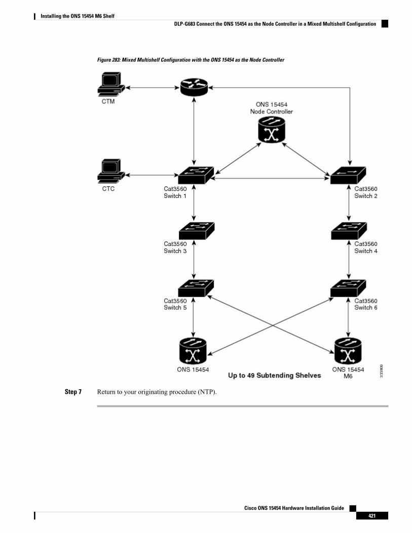
Figure 283: Mixed Multishelf Configuration with the ONS 15454 as the Node Controller
Step 7 Return to your originating procedure (NTP).
Cisco ONS 15454 Hardware Installation Guide421
Installing the ONS 15454 M6 ShelfDLP-G683 Connect the ONS 15454 as the Node Controller in a Mixed Multishelf Configuration
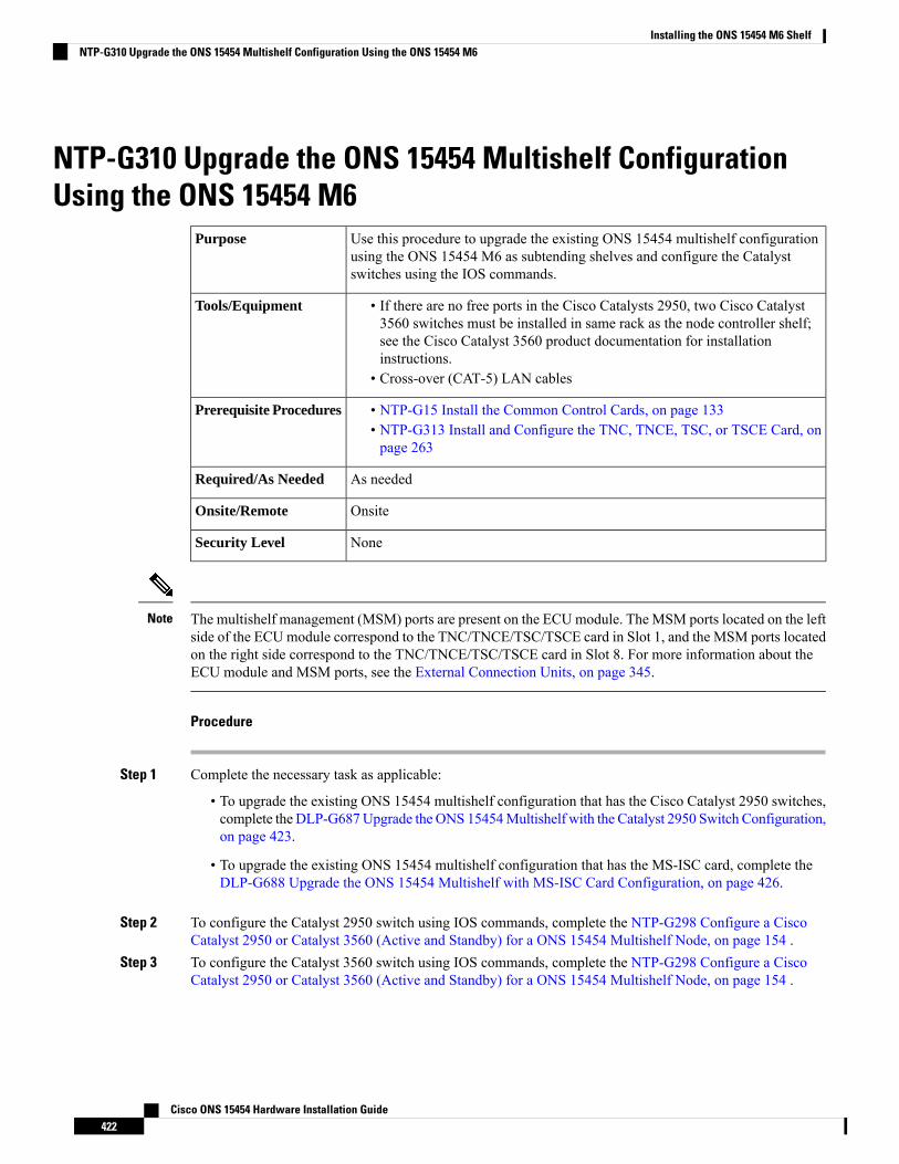
NTP-G310 Upgrade the ONS 15454 Multishelf ConfigurationUsing the ONS 15454 M6
Use this procedure to upgrade the existing ONS 15454 multishelf configurationusing the ONS 15454 M6 as subtending shelves and configure the Catalystswitches using the IOS commands.
Purpose
• If there are no free ports in the Cisco Catalysts 2950, two Cisco Catalyst3560 switches must be installed in same rack as the node controller shelf;see the Cisco Catalyst 3560 product documentation for installationinstructions.
• Cross-over (CAT-5) LAN cables
Tools/Equipment
• NTP-G15 Install the Common Control Cards, on page 133• NTP-G313 Install and Configure the TNC, TNCE, TSC, or TSCE Card, onpage 263
Prerequisite Procedures
As neededRequired/As Needed
OnsiteOnsite/Remote
NoneSecurity Level
The multishelf management (MSM) ports are present on the ECUmodule. The MSM ports located on the leftside of the ECUmodule correspond to the TNC/TNCE/TSC/TSCE card in Slot 1, and the MSM ports locatedon the right side correspond to the TNC/TNCE/TSC/TSCE card in Slot 8. For more information about theECU module and MSM ports, see the External Connection Units, on page 345.
Note
Procedure
Step 1 Complete the necessary task as applicable:
• To upgrade the existing ONS 15454 multishelf configuration that has the Cisco Catalyst 2950 switches,complete the DLP-G687Upgrade the ONS 15454Multishelf with the Catalyst 2950 Switch Configuration,on page 423.
• To upgrade the existing ONS 15454 multishelf configuration that has the MS-ISC card, complete theDLP-G688 Upgrade the ONS 15454 Multishelf with MS-ISC Card Configuration, on page 426.
Step 2 To configure the Catalyst 2950 switch using IOS commands, complete the NTP-G298 Configure a CiscoCatalyst 2950 or Catalyst 3560 (Active and Standby) for a ONS 15454 Multishelf Node, on page 154 .
Step 3 To configure the Catalyst 3560 switch using IOS commands, complete the NTP-G298 Configure a CiscoCatalyst 2950 or Catalyst 3560 (Active and Standby) for a ONS 15454 Multishelf Node, on page 154 .
Cisco ONS 15454 Hardware Installation Guide422
Installing the ONS 15454 M6 ShelfNTP-G310 Upgrade the ONS 15454 Multishelf Configuration Using the ONS 15454 M6
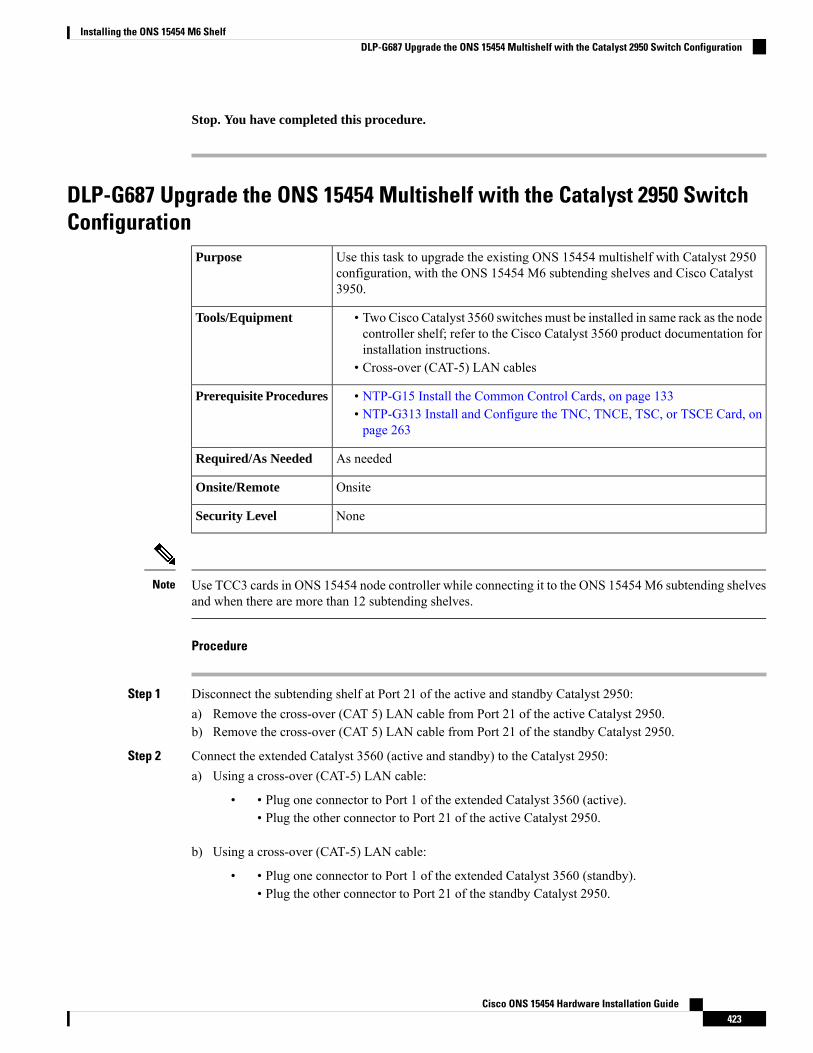
Stop. You have completed this procedure.
DLP-G687 Upgrade the ONS 15454 Multishelf with the Catalyst 2950 SwitchConfiguration
Use this task to upgrade the existing ONS 15454 multishelf with Catalyst 2950configuration, with the ONS 15454 M6 subtending shelves and Cisco Catalyst3950.
Purpose
• Two Cisco Catalyst 3560 switches must be installed in same rack as the nodecontroller shelf; refer to the Cisco Catalyst 3560 product documentation forinstallation instructions.
• Cross-over (CAT-5) LAN cables
Tools/Equipment
• NTP-G15 Install the Common Control Cards, on page 133• NTP-G313 Install and Configure the TNC, TNCE, TSC, or TSCE Card, onpage 263
Prerequisite Procedures
As neededRequired/As Needed
OnsiteOnsite/Remote
NoneSecurity Level
Use TCC3 cards in ONS 15454 node controller while connecting it to the ONS 15454 M6 subtending shelvesand when there are more than 12 subtending shelves.
Note
Procedure
Step 1 Disconnect the subtending shelf at Port 21 of the active and standby Catalyst 2950:a) Remove the cross-over (CAT 5) LAN cable from Port 21 of the active Catalyst 2950.b) Remove the cross-over (CAT 5) LAN cable from Port 21 of the standby Catalyst 2950.
Step 2 Connect the extended Catalyst 3560 (active and standby) to the Catalyst 2950:a) Using a cross-over (CAT-5) LAN cable:
• • Plug one connector to Port 1 of the extended Catalyst 3560 (active).• Plug the other connector to Port 21 of the active Catalyst 2950.
b) Using a cross-over (CAT-5) LAN cable:
• • Plug one connector to Port 1 of the extended Catalyst 3560 (standby).• Plug the other connector to Port 21 of the standby Catalyst 2950.
Cisco ONS 15454 Hardware Installation Guide423
Installing the ONS 15454 M6 ShelfDLP-G687 Upgrade the ONS 15454 Multishelf with the Catalyst 2950 Switch Configuration
Step 3 Reconnect the ONS 15454 subtending shelf disconnected in Step 1 to the Catalyst 3560 switches:a) Using a cross-over (CAT-5) LAN cable:
• • Plug one connector into the front panel of the subtending shelf TCC2/TCC2P/TCC3 card inSlot 7.
• Plug the other connector into Port 2 of the active Catalyst 3560.
b) Using a cross-over (CAT-5) LAN cable:
• • Plug one connector into the front panel of the subtending shelf TCC2/TCC2P/TCC3 card inSlot 11.
• Plug the other connector into Port 2 of the standby Catalyst 3560.
Step 4 Repeat Step 3a and Step 3b to connect additional ONS 15454 subtending shelves using Port 3 through Port20 on the Catalyst 3560 switches.
Step 5 To connect an ONS 15454 M6 subtending shelf to the Catalyst 3560 switches, complete the following:a) Using a cross-over (CAT-5) LAN cable:
• • Plug one connector into the MSM port of the subtending ONS 15454M6 shelf that correspondsto the TNC/TNCE/TSC/TSCE card in Slot 1.
• Plug the other connector into Port 3 of the active Catalyst 3560.
b) Using a cross-over (CAT-5) LAN cable:
• • Plug one connector into the MSM port of the subtending ONS 15454M6 shelf that correspondsto the TNC/TNCE/TSC/TSCE card in Slot 8.
• Plug the other connector into Port 3 of the standby Catalyst 3560.
c) Repeat Step 4a and Step 4b to connect additional ONS 15454 M6 subtending shelves in the multishelfconfiguration using Port 4 to Port 20 on the Catalyst 3560 switches.
Cisco ONS 15454 Hardware Installation Guide424
Installing the ONS 15454 M6 ShelfDLP-G687 Upgrade the ONS 15454 Multishelf with the Catalyst 2950 Switch Configuration
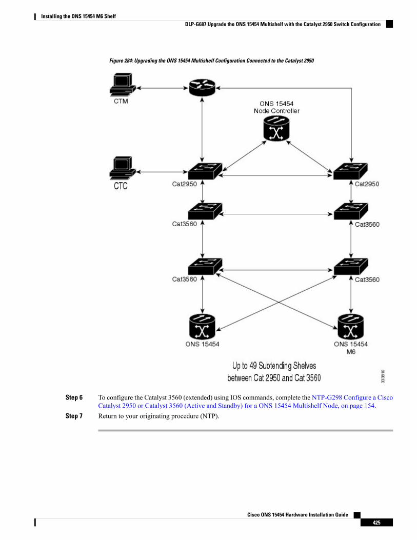
Figure 284: Upgrading the ONS 15454 Multishelf Configuration Connected to the Catalyst 2950
Step 6 To configure the Catalyst 3560 (extended) using IOS commands, complete the NTP-G298 Configure a CiscoCatalyst 2950 or Catalyst 3560 (Active and Standby) for a ONS 15454 Multishelf Node, on page 154.
Step 7 Return to your originating procedure (NTP).
Cisco ONS 15454 Hardware Installation Guide425
Installing the ONS 15454 M6 ShelfDLP-G687 Upgrade the ONS 15454 Multishelf with the Catalyst 2950 Switch Configuration
DLP-G688 Upgrade the ONS 15454 Multishelf with MS-ISC Card ConfigurationUse this task to upgrade the existing ONS 15454 multishelf configuration thathas the MS-ISC card installed, with the ONS 15454 M6 subtending shelves andCisco Catalyst 3950.
Purpose
• Two Cisco Catalyst 3560 switches must be installed in same rack as the nodecontroller shelf; refer to the Cisco Catalyst 3560 product documentation forinstallation instructions.
• Cross-over (CAT-5) LAN cables (3, plus 2 for each subtending shelf)
Tools/Equipment
• NTP-G15 Install the Common Control Cards, on page 133• NTP-G313 Install and Configure the TNC, TNCE, TSC, or TSCE Card, onpage 263
Prerequisite Procedures
As neededRequired/As Needed
OnsiteOnsite/Remote
NoneSecurity Level
Use TCC3 cards in ONS 15454 node controller while connecting it to the ONS 15454 M6 subtending shelvesand when there are more than 12 subtending shelves.
Note
The CTC in ONS 15454 M6 shelf view displays the three ports of the MS-ISC card, and EMS and circuitports present on the ECU.
Note
Procedure
Step 1 Disconnect the ONS 15454 subtending shelf from the EAPs:a) Remove the cross-over (CAT 5) LAN cable (connecting the ONS 15454 subtending shelf) from the SSC8
port of the right EAP.b) Remove the cross-over (CAT 5) LAN cable (connecting the ONS 15454 subtending shelf) from the SSC8
port of the left EAP.
Step 2 Connect the EAPs to the Catalyst 3560:a) Using a cross-over (CAT-5) LAN cable:
• • Plug one connector to the SSC8 port of the right EAP.• Plug the other connector to Port 1 of the active Catalyst 3560.
b) Using a cross-over (CAT-5) LAN cable:
• • Plug one connector to the SSC8 port of the left EAP.• Plug the other connector to Port 1 of the standby Catalyst 3560.
Cisco ONS 15454 Hardware Installation Guide426
Installing the ONS 15454 M6 ShelfDLP-G688 Upgrade the ONS 15454 Multishelf with MS-ISC Card Configuration
Step 3 Reconnect the ONS 15454 subtending shelf disconnected in Step1 to the Catalyst 3560 switches:a) Using a cross-over (CAT-5) LAN cable:
• • Plug one connector into the front panel of the subtending shelf TCC2/TCC2P/TCC3 card inSlot 7.
• Plug the other connector into Port 2 of the active Catalyst 3560.
b) Using a cross-over (CAT-5) LAN cable:
• • Plug one connector into the front panel of the subtending shelf TCC2/TCC2P/TCC3 card inSlot 11.
• Plug the other connector into Port 2 of the standby Catalyst 3560.
Step 4 Repeat Step 3a and Step 3b to connect additional ONS 15454 shelves using Port 3 to Port 24 on the Catalyst3560 switches.
Step 5 To connect an ONS 15454 M6 subtending shelf to the Catalyst 3560 switches, complete the following:a) Using a cross-over (CAT-5) LAN cable:
• • Plug one connector into the MSM port of the subtending ONS 15454M6 shelf that correspondsto the TNC/TNCE/TSC/TSCE card in Slot 1.
• Plug the other connector into Port 3 of the active Catalyst 3560.
b) Using a cross-over (CAT-5) LAN cable:
• • Plug one connector into the MSM port of the subtending ONS 15454M6 shelf that correspondsto the TNC/TNCE/TSC/TSCE card in Slot 8.
• Plug the other connector into Port 3 of the standby Catalyst 3560.
c) Repeat Steps 4a and 4b to connect additional ONS 15454 M6 subtending shelves in the multishelfconfiguration using Port 4 to Port 24 on the Catalyst 3560 switches.
Cisco ONS 15454 Hardware Installation Guide427
Installing the ONS 15454 M6 ShelfDLP-G688 Upgrade the ONS 15454 Multishelf with MS-ISC Card Configuration
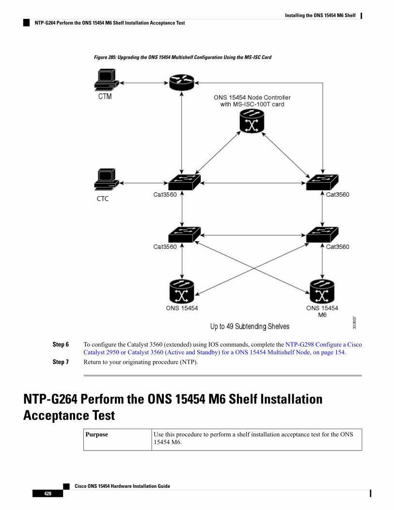
Figure 285: Upgrading the ONS 15454 Multishelf Configuration Using the MS-ISC Card
Step 6 To configure the Catalyst 3560 (extended) using IOS commands, complete the NTP-G298 Configure a CiscoCatalyst 2950 or Catalyst 3560 (Active and Standby) for a ONS 15454 Multishelf Node, on page 154.
Step 7 Return to your originating procedure (NTP).
NTP-G264 Perform the ONS 15454 M6 Shelf InstallationAcceptance Test
Use this procedure to perform a shelf installation acceptance test for the ONS15454 M6.
Purpose
Cisco ONS 15454 Hardware Installation Guide428
Installing the ONS 15454 M6 ShelfNTP-G264 Perform the ONS 15454 M6 Shelf Installation Acceptance Test
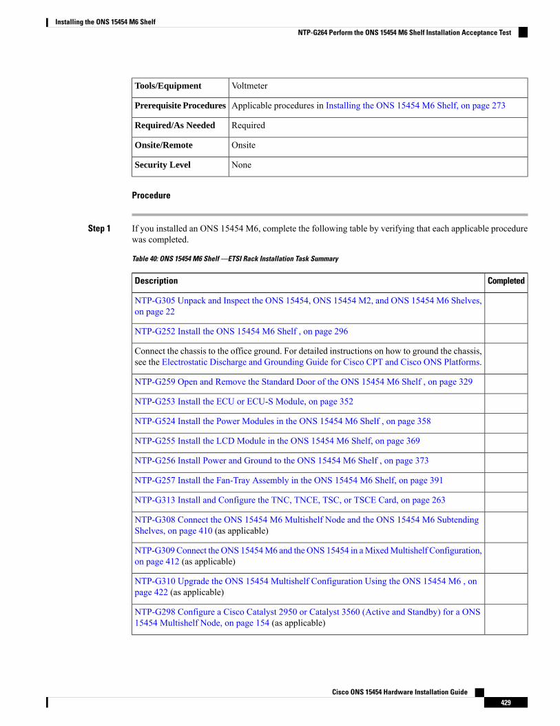
VoltmeterTools/Equipment
Applicable procedures in Installing the ONS 15454 M6 Shelf, on page 273Prerequisite Procedures
RequiredRequired/As Needed
OnsiteOnsite/Remote
NoneSecurity Level
Procedure
Step 1 If you installed an ONS 15454 M6, complete the following table by verifying that each applicable procedurewas completed.
Table 40: ONS 15454 M6 Shelf —ETSI Rack Installation Task Summary
CompletedDescription
NTP-G305 Unpack and Inspect the ONS 15454, ONS 15454 M2, and ONS 15454 M6 Shelves,on page 22
NTP-G252 Install the ONS 15454 M6 Shelf , on page 296
Connect the chassis to the office ground. For detailed instructions on how to ground the chassis,see the Electrostatic Discharge and Grounding Guide for Cisco CPT and Cisco ONS Platforms.
NTP-G259 Open and Remove the Standard Door of the ONS 15454 M6 Shelf , on page 329
NTP-G253 Install the ECU or ECU-S Module, on page 352
NTP-G524 Install the Power Modules in the ONS 15454 M6 Shelf , on page 358
NTP-G255 Install the LCD Module in the ONS 15454 M6 Shelf, on page 369
NTP-G256 Install Power and Ground to the ONS 15454 M6 Shelf , on page 373
NTP-G257 Install the Fan-Tray Assembly in the ONS 15454 M6 Shelf, on page 391
NTP-G313 Install and Configure the TNC, TNCE, TSC, or TSCE Card, on page 263
NTP-G308 Connect the ONS 15454 M6 Multishelf Node and the ONS 15454 M6 SubtendingShelves, on page 410 (as applicable)
NTP-G309 Connect the ONS 15454M6 and the ONS 15454 in aMixedMultishelf Configuration,on page 412 (as applicable)
NTP-G310 Upgrade the ONS 15454 Multishelf Configuration Using the ONS 15454 M6 , onpage 422 (as applicable)
NTP-G298 Configure a Cisco Catalyst 2950 or Catalyst 3560 (Active and Standby) for a ONS15454 Multishelf Node, on page 154 (as applicable)
Cisco ONS 15454 Hardware Installation Guide429
Installing the ONS 15454 M6 ShelfNTP-G264 Perform the ONS 15454 M6 Shelf Installation Acceptance Test
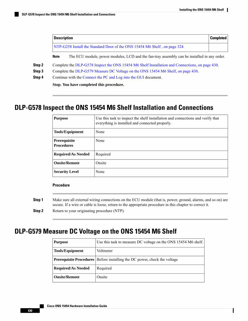
CompletedDescription
NTP-G258 Install the Standard Door of the ONS 15454 M6 Shelf , on page 324
The ECU module, power modules, LCD and the fan-tray assembly can be installed in any order.Note
Step 2 Complete the DLP-G578 Inspect the ONS 15454 M6 Shelf Installation and Connections, on page 430.Step 3 Complete the DLP-G579 Measure DC Voltage on the ONS 15454 M6 Shelf, on page 430.Step 4 Continue with the Connect the PC and Log into the GUI document.
Stop. You have completed this procedure.
DLP-G578 Inspect the ONS 15454 M6 Shelf Installation and ConnectionsUse this task to inspect the shelf installation and connections and verify thateverything is installed and connected properly.
Purpose
NoneTools/Equipment
NonePrerequisiteProcedures
RequiredRequired/As Needed
OnsiteOnsite/Remote
NoneSecurity Level
Procedure
Step 1 Make sure all external wiring connections on the ECU module (that is, power, ground, alarms, and so on) aresecure. If a wire or cable is loose, return to the appropriate procedure in this chapter to correct it.
Step 2 Return to your originating procedure (NTP).
DLP-G579 Measure DC Voltage on the ONS 15454 M6 ShelfUse this task to measure DC voltage on the ONS 15454 M6 shelf.Purpose
VoltmeterTools/Equipment
Before installing the DC power, check the voltagePrerequisite Procedures
RequiredRequired/As Needed
OnsiteOnsite/Remote
Cisco ONS 15454 Hardware Installation Guide430
Installing the ONS 15454 M6 ShelfDLP-G578 Inspect the ONS 15454 M6 Shelf Installation and Connections
NoneSecurity Level
Do not apply power to the shelf until you complete all installation steps.Caution
To ensure safety of personnel and equipment, do not connect any power cables into the power moduleuntil the module is completely installed into the chassis. Statement 389
Warning
To reduce the risk of electric shock, switch on the power only after the power cord is completely installedinto the power module. Statement 390
Warning
Procedure
Step 1 Using a voltmeter, verify the office ground and power:a) Place the black lead (positive) on the frame ground on the bay. Hold it there while completing Step b.b) Place the red lead (negative) on the fuse power points on the third-party power distribution panel to verify
that they read between –40.5 VDC and –57.6 VDC (power) and 0 (return ground).
Step 2 Using a voltmeter, verify the shelf ground and power wiring:a) Place the black lead (positive) on the RET1 and the red lead on the –48 V point. Verify a reading between
–40.5 VDC and –57.6 VDC. If there is no voltage, check the following and correct if necessary:
• Battery and ground are reversed to the shelf.• Battery is open or missing.• Return is open or missing.
Step 3 Repeat Step 1 and Step 2 for the RET2 and –48 V of the redundant power supply input.Step 4 Return to your originating procedure (NTP).
NTP-G317 Connect the ONS 15454 M6 Multishelf Node and theONS 15454 M6 Subtending Shelves with Simplex Controllers
Use this procedure to connect the ONS 15454 M6 multishelf node and the ONS15454 M6 subtending shelves with simplex controllers.
Purpose
Cross-over (CAT-5) LAN cablesTools/Equipment
NTP-G313 Install and Configure the TNC, TNCE, TSC, or TSCE Card. See theCisco ONS 15454 DWDM Configuration Guide.
Prerequisite Procedures
Cisco ONS 15454 Hardware Installation Guide431
Installing the ONS 15454 M6 ShelfNTP-G317 Connect the ONS 15454 M6 Multishelf Node and the ONS 15454 M6 Subtending Shelves with Simplex Controllers
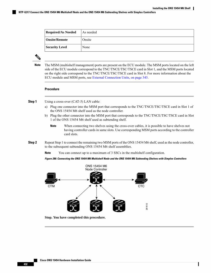
As neededRequired/As Needed
OnsiteOnsite/Remote
NoneSecurity Level
The MSM (multishelf management) ports are present on the ECUmodule. The MSM ports located on the leftside of the ECUmodule correspond to the TNC/TNCE/TSC/TSCE card in Slot 1, and the MSM ports locatedon the right side correspond to the TNC/TNCE/TSC/TSCE card in Slot 8. For more information about theECU module and MSM ports, see External Connection Units, on page 345.
Note
Procedure
Step 1 Using a cross-over (CAT-5) LAN cable:a) Plug one connector into the MSM port that corresponds to the TNC/TNCE/TSC/TSCE card in Slot 1 of
the ONS 15454 M6 shelf used as the node controller.b) Plug the other connector into the MSM port that corresponds to the TNC/TNCE/TSC/TSCE card in Slot
1 of the ONS 15454 M6 shelf used as subtending shelf.
When connecting two shelves using the cross-over cables, it is possible to have shelves nothaving controller cards in same slots. Use correspondingMSM ports according to the controllercard slots.
Note
Step 2 Repeat Step 1 to connect the remaining twoMSMports of the ONS 15454M6 shelf, used as the node controller,to the subsequent subtending ONS 15454 M6 shelf assemblies.
You can connect up to a maximum of 3 SSCs in the multishelf configuration.Note
Figure 286: Connecting the ONS 15454 M6 Multishelf Node and the ONS 15454 M6 Subtending Shelves with Simplex Controllers
Stop. You have completed this procedure.
Cisco ONS 15454 Hardware Installation Guide432
Installing the ONS 15454 M6 ShelfNTP-G317 Connect the ONS 15454 M6 Multishelf Node and the ONS 15454 M6 Subtending Shelves with Simplex Controllers
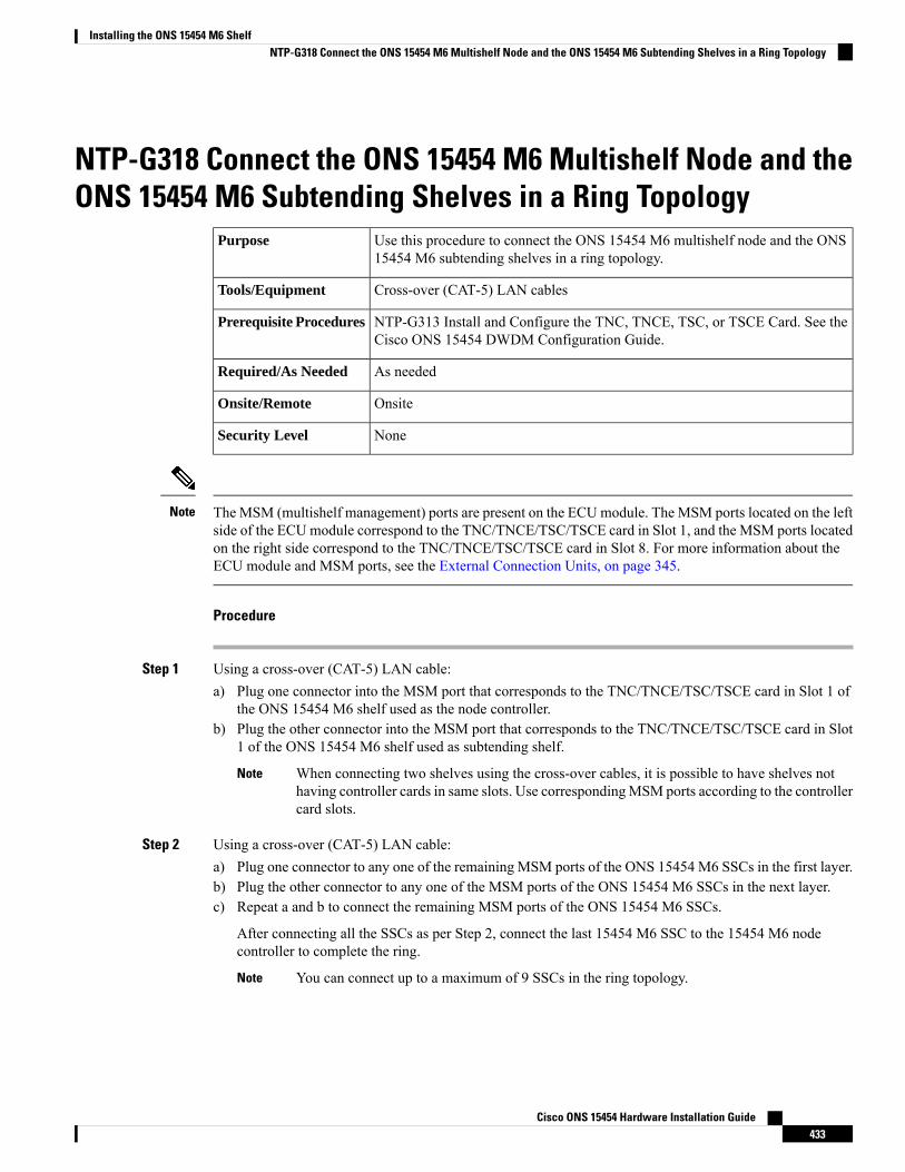
NTP-G318 Connect the ONS 15454 M6 Multishelf Node and theONS 15454 M6 Subtending Shelves in a Ring Topology
Use this procedure to connect the ONS 15454 M6 multishelf node and the ONS15454 M6 subtending shelves in a ring topology.
Purpose
Cross-over (CAT-5) LAN cablesTools/Equipment
NTP-G313 Install and Configure the TNC, TNCE, TSC, or TSCE Card. See theCisco ONS 15454 DWDM Configuration Guide.
Prerequisite Procedures
As neededRequired/As Needed
OnsiteOnsite/Remote
NoneSecurity Level
The MSM (multishelf management) ports are present on the ECUmodule. The MSM ports located on the leftside of the ECUmodule correspond to the TNC/TNCE/TSC/TSCE card in Slot 1, and the MSM ports locatedon the right side correspond to the TNC/TNCE/TSC/TSCE card in Slot 8. For more information about theECU module and MSM ports, see the External Connection Units, on page 345.
Note
Procedure
Step 1 Using a cross-over (CAT-5) LAN cable:a) Plug one connector into the MSM port that corresponds to the TNC/TNCE/TSC/TSCE card in Slot 1 of
the ONS 15454 M6 shelf used as the node controller.b) Plug the other connector into the MSM port that corresponds to the TNC/TNCE/TSC/TSCE card in Slot
1 of the ONS 15454 M6 shelf used as subtending shelf.
When connecting two shelves using the cross-over cables, it is possible to have shelves nothaving controller cards in same slots. Use correspondingMSM ports according to the controllercard slots.
Note
Step 2 Using a cross-over (CAT-5) LAN cable:a) Plug one connector to any one of the remaining MSM ports of the ONS 15454 M6 SSCs in the first layer.b) Plug the other connector to any one of the MSM ports of the ONS 15454 M6 SSCs in the next layer.c) Repeat a and b to connect the remaining MSM ports of the ONS 15454 M6 SSCs.
After connecting all the SSCs as per Step 2, connect the last 15454 M6 SSC to the 15454 M6 nodecontroller to complete the ring.
You can connect up to a maximum of 9 SSCs in the ring topology.Note
Cisco ONS 15454 Hardware Installation Guide433
Installing the ONS 15454 M6 ShelfNTP-G318 Connect the ONS 15454 M6 Multishelf Node and the ONS 15454 M6 Subtending Shelves in a Ring Topology
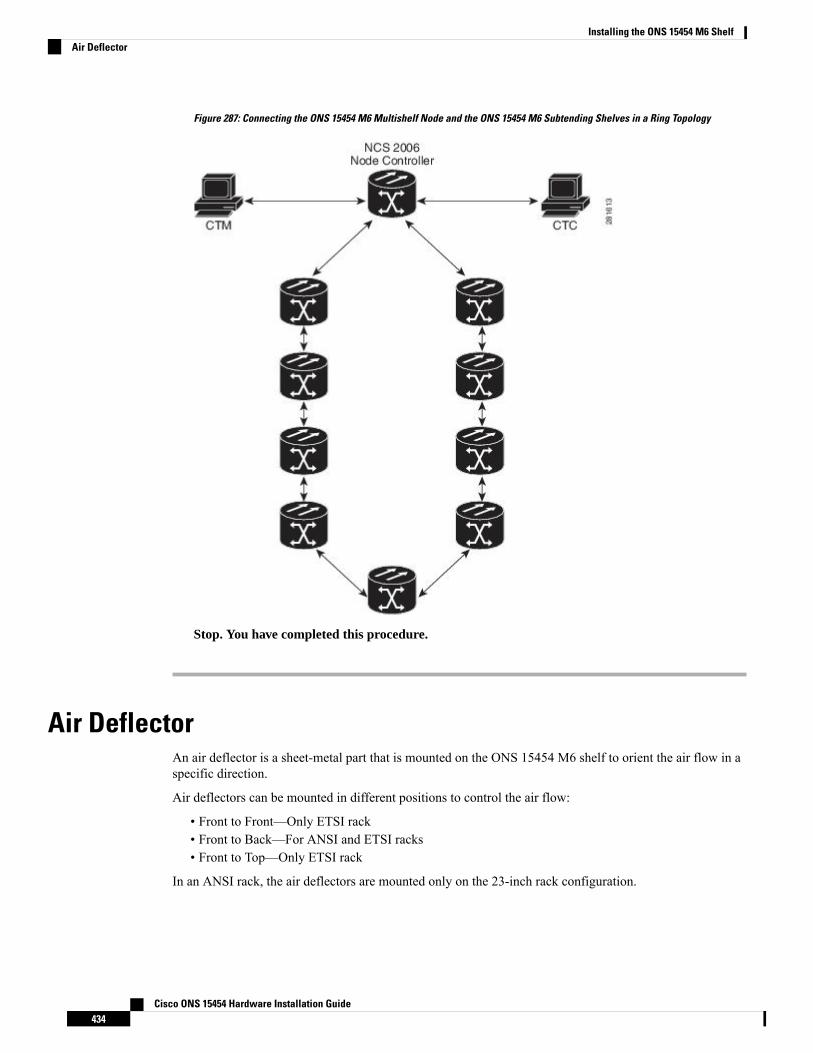
Figure 287: Connecting the ONS 15454 M6 Multishelf Node and the ONS 15454 M6 Subtending Shelves in a Ring Topology
Stop. You have completed this procedure.
Air DeflectorAn air deflector is a sheet-metal part that is mounted on the ONS 15454 M6 shelf to orient the air flow in aspecific direction.
Air deflectors can be mounted in different positions to control the air flow:
• Front to Front—Only ETSI rack• Front to Back—For ANSI and ETSI racks• Front to Top—Only ETSI rack
In an ANSI rack, the air deflectors are mounted only on the 23-inch rack configuration.
Cisco ONS 15454 Hardware Installation Guide434
Installing the ONS 15454 M6 ShelfAir Deflector
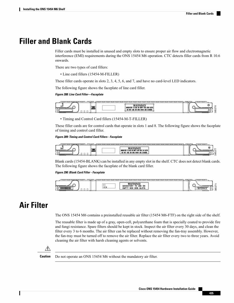
Filler and Blank CardsFiller cards must be installed in unused and empty slots to ensure proper air flow and electromagneticinterference (EMI) requirements during the ONS 15454 M6 operation. CTC detects filler cards from R 10.6onwards.
There are two types of card fillers:
• Line card fillers (15454-M-FILLER)
These filler cards operate in slots 2, 3, 4, 5, 6, and 7, and have no card-level LED indicators.
The following figure shows the faceplate of line card filler.
Figure 288: Line Card Filler—Faceplate
• Timing and Control Card fillers (15454-M-T-FILLER)
These filler cards are for control cards that operate in slots 1 and 8. The following figure shows the faceplateof timing and control card filler.
Figure 289: Timing and Control Card Fillers - Faceplate
Blank cards (15454-BLANK) can be installed in any empty slot in the shelf. CTC does not detect blank cards.The following figure shows the faceplate of the blank card filler.
Figure 290: Blank Card Filler - Faceplate
Air FilterThe ONS 15454 M6 contains a preinstalled reusable air filter (15454 M6-FTF) on the right side of the shelf.
The reusable filter is made up of a gray, open-cell, polyurethane foam that is specially coated to provide fireand fungi resistance. Spare filters should be kept in stock. Inspect the air filter every 30 days, and clean thefilter every 3 to 6 months. The air filter can be replaced without removing the fan-tray assembly. However,the fan-tray must be turned off to remove the air filter. Replace the air filter every two to three years. Avoidcleaning the air filter with harsh cleaning agents or solvents.
Do not operate an ONS 15454 M6 without the mandatory air filter.Caution
Cisco ONS 15454 Hardware Installation Guide435
Installing the ONS 15454 M6 ShelfFiller and Blank Cards
Shelf Voltage and Temperature
The temperature that the TNC, TNCE, TSC, or TSCE sensors measure appear on the LCD screen in the ONS15454 M6 chassis.
Note
The input voltages and temperature of the ONS 15454 M6 chassis are displayed in the Shelf view >Provisioning >General >Voltage/Temperature pane in CTC. The voltage supplied to the shelf (in millivolts)is displayed in the Voltage area of the Voltage/Temperature pane. The temperature of the shelf (in degreeCelsius) is displayed in the Temperature area of the pane.
The Voltage/Temperature pane retrieves the following values for the ONS 15454 M6 chassis:
• Voltage A—Voltage of the shelf that corresponds to power supply A, in millivolts.• Voltage B—Voltage of the shelf that corresponds to power supply B, in millivolts.• Chassis Temperature—Temperature of the shelf, in degrees Celsius.
In a multishelf configuration, the voltage and temperature of each shelf is displayed in the Shelf view >Provisioning > General > Voltage/Temperature pane.
Cooling ProfileThe cooling profile feature allows you to control the speed of the fans in the ONS 15454 M6 shelf dependingon the I/O cards used.
CTC allows you to choose a cooling profile for ONS 15454 M6 shelf. You can change the cooling profile inShelf view > Provisioning > General > Voltage/Temperature pane in CTC. The supported cooling profilevalues are Low, Medium, and High. The default cooling profile value is High. You can change the coolingprofile depending on the cards used in the shelf.
If there are multiple cards in the shelf, you must choose the cooling profile of the card that requires the highestcooling profile. For example, if the shelf has two cards with low cooling profile, three cards with mediumcooling profile, and one card with high cooling profile, you must choose a high cooling profile for the shelf.
The wrong cooling profile chosen for the shelf might harm the cards present in the shelf.Caution
If a wrong cooling profile is chosen for the shelf, the COOL-MISM condition is raised on the shelf. For moreinformation on the alarm, see the “COOL-MISM” alarm in Chapter 2, Alarm Troubleshooting of Cisco ONS15454 DWDM Troubleshooting Guide .
The following table shows the cards that require high, medium, and low cooling profile.
Cisco ONS 15454 Hardware Installation Guide436
Installing the ONS 15454 M6 ShelfShelf Voltage and Temperature

Table 41: Cooling Profile Values for ONS 15454 M6 Cards
Cards with High Cooling ProfileCards with Medium Cooling ProfileCards with Low Cooling Profile
• 100G-LC-C• 10X10G-LC• CFP-LC• EDRA1-26, EDRA1-35• EDRA2-26, EDRA2-35
• 10GE-XP• 40-SMR1-C• 40-SMR2-C• 40-WSS-C• 40-WSS-L
• 32-WSS• 32-WSS-L• 32-DMX• 32-DMX-L• 32-DMX-O
• 40E-MXP-C• 40E-TXP-C• 40G-MXP-C• 40G-TXP-C• ADM-10G
• 40-DMX-C• 40-DMX-L• 32-MUX-O• 40-MUX-C• 40-MUX-L
• AR_MXP• AR_XP• GE-XP• MXP_2.5G_10E• MXP_2.5G_10G
• 40-WXC-C• 40-WXC-L• 80-WXC-C• AD-1B• AD-1C
• MXP_2.5G_10X• MXP_MR_10DME• MXP_MR_10DMEX• MXP_MR_2.5G• MXPP_MR_2.5G
• AD-2C• AD-4B• AD-4C• MD-4• MMU
• OPT-RAMP-C• OPT-RAMP-CE• OTU2_XP• RAMAN-COP• RAMAN-CTP
• OPT-AMP-17-C• OPT-AMP-C• OPT-AMP-L• OPT-BST• OPT-BST-E• OPT-BST-L• OPT-EDFA-17• OPT-EDFA-24• OPT-PRE• OSCM• OSC-CSM• PSM• TDC-CC• TDC-FC• TXP_MR_10E• TXP_MR_10EX• TXP_MR_10G• TXP_MR_2.5G• TXPP_MR_2.5G
Cisco ONS 15454 Hardware Installation Guide437
Installing the ONS 15454 M6 ShelfCooling Profile

Cisco ONS 15454 Hardware Installation Guide438
Installing the ONS 15454 M6 ShelfCooling Profile

C H A P T E R 6Maintaining the ONS 15454 M12 (ANSI and ETSI),ONS 15454 M2 and ONS 15454 M6 Shelf
This chapter explains how to maintain the ONS 15454 (ANSI and ETSI), ONS 15454 M2 and ONS 15454M6 shelf installations.
Unless otherwise specified, “ONS 15454” refers to both ANSI and ETSI M12 shelf assemblies.Note
Due to memory limitations, TCC2/TCC2P cards are not supported as the node controller in multi-shelfconfiguration fromR10.5.2.6. Hence, it is recommended to use TCC3 card as the node controller in multi-shelfconfiguration. However, the TCC2/TCC2P cards can be used as a subtended controller and also in a stand-aloneconfiguration.
Note
• NTP-G114 Inspect and Replace the Air Filter, on page 439• NTP-G274 Replace the Air Filter of the ONS 15454 M2 Shelf Assembly, on page 443• NTP-G262 Replace the Air Filter of the ONS 15454 M6 Shelf Assembly, on page 445• NTP-G263 Replace the Air Filter of the AC Power Module in the ONS 15454 M6 Shelf Assembly, onpage 448
• NTP-G115 Clean Fiber Connectors, on page 449• NTP-G40 Replace the Front Door , on page 452• NTP-G116 Replace the Fan-Tray Assembly of the ONS 15454 Shelf Assembly, on page 454• NTP-G272 Replace the Fan-Tray Assembly of the ONS 15454 M2 Shelf Assembly, on page 460• NTP-G260 Replace the Fan-Tray Assembly of the ONS 15454 M6 Shelf Assembly, on page 462• NTP-G117 Replace the ANSI Shelf Alarm Interface Panel, on page 464• NTP-G118 Replace the ANSI Shelf Plastic Lower Backplane Cover, on page 467• NTP-G795 Change System Mode Using LCD, on page 468
NTP-G114 Inspect and Replace the Air FilterThis procedure ensures that the air filter is free from dirt and dust, which allowsoptimum air flow and prevents dirt and dust from entering the shelf.
Purpose
Cisco ONS 15454 Hardware Installation Guide439
New air filter, pinned hex key toolTools/Equipment
NonePrerequisite Procedures
As neededRequired/As Needed
OnsiteOnsite/Remote
NoneSecurity Level
Do not reach into a vacant slot or chassis while you install or remove a module or a fan. Exposed circuitrycould constitute an energy hazard. Statement 206
Warning
The air filters are single-use only. They must not be cleaned and reused. This is a Telcordia NEBS requirement,GR-63-CORE Issue 4.
Note
Air filters must be inspected every month. If they are dirty or clogged with dust, they must be replaced witha new air filter.
Note
If you install the air filter below 15454E-CC-FTA or 15454-CC-FTA, only filters with part numbers700-23193-01 and 700-23194-01 can be used in this configuration.
Note
Although the air filter can work with older fan trays if it is installed with either side facing up, it is recommendedthat you install it with the metal bracing facing up to preserve the surface of the filter. You must install theair filter with the metal bracing facing up with 15454E-CC-FTA or 15454-CC-FTA.
Caution
To install the air filter inside the air ramp unit (15454E-AIR-RAMP or 15454-AIR-RAMP), use the ETSIversion of the air filter (15454-FTF2 or 15454E-FTF4).
Note
Procedure
Step 1 If the air filter is installed in the external filter brackets, slide the filter out of the brackets while being carefulnot to dislodge any dust that might have collected on the filter and proceed to Step 8. Figure 291: ANSI ShelfFan-Tray Air Filter in an External Filter Bracket (Front Door Removed), on page 441 shows the fan-tray airfilter in an external filter bracket on an ANSI shelf. Figure 292: ETSI Shelf Fan-Tray Air Filter in an External
Cisco ONS 15454 Hardware Installation Guide440
Maintaining the ONS 15454 M12 (ANSI and ETSI), ONS 15454 M2 and ONS 15454 M6 ShelfNTP-G114 Inspect and Replace the Air Filter
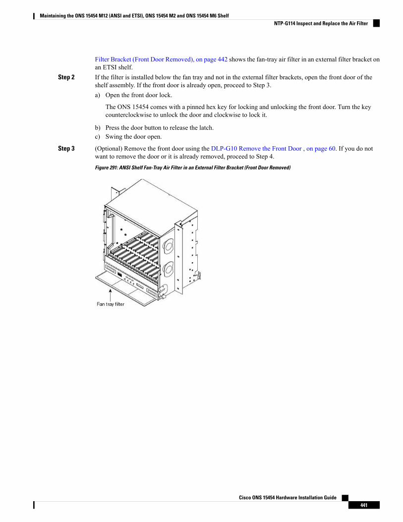
Filter Bracket (Front Door Removed), on page 442 shows the fan-tray air filter in an external filter bracket onan ETSI shelf.
Step 2 If the filter is installed below the fan tray and not in the external filter brackets, open the front door of theshelf assembly. If the front door is already open, proceed to Step 3.a) Open the front door lock.
The ONS 15454 comes with a pinned hex key for locking and unlocking the front door. Turn the keycounterclockwise to unlock the door and clockwise to lock it.
b) Press the door button to release the latch.c) Swing the door open.
Step 3 (Optional) Remove the front door using the DLP-G10 Remove the Front Door , on page 60. If you do notwant to remove the door or it is already removed, proceed to Step 4.
Figure 291: ANSI Shelf Fan-Tray Air Filter in an External Filter Bracket (Front Door Removed)
Cisco ONS 15454 Hardware Installation Guide441
Maintaining the ONS 15454 M12 (ANSI and ETSI), ONS 15454 M2 and ONS 15454 M6 ShelfNTP-G114 Inspect and Replace the Air Filter
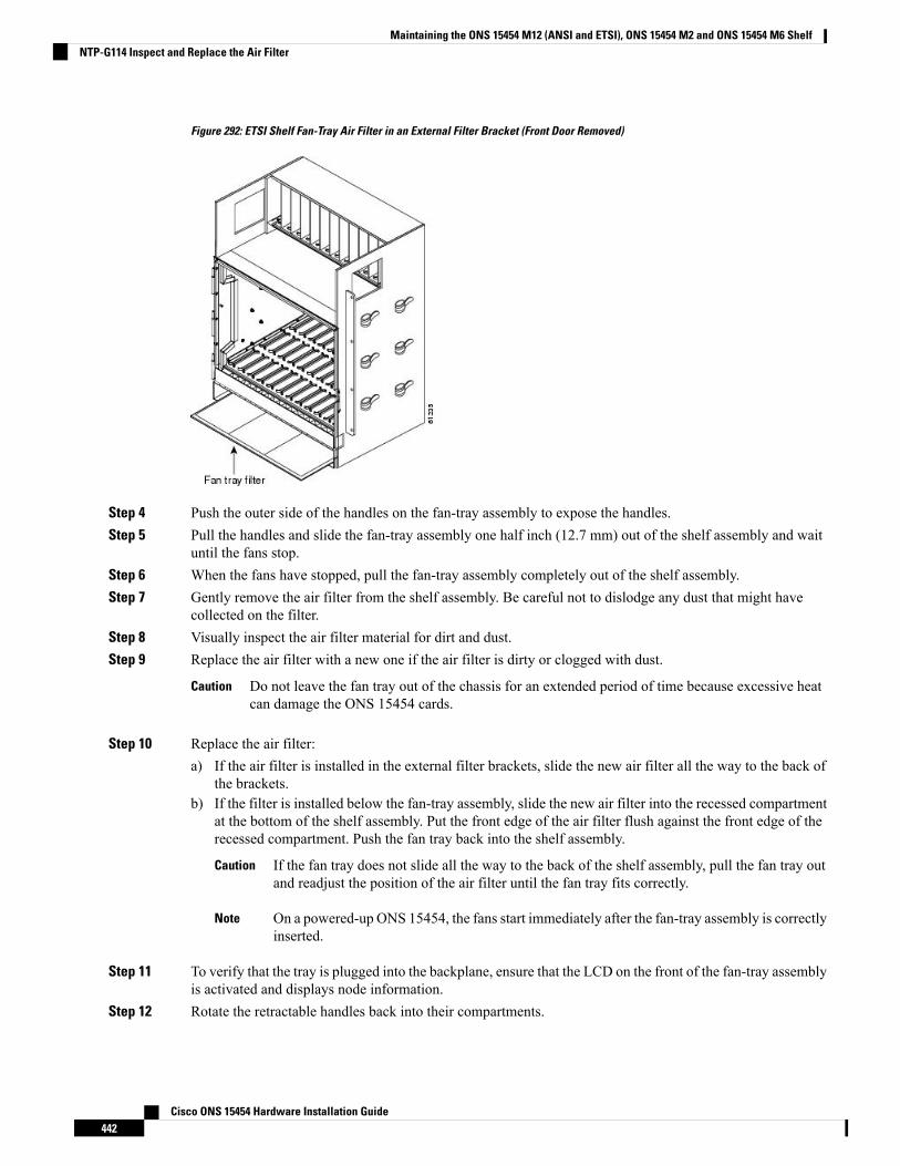
Figure 292: ETSI Shelf Fan-Tray Air Filter in an External Filter Bracket (Front Door Removed)
Step 4 Push the outer side of the handles on the fan-tray assembly to expose the handles.Step 5 Pull the handles and slide the fan-tray assembly one half inch (12.7 mm) out of the shelf assembly and wait
until the fans stop.Step 6 When the fans have stopped, pull the fan-tray assembly completely out of the shelf assembly.Step 7 Gently remove the air filter from the shelf assembly. Be careful not to dislodge any dust that might have
collected on the filter.Step 8 Visually inspect the air filter material for dirt and dust.Step 9 Replace the air filter with a new one if the air filter is dirty or clogged with dust.
Do not leave the fan tray out of the chassis for an extended period of time because excessive heatcan damage the ONS 15454 cards.
Caution
Step 10 Replace the air filter:a) If the air filter is installed in the external filter brackets, slide the new air filter all the way to the back of
the brackets.b) If the filter is installed below the fan-tray assembly, slide the new air filter into the recessed compartment
at the bottom of the shelf assembly. Put the front edge of the air filter flush against the front edge of therecessed compartment. Push the fan tray back into the shelf assembly.
If the fan tray does not slide all the way to the back of the shelf assembly, pull the fan tray outand readjust the position of the air filter until the fan tray fits correctly.
Caution
On a powered-up ONS 15454, the fans start immediately after the fan-tray assembly is correctlyinserted.
Note
Step 11 To verify that the tray is plugged into the backplane, ensure that the LCD on the front of the fan-tray assemblyis activated and displays node information.
Step 12 Rotate the retractable handles back into their compartments.
Cisco ONS 15454 Hardware Installation Guide442
Maintaining the ONS 15454 M12 (ANSI and ETSI), ONS 15454 M2 and ONS 15454 M6 ShelfNTP-G114 Inspect and Replace the Air Filter
Step 13 If you removed the door, complete the NTP-G40 Replace the Front Door , on page 452. If not, close and lockthe door.
Stop. You have completed this procedure.
NTP-G274 Replace the Air Filter of the ONS 15454 M2 ShelfAssembly
This procedure replaces the air filter of the ONS 15454 M2 shelf assembly.Purpose
New air filterTools/Equipment
• NTP-G266 Install the ONS 15454 M2 Shelf, on page 196• Connect the chassis to the office ground. For detailed instructions on howto ground the chassis, refer to the Electrostatic Discharge and GroundingGuide for Cisco CPT and Cisco ONS Platforms.
Prerequisite Procedures
As NeededRequired/As Needed
RemoteOnsite/Remote
Provisioning or higherSecurity Level
The air filters are single-use only. They must not be cleaned and reused. This is a Telcordia NEBS requirement,GR-63-CORE Issue 4.
Note
Air filters must be inspected every month. If they are dirty or clogged with dust, they must be replaced witha new air filter.
Note
Procedure
Step 1 Untighten the screw on the air-filter (see the following figure).
Cisco ONS 15454 Hardware Installation Guide443
Maintaining the ONS 15454 M12 (ANSI and ETSI), ONS 15454 M2 and ONS 15454 M6 ShelfNTP-G274 Replace the Air Filter of the ONS 15454 M2 Shelf Assembly
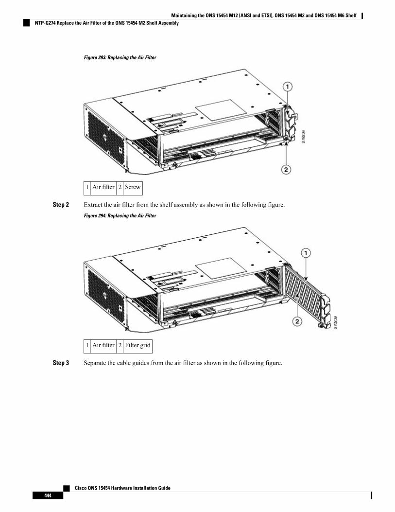
Figure 293: Replacing the Air Filter
Screw2Air filter1
Step 2 Extract the air filter from the shelf assembly as shown in the following figure.
Figure 294: Replacing the Air Filter
Filter grid2Air filter1
Step 3 Separate the cable guides from the air filter as shown in the following figure.
Cisco ONS 15454 Hardware Installation Guide444
Maintaining the ONS 15454 M12 (ANSI and ETSI), ONS 15454 M2 and ONS 15454 M6 ShelfNTP-G274 Replace the Air Filter of the ONS 15454 M2 Shelf Assembly
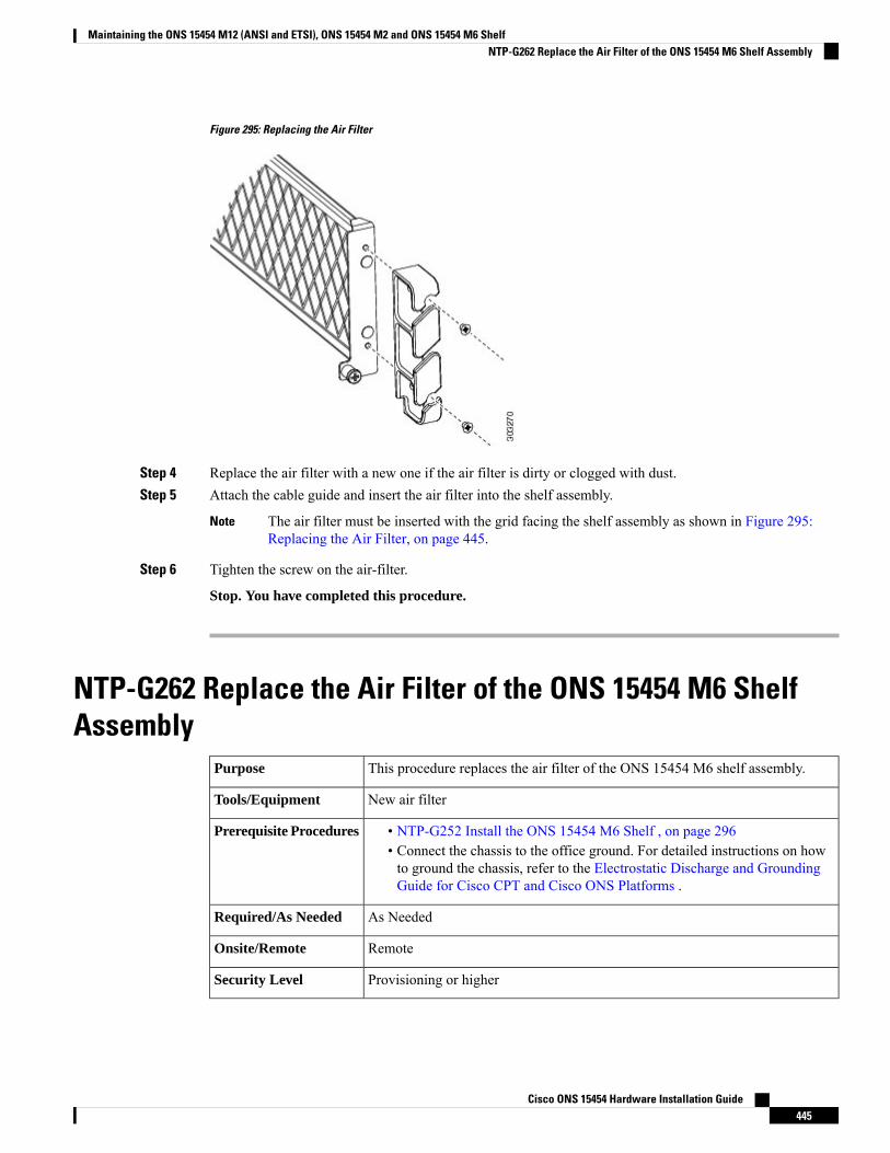
Figure 295: Replacing the Air Filter
Step 4 Replace the air filter with a new one if the air filter is dirty or clogged with dust.Step 5 Attach the cable guide and insert the air filter into the shelf assembly.
The air filter must be inserted with the grid facing the shelf assembly as shown in Figure 295:Replacing the Air Filter, on page 445.
Note
Step 6 Tighten the screw on the air-filter.
Stop. You have completed this procedure.
NTP-G262 Replace the Air Filter of the ONS 15454 M6 ShelfAssembly
This procedure replaces the air filter of the ONS 15454 M6 shelf assembly.Purpose
New air filterTools/Equipment
• NTP-G252 Install the ONS 15454 M6 Shelf , on page 296• Connect the chassis to the office ground. For detailed instructions on howto ground the chassis, refer to the Electrostatic Discharge and GroundingGuide for Cisco CPT and Cisco ONS Platforms .
Prerequisite Procedures
As NeededRequired/As Needed
RemoteOnsite/Remote
Provisioning or higherSecurity Level
Cisco ONS 15454 Hardware Installation Guide445
Maintaining the ONS 15454 M12 (ANSI and ETSI), ONS 15454 M2 and ONS 15454 M6 ShelfNTP-G262 Replace the Air Filter of the ONS 15454 M6 Shelf Assembly
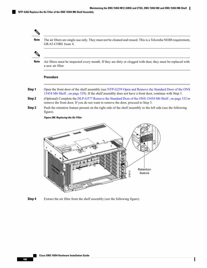
The air filters are single-use only. They must not be cleaned and reused. This is a Telcordia NEBS requirement,GR-63-CORE Issue 4.
Note
Air filters must be inspected every month. If they are dirty or clogged with dust, they must be replaced witha new air filter.
Note
Procedure
Step 1 Open the front door of the shelf assembly (see NTP-G259 Open and Remove the Standard Door of the ONS15454 M6 Shelf , on page 329). If the shelf assembly does not have a front door, continue with Step 3.
Step 2 (Optional) Complete the DLP-G577 Remove the Standard Door of the ONS 15454 M6 Shelf , on page 332 toremove the front door. If you do not want to remove the door, proceed to Step 3.
Step 3 Push the retention feature present on the right side of the shelf assembly to the left side (see the followingfigure).
Figure 296: Replacing the Air Filter
Step 4 Extract the air filter from the shelf assembly (see the following figure).
Cisco ONS 15454 Hardware Installation Guide446
Maintaining the ONS 15454 M12 (ANSI and ETSI), ONS 15454 M2 and ONS 15454 M6 ShelfNTP-G262 Replace the Air Filter of the ONS 15454 M6 Shelf Assembly
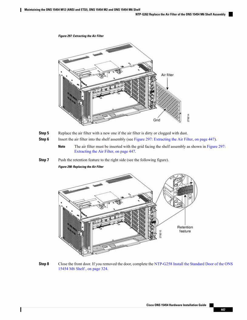
Figure 297: Extracting the Air Filter
Step 5 Replace the air filter with a new one if the air filter is dirty or clogged with dust.Step 6 Insert the air filter into the shelf assembly (see Figure 297: Extracting the Air Filter, on page 447).
The air filter must be inserted with the grid facing the shelf assembly as shown in Figure 297:Extracting the Air Filter, on page 447.
Note
Step 7 Push the retention feature to the right side (see the following figure).
Figure 298: Replacing the Air Filter
Step 8 Close the front door. If you removed the door, complete the NTP-G258 Install the Standard Door of the ONS15454 M6 Shelf , on page 324.
Cisco ONS 15454 Hardware Installation Guide447
Maintaining the ONS 15454 M12 (ANSI and ETSI), ONS 15454 M2 and ONS 15454 M6 ShelfNTP-G262 Replace the Air Filter of the ONS 15454 M6 Shelf Assembly
Stop. You have completed this procedure.
NTP-G263 Replace the Air Filter of the AC Power Module in theONS 15454 M6 Shelf Assembly
This procedure replaces the air filter of the AC power module in the ONS 15454M6 shelf assembly.
Purpose
New air filterTools/Equipment
• NTP-G252 Install the ONS 15454 M6 Shelf , on page 296• Connect the chassis to the office ground. For detailed instructions on howto ground the chassis, refer to the Electrostatic Discharge and GroundingGuide for Cisco CPT and Cisco ONS Platforms .
• DLP-G569 Install the AC Power Module in the ONS 15454 M6 Shelf, onpage 358
Prerequisite Procedures
As NeededRequired/As Needed
RemoteOnsite/Remote
Provisioning or higherSecurity Level
The air filters are single-use only. They must not be cleaned and reused. This is a Telcordia NEBS requirement,GR-63-CORE Issue 4.
Note
Air filters must be inspected every month. If they are dirty or clogged with dust, they must be replaced witha new air filter.
Note
Procedure
Step 1 Open the front door of the shelf assembly (see DLP-G576 Open the Standard Door of the ONS 15454 M6Shelf , on page 330). If the shelf assembly does not have a front door, continue with Step 3.
Step 2 (Optional) Complete the DLP-G577 Remove the Standard Door of the ONS 15454 M6 Shelf , on page 332 toremove the front door. If you do not want to remove the door, proceed to Step 3.
Step 3 Remove the air filter on the AC power module (see Figure 296: Replacing the Air Filter, on page 446).
Cisco ONS 15454 Hardware Installation Guide448
Maintaining the ONS 15454 M12 (ANSI and ETSI), ONS 15454 M2 and ONS 15454 M6 ShelfNTP-G263 Replace the Air Filter of the AC Power Module in the ONS 15454 M6 Shelf Assembly
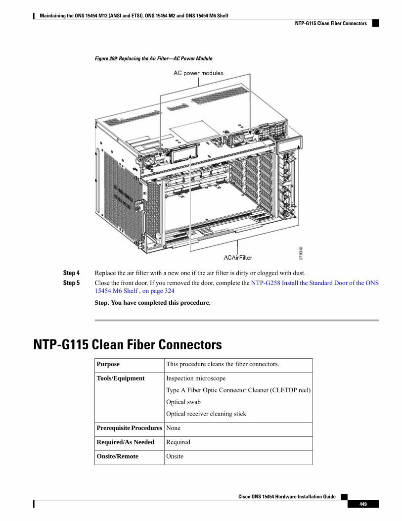
Figure 299: Replacing the Air Filter—AC Power Module
Step 4 Replace the air filter with a new one if the air filter is dirty or clogged with dust.Step 5 Close the front door. If you removed the door, complete the NTP-G258 Install the Standard Door of the ONS
15454 M6 Shelf , on page 324
Stop. You have completed this procedure.
NTP-G115 Clean Fiber ConnectorsThis procedure cleans the fiber connectors.Purpose
Inspection microscope
Type A Fiber Optic Connector Cleaner (CLETOP reel)
Optical swab
Optical receiver cleaning stick
Tools/Equipment
NonePrerequisite Procedures
RequiredRequired/As Needed
OnsiteOnsite/Remote
Cisco ONS 15454 Hardware Installation Guide449
Maintaining the ONS 15454 M12 (ANSI and ETSI), ONS 15454 M2 and ONS 15454 M6 ShelfNTP-G115 Clean Fiber Connectors
NoneSecurity Level
Invisible laser radiation may be emitted from the end of the unterminated fiber cable or connector. Donot view directly with optical instruments. Viewing the laser output with certain optical instruments(for example, eye loupes, magnifiers, and microscopes) within a distance of 100 mm may pose an eyehazard. Statement 1056
Warning
Procedure
Step 1 Using an inspection microscope, inspect each fiber connector for dirt, cracks, or scratches.Step 2 Replace any damaged fiber connectors.
Replace all dust caps whenever the equipment is unused for 30 minutes or more.Note
Step 3 Complete the DLP-G262 Clean Fiber Connectors with CLETOP, on page 451 as necessary.Step 4 Complete the DLP-G263 Clean the Fiber Adapters, on page 451 as necessary.
To clean multi-fiber optic connectors, complete the DLP-G261 Clean Multi Fiber-Optic CableConnectors, on page 450 as necessary.
Note
Stop. You have completed this procedure.
DLP-G261 Clean Multi Fiber-Optic Cable ConnectorsThis task cleans the multi fiber optic connectorsPurpose
Cleaning Cartridge for multi fiber optic connectorsTools/Equipment
NonePrerequisite Procedures
RequiredRequired/As Needed
OnsiteOnsite/Remote
NoneSecurity Level
Invisible laser radiation may be emitted from disconnected fibers or connectors. Do not stare into beamsor view directly with optical instruments. Statement 1051
Warning
Procedure
Step 1 Remove the protective cap on the optical fiber cable connector.
Cisco ONS 15454 Hardware Installation Guide450
Maintaining the ONS 15454 M12 (ANSI and ETSI), ONS 15454 M2 and ONS 15454 M6 ShelfDLP-G261 Clean Multi Fiber-Optic Cable Connectors
Step 2 Read the manufacturer (cleaning cartridge) instructions to insert the connector into the cleaning cartridge.Step 3 Slide the lever on the cartridge to swipe the connector surface.Step 4 Insert the fiber connector into the applicable adapter or attach a dust cap to the fiber connector.
If you must replace a dust cap on a connector, first verify that the dust cap is clean.Note
Step 5 Return to your originating procedure (NTP).
DLP-G262 Clean Fiber Connectors with CLETOPThis task cleans the fiber connectors with CLETOP.Purpose
Type A Fiber Optic Connector Cleaner (CLETOP reel)
Optical receiver cleaning stick
Tools/Equipment
NonePrerequisite Procedures
RequiredRequired/As Needed
OnsiteOnsite/Remote
NoneSecurity Level
Procedure
Step 1 Remove the dust cap from the fiber connector.Step 2 Press the lever up to open the shutter door. Each time you press the lever, you expose a clean wiping surface.Step 3 Insert the connector into the CLETOP cleaning cassette slot, rotate one quarter turn, and gently swipe
downwards.Step 4 Use an inspection microscope to inspect each fiber connector for dirt, cracks, or scratches. If the connector
is not clean, repeat Steps 1 to 3.Step 5 Insert the fiber connector into the applicable adapter or attach a dust cap to the fiber connector.
If you must replace a dust cap on a connector, first verify that the dust cap is clean. To clean thedust cap, wipe the outside of the cap using a dry, lint-free wipe and the inside of the dust cap usinga CLETOP stick swab (14100400).
Note
Step 6 Return to your originating procedure (NTP).
DLP-G263 Clean the Fiber AdaptersThis task cleans the fiber adapters.Purpose
CLETOP stick swabTools/Equipment
NonePrerequisite Procedures
Cisco ONS 15454 Hardware Installation Guide451
Maintaining the ONS 15454 M12 (ANSI and ETSI), ONS 15454 M2 and ONS 15454 M6 ShelfDLP-G262 Clean Fiber Connectors with CLETOP
RequiredRequired/As Needed
OnsiteOnsite/Remote
NoneSecurity Level
Procedure
Step 1 Remove the dust plug from the fiber adapter.Step 2 Insert a CLETOP stick swab (14100400) into the adapter opening and rotate the swab.Step 3 Place dust plugs on the fiber adapters when not in use.Step 4 Return to your originating procedure (NTP).
NTP-G40 Replace the Front DoorThis procedure replaces the front door and door ground strap after installing cardsand fiber-optic cables.
Purpose
#2 Phillips screwdriver
Medium slot-head screwdriver
Small slot-head screwdriver
Tools/Equipment
NTP-G259 Open and Remove the Standard Door of the ONS 15454 M6 Shelf ,on page 329
Prerequisite Procedures
RequiredRequired/As Needed
OnsiteOnsite/Remote
NoneSecurity Level
Be careful not to crimp any fiber cables that are connected to the MXP/TXP cards or DWDM cards. Somemight not have the fiber boot attached.
Note
Procedure
Step 1 Insert the front door into the hinges on the shelf assembly.Step 2 (ANSI only) Attach one end of the ground strap terminal lug (72-3622-01) to the male stud on the inside of
the door. Attach and tighten the #6 Kepnut (49-0600-01) using the open-end wrench.
Cisco ONS 15454 Hardware Installation Guide452
Maintaining the ONS 15454 M12 (ANSI and ETSI), ONS 15454 M2 and ONS 15454 M6 ShelfNTP-G40 Replace the Front Door
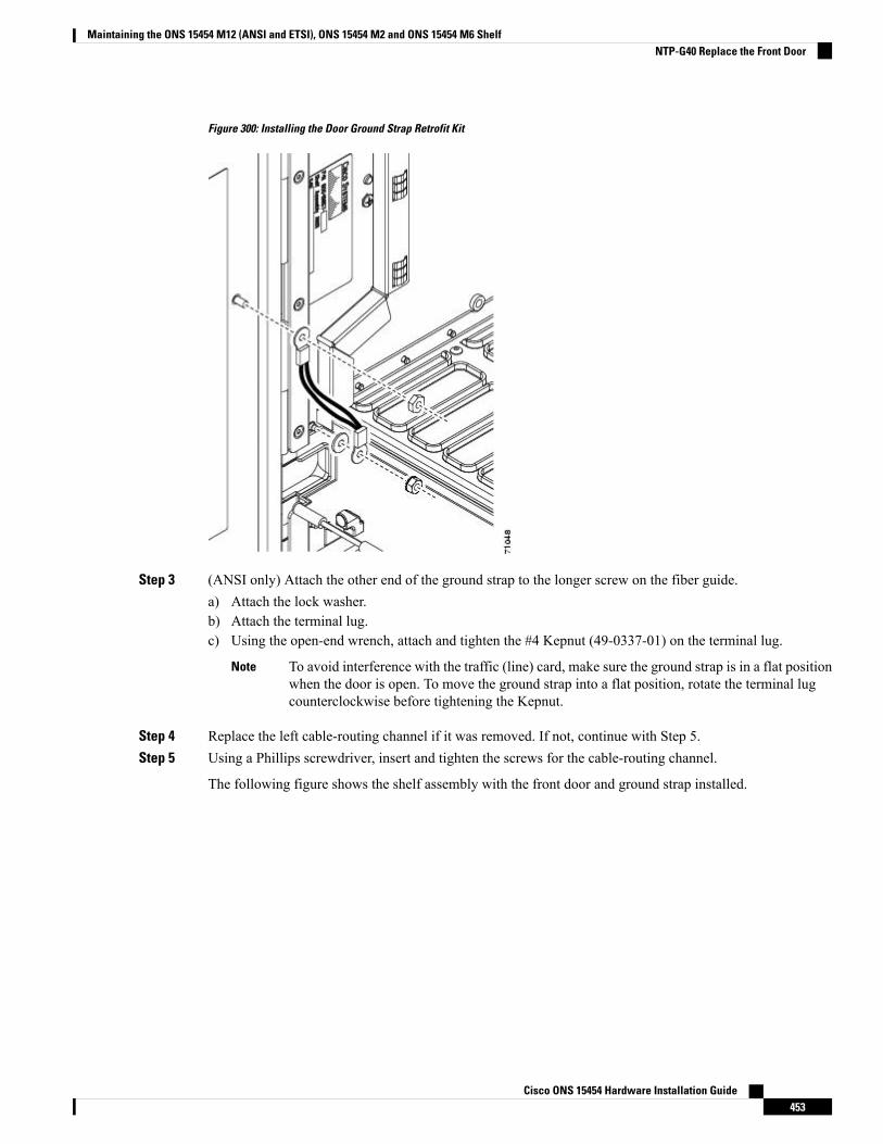
Figure 300: Installing the Door Ground Strap Retrofit Kit
Step 3 (ANSI only) Attach the other end of the ground strap to the longer screw on the fiber guide.a) Attach the lock washer.b) Attach the terminal lug.c) Using the open-end wrench, attach and tighten the #4 Kepnut (49-0337-01) on the terminal lug.
To avoid interference with the traffic (line) card, make sure the ground strap is in a flat positionwhen the door is open. To move the ground strap into a flat position, rotate the terminal lugcounterclockwise before tightening the Kepnut.
Note
Step 4 Replace the left cable-routing channel if it was removed. If not, continue with Step 5.Step 5 Using a Phillips screwdriver, insert and tighten the screws for the cable-routing channel.
The following figure shows the shelf assembly with the front door and ground strap installed.
Cisco ONS 15454 Hardware Installation Guide453
Maintaining the ONS 15454 M12 (ANSI and ETSI), ONS 15454 M2 and ONS 15454 M6 ShelfNTP-G40 Replace the Front Door
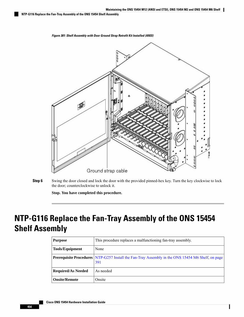
Figure 301: Shelf Assembly with Door Ground Strap Retrofit Kit Installed (ANSI)
Step 6 Swing the door closed and lock the door with the provided pinned-hex key. Turn the key clockwise to lockthe door; counterclockwise to unlock it.
Stop. You have completed this procedure.
NTP-G116 Replace the Fan-Tray Assembly of the ONS 15454Shelf Assembly
This procedure replaces a malfunctioning fan-tray assembly.Purpose
NoneTools/Equipment
NTP-G257 Install the Fan-Tray Assembly in the ONS 15454 M6 Shelf, on page391
Prerequisite Procedures
As neededRequired/As Needed
OnsiteOnsite/Remote
Cisco ONS 15454 Hardware Installation Guide454
Maintaining the ONS 15454 M12 (ANSI and ETSI), ONS 15454 M2 and ONS 15454 M6 ShelfNTP-G116 Replace the Fan-Tray Assembly of the ONS 15454 Shelf Assembly
NoneSecurity Level
The 15454-FTA3 fan-tray assembly can only be installed in ONS 15454 R3.1 and later shelf assemblies(15454-SA-ANSI, P/N: 800-19857; 15454-SA-HD, P/N: 800-24848). The fan-tray assembly includes a pinthat prevents it from being installed in ONS 15454 shelf assemblies released before ONS 15454 R3.1(15454-SA-NEBS3E, 15454-SA-NEBS3, and 15454-SA-R1, P/N: 800-07149). Equipment damage can resultfrom attempting to install the 15454-FTA3 in a incompatible shelf assembly.
Caution
Do not force a fan-tray assembly into place. Doing so can damage the connectors on the fan tray and/or theconnectors on the backplane.
Caution
15454-CC-FTA (ANSI) is compatible with Software R2.2.2 and greater, and shelf assemblies 15454-SA-ANSIand 15454-SA-HD. 15454E-CC-FTA (ETSI) is compatible with Software R4.0 and greater, and shelf assembly15454-SA-ETSI.
Caution
As with the FTA3, the 15454E-CC-FTA and 15454-CC-FTA Fan Fail LED on the front of the fan-trayassembly illuminates when one or more fans fail to indicate that a fan-tray assembly or AIP replacement isrequired. But the Fan Fail LED on the 15454E-CC-FTA and 15454-CC-FTA will also illuminate when onlyone power source is connected to the chassis, and or any fuse blows. In such conditions, the Fan Alarm istriggered and the fans run at maximum speed.
Caution
To replace the fan-tray assembly, it is not necessary to move any of the cable management facilities.Note
Procedure
Step 1 Review Table 42: Incompatibility Alarms for ONS 15454 ANSI , on page 455 (ANSI) or Table 43:Incompatibility Alarms for ONS 15454 ETSI , on page 456 (ETSI) to ensure that you have compatiblecomponents when replacing the fan-tray assembly. Note the alarms that will be generated when anincompatibility occurs.
If you need to determine the hardware that has been installed on a node, click the Inventory tab innode view.
Note
Table 42: Incompatibility Alarms for ONS 15454 ANSI
AlarmsEthernet Cards810GCards7AIP6Fan Tray5Shelf Assembly4
Mismatch of equipment attributes(MEA) on the alarm interfacepanel (AIP)
——No fuse——
Cisco ONS 15454 Hardware Installation Guide455
Maintaining the ONS 15454 M12 (ANSI and ETSI), ONS 15454 M2 and ONS 15454 M6 ShelfNTP-G116 Replace the Fan-Tray Assembly of the ONS 15454 Shelf Assembly
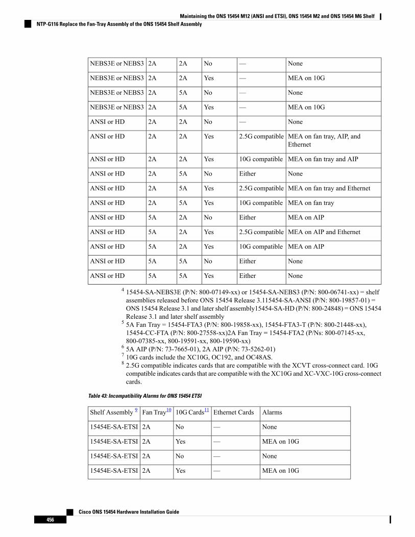
None—No2A2ANEBS3E or NEBS3
MEA on 10G—Yes2A2ANEBS3E or NEBS3
None—No5A2ANEBS3E or NEBS3
MEA on 10G—Yes5A2ANEBS3E or NEBS3
None—No2A2AANSI or HD
MEA on fan tray, AIP, andEthernet
2.5G compatibleYes2A2AANSI or HD
MEA on fan tray and AIP10G compatibleYes2A2AANSI or HD
NoneEitherNo5A2AANSI or HD
MEA on fan tray and Ethernet2.5G compatibleYes5A2AANSI or HD
MEA on fan tray10G compatibleYes5A2AANSI or HD
MEA on AIPEitherNo2A5AANSI or HD
MEA on AIP and Ethernet2.5G compatibleYes2A5AANSI or HD
MEA on AIP10G compatibleYes2A5AANSI or HD
NoneEitherNo5A5AANSI or HD
NoneEitherYes5A5AANSI or HD
4 15454-SA-NEBS3E (P/N: 800-07149-xx) or 15454-SA-NEBS3 (P/N: 800-06741-xx) = shelfassemblies released before ONS 15454 Release 3.115454-SA-ANSI (P/N: 800-19857-01) =ONS 15454 Release 3.1 and later shelf assembly15454-SA-HD (P/N: 800-24848) = ONS 15454Release 3.1 and later shelf assembly
5 5A Fan Tray = 15454-FTA3 (P/N: 800-19858-xx), 15454-FTA3-T (P/N: 800-21448-xx),15454-CC-FTA (P/N: 800-27558-xx)2A Fan Tray = 15454-FTA2 (P/Ns: 800-07145-xx,800-07385-xx, 800-19591-xx, 800-19590-xx)
6 5A AIP (P/N: 73-7665-01), 2A AIP (P/N: 73-5262-01)7 10G cards include the XC10G, OC192, and OC48AS.8 2.5G compatible indicates cards that are compatible with the XCVT cross-connect card. 10Gcompatible indicates cards that are compatible with the XC10G andXC-VXC-10G cross-connectcards.
Table 43: Incompatibility Alarms for ONS 15454 ETSI
AlarmsEthernet Cards10GCards11Fan Tray10Shelf Assembly 9
None—No2A15454E-SA-ETSI
MEA on 10G—Yes2A15454E-SA-ETSI
None—No2A15454E-SA-ETSI
MEA on 10G—Yes2A15454E-SA-ETSI
Cisco ONS 15454 Hardware Installation Guide456
Maintaining the ONS 15454 M12 (ANSI and ETSI), ONS 15454 M2 and ONS 15454 M6 ShelfNTP-G116 Replace the Fan-Tray Assembly of the ONS 15454 Shelf Assembly
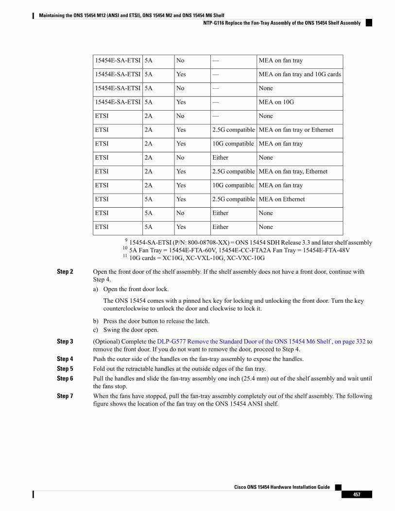
MEA on fan tray—No5A15454E-SA-ETSI
MEA on fan tray and 10G cards—Yes5A15454E-SA-ETSI
None—No5A15454E-SA-ETSI
MEA on 10G—Yes5A15454E-SA-ETSI
None—No2AETSI
MEA on fan tray or Ethernet2.5G compatibleYes2AETSI
MEA on fan tray10G compatibleYes2AETSI
NoneEitherNo2AETSI
MEA on fan tray, Ethernet2.5G compatibleYes2AETSI
MEA on fan tray10G compatibleYes2AETSI
MEA on Ethernet2.5G compatibleYes5AETSI
NoneEitherNo5AETSI
NoneEitherYes5AETSI
9 15454-SA-ETSI (P/N: 800-08708-XX) =ONS 15454 SDHRelease 3.3 and later shelf assembly10 5A Fan Tray = 15454E-FTA-60V, 15454E-CC-FTA2A Fan Tray = 15454E-FTA-48V11 10G cards = XC10G, XC-VXL-10G, XC-VXC-10G
Step 2 Open the front door of the shelf assembly. If the shelf assembly does not have a front door, continue withStep 4.a) Open the front door lock.
The ONS 15454 comes with a pinned hex key for locking and unlocking the front door. Turn the keycounterclockwise to unlock the door and clockwise to lock it.
b) Press the door button to release the latch.c) Swing the door open.
Step 3 (Optional) Complete the DLP-G577 Remove the Standard Door of the ONS 15454 M6 Shelf , on page 332 toremove the front door. If you do not want to remove the door, proceed to Step 4.
Step 4 Push the outer side of the handles on the fan-tray assembly to expose the handles.Step 5 Fold out the retractable handles at the outside edges of the fan tray.Step 6 Pull the handles and slide the fan-tray assembly one inch (25.4 mm) out of the shelf assembly and wait until
the fans stop.Step 7 When the fans have stopped, pull the fan-tray assembly completely out of the shelf assembly. The following
figure shows the location of the fan tray on the ONS 15454 ANSI shelf.
Cisco ONS 15454 Hardware Installation Guide457
Maintaining the ONS 15454 M12 (ANSI and ETSI), ONS 15454 M2 and ONS 15454 M6 ShelfNTP-G116 Replace the Fan-Tray Assembly of the ONS 15454 Shelf Assembly
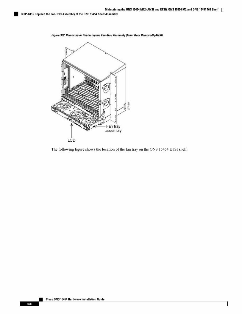
Figure 302: Removing or Replacing the Fan-Tray Assembly (Front Door Removed) (ANSI)
The following figure shows the location of the fan tray on the ONS 15454 ETSI shelf.
Cisco ONS 15454 Hardware Installation Guide458
Maintaining the ONS 15454 M12 (ANSI and ETSI), ONS 15454 M2 and ONS 15454 M6 ShelfNTP-G116 Replace the Fan-Tray Assembly of the ONS 15454 Shelf Assembly
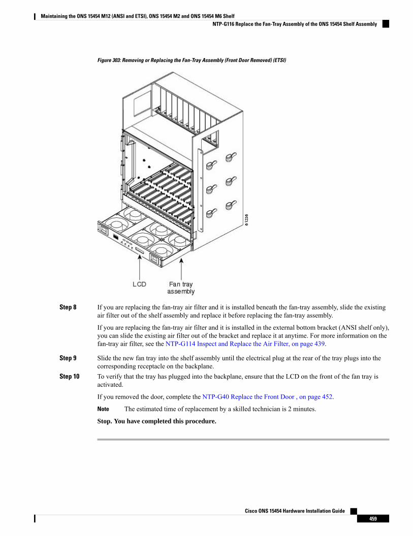
Figure 303: Removing or Replacing the Fan-Tray Assembly (Front Door Removed) (ETSI)
Step 8 If you are replacing the fan-tray air filter and it is installed beneath the fan-tray assembly, slide the existingair filter out of the shelf assembly and replace it before replacing the fan-tray assembly.
If you are replacing the fan-tray air filter and it is installed in the external bottom bracket (ANSI shelf only),you can slide the existing air filter out of the bracket and replace it at anytime. For more information on thefan-tray air filter, see the NTP-G114 Inspect and Replace the Air Filter, on page 439.
Step 9 Slide the new fan tray into the shelf assembly until the electrical plug at the rear of the tray plugs into thecorresponding receptacle on the backplane.
Step 10 To verify that the tray has plugged into the backplane, ensure that the LCD on the front of the fan tray isactivated.
If you removed the door, complete the NTP-G40 Replace the Front Door , on page 452.
The estimated time of replacement by a skilled technician is 2 minutes.Note
Stop. You have completed this procedure.
Cisco ONS 15454 Hardware Installation Guide459
Maintaining the ONS 15454 M12 (ANSI and ETSI), ONS 15454 M2 and ONS 15454 M6 ShelfNTP-G116 Replace the Fan-Tray Assembly of the ONS 15454 Shelf Assembly
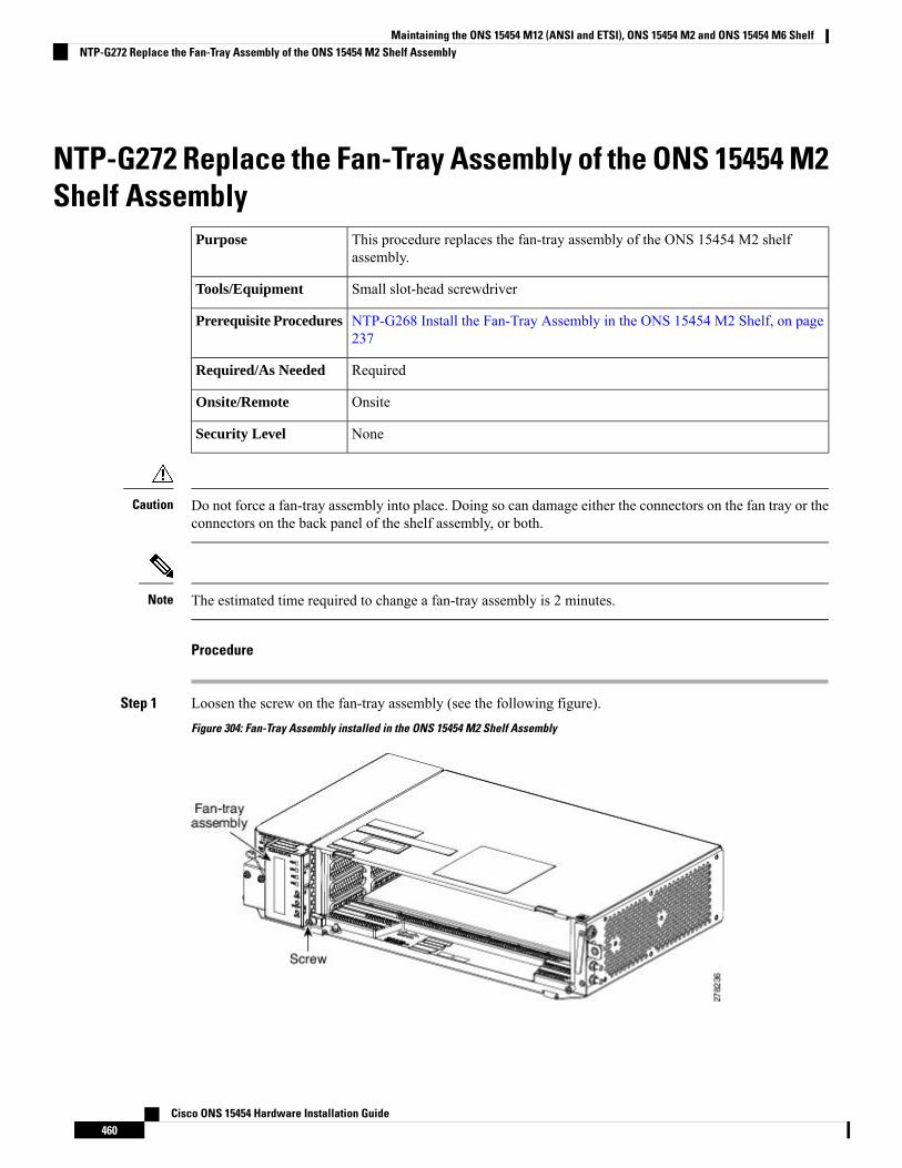
NTP-G272 Replace the Fan-Tray Assembly of the ONS 15454 M2Shelf Assembly
This procedure replaces the fan-tray assembly of the ONS 15454 M2 shelfassembly.
Purpose
Small slot-head screwdriverTools/Equipment
NTP-G268 Install the Fan-Tray Assembly in the ONS 15454 M2 Shelf, on page237
Prerequisite Procedures
RequiredRequired/As Needed
OnsiteOnsite/Remote
NoneSecurity Level
Do not force a fan-tray assembly into place. Doing so can damage either the connectors on the fan tray or theconnectors on the back panel of the shelf assembly, or both.
Caution
The estimated time required to change a fan-tray assembly is 2 minutes.Note
Procedure
Step 1 Loosen the screw on the fan-tray assembly (see the following figure).
Figure 304: Fan-Tray Assembly installed in the ONS 15454 M2 Shelf Assembly
Cisco ONS 15454 Hardware Installation Guide460
Maintaining the ONS 15454 M12 (ANSI and ETSI), ONS 15454 M2 and ONS 15454 M6 ShelfNTP-G272 Replace the Fan-Tray Assembly of the ONS 15454 M2 Shelf Assembly
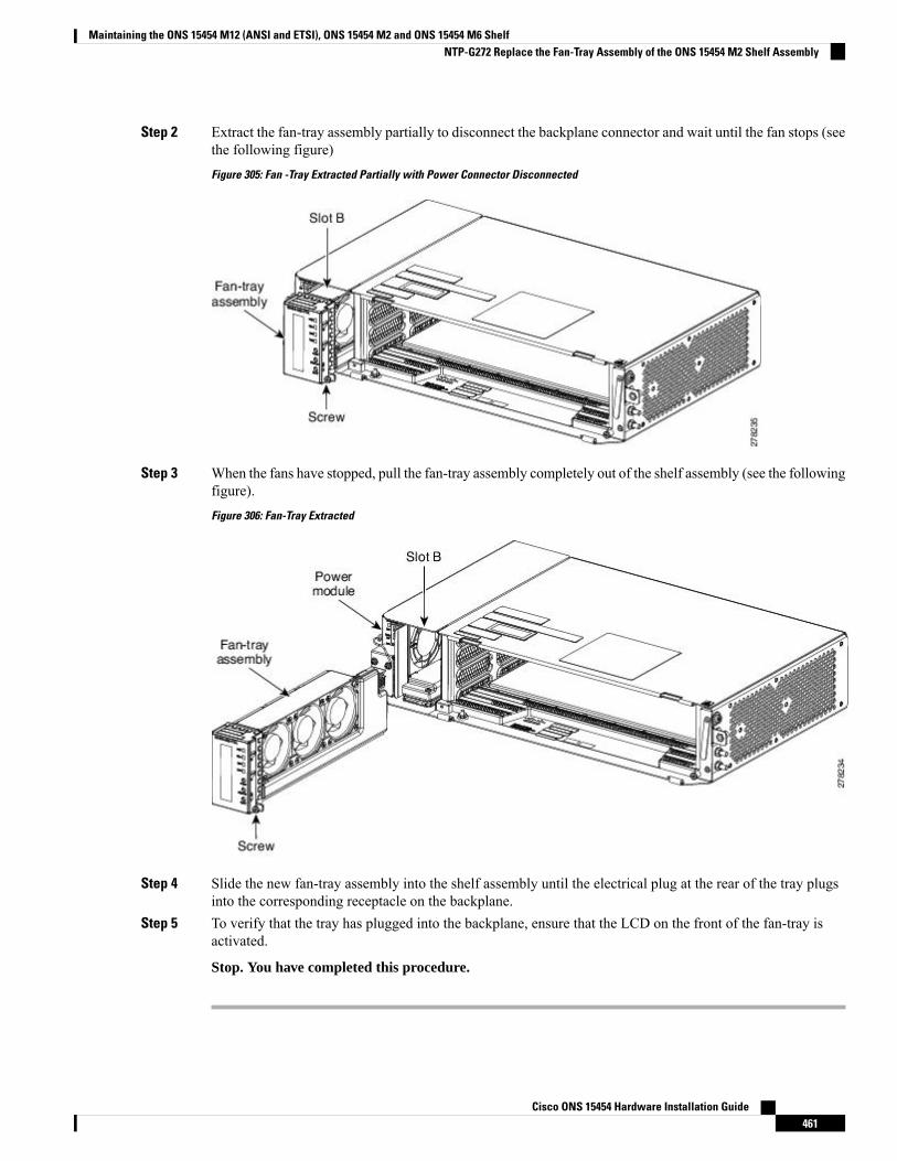
Step 2 Extract the fan-tray assembly partially to disconnect the backplane connector and wait until the fan stops (seethe following figure)
Figure 305: Fan -Tray Extracted Partially with Power Connector Disconnected
Step 3 When the fans have stopped, pull the fan-tray assembly completely out of the shelf assembly (see the followingfigure).
Figure 306: Fan-Tray Extracted
Step 4 Slide the new fan-tray assembly into the shelf assembly until the electrical plug at the rear of the tray plugsinto the corresponding receptacle on the backplane.
Step 5 To verify that the tray has plugged into the backplane, ensure that the LCD on the front of the fan-tray isactivated.
Stop. You have completed this procedure.
Cisco ONS 15454 Hardware Installation Guide461
Maintaining the ONS 15454 M12 (ANSI and ETSI), ONS 15454 M2 and ONS 15454 M6 ShelfNTP-G272 Replace the Fan-Tray Assembly of the ONS 15454 M2 Shelf Assembly
NTP-G260 Replace the Fan-Tray Assembly of the ONS 15454 M6Shelf Assembly
This procedure replaces the fan-tray assembly of the ONS 15454 M6 shelfassembly.
Purpose
Small slot-head screwdriverTools/Equipment
NTP-G257 Install the Fan-Tray Assembly in the ONS 15454 M6 Shelf, on page391
Prerequisite Procedures
RequiredRequired/As Needed
OnsiteOnsite/Remote
NoneSecurity Level
Do not force a fan-tray assembly into place. Doing so can damage either the connectors on the fan tray or theconnectors on the back panel of the shelf assembly, or both.
Caution
The estimated time required to change a fan-tray assembly is 2 minutes.Note
Procedure
Step 1 Open the front door of the shelf assembly (see DLP-G576 Open the Standard Door of the ONS 15454 M6Shelf , on page 330 ). If the shelf assembly does not have a front door, continue with Step 3.
Step 2 (Optional) Complete the DLP-G577 Remove the Standard Door of the ONS 15454 M6 Shelf , on page 332 toremove the front door. If you do not want to remove the door, proceed to Step 3.
Step 3 Untighten the screws on the fan-tray assembly (see the following figure).
Cisco ONS 15454 Hardware Installation Guide462
Maintaining the ONS 15454 M12 (ANSI and ETSI), ONS 15454 M2 and ONS 15454 M6 ShelfNTP-G260 Replace the Fan-Tray Assembly of the ONS 15454 M6 Shelf Assembly
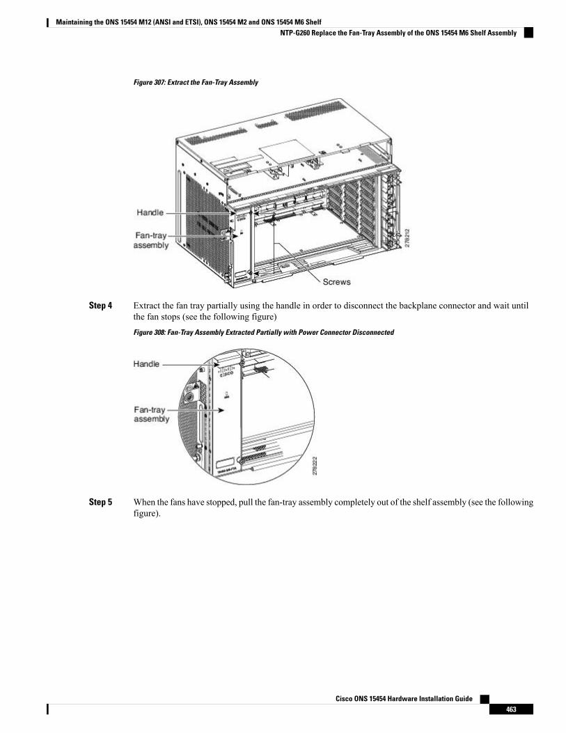
Figure 307: Extract the Fan-Tray Assembly
Step 4 Extract the fan tray partially using the handle in order to disconnect the backplane connector and wait untilthe fan stops (see the following figure)
Figure 308: Fan-Tray Assembly Extracted Partially with Power Connector Disconnected
Step 5 When the fans have stopped, pull the fan-tray assembly completely out of the shelf assembly (see the followingfigure).
Cisco ONS 15454 Hardware Installation Guide463
Maintaining the ONS 15454 M12 (ANSI and ETSI), ONS 15454 M2 and ONS 15454 M6 ShelfNTP-G260 Replace the Fan-Tray Assembly of the ONS 15454 M6 Shelf Assembly
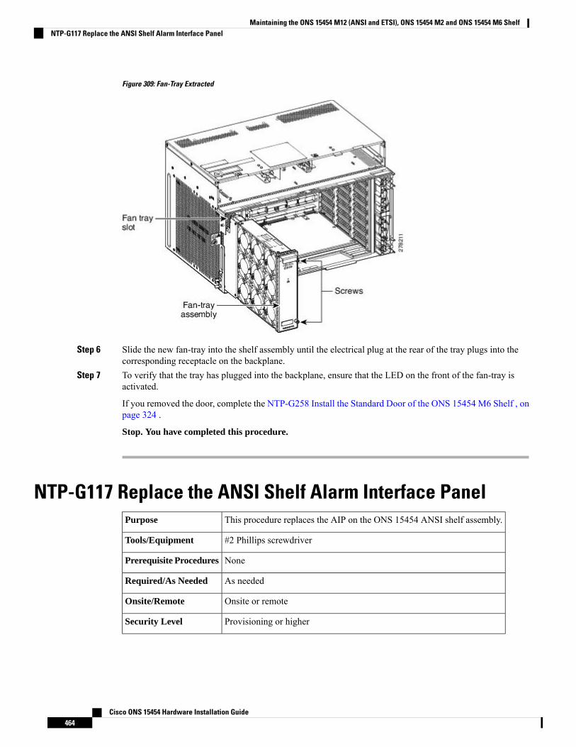
Figure 309: Fan-Tray Extracted
Step 6 Slide the new fan-tray into the shelf assembly until the electrical plug at the rear of the tray plugs into thecorresponding receptacle on the backplane.
Step 7 To verify that the tray has plugged into the backplane, ensure that the LED on the front of the fan-tray isactivated.
If you removed the door, complete the NTP-G258 Install the Standard Door of the ONS 15454 M6 Shelf , onpage 324 .
Stop. You have completed this procedure.
NTP-G117 Replace the ANSI Shelf Alarm Interface PanelThis procedure replaces the AIP on the ONS 15454 ANSI shelf assembly.Purpose
#2 Phillips screwdriverTools/Equipment
NonePrerequisite Procedures
As neededRequired/As Needed
Onsite or remoteOnsite/Remote
Provisioning or higherSecurity Level
Cisco ONS 15454 Hardware Installation Guide464
Maintaining the ONS 15454 M12 (ANSI and ETSI), ONS 15454 M2 and ONS 15454 M6 ShelfNTP-G117 Replace the ANSI Shelf Alarm Interface Panel
Do not use a 2A AIP with a 5A fan-tray assembly; doing so will cause a blown fuse on the AIP.Caution
Always use the supplied ESD wristband when working with a powered ONS 15454. For detailed instructionson how to wear the ESD wristband, refer to the Electrostatic Discharge and Grounding Guide for Cisco CPTand Cisco ONS Platforms.
Caution
Do not perform this procedure on a node with live traffic. Hot-swapping the AIP can affect traffic and resultin a loss of data. For assistance with AIP replacement, contact the Cisco TAC. See the ObtainingDocumentation, Obtaining Support, and Security Guidelines, on page xxix section.
Caution
Procedure
Step 1 ReviewTable 42: IncompatibilityAlarms for ONS 15454ANSI , on page 455 to ensure that you have compatiblecomponents when replacing the ANSI shelf AIP and note the alarms that will occur when an incompatibilityoccurs.
Step 2 Ensure that all nodes in the affected network are running the same software version before replacing the AIPand repairing circuits:a) In network view or multishelf view (multishelf mode), click, click the Maintenance > Software tabs.
The working software version for each node is listed in the Working Version column.b) If you need to upgrade the software on a node, refer to the release-specific software upgrade document.
No hardware should be changed or circuit repair performed until after the software upgrade is complete.If you do not need to upgrade software or have completed the software upgrade, proceed to Step 3.
Step 3 Record the MAC address of the old AIP:a) Log into the node where you will replace the AIP. See the DLP-G46 Log into CTC.b) In node view (single-shelf mode) or multishelf view (multishelf mode), click the Provisioning > Network
tabs.c) Record the MAC address shown in the General tab.
Step 4 Call Cisco TAC for assistance in replacing the AIP and maintaining the original MAC address. See theObtaining Documentation, Obtaining Support, and Security Guidelines, on page xxix.
Step 5 Complete the “DLP-G13 Remove the Lower Backplane Cover” in theCisco ONS 15454 Hardware InstallationGuide .
Step 6 Unscrew the two screws that hold the AIP cover in place.Step 7 Grip the cover and gently pull away from the backplane.
On the 15454-SA-HD (P/N: 800-24848), 15454-SA-NEBS3E, 15454-SA-NEBS3, and 15454-SA-R1(P/N: 800-07149) shelves, the AIP cover is clear plastic. On the 15454-SA-ANSI shelf (P/N:800-19857), the AIP cover is metal.
Note
Step 8 Grip the AIP and gently pull it away from the backplane.Step 9 Disconnect the fan-tray assembly power cable from the AIP.Step 10 Set the old AIP aside for return to Cisco.
Cisco ONS 15454 Hardware Installation Guide465
Maintaining the ONS 15454 M12 (ANSI and ETSI), ONS 15454 M2 and ONS 15454 M6 ShelfNTP-G117 Replace the ANSI Shelf Alarm Interface Panel
The type of shelf that the AIP resides in determines the version of AIP that should replace the failedAIP. The 15454-SA-ANSI shelf (P/N: 800-19857) and 15454-SA-HD (P/N: 800-24848) currentlyuse the 5AAIP, (P/N: 73-7665-01). The 15454-SA-NEBS3E, 15454-SA-NEBS3, and 15454-SA-R1(P/N: 800-07149) shelves and earlier use the 2A AIP (P/N: 73-5262-01).
Caution
Do not put a 2AAIP (P/N: 73-5262-01) into a 15454-SA-ANSI (P/N: 800-19857) or 15454-SA-HD(P/N: 800-24848) shelf; doing so will cause a blown fuse on the AIP.
Caution
Step 11 Attach the fan-tray assembly power cable to the new AIP.Step 12 Place the new AIP on the backplane by plugging the panel into the backplane using the DIN connector.Step 13 Replace the AIP cover over the AIP and secure the cover with the two screws.Step 14 Replace the lower backplane cover and secure the cover with the five screws.Step 15 In node view (single-shelf mode) or multishelf view (multishelf mode), click the Provisioning > Network
tabs.
Cisco recommends that TCC2/TCC2P/TCC3/TNC/TSC card resets be performed in a maintenancewindow to avoid any potential service disruptions.
Caution
Step 16 Reset the standby TCC2/TCC2P/TCC3/TNC/TSC card:a) Right-click the standby TCC2/TCC2P/TCC3/TNC/TSC card and choose Reset Card.b) Click Yes in the Resetting Card dialog box. As the card resets, a loading (Ldg) indication appears on the
card in CTC.
The reset takes approximately five minutes. Do not perform any other steps until the reset iscomplete.
Note
Step 17 Complete the “DLP-G250 Reset the TCC2/TCC2P/TCC3/TNC/TSC Card” task in the Cisco ONS 15454DWDM Configuration Guide to reset the active TCC2/TCC2P/TCC3/TNC/TSC card.
Step 18 From the File drop-down list, choose Exit to exit the CTC session.Step 19 Log back into the node. In the Login dialog box, choose (None) from the Additional Nodes drop-down list.Step 20 Record the new MAC address:
a) In node view (single-shelf mode) or multishelf view (multishelf mode), click the Provisioning > Networktabs.
b) Record the MAC address shown in the General tab.
Step 21 In node view (single-shelf mode) or multishelf view (multishelf mode), click the Circuits tab. Note that allcircuits listed have a status of PARTIAL.
Step 22 In node view (single-shelf mode) or multishelf view (multishelf mode), choose Repair Circuits from theTools drop-down list. The Circuit Repair dialog box appears.
Step 23 Read the instructions in the Circuit Repair dialog box. If all the steps in the dialog box have been completed,click Next. Ensure that you have the old and new MAC addresses.
Step 24 The Node MAC Addresses dialog box appears:a) From the Node drop-down list, choose the name of the node where you replaced the AIP.b) In the Old MAC Address field, enter the old MAC address that was recorded in Step 3.c) Click Next.
Step 25 The Repair Circuits dialog box appears. Read the information in the dialog box and click Finish.
Cisco ONS 15454 Hardware Installation Guide466
Maintaining the ONS 15454 M12 (ANSI and ETSI), ONS 15454 M2 and ONS 15454 M6 ShelfNTP-G117 Replace the ANSI Shelf Alarm Interface Panel

The CTC session freezes until all circuits are repaired. Circuit repair can take up to five minutes ormore depending on the number of circuits provisioned.
Note
When the circuit repair is complete, the Circuits Repaired dialog box appears.
Step 26 Click OK.Step 27 In node view of the new node, click the Circuits tab. Check to ensure that all circuits listed have a status of
DISCOVERED. If all circuits listed are not DISCOVERED, call the Cisco TAC at (800) 553-2447 to opena Return Material Authorization (RMA).
Stop. You have completed this procedure.
NTP-G118 Replace the ANSI Shelf Plastic Lower BackplaneCover
This procedure replaces themetal cover with the plastic cover located at the bottomrear of the ONS 15454 ANSI shelf.
Purpose
Phillips screwdriverTools/Equipment
NonePrerequisite Procedures
As neededRequired/As Needed
OnsiteOnsite/Remote
NoneSecurity Level
Procedure
Step 1 Use the Phillips screwdriver to unscrew the five retaining screws that hold the metal cover in place.Step 2 Grasp the metal cover on each side.Step 3 Gently pull the metal cover away from the backplane.Step 4 Place the plastic cover against the shelf assembly and align the screw holes on the cover and the shelf assembly.
Cisco ONS 15454 Hardware Installation Guide467
Maintaining the ONS 15454 M12 (ANSI and ETSI), ONS 15454 M2 and ONS 15454 M6 ShelfNTP-G118 Replace the ANSI Shelf Plastic Lower Backplane Cover
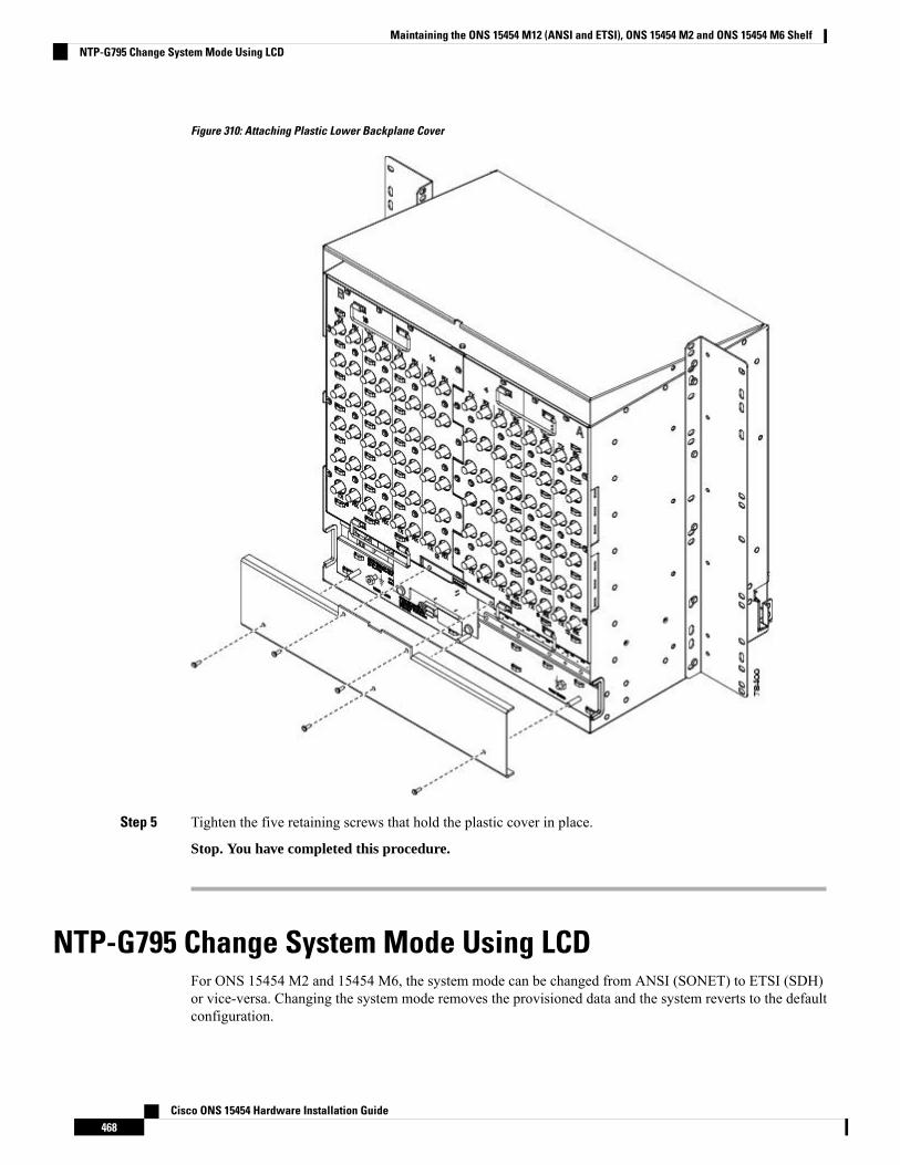
Figure 310: Attaching Plastic Lower Backplane Cover
Step 5 Tighten the five retaining screws that hold the plastic cover in place.
Stop. You have completed this procedure.
NTP-G795 Change System Mode Using LCDFor ONS 15454 M2 and 15454 M6, the system mode can be changed from ANSI (SONET) to ETSI (SDH)or vice-versa. Changing the system mode removes the provisioned data and the system reverts to the defaultconfiguration.
Cisco ONS 15454 Hardware Installation Guide468
Maintaining the ONS 15454 M12 (ANSI and ETSI), ONS 15454 M2 and ONS 15454 M6 ShelfNTP-G795 Change System Mode Using LCD
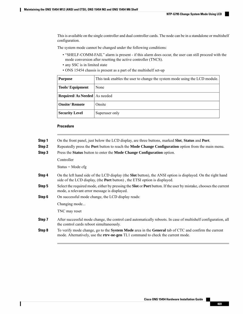
This is available on the single controller and dual controller cards. The node can be in a standalone or multishelfconfiguration.
The system mode cannot be changed under the following conditions:
• “SHELF-COMM-FAIL” alarm is present - if this alarm does occur, the user can still proceed with themode conversion after resetting the active controller (TNCS).
• any SSC is in limited state• ONS 15454 chassis is present as a part of the multishelf set-up
This task enables the user to change the system mode using the LCD module.Purpose
NoneTools/ Equipment
As neededRequired/ As Needed
OnsiteOnsite/ Remote
Superuser onlySecurity Level
Procedure
Step 1 On the front panel, just below the LCD display, are three buttons, marked Slot, Status and Port.Step 2 Repeatedly press the Port button to reach the Mode Change Configuration option from the main menu.Step 3 Press the Status button to enter the Mode Change Configuration option.
Controller
Status = Mode cfg
Step 4 On the left hand side of the LCD display (the Slot button), the ANSI option is displayed. On the right handside of the LCD display, (the Port button) , the ETSI option is displayed.
Step 5 Select the required mode, either by pressing the Slot or Port button. If the user by mistake, chooses the currentmode, a relevant error message is displayed.
Step 6 On successful mode change, the LCD display reads:
Changing mode...
TNC may reset
Step 7 After successful mode change, the control card automatically reboots. In case of multishelf configuration, allthe control cards reboot simultaneously.
Step 8 To verify mode change, go to the System Mode area in the General tab of CTC and confirm the currentmode. Alternatively, use the rtrv-ne-gen TL1 command to check the current mode.
Cisco ONS 15454 Hardware Installation Guide469
Maintaining the ONS 15454 M12 (ANSI and ETSI), ONS 15454 M2 and ONS 15454 M6 ShelfNTP-G795 Change System Mode Using LCD

Cisco ONS 15454 Hardware Installation Guide470
Maintaining the ONS 15454 M12 (ANSI and ETSI), ONS 15454 M2 and ONS 15454 M6 ShelfNTP-G795 Change System Mode Using LCD

A P P E N D I X AHardware Specifications
This appendix contains hardware and software specifications of the ONS 15454 (ANSI and ETSI), ONS15454 M2, and ONS 15454 M6 shelf.
Unless otherwise specified, “ONS 15454” refers to both ANSI and ETSI M12 shelf assemblies.Note
Unless otherwise specified, the ECUmodule refers to the ECU, ECU2, and ECU-60V units. For details aboutthe various ECU modules, see the External Connection Units, on page 345.
Note
Due to memory limitations, TCC2/TCC2P cards are not supported as the node controller in multi-shelfconfiguration fromR10.5.2.6. Hence, it is recommended to use TCC3 card as the node controller in multi-shelfconfiguration. The TCC2P card can be used as a control card in a subtended shelf where the node controlleris TCC3 card on ONS 15454 chassis or TNC/TNCE/TNCS/TNCS-O cards on ONS 15454M6 or NCS 20015chassis. The TCC2P card can also be used as a node controller in a stand-alone configuration.
Note
The following sections are included:
• ONS 15454 Shelf Specifications, on page 471• ONS 15454 M2 Shelf Specifications, on page 475• ONS 15454 M6 Shelf Specifications, on page 478
ONS 15454 Shelf SpecificationsThis section provides specifications for shelf bandwidth; a list of topologies; Cisco Transport Controller (CTC)specifications; the LAN, Transaction Language One (TL1), modem, and alarm specifications; timing, power,and environmental specifications; and shelf dimensions.
BandwidthThe ONS 15454 has these bandwidth specifications:
Cisco ONS 15454 Hardware Installation Guide471
• Total bandwidth: 240 Gbps• Data plane bandwidth: 160 Gbps• SONET/SDH plane bandwidth: 80 Gbps
ConfigurationsThe ONS 15454 can be configured for these dense wavelength division multiplexing (DWDM) topologies:
• Hubbed rings• Multihubbed rings• Point-to-point• Linear• Linear with optical add/drop multiplexing (OADM)• Hybrid terminal node• Hybrid OADM node• Hybrid line amplifier node
Cisco Transport ControllerCTC, the ONS 15454 craft interface software, has these specifications:
• 10BaseT Ethernet• TCC2/TCC2P/TCC3/TNC/TNCE/TSC/TSCE card access: RJ-45 connector• Backplane access: LAN pin field (ANSI only)• FrontMount Electrical Connection (FMEC) access: LAN connector onMIC-C/T/P faceplate (ETSI only)
External LAN InterfaceThe ONS 15454 external LAN interface has these specifications:
• 10BaseT Ethernet• Backplane access: LAN pin field (ANSI only)• FMEC access: LAN connector on MIC-C/T/P faceplate (ETSI only)
TL1 Craft InterfaceThe ONS 15454 TL1 craft interface has these specifications:
• Speed: 9600 bps• TCC2/TCC2P/TCC3/TNC/TNCE/TSC/TSCE access: EIA/TIA-232 DB-9 type connector• Backplane access: CRAFT pin field (ANSI only)
Modem InterfaceThe ONS 15454 modem interface has these specifications:
• Hardware flow control• TCC2/TCC2P/TCC3/TNC/TNCE/TSC/TSCE: EIA/TIA-232 DB-9 type connector
Cisco ONS 15454 Hardware Installation Guide472
Hardware SpecificationsConfigurations
Alarm InterfaceThe ONS 15454 alarm interface has these specifications:
• ETSI
• Visual: Critical, Major, Minor, Remote• Audible: Critical, Major, Minor, Remote• FMEC access: 62-Pin DB connector on MIC-A/P faceplate• Alarm inputs: Common 32-VDC output for all alarm-inputs, closed contact limited to 2 mA• Control outputs: Open contact maximum 60 VDC, closed contact maximum 100 mA
• ANSI
• Visual: Critical, Major, Minor, Remote• Audible: Critical, Major, Minor, Remote• Backplane access: Alarm pin fields• Alarm contacts: 0.045 mm, –48 V, 50 mA
EIA Interface (ANSI only)The ONS 15454 electrical interface assembly (EIA) interface has these specifications:
• SMB: AMP #415504-3 75-ohm, 4-leg connectors• BNC: Trompeter #UCBJ224 75-ohm 4 leg connector (King or ITT are also compatible)• AMP Champ: AMP#552246-1 with #552562-2 bail locks
BITS Interface (ANSI only)The ONS 15454 building integrated timing supply (BITS) interface has these specifications:
• 2 DS-1 BITS inputs• 2 derived DS-1 outputs• Backplane access: BITS pin field
System TimingThe ONS 15454 ANSI has these system timing specifications:
• Stratum 3 per Telcordia GR-253-CORE• Free running accuracy: +/– 4.6 ppm• Holdover stability: 3.7 x 10⁻⁷ per day, including temperature (< 255 slips in first 24 hours)• Reference: External BITS, line, internal
The ONS 15454 ETSI has these system timing specifications:
• Stratum 3E, per ITU-T G.813• Free running accuracy: +/– 4.6 ppm• Holdover stability: 3.7 exp –7 per day, including temperature (< 255 slips in first 24 hours)• Reference: External BITS, line, internal
Cisco ONS 15454 Hardware Installation Guide473
Hardware SpecificationsAlarm Interface
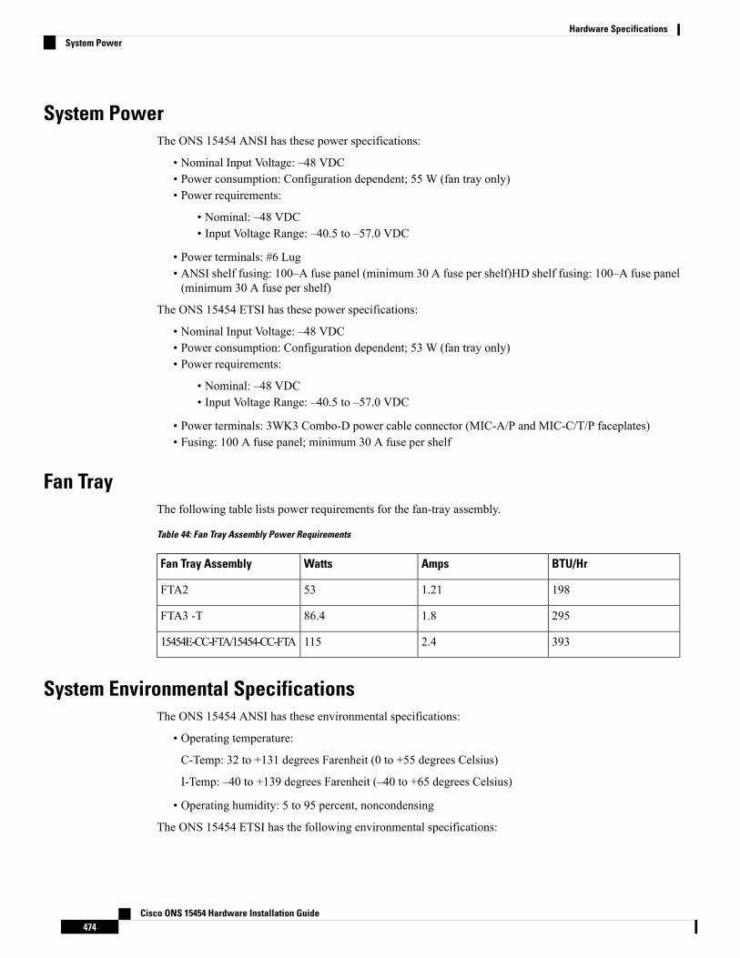
System PowerThe ONS 15454 ANSI has these power specifications:
• Nominal Input Voltage: –48 VDC• Power consumption: Configuration dependent; 55 W (fan tray only)• Power requirements:
• Nominal: –48 VDC• Input Voltage Range: –40.5 to –57.0 VDC
• Power terminals: #6 Lug• ANSI shelf fusing: 100–A fuse panel (minimum 30 A fuse per shelf)HD shelf fusing: 100–A fuse panel(minimum 30 A fuse per shelf)
The ONS 15454 ETSI has these power specifications:
• Nominal Input Voltage: –48 VDC• Power consumption: Configuration dependent; 53 W (fan tray only)• Power requirements:
• Nominal: –48 VDC• Input Voltage Range: –40.5 to –57.0 VDC
• Power terminals: 3WK3 Combo-D power cable connector (MIC-A/P and MIC-C/T/P faceplates)• Fusing: 100 A fuse panel; minimum 30 A fuse per shelf
Fan TrayThe following table lists power requirements for the fan-tray assembly.
Table 44: Fan Tray Assembly Power Requirements
BTU/HrAmpsWattsFan Tray Assembly
1981.2153FTA2
2951.886.4FTA3 -T
3932.411515454E-CC-FTA/15454-CC-FTA
System Environmental SpecificationsThe ONS 15454 ANSI has these environmental specifications:
• Operating temperature:
C-Temp: 32 to +131 degrees Farenheit (0 to +55 degrees Celsius)
I-Temp: –40 to +139 degrees Farenheit (–40 to +65 degrees Celsius)
• Operating humidity: 5 to 95 percent, noncondensing
The ONS 15454 ETSI has the following environmental specifications:
Cisco ONS 15454 Hardware Installation Guide474
Hardware SpecificationsSystem Power
• Operating temperature: 32 to 131 degrees Fahrenheit (0 to +55 degrees Celsius)• Operating humidity: 5 to 95 percent, noncondensing
DimensionsThe ONS 15454 ANSI shelf assembly has these dimensions:
• Height: 18.5 in. (40.7 cm)• Width: 19 or 23 in. (41.8 or 50.6 cm) with mounting ears attached• Depth: 12 in. (26.4 cm) (5 in. or 12.7 cm projection from rack)• Weight: 55 lb (24.947 kg) empty
The ONS 15454 ETSI shelf assembly has the following dimensions:
• Height: 616.5 mm (24.27 in.)• Width: 535 mm (17 in.) without mounting ears attached• Depth: 280 mm (11.02 in.)• Weight: 26 kg empty (57.3 lb)
ONS 15454 M2 Shelf SpecificationsThis section provides specifications for shelf bandwidth; a list of topologies; Cisco Transport Controller (CTC)specifications; the LAN, Transaction Language One (TL1), modem, and alarm specifications; timing, power,and environmental specifications; and shelf dimensions.
BandwidthThe ONS 15454 M2 has these bandwidth specifications (depending on the applications):
• Total bandwidth: 200 Gbps• Data plane bandwidth: 100 Gbps per slot
ConfigurationsThe ONS 15454M2 can be configured for these dense wavelength divisionmultiplexing (DWDM) topologies:
• Hubbed rings• Multihubbed rings• Point-to-point• Linear• Linear with optical add/drop multiplexing (OADM)• Line amplifier node• Transponder Shelf• Layer 2 aggregation shelf
Cisco Transport ControllerCTC, the ONS 15454 M2 craft interface software, has these specifications:
Cisco ONS 15454 Hardware Installation Guide475
Hardware SpecificationsDimensions
• 10/100BaseT Ethernet• TNC/TNCE/TSC/TSCE card access: RJ-45 LAN connector on the controller front plate
External LAN Interface for EMSThe ONS 15454 M2 external LAN interface has these specifications:
• 10/100BaseT Ethernet located on the power module
TL1 Craft InterfaceThe ONS 15454 M2 TL1 craft interface has these specifications:
• TNC/TNCE/TSC/TSCE access: EIA/TIA-232 DB-9 type connector
Modem InterfaceThe ONS 15454 M2 modem interface has these specifications:
• Hardware flow control• TNC/TNCE/TSC/TSCE: EIA/TIA-232 DB-9 type connector
Alarm InterfaceThe ONS 15454 M2 does not support alarm interface.
Passive Unit Remote InventoryThe ONS 15454 M2 provides 1 standard USB port located on the power module to retrieve the passive unitsinventory data.
BITS InterfaceThe ONS 15454 M2 building integrated timing supply (BITS) interface has these specifications:
• 1 DS-1 BITS inputs wire wrap for ANSI applications• 1 derived DS-1 outputs wire wrap for ANSI applications• 1 E1 BITS input DIN-1.0/2.3 for ETSI applications• 1 E1 BITS output DIN-1.0/2.3 for ETSI applications
System TimingThe ONS 15454 M2 for ANSI has these timing specifications:
• Stratum 3 per Telcordia GR-253-CORE• Free running accuracy: +/- 4.6 ppm• Holdover stability: 3.7 x 10⁻⁷ per day, including temperature (< 255 slips in first 24 hours)• Reference: External BITS, line, internal
Cisco ONS 15454 Hardware Installation Guide476
Hardware SpecificationsExternal LAN Interface for EMS
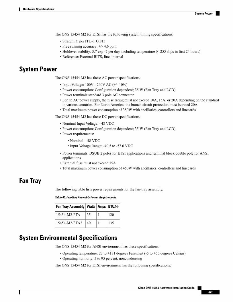
The ONS 15454 M2 for ETSI has the following system timing specifications:
• Stratum 3, per ITU-T G.813• Free running accuracy: +/- 4.6 ppm• Holdover stability: 3.7 exp -7 per day, including temperature (< 255 slips in first 24 hours)• Reference: External BITS, line, internal
System PowerThe ONS 15454 M2 has these AC power specifications:
• Input Voltage: 100V - 240V AC (+/- 10%)• Power consumption: Configuration dependent; 35 W (Fan Tray and LCD)• Power terminals standard 3 pole AC connector• For an AC power supply, the fuse rating must not exceed 10A, 15A, or 20A depending on the standardin various countries. For North America, the branch circuit protection must be rated 20A
• Total maximum power consumption of 350W with ancillaries, controllers and linecards
The ONS 15454 M2 has these DC power specifications:
• Nominal Input Voltage: –48 VDC• Power consumption: Configuration dependent; 35 W (Fan Tray and LCD)• Power requirements:
• Nominal: –48 VDC• Input Voltage Range: -40.5 to -57.6 VDC
• Power terminals: DSUB 2 poles for ETSI applications and terminal block double pole for ANSIapplications
• External fuse must not exceed 15A• Total maximum power consumption of 450W with ancillaries, controllers and linecards
Fan TrayThe following table lists power requirements for the fan-tray assembly.
Table 45: Fan-Tray Assembly Power Requirements
BTU/HrAmpsWattsFan Tray Assembly
12013515454-M2-FTA
13514015454-M2-FTA2
System Environmental SpecificationsThe ONS 15454 M2 for ANSI environment has these specifications:
• Operating temperature: 23 to +131 degrees Farenheit (-5 to +55 degrees Celsius)• Operating humidity: 5 to 95 percent, noncondensing
The ONS 15454 M2 for ETSI environment has the following specifications:
Cisco ONS 15454 Hardware Installation Guide477
Hardware SpecificationsSystem Power
• Operating temperature: 23 to 131 degrees Fahrenheit (-5 to +55 degrees Celsius)• Operating humidity: 5 to 95 percent, noncondensing
DimensionsThe ONS 15454 M2 shelf assembly has these dimensions:
• Height: 3.5 inches (88.9 mm)• Width: 19 or 23 inches (482.6 or 584.2 mm) with mounting ears attached• Depth: 11.1 inches (281.94 mm)• Weight:
• 11.02 pounds (5 kg) with preinstalled air filter and no cards installed• 15.40 pounds (6.82 kg) with the power module, fan-tray assembly and air filter installed but withno cards.
ONS 15454 M6 Shelf SpecificationsThis section provides specifications for shelf bandwidth; a list of topologies; Cisco Transport Controller (CTC)specifications; the LAN, Transaction Language One (TL1), modem, and alarm specifications; timing, power,and environmental specifications; and ONS 15454 M6 shelf dimensions.
BandwidthThe ONS 15454 M6 has the following bandwidth specifications (depending on the applications):
• Total bandwidth: 600 Gbps• Data plane bandwidth: 100 Gbps per slot
ConfigurationsThe ONS 15454 M6 can be configured for the following dense wavelength division multiplexing (DWDM)topologies:
• Hubbed rings• Multihubbed rings• Point-to-point• Linear• Linear with optical add/drop multiplexing (OADM)• Hybrid terminal node• Hybrid OADM node• Hybrid line amplifier node• Transponder Shelf• Layer 2 aggregation shelf
Cisco ONS 15454 Hardware Installation Guide478
Hardware SpecificationsDimensions
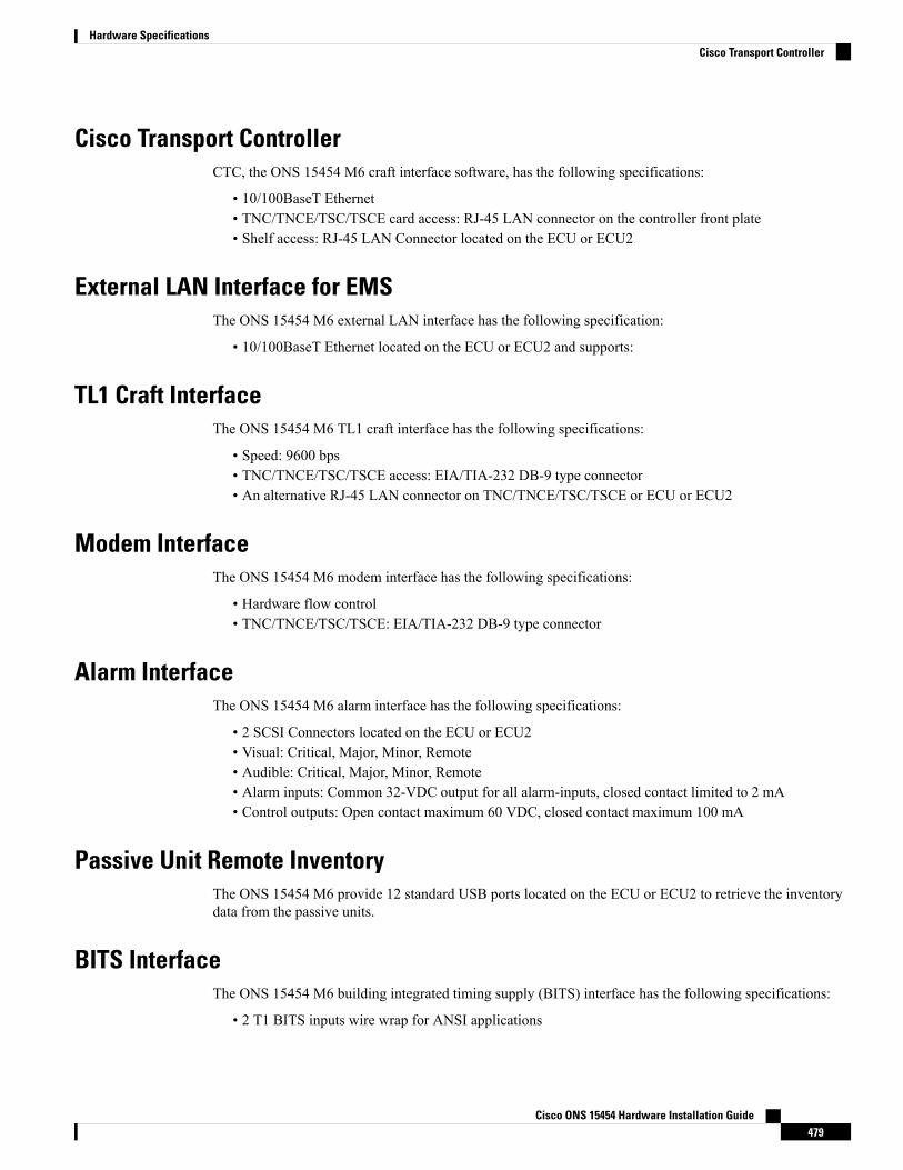
Cisco Transport ControllerCTC, the ONS 15454 M6 craft interface software, has the following specifications:
• 10/100BaseT Ethernet• TNC/TNCE/TSC/TSCE card access: RJ-45 LAN connector on the controller front plate• Shelf access: RJ-45 LAN Connector located on the ECU or ECU2
External LAN Interface for EMSThe ONS 15454 M6 external LAN interface has the following specification:
• 10/100BaseT Ethernet located on the ECU or ECU2 and supports:
TL1 Craft InterfaceThe ONS 15454 M6 TL1 craft interface has the following specifications:
• Speed: 9600 bps• TNC/TNCE/TSC/TSCE access: EIA/TIA-232 DB-9 type connector• An alternative RJ-45 LAN connector on TNC/TNCE/TSC/TSCE or ECU or ECU2
Modem InterfaceThe ONS 15454 M6 modem interface has the following specifications:
• Hardware flow control• TNC/TNCE/TSC/TSCE: EIA/TIA-232 DB-9 type connector
Alarm InterfaceThe ONS 15454 M6 alarm interface has the following specifications:
• 2 SCSI Connectors located on the ECU or ECU2• Visual: Critical, Major, Minor, Remote• Audible: Critical, Major, Minor, Remote• Alarm inputs: Common 32-VDC output for all alarm-inputs, closed contact limited to 2 mA• Control outputs: Open contact maximum 60 VDC, closed contact maximum 100 mA
Passive Unit Remote InventoryThe ONS 15454 M6 provide 12 standard USB ports located on the ECU or ECU2 to retrieve the inventorydata from the passive units.
BITS InterfaceThe ONS 15454 M6 building integrated timing supply (BITS) interface has the following specifications:
• 2 T1 BITS inputs wire wrap for ANSI applications
Cisco ONS 15454 Hardware Installation Guide479
Hardware SpecificationsCisco Transport Controller
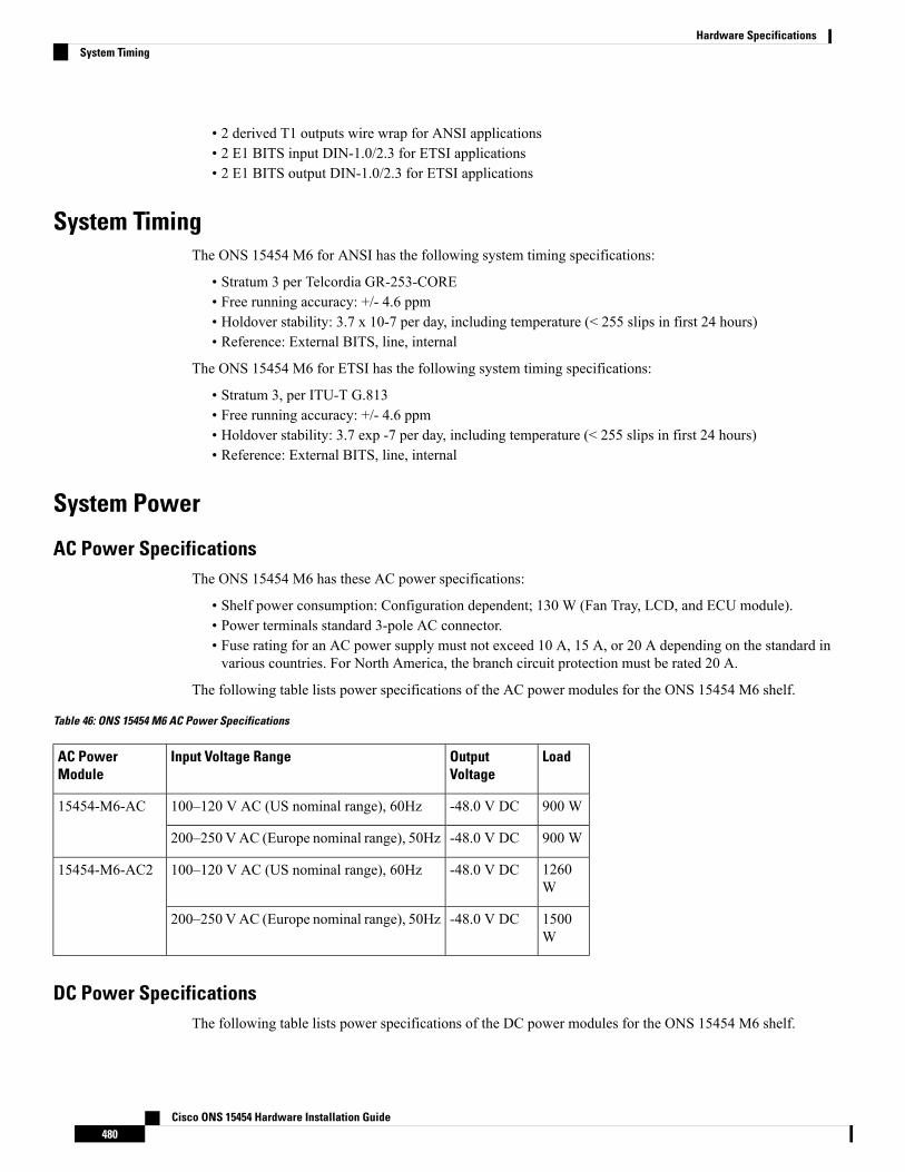
• 2 derived T1 outputs wire wrap for ANSI applications• 2 E1 BITS input DIN-1.0/2.3 for ETSI applications• 2 E1 BITS output DIN-1.0/2.3 for ETSI applications
System TimingThe ONS 15454 M6 for ANSI has the following system timing specifications:
• Stratum 3 per Telcordia GR-253-CORE• Free running accuracy: +/- 4.6 ppm• Holdover stability: 3.7 x 10⁻⁷ per day, including temperature (< 255 slips in first 24 hours)• Reference: External BITS, line, internal
The ONS 15454 M6 for ETSI has the following system timing specifications:
• Stratum 3, per ITU-T G.813• Free running accuracy: +/- 4.6 ppm• Holdover stability: 3.7 exp -7 per day, including temperature (< 255 slips in first 24 hours)• Reference: External BITS, line, internal
System Power
AC Power SpecificationsThe ONS 15454 M6 has these AC power specifications:
• Shelf power consumption: Configuration dependent; 130 W (Fan Tray, LCD, and ECU module).• Power terminals standard 3-pole AC connector.• Fuse rating for an AC power supply must not exceed 10 A, 15 A, or 20 A depending on the standard invarious countries. For North America, the branch circuit protection must be rated 20 A.
The following table lists power specifications of the AC power modules for the ONS 15454 M6 shelf.
Table 46: ONS 15454 M6 AC Power Specifications
LoadOutputVoltage
Input Voltage RangeAC PowerModule
900 W-48.0 V DC100–120 V AC (US nominal range), 60Hz15454-M6-AC
900 W-48.0 V DC200–250 VAC (Europe nominal range), 50Hz
1260W
-48.0 V DC100–120 V AC (US nominal range), 60Hz15454-M6-AC2
1500W
-48.0 V DC200–250 VAC (Europe nominal range), 50Hz
DC Power SpecificationsThe following table lists power specifications of the DC power modules for the ONS 15454 M6 shelf.
Cisco ONS 15454 Hardware Installation Guide480
Hardware SpecificationsSystem Timing
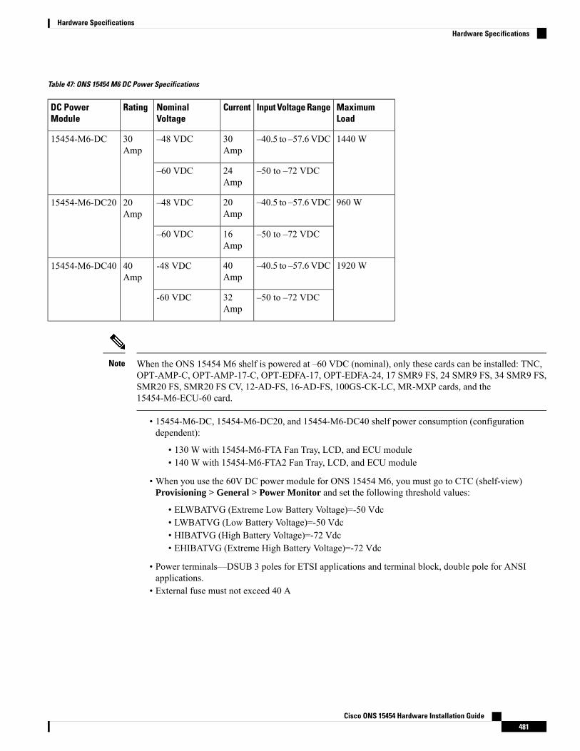
Table 47: ONS 15454 M6 DC Power Specifications
MaximumLoad
Input Voltage RangeCurrentNominalVoltage
RatingDC PowerModule
1440 W–40.5 to –57.6VDC30Amp
–48 VDC30Amp
15454-M6-DC
–50 to –72 VDC24Amp
–60 VDC
960 W–40.5 to –57.6VDC20Amp
–48 VDC20Amp
15454-M6-DC20
–50 to –72 VDC16Amp
–60 VDC
1920 W–40.5 to –57.6VDC40Amp
-48 VDC40Amp
15454-M6-DC40
–50 to –72 VDC32Amp
-60 VDC
When the ONS 15454 M6 shelf is powered at –60 VDC (nominal), only these cards can be installed: TNC,OPT-AMP-C, OPT-AMP-17-C, OPT-EDFA-17, OPT-EDFA-24, 17 SMR9 FS, 24 SMR9 FS, 34 SMR9 FS,SMR20 FS, SMR20 FS CV, 12-AD-FS, 16-AD-FS, 100GS-CK-LC, MR-MXP cards, and the15454-M6-ECU-60 card.
Note
• 15454-M6-DC, 15454-M6-DC20, and 15454-M6-DC40 shelf power consumption (configurationdependent):
• 130 W with 15454-M6-FTA Fan Tray, LCD, and ECU module• 140 W with 15454-M6-FTA2 Fan Tray, LCD, and ECU module
• When you use the 60V DC power module for ONS 15454 M6, you must go to CTC (shelf-view)Provisioning > General > Power Monitor and set the following threshold values:
• ELWBATVG (Extreme Low Battery Voltage)=-50 Vdc• LWBATVG (Low Battery Voltage)=-50 Vdc• HIBATVG (High Battery Voltage)=-72 Vdc• EHIBATVG (Extreme High Battery Voltage)=-72 Vdc
• Power terminals—DSUB 3 poles for ETSI applications and terminal block, double pole for ANSIapplications.
• External fuse must not exceed 40 A
Cisco ONS 15454 Hardware Installation Guide481
Hardware SpecificationsHardware Specifications
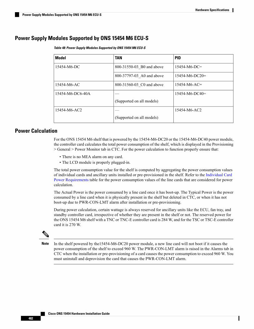
Power Supply Modules Supported by ONS 15454 M6 ECU-S
Table 48: Power Supply Modules Supported by ONS 15454 M6 ECU-S
PIDTANModel
15454-M6-DC=800-31550-03_B0 and above15454-M6-DC
15454-M6-DC20=800-37797-03_A0 and above
15454-M6-AC=800-31560-03_C0 and above15454-M6-AC
15454-M6-DC40=—
(Supported on all models)
15454-M6-DC6-40A
15454-M6-AC2—
(Supported on all models)
15454-M6-AC2
Power CalculationFor the ONS 15454M6 shelf that is powered by the 15454-M6-DC20 or the 15454-M6-DC40 power module,the controller card calculates the total power consumption of the shelf, which is displayed in the Provisioning> General > Power Monitor tab in CTC. For the power calculation to function properly ensure that:
• There is no MEA alarm on any card.• The LCD module is properly plugged-in.
The total power consumption value for the shelf is computed by aggregating the power consumption valuesof individual cards and ancillary units installed or pre-provisioned in the shelf. Refer to the Individual CardPower Requirements table for the power consumption values of the line cards that are considered for powercalculation.
The Actual Power is the power consumed by a line card once it has boot-up. The Typical Power is the powerconsumed by a line card when it is physically present in the shelf but deleted in CTC, or when it has notboot-up due to PWR-CON-LMT alarm after installation or pre-provisioning.
During power calculation, certain wattage is always reserved for ancillary units like the ECU, fan tray, andstandby controller card, irrespective of whether they are present in the shelf or not. The reserved power forthe ONS 15454M6 shelf with a TNC or TNC-E controller card is 284W, and for the TSC or TSC-E controllercard it is 270 W.
In the shelf powered by the15454-M6-DC20 power module, a new line card will not boot if it causes thepower consumption of the shelf to exceed 960 W. The PWR-CON-LMT alarm is raised in the Alarms tab inCTC when the installation or pre-provisioning of a card causes the power consumption to exceed 960 W. Youmust uninstall and deprovision the card that causes the PWR-CON-LMT alarm.
Note
Cisco ONS 15454 Hardware Installation Guide482
Hardware SpecificationsPower Supply Modules Supported by ONS 15454 M6 ECU-S
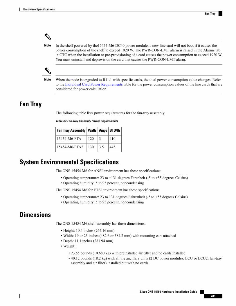
In the shelf powered by the15454-M6-DC40 power module, a new line card will not boot if it causes thepower consumption of the shelf to exceed 1920 W. The PWR-CON-LMT alarm is raised in the Alarms tabin CTC when the installation or pre-provisioning of a card causes the power consumption to exceed 1920 W.You must uninstall and deprovision the card that causes the PWR-CON-LMT alarm.
Note
When the node is upgraded to R11.1 with specific cards, the total power consumption value changes. Referto the Individual Card Power Requirements table for the power consumption values of the line cards that areconsidered for power calculation.
Note
Fan TrayThe following table lists power requirements for the fan-tray assembly.
Table 49: Fan-Tray Assembly Power Requirements
BTU/HrAmpsWattsFan Tray Assembly
410312015454-M6-FTA
4453.513015454-M6-FTA2
System Environmental SpecificationsThe ONS 15454 M6 for ANSI environment has these specifications:
• Operating temperature: 23 to +131 degrees Farenheit (-5 to +55 degrees Celsius)• Operating humidity: 5 to 95 percent, noncondensing
The ONS 15454 M6 for ETSI environment has these specifications:
• Operating temperature: 23 to 131 degrees Fahrenheit (-5 to +55 degrees Celsius)• Operating humidity: 5 to 95 percent, noncondensing
DimensionsThe ONS 15454 M6 shelf assembly has these dimensions:
• Height: 10.4 inches (264.16 mm)• Width: 19 or 23 inches (482.6 or 584.2 mm) with mounting ears attached• Depth: 11.1 inches (281.94 mm)• Weight:
• 23.55 pounds (10.680 kg) with preinstalled air filter and no cards installed• 40.12 pounds (18.2 kg) with all the ancillary units (2 DC power modules, ECU or ECU2, fan-trayassembly and air filter) installed but with no cards.
Cisco ONS 15454 Hardware Installation Guide483
Hardware SpecificationsFan Tray

Cisco ONS 15454 Hardware Installation Guide484
Hardware SpecificationsDimensions
I N D E X
mounting brackets 35reversing the brackets to covert the rack size 35
A
acceptance tests 145, 147, 269, 270, 428, 430shelf connections 147, 270, 430shelf installation 145, 269, 428
accessing, TL1 craft interface 113ACO 99AEP 87, 93, 114
connecting external wire-wrap panel 114description 87, 93installing on backplane 93pin assignments 87, 93printed circuit board assembly 87See also AIC-I card [AEP 93
zzz] 93AIC-I card 96, 137
installing 137See also external alarms [AIC-I card 137
zzz] 137See also external controls [AIC-I card 137
zzz] 137See also pin assignments [AIC-I card 96
zzz] 96AIP 56, 58
description 58location 56replacing 58
AIP, replacing 464air filter 36, 84, 439
inspecting, cleaning, and replacing 439installing below the fan-tray assembly 84installing below the shelf assembly with external brackets 36location 84requirement 84
air filter, description 84, 272, 435air ramp 26, 29, 122
ANSI placement overview 26ETSI placement overview 29typical site layout 122
air ramp, installing 44alarm interface panel. See AIP 58
alarms 454, 473incompatibility alarms 454interface specifications 473
AMP champ 114attaching 93
AEP to the backplane 93
B
backplane 55, 56, 65, 66, 93, 96, 108, 111, 112, 113, 120, 467AEP connections 93alarm wire connections 108alarm wire illustration 108attaching AEP 93connection overview 96covers, overview 55installing the rear cover 120LAN wire connections 112lower cover, description 56rear cover, description 56removing the lower cover 65removing the sheet metal cover 66replacing the lower cover 467timing wire connections 111TL1 craft interface connections 113
bandwidth 471specifications 471
battery termination 73bay assembly. See 28BITS 100, 106, 108, 111, 473
ANSI interface specifications 473external alarm pin assignments (ANSI) 108external timing pin assignments (ANSI) 111external timing pin assignments (ETSI) 106pin field assignments 100
blade. See card 133, 263bottom brackets. See air filter 36
C
cabinet compartment. See front door 59cables 73, 103, 106, 107, 108, 111, 113, 156, 160, 175, 177
coaxial cable 106EAP 156
Cisco ONS 15454 Hardware Installation GuideIN-1
cables (continued)fiber management 160, 175installing alarm cables 103, 108installing timing cables 106, 111installing TL1 craft interface cables 113routing power cables 73See also LAN cables [cables 107
zzz] 107tie-down bar 177
Card Slot Requirements 17cards 17, 20, 21
replacement 21slot requirements 20symbol and slot correspondence 17, 20, 21
Catalyst 2950 154changing 35, 200, 204, 301, 306
rack size 35, 200, 204, 301, 306circuits 464
Repair Circuit dialog box 464Cisco Transport Planner 125
requirement 125cleaning 439, 449, 451
air filter 439fiber adaptors 451fiber connectors 449
CLETOP 451clock 73, 246, 251, 380, 384
resetting 73, 246, 251, 380, 384closing 119
FMEC cover 119coating bare power conductors 73, 246, 251, 380, 384coaxial cable 106common control cards 133
See AIC-I card 133See MS-ISC-100T card 133See TCC2 card 133See TCC2P card 133
configuring 154Catalyst 2950 for a multishelf node 154
connecting 67, 72, 73, 107, 114, 140, 241, 243, 246, 251, 380cable to MIC-C/T/P 67, 107external wire-wrap pin to AEP 114ground to ETSI shelf 241multishelf node and subtending shelves to an MS-ISC-100T
card 140power to ANSI shelf 73, 246, 251, 380power to ETSI shelf 72, 243
covers 62See backplane 62See FMEC cover 62
crimp tool 73CTC 134, 264, 472
specifications 472verifying software release 134, 264
cutting fuse and alarm cables 73, 246, 380
D
database 58MAC address 58
date 72, 243, 376default 72, 243, 376
DB-62 connector 103DCU 122, 125
installing the DCU chassis 125typical rack layout 122
default para font 28, 41, 156detaching the ground strap 60DWDM 122, 125, 175, 472
configurations 472fiber tray 175optional hardware 125rack layouts 122topologies 472
E
EAP 156cable 156descriptionEthernet adapter panel. See 156
EIA interface specifications 473EIA/TIA-232 port 113
accessing a TL1 craft interface 113do not use backplane pins simultaneously 113
Electrostatic Discharge and Grounding Guide for Cisco Cisco CPT andCisco ONS Platforms 59, 67, 69, 72, 73, 76, 102, 133, 196, 218, 220, 221, 222, 224, 228, 232, 233, 235, 237, 239, 241, 243, 246, 251, 253, 254, 256, 263, 269, 296, 324, 329, 330, 334, 341, 352, 358, 361, 362, 363, 366, 368, 369, 371, 373, 376, 380, 384, 388, 389, 391, 400, 428, 443, 445, 464
Electrostatic Discharge and Grounding Guide for Cisco CPT and CiscoONS Platforms 69, 448
environmental specifications 474equipment 125
installing DWDM equipment 125See also installation [equipment 125
zzz] 125ESD plug input 59, 221, 330external alarms 87, 99, 103, 108, 114
alarm input connectors (ANSI) 114pin assignments (ETSI) 103pin assignments using external wire-wrap panel 114pin assignments with AEP 87wiring (ANSI) 108wiring (ETSI) 103wiring description 99
external brackets. See air filter 36external controls 87, 99, 103, 108, 114
alarm output connectors 114pin assignments (ETSI) 103pin assignments using external wire-wrap panel 114pin assignments with AEP 87
Cisco ONS 15454 Hardware Installation GuideIN-2
INDEX

external controls (continued)wiring (ETSI) 103, 108wiring description 99
external LAN interface 472external wire-wrap panel 114
F
fan-tray air filter. See air filter 36fan-tray assembly 78, 83, 84, 237, 390, 391, 439, 454, 464
description 78, 390fan failure 83, 237, 391fan speed 83, 237, 391installing 84, 391power cable 464removing to replace air filter 439replacing 454
fans 83, 237, 391failure 83, 237, 391speed 83, 237, 391
fiber 126, 127, 160, 162, 175, 449, 451capacity 160cleaning adapters 451cleaning connectors 449installing the fiber patch-panel tray 126installing the fiber-storage tray 127management 160managing using the Y-cable module tray 175managing with the patch-panel tray 162
fiber patch-panel tray 126installing 126
fiber-storage tray 127installing 127
filler cards 158, 271, 435description 158, 271, 435faceplate (illustration) 158, 435
filter stopper 36flange 28, 36, 276FlexLayer 129, 130, 131, 132
hardware part numbers 130installing FlexLayer modules 130installing the FlexLayer shelf 129installing Y-cable modules in FlexLayer chassis 131, 132See also Y-cable protection [FlexLayer 129
zzz] 129FMEC 67
See FMEC cover 67See MIC-A/P FMEC 67See MIC-C/T/P FMEC 67
FMEC cover 63, 64, 119installing and closing 119opening 63removing 64
FMECs 4, 67cover 4description 67
frame-ground pin 113front door 47, 59, 60, 217, 221, 222, 322, 330, 332, 452
description 47installing ground strap retrofit kit 452label (ANSI) 47, 217, 322opening 59, 221, 330removing 60, 222, 332removing (ANSI) 47replacing 452
fuse and alarm panel 3, 4, 6, 28, 31, 73, 76, 246, 254, 276, 380, 389description 3, 4, 6location (ANSI) 28, 276location (ETSI) 31measuring and cutting cables 73, 246, 380verifying office battery and ground 76, 254, 389
G
ground 69, 76, 240, 241, 254, 371, 372, 373, 389ANSI 240, 371connecting to ETSI shelf 241ETSI 240, 372installing 69, 241, 373verifying before turning on office power 76, 254, 389
ground strap 60, 452avoiding interference with cards 452detaching 60retrofit kit 452
I
inspecting 22, 23, 439air filter 439shelf assembly 22, 23
installation 3, 4, 6, 27, 145, 180, 269, 275, 428acceptance test 145, 269, 428overview 3, 4, 6See also rack [installation 27, 180, 275
zzz] 27, 180, 275installing 33, 36, 41, 44, 67, 69, 84, 93, 103, 106, 107, 108, 111, 112, 113,
119, 120, 125, 126, 127, 128, 129, 130, 131, 132, 134, 137, 138, 196, 241, 264, 296, 320, 373, 391, 452
AEP 93AIC-I card 137air filter 36, 84air ramp 44alarm wires on the backplane 108alarm wires on the MIC-A/P 103backplane rear cover 120DCU shelf assembly 125DCUs 125default para font 320DWDM equipment 125fan-tray assembly 84, 391fiber patch-panel tray 126
Cisco ONS 15454 Hardware Installation GuideIN-3
INDEX
installing (continued)fiber-storage tray 127FlexLayer modules 130FlexLayer shelf 129FMEC cover 119front door ground strap retrofit kit 452ground 69, 241, 373LAN wires on the backplane 112LAN wires on the MIC-C/T/P 107MIC cards 67mounting[installing 320
zzz] 320MS-ISC-100T card 138rear cover mounting brackets 120See also 41shelf assembly 33, 196, 296TCC2/TCC2P card 134, 264timing wires on the backplane 111timing wires on the MIC-C/T/P 106TL1 craft interface wires 113Y-cable module tray 128Y-cable protection modules 131, 132
K
Kepnut 60
L
LAN 100, 107connection points 100pin assignments 100See also LAN cable [LAN 107
zzz] 107LAN cable 67, 107, 112, 113, 140
accessing a TL1 craft interface 113connecting cable to MIC-C/T/P 67, 107connecting nodes in multishelf mode 140installing cable on MIC-C/T/P FMEC 107installing LAN wires on the backplane 112
laser warning 47, 217, 322LCD 134, 264
verifying software version 134, 264lock washer 452
M
MAC address 58, 464AIP 58AIP replacement 464
managing 162, 175fiber using the Y-cable module tray 175fiber with the patch-panel tray 162
measuring 73, 148, 246, 270, 380, 430fuse and alarm cables 73, 246, 380
measuring (continued)voltage 148, 270, 430
mesh patch-panel 164tray 164
MIC-A/P FMEC 67, 72, 103description 67installing 67installing alarm cables 103pin connections 72
MIC-C/T/P FMEC 67, 72, 106, 107description 67installing 67installing LAN cables 107installing timing cables 106pin connections 72timing connectors 106
modem interface 472module. See card 133, 263mounting 31, 38, 39, 41, 182, 277, 278, 317, 319, 320
multiple nodes in a rack 31, 41, 278, 320shelf assembly in a rack (one person) 38, 317shelf assembly in a rack (two people) 39, 319single node in a rack 182, 277
mounting brackets 120, 200, 204, 301, 306installing the rear cover 120reversing the brackets to covert the rack size 200, 204, 301, 306
mounting brackets, description 27, 275mounting[installing 41
zzz] 41MS-ISC-100T card 138, 140, 156
connecting to a shelf 140EAPsmultishelf 156
EAPs 156installing 138LED sequence 138
multishelf LAN topologies 139ONS 15454 139
multishelf management 139ONS 15454 139
multishelf mode 140, 154configuring a Catalyst 2950 154connecting shelves 140See also MS-ISC-100T card [multishelf mode 140
zzz] 140See also subtending shelf [multishelf mode 140
zzz] 140
N
NTP-G24 Set Up Name, Date, Time, and Contact Information, page5-15 243, 246, 251
NTP-G38 Provision OSC Terminations, page 5-121 268number of shelves 139
ONS 15454 139
Cisco ONS 15454 Hardware Installation GuideIN-4
INDEX
O
office power. See power 69, 241, 373opening 59, 63, 221, 330
FMEC cover 63front door 59, 221, 330
P
patch-panel tray 162, 163, 164(40-channel) 163deep (32-channel) 162eight degree 164managing fiber with 162mesh 164
pin assignments 72, 87, 93, 96, 103, 106, 107, 108, 111, 112, 113, 114AEP 87, 93alarms, ANSI 96craft interface (ANSI) 113external alarms and controls (ANSI) 108external alarms and controls (ETSI) 103LAN (ANSI) 112LAN (ETSI) 107overview (ANSI) 96power and ground on the MIC-A/P 72power and ground on the MIC-C/T/P 72timing (ANSI) 111timing (ETSI) 106wire-wrap panel on the AEP 114
pinned hex (Allen) key 38, 39, 41, 59mounting shelves 38, 39, 41opening the front door 59
plug-in unit. See card 133power 72, 73, 76, 148, 243, 246, 251, 253, 254, 270, 380, 384, 388, 389, 430,
474BAT1 backplane power terminal 73coating bare conductors 73, 246, 251, 380, 384connecting office power to ANSI shelf 73, 246, 251, 380connecting office power to ETSI shelf 72, 243fan-tray assembly 474measuring voltage 148, 270, 430RET2 backplane power terminal 73routing cables 73See also ground [power 73, 246, 380
zzz] 73, 246, 380specifications 474turning on and verifying office power 76, 253, 254, 388, 389
R
rack 27, 28, 29, 31, 35, 38, 39, 41, 122, 179, 181, 182, 200, 204, 274, 275, 276, 277, 278, 301, 306, 317, 319, 320
converting the rack size 35bay assembly 28converting the rack size 200, 204, 301, 306
rack (continued)installation overview (ANSI) 179, 274installation overview (ETSI) 29, 181, 276mount a single node (ANSI) 28, 181, 275mount multiple nodes (ANSI) 28, 276mounting a single node 38, 39, 317, 319mounting a single node (ETSI) 182, 277mounting multiple nodes 41, 320mounting multiple nodes (ETSI) 31, 278reversible mounting bracket 27, 275typical DWDM layouts 122
rear cover 56removing 47, 60, 64, 65, 66, 222, 332, 439
backplane lower cover 65backplane sheet metal cover 66fan-tray assembly 439FMEC cover 64front door 60, 222, 332front door (ANSI) 47
replacing 439, 452, 454, 464, 467AIP 464air filter 439fan-tray assembly 454front door 452lower backplane cover 467
replacing the AIP 58resetting 73, 246, 251, 380, 384
TCC2/TCC2P card clock 73, 246, 251, 380, 384reversing the mounting brackets 35, 200, 204, 301, 306routing 73
power cables 73
S
Shelf 77, 78, 272, 436Temperature 78, 272, 436Voltage 77, 78, 272, 436
shelf assembly 22, 23, 28, 29, 31, 33, 38, 39, 41, 125, 130, 179, 181, 182, 196, 274, 276, 277, 278, 296, 317, 319, 320, 471, 475
ANSI, bay assembly 28ANSI, description 179, 274ANSI, dimensions 179, 274, 475ETSI, description 29, 181, 276ETSI, dimensions 276, 475ETSI, mounting 31, 182, 277, 278FlexLayer shelf assembly illustration 130inspecting 23installing 33, 196, 296installing the DCU shelf assembly 125mounting in a rack 38, 39, 41, 317, 319, 320See also installation [shelf assembly 22
zzz] 22specifications 471unpacking and inspecting 22verifying 22
Cisco ONS 15454 Hardware Installation GuideIN-5
INDEX
slots 20, 67, 160fiber management 160FMEC slots 67requirements 20
software 134, 264verifying software version 134, 264
standoff kit 36subtending shelf 140
connecting to an MS-ISC-100T card 140
T
TCC2 card 73, 113, 134, 246, 251, 264, 380, 384, 472clock reset 73, 246, 251, 380, 384installing 134, 264LED sequence 134modem interface 472See also EIA/TIA-232 port [TCC2 card 113
zzz] 113TL1 craft interface 472
TCC2P card 73, 113, 134, 246, 251, 264, 380, 384, 472clock reset 73, 246, 251, 380, 384installing 134, 264LED sequence 134modem interface 472See also EIA/TIA-232 port [TCC2P card 113
zzz] 113TL1 craft interface 472
TCC3 card 134LED sequence 134
Temperature 77, 78, 272, 436Shelf 77, 78, 272, 436
terminal lug 452third-party equipment 3, 4, 6
fuse and alarm panels 3, 4, 6timing 100, 106, 473
connections 100installing timing cables on ETSI shelf 106specifications 473
TL1 101, 113, 472craft interface connection 101, 113EIA/TIA-232 port connection 113interface specifications 472pin assignments 113
TNC card 263, 267, 268configuring UDC and VoIP 268installing 263provisioning PPM and port 267
TransportPlanner. See Cisco TransportPlanner 125TSC card 263
installing 263turning on office power 76, 253, 254, 388, 389
U
unpacking the shelf assembly 22
V
verifying 22, 76, 134, 148, 253, 254, 264, 270, 388, 389, 430ground 76, 254, 389office power 76, 253, 254, 388, 389shelf assembly 22shelf ground and power 148, 270, 430software version 134, 264
Voltage 77, 78, 272, 436Shelf 77, 78, 272, 436
voltage, measuring 148, 270, 430voltmeter 76, 148, 254, 270, 389, 430
verifying office battery and ground 76, 254, 389verifying the office ground and power 148, 270, 430verifying the shelf and ground power wiring 148, 270, 430verifying the shelf for –48 VDC 76, 254, 389
W
warnings 47, 217, 322laser 47, 217, 322
wire-wrap panel, external 114wires. See cables 103
Y
Y-cable modules 128, 131, 132installing modules 131, 132installing the tray 128
Y-cable protection 175managing fibers 175
Cisco ONS 15454 Hardware Installation GuideIN-6
INDEX