Line Hardware
34
-
Upload
khangminh22 -
Category
Documents
-
view
0 -
download
0
Transcript of Line Hardware

Line Hardware
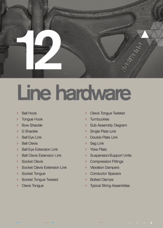
Ball Hooks & Tongue Hook
www.dulmison.com.au12-2
Line
Har
dw
are
BHSS70BHLS70
TH70
707070
252525
323232
202525
1616-
578267
Forged SteelForged SteelForged Steel
123
DimensionsA B E F (Ball) S Material
Fig.No.
MinimumFailing Load
kNCat No.
Fig. 1 Ball Hook Short Shank Fig. 2 Ball Hook Long Shank
Fig. 3 Tongue Hook
E
E
A
B
S
16
FF
E
A
Optionalhole for
safetylatch
Optionalhole for
safety latcho5.5
18o hole
B
S
Cat BHSS70

S70AS70QS120AS160A
7070120160
16161620
22.5022.5022.5024.50
34343440
16161620
67676776
Forged SteelForged SteelForged SteelForged Steel
1211
Dimensions
A B EBolt/Rivet
Dia. S MaterialFig.No.
MinimumFailing Load
kNCat No.
Line Hardware
Bow Shackle
www.dulmison.com.au 12-3
Line
Har
dw
are
E
A
B
E
B
Bolt/RivetDia.
S
Fig. 1
A
B B
Bolt/RivetDia.
S S
SD70ASD70Q
7070
1616
4444
1616
100100
Forged SteelForged Steel
12
Dimensions
A BBolt/Rivet
Dia. S MaterialFig.No.
MinimumFailing Load
kNCat No.
Fig. 2Fig. 1
Cat S70A
D Shackle
Fig. 2
Cat SD70Q
Line Hardware
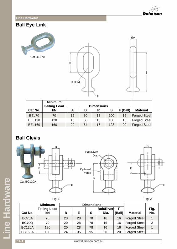
Ball Eye Link
www.dulmison.com.au12-4
Line
Har
dw
are
BEL70BEL120BEL160
70120160
161620
505064
131316
100100128
161620
Forged SteelForged SteelForged Steel
DimensionsA B R S F (Ball) Material
MinimumFailing Load
kNCat No.
F
oA
B
S
R Rad.
E
F
B
E
F
B
Bolt/RivetDia.
S
OptionalProfile
Ball Clevis
Fig. 1 Fig. 2
BC70ABC70QBC120ABC160A
7070120160
20202024
28282835
78787895
16161620
16161620
Forged SteelForged SteelForged SteelForged Steel
1211
Dimensions
B E SBolt/Rivet
Dia.F
(Ball) MaterialFig.No.
MinimumFailing Load
kNCat No.
Cat BEL70
Cat BC120A
Line Hardware
Ball Eye Extension Link
www.dulmison.com.au 12-5
Line
Har
dw
are
BEEL160ABEEL160DBEEL160E
160160160
202020
646464
787878
202020
232323
242424
161616
250500800
Forged SteelForged SteelForged Steel
DimensionsA B C F I J R S Material
MinimumFailing Load
kNCat No.
C C
F
B
A R
S
DE
B
B
Bolt Dia.
C C
F
S
I J
Standard length S also available in 350, 1000 and 1330mm long
BCEL160A 160 24 78 24 35 20 20 23 24 295 Forged Steel
Dimensions
B C D E FBoltDia.
IMax J S Material
MinimumFailing
Load kNCat No.
Ball Clevis Extension Link
H J
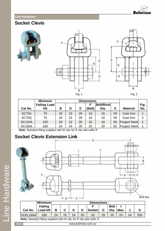
Line Hardware
www.dulmison.com.au12-6
Line
Har
dw
are
D
E
B
F
S
D
E
B
F
S
SC70ASC70QSC120ASC160A
7070120160
20202024
22222224
28282835
16161620
16161620
59595962
Cast IronCast Iron
Forged SteelForged Steel
1211
Dimensions
B D EF
(Ball)Bolt/Rivet
Dia. S Material
MinimumFailing Load
kNCat No.
DE
B
Bolt Dia.
F
S
I J
SCEL160A 160 24 78 24 35 20 25 20 23 24 250
Dimensions
B C D EF
Socket GBoltDia.
IMax. J S
MinimumFailing
Load kNCat No.
Socket Clevis Extension Link
G C
Socket Clevis
Fig. 1 Fig. 2
Fig.No.
Note: Standard fitting supplied with W clip; for R clip add suffix R
Note: Standard fitting supplied with W clip; for R clip add suffix R
Line Hardware
www.dulmison.com.au 12-7
Line
Har
dw
are
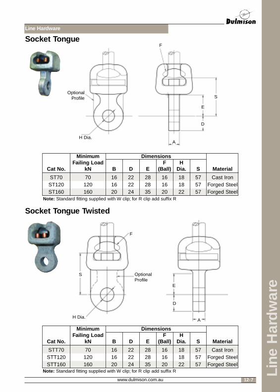
D
E
AH Dia.
F
SOptional
Profile
ST70ST120ST160
70120160
161620
222224
282835
161620
181822
575757
Cast IronForged SteelForged Steel
Dimensions
B D EF
(Ball)H
Dia. S Material
MinimumFailing Load
kNCat No.
Socket Tongue
D
E
AH Dia.
F
S OptionalProfile
STT70STT120STT160
70120160
161620
222224
282835
161620
181822
575757
Cast IronForged SteelForged Steel
Dimensions
B D EF
(Ball)H
Dia. S Material
MinimumFailing Load
kNCat No.
Socket Tongue Twisted
Note: Standard fitting supplied with W clip; for R clip add suffix R
Note: Standard fitting supplied with W clip; for R clip add suffix R

Line Hardware
Clevis Tongue
www.dulmison.com.au12-8
Line
Har
dw
are
D
D
E
E
A
H
B
D
D
E
E
A
B
S
CT70ACT70QCT120A
7070120
161616
202020
222222
282828
181818
161616
727272
Cast IronCast Iron
Forged Steel
121
Dimensions
A B D EH
Dia.Bolt/Rivet
Dia. S MaterialFig.No.
MinimumFailing
Load kNCat No.
D
D
E
E
HH
B Bolt Dia. B
S
D
E
S
Clevis Tongue TwistedA
Fig. 1
Fig. 1 Fig. 2
Fig. 2
CTT70ACTT70QCTT120ACTT160A
7070120160
16161620
20202024
22222224
28282835
18181822
16161620
76767676
Forged SteelForged SteelForged SteelForged Steel
1211
Dimensions
A B D EH
Dia.Bolt/Rivet
Dia. S MaterialFig.No.
MinimumFailing
Load kNCat No.

**When ordering turnbuckles nominate suffix as follows:
TB160 followed by -EE Nominating Eye/Eye TL Nominating Tongue/ClevisET Nominating Eye/Tongue LL Nominating Clevis/ClevisEL Nominating Eye/Clevis TT Nominating Tongue/Tongue
Other sizes may be available on request.
Line Hardware
Turnbuckles
Sub Assembly ZZ
www.dulmison.com.au 12-9
Line
Har
dw
are
TB160** 160 20 24 24 35 32 64 20 Forged Steel
Dimensions
A B D E F GBoltDia. Material
MinimumFailing Load
kNCat No.
Use suffix Afor nut andbolt assembly
Use suffix Qfor rivet and splitpin assembly
A Q
Bolt diameter 16mm for 70kN/120kN and 20mm for 160kNRivet diameter 16mm for 70kN
JG
F
OA
D E
B
J
H H
A A
Cat TB160EL
Cat TB160TT
Line Hardware
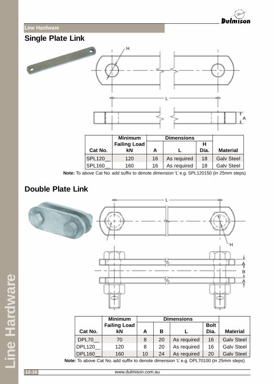
Single Plate Link
Double Plate Link
www.dulmison.com.au12-10
Line
Har
dw
are
SPL120__SPL160__
120160
1616
As requiredAs required
1818
Galv SteelGalv Steel
Dimensions
A LH
Dia. Material
MinimumFailing Load
kNCat No.
DPL70__DPL120__DPL160__
70120160
8810
202024
As requiredAs requiredAs required
161620
Galv SteelGalv SteelGalv Steel
Dimensions
A B LBoltDia. Material
MinimumFailing Load
kNCat No.
L
H
A
L
H
A
A
B
Note: To above Cat No. add suffix to denote dimension ‘L’ e.g. SPL120150 (in 25mm steps)
Note: To above Cat No. add suffix to denote dimension ‘L’ e.g. DPL70100 (in 25mm steps)

Line Hardware
Sag Link
Yoke Plate - Triangular/RectangularTypical only, consult Dulmison for more details
www.dulmison.com.au 12-11
Line
Har
dw
are
SL70SL120
SL160**
70120160
16 - 1816 - 1820 - 22
202024
161620
181822
Galv SteelGalv SteelGalv Steel
Dimensions
A BH
Dia.BoltDia. Material
MinimumFailing Load
kNCat No.
Note: Other variations available.
YPT70YPT120YPT160
YPR70YPR120YPR160
70120160
161620
767676
380380380
181822
Galv SteelGalv SteelGalv Steel
DimensionsMinimumFailing Load
kN A B CH
Dia. MaterialCat No.
RectangularCat No.
Triangular
Note: Dimensions ‘B’ and ‘C’ are subject to customer requirements.
Adjustable length between 557mm Min. - 974mm Max.
AB
H
H
C
B
Maintenance Hole
H
C
B
Line Hardware
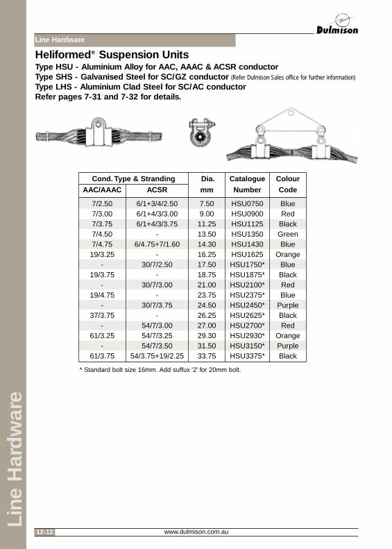
Heliformed® Suspension UnitsType HSU - Aluminium Alloy for AAC, AAAC & ACSR conductorType SHS - Galvanised Steel for SC/GZ conductor (Refer Dulmison Sales office for further information)
Type LHS - Aluminium Clad Steel for SC/AC conductorRefer pages 7-31 and 7-32 for details.
www.dulmison.com.au12-12
Line
Har
dw
are
7/2.507/3.007/3.757/4.507/4.7519/3.25
-19/3.75
-19/4.75
-37/3.75
-61/3.25
-61/3.75
6/1+3/4/2.506/1+4/3/3.006/1+4/3/3.75
-6/4.75+7/1.60
-30/7/2.50
-30/7/3.00
-30/7/3.75
-54/7/3.0054/7/3.2554/7/3.50
54/3.75+19/2.25
7.509.0011.2513.5014.3016.2517.5018.7521.0023.7524.5026.2527.0029.3031.5033.75
HSU0750HSU0900HSU1125HSU1350HSU1430HSU1625HSU1750*HSU1875*HSU2100*HSU2375*HSU2450*HSU2625*HSU2700*HSU2930*HSU3150*HSU3375*
BlueRed
BlackGreenBlue
OrangeBlueBlackRedBlue
PurpleBlackRed
OrangePurpleBlack
Dia.
mm
Catalogue
Number
Colour
Code
Cond. Type & Stranding
AAC/AAAC ACSR
* Standard bolt size 16mm. Add suffux ‘2’ for 20mm bolt.
Line Hardware
www.dulmison.com.au 12-13
Line
Har
dw
are
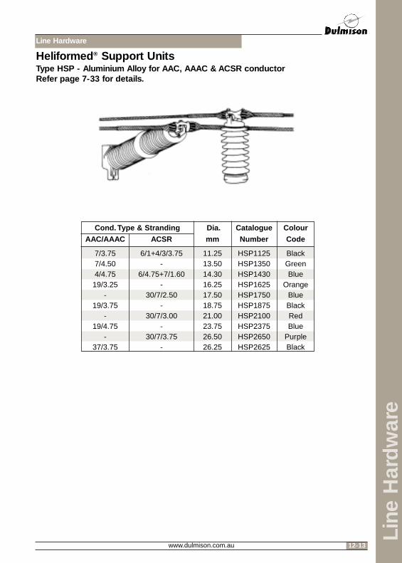
Heliformed® Support UnitsType HSP - Aluminium Alloy for AAC, AAAC & ACSR conductorRefer page 7-33 for details.
7/3.757/4.504/4.7519/3.25
-19/3.75
-19/4.75
-37/3.75
6/1+4/3/3.75-
6/4.75+7/1.60-
30/7/2.50-
30/7/3.00-
30/7/3.75-
11.2513.5014.3016.2517.5018.7521.0023.7526.5026.25
HSP1125HSP1350HSP1430HSP1625HSP1750HSP1875HSP2100HSP2375HSP2650HSP2625
BlackGreenBlue
OrangeBlueBlackRedBlue
PurpleBlack
Dia.
mm
Catalogue
Number
Colour
Code
Cond. Type & Stranding
AAC/AAAC ACSR
Line Hardware
www.dulmison.com.au12-14
Line
Har
dw
are
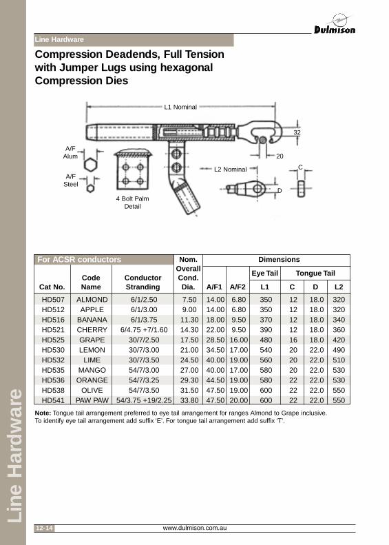
Compression Deadends, Full Tensionwith Jumper Lugs using hexagonalCompression Dies
HD507HD512HD516HD521HD525HD530HD532HD535HD536HD538HD541
ALMONDAPPLE
BANANACHERRYGRAPELEMON
LIMEMANGO
ORANGEOLIVE
PAW PAW
6/1/2.506/1/3.006/1/3.75
6/4.75 +7/1.6030/7/2.5030/7/3.0030/7/3.5054/7/3.0054/7/3.2554/7/3.50
54/3.75 +19/2.25
7.509.0011.3014.3017.5021.0024.5027.0029.3031.5033.80
14.0014.0018.0022.0028.5034.5040.0040.0044.5047.5047.50
6.806.809.509.5016.0017.0019.0017.0019.0019.0020.00
350350370390480540560580580600600
1212121216202020222222
18.018.018.018.018.022.022.022.022.022.022.0
320320340360420490510530530550550
Nom.OverallCond.Dia.
Dimensions
Eye Tail
A/F1 A/F2 L1 C D L2
Tongue TailCodeName
ConductorStrandingCat No.
Note: Tongue tail arrangement preferred to eye tail arrangement for ranges Almond to Grape inclusive.To identify eye tail arrangement add suffix ‘E’. For tongue tail arrangement add suffix ‘T’.
For ACSR conductors
L1 Nominal
L2 Nominal
4 Bolt PalmDetail
A/FAlum
A/FSteel
32
20
C
D

Line Hardware
www.dulmison.com.au 12-15
Line
Har
dw
are
Compression Deadends, Full Tensionwith Jumper Lugs using hexagonalCompression Dies
HD604HD606HD608HD611HD612HD615HD616HD618HD620HD621HD623HD624
LEOLIBRAMARS
MERCURYMOON
NEPTUNEPLUTO
SATURNTAURUSTRITONURANUSVENUS
7/2.507/3.007/3.757/4.507/4.7519/3.2519/3.7537/3.0019/4.7537/3.7561/3.2561/3.75
7.509.0011.3013.5014.3016.3018.8021.0023.8026.3029.3033.80
14.014.018.022.022.028.528.534.540.040.044.547.5
310330350370370420440460500500580600
121212121212121216162020
181818181818181818182020
280300320340340390410430480480530570
Nom.OverallCond.Dia.
Dimensions
Eye Tail
A/F L1 C D L2
Tongue Tail
Code NameCond.
StrandingCat No.
Note: Tongue tail arrangement preferred to eye tail arrangement for ranges Jupiter to Triton inclusive.Eye tail arrangements for Uranus and larger should have centre palm arrangements.To identify eye tail arrangement add suffix ‘E’. For tongue tail arrangement add suffix ‘T’.
For AAC conductors
HD702HD703HD704HD705HD706HD707HD708HD709HD710HD711HD712HD713
DIAMONDEMERALDGARNET
JADEJASPER
OPALPEARLRUBY
RUTILESAPPHIRE
SPINELTOPAZ
CHLORINEFLUORINE
HELIUMHYDROGEN
IODINEKRYPTON
NEONNITROGENOXYGEN
PHOSPHORUSSELENIUMSULPHUR
7/2.507/3.007/3.757/4.507/4.7519/3.2519/3.7537/3.0019/4.7537/3.7561/3.2561/3.75
7.509.0011.3013.5014.3016.3018.8021.0023.8026.3029.3033.80
14.014.018.022.022.028.530.034.540.040.044.547.5
310330350370370420440460500500580600
121212121212121220202222
181818181818181822222222
280300320340340380420450490490530570
Nom.OverallCond.Dia.
Dimensions
Eye Tail
A/F L1 C D L2
Tongue TailCode Name
AAAC AAAC/1120Cond.
StrandingCat No.
Note: Tongue tail arrangement preferred to eye tail arrangement for ranges Amethyst to Pearl inclusive.Eye tail arrangements for Spinel and larger should have centre palm arrangements.To identify eye tail arrangement add suffix ‘E’. For tongue tail arrangement add suffix ‘T’.
For AAAC conductors

Line Hardware
www.dulmison.com.au12-16
Line
Har
dw
are
240240280320360360400440480560560640780
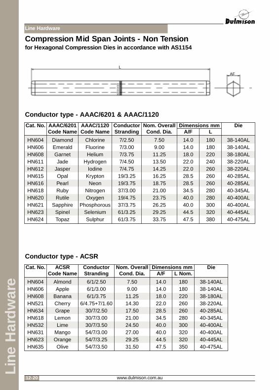
Conductor type – AACAAC Full Tension Midspan Joints, are manufactured from an Aluminium extrusion, equivalent instrength to the conductor onto which the fitting is applied.
Each fitting is manufactured with internal and external tapers, to eliminate stresses associatedwith compression, and reduce corona discharge.
Each fitting is clearly marked with the compression length, the applicable conductor stranding,and the appropriate compression die size. All design parameters for the items in this section arein accordance with AS1154.
Compression Mid Span Joints - Full Tensionfor Hexagonal Compression Dies in accordance with AS1154
HM603HM604HM606HM608HM611HM612HM615HM616HM618HM620HM621HM623HM624
JupiterLeoLibraMars
MercuryMoon
NeptunePluto
SaturnTaurusTriton
UranusVenus
7/2.257/2.507/3.007/3.757/4.507/4.7519/3.2519/3.7537/3.0019/4.7537/3.7561/3.2561/3.75
6.757.509.0011.2513.5014.2516.2518.7521.0023.7526.2529.2533.75
11.014.014.018.022.022.028.528.534.540.040.044.547.5
Dimensions mmConductorStranding
Nom. OverallCond. Dia. A/F L
DieAACCode Name
Cat. No.
38-110AL38-140AL38-140AL38-180AL38-220AL38-220AL40-285AL40-285AL40-345AL40-400AL40-400AL40-445AL40-475AL
LAF

Line Hardware
www.dulmison.com.au 12-17
Line
Har
dw
are
Compression Mid Span Joints - Full Tensionfor Hexagonal Compression Dies in accordance with AS1154
Conductor type AAAC/6201 & AAAC/1120AAAC Full Tension Compression Midspan Joints, are manufactured from an Aluminium extrusion,equivalent in strength to the conductor onto which the fitting is applied.
Each fitting is manufactured with internal and external tapers, to eliminate stresses associatedwith compression, and reduce corona discharge.
Each fitting is clearly marked with the compression length, the applicable conductor stranding,and the appropriate compression die size. All design parameters for the items in this section arein accordance with AS1154.
240280320360360400440480560560640780
HM702HM703HM704HM705HM706HM707HM708HM709HM710HM711HM712HM713
DiamondEmeraldGarnetJade
JasperOpalPearlRubyRutile
SapphireSpinelTopaz
ChlorineFluorineHelium
HydrogenIodine
KryptonNeon
NitrogenOxygen
PhosphorousSeleniumSulphur
7/2.507/3.007/3.757/4.507/4.7519/3.2519/3.7537/3.0019/4.7537/3.7561/3.2561/3.75
7.509.0011.2513.5014.2516.2518.7521.0023.7526.2529.2533.75
14.014.018.022.022.028.530.034.540.040.044.547.5
Dimensions mmConductorStranding
Nom. OverallCond. Dia. A/F L
DieAAAC/6201Code Name
AAAC/1120Code Name
Cat. No.
38-140AL38-140AL38-180AL38-220AL38-220AL40-285AL40-300AL40-345AL40-400AL40-400AL40-445AL40-475AL
AF L

Line Hardware
www.dulmison.com.au12-18
Line
Har
dw
are
Conductor type – ACSRACSR Full Tension Compression Midspan Joints, are manufactured from an Aluminium outerextrusion, and an inner steel tubular core. The two piece design ensures a design strengthequivalent to the conductor onto which the fitting is applied.
Each fitting is manufactured with internal and external tapers, to eliminate stresses associatedwith compression, and reduce corona discharge.
Each fitting is clearly marked with the compression length, the applicable conductor stranding,and the appropriate compression die size. All design parameters for the items in this section arein accordance with AS1154.
Compression Mid Span Joints - Full Tensionfor Hexagonal Compression Dies in accordance with AS1154
HM507HM512HM516HM521HM525HM530HM532HM535HM536HM538
AlmondApple
BananaCherryGrapeLemonLime
MangoOrangeOlive
6/1/2.506/1/3.006/1/3.75
6/4.75+7/1.6030/7/2.5030/7/3.0030/7/3.5054/7/3.0054/7/3.2554/7/3.50
7.509.0011.2514.3017.5021.0024.5027.0029.2531.50
14.014.018.022.028.534.540.040.044.547.5
38-140AL38-140AL38-180AL38-220AL40-285AL40-345AL40-400AL40-400AL40-445AL40-475AL
400400440480600640680720720760
100100120140180180200220220240
6.86.89.59.516.017.019.017.019.019.0
38-68ST1438-68ST1438-95ST38-95ST38-160ST40-170ST40-190ST40-170ST40-190ST40-190ST
160160160160200240240240240240
ACSR
Cat.No.
CodeName
ConductorStranding
Nom.OverallCond.Dia. A/F1 Die
L1Nom.
CA A/F2 DieL2
Nom.
DimensionsAluminium Steel
L1
L2
CAAF1 AF2
*6 Knurl
CA

Line Hardware
www.dulmison.com.au 12-19
Line
Har
dw
are
Conductor type – AACNon Tension Compression Mid Span Joints are manufactured from an Aluminium extrusion.
As these joints are installed at low tension values, one fitting can be used for all cable types of thesame size (OD).
Compression Mid Span Joints - Non Tensionfor Hexagonal compression Dies in accordance with AS1154
160180180220240260260260280280300320380
HN603HN604HN606HN608HN611HN612HN615HN616HN618HN620HN621HN623HN624
JupiterLeoLibraMars
MercuryMoon
NeptunePluto
SaturnTaurusTriton
UranusVenus
7/2.257/2.507/3.007/3.757/4.507/4.7519/3.2519/3.7537/3.0019/4.7537/3.7561/3.2561/3.75
6.757.509.0011.2513.5014.2516.2518.7521.0023.7526.2529.2533.75
11.014.014.018.022.022.028.528.534.540.040.044.547.5
Dimensions mmConductorStranding
Nom. OverallCond. Dia. A/F L
DieAACCode Name
Cat. No.
38-110AL38-140AL38-140AL38-180AL38-220AL38-220AL40-285AL40-285AL40-345AL40-400AL40-400AL40-445AL40-475AL
AF
L
Line Hardware
www.dulmison.com.au12-20
Line
Har
dw
are
Conductor type - AAAC/6201 & AAAC/1120
Conductor type - ACSR
Compression Mid Span Joints - Non Tensionfor Hexagonal Compression Dies in accordance with AS1154
180180220240260260260280280300320380
HN604HN606HN608HN611HN612HN615HN616HN618HN620HN621HN623HN624
DiamondEmeraldGarnetJade
JasperOpalPearlRubyRutile
SapphireSpinelTopaz
ChlorineFluorineHelium
HydrogenIodine
KryptonNeon
NitrogenOxygen
PhosphorousSeleniumSulphur
7/2.507/3.007/3.757/4.507/4.7519/3.2519/3.7537/3.0019/4.7537/3.7561/3.2561/3.75
7.509.0011.2513.5014.2516.2518.7521.0023.7526.2529.2533.75
14.014.018.022.022.028.528.534.540.040.044.547.5
Dimensions mmConductorStranding
Nom. OverallCond. Dia. A/F L
DieAAAC/6201Code Name
AAAC/1120Code Name
Cat. No.
38-140AL38-140AL38-180AL38-220AL38-220AL40-285AL40-285AL40-345AL40-400AL40-400AL40-445AL40-475AL
180180220260260280300320320350
HN604HN606HN608HN521HN634HN618HN532HN631HN623HN635
AlmondApple
BananaCherryGrapeLemonLime
MangoOrangeOlive
6/1/2.506/1/3.006/1/3.75
6/4.75+7/1.6030/7/2.5030/7/3.0030/7/3.5054/7/3.0054/7/3.2554/7/3.50
7.509.0011.2514.3017.5021.0024.5027.0029.2531.50
14.014.018.022.028.534.540.040.044.547.5
Dimensions mmConductorStranding
Nom. OverallCond. Dia. A/F L Nom.
DieACSRCode Name
Cat. No.
38-140AL38-140AL38-180AL38-220AL40-285AL40-345AL40-400AL40-400AL40-445AL40-475AL
AF
L

Line Hardware
www.dulmison.com.au 12-21
Line
Har
dw
are
Material: Stainless Steel
Compression Deadend - for Earthwireusing Hexagonal Compression Dies
HD806THD807THD808THD809THD811THD812T
7/2.757/3.2519/2.007/3.7519/2.7519/3.25
8.259.7510.0011.2513.7516.25
17.017.019.019.026.026.0
225225225225240260
181818181818
Nom.Overall
Cond. Dia. A/F
Dimensions
L D
ConductorStranding
SC/GZ (AC)Cat No.
Material: Stainless Steel
Compression Midspan Joint - for Earthwireusing Hexagonal Compression Dies
HM804HM807HM808HM809HM811HM812
3/2.757/3.2519/2.007/3.7519/2.7519/3.25
5.909.7510.0011.2513.7516.25
11.017.019.019.026.026.0
160240240250260300
Nom.Overall
Cond. Dia. A/F
Dimensions
L
ConductorStranding
SC/GZ (AC)Cat No.
AF
L
LA/F
D O14 for earthwire

Line Hardware
www.dulmison.com.au12-22
Line
Har
dw
are
Materials: Clamp - cast of high strengthaluminium alloy.
Bolt - stainless steel boltFlat Washer - stainless steelSpring Washer - stainless steelMessenger - exclusive Heliformed®
19 strand EHSgalvanised steel.
Masses - high grade zinc.
General Recommendations:Dogbone Dampers are designed to eliminate conductorfatigue damage and line maintenance costs by effectivelydiminishing aeolian vibration, thereby allowing increasedline tensions. The messenger cable and unique dogboneshape of the masses are designed to achieve optimalenergy dissipation for minimal clamp movement. Themessenger cable and dogbone weights are matched to give additional resonant modes and widereffective frequency response. The mechanical impedance of the damper is matched to theconductor to optimise performance. The offset dogbone shaped masses introduces a torsionalmode of vibration damping not present in conventional Stockbridge type dampers.
The range of Dogbone Vibration Dampers is a development resulting from our extensiveexperience and research in the field of conductor vibration control. The Dogbone concept is basedon the known and proven principles of the Stockbridge Damper but embodies improvementswhich increase both power dissipation and range of frequency response beyond those of aStockbridge Damper. The performance of the Dogbone Damper has been further improved usingthe latest CIGRE and IEEE recommended methods including I.S.W.R. Power Dissipation andMechanical Impedance Testing.
Radio Interference Voltage (RIV):Dogbone Dampers are designed to be corona free at all operating voltages.
Placement:Due to the many parameters involved and the exhaustive tests conducted by Dulmison foroptimum damper placement and performance, it is recommended that Dulmison be consulted forexact damper requirements.
Option:Armour Rods can be supplied for added protection to OPGW Cable. See page 7-16 for details.
See overleaf for table of catalogue numbers and conductor suitability.
Dogbone Vibration Damper

Line Hardware
www.dulmison.com.au 12-23
Line
Har
dw
are
Dogbone Vibration DamperCont’d
DB05B07SSDB05B10SS
DB05B12SS
DB05B15SSDB05B18SSDB05B21SSDB05B24SS
DB1B18SS
DB1B21SS
DB2B21SS
DB2B24SS
DB2B27SS
DB3B31SS
7.1-10.010.1-12.0
12.1-15.0
15.1-18.018.1-21.021.1-24.024.1-27.0
18.1-21.0
21.1-24.0
21.1-24.0
24.1-27.0
27.1-31.0
31.1-34.0
MERCURYMOON
NEPTUNEPLUTO
SATURN
TAURUS
TRITON
URANUS
VENUS
HYDROGENIODINE JADE
JASPERKRYPTON OPALNEON PEARL
NITROGENRUBY
OXYGENRUTILE
PHOSPHORUSSAPPHIRE
SPINELSELENIUMSULPHURSILICONTOPAZ
BANANA
CHERRY
GRAPE
LEMON
LIMEMANGO
ORANGE
OLIVEPAW PAW
7/2.75 7/3.257/3.75 7/4.00
19/2.75
19/3.25
AAAC ACSR SC/GZ
Clamp Diameter
Range AAC
Conductor Type
Cat No.
Only used for OPGWOnly used for OPGW

Line Hardware
www.dulmison.com.au12-24
Line
Har
dw
are
Dulmison Spiral Vibration Dampers are designed for use on conductors and guy wires rangingfrom 4.42mm to 19.30mm.They are designed to reduce aeolian vibration by acting as aninterference device for the aeolian vibration pattern, and are generally the most effective devicesfor use on small diameter conductors and earthwires. Dulmison Spiral Vibration Dampers aremanufactured from UV stable, high impact PVC and are suitable for use in ambient temperaturesranging from -40oC to 70oC. Further information is shown on page 7-30 of this catalogue.
Heliformed® Spiral Vibration DamperType SVD, for standard metric conductors 4.42mm to 19.30mm O.D.
Damping sectionGrippingsection
Conductor Dia.Range mm
4.41 - 6.346.35 - 8.298.30 - 11.7211.73 - 14.3114.32 - 19.30
SVD 0441SVD 0635SVD 0830SVD 1173SVD 1432
252525258
RedBlueBlackYellowGreen
CatalogueNumber
Std.Pack
ColourCode
Line Hardware
www.dulmison.com.au 12-25
Line
Har
dw
are
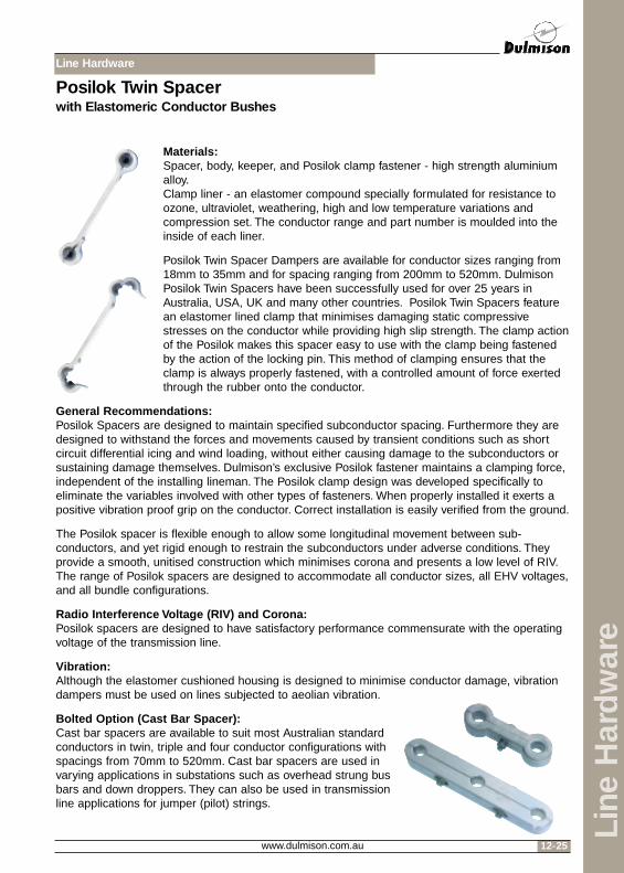
Materials:Spacer, body, keeper, and Posilok clamp fastener - high strength aluminiumalloy.Clamp liner - an elastomer compound specially formulated for resistance toozone, ultraviolet, weathering, high and low temperature variations andcompression set. The conductor range and part number is moulded into theinside of each liner.
Posilok Twin Spacer Dampers are available for conductor sizes ranging from18mm to 35mm and for spacing ranging from 200mm to 520mm. DulmisonPosilok Twin Spacers have been successfully used for over 25 years inAustralia, USA, UK and many other countries. Posilok Twin Spacers featurean elastomer lined clamp that minimises damaging static compressivestresses on the conductor while providing high slip strength. The clamp actionof the Posilok makes this spacer easy to use with the clamp being fastenedby the action of the locking pin. This method of clamping ensures that theclamp is always properly fastened, with a controlled amount of force exertedthrough the rubber onto the conductor.
General Recommendations:Posilok Spacers are designed to maintain specified subconductor spacing. Furthermore they aredesigned to withstand the forces and movements caused by transient conditions such as shortcircuit differential icing and wind loading, without either causing damage to the subconductors orsustaining damage themselves. Dulmison’s exclusive Posilok fastener maintains a clamping force,independent of the installing lineman. The Posilok clamp design was developed specifically toeliminate the variables involved with other types of fasteners. When properly installed it exerts apositive vibration proof grip on the conductor. Correct installation is easily verified from the ground.
The Posilok spacer is flexible enough to allow some longitudinal movement between sub-conductors, and yet rigid enough to restrain the subconductors under adverse conditions. Theyprovide a smooth, unitised construction which minimises corona and presents a low level of RIV.The range of Posilok spacers are designed to accommodate all conductor sizes, all EHV voltages,and all bundle configurations.
Radio Interference Voltage (RIV) and Corona:Posilok spacers are designed to have satisfactory performance commensurate with the operatingvoltage of the transmission line.
Vibration:Although the elastomer cushioned housing is designed to minimise conductor damage, vibrationdampers must be used on lines subjected to aeolian vibration.
Bolted Option (Cast Bar Spacer):Cast bar spacers are available to suit most Australian standardconductors in twin, triple and four conductor configurations withspacings from 70mm to 520mm. Cast bar spacers are used invarying applications in substations such as overhead strung busbars and down droppers. They can also be used in transmissionline applications for jumper (pilot) strings.
Posilok Twin Spacerwith Elastomeric Conductor Bushes

Line Hardware
www.dulmison.com.au12-26
Line
Har
dw
are
Materials:Frame - High strength aluminium alloyPosilok Arm - (xSDP)Bolted Arm - (xSDB)Elastomer Liners - used only with the Posilok Keeper
especially compounded for resistance to ozone, weathering,extreme high and low temperatures and compression set. Theconductor range is moulded into the inside of each insert.
General Recommendations:Spacer Dampers are recommended for multi-conductorbundles with industry standard spacing. The Spacer Damperis designed to withstand the forces and movements caused bytransient conditions such as short circuit, differential icing andwind loading, without either causing damage to thesubconductors or sustaining damage themselves. The designaccommodates both longitudinal movement of thesubconductors, vertical sag differences, as well ascompressive and tensil forces. When the Spacer Damperis installed in accordance with Dulmison’s recommendationsfor subspan lengths, it constitutes a system which replacesconventional spacers and vibration dampers. SpacerDampers will control both aeolian vibration andsubconductor oscillation to levels recognised as acceptablewithin the industry and to the customers expressed needs.Dulmison will tailor the recommendations to terrain anddesign parameters.
Corona and RIV:Spacer Dampers are designed to have a satisfactoryperformance commensurate with the operating voltage ofthe transmission line.
Fault Currents:All of Dulmison’s Spacer Dampers are designed for a minimum compressive withstand loadbetween clamps of 1130kg and a minimum tensile to withstand load of 560kg.
Placement:Due to the many factors involved in designing an effective spacer damper system, it isrecommended that Dulmison be consulted for specific recommendations on both the choice ofSpacer Dampers and placement.
Damping:Spacer Dampers can accommodate torsional clamp arm movement of plus or minus 13 degrees,conical clamp arm movement of plus or minus 8 degrees, and longitudinal movement of plus orminus 38mm. These are possible because of the properties of our elastomeric damping elements.There are two per arm, one on each side. They are especially compounded to give long life underconditions of ozone, ultra violet light, anticipated temperature extremes, and continual conductormotion. Their ability to dampen over many years has been well established throughout the worldin all types of climates.
Spacer Dampers
2 Bundle PosilokSpacer Damper
3 Bundle PosilokSpacer Damper
4 Bundle PosilokSpacer Damper
Line Hardware
www.dulmison.com.au 12-27
Line
Har
dw
are
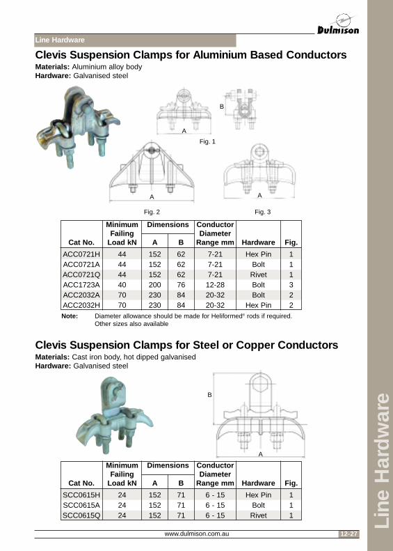
Clevis Suspension Clamps for Aluminium Based ConductorsMaterials: Aluminium alloy bodyHardware: Galvanised steel
Clevis Suspension Clamps for Steel or Copper ConductorsMaterials: Cast iron body, hot dipped galvanisedHardware: Galvanised steel
ACC0721HACC0721AACC0721QACC1723AACC2032AACC2032H
444444407070
152152152200230230
626262768484
7-217-217-2112-2820-3220-32
Hex PinBoltRivetBoltBolt
Hex Pin
111322
Dimensions
A B
ConductorDiameter
Range mm Hardware Fig.
MinimumFailing
Load kNCat No.
Note: Diameter allowance should be made for Heliformed® rods if required.Other sizes also available
SCC0615HSCC0615ASCC0615Q
242424
152152152
717171
6 - 156 - 156 - 15
Hex PinBoltRivet
111
Dimensions
A B
ConductorDiameter
Range mm Hardware Fig.
MinimumFailing
Load kNCat No.
A
B
A
Fig. 2
Fig. 1
Fig. 3
A
A
B

Line Hardware
www.dulmison.com.au12-28
Line
Har
dw
are
Trunnion Suspension Clampsfor Aluminium Based ConductorsMaterials: Aluminium alloy bodyHardware: Galvanised steel
Suspension Clamp for Steel or Copper ConductorsMaterials: Galvanised cast ironHardware: Galvanised steel
ATC1221AATC2127AATC2736AATC3646AATC4652AATC4565A
444444444444
152203229250300327
202020232047
95120140150175140
12 - 2121 - 2727 - 3636 - 4446 - 5245 - 65
BoltBoltBoltBoltBoltBolt
111223
Dimensions
A B C
ConductorDiameter
Range mm Hardware Fig.
MinimumFailing
Load kNCat No.
Note: Diameter allowance should be made for Heliformed® rods if required.
SCC0244SCC0818M
7070
230230
2241.5
2023
6.5 - 168 - 19
Dimensions
A B C
ConductorDiameter
Range mm
MinimumFailing
Load kNCat No.
A
A A
B
C
Fig. 1
Fig. 2 Fig. 3
A B
C

Line Hardware
www.dulmison.com.au 12-29
Line
Har
dw
are
Aluminium Angle Clamp for Aluminium Based ConductorsMaterials: Aluminium alloy bodyHardware: Galvanised steel
AAC0616AAAC1025AAAC1025H
343434
280330330
103130130
6 - 1616 - 2516 - 25
BoltBolt
Hex Pin
Dimensions
A B
ConductorDiameter
Range mm Hardware
MinimumFailing
Load kNCat No.
A
B

Line Hardware
www.dulmison.com.au12-30
Line
Har
dw
are
Strain ClampMaterials: Refer tableHardware: Galvanised steel
ASC0614ASCK3A12-19.5
SCL5A29SCL5A31SCL5A46
STC5-15-4749T
Al. AlloyAl. AlloyAl. AlloyAl. AlloyAl. Alloy
Galv. Iron
175200330350350200
193187210489489187
17.52130384719
161616161616
8.0 - 11.012.0 - 19.513.0 - 30.017.5 - 31.028.5 - 47.05.0 - 15.0
BoltRivetRivetRivetRivetRivet
123442
Dimensions
BA D E
ConductorDiameter
Range mm Hardware Fig.MaterialCat No.
A
AA
B
A
D
E
B
B
B
Fig. 1
Fig. 2 Fig. 3 Fig. 4

Line Hardware
www.dulmison.com.au 12-31
Line
Har
dw
are
Typical String AssembliesSingle Conductor Single Insulator Suspension Assembly
Bow Shackle
Ball Eye Link
Insulator
Socket Tongue Twisted
Heliformed® Suspension Unit
Conductor
Typical String AssembliesTwin Conductor Single Insulator Suspension Assembly
Bow Shackle
Ball Eye Link
Insulator
Conductor
Socket Clevis
Heliformed®
Suspension Unit
Yoke Plate
Clevis TongueTwisted

Line Hardware
www.dulmison.com.au12-32
Line
Har
dw
are
Typical String AssembliesSingle Conductor Single Insulator Tension Assembly
Bow ShackleBall Eye
Link
Insulator
Sag Link
Eyetail CompressionDeadendSocket Tongue Twisted
Typical String AssembliesTwin Conductor Single Insulator Tension Assembly
Bow ShackleBall Eye
Link
InsulatorSag Link
YokePlate
Eyetail CompressionDeadend
SocketClevis

Line Hardware
www.dulmison.com.au 12-33
Line
Har
dw
are
Typical String AssembliesSingle Conductor Single Insulator Jumper (Pilot) Assembly
Bow Shackle
Ball Eye Link
Insulator
Conductor
Trunnion Suspension Clamp
Twisted Socket Tongue
Bow Shackle
Ball Eye Link
Socket Clevis
Yoke Plate
Insulator
ConductorTrunnion Suspension Clamp
Twisted Clevis Tongue
Typical String AssembliesTwin Conductor Single Insulator Jumper (Pilot) Assembly

Line Hardware
www.dulmison.com.au12-34
Line
Har
dw
are
Typical String AssembliesSingle Conductor Single Insulator Flying Angle Assembly
Bow Shackle
Ball EyeLink
Insulator
Yoke PlateClevis Tongue
Heliformed®
Suspension Unit Conductor
Socket Tongue