
PRAKTIKUM INTERPRETASI CITRA MULTISPEKTRAL MENGGUNAKAN ENVI 4.5
Upload
khangminh22Category
view
2download
0
Cisco ONS 15454 Troubleshooting GuideProduct and Documentation Release 4.1.x and Release 4.5Last Updated: October 22, 2007
Corporate HeadquartersCisco Systems, Inc.170 West Tasman DriveSan Jose, CA 95134-1706 USAhttp://www.cisco.comTel: 408 526-4000
800 553-NETS (6387)Fax: 408 526-4100
Customer Order Number: DOC-7815671=Text Part Number: 78-15671-03

THE SPECIFICATIONS AND INFORMATION REGARDING THE PRODUCTS IN THIS MANUAL ARE SUBJECT TO CHANGE WITHOUT NOTICE. ALL STATEMENTS, INFORMATION, AND RECOMMENDATIONS IN THIS MANUAL ARE BELIEVED TO BE ACCURATE BUT ARE PRESENTED WITHOUT WARRANTY OF ANY KIND, EXPRESS OR IMPLIED. USERS MUST TAKE FULL RESPONSIBILITY FOR THEIR APPLICATION OF ANY PRODUCTS.
THE SOFTWARE LICENSE AND LIMITED WARRANTY FOR THE ACCOMPANYING PRODUCT ARE SET FORTH IN THE INFORMATION PACKET THAT SHIPPED WITH THE PRODUCT AND ARE INCORPORATED HEREIN BY THIS REFERENCE. IF YOU ARE UNABLE TO LOCATE THE SOFTWARE LICENSE OR LIMITED WARRANTY, CONTACT YOUR CISCO REPRESENTATIVE FOR A COPY.
The following information is for FCC compliance of Class A devices: This equipment has been tested and found to comply with the limits for a Class A digital device, pursuant to part 15 of the FCC rules. These limits are designed to provide reasonable protection against harmful interference when the equipment is operated in a commercial environment. This equipment generates, uses, and can radiate radio-frequency energy and, if not installed and used in accordance with the instruction manual, may cause harmful interference to radio communications. Operation of this equipment in a residential area is likely to cause harmful interference, in which case users will be required to correct the interference at their own expense.
The following information is for FCC compliance of Class B devices: The equipment described in this manual generates and may radiate radio-frequency energy. If it is not installed in accordance with Cisco’s installation instructions, it may cause interference with radio and television reception. This equipment has been tested and found to comply with the limits for a Class B digital device in accordance with the specifications in part 15 of the FCC rules. These specifications are designed to provide reasonable protection against such interference in a residential installation. However, there is no guarantee that interference will not occur in a particular installation.
Modifying the equipment without Cisco’s written authorization may result in the equipment no longer complying with FCC requirements for Class A or Class B digital devices. In that event, your right to use the equipment may be limited by FCC regulations, and you may be required to correct any interference to radio or television communications at your own expense.
You can determine whether your equipment is causing interference by turning it off. If the interference stops, it was probably caused by the Cisco equipment or one of its peripheral devices. If the equipment causes interference to radio or television reception, try to correct the interference by using one or more of the following measures:
• Turn the television or radio antenna until the interference stops.
• Move the equipment to one side or the other of the television or radio.
• Move the equipment farther away from the television or radio.
• Plug the equipment into an outlet that is on a different circuit from the television or radio. (That is, make certain the equipment and the television or radio are on circuits controlled by different circuit breakers or fuses.)
Modifications to this product not authorized by Cisco Systems, Inc. could void the FCC approval and negate your authority to operate the product.
The Cisco implementation of TCP header compression is an adaptation of a program developed by the University of California, Berkeley (UCB) as part of UCB’s public domain version of the UNIX operating system. All rights reserved. Copyright © 1981, Regents of the University of California.
NOTWITHSTANDING ANY OTHER WARRANTY HEREIN, ALL DOCUMENT FILES AND SOFTWARE OF THESE SUPPLIERS ARE PROVIDED “AS IS” WITH ALL FAULTS. CISCO AND THE ABOVE-NAMED SUPPLIERS DISCLAIM ALL WARRANTIES, EXPRESSED OR IMPLIED, INCLUDING, WITHOUT LIMITATION, THOSE OF MERCHANTABILITY, FITNESS FOR A PARTICULAR PURPOSE AND NONINFRINGEMENT OR ARISING FROM A COURSE OF DEALING, USAGE, OR TRADE PRACTICE.
IN NO EVENT SHALL CISCO OR ITS SUPPLIERS BE LIABLE FOR ANY INDIRECT, SPECIAL, CONSEQUENTIAL, OR INCIDENTAL DAMAGES, INCLUDING, WITHOUT LIMITATION, LOST PROFITS OR LOSS OR DAMAGE TO DATA ARISING OUT OF THE USE OR INABILITY TO USE THIS MANUAL, EVEN IF CISCO OR ITS SUPPLIERS HAVE BEEN ADVISED OF THE POSSIBILITY OF SUCH DAMAGES.
Cisco ONS 15454 Troubleshooting GuideCopyright © 2007 Cisco Systems Inc. All rights reserved.
CCVP, the Cisco logo, and the Cisco Square Bridge logo are trademarks of Cisco Systems, Inc.; Changing the Way We Work, Live, Play, and Learn is a service mark of Cisco Systems, Inc.; and Access Registrar, Aironet, BPX, Catalyst, CCDA, CCDP, CCIE, CCIP, CCNA, CCNP, CCSP, Cisco, the Cisco Certified Internetwork Expert logo, Cisco IOS, Cisco Press, Cisco Systems, Cisco Systems Capital, the Cisco Systems logo, Cisco Unity, Enterprise/Solver, EtherChannel, EtherFast, EtherSwitch, Fast Step, Follow Me Browsing, FormShare, GigaDrive, HomeLink, Internet Quotient, IOS, iPhone, IP/TV, iQ Expertise, the iQ logo, iQ Net Readiness Scorecard, iQuick Study, LightStream, Linksys, MeetingPlace, MGX, Networking Academy, Network Registrar, Packet, PIX, ProConnect, ScriptShare, SMARTnet, StackWise, The Fastest Way to Increase Your Internet Quotient, and TransPath are registered trademarks of Cisco Systems, Inc. and/or its affiliates in the United States and certain other countries.
All other trademarks mentioned in this document or Website are the property of their respective owners. The use of the word partner does not imply a partnership relationship between Cisco and any other company. (0705R)

CFebruary 2004
C O N T E N T S
About this Guide xxvii
Revision History xxvii
Audience xxvii
Document Organization xxvii
Document Conventions xxviii
Where to Find Safety and Warning Information xxix
Obtaining Documentation xxix
Cisco.com xxix
Ordering Documentation xxix
Cisco Optical Networking Product Documentation CD-ROM xxx
Documentation Feedback xxx
Obtaining Technical Assistance xxx
Cisco TAC Website xxx
Opening a TAC Case xxxi
TAC Case Priority Definitions xxxi
Obtaining Additional Publications and Information xxxi
C H A P T E R 1 General Troubleshooting 1-1
1.1 Network Troubleshooting Tests 1-2
1.2 Identify Points of Failure on a DS-N Circuit Path 1-6
1.2.1 Perform a Facility (Line) Loopback on a Source DS-N Port 1-6
Create the Facility (Line) Loopback on the Source DS-N Port 1-7
Test the Facility (Line) Loopback Circuit 1-7
Test the DS-N Cabling 1-8
Test the DS-N Card 1-9
Test the EIA 1-9
1.2.2 Perform a Hairpin on a Source Node Port 1-10
Create the Hairpin on the Source Node Port 1-11
Test the Hairpin Circuit 1-12
Test the Standby Cross-Connect Card 1-12
Retest the Original Cross-Connect Card 1-13
1.2.3 Perform a Terminal (Inward) Loopback on a Destination DS-N Port 1-14
Create the Terminal (Inward) Loopback on a Destination DS-N Port 1-15
Test the Terminal (Inward) Loopback Circuit on the Destination DS-N Port 1-16
iiiisco ONS 15454 Troubleshooting Guide, R4.1.x and R4.5

Contents
Test the Destination DS-N Card 1-17
1.2.4 Perform a Hairpin on a Destination Node 1-17
Create the Hairpin on the Destination Node 1-18
Test the Hairpin Circuit 1-18
Test the Standby Cross-Connect Card 1-19
Retest the Original Cross-Connect Card 1-20
1.2.5 Perform a Facility (Line) Loopback on a Destination DS-N Port 1-21
Create a Facility (Line) Loopback Circuit on a Destination DS-N Port 1-21
Test the Facility (Line) Loopback Circuit 1-22
Test the DS-N Cabling 1-23
Test the DS-N Card 1-23
Test the EIA 1-24
1.3 Using the DS3XM-6 Card FEAC (Loopback) Functions 1-25
1.3.1 FEAC Send Code 1-26
1.3.2 FEAC Inhibit Loopback 1-26
1.3.3 FEAC Alarms 1-26
1.4 Identify Points of Failure on an OC-N Circuit Path 1-27
1.4.1 Perform a Facility (Line) Loopback on a Source-Node OC-N or G-Series Port 1-27
Create the Facility (Line) Loopback on the Source OC-N or G-Series Port 1-28
Test the Facility (Line) Loopback Circuit 1-28
Test the OC-N or G-Series Card 1-29
1.4.2 Perform a Terminal (Inward) Loopback on a Source-Node OC-N or G-Series Port 1-29
Create the Terminal (Inward) Loopback on a Source Node OC-N Port 1-30
Test the Terminal Loopback Circuit 1-31
Test the OC-N Card 1-32
1.4.3 Create the XC Loopback on the Source OC-N Port 1-33
Test the XC Loopback Circuit 1-34
Test the Standby Cross-Connect Card 1-34
Retest the Original Cross-Connect Card 1-35
1.4.4 Create a Facility (Line) Loopback on an Intermediate-Node OC-N or G-Series Port 1-36
Create a Facility (Line) Loopback on an Intermediate-Node OC-N or G-Series Port 1-37
Test the Facility (Line) Loopback Circuit 1-38
Test the OC-N or G-Series Card 1-38
1.4.5 Create a Terminal Loopback on Intermediate-Node OC-N or G-Series Ports 1-39
Create a Terminal Loopback on Intermediate-Node OC-N or G-Series Ports 1-40
Test the Terminal Loopback Circuit 1-41
Test the OC-N or G-Series Card 1-41
1.4.6 Perform a Facility (Line) Loopback on a Destination-Node OC-N or G-Series Port 1-42
Create the Facility (Line) Loopback on a Destination Node OC-N or G-Series Port 1-42
Test the Facility (Line) Loopback Circuit 1-43
ivCisco ONS 15454 Troubleshooting Guide, R4.1.x and R4.5
February 2004

Contents
Test the OC-N or G-Series Card 1-44
1.4.7 Perform a Terminal Loopback on a Destination Node OC-N or G-Series Port 1-45
Create the Terminal Loopback on a Destination Node OC-N or G-Series Port 1-45
Test the Terminal Loopback Circuit 1-46
Test the OC-N or G-Series Card 1-47
1.5 Restoring the Database and Default Settings 1-48
1.5.1 Restore the Node Database 1-48
Restore the Database 1-48
1.5.2 Restore the Node to Factory Configuration 1-49
Use the Reinitialization Tool to Clear the Database and Upload Software (Windows) 1-51
Use the Reinitialization Tool to Clear the Database and Upload Software (UNIX) 1-52
1.6 PC Connectivity Troubleshooting 1-54
1.6.1 Unable to Verify the IP Configuration of Your PC 1-54
Verify the IP Configuration of Your PC 1-54
1.6.2 Browser Login Does Not Launch Java 1-55
Reconfigure the PC Operating System Java Plug-in Control Panel 1-55
Reconfigure the Browser 1-55
1.6.3 Unable to Verify the NIC Connection on Your PC 1-56
1.6.4 Verify PC Connection to the ONS 15454 (ping) 1-57
Ping the ONS 15454 1-57
1.6.5 The IP Address of the Node is Unknown 1-58
Retrieve Unknown Node IP Address 1-58
1.7 CTC Operation Troubleshooting 1-58
1.7.1 Unable to Launch CTC Help After Removing Netscape 1-58
Reset Internet Explorer as the Default Browser for CTC 1-59
1.7.2 Unable to Change Node View to Network View 1-59
Reset the CTC_HEAP Environment Variable for Windows 1-60
Reset the CTC_HEAP Environment Variable for Solaris 1-60
1.7.3 Browser Stalls When Downloading CTC JAR Files From TCC+/TCC2 1-60
Disable the VirusScan Download Scan 1-61
1.7.4 CTC Does Not Launch 1-61
Redirect the Netscape Cache to a Valid Directory 1-61
1.7.5 Slow CTC Operation or Login Problems 1-62
Delete the CTC Cache File Automatically 1-62
Delete the CTC Cache File Manually 1-63
1.7.6 Node Icon is Grey on CTC Network View 1-64
1.7.7 CTC Cannot Launch Due to Applet Security Restrictions 1-64
Manually Edit the java.policy File 1-65
1.7.8 Java Runtime Environment Incompatible 1-65
vCisco ONS 15454 Troubleshooting Guide, R4.1.x and R4.5
February 2004

Contents
Launch CTC to Correct the Core Version Build 1-66
1.7.9 Different CTC Releases Do Not Recognize Each Other 1-66
Launch CTC to Correct the Core Version Build 1-67
1.7.10 Username or Password Do Not Match 1-67
Verify Correct Username and Password 1-68
1.7.11 No IP Connectivity Exists Between Nodes 1-68
1.7.12 DCC Connection Lost 1-68
1.7.13 “Path in Use” Error When Creating a Circuit 1-69
1.7.14 Calculate and Design IP Subnets 1-69
1.7.15 Ethernet Connections 1-70
Verify Ethernet Connections 1-70
1.7.16 VLAN Cannot Connect to Network Device from Untag Port 1-71
Change VLAN Port Tag and Untagged Settings 1-72
1.7.17 Cross-Connect Card Oscillator Fails 1-73
Resolve the XC Oscillator Failure When Slot 8 XC Card is Active 1-73
Resolve the XC Oscillator Failure When Slot 10 XC Card is Active 1-74
1.8 Circuits and Timing 1-74
1.8.1 OC-N Circuit Transitions to Partial State 1-75
View the State of OC-N Circuit Nodes 1-75
1.8.2 AIS-V on DS3XM-6 Unused VT Circuits 1-76
Clear AIS-V on DS3XM-6 Unused VT Circuits 1-76
1.8.3 Circuit Creation Error with VT1.5 Circuit 1-77
1.8.4 Unable to Create Circuit From DS-3 Card to DS3XM-6 Card 1-77
1.8.5 DS-3 Card Does Not Report AIS-P From External Equipment 1-78
1.8.6 OC-3 and DCC Limitations 1-78
1.8.7 ONS 15454 Switches Timing Reference 1-78
1.8.8 Holdover Synchronization Alarm 1-79
1.8.9 Free-Running Synchronization Mode 1-79
1.8.10 Daisy-Chained BITS Not Functioning 1-80
1.8.11 Blinking STAT LED after Installing a Card 1-80
1.9 Fiber and Cabling 1-80
1.9.1 Bit Errors Appear for a Traffic Card 1-81
1.9.2 Faulty Fiber-Optic Connections 1-81
Verify Fiber-Optic Connections 1-82
1.9.2.1 Crimp Replacement LAN Cables 1-83
1.9.2.2 Replace Faulty GBIC or SFP Connectors 1-85
Remove GBIC or SFP Connectors 1-87
Installing a GBIC with Clips 1-87
Installing a GBIC with a Handle 1-88
1.9.3 OC-N Card Transmit and Receive Levels 1-89
viCisco ONS 15454 Troubleshooting Guide, R4.1.x and R4.5
February 2004
Contents
1.10 Power and LED Tests 1-89
1.10.1 Power Supply Problems 1-90
Isolate the Cause of Power Supply Problems 1-90
1.10.2 Power Consumption for Node and Cards 1-91
1.10.3 Lamp Test for Card LEDs 1-91
Verify Card LED Operation 1-92
C H A P T E R 2 Alarm Troubleshooting 2-1
2.1 Alarm Index by Default Severity 2-1
2.1.1 Critical Alarms (CR) 2-1
2.1.2 Major Alarms (MJ) 2-2
2.1.3 Minor Alarms (MN) 2-3
2.1.4 Conditions (NA or NR) 2-3
2.2 Alarms and Conditions Indexed By Alphabetical Entry 2-5
2.3 Logical Object Type Definitions 2-8
2.4 Alarm Index by Logical Object Type 2-9
2.5 Trouble Notifications 2-22
2.5.1 Conditions 2-22
2.5.2 Severities 2-22
2.6 Safety Summary 2-23
2.7 Alarm Procedures 2-23
2.7.1 AIS 2-24
Clear the AIS Condition 2-24
2.7.2 AIS-L 2-24
Clear the AIS-L Condition 2-25
2.7.3 AIS-P 2-25
Clear the AIS-P Condition 2-25
2.7.4 AIS-V 2-25
Clear the AIS-V Condition 2-26
2.7.5 ALS 2-26
2.7.6 AMPLI-INIT 2-26
Clear the AMPLI-INIT Condition 2-26
2.7.7 APC-DISABLED 2-26
Clear the APC-DISABLED Alarm 2-27
2.7.8 APC-FAIL 2-27
Clear the APC-FAIL Alarm 2-27
2.7.9 APSB 2-27
Clear the APSB Alarm 2-28
2.7.10 APSCDFLTK 2-28
viiCisco ONS 15454 Troubleshooting Guide, R4.1.x and R4.5
February 2004

Contents
Clear the APSCDFLTK Alarm 2-28
2.7.11 APSC-IMP 2-29
Clear the APSC-IMP Alarm 2-29
2.7.12 APSCINCON 2-30
Clear the APSCINCON Alarm 2-30
2.7.13 APSCM 2-30
Clear the APSCM Alarm 2-31
2.7.14 APSCNMIS 2-31
Clear the APSCNMIS Alarm 2-31
2.7.15 APSMM 2-32
Clear the APSMM Alarm 2-32
2.7.16 AS-CMD 2-32
Clear the AS-CMD Condition 2-32
2.7.17 AS-MT 2-33
Clear the AS-MT Condition 2-33
2.7.18 AUD-LOG-LOSS 2-34
Clear the AUD-LOG-LOSS Condition 2-34
2.7.19 AUD-LOG-LOW 2-34
2.7.20 AUTOLSROFF 2-34
Clear the AUTOLSROFF Alarm 2-35
2.7.21 AUTORESET 2-36
Clear the AUTORESET Alarm 2-36
2.7.22 AUTOSW-AIS 2-36
Clear the AUTOSW-AIS Condition 2-37
2.7.23 AUTOSW-LOP (STSMON) 2-37
Clear the AUTOSW-LOP (STSMON) Condition 2-37
2.7.24 AUTOSW-LOP (VTMON) 2-37
Clear the AUTOSW-LOP (VTMON) Alarm 2-37
2.7.25 AUTOSW-PDI 2-37
Clear the AUTOSW-PDI Condition 2-38
2.7.26 AUTOSW-SDBER 2-38
Clear the AUTOSW-SDBER Condition 2-38
2.7.27 AUTOSW-SFBER 2-38
Clear the AUTOSW-SFBER Condition 2-38
2.7.28 AUTOSW-UNEQ (STSMON) 2-39
Clear the AUTOSW-UNEQ (STSMON) Condition 2-39
2.7.29 AUTOSW-UNEQ (VTMON) 2-39
Clear the AUTOSW-UNEQ (VTMON) Alarm 2-39
2.7.30 BAT-A-HGH-VLT 2-39
Clear the BAT-A-HGH-VLT Condition 2-40
viiiCisco ONS 15454 Troubleshooting Guide, R4.1.x and R4.5
February 2004

Contents
2.7.31 BAT-A-LOW-VLT 2-40
Clear the BAT-A-LOW-VLT Condition 2-40
2.7.32 BAT-B-HGH-VLT 2-40
Clear the BAT-B-HGH-VLT Condition 2-40
2.7.33 BAT-B-LOW-VLT 2-40
Clear the BAT-B-LOW-VLT Condition 2-41
2.7.34 BKUPMEMP 2-41
Clear the BKUPMEMP Alarm 2-41
2.7.35 BLSROSYNC 2-42
Clear the BLSROSYNC Alarm 2-42
2.7.36 CARLOSS (DWDM Client) 2-42
Clear the CARLOSS (DWDM Client) Alarm 2-42
2.7.37 CARLOSS (DWDM Trunk) 2-43
Clear the CARLOSS (DWDM Trunk) Alarm 2-43
2.7.38 CARLOSS (EQPT) 2-43
Clear the CARLOSS (EQPT) Alarm 2-43
2.7.39 CARLOSS (E-Series Ethernet) 2-44
Clear the CARLOSS (E-Series Ethernet) Alarm 2-44
2.7.40 CARLOSS (G-Series Ethernet) 2-46
Clear the CARLOSS (G-Series Ethernet) Alarm 2-46
2.7.41 CARLOSS (ML-Series Ethernet) 2-48
Clear the CARLOSS (ML-Series Ethernet) Alarm 2-49
2.7.42 CKTDOWN 2-49
Clear the CKTDOWN Alarm 2-49
2.7.43 CLDRESTART 2-51
Clear the CLDRESTART Condition 2-52
2.7.44 COMIOXC 2-52
Clear the COMIOXC Alarm 2-52
2.7.45 COMM-FAIL 2-53
Clear the COMM-FAIL Alarm 2-53
2.7.46 CONTBUS-A-18 2-53
Clear the CONTBUS-A-18 Alarm 2-54
2.7.47 CONTBUS-B-18 2-54
Clear the CONTBUS-B-18 Alarm 2-54
2.7.48 CONTBUS-IO-A 2-55
Clear the CONTBUS-IO-A Alarm 2-55
2.7.49 CONTBUS-IO-B 2-56
Clear the CONTBUS-IO-B Alarm 2-56
2.7.50 CTNEQPT-PBPROT 2-57
Clear the CTNEQPT-PBPROT Alarm 2-58
ixCisco ONS 15454 Troubleshooting Guide, R4.1.x and R4.5
February 2004

Contents
2.7.51 CTNEQPT-PBWORK 2-58
Clear the CTNEQPT-PBWORK Alarm 2-59
2.7.52 DATAFLT 2-60
Clear the DATAFLT Alarm 2-60
2.7.53 DBOSYNC 2-60
Clear the DBOSYNC Alarm 2-61
2.7.54 DS3-MISM 2-61
Clear the DS3-MISM Condition 2-61
2.7.55 DSP-COMM-FAIL 2-62
2.7.56 DSP-FAIL 2-62
Clear the DSP-FAIL Alarm 2-62
2.7.57 EHIBATVG-A 2-62
Clear the EHIBATVG-A Alarm 2-63
2.7.58 EHIBATVG-B 2-63
Clear the EHIBATVG-B Alarm 2-63
2.7.59 ELWBATVG-A 2-63
Clear the ELWBATVG-A Alarm 2-63
2.7.60 ELWBATVG-B 2-64
Clear the ELWBATVG-B Alarm 2-64
2.7.61 EOC 2-64
Clear the EOC Alarm 2-65
2.7.62 EQPT 2-66
Clear the EQPT Alarm 2-66
2.7.63 EQPT-MISS 2-67
Clear the EQPT-MISS Alarm 2-67
2.7.64 ERFI-P-CONN 2-67
Clear the ERFI-P-CONN Condition 2-68
2.7.65 ERFI-P-PAYLD 2-68
Clear the ERFI-P-PAYLD Condition 2-68
2.7.66 ERFI-P-SRVR 2-68
Clear the ERFI-P-SRVR Condition 2-68
2.7.67 ERROR-CONFIG 2-69
Clear the ERROR-CONFIG Alarm 2-69
2.7.68 E-W-MISMATCH 2-70
Clear the E-W-MISMATCH Alarm with a Physical Switch 2-70
Clear the E-W-MISMATCH Alarm in CTC 2-71
2.7.69 EXCCOL 2-72
Clear the EXCCOL Alarm 2-72
2.7.70 EXERCISE-RING-FAIL 2-72
Clear the EXERCISE-RING-FAIL Condition 2-72
xCisco ONS 15454 Troubleshooting Guide, R4.1.x and R4.5
February 2004

Contents
2.7.71 EXERCISE-RING-REQ 2-73
2.7.72 EXERCISE-SPAN-FAIL 2-73
Clear the EXERCISE-SPAN-FAIL Condition 2-73
2.7.73 EXERCISE-SPAN-REQ 2-73
2.7.74 EXT 2-74
Clear the EXT Alarm 2-74
2.7.75 EXTRA-TRAF-PREEMPT 2-74
Clear the EXTRA-TRAF-PREEMPT Alarm 2-74
2.7.76 FAILTOSW 2-75
Clear the FAILTOSW Condition 2-75
2.7.77 FAILTOSW-PATH 2-75
Clear the FAILTOSW-PATH Condition in a Path Protection Configuration 2-76
2.7.78 FAILTOSWR 2-76
Clear the FAILTOSWR Condition in a Four-Fiber BLSR Configuration 2-77
2.7.79 FAILTOSWS 2-78
Clear the FAILTOSWS Condition 2-78
2.7.80 FAN 2-80
Clear the FAN Alarm 2-80
2.7.81 FANDEGRADE 2-80
Clear the FANDEGRADE Alarm 2-80
2.7.82 FE-AIS 2-81
Clear the FE-AIS Condition 2-81
2.7.83 FEC-MISM 2-81
Clear the FEC-MISM Alarm 2-81
2.7.84 FE-DS1-MULTLOS 2-82
Clear the FE-DS1-MULTLOS Condition 2-82
2.7.85 FE-DS1-NSA 2-82
Clear the FE-DS1-NSA Condition 2-82
2.7.86 FE-DS1-SA 2-83
Clear the FE-DS1-SA Condition 2-83
2.7.87 FE-DS1-SNGLLOS 2-83
Clear the FE-DS1-SNGLLOS Condition 2-83
2.7.88 FE-DS3-NSA 2-84
Clear the FE-DS3-NSA Condition 2-84
2.7.89 FE-DS3-SA 2-84
Clear the FE-DS3-SA Condition 2-84
2.7.90 FE-EQPT-NSA 2-85
Clear the FE-EQPT-NSA Condition 2-85
2.7.91 FE-EXERCISING-RING 2-85
2.7.92 FE-EXERCISING-SPAN 2-86
xiCisco ONS 15454 Troubleshooting Guide, R4.1.x and R4.5
February 2004

Contents
2.7.93 FE-FRCDWKSWPR-RING 2-86
Clear the FE-FRCDWKSWPR-RING Condition 2-86
2.7.94 FE-FRCDWKSWPR-SPAN 2-86
Clear the FE-FRCDWKSWPR-SPAN Condition 2-87
2.7.95 FE-IDLE 2-87
Clear the FE-IDLE Condition 2-87
2.7.96 FE-LOCKOUTOFPR-SPAN 2-87
Clear the FE-LOCKOUTOFPR-SPAN Condition 2-88
2.7.97 FE-LOF 2-88
Clear the FE-LOF Condition 2-88
2.7.98 FE-LOS 2-88
Clear the FE-LOS Condition 2-89
2.7.99 FE-MANWKSWPR-RING 2-89
Clear the FE-MANWKSWPR-RING Condition 2-89
2.7.100 FE-MANWKSWPR-SPAN 2-89
Clear the FE-MANWKSWPR-SPAN Condition 2-90
2.7.101 FEPRLF 2-90
Clear the FEPRLF Alarm on a Four-Fiber BLSR 2-90
2.7.102 FORCED-REQ 2-90
Clear the FORCED-REQ Condition 2-91
2.7.103 FORCED-REQ-RING 2-91
Clear the FORCED-REQ-RING Condition 2-91
2.7.104 FORCED-REQ-SPAN 2-91
Clear the FORCED-REQ-SPAN Condition 2-91
2.7.105 FRCDSWTOINT 2-91
2.7.106 FRCDSWTOPRI 2-92
2.7.107 FRCDSWTOSEC 2-92
2.7.108 FRCDSWTOTHIRD 2-92
2.7.109 FRNGSYNC 2-92
Clear the FRNGSYNC Alarm 2-93
2.7.110 FSTSYNC 2-93
2.7.111 FULLPASSTHR-BI 2-93
Clear the FULLPASSTHR-BI Condition 2-93
2.7.112 GCC-EOC 2-93
Clear the GCC-EOC Alarm 2-94
2.7.113 HI-LASERBIAS 2-94
Clear the HI-LASERBIAS Alarm 2-94
2.7.114 HI-LASERTEMP 2-94
Clear the HI-LASERTEMP Alarm 2-95
2.7.115 HI-RXPOWER 2-95
xiiCisco ONS 15454 Troubleshooting Guide, R4.1.x and R4.5
February 2004

Contents
Clear the HI-RXPOWER Alarm 2-95
2.7.116 HI-RXTEMP 2-96
Clear the HI-RXTEMP Alarm 2-96
2.7.117 HITEMP 2-97
Clear the HITEMP Alarm 2-97
2.7.118 HI-TXPOWER 2-97
Clear the HI-TXPOWER Alarm 2-98
2.7.119 HLDOVRSYNC 2-98
Clear the HLDOVRSYNC Alarm 2-98
2.7.120 IMPROPRMVL 2-99
Clear the IMPROPRMVL Alarm 2-99
2.7.121 INC-ISD 2-100
2.7.122 INHSWPR 2-101
Clear the INHSWPR Condition 2-101
2.7.123 INHSWWKG 2-101
Clear the INHSWWKG Condition 2-101
2.7.124 INTRUSION-PSWD 2-101
Clear the INTRUSION-PSWD Condition 2-102
2.7.125 INVMACADR 2-102
Clear the INVMACADR Alarm 2-102
2.7.126 IOSCFGCOPY 2-104
2.7.127 KB-PASSTHR 2-104
Clear the KB-PASSTHR Condition 2-104
2.7.128 KBYTE-APS-CHANNEL-FAILURE 2-105
Clear the KBYTE-APS-CHANNEL-FAILURE Alarm 2-105
2.7.129 LAN-POL-REV 2-105
Clear the LAN-POL-REV Condition 2-105
2.7.130 LASEREOL 2-106
Clear the LASEREOL Alarm 2-106
2.7.131 LKOUTPR-S 2-106
Clear the LKOUTPR-S Condition 2-106
2.7.132 LMP-HELLODOWN 2-107
Clear the LMP-HELLODOWN Alarm 2-107
2.7.133 LMP-NDFAIL 2-107
Clear the LMP-NDFAIL Alarm 2-107
2.7.134 LOC 2-107
Clear the LOC Alarm 2-108
2.7.135 LOCKOUT-REQ 2-108
Clear the LOCKOUT-REQ Condition 2-108
2.7.136 LOCKOUT-REQ-RING 2-108
xiiiCisco ONS 15454 Troubleshooting Guide, R4.1.x and R4.5
February 2004

Contents
Clear the LOCKOUT-REQ-RING Condition 2-108
2.7.137 LOF (BITS) 2-108
Clear the LOF (BITS) Alarm 2-109
2.7.138 LOF (DS-1) 2-109
Clear the LOF (DS-1) Alarm 2-110
2.7.139 LOF (DS-3) 2-110
Clear the LOF (DS-3) Alarm 2-111
2.7.140 LOF (DWDM Client) 2-111
Clear the LOF (DWDM Client) Alarm 2-111
2.7.141 LOF (DWDM Trunk) 2-111
Clear the LOF (DWDM Trunk) Alarm 2-112
2.7.142 LOF (EC1-12) 2-112
Clear the LOF (EC1-12) Alarm 2-112
2.7.143 LOF (OC-N) 2-112
Clear the LOF (OC-N) Alarm 2-113
2.7.144 LO-LASERBIAS 2-113
Clear the LO-LASERBIAS Alarm 2-113
2.7.145 LO-LASERTEMP 2-113
Clear the LO-LASERTEMP Alarm 2-114
2.7.146 LOM 2-114
Clear the LOM Alarm 2-114
2.7.147 LOP-P 2-115
Clear the LOP-P Alarm 2-115
2.7.148 LOP-V 2-115
Clear the LOP-V Alarm 2-116
2.7.149 LO-RXPOWER 2-116
Clear the LO-RXPOWER Alarm 2-116
2.7.150 LO-RXTEMP 2-117
Clear the LO-RXTEMP Alarm 2-117
2.7.151 LOS (BITS) 2-117
Clear the LOS (BITS) Alarm 2-118
2.7.152 LOS (DS-1) 2-118
Clear the LOS (DS-1) Alarm 2-118
2.7.153 LOS (DS-3) 2-119
Clear the LOS (DS-3) Alarm 2-119
2.7.154 LOS (DWDM Client or Trunk) 2-120
Clear the LOS (DWDM Client) Alarm 2-120
2.7.155 LOS (EC1-12) 2-120
Clear the LOS (EC1-12) Alarm 2-121
2.7.156 LOS (FUDC) 2-122
xivCisco ONS 15454 Troubleshooting Guide, R4.1.x and R4.5
February 2004

Contents
Clear the LOS (FUDC) Alarm 2-122
2.7.157 LOS (MSUDC) 2-123
Clear the LOS (MSUDC) Alarm 2-123
2.7.158 LOS (OC-N) 2-124
Clear the LOS (OC-N) Alarm 2-124
2.7.159 LOS (OTN) 2-125
Clear the LOS (OTN) Alarm 2-125
2.7.160 LO-TXPOWER 2-126
Clear the LO-TXPOWER Alarm 2-126
2.7.161 LPBKCRS 2-126
Clear the LPBKCRS Condition 2-126
2.7.162 LPBKDS1FEAC 2-127
Clear the LPBKDS1FEAC Condition 2-127
2.7.163 LPBKDS1FEAC-CMD 2-127
2.7.164 LPBKDS3FEAC 2-127
Clear the LPBKDS3FEAC Condition 2-128
2.7.165 LPBKDS3FEAC-CMD 2-128
2.7.166 LPBKFACILITY (DS-1 or DS-3) 2-128
Clear the LPBKFACILITY (DS-1 or DS-3) Condition 2-129
2.7.167 LPBKFACILITY (DWDM Client, DWDM Trunk) 2-129
Clear the LPBKFACILITY (DWDM Client, DWDM Trunk) Condition 2-129
2.7.168 LPBKFACILITY (EC1-12) 2-130
Clear the LPBKFACILITY (EC1-12) Condition 2-130
2.7.169 LPBKFACILITY (G-Series Ethernet) 2-130
Clear the LPBKFACILITY (G-Series Ethernet) Condition 2-130
2.7.170 LPBKFACILITY (OC-N) 2-131
Clear the LPBKFACILITY (OC-N) Condition 2-131
2.7.171 LPBKTERMINAL (DS-1, DS-3, EC-1-12, OC-N) 2-131
Clear the LPBKTERMINAL (DS-1, DS-3, EC-1-12, OC-N) Condition 2-132
2.7.172 LPBKTERMINAL (DWDM Client, DWDM Trunk) 2-132
Clear the LPBKTERMINAL (DWDM Client) Condition 2-132
2.7.173 LPBKTERMINAL (G-Series Ethernet) 2-132
Clear the LPBKTERMINAL (G-Series Ethernet) Condition 2-133
2.7.174 MAN-REQ 2-133
Clear the MAN-REQ Condition 2-133
2.7.175 MANRESET 2-133
2.7.176 MANSWTOINT 2-133
2.7.177 MANSWTOPRI 2-134
2.7.178 MANSWTOSEC 2-134
2.7.179 MANSWTOTHIRD 2-134
xvCisco ONS 15454 Troubleshooting Guide, R4.1.x and R4.5
February 2004

Contents
2.7.180 MANUAL-REQ-RING 2-134
Clear the MANUAL-REQ-RING Condition 2-135
2.7.181 MANUAL-REQ-SPAN 2-135
Clear the MANUAL-REQ-SPAN Condition 2-135
2.7.182 MEA (AIP) 2-135
Clear the MEA (AIP) Alarm 2-135
2.7.183 MEA (BPLANE) 2-135
Clear the MEA (BPLANE) Alarm 2-136
2.7.184 MEA (EQPT) 2-136
Clear the MEA (EQPT) Alarm 2-136
2.7.185 MEA (FAN) 2-138
Clear the MEA (FAN) Alarm 2-138
2.7.186 MEM-GONE 2-139
2.7.187 MEM-LOW 2-139
2.7.188 MFGMEM (AEP, AIP, BPLANE, FAN and Fan-Tray Assembly) 2-139
Clear the MFGMEM (AEP, AIP, BPLANE, FAN and Fan-Tray Assembly) Alarm 2-140
2.7.189 NO-CONFIG 2-140
Clear the NO-CONFIG Condition 2-140
2.7.190 NOT-AUTHENTICATED 2-141
2.7.191 ODUK-AIS-PM 2-141
Clear the ODUK-AIS-PM Condition 2-141
2.7.192 ODUK-BDI-PM 2-141
Clear the ODUK-BDI-PM Condition 2-142
2.7.193 ODUK-LCK-PM 2-142
Clear the ODUK-LCK-PM Condition 2-142
2.7.194 ODUK-OCI-PM 2-142
Clear the ODUK-OCI-PM Condition 2-143
2.7.195 ODUK-SD-PM 2-143
Clear the ODUK-SD-PM Condition 2-143
2.7.196 ODUK-SF-PM 2-143
Clear the ODUK-SF-PM Condition 2-144
2.7.197 ODUK-TIM-PM 2-144
Clear the ODUK-TIM-PM Condition 2-144
2.7.198 OPTNTWMIS 2-144
Clear the OPTNTWMIS Alarm 2-145
2.7.199 OTUK-AIS 2-145
Clear the OTUK-AIS Condition 2-145
2.7.200 OTUK-BDI 2-145
Clear the OTUK-BDI condition 2-145
2.7.201 OTUK-LOF 2-146
xviCisco ONS 15454 Troubleshooting Guide, R4.1.x and R4.5
February 2004
Contents
Clear the OTUK-LOF Alarm 2-146
2.7.202 OTUK-SD 2-146
Clear the OTUK-SD Condition 2-147
2.7.203 OTUK-SF 2-147
Clear the OTUK-SF Condition 2-147
2.7.204 OTUK-TIM 2-147
Clear the OTUK-TIM Condition 2-147
2.7.205 PDI-P 2-148
Clear the PDI-P Condition 2-149
2.7.206 PEER-NORESPONSE 2-149
Clear the PEER-NORESPONSE Alarm 2-150
2.7.207 PLM-P 2-150
Clear the PLM-P Alarm 2-151
2.7.208 PLM-V 2-152
Clear the PLM-V Alarm 2-152
2.7.209 PORT-CODE-MISM 2-152
Clear the PORT-CODE-MISM Alarm 2-152
2.7.210 PORT-COMM-FAIL 2-153
Clear the PORT-COMM-FAIL Alarm 2-153
2.7.211 PORT-MISMATCH 2-153
2.7.212 PORT-MISSING 2-153
Clear the PORT-MISSING Alarm 2-154
2.7.213 PRC-DUPID 2-154
Clear the PRC-DUPID Alarm 2-154
2.7.214 PROTNA 2-154
Clear the PROTNA Alarm 2-155
2.7.215 PTIM 2-155
Clear the PTIM Alarm 2-155
2.7.216 PWR-A 2-156
Clear the PWR-A Alarm 2-156
2.7.217 PWR-B 2-156
Clear the PWR-B Alarm 2-157
2.7.218 PWR-REDUN 2-157
Clear the PWR-REDUN Alarm 2-157
2.7.219 RAI 2-157
Clear the RAI Condition 2-158
2.7.220 RCVR-MISS 2-158
Clear the RCVR-MISS Alarm 2-158
2.7.221 RFI 2-158
.Clear the RFI Condition 2-159
xviiCisco ONS 15454 Troubleshooting Guide, R4.1.x and R4.5
February 2004

Contents
2.7.222 RFI-L 2-159
Clear the RFI-L Condition 2-159
2.7.223 RFI-P 2-159
Clear the RFI-P Condition 2-159
2.7.224 RFI-V 2-160
Clear the RFI-V Condition 2-160
2.7.225 RING-ID-MIS 2-161
Clear the RING-ID-MIS Alarm 2-161
2.7.226 RING-MISMATCH 2-161
Clear the RING-MISMATCH Alarm 2-161
2.7.227 RING-SW-EAST 2-162
2.7.228 RING-SW-WEST 2-162
2.7.229 RSVP-HELLODOWN 2-162
Clear the RSVP-HELLODOWN Alarm 2-162
2.7.230 RUNCFG-SAVENEED 2-163
2.7.231 SD (DS-1, DS-3) 2-163
Clear the SD (DS-1, DS-3) Condition 2-164
2.7.232 SD (DWDM Client, DWDM Trunk) 2-164
Clear the SD (DWDM Client or Trunk) Condition 2-165
2.7.233 SD-L 2-165
Clear the SD-L Condition 2-165
2.7.234 SD-P 2-165
Clear the SD-P Condition 2-166
2.7.235 SF (DS-1, DS-3) 2-166
Clear the SF (DS-1, DS-3) Condition 2-166
2.7.236 SF (DWDM Client, Trunk) 2-167
Clear the SF (DWDM Client, Trunk) Condition 2-167
2.7.237 SF-L 2-167
Clear the SF-L Condition 2-167
2.7.238 SF-P 2-168
Clear the SF-P Condition 2-168
2.7.239 SFTWDOWN 2-168
2.7.240 SNTP-HOST 2-168
Clear the SNTP-HOST Alarm 2-169
2.7.241 SPAN-SW-EAST 2-169
2.7.242 SPAN-SW-WEST 2-169
2.7.243 SQUELCH 2-170
Clear the SQUELCH Condition 2-170
2.7.244 SQUELCHED 2-171
Clear the SQUELCHED Alarm 2-171
xviiiCisco ONS 15454 Troubleshooting Guide, R4.1.x and R4.5
February 2004
Contents
2.7.245 SSM-DUS 2-172
2.7.246 SSM-FAIL 2-172
Clear the SSM-FAIL Alarm 2-172
2.7.247 SSM-LNC 2-172
2.7.248 SSM-OFF 2-173
Clear the SSM-OFF Condition 2-173
2.7.249 SSM-PRC 2-173
2.7.250 SSM-PRS 2-173
2.7.251 SSM-RES 2-173
2.7.252 SSM-SMC 2-174
2.7.253 SSM-ST2 2-174
2.7.254 SSM-ST3 2-174
2.7.255 SSM-ST3E 2-174
2.7.256 SSM-ST4 2-175
2.7.257 SSM-STU 2-175
Clear the SSM-STU Condition 2-175
2.7.258 SSM-TNC 2-175
2.7.259 SWMTXMOD 2-176
Clear the SWMTXMOD Alarm 2-176
2.7.260 SWTOPRI 2-177
2.7.261 SWTOSEC 2-177
Clear the SWTOSEC Condition 2-177
2.7.262 SWTOTHIRD 2-177
Procedure: Clear the SWTOTHIRD Condition 2-178
2.7.263 SYNC-FREQ 2-178
Clear the SYNC-FREQ Condition 2-178
2.7.264 SYNCPRI 2-178
Clear the SYNCPRI Alarm 2-179
2.7.265 SYNCSEC 2-179
Clear the SYNCSEC Alarm 2-179
2.7.266 SYNCTHIRD 2-180
Clear the SYNCTHIRD Alarm 2-180
2.7.267 SYSBOOT 2-180
2.7.268 TIM 2-181
Clear the TIM Alarm or Condition 2-181
2.7.269 TIM-MON 2-181
Clear the TIM-MON Alarm 2-182
2.7.270 TIM-P 2-182
Clear the TIM-P Alarm 2-182
2.7.271 TPTFAIL (G-Series Ethernet) 2-183
xixCisco ONS 15454 Troubleshooting Guide, R4.1.x and R4.5
February 2004

Contents
Clear the TPTFAIL (G-Series) Alarm 2-183
2.7.272 TPTFAIL (ML-Series Ethernet) 2-183
Clear the TPTFAIL (ML-Series) Alarm 2-184
2.7.273 TRMT 2-184
Clear the TRMT Alarm 2-184
2.7.274 TRMT-MISS 2-185
Clear the TRMT-MISS Alarm 2-185
2.7.275 TUNDERRUN 2-185
Clear the TUNDERRUN Alarm 2-185
2.7.276 UNC-WORD 2-186
Clear the UNC-WORD Condition 2-186
2.7.277 UNEQ-P 2-186
Clear the UNEQ-P Alarm 2-187
2.7.278 UNEQ-V 2-188
Clear the UNEQ-V Alarm 2-189
2.7.279 WKSWPR 2-189
Clear the WKSWPR Condition 2-189
2.7.280 WTR 2-189
2.7.281 WVL-MISMATCH 2-190
Clear the WVL-MISMATCH alarm 2-190
2.8 DS3-12 E Line Alarms 2-190
2.9 DWDM and Non-DWDM Card LED Activity 2-191
2.9.1 DWDM Card LED Activity After Insertion 2-191
2.9.2 Non-DWDM Card LED Activity After Insertion 2-191
2.9.3 DWDM Card LED Activity During Reset 2-192
2.9.4 Non-DWDM Card LED Activity During Reset 2-192
2.9.5 Non-DWDM Cross-Connect LED Activity During Side Switch 2-192
2.9.6 Non-DWDM Card LED State After Successful Reset 2-192
2.10 Common Procedures in Alarm Troubleshooting 2-192
Identify a Ring ID or Node ID Number 2-193
Change a Ring ID Number 2-193
Change a Node ID Number 2-193
Verify Node Visibility for Other Nodes 2-193
Verify or Create Node DCC Terminations 2-194
Lock Out a BLSR Span 2-194
Clear a BLSR Span Lock Out 2-194
Clear a Path Protection Lock Out 2-195
Switch Protection Group Traffic with an External Switching Command 2-195
Side Switch the Active and Standby Cross-Connect Cards 2-195
xxCisco ONS 15454 Troubleshooting Guide, R4.1.x and R4.5
February 2004

Contents
Clear an External Switching Command 2-196
Delete a Circuit 2-196
Clear a Loopback 2-196
Reset Active TCC+/TCC2 Card and Activate Standby Card 2-196
Remove and Reinsert (Reseat) the Standby TCC+/TCC2 2-197
Reset a Traffic Card or Cross-Connect Card in CTC 2-198
Verify BER Threshold Level 2-198
Physically Replace a Card 2-198
Remove and Reinsert (Reseat) a Card 2-199
Remove and Reinsert Fan-Tray Assembly 2-199
C H A P T E R 3 Replace Hardware 3-1
3.1 Replace an In-Service Cross-Connect Card 3-1
3.2 Replace the Air Filter 3-5
3.2.1 Inspect, Clean, and Replace the Reusable Air Filter 3-5
3.2.2 Inspect and Replace the Disposable Air Filter 3-7
3.3 Determine Fan-Tray and AIP Replacement Compatibility 3-9
3.4 Replace the Fan-Tray Assembly 3-11
3.5 Replace the Alarm Interface Panel 3-12
3.6 Replace an Electrical Interface Assembly 3-17
3.7 Replace the Small Form-Factor Pluggable Connector 3-18
xxiCisco ONS 15454 Troubleshooting Guide, R4.1.x and R4.5
February 2004

Contents
xxiiCisco ONS 15454 Troubleshooting Guide, R4.1.x and R4.5
February 2004

F I G U R E S
Figure 1-1 Facility (Line) Loopback Process on a DS-N Card 1-2
Figure 1-2 Facility (Line) Loopback Process on an OC-N Card 1-3
Figure 1-3 Terminal Loopback Process on an OC-N Card 1-3
Figure 1-4 Terminal Loopback Process on a DS-N Card 1-4
Figure 1-5 Terminal Loopback on a DS-N Card with Bridged Signal 1-5
Figure 1-6 Terminal Loopback on an OC-N Card with Bridged Signal 1-5
Figure 1-7 Hairpin Circuit Process on a DS-N Card 1-5
Figure 1-8 A Facility (Line) Loopback on a Circuit Source DS-N Port 1-6
Figure 1-9 Hairpin on a Source Node Port 1-11
Figure 1-10 Terminal (Inward) Loopback on a Destination DS-N Port 1-14
Figure 1-11 Hairpin on a Destination Node 1-18
Figure 1-12 Facility (Line) Loopback on a Destination DS-N Port 1-21
Figure 1-13 Accessing FEAC Functions on the DS3XM-6 Card 1-25
Figure 1-14 Diagram of FEAC 1-26
Figure 1-15 Facility (Line) Loopback on a Circuit Source OC-N Port 1-27
Figure 1-16 Terminal (Inward) Loopback on a Source-Node OC-N Port 1-30
Figure 1-17 Terminal (Inward) Loopback on a G-Series Port 1-30
Figure 1-18 XC Loopback on a Source OC-N Port 1-33
Figure 1-19 Facility (Line) Loopback on an Intermediate-Node OC-N 1-36
Figure 1-20 Terminal Loopback on an Intermediate-Node OC-N Port 1-39
Figure 1-21 Facility (Line) Loopback on a Destination Node OC-N Port 1-42
Figure 1-22 Terminal Loopback on a Destination Node OC-N Port 1-45
Figure 1-23 Reinitialization Tool in Windows 1-51
Figure 1-24 Reinitialization Tool in UNIX 1-53
Figure 1-25 Deleting the CTC Cache 1-63
Figure 1-26 Ethernet Connectivity Reference 1-70
Figure 1-27 A VLAN with Ethernet ports at Tagged and Untag 1-71
Figure 1-28 Configuring VLAN Membership for Individual Ethernet Ports 1-72
Figure 1-29 RJ-45 Pin Numbers 1-84
Figure 1-30 LAN Cable Layout 1-84
Figure 1-31 Cross-Over Cable Layout 1-85
xxiiiCisco ONS 15454 Troubleshooting Guide, R4.1.x and R4.5
February 2004

Figures
Figure 1-32 GBICs 1-86
Figure 1-33 GBIC Installation (with Clips) 1-88
Figure 2-1 Shelf LCD Panel 2-35
Figure 3-1 A Reusable Fan-Tray Air Filter in an External Filter Bracket (Front Door Removed) 3-6
Figure 3-2 Inserting or Removing the Fan-Tray Assembly (Front Door Removed) 3-8
Figure 3-3 Inserting or Removing a Disposable Fan-Tray Air Filter (Front Door Removed) 3-9
Figure 3-4 Removing or Replacing the Fan-Tray Assembly (Front Door Removed) 3-12
Figure 3-5 Find the MAC Address 3-14
Figure 3-6 Lower Backplane Cover 3-14
Figure 3-7 Repairing Circuits 3-16
Figure 3-8 Recording the Old MAC Address Before Replacing the AIP 3-16
Figure 3-9 Circuit Repair Information 3-17
xxivCisco ONS 15454 Troubleshooting Guide, R4.1.x and R4.5
February 2004

T A B L E S
Table 1 Document Conventions xxviii
Table 1-1 DS-N, OC-N, and EC-N Card Loopback Behavior 1-4
Table 1-2 Restore the Node Database 1-48
Table 1-3 Restore the Node to Factory Configuration 1-50
Table 1-4 Unable to Verify the IP Configuration of Your PC 1-54
Table 1-5 Browser Login Does Not Launch Java 1-55
Table 1-6 Unable to Verify the NIC Connection on your PC 1-56
Table 1-7 Verify PC Connection to ONS 15454 (ping) 1-57
Table 1-8 Retrieve the Unknown IP Address of the Node 1-58
Table 1-9 Unable to Launch CTC Help After Removing Netscape 1-59
Table 1-10 Browser Stalls When Downloading Files From TCC+/TCC2 1-60
Table 1-11 Browser Stalls When Downloading jar File From TCC+/TCC2 1-61
Table 1-12 CTC Does Not Launch 1-61
Table 1-13 Slow CTC Operation or Login Problems 1-62
Table 1-14 Node Icon is Grey on CTC Network View 1-64
Table 1-15 CTC Cannot Launch Due to Applet Security Restrictions 1-64
Table 1-16 Java Runtime Environment Incompatible 1-65
Table 1-17 JRE Compatibility 1-66
Table 1-18 Different CTC Releases Do Not Recognize Each Other 1-67
Table 1-19 Username or Password Do Not Match 1-68
Table 1-20 No IP Connectivity Exists Between Nodes 1-68
Table 1-21 DCC Connection Lost 1-69
Table 1-22 “Path in Use” error when creating a circuit 1-69
Table 1-23 Calculate and Design IP Subnets 1-69
Table 1-24 Calculate and Design IP Subnets 1-70
Table 1-25 Verify VLAN Connection to Network Device from Untag Port 1-72
Table 1-26 Cross-Connect Card Oscillator Fails 1-73
Table 1-27 Circuit in Partial State 1-75
Table 1-28 Calculate and Design IP Subnets 1-76
Table 1-29 Circuit Creation Error with VT1.5 Circuit 1-77
Table 1-30 Unable to Create Circuit from DS-3 Card to DS3XM-6 Card 1-77
xxvCisco ONS 15454 Troubleshooting Guide, R4.1.x and R4.5
February 2004

Tables
Table 1-31 DS3 Card Does Not Report AIS-P From External Equipment 1-78
Table 1-32 OC-3 and DCC Limitations 1-78
Table 1-33 ONS 15454 Switches Timing Reference 1-79
Table 1-34 Holdover Synchronization Alarm 1-79
Table 1-35 Free-Running Synchronization Mode 1-79
Table 1-36 Daisy-Chained BITS Sources Not Functioning 1-80
Table 1-37 Blinking STAT LED on Installed Card 1-80
Table 1-38 Bit Errors Appear for a Line Card 1-81
Table 1-39 Faulty Fiber-Optic Connections 1-81
Table 1-40 LAN Cable Pinout 1-84
Table 1-41 Cross-Over Cable Pinout 1-85
Table 1-42 Available GBICs 1-86
Table 1-43 Available SFPs 1-86
Table 1-44 OC-N Card Transmit and Receive Levels 1-89
Table 1-45 Power Supply Problems 1-90
Table 1-46 Power Consumption for Node and Cards 1-91
Table 1-47 Lamp Test for Card LEDs 1-91
Table 2-1 Critical Alarm Index 2-2
Table 2-2 Major Alarm Index 2-2
Table 2-3 Minor Alarm Index 2-3
Table 2-4 Conditions Index 2-4
Table 2-5 Alphabetical Alarm Index 2-5
Table 2-6 Alarm Type/Object Definition 2-8
Table 2-7 Alarm Index by Alarm Type 2-10
Table 2-8 DS3-12E Line Alarms 2-190
Table 3-1 Incompatibility Alarms 3-10
xxviCisco ONS 15454 Troubleshooting Guide, R4.1.x and R4.5
February 2004

About this Guide
Note The terms "Unidirectional Path Switched Ring" and "UPSR" may appear in Cisco literature. These terms do not refer to using Cisco ONS 15xxx products in a unidirectional path switched ring configuration. Rather, these terms, as well as "Path Protected Mesh Network" and "PPMN," refer generally to Cisco's path protection feature, which may be used in any topological network configuration. Cisco does not recommend using its path protection feature in any particular topological network configuration.
This guide gives descriptions and procedures used for trouble clearing, alarm troubleshooting, and hardware replacement on a Cisco ONS 15454 node and network. Two software releases were combined in this guide. Software Release 4.1 applies to all non-DWDM content. Software Release 4.5 applies only to DWDM content. Each DWDM-related procedure and task is clearly labeled.
Revision History
For installing, turning up, provisioning, and maintaining a Cisco ONS 15454 node and network, refer to the Cisco ONS 15454 Procedure Guide. For explanation and information, refer to the Cisco ONS 15454 Reference Manual.
AudienceTo use this publication, you should be familiar with Cisco or equivalent optical transmission hardware and cabling, telecommunications hardware and cabling, electronic circuitry and wiring practices, and preferably have experience as a telecommunications technician.
Document OrganizationThis Cisco ONS 15454 Troubleshooting Guide, R4.1.x and R4.5 is organized into the following chapters:
Date Notes
03/30/2007 Revision History Table added for the first time
08/24/2007 Updated About this Guide chapter.
xxviiCisco ONS 15454 Troubleshooting Guide, R4.1.x and R4.5
February 2004

About this GuideDocument Conventions
• Chapter 1, “General Troubleshooting,” provides general information, procedures, and problem-solving scenarios for resolving hardware such as physical electrical or circuit path connections, and software issues such as local terminal LAN connectivity or CTC session initiation problems.
• Chapter 2, “Alarm Troubleshooting,” gives lists of currently-used alarms and conditions by severity (Critical, Major, Minor, Not Alarmed, or Not Reported) and by object. It contains descriptions of each alarm or condition used in Release 4.1 and 4.5, and gives clearing instructions when appropriate. This chapter also gives short procedures that are used in alarm-clearing.
• Chapter 3, “Replace Hardware,” gives procedures for replacing system parts that fit inside the shelf, such as fan filters or fan trays, the electrical interface assembly, cross-connect card where appropriate, and connectors.
Document ConventionsThis publication uses the following conventions:
Note Means reader take note. Notes contain helpful suggestions or references to material not covered in the document.
Caution Means reader be careful. In this situation, the user might do something that could result in equipment damage or loss of data.
Table 1 Document Conventions
Convention Application
boldface Commands and keywords in body text.
italic Command input that is supplied by the user.
[ ] Keywords or arguments that appear within square brackets are optional.
{ x | x | x } A choice of keywords (represented by x) appears in braces separated by vertical bars. The user must select one.
Ctrl The control key. For example, where Ctrl + D is written, hold down the Control key while pressing the D key.
screen font Examples of information displayed on the screen.
boldface screen font Examples of information that the user must enter.
< > Command parameters that must be replaced by module-specific codes.
xxviiiCisco ONS 15454 Troubleshooting Guide, R4.1.x and R4.5
February 2004

About this GuideWhere to Find Safety and Warning Information
Where to Find Safety and Warning InformationFor safety and warning information, refer to the Cisco Optical Transport Products Safety and Compliance Information document that accompanied the product. This publication describes the international agency compliance and safety information for the Cisco ONS 15xxx systems. It also includes translations of the safety warnings that appear in the ONS 15xxx system documentation.
Obtaining DocumentationCisco documentation and additional literature are available on Cisco.com. Cisco also provides several ways to obtain technical assistance and other technical resources. These sections explain how to obtain technical information from Cisco Systems.
Cisco.comYou can access the most current Cisco documentation on the World Wide Web at this URL:
http://www.cisco.com/univercd/home/home.htm
You can access the Cisco website at this URL:
http://www.cisco.com
International Cisco websites can be accessed from this URL:
http://www.cisco.com/public/countries_languages.shtml
Ordering DocumentationYou can find instructions for ordering documentation at this URL:
http://www.cisco.com/univercd/cc/td/doc/es_inpck/pdi.htm
Warning IMPORTANT SAFETY INSTRUCTIONS
This warning symbol means danger. You are in a situation that could cause bodily injury. Before you work on any equipment, be aware of the hazards involved with electrical circuitry and be familiar with standard practices for preventing accidents. To see translations of the warnings that appear in this publication, refer to the translated safety warnings that accompanied this device.
Note: SAVE THESE INSTRUCTIONS
Note: This documentation is to be used in conjunction with the specific product installation guide that shipped with the product. Please refer to the Installation Guide, Configuration Guide, or other enclosed additional documentation for further details.
xxixCisco ONS 15454 Troubleshooting Guide, R4.1.x and R4.5
February 2004

About this GuideCisco Optical Networking Product Documentation CD-ROM
You can order Cisco documentation in these ways:
• Registered Cisco.com users (Cisco direct customers) can order Cisco product documentation from the Ordering tool:
http://www.cisco.com/en/US/partner/ordering/index.shtml
• Nonregistered Cisco.com users can order documentation through a local account representative by calling Cisco Systems Corporate Headquarters (California, USA) at 408 526-7208 or, elsewhere in North America, by calling 800 553-NETS (6387).
Cisco Optical Networking Product Documentation CD-ROMOptical networking-related documentation, including Cisco ONS 15454 product documentation, is available in a CD-ROM package that ships with your product. The Optical Networking Product Documentation CD-ROM is updated periodically and may be more current than printed documentation.
Documentation FeedbackYou can submit e-mail comments about technical documentation to [email protected].
You can submit comments by using the response card (if present) behind the front cover of your document or by writing to the following address:
Cisco SystemsAttn: Customer Document Ordering170 West Tasman DriveSan Jose, CA 95134-9883
We appreciate your comments.
Obtaining Technical AssistanceFor all customers, partners, resellers, and distributors who hold valid Cisco service contracts, the Cisco Technical Assistance Center (TAC) provides 24-hour-a-day, award-winning technical support services, online and over the phone. Cisco.com features the Cisco TAC website as an online starting point for technical assistance. If you do not hold a valid Cisco service contract, please contact your reseller.
Cisco TAC WebsiteThe Cisco TAC website provides online documents and tools for troubleshooting and resolving technical issues with Cisco products and technologies. The Cisco TAC website is available 24 hours a day, 365 days a year. The Cisco TAC website is located at this URL:
http://www.cisco.com/tac
Accessing all the tools on the Cisco TAC website requires a Cisco.com user ID and password. If you have a valid service contract but do not have a login ID or password, register at this URL:
http://tools.cisco.com/RPF/register/register.do
xxxCisco ONS 15454 Troubleshooting Guide, R4.1.x and R4.5
February 2004

About this GuideOpening a TAC Case
Opening a TAC CaseUsing the online TAC Case Open Tool is the fastest way to open P3 and P4 cases. (P3 and P4 cases are those in which your network is minimally impaired or for which you require product information.) After you describe your situation, the TAC Case Open Tool automatically recommends resources for an immediate solution. If your issue is not resolved using the recommended resources, your case will be assigned to a Cisco TAC engineer. The online TAC Case Open Tool is located at this URL:
http://www.cisco.com/tac/caseopen
For P1 or P2 cases (P1 and P2 cases are those in which your production network is down or severely degraded) or if you do not have Internet access, contact Cisco TAC by telephone. Cisco TAC engineers are assigned immediately to P1 and P2 cases to help keep your business operations running smoothly.
To open a case by telephone, use one of the following numbers:
Asia-Pacific: +61 2 8446 7411 (Australia: 1 800 805 227) EMEA: +32 2 704 55 55 USA: 1 800 553-2447
For a complete listing of Cisco TAC contacts, go to this URL:
http://www.cisco.com/warp/public/687/Directory/DirTAC.shtml
TAC Case Priority DefinitionsTo ensure that all cases are reported in a standard format, Cisco has established case priority definitions.
Priority 1 (P1)—Your network is “down” or there is a critical impact to your business operations. You and Cisco will commit all necessary resources around the clock to resolve the situation.
Priority 2 (P2)—Operation of an existing network is severely degraded, or significant aspects of your business operation are negatively affected by inadequate performance of Cisco products. You and Cisco will commit full-time resources during normal business hours to resolve the situation.
Priority 3 (P3)—Operational performance of your network is impaired, but most business operations remain functional. You and Cisco will commit resources during normal business hours to restore service to satisfactory levels.
Priority 4 (P4)—You require information or assistance with Cisco product capabilities, installation, or configuration. There is little or no effect on your business operations.
Obtaining Additional Publications and InformationInformation about Cisco products, technologies, and network solutions is available from various online and printed sources.
• Cisco Marketplace provides a variety of Cisco books, reference guides, and logo merchandise. Go to this URL to visit the company store:
http://www.cisco.com/go/marketplace/
• The Cisco Product Catalog describes the networking products offered by Cisco Systems, as well as ordering and customer support services. Access the Cisco Product Catalog at this URL:
http://cisco.com/univercd/cc/td/doc/pcat/
xxxiCisco ONS 15454 Troubleshooting Guide, R4.1.x and R4.5
February 2004

About this GuideObtaining Additional Publications and Information
• Cisco Press publishes a wide range of general networking, training and certification titles. Both new and experienced users will benefit from these publications. For current Cisco Press titles and other information, go to Cisco Press online at this URL:
http://www.ciscopress.com
• Packet magazine is the Cisco quarterly publication that provides the latest networking trends, technology breakthroughs, and Cisco products and solutions to help industry professionals get the most from their networking investment. Included are networking deployment and troubleshooting tips, configuration examples, customer case studies, tutorials and training, certification information, and links to numerous in-depth online resources. You can access Packet magazine at this URL:
http://www.cisco.com/packet
• iQ Magazine is the Cisco bimonthly publication that delivers the latest information about Internet business strategies for executives. You can access iQ Magazine at this URL:
http://www.cisco.com/go/iqmagazine
• Internet Protocol Journal is a quarterly journal published by Cisco Systems for engineering professionals involved in designing, developing, and operating public and private internets and intranets. You can access the Internet Protocol Journal at this URL:
http://www.cisco.com/ipj
• Training—Cisco offers world-class networking training. Current offerings in network training are listed at this URL:
http://www.cisco.com/en/US/learning/index.html
xxxiiCisco ONS 15454 Troubleshooting Guide, R4.1.x and R4.5
February 2004
Cisco ONS 15454March 2004
C H A P T E R 1
General TroubleshootingNote The terms "Unidirectional Path Switched Ring" and "UPSR" may appear in Cisco literature. These terms do not refer to using Cisco ONS 15xxx products in a unidirectional path switched ring configuration. Rather, these terms, as well as "Path Protected Mesh Network" and "PPMN," refer generally to Cisco's path protection feature, which may be used in any topological network configuration. Cisco does not recommend using its path protection feature in any particular topological network configuration.
This chapter provides procedures for troubleshooting the most common problems encountered when operating a Cisco ONS 15454. To troubleshoot specific ONS 15454 alarms, see Chapter 2, “Alarm Troubleshooting.” If you cannot find what you are looking for contact the Cisco Technical Assistance Center (TAC, 800-553-2447).
This chapter includes the following sections on network problems:
• Network Troubleshooting Tests—Describes loopbacks and hairpin circuits, which you can use to test circuit paths through the network or logically isolate faults.
Note For network acceptance tests, refer to the Cisco ONS 15454 Procedure Guide.
• Identify Points of Failure on a DS-N Circuit Path—Explains how to perform the tests described in the “1.1 Network Troubleshooting Tests” section on a DS-N circuit.
• Using the DS3XM-6 Card FEAC (Loopback) Functions—Describes the far-end alarm and control (FEAC) functions on the DS3XM-6 card.
• Identify Points of Failure on an OC-N Circuit Path—Explains how to perform the tests described in the “1.1 Network Troubleshooting Tests” section on an OC-N circuit.
The remaining sections describe symptoms, problems, and solutions that are categorized according to the following topics:
• Restoring the Database and Default Settings—Provides procedures for restoring software data and restoring the node to the default setup.
• PC Connectivity Troubleshooting—Provides troubleshooting procedures for PC and network connectivity to the ONS 15454.
• CTC Operation Troubleshooting—Provides troubleshooting procedures for CTC login or operation problems.
• Circuits and Timing—Provides troubleshooting procedures for circuit creation and error reporting as well as timing reference errors and alarms.
1-1 Troubleshooting Guide, R4.1.x and R4.5

Chapter 1 General Troubleshooting1.1 Network Troubleshooting Tests
• Fiber and Cabling—Provides troubleshooting procedures for fiber and cabling connectivity errors.
• Power and LED Tests—Provides troubleshooting procedures for power supply and LED indicator problems.
1.1 Network Troubleshooting TestsUse loopbacks and hairpins to test newly created SONET circuits before running live traffic or to logically locate the source of a network failure. All ONS 15454 OC-N cards except some cards allow loopbacks and hairpins. The G-Series Ethernet cards allows terminal and facility loopbacks on the OC-N circuit path, like the OC-N cards. ONS 15454 DWDM cards do not allow loopbacks, but loopback from the transponder cards and line cards can be used to check functionality.
Caution Facility (line) or terminal loopback can be service-affecting. To protect traffic, apply a lockout or force switch to the target loopback port. For more information on these operations, refer to the Cisco ONS 15454 Procedure Guide.
Caution On OC-N cards, a facility (line) loopback applies to the entire card and not an individual circuit. Exercise caution when using loopbacks on an OC-N card carrying live traffic.
A facility (line) loopback tests the line interface unit (LIU) of a card, the EIA (electrical interface assembly), and related cabling. After applying a facility loopback on a port, use a test set to run traffic over the loopback. A successful facility loopback isolates the LIU, the EIA, or cabling plant as the potential cause of a network problem. Figure 1-1 shows a facility loopback on a DS-N card.
Figure 1-1 Facility (Line) Loopback Process on a DS-N Card
To test the LIU on an OC-N card, connect an optical test set to the OC-N port and perform a facility (line) loopback or use a loopback or hairpin on a card that is farther along the circuit path. Figure 1-2 shows a facility loopback on an OC-N card.
DS-N OC-NXC
5526
1
Test Set
1-2Cisco ONS 15454 Troubleshooting Guide, R4.1.x and R4.5
March 2004

Chapter 1 General Troubleshooting1.1 Network Troubleshooting Tests
Figure 1-2 Facility (Line) Loopback Process on an OC-N Card
Caution Before performing a facility (line) loopback on an OC-N card, be sure the card contains at least two data communications channel (DCC) paths to the node where the card is installed. A second DCC provides a nonlooped path to log into the node after the loopback is applied, enabling you to remove the facility loopback. Ensuring a second DCC is not necessary if you are directly connected to the ONS 15454 containing the loopback OC-N card.
A terminal loopback tests a circuit path as it passes through the cross-connect card (XC, XCVT, or XC10G) and loops back from the card with the loopback. Figure 1-3 shows a terminal loopback on an OC-N card. The test-set traffic comes in on the DS-N card and goes through the cross-connect card to the OC-N card. The terminal loopback on the OC-N card turns the signal around before it reaches the LIU and sends it back through the cross-connect card to the DS-N card. This test verifies that the cross-connect card and terminal circuit paths are valid, but does not test the LIU on the OC-N card.
Figure 1-3 Terminal Loopback Process on an OC-N Card
Figure 1-4 shows a terminal loopback on a DS-N card. The test-set traffic comes in on the OC-N card and goes through the cross-connect card to the DS-N card. The terminal loopback on the DS-N card turns the signal around before it reaches the LIU and sends it back through the cross-connect card to the OC-N card. This test verifies that the cross-connect card and terminal circuit paths are valid, but does not test the LIU on the DS-N card.
Setting a terminal loopback on the G-Series card may not stop the Tx Packets counter or the Rx Packet counters on the CTC card-level view Performance > Statistics page from increasing. The counters can increment even though the loopbacked port has temporarily disabled the transmit laser and is dropping any received packets.
The Tx Packet statistic continues to increment because the statistic is not based on the packets transmitted by the Tx laser but on the Tx signal inside the G-Series card. In normal in-service port operation, the Tx signal being recorded does result in the Tx laser transmitting packets, but in a terminal loopback this signal is being looped back within the G-Series card and does not result in the Tx laser transmitting packets.
DS-N OC-NXC
Test Set
7826
055
266
OC-N
Test Set
XCDS-N
1-3Cisco ONS 15454 Troubleshooting Guide, R4.1.x and R4.5
March 2004

Chapter 1 General Troubleshooting1.1 Network Troubleshooting Tests
The Rx Packet counter may also continue to increment when the G-Series card is in terminal loopback. Rx packets from any connected device are dropped and not recorded, but the internally looped back packets follow the G-Series card’s normal receive path and register on the Rx Packet counter.
Figure 1-4 Terminal Loopback Process on a DS-N Card
ONS 15454 port loopbacks either terminate or bridge the loopback signal. In the ONS 15454 system, all optical, electrical, and Ethernet facility loopbacks are terminated as shown in Table 1-1. During terminal loopbacks, some ONS cards bridge the loopback signal while others terminate it.
If an optical, electrical, or Ethernet port terminates a terminal or facility loopback signal, this means that the signal only loops back to the originating port and is not transmitted downstream. If the port bridges a loopback signal, the signal loops back to the originating port and is also transmitted downstream.
All ONS 15454 card bridging and terminating behaviors are listed in Table 1-1. When a port on a card in the left column of this table originates a terminal or facility loopback, the signal behaves as listed in the middle and right columns.
Note In Table 1-1, no AIS signal is injected if the signal is bridged. If the signal is terminated, an applicable AIS is injected downstream for all cards except Ethernet cards.
The loopback itself is listed in the Alarms window. For example, the window would list the LPBKTERMINAL condition or LPBKFACILITY condition for a tested port.
In addition to the Alarms window listing, the following behaviors occur:
• If a DS-N, OC-N, or EC-1 port is placed in out of service (OOS) state, it injects an AIS signal upstream and downstream.
DS-N
Test Set
XC OC-N
7825
9
Table 1-1 DS-N, OC-N, and EC-N Card Loopback Behavior
Card/Port Terminal loopback signal Facility loopback signal
DS-1 Terminated Terminated
DS-3 Bridged Terminated
Transmux Bridged Terminated
All OC-N cards Bridged Terminated
EC-1 Bridged Terminated
G-Series Ethernet Terminated1
1. G-Series Ethernet terminal loopback is terminated and Ethernet transmission is disabled. No AIS is inserted for Ethernet, but a TPTFAIL alarm is raised on the far-end Ethernet port.
Terminated2
2. G-Series facility loopback is terminated and no AIS is sent downstream. However, the Cisco Link Integrity signal continues to be sent downstream.
1-4Cisco ONS 15454 Troubleshooting Guide, R4.1.x and R4.5
March 2004

Chapter 1 General Troubleshooting1.1 Network Troubleshooting Tests
• If a DS-N, OC-N, or EC-1port is placed in out of service auto in-service (OOS_AINS) state or in the out of service maintenance (OOS_MT) state before loopback testing, the port clears the AIS signal upstream and downstream unless there is a service-affecting defect that would also cause an AIS signal to be injected. For more information about placing ports into alternate states for testing, refer to the Cisco ONS 15454 Procedure Guide.
Bridged DS-N and OC-N terminal loopback examples are shown in Figure 1-5 and Figure 1-6.
Figure 1-5 Terminal Loopback on a DS-N Card with Bridged Signal
Figure 1-6 Terminal Loopback on an OC-N Card with Bridged Signal
A hairpin circuit brings traffic in and out on a DS-N port rather than sending the traffic onto the OC-N card. A hairpin loops back only the specific STS or VT circuit and does not cause an entire OC-N port to loop back, thus preventing a drop of all traffic on the OC-N port. The hairpin allows you to test a specific STS or VT circuit on nodes running live traffic. Figure 1-7 shows the hairpin circuit process on a DS-N card.
Figure 1-7 Hairpin Circuit Process on a DS-N Card
A cross-connect loopback tests a circuit path as it passes through the cross-connect card and loops back to the port being tested. Testing and verifying circuit integrity often involves taking down the whole line; however, a cross-connect loopback allows you to create a loopback on any embedded channel at supported payloads at the STS-1 granularity and higher. For example, you can loop back a single STS-1, STS-3c, STS-6c, etc. on an optical facility (line) without interrupting the other STS circuits.
SourceONS Node
DestinationONS Node
XCDS-N OC-N DS-NXCOC-N
Test SetTest Set
1150
49
SourceONS Node
DestinationONS Node
XCOC-N OC-N OC-NXCOC-N
Test SetTest Set
1150
50
5548
5
OC-N
Test Set
XCDS-N
1-5Cisco ONS 15454 Troubleshooting Guide, R4.1.x and R4.5
March 2004

Chapter 1 General Troubleshooting1.2 Identify Points of Failure on a DS-N Circuit Path
The following restrictions apply to cross-connect loopbacks:
• You can create a cross-connect loopback on all working or protect optical ports unless the protect port is used in a 1+1 protection group and is in working mode.
• If a terminal or facility loopback exists on a port, you cannot use the cross-connect loopback.
1.2 Identify Points of Failure on a DS-N Circuit PathFacility (line) loopbacks, terminal (inward) loopbacks, and hairpin circuits are often used to test a circuit path through the network or to logically isolate a fault. Performing a loopback test at each point along the circuit path systematically isolates possible points of failure.
The example in this section tests a DS-N circuit on a two-node, bidirectional line switched ring (BLSR). Using a series of facility loopbacks, terminal loopbacks, and hairpins, the path of the circuit is traced and the possible points of failure are tested and eliminated. A logical progression of five network test procedures apply to this sample scenario:
Note The test sequence for your circuits will differ according to the type of circuit and network topology.
1. A facility (line) loopback on the source node DS-N
2. A hairpin on the source node DS-N
3. A terminal (inward) loopback on the destination node DS-N
4. A hairpin on the destination node DS-N
5. A facility (line) loopback on the destination DS-N
Note All loopback tests require on-site personnel.
1.2.1 Perform a Facility (Line) Loopback on a Source DS-N PortThe facility (line) loopback test is performed on the node source port in the network circuit, in this example, the DS-N port in the source node. Completing a successful facility (line) loopback on this port isolates the cabling, the DS-N card, and the EIA as possible failure points. Figure 1-8 shows an example of a facility loopback on a source DS-N port.
Figure 1-8 A Facility (Line) Loopback on a Circuit Source DS-N Port
SourceONS Node
DestinationONS Node
5526
2
DS-N OC-NXC OC-N DS-NXC
Test Set
1-6Cisco ONS 15454 Troubleshooting Guide, R4.1.x and R4.5
March 2004

Chapter 1 General Troubleshooting1.2.1 Perform a Facility (Line) Loopback on a Source DS-N Port
Caution Performing a loopback on an in-service circuit is service-affecting. To protect traffic, apply a lockout or force switch to the target loopback port. For more information on these operations, refer to the Cisco ONS 15454 Procedure Guide.
Note DS-3 facility (line) loopbacks do not transmit an AIS condition in the direction away from the loopback. Instead of a DS-3 AIS, a continuance of the signal transmitted to the loopback is provided.
Create the Facility (Line) Loopback on the Source DS-N Port
Note This procedure does not apply to DWDM (Software R4.5).
Step 1 Connect an electrical test set to the port you are testing.
Use appropriate cabling to attach the Tx and Rx terminals of the electrical test set to the EIA connectors or DSx panel for the port you are testing. The Tx and Rx terminals connect to the same port. Adjust the test set accordingly.
Step 2 Use CTC to create the facility (line) loopback on the port being tested:
a. In node view, double-click the card where you will perform the loopback.
b. Click the Maintenance > Loopback tabs.
c. Choose OOS_MT from the State column for the port being tested. If this is a multiport card, select the appropriate row for the port being tested.
d. Choose Facility (Line) from the Loopback Type column for the port being tested. If this is a multiport card, select the appropriate row for the port being tested.
e. Click Apply.
f. Click Yes in the Confirmation Dialog box.
Note It is normal for a LPBKFACILITY condition to appear during loopback setup. The condition clears when you remove the loopback.
Step 3 Complete the “Test the Facility (Line) Loopback Circuit” procedure on page 1-7.
Test the Facility (Line) Loopback Circuit
Note This procedure does not apply to DWDM (Software R4.5).
Step 1 If the test set is not already sending traffic, send test traffic on the loopback circuit.
Step 2 Examine the traffic received by the test set. Look for errors or any other signal information that the test set is capable of indicating.
1-7Cisco ONS 15454 Troubleshooting Guide, R4.1.x and R4.5
March 2004

Chapter 1 General Troubleshooting1.2.1 Perform a Facility (Line) Loopback on a Source DS-N Port
Step 3 If the test set indicates a good circuit, no further testing is necessary with the facility loopback.
a. Clear the facility (line) loopback:
• Click the Maintenance > Loopback tabs.
• Choose None from the Loopback Type column for the port being tested.
• Choose the appropriate state (IS, OOS, OOS_AINS) from the State column for the port being tested.
• Click Apply.
• Click Yes in the Confirmation Dialog box.
b. Complete the “Perform a Hairpin on a Source Node Port” procedure on page 1-10.
Step 4 If the test set indicates a faulty circuit, the problem might be a faulty DS-N card, faulty cabling from the DS-N card to the DSx panel or the EIA, or a faulty EIA.
Step 5 Complete the “Test the DS-N Cabling” procedure on page 1-8.
Test the DS-N Cabling
Note This procedure does not apply to DWDM (Software R4.5).
Step 1 Replace the suspected bad cabling (the cables from the test set to the DSx panel or the EIA ports) with a known-good cable.
If a known-good cable is not available, test the suspected bad cable with a test set. Remove the suspected bad cable from the DSx panel or the EIA and connect the cable to the Tx and Rx terminals of the test set. Run traffic to determine whether the cable is good or defective.
Step 2 Resend test traffic on the loopback circuit with a known-good cable installed.
Step 3 If the test set indicates a good circuit, the problem was probably the defective cable.
a. Replace the defective cable.
b. Clear the facility (line) loopback:
• Click the Maintenance > Loopback tabs.
• Choose None from the Loopback Type column for the port being tested.
• Choose the appropriate state (IS, OOS, OOS_AINS) from the State column for the port being tested.
• Click Apply.
• Click Yes in the Confirmation Dialog box.
c. Complete the “Perform a Hairpin on a Source Node Port” procedure on page 1-10.
Step 4 If the test set indicates a faulty circuit, the problem might be a faulty card or a faulty EIA.
Step 5 Complete the “Test the DS-N Card” procedure on page 1-9.
1-8Cisco ONS 15454 Troubleshooting Guide, R4.1.x and R4.5
March 2004

Chapter 1 General Troubleshooting1.2.1 Perform a Facility (Line) Loopback on a Source DS-N Port
Test the DS-N Card
Note This procedure does not apply to DWDM (Software R4.5).
Step 1 Replace the suspected bad card with a known-good card. Complete the “Physically Replace a Card” procedure on page 2-198.
Caution Removing a card that currently caries traffic on one or more ports can cause a traffic hit. To avoid this, perform an external switch if a switch has not already occurred. Consult the Cisco ONS 15454 Procedure Guide for information.
Step 2 Resend test traffic on the loopback circuit with a known-good card installed.
Step 3 If the test set indicates a good circuit, the problem was probably the defective card.
a. Return the defective card to Cisco through the RMA process. Contact Cisco TAC (800-553-2447).
b. Complete the “Physically Replace a Card” procedure on page 2-198 for the faulty card.
c. Clear the facility (line) loopback before testing the next segment of the network circuit path.
• Click the Maintenance > Loopback tabs.
• Choose None from the Loopback Type column for the port being tested.
• Choose the appropriate state (IS, OOS, OOS_AINS) from the State column for the port being tested.
• Click Apply.
• Click Yes in the Confirmation Dialog box.
d. Complete the “Perform a Hairpin on a Source Node Port” procedure on page 1-10.
Step 4 If the test set indicates a faulty circuit, the problem might be a faulty EIA.
Step 5 Complete the “Test the EIA” procedure on page 1-9.
Test the EIA
Note This procedure does not apply to DWDM (Software R4.5).
Step 1 Remove and reinstall the EIA to ensure a proper seating:
a. Remove the lower backplane cover. Loosen the five screws that secure it to the ONS 15454 and pull it away from the shelf assembly.
b. Loosen the nine perimeter screws that hold the EIA panel in place.
c. Lift the EIA panel by the bottom to remove it from the shelf assembly.
d. Follow the installation procedure for the appropriate EIA. See the “3.6 Replace an Electrical Interface Assembly” section on page 3-17.
1-9Cisco ONS 15454 Troubleshooting Guide, R4.1.x and R4.5
March 2004

Chapter 1 General Troubleshooting1.2.2 Perform a Hairpin on a Source Node Port
Step 2 Resend test traffic on the loopback circuit with known-good cabling, a known-good card, and the reinstalled EIA.
Step 3 If the test set indicates a good circuit, the problem was probably an improperly seated EIA.
a. Clear the facility (line) loopback:
• Click the Maintenance > Loopback tabs.
• Choose None from the Loopback Type column for the port being tested.
• Choose the appropriate state (IS, OOS, OOS_AINS) from the State column for the port being tested.
• Click Apply.
• Click Yes in the Confirmation Dialog box.
b. Proceed to Step 8.
Step 4 If the test set indicates a faulty circuit, the problem is probably a defective EIA.
a. Return the defective EIA to Cisco through the RMA process. Contact Cisco TAC (800-553-2447).
b. Replace the faulty EIA. See the “3.6 Replace an Electrical Interface Assembly” section on page 3-17.
Step 5 Resend test traffic on the loopback circuit with known-good cabling, a known-good card, and the replacement EIA.
Step 6 If the test set indicates a faulty circuit, repeat all of the facility loopback procedures.
Step 7 If the test set indicates a good circuit, the problem was probably the defective EIA.
Clear the facility (line) loopback:
• Click the Maintenance > Loopback tabs.
• Choose None from the Loopback Type column for the port being tested.
• Choose the appropriate state (IS, OOS, OOS_AINS) from the State column for the port being tested.
• Click Apply.
• Click Yes in the Confirmation Dialog box.
Step 8 Complete the “Perform a Hairpin on a Source Node Port” procedure on page 1-10.
1.2.2 Perform a Hairpin on a Source Node PortThe hairpin test is performed on the cross-connect card in the network circuit. A hairpin circuit uses the same port for both source and destination. Completing a successful hairpin through the card isolates the possibility that the cross-connect card is the cause of the faulty circuit. Figure 1-9 shows an example of a hairpin loopback on a source node port.
1-10Cisco ONS 15454 Troubleshooting Guide, R4.1.x and R4.5
March 2004

Chapter 1 General Troubleshooting1.2.2 Perform a Hairpin on a Source Node Port
Figure 1-9 Hairpin on a Source Node Port
Note The ONS 15454 does not support simplex operation on the cross-connect card. Two cross-connect cards of the same type must be installed for each node.
Create the Hairpin on the Source Node Port
Note This procedure does not apply to DWDM (Software R4.5).
Step 1 Connect an electrical test set to the port you are testing.
a. If you just completed the “Perform a Facility (Line) Loopback on a Source DS-N Port” procedure on page 1-6, leave the electrical test set hooked up to the DS-N port in the source node.
b. If you are starting the current procedure without the electrical test set hooked up to the DS-N port, use appropriate cabling to attach the Tx and Rx terminals of the electrical test set to the DSx panel or the EIA connectors for the port you are testing. The Tx and Rx terminals connect to the same port.
c. Adjust the test set accordingly.
Step 2 Use CTC to set up the hairpin on the port being tested:
a. Click the Circuits tab and click Create.
b. In the Circuit Attributes dialog box, give the circuit an easily identifiable name, such as “Hairpin1.”
c. Set the Circuit Type and Size to the normal preferences.
d. Uncheck the Bidirectional check box and click Next.
e. In the Circuit Creation Source dialog box, select the same Node, card Slot, Port, and STS or VT where the test set is connected and click Next.
f. In the Circuit Creation Destination dialog box, use the same Node, card Slot, Port, and STS or VT used for the Circuit Source dialog box and click Finish.
Step 3 Confirm that the newly created circuit appears on the Circuits tab list as a one-way circuit.
Step 4 Complete the “Test the Hairpin Circuit” procedure on page 1-12.
SourceONS Node
DestinationONS Node
5526
3
OC-N DS-NXCOC-N
Test Set
XCDS-N
1-11Cisco ONS 15454 Troubleshooting Guide, R4.1.x and R4.5
March 2004

Chapter 1 General Troubleshooting1.2.2 Perform a Hairpin on a Source Node Port
Test the Hairpin Circuit
Note This procedure does not apply to DWDM (Software R4.5).
Step 1 If the test set is not already sending traffic, send test traffic on the loopback circuit.
Step 2 Examine the test traffic received by the test set. Look for errors or any other signal information that the test set is capable of indicating.
Step 3 If the test set indicates a good circuit, no further testing is necessary with the hairpin circuit.
a. Clear the hairpin circuit:
• Click the Circuits tab.
• Choose the hairpin circuit being tested.
• Click Delete.
• Click Yes in the Delete Circuits box.
• Confirm that the hairpin circuit is deleted form the Circuits tab list.
b. Complete the “Perform a Terminal (Inward) Loopback on a Destination DS-N Port” procedure on page 1-14.
Step 4 If the test set indicates a faulty circuit, there might be a problem with the cross-connect card.
Step 5 Complete the “Test the Standby Cross-Connect Card” procedure on page 1-12.
Test the Standby Cross-Connect Card
Note This procedure does not apply to DWDM (Software R4.5).
Step 1 Perform a reset on the standby cross-connect card:
a. Determine the standby cross-connect card. On both the physical node and the CTC window, the ACT/SBY LED of the standby cross-connect card is amber and the ACT/SBY LED of the active cross-connect card is green.
b. Position the cursor over the standby cross-connect card.
c. Right-click and choose RESET CARD.
Step 2 Initiate an external switching command (side switch) on the cross-connect cards before retesting the loopback circuit:
Caution Cross-connect side switches are service-affecting. Any live traffic on any card in the node endures a hit of up to 50 ms.
a. Determine the standby cross-connect card. The ACT/SBY LED of the standby cross-connect card is amber and the ACT/SBY LED of the active cross-connect card is green.
b. In the node view, select the Maintenance > Cross-Connect tabs.
1-12Cisco ONS 15454 Troubleshooting Guide, R4.1.x and R4.5
March 2004

Chapter 1 General Troubleshooting1.2.2 Perform a Hairpin on a Source Node Port
c. In the Cross-Connect Cards menu, click Switch.
d. Click Yes in the Confirm Switch dialog box.
Note After the active cross-connect goes into standby, the original standby slot becomes active. This causes the ACT/SBY LED to become green on the former standby card.
Step 3 Resend test traffic on the loopback circuit.
The test traffic now travels through the alternate cross-connect card.
Step 4 If the test set indicates a faulty circuit, assume the cross-connect card is not causing the problem.
a. Clear the hairpin circuit:
• Click the Circuits tab.
• Choose the hairpin circuit being tested.
• Click Delete.
• Click Yes in the Delete Circuits dialog box.
• Confirm that the hairpin circuit is deleted form the Circuits tab list.
b. Complete the “Perform a Terminal (Inward) Loopback on a Destination DS-N Port” procedure on page 1-14.
Step 5 If the test set indicates a good circuit, the problem might be a defective cross-connect card.
Step 6 To confirm a defective original cross-connect card, complete the “Retest the Original Cross-Connect Card” procedure on page 1-13.
Retest the Original Cross-Connect Card
Note This procedure does not apply to DWDM (Software R4.5).
Step 1 Initiate an external switching command (side switch) on the cross-connect cards to make the original cross-connect card the active card:
a. Determine the standby cross-connect card. The ACT/SBY LED of the standby cross-connect card is amber and the ACT/SBY LED of the active cross-connect card is green.
b. In node view, select the Maintenance > Cross-Connect tabs.
c. From the Cross-Connect Cards menu, choose Switch.
d. Click Yes in the Confirm Switch dialog box.
Step 2 Resend test traffic on the loopback circuit.
Step 3 If the test set indicates a faulty circuit, the problem is probably the defective card.
a. Return the defective card to Cisco through the RMA process. Contact Cisco TAC (800-553-2447).
b. Replace the defective cross-connect card. Complete the “Replace an In-Service Cross-Connect Card” procedure on page 3-1.
c. Clear the hairpin circuit:
1-13Cisco ONS 15454 Troubleshooting Guide, R4.1.x and R4.5
March 2004

Chapter 1 General Troubleshooting1.2.3 Perform a Terminal (Inward) Loopback on a Destination DS-N Port
• Click the Circuits tab.
• Choose the hairpin circuit being tested.
• Click Delete.
• Click Yes in the Delete Circuits dialog box.
• Confirm that the hairpin circuit is deleted form the Circuits tab list.
d. Proceed to the Step 5.
Step 4 If the test set indicates a good circuit, the cross-connect card might have had a temporary problem that was cleared by the side switch.
Clear the hairpin circuit:
• Click the Circuits tab.
• Choose the hairpin circuit being tested.
• Click Delete.
• Click Yes in the Delete Circuits dialog box.
• Confirm that the hairpin circuit is deleted form the Circuits tab list.
Step 5 Complete the “Perform a Terminal (Inward) Loopback on a Destination DS-N Port” procedure on page 1-14.
1.2.3 Perform a Terminal (Inward) Loopback on a Destination DS-N PortThe terminal (inward) loopback test is performed on the node destination port in the circuit, in this example, the DS-N port in the destination node. First, create a bidirectional circuit that starts on the source node DS-N port and loops back on the destination node DS-N port. Then proceed with the terminal loopback test. Completing a successful terminal loopback to a destination node DS-N port verifies that the circuit is good up to the destination DS-N. Figure 1-10 shows an example of a terminal loopback on a destination DS-N port.
Figure 1-10 Terminal (Inward) Loopback on a Destination DS-N Port
Caution Performing a loopback on an in-service circuit is service-affecting. To protect traffic, apply a lockout or force switch to the target loopback port. For more information on these operations, refer to the Cisco ONS 15454 Procedure Guide.
SourceONS Node
DestinationONS Node
5526
5
Test Set
XCDS-N OC-N DS-NXCOC-N
1-14Cisco ONS 15454 Troubleshooting Guide, R4.1.x and R4.5
March 2004

Chapter 1 General Troubleshooting1.2.3 Perform a Terminal (Inward) Loopback on a Destination DS-N Port
Note DS-3 terminal loopbacks do not transmit an AIS condition in the direction away from the loopback. Instead of a DS-3 AIS, a continuance of the signal transmitted to the loopback is provided.
Create the Terminal (Inward) Loopback on a Destination DS-N Port
Note This procedure does not apply to DWDM (Software R4.5).
Step 1 Connect an electrical test set to the port you are testing:
a. If you just completed the “Perform a Hairpin on a Source Node Port” procedure on page 1-10, leave the electrical test set hooked up to the DS-N port in the source node.
b. If you are starting the current procedure without the electrical test set hooked up to the DS-N port, use appropriate cabling to attach the Tx and Rx terminals of the electrical test set to the DSx panel or the EIA connectors for the port you are testing. Both Tx and Rx connect to the same port.
c. Adjust the test set accordingly.
Step 2 Use CTC to set up the terminal loopback circuit on the port being tested:
a. Click the Circuits tab and click Create.
b. In the Circuit Attributes dialog box, give the circuit an easily identifiable name, such as “DSNtoDSN.”
c. Set Circuit Type and Size to the normal preferences.
d. Leave the Bidirectional check box checked and click Next.
e. In the Circuit Creation Source dialog box, select the same Node, card Slot, Port, and STS or VT where the test set is connected and click Next.
f. In the Circuit Creation Destination dialog box, fill in the destination Node, card Slot, Port, and STS or VT (the DS-N port in the destination node) and click Finish.
Step 3 Confirm that the newly created circuit appears on the Circuits tab list as a 2-way circuit.
Note It is normal for a LPBKTERMINAL condition to appear during a loopback setup. The condition clears when you remove the loopback.
Note DS-3 terminal loopbacks do not transmit a DS-3 AIS (see the “AIS” condition on page 2-24) in the direction away from the loopback. Instead of a DS-3 AIS, a continuance of the signal transmitted to the loopback is provided.
Step 4 Create the terminal (inward) loopback on the destination port being tested:
a. Go to the node view of the destination node:
• Choose View > Go To Other Node from the menu bar.
• Choose the node from the drop-down list in the Select Node dialog box and click OK.
b. In node view, double-click the card that requires the loopback, such as the DS-N card in the destination node.
1-15Cisco ONS 15454 Troubleshooting Guide, R4.1.x and R4.5
March 2004
Chapter 1 General Troubleshooting1.2.3 Perform a Terminal (Inward) Loopback on a Destination DS-N Port
c. Click the Maintenance > Loopback tabs.
d. Select OOS_MT from the State column. If this is a multiport card, select the row appropriate for the desired port.
e. Select Terminal (Inward) from the Loopback Type column. If this is a multiport card, select the row appropriate for the desired port.
f. Click Apply.
g. Click Yes in the Confirmation Dialog box.
Step 5 Complete the “Test the Terminal (Inward) Loopback Circuit on the Destination DS-N Port” procedure on page 1-16.
Test the Terminal (Inward) Loopback Circuit on the Destination DS-N Port
Note This procedure does not apply to DWDM (Software R4.5).
Step 1 the test set is not already sending traffic, send test traffic on the loopback circuit.
Step 2 Examine the test traffic being received by the test set. Look for errors or any other signal information that the test set is capable of indicating.
Step 3 If the test set indicates a good circuit, no further testing is necessary on the loopback circuit.
a. Clear the terminal (inward) loopback:
• Double-click the DS-N card in the destination node with the terminal loopback.
• Click the Maintenance > Loopback tabs.
• Select None from the Loopback Type column for the port being tested.
• Select the appropriate state (IS, OOS, OOS_AINS) in the State column for the port being tested.
• Click Apply.
• Click Yes in the Confirmation Dialog box.
b. Clear the terminal loopback:
• Click the Circuits tab.
• Choose the loopback circuit being tested.
• Click Delete.
• Click Yes in the Delete Circuits dialog box.
c. Complete the “Perform a Hairpin on a Destination Node” procedure on page 1-17.
Step 4 If the test set indicates a faulty circuit, the problem might be a faulty card.
Step 5 Complete the “Test the Destination DS-N Card” procedure on page 1-17.
1-16Cisco ONS 15454 Troubleshooting Guide, R4.1.x and R4.5
March 2004

Chapter 1 General Troubleshooting1.2.4 Perform a Hairpin on a Destination Node
Test the Destination DS-N Card
Note This procedure does not apply to DWDM (Software R4.5).
Step 1 Replace the suspected bad card with a known-good card. Complete the “Physically Replace a Card” procedure on page 2-198.
Caution Removing a card that currently caries traffic on one or more ports can cause a traffic hit. To avoid this, perform an external switch if a switch has not already occurred. Consult the Cisco ONS 15454 Procedure Guide for information.
Step 2 Resend test traffic on the loopback circuit with a known-good card.
Step 3 If the test set indicates a good circuit, the problem was probably the defective card.
a. Return the defective card to Cisco through the RMA process. Contact Cisco TAC (800-553-2447).
b. Replace the defective DS-N card. Complete the “Physically Replace a Card” procedure on page 2-198.
c. Clear the terminal (inward) loopback:
• Double-click the DS-N card in the destination node with the terminal loopback.
• Click the Maintenance > Loopback tabs.
• Select None from the Loopback Type column for the port being tested.
• Select the appropriate state (IS, OOS, OOS_AINS) in the State column for the port being tested.
• Click Apply.
• Click Yes in the Confirmation Dialog box.
d. Clear the terminal (inward) loopback:
• Click the Circuits tab.
• Choose the loopback circuit being tested.
• Click Delete.
• Click Yes in the Delete Circuits dialog box.
Step 4 Complete the “Perform a Hairpin on a Destination Node” procedure on page 1-17.
1.2.4 Perform a Hairpin on a Destination NodeThe hairpin test is performed on the cross-connect card in the network circuit. A hairpin circuit uses the same port for both source and destination. Completing a successful hairpin through the card isolates the possibility that the cross-connect card is the cause of the faulty circuit. Figure 1-11 shows an example of a hairpin loopback on a destination node.
1-17Cisco ONS 15454 Troubleshooting Guide, R4.1.x and R4.5
March 2004
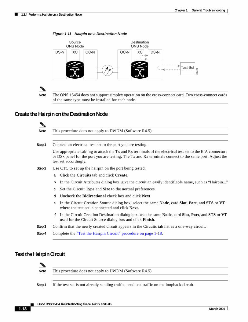
Chapter 1 General Troubleshooting1.2.4 Perform a Hairpin on a Destination Node
Figure 1-11 Hairpin on a Destination Node
Note The ONS 15454 does not support simplex operation on the cross-connect card. Two cross-connect cards of the same type must be installed for each node.
Create the Hairpin on the Destination Node
Note This procedure does not apply to DWDM (Software R4.5).
Step 1 Connect an electrical test set to the port you are testing.
Use appropriate cabling to attach the Tx and Rx terminals of the electrical test set to the EIA connectors or DSx panel for the port you are testing. The Tx and Rx terminals connect to the same port. Adjust the test set accordingly.
Step 2 Use CTC to set up the hairpin on the port being tested:
a. Click the Circuits tab and click Create.
b. In the Circuit Attributes dialog box, give the circuit an easily identifiable name, such as “Hairpin1.”
c. Set the Circuit Type and Size to the normal preferences.
d. Uncheck the Bidirectional check box and click Next.
e. In the Circuit Creation Source dialog box, select the same Node, card Slot, Port, and STS or VT where the test set is connected and click Next.
f. In the Circuit Creation Destination dialog box, use the same Node, card Slot, Port, and STS or VT used for the Circuit Source dialog box and click Finish.
Step 3 Confirm that the newly created circuit appears in the Circuits tab list as a one-way circuit.
Step 4 Complete the “Test the Hairpin Circuit” procedure on page 1-18.
Test the Hairpin Circuit
Note This procedure does not apply to DWDM (Software R4.5).
Step 1 If the test set is not already sending traffic, send test traffic on the loopback circuit.
SourceONS Node
DestinationONS Node
OC-N XCOC-NXCDS-N DS-N
Test Set
7877
8
1-18Cisco ONS 15454 Troubleshooting Guide, R4.1.x and R4.5
March 2004

Chapter 1 General Troubleshooting1.2.4 Perform a Hairpin on a Destination Node
Step 2 Examine the test traffic received by the test set. Look for errors or any other signal information that the test set is capable of indicating.
Step 3 If the test set indicates a good circuit, no further testing is necessary with the hairpin circuit.
a. Clear the hairpin circuit:
• Click the Circuits tab.
• Choose the hairpin circuit being tested.
• Click Delete.
• Click Yes in the Delete Circuits dialog box.
• Confirm that the hairpin circuit is deleted form the Circuits tab list.
b. Complete the “Perform a Facility (Line) Loopback on a Destination DS-N Port” procedure on page 1-21.
Step 4 If the test set indicates a faulty circuit, there might be a problem with the cross-connect card.
Step 5 Complete the “Test the Standby Cross-Connect Card” procedure on page 1-19.
Test the Standby Cross-Connect Card
Note This procedure does not apply to DWDM (Software R4.5).
Step 1 Perform a reset on the standby cross-connect card:
a. Determine the standby cross-connect card. On both the physical node and the CTC window, the ACT/SBY LED of the standby cross-connect card is amber and the ACT/SBY LED of the active cross-connect card is green.
b. Position the cursor over the standby cross-connect card.
c. Right-click and choose RESET CARD.
Step 2 Initiate an external switching command (side switch) on the cross-connect cards before retesting the loopback circuit:
Caution Cross-connect side switches are service-affecting. Any live traffic on any card in the node endures a hit of up to 50 ms.
a. Determine the standby cross-connect card. The ACT/SBY LED of the standby cross-connect card is amber and the ACT/SBY LED of the active cross-connect card is green.
b. In the node view, select the Maintenance > Cross-Connect tabs.
c. In the Cross-Connect Cards menu, click Switch.
d. Click Yes in the Confirm Switch box.
Note After the active cross-connect goes into standby, the original standby slot becomes active. This causes the ACT/SBY LED to become green on the former standby card.
1-19Cisco ONS 15454 Troubleshooting Guide, R4.1.x and R4.5
March 2004

Chapter 1 General Troubleshooting1.2.4 Perform a Hairpin on a Destination Node
Step 3 Resend test traffic on the loopback circuit.
The test traffic now travels through the alternate cross-connect card.
Step 4 If the test set indicates a faulty circuit, assume the cross-connect card is not causing the problem.
a. Clear the hairpin circuit:
• Click the Circuits tab.
• Choose the hairpin circuit being tested.
• Click Delete.
• Click Yes in the Delete Circuits dialog box.
• Confirm that the hairpin circuit is deleted form the Circuits tab list.
b. Complete the “Perform a Facility (Line) Loopback on a Destination DS-N Port” procedure on page 1-21.
Step 5 If the test set indicates a good circuit, the problem might be a defective cross-connect card.
Step 6 To confirm a defective original cross-connect card, complete the “Retest the Original Cross-Connect Card” procedure on page 1-20.
Retest the Original Cross-Connect Card
Note This procedure does not apply to DWDM (Software R4.5).
Step 1 Initiate an external switching command (side switch) on the cross-connect cards to make the original cross-connect card the active card.
a. Determine the standby cross-connect card. The ACT/SBY LED of the standby cross-connect card is amber and the ACT/SBY LED of the active cross-connect card is green.
b. In node view, select the Maintenance > Cross-Connect tabs.
c. In the Cross-Connect Cards menu, click Switch.
d. Click Yes in the Confirm Switch dialog box.
Step 2 Resend test traffic on the loopback circuit.
Step 3 If the test set indicates a faulty circuit, the problem is probably the defective card.
a. Return the defective card to Cisco through the RMA process. Contact Cisco TAC (800-553-2447).
b. Replace the defective cross-connect card. Complete the “Replace an In-Service Cross-Connect Card” procedure on page 3-1.
c. Clear the hairpin circuit before testing the next segment of the network circuit path.
• Click the Circuits tab.
• Choose the hairpin circuit being tested.
• Click Delete.
• Click Yes in the Delete Circuits dialog box.
d. Proceed to Step 5.
1-20Cisco ONS 15454 Troubleshooting Guide, R4.1.x and R4.5
March 2004

Chapter 1 General Troubleshooting1.2.5 Perform a Facility (Line) Loopback on a Destination DS-N Port
Step 4 If the test set indicates a good circuit, the cross-connect card might have had a temporary problem that was cleared by the side switch.
Clear the hairpin circuit:
a. Click the Circuits tab.
b. Choose the hairpin circuit being tested.
c. Click Delete.
d. Click Yes in the Delete Circuits dialog box.
Step 5 Complete the “Perform a Facility (Line) Loopback on a Destination DS-N Port” procedure on page 1-21.
1.2.5 Perform a Facility (Line) Loopback on a Destination DS-N PortThe facility loopback test is performed on the node source port in the circuit, in this example, the destination DS-N port in the destination node. Completing a successful facility loopback on this port isolates the possibility that the destination node cabling, DS-N card, LIU, or EIA is responsible for a faulty circuit. Figure 1-12 shows an example of a facility loopback on a destination DS-N port.
Figure 1-12 Facility (Line) Loopback on a Destination DS-N Port
Caution Performing a loopback on an in-service circuit is service-affecting.
Note DS-3 facility (line) loopbacks do not transmit an AIS condition in the direction away from the loopback. Instead of a DS-3 AIS, a continuance of the signal transmitted to the loopback is provided.
Create a Facility (Line) Loopback Circuit on a Destination DS-N Port
Note This procedure does not apply to DWDM (Software R4.5).
Step 1 Connect an electrical test set to the port you are testing:
a. If you just completed the “Perform a Hairpin on a Destination Node” procedure on page 1-17, leave the electrical test set hooked up to the DS-N port in the destination node.
SourceONS Node
DestinationONS Node
5528
3
DS-N OC-NXC OC-N DS-NXC
Test Set
1-21Cisco ONS 15454 Troubleshooting Guide, R4.1.x and R4.5
March 2004

Chapter 1 General Troubleshooting1.2.5 Perform a Facility (Line) Loopback on a Destination DS-N Port
b. If you are starting the current procedure without the electrical test set hooked up to the DS-N port, use appropriate cabling to attach the Tx and Rx terminals of the electrical test set to the DSx panel or the EIA connectors for the port you are testing. Both Tx and Rx connect to the same port.
c. Adjust the test set accordingly.
Step 2 Use CTC to create the facility (line) loopback on the port being tested:
a. In node view, double-click the card where the loopback will be performed.
b. Click the Maintenance > Loopback tabs.
c. Select Facility (Line) from the Loopback Type column for the port being tested. If this is a multiport card, select the row appropriate for the desired port.
d. Click Apply.
e. Click Yes in the Confirmation Dialog box.
Note It is normal for a LPBKFACILITY condition to appear during loopback setup. The condition clears when you remove the loopback.
Step 3 Complete the “Test the Facility (Line) Loopback Circuit” procedure on page 1-22.
Test the Facility (Line) Loopback Circuit
Note This procedure does not apply to DWDM (Software R4.5).
Step 1 If the test set is not already sending traffic, send test traffic on the loopback circuit.
Step 2 Examine the test traffic received by the test set. Look for errors or any other signal information that the test set is capable of indicating.
Step 3 If the test set indicates a good circuit, no further testing is necessary with the loopback circuit.
Clear the facility (line) loopback:
• Click the Maintenance > Loopback tabs.
• Choose None from the Loopback Type column for the port being tested.
• Choose the appropriate state (IS, OOS, OOS_AINS) from the State column for the port being tested.
• Click Apply.
• Click Yes in the Confirmation Dialog box.
The entire DS-N circuit path has now passed its comprehensive series of loopback tests. This circuit qualifies to carry live traffic.
Step 4 If the test set indicates a faulty circuit, the problem might be a faulty DS-N card, faulty cabling from the DS-N card to the DSx panel or the EIA, or a faulty EIA.
Step 5 Complete the “Test the DS-N Cabling” procedure on page 1-23.
1-22Cisco ONS 15454 Troubleshooting Guide, R4.1.x and R4.5
March 2004

Chapter 1 General Troubleshooting1.2.5 Perform a Facility (Line) Loopback on a Destination DS-N Port
Test the DS-N Cabling
Note This procedure does not apply to DWDM (Software R4.5).
Step 1 Replace the suspect cabling (the cables from the test set to the DSx panel or the EIA ports) with a known-good cable.
If a known-good cable is not available, test the suspected bad cable with a test set. Remove the suspected bad cable from the DSx panel or the EIA and connect the cable to the Tx and Rx terminals of the test set. Run traffic to determine whether the cable is good or defective.
Step 2 Resend test traffic on the loopback circuit with a known-good cable installed.
Step 3 If the test set indicates a good circuit, the problem was probably the defective cable.
a. Replace the defective cable.
b. Clear the facility (line) loopback:
• Click the Maintenance > Loopback tabs.
• Choose None from the Loopback Type column for the port being tested.
• Choose the appropriate state (IS, OOS, OOS_AINS) from the State column for the port being tested.
• Click Apply.
• Click Yes in the Confirmation Dialog box.
The entire DS-N circuit path has now passed its comprehensive series of loopback tests. This circuit qualifies to carry live traffic.
Step 4 If the test set indicates a faulty circuit, the problem might be a faulty card or a faulty EIA.
Step 5 Complete the “Test the DS-N Card” procedure on page 1-23.
Test the DS-N Card
Note This procedure does not apply to DWDM (Software R4.5).
Step 1 Replace the suspected bad card with a known-good card.
Caution Removing a card that currently caries traffic on one or more ports can cause a traffic hit. To avoid this, perform an external switch if a switch has not already occurred. Consult the Cisco ONS 15454 Procedure Guide for information.
Step 2 Resend test traffic on the loopback circuit with a known-good card installed.
Step 3 If the test set indicates a good circuit, the problem was probably the defective card.
a. Return the defective card to Cisco through the RMA process. Contact Cisco TAC (800-553-2447).
b. Complete the “Physically Replace a Card” procedure on page 2-198 for the faulty card.
1-23Cisco ONS 15454 Troubleshooting Guide, R4.1.x and R4.5
March 2004

Chapter 1 General Troubleshooting1.2.5 Perform a Facility (Line) Loopback on a Destination DS-N Port
c. Clear the facility (line) loopback:
• Click the Maintenance > Loopback tabs.
• Choose None from the Loopback Type column for the port being tested.
• Choose the appropriate state (IS, OOS, OOS_AINS) from the State column for the port being tested.
• Click Apply.
• Click Yes in the Confirmation Dialog box.
The entire DS-N circuit path has now passed its comprehensive series of loopback tests. This circuit qualifies to carry live traffic.
Step 4 If the test set indicates a faulty circuit, the problem might be a faulty EIA.
Step 5 Complete the “Test the EIA” procedure on page 1-24.
Test the EIA
Note This procedure does not apply to DWDM (Software R4.5).
Step 1 Remove and reinstall the EIA to ensure a proper seating.
a. Remove the lower backplane cover, loosen the five screws that secure it to the ONS 15454, and pull it away from the shelf assembly.
b. Loosen the nine perimeter screws that hold the EIA panel in place.
c. Lift the EIA panel by the bottom to remove it from the shelf assembly.
d. Follow the installation procedure for the appropriate EIA. Complete the “Replace an Electrical Interface Assembly” procedure on page 3-17.
Step 2 Resend test traffic on the loopback circuit with known-good cabling, a known-good card, and the reinstalled EIA.
Step 3 If the test set indicates a good circuit, the problem was probably an improperly seated EIA.
Clear the facility (line) loopback:
• Click the Maintenance > Loopback tabs.
• Choose None from the Loopback Type column for the port being tested.
• Choose the appropriate state (IS, OOS, OOS_AINS) from the State column for the port being tested.
• Click Apply.
• Click Yes in the Confirmation Dialog box.
The entire DS-N circuit path has now passed its comprehensive series of loopback tests. This circuit qualifies to carry live traffic.
Step 4 If the test set indicates a faulty circuit, the problem is probably the defective EIA.
a. Return the defective EIA to Cisco through the RMA process. Contact Cisco TAC (800-553-2447).
b. Replace the faulty EIA. See “3.1 Replace an In-Service Cross-Connect Card” section on page 3-1 for details.
1-24Cisco ONS 15454 Troubleshooting Guide, R4.1.x and R4.5
March 2004

Chapter 1 General Troubleshooting1.3 Using the DS3XM-6 Card FEAC (Loopback) Functions
Step 5 Resend test traffic on the loopback circuit with known-good cabling, a known-good card, and the replacement EIA.
Step 6 If the test set indicates a faulty circuit, repeat all of the facility loopback procedures.
If the faulty circuit persists, contact Cisco TAC (800-553-2447).
Step 7 If the test set indicates a good circuit, the problem was probably the defective EIA.
Clear the facility (line) loopback:
• Click the Maintenance > Loopback tabs.
• Choose None from the Loopback Type column for the port being tested.
• Choose the appropriate state (IS, OOS, OOS_AINS) from the State column for the port being tested.
• Click Apply.
• Click Yes in the Confirmation Dialog box.
The entire DS-N circuit path has now passed its comprehensive series of loopback tests. This circuit qualifies to carry live traffic.
1.3 Using the DS3XM-6 Card FEAC (Loopback) FunctionsThe DS3XM-6 card supports FEAC functions that are not available on basic DS-3 cards. Click the Maintenance tab at the DS3XM-6 card view to reveal the two additional function columns. Figure 1-13 on page 1-25 shows the DS3 subtab and the additional Send Code and Inhibit FE Lbk function columns.
Figure 1-13 Accessing FEAC Functions on the DS3XM-6 Card
1-25Cisco ONS 15454 Troubleshooting Guide, R4.1.x and R4.5
March 2004

Chapter 1 General Troubleshooting1.3.1 FEAC Send Code
The far end in FEAC refers to the piece of equipment that is connected to the DS3XM-6 card and not the far end of a circuit. In Figure 1-14, if a DS3XM-6 (near-end) port is configured to send a Line Loop Code, the code will be sent to the connected test set, not the DS3XM-6 (far-end) port.
Figure 1-14 Diagram of FEAC
1.3.1 FEAC Send CodeThe Send Code column on the maintenance tab of a DS3XM-6 port only applies to out-of-service (OOS_MT, OOS_AINS) ports configured for CBIT framing. The column lets a user select No Code (the default) or Line Loop Code. Selecting Line Loop Code inserts a line loop activate FEAC in the CBIT overhead transmitting to the connected facility (line). This code initiates a loopback from the facility to the ONS 15454. Selecting No Code sends a line-loop-deactivate FEAC code to the connected equipment, which will remove the loopback. You can also insert a FEAC for the 28 individual DS-1 circuits transmuxed into a DS-3 circuit.
1.3.2 FEAC Inhibit LoopbackThe DS3XM-6 ports and transmuxed DS-1s initiate loopbacks when they receive FEAC Line Loop codes. If the Inhibit Loopback check box is checked for a DS-3 port, then that port will ignore any received FEAC Line Loop codes and will not loop back. The port can still be put into loopback manually using the Loopback Type column even if the Inhibit Loopback check box is selected. Only DS-3 ports can be configured to inhibit responses to FEAC loopback commands, individual DS-1 ports cannot inhibit their responses.
1.3.3 FEAC Alarms The node raises a LPBKDS1FEAC-CMD or LPBKDS3FEAC-CMD condition for a DS-1 or DS-3 port if a FEAC loopback code is sent to the far end.
If the ONS 15454 port is in loopback from having received a loopback activate FEAC code, a LPBKDS1FEAC or LPBKDS3FEAC condition occurs. The condition will clear when a loopback deactivate FEAC command is received on that port.
A DS3E card will respond to, and can inhibit, received FEAC DS-3 level loopback codes. A DS3E card cannot be configured to send FEAC codes.
TxRx
DS3XM(Near End)
TxRx
OC48
OC48Ring
Test Set
Node BNode A
CPERxTx
OC48
TxRx
DS3XM(Far End)
6184
5
1-26Cisco ONS 15454 Troubleshooting Guide, R4.1.x and R4.5
March 2004

Chapter 1 General Troubleshooting1.4 Identify Points of Failure on an OC-N Circuit Path
1.4 Identify Points of Failure on an OC-N Circuit PathFacility (line) loopbacks, terminal (inward) loopbacks, and cross-connect loopback circuits are often used together to test the circuit path through the network or to logically isolate a fault. Performing a loopback test at each point along the circuit path systematically isolates possible points of failure.
The example in this section tests an OC-N circuit on a three-node, bidirectional line switched ring (BLSR). Using a series of facility loopbacks and terminal (inward) loopbacks, the path of the circuit is traced and the possible points of failure are tested and eliminated. A logical progression of seven network test procedures apply to this example scenario:
Note The test sequence for your circuits will differ according to the type of circuit and network topology.
1. A facility (line) loopback on the source node OC-N port or G-Series port
2. A terminal (inward) loopback on the source node OC-N port or G-Series port
3. A cross-connect loopback on the source OC-N port
4. A facility (line) loopback on the intermediate node OC-N port or G-Series port
5. A terminal (inward) loopback on the intermediate node OC-N port or G-Series port
6. A facility (line) loopback on the destination node OC-N port or G-Series port
7. A terminal (inward) loopback on the destination node OC-N port or G-Series port
Note All loopback tests require on-site personnel.
1.4.1 Perform a Facility (Line) Loopback on a Source-Node OC-N or G-Series Port
The facility (line) loopback test is performed on the node source port in the network circuit, in this example, the source OC-N port in the source node. Completing a successful facility (line) loopback on this port isolates the OC-N or G-Series port as a possible failure point. Figure 1-15 shows an example of a facility loopback on a circuit source OC-N port.
Note Facility (line) loopbacks are not available for G-Series cards prior to Release 4.1.
Figure 1-15 Facility (Line) Loopback on a Circuit Source OC-N Port
DestinationONS Node
OC-N OC-NXC
SourceONS Node
IntermediateONS Node
OC-N OC-NXCOC-N
Test Set
XCOC-N
7878
3
1-27Cisco ONS 15454 Troubleshooting Guide, R4.1.x and R4.5
March 2004

Chapter 1 General Troubleshooting1.4.1 Perform a Facility (Line) Loopback on a Source-Node OC-N or G-Series Port
Caution Performing a loopback on an in-service circuit is service-affecting.
Create the Facility (Line) Loopback on the Source OC-N or G-Series Port
Step 1 Connect an optical test set to the port you are testing.
Use appropriate cabling to attach the Tx and Rx terminals of the optical test set to the port you are testing. The Tx and Rx terminals connect to the same port. Adjust the test set accordingly.
Step 2 Use CTC to create the facility (line) loopback circuit on the port being tested:
a. In node view, double-click the card where you will perform the loopback.
b. Click the Maintenance > Loopback tabs.
c. Choose OOS_MT from the State column for the port being tested. If this is a multiport card, select the appropriate row for the desired port.
d. Choose Facility (Line) from the Loopback Type column for the port being tested. If this is a multiport card, select the appropriate row for the desired port.
e. Click Apply.
f. Click Yes in the Confirmation Dialog box.
Note It is normal for a LPBKFACILITY condition to appear during loopback setup. The condition clears when you remove the loopback.
Step 3 Complete the “Test the Facility (Line) Loopback Circuit” procedure on page 1-28.
Test the Facility (Line) Loopback Circuit
Step 1 If the test set is not already sending traffic, send test traffic on the loopback circuit.
Step 2 Examine the traffic received by the test set. Look for errors or any other signal information that the test set is capable of indicating.
Step 3 If the test set indicates a good circuit, no further testing is necessary with the facility loopback.
a. Clear the facility (line) loopback:
• Click the Maintenance > Loopback tabs.
• Choose None from the Loopback Type column for the port being tested.
• Choose the appropriate state (IS, OOS, OOS_AINS) from the State column for the port being tested.
• Click Apply.
• Click Yes in the Confirmation Dialog box.
b. Complete the “Perform a Terminal (Inward) Loopback on a Source-Node OC-N or G-Series Port” procedure on page 1-29.
Step 4 If the test set indicates a faulty circuit, the problem might be a faulty OC-N or G-Series card.
1-28Cisco ONS 15454 Troubleshooting Guide, R4.1.x and R4.5
March 2004

Chapter 1 General Troubleshooting1.4.2 Perform a Terminal (Inward) Loopback on a Source-Node OC-N or G-Series Port
Step 5 Complete the “Test the OC-N or G-Series Card” procedure on page 1-29.
Test the OC-N or G-Series Card
Step 1 Replace the suspected bad card with a known-good card. Complete the “Physically Replace a Card” procedure on page 2-198.
Caution Removing a card that currently caries traffic on one or more ports can cause a traffic hit. To avoid this, perform an external switch if a switch has not already occurred. Consult the Cisco ONS 15454 Procedure Guide for information.
Step 2 Resend test traffic on the loopback circuit with a known-good card installed.
Step 3 If the test set indicates a good circuit, the problem was probably the defective card.
a. Return the defective card to Cisco through the RMA process. Contact Cisco TAC (800-553-2447).
b. Replace the faulty card. Complete the “Physically Replace a Card” procedure on page 2-198.
c. Clear the facility (line) loopback:
• Click the Maintenance > Loopback tabs.
• Choose None from the Loopback Type column for the port being tested.
• Choose the appropriate state (IS, OOS, OOS_AINS) from the State column for the port being tested.
• Click Apply.
• Click Yes in the Confirmation Dialog box.
Step 4 Complete the “Perform a Terminal (Inward) Loopback on a Source-Node OC-N or G-Series Port” procedure on page 1-29.
1.4.2 Perform a Terminal (Inward) Loopback on a Source-Node OC-N or G-Series Port
The terminal (inward) loopback test is performed on the node destination port. In the circuit in this example, the destination OC-N port in the source node. First, create a bidirectional circuit that starts on the node source OC-N or G-Series port and loops back on the node destination OC-N or G-Series port. Then proceed with the terminal loopback test. Completing a successful terminal loopback to a node destination OC-N or G-Series port verifies that the circuit is good up to the destination OC-N or G-Series. Figure 1-16 shows an example of a terminal loopback on a destination OC-N port.
Note Terminal (inward) loopbacks are not available for DWDM cards in Release 4.5.
Note Terminal (inward) loopbacks are not available for G-Series cards prior to Release 4.0.
1-29Cisco ONS 15454 Troubleshooting Guide, R4.1.x and R4.5
March 2004

Chapter 1 General Troubleshooting1.4.2 Perform a Terminal (Inward) Loopback on a Source-Node OC-N or G-Series Port
Figure 1-16 Terminal (Inward) Loopback on a Source-Node OC-N Port
Figure 1-17 shows terminal loopback on a G-Series card.
Figure 1-17 Terminal (Inward) Loopback on a G-Series Port
Caution Performing a loopback on an in-service circuit is service-affecting.
Create the Terminal (Inward) Loopback on a Source Node OC-N Port
Step 1 Connect an optical test set to the port you are testing:
a. If you just completed the “1.4.1 Perform a Facility (Line) Loopback on a Source-Node OC-N or G-Series Port” section on page 1-27, leave the optical test set hooked up to the OC-N port in the source node.
DestinationONS Node
OC-N OC-NXC
SourceONS Node
IntermediateONS Node
OC-N OC-NXCOC-N
Test Set
OC-N XC
7878
4
4 portsGigE
Processor Subsystem
GBIC 1 SERDES
MainRX BPIA
MainTX BPIA
GigEMAC
GBIC 2 SERDES GigEMAC
BACKPLANESTS48
GBIC 3 SERDES GigEMAC
GBIC 4 SERDES GigEMAC
TerminalLoopback
FacilityLoopback
FPGABlock
PathTermination
Block
BTC192
9646
1
ProtectRX BPIA
ProtectTX BPIA
New
1-30Cisco ONS 15454 Troubleshooting Guide, R4.1.x and R4.5
March 2004

Chapter 1 General Troubleshooting1.4.2 Perform a Terminal (Inward) Loopback on a Source-Node OC-N or G-Series Port
b. If you are starting the current procedure without the optical test set hooked up to the OC-N port, use appropriate cabling to attach the Tx and Rx terminals of the optical test set to the port you are testing. Both Tx and Rx connect to the same port.
c. Adjust the test set accordingly.
Step 2 Use CTC to set up the terminal (inward) loopback circuit on the port being tested:
a. Click the Circuits tab and click Create.
b. In the Circuit Attributes dialog box, give the circuit an easily identifiable name, such as “OCN1toOCN2.”
c. Set Circuit Type and Size to the normal preferences.
d. Leave the Bidirectional check box checked and click Next.
e. In the Circuit Creation Source dialog box, select the same Node, card Slot, Port, and STS or VT where the test set is connected and click Next.
f. In the Circuit Creation Destination dialog box, fill in the destination Node, card Slot, Port, and STS or VT (the OC-N port in the source node) and click Finish.
Step 3 Confirm that the newly created circuit appears on the Circuits tab list as a 2-way circuit.
Note It is normal for a LPBKTERMINAL condition to appear during a loopback setup. The condition clears when you remove the loopback.
Step 4 Create the terminal (inward) loopback on the destination port being tested:
a. In node view, double-click the card that requires the loopback, such as the destination OC-N card in the source node.
b. Click the Maintenance > Loopback tabs.
c. Select OOS_MT from the State column. If this is a multiport card, select the row appropriate for the desired port.
d. Select Terminal (Inward) from the Loopback Type column. If this is a multiport card, select the row appropriate for the desired port.
e. Click Apply.
f. Click Yes in the Confirmation Dialog box.
Step 5 Complete the “Test the Terminal Loopback Circuit” procedure on page 1-31.
Test the Terminal Loopback Circuit
Step 1 If the test set is not already sending traffic, send test traffic on the loopback circuit.
Step 2 Examine the test traffic being received by the test set. Look for errors or any other signal information that the test set is capable of indicating.
Step 3 If the test set indicates a good circuit, no further testing is necessary on the loopback circuit.
a. Clear the terminal loopback:
• Double-click the OC-N card in the source node with the terminal loopback.
• Click the Maintenance > Loopback tabs.
1-31Cisco ONS 15454 Troubleshooting Guide, R4.1.x and R4.5
March 2004

Chapter 1 General Troubleshooting1.4.2 Perform a Terminal (Inward) Loopback on a Source-Node OC-N or G-Series Port
• Select None from the Loopback Type column for the port being tested.
• Select the appropriate state (IS, OOS, OOS_AINS) in the State column for the port being tested.
• Click Apply.
• Click Yes in the Confirmation Dialog box.
b. Clear the terminal loopback circuit:
• Click the Circuits tab.
• Choose the loopback circuit being tested.
• Click Delete.
• Click Yes in the Delete Circuits dialog box.
c. Complete the “Create a Facility (Line) Loopback on an Intermediate-Node OC-N or G-Series Port” procedure on page 1-37.
Step 4 If the test set indicates a faulty circuit, the problem might be a faulty card.
Step 5 Complete the “Test the OC-N Card” procedure on page 1-32.
Test the OC-N Card
Note This procedure does not apply to DWDM (Software R4.5).
Step 1 Replace the suspected bad card with a known-good card. Complete the “Physically Replace a Card” procedure on page 2-198.
Caution Removing a card that currently caries traffic on one or more ports can cause a traffic hit. To avoid this, perform an external switch if a switch has not already occurred. Consult the Cisco ONS 15454 Procedure Guide for information.
Step 2 Resend test traffic on the loopback circuit with a known-good card.
Step 3 If the test set indicates a good circuit, the problem was probably the defective card.
a. Return the defective card to Cisco through the RMA process. Contact Cisco TAC (800-553-2447).
b. Replace the defective OC-N card. Complete the “Physically Replace a Card” procedure on page 2-198.
c. Clear the terminal loopback before testing the next segment of the network circuit path.
• Double-click the OC-N card in the source node with the terminal loopback.
• Click the Maintenance > Loopback tabs.
• Select None from the Loopback Type column for the port being tested.
• Select the appropriate state (IS, OOS, OOS_AINS) in the State column for the port being tested.
• Click Apply.
• Click Yes in the Confirmation Dialog box.
d. Clear the terminal loopback circuit before testing the next segment of the network circuit path.
1-32Cisco ONS 15454 Troubleshooting Guide, R4.1.x and R4.5
March 2004

Chapter 1 General Troubleshooting1.4.3 Create the XC Loopback on the Source OC-N Port
• Click the Circuits tab.
• Choose the loopback circuit being tested.
• Click Delete.
• Click Yes in the Delete Circuits dialog box.
Step 4 Complete the “Create the XC Loopback on the Source OC-N Port” procedure on page 1-33.
1.4.3 Create the XC Loopback on the Source OC-N Port
Note This procedure does not apply to DWDM (Software R4.5).
The XC loopback test occurs on the cross-connect card in a network circuit. An XC loopback circuit uses the same port for both source and destination. Completing a successful XC loopback through the cross-connect card isolates the possibility that the cross-connect card is the cause of the faulty circuit. Figure 1-18 shows an example of an XC loopback on a source OC-N port.
Figure 1-18 XC Loopback on a Source OC-N Port
Step 1 Connect an optical test set to the port you are testing.
Note Refer to the manufacturer’s instructions for detailed information on connection and setup of the optical test set.
a. If you just completed the “1.4.2 Perform a Terminal (Inward) Loopback on a Source-Node OC-N or G-Series Port” section on page 1-29, leave the optical test set hooked up to the OC-N port in the source node.
b. If you are starting the current procedure without the optical test set hooked up to the OC-N port, use appropriate cabling to attach the Tx and Rx terminals of the optical test set to the port you are testing. The Tx and Rx terminals connect to the same port.
c. Adjust the test set accordingly.
Step 2 Use CTC to put the circuit being tested out of service:
a. In node view, double-click the card where the test set is connected. The card view appears.
b. In card view, click the Provisioning > Line tabs.
c. Choose OOS or OOS_MT from the Status column for the port being tested.
XCTest Set OC-NyOC-Nx
8375
0
1-33Cisco ONS 15454 Troubleshooting Guide, R4.1.x and R4.5
March 2004

Chapter 1 General Troubleshooting1.4.3 Create the XC Loopback on the Source OC-N Port
d. Click Apply.
Step 3 Use CTC to set up the XC loopback on the circuit being tested:
a. In card view, click the Provisioning > SONET STS tabs.
b. Click the check box in the XC Loopback column for the port being tested.
c. Click Apply.
d. Click Yes in the confirmation dialog.
Step 4 Complete the “Test the XC Loopback Circuit” procedure on page 1-34.
Test the XC Loopback Circuit
Note This procedure does not apply to DWDM (Software R4.5).
Step 1 If the test set is not already sending traffic, send test traffic on the loopback circuit.
Step 2 Examine the test traffic received by the test set. Look for errors or any other signal information that the test set is capable of indicating.
Step 3 If the test set indicates a good circuit, no further testing is necessary with the cross-connect.
a. Clear the XC loopback:
• In card view, click the Provisioning > SONET STS tabs.
• Uncheck the check box in the XC Loopback column for the circuit being tested.
• Click Apply.
• Click Yes in the confirmation dialog.
b. Complete the “Create a Facility (Line) Loopback on an Intermediate-Node OC-N or G-Series Port” procedure on page 1-37.
Step 4 If the test set indicates a faulty circuit, there might be a problem with the cross-connect card.
Step 5 Complete the “Test the Standby Cross-Connect Card” procedure on page 1-34.
Test the Standby Cross-Connect Card
Note This procedure does not apply to DWDM (Software R4.5).
Step 1 Perform a reset on the standby cross-connect card:
a. Determine the standby cross-connect card. On both the physical node and the CTC window, verify that the active cross-connect card displays a green ACT LED and the standby cross-connect card displays an amber SBY LED.
b. Position the cursor over the standby cross-connect card.
c. Right-click and choose RESET CARD.
1-34Cisco ONS 15454 Troubleshooting Guide, R4.1.x and R4.5
March 2004

Chapter 1 General Troubleshooting1.4.3 Create the XC Loopback on the Source OC-N Port
Step 2 Initiate an external switching command (side switch) of the cross-connect cards before retesting the loopback circuit:
Caution Cross-connect side switches are service-affecting. Any live traffic on any card in the node endures a hit of up to 50 ms.
a. Determine the standby cross-connect card. The active cross-connect card displays a green ACT LED and the standby cross-connect card displays an amber SBY LED.
b. In the node view, select the Maintenance > Cross-Connect tabs.
c. In the Cross-Connect Cards menu, click Switch.
d. Click Yes in the Confirm Switch dialog box.
Note After the active cross-connect goes into standby, the original standby slot becomes active. This causes the ACT LED to become green on the former standby card.
Step 3 Resend test traffic on the loopback circuit.
The test traffic now travels through the alternate cross-connect card.
Step 4 If the test set indicates a faulty circuit, assume the cross-connect card is not causing the problem.
Clear the XC loopback circuit:
• Click the Circuits tab.
• Choose the XC loopback circuit being tested.
• Click Delete.
• Click Yes in the Delete Circuits dialog box.
• Confirm that the XC loopback circuit is deleted form the Circuits tab list.
Step 5 If the test set indicates a good circuit, the problem might be a defective cross-connect card.
Step 6 To confirm a defective original cross-connect card, complete the “Retest the Original Cross-Connect Card” procedure on page 1-35.
Retest the Original Cross-Connect Card
Note This procedure does not apply to DWDM (Software R4.5).
Step 1 Initiate an external switching command (side switch) on the cross-connect cards to make the original cross-connect card the active card.
a. Determine the standby cross-connect card. The ACT/SBY LED of the standby cross-connect card is amber and the ACT/SBY LED of the active cross-connect card is green.
b. In node view, select the Maintenance > Cross-Connect tabs.
c. In the Cross-Connect Cards menu, click Switch.
d. Click Yes in the Confirm Switch dialog box.
1-35Cisco ONS 15454 Troubleshooting Guide, R4.1.x and R4.5
March 2004

Chapter 1 General Troubleshooting1.4.4 Create a Facility (Line) Loopback on an Intermediate-Node OC-N or G-Series Port
Step 2 Resend test traffic on the loopback circuit.
Step 3 If the test set indicates a faulty circuit, the problem is probably the defective card.
a. Return the defective card to Cisco through the RMA process. Contact Cisco TAC (800-553-2447).
b. Replace the defective cross-connect card. See the “3.1 Replace an In-Service Cross-Connect Card” section on page 3-1 for details.
c. Clear the XC loopback circuit:
• Click the Circuits tab.
• Choose the XC loopback circuit being tested.
• Click Delete.
• Click Yes in the Delete Circuits dialog box.
Step 4 If the test set indicates a good circuit, the cross-connect card might have had a temporary problem that was cleared by the side switch.
Clear the XC loopback circuit:
• Click the Circuits tab.
• Choose the XC loopback circuit being tested.
• Click Delete.
• Click Yes in the Delete Circuits dialog box.
1.4.4 Create a Facility (Line) Loopback on an Intermediate-Node OC-N or G-Series Port
The facility (line) loopback test is performed on the node source port in the network circuit, in this example, the source OC-N or G-Series port in the intermediate node. Completing a successful facility loopback on this port isolates the OC-N or G-Series port as a possible failure point. Figure 1-19 on page 1-36 shows an example of a facility loopback on a intermediate node circuit source OC-N.
Note Only G-Series loopbacks are possible on DWDM nodes.
Figure 1-19 Facility (Line) Loopback on an Intermediate-Node OC-N
Caution Performing a loopback on an in-service circuit is service-affecting.
DestinationONS Node
OC-N OC-NXC
SourceONS Node
IntermediateONS Node
OC-N OC-NXC
Test Set
OC-N XC OC-N
7878
1
1-36Cisco ONS 15454 Troubleshooting Guide, R4.1.x and R4.5
March 2004

Chapter 1 General Troubleshooting1.4.4 Create a Facility (Line) Loopback on an Intermediate-Node OC-N or G-Series Port
Create a Facility (Line) Loopback on an Intermediate-Node OC-N or G-Series Port
Step 1 Connect an optical test set to the port you are testing:
a. If you just completed the “1.4.2 Perform a Terminal (Inward) Loopback on a Source-Node OC-N or G-Series Port” section on page 1-29, leave the optical test set hooked up to the OC-N port in the source node.
b. If you are starting the current procedure without the optical test set hooked up to the OC-N or G-Series port, use appropriate cabling to attach the Tx and Rx terminals of the optical test set to the port you are testing. Both Tx and Rx connect to the same port.
c. Adjust the test set accordingly.
Step 2 Use CTC to set up the facility (line) loopback circuit on the port being tested:
a. Click the Circuits tab and click Create.
b. In the Circuit Attributes dialog box, give the circuit an easily identifiable name, such as “OCN1toOCN3.”
c. Set Circuit Type and Size to the normal preferences.
d. Leave the Bidirectional check box checked and click Next.
e. In the Circuit Creation Source dialog box, select the same Node, card Slot, Port, and STS or VT where the test set is connected and click Next.
f. In the Circuit Creation Destination dialog box, fill in the destination Node, card Slot, Port, and STS or VT (the OC-N port in the intermediate node) and click Finish.
Step 3 Confirm that the newly created circuit appears on the Circuits tab list as a 2-way circuit.
Note It is normal for a LPBKFACILITY condition to appear during a loopback setup. The condition clears when you remove the loopback.
Step 4 Create the facility (line) loopback on the destination port being tested:
a. Go to the node view of the intermediate node:
• Choose View > Go To Other Node from the menu bar.
• Choose the node from the drop-down list in the Select Node dialog box and click OK.
b. In node view, double-click the card that requires the loopback, such as the destination OC-N or G-Series card in the intermediate node.
c. Click the Maintenance > Loopback tabs.
d. Select OOS_MT from the State column. If this is a multiport card, select the row appropriate for the desired port.
e. Select Terminal (Inward) from the Loopback Type column. If this is a multiport card, select the row appropriate for the desired port.
f. Click Apply.
g. Click Yes in the Confirmation Dialog dialog box.
Step 5 Complete the “Test the Facility (Line) Loopback Circuit” procedure on page 1-38.
1-37Cisco ONS 15454 Troubleshooting Guide, R4.1.x and R4.5
March 2004

Chapter 1 General Troubleshooting1.4.4 Create a Facility (Line) Loopback on an Intermediate-Node OC-N or G-Series Port
Test the Facility (Line) Loopback Circuit
Step 1 If the test set is not already sending traffic, send test traffic on the loopback circuit.
Step 2 Examine the traffic received by the test set. Look for errors or any other signal information that the test set is capable of indicating.
Step 3 If the test set indicates a good circuit, no further testing is necessary with the facility (line) loopback.
a. Clear the facility loopback:
• Click the Maintenance > Loopback tabs.
• Choose None from the Loopback Type column for the port being tested.
• Choose the appropriate state (IS, OOS, OOS_AINS) from the State column for the port being tested.
• Click Apply.
• Click Yes in the confirmation dialog box.
b. Clear the facility (line) loopback circuit:
• Click the Circuits tab.
• Choose the loopback circuit being tested.
• Click Delete.
• Click Yes in the Delete Circuits dialog box.
c. Complete the “Create a Terminal Loopback on Intermediate-Node OC-N or G-Series Ports” procedure on page 1-40.
Step 4 If the test set indicates a faulty circuit, the problem might be a faulty OC-N card.
Step 5 Complete the “Test the OC-N or G-Series Card” procedure on page 1-38.
Test the OC-N or G-Series Card
Step 1 Replace the suspected bad card with a known-good card. Complete the “Physically Replace a Card” procedure on page 2-198.
Caution Removing a card that currently caries traffic on one or more ports can cause a traffic hit. To avoid this, perform an external switch if a switch has not already occurred. Consult the Cisco ONS 15454 Procedure Guide for information.
Step 2 Resend test traffic on the loopback circuit with a known-good card installed.
Step 3 If the test set indicates a good circuit, the problem was probably the defective card.
a. Return the defective card to Cisco through the RMA process. Contact Cisco TAC (800-553-2447).
b. Replace the faulty card. Complete the “Physically Replace a Card” procedure on page 2-198.
c. Clear the facility (line) loopback:
• Click the Maintenance > Loopback tabs.
• Choose None from the Loopback Type column for the port being tested.
1-38Cisco ONS 15454 Troubleshooting Guide, R4.1.x and R4.5
March 2004

Chapter 1 General Troubleshooting1.4.5 Create a Terminal Loopback on Intermediate-Node OC-N or G-Series Ports
• Choose the appropriate state (IS, OOS, OOS_AINS) from the State column for the port being tested.
• Click Apply.
• Click Yes in the Confirmation Dialog box.
d. Clear the facility loopback circuit:
• Click the Circuits tab.
• Choose the loopback circuit being tested.
• Click Delete.
• Click Yes in the Delete Circuits dialog box.
Step 4 Complete the “Create a Terminal Loopback on Intermediate-Node OC-N or G-Series Ports” procedure on page 1-40.
1.4.5 Create a Terminal Loopback on Intermediate-Node OC-N or G-Series Ports
The terminal loopback test is performed on the node destination port in the circuit, in this example, the destination OC-N or G-Series port in the intermediate node. First, create a bidirectional circuit that starts on the node source OC-N or G-Series port and loops back on the node destination OC-N or G-Series port. Then proceed with the terminal loopback test. Completing a successful terminal loopback to a node destination OC-N or G-Series port verifies that the circuit is good up to the destination OC-N or G-Series. Figure 1-20 on page 1-39 shows an example of a terminal loopback on an intermediate node destination OC-N port.
Note Only G-Series loopbacks are possible on DWDM nodes.
Figure 1-20 Terminal Loopback on an Intermediate-Node OC-N Port
Caution Performing a loopback on an in-service circuit is service-affecting.
DestinationONS Node
OC-N OC-NXC
SourceONS Node
IntermediateONS Node
OC-N
Test Set
OC-N XC OC-N OC-N XC
7878
2
1-39Cisco ONS 15454 Troubleshooting Guide, R4.1.x and R4.5
March 2004

Chapter 1 General Troubleshooting1.4.5 Create a Terminal Loopback on Intermediate-Node OC-N or G-Series Ports
Create a Terminal Loopback on Intermediate-Node OC-N or G-Series Ports
Step 1 Connect an optical test set to the port you are testing:
a. If you just completed the “Create a Facility (Line) Loopback on an Intermediate-Node OC-N or G-Series Port” section on page 1-37, leave the optical test set hooked up to the OC-N or G-Series port in the source node.
b. If you are starting the current procedure without the optical test set hooked up to the OC-N or G-Series port, use appropriate cabling to attach the Tx and Rx terminals of the optical test set to the port you are testing. Both Tx and Rx connect to the same port.
c. Adjust the test set accordingly.
Step 2 Use CTC to set up the terminal loopback circuit on the port being tested:
a. Click the Circuits tab and click Create.
b. In the Circuit Attributes dialog box, give the circuit an easily identifiable name, such as “OCN1toOCN4.”
c. Set Circuit Type and Size to the normal preferences.
d. Leave the Bidirectional check box checked and click Next.
e. In the Circuit Creation Source dialog box, select the same Node, card Slot, Port, and STS or VT where the test set is connected and click Next.
f. In the Circuit Creation Destination dialog box, fill in the destination Node, card Slot, Port, and STS or VT (the OC-N or G-Series port in the intermediate node) and click Finish.
Step 3 Confirm that the newly created circuit appears on the Circuits tab list as a 2-way circuit.
Note It is normal for a LPBKTERMINAL condition to appear during a loopback setup. The condition clears when you remove the loopback.
Step 4 Create the terminal loopback on the destination port being tested:
a. Go to the node view of the intermediate node:
• Choose View > Go To Other Node from the menu bar.
• Choose the node from the drop-down list in the Select Node dialog box and click OK.
b. In node view, double-click the card that requires the loopback, such as the destination OC-N or G-Series card in the intermediate node.
c. Click the Maintenance > Loopback tabs.
d. Select OOS_MT from the State column. If this is a multiport card, select the row appropriate for the desired port.
e. Select Terminal (Inward) from the Loopback Type column. If this is a multiport card, select the row appropriate for the desired port.
f. Click Apply.
g. Click Yes in the Confirmation Dialog dialog box.
Step 5 Complete the “Test the Terminal Loopback Circuit” procedure on page 1-41.
1-40Cisco ONS 15454 Troubleshooting Guide, R4.1.x and R4.5
March 2004
Chapter 1 General Troubleshooting1.4.5 Create a Terminal Loopback on Intermediate-Node OC-N or G-Series Ports
Test the Terminal Loopback Circuit
Step 1 If the test set is not already sending traffic, send test traffic on the loopback circuit.
Step 2 Examine the test traffic being received by the test set. Look for errors or any other signal information that the test set is capable of indicating.
Step 3 If the test set indicates a good circuit, no further testing is necessary on the loopback circuit.
a. Clear the terminal loopback:
• Double-click the OC-N or G-Series card in the intermediate node with the terminal loopback.
• Click the Maintenance > Loopback tabs.
• Select None from the Loopback Type column for the port being tested.
• Select the appropriate state (IS, OOS, OOS_AINS) in the State column for the port being tested.
• Click Apply.
• Click Yes in the Confirmation Dialog box.
b. Clear the terminal loopback circuit:
• Click the Circuits tab.
• Choose the loopback circuit being tested.
• Click Delete.
• Click Yes in the Delete Circuits dialog box.
c. Complete the “Perform a Facility (Line) Loopback on a Destination-Node OC-N or G-Series Port” procedure on page 1-42.
Step 4 If the test set indicates a faulty circuit, the problem might be a faulty card.
Step 5 Complete the “Test the OC-N or G-Series Card” procedure on page 1-41.
Test the OC-N or G-Series Card
Step 1 Replace the suspected bad card with a known-good card. Complete the “Physically Replace a Card” procedure on page 2-198.
Caution Removing a card that currently caries traffic on one or more ports can cause a traffic hit. To avoid this, perform an external switch if a switch has not already occurred. Consult the Cisco ONS 15454 Procedure Guide for information.
Step 2 Resend test traffic on the loopback circuit with a known-good card.
Step 3 If the test set indicates a good circuit, the problem was probably the defective card.
a. Return the defective card to Cisco through the RMA process. Contact Cisco TAC (800-553-2447).
b. Replace the defective OC-N or G-Series card. Complete the “Physically Replace a Card” procedure on page 2-198.
c. Clear the terminal loopback:
• Double-click the OC-N or G-Series card in the source node with the terminal loopback.
1-41Cisco ONS 15454 Troubleshooting Guide, R4.1.x and R4.5
March 2004

Chapter 1 General Troubleshooting1.4.6 Perform a Facility (Line) Loopback on a Destination-Node OC-N or G-Series Port
• Click the Maintenance > Loopback tabs.
• Select None from the Loopback Type column for the port being tested.
• Select the appropriate state (IS, OOS, OOS_AINS) in the State column for the port being tested.
• Click Apply.
• Click Yes in the Confirmation Dialog box.
d. Clear the terminal loopback circuit:
• Click the Circuits tab.
• Choose the loopback circuit being tested.
• Click Delete.
• Click Yes in the Delete Circuits dialog box.
Step 4 Complete the “Perform a Facility (Line) Loopback on a Destination-Node OC-N or G-Series Port” procedure on page 1-42.
1.4.6 Perform a Facility (Line) Loopback on a Destination-Node OC-N or G-Series Port
The facility (line) loopback test is performed on the node source port in the network circuit, in this example, the source OC-N port in the destination node. Completing a successful facility loopback on this port isolates the port as a possible failure point. Figure 1-21 shows an example of a facility loopback on a destination node circuit source OC-N port. The process works similarly for a G-Series card.
Figure 1-21 Facility (Line) Loopback on a Destination Node OC-N Port
Caution Performing a loopback on an in-service circuit is service-affecting.
Create the Facility (Line) Loopback on a Destination Node OC-N or G-Series Port
Step 1 Connect an optical test set to the port you are testing:
a. If you just completed the “Create a Terminal Loopback on Intermediate-Node OC-N or G-Series Ports” procedure on page 1-40, leave the optical test set hooked up to the OC-N or G-Series port in the source node.
DestinationONS Node
OC-N OC-NXC
SourceONS Node
IntermediateONS Node
Test Set
OC-N XC OC-N OC-N XC OC-N
7877
9
1-42Cisco ONS 15454 Troubleshooting Guide, R4.1.x and R4.5
March 2004

Chapter 1 General Troubleshooting1.4.6 Perform a Facility (Line) Loopback on a Destination-Node OC-N or G-Series Port
b. If you are starting the current procedure without the optical test set hooked up to the OC-N or G-Series port, use appropriate cabling to attach the Tx and Rx terminals of the optical test set to the port you are testing. Both Tx and Rx connect to the same port.
c. Adjust the test set accordingly.
Step 2 Use CTC to set up the facility (line) loopback circuit on the port being tested:
a. Click the Circuits tab and click Create.
b. In the Circuit Attributes dialog box, give the circuit an easily identifiable name, such as “OCN1toOCN5.”
c. Set Circuit Type and Size to the normal preferences.
d. Leave the Bidirectional check box checked and click Next.
e. In the Circuit Creation Source dialog box, select the same Node, card Slot, Port, and STS or VT where the test set is connected and click Next.
f. In the Circuit Creation Destination dialog box, fill in the destination Node, card Slot, Port, and STS or VT (the OC-N or G-Series port in the destination node) and click Finish.
Step 3 Confirm that the newly created circuit appears on the Circuits tab list as a 2-way circuit.
Note It is normal for a LPBKFACILITY condition to appear during a loopback setup. The condition clears when you remove the loopback.
Step 4 Create the facility (line) loopback on the destination port being tested:
a. Go to the node view of the destination node:
• Choose View > Go To Other Node from the menu bar.
• Choose the node from the drop-down list in the Select Node dialog box and click OK.
b. In node view, double-click the card that requires the loopback, such as the destination OC-N or G-Series card in the destination node.
c. Click the Maintenance > Loopback tabs.
d. Select OOS_MT from the State column. If this is a multiport card, select the row appropriate for the desired port.
e. Select Terminal (Inward) from the Loopback Type column. If this is a multiport card, select the row appropriate for the desired port.
f. Click Apply.
g. Click Yes in the Confirmation Dialog box.
Step 5 Complete the “Test the Facility (Line) Loopback Circuit” procedure on page 1-38.
Test the Facility (Line) Loopback Circuit
Step 1 If the test set is not already sending traffic, send test traffic on the loopback circuit.
Step 2 Examine the traffic received by the test set. Look for errors or any other signal information that the test set is capable of indicating.
1-43Cisco ONS 15454 Troubleshooting Guide, R4.1.x and R4.5
March 2004

Chapter 1 General Troubleshooting1.4.6 Perform a Facility (Line) Loopback on a Destination-Node OC-N or G-Series Port
Step 3 If the test set indicates a good circuit, no further testing is necessary with the facility loopback.
a. Clear the facility (line) loopback:
• Click the Maintenance > Loopback tabs.
• Choose None from the Loopback Type column for the port being tested.
• Choose the appropriate state (IS, OOS, OOS_AINS) from the State column for the port being tested.
• Click Apply.
• Click Yes in the confirmation dialog box.
b. Clear the facility (line) loopback circuit:
• Click the Circuits tab.
• Choose the loopback circuit being tested.
• Click Delete.
• Click Yes in the Delete Circuits dialog box.
c. Complete the “Perform a Terminal Loopback on a Destination Node OC-N or G-Series Port” procedure on page 1-45.
Step 4 If the test set indicates a faulty circuit, the problem might be a faulty OC-N card.
Step 5 Complete the “Test the OC-N or G-Series Card” procedure on page 1-38.
Test the OC-N or G-Series Card
Step 1 Replace the suspected bad card with a known-good card. Complete the “Physically Replace a Card” procedure on page 2-198.
Caution Removing a card that currently caries traffic on one or more ports can cause a traffic hit. To avoid this, perform an external switch if a switch has not already occurred. Consult the Cisco ONS 15454 Procedure Guide for information.
Step 2 Resend test traffic on the loopback circuit with a known-good card installed.
Step 3 If the test set indicates a good circuit, the problem was probably the defective card.
a. Return the defective card to Cisco through the RMA process. Contact Cisco TAC (800-553-2447).
b. Replace the faulty card. Complete the “Physically Replace a Card” procedure on page 2-198.
c. Clear the facility (line) loopback:
• Click the Maintenance > Loopback tabs.
• Choose None from the Loopback Type column for the port being tested.
• Choose the appropriate state (IS, OOS, OOS_AINS) from the State column for the port being tested.
• Click Apply.
• Click Yes in the Confirmation Dialog box.
d. Clear the facility loopback circuit:
1-44Cisco ONS 15454 Troubleshooting Guide, R4.1.x and R4.5
March 2004

Chapter 1 General Troubleshooting1.4.7 Perform a Terminal Loopback on a Destination Node OC-N or G-Series Port
• Click the Circuits tab.
• Choose the loopback circuit being tested.
• Click Delete.
• Click Yes in the Delete Circuits dialog box.
Step 4 Complete the “Perform a Terminal Loopback on a Destination Node OC-N or G-Series Port” procedure on page 1-45.
1.4.7 Perform a Terminal Loopback on a Destination Node OC-N or G-Series Port
The terminal loopback test is performed on the node destination port in the circuit, in this example, the destination OC-N port in the destination node. First, create a bidirectional circuit that starts on the node source OC-N port and loops back on the node destination OC-N port. Then proceed with the terminal loopback test. Completing a successful terminal loopback to a node destination OC-N port verifies that the circuit is good up to the destination OC-N. Figure 1-22 shows an example of a terminal loopback on an intermediate node destination OC-N port. The process is similar for a G-Series port.
Note Only G-Series loopbacks are possible on DWDM nodes.
Figure 1-22 Terminal Loopback on a Destination Node OC-N Port
Caution Performing a loopback on an in-service circuit is service-affecting.
Create the Terminal Loopback on a Destination Node OC-N or G-Series Port
Step 1 Connect an optical test set to the port you are testing:
a. If you just completed the “Perform a Facility (Line) Loopback on a Destination-Node OC-N or G-Series Port” procedure on page 1-42, leave the optical test set hooked up to the OC-N or G-Series port in the source node.
b. If you are starting the current procedure without the optical test set hooked up to the OC-N or G-Series port, use appropriate cabling to attach the Tx and Rx terminals of the optical test set to the port you are testing. Both Tx and Rx connect to the same port.
c. Adjust the test set accordingly.
DestinationONS Node
OC-N
SourceONS Node
IntermediateONS Node
Test Set
OC-N XC OC-N OC-N XC OC-N OC-N XC
7878
0
1-45Cisco ONS 15454 Troubleshooting Guide, R4.1.x and R4.5
March 2004

Chapter 1 General Troubleshooting1.4.7 Perform a Terminal Loopback on a Destination Node OC-N or G-Series Port
Step 2 Use CTC to set up the terminal loopback circuit on the port being tested:
a. Click the Circuits tab and click Create.
b. In the Circuit Attributes dialog box, give the circuit an easily identifiable name, such as “OCN1toOCN6.”
c. Set Circuit Type and Size to the normal preferences.
d. Leave the Bidirectional check box checked and click Next.
e. In the Circuit Creation Source dialog box, select the same Node, card Slot, Port, and STS or VT where the test set is connected and click Next.
f. In the Circuit Creation Destination dialog box, fill in the destination Node, card Slot, Port, and STS or VT (the OC-N or G-Series port in the destination node) and click Finish.
Step 3 Confirm that the newly created circuit appears on the Circuits tab list as a 2-way circuit.
Note It is normal for a LPBKTERMINAL condition to appear during a loopback setup. The condition clears when you remove the loopback.
Step 4 Create the terminal loopback on the destination port being tested:
a. Go to the node view of the destination node:
• Choose View > Go To Other Node from the menu bar.
• Choose the node from the drop-down list in the Select Node dialog box and click OK.
b. In node view, double-click the card that requires the loopback, such as the destination OC-N or G-Series card in the destination node.
c. Click the Maintenance > Loopback tabs.
d. Select OOS_MT from the State column. If this is a multiport card, select the row appropriate for the desired port.
e. Select Terminal (Inward) from the Loopback Type column. If this is a multiport card, select the row appropriate for the desired port.
f. Click Apply.
g. Click Yes in the Confirmation Dialog dialog box.
Step 5 Complete the “Test the Terminal Loopback Circuit” procedure on page 1-46.
Test the Terminal Loopback Circuit
Step 1 If the test set is not already sending traffic, send test traffic on the loopback circuit.
Step 2 Examine the test traffic being received by the test set. Look for errors or any other signal information that the test set is capable of indicating.
Step 3 If the test set indicates a good circuit, no further testing is necessary on the loopback circuit.
a. Clear the terminal loopback:
• Double-click the OC-N or G-Series card in the intermediate node with the terminal loopback.
• Click the Maintenance > Loopback tabs.
1-46Cisco ONS 15454 Troubleshooting Guide, R4.1.x and R4.5
March 2004

Chapter 1 General Troubleshooting1.4.7 Perform a Terminal Loopback on a Destination Node OC-N or G-Series Port
• Select None from the Loopback Type column for the port being tested.
• Select the appropriate state (IS, OOS, OOS_AINS) in the State column for the port being tested.
• Click Apply.
• Click Yes in the Confirmation Dialog box.
b. Clear the terminal loopback circuit:
• Click the Circuits tab.
• Choose the loopback circuit being tested.
• Click Delete.
• Click Yes in the Delete Circuits dialog box.
c. The entire OC-N or G-Series circuit path has now passed its comprehensive series of loopback tests. This circuit qualifies to carry live traffic.
Step 4 If the test set indicates a faulty circuit, the problem might be a faulty card.
Step 5 Complete the “Test the OC-N or G-Series Card” procedure on page 1-47.
Test the OC-N or G-Series Card
Step 1 Replace the suspected bad card with a known-good card. Complete the “Physically Replace a Card” procedure on page 2-198.
Caution Removing a card that currently caries traffic on one or more ports can cause a traffic hit. To avoid this, perform an external switch if a switch has not already occurred. Consult the Cisco ONS 15454 Procedure Guide for information.
Step 2 Resend test traffic on the loopback circuit with a known-good card.
Step 3 If the test set indicates a good circuit, the problem was probably the defective card.
a. Return the defective card to Cisco through the RMA process. Contact Cisco TAC (800-553-2447).
b. Replace the defective OC-N card. Complete the “Physically Replace a Card” procedure on page 2-198.
c. Clear the terminal loopback:
• Double-click the OC-N or G-Series card in the source node with the terminal loopback.
• Click the Maintenance > Loopback tabs.
• Select None from the Loopback Type column for the port being tested.
• Select the appropriate state (IS, OOS, OOS_AINS) in the State column for the port being tested.
• Click Apply.
• Click Yes in the Confirmation Dialog box.
d. Clear the terminal loopback circuit:
• Click the Circuits tab.
• Choose the loopback circuit being tested.
1-47Cisco ONS 15454 Troubleshooting Guide, R4.1.x and R4.5
March 2004

Chapter 1 General Troubleshooting1.5 Restoring the Database and Default Settings
• Click Delete.
• Click Yes in the Delete Circuits dialog box.
The entire OC-N circuit path has now passed its comprehensive series of loopback tests. This circuit qualifies to carry live traffic.
1.5 Restoring the Database and Default SettingsThis section contains troubleshooting for node operation errors that require restoration of software data or the default node setup.
1.5.1 Restore the Node Database
Symptom One or more nodes are not functioning properly or have incorrect data.
Table 1-2 describes the potential causes of the symptom and the solution.
Restore the Database
Note The following parameters are not backed up and restored: node name, IP address, subnet mask and gateway, and IIOP port. If you change the node name and then restore a backed up database with a different node name, the circuits map to the new renamed node. Cisco recommends keeping a record of the old and new node names.
Caution E1000-2 cards lose traffic for approximately 90 seconds when an ONS 15454 database is restored. Traffic is lost during the period of spanning tree reconvergence. The CARLOSS alarm appears and clears during this period.
Caution If you are restoring the database on multiple nodes, wait until the TCC+/TCC2 reboot has completed on each node before proceeding to the next node.
Step 1 In CTC, log into the node where you will restore the database:
a. On the PC connected to the ONS 15454, start Netscape or Internet Explorer.
b. In the Netscape or Internet Explorer Web address (URL) field, enter the ONS 15454 IP address.
Table 1-2 Restore the Node Database
Possible Problem Solution
Incorrect or corrupted node database.
Perform a Restore the Database procedure. Refer to the “Restore the Database” procedure on page 1-48.
1-48Cisco ONS 15454 Troubleshooting Guide, R4.1.x and R4.5
March 2004

Chapter 1 General Troubleshooting1.5.2 Restore the Node to Factory Configuration
A Java Console window displays the CTC file download status. The web browser displays information about your Java and system environments. If this is the first login, CTC caching messages appear while CTC files are downloaded to your computer. The first time you connect to an ONS 15454, this process can take several minutes. After the download, the CTC Login dialog box appears.
c. In the Login dialog box, type a user name and password (both are case sensitive) and click Login. The CTC node view window appears.
Step 2 Ensure that no ring or span (four-fiber only) switch events are present; for example, ring-switch east or west, and span-switch east or west. In network view, click the Conditions tab and click Retrieve Conditions to view a list of conditions.
Step 3 If switch events need to be cleared, in node view click the Maintenance > BLSR tabs and view the West Switch and East Switch columns.
a. If a switch event (not caused by a line failure) is present, choose CLEAR from the drop-down menu and click Apply.
b. If a switch event caused by the Wait to Restore (WTR) condition is present, choose LOCKOUT SPAN from the drop-down menu and click Apply. When the LOCKOUT SPAN is applied, choose CLEAR from the drop-down menu and click Apply.
Step 4 In node view, click the Maintenance > Database tabs.
Step 5 Click Restore.
Step 6 Locate the database file stored on the workstation hard drive or on network storage.
Note To clear all existing provisioning, locate and upload the database found on the latest ONS 15454 software CD.
Step 7 Click the database file to highlight it.
Step 8 Click Open. The DB Restore dialog box appears. Opening a restore file from another node or from an earlier backup might affect traffic on the login node.
Step 9 Click Yes.
The Restore Database dialog box monitors the file transfer.
Step 10 Wait for the file to complete the transfer to the TCC+/TCC2 card.
Step 11 Click OK when the “Lost connection to node, changing to Network View” dialog box appears. Wait for the node to reconnect.
Step 12 If you cleared a switch in Step 3, reapply the switch as needed.
1.5.2 Restore the Node to Factory Configuration
Symptom A node has both TCC+/TCC2 cards in standby state, and you are unable reset the TCC+/TCC2 cards to make the node functional.
Table 1-3 describes the possible problems and the solution.
1-49Cisco ONS 15454 Troubleshooting Guide, R4.1.x and R4.5
March 2004

Chapter 1 General Troubleshooting1.5.2 Restore the Node to Factory Configuration
Caution Cisco strongly recommends that you keep different node databases in separate folders. This is because the reinit tool chooses the first product-specific software package in the specified directory if you use the Search Path field instead of the Package and Database fields. You may accidentally copy an incorrect database if multiple databases are kept in the specified directory.
Caution Restoring a node to the factory configuration deletes all cross-connects on the node.
Caution If you are restoring the database on multiple nodes, wait until the TCC+/TCC2 cards have rebooted on each node before proceeding to the next node.
Caution Restoring a node to factory configuration on a Windows or Unix workstation should only be carried out on a standby TCC+/TCC2 card.
Caution Cisco recommends that you take care to save the node database to safe location if you will not be restoring the node using the database provided on the software CD.
Note The following parameters are not backed up and restored when you delete the database and restore the factory settings: node name, IP address, subnet mask and gateway, and IIOP port. If you change the node name and then restore a backed up database with a different node name, the circuits map to the new renamed node. Cisco recommends keeping a record of the old and new node names.
Note If the software package files and database backup files are located in different directories, complete the Package and Database fields (Figure 1-23 on page 1-51).
Note If you need to install or replace one or more TCC+/TCC2 cards, refer to the Cisco ONS 15454 Procedure Guide for installation instructions.
Table 1-3 Restore the Node to Factory Configuration
Possible Problem Solution
Failure of both TCC+/TCC2 cards in the node.
Restore the node to factory configuration. Refer to the “Use the Reinitialization Tool to Clear the Database and Upload Software (Windows)” procedure on page 1-51 or the “Use the Reinitialization Tool to Clear the Database and Upload Software (UNIX)” procedure on page 1-52 as appropriate.
Replacement of both TCC+/TCC2 cards at the same time.
1-50Cisco ONS 15454 Troubleshooting Guide, R4.1.x and R4.5
March 2004

Chapter 1 General Troubleshooting1.5.2 Restore the Node to Factory Configuration
Use the Reinitialization Tool to Clear the Database and Upload Software (Windows)
Caution Restoring a node to the factory configuration deletes all cross-connects on the node.
Caution Restoring a node to factory configuration on a Windows workstation should only be carried out on a standby TCC+/TCC2 card.
Note The TCC+/TCC2 cards reboot several times during this procedure. Wait until they are completely rebooted before continuing.
Step 1 Insert the system software CD containing the reinit tool (Figure 1-23), software, and defaults database into the computer CD-ROM drive. If the CTC Installation Wizard opens, click Cancel.
Step 2 To find the recovery tool file, go to Start > Run > Browse and select the CD drive.
Step 3 On the CD drive, go to the CISCO15454 folder and choose All Files from the Files of Type drop-down menu.
Step 4 Select the RE-INIT.jar file and click Open to open the reinit tool (Figure 1-23).
Figure 1-23 Reinitialization Tool in Windows
Step 5 If the node you are reinitializing is an external network element (ENE) in a proxy server network, enter the IP address of the gateway network element (GNE) in the GNE IP field. If not, leave it blank.
Step 6 Enter the node name or IP address of the node you are reinitializing in the Node IP field (Figure 1-23).
Step 7 If the User ID field does not contain your user ID, enter the ID. Enter your password in the Password field.
Step 8 Verify that the Re-Init Database, Upload Package, and Confirm check boxes are checked. If any one is not checked, check the check box.
Step 9 In the Search Path field, verify that the path to the CISCO15454 folder on the CD drive is listed.
1-51Cisco ONS 15454 Troubleshooting Guide, R4.1.x and R4.5
March 2004

Chapter 1 General Troubleshooting1.5.2 Restore the Node to Factory Configuration
Caution Before you perform the next step, be sure you are uploading the correct database. You cannot reverse the upload process after you click Yes.
Step 10 Click Go. A confirmation dialog box opens.
Step 11 Click Yes.
Step 12 The status bar at the bottom of the screen displays Complete when the node has activated the software and uploaded the database.
Note The Complete message only indicates that the TCC+/TCC2 successfully uploaded the database, not that the database restore was successful. The TCC+/TCC2 then tries to restore the database after it reboots.
Step 13 If you are logged into CTC, close the browser window and disconnect the straight-through LAN cable from the RJ-45 (LAN) port on the TCC+/TCC2 card or on the hub or switch to which the ONS 15454 is physically connected. Reconnect your straight-through LAN cable to the LAN port and log back into CTC.
Step 14 Manually set the node name and network configuration to site-specific values. Refer to the Cisco ONS 15454 Procedure Guide for information on setting the node name, IP address, mask and gateway, and IIOP port.
Use the Reinitialization Tool to Clear the Database and Upload Software (UNIX)
Caution Restoring a node to the factory configuration deletes all cross-connects on the node.
Caution Restoring a node to factory configuration on a Unix workstation should only be carried out on a standby TCC+/TCC2 card.
Note JRE 1.03_02 must also be installed on the computer you use to perform this procedure.
Note The TCC+/TCC2 cards reboot several times during this procedure. Wait until they are completely rebooted before continuing.
Step 1 Insert the system software CD containing the reinit tool, software, and defaults database into the computer CD-ROM drive. If the CTC Installation Wizard opens, click Cancel.
Step 2 To find the recovery tool file, go to the CISCO15454 directory on the CD (usually /cdrom/cdrom0/CISCO15454).
Step 3 If you are using a file explorer, double click the RE-INIT.jar file to open the reinit tool (Figure 1-24). If you are working with a command line interface, runjava -jar RE-INIT.jar.
1-52Cisco ONS 15454 Troubleshooting Guide, R4.1.x and R4.5
March 2004

Chapter 1 General Troubleshooting1.5.2 Restore the Node to Factory Configuration
Figure 1-24 Reinitialization Tool in UNIX
Step 4 If the node you are reinitializing is an external network element (ENE) in a proxy server network, enter the IP address of the gateway network element (GNE) in the GNE IP field. If not, leave it blank.
Step 5 Enter the node name or IP address of the node you are reinitializing in the Node IP field (Figure 1-24).
Step 6 If the User ID field does not contain your user ID, enter the ID. Enter your password in the Password field.
Step 7 Verify that the Re-Init Database, Upload Package, and Confirm check boxes are checked. If one is not checked, check that check box.
Step 8 In the Search Path field, verify that the path to the CISCO15454 folder on the CD-ROM drive is listed.
Caution Before you perform the next step, be sure you are uploading the correct database. You cannot reverse the upload process after you click Yes.
Step 9 Click Go. A confirmation dialog box opens.
Step 10 Click Yes.
Step 11 The status bar at the bottom of the window displays Complete when the node has activated the software and uploaded the database.
Note The Complete message only indicates that the TCC+/TCC2 successfully uploaded the database, not that the database restore was successful. The TCC+/TCC2 then tries to restore the database after it reboots.
Step 12 If you are logged into CTC, close the browser window and disconnect the straight-through LAN cable from the RJ-45 (LAN) port on the TCC+/TCC2 or on the hub or switch to which the ONS 15454 is physically connected. Reconnect your straight-through LAN cable to the LAN port and log back into CTC.
Step 13 Set the node name and network configuration to site-specific values. Refer to the Cisco ONS 15454 Procedure Guide for information on provisioning the node name, IP address, subnet mask and gateway, and IIOP port.
1-53Cisco ONS 15454 Troubleshooting Guide, R4.1.x and R4.5
March 2004

Chapter 1 General Troubleshooting1.6 PC Connectivity Troubleshooting
1.6 PC Connectivity TroubleshootingThis section contains troubleshooting procedures for PC and network connectivity to the ONS 15454.
1.6.1 Unable to Verify the IP Configuration of Your PC
Symptom When connecting your PC to the ONS 15454, you are unable to successfully ping the IP address of your PC to verify the IP configuration.
Table 1-4 on page 1-54 describes the possible problems and the solutions.
Verify the IP Configuration of Your PC
Step 1 Open a DOS command window by selecting Start > Run from the Start menu.
Step 2 In the Open field, type command and then click OK. The DOS command window appears.
Step 3 At the prompt in the DOS window, type one of the following commands:
• For Windows 98, NT, and 2000, type ipconfig and press the Enter key.
• For Windows 95, type winipcfg and press the Enter key.
The Windows IP configuration information appears, including the IP address, subnet mask, and the default gateway.
Note The winipcfg command will only return the information above if you are on a network.
Step 4 At the prompt in the DOS window, type ping followed by the IP address shown in the Windows IP configuration information previously displayed.
Step 5 Press the Enter key to execute the command.
If the DOS window appears multiple (usually four) replies, the IP configuration is working properly.
If you do not receive a reply, your IP configuration might not be properly set. Contact your Network Administrator for instructions to correct the IP configuration of your PC.
Table 1-4 Unable to Verify the IP Configuration of Your PC
Possible Problem Solution
The IP address was typed incorrectly.
Verify that the IP address used to ping the PC matches the IP address displayed when in the Windows IP Configuration information retrieved from the system. See the “Verify the IP Configuration of Your PC” procedure on page 1-54.
The IP configuration of your PC is not properly set.
Verify the IP configuration of your PC. Complete the “Verify the IP Configuration of Your PC” procedure on page 1-54. If this procedure is unsuccessful, contact your Network Administrator for instructions to correct the IP configuration of your PC.
1-54Cisco ONS 15454 Troubleshooting Guide, R4.1.x and R4.5
March 2004

Chapter 1 General Troubleshooting1.6.2 Browser Login Does Not Launch Java
1.6.2 Browser Login Does Not Launch Java
Symptom The message “Loading Java Applet” does not appear and the JRE does not launch during the initial login.
Table 1-5 describes the possible problem and the solution.
Reconfigure the PC Operating System Java Plug-in Control Panel
Step 1 From the Windows start menu, click Settings > Control Panel.
Step 2 If Java Plug-in does not appear, the JRE might not be installed on your PC.
a. Run the Cisco ONS 15454 software CD.
b. Open the CD drive:\Windows\JRE folder.
c. Double-click the j2re-1_3_1_02-win icon to run the JRE installation wizard.
d. Follow the JRE installation wizard steps.
Step 3 From the Windows start menu, click Settings > Control Panel.
Step 4 In the Java Plug-in Control Panel window, double-click the Java Plug-in 1.3.1_02 icon.
Step 5 Click the Advanced tab on the Java Plug-in Control Panel.
Step 6 Navigate to C:\ProgramFiles\JavaSoft\JRE\1.3.1_02
Step 7 Select JRE 1.3.
Step 8 Click Apply.
Step 9 Close the Java Plug-in Control Panel window.
Reconfigure the Browser
Step 1 From the Start Menu, launch your browser application.
Step 2 If you are using Netscape Navigator:
a. On the Netscape Navigator menu bar, click the Edit > Preferences menus.
b. In the Preferences window, click the Advanced > Proxies categories.
c. In the Proxies window, click the Direct connection to the Internet check box and click OK.
d. On the Netscape Navigator menu bar, click the Edit > Preferences menus.
Table 1-5 Browser Login Does Not Launch Java
Possible Problem Solution
The PC operating system and browser are not properly configured.
Reconfigure the PC operating system java plug-in control panel and the browser settings.
Complete the “Reconfigure the PC Operating System Java Plug-in Control Panel” procedure on page 1-55 and the “Reconfigure the Browser” procedure on page 1-55.
1-55Cisco ONS 15454 Troubleshooting Guide, R4.1.x and R4.5
March 2004

Chapter 1 General Troubleshooting1.6.3 Unable to Verify the NIC Connection on Your PC
e. In the Preferences window, click the Advanced > Cache categories.
f. Confirm that the Disk Cache Folder field shows one of the following paths:
• For Windows 95/98/ME, C:\ProgramFiles\Netscape\Communicator\cache
• For Windows NT/2000, C:\ProgramFiles\Netscape\<username>\Communicator\cache.
g. If the Disk Cache Folder field is not correct, click Choose Folder.
h. Navigate to the file listed in Step f, and click OK.
i. Click OK on the Preferences window and exit the browser.
Step 3 If you are using Internet Explorer:
a. On the Internet Explorer menu bar, click the Tools > Internet Options menus.
b. In the Internet Options window, click the Advanced tab.
c. In the Settings menu, scroll down to Java (Sun) and click the Use Java 2 v1.3.1_02 for <applet> (requires restart) check box.
d. Click OK in the Internet Options window and exit the browser.
Step 4 Temporarily disable any virus-scanning software on the computer. See the “1.7.3 Browser Stalls When Downloading CTC JAR Files From TCC+/TCC2” section on page 1-60.
Step 5 Verify that the computer does not have two network interface cards (NICs) installed. If the computer does have two NICs, remove one.
Step 6 Restart the browser and log on to the ONS 15454.
1.6.3 Unable to Verify the NIC Connection on Your PC
Symptom When connecting your PC to the ONS 15454, you are unable to verify the NIC connection is working properly because the link LED is not illuminated or flashing.
Table 1-6 describes the possible problems and the solutions.
Table 1-6 Unable to Verify the NIC Connection on your PC
Possible Problem Solution
The CAT-5 cable is not plugged in properly.
Confirm both ends of the cable are properly inserted. If the cable is not fully inserted due to a broken locking clip, the cable should be replaced.
The CAT-5 cable is damaged.
Ensure that the cable is in good condition. If in doubt, use a known-good cable. Often, cabling is damaged due to pulling or bending.
Incorrect type of CAT-5 cable is being used.
If connecting an ONS 15454 directly to your laptop/PC or a router, use a straight-through CAT-5 cable. When connecting the ONS 15454 to a hub or a LAN switch, use a crossover CAT-5 cable.
For details on the types of CAT-5 cables, see the “1.9.2.1 Crimp Replacement LAN Cables” section on page 1-83.
1-56Cisco ONS 15454 Troubleshooting Guide, R4.1.x and R4.5
March 2004

Chapter 1 General Troubleshooting1.6.4 Verify PC Connection to the ONS 15454 (ping)
1.6.4 Verify PC Connection to the ONS 15454 (ping)
Symptom The TCP/IP connection was established and then lost.
Table 1-7 describes the possible problem and the solution.
Ping the ONS 15454
Step 1 Display the command prompt:
a. If you are using a Microsoft Windows operating system, from the Start Menu choose Run, type command in the Open field of the Run dialog box, and click OK.
b. If you are using a Sun Solaris operating system, from the Common Desktop Environment (CDE) click the Personal Application tab and click Terminal.
Step 2 For both the Sun and Microsoft operating systems, at the prompt type:
ping ONS-15454-IP-address
For example:
ping 198.168.10.10.
Step 3 If the workstation has connectivity to the ONS 15454, the ping is successful and displays a reply from the IP address. If the workstation does not have connectivity, a “Request timed out” message appears.
Step 4 If the ping is successful, an active TCP/IP connection exists. Restart CTC.
Step 5 If the ping is not successful, and the workstation connects to the ONS 15454 through a LAN, check that the workstation’s IP address is on the same subnet as the ONS node.
The NIC is improperly inserted or installed.
If you are using a PCMCIA-based NIC, remove and re-insert the NIC to make sure the NIC is fully inserted.
If the NIC is built into the laptop/PC, verify that the NIC is not faulty.
The NIC is faulty. Confirm that the NIC is working properly. If you have no issues connecting to the network (or any other node), then the NIC should be working correctly.
If you have difficulty connecting a to the network (or any other node), then the NIC might be faulty and needs to be replaced.
Table 1-6 Unable to Verify the NIC Connection on your PC (continued)
Possible Problem Solution
Table 1-7 Verify PC Connection to ONS 15454 (ping)
Possible Problem Solution
A lost connection between the PC and the ONS 1554.
Use a standard ping command to verify the TCP/IP connection between the PC and the ONS 15454 TCC+/TCC2 card. A ping command will work if the PC connects directly to the TCC+/TCC2 card or uses a LAN to access the TCC+/TCC2 card.
Complete the “Ping the ONS 15454” procedure on page 1-57.
1-57Cisco ONS 15454 Troubleshooting Guide, R4.1.x and R4.5
March 2004
Chapter 1 General Troubleshooting1.6.5 The IP Address of the Node is Unknown
Step 6 If the ping is not successful and the workstation connects directly to the ONS 15454, check that the link light on the workstation’s NIC is illuminated.
1.6.5 The IP Address of the Node is Unknown
Symptom The IP address of the node is unknown and you are enable login.
Table 1-8 describes the possible problem and the solution.
Retrieve Unknown Node IP Address
Step 1 Connect your PC directly to the active TCC+/TCC2 card Ethernet port on the faceplate.
Step 2 Start the Sniffer application on your PC.
Step 3 Perform a hardware reset by pulling and reseating the active TCC+/TCC2 card.
Step 4 After the TCC+/TCC2 card completes resetting, it will broadcast its IP address. The Sniffer software on your PC will capture the IP address being broadcast.
1.7 CTC Operation TroubleshootingThis section contains troubleshooting procedures for CTC login or operation problems.
1.7.1 Unable to Launch CTC Help After Removing Netscape
Symptom After removing Netscape and running CTC using Internet Explorer, the user is unable to launch the CTC Help and receives an “MSIE is not the default browser” error message.
Table 1-9 describes the possible problem and the solution.
Table 1-8 Retrieve the Unknown IP Address of the Node
Possible Problem Solution
The node is not set to the default IP address.
Leave one TCC+/TCC2 card in the shelf. Connect a PC directly to the remaining TCC+/TCC2 card and perform a hardware reset of the card. The TCC+/TCC2 card will transmit the IP address after the reset to enable you to capture the IP address for login.
Complete the “Retrieve Unknown Node IP Address” procedure on page 1-58.
1-58Cisco ONS 15454 Troubleshooting Guide, R4.1.x and R4.5
March 2004

Chapter 1 General Troubleshooting1.7.2 Unable to Change Node View to Network View
Reset Internet Explorer as the Default Browser for CTC
Step 1 Open the Internet Explorer browser.
Step 2 From the menu bar, click Tools > Internet Options. The Internet Options window appears.
Step 3 In the Internet Options window, click the Programs tab.
Step 4 Click the Internet Explorer should check to see whether it is the default browser check box.
Step 5 Click OK.
Step 6 Exit any and all open and running CTC and Internet Explorer applications.
Step 7 Launch Internet Explorer and open a new CTC session. You should now be able to access the CTC Help.
1.7.2 Unable to Change Node View to Network View
Symptom When activating a large, multinode BLSR from Software Release 3.2 to Software Release 3.3, some of the nodes appear grayed out. Logging into the new CTC, the user is unable to change node view to network view on any and all nodes, from any workstation. This is accompanied by an “Exception occurred during event dispatching: java.lang.OutOfMemoryError” in the java window.
Table 1-10 describes the possible problem and the solution.
Table 1-9 Unable to Launch CTC Help After Removing Netscape
Possible Problem Solution
Loss of association between browser and Help files.
When the CTC software and Netscape are installed, the Help files are associated with Netscape by default. When you remove Netscape, the Help files are not automatically associated with Internet Explorer as the default browser.
Reset Internet Explorer as the default browser so that CTC will associate the Help files to the correct browser.
Complete the “Reset Internet Explorer as the Default Browser for CTC” procedure on page 1-59 to associate the CTC Help files to the correct browser.
1-59Cisco ONS 15454 Troubleshooting Guide, R4.1.x and R4.5
March 2004

Chapter 1 General Troubleshooting1.7.3 Browser Stalls When Downloading CTC JAR Files From TCC+/TCC2
Reset the CTC_HEAP Environment Variable for Windows
Step 1 Exit any and all open and running CTC and Netscape applications.
Step 2 From the Windows Desktop, right-click My Computer and choose Properties in the shortcut menu.
Step 3 In the System Properties window, click the Advanced tab.
Step 4 Click Environment Variables to open the Environment Variables window.
Step 5 Click New under the User variables field or the System variables field.
Step 6 Type CTC_HEAP in the Variable Name field.
Step 7 Type 256 in the Variable Value field, and then click OK to create the variable.
Step 8 Click OK in the Environment Variables window to accept the changes.
Step 9 Click OK in the System Properties window to accept the changes.
Restart the browser and CTC software.
Reset the CTC_HEAP Environment Variable for Solaris
Step 1 From the user shell window, kill any CTC applications.
Step 2 Kill any Netscape applications.
Step 3 In the user shell window, set the environment variable to increase the heap size:
% setenv CTC_HEAP 256
Restart the browser and CTC software in the same user shell window.
1.7.3 Browser Stalls When Downloading CTC JAR Files From TCC+/TCC2
Symptom The browser stalls or hangs when downloading a CTC JAR file from the TCC+/TCC2 card.
Table 1-11 describes the possible problem and the solution.
Table 1-10 Browser Stalls When Downloading Files From TCC+/TCC2
Possible Problem Solution
The large, multinode BLSR requires more memory for the graphical user interface (GUI) environment variables.
Reset the system or user CTC_HEAP environment variable to increase the memory limits.
Complete the “Reset the CTC_HEAP Environment Variable for Windows” procedure on page 1-60 or the “Reset the CTC_HEAP Environment Variable for Solaris” procedure on page 1-60 to enable the CTC_HEAP variable change.
Note This problem typically affects large networks where additional memory is required to manage large numbers of nodes and circuits.
1-60Cisco ONS 15454 Troubleshooting Guide, R4.1.x and R4.5
March 2004

Chapter 1 General Troubleshooting1.7.4 CTC Does Not Launch
Disable the VirusScan Download Scan
Step 1 From the Windows Start menu, choose Programs > Network Associates > VirusScan Console.
Step 2 Double-click the VShield icon listed in the VirusScan Console dialog box.
Step 3 Click Configure on the lower part of the Task Properties window.
Step 4 Click the Download Scan icon on the left of the System Scan Properties dialog box.
Step 5 Uncheck the Enable Internet download scanning check box.
Step 6 Click Yes when the warning message appears.
Step 7 Click OK on the System Scan Properties dialog box.
Step 8 Click OK on the Task Properties window.
Step 9 Close the McAfee VirusScan window.
1.7.4 CTC Does Not Launch
Symptom CTC does not launch, usually an error message appears before the login window appears.
Table 1-12 describes the possible problem and the solution.
Redirect the Netscape Cache to a Valid Directory
Step 1 Launch Netscape.
Step 2 Display the Edit menu.
Table 1-11 Browser Stalls When Downloading jar File From TCC+/TCC2
Possible Problem Solution
McAfee VirusScan software might be interfering with the operation. The problem occurs when the VirusScan Download Scan is enabled on McAfee VirusScan 4.5 or later.
Disable the VirusScan Download Scan feature. Complete the “Disable the VirusScan Download Scan” procedure on page 1-61.
Table 1-12 CTC Does Not Launch
Possible Problem Solution
The Netscape browser cache might point to an invalid directory.
Redirect the Netscape cache to a valid directory. Complete the “Redirect the Netscape Cache to a Valid Directory” procedure on page 1-61.
1-61Cisco ONS 15454 Troubleshooting Guide, R4.1.x and R4.5
March 2004

Chapter 1 General Troubleshooting1.7.5 Slow CTC Operation or Login Problems
Step 3 Choose Preferences.
Step 4 Under the Category column on the left side, expand the Advanced category and choose the Cache tab.
Step 5 Change your disk cache folder to point to the cache file location.
The cache file location is usually C:\ProgramFiles\Netscape\Users\yourname\cache. The yourname segment of the file location is often the same as the user name.
1.7.5 Slow CTC Operation or Login Problems
Symptom You experience slow CTC operation or have problems logging into CTC.
Table 1-13 describes the possible problem and the solution.
Delete the CTC Cache File Automatically
Caution All running sessions of CTC must be halted before deleting the CTC cache. Deleting CTC cache might cause any CTC running on this system to behave in an unexpected manner.
Step 1 Enter an ONS 15454 IP address into the browser URL field. The initial browser window shows a Delete CTC Cache button.
Step 2 Close all open CTC sessions and browser windows. The PC operating system does not allow you to delete files that are in use.
Step 3 Click Delete CTC Cache on the initial browser window to clear the CTC cache. Figure 1-25 shows the Delete CTC Cache window.
Note For CTC releases prior to 3.0, automatic deletion is unavailable. For CTC cache file manual deletion, complete the “Delete the CTC Cache File Manually” procedure on page 1-63.
Table 1-13 Slow CTC Operation or Login Problems
Possible Problem Solution
The CTC cache file might be corrupted or might need to be replaced.
Delete the CTC cache file. This operation forces the ONS 15454 to download a new set of JAR files to your computer hard drive. Complete the “Delete the CTC Cache File Automatically” procedure on page 1-62 or the “Delete the CTC Cache File Manually” procedure on page 1-63.
1-62Cisco ONS 15454 Troubleshooting Guide, R4.1.x and R4.5
March 2004

Chapter 1 General Troubleshooting1.7.5 Slow CTC Operation or Login Problems
Figure 1-25 Deleting the CTC Cache
Delete the CTC Cache File Manually
Caution All running sessions of CTC must be halted before deleting the CTC cache. Deleting the CTC cache might cause any CTC running on this system to behave in an unexpected manner.
Step 1 To delete the JAR files manually, from the Windows Start menu choose Search > For Files or Folders.
Step 2 Enter *.jar in the Search for files or folders named field in the Search Results dialog box and click Search Now.
Step 3 Click the Modified column in the Search Results dialog box to find the JAR files that match the date when you downloaded the files from the TCC+/TCC2. These files might include CTC*.jar, CMS*.jar, and jar_cache*.tmp.
Step 4 Highlight the files and press the keyboard Delete key.
Step 5 Click Yes in the Confirm dialog box.
1-63Cisco ONS 15454 Troubleshooting Guide, R4.1.x and R4.5
March 2004

Chapter 1 General Troubleshooting1.7.6 Node Icon is Grey on CTC Network View
1.7.6 Node Icon is Grey on CTC Network View
Symptom The CTC network view shows one or more node icons as grey in color and without a node name.
Table 1-14 describes the possible problems and the solutions.
1.7.7 CTC Cannot Launch Due to Applet Security Restrictions
Symptom The error message “Unable to launch CTC due to applet security restrictions” appears after you enter the IP address in the browser window.
Table 1-15 on page 1-64 describes the possible problem and the solution.
Table 1-14 Node Icon is Grey on CTC Network View
Possible Problem Solution
Different CTC releases not recognizing each other.
Correct the core version build as described in the “1.7.9 Different CTC Releases Do Not Recognize Each Other” section on page 1-66.
A username/password mismatch.
Correct the username and password as described in the “1.7.10 Username or Password Do Not Match” section on page 1-67.
No IP connectivity between nodes.
Usually accompanied by Ethernet-specific alarms. Verify the Ethernet connections as described in the “1.7.15 Ethernet Connections” section on page 1-70.
A lost DCC connection. Usually accompanied by an embedded operations channel (EOC) alarm. Clear the EOC alarm and verify the DCC connection as described in the “EOC” alarm on page 2-64.
Table 1-15 CTC Cannot Launch Due to Applet Security Restrictions
Possible Problem Solution
You are logging into a node running CTC Software R4.0 or earlier. Releases before R4.1 require a modification to the java.policy file so that CTC JAR files can be downloaded to the computer. The modified java.policy file may not exist on the computer.
1. Install the software CD for the release of the node you are logging into.
2. Run the CTC Setup Wizard (double-click Setup.exe).
3. Choose Custom installation, then choose the Java Policy option. For additional information, refer to the CTC installation information in the Cisco ONS 15454 Procedure Guide.
4. If the software CD is not available, you must manually edit the java.policy file on your computer. Complete the “Manually Edit the java.policy File” procedure on page 1-65.
1-64Cisco ONS 15454 Troubleshooting Guide, R4.1.x and R4.5
March 2004

Chapter 1 General Troubleshooting1.7.8 Java Runtime Environment Incompatible
Manually Edit the java.policy File
Step 1 Search your computer for java.policy file and open it with a text editor (Notepad or Wordpad).
Step 2 Verify that the end of this file has the following lines:
// Insert this into the system-wide or a per-user java.policy file.// DO NOT OVERWRITE THE SYSTEM-WIDE POLICY FILE--ADD THESE LINES!
grant codeBase "http://*/fs/LAUNCHER.jar" {permission java.security.AllPermission;
};
Step 3 If these five lines are not in the file, enter them manually.
Step 4 Save the file and restart Netscape.
CTC should now start correctly.
Step 5 If the error message is still reported, save the java.policy file as .java.policy. On Win95/98/2000 PCs, save the file to the C:\Windows folder. On Windows NT 4.0 or later PCs, save the file to all of the user folders on that PC, for example, C:\Winnt\profiles\joeuser.
1.7.8 Java Runtime Environment Incompatible
Symptom The CTC application does not run properly.
Table 1-16 describes the possible problem and the solution.
Table 1-16 Java Runtime Environment Incompatible
Possible Problem Solution
The compatible Java 2 JRE is not installed.
The JRE contains the Java virtual machine, runtime class libraries, and Java application launcher that are necessary to run programs written in the Java programming language.
The ONS 15454 CTC is a Java application. A Java application, unlike an applet, cannot rely completely on a web browser for installation and runtime services. When you run an application written in the Java programming language, you need the correct JRE installed. The correct JRE for each CTC software release is included on the Cisco ONS 15454 software CD and on the Cisco ONS 15454 documentation CD. Complete the “Launch CTC to Correct the Core Version Build” procedure on page 1-66.
If you are running multiple CTC software releases on a network, the JRE installed on the computer must be compatible with the different software releases. Table 1-17 shows JRE compatibility with ONS 15454 software releases.
1-65Cisco ONS 15454 Troubleshooting Guide, R4.1.x and R4.5
March 2004

Chapter 1 General Troubleshooting1.7.9 Different CTC Releases Do Not Recognize Each Other
Launch CTC to Correct the Core Version Build
Step 1 Exit the current CTC session and completely close the browser.
Step 2 Start the browser.
Step 3 Type the ONS 15454 IP address of the node that reported the alarm. This can be the original IP address you logged on with or an IP address other than the original.
Step 4 Log into CTC. The browser downloads the jar file from CTC.
Note After Release 2.2.2, the single CMS.jar file evolved into core and element files. Core files are common to the ONS 15454, ONS 15454 SDH, and ONS 15327, while the element files are unique to the particular product. For example, the ONS 15327 Release 1.0 uses a 2.3 core build and a 1.0 element build. To display the CTC Core Version number, from the CTC menu bar click Help > About CTC. This lists the core and element builds discovered on the network.
1.7.9 Different CTC Releases Do Not Recognize Each Other
Symptom This situation is often accompanied by the INCOMPATIBLE-SW alarm.
Table 1-18 describes the possible problem and the solution.
Table 1-17 JRE Compatibility
ONS Software Release JRE 1.2.2 Compatible JRE 1.3 Compatible
ONS 15454 Release 2.2.1 and earlier
Yes No
ONS 15454 Release 2.2.2 Yes Yes
ONS 15454 Release 3.0 Yes Yes
ONS 15454 Release 3.1 Yes Yes
ONS 15454 Release 3.2 Yes Yes
ONS 15454 Release 3.3 Yes Yes
ONS 15454 Release 3.4 No Yes
ONS 15454 Release 4.01
1. Software R4.0 will notify you if an older version JRE is running on your PC or UNIX workstation.
No Yes
ONS 15454 Release 4.1 No Yes
ONS 15454 Release 4.5 No Yes
1-66Cisco ONS 15454 Troubleshooting Guide, R4.1.x and R4.5
March 2004

Chapter 1 General Troubleshooting1.7.10 Username or Password Do Not Match
Launch CTC to Correct the Core Version Build
Step 1 Exit the current CTC session and completely close the browser.
Step 2 Start the browser.
Step 3 Type the ONS 15454 IP address of the node that reported the alarm. This can be the original IP address you logged on with or an IP address other than the original.
Step 4 Log into CTC. The browser will download the jar file from CTC.
Note After Release 2.2.2, the single CMS.jar file evolved into core and element files. Core files are common to the ONS 15454, ONS 15454 SDH, and ONS 15327, while the element files are unique to the particular product. For example, the ONS 15327 Release 1.0 uses a 2.3 core build and a 1.0 element build. To display the CTC Core Version number, from the CTC menu bar click Help > About CTC. This lists the core and element builds discovered on the network.
1.7.10 Username or Password Do Not Match
Symptom A mismatch often occurs concurrently with a NOT-AUTHENTICATED alarm.
Table 1-19 describes the possible problem and the solution.
Table 1-18 Different CTC Releases Do Not Recognize Each Other
Possible Problem Solution
The software loaded on the connecting workstation and the software on the TCC+/TCC2 card are incompatible.
This occurs when the TCC+/TCC2 software is upgraded but the PC has not yet upgraded the compatible CTC jar file. It also occurs on login nodes with compatible software that encounter other nodes in the network that have a newer software version.
Note Remember to always log into the ONS node with the latest CTC core version first. If you initially log into an ONS node running a CTC core version of 2.2 or lower and then attempt to log into another ONS node in the network running a higher CTC core version, the lower version node does not recognize the new node.
Complete the “Launch CTC to Correct the Core Version Build” procedure on page 1-67.
1-67Cisco ONS 15454 Troubleshooting Guide, R4.1.x and R4.5
March 2004

Chapter 1 General Troubleshooting1.7.11 No IP Connectivity Exists Between Nodes
Verify Correct Username and Password
Step 1 Ensure that your keyboard Caps Lock key is not turned on and affecting the case-sensitive entry of the username and password.
Step 2 Contact your system administrator to verify the username and password.
Step 3 Call Cisco TAC to have them enter your system and create a new user name and password.
1.7.11 No IP Connectivity Exists Between Nodes
Symptom The nodes have a grey icon and is usually accompanied by alarms.
Table 1-20 describes the possible problem and the solution.
1.7.12 DCC Connection Lost
Symptom The node is usually accompanied by alarms and the nodes in the network view have a grey icon. This symptom is usually accompanied by an EOC alarm.
Table 1-21 describes the possible problem and the solution.
Table 1-19 Username or Password Do Not Match
Possible Problem Solution
The username or password entered do not match the information stored in the TCC+/TCC2.
All ONS nodes must have the same username and password created to display every ONS node in the network. You can also be locked out of certain ONS nodes on a network if your username and password were not created on those specific ONS nodes.
For initial logon to the ONS 15454, type the CISCO15 user name in capital letters and click Login (no password is required). If you are using a CTC Software Release 2.2.2 or earlier and CISCO15 does not work, type cerent454 for the user name.
Complete the “Verify Correct Username and Password” procedure on page 1-68.
Table 1-20 No IP Connectivity Exists Between Nodes
Possible Problem Solution
A lost Ethernet connection.
Usually is accompanied by Ethernet-specific alarms. Verify the Ethernet connections as described in the “1.7.15 Ethernet Connections” section on page 1-70.
1-68Cisco ONS 15454 Troubleshooting Guide, R4.1.x and R4.5
March 2004

Chapter 1 General Troubleshooting1.7.13 “Path in Use” Error When Creating a Circuit
1.7.13 “Path in Use” Error When Creating a Circuit
Symptom While creating a circuit, you get a “Path in Use” error that prevents you from completing the circuit creation.
Table 1-22 describes the possible problem and the solution.
1.7.14 Calculate and Design IP Subnets
Symptom You cannot calculate or design IP subnets on the ONS 15454.
Table 1-23 describes the possible problem and the solution.
Table 1-21 DCC Connection Lost
Possible Problem Solution
A lost DCC connection. Usually accompanied by an EOC alarm. Clear the EOC alarm and verify the DCC connection as described in the “EOC” alarm on page 2-64.
Table 1-22 “Path in Use” error when creating a circuit
Possible Problem Solution
Another user has already selected the same source port to create another circuit.
CTC does not remove a card or port from the available list until a circuit is completely provisioned. If two users simultaneously select the same source port to create a circuit, the first user to complete circuit provisioning gets use of the port. The other user will get the “Path in Use” error.
Cancel the circuit creation and start over, or click Back until you return to the initial circuit creation window. The source port that was previously selected no longer appears in the available list because it is now part of a provisioned circuit. Select a different available port and begin the circuit creation process again.
Table 1-23 Calculate and Design IP Subnets
Possible Problem Solution
The IP capabilities of the ONS 15454 require specific calculations to properly design IP subnets.
Cisco provides a free online tool to calculate and design IP subnets. Go to http://www.cisco.com/techtools/ip_addr.html. For information about ONS 15454 IP capability, refer to the Cisco ONS 15454 Reference Manual.
1-69Cisco ONS 15454 Troubleshooting Guide, R4.1.x and R4.5
March 2004

Chapter 1 General Troubleshooting1.7.15 Ethernet Connections
1.7.15 Ethernet Connections
Symptom Ethernet connections appear to be broken or are not working properly.
Table 1-24 describes the possible problem and the solution.
Figure 1-26 Ethernet Connectivity Reference
Verify Ethernet Connections
Step 1 Verify that the alarm filter is turned OFF.
Step 2 Check for SONET/DWDM alarms on the STS-N that carries the VLAN #1 Ethernet circuit. Clear any alarms by looking them up in Chapter 2, “Alarm Troubleshooting.”
Step 3 Check for Ethernet-specific alarms. Clear any raised alarms by looking up that alarm in Chapter 2, “Alarm Troubleshooting.”
Step 4 Verify that the ACT LED on the Ethernet card is green.
Step 5 Verify that Ports 1 and 3 on ONS 15454 #1 and Ports 1 and 2 on ONS 15454 #2 have green link-integrity LEDs illuminated.
Step 6 If no green link-integrity LED is illuminated for any of these ports:
a. Verify physical connectivity between the ONS 15454s and the attached device.
b. Verify that the ports are enabled on the Ethernet cards.
Table 1-24 Calculate and Design IP Subnets
Possible Problem Solution
Improperly seated connections.
You can fix most connectivity problems in an Ethernet network by following a few guidelines. See Figure 1-26 when consulting the steps in the “Verify Ethernet Connections” procedure on page 1-70.Incorrect connections.
VirtualLAN # 1
Device "A"192.168.1.25255.255.255.0VLAN #1 Member
Device "C"192.168.1.50255.255.255.0VLAN #1 Member
Device "D"192.168.1.100255.255.255.0VLAN #1 Member
ONS Node #1Port #1 VLAN #1Port #3 VLAN #1
ONS Node #2Port #1 VLAN #1Port #2 VLAN #1
Device "B"192.168.1.75255.255.255.0VLAN #1 Member
3216
7
1-70Cisco ONS 15454 Troubleshooting Guide, R4.1.x and R4.5
March 2004

Chapter 1 General Troubleshooting1.7.16 VLAN Cannot Connect to Network Device from Untag Port
c. Verify that you are using the proper Ethernet cable and that it is wired correctly, or replace the cable with a known-good Ethernet cable.
d. Check the status LED on the Ethernet card faceplate to ensure the card booted up properly. This LED should be steady green. If necessary, remove and reinsert the card and allow it to reboot.
e. It is possible that the Ethernet port is functioning properly but the link LED itself is broken. Complete the procedure in the “Verify Card LED Operation” procedure on page 1-92.
Step 7 Verify connectivity between device A and device C by pinging between these locally attached devices. Complete the “1.6.4 Verify PC Connection to the ONS 15454 (ping)” section on page 1-57. If the ping is unsuccessful:
a. Verify that device A and device C are on the same IP subnet.
b. Display the Ethernet card in CTC card view and click the Provisioning > VLAN tabs to verify that both Port 1 and Port 3 on the card are assigned to the same VLAN.
c. If a port is not assigned to the correct VLAN, click that port column in the VLAN row and set the port to Tagged or Untag. Click Apply.
Step 8 Repeat Step 7 for devices B and D.
Step 9 Verify that the Ethernet circuit that carries VLAN #1 is provisioned and that ONS 15454 #1 and ONS 15454 #2 ports also use VLAN #1.
1.7.16 VLAN Cannot Connect to Network Device from Untag Port
Symptom Networks that have a VLAN with one ONS 15454 Ethernet card port set to Tagged and one ONS 15454 Ethernet card set to Untag might have difficulty implementing Address Resolution Protocol (ARP) for a network device attached to the Untag port (Figure 1-27). They might also see a higher than normal runt packets count at the network device attached to the Untag port. This symptom/limitation also exists when ports within the same card or ports within the same chassis are put on the same VLAN, with a mix of tagged and untagged.
Figure 1-27 A VLAN with Ethernet ports at Tagged and Untag
Table 1-25 describes the possible problems and the solution.
5524
3
Workstation #1 ONS Nodewith Ethernet card
VLAN port set to Tagged
ONS Nodewith Ethernet cardVLAN port set to Untag
SONET/SDHEthernet
Workstation #2
1-71Cisco ONS 15454 Troubleshooting Guide, R4.1.x and R4.5
March 2004

Chapter 1 General Troubleshooting1.7.16 VLAN Cannot Connect to Network Device from Untag Port
Change VLAN Port Tag and Untagged Settings
Step 1 Display the CTC card view for the Ethernet card involved in the problem VLAN.
Step 2 Click the Provisioning > Ether VLAN tabs (Figure 1-28).
Figure 1-28 Configuring VLAN Membership for Individual Ethernet Ports
Step 3 If the port is set to Tagged, continue to look at other cards and their ports in the VLAN until you find the port that is set to Untag.
Step 4 At the VLAN port set to Untag, click the port and choose Tagged.
Table 1-25 Verify VLAN Connection to Network Device from Untag Port
Possible Problem Solution
The Tagged ONS 15454 adds the IEEE 802.1Q tag and the Untag ONS 15454 removes the Q-tag without replacing the bytes. The NIC of the network device categorizes the packet as a runt and drops the packet.
The solution is to set both ports in the VLAN to Tagged to stop the stripping of the 4 bytes from the data packet and prevent the NIC card in the network access device from recognizing the packet as a runt and dropping it. Network devices with IEEE 802.1Q-compliant NIC cards accept the tagged packets. Network devices with non IEEE 802.1Q compliant NIC cards still drop these tagged packets. The solution might require upgrading network devices with non IEEE 802.1Q compliant NIC cards to IEEE 802.1Q compliant NIC cards. You can also set both ports in the VLAN to Untag, but you will lose IEEE 802.1Q compliance.
Dropped packets can also occur when ARP attempts to match the IP address of the network device attached to the Untag port with the physical MAC address required by the network access layer.
1-72Cisco ONS 15454 Troubleshooting Guide, R4.1.x and R4.5
March 2004
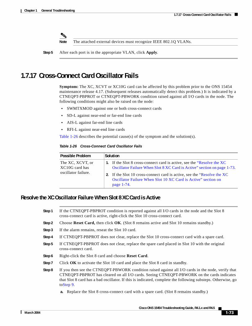
Chapter 1 General Troubleshooting1.7.17 Cross-Connect Card Oscillator Fails
Note The attached external devices must recognize IEEE 802.1Q VLANs.
Step 5 After each port is in the appropriate VLAN, click Apply.
1.7.17 Cross-Connect Card Oscillator FailsSymptom: The XC, XCVT or XC10G card can be affected by this problem prior to the ONS 15454 maintenance release 4.17. (Subsequent releases automatically detect this problem.) It is indicated by a CTNEQPT-PBPROT or CTNEQPT-PBWORK condition raised against all I/O cards in the node. The following conditions might also be raised on the node:
• SWMTXMOD against one or both cross-connect cards
• SD-L against near-end or far-end line cards
• AIS-L against far-end line cards
• RFI-L against near-end line cards
Table 1-26 describes the potential cause(s) of the symptom and the solution(s).
Resolve the XC Oscillator Failure When Slot 8 XC Card is Active
Step 1 If the CTNEQPT-PBPROT condition is reported against all I/O cards in the node and the Slot 8 cross-connect card is active, right-click the Slot 10 cross-connect card.
Step 2 Choose Reset Card, then click OK. (Slot 8 remains active and Slot 10 remains standby.)
Step 3 If the alarm remains, reseat the Slot 10 card.
Step 4 If CTNEQPT-PBPROT does not clear, replace the Slot 10 cross-connect card with a spare card.
Step 5 If CTNEQPT-PBPROT does not clear, replace the spare card placed in Slot 10 with the original cross-connect card.
Step 6 Right-click the Slot 8 card and choose Reset Card.
Step 7 Click OK to activate the Slot 10 card and place the Slot 8 card in standby.
Step 8 If you then see the CTNEQPT-PBWORK condition raised against all I/O cards in the node, verify that CTNEQPT-PBPROT has cleared on all I/O cards. Seeing CTNEQPT-PBWORK on the cards indicates that Slot 8 card has a bad oscillator. If this is indicated, complete the following substeps. Otherwise, go toStep 9.
a. Replace the Slot 8 cross-connect card with a spare card. (Slot 8 remains standby.)
Table 1-26 Cross-Connect Card Oscillator Fails
Possible Problem Solution
The XC, XCVT, or XC10G card has oscillator failure.
1. If the Slot 8 cross-connect card is active, see the “Resolve the XC Oscillator Failure When Slot 8 XC Card is Active” section on page 1-73.
2. If the Slot 10 cross-connect card is active, see the “Resolve the XC Oscillator Failure When Slot 10 XC Card is Active” section on page 1-74.
1-73Cisco ONS 15454 Troubleshooting Guide, R4.1.x and R4.5
March 2004

Chapter 1 General Troubleshooting1.8 Circuits and Timing
b. Reseat the Slot 10 cross-connect card to activate the Slot 8 card and make Slot 10 standby.
c. Verify that the CTNEQPT-PBWORK condition has cleared on all I/O cards.
Step 9 If you see CTNEQPT-PBPROT reported against all I/O cards in the node, this indicates that the Slot 10 card has a bad oscillator. If so, complete the following steps:
a. Replace the Slot 10 cross-connect card with a spare card. (The Slot 8 card is now active.)
b. Reseat the Slot 8 cross-connect card to make Slot 10 active.
c. Verify that the CTNEQPT-PBPROT condition has cleared on all I/O cards.
Resolve the XC Oscillator Failure When Slot 10 XC Card is Active
Step 1 If the CTNEQPT-PBWORK condition is reported against all I/O cards in the node and the Slot 10 card is active, right-click the Slot 8 cross-connect card.
Step 2 Choose Reset Card and click OK. (Slot 10 remains active and Slot 8 remains standby.)
Step 3 If the CTNEQPT-PBWORK condition does not clear, reseat the Slot 8 cross-connect card.
Step 4 If the condition does not clear, replace the Slot 8 cross-connect card with an identical, spare card.
Step 5 If the condition does not clear, replace the spare card placed in Slot 8 with the original cross-connect card.
Step 6 Right-click the Slot 10 cross-connect card.
Step 7 Choose Reset Card and click OK. The Slot 8 cross-connect card becomes active and Slot 10 becomes standby.
Step 8 If you have switched the Slot 8 card to active and continue to see CTNEQPT-PBWORK reported against all I/O cards in the node, this indicates the Slot 8 card has a bad oscillator. If this is indicated, complete the following substeps. If not, go to Step 9.
a. Replace the Slot 8 cross-connect card with a spare card. (The Slot 10 card is made active.)
b. Reseat the Slot 10 cross-connect card to make Slot 8 active.
c. Verify that the CTNEQPT-PBWORK condition has cleared on all I/O cards.
Step 9 If you then see the CTNEQPT-PBPROT condition raised against all I/O cards, verify that CTNEQPT-PBWORK has cleared on the I/O cards. This indicates that Slot 10 has a bad oscillator. If so, complete the following substeps:
a. Replace the Slot 10 cross-connect card with a spare card. (Slot 10 remains standby.)
b. Reseat the Slot 8 cross-connect card to activate the Slot 10 card and make Slot 8 standby.
c. Verify that the CTNEQPT-PBPROT condition has cleared on all I/O cards.
1.8 Circuits and TimingThis section provides solutions to circuit creation and reporting errors, as well as common timing reference errors and alarms.
1-74Cisco ONS 15454 Troubleshooting Guide, R4.1.x and R4.5
March 2004

Chapter 1 General Troubleshooting1.8.1 OC-N Circuit Transitions to Partial State
1.8.1 OC-N Circuit Transitions to Partial State
Symptom An automatic or manual transition of a circuit from one state to another state results in one of the following partial state conditions:
• OOS_PARTIAL: At least one of the OC-N connections in the circuit is in OOS state and at least one other connection in the circuit is in IS, OOS_MT, or OOS_AINS state.
• OOS_MT_PARTIAL: At least one connection in the OC-N circuit is in OOS_MT state and at least one other connection in the circuit is in IS, OOS_MT, or OOS_AINS state.
• OOS_AINS_PARTIAL: At least one connection in the OC-N circuit is in the OOS_AINS state and at least one other connection in the circuit is in IS or OOS_AINS state.
Table 1-27 describes the possible problems and the solutions.
View the State of OC-N Circuit Nodes
Note This procedure does not apply to DWDM (Software R4.5).
Step 1 Click the Circuits tab.
Step 2 From the Circuits tab list, select the circuit with the *_PARTIAL status condition.
Step 3 Click Edit. The Edit Circuit window appears.
Table 1-27 Circuit in Partial State
Possible Problem Solution
During a manual transition, CTC cannot communicate with one of the nodes or one of the nodes is on a version of software that does not support the new state model.
Repeat the manual transition operation. If the partial state persists, determine which node in the circuit is not changing to the desired state. Complete the “View the State of OC-N Circuit Nodes” procedure on page 1-75.
Log onto the circuit node that did not change to the desired state and determine the version of software. If the software on the node is Software R3.3 or earlier, upgrade the software. Refer to the Cisco ONS 15454 Software Upgrade Guide for software upgrade procedures.
Note If the node software cannot be upgraded to R4.0, the partial state condition can be avoided by only using the circuit state supported in the earlier software version.
During an automatic transition, some path-level defects and/or alarms were detected on the circuit.
Determine which node in the circuit is not changing to the desired state. Complete the “View the State of OC-N Circuit Nodes” procedure on page 1-75.
Log onto the circuit node that did not change to the desired state and examine the circuit for path-level defects, improper circuit termination, or alarms. Refer to the Cisco ONS 15454 Procedure Guide for procedures to clear alarms and change circuit configuration settings.
Resolve and clear the defects and/or alarms on the circuit node and verify that the circuit transitions to the desired state.
One end of the circuit is not properly terminated.
1-75Cisco ONS 15454 Troubleshooting Guide, R4.1.x and R4.5
March 2004

Chapter 1 General Troubleshooting1.8.2 AIS-V on DS3XM-6 Unused VT Circuits
Step 4 In the Edit Circuit window, click the State tab (if you are viewing a SONET circuit).
The State tab window lists the Node, CRS End A, CRS End B, and CRS State for each of the nodes in the circuit.
1.8.2 AIS-V on DS3XM-6 Unused VT Circuits
Symptom An incomplete circuit path causes an alarm indications signal (AIS).
Table 1-28 describes the possible problem and the solution.
Clear AIS-V on DS3XM-6 Unused VT Circuits
Note This procedure does not apply to DWDM (Software R4.5).
Step 1 Determine the affected port.
Step 2 Record the node ID, slot number, port number, or VT number.
Step 3 Create a unidirectional VT circuit from the affected port back to itself, such as Source node/Slot 2/Port 2/VT 13 cross connected to Source node/Slot 2/Port 2/VT 13.
Step 4 Uncheck the bidirectional check box in the circuit creation window.
Step 5 Give the unidirectional VT circuit an easily recognizable name, such as “delete me.“
Step 6 Display the DS3XM-6 card in CTC card view. Click the Maintenance > DS1 tabs.
Step 7 Locate the VT that is reporting the alarm (for example, DS3 #2, DS1 #13).
Step 8 From the Loopback Type list, choose Facility (Line) and click Apply.
Step 9 Click Circuits.
Step 10 Find the one-way circuit you created in Step 3. Select the circuit and click Delete.
Step 11 Click Yes in the Delete Confirmation dialog box.
Step 12 Display the DS3XM-6 card in CTC card view. Click Maintenance > DS1.
Step 13 Locate the VT in Facility (line) Loopback.
Step 14 From the Loopback Type list, choose None and then click Apply.
Step 15 Click the Alarms tab and verify that the AIS-V alarms have cleared.
Table 1-28 Calculate and Design IP Subnets
Possible Problem Solution
The port on the reporting node is in-service but a node upstream on the circuit does not have an OC-N port in service.
An AIS-V indicates that an upstream failure occurred at the virtual tributary (VT) layer. AIS-V alarms also occur on DS3XM-6 VT circuits that are not carrying traffic and on stranded bandwidth.
Complete the “Clear AIS-V on DS3XM-6 Unused VT Circuits” procedure on page 1-76.
1-76Cisco ONS 15454 Troubleshooting Guide, R4.1.x and R4.5
March 2004

Chapter 1 General Troubleshooting1.8.3 Circuit Creation Error with VT1.5 Circuit
Step 16 Repeat this procedure for all the AIS-V alarms on the DS3XM-6 cards.
1.8.3 Circuit Creation Error with VT1.5 Circuit
Symptom You might receive an “Error while finishing circuit creation. Unable to provision circuit. Unable to create connection object at node_name” message when trying to create a VT1.5 circuit in CTC.
Table 1-29 describes the possible problem and the solution.
1.8.4 Unable to Create Circuit From DS-3 Card to DS3XM-6 Card
Symptom You cannot create a circuit from a DS-3 card to a DS3XM-6 card.
Table 1-30 describes the possible problem and the solution.
Table 1-29 Circuit Creation Error with VT1.5 Circuit
Possible Problem Solution
You might have run out of bandwidth on the VT cross-connect matrix at the ONS 15454 indicated in the error message.
The matrix has a maximum capacity of 336 bidirectional VT1.5 cross-connects. Certain configurations exhaust VT capacity with less than 336 bidirectional VT1.5s in a BLSR or less than 224 bidirectional VT1.5s in a path protection or 1+1 protection group. Refer to the Cisco ONS 15454 Reference Manual for more information.
Table 1-30 Unable to Create Circuit from DS-3 Card to DS3XM-6 Card
Possible Problem Solution
A DS-3 card and a DS3XM-6 card have different functions.
A DS3XM-6 card converts each of its six DS-3 interfaces into 28 DS-1s for cross-connection through the network. Thus you can create a circuit from a DS3XM-6 card to a DS-1 card, but not from a DS3XM-6 card to a DS-3 card. These differences are evident in the STS path overhead. The DS-3 card uses asynchronous mapping for DS-3, which is indicated by the C2 byte in the STS path overhead that has a hex code of 04. A DS3XM-6 has a VT payload with a C2 hex value of 02.
Note You can find instructions for creating circuits in the Cisco ONS 15454 Procedure Guide.
1-77Cisco ONS 15454 Troubleshooting Guide, R4.1.x and R4.5
March 2004

Chapter 1 General Troubleshooting1.8.5 DS-3 Card Does Not Report AIS-P From External Equipment
1.8.5 DS-3 Card Does Not Report AIS-P From External Equipment
Symptom A DS3-12, DS3N-12, DS3-12E or DS3N-12E card does not report STS AIS-P from the external equipment/line side.
Table 1-31 on page 1-78 describes the possible problem and the solution.
1.8.6 OC-3 and DCC Limitations
Symptom Limitations to OC-3 and DCC usage.
Table 1-32 describes the possible problem and the solution.
1.8.7 ONS 15454 Switches Timing Reference
Symptom Timing references switch when one or more problems occur.
Table 1-33 describes the possible problems and the solution.
Table 1-31 DS3 Card Does Not Report AIS-P From External Equipment
Possible Problem Solution
The card is functioning as designed.
This card terminates the port signal at the backplane so STS AIS-P is not reported from the external equipment/line side.
DS3-12, DS3N-12,DS3-12E and DS3N-12E cards have DS3 header monitoring functionality, which allows you to view performance monitoring (PM) on the DS3 path. Nevertheless, you cannot view AIS-P on the STS path. For more information on the PM capabilities of the DS3-12,DS3N-12, DS3-12E or DS3N-12E cards, refer to the Cisco ONS 15454 Procedure Guide.
Table 1-32 OC-3 and DCC Limitations
Possible Problem Solution
OC-3 and DCC have limitations for the ONS 15454.
For an explanation of OC-3 and DCC limitations, refer to the DCC Tunnels section of the Cisco ONS 15454 Procedure Guide.
1-78Cisco ONS 15454 Troubleshooting Guide, R4.1.x and R4.5
March 2004

Chapter 1 General Troubleshooting1.8.8 Holdover Synchronization Alarm
1.8.8 Holdover Synchronization Alarm
Symptom The clock is running at a different frequency than normal and the HLDOVRSYNC alarm appears.
Table 1-34 describes the possible problem and the solution.
1.8.9 Free-Running Synchronization Mode
Symptom The clock is running at a different frequency than normal and the FRNGSYNC alarm appears.
Table 1-35 describes the possible problem and the solution.
Table 1-33 ONS 15454 Switches Timing Reference
Possible Problem Solution
The optical or BITS input is receiving loss of signal (LOS), loss of frame (LOF), or alarm indication signal (AIS) alarms from its timing source.
The ONS 15454 internal clock operates at a Stratum 3E level of accuracy. This gives the ONS 15454 a free-running synchronization accuracy of ± 4.6 ppm and a holdover stability of less than 255 slips in the first 24 hours or 3.7 x 10⁻⁷/day, including temperature.
ONS 15454 free-running synchronization relies on the Stratum 3 internal clock. Over an extended time period, using a higher quality Stratum 1 or Stratum 2 timing source results in fewer timing slips than a lower quality Stratum 3 timing source.
The optical or BITS input is not functioning.
The Synchronization Status Messaging (SSM) message is set to Do Not Use for Synchronization (DUS).
SSM indicates a Stratum 3 or lower clock quality.
The input frequency is off by more than 15 ppm.
The input clock wanders and has more than three slips in 30 seconds.
A bad timing reference existed for at least two minutes.
Table 1-34 Holdover Synchronization Alarm
Possible Problem Solution
The last reference input has failed.
The clock is running at the frequency of the last known-good reference input. This alarm is raised when the last reference input fails. See the “2.7.119 HLDOVRSYNC” section on page 2-98 for a detailed description of this alarm.
Note The ONS 15454 supports holdover timing per Telcordia GR-436 when provisioned for external (BITS) timing.
Table 1-35 Free-Running Synchronization Mode
Possible Problem Solution
No reliable reference input is available.
The clock is using the internal oscillator as its only frequency reference. This occurs when no reliable, prior timing reference is available. See the “FRNGSYNC” condition on page 2-92 for a detailed description.
1-79Cisco ONS 15454 Troubleshooting Guide, R4.1.x and R4.5
March 2004

Chapter 1 General Troubleshooting1.8.10 Daisy-Chained BITS Not Functioning
1.8.10 Daisy-Chained BITS Not Functioning
Symptom You are unable to daisy chain the BITS sources.
Table 1-36 describes the possible problem and the solution.
1.8.11 Blinking STAT LED after Installing a Card
Symptom After installing a card, the STAT LED blinks continuously for more than 60 seconds.
Table 1-37 describes the possible problem and the solution.
1.9 Fiber and CablingThis section explains problems typically caused by cabling connectivity errors. It also includes instructions for crimping CAT-5 cable and lists the optical fiber connectivity levels.
Table 1-36 Daisy-Chained BITS Sources Not Functioning
Possible Problem Solution
Daisy-chained BITS sources are not supported on the ONS 15454.
Daisy-chained BITS sources cause additional wander buildup in the network and is therefore not supported. Instead, use a timing signal generator to create multiple copies of the BITS clock and separately link them to each ONS 15454.
Table 1-37 Blinking STAT LED on Installed Card
Possible Problem Solution
The card cannot boot because it failed the Power On Shelf Test (POST) diagnostics.
The blinking STAT LED indicates that POST diagnostics are being performed. If the LED continues to blink more than 60 seconds, the card has failed the POST diagnostics test and has failed to boot.
If the card has truly failed, an EQPT alarm is raised against the slot number with an “Equipment Failure” description. Check the alarm tab for this alarm to appear for the slot where the card was installed.
To attempt recovery, remove and reinstall the card and observe the card boot process. If the card fails to boot, replace the card.
Caution Removing a card that currently caries traffic on one or more ports can cause a traffic hit. To avoid this, perform an external switch if a switch has not already occurred. Consult the Cisco ONS 15454 Procedure Guide for information.
1-80Cisco ONS 15454 Troubleshooting Guide, R4.1.x and R4.5
March 2004

Chapter 1 General Troubleshooting1.9.1 Bit Errors Appear for a Traffic Card
1.9.1 Bit Errors Appear for a Traffic Card
Symptom A traffic card has multiple bit errors.
Table 1-38 describes the possible problem and the solution.
1.9.2 Faulty Fiber-Optic Connections
Symptom A line card has multiple SONET/DWDM alarms and/or signal errors.
Table 1-39 describes the possible problems and the solutions.
Warning Follow all directions and warning labels when working with optical fibers. To prevent eye damage, never look directly into a fiber or connector. Class IIIb laser. Danger, laser radiation when open. The OC-192 laser is off when the safety key is off (labeled 0). The laser is on when the card is booted and the safety key is in the on position (labeled 1). The port does not have to be in service for the laser to be on. Avoid direct exposure to the beam. Invisible radiation is emitted from the aperture at the end of the fiber optic cable when connected, but not terminated.
Table 1-38 Bit Errors Appear for a Line Card
Possible Problem Solution
Faulty cabling or low optical-line levels.
Bit errors on line (traffic) cards usually originate from cabling problems or low optical-line levels. The errors can be caused by synchronization problems, especially if PJ (pointer justification) errors are reported. Moving cards into different error-free slots will isolate the cause. Use a test set whenever possible because the cause of the errors could be external cabling, fiber, or external equipment connecting to the ONS 15454. Troubleshoot cabling problems using the “1.1 Network Troubleshooting Tests” section on page 1-2. Troubleshoot low optical levels using the “1.9.2 Faulty Fiber-Optic Connections” section on page 1-81.
Table 1-39 Faulty Fiber-Optic Connections
Possible Problem Solution
Faulty fiber-optic connections.
Faulty fiber-optic connections can be the source of SONET/DWDM alarms and signal errors. Complete the “Verify Fiber-Optic Connections” procedure on page 1-82.
Faulty CAT-5 cables. Faulty CAT-5 cables can be the source of SONET/DWDM alarms and signal errors. Complete the “1.9.2.1 Crimp Replacement LAN Cables” section on page 1-83.
Faulty gigabit interface connectors (GBIC).
Faulty gigabit interface connectors can be the source of SONET/DWDM alarms and signal errors. See the “1.9.2.2 Replace Faulty GBIC or SFP Connectors” section on page 1-85.
1-81Cisco ONS 15454 Troubleshooting Guide, R4.1.x and R4.5
March 2004

Chapter 1 General Troubleshooting1.9.2 Faulty Fiber-Optic Connections
Verify Fiber-Optic Connections
Step 1 Ensure that a single-mode fiber connects to the ONS 15454 OC-N card.
SM or SM Fiber should be printed on the fiber span cable. ONS 15454 OC-N cards do not use multimode fiber.
Step 2 Ensure that the connector keys on the SC fiber connector are properly aligned and locked.
Step 3 Check that the single-mode fiber power level is within the specified range:
a. Remove the Rx end of the suspect fiber.
b. Connect the receive end of the suspect fiber to a fiber-optic power meter, such as a GN Nettest LP-5000.
c. Determine the power level of fiber with the fiber-optic power meter.
d. Verify the power meter is set to the appropriate wavelength for the OC-N card being tested (either 1310 nm or 1550 nm depending on the specific card).
e. Verify that the power level falls within the range specified for the card if it is an OC-N card; see the “1.9.3 OC-N Card Transmit and Receive Levels” section on page 1-89.
Step 4 If the power level falls below the specified range for the OC-N card:
a. Clean or replace the fiber patch cords. Clean the fiber according to site practice or, if none exists, follow the procedure in the Cisco ONS 15454 Procedure Guide. If possible, do this for the OC-N card you are working on and the far-end card.
b. Clean the optical connectors on the card. Clean the connectors according to site practice or, if none exists, follow the procedure in the Cisco ONS 15454 Procedure Guide. If possible, do this for the OC-N card you are working on and the far-end card.
c. Ensure that the far-end transmitting card is not an ONS IR card when an ONS LR card is appropriate.
IR cards transmit a lower output power than LR cards.
d. Replace the far-end transmitting OC-N card to eliminate the possibility of a degrading transmitter on this OC-N card.
Caution Removing a card that currently caries traffic on one or more ports can cause a traffic hit. To avoid this, perform an external switch if a switch has not already occurred. Consult the Cisco ONS 15454 Procedure Guide for information.
e. If the power level still falls below the specified range with the replacement fibers and replacement card, check for one of these three factors that attenuate the power level and affect link loss (LL):
• Excessive fiber distance; single-mode fiber attenuates at approximately 0.5 dB/km.
• Excessive number or fiber connectors; connectors take approximately 0.5 dB each.
• Excessive number of fiber splices; splices take approximately 0.5 dB each.
Note These are typical attenuation values. Refer to the specific product documentation for the actual values or use an optical time domain reflectometer (OTDR) to establish precise link loss and budget requirements.
1-82Cisco ONS 15454 Troubleshooting Guide, R4.1.x and R4.5
March 2004

Chapter 1 General Troubleshooting1.9.2 Faulty Fiber-Optic Connections
Step 5 If no power level shows on the fiber, the fiber is bad or the transmitter on the OC-N card failed.
a. Check that the Tx and Rx fibers are not reversed. LOS and EOC alarms normally accompany reversed Tx and Rx fibers. Switching reversed Tx and Rx fibers clears the alarms and restores the signal.
b. Clean or replace the fiber patch cords. Clean the fiber according to site practice or, if none exists, follow the procedure in the Cisco ONS 15454 Procedure Guide. If possible, do this for the OC-N card you are working on and the far-end card.
c. Retest the fiber power level.
d. If the replacement fiber still shows no power, replace the OC-N card.
Caution Removing a card that currently caries traffic on one or more ports can cause a traffic hit. To avoid this, perform an external switch if a switch has not already occurred. Consult the Cisco ONS 15454 Procedure Guide for information.
Step 6 If the power level on the fiber is above the range specified for the card, ensure that an ONS long-range (LR) card is not being used when an ONS intermediate-range (IR) card is appropriate.
LR cards transmit a higher output power than IR cards. When used with short runs of fiber, an LR transmitter will be too powerful for the receiver on the receiving OC-N card.
Receiver overloads occur when maximum receiver power is exceeded.
Tip To prevent overloading the receiver, use an attenuator on the fiber between the ONS OC-N card transmitter and the receiver. Place the attenuator on the receive transmitter of the ONS OC-N cards. Refer to the attenuator documentation for specific instructions.
Tip Most fiber has text printed on only one of the two fiber strands. Use this to identify which fiber is connected to Tx and which fiber is connected to Rx.
1.9.2.1 Crimp Replacement LAN Cables
You can crimp your own LAN cables for use with the ONS 15454. Use a cross-over cable when connecting an ONS 15454 to a hub, LAN modem, or switch, and use a LAN cable when connecting an ONS 15454 to a router or workstation. Use CAT-5 cable RJ-45 T-568B, Color Code (100 Mbps), and a crimping tool. Figure 1-29 shows the layout of an RJ-45 connector.
1-83Cisco ONS 15454 Troubleshooting Guide, R4.1.x and R4.5
March 2004

Chapter 1 General Troubleshooting1.9.2 Faulty Fiber-Optic Connections
Figure 1-29 RJ-45 Pin Numbers
Figure 1-30 shows a LAN cable layout.
Figure 1-30 LAN Cable Layout
Table 1-40 shows the LAN cable pinouts.
Figure 1-31 shows a cross-over cable layout.
5504
8
8 7 6 5 4 3 2 1 1 2 3 4 5 6 7 8
End view of RJ-45 plug Looking into an RJ-45 jack
1234
56
78
1234
56
78
5541
5
Table 1-40 LAN Cable Pinout
Pin Color Pair Name Pin
1 white/orange 2 Transmit Data + 1
2 orange 2 Transmit Data – 2
3 white/green 3 Receive Data + 3
4 blue 1 — 4
5 white/blue 1 — 5
6 green 3 Receive Data – 6
7 white/brown 4 — 7
8 brown 4 — 8
1-84Cisco ONS 15454 Troubleshooting Guide, R4.1.x and R4.5
March 2004

Chapter 1 General Troubleshooting1.9.2 Faulty Fiber-Optic Connections
Figure 1-31 Cross-Over Cable Layout
Table 1-41 shows the cross-over cable pinouts.
Note Odd-numbered pins always connect to a white wire with a colored stripe.
1.9.2.2 Replace Faulty GBIC or SFP Connectors
GBICs and small form-factor pluggables (SFP) are hot-swappable and can be installed or removed while the card or shelf assembly is powered and running.
Warning GBICs are Class I laser products. These products have been tested and comply with Class I limits.
Warning Invisible laser radiation may be emitted from the aperture ports of the single-mode fiber optic modules when no cable is connected. Avoid exposure and do not stare into open apertures.
GBICs and SFPs are input/output devices that plug into a Gigabit Ethernet card to link the port with the fiber-optic network. The type of GBIC or SFP determines the maximum distance that the Ethernet traffic can travel from the card to the next network device. For a description of GBICs and SFPs and their capabilities, see Table 1-42 on page 1-86 and Table 1-43 on page 1-86, and refer to the Cisco ONS 15454 Reference Manual.
1
2
3
4
5
6
7
8
1
2
3
4
5
6
7
8
5541
6
Table 1-41 Cross-Over Cable Pinout
Pin Color Pair Name Pin
1 white/orange 2 Transmit Data + 3
2 orange 2 Transmit Data – 6
3 white/green 3 Receive Data + 1
4 blue 1 — 4
5 white/blue 1 — 5
6 green 3 Receive Data – 2
7 white/brown 4 — 7
8 brown 4 — 8
1-85Cisco ONS 15454 Troubleshooting Guide, R4.1.x and R4.5
March 2004

Chapter 1 General Troubleshooting1.9.2 Faulty Fiber-Optic Connections
Note GBICs and SFPs must be matched on either end by type: SX to SX, LX to LX, or ZX to ZX.
Note DWDM and CWDM GBICs do not function with Software R4.5.
GBICs are available in two different models. One GBIC model has two clips (one on each side of the GBIC) that secure the GBIC in the slot on the E1000-2-G, G-Series, or G1K-4 card. The other model has a locking handle. Both models are shown in Figure 1-32.
Figure 1-32 GBICs
Table 1-42 shows the available GBICs.
Note The GBICs are very similar in appearance. Check the GBIC label carefully before installing it.
Table 1-43 shows the available SFPs.
ReceiverClip
HandleTransmitter Receiver
Transmitter 5117
8
Table 1-42 Available GBICs
GBICAssociated Cards Application Fiber Product Number
1000BaseSX E1000-2-GG-SeriesG1K-4
Short reach Multimode fiber up to 550 m long
15454E-GBIC-SX=
1000BaseLX E1000-2-GG-SeriesG1K-4
Long reach Single-mode fiber up to 10 km long
15454E-GBIC-LX=
1000BaseZX G-SeriesG1K-4
Extra long reach
Single-mode fiber up to 70 km long
15454E-GBIC-ZX=
Table 1-43 Available SFPs
SFPAssociated Cards Application Fiber Product Number
1000BaseSX ML1000-2 Short reach Multimode fiber up to 550 m long 15454E-SFP-LC-SX=
1000BaseLX ML1000-2 Long reach Single-mode fiber up to 10 km long
15454E-SFP-LC-LX=
1-86Cisco ONS 15454 Troubleshooting Guide, R4.1.x and R4.5
March 2004

Chapter 1 General Troubleshooting1.9.2 Faulty Fiber-Optic Connections
Remove GBIC or SFP Connectors
Step 1 Disconnect the network fiber cable from the GBIC SC connector or SFP LC duplex connector.
Warning Invisible laser radiation may be emitted from disconnected fibers or connectors. Do not stare into beams or view directly with optical instruments.
Step 2 Release the GBIC or SFP from the slot by simultaneously squeezing the two plastic tabs on each side.
Step 3 Slide the GBIC or SFP out of the Gigabit Ethernet module slot. A flap closes over the GBIC or SFP slot to protect the connector on the Gigabit Ethernet card.
Installing a GBIC with Clips
Step 1 Remove the GBIC from its protective packaging.
Step 2 Check the label to verify that the GBIC is the correct type (SX, LX, or ZX) for your network.
Step 3 Verify that you are installing compatible GBICs; for example, SX to SX, LX to LX, or ZX to ZX.
Step 4 Grip the sides of the GBIC with your thumb and forefinger and insert the GBIC into the slot on the E1000-2, E1000-2-G, or G-Series card (Figure 1-33).
Note GBICs are keyed to prevent incorrect installation.
1-87Cisco ONS 15454 Troubleshooting Guide, R4.1.x and R4.5
March 2004

Chapter 1 General Troubleshooting1.9.2 Faulty Fiber-Optic Connections
Figure 1-33 GBIC Installation (with Clips)
Step 5 Slide the GBIC through the flap that covers the opening until you hear a click. The click indicates the GBIC is locked into the slot.
Step 6 When you are ready to attach the network fiber-optic cable, remove the protective plug from the GBIC and save the plug for future use.
Step 7 Return to your originating procedure (NTP).
Installing a GBIC with a Handle
Step 1 Remove the GBIC from its protective packaging.
Step 2 Check the label to verify that the GBIC is the correct type (SX, LX, or ZX) for your network.
Step 3 Verify that you are installing compatible GBICs; for example, SX to SX, LX to LX, or ZX to ZX.
Step 4 Remove the protective plug from the SC-type connector.
Step 5 Grip the sides of the GBIC with your thumb and forefinger and insert the GBIC into the slot on the E1000-2, E1000-2-G, G1K-4, or G-Series card.
E10002
FAIL
ACT
1
SF
33678 12931
2
RX
TX
RX
TX
ACT/LINK
ACT/LINK
4473
4
Plug
1-88Cisco ONS 15454 Troubleshooting Guide, R4.1.x and R4.5
March 2004

Chapter 1 General Troubleshooting1.9.3 OC-N Card Transmit and Receive Levels
Note GBICs are keyed to prevent incorrect installation.
Step 6 Lock the GBIC into place by closing the handle down. The handle is in the correct closed position when it does not obstruct access to SC-type connector.
Step 7 Return to your originating procedure (NTP).
1.9.3 OC-N Card Transmit and Receive LevelsEach OC-N card has a transmit and receive connector on its faceplate. Table 1-44 lists these levels.
1.10 Power and LED TestsThis section provides symptoms and solutions for power supply, power consumption, and LED indicator problems.
Table 1-44 OC-N Card Transmit and Receive Levels
OC-N Card Receive Transmit
OC3 IR 4/STM1SH 1310 –28 to –8 dBm –15 to –8 dBm
OC3 IR/STM 1SH 1310-8 –30 to –8 dBm –15 to –8 dBm
OC12 IR/STM4 SH 1310 –28 to –8 dBm –15 to –8 dBm
OC12 LR/STM4 LH 1310 –28 to –8 dBm –3 to +2 dBm
OC12 LR/STM4 LH 1550 –28 to –8 dBm –3 to +2 dBm
OC12 IR/STM4 SH 1310-4 –28 to –8 dBm –3 to +2 dBm
OC48 IR/STM16 SH AS 1310 –18 to 0 dBm –5 to 0 dBm
OC48 LR/STM16 LH AS 1550 –28 to –8 dBm –2 to +3 dBm
OC48 ELR/STM16 EH 100GHz –28 to –8 dBm –2 to 0 dBm
OC192 SR/STM64 IO 1310 –11 to –1 dBm –6 to –1 dBm
OC192 IR STM64 SH 1550 –14 to –1 dBm –1 to +2 dBm
OC192 LR/STM64 LH 1550 –21 to –9 dBm +7 to +10 dBm
OC192 LR/STM64 LH ITU 15xx.xx –22 to –9 dBm +3 to +6 dBm
TXP-MR-10G
Trunk side:Client side:
–26 to –8 dBm–14 to –1 dBm
–16 to +3 dBm–6 to –1 dBm
MXP-2.5G-10G
Trunk side:Client side:
–26 to –8 dBmdepends on SFP
–16 to +3 dBmdepends on SFP
1-89Cisco ONS 15454 Troubleshooting Guide, R4.1.x and R4.5
March 2004

Chapter 1 General Troubleshooting1.10.1 Power Supply Problems
1.10.1 Power Supply Problems
Symptom Loss of power or low voltage, resulting in a loss of traffic and causing the LCD clock to reset to the default date and time.
Table 1-45 describes the possible problems and the solution.
Warning When working with live power, always use proper tools and eye protection.
Warning Always use the supplied electrostatic discharge (ESD) wristband when working with a powered ONS 15454. Plug the wristband cable into the ESD jack located on the lower-right outside edge of the shelf assembly.
Caution Operations that interrupt power supply or short the power connections to the ONS 15454 are service-affecting.
Isolate the Cause of Power Supply Problems
Step 1 If a single ONS 15454 show signs of fluctuating power or power loss:
a. Verify that the –48 VDC #8 power terminals are properly connected to a fuse panel. These power terminals are located on the lower section of the backplane EIA under the clear plastic cover.
b. Verify that the power cable is #12 or #14 AWG and in good condition.
c. Verify that the power cable connections are properly crimped. Stranded #12 or #14 AWG does not always crimp properly with Staycon type connectors.
d. Verify that 20-A fuses are used in the fuse panel.
e. Verify that the fuses are not blown.
Table 1-45 Power Supply Problems
Possible Problem Solution
Loss of power or low voltage.
The ONS 15454 requires a constant source of DC power to properly function. Input power is –48 VDC. Power requirements range from –42 VDC to –57 VDC.
A newly installed ONS 15454 that is not properly connected to its power supply does not operate. Power problems can be confined to a specific ONS 15454 or affect several pieces of equipment on the site.
A loss of power or low voltage can result in a loss of traffic and causes the LCD clock on the ONS 15454 to default to January 1, 1970, 00:04:15. To reset the clock, in node view click the Provisioning > General tabs and change the Date and Time fields.
Complete the “Isolate the Cause of Power Supply Problems” procedure on page 1-90.
Improperly connected power supply.
1-90Cisco ONS 15454 Troubleshooting Guide, R4.1.x and R4.5
March 2004

Chapter 1 General Troubleshooting1.10.2 Power Consumption for Node and Cards
f. Verify that a rack-ground cable attaches to the frame-ground terminal (FGND) on the right side of the ONS 15454 EIA. Connect this cable to the ground terminal according to local site practice.
g. Verify that the DC power source has enough capacity to carry the power load.
h. If the DC power source is battery-based:
• Check that the output power is high enough. Power requirements range from –42 VDC to –57 VDC.
• Check the age of the batteries. Battery performance decreases with age.
• Check for opens and shorts in batteries, which might affect power output.
• If brownouts occur, the power load and fuses might be too high for the battery plant.
Step 2 If multiple pieces of site equipment show signs of fluctuating power or power loss:
a. Check the uninterruptible power supply (UPS) or rectifiers that supply the equipment. Refer to the UPS manufacturer’s documentation for specific instructions.
b. Check for excessive power drains caused by other equipment, such as generators.
c. Check for excessive power demand on backup power systems or batteries when alternate power sources are used.
1.10.2 Power Consumption for Node and Cards
Symptom You are unable to power up a node or the cards in a node.
Table 1-46 describes the possible problem and the solution.
1.10.3 Lamp Test for Card LEDs
Symptom Card LED does not light or you are unsure if LEDs are working properly.
Table 1-47 describes the possible problem and the solution.
Table 1-46 Power Consumption for Node and Cards
Possible Problem Solution
Improper power supply. Refer to power information in the Cisco ONS 15454 Reference Manual.
Table 1-47 Lamp Test for Card LEDs
Possible Problem Solution
Faulty LED A lamp test verifies that all the card LEDs work. Run this diagnostic test as part of the initial ONS 15454 turn-up, a periodic maintenance routine, or any time you question whether an LED is in working order.
Complete the “Verify Card LED Operation” procedure on page 1-92.
1-91Cisco ONS 15454 Troubleshooting Guide, R4.1.x and R4.5
March 2004

Chapter 1 General Troubleshooting1.10.3 Lamp Test for Card LEDs
Verify Card LED Operation
Step 1 In CTC, click the Maintenance > Diagnostic tabs.
Step 2 Click Lamp Test.
Step 3 Watch to make sure all the LEDs on the cards illuminate for several seconds.
Step 4 Click OK on the Lamp Test Run dialog box.
If an LED does not light up, the LED is faulty. Call the Cisco TAC and fill out an RMA to return the card.
1-92Cisco ONS 15454 Troubleshooting Guide, R4.1.x and R4.5
March 2004
Cisco ONS 15454July 2005
C H A P T E R 2
Alarm TroubleshootingNote The terms "Unidirectional Path Switched Ring" and "UPSR" may appear in Cisco literature. These terms do not refer to using Cisco ONS 15xxx products in a unidirectional path switched ring configuration. Rather, these terms, as well as "Path Protected Mesh Network" and "PPMN," refer generally to Cisco's path protection feature, which may be used in any topological network configuration. Cisco does not recommend using its path protection feature in any particular topological network configuration.
This chapter gives a description, severity, and troubleshooting procedure for each commonly encountered Cisco ONS 15454 alarm and condition. Tables 2-1 through 2-4 provide lists of ONS 15454 alarms organized by severity. Table 2-5 on page 2-5 provides a list of alarm organized alphabetically. Table 2-7 on page 2-10 provides a list of alarms organized by alarm type. For a comprehensive list of all conditions, refer to the Cisco ONS 15454 and Cisco ONS 15327 TL1 Command Guide.
The troubleshooting procedure for an alarm applies to both the Cisco Transport Controller (CTC) and TL1 version of that alarm. If the troubleshooting procedure does not clear the alarm, log onto http://www.cisco.com/tac for more information or call the Cisco Technical Assistance Center (TAC) to report a service-affecting problem (1-800-553-2447).
For alarm profile information, refer to the Cisco ONS 15454 Procedure Guide.
2.1 Alarm Index by Default SeverityThe following tables group alarms and conditions by the severity displayed in the CTC Alarms window in the severity (SEV) column, which is the same severity used when reported by TL1. All severities listed in this manual are the default profile settings. Alarm severities can be altered from default settings for individual alarms or groups of alarms by creating a non-default alarm profile and applying it on a port, card, or shelf basis. All settings (default or user-defined) that are Critical (CR) or Major (MJ) are demoted to Minor (MN) in Non-Service-Affecting (NSA) situations as defined in Telcordia GR-474.
Note The CTC default alarm profile contains alarms that apply to multiple product platforms. The alarms that apply to this product are listed in the following tables and sections.
2.1.1 Critical Alarms (CR)Table 2-1 lists Critical alarms.
2-1 Troubleshooting Guide, R4.1.x and R4.5

Chapter 2 Alarm Troubleshooting2.1.2 Major Alarms (MJ)
2.1.2 Major Alarms (MJ)Table 2-2 lists Major alarms.
Table 2-1 Critical Alarm Index
AUTOLSROFF, page 2-34 LOF (DWDM Client), page 2-111 MEA (EQPT), page 2-136
BKUPMEMP, page 2-41 LOF (DWDM Trunk), page 2-111 MEA (FAN), page 2-138
CKTDOWN, page 2-49 LOF (EC1-12), page 2-112 MFGMEM (AEP, AIP, BPLANE, FAN and Fan-Tray Assembly), page 2-139
COMIOXC, page 2-52 LOF (OC-N), page 2-112 for DWDM OTUK-LOF, page 2-146
CTNEQPT-PBPROT, page 2-57 LOM, page 2-114 PLM-P, page 2-150
CTNEQPT-PBWORK, page 2-58 LOP-P, page 2-115 PORT-CODE-MISM, page 2-152 (for Release 4.5)
EQPT, page 2-66 LOS (DS-3), page 2-119 PORT-COMM-FAIL, page 2-153 (for Release 4.5)
EQPT-MISS, page 2-67 LOS (DWDM Client or Trunk), page 2-120
PORT-MISMATCH, page 2-153 (for Release 4.5)
FAN, page 2-80 LOS (EC1-12), page 2-120 PORT-MISSING, page 2-153 (for Release 4.5)
HITEMP, page 2-97, NE LOS (OC-N), page 2-124 SWMTXMOD, page 2-176
IMPROPRMVL, page 2-99 LOS (OTN), page 2-125 TIM, page 2-181 for Release 4.5 DWDM
LOC, page 2-107 MEA (AIP), page 2-135 TIM-P, page 2-182, for STSTRM
LOF (DS-3), page 2-110 MEA (BPLANE), page 2-135 UNEQ-P, page 2-186
Table 2-2 Major Alarm Index
APC-DISABLED, page 2-26 DSP-FAIL, page 2-62 PLM-V, page 2-152 (for Release 4.1)
APC-FAIL, page 2-27 EOC, page 2-64 PORT-CODE-MISM, page 2-152 (for Release 4.1)
APSCM, page 2-30 E-W-MISMATCH, page 2-70 PORT-COMM-FAIL, page 2-153 (for Release 4.1)
APSCNMIS, page 2-31 EXTRA-TRAF-PREEMPT, page 2-74 PORT-MISMATCH, page 2-153 (for Release 4.1)
BLSROSYNC, page 2-42 FANDEGRADE, page 2-80 PORT-MISSING, page 2-153 (for Release 4.1)
CARLOSS (DWDM Client), page 2-42 FEC-MISM, page 2-81 PRC-DUPID, page 2-154
CARLOSS (DWDM Trunk), page 2-43 GCC-EOC, page 2-93 RCVR-MISS, page 2-158
CARLOSS (EQPT), page 2-43 HLDOVRSYNC, page 2-98, for Release 4.5
RING-ID-MIS, page 2-161
CARLOSS (E-Series Ethernet), page 2-44 INVMACADR, page 2-102 RING-MISMATCH, page 2-161
CARLOSS (G-Series Ethernet), page 2-46 LOF (BITS), page 2-108 SYSBOOT, page 2-180
2-2Cisco ONS 15454 Troubleshooting Guide, R4.1.x and R4.5
July 2005

Chapter 2 Alarm Troubleshooting2.1.3 Minor Alarms (MN)
2.1.3 Minor Alarms (MN)Table 2-3 lists Minor alarms.
2.1.4 Conditions (NA or NR)Table 2-4 lists Not Alarmed or Not Reported conditions.
CARLOSS (ML-Series Ethernet), page 2-48
LOF (DS-1), page 2-109 TPTFAIL (G-Series Ethernet), page 2-183
CONTBUS-A-18, page 2-53 LOP-V, page 2-115 TPTFAIL (ML-Series Ethernet), page 2-183
CONTBUS-B-18, page 2-54 LOS (BITS), page 2-117 TRMT, page 2-184
CONTBUS-IO-A, page 2-55 LOS (DS-1), page 2-118 TRMT-MISS, page 2-185
CONTBUS-IO-B, page 2-56 MEM-GONE, page 2-139 TUNDERRUN, page 2-185
DBOSYNC, page 2-60 OPTNTWMIS, page 2-144 UNEQ-V, page 2-188
DSP-COMM-FAIL, page 2-62 PEER-NORESPONSE, page 2-149 WVL-MISMATCH, page 2-190
Table 2-2 Major Alarm Index (continued)
Table 2-3 Minor Alarm Index
APSB, page 2-27 FSTSYNC, page 2-93 MEM-LOW, page 2-139
APSCDFLTK, page 2-28 HI-LASERBIAS, page 2-94 NOT-AUTHENTICATED, page 2-141
APSC-IMP, page 2-29 HI-LASERTEMP, page 2-94 PLM-V, page 2-152, for Release 4.5
APSCINCON, page 2-30 HI-RXPOWER, page 2-95 PROTNA, page 2-154
APSMM, page 2-32 HI-RXTEMP, page 2-96 PTIM, page 2-155
AUTORESET, page 2-36 HITEMP, page 2-97, for EQPT PWR-A, page 2-156
AUTOSW-LOP (VTMON), page 2-37 HI-TXPOWER, page 2-97 PWR-B, page 2-156
AUTOSW-UNEQ (VTMON), page 2-39 KBYTE-APS-CHANNEL-FAILURE, page 2-105
PWR-REDUN, page 2-157
COMM-FAIL, page 2-53, for Release 4.5 EQPT
LASEREOL, page 2-106 RSVP-HELLODOWN, page 2-162
DATAFLT, page 2-60 LMP-HELLODOWN, page 2-107 SFTWDOWN, page 2-168
EHIBATVG-A, page 2-62 LMP-NDFAIL, page 2-107 SNTP-HOST, page 2-168
EHIBATVG-B, page 2-63 LO-LASERBIAS, page 2-113 SSM-FAIL, page 2-172
ELWBATVG-A, page 2-63 LO-LASERTEMP, page 2-113 SYNCPRI, page 2-178
ELWBATVG-B, page 2-64 LO-RXPOWER, page 2-116 SYNCSEC, page 2-179
ERROR-CONFIG, page 2-69 LO-RXTEMP, page 2-117 SYNCTHIRD, page 2-180
EXCCOL, page 2-72 LOS (FUDC), page 2-122 TIM-MON, page 2-181
EXT, page 2-74 LO-TXPOWER, page 2-126 TIM-P, page 2-182, for STSMON
FEPRLF, page 2-90
2-3Cisco ONS 15454 Troubleshooting Guide, R4.1.x and R4.5
July 2005

Chapter 2 Alarm Troubleshooting2.1.4 Conditions (NA or NR)
Table 2-4 Conditions Index
AIS, page 2-24 FE-MANWKSWPR-RING, page 2-89 ODUK-SF-PM, page 2-143
AIS-L, page 2-24 FE-MANWKSWPR-SPAN, page 2-89 ODUK-TIM-PM, page 2-144
AIS-P, page 2-25 FORCED-REQ, page 2-90 OTUK-AIS, page 2-145
AIS-V, page 2-25 FORCED-REQ-RING, page 2-91 OTUK-BDI, page 2-145
ALS, page 2-26 FORCED-REQ-SPAN, page 2-91 OTUK-SD, page 2-146
AMPLI-INIT, page 2-26 FRCDSWTOINT, page 2-91 OTUK-SF, page 2-147
AS-CMD, page 2-32 FRCDSWTOPRI, page 2-92 OTUK-TIM, page 2-147
AS-MT, page 2-33 FRCDSWTOSEC, page 2-92 PDI-P, page 2-148
AUD-LOG-LOSS, page 2-34 FRCDSWTOTHIRD, page 2-92 RAI, page 2-157
AUD-LOG-LOW, page 2-34 FRNGSYNC, page 2-92 RFI, page 2-158
AUTOSW-AIS, page 2-36 FULLPASSTHR-BI, page 2-93 RFI-L, page 2-159
AUTOSW-LOP (STSMON), page 2-37 HLDOVRSYNC, page 2-98, for Release 4.1
RFI-P, page 2-159
AUTOSW-PDI, page 2-37 INC-ISD, page 2-100 RFI-V, page 2-160
AUTOSW-SDBER, page 2-38 INHSWPR, page 2-101 RING-SW-EAST, page 2-162
AUTOSW-SFBER, page 2-38 INHSWWKG, page 2-101 RING-SW-WEST, page 2-162
AUTOSW-UNEQ (STSMON), page 2-39 INTRUSION-PSWD, page 2-101 RUNCFG-SAVENEED, page 2-163
BAT-A-HGH-VLT, page 2-39 IOSCFGCOPY, page 2-104 SD (DS-1, DS-3), page 2-163
BAT-A-LOW-VLT, page 2-40 KB-PASSTHR, page 2-104 SD (DWDM Client, DWDM Trunk), page 2-164
BAT-B-HGH-VLT, page 2-40 LAN-POL-REV, page 2-105 SD-L, page 2-165
BAT-B-LOW-VLT, page 2-40 LKOUTPR-S, page 2-106 SD-P, page 2-165
CLDRESTART, page 2-51 LOCKOUT-REQ, page 2-108 SF (DS-1, DS-3), page 2-166
DS3-MISM, page 2-61 LOCKOUT-REQ-RING, page 2-108 SF (DWDM Client, Trunk), page 2-167
ERFI-P-CONN, page 2-67 LPBKCRS, page 2-126 SF-L, page 2-167
ERFI-P-PAYLD, page 2-68 LPBKDS1FEAC, page 2-127 SF-P, page 2-168
ERFI-P-SRVR, page 2-68 LPBKDS1FEAC-CMD, page 2-127 SPAN-SW-EAST, page 2-169
EXERCISE-RING-FAIL, page 2-72 LPBKDS3FEAC, page 2-127 SPAN-SW-WEST, page 2-169
EXERCISE-RING-REQ, page 2-73 LPBKDS3FEAC-CMD, page 2-128 SQUELCH, page 2-170
EXERCISE-SPAN-FAIL, page 2-73 LPBKFACILITY (DS-1 or DS-3), page 2-128
SQUELCHED, page 2-171
EXERCISE-SPAN-REQ, page 2-73 LPBKFACILITY (DWDM Client, DWDM Trunk), page 2-129
SSM-DUS, page 2-172
FAILTOSW, page 2-75 LPBKFACILITY (EC1-12), page 2-130 SSM-LNC, page 2-172
FAILTOSW-PATH, page 2-75 LPBKFACILITY (G-Series Ethernet), page 2-130
SSM-OFF, page 2-173
FAILTOSWR, page 2-76 LPBKFACILITY (OC-N), page 2-131 SSM-PRC, page 2-173
2-4Cisco ONS 15454 Troubleshooting Guide, R4.1.x and R4.5
July 2005

Chapter 2 Alarm Troubleshooting2.2 Alarms and Conditions Indexed By Alphabetical Entry
2.2 Alarms and Conditions Indexed By Alphabetical EntryTable 2-5 lists alarms and conditions by the name displayed on the CTC Alarms window or Conditions window.
FAILTOSWS, page 2-78 LPBKTERMINAL (DS-1, DS-3, EC-1-12, OC-N), page 2-131
SSM-PRS, page 2-173
FE-AIS, page 2-81 LPBKTERMINAL (DWDM Client, DWDM Trunk), page 2-132
SSM-RES, page 2-173
FE-DS1-MULTLOS, page 2-82 LPBKTERMINAL (G-Series Ethernet), page 2-132
SSM-SMC, page 2-174
FE-DS1-NSA, page 2-82 MAN-REQ, page 2-133 SSM-ST2, page 2-174
FE-DS1-SA, page 2-83 MANRESET, page 2-133 SSM-ST3, page 2-174
FE-DS1-SNGLLOS, page 2-83 MANSWTOINT, page 2-133 SSM-ST3E, page 2-174
FE-DS3-NSA, page 2-84 MANSWTOPRI, page 2-134 SSM-ST4, page 2-175
FE-DS3-SA, page 2-84 MANSWTOSEC, page 2-134 SSM-STU, page 2-175
FE-EQPT-NSA, page 2-85 MANSWTOTHIRD, page 2-134 SSM-TNC, page 2-175
FE-EXERCISING-RING, page 2-85 MANUAL-REQ-RING, page 2-134 SWTOPRI, page 2-177
FE-EXERCISING-SPAN, page 2-86 MANUAL-REQ-SPAN, page 2-135 SWTOSEC, page 2-177
FE-FRCDWKSWPR-RING, page 2-86 NO-CONFIG, page 2-140 SWTOTHIRD, page 2-177
FE-FRCDWKSWPR-SPAN, page 2-86 ODUK-AIS-PM, page 2-141 SYNC-FREQ, page 2-178
FE-IDLE, page 2-87 ODUK-BDI-PM, page 2-141 TIM, page 2-181 for OC-N and Release 4.1 DWDM
FE-LOCKOUTOFPR-SPAN, page 2-87 ODUK-LCK-PM, page 2-142 UNC-WORD, page 2-186
FE-LOF, page 2-88 ODUK-OCI-PM, page 2-142 WKSWPR, page 2-189
FE-LOS, page 2-88 ODUK-SD-PM, page 2-143 WTR, page 2-189
Table 2-4 Conditions Index (continued)
Table 2-5 Alphabetical Alarm Index
AIS, page 2-24 FE-IDLE, page 2-87 NO-CONFIG, page 2-140
AIS-L, page 2-24 FE-LOCKOUTOFPR-SPAN, page 2-87
NOT-AUTHENTICATED, page 2-141
AIS-P, page 2-25 FE-LOF, page 2-88 ODUK-AIS-PM, page 2-141
AIS-V, page 2-25 FE-LOS, page 2-88 ODUK-BDI-PM, page 2-141
ALS, page 2-26 FE-MANWKSWPR-RING, page 2-89 ODUK-LCK-PM, page 2-142
AMPLI-INIT, page 2-26 FE-MANWKSWPR-SPAN, page 2-89 ODUK-OCI-PM, page 2-142
APC-DISABLED, page 2-26 FEPRLF, page 2-90 ODUK-SD-PM, page 2-143
APC-FAIL, page 2-27 FORCED-REQ, page 2-90 ODUK-SF-PM, page 2-143
APSB, page 2-27 FORCED-REQ-RING, page 2-91 ODUK-TIM-PM, page 2-144
APSCDFLTK, page 2-28 FORCED-REQ-SPAN, page 2-91 OPTNTWMIS, page 2-144
2-5Cisco ONS 15454 Troubleshooting Guide, R4.1.x and R4.5
July 2005

Chapter 2 Alarm Troubleshooting2.2 Alarms and Conditions Indexed By Alphabetical Entry
APSC-IMP, page 2-29 FRCDSWTOINT, page 2-91 OTUK-AIS, page 2-145
APSCINCON, page 2-30 FRCDSWTOPRI, page 2-92 OTUK-BDI, page 2-145
APSCM, page 2-30 FRCDSWTOSEC, page 2-92 OTUK-LOF, page 2-146
APSCNMIS, page 2-31 FRCDSWTOTHIRD, page 2-92 OTUK-SD, page 2-146
APSMM, page 2-32 FRNGSYNC, page 2-92 OTUK-SF, page 2-147
AS-CMD, page 2-32 FSTSYNC, page 2-93 OTUK-TIM, page 2-147
AS-MT, page 2-33 FULLPASSTHR-BI, page 2-93 PDI-P, page 2-148
AUD-LOG-LOSS, page 2-34 GCC-EOC, page 2-93 PEER-NORESPONSE, page 2-149
AUD-LOG-LOW, page 2-34 HI-LASERBIAS, page 2-94 PLM-P, page 2-150
AUTOLSROFF, page 2-34 HI-LASERTEMP, page 2-94 PLM-V, page 2-152
AUTORESET, page 2-36 HI-RXPOWER, page 2-95 PORT-CODE-MISM, page 2-152
AUTOSW-AIS, page 2-36 HI-RXTEMP, page 2-96 PORT-COMM-FAIL, page 2-153
AUTOSW-LOP (STSMON), page 2-37 HITEMP, page 2-97 PORT-MISMATCH, page 2-153
AUTOSW-LOP (VTMON), page 2-37 HI-TXPOWER, page 2-97 PORT-MISSING, page 2-153
AUTOSW-PDI, page 2-37 HLDOVRSYNC, page 2-98 PRC-DUPID, page 2-154
AUTOSW-SDBER, page 2-38 IMPROPRMVL, page 2-99 PROTNA, page 2-154
AUTOSW-SFBER, page 2-38 INC-ISD, page 2-100 PTIM, page 2-155
AUTOSW-UNEQ (STSMON), page 2-39 INHSWPR, page 2-101 PWR-A, page 2-156
AUTOSW-UNEQ (VTMON), page 2-39 INHSWWKG, page 2-101 PWR-B, page 2-156
BAT-A-HGH-VLT, page 2-39 INTRUSION-PSWD, page 2-101 PWR-REDUN, page 2-157
BAT-A-LOW-VLT, page 2-40 INVMACADR, page 2-102 RAI, page 2-157
BAT-B-HGH-VLT, page 2-40 IOSCFGCOPY, page 2-104 RCVR-MISS, page 2-158
BAT-B-LOW-VLT, page 2-40 KB-PASSTHR, page 2-104 RFI, page 2-158
BKUPMEMP, page 2-41 KBYTE-APS-CHANNEL-FAILURE, page 2-105
RFI-L, page 2-159
BLSROSYNC, page 2-42 LAN-POL-REV, page 2-105 RFI-P, page 2-159
CARLOSS (DWDM Client), page 2-42 LASEREOL, page 2-106 RFI-V, page 2-160
CARLOSS (DWDM Trunk), page 2-43 LKOUTPR-S, page 2-106 RING-ID-MIS, page 2-161
CARLOSS (EQPT), page 2-43 LMP-HELLODOWN, page 2-107 RING-MISMATCH, page 2-161
CARLOSS (E-Series Ethernet), page 2-44 LMP-NDFAIL, page 2-107 RING-SW-EAST, page 2-162
CARLOSS (G-Series Ethernet), page 2-46 LOC, page 2-107 RING-SW-WEST, page 2-162
CARLOSS (ML-Series Ethernet), page 2-48
LOCKOUT-REQ, page 2-108 RSVP-HELLODOWN, page 2-162
CKTDOWN, page 2-49 LOCKOUT-REQ-RING, page 2-108 RUNCFG-SAVENEED, page 2-163
CLDRESTART, page 2-51 LOF (BITS), page 2-108 SD (DS-1, DS-3), page 2-163
COMIOXC, page 2-52 LOF (DS-1), page 2-109 SD (DWDM Client, DWDM Trunk), page 2-164
COMM-FAIL, page 2-53 LOF (DS-3), page 2-110 SD-L, page 2-165
Table 2-5 Alphabetical Alarm Index (continued)
2-6Cisco ONS 15454 Troubleshooting Guide, R4.1.x and R4.5
July 2005

Chapter 2 Alarm Troubleshooting2.2 Alarms and Conditions Indexed By Alphabetical Entry
CONTBUS-A-18, page 2-53 LOF (DWDM Client), page 2-111 SD-P, page 2-165
CONTBUS-B-18, page 2-54 LOF (DWDM Trunk), page 2-111 SF (DS-1, DS-3), page 2-166
CONTBUS-IO-A, page 2-55 LOF (EC1-12), page 2-112 SF (DWDM Client, Trunk), page 2-167
CONTBUS-IO-B, page 2-56 LOF (OC-N), page 2-112 SF-L, page 2-167
CTNEQPT-PBPROT, page 2-57 LO-LASERBIAS, page 2-113 SF-P, page 2-168
CTNEQPT-PBWORK, page 2-58 LO-LASERTEMP, page 2-113 SFTWDOWN, page 2-168
DATAFLT, page 2-60 LOM, page 2-114 SNTP-HOST, page 2-168
DBOSYNC, page 2-60 LOP-P, page 2-115 SPAN-SW-EAST, page 2-169
DS3-MISM, page 2-61 LOP-V, page 2-115 SPAN-SW-WEST, page 2-169
DSP-COMM-FAIL, page 2-62 LO-RXPOWER, page 2-116 SQUELCH, page 2-170
DSP-FAIL, page 2-62 LO-RXTEMP, page 2-117 SQUELCHED, page 2-171
EHIBATVG-A, page 2-62 LOS (BITS), page 2-117 SSM-DUS, page 2-172
EHIBATVG-B, page 2-63 LOS (DS-1), page 2-118 SSM-FAIL, page 2-172
ELWBATVG-A, page 2-63 LOS (DS-3), page 2-119 SSM-LNC, page 2-172
ELWBATVG-B, page 2-64 LOS (DWDM Client or Trunk), page 2-120
SSM-OFF, page 2-173
EOC, page 2-64 LOS (EC1-12), page 2-120 SSM-PRC, page 2-173
EQPT, page 2-66 LOS (FUDC), page 2-122 SSM-PRS, page 2-173
EQPT-MISS, page 2-67 LOS (OC-N), page 2-124 SSM-RES, page 2-173
ERFI-P-CONN, page 2-67 LOS (OTN), page 2-125 SSM-SMC, page 2-174
ERFI-P-PAYLD, page 2-68 LO-TXPOWER, page 2-126 SSM-ST2, page 2-174
ERFI-P-SRVR, page 2-68 LPBKCRS, page 2-126 SSM-ST3, page 2-174
ERROR-CONFIG, page 2-69 LPBKDS1FEAC, page 2-127 SSM-ST3E, page 2-174
E-W-MISMATCH, page 2-70 LPBKDS1FEAC-CMD, page 2-127 SSM-ST4, page 2-175
EXCCOL, page 2-72 LPBKDS3FEAC, page 2-127 SSM-STU, page 2-175
EXERCISE-RING-FAIL, page 2-72 LPBKDS3FEAC-CMD, page 2-128 SSM-TNC, page 2-175
EXERCISE-RING-REQ, page 2-73 LPBKFACILITY (DS-1 or DS-3), page 2-128
SWMTXMOD, page 2-176
EXERCISE-SPAN-FAIL, page 2-73 LPBKFACILITY (DWDM Client, DWDM Trunk), page 2-129
SWTOPRI, page 2-177
EXERCISE-SPAN-REQ, page 2-73 LPBKFACILITY (EC1-12), page 2-130
SWTOSEC, page 2-177
EXT, page 2-74 LPBKFACILITY (G-Series Ethernet), page 2-130
SWTOTHIRD, page 2-177
EXTRA-TRAF-PREEMPT, page 2-74 LPBKFACILITY (OC-N), page 2-131 SYNC-FREQ, page 2-178
FAILTOSW, page 2-75 LPBKTERMINAL (DS-1, DS-3, EC-1-12, OC-N), page 2-131
SYNCPRI, page 2-178
FAILTOSW-PATH, page 2-75 LPBKTERMINAL (DWDM Client, DWDM Trunk), page 2-132
SYNCSEC, page 2-179
Table 2-5 Alphabetical Alarm Index (continued)
2-7Cisco ONS 15454 Troubleshooting Guide, R4.1.x and R4.5
July 2005

Chapter 2 Alarm Troubleshooting2.3 Logical Object Type Definitions
2.3 Logical Object Type DefinitionsONS 15454 alarms are grouped according to their logical object types in alarm profile listings (for example: ML1000: CARLOSS). Each alarm entry in this chapter lists its type. These are defined in Table 2-6.
FAILTOSWR, page 2-76 LPBKTERMINAL (G-Series Ethernet), page 2-132
SYNCTHIRD, page 2-180
FAILTOSWS, page 2-78 MAN-REQ, page 2-133 SYSBOOT, page 2-180
FAN, page 2-80 MANRESET, page 2-133 TIM, page 2-181
FANDEGRADE, page 2-80 MANSWTOINT, page 2-133 TIM-MON, page 2-181
FE-AIS, page 2-81 MANSWTOPRI, page 2-134 TIM-P, page 2-182
FEC-MISM, page 2-81 MANSWTOSEC, page 2-134 TPTFAIL (G-Series Ethernet), page 2-183
FE-DS1-MULTLOS, page 2-82 MANSWTOTHIRD, page 2-134 TPTFAIL (ML-Series Ethernet), page 2-183
FE-DS1-NSA, page 2-82 MANUAL-REQ-RING, page 2-134 TRMT, page 2-184
FE-DS1-SA, page 2-83 MANUAL-REQ-SPAN, page 2-135 TRMT-MISS, page 2-185
FE-DS1-SNGLLOS, page 2-83 MEA (AIP), page 2-135 TUNDERRUN, page 2-185
FE-DS3-NSA, page 2-84 MEA (BPLANE), page 2-135 UNC-WORD, page 2-186
FE-DS3-SA, page 2-84 MEA (EQPT), page 2-136 UNEQ-P, page 2-186
FE-EQPT-NSA, page 2-85 MEA (FAN), page 2-138 UNEQ-V, page 2-188
FE-EXERCISING-RING, page 2-85 MEM-GONE, page 2-139 WKSWPR, page 2-189
FE-EXERCISING-SPAN, page 2-86 MEM-LOW, page 2-139 WTR, page 2-189
FE-FRCDWKSWPR-RING, page 2-86 MFGMEM (AEP, AIP, BPLANE, FAN and Fan-Tray Assembly), page 2-139
WVL-MISMATCH, page 2-190
FE-FRCDWKSWPR-SPAN, page 2-86
Table 2-5 Alphabetical Alarm Index (continued)
Table 2-6 Alarm Type/Object Definition
AICI-AEP Alarm interface controller-International and/or Alarm expansion panel
AICI-AIE1 Alarm interface controller-international
AIP Auxiliary interface protection module
BITS Building integration timing supply (BITS) incoming references (BITS-1, BITS-2)
BPLANE The backplane
CLIENT The low-speed port, such as a TXP or MXP, where the optical signal is dropped
DS1 A DS-1 line on a DS-1 card
DS3 A DS-3 line on a DS-3 card
E100T An Ethernet line on an E100T-12 card or E100T-G card
2-8Cisco ONS 15454 Troubleshooting Guide, R4.1.x and R4.5
July 2005

Chapter 2 Alarm Troubleshooting2.4 Alarm Index by Logical Object Type
2.4 Alarm Index by Logical Object TypeTable 2-7 gives the name and page number of every alarm in the chapter, organized by logical object type.
Note This table includes logical objects and alarms configured for a default node. The alarm profile list contain more alarms or conditions that may be used to customize the alarm profile, or some items that are present but not configurable by the user. Consult Cisco for more information about these alarms and conditions.
Note The items in this table appear in the same order as they do in the alarm profile list. The list contains only Release 4.1 alarms.
E1000F An Ethernet line on an E1000-2 card or E1000-2-G card
EC1-12 An EC1 line on an EC1-12 card
ENV ALRM An environmental alarm port
EQPT A card in any of the 8 card slots. The EQPT object is used for alarms that refer to the card itself and all other objects on the card including ports, lines, STS and VT
EXT-SREF BITS outgoing references (SYNC-BITS1, SYNC-BITS2)
FAN Fan-tray assembly
FUDC SONET byte user data channel
G1000 High Density Gigabit Ethernet; applies to G1000-4 cards.
ML100T An Ethernet line on an ML100T-12 card
ML1000 An Ethernet line on an ML1000-2 card
MSUDC SONET Multiplex Section User Data Channel
NE The entire network element
NE-SREF Represents the timing status of the NE
OCN An OC-N line on an OC-N card
STSMON STS alarm detection at the monitor point (upstream from the cross-connect)
STSRNG STS ring
STSTRM STS alarm detection at termination (downstream from the cross-connect)
TRUNK The optical or DWDM card carrying the high-speed signal
UCP-CKT UCP circuit
UCP-IPCC Unified control plane (UCP) communication channel
VTMON VT1 alarm detection at the monitor point (upstream from the cross-connect)
VTTERM VT1 alarm detection at termination (downstream from the cross-connect)
1. In the SONET ONS 15454 platform, this alarm object refers only to the AIC-I, not the AIE.
Table 2-6 Alarm Type/Object Definition (continued)
2-9Cisco ONS 15454 Troubleshooting Guide, R4.1.x and R4.5
July 2005

Chapter 2 Alarm Troubleshooting2.4 Alarm Index by Logical Object Type
Table 2-7 Alarm Index by Alarm Type
AICI-AEP: EQPT, page 2-66
AICI-AEP: MFGMEM (AEP, AIP, BPLANE, FAN and Fan-Tray Assembly), page 2-139
AICI-AIE1: EQPT, page 2-66
AICI-AIE1: MFGMEM (AEP, AIP, BPLANE, FAN and Fan-Tray Assembly), page 2-139
AIP: INVMACADR, page 2-102
AIP: MEA (AIP), page 2-135
AIP: MFGMEM (AEP, AIP, BPLANE, FAN and Fan-Tray Assembly), page 2-139
BITS: AIS, page 2-24
BITS: LOF (BITS), page 2-108
BITS: LOS (BITS), page 2-117
BITS: SSM-DUS, page 2-172
BITS: SSM-FAIL, page 2-172
BITS: SSM-OFF, page 2-173
BITS: SSM-PRS, page 2-173
BITS: SSM-RES, page 2-173
BITS: SSM-SMC, page 2-174
BITS: SSM-ST2, page 2-174
BITS: SSM-ST3, page 2-174
BITS: SSM-ST3E, page 2-174
BITS: SSM-ST4, page 2-175
BITS: SSM-STU, page 2-175
BITS: SSM-TNC, page 2-175
BPLANE: AS-CMD, page 2-32
BPLANE: MFGMEM (AEP, AIP, BPLANE, FAN and Fan-Tray Assembly), page 2-139
CLIENT: AIS, page 2-24
CLIENT: AS-CMD, page 2-32
CLIENT: AS-MT, page 2-33
CLIENT: AUTOLSROFF, page 2-34
CLIENT: CARLOSS (DWDM Client), page 2-42
CLIENT: EOC, page 2-64
CLIENT: FAILTOSW, page 2-75
CLIENT: FORCED-REQ-SPAN, page 2-91
CLIENT: HI-LASERBIAS, page 2-94
CLIENT: HI-LASERTEMP, page 2-94
CLIENT: HI-RXPOWER, page 2-95
CLIENT: HI-TXPOWER, page 2-97
2-10Cisco ONS 15454 Troubleshooting Guide, R4.1.x and R4.5
July 2005

Chapter 2 Alarm Troubleshooting2.4 Alarm Index by Logical Object Type
CLIENT: LO-LASERBIAS, page 2-113
CLIENT: LO-LASERTEMP, page 2-113
CLIENT: LO-RXPOWER, page 2-116
CLIENT: LO-TXPOWER, page 2-126
CLIENT: LOCKOUT-REQ, page 2-108
CLIENT: LOF (DWDM Client), page 2-111
CLIENT: LOS (DWDM Client or Trunk), page 2-120
CLIENT: LPBKFACILITY (DWDM Client, DWDM Trunk), page 2-129
CLIENT: LPBKTERMINAL (DWDM Client, DWDM Trunk), page 2-132
CLIENT: MANUAL-REQ-SPAN, page 2-135
CLIENT: PORT-CODE-MISM, page 2-152
CLIENT: PORT-COMM-FAIL, page 2-153
CLIENT: PORT-MISMATCH, page 2-153
CLIENT: PORT-MISSING, page 2-153
CLIENT: RFI, page 2-158
CLIENT: SD (DWDM Client, DWDM Trunk), page 2-164
CLIENT: SF (DWDM Client, Trunk), page 2-167
CLIENT: SQUELCHED, page 2-171
CLIENT: SSM-DUS, page 2-172
CLIENT: SSM-FAIL, page 2-172
CLIENT: SSM-LNC, page 2-172
CLIENT: SSM-OFF, page 2-173
CLIENT: SSM-PRC, page 2-173
CLIENT: SSM-PRS, page 2-173
CLIENT: SSM-RES, page 2-173
CLIENT: SSM-SDH-TN (not used)
CLIENT: SSM-SETS (not used)
CLIENT: SSM-SMC, page 2-174
CLIENT: SSM-ST2, page 2-174
CLIENT: SSM-ST3, page 2-174
CLIENT: SSM-ST3E, page 2-174
CLIENT: SSM-ST4, page 2-175
CLIENT: SSM-STU, page 2-175
CLIENT: SSM-TNC, page 2-175
CLIENT: TIM, page 2-181
CLIENT: WKSWPR, page 2-189
CLIENT: WTR, page 2-189
Table 2-7 Alarm Index by Alarm Type (continued)
2-11Cisco ONS 15454 Troubleshooting Guide, R4.1.x and R4.5
July 2005

Chapter 2 Alarm Troubleshooting2.4 Alarm Index by Logical Object Type
DS1: AIS, page 2-24
DS1: AS-CMD, page 2-32
DS1: AS-MT, page 2-33
DS1: LOF (DS-1), page 2-109
DS1: LOS (DS-1), page 2-118
DS1: LPBKDS1FEAC, page 2-127
DS1: LPBKDS1FEAC-CMD, page 2-127
DS1: LPBKFACILITY (DS-1 or DS-3), page 2-128
DS1: LPBKTERMINAL (DS-1, DS-3, EC-1-12, OC-N), page 2-131
DS1: RAI, page 2-157
DS1: RCVR-MISS, page 2-158
DS1: SD (DS-1, DS-3), page 2-163
DS1: SF (DS-1, DS-3), page 2-166
DS1: TRMT, page 2-184
DS1: TRMT-MISS, page 2-185
DS3: AIS, page 2-24
DS3: AS-CMD, page 2-32
DS3: AS-MT, page 2-33
DS3: DS3-MISM, page 2-61
DS3: FE-AIS, page 2-81
DS3: FE-DS1-MULTLOS, page 2-82
DS3: FE-DS1-NSA, page 2-82
DS3: FE-DS1-SA, page 2-83
DS3: FE-DS1-SNGLLOS, page 2-83
DS3: FE-DS3-NSA, page 2-84
DS3: FE-DS3-SA, page 2-84
DS3: FE-EQPT-NSA, page 2-85
DS3: FE-IDLE, page 2-87
DS3: FE-LOF, page 2-88
DS3: FE-LOS, page 2-88
DS3: INC-ISD, page 2-100
DS3: LOF (DS-3), page 2-110
DS3: LOS (DS-3), page 2-119
DS3: LPBKDS1FEAC, page 2-127
DS3: LPBKDS3FEAC, page 2-127
DS3: LPBKDS3FEAC-CMD, page 2-128
DS3: LPBKFACILITY (DS-1 or DS-3), page 2-128
Table 2-7 Alarm Index by Alarm Type (continued)
2-12Cisco ONS 15454 Troubleshooting Guide, R4.1.x and R4.5
July 2005

Chapter 2 Alarm Troubleshooting2.4 Alarm Index by Logical Object Type
DS3: LPBKTERMINAL (DS-1, DS-3, EC-1-12, OC-N), page 2-131
DS3: RAI, page 2-157
DS3: SD (DS-1, DS-3), page 2-163
DS3: SF (DS-1, DS-3), page 2-166
E100T: AS-CMD, page 2-32
E100T: CARLOSS (E-Series Ethernet), page 2-44
E1000F: AS-CMD, page 2-32
E1000F: CARLOSS (E-Series Ethernet), page 2-44
EC1-12: AIS-L, page 2-24
EC1-12: AS-CMD, page 2-32
EC1-12: AS-MT, page 2-33
EC1-12: LOF (EC1-12), page 2-112
EC1-12: LOS (EC1-12), page 2-120
EC1-12: LPBKFACILITY (EC1-12), page 2-130
EC1-12: LPBKTERMINAL (DS-1, DS-3, EC-1-12, OC-N), page 2-131
EC1-12: RFI-L, page 2-159
EC1-12: SD-L, page 2-165
EC1-12: SF-L, page 2-167
ENVALRM: EXT, page 2-74
EQPT: AS-CMD, page 2-32
EQPT: AUTORESET, page 2-36
EQPT: BKUPMEMP, page 2-41
EQPT: CARLOSS (EQPT), page 2-43
EQPT: CLDRESTART, page 2-51
EQPT: COMIOXC, page 2-52
EQPT: CONTBUS-A-18, page 2-53
EQPT: CONTBUS-B-18, page 2-54
EQPT: CONTBUS-IO-A, page 2-55
EQPT: CONTBUS-IO-B, page 2-56
EQPT: CTNEQPT-PBPROT, page 2-57
EQPT: CTNEQPT-PBWORK, page 2-58
EQPT: EQPT, page 2-66
EQPT: ERROR-CONFIG, page 2-69
EQPT: EXCCOL, page 2-72
EQPT: FAILTOSW, page 2-75
EQPT: FORCED-REQ, page 2-90
EQPT: HITEMP, page 2-97
Table 2-7 Alarm Index by Alarm Type (continued)
2-13Cisco ONS 15454 Troubleshooting Guide, R4.1.x and R4.5
July 2005

Chapter 2 Alarm Troubleshooting2.4 Alarm Index by Logical Object Type
EQPT: IMPROPRMVL, page 2-99
EQPT: INHSWPR, page 2-101
EQPT: INHSWWKG, page 2-101
EQPT: IOSCFGCOPY, page 2-104
EQPT: LOCKOUT-REQ, page 2-108
EQPT: MAN-REQ, page 2-133
EQPT: MANRESET, page 2-133
EQPT: MEA (EQPT), page 2-136
EQPT: MEM-GONE, page 2-139
EQPT: MEM-LOW, page 2-139
EQPT: NO-CONFIG, page 2-140
EQPT: PEER-NORESPONSE, page 2-149
EQPT: PROTNA, page 2-154
EQPT: PWR-REDUN, page 2-157
EQPT: RUNCFG-SAVENEED, page 2-163
EQPT: SFTWDOWN, page 2-168
EQPT: SWMTXMOD, page 2-176
EQPT: WKSWPR, page 2-189
EQPT: WTR, page 2-189
EXT-SREF: FRCDSWTOPRI, page 2-92
EXT-SREF: FRCDSWTOSEC, page 2-92
EXT-SREF: FRCDSWTOTHIRD, page 2-92
EXT-SREF: MANSWTOPRI, page 2-134
EXT-SREF: MANSWTOSEC, page 2-134
EXT-SREF: MANSWTOTHIRD, page 2-134
EXT-SREF: SWTOPRI, page 2-177
EXT-SREF: SWTOSEC, page 2-177
EXT-SREF: SWTOTHIRD, page 2-177
EXT-SREF: SYNCPRI, page 2-178
EXT-SREF: SYNCSEC, page 2-179
EXT-SREF: SYNCTHIRD, page 2-180
FAN: EQPT-MISS, page 2-67
FAN: FAN, page 2-80
FAN: MEA (FAN), page 2-138
FAN: MFGMEM (AEP, AIP, BPLANE, FAN and Fan-Tray Assembly), page 2-139
FUDC: AIS, page 2-24
FUDC: LOS (FUDC), page 2-122
Table 2-7 Alarm Index by Alarm Type (continued)
2-14Cisco ONS 15454 Troubleshooting Guide, R4.1.x and R4.5
July 2005

Chapter 2 Alarm Troubleshooting2.4 Alarm Index by Logical Object Type
G1000: AS-CMD, page 2-32
G1000: AS-MT, page 2-33
G1000: CARLOSS (G-Series Ethernet), page 2-46
G1000: LPBKFACILITY (G-Series Ethernet), page 2-130
G1000: LPBKTERMINAL (G-Series Ethernet), page 2-132
G1000: TPTFAIL (G-Series Ethernet), page 2-183
ML1000: AS-CMD, page 2-32
ML1000: CARLOSS (ML-Series Ethernet), page 2-48
ML1000: TPTFAIL (ML-Series Ethernet), page 2-183
ML100T: AS-CMD, page 2-32
ML100T: CARLOSS (ML-Series Ethernet), page 2-48
ML100T: TPTFAIL (ML-Series Ethernet), page 2-183
MSUDC: AIS, page 2-24
MSUDC: LOS (MSUDC), page 2-123
NE-SREF: FRCDSWTOINT, page 2-91
NE-SREF: FRCDSWTOPRI, page 2-92
NE-SREF: FRCDSWTOSEC, page 2-92
NE-SREF: FRCDSWTOTHIRD, page 2-92
NE-SREF: FRNGSYNC, page 2-92
NE-SREF: FSTSYNC, page 2-93
NE-SREF: HLDOVRSYNC, page 2-98
NE-SREF: MANSWTOINT, page 2-133
NE-SREF: MANSWTOPRI, page 2-134
NE-SREF: MANSWTOSEC, page 2-134
NE-SREF: MANSWTOTHIRD, page 2-134
NE-SREF: SSM-PRS, page 2-173
NE-SREF: SSM-RES, page 2-173
NE-SREF: SSM-SMC, page 2-174
NE-SREF: SSM-ST2, page 2-174
NE-SREF: SSM-ST3, page 2-174
NE-SREF: SSM-ST3E, page 2-174
NE-SREF: SSM-ST4, page 2-175
NE-SREF: SSM-STU, page 2-175
NE-SREF: SSM-TNC, page 2-175
NE-SREF: SWTOPRI, page 2-177
NE-SREF: SWTOSEC, page 2-177
NE-SREF: SWTOTHIRD, page 2-177
Table 2-7 Alarm Index by Alarm Type (continued)
2-15Cisco ONS 15454 Troubleshooting Guide, R4.1.x and R4.5
July 2005

Chapter 2 Alarm Troubleshooting2.4 Alarm Index by Logical Object Type
NE-SREF: SYNCPRI, page 2-178
NE-SREF: SYNCSEC, page 2-179
NE-SREF: SYNCTHIRD, page 2-180
NE: AS-CMD, page 2-32
NE: AUD-LOG-LOSS, page 2-34
NE: AUD-LOG-LOW, page 2-34
NE: BAT-A-HGH-VLT, page 2-39
NE: BAT-A-LOW-VLT, page 2-40
NE: BAT-B-HGH-VLT, page 2-40
NE: BAT-B-LOW-VLT, page 2-40
NE: DATAFLT, page 2-60
NE: DBOSYNC, page 2-60
NE: EHIBATVG-A, page 2-62
NE: EHIBATVG-B, page 2-63
NE: ELWBATVG-A, page 2-63
NE: ELWBATVG-B, page 2-64
NE: HITEMP, page 2-97
NE: I-HITEMP (not used for ONS 15454 Release 4.1)
NE: INTRUSION-PSWD, page 2-101
NE: LAN-POL-REV, page 2-105
NE: PRC-DUPID, page 2-154
NE: PWR-A, page 2-156
NE: PWR-B, page 2-156
NE: SNTP-HOST, page 2-168
NE: SYSBOOT, page 2-180
OCN: AIS-L, page 2-24
OCN: APSB, page 2-27
OCN: APSC-IMP, page 2-29
OCN: APSCDFLTK, page 2-28
OCN: APSCINCON, page 2-30
OCN: APSCM, page 2-30
OCN: APSCNMIS, page 2-31
OCN: APSMM, page 2-32
OCN: AS-CMD, page 2-32
OCN: AS-MT, page 2-33
OCN: AUTOLSROFF, page 2-34
OCN: BLSROSYNC, page 2-42
Table 2-7 Alarm Index by Alarm Type (continued)
2-16Cisco ONS 15454 Troubleshooting Guide, R4.1.x and R4.5
July 2005

Chapter 2 Alarm Troubleshooting2.4 Alarm Index by Logical Object Type
OCN: E-W-MISMATCH, page 2-70
OCN: EOC, page 2-64
OCN: EXERCISE-RING-FAIL, page 2-72
OCN: EXERCISE-RING-REQ, page 2-73
OCN: EXERCISE-SPAN-FAIL, page 2-73
OCN: EXERCISE-SPAN-REQ, page 2-73
OCN: EXTRA-TRAF-PREEMPT, page 2-74
OCN: FAILTOSW, page 2-75
OCN: FAILTOSWR, page 2-76
OCN: FAILTOSWS, page 2-78
OCN: FE-EXERCISING-RING, page 2-85
OCN: FE-EXERCISING-SPAN, page 2-86
OCN: FE-FRCDWKSWPR-RING, page 2-86
OCN: FE-FRCDWKSWPR-SPAN, page 2-86
OCN: FE-LOCKOUTOFPR-SPAN, page 2-87
OCN: FE-MANWKSWPR-RING, page 2-89
OCN: FE-MANWKSWPR-SPAN, page 2-89
OCN: FEPRLF, page 2-90
OCN: FORCED-REQ-RING, page 2-91
OCN: FORCED-REQ-SPAN, page 2-91
OCN: KBYTE-APS-CHANNEL-FAILURE, page 2-105
OCN: LASEREOL, page 2-106
OCN: LKOUTPR-S, page 2-106
OCN: LOCKOUT-REQ, page 2-108
OCN: LOF (OC-N), page 2-112
OCN: LOS (OC-N), page 2-124
OCN: LPBKFACILITY (OC-N), page 2-131
OCN: LPBKTERMINAL (DS-1, DS-3, EC-1-12, OC-N), page 2-131
OCN: MANUAL-REQ-RING, page 2-134
OCN: MANUAL-REQ-SPAN, page 2-135
OCN: PRC-DUPID, page 2-154
OCN: RFI-L, page 2-159
OCN: RING-MISMATCH, page 2-161
OCN: RING-SW-EAST, page 2-162
OCN: RING-SW-WEST, page 2-162
OCN: SD-L, page 2-165
OCN: SF-L, page 2-167
Table 2-7 Alarm Index by Alarm Type (continued)
2-17Cisco ONS 15454 Troubleshooting Guide, R4.1.x and R4.5
July 2005
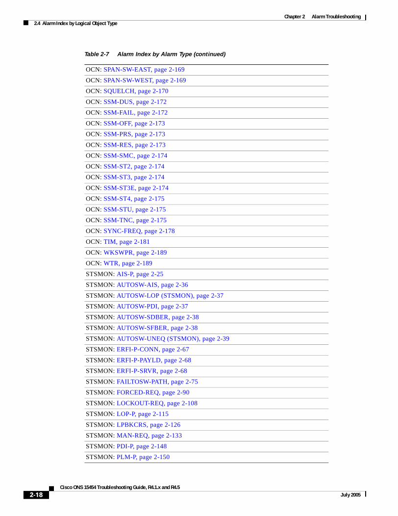
Chapter 2 Alarm Troubleshooting2.4 Alarm Index by Logical Object Type
OCN: SPAN-SW-EAST, page 2-169
OCN: SPAN-SW-WEST, page 2-169
OCN: SQUELCH, page 2-170
OCN: SSM-DUS, page 2-172
OCN: SSM-FAIL, page 2-172
OCN: SSM-OFF, page 2-173
OCN: SSM-PRS, page 2-173
OCN: SSM-RES, page 2-173
OCN: SSM-SMC, page 2-174
OCN: SSM-ST2, page 2-174
OCN: SSM-ST3, page 2-174
OCN: SSM-ST3E, page 2-174
OCN: SSM-ST4, page 2-175
OCN: SSM-STU, page 2-175
OCN: SSM-TNC, page 2-175
OCN: SYNC-FREQ, page 2-178
OCN: TIM, page 2-181
OCN: WKSWPR, page 2-189
OCN: WTR, page 2-189
STSMON: AIS-P, page 2-25
STSMON: AUTOSW-AIS, page 2-36
STSMON: AUTOSW-LOP (STSMON), page 2-37
STSMON: AUTOSW-PDI, page 2-37
STSMON: AUTOSW-SDBER, page 2-38
STSMON: AUTOSW-SFBER, page 2-38
STSMON: AUTOSW-UNEQ (STSMON), page 2-39
STSMON: ERFI-P-CONN, page 2-67
STSMON: ERFI-P-PAYLD, page 2-68
STSMON: ERFI-P-SRVR, page 2-68
STSMON: FAILTOSW-PATH, page 2-75
STSMON: FORCED-REQ, page 2-90
STSMON: LOCKOUT-REQ, page 2-108
STSMON: LOP-P, page 2-115
STSMON: LPBKCRS, page 2-126
STSMON: MAN-REQ, page 2-133
STSMON: PDI-P, page 2-148
STSMON: PLM-P, page 2-150
Table 2-7 Alarm Index by Alarm Type (continued)
2-18Cisco ONS 15454 Troubleshooting Guide, R4.1.x and R4.5
July 2005
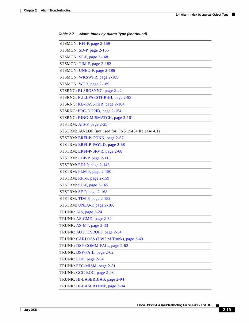
Chapter 2 Alarm Troubleshooting2.4 Alarm Index by Logical Object Type
STSMON: RFI-P, page 2-159
STSMON: SD-P, page 2-165
STSMON: SF-P, page 2-168
STSMON: TIM-P, page 2-182
STSMON: UNEQ-P, page 2-186
STSMON: WKSWPR, page 2-189
STSMON: WTR, page 2-189
STSRNG: BLSROSYNC, page 2-42
STSRNG: FULLPASSTHR-BI, page 2-93
STSRNG: KB-PASSTHR, page 2-104
STSRNG: PRC-DUPID, page 2-154
STSRNG: RING-MISMATCH, page 2-161
STSTRM: AIS-P, page 2-25
STSTRM: AU-LOF (not used for ONS 15454 Release 4.1)
STSTRM: ERFI-P-CONN, page 2-67
STSTRM: ERFI-P-PAYLD, page 2-68
STSTRM: ERFI-P-SRVR, page 2-68
STSTRM: LOP-P, page 2-115
STSTRM: PDI-P, page 2-148
STSTRM: PLM-P, page 2-150
STSTRM: RFI-P, page 2-159
STSTRM: SD-P, page 2-165
STSTRM: SF-P, page 2-168
STSTRM: TIM-P, page 2-182
STSTRM: UNEQ-P, page 2-186
TRUNK: AIS, page 2-24
TRUNK: AS-CMD, page 2-32
TRUNK: AS-MT, page 2-33
TRUNK: AUTOLSROFF, page 2-34
TRUNK: CARLOSS (DWDM Trunk), page 2-43
TRUNK: DSP-COMM-FAIL, page 2-62
TRUNK: DSP-FAIL, page 2-62
TRUNK: EOC, page 2-64
TRUNK: FEC-MISM, page 2-81
TRUNK: GCC-EOC, page 2-93
TRUNK: HI-LASERBIAS, page 2-94
TRUNK: HI-LASERTEMP, page 2-94
Table 2-7 Alarm Index by Alarm Type (continued)
2-19Cisco ONS 15454 Troubleshooting Guide, R4.1.x and R4.5
July 2005

Chapter 2 Alarm Troubleshooting2.4 Alarm Index by Logical Object Type
TRUNK: HI-RXPOWER, page 2-95
TRUNK: HI-RXTEMP, page 2-96
TRUNK: HI-TXPOWER, page 2-97
TRUNK: LO-LASERBIAS, page 2-113
TRUNK: LO-LASERTEMP, page 2-113
TRUNK: LO-RXPOWER, page 2-116
TRUNK: LO-RXTEMP, page 2-117
TRUNK: LOS (OTN), page 2-125
TRUNK: LO-TXPOWER, page 2-126
TRUNK: LOC, page 2-107
TRUNK: LOF (DWDM Trunk), page 2-111
TRUNK: LOM, page 2-114
TRUNK: LOS (DWDM Client or Trunk), page 2-120
TRUNK: LPBKFACILITY (DWDM Client, DWDM Trunk), page 2-129
TRUNK: LPBKTERMINAL (DWDM Client, DWDM Trunk), page 2-132
TRUNK: ODUK-AIS-PM, page 2-141
TRUNK: ODUK-BDI-PM, page 2-141
TRUNK: ODUK-LCK-PM, page 2-142
TRUNK: ODUK-OCI-PM, page 2-142
TRUNK: ODUK-SD-PM, page 2-143
TRUNK: ODUK-SF-PM, page 2-143
TRUNK: ODUK-TIM-PM, page 2-144
TRUNK: OTUK-AIS, page 2-145
TRUNK: OTUK-BDI, page 2-145
TRUNK: OTUK-IAE (not used for ONS 15454 Release 4.1)
TRUNK: OTUK-LOF, page 2-146
TRUNK: OTUK-SD, page 2-146
TRUNK: OTUK-SF, page 2-147
TRUNK: OTUK-TIM, page 2-147
TRUNK: RFI, page 2-158
TRUNK: SD (DWDM Client, DWDM Trunk), page 2-164
TRUNK: SF (DWDM Client, Trunk), page 2-167
TRUNK: SSM-DUS, page 2-172
TRUNK: SSM-FAIL, page 2-172
TRUNK: SSM-LNC, page 2-172
TRUNK: SSM-OFF, page 2-173
TRUNK: SSM-PRC, page 2-173
Table 2-7 Alarm Index by Alarm Type (continued)
2-20Cisco ONS 15454 Troubleshooting Guide, R4.1.x and R4.5
July 2005

Chapter 2 Alarm Troubleshooting2.4 Alarm Index by Logical Object Type
TRUNK: SSM-PRS, page 2-173
TRUNK: SSM-RES, page 2-173
TRUNK: SSM-SDH-TN (not used for ONS 15454 Release 4.1)
TRUNK: SSM-SETS (not used for ONS 15454 Release 4.1)
TRUNK: SSM-SMC, page 2-174
TRUNK: SSM-ST2, page 2-174
TRUNK: SSM-ST3, page 2-174
TRUNK: SSM-ST3E, page 2-174
TRUNK: SSM-ST4, page 2-175
TRUNK: SSM-STU, page 2-175
TRUNK: SSM-TNC, page 2-175
TRUNK: TIM, page 2-181
TRUNK: UNC-WORD, page 2-186
TRUNK: WTR, page 2-189
TRUNK: WVL-MISMATCH, page 2-190
UCP-CKT: CKTDOWN, page 2-49
UCP-IPCC: LMP-HELLODOWN, page 2-107
UCP-IPCC: LMP-NDFAIL, page 2-107
UCP-NBR: RSVP-HELLODOWN, page 2-162
VT-MON: AIS-V, page 2-25
VT-MON: AUTOSW-AIS, page 2-36
VT-MON: AUTOSW-LOP (VTMON), page 2-37
VT-MON: AUTOSW-UNEQ (VTMON), page 2-39
VT-MON: FAILTOSW-PATH, page 2-75
VT-MON: FORCED-REQ, page 2-90
VT-MON: LOCKOUT-REQ, page 2-108
VT-MON: LOP-V, page 2-115
VT-MON: MAN-REQ, page 2-133
VT-MON: UNEQ-V, page 2-188
VT-MON: WKSWPR, page 2-189
VT-MON: WTR, page 2-189
VT-TERM: AIS-V, page 2-25
VT-TERM: LOP-V, page 2-115
VT-TERM: PLM-V, page 2-152
VT-TERM: RFI-V, page 2-160
VT-TERM: SD-P, page 2-165
Table 2-7 Alarm Index by Alarm Type (continued)
2-21Cisco ONS 15454 Troubleshooting Guide, R4.1.x and R4.5
July 2005

Chapter 2 Alarm Troubleshooting2.5 Trouble Notifications
2.5 Trouble NotificationsThe ONS 15454 uses standard Telcordia categories to characterize levels of trouble. The ONS 15454 reports alarmed trouble notifications and Not-Alarmed (NA) notifications, if selected, in the CTC Alarms window. Alarms typically signify a problem that the user needs to fix, such as an LOS, while Not-Alarmed (NA) notifications do not necessarily need immediate troubleshooting.
Telcordia further divides alarms into Service-Affecting (SA) and NSA status. A Service-Affecting (SA) failure affects a provided service or the network's ability to provide service. For example, the “TRMT-MISS” alarm on page 2-185 is characterized by default as an SA failure. TRMT-MISS occurs when a cable connector is removed from an active DS-1 card port. The default severity assumes that service has been interrupted or moved. If the DS-1 card is in a protection group and the traffic is on the protect card rather than the working card, or if the port with the TRMT-MISS alarm has no circuits provisioned, TRMT-MISS would be raised as NSA because traffic was not interrupted or moved.
2.5.1 ConditionsThe term “Condition” refers to any problem detected on an ONS 15454 shelf, whether or not the problem is reported (that is, whether or not it generates a trouble notification). Reported conditions include alarms, Not-Alarmed conditions, and Not-Reported (NR) conditions. A snapshot of all current raised conditions on a node, whether they are reported or not, can be retrieved using the CTC Conditions window or using TL1's set of RTRV-COND commands. You can see the actual reporting messages for alarms and NAs in the CTC History tab.
For a comprehensive list of all conditions, refer to the Cisco ONS 15454 and Cisco ONS 15327 TL1 Command Guide.
2.5.2 SeveritiesThe ONS 15454 uses Telcordia standard severities: Critical (CR), Major (MJ), and Minor (MN). Non-Service Affecting (NSA) alarms always have a Minor (MN) severity. Service-Affecting (SA) alarms may be Critical (CR), Major (MJ), or Minor (MN). Critical alarms generally indicate severe, service-affecting trouble that needs immediate correction. A Major (MJ) alarm is a serious alarm, but the trouble has less impact on the network. For SONET signal alarms, traffic loss of traffic on more than five DS-1 circuits is Critical. Loss of traffic on one to five DS-1 circuits is Major (MJ). Loss of traffic on an STS-1, which can hold 28 DS-1 circuits, would be a Critical (CR), Service-Affecting (SA) alarm.
An example of a Non-Service Affecting (NSA) alarm is the “FSTSYNC” condition on page 2-93 (Fast Start Synchronization Mode), which indicates the ONS 15454 is choosing a new timing reference because the previously used reference has failed. The user needs to troubleshoot the loss of the prior timing source, but the loss is not immediately disruptive to service.
VT-TERM: SF-P, page 2-168
VT-TERM: UNEQ-V, page 2-188
1. AIE is unused in ONS 15454.
Table 2-7 Alarm Index by Alarm Type (continued)
2-22Cisco ONS 15454 Troubleshooting Guide, R4.1.x and R4.5
July 2005

Chapter 2 Alarm Troubleshooting2.6 Safety Summary
Telcordia standard severities are the default settings for the ONS 15454. A user may customize ONS 15454 alarm severities with the alarm profiles feature. For alarm profile procedures, refer to the Cisco ONS 15454 Procedure Guide.
This chapter lists the default profile alarm severity for the Service-Affecting (SA) case of each alarm when it is applicable. Any alarm with a profile value of Critical (CR) or Major (MJ) will, if reported as Non-Service Affecting (NSA) because no traffic is lost, be reported with a Minor (MN) severity instead, in accordance with Telcordia rules.
2.6 Safety SummaryThis section covers safety considerations designed to ensure safe operation of the ONS 15454. Personnel should not perform any procedures in this chapter unless they understand all safety precautions, practices, and warnings for the system equipment. Some troubleshooting procedures require installation or removal of cards, in these instances users should pay close attention to the following caution and warnings:
Caution Hazardous voltage or energy might be present on the backplane when the system is operating. Use caution when removing or installing cards.
Some troubleshooting procedures require installation or removal of OC-192 cards, in these instances users should pay close attention to the following warnings:
Warning On the OC-192 card, the laser is on when the card is booted and the safety key is in the on position (labeled 1). The port does not have to be in service (IS) for the laser to be on. The laser is off when the safety key is off (labeled 0).
Warning Invisible laser radiation might be emitted from the end of the unterminated fiber cable or connector. Do not stare into the beam directly with optical instruments. Viewing the laser output with certain optical instruments (for example, eye loupes, magnifiers, and microscopes) within a distance of 100 mm might pose an eye hazard. Use of controls or adjustments or performance of procedures other than those specified might result in hazardous radiation exposure.
Warning Class 1 laser product.
Warning Class 1M laser radiation when open. Do not view directly with optical instruments
2.7 Alarm ProceduresThis section list alarms alphabetically and includes some conditions commonly encountered when troubleshooting alarms. The severity, description, and troubleshooting procedure accompany each alarm and condition.
2-23Cisco ONS 15454 Troubleshooting Guide, R4.1.x and R4.5
July 2005

Chapter 2 Alarm Troubleshooting2.7.1 AIS
Note When you check the status of alarms for cards, ensure that the alarm filter icon in the lower right corner is not indented. If it is, click it to turn it off. When you are done checking for alarms, click the alarm filter icon again to turn filtering back on.
Note When checking alarms, make sure that alarm suppression is not enabled on the card or port. For more information about alarm suppression, see the Cisco ONS 15454 Procedure Guide.
Note In this section, alarm logical objects are only given when they appear in the Release 4.1 alarm profile list.
2.7.1 AIS• Not Reported (NR), Non-Service Affecting (NSA)
• Logical Objects: BITS, CLIENT, DS1, DS3, FUDC, MSUDC, TRUNK
The Alarm Indication Signal (AIS) condition indicates that this node is detecting AIS in the incoming signal SONET overhead.
Generally, any AIS is a special SONET signal that tells the receiving node that the sending node has no valid signal available to send. AIS is not considered an error. The fault condition AIS is raised by the receiving node on each input where it sees the AIS instead of a real signal. In most cases when this condition is raised, an upstream node is raising an alarm to indicate a signal failure; all nodes downstream from it only raise some type of AIS. This condition clears when you resolved the problem on the upstream node.
Note DS-3 and EC-1 terminal (inward) loopbacks do not transmit an AIS in the direction away from the loopback. Instead of AIS, a continuance of the signal transmitted into the loopback is provided.
Clear the AIS Condition
Step 1 Verify whether there are alarms on the upstream nodes and equipment, especially the “LOS (OC-N)” alarm on page 2-124, or OOS ports.
Step 2 Clear the upstream alarms using the applicable procedure(s) in this chapter.
Step 3 If the condition does not clear, log onto http://www.cisco.com/tac for more information or call TAC (1-800-553-2447).
2.7.2 AIS-L• Not Reported (NR), Non-Service Affecting (NSA)
• Logical Objects: EC1-12, OCN
The AIS Line condition indicates that this node is detecting Line-level AIS in the incoming signal.
2-24Cisco ONS 15454 Troubleshooting Guide, R4.1.x and R4.5
July 2005

Chapter 2 Alarm Troubleshooting2.7.3 AIS-P
Generally, any AIS is a special SONET signal that tells the receiving node that the sending node has no valid signal available to send. AIS is not considered an error. The fault condition AIS is raised by the receiving node on each input where it sees the signal AIS instead of a real signal. In most cases when this condition is raised, an upstream node is raising an alarm to indicate a signal failure; all nodes downstream from it only raise some type of AIS. This condition clears when you resolved the problem on the upstream node.
Clear the AIS-L Condition
Step 1 Complete the “Clear the AIS Condition” procedure on page 2-24.
Step 2 If the condition does not clear, log onto http://www.cisco.com/tac for more information or call TAC (1-800-553-2447).
2.7.3 AIS-P• Not Reported (NR), Non-Service Affecting (NSA)
• Logical Objects: STSMON, STSTRM
The AIS Path condition means that this node is detecting AIS in the incoming path.
Generally, any AIS is a special SONET signal that tells the receiving node that the sending node has no valid signal available to send. AIS is not considered an error. The fault condition AIS is raised by the receiving node on each input where it sees the signal AIS instead of a real signal. In most cases when this condition is raised, an upstream node is raising an alarm to indicate a signal failure; all nodes downstream from it only raise some type of AIS. This condition clears when you resolved the problem on the upstream node.
Clear the AIS-P Condition
Step 1 Complete the “Clear the AIS Condition” procedure on page 2-24.
Step 2 If the condition does not clear, log onto http://www.cisco.com/tac for more information or call TAC (1-800-553-2447).
2.7.4 AIS-V• Not Reported (NR), Non-Service Affecting (NSA)
• Logical Objects: VTMON, VTTERM
The AIS Virtual Tributary (VT) condition means that this node is detecting AIS in the incoming VT-level path.
Generally, any AIS is a special SONET signal that tells the receiving node that the sending node has no valid signal available to send. AIS is not considered an error. The fault condition AIS is raised by the receiving node on each input where it sees the signal AIS instead of a real signal. In most cases when
2-25Cisco ONS 15454 Troubleshooting Guide, R4.1.x and R4.5
July 2005

Chapter 2 Alarm Troubleshooting2.7.5ALS
this condition is raised, an upstream node is raising an alarm to indicate a signal failure; all nodes downstream from it only raise some type of AIS. This condition clears when you resolved the problem on the upstream node.
See the “AIS-V on DS3XM-6 Unused VT Circuits” section on page 1-76 for more information.
Clear the AIS-V Condition
Step 1 Complete the “Clear the AIS Condition” procedure on page 2-24.
Step 2 If the condition does not clear, log onto http://www.cisco.com/tac for more information or call TAC (1-800-553-2447).
2.7.5 ALS• Not Alarmed (NA), Non-Service Affecting (NSA)
• Occurs only on DWDM (Software R4.5) nodes
The Automatic Laser Shutdown condition occurs when an amplifier (OPT-BST or OPT-PRE) is switched on. The turn-on process lasts approximately nine seconds, and the condition clears after approximately 10 seconds.
Note ALS is an informational condition. It does not require troubleshooting.
2.7.6 AMPLI-INIT• Not Alarmed (NA), Non-Service Affecting (NSA)
• Occurs only on DWDM (Software R4.5) nodes
The Amplifier Initialized condition occurs when an amplifier card (OPT-BST or OPT-PRE) is not able to calculate gain. This condition typically accompanies the “APC-DISABLED” alarm on page 2-26 alarm.
Clear the AMPLI-INIT Condition
Step 1 Complete the “Delete a Circuit” procedure on page 2-196 on the most recently created circuit.
Step 2 Recreate this circuit using the procedures in the Cisco ONS 15454 Procedure Guide.
Step 3 If the condition does not clear, log onto http://www.cisco.com/tac for more information or call TAC (1-800-553-2447).
2.7.7 APC-DISABLED• Major (MJ), Non-Service Affecting (NSA)
2-26Cisco ONS 15454 Troubleshooting Guide, R4.1.x and R4.5
July 2005

Chapter 2 Alarm Troubleshooting2.7.8 APC-FAIL
• Occurs only on DWDM (Software R4.5) nodes
The Automatic Power Control (APC) Disabled occurs when the information related to the number of channels is not reliable. The alarm can occur when the any of the following alarms also occur: the “EQPT” alarm on page 2-66, the “IMPROPRMVL” alarm on page 2-99, and the “MEA (EQPT)” alarm on page 2-136. If the alarm occurs with the creation of the first circuit, delete and then recreate it.
Clear the APC-DISABLED Alarm
Step 1 Complete the appropriate procedure to clear the primary alarm:
• Clear the EQPT Alarm, page 2-66
• Clear the IMPROPRMVL Alarm, page 2-99
• Clear the MEA (EQPT) Alarm, page 2-136
Step 2 If the alarm does not clear, complete the “Delete a Circuit” procedure on page 2-196 and then recreate it.
Step 3 If the alarm does not clear, log onto http://www.cisco.com/tac for more information or call TAC (1-800-553-2447).
2.7.8 APC-FAIL• Major (MJ), Non-Service Affecting (NSA)
• Occurs only on DWDM (Software R4.5) nodes
The APC Failure alarm occurs when APC has not been able to create a setpoint on a node because it has consumed all allocated power margins. These power margins (from 0 dB to 3 dB) are allocated when the network is installed. Margins can be consumed due to fiber aging or the insertion of unexpected extra loss in the span after a fiber cut.
Clear the APC-FAIL Alarm
Step 1 Isolate the cause of increased margin use:
• If it is due to fiber aging, replace the indicated fiber. (You can test the integrity of the fiber using optical testing equipment.)
• If it is due to a fiber cut, resolve this issue to resolve this alarm.
Step 2 If the alarm does not clear, log onto http://www.cisco.com/tac for more information or call TAC (1-800-553-2447).
2.7.9 APSB• Minor (MN), Non-Service Affecting (NSA)
• Logical Object: OCN
2-27Cisco ONS 15454 Troubleshooting Guide, R4.1.x and R4.5
July 2005

Chapter 2 Alarm Troubleshooting2.7.10 APSCDFLTK
The Automatic Protection Switching (APS) Channel Byte Failure alarm occurs when line terminating equipment detects protection switching byte failure in the incoming APS signal. The failure occurs when an inconsistent APS byte or invalid code is detected. Some older, non-Cisco SONET nodes send invalid APS codes if they are configured in a 1+1 protection scheme with newer SONET nodes, such as the ONS 15454. These invalid codes causes an APSB on an ONS node.
Clear the APSB Alarm
Step 1 Use an optical test set to examine the incoming SONET overhead to confirm inconsistent or invalid K bytes.
For specific procedures to use the test set equipment, consult the manufacturer. If corrupted K bytes are confirmed and the upstream equipment is functioning properly, the upstream equipment might not interoperate effectively with the ONS 15454.
Step 2 If the alarm does not clear and the overhead shows inconsistent or invalid K bytes, you might need to replace the upstream cards for protection switching to operate properly.
Step 3 If the alarm does not clear, log onto http://www.cisco.com/tac for more information or call TAC (1-800-553-2447).
2.7.10 APSCDFLTK• Minor (MN), Non-Service Affecting (NSA)
• Logical Object: OCN
The APS Default K Byte Received alarm occurs when a bidirectional line switched ring (BLSR) is not properly configured, for example, when a four-node BLSR has one node configured as path protection. A node in a path protection or 1+1 configuration does not send the two valid K1/K2 APS bytes anticipated by a system configured for BLSR. One of the bytes sent is considered invalid by the BLSR configuration. The K1/K2 byte is monitored by receiving equipment for link-recovery information.
Troubleshooting for APSCDFLTK is often similar to troubleshooting for the “BLSROSYNC” alarm on page 2-42.
Clear the APSCDFLTK Alarm
Step 1 Complete the “Identify a Ring ID or Node ID Number” procedure on page 2-193 to verify that each node has a unique node ID number.
Step 2 Repeat Step 1 for all nodes in the ring.
Step 3 If two nodes have the same node ID number, complete the “Change a Node ID Number” procedure on page 2-193 to change one node’s ID number so that each node ID is unique.
Step 4 If the alarm does not clear, verify correct configuration of east port and west port optical fibers. (See the “E-W-MISMATCH” alarm on page 2-70.) West port fibers must connect to east port fibers, and vice versa. The Cisco ONS 15454 Procedure Guide provides a procedure for fibering BLSRs.
Step 5 If the alarm does not clear and if the network is a four-fiber BLSR, make sure that each protect fiber is connected to another protect fiber and each working fiber is connected to another working fiber. The software does not report any alarm if a working fiber is incorrectly attached to a protection fiber.
2-28Cisco ONS 15454 Troubleshooting Guide, R4.1.x and R4.5
July 2005

Chapter 2 Alarm Troubleshooting2.7.11 APSC-IMP
Step 6 If the alarm does not clear, complete the “Verify Node Visibility for Other Nodes” procedure on page 2-193.
Step 7 If nodes are not visible, complete the “Verify or Create Node DCC Terminations” procedure on page 2-194 to ensure that SONET DCC terminations exist on each node.
Step 8 If the alarm does not clear, log onto http://www.cisco.com/tac for more information or call TAC (1-800-553-2447).
2.7.11 APSC-IMP• Minor (MN), Non-Service Affecting (NSA)
• Logical Object: OCN
An Improper SONET APS Code alarm indicates invalid K bytes. The APSC-IMP alarm occurs on OC-N cards in a BLSR configuration. The receiving equipment monitors K bytes or K1 and K2 APS bytes for an indication to switch from the working card to the protect card or vice versa. K1/K2 bytes also contain bits that tell the receiving equipment whether the K byte is valid. APSCIMP occurs when these bits indicate a bad or invalid K byte. The alarm clears when the node receives valid K bytes.
Note This alarm can occur on a VT tunnel when it does not have VT circuits provisioned. It can also occur when the exercise command or a lock out is applied to a span. An externally switched span will not raise this alarm because traffic is pre-empted.
Caution Always use the supplied electrostatic discharge wristband when working with a powered ONS 15454. Plug the wristband cable into the ESD jack located at the lower-right outside edge of the shelf assembly.
Clear the APSC-IMP Alarm
Step 1 Use an optical test set to determine the validity of the K byte signal by examining the received signal.
For specific procedures to use the test set equipment, consult the manufacturer.
If the K byte is invalid, the problem is with upstream equipment and not in the reporting ONS 15454. Troubleshoot the upstream equipment using the procedures in this chapter, as applicable. If the upstream nodes are not ONS 15454s, consult the appropriate user documentation.
Step 2 If the K byte is valid, verify that each node has a ring ID that matches the other node ring IDs. Complete the “Identify a Ring ID or Node ID Number” procedure on page 2-193.
Step 3 Repeat Step 2 for all nodes in the ring.
Step 4 If a node has a ring ID number that does not match the other nodes, make the ring ID number of that node identical to the other nodes. Complete the “Change a Ring ID Number” procedure on page 2-193.
Step 5 If the alarm does not clear, log onto http://www.cisco.com/tac for more information or call TAC (1-800-553-2447).
2-29Cisco ONS 15454 Troubleshooting Guide, R4.1.x and R4.5
July 2005

Chapter 2 Alarm Troubleshooting2.7.12 APSCINCON
2.7.12 APSCINCON• Minor (MN), Non-Service Affecting (NSA)
• Logical Object: OCN
An APS Inconsistent alarm means that an inconsistent APS byte is present. The SONET overhead contains K1/K2 APS bytes that notify receiving equipment, such as the ONS 15454, to switch the SONET signal from a working to a protect path. An inconsistent APS code occurs when three consecutive frames do not contain identical APS bytes. Inconsistent APS bytes give the receiving equipment conflicting commands about switching.
Clear the APSCINCON Alarm
Step 1 Look for other alarms, especially the “LOS (OC-N)” alarm on page 2-124, the “LOF (OC-N)” alarm on page 2-112, or the “AIS” alarm on page 2-24. Clearing these alarms clears the APSCINCON alarm.
Step 2 If an APSINCON alarm occurs with no other alarms, log onto http://www.cisco.com/tac for more information or call TAC (1-800-553-2447).
2.7.13 APSCM• Major (MJ), Service-Affecting (SA)
• Logical Object: OCN
The APS Channel Mismatch alarm occurs when the ONS 15454 expects a working channel but receives a protection channel. In many cases, the working and protection channels are crossed and the protect channel is active. If the fibers are crossed and the working line is active, the alarm does not occur. The APSCM alarm occurs only on the ONS 15454 when bidirectional protection is used on OC-N cards in a 1+1 configuration.
Warning On the OC-192 card, the laser is on when the card is booted and the safety key is in the on position (labeled 1). The port does not have to be in service (IS) for the laser to be on. The laser is off when the safety key is off (labeled 0).
Warning Invisible laser radiation might be emitted from the end of the unterminated fiber cable or connector. Do not stare into the beam directly with optical instruments. Viewing the laser output with certain optical instruments (for example, eye loupes, magnifiers, and microscopes) within a distance of 100 mm might pose an eye hazard. Use of controls or adjustments or performance of procedures other than those specified might result in hazardous radiation exposure.
Caution Always use the supplied electrostatic discharge wristband when working with a powered ONS 15454. Plug the wristband cable into the ESD jack located at the lower-right outside edge of the shelf assembly.
2-30Cisco ONS 15454 Troubleshooting Guide, R4.1.x and R4.5
July 2005
Chapter 2 Alarm Troubleshooting2.7.14 APSCNMIS
Clear the APSCM Alarm
Step 1 Verify that the working-card channel fibers are physically connected directly to the adjoining node’s working-card channel fibers.
Step 2 If the fibers are correctly connected, verify that the protection-card channel fibers are physically connected directly to the adjoining node’s protection-card channel fibers.
Step 3 If the alarm does not clear, log onto http://www.cisco.com/tac for more information or call TAC to report a service-affecting problem (1-800-553-2447).
2.7.14 APSCNMIS• Major (MJ), Service-Affecting (SA)
• Logical Object: OCN
The APS Node ID Mismatch alarm occurs when the source node ID contained in the SONET K2 byte of the incoming APS channel is not present in the ring map. The APSCNMIS alarm might occur and clear when a BLSR is being provisioned. If so, you can disregard the temporary occurrence. If the APSCNMIS remains, the alarm clears when a K byte with a valid source node ID is received.
Clear the APSCNMIS Alarm
Step 1 Complete the “Identify a Ring ID or Node ID Number” procedure on page 2-193 to verify that each node has a unique node ID number.
Step 2 If the Node ID column contains any two nodes with the same node ID listed, record the repeated node ID.
Step 3 Click Close in the Ring Map dialog box.
Step 4 If two nodes have the same node ID number, complete the “Change a Node ID Number” procedure on page 2-193 to change one node’s ID number so that each node ID is unique.
Note If the node names shown in the network view do not correlate with the node IDs, log into each node and click the Provisioning > BLSR tabs. The BLSR window shows the node ID of the login node.
Note Applying and removing a lock out on a span causes the ONS 15454 to generate a new K byte. The APSCNMIS alarm clears when the node receives a K byte containing the correct node ID.
Step 5 If the alarm does not clear, use the “Lock Out a BLSR Span” procedure on page 2-194 to lock out the span.
Step 6 Complete the “Clear a BLSR Span Lock Out” procedure on page 2-194 to clear the lock out.
Step 7 If the alarm does not clear, log onto http://www.cisco.com/tac for more information or call TAC to report a service-affecting problem (1-800-553-2447).
2-31Cisco ONS 15454 Troubleshooting Guide, R4.1.x and R4.5
July 2005

Chapter 2 Alarm Troubleshooting2.7.15 APSMM
2.7.15 APSMM• Minor (MN), Non-Service Affecting (NSA)
• Logical Object: OCN
An APS Mode Mismatch failure alarm occurs when there is a mismatch of the protection switching schemes at the two ends of the span. If one node is provisioned for bidirectional switching, the node at the other end of the span must also be provisioned for bidirectional switching. If one end is provisioned for bidirectional and the other is provisioned for unidirectional, an APSMM alarm occurs in the ONS node that is provisioned for bidirectional. The APSMM alarm occurs in a 1+1 configuration.
Clear the APSMM Alarm
Step 1 For the reporting ONS 15454, display the node view and verify the protection scheme provisioning.
a. Click the Provisioning > Protection tabs.
b. Choose the 1+1 protection group configured for the OC-N cards.
The chosen protection group is the protection group optically connected (with DCC connectivity) to the far end.
Record whether the Bidirectional Switching check box is checked.
Step 2 Log into the far-end node and verify that the OC-N 1+1 protection group is provisioned.
Step 3 Verify that the Bidirectional Switching check box matches the checked or unchecked condition of the box recorded in Step 1. If not, change it to match.
Step 4 Click Apply.
Step 5 If the alarm does not clear, log onto http://www.cisco.com/tac for more information or call TAC (1-800-553-2447).
2.7.16 AS-CMD• Not Alarmed (NA), Non-Service Affecting (NSA)
• Portions of this procedure do not apply to DWDM
• Logical Objects: BPLANE, CLIENT, DS-1, DS3, E100T, E1000F, EC1-12, EQPT, G1000, ML100T, ML1000, NE, OCN, TRUNK
The Alarms Suppressed by User Command condition applies to the network element (SYSTEM object), backplane, a single card, or a port on a card. It occurs when alarms are suppressed for that object and its subordinate objects; that is, suppressing alarms on a card also suppresses alarms on its ports.
Clear the AS-CMD Condition
Step 1 For all nodes, in the node view, click the Conditions tab.
Step 2 Click Retrieve. If you have already retrieved conditions, look under the Object column and Eqpt Type column, note what entity the condition is reported against, such as a port, slot, or shelf.
2-32Cisco ONS 15454 Troubleshooting Guide, R4.1.x and R4.5
July 2005

Chapter 2 Alarm Troubleshooting2.7.17 AS-MT
If the condition is reported against a slot and card, alarms were either suppressed for the entire card or for one of the ports. Note the slot number and continue with Step 3.
If the condition is reported against the backplane, go to Step 7.
If the condition is reported against a “system,” go to Step 8.
Step 3 If the AS-CMD condition is reported for a card in a Software R4.1 or earlier node, determine whether alarms are suppressed for a port and if so, raise the suppressed alarms:
a. Double-click the card to display the card view.
b. Click the Provisioning > Alarm Behavior tabs.
• If the Suppress Alarms column check box is checked for a port row, deselect it and click Apply.
• If the Suppress Alarms column check box is not checked for a port row, click View > Go to Previous View.
Step 4 In node view for a Release 4.1 or earlier node, if the AS-CMD condition is reported for a card and not an individual port, click the Provisioning > Alarm Behavior tabs.
Step 5 Locate the row for the reported card slot. (The slot number information was in the Object column in the Conditions window that you noted in Step 2.)
Step 6 Click the Suppress Alarms column check box to deselect the option for the card row.
Step 7 If the condition is reported for the backplane, the alarms are suppressed for cards such as the AIP that are not in the optical or electrical slots. To clear the alarm:
a. In node view, click the Provisioning > Alarm Behavior tabs.
b. In the Backplane row, deselect the Suppress Alarms column check box.
c. Click Apply.
Step 8 If the condition is reported for the shelf, cards and other equipment are affected. To clear the alarm:
a. In node view, click the Provisioning > Alarm Behavior tabs.
b. Click the Suppress Alarms check box located at the bottom of the window to deselect the option.
c. Click Apply.
Step 9 If the condition does not clear, log onto http://www.cisco.com/tac for more information or call TAC (1-800-553-2447).
2.7.17 AS-MT• Not Alarmed (NA), Non-Service Affecting (NSA)
• Occurs only on Software R4.1 or earlier nodes
• Logical Objects: CLIENT, DS1, DS3, EC1-12, G1000, OCN, TRUNK
The Alarms Suppressed for Maintenance Command condition applies to OC-N and electrical (traffic) cards and occurs when a port is placed in the out-of-service maintenance (OOS-MT) state for loopback testing operations.
Clear the AS-MT Condition
Step 1 Complete the “Clear a Loopback” procedure on page 2-196.
2-33Cisco ONS 15454 Troubleshooting Guide, R4.1.x and R4.5
July 2005

Chapter 2 Alarm Troubleshooting2.7.18 AUD-LOG-LOSS
Step 2 If the condition does not clear, log onto http://www.cisco.com/tac for more information or call TAC (1-800-553-2447).
2.7.18 AUD-LOG-LOSS• Not Alarmed (NA), Non-Service Affecting (NSA)
• Logical Object: NE
The Audit Trail Log Loss condition occurs when the log is 100% full and that the oldest entries are being replaced as new entries are generated. The log capacity is 640 entries.
Clear the AUD-LOG-LOSS Condition
Step 1 In the node view, click the Maintenance > Audit tabs.
Step 2 Click Retrieve.
Step 3 Click Archive.
Step 4 In the Archive Audit Trail dialog box, navigate to the directory (local or network) where you want to save the file.
Step 5 Enter a name in the File Name field.
You do not have to assign an extension to the file. It is readable in any application that supports text files, such as WordPad, Microsoft Word (imported), etc.
Step 6 Click Save.
The 640 entries will be saved in this file. New entries will continue with the next number in the sequence, rather than starting over.
Step 7 If the alarm does not clear, log onto http://www.cisco.com/tac for more information or call TAC (1-800-553-2447).
2.7.19 AUD-LOG-LOW• Not Reported (NR), Non-Service Affecting (NSA)
• Logical Object: NE
The Audit Trail Log Loss condition occurs when the audit trail log is 80% full.
Note AUD-LOG-LOW is an informational condition. It does not require troubleshooting.
2.7.20 AUTOLSROFF• Critical (CR), Service-Affecting (SA)
• Occurs only on Software R4.1 or earlier nodes
2-34Cisco ONS 15454 Troubleshooting Guide, R4.1.x and R4.5
July 2005

Chapter 2 Alarm Troubleshooting2.7.20 AUTOLSROFF
• Logical Object: CLIENT, OCN, TRUNK
The Auto Laser Shutdown alarm occurs when the OC-192 card temperature exceeds 194° F (90 ° C). The internal equipment automatically shuts down the OC-192 laser when the card temperature rises to prevent the card from self-destructing.
Warning On the OC-192 card, the laser is on when the card is booted and the safety key is in the on position (labeled 1). The port does not have to be in service (IS) for the laser to be on. The laser is off when the safety key is off (labeled 0).
Warning Invisible laser radiation might be emitted from the end of the unterminated fiber cable or connector. Do not stare into the beam directly with optical instruments. Viewing the laser output with certain optical instruments (for example, eye loupes, magnifiers, and microscopes) within a distance of 100 mm might pose an eye hazard. Use of controls or adjustments or performance of procedures other than those specified might result in hazardous radiation exposure.
Clear the AUTOLSROFF Alarm
Step 1 View the temperature displayed on the ONS 15454 LCD front panel (Figure 2-1).
Figure 2-1 Shelf LCD Panel
Step 2 If the temperature of the shelf exceeds 194° F (90° C), the alarm should clear if you solve the ONS 15454 temperature problem. Complete the “Clear the HITEMP Alarm” procedure on page 2-97.
Step 3 If the temperature of the shelf is under 194° F (90° C), the HITEMP alarm is not the cause of the AUTOLSROFF alarm. Complete the “Physically Replace a Card” procedure on page 2-198 for the OC-192 card.
Caution Removing a card that currently carries traffic on one or more ports can cause a traffic hit. To avoid this, perform an external switch if a switch has not already occurred. Consult the Cisco ONS 15454 Procedure Guide for information.
Note When replacing a card with an identical type of card, no additional CTC provisioning is required.
Step 4 If card replacement does not clear the alarm, call the Technical Assistance Center (TAC) at (1-800-553-2447) to discuss the case and if necessary open a returned materials authorization (RMA) on the original OC-192 card.
FAN FAIL
Slot
8/18/0304.06-002L-10
24˚C
9775
8CRIT MAJ MIN
Status Port
2-35Cisco ONS 15454 Troubleshooting Guide, R4.1.x and R4.5
July 2005

Chapter 2 Alarm Troubleshooting2.7.21 AUTORESET
2.7.21 AUTORESET• Minor (MN), Non-Service Affecting (NSA)
• Logical Object: EQPT
The Automatic System Reset alarm occurs when you change an IP address or perform any other operation that causes an automatic card-level reboot.
Caution Always use the supplied electrostatic discharge wristband when working with a powered ONS 15454. Plug the wristband cable into the ESD jack located at the lower-right outside edge of the shelf assembly.
Clear the AUTORESET Alarm
Step 1 Verify that additional alarms that might have triggered an automatic reset.
Step 2 If the card automatically resets more than once a month with no apparent cause, complete the “Physically Replace a Card” procedure on page 2-198.
Caution Removing a card that currently carries traffic on one or more ports can cause a traffic hit. To avoid this, perform an external switch if a switch has not already occurred. Consult the Cisco ONS 15454 Procedure Guide for information.
Note When you replace a card with an identical type of card, you do not need to make any changes to the database.
Step 3 If the alarm does not clear, log onto http://www.cisco.com/tac for more information or call TAC (1-800-553-2447).
2.7.22 AUTOSW-AIS• Not Reported (NR), Non-Service Affecting (NSA)
• Logical Objects: STSMON, VTMON
The Automatic Path Protection Switch Caused by AIS condition indicates that automatic path protection switching occurred because of an AIS condition. The path protection is configured for revertive switching and reverts to the working path after the fault clears. The AIS also clears when the upstream trouble is cleared.
Generally, any AIS is a special SONET signal that tells the receiving node that the sending node has no valid signal available to send. AIS is not considered an error. The fault condition AIS is raised by the receiving node on each input where it sees the signal AIS instead of a real signal. In most cases when this condition is raised, an upstream node is raising an alarm to indicate a signal failure; all nodes downstream from it only raise some type of AIS. This condition clears when you resolved the problem on the upstream node.
2-36Cisco ONS 15454 Troubleshooting Guide, R4.1.x and R4.5
July 2005

Chapter 2 Alarm Troubleshooting2.7.23 AUTOSW-LOP (STSMON)
Clear the AUTOSW-AIS Condition
Step 1 Complete the “Clear the AIS Condition” procedure on page 2-24.
Step 2 If the condition does not clear, log onto http://www.cisco.com/tac for more information or call TAC (1-800-553-2447).
2.7.23 AUTOSW-LOP (STSMON)• Not Alarmed (NA), Non-Service Affecting (NSA)
• Logical Object: STSMON
The Automatic Path Protection Switch Caused by Loss of Pointer (LOP) condition indicates that automatic path protection switching occurred because of the “LOP-P” alarm on page 2-115. The path protection is configured for revertive switching and reverts to the working path after the fault clears.
Clear the AUTOSW-LOP (STSMON) Condition
Step 1 Complete the “Clear the LOP-P Alarm” procedure on page 2-115.
Step 2 If the condition does not clear, log onto http://www.cisco.com/tac for more information or call TAC (1-800-553-2447).
2.7.24 AUTOSW-LOP (VTMON)• Minor (MN), Service-Affecting (SA)
• Logical Object: VTMON
The AUTOSW-LOP alarm indicates that automatic path protection switching occurred because of the “LOP-V” alarm on page 2-115. The path protection is configured for revertive switching and reverts to the working path after the fault clears.
Clear the AUTOSW-LOP (VTMON) Alarm
Step 1 Complete the “Clear the LOP-V Alarm” procedure on page 2-116.
Step 2 If the alarm does not clear, log onto http://www.cisco.com/tac for more information or call TAC to report a service-affecting problem (1-800-553-2447).
2.7.25 AUTOSW-PDI• Not Alarmed (NA), Non-Service Affecting (NSA)
2-37Cisco ONS 15454 Troubleshooting Guide, R4.1.x and R4.5
July 2005

Chapter 2 Alarm Troubleshooting2.7.26 AUTOSW-SDBER
• Logical Object: STSMON
The Automatic Path Protection Switch Caused by Payload Defect Indication (PDI) condition indicates that automatic path protection switching occurred because of a “PDI-P” alarm on page 2-148. The path protection is configured for revertive switching and reverts to the working path after the fault clears.
Clear the AUTOSW-PDI Condition
Step 1 Complete the “Clear the PDI-P Condition” procedure on page 2-149.
Step 2 If the condition does not clear, log onto http://www.cisco.com/tac for more information or call TAC (1-800-553-2447).
2.7.26 AUTOSW-SDBER• Not Alarmed (NA), Non-Service Affecting (NSA)
• Logical Object: STSMON
The Automatic Path Protection Switch Caused by Signal Degrade Bit Error Rate (SDBER) condition indicates that a signal degrade (see the “SD (DS-1, DS-3)” condition on page 2-163) caused automatic path protection switching to occur. The path protection is configured for revertive switching and reverts to the working path when the SD is resolved.
Clear the AUTOSW-SDBER Condition
Step 1 Complete the “Clear the SD (DS-1, DS-3) Condition” procedure on page 2-164.
Step 2 If the condition does not clear, log onto http://www.cisco.com/tac for more information or call TAC (1-800-553-2447).
2.7.27 AUTOSW-SFBER• Not Alarmed (NA), Non-Service Affecting (NSA)
• Logical Object: STSMON
The Automatic USPR Switch Caused by Signal Fail Bit Error Rate (SFBER) condition indicates that the “SF (DS-1, DS-3)” condition on page 2-166 caused automatic path protection switching to occur. The path protection is configured for revertive switching and reverts to the working path when the SF is resolved.
Clear the AUTOSW-SFBER Condition
Step 1 Complete the “Clear the SF (DS-1, DS-3) Condition” procedure on page 2-166.
2-38Cisco ONS 15454 Troubleshooting Guide, R4.1.x and R4.5
July 2005

Chapter 2 Alarm Troubleshooting2.7.28 AUTOSW-UNEQ (STSMON)
Step 2 If the condition does not clear, log onto http://www.cisco.com/tac for more information or call TAC (1-800-553-2447).
2.7.28 AUTOSW-UNEQ (STSMON)• Not Alarmed (NA), Non-Service Affecting (NSA)
• Logical Object: STSMON
The Automatic Path Protection Switch Caused by Unequipped condition indicates that an UNEQ alarm caused automatic path protection switching to occur. The path protection is configured for revertive switching and reverts to the working path after the fault clears.
Clear the AUTOSW-UNEQ (STSMON) Condition
Step 1 Complete the “Clear the UNEQ-P Alarm” procedure on page 2-187.
Step 2 If the condition does not clear, log onto http://www.cisco.com/tac for more information or call TAC (1-800-553-2447).
2.7.29 AUTOSW-UNEQ (VTMON)• Minor (MN), Service-Affecting (SA)
• Logical Object: VTMON
AUTOSW-UNEQ (VTMON) indicates that the “UNEQ-V” alarm on page 2-188 alarm caused automatic path protection switching to occur. The path protection is configured for revertive switching and reverts to the working path after the fault clears.
Clear the AUTOSW-UNEQ (VTMON) Alarm
Step 1 Complete the “Clear the UNEQ-V Alarm” procedure on page 2-189.
Step 2 If the alarm does not clear, log onto http://www.cisco.com/tac for more information or call TAC to report a service-affecting problem (1-800-553-2447).
2.7.30 BAT-A-HGH-VLT • Not Reported (NR), Non-Service Affecting (NSA)
• Logical Object: NE
The High Voltage Battery (BAT) A condition occurs when the voltage level on battery lead A is between –52 VDC and –56.7 VDC. The condition indicates that the voltage on the battery lead is high. The condition remains until the voltage remains under this range for 120 seconds.
2-39Cisco ONS 15454 Troubleshooting Guide, R4.1.x and R4.5
July 2005

Chapter 2 Alarm Troubleshooting2.7.31 BAT-A-LOW-VLT
Clear the BAT-A-HGH-VLT Condition
Step 1 The problem is external to the ONS 15454. Troubleshoot the power source supplying battery lead A.
Step 2 If the condition does not clear, log onto http://www.cisco.com/tac for more information or call TAC (1-800-553-2447).
2.7.31 BAT-A-LOW-VLT • Not Reported (NR), Non-Service Affecting (NSA)
• Logical Object: NE
The Low Voltage Battery A condition occurs when the voltage on battery feed A is low. The low voltage battery A condition occurs when the voltage on battery feed A is between –44 VDC and –40 VDC. The condition clears when voltage remains above this range for 120 seconds.
Clear the BAT-A-LOW-VLT Condition
Step 1 The problem is external to the ONS 15454. Troubleshoot the power source supplying battery lead A.
Step 2 If the condition does not clear, log onto http://www.cisco.com/tac for more information or call TAC (1-800-553-2447).
2.7.32 BAT-B-HGH-VLT • Not Reported (NR), Non-Service Affecting (NSA)
• Logical Object: NE
The High Voltage Battery B condition occurs when the voltage level on battery lead B is between –52 VDC and –56.7 VDC. The condition indicates that the voltage on the battery lead is high. The condition remains until the voltage remains under this range for 120 seconds.
Clear the BAT-B-HGH-VLT Condition
Step 1 The problem is external to the ONS 15454. Troubleshoot the power source supplying battery lead B.
Step 2 If the condition does not clear, log onto http://www.cisco.com/tac for more information or call TAC (1-800-553-2447).
2.7.33 BAT-B-LOW-VLT • Not Reported (NR), Non-Service Affecting (NSA)
2-40Cisco ONS 15454 Troubleshooting Guide, R4.1.x and R4.5
July 2005

Chapter 2 Alarm Troubleshooting2.7.34 BKUPMEMP
• Logical Object: NE
The Low Voltage Battery B condition occurs when the voltage level on battery lead B is between –44 VDC and –40 VDC. The condition indicates that the voltage on the battery lead is high. The condition remains until the voltage remains under this range for 120 seconds.
Clear the BAT-B-LOW-VLT Condition
Step 1 The problem is external to the ONS 15454. Troubleshoot the power source supplying battery lead B.
Step 2 If the condition does not clear, log onto http://www.cisco.com/tac for more information or call TAC (1-800-553-2447).
2.7.34 BKUPMEMP• Critical (CR), Non-Service Affecting (NSA)
• Logical Object: EQPT
The Primary Non-Volatile Backup Memory Failure alarm refers to a problem with the TCC+/TCC2 card’s flash memory. The alarm occurs when the TCC+/TCC2 card is in use and has one of four problems: the flash manager fails to format a flash partition; the flash manager fails to write a file to a flash partition; there is a problem at the driver level, or the code volume fails cyclic redundancy checking (CRC). CRC is a method to verify for errors in data transmitted to the TCC+/TCC2.
The BKUPMEMP alarm can also cause the “EQPT” alarm on page 2-66. If the EQPT alarm is caused by BKUPMEMP, complete the following procedure to clear the BKUPMEMP and the EQPT alarm.
Caution It can take up to 30 minutes for software to be updated on a standby TCC+/TCC2 card.
Clear the BKUPMEMP Alarm
Step 1 Verify that both TCC+/TCC2 cards are powered and enabled by confirming lighted ACT/SBY LEDs on the TCC+/TCC2 cards.
Step 2 If both TCC+/TCC2 cards are powered and enabled, reset the TCC+/TCC2 card against which the alarm is raised. If the card is the active TCC+/TCC2 card, complete the “Reset Active TCC+/TCC2 Card and Activate Standby Card” procedure on page 2-196. If the card is the standby TCC+/TCC2, use the substeps below.
a. Right-click the standby TCC+/TCC2 card in CTC.
b. Choose Reset Card from the shortcut menu.
c. Click Yes in the Are You Sure dialog box. The card resets, the FAIL LED blinks on the physical card.
d. Wait ten minutes to verify that the card you reset completely reboots.
2-41Cisco ONS 15454 Troubleshooting Guide, R4.1.x and R4.5
July 2005

Chapter 2 Alarm Troubleshooting2.7.35 BLSROSYNC
Step 3 If the TCC+/TCC2 you reset does not reboot successfully, or the alarm has not cleared, call TAC (1-800-553-2447). If the TAC technician tells you to reseat the card, complete the “Remove and Reinsert (Reseat) the Standby TCC+/TCC2” procedure on page 2-197. If the TAC technician tells you to remove the card and reinstall a new one, follow the “Physically Replace a Card” procedure on page 2-198.
2.7.35 BLSROSYNC• Major (MJ), Service-Affecting (SA)
• Logical Object: STSRNG
The BLSR Out Of Synchronization alarm is caused when you attempt to add or delete a circuit and a node on a working ring loses its DCC connection because all transmit and receive fiber has been removed. CTC cannot generate the ring table and causes the BLSROSYNC alarm.
Clear the BLSROSYNC Alarm
Step 1 Reestablish cabling continuity to the node reporting the alarm.
When the DCC is established between the node and the rest of the BLSR, it becomes visible to the BLSR and should be able to function on the circuits.
Step 2 If alarms occur when you have provisioned the DCCs, see the “EOC” section on page 2-64.
Step 3 If the alarm does not clear, log onto http://www.cisco.com/tac for more information or call TAC to report a service-affecting problem (1-800-553-2447).
2.7.36 CARLOSS (DWDM Client)• Major (MJ), Service-Affecting (SA)
• Logical Object: CLIENT
A Carrier Loss alarm on the TXP_MR_10G, TXP_MR_2.5G, TXPP_MR_2.5G, or MXP_2.5G_10G card occurs when ITU-T G.709 monitoring is turned off at the client port. It is similar to the “LOS (OC-N)” alarm on page 2-124.
Clear the CARLOSS (DWDM Client) Alarm
Step 1 From node view, double-click the TXP_MR_10G, TXP_MR_2.5G, TXPP_MR_2.5G, or MXP_2.5G_10G card to display card view.
Step 2 Click the Provisioning > OTN > OTN Lines tabs.
Step 3 Check the check box under the G.709 OTN column.
Step 4 If the alarm does not clear, log onto http://www.cisco.com/techsupport for more information or call Cisco TAC (1-800-553-2447) in order to report a service-affecting problem.
2-42Cisco ONS 15454 Troubleshooting Guide, R4.1.x and R4.5
July 2005

Chapter 2 Alarm Troubleshooting2.7.37 CARLOSS (DWDM Trunk)
2.7.37 CARLOSS (DWDM Trunk)• Major (MJ), Service-Affecting (SA)
• Logical Object: TRUNK
A Carrier Loss alarm on the optical trunk connecting to TXP_MR_10G, TXP_MR_2.5G, TXPP_MR_2.5G, or MXP_2.5G_10G cards is raised when ITU-T G.709 monitoring is disabled.
Clear the CARLOSS (DWDM Trunk) Alarm
Step 1 Complete the “Clear the CARLOSS (DWDM Client) Alarm” procedure on page 2-42.
Step 2 If the alarm does not clear, log onto http://www.cisco.com/techsupport for more information or call Cisco TAC (1-800-553-2447) in order to report a service-affecting problem.
2.7.38 CARLOSS (EQPT)• Major (MJ), Service-Affecting (SA)
• Logical Object: EQPT
A Carrier Loss on the LAN Equipment alarm generally occurs on optical cards when the ONS 15454 and the workstation hosting CTC do not have a TCP/IP connection. The problem involves the LAN or data circuit used by the RJ-45 (LAN) connector on the TCC+/TCC2 card or the LAN backplane pin connection on the ONS 15454. The CARLOSS alarm does not involve an Ethernet circuit connected to an Ethernet port. The problem is in the connection and not CTC or the ONS 15454.
On TXP and MXP cards, CARLOSS is also raised against trunk ports when G.709 monitoring is turned off.
A TXP 2.5 G card can raise a CARLOSS alarm when the payload is incorrectly configured for the 10 Gigabit Ethernet or 1 Gigabit Ethernet payload data type.
Clear the CARLOSS (EQPT) Alarm
Step 1 If the reporting card is a TXP card, verify the type of payload configured:
a. Double-click the reporting TXP card.
b. Click the Provisioning > Card tabs.
c. From the Payload type list choose the correct payload for the card and click Apply.
Step 2 If the reporting card is an optical card, verify connectivity by pinging the ONS 15454 that is reporting the alarm:
a. If you are using a Microsoft Windows operating system, from the Start Menu choose Programs > Accessories > Command Prompt.
b. If you are using a Sun Solaris operating system, from the Common Desktop Environment (CDE) click the Personal Application tab and click Terminal.
c. For both the Sun and Microsoft operating systems, at the prompt type:
ping [ONS 15454 IP address]
2-43Cisco ONS 15454 Troubleshooting Guide, R4.1.x and R4.5
July 2005

Chapter 2 Alarm Troubleshooting2.7.39 CARLOSS (E-Series Ethernet)
For example, ping 198.168.10.10.
If the workstation has connectivity to the ONS 15454, it shows a “reply from [IP Address]” after the ping. If the workstation does not have connectivity, a “Request timed out” message appears.
Step 3 If the ping is successful, an active TCP/IP connection exists. Restart CTC:
a. Exit from CTC.
b. Reopen the browser.
c. Log into CTC.
Step 4 Verify that the straight-through (CAT-5) LAN cable is properly connected and attached to the correct port.
Step 5 If the straight-through (CAT-5) LAN cable is properly connected and attached to the port, verify that the cable connects the card to another Ethernet device and is not misconnected to an OC-N card.
Step 6 If you are unable to establish connectivity, replace the straight-through cable with a new known-good cable.
Step 7 If you are unable to establish connectivity, perform standard network or LAN diagnostics. For example, trace the IP route, verify cables continuity, and troubleshoot any routers between the node and CTC.
Step 8 If the alarm does not clear, log onto http://www.cisco.com/tac for more information or call TAC to report a service-affecting problem (1-800-553-2447).
2.7.39 CARLOSS (E-Series Ethernet)• Major (MJ), Service-Affecting (SA)
• Occurs only on Software R4.1 or earlier nodes
• Logical Object: E100T, E1000F
A Carrier Loss alarm on the LAN E-Series Ethernet (traffic) card is the data equivalent of the “LOS (OC-N)” alarm on page 2-124. The Ethernet card has lost its link and is not receiving a valid signal. The most common causes of the CARLOSS alarm are a disconnected cable, an Ethernet GBIC fiber connected to an optical (traffic) card rather than an Ethernet device, or an improperly installed Ethernet card. Ethernet card ports must be enabled (in service, IS) for CARLOSS to occur. CARLOSS is declared after no signal is received for approximately 2.5 seconds.
The CARLOSS alarm also occurs after a node database is restored. After restoration, the alarm clears in approximately 30 seconds after the node reestablishes spanning tree protocol (STP). The database restoration circumstance applies to the E-series Ethernet cards but not the G1000-4 card, because the G1000-4 card does not use STP and is unaffected by STP reestablishment.
Caution Always use the supplied electrostatic discharge wristband when working with a powered ONS 15454. Plug the wristband cable into the ESD jack located at the lower-right outside edge of the shelf assembly.
Clear the CARLOSS (E-Series Ethernet) Alarm
Step 1 Verify that the straight-through (CAT-5) LAN cable is properly connected and attached to the correct port.
2-44Cisco ONS 15454 Troubleshooting Guide, R4.1.x and R4.5
July 2005

Chapter 2 Alarm Troubleshooting2.7.39 CARLOSS (E-Series Ethernet)
Step 2 If the straight-through (CAT-5) LAN cable is properly connected and attached to the port, verify that the cable connects the card to another Ethernet device and is not misconnected to an OC-N card.
Step 3 If no misconnection to an OC-N card exists, verify that the transmitting device is operational. If not, troubleshoot the device.
Step 4 If the alarm does not clear, use an Ethernet test set to determine whether a valid signal is coming into the Ethernet port.
For specific procedures to use the test set equipment, consult the manufacturer.
Step 5 If a valid Ethernet signal is not present and the transmitting device is operational, replace the straight-through (CAT-5) LAN cable connecting the transmitting device to the Ethernet port.
Step 6 If a valid Ethernet signal is present, complete the “Remove and Reinsert (Reseat) a Card” procedure on page 2-199 for the Ethernet (traffic) card.
Step 7 If the alarm does not clear, complete the “Physically Replace a Card” procedure on page 2-198 for the Ethernet card.
Caution Removing a card that currently carries traffic on one or more ports can cause a traffic hit. To avoid this, perform an external switch if a switch has not already occurred. Consult the Cisco ONS 15454 Procedure Guide for information.
Note When replacing a card with an identical type of card, no additional CTC provisioning is required.
Step 8 If a CARLOSS alarm repeatedly appears and clears, use the following steps to examine the layout of your network to determine whether the Ethernet circuit is part of an Ethernet manual cross-connect.
Step 9 If the reporting Ethernet circuit is part of an Ethernet manual cross-connect, then the reappearing alarm might be a result of mismatched STS circuit sizes in the setup of the manual cross-connect. Perform the following steps unless the Ethernet circuit is part of a manual cross-connect:
a. Right-click anywhere in the row of the CARLOSS alarm.
b. Click the Select Affected Circuits dialog box that appears.
c. Record the information in the type and size columns of the highlighted circuit.
d. From the examination of the layout of your network, determine which ONS 15454 and card host the Ethernet circuit at the other end of the Ethernet manual cross-connect.
• Log into the ONS 15454 at the other end of the Ethernet manual cross-connect.
• Double-click the Ethernet card that is part of the Ethernet manual cross-connect.
• Click the Circuits tab.
• Record the information in the type and size columns of the circuit that is part of the Ethernet manual cross-connect. The Ethernet manual cross-connect circuit connects the Ethernet card to an OC-N card at the same node.
e. Use the information you recorded to determine whether the two Ethernet circuits on each side of the Ethernet manual cross-connect have the same circuit size.
If one of the circuit sizes is incorrect, complete the “Delete a Circuit” procedure on page 2-196 and reconfigure the circuit with the correct circuit size. For more information, refer to the Cisco ONS 15454 Procedure Guide.
2-45Cisco ONS 15454 Troubleshooting Guide, R4.1.x and R4.5
July 2005

Chapter 2 Alarm Troubleshooting2.7.40 CARLOSS (G-Series Ethernet)
Step 10 If the alarm does not clear, log onto http://www.cisco.com/tac for more information or call TAC to report a service-affecting problem (1-800-553-2447).
2.7.40 CARLOSS (G-Series Ethernet)• Major (MJ), Service-Affecting (SA)
• Logical Object: G1000
A Carrier Loss alarm on the LAN G-Series Ethernet (traffic) card is the data equivalent of the “LOS (OC-N)” condition on page 2-124. The Ethernet card has lost its link and is not receiving a valid signal.
CARLOSS on the G1000-4 card is caused by one of two situations:
• The G1000-4 port reporting the alarm is not receiving a valid signal from the attached Ethernet device. The CARLOSS can be caused by an improperly connected Ethernet cable or a problem with the signal between the Ethernet device and the G1000-4 port.
• If a problem exists in the end-to-end path (including possibly the far-end G1000-4 card), it causes the reporting G1000-4 card to turn off the Gigabit Ethernet transmitter. Turning off the transmitter typically causes the attached device to turn off its link laser, which results in a CARLOSS on the reporting G1000-4 card. The root cause is the problem in the end-to-end path. When the root cause is cleared, the far-end G1000-4 port turns the transmitter laser back on and clears the CARLOSS on the reporting card. If a turned-off transmitter causes the CARLOSS alarm, other alarms such as the “TPTFAIL (G-Series Ethernet)” alarm on page 2-183 or OC-N alarms or conditions on the end-to-end path normally accompany the CARLOSS (G-Series) alarm.
Refer to the Cisco ONS 15454 Reference Manual for a description of the G1000-4 card's end-to-end Ethernet link integrity capability. Also see the “TRMT” alarm on page 2-184 for more information about alarms that occur when a point-to-point circuit exists between two G1000-4 cards.
Ethernet card ports must be enabled (in service, IS) for CARLOSS to occur. CARLOSS is declared after no signal is received for approximately 2.5 seconds.
Caution Always use the supplied electrostatic discharge wristband when working with a powered ONS 15454. Plug the wristband cable into the ESD jack located at the lower-right outside edge of the shelf assembly.
Clear the CARLOSS (G-Series Ethernet) Alarm
Step 1 Verify that the fiber cable is properly connected and attached to the correct port.
Step 2 If the fiber cable is correctly connected and attached, verify that the cable connects the card to another Ethernet device and is not misconnected to an OC-N card.
Step 3 If no misconnection to the OC-N card exists, verify that the attached transmitting Ethernet device is operational. If not, troubleshoot the device.
Step 4 Verify that optical receive levels are within the normal range.
Step 5 If the alarm does not clear, use an Ethernet test set to determine that a valid signal is coming into the Ethernet port.
For specific procedures to use the test set equipment, consult the manufacturer.
2-46Cisco ONS 15454 Troubleshooting Guide, R4.1.x and R4.5
July 2005

Chapter 2 Alarm Troubleshooting2.7.40 CARLOSS (G-Series Ethernet)
Step 6 If a valid Ethernet signal is not present and the transmitting device is operational, replace the fiber cable connecting the transmitting device to the Ethernet port.
Step 7 If the alarm does not clear and link autonegotiation is enabled on the G1000-4 port, but the autonegotiation process fails, the G1000-4 card turns off its transmitter laser and reports a CARLOSS alarm. If link autonegotiation has been enabled for the port, verify whether there are conditions that could cause autonegotiation to fail:
a. Confirm that the attached Ethernet device has autonegotiation enabled and is configured for compatibility with the asymmetric flow control on the G1000-4 card.
b. Confirm that the attached Ethernet device configuration allows reception of flow control frames.
Step 8 If the alarm does not clear, disable and reenable the Ethernet port to attempt to remove the CARLOSS condition. (The autonegotiation process restarts.)
Step 9 If the alarm does not clear and the “TPTFAIL (G-Series Ethernet)” alarm on page 2-183 is also reported, complete the “Clear the TPTFAIL (G-Series) Alarm” procedure on page 2-183. If the TPTFAIL alarm is not reported, continue to the next step.
Note When the CARLOSS and the TPTFAIL alarms are reported, the reason for the condition might be the G1000-4's end-to-end link integrity feature taking action on a remote failure indicated by the TPTFAIL alarm.
Step 10 If the TPTFAIL alarm was not reported, verify whether a terminal (inward) loopback has been provisioned on the port:
a. In the node view, click the card to go to card view.
b. Click the Conditions tab and the Retrieve Conditions button.
c. If LPBKTERMINAL is listed for the port, a loopback is provisioned. Go to Step 11. If IS is listed, go to Step 12.
Step 11 If a loopback was provisioned, complete the “Clear a Loopback” procedure on page 2-196.
On the G1000-4 card, provisioning a terminal (inward) loopback causes the transmit laser to turn off. If an attached Ethernet device detects the loopback as a loss of carrier, the attached Ethernet device shuts off the transmit laser to the G1000-4 card. Terminating the transmit laser could raise the CARLOSS alarm because the loopbacked G1000-4 port detects the termination.
If the does not have a LPBKTERMINAL condition, continue to Step 12.
Step 12 If a CARLOSS alarm repeatedly appears and clears, the reappearing alarm might be a result of mismatched STS circuit sizes in the setup of the manual cross-connect. Perform the following steps if the Ethernet circuit is part of a manual cross-connect.
Note An Ethernet manual cross-connect is used when another vendors’ equipment sits between ONS 15454s, and the OSI/TARP-based equipment does not allow tunneling of the ONS 15454 TCP/IP-based DCC. To circumvent a lack of continuous DCC, the Ethernet circuit is manually cross connected to an STS channel riding through the non-ONS network.
a. Right-click anywhere in the row of the CARLOSS alarm.
b. Right-click or left-click the Select Affected Circuits dialog box.
c. Record the information in the type and size columns of the highlighted circuit.
d. Examine the layout of your network and determine which ONS 15454 and card host the Ethernet circuit at the other end of the Ethernet manual cross-connect.
2-47Cisco ONS 15454 Troubleshooting Guide, R4.1.x and R4.5
July 2005
Chapter 2 Alarm Troubleshooting2.7.41 CARLOSS (ML-Series Ethernet)
• Log into the ONS 15454 at the other end of the Ethernet manual cross-connect.
• Double-click the Ethernet (traffic) card that is part of the Ethernet manual cross-connect.
• Click the Circuits tab.
• Record the information in the type and size columns of the circuit that is part of the Ethernet manual cross-connect. The cross-connect circuit connects the Ethernet card to an OC-N card at the same node.
e. Determine whether the two Ethernet circuits on each side of the Ethernet manual cross-connect have the same circuit size from the circuit size information you recorded.
f. If one of the circuit sizes is incorrect, complete the “Delete a Circuit” procedure on page 2-196 and reconfigure the circuit with the correct circuit size. Refer to the Cisco ONS 15454 Procedure Guide for detailed procedures to create circuits.
Step 13 If a valid Ethernet signal is present, complete the “Remove and Reinsert (Reseat) a Card” procedure on page 2-199.
Step 14 If the alarm does not clear, complete the “Physically Replace a Card” procedure on page 2-198 for the Ethernet card.
Caution Removing a card that currently carries traffic on one or more ports can cause a traffic hit. To avoid this, perform an external switch if a switch has not already occurred. Consult the Cisco ONS 15454 Procedure Guide for information.
Note When replacing a card with an identical type of card, no additional CTC provisioning is required.
Step 15 If the alarm does not clear, log onto http://www.cisco.com/tac for more information or call TAC to report a service-affecting problem (1-800-553-2447).
2.7.41 CARLOSS (ML-Series Ethernet)• Major (MJ), Service-Affecting (SA)
• Logical Object: ML100T, ML1000
A Carrier Loss alarm on the ML-series Ethernet (traffic) card is the data equivalent of the “LOS (OC-N)” alarm on page 2-124. The Ethernet port has lost its link and is not receiving a valid signal.
A CARLOSS alarm is caused when the Ethernet port has been configured from the internal operating system (IOS) command line interface (CLI) as a no shutdown port and one of the following items also occurs:
• The cable is not properly connected to the near or far port
• Auto-negotiation is failing
• The speed (10/100 ports only) is set incorrectly
For information about provisioning ML-series Ethernet cards from the IOS interface, refer to the Cisco ONS 15454 SONET/SDH ML-Series Multilayer Ethernet Card Software Feature and Configuration Guide, Release 4.1.
2-48Cisco ONS 15454 Troubleshooting Guide, R4.1.x and R4.5
July 2005

Chapter 2 Alarm Troubleshooting2.7.42 CKTDOWN
Clear the CARLOSS (ML-Series Ethernet) Alarm
Step 1 Verify that the LAN cable is properly connected and attached to the correct port on the ML-series card and on the peer Ethernet port.
Step 2 If the alarm does not clear, verify that autonegotiation is set properly on the ML card port and the peer Ethernet port.
Step 3 If the alarm does not clear, verify that the speed is set properly on the ML card port and the peer Ethernet port if you are using 10/100 ports.
Step 4 If the alarm does not clear, the Ethernet signal is not valid, but the transmitting device is operational, replace the LAN cable connecting the transmitting device to the Ethernet port.
Step 5 If the alarm does not clear, disable and reenable the Ethernet port by performing a “shutdown” and then a “no shutdown” on the IOS CLI. Autonegotiation will restart.
Step 6 If the alarm does not clear, perform a facility (line) loopback on the ML card. Complete the “1.2.1 Perform a Facility (Line) Loopback on a Source DS-N Port” procedure on page 1-6.
Step 7 If the problem persists with the loopback installed, complete the “Remove and Reinsert (Reseat) a Card” procedure on page 2-199.
Step 8 If the alarm does not clear, complete the “Physically Replace a Card” procedure on page 2-198.
Caution Removing a card that currently carries traffic on one or more ports can cause a traffic hit. To avoid this, perform an external switch if a switch has not already occurred. Consult the Cisco ONS 15454 Procedure Guide for information.
Note When replacing a card with an identical type of card, no additional CTC provisioning is required.
Step 9 If the alarm does not clear, log onto http://www.cisco.com/tac for more information or call TAC to report a service-affecting problem (1-800-553-2447).
2.7.42 CKTDOWN• Critical (CR), Service-Affecting (SA)
• Logical Object: UCP-CKT
The UCP Circuit Down alarm applies to logical circuits created within the UCP between devices. It occurs when the there is signaling failure across a UCP interface. The failure can be caused by a number of things, such as failure to route the call within the core network. In that case, the alarm cannot be resolved from the ONS 15454 because it is an edge device.
Clear the CKTDOWN Alarm
Step 1 Ensure that the channel to neighbor has been provisioned with the correct IP address:
a. In the node view, click the Provisioning > UCP > Neighbor tabs.
2-49Cisco ONS 15454 Troubleshooting Guide, R4.1.x and R4.5
July 2005

Chapter 2 Alarm Troubleshooting2.7.42 CKTDOWN
b. View the entries to find out whether the node you are trying to contact is listed.
The node name is listed under the Name column and the IP address is listed under the Node ID column. If the Node ID says 0.0.0.0 and the Enable Discovery check box is selected, the node could not automatically identify the IP address. Ping the node to ensure that it is physically and logically accessible.
c. Click Start > Programs > Accessories > Command Prompt to open an MS-DOS command window for pinging the neighbor.
d. At the command prompt (C:\>), type:
ping [node DNS name or node IP address]
If you typed the domain name services (DNS) name and the ping was successful, you will see:
pinging [node dns name].[domain name].com. [node IP address] with 32 bytes of data:Reply from [IP address]: bytes=32 time=10ms TTL=60Reply from [IP address]: bytes=32 time=10ms TTL=60Reply from [IP address]: bytes=32 time=10ms TTL=60Reply from [IP address]: bytes=32 time=10ms TTL=60
Ping statistics for [IP address]:Packets sent = 4 Received = 4 Lost = 0 (0% lost),Approximate round trip time in milli-seconds:Minimum = [minimum ms], Maximum = [maximum ms], Average = [average ms]
If you typed the IP address and the ping command is successful, the result will look similar but will not include the DNS name in the first line.
e. If your DNS name or IP address ping was successful, IP access to the node is confirmed, but your neighbor configuration is wrong. Delete the neighbor by selecting it in the window and clicking Delete.
f. If the ping was unsuccessful, you will get the following reply repeated for each try:
Request timed out.
A negative reply indicates that the neighbor node is not physically or logically accessible. Resolve the access problem, which is probably a cabling issue.
Step 2 If the neighbor has not been provisioned, or if you had to delete the neighbor, create one:
a. In the Provisioning > UCP > Neighbor tabs, click the Create button.
b. In the Neighbor Discovery window, enter the node’s DNS node name in the Neighbor Name field. Leave the Enable Discovery check box checked (default setting) if you want the neighbor to be discovered through the network.
c. Click OK.
The node is listed in the Neighbor column list. If the neighbor discovery worked, the neighbor IP address is listed in the Node ID column. If it is not successful, the column will say 0.0.0.0.
Step 3 If neighbor discovery is enabled, make sure that the neighbor node ID, remote IPCC have been discovered correctly.
Step 4 Click the Provisioning > UCP > IPCC tabs and view the IPCC listing. If the IPCC has been created correctly, the Remote IP column contains the neighbor’s IP address.
Step 5 If the neighbor IP address is not correctly discovered, the field contains 0.0.0.0.
a. Click the entry to select the neighbor IP address and click Delete.
2-50Cisco ONS 15454 Troubleshooting Guide, R4.1.x and R4.5
July 2005

Chapter 2 Alarm Troubleshooting2.7.43 CLDRESTART
b. If you get an error that will not allow you to delete the IPCC, you will have to delete the neighbor and recreate it. Click the Neighbor tab.
c. Click to select the neighbor and click Delete.
d. Then go back to Step 2 to recreate the neighbor.
Step 6 If remote IPCC has not been discovered, or if it had to be deleted, create the connection:
a. In the Provisioning > UCP > IPCC tabs, click Create.
b. In the Unified Control Plane Provisioning window, click Next.
c. If no IPCCs are listed, click Create.
d. In the Create New IPCC window, click on the DCC termination corresponding to the core network interface.
Leave the SDCC radio button selected (as long as DCCs have been created on the node) and leave the Leave Unchanged radio button selected.
e. Click OK. The IPCC is listed in the Unified Control Plane Provisioning window.
f. Click the neighbor to select it, and click Next.
g. Choose the UCP interface [for example Slot 5 (OC-48), port 1] where the core network is connected from the pull-down menu. The field default is the node where you are logged in.
h. Choose the UCP interface TNA address type. The default is IPv4. The address field lists the login node IP address by default.
i. Click Finish. If creation is successful, the Remote ID column in the IPCC tab will contain the neighbor’s IP address.
Step 7 Ensure that the local and remote interface IDs have been provisioned correctly:
a. Click the Interface tab. View the slot and port listed in the Interface column (for example, Slot 5 (OC48), port 1).
b. Compare the listed interface listed with the IPCC tab SDCC column entry.
Step 8 If the Interface column is not the same as the SDCC column entry, click the entry in the Interface window to select it and click Delete.
Step 9 Click Next.
Step 10 In the Existing CCIDs list, click the IPCC containing the DCC connection. Click Next.
The correct interface for the selected CCID is shown in the UPC Interface field, and the correct IP address information for the login node is shown by default in the other fields. Click Finish.
Step 11 If you completed all of these steps and verified the information, the alarm could be the result of a misconfiguration in the core network. Contact the core site administrators.
Step 12 If the alarm does not clear, log onto http://www.cisco.com/tac for more information or call TAC to report a service-affecting problem (1-800-553-2447).
2.7.43 CLDRESTART• Not Alarmed (NA), Non-Service Affecting (NSA)
• Logical Object: EQPT
2-51Cisco ONS 15454 Troubleshooting Guide, R4.1.x and R4.5
July 2005
Chapter 2 Alarm Troubleshooting2.7.44 COMIOXC
The Cold Restart condition occurs when a card is physically removed and inserted, replaced, or when the ONS 15454 is first powered up.
Caution Always use the supplied electrostatic discharge wristband when working with a powered ONS 15454. Plug the wristband cable into the ESD jack located at the lower-right outside edge of the shelf assembly.
Clear the CLDRESTART Condition
Step 1 If the condition fails to clear after the card reboots, complete the “Remove and Reinsert (Reseat) a Card” procedure on page 2-199.
Step 2 If the condition does not clear, complete the “Physically Replace a Card” procedure on page 2-198 for the card.
Caution Removing a card that currently carries traffic on one or more ports can cause a traffic hit. To avoid this, perform an external switch if a switch has not already occurred. Consult the Cisco ONS 15454 Procedure Guide for information.
Note When you replace a card with an identical type of card, you do not need to make any changes to the database.
Step 3 If the condition does not clear, log onto http://www.cisco.com/tac for more information or call TAC (1-800-553-2447).
2.7.44 COMIOXC• Critical (CR), Service-Affecting (SA)
• Occurs only on Software R4.1 or earlier nodes
• Logical Object: EQPT
The Input/Output Slot To Cross-Connect Communication Failure alarm is caused by the cross-connect card. It occurs when there is a communication failure for a traffic (multispeed slots or high-speed) slot.
Clear the COMIOXC Alarm
Step 1 Complete the “Reset a Traffic Card or Cross-Connect Card in CTC” procedure on page 2-198 on the reporting cross-connect card. For the LED behavior, see the “Non-DWDM Card LED Activity During Reset” section on page 2-192.
Step 2 Verify that the reset is complete and error-free, and that no new related alarms appear in CTC. For LED appearance, see the “Non-DWDM Card LED State After Successful Reset” section on page 2-192.
Step 3 If the CTC reset does not clear the alarm, move traffic off the reporting cross-connect card. Complete the “Side Switch the Active and Standby Cross-Connect Cards” procedure on page 2-195.
2-52Cisco ONS 15454 Troubleshooting Guide, R4.1.x and R4.5
July 2005

Chapter 2 Alarm Troubleshooting2.7.45 COMM-FAIL
Step 4 Complete the “Remove and Reinsert (Reseat) a Card” procedure on page 2-199 for the reporting cross-connect card.
Step 5 If the alarm does not clear, complete the “Physically Replace a Card” procedure on page 2-198 for the reporting cross-connect card.
Note When you replace a card with an identical type of card, you do not need to make any changes to the database.
Step 6 If the alarm does not clear, log onto http://www.cisco.com/tac for more information or call TAC to report a service-affecting problem (1-800-553-2447).
2.7.45 COMM-FAIL• Minor (MN), Non-Service Affecting (NSA)
• Occurs only on DWDM (Software R4.5) nodes
The Plug-In Module (card) Communication Failure indicates that there is a communication failure between the TCC2 and the card. The failure could indicate a broken card interface.
Clear the COMM-FAIL Alarm
Step 1 Complete the “Reset a Traffic Card or Cross-Connect Card in CTC” procedure on page 2-198 for the reporting card.
Step 2 If the alarm does not clear, complete the “Physically Replace a Card” procedure on page 2-198 for the card.
Caution Removing a card that currently carries traffic on one or more ports can cause a traffic hit. To avoid this, perform an external switch if a switch has not already occurred. Consult the Cisco ONS 15454 Procedure Guide for information.
Step 3 If the condition does not clear, log onto http://www.cisco.com/tac for more information or call TAC (1-800-553-2447).
2.7.46 CONTBUS-A-18• Major (MJ), Non-Service Affecting (NSA)
• Logical Object: EQPT
A Communication Failure from TCC+/TCC2 Slot to TCC+/TCC2 Slot alarm occurs when the main processor on the TCC+/TCC2 card in Slot 7 (termed TCC A) loses communication with the coprocessor on the same card.
2-53Cisco ONS 15454 Troubleshooting Guide, R4.1.x and R4.5
July 2005

Chapter 2 Alarm Troubleshooting2.7.47 CONTBUS-B-18
Caution Always use the supplied electrostatic discharge wristband when working with a powered ONS 15454. Plug the wristband cable into the ESD jack located at the lower-right outside edge of the shelf assembly.
Clear the CONTBUS-A-18 Alarm
Step 1 Complete the “Reset Active TCC+/TCC2 Card and Activate Standby Card” procedure on page 2-196 to make the TCC+/TCC2 in Slot 11 active.
Step 2 Wait approximately 10 minutes for the TCC+/TCC2 in Slot 7 to reset as the standby TCC+/TCC2. Verify that the standby LED is illuminated before proceeding to the next step.
Step 3 Position the cursor over the TCC+/TCC2 card in Slot 11 and complete the “Reset Active TCC+/TCC2 Card and Activate Standby Card” procedure on page 2-196 to make the standby TCC+/TCC2 in Slot 7 active.
Step 4 If the reset card has not rebooted successfully, or the alarm has not cleared, call TAC (1-800-553-2447). If the TAC technician tells you to reseat the card, complete the “Remove and Reinsert (Reseat) the Standby TCC+/TCC2” procedure on page 2-197. If the TAC technician tells you to remove the card and reinstall a new one, follow the “Physically Replace a Card” procedure on page 2-198.
2.7.47 CONTBUS-B-18• Major (MJ), Non-Service Affecting (NSA)
• Logical Object: EQPT
A Communication Failure from TCC+/TCC2 Slot to TCC+/TCC2 Slot alarm occurs when the main processor on the TCC+/TCC2 card in Slot 11 (termed TCC B) loses communication with the coprocessor on the same card.
Caution Always use the supplied electrostatic discharge wristband when working with a powered ONS 15454. Plug the wristband cable into the ESD jack located at the lower-right outside edge of the shelf assembly.
Clear the CONTBUS-B-18 Alarm
Step 1 Position the cursor over the TCC+/TCC2 card in Slot 11 and complete the “Reset Active TCC+/TCC2 Card and Activate Standby Card” procedure on page 2-196 to make the TCC+/TCC2 in Slot 7 active.
Step 2 Wait approximately 10 minutes for the TCC+/TCC2 in Slot 11 to reset as the standby TCC+/TCC2. Verify that the standby LED is illuminated before proceeding to the next step.
Step 3 Position the cursor over the TCC+/TCC2 card in Slot 7 and complete the “Reset Active TCC+/TCC2 Card and Activate Standby Card” procedure on page 2-196 to make the standby TCC+/TCC2 in Slot 11 active.
2-54Cisco ONS 15454 Troubleshooting Guide, R4.1.x and R4.5
July 2005

Chapter 2 Alarm Troubleshooting2.7.48 CONTBUS-IO-A
Step 4 If the reset card has not rebooted successfully, or the alarm has not cleared, call TAC (1-800-553-2447). If the TAC technician tells you to reseat the card, complete the “Reset Active TCC+/TCC2 Card and Activate Standby Card” procedure on page 2-196. If the TAC technician tells you to remove the card and reinstall a new one, follow the “Physically Replace a Card” procedure on page 2-198.
2.7.48 CONTBUS-IO-A• Major (MJ), Non-Service Affecting (NSA)
• Logical Object: EQPT
A TCC A to Shelf Slot Communication Failure alarm occurs when the active TCC+/TCC2 card in Slot 7 (TCC A) has lost communication with another card in the shelf. The other card is identified by the Object column in the CTC alarm window.
The CONTBUS-IO-A alarm might appear briefly when the ONS 15454 switches to the protect TCC+/TCC2 card. In the case of a TCC+/TCC2 protection switch, the alarm clears after the other cards establish communication with the new active TCC+/TCC2 card. If the alarm persists, the problem is with the physical path of communication from the TCC+/TCC2 card to the reporting card. The physical path of communication includes the TCC+/TCC2 card, the other card, and the backplane.
This alarm can also appear when you upgrade from TCC+ cards to TCC2 cards. In this case, it clears without intervention within about 13 minutes.
Caution Always use the supplied electrostatic discharge wristband when working with a powered ONS 15454. Plug the wristband cable into the ESD jack located at the lower-right outside edge of the shelf assembly.
Clear the CONTBUS-IO-A Alarm
Step 1 Ensure that the reporting card is physically present in the shelf. Record the card type. Click the Inventory tab to reveal the provisioned type.
If the actual card type and the provisioned card type do not match, see the “MEA (BPLANE)” alarm on page 2-135 for the reporting card.
Step 2 If the alarm object is any single card slot other than the standby TCC+/TCC2 in Slot 11, perform a CTC reset of the object card. Complete the “Reset a Traffic Card or Cross-Connect Card in CTC” procedure on page 2-198. For the LED behavior, see the “Non-DWDM Card LED Activity During Reset” section on page 2-192.
Step 3 If the alarm object is the standby TCC+/TCC2 in Slot 11, perform a soft reset of this card:
a. Right-click the Slot 11 TCC+/TCC2 card.
b. Choose Reset Card from the shortcut menu.
c. Click Yes in the confirmation dialog box. Wait ten minutes to verify that the card you reset completely reboots and becomes the standby card.
Step 4 If CONTBUS-IO-A is raised on several cards at once, complete the “Reset Active TCC+/TCC2 Card and Activate Standby Card” procedure on page 2-196.
Wait ten minutes to verify that the card you reset completely reboots and becomes the standby card.
2-55Cisco ONS 15454 Troubleshooting Guide, R4.1.x and R4.5
July 2005

Chapter 2 Alarm Troubleshooting2.7.49 CONTBUS-IO-B
Step 5 Verify that the reset is complete and error-free and that no new related alarms appear in CTC. For LED appearance, see the “Non-DWDM Card LED State After Successful Reset” section on page 2-192.
Step 6 If the CTC reset does not clear the alarm, complete the “Remove and Reinsert (Reseat) a Card” procedure on page 2-199 for the reporting card.
Step 7 If the reseated card has not rebooted successfully, or the alarm has not cleared, call TAC (1-800-553-2447). If the TAC technician tells you to reseat the card, complete the “Remove and Reinsert (Reseat) the Standby TCC+/TCC2” procedure on page 2-197. If the TAC technician tells you to remove the card and reinstall a new one, follow the “Physically Replace a Card” procedure on page 2-198.
2.7.49 CONTBUS-IO-B• Major (MJ), Non-Service Affecting (NSA)
• Logical Object: EQPT
A TCC B to Shelf Slot Communication Failure alarm occurs when the active TCC+/TCC2 card in Slot 11 (TCC B) has lost communication with another card in the shelf. The other card is identified by the Object column in the CTC alarm window.
The CONTBUS-IO-B alarm might appear briefly when the ONS 15454 switches to the protect TCC+/TCC2 card. In the case of a TCC+/TCC2 protection switch, the alarm clears after the other cards establish communication with the new active TCC+/TCC2 card. If the alarm persists, the problem is with the physical path of communication from the TCC+/TCC2 card to the reporting card. The physical path of communication includes the TCC+/TCC2 card, the other card, and the backplane.
This alarm can also appear when you upgrade from TCC+ cards to TCC2 cards. In this case, it clears without intervention within about 13 minutes.
Caution Always use the supplied electrostatic discharge wristband when working with a powered ONS 15454. Plug the wristband cable into the ESD jack located at the lower-right outside edge of the shelf assembly.
Clear the CONTBUS-IO-B Alarm
Step 1 Ensure that the reporting card is physically present in the shelf. Record the card type. Click the Inventory tab to reveal the provisioned type.
If the actual card type and the provisioned card type do not match, see the “MEA (BPLANE)” alarm on page 2-135 for the reporting card.
Step 2 If the alarm object is any single card slot other than the standby TCC+/TCC2 in Slot 7, perform a CTC reset of the object card. Complete the “Reset a Traffic Card or Cross-Connect Card in CTC” procedure on page 2-198. For the LED behavior, see the “Non-DWDM Card LED Activity During Reset” section on page 2-192.
Step 3 If the alarm object is the standby TCC+/TCC2 in Slot 7, perform a soft reset of this card:
a. Right-click the Slot 7 TCC+/TCC2 card.
b. Choose Reset Card from the shortcut menu.
c. Click Yes in the confirmation dialog box. Wait ten minutes to verify that the card you reset completely reboots and becomes the standby card.
2-56Cisco ONS 15454 Troubleshooting Guide, R4.1.x and R4.5
July 2005
Chapter 2 Alarm Troubleshooting2.7.50 CTNEQPT-PBPROT
Step 4 If CONTBUS-IO-B is raised on several cards at once, complete the “Reset Active TCC+/TCC2 Card and Activate Standby Card” procedure on page 2-196.
Wait ten minutes to verify that the card you reset completely reboots and becomes the standby card.
Step 5 Verify that the reset is complete and error-free and that no new related alarms appear in CTC. For LED appearance, see the “Non-DWDM Card LED State After Successful Reset” section on page 2-192.
Step 6 If the CTC reset does not clear the alarm, complete the “Remove and Reinsert (Reseat) a Card” procedure on page 2-199 for the reporting card.
Step 7 If the reseated card has not rebooted successfully, or the alarm has not cleared, call TAC (1-800-553-2447). If the TAC technician tells you to reseat the card, complete the “Remove and Reinsert (Reseat) the Standby TCC+/TCC2” procedure on page 2-197. If the TAC technician tells you to remove the card and reinstall a new one, follow the “Physically Replace a Card” procedure on page 2-198.
2.7.50 CTNEQPT-PBPROT• Critical (CR), Service-Affecting (SA)
• Occurs only on Software R4.1 or earlier nodes
• Logical Object: EQPT
The Interconnection Equipment Failure Protect Cross-Connect Card Payload Bus Alarm indicates a failure of the main payload between the Slot 10 cross-connect card and the reporting traffic card. The cross-connect card and the reporting card are no longer communicating through the backplane. The problem exists in the cross-connect card, the reporting traffic card, the TCC+/TCC2 card, or the backplane.
Note If all traffic cards show CTNEQPT-PBPROT alarm, complete the “Remove and Reinsert (Reseat) the Standby TCC+/TCC2” procedure on page 2-197 for the standby TCC+/TCC2 card. If the reseat fails to clear the alarm, complete the “Physically Replace a Card” procedure on page 2-198 for the standby TCC+/TCC2 card. Do not physically reseat an active TCC+/TCC2 card. Reseating the TCC+/TCC2 disrupts traffic.
Note This alarm automatically raises and clears when the Slot 8 cross-connect card is reseated.
Caution It can take up to 30 minutes for software to be updated on a standby TCC+/TCC2 card.
Caution Always use the supplied electrostatic discharge wristband when working with a powered ONS 15454. Plug the wristband cable into the ESD jack located at the lower-right outside edge of the shelf assembly.
2-57Cisco ONS 15454 Troubleshooting Guide, R4.1.x and R4.5
July 2005

Chapter 2 Alarm Troubleshooting2.7.51 CTNEQPT-PBWORK
Clear the CTNEQPT-PBPROT Alarm
Step 1 Perform a CTC reset on the standby cross-connect card. Complete the “Reset a Traffic Card or Cross-Connect Card in CTC” procedure on page 2-198. For the LED behavior, see the “Non-DWDM Card LED Activity During Reset” section on page 2-192.
Step 2 Verify that the reset is complete and error-free, and that no new related alarms appear in CTC. For LED appearance, see the “Non-DWDM Card LED State After Successful Reset” section on page 2-192.
If the cross-connect reset is not complete and error-free or if the TCC+/TCC2 reboots automatically, call TAC (1-800-553-2447).
Step 3 If the alarm does not clear, complete the “Remove and Reinsert (Reseat) a Card” procedure on page 2-199 for the standby cross-connect card.
Step 4 Determine whether the card is an active card or standby card in a protection group. Click the node view Maintenance > Protection tabs, then click the protection group. The cards and their status will be displayed in the list.
Step 5 If the reporting traffic card is the active card in the protection group, complete the “Switch Protection Group Traffic with an External Switching Command” procedure on page 2-195. After you move traffic off the active card, or if the reporting card is standby, continue with the following steps.
Step 6 Complete the “Reset a Traffic Card or Cross-Connect Card in CTC” procedure on page 2-198 on the reporting card. For the LED behavior, see the “Non-DWDM Card LED Activity During Reset” section on page 2-192.
Step 7 Verify that the reset is complete and error-free, and that no new related alarms appear in CTC. For LED appearance, see the “Non-DWDM Card LED State After Successful Reset” section on page 2-192.
Step 8 If the alarm does not clear, complete the “Remove and Reinsert (Reseat) a Card” procedure on page 2-199 for the reporting card.
Step 9 Complete the “Clear an External Switching Command” procedure on page 2-196.
Step 10 If the alarm does not clear, complete the “Physically Replace a Card” procedure on page 2-198 for the reporting traffic card.
Caution Removing a card that currently carries traffic on one or more ports can cause a traffic hit. To avoid this, perform an external switch if a switch has not already occurred. Consult the Cisco ONS 15454 Procedure Guide for information.
Step 11 If the alarm does not clear, log onto http://www.cisco.com/tac for more information or call TAC to report a service-affecting problem (1-800-553-2447).
2.7.51 CTNEQPT-PBWORK• Critical (CR), Service-Affecting (SA)
• Occurs only on Software R4.1 or earlier nodes
• Logical Object: EQPT
2-58Cisco ONS 15454 Troubleshooting Guide, R4.1.x and R4.5
July 2005

Chapter 2 Alarm Troubleshooting2.7.51 CTNEQPT-PBWORK
The Interconnection Equipment Failure Working Cross-Connect Card Payload Bus alarm indicates a failure in the main payload bus between the Slot 8 cross-connect card the reporting traffic card. The cross-connect card and the reporting card are no longer communicating through the backplane. The problem exists in the cross-connect card, the reporting traffic card, or the backplane.
Note If all traffic cards show CTNEEQPT-PBWORK alarm, complete the “Reset Active TCC+/TCC2 Card and Activate Standby Card” procedure on page 2-196 for the active TCC+/TCC2 card and then complete the “Remove and Reinsert (Reseat) the Standby TCC+/TCC2” procedure on page 2-197. If the reseat fails to clear the alarm, complete the “Physically Replace a Card” procedure on page 2-198 for the TCC+/TCC2 card. Do not physically reseat an active TCC+/TCC2 card; it disrupts traffic.
Note This alarm automatically raises and clears when the Slot 10 cross-connect card is reseated.
Caution Always use the supplied electrostatic discharge wristband when working with a powered ONS 15454. Plug the wristband cable into the ESD jack located at the lower-right outside edge of the shelf assembly.
Clear the CTNEQPT-PBWORK Alarm
Step 1 Complete the “Side Switch the Active and Standby Cross-Connect Cards” procedure on page 2-195 for the active cross-connect card.
Note After the active cross-connect goes into standby, the original standby slot becomes active. The active card ACT/SBY LED becomes green.
Step 2 Complete the “Reset a Traffic Card or Cross-Connect Card in CTC” procedure on page 2-198 for the reporting card. For the LED behavior, see the “Non-DWDM Card LED Activity During Reset” section on page 2-192.
Step 3 Verify that the reset is complete and error-free, and that no new related alarms appear in CTC. For LED appearance, see the “Non-DWDM Card LED State After Successful Reset” section on page 2-192.
Step 4 If the alarm does not clear, complete the “Remove and Reinsert (Reseat) a Card” procedure on page 2-199 for the standby cross-connect card.
Note The ACT/SBY LED of the active card is green. The ACT/SBY LED of the standby card is amber.
Step 5 If the alarm does not clear and the reporting traffic card is the active card in the protection group, complete the “Switch Protection Group Traffic with an External Switching Command” procedure on page 2-195. If the card is standby, or if you have moved traffic off the active card, proceed with the following steps.
Step 6 Complete the “Reset a Traffic Card or Cross-Connect Card in CTC” procedure on page 2-198 for the reporting card. For the LED behavior, see the “Non-DWDM Card LED Activity During Reset” section on page 2-192.
Step 7 Verify that the reset is complete and error-free, and that no new related alarms appear in CTC. For LED appearance, see the “Non-DWDM Card LED State After Successful Reset” section on page 2-192.
2-59Cisco ONS 15454 Troubleshooting Guide, R4.1.x and R4.5
July 2005

Chapter 2 Alarm Troubleshooting2.7.52 DATAFLT
Step 8 If the CTC reset does not clear the alarm, complete the “Remove and Reinsert (Reseat) a Card” procedure on page 2-199 for the reporting card.
Step 9 If you switched traffic, complete the “Clear an External Switching Command” procedure on page 2-196.
Step 10 If the alarm does not clear, complete the “Physically Replace a Card” procedure on page 2-198 for the cross-connect card.
Note When you replace a card with an identical type of card, you do not need to make any changes to the database.
Step 11 If the alarm does not clear, complete the “Physically Replace a Card” procedure on page 2-198 for the reporting traffic card.
Step 12 If the alarm does not clear, log onto http://www.cisco.com/tac for more information or call TAC to report a service-affecting problem (1-800-553-2447).
2.7.52 DATAFLT• Minor (MN), Non-Service Affecting (NSA)
• Logical Object: NE
The Software Data Integrity Fault alarm occurs when the TCC+/TCC2 exceeds its flash memory capacity.
Caution When the system reboots, the last configuration entered is not saved.
Clear the DATAFLT Alarm
Step 1 Complete the “Reset Active TCC+/TCC2 Card and Activate Standby Card” procedure on page 2-196.
Step 2 If the alarm does not clear, log onto http://www.cisco.com/tac for more information or call TAC (1-800-553-2447).
2.7.53 DBOSYNC• Major (MJ), Non-Service Affecting (NSA)
• Logical Object: NE
The standby Database Out Of Synchronization alarm occurs when the standby TCC+/TCC2 “To be Active” database does not synchronize with the active database on the active TCC+/TCC2.
Caution If you reset the active TCC+/TCC2 card while this alarm is raised, you will lose current provisioning.
2-60Cisco ONS 15454 Troubleshooting Guide, R4.1.x and R4.5
July 2005

Chapter 2 Alarm Troubleshooting2.7.54 DS3-MISM
Clear the DBOSYNC Alarm
Step 1 Save a backup copy of the active TCC+/TCC2 database. Complete the “Back Up the Database” procedure in the Cisco ONS 15454 Procedure Guide.
Step 2 Make a minor provisioning change to the active database to see if applying a provisioning change if applying a provisioning change clears the alarm:
a. In the node view, click the Provisioning > General tabs.
b. In the Description field, make a small change such as adding a period to the existing entry.
The change causes a database write but will not affect the node state. The write might take up to a minute.
Step 3 If the alarm does not clear, log onto http://www.cisco.com/tac for more information or call TAC (1-800-553-2447).
2.7.54 DS3-MISM• Not Alarmed (NA), Non-Service Affecting (NSA)
• Logical Object: DS3
• Occurs only on Software R4.1 or earlier nodes
The DS-3 Frame Format Mismatch condition indicates a frame format mismatch on a signal transiting the DS3XM-6 card. The condition occurs when the provisioned line type and incoming signal frame format type do no match. For example, if the line type is set to C-BIT for a DS3XM-6 card, and the incoming signal’s frame format is detected as M13, then the ONS 15454 reports a DS3-MISM condition.
Clear the DS3-MISM Condition
Step 1 Display the CTC card view for the reporting DS3XM-6 card.
Step 2 Click the Provisioning > Line tabs.
Step 3 For the row on the appropriate port, verify that the Line Type column is set to match the expected incoming signal.
Step 4 If the Line Type pull-down menu does not match the expected incoming signal, select the correct Line Type in the pull-down menu.
Step 5 Click Apply.
Step 6 If the condition does not clear after the user verifies that the provisioned line type matches the expected incoming signal, use an optical test set to verify that the actual signal coming into the ONS 15454 matches the expected incoming signal.
For specific procedures to use the test set equipment, consult the manufacturer.
Step 7 If the condition does not clear, log onto http://www.cisco.com/tac for more information or call TAC (1-800-553-2447).
2-61Cisco ONS 15454 Troubleshooting Guide, R4.1.x and R4.5
July 2005

Chapter 2 Alarm Troubleshooting2.7.55 DSP-COMM-FAIL
2.7.55 DSP-COMM-FAIL• Major (MJ), Service-Affecting (SA)
• Logical Object: TRUNK
The DSP Communication Failure alarm indicates that there is a communications failure between a muxponder (MXP) or transponder (TXP) card microprocessor and the on-board DSP chip that controls the trunk (DWDM) port. This alarm typically occurs after a DSP code upgrade.
The alarm is temporary and does not require user action. The MXP or TXP card microprocessor will attempt to restore communication with the DSP chip until the alarm is cleared.
If the alarm is raised for an extended period, the MXP or TXP card will raise the “DSP-FAIL” alarm on page 2-62.
Note If the DSP-COMM-FAIL alarm continues for an extended period, traffic could be affected.
Note DSP-COMM-FAIL is informational. The alarm does not require troubleshooting.
2.7.56 DSP-FAIL• Major (MJ), Service-Affecting (SA)
• Logical Object: TRUNK
The DSP Failure alarm indicates that a “DSP-COMM-FAIL” alarm on page 2-62 has persisted for an extended period on an MXP or TXP card. It indicates that the card is faulty.
Clear the DSP-FAIL Alarm
Step 1 Complete the “Physically Replace a Card” procedure on page 2-198 for the reporting MXP or TXP card.
Caution Removing a card that currently carries traffic on one or more ports can cause a traffic hit. To avoid this, perform an external switch if a switch has not already occurred. Consult the Cisco ONS 15454 Procedure Guide for information.
Step 2 If the alarm does not clear, log onto http://www.cisco.com/tac for more information or call TAC to report a service-affecting problem (1-800-553-2447).
2.7.57 EHIBATVG-A • Minor (MN), Non-Service Affecting (NSA)
• Logical Object: NE
2-62Cisco ONS 15454 Troubleshooting Guide, R4.1.x and R4.5
July 2005

Chapter 2 Alarm Troubleshooting2.7.58 EHIBATVG-B
The Extreme High Voltage Battery A alarm occurs when the voltage level on battery lead A exceeds –56.7 VDC. The alarm indicates that the voltage on the battery lead is extremely high, and power redundancy is no longer guaranteed. The alarm remains until the voltage remains under –56.7 VDC in the normal range for 120 seconds.
Clear the EHIBATVG-A Alarm
Step 1 The problem is external to the ONS 15454. Troubleshoot the power source supplying battery lead A.
Step 2 If the alarm does not clear, log onto http://www.cisco.com/tac for more information or call TAC (1-800-553-2447).
2.7.58 EHIBATVG-B• Minor (MN), Non-Service Affecting (NSA)
• Logical Object: NE
The Extreme High Voltage Battery B alarm occurs when the voltage level on battery lead B exceeds –56.7 VDC. The alarm indicates that the voltage on the battery lead is extremely high, and power redundancy is no longer guaranteed. The alarm remains until the voltage remains under –56.7 VDC in the normal range for 120 seconds.
Clear the EHIBATVG-B Alarm
Step 1 The problem is external to the ONS 15454. Troubleshoot the power source supplying battery lead B.
Step 2 If the alarm does not clear, log onto http://www.cisco.com/tac for more information or call TAC (1-800-553-2447).
2.7.59 ELWBATVG-A• Minor (MN), Non-Service Affecting (NSA)
• Logical Object: NE
The Extreme Low Voltage Battery A alarm occurs when the voltage on battery feed A is extremely low or has been lost, and power redundancy is no longer guaranteed. The extreme low voltage battery A alarm occurs when the voltage on battery feed A falls under –40.5 VDC. The alarm clears when voltage remains above –40.5 VDC in the normal range for 120 seconds.
Clear the ELWBATVG-A Alarm
Step 1 The problem is external to the ONS 15454. Troubleshoot the power source supplying battery lead A.
2-63Cisco ONS 15454 Troubleshooting Guide, R4.1.x and R4.5
July 2005

Chapter 2 Alarm Troubleshooting2.7.60 ELWBATVG-B
Step 2 If the alarm does not clear, log onto http://www.cisco.com/tac for more information or call TAC (1-800-553-2447).
2.7.60 ELWBATVG-B • Minor (MN), Non-Service Affecting (NSA)
• Logical Object: NE
The Extreme Low Voltage Battery B alarm occurs when the voltage on battery feed B is extremely low or has been lost, and power redundancy is no longer guaranteed. The extreme low voltage battery B alarm occurs when the voltage on battery feed B falls under–40.5 VDC. The alarm clears when voltage remains above –40.5 VDC in the normal range for 120 seconds.
Clear the ELWBATVG-B Alarm
Step 1 The problem is external to the ONS 15454. Troubleshoot the power source supplying battery lead B.
Step 2 If the alarm does not clear, log onto http://www.cisco.com/tac for more information or call TAC (1-800-553-2447).
2.7.61 EOC• Major (MJ), Non-Service Affecting (NSA)
• Portions of this procedure are different for DWDM
• Logical Objects: CLIENT, OCN, TRUNK
The SONET Data Communications Channel (DCC) Termination Failure alarm occurs when the ONS 15454 loses its data communications channel. The DCC is three bytes, D1 through D3, in the SONET overhead. The bytes convey information about Operation, Administration, Maintenance, and Provisioning (OAM&P). The ONS 15454 uses the DCC on the SONET section layer to communicate network management information.
Warning On the OC-192 card, the laser is on when the card is booted and the safety key is in the on position (labeled 1). The port does not have to be in service (IS) for the laser to be on. The laser is off when the safety key is off (labeled 0).
Warning Invisible laser radiation might be emitted from the end of the unterminated fiber cable or connector. Do not stare into the beam directly with optical instruments. Viewing the laser output with certain optical instruments (for example, eye loupes, magnifiers, and microscopes) within a distance of 100 mm might pose an eye hazard. Use of controls or adjustments or performance of procedures other than those specified might result in hazardous radiation exposure.
2-64Cisco ONS 15454 Troubleshooting Guide, R4.1.x and R4.5
July 2005

Chapter 2 Alarm Troubleshooting2.7.61 EOC
Caution Always use the supplied electrostatic discharge wristband when working with a powered ONS 15454. Plug the wristband cable into the ESD jack located at the lower-right outside edge of the shelf assembly.
Note If a circuit shows an incomplete state when the EOC alarm is raised, it occurs when the logical circuit is in place, and will be able to carry traffic when the DCC termination issue is resolved. You do not need to delete the circuit when troubleshooting this alarm.
Clear the EOC Alarm
Step 1 If the “LOS (DS-1)” alarm on page 2-118 is also reported, complete the “Clear the LOS (DS-1) Alarm” procedure on page 2-118.
Step 2 If the alarm does not clear on the reporting node, verify the physical connections between the cards and the fiber-optic cables that are configured to carry DCC traffic.
Step 3 If the physical connections are correct and configured to carry DCC traffic, verify that both ends of the fiber span have in-service (IS) ports by checking that the ACT LED on each OC-N card is illuminated.
Step 4 If the ACT LEDs on OC-N cards are illuminated, complete the “Verify or Create Node DCC Terminations” procedure on page 2-194 to verify that the DCC is provisioned for the ports at both ends of the fiber span.
Step 5 Repeat Step 4 at the adjacent nodes.
Step 6 If DCC is provisioned for the ends of the span, verify that the port is active and in service:
a. Confirm that the OC-N card shows a green LED in CTC or on the physical card.
A green LED indicates an active card. An amber LED indicates a standby card.
b. To determine whether the port is in service, double-click the card in CTC to display the card view.
c. Click the Provisioning > Line tabs.
d. Verify that the State column lists the port as IS.
e. If the State column lists the port as OOS, click the column and click IS from the pull-down menu. Click Apply.
Step 7 For all nodes, if the card is in service, use an optical test set to verify whether signal failures are present on fiber terminations.
For specific procedures to use the test set equipment, consult the manufacturer.
Caution Using an optical test set disrupts service on the OC-N card. It might be necessary to manually switch traffic carrying circuits over to a protection path.
Step 8 If no signal failures on terminations exist, measure power levels to verify that the budget loss is within the parameters of the receiver. See the “OC-N Card Transmit and Receive Levels” section on page 1-89 for Software Release 4.1 (or earlier) card levels and see the Cisco ONS 15454 Reference Manual for Release 4.5 (DWDM) card levels.
Step 9 If budget loss is within parameters, ensure that fiber connectors are securely fastened and properly terminated. For more information refer to the “Install the Fiber-Optic Cables” procedure in the Cisco ONS 15454 Procedure Guide.
2-65Cisco ONS 15454 Troubleshooting Guide, R4.1.x and R4.5
July 2005

Chapter 2 Alarm Troubleshooting2.7.62 EQPT
Step 10 If fiber connectors are properly fastened and terminated, complete the “Reset Active TCC+/TCC2 Card and Activate Standby Card” procedure on page 2-196.
Wait ten minutes to verify that the card you reset completely reboots and becomes the standby card.
Resetting the active TCC+/TCC2 switches control to the standby TCC+/TCC2. If the alarm clears when the ONS 15454 switches to the standby TCC+/TCC2, the user can assume that the original active TCC+/TCC2 is the cause of the alarm.
Step 11 If the TCC+/TCC2 replacement does not clear the alarm, delete the problematic DCC termination:
a. For Release 4.5 (DWDM) nodes, click the Provisioning > DCC/GCC/OSC tabs. For Release 4.1 or earlier nodes, click the Provisioning > DCC/GCC tabs.
b. Highlight the problematic DCC termination.
c. Click Delete.
d. Click Yes in the confirmation dialog box.
Step 12 Recreate the DCC termination using the Cisco ONS 15454 Procedure Guide.
Step 13 Verify that both ends of the DCC have been recreated at the optical ports.
Step 14 If the alarm has not cleared, call TAC (1-800-553-2447). If the TAC technician tells you to reseat the card, complete the “Remove and Reinsert (Reseat) the Standby TCC+/TCC2” procedure on page 2-197. If the TAC technician tells you to remove the card and reinstall a new one, follow the “Physically Replace a Card” procedure on page 2-198.
2.7.62 EQPT• Critical (CR), Service-Affecting (SA)
• Logical Objects: AICI-AEP, AICI-AIE
An Equipment Failure alarm indicates that a hardware failure has occurred on the reporting card.
If the EQPT alarm occurs with a BKUPMEMP alarm, see the “BKUPMEMP” alarm on page 2-41. The BKUPMEMP procedure also clears the EQPT alarm.
Caution Always use the supplied electrostatic discharge wristband when working with a powered ONS 15454. Plug the wristband cable into the ESD jack located at the lower-right outside edge of the shelf assembly.
Clear the EQPT Alarm
Step 1 Complete the “Reset a Traffic Card or Cross-Connect Card in CTC” procedure on page 2-198 for the reporting card. For the LED behavior, see the “Non-DWDM Card LED Activity During Reset” section on page 2-192.
Step 2 Verify that the reset is complete and error-free, and that no new related alarms appear in CTC. For LED appearance, see the “Non-DWDM Card LED State After Successful Reset” section on page 2-192.
Step 3 If the CTC reset does not clear the alarm, complete the “Remove and Reinsert (Reseat) a Card” procedure on page 2-199 for the reporting card.
Step 4 If the physical reseat of the card fails to clear the alarm, complete the “Physically Replace a Card” procedure on page 2-198 for the reporting card.
2-66Cisco ONS 15454 Troubleshooting Guide, R4.1.x and R4.5
July 2005

Chapter 2 Alarm Troubleshooting2.7.63 EQPT-MISS
Caution Removing a card that currently carries traffic on one or more ports can cause a traffic hit. To avoid this, perform an external switch if a switch has not already occurred. Consult the Cisco ONS 15454 Procedure Guide for information.
Note When you replace a card with an identical type of card, you do not need to make any changes to the database.
Step 5 If the alarm does not clear, log onto http://www.cisco.com/tac for more information or call TAC to report a service-affecting problem (1-800-553-2447).
2.7.63 EQPT-MISS• Critical (CR), Service-Affecting (SA)
• Logical Object: FAN
The Replaceable Equipment or Unit Missing alarm is reported against the fan-tray assembly unit. It indicates that the replaceable fan-tray assembly is missing or not fully inserted or that the ribbon cable connecting the AIP to the system board may be bad.
Caution Always use the supplied electrostatic discharge wristband when working with a powered ONS 15454. Plug the wristband cable into the ESD jack located at the lower-right outside edge of the shelf assembly.
Clear the EQPT-MISS Alarm
Step 1 If the alarm is reported against the fan, verify that the fan-tray assembly is present.
Step 2 If the fan-tray assembly is present, complete the “Remove and Reinsert Fan-Tray Assembly” procedure on page 2-199.
Step 3 If no fan-tray assembly is present, obtain a fan-tray assembly and refer to the “Install the Fan-Tray Assembly,” procedure in the Cisco ONS 15454 Procedure Guide.
Step 4 If the alarm does not clear, replace the ribbon cable from the AIP to the system board with a known-good ribbon cable.
Step 5 If the alarm does not clear, log onto http://www.cisco.com/tac for more information or call TAC to report a service-affecting problem (1-800-553-2447).
2.7.64 ERFI-P-CONN• Not Reported (NR), Non-Service Affecting (NSA)
• Logical Objects: STSMON, STSTRM
2-67Cisco ONS 15454 Troubleshooting Guide, R4.1.x and R4.5
July 2005

Chapter 2 Alarm Troubleshooting2.7.65 ERFI-P-PAYLD
The three-bit (Enhanced) Remote Failure Indication - Path - Connectivity condition is triggered on DS-1, DS-3, and VT circuits when the “UNEQ-P” alarm on page 2-186 and the “TIM-P” alarm on page 2-182 are raised on the transmission signal.
Clear the ERFI-P-CONN Condition
Step 1 Complete the “Clear the UNEQ-P Alarm” procedure on page 2-187. This should clear the ERFI condition.
Step 2 If the condition does not clear, log onto http://www.cisco.com/tac for more information or call TAC (1-800-553-2447).
2.7.65 ERFI-P-PAYLD• Not Reported (NR), Non-Service Affecting (NSA)
• Logical Objects: STSMON, STSTRM
The three-bit (Enhanced) Remote Failure Indication - Path - Payload condition is triggered on DS-1, DS-3, and VT circuits when the “PLM-P” alarm on page 2-150 alarm is raised on the transmission signal.
Clear the ERFI-P-PAYLD Condition
Step 1 Complete the “Clear the PLM-P Alarm” procedure on page 2-151. This should clear the ERFI condition.
Step 2 If the condition does not clear, log onto http://www.cisco.com/tac for more information or call TAC (1-800-553-2447).
2.7.66 ERFI-P-SRVR• Not Reported (NR), Non-Service Affecting (NSA)
• Logical Objects: STSMON, STSTRM
The three-bit (Enhanced) Remote Failure Indication Path Server condition is triggered on DS-1, DS-3, and VT circuits when the “AIS-P” alarm on page 2-25 or the “LOP-P” alarm on page 2-115 is raised on the transmission signal.
Clear the ERFI-P-SRVR Condition
Step 1 Complete the “Clear the LOP-P Alarm” procedure on page 2-115. This should clear the ERFI condition.
Step 2 If the condition does not clear, log onto http://www.cisco.com/tac for more information or call TAC (1-800-553-2447).
2-68Cisco ONS 15454 Troubleshooting Guide, R4.1.x and R4.5
July 2005

Chapter 2 Alarm Troubleshooting2.7.67 ERROR-CONFIG
2.7.67 ERROR-CONFIG• Minor (MN), Non-Service Affecting (NSA)
• Logical Object: EQPT
The Error in Startup Configuration alarm applies to the ML-series Ethernet (traffic) cards. These cards process startup configuration files line by line. If one or more lines cannot be executed, the error causes the ERROR-CONFIG alarm. ERROR-CONFIG is not caused by hardware failure.
The typical reasons for an errored startup file are that (1) you stored the configuration for one type of ML card in the database and then installed another type in its slot, and (2) the configuration file contained a syntax error on one of the lines.
For information about provisioning the ML-series Ethernet cards from the IOS interface, refer to the Cisco ONS 15454 SONET/SDH ML-Series Multilayer Ethernet Card Software Feature and Configuration Guide, Release 4.1.
Clear the ERROR-CONFIG Alarm
Step 1 If you have a different type of ML card specified in the startup configuration file than what you have installed, create the correct startup configuration.
Follow the card provisioning instructions in the Cisco ONS 15454 SONET/SDH ML-Series Multilayer Ethernet Card Software Feature and Configuration Guide, Release 4.1.
Step 2 Upload the configuration file to the TCC+/TCC2:
a. In the node view, right-click the ML card graphic.
b. Choose IOS Startup Config from the shortcut menu.
c. Click Upload to TCC and navigate to the file location.
Step 3 Complete the “Reset a Traffic Card or Cross-Connect Card in CTC” procedure on page 2-198.
Step 4 If the alarm does not clear or if your configuration file was correct according to the installed card, start an IOS CLI for the card:
a. Right click the ML card graphic in node view.
b. Choose Open IOS Connection from the shortcut menu.
Note Open IOS Connection is not available unless the ML card is physically installed in the shelf.
Follow the card provisioning instructions in the Cisco ONS 15454 SONET/SDH ML-Series Multilayer Ethernet Card Software Feature and Configuration Guide to correct the errored configuration file line.
Step 5 Execute the CLI command copy run start. The command copies the new card configuration into the database and clears the alarm.
Step 6 If the alarm does not clear, log onto http://www.cisco.com/tac for more information or call TAC (1-800-553-2447).
2-69Cisco ONS 15454 Troubleshooting Guide, R4.1.x and R4.5
July 2005

Chapter 2 Alarm Troubleshooting2.7.68 E-W-MISMATCH
2.7.68 E-W-MISMATCH• Major (MJ), Service-Affecting (SA)
• Logical Object: OCN
A Procedural Error Misconnect East/West Direction alarm occurs when nodes in a ring have an east slot misconnected to another east slot or a west slot misconnected to another west slot. In most cases, the user did not connect the fibers correctly, or the ring provisioning plan was flawed. You can physically reconnect the cable to the correct slots to clear the E-W-MISMATCH alarm. Alternately, you can delete and recreate the span in CTC to change the west line and east line designations. The CTC method clears the alarm, but might change the traditional east-west node connection pattern of the ring.
Note The E-W-MISMATCH alarm also appears during the initial set up of a ring with its East-West slots configured correctly. If the alarm appears during the initial setup, the alarm clears itself shortly after the ring setup is complete.
Note The lower numbered slot at a node is traditionally labeled as the west slot and the higher numbered slot is labeled as the east slot. For example, Slot 6 is west and Slot 12 is east.
Note The physical switch procedure is the recommend method of clearing the E-W-MISMATCH alarm. The physical switch method reestablishes the logical pattern of connection in the ring. However, you can also use CTC to recreate the span and identify the misconnected slots as east and west. The CTC method is useful when the misconnected node is not geographically near the troubleshooter.
Clear the E-W-MISMATCH Alarm with a Physical Switch
Step 1 Diagram the ring setup, including nodes and spans, on a piece of paper or white board.
Step 2 In the node view, click View > Go to Network View.
Step 3 Label each of the nodes on the diagram with the same name that appears on the network map.
Step 4 Right-click each span to reveal the node name/slot/port for each end of the span.
Step 5 Label the span ends on the diagram with the same information. For example, with Node1/Slot12/Port1 - Node2/Slot6/Port1 (2F BLSR OC48, Ring ID=0), label the end of the span that connects Node 1 and Node 2 at the Node 1 end as Slot 12/Port 1. Label the Node 2 end of that same span Slot 6/ Port 1.
Step 6 Repeat Steps 4 and 5 for each span on your diagram.
Step 7 Label the highest slot at each node east and the lowest slot at each node west.
Step 8 Examine the diagram. You should see a clockwise pattern of west slots connecting to east slots for each span.
Step 9 If any span has an east-to-east or west-to-west connection, physically switching the fiber connectors from the card that does not fit the pattern to the card that continues the pattern should clear the alarm.
2-70Cisco ONS 15454 Troubleshooting Guide, R4.1.x and R4.5
July 2005

Chapter 2 Alarm Troubleshooting2.7.68 E-W-MISMATCH
Warning On the OC-192 card, the laser is on when the card is booted and the safety key is in the on position (labeled 1). The port does not have to be in service for the laser to be on. The laser is off when the safety key is off (labeled 0).
Warning Invisible laser radiation might be emitted from the end of the unterminated fiber cable or connector. Do not stare into the beam directly with optical instruments. Viewing the laser output with certain optical instruments (for example, eye loupes, magnifiers, and microscopes) within a distance of 100 mm might pose an eye hazard. Use of controls or adjustments or performance of procedures other than those specified might result in hazardous radiation exposure.
Step 10 If the alarm does not clear, log onto http://www.cisco.com/tac for more information or call TAC to report a service-affecting problem (1-800-553-2447).
Clear the E-W-MISMATCH Alarm in CTC
Step 1 Log into the misconnected node. A misconnected node has both ring fibers connecting it to its neighbor nodes misconnected.
Step 2 Click the Maintenance > BLSR tabs.
Step 3 From the row of information for the fiber span, complete the “Identify a Ring ID or Node ID Number” procedure on page 2-193 to identify the node ID, ring ID, and the slot and port in the East Line list and West Line columns. Record the above information.
Step 4 Click View > Go to Network View.
Step 5 Delete and recreate the BLSR:
a. Click the Provisioning > BLSR tabs.
b. Click the row from Step 3 to select it and click Delete.
c. Click Create BLSR.
d. Fill in the ring ID and node ID from the information collected in Step 3.
e. Click Finish in the BLSR Creation window.
Step 6 Display the node view and click the Maintenance > BLSR tabs.
Step 7 Change the West Line pull-down menu to the slot you recorded for the East Line in Step 3.
Step 8 Change the East Line pull-down menu to the slot you recorded for the West Line in Step 3.
Step 9 Click OK.
Step 10 If the alarm does not clear, log onto http://www.cisco.com/tac for more information or call TAC to report a service-affecting problem (1-800-553-2447).
2-71Cisco ONS 15454 Troubleshooting Guide, R4.1.x and R4.5
July 2005
Chapter 2 Alarm Troubleshooting2.7.69 EXCCOL
2.7.69 EXCCOL• Minor (MN), Non-Service Affecting (NSA)
• Logical Object: EQPT
The Excess Collisions on the LAN alarm indicates that too many collisions are occurring between data packets on the network management LAN, and communications between the ONS 15454 and CTC might be affected.The network management LAN is the data network connecting the workstation running the CTC software to the TCC+/TCC2 card. The problem causing the alarm is external to the ONS 15454.
Troubleshoot the network management LAN connected to the TCC+/TCC2 card for excess collisions. You might need to contact the system administrator of the network management LAN to accomplish the following steps.
Clear the EXCCOL Alarm
Step 1 Verify that the network device port connected to the TCC+/TCC2 card has a flow rate set to 10 Mb, half-duplex.
Step 2 If the port has the correct flow rate and duplex setting, troubleshoot the network device connected to the TCC+/TCC2 card and the network management LAN.
Step 3 If the alarm does not clear, log onto http://www.cisco.com/tac for more information or call TAC (1-800-553-2447).
2.7.70 EXERCISE-RING-FAIL• Not Alarmed (NA), Non-Service Affecting (NSA)
• Logical Object: OCN
The Exercise-Ring command issues ring protection switching of the requested channel without completing the actual bridge and switch. The EXERCISE-RING-FAIL condition is raised if the command was issued and accepted but the exercise did not take place.
Note If the exercise command gets rejected due to the existence of a higher priority condition in the ring, EXERCISE-RING-FAIL will not be reported.
Procedure: Clear the EXERCISE-RING-FAIL Condition
Step 1 Look for and clear, if present, the “LOF (OC-N)” alarm on page 2-112, the “LOS (OC-N)” alarm on page 2-124, or BLSR alarms.
Step 2 Reissue the Exercise Ring command:
a. Click the Provisioning > BLSR tabs.
b. Click the row of the affected ring under the West Switch column.
c. Select Exercise Ring in the pull-down menu.
2-72Cisco ONS 15454 Troubleshooting Guide, R4.1.x and R4.5
July 2005

Chapter 2 Alarm Troubleshooting2.7.71 EXERCISE-RING-REQ
Step 3 If the condition does not clear, log onto http://www.cisco.com/tac for more information or call TAC (1-800-553-2447).
2.7.71 EXERCISE-RING-REQ• Not Alarmed (NA), Non-Service Affecting (NSA)
• Logical Object: OCN
The Exercise Request on Ring condition occurs when optical (traffic) cards in two-fiber and four-fiber BLSRs are tested using the EXERCISE RING command.
Note EXERCISE-RING-REQ is an informational condition. It does not require troubleshooting.
2.7.72 EXERCISE-SPAN-FAIL• Not Alarmed (NA), Non-Service Affecting (NSA)
• Logical Object: OCN
The Exercise Span command issues span switching of the requested channel without completing the actual bridge and switch. The EXERCISE-SPAN-FAILED alarm is raised if the command was issued and accepted but the exercise did not take place.
Note If the exercise command gets rejected due to the existence of a higher priority condition in the span or ring, EXERCISE-SPAN-FAIL will not be reported.
Procedure: Clear the EXERCISE-SPAN-FAIL Condition
Step 1 Look for and clear, if present, the “LOF (OC-N)” alarm on page 2-112, the “LOS (OC-N)” alarm on page 2-124, or a BLSR alarm.
Step 2 Reissue the Exercise Span command:
a. Click the Maintenance > BLSR tabs.
b. Determine whether the card you would like to exercise is the west card or the east card.
c. Click the row of the affected span under the East Switch or West Switch column.
d. Select Exercise Span in the pull-down menu.
Step 3 If the condition does not clear, log onto http://www.cisco.com/tac for more information or call TAC (1-800-553-2447).
2.7.73 EXERCISE-SPAN-REQ• Not Alarmed (NA), Non-Service Affecting (NSA)
2-73Cisco ONS 15454 Troubleshooting Guide, R4.1.x and R4.5
July 2005
Chapter 2 Alarm Troubleshooting2.7.74 EXT
• Logical Object: OCN
The Exercise Request on Span condition occurs when optical (traffic) cards in a four-fiber BLSR are tested using the EXERCISE SPAN command.
Note EXERCISE-SPAN-REQ is an informational condition. It does not require troubleshooting.
2.7.74 EXT• Minor (MN), Non-Service Affecting (NSA)
• Logical Object: ENVALRM
A Failure Detected External to the NE alarm occurs because an environmental alarm is present, for example, a door is open or flooding has occurred.
Clear the EXT Alarm
Step 1 In the node view, double-click the AIC or AIC-I card to display the card view.
Step 2 Click the Maintenance tab to gather further information about the EXT alarm.
Step 3 Perform your standard operating procedure for the environmental condition.
Step 4 If the alarm does not clear, log onto http://www.cisco.com/tac for more information or call TAC (1-800-553-2447).
2.7.75 EXTRA-TRAF-PREEMPT• Major (MJ), Service Affecting (NSA)
• Logical Object: OCN
An Extra Traffic Preempted alarm occurs on OC-N cards in two-fiber and four-fiber BLSRs because low-priority traffic directed to the protect system has been preempted by a working system protection switch.
Clear the EXTRA-TRAF-PREEMPT Alarm
Step 1 Verify that the protection switch has occurred by checking the Conditions tab.
Step 2 If a ring switch has occurred, clear the ring switch on the working system by following the appropriate alarm in this chapter.
Step 3 If the alarm occurred on a four-fiber BLSR and the span switch occurred on this OC-N, clear the span switch on the working system.
Step 4 If the alarm does not clear, log onto http://www.cisco.com/tac for more information or call TAC to report a service-affecting problem (1-800-553-2447).
2-74Cisco ONS 15454 Troubleshooting Guide, R4.1.x and R4.5
July 2005

Chapter 2 Alarm Troubleshooting2.7.76 FAILTOSW
2.7.76 FAILTOSW• Not Alarmed (NA), Non-Service Affecting (NSA)
• Logical Objects: CLIENT, EQPT, OCN
The Failure to Switch to Protection condition occurs when a working electrical (traffic) card cannot switch to the protect card in a 1:N, Y-cable, or splitter protection group, because another working electrical (traffic) card with a higher-priority alarm has switched to the protect card.
Clear the FAILTOSW Condition
Step 1 Look up and troubleshoot the higher-priority alarm. Clearing the higher-priority condition frees the 1:N card and clears the FAILTOSW.
Note A higher-priority alarm is an alarm raised on the working DS-N card using the 1:N card protection group. The working DS-N card is reporting an alarm but not reporting a FAILTOSW condition.
Step 2 If the condition does not clear, replace the working electrical (traffic) card that is reporting the higher priority alarm by following the “Physically Replace a Card” procedure on page 2-198. This card is the working electrical card using the 1:N card protection and not reporting FAILTOSW.
Replacing the working electrical card that is reporting the higher-priority alarm allows traffic to revert to the working slot and the card reporting the FAILTOSW to switch to the protect card.
Caution Removing a card that currently carries traffic on one or more ports can cause a traffic hit. To avoid this, perform an external switch if a switch has not already occurred. Consult the Cisco ONS 15454 Procedure Guide for information.
Note When you replace a card with an identical type of card, you do not need to make any changes to the database.
Step 3 If the condition does not clear, log onto http://www.cisco.com/tac for more information or call TAC (1-800-553-2447).
2.7.77 FAILTOSW-PATH• Not Alarmed (NA), Non-Service Affecting (NSA)
• Logical Objects: STSMON, VTMON
The Fail to Switch to Protection Path condition occurs when the working path does not switch to the protection path on a path protection. Common causes of the FAILTOSW-PATH alarm include a missing or defective protection card or a lock out set on one of the path protection nodes.
2-75Cisco ONS 15454 Troubleshooting Guide, R4.1.x and R4.5
July 2005

Chapter 2 Alarm Troubleshooting2.7.78 FAILTOSWR
Caution Always use the supplied electrostatic discharge wristband when working with a powered ONS 15454. Plug the wristband cable into the ESD jack located at the lower-right outside edge of the shelf assembly.
Clear the FAILTOSW-PATH Condition in a Path Protection Configuration
Step 1 Look up and clear the higher priority alarm. Clearing this condition frees the standby card and clears the FAILTOSW-PATH condition.
Step 2 If the condition does not clear, replace the active OC-N card that is reporting the higher priority alarm. Complete the “Physically Replace a Card” procedure on page 2-198. Replacing the active OC-N card that is reporting the higher priority alarm allows traffic to revert to the active slot. Reverting frees the standby card, which can then take over traffic from the card reporting the lower priority alarm and the FAILTOSW-PATH condition.
Caution Removing a card that currently carries traffic on one or more ports can cause a traffic hit. To avoid this, perform an external switch if a switch has not already occurred. Consult the Cisco ONS 15454 Procedure Guide for information.
Note When you replace a card with an identical type of card, you do not need to make any changes to the database.
Step 3 If the condition does not clear, log onto http://www.cisco.com/tac for more information or call TAC (1-800-553-2447).
2.7.78 FAILTOSWR• Not Alarmed (NA), Non-Service Affecting (NSA)
• Logical Object: OCN
The Fail to Switch to Protection Ring condition occurs when a ring switch did not complete because of internal APS problems.
FAILTOSWR clears when one of the following actions occurs: a higher priority event, such as an external switch command, the next ring switch succeeds, or the cause of the APS switch (such as the “SD (DS-1, DS-3)” condition on page 2-163 or the “SF (DS-1, DS-3)” condition on page 2-166) clears.
Warning On the OC-192 card, the laser is on when the card is booted and the safety key is in the on position (labeled 1). The port does not have to be in service for the laser to be on. The laser is off when the safety key is off (labeled 0).
2-76Cisco ONS 15454 Troubleshooting Guide, R4.1.x and R4.5
July 2005

Chapter 2 Alarm Troubleshooting2.7.78 FAILTOSWR
Warning Invisible laser radiation might be emitted from the end of the unterminated fiber cable or connector. Do not stare into the beam directly with optical instruments. Viewing the laser output with certain optical instruments (for example, eye loupes, magnifiers, and microscopes) within a distance of 100 mm might pose an eye hazard. Use of controls or adjustments or performance of procedures other than those specified might result in hazardous radiation exposure.
Clear the FAILTOSWR Condition in a Four-Fiber BLSR Configuration
Step 1 Perform the EXERCISE RING command on the reporting card:
a. Click the Provisioning > BLSR tabs.
b. Click the row of the affected ring under the West Switch column.
c. Select Exercise Ring in the pull-down menu.
Step 2 If the condition does not clear, in the node view, click View > Go to Network View.
Step 3 Look for alarms on OC-N cards that make up the ring or span and troubleshoot these alarms.
Step 4 If clearing other alarms does not clear the FAILTOSWR condition, log into the near-end node and click the Maintenance > BLSR tabs.
Step 5 Record the OC-N cards listed under West Line and East Line. Ensure that these OC-N cards are active and in service:
a. Confirm that the OC-N card shows a green LED in CTC or on the physical card.
A green LED indicates an active card. An amber LED indicates a standby card.
b. To determine whether the OC-N port is in service, double-click the card in CTC to display the card view.
c. Click the Provisioning > Line tabs.
d. Verify that the State column lists the port as IS.
e. If the State column lists the port as OOS, click the column and choose IS. Click Apply.
Step 6 If the OC-N cards are active and in service, verify fiber continuity to the ports on the recorded cards.
Step 7 If fiber continuity to the ports is OK, verify that the correct port is in service:
a. Confirm that the OC-N card shows a green LED in CTC or on the physical card.
A green LED indicates an active card. An amber LED indicates a standby card.
b. To determine whether the OC-N port is in service, double-click the card in CTC to display the card view.
c. Click the Provisioning > Line tabs.
d. Verify that the State column lists the port as IS.
e. If the State column lists the port as OOS, click the column and choose IS. Click Apply.
Step 8 If the correct port is in service, use an optical test set to verify that a valid signal exists on the line.
For specific procedures to use the test set equipment, consult the manufacturer. Test the line as close to the receiving card as possible.
2-77Cisco ONS 15454 Troubleshooting Guide, R4.1.x and R4.5
July 2005

Chapter 2 Alarm Troubleshooting2.7.79 FAILTOSWS
Caution Using an optical test set disrupts service on the optical (traffic) card. It might be necessary to manually switch traffic carrying circuits over to a protection path.
Step 9 If the signal is valid, clean the fiber according to site practice. If no site practice exists, complete the procedure in the Cisco ONS 15454 Procedure Guide.
Step 10 If cleaning the fiber does not clear the condition, verify that the power level of the optical signal is within the OC-N card’s receiver specifications. The “OC-N Card Transmit and Receive Levels” section on page 1-89 lists these specifications.
Step 11 Repeat Steps 6 through 10 for any other ports on the card.
Step 12 If the optical power level for all OC-N cards is within specifications, complete the “Physically Replace a Card” procedure on page 2-198 for the protect standby OC-N card.
Caution Removing a card that currently carries traffic on one or more ports can cause a traffic hit. To avoid this, perform an external switch if a switch has not already occurred. Consult the Cisco ONS 15454 Procedure Guide for information.
Step 13 If the condition does not clear after you replace the BLSR cards on the node one by one, follow Steps 4 through 12 for each of the nodes in the ring.
Step 14 If the condition does not clear, log onto http://www.cisco.com/tac for more information or call TAC (1-800-553-2447).
2.7.79 FAILTOSWS• Not Alarmed (NA), Non-Service Affecting (NSA)
• Logical Object: OCN
The Failure to Switch to Protection Span condition signals an APS span switch failure. For a four-fiber BLSR, a failed span switch initiates a ring switch. If the ring switch occurs, the FAILTOSWS condition does not appear. If the ring switch does not occur, the FAILTOSWS condition appears. FAILTOSWS clears when one of the following actions occur: a higher priority event, such as an external switch command occurs, the next span switch succeeds, or the cause of the APS switch (such as the “SD (DS-1, DS-3)” condition on page 2-163 or the “SF (DS-1, DS-3)” condition on page 2-166) clears.
Clear the FAILTOSWS Condition
Step 1 Perform the EXERCISE SPAN command on the reporting card:
a. Click the Maintenance > BLSR tabs.
b. Determine whether the card you would like to exercise is the west card or the east card.
c. Click the row of the affected span under the East Switch or West Switch column.
d. Select Exercise Span in the pull-down menu.
Step 2 If the condition does not clear, in the node view, click View > Go to Network View.
Step 3 Look for alarms on OC-N cards that make up the ring or span and troubleshoot these alarms.
2-78Cisco ONS 15454 Troubleshooting Guide, R4.1.x and R4.5
July 2005
Chapter 2 Alarm Troubleshooting2.7.79 FAILTOSWS
Step 4 If clearing other alarms does not clear the FAILTOSWS condition, log into the near-end node and click the Maintenance > BLSR tabs.
Step 5 Record the OC-N cards listed under West Line and East Line. Ensure that these OC-N cards are active and in service:
a. Confirm that the OC-N card shows a green LED in CTC or on the physical card.
A green LED indicates an active card. An amber LED indicates a standby card.
b. To determine whether the OC-N port is in service, double-click the card in CTC to display the card view.
c. Click the Provisioning > Line tabs.
d. Verify that the State column lists the port as IS.
e. If the State column lists the port as OOS, click the column and choose IS. Click Apply.
Step 6 If the OC-N cards are active and in service, verify fiber continuity to the ports on the recorded cards.
Step 7 If fiber continuity to the ports is OK, verify that the correct port is in service:
a. Confirm that the OC-N card shows a green LED in CTC or on the physical card.
A green LED indicates an active card. An amber LED indicates a standby card.
b. To determine whether the OC-N port is in service, double-click the card in CTC to display the card view.
c. Click the Provisioning > Line tabs.
d. Verify that the State column lists the port as IS.
e. If the State column lists the port as OOS, click the column and choose IS. Click Apply.
Step 8 If the correct port is in service, use an optical test set to verify that a valid signal exists on the line.
For specific procedures to use the test set equipment, consult the manufacturer. Test the line as close to the receiving card as possible.
Caution Using an optical test set disrupts service on the optical (traffic) card. It might be necessary to manually switch traffic carrying circuits over to a protection path.
Step 9 If the signal is valid, clean the fiber according to site practice. If no site practice exists, complete the procedure in the Cisco ONS 15454 Procedure Guide.
Step 10 If cleaning the fiber does not clear the condition, verify that the power level of the optical signal is within the OC-N card’s receiver specifications. The “OC-N Card Transmit and Receive Levels” section on page 1-89 lists these specifications.
Step 11 Repeat Steps 6 through 10 for any other ports on the card.
Step 12 If the optical power level for all OC-N cards is within specifications, complete the “Physically Replace a Card” procedure on page 2-198 for the protect standby OC-N card.
Caution Removing a card that currently carries traffic on one or more ports can cause a traffic hit. To avoid this, perform an external switch if a switch has not already occurred. Consult the Cisco ONS 15454 Procedure Guide for information.
Step 13 If the condition does not clear after you replace the BLSR cards on the node one by one, follow Steps 4 through 12 for each of the nodes in the ring.
2-79Cisco ONS 15454 Troubleshooting Guide, R4.1.x and R4.5
July 2005

Chapter 2 Alarm Troubleshooting2.7.80 FAN
Step 14 If the condition does not clear, log onto http://www.cisco.com/tac for more information or call TAC (1-800-553-2447).
2.7.80 FAN• Critical (CR), Service-Affecting (SA)
• Logical Object: FAN
The Fan Failure alarm indicates a problem with the fan-tray assembly. When the fan-tray assembly is not fully functional, the temperature of the ONS 15454 can rise above its normal operating range. The fan-tray assembly contains six fans and needs a minimum of five working fans to properly cool the ONS 15454. However, even with five working fans, the fan-tray assembly can need replacement because a sixth working fan is required for extra protection against overheating.
Caution Always use the supplied electrostatic discharge wristband when working with a powered ONS 15454. Plug the wristband cable into the ESD jack located at the lower-right outside edge of the shelf assembly.
Clear the FAN Alarm
Step 1 Verify whether the air filter needs replacement. Complete the “3.2.1 Inspect, Clean, and Replace the Reusable Air Filter” procedure on page 3-5.
Step 2 If the filter is clean, complete the “Remove and Reinsert Fan-Tray Assembly” procedure on page 2-199.
Note The fan should run immediately when correctly inserted.
Step 3 If the fan does not run or the alarm persists, complete the “3.4 Replace the Fan-Tray Assembly” procedure on page 3-11.
Step 4 If the replacement fan-tray assembly does not operate correctly, log onto http://www.cisco.com/tac for more information or call TAC to report a service-affecting problem (1-800-553-2447).
2.7.81 FANDEGRADE• Major (MJ), Non-Service Affecting (NSA)
The Partial Fan Failure Speed Control Degradation alarm occurs if fan speed for one of the fans in the fan-tray assembly falls under 500 RPM when read by a tachometry counter.
Clear the FANDEGRADE Alarm
Step 1 Complete the “Clear the FAN Alarm” procedure on page 2-80.
2-80Cisco ONS 15454 Troubleshooting Guide, R4.1.x and R4.5
July 2005
Chapter 2 Alarm Troubleshooting2.7.82 FE-AIS
Step 2 If the alarm does not clear, log onto http://www.cisco.com/tac for more information or call TAC (1-800-553-2447).
2.7.82 FE-AIS• Not Alarmed (NA), Non-Service Affecting (NSA)
• Logical Object: DS3
The Far-End AIS condition occurs when an AIS has occurred at the far-end node. FE-AIS usually occurs in conjunction with a downstream LOS alarm (see the “LOS (OC-N)” alarm on page 2-124).
Generally, any AIS is a special SONET signal that tells the receiving node that the sending node has no valid signal available to send. AIS is not considered an error. The fault condition AIS is raised by the receiving node on each input where it sees the signal AIS instead of a real signal. In most cases when this condition is raised, an upstream node is raising an alarm to indicate a signal failure; all nodes downstream from it only raise some type of AIS. This condition clears when you resolved the problem on the upstream node.
Clear the FE-AIS Condition
Step 1 Complete the “Clear the AIS Condition” procedure on page 2-24.
Step 2 If the condition does not clear, log onto http://www.cisco.com/tac for more information or call TAC (1-800-553-2447).
2.7.83 FEC-MISM• Major (MJ), Service-Affecting (SA)
• Logical Object: TRUNK
The forward error correction (FEC) Mismatch alarm occurs if one end of a span using MXP or TXP cards is configured to use FEC and the other is not. FEC-MISM is related to G.709 and is only raised against a trunk port.
Clear the FEC-MISM Alarm
Step 1 Double-click the MXP or TXP card.
Step 2 Click the Provisioning > OTN > OTN Lines tab.
Step 3 Check the FEC column check box.
Step 4 Verify that the far-end card is configured the same way by repeating Step 1 through Step 3.
Step 5 If the alarm does not clear, log onto http://www.cisco.com/tac for more information or call TAC to report a service-affecting problem (1-800-553-2447).
2-81Cisco ONS 15454 Troubleshooting Guide, R4.1.x and R4.5
July 2005

Chapter 2 Alarm Troubleshooting2.7.84 FE-DS1-MULTLOS
2.7.84 FE-DS1-MULTLOS• Not Alarmed (NA), Non-Service Affecting (NSA)
• Logical Object: DS3
The Far-End Multiple DS-1 LOS Detected condition occurs when multiple DS-1 signals are lost on a far-end DS-1 card. The prefix FE means the main alarm is occurring at the far-end node and not at the node reporting the FE-DS1-MULTLOS condition. Troubleshoot the FE alarm or condition by troubleshooting the main alarm at its source. Both alarms or conditions clear when the main alarm clears.
Clear the FE-DS1-MULTLOS Condition
Step 1 To troubleshoot an FE condition, determine which node and card link directly to the card reporting the FE condition. For example, an FE condition on a card in Slot 12 of Node 1 might relate to a main alarm from a card in Slot 6 of Node 2.
Step 2 Log into the node that links directly to the card reporting the FE condition.
Step 3 Clear the main alarm. Refer to the appropriate alarm section in this chapter for troubleshooting instructions.
Step 4 If the condition does not clear, log onto http://www.cisco.com/tac for more information or call TAC (1-800-553-2447).
2.7.85 FE-DS1-NSA • Not Alarmed (NA), Non-Service Affecting (NSA)
• Logical Object: DS3
The Far End DS-1 Equipment Failure Non-Service Affecting condition occurs when a far-end DS-1 equipment failure occurs, but does not affect service because the port is protected and traffic is able to switch to the protect port.
The prefix FE means the main alarm is occurring at the far-end node and not at the node reporting the FE-DS1-NSA alarm. Troubleshoot the FE condition by troubleshooting the main alarm at its source. Both the alarms or conditions clear when the main alarm clears.
Clear the FE-DS1-NSA Condition
Step 1 To troubleshoot an FE condition, determine which node and card link directly to the card reporting the FE alarm. For example, an alarm from a card in Slot 12 of Node 1 might link to an alarm from a card in Slot 6 of Node 2.
Step 2 Log into the node that links directly to the card reporting the FE condition.
Step 3 Clear the main alarm. Refer to the appropriate alarm section in this chapter for troubleshooting instructions.
Step 4 If the condition does not clear, log onto http://www.cisco.com/tac for more information or call TAC (1-800-553-2447).
2-82Cisco ONS 15454 Troubleshooting Guide, R4.1.x and R4.5
July 2005

Chapter 2 Alarm Troubleshooting2.7.86 FE-DS1-SA
2.7.86 FE-DS1-SA• Not Alarmed (NA), Non-Service Affecting (NSA)
• Logical Object: DS3
The Far End DS-1 Equipment Failure Service Affecting condition occurs when there is a far-end equipment failure on a DS-1 card that affects service because traffic is unable to switch to the protect port.
The prefix FE means the main alarm is occurring at the far-end node and not at the node reporting the FE-DS1-SA alarm. Troubleshoot the FE condition by troubleshooting the main alarm at its source. Both the alarms or conditions clear when the main alarm clears.
Clear the FE-DS1-SA Condition
Step 1 To troubleshoot an FE condition, determine which node and card link directly to the card reporting the FE alarm. For example, an alarm from a card in Slot 12 of Node 1 might link to an alarm from a card in Slot 6 of Node 2.
Step 2 Log into the node that links directly to the card reporting the FE condition.
Step 3 Clear the main alarm. Refer to the appropriate alarm section in this chapter for troubleshooting instructions.
Step 4 If the condition does not clear, log onto http://www.cisco.com/tac for more information or call TAC (1-800-553-2447).
2.7.87 FE-DS1-SNGLLOS• Not Alarmed (NA), Non-Service Affecting (NSA)
• Logical Object: DS3
The Far-End Single DS-1 LOS condition occurs when a single DS-1 signal is lost on far-end DS-1 equipment. Signal loss also causes the “LOS (OC-N)” alarm on page 2-124. The prefix FE in an alarm or condition means the main alarm is occurring at the far-end node and not at the node reporting the FE-DS1-SNGLLOS alarm. Troubleshoot the FE condition by troubleshooting the main alarm at its source. Both alarms or conditions clear when the main alarm clears.
Clear the FE-DS1-SNGLLOS Condition
Step 1 To troubleshoot an FE condition, determine which node and card link directly to the card reporting the FE condition. For example, an FE condition on a card in Slot 12 of Node 1 might link to an alarm from a card in Slot 6 of Node 2.
Step 2 Log into the node that links directly to the card reporting the FE condition.
Step 3 Clear the main alarm. Refer to the appropriate alarm section in this chapter for troubleshooting instructions.
2-83Cisco ONS 15454 Troubleshooting Guide, R4.1.x and R4.5
July 2005

Chapter 2 Alarm Troubleshooting2.7.88 FE-DS3-NSA
Step 4 If the condition does not clear, log onto http://www.cisco.com/tac for more information or call TAC (1-800-553-2447).
2.7.88 FE-DS3-NSA• Not Alarmed (NA), Non-Service Affecting (NSA)
• Logical Object: DS3
The Far End DS-3 Equipment Failure Non-Service Affecting condition occurs when a far-end DS-3 equipment failure occurs, but does not affect service because the port is protected and traffic is able to switch to the protect port.
The prefix FE means the main alarm is occurring at the far-end node and not at the node reporting FE-DS3-NSA alarm. Troubleshoot the FE condition by troubleshooting the main alarm at its source. Both the alarms or conditions clear when the main alarm clears.
Clear the FE-DS3-NSA Condition
Step 1 To troubleshoot an FE condition, determine which node and card link directly to the card reporting the FE alarm. For example, an alarm from a card in Slot 12 of Node 1 might link to an alarm from a card in Slot 6 of Node 2.
Step 2 Log into the node that links directly to the card reporting the FE condition.
Step 3 Clear the main alarm. Refer to the appropriate alarm section in this chapter for troubleshooting instructions.
Step 4 If the condition does not clear, log onto http://www.cisco.com/tac for more information or call TAC (1-800-553-2447).
2.7.89 FE-DS3-SA• Not Alarmed (NA), Non-Service Affecting (NSA)
• Logical Object: DS3
The Far End DS-3 Equipment Failure Service Affecting condition occurs when there is a far-end equipment failure on a DS-3 card that affects service because traffic is unable to switch to the protect port.
The prefix FE in an alarm or condition means the main alarm is occurring at the far-end node and not at the node reporting the FE condition. Troubleshoot the FE alarm by troubleshooting the main alarm at its source. Both alarms or conditions clear when the main alarm clears.
Clear the FE-DS3-SA Condition
Step 1 To troubleshoot an FE condition, determine which node and card link directly to the card reporting the FE alarm. For example, an alarm from a card in Slot 12 of Node 1 might link to an alarm from a card in Slot 6 of Node 2.
2-84Cisco ONS 15454 Troubleshooting Guide, R4.1.x and R4.5
July 2005

Chapter 2 Alarm Troubleshooting2.7.90 FE-EQPT-NSA
Step 2 Log into the node that links directly to the card reporting the FE condition.
Step 3 Clear the main alarm. Refer to the appropriate alarm section in this chapter for troubleshooting instructions.
Step 4 If the condition does not clear, log onto http://www.cisco.com/tac for more information or call TAC (1-800-553-2447).
2.7.90 FE-EQPT-NSA• Not Alarmed (NA), Non-Service Affecting (NSA)
• Logical Object: DS3
The Far End Common Equipment Failure condition occurs when a non-service affecting equipment failure is detected on the far-end DS-3 equipment. The prefix FE occurs when the main alarm is occurring at the far-end node and not at the node reporting the FE-EQPT-NSA alarm. Troubleshoot the FE alarm or condition by troubleshooting the main alarm at its source. Both alarms or conditions clear when the main alarm clears.
Caution Always use the supplied electrostatic discharge wristband when working with a powered ONS 15454. Plug the wristband cable into the ESD jack located at the lower-right outside edge of the shelf assembly.
Clear the FE-EQPT-NSA Condition
Step 1 To troubleshoot an FE condition, determine which node and card link directly to the card reporting the FE condition. For example, an FE condition on a card in Slot 12 of Node 1 might relate to a main alarm from a card in Slot 6 of Node 2.
Step 2 Log into the node that links directly to the card reporting the FE condition.
Step 3 Clear the main alarm. Refer to the appropriate alarm section in this chapter for troubleshooting instructions.
Step 4 If the condition does not clear, log onto http://www.cisco.com/tac for more information or call TAC (1-800-553-2447).
2.7.91 FE-EXERCISING-RING• Not Alarmed (NA), Non-Service Affecting (NSA)
• Logical Object: OCN
The Far End Exercising Ring condition occurs when far-end optical (traffic) cards in a two-fiber or four-fiber BLSR are being tested using the EXERCISE RING command.The prefix FE means the main alarm is occurring at the far-end node and not at the node reporting the FE-EXERCISING-RING condition.
Note FE-EXERCISING-RING is an informational condition. It does not require troubleshooting.
2-85Cisco ONS 15454 Troubleshooting Guide, R4.1.x and R4.5
July 2005

Chapter 2 Alarm Troubleshooting2.7.92 FE-EXERCISING-SPAN
2.7.92 FE-EXERCISING-SPAN• Not Alarmed (NA), Non-Service Affecting (NSA)
• Logical Object: OCN
The Far End Exercising Span condition occurs when far-end optical (traffic) cards in a four-fiber BLSR are being tested using the EXERCISE SPAN command.The prefix FE means the main alarm is occurring at the far-end node and not at the node reporting the FE-EXERCISING-SPAN condition.
Note FE-EXERCISING-SPAN is an informational condition. It does not require troubleshooting.
2.7.93 FE-FRCDWKSWPR-RING• Not Alarmed (NA), Non-Service Affecting (NSA)
• Logical Object: OCN
The Far End Ring Working Facility Forced to Switch to Protection condition occurs from a far-end node when a ring is forced from working to protect using the FORCE RING command.
The prefix FE means the main alarm is occurring at the far-end node and not at the node reporting the FE-FRCDWKSWPR-RING condition. Troubleshoot the FE condition by troubleshooting the main alarm at its source. Both the alarms or conditions clear when the main alarm clears.
Clear the FE-FRCDWKSWPR-RING Condition
Step 1 To troubleshoot an FE condition, determine which node and card link directly to the card reporting the FE alarm. For example, an FE-AIS condition from the OC-48 card in Slot 12 of Node 1 might link to the main AIS condition from an OC-48 card in Slot 6 of Node 2.
Step 2 Log into the node that links directly to the card reporting the FE condition.
Step 3 Clear the main alarm. See the “Clear a BLSR Span Lock Out” procedure on page 2-194 for instructions.
Step 4 If the condition does not clear, log onto http://www.cisco.com/tac for more information or call TAC (1-800-553-2447).
2.7.94 FE-FRCDWKSWPR-SPAN• Not Alarmed (NA), Non-Service Affecting (NSA)
• Logical Object: OCN
The Far End Working Facility Forced to Switch to Protection Span condition occurs from a far-end node when a span on a four-fiber BLSR is forced from working to protect using the FORCE SPAN command.
The prefix FE means the main alarm is occurring at the far-end node and not at the node reporting the FE-FRCDWKSWPR-SPAN condition. Troubleshoot the FE condition by troubleshooting the main alarm at its source. Both the alarms or conditions clear when the main alarm clears.
2-86Cisco ONS 15454 Troubleshooting Guide, R4.1.x and R4.5
July 2005

Chapter 2 Alarm Troubleshooting2.7.95 FE-IDLE
Clear the FE-FRCDWKSWPR-SPAN Condition
Step 1 To troubleshoot an FE condition, determine which node and card link directly to the card reporting the FE alarm. For example, an FE-AIS condition from the OC-48 card in Slot 12 of Node 1 might link to the main AIS condition from an OC-48 card in Slot 6 of Node 2.
Step 2 Log into the node that links directly to the card reporting the FE condition.
Step 3 Clear the main alarm. See the “Clear a BLSR Span Lock Out” procedure on page 2-194 for instructions.
Step 4 If the condition does not clear, log onto http://www.cisco.com/tac for more information or call TAC (1-800-553-2447).
2.7.95 FE-IDLE• Not Alarmed (NA), Non-Service Affecting (NSA)
• Logical Object: DS3
The Far End Idle condition occurs when a far-end node detects an idle DS-3 signal.
The prefix FE in an alarm or condition occurs when the main alarm is occurring at the far-end node and not at the node reporting the FE-IDLE condition. Troubleshoot the FE alarm or condition by troubleshooting the main alarm at its source. Both alarms clear when the main alarm clears.
Clear the FE-IDLE Condition
Step 1 To troubleshoot the FE condition, determine which node and card link directly to the card reporting the FE condition. For example, an FE condition on a card in Slot 12 of Node 1 might relate to a main alarm from a card in Slot 6 of Node 2.
Step 2 Log into the node that links directly to the card reporting the FE condition.
Step 3 Clear the main alarm. Complete the “Clear a BLSR Span Lock Out” procedure on page 2-194.
Step 4 If the condition does not clear, log onto http://www.cisco.com/tac for more information or call TAC (1-800-553-2447).
2.7.96 FE-LOCKOUTOFPR-SPAN• Not Alarmed (NA), Non-Service Affecting (NSA)
• Logical Object: OCN
The Far-End lock out of Protection Span condition occurs when a BSLR span is locked out of the protection system from a far-end node using the LOCKOUT SPAN command.
The prefix FE means the main alarm is occurring at the far-end node and not at the node reporting the FE-LOCKOUTOFPR-SPAN condition. Troubleshoot the FE condition by troubleshooting the main alarm at its source. Both the alarms or conditions clear when the main alarm clears.
2-87Cisco ONS 15454 Troubleshooting Guide, R4.1.x and R4.5
July 2005

Chapter 2 Alarm Troubleshooting2.7.97 FE-LOF
Clear the FE-LOCKOUTOFPR-SPAN Condition
Step 1 To troubleshoot an FE condition, determine which node and card link directly to the card reporting the FE alarm. For example, an FE-AIS condition from the OC-48 card in Slot 12 of Node 1 might link to the main AIS condition from an OC-48 card in Slot 6 of Node 2.
Step 2 Log into the node that links directly to the card reporting the FE condition.
Step 3 Make sure there is no lock out set. See the “Clear a BLSR Span Lock Out” procedure on page 2-194 for instructions.
Step 4 If the condition does not clear, log onto http://www.cisco.com/tac for more information or call TAC (1-800-553-2447).
2.7.97 FE-LOF • Not Alarmed (NA), Non-Service Affecting (NSA)
• Logical Object: DS3
The Far End LOF condition occurs when a far-end node reports the “LOF (DS-3)” alarm on page 2-110.
The prefix FE in an alarm or condition occurs when the main alarm is occurring at the far-end node and not at the node reporting the FE-LOF condition. Troubleshoot the FE alarm or condition by troubleshooting the main alarm at its source. Both alarms or conditions clear when the main alarm clears.
Clear the FE-LOF Condition
Step 1 To troubleshoot an FE condition, determine which node and card link directly to the card reporting the FE condition. For example, an FE condition on a card in Slot 12 of Node 1 might relate to a main alarm from a card in Slot 6 of Node 2.
Step 2 Log into the node that links directly to the card reporting the FE condition.
Step 3 Complete the “Clear the LOF (DS-1) Alarm” procedure on page 2-110. It also applies to FE-LOF.
Step 4 If the condition does not clear, log onto http://www.cisco.com/tac for more information or call TAC (1-800-553-2447).
2.7.98 FE-LOS• Not Alarmed (NA), Non-Service Affecting (NSA)
• Logical Object: DS3
The Far End LOS condition occurs when a far-end node reports the “LOS (DS-3)” alarm on page 2-119.
The prefix FE occurs when the main alarm is occurring at the far-end node, and not at the node reporting the FE-LOS condition. Troubleshoot the FE condition by troubleshooting the main alarm at its source. Both alarms or conditions clear when the main alarm clears.
2-88Cisco ONS 15454 Troubleshooting Guide, R4.1.x and R4.5
July 2005

Chapter 2 Alarm Troubleshooting2.7.99 FE-MANWKSWPR-RING
Clear the FE-LOS Condition
Step 1 To troubleshoot the FE condition, determine which node and card link directly to the card reporting the FE condition. For example, an FE condition on a card in Slot 12 of Node 1 might relate to a main alarm from a card in Slot 6 of Node 2.
Step 2 Log into the node that links directly to the card reporting the FE condition.
Step 3 Complete the “Clear the LOS (DS-1) Alarm” procedure on page 2-118.
Step 4 If the condition does not clear, log onto http://www.cisco.com/tac for more information or call TAC (1-800-553-2447).
2.7.99 FE-MANWKSWPR-RING• Not Alarmed (NA), Non-Service Affecting (NSA)
• Logical Object: OCN
The Far End Ring Manual Switch of Working Facility to Protect condition occurs when a BLSR working ring is switched from working to protect at a far-end node using the MANUAL RING command.
The prefix FE means the main alarm is occurring at the far-end node and not at the node reporting the FE-MANWKSWPR-RING condition. Troubleshoot the FE condition by troubleshooting the main alarm at its source. Both the alarms or conditions clear when the main alarm clears.
Clear the FE-MANWKSWPR-RING Condition
Step 1 To troubleshoot an FE condition, determine which node and card link directly to the card reporting the FE alarm. For example, an FE-AIS condition from the OC-48 card in Slot 12 of Node 1 might link to the main AIS condition from an OC-48 card in Slot 6 of Node 2.
Step 2 Log into the node that links directly to the card reporting the FE condition.
Step 3 Complete the “Clear a BLSR Span Lock Out” procedure on page 2-194.
Step 4 If the condition does not clear, log onto http://www.cisco.com/tac for more information or call TAC (1-800-553-2447).
2.7.100 FE-MANWKSWPR-SPAN• Not Alarmed (NA), Non-Service Affecting (NSA)
• Logical Object: OCN
The Far-End Manual Switch Span Working Facility to Protect condition occurs when a BLSR span is switched from working to protect at the far-end node using the MANUAL SPAN command.
The prefix FE means the main alarm is occurring at the far-end node and not at the node reporting the alarm. Troubleshoot the FE condition by troubleshooting the main alarm at its source. Both the alarms or conditions clear when the main alarm clears.
2-89Cisco ONS 15454 Troubleshooting Guide, R4.1.x and R4.5
July 2005

Chapter 2 Alarm Troubleshooting2.7.101 FEPRLF
Clear the FE-MANWKSWPR-SPAN Condition
Step 1 To troubleshoot an FE condition, determine which node and card link directly to the card reporting the FE alarm. For example, an FE-AIS condition from the OC-48 card in Slot 12 of Node 1 might link to the main AIS condition from an OC-48 card in Slot 6 of Node 2.
Step 2 Log into the node that links directly to the card reporting the FE condition.
Step 3 Complete the “Clear a BLSR Span Lock Out” procedure on page 2-194.
Step 4 If the condition does not clear, log onto http://www.cisco.com/tac for more information or call TAC (1-800-553-2447).
2.7.101 FEPRLF• Minor (MN), Non-Service Affecting (NSA)
• Logical Object: OCN
The Far End Protection Line Failure alarm occurs when an APS channel “SF (DS-1, DS-3)” condition on page 2-166 occurs on the protect card coming into the node.
Note The FEPRLF alarm occurs only on the ONS 15454 when bidirectional protection is used on optical (traffic) cards in a 1+1 configuration or 4-fiber BLSR configuration.
Clear the FEPRLF Alarm on a Four-Fiber BLSR
Step 1 To troubleshoot the FE alarm, determine which node and card link directly to the card reporting the FE alarm. For example, an FE condition on a card in Slot 12 of Node 1 might relate to a main alarm from a card in Slot 6 of Node 2.
Step 2 Log into the node that links directly to the card reporting the FE condition.
Step 3 Clear the main alarm. Refer to the appropriate alarm section in this chapter in this chapter for instructions.
Step 4 If the alarm does not clear, log onto http://www.cisco.com/tac for more information or call TAC (1-800-553-2447).
2.7.102 FORCED-REQ• Not Alarmed (NA), Non-Service Affecting (NSA)
• Logical Objects: EQPT, STSMON, VTMON
The Force Switch Request on Facility or Equipment condition occurs when you enter the Force command on a span or card to force traffic from a working card or working span to a protection card or protection span or vice versa. You do not need to clear the condition if you want the force switch to remain.
2-90Cisco ONS 15454 Troubleshooting Guide, R4.1.x and R4.5
July 2005

Chapter 2 Alarm Troubleshooting2.7.103 FORCED-REQ-RING
Clear the FORCED-REQ Condition
Step 1 Complete the “Clear a BLSR Span Lock Out” procedure on page 2-194.
Step 2 If the condition does not clear, log onto http://www.cisco.com/tac for more information or call TAC (1-800-553-2447).
2.7.103 FORCED-REQ-RING• Not Alarmed (NA), Non-Service Affecting (NSA)
• Logical Object: OCN
The Force Switch Request Ring condition applies to optical trunk cards when the FORCE RING command is applied to two-fiber and four-fiber BLSRs to move traffic from working to protect.
Clear the FORCED-REQ-RING Condition
Step 1 Complete the “Clear a BLSR Span Lock Out” procedure on page 2-194.
Step 2 If the condition does not clear, log onto http://www.cisco.com/tac for more information or call TAC (1-800-553-2447).
2.7.104 FORCED-REQ-SPAN• Not Alarmed (NA), Non-Service Affecting (NSA)
• Logical Objects: CLIENT, OCN
The Force Switch Request Span condition applies to optical trunk cards in four-fiber BLSRs when the FORCE SPAN command is applied to a BLSR to force traffic from working to protect or from protect to working.
Clear the FORCED-REQ-SPAN Condition
Step 1 Complete the “Clear the FORCED-REQ Condition” procedure on page 2-91.
Step 2 If the condition does not clear, log onto http://www.cisco.com/tac for more information or call TAC (1-800-553-2447).
2.7.105 FRCDSWTOINT • Not Alarmed (NA), Non-Service Affecting (NSA)
• Logical Object: NE-SREF
2-91Cisco ONS 15454 Troubleshooting Guide, R4.1.x and R4.5
July 2005

Chapter 2 Alarm Troubleshooting2.7.106 FRCDSWTOPRI
The Force Switch to Internal Timing condition occurs when the user issues a Force command to switch to an internal timing source.
Note FRCDSWTOINT is an informational condition. It does not require troubleshooting.
2.7.106 FRCDSWTOPRI• Not Alarmed (NA), Non-Service Affecting (NSA)
• Logical Objects: EXT-SREF, NE-SREF
The Force Switch to Primary Timing Source condition occurs when the user issues a Force command to switch to the primary timing source.
Note FRCDSWTOPRI is an informational condition. It does not require troubleshooting.
2.7.107 FRCDSWTOSEC• Not Alarmed (NA), Non-Service Affecting (NSA)
• Logical Objects: EXT-SREF, NE-SREF
The Force Switch to Second Timing Source condition occurs when the user issues a Force command to switch to the second timing source.
Note FRCDSWTOSEC is an informational condition. It does not require troubleshooting.
2.7.108 FRCDSWTOTHIRD• Not Alarmed (NA), Non-Service Affecting (NSA)
• Logical Objects: EXT-SREF, NE-SREF
The Force Switch to Third Timing Source condition occurs when the user issues a Force command to switch to the third timing source.
Note FRCDSWTOTHIRD is an informational condition. It does not require troubleshooting.
2.7.109 FRNGSYNC• Not Alarmed (NA), Non-Service Affecting (NSA)
• Logical Object: NE-SREF
The Free Running Synchronization Mode alarm occurs when the reporting ONS 15454 is in free run synchronization mode. External timing sources have been disabled and the node is using its internal clock, or the ONS 15454 has lost its designated BITS timing source. After the 24-hour holdover period expires, timing slips might begin to occur on an ONS 15454 relying on an internal clock.
2-92Cisco ONS 15454 Troubleshooting Guide, R4.1.x and R4.5
July 2005

Chapter 2 Alarm Troubleshooting2.7.110 FSTSYNC
Clear the FRNGSYNC Alarm
Step 1 If the ONS 15454 is configured to operate from its internal clock, disregard the FRNGSYNC alarm.
Step 2 If the ONS 15454 is configured to operate from an external timing source, verify that the BITS timing source is valid. Common problems with a BITS timing source include reversed wiring and bad timing cards.
Step 3 If the BITS source is valid, clear alarms related to the failures of the primary and secondary reference sources, such as the “SYNCPRI” alarm on page 2-178 and the “SYNCSEC” alarm on page 2-179.
Step 4 If the condition does not clear, log onto http://www.cisco.com/tac for more information or call TAC (1-800-553-2447).
2.7.110 FSTSYNC• Minor (MN), Non-Service Affecting (NSA)
• Logical Object: NE-SREF
A Fast Start Synchronization mode alarm occurs when the ONS 15454 is choosing a new timing reference. The previous timing reference has failed.
The FSTSYNC alarm disappears after approximately 30 seconds. If the alarm does not clear, log onto http://www.cisco.com/tac for more information or call TAC (1-800-553-2447).
Note FSTSYNC is an informational alarm. It does not require troubleshooting.
2.7.111 FULLPASSTHR-BI• Not Alarmed (NA), Non-Service Affecting (NSA)
• Logical Object: STSRNG
The Bidirectional Full Pass-Through Active condition occurs on a non-switching node in a BLSR when the protect channels on the node are active and carrying traffic, and there is a change in the receive K byte from No Request.
Clear the FULLPASSTHR-BI Condition
Step 1 Complete the “Clear a BLSR Span Lock Out” procedure on page 2-194.
Step 2 If the condition does not clear, log onto http://www.cisco.com/tac for more information or call TAC (1-800-553-2447).
2.7.112 GCC-EOC• Major (MJ), Non-Service Affecting (NSA)
2-93Cisco ONS 15454 Troubleshooting Guide, R4.1.x and R4.5
July 2005

Chapter 2 Alarm Troubleshooting2.7.113 HI-LASERBIAS
• Logical Object: TRUNK
The GCC Embedded Operation Channel Failure alarm applies to the OTN communication channel for TXP and MXP cards. The GCC-EOC is raised when the channel cannot operate.
Clear the GCC-EOC Alarm
Step 1 Complete the “Clear the EOC Alarm” procedure on page 2-65.
Step 2 If the alarm does not clear, log onto http://www.cisco.com/tac for more information or call TAC (1-800-553-2447).
2.7.113 HI-LASERBIAS• Minor (MN), Non-Service Affecting (NSA)
• Applies only to Software R4.1 or earlier nodes
• Logical Objects: CLIENT, TRUNK
The Equipment High Transmit Laser Bias Current alarm is raised against TXP and MXP card laser performance in Release 4.1 shelves. The alarm indicates that the card laser has reached the maximum laser bias tolerance.
Laser bias typically starts at about 30% of the manufacturer’s maximum laser bias specification and increases as the laser ages. So if the HI-LASERBIAS alarm threshold is set at 100% of the maximum, the laser’s usability has ended. If the threshold is set at 90% of the maximum, the card is still usable for several weeks or months before it needs to be replaced.
Clear the HI-LASERBIAS Alarm
Step 1 Complete the “Clear the LASEREOL Alarm” procedure on page 2-106. Replacement is not urgent and can be scheduled during a maintenance window.
Step 2 If the alarm does not clear, log onto http://www.cisco.com/tac for more information or call TAC (1-800-553-2447).
2.7.114 HI-LASERTEMP• Minor (MN), Non-Service Affecting (NSA)
• Applies only to Software R4.1 or earlier nodes
• Logical Object: CLIENT, TRUNK
The Equipment High Laser Optical Transceiver Temperature alarm applies to the TXP and MXP cards in Release 4.1 shelves. HI-LASERTEMP occurs when the internally measured transceiver temperature exceeds the card default level by 2° C.
2-94Cisco ONS 15454 Troubleshooting Guide, R4.1.x and R4.5
July 2005

Chapter 2 Alarm Troubleshooting2.7.115 HI-RXPOWER
Note To verify the card laser temperature level, double-click the card in node view and click the Performance > Optics PM tabs. Maximum, minimum, and average laser temperatures are shown in the Current column entries in the Laser Temp rows.
Clear the HI-LASERTEMP Alarm
Step 1 Complete the “Reset a Traffic Card or Cross-Connect Card in CTC” procedure on page 2-198 for the reporting MXP or TXP card.
Step 2 If the alarm does not clear, complete the “Physically Replace a Card” procedure on page 2-198 for the reporting MXP or TXP card.
Caution Removing a card that currently carries traffic on one or more ports can cause a traffic hit. To avoid this, perform an external switch if a switch has not already occurred. Consult the Cisco ONS 15454 Procedure Guide for information.
Step 3 If the alarm does not clear, log onto http://www.cisco.com/tac for more information or call TAC (1-800-553-2447).
2.7.115 HI-RXPOWER• Minor (MN), Non-Service Affecting (NSA)
• Logical Objects: CLIENT, TRUNK
The Equipment High Receive Power alarm is an indicator of the optical signal power that is transmitted to the TXP or MXP card. HI-RXPOWER occurs when the measured optical power of the received signal exceeds the threshold. The threshold value is user-provisionable.
Clear the HI-RXPOWER Alarm
Step 1 Find out whether gain (the amplification power) of any amplifiers has been changed. The change will also cause channel power to need adjustment.
Step 2 Find out whether channels have been dropped from the fiber. Increasing or decreasing channels can affect power. If channels have been dropped off, the power levels of all channels will have to be adjusted.
Note If the card is part of an amplified dense wavelength multiplexing system, dropping channels on the fiber affects the transmission power of each channel more than it would in an unamplified system.
Step 3 At the transmit end of the errored circuit, decrease the transmit power level within safe limits.
2-95Cisco ONS 15454 Troubleshooting Guide, R4.1.x and R4.5
July 2005

Chapter 2 Alarm Troubleshooting2.7.116 HI-RXTEMP
Step 4 If neither of these problems cause the HI-RXPOWER alarm, there is a slight possibility that another wavelength is drifting on top of the alarmed signal. In this case, the receiver gets signals from two transmitters at once and data alarms would be present. If wavelengths are drifting, the data will be garbled and receive power will increase by about +3dB.
Step 5 If the alarm does not clear, add fiber attenuators to the receive ports. Start with low-resistance attenuators and use stronger ones as needed, depending on factors such as the transmission distance according to standard practice.
Step 6 If the alarm does not clear, and no faults are present on the other port(s) of the transmit or receive card, use known-good loopback cable to complete the “1.2.1 Perform a Facility (Line) Loopback on a Source DS-N Port” procedure on page 1-6.
Step 7 If a port is bad and you need to use all the port bandwidth, complete the “Physically Replace a Card” procedure on page 2-198. If the port is bad but you can move the traffic to another port, replace the card at the next available maintenance window.
Caution Removing a card that currently carries traffic on one or more ports can cause a traffic hit. To avoid this, perform an external switch if a switch has not already occurred. Consult the Cisco ONS 15454 Procedure Guide for information.
Step 8 If the alarm does not clear, log onto http://www.cisco.com/tac for more information or call TAC (1-800-553-2447).
2.7.116 HI-RXTEMP• Minor (MN) Non-Service Affecting (NSA)
• Applies only to Software R4.1 nodes
• Logical Object: TRUNK
The Equipment High Receive temperature alarm refers to the temperature of the trunk card port for the TXP and MXP cards in Release 4.1 shelves. The HI-RXTEMP threshold is user-provisionable.
Clear the HI-RXTEMP Alarm
Step 1 If an EXT alarm is also present, complete the “Clear the EXT Alarm” procedure on page 2-74.
Step 2 If a shelf HITEMP alarm is also present, complete the “Clear the HITEMP Alarm” procedure on page 2-97.
Step 3 If a HI-LASERTEMP alarm is also present, complete the “Clear the HI-LASERTEMP Alarm” procedure on page 2-95.
Note If no data alarms have occurred, the card does not need to be replaced immediately.
Step 4 If the alarm does not clear, log onto http://www.cisco.com/tac for more information or call TAC (1-800-553-2447).
2-96Cisco ONS 15454 Troubleshooting Guide, R4.1.x and R4.5
July 2005

Chapter 2 Alarm Troubleshooting2.7.117 HITEMP
2.7.117 HITEMP• Critical (CR), Service-Affecting (SA) for NE
• Minor (MN), Non-Service Affecting (NSA) for EQPT
• Logical Objects: EQPT, NE
The High Temperature alarm occurs when the temperature of the ONS 15454 is above 122° F (50° C).
Caution Always use the supplied electrostatic discharge wristband when working with a powered ONS 15454. Plug the wristband cable into the ESD jack located at the lower-right outside edge of the shelf assembly.
Clear the HITEMP Alarm
Step 1 View the temperature displayed on the ONS 15454 LCD front panel. For an illustration of the LCD panel, refer to NTP-70, “View Alarm Counts on the LCD for a Slot or Port,” in the Cisco ONS 15454 Procedure Guide.
Step 2 Verify whether the environmental temperature of the room is not abnormally high.
Step 3 If the room temperature is not abnormal, physically ensure that nothing prevents the fan-tray assembly from passing air through the ONS 15454.
Step 4 If airflow is not blocked, physically ensure that blank faceplates fill the ONS 15454 empty slots. Blank faceplates help airflow.
Step 5 If faceplates fill the empty slots, verify whether the air filter to see whether it needs replacement. Refer to NTP-107, “Inspect and Maintain the Air Filter,” in the Cisco ONS 15454 Procedure Guide
Step 6 If the filter is clean, complete the “Remove and Reinsert Fan-Tray Assembly” procedure on page 2-199.
Note The fan should run immediately when correctly inserted.
Step 7 If the fan does not run or the alarm persists, complete the “3.4 Replace the Fan-Tray Assembly” procedure on page 3-11.
Step 8 If the replacement fan-tray assembly does not operate correctly, log onto http://www.cisco.com/tac for more information or call TAC to report a service-affecting problem (1-800-553-2447) if it applies to the NE, or a non-service-affecting problem if it applies to equipment.
2.7.118 HI-TXPOWER• Minor (MN), Non-Service Affecting (NSA)
• Logical Objects: CLIENT, TRUNK
The Equipment High Transmit Power alarm is an indicator on the TXP card and MXP card transmitted optical signal power. HI-TXPOWER occurs when the measured optical power of the transmitted signal exceeds the threshold.
2-97Cisco ONS 15454 Troubleshooting Guide, R4.1.x and R4.5
July 2005

Chapter 2 Alarm Troubleshooting2.7.119 HLDOVRSYNC
Clear the HI-TXPOWER Alarm
Step 1 In the node view, display the card view for the TXP or MXP card.
Step 2 Click the Provisioning > Optical Thresholds tabs.
Step 3 Decrease (i.e. change toward the negative direction) the TX Power High column value by 0.5 dBm.
Step 4 If the card transmit power setting cannot be lowered without disrupting the signal, complete the “Physically Replace a Card” procedure on page 2-198.
Caution Removing a card that currently carries traffic on one or more ports can cause a traffic hit. To avoid this, perform an external switch if a switch has not already occurred. Consult the Cisco ONS 15454 Procedure Guide for information.
Step 5 If the alarm does not clear, log onto http://www.cisco.com/tac for more information or call TAC (1-800-553-2447).
2.7.119 HLDOVRSYNC• Major (MJ), Service-Affecting (SA) for Release 4.5
• Not Alarmed (NA), Non-Service Affecting (NSA) for Release 4.1
• Logical Object: NE-SREF
The Holdover Synchronization Mode alarm indicates a loss of the primary or secondary timing reference. Timing reference loss occurs when line coding on the timing input is different from the configuration on the ONS 15454. It also usually occurs during the selection of a new node reference clock. The HLDOVRSYNC alarm indicates that the ONS 15454 has gone into holdover and is using the ONS 15454 internal reference clock, which is a Stratum 3-level timing device. The alarm clears when primary or secondary timing is reestablished.
Clear the HLDOVRSYNC Alarm
Step 1 Clear additional alarms that relate to timing, such as
• FRNGSYNC, page 2-92
• FSTSYNC, page 2-93
• HLDOVRSYNC, page 2-98
• LOF (BITS), page 2-108
• LOS (BITS), page 2-117
• MANSWTOINT, page 2-133
• MANSWTOPRI, page 2-134
• MANSWTOSEC, page 2-134
• MANSWTOTHIRD, page 2-134
• SWTOPRI, page 2-177
2-98Cisco ONS 15454 Troubleshooting Guide, R4.1.x and R4.5
July 2005

Chapter 2 Alarm Troubleshooting2.7.120 IMPROPRMVL
• SWTOSEC, page 2-177
• SWTOTHIRD, page 2-177
• SYNC-FREQ, page 2-178
• SYNCPRI, page 2-178
• SYNCSEC, page 2-179
• SYNCTHIRD, page 2-180
Step 2 Reestablish a primary and secondary timing source according to local site practice.
Step 3 If the alarm does not clear, log onto http://www.cisco.com/tac for more information or call TAC (1-800-553-2447). If the alarm applies to a Release 4.5 node, it is a service-affecting problem.
2.7.120 IMPROPRMVL• Critical (CR), Service-Affecting (SA)
• Portions of this procedure are different for DWDM.
• Logical Object: EQPT
The Improper Removal alarm occurs when a card is physically removed from its slot before it is deleted from CTC. The card does not need to be in service to cause the IMPROPRMVL alarm, it only needs to be recognized by CTC. The alarm does not appear if you delete the card from CTC before you physically remove the card from the node.
Caution It can take up to 30 minutes for software to be updated on a standby TCC+/TCC2 card.
Caution Do not remove a card during a card reboot. If CTC begins to reboot a card before you remove the card, allow the card to finish rebooting. After the card reboots, delete the card in CTC again and physically remove the card before it begins to reboot.
Caution Always use the supplied electrostatic discharge wristband when working with a powered ONS 15454. Plug the wristband cable into the ESD jack located at the lower-right outside edge of the shelf assembly.
Note CTC gives the user approximately 15 seconds to physically remove the card before CTC begins a card reboot.
Clear the IMPROPRMVL Alarm
Step 1 In the node view, right-click the card reporting the IMPROPRMVL.
Step 2 Choose Delete from the shortcut menu.
2-99Cisco ONS 15454 Troubleshooting Guide, R4.1.x and R4.5
July 2005

Chapter 2 Alarm Troubleshooting2.7.121 INC-ISD
Note CTC does not allow you to delete the reporting card if the card is in service, has a circuit mapped to it, is paired in a working protection scheme, has DCC enabled, or is used as a timing reference.
Step 3 If any ports on the card are in service, take them out of service (OOS):
Caution Before taking a port out of service (OOS), ensure that no live traffic is present.
a. In node view, double-click the reporting card to display the card view.
b. Click the Provisioning tab.
c. Click the State column of any in-service (IS) ports.
d. Choose OOS to take the ports out of service.
Step 4 If a circuit has been mapped to the card, complete the “Delete a Circuit” procedure on page 2-196.
Caution Before deleting the circuit, ensure that the circuit does not carry live traffic.
Step 5 If the card is paired in a protection scheme, delete the protection group:
a. Click View > Go to Previous View to return to the node view.
b. If you are already in node view, click the Provisioning > Protection tabs.
c. Click the protection group of the reporting card.
d. Click Delete.
Step 6 If the card is provisioned for DCC, delete the DCC provisioning:
a. For Software Release 4.5 (DWDM) nodes, click the Provisioning > DCC/GCC/OSC tabs. For Release 4.1 (or earlier) nodes, click the Provisioning > DCC/GCC tabs.
b. Click the slots and ports listed in DCC terminations.
c. Click Delete and click Yes in the dialog box that appears.
Step 7 If the card is used as a timing reference, change the timing reference:
a. Click the Provisioning > Timing tabs.
b. Under NE Reference, click the pull-down menu for Ref-1.
c. Change Ref-1 from the listed OC-N card to Internal Clock.
d. Click Apply.
Step 8 Right-click the card reporting the IMPROPRMVL alarm and choose Delete.
Step 9 If the alarm does not clear, log onto http://www.cisco.com/tac for more information or call TAC to report a service-affecting problem (1-800-553-2447).
2.7.121 INC-ISD• Not Alarmed (NA), Non-Service Affecting (NSA)
• Logical Object: DS3
2-100Cisco ONS 15454 Troubleshooting Guide, R4.1.x and R4.5
July 2005
Chapter 2 Alarm Troubleshooting2.7.122 INHSWPR
The DS-3 Idle condition indicates that the DS-3 card is receiving an idle signal, meaning that the payload of the signal contains a repeating pattern of bits. The INC-ISD condition occurs when the transmitting port has an OO-MT state. It is resolved when the OOS state ends.
Note INC-ISD is a condition and not an alarm. It is for information only and does not require troubleshooting.
2.7.122 INHSWPR• Not Alarmed (NA), Non-Service Affecting (NSA)
• Logical Object: EQPT
The Inhibit Switch To Protect Request on Equipment condition occurs on traffic cards when the ability to switch to protect has been disabled. If the card is part of a 1:1 or 1+1 protection scheme, traffic remains locked onto the working system. If the card is part of a1:N protection scheme, traffic can be switched between working cards when the switched to protect is disabled.
Clear the INHSWPR Condition
Step 1 Complete the “Clear an External Switching Command” procedure on page 2-196.
Step 2 If the condition does not clear, log onto http://www.cisco.com/tac for more information or call TAC (1-800-553-2447).
2.7.123 INHSWWKG • Not Alarmed (NA), Non-Service Affecting (NSA)
• Logical Object: EQPT
The Inhibit Switch To Working Request on Equipment condition occurs on traffic cards when the ability to switch to working has been disabled. If the card is part of a 1:1 or 1+1 protection scheme, traffic remains locked onto the protect system. If the card is part of a1:N protection scheme, traffic can be switched between protect cards when the switched to working is disabled.
Clear the INHSWWKG Condition
Step 1 Complete the “Clear an External Switching Command” procedure on page 2-196.
Step 2 If the condition does not clear, log onto http://www.cisco.com/tac for more information or call TAC (1-800-553-2447).
2.7.124 INTRUSION-PSWD• Not Alarmed (NA), Non-Service Affecting (NSA)
2-101Cisco ONS 15454 Troubleshooting Guide, R4.1.x and R4.5
July 2005

Chapter 2 Alarm Troubleshooting2.7.125 INVMACADR
• Logical Object: NE
The Security Intrusion Attempt Detected, See Audit Log condition occurs after a user attempts a settable (by Superuser) number of unsuccessful logins, a login with an expired password, or an invalid password. The alarmed user is locked out of the system, and INTRUSION-PSWD condition is raised. This condition is only shown in Superuser login sessions, not login sessions for lower-level users. The INTRUSION-PSWD alarm is automatically cleared when a settable lockout timeout expires, or it can be manually cleared in CTC by the Superuser if lockout is permanent.
Clear the INTRUSION-PSWD Condition
Step 1 Click the Provisioning > Security tabs.
Step 2 Click the Clear Security Intrusion Password Alarm button.
Step 3 If the condition does not clear, log onto http://www.cisco.com/tac for more information or call TAC (1-800-553-2447).
2.7.125 INVMACADR• Major (MJ), Non-Service Affecting (NSA)
• Logical Object: AIP
The Equipment Failure Invalid MAC Address alarm occurs when the ONS 15454 Media Access Control layer address (MAC Address) is invalid. Each ONS 15454 has a unique, permanently assigned MAC address that resides on an Alarm Interface Panel (AIP) EEPROM. The TCC+/TCC2 card reads the address value from the AIP chip during boot-up and keeps this value in its Synchronous Dynamic RAM (SDRAM). Under normal circumstances, the read-only MAC address can be viewed in the Provisioning/Network tab in the Cisco Transport Controller (CTC).
The Cisco ONS 15454 uses both IP and MAC addresses for circuit routing. When an INVMACADR alarm exists on a node, you will see an incomplete circuit in the CTC circuit status column. The circuit works and is able to carry traffic, but CTC cannot logically display the circuit’s end-to-end information.
An invalid MAC address can by caused when:
• There is a read error from the AIP during bootup; in this case, the reading TCC+/TCC2 uses the default MAC address (00-10-cf-ff-ff-ff).
• There is a read error occurring on one of the redundant TCC+/TCC2 cards that read the address from the AIP; these cards read the address independently and could therefore each read different address values.
• An AIP component failure causes a read error.
• The ribbon cable connecting the AIP card to the backplane is bad
Clear the INVMACADR Alarm
Step 1 Check for any outstanding alarms that were raised against the active and standby TCC+/TCC2 and resolve them.
2-102Cisco ONS 15454 Troubleshooting Guide, R4.1.x and R4.5
July 2005

Chapter 2 Alarm Troubleshooting2.7.125 INVMACADR
Step 2 Determine whether the LCD display on the fan tray (Figure 2-1 on page 2-35) is blank or if the text is garbled. If so, proceed to Step 8. If not, continue with Step 3.
Step 3 At the earliest maintenance window, reset the standby TCC+/TCC2:
Note The reset will take approximately five minutes. Do not perform any other step until the reset is complete.
a. Log into a node on the network. If you are already logged in, continue with Step b.
b. Identify the active TCC+/TCC2 card.
If you are looking at the physical ONS 15454, the ACT/SBY LED of the active TCC+/TCC2 is green. The ACT/STBLY LED of the standby TCC+/TCC2 is amber.
c. Right-click the standby TCC+/TCC2 card in CTC.
d. Choose Reset Card from the shortcut menu.
e. Click Yes at the Are You Sure dialog box.
The card resets, the FAIL LED blinks on the physical card, and connection to the node is lost. CTC switches to network view.
f. Verify that the reset is complete and error-free, and that no new related alarms appear in CTC. For LED appearance, see the “Non-DWDM Card LED State After Successful Reset” section on page 2-192.
g. Double-click the node and ensure that the reset TCC+/TCC2 card is still in standby mode and that the other TCC+/TCC2 card is active.
If you are looking at the physical ONS 15454, the ACT/SBY LED of the active TCC+/TCC2 is green. The ACT/STBLY LED of the standby TCC+/TCC2 is amber.
h. Ensure that no new alarms appear in the Alarms window in CTC that are associated with this reset.
If the standby TCC+/TCC@ fails to boot into standby mode and reloads continuously, the alarm interface panel (AIP) is likely defective. In this case, the standby TCC+/TCC2 is unsuccessfully attempting to read the EEPROM located on the AIP. The TCC+/TCC2 reloads until it reads the EEPROM. Proceed to Step 8.
Step 4 If the standby TCC+/TCC2 rebooted successfully into standby mode, complete the “Reset Active TCC+/TCC2 Card and Activate Standby Card” procedure on page 2-196.
Resetting the active TCC+/TCC2 causes the standby TCC+/TCC2 to become active. The standby TCC+/TCC2 keeps a copy of the chassis MAC address. If its stored MAC address is valid, the alarm should clear.
Step 5 After the reset, note whether or not the INVMACADR alarm has cleared or is still present.
Step 6 Complete the “Reset Active TCC+/TCC2 Card and Activate Standby Card” procedure on page 2-196 again to place the standby TCC+/TCC2 back into active mode.
After the reset, note whether or not the INVMACADR alarm has cleared or is still present. If the INVMACADR alarm remains standing through both TCC+/TCC2 resets, this indicates that the AIP is probably defective. Proceed to Step 8.
If the INVMACADR was raised during one TCC+/TCC2 reset and cleared during the other, the TCC2 that was active during the alarm raise needs to be replaced. Continue with Step 7.
2-103Cisco ONS 15454 Troubleshooting Guide, R4.1.x and R4.5
July 2005

Chapter 2 Alarm Troubleshooting2.7.126 IOSCFGCOPY
Step 7 If the faulty TCC+/TCC2 is currently in standby mode, complete the “Physically Replace a Card” procedure on page 2-198 for this card. If the faulty TCC+/TCC2 card is currently active, during the next available maintenance window complete the “Reset Active TCC+/TCC2 Card and Activate Standby Card” procedure on page 2-196 and then complete the “Physically Replace a Card” procedure on page 2-198.
Note If the replacement TCC+/TCC2 is loaded with a different software version from the current TCC+/TCC2 card, the card bootup may take up to 30 minutes. During this time, the card LEDs flicker between Fail and Act/Sby as the active TCC+/TCC2 version software is copied to the new standby card.
Step 8 Open a case with the Cisco Technical Assistance Center (1-800-553-2447) for assistance with determining the node’s previous MAC address.
Step 9 Replace the ribbon cable between the system board and the AIP with a known-good cable.
Step 10 If the alarm persists, complete the “3.5 Replace the Alarm Interface Panel” procedure on page 3-12.
Step 11 If the alarm does not clear, log onto http://www.cisco.com/tac for more information or call TAC (1-800-553-2447).
2.7.126 IOSCFGCOPY• Not Alarmed (NA), Non-Service Affecting (NSA)
• Logical Object: EQPT
The internal operating system (IOS) Configuration Copy in Progress condition occurs on ML-Series Ethernet cards when an IOS startup configuration file is being uploaded or downloaded to or from an ML-series card. (This condition is very similar to the “SFTWDOWN” condition on page 2-168 except that it applies to ML-Series Ethernet cards rather than to the TCC+/TCC2.)
The condition clears once the copy operation is complete. (If it does not complete correctly, the “NO-CONFIG” condition on page 2-140 may be raised.)
Note IOSCFGCOPY is an informational condition.
2.7.127 KB-PASSTHR• Not Alarmed (NA), Non-Service Affecting (NSA)
• Logical Object: STSRNG
The K Bytes Pass Through Active condition occurs on a non-switching node in a BLSR when the protect channels on the node are not active and the node is in K Byte Pass-Through State.
Clear the KB-PASSTHR Condition
Step 1 Complete the “Clear a BLSR Span Lock Out” procedure on page 2-194.
2-104Cisco ONS 15454 Troubleshooting Guide, R4.1.x and R4.5
July 2005

Chapter 2 Alarm Troubleshooting2.7.128 KBYTE-APS-CHANNEL-FAILURE
Step 2 If the condition does not clear, log onto http://www.cisco.com/tac for more information or call TAC (1-800-553-2447).
2.7.128 KBYTE-APS-CHANNEL-FAILURE• Minor (MN), Non-Service Affecting (NSA)
• Logical Object: OC-N
The APS Channel Failure alarm is raised when there a span provisioned for different APS channels on each side. For instance, the alarm is raised if K3 is selected on one end and F1, E2, or Z2 is selected on the other end.
This alarm is also raised during checksum failure occurs if the K1 and K2 bytes are overwritten by test equipment. It is not raised in bidirectional full pass-through or K Byte pass-through states. The alarm is overridden by AIS-P, LOF, LOS, or SF-BER alarms.
Clear the KBYTE-APS-CHANNEL-FAILURE Alarm
Step 1 The alarm most frequently is raised due to mismatched span provisioning. In this case, reprovision one side of the span with the same parameters. To do this, refer to the Cisco ONS 15454 Procedure Guide.
Step 2 If the error is not caused by misprovisioning, it is due to checksum errors within an OC-N, cross-connect, or TCC2 card. Complete the “Side Switch the Active and Standby Cross-Connect Cards” alarm on page 2-195 to allow the CTC to resolve the issue.
Step 3 If third-party equipment is involved, ensure that it is configured for the same APS channel as the Cisco ONS equipment.
Step 4 If the alarm does not clear, log onto http://www.cisco.com/techsupport for more information or call Cisco TAC (1-800-553-2447).
2.7.129 LAN-POL-REV• Not Alarmed (NA), Non-Service Affecting (NSA)
• Logical Object: NE
The Lan Connection Polarity Reversed condition is not raised in shelves that contain TCC2 cards. But it can be raised by the TCC+ card during software upgrade when the card detects that a connected Ethernet cable has reversed receive wire pairs. The TCC+ automatically compensates for this reversal, but LAN-POL-REV stays active.
Clear the LAN-POL-REV Condition
Step 1 Replace the connected Ethernet cable with a cable that has the correct pinout. For correct pin mapping, refer to the Cisco ONS 15454 Procedure Guide.
2-105Cisco ONS 15454 Troubleshooting Guide, R4.1.x and R4.5
July 2005

Chapter 2 Alarm Troubleshooting2.7.130 LASEREOL
Step 2 If the condition does not clear, log onto http://www.cisco.com/tac for more information or call TAC (1-800-553-2447).
2.7.130 LASEREOL• Minor (MN), Non-Service Affecting (NSA)
• Logical Object: OCN
The Laser Approaching End of Life alarm applies to TXP and MXP cards. It is typically accompanied by the “HI-LASERBIAS” alarm on page 2-94. It is an indicator that the laser in the card will need to be replaced. How soon the replacement must happen depends upon the HI-LASERBIAS threshold. If the threshold is set under 100%, the laser replacement can usually be done during a maintenance window. But if the HI-LASERBIAS threshold is set at 100% and is accompanied by data errors, the card must be replaced sooner.
Clear the LASEREOL Alarm
Step 1 Complete the “Physically Replace a Card” procedure on page 2-198.
Caution Removing a card that currently carries traffic on one or more ports can cause a traffic hit. To avoid this, perform an external switch if a switch has not already occurred. Consult the Cisco ONS 15454 Procedure Guide for information.
Step 2 If the alarm does not clear, log onto http://www.cisco.com/tac for more information or call TAC (1-800-553-2447).
2.7.131 LKOUTPR-S• Not Alarmed (NA), Non-Service Affecting (NSA)
• Logical Object: OCN
The Lockout of Protection Span condition occurs on a BSLR node when traffic is locked out of a protect span using the LOCKOUT SPAN command.
Clear the LKOUTPR-S Condition
Step 1 Complete the “Clear a BLSR Span Lock Out” procedure on page 2-194.
Step 2 If the condition does not clear, log onto http://www.cisco.com/tac for more information or call TAC (1-800-553-2447).
2-106Cisco ONS 15454 Troubleshooting Guide, R4.1.x and R4.5
July 2005

Chapter 2 Alarm Troubleshooting2.7.132 LMP-HELLODOWN
2.7.132 LMP-HELLODOWN• Minor (MN), Non-Service Affecting (NSA)
• Logical Object: UPC-IPCC
The Link Management Protocol (LMP) Hello Down alarm occurs when the Hello protocol, which monitors UCP control channel status, is not available for link management. The unavailability can be caused by physical layer errors (such as cabling) or by control channel misconfiguration.
Clear the LMP-HELLODOWN Alarm
Step 1 Verify that transmit and receive cables are not crossed at each end (login site and neighbor site).
Step 2 Verify that the “LOF (OC-N)” alarm on page 2-112 is not present on the source or destination nodes. If so, complete the “Clear the LOS (OC-N) Alarm” procedure on page 2-124.
Step 3 If the alarm does not clear, complete the “Clear the CKTDOWN Alarm” procedure on page 2-49 to verify that IPCC provisioning is valid on both ends of the UNI.
Step 4 If the alarm does not clear, log onto http://www.cisco.com/tac for more information or call TAC (1-800-553-2447).
2.7.133 LMP-NDFAIL• Minor (MN) Non-Service Affecting (NSA)
• Logical Object: UCP-IPCC
The LMP Neighbor Detection Fail alarm occurs when neighbor detection within the UCP has failed. LMP-NDFAIL can be caused by physical failure (such as cabling) between the neighbors or by control channel misconfiguration.
Clear the LMP-NDFAIL Alarm
Step 1 Complete the “Clear the LMP-HELLODOWN Alarm” procedure on page 2-107.
Step 2 If the alarm does not clear, log onto http://www.cisco.com/tac for more information or call TAC (1-800-553-2447).
2.7.134 LOC• Critical (CR), Service-Affecting (SA)
• Logical Object: TRUNK
The LOC alarm can be either Loss of Fiber Continuity for the 32-MUX-O card when G709 is turned on for trunk ports, or it can be Loss of Channel for MXP and TXP cards when G.709 monitoring is enabled. It is similar to the “LOS (OC-N)” alarm on page 2-124.
2-107Cisco ONS 15454 Troubleshooting Guide, R4.1.x and R4.5
July 2005

Chapter 2 Alarm Troubleshooting2.7.135 LOCKOUT-REQ
Clear the LOC Alarm
Step 1 Complete the “Clear the LOS (OC-N) Alarm” procedure on page 2-124.
Step 2 If the alarm does not clear, log onto http://www.cisco.com/tac for more information or call TAC to report a service-affecting problem (1-800-553-2447).
2.7.135 LOCKOUT-REQ• Not Alarmed (NA), Non-Service Affecting (NSA)
• Logical Objects: CLIENT, EQPT, STSMON, TRUNK, VTMON
The Lockout Switch Request on Facility/Equipment condition occurs when a user initiates a lock out switch request for an OC-N card or a lock out switch request on a path protection at the path level. A lock out prevents protection switching. Clearing the lock out again allows protection switching and clears the LOCKOUT-REQ condition.
Clear the LOCKOUT-REQ Condition
Step 1 Complete the “Clear a Path Protection Lock Out” procedure on page 2-195.
Step 2 If the condition does not clear, log onto http://www.cisco.com/tac for more information or call TAC (1-800-553-2447).
2.7.136 LOCKOUT-REQ-RING• Not Alarmed (NA), Non-Service Affecting (NSA)
The Lockout Switch Request Ring condition occurs when a LOCKOUT RING command is applied to a BLSR to prevent all protection switching on the ring.
Clear the LOCKOUT-REQ-RING Condition
Step 1 Complete the “Clear a BLSR Span Lock Out” procedure on page 2-194.
Step 2 If the condition does not clear, log onto http://www.cisco.com/tac for more information or call TAC (1-800-553-2447).
2.7.137 LOF (BITS)• Major (MJ), Service-Affecting (SA)
• Logical Object: BITS
2-108Cisco ONS 15454 Troubleshooting Guide, R4.1.x and R4.5
July 2005

Chapter 2 Alarm Troubleshooting2.7.138 LOF (DS-1)
The Loss of Frame (LOF) BITS alarm occurs when a port on the TCC+/TCC2 BITS input detects an LOF on the incoming BITS timing reference signal. LOF indicates that the receiving ONS 15454 has lost frame delineation in the incoming data.
Caution Always use the supplied electrostatic discharge wristband when working with a powered ONS 15454. Plug the wristband cable into the ESD jack located at the lower-right outside edge of the shelf assembly.
Note The procedure assumes that the BITS timing reference signal is functioning properly. It also assumes the alarm is not appearing during node turnup.
Clear the LOF (BITS) Alarm
Step 1 Verify that the line framing and line coding match between the BITS input and the TCC+/TCC2:
a. In node view or card view, note the slot and port reporting the alarm.
b. Find the coding and framing formats of the external BITS timing source. The formats should be in the user documentation for the external BITS timing source or on the timing source itself.
c. Click the Provisioning > Timing tabs to display the General Timing window.
d. Verify that Coding matches the coding of the BITS timing source, either B8ZS or AMI.
e. If the coding does not match, click Coding and choose the appropriate coding from the pull-down menu.
f. Verify that Framing matches the framing of the BITS timing source, either ESF or SF (D4).
g. If the framing does not match, click Framing and choose the appropriate framing from the pull-down menu.
Note On the timing subtab, the B8ZS coding field is normally paired with ESF in the Framing field, and the AMI coding field is normally paired with SF (D4) in the Framing field.
Step 2 If the alarm does not clear when the line framing and line coding match between the BITS input and the TCC+/TCC2, complete the “Physically Replace a Card” procedure on page 2-198 for the TCC+/TCC2 card.
Note When you replace a card with an identical type of card, you do not need to make any changes to the database.
Step 3 If the alarm does not clear, log onto http://www.cisco.com/tac for more information or call TAC to report a service-affecting problem (1-800-553-2447).
2.7.138 LOF (DS-1)• Major (MJ), Service-Affecting (SA)
2-109Cisco ONS 15454 Troubleshooting Guide, R4.1.x and R4.5
July 2005

Chapter 2 Alarm Troubleshooting2.7.139 LOF (DS-3)
• Occurs only on Software R4.1 or earlier nodes
• Logical Object: DS1
The DS-1 LOF alarm indicates that the receiving ONS 15454 has lost frame delineation in an incoming DS-1 data stream. If the LOF appears on the DS1-N-14 card, the transmitting equipment might have its framing set to a format that differs from the receiving ONS 15454.
Clear the LOF (DS-1) Alarm
Step 1 Verify that the line framing and line coding match between the DS1-N-14 port and the signal source:
a. In CTC, note the slot and port reporting the alarm.
b. Find the coding and framing formats of the signal source for the card reporting the alarm. You might need to contact your network administrator for the format information.
c. Display the card view of the reporting card.
d. Click the Provisioning > Line tabs.
e. Verify that the line type of the reporting port matches the line type of the signal source (DS4 and DS4, unframed and unframed, or ESF and ESF). If the signal source line type does not match the reporting port, click the Line Type cell to reveal a pull-down menu and choose the matching type.
f. Verify that the reporting Line Coding matches the signal source’s line coding (AMI and AMI or B8ZS and B8ZS). If the signal source line coding does not match the reporting port, click the Line Coding cell and choose the right type from the pull-down menu.
g. Click Apply.
Note On the Line tab, the B8ZS coding field is normally paired with ESF in the Framing field. AMI coding is normally paired with SF (D4) in the Framing field.
Note When you replace a card with an identical type of card, you do not need to make any changes to the database.
Step 2 If the alarm does not clear, log onto http://www.cisco.com/tac for more information or call TAC to report a service-affecting problem (1-800-553-2447).
2.7.139 LOF (DS-3)• Critical (CR), Service-Affecting (SA)
• Occurs only on Software R4.1 or earlier nodes
• Logical Object: DS3
The DS-3 LOF alarm indicates that the receiving ONS 15454 has lost frame delineation in the incoming DS-3 data stream. The framing of the transmitting equipment might be set to a format that differs from the receiving ONS 15454. On DS3XM-6 cards, the alarm occurs only on cards with the provisionable framing format set to C-bit or M13 and not on cards with the provisionable framing format is set to unframed.
2-110Cisco ONS 15454 Troubleshooting Guide, R4.1.x and R4.5
July 2005

Chapter 2 Alarm Troubleshooting2.7.140 LOF (DWDM Client)
Clear the LOF (DS-3) Alarm
Step 1 Change the line type of the non-ONS equipment attached to the reporting card to C-bit:
a. Display the card view of the reporting card.
b. Click the Provisioning > Line tabs.
c. Verify that the line type of the reporting port matches the line type of the signal source.
d. If the signal source line type does not match the reporting port, click Line Type and choose C-bit from the pull-down menu.
e. Click Apply.
Step 2 If the alarm does not clear, log onto http://www.cisco.com/tac for more information or call TAC to report a service-affecting problem (1-800-553-2447).
2.7.140 LOF (DWDM Client)• Critical (CR), Service-Affecting (SA)
• Logical Object: CLIENT
The Loss of Frame for a DWDM client applies to TXP_MR_10G, TXP_MR_2.5G, TXPP_MR_2.5G, or MXP_2.5G_10G cards. It is raised when the card port has lost frame delineation in the incoming data. LOF occurs when the SONET overhead loses a valid framing pattern for 3 milliseconds. Receiving two consecutive valid A1/A2 framing patterns clears the alarm.
Clear the LOF (DWDM Client) Alarm
Step 1 Complete the “Clear the LOF (OC-N) Alarm” procedure on page 2-113.
Step 2 If the alarm does not clear, or if you need assistance conducting network troubleshooting tests, call Cisco TAC (1-800-553-2447) to report a service-affecting problem.
2.7.141 LOF (DWDM Trunk)• Critical (CR), Service-Affecting (SA)
• Logical Object: TRUNK
The Loss of Frame for the DWDM trunk applies to the trunk optical or electrical signal that is carried to TXP_MR_10G, TXP_MR_2.5G, TXPP_MR_2.5G, or MXP_2.5G_10G cards. It indicates that the receiving ONS 15454 has lost frame delineation in the incoming data from trunk that serves the cards. LOF occurs when the SONET overhead loses a valid framing pattern for 3 milliseconds. Receiving two consecutive valid A1/A2 framing patterns clears the alarm.
2-111Cisco ONS 15454 Troubleshooting Guide, R4.1.x and R4.5
July 2005

Chapter 2 Alarm Troubleshooting2.7.142 LOF (EC1-12)
Clear the LOF (DWDM Trunk) Alarm
Step 1 Complete the “Clear the LOF (OC-N) Alarm” procedure on page 2-113.
Step 2 If the alarm does not clear, log onto http://www.cisco.com/techsupport for more information or call Cisco TAC (1-800-553-2447) in order to report a service-affecting problem.
2.7.142 LOF (EC1-12)• Critical (CR), Service-Affecting (SA)
• Occurs only on Software R4.1 or earlier nodes
• Logical Object: EC1-12
The EC1-12 LOF alarm occurs when a port on the reporting electrical card has an LOF condition. LOF indicates that the receiving ONS 15454 has lost frame delineation in the incoming data. LOF occurs when the SONET overhead loses a valid framing pattern for 3 milliseconds. Receiving two consecutive valid A1/A2 framing patterns clears the alarm.
LOF on an OC-N card is sometimes an indication that the OC-N card reporting the alarm expects a specific line rate and the input line rate source does not match the input line rate of the optical receiver.
Caution Always use the supplied electrostatic discharge wristband when working with a powered ONS 15454. Plug the wristband cable into the ESD jack located at the lower-right outside edge of the shelf assembly.
Clear the LOF (EC1-12) Alarm
Step 1 Verify cabling continuity to the port reporting the alarm.
Step 2 If cabling continuity is OK, clean the fiber according to site practice. If no site practice exists, complete the procedure in the Cisco ONS 15454 Procedure Guide.
Step 3 If the alarm does not clear, see the “Network Troubleshooting Tests” section on page 1-2 to isolate the fault causing the LOF alarm.
Step 4 If the alarm does not clear, or if you need assistance conducting network troubleshooting tests, call TAC to report a service-affecting problem (1-800-553-2447).
2.7.143 LOF (OC-N)• Critical (CR), Service-Affecting (SA)
• Occurs only on Software R4.1 or earlier nodes
• Logical Object: OCN
2-112Cisco ONS 15454 Troubleshooting Guide, R4.1.x and R4.5
July 2005

Chapter 2 Alarm Troubleshooting2.7.144 LO-LASERBIAS
The LOF alarm occurs when a port on the reporting OC-N card or TXP card has an LOF condition. LOF indicates that the receiving ONS 15454 has lost frame delineation in the incoming data. LOF occurs when the SONET overhead loses a valid framing pattern for 3 milliseconds. Receiving two consecutive valid A1/A2 framing patterns clears the alarm.
LOF on an OC-N card is sometimes an indication that the OC-N card reporting the alarm expects a specific line rate and the input line rate source does not match the input line rate of the optical receiver.
Caution Always use the supplied electrostatic discharge wristband when working with a powered ONS 15454. Plug the wristband cable into the ESD jack located at the lower-right outside edge of the shelf assembly.
Clear the LOF (OC-N) Alarm
Step 1 Verify cabling continuity to the port reporting the alarm.
Step 2 If cabling continuity is OK, clean the fiber according to site practice. If no site practice exists, complete the procedure in the Cisco ONS 15454 Procedure Guide.
Step 3 If the alarm does not clear, see the “Network Troubleshooting Tests” section on page 1-2 to isolate the fault causing the LOF alarm.
Step 4 If the alarm does not clear, or if you need assistance conducting network troubleshooting tests, call TAC to report a service-affecting problem (1-800-553-2447).
2.7.144 LO-LASERBIAS• Minor (MN), Non-Service Affecting (NSA)
• Logical Objects: CLIENT, TRUNK
The Equipment Low Transmit Laser Bias Current alarm is raised against the TXP and MXP card laser performance. The alarm indicates that the card laser has reached the minimum laser bias tolerance.
If the LO-LASERBIAS alarm threshold is set at 0% (the default), the laser’s usability has ended. If the threshold is set at 5% to10%, the card is still usable for several weeks or months before you need to replace it.
Clear the LO-LASERBIAS Alarm
Step 1 Complete the “Clear the LASEREOL Alarm” procedure on page 2-106.
Replacement is not urgent and can be scheduled during a maintenance window.
Step 2 If the alarm does not clear, log onto http://www.cisco.com/tac for more information or call TAC (1-800-553-2447).
2.7.145 LO-LASERTEMP• Minor (MN), Non-Service Affecting (NSA)
2-113Cisco ONS 15454 Troubleshooting Guide, R4.1.x and R4.5
July 2005
Chapter 2 Alarm Troubleshooting2.7.146 LOM
• Applies only to Software R4.1 or earlier nodes
• Logical Objects: CLIENT, TRUNK
The Equipment Low Laser Optical Transceiver Temperature alarm applies to the TXP and MXP cards in Release 4.1 shelves. LO-LASERTEMP occurs when the internally measured transceiver temperature falls 2° C under the card default level.
Note To verify the card laser temperature level, double-click the card in node view and click the Performance > Optics PM tabs. Maximum, minimum, and average laser temperatures are shown in the Current column entries in the Laser Temp rows.
Clear the LO-LASERTEMP Alarm
Step 1 Complete the “Reset a Traffic Card or Cross-Connect Card in CTC” procedure on page 2-198 for the reporting MXP or TXP card.
Step 2 If the alarm does not clear, complete the “Physically Replace a Card” procedure on page 2-198 for the reporting MXP or TXP card.
Caution Removing a card that currently carries traffic on one or more ports can cause a traffic hit. To avoid this, perform an external switch if a switch has not already occurred. Consult the Cisco ONS 15454 Procedure Guide for information.
Step 3 If the alarm does not clear, log onto http://www.cisco.com/tac for more information or call TAC (1-800-553-2447).
2.7.146 LOM• Critical (CR), Service-Affecting (SA)
• Logical Object: TRUNK
The optical transport unit (OTU) Loss of Multiframe alarm applies to MXP and TXP cards when the Multi Frame Alignment Signal (MFAS) overhead field is errored for more than five frames and persists for more than three milliseconds.
Clear the LOM Alarm
Step 1 Complete the “Clear the SD (DWDM Client or Trunk) Condition” procedure on page 2-165.
Step 2 If the alarm does not clear, log onto http://www.cisco.com/tac for more information or call TAC to report a service-affecting problem (1-800-553-2447).
2-114Cisco ONS 15454 Troubleshooting Guide, R4.1.x and R4.5
July 2005

Chapter 2 Alarm Troubleshooting2.7.147 LOP-P
2.7.147 LOP-P• Critical (CR), Service-Affecting (SA)
• Logical Objects: STSMON, STSTRM
A Loss of Pointer Path alarm indicates that the SONET path pointer in the overhead has been lost. LOP occurs when valid H1/H2 pointer bytes are missing from the overhead. Receiving equipment monitors the H1/H2 pointer bytes to locate the SONET payload. An LOP-P alarm occurs when eight, nine, or ten consecutive frames do not have valid pointer values. The alarm clears when three consecutive valid pointers are received.
The LOP-P alarm can occur when the received payload does not match the provisioned payload. The alarm is caused by a circuit type mismatch on the concatenation facility. For example, if an STS-1 is sent across a circuit provisioned for STS-3c, an LOP-P alarm occurs.
Caution Always use the supplied electrostatic discharge wristband when working with a powered ONS 15454. Plug the wristband cable into the ESD jack located at the lower-right outside edge of the shelf assembly.
Clear the LOP-P Alarm
Step 1 In the node view, click the Circuits tab and view the alarmed circuit.
Step 2 Verify the circuit size listed in the Size column. If the size is different from what is expected, such as an STS 3c instead of an STS1, this will cause the alarm.
Step 3 If you have been monitoring the circuit with optical test equipment, a mismatch between the provisioned circuit size and the size expected by the test set can cause this alarm. Ensure that the test set monitoring is set up for the same size as the circuit provisioning.
For instructions to use the optical test set, consult the manufacturer.
Step 4 If you have not been using a test set, or if the test set is correctly set up, the error is in the provisioned CTC circuit size. Complete the “Delete a Circuit” procedure on page 2-196.
Step 5 Recreate the circuit for the correct size. For instructions, see the “Create Circuits and VT Tunnels” chapter in the Cisco ONS 15454 Procedure Guide.
Step 6 If the alarm does not clear, log onto http://www.cisco.com/tac for more information or call TAC to report a service-affecting problem (1-800-553-2447).
2.7.148 LOP-V• Major (MJ), Service-Affecting (SA)
• Logical Objects: VTMON, VT-TERM
The LOP VT alarm indicates a loss of pointer at the VT level.
The LOP-V alarm can occur when the received payload does not match the provisioned payload. LOP-V is caused by a circuit size mismatch on the concatenation facility.
2-115Cisco ONS 15454 Troubleshooting Guide, R4.1.x and R4.5
July 2005

Chapter 2 Alarm Troubleshooting2.7.149 LO-RXPOWER
Caution Always use the supplied electrostatic discharge wristband when working with a powered ONS 15454. Plug the wristband cable into the ESD jack located at the lower-right outside edge of the shelf assembly.
Clear the LOP-V Alarm
Step 1 Complete the “Clear the LOP-P Alarm” procedure on page 2-115.
Step 2 If the alarm does not clear, log onto http://www.cisco.com/tac for more information or call TAC to report a service-affecting problem (1-800-553-2447).
2.7.149 LO-RXPOWER• Minor (MN), Non-Service Affecting (NSA)
• Logical Objects: CLIENT, TRUNK
The Equipment Low Receive Power alarm is an indicator for TXP card and MXP card received optical signal power. LO-RXPOWER occurs when the measured optical power of the received signal falls under the threshold. The threshold value is user-provisionable.
Clear the LO-RXPOWER Alarm
Step 1 At the transmit end of the errored circuit, increase the transmit power level within safe limits.
Step 2 Find out whether new channels have been added to the fiber. Up to 32 channels can be transmitted on the same fiber, but the number of channels affects power. If channels have been added, power levels of all channels need to be adjusted.
Note If the card is part of an amplified dense wavelength multiplexing system, adding channels on the fiber affects the transmission power of each channel more than it would in an unamplified system.
Step 3 Find out whether gain (the amplification power) of any amplifiers has been changed. Changing amplification will also cause channel power to need adjustment.
Step 4 If the alarm does not clear, remove any receive fiber attenuators, or replace them with lower-resistance attenuators.
Step 5 If the alarm does not clear, inspect and clean the receive and transmit node fiber connections according to site practice. If no site practice exists, complete the procedure in the Cisco ONS 15454 Procedure Guide.
Step 6 If the alarm does not clear, ensure that the fiber is not broken or damaged by testing it with an optical test set. If no test set is available, use the fiber for a facility (line) loopback on a known-good port. The error readings you get will not be as precise, but you will generally know whether the fiber is faulty.
For specific procedures to use the test set equipment, consult the manufacturer.
2-116Cisco ONS 15454 Troubleshooting Guide, R4.1.x and R4.5
July 2005

Chapter 2 Alarm Troubleshooting2.7.150 LO-RXTEMP
Step 7 If the alarm does not clear, and no faults are present on the other port(s) of the transmit or receive card, do a facility loopback on the transmit and receive ports with known-good loopback cable. Complete the “1.2.1 Perform a Facility (Line) Loopback on a Source DS-N Port” procedure on page 1-6.
Step 8 If a port is bad and you need to use all the port bandwidth, complete the “Physically Replace a Card” procedure on page 2-198. If the port is bad but you can move the traffic to another port, replace the card at the next available maintenance window.
Caution Removing a card that currently carries traffic on one or more ports can cause a traffic hit. To avoid this, perform an external switch if a switch has not already occurred. Consult the Cisco ONS 15454 Procedure Guide for information.
Step 9 If no ports are shown bad and the alarm does not clear, log onto http://www.cisco.com/tac for more information or call TAC (1-800-553-2447).
2.7.150 LO-RXTEMP• Minor (MN), Non-Service Affecting (NSA)
• Applies only to Software R4.1 or earlier nodes
• Logical Object: TRUNK
The Equipment Low Receive temperature alarm refers to the temperature of the trunk card port for the TXP and MXP cards in Release 4.1 shelves. The LO-RXTEMP threshold is user-provisionable. The alarm does not occur unless the RxTemp Low threshold is set above 0° F or C.
Clear the LO-RXTEMP Alarm
Step 1 If this alarm accompanies other receive or transmit alarms for power, troubleshoot these alarms first.
Step 2 If the alarm does not clear, display the MXP or TXP card view.
Step 3 Click the Provisioning > Optical Thresholds tabs.
Step 4 Adjust the temperature in the Rx Temp Low column down a few degrees.
Step 5 If the alarm does not clear, log onto http://www.cisco.com/tac for more information or call TAC (1-800-553-2447).
2.7.151 LOS (BITS)• Major (MJ), Service-Affecting (SA)
• Logical Object: BITS
The LOS (BITS) alarm indicates that the TCC+/TCC2 card has an LOS from the BITS timing source. The LOS (BITS-N) means the BITS clock or the connection to the BITS clock failed.
2-117Cisco ONS 15454 Troubleshooting Guide, R4.1.x and R4.5
July 2005

Chapter 2 Alarm Troubleshooting2.7.152 LOS (DS-1)
Caution Always use the supplied electrostatic discharge wristband when working with a powered ONS 15454. Plug the wristband cable into the ESD jack located at the lower-right outside edge of the shelf assembly.
Clear the LOS (BITS) Alarm
Step 1 Verify the wiring connection from the BITS clock pin fields on the ONS 15454 backplane to the timing source.
Step 2 If wiring is OK, verify that the BITS clock is operating properly.
Step 3 If the alarm does not clear, log onto http://www.cisco.com/tac for more information or call TAC to report a service-affecting problem (1-800-553-2447).
2.7.152 LOS (DS-1)• Major (MJ), Service-Affecting (SA)
• Occurs only on Software R4.1 or earlier nodes
• Logical Object: DS1
A LOS (DS-1) alarm for a DS-3 port or a DS-1 port occurs when the port on the card is in service but no signal is being received. The cabling is not correctly connected to the card, or no signal exists on the line.
Caution Always use the supplied electrostatic discharge wristband when working with a powered ONS 15454. Plug the wristband cable into the ESD jack located at the lower-right outside edge of the shelf assembly.
Clear the LOS (DS-1) Alarm
Step 1 Verify that the fiber cable is properly connected and attached to the correct port.
Step 2 If the fiber cable is correctly connected and attached, verify that the cable connects the card to another Ethernet device and is not misconnected to an OC-N card.
Step 3 If no misconnection to the OC-N card exists, verify that the attached transmitting Ethernet device is operational. If not, troubleshoot the device.
Step 4 Verify that optical receive levels are within the normal range.
Step 5 If the alarm does not clear, use an Ethernet test set to determine that a valid signal is coming into the Ethernet port.
For specific procedures to use the test set equipment, consult the manufacturer.
Step 6 If a valid Ethernet signal is not present and the transmitting device is operational, replace the fiber cable connecting the transmitting device to the Ethernet port.
Step 7 If no other alarms are present that might be the source of the LOS (DS-1), or if clearing an alarm did not clear the LOS, complete the “Physically Replace a Card” procedure on page 2-198 for the reporting card.
2-118Cisco ONS 15454 Troubleshooting Guide, R4.1.x and R4.5
July 2005

Chapter 2 Alarm Troubleshooting2.7.153 LOS (DS-3)
Caution Removing a card that currently carries traffic on one or more ports can cause a traffic hit. To avoid this, perform an external switch if a switch has not already occurred. Consult the Cisco ONS 15454 Procedure Guide for information.
Note When you replace a card with an identical type of card, you do not need to make any changes to the database.
Step 8 If the alarm does not clear, log onto http://www.cisco.com/tac for more information or call TAC to report a service-affecting problem (1-800-553-2447).
2.7.153 LOS (DS-3)• Critical (CR), Service-Affecting (SA)
• Occurs only on Software R4.1 or earlier nodes
• Logical Object: DS3
The LOS (DS-3) for either a DS-3 port or a DS-1 port occurs when the port on the card is in service but no signal is being received. The cabling is not correctly connected to the card, or no signal exists on the line. Possible causes for no signal on the line include upstream equipment failure or a fiber cut.
Caution Always use the supplied electrostatic discharge wristband when working with a powered ONS 15454. Plug the wristband cable into the ESD jack located at the lower-right outside edge of the shelf assembly.
Note If a circuit shows an incomplete state when this alarm is raised, the logical circuit is in place and will be able to carry traffic when the connection issue is resolved. You do not need to delete the circuit when troubleshooting this alarm.
Clear the LOS (DS-3) Alarm
Step 1 Verify cabling continuity to the port.
Step 2 If the cabling is OK, verify that the correct port is in service:
a. Confirm that the OC-N card shows a green LED in CTC or on the physical card.
A green LED indicates an active card. An amber LED indicates a standby card.
b. To determine whether the OC-N port is in service, double-click the card in CTC to display the card view.
c. Click the Provisioning > Line tabs.
d. Verify that the State column lists the port as IS.
e. If the State column lists the port as OOS, click the column and choose IS. Click Apply.
Step 3 If the correct port is in service, use an optical test set to confirm that a valid signal exists on the line.
2-119Cisco ONS 15454 Troubleshooting Guide, R4.1.x and R4.5
July 2005

Chapter 2 Alarm Troubleshooting2.7.154 LOS (DWDM Client or Trunk)
For specific procedures to use the test set equipment, consult the manufacturer. Test the line as close to the receiving card as possible.
Step 4 If the signal is valid, ensure that the transmit and receive outputs from the DSx panel to your equipment are properly connected.
Step 5 If a valid signal exists, replace the DS-N connector on the ONS 15454.
Step 6 Repeat Steps 1–4 for any other port on the card that reports the LOS (DS-3).
Step 7 If the alarm does not clear, look for and troubleshoot any other alarm that might identify the source of the problem.
Step 8 If no other alarms exist that might be the source of the LOS (DS-3), or if clearing an alarm did not clear the LOS, complete the “Physically Replace a Card” procedure on page 2-198 for the reporting card.
Caution Removing a card that currently carries traffic on one or more ports can cause a traffic hit. To avoid this, perform an external switch if a switch has not already occurred. Consult the Cisco ONS 15454 Procedure Guide for information.
Note When you replace a card with an identical type of card, you do not need to make any changes to the database.
Step 9 If the alarm does not clear, log onto http://www.cisco.com/tac for more information or call TAC to report a service-affecting problem (1-800-553-2447).
2.7.154 LOS (DWDM Client or Trunk)• Critical (CR), Service-Affecting (SA)
• Logical Objects: CLIENT, TRUNK
The Loss of Signal for a DWDM client applies to TXP_MR_10G, TXP_MR_2.5G, TXPP_MR_2.5G, or MXP_2.5G_10G cards. The alarm is raised when the card port is not receiving input. An AIS is sent upstream.
Clear the LOS (DWDM Client) Alarm
Step 1 Complete the “Clear the LOS (OC-N) Alarm” procedure on page 2-124.
Step 2 If the alarm does not clear, log onto http://www.cisco.com/techsupport for more information or call Cisco TAC (1-800-553-2447) in order to report a service-affecting problem.
2.7.155 LOS (EC1-12)• Critical (CR), Service-Affecting (SA)
2-120Cisco ONS 15454 Troubleshooting Guide, R4.1.x and R4.5
July 2005

Chapter 2 Alarm Troubleshooting2.7.155 LOS (EC1-12)
• Occurs only on Software R4.1 or earlier nodes
• Logical Object: EC1-12
LOS on an EC1-12 port occurs when a SONET receiver detects an all-zero pattern for 10 microseconds or longer. An LOS (EC1-12) means the upstream transmitter has failed. If an EC1-12 LOS alarm is not accompanied by additional alarms, a fiber break or cabling problem is usually the cause of the alarm. The condition clears when two consecutive valid frames are received.
Caution Always use the supplied electrostatic discharge wristband when working with a powered ONS 15454. Plug the wristband cable into the ESD jack located at the lower-right outside edge of the shelf assembly
Note If a circuit shows an incomplete state when this alarm is raised, the logical circuit is in place and will be able to carry traffic when the connection issue is resolved. You do not need to delete the circuit when troubleshooting this alarm.
Clear the LOS (EC1-12) Alarm
Step 1 Verify cabling continuity to the port reporting the alarm.
Step 2 If the cabling is OK, verify that the correct port is in service:
a. Confirm that the OC-N card shows a green LED in CTC or on the physical card.
A green LED indicates an active card. An amber LED indicates a standby card.
b. To determine whether the OC-N port is in service, double-click the card in CTC to display the card view.
c. Click the Provisioning > Line tabs.
d. Verify that the State column lists the port as IS.
e. If the State column lists the port as OOS, click the column and choose IS. Click Apply.
Step 3 If the correct port is in service, use an optical test set to confirm that a valid signal exists on the line.
For specific procedures to use the test set equipment, consult the manufacturer. Test the line as close to the receiving card as possible.
Step 4 If the signal is valid, ensure that the transmit and receive outputs from the DSx panel to your equipment are properly connected.
Step 5 If a valid signal exists, replace the cable connector on the ONS 15454.
Step 6 Repeat Steps 1–4 for any other port on the card that reports the LOS (EC1-12).
Step 7 If the alarm does not clear, look for and troubleshoot any other alarm that might identify the source of the problem.
Step 8 If no other alarms exist that might be the source of the LOS (EC1-12), or if clearing an alarm did not clear the LOS, complete the “Physically Replace a Card” procedure on page 2-198 for the reporting card.
Caution Removing a card that currently carries traffic on one or more ports can cause a traffic hit. To avoid this, perform an external switch if a switch has not already occurred. Consult the Cisco ONS 15454 Procedure Guide for information.
2-121Cisco ONS 15454 Troubleshooting Guide, R4.1.x and R4.5
July 2005

Chapter 2 Alarm Troubleshooting2.7.156 LOS (FUDC)
Note When you replace a card with an identical type of card, you do not need to make any changes to the database.
Step 9 If the alarm does not clear, log onto http://www.cisco.com/tac for more information or call TAC to report a service-affecting problem (1-800-553-2447).
2.7.156 LOS (FUDC)• Minor (MN), Non-Service Affecting (NSA)
• Logical Object: FUDC
The LOS (FUDC) alarm is raised if there is a UDC circuit created on the AIC-I DCC port but the port is not receiving signal input. The downstream node will have an AIS condition raised against the AIC-I DCC port transmitting the UDC.
Clear the LOS (FUDC) Alarm
Step 1 Verify cable continuity to the AIC-I UDC port.
Step 2 Verify that there is a valid input signal using a test set.
Step 3 If there is a valid signal, clean the fiber according to site practice. If no site practice exists, complete the procedure in the Cisco ONS 15454 Procedure Guide.
Step 4 If the alarm does not clear, verify that the UDC is provisioned:
a. At the network view, click the Provisioning > Overhead Circuits tabs.
b. If no UDC circuit exists, create one. Refer to the Cisco ONS 15454 Procedure Guide.
c. If a user data circuit exists (shown as User Data F1 under the Type column), check the source and destination ports. These must be located on AIC-I cards to function.
Step 5 If the alarm does not clear, look for and troubleshoot any other alarm that could identify the source of the problem.
Step 6 If no other alarms exist that could be the source of the LOS (FUDC), or if clearing another alarm did not clear the LOS, complete the “Physically Replace a Card” procedure on page 2-198 for the reporting card.
Caution Removing a card that currently carries traffic on one or more ports can cause a traffic hit. To avoid this, perform an external switch if a switch has not already occurred. See the “Switch Protection Group Traffic with an External Switching Command” procedure on page 2-195 for more information.
Note When you replace a card with an identical type of card, you do not need to make any changes to the database.
2-122Cisco ONS 15454 Troubleshooting Guide, R4.1.x and R4.5
July 2005

Chapter 2 Alarm Troubleshooting2.7.157 LOS (MSUDC)
Step 7 If the alarm does not clear, log onto http://www.cisco.com/techsupport for more information or call Cisco TAC (1-800-553-2447).
2.7.157 LOS (MSUDC)• Minor (MN), Non-Service Affecting (NSA)
• Logical Object: MSUDC
The LOS (MSUDC) alarm is raised if there is a UDC circuit created on the AIC-I DCC port but the port is not receiving signal input. The downstream node will have an AIS condition raised against the AIC-I DCC port transmitting the UDC.
Clear the LOS (MSUDC) Alarm
Step 1 Verify cable continuity to the AIC-I UDC port.
Step 2 Verify that there is a valid input signal using a test set.
Step 3 If there is a valid signal, clean the fiber according to site practice. If no site practice exists, complete the procedure in the Cisco ONS 15454 Procedure Guide.
Step 4 If the alarm does not clear, verify that the UDC is provisioned:
a. At the network view, click the Provisioning > Overhead Circuits tabs.
b. If no UDC circuit exists, create one. Refer to the Cisco ONS 15454 Procedure Guide.
c. If a user data circuit exists (shown as User Data F1 under the Type column), check the source and destination ports. These must be located on AIC-I cards to function.
Step 5 If the alarm does not clear, look for and troubleshoot any other alarm that could identify the source of the problem.
Step 6 If no other alarms exist that could be the source of the LOS (FUDC), or if clearing another alarm did not clear the LOS, complete the “Physically Replace a Card” procedure on page 2-198 for the reporting card.
Caution Removing a card that currently carries traffic on one or more ports can cause a traffic hit. To avoid this, perform an external switch if a switch has not already occurred. See the “Switch Protection Group Traffic with an External Switching Command” procedure on page 2-195 for more information.
Note When you replace a card with an identical type of card, you do not need to make any changes to the database.
Step 7 If the alarm does not clear, log onto http://www.cisco.com/techsupport for more information or call Cisco TAC (1-800-553-2447).
2-123Cisco ONS 15454 Troubleshooting Guide, R4.1.x and R4.5
July 2005
Chapter 2 Alarm Troubleshooting2.7.158 LOS (OC-N)
2.7.158 LOS (OC-N)• Critical (CR), Service-Affecting (SA)
• Minor (MN), Non-Service Affecting (NSA) for MSUDC
• Logical Object: OCN
A LOS alarm on an OC-N or TXP port occurs when a SONET receiver detects an all-zero pattern for 10 microseconds or longer. An LOS alarm means the upstream transmitter has failed. If an OC-N LOS alarm is not accompanied by additional alarms, a fiber break is usually the cause of the alarm. The condition clears when two consecutive valid frames are received.
Warning On the OC-192 card, the laser is on when the card is booted and the safety key is in the on position (labeled 1). The port does not have to be in service for the laser to be on. The laser is off when the safety key is off (labeled 0).
Warning Invisible laser radiation might be emitted from the end of the unterminated fiber cable or connector. Do not stare into the beam directly with optical instruments. Viewing the laser output with certain optical instruments (for example, eye loupes, magnifiers, and microscopes) within a distance of 100 mm might pose an eye hazard. Use of controls or adjustments or performance of procedures other than those specified might result in hazardous radiation exposure.
Caution Always use the supplied electrostatic discharge wristband when working with a powered ONS 15454. Plug the wristband cable into the ESD jack located at the lower-right outside edge of the shelf assembly.
Note If a circuit shows an incomplete state when this alarm is raised, the logical circuit is in place and will be able to carry traffic when the connection issue is resolved. You do not need to delete the circuit when troubleshooting this alarm.
Clear the LOS (OC-N) Alarm
Step 1 Verify fiber continuity to the port.
Step 2 If the cabling is OK, verify that the correct port is in service:
a. Confirm that the OC-N card shows a green LED in CTC or on the physical card.
A green LED indicates an active card. An amber LED indicates a standby card.
b. To determine whether the OC-N port is in service, double-click the card in CTC to display the card view.
c. Click the Provisioning > Line tabs.
d. Verify that the State column lists the port as IS.
e. If the State column lists the port as OOS, click the column and choose IS. Click Apply.
Step 3 If the correct port is in service, clean the fiber according to site practice. If no site practice exists, complete the procedure in the Cisco ONS 15454 Procedure Guide.
2-124Cisco ONS 15454 Troubleshooting Guide, R4.1.x and R4.5
July 2005

Chapter 2 Alarm Troubleshooting2.7.159 LOS (OTN)
Step 4 If the alarm does not clear, verify that the power level of the optical signal is within the OC-N card’s receiver specifications. The “OC-N Card Transmit and Receive Levels” section on page 1-89 lists these specifications for each OC-N card, and the Cisco ONS 15454 Reference Manual lists levels for DWDM cards.
Step 5 If optical power level is within specifications, use an optical test set to verify that a valid signal exists on the line.
For specific procedures to use the test set equipment, consult the manufacturer. Test the line as close to the receiving card as possible.
Step 6 If a valid signal exists, replace the connector on the backplane.
Step 7 Repeat Steps 1–6 for any other port on the card reporting the LOS (OC-N).
Step 8 If the alarm does not clear, look for and troubleshoot any other alarm that might identify the source of the problem.
Step 9 If no other alarms exist that might be the source of the LOS (OC-N), or if clearing an alarm did not clear the LOS, complete the “Physically Replace a Card” procedure on page 2-198 for the reporting card.
Caution Removing a card that currently carries traffic on one or more ports can cause a traffic hit. To avoid this, perform an external switch if a switch has not already occurred. Consult the Cisco ONS 15454 Procedure Guide for information.
Note When you replace a card with an identical type of card, you do not need to make any changes to the database.
Step 10 If the alarm does not clear, log onto http://www.cisco.com/tac for more information or call TAC to report a service-affecting problem (1-800-553-2447).
2.7.159 LOS (OTN)• Critical (CR), Service-Affecting (SA)
The Loss of Signal for the OTN applies to add/drop, amplifier, multiplexer, demultiplexer, and combiner cards. It indicates that there is a loss or received signal at the OSC-CSM card or OPT-BST card port. Troubleshooting for this alarm is similar to LOS (OC-N), page 2-124.
Clear the LOS (OTN) Alarm
Step 1 Complete the “Clear the LOS (OC-N) Alarm” procedure on page 2-124.
Step 2 If the alarm does not clear, log onto http://www.cisco.com/techsupport for more information or call Cisco TAC (1-800-553-2447) in order to report a service-affecting problem.
2-125Cisco ONS 15454 Troubleshooting Guide, R4.1.x and R4.5
July 2005

Chapter 2 Alarm Troubleshooting2.7.160 LO-TXPOWER
2.7.160 LO-TXPOWER• Minor (MN), Non-Service Affecting (NSA)
• Logical Objects: CLIENT, TRUNK
The Equipment Low Transmit Power alarm is an indicator for TXP card and MXP card transmitted optical signal power. LO-TXPOWER occurs when the measured optical power of the transmitted signal falls under the threshold. The threshold value is user-provisionable.
Clear the LO-TXPOWER Alarm
Step 1 Display the MXP or TXP card view.
Step 2 Click the Provisioning > Optical Thresholds tabs.
Step 3 Increase the TX Power Low column value by 0.5 dBm.
Step 4 If the card transmit power setting cannot be increased without affecting the signal, complete the “Physically Replace a Card” procedure on page 2-198.
Caution Removing a card that currently carries traffic on one or more ports can cause a traffic hit. To avoid this, perform an external switch if a switch has not already occurred. Consult the Cisco ONS 15454 Procedure Guide for information.
Step 5 If the alarm does not clear, log onto http://www.cisco.com/tac for more information or call TAC (1-800-553-2447).
2.7.161 LPBKCRS• Not Alarmed (NA), Non-Service Affecting (NSA)
• Occurs only on Software R4.1 or earlier nodes
• Logical Object: STSMON
The Loopback Cross-Connect condition indicates that there is a software cross-connect loopback active between a traffic (optical) card and a cross-connect card. A cross-connect loopback is a sub-line speed test that does not affect traffic.
For more information on loopbacks, see the “Identify Points of Failure on a DS-N Circuit Path” section on page 1-6.
Clear the LPBKCRS Condition
Step 1 To remove the loopback cross-connect condition, double-click the traffic (optical) card in CTC to display the card view.
Step 2 Click the Provisioning > SONET STS tabs.
Step 3 In the XC Loopback column, deselect the check box for the port.
Step 4 Click Apply.
2-126Cisco ONS 15454 Troubleshooting Guide, R4.1.x and R4.5
July 2005

Chapter 2 Alarm Troubleshooting2.7.162 LPBKDS1FEAC
Step 5 If the condition does not clear, log onto http://www.cisco.com/tac for more information or call TAC (1-800-553-2447).
2.7.162 LPBKDS1FEAC• Not Alarmed (NA), Non-Service Affecting (NSA)
• Occurs only on Software R4.1 or earlier nodes
• Logical Objects: DS1, DS3
A Loopback Caused by FEAC Command DS-1 condition on the DS3XM-6 card occurs when a DS-1 loopback signal is received from the far-end node due to a Far-End Alarm and Control (FEAC) command. An FEAC command is often used with loopbacks.
Clear the LPBKDS1FEAC Condition
Step 1 At the node view, double-click the DS3XM-6 card to display the card view.
Step 2 Click the Maintenance > DS1 tabs.
Step 3 Click the Send Code column, cell for the port and click No Code from the pull-down menu.
Step 4 If the condition does not clear, log onto http://www.cisco.com/tac for more information or call TAC (1-800-553-2447).
2.7.163 LPBKDS1FEAC-CMD• Not Alarmed (NA), Non-Service Affecting (NSA)
• Occurs only on Software R4.1 or earlier nodes
• Logical Object: DS1
The DS-1 Loopback Command Sent To Far End condition occurs on the near-end node when you send a DS-1 FEAC loopback. For more information about FEAC loopbacks, see the “Using the DS3XM-6 Card FEAC (Loopback) Functions” section on page 1-25.
Note LPBKDS1FEAC-CMD is an informational condition. It does not require troubleshooting.
2.7.164 LPBKDS3FEAC• Not Alarmed (NA), Non-Service Affecting (NSA)
• Occurs only on Software Release 4.1 or earlier nodes
• Logical Object: DS3
2-127Cisco ONS 15454 Troubleshooting Guide, R4.1.x and R4.5
July 2005

Chapter 2 Alarm Troubleshooting2.7.165 LPBKDS3FEAC-CMD
A Loopback Due to FEAC Command DS-3 condition occurs when a DS3XM-6 card loopback signal is received from the far-end node because of a Far-End Alarm and Control (FEAC) command. An FEAC command is often used with loopbacks. LPBKDS3FEAC is only reported by DS3XM-6 cards. and DS3-12E cards. A DS3XM-6 card both generates and reports FEAC alarms or conditions, but a DS3-12E card only reports FEAC alarms or conditions.
Caution CTC permits loopbacks on an in-service (IS) circuit. Loopbacks are service-affecting.
Note LPBKDS3FEAC is an informational condition. It does not require troubleshooting.
Clear the LPBKDS3FEAC Condition
Step 1 At the node view, double-click the DS3XM-6 card to display the card view.
Step 2 Click the Maintenance > DS3 tabs.
Step 3 Click the Send Code column, cell for the port and click No Code from the pull-down menu.
Step 4 If the condition does not clear, log onto http://www.cisco.com/tac for more information or call TAC (1-800-553-2447).
2.7.165 LPBKDS3FEAC-CMD• Not Alarmed (NA), Non-Service Affecting (NSA)
• Occurs only on Software R4.1 or earlier nodes
• Logical Object: DS3
The DS-3 Loopback Command Sent To Far End condition occurs on the near-end node when you send a DS-3 FEAC loopback. For more information about FEAC loopbacks, see the “Using the DS3XM-6 Card FEAC (Loopback) Functions” section on page 1-25.
Note LPBKDS3FEAC-CMD is an informational condition. It does not require troubleshooting.
2.7.166 LPBKFACILITY (DS-1 or DS-3)• Not Alarmed (NA), Non-Service Affecting (NSA)
• Occurs only on Software R4.1 or earlier nodes
• Logical Objects: DS1, DS3
A Loopback Facility condition occurs when a software facility (line) loopback is active for a port on the reporting card.
For more information about loopbacks, see the “Network Troubleshooting Tests” section on page 1-2 or the “Identify Points of Failure on a DS-N Circuit Path” section on page 1-6.
2-128Cisco ONS 15454 Troubleshooting Guide, R4.1.x and R4.5
July 2005

Chapter 2 Alarm Troubleshooting2.7.167 LPBKFACILITY (DWDM Client, DWDM Trunk)
Note CTC permits loopbacks to be performed on an in-service (IS) circuit. Performing a loopback is service-affecting. If you did not perform a lockout or force switch to protect traffic, the LPBKFACILITY condition can be accompanied by a more serious alarms such as LOS.
Note DS-3 facility (line) loopbacks do not transmit an AIS in the direction away from the loopback. Instead of AIS, a continuance of the signal transmitted to the loopback is provided.
Note DS3XM-6 cards only support facility (line) loopbacks on DS-1 circuits.
Clear the LPBKFACILITY (DS-1 or DS-3) Condition
Step 1 From the node view, double-click the reporting DS3XM-6 card to display the card view.
Step 2 Click the Maintenance > DS3 tab.
If the condition is reported against a DS-1 line, also click the DS1 tab.
Step 3 Complete the “Clear a Loopback” procedure on page 2-196.
Step 4 If the condition does not clear, log onto http://www.cisco.com/tac for more information or call TAC (1-800-553-2447).
2.7.167 LPBKFACILITY (DWDM Client, DWDM Trunk)• Not Alarmed (NA), Non-Service Affecting (NSA)
• Logical Objects: CLIENT, TRUNK
A Loopback Facility condition on TXP_MR_10G, TXP_MR_2.5G, TXPP_MR_2.5G, or MXP_2.5G_10G cards occurs when a port has a software facility (line) loopback active.
For more information about loopbacks, see the “Identify Points of Failure on a DS-N Circuit Path” section on page 1-6.
Caution CTC permits loopbacks to be performed on an in-service (IS) circuit. Loopbacks are service-affecting.
Clear the LPBKFACILITY (DWDM Client, DWDM Trunk) Condition
Step 1 Complete the “Clear a Loopback” procedure on page 2-196.
Step 2 If the condition does not clear, log onto http://www.cisco.com/techsupport for more information or call Cisco TAC (1-800-553-2447).
2-129Cisco ONS 15454 Troubleshooting Guide, R4.1.x and R4.5
July 2005

Chapter 2 Alarm Troubleshooting2.7.168 LPBKFACILITY (EC1-12)
2.7.168 LPBKFACILITY (EC1-12)• Not Alarmed (NA), Non-Service Affecting (NSA)
• Occurs only on Software R4.1 or earlier nodes
• Logical Object: EC1-12
A Loopback Facility condition occurs when a software facility (line) loopback is active for a port on the reporting card.
For more information about loopbacks, see the “Network Troubleshooting Tests” section on page 1-2 or the “Identify Points of Failure on a DS-N Circuit Path” section on page 1-6.
Caution CTC permits loopbacks to be performed on an in-service (IS) circuit. Loopbacks are service-affecting.
Clear the LPBKFACILITY (EC1-12) Condition
Step 1 The loopback originates from the DS3XM-6 card. Complete the “Clear the LPBKDS3FEAC Condition” procedure on page 2-128.
Step 2 If the condition does not clear, log onto http://www.cisco.com/tac for more information or call TAC (1-800-553-2447).
2.7.169 LPBKFACILITY (G-Series Ethernet)• Not Alarmed (NA), Non-Service Affecting (NSA)
• Logical Object: G1000
A Loopback Facility condition occurs when a software facility (line) loopback is active for a port on the reporting card.
When a port in terminal (inward) loopback, its outgoing signal is redirected into the receive direction on the same port, and the externally received signal is ignored. On the G1000-4 card the outgoing signal is not transmitted; it is only redirected in the receive direction. G1000-4 cards only support terminal loopbacks.
For more information about loopbacks, see the “Identify Points of Failure on a DS-N Circuit Path” section on page 1-6.
Clear the LPBKFACILITY (G-Series Ethernet) Condition
Step 1 Complete the “Clear a Loopback” procedure on page 2-196.
Step 2 If the condition does not clear, log onto http://www.cisco.com/tac for more information or call TAC (1-800-553-2447).
2-130Cisco ONS 15454 Troubleshooting Guide, R4.1.x and R4.5
July 2005

Chapter 2 Alarm Troubleshooting2.7.170 LPBKFACILITY (OC-N)
2.7.170 LPBKFACILITY (OC-N)• Not Alarmed (NA), Non-Service Affecting (NSA)
• Occurs only on Software R4.1 or earlier nodes
• Logical Object: OCN
A Loopback Facility condition occurs when a software facility (line) loopback is active for a port on the reporting card.
For more information about loopbacks, see the “Identify Points of Failure on a DS-N Circuit Path” section on page 1-6.
Note OC-3 facility loopbacks do not transmit an AIS in the direction away from the loopback. Instead of AIS, a continuance of the signal transmitted to the loopback is provided.
Clear the LPBKFACILITY (OC-N) Condition
Step 1 Complete the “Clear a Loopback” procedure on page 2-196.
Step 2 If the condition does not clear, log onto http://www.cisco.com/tac for more information or call TAC (1-800-553-2447).
Caution Before performing a facility (line) loopback on an OC-N card, make sure the card contains at least two DCC paths to the node where the card is installed. A second DCC path provides a non-looped path to log into the node after the loopback is applied, thus enabling you to remove the facility loopback. Ensuring a second DCC is not necessary if you are directly connected to the ONS 15454 containing the loopback OC-N.
2.7.171 LPBKTERMINAL (DS-1, DS-3, EC-1-12, OC-N)• Not Alarmed (NA), Non-Service Affecting (NSA)
• Occurs only on Software R4.1 or earlier nodes
• Logical Objects: DS1, DS3, EC1-12, OCN
A Loopback Terminal condition occurs when a software facility (line) loopback is active for a port on the reporting card. DS-N and OC-N terminal (inward) loopbacks do not typically return an AIS.
Note DS-3 and EC-1 terminal (inward) loopbacks do not transmit an in the direction away from the loopback. Instead of an AIS, a continuance of the signal transmitted to the loopback is provided.
Note Performing a loopback on an in-service circuit is service-affecting. If you did not perform a lockout or force switch to protect traffic, the LPBKTERMINAL condition can also be accompanied by a more serious alarm such as LOS.
2-131Cisco ONS 15454 Troubleshooting Guide, R4.1.x and R4.5
July 2005

Chapter 2 Alarm Troubleshooting2.7.172 LPBKTERMINAL (DWDM Client, DWDM Trunk)
For more information about loopbacks, see the “Network Troubleshooting Tests” section on page 1-2.
Clear the LPBKTERMINAL (DS-1, DS-3, EC-1-12, OC-N) Condition
Step 1 Complete the “Clear a Loopback” procedure on page 2-196.
Step 2 If the condition does not clear, log onto http://www.cisco.com/tac for more information or call TAC (1-800-553-2447).
Note Terminal (inward) loopback is not supported at the DS-1 level for the DS3XM-6 card.
2.7.172 LPBKTERMINAL (DWDM Client, DWDM Trunk)• Not Alarmed (NA), Non-Service Affecting (NSA)
• Logical Objects: CLIENT, TRUNK
A Loopback Terminal condition occurs when a software terminal (inward) loopback is active for a TXP_MR_10G, TXP_MR_2.5G, TXPP_MR_2.5G, or MXP_2.5G_10G card port.
For more information about loopbacks, see the “Identify Points of Failure on a DS-N Circuit Path” section on page 1-6.
Caution CTC permits loopbacks to be performed on an in-service (IS) circuit. Loopbacks are service-affecting.
Clear the LPBKTERMINAL (DWDM Client) Condition
Step 1 Complete the “Clear the LPBKFACILITY (DWDM Client, DWDM Trunk) Condition” procedure on page 2-129.
Step 2 If the condition does not clear, log onto http://www.cisco.com/techsupport for more information or call Cisco TAC (1-800-553-2447).
2.7.173 LPBKTERMINAL (G-Series Ethernet)• Not Alarmed (NA), Non-Service Affecting (NSA)
• Logical Object: G1000
A Loopback Terminal condition occurs when a software terminal (inward) loopback is active for a port on the reporting card.
When a port in terminal (inward) loopback, its outgoing signal is redirected into the receive direction on the same port, and the externally received signal is ignored. On the G1000-4 card the outgoing signal is not transmitted; it is only redirected in the receive direction. G1000-4 cards only support terminal loopbacks.
2-132Cisco ONS 15454 Troubleshooting Guide, R4.1.x and R4.5
July 2005

Chapter 2 Alarm Troubleshooting2.7.174 MAN-REQ
For more information about loopbacks, see the “Network Troubleshooting Tests” section on page 1-2.
Clear the LPBKTERMINAL (G-Series Ethernet) Condition
Step 1 Complete the “Clear a Loopback” procedure on page 2-196.
Step 2 If the condition does not clear, log onto http://www.cisco.com/tac for more information or call TAC (1-800-553-2447).
2.7.174 MAN-REQ• Not Alarmed (NA), Non-Service Affecting (NSA)
• Logical Objects: EQPT, STSMON, VTMON
The Manual Switch Request on a Facility/Equipment condition occurs when a user initiates a manual switch request on an OC-N card or path protection path. Clearing the manual switch clears the MAN-REQ condition.
Clear the MAN-REQ Condition
Step 1 Complete the “Clear a Path Protection Lock Out” procedure on page 2-195.
Step 2 If the condition does not clear, log onto http://www.cisco.com/tac for more information or call TAC (1-800-553-2447).
2.7.175 MANRESET• Not Alarmed (NA), Non-Service Affecting (NSA)
• Logical Object: EQPT
A User-Initiated Manual Reset condition occurs when you right-click a card in CTC and choose Reset. Resets performed during a software upgrade also prompt the condition. The MANRESET condition clears automatically when the card finishes resetting.
Note MANRESET is an informational condition. It does not require troubleshooting.
2.7.176 MANSWTOINT• Not Alarmed (NA), Non-Service Affecting (NSA)
• Logical Object: NE-SREF
The Manual Switch To Internal Clock condition occurs when the NE timing source is manually switched to the internal timing source.
2-133Cisco ONS 15454 Troubleshooting Guide, R4.1.x and R4.5
July 2005

Chapter 2 Alarm Troubleshooting2.7.177 MANSWTOPRI
Note MANSWTOINT is an informational condition. It does not require troubleshooting.
2.7.177 MANSWTOPRI• Not Alarmed (NA), Non-Service Affecting (NSA)
• Logical Objects: EXT-SREF, NE-SREF
The Manual Switch To Primary Reference condition occurs when the NE timing source is manually switched to the primary timing source.
Note MANSWTOPRI is an informational condition. It does not require troubleshooting.
2.7.178 MANSWTOSEC• Not Alarmed (NA), Non-Service Affecting (NSA)
• Logical Objects: EXT-SREF, NE-SREF
The Manual Switch To Second Reference condition occurs when the NE timing source is manually switched to the second timing source.
Note MANSWTOSEC is an informational condition. It does not require troubleshooting.
2.7.179 MANSWTOTHIRD• Not Alarmed (NA), Non-Service Affecting (NSA)
• Logical Objects: EXT-SREF, NE-SREF
The Manual Switch To Third Reference condition occurs when the NE timing source is manually switched to the tertiary timing source.
Note MANSWTOTHIRD is an informational condition. It does not require troubleshooting.
2.7.180 MANUAL-REQ-RING• Not Alarmed (NA), Non-Service Affecting (NSA)
• Logical Object: OCN
The Manual Switch Request on Ring condition occurs when a user initiates a MANUAL RING command on two-fiber and four-fiber BLSR rings to switch from working to protect or protect to working.
2-134Cisco ONS 15454 Troubleshooting Guide, R4.1.x and R4.5
July 2005

Chapter 2 Alarm Troubleshooting2.7.181 MANUAL-REQ-SPAN
Clear the MANUAL-REQ-RING Condition
Step 1 Complete the “Clear a BLSR Span Lock Out” procedure on page 2-194.
Step 2 If the condition does not clear, log onto http://www.cisco.com/tac for more information or call TAC (1-800-553-2447).
2.7.181 MANUAL-REQ-SPAN• Not Alarmed (NA), Non-Service Affecting (NSA)
• Logical Objects: CLIENT, OCN
The Manual Switch Request on Ring condition occurs on four-fiber BLSRs when a user initiates a MANUAL SPAN command to move BLSR traffic from a working span to a protect span.
Clear the MANUAL-REQ-SPAN Condition
Step 1 Complete the “Clear a BLSR Span Lock Out” procedure on page 2-194.
Step 2 If the condition does not clear, log onto http://www.cisco.com/tac for more information or call TAC (1-800-553-2447).
2.7.182 MEA (AIP)• Critical (CR), Service-Affecting (SA)
• Logical Object: AIP
If the Mismatch of Equipment Attributes (MEA) alarm is reported against the Alarm Interface Panel (AIP), the fuse in the AIP board blew or is missing. The MEA alarm also occurs when an old AIP board with a 2-Amp fuse is installed in a newer 10 Gbps-compatible or ANSI shelf assembly (15454-SA-ANSI).
Clear the MEA (AIP) Alarm
Step 1 Complete the “3.5 Replace the Alarm Interface Panel” procedure on page 3-12.
Step 2 If the alarm does not clear, log onto http://www.cisco.com/tac for more information or call TAC to report a service-affecting problem (1-800-553-2447).
2.7.183 MEA (BPLANE)• Critical (CR), Service-Affecting (SA)
2-135Cisco ONS 15454 Troubleshooting Guide, R4.1.x and R4.5
July 2005

Chapter 2 Alarm Troubleshooting2.7.184 MEA (EQPT)
The MEA alarm for the backplane occurs when the revision of the backplane is incompatible with cross-connect equipment.
Clear the MEA (BPLANE) Alarm
Step 1 If the MEA is also raised against other equipment, such as the AIP or a fan-tray assembly, troubleshoot these alarms first.
Step 2 If alarms are reported directly against the cross-connect card, such as the “SWMTXMOD” alarm on page 2-176, troubleshoot these alarms next.
Step 3 If the alarm does not clear, determine whether the ONS 15454 shelf assembly is a newer ANSI 10-Gbps compatible shelf assembly (15454-SA-ANSI) or an earlier shelf assembly:
a. At the node view, click the Inventory tab.
b. Under the HW Part # column, if the part number is 800-19857-XX or 800-19856-XX, then you have a 15454-SA-ANSI shelf or 10-Gbps compatible shelf assembly.
c. Under the HW Part # column, if the number is not 800-19856-XX or 800-19856-XX, then you are using an earlier shelf assembly.
Note On the 15454-SA-NEBS3E, 15454-SA-NEBS3, and 15454-SA-R1 (P/N: 800-07149) shelves the AIP cover is clear plastic. On the 15454-SA-ANSI shelf (P/N: 800-19857), the AIP cover is metal.
Step 4 If the shelf assembly is not compatible with 10-Gbps equipment, log onto http://www.cisco.com/tac for more information or call TAC to report a service-affecting problem (1-800-553-2447).
2.7.184 MEA (EQPT)• Critical (CR), Service-Affecting (SA)
• Logical Object: EQPT
The MEA alarm for equipment is reported against a card slot when the physical card inserted into a slot does not match the card type that is provisioned for that slot in CTC. The alarm also occurs when certain cards introduced in Release 3.1 or later are inserted into an older, pre-ANSI shelf assembly or when older Ethernet (traffic) cards (E1000-2 and E100T-12) are used in a newer ANSI 10-Gbps compatible shelf assembly. Removing the incompatible cards clears the alarm.
Note If an OC3-8 card is installed in a high-speed slot (Slots 5-6 and 12-13), it will not appear in CTC and will raise an MEA.
Clear the MEA (EQPT) Alarm
Step 1 Determine whether the ONS 15454 shelf assembly is a newer ANSI 10-Gbps compatible shelf assembly (15454-SA-ANSI) or an earlier shelf assembly. In the node view, click the Inventory tab.
2-136Cisco ONS 15454 Troubleshooting Guide, R4.1.x and R4.5
July 2005

Chapter 2 Alarm Troubleshooting2.7.184 MEA (EQPT)
Under the HW Part # column, if the part number is 800-19857-XX, then you have a 15454-SA-ANSI shelf or 10-Gbps compatible shelf assembly.
Under the HW Part # column, if the number is not 800-19856-XX, then you are using an earlier shelf assembly.
Note On the 15454-SA-NEBS3E, 15454-SA-NEBS3, and 15454-SA-R1 (P/N: 800-07149) shelves the AIP cover is clear plastic. On the 15454-SA-ANSI shelf (P/N: 800-19857), the AIP cover is metal.
Step 2 Physically verify the type of card that sits in the slot reported in the object column of the MEA row on the Alarms window by reading the name at the top of the card’s faceplate.
a. If you have a newer ANSI 10-Gbps compatible shelf assembly (15454-SA-ANSI) and the card reporting the alarm is not an E1000-2 or E100T-12, proceed to Step 3.
b. If you have a newer ANSI 10-Gbps compatible shelf assembly (15454-SA-ANSI) and the card reporting the alarm is an E1000-2 or E100T-12, then that version of the Ethernet (traffic) card is incompatible and must be removed.
Note The E1000-2-G and E100T-G cards are compatible with the newer ANSI 10-Gbps compatible shelf assembly and are the functional equivalent of the older, non-compatible E1000-2 and E100T-12 cards. E1000-2-G and E100T-G cards can be used as replacements for E1000-2 and E100T-12 cards in a ANSI 10-Gbps compatible shelf assembly.
c. If you have a pre-ANSI shelf assembly and the card reporting the alarm is not a card introduced in Release 3.1 or later, which includes the XC10G, OC-192, E1000-2-G, E100T-G, or OC-48 any slot (AS), proceed to Step 3.
d. If you have a pre-ANSI shelf assembly and the card reporting the alarm is a card introduced in Release 3.1 or later, which includes the XC10G, OC-192, E1000-2-G, E100T-G, or OC-48 any slot (AS), the reporting card is incompatible with the shelf assembly and must be removed.
Step 3 In CTC, click the Inventory tab to reveal the provisioned card type.
Step 4 If you prefer the card type depicted by CTC, complete the “Physically Replace a Card” procedure on page 2-198 for the reporting card.
Caution Removing a card that currently carries traffic on one or more ports can cause a traffic hit. To avoid this, perform an external switch if a switch has not already occurred. Consult the Cisco ONS 15454 Procedure Guide for information.
Step 5 If you prefer the card that physically occupies the slot and the card is not in service, has no circuits mapped to it, and is not part of a protection group, put the cursor over the provisioned card in CTC and right-click to choose Delete Card.
The card that physically occupies the slot reboots, and CTC automatically provisions the card type into that slot.
Note If the card is in service, has a circuit mapped to it, is paired in a working protection scheme, has DCC communications turned on, or is used as a timing reference, CTC does not allow you to delete the card.
2-137Cisco ONS 15454 Troubleshooting Guide, R4.1.x and R4.5
July 2005

Chapter 2 Alarm Troubleshooting2.7.185 MEA (FAN)
Step 6 If any ports on the card are in service, take them out of service (OOS):
Caution Before taking ports out of service, ensure that no live traffic.
a. Double-click the reporting card to display the card view.
b. Click the Provisioning tab.
c. Click the State of any in-service ports.
d. Choose OOS to take the ports out of service.
Step 7 If a circuit has been mapped to the card, complete the “Delete a Circuit” procedure on page 2-196.
Caution Before deleting the circuit, ensure that live traffic is not present.
Step 8 If the card is paired in a protection scheme, delete the protection group:
a. Click the Provisioning > Protection tabs.
b. Choose the protection group of the reporting card.
c. Click Delete.
Step 9 Right-click the card reporting the alarm.
Step 10 Choose Delete.
The card that physically occupies the slot reboots, and CTC automatically provisions the card type into that slot.
Step 11 If the alarm does not clear, log onto http://www.cisco.com/tac for more information or call TAC to report a service-affecting problem (1-800-553-2447).
2.7.185 MEA (FAN)• Critical (CR), Service-Affecting (SA)
• Logical Object: FAN
The MEA alarm is reported against the fan-tray assembly when a newer fan-tray assembly (15454-FTA3) with a 5 Amp fuse is used with an older shelf assembly or when an older fan-tray assembly with a 2-Amp fuse is used with a newer 10-Gbps compatible or ANSI shelf assembly (15454-SA-ANSI) that contains cards introduced in Release 3.1 or later. If a newer ANSI shelf assembly contains only cards introduced before Release 3.1, then an older fan-tray assembly (15454-FTA-2) can be used and does not report an MEA alarm.
Clear the MEA (FAN) Alarm
Step 1 Determine whether the ONS 15454 shelf assembly is a newer ANSI 10-Gbps compatible shelf assembly (15454-SA-ANSI) or an earlier shelf assembly. In node view, click the Inventory tab.
Under the HW Part # column, if the part number is 800-19857-XX or 800-19856-XX, then you have a 15454-SA-ANSI shelf or 10-Gbps compatible shelf assembly.
2-138Cisco ONS 15454 Troubleshooting Guide, R4.1.x and R4.5
July 2005

Chapter 2 Alarm Troubleshooting2.7.186 MEM-GONE
Under the HW Part # column, if the number is not 800-19857-XX or 800-19856-XX, then you are using an earlier shelf assembly.
Step 2 If you have a 15454-SA-ANSI shelf or 10-Gbps compatible shelf assembly, the alarm indicates that an older incompatible fan-tray assembly is installed in the shelf assembly. Obtain a newer fan-tray assembly (15454-FTA3) with a 5 Amp fuse and complete the “3.4 Replace the Fan-Tray Assembly” procedure on page 3-11.
Step 3 If you are using an earlier shelf assembly, the alarm indicates that you are using a newer fan-tray assembly (15454-FTA3), which is incompatible with the earlier version of the shelf assembly. Obtain an earlier version of the fan-tray assembly (15454-FTA2) and complete the “3.4 Replace the Fan-Tray Assembly” procedure on page 3-11.
Step 4 If the alarm does not clear, log onto http://www.cisco.com/tac for more information or call TAC to report a service-affecting problem (1-800-553-2447).
2.7.186 MEM-GONE• Major (MJ), Non-Service Affecting (NSA)
• Logical Object: EQPT
The Memory Gone alarm occurs when data generated by software operations exceeds the memory capacity of the TCC+/TCC2 card. CTC does not function properly until the alarm clears. The alarm clears when additional memory becomes available.
The alarm does not require user intervention. If the alarm does not clear, log onto http://www.cisco.com/tac for more information or call TAC (1-800-553-2447).
2.7.187 MEM-LOW• Minor (MN), Non-Service Affecting (NSA)
• Logical Object: EQPT
The Free Memory of Card Almost Gone alarm occurs when data generated by software operations is close to exceeding the memory capacity of the TCC+/TCC2 card. The alarm clears when additional memory becomes available. If additional memory is not made available and the memory capacity of the TCC+/TCC2 card is exceeded, CTC ceases to function.
The alarm does not require user intervention. If the alarm does not clear, log onto http://www.cisco.com/tac for more information or call TAC (1-800-553-2447).
2.7.188 MFGMEM (AEP, AIP, BPLANE, FAN and Fan-Tray Assembly)• Critical (CR), Service-Affecting (SA)
• Logical Objects: AICI-AEP, AIP, BPLANE, FAN and Fan-Tray Assembly
The MFGMEM or Manufacturing Data Memory Failure alarm occurs if the ONS 15454 cannot access the data in the erasable programmable read-only memory (EEPROM). Either the memory module on the component failed or the TCC+/TCC2 lost the ability to read that module. The EEPROM stores
2-139Cisco ONS 15454 Troubleshooting Guide, R4.1.x and R4.5
July 2005

Chapter 2 Alarm Troubleshooting2.7.189 NO-CONFIG
manufacturing data that is needed for both compatibility and inventory issues. The EEPROM on the alarm interface panel (AIP) also stores the MAC address. An inability to read a valid MAC address disrupts IP connectivity and grays out the ONS 15454 icon on the CTC network view.
Clear the MFGMEM (AEP, AIP, BPLANE, FAN and Fan-Tray Assembly) Alarm
Step 1 Complete the “Reset Active TCC+/TCC2 Card and Activate Standby Card” procedure on page 2-196.
Wait ten minutes to verify that the card you reset completely reboots and becomes the standby card.
Step 2 If the reset card has not rebooted successfully, or the alarm has not cleared, call TAC (1-800-553-2447). If the TAC technician tells you to reseat the card, complete the “Remove and Reinsert (Reseat) the Standby TCC+/TCC2” procedure on page 2-197. If the TAC technician tells you to remove the card and reinstall a new one, follow the “Physically Replace a Card” procedure on page 2-198.
Step 3 If the MFGMEM alarm continues to report after replacing the TCC+/TCC2 cards, the problem is with the EEPROM.
Step 4 If the MFGMEM is reported from the fan-tray assembly, obtain a fan-tray assembly and complete the “3.4 Replace the Fan-Tray Assembly” procedure on page 3-11.
Step 5 If the MFGMEM is reported from the AIP, the backplane, or the alarm persists after the fan-tray assembly is replaced, log onto http://www.cisco.com/tac for more information or call TAC (1-800-553-2447).
Step 6 If the alarm does not clear, log onto http://www.cisco.com/tac for more information or call TAC to report a service-affecting problem (1-800-553-2447).
2.7.189 NO-CONFIG• Not Alarmed (NA), Non-Service Affecting (NSA)
• Logical Object: EQPT
The No Startup Configuration condition applies to ML-series Ethernet (traffic) cards and occurs when you pre-provision a high-speed slot (Slots 5-6 and 12-13) for the card without inserting the card first, or when you insert a card without pre-provisioning. (This is an exception to the usual rule in card provisioning.) Because this is normal operation, you should expect this alarm during provisioning. When the startup configuration file is copied to the active TCC+/TCC2, the alarm clears.
Clear the NO-CONFIG Condition
Step 1 Create a startup configuration for the card in IOS.
Follow the card provisioning instructions in the Cisco ONS 15454 SONET/SDH ML-Series Multilayer Ethernet Card Software Feature and Configuration Guide.
Step 2 Upload the configuration file to the TCC+/TCC2:
a. In the node view, right-click the ML card graphic.
b. Choose IOS Startup Config from the shortcut menu.
c. Click Upload to TCC and navigate to the file location.
Step 3 Complete the “Reset a Traffic Card or Cross-Connect Card in CTC” procedure on page 2-198.
2-140Cisco ONS 15454 Troubleshooting Guide, R4.1.x and R4.5
July 2005
Chapter 2 Alarm Troubleshooting2.7.190 NOT-AUTHENTICATED
Step 4 If the condition does not clear, log onto http://www.cisco.com/tac for more information or call TAC (1-800-553-2447).
2.7.190 NOT-AUTHENTICATED• Default Severity: Minor (MN), Non-Service-Affecting (NSA)
• Logical Object: SYSTEM
The NOT-AUTHENTICATED alarm is raised by CTC (not by the NE) when it fails to log into a node. This alarm only displays in CTC where the login failure occurred. This alarm differs from the “INTRUSION-PSWD” alarm on page 2-101 in that INTRUSION-PSWD occurs when a user exceeds the login failures threshold.
Note NOT-AUTHENTICATED is an informational alarm and is resolved when CTC successfully logs into the node.
2.7.191 ODUK-AIS-PM• Not Reported (NR), Non-Service Affecting (NSA)
• Logical Object: TRUNK
The Optical Data Unit (ODUK) AIS Path Monitoring (PM) condition applies to TXP cards and MXP cards when G.709 monitoring is enabled for the cards. ODUK-AIS-PM is a secondary condition that indicates a more serious condition such as the “LOS (OC-N)” alarm on page 2-124 occurring downstream. The ODUK-AIS-PM condition is reported in the path monitoring area of the optical data unit wrapper overhead. ODUK-AIS-PM is caused by the upstream “ODUK-OCI-PM” condition on page 2-142.
G.709 monitoring refers to a digital data wrapper that is transparent across networking standards (such as SONET) and protocols (such as Ethernet or IP). For information about provisioning the TXP and MXP cards to enable G.709 monitoring, refer to the Cisco ONS 15454 Procedure Guide.
Clear the ODUK-AIS-PM Condition
Step 1 Verify whether upstream nodes and equipment have alarms, especially the “LOS (OC-N)” alarm on page 2-124, or OOS ports.
Step 2 Clear the upstream alarms using the applicable procedure(s) in this chapter.
Step 3 If the condition does not clear, log onto http://www.cisco.com/tac for more information or call TAC (1-800-553-2447).
2.7.192 ODUK-BDI-PM• Not Reported (NR), Non-Service Affecting (NSA)
2-141Cisco ONS 15454 Troubleshooting Guide, R4.1.x and R4.5
July 2005

Chapter 2 Alarm Troubleshooting2.7.193 ODUK-LCK-PM
• Logical Object: TRUNK
The ODUK Backward Defect Indicator (BDI) PM condition applies to TXP cards and MXP cards when G.709 monitoring is enabled for the cards. It indicates that there is a path termination error upstream in the data. The error is read as a BDI bit in the path monitoring area of the digital wrapper overhead. ODUK-BDI-PM occurs when the “PORT-CODE-MISM” condition on page 2-152 occurs upstream.
G.709 monitoring refers to a digital data wrapper that is transparent across networking standards (such as SONET) and protocols (such as Ethernet or IP). For information about provisioning the TXP and MXP cards to enable G.709 monitoring, refer to the Cisco ONS 15454 Procedure Guide.
Clear the ODUK-BDI-PM Condition
Step 1 Complete the “Clear the OTUK-BDI condition” procedure on page 2-145.
Step 2 If the condition does not clear, log onto http://www.cisco.com/tac for more information or call TAC (1-800-553-2447).
2.7.193 ODUK-LCK-PM• Not Reported (NR), Non-Service Affecting (NSA)
• Logical Object: TRUNK
The ODUK Locked Defect (LCK) PM condition applies to TXP and MXP cards when G.709 monitoring is enabled for the cards. ODUK-LCK-PM indicates that a signal is being sent downstream to indicate that the upstream connection is locked, preventing the signal from being passed. The lock is indicated by the STAT bit in the path overhead monitoring fields of the optical transport unit overhead of the digital wrapper.
G.709 monitoring refers to a digital data wrapper that is transparent across networking standards (such as SONET) and protocols (such as Ethernet or IP). For information about provisioning the TXP and MXP cards to enable G.709 monitoring, refer to the Cisco ONS 15454 Procedure Guide.
Clear the ODUK-LCK-PM Condition
Step 1 Unlock the upstream node signal.
Step 2 If the condition does not clear, log onto http://www.cisco.com/tac for more information or call TAC (1-800-553-2447).
2.7.194 ODUK-OCI-PM• Not Reported (NR), Non-Service Affecting (NSA)
• Logical Object: TRUNK
2-142Cisco ONS 15454 Troubleshooting Guide, R4.1.x and R4.5
July 2005

Chapter 2 Alarm Troubleshooting2.7.195 ODUK-SD-PM
The ODUK Open Connection Indication (OCI) PM condition applies to TXP cards and MXP cards when G.709 monitoring is enabled for the cards. It indicates that the upstream signal is not connected to a trail termination source. The error is read as a STAT bit in the path monitoring area of the digital wrapper overhead. ODUK-OCI-PM causes a “ODUK-LCK-PM” condition on page 2-142 downstream.
G.709 monitoring refers to a digital data wrapper that is transparent across networking standards (such as SONET) and protocols (such as Ethernet or IP). For information about provisioning the TXP and MXP cards to enable G.709 monitoring, refer to the Cisco ONS 15454 Procedure Guide.
Clear the ODUK-OCI-PM Condition
Step 1 Verify the fiber connectivity at nodes upstream.
Step 2 If the condition does not clear, log onto http://www.cisco.com/tac for more information or call TAC (1-800-553-2447).
2.7.195 ODUK-SD-PM• Not Alarmed (NA), Non-Service Affecting (NSA)
• Logical Object: TRUNK
The ODUK Signal Degrade (SD) PM condition applies to TXP cards and MXP cards when G.709 monitoring is enabled. ODUK-SD-PM indicates that incoming signal quality is poor, but the incoming line BER has not passed the fail threshold. The BER problem is indicated in the path monitoring area of the optical data unit frame overhead.
G.709 monitoring refers to a digital data wrapper that is transparent across networking standards (such as SONET) and protocols (such as Ethernet or IP). For information about provisioning the TXP and MXP cards to enable G.709 monitoring, refer to the Cisco ONS 15454 Procedure Guide.
Clear the ODUK-SD-PM Condition
Step 1 Complete the “Clear the SD (DWDM Client or Trunk) Condition” procedure on page 2-165.
Step 2 If the condition does not clear, log onto http://www.cisco.com/tac for more information or call TAC (1-800-553-2447).
2.7.196 ODUK-SF-PM• Not Alarmed (NA), Non-Service Affecting (NSA)
• Logical Object: TRUNK
The ODUK Signal Fail (SF) PM condition (ODUK-SD-PM) applies to TXP_MR_10G, TXP_MR_2.5G, TXPP_MR_2.5G, or MXP_2.5G_10G cards when ITU-T G.709 monitoring is enabled. ODUK-SF-PM indicates that incoming signal quality is poor and the incoming line BER has passed the fail threshold. The BER problem is indicated in the path monitoring area of the optical data unit frame overhead.
2-143Cisco ONS 15454 Troubleshooting Guide, R4.1.x and R4.5
July 2005

Chapter 2 Alarm Troubleshooting2.7.197 ODUK-TIM-PM
G.709 monitoring refers to a digital data wrapper that is transparent across networking standards (such as SONET) and protocols (such as Ethernet or IP). For information about provisioning the TXP and MXP cards to enable G.709 monitoring, refer to the Cisco ONS 15454 Procedure Guide.
Clear the ODUK-SF-PM Condition
Step 1 Complete the “Clear the SF (DS-1, DS-3) Condition” procedure on page 2-166.
Step 2 If the condition does not clear, log onto http://www.cisco.com/tac for more information or call TAC (1-800-553-2447).
2.7.197 ODUK-TIM-PM• Not Alarmed (NA), Non-Service Affecting (NSA)
• Logical Object: TRUNK
The ODUK Trace Identifier Mismatch (TIM) PM condition applies to the path monitoring area of the optical transport network (OTN) overhead for TXP cards and MXP cards. The condition occurs when there is a trace identifier mismatch in the data stream. ODUK-TIM-PM causes a “ODUK-BDI-PM” condition on page 2-141 downstream.
The ODUK-TIM-PM condition applies to TXP cards and MXP cards when G.709 monitoring is enabled for the cards. It indicates that there is an error upstream in the optical transport unit overhead of the digital wrapper.
G.709 monitoring refers to a digital data wrapper that is transparent across networking standards (such as SONET) and protocols (such as Ethernet or IP). For information about provisioning the TXP and MXP cards to enable G.709 monitoring, refer to the Cisco ONS 15454 Procedure Guide.
Clear the ODUK-TIM-PM Condition
Step 1 Complete the “Clear the TIM-P Alarm” procedure on page 2-182.
Step 2 If the condition does not clear, log onto http://www.cisco.com/tac for more information or call TAC (1-800-553-2447).
2.7.198 OPTNTWMIS• Major (MJ), Non-Service Affecting (NSA)
• Occurs only on DWDM (Software R4.5) nodes
The Optical Network Type Mismatch alarm is raised when DWDM nodes are not configured for the same type of network, either MetroCore and MetroAccess. All DWDM nodes on the same network must be configured for the same network type because APC and ANS behave differently on each of these network types.
When the OPTNTWMIS occurs, the “APC-DISABLED” alarm on page 2-26 may also be raised.
2-144Cisco ONS 15454 Troubleshooting Guide, R4.1.x and R4.5
July 2005

Chapter 2 Alarm Troubleshooting2.7.199 OTUK-AIS
Clear the OPTNTWMIS Alarm
Step 1 At the node view of the alarmed node, click the Provisioning > WDM-ANS tabs.
Step 2 Choose the correct option from the Network Type list box, and click Apply.
Step 3 If the alarm does not clear, log onto http://www.cisco.com/tac for more information or call TAC (1-800-553-2447).
2.7.199 OTUK-AIS• Not Reported (NR), Non-Service Affecting (NSA)
• Logical Object: TRUNK
The Optical Transport Unit (OTUK) AIS condition applies to transponder (TXP) cards and muxponder (MXP) cards when G.709 monitoring is enabled for the cards. OTUK-AIS is a secondary condition that indicates a more serious condition, such as the “LOS (OC-N)” alarm on page 2-124, is occurring downstream. OTUK-AIS is reported in the optical transport unit overhead of the digital wrapper.
G.709 monitoring refers to a digital data wrapper that is transparent across networking standards (such as SONET) and protocols (such as Ethernet or IP). For information about provisioning the TXP and MXP cards to enable G.709 monitoring, refer to the Cisco ONS 15454 Procedure Guide.
Clear the OTUK-AIS Condition
Step 1 Complete the “Clear the AIS Condition” procedure on page 2-24.
Step 2 If the alarm does not clear, log onto http://www.cisco.com/tac for more information or call TAC (1-800-553-2447).
2.7.200 OTUK-BDI• Not Reported (NR), Non-Service Affecting (NSA)
• Logical Object: TRUNK
The OTUK BDI condition applies to TXP cards and MXP cards when G.709 monitoring is enabled for the cards. OTUK-BDI is indicated by the BDI bit in the section monitoring overhead. The alarm occurs when there is an SF condition upstream. OTUK-BDI is triggered by the “OTUK-TIM” condition on page 2-147.
G.709 monitoring refers to a digital data wrapper that is transparent across networking standards (such as SONET) and protocols (such as Ethernet or IP). For information about provisioning the TXP and MXP cards to enable G.709 monitoring, refer to the Cisco ONS 15454 Procedure Guide.
Clear the OTUK-BDI condition
Step 1 Verify whether upstream nodes have the “OTUK-AIS” condition on page 2-145.
2-145Cisco ONS 15454 Troubleshooting Guide, R4.1.x and R4.5
July 2005

Chapter 2 Alarm Troubleshooting2.7.201 OTUK-LOF
Step 2 In the upstream node, click the MXP or TXP card in the node view to display the card view.
Step 3 Click the Provisioning > OTN > Trail Trade Identifier tabs.
Step 4 Compare the Current Transmit String with the Current Expected String in the downstream node. (Verify the Current Expected String by making the same navigations in another CTC session to the downstream node.)
Step 5 If the two do not match, modify the Current Expected String.
Step 6 If the alarm does not clear, log onto http://www.cisco.com/tac for more information or call TAC (1-800-553-2447).
2.7.201 OTUK-LOF• Critical (CR), Service-Affecting (SA)
• Logical Object: TRUNK
The OTUK-LOF alarm applies to TXP cards and MXP cards when G.709 monitoring is enabled for the cards. The alarm indicates that the card has lost frame delineation on the input data. Loss of frame occurs when the optical transport unit overhead frame alignment (FAS) area is errored for more than five frames and that the error persists more than three milliseconds.
G.709 monitoring refers to a digital data wrapper that is transparent across networking standards (such as SONET) and protocols (such as Ethernet or IP). For information about provisioning the TXP and MXP cards to enable G.709 monitoring, refer to the Cisco ONS 15454 Procedure Guide.
Clear the OTUK-LOF Alarm
Step 1 Complete the “Clear the LOF (OC-N) Alarm” procedure on page 2-113.
Step 2 If the alarm does not clear, or if you need assistance conducting network troubleshooting tests, call TAC to report a service-affecting problem (1-800-553-2447).
2.7.202 OTUK-SD• Not Alarmed (NA) Non-Service Affecting (NSA)
• Logical Object: TRUNK
The OTUK-SD condition applies to TXP cards and MXP cards when G.709 monitoring is enabled. The condition indicates that incoming signal quality is poor, but the incoming line BER has not passed the fail threshold. The BER problem is indicated in the optical transport unit frame overhead.
G.709 monitoring refers to a digital data wrapper that is transparent across networking standards (such as SONET) and protocols (such as Ethernet or IP). For information about provisioning the TXP and MXP cards to enable G.709 monitoring, refer to the Cisco ONS 15454 Procedure Guide.
2-146Cisco ONS 15454 Troubleshooting Guide, R4.1.x and R4.5
July 2005

Chapter 2 Alarm Troubleshooting2.7.203 OTUK-SF
Clear the OTUK-SD Condition
Step 1 Complete the “Clear the SD (DS-1, DS-3) Condition” procedure on page 2-164.
Step 2 If the condition does not clear, log onto http://www.cisco.com/tac for more information or call TAC (1-800-553-2447).
2.7.203 OTUK-SF• Not Alarmed (NA), Non-Service Affecting (NSA)
• Logical Object: TRUNK
The OTUK-SF condition applies to TXP cards and MXP cards when G.709 monitoring is enabled. The condition indicates that incoming signal quality is poor and that the BER for the incoming line has passed the fail threshold. The BER problem is indicated in the optical transport unit frame overhead.
G.709 monitoring refers to a digital data wrapper that is transparent across networking standards (such as SONET) and protocols (such as Ethernet or IP). For information about provisioning the TXP and MXP cards to enable G.709 monitoring, refer to the Cisco ONS 15454 Procedure Guide.
Clear the OTUK-SF Condition
Step 1 Complete the “Clear the SD (DS-1, DS-3) Condition” procedure on page 2-164.
Step 2 If the condition does not clear, log onto http://www.cisco.com/tac for more information or call TAC (1-800-553-2447).
2.7.204 OTUK-TIM• Not Alarmed (NA), Non-Service Affecting (NSA)
• Logical Object: TRUNK
The OTUK-TIM alarm applies to TXP cards and MXP cards when G.709 monitoring is enabled and section trace mode is set to manual. The alarm indicates that the expected TT1 string does not match the received TTI string in the optical transport unit overhead of the digital wrapper. OTUK-TIM triggers an “ODUK-BDI-PM” condition on page 2-141.
G.709 monitoring refers to a digital data wrapper that is transparent across networking standards (such as SONET) and protocols (such as Ethernet or IP). For information about provisioning the TXP and MXP cards to enable G.709 monitoring, refer to the Cisco ONS 15454 Procedure Guide.
Clear the OTUK-TIM Condition
Step 1 Complete the “Clear the TIM-P Alarm” procedure on page 2-182.
2-147Cisco ONS 15454 Troubleshooting Guide, R4.1.x and R4.5
July 2005

Chapter 2 Alarm Troubleshooting2.7.205 PDI-P
Step 2 If the condition does not clear, log onto http://www.cisco.com/tac for more information or call TAC (1-800-553-2447).
2.7.205 PDI-P• Not Alarmed (NA), Non-Service Affecting (NSA)
• Logical Objects: STSMON, STSTRM
PDI-P is a set of application-specific codes contained in the STS path overhead (POH) generated by the ONS node. The alarm indicates to downstream equipment that there is a defect in one or more of the directly mapped payloads contained in that STS synchronous payload envelope (SPE), for example, to the path selector in a downstream ONS node configured as part of a path protection. The PDI-P codes appear in the STS Signal Label (C2 byte).
The “AIS” condition on page 2-24 often accompanies the PDI-P condition. If the PDI-P is the only condition reported with the AIS, clear the PDI-P condition to clear the AIS condition. PDI-P can also occur during an upgrade, but usually clears itself and is not a valid condition.
A PDI-P condition reported on the port of an OC-N card supporting a G1000-4 card circuit might result from the end-to-end Ethernet link integrity feature of the G1000-4. If the link integrity is the cause, it is typically accompanied by the “TPTFAIL (G-Series Ethernet)” alarm on page 2-183 or the “CARLOSS (G-Series Ethernet)” alarm on page 2-46 reported against one or both Ethernet ports terminating the circuit. If TPTFAIL or CARLOSS are reported against one or both of the Ethernet ports, troubleshooting the accompanying alarm clears the PDI-P condition.
A PDI-P condition reported on the port of an OC-N card supporting an ML-series card circuit might result from the end-to-end Ethernet link integrity feature of the ML-series card. If the link integrity is the cause, it is typically accompanied by the “TPTFAIL (G-Series Ethernet)” alarm on page 2-183 alarm reported against one or both packet over SONET (POS) ports terminating the circuit. If TPTFAIL is reported against one or both of POS ports, troubleshooting the accompanying alarm clears the PDI-P condition. Refer to the Cisco ONS 15454 SONET/SDH ML-Series Multilayer Ethernet Card Software Feature and Configuration Guide for more information about ML-series cards.
Warning On the OC-192 card, the laser is on when the card is booted and the safety key is in the on position (labeled 1). The port does not have to be in service for the laser to be on. The laser is off when the safety key is off (labeled 0).
Warning Invisible laser radiation might be emitted from the end of the unterminated fiber cable or connector. Do not stare into the beam directly with optical instruments. Viewing the laser output with certain optical instruments (for example, eye loupes, magnifiers, and microscopes) within a distance of 100 mm might pose an eye hazard. Use of controls or adjustments or performance of procedures other than those specified might result in hazardous radiation exposure.
Caution Always use the supplied electrostatic discharge wristband when working with a powered ONS 15454. Plug the wristband cable into the ESD jack located at the lower-right outside edge of the shelf assembly.
2-148Cisco ONS 15454 Troubleshooting Guide, R4.1.x and R4.5
July 2005

Chapter 2 Alarm Troubleshooting2.7.206 PEER-NORESPONSE
Clear the PDI-P Condition
Step 1 Verify that all circuits terminating in the reporting card are in an active state:
a. Click the Circuits tab.
b. Verify that the State column lists the port as active.
c. If the State column lists the port as incomplete, wait 10 minutes for the ONS 15454 to initialize fully. If the incomplete state does not change after full initialization, log onto http://www.cisco.com/tac for more information or call TAC to report a service-affecting problem (1-800-553-2447).
Step 2 After determining that the port is active, ensure that the signal source to the card reporting the alarm is working.
Step 3 If traffic is affected, complete the “Delete a Circuit” procedure on page 2-196.
Caution Deleting a circuit might affect traffic.
Step 4 Recreate the circuit with the correct circuit size. Refer to the Cisco ONS 15454 Procedure Guide for detailed procedures to create circuits.
Step 5 If circuit deletion and recreation does not clear the condition, verify that there is no problem stemming from the far-end OC-N card providing STS payload to the reporting card.
Step 6 If the condition does not clear, confirm the cross-connect between the OC-N card and the reporting card.
Step 7 If the condition does not clear, clean the far-end optical fiber according to site practice. If no site practice exists, complete the procedure in the Cisco ONS 15454 Procedure Guide.
Step 8 If the condition does not clear, complete the “Physically Replace a Card” procedure on page 2-198 for the optical/electrical (traffic) cards.
Caution Removing a card that currently carries traffic on one or more ports can cause a traffic hit. To avoid this, perform an external switch if a switch has not already occurred. Consult the Cisco ONS 15454 Procedure Guide for information.
Note When you replace a card with an identical type of card, you do not need to make any changes to the database.
Step 9 If the condition does not clear, log onto http://www.cisco.com/tac for more information or call TAC (1-800-553-2447).
2.7.206 PEER-NORESPONSE• Major (MJ), Non-Service Affecting (NSA)
• Logical Object: EQPT
2-149Cisco ONS 15454 Troubleshooting Guide, R4.1.x and R4.5
July 2005

Chapter 2 Alarm Troubleshooting2.7.207 PLM-P
The switch agent raises a Peer Card Not Responding alarm if either traffic card in a protection group does not receive a response to the peer status request message. PEER-NORESPONSE is a software failure and occurs at the task level, as opposed to a communication failure, which is a hardware failure between peer cards.
Clear the PEER-NORESPONSE Alarm
Step 1 Complete the “Reset a Traffic Card or Cross-Connect Card in CTC” procedure on page 2-198 for the reporting card. For the LED behavior, see the “Non-DWDM Card LED Activity During Reset” section on page 2-192.
Step 2 Verify that the reset is complete and error-free, and that no new related alarms appear in CTC. For LED appearance, see the “Non-DWDM Card LED State After Successful Reset” section on page 2-192.
Step 3 Complete the “Reset a Traffic Card or Cross-Connect Card in CTC” procedure on page 2-198 for the reporting card. For the LED behavior, see the “Non-DWDM Card LED Activity During Reset” section on page 2-192.
Step 4 Verify that the reset is complete and error-free, and that no new related alarms appear in CTC. For LED appearance, see the “Non-DWDM Card LED State After Successful Reset” section on page 2-192.
Step 5 If the alarm does not clear, log onto http://www.cisco.com/tac for more information or call TAC (1-800-553-2447).
2.7.207 PLM-P• Critical (CR), Service-Affecting (SA)
• Logical Objects: STSMON, STSTRM
A Payload Label Mismatch Path alarm indicates that signal does not match its label. The condition occurs due to an invalid C2 byte value in the SONET path overhead.
For example, on Software R4.1 (or earlier) nodes, this condition can occur when you have a DS3XM-6 card connected to a DS-3 card instead of a DS-1 card. The DS3XM-6 card expects a C2 label byte value of 01. A DS-1 card will transmit this value, but a DS-3 card will transmit a value of 04. The mismatch between the sent and expected values causes the PLM-P alarm.
Warning On the OC-192 card, the laser is on when the card is booted and the safety key is in the on position (labeled 1). The port does not have to be in service for the laser to be on. The laser is off when the safety key is off (labeled 0).
Warning Invisible laser radiation might be emitted from the end of the unterminated fiber cable or connector. Do not stare into the beam directly with optical instruments. Viewing the laser output with certain optical instruments (for example, eye loupes, magnifiers, and microscopes) within a distance of 100 mm might pose an eye hazard. Use of controls or adjustments or performance of procedures other than those specified might result in hazardous radiation exposure.
2-150Cisco ONS 15454 Troubleshooting Guide, R4.1.x and R4.5
July 2005

Chapter 2 Alarm Troubleshooting2.7.207 PLM-P
Caution Always use the supplied electrostatic discharge wristband when working with a powered ONS 15454. Plug the wristband cable into the ESD jack located at the lower-right outside edge of the shelf assembly.
Clear the PLM-P Alarm
Step 1 Verify that all circuits terminating in the reporting card are active:
a. Click the Circuits tab.
b. Verify that the State column lists the port as active.
c. If the State column lists the port as incomplete, wait 10 minutes for the ONS 15454 to initialize fully. If the incomplete state does not change after full initialization, log onto http://www.cisco.com/tac for more information or call TAC to report a service-affecting problem (1-800-553-2447).
Step 2 After determining the port is active, verify the signal source to the traffic card reporting the alarm with an optical test set according to site specific practice.
For specific procedures to use the test set equipment, consult the manufacturer.
Step 3 If traffic is being affected, complete the “Delete a Circuit” procedure on page 2-196.
Caution Deleting a circuit might affect traffic.
Step 4 Recreate the circuit with the correct circuit size. Refer to the Cisco ONS 15454 Procedure Guide for detailed procedures to create circuits.
Step 5 If the circuit deletion and recreation does not clear the alarm, verify the far-end OC-N card that provides STS payload to the DS-N card.
Step 6 If the alarm does not clear, verify the cross-connect between the OC-N card and the DS-N card.
Step 7 If the alarm does not clear, clean the far-end optical fiber according to site practice. If no site practice exists, complete the procedure in the Cisco ONS 15454 Procedure Guide.
Step 8 If the alarm does not clear, complete the “Physically Replace a Card” procedure on page 2-198 for the reporting traffic card.
Caution Removing a card that currently carries traffic on one or more ports can cause a traffic hit. To avoid this, perform an external switch if a switch has not already occurred. Consult the Cisco ONS 15454 Procedure Guide for information.
Note When you replace a card with an identical type of card, you do not need to make any changes to the database.
Step 9 If the alarm does not clear, log onto http://www.cisco.com/tac for more information or call TAC to report a service-affecting problem (1-800-553-2447).
2-151Cisco ONS 15454 Troubleshooting Guide, R4.1.x and R4.5
July 2005

Chapter 2 Alarm Troubleshooting2.7.208 PLM-V
2.7.208 PLM-V• Major (MJ), Service-Affecting (SA) for Release 4.1
• Minor (MN), Service-Affecting (SA) for Release 4.5
• Logical Object: VTTERM
A Payload Label Mismatch VT Layer alarm indicates that the content of the V5 byte in the SONET overhead is inconsistent or invalid. PLM-V occurs when ONS nodes interoperate with equipment that performs bit-synchronous mapping for DS-1. ONS nodes use asynchronous mapping.
Clear the PLM-V Alarm
Step 1 Verify that your signal source matches the signal allowed by the traffic card. For example, the traffic card does not allow VT6 or VT9 mapping.
Step 2 If the signal source matches the card, verify that the SONET VT path originator is sending the correct VT label value. You can find the SONET VT path originator using circuit provisioning steps.
Step 3 If the alarm does not clear, log onto http://www.cisco.com/tac for more information or call TAC to report a service-affecting problem (1-800-553-2447).
2.7.209 PORT-CODE-MISM • Critical (CR), Service-Affecting (SA) for Release 4.5
• Major (MJ) Service Affecting (SA) for Release 4.1
• Logical Object: CLIENT
The Pluggable Port Security Code Mismatch alarm refers to ML-series Ethernet (traffic) cards, MXPs, and TXPs. PORT-CODE-MISM occurs when the SFP connector that is plugged into the card is not supported by Cisco.
Clear the PORT-CODE-MISM Alarm
Step 1 Unplug the SFP connector and fiber from the reporting card.
Step 2 If the SFP connector has a latch securing the fiber cable, pull the latch upward to release the cable.
Step 3 Pull the fiber cable straight out of the connector.
Step 4 Plug the fiber into a Cisco-supported SFP connector.
Step 5 If the new SFP connector has a latch, close the latch over the cable to secure it.
Step 6 Plug the cabled SFP connector into the card port until it clicks.
Step 7 If the alarm does not clear, log onto http://www.cisco.com/tac for more information or call TAC to report a service-affecting problem (1-800-553-2447).
2-152Cisco ONS 15454 Troubleshooting Guide, R4.1.x and R4.5
July 2005

Chapter 2 Alarm Troubleshooting2.7.210 PORT-COMM-FAIL
2.7.210 PORT-COMM-FAIL• Critical (CR), Service-Affecting (SA) for Release 4.5
• Major (MJ), Service-Affecting (SA) for Release 4.1
• Logical Object: CLIENT
The Port Communication Failure alarm applies to TXP and MXP card SFPs. It occurs when the card cannot communicate with the SFP.
Clear the PORT-COMM-FAIL Alarm
Step 1 Replace the faulty SFP with a new SFP:
a. Unplug the SFP connector and fiber from the ML-series Ethernet (traffic) card.
b. If the SFP connector has a latch securing the fiber cable, pull the latch upward to release the cable.
c. Pull the fiber cable straight out of the connector.
d. Plug the fiber into a Cisco-supported SFP connector.
e. If the new SFP connector has a latch, close the latch over the cable to secure it.
f. Plug the cabled SFP connector into the ML-series Ethernet card port until it clicks.
Step 2 If the condition does not clear, log onto http://www.cisco.com/tac for more information or call TAC to report a service-affecting problem (1-800-553-2447).
2.7.211 PORT-MISMATCH• Critical (CR), Service-Affecting (SA) for Release 4.5
• Major (MJ), Service Affecting (SA) for Release 4.1
• Logical Objects: CLIENT
The Pluggable Port Mismatch alarm applies to ML-series Ethernet (traffic) card and TXP card SFP connectors. The alarm indicates that the provisioned payload for the connector does not match the SFP configuration.
The error must be resolved in the IOS configuration. PORT-MISMATCH cannot be resolved in CTC. For information about provisioning the ML-series Ethernet cards from the IOS interface, refer to the Cisco ONS 15454 SONET/SDH ML-Series Multilayer Ethernet Card Software Feature and Configuration Guide, Release 4.1. If the alarm does not clear, log onto http://www.cisco.com/tac for more information or call TAC to report a service-affecting problem (1-800-553-2447).
2.7.212 PORT-MISSING• Critical (CR), Service-Affecting (SA) for Release 4.5
• Major (MJ), Non-Service Affecting (NSA) for Release 4.1
• Logical Object: CLIENT
2-153Cisco ONS 15454 Troubleshooting Guide, R4.1.x and R4.5
July 2005

Chapter 2 Alarm Troubleshooting2.7.213 PRC-DUPID
The Pluggable Port Code Missing alarm applies to ML-series Ethernet (traffic) card SFP connectors. The alarm indicates that the connector is not plugged into the card port.
For information about provisioning the ML-series Ethernet cards from the IOS interface, refer to the Cisco ONS 15454 SONET/SDH ML-Series Multilayer Ethernet Card Software Feature and Configuration Guide, Release 4.1.
Clear the PORT-MISSING Alarm
Step 1 If fiber is not plugged into the SFP connector, plug it in.
Step 2 If the SFP connector has a latch, pull the latch over the connector.
Step 3 Push the SFP connector into the ML-series Ethernet (traffic) card port until it clicks in place.
Step 4 If the alarm does not clear, log onto http://www.cisco.com/tac for more information or call TAC (1-800-553-2447). If the alarm applies to a Release 4.5 node, it is service-affecting.
2.7.213 PRC-DUPID• Major (MJ), Service-Affecting (SA) for Ring
• Major (MJ), Non-Service Affecting (NSA) for NE
• Logical Object: NE, OCN, STSRNG
The Procedural Error Duplicate Node ID alarm indicates that two identical node IDs exist in the same ring. The ONS 15454 requires each node in the ring to have a unique node ID.
Clear the PRC-DUPID Alarm
Step 1 Log into a node on the ring.
Step 2 Find the node ID by completing the “Identify a Ring ID or Node ID Number” procedure on page 2-193.
Step 3 Repeat Step 2 for all the nodes on the ring.
Step 4 If two nodes have an identical node ID number, complete the “Change a Node ID Number” procedure on page 2-193 so that each node ID is unique.
Step 5 If the alarm does not clear, log onto http://www.cisco.com/tac for more information or call TAC to report a service-affecting problem (1-800-553-2447).
2.7.214 PROTNA • Minor (MN), Non-Service Affecting (NSA)
• Logical Object: EQPT
2-154Cisco ONS 15454 Troubleshooting Guide, R4.1.x and R4.5
July 2005

Chapter 2 Alarm Troubleshooting2.7.215 PTIM
The Protection Unit Not Available alarm is raised on an active TCC+/TCC2 or XC10G card when the protect card is not available. The protect card may have another alarm raised or may be in reset. The alarm clears as soon as the protect card comes back in service and is in the SBY state. (This is indicated by a green SBY LED.) If the protect card does not go into SBY mode, the alarm remains standing.
If the PROTNA alarm is raised on the active XC card, indicating that the protect card is not in SBY state, the side switch command is denied in CTC. The command remains disabled as long as the PROTNA alarm is raised on the active card.
If the alarm is raised on the active XC card and you attempt a physical card pull or reset on the active card, a traffic hit will result. Soft-reset of the protect XC card is also denied.
If PROTNA is raised and the protect card keeps rebooting, an EQPT-FAIL alarm is raised on the protect card.
Clear the PROTNA Alarm
Step 1 If the PROTNA alarm occurs on the active TCC2 or cross-connect card and does not clear, ensure that there is a redundant control card installed and provisioned in the chassis.
Step 2 If there is a redundant card installed, ensure that the protect card is in SBY mode. This is indicated by the green SBY LED.
Step 3 If the protect card is not in SBY state, check for and resolve any alarms against that card, such as EQPT-FAIL.
Step 4 If the alarm does not clear, complete the “Remove and Reinsert (Reseat) a Card” procedure on page 2-199 for the errored card.
Step 5 If the alarm does not clear, log onto http://www.cisco.com/tac for more information or call TAC (1-800-553-2447).
2.7.215 PTIM• Minor (MN), Non-Service Affecting (NSA)
The Payload Type Identifier Mismatch alarm occurs when there is a mismatch between the way the G.709 option is configured on MXP cards and TXP card at each end of the optical span.
Clear the PTIM Alarm
Step 1 Double-click the alarmed MXP or TXP card to display the card view.
Step 2 Click the Provisioning > OTN > OTN Lines tabs.
Step 3 Ensure that the G.709 OTN checkbox is checked. If not, check it and click Apply.
Step 4 If the alarm does not clear, log onto http://www.cisco.com/tac for more information or call TAC (1-800-553-2447).
2-155Cisco ONS 15454 Troubleshooting Guide, R4.1.x and R4.5
July 2005

Chapter 2 Alarm Troubleshooting2.7.216 PWR-A
2.7.216 PWR-A• Minor (MN), Non-Service Affecting (NSA)
• Logical Object: NE
The NE Power Failure At Connector A alarm applies to the NE shelf. It occurs when there is no power supplied to the main power connector. PWR-A can occur if power is connected to the backup power connector (Connector B) but not to Connector A, because power must be applied to both supplies.
Warning Hazardous energy level available at the power source and power connection. Do not bridge across battery terminals or bridge battery terminal to ground; metal objects heat up and can cause serious burns or weld the metal object to the terminals.
Note When TCC2s are installed in the ONS 15454 shelf, the recovery time for the PWR-A alarm is approximately two minutes. If TCC+ cards are installed, the recovery is 10 seconds or less.
Clear the PWR-A Alarm
Step 1 Ensure that a power connection is present between the power source and power connector A.
Step 2 If necessary, reseat the connections between the source and the power connector A.
Step 3 If the alarm does not clear, verify the continuity of the power connection with a voltmeter using the “Measure Voltage” task in the Cisco ONS 15454 Procedure Guide.
Step 4 If the alarm does not clear, verify the source power output with a voltmeter using the “Measure Voltage” task in the Cisco ONS 15454 Procedure Guide.
Step 5 If the alarm does not clear, log onto http://www.cisco.com/tac for more information or call TAC (1-800-553-2447).
2.7.217 PWR-B• Minor (MN), Non-Service Affecting (NSA)
• Logical Object: NE
The NE Power Failure at Connector B alarm applies to the NE rack. It occurs when there is no power supplied to the backup power connector. PWR-B can occur if power is connected to the main power connector (Connector A) but not to Connector B, because power must be applied to both supplies.
Warning Hazardous energy level available at the power source and power connection. Do not bridge across battery terminals or bridge battery terminal to ground; metal objects heat up and can cause serious burns or weld the metal object to the terminals.
Note When TCC2s are installed in the ONS 15454 shelf, the recovery time for the PWR-A alarm is approximately two minutes. If TCC+ cards are installed, the recovery is 10 seconds or less.
2-156Cisco ONS 15454 Troubleshooting Guide, R4.1.x and R4.5
July 2005

Chapter 2 Alarm Troubleshooting2.7.218 PWR-REDUN
Clear the PWR-B Alarm
Step 1 Ensure that a power connection is present between the power source and power connector B.
Step 2 If necessary, reseat the connections between the source and power connector B.
Step 3 If the alarm does not clear, verify the continuity of the power connection with a voltmeter using the “Measure Voltage” task in the Cisco ONS 15454 Procedure Guide.
Step 4 If the alarm does not clear, verify the source power output with a voltmeter using the “Measure Voltage” task in the Cisco ONS 15454 Procedure Guide.
Step 5 If the alarm does not clear, log onto http://www.cisco.com/tac for more information or call TAC (1-800-553-2447).
2.7.218 PWR-REDUN• Minor (MN), Non-Service Affecting (NSA)
• Logical Object: EQPT
The Redundant Power Capability Lost alarm applies to cards that have two built-in fuses [such as the TCC+/TCC2 and newer optical (traffic) cards]. The alarm indicates that one of the fuses has blown and must be serviced. When this alarm occurs, the card’s power redundancy is lost because only one card power connection can contact one of the redundant power supplies.
Clear the PWR-REDUN Alarm
Step 1 The card fuse is not field-replaceable. Complete the “Physically Replace a Card” procedure on page 2-198.
Caution Removing a card that currently carries traffic on one or more ports can cause a traffic hit. To avoid this, perform an external switch if a switch has not already occurred. Consult the Cisco ONS 15454 Procedure Guide for information.
Step 2 Log onto http://www.cisco.com/tac for more information or call TAC (1-800-553-2447) to arrange a card return for service.
2.7.219 RAI• Not Alarmed (NA), Non-Service Affecting (NSA)
• Logical Objects: DS1, DS3
The Remote Alarm Indication condition signifies an end-to-end failure. The error condition is sent from one end of the SONET path to the other. RAI on the DS3XM-6 card indicates that the far-end node is receiving a DS-3 “AIS” condition on page 2-24.
2-157Cisco ONS 15454 Troubleshooting Guide, R4.1.x and R4.5
July 2005

Chapter 2 Alarm Troubleshooting2.7.220 RCVR-MISS
Clear the RAI Condition
Step 1 Complete the “Clear the AIS Condition” procedure on page 2-24.
Step 2 If the condition does not clear, log onto http://www.cisco.com/tac for more information or call TAC (1-800-553-2447).
2.7.220 RCVR-MISS• Major (MJ), Service-Affecting (SA)
• Occurs only on Software R4.1 or earlier nodes
• Logical Object: DS1
A Facility Termination Equipment Receiver Missing alarm occurs when the facility termination equipment detects an incorrect amount of impedance on its backplane connector. Incorrect impedance usually occurs when a receive cable is missing from the DS-1 port or a possible mismatch of backplane equipment occurs, for example, an SMB connector or a BNC connector is connected to a DS-1 card.
Note DS-1s are four-wire circuits and need a positive (tip) and negative (ring) connection for both transmit and receive.
Caution Always use the supplied electrostatic discharge wristband when working with a powered ONS 15454. Plug the wristband cable into the ESD jack located at the lower-right outside edge of the shelf assembly.
Clear the RCVR-MISS Alarm
Step 1 Ensure that the device attached to the DS-1 port is operational.
Step 2 If the attachment is OK, verify that the cabling is securely connected.
Step 3 If the cabling is OK, verify that the pinouts are correct.
Step 4 If the pinouts are correct, replace the receive cable.
Step 5 If the alarm does not clear, log onto http://www.cisco.com/tac for more information or call TAC to report a service-affecting problem (1-800-553-2447).
2.7.221 RFI• Not Reported (NR), Non-Service Affecting (NSA)
• Logical Objects: CLIENT, TRUNK
2-158Cisco ONS 15454 Troubleshooting Guide, R4.1.x and R4.5
July 2005

Chapter 2 Alarm Troubleshooting2.7.222 RFI-L
The Remote Failure Indication condition is similar to the “RFI-L” condition on page 2-159 but it is raised against an MXP or TXP card when it has the “AIS” condition on page 2-24. The MXP or TXP cards will only raise AIS (or RFI) when they are in line or section termination mode. That is, when the MXP or TXP card in line termination mode or section termination mode has improperly terminated overhead bytes.
.Clear the RFI Condition
Step 1 Complete the “Delete a Circuit” procedure on page 2-196 and then recreate the circuit.
Step 2 If the condition does not clear, log onto http://www.cisco.com/tac for more information or call TAC (1-800-553-2447).
2.7.222 RFI-L• Not Reported (NR), Non-Service Affecting (NSA)
• Logical Objects: EC1-12, OCN
A Remote Fault Indication (RFI) Line condition occurs when the ONS 15454 detects an RFI in the SONET overhead because of a fault in another node. Resolving the fault in the adjoining node clears the RFI-L condition in the reporting node. RFI-L indicates that the condition is occurring at the line level.
Clear the RFI-L Condition
Step 1 Log into the node at the far-end node of the reporting ONS 15454.
Step 2 Identify and clear any alarms, particularly the “LOS (OC-N)” alarm on page 2-124.
Step 3 If the condition does not clear, log onto http://www.cisco.com/tac for more information or call TAC (1-800-553-2447).
2.7.223 RFI-P• Not Reported (NR), Non-Service Affecting (NSA)
• Logical Objects: STSMON, STSTRM
An RFI Path condition occurs when the ONS 15454 detects an RFI in the SONET overhead because of a fault in another node. Resolving the fault in the adjoining node clears the RFI-P condition in the reporting node. RFI-P occurs in the node that terminates a path.
Clear the RFI-P Condition
Step 1 Verify that the ports are enabled and in service (IS) on the reporting ONS 15454:
a. Confirm that the OC-N card shows a green LED in CTC or on the physical card.
2-159Cisco ONS 15454 Troubleshooting Guide, R4.1.x and R4.5
July 2005

Chapter 2 Alarm Troubleshooting2.7.224 RFI-V
A green LED indicates an active card. An amber LED indicates a standby card.
b. To determine whether the OC-N port is in service, double-click the card in CTC to display the card view.
c. Click the Provisioning > Line tabs.
d. Verify that the State column lists the port as IS.
e. If the State column lists the port as OOS, click the column and choose IS. Click Apply.
Step 2 To find the path and node failure, verify the integrity of the SONET STS circuit path at each of the intermediate SONET nodes.
Step 3 Clear alarms in the node with the failure, especially the “UNEQ-P” alarm on page 2-186 or the “UNEQ-V” alarm on page 2-188.
Step 4 If the condition does not clear, log onto http://www.cisco.com/tac for more information or call TAC (1-800-553-2447).
2.7.224 RFI-V• Not Reported (NR), Non-Service Affecting (NSA)
• Logical Object: VTTERM
An RFI VT Layer condition occurs when the ONS 15454 detects an RFI in the SONET overhead because of a fault in another node. Resolving the fault in the adjoining node clears the RFI-V condition in the reporting node. RFI-V indicates that an upstream failure has occurred at the VT layer.
Caution Always use the supplied electrostatic discharge wristband when working with a powered ONS 15454. Plug the wristband cable into the ESD jack located at the lower-right outside edge of the shelf assembly.
Clear the RFI-V Condition
Step 1 Verify that the connectors are securely fastened and connected to the correct slot. For more information, refer to the Cisco ONS 15454 Procedure Guide.
Step 2 If connectors are correctly connected, verify that the DS-1 port is active and in service (IS):
a. Confirm that the OC-N card shows a green LED in CTC or on the physical card.
A green LED indicates an active card. An amber LED indicates a standby card.
b. To determine whether the OC-N port is in service, double-click the card in CTC to display the card view.
c. Click the Provisioning > Line tabs.
d. Verify that the State column lists the port as IS.
e. If the State column lists the port as OOS, click the column and choose IS. Click Apply.
Step 3 If the ports are active and in service, use an optical test set to verify that the signal source does not have errors.
For specific procedures to use the test set equipment, consult the manufacturer.
Step 4 If the signal is valid, log into the node at the far-end of the reporting ONS 15454.
2-160Cisco ONS 15454 Troubleshooting Guide, R4.1.x and R4.5
July 2005

Chapter 2 Alarm Troubleshooting2.7.225 RING-ID-MIS
Step 5 Clear alarms in the far-end node, especially the “UNEQ-P” alarm on page 2-186 or the “UNEQ-V” alarm on page 2-188.
Step 6 If the condition does not clear, log onto http://www.cisco.com/tac for more information or call TAC (1-800-553-2447).
2.7.225 RING-ID-MIS• Major (MJ), Non-Service Affecting (NSA)
• Occurs only on DWDM (Software R4.5) nodes
The Ring ID Mismatch condition refers to the ring OSC in APC. It occurs when a ring ID does not match other detectable node ring IDs, and can cause problems with applications that require data exchange with APC. This alarm is similar to BLSR RING-MISMATCH, but rather than apply to ring protection, RING-ID-MIS applies to DWDM node discovery within the same network.
Clear the RING-ID-MIS Alarm
Step 1 Complete the “Clear the RING-MISMATCH Alarm” procedure on page 2-161.
Step 2 If the alarm does not clear, log onto http://www.cisco.com/tac for more information or call TAC (1-800-553-2447).
2.7.226 RING-MISMATCH• Major (MJ), Service-Affecting (SA)
• Logical Object: STSRNG
A Procedural Error Mismatch Ring alarm occurs when the ring ID of the ONS 15454 that is reporting the alarm does not match the ring ID of another ONS node in the BLSR. ONS nodes connected in a BLSR must have identical ring IDs to function. RING-MISMATCH is somewhat similar to RING-ID-MIS, but it applies to BLSR protection discovery instead of DWDM node discovery.
Clear the RING-MISMATCH Alarm
Step 1 In the node view, click the Provisioning > BLSR tabs.
Step 2 Note the number in the Ring ID field.
Step 3 Log into the next ONS node in the BLSR.
Step 4 Complete the “Identify a Ring ID or Node ID Number” procedure on page 2-193.
Step 5 If the ring ID matches the ring ID in the reporting ONS node, repeat Step 4 for the next ONS node in the BLSR.
Step 6 Complete the “Change a Ring ID Number” procedure on page 2-193.
Step 7 Verify that the ring map is correct.
2-161Cisco ONS 15454 Troubleshooting Guide, R4.1.x and R4.5
July 2005

Chapter 2 Alarm Troubleshooting2.7.227 RING-SW-EAST
Step 8 If the alarm does not clear, log onto http://www.cisco.com/tac for more information or call TAC to report a service-affecting problem (1-800-553-2447).
2.7.227 RING-SW-EAST• Not Alarmed (NA), Non-Service Affecting (NSA)
• Logical Object: OCN
The Ring Switch Is Active East Side condition occurs when a ring switch occurs at the east side of two-fiber or four-fiber BLSR. The condition clears when the switch is cleared.
Note RING-SW-EAST is an informational condition. It does not require troubleshooting.
2.7.228 RING-SW-WEST• Not Alarmed (NA), Non-Service Affecting (NSA)
• Logical Object: OCN
The Ring Switch Is Active West Side condition occurs when a ring switch occurs at the west side of a two-fiber or four-fiber BLSR. The condition clears when the switch is cleared.
Note RING-SW-WEST is an informational condition. It does not require troubleshooting.
2.7.229 RSVP-HELLODOWN• Minor (MN), Non-Service Affecting (NSA)
• Logical Object: UCP-IPCC
The Resource Reservation Protocol (RSVP) Hello Down alarm occurs when the Hello protocol, which monitors UCP control channel status, is not available for reserving resources. The lack of availability can be caused by misconfiguration or loss of connectivity between the reporting node and its neighbor.
Clear the RSVP-HELLODOWN Alarm
Step 1 Ensure that there are no physical layer problems between the reporting node and its neighbor.
Step 2 Ensure that neighbor discovery (if enabled) has completed without any errors:
a. In the node CTC view, click the Provisioning > UCP > Neighbor tabs.
b. Look for the neighbor ID and address. If it is present, neighbor discovery is working.
Step 3 Ensure that RSVP hello is enabled on the neighbor node. If the neighbor is a Cisco 15454, use the following procedure to ensure that RSVP Hello is enabled on the neighbor. If not, use the corresponding procedure on the core network element:
a. In the node view, click View > Go to Network View.
2-162Cisco ONS 15454 Troubleshooting Guide, R4.1.x and R4.5
July 2005

Chapter 2 Alarm Troubleshooting2.7.230 RUNCFG-SAVENEED
b. Double-click the neighbor node in the network map.
c. Click the Provisioning > UCP > Node tabs on this neighbor.
d. Ensure that the RSVP area of the window contains entries in the Restart Time, Retransmit Interval, Recovery Time, and Refresh Interval fields.
Step 4 If the alarm does not clear, log onto http://www.cisco.com/tac for more information or call TAC (1-800-553-2447).
2.7.230 RUNCFG-SAVENEED• Not Alarmed (NA), Non-Service Affecting (NSA)
• Logical Object: EQPT
The Run Configuration Save Needed condition occurs when you change the running configuration file for ML1000 and ML100T cards. It is a reminder that you must save the change to the startup configuration file for it to be permanent.
The condition clears after you save the running configuration to the startup configuration, such as by entering copy run start at the CLI. If you do not save the change, the change is lost after the card reboots.
2.7.231 SD (DS-1, DS-3)• Not Alarmed (NA), Non-Service Affecting (NSA)
• Logical Objects: DS1, DS3
A Signal Degrade (SD) condition for DS-1 or DS-3 occurs when the quality of an electrical signal is so poor that the BER on the incoming optical line has passed the signal degrade threshold. Signal degrade is defined by Telcordia as a soft failure condition. SD and also signal fail (SF) both monitor the incoming BER and are similar alarms, but SD is triggered at a lower bit error rate than SF.
The BER threshold on the ONS 15454 is user provisionable and has a range for SD from 10–9 to 10–5.
SD can be reported on electrical card ports that are in inservice (IS), out-of-service-auto-inservice (OOS-AINS), or auto-inservice (AINS) states, but not in out-of-service (OOS) state. The BER count increase associated with this alarm does not take an IS port out of service, but if it occurs on an AINS port, the alarm prevents the port from going into service.
The SD condition clears when the BER level falls to one-tenth of the threshold level that triggered the condition. A BER increase is sometimes caused by a physical fiber problem, including a faulty fiber connection, a bend in the fiber that exceeds the permitted bend radius, or a bad fiber splice. SD can also be caused by repeated XC10G cross-connect card switches that in turn can cause switching on the lines or paths.
Warning Invisible laser radiation could be emitted from the end of the unterminated fiber cable or connector. Do not stare into the beam directly with optical instruments. Viewing the laser output with certain optical instruments (for example, eye loupes, magnifiers, and microscopes) within a distance of 100 mm could pose an eye hazard. Use of controls or adjustments or performance of procedures other than those specified could result in hazardous radiation exposure.
2-163Cisco ONS 15454 Troubleshooting Guide, R4.1.x and R4.5
July 2005

Chapter 2 Alarm Troubleshooting2.7.232 SD (DWDM Client, DWDM Trunk)
Caution Always use the supplied electrostatic discharge wristband when working with a powered ONS 15454. Plug the wristband cable into the ESD jack located at the lower-right outside edge of the shelf assembly.
Note Some levels of BER errors (such as 10E_9) take a long period to raise or clear, about 9,000 seconds, or 150 minutes. If the SD threshold is provisioned at 10E_9 rate, the SD alarm needs at least one and a half hours to raise and then another period at least as long to clear.
Note The recommended test set for use on all SONET ONS electrical cards is the Omniber 718.
Clear the SD (DS-1, DS-3) Condition
Step 1 Complete the “Verify BER Threshold Level” procedure on page 2-198.
Step 2 If the BER threshold is correct and at the expected level, use an optical test set to measure the power level of the line to ensure it is within guidelines.
For specific procedures to use the test set equipment, consult the manufacturer.
Step 3 If the optical power level is okay, verify that optical receive levels are within the acceptable range.
Step 4 If receive levels are okay, clean the fibers at both ends according to site practice. If no site practice exists, complete the procedure in the Cisco ONS 15454 Procedure Guide.
Step 5 If the condition does not clear, verify that single-mode fiber is used.
Step 6 If the fiber is the correct type, verify that a single-mode laser is used at the far-end node.
Step 7 If the problem does not clear, the transmitter at the other end of the optical line could be failing and require replacement.
Caution Removing a card that currently carries traffic on one or more ports can cause a traffic hit. To avoid this, perform an external switch if a switch has not already occurred. See the “Switch Protection Group Traffic with an External Switching Command” procedure on page 2-195 for more information.
Note When you replace a card with an identical type of card, you do not need to make any changes to the database.
Step 8 If the condition does not clear, log onto http://www.cisco.com/techsupport for more information or call Cisco TAC (1-800-553-2447).
2.7.232 SD (DWDM Client, DWDM Trunk)• Not Alarmed (NA), Non-Service Affecting (NSA)
• Logical Objects: CLIENT, TRUNK
2-164Cisco ONS 15454 Troubleshooting Guide, R4.1.x and R4.5
July 2005
Chapter 2 Alarm Troubleshooting2.7.233 SD-L
A Signal Degrade (SD) condition occurs when the quality of an optical signal to the MXP_2.5G_10G, TXP_MR_10G, TXP_MR_2.5G, or TXPP_MR_2.5G card is so poor that the BER on the incoming optical line has passed the signal degrade threshold. The alarm applies to the card ports (DWDM client) and the trunk carrying optical or electrical signals to the card.
Signal degrade is defined by Telcordia as a soft failure condition. SD and SF both monitor the incoming BER and are similar alarms, but SD is triggered at a lower BER than SF. The BER threshold on the ONS 15454 is user provisionable and has a range for SD from 10–9 to 10–5.
Clear the SD (DWDM Client or Trunk) Condition
Step 1 Complete the “Clear the SD (DS-1, DS-3) Condition” procedure on page 2-164.
Step 2 If the condition does not clear, log onto http://www.cisco.com/techsupport for more information or call Cisco TAC (1-800-553-2447).
2.7.233 SD-L• Not Alarmed (NA), Non-Service Affecting (NSA)
• Logical Objects: EC1-12, OCN
An SD Line condition is similar to the “SD (DS-1, DS-3)” condition on page 2-163. It applies to the line level of the SONET signal
Clear the SD-L Condition
Step 1 Complete the “Clear the SD (DS-1, DS-3) Condition” procedure on page 2-164.
Step 2 If the condition does not clear, log onto http://www.cisco.com/tac for more information or call TAC (1-800-553-2447).
2.7.234 SD-P• Not Alarmed (NA), Non-Service Affecting (NSA)
• Logical Objects: STSMON, STSTRM, VT-TERM
An SD Path condition is similar to the “SD (DS-1, DS-3)” condition on page 2-163, but it applies to the path (STS) layer of the SONET overhead. A path or ST- level SD alarm travels on the B3 byte of the SONET overhead.
For path protection circuits, the BER threshold on the ONS 15454 is user provisionable and has a range for SD from 10-9 to 10-5. For BLSR 1+1 and unprotected circuits, the BER threshold value is not user provisionable and the error rate is hard-coded to 10-6.
On path protection, an SD-P condition causes a switch from the working card to the protect card at the path (STS) level. On BLSR 1+1 or on unprotected circuits, an SD-P condition does not cause switching.
2-165Cisco ONS 15454 Troubleshooting Guide, R4.1.x and R4.5
July 2005

Chapter 2 Alarm Troubleshooting2.7.235 SF (DS-1, DS-3)
The BER increase that causes the alarm is sometimes caused by a physical fiber problem such as a poor fiber connection, a bend in the fiber that exceeds the permitted bend radius, or a bad fiber splice.
Signal degrade and signal fail both monitor the incoming BER and are similar alarms, but SD is triggered at a lower bit error rate than SF. SD causes the card to switch from working to protect. The SD alarm clears when the BER level falls to one-tenth of the threshold level that triggered the alarm.
Clear the SD-P Condition
Step 1 Complete the “Clear the SD (DS-1, DS-3) Condition” procedure on page 2-164.
Step 2 If the condition does not clear, log onto http://www.cisco.com/tac for more information or call TAC (1-800-553-2447).
2.7.235 SF (DS-1, DS-3)• Not Alarmed (NA), Non-Service Affecting (NSA)
• Logical Objects: DS1, DS3
A Signal Fail (SF) condition occurs when the quality of the signal is so poor that the BER on the incoming optical line passed the signal failure threshold. Signal failure is defined by Telcordia as a “hard failure” condition. The SD and SF conditions both monitor the incoming BER error rate and are similar conditions, but SF is triggered at a higher BER than SD.
The BER threshold on the ONS 15454 is user provisionable and has a range for SF from 10-5 to 10-3.
Warning Invisible laser radiation could be emitted from the end of the unterminated fiber cable or connector. Do not stare into the beam directly with optical instruments. Viewing the laser output with certain optical instruments (for example, eye loupes, magnifiers, and microscopes) within a distance of 100 mm could pose an eye hazard. Use of controls or adjustments or performance of procedures other than those specified could result in hazardous radiation exposure.
Caution Always use the supplied electrostatic discharge wristband when working with a powered ONS 15454. Plug the wristband cable into the ESD jack located at the lower-right outside edge of the shelf assembly.
Clear the SF (DS-1, DS-3) Condition
Step 1 Complete the “Clear the SD (DS-1, DS-3) Condition” procedure on page 2-164.
Step 2 If the condition does not clear, log onto http://www.cisco.com/techsupport for more information or call Cisco TAC (1-800-553-2447).
2-166Cisco ONS 15454 Troubleshooting Guide, R4.1.x and R4.5
July 2005

Chapter 2 Alarm Troubleshooting2.7.236 SF (DWDM Client, Trunk)
2.7.236 SF (DWDM Client, Trunk)• Not Alarmed (NA), Non-Service Affecting (NSA)
• Logical Objects: CLIENT, TRUNK
A Signal Degrade (SD) for the DWDM client or trunk occurs when the quality of an optical signal to the MXP_2.5G_10G, TXP_MR_10G, TXP_MR_2.5G, or TXPP_MR_2.5G card is so poor that the BER on the incoming optical line has passed the signal fail threshold. The alarm applies to the card ports (DWDM client) and the trunk carrying optical or electrical signals to the card.
Signal fail is defined by Telcordia as a soft failure condition. SF monitors the incoming BER and is triggered when the BER surpasses the default range.
Warning Invisible laser radiation could be emitted from the end of the unterminated fiber cable or connector. Do not stare into the beam directly with optical instruments. Viewing the laser output with certain optical instruments (for example, eye loupes, magnifiers, and microscopes) within a distance of 100 mm could pose an eye hazard. Use of controls or adjustments or performance of procedures other than those specified could result in hazardous radiation exposure.
Caution Always use the supplied electrostatic discharge wristband when working with a powered ONS 15454. Plug the wristband cable into the ESD jack located at the lower-right outside edge of the shelf assembly.
Clear the SF (DWDM Client, Trunk) Condition
Step 1 Complete the “Clear the SD (DS-1, DS-3) Condition” procedure on page 2-164.
Step 2 If the condition does not clear, log onto http://www.cisco.com/techsupport for more information or call Cisco TAC (1-800-553-2447).
2.7.237 SF-L• Not Alarmed (NA), Non-Service Affecting (NSA)
• Logical Objects: EC1-12, OCN
An SF Line condition is similar to the “SF (DS-1, DS-3)” condition on page 2-166, but it applies to the line layer of the signal.
Clear the SF-L Condition
Step 1 Complete the “Clear the SD (DS-1, DS-3) Condition” procedure on page 2-164.
Step 2 If the condition does not clear, log onto http://www.cisco.com/tac for more information or call TAC (1-800-553-2447).
2-167Cisco ONS 15454 Troubleshooting Guide, R4.1.x and R4.5
July 2005

Chapter 2 Alarm Troubleshooting2.7.238 SF-P
2.7.238 SF-P• Not Alarmed (NA), Non-Service Affecting (NSA)
• Logical Objects: STSMON, STSTRM, VT-TERM
An SF Path condition is similar to an “SF (DS-1, DS-3)” condition on page 2-166, but it applies to the path (STS) layer of the SONET overhead. A path or ST- level SD alarm travels on the B3 byte of the SONET overhead.
For path protection circuits, the BER threshold on the ONS 15454 is user provisionable and has a range for SF from 10-5 to 10-3. For BLSR 1+1 or unprotected circuits, the BER threshold value is not user provisionable and the error rate is hard-coded to 10-3.
For path protection, SF-P causes a switch from the working card to the protect card at the path (STS) level. For BLSR 1+1 or unprotected circuits, SF-P does not cause switching.The BER increase that causes the alarm is sometimes caused by a physical fiber problem such as a poor fiber connection, a bend in the fiber that exceeds the permitted bend radius, or a bad fiber splice.
Clear the SF-P Condition
Step 1 Complete the “Clear the SD (DS-1, DS-3) Condition” procedure on page 2-164.
Step 2 If the condition does not clear, log onto http://www.cisco.com/tac for more information or call TAC (1-800-553-2447).
2.7.239 SFTWDOWN• Minor (MN), Non-Service Affecting (NSA)
• Logical Object: EQPT
A Software Download in Progress alarm occurs when the TCC+/TCC2 is downloading or transferring software.
No action is necessary. Wait for the transfer or the software download to complete. If the alarm does not clear, log onto http://www.cisco.com/tac for more information or call TAC (1-800-553-2447).
Caution It can take up to 30 minutes for software to be updated on a standby TCC+/TCC2 card.
Note SFTWDOWN is an informational alarm.
2.7.240 SNTP-HOST• Minor (MN), Non-Service Affecting (NSA)
• Logical Object: NE
2-168Cisco ONS 15454 Troubleshooting Guide, R4.1.x and R4.5
July 2005

Chapter 2 Alarm Troubleshooting2.7.241 SPAN-SW-EAST
The Simple Network Timing Protocol (SNTP) Host Failure alarm indicates that an ONS node serving as an IP proxy for the other ONS nodes in the ring is not forwarding SNTP information to the other ONS nodes in the network. The forwarding failure can result from two causes, either the IP network attached to the ONS proxy node is experiencing problems, or the ONS proxy node itself is not functioning properly.
Clear the SNTP-HOST Alarm
Step 1 Ping the SNTP host from a workstation in the same subnet to ensure that communication is possible within the subnet.
Step 2 If the ping fails, contact the network administrator who manages the IP network that supplies the SNTP information to the proxy and determine whether the network is experiencing problems which might affect the SNTP server/router connecting to the proxy ONS 15454.
Step 3 If no network problems exist, ensure that the ONS 15454 proxy is provisioned correctly:
a. In node view for the ONS node serving as the proxy, click the Provisioning > General tabs.
b. Ensure that the Use NTP/SNTP Server check box is checked.
c. If the Use NTP/SNTP Server check box is not checked, click it.
d. Ensure that the Use NTP/SNTP Server field contains a valid IP address for the server.
Step 4 If proxy is correctly provisioned, refer to the Cisco ONS 15454 Reference Manual for more information on SNTP Host.
Step 5 If the alarm does not clear, log onto http://www.cisco.com/tac for more information or call TAC (1-800-553-2447).
2.7.241 SPAN-SW-EAST• Not Alarmed (NA), Non-Service Affecting (NSA)
• Logical Object: OCN
The Span Switch Is Active East Side condition occurs when a span switch occurs at the east side of a four-fiber BLSR span. The condition clears when the switch is cleared.
Note SPAN-SW-EAST is an informational condition. It does not require troubleshooting.
2.7.242 SPAN-SW-WEST• Not Alarmed (NA), Non-Service Affecting (NSA)
• Logical Object: OCN
The Span Switch Is Active West Side condition occurs when a span switch occurs at the west side of a four-fiber BLSR span. The condition clears when the switch is cleared.
Note SPAN-SW-WEST is an informational condition. It does not require troubleshooting.
2-169Cisco ONS 15454 Troubleshooting Guide, R4.1.x and R4.5
July 2005

Chapter 2 Alarm Troubleshooting2.7.243 SQUELCH
2.7.243 SQUELCH• Not Alarmed (NA), Non-Service Affecting (NSA)
• Logical Object: OCN
The Ring Squelching Traffic condition occurs in a BLSR when a node that originates or terminates STS circuits fails or is isolated by multiple fiber cuts or maintenance FORCE RING commands. The isolation or failure of the node disables circuits that originate or terminate on the failed node. Squelch alarms appear on one or both of the nodes on either side of the isolated/failed node. The “AIS-P” condition on page 2-25 also appears on all nodes in the ring except the isolated node.
Caution Always use the supplied electrostatic discharge wristband when working with a powered ONS 15454. Plug the wristband cable into the ESD jack located at the lower-right outside edge of the shelf assembly.
Warning On the OC-192 card, the laser is on when the card is booted and the safety key is in the on position (labeled 1). The port does not have to be in service for the laser to be on. The laser is off when the safety key is off (labeled 0).
Warning Invisible laser radiation might be emitted from the end of the unterminated fiber cable or connector. Do not stare into the beam directly with optical instruments. Viewing the laser output with certain optical instruments (for example, eye loupes, magnifiers, and microscopes) within a distance of 100 mm might pose an eye hazard. Use of controls or adjustments or performance of procedures other than those specified might result in hazardous radiation exposure.
Clear the SQUELCH Condition
Step 1 Determine the isolated node:
a. In the node view, click View > Go to Network View.
b. The grayed out node with red spans is the isolated node.
Step 2 Verify fiber continuity to the ports on the isolated node.
Step 3 If fiber continuity is OK, verify that the proper ports are in service:
a. Confirm that the OC-N card shows a green LED in CTC or on the physical card.
A green LED indicates an active card. An amber LED indicates a standby card.
b. To determine whether the OC-N port is in service, double-click the card in CTC to display the card view.
c. Click the Provisioning > Line tabs.
d. Verify that the State column lists the port as IS.
e. If the State column lists the port as OOS, click the column and choose IS. Click Apply.
Step 4 If the correct ports are in service, use an optical test set to verify that a valid signal exists on the line.
For specific procedures to use the test set equipment, consult the manufacturer. Test the line as close to the receiving card as possible.
2-170Cisco ONS 15454 Troubleshooting Guide, R4.1.x and R4.5
July 2005

Chapter 2 Alarm Troubleshooting2.7.244 SQUELCHED
Step 5 If the signal is valid, verify that the power level of the optical signal is within the optical (traffic) card’s receiver specifications. Refer to the Cisco ONS 15454 Reference Manual for card specifications.
Step 6 If the receiver levels are OK, ensure that the optical transmit and receive fibers are connected properly.
Step 7 If the connectors are OK, complete the “Physically Replace a Card” procedure on page 2-198 for the OC-N card.
Caution Removing a card that currently carries traffic on one or more ports can cause a traffic hit. To avoid this, perform an external switch if a switch has not already occurred. Consult the Cisco ONS 15454 Procedure Guide for information.
Step 8 If the condition does not clear, log onto http://www.cisco.com/tac for more information or call TAC (1-800-553-2447).
2.7.244 SQUELCHED• Not Alarmed (NA), Non-Service Affecting (SA)
• Logical Object: CLIENT
The DWDM Client Signal Squelched alarm is raised by an MXP or TXP card when G.709 monitoring is enabled and the card is operating in transparent mode. The alarm occurs on a far-end MXP or TXP client port when the near end detects the “LOF (OC-N)” alarm on page 2-112 or the “LOS (OC-N)” alarm on page 2-124. The signal loss is indicated by the “OTUK-AIS” alarm on page 2-145, in the OTN overhead. SQUELCHED can also indicate that the far-end trunk signal is invalid.
Clear the SQUELCHED Alarm
Step 1 Verify that the far-end node and near-end node are not reporting the “LOF (OC-N)” alarm on page 2-112 or the “LOS (OC-N)” alarm on page 2-124. If so, complete the “Clear the LOF (OC-N) Alarm” procedure on page 2-113.
Step 2 If no LOF or LOS is reported, verify that the far-end node and near-end are not reporting the trunk “WVL-MISMATCH” alarm on page 2-190 or the “DSP-FAIL” alarm on page 2-62. If either alarm is reported, complete the “Clear the WVL-MISMATCH alarm” procedure on page 2-190 or the “Clear the DSP-FAIL Alarm” procedure on page 2-62 as appropriate.
Step 3 If no WVL-MISMATCH or DSP-FAIL is reported, verify that the near-end port reporting the SQUELCHED alarm is in service and is not in loopback:
a. Double-click the client card to display the card view.
b. Click the Maintenance > Loopback tabs.
c. If the port State column says OOS or OOS_MT, click the cell to highlight it and choose IS from the pull-down menu. Changing the state to IS will also clear any loopback provisioned on the port.
Step 4 If the condition does not clear, log onto http://www.cisco.com/tac for more information or call TAC (1-800-553-2447).
2-171Cisco ONS 15454 Troubleshooting Guide, R4.1.x and R4.5
July 2005

Chapter 2 Alarm Troubleshooting2.7.245 SSM-DUS
2.7.245 SSM-DUS • Not Alarmed (NA), Non-Service Affecting (NSA)
• Logical Objects: BITS, CLIENT, OCN, TRUNK
The Synchronization Status (SSM) Message Quality Changed to Do-Not-Use (DUS) condition occurs when the synchronization status message (SSM) quality level degrades to DUS or is manually changed to DUS.
The signal is often manually changed to DUS to prevent timing loops from occurring. Sending a DUS prevents the timing from being reused in a loop. The DUS signal can also be sent for line maintenance testing.
Note SSM-DUS is an informational condition. It does not require troubleshooting.
2.7.246 SSM-FAIL• Minor (MN), Non-Service Affecting (NSA)
• Logical Objects: BITS, CLIENT, OCN, TRUNK
The SSM Failed alarm occurs when the synchronization status messaging received by the ONS 15454 fails. The problem is external to ONS 15454. The ONS 15454 is set up to receive SSM, but the timing source is not delivering valid SSM messages.
Clear the SSM-FAIL Alarm
Step 1 Verify that SSM is enabled on the external timing source.
Step 2 If timing is enabled, use an optical test set to determine that the external timing source is delivering SSM.
For specific procedures to use the test set equipment, consult the manufacturer.
If the alarm does not clear, log onto http://www.cisco.com/tac for more information or call TAC (1-800-553-2447).
2.7.247 SSM-LNC• Not Alarmed (NA), Non-Service Affecting (NSA)
• Logical Objects: CLIENT, TRUNK
The SSM Local Node Clock (LNC) Traceable condition occurs when the SSM (S1) byte of the SONET overhead multiplexing section has been changed to signify that the line or BITS timing source is LNC.
Note SSM-LNC is an informational condition. It does not require troubleshooting.
2-172Cisco ONS 15454 Troubleshooting Guide, R4.1.x and R4.5
July 2005

Chapter 2 Alarm Troubleshooting2.7.248 SSM-OFF
2.7.248 SSM-OFF• Not Alarmed (NA), Non-Service Affecting (NSA)
• Logical Objects: BITS, CLIENT, OCN, TRUNK
The SSM Off condition applies to references used for timing the node. It occurs when the SSM for the reference has been turned off. The ONS 15454 is set up to receive SSM, but the timing source is not delivering SSM messages.
Clear the SSM-OFF Condition
Step 1 Complete the “Clear the SSM-FAIL Alarm” procedure on page 2-172.
Step 2 If the condition does not clear, log onto http://www.cisco.com/tac for more information or call TAC (1-800-553-2447).
2.7.249 SSM-PRC• Not Alarmed (NA), Non-Service Affecting (NSA)
• Logical Objects: CLIENT, TRUNK
The SSM Primary Reference Clock (PRC) Traceable condition occurs when the SONET transmission level is changed to PRC.
Note SSM-PRC is an informational condition. It does not require troubleshooting.
2.7.250 SSM-PRS• Not Alarmed (NA), Non-Service Affecting (NSA)
• Logical Objects: BITS, CLIENT, NE-SREF, OCN, TRUNK
The SSM Primary Reference Source (PRS) Traceable condition occurs when the SSM transmission level is changed to Stratum 1 Traceable.
Note SSM-PRS is an informational condition. It does not require troubleshooting.
2.7.251 SSM-RES• Not Alarmed (NA), Non-Service Affecting (NSA)
• Logical Objects: BITS, CLIENT, NE-SREF, OCN, TRUNK
The SSM Reserved (RES) For Network Synchronization Use condition occurs when the synchronization message quality level is changed to RES.
2-173Cisco ONS 15454 Troubleshooting Guide, R4.1.x and R4.5
July 2005

Chapter 2 Alarm Troubleshooting2.7.252 SSM-SMC
Note SSM-RES is an informational condition. It does not require troubleshooting.
2.7.252 SSM-SMC• Not Alarmed (NA), Non-Service Affecting (NSA)
• Logical Objects: BITS, CLIENT, NE-SREF, OCN, TRUNK
The SSM SONET Minimum Clock (SMC) Traceable condition occurs when the synchronization message quality level changes to SMC. The login node does not use the clock because the node cannot use any reference beneath its internal level, which is ST3.
Note SSM-SMC is an informational condition. It does not require troubleshooting.
2.7.253 SSM-ST2• Not Alarmed (NA), Non-Service Affecting (NSA)
• Logical Objects: BITS, CLIENT, NE-SREF, OCN, TRUNK
The SSM Stratum 2 (ST2) Traceable condition occurs when the synchronization message quality level is changed to ST2.
Note SSM-ST2 is an informational condition. It does not require troubleshooting.
2.7.254 SSM-ST3• Not Alarmed (NA), Non-Service Affecting (NSA)
• Logical Objects: BITS, CLIENT, NE-SREF, OCN, TRUNK
The SSM Stratum 3 (ST3) Traceable condition occurs when the synchronization message quality level is changed to ST3.
Note SSM-ST3 is an informational condition. It does not require troubleshooting.
2.7.255 SSM-ST3E• Not Alarmed (NA), Non-Service Affecting (NSA)
• Logical Objects: BITS, CLIENT, NE-SREF, OCN, TRUNK
The SSM Stratum 3E (ST3E) Traceable condition indicates that the synchronization message quality level is changed to ST3E from a lower level of synchronization. SSM-ST3E is a Generation 2 SSM and is not used for Generation 1.
2-174Cisco ONS 15454 Troubleshooting Guide, R4.1.x and R4.5
July 2005

Chapter 2 Alarm Troubleshooting2.7.256 SSM-ST4
Note SSM-ST3E is an informational condition. It does not require troubleshooting.
2.7.256 SSM-ST4• Not Alarmed (NA), Non-Service Affecting (NSA)
• Logical Objects: BITS, CLIENT, NE-SREF, OCN, TRUNK
The SSM Stratum 4 (ST4) Traceable condition occurs when the synchronization message quality level is lowered to ST4. The message quality is not used because it is below ST3.
Note SSM-ST4 is an informational condition. It does not require troubleshooting.
2.7.257 SSM-STU• Not Alarmed (NA), Non-Service Affecting (NSA)
• Logical Objects: BITS, CLIENT, NE-SREF, OCN, TRUNK
The SSM Synchronization Traceability Unknown (STU) condition occurs when the reporting node is timed to a reference that does not support SSM, but the ONS 15454 has SSM support enabled. STU can also occur if the timing source is sending out SSM messages but SSM is not enabled on the ONS 15454.
Clear the SSM-STU Condition
Step 1 In the node view, click the Provisioning > Timing tabs.
Step 2 If Sync Messaging is checked, uncheck the box.
Step 3 If Sync Messaging is unchecked, check the box.
Step 4 Click Apply.
Step 5 If the condition does not clear, log onto http://www.cisco.com/tac for more information or call TAC (1-800-553-2447).
2.7.258 SSM-TNC• Not Alarmed (NA), Non-Service Affecting (NSA)
• Logical Objects: BITS, CLIENT, NE-SREF, OC-N, TRUNK
The SSM Transit Node Clock (TNC) Traceable condition occurs when the synchronization message quality level is changed to TNC.
Note SSM-TNC is an informational condition. It does not require troubleshooting.
2-175Cisco ONS 15454 Troubleshooting Guide, R4.1.x and R4.5
July 2005

Chapter 2 Alarm Troubleshooting2.7.259 SWMTXMOD
2.7.259 SWMTXMOD• Critical (CR), Service-Affecting (SA)
• Occurs only on Software R4.1 or earlier nodes
• Logical Object: EQPT
The Switching Matrix Module Failure alarm occurs on the cross-connect card or a traffic card. If the alarm reports against a traffic card, it occurs when the logic component on the cross-connect card is out of frame (OOF) with the logic component on the reporting traffic card. All traffic on the reporting traffic card is lost.
If the alarm reports against a cross-connect card, it occurs when a logic component internal to the reporting cross-connect card is out of frame with a second logic component on the same cross-connect card. One or more traffic cards might lose traffic as a result of the cross-connect frame failure.
Clear the SWMTXMOD Alarm
Step 1 If the card reporting the alarm is the standby cross-connect card, complete the “Reset a Traffic Card or Cross-Connect Card in CTC” procedure on page 2-198 for the card. For the LED behavior, see the “Non-DWDM Card LED Activity During Reset” section on page 2-192.
Step 2 Verify that the reset is complete and error-free, and that no new related alarms appear in CTC. For LED appearance, see the “Non-DWDM Card LED State After Successful Reset” section on page 2-192.
Step 3 If the alarm does not clear, complete the “Remove and Reinsert (Reseat) a Card” procedure on page 2-199 for the standby cross-connect card.
Step 4 If the card reporting the alarm is the active cross-connect card, complete the “Side Switch the Active and Standby Cross-Connect Cards” procedure on page 2-195.
Note After the active cross-connect goes into standby, the original standby slot becomes active. The former standby card ACT/SBY LED becomes green.
Step 5 If the card reporting the alarm is not the active cross-connect card or if you completed the side switch in Step 4, complete the “Reset a Traffic Card or Cross-Connect Card in CTC” procedure on page 2-198 for the reporting card. For the LED behavior, see the “Non-DWDM Card LED Activity During Reset” section on page 2-192.
Step 6 Verify that the reset is complete and error-free, and that no new related alarms appear in CTC. For LED appearance, see the “Non-DWDM Card LED State After Successful Reset” section on page 2-192.
Step 7 If the alarm does not clear, complete the “Remove and Reinsert (Reseat) a Card” procedure on page 2-199 for the standby cross-connect card.
Step 8 If the card reporting the alarm is a traffic card, complete the “Side Switch the Active and Standby Cross-Connect Cards” procedure on page 2-195.
Step 9 If the alarm does not clear after the cross-connect card side switch, complete the “Reset a Traffic Card or Cross-Connect Card in CTC” procedure on page 2-198 for the reporting card. For the LED behavior, see the “Non-DWDM Card LED Activity During Reset” section on page 2-192.
Step 10 Verify that the reset is complete and error-free, and that no new related alarms appear in CTC. For LED appearance, see the “Non-DWDM Card LED State After Successful Reset” section on page 2-192.
Step 11 If the alarm does not clear, complete the “Remove and Reinsert (Reseat) a Card” procedure on page 2-199 for the traffic line card.
2-176Cisco ONS 15454 Troubleshooting Guide, R4.1.x and R4.5
July 2005

Chapter 2 Alarm Troubleshooting2.7.260 SWTOPRI
Step 12 If the alarm does not clear, log onto http://www.cisco.com/tac for more information or call TAC to report a service-affecting problem (1-800-553-2447).
2.7.260 SWTOPRI• Not Alarmed (NA), Non-Service Affecting (NSA)
• Logical Objects: EXT-SREF, NE-SREF
The Synchronization Switch to Primary Reference condition occurs when the ONS 15454 switches to the primary timing source (reference 1). The ONS 15454 uses three ranked timing references. The timing references are typically two BITS-level or line-level sources and an internal reference.
Note SWTOPRI is an informational condition. It does not require troubleshooting.
2.7.261 SWTOSEC• Not Alarmed (NA), Non-Service Affecting (NSA)
• Logical Objects: EXT-SREF, NE-SREF
The Synchronization Switch to Secondary Reference condition occurs when the ONS 15454 has switched to the secondary timing source (reference 2). The ONS 15454 uses three ranked timing references. The timing references are typically two BITS-level or line-level sources and an internal reference.
Clear the SWTOSEC Condition
Step 1 To clear the condition, clear alarms related to failures of the primary source, such as the “SYNCPRI” alarm on page 2-178.
Step 2 If the condition does not clear, log onto http://www.cisco.com/tac for more information or call TAC (1-800-553-2447).
2.7.262 SWTOTHIRD• Not Alarmed (NA), Non-Service Affecting (NSA)
• Logical Objects: EXT-SREF, NE-SREF
The Synchronization Switch to Third Reference condition occurs when the ONS 15454 has switched to the third timing source (reference 3). The ONS 15454 uses three ranked timing references. The timing references are typically two BITS-level or line-level sources and an internal reference.
2-177Cisco ONS 15454 Troubleshooting Guide, R4.1.x and R4.5
July 2005

Chapter 2 Alarm Troubleshooting2.7.263 SYNC-FREQ
Procedure: Clear the SWTOTHIRD Condition
Step 1 To clear the condition, clear alarms related to failures of the primary source, such as the “SYNCPRI” alarm on page 2-178 or the “SYNCSEC” alarm on page 2-179.
Step 2 If the condition does not clear, log onto http://www.cisco.com/tac for more information or call TAC (1-800-553-2447).
2.7.263 SYNC-FREQ• Not Alarmed (NA), Non-Service Affecting (NSA)
• Logical Objects: BITS, OCN
The Synchronization Reference Frequency Out Of Bounds condition is reported against any reference that is out of the bounds for valid references. The login node fails the reference and chooses another internal or external reference to use.
Clear the SYNC-FREQ Condition
Step 1 Use an optical test set to verify the timing frequency of the line or BITS timing source and ensure that it falls within the proper frequency:
For specific procedures to use the test set equipment, consult the manufacturer. For BITS, the proper timing frequency range is approximately -15 PPM to 15 PPM. For optical line timing, the proper frequency range is approximately -16 PPM to 16 PPM.
Step 2 If the reference source frequency is not outside of bounds, complete the “Physically Replace a Card” procedure on page 2-198 for the TCC+/TCC2 card.
Note When you replace a card with an identical type of card, you do not need to make any changes to the database.
Note It takes up to 30 minutes for the active TCC+/TCC2 to transfer the system software to the newly installed TCC+/TCC2. Software transfer occurs in instances where different software versions exist on the two cards. During the transfer operation, the LEDs on the TCC+/TCC2 flash fail and then the active/standby LED flashes. When the transfer completes, the TCC+/TCC2 reboots and goes into standby mode after approximately three minutes.
Step 3 If the SYNC-FREQ condition continues to report after replacing the TCC+/TCC2 card, log onto http://www.cisco.com/tac for more information or call TAC (1-800-553-2447).
2.7.264 SYNCPRI• Minor (MN), Non-Service Affecting (NSA)
2-178Cisco ONS 15454 Troubleshooting Guide, R4.1.x and R4.5
July 2005

Chapter 2 Alarm Troubleshooting2.7.265 SYNCSEC
• Logical Objects: EXT-SREF, NE-SREF
A Loss of Timing on Primary Reference alarm occurs when the ONS 15454 loses the primary timing source (reference 1). The ONS 15454 uses three ranking timing references. The timing references are typically two BITS-level or line-level sources and an internal reference. If SYNCPRI occurs, the ONS 15454 should switch to its secondary timing source (reference 2). Switching to the secondary timing source also triggers the “SWTOSEC” alarm on page 2-177.
Clear the SYNCPRI Alarm
Step 1 In the node view, click the Provisioning > Timing tabs.
Step 2 Verify the current configuration for the REF-1 of the NE Reference.
Step 3 If the primary reference is a BITS input, complete the “Clear the LOS (BITS) Alarm” procedure on page 2-118.
Step 4 If the primary reference clock is an incoming port on the ONS 15454, complete the “Clear the LOS (OC-N) Alarm” procedure on page 2-124.
Step 5 If the condition does not clear, log onto http://www.cisco.com/tac for more information or call TAC (1-800-553-2447).
2.7.265 SYNCSEC• Minor (MN), Non-Service Affecting (NSA)
• Logical Objects: EXT-SREF, NE-SREF
A Loss of Timing on Secondary Reference alarm occurs when the ONS 15454 loses the secondary timing source (reference 2). The ONS 15454 uses three ranked timing references. The timing references are typically two BITS-level or line-level sources and an internal reference. If SYNCSEC occurs, the ONS 15454 should switch to the third timing source (reference 3) to obtain valid timing for the ONS 15454. Switching to the third timing source also triggers the “SWTOTHIRD” alarm on page 2-177.
Clear the SYNCSEC Alarm
Step 1 In the node view, click the Provisioning > Timing tabs.
Step 2 Verify the current configuration of the REF-2 for the NE Reference.
Step 3 If the secondary reference is a BITS input, complete the “Clear the LOS (BITS) Alarm” procedure on page 2-118.
Step 4 Verify that the BITS clock is operating properly.
Step 5 If the secondary timing source is an incoming port on the ONS 15454, complete the “Clear the LOS (OC-N) Alarm” procedure on page 2-124.
Step 6 If the alarm does not clear, log onto http://www.cisco.com/tac for more information or call TAC (1-800-553-2447).
2-179Cisco ONS 15454 Troubleshooting Guide, R4.1.x and R4.5
July 2005

Chapter 2 Alarm Troubleshooting2.7.266 SYNCTHIRD
2.7.266 SYNCTHIRD• Minor (MN), Non-Service Affecting (NSA)
• Logical Objects: EXT-SREF, NE-SREF
A Loss of Timing on Third Reference alarm occurs when the ONS 15454 loses the third timing source (reference 3). The ONS 15454 uses three ranking timing references. The timing references are typically two BITS-level or line-level sources and an internal reference. If SYNCTHIRD occurs and the ONS 15454 uses an internal reference for source three, the TCC+/TCC2 card might have failed. The ONS 15454 often reports either the “FRNGSYNC” condition on page 2-92 or the “HLDOVRSYNC” condition on page 2-98 after a SYNCTHIRD alarm.
Caution Always use the supplied electrostatic discharge wristband when working with a powered ONS 15454. Plug the wristband cable into the ESD jack located at the lower-right outside edge of the shelf assembly.
Clear the SYNCTHIRD Alarm
Step 1 In node view, click the Provisioning > Timing tabs.
Step 2 Verify that the current configuration of the REF-3 for the NE Reference. For more information about references, refer to the Cisco ONS 15454 Procedure Guide.
Step 3 If the third timing source is a BITS input, complete the “Clear the LOS (BITS) Alarm” procedure on page 2-118.
Step 4 If the third timing source is an incoming port on the ONS 15454, complete the “Clear the LOS (OC-N) Alarm” procedure on page 2-124.
Step 5 If the third timing source uses the internal ONS 15454 timing, complete the “Reset Active TCC+/TCC2 Card and Activate Standby Card” procedure on page 2-196.
Wait ten minutes to verify that the card you reset completely reboots and becomes the standby card.
Step 6 If the reset card has not rebooted successfully, or the alarm has not cleared, call TAC (1-800-553-2447). If the TAC technician tells you to reseat the card, complete “Remove and Reinsert (Reseat) the Standby TCC+/TCC2” procedure on page 2-197. If the TAC technician tells you to remove the card and reinstall a new one, follow the “Physically Replace a Card” procedure on page 2-198.
2.7.267 SYSBOOT• Major (MJ), Service-Affecting (SA)
• Logical Object: NE
The System Reboot alarm indicates that new software is booting on the TCC+/TCC2 card. No action is required. The alarm clears when all cards finish rebooting the new software. The reboot takes up to 30 minutes.
If it does not clear, log onto http://www.cisco.com/tac for more information or call TAC to report a service-affecting problem (1-800-553-2447).
2-180Cisco ONS 15454 Troubleshooting Guide, R4.1.x and R4.5
July 2005

Chapter 2 Alarm Troubleshooting2.7.268 TIM
Note SYSBOOT is an informational alarm. It only requires troubleshooting if it does not clear.
2.7.268 TIM• Critical (CR), Service-Affecting (SA) for Release 4.5 DWDM
• Not Alarmed (NA), Non-Service Affecting (NSA) for OC-N
• Not Alarmed (NA), Non-Service Affecting (NSA) for Release 4.1 DWDM
• Logical Objects: CLIENT, OCN, TRUNK
The Section Trace Identifier Mismatch (TIM) occurs when the expected J0 section trace string does not match the received section trace string.
If the condition occurs on a port that has been operating with no alarms, the circuit path has changed or someone entered a new incorrect value into the Current Transmit String field. Follow the procedure below to clear either instance.
TIM occurs on a port that has previously been operating without alarms if someone switches optical fibers that connect the ports. TIM is usually accompanied by other alarms, such as the “LOS (OC-N)” alarm on page 2-124 or the “UNEQ-P” alarm on page 2-186. If these alarms accompany TIM, reattach or replace the original cables/fibers to clear the alarms. If a Transmit or Expected String was changed, restore the original string.
Clear the TIM Alarm or Condition
Step 1 Log into the circuit source node and click the Circuits tab.
Step 2 Select the circuit reporting the condition, then click Edit.
Step 3 In the Edit Circuit window, check the Show Detailed Map box.
Step 4 On the detailed circuit map, right-click the source circuit port and choose Edit J1 Path Trace (port) from the shortcut menu.
Step 5 On the detailed circuit map, right-click the drop/destination circuit port and choose Edit Path Trace from the shortcut menu.
Step 6 Compare the Current Transmit String and the Current Expected String entries in the Edit J1 Path Trace dialog box.
Step 7 If the strings differ, correct the Transmit or Expected strings and click Apply.
Step 8 Click Close.
Step 9 If the alarm does not clear, log onto http://www.cisco.com/tac for more information or call TAC (1-800-553-2447).
2.7.269 TIM-MON• Minor (MN), Non-Service Affecting (NSA)
2-181Cisco ONS 15454 Troubleshooting Guide, R4.1.x and R4.5
July 2005

Chapter 2 Alarm Troubleshooting2.7.270 TIM-P
The TIM Section Monitor Trace Identifier Mismatch alarm is similar to the “TIM-P” alarm on page 2-182, but it applies to TXP and MXP cards when they are configured in transparent mode. (In Transparent termination mode, all SONET overhead bytes are passed through from client ports to the trunk ports or vice versa.)
Clear the TIM-MON Alarm
Step 1 Complete the “Clear the TIM-P Alarm” procedure on page 2-182.
Step 2 If the alarm does not clear, log onto http://www.cisco.com/tac for more information or call TAC (1-800-553-2447).
2.7.270 TIM-P• Critical (CR), Service-Affecting (SA) for STSTerm
• Minor (MN), Non-Service Affecting (NSA) for STSMon
• Logical Objects: STSMon, STSTerm
The TIM Path alarm is raised when the expected SONET path trace string does not match the received path trace string.
The alarm is raised on an incoming SONET span card in the following sequence:
• A signal error occurs on a DS-1 or DS-3 electrical signal;
• The electrical card reports the error to the TCC+/TCC2;
• The TCC2 determines that the error is on the SONET overhead instead of the electrical signal itself, and raises the alarm against the receiving SONET port.
Path Trace Mode must be set to Manual or Auto for the TIM-P alarm to occur. In manual mode at the Path Trace window, type the expected string into the Current Expected String field for the receiving port. The string must match the string typed into the Transmit String field for the sending port. If these fields do not match, the login node raises the TIM-P alarm.
In Auto mode on the receiving port, the card sets the expected string to the value of the received string. If the alarm occurs on a port that has been operating with no alarms, the circuit path has changed or a new, incorrect value has been entered in the Current Transmit String field. This procedure applies to either situation.
TIM-P also occurs on a port that has previously been operating without alarms if DS-3 cables or optical fibers connecting the ports are switched or removed. TIM-P is usually accompanied by other alarms, such as the “LOS (OC-N)” alarm on page 2-124, the “UNEQ-P” alarm on page 2-186, or the “PLM-P” alarm on page 2-150. If these alarms accompany TIM-P, reattach or replace the original cables/fibers to clear the alarms.
Clear the TIM-P Alarm
Step 1 Complete the “Clear the TIM Alarm or Condition” procedure on page 2-181.
2-182Cisco ONS 15454 Troubleshooting Guide, R4.1.x and R4.5
July 2005

Chapter 2 Alarm Troubleshooting2.7.271 TPTFAIL (G-Series Ethernet)
Step 2 If the alarm does not clear, log onto http://www.cisco.com/techsupport for more information or call Cisco TAC (1-800-553-2447) to report a service-affecting problem.
2.7.271 TPTFAIL (G-Series Ethernet)• Major (MJ), Service-Affecting (SA)
• Logical Object: G1000
The Transport (TPT) Layer Failure alarm for the G-series Ethernet (traffic) cards indicates a break in the end-to-end Ethernet link integrity feature of the G1000-4 cards. TPTFAIL indicates a far-end condition and not a problem with the port reporting TPTFAIL.
The TPTFAIL alarm indicates a problem on either the SONET path or the remote Ethernet port that prevents the complete end-to-end Ethernet path from working. If any SONET path alarms such as the “AIS-P” alarm on page 2-25, the “LOP-P” alarm on page 2-115, the “PDI-P” alarm on page 2-148, or the “UNEQ-P” alarm on page 2-186 exist on the SONET path used by the Ethernet port, the affected port causes a TPTFAIL alarm. Also, if the far-end G1000-4 Ethernet port is administratively disabled or it is reporting the “CARLOSS (G-Series Ethernet)” alarm on page 2-46, the C2 byte in the SONET path overhead indicates the “PDI-P” alarm on page 2-148 which in turn causes a TPTFAIL to be reported against the near-end port.
When a TPTFAIL alarm occurs, the near-end port is automatically disabled (transmit laser turned off). In turn the laser shutoff can also cause the external Ethernet device attached at the near end to detect a link down and turn off its transmitter. This also causes a CARLOSS alarm to occur on the reporting port. In all cases the source problem is either in the SONET path being used by the G1000-4 port or the far- end G1000-4 port to which it is mapped.
Clear the TPTFAIL (G-Series) Alarm
Step 1 An occurrence of TPTFAIL on a G1000-4 port indicates either a problem with the SONET path that the port is using or with the far end G1000-4 port that is mapped to the port. Clear any alarms being reported by the OC-N card on the G1000-4 circuit.
Step 2 If no alarms are reported by the OC-N card, or if the “PDI-P” condition on page 2-148 is reported, the problem might be on the far-end G1000-4 port. Clear any alarms, such as CARLOSS, reported against the far-end port or card.
Step 3 If the alarm does not clear, log onto http://www.cisco.com/tac for more information or call TAC to report a service-affecting problem (1-800-553-2447).
2.7.272 TPTFAIL (ML-Series Ethernet)• Major (MJ), Service-Affecting (SA)
• Logical Object: M100T, ML1000
The TPT Layer Failure alarm for the ML-series Ethernet (traffic) cards indicates a break in the end-to-end POS link integrity feature of the ML-series POS cards. TPTFAIL indicates a far-end condition or misconfiguration of the POS port.
2-183Cisco ONS 15454 Troubleshooting Guide, R4.1.x and R4.5
July 2005

Chapter 2 Alarm Troubleshooting2.7.273 TRMT
The TPTFAIL alarm indicates a problem on either the SONET path, the remote POS port, or a misconfiguration of the POS port which prevents the complete end-to-end POS path from working. If any SONET path alarms such as the “AIS-P” condition on page 2-25, the “LOP-P” alarm on page 2-115, the “PDI-P” condition on page 2-148, or the “UNEQ-P” alarm on page 2-186 exist on the circuit used by the POS port, the affected port might report a TPTFAIL alarm. If the far-end ML-series POS port is administratively disabled, it inserts an “AIS-P” condition on page 2-25 that is detected by the near-end port. The near-end port could report TPTFAIL in this event. If the POS port is misconfigured at the IOS CLI level, the misconfiguration will cause the port to go down and report TPTFAIL.
Clear the TPTFAIL (ML-Series) Alarm
Step 1 If there are no SONET alarms reported against the POS port circuit, verify that both POS ports are properly configured. Refer to the Cisco ONS 15454 SONET/SDH ML-Series Multilayer Ethernet Card Software Feature and Configuration Guide for configuration information.
Step 2 If the “PLM-P” alarm on page 2-150 is the only one reported against the POS port circuit, verify that both POS ports are properly configured. Refer to the Cisco ONS 15454 SONET/SDH ML-Series Multilayer Ethernet Card Software Feature and Configuration Guide for configuration information.
Step 3 If the “PDI-P” condition on page 2-148 is the only one reported against the POS port circuit and the circuit is terminated by a G-series card, verify whether a “CARLOSS (G-Series Ethernet)” alarm on page 2-46 is reported against the G-series card, and if so, complete the “Clear the CARLOSS (G-Series Ethernet) Alarm” procedure on page 2-46.
Step 4 If the “AIS-P” alarm on page 2-25, the “LOP-P” alarm on page 2-115, or the “UNEQ-P” alarm on page 2-186 is present, clear those alarms using the procedures in those sections.
Step 5 If the alarm does not clear, log onto http://www.cisco.com/tac for more information or call TAC to report a service-affecting problem (1-800-553-2447).
2.7.273 TRMT• Major (MJ), Service-Affecting (SA)
• Occurs only on Software R4.1 or earlier nodes
• Logical Object: DS1
A Missing Transmitter alarm occurs when there is a transmit failure on the DS-1 card because of an internal hardware failure. The card must be replaced.
Clear the TRMT Alarm
Step 1 Complete the “Physically Replace a Card” procedure on page 2-198 for the reporting DS-1 card.
Caution Removing a card that currently carries traffic on one or more ports can cause a traffic hit. To avoid this, perform an external switch if a switch has not already occurred. Consult the Cisco ONS 15454 Procedure Guide for information.
2-184Cisco ONS 15454 Troubleshooting Guide, R4.1.x and R4.5
July 2005

Chapter 2 Alarm Troubleshooting2.7.274 TRMT-MISS
Note When you replace a card with an identical type of card, you do not need to make any changes to the database.
Step 2 If the alarm does not clear, call the Technical Assistance Center (TAC) at(1-800-553-2447) to discuss the failed card and possibly open a returned materials authorization (RMA).
2.7.274 TRMT-MISS• Major (MJ), Service-Affecting (SA)
• Occurs only on Software R4.1 or earlier nodes
• Logical Object: DS1
A Facility Termination Equipment Transmitter Missing alarm occurs when the facility termination equipment detects an incorrect amount of impedance on its backplane connector. Incorrect impedance is detected when a transmit cable is missing on the DS-1 port or the backplane does not match the inserted card; for example, an SMB connector or a BNC connector connects to a DS-1 card instead of a DS-3 card.
Note DS-1s are four-wire circuits and need a positive and negative connection for both transmit and receive.
Clear the TRMT-MISS Alarm
Step 1 Verify that the device attached to the DS-1 port is operational.
Step 2 If the device is operational, verify that the cabling is securely connected.
Step 3 If the cabling is secure, verify that the pinouts are correct.
Step 4 If the pinouts are correct, replace the transmit cable.
Step 5 If the alarm does not clear, log onto http://www.cisco.com/tac for more information or call TAC to report a service-affecting problem (1-800-553-2447).
2.7.275 TUNDERRUN• Major (MJ), Service-Affecting (SA)
The Ethernet Transmit Underrun alarm is raised by a G1000-4 card when there is a major hardware fault on a port. TUNDERRUN is not seen under other circumstances.
Clear the TUNDERRUN Alarm
Step 1 Complete the “Remove and Reinsert (Reseat) a Card” procedure on page 2-199 for the alarmed G1000-4 card.
2-185Cisco ONS 15454 Troubleshooting Guide, R4.1.x and R4.5
July 2005
Chapter 2 Alarm Troubleshooting2.7.276 UNC-WORD
Step 2 If the alarm does not clear, complete the “Physically Replace a Card” procedure on page 2-198 for the card.
Caution Removing a card that currently carries traffic on one or more ports can cause a traffic hit. To avoid this, perform an external switch if a switch has not already occurred. Consult the Cisco ONS 15454 Procedure Guide for information.
Step 3 If the alarm does not clear, log onto http://www.cisco.com/tac for more information or call TAC to report a service-affecting problem (1-800-553-2447).
2.7.276 UNC-WORD• Not Alarmed (NA), Non-Service Affecting (NSA)
• Logical Object: TRUNK
The Uncorrected FEC Word condition indicates that FEC, which is used to lower signal to noise ratio by 7dB to 8dB, could not correct the frame sufficiently.
Clear the UNC-WORD Condition
Step 1 Complete the “Clear the SF (DS-1, DS-3) Condition” procedure on page 2-166.
Step 2 If the condition does not clear, log onto http://www.cisco.com/tac for more information or call TAC (1-800-553-2447).
2.7.277 UNEQ-P• Critical (CR), Service-Affecting (SA)
• Logical Objects: STSMON, STSTRM
An SLMF UNEQ Path alarm occurs when the path does not have a valid sender. The UNEQ-P indicator is carried in the C2 signal path byte in the SONET overhead. The source of the problem is the node that is transmitting the signal into the node reporting the UNEQ-P.
The alarm might result from an incomplete circuit or an empty VT tunnel. UNEQ-P occurs in the node that terminates a path.
Note If you have created a new circuit but it has no signal, a UNEQ-P alarm is reported on the OC-N cards and the “AIS-P” condition on page 2-25 is reported on the terminating cards. These alarms clear when the circuit carries a signal.
Caution Deleting a circuit affects traffic.
2-186Cisco ONS 15454 Troubleshooting Guide, R4.1.x and R4.5
July 2005

Chapter 2 Alarm Troubleshooting2.7.277 UNEQ-P
Caution Always use the supplied electrostatic discharge wristband when working with a powered ONS 15454. Plug the wristband cable into the ESD jack located at the lower-right outside edge of the shelf assembly.
Clear the UNEQ-P Alarm
Step 1 In the node view, click View > Go to Network View.
Step 2 Right-click the alarm to display the Select Affected Circuits dialog box.
Step 3 Click the Select Affected Circuits dialog box.
Step 4 When the affected circuits appear, look in the Type column for VTT, which indicates a VT tunnel Circuit. A VT tunnel with no VTs assigned might be the cause of an UNEQ-P alarm.
Step 5 If the Type column does not contain VTT there are no VT tunnels connected with the alarm. Go to Step 7.
Step 6 If the Type column does contain VTT, attempt to delete these row(s):
Note The node does not allow you to delete a valid VT tunnel or one with a valid VT circuit inside.
a. Click the VT tunnel circuit row to highlight it. Complete the “Delete a Circuit” procedure on page 2-196.
b. If an error message dialog box appears, the VT tunnel is valid and not the cause of the alarm.
c. If any other columns contain VTT, repeat Figure 2-1Step 6.
Step 7 If all ONS nodes in the ring appear in the CTC network view, verify whether the circuits are complete:
a. Click the Circuits tab.
b. Verify that INCOMPLETE is not listed in the State column of any circuits.
Step 8 If you find circuits listed as incomplete, use an optical test set to verify that these circuits are not working circuits that continue to pass traffic.
For specific procedures to use the test set equipment, consult the manufacturer.
Step 9 If the incomplete circuits are not needed or are not passing traffic, delete the incomplete circuits.
Complete the “Delete a Circuit” procedure on page 2-196.
Step 10 Recreate the circuit with the correct circuit size. Refer to the Cisco ONS 15454 Procedure Guide.
Step 11 Log back in and verify that all circuits terminating in the reporting card are active:
a. Click the Circuits tab.
b. Verify that the State column lists all circuits as active.
Step 12 If the alarm does not clear, clean the far-end optical fiber according to site practice. If no site practice exists, complete the procedure in the Cisco ONS 15454 Procedure Guide.
Warning On the OC-192 card, the laser is on when the card is booted and the safety key is in the on position (labeled 1). The port does not have to be in service for the laser to be on. The laser is off when the safety key is off (labeled 0).
2-187Cisco ONS 15454 Troubleshooting Guide, R4.1.x and R4.5
July 2005

Chapter 2 Alarm Troubleshooting2.7.278 UNEQ-V
Warning Invisible laser radiation might be emitted from the end of the unterminated fiber cable or connector. Do not stare into the beam directly with optical instruments. Viewing the laser output with certain optical instruments (for example, eye loupes, magnifiers, and microscopes) within a distance of 100 mm might pose an eye hazard. Use of controls or adjustments or performance of procedures other than those specified might result in hazardous radiation exposure.
Step 13 If the alarm does not clear, complete the “Physically Replace a Card” procedure on page 2-198 for the OC-N and DS-N cards.
Caution Removing a card that currently carries traffic on one or more ports can cause a traffic hit. To avoid this, perform an external switch if a switch has not already occurred. Consult the Cisco ONS 15454 Procedure Guide for information.
Note When you replace a card with an identical type of card, you do not need to make any changes to the database.
Step 14 If the alarm does not clear, log onto http://www.cisco.com/tac for more information or call TAC to report a service-affecting problem (1-800-553-2447).
2.7.278 UNEQ-V• Major (MJ), Service-Affecting (SA)
• Logical Object: VTMON, VT-TERM
An SLMF UNEQ VT alarm indicates that the node is receiving SONET path overhead with bits 5, 6, and 7 of the V5 overhead byte all set to zeroes. The source of the problem is the node that is transmitting the VT-level signal into the node reporting the UNEQ-P. The problem node is the next node upstream that processes the signal at the VT level. The V in UNEQ-V indicates that the failure has occurred at the VT layer.
Warning On the OC-192 card, the laser is on when the card is booted and the safety key is in the on position (labeled 1). The port does not have to be in service for the laser to be on. The laser is off when the safety key is off (labeled 0).
Warning Invisible laser radiation might be emitted from the end of the unterminated fiber cable or connector. Do not stare into the beam directly with optical instruments. Viewing the laser output with certain optical instruments (for example, eye loupes, magnifiers, and microscopes) within a distance of 100 mm might pose an eye hazard. Use of controls or adjustments or performance of procedures other than those specified might result in hazardous radiation exposure.
2-188Cisco ONS 15454 Troubleshooting Guide, R4.1.x and R4.5
July 2005

Chapter 2 Alarm Troubleshooting2.7.279 WKSWPR
Caution Always use the supplied electrostatic discharge wristband when working with a powered ONS 15454. Plug the wristband cable into the ESD jack located at the lower-right outside edge of the shelf assembly.
Clear the UNEQ-V Alarm
Step 1 Complete the “Clear the UNEQ-P Alarm” procedure on page 2-187.
Step 2 If the alarm does not clear, log onto http://www.cisco.com/tac for more information or call TAC to report a service-affecting problem (1-800-553-2447).
2.7.279 WKSWPR• Not Alarmed (NA), Non-Service Affecting (NSA)
• Logical Objects: CLIENT, EQPT, OCN, STSMON, VTMON
The Working Switched To Protection condition occurs when a line experiences the “LOS (OC-N)” alarm on page 2-124, the “SF (DS-1, DS-3)” condition on page 2-166, or the “SD (DWDM Client, DWDM Trunk)” condition on page 2-164.
Clear the WKSWPR Condition
Step 1 Complete the “Clear the LOS (OC-N) Alarm” procedure on page 2-124.
Step 2 If the condition does not clear, log onto http://www.cisco.com/tac for more information or call TAC (1-800-553-2447).
2.7.280 WTR• Not Alarmed (NA), Non-Service Affecting (NSA)
• Logical Objects: CLIENT, EQPT, OCN, STSMON, TRUNK, VTMON
The Wait To Restore condition occurs when the “WKSWPR” condition on page 2-189 is raised the wait-to-restore time has not expired, meaning the active protect path cannot revert to the working path. The condition clears when the timer expires and traffic is switched back to the working path.
Caution DS-1 traffic loss can occur on a DS-1 with 1:N protection if a DS-1 card is reset with the protect card in the WTR state.
Note WTR is an informational condition. It does not require troubleshooting.
2-189Cisco ONS 15454 Troubleshooting Guide, R4.1.x and R4.5
July 2005

Chapter 2 Alarm Troubleshooting2.7.281 WVL-MISMATCH
2.7.281 WVL-MISMATCH• Major (MJ), Service-Affecting (SA)
• Logical Object: TRUNK
The Equipment Wavelength Mismatch alarm applies to the TXP and MXP cards. It occurs when you provision the card in CTC with a wavelength that the card does not support.
Clear the WVL-MISMATCH alarm
Step 1 In node view, double-click the TXP or MXP card to display the card view.
Step 2 Click the Provisioning > Card tabs.
Step 3 In the Wavelength field, view the provisioned card wavelength.
Step 4 If you have access to the site, compare the wavelength listed on the card faceplate with the provisioned wavelength. If you are remote, compare this wavelength with the card identification in the inventory:
a. In the node view, click the Inventory tab.
b. Locate the slot where the TXP or MXP card is installed and view the card wavelength in the name.
Step 5 If the card was provisioned for the wrong wavelength, double-click the card in the node view to display the card view.
Step 6 Click the Provisioning > Card tabs.
Step 7 In the Wavelength field, click the pull-down menu and choose the correct wavelength.
Step 8 Click Apply.
Step 9 If the alarm does not clear, log onto http://www.cisco.com/tac for more information or call TAC to report a service-affecting problem (1-800-553-2447).
2.8 DS3-12 E Line AlarmsUnlike the standard DS-3 card, which uses the unframed format exclusively, the DS3-12E card provides three choices: unframed, M13, or C-bit. The choice of framing format determines the line alarms that the DS3-12E card reports. The following table lists the line alarms reported under each format.
The choice of framing format does not affect the reporting of STS alarms. Regardless of format, the DS3-12E card reports the same STS alarms as the standard DS-3 card.
Table 2-8 DS3-12E Line Alarms
Alarm UNFRAMED M13 CBIT
LOS Yes Yes Yes
AIS Yes Yes Yes
LOF No Yes Yes
IDLE No Yes Yes
RAI No Yes Yes
2-190Cisco ONS 15454 Troubleshooting Guide, R4.1.x and R4.5
July 2005

Chapter 2 Alarm Troubleshooting2.9 DWDM and Non-DWDM Card LED Activity
2.9 DWDM and Non-DWDM Card LED ActivityDWDM cards and non-DWDM cards in the ONS 15454 system have somewhat different LED activity. The following sections list the LED behavior that occurs during card insertion, resetting, or in the case of the non-DWDM system, cross-connect card side-switching.
2.9.1 DWDM Card LED Activity After InsertionWhen a DWDM card is inserted in the shelf, the following LED activity occurs:
• The FAIL LED illuminates for approximately 35 seconds
• The FAIL LED blinks for approximately 40 seconds
• All LEDs illuminate and then turn off within 5 seconds
• If new software is being downloaded to the card, the ACT and SF LEDs blink for 20 seconds to 3.5 minutes, depending on the card type.
• The ACT LED illuminates.
• The signal fail (SF) LED stays illuminated until all card ports connect to their far-end counterparts and a signal is present.
2.9.2 Non-DWDM Card LED Activity After InsertionWhen a Non-DWDM card is inserted, the following LED activity occurs:
• The red FAIL LED turns on and remains illuminated for 20 to 30 seconds.
• The red FAIL LED blinks for 35 to 45 seconds.
• All LEDs blink once and turn off for 5 to 10 seconds.
• The ACT or ACT/SBY LED turns on. The signal fail (SF) LED can persist until all card ports connect to their far end counterparts and a signal is present.
Terminal Lpbk Yes Yes Yes
Facility Lpbk Yes Yes Yes
FE Lpbk No No Yes
FE Common Equipment Failure No No Yes
FE Equipment Failure-SA No No Yes
FE LOS No No Yes
FE LOF No No Yes
FE AIS No No Yes
FE IDLE No No Yes
FE Equipment Failure-NSA No No Yes
Table 2-8 DS3-12E Line Alarms (continued)
Alarm UNFRAMED M13 CBIT
2-191Cisco ONS 15454 Troubleshooting Guide, R4.1.x and R4.5
July 2005

Chapter 2 Alarm Troubleshooting2.9.3 DWDM Card LED Activity During Reset
2.9.3 DWDM Card LED Activity During ResetWhen a DWDM card resets (by software or hardware), the following LED activity occurs:
• The FAIL LED switches on for few seconds
• The FAIL LED on the physical card blinks and turns off
• The white LED with the letters “LDG” appears on the reset card in CTC
• The green ACT LED appears in CTC
2.9.4 Non-DWDM Card LED Activity During ResetWhile a Non-DWDM card resets, the following LED activity occurs:
• The FAIL LED on the physical card blinks and turns off
• The white LED with the letters “LDG” appears on the reset card in CTC
• The green ACT LED appears in CTC
2.9.5 Non-DWDM Cross-Connect LED Activity During Side SwitchWhile a cross-connect card is switched in CTC from active (ACT) to standby (SBY) or vice versa, the following LED activity occurs:
• The FAIL LED on the physical card blinks and turns off
• The standby card yellow SBY LED becomes a green ACT LED, indicating it is now active
• The active card green ACT LED becomes a yellow SBY LED, indicating it is now standby
2.9.6 Non-DWDM Card LED State After Successful Reset• If you are looking at the physical ONS 15454, the ACT/SBY LED is illuminated.
• If you are looking at the node view of the ONS 15454, the current standby card has an amber LED depiction with the initials “SBY,” and this has replaced the white “LDG” depiction on the card in CTC.
• If you are looking at the node view of the ONS 15454, the current active card has a green LED depiction with the initials “ACT,” and this has replaced the white “LDG” depiction on the card in CTC.
2.10 Common Procedures in Alarm TroubleshootingThis section gives common procedures that are frequently used when troubleshooting alarms. For more information about ring or node traffic switching operations, refer to the Cisco ONS 15454 Procedure Guide.
2-192Cisco ONS 15454 Troubleshooting Guide, R4.1.x and R4.5
July 2005

Chapter 2 Alarm Troubleshooting2.10 Common Procedures in Alarm Troubleshooting
Identify a Ring ID or Node ID Number
Step 1 Log into a node on the network. If you are already logged in, go to Step 2.
Step 2 In the node view, click View > Go to Network View.
Step 3 Click the Provisioning > BLSR tabs.
From the Ring ID column, record the Ring ID, or in the nodes column, record the Node IDs in the BLSR. The Node IDs are the numbers in parentheses next to the node name.
Change a Ring ID Number
Step 1 Log into a node on the network. If you are already logged in, go to Step 2.
Step 2 In the node view, click View > Go to Network View.
Step 3 Click the Provisioning > BLSR tabs.
Step 4 Highlight the ring and click Edit.
Step 5 In the BLSR window, enter the new ID in the Ring ID field.
Step 6 Click Apply.
Step 7 Click Yes at the Changing Ring ID dialog box.
Change a Node ID Number
Step 1 Log into a node on the network. If you are already logged in, go to Step 2.
Step 2 In the node view, click View > Go to Network View.
Step 3 Click the Provisioning > BLSR tabs.
Step 4 Highlight the ring and click Edit.
Step 5 In the BLSR window, right-click the node on the ring map.
Step 6 Select Set Node ID from the shortcut menu.
Step 7 Enter the new ID in the field.
Step 8 Click Apply.
Verify Node Visibility for Other Nodes
Step 1 Log into a node on the network. If you are already logged in, continue with Step 2.
Step 2 In the node view, click the Provisioning > BLSR tabs.
Step 3 Highlight a BLSR.
Step 4 Click Ring Map.
2-193Cisco ONS 15454 Troubleshooting Guide, R4.1.x and R4.5
July 2005

Chapter 2 Alarm Troubleshooting2.10 Common Procedures in Alarm Troubleshooting
Step 5 Verify that each node in the ring appears on the ring map with a node ID and IP address.
Step 6 Click Close.
Verify or Create Node DCC Terminations
• Portions of this procedure are different for DWDM
Step 1 Log into a node on the network. If you are already logged in, continue with Step 2.
Step 2 In the node view, click the Provisioning > DCC/GCC/OSC tabs (Software R4.5) or the Provisioning > DCC/GCC tabs (Software R4.1 or earlier).
Step 3 View the Port column entries to see where terminations are present for a node. If terminations are missing, proceed to Step 4.
Step 4 If necessary, create a DCC termination:
a. Click Create.
b. In the Create SDCC Terminations dialog box, click the ports where you want to create the DCC termination. To select more than one port, press the Shift key.
c. In the Port State area, click the Set to IS radio button.
d. Verify that the Disable OSPF on Link check box is unchecked.
e. Click OK.
Lock Out a BLSR Span
Step 1 Log into a node on the network. If you are already logged in, continue with Step 2.
Step 2 In the node view, click the Maintenance > BLSR tabs.
Step 3 Click the BLSR row table cell under the West Switch column to reveal the pull-down menu.
Step 4 Choose LOCKOUT SPAN and click Apply.
Step 5 Click OK on the BLSR Operations dialog box.
Clear a BLSR Span Lock Out
Step 1 Log into a node on the network. If you are already logged in, continue with Step 2.
Step 2 In the node view, click the Maintenance > BLSR tabs.
Step 3 Click the BLSR row table cell under the West Switch column to reveal the pull-down menu.
Step 4 Choose CLEAR and click Apply.
Step 5 Click OK on the BLSR Operations dialog box.
2-194Cisco ONS 15454 Troubleshooting Guide, R4.1.x and R4.5
July 2005

Chapter 2 Alarm Troubleshooting2.10 Common Procedures in Alarm Troubleshooting
Clear a Path Protection Lock Out
Step 1 Log into a node on the network. If you are already logged in, continue with Step 2.
Step 2 In the node view, click View > Go to Network View.
Step 3 Right-click the span where you want to clear the switch. Choose Circuits from the shortcut menu.
Step 4 In the Circuits on Span dialog box, choose CLEAR from the Perform Path Protection Span Switching pull-down menu to remove a previously set switch command. Click Apply.
Step 5 In the Confirm Path Protection Switch dialog box, click Yes.
Step 6 In the Protection Switch Result dialog box, click OK.
In the Circuits on Span window, the switch state for all path protection circuits is CLEAR.
Switch Protection Group Traffic with an External Switching Command
Step 1 Log into a node on the network. If you are already logged in, continue with Step 2.
Step 2 Display the node view.
Step 3 Click the Maintenance > Protection tabs.
Step 4 Double-click the protection group that contains the reporting card.
Step 5 Click the Working or active card of the selected groups.
Step 6 Click Switch and Yes in the confirmation dialog box.
Side Switch the Active and Standby Cross-Connect Cards
Caution The cross-connect card side switch is traffic-affecting.
Step 1 Log into a node on the network. If you are already logged in, continue with Step 2.
Step 2 Display the node view.
Step 3 Determine the active or standby cross-connect card.
The ACT/SBY LED of the active card is green. The ACT/SBY LED of the standby card is amber.
Note You can also position the cursor over the card graphic to display a popup identifying the card as active or standby.
Step 4 In node view, click the Maintenance > Cross-Connect > Cards tabs.
Step 5 Click Switch.
2-195Cisco ONS 15454 Troubleshooting Guide, R4.1.x and R4.5
July 2005

Chapter 2 Alarm Troubleshooting2.10 Common Procedures in Alarm Troubleshooting
Step 6 Click Yes in the Confirm Switch dialog box. See the “Non-DWDM Cross-Connect LED Activity During Side Switch” section on page 2-192 for LED information.
Clear an External Switching Command
Step 1 Log into a node on the network. If you are already logged in, continue with Step 2.
Step 2 In the node view, click the Maintenance > Protection tabs.
Step 3 Double-click the protection group that contains the reporting card.
Step 4 Highlight either selected group.
Step 5 Click Clear and click Yes in the confirmation dialog box.
Delete a Circuit
Step 1 Log into a node on the network. If you are already logged in, continue with Step 2.
Step 2 In node view, click the Circuits tab.
Step 3 Click the circuit row to highlight it and click Delete.
Step 4 Click Yes at the Delete Circuits dialog box.
Clear a Loopback
Step 1 Log into a node on the network. If you are already logged in, continue with Step 2.
Step 2 Double-click the reporting card in CTC to display the card view.
Step 3 Click the Maintenance tab.
Step 4 In the Loopback Type column, determine whether any port row shows a state other than None.
Step 5 If a row contains another state besides None, click in the column cell to display the pull-down menu and select None.
Step 6 In the State column, determine whether any port row shows a state other than IS.
Step 7 If a row shows a state other than INS, click in the column cell to display the pull-down menu and select IS.
Step 8 Click Apply.
Reset Active TCC+/TCC2 Card and Activate Standby Card
Caution The TCC+/TCC2 card reset can be traffic-affecting.
2-196Cisco ONS 15454 Troubleshooting Guide, R4.1.x and R4.5
July 2005

Chapter 2 Alarm Troubleshooting2.10 Common Procedures in Alarm Troubleshooting
Step 1 Log into a node on the network. If you are already logged in, continue with Step 2.
Step 2 Identify the active TCC+/TCC2 card.
If you are looking at the physical ONS 15454, the ACT/SBY LED of the active TCC+/TCC2 is green. The ACT/STBLY LED of the standby TCC+/TCC2 is amber.
Step 3 Right-click the active TCC+/TCC2 card in CTC.
Step 4 Choose Reset Card from the shortcut menu.
Step 5 Click Yes at the Are You Sure dialog box.
The card resets, the FAIL LED blinks on the physical card, and connection to the node is lost. CTC switches to network view.
Step 6 Verify that the reset is complete and error-free, and that no new related alarms appear in CTC. For LED appearance, see the “Non-DWDM Card LED State After Successful Reset” section on page 2-192.
Double-click the node and ensure that the reset TCC+/TCC2 card is in standby mode and that the other TCC+/TCC2 card is active.
• If you are looking at the physical ONS 15454, the ACT/SBY LED of the active TCC+/TCC2 is green. The ACT/STBLY LED of the standby TCC+/TCC2 is amber.
• No new alarms appear in the Alarms window in CTC.
• If you are looking at the physical ONS 15454, the active TCC+/TCC2 ACT/SBY LED is green, and the LED of the standby TCC+/TCC2 is amber.
Remove and Reinsert (Reseat) the Standby TCC+/TCC2
Caution Do not perform this action without the supervision and direction of TAC (1-800-553-2447).
Caution The TCC+/TCC2 card reseat can be traffic-affecting.
Caution When the shelf contains two TCC+ cards or two TCC2 cards, you may temporarily lose Ethernet connectivity when physically reseating the standby card. If this occurs, unplug the Ethernet connection from the backplane and replug it after several seconds.
Note Before you reset the TCC+/TCC2, you should wait at least 60 seconds after the last provisioning change you made to avoid losing any changes to the database.
Step 1 Log into a node on the network. If you are already logged in, continue with Step 2.
Step 2 Ensure that the TCC+/TCC2 you want to reset is in standby mode. On the TCC+/TCC2 card, the ACT/SBY (Active/Standby) LED is amber when the TCC+/TCC2 is in standby mode.
Step 3 When the TCC+/TCC2 is in standby mode, unlatch both the top and bottom ejector levers on the TCC+/TCC2 card.
2-197Cisco ONS 15454 Troubleshooting Guide, R4.1.x and R4.5
July 2005

Chapter 2 Alarm Troubleshooting2.10 Common Procedures in Alarm Troubleshooting
Step 4 Physically pull the card at least partly out of the slot until the lighted LEDs turn off.
Step 5 Wait 30 seconds. Reinsert the card and close the ejector levers.
Note The TCC+/TCC2 will take several minutes to reboot and will display the amber standby LED after rebooting. Refer to the Cisco ONS 15454 Procedure Guide for more information about LED behavior during TCC+/TCC2 card reboots.
Reset a Traffic Card or Cross-Connect Card in CTC
Step 1 Log into a node on the network. If you are already logged in, continue with Step 2.
Step 2 In node view, position the cursor over the multispeed slot (Slots 1 to 4 and 14 to 17) or high-speed slot (Slots 5,6 and 12 and 13) reporting the alarm.
Step 3 Right-click and choose RESET CARD from the shortcut menu.
Step 4 Click Yes in the Are You Sure dialog box.
Verify BER Threshold Level
Step 1 Log into a node on the network. If you are already logged in, continue with Step 2.
Step 2 In the node view, double-click the card reporting the alarm to display the card view.
Step 3 Click the Provisioning > Line tabs.
Step 4 Under the SD BER (or SF BER) column on the Provisioning window, verify that the cell entry is consistent with the originally provisioned threshold. The default setting is 1E-7.
Step 5 If the entry is consistent with the original provisioning, go back to your original procedure.
Step 6 If the entry is not consistent with what the system was originally provisioned for, click the cell to reveal the range of choices and click the original entry.
Step 7 Click Apply.
Physically Replace a Card
Caution Removing a card that currently carries traffic on one or more ports can cause a traffic hit. To avoid this, perform an external switch if a switch has not already occurred. Consult the Cisco ONS 15454 Procedure Guide for information.
Step 1 Open the card ejectors.
Step 2 Slide the card out of the slot.
Step 3 Open the ejectors on the replacement card.
2-198Cisco ONS 15454 Troubleshooting Guide, R4.1.x and R4.5
July 2005

Chapter 2 Alarm Troubleshooting2.10 Common Procedures in Alarm Troubleshooting
Step 4 Slide the replacement card into the slot along the guide rails.
Step 5 Close the ejectors.
Remove and Reinsert (Reseat) a Card
Step 1 Open the card ejectors.
Step 2 Slide the card halfway out of the slot along the guide rails.
Step 3 Slide the card all the way back into the slot along the guide rails.
Step 4 Close the ejectors.
Remove and Reinsert Fan-Tray Assembly
Step 1 Use the retractable handles embedded in the front of the fan-tray assembly to pull it forward several inches.
Step 2 Push the fan-tray assembly firmly back into the ONS 15454.
Step 3 Close the retractable handles.
2-199Cisco ONS 15454 Troubleshooting Guide, R4.1.x and R4.5
July 2005

Chapter 2 Alarm Troubleshooting2.10 Common Procedures in Alarm Troubleshooting
2-200Cisco ONS 15454 Troubleshooting Guide, R4.1.x and R4.5
July 2005

Cisco ONS 15454February 2004
C H A P T E R 3
Replace HardwareNote The terms "Unidirectional Path Switched Ring" and "UPSR" may appear in Cisco literature. These terms do not refer to using Cisco ONS 15xxx products in a unidirectional path switched ring configuration. Rather, these terms, as well as "Path Protected Mesh Network" and "PPMN," refer generally to Cisco's path protection feature, which may be used in any topological network configuration. Cisco does not recommend using its path protection feature in any particular topological network configuration.
This chapter provides procedures for replacing Cisco ONS 15454 hardware.
1. 3.1 Replace an In-Service Cross-Connect Card, page 3-1—Complete this procedure to replace an in-service cross-connect card.
2. 3.2 Replace the Air Filter, page 3-5—Complete this procedure to replace a reusable or disposable air filter.
3. 3.3 Determine Fan-Tray and AIP Replacement Compatibility, page 3-9—Complete this procedure to verify replacement hardware compatibility.
4. 3.4 Replace the Fan-Tray Assembly, page 3-11—Complete this procedure to replace the fan-tray assembly.
5. 3.5 Replace the Alarm Interface Panel, page 3-12—Complete this procedure to replace the alarm interface panel (AIP).
6. 3.6 Replace an Electrical Interface Assembly, page 3-17—Complete this procedure to replace the electrical interface assembly (EIA).
7. 3.7 Replace the Small Form-Factor Pluggable Connector, page 3-18—Complete this procedure as needed to replace the small-form pluggable (SFP) connector used with ML-Series Ethernet cards.
3.1 Replace an In-Service Cross-Connect Card
Warning Do not reach into a vacant slot or chassis while you install or remove a module or a fan. Exposed circuitry could constitute an energy hazard.
3-1 Troubleshooting Guide, R4.1.x and R4.5

Chapter 3 Replace Hardware3.1 Replace an In-Service Cross-Connect Card
Caution Removing any active card from the ONS 15454 can result in traffic interruption. Use caution when replacing cards and verify that only inactive or standby cards are being replaced. If the active card needs to be replaced, follow the steps below to switch the XC/XCVT/XC10G card to standby prior to removing the card from the node.
Note An improper removal (IMPROPRMVL) alarm is raised when a card reseat is performed, unless the card is first deleted in CTC. The alarm will clear after the card replacement is complete.
In a BLSR, path protection, or 1+1 configuration, pulling the active cross-connect card (XC/XCVT/XC10G) without a lock out might cause circuits to switch. Therefore, you must inhibit protection switching before replacing the in-service cross-connect card.
Step 1 Log into the node where you will replace the card. For login procedures, see the Cisco ONS 15454 Procedure Guide.
Step 2 Ensure the working span is active on both local and remote nodes. The purpose of verifying the active span is to know which one to lock out:
a. In node view, click the Maintenance > BLSR tabs.
b. Locate the applicable span.
In the West Line and East Line columns, the working/active span is identified by (Work/Act).
Step 3 Make sure that no alarm filters are applied. Ensure the working span is carrying error-free traffic (no SD or SF alarms present). Display the network view and click the Alarms tab to display alarms.
Step 4 Lock out or switch the protection span according to the network topology. To lock out a BLSR, go to Step 5. To lock out a protection span in a 1+1 protection scheme, go to Step 6. To switch path protection traffic, go to Step 7.
Step 5 Lock out the protection span in a BLSR protection scheme:
a. In node view, click the Provisioning > BLSR tabs.
b. Choose the BLSR and click Edit.
Tip To move an icon to a new location, for example, to see BLSR channel (port) information more clearly, you can drag and drop icons on the Edit BLSR network graphic.
c. To lock out a west span:
• Right-click any BLSR node west channel (port) and choose Set West Protection Operation.
Note For two-fiber BLSRs, the squares on the node icons represent the BLSR working and protect channels. You can right-click either channel. For four-fiber BLSRs, the squares represent ports. You can right-click either working port.
• In the Set West Protection Operation dialog box, choose LOCKOUT SPAN from the pull-down menu. Click OK.
• In the Confirm BLSR Operation dialog box, click Yes. An “L” indicating the lock out appears on the selected channel (port) where you created the lock out.
3-2Cisco ONS 15454 Troubleshooting Guide, R4.1.x and R4.5
February 2004

Chapter 3 Replace Hardware3.1 Replace an In-Service Cross-Connect Card
• Lock outs generate LKOUTPR-S and FE-LOCKOUTOFPR-SPAN conditions.
d. To lock out an east span:
• Right-click the node’s east channel (port) and choose Set East Protection Operation.
• In the Set East Protection Operation dialog box, choose LOCKOUT SPAN from the pull-down menu. Click OK.
• In the Confirm BLSR Operation dialog box, click Yes. An “L” indicating the lock out appears on the selected channel (port) where you invoked the protection switch.
• Lock outs generate LKOUTPR-S and FE-LOCKOUTOFPR-SPAN conditions.
• From the File menu, choose Close.
Step 6 To lock out a protection span in a 1+1 protection scheme:
a. In node view, click the Maintenance > Protection tabs.
b. Under Protection Groups, click the protection group that contains the card you want to lock out.
c. Under Selected Group, click the card you want to lock traffic out of.
d. From Inhibit Switching, click Lock Out.
e. Click Yes on the confirmation dialog box.
The lock out has been applied and traffic is switched to the opposite card.
Note Provisioning a lock out causes a LOCKOUT-REQ or an FE-LOCKOUT condition to be raised on CTC. Clearing the lock out switch request clears these conditions; they are informational only.
Step 7 To Force switch traffic in a Path Protection scheme:
• In node view, choose Go to Network View.
• Right-click the span where you want to switch path protection traffic away. Choose Circuits from the shortcut menu.
• In the Circuits on Span dialog box, choose FORCE SWITCH AWAY. Click Apply.
• In the Confirm Path Protection Switch dialog box, click Yes.
• In the Protection Switch Result dialog box, click OK.
In the Circuits on Span window, the Switch State for all circuits is Force.
Note A Force switch request on a span or card causes CTC to raise a FORCED-REQ condition. The condition clears when you clear the Force switch; it is informational only.
Step 8 When the protection span has been locked out, determine the active cross-connect card (XC/XCVT/XC10G). The ACT/STBY LED of the active card is green. The ACT/STBY LED of the standby card is amber.
Note You can also place the cursor over the card graphic to display a pop-up identifying the card as active or standby.
3-3Cisco ONS 15454 Troubleshooting Guide, R4.1.x and R4.5
February 2004

Chapter 3 Replace Hardware3.1 Replace an In-Service Cross-Connect Card
Step 9 Switch the active cross-connect card (XC/XCVT/XC10G) to standby:
a. In the node view, click the Maintenance > XC Cards tabs.
b. Under Cross Connect Cards, choose Switch.
c. Click Yes on the Confirm Switch dialog box.
Note After the active XC/XCVT/XC10G goes into standby, the original standby slot becomes active. This causes the ACT/STBY LED to become green on the former standby card.
Step 10 Physically remove the new standby cross-connect card (XC/XCVT/XC10G) from the ONS 15454.
Step 11 Insert the replacement cross-connect card (XC/XCVT/XC10G) into the empty slot.
The replacement card boots up and becomes ready for service after approximately one minute.
Step 12 Release the protection lock out(s) applied in Step 4:
a. Release the lock out of the protection span in a BLSR protection scheme:
• In node view, click the Provisioning > BLSR tabs.
• Choose the BLSR and click Edit.
Tip To move an icon to a new location, for example, to see BLSR channel (port) information more clearly, you can drag and drop icons on the Edit BLSR network graphic.
• Right-click the BLSR node channel (port) where the lock out will be cleared and choose Set West Protection Operation or Set East Protection Operation.
• In the dialog box, choose CLEAR from the pull-down menu. Click OK.
• In the Confirm BLSR Operation dialog box, click Yes. The “L” indicating the lock out is removed from the network view map.
• From the File menu, choose Close.
b. Release the lock out of the protection span in a 1+1 protection scheme:
• In node view, click the Maintenance > Protection tabs.
• Under Protection Groups, click the protection group that contains the card you want to clear.
• Under Selected Group, click the card you want to clear.
• From Inhibit Switching, click Unlock.
• Click Yes on the confirmation dialog box.
c. Clear the Force switch for the path protection scheme:
• In node view, choose Go to Network View.
• Right-click the span where you want to clear the switch. Choose Circuits from the shortcut menu.
• In the Circuits on Span dialog box, choose CLEAR to remove the Force switch. Click Apply.
• In the Confirm Path Protection Switch dialog box, click Yes.
• In the Protection Switch Result dialog box, click OK.
• In the Circuits on Span window, the Switch State for all path protection circuits is CLEAR.
3-4Cisco ONS 15454 Troubleshooting Guide, R4.1.x and R4.5
February 2004
Chapter 3 Replace Hardware3.2 Replace the Air Filter
The lock out is cleared.
3.2 Replace the Air FilterInspect the air filters every 30 days and clean as needed.
3.2.1 Inspect, Clean, and Replace the Reusable Air FilterYou need a vacuum cleaner or detergent and water faucet, a spare filter, and a pinned hex key.
Warning Do not reach into a vacant slot or chassis while you install or remove a module or a fan. Exposed circuitry could constitute an energy hazard.
Although the filter will work if it is installed with either side facing up, Cisco recommends that you install it with the metal bracing facing up to preserve the surface of the filter.
Step 1 Verify that you are replacing a reusable air filter. The reusable filter is made of a gray, open-cell, polyurethane foam that is specially coated to provide fire and fungi resistance. NEBS 3E and later versions of the ONS 15454 use a reusable air filter.
Step 2 If the air filter is installed in the external filter brackets, slide the filter out of the brackets while being careful not to dislodge any dust that may have collected on the filter and proceed to Step 3. Figure 3-1 illustrates a reusable fan-tray air filter in an external filter bracket. If the filter is installed beneath the fan tray and not in the external filter brackets:
a. Open the front door of the shelf assembly. If it is already open or the shelf assembly does not have a front door, continue with Step 3.
• Open the front door lock.
The ONS 15454 comes with a pinned hex key for locking and unlocking the front door. Turn the key counterclockwise to unlock the door and clockwise to lock it.
• Press the door button to release the latch.
• Swing the door open.
b. Remove the front door (optional). If you do not want to remove the door, proceed to Step 3:
• Detach the ground strap from either the door or the chassis by removing one of the Kepnuts.
• Place the Kepnut back on the stud after the ground strap is removed to avoid misplacement.
• Secure the dangling end of the ground strap to the door or chassis with tape.
3-5Cisco ONS 15454 Troubleshooting Guide, R4.1.x and R4.5
February 2004

Chapter 3 Replace Hardware3.2.1 Inspect, Clean, and Replace the Reusable Air Filter
Figure 3-1 A Reusable Fan-Tray Air Filter in an External Filter Bracket (Front Door Removed)
Step 3 Push the outer side of the handles on the fan-tray assembly to expose the handles.
Step 4 Pull the handles and slide the fan-tray assembly one inch out of the shelf assembly and wait until the fans stop.
Step 5 When the fans have stopped, pull the fan-tray assembly completely out of the shelf assembly.
Step 6 Gently remove the air filter from the shelf assembly. Be careful not to dislodge any dust that may have collected on the filter.
Step 7 Visually inspect the air filter material for dirt and dust.
Step 8 If the reusable air filter has a concentration of dirt and dust, either vacuum or wash the air filter. Prior to washing the air filter, replace the dirty air filter with a clean air filter and also reinsert the fan-tray assembly. Wash the dirty air filter under a faucet with a light detergent.
Spare ONS 15454 filters should be kept in stock for this purpose.
Note Cleaning should take place outside the operating environment to avoid releasing dirt and dust near the equipment.
Step 9 If you washed the filter, allow it to completely air dry for at least eight hours.
Caution Do not put a damp filter back in the ONS 15454.
a. If the air filter is installed in the external filter brackets, slide the air filter all the way to the back of the brackets to complete the procedure.
b. If the filter is installed beneath the fan-tray assembly, remove the fan-tray assembly and slide the air filter into the recessed compartment at the bottom of the shelf assembly. Put the front edge of the air filter flush against the front edge of the recessed compartment. Push the fan tray back into the shelf assembly.
FAN FAILCRIT
MAJMIN
3423
7
Fan tray filter
3-6Cisco ONS 15454 Troubleshooting Guide, R4.1.x and R4.5
February 2004

Chapter 3 Replace Hardware3.2.2 Inspect and Replace the Disposable Air Filter
Caution If the fan tray does not slide all the way to the back of the shelf assembly, pull the fan tray out and readjust the position of the reusable filter until the fan tray fits correctly.
Note On a powered-up ONS 15454, the fans start immediately after the fan-tray assembly is correctly inserted.
Step 10 To verify that the tray is plugged into the backplane, ensure that the LCD on the front of the fan-tray assembly is activated and displays node information.
Step 11 Rotate the retractable handles back into their compartments.
Step 12 If you replace the door, also reattach the ground strap.
3.2.2 Inspect and Replace the Disposable Air FilterThe disposable air filter is installed beneath the fan-tray assembly only, so you must remove the fan-tray assembly to inspect and replace the disposable air filter.
Step 1 Verify that you are replacing a disposable air filter. The disposable filter is made of spun white polyester that is flame retardant. NEBS 3E and earlier versions of the ONS 15454 use a disposable air filter.
Step 2 Open the front door of the shelf assembly. If the shelf assembly does not have a front door, continue with Step 4.
a. Open the front door lock.
The ONS 15454 comes with a pinned hex key for locking and unlocking the front door. Turn the key counterclockwise to unlock the door and clockwise to lock it.
b. Press the door button to release the latch.
c. Swing the door open.
Step 3 Remove the front door (optional). If you do not want to remove the door, proceed to Step 4.
a. Detach the ground strap from either the door or the chassis by removing one of the Kepnuts.
b. Place the Kepnut back on the stud after the ground strap is removed to avoid misplacement.
c. Secure the dangling end of the ground strap to the door or chassis with tape.
Step 4 Push the outer side of the handles on the fan-tray assembly to expose the handles.
Step 5 Pull the handles and slide the fan-tray assembly one inch out of the shelf assembly and wait until the fans stop.
Step 6 When the fans have stopped, pull the fan-tray assembly completely out of the shelf assembly (Figure 3-2).
3-7Cisco ONS 15454 Troubleshooting Guide, R4.1.x and R4.5
February 2004

Chapter 3 Replace Hardware3.2.2 Inspect and Replace the Disposable Air Filter
Figure 3-2 Inserting or Removing the Fan-Tray Assembly (Front Door Removed)
Step 7 Gently remove the air filter from the shelf assembly (Figure 3-3). Be careful not to dislodge any dust that may have collected on the filter.
Step 8 Visually inspect the white filter material for dirt and dust.
Step 9 If the air filter shows a heavy concentration of dirt and dust, replace it with a new filter by sliding the filter into the bottom of the shelf assembly. Make sure that the front of the filter is flush with the front of the shelf assembly and that the air flow indicators on the filter point upwards.
Fan tray filter
Fan trayassembly Small engraved
direction arrow71
527
FAN FAILCRIT
MAJMIN
3-8Cisco ONS 15454 Troubleshooting Guide, R4.1.x and R4.5
February 2004
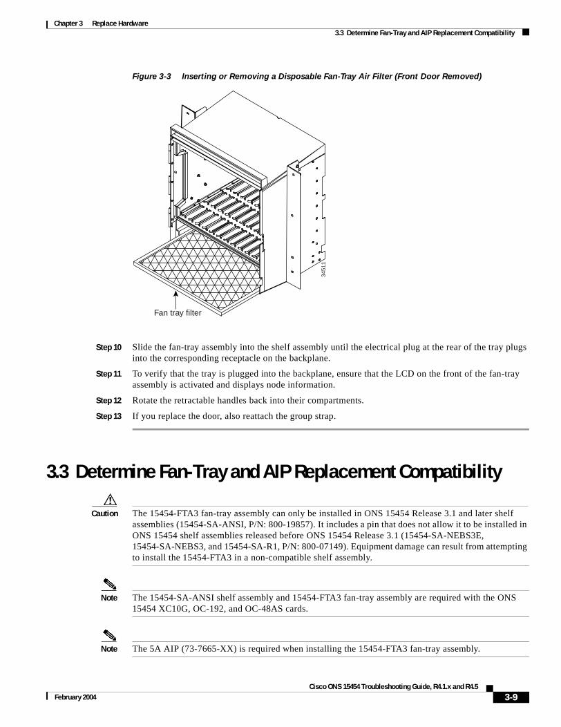
Chapter 3 Replace Hardware3.3 Determine Fan-Tray and AIP Replacement Compatibility
Figure 3-3 Inserting or Removing a Disposable Fan-Tray Air Filter (Front Door Removed)
Step 10 Slide the fan-tray assembly into the shelf assembly until the electrical plug at the rear of the tray plugs into the corresponding receptacle on the backplane.
Step 11 To verify that the tray is plugged into the backplane, ensure that the LCD on the front of the fan-tray assembly is activated and displays node information.
Step 12 Rotate the retractable handles back into their compartments.
Step 13 If you replace the door, also reattach the group strap.
3.3 Determine Fan-Tray and AIP Replacement Compatibility
Caution The 15454-FTA3 fan-tray assembly can only be installed in ONS 15454 Release 3.1 and later shelf assemblies (15454-SA-ANSI, P/N: 800-19857). It includes a pin that does not allow it to be installed in ONS 15454 shelf assemblies released before ONS 15454 Release 3.1 (15454-SA-NEBS3E, 15454-SA-NEBS3, and 15454-SA-R1, P/N: 800-07149). Equipment damage can result from attempting to install the 15454-FTA3 in a non-compatible shelf assembly.
Note The 15454-SA-ANSI shelf assembly and 15454-FTA3 fan-tray assembly are required with the ONS 15454 XC10G, OC-192, and OC-48AS cards.
Note The 5A AIP (73-7665-XX) is required when installing the 15454-FTA3 fan-tray assembly.
3451
1
Fan tray filter
3-9Cisco ONS 15454 Troubleshooting Guide, R4.1.x and R4.5
February 2004

Chapter 3 Replace Hardware3.3 Determine Fan-Tray and AIP Replacement Compatibility
Step 1 Review Table 3-1 to ensure you have compatible components when replacing the fan-tray assembly or the AIP and note the alarms that will occur when an incompatibility occurs.
Note If you need to determine the hardware that has been installed on a node, click the inventory tab in node view.
Step 2 See the “3.4 Replace the Fan-Tray Assembly” section on page 3-11 to replace the fan-tray assembly or the “3.5 Replace the Alarm Interface Panel” section on page 3-12 to replace the AIP.
Table 3-1 Incompatibility Alarms
Shelf Assembly 1
1. 15454-SA-ANSI (P/N: 800-19857-01) = ONS 15454 Release 3.1 and later shelf assembly,15454-SA-NEBS3E (P/N: 800-07149-xx) or 15454-SA-NEBS3 (P/N: 800-06741-xx) = shelf assemblies released before ONS 15454 Release 3.1
Fan Tray2
2. 5A Fan Tray = 15454-FTA3 (P/N: 800-19858-xx) or 15454-FTA3-T (P/N: 800-21448-xx),2A Fan Tray = 15454-FTA2 (P/Ns: 800-07145-xx, 800-07385-xx, 800-19591-xx, 800-19590-xx)
AIP3
3. 5A AIP (P/N: 73-7665-01), 2A AIP (P/N: 73-5262-01)
10G Cards4
4. 10G cards = XC-10G, OC-192, OC-48AS
Ethernet Cards5
5. 2.5G compatible Ethernet cards = E1000-T, E1000-2, E1000T-G, E10002-G, G1000-4, G1K-410G compatible Ethernet cards = E1000T-G, E10002-G, G1000-4, G1K-4, ML100T-12, ML1000-2
Alarms
— — No fuse — — MEA on AIP
NEBS3E or NEBS3 2A 2A No — None
NEBS3E or NEBS3 2A 2A Yes — MEA on 10G
NEBS3E or NEBS3 2A 5A No — None
NEBS3E or NEBS3 2A 5A Yes — MEA on 10G
ANSI 2A 2A No — None
ANSI 2A 2A Yes 2.5G compatible MEA on fan tray, AIP, Ethernet
ANSI 2A 2A Yes 10G compatible MEA on fan tray, AIP
ANSI 2A 5A No Either None
ANSI 2A 5A Yes 2.5G compatible MEA on fan tray, Ethernet
ANSI 2A 5A Yes 10G compatible MEA on fan tray
ANSI 5A 2A No Either MEA on AIP
ANSI 5A 2A Yes 2.5G compatible MEA on AIP, Ethernet
ANSI 5A 2A Yes 10G compatible MEA on AIP
ANSI 5A 5A No Either None
ANSI 5A 5A Yes Either None
3-10Cisco ONS 15454 Troubleshooting Guide, R4.1.x and R4.5
February 2004

Chapter 3 Replace Hardware3.4 Replace the Fan-Tray Assembly
3.4 Replace the Fan-Tray Assembly
Caution The 15454-FTA3 fan-tray assembly can only be installed in ONS 15454 Release 3.1 and later shelf assemblies (15454-SA-ANSI, P/N: 800-19857). It includes a pin that does not allow it to be installed in ONS 15454 shelf assemblies released before ONS 15454 Release 3.1 (15454-SA-NEBS3E, 15454-SA-NEBS3, and 15454-SA-R1, P/N: 800-07149). Equipment damage can result from attempting to install the 15454-FTA3 in a non-compatible shelf assembly.
Caution Do not force a fan-tray assembly into place. Doing so can damage the connectors on the fan tray and/or the connectors on the backplane.
Note The 15454-SA-ANSI shelf assembly and 15454-FTA3 fan-tray assembly are required with the ONS 15454 XC-10G, OC-192, and OC-48 any slot (AS) cards.
To replace the fan-tray assembly (FTA), it is not necessary to move any of the cable management facilities.
Step 1 Open the front door of the shelf assembly. If the shelf assembly does not have a front door, continue with Step 3.
a. Open the front door lock.
The ONS 15454 comes with a pinned hex key for locking and unlocking the front door. Turn the key counterclockwise to unlock the door and clockwise to lock it.
b. Press the door button to release the latch.
c. Swing the door open.
Step 2 Remove the front door (optional). If you do not want to remove the door, proceed to Step 3.
a. Detach the ground strap from either the door or the chassis by removing one of the Kepnuts.
b. Place the Kepnut back on the stud after the ground strap is removed to avoid misplacement.
c. Secure the dangling end of the ground strap to the door or chassis with tape.
Step 3 Push the outer side of the handles on the fan-tray assembly to expose the handles.
Step 4 Fold out the retractable handles at the outside edges of the fan tray.
Step 5 Pull the handles and slide the fan-tray assembly one inch out of the shelf assembly and wait until the fans stop.
Step 6 When the fans have stopped, pull the fan-tray assembly completely out of the shelf assembly. Figure 3-4 shows the location of the fan tray.
3-11Cisco ONS 15454 Troubleshooting Guide, R4.1.x and R4.5
February 2004
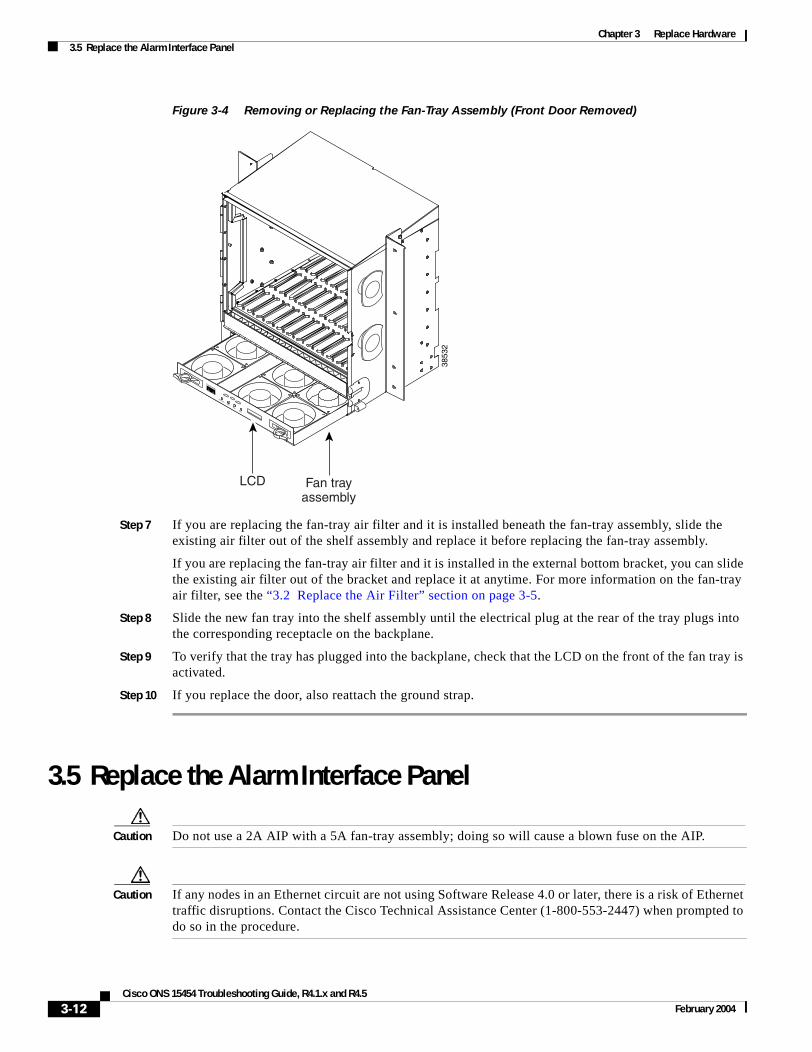
Chapter 3 Replace Hardware3.5 Replace the Alarm Interface Panel
Figure 3-4 Removing or Replacing the Fan-Tray Assembly (Front Door Removed)
Step 7 If you are replacing the fan-tray air filter and it is installed beneath the fan-tray assembly, slide the existing air filter out of the shelf assembly and replace it before replacing the fan-tray assembly.
If you are replacing the fan-tray air filter and it is installed in the external bottom bracket, you can slide the existing air filter out of the bracket and replace it at anytime. For more information on the fan-tray air filter, see the “3.2 Replace the Air Filter” section on page 3-5.
Step 8 Slide the new fan tray into the shelf assembly until the electrical plug at the rear of the tray plugs into the corresponding receptacle on the backplane.
Step 9 To verify that the tray has plugged into the backplane, check that the LCD on the front of the fan tray is activated.
Step 10 If you replace the door, also reattach the ground strap.
3.5 Replace the Alarm Interface Panel
Caution Do not use a 2A AIP with a 5A fan-tray assembly; doing so will cause a blown fuse on the AIP.
Caution If any nodes in an Ethernet circuit are not using Software Release 4.0 or later, there is a risk of Ethernet traffic disruptions. Contact the Cisco Technical Assistance Center (1-800-553-2447) when prompted to do so in the procedure.
FAN FAILCRIT
MAJMIN
3853
2
Fan trayassembly
LCD
3-12Cisco ONS 15454 Troubleshooting Guide, R4.1.x and R4.5
February 2004

Chapter 3 Replace Hardware3.5 Replace the Alarm Interface Panel
Caution Always use the supplied ESD wristband when working with a powered ONS 15454. Plug the wristband cable into the ESD jack located on the lower-right outside edge of the shelf assembly.
Note Perform this procedure during a maintenance window. Resetting the active TCC+/TCC2 card can cause a service disruption of less then 50 ms to OC-N or DS-N traffic. Resetting the active TCC+/TCC2 card can cause a service disruption of 3 to 5 minutes on all Ethernet traffic due to spanning tree reconvergence if any nodes in the Ethernet circuit are not using Software Release 4.0 or later.
Caution Do not perform this procedure on a node with live traffic. Hot-swapping the AIP can affect traffic and result in a loss of data. For assistance with AIP replacement contact Cisco Technical Assistance Center (1-800-553-2447).
This procedure replaces an existing AIP with a new AIP on an in-service node without affecting traffic; however, shared packet rings may need to be deleted and rebuilt after the repair procedure. (To do this, consult the Cisco ONS 15454 Procedure Guide.) Ethernet circuits that traverse nodes with a software release prior to 4.0 will be affected.
The above information should clearly state that shared packet ring circuits will need to be deleted and rebuilt after the circuit repair procedure.
You need a #2 Phillips screwdriver.
Step 1 Ensure that all nodes in the affected network are running the same software version before replacing the AIP and repairing circuits:
a. In network view, click the Maintenance > Software tabs. The working software version for each node is listed in the Working Version column.
b. If you need to upgrade the software on a node, refer to the Cisco ONS 15454 Software Upgrade Guide for software upgrade procedures. No hardware should be changed or circuit repair performed until after the software upgrade is complete. If you do not need to upgrade software or have completed the software upgrade, proceed to Step 2.
Step 2 Record the MAC address of the old AIP:
a. Log into the node where you will replace the AIP. For login procedures, see the Cisco ONS 15454 Procedure Guide.
b. In node view, click the Provisioning > Network tabs.
c. Record the MAC address shown in the General tab (Figure 3-5).
3-13Cisco ONS 15454 Troubleshooting Guide, R4.1.x and R4.5
February 2004

Chapter 3 Replace Hardware3.5 Replace the Alarm Interface Panel
Figure 3-5 Find the MAC Address
Step 3 Call Cisco TAC (1-800-553-2447) for assistance in replacing the AIP and maintaining the original MAC address.
Step 4 Unscrew the five screws that hold the lower backplane cover in place (Figure 3-6).
Step 5 Grip the lower backplane cover and gently pull it away from the backplane.
Figure 3-6 Lower Backplane Cover
Step 6 Unscrew the two screws that hold the AIP cover in place.
Step 7 Grip the cover and gently pull away from the backplane.
Note On the 15454-SA-NEBS3E, 15454-SA-NEBS3, and 15454-SA-R1 (P/N: 800-07149) shelves the AIP cover is clear plastic. On the 15454-SA-ANSI shelf (P/N: 800-19857), the AIP cover is metal.
3206
9
Retainingscrews
3-14Cisco ONS 15454 Troubleshooting Guide, R4.1.x and R4.5
February 2004

Chapter 3 Replace Hardware3.5 Replace the Alarm Interface Panel
Step 8 Grip the AIP and gently pull it away from the backplane.
Step 9 Disconnect the fan-tray assembly power cable from the AIP.
Step 10 Set the old AIP aside for return to Cisco.
Caution The type of shelf the AIP resides in will determine the version of AIP that will replace the failed AIP. The 15454-SA-ANSI shelf (P/N: 800-19857) currently uses the 5A AIP, (P/N: 73-7665-01). The 15454-SA-NEBS3E, 15454-SA-NEBS3, and 15454-SA-R1 (P/N: 800-07149) shelves and lower currently use the 2A AIP (P/N: 73-5262-01).
Caution Do not put a 2A AIP (P/N: 73-5262-01) into a 15454-SA-ANSI shelf (P/N: 800-19857); doing so will cause a blown fuse on the AIP.
Step 11 Attach the fan-tray assembly power cable to the new AIP.
Step 12 Place the new AIP on the backplane by plugging the panel into the backplane using the DIN connector.
Step 13 Replace the AIP cover over the AIP and secure the cover with the two screws.
Step 14 Replace the lower backplane cover and secure the cover with the five screws.
Step 15 In node view, click the Provisioning > Network tabs.
Caution Cisco recommends TCC+/TCC2 resets be performed in a maintenance window to avoid any potential service disruptions.
Step 16 Reset the standby TCC+/TCC2 card:
a. Right-click the standby TCC+/TCC2 card and choose Reset Card.
b. Click Yes on the Resetting Card dialog box. As the card resets, a loading (Ldg) indication will appear on the card in CTC.
Note The reset will take approximately five minutes. Do not perform any other steps until the reset is complete.
Step 17 Reset the active TCC+/TCC2 card:
a. Right click the active TCC+/TCC2 card and choose Reset Card.
b. Click Yes on the Resetting Card dialog box. As the card resets, a Ldg indication will appear on the card in CTC.
Note The reset will take approximately five minutes and CTC will lose its connection with the node.
Step 18 From the File pull-down menu choose Exit to exit the CTC session.
Step 19 Log back into the node. At the Login dialog box, choose (None) from the Additional Nodes pull-down menu.
Step 20 Record the new MAC address:
a. In node view, click the Provisioning > Network tabs.
3-15Cisco ONS 15454 Troubleshooting Guide, R4.1.x and R4.5
February 2004

Chapter 3 Replace Hardware3.5 Replace the Alarm Interface Panel
b. Record the MAC address shown in the General tab.
Step 21 In node view, click the Circuits tab. Note that all circuits listed are in an INCOMPLETE state.
Step 22 In node view, choose Repair Circuits from the Tools pull-down menu. The Circuit Repair dialog box is displayed.
Step 23 Read the instructions in the Circuit Repair dialog box (Figure 3-7). If all the steps in the dialog box have been completed, click Next>. Ensure you have the old and new MAC addresses.
Figure 3-7 Repairing Circuits
Step 24 The Node MAC Addresses dialog box displays (Figure 3-8):
a. From the Node pull-down menu, choose the name of the node where you replaced the AIP.
b. In the Old MAC Address field, enter the old MAC address that was recorded in Step 2.
c. Click Next.
Figure 3-8 Recording the Old MAC Address Before Replacing the AIP
Step 25 The Repair Circuits dialog box displays (Figure 3-9). Read the information in the dialog box and click Finish.
3-16Cisco ONS 15454 Troubleshooting Guide, R4.1.x and R4.5
February 2004

Chapter 3 Replace Hardware3.6 Replace an Electrical Interface Assembly
Figure 3-9 Circuit Repair Information
Note The CTC session will freeze until all circuits are repaired. Circuit repair can take up to five minutes or more depending on the number of circuits provisioned.
When the circuit repair is complete, the Circuits Repaired dialog box will display.
Step 26 Click OK.
Step 27 In the node view of the new node, click the Circuits tab. Note that all circuits listed are in an ACTIVE state. If all circuits listed are not in an ACTIVE state, call the Cisco Technical Assistance Center TAC (1-800-553-2447) to open a Return Material Authorization (RMA).
3.6 Replace an Electrical Interface AssemblyYou need a #2 Phillips screwdriver. If you use high-density BNC EIAs, you also need a BNC insertion and removal tool.
Step 1 To remove the lower backplane cover, loosen the five screws that secure it to the ONS 15454 and pull it away from the shelf assembly (Figure 3-6).
Step 2 Loosen the nine perimeter screws that hold the backplane sheet metal cover or EIA in place. Do not remove the interior screws.
Note If you are removing an AMP Champ EIA, remove the fastening plate before proceeding. To remove the fastening plate, loosen the two thumbscrews.
Step 3 If a backplane cover is attached to the ONS 15454, lift the panel by the bottom to remove it from the shelf assembly and store the panel for later use.
Step 4 If an EIA is attached to the ONS 15454, lift the EIA handles and gently pull it away from the backplane.
Note Attach backplane sheet metal covers whenever EIAs are not installed.
3-17Cisco ONS 15454 Troubleshooting Guide, R4.1.x and R4.5
February 2004

Chapter 3 Replace Hardware3.7 Replace the Small Form-Factor Pluggable Connector
Step 5 Line up the connectors on the new EIA with the mating connectors on the backplane.
Step 6 Gently push the EIA until both sets of connectors fit together snugly.
Step 7 Replace the nine perimeter screws that you removed while removing the backplane cover.
Step 8 If you are installing an AMP Champ EIA, attach the fastening plate with the two thumbscrews.
Step 9 Reattach the lower backplane cover.
3.7 Replace the Small Form-Factor Pluggable Connector
Step 1 Unplug the SFP connector and fiber from the ML-series Ethernet card.
Step 2 If the SFP connector has a latch securing the fiber-optic cable, pull it upward to release the cable.
Step 3 Pull the fiber cable straight out of the connector.
Step 4 Plug the fiber into a Cisco-supported SFP connector.
Step 5 If the new SFP connector has a latch, close the latch over the cable to secure it.
Step 6 Plug the cabled SFP connector into the ML-series Ethernet card port until it clicks.
3-18Cisco ONS 15454 Troubleshooting Guide, R4.1.x and R4.5
February 2004
Copyright © 2022 FDOKUMEN