EFI XF 4.5 - CiteSeerX
333
1 Copyright © EFI, 2006-2010 This manual may not be copied or reproduced in any form, whether by printing, photocopying or any other method of reproduction without written permission. EFI accepts no liability with regard to the use of this program or any errors or omissions in this manual. The information in this manual represents the state of the software at the time of printing. EFI reserves the right to make technical changes at any time. The products named in this manual are registered trademarks of their respective manufacturers. Acrobat, Adobe and PostScript are either registered trademarks or trademarks of Adobe Systems Incorporated in the United States and/or other countries. HKS® is a registered trademark of HKS Trademark Association. PANTONE® is a registered trademark of Pantone, Inc. Additional third party copyrights and notices: Portions Copyright (c) 1990, 1994 Regents of The University of Michigan. All Rights Reserved. Portions Copyright (c) 1983 Regents of the University of California. All rights reserved. Redistribution and use in source and binary forms, with or without modification, are permitted provided that the following conditions are met: Redistributions of source code must retain the above copyright notice, this list of conditions and the following disclaimer. Redistributions in binary form must reproduce the above copyright notice, this list of conditions and the following disclaimer in the documentation and/or other materials provided with the distribution. All advertising materials mentioning features or use of this software must display the following acknowledgement: This product includes software developed by the University of California, Berkeley and its contributors. Neither the name of the University nor the names of its contributors may be used to endorse or promote products derived from this software without specific prior written permission. This software is provided by the regents and contributors "as is" and any express or implied warranties, including, but not limited to, the implied warranties of merchantability and fitness for a particular purpose are disclaimed. In no event shall the regents or contributors be liable for any direct, indirect, incidental, special, exemplary, or consequential damages (including, but not limited to, procurement of substitute goods or services, loss of use, data, or profits; or business interruption) however caused and on any theory of liability, whether in contract, strict liability, or tort (including negligence or otherwise) arising in any way out of the use of this software, even if advised of the possibility of such damage. Copyright (c) 1983 Regents of the University of California. Copyright (c) 1990, 1991 Regents of The University of Michigan. Portions Copyright (c) 1990,1991 Regents of The University of Michigan. All Rights Reserved. Permission to use, copy, modify, and distribute this software and its documentation for any purpose and without fee is hereby granted, provided that the above copyright notice appears in all copies and that both that copyright notice and this permission notice appear in supporting documentation, and that the name of The University of Michigan not be used in advertising or publicity pertaining to distribution of the software without specific, written prior permission. This software is supplied "as is" without expressed or implied warranties of any kind. Research Systems Unix Group The University of Michigan c/o Mike Clark 535 W. William Street Ann Arbor, Michigan +1-313-763-0525 [email protected] First published November 2010
-
Upload
khangminh22 -
Category
Documents
-
view
4 -
download
0
Transcript of EFI XF 4.5 - CiteSeerX
1
Copyright © EFI, 2006-2010
This manual may not be copied or reproduced in any form, whether by printing, photocopying or any other method of reproduction without written permission.
EFI accepts no liability with regard to the use of this program or any errors or omissions in this manual. The information in this manual represents the state of the software at the time of printing. EFI reserves the right to make technical changes at any time.
The products named in this manual are registered trademarks of their respective manufacturers.
Acrobat, Adobe and PostScript are either registered trademarks or trademarks of Adobe Systems Incorporated in the United States and/or other countries.
HKS® is a registered trademark of HKS Trademark Association. PANTONE® is a registered trademark of Pantone, Inc.
Additional third party copyrights and notices:
Portions Copyright (c) 1990, 1994 Regents of The University of Michigan. All Rights Reserved.
Portions Copyright (c) 1983 Regents of the University of California. All rights reserved.
Redistribution and use in source and binary forms, with or without modification, are permitted provided that the following conditions are met:
Redistributions of source code must retain the above copyright notice, this list of conditions and the following disclaimer.
Redistributions in binary form must reproduce the above copyright notice, this list of conditions and the following disclaimer in the documentation and/or other materials provided with the distribution.
All advertising materials mentioning features or use of this software must display the following acknowledgement: This product includes software developed by the University of California, Berkeley and its contributors.
Neither the name of the University nor the names of its contributors may be used to endorse or promote products derived from this software without specific prior written permission.
This software is provided by the regents and contributors "as is" and any express or implied warranties, including, but not limited to, the implied warranties of merchantability and fitness for a particular purpose are disclaimed. In no event shall the regents or contributors be liable for any direct, indirect, incidental, special, exemplary, or consequential damages (including, but not limited to, procurement of substitute goods or services, loss of use, data, or profits; or business interruption) however caused and on any theory of liability, whether in contract, strict liability, or tort (including negligence or otherwise) arising in any way out of the use of this software, even if advised of the possibility of such damage.
Copyright (c) 1983 Regents of the University of California. Copyright (c) 1990, 1991 Regents of The University of Michigan. Portions Copyright (c) 1990,1991 Regents of The University of Michigan. All Rights Reserved.
Permission to use, copy, modify, and distribute this software and its documentation for any purpose and without fee is hereby granted, provided that the above copyright notice appears in all copies and that both that copyright notice and this permission notice appear in supporting documentation, and that the name of The University of Michigan not be used in advertising or publicity pertaining to distribution of the software without specific, written prior permission. This software is supplied "as is" without expressed or implied warranties of any kind.
Research Systems Unix Group The University of Michigan c/o Mike Clark 535 W. William Street Ann Arbor, Michigan
+1-313-763-0525 [email protected]
First published November 2010

TABLE OF CONTENTS 3
TABLE OF CONTENTS
INTRODUCTION 13
What is EFI XF? 13
Program architecture 14
System requirements 14
Program folders 15
Conventions 20
SETTING UP 21
Starting the EFI XF Client 21
Logging on to an EFI XF Server 22
System workflows 23
Default system workflows 23
Setting up system workflows 24
Licensing 34
How does the license management system work? 34
Licensing the software 35
GETTING TO KNOW YOUR SOFTWARE 40
Job Explorer 40
System Manager 41
TABLE OF CONTENTS 4
SETTINGS IN SYSTEM MANAGER 43
Menus 43
EFI XF Client (Macintosh only) 43
File menu 43
Edit menu 44
System menu 47
Tools menu 47
? menu (Windows)/Help menu (Macintosh) 48
Toolbar 48
Property Inspector 49
Server tab > Info pane 49
User settings 50
Workflow settings 50
Output device settings 85
MANAGING SYSTEM WORKFLOWS 90
Making changes to system workflows 90
Available menu commands 91
Saving and restoring settings 93
SETTINGS IN JOB EXPLORER 97
Menus 97
EFI XF Client (Macintosh only) 97
File Menu 97
Edit menu 98
Nesting menu 103
Tools menu 103
View menu 104
? menu (Windows)/Help menu (Macintosh) 106
Context menus 107

TABLE OF CONTENTS 5
Toolbars 108
First toolbar 108
Second toolbar 109
Preview toolbar 111
Property Inspector 111
Input tab > File Info pane 111
Input tab > Settings pane 112
Layout tab > Job Layout pane 112
Layout tab > Nesting pane 112
Layout tab > Step & Repeat pane 112
Layout tab > Footer pane 113
Color tab > Color Management pane 113
Finishing tab > Marks pane 113
Output tab > Print pane 114
Output tab > Special pane 114
Output tab > File Output pane 114
Verify tab > Control Strip 1/Control Strip 2 pane 114
System tab > Server pane 115
System tab > Device pane 115
Keyboard shortcuts 115
Activating options 115
Activating toolbars 116
General 116
Page position 117
Nesting jobs 117
Zoom 118
Rulers, guides and grid 119

TABLE OF CONTENTS 6
PRINTING AND MONITORING PRINT JOBS 120
Printing directly from EFI XF 120
Job Monitor 123
Menus 125
Printing via Job Monitor 126
Printing via a hotfolder 127
Unidriver 129
Windows 129
Macintosh 132
Virtual printing 134
Installed protocols according to operating system 134
Setting up AppleTalk for Windows XP 135
Setting up EFI XF 137
Setting up the computer on which the graphics application is installed 140
Printing from an application 145
CROPPING 146
NESTINGS 148
What are nestings? 148
User interface 149
Creating nestings 150
Automatic nestings 150
Manual nestings 151
Editing nestings 152
Adding jobs to a nesting 152
Adding/deleting sheets 152
Removing jobs from nestings 152

TABLE OF CONTENTS 7
EFI XF CONTROL 153
What is EFI XF Control? 153
Available features 153
EFI XF Online Update 154
EFI XF Profiles Online Update 155
EFI XF Offline Update 155
EFI XF Server Stop/EFI XF Server Start/EFI XF Server Restart 155
EFI XF Client Start 155
EFI XF Server Configuration (Windows only) 156
Activate EFI XF 156
Show dongle ID 156
Show license information 156
Autostart EFI XF Control (Windows)/Open at Login (Macintosh) 156
Server File Maintenance 157
Exit (Windows)/Quit (Macintosh) 157
PRODUCTION OPTION 158
What production tools are available? 158
Production Option settings 158
Tiling 159
Tiling toolbar 159
Tiling pane 160
Creating a tiling 163
Working with tilings 165
Printing 169
Step & repeat 169
Additional color management settings 170
Color tab > Color Adjustment pane 170
Color tab > Color Management pane 171
Job merge 172

TABLE OF CONTENTS 8
COLOR VERIFIER OPTION 175
ISO support 176
Scope of delivery 177
Starting Color Verifier 178
User interface 178
Program window 178
Preferences dialog 179
EFI 3D Viewer 189
Menus 191
Color Verifier settings in EFI XF 195
System Manager 195
Job Explorer 199
Implementing Color Verifier in EFI XF 200
Practical examples of how to use Color Verifier 206
Achieving Fogra Proof Certification 206
Achieving an ISO 12647-7 compliant proof 209
Analyzing the results 212
Evaluating the results in EFI XF 216
ES-1000 217
How to measure with ES-1000 217
Safety instructions 218
Maintenance 219
Service 219
Declaration of conformity 220
Warranty conditions 221
ES-1000 Warranty/Repair Form 222

TABLE OF CONTENTS 9
SPOT COLOR OPTION 223
How are spot colors managed in EFI XF? 223
Spot color settings in EFI XF 223
System Manager 224
Job Explorer 228
Starting Color Editor 230
User interface 231
Menus 232
Toolbar 233
Defining spot colors 234
Editing spot colors 242
Modifying the gradation 242
Modifying the overprint and gamma values 243
Searching for and replacing spot colors 244
Deleting spot color tables 245
LINTOOL/COLOR MANAGER OPTION 246
EFI linearization and profiling tools 246
What is LinTool? 246
What is Color Manager? 247
System Manager settings 247
Starting LinTool/Color Manager 247
User interface 248
Menus 249
How does color management in EFI XF work? 249
Profiles 249
Linearizations 250
Working with LinTool/Color Manager 250
When to perform a printer re-linearization 250
Tips 251

TABLE OF CONTENTS 10
ONEBIT OPTION 252
OneBit Option settings 252
System Manager 253
Job Explorer 255
DOT CREATOR OPTION 256
How does Dot Creator work? 257
Starting Dot Creator 261
User interface 262
Menus 263
Additional settings in EFI XF 264
Creating halftone screens 266
Implementing halftone screens in EFI XF 268
FILE OUTPUT OPTION/GRAVURE OUTPUT OPTION 272
Print-to-file options 272
What is the File Output Option? 272
What is the EFI Gravure Output Option? 272
Printing to file 272
JAPANESE FONTS 274
FIERY OPTION 275
Fiery Option settings 275
Printing to an EFI Fiery output device 275

TABLE OF CONTENTS 11
JDF CONNECTOR 277
Installing JDF Connector 277
Supported file formats 278
Setting up a JDF connection 278
PNI software 278
JDF settings in EFI XF 279
JDF jobs in EFI XF 280
Loading JDF jobs in EFI XF 280
Editing JDF jobs in EFI XF 281
PRINTING TO VUTEK PRINTERS 284
Licenses 284
Additional settings in EFI XF 284
Printing to a VUTEk printer 285
PERFORMANCE OPTION 287
Additional settings in EFI XF 287
CUTTING OPTIONS 289
Additional settings in EFI XF 289
Finishing tab > Cut pane 290
Cut Marks Option 295
i-cut marks 295
FOTOBA cut marks 297
Grommet marks 298
Zünd Cut Center 300
Cut Server Option (Windows only) 301

TABLE OF CONTENTS 12
Working with contour cut files 303
Preparing contour cut files in the application 303
Setting up a workflow in EFI XF 304
Tips and tricks 305
RGB PROFILE CONNECTOR 308
TROUBLESHOOTING 310
Server/Logging on 310
Licensing 312
Printing 314
Color management 317
Media profiles 317
Add-on modules 318
USB devices 319
EFI Support 320
Knowledge Center 320
Online user forum 320
UNINSTALLING 321
Windows 321
Macintosh 322
GLOSSARY 324
INDEX 330
INTRODUCTION 13
INTRODUCTION
This section describes the purpose for which the software was designed, provides details of the hardware and software requirements necessary to set up and run your software and gives an overview of the folder structure.
What is EFI XF?The EFI XF product family is the perfect tool for anyone wanting to achieve high-quality color reproduction. The software runs on both Windows and Macintosh and produces color-accurate output, while avoiding the need for complicated color management settings.
EFI XF is available in two product configurations: EFI Colorproof XF for the proofing markets and EFI Fiery XF targetting Sign & Display and Print-for-Pay markets.
Both the EFI Colorproof and the EFI Fiery XF configurations are ICC-compliant cross-platform Client/Server applications and can be flexibly configured to the customers’ needs and for any size of operation due to their modular architecture.
The structured user interface and various wizards easily allow customers to either simulate the colors achieved on a professional printing press or any other printer, thereby making it possible to reproduce genuine proofs on a conventional printer, or to achieve the maximum gamut of the printer, media and ink combination.
EFI Colorproof XF focusses on ISO 12467-7/8-compliant validation printing and contract proofing , while EFI Fiery XF is configured for production-heavy environments with intelligent clean color technologies, tiling, advanced step & repeat, color adjustments for last minute editings and professional finishing.
In the following "EFI XF" is used for both solutions, as the functional range is the same when all the available add-on modules are installed.
INTRODUCTION 14
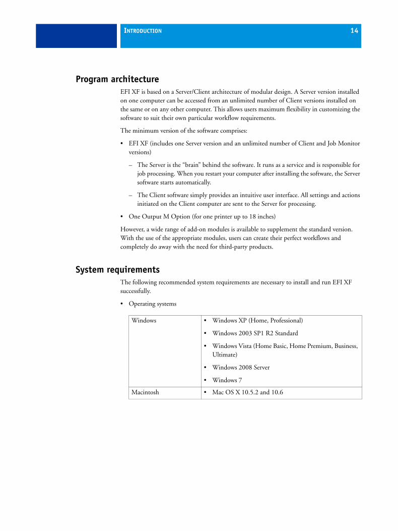
Program architectureEFI XF is based on a Server/Client architecture of modular design. A Server version installed on one computer can be accessed from an unlimited number of Client versions installed on the same or on any other computer. This allows users maximum flexibility in customizing the software to suit their own particular workflow requirements.
The minimum version of the software comprises:
• EFI XF (includes one Server version and an unlimited number of Client and Job Monitor versions)
– The Server is the “brain” behind the software. It runs as a service and is responsible for job processing. When you restart your computer after installing the software, the Server software starts automatically.
– The Client software simply provides an intuitive user interface. All settings and actions initiated on the Client computer are sent to the Server for processing.
• One Output M Option (for one printer up to 18 inches)
However, a wide range of add-on modules is available to supplement the standard version. With the use of the appropriate modules, users can create their perfect workflows and completely do away with the need for third-party products.
System requirementsThe following recommended system requirements are necessary to install and run EFI XF successfully.
• Operating systems
Windows • Windows XP (Home, Professional)
• Windows 2003 SP1 R2 Standard
• Windows Vista (Home Basic, Home Premium, Business, Ultimate)
• Windows 2008 Server
• Windows 7
Macintosh • Mac OS X 10.5.2 and 10.6

INTRODUCTION 15
• Hardware
Program foldersThis section gives an overview of the file structure of EFI XF to enable you to locate program files, custom files and other important files quickly and easily.
A direct link to some of the most commonly used folders is also available via:
• Start > All Programs > EFI > XF > Links (Windows)
• Links icon in the Dock (Macintosh)
Server • PC: 2 GHz Pentium IV PC or higher (dual processor recommended)
• Macintosh: Intel Mac (dual processor recommended)
• 1 GB RAM for each processor
• 60 GB free hard disk space
• 10/100 MBit network interface card
• 2 available USB ports (for dongle and measuring device)
Client • PC: 2 GHz Pentium IV PC
• Macintosh: Intel Mac
• 512 MB RAM
• 10/100 MBit network interface
• 1 available USB port (for measuring device)

INTRODUCTION 16
• Installation folder
Unless you choose a different location, fix program components of EFI XF are installed by default in the following folder:
* If you chose not to install EFI XF to the default location, all the program folders, including the Server folder, are installed in the user-defined folder.
The application folder contains the following five subfolders:
Windows XP/2003/2008/Vista/7
32 bit on 32-bit OS \Program Files\EFI\EFI XF
32 bit on 64-bit OS \Program Files(x86)\EFI\EFI XF
64 bit on 64-bit OS* \Program Files(x86)\EFI\EFI XF (Server folder only)
\Program Files(x86)\EFI\EFI XF (all other program folders)
Macintosh /Applications/EFI XF
Folder name Subfolder name Contains
Client Program files for EFI XF, including additionally licensed options
Color Manager Charts Charts for linearization and profiling in Color Manager
Color Verifier Charts Charts for checking color accuracy in Color Verifier
Documentation HTML Help files and PDF user manual
IT8_CharacterizationData IT8.7/4 profiling charts for Fogra Proof Certification
MonitorProfile Default and custom monitor profiles
Samples EFI_Form_Offset reference test files
Lineal_01.ps for calculating media length correction
Print & Cut test files
EFI_White_ink
EFI RGB Profile Connector
Program files

INTRODUCTION 17
JDF All JDF program
Monitor Program files for Job Monitor
Server All program files related to the Server
Tools Program file for EFI XF Server Information
Definition Strip for X-Rite DTP-20
TIDforMKV2OXP-V2.tif (TID patch for DTP 20 measuring device)
EFI AppleTalk driver AppleTalk driver required for AppleTalk support on Windows XP computers
FograCert FograCert test forms for Fogra Proof Certification
PPD PPDs
Printer PnP (Windows only)
Plug & play files for supported printers
USB Measurement Devices (Windows only)
Device drivers for supported measuring devices
Folder name Subfolder name Contains

INTRODUCTION 18
• Work folder
You will find all work files directly associated with job processing located in the following folders:
If you cannot see the Application Data folder, it may be because it is set up as a hidden folder on your computer. Consult your administrator if you have trouble accessing this folder.
The folder EFI XF contains the following folders and subfolders:
Windows 2000/XP \Documents and Settings\All Users\Application Data\EFI\EFI XF
Windows 2008/Vista/7 \ProgramData\EFI\EFI XF
Macintosh /Library/Application Support/EFI/EFI XF
Folder name Subfolder name Contains
Client Working Temporary files. Used to save linearization and profiling files from Color Manager as well as Remoteproof Containers for manual creation.

INTRODUCTION 19
Server Backup Backup files of system workflows
ControlCharts it8 files for the checking the measured color values of the control strips
ControlStrip Control strips for footer
Environments Backup files of environments
Export Default folder for print-to-file jobs
JobFolder Temporary job files
Log Log files. Important in case of support queries.
Logo Copies of logo files selected for job ticket
Output Print (bco) files
Preview Preview files
Profiles
\Balance
\Monitor
\Reference
\Reference Additional
\Spotcolor
Default 3cc files; vcc and vpc files created in Color Manager
Monitor profiles
Reference profiles in common use in the industry
Device link profiles
Additional reference profiles in common use around the world
Spot color tables (bct) created in Color Editor
Remote Incoming and outgoing Remoteproof Containers (rpf ) to and from Color Verifier
Screening Screening files (spt) created in Dot Creator
Tickets Record of all actions taken in EFI XF. Important in case of support queries.
Folder name Subfolder name Contains

INTRODUCTION 20
• Media profiles
Media profiles are installed in the following folders:
• License files
License files are installed in the following folders:
ConventionsCautions must be read carefully. They indicate important information which can help you prevent errors when using the software.
Tips and information which you may find useful to perform a certain step.
The screen captures illustrated in this manual have been created from a mixture of both the Windows and Macintosh versions of the software. Depending on which version you are using, the image on your screen may look slightly different. However, unless otherwise stated, the functionality is the same for both operating systems.
Windows XP/2003/2008 \Program Files\EFI\EFI Media Profiles
Windows Vista/7 \ProgramData\EFI\EFI Media Profiles
Macintosh /Library/Application Support/EFI/EFI Media Profiles
Windows XP/2003/2008/Vista/7
\Program Files\FlexLM
Macintosh /Applications/FlexLM

SETTING UP 21
SETTING UP
Starting the EFI XF ClientTo start the EFI XF Client:
• Double-click the program icon on the computer desktop (Windows)
• Click the program icon in the Dock (Macintosh)
The software cannot be started before it is licensed. If an error message appears to inform you that no valid license is available, you may have generated a license for an incorrect dongle ID.
Open the license file to check which dongle ID you typed in. See “License files” on page 20 for details of where license files are installed. If this does not match the dongle ID displayed in EFI XF Control, please send an e-mail to:
• [email protected] (for Europe/Asia/Australia/Africa)
• [email protected] (for North and South America)
giving details of:
• the EAC code(s) of the incorrectly generated license(s)
• the correct dongle ID (from EFI XF Control)
• the incorrectly typed dongle ID (printed in the license file)
See also:
“Licensing” on page 34
Program icon

SETTING UP 22
Logging on to an EFI XF ServerIf an EFI XF Server and Client are installed on the same computer, the EFI XF Client automatically logs on to that Server as the default administrator the first time you start the software. If no EFI XF Server is installed on the same computer, the following window opens when you try to start the software. You must log on to an EFI XF Server before you can proceed.
If a firewall is in use in your network, make sure that it is configured so that communication between Server and Client computers is possible. The following ports must be available on the Server and Client computers:
• 8010 (TCP and UDP)
• 50005 to 500025 (TCP)
• 20020 to 20021 (UDP)
Furthermore, make sure that the following applications can communicate with the network:
Login window
Server EFI_XF_Server.exe EFI_Activation_Wizard.exe (located in the subfolder Activation on PC) EFI_XF_Control.exe ProfileUpdater.exe Updater.exe
Client EFI_XF_Client.exe EFI_ClientPtchr.exe EFI_ClientPatcher.exe EFIColorEditor.exe EFIColorManager.exe EFIColorVerifier.exe EFIDotCreator.exe

SETTING UP 23
For the Windows firewall, the port and application settings are created automatically by the installer.
TO LOG ON TO AN EFI XF SERVER
1 Type the default login information, as follows:
User name: admin Password: admin
This is the default administrator login information. You can log in under different user credentials if EFI XF has already been set up and additional users have been created.
2 Select the IP address of the Server computer.
A list of all available EFI XF Servers in your sub-network is displayed with IP address in the drop-down list box. If Server and Client are installed on the same computer, ”localhost” is selected by default. However, you can also type in manually the IP address of an EFI XF Server. Ask your system administrator if you are not sure which TCP/IP address to use.
If you are currently logged on to a Server installed on a different computer and want to log on to a local Server installed on the same computer as the EFI XF Client, you can type “localhost” instead of an IP address. This means that the default IP address 127.0.0.1 is used by the software.
3 Click OK.
The connected Server is displayed at the bottom of the program window.
System workflowsThis documentation makes a distinction between the terms “system workflow” and “workflow”. The term “system workflow” consists of a user, workflow and output device. It refers to all work processes from file input by a certain user to file output on a specified printer. The term “workflow” is concerned only with file processing and the way files are handled in EFI XF.
Default system workflowsEFI XF is installed with one default system workflow, consisting of two users, one workflow and one output device.
The user "admin" (default password "admin") is permitted to create, set up and manage system workflows in System Manager.
Default system workflow configuration
SETTING UP 24
The user "guest" (default password "guest") is permitted to print and manage his or her own print jobs in Job Explorer but does not have access to System Manager and cannot create or modify system workflows. ”Guest” enables infrequent users of EFI XF to log on quickly and easily, without first having to be defined as an individual user.
The workflow “EFI Linearization” and the output device “Linearization device” are used primarily in conjunction with LinTool and Color Manager for printer linearization and profile creation. Only users with administrator rights can print jobs via this workflow. You must configure the linearization device before you can access LinTool or Color Manager.
If you set up a workflow and output device as part of the installation procedure, these will also be visible in System Manager.
Setting up system workflowsYou can set up a system workflow in:
• Setup Wizard (Windows) or Setup Assistant (Macintosh)
The Setup Wizard/Assistant leads you logically through the minimum of steps necessary to set up a system workflow for the default users. You can finetune your workflow settings later in System Manager, if required.
Normally, you will already have created a system workflow in this way when you installed EFI XF.
• System Manager
In System Manager, you can create additional users, workflows and output devices. You can also change the configuration of existing workflows.
To set up an output device, you must have media profiles for your printer installed on the computer. If you did not install any media profiles during program installation, install them now from the software DVD or via EFI XF Control. See “EFI XF Control” on page 153 for further information.
Setting up in Setup Wizard/Assistant
Setup Wizard/Assistant provides step-by-step instructions on how to configure a basic system workflow.
System workflows created in this way enable the default users to output print jobs in their original size and with color management applied.
SETTING UP 25
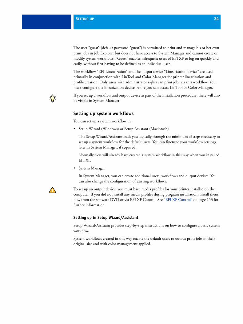
TO SET UP A SYSTEM WORKFLOW IN SETUP WIZARD/ASSISTANT
You can click Finish Now at any time to exit the setup procedure. Any settings that you have already made are saved.
1 In the toolbar, click System Manager.
2 From the System menu, choose Setup Wizard (Windows) or Setup Assistant (Macintosh).
Introduction window

SETTING UP 26
3 Click Continue to open the Workflow dialog.
4 From the drop-down list box, choose the field of application: Proof, Photo or Production. Then select the template that best suits your workflow requirements.
EFI XF provides many default workflow templates. Each has been set up with specific color management settings for a particular workflow scenario.
Alternatively, select “Custom” to create a workflow with no predefined industry-specific settings or “None” if you prefer to create a workflow later in EFI XF.
Creating a workflow
SETTING UP 27
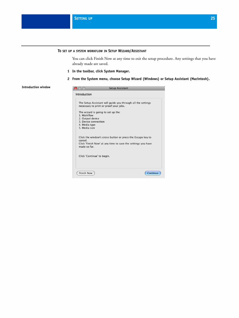
5 Click Continue to display the Output device dialog.
6 From the drop-down list box, select “Create a new output device”.
Alternatively, select “None” if you prefer to create an output device later in EFI XF.
7 From the drop-down list box, select your output device.
When you make a selection, the Setup Wizard/Assistant displays the number of media profiles installed for the output device.
If no media profiles are installed, an error message is displayed. In this case, you must cancel the setup and install the appropriate media profiles from the software DVD or via EFI XF Control. See “EFI XF Control” on page 153 for further information.
Selecting an output device

SETTING UP 28
8 Click Continue to open the Device connection dialog.
9 Select a connection type.
• Select “Print to system printer” to print to a Windows printer that has already been set up as a system printer in Windows.
The available printers are listed in the drop-down list box.
This setting is only available for Windows and the system printer must be a printer supported by EFI XF.
• Select “Print via IP network” if you want to print via TCP/IP.
Type the IP address in the appropriate edit box. You can check whether the connection to the printer has been properly established by clicking Test. To test the connection, the printer must be switched on. If you receive an error message, consult your system administrator for advice.
Select the type of TCP/IP protocol that your printer uses for data transfer.
– Raw on port
Most printers support RAW printing to port 9100. However, please note that this setting depends on the network settings made at the printer and may, therefore, be different.
Setting up a connection

SETTING UP 29
– LPR. The queue name is
If your printer supports LPR printing, type the queue name in the edit box.
In most cases, you can leave this edit box blank. It is normally only necessary to type a queue name if you are printing via a Unix system or a print server with multiple interfaces. Refer to your printer manual for further information.
• Select “Print via port” to print to a printer that is connected via USB to the Server computer.
The printer must be switched on when you start EFI XF. Otherwise, it will not be automatically detected.
10 Click Continue to open the Media type dialog.
11 From the drop-down list box “Ink type”, select the type of ink inserted in the printer.
12 From the drop-down list box “Media name”, select the media you want to use.
EFI XF provides media profiles that have been created for specific combinations of media, ink and resolution. Furthermore, you can implement your own custom media profiles that have been created for your exact printer.
13 From the drop-down list box “Print quality”, select a combination of color mode, resolution and print mode.
The list of available print qualities depends on the media profiles that are installed.
Selecting a media type

SETTING UP 30
14 Click Continue to open the Media size dialog.
15 In the Media Size dialog, make media-specific settings.
Which settings are available depends on the selected printer.
• From the drop-down list box “Source”, select the source of media feed.
• From the drop-down list box “Format”, select the media size. Only default sizes are available initially, but you can define your own media sizes in EFI XF.
• If supported by your particular printer, you can select borderless printing.
16 Click Finish.
Your workflow and output device are now set up.
Selecting a media size
SETTING UP 31
Setting up in System Manager
Creating system workflows in System Manager gives you access to all the settings available in EFI XF.
Once you have created a system workflow, you need to set it online.
TO CREATE A NEW USER
You can set up each co-worker as a user in EFI XF and define user-defined privileges for each.
1 Create a new user by:
• Clicking New User in the toolbar, or
• Right-clicking on an existing user in the layout area and choosing New User from the context menu, or
• Choosing File > New > User
A user with the name “New User 1” is created. The User tab displays the Profile pane.
2 Define a name for the user by:
• Double-clicking on “New User 1” in the layout area, overwriting the default name and pressing <Enter>, or
• Overwriting “New User 1” on the Profile pane
3 On the Profile pane, define a password. Then confirm it by re-typing it in the appropriate edit box.
4 Using the drop-down list box, specify whether the new user will have administrator or user rights.
Administrators have access to System Manager and are permitted to create, set up and manage workflows. Users without administrative rights are only able to submit print jobs and make job-specific settings in Job Explorer.
5 Define whether the new user will be allowed to make job-specific settings for color management, spot colors and color verification.
6 In the toolbar, click Save.

SETTING UP 32
TO CREATE A WORKFLOW
1 Create a new workflow by:
• Clicking New Workflow in the toolbar, or
• Right-clicking on an existing workflow in the layout area and choosing New Workflow from the context menu, or
• Choosing File > New > Workflow
The window New Workflow from Template opens.
2 From the drop-down list box, choose the field of application: Proof, Photo or Production. Alternatively, choose “Custom” to create a workflow with no predefined industry-specific settings.
3 From the list box “Template Name”, choose the workflow template that best suits your needs.
EFI XF provides many default workflow templates. Each has been set up with specific color management settings for a particular workflow scenario, such as pre-press, print production, photo printing or contour cutting.
Initially only the default workflows are available as templates. However, once you have created your own workflows, you can save them and add them to the list. Workflow templates are saved with all the settings defined for the original workflow and serve as the basis for new workflows with similar properties. This enables you, for example, to use the same workflow settings to print to different output devices, since each workflow can only be connected to one printer at a time.
4 Click Load.
A new workflow with the name of the selected workflow template is created, supplemented by a consecutive number.
New Workflow from Template dialog

SETTING UP 33
5 Define a unique name for the workflow by:
• Double-clicking on the new workflow in the layout area, overwriting the default name and pressing <Enter>, or
• Overwriting the default name on the General pane of the Workflow tab
6 Type a brief workflow description, if required.
The default settings are automatically displayed, but you can add any additional information.
7 Define your preview and file deletion settings, if required.
8 Check the settings which affect the processing and print speed of your jobs.
9 On the remaining tabs, make any additional settings.
For example, on the Layout tab, you can set up your workflow for automatic nesting or step & repeat.
10 When you are finished, save your workflow by clicking Save in the toolbar.
To save your newly created workflow as a basis for further workflows, choose Save as Template from the File menu and define a name.
The next time you create a new workflow, it will be displayed as a custom template in the window “New Workflow from Template”.
TO CREATE A NEW OUTPUT DEVICE
1 Create a new output device by:
• Clicking New Output Device in the toolbar
• Right-clicking on an existing output device in the layout area and choosing New Output Device from the context menu, or
• Choosing File > New > Output Device
2 Set up the new output device.
See also:
“User settings” on page 50
“Workflow settings” on page 50
“Output device settings” on page 85
Setting system workflows online
When you have created a system workflow, the next step is to set it online.
When a workflow is fully online, all jobs are automatically processed and printed as soon as they are loaded in EFI XF.

SETTING UP 34
TO SET A SYSTEM WORKFLOW ONLINE
1 Check that your system workflow is properly connected.
Users, workflows and output devices must be visibly joined by a black line.
To connect two objects, click object one (e.g. user) and drag the cursor across to object two (e.g. workflow). Make sure to drag the cursor from the margin area of an object. Dragging from the center rearranges the order in which your users, workflows or output devices are displayed.
2 Check that your system workflow is online.
A fully online system workflow is indicated by green arrows from user through to output device.
See also:
“Making changes to system workflows” on page 90
LicensingEFI XF is a modular-based software, designed to guarantee that you receive a product tailored to meet your individual workflow needs. The software is subject to a complex license management system, which ensures that only those options which make up your chosen configuration are visible in the software.
How does the license management system work?A so-called “EAC” (Entitlement Access Code) is provided to you whenever your purchase EFI XF or one of its modules. The EAC contains information about the product and output options you have purchased and are, therefore, entitled to use.
To create a license file, you are required to type in the EAC code printed inside the product packaging, so make sure you have this at hand.
Your dealer is responsible for ensuring that you receive all the necessary items. You will find the EAC code printed on the Product Activation Certificate. If the Product Activation Certificate is missing from the scope of delivery, contact your dealer for assistance.
Connected system workflows depicted by a black line

SETTING UP 35
To prevent unlawful copying of the software, EFI uses a hardware copy protection (dongle). The dongle is a piece of hardware which has an electronically integrated “dongle ID”. Each dongle is unique and can be identified by its ID. The licensing procedure works by extracting a unique hardware ID from the dongle provided with the software. The license file creates a fixed link between the software and the dongle.
The number of license files you require depends on the particular software configuration you have purchased. If any license file is not detected when you launch EFI XF, that part of the software will not be available. If no license files are detected, EFI XF will not start and an error message will appear.
During product registration, a license file is generated and installed. You can license EFI XF automatically or manually. To generate a license file, you require a computer with Internet access. If the EFI XF Server is installed on a computer without Internet access, you must install the license file manually.
Licensing the softwareNormally, you will already have generated and installed a license file as part of the software installation procedure. However, there may be occasions when you need to reinstall an existing license file or generate a new license file for a newly purchased EFI XF add-on module.
The following methods are available for generating and installing a license file:
• On the Server computer, you can access the Activation Wizard/Assistant via the menu command Activate EFI XF in EFI XF Control.
• On the Client computer, you can access the Activation Wizard/Assistant via the System menu in System Manager.
• On a computer with Internet access, go to http://activation.efi.com
Before starting the licensing procedure via the Activation Wizard/Assistant, note the following:
• Make sure that the dongle is plugged into a USB port on the computer. The dongle may take up to one minute to be detected.
• Ensure that only the EFI XF dongle is plugged into your computer. If multiple dongles are plugged in, this can lead to license recognition problems.
• If you are installing this software to upgrade from an earlier version, make sure that you do NOT delete the existing license files from the FlexLM folder. These are required in addition to the new license file(s).
• If you are extending an existing configuration of EFI XF, make sure to exit all Client versions of the software.

SETTING UP 36
TO LICENSE AUTOMATICALLY VIA THE ACTIVATION WIZARD/ASSISTANT
Use this method if your computer has Internet access.
1 Start the Activation Wizard/Assistant.
2 Click the Automatically tab.
3 Enter the EAC code in the appropriate edit boxes and click Next Step to establish a connection to the EFI Activation Server.
The EAC code is case-sensitive.
4 Read carefully the information regarding product registration. Then click Next Step.
5 Fill out the online form with your user registration details.
If you have previously registered an EFI product, the form is filled out automatically if you type your e-mail address and click Retrieve.
6 Click Install License.
A license file is created and downloaded to the FlexLM folder on your computer.
If problems arise when trying to download a license file, go to the website: http://activation.efi.com.
7 Click Finish to exit the Activation Wizard/Assistant.
You may need to restart the EFI XF Server if the license is not automatically detected
Setup wizard: Creating a license file (Automatic)

SETTING UP 37
TO LICENSE MANUALLY VIA THE ACTIVATION WIZARD/ASSISTANT
Use this method if your computer does not have Internet access.
1 Start the Activation Wizard/Assistant.
2 Click the Manually tab.
3 Make a note of the displayed dongle ID or copy and paste the dongle ID number into a text file by clicking Copy ID.
4 From a computer with Internet access, go to the website http://activation.efi.com and follow the on-screen instructions to generate and download a license file.
Make sure you have the following information handy:
• the dongle ID
• the Entitlement Access Code (EAC) printed inside the product packaging.
5 Copy the downloaded license file to a location on the computer with the EFI XF Server e.g. the computer desktop.
6 In the Activation Wizard/Assistant, click Install License and browse to the downloaded license file.
7 Select the license file and click Open.
The license file is copied to the FlexLM folder on your computer.
Setup wizard: Creating a license file (Manual)
SETTING UP 38
8 Click Finish.
You may need to restart the EFI XF Server if the license is not automatically detected.
TO LICENSE VIA THE EFI ACTIVATION WEBSITE
Use this method to generate a license file if you do not have access to the Activation Wizard/Assistant.
In addition to the EAC code, you are also required to type the dongle ID. On the Server computer, go to EFI XF Control and choose Show dongle ID from the context menu.
1 Go to the website http://activation.efi.com.
The Login dialog opens.
2 Make a language selection to define the display language.
3 Enter the EAC code in the appropriate edit boxes.
The EAC code is case-sensitive
4 Click Submit to open the Entitlement Information dialog.
5 Select the check box to the left of each listed product to indicate the modules for which you wish to generate a license file.
6 Click Next to open the Host Information dialog.
7 Type your dongle ID in the edit box.
8 Click Next to open the EFI Global Registration dialog.
9 Type an e-mail address.
The e-mail address will be used to notify you of product innovations, etc.
10 Click Next to open the User Profile dialog.
11 Fill out the online form with your user registration details.
12 Click Next to open the Review Information dialog.
13 Check the order information and the dongle ID.
If you need to make any changes, click Previous to return to an earlier dialog.
14 Click Next to open the License(s) dialog.
15 Specify how you want to receive your license file.
• Click Save to File to save the generated license file to a defined location on your computer. The license file is saved in text format with the file extension *.lic.
• Click Send Email to send the license file to any valid e-mail address. A dialog opens to confirm that the license file has been sent to the specified e-mail address.
16 Click Logout to exit the website.

SETTING UP 39
17 To install the license file, follow the instructions for licensing manually.
It is a good idea to save a backup copy of your license file should you need to reinstall it at any time. Alternatively, you can return to the Activation Wizard/Assistant at any time and download a copy of a previously generated license file.
You can check which license files are installed by choosing EFI XF Server Information from the ? menu (Windows) or from the Help menu (Macintosh).
See also:
“EFI XF Server Information” on page 48
“EFI XF Control” on page 153

GETTING TO KNOW YOUR SOFTWARE 40
GETTING TO KNOW YOUR SOFTWARE
The user interface of EFI XF is divided into the following two program windows, which you display by clicking the appropriate button in the program window bar:
• Job Explorer (administrators and users) Here you load and apply settings to your print jobs.
• System Manager (administrators only) Here you set up and configure your workflows and printers, create users and grant them access rights to print via specific workflows.
Job ExplorerJob Explorer is where you load, organize and preview jobs, and make job settings.
The job list provides an overview of loaded jobs. A selected job is previewed in the preview window and you can configure job-specific settings in the property inspector.
Job Explorer1 Menu bar2 Toolbars3 Job list4 Property inspector5 Preview window6 Selector
5
6
4
1
2
3

GETTING TO KNOW YOUR SOFTWARE 41
The Selector acts as filter, listing jobs according to workflow, output device or job status. The button “All Jobs” lets you view all your jobs in the job list. By default, the Selector is hidden when you start EFI XF for the first time. To display the Selector, choose Show Selector from the View menu.
The job list contains job-specific information, such as job status and file name. Each job status is indicated by a different color.
You can add or remove columns to display the information that is most important to you by right-clicking on a column heading and choosing the required items from the context menu.
You can also change the order of the columns in the job list by holding down the mouse button on a column heading and dragging to the left to a different position. The column heading “Job Status” and “File name” are fixed and cannot be repositioned or removed.
System ManagerSystem Manager is where you create and configure system workflows. It is available only to users with administrator status.
System Manager gives you a clear overview of:
• which users can print to which workflows
• the output device assigned to each workflow
System Manager1 Layout area for creating,
configuring and managing system workflows
2 Property inspector
1
2

GETTING TO KNOW YOUR SOFTWARE 42
In System Manager, you can halt jobs at certain stages of the workflow. This may be desirable to perform certain tasks. For example, a workflow can be diverted quickly and easily to another output device if a particular printer needs servicing.
The changes you make in this window are applied to all jobs in the job list that have not yet been processed.
See also:
“Setting system workflows online” on page 33

SETTINGS IN SYSTEM MANAGER 43
SETTINGS IN SYSTEM MANAGER
These sections describe the individual settings concerned with creating and setting up system workflows. They deal only with those settings available in the basic software configuration. Settings related to add-on modules are dealt with in the respective sections.
Menus
EFI XF Client (Macintosh only)• About
Choose this command to open a window with details of your program version.
• Quit EFI XF Client
Choose this command to exit EFI XF. The next time you start EFI XF you will automatically be logged on with the same user data.
File menu• New
– User
Choose this command to add a new user.
– Workflow
Choose this command to create a new workflow that is based on one of the default workflow templates or on any other workflow that you have previously saved as a workflow template.
– Output Device
Choose this command to create a new output device.
• Import Environment
Choose this command to load a backup file of your system workflow environment.
• Save
Choose this command to save all the changes made to the system workflow.

SETTINGS IN SYSTEM MANAGER 44
• Save as Template
Choose this command to save a new workflow template you have created under any chosen name. Workflow templates form the basis for new workflows with the same or similar settings.
• Save as Environment
An environment is a combination of workflow and printer. Choose this command to create a backup copy of your workflow and printer settings.
• Backup
Choose this command to create a backup copy of your system workflows.
• Restore
Choose this command to restore a previously backed up copy of your system workflows.
• Login
Choose this command to display the "Login" dialog. This command enables you to log in under a different user name or to log on to a different EFI XF Server.
• Logoff and Exit
Choose this command to log off and exit the EFI XF Client. The next time you start EFI XF the "Login" dialog opens.
It is advisable to log off with this command if more than one person is using the same computer. This ensures that each user logs on to his workflow settings.
• Exit (Windows only)
Choose this command to exit EFI XF. The next time you start EFI XF you will automatically be logged on with the same user data.
Edit menu• Languages (Windows only)
Choose this command to change the language in which the user interface is displayed. You must restart the EFI XF Client before the new language takes effect. By default, the language of the operating system is displayed.
On a Macintosh, you can change the language in the international settings in “System Preferences”.
If you change the display language, make sure that the help set for that language is installed. Otherwise, no help will be available from the Help menu. You can install help sets in additional languages from the software DVD.
Please note that to display one of the supported Asian languages on a PC, EFI XF must be running on an operating system that supports double-byte fonts.

SETTINGS IN SYSTEM MANAGER 45
• Measurement system
Choose this command to define which system of measurement is used in EFI XF. The default setting corresponds with the system of measurement set up in the operating system. However, you can choose between millimeter, centimeter, meter, inch and foot.
• Monitor Profile
EFI XF provides you with the opportunity to verify color accuracy on a computer screen. This is known as "soft proofing". However, much like the color output of each printer can vary greatly, so each monitor displays color slightly differently. To overcome this problem, it is important that the monitor is regularly calibrated to a certain standard. Monitor calibration consists of two steps:
– adjusting the brightness and control settings on the monitor itself to set values and
– creating a monitor profile, which defines the white point, gamma and RGB phosphor settings
Windows and Macintosh computers provide standard monitor profiles as part of the operating system software. In EFI XF you can select a monitor profile that you have created yourself or one provided with the operating system.
• Copy
Choose this command to copy a selected user, workflow or output device to the clipboard.
• Paste
Choose this command to insert a duplicate of a user, workflow or output device from the clipboard.
• Delete
Choose this command to delete the selected user, workflow or output device.
• System
This command enables you to make global settings to connect and disconnect users, workflows and output devices to and from a system workflow.
• User
This command contains user-related settings which enable you to:
– Check which workflows a selected user is connected to
– Check if the selected user is online/offline
– Connect the selected user to all workflows
Users with no administrator rights cannot be connected to the EFI Linearization workflow.
SETTINGS IN SYSTEM MANAGER 46
– Disconnect a selected user from all workflows
– Create a new user
– Delete the selected user
• Workflow
This command enables you to:
– View which users are connected to the selected workflow
– View which output device is connected to the selected workflow
– Set up a connection from user to workflow so that that user can load jobs in EFI XF
– Set up a connection to an output device so that jobs can be processed and printed
– Connect all users to the selected workflow
– Disconnect all users from the selected workflow
– Disconnect the output device from the workflow
– Save a system workflow as an environment
– Create a new workflow
– Delete a selected workflow
• Output Device
This command enables you to:
– View which workflows are connected to the selected output device
– Check if a selected output device is online/offline
– Linearize/re-linearize an output device. When you choose the appropriate commands, the configuration of the selected printer is automatically transferred to the linearization device and LinTool/Color Manager is started.
– Connect all workflows to the selected output device
– Disconnect the selected output device from all workflows
– Create a new output device
– Delete a selected output device
• JDF Device Registration
This setting is used in conjunction with JDF Connector to set up a JDF connection to JDF-compliant EFI products.
• Export Media Catalog
This command saves the media settings in CSV format. The media settings file can be imported into EFI Digital StoreFront.

SETTINGS IN SYSTEM MANAGER 47
System menu• Start Font Download
Choose this command to convert EFI XF to a low-res printer. This is ncessary if you want to use Japanese fonts.
• Stop Font Download
Choose this command to cancel font downloading.
• Activation Wizard (Windows)/Activation Assistant (Macintosh)
Leads you through the licensing steps necessary to activate newly purchased EFI XF modules. You can also use this command to manually reinstall an existing license.
• Setup Wizard (Windows)/Setup Assistant (Macintosh)
Leads you step by step through the settings necessary to create new system workflows or to make changes to existing ones.
• Clean Up
Choose this command to delete files that are no longer needed. You can choose to delete output files, preview files, temporary files, spot color definitions, files loaded in the job list and log files. Alternatively, select “All” to delete all.
See also:
“Setting up in Setup Wizard/Assistant” on page 24
“Licensing the software” on page 35
“Japanese fonts” on page 274
“JDF Connector” on page 277
Tools menu• Open EFI LinTool
Choose this command to start EFI LinTool (default tool) — a tool for ensuring your printer’s color consistency.
• EFI XF Uploader
This command uploads selected icc profiles, spot color tables (bct), optimization files (3cc) and visual correction files (vcc) from, for example, a USB stick to the appropriate program folder. This saves you from having to browse to the folder location to copy the files manually.
• Job Explorer
Choose this command to switch to Job Explorer.

SETTINGS IN SYSTEM MANAGER 48
The Tools menu also contains the commands for starting the available add-on modules. Commands for starting Color Manager, Color Verifier, Color Editor and Dot Creator are also available if you have a valid license.
? menu (Windows)/Help menu (Macintosh)• Help
Choose this command to start the HTML online Help for EFI XF.
If you change the display language, make sure that the help set for that language is installed. Otherwise, no help will be available from the Help menu. You can install help sets in additional languages from the software DVD.
• EFI Website
Choose this command to access the EFI homepage.
• EFI Technical Support
Choose this command to find out how to contact our Support team if you require help with your product.
• EFI XF Server Information
Choose this command to open a window in which you can view
– which software versions (including updates) are installed
– which options (license files) are installed
This menu command is only enabled if Server and Client are installed on the same computer.
• About (Windows only)
Choose this command to open a window with details of your program version.
ToolbarNew User: Click this button to add a new user.
New Workflow: Click this button to add a new workflow to the system workflow. Choose a predefined workflow template or design your own.
New Output Device: Click this button to add a new printer.
Save: Click this button to save your settings.

SETTINGS IN SYSTEM MANAGER 49
Delete Selected Object: Click this button to delete a selected item.
EFI LinTool: Click this button to start EFI LinTool (default tool) — a tool for ensuring your printer’s color consistency.
Job Explorer: Click this button to switch to the program window “Job Explorer” where you load and process jobs.
System Manager (this window) (for users with administrative rights only): Click this button to display the program window “System Manager” where you set up system workflows.
Property InspectorThe Property Inspector displays the settings of a selected:
• user
• workflow or
• output device
All the settings you make in System Manager are made for a selected workflow and are applied to all jobs processed via that workflow. Job-specific settings are possible in Job Explorer, which override the settings made in this program window.
Server tab > Info paneUnlike the other tabs and panes in the Property Inspector which are user-, workflow- or output device-specific, depending on which element is selected in the layout area, the Info pane on the Server tab is always available. It displays information about current system utilization and the job status of all jobs. It also displays the amount of used hard disk space on your computer.
EFI XF requires a certain amount of free disk space. Be aware that if less than 2.5% free disk space or less than 5 GB free disk space is available, you may not be able to load and process jobs in EFI XF.

SETTINGS IN SYSTEM MANAGER 50
User settingsThe users settings are available when you select a user in the layout area.
User tab > Profile pane
• User name
Use this edit box to type a name for a new user or change the name of an already defined user.
• Password
Define a password. Note that passwords are case-sensitive.
Confirm the password by retyping it in the appropriate edit box.
You may change the password of the default administrator if you wish. However, please note that if the default administrator is the only user with administrator rights and the password is misplaced, you will no longer be able to access the software to make settings at administrator level.
• User role
Select whether the user will have administrator or user rights.
Users with administrative rights have access to System Manager and are permitted to create, set up and manage workflows.
Users with no administrative rights are only able to submit print jobs and make job-specific settings in Job Explorer.
• Privileges
The rights of all users can be extended to allow them to make job settings for color management, spot colors and color verification.
Workflow settingsThe workflow settings are available when you select a workflow in the layout area.
Workflow tab > General pane
• Name
Type a name for a new workflow or change the name of an already defined workflow. It is not possible to change the name of the default linearization workflow.
• Description
The “Description” box gives details of some of the more important settings of the template used to create the workflow. You can edit the text to reflect changed settings or add comments.

SETTINGS IN SYSTEM MANAGER 51
• Preview settings
– Create previews (even if workflow is offline)
Select this setting if you want to display an automatic preview of all loaded print jobs. If this setting is set to off, you can still create job-specific previews in Job Explorer.
– Resolution
Select a radio button to define the resolution of a displayed preview in dpi or pixel.
• Source files
Use the drop-down list box to choose when job files saved to the JobFolder are automatically deleted. Files can be deleted:
– Never
– Automatically after printing
– After a specified number of days. Type the time span in days in the edit box.
Any setting you make for source file deletion is automatically applied to output/preview files. It is not possible to delete source files alone.
• Delete source files from hotfolder
Select this check box to delete job files copied to a hotfolder.
• Output/preview files
During job processing, EFI XF creates a print file of each job and saves it to the Output folder. If the preview function is activated for the workflow, a preview file is also saved to the Preview folder. Use the drop-down list box to choose when output and preview files saved to these folders are automatically deleted. Files can be deleted:
– Never
– Automatically after printing
– After a specified number of days. Type the time span in days in the edit box.
If you have previously made a setting to delete source files, the same setting is automatically applied to output/preview files. An independent setting is only possible if you have specified that source files are never to be deleted.

SETTINGS IN SYSTEM MANAGER 52
• Speed
– High priority workflow
Select this check box to ensure that all jobs printed via this workflow go straight to the front of the print queue, i.e. if more than one workflow is printing to the same printer, all jobs received via a high-priority workflow will be output first.
– Bi-directional
If your printer supports this feature, select the check box to increase print speed. Bi-directional printing is faster than unidirectional printing, as the print head prints in both directions, but may provide less accurate results.
Please note that some settings in the linearization may be overwritten.
– RIP and print on the fly
Select this check box if you want your jobs to start printing as soon as processing starts. If this check box is not selected, printing will not commence until job processing has been fully completed.
Simultaneous processing and printing may cause the printer to pause from time to time. This can lead to undesirable lines on the printout.
• RIP Resolution
Use the slidebar to define whether speed or quality is the more important factor during processing. By reducing the resolution at which the print job is processed you increase the processing speed.
Processing a print job at a low resolution may result in a draft-quality output, whereas printing at a high resolution setting will take longer. Selecting a low resolution can be useful for photographic images where the resolution is normally not higher than 300 dpi. It is not possible to process a print job at a higher resolution than the output resolution.
If the Japanese font option is installed, the RIP resolution of PostScript-based files is restricted to 1200 dpi.
SETTINGS IN SYSTEM MANAGER 53
Input tab > General pane
To enable job detection settings, you must first set the workflow offline. To do so, click on the green arrow at workflow entry.
• Hotfolder
Define the folder that is routinely monitored by EFI XF for incoming files. When new files are detected, they are automatically loaded for processing.
A hotfolder is usually located in a network environment where it can be accessed by any number of users who do not have the EFI XF Client installed on their computers.
The EFI XF Server runs on Windows as a service. To enable communication with hotfolders via the network, you need to assign network access rights for the EFI XF Server by creating a user with administrative rights. See “Printing via a hotfolder” on page 127.
If Server and Client are installed on the same computer, set the workflow offline and click Choose to navigate to the folder you wish to use as a hotfolder. A hotfolder can be located anywhere on the network.
Please be aware of the consequences of inadvertently defining your computer desktop or a network drive as a hotfolder. This will cause all the files saved to this location to be loaded.
If Server and Client are installed on different computers, you can only print from hotfolders located inside the JobFolder of the EFI XF Server application folder.
It is recommended that you use a computer on which an EFI XF Server is installed to set up hotfolders.
• Enable load balancing
If the selected hotfolder is being monitored by more than one workflow, you have to select this check box to instruct EFI XF to distribute the workload by diverting print jobs to the first idle workflow that becomes available.
This ensures that print jobs are always output as quickly as possible, e.g. if one workflow is busy processing a large-volume print job or if one Server encounters a problem. Once a job starts being processed, it is automatically moved to the JobFolder to ensure that it is not processed again. This prevents jobs being processed by two workflows simultaneously.
The advantage of load balancing is that it utilizes all the available system resources as efficiently as possible.
SETTINGS IN SYSTEM MANAGER 54
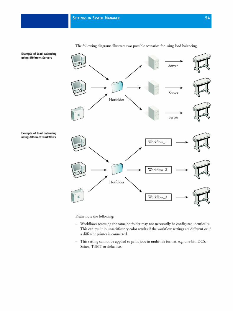
The following diagrams illustrate two possible scenarios for using load balancing.
Please note the following:
– Workflows accessing the same hotfolder may not necessarily be configured identically. This can result in unsatisfactory color results if the workflow settings are different or if a different printer is connected.
– This setting cannot be applied to print jobs in multi-file format, e.g. one-bit, DCS, Scitex, Tiff/IT or delta lists.
Example of load balancing using different Servers
Example of load balancing using different workflows
Hotfolder
Server
Server
Server
Workflow_1
Workflow_2
Workflow_3
Hotfolder

SETTINGS IN SYSTEM MANAGER 55
• Enable AppleTalk spooler
This option must be selected if you wish to print directly to EFI XF from a Macintosh application using the PPD provided on the software DVD.
By default, this setting is dimmed on Windows XP computers because Windows XP does not support AppleTalk printing. However, if you need to print via AppleTalk from a Windows XP computer, a special EFI AppleTalk driver is provided with your product. See “Setting up AppleTalk for Windows XP” on page 135 for further information.
To set up printing via the PPD:
– AppleTalk must be installed on the Server computer
– a hotfolder must be defined
• Create virtual printer
This setting enables you to set up an EFI XF workflow as a virtual printer. It can be selected from the print dialog of any application and thus enables users to print directly to EFI XF.To set up a virtual printer, you must first define a hotfolder on this pane. Then, select the check box and define a name for the virtual printer. This is the name that will be displayed in the printer list of the application.
The virtual printer is created when you switch the workflow online at workflow entry.
• Import color management settings of remote job
– Use color management settings of remote job
Select this radio button if you are processing an EFI Remoteproof Container and wish to apply the color management settings from the JDF file. In this case, the color management settings defined for the workflow will be ignored.
– Use color management settings of workflow
Select this radio button if you are processing an EFI Remoteproof Container and wish to apply the color management settings defined for the workflow. In this case, the color management settings saved to the JDF file of the EFI Remoteproof Container will be ignored.
• JDF Communication
Select the check box to enable JDF communication with other EFI applications as well as with Adobe Acrobat. You can elect to close jobs automatically after printing if you want.
See also:
“Making changes to system workflows” on page 90
“Printing and monitoring print jobs” on page 120
“EFI XF Server Configuration (Windows only)” on page 156
“JDF Connector” on page 277

SETTINGS IN SYSTEM MANAGER 56
Input tab > PS/PDF pane
• PS/PDF
– Stop job processing if font is missing
When you select this check box, job processing is halted if EFI XF detects a missing font. The missing fonts are listed. However, you can still preview jobs correctly.
If the check box is left unchecked, print jobs with non-available fonts are output using the default font Courier instead.
– Use size out of the
You can specify which PDF setting is applied to calculate the page size.
Media box Describes the size of the output media and is displayed in the print dialog. All the other boxes are smaller and are found inside the media box.
Crop box Defines the region to which the contents of the page are to be clipped (or cropped) when displayed or printed. Unlike the other boxes, the crop box has no defined meaning in terms of physical page geometry or intended use. It merely suggests where the page should be clipped.
Bleed box Defines the bounds to which the contents of the page should be clipped when output in a production environment.
Art box Defines the meaningful content of the page, including potential white space.
Trim box Defines the intended dimensions of the finished page after trimming. This type of box is used by imposition applications for arranging the order of pages.

SETTINGS IN SYSTEM MANAGER 57
– Calculate page size
Select this check box to instruct EFI XF to RIP the whole document at a low resolution. It is slower than extracting the information from the bounding box but produces more accurate results. This setting helps to prevent image distortion when printing from some graphics applications.
– Simulate overprinting in composite jobs
This check box enables you to determine whether overprint settings defined in your image file are applied during printing.
Normally, when two objects of different colors overlap, there is a knock-out effect, i.e. they will not print on top of each other. Intentionally printing one layer of ink on top of another is known as overprinting. Overprinting is sometimes used to prevent gaps between adjoining colors.
This setting lets you simulate overprinting in composite jobs. This would otherwise not be possible, since overprinting is not supported by composite jobs.
By selecting the check box and examining the preview, you can check the behavior of possible overprint settings in your file before printing.
If you have a license for the Spot Color Option, overprinting is incorporated in the settings for in-RIP separation. Therefore, it is recommended that you simulate overprinting in composite jobs only if you do not have a license for the Spot Color Option or if you have a license for the Spot Color Option but in-RIP separation is disabled.
This setting has no effect on separated jobs.
PDF boxes1 Media box2 Bleed box3 Trim box/crop box4 ArtBox
1
2
3
4

SETTINGS IN SYSTEM MANAGER 58
– Working color space
Here you can define a color mode for your input data. For example, if your PDF is composed mainly of RGB images, select "RGB". In this case, the RGB source profile selected on the Color Management pane is automatically applied to the entire PDF. Similarly, selecting “CMYK” as the working color space causes your PDF to be output using the selected CMYK source profile. For proofing, you must use the CMYK working color space.
– EPS job detection
The setting “Waiting time for job completion” defines the time span during which EFI XF waits for incoming files that belong to a particular print job. Once this time span has elapsed, the software assumes that all files have been received and starts printing.
The default setting is five seconds. However, depending on the size and type of your print jobs, you may wish to change it. For example, for some large-volume separated jobs, a time span of sixty seconds may be needed to ensure that all the separations are received and processed as one print job. Alternatively, for an EPS composite file a setting of one second may well be sufficient to ensure that your print jobs are output as quickly as possible.
With the setting “Default resolution” you can override the default resolution of 72 dpi. Occasionally, EFI XF has difficulty correctly extracting and interpreting the resolution of incoming PS and PDF files. Normally, 72 dpi is perfectly adequate. However, in a very few cases, it is possible that rounding down errors may occur due to internal processing in EFI XF. This can cause a white edge to be output along the right and bottom edges of images — the result of missing pixels.
This is only really noticeable in step & repeat jobs, where a thin white line may be visible between images, although no spacing is defined.
CMYK workflow
RGB workflow

SETTINGS IN SYSTEM MANAGER 59
To overcome the problem, EFI XF provides the option to define an input resolution of between 1 dpi and 720 dpi. Selecting the input resolution size from the image helps to prevent rounding off errors.
• PDF print engine
– PDF print engine
By default, print jobs are processed using the Adobe PostScript 3 Engine (also known as Configurable PostScript Interpreter or CPSI). It is able to process PostScript level 3 and PDF files. During job processing, source files are converted to PostScript format.
If your job is in PDF format, you can choose "Adobe PDF Print Engine" (also known as APPE). This setting processes PDF files without converting them first to PostScript.
APPE can only process 32 separations, whereas CPSI supports up to 255. If more than 32 separations are detected in a job, CPSI is automatically used.
– Image EPS/PDF print engine
The setting "Native" can be applied to a single EPS image saved in a PDF frame. It specifies that only the EPS image is output, i.e. without the surrounding PDF frame. This results in a quicker processing time and better output quality since, if the image is an RGB image, the selected source profiles are applied. This feature was developed mainly for users printing directly from Photoshop.
The setting "Adobe PostScript 3 Engine" specifies that the image file is output with the PDF frame. This setting is automatically applied if the job contains more than one EPS image.
PDF boxes1 EPS image2 PDF frame
1
2

SETTINGS IN SYSTEM MANAGER 60
Input tab > Formats pane
• TIFF/IT/Scitex CT/LW
– Give priority to (TIFF/IT only)
TIFF/ITfiles are composed of a CT (image data) and an LW (text data) file. If you select this radio button, EFI XF will wait until it detects both files before processing the job. This setting ensures that CT files are not processed on their own.
CMYK TIFF files are composed of one file only. If you select this radio button, EFI XF will start job processing as soon as it detects the file.
– Recognition (TIFF/IT and Scitex CT/LW)
Many TIFF/IT and Scitex CT/LW files are automatically created with a final page. A final page is an additional file and contains information which ensures that the LW file and the CT file are clearly recognized as being part of the same print job. Select the appropriate radio button if your files have a final page. Select the radio button “The last ... characters differ from the file name” if your TIFF/IT or Scitex CT/LW files do not have a final page.
If no final page is available, EFI XF tries to match the files by their names. For example, if you have two files, “Doc4_CT.CT” and “Doc4_LW.LW”, which belong to the same print job, EFI XF does not recognize this because of the different file names. However, if you instruct the software to ignore the last two characters before the dot, this reduces both file names to “Doc4_” and makes them immediately recognizable as one print job.
Layout tab > Job Layout pane
• Sheet size
From the drop-down list box, select whether you want to print on:
– The media size set up for the output device
– One of the predefined media sizes available for the selected printer
– A custom media size. To define a custom media size, type the required sheet dimensions in the appropriate edit boxes.
• Rotate
Select whether you want to rotate your print job. Choose from “Do not rotate”, “Rotate 90 degrees”, “Rotate 180 degrees” or “Rotate 270 degrees”. If you select “Minimal media consumption”, EFI XF will automatically rotate your images, if necessary, to keep wastage to a minimum.
• Mirror
Select the appropriate check box to print a horizontal or vertical mirror image of your print jobs.

SETTINGS IN SYSTEM MANAGER 61
• Scale page
Select a scaling factor from the drop-down list box to define how your print job will be adapted to the size of media you are using. The following settings are available:
– Do not scale
With this setting, your image is printed in its original size. A warning will be displayed if it will not fit fully on the media.
– Fit to page size
With this setting, your image is scaled so that either the height or the width of your image is adjusted to the printable height or width of the media.
– Fit to width
With this setting, your image is scaled horizontally so that the width of your image is adjusted to the printable width of the media.
However, this may mean that the height of your image is clipped. You can check the preview to see what effect this setting will have on the printed image and make sure that it will fit properly on the selected media size.
– Fit to height
With this setting, your image is scaled vertically so that the height of your image is adjusted to the printable height of the media.
However, this may mean that the width of your image is clipped. You can check the preview to see what effect this setting will have on the printed image and make sure that it will fit properly on the selected media size.
This setting is not available if you are printing on roll media.
– Scale job percentually
With this setting, you can define an enlargement or reduction factor for your image. A value of more than 100 increases the size of your image, whereas a value of less than 100 decreases the image size. Please note that defining different factors for width and height will result in a distorted output of your image.
This setting is overridden by the uniform page scaling setting on the Nesting pane.
– Scale job numerically
With this setting, you can define a new height and width for your image.
This setting is overidden if uniform page scaling is defined on the Nesting pane.
SETTINGS IN SYSTEM MANAGER 62
• Align page to sheet
Choose an alignment setting by selecting the appropriate cell in the diagram. For example, if you check the middle cell, your job will be output centered horizontally and vertically on the selected media. This setting takes job margins into account.
If the output device is set up to print on roll media, only horizontal alignment is possible.
• Job margin
You can define margins for more precise positioning of images. Printer hardware margins are still applied.
Layout tab > Nesting pane
• Nesting
Select this check box to output all print jobs loaded via this workflow as part of an automatic nesting.
In an automatic nesting workflow, all loaded jobs are grouped together and output as a single print job according to the settings made on this tab.
If this check box is not selected, you can still create nestings manually in Job Explorer.
Nesting and step & repeat cannot be used simultaneously.
• Optimize layout for
Select a radio button to define whether images should be:
– Positioned to waste as little space as possible on the media or
– Aligned so that they can be cut out using as few straight horizontal cuts as possible.
– Aligned so that they can be cut out using as few straight vertical cuts as possible.
• Allow rotation of pages
Select this check box to enable images to be automatically rotated in order to make better use of the available space.
• Uniform page scaling
By selecting this check box you can define a uniform output size for all jobs. The combo box contains default sizes. However, you can also create your own scaling sizes by typing a width and a height in the appropriate edit boxes, and clicking the plus (+) button.
You can delete a custom scaling size by selecting it in the combo box and clicking the minus (-) button. It is not possible to delete default scaling sizes.
This setting overrides the scale job percentually and scale job numerically settings on the Job Layout pane.

SETTINGS IN SYSTEM MANAGER 63
• Spacing
– Between nesting elements
Use the edit boxes to define the vertical and horizontal gap between pages on the nesting.
– Around nesting (picture mount)
Here you define a paper-white margin around the nesting to simulate a picture mount. This setting takes into account the non-printable area. Type the required values in the edit boxes.
• Create nesting after a minimum of
With the following settings you define the point at which an automatic nesting will be output.
– % of the sheet is filled
Select this radio button and define what percentage of the sheet must be filled before a nesting is output.
– % of the line is filled
Select this radio button and define what percentage of the line must be filled before a nesting is output. This setting is useful if you are printing on a roll substrate.
– Always nest after
Select this check box and define a period of time after which EFI XF will automatically output a nesting of all loaded images.
This setting has priority over the other auto-nesting settings, e.g. a nesting will be printed after the set period even if the minimum percentage of the sheet or line has not been filled.
See also:
“Nestings” on page 148
Layout tab > Step & Repeat pane
The step-and-repeat feature enables you to create multiple copies of a job and output as one print job.
Step & repeat

SETTINGS IN SYSTEM MANAGER 64
Step & repeat jobs can also be created from multi-page documents. Each page of the loaded print job forms a new step & repeat page. The step & repeat settings are applied identically to all pages. This enables you to output step & repeat jobs on a duplex printer for double-sided printing.
• Step & Repeat
Select this check box to print multiple images of a single print job according to the layout settings defined on this tab.
Automatic nesting and automatic step & repeat cannot be used simultaneously.
The settings you make on this tab can be grouped together and saved in the form of a preset.
Initially, no presets are available. However, once you have made settings on this pane, you can save them under a defined name. The preset becomes immediately available for selection from the drop-down list box.
To make changes and overwrite an existing preset make sure that the preset is not selected for any other workflow. Presets can only be overwritten in System Manager. In Job Explorer, you must save your changes under a new name.
• Spacing
Use this setting to define the horizontal and vertical gap between images. The illustration above shows horizontal and vertical spacing of 1 mm between images.
• Step and repeat method
– Total number of copies
Select this radio button and define the number of copies you want to create. The original image is included in the total number of copies. Thus, if you define “8”, it means one original and seven copies.
– Rows and columns
With this setting you define the number of rows and columns to fill. Select the appropriate check boxes to fill as many rows or columns as will fit on the sheet size. Alternatively, to define a specific number of rows or columns, deselect the appropriate check box. Then use the edit box to type in the required number. The default setting is one row and one column, i.e. one image.
– Fill sheet
Select this radio button to fill the selected sheet size.
It is possible to output step and repeat patterns as tiles by defining a sheet size that is bigger than the media size set for the printer.

SETTINGS IN SYSTEM MANAGER 65
Layout tab > Footer pane
EFI XF lets you output a footer with your jobs. A footer contains job-specific information and can consist of:
• One or two control strips used for verifying color accuracy. Control strips can be selected on the Verify tab.
• A job ticket containing information pertinent to the print job. It lets you know which settings were applied to achieve the print result, e.g. printer model, media, ink, profiles, rendering intents, print resolution, scaling factor.
The following settings are available:
• Edit page/sheet footer
This setting defines whether the remaining settings you make on this pane are applied to pages or sheets. In a nesting workflow, you can make separate settings for sheets and pages. For one-page jobs on a sheet, the setting “Edit sheet footer” has no effect.
This setting is deactivated for step & repeat.
Edit sheet footer Prints a footer per sheet, e.g. one footer per nesting
Edit page footer Prints a footer for each page, e.g. one footer per document in a nesting.

SETTINGS IN SYSTEM MANAGER 66
• Footer layout
A footer is printed left aligned under the job.
The two available footer layout settings can be applied to simple jobs and nesting parent jobs. For jobs inside a nesting (nesting child jobs) the setting "Must not exceed page width” is automatically applied.
– Must not exceed page width
In this case, the total width of the footer will not be wider than the page. If necessary, the job ticket and control strip(s) will be positioned one above the other on two separate rows.
– Can fill sheet width
In this case, the job ticket and control strip(s) use up the full width of the available media. If the media is not wide enough to fit job ticket and control strip(s) in a single row, the control strip(s) are automatically placed on a second row under the job ticket.
Footer width must not exceed page width
Footer can fill sheet width

SETTINGS IN SYSTEM MANAGER 67
• Job ticket
Select the check box to print out a job ticket with your print job. Then click Job Ticket to define which information is included.
Job tickets comprise six different lines. You can choose which information is output with your jobs by selecting the appropriate check boxes. In Job Explorer, the preview displays a generic job ticket only.
By default, line 1 consists of the EFI logo. This is always displayed on the left of the job ticket. However, you can upload any image file in JPEG or TIFF format, e.g. your own company logo. To implement your own image, click Upload and browse to the chosen file. Then click Open.
Logo size is limited to a maximum of 5 x 5 cm. If you load a file that exceeds these measurements, it will be scaled proportionally so that either the width or the height is reduced to 5 cm. Images that are smaller than 5 x 5 cm are output in their original size. Logos are always output color managed, providing color management is activated.
Line 6 has room for user-defined information.
Job ticket

SETTINGS IN SYSTEM MANAGER 68
• Max. ticket width
The default width of job tickets is the width of the page, minus the width of selected control strips, which have a higher priority. If too little space is available to display job ticket and control strip in one line, the control strip is printed on a second line underneath. This setting works in conjunction with the settings “Must not exceed page width” and “Can fill sheet width”.
• Max. ticket height
The default height for job tickets is 5 cm. If a job ticket exceeds the defined ticket height, it is cropped. If job ticket and control strip are positioned one above the other, you can change the ticket height setting to ensure prevent unwanted white space between them.
• Font size
You can specify any font size for job ticket text. The default font size if 6 pt.
• Distance to job
Use this setting to define the gap between image and job ticket.
See also:
“Verify tab > Control Strip 1/Control Strip 2” on page 82
Color tab > Color Management pane
• Color management
Select this check box to make color-management settings and create color-accurate output. If color management is not activated, it is not possible to select any profiles.
• Presets
Default color management presets for proofing, production, photo, business graphics and convert to grayscale are provided with the software. You can also define your own settings and save them in the form of a preset. The preset becomes immediately available for selection from the drop-down list box.
To make changes and overwrite an existing custom preset make sure that the preset is not selected for any other workflow. Presets can only be overwritten in System Manager. In Job Explorer, you must save your changes under a new name. The default color management presets cannot be modified or deleted.

SETTINGS IN SYSTEM MANAGER 69
• Dynamic rendering intent
With this setting, EFI XF analyzes the colors of the job and determines whether they can be accurately reproduced on the selected output device. Based on this analysis, the most appropriate rendering intent for the job is automatically selected.
The simulation profile takes precedence over the source profile. If a simulation profile is assigned to the job, only the rendering intent of the simulation profile will be affected by this setting. If no simulation profile is available, rendering intents for the source profiles are selected.
If the dynamic rendering intent setting is applied in Job Explorer, the most appropriate rendering intents are selected as soon as you click Save.
A job preview is always created, regardless of whether the preview setting is activated for the workflow or not.
Job color analysis Rendering intent Description
All colors within the reproducible gamut of the output device
Relative colorimetric
This rendering intent reproduces the exact colors of the job and no gamut compression is necessary.
Some colors outside the reproducible gamut of the output device
Perceptual This rendering intent compresses the colors of the print job so that all can be printed without any gamut clipping taking place.
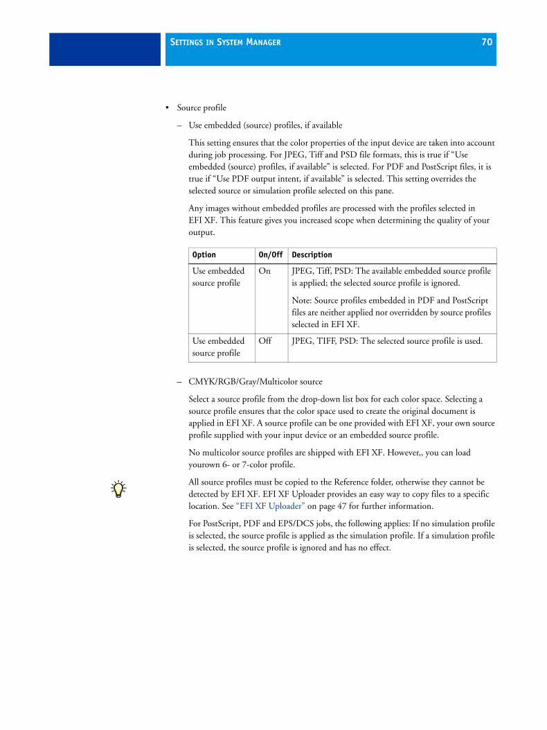
SETTINGS IN SYSTEM MANAGER 70
• Source profile
– Use embedded (source) profiles, if available
This setting ensures that the color properties of the input device are taken into account during job processing. For JPEG, Tiff and PSD file formats, this is true if “Use embedded (source) profiles, if available” is selected. For PDF and PostScript files, it is true if “Use PDF output intent, if available” is selected. This setting overrides the selected source or simulation profile selected on this pane.
Any images without embedded profiles are processed with the profiles selected in EFI XF. This feature gives you increased scope when determining the quality of your output.
– CMYK/RGB/Gray/Multicolor source
Select a source profile from the drop-down list box for each color space. Selecting a source profile ensures that the color space used to create the original document is applied in EFI XF. A source profile can be one provided with EFI XF, your own source profile supplied with your input device or an embedded source profile.
No multicolor source profiles are shipped with EFI XF. However,, you can load yourown 6- or 7-color profile.
All source profiles must be copied to the Reference folder, otherwise they cannot be detected by EFI XF. EFI XF Uploader provides an easy way to copy files to a specific location. See “EFI XF Uploader” on page 47 for further information.
For PostScript, PDF and EPS/DCS jobs, the following applies: If no simulation profile is selected, the source profile is applied as the simulation profile. If a simulation profile is selected, the source profile is ignored and has no effect.
Option On/Off Description
Use embedded source profile
On JPEG, Tiff, PSD: The available embedded source profile is applied; the selected source profile is ignored.
Note: Source profiles embedded in PDF and PostScript files are neither applied nor overridden by source profiles selected in EFI XF.
Use embedded source profile
Off JPEG, TIFF, PSD: The selected source profile is used.

SETTINGS IN SYSTEM MANAGER 71
– Rendering Intent
Select a rendering intent from the drop-down list box for each color space. Choose from the following:
Rendering intent Description
Absolute colorimetric (paper white)
This rendering intent leaves all colors that lie within the destination color gamut unchanged, thus maintaining color accuracy. If the destination color gamut is smaller than the source color gamut, it may mean that two distinct colors from the source color gamut are mapped to the same color in the destination color gamut.
This rendering intent is suitable for creating proofs with paper white simulation. Paper white simulation means that the color of the reference paper is also simulated. For example, if you select the reference profile "ISOnewspaper26v4.icc" in combination with the rendering intent "Absolute colorimetric (paper white)", your image will be printed on a gray background to simulate the color of newsprint.
This rendering intent is also applied to a control strip/job ticket as well as to the area between image and crop marks. The effect is not visible in the preview but can be seen in the printout.
Paper white simulation is not applied to white space between image and crop marks.
Perceptual This rendering intent preserves the visual relationship between colors in a way that is perceived natural to the human eye by compressing all colors and scaling them to fit into the available destination color space. Since all colors are affected, even those that would normally lie within the color gamut of the destination color space are compressed — even if they could normally be accurately reproduced.
This rendering intent is most suitable for printing photographic images, where having the largest possible color space is more important than a color-accurate print result. It is therefore not recommended for the output of color-accurate proofs.
SETTINGS IN SYSTEM MANAGER 72
Saturated This rendering intent aims to preserve vivid color at the expense of accurate color. The source color gamut is scaled to the destination color gamut, but preserves relative saturation instead of hue. This means that color hues may shift if the destination color space is smaller than the source color space.
This rendering intent is designed primarily for business graphics, where bright, saturated colors are more important than the exact relationship between colors (such as in a photographic image).
Perceptual-absolute This rendering intent was developed by EFI. It combines the advantages of the rendering intent “Perceptual”, with regard to image definition in areas of shadow, with the color accuracy and paper white simulation of the rendering intent “Absolute colorimetric”.
With this rendering intent, image data retains its definition in dark areas, i.e. shades of color are still visible in areas of shadow.
This rendering intent is particularly suitable for photographers who need to convert a large source color space (RGB) to a smaller destination color space (CMYK).
Rendering intent Description
SETTINGS IN SYSTEM MANAGER 73
Relative colorimetric (no paper white)
This rendering intent compares the white point of the source color space with that of the destination color space and adjusts all colors accordingly. All colors that lie within the color gamut of the destination color space are accurately reproduced. Any colors that lie outside the color gamut of the destination color space are replaced by the colorimetrically closest color that can be reproduced.
This rendering intent is suitable for creating proofs with no paper white simulation.
Relative colorimetric with black point compensation/
Absolute colorimetric with black point compensation
If the black point of the source color space differs greatly from that of the target color space, you can apply black point compensation on top of the rendering intents “Relative colorimetric” and “Absolute colorimetric”.
With black point compensation, the full dynamic range of the source color space is mapped to the full dynamic range of the destination color space. However, if the black point of the source color space is darker, contrast is lost during the conversion.
Activating black point compensation may cause gray shadows. However, this setting can be applied usefully to darker source black points.
Applying black point compensation may give more shadow detail and avoid gamut clipping if the darkest points of the source are darker than the proofing system is able to print. Differences in the black point are compensated for by introducing more deviation between target and proof shadow areas so, although the result will be visually better, the measured color values may not be as good.
Rendering intent Description

SETTINGS IN SYSTEM MANAGER 74
• Simulation profile
– Use PDF output intent, if available
This setting ensures that if an output intent is embedded in a PDF/X-3 file, it will be applied as a simulation profile.
This setting only has an effect on PDF and PostScript files.
– Simulation profile
Select a simulation profile from the drop-down list box to simulate output on a particular printing press.
You can load a simulation profile provided with EFI XF or one supplied, for example, by your printing house. To use your own simulation profile, you must copy it to the Reference folder.
EFI provides a number of additional customized profiles, which you may find useful. You will find these in subfolders of the Reference Additional folder. To use, copy to the Reference folder. Only profiles located in the Reference folder can be selected in EFI XF.
– Rendering Intent
Select a rendering intent from the drop-down list box.
Output intent in PDF/X-3 files
Option On/Off Description
Use PDF output intent
On PDF, PostScript: The available output intent is applied; the selected simulation profile is ignored.
Use PDF output intent
Off PDF, PostScript: The selected simulation profile is applied. If no simulation profile is selected, depending on the working color space of the RIP, the selected source profile is applied. (See “Working color space” on page 58).

SETTINGS IN SYSTEM MANAGER 75
• Advanced settings
– Convert to grayscale
This setting lets you define the shade of grayscale output without applying an L*a*b* optimization file. Five different steps are available — from a yellowish tint (very warm gray) to a bluish tint (very cold gray). Select the check box and choose a shade of gray from the drop-down list box.
– L*a*b* optimization
If you have created an optimization file using either the Color Manager or Color Verifier options you can select it from the drop-down list box. Optimization files provide more precise printer adjustment. They have the file extension .3cc and must be saved to the Balance folder.
– Color optimization
The setting “Black as inkjet black” ensures that any text or diagrams that have been defined as pure black are printed with black ink only. In addition, you can define the percentage of black at which pure black ink will be used. Type the desired percentage in the edit box.
If the option "Black as inkjet black" is not selected, black will be composed of the available CMYK inks as defined in the applied ICC profiles.
This setting is recommended for the output of grayscale images. It ensures stable prints with no shifts in color.
– Plate compensation
In LinTool/Color Manager you can modify plate characteristics that are often applied to one-bit files. As color management normally relies on receiving linear input data to apply color management properly, there is a need to compensate non-linear plate characteristics of the one-bit files for color-accurate output. The Visual Correction tool of LinTool/Color Manager allows you to enter compensation values manually.
Be aware that that there is no fixed formula for modifying plate characteristics of one-bit files in the Visual Correction tool. However, you can also use the tool to edit input data of any supported contone file format for process and spot colors. In the case of contone file formats, a simple formula is applied, e.g. a 5% increase for the 50% patch will yield 55%.
See also:
“Rendering Intent” on page 71.
Grayscale variations
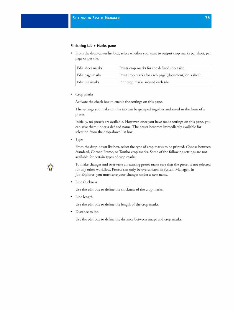
SETTINGS IN SYSTEM MANAGER 76
Finishing tab > Marks pane
• From the drop-down list box, select whether you want to output crop marks per sheet, per page or per tile:
• Crop marks
Activate the check box to enable the settings on this pane.
The settings you make on this tab can be grouped together and saved in the form of a preset.
Initially, no presets are available. However, once you have made settings on this pane, you can save them under a defined name. The preset becomes immediately available for selection from the drop-down list box.
• Type
From the drop-down list box, select the type of crop marks to be printed. Choose between Standard, Corner, Frame, or Tombo crop marks. Some of the following settings are not available for certain types of crop marks.
To make changes and overwrite an existing preset make sure that the preset is not selected for any other workflow. Presets can only be overwritten in System Manager. In Job Explorer, you must save your changes under a new name.
• Line thickness
Use the edit box to define the thickness of the crop marks.
• Line length
Use the edit box to define the length of the crop marks.
• Distance to job
Use the edit box to define the distance between image and crop marks.
Edit sheet marks Prints crop marks for the defined sheet size.
Edit page marks Print crop marks for each page (document) on a sheet.
Edit tile marks Pint crop marks around each tile.

SETTINGS IN SYSTEM MANAGER 77
• Bleed
This setting repositions the crop marks in relation to the image. Select one of the available radio buttons. Then add the desired margin width in the edit box.
– Cut image
Select this radio button to crop each edge of your image by a defined margin width, e.g. to eliminate unwanted paper white around an image or to reduce the size of an image.
– Add frame
Select this radio button to add white space between image and crop marks.
The setting “Distance to job” is also taken into account when you apply this setting, e.g. if you set crop marks at a distance of 1 cm to the job and add a 1 cm frame in the bleed setting, the crop marks will be positioned 2 cm from the image.
Output tab > Basic pane
On this pane, you can make basic print settings.
• Copies
Type the number of copies you wish to print. If you are printing three copies of a three-page document, the pages will be output in the following order: 1, 1, 1, 2, 2, 2, 3, 3, 3.
If you prefer to output sorted copies, select the check box. In this case, the pages of your document will be output as follows: 1, 2, 3, 1, 2, 3, 1, 2, 3.
In a nesting workflow, you define the number of copies in System Manager. If, for example, three copies are defined, each job is imported three times into the nesting. However, the nesting is printed only once.
In a manual workflow, each job is imported only once into the nesting since “1” is the default number of copies. If you set the number of copies to “3” in Job Explorer, the nesting is printed three times.
Bleed: cut image
Bleed: add framee

SETTINGS IN SYSTEM MANAGER 78
• Separations
Select an option from the drop-down list box to determine how separated files will be output.
– Merge separations
Select this setting to combine all color separations and output as one printout.
– Color separations
Select this setting to output one printout for each color separation.
– Grayed separations
Select this setting to output one grayscale printout for each color separation.
• Invert
Select this check box to print an inverted image (color negative) of your print jobs.
• Crop image to fit media size
Here, you can define whether images, that are too big to fit on the selected media size, will be output or not.
By default, the check box is not selected. If you try and output a job that is too large for the media, a warning message is displayed. The job is not printed. You can overcome the problem, for example, by switching to a different media size, selecting a scaling factor or outputting the image as a tiling.
If the check box is selected, a job that exceeds the media size is printed. However, the portion of the job that falls outside the media size is cropped. A warning message to this effect is displayed on the File Info pane.
A control strip is not printed if it exceeds the media size.

SETTINGS IN SYSTEM MANAGER 79
Output tab > Advanced pane
• Final run characteristics
These settings enable you to simulate print characteristics commonly found in different printing methods. You can choose between:
– Show missing dots up to
This setting simulates the effect that occurs in gravure printing when ink is not evenly transferred from the cylinder. Use the slidebar to define the percent area coverage of missing dots.
– Define first printable dot
This setting enables you to define where the first printable dot will start. This is particularly useful in flexo printing where the first printable dot may be 10% or higher. Use the slidebar to define the percent area coverage for the first printable dot.
This setting can be applied to contone data but not to halftone data.
Show missing dots up to1 Missing dots
100% 40% 0%
1
Example of a job with a first printable dot setting of 10%.
100% 10% 0%

SETTINGS IN SYSTEM MANAGER 80
– Noise smoothing
This setting produces an image which more closely resembles output on a printing press. It creates a less smooth effect than an inkjet printout. Use the slidebar to define the amount of noise smoothing.
Output tab > Remote pane
With the settings on this pane, you instruct EFI XF when and where to create a Remoteproof Container during file processing.
A Remoteproof Container consists of a PDF or TIFF file (print file) and a JDF file (settings file). These are combined into a single file with the file extension RPF. A Remoteproof Container contains all the information necessary to create an exact replica of the original file at a remote location.
RPF files can be loaded and processed in any EFI proofing software.
A Remoteproof Container can be created:
• Automatically after printout or, in a Verify workflow, as soon as a control strip has been measured
• Manually, by clicking Create Now in Job Explorer
On creation, Remoteproof Containers can be:
• Uploaded to EFI Web Control Center Remoteproof Containers are always saved to the Remote\WCC folder.
• Saved to a defined folder If Server and Client are installed on different computers, you can only export to subfolders of the Remote folder. Click Choose and browse to your chosen folder.
Result of noise smoothing 100% 0%
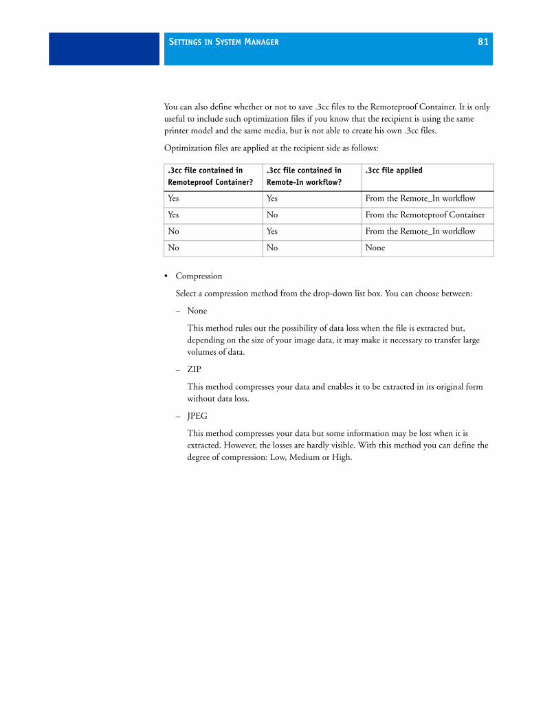
SETTINGS IN SYSTEM MANAGER 81
You can also define whether or not to save .3cc files to the Remoteproof Container. It is only useful to include such optimization files if you know that the recipient is using the same printer model and the same media, but is not able to create his own .3cc files.
Optimization files are applied at the recipient side as follows:
• Compression
Select a compression method from the drop-down list box. You can choose between:
– None
This method rules out the possibility of data loss when the file is extracted but, depending on the size of your image data, it may make it necessary to transfer large volumes of data.
– ZIP
This method compresses your data and enables it to be extracted in its original form without data loss.
– JPEG
This method compresses your data but some information may be lost when it is extracted. However, the losses are hardly visible. With this method you can define the degree of compression: Low, Medium or High.
.3cc file contained in Remoteproof Container?
.3cc file contained in Remote-In workflow?
.3cc file applied
Yes Yes From the Remote_In workflow
Yes No From the Remoteproof Container
No Yes From the Remote_In workflow
No No None

SETTINGS IN SYSTEM MANAGER 82
Verify tab > Control Strip 1/Control Strip 2
A control strip consists of one or more rows of different color patches that are used to obtain color values using a measuring device. It is recommended that you select this setting whenever you want to make color consistency checks.
Control strips and job ticket information are output as a footer. See “Layout tab > Footer pane” on page 65 for footer and job ticket settings.
• Control strip settings
– Control Strip 1/Control Strip 2
From the drop-down list box, select a control strip. You can use one of the control strips provided with the software or a control strip of your choice. Control strip files must be saved to the ControlStrip folder. EFI XF can process all supported file formats except separated files; there is no size restriction.
EFI provides a service for creating customized control strips. Contact [email protected] for further information.
EFI XF supports the EFI Dynamic Wedges. The EFI Dynamic Wedge is a dynamically created control strip that is made up of the key colors contained in the job. Key colors are the colors that feature the most prominently in a job. For example, if your job is composed mainly of shades of blue, the dynamic wedge will have a high proportion of
1 Job ticket2 Control strip
12

SETTINGS IN SYSTEM MANAGER 83
blue patches. Each dynamic wedge is unique to a particular job, as each job is composed of a different set of key colors. As with other control strips, you can use the dynamic wedge to verify and, if required, optimize color accuracy. See “EFI dynamic wedge options (control strip 1 only)” on page 84 for details of dynamic wedge settings.
– Print with color management
Deselect the check box if you do not wish to apply color management to the control strip.
– Use control strip on
Select “Pages” to output a control strip with your job.
For nestings, you can output a control strip per page or per nesting. For multi-page documents, the control strip is created for the job as a whole, but not for individual pages.
Dynamic wedge

SETTINGS IN SYSTEM MANAGER 84
• EFI dynamic wedge options (control strip 1 only)
The dynamic wedge settings described below become available only after you:
– Select the radio button to apply the control strip to “Pages”. You cannot apply a dynamic wedge if “Sheets” is selected.
– Choose “Dynamic wedge” from the drop-down list box.
Then, from the appropriate drop-down list boxes, select:
– The measuring device that you will use to measure the color patches
– The maximum number of color patches for the dynamic wedge
16, 32 and 64 patches are possible. Fewer patches will be printed if all the job’s key colors can be represented using less than the defined number of patches.
– Whether the dynamic wedge should consist of process colors, spot colors or a mixture of both. The dynamic wedge can also display color gradients if these are defined in the L*a*b* color space in Color Editor. Color Editor is a component of the Spot Color Option.
The preview displays a generic media wedge. The colors extracted from the image are visible only on the Verify tab in Job Explorer and in the printout.
You can output two control strips with your jobs. For example:
• The dynamic wedge for job-specific analysis of key colors
• A Ugra/Fogra or IDEAlliance control strip for ISO 12467-7/8-compliant proof verification.
Selecting two control strips gives you the opportunity to output one with color management and one without.
Some output devices with an embedded measuring device can only measure one control strip per job.
See also:
“Layout tab > Footer pane” on page 65
“To define or edit a spot color in Color Editor” on page 237
SETTINGS IN SYSTEM MANAGER 85
Output device settingsThe output device settings are available when you select an output device in the layout area.
Device tab > Setup pane
• Name
Type a name for a new output device or change the name of an already defined output device. It is not possible to change the name of the linearization device.
• Description
Type a brief description, if required.
• Device type
Select your printer model from the drop-down list box.
Profiles are provided with your software and saved to the Profiles folder. If no profiles are located in this folder, an error message to this effect will be displayed when you select a device type and you will not be able to set up your printer. In this case, you must install the appropriate media profiles from the software DVD or via EFI XF Control.
• Connection type
– Print to system printer
Select this radio button to print to a printer that has already been set up as a system printer on the Server computer. The system printer in this case must be the printer selected on this pane.
– Print via network
Select this radio button to print to a network printer.
Type the IP address of the network printer in the edit box.The printer’s TCP/IP address may be a defined name or a series of numbers, e.g. 10.1.149.33. Ask your system administrator if you are not sure of your printer’s TCP/IP address.
Click Test to check that a connection to the printer has been properly established. To test the connection, the printer must be switched on. If you receive an error message, consult your system administrator for advice.

SETTINGS IN SYSTEM MANAGER 86
Select the type of TCP/IP protocol that your printer uses for data transfer.
– Print via port
Select this radio button and choose the name of your printer from the drop-down list box to print to a printer that is connected via USB to the Server computer. The printer must be switched on when you start EFI XF. Otherwise, it will not be automatically detected.
Device tab > Media pane
• Presets
Select a previously defined combination of print settings from the drop-down list box or save the settings you make on this pane as a preset.
• To create a preset, make your settings and click Save. A dialog opens in which you define a name for your combination of settings. Specify a name in the edit box and click Save.Ink type
Select the type of ink that is inserted in your printer.
• Media name
Select the name of the media you will be printing on.
If you select a media type that is patched to a Device Link profile, EFI XF will indicate this.
A Device Link profile represents a fixed combination of printer and media type.
Device Link profiles can be created with Color Manager. They must be patched to the EPL linearization file and a media profile using Profile Connector. This tool is available in LinTool and Color Manager.
Device Link profiles must be saved to the folder where the media profiles are saved. Otherwise they cannot be detected in EFI XF.
RAW on port Select “RAW on port” if your printer supports RAW printing. Most printers support RAW printing to port 9100. However, please note that this setting depends on the network settings made at the printer and may, therefore, be different.
LPR queue Select “LPR queue” if your printer supports LPR printing. Then type the queue name in the edit box. It is normally only necessary to type a queue name if you are printing via a Unix system or a print server with multiple interfaces. Therefore, in most cases, you can leave this edit box blank. Please refer to your printer manual for further information.

SETTINGS IN SYSTEM MANAGER 87
• Calibration set
This area displays the epl base linearization which is patched to the selected media type. If more than one epl is available, you can select which one you want to use from the drop-down list box.
By clicking Catalog you can display a list of all the epl files available for the selected media name and view the printer conditions under which they were created.
Click New to open LinTool/Color Manager if you want to create a new base linearization.
The current printer settings are automatically transferred to the linearization device. In other words, the default or previously made settings of the linearization device will be overwritten.
• Visual correction
If you have modified your printer’s color reproduction properties using LinTool or Color Manager, select the new linearization file from the drop-down list box. Visual correction files have the file extension .vcc and must be saved to the Balance folder. A selected vcc file is saved as part of a media set. The effect of the applied .vcc file can be seen in the printout, but is not visible in the preview.
• Media length correction
This feature lets you correct any inconsistency in the length of the printed image. This may occur as a result of the particular combination of printer and media that you are using.
Normally, job length and printed image length are the same. However, if you discover that your printed image is longer or shorter than it should be, you can adjust the output length.
The file Lineal_01.ps is provided in the Samples folder for this purpose. The printed image displays a set of ruler markings 0.5 m x 0.5 m. Print out the file and measure the length of the ruler markings. If the measurement is not accurate, you can compensate for the difference by typing the target length and the actual measured length in the appropriate edit boxes.
This setting is independent of the hardware setting available at the control panel of some printers.

SETTINGS IN SYSTEM MANAGER 88
• Media size
– Source
Select the source of the paper feed from the drop-down list box.This setting is printer-dependent and varies according to the types of media feed and number of media trays installed for your particular printer.
– Format
Select the size of the media inserted in the printer from the drop-down list box.
If your media size is not listed, you can define a user-defined format. Type the desired height and width in the edit boxes and click Save. A dialog opens to let you define a name. When you close the dialog, your user-defined format is automatically selected.
To delete, select a user-defined media format and click Delete. It is not possible to delete default media formats.
Device tab > Special pane
The features on this pane are only available if they are supported by your printer. See your printer documentation for further information.
• Output tray
• Duplex printing
• Autocut feature
• Media suction
• Printer dryer function
• Dry time definition
• Borderless printing
To achieve borderless printing you must also select the page layout setting “Fit to page size”.
• Control heater temperature at RIP
EFI XF provides a setting for controlling the heaters of some printer models. This means that you can switch heaters on/off and set the temperature in the software as well as at the printer control panel. The setting is printer-specific and displays only the heater settings available for the selected printer.
The use of heaters affects color reproduction, so you may need to perform a printer calibration in LinTool/Color Manager. However, before you create a new base linearization, make the desired heater settings for the linearization device first. The selected heater settings are then automatically saved when you create a new base linearization file.

SETTINGS IN SYSTEM MANAGER 89
• Print mode
This setting provides a convenient way to change the resolution and print mode (number of passes) at workflow or job level, without first having to create a new base linearization file and media profile.
This feature can be useful if you want to output an image in draft quality, where color accuracy is not so important. However, you should be aware that shifts in color can occur. An error message warns you as soon as you select a print mode or resolution that is different from the one in the base linearization.
To reset the print mode and resolution to the default values of the base linearization file, click Reset to default.
• Calibration set
Some printers have an internal calibration feature, which is supported by EFI XF. This setting lets you choose whether or not to apply the printer calibration by applying or ignoring the setting made at the printer control panel.
Whichever setting you select, you should use the same one for linearization/profiling.
• Automatic calibration interval
This setting enables you to calibrate the printer using the printer’s built-in measuring device. Regular calibration, in which the total ink limits are redefined, ensures that the color reproduction of the printer remains constant — from one print to another, as well as between two printers of the same model, irrespective of system variables such as ink level, environment conditions and life of the print head.
Printer calibration is initiated automatically according to the time interval defined on this pane. Each calibration is valid only for the particular combination of media type and resolution currently selected on the Media pane. After calibration, the result is automatically assigned to the appropriate media profile.
• White ink printing
Different settings are available for printers that support white ink printing. By selecting white ink you can:
– Output control strip(s) with a white background
– Define the amount of white ink coverage
– Add a percentage of CMYK ink (max. 20% per channel) to white to create off-white shades. These can be saved as a preset.
– Specify an opacity value in percent
– Define the printing order, i.e. color on white or white on color
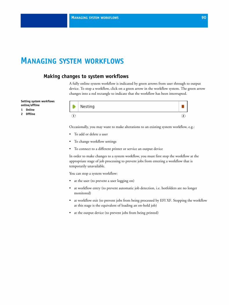
MANAGING SYSTEM WORKFLOWS 90
MANAGING SYSTEM WORKFLOWS
Making changes to system workflowsA fully online system workflow is indicated by green arrows from user through to output device. To stop a workflow, click on a green arrow in the workflow system. The green arrow changes into a red rectangle to indicate that the workflow has been interrupted.
Occasionally, you may want to make alterations to an existing system workflow, e.g.:
• To add or delete a user
• To change workflow settings
• To connect to a different printer or service an output device
In order to make changes to a system workflow, you must first stop the workflow at the appropriate stage of job processing to prevent jobs from entering a workflow that is temporarily unavailable.
You can stop a system workflow:
• at the user (to prevent a user logging on)
• at workflow entry (to prevent automatic job detection, i.e. hotfolders are no longer monitored)
• at workflow exit (to prevent jobs from being processed by EFI XF. Stopping the workflow at this stage is the equivalent of loading an on-hold job)
• at the output device (to prevent jobs from being printed)
Setting system workflows online/offline1 Online2 Offline 1 2

MANAGING SYSTEM WORKFLOWS 91
Available menu commandsContext menus are available for users, workflows and output devices which make it easy to manage your system workflows.
User settings
• Connected Workflows
Choose a workflow from the submenu to connect the user to a specific workflow.
• User is online/offline
This command shows whether a selected user is logged on to EFI XF. In addition, you can use this command to connect or disconnect a user from his workflows.
• Connect to All Workflows
Choose this command to connect the user to all available workflows.
• Disconnect from All Workflows
Choose this command to disconnect the user from all workflows.
• New User
Choose this command to add a new user.
• Delete User
Choose this command to delete the user.
Workflow settings
• Connected Users
Choose a name from the submenu to connect the user to the workflow.
• Connected Output Device
Choose an output device from the submenu to connect the workflow to a specific output device. Each workflow can only be connected to one output device.
• Workflow Accepts New Jobs
Choose this command to switch the workflow online so that jobs can be received from users. If a workflow is already online to users, this is indicated by a check mark.
• Workflow Processes and Prints Jobs
Choose this command to switch the workflow online/offline to the output device. If a workflow is online to an output device, this is indicated by a check mark. In an offline status, jobs are processed but not submitted to the output device.
• Connect All Users to Workflow
Choose this command to connect all users to the workflow.

MANAGING SYSTEM WORKFLOWS 92
• Disconnect All Users from Workflow
Choose this command to disconnect all users from the workflow.
• Disconnect Output Device
Choose this command to disconnect the output device from the workflow.
• Save as Environment
An environment is a combination of workflow and printer settings. Choose this command to create a backup copy of your workflow and printer settings.
• New Workflow
Choose this command to select a workflow template and create a new workflow.
• Delete Workflow
Choose this command to delete the workflow. The workflow must be completely offline.
Output device settings
• Connected Workflows
Choose a workflow from the submenu to connect it to the output device.
• Device is Online/Offline
Choose this command to switch the output device online/offline. The output device must be online to output print jobs.
• Linearize Device
Choose this command to open LinTool/Color Manager and to create a new base linearization. This setting overwrites the device settings of the linearization device and reconfigures it using the settings of the selected output device.
• Re-linearize Device
Choose this command to open LinTool/Color Manager and to relinearize the selected output device.
• Connect Output Device to All Workflows
Choose this command to connect all available workflows to the output device.
• Disconnect Output Device from All Workflows
Choose this command to disconnect all workflows from the output device.
• New Output Device
Choose this command to add a new output device.

MANAGING SYSTEM WORKFLOWS 93
• Delete Output Device
Choose this command to delete the output device. The output device must first be disconnected from all workflows.
See also:
“Device tab > Special pane” on page 88
Saving and restoring settingsSetting up workflows for your exact needs can be quite time-consuming. For this reason, EFI XF offers you the opportunity to save settings in a backup file.
In EFI XF, there are two types of backups: system configuration and environment settings
• System configuration
This is useful if you need to reinstall the software at any time. It saves:
– All user settings
– All workflow settings, including selected presets, linearization files, spot color tables and profiles.
– All printer setups
• Environment settings
This is useful if you output repeat jobs at regular intervals and need to be sure that you use exactly the same settings each time. Environment backups also enable you to provide customers with exact workflow/printer information.
An environment saves:
– All workflow settings, including selected profiles, presets, linearization files and spot color tables
– The printer setup, excluding the port configuration
You can save an environment for:
– a workflow selected in System Manager
– a job selected in Job Explorer
It is possible to import a backed up workflow from EFI eXpress into EFI XF.

MANAGING SYSTEM WORKFLOWS 94
TO SAVE SYSTEM CONFIGURATION SETTINGS
1 From the File menu in System Manager, choose Backup.
The EFI XF Backup dialog opens.
2 Select the check boxes of the items you wish to back up.
All system configuration settings are automatically saved by default.
3 Define a backup location.
System configuration files are saved to two locations: the default Backup folder, and a freely definable destination, e.g. desktop. To define a different destination, click Select and browse to the required location.
4 Click Save.
A window opens when the backup has been successfully completed.
5 Click OK to complete the backup procedure.
TO RESTORE SYSTEM CONFIGURATION SETTINGS
1 From the File menu in System Manager, choose Restore.
The Backup window opens to display the backup files located in the Backup folder.
If you restore a system configuration after deleting and reinstalling EFI XF, this folder is empty. In this case, click Choose and browse to the location of the second backup file. Unless defined otherwise during the backup procedure, you will find the second file on the desktop of your computer.
2 Select the backup file to be restored.
Dialog EFI XF Backup

MANAGING SYSTEM WORKFLOWS 95
3 Click OK.
A window opens when the restore has been successfully completed.
4 Click OK.
You need to restart the Server to view your restored system configuration.
TO SAVE AN ENVIRONMENT
1 Save a workflow or job environment by:
• In System Manager, selecting a workflow in the layout area and choosing File > Save as Environment
• In System Manager, right-clicking on a workflow in the layout area and choosing Save as Environment from the context menu, or
• In Job Explorer, right-clicking on a job in the job list and choosing Save as Environment from the context menu
The dialog Save as Environment opens. If you are saving a workflow environment, the workflow settings are displayed. For a job environment, the edit box is empty to enable you to type your own job information.
2 Define a backup location.
Environment backup files are saved to two locations: the default Environments folder, and a freely definable destination, e.g. desktop. To define a different destination, click Choose and browse to the required location.
Dialog Save as Environment

MANAGING SYSTEM WORKFLOWS 96
3 Click Save.
Environment names are assigned automatically by EFI XF. Job environments are made up of the file name and the output device. Workflow environments indicate the workflow name, the output device and the creation date.
If an environment name already exists, you are asked whether you want to overwrite the original file with the new settings.
A window opens when the backup has been successfully completed. Environments files have the file extension xfe.
4 Click OK to complete the backup procedure.
TO RESTORE AN ENVIRONMENT
Environments can only be restored in System Manager.
1 Import an environment by:
• Right-clicking on an empty part of the layout area and choosing Import Environment from the context menu, or
• Choosing File > Import Environment
The Import Environment window opens to display the backup files located in the Environments folder.
If this folder is empty, click Choose and browse to the location of the second backup file.
2 Select the backup file to be restored.
3 To allow saved files and profiles of the same name to be overwritten, select the check box “Allow overwriting”.
If you leave this check box unchecked, only files with unique names are restored.
4 Click OK to restore the environment.
The EFI XF Information window opens when the restore has been successfully completed.
5 Click OK.
The restored environment can be seen in System Manager.
• If an appropriate output option license is available, workflow and output device are restored and connected. However, the printer port setting is reset to its default value, so you must set up a connection before you can print.
• If an insufficient number of appropriate output option licenses is available, workflow and output device are restored, but not connected.
• If no appropriate output option license is available, the workflow is restored, but not the output device.
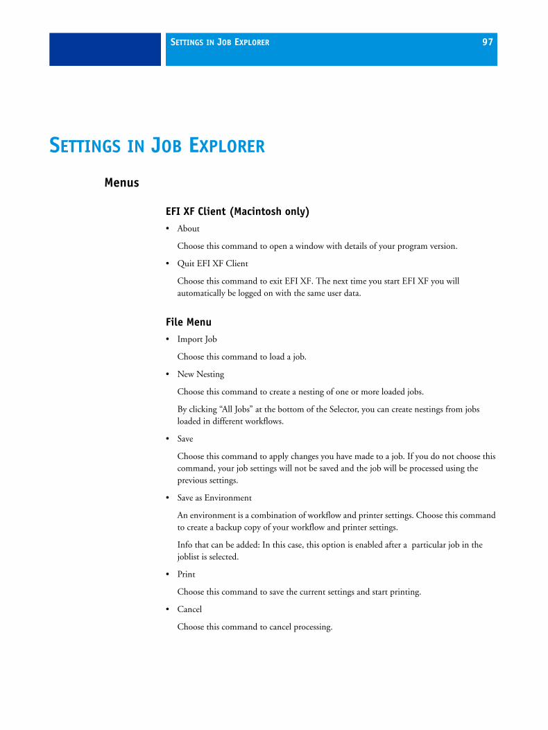
SETTINGS IN JOB EXPLORER 97
SETTINGS IN JOB EXPLORER
Menus
EFI XF Client (Macintosh only)• About
Choose this command to open a window with details of your program version.
• Quit EFI XF Client
Choose this command to exit EFI XF. The next time you start EFI XF you will automatically be logged on with the same user data.
File Menu• Import Job
Choose this command to load a job.
• New Nesting
Choose this command to create a nesting of one or more loaded jobs.
By clicking “All Jobs” at the bottom of the Selector, you can create nestings from jobs loaded in different workflows.
• Save
Choose this command to apply changes you have made to a job. If you do not choose this command, your job settings will not be saved and the job will be processed using the previous settings.
• Save as Environment
An environment is a combination of workflow and printer settings. Choose this command to create a backup copy of your workflow and printer settings.
Info that can be added: In this case, this option is enabled after a particular job in the joblist is selected.
Choose this command to save the current settings and start printing.
• Cancel
Choose this command to cancel processing.

SETTINGS IN JOB EXPLORER 98
• Login
Choose this command to display the “Login” dialog. This command enables you to log in under a different user name or to log on to a different Server.
• Logoff and Exit
Choose this command to log off and exit the EFI XF Client. The next time you start EFI XF the "Login" dialog opens.
• Exit (Windows only)
Choose this command to exit EFI XF. The next time you start EFI XF you will automatically be logged on with the same user data.
Edit menuMost commands in this menu are also available if you right-click on an image in the preview window.
• Select
Choose the command “All” to select all the jobs in the job list. The commands “Page Below”/Page Above” can be applied to overlapping pages in a nesting. Choose “Page Below”/”Page Above” to select the page placed on top of or below the current selection. “None” deselects all selected pages.
• Cut
Choose this command to unplace a selected page from a nesting. The page is saved to the clipboard and can be reinserted using the command "Paste".
• Copy
Choose this command to copy a selected page from a nesting. The page is saved to the clipboard and can be copied as many times as required using the command "Paste".
• Paste
Choose this command to insert a page that you have previously copied or removed from a nesting using the command "Copy" or “Cut”.
• Delete
Choose this command to delete a job, including nested pages. You can also use this command to delete individual copies of an image. However, if you delete the original image, all copies will be deleted.
• Preview
Choose this command to save the current settings, including those not displayed on the fly, and force a preview of an image. This is useful for workflows for which the setting “Create preview before RIPing” is not activated by default.
SETTINGS IN JOB EXPLORER 99
• Placed
Choose this command to place or unplace a page in a nesting. When unplaced, the page is removed from the nesting preview. By selecting the nesting file, you can place or unplace all files in the nesting at once.
• Locked
Choose this command to set a nested page at its current settings and position on the sheet. A locked page cannot be modified, nor can it be rearranged on the sheet.
• Remove from Nesting
Choose this command to remove a job from a nesting. A separate job is created in the job list of the same workflow.
• Order
Choose this command to alter the order of overlapping pages in a nesting. You can move a selected page to the front or back of the stack or move it up or down a level. This function can also be performed on multiple file selections.
To select multiple pages, hold down the <Shift> key and press the left mouse button.
• Align
Choose this command to define an alignment for selected pages in a nesting. Pages can be aligned according to their upper, lower, left or right edges or according to their vertical or horizontal centers.
To select multiple pages in the preview simultaneously, hold down the <Shift> key. To select multiple pages in the job list, use the <Ctrl> key and press the left mouse button.
Randomly positioned images
Aligned upper edges ...

SETTINGS IN JOB EXPLORER 100
• Distribute
Choose this command to arrange selected nested pages evenly on the sheet so that their center points are equidistant from each other. You can distribute pages according to their upper, lower, left or right edges or according to their vertical or horizontal centers. This feature is primarily intended for use in conjunction with the align feature.
To select multiple pages simultaneously, hold down the <Shift> key and press the left mouse button.
• Scale
Choose this command to enlarge or reduce the size of an image.
– No Scaling
This setting returns a previously scaled image to its default size.
– Percentual
Select a scale factor from the submenu.
The applied scale factor is indicated by a check mark next to the appropriate setting.
You can also scale an image by selecting it in the preview window and dragging the mouse or using the transform tools.
– Fit to
Choose "Sheet", "Sheet Width" or "Sheet Height" from the submenu.
Scaling to sheet size will enlarge the image to either the width or the height of the media. The image keeps its original proportions and scaling does not exceed the sheet format, i.e. no cropping takes place.
Scaling to sheet width or sheet height will scale the image to the width or height of the sheet respectively.
– Scale Proportionally
Choosing this command ensures that image proportions are maintained when you scale an image manually in the preview window. To scale an image manually, select an image by one of the corner handles and drag the mouse until the required image size is reached.
Deselecting this command allows the width and height of images to be disproportionately scaled. Be aware that this results in image distortions.
... and horizontal centers distributed

SETTINGS IN JOB EXPLORER 101
• Rotate
– Rotate 0, 90, 180 or 270 degrees
Choose this command to rotate an image by the selected angle.
You can also rotate a selected image by moving the cursor next to (but not directly onto) one of the handles. The cursor form changes, enabling you to rotate the image as required. When you release the cursor, the image will automatically snap to the nearest 90 degree angle of rotation. Alternatively, you can use the transform tools.
– Flip Horizontally
Select this command to create a mirror image by flipping a selected image on its vertical axis.
You can also flip an image using the transform tools.
– Flip Vertically
Select this command to create a mirror image by flipping a selected image on its horizontal axis.
You can also flip an image using the transform tools.
• Reset Page
Choose this command to return an image to its original untransformed state.
• Languages (Windows only)
Choose this command to change the language in which the user interface is displayed. You must restart the EFI XF Client before the new language takes effect. By default, the language of the operating system is displayed.
On a Macintosh, you can change the language via the international settings in “System Preferences”.
To display one of the supported Asian languages on a PC, EFI XF must be running on an operating system that supports double-byte fonts.
• Measurement System
Choose this command to define which system of measurement is used in EFI XF. The default setting corresponds with the system of measurement set up in the operating system. However, you can choose between millimeter, centimeter, meter, inch and foot.

SETTINGS IN JOB EXPLORER 102
• Monitor Profile
EFI XF provides you with the opportunity to verify color accuracy on a computer screen. This is known as "soft proofing". However, much like the color output of each printer can vary greatly, so each monitor displays color slightly differently. To overcome this problem, it is important that the monitor is regularly calibrated to a certain standard. Monitor calibration consists of two steps:
– adjusting the brightness and control settings on the monitor itself to set values and
– creating a monitor profile, which defines the white point, gamma and RGB phosphor settings
Windows and Macintosh computers provide standard monitor profiles as part of the operating system software. In EFI XF you can select a monitor profile that you have created yourself or one provided with the operating system.
• Copy To
Choose this command to copy a job from one workflow to another.
• Move To
Choose this command to transfer a job from one workflow to another.
• JDF Processing
The sub-command Add Content File enables you to add additional files to a job loaded in a JDF workflow.
See also:
“Transform tools” on page 109
“Keyboard shortcuts” on page 115
“JDF Connector” on page 277
“Adding content files to a JDF job” on page 281
Monitor Profile dialog

SETTINGS IN JOB EXPLORER 103
Nesting menuThe commands in this menu are also available if you right-click anywhere outside a nested job in the preview window.
• New Sheet
Choose this command to add a new sheet to an existing nesting. A sheet is the physical size of the media you have defined either for the printer (Device > Media) or as a sheet (Layout > Sheet).
• Delete Sheet
Choose this command to delete a sheet from a nesting.To delete the final sheet, select the command Edit > Delete.
• Go To
Choose this command to scroll through a multi-sheet nesting. You can scroll backward and forward through individual sheets or proceed directly to the first or last sheet of a nesting.
• Refresh
Choose this command to rearrange the pages of a nesting after you have made changes. This command corresponds to the button of the same name found on the “Nesting” tab of the “Layout” bar.
Tools menu• Open EFI LinTool
Choose this command to start EFI LinTool (default tool) — a tool for ensuring your printer’s color consistency.
• EFI XF Uploader
This command uploads selected media profiles, icc profiles, spot color tables (bct), optimization files (3cc) and visual correction files (vcc) from, for example, a USB stick to the appropriate program folder. This saves you from having to browse to the folder location to copy the files manually.
• System Manager (users with administrative rights only)
Choose this command to switch to System Manager.
The Tools menu also contains the commands for starting the available add-on modules. Commands for starting Color Manager, Color Verifier, Color Editor and Dot Creator are available if you have a valid license.

SETTINGS IN JOB EXPLORER 104
View menu• Zoom in
Choose this command to enlarge the size of the preview.
• Zoom out
Choose this command to reduce the size of the preview.
• Fit to
Choose this command to modify the preview view.
– Window
This setting scales the sheet so that it is completely visible in the preview window.
– Selection
This setting scales a selected image or page to the size of the preview window.
– Actual Size
This setting scales the sheet and all inserted pages to their actual size.
• Clear Guides
Guides appear as non-printing lines and help you to layout pages on your nesting sheet. Choose this command to delete guides that you have previously placed.
You can also delete a guide by dragging it to the ruler. Drag horizontal guides to the horizontal ruler and vertical guides to the vertical ruler.
To place a guide, you must first display the rulers. From the "View" menu, choose "Visual aids" and select "Rulers" from the submenu.
To create a horizontal guide, hold down the mouse button on the horizontal ruler and drag to the desired position on the sheet. To create a vertical guide, drag from the vertical ruler. Please note that guides are not saved. When you exit EFI XF, all guides are automatically deleted.
To move a guide, move the cursor over the guide until the x or y coordinate appears. Then, hold down the mouse button and drag the guide to a new position. Please note that it is not possible to move locked guides.
• Lock Guides
Choose this command to lock guides in a fixed position.

SETTINGS IN JOB EXPLORER 105
• Snap to
Choose this command to ensure precise image alignment. When this command is activated, guides, grid or objects receive a magnetic property which causes images in their proximity to snap to them.
When “Snap to Objects” is selected, the set spacing between nesting elements is still observed when you refresh the preview.
• Visual Aids
This command contains a number of sub-commands to help you layout your nesting.
– Rulers
Choose this command to show or hide the horizontal and vertical rulers. The unit of measurement used is defined on the "Edit" menu.
You can change the zero coordinates (0, 0) by pressing and holding down the left mouse button on the top left of the preview window (where the vertical and horizontal rulers intersect) and dragging the mouse to the required position.
To reset the zero coordinates, double-click on the intersection of the rulers in the top left corner of the preview window.
– Guides
Choose this command to show or hide the guides.
– Grid
The grid is a set of evenly spaced non-printing horizontal and vertical lines that helps you to layout pages on a sheet. Choose this command to show or hide the grid. The grid spacing is fixed, but adapts automatically according to the selected zoom factor.
– Marks
Choose this command to show or hide applied crop marks.
– Page Frame
Choose this command to draw a black frame around each page on the sheet. You may find this useful to see the page borders, e.g. to check if an object on a page has a lot of white space around it which may be overlapping other images.
– Overlaps
Choose this command to check if pages are overlapping. Overlapping pages are indicated by a red frame.
– Sheet Margins
Choose this command to display the non-printable margins as defined by the printer's firmware.

SETTINGS IN JOB EXPLORER 106
– All
Choose this command to select all the visual aids on this menu in one step.
– None
Choose this command to deselect all the visual aids on this menu in one step.
• Show/Hide Preview
Choose this command to show/hide the preview window. This command has a toggle effect.
• Show/Hide Selector
Choose this command to show/hide the Selector. This command has a toggle effect.
• Show/Hide Property Inspector
Choose this command to show/hide the Property Inspector. This command has a toggle effect.
• Maximize Preview
Choose this command to display an enlarged view of the preview window. Choose it again to revert to the default Job Explorer window.
? menu (Windows)/Help menu (Macintosh)• Help
Choose this command to start the online Help for EFI XF.
• EFI Website
Choose this command to access the EFI homepage.
• EFI Technical Support
Choose this command to send an e-mail direct to our Support team if you require help with your product.
• EFI XF Server Information
Choose this command to open a window in which you can view:
– which software versions (including updates) are installed
– which options (license files) are installed
This menu command is only enabled if Server and Client are installed on the same computer.
• About (Windows only)
Choose this command to open a window with details of your program version.

SETTINGS IN JOB EXPLORER 107
Context menusJob Explorer has a number of context menus which provide shortcuts to some of the most commonly used menu commands from the “Edit” and “Nesting” menus.
Context menus become available when you right-click on:
• An image in the preview window. The commands are the same as those found in the Edit menu.
• Any area outside an image in the preview window. The commands are the same as those found in the “Nesting” menu.
• Any object in the job list.The commands are as follows:::
New Nesting See “New Nesting” on page 97
Add Job to Nesting Choose this command to add a new job to an existing nesting.
Remove from Nesting See “Remove from Nesting” on page 99
Preview See “Preview” on page 98
Thumbnail Size The job list displays thumbnail images of all loaded jobs. You can determine the size of thumbnail images: small, medium or large
Save See “Save” on page 97
Print See “Print” on page 97
Optimize & Print Choose this command to base the optimization on two control strips simultaneously.
Cancel See “Cancel” on page 97
Save as Environment See “Save as Environment” on page 97
Create EFI Remoteproof Container
See “Output tab > Remote pane” on page 80
Normal Priority Choose this command to set a high-priority job to normal. In this case, the job will be output in the order in which it was received in the job list.
High Priority Choose this command to send a selected job to the front of the print queue, i.e. if more than one job is printing to the same workflow, a high-priority job will be output before jobs with a lower priority. However, jobs already being processed will be completed first.
Copy to See “Copy To” on page 102
Move to See “Move To” on page 102
Delete Choose this command to delete a selected item.

SETTINGS IN JOB EXPLORER 108
• Any empty area in the job list. The commands are as follows:
See also:
“Edit menu” on page 98
“Nesting menu” on page 103
Toolbars
First toolbarImport Job Click this button to load a job.
Create Nesting Click this button to create a nesting of one or more loaded jobs.
Save Click this button to save the current settings.
Print Click this button to start printing.
A button for Print & Cut is also available here if you have a valid license.
Delete Job Click this button to delete the selected job from the job list.
Cancel Printing Click this button to cancel printing.
EFI LinTool Click this button to start EFI LinTool (default tool) — a tool for ensuring your printer’s color consistency.
Buttons for starting Color Manager, Color Verifier, Color Editor and Dot Creator are also available here if you have a valid license.
Hide/Show Property Inspector
Choose this command to show/hide the Property Inspector. This command has a toggle effect.
Close JDF Job Choose this command to close a completed JDF job. See “Closing a JDF job” on page 283
Rename Choose this command to rename a nesting, step & repeat or JDF job.
Import Job See “Import Job” on page 97

SETTINGS IN JOB EXPLORER 109
Transform Job Click this button to display the transform tools.
Crop Job Click this button to display the crop tools.
Job Explorer (this window) Click this button to display the program window “Job Explorer” where you load and process jobs.
System Manager (for users with administrative rights only) Click this button to display the program window “System Manager” where you set up system workflows
Second toolbarOrder: Click the arrow to the right of this button to alter the order of overlapping pages in a nesting. You can move a selected page to the front or back of the stack or move it up or down a level. This function can also be performed on multiple page selections. To select multiple pages simultaneously, hold down the <Shift> key.
Align: Click the arrow to the right of this button to define an alignment for selected pages in a nesting. Pages can be aligned according to their upper, lower, left or right edges or according to their vertical or horizontal centers. To select multiple pages simultaneously, hold down the <Shift> key.
Distribute: Click the arrow to the right of this button to arrange selected nested pages evenly on the sheet so that their center points are equidistant from each other. You can distribute pages according to their upper, lower, left or right edges or according to their vertical or horizontal centers. This feature is primarily intended for use in conjunction with the align feature. To select multiple pages simultaneously, hold down the <Shift> key. See also the defintion of “Sheet” on page 328 and “Page” on page 327.
The remaining buttons on this toolbar vary according to whether the transform tool or the crop tool is selected.
Transform tools
If the transform tool is selected, the following buttons become available on the second toolbar.
Position Image Use these edit boxes to position an image at precise coordinates. The defined coordinates refer to the top left corner of an image. If multiple pages are selected, the relative position of the pages to each other remains constant.

SETTINGS IN JOB EXPLORER 110
Width and height Use these edit boxes to modify the width or height of an image. Enter the values using the system of measurement defined on the Edit menu. If multiple images are selected, the scaling is applied to the image that is nearest to the top left corner of the sheet. All other images are scaled in proportion. To enter a scaling factor as a percentage, click the button Scale Percentually.
Scale Proportionally: Click this button to ensure that the width and height of your images are scaled proportionally. If you modify the width of an image, the height will automatically change to maintain the original proportions.
Scale Percentually: If you click this button, you can type in a scaling factor for width and height as a percentage.
Rotatation Angle: Select an angle of rotation from the drop-down list box. Angles of 0, 90, 180 and 270 degrees are possible.
Flip Horizontally: Click this button to create a mirror image by flipping a selected image on its vertical axis.
Flip Vertically: Click this button to create a mirror image by flipping a selected image on its horizontal axis.
Lock: Click this button to fix a nested page at its current setting and position on the sheet. A locked page cannot be modified, nor can it be rearranged on the sheet.
Reset Transformations: Click this button to return an image to its original untransformed state.
Crop tools
The crop tools enable you to define and output a specific area of an image, without printing the whole image.
If the crop tool is selected, the following buttons become available on the second toolbar.
Define cropped image size The edit boxes show the current image size. If you type in new dimensions, the image is cropped along the bottom and right edges.
Define cropped margin width: Use these edit boxes to crop the top, bottom, left or right margins of an image.
Reset: Click this button to return an image to its original uncropped state.
See also:
“Cropping” on page 146

SETTINGS IN JOB EXPLORER 111
Preview toolbarMaximize Preview: Click this button and choose Maximize Preview to display an enlarged view of the preview window. Click it again and chooe Default Preview to revert to the default Job Explorer window.
Visual Aids: Click this button to access the layout commands available from the Edit menu.
Show Job/Show Job Layout: Click this button to toggle between previewing a selected image with or without displaying its position on the media.
Zoom Job: Click this button to zoom in on the preview. Select the tool and click inside the preview window. To deselect the zoom function, click the Transform Job button in the first toolbar.
Zoom Factor: Click the arrow button to increase or reduce the size of the previewed image and select a zoom factor from the drop-down list box. You can also choose to display a preview that equals the size of the preview window, the size of the selected area or the actual size of the image. Alternatively, type a scale factor in the edit box.
Scroll buttons: These buttons enable you to scroll forwards and backwards through a multi-page document or a multi-page nesting.
See also:
“Visual Aids” on page 105
“Fit to” on page 104
Property InspectorThe Property Inspector of Job Explorer displays the settings made for the workflow in System Manager. In addition, some job-specific settings are possible which override the corresponding workflow settings of the same name for that particular job.
Many of the settings are identical to the settings that have previously been defined for the workflow. Therefore, this section describes only the differences.
Input tab > File Info paneThe File Info pane displays job-specific information, plus any warnings and error messages that affect job processing.
It also contains settings for JDF jobs. See “JDF Connector” on page 277 for further information on processing JDF jobs in EFI XF.

SETTINGS IN JOB EXPLORER 112
Input tab > Settings paneOn this pane you make settings for PS/PDF, TIFF/IT, Scitex CT/LW or one-bit files. If a job in any other file format is loaded, the Settings pane is not available.
The settings are identical with the settings on the PS/PDF pane in System Manager. However, in Job Explorer only those settings applicable to the loaded job are shown.
Layout tab > Job Layout paneThe settings on this pane are identical with the settings of the pane of the same name that are available in System Manager.
See also:
“Layout tab > Job Layout pane” on page 60
Layout tab > Nesting paneThis tab enables users with no administrator rights to define basic settings which affect media consumption, such as rotation and spacing between nesting objects.
All the settings made to nested pages on this tab must be "confirmed" by clicking Refresh. In addition to rearranging the pages in accordance with the new settings, the Refresh button also saves your changes.
See also:
“Layout tab > Nesting pane” on page 62
“Nestings” on page 148
Layout tab > Step & Repeat paneThis pane has two buttons in addition to the settings of the same name that are available in System Manager.
• Display
If you create a manual step & repeat in Job Explorer you must click Display for the settings to take effect.
Step & repeat jobs receive the name “StepAndRepeat”. You can rename step & repeat jobs by selecting the job and choosing Rename from the context menu.
Only original images can be selected and edited. Therefore, make sure that your image is scaled to the required size, etc. before performing step and repeat.
Once you have created a step and repeat, the original image is marked with a lock icon to indicate that the image can no longer be edited.

SETTINGS IN JOB EXPLORER 113
• Reset
To make changes to the original image (e.g. scaling, rotation) or to modify step & repeat settings, you must first delete all the copies by clicking Reset.
See also:
“Layout tab > Step & Repeat pane” on page 63
Layout tab > Footer paneThe settings on this pane are identical with the settings of the same name that are available in System Manager.
See also:
“Layout tab > Footer pane” on page 65
Color tab > Color Management paneThe Color Management pane lets you activate or deactive color management for individual print jobs. Here you select which profiles. rendering intents and customized color optimization files will be applied during printing.
The same settings are available as in System Manager.
See also:
“Color tab > Color Management pane” on page 68
Finishing tab > Marks paneThe settings on this pane enable you to choose job-specific crop marks. The settings are identical with the settings in System Manager.
See also:
“Finishing tab > Marks pane” on page 76

SETTINGS IN JOB EXPLORER 114
Output tab > Print paneThe Print pane combines the settings from the Basic and Advanced panes that are available in System Manager. It also enables you to create a custom media size and to apply a different media set to a selected job. Media sets are created for a specific combination of settings, e.g. for a particular type of media or for a certain type of ink.
In addition to the number of copies of a print job, you can also select a range of pages. Select the radio button “All” to print all pages of a multi-page document to print out only certain pages, select “Page/Sheet” and type individual page numbers. For example, to print pages 2, 6, 10, 11, 12 and 13, type 2,6,10-13.
See also:
“Output tab > Basic pane” on page 77
“Output tab > Advanced pane” on page 79
“Device tab > Media pane” on page 86
Output tab > Special paneThe same settings are available as in System Manager.
See also:
“Device tab > Special pane” on page 88
Output tab > File Output paneThis pane contains settings for creating a Remoteproof Container, as available on the Remote pane in System Manager. In addition, the Create Now button is available for manual creation of a Remoteproof Container creation. It lets you create a Remoteproof Container when you are ready.
See also:
“Output tab > Remote pane” on page 80
Verify tab > Control Strip 1/Control Strip 2 paneThis pane displays the same settings as in System Manager. If the dynamic wedge setting is selected for the job, the color values of the colors extracted from the job are also displayed in table form, together with any warning messages, such as “out of gamut”, when you click Save.
See also:
“Verify tab > Control Strip 1/Control Strip 2” on page 82

SETTINGS IN JOB EXPLORER 115
System tab > Server paneThis pane shows the amount of used hard disk space on your computer.
The used disk space should not be allowed to exceed 97.5%; otherwise you will not be able to load and process print jobs in EFI XF.
This tab also displays an overview of the status of all the jobs of the logged on user.
The Server pane is indentical to the Server tab > Info pane in System Manager.
System tab > Device paneThis pane displays the name and type of the connected output device.
EFI XF supports remote printer monitoring for some specific printers and can retrieve certain information from the printer and display it on this pane. On this pane, you can check:
• The current printer status
• Which media is inserted in the printer
• How much ink is left in each of the ink cartridges
See also:
“Device tab > Setup pane” on page 85
Keyboard shortcutsKey combinations are available in Job Explorer. In the main, they correspond to the shortcuts that you will already be familiar with from popular graphics programs.
In the case of key combinations, many of the shortcuts that can be applied to individual images can also be applied to multiple job selections on a nesting.
Activating options
Function Function key
Start Color Manager/LinTool <F2>
Start Color Verifier <F3>
Start Color Editor <F4>
Start Dot Creator <F5>
Start EFI XF Uploader <F7>

SETTINGS IN JOB EXPLORER 116
Activating toolbars
General
Function Function key
Transform toolbar <T>
Crop toolbar <C>
Edit tiling toolbar <E>
Zoom toolbar <Z>
Function Key combination
Switch between Job Explorer and System Manager
<F6>
Show context menu for a selected page (“Edit” menu)
Right-mouse click on a page
Show context menu for a selected sheet (“Nesting” menu)
Right-mouse click on a sheet
Show context menu (“View” menu)
<Shift>+right-mouse click on a sheet
Select page Click on page
Scale page(s) (Crop tool selected)
Click on page handle. Then press <Alt> and drag cursor.
Crop page(s) (Transform tool selected)
Click on page handle. Then press <Alt> and drag cursor.
Rotate page(s) Click on page edge and drag image. Rotations snap automatically to 90, 180, 270 or 360 degrees.
Move job to different workflow <Alt>+<Ctrl>+<M>
Copy job to different workflow <Alt>+<Ctrl>+<C>
Invert • <Ctrl>+<I>
• <Apple>+<I>
Reset page • <Ctrl>+<Shift>+<R>
• <Apple>+<Shift>+<R>
Maximize preview window • <Ctrl>+<Shift>+<M>
• <Apple>+<Shift>+<M>
Next page <Ctrl>+<Page down>
Previous page <Ctrl>+<Page up>

SETTINGS IN JOB EXPLORER 117
Page position
Nesting jobs
Go to first page • <Ctrl>+<Home>
• <Apple>+<Alt>+<Page down>
Go to last page • <Ctrl>+<End>
• <Apple>+<Alt>+<Page up>
Show/hide crosshairs for more precise page layout
<Tab>
Function Key combination
Move page 0.5 mm on sheet Arrow keys
Move page 10 mm on the sheet <Shift>+arrow keys
Move sheet randomly <Space bar>+drag mouse
Scroll sheet up/down • <Page up>/<Page down>
• Scroll wheel up/down
Scroll sheet left/right • <Shift>+<Page up>/<Page down>
• <Ctrl>+Scroll wheel up/down
Scroll to top/bottom of sheet <Home>/<End>
Scroll to left/right edge of sheet <Shift>+<Home>/<End>
Function Key combination
Select all jobs • <Ctrl>+<A>
• <Apple+<A>
Add page to selection <Shift>+click on page
Select jobs in a cropped area Mouse click and drag lasso
Remove page from selection <Shift>+click on page
Move selected pages Drag cursor
Remove selected page(s) and copy to clipboard (unplace page)
• <Ctrl>+<X>
• Apple+<X>
Delete selected page(s) <Ctrl>+<Backspace>
Function Key combination

SETTINGS IN JOB EXPLORER 118
Zoom
Copy selected page(s) • <Ctrl>+<C>
• <Apple>+<C>
Paste selected page(s) from the clipboard
• <Ctrl>+<V>
• <Apple>+<V>
Refresh nesting • <Ctrl>+<Alt>+<R>
• <Apple><Alt>+<R>
Add sheet • <Ctrl>+<Alt>+<+>
• <Apple><Alt>+<+>
Lock page • <Ctrl>+<L>
• <Apple>+<L>
Unlock page • <Ctrl>+<Alt>+<L>
• <Apple>+<Alt>+<L>
Function Key combination
Zoom in/out • <Ctrl>+<+>/<>
• <Apple>+<+>/<>
• <Alt>+Scroll wheel
Fit sheet to window • <Ctrl>+<0>
• <Apple>+<0>
Fit to actual size • <Ctrl>+<Alt>+<0>
• <Apple>+<Alt>+<0>
Fit selection to window • <Ctrl>+<F>
• <Apple>+<F>
Fit selection to window and zoom out one step
• <Ctrl>+<Alt>+<F>
• <Apple>+<Alt>+<F>
Zoom in two steps • <Ctrl>+<Space bar>+mouse click
• <Apple>+<Space bar>+mouse click
Function Key combination

SETTINGS IN JOB EXPLORER 119
Rulers, guides and grid
Zoom out two steps • <Alt>+<Space bar>+mouse click
Zoom into selected area • <Ctrl>+drag lasso
• <Apple>+drag lasso
Function Key combination
Show/hide ruler • <Ctrl>+<R>
• <Apple>+<R>
Set ruler to new zero coordinates Drag cursor from top left corner of preview window (where vertical and horizontal rulers intersect)
Return ruler to default zero coordinates
Double-click in top left corner of preview window (where vertical and horizontal rulers intersect)
Create guide Drag cursor from ruler
Re-position guide Select and drag guide to new position
Delete guide Drag guide and release in ruler (unlocked guides only)
Show/hide guides • <Ctrl>+<;>
• <Apple>+<;>
Lock/unlock guides • <Ctrl>+<Alt>+<;>
• <Apple>+<Alt>+<;>
Show/hide grid • <Ctrl>+<“>
• <Apple>+<“>
Override snap to <Shift>+drag cursor
Function Key combination

PRINTING AND MONITORING PRINT JOBS 120
PRINTING AND MONITORING PRINT JOBS
EFI XF can process the following formats: PostScript, PDF, TIFF, JPEG, JPEG2000, RAW, EPS, Delta Lists, Scitex CT/LW, TIFF/IT, DCS1/DCS2, RPF and PSD. One-bit file formats are also accepted if the OneBit Option is installed. Files in all other formats may be loaded but receive the job status “Not supported” and cannot be processed.
If the EFI XF Server computer has too little available hard disk space, you will not be able to load and process print jobs in EFI XF. If problems arise, please check the amount of available hard disk space.
See also:
“System tab > Server pane” on page 115
Printing directly from EFI XFOnce a system workflow has been set up, you can print your first job. This section leads you step by step through a practical example of how to obtain your first printout.
TO PRINT DIRECTLY FROM EFI XF
1 Make sure that a media is loaded in the printer.

PRINTING AND MONITORING PRINT JOBS 121
2 Start EFI XF and display Job Explorer.
Job Explorer

PRINTING AND MONITORING PRINT JOBS 122
3 Load a job using one of the following methods:
• In the toolbar, click Import Job.
• Select File > Import Job.
• Right-click the mouse button in the job list and choose Import Job from the context menu.
• Use the drag-and-drop function to release a file directly in the job list area.
A dialog opens.
4 Select a workflow from the list and activate the check box “Hold Job”.
This means that your job is loaded but not automatically processed in EFI XF. This gives you an opportunity to make job-specific settings before output, if required.
If your job can be processed and output exactly according to the workflow settings, leave the check box “Hold Job” unchecked. In this case, your job will be output as soon as it is loaded in EFI XF.
5 Click Import.
Your job is loaded in EFI XF.
Alternatively, files can also be copied into a defined hotfolder. In this case, the print jobs are automatically loaded in the assigned workflow.
6 Select your job in the job list.
Depending on the workflow settings, an image preview may or may not be created and displayed.
7 Make any required job-specific settings in the Property Inspector.
Job-specific settings override the workflow settings made in System Manager.
Import to dialog

PRINTING AND MONITORING PRINT JOBS 123
8 To print your job use one of the following methods:
• In the toolbar, click Print.
• Select File > Print.
• Right-click the mouse button in the job list and choose Print from the context menu.
See also:
“Settings in System Manager” on page 43
Job MonitorJob Monitor is a tool used to manage print jobs. You can install it from the software DVD on an unlimited number of computers.
The displayed information is user-dependent, users see only the workflows to which they have access. However, users with administrative rights can view and manage print jobs of other users printing to the same workflows. Users with user rights only can only see and manage their own jobs.
In Job Monitor you can:
• View all print jobs for all your workflows at once
• View your print jobs according to workflow, status or printer
• Add print jobs to workflows
• Cancel and delete your own print jobs
• Start job processing and printing

PRINTING AND MONITORING PRINT JOBS 124
TO START JOB MONITOR
1 Double-click the EFI XF Job Monitor icon.
On Windows computers, this is located on the desktop. On Macintosh computers you will find the icon in the Dock.
If Job Monitor is installed on the same computer as the EFI XF Server, the application starts. If Job Monitor and EFI XF Server are installed on different computers or if the EFI XF Server is not running, the Login window opens.
2 Make sure that the EFI XF Server is running. Then, log in with the same user name and password that you use to log in to the EFI XF Client.
3 Select the IP address of the Server computer.
A list of all available EFI XF Servers in your sub-network is displayed with IP address in the drop-down list box. You can also type in manually the IP address of an EFI XF Server. Ask your system administrator if you are not sure which TCP/IP address to use.
The Job Monitor window opens.
Program icon
Login window
Job Monitor window

PRINTING AND MONITORING PRINT JOBS 125
Menus
EFI XF Job Monitor menu (Macintosh only)
• About
Choose this command to open a window with details of your program version.
• Quit EFI XF Job Monitor
Choose this command to exit Job Monitor. The next time you start EFI XF you will automatically be logged on with the same user data.
Jobs menu
• Import Job
Choose this command to load a print job in Job Monitor.
Choose this command to start printing a selected print job.
• Cancel Printing
Choose this command to cancel printing of a selected print job.
• Delete Job
Choose this command to delete a print job.
• Login
Choose this command to display the "Login" dialog. This command enables you to log in under a different user name or to log on to a different Server.
• Logoff and Exit
Choose this command to log off and exit Job Monitor. The next time you start Job Monitor the "Login" dialog opens.
• Exit (Windows only)
Choose this command to exit Job Monitor. The next time you start EFI XF you will automatically be logged on with the same user data.

PRINTING AND MONITORING PRINT JOBS 126
Edit menu (Windows only)
• Languages
Choose this command to change the language in which the user interface is displayed. You must restart Job Monitor before the new language takes effect. By default, the language of the operating system is displayed.
On a Macintosh, you can change the language via the international settings in “System Preferences”.
Please note that to display one of the supported Asian languages on a PC, EFI XF must be running on an operating system that supports double-byte fonts.
List menu
• View
Choose this command to expand or collapse the Job Monitor window. In a collapsed state, only the Selector is displayed. In an expanded state, the job list is also visible.
? menu (Windows)/Help menu (Macintosh)
• EFI Website
Choose this command to access the EFI homepage.
• About (Windows only)
Choose this command to open a window with details of your program version.
Printing via Job MonitorJob Monitor provides users with an easy way to submit print jobs to EFI XF from any computer that does not have the EFI XF Client software installed.
TO PRINT JOBS WITH JOB MONITOR
1 Make sure that a media is loaded in the printer.
2 Start Job Monitor and log on to an EFI XF Server.
3 Highlight a workflow in the Selector area.

PRINTING AND MONITORING PRINT JOBS 127
4 Load a job using one of the following methods:
• Select Jobs > Import Job and navigate to your file.
• Right-click the mouse button in the job list and choose Import Job from the context menu.
• Use the drag-and-drop function to release a file directly in the job list area.
A dialog opens.
If you load a job without previously selecting a workflow in the Selector area (e.g. if all print jobs or only those for a particular printer or with a certain status are displayed), a dialog opens with a list of available workflows. Select a workflow from the list and click Import.
If you activate the check box “Hold Job” your jobs will be loaded in EFI XF but will not be processed. Job processing must be started manually.
Your job is processed according to the workflow settings and output on the printer.
Printing via a hotfolderA hotfolder enables users, who do not have EFI XF installed on their computers, to copy print jobs to a centrally located folder on the network.
All jobs placed in the hotfolder are loaded and processed in EFI XF according to the settings for the particular workflow.
Workflows printing via the same hotfolder may not necessarily be configured identically. This can result in unsatisfactory color results if the workflow settings are different or if a different printer is connected. See also “Input tab > General pane” on page 53 for more information on load balancing.
Import to dialog

PRINTING AND MONITORING PRINT JOBS 128
TO CREATE A HOTFOLDER
1 In System Manager, select a workflow.
2 Set the workflow offline by clicking on the green arrows at workflow entry.
3 On the Input tab, open the General pane and define a hotfolder.
If the EFI XF Server is installed on Windows, please observe the following:
• The EFI XF Server runs on Windows as a service. To enable EFI XF to communicate with hotfolders via the network, you need to assign network access rights for the EFI XF Server by creating a user with administrative rights.
• The user must be given read/write privileges and be logged on:
– on the computer with the EFI XF Server
– on the computer with the hotfolder
• In a network environment, you need to set up a folder containing one subfolder. The folder must be set up as a shared folder for the network: Right-click the folder and choose Properties from the context menu. On the Sharing tab, select "Share this folder" and define a share name. Click Permissions and assign full read/write privileges. The subfolder can then be used as the hotfolder.
• In EFI XF browse to the hotfolder via My Network Places.
Do not select a folder that has been mapped as an internal link.
Setting up folder sharing in Windows XP

PRINTING AND MONITORING PRINT JOBS 129
TO PRINT VIA A HOTFOLDER
• Copy print jobs manually into a hotfolder or
• Set up a hotfolder as a virtual printer. This enables you to submit jobs directly from an application.
The loaded jobs are processed according to the workflow settings.
See also:
“Hotfolder” on page 53
“Virtual printing” on page 134
“Windows login rights” on page 316
UnidriverUnidriver is a special printer driver developed by EFI and shipped with the software. It enables you to print directly to EFI XF from any application.
If you installed Unidriver when you installed EFI XF, follow the instructions below to set it up for the appropriate operating system.
If Unidriver is not yet installed on your computer, you can install it now from the software DVD. You can install Unidriver:
• by starting the EFI XF installation procedure and selecting Unidriver from the list of features to install (see the Quick Start Guide for further information)
• from the Tools and Other folder. Double-click the application file in the folder and follow the on-screen instructions.
WindowsFollow the steps described below to set up and print with Unidriver.
TO SET UP UNIDRIVER
Make sure that EFI XF is running before you perform the following steps.
1 In Printers and Faxes, right-click on the printer “EFI XF Unidriver” and choose Properties from the context menu.
The EFI XF Unidriver Properties dialog opens.

PRINTING AND MONITORING PRINT JOBS 130
2 On the General tab, click Printing Preferences.
The following dialog opens:
3 Make sure that EFI XF is selected in the drop-down list box “Type”.
4 From the drop-down list box “Connection”, select the computer on which the EFI XF Server is installed. Alternatively, type the IP address of the EFI XF Server in the edit box.
5 Type a user name and password (as defined in EFI XF). Then click Connect.
The Unidriver Preferences dialog opens.
Enter network IP address dialog
Unidriver Preferences dialog
PRINTING AND MONITORING PRINT JOBS 131
6 From the drop-down list box, select the workflow you want to print to.
The tabs show the print settings made in EFI XF for the selected workflow. If you do not wish to use the workflow settings from EFI XF, you can make your own custom settings and apply them to jobs. When you have made your required changes, select the check box “Use my settings”.
You can log on to a different EFI XF Server at any time by clicking Connect and entering a different IP address.
7 Click OK to exit the Unidriver Preferences dialog.
8 In Printers and Faxes, right-click on the printer “EFI XF Unidriver” and choose Set as Default Printer from the context menu, if required.
TO PRINT FROM AN APPLICATION
The actual steps may vary slightly from the description below, depending on the application from which you are printing.
1 In the graphics application, select the print command.
2 In the print dialog, make sure that the printer “EFI XF Unidriver” is selected.
3 Proceed as follows:
• If you do not need to make job settings in Unidriver, continue with the on-screen instructions to print your job.
If an error message informs you that the connection failed, click OK. Make sure that the EFI XF Server is running. Then follow the steps in “To set up Unidriver” on page 129 to set up a connection to EFI XF.
• To view or make changes to Unidriver settings before printing, click Printing Preferences, Properties, or similar, depending on the application from which you are printing.

PRINTING AND MONITORING PRINT JOBS 132
MacintoshFollow the steps described below to set up and print with Unidriver.
TO SET UP UNIDRIVER
Make sure that EFI XF is running before you perform the following steps.
1 In Print & Fax, click the plus (+) button.
2 On the More Printers tab, make sure that EFI Unidriver is selected in the pull-down menu.
3 On the Automatic tab, make sure that EFI XF is selected for the Unidriver type.
4 From the list box, select the computer on which the EFI XF Server is installed and click Add
If the computer is not displayed in the list, click the Manual tab. Select “EFI Unidriver” from the pull-down menu and type the IP address in the appropriate edit box. Then click Add.
The EFI Unidriver printer is added to the printer list. It is now available for selection in the printer dialog of graphics applications.
To log on to a different EFI XF Server you must set up Unidriver again for the appropriate IP address.
Enter network IP address dialog

PRINTING AND MONITORING PRINT JOBS 133
TO PRINT FROM AN APPLICATION
The actual steps may vary slightly from the description below, depending on the application from which you are printing.
1 In the graphics application, select the print command.
2 In the print dialog, make sure that the printer “EFI Unidriver” is selected.
3 Proceed as follows:
• If you do not need to make job settings in Unidriver, continue with the on-screen instructions to print your job.
• To view or make changes to Unidriver settings before printing, select “EFI Unidriver” from the pull-down menu and click Change Settings.
The Preferences dialog opens. From the pull-down menu, select the workflow you want to print to.
The tabs show the print settings made in EFI XF. If you do not wish to use the settings from EFI XF, you can make your own custom settings and apply them to jobs. When you have made your required changes, select the check box “Use my settings”. The click OK to submit the job to EFI XF.
If an error message informs you that the connection failed, click OK. Make sure that the EFI XF Server is running. Then follow the steps in “To set up Unidriver” on page 129 to set up a connection to EFI XF.
Unidriver Preferences dialog

PRINTING AND MONITORING PRINT JOBS 134
Virtual printingTo print straight from an application, you need to set up EFI XF as a virtual printer. This requires you to make certain settings in EFI XF and on the computer on which the graphics application is installed. When EFI XF has been correctly set up as a virtual printer, you can select it in the print dialog of the graphics application.
Installed protocols according to operating systemWhether or not EFI XF is visible as a printer in the network is controlled by protocol drivers. If no protocol driver is installed, it may not be possible for EFI XF to communicate with the computer on which the application is installed. Ensure that the necessary protocol is installed before setting up EFI XF as a virtual printer.
The table below illustrates which protocols are supported by which operating systems.
* The Windows service needs to be installed.
** SMB stands for Server Message Block. It is a protocol for sharing files, printers, serial ports, and communications abstractions between computers.
The following tables show whether the virtual printer will be available to the user depending on which protocol is installed.
Protocols supported by operating system Windows 2003/ 2008 Server
Windows XP
Windows Vista/7
Mac OS X
AppleTalk Yes* Yes* Yes* Yes
TCP/IP Yes* Yes* Yes* Yes
SMB** Yes Yes Yes No
Protocols installed on Windows XP/Vista/7 Client computer
Prints to EFI XF installed on:
Windows 2003/ 2008 Server
Windows XP
Windows Vista/7
Mac OS X
AppleTalk No No No No
TCP/IP Yes Yes Yes Yes
SMB Yes Yes Yes No

PRINTING AND MONITORING PRINT JOBS 135
Setting up AppleTalk for Windows XPAn EFI AppleTalk driver is provided for users of Windows XP Professional and Windows XP Home operating systems.
To enable a Macintosh computer and a Windows XP Server computer to communicate via AppleTalk, the EFI AppleTalk driver must first be installed as a protocol on the Windows XP computer. The EFI AppleTalk driver supports all Apple Macintosh OS up to Mac OS 9 and all versions of Mac OS X.
Protocols installed on Windows 2003 Client computer
Prints to EFI XF installed on:
Windows 2003/ 2008 Server
Windows XP
Windows Vista/7
Mac OS X
AppleTalk Yes No No No
TCP/IP Yes Yes Yes Yes
SMB Yes Yes Yes No
Protocols installed on Macintosh OS X Client computer
Prints to EFI XF installed on:
Windows 2003/ 2008 Server
Windows XP
Windows Vista/7
Mac OS X
AppleTalk Yes Yes Yes Yes
TCP/IP Yes Yes Yes Yes
SMB Yes Yes Yes No
Protocols installed on Macintosh OS 9 Client computer
Prints to EFI XF installed on:
Windows 2003/ 2008 Server
Windows XP
Windows Vista/7
Mac OS X
AppleTalk Yes Yes Yes Yes
TCP/IP No No No No
SMB No No No No

PRINTING AND MONITORING PRINT JOBS 136
TO INSTALL THE APPLETALK DRIVER
1 From Control Panel, double-click Network connections. Then, right-click the LAN or high-speed Internet connection and choose Properties from the context menu to open the Local Area Connection Properties window.
2 On the General tab, click Install.
The Select Network Component Type window opens.
3 Double-click Protocol.
The Select Network Protocol window opens.
4 Click Have Disk and navigate to the netefiatalk.inf file located in the EFI AppleTalk Driver folder of your current EFI XF installation.
During installation, you may be requested to load the netefiatalk.sys file. You will find it located in the same folder.
5 Click Open to install the printer driver, and follow the on-screen instructions.
6 After installation, return to the Local Area Connection Properties window, and display the properties of the newly installed EFI AppleTalk driver. Make sure that your current network card is displayed and that a valid AppleTalk zone is selected.
7 Close all windows and restart your Windows computer.
Please read the following carefully. It may help to prevent problems when using the EFI AppleTalk driver.
• When you have successfully installed the EFI AppleTalk driver, make sure that a physical network card and a valid AppleTalk zone are selected. If there is no AppleTalk zone available on your network or if you are using a cross-link cable to connect the PC with the Macintosh, please also enter the properties of the EFI AppleTalk driver. The EFI AppleTalk driver is directly connected to your network card and requires certain information about it. Selecting the properties enables the driver to get access to this information.
• Make sure to restart your Windows XP computer after installing the EFI AppleTalk driver. If you do not perform a restart, EFI XF will not be able to detect the newly installed driver.
• When you have restarted your Windows XP computer, EFI XF can run a font download spooler and also set up hotfolders as AppleTalk printers if the AppleTalk spooler is enabled. If you want to perform a font download, it is recommended that you do so before you set up a hotfolder as an AppleTalk printer.
• The EFI AppleTalk driver is not compatible with any Microsoft AppleTalk protocol. Although no Microsoft AppleTalk protocol is available for Windows XP, it is strongly recommended that you uninstall any Microsoft AppleTalk protocols before using the EFI AppleTalk driver.

PRINTING AND MONITORING PRINT JOBS 137
Setting up EFI XFTo print straight from an application, you must first make certain settings in EFI XF.
Setting up EFI XF as a virtual printer
To set up EFI XF as a virtual printer the TCP/IP or SMB protocols must be installed on the computer.
TO SET UP A VIRTUAL PRINTER
1 In System Manager, set the workflow offline.
2 On the Input tab, open the General pane.
3 Define a hotfolder.
4 Select the check box "Create virtual printer" and define a printer name in the edit box.
This is the name that will be displayed in the print dialog of the application.
5 Click Save to save the workflow.
6 Set the workflow online.
7 Make sure that the virtual printer is set up for printer sharing in the operating system.
• Windows: In Printers and Faxes, right-click the virtual printer icon and select Properties from the context menu. Click the Sharing tab and make sure that the radio button “Share this printer” is selected. Select also “List in the directory” to ensure that the printer can be seen by other users on the network
• Macintosh: In Print & Fax, check that the virtual printer is displayed and selected. Make sure that the check box for sharing the printer is selected.
Once you have set up EFI XF, certain settings are needed on the computer on which the graphics application is installed. See “Setting up the client computer for TCP/IP or SMB printing” on page 140 for further information.
See also:
“Hotfolder” on page 53
“Printing via a hotfolder” on page 127
“Setting up AppleTalk for Windows XP” on page 135
“Setting up the computer on which the graphics application is installed” on page 140

PRINTING AND MONITORING PRINT JOBS 138
Setting up EFI XF as an AppleTalk spooler
To set up EFI XF as an AppleTalk spooler, the AppleTalk protocol must be installed on the computer. AppleTalk is a protocol used by Macintosh computers. Define an AppleTalk spooler only if your graphics application is installed on a Macintosh and you want to use the AppleTalk protocol.
AppleTalk is not supported by Windows XP. If EFI XF is installed on this operating system, you need to install the EFI AppleTalk driver first. Alternatively, try setting up a connection using the TCP/IP protocol instead.
TO SET UP AN APPLETALK SPOOLER
1 In System Manager, set the workflow offline.
2 On the Input tab, open the General pane.
3 Define a hotfolder.
4 Select the check box "Enable AppleTalk Spooler" and define a printer name in the edit box.
This is the name that will be displayed in the print dialog of the application. If you do not enter a name, the default name “workflow name on computer name” is used.
5 Set the workflow online.
6 Click Save to save the workflow.
7 Make sure that the AppleTalk spooler is set up for printer sharing in the operating system.
TO SETUP UP THE APPLETALK SPOOLER FOR PRINTER SHARING IN WINDOWS
1 Select Start > Printers and Faxes.
2 Double-click Add Printer and click Next.
3 In the dialog Local or Network Printer, select “Local printer attached to this computer.” Then click Next.
4 In the dialog Select a Printer Port, select “Use the following port.” Then select a port from the drop-down list box and click Next.
5 In the dialog Install Printer Software, select the printer manufacturer EFI. Then select EFI XF from the printer list and click Next.
6 In the dialog Use Existing Driver, select Have Disk and click Next.
7 In the dialog Install From Disk, click Browse and browse to the Windows PPD for Windows XP which is located in the Modules folder.
8 Double-click the EFI_PRINT.inf file. Then click OK.
9 In the dialog Install Printer Software, select the EFI XF printer in the printer list and click OK.

PRINTING AND MONITORING PRINT JOBS 139
10 In the dialog Use Existing Driver, select “Keep existing driver (recommended)” and click Next.
11 In the dialog Name Your Printer, type a name.
This is the name that will be displayed in the print dialog of the graphics application.
12 Specify whether you want to set up EFI XF as the default printer and click Next.
13 In the dialog Printer Sharing, make sure that EFI XF is set up as a shared printer. Then click Next.
14 In the dialog Locations and Comment, define the location and capabilities of the EFI XF printer, if required. Then click Next.
15 In the dialog Print Test Page, output a test page, if required.
16 Click Finish.
TO SETUP UP THE APPLETALK SPOOLER FOR PRINTER SHARING ON MACINTOSH
1 In System Preferences, double-click Print & Fax.
2 On the Printing tab, click the plus (+) button to open the Printer Browser dialog.
3 Click More Printers.
4 From the pull-down menu, select “AppleTalk”.
5 From the pull-down menu, select your AppleTalk zone.
6 Select the AppleTalk spooler in the printer list and click Add.
7 Click the Sharing tab and make sure that the check box “Share these printers with other computers” is selected.
Ensure also that the check box next to the AppleTalk spooler is selected.
8 Close all dialogs.
Once you have set up EFI XF, certain settings are needed on the computer on which the graphics application is installed. See “Setting up the client computer for AppleTalk printing” on page 143 for further information.
See also:
“Hotfolder” on page 53

PRINTING AND MONITORING PRINT JOBS 140
Setting up the computer on which the graphics application is installedBefore you can start printing, you must set up EFI XF as a printer on the computer on which the graphics application is installed. This documentation gives details of how to set up the Windows XP and Macintosh OS X 10.5 operating systems. Other operating systems may be slightly different.
See also:
“Printing from an application” on page 145
Setting up the client computer for TCP/IP or SMB printing
Follow the steps below to set up the Client computer on which the graphics application is installed. Make sure that the workflow is online in System Manager.
EFI XF WINDOWS SERVER/WINDOWS APPLICATION
In Windows, EFI XF automatically creates a shared printer that can be used like any other shared printer.
1 Select Start > Printers & Faxes.
2 Click “Add a Printer” and click Next.
3 Select the radio button for adding a network printer and click Next.
4 Select “Find a printer in the directory” and click Next.
5 Type the name of the EFI XF printer and click Find Now.
If the printer is not found, make sure that it is correctly set up to be listed in the directory. See “Setting up EFI XF as a virtual printer” on page 137 for further information.
6 Double-click the EFI XF printer in the list.
7 Define whether you want to set up EFI XF as the default printer and click Next.
8 Click Finish.
You can now select EFI XF as a printer in your graphics application.
EFI XF installed on: Windows XP
Graphics application installed on: Windows XP

PRINTING AND MONITORING PRINT JOBS 141
EFI XF MACINTOSH SERVER/MACINTOSH OS X APPLICATION
In Macintosh OS X, EFI XF automatically creates a shared printer which can be used like any other shared printer. No further steps are necessary and you can select EFI XF as a printer in your graphics application..
EFI XF WINDOWS SERVER/MACINTOSH OS X APPLICATION
1 In System Preferences, double-click Print & Fax.
2 Click the plus (+) button.
3 On the Windows tab, select first the domain and then the Windows computer on which EFI XF is installed.
The Windows login dialog appears.
4 Type your Windows network user name and password required to access the EFI XF computer and click Connect.
5 On the Windows tab, select the name of the virtual printer.
6 From the pull-down menu Print Using, choose Other and browse to the EFI XF ppd. Then click Open.
On the Windows tab, click Add.The virtual printer is added to the list of available printers. You can now select EFI XF as a printer in your graphics application.
If you experience difficulty printing via this method, you may be able to get round the problem by adding your Windows login details to the print command, as described below.
7 On Macintosh, start the Web browser and type http://localhost:631. Then press <Enter>.
The Common UNIX Printing System window appears.
8 Select the Printers tab.
9 Scroll down to the virtual printer that you added in Print & Fax and click Modify Printer.
10 In the window Modify Printer, click Continue.
11 In the window Device for, click Continue.
EFI XF installed on: Mac OS X 10.5
Graphics application installed on: Mac OS X 10.5
EFI XF installed on: Windows XP
Graphics application installed on: Mac OS X 10.5

PRINTING AND MONITORING PRINT JOBS 142
12 In the window Device URI for, add your Windows login data to the device URI as follows:
Old: smb://computername:139/virtualprintername
New: smb://username:password@domain/computername:139/virtualprintername
The user name and password are saved but are not visible to any user on the network.
13 Click Continue.
14 In the window Make/Manufacturer for, select EFI from the printer list and click Continue.
15 In the window Model/Driver for, select EFI XF from the list and click Modify Printer.
EFI XF MACINTOSH SERVER/WINDOWS APPLICATION
1 Open Control Panel and select Printers and Faxes.
2 Select “Add a printer” and click Next.
3 Select the radio button for adding a network printer and click Next.
4 Select the radio button for connecting to a printer on the Internet or on a home or office network.
5 Fill in the text input field URL by entering the IP address of the Macintosh server computer and the port number 631.
For example: http://xx.xxx.xx.x:631/printers/EFIXF (where xx.xxx.xx.x stands for the IP address of the Macintosh computer on which EFI XF is installed.
6 Click Next.
7 Click Have Disk and browse to the netefiatalk.inf file located in the Modules folder.
8 Open the PPD folder.
9 Open the folder for your operating system and double-click on the file *.inf to select it.
10 Follow the on-screen instructions to proceed with the printer driver installation.
EFI XF is added to the list of available printers and can be selected in your application.
See also:
“Setting up AppleTalk for Windows XP” on page 135
EFI XF installed on: Mac OS X 10.5
Graphics application installed on: Windows XP

PRINTING AND MONITORING PRINT JOBS 143
Setting up the client computer for AppleTalk printing
Before performing the steps in the following sections, make sure that EFI XF has been set up as a virtual printer.
EFI XF MACINTOSH SERVER/MACINTOSH OS X APPLICATION
1 Copy the Macintosh PPD from the installation folder to the following location on the hard disk of the computer on which the application is installed: Macintosh HD:Library:Printers:PPDs:Contents:Resources.
2 Make sure that EFI XF is started.
3 In System Preferences, click Print & Fax.
4 Click the plus (+) button.
5 On the AppleTalk tab, select your AppleTalk zone.
6 From the printer list, select the EFI XF printer.
This is the AppleTalk spooler name defined in EFI XF.
7 Click Add.
EFI XF is added to the list of available printers and can be selected in your application.
EFI XF MACINTOSH SERVER/MACINTOSH OS 9 AND MAC OS X CLASSIC MODE APPLICATION
1 Copy the Macintosh PPD from the installation folder to the following location on the hard disk of the computer on which the application is installed: System extensions:Printer descriptions.
2 Make sure that EFI XF is started.
3 Open the Chooser.
4 Make sure that AppleTalk is active.
5 Select a LaserWriter 8 printer.
A list of PostScript printers is displayed.
EFI XF installed on: Mac OS X 10.5
Graphics application installed on: Mac OS X 10.5
EFI XF installed on: Mac OS X 10.5
Graphics application installed on: Mac OS X Classic Mode Mac OS 9
PRINTING AND MONITORING PRINT JOBS 144
6 Select the EFI XF printer.
This is the AppleTalk spooler name defined in EFI XF.
7 Click Create.
A dialog for selecting a PPD for your printer opens.
8 Double-click the Macintosh PPD for EFI XF.
If the PPD file is grayed out and cannot be selected, use a Macintosh OS 9 shareware application such as FileTyper or FileXaminer to correct the file type and change it to text format.
9 Close the Chooser.
EFI XF is added to the list of available printers and can be selected in your application.
EFI XF WINDOWS XP SERVER/MACINTOSH OS X APPLICATION
In Windows, make sure that print services for Unix are selected. You will find this setting in Control Panel > Add or Remove Programs > Add/Remove Windows Components. In the Windows Components Wizard, select “Other Network File and Print Services” and click Details. Then select the check box “Print Services for Unix” and click OK. In the Windows Components Wizard, click Next and follow the on-screen instructions to install additional Windows components.
1 In System Preferences, click Print & Fax.
2 On the Printing tab, click the plus (+) button to open the Printer Browser dialog.
3 Click More Printers.
4 From the pull-down menu, select AppleTalk.
5 From the pull-down menu, select your AppleTalk zone.
6 From the printer list, select the EFI XF printer and click Add.
EFI XF is added to the list of available printers and can be selected in your application.
EFI XF installed on: Windows XP
Graphics application installed on: Mac OS X 10.5

PRINTING AND MONITORING PRINT JOBS 145
Printing from an applicationTo print directly from an application, EFI XF must already be set up correctly as a virtual printer or AppleTalk spooler.
TO PRINT FROM AN APPLICATION
1 Start EFI XF.
If EFI XF is set up for TCP/IP or SMB printing and the program is not started, EFI XF is not available as a printer in the application. For AppleTalk printing, you can select the printer in the graphics application; however, an error message informs you that the printer is currently not available.
2 Open the image file in the application in which it was created and select the print command.
3 From the pop-up menu, select the EFI XF printer, and make any desired settings in the print dialog.
Be aware that any settings you make in the print dialog, e.g. number of printed copies, overwrites the equivalent setting in EFI XF.
4 Click OK.
The job is sent to EFI XF and appears in the job list.
When printing directly from an application on roll media or a user-defined media size, the printable media length is restricted to slightly less than two meters. To overcome the problem, try using the drag-and-drop function to load your job directly in EFI XF.
See also:
“Virtual printing” on page 134

CROPPING 146
CROPPING
To crop an image, you must first activate the crop tool in the toolbar.
Then, hold down the mouse button and drag the cursor to create a crop box. Guide lines and the snap-to function can help you to specify an exact area.
TO REPOSITION A SELECTED CROP BOX
• Hold down the Alt key and drag the cursor or
• Enter new dimensions in the appropriate edit boxes. The toolbar has two edit boxes for defining and displaying the height and width of a crop box.
TO RESIZE A SELECTED CROPPED IMAGE
• Position the cursor on a node along an edge of the image and drag the cursor or
• Use the edit boxes in the toolbar to type in new values.
Crop Job button
Selecting an area to crop

CROPPING 147
TO CANCEL A SELECTED CROP AREA
• Press the Esc key or
• Click the Reset button to return the image to its original state or
• Hold down the right mouse button and choose Cancel crop from the context menu (Windows) or
• Hold down <Ctrl> and choose Cancel crop from the pop-up menu (Macintosh)
When you are satisfied with the size and position of the crop box, proceed as follows to crop the image:
• Press <Enter> or
• Click the mouse button twice or
• Hold down the right mouse button and choose Apply crop from the context menu (Windows)
• Press <Ctrl> and choose Apply crop from the pop-up menu (Macintosh)
In the case of images with crop marks, the crop marks are reapplied to the newly cropped area.
If, after cropping, you are unhappy with the result, you can uncrop the image by clicking Reset.
See also:
“Crop tools” on page 110
Cropped image

NESTINGS 148
NESTINGS
What are nestings?The nesting feature in EFI XF enables you to output any number of files collectively as one single print job.
There are two types of nestings: automatic and manual. Automatic nesting is defined for a specific workflow in System Manager. It ensures that all jobs processed via that workflow are printed out as part of a nesting job. If a workflow is not set up for automatic nesting, nestings of chosen jobs can be compiled manually in Job Explorer.
In a workflow set up for automatic nestings, jobs are output as soon as, but not before, a defined state has been reached. EFI XF arranges them in the nesting in accordance with the workflow settings and outputs them automatically. This gives users the freedom to submit non-urgent print jobs at any time.
In a manually created nesting, you have full control over which images are grouped together and how they are arranged.A manual nesting also lets you perform job-specific changes to images before printing.
Each nested job can be assigned individual color management settings, e.g. profiles, spot color tables, etc.
It is possible to output nestings as tiles by first defining a sheet size that is bigger than the media size set up for the printer and then creating a tiling.
See also:
“Color tab > Color Management pane” on page 68
“Tiling” on page 159

NESTINGS 149
User interfaceUser interface
1
2
3 4 5 6
7
1 Page on a nesting. Pages can be in any supported file format.
2 A nesting sheet represents the output size. If the defined sheet size exceeds the maximum media size supported by the selected printer, the nesting can be output as a tiling.
3 Click to display all loaded jobs. This enables you to create nestings of jobs from different workflows.
4 Tree view of job list.
5 Places or unplaces a page. When unplaced, the page is removed from the nesting preview and is also not output if the job is submitted to the printer. A green check mark indicates that all subfiles are placed; a gray check mark indicates that some, but not all, subfiles are placed.

NESTINGS 150
Creating nestingsIn System Manager, you can set up automatic nesting workflows. All jobs loaded in EFI XF are automatically nested.
In Job Explorer, you can create manual nestings of selected jobs.
Automatic nestingsIn a workflow set up for automatic nestings, printing starts automatically as soon as one of the following criteria has been reached:
• The defined length of time has elapsed since the last job was loaded.
This setting has priority over the other auto-nesting settings, e.g. a nesting will be printed after the set period even if the minimum percentage of the sheet or line has not been filled.
• The defined percentage of the sheet area has been filled
• The defined percentage of a line has been filled
TO CREATE A WORKFLOW FOR AUTOMATIC NESTING
1 Log on to EFI XF as a user with administrative rights.
2 In System Manager, click the Layout tab and open the Nesting pane.
3 Select the “Nesting” check box.
4 Make the rest of your settings on the Nesting pane.
When you load a job, EFI XF automatically creates a nesting and outputs it according to the workflow settings.
In an automatic nesting workflow, you do not normally have the chance to perform job-specific settings in Job Explorer before job processing starts. There are two ways round this problem:
• In Job Explorer, cancel job processing
• In System Manager, set the workflow offline at workflow exit
When you are satisfied with your changes, click Print to restart job processing.
6 Sets a page at its current settings and position on the sheet. A locked page (closed padlock) cannot be modified, nor can it be rearranged on the sheet. To make modifications, the page must first be unlocked (open padlock). It is possible to lock single pages of a multi-page document. Clicking the padlock icon locks and unlocks an image.
7 Saves your changes to the nesting. All images are rearranged according to the current settings made on the Nesting pane and the preview is updated.

NESTINGS 151
See also:
“Layout tab > Nesting pane” on page 62
“Copies” on page 77
“Making changes to system workflows” on page 90
Manual nestingsIf you are not printing to an automatic nesting workflow, you can compile your own manual nestings and output them when you are ready.
TO CREATE A MANUAL NESTING
1 In Job Explorer, load one or more jobs as “hold” jobs.
In the case of jobs loaded via drag and drop or via a hotfolder, the loaded jobs are processed according to the workflow settings. To create a nesting of jobs loaded in this way, you may have to cancel job processing or set the workflow offline at workflow exit.
2 Create a nesting by selecting one or more jobs in the job list and:
• Clicking Create Nesting in the toolbar, or
• Choosing New Nesting from the context menu, or
• Choosing File > New Nesting
A nesting is created. The jobs are visible in the preview. Nesting jobs receive the name "Nesting". You can rename nesting jobs by selecting the job and choosing Rename from the context menu.
By clicking “All Jobs” at the bottom of the Selector, you can create nestings from jobs loaded in different workflows. Select the required jobs, choose the New Nesting command and, in the window that opens, select the workflow in which to create the nesting.
3 On the Layout tab, open the Nesting pane and make your required settings.
4 Click Refresh to ensure that all the jobs are placed and arranged in the nesting in accordance with the defined settings.
All manually made settings are undone when you click Refresh. You can prevent this by locking images. A locked page (closed padlock) cannot be modified, nor can it be rearranged on the sheet.
Jobs that are bigger than the defined sheet size cannot be placed and must be scaled first.
See also:
“Copies” on page 77
“Layout tab > Nesting pane” on page 112
NESTINGS 152
Editing nestings
Adding jobs to a nestingYou can add jobs to an existing nesting by:
• Selecting the nesting job and choosing Add Job to Nesting from the context menu, or
• Dragging and dropping an image from the job list onto the nesting job
Jobs that are added appear in the list of nested jobs, but are not initially visible in the preview.
To view newly added jobs, select the check box “Placed”. This setting is located next to the job in the job list.
To rearrange newly added jobs, select the nesting job. On the Layout tab, open the Nesting pane and click Refresh. All images are rearranged according to the current settings made on the Nesting pane and the preview is updated.
Adding/deleting sheetsNestings do not necessarily have to be output on a single sheet or roll. You can add new sheets equivalent to the size of the original by choosing Nesting > New Sheet.
Similarly, you can delete the selected sheet by choosing Nesting > Delete Sheet.
Removing jobs from nestingsYou can remove a job that you no longer want to output as part of the nesting by right-clicking on a nested job in the job list and choosing Remove from Nesting from the context menu. The job remains in the job list but is no longer part of the nesting.

EFI XF CONTROL 153
EFI XF CONTROL
What is EFI XF Control?During installation of the Server software, a button is created in the system tray on the lower right of the computer desktop (Windows) or in the Dock (Macintosh). This button represents EFI XF Control, a tool used to control the Server.
EFI XF Control consists of a number of menu commands, which are accessed by
• Right-clicking the EFI XF Control button (Windows)
• Holding down <Ctrl> and clicking the EFI XF Control button (Macintosh).
Available features
EFI XF Control icon
EFI XF Control1 EFI XF Control icon
1

EFI XF CONTROL 154
EFI XF Online UpdateEFI provides users with the opportunity to download software updates from the EFI website.
It is recommended that you regularly search for and install all updates to ensure that your software is always up to date.
Online updates are only possible on the Server computer. If your Server computer does not have Internet access, you can obtain software updates from your EFI dealer and install them using the menu command “EFI XF Offline Update”.
If you want to check which updates are installed on your computer, choose EFI XF Server Information from the ? menu (Windows) or from the “Help” menu (Macintosh). A list of currently installed updates is displayed on the Installed XF Updates tab. This command is only available if Server and Client are installed on the same computer.
TO UPDATE YOUR SOFTWARE
1 Exit all applications.
2 Select EFI XF Online Update to start the updater application.
3 Select the appropriate check box if you want to save a copy of the update files after installation.
Files downloaded via EFI XF Online Update are saved to the EFI XF application folder and deleted after installation. If you select the check box, a copy of the update files is created outside the application folder.
4 Then click Next.
An application with a list of currently available software updates opens. The window indicates which update files are available and also gives information regarding file size and version number.
5 Select the check boxes of the updates you wish to install and click “Next”.
The update files are downloaded to your computer and EFI XF is updated. If you opted to save a copy of the update files, a folder EFI Downloads is created on your desktop. In the case of Macintosh updates, the files are downloaded to the Tools folder.
6 Follow the on-screen instructions to complete installation and restart your computer.
The next time you start each EFI XF Client, an application starts which automatically updates the Client and options. Click Install to install the new files.

EFI XF CONTROL 155
EFI XF Profiles Online UpdateEFI provides users with the opportunity to download additional or improved media profiles from the EFI website.
It is recommended that you regularly search for and install all updates to ensure that your software is always up to date.
Online updates are only possible on the Server computer. If your Server computer does not have Internet access, you can obtain profile updates from your EFI dealer and install them using the menu command EFI XF Offline Update.
TO INSTALL NEW MEDIA PROFILES
1 Exit all applications.
2 Select “EFI XF Profiles Online Update” to start the updater application. Then click Next.
3 From the column “Manufacturer/Model”, select your printer manufacturer.
4 From the column “Media Profiles”, select the check box(es) for the media profiles you want to install.
It is possible to select the media profiles for different output devices in one download. You can view the list of selected media profiles by clicking Download List. To add or remove media profiles from the list, click Add More Profiles to return to the Profile Updater window..
5 Click Download to install the selected media profiles.
6 Click Finish to complete the installation.
EFI XF Offline UpdateIf your computer does not have Internet access, software updates and media profiles can be obtained from your EFI dealer or downloaded from the EFI website from a different computer. When you have saved the software updates or profiles on your computer, use this menu command to install them.
EFI XF Server Stop/EFI XF Server Start/EFI XF Server RestartChoose this command to stop, start or restart the EFI XF Server.
EFI XF Client StartChoose this command to start EFI XF from the system tray. This command is only available if Client and Server are installed on the same computer.

EFI XF CONTROL 156
EFI XF Server Configuration (Windows only)The EFI XF Server runs on Windows as a service. By default, the login rights are defined for the local computer. This means that EFI XF is not able to communicate with folders located in a network environment. This may present problems, for example, if you wish to print jobs via a hotfolder. In this case, you need to assign network access rights for the EFI XF Server.
See also:
“Printing via a hotfolder” on page 127
Activate EFI XFChoose this command to generate and install a new license file. When you install a license in this way, it takes approximately one minute for the license to be detected by the EFI XF Server.
See also:
“Licensing” on page 34
Show dongle IDChoose this command to display your dongle ID. This number is required to download a license file from the EFI website. You can copy the dongle ID to the clipboard and paste it when you generate a license file.
Show license informationChoose this command to show which options are activated and the expiration date of your license.
Autostart EFI XF Control (Windows)/Open at Login (Macintosh)By default, EFI XF Control will be started automatically whenever you turn on your computer. The command has a check mark next to it.
Choose this command to remove the check mark if you do not want EFI XF Control to be started automatically. In this case, you can start the tool manually when required, as follows:
• Start > All Programs > EFI > EFI XF > EFI XF Control (Windows XP/Vista/7)
In Windows Vista/7, make sure that you have administrator privileges.
• Start > Programs > EFI > EFI XF > EFI XF Control (Windows 2003)
• HD > Applications > EFI XF > Server > EFI XF Control (Macintosh)

EFI XF CONTROL 157
Server File MaintenanceThis setting is enabled only when the EFI XF Server is not running.
Choose this command to redefine the path to important Server folders. You can define a new location for media profiles, reference profiles, the JobFolder, output files and temporary files, including CPSI and APPE files. As an example, you might prefer to save media profiles on a different partition on the computer to save space on the C drive.
Exit (Windows)/Quit (Macintosh)Choose this command to exit EFI XF Control. To restart, select:
• Start > All Programs > EFI > EFI XF > EFI XF Control (Windows XP/Vista/7)
In Windows Vista/7, make sure that you have administrator privileges.
• Start > Programs > EFI > EFI XF > EFI XF Control (Windows 2003)
• EFI XF Control > Open (Macintosh)
Server File Maintenance dialog

PRODUCTION OPTION 158
PRODUCTION OPTION
The Production Option is available as an add-on module.
What production tools are available?The Production Option provides the following:
• A tiling function to enable you to print an image, which would normally exceed your printer’s maximum print size, by breaking it into parts (tiles) for printing. The tiles are pieced together after printing to produce an oversize poster or banner, etc.
• An extended step & repeat feature with which to achieve many different and interesting patterns
• Simple color adjustment tools
• A job merge feature which enables you to define a “master” file as a background image. “Content” files are output superimposed on the selected master file.
Production Option settingsIf you have a license file for the Production Option, EFI XF is extended as follows:
• The Tiling pane is added to the Layout tab.
• Special tiling tools become available in the toolbar (Job Explorer only).
• Additional settings become available on the Step & Repeat pane of the Layout tab
• The Color adjustment pane is added to the Color tab.
• Clean color settings become available on the Color Management pane of the Color tab.
• Job merge settings become available on the Formats pane of the Input tab (System Manager) and on the Settings pane of the Input tab (Job Explorer).
• The View > Visual Aids menu has a new command for showing/hiding tiles of a tiled image.
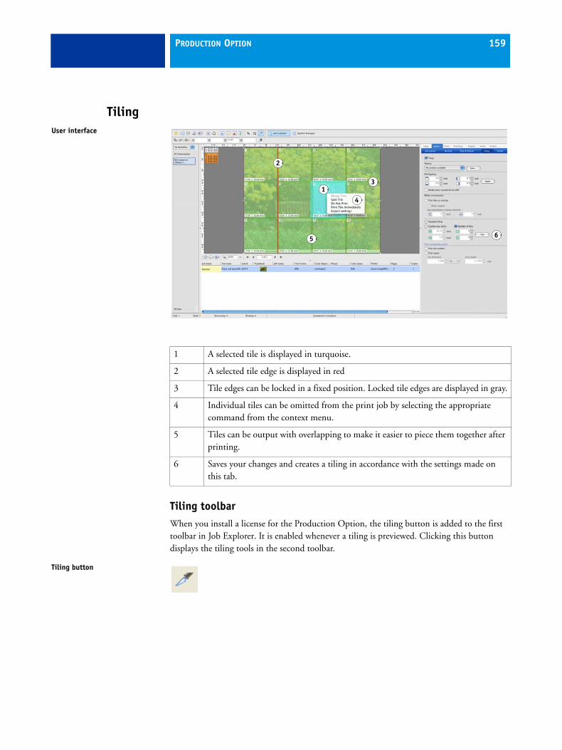
PRODUCTION OPTION 159
Tiling
Tiling toolbarWhen you install a license for the Production Option, the tiling button is added to the first toolbar in Job Explorer. It is enabled whenever a tiling is previewed. Clicking this button displays the tiling tools in the second toolbar.
User interface
1
2
3
4
5 6
1 A selected tile is displayed in turquoise.
2 A selected tile edge is displayed in red
3 Tile edges can be locked in a fixed position. Locked tile edges are displayed in gray.
4 Individual tiles can be omitted from the print job by selecting the appropriate command from the context menu.
5 Tiles can be output with overlapping to make it easier to piece them together after printing.
6 Saves your changes and creates a tiling in accordance with the settings made on this tab.
Tiling button
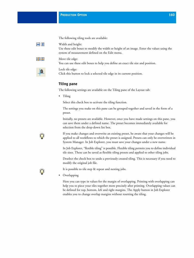
PRODUCTION OPTION 160
The following tiling tools are available:
Width and height: Use these edit boxes to modify the width or height of an image. Enter the values using the system of measurement defined on the Edit menu.
Move tile edge: You can use these edit boxes to help you define an exact tile size and position.
Lock tile edge: Click this button to lock a selected tile edge in its current position.
Tiling paneThe following settings are available on the Tiling pane of the Layout tab:
• Tiling
Select this check box to activate the tiling function.
The settings you make on this pane can be grouped together and saved in the form of a preset.
Initially, no presets are available. However, once you have made settings on this pane, you can save them under a defined name. The preset becomes immediately available for selection from the drop-down list box.
If you make changes and overwrite an existing preset, be aware that your changes will be applied to all workflows to which the preset is assigned. Presets can only be overwritten in System Manager. In Job Explorer, you must save your changes under a new name.
In Job Explorer, “flexible tiling” is possible. Flexible tiling permits you to define individual tile sizes. These can be saved as flexible tiling presets and applied to other tiling jobs.
Deselect the check box to undo a previously created tiling. This is necessary if you need to modify the original job file.
It is possible to tile step & repeat and nesting jobs.
• Overlapping
Here you can type in values for the margin of overlapping. Printing with overlapping can help you to piece your tiles together more precisely after printing. Overlapping values can be defined for top, bottom, left and right margins. The Apply button in Job Explorer enables you to change overlap margins without resetting the tiling.
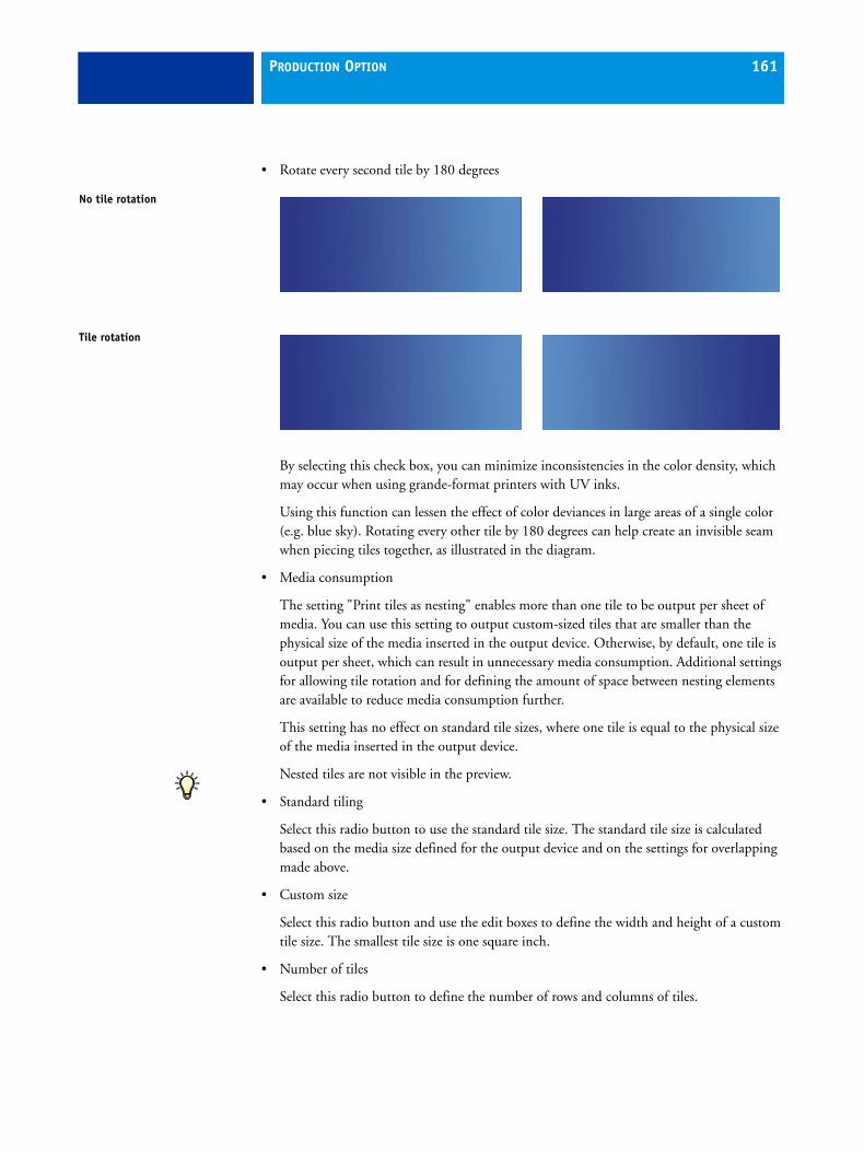
PRODUCTION OPTION 161
• Rotate every second tile by 180 degrees
By selecting this check box, you can minimize inconsistencies in the color density, which may occur when using grande-format printers with UV inks.
Using this function can lessen the effect of color deviances in large areas of a single color (e.g. blue sky). Rotating every other tile by 180 degrees can help create an invisible seam when piecing tiles together, as illustrated in the diagram.
• Media consumption
The setting "Print tiles as nesting" enables more than one tile to be output per sheet of media. You can use this setting to output custom-sized tiles that are smaller than the physical size of the media inserted in the output device. Otherwise, by default, one tile is output per sheet, which can result in unnecessary media consumption. Additional settings for allowing tile rotation and for defining the amount of space between nesting elements are available to reduce media consumption further.
This setting has no effect on standard tile sizes, where one tile is equal to the physical size of the media inserted in the output device.
Nested tiles are not visible in the preview.
• Standard tiling
Select this radio button to use the standard tile size. The standard tile size is calculated based on the media size defined for the output device and on the settings for overlapping made above.
• Custom size
Select this radio button and use the edit boxes to define the width and height of a custom tile size. The smallest tile size is one square inch.
• Number of tiles
Select this radio button to define the number of rows and columns of tiles.
No tile rotation
Tile rotation

PRODUCTION OPTION 162
• Tile (Job Explorer only)
After you have defined tiling settings, click this button to tile the selected job.
Clicking this button again after a tiling has been created resets the tiling and undoes any flexible tile settings you have made.
• Print overlapping marks
The following additional settings are available if you have defined overlapping margins. Tile numbers and marks are printed outside the actual tile area so as not to mar the image.
– Print tile number
With this setting, each tile is printed with a consecutive number. This helps you piece them together in the right order after output.
– Print marks
To output marks for overlapping tiles, select the check box and type in values for line length and line thickness in the appropriate edit boxes. This setting enables more precise tile alignment when piecing the image together after output.
Tile numbers and overlapping marks are only seen in the printout. They are not visible in the preview window of Job Explorer. However, the print area of each tile is smaller when one of these settings is defined.
Marks for tiles have nothing to do with crop marks and it is not necessary to make any settings on the Marks pane. However, with the exception of FOTOBA crop marks, if you have previously selected a type of crop mark and defined a distance to job, the print marks made on this pane will be applied on top of these settings.
Overlapping tiles
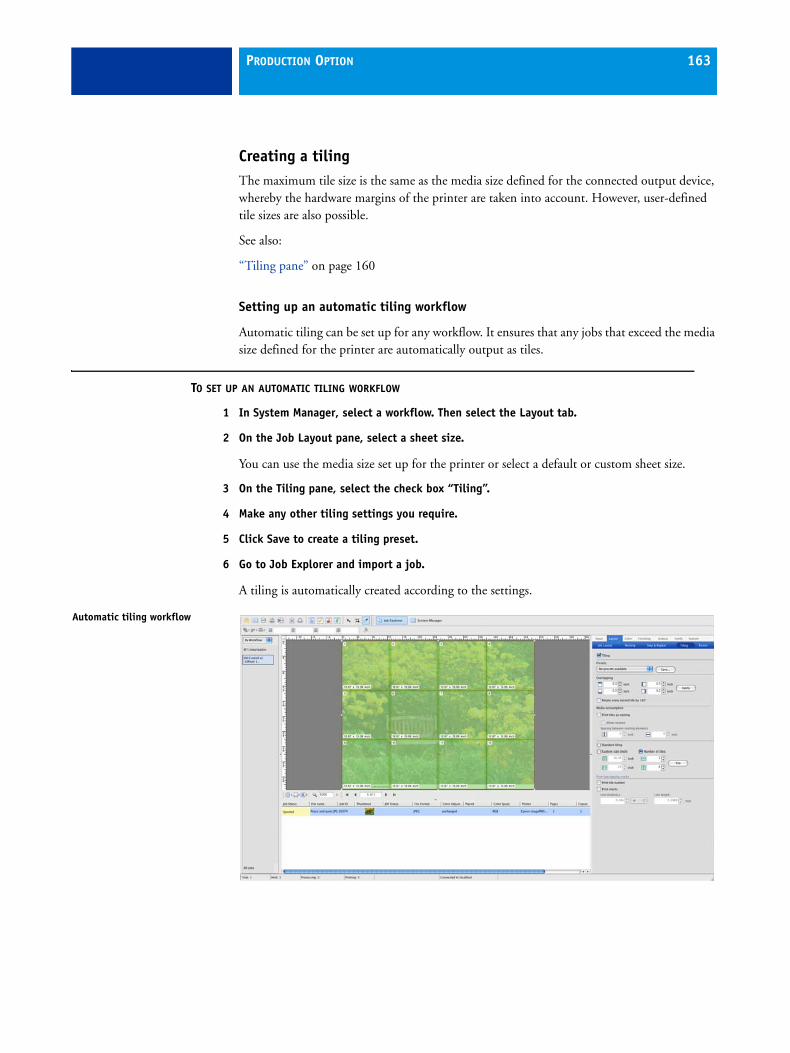
PRODUCTION OPTION 163
Creating a tilingThe maximum tile size is the same as the media size defined for the connected output device, whereby the hardware margins of the printer are taken into account. However, user-defined tile sizes are also possible.
See also:
“Tiling pane” on page 160
Setting up an automatic tiling workflow
Automatic tiling can be set up for any workflow. It ensures that any jobs that exceed the media size defined for the printer are automatically output as tiles.
TO SET UP AN AUTOMATIC TILING WORKFLOW
1 In System Manager, select a workflow. Then select the Layout tab.
2 On the Job Layout pane, select a sheet size.
You can use the media size set up for the printer or select a default or custom sheet size.
3 On the Tiling pane, select the check box “Tiling”.
4 Make any other tiling settings you require.
5 Click Save to create a tiling preset.
6 Go to Job Explorer and import a job.
A tiling is automatically created according to the settings.
Automatic tiling workflow

PRODUCTION OPTION 164
In an automatic tiling workflow, the tiling settings are automatically applied to all jobs. However, by importing a file as a “hold job”, you can modify the tiling settings for individual jobs, as required.
Manual tiling
If a workflow is not set up for automatic tiling, you can still output a single job, a nesting job or a step & repeat job as a tiling if it exceeds the size of the media defined for the printer.
TO CREATE A MANUAL TILING
1 Go to Job Explorer and load a job as a “hold job” in any workflow.
2 Select a single job, a nesting job or a step & repeat job in the job list.
The preview displays the image in relation to the selected media format.
3 On the Layout tab, open the Tiling pane.
4 On the Tiling pane, select the check box “Tiling”.
Loading a tiling job

PRODUCTION OPTION 165
5 Make any other required tiling settings on this pane and click Tile.
A tiling is automatically created according to the settings.
It is possible to switch backward and forward between the tiling and transform toolbars, if required.
Working with tilings
Selecting multiple tiles
There are two different ways to select a multiple number of tiles.
TO SELECT RANDOM TILES
1 In Windows, press and hold down the <Ctrl> key (Windows). On Macintosh, press <Apple> + <Ctrl>.
2 Click the mouse button on the individual tiles to be selected.
TO SELECT CONSECUTIVE TILES
1 Press and hold down the Shift key.
2 Click the mouse button on the first tile to be selected.
3 Click the mouse button on the last tile to be selected.
Loading a tiling job

PRODUCTION OPTION 166
Changing tile sizes
Before printing a tiling, you may wish to resize tiles to avoid awkward joins in your image, such as down the middle of a face.
There are several ways to change tile sizes:
• You can change the size of an entire row or column of tiles.
• You can change the size of individual tiles. However, certain restrictions are in place so that, for example, it is not possible to create a file that would result in the partial resizing or negative overlapping of other tiles.
TO CHANGE TILE SIZES
When you alter the size of one tile, the size of adjacent tiles is increased or reduced accordingly.
You can alter the size of a selected tile by typing exact dimensions in the edit boxes located in the tiling toolbar. Alternatively, you can use drag and drop to move tile edges, as follows:
1 Move the cursor over a tile edge until it changes form.
2 Select the tile edge as follows:
• To select the edge of a row of tiles, press and hold down the mouse button. This affects the size of the whole row or column of tiles.
• To alter the edge of any individual tile, press Alt and then press and hold down the mouse button. This permits so-called “flexible tiling”. It enables you to change the size of an individual tile.
The selected tile edge changes to bright red and the tools in the tiling toolbar become enabled.
Flexible tile sizes

PRODUCTION OPTION 167
3 Drag the cursor to the required position.
The current cursor position is displayed in the preview window to help you pinpoint the exact coordinates of the edge more easily. Alternatively, you can type exact horizontal or vertical values in the appropriate edit boxes of the tiling toolbar.
Reducing the size of one tile may cause an adjacent tile to stretch until it exceeds the dimensions of the selected media size. In this case, a new tile is automatically created. You can remove unwanted tiles created in this way by dragging the edge out of the tiling.
Fixing a tile edge at its current position
You can fix a tile edge at its current position by:
• Selecting a tile edge and clicking the padlock button in the toolbar
• Right-clicking a tile edge and choosing the appropriate command from the context menu.
Merging tiles
When you select two or more consecutive tiles, the command Merge Tiles becomes enabled in the context menu. This command lets you combine two or more tiles into one by deleting a tile edge. However, it is not possible to merge tiles whose combined size would exceed the selected media size.
See also:
“Selecting multiple tiles” on page 165
Splitting tiles
When you click on a tile, the command Split Tile becomes enabled in the ccontext menu. Choosing this command opens a dialog in which you can define a horizontal and vertical number of equal sized tiles. The smallest permitted tile size is 1 square inch.
Click OK to apply the setting.
Flexible tile sizes

PRODUCTION OPTION 168
Exporting tile settings
You can save the width, height and x/y coordinates of each tile as well as overlapping information to Excel format. Right-click on a tile and choose Export settings from the context menu. The tile settings are exported in the measurement system set up in the Edit menu.
The specification sheet can be a useful aid to installation crews who have the task of piecing the printed tiles together.
Hiding tiles
You can temporarily untile a previewed image by choosing View > Visual Aids > Tiles. This setting removes the tiling from the preview. It does not delete the tiling. To preview the tiled image again, reselect the command. Alternatively, click the Transform Job button.
Exporting tiling settings

PRODUCTION OPTION 169
PrintingTo print a whole tiling job, select the print command from the File menu.
In addition, EFI XF lets you:
• print selected tiles immediately (e.g. to reprint individual tiles without having to redo the whole job)
• omit selected tiles from the print job (e.g. to avoid printing parts of tilings that are not needed when pieced together, such as those covering window areas)
You will find the appropriate commands in the context menu that is displayed when you right-click a tile.
Step & repeatThe step-and-repeat pane on the Layout tab enables you to create multiple copies of a file and output as one print job. With the Production Option, the following additional settings become available which make it possible to achieve many different and interesting patterns.
• Step Offset
Use this setting to define the amount of horizontal or vertical shift from one image to the next. Select the appropriate radio button for horizontal or vertical offset. Then type the required amount of offset in the combo box. The illustration shows a horizontal offset of 50%. Images are printed so that pattern repeats can be aligned seamlessly.
• Mirror every 2nd
Select a check box to flip a row and/or column of images. The illustration shows the mirror function applied to both rows and columns.
Once the step-and-repeat function has been applied, it is not possible to make further changes to the original image. This is indicated by a lock icon. To make changes to the original image (e.g. scaling, rotation), you must first delete all the copies by clicking Reset.
Horizontal shift
Horizontal and vertical mirroring

PRODUCTION OPTION 170
Additional color management settings
Color tab > Color Adjustment paneThe following settings are available:
• Color adjustment
Select this check box to activate and edit the settings on this pane. If the check box is not selected, no color adjustments are possible. Any settings made previously will not be applied during printing.
In Job Explorer, you can compare your color adjustments with the original colors by activating and deactivating this check box.
The settings you make on this pane can be grouped together and saved in the form of a preset. Initially, no presets are available. However, once you have made settings on this pane, you can save them under a defined name. The preset becomes immediately available for selection from the drop-down list box.
To make changes and overwrite an existing preset make sure that the preset is not selected for any other workflow. Presets can only be overwritten in System Manager. In Job Explorer, you must save your changes under a new name.
• Apply color adjustment to control strip
This setting lets you choose whether to apply color adjustments not only to your image but also to a selected control strip.
Color adjustments cannot be applied to dynamic wedges.
If you simply want to check the general stability of the printer, there is no need to apply color adjustments to the control strip. In this case, you can leave the setting unchecked.
However, if you wish to check color consistency and ensure that the same color adjustments have been applied to different jobs, you should activate the check box to make certain that the printed control strip has the same color properties as the image. This ensures that you receive reliable color values when measuring the control strip.
• Slidebars CMYK/RGB
Use the slidebars or edit boxes to add or subtract color for CMYK or RGB images. In Job Explorer, EFI XF automatically recognizes the color space of an imported image and disables the color channels that are not required.
These settings are not available if your print job contains spot colors. Nor can color corrections be applied to CMYKRGB or CMYKOG files.

PRODUCTION OPTION 171
• Brightness/Contrast/Saturation
Use the slidebars or edit boxes to adjust the brightness, contrast and saturation of your images. These settings are applied to the color adjustments defined above.
• Blur/Sharpen
Use the slidebar or edit boxes to blur or sharpen your images.
Color tab > Color Management paneThe following additional setting is available in the drop-down list box “Color optimization”:
• Clean colors
The function of “Clean colors” is to cleanse process and secondary colors of any impure color which has been added in color management during the conversion from RGB to CMYK.
The setting is intended primarily for banner and poster production. It ensures that your printouts are output in vivid and saturated colors, but without affecting critical color areas such as grays, skin tones and spot colors.
Selecting “Clean colors” enables the threshold settings. There are two settings: “Automatic cleaning” and “Manual cleaning”. In Automatic mode, EFI XF provides optimal values based on the selected printer, media and profiles. The “Manual cleaning” setting lets you define the percentage at which impure color is removed. It is recommended that you use “Automatic cleaning”.
• Clean colors + black text as inkjet black/ Clean colors + black text and images as inkjet black
These settings are a combination of the settings “Clean colors” and “Black as inkjet black”. Whereas “Clean colors” is applied only to process and secondary colors (which does not include black), thesesettings ensure that black ink (e.g. text or text and images) is also cleaned.

PRODUCTION OPTION 172
Job mergeThe job merge feature enables you to define a mask or “master” file as a background image. Afterward, you define “content” files to be superimposed on the “master” file in the output.
You can merge any two files using the job merge feature. The only prerequisites are:
• The content and master files must have the same page size
• The background color of the content file must be defined as 100% white
If the content file is a multi-page document, the master file will be applied to all pages of the document.
If page layout settings (rotation, scaling, etc.) or crop marks are applied to the content file, the same settings are automatically applied to the merged master file. However, color management settings are not transferable between documents.
Job merge1 Master file2 Multi-page content file
(imported into EFI XF as a nesting)
3 Merged files
1 2 3
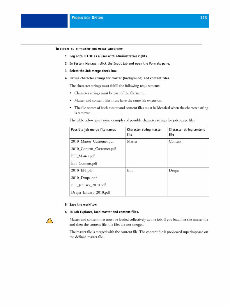
PRODUCTION OPTION 173
TO CREATE AN AUTOMATIC JOB MERGE WORKFLOW
1 Log onto EFI XF as a user with administrative rights.
2 In System Manager, click the Input tab and open the Formats pane.
3 Select the Job merge check box.
4 Define character strings for master (background) and content files.
The character strings must fulfill the following requirements:
• Character strings must be part of the file name.
• Master and content files must have the same file extension.
• The file names of both master and content files must be identical when the character string is removed.
The table below gives some examples of possible character strings for job merge files.
5 Save the workflow.
6 In Job Explorer, load master and content files.
Master and content files must be loaded collectively as one job. If you load first the master file and then the content file, the files are not merged.
The master file is merged with the content file. The content file is previewed superimposed on the defined master file.
Possible job merge file names Character string master file
Character string content file
2010_Master_Customer.pdf
2010_Content_Customer.pdf
EFI_Master.pdf
EFI_Content.pdf
Master Content
2010_EFI.pdf
2010_Drupa.pdf
EFI_January_2010.pdf
Drupa_January_2010.pdf
EFI Drupa

PRODUCTION OPTION 174
TO CREATE MANUAL JOB MERGE FILES
For manually merged files, it is not necessary to comply with a specific naming convention. Files of any name or format can be merged. The only prerequisites are:
• The pages must be of the same size
• The background color of the content file must be defined as 100% white
1 In Job Explorer, load one or more jobs as “hold” jobs.
In the case of jobs loaded via drag and drop or via a hotfolder, the loaded jobs are processed according to the workflow settings. To create job merge files of jobs loaded in this way, you may have to cancel job processing or set the workflow offline at workflow exit.
2 In the job list, select the job that will become the master (background) file.
3 On the Input tab, open the Settings pane.
4 Select the check box “Job merge” and the radio button “Master job”. Then click Save.
5 In the job list, select the content job to be superimposed on the master file.
6 On the Input tab, open the Settings pane.
7 Select the check box “Job merge” and the radio button “Content job”.
8 From the drop-down list box “Assign master job”, select the master file from the list. Then click Save.
9 In the preview, select the content file.
The content file is previewed superimposed on the defined master file.
Unlike in automatic job merge workflows, the master file remains in the job list after merging. As long as the master file is loaded in Job Explorer, you can apply it to other jobs.

COLOR VERIFIER OPTION 175
COLOR VERIFIER OPTION
Color Verifier is a color checker tool. It enables you to measure and compare two different sets of color values to ensure that color accuracy is maintained.
The software is extremely flexible and can be used to check the color accuracy of the following different output combinations:
• Profile-to-proof
• Proof-to-proof
• Proof-to-print
• Print-to-print
• Profile-to-print
Comparing profile-to-proof is one of the most useful applications for Color Verifier. For example, in a normal everyday situation, you can compare the color values of a proof that has been created on your printer with those of the profile that simulates the printing press used for the final print run. If the measured color values are a good match, this indicates that the proof lies within the defined tolerances and therefore reproduces the printing process correctly.
The measured values can be saved, so that the information can be dispatched easily, e.g. via e-mail, to verify the print quality. This makes Color Verifier ideal for use in both in-house as well as in remote environments.
Please be aware that it is not possible to process grayscale files in Color Verifier. L*a*b* files can be verified using the dynamic wedge.

COLOR VERIFIER OPTION 176
ISO supportColor Verifier supports the following latest norms:
• ISO 12647-7/12647-8 defines general proofing requirements for offset printing and all digital printing technologies.
• ISO 12647-2 (second edition) defines the latest standards for offset printing.
Color Verifier is, therefore, an indispensable tool for:
• achieving Fogra Proof Certification
• creating an ISO 12647-7/12647-8 compliant proof
The following ICC profiles and characterization data sets are provided:
The following two offset reference characterization data sets are provided:
See also:
“Program folders” on page 15
Reference profile Characterization data set TIL
ISOcoated_v2_eci.icc FOGRA 39L 330%
ISOcoated_V2_300_eci.icc FOGRA 39L 300%
SC_paper_eci.icc FOGRA 40L 270%
Media wedge/IT8 chart Characterization data sets
Ugra/Fogra media wedge 2.2a Ugra/Fogra media wedge 3.0a
Fogra39_MKCheck.it8 and Fogra40_MKCheck.it8
IT8.7/4 Fogra39L_IT8.74.it8 and Fogra40L_IT8.74.it8
IT8.7/3 Fogra39_IT8.73.it8 and Fogra40_IT8.73.it8
ECI2002 Fogra39_ECI2002.it8 and Fogra40_ECI2002.it8

COLOR VERIFIER OPTION 177
Scope of delivery Color Verifier is available as an add-on module for EFI XF (with or without the ES-1000 measuring device).
If you have purchased an ES-1000 measuring device with the Color Verifier software, check that you have received all the items illustrated.
Please note that a number of additional items are shipped with the ES-1000, which are not required for Color Verifier.
The ES-1000 measuring device and the calibration plate with white reference each have a serial number. The serial numbers of the respective devices must match; otherwise a correct calibration is not possible.
Make sure to follow the instructions regarding installation and maintenance.
See also:
“ES-1000” on page 217
Scope of delivery1 ES-10002 Calibration plate with
white reference3 Patch guide4 Backer board with strip
guide5 USB cable
1 2
4
5
3

COLOR VERIFIER OPTION 178
Starting Color VerifierTo start Color Verifier:
• Choose Tools > EFI Color Verifier
• In the toolbar of EFI XF, click “EFI Color Verifier” to launch the application.
User interface
Program window
Program icon
User interface
6
3
7
4
9
5
8
1 2
01
1 Displays the first set of loaded or measured color values.
2 Displays the second set of loaded or measured color values for comparison.
3 Displays a list of jobs received from EFI XF.
4 2D view of color values. When you move the mouse cursor over a color, the corresponding value is highlighted in the M1/M2 table and in the color wheel. The appropriate delta E value is also highlighted.
COLOR VERIFIER OPTION 179
Preferences dialogTo open the Preferences dialog:
• Click Edit in the program window
• From the File menu, choose Preferences
Most of the settings in the Preferences dialog apply only if you are using Color Verifier as a stand-alone tool. If Color Verifier is incorporated into an EFI XF workflow, you make the equivalent settings in System Manager. The settings are transferred to Color Verifier with the job and displayed in the Preferences dialog.
The Preferences dialog consists of two tabs. The first pane is concerned with general settings. On the second pane you define the parameters necessary to check and verify color accuracy.
5 The 2D view represents a cross-section of the L*a*b* color space. Using the slide bar, you can shift the cutting plane to show the a*b* dimensions for a particular L* value.
6 3D view. To rotate the 3D image, hold down the mouse button on the color wheel and move the cursor.
7 Enlarge 2D/3D view. In the 3D view, you can change the display settings.
8 Results area. Shows whether the measured values for delta E and paper white are within the defined values. Additional tabs show whether the measured values for delta E and paper white are within the tolerances defined for each color channel.
9 Establishes a connection to the measuring device.
10 In the “Preferences” dialog you define measurement settings.

COLOR VERIFIER OPTION 180
General tab
General tab

COLOR VERIFIER OPTION 181
• User interface
– Language (Windows only)
Choose this command to change the language in which the user interface is displayed. By default, Color Verifier is displayed in the language selected during installation.
On a Macintosh, you can change the language via the international settings in “System preferences”.
– Enable Delta E warning indicator
When you select this check box, the amount of deviation from the defined tolerance values is illustrated in the delta E table. The following color code is used:
– Enable measurement approval
This setting enables you to verify measurement readings that are not within the defined tolerance values. In this case, the job is displayed in Job Explorer with the job status “Verified”.
This setting has no functionality if you are using Color Verifier as astand-alone tool.
– Use system speaker for beep
By default, EFI XF uses the beep tone from the operating system. If you deselect this check box, the beep tone from the measuring device is used instead.
• Define default folders
– Save files to
Click Choose to change the default folder in which to save your files.
– Load characterization data from
Click Choose to change the default folder from which to load characterization data files.
Color Delta E value
White The color patch is within the permitted tolerance.
Yellow The color patch exceeds the permitted average tolerance but is within the defined maximum tolerance value.
Red The color patch exceeds the defined maximum tolerance value and causes a “not passed” result.

COLOR VERIFIER OPTION 182
• General
– Light source for spectral data conversion
Here you make the light (illuminant) setting for the conversion from spectrophotometric values to L*a*b*. Choose between D-50, D-65 and C.
– Observer angle for spectral data conversion
Here you define the angle for the conversion from spectrophotometric values to L*a*b*. 2° is the default setting, but 10° is sometimes used in the packaging or textile industry.
• Monitor gamma
Select the gamma setting. The gamma setting adjusts how the M1 and M2 readings appear on your computer screen.
Comparison Settings tab
Comparison Settings tab

COLOR VERIFIER OPTION 183
• Measuring device
Select your measuring device from the drop-down list box.
This setting acts as a filter and ensures that only those charts, control strips and media wedges available for a particular device are listed. It is also possible to select custom control strips from a defined folder.
– Measure whole control strip
Select this radio button to measure all the color patches of the selected control strip. If you also select the check box “Check direction of measurement”, the colors are measured according to the direction in which the measuring device is moved, i.e. from left to right or from right to left. However, this feature is not supported for all measuring devices. If this check box is not selected, the control strip color values are always displayed as if the measurement had been read from left to right.
– Measure single patches
Select this radio button to measure the color values of individual color patches
• Barbieri measuring devices
Additional measuring mode settings are available if you use a Barbieri SpectroLFP or Spectro Swing measuring device. The settings are:
– Enable autopositioning mode
– Enable Up-Down measuring mode
– Enable Transmission measuring mode
– Enable 6mm aperture
• Chart or wedge selection
Select a profiling chart,control strip or a media wedge for measuring or comparison purposes. Only those profiling charts, control strips and media wedges available for the selected measuring device are listed.
Once you have selected a chart or media wedge, Color Verifier displays information regarding the layout and number of color patches.
If you are using a DTP20 measuring device, you are required to measure a TID patch before measuring the control strip. In most cases, this patch is printed out automatically with your print job. However, if you select an Ugra Fogra media wedge, you will need to print the TID patch separately. The file “-TIDforMKV20XP-V2.tif ” is provided in the Tools folder for this purpose.
• Characterization data
If you have selected a Ugra/Fogra media wedge or an ISO IT8.7/4 or ISO 12647-7 profiling chart, you can load it8 characterization data from the drop-down list box. The check box lets you specify that the characterization data is loaded automatically.
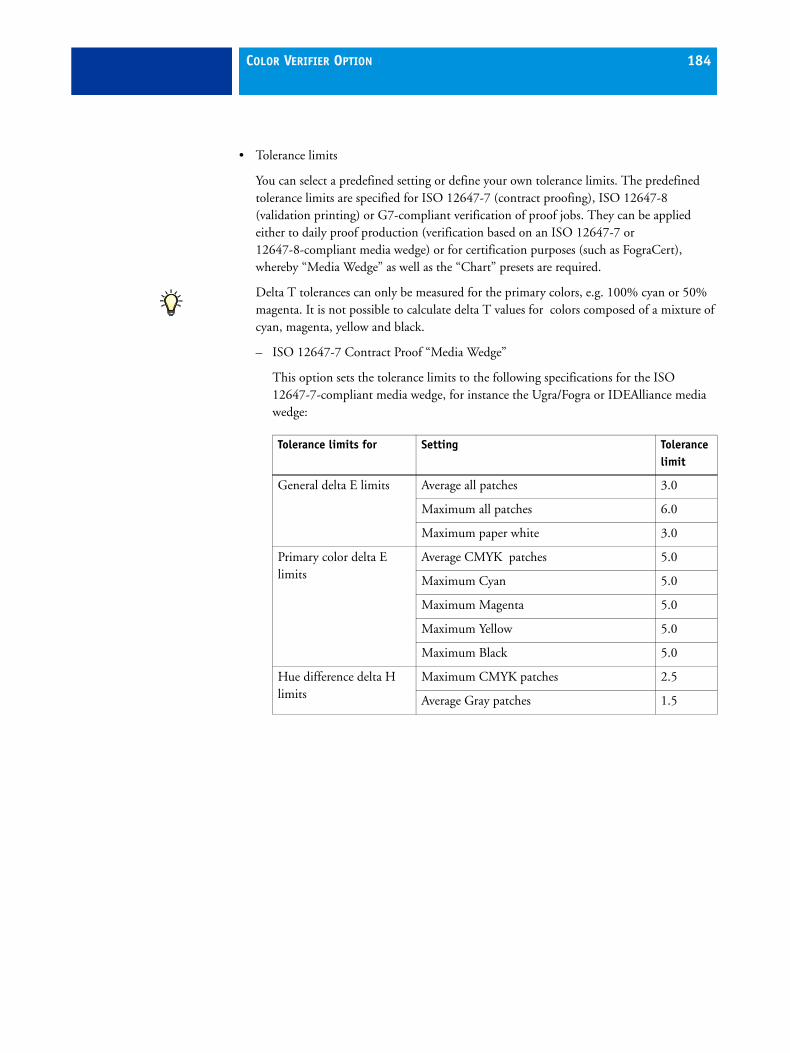
COLOR VERIFIER OPTION 184
• Tolerance limits
You can select a predefined setting or define your own tolerance limits. The predefined tolerance limits are specified for ISO 12647-7 (contract proofing), ISO 12647-8 (validation printing) or G7-compliant verification of proof jobs. They can be applied either to daily proof production (verification based on an ISO 12647-7 or 12647-8-compliant media wedge) or for certification purposes (such as FograCert), whereby “Media Wedge” as well as the “Chart” presets are required.
Delta T tolerances can only be measured for the primary colors, e.g. 100% cyan or 50% magenta. It is not possible to calculate delta T values for colors composed of a mixture of cyan, magenta, yellow and black.
– ISO 12647-7 Contract Proof “Media Wedge”
This option sets the tolerance limits to the following specifications for the ISO 12647-7-compliant media wedge, for instance the Ugra/Fogra or IDEAlliance media wedge:
Tolerance limits for Setting Tolerance limit
General delta E limits Average all patches 3.0
Maximum all patches 6.0
Maximum paper white 3.0
Primary color delta E limits
Average CMYK patches 5.0
Maximum Cyan 5.0
Maximum Magenta 5.0
Maximum Yellow 5.0
Maximum Black 5.0
Hue difference delta H limits
Maximum CMYK patches 2.5
Average Gray patches 1.5

COLOR VERIFIER OPTION 185
– ISO 12647-7 Contract Proof “Chart”
This option sets the tolerance limits to the following specifications, as defined by ISO 12647-7 (used for FograCert applications):
Fogra IT8.7/4 chart
Tolerance limits for Setting Tolerance limit
General delta E limits Average all patches 4.0
Average outer gamut patches 4.0
Maximum for 95% of patches 6.0
Tone value difference tolerance limits
Maximum CMYK patches 5.0

COLOR VERIFIER OPTION 186
– ISO 12647-8 Validation Print “Media Wedge” NWIP
This option sets the tolerance limits to the following ISO 12647-8 definitions that Fogra currently uses for FograCert Validation Print Certification. The tolerance limits are based on the New Work Item Proposal (NWIP) of the ISO 12647-8.
– ISO 12647-8 Validation Print “Media Wedge” CD2
These tolerance limits will replace the ISO 12647-8 NWIP definitions that are currently used for FograCert Validation Print Certification. The values are current at the time of going to press, and are expected to be the tolerance limits defined for the release version of ISO 12647-8.
Tolerance limits for Setting Tolerance limit
General delta E limits Average all patches 3.0
Maximum all patches 8.0
Maximum paper white 3.0
Primary color delta E limits
Average CMYK patches 5.0
Maximum Cyan 5.0
Maximum Magenta 5.0
Maximum Yellow 5.0
Maximum Black 5.0
Hue difference delta H limits
Maximum CMYK patches 2.5
Average Gray patches 1.5
Tolerance limits for Setting Tolerance limit
General delta E limits Average all patches 3.0
Maximum all patches 8.0
Maximum paper white 3.0
Hue difference delta H limits
Maximum CMYRGBK patches 4.0
Chromaticness difference delta F limit
Average dF 2.5

COLOR VERIFIER OPTION 187
– ISO 12647-8 Validation Print “Chart” NWIP
This option sets the tolerance limits to the following specifications, as defined by ISO 12647-8 NWIP (for FograCert applications)
– ISO 12647-8 Validation Print “Chart” CD2
These criteria and tolerance limits will replace the ISO 12647-8 NWIP definitions that are currently used for FograCert Validation Print Certification. They are based on the current Committee Draft (CD2) status. The values are current at the time of going to press, and are expected to be the tolerance limits defined for the release version of ISO 12647-8.
– G7 Contract Proof “Media Wedge”
This option sets the tolerance limits to the following specifications for G7- compliant analysis of the ISO 12647-7-compliant media wedge, such as the IDEAlliance control strip:
Tolerance limits for Setting Tolerance limit
General delta E limits Average all patches 4.0
Average outer gamut patches 4.0
Maximum for 95% of patches 6.0
Tone value difference tolerance limits
Maximum CMYK patches 10.0
Tolerance limits for Setting Tolerance limit
General delta E limits Average all patches 3.0
Average outer gamut patches 4.0
Maximum for 95% of patches 6.0
Tone value difference tolerance limits
Maximum CMYK patches 10.0
Tolerance limits for Setting Tolerance limit
General delta E limits Average all patches 1.5

COLOR VERIFIER OPTION 188
– Dynamic wedge
This option enables you to define general delta E limits if you want to measure the color values achieved for a dynamic wedge. The default settings are:
Other values are not permitted due to the unique composition of color patches for each job. However, if you want to evaluate additional tolerance limits in a dynamic wedge, you can create a custom preset.
See “Custom” on page 188 for further information on using the Normative and Informative buttons and for details on how to create and apply user-defined dynamic wedge presets.
– Custom
By selecting “Custom” in the drop-down list box, you can define your own tolerance limits and save them as a custom preset. Custom presets provide an easy way to save the latest norms or your individual requirements (house standard).
Furthermore, you can use the Normative and Informative buttons. These settings affect job verification as follows:
Tolerance limits for Setting Tolerance limit
General delta E limits Average all patches 3.0
Maximum all patches 6.0
Normative Normative values are evaluated. If any of the measurements lie outside the specified range of tolerance, Color Verifier will indicate that the result is not satisfactory and the job will fail the verification.
Informative Informative values are evaluated for reference purposes only and have no effect on whether the job passes or fails the verification. Only normative tolerances are taken into account, i.e. a job can be successfully verified, even if an informative value exceeds the defined tolerance limits.
Off If you select "Off", the tolerance limit is not evaluated and is not included in the evaluation.

COLOR VERIFIER OPTION 189
Once you have defined the required tolerance limits, click Save and define a unique name.
Via the check box “Show preset in XF Client”, you can transfer custom presets to the EFI XF Client and apply them to verify workflows. Creating presets in Color Verifier enables you to define settings, which are not available in the EFI XF Client. The transferred presets are available on the Verify tab.
You can use the check box “Use for dynamic wedge” to apply custom settings to a dynamic wedge. This enables you to evaluate additional tolerance limits besides the general delta E limits defined in the default dynamic wedge preset.
Custom presets cannot be deleted if they are currently applied to a job.
EFI 3D ViewerTo open EFI 3D Viewer, first display a 3D view, then click Enlarge 3D view. In EFI 3D Viewer you can define the following settings:
• M1/M2
Click on the appropriate tab to define the settings for displaying your M1 or M2 measurement values.
3D Viewer

COLOR VERIFIER OPTION 190
• Nodes
Select this check box to display the nodes of the individual color measurements. The color in which the nodes are displayed is indicated in the area next to the check box. To alter the default color, double-click on the colored area and select or define a color in the Color dialog.
• Lines
Select this check box to connect the nodes of the individual color measurements. The color in which the lines are displayed is indicated in the area next to the check box. To alter the default color, double-click on the colored area and select or define a color in the Color dialog.
• Fill
Select this check box to display the represented color space as a solid form. The color in which the solid form is displayed is indicated in the area next to the check box. To alter the default color, double-click on the colored area and select or define a color in the Color dialog.
• Transparency
This slidebar allows you to define the degree of transparency for M1 or M2 values.
• Visible
Select this check box to show or hide the pictorial diagram of M1 or M2 values. This setting has the same effect as the check boxes “Show in color space”.
• Background color
Click the colored area to open the Color dialog and select or define the background color of EFI 3D Viewer.
• Color disk
When this check box is selected, the color disk is displayed in EFI 3D Viewer. Deselect this check box to hide the color disk.
• Full color gamut
Select this check box to apply the full color gamut to the displayed measured values. This setting overrides the “Fill” setting made in this dialog. It is only available in conjunction with the setting “Smooth”.
• Smooth
Select this check box to smooth the edges of the displayed measured values.
• Enable projection
Select this check box to activate the Projection Point button.

COLOR VERIFIER OPTION 191
• Projection Point
Click this button to open a dialog in which you can define an L*a*b* value to be compared with M1 or M2. The defined node is displayed in EFI 3D Viewer. If the color lies outside the depicted color gamut, a line is drawn to illustrate the point to which the color would be mapped.
• Set defaults
Click this button to return all the settings in this dialog to their default values.
• Reset rotation
Using this setting rotates the 3D view to the same angle of rotation as the 2D view, i.e. it displays an a*b* view of the color gamut.
• Close
Click this button to close EFI 3D Viewer.
Menus
EFI Color Verifier (Macintosh only)
• About EFI Color Verifier
Choose this command to open a window with details of your program version.
• Login
Choose this command to display the Login dialog. This command enables you to log in under a different user name or to log on to a different Server.
• Preferences
Choose this command to open the Preferences dialog.
• Quit EFI Color Verifier
Choose this command to exit Color Verifier. If you have not previously saved your settings, you will be prompted to do so before the program closes.

COLOR VERIFIER OPTION 192
File menu
• Open M1
Choose this command to load the first set of values, e.g. a reference profile or a JDF or CSV file.
This menu command corresponds to the Open button for measurement 1.
• Open M2
Choose this command to load the second set of values, e.g. a reference profile or a JDF or CSV file.
This menu command corresponds to the Open button for measurement 2.
• Save
Choose this command to save the displayed readings.
Your settings are saved in CSV format. A CSV file can be opened and edited in any spreadsheet application.
When you choose this command, the folder you defined as the data folder is automatically opened.
• Add data to JDF
Choose this command to add the currently displayed readings to an already existing JDF file contained in an EFI Remoteproof Container. You can save multiple sets of measurements to a JDF or CSV file.
It is not possible to create a new JDF file using this command. Your settings can only be added to an already existing file.
You must have EFI XF installed on the computer in order to access a JDF file.
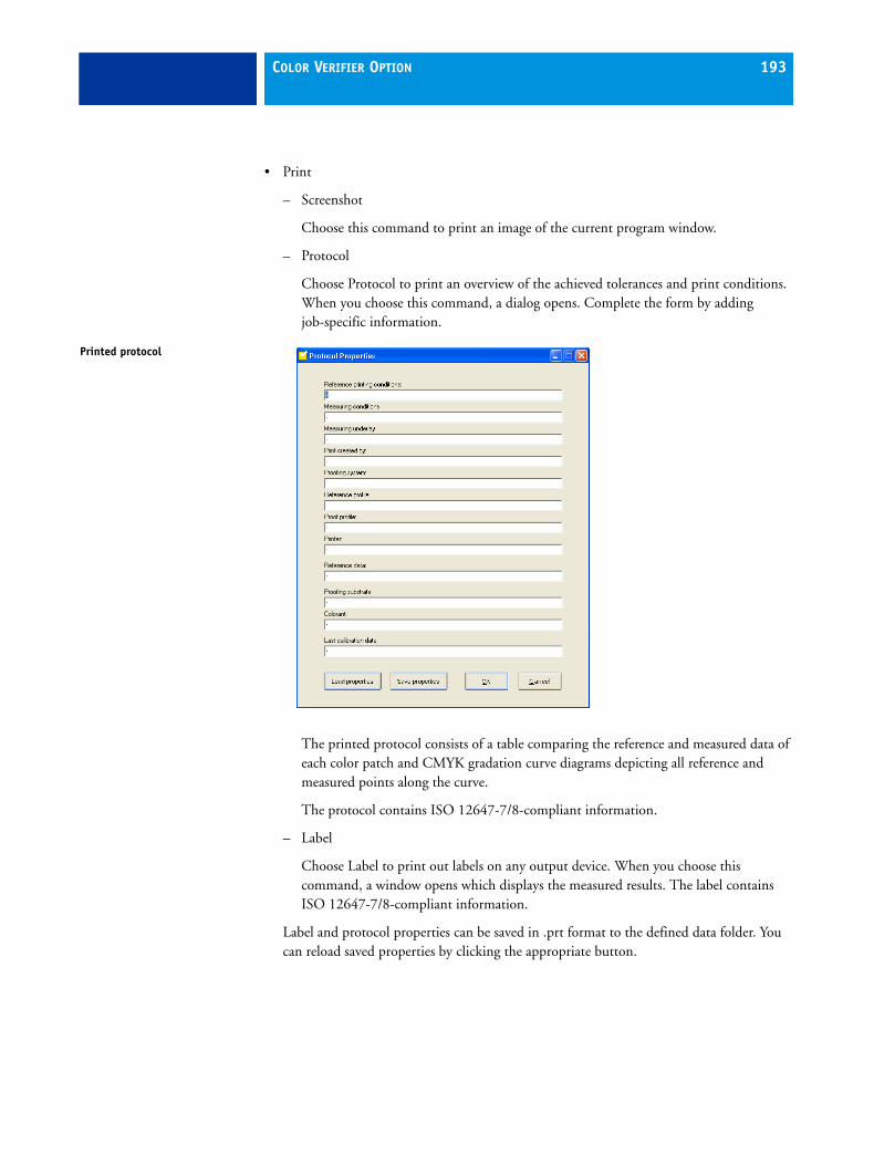
COLOR VERIFIER OPTION 193
– Screenshot
Choose this command to print an image of the current program window.
– Protocol
Choose Protocol to print an overview of the achieved tolerances and print conditions. When you choose this command, a dialog opens. Complete the form by adding job-specific information.
The printed protocol consists of a table comparing the reference and measured data of each color patch and CMYK gradation curve diagrams depicting all reference and measured points along the curve.
The protocol contains ISO 12647-7/8-compliant information.
– Label
Choose Label to print out labels on any output device. When you choose this command, a window opens which displays the measured results. The label contains ISO 12647-7/8-compliant information.
Label and protocol properties can be saved in .prt format to the defined data folder. You can reload saved properties by clicking the appropriate button.
Printed protocol

COLOR VERIFIER OPTION 194
• Printer setup (Windows)/Page Setup (Macintosh)
Choose this command to select a printer and make the desired printer settings. The printer you set up is the one used to print screenshots, protocols and labels.
• Login (Windows only)
Choose this command to display the Login dialog. This command enables you to log in under a different user name or to log on to a different Server.
• Preferences
Choose this command to open the Preferences dialog.
• Exit (Windows)/Quit (Macintosh)
Choose this command to exit Color Verifier. If you have not previously saved your settings, you will be prompted to do so before the program closes.
See also:
“Analyzing the results” on page 212
View menu
• Color space
With this command you select in which color space the measured readings will be displayed.
Choose between RGB, L*a*b*, XYZ, CIELCH or Density. L*a*b* is the default color space setting for this command.
“Density” is only available for selection if you have already measured and displayed color values. In a color-accurate proof, the displayed density values are comparable with the density values obtained during a production run. However, be aware that the density values of individual inkjet inks are not comparable with the density values of printing inks. This is because, for example, the cyan ink used in offset printing is different from the cyan ink used in an inkjet printer.
This function is also available via the context menu. To display the context menu, right-click the tables with the displayed M1 and M2 color measurements.
• Delta E format
With this command you select the color space in which the tolerance, i.e. the color deviation, between the two loaded sets of color values will be displayed. The tolerance is expressed as delta E values.
Choose between dE CIE 76, dE CMC, dE 94 and dE 2000 tolerancing.
This command is also available via the context menu. To display the context menu, right-click the delta E table.

COLOR VERIFIER OPTION 195
Help menu
• Help (Windows)/EFI Color Verifier Help (Macintosh)
Choose this command to access online help.
• EFI Website
Choose this command to access the EFI homepage.
• EFI Technical Support
Choose this command to send an e-mail direct to our Support team if you require help with your product.
• About (Windows only)
Choose this command to open a window with details of your program version.
Color Verifier settings in EFI XF If you have purchased Color Verifier as an add-on module, the program windows System Manager and Job Explorer are extended as follows:
• a program icon appears in the toolbar
• Additional settings become available on the Verify tab in the property inspector.
System Manager
Verify tab > Control Strip 1/Control Strip 2
The settings you make on the Control Strip panes are transferred with the job to Color Verifier and displayed in the Preferences dialog.
• Verify
Select this check box to incorporate Color Verifier into your workflow. When selected, print jobs are automatically sent to Color Verifier during job processing to enable you to check the color consistency of your printouts.
Program icon

COLOR VERIFIER OPTION 196
• Characterization data
– Generated from reference file
Here you select a reference that represents the target color values you want to achieve. When you measure the control strip, the color values are measured against the tolerances defined by the reference. Depending on the type of control strip you select, different references are possible.
The table below shows which characterization data to use for which reference profile.
Type of control strip Target colors of reference
Reference profile
Measurement saved to EFI Remoteproof Container (RPF)
SWOP/ GRACoL
Fogra characterization data
EFI Color Verifier Chart
Yes Yes No No
IDEAlliance ISO 12647-7
Yes No Yes No
Ugra Fogra-MediaWedge
Yes No No Yes
Characterization data Reference profile
Fogra 27 ISOcoated.icc
Fogra 28 ISOwebcoated.icc
Fogra 29 ISOuncoated.icc
Fogra 30 ISOuncoatedyellowish.icc
Fogra 31 ISOcofcoated.icc
Fogra 32 ISOcofuncoated.icc
Fogra 39 ISOcoated_v2_eci.icc/ ISOcoated_v2_300_eci.icc
Fogra 40 SC_paper_eci.icc
Fogra 41 PSO_MFC_paper_eci.icc
Fogra 42 PSO_SNP_paper_eci.icc
Fogra 43 PSO_Coated_NPscreen_ISO12647_eci.icc
Fogra 44 PSO_Uncoated_NPscreen_ISO12647_eci.icc
Fogra 45 PSO_LWC_Improved_eci.icc
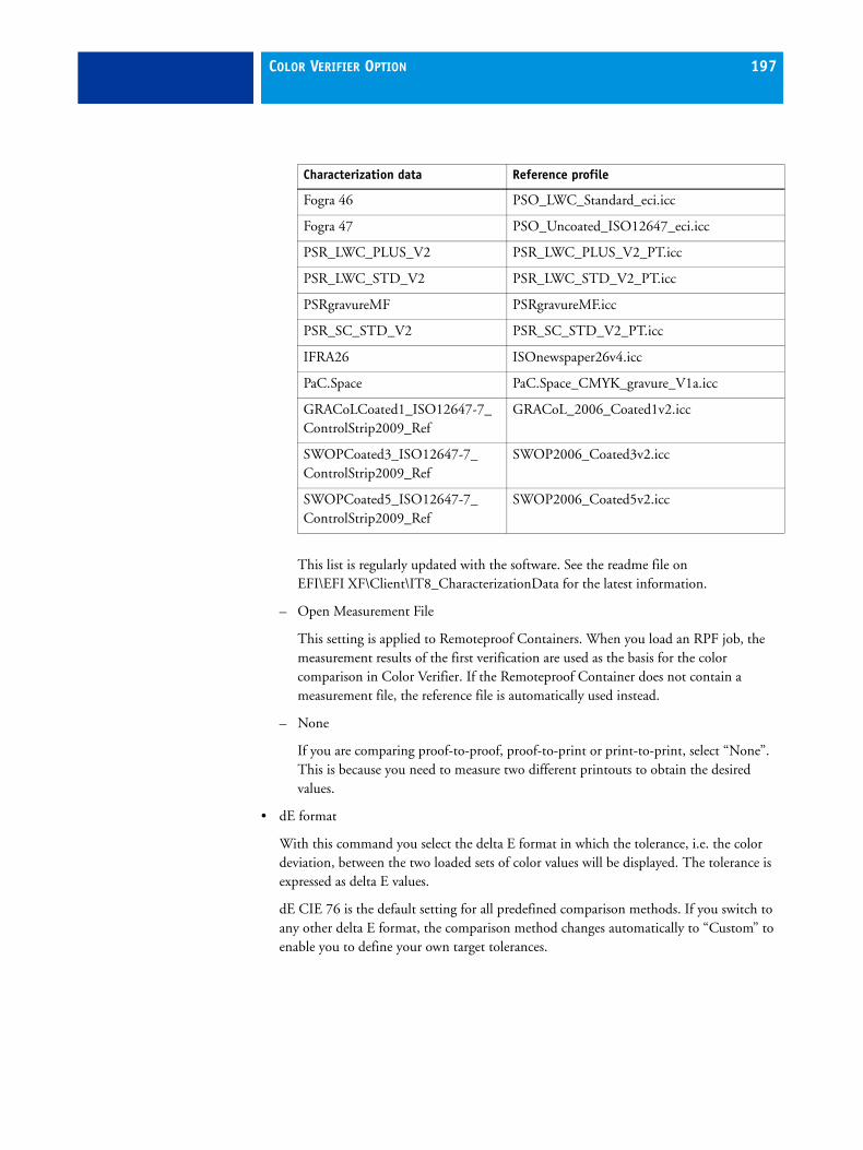
COLOR VERIFIER OPTION 197
This list is regularly updated with the software. See the readme file on EFI\EFI XF\Client\IT8_CharacterizationData for the latest information.
– Open Measurement File
This setting is applied to Remoteproof Containers. When you load an RPF job, the measurement results of the first verification are used as the basis for the color comparison in Color Verifier. If the Remoteproof Container does not contain a measurement file, the reference file is automatically used instead.
– None
If you are comparing proof-to-proof, proof-to-print or print-to-print, select “None”. This is because you need to measure two different printouts to obtain the desired values.
• dE format
With this command you select the delta E format in which the tolerance, i.e. the color deviation, between the two loaded sets of color values will be displayed. The tolerance is expressed as delta E values.
dE CIE 76 is the default setting for all predefined comparison methods. If you switch to any other delta E format, the comparison method changes automatically to “Custom” to enable you to define your own target tolerances.
Fogra 46 PSO_LWC_Standard_eci.icc
Fogra 47 PSO_Uncoated_ISO12647_eci.icc
PSR_LWC_PLUS_V2 PSR_LWC_PLUS_V2_PT.icc
PSR_LWC_STD_V2 PSR_LWC_STD_V2_PT.icc
PSRgravureMF PSRgravureMF.icc
PSR_SC_STD_V2 PSR_SC_STD_V2_PT.icc
IFRA26 ISOnewspaper26v4.icc
PaC.Space PaC.Space_CMYK_gravure_V1a.icc
GRACoLCoated1_ISO12647-7_ ControlStrip2009_Ref
GRACoL_2006_Coated1v2.icc
SWOPCoated3_ISO12647-7_ ControlStrip2009_Ref
SWOP2006_Coated3v2.icc
SWOPCoated5_ISO12647-7_ ControlStrip2009_Ref
SWOP2006_Coated5v2.icc
Characterization data Reference profile

COLOR VERIFIER OPTION 198
• Target tolerances
Here you specify the target tolerances for your printout. EFI XF provides target tolerance presets for the following recognized standards:
– the ISO 12647-7 Contract Proof“Media Wedge”
– the ISO 12647-8 Validation Print “Media Wedge” NWIP
– the ISO 12647-8 Validation Print “Media Wedge” CD2
– the G7 Contract Proof “Media Wedge”
The ISO 12647-8 Validation Print “Media Wedge” NWIP sets the tolerance limits to the definitions that Fogra currently uses for FograCert Validation Print Certification. However, this standard is in the process of being replaced by ISO 12647-8 Validation Print “Media Wedge” CD2. The values are current at the time of going to press, and are expected to be the tolerance limits defined for the release version of ISO 12647-8.
Depending on whether or not the color values of the measured control strip lie within the defined tolerances, your printout will be awarded the mark “passed” or “not passed”.
Alternatively, by selecting “Custom”, you can overwrite the predefined values in the table with your own target values. Custom presets created in Color Verifier can also be selected here.
For the dynamic wedge it is only possible to define general delta E limits. Other values are not permitted due to the unique composition of color patches for each job.
• Print label
Once you have obtained comparison results, you can print them out as a label. The label includes all the necessary ISO 12647-7/8-compliant information. You can print out the label automatically whatever result is achieved. Alternatively, by selecting the check box “Print only if verification results passed”, you can specify that a label will only be printed if all measured results are within the defined tolerances and a “pass” is achieved.
This setting is only available for certain printers with integrated measuring device. You must select an appropriate Ugra Fogra media wedge for your printer.
See also:
“Color tab > Color Management pane” on page 68
“Control strip settings” on page 82
“Tolerance limits” on page 184
“Delta E format” on page 194
“Label” on page 215

COLOR VERIFIER OPTION 199
Job Explorer
Verify tab > Control Strip 1/Control Strip 2
Color values evaluated in Color Verifier are sent back to EFI XF and displayed on the Control Strip 1/Control Strip 2 panes. The results indicate whether the readings lie within the tolerances defined in System Manager.
The following settings are available:
• Verify control strip name
This setting enables you to choose which control strip will be measured and verified in Color Verifier. If two control strips are attached to the job, you can define whether one or both are sent to Color Verifier. If neither check box is selected, the job is not sent to Color Verifier after printing.
• Target tolerances
The results of the color accuracy check are transferred from Color Verifier and displayed in table form. At the same time, the Optimize and Verify buttons are enabled.
– Optimize
Clicking Optimize adjusts the control strip colors of the reference profile to those of the media profile.
It is not possible to optimize images if any of the following have been applied:
Color adjustments Clean colors Perceptual or Saturated rendering intent Dynamic rendering intent
The context menu command Optimize & Print is available if your job contains two control strips and you wish to base the optimization on both simultaneously.
– Verify
Click this button to start Color Verifier and load the current job data. This button is available only for jobs in a verify workflow, for which a color strip is selected.
If the job has already been measured, clicking Verify will start Color Verifier to enable you to recheck the measured values.

COLOR VERIFIER OPTION 200
Implementing Color Verifier in EFI XF Color Verifier can be used:
• To verify the proof (or print) for ISO 12647-7 or 12647-8 or G7 compliance
• To verify any house standard
• For certification purposes (e.g. FograCert)
• To verify color consistency
TO SET UP A COLOR VERIFIER WORKFLOW
The following steps describe only the settings that are concerned with verifying color accuracy. You can, of course, make additional settings to suit your own particular workflow requirements.
1 In System Manager, create a new workflow.
A number of default workflow templates are available that are already set up with all the settings necessary for a basic verifier workflow.
If you wish to set up your own verifier workflow from scratch, make sure that the workflow is set up with the following settings.
2 On the Layout tab > Footer pane:
• From the drop-down list box, select “Edit page footer”.

COLOR VERIFIER OPTION 201
3 On the Verify tab > Control Strip 1/Control Strip 2 panes:
• From the drop-down list box “Control Strip” (Control Strip 1 pane only), select a control strip.
EFI XF lets you select two different control strips. For example, you could output one dynamic wedge and one Ugra/Fogra media wedge, or one Ugra/Fogra media wedge with color management and one without.
If you select “Dynamic wedge”, you must also:
– Select which measuring device you will use
– Define the required number of color patches and
– Specify whether the dynamic wedge should consist of process colors, spot colors or a mixture of both
• Select the check box “Verify”.
• From the drop-down list box “Characterization data”, select a reference that represents the target color values you want to achieve. The reference you select can be characterization data, the reference profile or the measurement file from a Remoteproof Container, See also “Characterization data” on page 196 for further information.
• From the drop-down list box “dE format” define how delta E should be calculated.
You can choose between “dE CIE 76” (default), “dE 94”, “dE 2000” and “dE CMC”.
• From the drop-down list box “Target tolerances”, specify the target tolerances for your printout. You can select predefined target tolerances or define your own. See also “Target tolerances” on page 198 for further information.
You can also select custom tolerances that have been saved as a preset in Color Verifier. See also “Custom” on page 188.
4 On the Output tab > Remote pane:
• Select the radio button “Automatically” or “Manually” if you wish to create a Remoteproof Container and save job settings and color measurement results to an RPF file. RPF files contain all the color management settings essential to ensure that color consistency is maintained when the same job is output at different locations.
5 Save the workflow.

COLOR VERIFIER OPTION 202
TO PROCESS A JOB IN A COLOR VERIFIER WORKFLOW
1 Load a job
If the workflow is set up to output two control strips, you can define whether one or both will be used to verify color accuracy in Color Verifier. Go to the Verify tab > Control Strip 1/Control Strip 2 pane in Job Explorer, and select or deselect the check box “Verify control_strip_name” accordingly.
2 Print the job.
After printing, the job file is automatically submitted to Color Verifier.
3 Start Color Verifier.
The printed job is displayed on the Job List/Preview tab.
4 On the Job List/Preview tab, expand the job file and double-click the job file.
Jobs submitted to Color Verifier from EFI XF are composed of a job ID and the job name, e.g. “0071 Hessen2”.
If you are comparing color results with those defined by a reference profile or Fogra characterization data, the appropriate target color values are loaded automatically as M1 values.
Color Verifier with job loaded from EFI XF
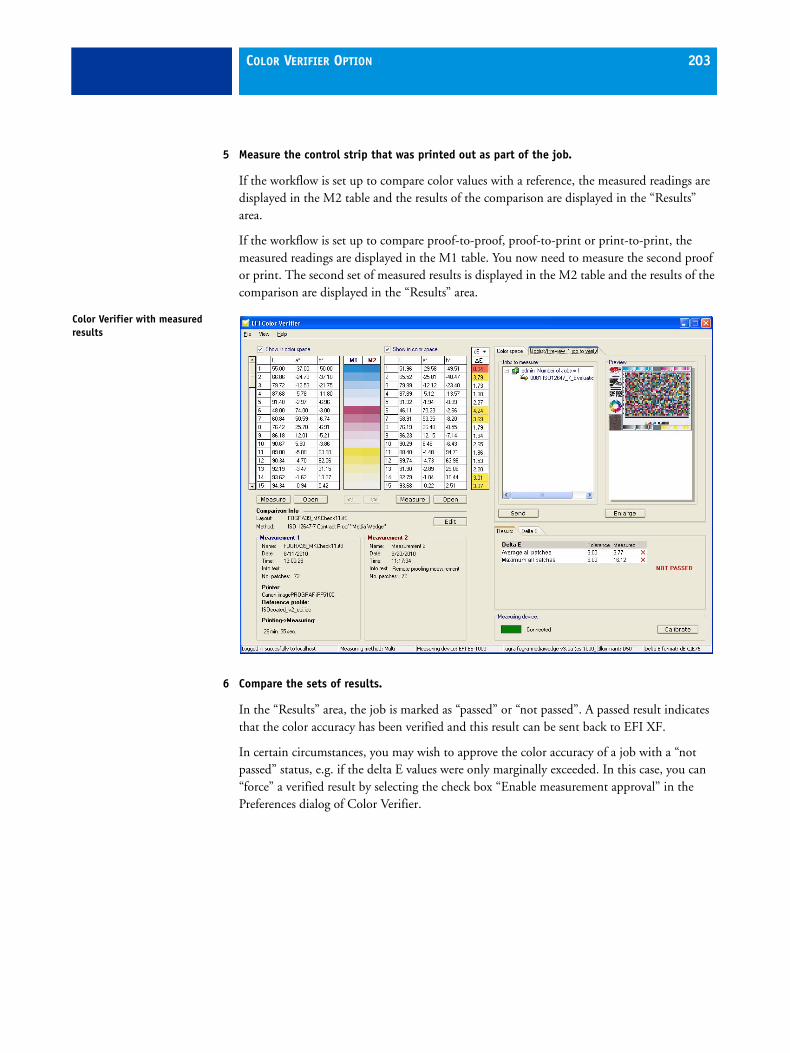
COLOR VERIFIER OPTION 203
5 Measure the control strip that was printed out as part of the job.
If the workflow is set up to compare color values with a reference, the measured readings are displayed in the M2 table and the results of the comparison are displayed in the “Results” area.
If the workflow is set up to compare proof-to-proof, proof-to-print or print-to-print, the measured readings are displayed in the M1 table. You now need to measure the second proof or print. The second set of measured results is displayed in the M2 table and the results of the comparison are displayed in the “Results” area.
6 Compare the sets of results.
In the “Results” area, the job is marked as “passed” or “not passed”. A passed result indicates that the color accuracy has been verified and this result can be sent back to EFI XF.
In certain circumstances, you may wish to approve the color accuracy of a job with a “not passed” status, e.g. if the delta E values were only marginally exceeded. In this case, you can “force” a verified result by selecting the check box “Enable measurement approval” in the Preferences dialog of Color Verifier.
Color Verifier with measured results

COLOR VERIFIER OPTION 204
7 Click Send to transmit the results back to EFI XF.
The results are displayed in Job Explorer on the Control Strip pane(s).
If the color values were approved in Color Verifier, the job is displayed as “Verified”.
If the delta E values were not within the defined tolerances, the job is displayed as “Verification failed”. In this case, you can optimize the results by clicking Optimize and then repeating the procedure. For limitations on optimizing jobs in this way, see “Optimize” on page 199.
TO OUTPUT A COLOR-ACCURATE REPLICA AT A REMOTE LOCATION
If a verifier workflow has been set up to create an EFI Remoteproof Container, a file with the extension RPF is created. It contains not only the job itself but all the color management information from the job as well, such as spot color tables and profiles (but no media profiles). This information enables the recipient of an RPF file to output a color-accurate replica of the original at a remote location.
Please be aware that the most accurate results are achieved if the same printer model and media are used to create original and replica. Color accuracy is further enhanced if both printers are optimally calibrated.
1 Set up a workflow in EFI XF.
A default workflow template “Remote In” is available that is already set up with all the settings necessary to process an RPF file correctly.
However, if you prefer to set up your own workflow, make sure that it includes the following settings:
• On the Verify tab > Control Strip 1 pane, select the“Verify” check box.
• On the Input tab > General pane, select the radio button “Use color management settings of the remote job”.
This ensures that the original color management settings, including the reference profile, are automatically selected when you load the job.
2 Load the RPF file in EFI XF.
3 Print the job.
After output, the job is automatically submitted to Color Verifier.
4 Start Color Verifier.
The printed job is displayed on the Job List/Preview tab.

COLOR VERIFIER OPTION 205
5 On the Job List/Preview tab, double-click the job file.
The color values from the RPF file are displayed as the M1 values
6 Measure the control strip that was printed out as part of the job.
The measured values are displayed in the M2 table and the results of the comparison are displayed in the “Results” area.
7 Compare the sets of results.
In the “Results” area, the job is marked as “passed” or “not passed”. A passed result indicates that the color accuracy has been verified and this result can be sent back to EFI XF.
In certain circumstances, you may wish to approve the color accuracy of a job with a “not passed” status, e.g. if the delta E values were only marginally exceeded. In this case, you can “force” a verified result by selecting the check box “Enable measurement approval” in the Preferences dialog of Color Verifier.
Color Verifier with Job List/Preview tab

COLOR VERIFIER OPTION 206
8 Click Send to transmit the results back to EFI XF.
The results are displayed in Job Explorer on the Control Strip pane(s).
If the color values were approved in Color Verifier, the job is displayed as “Verified”.
If the delta E values were not within the defined tolerances, the job is displayed as “Verification failed”. In this case, you can optimize the results by clicking Optimize and then repeating the procedure. For limitations on optimizing jobs in this way, see “Optimize” on page 199
See also:
“Layout tab > Footer pane” on page 65
“Output tab > Remote pane” on page 80
“Verify tab > Control Strip 1/Control Strip 2” on page 195
“Analyzing the results” on page 212
“ES-1000” on page 217
Practical examples of how to use Color VerifierThis section contains some practical examples of how to use Color Verifier. Ugra/Fogra media wedges and IT8.7/4 profiling charts are provided with the software for this purpose.
Achieving Fogra Proof CertificationThe following use cases give three examples of how to perform a profiling chart analysis. This is required by the Fogra in order to achieve Fogra Contract Proof Certification based on ISO 12647-7.
To receive Fogra Proof Certification, certain criteria must be met:
• The job ticket selected in EFI XF must contain details of:
– The name of the proofing software,
– Colorant
– Type of substrate
– Printing condition to be simulated
– Color profiles used
– Time and date of printout
• The protocol/label must contain details of the date of the last printer calibration
COLOR VERIFIER OPTION 207
• The delta E and delta T values of the IT8.7/4 profiling chart must be within the defined tolerances.
• The delta E and delta H values of the Ugra/Fogra media wedge must be within the defined tolerances.
Use case 1: Measuring the IT8.7/4 random profiling chart
TO VERIFY COLOR CONSISTENCY
1 Print one of the random IT8.7/4 profiling charts for your measuring device.
Separate charts are provided for each measuring device.
2 Print the file ISO12647_7_Evaluation_A.pdf.
The Fogra requires this printout (and not the IT8.7/4 profiling chart) in order to issue a Fogra Proof Certification. It is important, therefore, that you print the FograCert chart immediately before or after you print the IT8.7/4 chart to ensure identical color values.
3 Connect your measuring device to your computer.
4 Start Color Verifier.
5 Open the Preferences dialog and make the following settings:
• Under “Measuring device”, select your measuring device.
• Under “Chart or wedge selection”, select the IT8.7/4 profiling chart that you printed.
• Under “Tolerance limits” select ISO 12647-7 Contract Proof “Chart”.
6 For M1: Click Measure and measure the random IT8.7/4 profiling chart that you printed out in step 1.
Verification method: By measurement
Measuring device: Any
If you are using an X-Rite iSis or SpectroScan, follow the instructions for use case 2.
M1: IT8.7/4 random profiling chart
M2: Fogra IT8.7/4 characterization data

COLOR VERIFIER OPTION 208
7 For M2: Click Open and load a Fogra characterization data set, e.g. Fogra39L_IT8.74R.it8 (for ISOcoated_v2_eci.icc).
You will find the file located in the IT8_CharacterizationData folder.
In “Fogra39L_IT8.74R.it8”, the “R” stands for “random”.
8 Analyze the results.
For Fogra Proof Certification you now need to print and measure a media wedge.
See also:
“Achieving an ISO 12647-7 compliant proof” on page 209
“Analyzing the results” on page 212
Use case 2: Measuring the IT8.7/4 visual profiling chart
TO VERIFY COLOR CONSISTENCY
1 Print the file ISO12647_7_Evaluation_A.pdf.
The Fogra requires this printout in order to issue a Fogra Proof Certification.
2 Connect your measuring device to your computer.
3 Start Color Verifier.
4 Open the Preferences dialog and make the following settings:
• Under “Measuring device”, select your measuring device.
• Under “Chart or wedge selection”, select the visual IT8.7/4 profiling chart “ISO12647_7_Evaluation_A.it8”.
• Under “Tolerance limits” select ISO 12647-7 Contract Proof “Chart”.
5 For M1: Click Measure and measure the IT8 visual profiling chart ISO12647_7_Evaluation_A.it8.
6 For M2: Click Open and load a Fogra characterization data set, e.g. Fogra39L_IT8.74.it8 (for ISOcoated_v2_eci.icc).
7 Analyze the results.
For Fogra Proof Certification you now need to print and measure a media wedge.
Verification method: By measurement
Measuring device: X-Rite iSis or SpectroScan
M1: IT8.7/4 visual profiling chart
M2: Fogra IT8.7/4 characterization data

COLOR VERIFIER OPTION 209
Use case 3: Comparing loaded IT8.7/4 data
TO VERIFY COLOR CONSISTENCY
1 Start Color Verifier.
2 Open the Preferences dialog and select for the tolerance limits ISO 12647-7 Contract Proof “Chart”.
3 For M1: Click Open and load the ISO IT8.7/4 profiling chart or a CVS file.
4 For M2: Click Open and load a Fogra characterization data set, e.g. Fogra39L_IT8.74.it8 (for ISOcoated_v2_eci.icc).
You will find the file located in the CharacterizationData folder.
5 Analyze the results.
For Fogra Proof Certification you now need to print and measure a media wedge.
See also:
“Achieving an ISO 12647-7 compliant proof” on page 209
“Analyzing the results” on page 212.
Achieving an ISO 12647-7 compliant proofThis section contains two examples of how to perform a media wedge analysis. This is required by the Fogra in order to achieve Fogra Proof Certification.
To create a compliant proof, the following criteria must be met:
• The job ticket selected in EFI XF must contain the information required for Fogra Proof Certification. See “Achieving Fogra Proof Certification” on page 206.
• The delta E and delta H values of the Ugra/Fogra media wedge must be within the defined tolerances.
Verification method: By loading a reference
Measuring device: n/a
M1: ICC profile or a CVS file
M2: Fogra IT8.7/4 characterization data

COLOR VERIFIER OPTION 210
Use case 1: Measuring a ISO 12647-7-compliant media wedge
TO VERIFY COLOR CONSISTENCY
1 Make sure you have a printout which contains an ISO 12647-7-compliant media wedge.
2 Connect your measuring device to your computer.
3 Start Color Verifier.
4 Open the Preferences dialog and make the following settings:
• Under “Measuring device”, select your measuring device.
• Under “Chart or wedge selection”, select the media wedge that you printed.
• Under “Tolerance limits” select ISO 12647-7 Contract Proof “Media Wedge”.
5 For M1: Click Measure and measure the media wedge.
6 For M2: Click Open and load a Fogra characterization data set, e.g. Fogra39.it8 (for ISOcoated_v2_eci.icc).
7 Analyze the results.
See also:
“Analyzing the results” on page 212
Use case 2: Measuring a Ugra/Fogra media wedge
Verification method: By measurement
Measuring device: Any
M1: Ugra/Fogra media wedge (v2.2/v3.0) or any ISO 12647-7-compliant media wedge
M2: Fogra MK10/MK11 reference data
Verification method: By measurement
Measuring device: Any
M1: Ugra/Fogra media wedge (v2.2/v3.0)
M2: Fogra MK10/MK11 reference data

COLOR VERIFIER OPTION 211
TO VERIFY COLOR CONSISTENCY
1 In EFI XF, set up a Color Verifier workflow.
2 On the Verify tab > Control Strip 1 pane, make the following settings:
• From the drop-down list box “Control Strip 1”, select a Ugra/Fogra media wedge.
• Select the check box “Verify”.
• From the drop-down list box “Characterization data”, select a Fogra characterization data set, e.g. Fogra39.it8 (for ISOcoated_v2_eci.icc).
3 Output a print job with the selected media wedge.
When it has been printed, the job is automatically submitted to Color Verifier for verification.
4 Connect your measuring device to your computer.
5 Start Color Verifier.
6 Go to the Job List/Preview tab and double-click the job to measure.
The color values from the job are displayed in the M1 column.
Your measuring device is automatically detected. If it is not, check that the measuring device is correctly connected. Then click Connect.
7 Click Measure and measure the media wedge.
The measured color values are displayed in the M2 column.
8 Analyze the results.
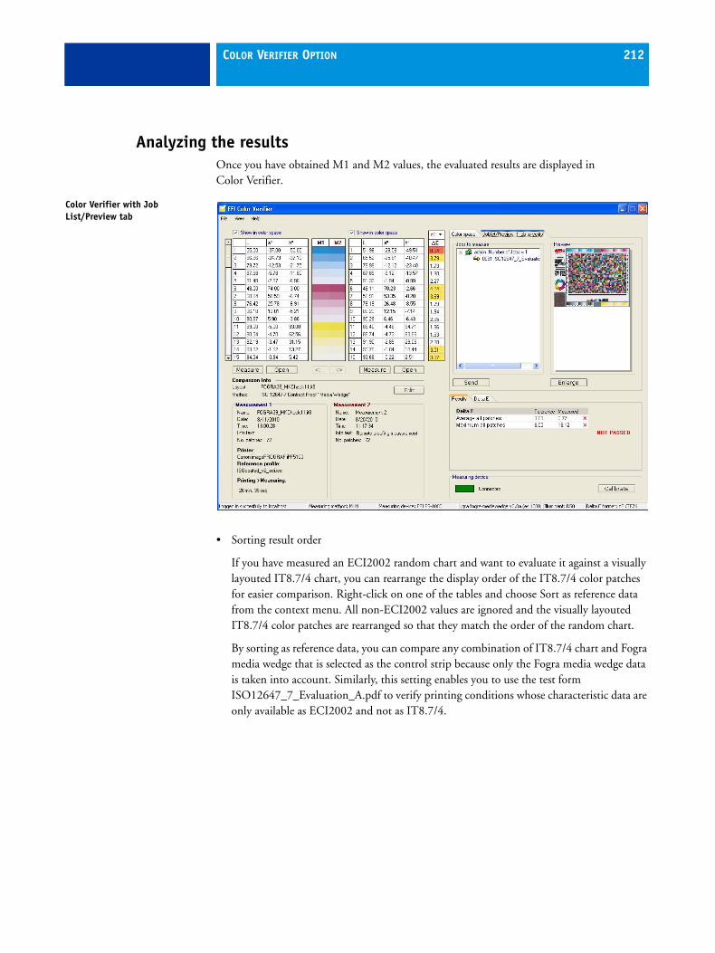
COLOR VERIFIER OPTION 212
Analyzing the resultsOnce you have obtained M1 and M2 values, the evaluated results are displayed in Color Verifier.
• Sorting result order
If you have measured an ECI2002 random chart and want to evaluate it against a visually layouted IT8.7/4 chart, you can rearrange the display order of the IT8.7/4 color patches for easier comparison. Right-click on one of the tables and choose Sort as reference data from the context menu. All non-ECI2002 values are ignored and the visually layouted IT8.7/4 color patches are rearranged so that they match the order of the random chart.
By sorting as reference data, you can compare any combination of IT8.7/4 chart and Fogra media wedge that is selected as the control strip because only the Fogra media wedge data is taken into account. Similarly, this setting enables you to use the test form ISO12647_7_Evaluation_A.pdf to verify printing conditions whose characteristic data are only available as ECI2002 and not as IT8.7/4.
Color Verifier with Job List/Preview tab

COLOR VERIFIER OPTION 213
• Results area
The Results tab contains a summary of the overall result. If any of the measurements lie outside the specified range of tolerance, Color Verifier indicates a result of “Not passed”.
A check mark indicates that the overall measurement is within the tolerance limit. A cross warns you if some or all the measurements exceeded the maximum tolerance values.
Pointing the mouse in the Results area displays the corresponding color patch in the M1/M2 tables.
The Delta E, Delta H, Delta T and Delta F tabs contain a detailed breakdown of the results and show exactly which color measurements were satisfactory.
The number of tabs displayed depends on the delta tolerances you defined in the EFI XF Client. For example, if you selected an ISO 12647-7 media wedge or G7, delta T values are not used.
If you are using Color Verifier as a stand-alone tool and selected ISO 12647-7 Contract Proof "Chart" or ISO 12647-8 Validation Print "Chart" in the Preferences dialog, you can also compare delta T values.
Results summary
Delta E results

COLOR VERIFIER OPTION 214
• Delta E table
In the delta table showing the achieved tolerances, you can use the drop-down list box in the table heading to switch between displaying delta E, delta H, delta T and delta F values.
• Protocol
The printed protocol includes ISO-12647-7- and 12647-8-compliant information. It also displays CMYK gradation curve diagrams depicting all reference and measured points along the curve.
Delta E table
Printed protocol

COLOR VERIFIER OPTION 215
• Label
The label includes all criteria for ISO 12647-7 and 12647-8-compliant verification of proofs.
Label

COLOR VERIFIER OPTION 216
Evaluating the results in EFI XFOnce a job is sent back to EFI XF from Color Verifier, the status of the job in the job list changes to “Verified” or “Verification failed” and the achieved results are displayed on the Verify tab.
If the job has the status “Verification failed”, it may be possible to get within the tolerances by performing a job-specific optimization. You can do this by clicking Optimize on the appropriate Control Strip pane. This causes a 3cc optimization file to be createdin the Server\Temp folder and applied to the job. Afterwards, you have to reprint the job and repeat the verify procedure in Color Verifier.If you have output your job with two control strips, it is only possible to optimize one of them. Once one control strip has been optimized, the Optimize button on the other Control Strip pane is dimmed. If you wish to optimize using both control strips, you can do so by selecting the job in the job list and choosing Optimize & print from the context menu.
It is not possible to optimize images if any of the following have been applied:
• Color adjustments
• Clean colors
• Perceptual or Saturated rendering intent
• Dynamic rendering intent
Evaluating the results in EFI XF
COLOR VERIFIER OPTION 217
ES-1000EFI provides an ES-1000 measuring device which can be purchased with the Color Verifier Option. The following sections contain information on how to connect, use and look after your ES-1000 measuring device.
See also:
“Scope of delivery” on page 177
“USB devices” on page 319
TO CONNECT THE ES-1000
1 Insert one end of the USB cable into the USB interface on the back of the ES-1000.
2 Insert the other end of the USB cable into a free USB port on your computer or to a USB hub that features a separate power supply.
Your system detects that a new hardware device has been connected.
3 Follow the on-screen instructions to install the device driver.
You will find the device driver in the Tools folder.
How to measure with ES-1000This section describes how to obtain color measurements using the ES-1000 measuring device shipped with Color Verifier.
For this exercise, you require a proof printed with a control strip.
It is only possible to measure control strips that are supported by Color Verifier.
TO MEASURE WITH ES-1000
1 Make sure that the ES-1000 is properly connected to your computer.
2 Place the ES-1000 on the calibration plate.
3 Start Color Verifier and check that “Connected” is displayed in the in the “Measuring device” area of the program window.
If an error message appears, check the cable connections. Then, open the Preferences dialog and make the following settings on the Comparison Settings tab:
• Under “Measuring device”, select first your measuring device and then the radio button “Measure whole control strip”.
• Under “Chart or wedge selection”, select the control strip to be measured.
4 Place your proof on a sheet of blank white paper.
This prevents a colored surface shimmering through the printout and affecting the color measurements.

COLOR VERIFIER OPTION 218
5 Place the scanning ruler on your proof so that the metal rod is facing away from you and the open slit is placed directly over the control strip.
6 In the “Measuring device” area of the program window, click Calibrate.
This enables the Measure and Open buttons. Color Verifier displays “Calibrated” when your measuring device is ready for measuring.
7 Click Measure.
There are two Measure buttons, one for M1 and one for M2 values.
8 Measure the colors in your proof, as follows:
• Place the measuring lamp of the ES-1000 in the open slit of the scanning ruler so that it is slightly to the left or right of the control strip.
• Hold down the button on the left side of the ES-1000.
Do not release the button until the measuring process has been completed. If you let go of the button, the measuring process will be aborted.
• Move the ES-1000 smoothly and at an even pace from one side of the color strip to the other.
When the control strip has been successfully measured, the readings are automatically displayed.
If you select the measuring method “Measure single patches” in the Preferences dialog, place the ES-1000 on the color in your proof whose color value you wish to determine. Then press and release the button on the left side of the measuring device. The color reading is automatically displayed.
Safety instructionsThe following safety instructions must be observed to avoid risk to the operator:
• Do not use the ES-1000 in environments where explosion hazards exist.
• Do not subject the ES-1000 to strong electromagnetic radiation.
• Do not use the ES-1000 in environments with temperatures in excess of 40°C or less than 10°C.
• Do not try to dismantle the ES-1000 for any reason. Unauthorized dismantling of the equipment will void any warranty claims.
• Do not store the ES-1000 in environments with temperatures in excess of 70°C or less than -20°C.
• Do not spill liquids on the ES-1000.
• Do not drop the ES-1000 in liquids.

COLOR VERIFIER OPTION 219
The following warnings must be observed when operating the ES-1000. Failure to heed these warnings can cause damage to the equipment.
• The ES-1000 should be used on a stable surface, and should not be exposed to sunlight or moisture.
• The ES-1000 must be protected from chemical agents, corrosive vapors, strong vibration and mechanical impact.
• Use original accessories and spare parts only.
MaintenanceThe following warnings should be observed in your day-to-day handling of the ES-1000. Failure to do so may result in data loss and operating anomalies.
• The plastic housing of the ES-1000 may be cleaned with soap and water on a damp cloth.
• The ES-1000 must be transported in its original packing to avoid damage.
• Clean the white ceramic tile with isopropyl alcohol on a soft clean cloth.
ServiceIt is important that you observe the following:
• Do not try to dismantle the ES-1000 for any reason. Unauthorized dismantling of the equipment will void all warranty claims.
• The measuring lamp in your ES-1000 should only be replaced by a trained service engineer at a certified service center.
• If you experience problems whilst using your ES-1000 that you cannot resolve with the information in this manual, please contact EFI Support.
See also:
“EFI Support” on page 320

COLOR VERIFIER OPTION 220
Declaration of conformityThe undersigned, representing the following manufacturer,
Gretag-Macbeth AG Althardstrasse 70 CH-8105 Regensdorf
herewith declares that the product
ES-1000™
is in conformity with the provisions of the following EC directives (including all applicable amendments)
EN 61326-1 (1997) + A1 (1998) Emission EN 61326-1 (1997) + A1 (1998) Immunity
and that the standards and/or technical specifications referenced have been applied.
Last two digits of the year in which the CE marking was affixed: 01
CH-8105 Regensdorf March 12, 2001
Th. Senn Vice President
Thomas Kunz Program Manager Color Management

COLOR VERIFIER OPTION 221
Warranty conditionsEFI warrants this product against defects in material and workmanship for a period of twenty-four (24) months from the date of sale, if not specified otherwise. During such time EFI will either replace or repair at its discretion defective parts free of charge. (Consumable parts are not covered.)
This warranty shall not apply to any goods supplied hereunder which after shipment are damaged, altered in any respect, or subjected to negligent treatment.
EFI’s sole and exclusive obligation for breach of the above warranties shall be the repair or replacement of any part, without charge, which within the warranty period is proven to EFI’s reasonable satisfaction to have been defective.
Repairs or replacement by EFI shall not revive an otherwise expired warranty, nor shall the same extend the duration of a warranty.
EFI shall in no event be liable for losses or costs to Buyer in manufacturing, or for Buyer’s overhead, other expenses, lost profits, goodwill, or any other special, indirect, consequential, incidental or other damages to persons or property resulting from a breach of any of the foregoing warranties.
There are no other warranties, either express or implied, which extend beyond the warranties set forth herein. The express warranties contained herein are in lieu of all other warranties, express or implied, including, but not limited to, the implied warranty or merchantability and fitness for a particular purpose or application. No representations or statements not expressly set forth herein shall be binding upon EFI as a warranty or otherwise.
To obtain warranty service, you must take the Product, or deliver the Product freight pre-paid, in either its original packaging or packaging affording an equal degree of protection, to an authorized EFI branch office. Proof of purchase in the form of a bill of sale or receipted invoice which is evidence that the unit is within the Warranty period must be presented to obtain warranty service.

COLOR VERIFIER OPTION 222
ES-1000 Warranty/Repair Form
Warranty Claim Repair Order
Serial number
....................................................................
Date of sale:
....................................................................
Error description:
............................................................................................................................................
............................................................................................................................................
............................................................................................................................................
............................................................................................................................................
User’s name and address:
............................................................................................................................................
............................................................................................................................................
...........................................................................................................................................
...........................................................................................................................................
............................................................................................................................................
E-mail address:
............................................................................................................................................
Town/Date:
....................................................................
Signature:
....................................................................

SPOT COLOR OPTION 223
SPOT COLOR OPTION
The Spot Color Option is available as an add-on module. It was developed to ensure that spot colors in your print jobs are correctly processed.
A spot color is a specially mixed ink that is applied on the printing press, as opposed to a mix of CMYK inks which make up process printing. Spot colors can be produced in a much more vibrant range of colors than can be created from mixing process colors. As an example, they are often used to print company logos.
Many different companies produce spot colors, together with a set of swatch books that show printed examples of these colors.
How are spot colors managed in EFI XF?The Spot Color Option manages spot colors in two different types of table:
• An internal table, which ensures the reproduction of predefined spot colors of different leading manufacturers. The internal spot color table cannot be edited. It is read-only.
• BCT files which contain user-defined spot colors in CMYK/OG/RGB and/or L*a*b* format.
Before spot colors can be output as spot colors, they must be defined and saved in a spot color table (bct file). When the bct file is loaded in EFI XF, the spot colors are automatically processed correctly. You can create a bct file per job or save all spot colors in one bct.
Spot color settings in EFI XFIf you have purchased Spot Color Option as an add-on module, the program windows System Manager and Job Explorer are extended as follows:
• A program icon appears in the toolbar. Clicking this button starts Color Editor, a tool for defining spot colors.
• An additional pane, Spot Colors, appears on the Color tab of property inspector.
• A setting for in-RIP definition appears on the PS/PDF pane of the Input tab.
• A setting for applying the PANTONE PLUS® spot color library is added to the Server tab > Info pane of System Manager.
Program icon
SPOT COLOR OPTION 224
System Manager
Server tab > Info pane
• Use PANTONE PLUS color definitions
This setting enables you to switch from the standard internal PANTONE spot color table to PANTONE PLUS® — a new spot color library that includes contemporary metallic, pastel and neon colors. When selected, the PANTONE PLUS color library is applied to all PANTONE spot color definitions in EFI XF.
Select the check box to output print jobs that were created using the new PANTONE PLUS series of colors. You do not have to restart either the EFI XF Server or Client for the new spot color library to take effect.
Input tab > PS/PDF pane
The following workflow setting is available on the PS/PDF pane of the Input tab:
• In-RIP separation
– Enable/Disable/Force
If your print job already contains RIP settings, e.g. from an external RIP or from a DTP program, you can choose whether these will be applied.
Select "Disable" to print all composite or in-RIP separated jobs as composite files. Separated files will still be processed as separated.
Select "Enable" to apply all available in-RIP information to print jobs. If no such information is detected in the print job, files are automatically output as composite.
PostScript files must contain not only details about color separations (process colors and spot colors), they also require start code information. This start code may be missing from PostScript files created by certain types of RIPs. In this case, the in-RIP information cannot be properly interpreted and the file will be output as composite.
If you select "Force", all files are processed as separated files.

SPOT COLOR OPTION 225
Color tab > Spot Colors pane
The following workflow settings are available on the Spot Colors pane:
• Input handling
This setting gives you more control over how CMYK and multicolor print jobs are handled in EFI XF. You can use this setting to define which source profile is applied.
When processing multicolor jobs with print information in multiple channels, it is recommended that you use PostScript format whenever possible.
The following settings are available:
– Automatic (Default)
With this setting, each incoming print job is analyzed to determine whether it is a CMYK or multicolor (CMYKOG/RGB) job. Based on this analysis, EFI XF applies the appropriate CMYK or multicolor source profile selected on the Color Management pane.
In the case of multicolor PostScript jobs, the selected multicolor source profile is applied as the input profile. However, the channel names in print job and profile must match each other exactly. The following table summarizes how different input jobs are handled:
If you have defined spot colors, remember to set the search priority on the Spot Colors pane to look for CMYK colors first.
In the case of multicolor TIFF jobs, only the number of color channels is important, not the colors themselves, i.e. to process a print job with seven channels, you require any multicolor source profile with seven colors. The print job is always processed using the colors of the multicolor profile. For example, if the source profile is CMYKRB, the print job is processed using CMYKRB. If the source profile is CMYKOG, the same print job is processed using CMYKOG.
Job Multicolor input profile Applied profile
CMYK - CMYK
CMYKOG CMYKOG CMYKOG
CMYKOGB CMKYOG CMYKOG (B simulated via Color Editor)
CMYKRGB CMYKOG CMYK (RGB simulated via Color Editor)
SPOT COLOR OPTION 226
– Force CMYK
This setting forces EFI XF to apply always the selected CMYK source profile, e.g. a multicolor print job will also be processed using the CMYK source profile.
This setting is not applied to RGB and gray print jobs, which are always processed according to the appropriate source profiles selected on the Color Management pane.
In the case of multicolor PostScript jobs, the additional colors, e.g. OG or RGB, are treated as spot colors. If no spot colors have been defined, an error message reports that unknown spot colors have been detected. The following table summarizes how different input jobs are handled:
In the case of multicolor TIFF jobs, print jobs are output as CMYK; the multicolor channels are lost. This setting could be usefully applied, for example, if the fifth and sixth channels contain information that you do not want to print out, e.g. guides, masks or outline paths. Selecting “Force CMYK” does away with the need to remove such information from the open file before printing.
– Force multicolor
This setting ensures that, regardless of the number of color channels, the selected multicolor source profile is always applied to multicolor print jobs. The number of channels in the multicolor profiles determines how the print job is identified. For example, if the multicolor profile has six channels, incoming jobs are treated as six-channel jobs.
Please note that RGB and gray jobs are not affected by this setting.
Job Applied profile
CMYK CMYK
CMYKOG CMYK (OG simulated via Color Editor)
CMYKOGB CMYK (OGB simulated via Color Editor)
CMYKRGB CMYK (RGB simulated via Color Editor)

SPOT COLOR OPTION 227
In the case of PostScript jobs, if the colors in the print job do not match the colors of the multicolor profile, additional channels are treated as spot colors, missing channels are left empty. The following table summarizes how different input jobs are handled:
If you have defined spot colors, remember to set the search priority on the Spot Colors pane to look for CMYK colors first.
In the case of TIFF jobs, if the print job has seven channels and the multicolor source profile has only six, the seventh channel is lost during job processing.
• Spot color settings
– Custom spot color library
From the drop-down list box, select a spot color table that contains your previously defined spot colors . Spot color tables must be saved to the Spotcolor folder.
– Search priority
Here you define the order in which spot colors are searched for.
Spot colors can be defined in the CMYK, CMYKOG, CMYKRGB and L*a*b* color spaces; they may also be included in the internal table or embedded in the source file. EFI XF uses the first instance of each spot color according to the specified search order.
You define the search order via the drop-down list boxes:
Job Multicolor input profile Applied profile
CMYK CMYKOG CMYKOG
CMYK CMYKRGB CMYKRGB
CMYKOG CMYKRGB CMYKRGB (O simulated via Color Editor)
CMYKRGB CMKYOG CMYKOG (RB simulated via Color Editor)
Internal Searches the integrated table of predefined spot colors of leading spot color manufacturers.
L*a*b*/CMYK(OG/RGB) Searches for spot colors in the defined color space.
Source File Searches for spot colors defined in the CMYK color space in the application and embedded in the source file.
If you search by source file, EFI XF detects embedded spot colors and displays them in Job Explorer as "known".
None This setting enables you to deactivate the spot color search feature.

SPOT COLOR OPTION 228
• Print unknown spot colors as warning color
Select this check box if you wish undefined spot colors to be output in a distinctive shade of orange. This makes them immediately recognizable in the printout.
Orange is the default color. However, you can output unknown spot colors in a different color by changing the CMYK values in the appropriate edit boxes.
If you click Reset, the values are reset to: C=0, M=50, Y=100, K=0.
Job ExplorerAn additional pane, Spot Colors, is available on the Color tab.
The settings on this tab become enabled as soon as you load a job that contains spot colors, so that you can determine how they will be handled during job processing.
The available settings are identical to the workflow settings found in System Manager. In addition, this pane identifies which colors are contained in a selected print job.
Process colors and spot colors are listed with details of whether they are known or unknown. This enables you to check whether spot colors will be processed correctly without first having to print the job.

SPOT COLOR OPTION 229
By unchecking the check box next to a process color or spot color, you can instruct EFI XF to exclude that color from the printout.
Spot Colors pane

SPOT COLOR OPTION 230
How spot colors will be handled in EFI XF depends on the settings that have previously been made for the workflow. For example, the workflow settings may specify that unknown spot colors should be replaced with a default color.
However, to print color-accurate spot colors, they must first be defined and saved as a spot color table. Then the spot color table has to be selected in EFI XF. A spot color table selected in System Manager is applied to all jobs loaded into the workflow. A spot color table selected in Job Explorer is applied to a specific job loaded in the job list. It overrides a spot color table selected for the workflow in System Manager.
Spot color tables must be saved to the Spotcolors folder. Otherwise, they cannot be selected in EFI XF. You can use bct files that were created in an earlier version of EFI XF by copying them manually to the Spotcolors folder.
See also:
“Custom spot color library” on page 227
Starting Color EditorIn Color Editor you can define spot colors.
To start Color Editor:
• Choose Tools > EFI Color Editor
• In the toolbar, click EFI Color Editor
Program icon

SPOT COLOR OPTION 231
User interface
User interface
1
2
34
5
6
7
8
9
1 List of spot colors defined in spot color table.
2 Area for specifying the name and color space in which the spot color will be defined.
3 Characterization table for defining continuous tones between 0% and 100%.
4 Diagram depicting color space and brightness of input values. Can be rotated to provide 3D view.
5 Scroll bar for defining the transparency (opacity) setting.
6 Area displaying 100% color patch in the selected color space(s).
7 Multi-functional button. Creates a connection to a measuring device if the L*a*b* color space is selected. Also used to start/stop a measuring process.
8 Opens the Gradation tab for modifying the lightness setting along the gradation curve.
9 Resets the orientation of the diagram to its original position. The color values are not affected.

SPOT COLOR OPTION 232
MenusThe menu bar contains the following commands:
EFI Color Editor (Macintosh only)
• About EFI Color Editor
Choose this command to open a window with details of your program version.
• Quit EFI Color Editor
Choose this command to close Color Editor.
File menu
• New
Choose this command to open a new spot color table.
• Open
Choose this command to open a dialog, from which you can navigate to the spot color table you want to open.
• Import
Choose this command to open a dialog, from which you can navigate to the spot color table you want to import, e.g. add to an already loaded spot color table.
• Show Internal
Choose this command to display the integrated spot color table of well-known spot color manufacturers. Some printers allow you to insert additional ink containers with spot colors. These spot colors are also managed in the internal table and can be selected from the end of the list. This setting ensures that the printer ink is used and color management for that color is by-passed during job processing.
• Save
Choose this command to save the changes you have made to the loaded spot color table.
• Save As
Choose this command to save the changes you have made to the loaded spot color table under a new name.
• Exit (Windows only)
Choose this command to close Color Editor.

SPOT COLOR OPTION 233
Edit menu
• Add Color
Choose this command to add a new color to a spot color table. This function is also available via the context menu.
• Delete Color
Choose this command to delete a selected spot color. This function is also available via the context menu.
• Search and Replace
Choose this command to open a dialog in which you can search for and replace the name of a spot color. This function is also available via the context menu.
• Overprint Settings
Choose this command to open a dialog for making global overprint and gamma settings that apply to all the spot colors in your spot color table.
Measuring Device menu
Color Editor supports many different measuring devices. Choose your measuring device from the submenu.
Help menu
• Help (Windows)/EFI Color Editor Help (Macintosh)
Choose this command to start the online Help.
• About EFI Color Editor (Windows only)
Choose this command to open a window with details of your program version.
ToolbarThe toolbar contains the following buttons and functions:
New: Click this button to create a new spot color table.
Open: Click this button to open an existing spot color table.
Save: Click this button to save your spot color table.
Add: Click this button to define a new spot color. This function is also available via the context menu.
SPOT COLOR OPTION 234
Delete: Click this button to delete a spot color from the spot color table. This function is also available via the context menu.
Search and Replace: Click this button to open the “Search and Replace” dialog. This function is also available via the context menu.
Search: Use this edit box to search for a specific spot color. Type in the name of the required color and press <Enter>.
Display format Use this drop-down list box to select the color space(s) in which you wish to display your spot colors.
Defining spot colorsIf EFI XF detects a spot color that has not been defined, an error message is displayed and job processing is aborted.
Spot colors of supported spot color manufacturers (Pantone, HKS, TOYO, DIC) are managed in the internal spot color table. These colors are automatically recognized in EFI XF and do not have to be defined if:
• the name used in the graphics application in which the file was created matches exactly the spot color name defined by the spot color manufacturer
• the search priority in EFI XF is set to include the internal spot color table
To process jobs containing unknown spot colors, you must either:
• define the spot colors in EFI XF or Color Editor
• instruct EFI XF to replace non-detected spot colors with a warning color
TO DEFINE SPOT COLORS FOR AN INCOMING JOB
If you load a job with a spot color that has not previously been defined, EFI XF reports an error and job processing is aborted. You must define the spot color before job processing can continue.
1 On the Color tab in Job Explorer, open the Spot Colors pane.
The names of detected colors (process and spot colors) are listed in the spot color definitions table. For non-defined spot colors, the “Source” column displays “Unknown”.
It is possible that missing spot colors have previously been defined in an existing spot color table. If this is the case, simply select the appropriate bct file from the drop-down list box. To check that the spot colors have been correctly recognized, make sure that the job is selected in the job list and refresh the preview. if the preview is displayed correctly, you can go on to output the job. To define new spot colors, continue with the steps below.

SPOT COLOR OPTION 235
2 In the “Source” cell of an unknown spot color, click on the arrow to open the drop-down list box. Then choose a setting from the following list:
3 In the “Map to” column, define the spot color.
You may have to scroll to the right to display the whole “Map to” column and make your settings.
CMYK CMYKRGB CMYKOG L*a*b*
Enables you to define the color values in the selected color space.
PANTONE HKS TOYO DIC
Enables you to select a color from the selected spot color manufacturer.
PRINTER If your printer allows you to insert additional ink tanks, this setting ensures that the printer ink is used. Color management for that color is by-passed during job processing (e.g. clear ink, white ink).
Alias Enables you to “map” one color to another. You could use this setting, for example, if the spot color used for your company logo has been defined in the graphics application under two diferent names.
Spot colors can be mapped to the CMYK process colors or to any CMYK or L*a*b* spot color in the table.
InkJet Provides an easy way to modify spot colors that were defined in either the PANTONE, HKS, TOYO or DIC libraries in the graphics application. For example, maybe the printout looks too blue and you need to reduce the amount of cyan. This can be very difficult if you do not know the exact color values. By selecting “Inkjet”, the equivalent CMYK/OG/RGB values of the internal color are displayed, making it much easier to make the necessary color changes. This setting ensures that the true colors of the printer are applied by by-passing color management.
CMYK CMYKRGB CMYKOG L*a*b*
Define the color values in the selected color space.
PANTONE HKS TOYO DIC
Select a spot color from the list.

SPOT COLOR OPTION 236
4 In the “Apply as” column, select a printer-specific color, if required.
This setting gives you increased scope by enabling you to assign the spot color to a specific printer ink channel.
If your printer supports white, clear or metallic inks, this setting provides further possibilities for simulating the final production run on an inkjet printer. It also enables you to create many interesting special effects.
5 In the “*” column, select a halftone screening angle, if required.
This setting enables you to select a screening angle for each color. The default screening angles are C = 15°, M = 45°, K = 75° and Y =90°. A screening angle of 75° is automatically applied to spot colors. Normally, you will not need to alter this setting.
In the Dot Creator Option, you can define a dot shape custom screening angles for each color. See “Dot Creator Option” on page 256 for further information on creating and implementing custom screening files in EFI XF.
PRINTER Select the appropriate ink channel from the available list.
Some settings have an “inverted” equivalent, which is recognizable by the letters “INV” after its name. If you select an inverted setting, the inversely proportional amount ink is applied, i.e. 0% color instead of 100% ink, 100% color instead of 0% ink or 70% color instead of 30% ink. In this way, you can use spot colors to simulate the final production run on a white or colored substrate.
This setting is useful in the packaging industry where gold or silver metallic colors are often used. However, some special effects can only successfully be achieved if your printer supports the appropriate ink colors.
Alias Select a CMYK process color or a previously defined spot color from the list. This creates a link between the two colors. Any changes you make to one spot color are automatically applied to the linked color also.
InkJet Make the required color adjustments in the CMYK/OG/RGB color space.

SPOT COLOR OPTION 237
6 In the toolbar, click Save to apply the defined colors to the loaded file and to refresh the preview.
A spot color table with the new spot color definition is created. Spot color tables are saved under the name SpotColorTable_xx_00.bct, where xx corresponds to the job ID and 00 is a running number. Each time you make and save changes, a new bct is created and the running number increases incrementally. This means that you can reassign previous spot color tables to the job, if you need to.
Job-specific spot color tables are automatically deleted with the job. If you want to retain a spot color table, open it in Color Editor and save it under a different name before you delete the job.
7 If the preview is displayed correctly, go on to output the job.
Spot colors defined in the property inspector are job-specific. However, they are not deleted with the job and can still be applied to other jobs. If you want to apply the spot color table to all jobs, you must load it in System Manager.
Spot colors can also be edited in Color Editor by clicking the Spot Color Editor button. When you click this button, Color Editor automatically opens the selected bct file. In Color Editor you can make more exact settings, such as for color gradations and the degree of transparency.
TO DEFINE OR EDIT A SPOT COLOR IN COLOR EDITOR
1 In the toolbar, click EFI Color Editor to launch Color Editor.
If spot color tables already exist, you are prompted to select one from the list. You can select a spot color table to add spot colors to an existing table. Otherwise, select “None” to create a new spot color table.
It is only possible to select one spot color table for each workflow. Therefore, consider adding new spot colors to an already existing table to ensure that all spot colors are detected.
2 Do one of the following:
• To add a new spot color to an existing spot color table, click Add a spot color.
• To create a new spot color table, proceed directly to the next step.
3 In the edit box, type a name for your spot color.
The name you define must match exactly the name used in the application in which the file was created.
4 Add any comments, if required.

SPOT COLOR OPTION 238
5 From the drop-down list box “Type”, select the spot color type. You can choose between:
CMYK, L*a*b* CMYK CMYKOG CMYKRGB
When you select one of these settings, a check box “As InkJet CMYK(OG/RGB)” becomes available. Select this setting to output your spot color using the full color gamut of the connected inkjet printer, as defined by the selected media profile. If you leave this setting unchecked, your spot color will be output using the smaller color gamut of the printing press, as defined by the selected reference profile.
If you define a spot color in the CMYKOG or CMYKRGB color space, it is recommended that you use the color gamut of the connected ink jet printer. This setting is enabled by default and ensures that pure orange and green or pure red, green and blue printer inks are used.
If you define a spot color in L*a*b*/CMYK, the search priority specified for the workflow or the job determines which color space is applied during job processing.
L*a*b* With this setting, you define spot colors in the L*a*b* color space. You can type the colors in by hand or use a measuring device to measure color patches.
Using the L*a*b* color space enables you to define intermediate colors in addition to the default 100% full-tone colors. Color gradients defined in L*a*b* can be included in the dynamic wedge.

SPOT COLOR OPTION 239
6 From the drop-down list box “Apply as”, select one of your printer’s ink channels, if required.
This setting gives you increased scope by enabling you to assign the spot color to a specific printer ink channel.
If your printer supports white, clear or metallic inks, this setting provides further possibilities for simulating the final production run on an inkjet printer. It also enables you to create many interesting special effects.
7 Use the slide bar to define the degree of transparency as a percentage.
In Color Editor, transparency refers to the translucency of a defined spot color. The opposite of translucency is opacity, which means light resistant. In other words, a transparency value of 0% is equal to an opacity value of 100% and vice versa.
Therefore, if you define a spot color that is 100% transparent, any colors that lie underneath the spot color will shimmer through. If a spot color is defined with a transparency value of 0%, any background colors beneath the spot color will not be visible.
Alias Enables you to “map” one color to another. You could use this setting, for example, if the spot color used for your company logo has been defined in the graphics application under two diferent names.
When you select “Alias”, the drop-down list box “Alias for” becomes enabled. Select a spot color from the drop-down list box “Alias for”. This creates a link between the two colors. Any changes you make to one spot color are automatically applied to the linked color also.
Spot colors can be mapped to:
• The spot colors of any supported spot color manufacturer
• Any spot color in the table that is already defined in the L*a*b* or CMYK/RGB/OG color space
• Any printer ink channel that is reserved for spot colors. This setting ensures that the printer ink is used. Color management for that color is by-passed during job processing.
Some settings have an “inverted” equivalent, which is recognizable by the letters “INV” after its name. If you select an inverted setting, the inversely proportional amount ink is applied, i.e. 0% color instead of 100% ink, 100% color instead of 0% ink or 70% color instead of 30% ink. In this way, you can use spot colors to simulate the final production run on a white or colored substrate.
This setting is useful in the packaging industry where gold or silver metallic colors are often used. However, some special effects can only successfully be achieved if your printer supports the appropriate ink colors.

SPOT COLOR OPTION 240
8 Click the Characterization tab.
The characterization table with color values for 0% and 100% inks is displayed.
9 Type in the full-tone (100%) color values of your spot color in the selected color space(s).
CMYK color codes can be purchased from your spot color manufacturer. To obtain L*a*b* values, you may first need to measure a printed patch of the spot color using a measuring device. The color values are automatically transferred to Color Editor.
You can view your spot color:
• As a color patch in the “100% Values” area
• In the 3D diagram
The 3D diagram depicts the 0% (white point) and the 100% value of your spot color.
By holding down the left mouse button and dragging the cursor, you can rotate the 3D diagram to assess your spot color from any chosen angle.
10 Define color gradients for your spot color, as described in the following steps.
If you do not need color gradients, proceed directly to step 14 to save your spot color table. Color gradients defined in L*a*b* are included in the dynamic wedge.
Characterization table

SPOT COLOR OPTION 241
11 On the Characterization tab, click the plus (+) button to add an empty row to the table.
If no empty row is available, click the plus (+) button below the table. To type values, double-click in a table cell.
If you do not know the precise color gradient values for a color defined in the L*a*b* color space, you can use a supported measuring device to measure a printed color patch of the required color. To do this, first connect your measuring device to the USB port of your computer. Then click Connect and follow the on-screen instructions to calibrate your measuring device.
Make sure that the L*a*b* color space is selected. Otherwise the Connect button or the Calibrate button will not be enabled.
When your device is ready, measure a color patch. The color values are automatically entered in the table.
The 0% value in the table represents the color of the media. Initially, it displays the unmeasured value for pure white. However, by following the described procedure, you can measure the L*a*b* values of the paper white. This enables spot color values to be converted for use with different media and ensures that color accuracy can be maintained on any color substrate.
12 Type the percentage of ink and the color values. Then press <Enter>.
13 Repeat the previous steps as often as required to define additional continuous tones.
14 Click Save to save your spot color table.
Spot color tables are saved by default to the Spotcolor folder. Only spot color tables saved to this folder can be loaded in EFI XF.
When the spot color table is loaded in EFI XF, the spot colors are automatically processed correctly in your print jobs.
TO OUTPUT NON-DEFINED SPOT COLORS
Occasionally, you may wish to output jobs without defining unknown spot colors first. EFI XF enables you to replace these colors with a warning color which makes them easily recognizable in the printout.
You can define a warning color in System Manager to apply to a workflow or in Job Explorer to apply to individual jobs.
1 On the Color tab, open the Spot Colors pane.
2 Select the check box “Print unknown spot colors as warning color”.
The default warning color is bright orange but you can define your own warning color by typing CMYK values in the appropriate edit boxes. You can reselect the default warning color at any time by clicking Reset.

SPOT COLOR OPTION 242
3 To see the effect, load a job with an unknown spot color.
The unknown spot color is displayed in the warning color:
• In the table of spot color definitions
• In the preview
Editing spot colors
Modifying the gradationIn theory, the color gradation from 0% to 100% should be linear. However, in practice this is not always the case.
If you are printing your spot color at, for example, 50% and ascertain that the color is too bright or too pale in the printout, you can remedy the problem by adding or subtracting color at the 50% mark along the gradation curve.
This setting should only be performed by experienced users.
TO COMPENSATE FOR NON-LINEAR GRADATIONS
1 Click the Gradation tab.
Gradation tab

SPOT COLOR OPTION 243
2 To modify the strength of color, click a point along the curve to define a node — the coordinates of the current cursor position are displayed below the gradation curve to help you locate the correct point.
By selecting the defined node and dragging the mouse to the required position, you can influence the color. Drag the mouse upward to add more color, or downward to substract color.
Alternatively, you can type the required coordinates directly in the table.
3 Click Save to save the setting to your spot color table.
Modifying the overprint and gamma valuesTo open the Overprint dialog, select Edit > Overprint Settings.
The settings in the Overprint dialog are used to simulate the overprint behavior of spot colors with other spot colors or process colors, e.g. black.
• Global Overprint
Use the “Global Overprint” slidebar to define how two or more colors will behave when printed on top of each other.
When printed individually, colors are unaffected by this setting.
A higher setting will result in a darker printout. For example, an overprint value of 100% means that the colors will be completely added to each other — something that is not possible on a proper printing press.
A lower setting will result in lighter printouts. This is because colors appear more opaque and hide parts of other colors.
Gradation tab
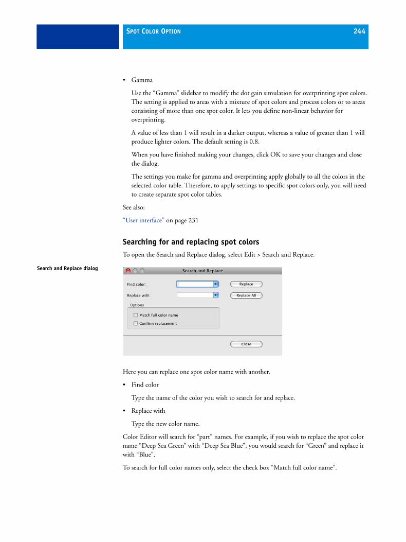
SPOT COLOR OPTION 244
• Gamma
Use the “Gamma” slidebar to modify the dot gain simulation for overprinting spot colors. The setting is applied to areas with a mixture of spot colors and process colors or to areas consisting of more than one spot color. It lets you define non-linear behavior for overprinting.
A value of less than 1 will result in a darker output, whereas a value of greater than 1 will produce lighter colors. The default setting is 0.8.
When you have finished making your changes, click OK to save your changes and close the dialog.
The settings you make for gamma and overprinting apply globally to all the colors in the selected color table. Therefore, to apply settings to specific spot colors only, you will need to create separate spot color tables.
See also:
“User interface” on page 231
Searching for and replacing spot colorsTo open the Search and Replace dialog, select Edit > Search and Replace.
Here you can replace one spot color name with another.
• Find color
Type the name of the color you wish to search for and replace.
• Replace with
Type the new color name.
Color Editor will search for “part” names. For example, if you wish to replace the spot color name “Deep Sea Green” with “Deep Sea Blue”, you would search for “Green” and replace it with “Blue”.
To search for full color names only, select the check box “Match full color name”.
Search and Replace dialog

SPOT COLOR OPTION 245
Use the buttons Replace or Replace All to rename your spot colors. If you select the check box “Confirm replacement”, a message will appear when Color Editor finds a match. To replace a color, click Yes in the dialog.
When you have completed making your changes, click Close. Then click Save to save your changes.
Deleting spot color tablesTo delete a spot color table, you must physically remove the bct file from the Spotcolor folder.

LINTOOL/COLOR MANAGER OPTION 246
LINTOOL/COLOR MANAGER OPTION
EFI linearization and profiling toolsColor reproduction is device-dependent, i.e. if you output the same file on two different devices, you will usually get two different sets of colors. Even two printers of the same model may show slight differences in their output.
To overcome this problem, the ICC (International Color Consortium) has developed a recognized standard for color management systems to allow uniform cross-device color reproduction. This standard is based on a series of profiles which control color reproduction from image creation to image output.
EFI XF provides two different tools which give you full control over the color properties of your printer and printouts.
What is LinTool?LinTool is a standard component of EFI XF. This tool has been especially designed to let you linearize your printer to ensure that you obtain consistent color-accurate results from your inkjet printer at all times.
All printer linearizations that you perform with LinTool are based on color values measured and displayed in the L*a*b* color space.
With LinTool, you receive a comprehensive set of tools with which to:
• Create a base linearization for your printer
• Return the printer to its original state by modifying its color reproduction properties using a measuring device
• Return the printer to its original state by modifying its color reproduction properties by visual correction
• Optimize an ICC profile to a specific reference profile
• Modify non-linear plate characteristics of one-bit files and a pre-linearization for all other file formats
• Patch the printer linearization file to a media profile and/or Device Link profile for implementation in EFI XF.

LINTOOL/COLOR MANAGER OPTION 247
What is Color Manager?Color Manager is a profiling tool that is available as an add-on module and thus requires a special license. It supplements the LinTool feature of EFI XF and provides you with additional tools with which to:
• Create your own media profiles
• Create your own reference profiles
• Create your own Device Link profiles
• Edit the white point of a media or reference profile
System Manager settings During program installation, a default linearization workflow and a default linearization device are created in System Manager. All print jobs that you submit from EFI LinTool/EFI Color Manager are processed via this system workflow.
The default linearization workflow ensures that no profiles are applied during printing. Thus, all linearization files processed via this workflow are non-color-managed. This is important as all the color measurements you perform during printer linearization or profiling must be based purely on the printer’s own color reproduction properties.
Any settings you make for the default linearization workflow will be ignored when jobs are submitted from LinTool or Color Manager. You can, however, use this workflow perfectly normally to output other, color-managed print jobs.
Before you can launch LinTool or Color Manager, you must first set up the default linearization device for your printer.
See also:
“Output device settings” on page 85
“Linearize Device” on page 92
Starting LinTool/Color ManagerTo start LinTool/Color Manager:
• Choose Tools > EFI LinTool/EFI Color Manager
• In the toolbar, click EFI LinTool/Color Manager
Program icon

LINTOOL/COLOR MANAGER OPTION 248
User interfaceThe structure of the program windows is the same for all tools. Each program window leads you step by step through the individual stages of the procedure.
User interface
1
3
2 4
1 The main program steps appear in each dialog. The colors of the buttons indicate what stage of the procedure you have reached:
Blue indicates the current tool and completed steps. White indicates the current step. Gray indicates steps that have not yet been performed.
2 The Wizard area leads you step by step through the actions to be performed in each dialog. The software will not allow you to proceed to the next dialog until you have successfully completed all the steps in the current dialog. You may, however, return to previous dialogs to make changes or check your settings. In this case, you must repeat all the subsequent steps in the procedure.
3 Hyperlinks are integrated into the Wizard text. Click on these to reveal additional information pertinent to the current step.
4 Advanced dialogs are available for some steps. These are not essential but are available for experienced users who wish to finetune certain settings.

LINTOOL/COLOR MANAGER OPTION 249
Menus• EFI Color Manager menu (Macintosh only)
– About
Choose this command to open a window with details of your program version.
– Quit EFI Color Manager
Choose this command to exit Color Manager.
• File menu
This menu contains commands for loading or saving files (e.g. a media profile, a base linearization, the measurements of an IT8 chart or a visual correction file) pertaining to the current step.
With the “Close” command you exit Color Manager (Windows only).
• ? menu (Windows)/Help menu (Macintosh)
– About (Windows only)
Choose this command to open a window with details of your program version.
– Help
Choose this command to start the HTML online Help for LinTool/Color Manager.
How does color management in EFI XF work?
ProfilesTo obtain color-accurate printouts in accordance with the ICC standard, EFI XF uses three types of ICC profiles — media profiles, simulation (reference) profiles and source profiles.
Media profiles
The media profile describes the color reproduction properties of the printer model you are using, based on the type of media, the type of ink and the resolution settings on your printer.
When you select a particular type of media, resolution and ink, EFI XF automatically chooses the correct media profile for these settings.
Simulation (reference) profiles
The simulation profile describes the color reproduction properties of the printing machine you wish to simulate on your inkjet printer. A set of generic profiles is provided with your software.

LINTOOL/COLOR MANAGER OPTION 250
Source profiles
The source profile describes the color reproduction of the input device. CMYK source profiles describe the color gamut of a printing press. They provide a reliable way to predict the color results of a production run on a traditional printer. RGB source profiles ensure high-quality output in vivid colors. They do this by maintaining the larger RGB color gamut during job processing.
Linearizations
Base linearization
A base linearization forms the basis for the media profile. It contains details of the quantities of color, under which the media profile was created, i.e. the color values necessary to achieve the maximum density of color while, at the same time, using as little ink as possible.
The base linearization determines the physical characteristics of how ink and media work together and optimizes these characteristics for profiling.
A base linearization is assigned (“patched”) to each media profile and is loaded automatically with the media profile.
A set of generic base linearization files is provided with your software.
Printer re-linearization
The color reproduction of your printer may change over a period of time. Performing a printer re-linearization enables you to re-adjust the color densities and return the printer to the original state used to generate the media profile.
A printer re-linearization can be performed using a measuring device (spectrophotometer) or visually. However, whereas a measuring device produces exact results, a visual printer re-linearization is based purely on manual adjustments and should therefore only be performed as an emergency measure by experienced users.
Working with LinTool/Color Manager
When to perform a printer re-linearizationYou will need to perform a printer re-linearization in the following instances:
• If you are using a media profile that was not created on your exact printer, e.g. the media profiles provided with EFI XF for your printer model. Even mass-produced printers of the same model display slightly different color properties which may result in certain color deviances. These deviances can be corrected by performing a printer re-linearization. Performing a printer re-linearization ensures that the color reproduction of your particular printer matches that of the reference printer used to create the base linearization and media profile.

LINTOOL/COLOR MANAGER OPTION 251
• After changing the print head. Replacing printer parts can affect the color properties of your printer.
• If you notice that your proofs no longer match earlier proof results. Performing a printer re-linearization ensures that the color reproduction of your printer remains constant.
As a general rule of thumb, it is a good idea to perform a printer re-linearization approximately every two weeks.
TipsThe following tips are intended to help you when working with LinTool/Color Manager:
Printing charts When printing linearization charts, make sure that the setting “Do not scale” is selected. It is essential that all linearization charts are printed in their original size in order to avoid problems when measuring the charts later on.
Media size Make sure that you use at least an A3 sized substrate (11 x 17 inches). This size is required to print the linearization charts.
Printing to a file format When printing to a file format is selected, the tools “Create media profile” and “Re-linearization by measurement” are not available.
Use of different measuring devices
It is not possible to edit a base linearization that was originally created with a different measuring device. If an error message to this effect appears, you will need to create a new base linearization.
Creating visual linearization and plate compensation files
When Server and Client are installed on different computers, you can save the correction files to any location. However, in order to load them in EFI XF, you must first copy them to the Balance folder.
Best Eye, ES-1000, eye-one
If you are using one of these measuring devices, it is important that you use the scanning ruler to ensure a 2 mm gap between measuring lamp and media.
X-Rite DTP 20 This measuring device has to be calibrated before use by measuring a so-called TID measuring strip. If you are measuring the Ugra/Fogra media wedge, you have to print the TID measuring strip separately. You will find the file “TIDforMKW20XP-V2.tiff ” in the Tools folder.
DTP41T If you are using the measuring device DTP41T, you will require an A1 sized substrate (23 x 33 inches) to print the charts.

ONEBIT OPTION 252
ONEBIT OPTION
The OneBit Option was developed to enable you to process one-bit files that have been produced by an imagesetter, a platesetter or a digital print solution in the pre-press industry.
To create one-bit files, these output devices have an integrated RIP which converts PostScript and PDF files into screen dots. The screen dot information is saved in the form of one-bit TIFF files — one file for each color separation.
The following one-bit file formats are supported: Tiff G4, Tiff G3, Packbit, LZW compressed Tiff, uncompressed Tiff, Presstek, Huffman, PCX, Len, Harlequin, Pagebuffer, Founder, DSC1/DCS2 (copy-dot format).
Since these files have already been RIPed once by an external RIP, the integrated RIP of EFI XF is not applied during one-bit-file processing. The necessary screen information (e.g. screen dot shape and size, screen ruling) is simply extracted from the one-bit file when the digital proof is printed.
Therefore, digital proofs that are output with the OneBit Option are not only color accurate, but also give a true screen representation of the final print run.
This makes the OneBit Option an ideal tool with which to check, for example, for possible moiré patterns or rosettes.
It is recommended that you do not use a laser printer to output one-bit files. This is because of the different screening methods. Applying both laser screening and one-bit screening to a print job makes it impossible to create high-quality proofs. Laser printers are, therefore, only suitable for creating imposition proofs.
OneBit Option settingsIf you have a license file for the OneBit Option, EFI XF is extended as follows:
In System Manager:
• The Formats pane of the Input tab is extended to include settings specific to one-bit files.
In Job Explorer:
• The Settings pane of the Input tab displays one-bit file settings and enables you to choose a job-specific proofing method.

ONEBIT OPTION 253
System ManagerThe following settings are available on the Formats pane to define how incoming one-bit files will be handled in the workflow:
• Number of seconds wait before job completion
This setting defines the time span, during which EFI XF waits for incoming one-bit files that belong to a particular print job. Once this time span has elapsed, the software assumes that all one-bit files have been received and starts printing.
• Number of one-bit files in a job
This setting defines the number of one-bit files that belong to a particular job. EFI XF waits until the defined number of color separations has been received before completing the print job.
This prevents jobs from being automatically printed as soon as the time-out period has elapsed, but before all the one-bit files have been received.
Similarly, it also ensures that printing will commence as soon as all one-bit files have been received, thus avoiding unnecessary idle time.
• Sub-directory for each job
This setting defines whether you want a sub-directory to be created for each job. You must select this option if your one-bit files were created by a RIP solution that automatically generates sub-directories for saving one-bit files.
• File name contains the name of the color separations
This setting ensures that EFI XF correctly recognizes the job name and all color separations that belong to each print job.
Select from the drop-down list box the file naming convention used by the RIP solution that created the one-bit files. Alternatively, you can type in your own variable. Make sure that you choose a syntax that is generic for all the files that you want to process.
By default, EFI XF analyzes file names from right to left, whereby the file extension is not taken into account.
The available character strings contain the following variables:
%j This variable represents the job name.
%c This variable represents the name of the color separation.
%f This variable stands for “ignore”. It is most often used to instruct EFI XF to ignore consecutive numbers (e.g. film numbers) which are automatically added to the file name by some RIP solutions. By inserting a figure, you can define the number of characters to be ignored, e.g. %4f.

ONEBIT OPTION 254
For example, you might have two one-bit jobs, as follows:
1357_bestbrochure_(cyan).tif 1358_bestbrochure_(magenta).tif 1359_bestbrochure_(yellow).tif 1360_bestbrochure_(black).tif
01_efiflyer_(cyan).tif 02_efiflyer_(magenta).tif 03_efiflyer_(yellow).tif 04_efiflyer_(black).tif
In this case, you would type the file name syntax “%f_%j_(%c).tif ” in the combo box.
This instructs EFI XF to:
– Process files which use an underscore as the separator
– Process files whose color separation names are set in parenthesis
– Ignore all characters in the file name to the first underscore (when read from right to left)
• Analyze file name from left to right
By default, EFI XF analyzes file names from right to left. However, in some cases it may be preferable to read file names from the left.
For example, you might have two one-bit jobs, as follows:
bestbrochure-(cyan)-00157.tif bestbrochure-(magenta)-00158.tif bestbrochure-(yellow)-00159.tif bestbrochure-(black)-00160.tif
efiflyer-(cyan)-01-00.tif efiflyer-(magenta)-02-00.tif efiflyer-(yellow)-03-00.tif efiflyer-(black)-04-00.tif
In this case, you would type the file name syntax “%j-(%c)-%5f.tif ” in the combo box.
This instructs EFI XF to:
– Process files whose job name is separated from the name of the color separation by a dash
– Process files whose color separation names are set in parenthesis
– Ignore all characters in the file name after the second dash (when read from left to right)

ONEBIT OPTION 255
• Extract color separation from file header
If you select this setting, the color information is extracted from the file header (information contained in the one-bit file itself ) instead of from the file name of the one-bit file.
This setting is useful if the individual color separations cannot be identified in the name of the one-bit files — some RIP devices do not save the color separation as part of the file name.
If you are using the Macintosh version of EFI XF, you may find that the file name is truncated at 32 characters, making it impossible to identify the color separation. In this case, using this setting may be a convenient way to get round the problem. Alternatively, you can rename the files before loading in EFI XF.
• Proofing method
– Imposition proof
Select this radio button if you want to make a final check before going to press.
Please note that imposition proofs are not color accurate. This setting should, therefore, be used only to check the content and completeness of the elements of the printing copy.
– Contract proof
Select this radio button to create a color-accurate screen proof.
Contract proofs are color managed. For this reason, they are often seen as a binding color contract between customer and printing house. A contract proof is usually the final proof created before going to press.
– Contract proof with sharp dots
Select this radio button to create a color-accurate screen proof.
As speed is an important factor, the print quality is slightly lower than that of a standard contract proof.
Job ExplorerThe Settings pane of the Input tab displays the workflow settings made in System Manager. You can choose a job-specific proofing method, if required.

DOT CREATOR OPTION 256
DOT CREATOR OPTION
Dot Creator is available as an add-on module. It enables you to create halftone screens from continuous-tone data.
Continuous-tones are difficult to output satisfactorily on conventional printing presses. This is because, unlike photography, differences in lightness cannot be directly reproduced in offset printing. Printed paper either has color or it does not. It is not possible to print “just a little color”.
Halftone screening is the name of the process used to overcome this problem. Here, color is represented by rows of dots, whereby the size of each dot and the distance between them can be varied to depict different color densities. The larger the dots and the closer the distance between them, the darker the reproduced color tone.
Halftone screening
Dot shapeScreen angle
Screen ruling

DOT CREATOR OPTION 257
How does Dot Creator work?
Moiré prevention
One halftone screen is created for each of the four process colors cyan, magenta, yellow and black. Light inks are not supported. Each halftone screen is then rotated and printed at a different angle to prevent moiré patterns appearing. The usual print order is: cyan, magenta, yellow, black.
Moiré patterns can occur as a result of an unfavorable combination of print resolution and screen ruling, e.g. if two halftone screens with only slightly different screen rulings are superimposed or if they are rotated by only slightly different angles. The screen angles C 15°, M 45°, K 75° and Y 90° or 0° produce the best results.
Dot Creator provides settings for defining screen ruling, screen angle and dot shape for each color channel as well as a feature for automatic prevention of moiré effects.
Screened printouts without moiré patterns are generally only possible with screen ruling of up to 150 lpi.
Color management
during conventional inkjet proofing, the printer driver receives color information from the color management module (CMM) and outputs the job using all the available printer inks.
However, for screened output, EFI XF sends color information for the four process colors only. Thus, it is not possible to output screening files of jobs that have already been color managed. Colors, including spot colors, are reproduced from CMYK inks by printing ink dots next to or on top of each other.
By default, all spot colors are screened using the screen ruling for black. However, you can change this later in Job Explorer, if required.
Screen anglesY 90°
K 75°
M 45°
C 15°

DOT CREATOR OPTION 258
Composite and separated output
Screening files can be used for both composite and for separated output.
• Composite output
Composite output provides a more accurate simulation of printing technologies that use wide screen ruling.
During composite output, all colors (process and spot colors) are printed on one page. Colors are printed on top of each other according to a defined screen ruling. This method can be used, for example, to simulate silk-screen screening on conventional inkjet printers.
• Separated output
Separated output can replace traditional image setter technologies that use wide screen rulings, e.g. in the silk-screen industry.
During separated output, each color channel is printed on a different page. All colors (process and spot colors) are reproduced in shades of gray. This method can be used to print on transparent dot film media using a conventional inkjet printer.
Screening methods
EFI XF supports two types of screening methods — v1 and v2.
• v1 screening
Using the v1 method, the screening file is applied to the output data. The printer driver processes the screening file and creates the output data. This means that the paper white simulation and full tones are also screened.
v1 workflow
Output as contone data
Print job
SPT EPL
Printer driver Printout
CM and spot color processing

DOT CREATOR OPTION 259
• v2 screening
With the v2 method, the screened file is applied to the input data. The input data is separated into grayscales, then the SPT file creates the screened data. Thereafter, the separated files are treated the same as one-bit files. For v2 screening you require the OneBit option.
This method of screening permits higher screen rulings and does not screen paper white simulations or full tones.
Please observe the following when applying the v2 screening method:
– Input files must be in the CMYK color space. v2 screening cannot be applied to RGB or L*a*b* data.
– The screening and printer resolution must be the same.
– It is not possible to create an EFI Remoteproof Container with v2 screened print jobs.
Comparison of v1 and v2 screening
The table below compares the two screening methods:
v2 workflowCM and spot color processing
Grayscale separation
Print job
SPTEPL
Printer driver Printout
v1 v2
AM screening — achievable screen ruling
100 lpi (with certain screen settings)
Up to 150 lpi (depending on the printer configuration)
Screening settings definable for each color in print job
Yes. Spot colors can be linked to one of the screening settings for C, M, Y or K. The default setting is black.
Yes. Spot colors can be linked to one of the screening settings for C, M, Y or K. The default setting is black.
Output Composite printout in pure inkjet CMYK screening
Composite printout includes screening for each color in print job.
Screen dot Pure inkjet dot Color-managed dots. Use of light inks.
Color accuracy By overprinting of pure inkjet dots
By overprinting of color-managed dots
Paper white simulation Screened Contone

DOT CREATOR OPTION 260
The differences in output are illustrated in the following diagram.
Full-tone reproduction Screened Contone
Support of contone printer mode
No Yes
Linearization/profiling New linearization and profiling using the screening file necessary
Can be patched to any existing EPL, as long as the screening resolution is the same as the printer resolution.
Speed - Up to 50% slower than v1
Dot sharpness - Slightly less sharp than v1
v1 v2
30% spot color dot
Printing press v2
Color-managed dots. Norm and light color. Color management via inkjet halftoning.
Color accurate, with same screening
v1
Pure inkjet CMYK. Color management via overprinting of pure inkjet dots.
Color accurate, but different screening

DOT CREATOR OPTION 261
Implementation in EFI XF
EFI XF uses different methods to implement v1 and v2 screening.
Method v1 requires you to create a new media profile that incorporates the screening file. For method v2 you can “patch” the screening file to an existing base linearization and media profile. The only requirement is that the screening file and the base linearization must be created for the same printer resolution.
The EFI XF Server applies v1 or v2 screening automatically, based on an internal evaluation of the incoming data.
The v1 screening method is applied if the Server detects:
• a base linearization file created for the halftoning method “Screening”
• an attached SPT screening file
The v2 screening method is applied if the Server detects:
• a base linearization file with the halftoning method Error diffusion (SE1) or Stochastic screening (SE2)
• an attached SPT screening file
Starting Dot CreatorTo start Dot Creator:
• Choose Tools > EFI Dot Creator
• In the toolbar, click EFI Dot Creator
v1/v2 screening in EFI XF
EPL (Screening) + SPT EPL (SE1/SE2) + SPT
EPL (Screening) + SPT
EPL (SE1/SE2) + SPT
v1 screening
v2 screeningPrint job
Program icon
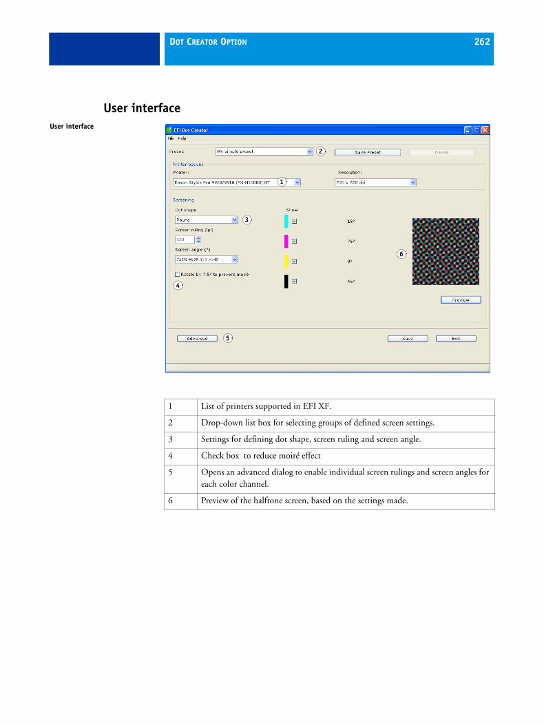
DOT CREATOR OPTION 262
User interfaceUser interface
1
2
3
4
5
6
1 List of printers supported in EFI XF.
2 Drop-down list box for selecting groups of defined screen settings.
3 Settings for defining dot shape, screen ruling and screen angle.
4 Check box to reduce moiré effect
5 Opens an advanced dialog to enable individual screen rulings and screen angles for each color channel.
6 Preview of the halftone screen, based on the settings made.

DOT CREATOR OPTION 263
MenusThe menu bar contains the following commands:
EFI Dot Creator (Macintosh only)
• About EFI Dot Creator
Choose this command to open a window with details of your program version.
• Quit EFI Dot Creator
Choose this command to close Dot Creator.
File menu
• Load SPT file
Choose this command to load a previously saved SPT file with screening and resolution settings.
• Preview
Choose this command to create a preview of the screen settings.
• Save
Choose this command to save the screen settings you have made in Dot Creator.
• Save as
Choose this command to save the changes you have made under a new name.
• Exit (Windows only)
Choose this command to close Dot Creator.
Help menu
• Help
Choose this command to start the online Help.
• About EFI Dot Creator (Windows only)
Choose this command to open a window with details of your program version.

DOT CREATOR OPTION 264
Additional settings in EFI XFIf you have a license file for Dot Creator, EFI XF is extended as follows:
• a program icon appears in the toolbar
• In LinTool or Color Manager:
In the program window for creating a base linearization, an additional drop-down list box becomes available when you select the halftoning mode “Screening”. This drop-down list box contains all the halftone screening files that have been created in Dot Creator for the printer and resolution selected on this tab.
Program icon

DOT CREATOR OPTION 265
• If you have a license file for the Spot Color Option:
In Job Explorer, the spot color table shows which screen angle will be used for each color. The default setting for spot colors is black, but you can select the screen angle of any other process color from the appropriate drop-down list box in the column “*”. You may have to scroll to the right to view this column.
This setting is useful if you are outputting separated gray films on a transparent media.
Spot Colors tab

DOT CREATOR OPTION 266
Creating halftone screensDot Creator provides you with three industry-standard settings for screen angles:
• C=15, M=75, Y=0, K=45
• C=8, M=51.5, Y=27, K=75
• C=18.4, M=71.6, Y=0, K=45
You can create halftone screens based on one of these settings or, alternatively, define your own customized screen angles for each color channel.
TO CREATE A HALFTONE SCREEN BASED ON PREDEFINED SCREEN ANGLES
1 Start Dot Creator.
2 From the drop-down list box, select a halftone printer.
It is not possible to implement screening files for contone printers.
3 From the drop-down list box, select a resolution.
4 From the drop-down list box, choose one of the following dot shapes: round, diamond, square, line, ellipse.
5 Select a screen ruling and a screen angle.
Program window

DOT CREATOR OPTION 267
6 Select the check box “Rotate by 7.5 ° to prevent moiré” if you want to rotate all screen angles by 7.5° counter-clockwise.
This setting simulates the screen angles commonly used in flexographic printing.
7 Click Preview to display a preview.
8 In the edit box “Preset”, define a name for your settings and click Save Preset.
The group of settings becomes available for selection from the drop-down list box “Preset”.
9 Click Save to create an SPT file and save your settings to the Screening folder.
The SPT file contains the defined screening and resolution settings. It can be loaded in Color Manager.
TO CREATE A HALFTONE SCREEN BASED ON SELF-DEFINED SCREEN ANGLES
1 Start Dot Creator.
2 Click the Advanced button to open the Advanced dialog.
3 From the drop-down list box, select a halftone printer.
It is not possible to implement screening files for contone printers.
4 From the drop-down list box, select a resolution.
Program window with advanced settings

DOT CREATOR OPTION 268
5 From the drop-down list box, choose one of the following dot shapes: round, diamond, square, line, ellipse.
6 Select the check box “Prevent moiré”, if required.
When this feature is selected, Dot Creator assesses the risk of moiré patterns and modifies the settings accordingly.
7 Type a screen ruling and a screen angle for each process color.
8 Click Preview to display a preview.
You can determine whether all or selected colors are previewed by selecting or deselecting the appropriate check boxes in the “Show” column.
9 In the edit box “Preset”, define a name for your settings and click Save Preset.
The group of settings becomes available for selection from the drop-down list box “Preset”.
10 Click Save to create an SPT file and save your settings to the Screening folder.
The SPT file consists of the defined lpi value and the set resolution. It can be loaded in Color Manager.
See also:
“Additional settings in EFI XF” on page 264
“Implementing halftone screens in EFI XF” on page 268
Implementing halftone screens in EFI XF When you have created a screening file, you need to implement it in EFI XF. There are two ways to implement screening files:
• Method v1 requires you to create a new media profile that incorporates the screening file. To apply the v1 screening method you need to create a media profile based on a base linearization with screening file.
• Method v2 enables you to “patch” a screening file to an existing base linearization and media profile. The only requirements are that:
– the screening file and the base linearization have been created for the same printer resolution
– the base linearization was created for the halftoning method error diffusion (SE1) or stochastic screening (SE2).

DOT CREATOR OPTION 269
TO CREATE A MEDIA PROFILE BASED ON A BASE LINEARIZATION WITH SCREENING FILE
The following steps describe how to create a media profile using Color Manager. If you do not have a license for Color Manager, you can create a media profile using any third-party profiling software. After creating, patch the media profile to the EPL linearization file using LinTool.
Make sure that the screening file is saved to the Screening folder before proceeding.
1 Connect a measuring device.
2 In EFI XF, make sure that the linearization device is correctly set up. Then start Color Manager.
3 Start the tool “Create Base Linearization” and make the following settings in the Settings dialog.
4 Select the connected measuring device.
5 Select the type of ink inserted in the printer.
6 Make your media settings.
• Select a media type that best matches your media.
• Select the name of an existing media or type a unique name.
7 Make your output settings.
• Make sure that you select exactly the resolution with which the screening file was created.
If the resolution does not match, Color Manager will not find the screening file.
• Select “Screening” as the halftoning method.
When you select “Screening”, the color mode switches automatically to CMYK. At the same time, the “Screening” setting becomes enabled and all halftone screen files for the selected resolution are autoamtically available in the drop-down list box.
If no screening files are visible, check that you have selected the correct resolution.
• Select the screening file from the drop-down list box.
8 Follow the on-line instructions given in the wizard to create a base linearization for your printer.
9 Create a media profile, based on the base linearization.
You can now implement your profile in EFI XF.

DOT CREATOR OPTION 270
TO PATCH MEDIA PROFILE AND BASE LINEARIZATION
1 From LinTool or Color Manager, start the tool “Profile Connector”.
2 In “Printer linearization”, click Select and browse to the base linearization file.
This may be a base linearization file you have created for a new media profile or an existing base linearization file.
3 Type the name of the media.
This is the name that will appear for selection in EFI XF. Define a custom name if you do not want to overwrite an existing media.
4 In “Dot Creator Screening”, click Select and browse to the screening file you created.
5 In “Connect to profiles”, select the check box “Media profile”. Then click Select and browse to the media profile.
6 Click OK to finish.
You can now implement your profile in EFI XF.
TO IMPLEMENT A MEDIA PROFILE WITH SCREENING DATA IN EFI XF
1 Start EFI XF, open System Manager and highlight your output device.
2 On the Device tab, open the Media pane.
• Select the same ink type that was used to create the EPL linearization file in LinTool/Color Manager.
• From the drop-down list box “Media name”, select the name defined in LinTool/Color Manager.
• From the drop-down list box “Calibration set”, select the EPL base linearization file that is linked to the SPT screening file.
For v1 screening, the screening file you created in Dot Creator is displayed in the properties list, along with the halftoning method Screening. For v2 screening, you see the screening file and the halftoning method error diffusion (SE1) or stochastic screening (SE2).
EFI XF detects automatically, based on the halftoning method used to create the base linearization, whether to apply v1 or v2 screening.
3 Click Save to save your settings as a media set.

DOT CREATOR OPTION 271
4 Save the workflow settings.
All your print jobs will now be output at the defined screen angles. Halftone screens can be applied to all jobs except one-bit files.
You can check which screen angles are applied to each color in Job Explorer. The Spot Colors pane of the Color tab displays all the detected process and spot colors of a selected print job.
By default, the screen angle for black is applied to spot colors. However, you can select the screen angle of any other process color from the drop-down list box.
See also:
“Screening methods” on page 258
“Implementation in EFI XF” on page 261

FILE OUTPUT OPTION/GRAVURE OUTPUT OPTION 272
FILE OUTPUT OPTION/GRAVURE OUTPUT OPTION
Print-to-file optionsOne license file enables you to set up a maximum of five file output/gravure output devices.
What is the File Output Option?The File Output Option was developed to enable you to print to a number of different file formats.
What is the EFI Gravure Output Option?This add-on option enables you to create separated grayscale TIFF files with automatic anti-aliasing. Anti-aliasing is the term used to describe the removal of jagged edges to give the appearance of smoother edges and higher resolution.
It works by taking into account how much an ideal edge overlaps adjacent pixels. The aliased edge simply rounds up or down with no intermediate value, whereas the anti-aliased edge gives a value proportional to how much of the edge was within each pixel. The effect of applying anti-aliasing is illustrated in the diagrams.
Printing to fileIf you have a license file for an output-to-file option, EFI XF is extended as follows:
In System Manager, additional device type settings become available on the Setup pane of the Device tab. When a print-to-file device type is selected, additional export settings can be made which are pertinent to the output file.
Anti-aliasing1 Without anti-aliasing2 With anti-aliasing
1 2

FILE OUTPUT OPTION/GRAVURE OUTPUT OPTION 273
Here you:
• define where to save your files
• select a device link and simulation profile
• select a compression method. You can choose between “None”, “ZIP” and “JPEG”.
• select a print resolution
• specify whether the resolution setting should be ignored for non-PostScript files
In Job Explorer, you will find these settings on the File Output pane of the Output tab.
TO PRINT TO FILE
1 Create a new output device.
2 On the Device tab, make the required settings on the Setup pane to define a name and select the device type.
In this case, you must select an EFI file output format from the drop-down list box. File output settings have the format “EFI xxx Output”, where xxx stands for the file type.
3 Define an export path to the folder in which the output files will be saved.
4 Select the check box “Use device link profile”, if required, and choose a profile from the drop-down list box.
This setting is not available for gravure output.
5 Select a simulation profile.
This setting is not available for gravure output.
6 Select a compression method, if required.
Which types of compression are available depends on the file format you are printing to.
7 Specify a resolution, if required.
This setting is not available for gravure output.
8 Select the check box to keep the input resolution of non-PostScript files, if required.
This setting is useful, for example, if you want to convert a set of digital files to a single color space without affecting the resolution (size) of the original images.
This setting is not available for gravure output.
9 Set up a system workflow and save your settings.
See also:
“Compression” on page 81

JAPANESE FONTS 274
JAPANESE FONTS
EFI XF is automatically installed with two Japanese printer fonts: Heisei-Mincho-W3 and Heisei-KakuGo-W5. Both are CID-formatted, low-res fonts. Additional double-byte fonts can be purchased from third-party providers. However, please note these must also be low-res.
To use the Japanese fonts, you must install the appropriate license and set up EFI XF for AppleTalk printing.
TO INSTALL JAPANESE FONTS FROM A THIRD-PARTY PROVIDER
1 Follow the instructions for installation provided with your third-party Japanese fonts.
Generally speaking, you install the fonts on a Macintosh OS 9 computer in the same AppleTalk network as EFI XF. During the installation, you may be required to select the EFI XF printer. Make sure that you select the correct AppleTalk spooler name.
It is not possible to install double-btye fonts by copying them directly to the CPSI\fonts folder. You may need to use Adobe’s Fonts downloader to do this.
2 When the font download has been completed, restart EFI XF.
3 To print using low-res Japanese fonts, choose Start Font Download from the System menu.
Activating font download converts EFI XF to a low-res printer.
See also:
“Licensing the software” on page 35
“RIP Resolution” on page 52
“Setting up EFI XF as an AppleTalk spooler” on page 138
FIERY OPTION 275
FIERY OPTION
The Fiery Option was developed to enable you to print directly from EFI XF to any EFI Fiery output device.
One license file enables you to set up a maximum of five output devices.
Fiery Option settingsIf you have a license file for the Fiery Option, EFI XF is extended as follows:
In System Manager, the device type “EFI Fiery” becomes available on the Setup pane of the Device tab.
Printing to an EFI Fiery output deviceIt is recommended that you do not perform any job settings at the Fiery Command WorkStation.If you make job-specific settings at the Fiery Command WorkStation, the color management settings from the Fiery Command WorkStation are applied on top of the color management settings from EFI XF. The result is non-accurate color output.
TO SET UP AN EFI FIERY OUTPUT DEVICE
1 Create a new output device.
2 On the Device tab, make the required settings on the Setup pane to define a name and select the device type.
In this case, you must select “EFI Fiery” from the drop-down list box.
If you do not want to print directly to an EFI Fiery output device, you can save your print jobs to PDF format instead by selecting “EFI PDF Output” from the drop-down list box.
3 Set up a connection to your printer.
The default setting for the Fiery Option is "Print to file". However, you can change this setting and output print jobs to a network printer, if preferred.
To output via a Fiery Command WorkStation, type the IP address of the EFI Fiery output device. Then, select the radio button “LPR. queue” and type a queue name: “Print”, “Hold” or “Direct”. Some versions of Fiery Command WorkStation also support printing via port 9100.
4 Define an export path to the folder in which the output files will be saved.
This setting is disabled if you select any printer connection other than “Print to file”.
FIERY OPTION 276
5 Select a compression method, if required.
You can choose between “None", "ZIP" and "JPEG".
6 On the Media pane, make media and print settings to be applied to your print job.
The source setting is set by default to “Automatic”. If you have set up to output via a Fiery Command WorkStation, it is possible to select duplex mode for the printer on the Special pane.
EFI XF provides a generic media profile for the Fiery Option. However, to achieve high-quality results, it is recommended that you create your own media profiles using Color Manager.
When defining a name for a customized media profile in Color Manager, it is important to ensure that the device is easily identifiable. This is because all Fiery output devices are selected as “EFI Fiery” on the Setup pane. Therefore, the media profiles for all EFI Fiery devices are displayed on the Media pane.
7 Set up a system workflow and save your settings.
See also:
“Compression” on page 81
“Printing and monitoring print jobs” on page 120

JDF CONNECTOR 277
JDF CONNECTOR
JDF Connector is shipped as part of the standard scrope of delivery. It enables you to integrate EFI XF into a JDF workflow by establishing bidirectional communication between EFI XF and other EFI JDF-compliant applications, such as EFI MIS and EFI DSF, or applications from third-party manufacturers, such as Adobe Acrobat.
Installing JDF ConnectorJDF Connector is provided as a separate tool on the installation DVD. If you did not install it when you installed EFI XF, you can do it now. Follow the instructions given in the Quick Start Guide.
JDF Connector must be installed on a computer on which the EFI XF Server is also installed.
JDF Connector runs as a service. It starts up automatically whenever the EFI XF Server is started. If the Server is not running, the JDF connection is interrupted.
JDF connectivity
JDF CONNECTOR 278
Supported file formatsThe following JDF/JMF file formats are supported:
• MIME package
• JDF/JMF with content (URL)
• JDF/JMF without content
See also:
“Adding content files to a JDF job” on page 281
“Assigning JDF tickets to jobs loaded in XF” on page 282
Setting up a JDF connection
PNI softwareTo use JDF Connector with EFI Print MIS products, e.g. EFI PrintSmith or EFI Hagen, you need to install and set up the PNI (PrintNet Integrator) software provided with your EFI product. See the instructions given in the user documentation of the EFI product for further information.
The PNI software enables you to select the IP address of the EFI Print MIS product in EFI XF.
PNI is not required to integrate EFI XF into a JDF workflow using EFI Web Control Center, EFI Digital StoreFront or Adobe Acrobat.

JDF CONNECTOR 279
JDF settings in EFI XFJDF Connector does not have its own user interface. To set up a JDF workflow you make certain settings in System Manager.
• JDF Device Registration
This setting is available in the Edit menu. It is needed to set up a JDF connection to JDF-compliant EFI Print MIS products, e.g. EFI PrintSmith or EFI Hagen. Make sure that the PNI software is correctly installed before making this setting.
To set up a JDF connection, type the IP address and port number of the workstation on which the PNI software is installed in the appropriate edit boxes. The default port number is 9200 in http mode and 12443 when running as https. You can check that the connection has been established by clicking Test.
• JDF communication
You activate JDF communication on the General pane of the Input tab. Selecting the check box makes the workflow accessible from other JDF devices.
Before setting up a JDF connection, make sure that:
– The workflow name and the output device name do not contain any spaces or special characters
– The workflow is connected to a valid output device
The setting “Close printed jobs automatically” is available if you do not need to write additional information, such as the number of waste printouts, etc., to the JDF file before closing. The number of good printouts is automatically transmitted back to the JDF-compliant application.
JDF device registration
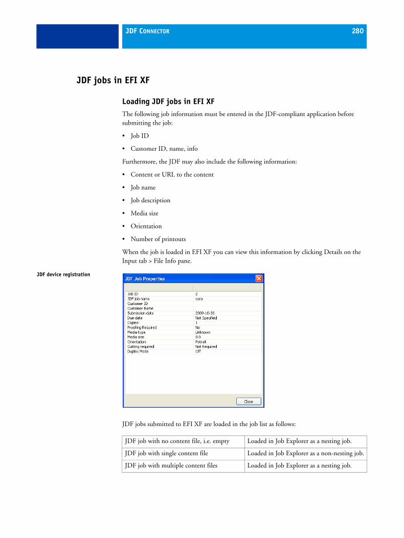
JDF CONNECTOR 280
JDF jobs in EFI XF
Loading JDF jobs in EFI XFThe following job information must be entered in the JDF-compliant application before submitting the job:
• Job ID
• Customer ID, name, info
Furthermore, the JDF may also include the following information:
• Content or URL to the content
• Job name
• Job description
• Media size
• Orientation
• Number of printouts
When the job is loaded in EFI XF you can view this information by clicking Details on the Input tab > File Info pane.
JDF jobs submitted to EFI XF are loaded in the job list as follows:
JDF device registration
JDF job with no content file, i.e. empty Loaded in Job Explorer as a nesting job.
JDF job with single content file Loaded in Job Explorer as a non-nesting job.
JDF job with multiple content files Loaded in Job Explorer as a nesting job.

JDF CONNECTOR 281
Job names are retained from the application. If a JDF job is submitted without a job name, it receives a default job name. You can rename JDF jobs by selecting the job and choosing Rename from the context menu.
By clicking on the plus (+) sign next to the job name, you can expand the JDF job to display the content files.
In the job list window, the ”JDF Status” column displays the current job status. The following status are possible:
A JDF job loaded in the job list is processed according to the workflow settings.
This means that, in an automatic workflow set up to close JDF jobs automatically after printing, no user intervention is possible.
Editing JDF jobs in EFI XFIn a normal situation, JDF jobs submitted to EFI XF are processed as soon as they are enter the job list. Therefore, if you need to edit a JDF job in EFI XF, make sure that you set up the workflow as a “hold” workflow. Once you have made your required changes, you can start printing manually.
Adding content files to a JDF job
It is not possible to add content to JDF jobs consisting of one single file.
You can add content files to JDF jobs that were submitted to EFI XF with no content or with multiple content by:
• Right-clicking on a JDF job and choosing Add Content File from the context menu, or
• Choosing Edit > JDF Processing > Add Content File
The Import Job window opens. You can add a file in any format supported by EFI XF.
Status Meaning
Receiving The JDF job is being loaded.
Received The JDF job is ready for printing.
Not complete The loaded JDF job has no content. You must add a content file before job processing can continue.
Completed Job processing has been completed.
This status is only displayed if “Close printed jobs automatically” is not selected for the workflow. Otherwise, jobs are deleted automatically from the job list as soon as they have been output.

JDF CONNECTOR 282
You can also add files to a JDF job by assigning a JDF ticket to a file you want to add to a JDF job. See “Assigning JDF tickets to jobs loaded in XF” on page 282.
Content files added in EFI XF are neither automatically placed nor arranged on the media. Therefore, you need to:
• Select the “Placed” check box for each file before it can be processed and
• Rearrange the images on the media to avoid overlapping. To arrange images, select the JDF job. Then go to the Nesting tab and click Refresh.
Assigning JDF tickets to jobs loaded in XF
In MIS-controlled environments, it is often desirable to track jobs regardless of how they are submitted to EFI XF.
For each JDF job loaded in EFI XF from a JDF-compliant application, a JDF ticket is created. However, occasionally you may need to load a job by another means, such as directly from a graphics application. This is necessary, for example, if the image is in a format that is not supported by the JDF-compliant application. In this case, you can send an empty JDF job to EFI XF and add the image as a content file by assigning a JDF ticket.
TO ASSIGN A JDF TICKET TO A JOB
1 In the job list, select the job to be added to the JDF job.
2 Display the Input > File Info pane.
3 From the drop-down list box “Attach JDF ticket”, select the JDF job and click Apply.
JDF ticket names are made up of the job ID and the file name. If the job has been loaded with the default name, renaming it with a unique name can make it easier to identify in the list of JDF tickets. To rename a JDF job, select it in the job list and choose Rename from the context menu.
The job is moved and becomes part of the JDF job.
Removing content files from a JDF job
You can remove a content file from a JDF job by right-clicking on a content file and choosing Delete from the context menu.

JDF CONNECTOR 283
Closing a JDF job
If the setting “Close printed jobs automatically” is selected for the workflow, JDF jobs are deleted automatically from the job list as soon as processing has been completed, i.e. after job output or, if Color Verifier is implemented in the workflow, after job verification.
If JDF jobs are not closed automatically, they remain in the job list until you close them manually. Only jobs with the status “Completed” can be closed.
You can close a JDF job by:
• Right-clicking on a JDF job and choosing Close JDF Job from the context menu, or
• Selecting a JDF job and clicking Close on the File Info pane of the Input tab.
When you select the Close command, the following dialog opens:
Here you type in auditing details relating to the job. You must give details of the number of good printouts and the number of waste printouts to close the job. All other information is optional.
Click Send to MIS & Close to transmit the job back to the JDF-compliant application and to delete the job from the job list.
Close JDF job dialog

PRINTING TO VUTEK PRINTERS 284
PRINTING TO VUTEK PRINTERS
LicensesYou can use a VUTEk license to set up any two output devices, e.g. two proofing devices, one VUTEk and one proofing device, or two VUTEK devices.
The same licenses can also be used to configure the default linearization device. However, please note that it is not permitted to exceed the maximum number of two different output devices all together. In other words, you may set up the linearization device for either of the two output devices already selected. However, a separate license is required if you wish to print to a third device type.
Additional settings in EFI XFOn the Special pane of the Device tab, you can select to output print head control bars with each job. A control bar is made up of stripes for each of the available printer inks. It ensures that ink keeps flowing through all the ink nozzles, thus helping to prevent blockages.
Settings are available for defining:
• the width of each color stripe
• the distance between each color stripe
• the distance between control bar and job
• the position of the control bar relative to the job
Print head control bar

PRINTING TO VUTEK PRINTERS 285
The preview displays a generic control bar only. It is not a true view of all the colors available for the connected output device.
Printing to a VUTEk printerWhen you print to a VUTEk printer, EFI XF automatically assigns a job name. The following is an example of a job name:
220_TestforVutek_66_T1_P2_3360_8c.rtl
Job names are composed of the following components:
TO SET UP A VUTEK PRINTER IN EFI XF
1 Create a new output device.
2 On the Device tab, make the required settings on the Setup pane to define a name and select a VUTEk printer.
The setting “Print to file” is automatically selected. This is because EFI XF automatically converts all print jobs to rtl format and saves them to the specified folder before submitting them to the VUTEk printer.
3 Define an export path to the folder in which the output files will be saved.
4 On the Media pane, make media and print settings to be applied to your print job.
EFI provides generic profiles for use with VUTEk printers. However, you can use your own profiles, if preferred. Please note that ICC and epl files must be saved to the EFI Media Profiles folder in order to be detected in EFI XF.
You can create a new base linearization file for your printer by clicking “New” to start LinTool/Color Manager. The add-on module Color Manager also provides a full set of tools with which to create your own media profiles.
1 A three-digit consecutive number between 000 and 999 (e.g. 220). The number is increased automatically for each successive job.
You can reset the number back to 000 by choosing “Reset Unique Number of RTL Files” from the System menu of System Manager.
2 The original file name (e.g. TestforVutek)
3 The job ID from EFI Fiery XF (e.g. 66)
4 The tile number, assuming the tiling function has been applied to the print job. The number "T1" stands for "no tiling".
5 The page number (e.g. "P2")
6 The printer model (e.g. "3360" stands for UltraVu II 3360 EC)
7 The color mode (e.g. 8c)

PRINTING TO VUTEK PRINTERS 286
5 Set up a system workflow and save your settings.
It is not recommended that you specify a print resolution when printing to a VUTEk printer. Considerable discrepancies can result, as the print resolution is already defined by the selected color profile and is also dependent on the selected printer.
See also:
“Output device settings” on page 85
“Managing system workflows” on page 90
“Printing and monitoring print jobs” on page 120

PERFORMANCE OPTION 287
PERFORMANCE OPTION
The Performance Option is an add-on module designed to increase the processing speed of your jobs. The speed can increase by more than three times the original processing time. However, the actual improvement is affected by the following factors:
• The chosen halftoning method
• The output resolution
• The number of available CPU processors
• Whether the computer is currently running other tasks
Additional settings in EFI XFIn System Manager, the following general settings are available on the Info pane of the Server tab:
• Use multi-threaded halftone processing
The conversion of contone to halftone data is the most time-consuming stage of job processing. By activating multi-threaded halftoning, you enable the halftone conversion of a single job to be processed simultaneously on several CPU processors, thus speeding up the output.
Multi-threaded halftoning is a global setting that is automatically applied to all workflows. However, not all output devices support this feature — it is only available for certain halftone printers driven by an EFI printer driver.
Generally speaking, the time-saving potential is greatest for the following types of jobs:
– Jobs that apply the halftoning method SE1 Multi-threaded halftoning has a greater effect on jobs created using a media profile with SE1 halftoning. This is because SE1 halftoning takes longer to process than SE2 halftoning. By activating multi-threaded halftoning, the task is spread out among several CPU processors.
– Jobs with a higher output resolution
Converting complex PostScript jobs to PDF/X-1a format can also help speed up job processing.
Please be aware that simultaneously processing multiple jobs can speed up, but may slow down, job processing under certain rare conditions. One job will be assigned a higher priority and will be processed on more than one CPU processor. This job will therefore be printed first, while other jobs will each be processed by a single CPU processor.
PERFORMANCE OPTION 288
• Number of Adobe PostScript 3 engines
The first time you start the application, EFI XF determines the default number of Adobe PostScript 3 engines that are loaded. The number equals the maximum available number of CPU processors available for the operating system — two for 32-bit computers and four for 64-bit computers.
Normally, the process colors of a job are processed one after another by one single CPU processor before being output. By increasing the number of Adobe PostScript 3 engines that are used, you can specifiy that multiple PostScript/PDF jobs are processed simultaneously. Thus, job processing is completed faster.
You must restart the EFI XF Server for the new value to take effect.
See also:
“PDF print engine” on page 59

CUTTING OPTIONS 289
CUTTING OPTIONS
The following cutting licenses are available for EFI XF:
• Cut Marks Option
This license provides support for the following:
– i-cut marks
– FOTOBA cut marks
– Grommet marks
– Zünd Cut Center
• Print & Cut Option
This license embodies printing and cutting for a range of manufacturer-oriented print-and-cut devices. With an appropriate device, it enables you to:
– Print only
– Print and cut in one output step
– Print and cut in two output steps (e.g. printing, laminating, cutting with one device)
– Cut only (e.g. colored substrate)
• Cut Server Option
This license provides support for a large number of cut devices, enabling you to submit jobs with predefined cut marks.
Additional settings in EFI XFIf you have a license for one of these options, EFI XF is extended as follows:
• The following program icon appears in the toolbar of Job Explorer:
• Additional settings appear on the Finishing tab.
• The menu command Print & Cut is added to the Edit menu and to the context menu in the job list.
Program icon

CUTTING OPTIONS 290
Finishing tab > Cut paneThe following settings are available:
• Presets
The settings you make on this pane can be grouped together and saved in the form of a preset.
Initially, no presets are available. However, once you have made settings on this pane, you can save them under a defined name. The preset becomes immediately available for selection from the drop-down list box.
To make changes and overwrite an existing preset make sure that the preset is not selected for any other workflow. Presets can only be overwritten in System Manager. In Job Explorer, you must save your changes under a new name.
• Send to cut server after printing (Cut Server Option only)
Select this check box to send the contour cut data to an auxilliary cutter device according to the cut settings defined on this pane.
• Cut device
– Device manufacturer
Select the manufacturer of your device from the drop-down list box.
– Device type
Select the cutter device type available for the selected device manufacturer.
– Cut marks type
Select which type of cut marks to use. Only those types of cut marks available for the selected device manufacturer are listed. The most commonly used cut mark type is preselected.
• Print with tinted background color (Cut Marks Option only)
On some media types, the cut marks can be difficult to detect. This setting overcomes the problem, by printing the cut marks on a yellowish background.
• Print between layout elements (Cut Marks Option only)
This setting prints cut marks between step & repeat and nesting elements.

CUTTING OPTIONS 291
• Bleeding (Cut Marks Option only)
This setting repositions the crop marks in relation to the image. Select one of the available radio buttons. Then add the desired margin width in the edit box.
– Cut image (not available for Zünd Cut Center)
Select this radio button to crop each edge of your image by a defined margin width, e.g. to eliminate unwanted paper white around an image or to reduce the size of an image.
– Add frame
Select this radio button to add white space between image and crop marks.
• Number of cut marks (Cut Marks Option only)
You can define the number of cut marks along the horizontal (top and bottom) or vertical (left and right) edges of the image. This setting is not available for Zünd Cut Center.
• Minimum distance between cut marks (Cut Marks Option only)
You can define the distance between two cut marks. In this case, EFI XF spaces out the cut marks along the horizontal and vertical edges accordingly.
Bleed: cut image
Bleed: add framee

CUTTING OPTIONS 292
• Cut data export
– Export path
Click Choose to define where you want to save contour cutting files. The following contour cutting files are created during job processing:
Contour cutting files are saved by default to the cut server hotfolder.
If the Cut Server Option and the EFI XF Server are installed on the same computer, and if the setting “Send to cut server after printing” is selected, the cut data export path is automatically selected.
If the Cut Server Option and the EFI XF Server are installed on different computers, you need to select manually the path to the hotfolder defined in the Cut Server Option. You do this by clicking Choose and browsing to the hotfolder.
– IP network (Zünd Cut Center only)
When outputting to a Zünd G3 device, type the IP address of the device on which the ZCC software is installed in the appropriate edit box. Then, type the IP port used by the ZCC server to communicate. As an example, this may be 9100, 8080 or 8088. Check the Zünd Cut Center documentation for further information.
You can check whether the connection to the Zünd Cut Center has been properly established by clicking Test. To test the connection, the ZCC software must be started. If you receive an error message, consult your system administrator for advice.
i-cut • A *.cut file (i-cut level 1)
• A *.cut file and an *.ai file (i-cut level 2)
Zünd Cut Center An *.ai file and a zcc file
Print and cut devices An *.ai file
Cut Server data export An *.ai file and an xml job ticket

CUTTING OPTIONS 293
• Contour cutting
– Extract contour path from EPS/PDF
Select the check box to specify that the contour information is extracted from the EPS or PDF print job. If you do not select this check box, the *.ai file contains only a cut frame (bounding box) around the particular job, even if it is a PDF or EPS print job. An *ai file is created only if a cut device is selected.
– Contour colors
The table contains a global list of available default contour types that are commonly used in the industry. These are automatically detected by EFI XF.
If the cutting path was defined using a spot color that has one of the default contour color names, the print job can be output.
If the cutting path was defined with a spot color that does not match any of the default contour color names, you must first define it EFI XF. Otherwise, an error message is displayed during job processing to indicate that the contour is an unknown spot color.
In System Manager, you can define a cutting method, such as “Bevel-cut” or “Kiss-cut” for some Zünd G3 output devices and for all i-cut output devices. The default setting is “Register”. User-defined methods are also possible.
Additionally, for some Zünd G3 output devices you can define a cutting mode and advanced settings. See “Zünd Cut Center” on page 300 for further information.
The plus (+) and minus (-) buttons enable you to add and delete user-defined contour colors. When you click the plus (+) button a new row appears in the table of global contour colors. Use the edit box to type in the name of the contour color. Take care to use the same name as defined in the application. Then, press <Enter> to save.
Defining contour colors in System Manager

CUTTING OPTIONS 294
Contour colors created in this way are added to the global list and are available for all workflows. Once you have defined a contour color, the cut data can be extracted to file.
You can delete user-defined contour colors by selecting the color in the list and clicking the minus (-) button. It is not possible to delete the default contour colors.
In Job Explorer, you can specify which spot color contains the cutting path by selecting the appropriate check box in the contour colors table. You must select the check box “Extract contour path from EPS/PDF” first to enable the check boxes in the contour colors table.
• Material information
This section of property inspector displays details of the name of the media, its format and thickness.
Working with contour colors in Job Explorer

CUTTING OPTIONS 295
Cut Marks Option
i-cut marksi-cut cut marks enable you to process and save to file complex, irregular cutting paths that have been defined in any popular graphics application. i-cut marks can be trimmed using a built-in or auxilliary cutter or print and cut plotter.
Contour cutting can be applied to all EPS and PDF print jobs. It allows you to:
• Extract cut contours
• Nest multiple images with cut contours
• Generate a cut frame around an image when contour data cannot be extracted, e.g. from a TIFF image
Forced in-RIP separation should be applied in EFI XF to EPS files.
You must have the Spot Color Option installed on your computer, as otherwise no files with contour cut data can be processed (if the cut information is defined as a spot color).
Contour markings are not visible in the printout.
Contour cutting marks
i-Cut marks1 Filled2 Reverse3 Ring
1 2 3

CUTTING OPTIONS 296
TO APPLY I-CUT MARKS
1 On the Finishing tab, open the Cut pane.
2 From the drop-down list box “Device manufacturer”, select “iCut”.
3 From the drop-down list box “Device type”, select “i-cut”.
4 From the drop-down list box “Cut marks type”, select the required type of i-Cut marks. Choose from “i-cut filled”, “i-cut reverse” or “i-cut ring”.
When you select i-cut marks, the following settings become available:
• Number of cut marks
You can define the number of i-cut marks along the horizontal or vertical edges of the image. The minimum number of i-cut marks is two (vertical and horizontal).
• Minimal distance (absolute placement)
You can define the distance between two i-cut marks. In this case, EFI XF spaces out the i-cut marks along the horizontal and vertical edges accordingly.
• Contour cutting
For all i-cut output devices you can define a cutting method, such as “Bevel-cut” or “Kiss-cut”. The default setting is “Register”.
Number of i-cut marks

CUTTING OPTIONS 297
FOTOBA cut marksThe Cut Marks Option provides full support for Digitrim devices, as well as for XL and WR roll cutters.
FOTOBA cut marks are designed to enable precise positioning of the cutting blade on each device.
TO APPLY FOTOBA CROP MARKS
1 On the Finishing tab, open the Marks pane and select the “Crop marks” check box.
2 From the drop-down list box “Type”, select the required type of FOTOBA crop marks. Choose from “FOTOBA DIGITRIM”, “FOTOBA XL” or “FOTOBA WR”.
When you select FOTOBA crop marks, the following settings become available:
• Cut fixed media slug
This setting deactivates the line thickness setting for FOTOBA XL and FOTOBA WR cut marks and applies a fixed cut slug of 8 mm. The cut slug defines the distance between two cutting blades on devices with more than one blade. This value is applied on top of a bleed value.
• Line thickness
Use this setting to change the thickness of the cut marks. This setting is applied to all Digitrim cut marks and to the horizontal cut marks for XL and WR roll cutters. Line thicknesses in the range 3 mm to 12 mm are possible.
• Fotoba single line
Use this setting to change the line thickness of vertical cut marks for XL and WR roll cutters. By default, this setting is set to “0” for FOTOBA WR cut marks, meaning that FOTOBA WR consists only of horizontal cut marks (top and bottom) in the default setting. By typing a value in the combo box, you can define vertical cut marks for FOTOBA WR.
FOTOBA cut marks1 Digitrim2 XL roll cutter3 WR roll cutter
1 2 3

CUTTING OPTIONS 298
Grommet marksGrommet marks are often used in the production market, e.g. to create advertising banners and flags.
TO APPLY GROMMET MARKS
1 On the Finishing tab, open the Marks pane and select the “Grommet marks” check box.
2 From the drop-down list box “Type”, select the required type of grommet marks. Choose from “Circle”, “Ring” or “Crosshair”.
When you select grommet marks, the following settings become available:
• Diameter/Line thickness/Color
Use these settings to define what the grommet marks will look like, e.g. size or color. Line thickness is available for grommet marks of the types “Ring” and “Crosshair”, but not for “Circle”.
• Margin
The default setting places the grommet marks along the edge of the image. However, you can reposition grommet marks relative to the border of the image by defining a margin width and selecting the radio button “Inside” or “Outside”.
Grommet margins1 Inside2 Outside
1
2
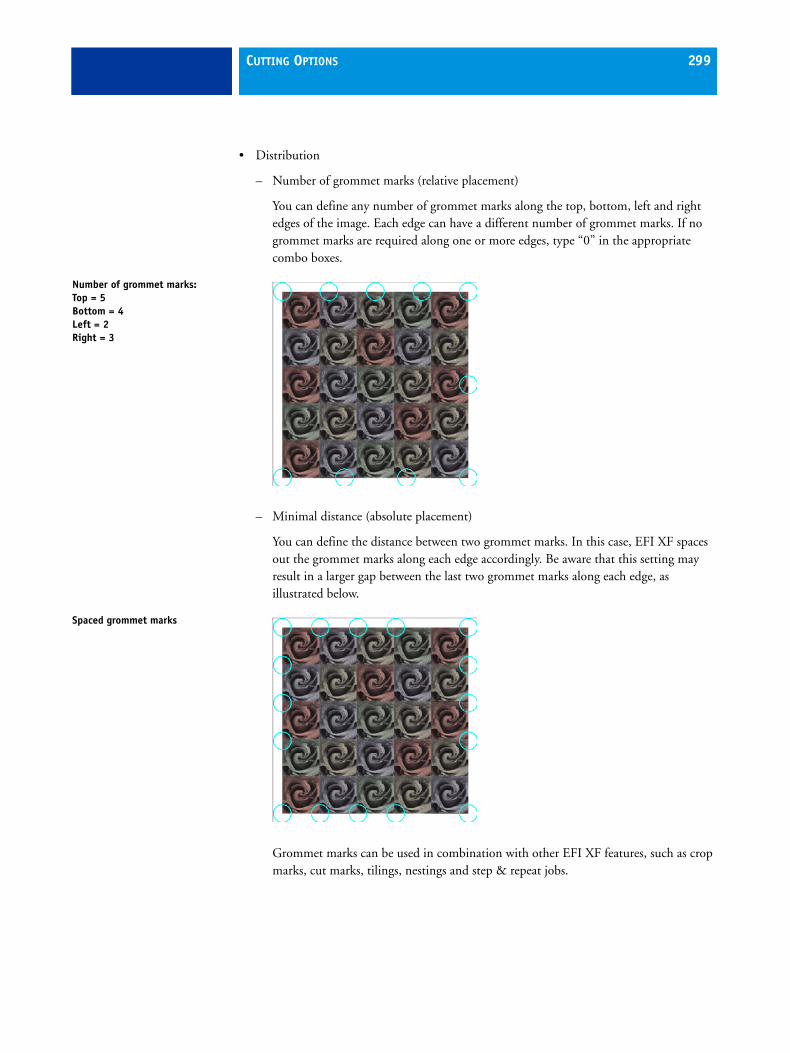
CUTTING OPTIONS 299
• Distribution
– Number of grommet marks (relative placement)
You can define any number of grommet marks along the top, bottom, left and right edges of the image. Each edge can have a different number of grommet marks. If no grommet marks are required along one or more edges, type “0” in the appropriate combo boxes.
– Minimal distance (absolute placement)
You can define the distance between two grommet marks. In this case, EFI XF spaces out the grommet marks along each edge accordingly. Be aware that this setting may result in a larger gap between the last two grommet marks along each edge, as illustrated below.
Grommet marks can be used in combination with other EFI XF features, such as crop marks, cut marks, tilings, nestings and step & repeat jobs.
Number of grommet marks: Top = 5 Bottom = 4 Left = 2 Right = 3
Spaced grommet marks
CUTTING OPTIONS 300
Zünd Cut CenterThe Cut Marks Option enables you to save more than one cutting path per print job. This is necessary when working with Zünd Cut Center as the software dynamically guides the operator through the cutting process by continually offering best choices based on the available cutting tools, as well as on the material to be cut, and quality requirements.
During job processing, jobs are automatically converted to ZCC format, the format required by the Zünd Cut Center.
For some types of Zünd G3 output devices you can define a cutting method, such as “Bevel-cut” or “Kiss-cut”. The default setting is “Register”.
Furthermore, for G3 output devices you can define how the cutting path will be processed. The default setting is “Standard”, but you can choose “Speed” or “Quality” from the drop-down list box. The speed setting causes the printout to be cut as quickly as possible but may not be exact. With the quality setting the output takes longer but the cut is more precise.
Advanced settings are also available for some cutting methods (see table below). You can access the advanced settings by clicking the pen button.
Cutting method Advanced settings available
Cutting method Advanced settings available
Register No Crease No
Thru-cut Yes Route Yes
Kiss-cut Yes Engrave Yes
Bevel-cut Yes Drill Yes
V-cut Yes Punch No
Draw Yes (None) No

CUTTING OPTIONS 301
TO OUTPUT TO ZÜND CUT CENTER
1 On the Finishing tab, open the Cutting pane.
2 From the drop-down list box “Device manufacturer”, select “Zund”.
3 From the drop-down list box “Device type”, select a G3-series cutting device.
4 From the drop-down list box “Cut marks type”, select the required type. Choose from “Zund circle (Camera)”, “Zund reverse circle (Camera), “Zund cross (Manual)” and “Zund reverse cross (Manual)”.
5 Select the check box “Print with tinted background color”, if required.
This setting outputs the cut marks on a background composed of 30% yellow. The effect of this setting is not visible in the preview.
6 Make your settings for bleeding and distance between cut marks, if required.
See “Finishing tab > Cut pane” on page 290 for further information
7 Set up a connection to Zünd Cut Center.
See “IP network (Zünd Cut Center only)” on page 292 for further information.
Cut Server Option (Windows only)The Cut Server Option provides support for a large number of cut devices, enabling you to submit jobs with predefined cut marks.
To use the Cut Server Option with EFI XF you also require a license for the Spot Color Option.
You can install EFI Cut Server from the software DVD. With an appropriate license you can:
• Start and use the application EFI Cut Server.
• Set up a maximum of two different cutters in EFI XF and run simultaneously up to four instances of EFI Cut Server that are installed on different computers.
• Select different cut mark types, including i-cut, in EFI XF.
Before you can process cut files you first need to install EFI Cut Server from the installation DVD. Then, you must start the application once to connect to the installed license.

CUTTING OPTIONS 302
TO START AND SET UP EFI CUT SERVER
1 double-click the program icon on your desktop.
The EFI Cut Server Login dialog opens.
2 From the drop-down list box, select the IP address of the computer on which the EFI Cut Server license is installed in the FlexLM folder. Then, click Select to open the Add Setup dialog.
3 Follow the on-screen instructions to set up your cut device.
Afterward, the program window opens.
Although the Cut Server Option must be installed on a Windows computer, you can send jobs to an EFI XF Server installed on either Windows or Macintosh.
See the Cut Server Help for information on using Cut Server.
EFI Cut Server program icon
EFI Cut Server

CUTTING OPTIONS 303
Working with contour cut filesThis section provides information on how to process files with contour cut information. Sample Print & Cut files are provided with your software for testing purposes.
Preparing contour cut files in the applicationIn order to process images with contour cut information, observe the following when creating the source file in the graphics application:
• The contour must be defined as a separate layer.
• The contour must be defined in a spot color.
The following set of contour spot colors commonly used in the industry are supported in EFI XF by default:
• Regmark
• Crease
• Kiss Cut
• Laser Cut
• Pen Plot
• Router Cut
• Score
• Through Cut
• CutContour
EFI XF automatically detects separated files created with any spot color with one of these names.
If the contour is saved under a non-default name, you must define it in EFI XF. This enables in-RIP separation which makes it possible for the contour information to be exported as a separated file. If you do not select in-RIP separation, the contour layer is simply output as part of the composite print job in accordance with the setting defined for the handling of unknown spot colors.
For EPS files, in-RIP separation must be set to “Force”. Also, when processing PS-based files, it is not possible to use the RGB working color space in conjuction with contour cutting marks.

CUTTING OPTIONS 304
Setting up a workflow in EFI XFThe following settings are necessary to output jobs via a cutting device or via a print and cut device.
TO SET UP CONTOUR CUTTING FOR A PRINT AND CUT DEVICE
1 Create a new workflow in the EFI XF Client.
A contour cutting template is provided for production applications to help you set up workflows with predefined settings for outputting print jobs with i-cut contour cut marks.
2 On the Finishing tab > Cut pane, select the check box “Extract contour path from EPS/PDF”.
3 Create a new output device and select a print and cut device as the device type.
4 On the Device tab > Special pane, select a contour cutting mode.
Depending on the setting you make, print jobs are processed as follows:.
TO SET UP CONTOUR CUTTING FOR A CUTTING DEVICE
1 Create a new workflow in the EFI XF Client.
2 On the Finishing tab > Cut pane:
• Select the check box “Send to cut server after printing”.
• Select appropriate cut marks for the cutter device.
• Make sure a cut contour export path is defined in EFI XF and in EFI Cut Server.
Print Prints the job, but does not cut the contour data.
Print & Cut Prints the job and cuts the contour data.
Cut only Cuts the contour data, but does not create a printout.
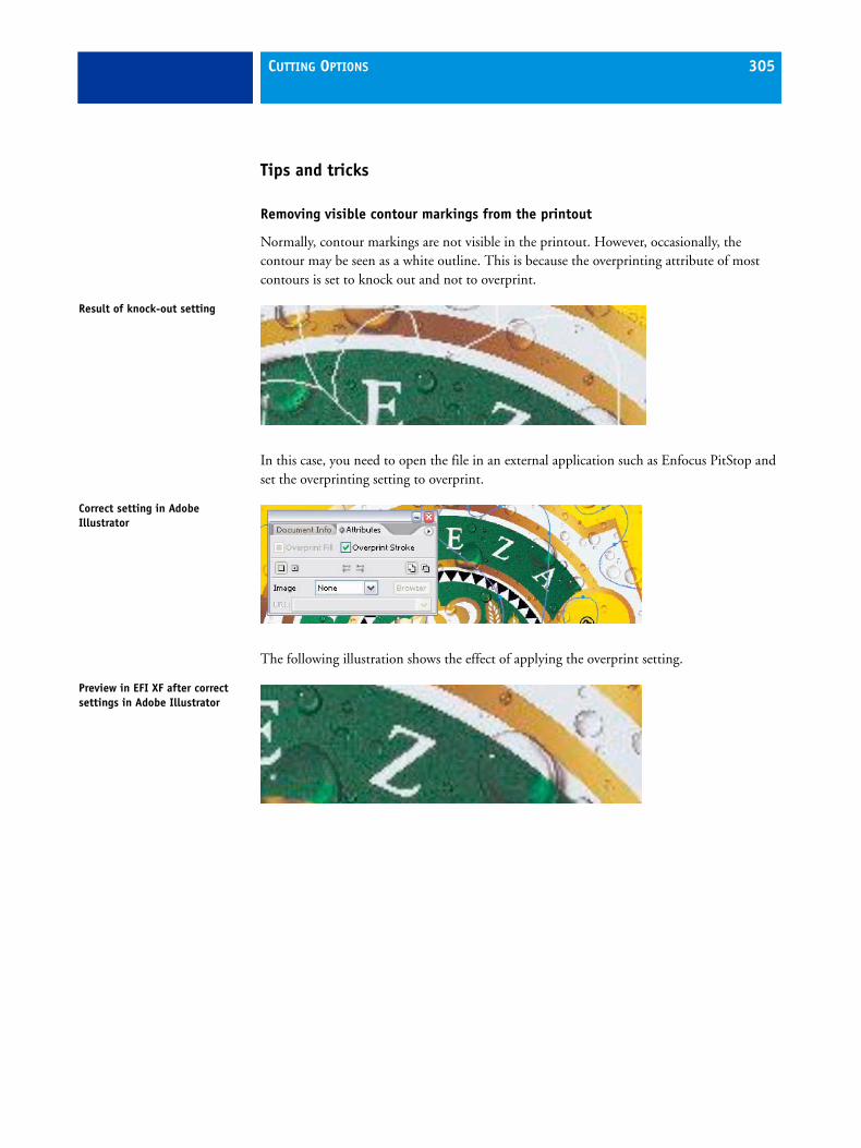
CUTTING OPTIONS 305
Tips and tricks
Removing visible contour markings from the printout
Normally, contour markings are not visible in the printout. However, occasionally, the contour may be seen as a white outline. This is because the overprinting attribute of most contours is set to knock out and not to overprint.
In this case, you need to open the file in an external application such as Enfocus PitStop and set the overprinting setting to overprint.
The following illustration shows the effect of applying the overprint setting.
Result of knock-out setting
Correct setting in Adobe Illustrator
Preview in EFI XF after correct settings in Adobe Illustrator
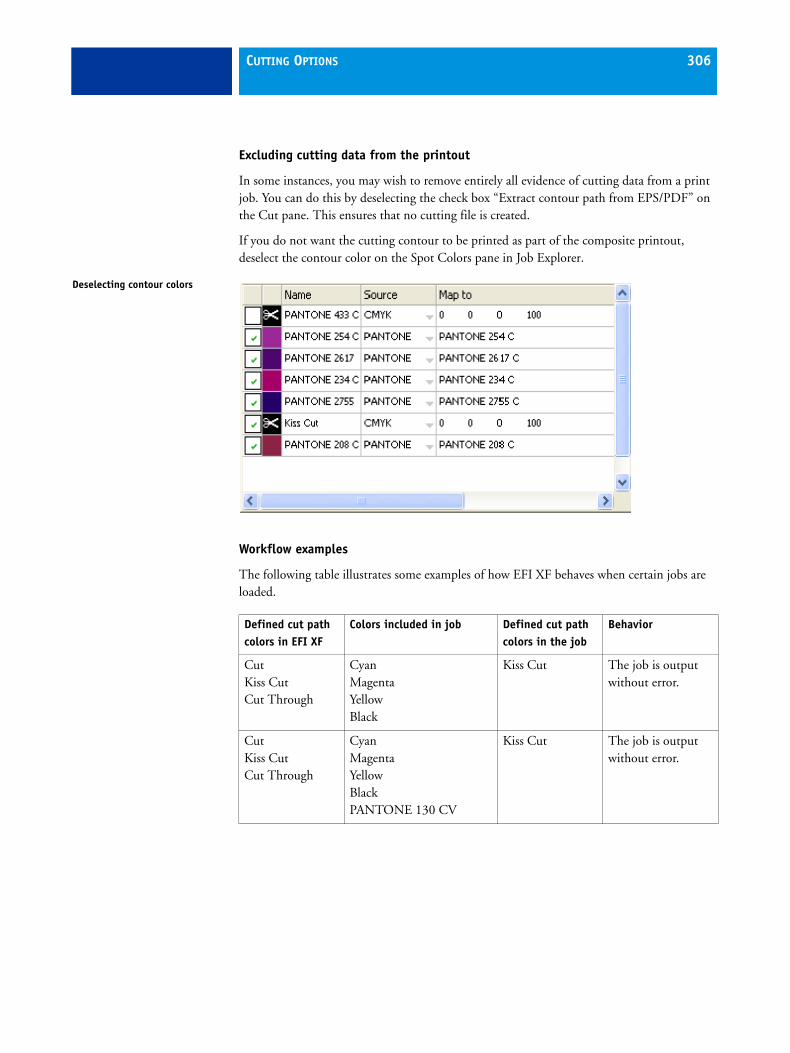
CUTTING OPTIONS 306
Excluding cutting data from the printout
In some instances, you may wish to remove entirely all evidence of cutting data from a print job. You can do this by deselecting the check box “Extract contour path from EPS/PDF” on the Cut pane. This ensures that no cutting file is created.
If you do not want the cutting contour to be printed as part of the composite printout, deselect the contour color on the Spot Colors pane in Job Explorer.
Workflow examples
The following table illustrates some examples of how EFI XF behaves when certain jobs are loaded.
Deselecting contour colors
Defined cut path colors in EFI XF
Colors included in job Defined cut path colors in the job
Behavior
Cut Kiss Cut Cut Through
Cyan Magenta Yellow Black
Kiss Cut The job is output without error.
Cut Kiss Cut Cut Through
Cyan Magenta Yellow Black PANTONE 130 CV
Kiss Cut The job is output without error.

CUTTING OPTIONS 307
Cut Kiss Cut Cut Through
Cyan Magenta Yellow Black
If the the process colors are not defined as spot colors, the job is output but no cut data is extracted.
Cut Kiss Cut Cut Through
Cyan Magenta Yellow Black PANTONE Hexachrome Blue
Dieline Depending on the spot color definitions, the job is output. However, no cut data is extracted.
Cut Kiss Cut Cut Through
Cyan Magenta Yellow Black
Kiss Cut Cut
Multiple contour colors are detected and can be selected on the Cut pane in Job Explorer.
Defined cut path colors in EFI XF
Colors included in job Defined cut path colors in the job
Behavior

RGB PROFILE CONNECTOR 308
RGB PROFILE CONNECTOR
RGB Profile Connector enables you to use RGB media profiles provided by your printer or paper manufacturer in EFI XF.
If the tool is not already installed on the computer, you can install it from the software DVD. Follow the installation instructions given in the Quick Start Guide.
TO CREATE A CUSTOM RGB MEDIA PROFILE FOR USE IN EFI XF
1 Go to Start > All Programs > EFI > XF > EFI RGB Profile Connector.
The dialog Enter network IP addresss opens.
2 Set up a connection to EFI XF.
Make sure that EFI XF is selected for “Type”.
Then, set up a connection to an EFI XF Server. If the EFI XF Server is installed on the same computer as RGB Profile Connector, you can select “localhost” from the drop-down list box. The IP address 127.0.0.1 is entered automatically. Otherwise, if the EFI XF Server and RGB Profile Connector are installed on different computers, select the name of the computer from the drop-down list box or type the appropriate IP address in the edit box.
Type your login credentials for EFI XF.
Login screen

RGB PROFILE CONNECTOR 309
3 Click Connect.
When you click Connect, a connection is set up to the EFI XF Server. If an error message appears, make sure that the EFI XF Server is started in EFI XF Control.
4 From the appropriate drop-down list boxes, select your RGB printer model and the type of ink inserted.
5 From the drop-down list box, select the media type that best matches the media for which the RGB media profile was created.
The media type information is usually provided in a separate file with the profile.
6 Define a media name.
By default, the media name is the same as the selected media type. You can leave the name unchanged or define a custom media name. The media profile will be available for selection in EFI XF under the name you define here.
7 From the appropriate drop-down list boxes, select the resolution, print mode and print direction for which the RGB media profile was created.
This information is usually provided in a separate file with the media profile or can be obtained from the download website.
8 Click Choose and browse to your custom RGB media profile.
9 In the EFI RGB Profile Connector dialog, click Install.
The new RGB media profile is copied to the EFI Media Profiles\My Profiles folder. To apply it in EFI XF, go to System Manager > Device tab > Media pane and select the media name you defined from the drop-down list box.
EFI RGB Profile Connector dialog
TROUBLESHOOTING 310
TROUBLESHOOTING
If you encounter problems while working with EFI XF, try performing the suggested solutions. If the problem still persists, please contact EFI Support.
Server/Logging on
I cannot see the Server user interface? How can I log in?
Cause: The Server runs as a service, so it has no user interface. All actions are initiated in the Client software.
Remedy: To start the Client, click the program icon on the desktop (Windows) or in the Dock (Macintosh). Alternatively, right-click on EFI XF Control and choose EFI XF Client Start from the context menu.
I am working with Windows. The Server does not accept any connection from a Client. What can I do in this case?
Cause: A firewall is set up which is blocking the communication.
Remedy: Unlock ports 50005 - 50025. Please refer to Windows help for further information.
I am working with Windows. Although I am able to log on to EFI XF successfully, I cannot see any users, workflows or output devices.
Cause: A firewall is set up which is blocking the communication.
Remedy: Unlock ports 50005 - 50025. Please refer to Windows help for further information.

TROUBLESHOOTING 311
When I try and log on, I get the error message “The user 'admin' is unknown. Please make sure that you type in the correct name.”
Cause: The file usr_0000.xml may be missing.
Remedy: In the Tickets folder, search for the file usr_0000.xml.
If you find the usr_0000.xml file, cut and paste it to a destination outside the Tickets folder. Then restart the Server. A new usr_0000.xml file is automatically created.
If the usr_0000.xml file is missing but you find a usr.0000.bak file, restart the Server. During Server restart, a new usr_0000.xml is automatically created.
If you cannot find either a usr.0000.xml or a usr.0000.bak file, contact EFI Support for a new usr.0000.xml file. When you receive the file, copy it to the Tickets folder.
The start screen opens briefly and then closes. Why is this?
Cause: This behavior occurs because Microsoft Windows uses the Data Execution Prevention (DEP) feature to help prevent damage from viruses and from other security threats.
Remedy: Deactivate Data Execution Prevention for EFI XF as follows:
1 Right-click on My Computer and choose Properties from the context menu.
2 In the System Properties dialog, select the Advanced tab.
3 Click the Settings button for performance.
4 In the Performance Options dialog, select the Data Execution Prevention tab.
5 Select the radio button “Turn on DEP for all programs and services except those I select:”. Then click Add and navigate to the Client folder.
6 Select all the application files with the extension *.exe and add them to the list of programs which are not affected by DEP.
7 Then add all the application files located in the Server folder in the same way.
See also:
“Logging on to an EFI XF Server” on page 22

TROUBLESHOOTING 312
Licensing
License not found
Cause: There may be licenses for different dongle IDs in the FlexLM folder.
Remedy: Make sure that the dongle for which the software is licensed is currently plugged in.
Cause: The base license(s) may have been removed from the FlexLM folder. If you have upgraded the software from an older version, you still require the original licenses of the previous versions.
Remedy: Make sure that the license for the predecessor version(s) as well as the upgrade license are correctly installed in the FlexLM folder.
The license file downloaded from the activation website cannot be installed.
Cause: The downloaded license file may have the wrong file extension.
Remedy: Check the file extension of the license file. Licenses with the extension *.txt are not recognized in EFI XF. Change the file extension from txt to lic.
If the file extension is not visible, go to Control Panel > Folder Options, select the View tab and make sure that the setting “Hide extensions for known file types” is not selected.
There is no valid license
Cause: EFI XF Control may not be running.
Remedy: Make sure that EFI XF Control is online before trying to log on to the Client. Right-click the EFI XF Control icon and choose EFI XF Server Start from the context menu.
Cause: One or more Windows services required by EFI XF may not be running.
Remedy: In Control Panel, go to Administrative Tools > Services. Check that the following services are started:
• EFI License Manager
• EFI XF Server
• DebugLog
If necessary, select the service that is currently not running and click “Restart the service”.

TROUBLESHOOTING 313
Cause: The dongle is not recognized.
Remedy: Connect the dongle to a different USB port.
To check whether the dongle is recognized, right-click on the EFI XF Control icon and choose Show dongle ID from the context menu.
If the dongle is not recognized, reinstall the dongle driver. You can download the latest dongle driver from http://www.aladdin.com/support/hasp.aspx. In the section for end-user downloads, select the HASP HL device driver.
Cause: The license file may have been generated for an incorrect dongle ID.
Remedy: Make sure that the right dongle ID is shown in the license file(s) of the purchased options.
To check the dongle ID, right-click the EFI XF Control icon and choose Show dongle ID from the context menu.
To verify the dongle ID of the license, open the license file in a text editor (e.g. Wordpad).
Check that the license file contains the following information:
• The name of the Server computer
• The dongle ID
Cause: If you are updating from an earlier version of the software, the licenses from that version may have been deleted from the FlexLM folder.
Remedy: EFI XF requires the license files from all earlier versions in addition to the upgrade license. If necessary, reinstall previously removed licenses via the Activate EFI XF command of EFI XF Control.
You can check which licenses are installed by selecting EFI XF Server Information from the ? menu (Windows) or from the Help menu (Macintosh). You must have a license for at least one Server, one Client and one Output Option M.
Cause: The system date and time may not be set up correctly.
Remedy: Check the BIOS setting in Windows.
Cause: The license files may not be detected.
Remedy: Try reinstalling all the license files. With the exception of the file default.lic, remove all license files from the FlexLM folder and then reinstall each file separately via EFI XF Control.
Make sure to install via EFI XF Control. Do not simply copy license files to the FlexLM folder.
TROUBLESHOOTING 314
You are unable to set up or connect any more output devices
Cause: You are trying to set up or connect an output device. However, you do not have enough Output Option licenses.
Remedy: Purchase an additional Output Option license.
Cause: You may be trying to set up the same printer via two different connection types.
Remedy: Make sure that all instances of the printer (including the linearization device) use the same connection type.
My printer is not listed in the printer list
Cause: You may be trying to connect to an output device that requires a separate license.
Remedy: Make sure that the installed license supports your printer model.
See also:
“Licensing the software” on page 35
Printing
Invalid page height
Cause: The information from the bounding box is not taken into account.
Remedy: In System Manager, highlight the workflow. On the Input tab, open the File formats pane and select “Calculate page size”.
Linearization cannot be processed
Cause: A corrupt epl is being applied.
Remedy: In System Manager, check the media set selected for the output device.
Open the epl file in Profile Connector, a tool provided with LinTool/Color Manager, and make sure that the name of the selected ICC profile matches that of the attached ICC profile.
If this does not help, try repatching the epl and the icc profile in Profile Connector.

TROUBLESHOOTING 315
Command Error
Cause: Some printers can be used with two different types of ink (e.g. Ultrachrome Photo and Matte). The error message occurs if the type of ink selected in EFI XF does not match the type of ink inserted in the printer.
Remedy: Make sure that you select the right type of ink for the output device. The black ink cartridge lets you identify the type of ink being used. Make the correct ink type setting on the Media pane of the Device tab.
I am unable to load any jobs. Why?
Cause: EFI XF requires a certain amount of free disk space. Be aware that if less than 2.5% free disk space or less than 5 GB free disk space is available, you may not be able to load and process jobs in EFI XF.
Remedy: Ensure that the hard disk has sufficient free space.
Cause: You may not have enough valid printer/output licenses. Bear in mind that your software may have been shipped with a 30-day license that allows you to set up a connection to up to ten output devices, A standard permanent license includes one output option for a medium-sized printer up to 18 inches wide.
Remedy: To check whether you have enough output licenses, proceed as follows:
1 In System Manager, disconnect all workflows from all output devices.
2 Highlight the linearization device.
3 On the Device tab, open the Setup pane and choose “First select a valid device type” from the drop-down list box.
4 Save the settings for the linearization device.
5 Connect one workflow to one output device.
6 In Job Explorer, try and load a job.
If you are still not able to load a job, ensure that the amount of used disk space does not exceed 95%. If necessary, free up additional space on the hard disk.
During job processing a bco file is created in the default Output folder. You can reduce the amount of hard disk space required by EFI XF during job processing by redefining this path, e.g. to a folder on a different drive, as follows:
7 Stop the Server.
8 Open the Tickets folder.

TROUBLESHOOTING 316
9 In a text editor, open the file sys_0000.xml
10 Search for the line beginning <Print type= and type in a new path.
Cause: The dongle may have become unplugged from the computer while the Server is still running.
Remedy: Make sure the dongle is properly inserted.
I have set up a hotfolder in a network, but submitted jobs do not appear in the job list. What is the problem?
Cause: The EFI XF Server runs on Windows as a service. By default, the login rights are defined for the local computer. This means that EFI XF is not able to communicate with folders located in a network environment. This may present problems, for example, if you wish to print jobs via a hotfolder.
Remedy: You need to assign network access rights for the EFI XF Server.
See also:
“EFI XF Server Configuration (Windows only)” on page 156
Windows login rights

TROUBLESHOOTING 317
Color management
Initialization of CMM failed
Cause: This could be a wrong setting on the Color management pane or the media profile may be corrupt.
Remedy: Check the color management settings defined for the workflow. Check also the quality settings made for the output device.
Media profiles
I am trying to use a media profile that I have received from a supplier. Why is the name not available for selection in EFI XF?
Cause: A media profile must always be “patched” to an epl file in order to be available for selection in EFI XF.
Remedy: Make sure that the media profile has been“patched” to an epl file using Profile Connector. This tool is a standard component of LinTool/ Color Manager.
I have created a media profile, but why is it not available for selection in EFI XF?
Cause: The profile may not be saved under a unique name, making it difficult to recognize in the list of available media profiles.
Remedy: It is recommended that you create a base linearization for a unique media name, so that the profile can be more easily found in EFI XF.
Cause: The epl file is not saved in the Profiles folder.
Remedy: Make sure that the epl file and the ICC profile are saved in the EFI Media Profiles folder.
TROUBLESHOOTING 318
Why do I receive the error message “Selected profile is invalid”?
Cause: The media profile may not be correctly “patched” to the epl file. Only media linked to an epl file are listed on the Media pane for the output device. If the media is not listed, it could be because EFI XF is not able to detect the epl.
Remedy: Make sure that the media profile has been correctly “patched” to an epl file using Profile Connector. This tool is a standard component of LinTool/Color Manager.
On the Color management pane, check the profile selection for the workflow.
Add-on modules
Color Manager, Color Verifier, Color Editor or Dot Creator will not launch in Windows 2003 Server/Windows XP
Cause: Data Execution Prevention may be deactivated.
Remedy: Activate Data Execution Prevention. Proceed as follows for Windows XP (the settings may vary slightly if you are using Windows 2003):
1 Right-click on My Computer and choose Properties from the context menu.
2 In the System Properties dialog, select the Advanced tab.
3 Click the Settings button for performance.
4 In the Performance Options dialog, select the “Data Execution Prevention” tab.
5 Select the radio button “Turn on DEP for essential Windows programs and services only”.
One-bit tiff error in EFI XF "Unknown spot colors detected"
Cause: The syntax is not correct for the naming of the one-bit tiff.
Remedy: On the Input > Formats pane, select the check box “Extract color separation from file header”.

TROUBLESHOOTING 319
USB devices
When I connect my USB measuring device to the computer, I am requested to install the device driver. Should the device driver not be detected automatically?
Cause: Occasionally the device driver may not be detected automatically when you connect the USB device to the computer.
Remedy: The device drivers are installed automatically with the software.
If the wizard prompts you to install the device driver from DVD, display the contents, browse to the USB Measurement Devices folder and select the appropriate device driver.
Why can my USB device (e.g. dongle) not be found?
Cause: The device driver may not be correctly installed.
Remedy: Install the device driver as follows:
1 Right-click on My Computer and choose Properties from the context menu.
2 On the Hardware tab, click Device Manager.
3 Search for Universal Serial Bus controllers.
4 Expand the list and search for the device that is not detected. Non-detected devices appear with a question mark next to them.
5 Right-click on the device entry and choose Update Driver from the context menu.
6 Download and install the current driver by selecting the recommended setting.

TROUBLESHOOTING 320
EFI SupportIf you run into difficulties while working with EFI XF and you cannot find the solution in this manual, please contact your reseller or distributor for technical assistance. To find the contact details for your region visit http://www.efi.com/support/contact-by-product.asp.
Make sure to provide the following information when contacting your reseller or distributor:
• Version name and release number of your software
• License information
• Printer model
• Operating system with version number
Any additional hardware and software you may have installed (e.g. ISDN boards, virus scanners, etc.)
Knowledge CenterEFI has set up an online knowledge center to supplement the information found in this user manual. The Knowledge Center is filled with useful information and tips on working with EFI XF. Therefore, if you are having trouble getting to grips with a certain feature of EFI XF, please visit our website at:
http://www.efi.com/services/proofing-services/knowledge-center.asp
Online user forumThe online forum is open to all users of EFI XF. It enables you to post questions related to any area of EFI XF directly to members of the EFI team. Furthermore, it permits open discussion with other forum members and thus provides an ideal platform for communicating with other users. To register as a forum member visit our website at:
http://proofingforums.efi.com

UNINSTALLING 321
UNINSTALLING
This section describes how to uninstall EFI XF, the media profiles and Unidriver. The dialogs may vary slightly, depending on the application you are uninstalling.
Windows
TO UNINSTALL VIA CONTROL PANEL
Use the procedure below to uninstall EFI XF, media profiles or Unidriver.
1 Open Control Panel.
2 Proceed as folows:
Windows XP: Double-click Add or Remove Programs.
Windows Vista/7: Double-click Programs\Programs and Features.
Windows 2003/2008: Double-click Software.
3 In the list of installed programs, select the application you want to uninstall and click Remove (Windows XP and Windows 2003) or Uninstall (Windows Vista and Windows 7).
4 Follow the procedure for your operating system for removing programs.
Make sure to restart your computer before reinstalling.
TO UNINSTALL VIA THE SETUP PROGRAM
Use the procedure below to uninstall EFI XF, media profiles or Unidriver.
1 Insert the software DVD into the DVD-ROM drive.
The start screen starts automatically. If the start screen does not appear, double-click the Start.exe file located on the DVD.

UNINSTALLING 322
2 Do one of the following:
• Click Install EFI XF to uninstall EFI XF.
• Click Install EFI XF Media Profiles to uninstall the media profiles.
• Open the folder EFI Tools > UniDriver folder and double-click the file Install EFI Unidriver.exe to uninstall Unidriver.
The Welcome dialog opens:
This dialog may look slightly different, depending on which component you are uninstalling.
3 Click Remove and follow the on-screen instructions to complete uninstallation.
Make sure to restart your computer before reinstalling.
Macintosh
TO UNINSTALL VIA THE SETUP PROGRAM
Use the procedure below to uninstall EFI XF, media profiles or Unidriver.
1 Insert the software DVD into the DVD-ROM drive.
2 Do one of the following:
• Double-click Install EFI XF to uninstall EFI XF.
• Double-click Install EFI Media Profiles to uninstall the media profiles.
• Open the Tools & Other folder and double-click EFI Unidriver to uninstall Unidriver.
Welcome dialog
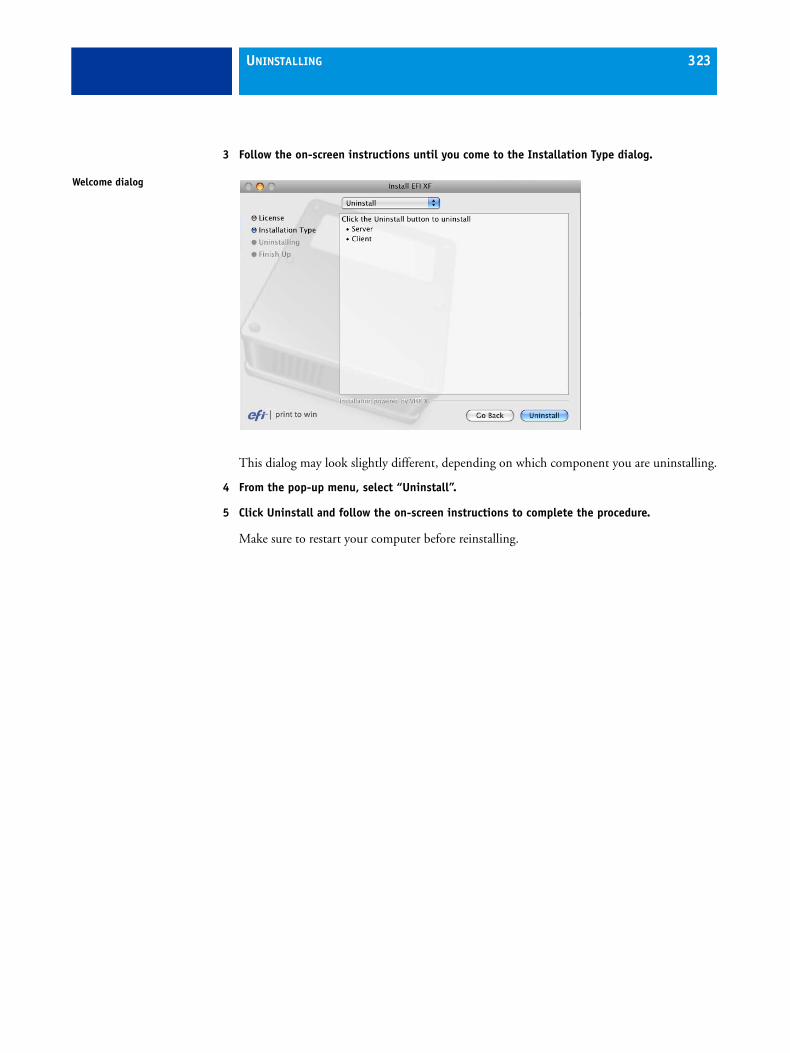
UNINSTALLING 323
3 Follow the on-screen instructions until you come to the Installation Type dialog.
This dialog may look slightly different, depending on which component you are uninstalling.
4 From the pop-up menu, select “Uninstall”.
5 Click Uninstall and follow the on-screen instructions to complete the procedure.
Make sure to restart your computer before reinstalling.
Welcome dialog
GLOSSARY 324
GLOSSARY
This glossary gives a brief explanation of the terms used in this manual.
Base linearization
Printers do not work in a linear fashion and achieve their maximum color density at approximately 50%. As a result, test charts for creating profiles do not have differentiated color patches for the upper chromatic values.
A base linearization makes the density curve of the printer linear (input value = output value), thus creating an important basis for ICC-compatible color management.
C
Color temperatur of 6,774 Kelvin, which corresponds to daylight.
Chromaticness difference
See Delta F
CIE 94
A tolerancing system utilizing three-dimensional ellipsoids as containers for color acceptance. CIE 94 is similar to CMC but lacks some of the hue lightness adjustments. CIE 94 colors have 95% agreement with color differences as our eyes see them. CIE 94 is used predominantly in the paint and coatings industry.
CIELAB
A color model based on the model proposed by the Commission Internationale d'Eclairage (CIE) in 1931 as an international standard for color measurement. In 1976, this model was refined and named CIELAB. L*a*b* color is designed to be device-independent and perceptually uniform. L*a*b* color consists of a luminance or lightness component (L*) and two chromatic components: the a* component (from green to red) and the b* component (from blue to yellow).
CIELCH
A color space similar to CIELAB, which uses cylindrical coordinates of lightness, chroma, and hue angle instead of rectangular coordinates.
CMC
A tolerancing system based on CIELCH. It portrays colors as three-dimensional ellipsoids and represents colors as they are interpreted by the human eye. CMC colors have 95% agreement with color differences as our eyes see them. CMC is used predominantly in the textile industry.

GLOSSARY 325
Compensation of plate characteristic
A function to linearize a non-linear plate characteristic of one-bit files before they are processed in color management. This enables the use of media profiles that are based on linear continuous-tone data.
To produce a color-accurate proof from non-linear plate characteristics calculated into the one-bit files requires a media profile that is based on the IT8 target using the non-linear one-bit files.
csv
A file format for saving color measurement results in Color Verifier. A csv file can also be opened and edited in any spreadsheet application.
Delta E
The mathematically calculated distance in the CIE L*a*b* color space between two colors. Delta E is used to check total color tolerances in a color-management environment.
Delta F
Describes the distance between two colors in the CIE a*b* color space.
Delta H
The difference in hue. In a color wheel, hue is defined by the angle between two colors.
See also Hue
Delta H

GLOSSARY 326
Delta T
The ISO 12647 norm defines delta T purely as a colorimetric value for dot gain — unlike the dot gain commonly referred to in printing houses, which is composed of an optical part (light trapping) and a mechanical part (dot spread).
Dot gain can only be measured using pure primary colors. If, for example, the full-tone color Cyan is output on an inkjet printer to simulate offset printing, it will not have the CMYK value 100, 0, 0, 0, but will also contain a percentage of magenta, yellow and black.
Device link profile
A Device Link profile represents a fixed combination of printer and media type.
Device Link profiles can be created with Color Manager. They must be patched to the EPL linearization file and a media profile using Profile Connector. This tool is available in LinTool and Color Manager.
Dot gain
See Tone value
EFI Remoteproof Container
The file format used to send the image file and settings from one location to another. It is used mainly in conjunction with Color Verifier. The EFI Remoteproof Container consists of a pdf file (print file) and a jdf file (settings file), which are compressed into a single file, the so-called EFI Remoteproof Container with the file extension RPF.
Final Page
A third file that is often produced in addition to CT and LW files during TIFF/IT file creation. A final page file contains information extracted from the CT and LW files and ensures that:
• CT and LW files are clearly recognizable as belonging to the same print job
• photos are always correctly positioned at the right coordinates in the final output file
A final page is essential if you are printing a job with a photo that is not positioned in the top left corner of the page.
Gamma
The ratio of the contrast range between original and reproduction. A gamma value of 1 means that the original and copy proof have the same contrast range.
Halftone screening
A process by which a continuous-tone image is converted into a pattern of regularly spaced dots. The individual dots all have the same density, but vary in size. The color tone of a printed area is dictated by the size of the printed dots — the larger the dots, the darker the reproduced color tone.

GLOSSARY 327
Hue
The dominant wavelength of a color. A color system, or model, measures color by hue, saturation and luminance. The hue is the predominant color, such as yellow or green, the saturation is the color intensity, and the luminance is the brightness.
jdf
Job Definition Format. A file format used in the graphics industry to standardize communication between the individual pre-press, print and further processing stages.
The jdf file contains all the settings made in an EFI proofing product that affect color reproduction, including print resolution and media.
L*a*b*
See CIELAB
Moiré
An interference pattern caused by incorrect selection of halftone screen angles relative to each other. Moiré can be minimized by keeping a 30-degree angle between the separate halftone screens. However, with a total of four colors and 90 degrees of angle to play with, this is not possible. To overcome this issue, yellow — the lightest and least visible color — is often positioned only 15 degrees away from cyan and the halftone angles are rotated 7.5 degrees from the vertical axis.
Page
Image on a nesting. Pages can be in any supported file format. For multi-page documents, each page is nested and previewed.
Portable Document Format. A method of formatting documents in such a way that they can be viewed and printed on multiple platforms using the freely available Adobe Acrobat Reader™.
Moiré pattern

GLOSSARY 328
Printer relinearization
A process to re-adjust the color densities and return the printer to the original state used to generate the base linearization.
Quantity of color
A process to define the maximum quantity of ink for each ink channel and so prevent colors from becoming oversaturated and “bleeding”.
RGB
The additive color system used in digital cameras and computer monitors where red, green, and blue light is captured separately and then combined to create a full color image.
Tone value
The amount that an ink halftone dot expands when applied to the surface of a media, causing darker tones or stronger colors. This is usually a factor of the type of press and the absorbency of the media.
For example, screen printing increases density by about 15%, so an image with a 50% black fill would appear as approximately 65% black after printing.
Screen angle
The degree of rotation at which a halftone screen is printed. Each element in a four-color separation must be photographed through a screen that has been placed at a specific angle in order to eliminate moiré patterns when the colors are superimposed. Precise alignment is necessary and the order in which the color separations are printed can also affect the finished print image.
See also Halftone screening and Moiré
Screen ruling
The number of lines per centimeter or per linear inch in a halftone screen. The higher the screen ruling, the smaller the dot size and the smoother the tonal changes will appear to the eye.
See also Halftone screening
Sheet
Sheet refers to the defined output size of a nesting. It can be equal to, or smaller or larger than the media size defined for the output device. If the defined sheet size exceeds the maximum media size supported by the selected printer, the nesting can be output as a tiling.
System workflow
A system workflow consists of a user, workflow and output device. It refers to all work processes from file input by a user to file output on a specified printer.

GLOSSARY 329
TIFF/IT
When image data is saved to TIFF/IT format, the pixel data of a job is saved to two different files:
• The CT (continuous tone) file describes low resolution and half-tone data (e.g. photos). A CT file may also be created for each separated spot color.
• The LW (line work) file describes high resolution text or line graphics.
In order for the print job to be output, these files have to be combined back together.
Total ink limit
The total ink limit describes the point at which a printer attains its maximum color density.
Most inkjet printers do not increase color density in a linear fashion. In many cases, the maximum color density is achieved at approx. 50%, as illustrated in the graph.
White point
In printing, the white point describes the whiteness of the paper. In colorimetric terms, the white point is defined as the chromaticity of a white light source or other emissive object. The white point may be expressed in terms of correlated color temperature or chromaticity coordinates.
XYZ
A device-independent color model developed by CIE (Commission Internationale de l'Eclairage), in which RGB values are mathematically transformed into a system that uses x, y and z as coordinates. While x and z values have no specific perceptual correlation, the y value represents brightness (luminance).
Total ink limit

INDEX 330
AAlignment
job 62nesting job 99, 109snap to 105
AppleTalkfor Windows XP 135printing 55spooler, setting up 138
BBackups 93
environment 95system configuration 94
Balancing, workload 53Black ink, using 75Black point compensation 73
CClean colors 171Color adjustment settings 170
applying to control strip 170Color Editor 230
color gradations 242defining spot colors 237editing spot colors 242menus 232overprint and gamma 243program window 231toolbar 233
Color managementembedded profiles 70in Remoteproof Container 55rendering intents 71settings 68troubleshooting 317
Color Manager Option 246program window 248
Color Verifier Option 1753D view 189characterization data 196evaluating results in EFI XF 216Fogra Proof Certification 206implementing in EFI XF 200ISO 12647-7 compliant proof 209ISO support 176measurement analysis 212measuring
control strip 183single patches 183
measuring device, selecting 183menus 191Preferences dialog 179printing 193program window 178scope of delivery 177target tolerances
optimizing in EFI XF 199selecting 198
tolerance limitscustom 188predefined 184
use cases 206workflow settings in EFI XF 195
Contour cutting 293, 303Control strip 82
applying color adjustments to 170dynamic 82
Copiesnumber of 77page range 114
Creatinghalftone screens 266nestings 150output devices 33step & repeat 169system workflows 24tiling 163users 31, 50workflow templates 44workflows 32, 50
INDEX

INDEX 331
Crop marks 76position 77, 291
Cropping 146job to media size 78tools 110
Cut marksFOTOBA 297grommet 298i-cut 295
Cut Server Option 289, 301Cutting options 289
contour cutting 303
DDeleting temporary files 51Disk space, available 115Dongle ID 156Dot Creator Option 256
creating halftone screens 266halftone screens in EFI XF 268menus 263program window 262screening methods 258settings in EFI XF 264v1 and v2 comparison 259
Dynamicrendering intent 69wedge 82, 84
preset 188, 198
EEAC code 34EFI XF
Control 153Autostart 156
setting up 24Uploader 47, 103
EFI XF ControlAutostart 156
Environmentbacking up 95restoring 96
EPL, selecting 87EPS job detection 58ES-1000 217
repair form 222using 217
FFiery Option 275File compression 80, 81File Output Option 272Final run characteristics 79First printable dot 79Flipping job 60, 101Folder location, changing 157Fonts, missing 56Footer 65, 82
job ticket 67layout 66
FOTOBA cut marks 297
GGravure Output Option 272Grayscale output 75Grommet marks 298Guides 104
HHalftone screens
creating 266implementing 268
Hard disk space, available 49Hotfolder 53
setting up 127
Ii-cut cut marks 295In-RIP separation 224Inverting job 78ISO support 176
JJapanese Fonts Option 274JDF Connector
content files 281editing jobs 281installing 277loading jobs 280renaming jobs 108setting up a workflow in EFI XF 278

INDEX 332
Jobalignment on nesting 99, 105, 109alignment on sheet 62copying 102flipping 60, 101inverting 78margins 62moving 102priority 107rotating 60, 101scaling 61sheet size 60status 49transform tools 109
Job Explorercontext menus 107keyboard shortcuts 115menus 97overview 40property inspector 111toolbars 108
Job list, displayed information 41Job merge 172Job Monitor 123Job ticket 65, 67
KKeyboard shortcuts 115
LL*a*b* optimization profiles 75Language of user interface, changing 44, 101Layout
nesting 62step & repeat 63, 169tiling 160
Licenseinformation 156installed 48
Licensing 34, 156troubleshooting 312
Linearization device 24configuring 46
LinTool 246Load balancing 53Logging on 22, 44, 98Logo, job ticket 67
MMeasurement system, changing 45, 101Media
consumption 62feed 88length correction 87profiles 20
changing location 47troubleshooting 317updating 155
size 88Monitor profiles 45, 102Multi-threaded halftone processing 287
NNestings 148
aligning jobs 99automatic 150editing 152job settings 98, 103layout aids 105layout settings 62manual 151number of copies 77overlapping jobs 99, 109renaming jobs 108tools 109
Noise smoothing 80
OOneBit Option 252Optimized profile, applying 75Option
Color Manager 246Color Verifier 175Cut Marks 289Cut Server 289Dot Creator 256Fiery 275File Output 272Gravure Output 272Japanese Fonts 274OneBit 252Performance 287Print & Cut 289Production Option 158Spot Color 223
INDEX 333
Output deviceconnecting 85creating 33setting up 86
Overprinting 57
PPDF
output intent 74page size 56print engine 59
Performance Option 287Plate characteristics, modifying 75Preview 98
settings 51size 104, 106tools 111zoom 104
Printengine 59, 288speed 52to file 272
Printercalibration 89special feature support 88
PrintingAppleTalk 55copies 77directly from EFI XF 120from a graphics application 145separated files 78tiles 169to file 272to VUTEk printers 284troubleshooting 314unknown spot colors 228, 241via a hotfolder 127via Job Monitor 126via Unidriver 129virtual printer 55
Production Option 158color adjustment 170job merge 172step & repeat 169tiling 159
Profilesembedded 70updating 155
Programfolders 15overview 40
Protocol drivers, installed 134
RRemoteproof Container
applying color management settings 55creating 80
Renaming jobs 108Rendering intents 71Resources, available hard disk space 49RGB Profile Connector 308RIP resolution 52Rotating job 60, 101
SScaling job 61Scitex CT/LW 60Separated file output 78Server
configuration 156logging on to 22
Server File Maintenance 157Setting up EFI XF 24Settings
nesting 62, 98, 103, 105printer-specific 88step & repeat 63, 169tiling 160white ink 89
Sheet size 60Software, updating 154, 155Spot Color Option 223Spot colors 223
defining in EFI XF 234deleting 245editing 242printing unknown 228, 241processing 228
Step & repeatcreating 169input resolution 58layout settings 63renaming jobs 108settings 63, 169

INDEX 334
Support 320contact 48, 106Knowledge Center 320online user forum 320
Systemconfiguration
backing up 94restoring 94
requirements 14workflows 23
default 23setting online 33setting up 24
System Managermenus 43overview 41property inspector 49toolbar 48
TTemporary files, deleting 51TIFF/IT 60Tiling 159
creating 163editing 165printing 169settings 160tools 159
ToolbarJob Explorer 108System Manager 48
Troubleshootingcolor management 317licensing 21, 312logging on 310media profiles 317options 318printing 314server 310USB devices 319
UUnidriver 129
Macintosh 132Windows 129
Uninstalling 321Updates
installed 48, 106USB devices, troubleshooting 319
Used disk space 115User
creating 31logging on 44, 98password 50settings 50
VVirtual printer 55, 134
setting up 137Visual correction files 87VUTEK printers 284
WWorkflow
creating 32high priority 52settings 50template, creating 44
Working color space 58Workload, distributing 53
ZZoom 104Zünd Cut Center 300


![s[lt;Fu xfd|f];DaGw /lx/xf];\ cgGtÆ - Nepal in Data](https://static.fdokumen.com/doc/165x107/6315e3cb15106505030bd20a/sltfu-xfdfdagw-lxxf-cggta-nepal-in-data.jpg)