2-Post Lift 4.2T - Crypton
28
Operations Manual C2L4200H4 / H5 1 2-Post Lift 4.2T C2L4200H4 C2L4200H5 Operations Manual I324093 Issue 1 Crypton - A Brand of the Continental Corporation
-
Upload
khangminh22 -
Category
Documents
-
view
7 -
download
0
Transcript of 2-Post Lift 4.2T - Crypton
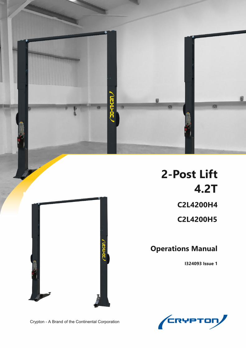
Operations Manual C2L4200H4 / H5
1
2-Post Lift4.2T
C2L4200H4
C2L4200H5
Operations Manual
I324093 Issue 1
Crypton - A Brand of the Continental Corporation
Operations Manual C2L4200H4 / H5
CAUTION!This manual is an integral part of theproduct and must be kept together with thelift throughout its lifetime.
It should therefore be kept in an easilyaccessible and familiar place andconsulted when in doubt. All productoperators must be able to read the manual.
The manufacturer is exempted from anyresponsibility for damage caused by failingto follow the indications in this manual andby improper use of the lifting device.
2
Operations Manual C2L4200H4 / H5
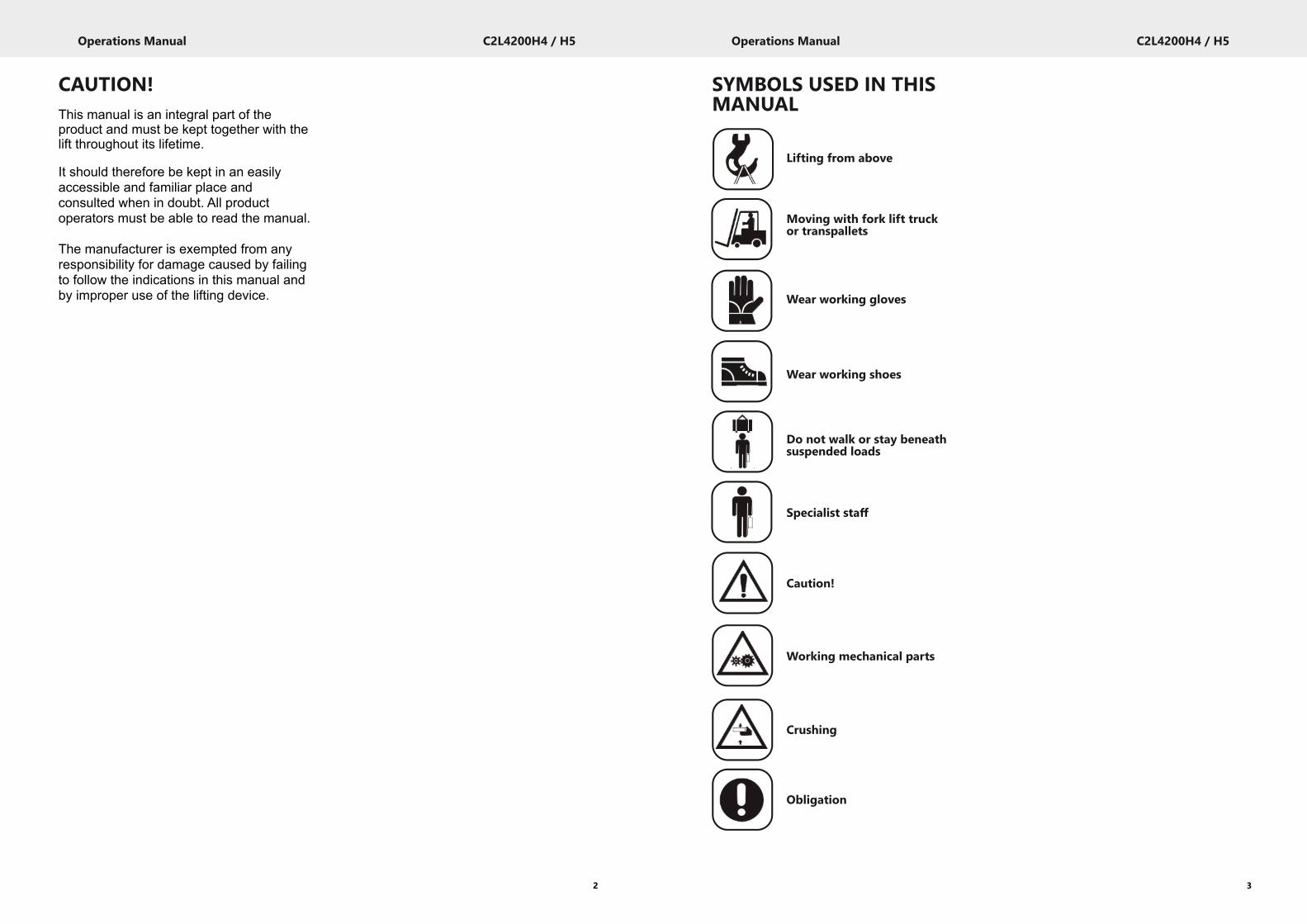
SYMBOLS USED IN THISMANUAL
3
Lifting from above
Moving with fork lift truckor transpallets
Wear working gloves
Wear working shoes
Do not walk or stay beneathsuspended loads
Specialist staff
Caution!
Working mechanical parts
Crushing
Obligation

Operations Manual C2L4200H4 / H5
5
Operations Manual C2L4200H4 / H5
4
CONTENTS
1. General Safety Precautions 6
2. Safety Devices 7
2.1 Padlockable main switch 7
2.2 Deadman device 7
2.3 Device to prevent accidental descent 7
2.4 Device to prevent electric overcharges 7
2.5 Overload valve 7
2.6 Arm anti-rotation device 7
2.7 IndIcation of outstanding device 7
2.8 Pictograms on lift 7
3. Intended Use 9
4. Technical Data 10
4.1 Pre-installation and movement 10
5. Description of Lift 11
5.1 Main technical specifications 11
5.2 Lift controls 11
5.3 Suitability for use 12
6. Checking the minimum requirementsfor the place of installation
12
7. Installation Instructions 14
7.1 Components and accessories forinstallation
14
7.2 Installation instructions 17
7.3 Voltage check 19
7.4 Connecting up to the mains 32
7.5 Phase sequence check 32
7.6 Completion and check 32
7.7 Arm stop 32
7.8 Checking the oil level 32
7.9 Air bleeding out the hydraulic circuit 34
7.10 Dismantling 34
8. Instructions for using the lift 8.1 Improper use of the lift 34
8.2 Use of accessories 34
8.3 Staff training 34
8.4 Important checks to be made 34
8.5 Description and function of controls 36
8.6 Emergency procedure: emergencydrop with power off
36
9. Troubleshooting 36
CONTENTS
10. Maintenance 38
10.1 Slideways 38
10.2 Cables and pulleys 38
10.3 Checking oil level 38
10.4 Checking the safety catches 38
11. Storage 38
11.1 Scrapping 38
12. Electrical Installation 39
13. Hydraulic System 40
14. Machine Identification Data 41
15. Spare Parts Table
15.1 Illustrated Summary 42
15.2 Column Group 43
15.3 Lifting Arm Unit 45
15.4 Hydraulic Power Pack 46
16. Hydraulic System Table Definition 47
17. Table for labels & danger warningdevices
48
18. Electrical System 49
19. Installation Report 50
20. Periodical Visit 51
21. Unscheduled Maintenance &Repairing
52
22. After Sales Service 53
23. Contact Details 53
Operations Manual C2L4200H4 / H5
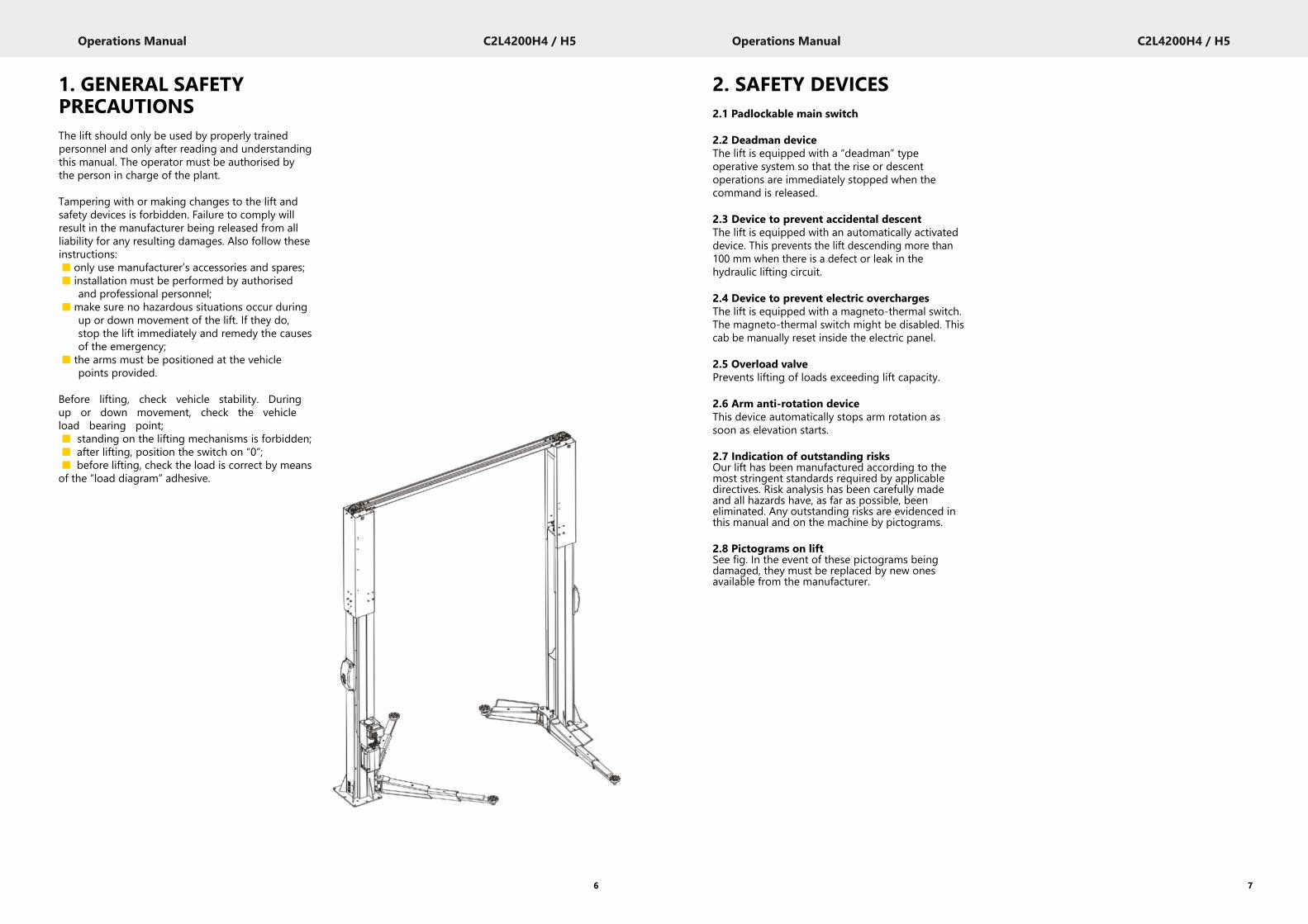
1. GENERAL SAFETYPRECAUTIONSThe lift should only be used by properly trainedpersonnel and only after reading and understandingthis manual. The operator must be authorised bythe person in charge of the plant.
Tampering with or making changes to the lift andsafety devices is forbidden. Failure to comply willresult in the manufacturer being released from allliability for any resulting damages. Also follow theseinstructions:■ only use manufacturer’s accessories and spares;■ installation must be performed by authorised
and professional personnel;■ make sure no hazardous situations occur during
up or down movement of the lift. If they do,stop the lift immediately and remedy the causesof the emergency;
■ the arms must be positioned at the vehiclepoints provided.
Before lifting, check vehicle stability. Duringup or down movement, check the vehicleload bearing point;■ standing on the lifting mechanisms is forbidden;■ after lifting, position the switch on “0”;■ before lifting, check the load is correct by meansof the “load diagram” adhesive.
6
Operations Manual C2L4200H4 / H5
2. SAFETY DEVICES2.1 Padlockable main switch
2.2 Deadman deviceThe lift is equipped with a “deadman” typeoperative system so that the rise or descentoperations are immediately stopped when thecommand is released.
2.3 Device to prevent accidental descentThe lift is equipped with an automatically activateddevice. This prevents the lift descending more than100 mm when there is a defect or leak in thehydraulic lifting circuit.
2.4 Device to prevent electric overchargesThe lift is equipped with a magneto-thermal switch.The magneto-thermal switch might be disabled. Thiscab be manually reset inside the electric panel.
2.5 Overload valvePrevents lifting of loads exceeding lift capacity.
2.6 Arm anti-rotation deviceThis device automatically stops arm rotation assoon as elevation starts.
2.7 Indication of outstanding risksOur lift has been manufactured according to themost stringent standards required by applicabledirectives. Risk analysis has been carefully madeand all hazards have, as far as possible, beeneliminated. Any outstanding risks are evidenced inthis manual and on the machine by pictograms.
2.8 Pictograms on liftSee fig. In the event of these pictograms beingdamaged, they must be replaced by new onesavailable from the manufacturer.
7
Operations Manual C2L4200H4 / H5
8
C RIPARTIZ IONE DEL CARICOLOAD DISTRIBUT IONGEW ICHT VERTEILUNGREPARTITION DE CHARGE
P1(P2) REPARTICIONDE LACARGA
C P1 P2 Q=P1+P2
Q mm kg kg kg710 1830 920 2750
P2(P1) 800 2100 1050 3150
900 2400 1200 3600
1000 2800 1400 4200
400Y
EA
R
VEICHLES LIFT
MODEL LIFT
SERIAL
N°
Y E A R CAPACITY KG. SERIAL N°
6
5
4
3
2
6
5
4 13
PORTATA
MAX1
2
Operations Manual C2L4200H4 / H5
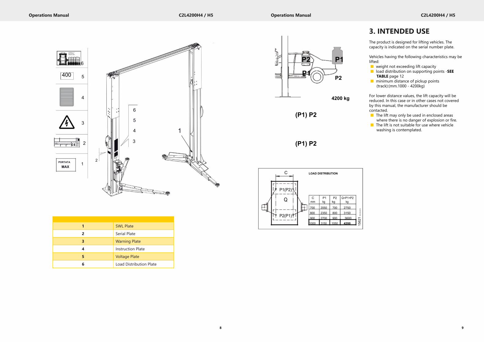
3. INTENDED USEThe product is designed for lifting vehicles. Thecapacity is indicated on the serial number plate.
Vehicles having the following characteristics may belifted:■ weight not exceeding lift capacity■ load distribution on supporting points -SEE
TABLE page 12■ minimum distance of pickup points
(track):(mm.1000 - 4200kg)
For lower distance values, the lift capacity will bereduced. In this case or in other cases not coveredby this manual, the manufacturer should becontacted.■ The lift may only be used in enclosed areas
where there is no danger of explosion or fire.■ The lift is not suitable for use where vehicle
washing is contemplated.
9
1 SWL Plate
2 Serial Plate
3 Warning Plate
4 Instruction Plate
5 Voltage Plate
6 Load Distribution Plate
P2 P1
P1P2
4200 kg
(P1) P2
(P1) P2
C LOAD DISTRIBUTION
P1(P2)
Q C P1 P2 Q=P1+P2mm kg kg kg
700 2050 700 2750
P2(P1)800 2350 800 3150900 2700 900 36001000 3150 1050 4200 15
621
EN14
93-201
0
Operations Manual C2L4200H4 / H5
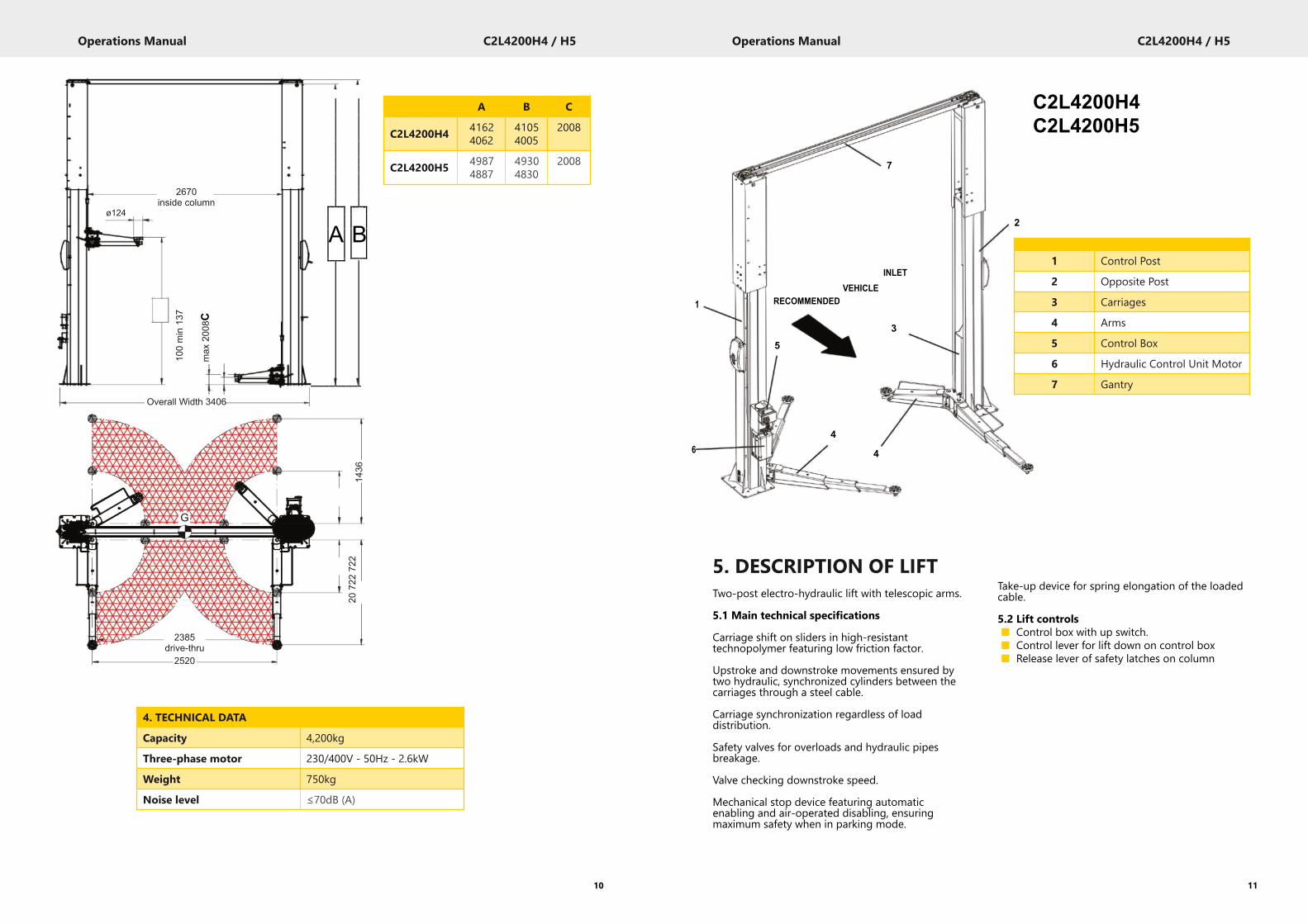
Take-up device for spring elongation of the loadedcable.
5.2 Lift controls■ Control box with up switch.■ Control lever for lift down on control box■ Release lever of safety latches on column
5. DESCRIPTION OF LIFTTwo-post electro-hydraulic lift with telescopic arms.
5.1 Main technical specifications
Carriage shift on sliders in high-resistanttechnopolymer featuring low friction factor.
Upstroke and downstroke movements ensured bytwo hydraulic, synchronized cylinders between thecarriages through a steel cable.
Carriage synchronization regardless of loaddistribution.
Safety valves for overloads and hydraulic pipesbreakage.
Valve checking downstroke speed.
Mechanical stop device featuring automaticenabling and air-operated disabling, ensuringmaximum safety when in parking mode.
11
Operations Manual C2L4200H4 / H5
10
2670inside column
ø124
100min13
7
max
2008C
Overall Width 3406
G
2385drive-thru2520
4 0 0 5 ] 0 6 2 ] a14
36622
072
272
2
4. TECHNICAL DATA
Capacity 4,200kg
Three-phase motor 230/400V - 50Hz - 2.6kW
Weight 750kg
Noise level ≤70dB (A)
A B C
C2L4200H4 41624062
41054005
2008
C2L4200H5 49874887
49304830
2008 7
INLETVEHICLE
1 RECOMMENDED
35
46 4
C2L4200H4C2L4200H5
2
1 Control Post
2 Opposite Post
3 Carriages
4 Arms
5 Control Box
6 Hydraulic Control Unit Motor
7 Gantry
A B
Operations Manual C2L4200H4 / H5
13
Operations Manual C2L4200H4 / H5
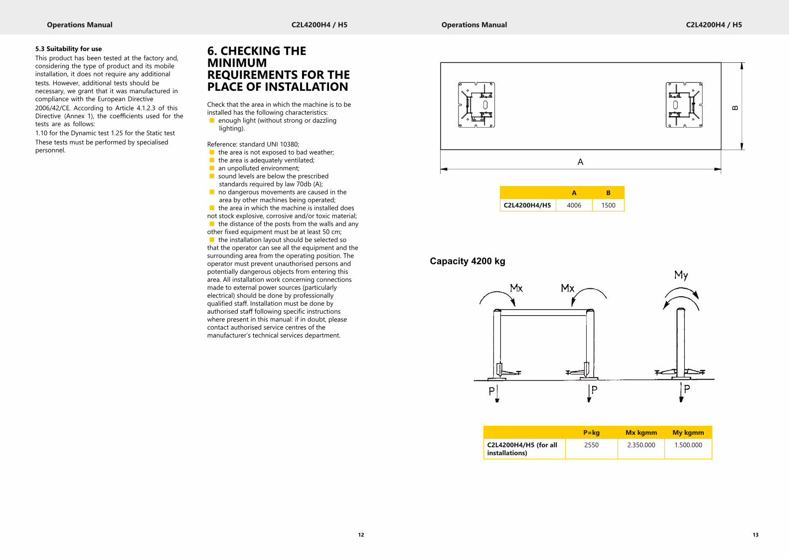
6. CHECKING THEMINIMUMREQUIREMENTS FOR THEPLACE OF INSTALLATIONCheck that the area in which the machine is to beinstalled has the following characteristics:■ enough light (without strong or dazzling
lighting).
Reference: standard UNI 10380;■ the area is not exposed to bad weather;■ the area is adequately ventilated;■ an unpolluted environment;■ sound levels are below the prescribed
standards required by law 70db (A);■ no dangerous movements are caused in the
area by other machines being operated;■ the area in which the machine is installed doesnot stock explosive, corrosive and/or toxic material;■ the distance of the posts from the walls and anyother fixed equipment must be at least 50 cm;■ the installation layout should be selected sothat the operator can see all the equipment and thesurrounding area from the operating position. Theoperator must prevent unauthorised persons andpotentially dangerous objects from entering thisarea. All installation work concerning connectionsmade to external power sources (particularlyelectrical) should be done by professionallyqualified staff. Installation must be done byauthorised staff following specific instructionswhere present in this manual: if in doubt, pleasecontact authorised service centres of themanufacturer’s technical services department.
5.3 Suitability for useThis product has been tested at the factory and,considering the type of product and its mobileinstallation, it does not require any additionaltests. However, additional tests should benecessary, we grant that it was manufactured incompliance with the European Directive2006/42/CE. According to Article 4.1.2.3 of thisDirective (Annex 1), the coefficients used for thetests are as follows:1.10 for the Dynamic test 1.25 for the Static testThese tests must be performed by specialisedpersonnel.
12
B
A
Capacity 4200 kg
A B
C2L4200H4/H5 4006 1500
P=kg Mx kgmm My kgmm
C2L4200H4/H5 (for allinstallations)
2550 2.350.000 1.500.000

REINFORCEDCONCRETE
POOR CONCRETE
?
105
Min
160
SCREW ANCHOR
POORCONCRETE
?
Operations Manual C2L4200H4 / H5
15
Operations Manual C2L4200H4 / H5
In the case of existing floors where suchcharacteristics cannot be checked a foundationcement casting should be laid for a minimumsurface area of m 4.00x1.50, with a depth of 25 cmhaving double reinforcement as described above.
The lift must be secured to the floor withmechanical screw anchors of the type HILTI HSL-3M12/25 or similar or with chemical anchors (vials)HILTI HVU M12x110 or similar, with a M12threaded bar in steel class 5.8 or higher.
7. INSTALLATIONINSTRUCTIONSThe lift should be installed on flat level floor ableto support LOADS TRANSMITTED TO SUPPORTAREA (See fig. 1).
7.1 Installation requirementsMinimum features for floor should be thefollowing:I) Concrete used: class R’bk 300 or higherII) Minimum thickness of the flooring net of anytiling and layoutblocks (See fig. 1a)C) Upper and lower reinforcement done at leastwith electro-welded wire net Ø 4x150 mm orcombined, and mesh not exceeding 250mm. Wirecover no greater than 25 cmD) Bearing capacity of area no less than 1,3Kg/cm2
These characteristics must be guaranteed over aminimum area dependent lift installed (see thetable in fig.1), where there must be no expansionjoints or cuts to break the continuity of the upperReinforcement.
14
REINFORCEDCONCRETE
110
Min
140
CHEMICAL ANCHOR
Whenever there are doubts about the actualconsistency of the floor, you are advised tocontact a qualified technician.
Operations Manual C2L4200H4 / H5
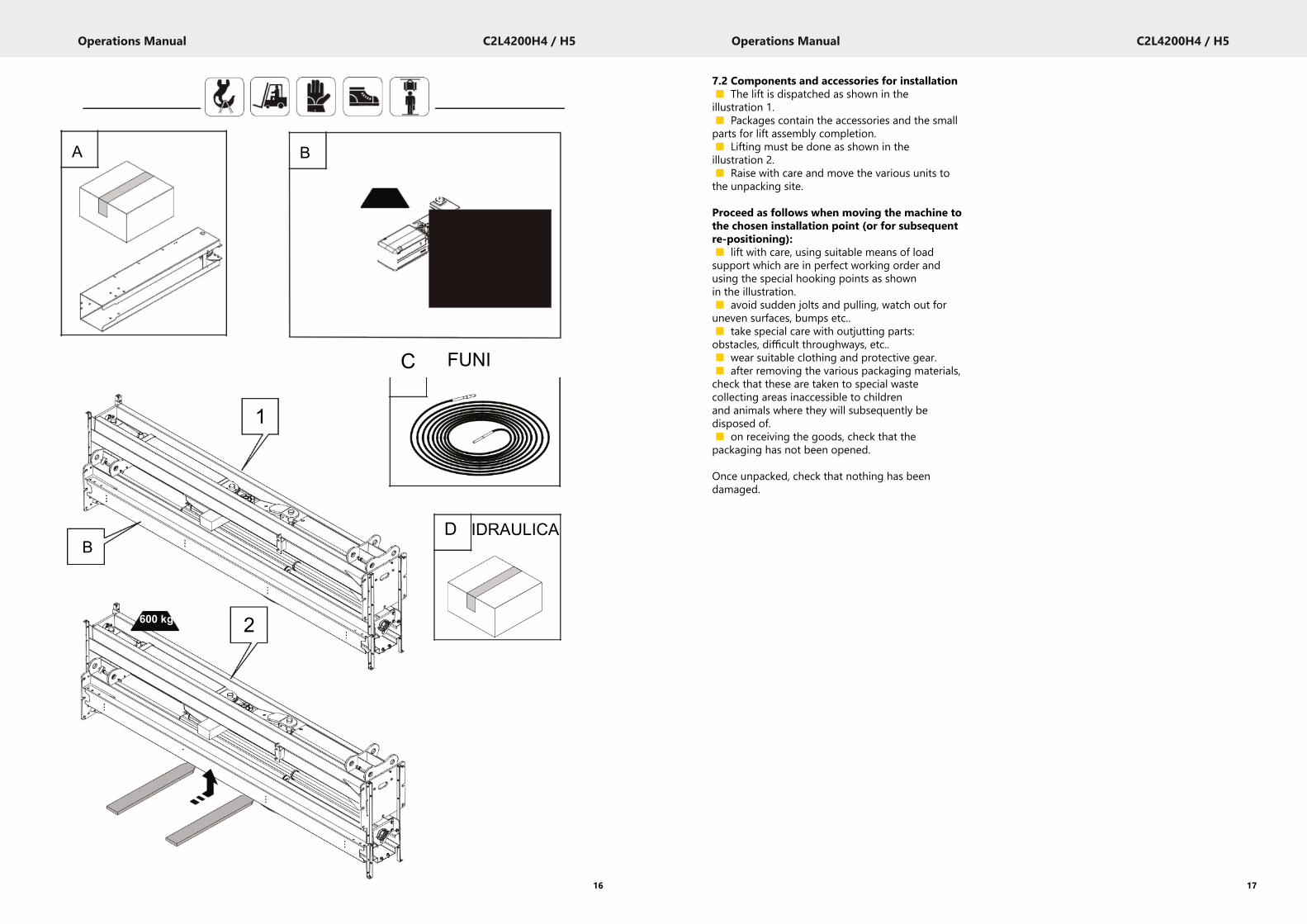
7.2 Components and accessories for installation■ The lift is dispatched as shown in theillustration 1.■ Packages contain the accessories and the smallparts for lift assembly completion.■ Lifting must be done as shown in theillustration 2.■ Raise with care and move the various units tothe unpacking site.
Proceed as follows when moving the machine tothe chosen installation point (or for subsequentre-positioning):■ lift with care, using suitable means of loadsupport which are in perfect working order andusing the special hooking points as shownin the illustration.■ avoid sudden jolts and pulling, watch out foruneven surfaces, bumps etc..■ take special care with outjutting parts:obstacles, difficult throughways, etc..■ wear suitable clothing and protective gear.■ after removing the various packaging materials,check that these are taken to special wastecollecting areas inaccessible to childrenand animals where they will subsequently bedisposed of.■ on receiving the goods, check that thepackaging has not been opened.
Once unpacked, check that nothing has beendamaged.
17
Operations Manual C2L4200H4 / H5
16
A
B
600 kg
B
20 kg
C FUNI
1
D IDRAULICA
2
Operations Manual C2L4200H4 / H5
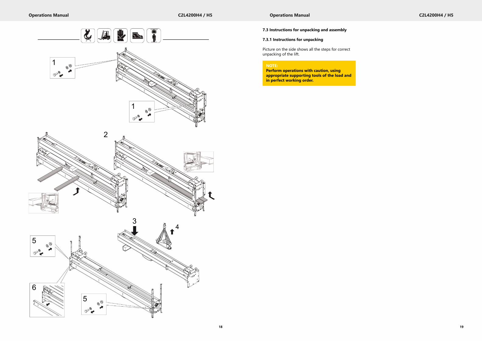
7.3 Instructions for unpacking and assembly
7.3.1 Instructions for unpacking
Picture on the side shows all the steps for correctunpacking of the lift.
19
Operations Manual C2L4200H4 / H5
18
1
1
2
3
5
65
4
NOTE:Perform operations with caution, usingappropriate supporting tools of the load andin perfect working order.
Operations Manual C2L4200H4 / H5
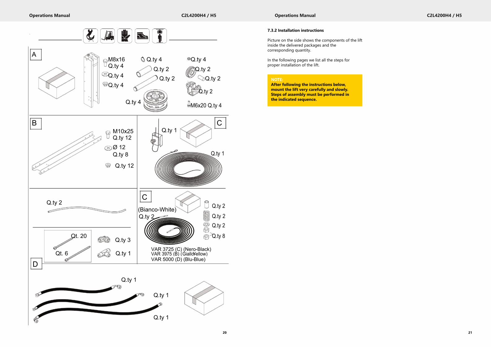
7.3.2 Installation instructions
Picture on the side shows the components of the liftinside the delivered packages and thecorresponding quantity.
In the following pages we list all the steps forproper installation of the lift.
21
Operations Manual C2L4200H4 / H5
20
AM8x16 Q.ty 4 Q.ty 4Q.ty 4 Q.ty 2 Q.ty 2Q.ty 4 Q.ty 2 Q.ty 2Q.ty 4
Q.ty 2
Q.ty 4 M6x20 Q.ty 4
B CM10x25 Q.ty 1Q.ty 12Ø 12Q.ty 8 Q.ty 1
Q.ty 12
Q.ty 2C
Q.ty 2(Bianco-White)Q.ty 2 Q.ty 2
Q.ty 2
Qt. 20Q.ty 3
Q.ty 8
Qt. 6 Q.ty 1VAR 3725 (C) (Nero-Black)VAR 3975 (B) (GialloY-ellow)
DVAR 5000 (D) (Blu-Blue)
Q.ty 1
Q.ty 1
Q.ty 1
NOTE:After following the instructions below,mount the lift very carefully and slowly.Steps of assembly must be performed inthe indicated sequence.
Operations Manual C2L4200H4 / H5
23
Operations Manual C2L4200H4 / H5
22
1aB = Min.
A = Max.
2a 2b
2c
2d3 2 1
4
F 500mm FF
6507,5 X 360mm mm
2e
Flex-Hose
Fune-Rope
Operations Manual C2L4200H4 / H5
25
Operations Manual C2L4200H4 / H5
24
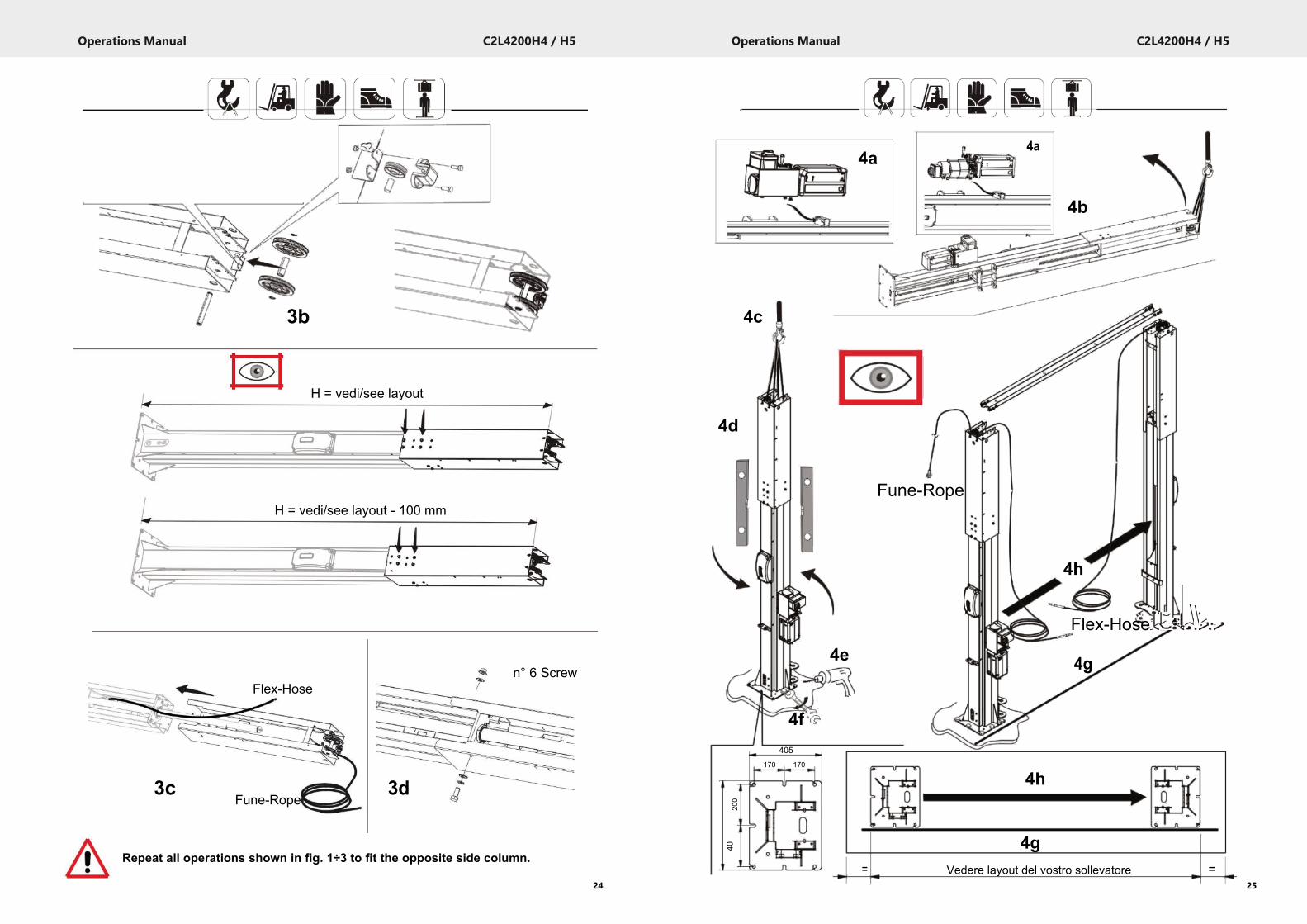
3b
H = vedi/see layout
H = vedi/see layout - 100 mm
n° 6 ScrewFlex-Hose
3cFune-Rope
3d
Repeat all operations shown in fig. 1÷3 to fit the opposite side column.
4a4a
4b
4c
4d
Fune-Rope
4h
Flex-Hose
4e 4g
4f405
170 170
200
20044
0
4h
4g= Vedere layout del vostro sollevatore =
Operations Manual C2L4200H4 / H5
27
Operations Manual C2L4200H4 / H5
26
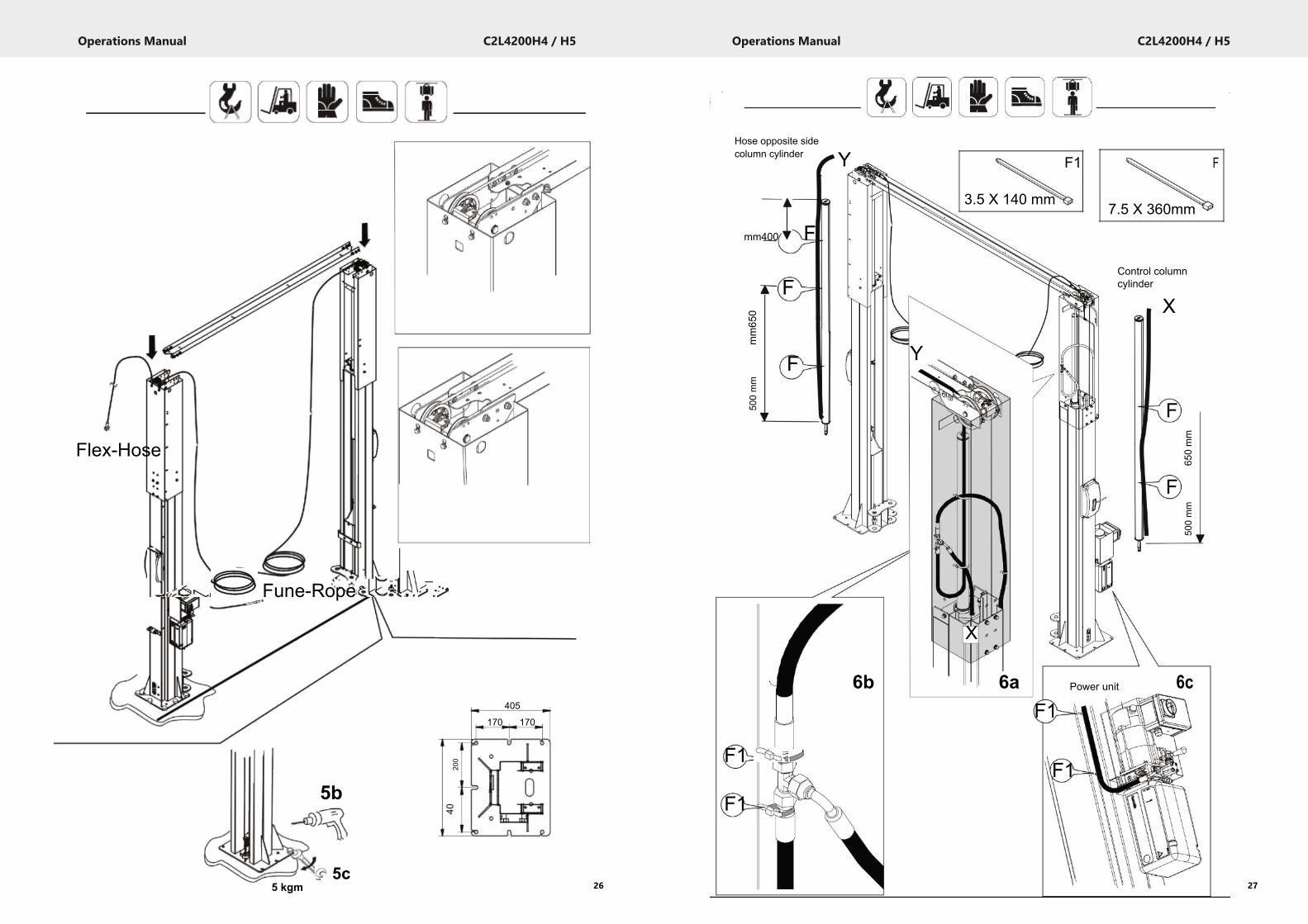
Flex-Hose
Fune-Rope
405
170 170
5 kgm
5b
5c
200
044
0
Hose opposite sidecolumn cylinder
mm400 F
F
mm65
0
F
500mm
F1
F1
Y F1 F
3.5 X 140 mm 7.5 X 360mm
Control columncylinder
X
Y
F
650mm
F
500mm
X
6b 6a 6cPower unit
F1
F1
Operations Manual C2L4200H4 / H5
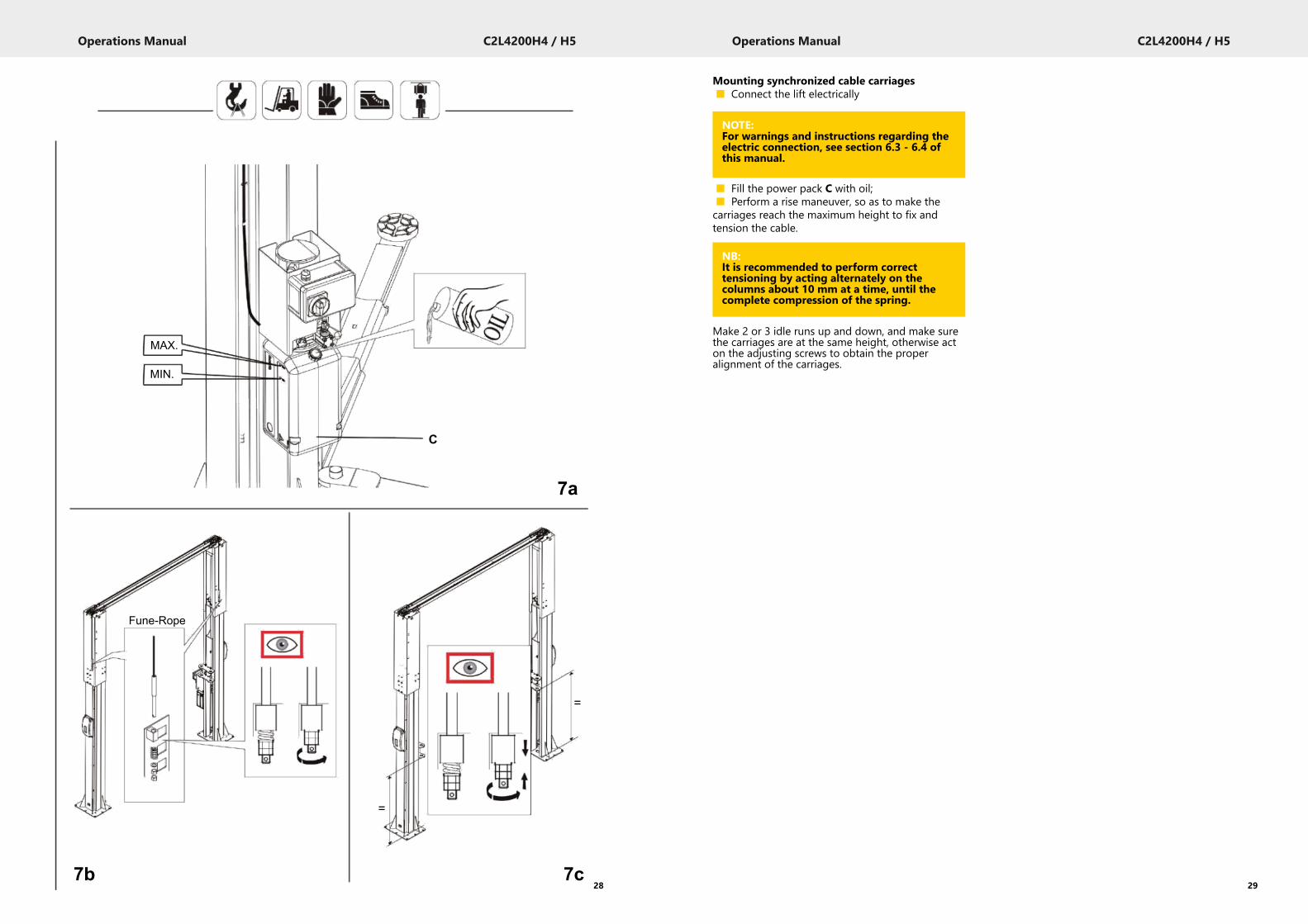
Mounting synchronized cable carriages■ Connect the lift electrically
■ Fill the power pack C with oil;■ Perform a rise maneuver, so as to make thecarriages reach the maximum height to fix andtension the cable.
Make 2 or 3 idle runs up and down, and make surethe carriages are at the same height, otherwise acton the adjusting screws to obtain the properalignment of the carriages.
29
Operations Manual C2L4200H4 / H5
28
MAX.
MIN.
C
7a
Fune-Rope
=
=
7b 7c
NOTE:For warnings and instructions regarding theelectric connection, see section 6.3 - 6.4 ofthis manual.
NB:It is recommended to perform correcttensioning by acting alternately on thecolumns about 10 mm at a time, until thecomplete compression of the spring.

Operations Manual C2L4200H4 / H5
31
Operations Manual C2L4200H4 / H5
30
F1
F1
F1
F1
F1
F1
F1
F1
F1
F1
F1 8a
8b
F1
3.5 X 140 mm
9a
9c
9b
10b
Operations Manual C2L4200H4 / H5
33
Operations Manual C2L4200H4 / H5
7.6 Phase sequence checkTurn the main switch to lift.If no carriage has moved after 10-15 seconds, itmeans that the motor might be running in thewrong direction. If so, reverse two power cables.
7.7 Completion and check■ Fit the long arms■ Fit the short arms■ Run a few load less strokes up and down todrain any air from the circuit.
Allow several minutes and run more load lessstrokes. Repeat until motion becomes smoothagain.
Should the problem persist, follow instructions givenon page 43 “AIR BLEEDING”.
7.8 Arm stopOnce the lift is down, make sure that the arm canmove freely.
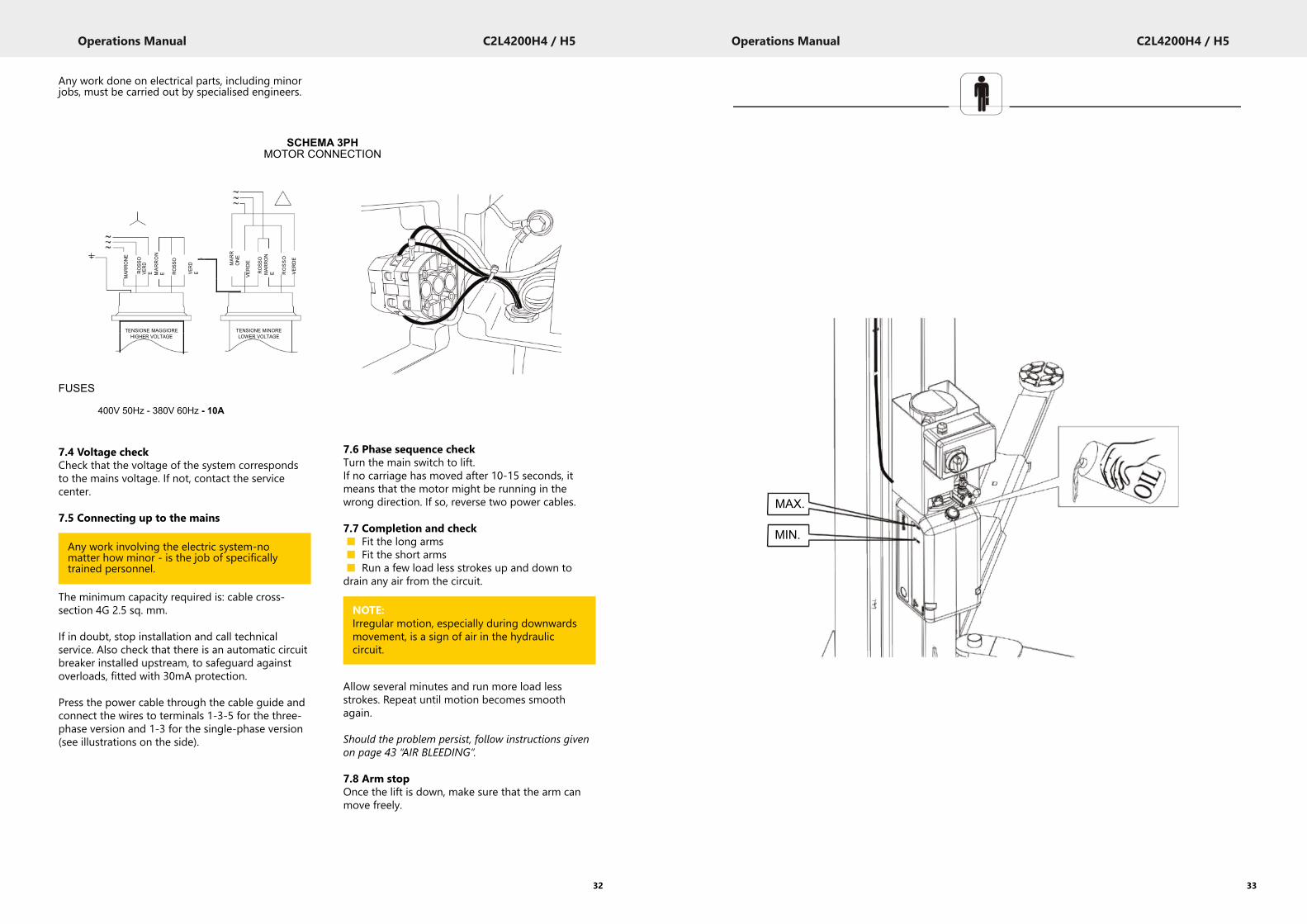
Any work done on electrical parts, including minorjobs, must be carried out by specialised engineers.
7.4 Voltage checkCheck that the voltage of the system correspondsto the mains voltage. If not, contact the servicecenter.
7.5 Connecting up to the mains
The minimum capacity required is: cable cross-section 4G 2.5 sq. mm.
If in doubt, stop installation and call technicalservice. Also check that there is an automatic circuitbreaker installed upstream, to safeguard againstoverloads, fitted with 30mA protection.
Press the power cable through the cable guide andconnect the wires to terminals 1-3-5 for the three-phase version and 1-3 for the single-phase version(see illustrations on the side).
32
MAR
RONE
ROSS
O
MARRON
E ROSS
O
MAR
RONE
VERDE
ROSS
OMAR
RON
E ROSSO
VERDE
VERD
E VERD
E
TENSIONE MAGGIORE TENSIONE MINOREHIGHER VOLTAGE LOWER VOLTAGE
1
3
FUSES
400V 50Hz - 380V 60Hz - 10A
SCHEMA 3PHMOTOR CONNECTION
Any work involving the electric system-nomatter how minor - is the job of specificallytrained personnel.
NOTE:Irregular motion, especially during downwardsmovement, is a sign of air in the hydrauliccircuit.
MAX.
MIN.
Operations Manual C2L4200H4 / H5
35
Operations Manual C2L4200H4 / H5
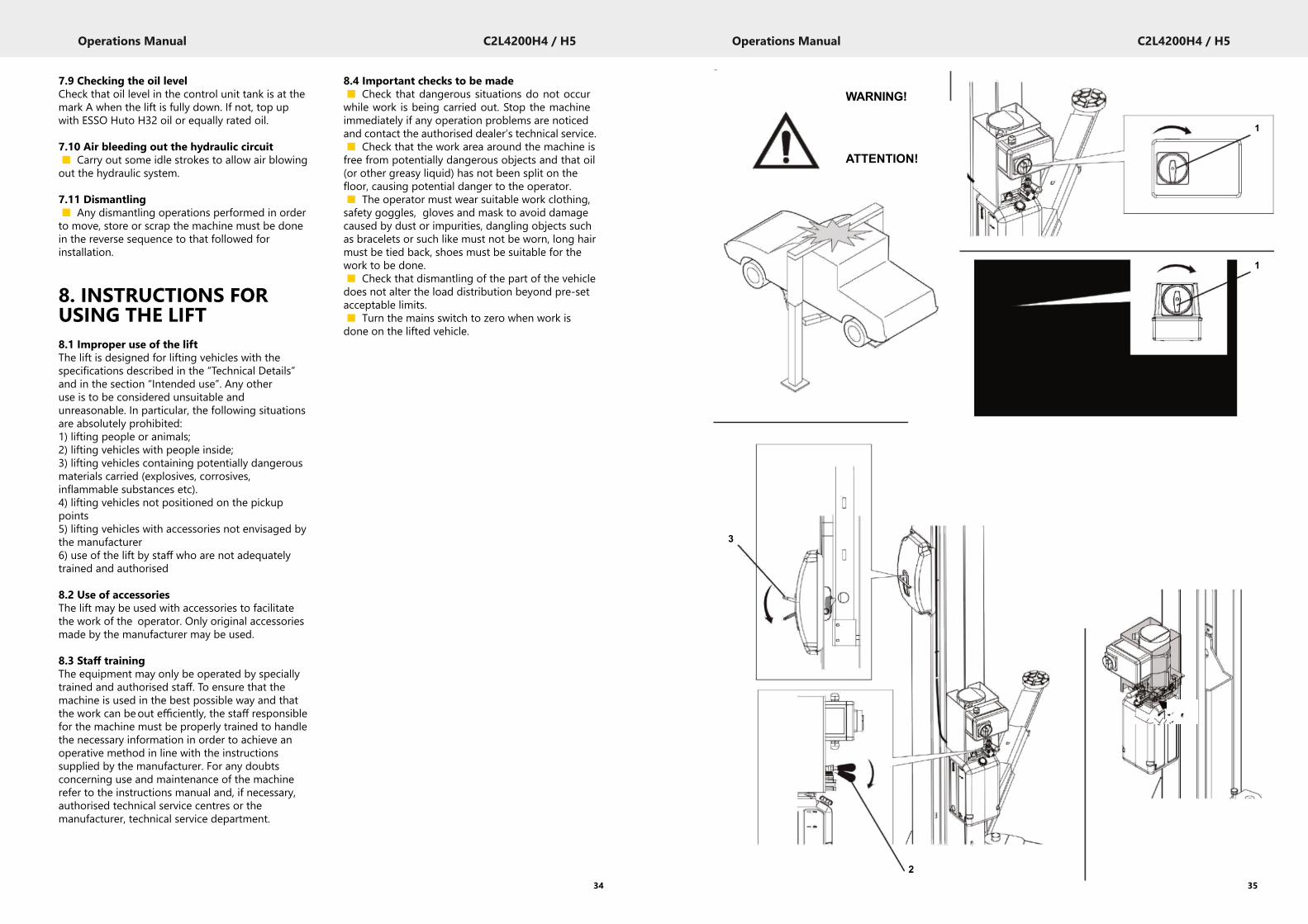
8.4 Important checks to be made■ Check that dangerous situations do not occurwhile work is being carried out. Stop the machineimmediately if any operation problems are noticedand contact the authorised dealer’s technical service.■ Check that the work area around the machine isfree from potentially dangerous objects and that oil(or other greasy liquid) has not been split on thefloor, causing potential danger to the operator.■ The operator must wear suitable work clothing,safety goggles, gloves and mask to avoid damagecaused by dust or impurities, dangling objects suchas bracelets or such like must not be worn, long hairmust be tied back, shoes must be suitable for thework to be done.■ Check that dismantling of the part of the vehicledoes not alter the load distribution beyond pre-setacceptable limits.■ Turn the mains switch to zero when work isdone on the lifted vehicle.
7.9 Checking the oil levelCheck that oil level in the control unit tank is at themark A when the lift is fully down. If not, top upwith ESSO Huto H32 oil or equally rated oil.
7.10 Air bleeding out the hydraulic circuit■ Carry out some idle strokes to allow air blowingout the hydraulic system.
7.11 Dismantling■ Any dismantling operations performed in orderto move, store or scrap the machine must be donein the reverse sequence to that followed forinstallation.
8. INSTRUCTIONS FORUSING THE LIFT8.1 Improper use of the liftThe lift is designed for lifting vehicles with thespecifications described in the “Technical Details”and in the section “Intended use”. Any otheruse is to be considered unsuitable andunreasonable. In particular, the following situationsare absolutely prohibited:1) lifting people or animals;2) lifting vehicles with people inside;3) lifting vehicles containing potentially dangerousmaterials carried (explosives, corrosives,inflammable substances etc).4) lifting vehicles not positioned on the pickuppoints5) lifting vehicles with accessories not envisaged bythe manufacturer6) use of the lift by staff who are not adequatelytrained and authorised
8.2 Use of accessoriesThe lift may be used with accessories to facilitatethe work of the operator. Only original accessoriesmade by the manufacturer may be used.
8.3 Staff trainingThe equipment may only be operated by speciallytrained and authorised staff. To ensure that themachine is used in the best possible way and thatthe work can beout efficiently, the staff responsiblefor the machine must be properly trained to handlethe necessary information in order to achieve anoperative method in line with the instructionssupplied by the manufacturer. For any doubtsconcerning use and maintenance of the machinerefer to the instructions manual and, if necessary,authorised technical service centres or themanufacturer, technical service department.
34
WARNING!
1
ATTENTION!
1
3
4
2
Operations Manual C2L4200H4 / H5
37
Operations Manual C2L4200H4 / H5
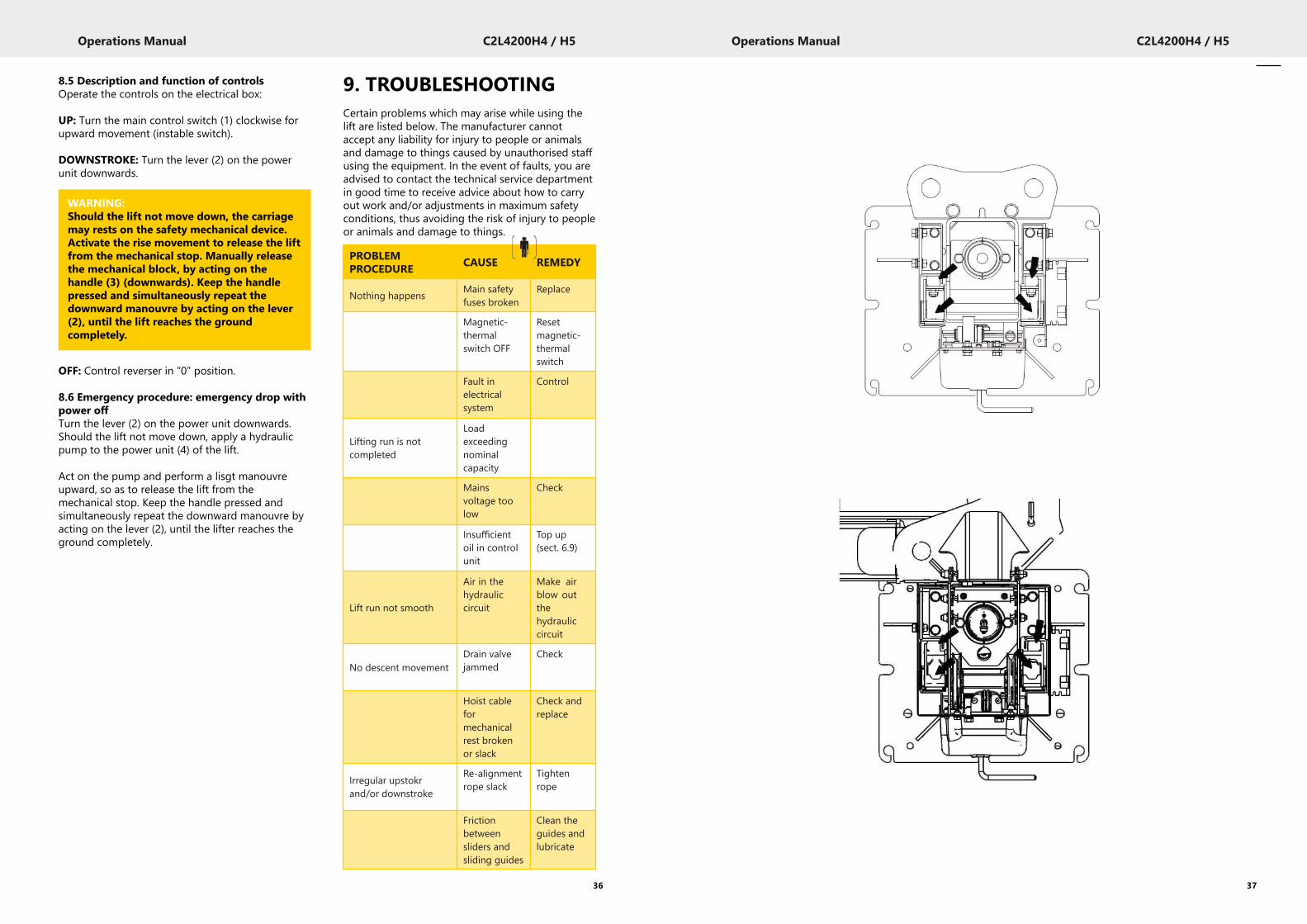
9. TROUBLESHOOTINGCertain problems which may arise while using thelift are listed below. The manufacturer cannotaccept any liability for injury to people or animalsand damage to things caused by unauthorised staffusing the equipment. In the event of faults, you areadvised to contact the technical service departmentin good time to receive advice about how to carryout work and/or adjustments in maximum safetyconditions, thus avoiding the risk of injury to peopleor animals and damage to things.
8.5 Description and function of controlsOperate the controls on the electrical box:
UP: Turn the main control switch (1) clockwise forupward movement (instable switch).
DOWNSTROKE: Turn the lever (2) on the powerunit downwards.
OFF: Control reverser in “0” position.
8.6 Emergency procedure: emergency drop withpower offTurn the lever (2) on the power unit downwards.Should the lift not move down, apply a hydraulicpump to the power unit (4) of the lift.
Act on the pump and perform a lisgt manouvreupward, so as to release the lift from themechanical stop. Keep the handle pressed andsimultaneously repeat the downward manouvre byacting on the lever (2), until the lifter reaches theground completely.
36
WARNING:Should the lift not move down, the carriagemay rests on the safety mechanical device.Activate the rise movement to release the liftfrom the mechanical stop. Manually releasethe mechanical block, by acting on thehandle (3) (downwards). Keep the handlepressed and simultaneously repeat thedownward manouvre by acting on the lever(2), until the lift reaches the groundcompletely.
PROBLEMPROCEDURE CAUSE REMEDY
Nothing happens Main safetyfuses broken
Replace
Magnetic-thermalswitch OFF
Resetmagnetic-thermalswitch
Fault inelectricalsystem
Control
Lifting run is notcompleted
Loadexceedingnominalcapacity
Mainsvoltage toolow
Check
Insufficientoil in controlunit
Top up(sect. 6.9)
Lift run not smooth
Air in thehydrauliccircuit
Make airblow outthehydrauliccircuit
No descent movementDrain valvejammed
Check
Hoist cableformechanicalrest brokenor slack
Check andreplace
Irregular upstokrand/or downstroke
Re-alignmentrope slack
Tightenrope
Frictionbetweensliders andsliding guides
Clean theguides andlubricate

Operations Manual C2L4200H4 / H5
12. ELECTRICALINSTALLATIONThis installation is to be carried out by the user.
39
Operations Manual C2L4200H4 / H5
INSTRUCTIONS FOR THE CORRECTMANAGEMENT OF WASTE FROM ELECTRIC ANDELECTRONIC EQUIPMENT (IN ITALIAN RAEE)ACCORDING TO LEGISLATIVE DECREE 49/14
With the aim of informing the users on how todispose of the product correctly (as provided inArticle 26, paragraph 1 of Legislative Decree49/2014), please note the following:
10. MAINTENANCELock the main switch with a padlock beforeproceeding with maintenance.
10.1 SlidewaysLubricate sliding guides every 3 months withgrease.
10.2 Cables and pulleysPeriodically check that cables feature no broken ordamaged strands, pulleys are in good condition.
10.3 Checking oil levelCheck oil level in the control unit.
10.4 Checking the safety catchesMake sure that the safety catch operates correctlyand the steel cable is not damaged.
11. STORAGEIn the event of the lift having to be stored for longperiods, disconnect the power supply, empty thetank/s containing liquids used for machineoperation and protect any parts that might bedamaged by dust.- Grease the parts that might bedamaged by dryness. - When the machine is startedagain, replace the seals indicated in the spare partssection.
11.1 Scrapping■ If the decision is taken not to use this machineany longer, we advise making this inoperative.■ Modify any parts of the machine which could bedangerous, leaving it harmless.■ Sort parts according to disposal class.■ Dispose of as scrap and metal and take to anauthorised scrap metal disposal centre.■ Special wastes must be sorted into uniformtypes, then disposed of through authorisedchannels.
38
CAUTION:Moving mechanical parts. Guard removal atoperator’s risk.
The crossed-out wheelie bin affixed to thedevice indicates that the product should notbe disposed of as regular waste (togetherwith “mixed urban waste”), but it should bemanaged separately in order to subject WEEEto specific operations aimed at reusing ortreating them, and remove and dispose ofsafely any substances that are harmful forenvironment and recycle raw materials thatcan be reused.”
3 PHASE
3 PHASEHz V 230 400F 50/60 POWER CABLE 3P + EARTH Xx2.5mmq16 A 10 A
10
F
1 1 3 5
0IG 2
PE4 6
nero 2.5mmq
Q1
M3
Q1 Magnet-thermal automatic switch 9-14A (version 230V) 6-10A (version 400V
M Motor
IG Main Switch
Operations Manual C2L4200H4 / H5
15. SPARE PARTS TABLES14. MACHINEIDENTIFICATION DATA
41
Operations Manual C2L4200H4 / H5
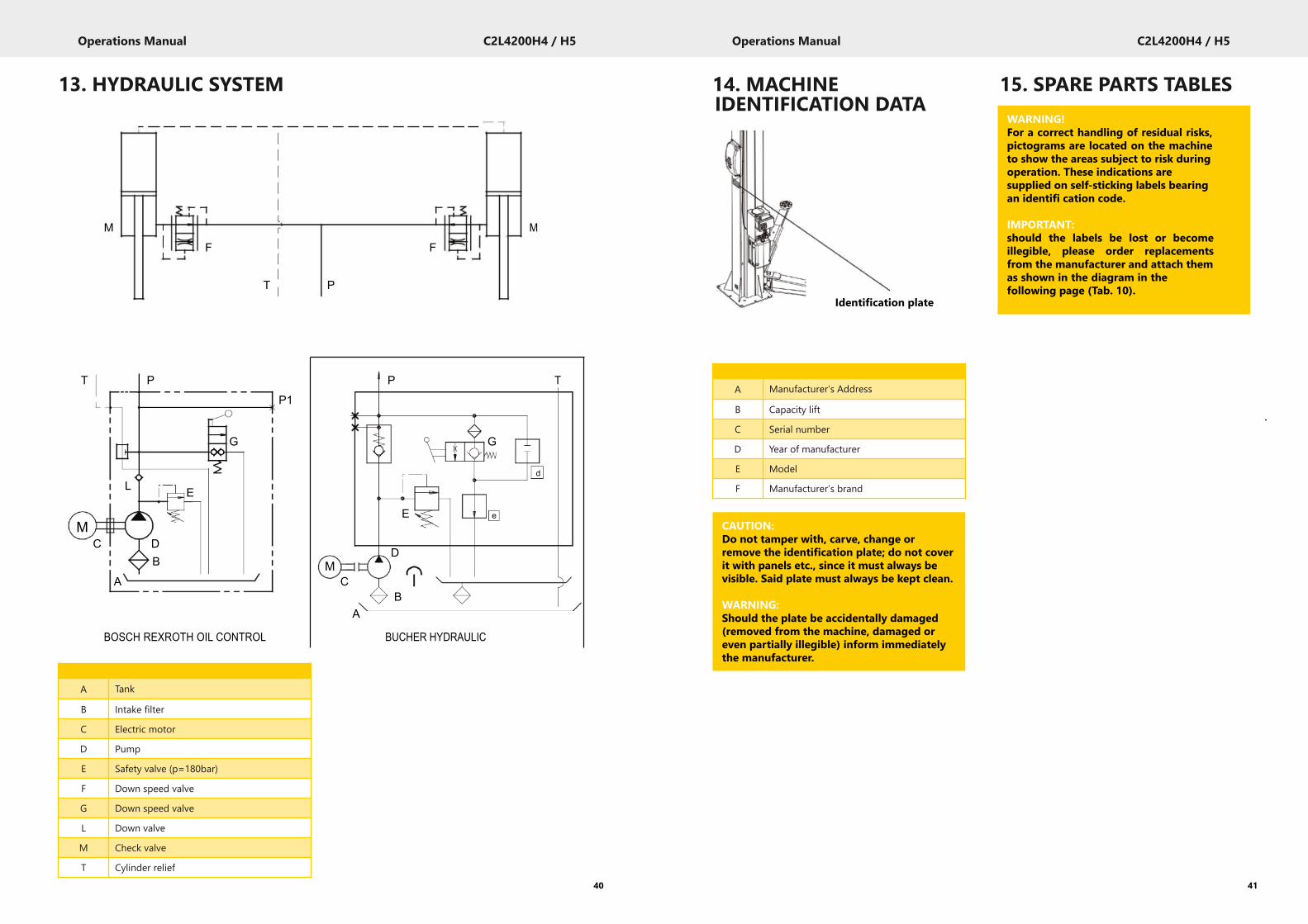
13. HYDRAULIC SYSTEM
40
M M
F F
T P
T P P TP1
G G
Ld
E
ME e
C DD
B MA C
BA
BOSCH REXROTH OIL CONTROL BUCHER HYDRAULIC
A Tank
B Intake filter
C Electric motor
D Pump
E Safety valve (p=180bar)
F Down speed valve
G Down speed valve
L Down valve
M Check valve
T Cylinder relief
Identification plate
A Manufacturer’s Address
B Capacity lift
C Serial number
D Year of manufacturer
E Model
F Manufacturer’s brand
CAUTION:Do not tamper with, carve, change orremove the identification plate; do not coverit with panels etc., since it must always bevisible. Said plate must always be kept clean.
WARNING:Should the plate be accidentally damaged(removed from the machine, damaged oreven partially illegible) inform immediatelythe manufacturer.
WARNING!For a correct handling of residual risks,pictograms are located on the machineto show the areas subject to risk duringoperation. These indications aresupplied on self-sticking labels bearingan identifi cation code.
IMPORTANT:should the labels be lost or becomeillegible, please order replacementsfrom the manufacturer and attach themas shown in the diagram in thefollowing page (Tab. 10).
Operations Manual C2L4200H4 / H5
Table no. / Change index
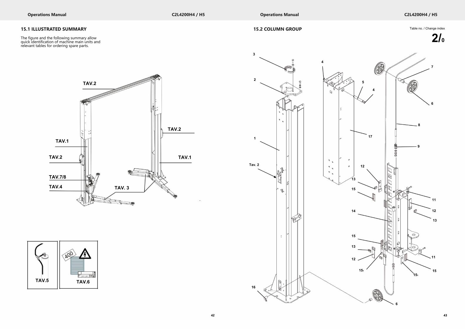
2/015.2 COLUMN GROUP
43
Operations Manual C2L4200H4 / H5
15.1 ILLUSTRATED SUMMARY
The figure and the following summary allowquick identification of machine main units andrelevant tables for ordering spare parts.
42
TAV.2
TAV.2
TAV.1
TAV.2
TAV.7/8
TAV.4
TAV.1
TAV. 3
TAV.2
TAV.5 TAV.6
3
4
2
1
Tav. 2
5
4
17
12
13
15
14
15
13
12
151
7
6
8
9
11
12
13
11
15151
16
6

Operations Manual C2L4200H4 / H5
Table no. / Change index
3B/015.3 LIFTING ARM UNIT
45
Operations Manual C2L4200H4 / H5
Table no. / Change index
2/0COLUMN GROUP
44
19
1713 11 1
12
97
13
1210
B6
415
35
11
9 4 10
13 5
12
11
16
715
314
AA B
18
2
B A 16
17
C B 18
11
A 9 8
10
B 98
1
106
2 5
34
C8
127
9
106
2 5
34
13 7
62 5
347
Operations Manual C2L4200H4 / H5
Table no. / Change index
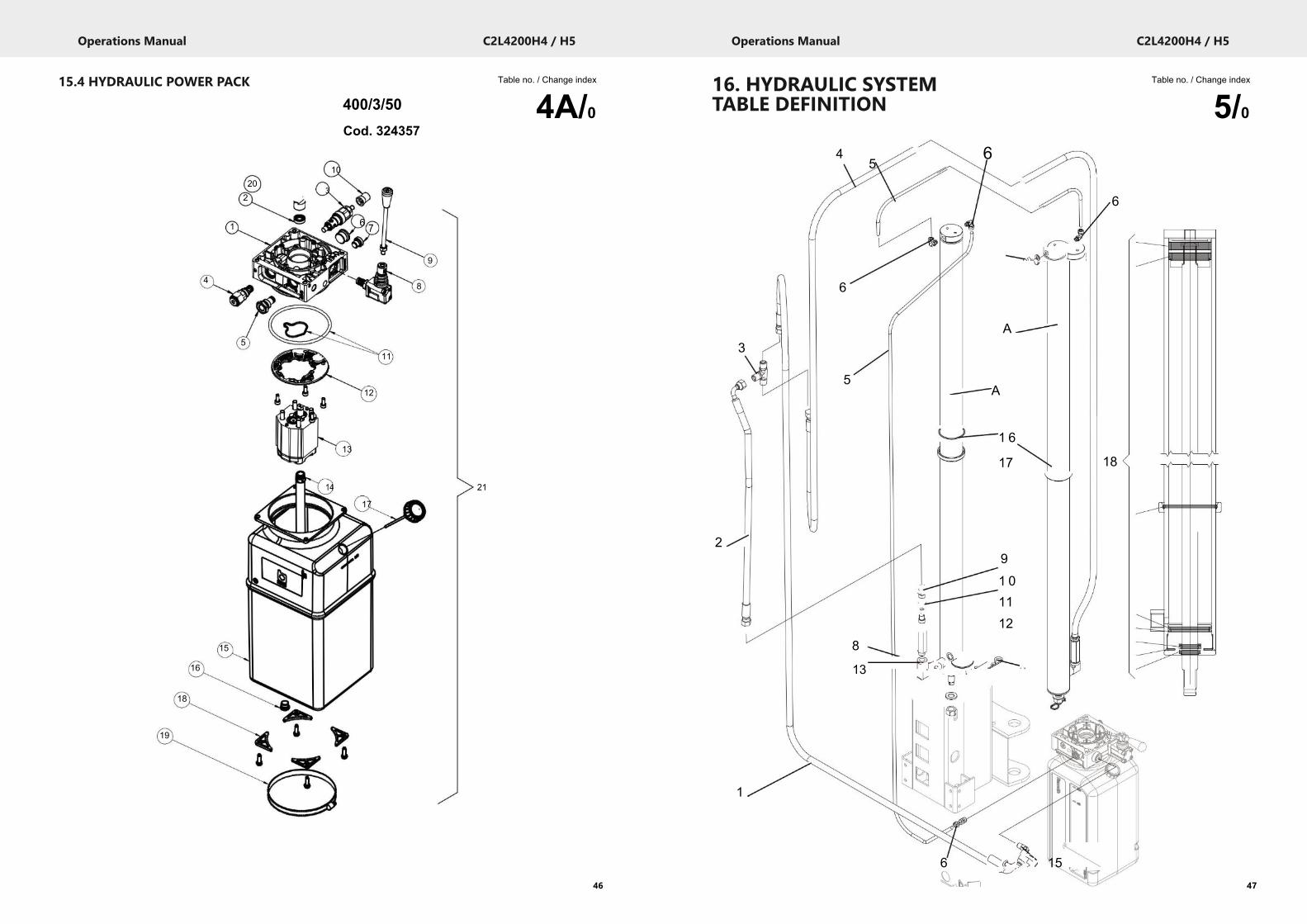
5/016. HYDRAULIC SYSTEMTABLE DEFINITION
47
Operations Manual C2L4200H4 / H5
Table no. / Change index
4A/015.4 HYDRAULIC POWER PACK
46
202
1
4
5
15
16
18
19
10
3
6 7
9
8
11
12
13
14 21
17
400/3/50Cod. 324357
3
2
1
4
6
5
8
13
56
7
A
A
1 6
17
91 01112
14
6 15
6
18
Operations Manual C2L4200H4 / H5
Table no. / Change index
7/0TABLE DEFINITION
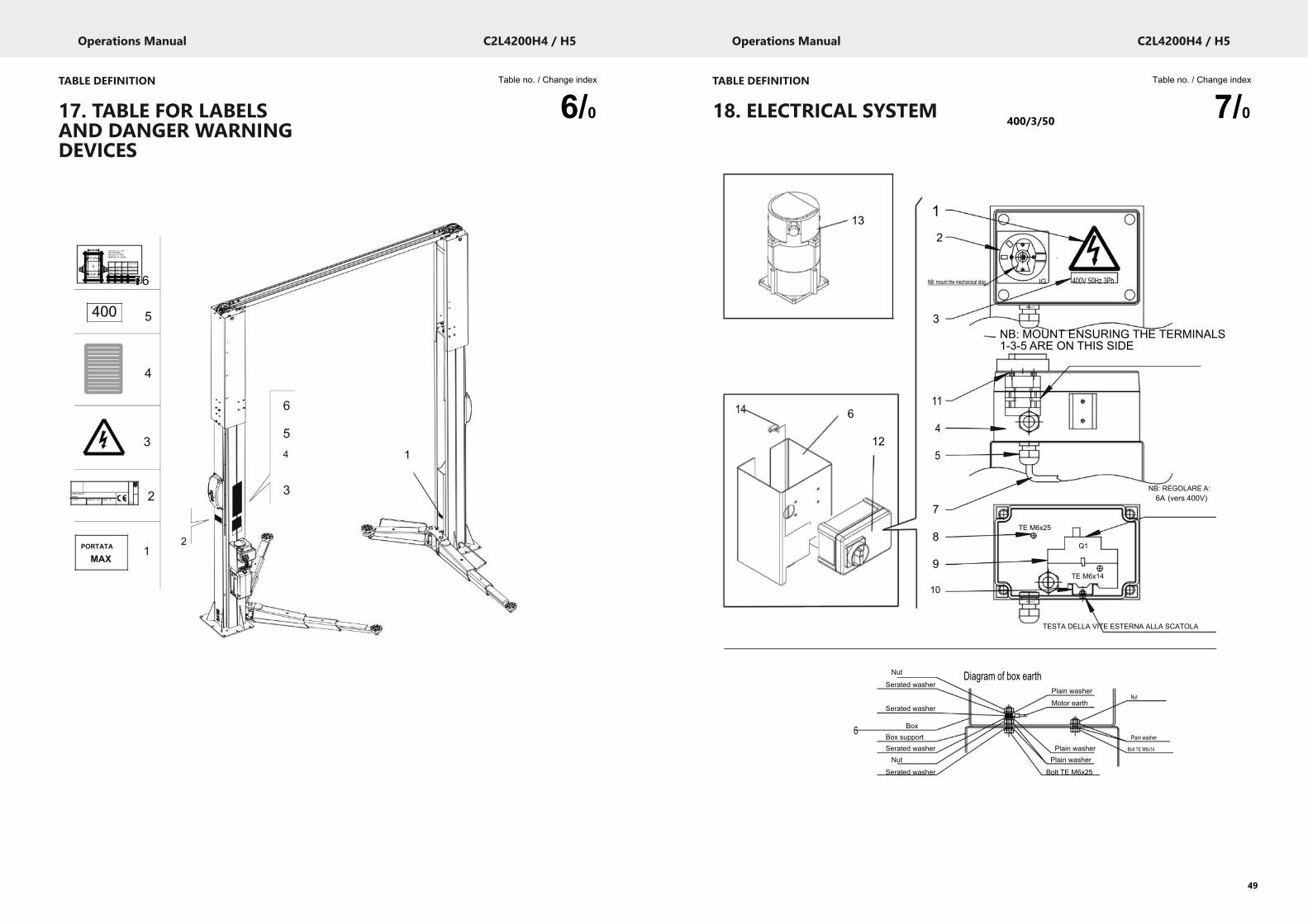
18. ELECTRICAL SYSTEM
49
Operations Manual C2L4200H4 / H5
Table no. / Change index
6/0TABLE DEFINITION
17. TABLE FOR LABELSAND DANGER WARNINGDEVICES
48
C RIPARTIZ IONE DEL CARICOLOAD DISTRIBUT IONGEW ICHT VERTEILUNGREPARTITION DE CHARGE
P1(P2) REPARTICION DE LACARGA
C P1 P2
Q mm kg kg710 1830 920
P2(P1) 800 2100 1050
900 2400 1200
1000 2800 1400
400
VEICHLESLIFTMODELY E A R CAPACITY KG. SERIAL N°
Q=P1+P2kg
2 7 5 0
3 1 5 0
3 6 0 0
4200
YE
AR
SERIAL
N°
MODEL
VEICHLE
SLIFT
6
5
4
3
2
6
54 1
3
PORTATA
MAX1
2
131
2
0
NB: mount the mechanical stop IG 400V 50Hz 3Ph
M20x1.5
3NB: MOUNT ENSURING THE TERMINALS1-3-5 ARE ON THIS SIDE
14 611
124
M20x1.5
5
7
8
9
10
NB: REGOLARE A:6A (vers.400V)
TE M6x25
Q1
TE M6x14
M20x1.5
TESTA DELLA VITE ESTERNA ALLA SCATOLA
Nut Diagram of box earthSerated washer
Plain washerNut
Motor earthSerated washer
6 BoxBox support Plain washer
Serated washer Plain washer Bolt TE M6x14
Nut Plain washer
Serated washer Bolt TE M6x25
400/3/50
Operations Manual C2L4200H4 / H5
51
Operations Manual C2L4200H4 / H5
50
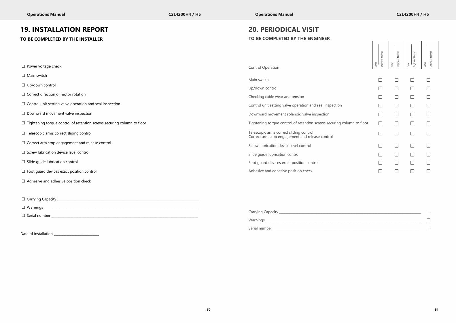
19. INSTALLATION REPORTTO BE COMPLETED BY THE INSTALLER
□ Power voltage check
□ Main switch
□ Up/down control
□ Correct direction of motor rotation
□ Control unit setting valve operation and seal inspection
□ Downward movement valve inspection
□ Tightening torque control of retention screws securing column to floor
□ Telescopic arms correct sliding control
□ Correct arm stop engagement and release control
□ Screw lubrication device level control
□ Slide guide lubrication control
□ Foot guard devices exact position control
□ Adhesive and adhesive position check
□ Carrying Capacity __________________________________________________________________________________________
□ Warnings _______________________________________________________________________________________________________________
□ Serial number ____________________________________________________________________________________________
Data of installation ____________________________
20. PERIODICAL VISITTO BE COMPLETED BY THE ENGINEER
Control Operation
Main switch
Up/down control
Checking cable wear and tension
Control unit setting valve operation and seal inspection
Downward movement solenoid valve inspection
Tightening torque control of retention screws securing column to floor
Telescopic arms correct sliding controlCorrect arm stop engagement and release control
Screw lubrication device level control
Slide guide lubrication control
Foot guard devices exact position control
Adhesive and adhesive position check
Carrying Capacity _________________________________________________________________________________________
Warnings ________________________________________________________________________________________________
Serial number ____________________________________________________________________________________________
Date:
Engine
erNam
e:
Date:
Engine
erNam
e:
Date:
Engine
erNam
e:
Date:
Engine
erNam
e:
Operations Manual C2L4200H4 / H5
53
Operations Manual C2L4200H4 / H5
52
21. UNSCHEDULED MAINTENANCE & REPAIRING
_____________________________________________________________________________________________________________________________________________________________________________________________________________________________________________________________________________________________________________________________________________________________________________________________________________________________________________________________________________________________________________________________________________________________________________________________________________________________________________________________________________________________________________________________________________________________________________________________________________________________________________________________________________________________________________________________________________________________________________________________________________________________________________________________________________________________________________________________________________________________________________________________________________________________________________________________________________________________________________________________________________________________________________________________________________________
22. AFTER SALESSERVICEApart from the routine maintenance andadjustments stipulated in this manual theequipment must not be tampered with in any way.
All further servicing must be carried out only by anengineer from an Authorised Agent. Failure toobserve these conditions will invalidate theGuarantee.
On-Site Service /Overhaul /Spare PartsIf you require a Service Engineer to attend ON SITE,either due to an equipment fault, or for machinecalibration, or if the equipment covered by thismanual requires to be sent back for factoryoverhaul, or if you need spare parts, please contactour Product Support Department.
■ Outside UK mainlandService for export customers are provided by theagent from whom your equipment was purchased.
■ UK After-Sales ServiceCall Crypton Support for details of local serviceagents.
■ Technical Information
Crypton also provide information and contractscovering:■ Car Data, Fault Code Information, DiagnosticInformation, Software Support Contracts,Software Updates & Accessories.
23. CONTACT DETAILS■ Sales
Tel: 0121 725 1400Email: [email protected]
■ Support
Tel: 0121 725 1366Email: [email protected]
Continental Automotive Trading UK Ltd36 Gravelly Industrial ParkBirmingham B24 8TA United Kingdomwww.cryptontechnology.com
Crypton - A Brand of the Continental Corporation
E & O E. The Company reserves the right tointroduce improvements in design or specificationwithout prior notice.
The sale of this product is subject to our standardterms, conditions and relevant product warranty.

Operations Manual C2L4200H4 / H5
54
Continental Automotive Trading UK Ltd, 36 Gravelly Industrial Park, B24 8TATel: 0121 725 1366 | Email: [email protected] | Web: www.cryptontechnology.comCrypton - A Brand of the Continental Corporation
E & O E. The Company reserves the right to introduceimprovements in design or specification without prior notice.
The sale of this product is subject to our standard terms,conditions and relevant product warranty.