advanced combat helmet (ach) nsn: 8470-01-529 ... - CIE Hub
176
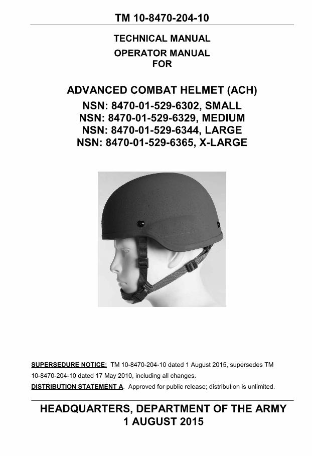
TM 10-8470-204-10 TECHNICAL MANUAL OPERATOR MANUAL FOR ADVANCED COMBAT HELMET (ACH) NSN: 8470-01-529-6302, SMALL NSN: 8470-01-529-6329, MEDIUM NSN: 8470-01-529-6344, LARGE NSN: 8470-01-529-6365, X-LARGE SUPERSEDURE NOTICE: TM 10-8470-204-10 dated 1 August 2015, supersedes TM 10-8470-204-10 dated 17 May 2010, including all changes. DISTRIBUTION STATEMENT A. Approved for public release; distribution is unlimited. HEADQUARTERS, DEPARTMENT OF THE ARMY 1 AUGUST 2015
-
Upload
khangminh22 -
Category
Documents
-
view
0 -
download
0
Transcript of advanced combat helmet (ach) nsn: 8470-01-529 ... - CIE Hub
TM 10-8470-204-10
TECHNICAL MANUAL OPERATOR MANUAL
FOR
ADVANCED COMBAT HELMET (ACH) NSN: 8470-01-529-6302, SMALL
NSN: 8470-01-529-6329, MEDIUM NSN: 8470-01-529-6344, LARGE
NSN: 8470-01-529-6365, X-LARGE
SUPERSEDURE NOTICE: TM 10-8470-204-10 dated 1 August 2015, supersedes TM
10-8470-204-10 dated 17 May 2010, including all changes.
DISTRIBUTION STATEMENT A. Approved for public release; distribution is unlimited.
HEADQUARTERS, DEPARTMENT OF THE ARMY 1 AUGUST 2015

TM 10-8470-204-10
a
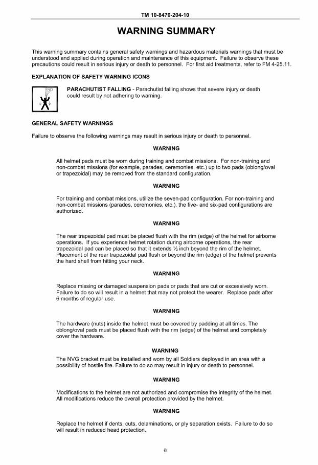
WARNING SUMMARY
This warning summary contains general safety warnings and hazardous materials warnings that must be understood and applied during operation and maintenance of this equipment. Failure to observe these precautions could result in serious injury or death to personnel. For first aid treatments, refer to FM 4-25.11.
EXPLANATION OF SAFETY WARNING ICONS
PARACHUTIST FALLING - Parachutist falling shows that severe injury or death could result by not adhering to warning.
GENERAL SAFETY WARNINGS
Failure to observe the following warnings may result in serious injury or death to personnel.
WARNING
All helmet pads must be worn during training and combat missions. For non-training and non-combat missions (for example, parades, ceremonies, etc.) up to two pads (oblong/oval or trapezoidal) may be removed from the standard configuration.
WARNING
For training and combat missions, utilize the seven-pad configuration. For non-training and non-combat missions (parades, ceremonies, etc.), the five- and six-pad configurations are authorized.
WARNING
The rear trapezoidal pad must be placed flush with the rim (edge) of the helmet for airborne operations. If you experience helmet rotation during airborne operations, the rear trapezoidal pad can be placed so that it extends ½ inch beyond the rim of the helmet. Placement of the rear trapezoidal pad flush or beyond the rim (edge) of the helmet prevents the hard shell from hitting your neck.
WARNING
Replace missing or damaged suspension pads or pads that are cut or excessively worn. Failure to do so will result in a helmet that may not protect the wearer. Replace pads after 6 months of regular use.
WARNING
The hardware (nuts) inside the helmet must be covered by padding at all times. The oblong/oval pads must be placed flush with the rim (edge) of the helmet and completely cover the hardware.
WARNING The NVG bracket must be installed and worn by all Soldiers deployed in an area with a possibility of hostile fire. Failure to do so may result in injury or death to personnel.
WARNING
Modifications to the helmet are not authorized and compromise the integrity of the helmet. All modifications reduce the overall protection provided by the helmet.
WARNING
Replace the helmet if dents, cuts, delaminations, or ply separation exists. Failure to do so will result in reduced head protection.

TM 10-8470-204-10
b
WARNING
Replace the helmet if edge beading is missing or loose. Missing or loose edge beading may expose rough helmet edges.
WARNING
When donning the helmet for the first time in a cold environment, wear the helmet for a few minutes or warm the pads, for example by placing in pockets, so that the pads will conform to the shape of your head. As the pads warm up and conform to the shape of your head, it may be necessary to retighten the chinstrap retention system.
WARNING
Your helmet must fit properly in order to adequately protect you. If you experience fit problems, excessive tightness or looseness, or helmet profile is too high or too low, refer to Evaluate and Adjust Helmet Fit guidelines.
WARNING
If you do not don and adjust the helmet properly as described in WP 0006 through 0008, the helmet may become tilted on your head and the chin cup may become uncentered.
WARNING
Always wear the helmet with the retention system properly fastened and adjusted. Failure to secure the retention system will decrease helmet stability.
WARNING
Replace the chinstrap retention assembly if the webbing is torn or frayed, if the buckles are broken or damaged, or if the hook and loop fasteners do not secure. Replace missing hardware and tighten loose hardware.
WARNING
Ensure that the screws do not protrude through the nuts when installed.
WARNING
Use only the hardware screws and nuts authorized in this manual.

TM 10-8470-204-10
A/blank
LIST OF EFFECTIVE PAGES NOTE: This manual supersedes TM 10-8470-204-10 dated 17 May 2010. Zero in “Change No.” column indicates an original page or work package.
Date of issue for the revised manual is:
Original 1 August 2015
TOTAL NUMBER OF PAGES FOR FRONT AND REAR MATTER IS 20 AND TOTAL NUMBER OF WORK PACKAGES IS 29, CONSISTING OF THE FOLLOWING:
Page/WP No. Change No. Front Cover 0 Warning Summary (2 pgs) 0 i-iv (4 pages) 0 Chapter 1 title page 0 Blank 0 WP 0001 (2 pgs) 0 WP 0002 (14 pgs) 0 WP 0003 (2 pgs) 0 Chapter 2 title page 0 Blank 0 WP 0004 (4 pgs) 0 WP 0005 (4 pgs) 0 WP 0006 (4 pgs) 0 WP 0007 (6 pgs) 0 WP 0008 (6 pgs) 0 WP 0009 (2 pgs) 0 Chapter 3 title page 0 Blank 0 WP 0010 (2 pgs) 0 Chapter 4 title page 0 Blank 0 WP 0011 (2 pgs) 0
Page/WP No. Change No. WP 0012 (32 pgs) 0 WP 0013 (6 pgs) 0 WP 0014 (4 pgs) 0 WP 0015 (4 pgs) 0 WP 0016 (4 pgs) 0 WP 0017 (6 pgs) 0 WP 0018 (2 pgs) 0 WP 0019 (6 pgs) 0 WP 0020 (4 pgs) 0 WP 0021 (2 pgs) 0 WP 0022 (2 pgs) 0 WP 0023 (4 pgs) 0 Chapter 5 title page 0 Blank WP 0024 (2 pgs) 0 WP 0025 (6 pgs) 0 WP 0026 (2 pgs) 0 WP 0027 (4 pgs) 0 WP 0028 (2 pgs) 0 WP 0029 (2 pgs) 0 Inside back cover 0 Back cover 0

TM 10-8470-204-10
i
HEADQUARTERS DEPARTMENT OF THE ARMY
WASHINGTON, D.C., 1 AUGUST 2015
TECHNICAL MANUAL
OPERATOR MANUAL FOR
ADVANCED COMBAT HELMET (ACH) NSN: 8470-01-529-6302, SMALL
NSN: 8470-01-529-6329, MEDIUM NSN: 8470-01-529-6344, LARGE
NSN: 8470-01-529-6365, X-LARGE
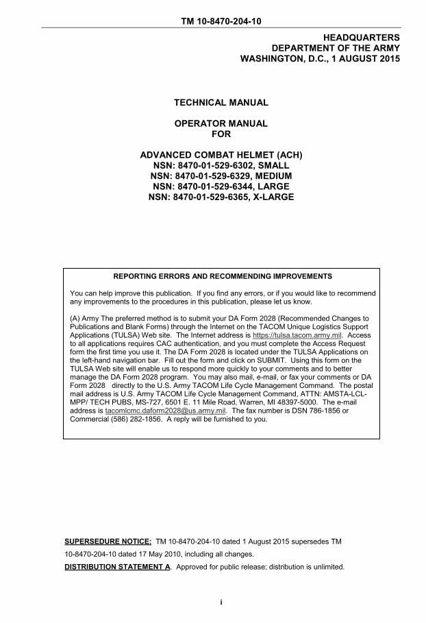
SUPERSEDURE NOTICE: TM 10-8470-204-10 dated 1 August 2015 supersedes TM
10-8470-204-10 dated 17 May 2010, including all changes.
DISTRIBUTION STATEMENT A. Approved for public release; distribution is unlimited.
REPORTING ERRORS AND RECOMMENDING IMPROVEMENTS
You can help improve this publication. If you find any errors, or if you would like to recommend any improvements to the procedures in this publication, please let us know.
(A) Army The preferred method is to submit your DA Form 2028 (Recommended Changes to Publications and Blank Forms) through the Internet on the TACOM Unique Logistics Support Applications (TULSA) Web site. The Internet address is https://tulsa.tacom.army.mil. Access to all applications requires CAC authentication, and you must complete the Access Request form the first time you use it. The DA Form 2028 is located under the TULSA Applications on the left-hand navigation bar. Fill out the form and click on SUBMIT. Using this form on the TULSA Web site will enable us to respond more quickly to your comments and to better manage the DA Form 2028 program. You may also mail, e-mail, or fax your comments or DA Form 2028 directly to the U.S. Army TACOM Life Cycle Management Command. The postal mail address is U.S. Army TACOM Life Cycle Management Command, ATTN: AMSTA-LCL-MPP/ TECH PUBS, MS-727, 6501 E. 11 Mile Road, Warren, MI 48397-5000. The e-mail address is [email protected]. The fax number is DSN 786-1856 or Commercial (586) 282-1856. A reply will be furnished to you.
TM 10-8470-204-10
ii
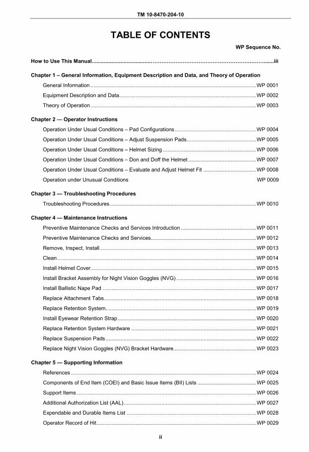
TABLE OF CONTENTS WP Sequence No.
How to Use This Manual ........................................ ……………………………………………………….......iii
Chapter 1 – General Information, Equipment Description and Data, and Theory of Operation
General Information .............................................................................................................. WP 0001
Equipment Description and Data ........................................................................................... WP 0002
Theory of Operation .............................................................................................................. WP 0003
Chapter 2 — Operator Instructions
Operation Under Usual Conditions – Pad Configurations ...................................................... WP 0004
Operation Under Usual Conditions – Adjust Suspension Pads .............................................. WP 0005
Operation Under Usual Conditions – Helmet Sizing .............................................................. WP 0006
Operation Under Usual Conditions – Don and Doff the Helmet ............................................. WP 0007
Operation Under Usual Conditions – Evaluate and Adjust Helmet Fit ................................... WP 0008
Operation under Unusual Conditions WP 0009
Chapter 3 — Troubleshooting Procedures
Troubleshooting Procedures ................................................................................................. WP 0010
Chapter 4 — Maintenance Instructions
Preventive Maintenance Checks and Services Introduction .................................................. WP 0011
Preventive Maintenance Checks and Services...................................................................... WP 0012
Remove, Inspect, Install ........................................................................................................ WP 0013
Clean .................................................................................................................................... WP 0014
Install Helmet Cover.............................................................................................................. WP 0015
Install Bracket Assembly for Night Vision Goggles (NVG) ..................................................... WP 0016
Install Ballistic Nape Pad ...................................................................................................... WP 0017
Replace Attachment Tabs ..................................................................................................... WP 0018
Replace Retention System .................................................................................................... WP 0019
Install Eyewear Retention Strap ............................................................................................ WP 0020
Replace Retention System Hardware ................................................................................... WP 0021
Replace Suspension Pads .................................................................................................... WP 0022
Replace Night Vision Goggles (NVG) Bracket Hardware....................................................... WP 0023
Chapter 5 — Supporting Information
References ........................................................................................................................... WP 0024
Components of End Item (COEI) and Basic Issue Items (BII) Lists ....................................... WP 0025
Support Items ....................................................................................................................... WP 0026
Additional Authorization List (AAL) ........................................................................................ WP 0027
Expendable and Durable Items List ...................................................................................... WP 0028
Operator Record of Hit .......................................................................................................... WP 0029
TM 10-8470-204-10
iii
HOW TO USE THIS MANUAL HOW TO OBTAIN TECHNICAL MANUALS
When a new system is introduced to the Army inventory, it is the responsibility of the receiving units to notify and inform the Unit Publications Clerk that a technical manual is available for the new system. Throughout the life cycle of the new system, the Distribution Center DOL-W will also provide updates and changes to the technical manual.
To receive new technical manuals or change packages to existing technical manuals (TM) for fielded equipment, provide the Unit Publications Clerk the full technical manual number, title, date of publication, and number of copies required. The Unit Publications Clerk will justify the request through the Unit Publications Officer. When the request is approved, the Unit Publications Clerk will use DA Form 12-R to order the series of technical manuals from the Army Publishing Directorate (APD).
Instructions for Unit Publications Clerk
Obtain DA Form 12-R and request a publications account from the APD Web site at http://www.apd.army.mil. Once on the Website, click on the “Orders/Subscriptions/Reports” tab. From the dropdown menu, select “Establish an Account,” then select “Tutorial” and follow the instructions in the tutorial presentation.
Complete information for obtaining Army publications can be found in DA PAM 25-33.
OVERVIEW
This manual contains operating instructions and maintenance procedures for the Advanced Combat Helmet (ACH). Primary chapters appear in upper case/capital letters; work packages are presented in numeric sequence, e.g., 0001, 0002; paragraphs within a work package are not numbered and are presented in a titled format. For a first level paragraph, titles are in all upper case/capital letters, e.g. Manual Organization and Page Numbering System. The location of additional material that must be referenced is clearly marked. Illustrations supporting maintenance procedures/text are located underneath, or as close to their referenced paragraph as possible.
This manual is divided into the following major sections:
Front Matter. Front matter consists of front cover, warning summary, title block, table of contents, and a how to use this manual page.
Chapter 1 - General Information, Equipment Description, and Theory of Operation. Contains descriptions, equipment data, and theory of operation information.
Chapter 2 – Operator Instructions. Contains sizing information, donning information, and operating instructions in both usual and unusual conditions.
Chapter 3 - Troubleshooting Procedures. Contains troubleshooting procedures for the ACH.
Chapter 4 – Maintenance Instructions. Contains instructions on hardware replacement, pad suspension replacement, cleaning, and PMCS.
Chapter 5 –Supporting Information. Contains reference information, Components of End Items (COEI)/Basic Issue Items (BII) Lists, Support Items, Additional Authorization List, Expendable and Durable Items List, and an Operator Record of Hit form.

TM 10-8470-204-10
iv
NAVIGATION
This TM is in work package format. All of the work packages contained within the TM are listed in the table of contents in the order they appear by chapters. The work package sequence number (e.g. WP 0001) is listed for each work package in the table of contents. The work package sequence number is at the top of each page of the work package and is also a part of the page number for each work package (e.g., 0001-1). The page numbers appear at the bottom of each page.
OPERATION AND MAINTENANCE
Before you use your helmet familiarize yourself with the assembly and fitting instructions and the operating instructions. Perform maintenance procedures on a regular basis. Always follow the WARNINGS and CAUTIONS.

TM 10-8470-204-10
CHAPTER 1
GENERAL INFORMATION, EQUIPMENT DESCRIPTION AND DATA
AND THEORY OF OPERATION
FOR
ADVANCED COMBAT HELMET (ACH)

TM 10-8470-204-10 0001 OPERATOR MAINTENANCE GENERAL INFORMATION
0001-1
SCOPE
This manual covers the basic fitting and use instructions for the Advanced Combat Helmet (ACH).
MAINTENANCE FORMS, RECORDS, AND REPORTS
Department of the Army forms and procedures used for equipment maintenance will be those prescribed by (as applicable) DA PAM 750-8, The Army Maintenance Management System (TAMMS) Users Manual; DA PAM 738-751, Functional Users Manual for the Army Maintenance Management Systems - Aviation (TAMMS-A); or AR 700-138, Army Logistics Readiness and Sustainability.
REPORTING EQUIPMENT IMPROVEMENT RECOMMENDATIONS (EIR)
If your ACH needs improvement, let us know. Send us an EIR. You, the user, are the only one who can tell us what you do not like about your equipment. Let us know why you do not like the design or performance.
ALL non-Aviation/Missile Warranty, EIR and PQDRs must be submitted through the Product Data Reporting and Evaluation Program (PDREP) Web site. The PDREP site is: https://www.pdrep.csd.disa.mil/.
If you do not have internet access, you may submit your information using an SF 368 (Product Quality Deficiency Report). You can send your SF 368 using e-mail, regular mail, or fax using the addresses/fax numbers specified in DA PAM 750-8, The Army Maintenance Management System (TAMMS) Users Manual. We will send you a reply.
CORROSION PREVENTION AND CONTROL (CPC)
Corrosion Prevention and Control (CPC) of Army and Marine materiel is a continuing concern. It is important that any corrosion problems with this item be reported so that the problem can be corrected and improvements can be made to prevent the problem in future items.
Corrosion specifically occurs with metals. An electrochemical process causes the degradation of metals. It is commonly caused by exposure to moisture, acids, bases, or salts. An example is the rusting of iron. Corrosion damage in metals can be seen, depending on the metal, as tarnishing, pitting, fogging, surface residue, and/or cracking. Plastics, composites, and rubbers can also degrade. Degradation is caused by thermal (heat), oxidation (oxygen), solvation (solvents), or photolytic (light, typically UV) processes.
The most common exposures are excessive heat or light. Damage from these processes will appear as cracking, softening, swelling, and/or breaking. SF Form 368, Product Quality Deficiency Report, should be submitted to the address specified in DA PAM 750-8, The Army Maintenance Management System (TAMMS) Users Manual.
DESTRUCTION OF ARMY MATERIEL TO PREVENT ENEMY USE
Not applicable to the ACH.
TM 10-8470-204-10 0001
0001-2
PREPARATION FOR STORAGE OR SHIPMENT
To prepare the ACH for shipment or storage, tag it and place it in its original container or a suitable box.
NOMENCLATURE CROSS REFERENCE LIST
Common Name Official Nomenclature Chinstrap Retention System Chinstrap Chinstrap Retention Assembly Pads Suspension System
LIST OF ABBREVIATIONS/ACRONYMS
Definition Abbreviation/Acronym Additional Authorization List AAL Advanced Combat Helmet ACH
Army (A) Army Regulation AR Basic Issue Item BII Bottle BT Central Issue Facility CIF Chemical, Biological, Radiological and Nuclear CBRN Commercial and Government Entity Code CAGEC Common Table of Allowances CTA Components of End Item COEI Corrosion Prevention Control CPC
Department of the Army DA Department of the Army Pamphlet DA PAM Each EA Equipment Improvement Report EIR
Field Manual FM In Accordance With IAW Joint Table of Allowances JTA (Modified) Table of Organization and Equipment (M)TOE Nape Protection Pad NAPP National Stock Number NSN
Night Observation Device* NOD Night Vision Device* NVD
Night Vision Goggles* NVG Number No. Operation Enduring Freedom (OEF) Camouflage Pattern OCP Package PG Personnel Armor System for Ground Troops PASGT Preventive Maintenance Checks and Services PMCSProduct Quality Deficiency Report(ing) PQDR Quantity QTY Standard Operating Procedure SOP Tables of Distribution and Allowances TDA TACOM Unique Logistics Support Application TULSA The Army Maintenance Management System (-Aviation) TAMMS (-A) Ultra-High Molecular Weight Polyethylene UHMWPE Ultraviolet UV Unit of Issue U/I Universal Camouflage Pattern UCP
*The three acronyms, NVD, NVG, and NOD, refer to the mounting bracket assembly component, and theseacronyms may be used interchangeably.
END OF WORK PACKAGE

TM 10-8470-204-10 0002 OPERATOR MAINTENANCE
EQUIPMENT DESCRIPTION AND DATA
0002-1
EQUIPMENT CHARACTERISTICS, CAPABILITIES AND FEATURES
This work package provides equipment descriptions and data for the Advanced Combat Helmet (ACH).
This helmet system provides ballistic and impact protection within the full spectrum of operational environments. These systems are compatible with the current night vision devices (NVDs), communications packages, and Chemical, Biological, Radiological and Nuclear (CBRN) defense equipment and body armor.
The ACH is designed to allow maximum sensory and situational awareness for the operator. The shell cut provides an unobstructed field of view and increased ambient hearing capabilities.
Each helmet system consists of a shell, a suspension system (pads), a retention system (chinstrap), and may include other accessories such as helmet cover and night vision goggle (NVG) mounting bracket. Additionally, an optional ballistic nape pad and eyewear retention straps are available. The optional ballistic nape pad is available for increased stability and protection against fragments from ground-level threats.
The retention systems and pad suspension system provide unsurpassed balance, stability and comfort as well as impact protection throughout all operational scenarios, including static-line airborne operations.

TM 10-8470-204-10 0002
0002-2
LOCATION AND DESCRIPTION OF MAJOR COMPONENTS
This section provides illustrations and descriptions of the helmets. Figure 1 shows the major components of an ACH with the H-Back Chinstrap Retention System. Figure 2 illustrates the ACH with an Improved H-Nape Chinstrap Retention System. Figure 3 shows the X-Back Retention System.
Figure 1. ACH with Universal H-Back Chinstrap Retention System.
Figure 2. ACH with Improved H-Nape Chinstrap Retention System.
INTEGRATED NAPE PAD
SLIDE BUCKLE
NIGHT VISION DEVICE BRACKET
HELMET COVER
HELMET SHELL
RETENTION SYSTEM
REMOVABLE NAPE PAD
SUSPENSION PADS
EYEWEAR RETENTION STRAP
RETENTION SYSTEM
SUSPENSION PADS
HELMET SHELL
TM 10-8470-204-10 0002
0002-3
LOCATION AND DESCRIPTION OF MAJOR COMPONENTS – CONTINUED
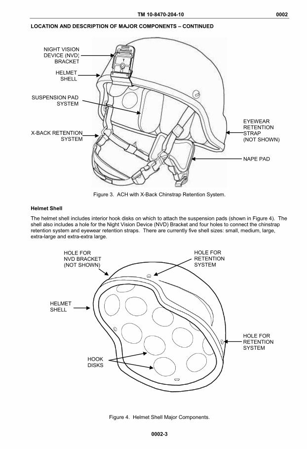
Figure 3. ACH with X-Back Chinstrap Retention System.
Helmet Shell
The helmet shell includes interior hook disks on which to attach the suspension pads (shown in Figure 4). The shell also includes a hole for the Night Vision Device (NVD) Bracket and four holes to connect the chinstrap retention system and eyewear retention straps. There are currently five shell sizes: small, medium, large, extra-large and extra-extra large.
Figure 4. Helmet Shell Major Components.
X-BACK RETENTION SYSTEM
HELMET SHELL
NIGHT VISION DEVICE (NVD)
BRACKET
SUSPENSION PAD SYSTEM
NAPE PAD
EYEWEAR RETENTION STRAP (NOT SHOWN)
HELMET SHELL
HOLE FOR RETENTION SYSTEM
HOLE FOR RETENTION SYSTEM
HOOK DISKS
HOLE FOR NVD BRACKET (NOT SHOWN)
TM 10-8470-204-10 0002
0002-4
Suspension Pad System
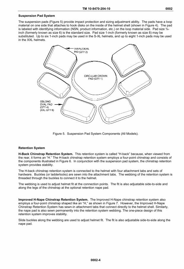
The suspension pads (Figure 5) provide impact protection and sizing adjustment ability. The pads have a loop material on one side that attaches to hook disks on the inside of the helmet shell (shown in Figure 4). The pad is labeled with identifying information (NSN, product information, etc.) on the loop material side. Pad size ¾-inch (formerly known as size 6) is the standard size. Pad size 1-inch (formerly known as size 8) may be substituted. Up to six 1-inch pads may be used in the S-XL helmets, and up to eight 1-inch pads may be used in the XXL helmets.
Figure 5. Suspension Pad System Components (All Models).
Retention System
H-Back Chinstrap Retention System. This retention system is called “H-back” because, when viewed from the rear, it forms an “H.” The H-back chinstrap retention system employs a four-point chinstrap and consists of the components illustrated in Figure 6. In conjunction with the suspension pad system, the chinstrap retention system provides stability.
The H-back chinstrap retention system is connected to the helmet with four attachment tabs and sets of hardware. Buckles (or ladderlocks) are sewn into the attachment tabs. The webbing of the retention system is threaded through the buckles to connect it to the helmet.
The webbing is used to adjust helmet fit at the connection points. The fit is also adjustable side-to-side and along the legs of the chinstrap at the optional retention nape pad.
Improved H-Nape Chinstrap Retention System. The Improved H-Nape chinstrap retention system also employs a four-point chinstrap shaped like an “H,” as shown in Figure 7. However, the Improved H-Nape Chinstrap Retention System has sewn-in attachment tabs that connect directly to the helmet shell. Similarly, the nape pad is also sewn permanently into the retention system webbing. The one-piece design of this retention system improves stability.
Slide buckles along the webbing are used to adjust helmet fit. The fit is also adjustable side-to-side along the nape pad.

TM 10-8470-204-10 0002
0002-5
LOCATION AND DESCRIPTION OF MAJOR COMPONENTS – CONTINUED
Figure 6. Universal H-Back Chinstrap Retention Systems Major Components.
Figure 7. Improved H-Nape Chinstrap Retention Systems Major Components.
RETENTION SYSTEM NAPE PAD (REMOVABLE)
RETENTION SYSTEM NAPE PAD (SEWN IN)
ADJUSTMENT STRAP
HARDWARE

TM 10-8470-204-10 0002
0002-6
LOCATION AND DESCRIPTION OF MAJOR COMPONENTS – CONTINUED
X-Back Chinstrap Retention System. The X- back chinstrap retention system (shown in Figure 8) uses a four-point design, but when viewed from the rear, it forms an “X.” The X-back chinstrap retention system attaches directly to the shell using a screw and nut and does not use attachment tabs at the shell.
Adjustments for fit can be made along the two front retention straps and along the two side adjustment straps. The chinstrap is adjustable at the center section of the chinstrap, where the chin cup is located. The integrated rear nape pad is not adjustable.
Figure 8. X-Back Chinstrap Retention System Major Components.
Ballistic Nape Pad
The optional ballistic nape pad is located at the base of the neck. It is designed to protect against ground-level threats and provide protection against fragments, while adding stability to the helmet. It attaches to the chinstrap retention system as shown in Figures 9 -13.
Nape Pad on Universal H-Back Retention Systems. When the ballistic nape pad is used on the H-back chinstrap retention system, it replaces the retention system nape pad.
Figure 9. Ballistic Nape Pad Location on Universal H-Back Retention System.
RETENTION SYSTEM NAPE PAD
CHINSTRAP WITH ADJUSTABLE CHIN CUP
RETENTION SYSTEM HARDWARE
BALLISTIC NAPE PAD
TM 10-8470-204-10 0002
0002-7
LOCATION AND DESCRIPTION OF MAJOR COMPONENTS – CONTINUED
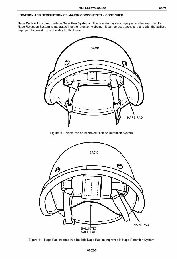
Nape Pad on Improved H-Nape Retention Systems. The retention system nape pad on the Improved H-Nape Retention System is integrated into the retention webbing. It can be used alone or along with the ballistic nape pad to provide extra stability for the helmet.
Figure 10. Nape Pad on Improved H-Nape Retention System.
Figure 11. Nape Pad Inserted into Ballistic Nape Pad on Improved H-Nape Retention System.
BACK
NAPE PAD BALLISTIC NAPE PAD
NAPE PAD
BACK
TM 10-8470-204-10 0002
0002-8
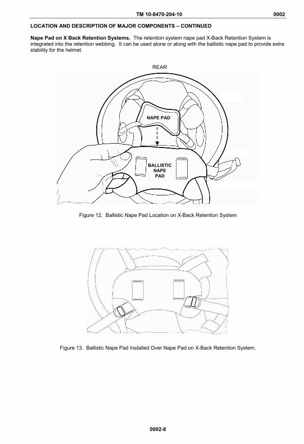
LOCATION AND DESCRIPTION OF MAJOR COMPONENTS – CONTINUED Nape Pad on X Back Retention Systems. The retention system nape pad X-Back Retention System is integrated into the retention webbing. It can be used alone or along with the ballistic nape pad to provide extra stability for the helmet.
Figure 12. Ballistic Nape Pad Location on X-Back Retention System
Figure 13. Ballistic Nape Pad Installed Over Nape Pad on X-Back Retention System.
REAR
NAPE PAD
BALLISTIC NAPE PAD
TM 10-8470-204-10 0002
0002-9
LOCATION AND DESCRIPTION OF MAJOR COMPONENTS – CONTINUED
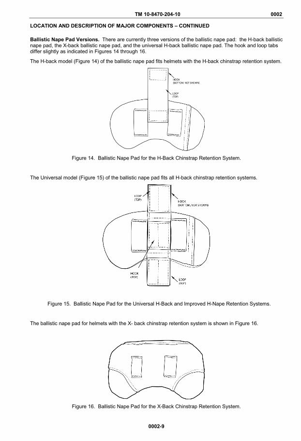
Ballistic Nape Pad Versions. There are currently three versions of the ballistic nape pad: the H-back ballistic nape pad, the X-back ballistic nape pad, and the universal H-back ballistic nape pad. The hook and loop tabs differ slightly as indicated in Figures 14 through 16.
The H-back model (Figure 14) of the ballistic nape pad fits helmets with the H-back chinstrap retention system.
Figure 14. Ballistic Nape Pad for the H-Back Chinstrap Retention System.
The Universal model (Figure 15) of the ballistic nape pad fits all H-back chinstrap retention systems.
Figure 15. Ballistic Nape Pad for the Universal H-Back and Improved H-Nape Retention Systems.
The ballistic nape pad for helmets with the X- back chinstrap retention system is shown in Figure 16.
Figure 16. Ballistic Nape Pad for the X-Back Chinstrap Retention System.
TM 10-8470-204-10 0002
0002-10
LOCATION AND DESCRIPTION OF MAJOR COMPONENTS – CONTINUED
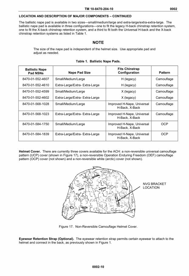
The ballistic nape pad is available in two sizes—small/medium/large and extra-large/extra-extra-large. The ballistic nape pad is available in three configurations—one to fit the legacy H-back chinstrap retention system, one to fit the X-back chinstrap retention system, and a third to fit both the Universal H-back and the X-back chinstrap retention systems as listed in Table 1.
NOTE The size of the nape pad is independent of the helmet size. Use appropriate pad and adjust as needed.
Table 1. Ballistic Nape Pads.
Ballistic Nape Pad NSNs Nape Pad Size
Fits Chinstrap Configuration Pattern
8470-01-552-4607 Small/Medium/Large H (legacy) Camouflage
8470-01-552-4610 Extra-Large/Extra- Extra-Large H (legacy) Camouflage
8470-01-552-4599 Small/Medium/Large X (legacy) Camouflage
8470-01-552-4602 Extra-Large/Extra- Extra-Large X (legacy) Camouflage
8470-01-568-1028 Small/Medium/Large Improved H-Nape, Universal H-Back, X-Back
Camouflage
8470-01-568-1023 Extra-Large/Extra- Extra-Large Improved H-Nape, Universal H-Back, X-Back
Camouflage
8470-01-584-1750 Small/Medium/Large Improved H-Nape, Universal H-Back, X-Back
OCP
8470-01-584-1839 Extra-Large/Extra- Extra-Large Improved H-Nape, Universal H-Back, X-Back
OCP
Helmet Cover. There are currently three covers available for the ACH: a non-reversible universal camouflage pattern (UCP) cover (shown in Figure 17), a non-reversible Operation Enduring Freedom (OEF) camouflage pattern (OCP) cover (not shown) and a non-reversible white (arctic) cover (not shown).
Figure 17. Non-Reversible Camouflage Helmet Cover.
Eyewear Retention Strap (Optional). The eyewear retention strap permits certain eyewear to attach to the helmet and connect in the back, as previously shown in Figure 1.
NVG BRACKET LOCATION
TM 10-8470-204-10 0002
0002-11
LOCATION AND DESCRIPTION OF MAJOR COMPONENTS – CONTINUED
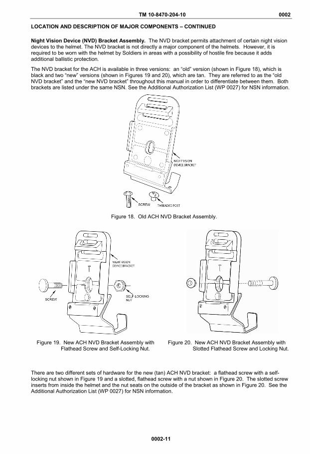
Night Vision Device (NVD) Bracket Assembly. The NVD bracket permits attachment of certain night vision devices to the helmet. The NVD bracket is not directly a major component of the helmets. However, it is required to be worn with the helmet by Soldiers in areas with a possibility of hostile fire because it adds additional ballistic protection.
The NVD bracket for the ACH is available in three versions: an “old” version (shown in Figure 18), which is black and two “new” versions (shown in Figures 19 and 20), which are tan. They are referred to as the “old NVD bracket” and the “new NVD bracket” throughout this manual in order to differentiate between them. Both brackets are listed under the same NSN. See the Additional Authorization List (WP 0027) for NSN information.
Figure 18. Old ACH NVD Bracket Assembly.
Figure 19. New ACH NVD Bracket Assembly with Flathead Screw and Self-Locking Nut.
Figure 20. New ACH NVD Bracket Assembly with Slotted Flathead Screw and Locking Nut.
There are two different sets of hardware for the new (tan) ACH NVD bracket: a flathead screw with a self-locking nut shown in Figure 19 and a slotted, flathead screw with a nut shown in Figure 20. The slotted screw inserts from inside the helmet and the nut seats on the outside of the bracket as shown in Figure 20. See the Additional Authorization List (WP 0027) for NSN information.
TM 10-8470-204-10 0002
0002-12
DIFFERENCES BETWEEN MODELS
Differences in Retention Systems
WARNING Although the shells may look virtually the same to the user, it is very important to distinguish between the various manufacturers and types of shells. The mounting hardware (screws) of the retention system must be the approved hardware for the specific helmet shell manufacturer to ensure ballistic integrity. Failure to use the appropriate mounting hardware, helmet, and retention system combination may result in reduced ballistic protection.
When replacing the chinstrap retention assembly, replace the mounting hardware (screws) as well. Hardware is not interchangeable. Failure to use the hardware associated with the specific retention system may result in injury or death.
The ACH has five different legacy retention systems. Four of the legacy retention systems are H-back and one is an X-back retention system. For sustainment/ replacement, the Army has approved two retention systems to work with all variants of the ACH: the universal H-back retention system (including hardware) and the improved H-Nape retention system (including hardware).
You may continue to use a helmet with a legacy retention system until it needs replacement. When SERVICING the helmet, be sure to retain and reinstall the original hardware for that retention system. If your legacy retention system is not serviceable, turn it in for replacement at Central Issue Facility (CIF) or in accordance with (IAW) Unit Standard Operating Procedure (SOP).
Differences in Night Vision Device (NVD) Bracket Assemblies
The NVD bracket is currently available in three versions for the ACH: an “old” version and two newer versions. They are referred to as the “old NVD bracket” and the “new NVD bracket” to differentiate between them. The size of the slot in the bracket, the hardware, and the color are different in the models.
The old version of the bracket (Figure 18) uses a flathead screw and threaded post and requires a flathead screwdriver for attachment to the helmet. It is black in color. The slot through which the screw and post are accepted is .17 inches.
The newer versions of the bracket are tan. The slot through which the screw and self-locking nut are accepted is slightly larger (.25 inches) than the old version. Two different sets of hardware come with these brackets:
• Some brackets use a flathead screw without a slot and a self-locking nut, as shown in Figure 19. Thescrew is inserted from the outside of the bracket to the inside of the helmet. The self-locking nut attachesto the screw inside the helmet.
• Other brackets use a slotted screw with a round locking nut, as shown in Figure 20. The screw insertsfrom inside the helmet to the outside of the bracket. The round nut seats on the outside of the bracket.

TM 10-8470-204-10 0002
0002-13/blank
EQUIPMENT DATA
Table 2 provides information pertaining to the mechanical data for all manufacturers’ models.
Table 2. Mechanical Data for the ACH (Maximum Values for All Models by Size).
Helmet Shell Size
Length* (inches)
Width* (inches)
Height* (inches)
Weight** (ounces)
Small 9.7 9.1 7.0 47
Medium 10.3 9.3 7.0 49
Large 10.5 9.5 7.0 53
X-Large 11.0 10.1 7.0 62
X-X-Large 11.7 10.7 7.0 64
*Dimensions (Length, Width, and Height) are overall exterior dimensions of the shell only. **Weight includes shell, retention system, and suspension system only; it does not include cover, NVD bracket, or eyewear retention system.
END OF WORK PACKAGE


TM 10-8470-204-10 0003 OPERATOR MAINTENANCE
THEORY OF OPERATION
0003-1/blank
The helmet is designed to provide the Soldier with ballistic and impact protection. They are compatible with night vision, communications, and Chemical, Biological, Radiological and Nuclear (CBRN) equipment.
The edge cut of the shell has been reduced when compared to the Personnel Armor System for Ground Troops (PASGT) helmet. This design enables better situational awareness through improved field of vision and hearing.
The shell provides ballistic protection. The pads act as a suspension system; they also enable the wearer to adjust the helmet’s fit. In conjunction with the shell, the suspension pad system provides impact protection.
The chinstrap retention system is a four point design, attaching to the shell at four locations. In conjunction with the pad suspension system, the chinstrap retention system provides improved stability.
END OF WORK PACKAGE


TM 10-8470-204-10
CHAPTER 2
OPERATOR INSTRUCTIONS
FOR
ADVANCED COMBAT HELMET (ACH)

TM 10-8470-204-10 0004 OPERATOR MAINTENANCE
OPERATION UNDER USUAL CONDITIONS – PAD CONFIGURATIONS
0004-1
INITIAL SETUP:
Tools and Special Tools None Required
References WP 0005
Materials/Parts None Required
PAD CONFIGURATIONS This work package provides instructions for different pad configurations.
WARNING All helmet pads must be worn for training and combat missions, and for high-risk operations such as airborne operations, air assault, and rappelling/ mountaineering. Helmet pads should cover internal hardware at all times, and is mandatory when wearing the helmet in high-risk operating environments. Failure to observe this warning may result in serious injury or death. Never remove the crown pad. Failure to observe this warning may result in serious injury or death to personnel. The hardware (nut) inside the helmet, where the retention system attachment tabs attach to the helmet (in four places), must be covered by pads. The oblong/oval pads must be placed flush with the rim (edge) of the helmet and completely cover the hardware. Failure to observe this warning may result in serious injury or death to personnel. Ensure that all helmet adjustment mechanisms are properly adjusted for a snug, secure fit at all times when the helmet is worn. Failure to do so may result in injury.
TM 10-8470-204-10 0004
0004-2
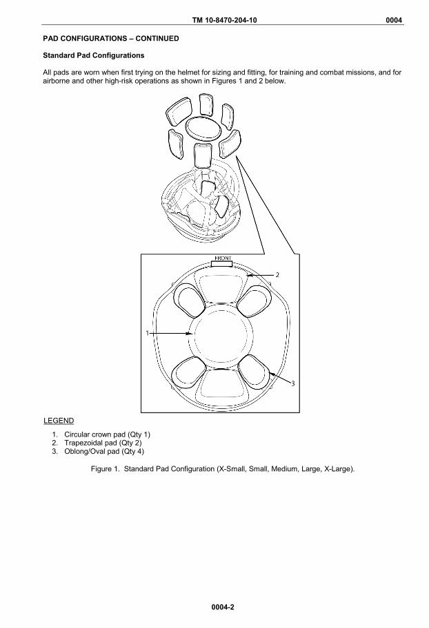
PAD CONFIGURATIONS – CONTINUED Standard Pad Configurations All pads are worn when first trying on the helmet for sizing and fitting, for training and combat missions, and for airborne and other high-risk operations as shown in Figures 1 and 2 below.
Figure 1. Standard Pad Configuration (X-Small, Small, Medium, Large, X-Large).
LEGEND
1. Circular crown pad (Qty 1) 2. Trapezoidal pad (Qty 2) 3. Oblong/Oval pad (Qty 4)

TM 10-8470-204-10 0004
0004-3
PAD CONFIGURATIONS – CONTINUED
Figure 2. Standard Pad Configuration (XX-Large).
LEGEND
1. Oblong/Oval pad (Qty 6) 2. Trapezoidal pad (Qty 2) 3. Circular crown pad (Qty 1)

TM 10-8470-204-10 0004
0004-4
PAD CONFIGURATIONS – CONTINUED Alternate Pad Configurations
WARNING
All helmet pads must be worn for training and combat missions, and for high-risk operations such as airborne operations, air assault, and rappelling/ mountaineering. Helmet pads should cover internal hardware at all times, and is mandatory when wearing the helmet in high-risk operating environments. Failure to observe this warning may result in serious injury or death.
Reduced (alternate) pad configurations are allowed only for non-training and non-combat missions to obtain a better fit or more comfort.
Up to two pads (oblong/oval or trapezoidal) can be removed from the standard configuration (Figures 1 and 2) in non-risk situations (i.e. non-training and non-combat missions) such as parades or ceremonies. The circular crown pad must always remain in the helmet. Pads can be placed in vertical or horizontal directions (as shown in WP 0005) or a combination or at an angle between horizontal and vertical (diagonal). Pads should be placed towards the inside edge of the helmet but may be adjusted to provide optimum comfort and stability. END OF WORK PACKAGE

TM 10-8470-204-10 0005 OPERATOR MAINTENANCE
OPERATION UNDER USUAL CONDITIONS – ADJUST SUSPENSION PADS
0005-1
INITIAL SETUP:
Tools and Special Tools None Required Materials/Parts None Required
References WP 0008 WP 0025 WP 0027
INTRODUCTION
This work package provides information about adjusting the pad suspension system. The suspension system is fully adjustable. The system has the following requirements and restrictions:
WARNING
For training and combat missions, Soldiers are to utilize the 7-pad or 9-pad (extra-extra large) configurations only. For non-training and non-combat missions (for example, parades, ceremonies, etc.) a maximum two-pad reduction is authorized. Failure to observe this warning may result in serious injury or death to personnel. Use only pads with authorized NSNs found in this manual. See the Additional Authorization Items List WP 0027. Failure to observe this warning may result in serious injury or death to personnel.
NOTE
If you experience fit problems, tightness or looseness, or helmet profile is too high or too low, refer to Evaluate and Adjust Helmet Fit WP 0008. When donning the helmet for the first time in a cold environment, it may be necessary to wear the helmet for a few minutes or to warm the pads by placing in pockets, so that the pads will conform to the shape of your head. As the pads warm up and conform to the shape of your head, retighten the chinstrap retention system if necessary. To maximize ventilation, the maximum pad reduction (two) is authorized in non-training and non-combat missions (for example, parades, ceremonies, etc).
If you experience hot spots or discomfort, rearrange the suspension pads to accommodate a more comfortable fit. If discomfort persists, select a larger or smaller helmet size. See WP 0025 for NSN information. The direction of the oblong/oval pads may be changed to maximize comfort. The oblong/oval pads may be routed vertically from bolt to crown. This configuration maximizes airflow for better temperature regulation. The oblong/oval pads may also be routed horizontally to make a seal around the user's head. This configuration is better suited for cold weather environments. Refer to Evaluate and Adjust Helmet Fit WP 0008.
TM 10-8470-204-10 0005
0005-2
WARNING
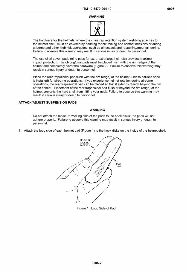
The hardware for the helmets, where the chinstrap retention system webbing attaches to the helmet shell, must be covered by padding for all training and combat missions or during airborne and other high risk operations, such as air assault and rappelling/mountaineering. Failure to observe this warning may result in serious injury or death to personnel.
The use of all seven pads (nine pads for extra-extra large helmets) provides maximum impact protection. The oblong/oval pads must be placed flush with the rim (edge) of the helmet and completely cover the hardware (Figure 2). Failure to observe this warning may result in serious injury or death to personnel.
Place the rear trapezoidal pad flush with the rim (edge) of the helmet (unless ballistic nape is installed) for airborne operations. If you experience helmet rotation during airborne operations, the rear trapezoidal pad can be placed so that it extends ½ inch beyond the rim of the helmet. Placement of the rear trapezoidal pad flush or beyond the rim (edge) of the helmet prevents the hard shell from hitting your neck. Failure to observe this warning may result in serious injury or death to personnel.
ATTACH/ADJUST SUSPENSION PADS
WARNING
Do not attach the moisture-wicking side of the pads to the hook disks; the pads will not adhere properly. Failure to observe this warning may result in serious injury or death to personnel.
1. Attach the loop side of each helmet pad (Figure 1) to the hook disks on the inside of the helmet shell.
Figure 1. Loop Side of Pad.
TM 10-8470-204-10 0005
0005-3
ATTACH/ADJUST SUSPENSION PADS – CONTINUED
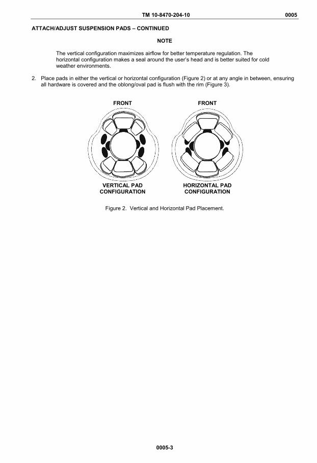
NOTE
The vertical configuration maximizes airflow for better temperature regulation. The horizontal configuration makes a seal around the user’s head and is better suited for cold weather environments.
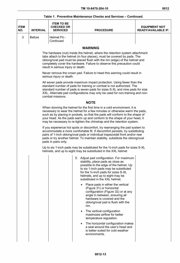
2. Place pads in either the vertical or horizontal configuration (Figure 2) or at any angle in between, ensuring
all hardware is covered and the oblong/oval pad is flush with the rim (Figure 3).
FRONT
FRONT
VERTICAL PAD
CONFIGURATION HORIZONTAL PAD CONFIGURATION
Figure 2. Vertical and Horizontal Pad Placement.

TM 10-8470-204-10 0005
0005-4
ATTACH/ADJUST SUSPENSION PADS – CONTINUED
NOTE
Figure 3 illustrates the helmet with a Universal H-back chinstrap retention system and hardware is an example of how the pads must be placed in order to correctly cover the hardware. The illustration applies regardless of which helmet or hardware is worn. Adjust pads as necessary.
Figure 3. Pad Placement Over Hardware.
3. To adjust the suspension pads pull the individual pads off the inner helmet hook disks. 4. Reattach pads as necessary for fit and comfort while keeping hardware covered. END OF TASK END OF WORK PACKAGE
LEGEND
1. Oblong/Oval Pad 2. Hook Disks 3. Conical Nut 4. Buckle 5. Attachment Tab 6. Trapezoidal Pad 7. Rim (edge) of Helmet
TM 10-8470-204-10 0006 OPERATOR MAINTENANCE
OPERATION UNDER USUAL CONDITIONS – HELMET SIZING
0006-1
INITIAL SETUP:
Tools and Special Tools Ruler (WP 0026, Item 3 Caliper (WP 0026, Item 4) Tape (WP 0026, Item 5)
Materials/Parts None Required
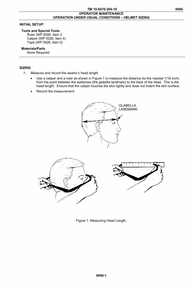
SIZING 1. Measure and record the wearer’s head length
• Use a caliper and a ruler as shown in Figure 1 to measure the distance (to the nearest 1/16 inch) from the point between the eyebrows (the glabella landmark) to the back of the head. This is the head length. Ensure that the caliper touches the skin lightly and does not indent the skin surface.
• Record the measurement.
Figure 1. Measuring Head Length.
GLABELLA LANDMARK
TM 10-8470-204-10 0006
0006-2
SIZING—CONTINUED
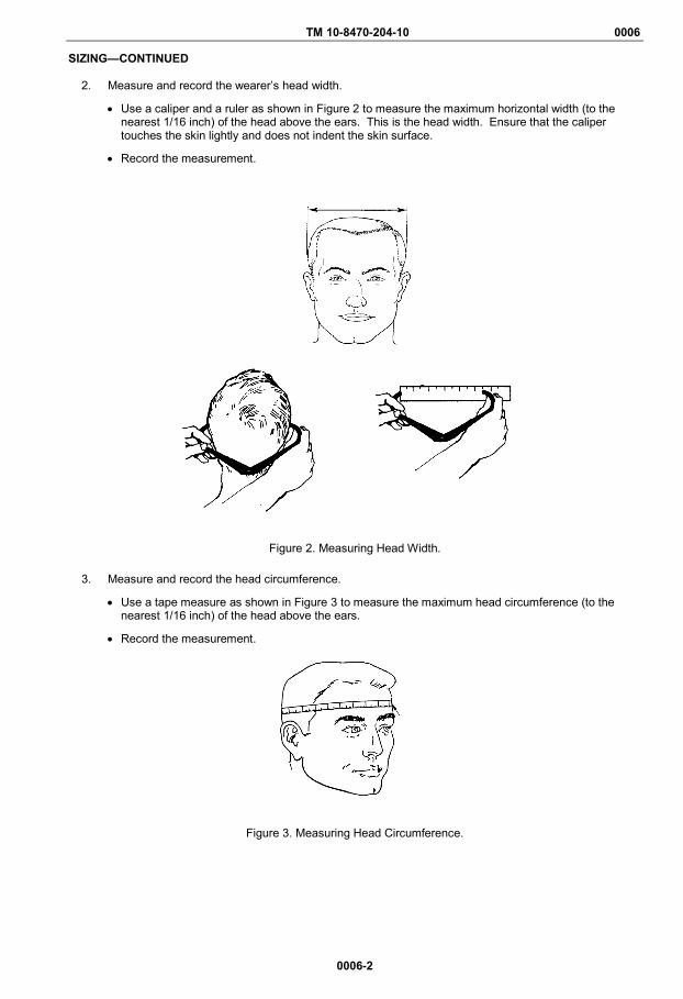
2. Measure and record the wearer’s head width.
• Use a caliper and a ruler as shown in Figure 2 to measure the maximum horizontal width (to the nearest 1/16 inch) of the head above the ears. This is the head width. Ensure that the caliper touches the skin lightly and does not indent the skin surface.
• Record the measurement.
Figure 2. Measuring Head Width.
3. Measure and record the head circumference.
• Use a tape measure as shown in Figure 3 to measure the maximum head circumference (to the nearest 1/16 inch) of the head above the ears.
• Record the measurement.
Figure 3. Measuring Head Circumference.
TM 10-8470-204-10 0006
0006-3/blank
SIZING—CONTINUED
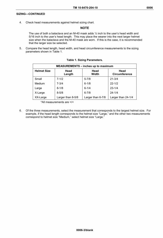
4. Check head measurements against helmet sizing chart.
NOTE
The use of both a balaclava and an M-40 mask adds ¼ inch to the user’s head width and 5/16 inch to the user’s head length. This may place the wearer into the next larger helmet size when the balaclava and the M-40 mask are worn. If this is the case, it is recommended that the larger size be selected.
5. Compare the head length, head width, and head circumference measurements to the sizing parameters shown in Table 1.
Table 1. Sizing Parameters.
MEASUREMENTS – inches up to maximum Helmet Size Head
Length Head Width
Head Circumference
Small 7-1/2 5-7/8 21-3/4 Medium 7-3/4 6-1/8 22-1/2 Large 8-1/8 6-1/4 23-1/4 X-Large 8-5/8 6-7/8 24-1/4 XX-Large Larger than 8-5/8 Larger than 6-7/8 Larger than 24-1/4
*All measurements are =/<
6. Of the three measurements, select the measurement that corresponds to the largest helmet size. For example, if the head length corresponds to the helmet size “Large,” and the other two measurements correspond to helmet size “Medium,” select helmet size “Large.”

TM 10-8470-204-10 0007 OPERATOR MAINTENANCE
OPERATION UNDER USUAL CONDITIONS – DON AND DOFF THE HELMET
0007-1
INITIAL SETUP:
Tools and Special Tools None Required Materials/Parts None Required
References WP 0004 WP 0005 WP 0008
GENERAL This work package provides instructions for donning and doffing a helmet with an H-back retention system, including adjusting the chinstrap to optimize fit and comfort.
WARNING
The hardware (nut) inside the helmet, where the retention system attachment tabs attach to the helmet (in four places), must be covered by pads. The oblong/oval pad must be placed flush with the rim (edge) of the helmet and completely cover the hardware. Failure to observe this precaution could result in serious injury or death. Never remove the crown pad. Failure to observe this precaution could result in serious injury or death. All seven pads provide maximum impact protection. Using fewer than the standard number of pads for training or combat is not authorized. The standard number of pads is seven pads for sizes S-XL, nine pads for size XXL. Alternate pad configurations may be used for non-training and non-combat missions. Ensure that all helmet adjustment mechanisms are properly adjusted for a snug, secure fit at all times when the helmet is worn. Failure to do so may result in an unstable helmet that reduces protection to the Soldier.
NOTE
When donning the helmet for the first time in a cold environment, wear the helmet for a few minutes or warm the pads, for example by placing in pockets, so that the pads will conform to the shape of your head. As the pads warm up and conform to the shape of your head, it may be necessary to retighten the chinstrap retention system. Failure to observe this warning may cause improper fit.
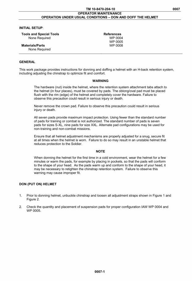
DON (PUT ON) HELMET 1. Prior to donning helmet, unbuckle chinstrap and loosen all adjustment straps shown in Figure 1 and
Figure 2. 2. Check the quantity and placement of suspension pads for proper configuration IAW WP 0004 and
WP 0005.
TM 10-8470-204-10 0007
0007-2
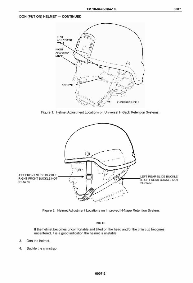
DON (PUT ON) HELMET — CONTINUED
Figure 1. Helmet Adjustment Locations on Universal H-Back Retention Systems.
Figure 2. Helmet Adjustment Locations on Improved H-Nape Retention System.
NOTE
If the helmet becomes uncomfortable and tilted on the head and/or the chin cup becomes uncentered, it is a good indication the helmet is unstable.
3. Don the helmet.
4. Buckle the chinstrap.
LEFT FRONT SLIDE BUCKLE (RIGHT FRONT BUCKLE NOT SHOWN)
LEFT REAR SLIDE BUCKLE (RIGHT REAR BUCKLE NOT SHOWN)

TM 10-8470-204-10 0007
0007-3
DON (PUT ON) HELMET — CONTINUED
5. Hold helmet in place, with one hand on top of helmet while adjusting helmet chinstrap with the other hand
as shown in Figure 3.
Figure 3. Hand on Top of Helmet.
6. For helmets with Universal H-Back retention systems, partially tighten the two rear adjustment straps by pulling them down one side at a time (Figure 4). For helmets with the Improved H-Nape retention system, partially tighten the two rear retention straps by sliding the buckles from the back toward the front, one side at a time (Figure 5).
Figure 4. Tighten Rear Adjustment Straps (Universal H-Back Retention Systems).
Figure 5. Tighten Rear Adjustment Straps (Improved H-Nape Retention Systems).

TM 10-8470-204-10 0007
0007-4
DON (PUT ON) HELMET — CONTINUED
7. For helmets with Universal H-Back retention systems, partially tighten the two front adjustment straps (Figure 6) one side at a time. For helmets with the Improved H-Nape retention system, partially tighten the two front retention straps (Figure 7) one side at a time.
Figure 6. Tighten Front Adjustment Straps (Universal H-Back Retention Systems).
Figure 7. Tighten Front Adjustment Straps (Improved H-Nape Retention Systems). 8. Hold helmet in place, and fully tighten front and rear of the retention system.
NOTE
When adjusting the chinstraps on helmets with universal H-back retention systems, keep the nape pad away from the ladder locks (buckles) to prevent jamming.
9. Adjust the nape pad as follows:
a. For helmets with a universal H-back retention system, slide nape pad (Figure 8) up and down along the rear legs of the chinstrap as necessary.
Figure 8. Tighten/Adjust Nape Pad (Universal H-Back Retention Systems).

TM 10-8470-204-10 0007
0007-5/blank
DON (PUT ON) HELMET — CONTINUED
b. For helmets with an improved H-nape retention system, slide the buckle on the nape pad from side to side (Figure 9).
Figure 9. Tighten/Adjust Nape Pad (Improve H-Nape Retention Systems). 10. Position the chinstrap according to personal comfort.
11. Check the helmet stability by attempting to rock the helmet back and forth on the head. If the helmet
rocks back and forth, it is not stable.
12. Repeat steps 2 through 11 until helmet is stable.
13. Evaluate the fit of the helmet IAW WP 0008. END OF TASK DOFF (REMOVE) OR LOOSEN HELMET 1. To loosen the chinstrap, push up on the ladder locks/buckle. 2. To remove the helmet, press the sides of the center section of the chinstrap buckle, on the chinstrap
retention system, inward. Once the buckle releases, remove the helmet. END OF TASK END OF WORK PACKAGE


TM 10-8470-204-10 0008 OPERATOR MAINTENANCE
OPERATION UNDER USUAL CONDITIONS–EVALUATE AND ADJUST HELMET FIT
0008-1
INITIAL SETUP:
Tools and Special Tools Multi-tool (WP 0026, Item 1)
Materials/Parts None Required
References WP 0004 WP 0005 WP 0006 WP 0007 WP 0012 WP 0013 WP 0022
WARNING
The hardware (nut) inside the helmet, where the retention system attachment tabs attach to the helmet (in four places), must be covered by pads. The oblong/oval pad must be placed flush with the rim (edge) of the helmet and completely cover the hardware. Failure to observe this precaution could result in serious injury or death. Never remove the crown pad. Failure to observe this precaution could result in serious injury or death. All seven pads provide maximum impact protection. Using fewer than the standard number of pads for training or combat is not authorized. The standard number of pads is seven pads for sizes S-XL, nine pads for size XXL. Alternate pad configurations may be used for non-training and non-combat missions. Ensure that all helmet adjustment mechanisms are properly adjusted for a snug, secure fit at all times when the helmet is worn. Failure to do so may result in injury.
NOTE
The illustrations in this work package are generic and represent all ACH manufacturers’ models. When donning the helmet for the first time in a cold environment, it is necessary to wear the helmet for a few minutes or otherwise warm the pads, such as by placing in pockets, so that the pads will conform to the shape of your head. As the pads warm up and conform to the shape of your head, it may be necessary to re-tighten the chinstrap and the retention system. If you experience hot spots or discomfort, try rearranging the pad system to accommodate a more comfortable fit. If discomfort persists, try substituting pairs of 1-inch oblong/oval pads or individual trapezoidal front and/or rear pads or try another helmet. To maintain stability, substitute the oblong/oval pads in pairs only.
EVALUATE FIT 1. Ensure the suspension pads are arranged in the standard pad configuration for the helmet size IAW WP
0004. If other equipment is to be used with the helmet, such as a headset, evaluate size with that equipment, if possible.
2. Don the helmet IAW WP 0007.
NOTE
Proper fit is achieved when the helmet does not sit too high (crown pad does not contact head or too much of forehead is exposed) or too low (too low on brow or not compatible with eyewear, etc.) and is not too tight or too loose (Figure 1). While evaluating fit, be sure to have the chinstrap retention system tightened as described in WP 0007.
TM 10-8470-204-10 0008
0008-2
EVALUATE FIT – CONTINUED
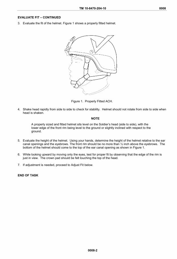
3. Evaluate the fit of the helmet. Figure 1 shows a properly fitted helmet.
Figure 1. Properly Fitted ACH.
4. Shake head rapidly from side to side to check for stability. Helmet should not rotate from side to side when head is shaken.
NOTE
A properly sized and fitted helmet sits level on the Soldier’s head (side to side), with the lower edge of the front rim being level to the ground or slightly inclined with respect to the ground.
5. Evaluate the height of the helmet. Using your hands, determine the height of the helmet relative to the ear canal openings and the eyebrows. The front rim should be no more than ½ inch above the eyebrows. The bottom of the helmet should come to the top of the ear canal opening as shown in Figure 1.
6. While looking upward by moving only the eyes, test for proper fit by observing that the edge of the rim is
just in view. The crown pad should be felt touching the top of the head. 7. If adjustment is needed, proceed to Adjust Fit below. END OF TASK
TM 10-8470-204-10 0008
0008-3
ADJUST FIT
If evaluation indicates the helmet is too tight, too loose, too high, or the crown pad does not touch the head, make adjustments as described below.
Helmet is Too Tight If the helmet is too tight, obtain a larger helmet. Helmet is Too Loose
NOTE
If helmet slides on the head while shaking the head side to side, helmet is too loose. Over time, the suspension pads may compress. Therefore, the pads and retention system may need to be adjusted, as described in WP 0005 to compensate for the compression and excess room in the helmet.
1. Inspect each pad for wear, deterioration, and compressibility in accordance with WP 0012 and WP 0013. If pad(s) does not return to original shape, replace in accordance with WP 0022.
2. Try on helmet. 3. If helmet is too loose, replace some or all of the ¾-inch oblong/oval pads (replace in pairs only) and
trapezoidal pads (may be replaced individually) with 1-inch pads. 4. If the helmet is still too loose, obtain a smaller helmet.
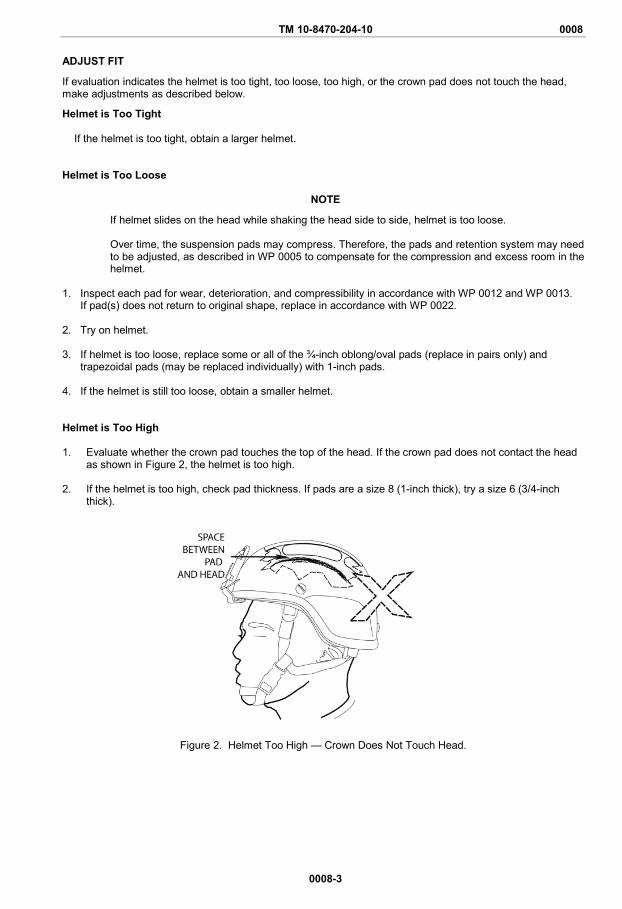
Helmet is Too High 1. Evaluate whether the crown pad touches the top of the head. If the crown pad does not contact the head
as shown in Figure 2, the helmet is too high.
2. If the helmet is too high, check pad thickness. If pads are a size 8 (1-inch thick), try a size 6 (3/4-inch thick).
Figure 2. Helmet Too High — Crown Does Not Touch Head.
TM 10-8470-204-10 0008
0008-4
ADJUST FIT – CONTINUED
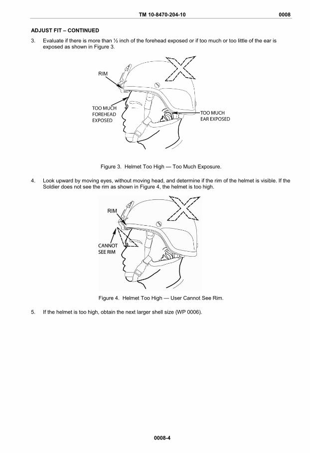
3. Evaluate if there is more than ½ inch of the forehead exposed or if too much or too little of the ear is exposed as shown in Figure 3.
Figure 3. Helmet Too High — Too Much Exposure.
4. Look upward by moving eyes, without moving head, and determine if the rim of the helmet is visible. If the Soldier does not see the rim as shown in Figure 4, the helmet is too high.
Figure 4. Helmet Too High — User Cannot See Rim.
5. If the helmet is too high, obtain the next larger shell size (WP 0006).
TM 10-8470-204-10 0008
0008-5/blank
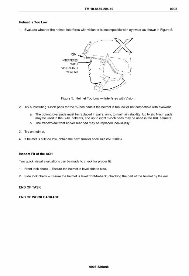
Helmet is Too Low: 1. Evaluate whether the helmet interferes with vision or is incompatible with eyewear as shown in Figure 5.
Figure 5. Helmet Too Low — Interferes with Vision.
2. Try substituting 1-inch pads for the ¾-inch pads if the helmet is too low or not compatible with eyewear.
a. The oblong/oval pads must be replaced in pairs, only, to maintain stability. Up to six 1-inch pads may be used in the S-XL helmets, and up to eight 1-inch pads may be used in the XXL helmets.
b. The trapezoidal front and/or rear pad may be replaced individually. 3. Try on helmet.
4. If helmet is still too low, obtain the next smaller shell size (WP 0006).
Inspect Fit of the ACH Two quick visual evaluations can be made to check for proper fit: 1. Front look check – Ensure the helmet is level side to side. 2. Side look check – Ensure the helmet is level front-to-back, checking the part of the helmet by the ear. END OF TASK
END OF WORK PACKAGE


TM 10-8470-204-10 0009 OPERATOR MAINTENANCE
OPERATION UNDER UNUSUAL CONDITIONS
0009-1/blank
INITIAL SETUP:
Tools and Special Tools None Required
References None
Materials/Parts None Required
OPERATING PROCEDURES There are no additional procedures for operation under unusual conditions.


TM 10-8470-204-10
CHAPTER 3
TROUBLESHOOTING
FOR
ADVANCED COMBAT HELMET (ACH)

TM 10-8470-204-10 0010 OPERATOR MAINTENANCE
TROUBLESHOOTING PROCEDURES
0010-1
INITIAL SETUP:
Tools and Special Tools None Required
Materials/Parts None Required
References WP 0014 WP 0016 WP 0019 WP 0022 WP 0023
TROUBLESHOOTING PROCEDURES This work package lists troubleshooting tasks and corrective actions for each component of the ACH. SYMPTOM Unable to fasten chinstrap retention assembly. MALFUNCTION Chinstrap buckle is dirty. CORRECTIVE ACTION Clean as described in WP 0014. MALFUNCTION Chinstrap buckle is broken. CORRECTIVE ACTION Replace entire retention system as described in WP 0019. SYMPTOM Unable to attain or maintain helmet stability. MALFUNCTION Chinstrap webbing is torn and/or frayed. CORRECTIVE ACTION Replace entire retention system as described in WP 0019. MALFUNCTION Pad suspension system is worn. CORRECTIVE ACTION Replace pad suspension system as described in WP 0022.

TM 10-8470-204-10 0010
0010-2
TROUBLESHOOTING PROCEDURES – CONTINUED SYMPTOM Pads will not stay secure in shell. MALFUNCTION Damaged pads. CORRECTIVE ACTION Replace pads as described in WP 0022. MALFUNCTION Dirty pads. CORRECTIVE ACTION Clean pads as described in WP 0014. MALFUNCTION Dirty hook disks. CORRECTIVE ACTION Clean helmet shell as described in WP 0014. MALFUNCTION Damaged hook disks. CORRECTIVE ACTION Turn into Central Issue Facility (CIF). SYMPTOM Night Vision Goggles (NVG) bracket is unstable. MALFUNCTION Night Vision Goggles (NVG) bracket is loose. CORRECTIVE ACTION
Tighten NVG screw. If condition persists, replace NVG hardware as described in WP 0023.
MALFUNCTION Night Vision Goggles (NVG) bracket is broken. CORRECTIVE ACTION
Remove and install NVG bracket as described in WP 0016. END OF TASK END OF WORK PACKAGE

TM 10-8470-204-10
CHAPTER 4
PREVENTIVE MAINTENANCE INSTRUCTIONS
FOR
ADVANCED COMBAT HELMET (ACH)


TM 10-8470-204-10 0011 OPERATOR MAINTENANCE
PREVENTIVE MAINTENANCE CHECKS AND SERVICES INTRODUCTION
0011-1/blank
INTRODUCTION Preventive Maintenance Checks and Services (PMCS) are performed to keep the ACH in good operating condition and ready for their primary mission. Operators are to perform PMCS of the helmets before, during, and after use, as well as annually. PMCS is performed according to the table provided. Pay attention to WARNING statements. A WARNING indicates that someone could be hurt or killed. Failure to observe these precautions could result in serious injury or death. Be sure to perform scheduled PMCS. Always perform PMCS in the same order so it becomes habit. With practice, you will quickly recognize problems with the equipment. Use DA Form 2404, Equipment Inspection and Maintenance Worksheet, to record any discovered faults. Do not record faults that you fix! PMCS PROCEDURES Table 1 in WP 0014 lists inspections and care required to keep your ACH in good operating condition. Explanation of Table 1 Columns Item No. Indicates the reference number. When completing DA Form 2404, Equipment Inspection and Maintenance Worksheet, include the item number for the item to check/service indicating a fault. Item numbers appear in the order you must perform the checks/services listed. Interval. Indicates when you must perform the procedure in the procedure column. Before - perform before equipment use During - perform during equipment use After - perform after equipment use Annually - perform following every year of equipment use. Item to be Checked or Serviced. Indicates the item to be checked or serviced. Procedure. Indicates the procedure you must perform on the item listed in Item to Check/Service column. Items that cannot be repaired must be replaced. Perform procedures at the time specified in the Interval column. Equipment Not Ready/Available If. Indicates faults that will prevent your equipment from performing its primary mission. If you perform procedures listed in Procedure column which show faults listed in this column, do not operate the equipment. Follow standard procedures for maintaining the equipment or reporting equipment failure. CORROSION PREVENTION AND CONTROL (CPC) Corrosion Prevention and Control (CPC) of Army and Marine materiel is a continuing concern. It is important that any corrosion problems with this item be reported so that the problem can be corrected and improvements can be made to prevent the problem in future items. Corrosion specifically occurs with metals. An electrochemical process causes the degradation of metals. It is commonly caused by exposure to moisture, acids, bases, or salts. An example is the rusting of iron. Corrosion damage in metals can be seen, depending on the metal, as tarnishing, pitting, fogging, surface residue, and/or cracking. Plastics, composites, and rubbers can also degrade. Degradation is caused by thermal (heat), oxidation (oxygen), solvation (solvents), or photolytic (light, typically UV) processes. The most common exposures are excessive heat or light. Damage from these processes will appear as cracking, softening, swelling, and/or breaking. SF Form 368, Product Quality Deficiency Report, should be submitted to the address specified in DA PAM 750-8, The Army Maintenance Management System (TAMMS) Users Manual.

TM 10-8470-204-10 0012 OPERATOR MAINTENANCE
PREVENTIVE MAINTENANCE CHECKS AND SERVICES
0012-1
INITIAL SETUP:
Tools and Special Tools Multi-Tool (WP 0026, Item 1) Screwdriver (WP 0026, Item 2)
Materials/Parts None Required
References WP 0004 WP 0005
Table 1. Preventive Maintenance Checks and Services.
ITEM NO. INTERVAL
ITEM TO BE CHECKED OR
SERVICED
PROCEDURE
EQUIPMENT NOT
READY/AVAILABLE IF:
1 Before Initial Use
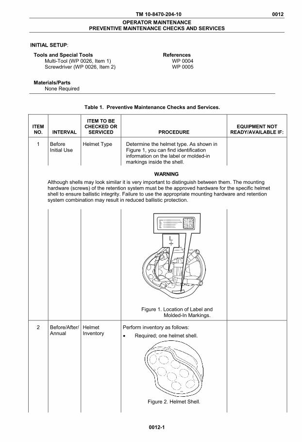
Helmet Type Determine the helmet type. As shown in Figure 1, you can find identification information on the label or molded-in markings inside the shell.
WARNING Although shells may look similar it is very important to distinguish between them. The mounting hardware (screws) of the retention system must be the approved hardware for the specific helmet shell to ensure ballistic integrity. Failure to use the appropriate mounting hardware and retention system combination may result in reduced ballistic protection.
Figure 1. Location of Label and Molded-In Markings.
2 Before/After/ Annual
Helmet Inventory
Perform inventory as follows: • Required; one helmet shell.
Figure 2. Helmet Shell.
TM 10-8470-204-10 0012
0012-2
Table 1. Preventive Maintenance Checks and Services – Continued.
ITEM NO. INTERVAL
ITEM TO BE CHECKED OR
SERVICED
PROCEDURE
EQUIPMENT NOT
READY/AVAILABLE IF:
2
Before/After/ Annual
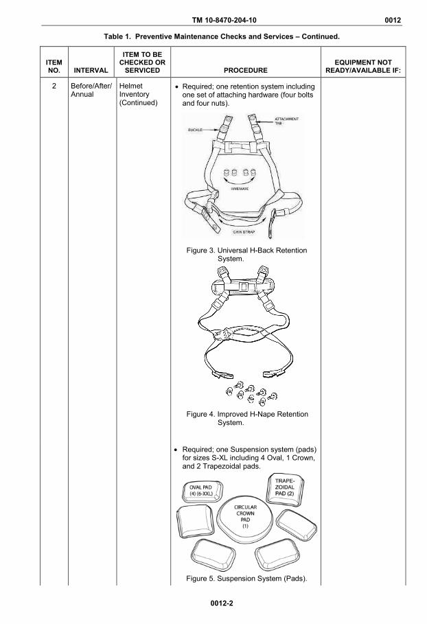
Helmet Inventory (Continued)
• Required; one retention system including one set of attaching hardware (four bolts and four nuts).
Figure 3. Universal H-Back Retention
System.
Figure 4. Improved H-Nape Retention
System.
• Required; one Suspension system (pads) for sizes S-XL including 4 Oval, 1 Crown, and 2 Trapezoidal pads.
Figure 5. Suspension System (Pads).

TM 10-8470-204-10 0012
0012-3
Table 1. Preventive Maintenance Checks and Services – Continued.
ITEM NO. INTERVAL
ITEM TO BE CHECKED OR
SERVICED
PROCEDURE
EQUIPMENT NOT
READY/AVAILABLE IF:
2 Before/After /Annual
Helmet Inventory – Continued
• Required; one non-reversible camouflage helmet cover.
Figure 6. Non-Reversible Camouflage
Helmet Cover.
• Optional; one Ballistic Nape Pad.
Figure 7. Ballistic Nape Pad for Universal
H-Back and Improved H-Nape Retention Systems.
Figure 8. Ballistic Nape Pad for Universal Retention Systems.
Figure 9. Ballistic Nape Pad for X-Back Retention Systems.
TM 10-8470-204-10 0012
0012-4
Table 1. Preventive Maintenance Checks and Services – Continued.
ITEM NO. INTERVAL
ITEM TO BE CHECKED OR
SERVICED
PROCEDURE
EQUIPMENT NOT
READY/AVAILABLE IF:
2 Before/After /Annual
Helmet Inventory – Continued
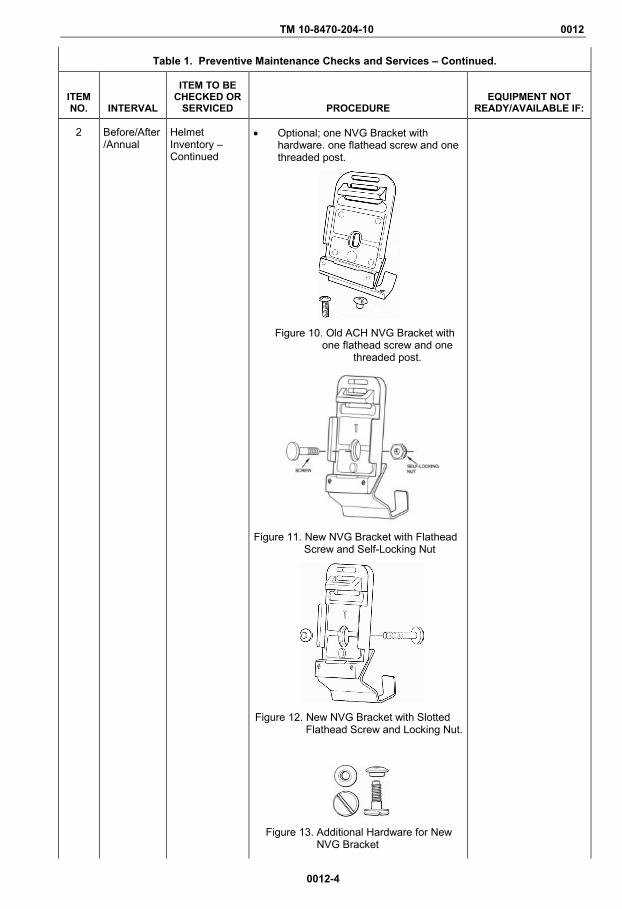
• Optional; one NVG Bracket with hardware. one flathead screw and one threaded post.
Figure 10. Old ACH NVG Bracket with one flathead screw and one
threaded post.
Figure 11. New NVG Bracket with Flathead
Screw and Self-Locking Nut
Figure 12. New NVG Bracket with Slotted
Flathead Screw and Locking Nut.
Figure 13. Additional Hardware for New
NVG Bracket
TM 10-8470-204-10 0012
0012-5
Table 1. Preventive Maintenance Checks and Services – Continued.
ITEM NO. INTERVAL
ITEM TO BE CHECKED OR
SERVICED PROCEDURE EQUIPMENT NOT
READY/AVAILABLE IF:
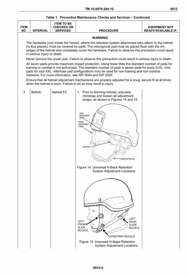
WARNING The hardware (nut) inside the helmet, where the retention system attachment tabs attach to the helmet (in four places), must be covered by pads. The oblong/oval pad must be placed flush with the rim (edge) of the helmet and completely cover the hardware. Failure to observe this precaution could result in serious injury or death. Never remove the crown pad. Failure to observe this precaution could result in serious injury or death. All seven pads provide maximum impact protection. Using fewer than the standard number of pads for training or combat is not authorized. The standard number of pads is seven pads for sizes S-XL, nine pads for size XXL. Alternate pad configurations may be used for non-training and non-combat missions. For more information, see WP 0004 and WP 0005. Ensure that all helmet adjustment mechanisms are properly adjusted for a snug, secure fit at all times when the helmet is worn. Failure to do so may result in injury.
3 Before Helmet Fit 1. Prior to donning helmet, unbuckle chinstrap and loosen all adjustment straps, as shown in Figures 14 and 15.
Figure 14. Universal H-Back Retention
System Adjustment Locations.
Figure 15. Improved H-Nape Retention System Adjustment Locations.
LEFT FRONT SLIDE BUCKLE
LEFT REAR SLIDE BUCKLE
CHINSTRAP BUCKLE
TM 10-8470-204-10 0012
0012-6
Table 1. Preventive Maintenance Checks and Services – Continued.
ITEM NO. INTERVAL
ITEM TO BE CHECKED OR
SERVICED
PROCEDURE
EQUIPMENT NOT
READY/AVAILABLE IF:
3 Before Helmet Fit - Continued
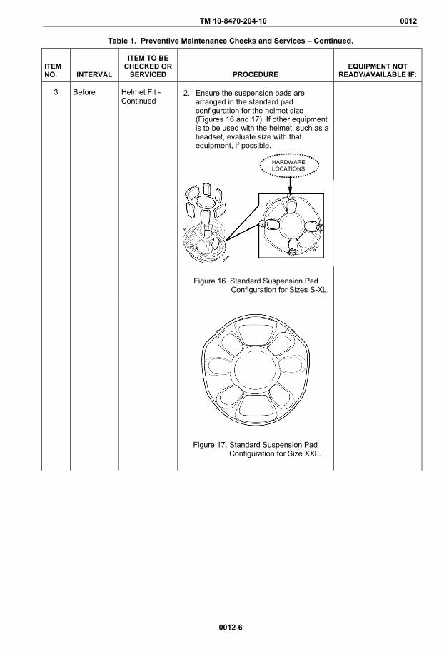
2. Ensure the suspension pads are arranged in the standard pad configuration for the helmet size (Figures 16 and 17). If other equipment is to be used with the helmet, such as a headset, evaluate size with that equipment, if possible.
Figure 16. Standard Suspension Pad
Configuration for Sizes S-XL.
Figure 17. Standard Suspension Pad Configuration for Size XXL.
HARDWARE LOCATIONS
TM 10-8470-204-10 0012
0012-7
Table 1. Preventive Maintenance Checks and Services – Continued.
ITEM NO. INTERVAL
ITEM TO BE CHECKED OR
SERVICED
PROCEDURE
EQUIPMENT NOT
READY/AVAILABLE IF:
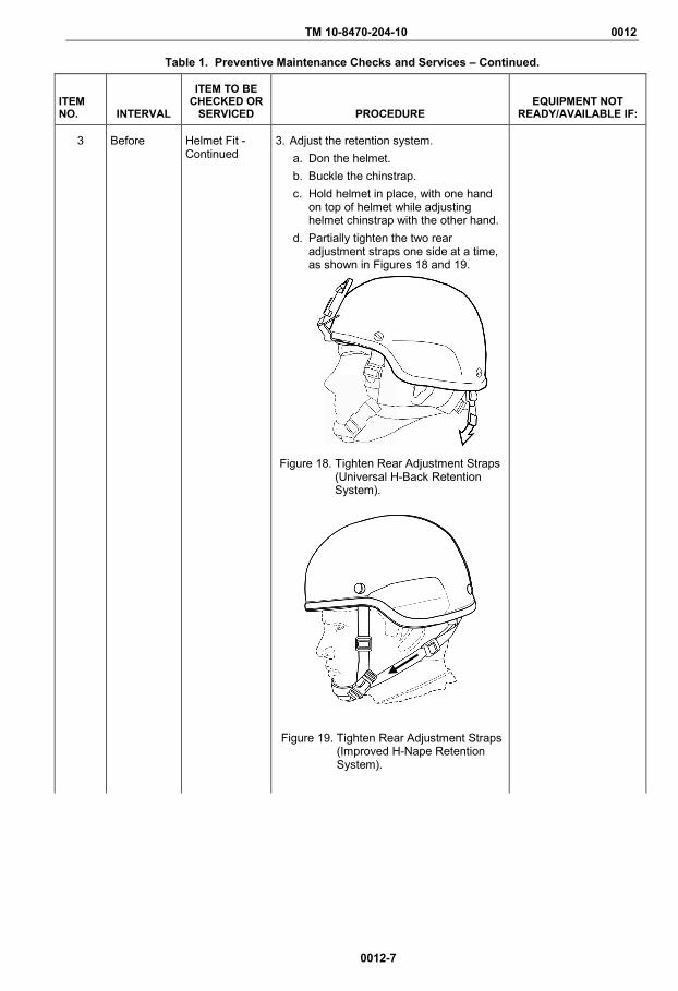
3 Before Helmet Fit - Continued
3. Adjust the retention system. a. Don the helmet. b. Buckle the chinstrap. c. Hold helmet in place, with one hand
on top of helmet while adjusting helmet chinstrap with the other hand.
d. Partially tighten the two rear adjustment straps one side at a time, as shown in Figures 18 and 19.
Figure 18. Tighten Rear Adjustment Straps
(Universal H-Back Retention System).
Figure 19. Tighten Rear Adjustment Straps (Improved H-Nape Retention System).
TM 10-8470-204-10 0012
0012-8
Table 1. Preventive Maintenance Checks and Services – Continued.
ITEM NO. INTERVAL
ITEM TO BE CHECKED OR
SERVICED
PROCEDURE
EQUIPMENT NOT
READY/AVAILABLE IF:
3 Before Helmet Fit - Continued
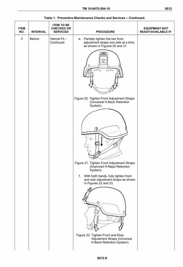
e. Partially tighten the two front adjustment straps one side at a time, as shown in Figures 20 and 21.
Figure 20. Tighten Front Adjustment Straps
(Universal H-Back Retention System).
Figure 21. Tighten Front Adjustment Straps
(Improved H-Nape Retention System).
f. With both hands, fully tighten front and rear adjustment straps as shown in Figures 22 and 23.
Figure 22. Tighten Front and Rear
Adjustment Straps (Universal H-Back Retention System).

TM 10-8470-204-10 0012
0012-9
Table 1. Preventive Maintenance Checks and Services – Continued.
ITEM NO. INTERVAL
ITEM TO BE CHECKED OR
SERVICED
PROCEDURE
EQUIPMENT NOT
READY/AVAILABLE IF:
3 Before Helmet Fit - Continued
Figure 23. Tighten Front and Rear
Adjustment Straps (Improved H-Nape Retention System).
NOTE When the helmet is tightened against the nape of the neck by pulling on end of webbing (Figure 23), the nape pad adds additional stability to the helmet such as when wearing NVGs. Keep the nape pad away from the ladder locks (buckles) while adjusting the chinstrap to prevent jamming.
g. Adjust the nape pad as follows: • Slide nape pad (Figure 24) up and
down along the rear legs of the chinstrap as necessary.
Figure 24. Adjust Nape Pad (Universal H-
Back Retention System).
• Slide buckle on nape pad (Figure 25) from side to side.
Figure 25. Adjust Nape Pad (Improved H-
Nape Retention System).
TM 10-8470-204-10 0012
0012-10
Table 1. Preventive Maintenance Checks and Services – Continued.
ITEM NO. INTERVAL
ITEM TO BE CHECKED OR
SERVICED
PROCEDURE
EQUIPMENT NOT
READY/AVAILABLE IF:
3 Before Helmet Fit - Continued
h. Position the chinstrap according to personal comfort.
i. Check the helmet stability by attempting to rock the helmet back and forth on the head. If the helmet rocks back and forth, it is not stable.
j. Repeat steps c through i until helmet is stable.
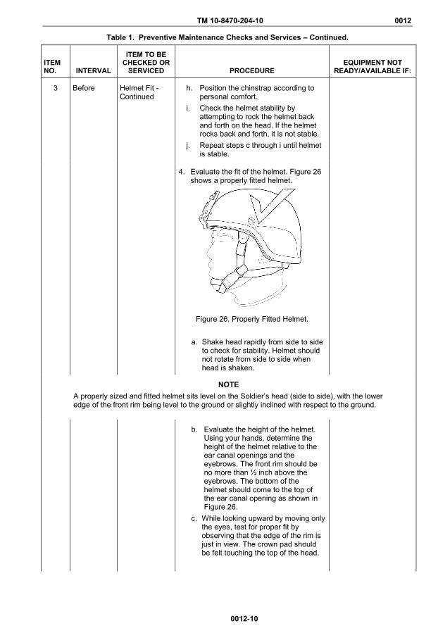
4. Evaluate the fit of the helmet. Figure 26 shows a properly fitted helmet.
Figure 26. Properly Fitted Helmet.
a. Shake head rapidly from side to side
to check for stability. Helmet should not rotate from side to side when head is shaken.
NOTE A properly sized and fitted helmet sits level on the Soldier’s head (side to side), with the lower edge of the front rim being level to the ground or slightly inclined with respect to the ground.
b. Evaluate the height of the helmet. Using your hands, determine the height of the helmet relative to the ear canal openings and the eyebrows. The front rim should be no more than ½ inch above the eyebrows. The bottom of the helmet should come to the top of the ear canal opening as shown in Figure 26.
c. While looking upward by moving only the eyes, test for proper fit by observing that the edge of the rim is just in view. The crown pad should be felt touching the top of the head.
TM 10-8470-204-10 0012
0012-11
Table 1. Preventive Maintenance Checks and Services – Continued.
ITEM NO. INTERVAL
ITEM TO BE CHECKED OR
SERVICED
PROCEDURE
EQUIPMENT NOT
READY/AVAILABLE IF:
3 Before Helmet Fit - Continued
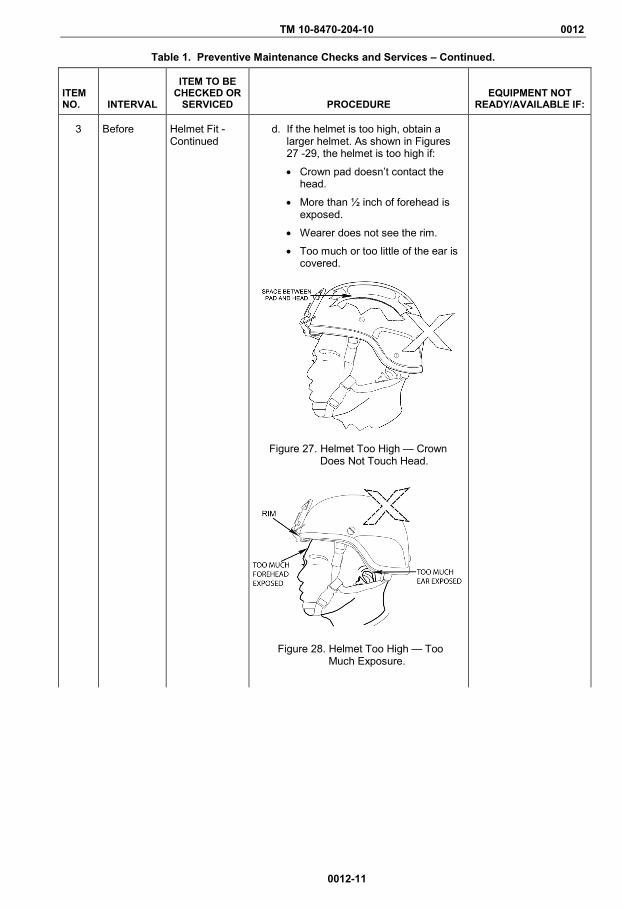
d. If the helmet is too high, obtain a larger helmet. As shown in Figures 27 -29, the helmet is too high if:
• Crown pad doesn’t contact the head.
• More than ½ inch of forehead is exposed.
• Wearer does not see the rim.
• Too much or too little of the ear is covered.
Figure 27. Helmet Too High — Crown
Does Not Touch Head.
Figure 28. Helmet Too High — Too
Much Exposure.

TM 10-8470-204-10 0012
0012-12
Table 1. Preventive Maintenance Checks and Services – Continued.
ITEM NO. INTERVAL
ITEM TO BE CHECKED OR
SERVICED
PROCEDURE
EQUIPMENT NOT
READY/AVAILABLE IF:
3 Before Helmet Fit - Continued
Figure 29. Helmet Too High — User Cannot
See Rim.
e. If the helmet is too low on brow (Figure 30) or not compatible with eyewear: • Try substituting 1-inch pads for
the ¾-inch pads. The oblong/oval pads must be replaced in pairs, only, to maintain stability. The trapezoidal front and/or rear pad may be replaced individually. Up to six 1-inch pads may be used in the S-XL helmets, and up to eight 1-inch pads may be used in the XXL helmets.
• Obtain a smaller helmet.
Figure 30. Helmet Too Low — Interferes
with Vision.
f. If the helmet is too tight, obtain a larger helmet.
g. If the helmet is too loose, first try replacing some or all of the ¾-inch oval pads (replace in pairs only) and trapezoidal pads (may be replaced individually) with 1-inch pads. If the helmet is still too loose, obtain a smaller helmet.
TM 10-8470-204-10 0012
0012-13
Table 1. Preventive Maintenance Checks and Services – Continued.
ITEM NO. INTERVAL
ITEM TO BE CHECKED OR
SERVICED
PROCEDURE
EQUIPMENT NOT
READY/AVAILABLE IF:
3 Before Helmet Fit - Continued
WARNING The hardware (nut) inside the helmet, where the retention system attachment tabs attach to the helmet (in four places), must be covered by pads. The oblong/oval pad must be placed flush with the rim (edge) of the helmet and completely cover the hardware. Failure to observe this precaution could result in serious injury or death.
Never remove the crown pad. Failure to heed this warning could result in serious injury or death.
All seven pads provide maximum impact protection. Using fewer than the standard number of pads for training or combat is not authorized. The standard number of pads is seven pads for sizes S-XL and nine pads for size XXL. Alternate pad configurations may only be used for non-training and non-combat missions.
NOTE When donning the helmet for the first time in a cold environment, it is necessary to wear the helmet for a few minutes or otherwise warm the pads, such as by placing in pockets, so that the pads will conform to the shape of your head. As the pads warm up and conform to the shape of your head, it may be necessary to re-tighten the chinstrap and the retention system.
If you experience hot spots or discomfort, try rearranging the pad system to accommodate a more comfortable fit. If discomfort persists, try substituting pairs of 1-inch oblong/oval pads or individual trapezoidal front and/or rear pads or try another helmet. To maintain stability, substitute the oblong/oval pads in pairs only.
Up to six 1-inch pads may be substituted for the ¾-inch pads for sizes S-XL helmets, and up to eight may be substituted in the XXL helmet
5. Adjust pad configuration. For maximum stability, place pads as close as possible to the edge of the helmet. Up to six 1-inch pads may be substituted for the ¾-inch pads for sizes S-XL helmets, and up to eight may be substituted in the XXL helmet.
• Place pads in either the vertical (Figure 31) or horizontal configuration (Figure 32) or at any angle in between, ensuring all hardware is covered and the oblong/oval pad is flush with the rim.
• The vertical configuration maximizes airflow for better temperature regulation.
• The horizontal configuration makes a seal around the user’s head and is better suited for cold weather environments.
TM 10-8470-204-10 0012
0012-14
Table 1. Preventive Maintenance Checks and Services – Continued.
ITEM NO. INTERVAL
ITEM TO BE CHECKED OR
SERVICED
PROCEDURE
EQUIPMENT NOT
READY/AVAILABLE IF:
3 Before Helmet Fit - Continued
FRONT
Figure 31. Vertical Pad Placement.
FRONT
Figure 32. Horizontal Pad Placement.
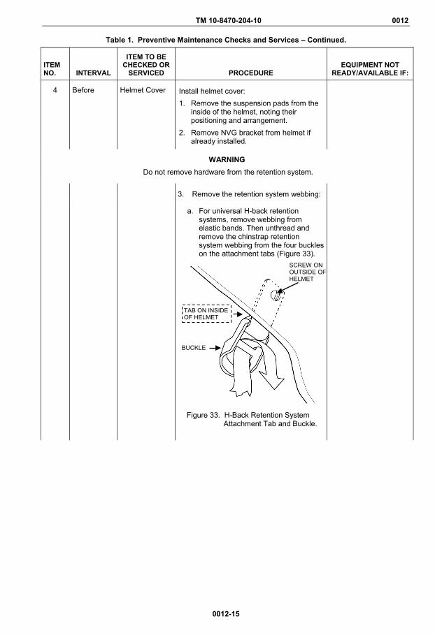
TM 10-8470-204-10 0012
0012-15
Table 1. Preventive Maintenance Checks and Services – Continued.
ITEM NO. INTERVAL
ITEM TO BE CHECKED OR
SERVICED
PROCEDURE
EQUIPMENT NOT
READY/AVAILABLE IF:
4 Before Helmet Cover Install helmet cover: 1. Remove the suspension pads from the
inside of the helmet, noting their positioning and arrangement.
2. Remove NVG bracket from helmet if already installed.
WARNING Do not remove hardware from the retention system.
3. Remove the retention system webbing:
a. For universal H-back retention systems, remove webbing from elastic bands. Then unthread and remove the chinstrap retention system webbing from the four buckles on the attachment tabs (Figure 33).
Figure 33. H-Back Retention System
Attachment Tab and Buckle.
SCREW ON OUTSIDE OF HELMET
BUCKLE
TAB ON INSIDE OF HELMET

TM 10-8470-204-10 0012
0012-16
Table 1. Preventive Maintenance Checks and Services – Continued.
ITEM NO. INTERVAL
ITEM TO BE CHECKED OR
SERVICED
PROCEDURE
EQUIPMENT NOT
READY/AVAILABLE IF:
4 Before Helmet Cover, Install for Improved H- Nape
b. For improved H-nape retention systems, remove all four sets of hardware and detach the entire retention system from the helmet. Retain all four sets of hardware to reuse.
Figure 34. Improved H-Nape Retention
System Attachment Tab and Hardware
4. Orient the helmet cover with the NVG
bracket location facing the front of the helmet, as shown in Figure 35.
Figure 35. Non-Reversible Universal Camouflage Helmet Cover.
5. Pull the cover over the back and sides of the helmet.
NVG BRACKET LOCATION
T-NUT ON INSIDE OF HELMET TAB ON
INSIDE OF HELMET
SCREW ON OUTSIDE OF HELMET
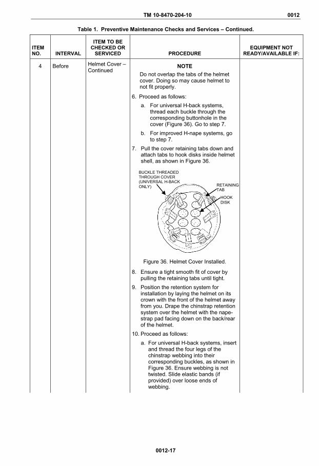
TM 10-8470-204-10 0012
0012-17
Table 1. Preventive Maintenance Checks and Services – Continued.
ITEM NO. INTERVAL
ITEM TO BE CHECKED OR
SERVICED
PROCEDURE
EQUIPMENT NOT
READY/AVAILABLE IF:
4 Before Helmet Cover – Continued
NOTE Do not overlap the tabs of the helmet cover. Doing so may cause helmet to not fit properly.
6. Proceed as follows: a. For universal H-back systems,
thread each buckle through the corresponding buttonhole in the cover (Figure 36). Go to step 7.
b. For improved H-nape systems, go to step 7.
7. Pull the cover retaining tabs down and attach tabs to hook disks inside helmet shell, as shown in Figure 36.
Figure 36. Helmet Cover Installed.
8. Ensure a tight smooth fit of cover by pulling the retaining tabs until tight.
9. Position the retention system for installation by laying the helmet on its crown with the front of the helmet away from you. Drape the chinstrap retention system over the helmet with the nape-strap pad facing down on the back/rear of the helmet.
10. Proceed as follows: a. For universal H-back systems, insert
and thread the four legs of the chinstrap webbing into their corresponding buckles, as shown in Figure 36. Ensure webbing is not twisted. Slide elastic bands (if provided) over loose ends of webbing.
BUCKLE THREADED THROUGH COVER (UNIVERSAL H-BACK ONLY) RETAINING
TAB
HOOK DISK

TM 10-8470-204-10 0012
0012-18
Table 1. Preventive Maintenance Checks and Services – Continued.
ITEM NO. INTERVAL
ITEM TO BE CHECKED OR
SERVICED
PROCEDURE
EQUIPMENT NOT
READY/AVAILABLE IF:
4 Before Helmet Cover – Continued
Figure 37. Universal H-Back Chinstrap Webbing and Buckles.
b. For Improved H-Nape systems, reattach the retention system to the helmet using all four sets of hardware removed earlier. See Figure 38. Ensure webbing is not twisted.
Figure 38. Improved H-Nape Webbing and Attachment Hardware.
SCREW ON OUTSIDE OF HELMET
ATTACHMENT TAB ON INSIDE OF HELMET
RETENTION WEBBING
T-NUT ON INSIDE OF HELMET TAB ON
INSIDE OF HELMET
SCREW ON OUTSIDE OF HELMET

TM 10-8470-204-10 0012
0012-19
Table 1. Preventive Maintenance Checks and Services – Continued.
ITEM NO. INTERVAL
ITEM TO BE CHECKED OR
SERVICED
PROCEDURE
EQUIPMENT NOT
READY/AVAILABLE IF:
11. If used, reinstall NVG bracket at this time (see Item 5).
12. Reinstall the suspension pads in their original position.
5 Before NVG Bracket Install the NVG bracket as described next. WARNING
The NVG bracket must be installed and worn by all Soldiers at all times. Failure to do so may result in injury or death to personnel. Verify that you have the correct hardware for the bracket model installed on the helmet as shown in Item 2. Failure to observe this warning may result in serious injury or death to personnel. Ensure that the threads are fully engaged for the screw retaining the NVG bracket to the shell and that the screw does not extend into the space between the head and the helmet shell interior.
1. Ensure that the NVG bracket assembly has all the components as shown in Figures 39 - 41.
2. Remove front trapezoidal pad, if necessary.
3. If there is a cover installed, loosen the hook and loop tabs, if necessary.
4. Line up the hole on the center of the bracket, the front vertical buttonhole on the cover, and the hole on the helmet shell.
NOTE It may be necessary to tap the bracket into place to properly align the helmet shell, cover, and bracket holes.
5. Insert the screw through the bracket assembly, cover, and helmet shell as follows:

TM 10-8470-204-10 0012
0012-20
Table 1. Preventive Maintenance Checks and Services – Continued.
ITEM NO. INTERVAL
ITEM TO BE CHECKED OR
SERVICED
PROCEDURE
EQUIPMENT NOT
READY/AVAILABLE IF:
5 Before NVG Bracket – Continued
• The black (old) ACH NVG bracket has a screw and threaded post as shown in Figure 39.
Figure 39. (Old) ACH NVG Bracket
Assembly.
• The tan (new) ACH NVG bracket has a screw and self-locking nut as shown in Figure 40.
Figure 40. (New) ACH NVG Bracket
Assembly
• The new ACH NVG bracket assembly has a screw (that is inserted from the inside of the helmet) and a nut as shown in Figure 41.
Figure 41. New ACH NVG Bracket
Assembly.
NIGHT VISION DEVICE BRACKET
CLEAT
THREADED POST
SCREW
ROUND NUT
SLOTTED SCREW
NIGHT VISION DEVICE BRACKET
SELF- LOCKING NUT SCREW

TM 10-8470-204-10 0012
0012-21
Table 1. Preventive Maintenance Checks and Services – Continued.
ITEM NO. INTERVAL
ITEM TO BE CHECKED OR
SERVICED
PROCEDURE
EQUIPMENT NOT
READY/AVAILABLE IF:
6. Using a multi-tool, slightly tighten the screw and self-locking nut or threaded post.
CAUTION Do not over tighten the self-locking nut/threaded post or the bracket may break.
7. Push the bracket up so that the cleat is tight against the rim (edge) of the helmet while completely tightening the screw and self-locking nut or threaded post.
8. Pull the helmet cover retaining tabs down and attach tabs to hook disks inside helmet shell.
9. Ensure a tight smooth fit of cover by pulling the retaining tabs until tight.
10. Replace the suspension pads if not installing the ballistic nape pad (Item 6).
6 Before Ballistic Nape Pad (Optional)
1. Prepare to install the Ballistic Nape Pad as follows: a. Obtain the proper ballistic nape pad
for your helmet model in the appropriate size. For more information see WP 0002.
b. Identify the size of the ballistic nape pad by looking on the inside of the nape pad cover pocket.
c. Remove the trapezoidal pad from the rear of helmet shell to provide access to the retention system and set it aside.
d. Orient the ballistic nape pad so that the camouflage side faces out and the mesh side faces to the inside of the helmet.
2. Proceed as follows: a. For universal H-back retention
systems, proceed to step 3. b. For improved H-nape retention
systems, proceed to step 4. 3. Universal H-Back retention systems:
a. Detach the existing nape pad that comes with the retention system by unfastening the hook and loop strap that holds the nape pad to the chinstrap. Then slide the nape pad off the strap (Figure 42).
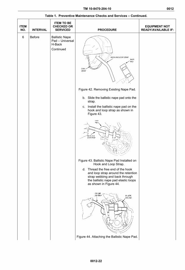
TM 10-8470-204-10 0012
0012-22
Table 1. Preventive Maintenance Checks and Services – Continued.
ITEM NO. INTERVAL
ITEM TO BE CHECKED OR
SERVICED
PROCEDURE EQUIPMENT NOT
READY/AVAILABLE IF:
6 Before Ballistic Nape Pad – Universal H-Back Continued
Figure 42. Removing Existing Nape Pad.
b. Slide the ballistic nape pad onto the strap.
c. Install the ballistic nape pad on the hook and loop strap as shown in Figure 43.
Figure 43. Ballistic Nape Pad Installed on
Hook and Loop Strap. d. Thread the free end of the hook
and loop strap around the retention strap webbing and back through the ballistic nape pad elastic loops as shown in Figure 44.
Figure 44. Attaching the Ballistic Nape Pad.

TM 10-8470-204-10 0012
0012-23
Table 1. Preventive Maintenance Checks and Services – Continued.
ITEM NO. INTERVAL
ITEM TO BE CHECKED OR
SERVICED
PROCEDURE EQUIPMENT NOT
READY/AVAILABLE IF:
6 Before Ballistic Nape Pad – Universal H-Back Continued
e. Slide the ballistic nape pad toward the helmet shell until shell and ballistic nape pad overlap by approximately ½ inch as shown in Figure 45.
Figure 45. Fitting Ballistic Nape Pad into
Helmet Shell.
f. With the ballistic nape pad overlapping the shell edge, press the loop tab against the hook disks on the inside of the shell as shown in Figure 46.
Figure 46. Attaching Ballistic Nape Pad to
Helmet Shell. g. Install the rear trapezoidal pad
such that it is firmly affixed to the hook disk and snug against the edge of the ballistic nape pad.
h. Position the Ballistic Nape Pad so there is about one inch of space between it and the trapezoidal pad. Figure 47 shows the completed installation.

TM 10-8470-204-10 0012
0012-24
Table 1. Preventive Maintenance Checks and Services – Continued.
ITEM NO. INTERVAL
ITEM TO BE CHECKED OR
SERVICED
PROCEDURE EQUIPMENT NOT
READY/AVAILABLE IF:
6 Before Ballistic Nape Pad – Universal H-Back Continued
Figure 47. Ballistic Nape on Universal H-Back Retention System.
Ballistic Nape Pad –Improved H-Nape
4. Improved H-Nape retention systems: a. Unbuckle the chinstrap. Then
detach the left front and left rear attachment tabs to remove two sides of the retention system from the helmet (Figure 48). Retain the two sets of hardware.
Figure 48. Remove Hardware from Left
Front and Left Rear Straps.
NOTE The ballistic nape pad installs over the built-in nape pad.
b. Thread the buckle for the left front strap through the elastic insert on the right side of the ballistic nape pad (Figure 49).
TABS DETACHED
CHINSTRAP UNBUCKLED
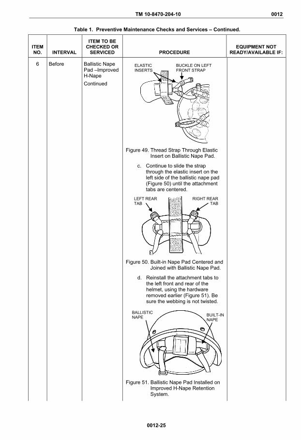
TM 10-8470-204-10 0012
0012-25
Table 1. Preventive Maintenance Checks and Services – Continued.
ITEM NO. INTERVAL
ITEM TO BE CHECKED OR
SERVICED
PROCEDURE EQUIPMENT NOT
READY/AVAILABLE IF:
6 Before Ballistic Nape Pad –Improved H-Nape Continued
Figure 49. Thread Strap Through Elastic Insert on Ballistic Nape Pad.
c. Continue to slide the strap through the elastic insert on the left side of the ballistic nape pad (Figure 50) until the attachment tabs are centered.
Figure 50. Built-in Nape Pad Centered and Joined with Ballistic Nape Pad.
d. Reinstall the attachment tabs to the left front and rear of the helmet, using the hardware removed earlier (Figure 51). Be sure the webbing is not twisted.
Figure 51. Ballistic Nape Pad Installed on Improved H-Nape Retention System.
BALLISTIC NAPE
RIGHT REAR TAB
LEFT REAR TAB
BUCKLE ON LEFT FRONT STRAP
ELASTIC INSERTS
BUILT-IN NAPE

TM 10-8470-204-10 0012
0012-26
Table 1. Preventive Maintenance Checks and Services – Continued.
ITEM NO. INTERVAL
ITEM TO BE CHECKED OR
SERVICED
PROCEDURE EQUIPMENT NOT
READY/AVAILABLE IF:
7 Before Optional: Eyewear Retention Strap
1. Remove suspension pads, noting how they are positioned.
2. Remove the rear retention strap webbing from the buckle.
3. Unfasten the helmet cover retaining tabs and pull the cover away to expose the hardware.
NOTE Be sure to install an eyewear retention strap on each of the two rear screws. Holding the post on inside of helmet will ensure the attachment tab does not disengage while completing the remaining steps.
4. Remove one of the rear screws using a screwdriver or like tool and a multi-tool (if available).
5. From the outside of the helmet, place an eyewear retention strap over the shaft of the screw with the snap socket and stud facing up and away from helmet as shown in Figure 52.
Figure 52. Universal Eyewear Retention
Strap and Screw Assembly.
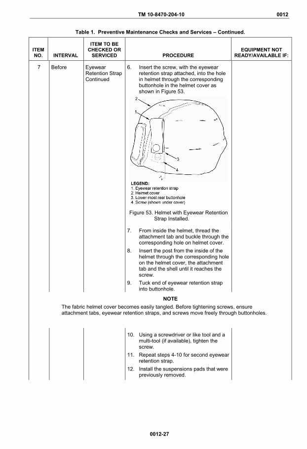
TM 10-8470-204-10 0012
0012-27
Table 1. Preventive Maintenance Checks and Services – Continued.
ITEM NO. INTERVAL
ITEM TO BE CHECKED OR
SERVICED
PROCEDURE EQUIPMENT NOT
READY/AVAILABLE IF:
7 Before Eyewear Retention Strap Continued
6. Insert the screw, with the eyewear retention strap attached, into the hole in helmet through the corresponding buttonhole in the helmet cover as shown in Figure 53.
Figure 53. Helmet with Eyewear Retention
Strap Installed.
7. From inside the helmet, thread the attachment tab and buckle through the corresponding hole on helmet cover.
8. Insert the post from the inside of the helmet through the corresponding hole on the helmet cover, the attachment tab and the shell until it reaches the screw.
9. Tuck end of eyewear retention strap into buttonhole.
NOTE The fabric helmet cover becomes easily tangled. Before tightening screws, ensure attachment tabs, eyewear retention straps, and screws move freely through buttonholes.
10. Using a screwdriver or like tool and a multi-tool (if available), tighten the screw.
11. Repeat steps 4-10 for second eyewear retention strap.
12. Install the suspensions pads that were previously removed.

TM 10-8470-204-10 0012
0012-28
Table 1. Preventive Maintenance Checks and Services – Continued.
ITEM NO. INTERVAL
ITEM TO BE CHECKED OR
SERVICED
PROCEDURE EQUIPMENT NOT
READY/AVAILABLE IF:
8 Before/After Helmet Inspect helmet as described next.
WARNING
If there is a mishap in which the helmet is subjected to a potentially damaging event that occurs sooner than a preventive maintenance check, inspect the helmet and the components. Failure to do so could result in serious injury or death to personnel.
Failure to follow the inspection criteria may result in reduced head protection, injury, or death.
Helmet Shell 1. Check for gouges, scrapes, cracks, delamination or other damage to shell. If gouges, scrapes, or damage extends below the surface (below the paint), refer to higher level maintenance for repair.
2. Check for loose or damaged edging. Refer to higher level maintenance for repair. Ensure that there is no visible gap that exists between the edging and the shell.
Gouges, scrapes, cracks, delamination, or other damage extends below the surface (below the paint). Edging is loose or damaged.
Chinstrap Retention Assembly
1. Check for cuts, frays or other damage or loose or damaged stitching in the webbing. If webbing is frayed more than ½ inch or has a discernible cut, or loose or damaged stitching, replace entire retention system as appropriate.
2. Check for missing, cracked, worn, or damaged attachment tab (with buckle). If attachment tab (with buckle) is missing, cracked, worn or damaged, replace attachment tab with buckle.
3. Check for missing, cracked, worn or damaged chinstrap buckle. If chinstrap buckle is missing, cracked, worn, or damaged, replace entire retention system.
4. Check for loose hardware. If hardware is loose, tighten hardware. If loosening persists, refer to higher level maintenance to obtain sealing (thread-locking) compound.
5. Check for missing hardware. Replace if hardware is missing.
Chinstrap webbing has cuts, frays, or other damage.
Attachment tab (with buckle) is missing, cracked, worn, or damaged.
Chinstrap buckle is missing, cracked, worn or damaged.
Hardware is loose.
Hardware is missing.
Pad Suspension System
1. Check for cuts, tears, or other damage to outer fabric, plastic, or inner foam. If pads are torn or cut exposing the inner padding material, replace.
2. Check pads for compressibility. Pads in service should resist compression the same as new pads when squeezed between thumb and forefinger. If pads have lost compressibility, replace.
Pads are torn, cut, or otherwise damaged.
Compressed pads do not return to original shape.
TM 10-8470-204-10 0012
0012-29
Table 1. Preventive Maintenance Checks and Services – Continued.
ITEM NO. INTERVAL
ITEM TO BE CHECKED OR
SERVICED
PROCEDURE
EQUIPMENT NOT
READY/AVAILABLE IF:
8 Before/After Continued
Helmet Cover
Check for cuts, frays, other damage to the fabric, or cut or frayed stitching. If damaged, replace.
There are cuts, frays, other damage to the fabric, or cut or frayed stitching.
Eyewear Retention Straps
1. Check for cuts, frays, or other damage to the webbing. If webbing is damaged, replace.
2. Check for broken snaps or studs. If snaps or studs are bent or broken, replace.
There are cuts or frays to the webbing. Snaps or studs are bent or broken.
NVG Bracket Assembly (if issued)
1. Check for cracked bracket. If bracket is cracked, replace.
2. Check for loose hardware. Tighten; if loosening persists replace hardware.
3. Check for missing hardware. Replace hardware.
Bracket is cracked. Hardware is loose. Hardware is missing.
Ballistic Nape Pad
1. Check for evidence of hit by a bullet or a fragment. If present, replace ballistic nape pad.
2. Check for tears or damage to the sleeve. If carrier is torn or damaged, replace ballistic nape pad carrier.
3. Check that the soft armor can be flattened after being bunched. If armor cannot be flattened after being bunched, replace nape pad insert or replace ballistic nape pad.
4. Check that hook and loop tab securely attaches nape pad to the helmet. If hook and loop tab does not securely attach ballistic nape pad to helmet, replace carrier.
5. Check that elastic is not torn beyond repair. If elastic is torn beyond repair, replace carrier.
6. Check that fabric carrier can be adequately cleaned, is not discolored, and has not been saturated with gasoline, bleach, or lubricants. If fabric carrier cannot be adequately cleaned, is discolored, or has been saturated with gasoline, bleach, or lubricants, replace carrier.
There is evidence of hit by a bullet or fragment. Carrier is torn or damaged. Soft armor is bunched and cannot be flattened. The hook and loop tab does not securely attach nape pad to the helmet. Elastic is torn beyond repair. The carrier cannot be adequately cleaned, is discolored, or has been saturated with gasoline, bleach or lubricants.

TM 10-8470-204-10 0012
0012-30
Table 1. Preventive Maintenance Checks and Services – Continued.
ITEM NO. INTERVAL
ITEM TO BE CHECKED OR
SERVICED
PROCEDURE
EQUIPMENT NOT
READY/AVAILABLE IF:
9 Weekly/As Needed
Helmet Clean your helmet weekly as described below or as needed depending on usage.
Retention System, Helmet Cover, Suspension Pads
1. Clean each component with mild soap and water.
2. Wash by hand or machine launder using gentle cycle and cold water.
CAUTION Do not machine dry. Machine drying may cause permanent damage to equipment.
3. Allow components to air dry.
CAUTION
Do not machine wash or dry any parts of the ballistic nape pads.
Do not attempt to dye item to fix discoloration.
Do not put ballistic panel in water. If the panel gets wet, allow to air dry away from direct heat or sunlight.
If panel becomes saturated with gasoline, bleach or lubricants, turn in for replacement as soon as possible.
Failure to follow these precautions could affect the protective qualities of the ballistic nape pad.
Ballistic Nape Pad
1. Remove soft ballistic panel from outer fabric carrier through opening in carrier as shown in Figure 54.
Figure 54. Removing Ballistic Panel from
Fabric Carrier.
2. Hand wash fabric carrier in cold or warm water, using only mild detergent or soap.
3. Clean ballistic panel by wiping exterior with a moistened sponge or cloth.
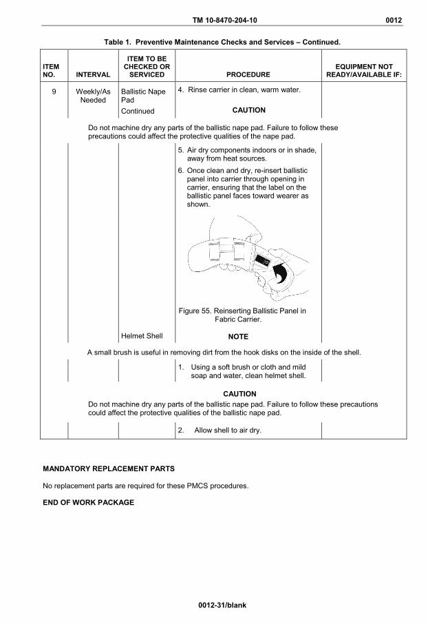
TM 10-8470-204-10 0012
0012-31/blank
Table 1. Preventive Maintenance Checks and Services – Continued.
ITEM NO. INTERVAL
ITEM TO BE CHECKED OR
SERVICED
PROCEDURE
EQUIPMENT NOT
READY/AVAILABLE IF:
9 Weekly/As Needed
Ballistic Nape Pad Continued
4. Rinse carrier in clean, warm water.
CAUTION
Do not machine dry any parts of the ballistic nape pad. Failure to follow these precautions could affect the protective qualities of the nape pad.
5. Air dry components indoors or in shade, away from heat sources.
6. Once clean and dry, re-insert ballistic panel into carrier through opening in carrier, ensuring that the label on the ballistic panel faces toward wearer as shown.
Figure 55. Reinserting Ballistic Panel in
Fabric Carrier.
Helmet Shell NOTE
A small brush is useful in removing dirt from the hook disks on the inside of the shell.
1. Using a soft brush or cloth and mild soap and water, clean helmet shell.
CAUTION Do not machine dry any parts of the ballistic nape pad. Failure to follow these precautions could affect the protective qualities of the ballistic nape pad.
2. Allow shell to air dry. MANDATORY REPLACEMENT PARTS No replacement parts are required for these PMCS procedures. END OF WORK PACKAGE


TM 10-8470-204-10
CHAPTER 5
MAINTENANCE INSTRUCTIONS
FOR
ADVANCED COMBAT HELMET (ACH)

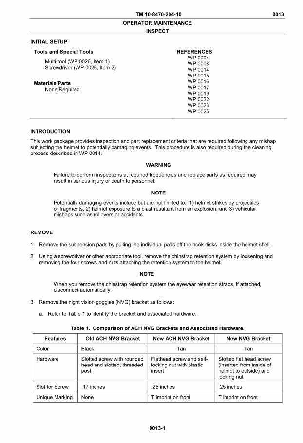
TM 10-8470-204-10 0013 OPERATOR MAINTENANCE
INSPECT
0013-1
INITIAL SETUP:
Tools and Special Tools
Multi-tool (WP 0026, Item 1) Screwdriver (WP 0026, Item 2)
Materials/Parts None Required
REFERENCES WP 0004 WP 0008 WP 0014 WP 0015 WP 0016 WP 0017 WP 0019 WP 0022 WP 0023 WP 0025
INTRODUCTION
This work package provides inspection and part replacement criteria that are required following any mishap subjecting the helmet to potentially damaging events. This procedure is also required during the cleaning process described in WP 0014.
WARNING
Failure to perform inspections at required frequencies and replace parts as required may result in serious injury or death to personnel.
NOTE
Potentially damaging events include but are not limited to: 1) helmet strikes by projectiles or fragments, 2) helmet exposure to a blast resultant from an explosion, and 3) vehicular mishaps such as rollovers or accidents.
REMOVE 1. Remove the suspension pads by pulling the individual pads off the hook disks inside the helmet shell.
2. Using a screwdriver or other appropriate tool, remove the chinstrap retention system by loosening and
removing the four screws and nuts attaching the retention system to the helmet.
NOTE
When you remove the chinstrap retention system the eyewear retention straps, if attached, disconnect automatically.
3. Remove the night vision goggles (NVG) bracket as follows:
a. Refer to Table 1 to identify the bracket and associated hardware.
Table 1. Comparison of ACH NVG Brackets and Associated Hardware.
Features Old ACH NVG Bracket New ACH NVG Bracket New NVG Bracket
Color Black Tan Tan
Hardware Slotted screw with rounded head and slotted, threaded post
Flathead screw and self-locking nut with plastic insert
Slotted flat head screw (inserted from inside of helmet to outside) and locking nut
Slot for Screw .17 inches .25 inches .25 inches
Unique Marking None T imprint on front T imprint on front

TM 10-8470-204-10 0013
0013-2
REMOVE – CONTINUED
b. Remove the NVG bracket hardware. Either:
(1) Use a screwdriver to loosen and remove the screw and threaded post, or (2) Use a multi-tool or like tool to loosen and remove the screw and self-locking nut.
c. Pull up on the bracket and remove it from the helmet.
4. Remove the ballistic nape pad, if installed, as follows:
a. Disconnect the hook and loop fasteners attaching the ballistic nape pad to the chinstrap retention system.
b. Remove the ballistic nape pad from the chinstrap retention system as described in WP 0017.
5. Remove the helmet cover as follows:
a. Disconnect the hook and loop fasteners. b. Pull the cover off the helmet.
NOTE
Inspect helmet shell first. If the helmet shell is damaged as described below, replace the helmet. See WP 0025 for NSN information.
INSPECT 1. Conduct visual inspection of helmet shell as follows:
a. Inspect the edge of the helmet for damage to the rubber edging. b. Look for evidence of peeling, fraying or extensive wear. c. Inspect the inside and outside surfaces of the helmet for damage.
(1) Look for holes and evidence of delamination (separation of helmet layers). Replace the helmet if
the shell has a hole through its surface or delamination extends below the surface of the helmet (below the paint).
(2) Look for surface scarring or indentations. Replace the helmet if there are any surface
indentations greater than 0.15 inches in depth.
d. If there is no evidence of helmet damage, continue to step 2.
WARNING
Replace all suspensions pads if Soldier/Marine receives concussion while wearing the helmet. Replacement of the pads is a precautionary measure. The helmet pads, at the time the Soldier/Marine received the concussion injury, likely provided the Soldier/Marine the designed level of protection. However, the pads may have sustained performance degrading damage during the event that caused the concussion. Failure to replace suspension pads may result in serious injury or death to personnel.
2. Conduct inspection of each suspension pad as follows:
a. Inspect visually for rips, tears or cuts. If any of the pads have evident physical damage (cuts, rips, holes, burns) as shown in Figure 1, they are defective and should be replaced as described in WP 0022.

TM 10-8470-204-10 0013
0013-3
INSPECT– CONTINUED
Figure 1. Damaged Suspension Pads.
b. Inspect each pad for dynamic response by squeezing all pads, including the crown and trapezoidal pads, lightly between the thumb and forefinger as shown in Figure 2.
WARNING
If any of the pads show a noticeable delay in returning to its original shape following compression between the thumb and forefinger or if it has other evident physical damage (cuts, rips, holes, burns) it is defective and should be replaced as described in WP 0022. Failure to do so may result in serious injury or death to personnel.
(1) Observe whether the pad instantly returns to its original shape upon release. If any of the pads
show a noticeable delay in returning to its original shape following compression between the thumb and forefinger, replace them as described in WP 0022.
Figure 2. Squeezing Pad for Dynamic Response.
(2) Observe whether pads exhibit indications of material breakdown or failure. Some indicators of material breakdown or failure are that they release just during or after compression; they feel stiffer than usual; they sound or feel crinkly during or after compression; or areas appear to be permanently depressed. Replace pads exhibiting signs of breakdown or failure as described in WP 0022.
c. If there is no evidence of material breakdown or failure and there have been no head injuries
diagnosed as a concussion, continue to step 3.

TM 10-8470-204-10 0013
0013-4
INSPECT – CONTINUED 3. Visually inspect the chinstrap retention system as follows:
a. Inspect the retention system for cuts, frays, other damage, and loose or damaged stitching in the webbing. If the webbing is frayed more than ½ inch or has a discernable cut, or loose or damaged stitching, replace the chinstrap retention system as described in WP 0019.
b. Inspect for missing, cracked, worn, or damaged hardware on buckle assembly. If the buckle assembly
is damaged or broken, replace the chinstrap retention system as described in WP 0019. c. Inspect for damaged or missing hardware. If there is missing or damaged hardware, replace it as
described in WP 0019. d. If there is loose hardware, tighten it. There should be nothing loose at this point.
e. Continue to step 4 if:
(1) There are no cuts, frays, or other damage to the chinstrap retention system stitching or webbing. (2) There is no missing, cracked, worn or damaged hardware. (3) The buckle assembly is not missing or damaged.
4. Visually inspect the NVG bracket as follows:
a. Inspect for a cracked bracket. If the NVG bracket is cracked, replace it as described in WP 0016. b. Inspect for missing hardware. If the NVG bracket hardware is missing or damaged, replace it as
described in WP 0023.
c. If the NVG bracket and hardware are not missing or damaged, continue to step 5. 5. Visually inspect the ballistic nape pad, if installed, as follows:
a. Inspect for evidence of being hit by bullet or a fragment. If the ballistic nape pad shows evidence of being hit by a bullet or fragment, replace the ballistic nape pad as described in WP 0017.
b. Inspect for tears or damage to the fabric carrier. If the fabric carrier is torn or damaged, replace it as
described in WP 0017.
c. If the ballistic nape pad shows no evidence of bullet or fragment damage and the fabric carrier is not torn or damaged continue to install the components.
END OF TASK
TM 10-8470-204-10 0013
0013-5/blank
INSTALL
WARNING
The hardware for all helmets, where the chinstrap retention system webbing attaches to the helmet shell, must be covered by padding during airborne and other high risk operations such as air assault and rappelling/mountaineering. The oblong/oval pads must be placed flush with the rim (edge) of the helmet and completely cover the hardware.
1. Install the chinstrap retention system as described in WP 0019.
2. Install the helmet cover as described in WP 0015. 3. Install the suspension pads as follows:
a. Attach the suspension pads in the standard configuration as described in WP 0004. b. Adjust the fit of the helmet, if necessary, as described in WP 0008.
4. Install the ballistic nape pad as described in WP 0017. 5. Install the NVG bracket as described in WP 0016. END OF TASK END OF WORK PACKAGE

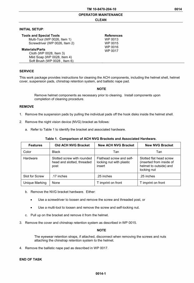
TM 10-8470-204-10 0014 OPERATOR MAINTENANCE
CLEAN
0014-1
INITIAL SETUP:
Tools and Special Tools Multi-Tool (WP 0026, Item 1) Screwdriver (WP 0026, Item 2)
Materials/Parts Cloth (WP 0028, Item 3) Mild Soap (WP 0028, Item 4) Soft Brush (WP 0028 , Item 6)
References WP 0013 WP 0015 WP 0016 WP 0017
SERVICE
This work package provides instructions for cleaning the ACH components, including the helmet shell, helmet cover, suspension pads, chinstrap retention system, and ballistic nape pad.
NOTE
Remove helmet components as necessary prior to cleaning. Install components upon completion of cleaning procedure.
REMOVE 1. Remove the suspension pads by pulling the individual pads off the hook disks inside the helmet shell.
2. Remove the night vision device (NVG) bracket as follows:
a. Refer to Table 1 to identify the bracket and associated hardware.
Table 1. Comparison of ACH NVG Brackets and Associated Hardware.
Features Old ACH NVG Bracket New ACH NVG Bracket New NVG Bracket
Color Black Tan Tan
Hardware Slotted screw with rounded head and slotted, threaded post
Flathead screw and self-locking nut with plastic insert
Slotted flat head screw (inserted from inside of helmet to outside) and locking nut
Slot for Screw .17 inches .25 inches .25 inches
Unique Marking None T imprint on front T imprint on front
b. Remove the NVG bracket hardware. Either:
• Use a screwdriver to loosen and remove the screw and threaded post, or • Use a multi-tool to loosen and remove the screw and self-locking nut.
c. Pull up on the bracket and remove it from the helmet.
3. Remove the cover and chinstrap retention system as described in WP 0015.
NOTE
The eyewear retention straps, if attached, disconnect when removing the screws and nuts attaching the chinstrap retention system to the helmet.
4. Remove the ballistic nape pad as described in WP 0017. END OF TASK
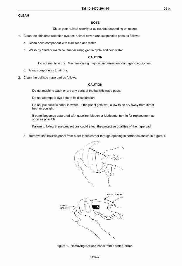
TM 10-8470-204-10 0014
0014-2
CLEAN
NOTE
Clean your helmet weekly or as needed depending on usage.
1. Clean the chinstrap retention system, helmet cover, and suspension pads as follows:
a. Clean each component with mild soap and water. b. Wash by hand or machine launder using gentle cycle and cold water.
CAUTION
Do not machine dry. Machine drying may cause permanent damage to equipment.
c. Allow components to air dry. 2. Clean the ballistic nape pad as follows:
CAUTION
Do not machine wash or dry any parts of the ballistic nape pads. Do not attempt to dye item to fix discoloration. Do not put ballistic panel in water. If the panel gets wet, allow to air dry away from direct heat or sunlight. If panel becomes saturated with gasoline, bleach or lubricants, turn in for replacement as soon as possible. Failure to follow these precautions could affect the protective qualities of the nape pad.
a. Remove soft ballistic panel from outer fabric carrier through opening in carrier as shown in Figure 1.
Figure 1. Removing Ballistic Panel from Fabric Carrier.
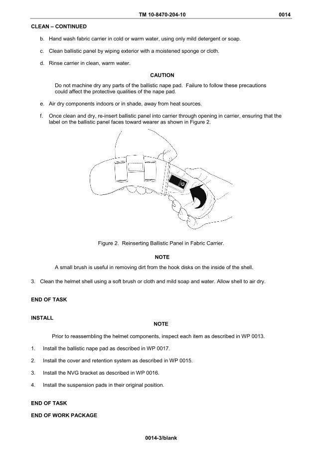
TM 10-8470-204-10 0014
0014-3/blank
CLEAN – CONTINUED
b. Hand wash fabric carrier in cold or warm water, using only mild detergent or soap. c. Clean ballistic panel by wiping exterior with a moistened sponge or cloth. d. Rinse carrier in clean, warm water.
CAUTION
Do not machine dry any parts of the ballistic nape pad. Failure to follow these precautions could affect the protective qualities of the nape pad.
e. Air dry components indoors or in shade, away from heat sources. f. Once clean and dry, re-insert ballistic panel into carrier through opening in carrier, ensuring that the
label on the ballistic panel faces toward wearer as shown in Figure 2.
Figure 2. Reinserting Ballistic Panel in Fabric Carrier.
NOTE
A small brush is useful in removing dirt from the hook disks on the inside of the shell.
3. Clean the helmet shell using a soft brush or cloth and mild soap and water. Allow shell to air dry. END OF TASK INSTALL
NOTE
Prior to reassembling the helmet components, inspect each item as described in WP 0013. 1. Install the ballistic nape pad as described in WP 0017. 2. Install the cover and retention system as described in WP 0015.
3. Install the NVG bracket as described in WP 0016. 4. Install the suspension pads in their original position.
END OF TASK END OF WORK PACKAGE

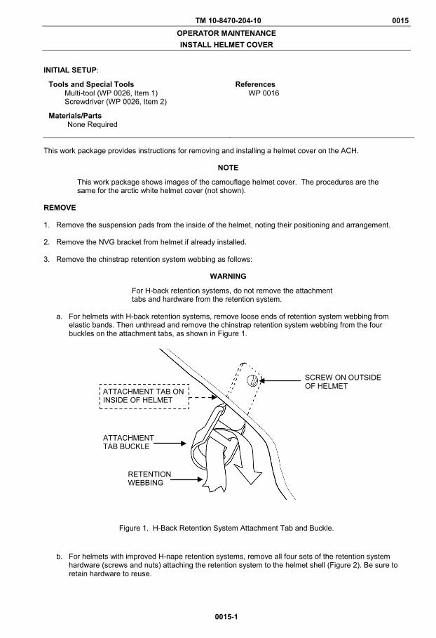
TM 10-8470-204-10 0015 OPERATOR MAINTENANCE INSTALL HELMET COVER
0015-1
INITIAL SETUP:
Tools and Special Tools Multi-tool (WP 0026, Item 1) Screwdriver (WP 0026, Item 2)
Materials/Parts None Required
References WP 0016
This work package provides instructions for removing and installing a helmet cover on the ACH.
NOTE
This work package shows images of the camouflage helmet cover. The procedures are the same for the arctic white helmet cover (not shown).
REMOVE 1. Remove the suspension pads from the inside of the helmet, noting their positioning and arrangement.
2. Remove the NVG bracket from helmet if already installed.
3. Remove the chinstrap retention system webbing as follows:
WARNING
For H-back retention systems, do not remove the attachment tabs and hardware from the retention system.
a. For helmets with H-back retention systems, remove loose ends of retention system webbing from
elastic bands. Then unthread and remove the chinstrap retention system webbing from the four buckles on the attachment tabs, as shown in Figure 1.
Figure 1. H-Back Retention System Attachment Tab and Buckle.
b. For helmets with improved H-nape retention systems, remove all four sets of the retention system hardware (screws and nuts) attaching the retention system to the helmet shell (Figure 2). Be sure to retain hardware to reuse.
ATTACHMENT TAB BUCKLE
SCREW ON OUTSIDE OF HELMET
ATTACHMENT TAB ON INSIDE OF HELMET
RETENTION WEBBING

TM 10-8470-204-10 0015
0015-2
REMOVE – CONTINUED
Figure 2. Improved H-Nape Retention System Attachment Tab and Hardware.
4. Disconnect the hook and loop fasteners attaching the helmet cover to the helmet shell. 5. Pull the old cover from the helmet. END OF TASK INSTALL 1. Orient the replacement helmet cover with the NVG bracket location facing the front of the helmet, as shown
in Figure 3.
Figure 3. Outside of Helmet Cover.
2. Pull the cover over the back and sides of the helmet.
NOTE
Do not overlap the tabs of the helmet cover. Doing so may cause helmet to fit improperly.
3. Proceed as follows:
a. For H-back retention systems, thread each buckle through the corresponding buttonhole in the cover. Then pull the cover retaining tabs down and attach tabs to hook disks inside helmet shell (Figure 4).
b. For improved H-nape retention systems, pull the cover retaining tabs down and attach tabs to hook disks inside helmet shell (Figure 4).
NVG BRACKET LOCATION
ATTACHMENT TAB ON INSIDE OF HELMET
SCREW ON OUTSIDE OF HELMET
T-NUT ON INSIDE OF HELMET
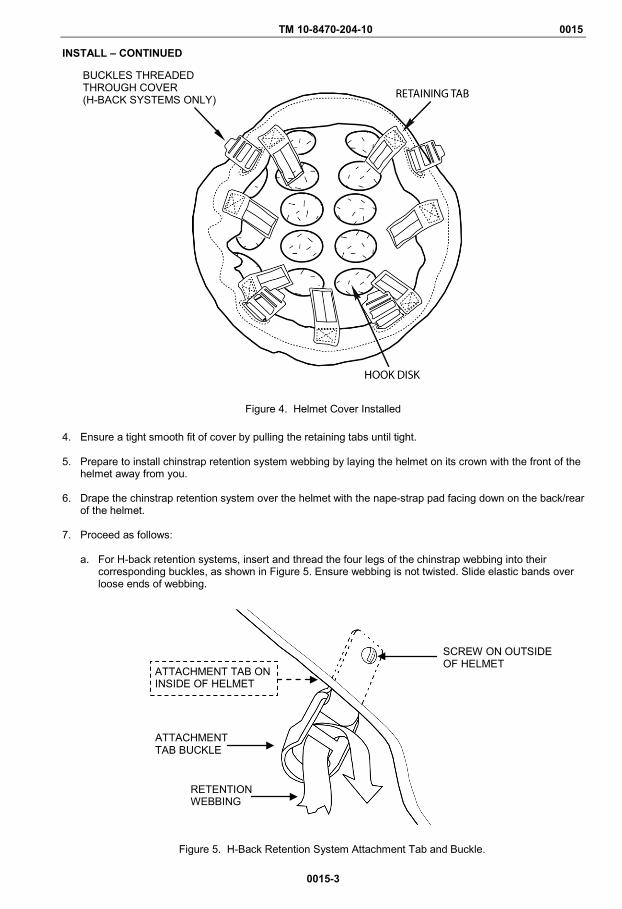
TM 10-8470-204-10 0015
0015-3
INSTALL – CONTINUED
Figure 4. Helmet Cover Installed
4. Ensure a tight smooth fit of cover by pulling the retaining tabs until tight.
5. Prepare to install chinstrap retention system webbing by laying the helmet on its crown with the front of the helmet away from you.
6. Drape the chinstrap retention system over the helmet with the nape-strap pad facing down on the back/rear
of the helmet.
7. Proceed as follows:
a. For H-back retention systems, insert and thread the four legs of the chinstrap webbing into their corresponding buckles, as shown in Figure 5. Ensure webbing is not twisted. Slide elastic bands over loose ends of webbing.
Figure 5. H-Back Retention System Attachment Tab and Buckle.
BUCKLES THREADED THROUGH COVER (H-BACK SYSTEMS ONLY)
ATTACHMENT TAB BUCKLE
SCREW ON OUTSIDE OF HELMET
ATTACHMENT TAB ON INSIDE OF HELMET
RETENTION WEBBING
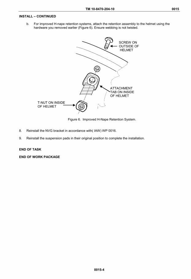
TM 10-8470-204-10 0015
0015-4
INSTALL – CONTINUED
b. For improved H-nape retention systems, attach the retention assembly to the helmet using the hardware you removed earlier (Figure 6). Ensure webbing is not twisted.
Figure 6. Improved H-Nape Retention System.
8. Reinstall the NVG bracket in accordance with( IAW) WP 0016. 9. Reinstall the suspension pads in their original position to complete the installation.
END OF TASK END OF WORK PACKAGE
ATTACHMENT TAB ON INSIDE OF HELMET
SCREW ON OUTSIDE OF HELMET
T-NUT ON INSIDE OF HELMET

TM 10-8470-204-10 0016 OPERATOR MAINTENANCE
INSTALL BRACKET ASSEMBLY FOR NIGHT VISION GOGGLES (NVG)
0016-1
INITIAL SETUP:
Tools and Special Tools Multi-Tool (WP 0026, Item 1) Screwdriver (WP 0026, Item 2)
References WP 0019 WP 0027
Materials/Parts None Required
INTRODUCTION This work package provides instructions for removing and installing the bracket assembly for the ACH night vision goggles (NVG). Refer to Table 1 to identify the bracket. REMOVE
WARNING
The NVG bracket must be installed and worn by all Soldiers at all times. Failure to do so may result in injury or death to personnel.
NOTE
The ACH NVG bracket assemblies share the same NSN. 1. If an NVG bracket is already installed and needs to be replaced, remove the existing bracket as follows:
a. Identify which NVG bracket is on helmet by referring to Table 1 and Figures 1 through 3.
Table 1. Comparison of ACH NVG Brackets.
Features Old ACH NVG Bracket New ACH NVG Bracket New NVG Bracket
Color Black Tan Tan
Hardware Slotted screw with rounded head and slotted, threaded post
Flathead screw and self-locking nut with plastic insert
Slotted flat head screw (inserted from inside of helmet to outside) and locking nut
Slot for Screw .17 inches .25 inches .25 inches
Unique Marking None T imprint on front T imprint on front
b. Remove front trapezoidal pad. c. Remove NVG bracket hardware. Either:
(1) Use a screwdriver to loosen and remove the screw and threaded post, or (2) Use a multi-tool to loosen and remove the screw and self-locking nut.
2. Pull up on the bracket and remove it from the helmet.
END OF TASK
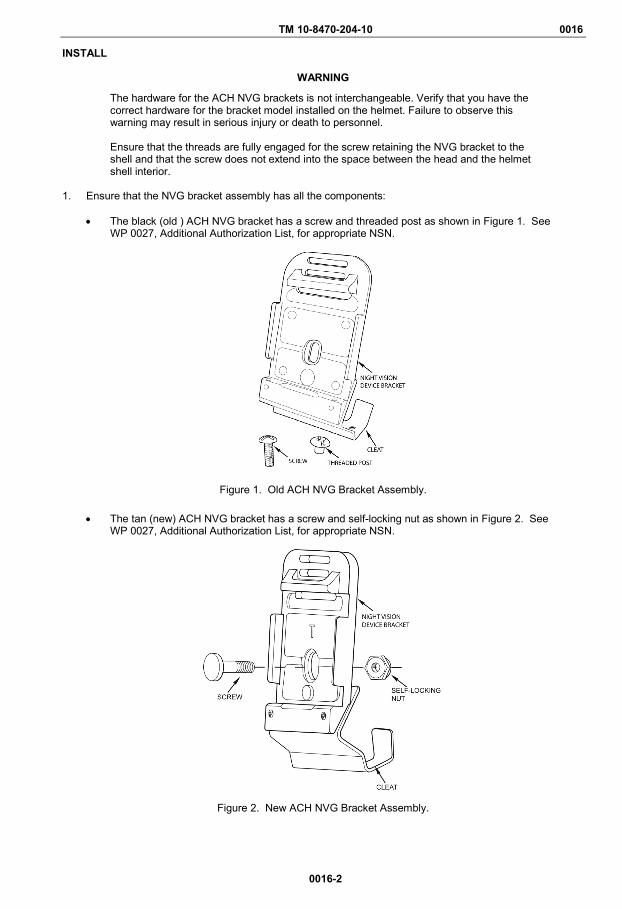
TM 10-8470-204-10 0016
0016-2
INSTALL
WARNING
The hardware for the ACH NVG brackets is not interchangeable. Verify that you have the correct hardware for the bracket model installed on the helmet. Failure to observe this warning may result in serious injury or death to personnel. Ensure that the threads are fully engaged for the screw retaining the NVG bracket to the shell and that the screw does not extend into the space between the head and the helmet shell interior.
1. Ensure that the NVG bracket assembly has all the components:
• The black (old ) ACH NVG bracket has a screw and threaded post as shown in Figure 1. See
WP 0027, Additional Authorization List, for appropriate NSN.
Figure 1. Old ACH NVG Bracket Assembly.
• The tan (new) ACH NVG bracket has a screw and self-locking nut as shown in Figure 2. See WP 0027, Additional Authorization List, for appropriate NSN.
Figure 2. New ACH NVG Bracket Assembly.

TM 10-8470-204-10 0016
0016-3/blank
INSTALL – CONTINUED
• The tan (new) NVG bracket has a screw and self-locking nut as shown in Figure 3. See WP 0027, Additional Authorization List, for appropriate NSN.
Figure 3. New NVG Bracket Assembly. 2. Remove trapezoidal pad, if necessary.
3. If there is a cover installed, loosen the hook and loop tabs, if necessary.
4. Line up the hole on the center of the bracket, the front vertical buttonhole on the cover, and the hole on
the helmet shell. NOTE
It may be necessary to tap the bracket into place to properly align the helmet shell, cover, and bracket holes.
5. Insert the screw through the bracket assembly, cover, and helmet shell as shown in Figures 1 through 3.
6. Using a multi-tool, slightly tighten the screw and self-locking nut or threaded post.
CAUTION
Do not over tighten the self-locking nut/threaded post or the bracket may break.
7. Push the bracket up so that the cleat is tight against the rim (edge) of the helmet while completely tightening the corresponding screw and self-locking nut or threaded post.
8. Pull the helmet cover retaining tabs down and attach tabs to hook disks inside helmet shell.
9. Ensure a tight smooth fit of cover by pulling the retaining tabs until tight.
10. Replace trapezoidal pad. END OF TASK END OF WORK PACKAGE
NUT FLATHEAD SLOTTED SCREW

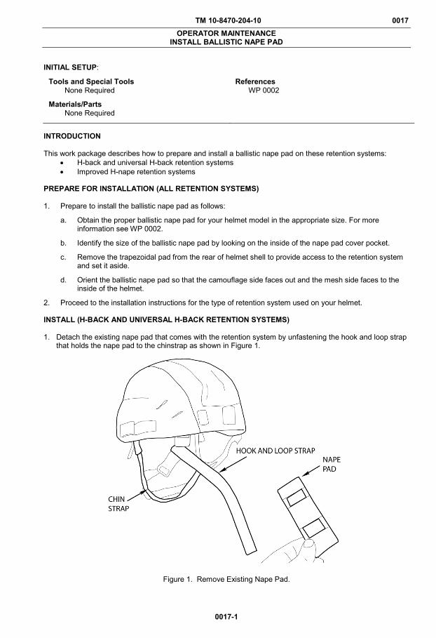
TM 10-8470-204-10 0017 OPERATOR MAINTENANCE
INSTALL BALLISTIC NAPE PAD
0017-1
INITIAL SETUP:
Tools and Special Tools None Required
References WP 0002
Materials/Parts None Required
INTRODUCTION This work package describes how to prepare and install a ballistic nape pad on these retention systems:
• H-back and universal H-back retention systems • Improved H-nape retention systems
PREPARE FOR INSTALLATION (ALL RETENTION SYSTEMS) 1. Prepare to install the ballistic nape pad as follows:
a. Obtain the proper ballistic nape pad for your helmet model in the appropriate size. For more information see WP 0002.
b. Identify the size of the ballistic nape pad by looking on the inside of the nape pad cover pocket.
c. Remove the trapezoidal pad from the rear of helmet shell to provide access to the retention system and set it aside.
d. Orient the ballistic nape pad so that the camouflage side faces out and the mesh side faces to the inside of the helmet.
2. Proceed to the installation instructions for the type of retention system used on your helmet. INSTALL (H-BACK AND UNIVERSAL H-BACK RETENTION SYSTEMS) 1. Detach the existing nape pad that comes with the retention system by unfastening the hook and loop strap
that holds the nape pad to the chinstrap as shown in Figure 1.
Figure 1. Remove Existing Nape Pad.
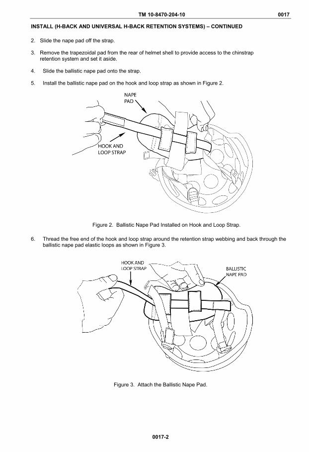
TM 10-8470-204-10 0017
0017-2
INSTALL (H-BACK AND UNIVERSAL H-BACK RETENTION SYSTEMS) – CONTINUED
2. Slide the nape pad off the strap. 3. Remove the trapezoidal pad from the rear of helmet shell to provide access to the chinstrap
retention system and set it aside. 4. Slide the ballistic nape pad onto the strap. 5. Install the ballistic nape pad on the hook and loop strap as shown in Figure 2.
Figure 2. Ballistic Nape Pad Installed on Hook and Loop Strap.
6. Thread the free end of the hook and loop strap around the retention strap webbing and back through the ballistic nape pad elastic loops as shown in Figure 3.
Figure 3. Attach the Ballistic Nape Pad.

TM 10-8470-204-10 0017
0017-3
INSTALL (H-BACK AND UNIVERSAL H-BACK RETENTION SYSTEMS) – CONTINUED 7. Slide the ballistic nape pad toward the helmet shell until shell and ballistic nape pad overlap by
approximately ½ inch as shown in Figure 4.
Figure 4. Fit Ballistic Nape Pad into Helmet Shell.
8. With the ballistic nape pad overlapping shell edge, press the loop tab against the hook disks on the inside of the shell (Figure 5).
Figure 5. Attach Ballistic Nape Pad to Helmet Shell.
9. Install the rear trapezoidal pad such that it is firmly affixed to the hook disk and snug against the edge of the ballistic nape pad.
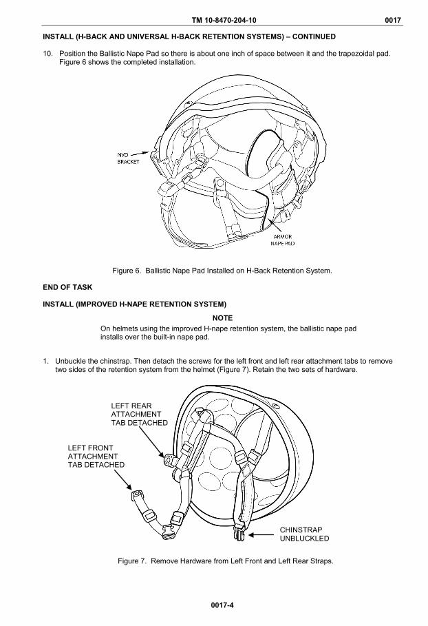
TM 10-8470-204-10 0017
0017-4
INSTALL (H-BACK AND UNIVERSAL H-BACK RETENTION SYSTEMS) – CONTINUED 10. Position the Ballistic Nape Pad so there is about one inch of space between it and the trapezoidal pad.
Figure 6 shows the completed installation.
Figure 6. Ballistic Nape Pad Installed on H-Back Retention System.
END OF TASK INSTALL (IMPROVED H-NAPE RETENTION SYSTEM)
NOTE On helmets using the improved H-nape retention system, the ballistic nape pad installs over the built-in nape pad.
1. Unbuckle the chinstrap. Then detach the screws for the left front and left rear attachment tabs to remove
two sides of the retention system from the helmet (Figure 7). Retain the two sets of hardware.
Figure 7. Remove Hardware from Left Front and Left Rear Straps.
LEFT REAR ATTACHMENT TAB DETACHED
LEFT FRONT ATTACHMENT TAB DETACHED
CHINSTRAP UNBLUCKLED
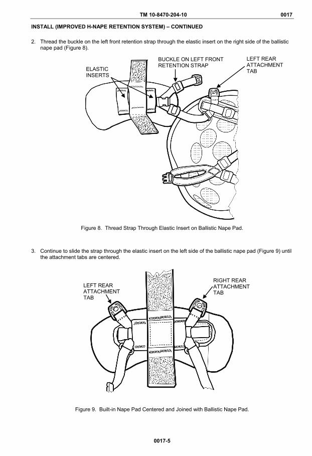
TM 10-8470-204-10 0017
0017-5
INSTALL (IMPROVED H-NAPE RETENTION SYSTEM) – CONTINUED 2. Thread the buckle on the left front retention strap through the elastic insert on the right side of the ballistic
nape pad (Figure 8).
Figure 8. Thread Strap Through Elastic Insert on Ballistic Nape Pad.
3. Continue to slide the strap through the elastic insert on the left side of the ballistic nape pad (Figure 9) until the attachment tabs are centered.
Figure 9. Built-in Nape Pad Centered and Joined with Ballistic Nape Pad.
BUCKLE ON LEFT FRONT RETENTION STRAP
LEFT REAR ATTACHMENT TAB ELASTIC
INSERTS
LEFT REAR ATTACHMENT TAB
RIGHT REAR ATTACHMENT TAB
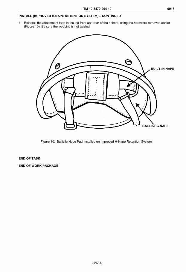
TM 10-8470-204-10 0017
0017-6
INSTALL (IMPROVED H-NAPE RETENTION SYSTEM) – CONTINUED
4. Reinstall the attachment tabs to the left front and rear of the helmet, using the hardware removed earlier (Figure 10). Be sure the webbing is not twisted
Figure 10. Ballistic Nape Pad Installed on Improved H-Nape Retention System.
END OF TASK END OF WORK PACKAGE
BUILT-IN NAPE
BALLISTIC NAPE
TM 10-8470-204-10 0018 OPERATOR MAINTENANCE
REPLACE ATTACHMENT TABS (UNIVERSAL H-BACK)
0018-1
INITIAL SETUP:
Tools and Special Tools Multi-tool (WP 0026, Item 1) Screwdriver (WP 0026, Item
2) Materials/Parts
None Required
References WP 0002 WP 0004 WP 0019 WP 0025 WP 0027
INTRODUCTION
This work package provides instructions for replacing the attachment tabs (with buckle) of the H-back universal chinstrap retention system. The tabs attach the chinstrap to the helmet.
REMOVE
1. Remove suspension pads as necessary to access hardware inside helmet, using a standard flatheadscrewdriver.
2. Unfasten the helmet cover retaining tabs to expose the two rear screws, and remove the cover.
3. Identify which chinstrap retention system is installed.
NOTE
Chinstrap retention system hardware is not interchangeable. If the chinstrap retention system needs to be replaced for any of the legacy H-back or the X-back products, replace the entire chinstrap retention system assembly with a new universal H-back chinstrap retention system (WP 0019) assembly. This assembly includes the corresponding universal H-back chinstrap retention system and hardware.
• If the helmet has a legacy H-back or X-back chinstrap retention system, install a new universal H-backchinstrap retention system as described in WP 0019.
• If the helmet has a universal H-back chinstrap retention system, go to step 4.
NOTE
The attachment tabs disengage from the helmet.
4. To remove the retention system:
a. Remove webbing from elastic bands.
b. Unthread and remove the chinstrap webbing from the four buckles on the attachment tabs.
c. Using a screwdriver, remove the four screws securing the attachment tabs to the helmet.
END OF TASK
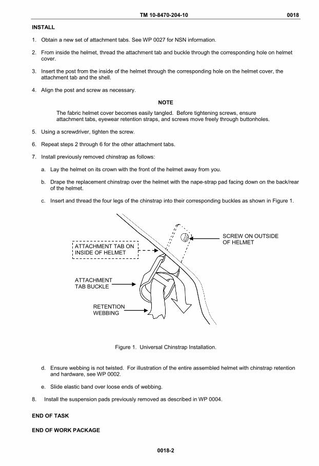
TM 10-8470-204-10 0018
0018-2
INSTALL 1. Obtain a new set of attachment tabs. See WP 0027 for NSN information. 2. From inside the helmet, thread the attachment tab and buckle through the corresponding hole on helmet
cover.
3. Insert the post from the inside of the helmet through the corresponding hole on the helmet cover, the attachment tab and the shell.
4. Align the post and screw as necessary.
NOTE
The fabric helmet cover becomes easily tangled. Before tightening screws, ensure attachment tabs, eyewear retention straps, and screws move freely through buttonholes.
5. Using a screwdriver, tighten the screw. 6. Repeat steps 2 through 6 for the other attachment tabs.
7. Install previously removed chinstrap as follows:
a. Lay the helmet on its crown with the front of the helmet away from you. b. Drape the replacement chinstrap over the helmet with the nape-strap pad facing down on the back/rear
of the helmet. c. Insert and thread the four legs of the chinstrap into their corresponding buckles as shown in Figure 1.
Figure 1. Universal Chinstrap Installation.
d. Ensure webbing is not twisted. For illustration of the entire assembled helmet with chinstrap retention
and hardware, see WP 0002.
e. Slide elastic band over loose ends of webbing.
8. Install the suspension pads previously removed as described in WP 0004.
END OF TASK
END OF WORK PACKAGE
ATTACHMENT TAB BUCKLE
SCREW ON OUTSIDE OF HELMET
ATTACHMENT TAB ON INSIDE OF HELMET
RETENTION WEBBING
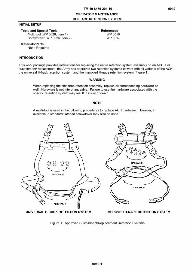
TM 10-8470-204-10 0019 OPERATOR MAINTENANCE
REPLACE RETENTION SYSTEM
0019-1
INITIAL SETUP:
Tools and Special Tools Multi-tool (WP 0026, Item 1) Screwdriver (WP 0026, Item 2)
Materials/Parts None Required
References WP 0016 WP 0017
INTRODUCTION This work package provides instructions for replacing the entire retention system assembly on an ACH. For sustainment/ replacement, the Army has approved two retention systems to work with all variants of the ACH: the universal H-back retention system and the improved H-nape retention system (Figure 1).
WARNING
When replacing the chinstrap retention assembly, replace all corresponding hardware as well. Hardware is not interchangeable. Failure to use the hardware associated with the specific retention system may result in injury or death.
NOTE
A multi-tool is used in the following procedures to replace ACH hardware. However, if available, a standard flathead screwdriver may also be used.
UNIVERSAL H-BACK RETENTION SYSTEM IMPROVED H-NAPE RETENTION SYSTEM
Figure 1. Approved Sustainment/Replacement Retention Systems.

TM 10-8470-204-10 0019
0019-2
REMOVE THE RETENTION SYSTEM ASSEMBLY 1. Remove the suspension pads from the inside of the helmet, noting their positioning and arrangement. 2. Remove NVG bracket from helmet if already installed. 3. If installed, remove the cover.
WARNING When replacing the chinstrap retention assembly, replace all corresponding hardware as well. Hardware is not interchangeable. Failure to use the hardware associated with the specific retention system may result in injury or death.
NOTE For legacy H-back retention systems, be sure to remove the entire retention system assembly including the attachment tabs by unscrewing the hardware at the point where the attachment tabs join the helmet shell.
4. Remove the entire chinstrap retention system. Refer to Figures 2 and 3 for hardware specifics.
Figure 2. H-Back Retention System Breakout.
Figure 3. Improved H-Nape Retention System Attachment Tab and Hardware. END OF TASK
ATTACHMENT TAB BUCKLE
SCREW ON OUTSIDE OF HELMET
ATTACHMENT TAB ON INSIDE OF HELMET
RETENTION WEBBING
ATTACHMENT TAB ON INSIDE OF HELMET
SCREW ON OUTSIDE OF HELMET
T-NUT ON INSIDE OF HELMET
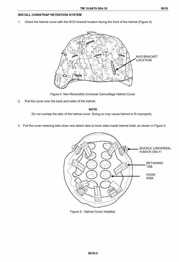
TM 10-8470-204-10 0019
0019-3
INSTALL CHINSTRAP RETENTION SYSTEM 1. Orient the helmet cover with the NVG bracket location facing the front of the helmet (Figure 4).
Figure 4. Non-Reversible Universal Camouflage Helmet Cover. 2. Pull the cover over the back and sides of the helmet.
NOTE Do not overlap the tabs of the helmet cover. Doing so may cause helmet to fit improperly.
3. Pull the cover retaining tabs down and attach tabs to hook disks inside helmet shell, as shown in Figure 5.
Figure 5. Helmet Cover Installed.
NVG BRACKET LOCATION
BUCKLE (UNIVERSAL H-BACK ONLY)
RETAINING TAB
HOOK DISK

TM 10-8470-204-10 0019
0019-4
INSTALL CHINSTRAP RETENTION ASSEMBLY – CONTINUED
4. Ensure a tight smooth fit of cover by pulling the retaining tabs until tight.5. Position the retention system for installation by laying the helmet on its crown with the front of the helmet
away from you.6. Drape the chinstrap retention system over the helmet with the nape-strap pad facing down on the back/rear
of the helmet.7. If a ballistic nape pad is to be worn, install it at this time (WP 0017).8. Attach the replacement retention assembly to the helmet using the hardware provided (Figures 6 and 7). If
the helmet has elastic bands along the webbing, slide the bands over the loose ends of webbing to secure.
Figure 6. H-Back Retention System Breakout.
Figure 7. Improved H-Nape Retention System.
T-NUT ON INSIDE OF HELMET
SCREW ON OUTSIDE OF HELMET
ATTACHMENT TAB ON INSIDE OF HELMET
ATTACHMENT TAB BUCKLE
SCREW ON OUTSIDE OF HELMET
ATTACHMENT TAB ON INSIDE OF HELMET
RETENTION WEBBING
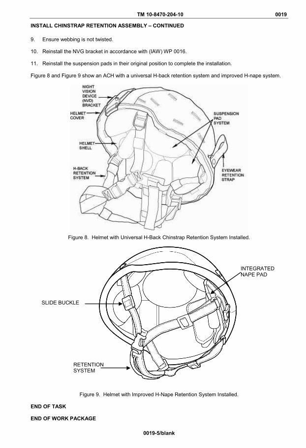
TM 10-8470-204-10 0019
0019-5/blank
INSTALL CHINSTRAP RETENTION ASSEMBLY – CONTINUED
9. Ensure webbing is not twisted.
10. Reinstall the NVG bracket in accordance with (IAW) WP 0016.
11. Reinstall the suspension pads in their original position to complete the installation.
Figure 8 and Figure 9 show an ACH with a universal H-back retention system and improved H-nape system.
Figure 8. Helmet with Universal H-Back Chinstrap Retention System Installed.
Figure 9. Helmet with Improved H-Nape Retention System Installed.
END OF TASK
END OF WORK PACKAGE
SLIDE BUCKLE
INTEGRATED NAPE PAD
RETENTION SYSTEM

TM 10-8470-204-10 0020 OPERATOR MAINTENANCE
INSTALL EYEWEAR RETENTION STRAP
0020-1
INITIAL SETUP:
Tools and Special Tools Multi-tool (WP 0026, Item 1) Screwdriver (WP 0026, Item 2)
Materials/Parts None Required
References WP 0002 WP 0019 WP 0025 WP 0027
REMOVE
1. Remove suspension pads as necessary to access hardware in rear of helmet, noting how they arepositioned.
2. If necessary, unfasten the cover retaining tabs to expose the two rear screws.
3. Identify which chinstrap retention assembly is installed as described in WP 0002.
4. If there is a universal H-back chinstrap retention assembly installed, continue to step 6.
5. If there is a legacy H-back or X-back chinstrap retention assembly installed:
a. Obtain a new universal H-back chinstrap retention system and hardware. See WP 0025 for NSNinformation.
b. Using a screwdriver, remove the old chinstrap retention system.
c. Install the front portion (front two screws) of the new universal H-back chinstrap retention system asdescribed in WP 0019.
6. For helmets with an existing universal H-back chinstrap retention system and existing eyewear retentionstraps installed, remove eyewear straps as follows:
a. Using a screwdriver, remove the screws on the rear of the helmet that attach the eyewear retentionstraps and the chinstrap retention system to the helmet. The eyewear retention strap and the rearportion of the chinstrap retention system disengage.
b. Continue to the Install procedure.
7. If there are no existing eyewear retention straps installed:
a. Obtain a pair of eyewear retention straps. See WP 0027 for NSN information.
b. Continue to the Install procedure.
END OF TASK

TM 10-8470-204-10 0020
0020-2
INSTALL 1. Remove the suspension pads. 2. If necessary, remove the rear retention strap webbing from the buckle.
3. Unfasten the helmet cover retaining tabs and pull the cover away to expose the hardware.
NOTE
Be sure to install an eyewear retention strap on each of the two rear screws.
Holding the post on inside of helmet will ensure the attachment tab does not disengage while completing the remaining steps.
4. Remove one of the rear screws using a screwdriver or like tool and a multi-tool (if available).
5. From the outside of the helmet, place an eyewear retention strap over the shaft of the screw with the
snap socket and stud facing up and away from helmet as shown in Figure 1.
Figure 1. Universal Eyewear Retention Strap and Screw Assembly.
LEGEND 1. Eyewear retention strap (unsnapped) 2. Snap socket 3. Post 4. Attachment tab with buckle (shown inside helmet) 5. Hole in attachment tab 6. Hole in helmet shell 7. Hole in eyewear retention strap 8. Screw 9. Snap stud

TM 10-8470-204-10 0020
0020-3/blank
INSTALL – CONTINUED 6. Insert the screw, with the eyewear retention strap attached, into the hole in helmet through the
corresponding buttonhole in the helmet cover as shown in Figure 2.
Figure 2. Helmet with Eyewear Retention Strap Installed.
7. From inside the helmet, thread the attachment tab and buckle through the corresponding hole on helmet cover.
8. Align the post and screw as necessary.
9. Insert the post from the inside of the helmet through the corresponding hole on the helmet cover, the attachment tab and the shell until it reaches the screw.
10. Tuck end of eyewear retention strap into buttonhole.
NOTE
The fabric helmet cover becomes easily tangled. Before tightening screws, ensure attachment tabs, eyewear retention straps, and screws move freely through buttonholes.
11. Using a screwdriver or like tool and a multi-tool (if available), tighten the screw. 12. Repeat steps 4-11 for the other strap.
13. Install the suspensions pads that were previously removed. END OF TASK END OF WORK PACKAGE
LEGEND 1. Eyewear retention strap 2. Helmet cover 3. Lower most rear buttonhole 4. Screw (shown under cover)

TM 10-8470-204-10 0021 OPERATOR MAINTENANCE
REPLACE CHINSTRAP RETENTION SYSTEM HARDWARE
0021-1
INITIAL SETUP:
Tools and Special Tools Screwdriver (WP 0026, Item 2)
Materials/Parts None Required
References WP 0004 WP 0005 WP 0019 WP 0020 WP 0027
INTRODUCTION This work package provides instructions for removing and replacing the ACH hardware.
WARNING
The hardware for chinstrap retention systems is not interchangeable. If chinstrap retention system hardware needs to be replaced for any of the legacy H-back or the X-back products, replace the entire chinstrap retention system assembly with a new universal H-back chinstrap retention system (WP 0019). This assembly includes the corresponding universal H-back chinstrap retention system and hardware.
NOTE
If any component of an X-back chinstrap assembly needs to be replaced, replace the entire chinstrap retention system assembly with a new universal H-back chinstrap retention system (WP 0019). This assembly includes the corresponding universal H-back chinstrap retention system and corresponding hardware. The only hardware authorized for use with the ACH is obtained with the NSN listed in WP 0027. All other hardware and chinstraps are no longer supported.
REMOVE 1. Remove the suspension pads as necessary to access hardware and chinstrap retention system. 2. Disconnect the hook and loop fasteners attaching the helmet cover to the shell. 3. Using screwdrivers if available, remove the hardware. The chinstrap retention system and eyewear
retention tabs (if applicable) disengage. INSTALL 1. Install the hardware as follows:
a. Insert new hardware (four sets of screws and nuts) through the attachment tabs of the chinstrap retention system (WP 0019), and the eye wear retention tabs (if applicable), as described in WP 0020.
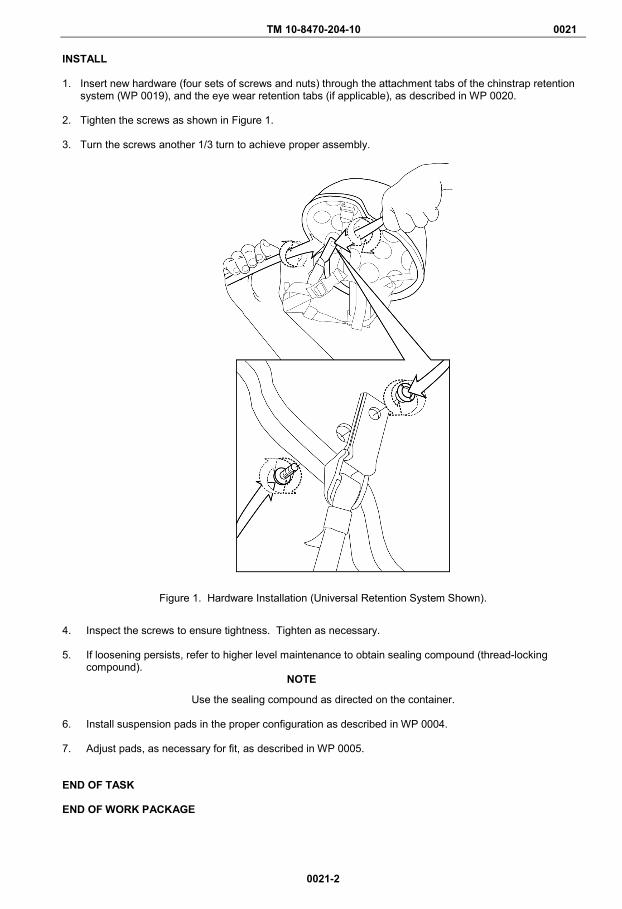
TM 10-8470-204-10 0021
0021-2
INSTALL 1. Insert new hardware (four sets of screws and nuts) through the attachment tabs of the chinstrap retention
system (WP 0019), and the eye wear retention tabs (if applicable), as described in WP 0020. 2. Tighten the screws as shown in Figure 1. 3. Turn the screws another 1/3 turn to achieve proper assembly.
Figure 1. Hardware Installation (Universal Retention System Shown).
4. Inspect the screws to ensure tightness. Tighten as necessary. 5. If loosening persists, refer to higher level maintenance to obtain sealing compound (thread-locking
compound). NOTE
Use the sealing compound as directed on the container. 6. Install suspension pads in the proper configuration as described in WP 0004. 7. Adjust pads, as necessary for fit, as described in WP 0005. END OF TASK END OF WORK PACKAGE

TM 10-8470-204-10 0022 OPERATOR MAINTENANCE
REPLACE SUSPENSION PADS
0022-1/blank
INITIAL SETUP:
Tools and Special Tools None Required
References WP 0004 WP 0005
Materials/Parts None Required
This work package provides information on replacing the suspension pads. REPLACE SUSPENSION PADS
NOTE
One side of the pads is covered with a loop material shown below in Figure 1. The loop side of the pad has production information on it. Attach only the loop side to the hook disks on the inside of the helmet; otherwise, the pads will not adhere to the helmet. The other side of the pads is covered by moisture-wicking fabric which does not adhere to helmet hook disks.
Figure 1. Oval/Oblong Retention Pad.
1. To replace the pad suspension, pull the individual pads off the inner helmet hook disks. 2. Reattach the pads as needed. See WP 0004 for configuration and WP 0005 for pad adjustment details. END OF TASK END OF WORK PACKAGE

TM 10-8470-204-10 0023 OPERATOR MAINTENANCE
REPLACE NIGHT VISION GOGGLES (NVG) BRACKET HARDWARE
0023-1
INITIAL SETUP:
Tools and Special Tools Multi-tool (WP 0026, Item 1) Screwdriver (WP 0026, Item 2)
References WP 0016 WP 0027
Materials/Parts None Required
INTRODUCTION This work package provides instructions for removing and replacing the old and the new ACH night vision goggles (NVG) bracket hardware.
WARNING
The NVG bracket must be installed and worn by all Soldiers deployed in an area with a possibility of hostile fire. Failure to do so may result in injury or death to personnel.
CAUTION
The hardware for the bracket assemblies is not interchangeable. Verify you have the correct hardware for the bracket model installed on the helmet IAW Table 1 in WP 0016.
REMOVE 1. Identify which bracket is on the helmet IAW Table 1 in WP 0016.
2. Remove existing hardware. Either:
a. Use a screwdriver to loosen and remove the screw and threaded post, or b. Use a multi-tool to loosen and remove the screw and self-locking nut.
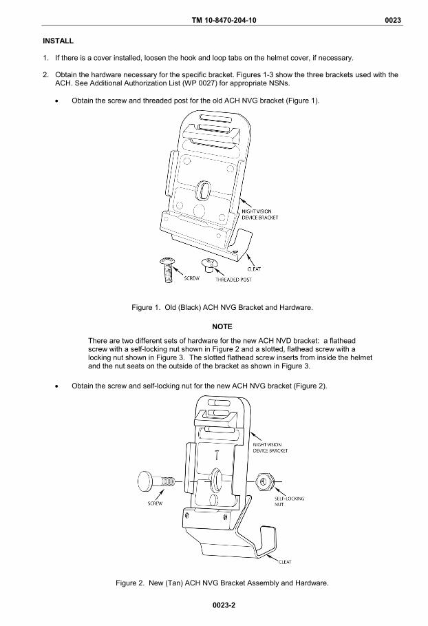
TM 10-8470-204-10 0023
0023-2
INSTALL
1. If there is a cover installed, loosen the hook and loop tabs on the helmet cover, if necessary. 2. Obtain the hardware necessary for the specific bracket. Figures 1-3 show the three brackets used with the
ACH. See Additional Authorization List (WP 0027) for appropriate NSNs. • Obtain the screw and threaded post for the old ACH NVG bracket (Figure 1).
Figure 1. Old (Black) ACH NVG Bracket and Hardware.
NOTE
There are two different sets of hardware for the new ACH NVD bracket: a flathead screw with a self-locking nut shown in Figure 2 and a slotted, flathead screw with a locking nut shown in Figure 3. The slotted flathead screw inserts from inside the helmet and the nut seats on the outside of the bracket as shown in Figure 3.
• Obtain the screw and self-locking nut for the new ACH NVG bracket (Figure 2).
Figure 2. New (Tan) ACH NVG Bracket Assembly and Hardware.
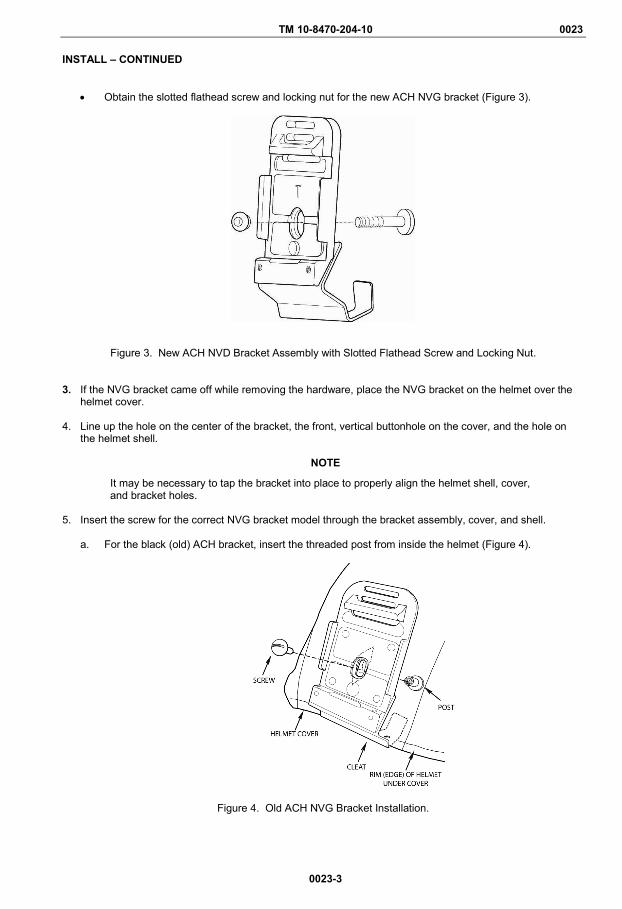
TM 10-8470-204-10 0023
0023-3
INSTALL – CONTINUED
• Obtain the slotted flathead screw and locking nut for the new ACH NVG bracket (Figure 3).
Figure 3. New ACH NVD Bracket Assembly with Slotted Flathead Screw and Locking Nut. 3. If the NVG bracket came off while removing the hardware, place the NVG bracket on the helmet over the
helmet cover.
4. Line up the hole on the center of the bracket, the front, vertical buttonhole on the cover, and the hole on the helmet shell.
NOTE
It may be necessary to tap the bracket into place to properly align the helmet shell, cover, and bracket holes.
5. Insert the screw for the correct NVG bracket model through the bracket assembly, cover, and shell.
a. For the black (old) ACH bracket, insert the threaded post from inside the helmet (Figure 4).
Figure 4. Old ACH NVG Bracket Installation.
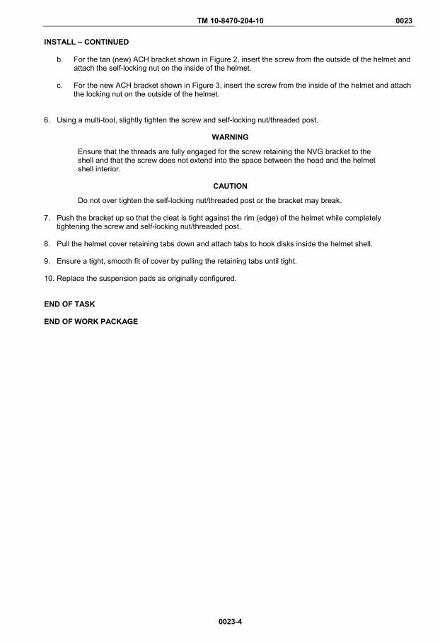
TM 10-8470-204-10 0023
0023-4
INSTALL – CONTINUED
b. For the tan (new) ACH bracket shown in Figure 2, insert the screw from the outside of the helmet and attach the self-locking nut on the inside of the helmet.
c. For the new ACH bracket shown in Figure 3, insert the screw from the inside of the helmet and attach
the locking nut on the outside of the helmet.
6. Using a multi-tool, slightly tighten the screw and self-locking nut/threaded post.
WARNING
Ensure that the threads are fully engaged for the screw retaining the NVG bracket to the shell and that the screw does not extend into the space between the head and the helmet shell interior.
CAUTION
Do not over tighten the self-locking nut/threaded post or the bracket may break.
7. Push the bracket up so that the cleat is tight against the rim (edge) of the helmet while completely tightening the screw and self-locking nut/threaded post.
8. Pull the helmet cover retaining tabs down and attach tabs to hook disks inside the helmet shell.
9. Ensure a tight, smooth fit of cover by pulling the retaining tabs until tight.
10. Replace the suspension pads as originally configured. END OF TASK END OF WORK PACKAGE
TM 10-8470-204-10
CHAPTER 6
SUPPORTING INFORMATION
FOR
ADVANCED COMBAT HELMET (ACH)

TM 10-8470-204-10 0024 OPERATOR MAINTENANCE
REFERENCES
0024-1/blank
SCOPE This work package lists related field manuals, forms, technical manuals, and miscellaneous publications. ARMY REGULATIONS AR 25-30 The Army Publishing Program AR 700-138 Army Logistics Readiness and Sustainability FIELD MANUALS FM 4-25.11 First Aid FORMS DA Form 12-R Request for Establishment of Publishing Account DA Form 2028 Recommended Changes to Publications and Blank Forms DA Form 2404 Equipment Inspection and Maintenance Worksheet SF 368 Product Quality Deficiency Report PAMPHLETS DA PAM 25-33 User’s Guide for Army Publications and Forms DA PAM 750-8 The Army Maintenance Management System (TAMMS) Users Manual DA PAM 738-751 Functional Users Manual for the Army Maintenance Management System-Aviation
(TAMMS-A) END OF WORK PACKAGE


TM 10-8470-204-10 0025 OPERATOR MAINTENANCE
COMPONENTS OF END ITEM (COEI) AND BASIC ISSUE ITEMS (BII) LISTS
0025-1
INTRODUCTION Scope This work package lists COEI and BII for the ACH to help you inventory items for safe and efficient operation of the equipment. General The COEI and BII information is divided into the following lists: Components of End Item (COEI). This list is for informational purposes only and is not authority to requisition replacements. These items are part of the ACH. As part of the end item, these items must be with the end item whenever it is issued or transferred between property accounts. Items of COEI are removed and separately packaged for transportation or shipment only when necessary. Illustrations are furnished to help you find and identify the items. Basic Issue Items (BII). These essential items are required to place the ACH in operation, operate it, and to do emergency repairs. Although shipped separately packaged, BII must be with the ACH during operation and when it is transferred between property accounts. Listing these items is your authority to request/requisition them for replacement based on authorization of the end item by the TOE/MTOE. Illustrations are furnished to help you find and identify the items. Explanation of Columns in the COEI List and BII List Column (1) Illus Number. Identifies the number of the item illustrated. Column (2) National Stock Number (NSN). Identifies the stock number of the item to be used for requisitioning purposes. Column (3) Description, CAGEC, and Part Number. Identifies the Federal item name (in all capital letters) followed by a minimum description when needed. The stowage location of COEI and BII is also included in this column. The last line below the description is the part number and the Commercial and Government Entity Code (CAGEC) (in parentheses) and the part number. Column (4) Usable On Code. When applicable, provides a code if the item is not the same for different models of equipment. Column (5) Unit of Issue (U/I). Indicates the physical measurement or count of the item, as issued, per the National Stock Number shown in column (2). Column (6) Qty Rqr. Indicates the quantity required.

TM 10-8470-204-10 0025
0025-2
Figure 1. ACH Components of End Item (COEI) List.
1 2
3 4
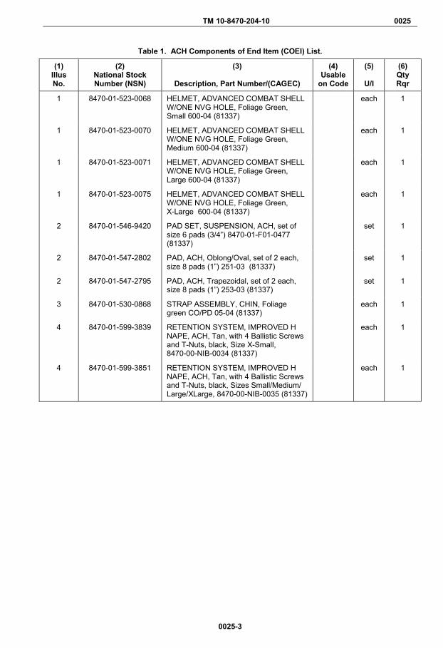
TM 10-8470-204-10 0025
0025-3
Table 1. ACH Components of End Item (COEI) List.
(1) Illus No.
(2) National Stock Number (NSN)
(3)
Description, Part Number/(CAGEC)
(4) Usable
on Code
(5)
U/I
(6) Qty Rqr
1 8470-01-523-0068 HELMET, ADVANCED COMBAT SHELL W/ONE NVG HOLE, Foliage Green, Small 600-04 (81337)
each 1
1 8470-01-523-0070 HELMET, ADVANCED COMBAT SHELL W/ONE NVG HOLE, Foliage Green, Medium 600-04 (81337)
each 1
1 8470-01-523-0071 HELMET, ADVANCED COMBAT SHELL W/ONE NVG HOLE, Foliage Green, Large 600-04 (81337)
each 1
1 8470-01-523-0075 HELMET, ADVANCED COMBAT SHELL W/ONE NVG HOLE, Foliage Green, X-Large 600-04 (81337)
each 1
2 8470-01-546-9420 PAD SET, SUSPENSION, ACH, set of size 6 pads (3/4”) 8470-01-F01-0477 (81337)
set 1
2 8470-01-547-2802 PAD, ACH, Oblong/Oval, set of 2 each, size 8 pads (1”) 251-03 (81337)
set 1
2 8470-01-547-2795 PAD, ACH, Trapezoidal, set of 2 each, size 8 pads (1”) 253-03 (81337)
set 1
3 8470-01-530-0868 STRAP ASSEMBLY, CHIN, Foliage green CO/PD 05-04 (81337)
each 1
4 8470-01-599-3839 RETENTION SYSTEM, IMPROVED H NAPE, ACH, Tan, with 4 Ballistic Screws and T-Nuts, black, Size X-Small, 8470-00-NIB-0034 (81337)
each 1
4 8470-01-599-3851 RETENTION SYSTEM, IMPROVED H NAPE, ACH, Tan, with 4 Ballistic Screws and T-Nuts, black, Sizes Small/Medium/ Large/XLarge, 8470-00-NIB-0035 (81337)
each 1

TM 10-8470-204-10 0025
0025-4
Figure 2. ACH Basic Issue Items (BII) List.
Table 2. ACH Basic Issue Items (BII) List.
(1) Illus No.
(2) National Stock Number (NSN)
(3)
Description, Part Number/(CAGEC)
(4) Usable
on Code
(5)
U/I
(6) Qty Rqr
1 8415-01-521-8806 COVER, HELMET, UNIVERSAL CAMOUFLAGE PATTERN with communication flap, size S/M 552-04-SMALL/MEDIUM (81337)
each 1
1 8415-01-521-8808 COVER, HELMET, UNIVERSAL CAMOUFLAGE PATTERN with communication flap, size L/XL 552-04-LARGE/XLARGE (81337)
each 1
1 8415-01-559-0105 COVER, HELMET, UNIVERSAL CAMOUFLAGE PATTERN with communication flap, size XXL 552-04-XXLARGE (81337)
each 1
1 8415-01-521-8357 COVER, HELMET, UNIVERSAL CAMOUFLAGE PATTERN without communication flap, size S/M 553-04-SMALL/MEDIUM (81337)
each 1
1 8415-01-521-8360 COVER, HELMET, UNIVERSAL CAMOUFLAGE PATTERN without communication flap, size L/XL 533-04-LARGE/XLARGE (81337)
each 1
2 8415-01-515-4286 COVER, HELMET, Non-reversible, Arctic with communication flap, size S/M85-04 (81337)
each 1
2 8415-01-515-4288 COVER, HELMET, Non-reversible, Arctic with communication flap, size L/XL 85-04 (81337)
each 1
2 8415-01-515-4289 COVER, HELMET, Non-reversible, Arctic without communication flap, size S/M (81337)
each 1
2 8415-01-515-4290 COVER, HELMET, Non-reversible, Arctic without communication flap, size L/XL(81337)
each 1
3 8415-01-580-0064 COVER, HELMET, OPERATION ENDURING FREEDOM CAMOUFLAGE PATTERN (OCP) with communication flap, size S/M MIL-DTL-32200 (58536)
each 1
3 8415-01-580-0038 COVER, HELMET, OPERATION ENDURING FREEDOM CAMOUFLAGE PATTERN (OCP) with communication flap, size L/XL MIL-DTL-32200 (81349)
each 1
3 8415-01-580-0074 COVER,HELMET, OPERATION ENDURING FREEDOM CAMOUFLAGE PATTERN (OCP) with communication flap, size XXL MIL-DTL-32200 (58536)
each 1

TM 10-8470-204-10 0025
0025-5/blank
Table 2. ACH Basic Issue Items (BII) List – Continued.
(1) Illus No.
(2) National Stock Number (NSN)
(3)
Description, Part Number/(CAGEC)
(4) Usable
on Code
(5)
U/I
(6) Qty Rqr
3 8415-01-592-2218 COVER, HELMET, OPERATION ENDURING FREEDOM CAMOUFLAGE PATTERN (OCP) without communication flap, size S/M MIL-DTL32200 SMALL/MEDIUM (58536)
each 1
3 8415-01-592-2220 COVER, HELMET, OPERATION ENDURING FREEDOM CAMOUFLAGE PATTERN (OCP), without communication flap, size L/XL MIL-DTL32200 LARGE/XLARGE (58536)
each 1
3 8415-01-592-2223 COVER, HELMET, OPERATION ENDURING FREEDOM CAMOUFLAGE PATTERN (OCP), without communication flap, size XXL MIL-DTL32200 XXLARGE (58536)
each 1
END OF WORK PACKAGE


TM 10-8470-204-10 0026 OPERATOR
SUPPORT ITEMS
0026-1/blank
This work package lists items you will need to operate and maintain the Advanced Combat Helmet (ACH). This list is for information purposes only and is not authority to requisition replacements.
Table 1. Support Items List.
(1) Item No.
(2) Description, Part Number/(CAGEC)
(3)
U/I
(4) National Stock Number (NSN)
1 MULTI-TOOL, Folding, Pocket, 68010201K/OCAD1 EA 5110-01-474-0894
2 SCREWDRIVER, Flat Tip, 30839 (08292) EA 5120-01-430-8104
3 RULER, A-A-563/58536 EA 7510-00-935-1005
4 CALIPER, 452-12/73792 EA 5210-01-434-9493
5 TAPE, Measuring, Fabric, 14-108/53440 EA 8315-00-782-3520
END OF WORK PACKAGE


TM 10-8470-204-10 0027 OPERATOR
ADDITIONAL AUTHORIZATION LIST (AAL)
0027-1
INTRODUCTION
Scope This work package lists additional items you are authorized for the support of the ACH.
General
This list identifies items that do not have to accompany the ACH and that do not have to be turned in with it. These items are all authorized to you by CTA, MTOE, TDA, or JTA.
Explanation of Columns in the AAL
Column (1) National Stock Number (NSN). Identifies the stock number of the item to be used for requisitioning purposes.
Column (2) Description, Part Number/(CAGEC). Identifies the Federal item name (in all capital letters) followed by a minimum description when needed. The last line below the description is the part number and the Commercial and Government Entity Code (CAGEC) (in parentheses).
Column (3) Usable On Code. When applicable, gives you a code if the item you need is not the same for different models of equipment.
Column (4) U/I. Unit of Issue (U/I) indicates the physical measurement or count of the item as issued per the National Stock Number shown in column (1).
Column (5) Qty Recm. Indicates the quantity recommended.
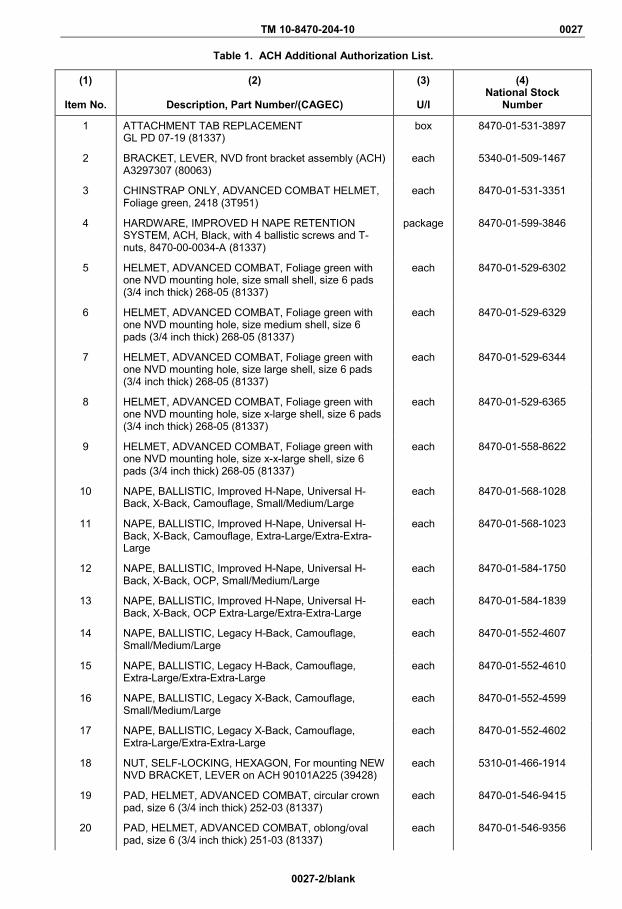
TM 10-8470-204-10 0027
0027-2/blank
Table 1. ACH Additional Authorization List.
(1)
Item No.
(2)
Description, Part Number/(CAGEC)
(3)
U/I
(4) National Stock
Number
1 ATTACHMENT TAB REPLACEMENT GL PD 07-19 (81337)
box 8470-01-531-3897
2 BRACKET, LEVER, NVD front bracket assembly (ACH) A3297307 (80063)
each 5340-01-509-1467
3 CHINSTRAP ONLY, ADVANCED COMBAT HELMET, Foliage green, 2418 (3T951)
each 8470-01-531-3351
4 HARDWARE, IMPROVED H NAPE RETENTION SYSTEM, ACH, Black, with 4 ballistic screws and T-nuts, 8470-00-0034-A (81337)
package 8470-01-599-3846
5 HELMET, ADVANCED COMBAT, Foliage green with one NVD mounting hole, size small shell, size 6 pads (3/4 inch thick) 268-05 (81337)
each 8470-01-529-6302
6 HELMET, ADVANCED COMBAT, Foliage green with one NVD mounting hole, size medium shell, size 6 pads (3/4 inch thick) 268-05 (81337)
each 8470-01-529-6329
7 HELMET, ADVANCED COMBAT, Foliage green with one NVD mounting hole, size large shell, size 6 pads (3/4 inch thick) 268-05 (81337)
each 8470-01-529-6344
8 HELMET, ADVANCED COMBAT, Foliage green with one NVD mounting hole, size x-large shell, size 6 pads (3/4 inch thick) 268-05 (81337)
each 8470-01-529-6365
9 HELMET, ADVANCED COMBAT, Foliage green with one NVD mounting hole, size x-x-large shell, size 6 pads (3/4 inch thick) 268-05 (81337)
each 8470-01-558-8622
10 NAPE, BALLISTIC, Improved H-Nape, Universal H-Back, X-Back, Camouflage, Small/Medium/Large
each 8470-01-568-1028
11 NAPE, BALLISTIC, Improved H-Nape, Universal H-Back, X-Back, Camouflage, Extra-Large/Extra-Extra-Large
each 8470-01-568-1023
12 NAPE, BALLISTIC, Improved H-Nape, Universal H-Back, X-Back, OCP, Small/Medium/Large
each 8470-01-584-1750
13 NAPE, BALLISTIC, Improved H-Nape, Universal H-Back, X-Back, OCP Extra-Large/Extra-Extra-Large
each 8470-01-584-1839
14 NAPE, BALLISTIC, Legacy H-Back, Camouflage, Small/Medium/Large
each 8470-01-552-4607
15 NAPE, BALLISTIC, Legacy H-Back, Camouflage, Extra-Large/Extra-Extra-Large
each 8470-01-552-4610
16 NAPE, BALLISTIC, Legacy X-Back, Camouflage, Small/Medium/Large
each 8470-01-552-4599
17 NAPE, BALLISTIC, Legacy X-Back, Camouflage, Extra-Large/Extra-Extra-Large
each 8470-01-552-4602
18 NUT, SELF-LOCKING, HEXAGON, For mounting NEW NVD BRACKET, LEVER on ACH 90101A225 (39428)
each 5310-01-466-1914
19 PAD, HELMET, ADVANCED COMBAT, circular crown pad, size 6 (3/4 inch thick) 252-03 (81337)
each 8470-01-546-9415
20 PAD, HELMET, ADVANCED COMBAT, oblong/oval pad, size 6 (3/4 inch thick) 251-03 (81337)
each 8470-01-546-9356

TM 10-8470-204-10 0027
0027-3/blank
Table 1. ACH Additional Authorization List – Continued.
(1)
Item No.
(2)
Description, Part Number/(CAGEC)
(3)
U/I
(4) National Stock
Number
21 PAD, HELMET, ADVANCED COMBAT, trapezoidal pad, size 6 (3/4 inch thick) 253-03 (81337)
each 8470-01-546-9407
22 PAD SET, SUSPENSION, ACH, set of size 6 pads (3/4 inch thick) 8470-01-F01-0477 (81337)
set 8470-01-546-9420
23 PAD, HELMET, ADVANCED COMBAT, oblong/oval pad, size 8 (1 inch thick)
each 8470-01-547-2802
24 PAD, HELMET, ADVANCED COMBAT, trapezoidal pad, size 8 (1 inch thick)
each 8470-01-547-2795
25 POST, HELMET, For mounting OLD NVD BRACKET, LEVER on ACH 8-2-647 (81337)
box 8470-01-144-5367
26 SCREW, MACHINE, For mounting NEW NVD BRACKET, LEVER on ACH A3297315 (80063)
each 5305-01-577-7740
27 SCREW, MACHINE, For mounting OLD NVD BRACKET, LEVER on ACH MS51957-44B (96906)
each 5305-00-433-3741
28 SCREW MACHINE, on ACH for empty NVD BRACKET HOLE ON ACH HELMET SHELL MS51957-43B (96906)
each 5305-00-182-9265
29 STRAP, EYEWEAR RETENTION, Foliage green MIL-DTL-32134 (81337)
pair 8415-01-521-8802
30 STRAP, EYEWEAR RETENTION, Tan MIL-DTL-32134 (81337)
pair 8415-01-521-8801
END OF WORK PACKAGE


TM 10-8470-204-10 0028 OPERATOR
EXPENDABLE AND DURABLE ITEMS LIST
0028-1/blank
INTRODUCTION
Scope
This work package lists expendable and durable items needed to operate and maintain the ACH. This list is for informational purposes only and is not authority to requisition the listed items. These items are authorized to you by CTA 50-970, Expendable/Durable Items (Except Medical, Class V Repair Parts, and Heraldic Items), CTA 50-909, Field and Garrison Furnishings and Equipment or CTA 8-100, Army Medical Department Expendable/ Durable Items.
Explanation of Columns in the Expendable/Durable Items List
Column (1) Item No. This number is assigned to the entry in the list and is referenced in the narrative instructions to identify the item (e.g., “Use brake fluid (Item 5, WP 0098)).
Column (2) Level. This column identifies the lowest level of maintenance that requires the listed item (C = Crew).
Column (3) National Stock Number (NSN). This is the NSN assigned to the item which you can use to requisition it.
Column (4) Item Name, Description, Part Number/(CAGEC). This column provides the other information you need to identify the item. The last line below the description is the part number and the Commercial and Government Entity Code (CAGEC) (in parentheses).
Column (5) U/I. Unit of Issue (U/I) code shows the physical measurement or count of an item, such as gallon, dozen, gross, etc.
Table 1. Expendable and Durable Items List.
END OF WORK PACKAGE
(1) Item No.
(2)
Level
(3) National Stock Number (NSN)
(4)
Item Name, Description, Part Number/(CAGEC)
(5)
U/I
1 C 8040-01-388-0735 ADHESIVE, adhesive for edging 40640(05972) BT
2 C 6850-01-228-7266 CLEANING COMPOUND, SOLVENT, clean up for adhesive 76820(05972)
BT
3 C CLOTH EA
4 C MILD SOAP EA
5 C 8030-01-104-5392 SEALING COMPOUND, thread locking compound 24221(05972)
BX
6 C SOFT BRUSH EA


TM 10-8470-204-10 0029 OPERATOR
OPERATOR RECORD OF HIT
0029-1
OPERATOR RECORD OF HIT
_______________________________________________________ Name: _________________________________________________ Rank: ________________________ Unit: ___________________________________________________ Phone: _______________ E-Mail: ______________________ HELMET Size: __________________ Date of Issue: _ _/_ _/_ _ Duty Being Performed When Hit: ____________________________ _______________________________________________________ _______________________________________________________ Hit Caused by (circle): Fragmentation (Mine, Grenade, Booby Trap, Artillery, Other) Date of Hit: _ _/_ _/_ _ Estimated range from point of detonation: _____________________ Location of Hit(s) on Advanced Combat Helmet: _______________________________________________________ _______________________________________________________ Continued to Perform Mission (circle one)?: Yes No Was Personal Injury Sustained (circle one)?: Yes No Description of Injury: ___________________________________ _______________________________________________________

TM 10-8470-204-10 0029
0029-2
OPERATOR RECORD OF HIT — Continued ARMY: Mail Record of Hit to postal address or responses to electronic mail address:
Postal Address: Project Manager Soldier Protection & Individual Equipment SFAE-SDR-SPIE 10170 Beach Road, Bldg 325 Fort Belvoir, VA 22060-5862 Electronic Mail Address: Mail to: [email protected] [email protected]
Call the Public Affairs Office at (703) 704-2802. END OF WORK PACKAGE
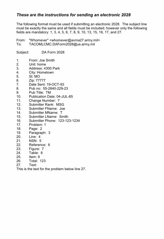
These are the instructions for sending an electronic 2028
The following format must be used if submitting an electronic 2028. The subject line must be exactly the same and all fields must be included; however only the following fields are mandatory: 1, 3, 4, 5, 6, 7, 8, 9, 10, 13, 15, 16, 17, and 27.
From: "Whomever" <[email protected]> To: [email protected]
Subject: DA Form 2028
1. From: Joe Smith2. Unit: home3. Address: 4300 Park4. City: Hometown5. St: MO6. Zip: 777777. Date Sent: 19-OCT-938. Pub no: 55-2840-229-239. Pub Title: TM10. Publication Date: 04-JUL-8511. Change Number: 712. Submitter Rank: MSG13. Submitter FName: Joe14. Submitter MName: T15. Submitter LName: Smith16. Submitter Phone: 123-123-123417. Problem: 118. Page: 219. Paragraph: 320. Line: 421. NSN: 522. Reference: 623. Figure: 724. Table: 825. Item: 926. Total: 12327. Text:This is the text for the problem below line 27.


RECOMMENDED CHANGES TO PUBLICATIONS AND BLANK FORMS
For use of this form, see AR 25-30; the proponent agency is ODISC4.
Use Part II (reverse) for Repair Parts and Special Tool Lists (RPSTL) and Supply Catalogs/ Supply Manuals (SC/SM).
DATE
21 October 2003
TO: (Forward to proponent of publication or form) (Include ZIP Code)
US ARMY TACOM LIFE CYCLE MANAGEMENT COMMAND ATTN: AMSTA-LCL-MPP/TECHPUBS MS 727, 6501 E. 11 Mile Road Warren, MI 48397-5000
FROM: (Activity and location) (Include ZIP Code)
PFC JANE DOE Co A 3RD Engineer Br. Ft Leonard Wood, MO 63108
PART I – ALL PUBLICATIONS (EXCEPT RPSTL AND SC/SM) AND BLANK FORMS PUBLICATION/FORM NUMBER TM 10-1670-296-20&P
DATE 30 October 2002
TITLE Unit Manual for Ancillary Equipment for Air Drop Systems
ITEM NO.
PAGE NO.
PARA- GRAP
H
LINE NO.
*
FIGURE NO.
TABLE NO.
RECOMMENDED CHANGES AND REASON (Provide exact wording of recommended changes, if
possible).
0036 00-2 1 In Table 1, Sewing Machine Code Symbols, the second sewing machine code symbol should be MDZZ not MD22.
Change the manual to show Sewing Machine, Industrial: Zig-Zag; 308 stitch; medium-duty; NSN 3530-01-181-1421 as a MDZZ code symbol.
*Reference to line numbers within the paragraph or subparagraph.
TYPED NAME, GRADE OR TITLE
Jane Doe, PFC
TELEPHONE EXCHANGE/ AUTOVON, PLUS EXTENSION (508)233-4141 DSN 256-4141
SIGNATURE
Jane Doe Jane Doe
DA FORM 2028, FEB 74 REPLACES DA FORM 2028, 1 DEC 68, WHICH WILL BE USED. USAPPC V3.00

TO: (Forward to proponent of publication or form) (Include ZIP Code)
US ARMY TACOM LIFE CYCLE MANAGEMENT COMMAND ATTN: AMSTA-LCL-MPP/TECHPUBS MS 727, 6501 E. 11 Mile Road Warren, MI 48397-5000
FROM: (Activity and location) (Include ZIP Code)
PFC JANE DOE Co A 3RD Engineer Br. Ft Leonard Wood, MO 63108
DATE
21 October 2003
PART II – REPAIR PARTS AND SPECIAL TOOL LISTS AND SUPPLY CATALOGS/SUPPLY MANUALS
PUBLICATION NUMBER TM 10-1670-296-20&P
DATE 30 October 2002
TITLE Unit Manual for Ancillary Equipment for Air Drop Systems
PAGE NO.
COLM NO.
LINE NO.
NATIONAL STOCK
NUMBER
REFERENCE NO.
FIGURE NO.
ITEM NO.
TOTAL NO. OF MAJOR
ITEMS SUPPORTED
RECOMMENDED ACTION
0066 00 4 Callout 16 in figure 4 is pointed to a D-Ring. In the Repair Part List key for Figure 4, item 16 is called a Snap Hook. Please correct one or the other.
PART III – REMARKS (Any general remarks or recommendations, or suggestions for improvement of publications and blank forms. Additional blank sheets may be used if more space is needed.)
TYPED NAME, GRADE OR TITLE TELEPHONE EXCHANGE/AUTOVON, PLUS EXTENSION SIGNATURE
UASPPC V3.00

RECOMMENDED CHANGES TO PUBLICATIONS AND BLANK FORMS
For use of this form, see AR 25-30; the proponent agency is ODISC4.
Use Part II (reverse) for Repair Parts and Special Tool Lists (RPSTL) and Supply Catalogs/Supply Manuals (SC/SM).
DATE
TO: (Forward to proponent of publication or form) (Include ZIP Code) US ARMY TACOM LIFE CYCLE MANAGEMENT COMMAND ATTN: AMSTA-LCL-MPP/TECHPUBS MS 727, 6501 E. 11 Mile Road Warren, MI 48397-5000
FROM: (Activity and location) (Include ZIP Code)
PART I – ALL PUBLICATIONS (EXCEPT RPSTL AND SC/SM) AND BLANK FORMS PUBLICATION/FORM NUMBER TM 10-8470-204-10
DATE 1 August 2015
TITLE Operator Manual for Advanced Combat Helmet (ACH)
ITEM NO.
PAGE NO.
PARA- GRAPH
LINE NO.
*
FIGURE NO.
TABLE NO.
RECOMMENDED CHANGES AND REASON (Provide exact wording of recommended changes, if possible).
*Reference to line numbers within the paragraph or subparagraph. TYPED NAME, GRADE OR TITLE TELEPHONE EXCHANGE/AUTOVON,
PLUS EXTENSION SIGNATURE
DA FORM 2028, FEB 74 REPLACES DA FORM 2028, 1 DEC 68, WHICH WILL BE USED. USAPPC V3.00
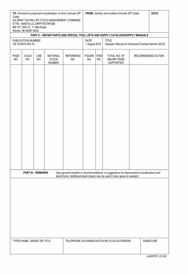
TO: (Forward to proponent of publication or form) (Include ZIP Code) US ARMY TACOM LIFE CYCLE MANAGEMENT COMMAND ATTN: AMSTA-LCL-MPP/TECHPUBS MS 727, 6501 E. 11 Mile Road Warren, MI 48397-5000
FROM: (Activity and location) (Include ZIP Code) DATE
PART II – REPAIR PARTS AND SPECIAL TOOL LISTS AND SUPPLY CATALOGS/SUPPLY MANUALS PUBLICATION NUMBER TM 10-8470-204-10
DATE 1 August 2015
TITLE Operator Manual for Advanced Combat Helmet (ACH)
PAGE NO.
COLM NO.
LINE NO.
NATIONAL STOCK
NUMBER
REFERENCE NO.
FIGURE NO.
ITEM NO.
TOTAL NO. OF MAJOR ITEMS SUPPORTED
RECOMMENDED ACTION
PART III – REMARKS (Any general remarks or recommendations, or suggestions for improvement of publications and blank forms. Additional blank sheets may be used if more space is needed.)
TYPED NAME, GRADE OR TITLE TELEPHONE EXCHANGE/AUTOVON, PLUS EXTENSION SIGNATURE
UASPPC V3.00

TM 10-8470-204-10
By Order of the Secretary of the Army:
Army Distribution: Initially published in electronic media only. When funds become available, this publication will be distributed in accordance with the initial distribution number (IDN) 256758 requirements for TM 10-8470-204-10.
RAYMOND T. ODIERNO General, United States Army
Chief of Staff
Official:
GERALD B. OKEEFE Administrative Assistant to the
Secretary of the Army 1518704


PIN: 080445-000