direction finder antenna as-3732/prd-11 (nsn 5865-01-165 ...
58
TM 11-5895-1227-14-4 TECHNICAL MANUAL OPERATOR’S, ORGANIZATIONAL, DIRECT SUPPORT AND GENERAL SUPPORT MAINTENANCE MANUAL DIRECTION FINDER ANTENNA AS-3732/PRD-11 (NSN 5865-01-165-4578) AND DIRECTION FINDER ANTENNA AS-3733/PRD-11 (NSN 5820-01-200-0177) HEADQUARTERS, DEPARTMENT OF THE ARMY 15 FEBRUARY 1988
-
Upload
khangminh22 -
Category
Documents
-
view
0 -
download
0
Transcript of direction finder antenna as-3732/prd-11 (nsn 5865-01-165 ...

TM 11-5895-1227-14-4
TECHNICAL MANUAL
OPERATOR’S, ORGANIZATIONAL,DIRECT SUPPORT AND GENERAL SUPPORT
MAINTENANCE MANUAL
DIRECTION FINDER ANTENNA AS-3732/PRD-11(NSN 5865-01-165-4578)
ANDDIRECTION FINDER ANTENNA AS-3733/PRD-11
( N S N 5 8 2 0 - 0 1 - 2 0 0 - 0 1 7 7 )
HEADQUARTERS, DEPARTMENT OF THE ARMY15 FEBRUARY 1988


TM 11-5895-1227-14-4
SAFETY SUMMARY
These general precautions should be followed whenever working with electronic equipment toprevent injury to personnel.
Do not work on electronic equipment unless there is another person nearby who isfamiliar with the operation and hazards of the equipment and who is competent inadministering first aid.
Whenever possible, turn off the power supply to the equipment before beginningmaintenance on the equipment.
Do not remove the protective covers to the equipment unless you are authorized to doso.
When the technicians are aided by operators, they must be warned about dangerous areas. Aperiodic reviewof safety precautions in TB 385-4, Safety Precautions for Maintenance of Electrical/Electronic Equipment, isrecommended.
Seek advice from your supervisor whenever you are in doubt about electrical safetyconditions.
For Artificial Respiration, refer to FM 21-11.
Extreme caution must be exercised when working with or around the antenna mast. Carelessor inattentive operation of the antenna mast and accessories can lead to personal injury anddamage to the antenna mast machinery or lofted payload. The following precautions must beobserved at all times. Other safety factors are defined at applicable parts of the operatingand maintenance instructions.
Electrical Hazard: Avoid overhead obstacles. Keep the antenna mast away fromelectric high power lines and telephone lines.
Antenna Mast Sections: Keep articles of clothing and hands and feet away from theantenna mast. Under no circumstances can antenna mast be climbed.
Guy Line Hazard: When moving around the operational site, be alert to guying anchorsand guy line placement.
PROPRIETARY STATEMENT
This document and subject matter disclosed herein are proprietary items to which Watkins-Johnson Company retains the exclusive right of dissemination, reproduction, manufacture, andsale.
A

TM 11-5895-1227-14-4
This document is provided to the individual or using organization for their use alone in thedirect support of the associated equipment unless permission for further disclosure is expresslygranted in writing.
B

*TM 11-5895-1227-14-4
TECHNICAL MANUAL
NO. 11-5895-1227-14-4
HEADQUARTERSDEPARTMENT OF THE ARMY
Washington, DC, 15 February 1988
Operator’s, organizational,Direct Support and General Support
Maintenance Manual
DIRECTION FINDER ANTENNA AS-3732/PRD-11(NSN 5865-01-160-4411)
ANDDIRECTION FINDER ANTENNA AS-3733/PRD-11
(NSN 5820-01-200-0177)
REPORTING ERRORS AND RECOMMENDING IMPROVEMENTS
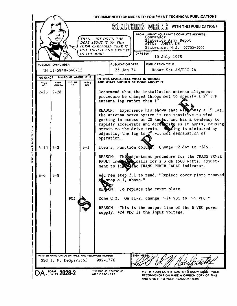
You can help improve this manual. If you find any mistakes or if you know of away to improve the proceduresplease let us know. Mail your letter, DA Form 2028 (Recommended Changes to Publications and Blank Forms), orDA Form 2028-2 located in the back of this manual direct to: Commander, US Army Communications-ElectronicsCommand and Fort Monmouth, ATTN: AMSEL-ME-MP, Fort Monmouth, N.J 07703-5000. A reply will befurnished direct to you.
TABLE OF CONTENTS
Section OINTRODUCTION
Paragraph Page
0 . 10.1.10.1.20.1.30.20 . 30.3.10.3.20.3.30 . 40 . 50.60 .70.80.9
0 - 10 - 10 - 10 - 10 - 10 - 10 - 10 - 20 - 20 - 30 - 20 - 20 - 20 - 30 - 3
Section IGENERAL DESCRIPTION
1 . 11 . 21 . 31 . 4
1 - 11 - 11 - 11 - 1
This manual supersedes TM 11-5895-1227-14-4, 1 June 1985. i

TM 11-5895-1227-14-4
TABLE OF CONTENTS - Continued
Paragraph
2.12.22.2.12.2.1.12.2.1.22 .32.42 . 5
3 .13.23.33.43.53.5.13.5.1.1
3 - 13 - 13 - 13 - 23 - 33 - 53 - 6
4.14 .24 .34 .44 . 54 . 64 . 74.7.14.7.2
4-2
5.15.25.35.3.15.3.25.3.35.3.3.15.3.3.25.3.3.35.3.4
i i
Page
SECTION IIINSTALLATION AND OPERATION
2-12-12-22-22-22-22-22-3
SECTION IIIPARTS LIST
SECTION VIMAINTENANCE AND SCHEMATIC DIAGRAMS
4-14-14-14-14-14 - 2
4 - 24 - 4
SECTION VWJ-9880A-1 DF ANTENNA
5-1
5 - 1
5 - 15 - 15 - 15 - 25 - 2
5-1
5-1
5-2

TM 11-5895-1227-14-4
TABLE OF CONTENTS - Continued
Paragraph
SECTION VWJ-9880A-1 DF ANTENNA - Continued
5.3.55.3.65.45 .55 .65 .75 .85 . 95.9.15.9.25.105.115.12APPENDIX A
BC
Figure
1-14 - 14 - 2
1 - 04 - 5
4 - 65 - 0
5 - 6
5 - 15 - 2
Table
1 - 12 - 1
LIST OF ILLUSTRATIONS
Page
5-25-25-25-25-35-35-35-35-35-55-55-55-5
A - 1B - 1C - 1
Page
LIST OF TABLES
Page
1 - 22 - 2
iii/(iv blank)


TM 11-5895-1227-14-4
SECTION O
INTRODUCTION
0.1 SCOPE
0.1.1 TYPE OF MANUAL
commercial manual.This is an Operator's, Organizational, Direct Support and General Support Maintenance
MODEL NUMBERS AND EQUIPMENT NAMES0 . 1 . 2
The Direction Finder Antennas, AS-3732/PRD-11 and AS-3733/PRD-11 areseparate antennas tha t can be used wi th the Rad io Rece ive r Di rec t ion F inder Se t ,AN/PRD-11. The other units of the direction finder set include the Receiver, AN/GRR-8(V),the Processor Display Control, C-11495/PRD-11 and the Panoramic IndicatorIP-1355/GRR-8(V). In this manual, the AS-3732/PRD-11 Direction Finder Antenna will bereferred to as the WJ-9880A DF Antenna. The receiver will be referred to as the WJ-8640Series Manpack Receiver and the processor display control wil l be referred to as theWJ-8975A Direction Finder. A complete cross reference of common equipment names andnomenclatures used in this manual is provided in paragraph 0.7.
0.1.3 PURPOSE OF EQUIPMENT
The Direction Finder Antennas collect radio frequency (rf) signals between 20 and175 MHz with a low bay section and 20 and 850 MHz rf signals with a high bay section. Theantennas also receive electrical signals from the WJ-8975 Direction Finder which activatesantenna elements in sequence for the process of obtaining a bearing on a transmitted signal.
0.2 CONSOLIDATED INDEX OF ARMY PUBLICATIONS AND BLANK FORMS
Refer to the latest issue of DA Pam 25-30 to determine whether there are new editions, changes oradditional publications pertaining to the equipment.
0.3 MAINTENANCE FORMS, RECORDS AND REPORTS
0.3.1 REPORTS OF MAINTENANCE AND UNSATISFACTORY EQUIPMENT
Department of the Army forms and procedures used for equipment maintenancewill be those prescribed by DA Pam 738-750 as contained in Maintenance Management Update.
0-1

TM 11-5895-1227-14-4
0.3.2 REPORT OF PACKAGING AND HANDLING DEFICIENCIES
Fill out and forward SF 364 (Report of Discrepancy (ROD)) as prescribed in AR 735-11-2/DLAR4140.55/NAVMATINST 4355.73 B/AFR 400-54/MCO 4430.3H.
0.3.3 DISCREPANCY IN SHIPMENT REPORT (DISREP) (SF 361)
Fill out and forward Discrepancy in Shipment Report (DISREP) (SF 361) as prescribed in AR 55-38/NAVSUPINST 4610.33C/AFR 75-18/MCO P4610.19D/DLAR 4500.15.
0.4 DESTRUCTION OF ARMY ELECTRONICS MATERIEL
Destruction of Army electronic materiel to prevent enemy use shall be inaccordance with TM 750-244-2.
0.5 ADMINISTRATIVE STORAGE
Disassembly and repacking of equipment for shipment or limited storage arecovered in Section II.
0.6 TOOLS AND TEST EQUIPMENT
Test equipment required for troubleshooting and maintenance of the directionfinder antennas is listed in paragraphs 4.5 and 5.7.
0.7 OFFICIAL NOMENCLATURE, NAMES, AND DESIGNATIONS
The list below will help you identify the official nomenclature of the majorequipment items used with the direction finder antennas. It also provides the common nameused in the manual when it is different from the official nomenclature. official nomenclaturemust be used when completing forms or when looking up technical manuals.
Common Name Official Nomenclature
Direction finder antenna Antenna, Direction Finder,AS-3732/PRD-11 or
Antenna, Direction Finder,AS-3733/PRD-11
Direction Finder, WJ-8975A Processor Display Control,C-11495/PRD-11
Manportable Vehicular Direction Radio Receiver DirectonFinding System Finder Set, AN/PRD-11
Manpack Receiver, WJ-8640 Receiver, AN/GRR-8(V)Signal Monitor, WJ-9180-1 Indicator, Panoramic,
IP-1355/GRR-8(V)
0-2

TM 11-5895-1227-14-4
0.8 REPORTING EQUIPMENT IMPROVEMENT RECOMMENDATIONS
If your DF Antenna needs improvement, let us know. Send us an EIR. You, the user, are the only onewho can tell us what you don’t like about the design. Put it on an SF 368 (Quality Deficiency Report). Mail it toCommander, US Army Communication-Electronics Command and Fort Monmouth, ATTN: AMSEL-ME-MP, FortMonmouth, NJ 07703-5000. We’ll send you a reply.
0.9 WARRANTY INFORMATION
The DF Antenna is warranted by Watkins-Johnson Company for a period of 1 year following delivery.It starts on the date found in block 23, DA Form 2408-9, in the logbook. This warranty may contain repairrestrictions. Report all defects in material or workmanship to your supervisor.
0-3

TM 11-5895-1227-14-4
Figure 1-1. WJ-9880A Direction Finder Antenna
1-0

TM 11-5895-1227-14-4
SECTION I
GENERAL DESCRIPTION
1.1 ELECTRICAL CHARACTERISTICS
The WJ-9880A Direction Finder Antenna is designed to be used in conjunctionwith the Watkins-Johnson Company’s Manportable/Vehicular Direction Finding System. Thissystem includes the WJ-8640 Series Manpack Receiver, the WJ-8975A Direction Finder, andtie WJ-9180 Series Signal Monitor. The WJ-9880Afor signals received in the band of 20 to 175 MHz.
1.2 MECHANICAL CHARACTERISTICS
DF Antenna provides bearing information
The WJ-9880A Direction Finder Antenna was designed for fixed site or vehicularoperation. The WJ-9880A DF Antenna has been ruggedized to withstand the most severeenvironmental conditions.
An adjustable tripod comes with the WJ-9880A DF Antenna to provide supportand ease of transportation. Vertical elevation of the WJ-9880A DF Antenna is accomplishedby means of a crank assembly located on the tripod. To transport the DF Antenna to anothersite, the tripod disconnects from the antenna with a turn of the thumbscrews. The antennaelements unscrew 1/4 turn from the antenna and the arms fold down toward the antenna mast.The tripod also folds down. If the WJ-9880A DF Antenna must be stored, storage space can beminimized by folding the antenna and the tripod.
Al l connec to r s needed to connec t the WJ-9880A DF Antenna wi th theManportable/Vehicular Direction Finding System are located on the antenna mast. Refer toTable 2-1 for connector nomenclature. A compass is supplied with the WJ-9880A DF Antennato provide accurate alignment of magnetic north for signal bearing coordinates.
1.3 EQUIPMENT SUPPLIED
The equipment supplied with the WJ-9880A DF Antenna includes an adjustabletripod, a standard compass (MIL-C-10436), and 50 foot RF cables.
1.4 EQUIPMENT REQUIRED BUT NOT SUPPLIED
The WJ-9880A Di rec t ion F inder Antenna works in con junc t ion wi th theManPortable/Vehicular Direction Finding System. This system includes:
1) WJ-8975A Direction Finder2) WJ-8640 Series Manpack Receiver3) WJ-9180 Series Signal Monitor (optional)4) The Antenna Control Cable (part of WJ-8975A equipment)
1-1

TM 11-5895-1227-14-4
Table 1-1. WJ-9880A DF Antenna Specifications
Frequency Range: 20-175 MHz
Vertical Angle Coverage: ±300
Environmental Limits:Wind 100 mph*Ice 1/4 inch radial dimension, maximum
Operating Size**: The antenna height is 67.53 inchesnominal, above the base. Theantenna is 39.5 inches in diameterThe antenna weighs 14 lbs., nominal.
Storage Size: The folded down antenna measures35 inches in height, with a diameterof 7.25 inches.
* Per instructions in paragraph 2.2. For more information, contactthe Watkins-Johnson Company, CEI Division, Gaithersburg,Maryland.
* * The height measurements for the antenna exclude the adjustabletripod which extends to a maximum of seventy-six inches. Whenretracted, the tripod measures thirty-nine inches. The tripodweighs 10 lbs., nominal.
SPECIFICATIONS NOTE
The specifications and the design of the typeWJ-9880A Direction Finder Antenna as indica-t ed in the p reced ing t ab le a re sub jec t toc h a n g e i n accordance with modificationimprovements.
1-2

TM 11-5895-1227-14-4
SECTION II
INSTALLATION AND OPERATION
2.1 UNPACKING AND INSPECTION
Examine the shipping carton for damage before unpacking the equipment. If thecarton appears to be damaged, have the carrier’s agent present when the equipment isunpacked. If this is not possible, retain all packaging material and shipping containers for thecarrier’s inspection to verify damage to the equipment after unpacking. Also verify that theequipment shipped corresponds to the packing slip. Contact the Watkins-Johnson Company,CEI Division or your Watkins-Johnson representative for any discrepancies or shortages.
2.2 INSTALLATION
To install the WJ-9880A DF Antenna, the following procedure should be followed.Table 2-1 outlines the connectors located on the antenna mast.
For field operation, the tripod must beset firmly on the ground. Extend the legsof the tripod to obtain a vertical position. (If the center column of the tripod is one or twodegrees from true vertical, this will not cause any significant error.) Once vertical position isobtained, make sure the legs of the tripod are pressed firmly into the ground. Before installingthe WJ-9880A DF Antenna on the tripod, wind conditions must be observed. Once the locationsite for the antenna is determined, verify what direction the wind is coming from. If one legof the tripod faces with the wind, a maximum wind speed of 30 mph can reaccommodated. Ifone leg of the tr ipod faces with the wind, a maximum wind speed of 45 mph can beaccommodated. The above figures represent a safety factor in which the antenna mounted onthe tripod will not upset due to high wind speeds. Variable wind speeds and directions requireextra support such as guy wires. In order to guy the tripod, wind speed and tripod height mustbe determined. If the tripod’s center column is not elevated, the antenna mounted on thetripod can withstand wind speeds up to 100 mph, providing the guy wires are 45° or more fromthe center column. If the tripod is used to the maximum extended height, wind speeds up to80 mph can be withstood, providing the guy wires are 450 or more from the center column.Place the WJ-9880A DF Antenna on the tripod. Unlock the arms of the WJ-9880A DFAntenna by pulling the knurled bolt outward. Once unlocked, swing the arms away from thecenter mast up toward the top of the antenna. When the arms are in place the knurled boltwill snap back into the locked position. Tighten the knurled bolt to lock the arms tight.(Refer to Figure 2-1 for an outline of the WJ-9880A DF Antenna.) Disassembly is done byunlocking the arms and pushing them down toward the base. With the arms of the antennalocked in the open position, insert the antenna elements and tighten.
NOTE
To ease the assembly effort , place the WJ-9880A DFAntenna on the tripod with the arms folded down, insert 4elements then unlock the arms and install the remainingelements.
With the compass mounted on the base of the antenna, rotate the antennathe compass indicates a northern direction. A black l ine on the underside of the lower
2-1

TM 11-5895-1227-14-4
assembly is the zero degree reference. Once the antenna is aligned, tighten the threethumbscrews and remove the compass from the antenna.
2.2.1
2.2.1.1
coverage of
2.2.1.2
CONNECTOR SIGNALS
Signal Output (J11)
This signal output connector is an N-Type. It is used for lower frequency20 to 175 MHz. It provides the RF signal to the receiver.
Antenna Switch (J10)
The antenna switch connector is a multipin type. This connector provides signalsto the antenna switch from the WJ-8875A Direction Finder for commutation of the dipoles.
Table 2-1. Type WJ-9880A DF Antenna Connectors
Connector Connector ConnectorNumber Nomenclature Function
J19 SIGNAL OUTPUT Provides RF signals in the 20 to175 MHz range.
J10 ANTENNA SWITCH Accepts signals from the WJ-8975ADirection Finder for Commutationof the dipoles.
2.3 EQUIPMENT MALFUNCTIONS
The WJ-9880A Direction Finder Antenna was thoroughly inspected and adjustedfor optimum performance prior to shipment. If any malfunctions are encountered afterperforming the recommended installation procedures, verify that the correct signals arepresent at the proper jacks. The schematic diagrams in Section IV will aid the maintenanceand troubleshooting of the unit. To avoid possible voiding of the warranty prior to taking anycorrective maintenance action, contact your Watkins-Johnson representative or the Watkins-Johnson Company, CEI Division, Gaithersburg, Maryland.
2.4 OPERATION
The following step by step operational description of the WJ-9880A DirectionFinder Antenna coincides with the Manportable/Vehicular Direction Finding System.
1. Set up the tripod to a vertical position and mount antenna ontotripod. (Refer to paragraph 2-2 on installation instructions.)
2. Connect multipin control cable to the Antenna Switch (J10) onthe an tenna and to the DF ANT CONTROL (J4) on theWJ-8975A.
2-2

TM 11-5895-1227-14-4
3.
4.
5.
6.
7.
8.
Connect the RF signal cable from the Signal Output from theSignal Output (J11) (for 20 to 175 MHz operation) on theWJ-9880A DF Antenna to the RF INPUT (J1) connector on theWJ-8640 Series Manpack Receiver.
Connect a cable from the SM OUTPUT (J2) connector on theWJ-8640 Series Manpack Receiver to the DF INPUT (J1)on theWJ-8975A Direction Finder.
If the signal is to be monitored, connect a cable from the SMOUTPUT (J2) of the WJ-8975A Direction Finder to the SMINPUT (J3) on the WJ-9180 Series Signal Monitor (optional).
Energize all equipment.
Set the WJ-8975A Direction Finder’s Function Switch (S4) toCAL. If the (BAND Select) (S2) is in the 80-250 MHz setting,the 3 digit display will read 0°. If the 20-80 MHz/250-500MHzsetting is used, the 3 digit display will read 180°. If the readingis not as indicated above, use the zero adjust to compensate.
Tune the desired Frequency on the WJ-8640 Series ManpackReceiver and determine the proper bandwidth for the clearestand strongest reception. Set the same bandwidth on theWJ-8975A Direction Finder via IF BANDWIDTH (S6). Also sett h e s a m e B A N D s e l e c t .
N O T E
The IF BANDWIDTHSwitches must be setFailure to do this may
and the BAND Selectthe same on both units.cause an error of 180°.
2.5 PREPARATION FOR RESHIPMENT
If the unit must be prepared for reshipment, the packaging methods should followthe patterns established in the original shipment. If retained, the original materials can bereused to a large extent or at least provide guidance for repacking.
2-3/(2-4 blank)


TM 11-5895-1227-14-4
SECTION III
REPLACEMENT PARTS LIST
3.1 UNIT NUMBERING METHOD
The unit numbering method of assigning reference designations (electrical symbolnumbers) has been used to identify assemblies, subassemblies (and modules) and parts. Anexample of the unit numbering method follows:
Subassembly Designation Al R1 Class and No. of Item
Identify from right to left as: First (l) resistor (R) offirst (1) subassembly (A)
As shown on the main chassis schematic, components which are an integral part ofthe main chassis have no subassembly designation.
3.2 REFERENCE DESIGNATION PREFIX
Partial reference designations have been used on the equipment and on theillustrations in this manual. The partial reference designations consist of the class letter(s)and identifying item number. The complete reference designations may reobtained by placingthe proper prefix before the partial reference designations. Reference Designation Prefixesare provided on drawings and illustrations in parenthesis within the figure titles.
3.3
Mfr.Code
14632
16179
28480
72982
LIST OF MANUFACTURERS
Name and AddressMfr.Code
Watkins-Johnson Company 73899700 Quince Orchard RoadGaithersburg, MD 20878
Omni-Spectra, Inc. 7504224600 Hallwood Ct.Farmington, MI 48024
Hewlett-Packard Co. 77820Corporate Headquarters1501 Page Mill RoadPalo Alto, CA 94304
Erie Tech. Products Inc. 80058644West 12th StreetErie, PA 16512
Name and Address
JFD Electronics Co.15th at 62nd StreetBrooklyn, NY 11219
TRW Elctrnc. ComponentsIRC Fixed Resistors401 North Broad StreetPhiladelphia, PA 19108
Bendix CorporationThe Electrical Comp. Div.Sherman AvenueSidney, NY 13838
Military Specifications
3-1

TM 11-5895-1227-14-4
Mfr.Code Name and Address
89110 AMP, Inc.155 Park StreetElizabethtown, PA 17022
Solitron Devices, Inc.Solitron/Microwave DivisionP.O. BOX 278Port Salerno, FL 33492
3.4 PARTS LIST
95077
Mfr.Code Name and Address
99800 American Precision IndustriesDelevan Electronics Division270 Quaker RoadEast Aurora, NY 14052
The parts list which follows contains all electrical partscertain mechanical parts which are subject to unusual wear orreplacement parts from the Watkins-Johnson Company, specify the
used in the equipment anddamage. When orderingtype and serial number of
the equipment and the reference designation and description of each part ordered. The list ofmanufacturers provided in paragraph 3.3 and the manufacturer’s part number for componentsare included as a guide to the user of the equipment in the field. These parts may notnecessarily agree with the parts installed in the equipment; however, the parts specified in thislist will provide satisfactory operation of the equipment. Replacement parts may be obtainedfrom any manufacturer as long as the physical and electrical parameters of the part selectedagree with the original indicated part. In the case of components defined by a military orindustrial specification, a vendor which can provide the necessary component is suggested as aconvenience to the user.
NOTE
As improved semiconductors become avail-able, it is the policy of Watkins-Johnson toincorporate them in proprietary products. Forthis reason some transistors, diodes, and inte-grated circuits installed in the equipment maynot agree with those specified in the partslists and schematic diagrams of this manual.However, the semiconductors designated inthe manual may be substituted in every casewith satisfactory results.
3-2

TM 11-5895-1227-14-4
3.5 TYPE WJ-9880(A) DF Antenna, (20-175 MHz) MAIN CHASSIS
3-3

TM 11-5895-1227-14-4
MAIN CHASSIS
3-4

TM 11-5895-1227-14-4
3.5.1 TYPE 794024-1 RF SWITCH REF DESIG PREFIX Al
3-5

TM 11-5895-1227-14-4
3 .5 .2 .1 Part 370094-1 Antenna Switch REP DESIG PREFIX A1A1
3-6

TM 11-5895-1227-14-4
SECTION IV
MAINTENANCE AND SCHEMATIC DIAGRAMS
4 . 1 FUNCTIONAL DESCRIPTION
Electrical impulses are sent from the Direction Finder to the Direction FinderAntenna turning the switching diodes in the antenna switch assembly on and off. Eachswitching diode causes the antenna arm circuitry to be turned off and on in a clockwisedirection from true north. As the switching diodes are turned on, rf signals, detected by theelements on each antenna arm, flow through the arm circuitry to the receiver through an rfcable.
4 . 2 PREVENTIVE MAINTENANCE CHECKS AND SERVICES
The WJ-9880A DF Antenna has been designed to operate for long periods of timewith little or no routine maintenance operations recommended. The intervals for theseoperations should be based on the operating environment. Should trouble occur, repair timewill be minimized if the maintenance technician is familiar with the schematic diagrams foundin this section. A complete parts list and illustrations showing part location can be found inSection III.
4.3 CLEANING AND LUBRICATION
The direction finder antenna should be kept free of dust, moisture, grease, andforeign matter. If available, use low velocity compressed air to blow accumulated dust fromthe exterior of the unit. A clean, dry cloth, a soft bristled brush, or a cloth saturated with amild soap solution may also be used. The WJ-9880A direction finder antenna does not needlubrication.
4.4 INSPECTION FOR DAMAGE OR WEAR
Many potential or existing troubles can be detected by a visual inspection of theantenna. For this reason, a complete visual inspection should be made at direct support forindication of mechanical and electrical defects whenever the antenna is inoperative. Elec-tronic components that show signs of deter iorat ion should be checked and a thoroughinvestigation of the associated circuitry should be made to verify proper operation. Mechani-cal parts should be inspected for excessive wear, looseness, misalignment, corrosion, and othersigns of deterioration.
4.5 TEST EQUIPMENT REQUIRED
The following instruments, or their equivalents, are required to properly trouble-shoot the WJ-9880A DF Antenna:
1) Digital Multimeter, AN/PSM-452) Test Lead Set, Simpson Cat. No. 005773) Signal Generator, SG-11124) Cable, RF 50 Ohm, HP 10503A
4-1

TM 11-5895-1227-14-4
5) RF Voltmeter, Boonton 92C6) High Frequency Probe, Boonton 92-12F
4 . 6 TROUBLESHOOTING PROCEDURES
Troubleshooting efforts should first be directed toward identifying the symptom.The schematic diagrams for the antenna are contained in Figures 4-1 and 4-2.
4 . 7 ASSEMBLY REMOVAL, REPAIR, AND REPLACEMENT
The WJ-9880A DF Antenna assemblies are mounted in such a way as to permiteasy accessibility/removal. Before the assembly is removed, any cable connections must beresoldered or disconnected. Repair procedures are straightforward and conventional.
4.7.1 ANTENNA SWITCH (A1)
The Antenna Switch (A1) can be removed by performing the following steps:
1 )
2 )
3)
4)
5)
6 )
7 )
8 )
9 )
Using No. 1 Phillips screwdriver remove 8 Phillips screws and lockwashersfrom top plate of antenna lower bay chassis.
NOTEMark all cables before disconnecting.
Using 5/16 open end wrench disconnect 8 cables J1 thru J8.
Pull
CAUTIONHandle cables with care. Cable ends can bedamaged and disconnected from cable throughimproper handling.
cables through holes in bottom plate.
Using No. 1 Phillips screwdriver remove 4 Phillips screws and lockwashers.Phillips screws are located between each pair of coaxial cables.
Using No. 1 Phillips screwdriver remove 4 Phillips screws and lockwasherslocated at bottom corners of bottom plate.
Push up on assembly to separate from mounting plate (rubber gasket maycause difficult separation).
Using 5/16 open end wrench disconnect RF cable from balun transformer.
Using 5/16 open end wrenchthru J8.
Using No. 1 Phillips screwretaining clamp.
disconnect 8 semi-rigid cables connected to J1
driver remove 1 Phillips screw holding cable
4-2

TM 11-5895-1227-14-4
10) Using No. 1 Phillips screwdriver remove 4 Phillips screws holding switchassembly to lower bay chassis.
11) Using soldering iron, tip (PTA) and solder removal tape desolder switchingwires FL1 thru FL8 and ground wire.
12) Remove assembly from lower bay chassis.
The Antenna Switch (A1) can be replaced by performing the following steps:
1)
2 )
3)
4 )
5 )
6 )
7 )
8)
9)
10)
11)
Replace antenna switch into lower bay chassis.
Resolder switching wires FL1 thru FL8 to antenna switch using solderingiron, tip (PTA) and solder.
Replace cable clamp and Phillips screw. Tighten using No. 1 Phillipsscrewdriver.
Replace 4 Phillips screws holding switch assembly to lower bay chassis,tighten using No. 1 Phillips screwdriver.
Reconnect 8 semi-rigid cables to J1 thru J8, tighten 1/4 turn using 5/16 inchopen end wrench. Do not over tighten.
Reconnect RF cable to balun transformer, tighten 1/4 turn using 5/16 inchopen end wrench. Do not over tighten.
Replace assembly and rubber gasket on antenna lower chassis.
Replace 4 Phillips screws and lockwashers located at bottom corners ofbottom plate, tighten using No. 1 Phillips screwdriver.
Replace 4 Phillips screws and lockwashers located between cable jacks,tighten using No. 1 Phillips screwdriver.
Replace 8 cables through bottom plate and on to jacks J1 thru J8, tightenl/4 turn using 5/16 inchopen end wrench. Do not over tighten.
Replace 8 Phillips screws and lockwashers securing top plate to antennalower bay chassis, tighten using No. 1 Phillips screwdriver.
4.7.2 DIRECT SUPPORT SUBASSEMBLY REPAIR AND REPLACEMENT
Repair and replacement of antenna subassemblies is not authorized at the directsupport maintenance level.
4-3

TM 11-5895-1227-14-4
Figure 4-1. Type 794024-1, -2, (WJ-9880)(A1),Schematic Diagram 370095
4-4

TM 11-5895-1227-14-4
Figure 4-2. Type WJ-9880 DF Antenna, Main Chassis,Schematic Diagram 370482
4-5

FIGURE 5-1 TM 11-5895 -1227-14-4
Figure 5-1. WJ-9880A-1 Direction Finder Antenna
5-0

TM 11-5895-1227-14-4
SECTION V WJ-9880A-1 DF ANTENNA5.1 ELECTRICAL CHARACTERISTICS
The WJ-9880A-1 DF Antenna is similar to the WJ-9880A DF Antenna. TheWJ-9880A-1 incorporates an upper antenna array including an additional RF Switch assembly(Type 794023-2.) The upper bay expands the frequency capability of the WJ-9880A-1 from20-850 MHz. The break frequency of the WJ-9880A-1 DF Antenna is between 150 to175 MHz. This is the range in which either the upper or lower antenna arrays are activated.
5.2 MECHANICAL CHARACTERISTICS
The WJ-9880A-1 DF Antenna is mechanically identical to the WJ-9880A DFAntenna. The basic difference is the addition of the upper antenna array which includes anadditional RF Switch Assembly. The antenna elements used in the upper bay are shorter inlength due to the extended frequency capability.
5.3 INSTALLATION AND OPERATION
Follow the paragraphs below for installation and operation procedures for theWJ-9880A-1 DF Antenna.
5.3.1 UNPACKING AND INSPECTION
Examine the shipping carton for damage before unpacking the equipment. If thecarton appears to be damaged, have the carrier’s agent present when the equipment isunpacked. If this is not possible, retain all packaging material and shipping containers for thecarrier’s inspection to verify damage to the equipment after unpacking. A1so verify that theequipment shipped corresponds to the packing slip. Contact the Watkins-Johnson Company,CEIDivision, or your Watkins-Johnson representative for any discrepancies or shortages.
5.3.2 INSTALLATION
The installation procedures for the WJ-9880A-1 DF Antenna are identical tothose of the WJ-9880A DF Antenna. Additional procedures include installing eight shortelements to the upper bay; connection of an rf cable to J19 if frequencies between 20 and 175MHz are to be received; or connection of an rf cable to J20 if frequencies between 150 and850 MHz are to be received. Refer to paragraph 2.2 for complete installation procedures.
5.3.3 CONNECTOR SIGNALS
5.3.3.1 Signal Output (J19)
This signal output connector is an N-type. It is for lower frequency coverage of20 to 175 MHz. It provides the RF signal to the receiver.
5-1

TM 11-5895-1227-14-4
5.3.3.2 Signal Output (J20)
This signal output connector is an N-type. It is used for higher frequencycoverage of 150 to 850 MHz. It provides the RF signal to the receiver.
5.3.3.3 Antenna Switch (J10)
The antenna switch connector is a multipin type. This connector provides signalsto the antenna switch from the WJ-8975A Direction Finder for commutation of the dipoles.
5.3.4 EQUIPMENT MALFUNCTIONS
The WJ-9880A-1 DF Antenna was thoroughly inspected and adjusted for optimumperformance prior to shipment. If any malfunctions are encountered after performing therecommended installation procedures, verify that the correct signals are present at the properjacks. The schematic diagrams in paragraph 5.11 will aid in the maintenance and trouble-shooting of the unit. To avoid possible voiding of the warranty prior to taking any correctivemaintenance action, contact your Watkins-Johnson representative or the Watkins-JohnsonCompany, CEI Division, Gaithersburg, Maryland.
5.3.5 OPERATION
The operat ion of the WJ-9880A-1 DF Antenna is identical to that of theWJ-9880A DF Antenna. The only difference is the connection of an rf cable to J19 iffrequencies between 20 and 175 MHz are to be received or connection of an rf cable to J20 iffrequencies between 150 and 850 MHz are to be received. Refer to paragraph 2.4 fo rcomplete operating procedures.
5.3.6 PREPARATION FOR RESHIPMENT
If the unit must be prepared for reshipment, the packaging methods should followthe patterns established in the original shipment. If retained, the original materials can bereused to a large extent or at least provide guidance for repacking.
5.4 PREVENTIVE MAINTENANCE CHECKS AND SERVICES
The WJ-9880A-1 DF Antenna has been designed to operate for long periods oftime with little or no routine maintenance. An occasional cleaning and inspection are the onlypreventive maintenance operations recommended. The intervals for these operations should bebased on the operating environment. Should trouble occur, repair time will be minimized ifthe maintenance technician is familiar with the schematic diagrams found in this section. A
be found in Section III and Incomplete parts list and illustrations showing part location canparagraph 5.10.
5.5 CLEANING AND LUBRICATION
The antenna should be kept free of dust, moisture,available, use low velocity compressed air to blow accumulated
grease and foreign matter. Ifdust from the exterior of the
- -
5-2

unit. A clean, dry cloth, a soft bristled brush, or amay also be used. The WJ-9880A-1 Direction Finder
5.6 INSPECTION FOR DAMAGE OR WEAR
TM 11-5895-1227-14-4
cloth saturated with cleaning compounddoes not need lubrication.
Many potential or existing troubles can be detected by visual inspection of theantenna. For this reason, a complete visual inspection should be made for indication ofmechanical and electrical defects on a periodic basis, or whenever the antenna is inoperative.Electronic components that show signs of deterioration should be checked and a thoroughinvestigation of the a s soc ia t ed c i r cu i t ry shou ld be made to ve r i fy p roper ope ra t ion .Mechanical parts should be inspected for excessive wear, looseness, misalignment, corrosion,and other signs of deterioration.
5.7 TEST EQUIPMENT REQUIRED
The following instruments, or their equivalents, are required to properly trouble-shoot the WJ-9880A-1 DF Antenna:
1) Digital Multimeter, AN/PSM-452) Test Lead Set, Simpson Cat. No. 005773) Signal Generator, SG-11124) Cable, RF, HP 10503A5) RF Voltmeter, Boonton 92C6) High Frequency Probe, Boonton 92-12F
5.8 TROUBLESHOOTING PROCEDURES
Troubleshooting efforts should first be directed towardThe schematic diagrams for the antenna are contained in Figures 4-1
5.9 ASSEMBLY REMOVAL. REPAIR. AND REPLACEMENT
identifying the symptom.and 5-2.
The WJ-9880A-1 DF Antenna assemblies are mounted in such a way as to permiteasy accessibility/removal. Before the assembly is removed, any cable connections must beresoldered or disconnected. Repair procedures are straightforward and conventional.
5.9.1 ANTENNA SWITCHES (A1andA2)
The Antenna Switch (A1) can be removed by following the procedures listed inparagraph 4.7.1. Antenna Switch (A2)) can be removed by performing the following steps:
1) Using No. 1 Phillips screwdriver remove top plate antenna upper bay chassisby removing 4 Phillips screws and lock washers from upper bay mountingplate.
2) Using No. 1 Phillips screwdriver remove 8 Phillips screws and lockwashersfrom upper bay mounting plate.
5-3

TM 11-5895-1227-14-4
3) Once screws are removed, push up on assembly to release from mountingplate (rubber gasket may cause difficult separation).
4) Using 5/16 inch open end wrench disconnect RF cable from balun trans-former.
5) Using 5/16 inch open end wrench disconnect 8 semi-rigid cables connectedto Jl thru J8.
6) Using No. 1 Phillips screwdriver remove 4 Phillips screws holding switchassembly to upper bay chassis.
7) Using a soldering iron, tip (PTA) and solder removal tape, desolder switchingwires FL1 thru FL8 and ground wire.
8) Remove assembly from upper bay chassis.
The Antenna Switches (A1 and A2) can be replaced by performing the followingsteps:
1)
2)
3)
4)
5)
6)
7)
8)
9)
Ensure zero degree mark on the upper and lower bay antenna switchhousings are alined.
Place antenna switch assembly into upper bay assembly.
Resolder switching wires FL1 thru FL8 and ground wire using soldering iron,tip (PTA) and solder.
Replace 4 Phillips screws securing switch assembly to upper bay chassis,tighten using No. 1 Phillips screwdriver.
Replace 8 semi-rigid cable connected to Jl thru J8, tighten 1/4 turn using5/16 inch open end wrench. Do not overtighten.
Reconnect RF cable to balun transformer.
Position assembly and rubber gasket on mounting plate.
Replace 8 Phillips screws and lockwashers securing assembly to mountingplate, tighten using No. 1 Phillips screwdriver.
Replace top plate using 4 Phillips screws and flat-washers, tighten usingNo. 1 Phillips screwdriver.
5.9.2 DIRECT SUPPORT SUBASSEMBLY REPAIR AND REPLACEMENT
Repair and replacement of antenna subassemblies is not authorized at the directsupport maintenance level.
5-4

TM 11-5895-1227-14-4
5.10 PARTS LIST
The added RF Switch Assembly (Type 794024-2) is identical electrically to theType 794024-1. Refer to paragraph 3.5.2 for the RF Switch List. The Type 794024-2 has thefollowing changes:
A1 Antenna Switch, P/N 370094-2J1 Connector Receptacle, P/N 2052-1658-02
The Type 370094-2 Antenna Switch is electrically identical to the tpye 370094-1.Refer to paragraph 3.5.2.l. The following has changed:
Cl Capacitor, P/N UY03-471JL1 Coil, P/N 1025-08
5.11 SCHEMATIC DIAGRAMS
Refer to Figure 4-1 for the Type 794024-2 Schematic Diagram. Figure 5-2 is theMain Chassis Schematic Diagram for the WJ-9880A-1 DF Antenna.
5.12 SIX FOOT ELEMENT MODIFICATION
For those units modified,Element (Type 794068-1) U2 throughinner element) and Antenna ElementType 470880.
or supplemented, with 6 foot lower bay element AntennaU9, is replaced with Antenna Element (Type 470884 -(Type 470883 - outer element). The mast extension is
5-5

Figure 5-2.
TM
1
1-5
89
5-1
22
7-1
4-4
5-6

TM 11-5895-1227-14-4
APPENDIX A
REFERENCES
Refer to TM 11-5895 -1227-14-1 for references.
A-1/(A-2 blank)

TM 11-5895-1227-14-4
APPENDIX B
MAINTENANCE ALLOCATION
Section I. INTRODUCTION
B-1. GENERAL
This appendix provides a summary of the maintenance operations for the directionfinder antennas. It authorizes categories of maintenance unrepairable items and componentsand the tools and equipment required to perform each function. This appendix may be used asan aid in planning maintenance operations.
B-2. MAINTENCE FUNTION
Maintenance functions will delimited to and defined as follows:
a . Inspect . To determine the serviceability of an item by comparing its physical,mechanical, and/or electrical characteristics with established standards through examination.
b . Tes t . To verify serviceability and to detect incipient failure by measuring themechanical or electrical characteristics of an item and comparing those characteristics withprescribed standards.
c . Serv ice . Operations required periodically to keep an item in proper operatingcondition, i.e., to clean (decontaminate), to preserve, to drain, to paint, or to replenish fuel,lubricants, hydraulic fluids, or compressed air supplies.
d . Ad jus t . To maintain, within prescribed limits, by bringing into properoperating condition, i.e., to clean (decontaminate), to preserve, to drain, to paint, or toreplenish fuel, lubricants, hydraulic fluids, or compressed air supplies.
e . A l i n e . To adjust specified variable elements of an item to bring aboutoptimum or desired performance.
f . Ca l ib ra te . To determine and cause corrections to be made or to be adjustedon instruments or test measuring and diagnostic equipments used in precision measurement.Consists of comparisons of twoaccuracy, to detect and adjustcompared.
g . I n s t a l l . The actmodule (component or assembly)
instruments, one of which is a certified standard of knownany discrepancy in the accuracy of the instrument being
of emplacing, seating, or fixing into position an item, part,for
h . R e p l a c e . The act ofmodule (component or assembly) for
an unserviceable counterpart.
substituting a serviceable likean unserviceable counterpart.
type part, subassembly, or
B-1
—.— . __ __ _ ___ ___ ____

TM 11-5895-1227-14-4
B-2. MAINTENANCE FUNCTIONS -
i . R e p a i r . The application of
Continued
maintenance services (inspect, test service, adjust,aline, calibrate, replace) or other maintenance actions (welding, grinding, riveting,straightening, facing, remachining, or resurfacing) to restore serviceability to an item bycorrecting specific damage, fault, malfunction, or failure in a part, subassembly, module(component or assembly), end item, or systern.
j . O v e r h a u l . That maintenance effort (service/action) necessary to restore anitem to a completely serviceable/operational condition as prescribed by maintenance standards(i.e. DMWR) in appropriate technical publications. Overhaul is normally the highest degree ofmaintenance performed by the Army. Overhaul does not normally return an item to like newcondition.
k . Rebuild. Consists of those services/actions necessary for the restoration ofunserviceable equipment to a like new condition in accordance with original manufacturingstandards. Rebuild is the highest degree of materiel maintenance applied to Army equipment.The rebuild operation includes the act of returning to zero those age measurements (hours,miles, etc. ) considered in classifying Army equipments/components.
B-3. COLUMN ENTRIES
a . Column 1 Group Number. Column 1 lists group numbers, the purpose of whichis to identify components, assemblies, subassemblies, and modules with the next higherassembly.
b . Column 2, Component/Assembly. Column 2 contains the noun names ofcomponents, assemblies, subassemblies, and modules for which maintenance is authorized.
c . Column 3, Maintenance Function. Column 3 l is ts the funct ions to beperformed on the item listed in column 2. When items are listed without maintenancefunctions, it is solely for purpose of having the group numbers in the MAC and RPSTLcoincide.
d . Column 4, Maintenance Category. Column 4 specifies, by the listing of a worktime figure in the appropriate subcolumn, the lowest level of maintenance authorized toperform the function listed in column 3. This figure represents the active time required toperform that maintenance function at the indicated category of maintenance. If the numberor complexity of the tasks within the l is ted maintenance function vary at differentmaintenance categories, appropriate work time figures will be shown for each category. Thenumber of task hours specified by the work time figure represents the average time requiredto restore an item to serviceable condition under typical field operating conditions. This timeincludes preparation time, troubleshooting time, and quality assurance/quality control time inaddition to the time required to perform the specific tasks identified for the maintenancefunctions authorized in the maintenance allocation chart.
COFHD
Operator or crewOrganizational MaintenanceDirect Support MaintenanceGeneral Support MaintenanceDepot Maintenance
B-2

TM 11-5895-1227-14-4
B-3. COLUMN ENTRIES - Continued
e . Column 5, Tools and Equipment. Column 5 specifies by code, those commontools sets (not individual tools) and special tools, test, and support equipment required toperform the designated function.
f . Column 6, Remarks. Column 6 contains an alphabetical code which leads tothe remark in Section IV, Remarks, which impertinent to the item opposiet the particular code.
B-4. TOOL AND TEST EQUIPMENT REQUIREMENTS (Section III)
a . Tool or Test Equipment Reference Code. The numbers in this column coincidewith the numbers used in the tools and equipment column in the MAC. The numbers indicatethe applicable tool or test equipment for the maintenance function.
b . Maintenance Category. The code in this column indicates the maintenancecategory allocated the tool or test equipment.
c . Nomenc la tu re . This column lists the noun name and nomenclature of the toolsand test equipment required to perform the maintenance functions.
d . National/NATO Stock Number. This column lists the National/NATO stocknumber of the specific tool or test equipment.
followed by
B-5.
column 6.
e . Tool Number. This column lists the manufacturers part number of the toolthe Federal Supply Code for manufacturers (5 digit) in parentheses.
REMARKS
a . Refe rence Code . This code refers to the appropriate item in Section II,
b . R e m a r k s . This column provides the required explanatory informationnecessary to clarity items appearing in Section II.
B-3

Group 03.
Group 0301.
Group 0302.
TM 11-5895-1227-14-4
SECTION II. MAINTENANCE ALLOCATION CHART
B-4

TM 11-5895-1227-14-4
SECTION III. TOOL AND TEST EQUIPMENT REQUIREMENTS
B-5

TM 11-5895-1227-14-4
3-6
SECTION IV. REMARKS

TM 11-5895-1227-14-4
APPENDIX C
BASIC ISSUE ITEMS LIST
SECTION I. INTRODUCTION
C-1. SCOPE
This appendix lists the basic issue items for the direction finder antennas to helpyou inventory items required for safe and efficient operation. There are no components ofend items.
C-2. GENERAL
The Basic Issue I tems (BII) has the minimum essential i tems required toreplace the antenna in operation, to operate it, and to perform emergency repairs. Althoughshipped separately packaged, BII must be with the equipment during operation and whenever itis transferred between property accounts. This manual is your authority to request/requisitionBII based on Table of Organization and Equipment/Modified Table of Organization andEquipment (TOE/MTOE) authorization of the end item.
C-3. EXPLANATION OF COLUMNS
The following provides an explanation of columns found in the tabular listings:
a. Column 1 - National Stock Number. This column indicates the nationalstock number assigned to the item and will be used for requisitioning purposes.
b. Column 2 - Description, FSCM and Part Number. This column indicates thefederal item–name and, when applicable, a brief description to identify and locate the item.The last line for each item indicates the FSCM (in parentheses) followed by the part number.
c. Column 3 - Unit of Measure (U/M). This column indicates the measure usedin performing the actual operation/maintenance function. This measurement is expressed by atwo character alphabetical abbreviation.
d. Column 4 - Quanti ty Required (Qty Rqd). This column indicates thequantity of the item authorized to be used with/on the equipment.
C-1

TM 11-5895-1227-14-4
SECTION II. BASIC ISSUE ITEMS
C-2


By order of the Secretary of the Army:
Official:
R.L. DILWORTHBrigadier General, United States Army
The Adjutant General
CARL E. VUONOGeneral, United States Army
Chief of Staff
DISTRIBUTION:To be distributed in accordance with DA Form 12-51 literature
requirements for AN/PRD-11.
U.S. GOVERNMENT PRINTING OFFICE : 1991 0 - 281-486 (42453)


PIN : 059451 - 000