POLITECNICO DI TORINO 3D printing of a cycling helmet with ...
80
POLITECNICO DI TORINO Department of Mechanical and Aerospace Engineering Master’s degree in Biomedical Engineering Master Thesis 3D printing of a cycling helmet with bioinspired structure and biomaterial: design, additive manufacturing, and FEM validation Supervisors Candidate A. Audenino Giorgia PROSPERI I. Torca J. Aurrekoetxea Torino, October 2021
-
Upload
khangminh22 -
Category
Documents
-
view
1 -
download
0
Transcript of POLITECNICO DI TORINO 3D printing of a cycling helmet with ...
POLITECNICO DI TORINO
Department of Mechanical and Aerospace Engineering
Masterrsquos degree in Biomedical EngineeringMaster Thesis
3D printing of a cycling helmet withbioinspired structure and biomaterialdesign additive manufacturing and
FEM validation
Supervisors Candidate
A Audenino Giorgia PROSPERII TorcaJ Aurrekoetxea
Torino October 2021
Euskadirako
Abstract
This thesis work was carried out in collaboration with Mondragon Unibertsitatea pre-cisely with the research groups of the Departments of Additive Manufacturing and Com-posite Materials The objective was to move away from the widespread creation of aPolystyrene (EPS) foam helmet and focus on new material the Low Weight PolylacticAcid (PLA LW) biodegradable biocompatible obtaining a lightweight and 3D printedhelmet with a bio-inspired structure (beetle structure) able to absorb a high amount ofenergy during the impact
Quasi-static compression tests on EPS samples of a generic helmet and samples ofPLA LW with the beetle structure were carried out to establish the differences betweenthe two materials and calculate the specific stress The PLA LW specific stress valueswere in an intermediate range between the EPS in the software CES Edupack and theanalyzed EPS sample of a generic helmet a valid reason to continue to carry out testson the PLA LW with the beetle structure
The following step was to create the helmet structure with Grasshopper (Rhinocerosplug-in) based on the head scan realized with a 3D Sense 2 Scanner printed the helmetThe printer was a Raise Pro 2 with a double extruder the first for the PLA LW filamentthe second for the water-soluble Polyvinyl Alcohol (PVA) The latter was used for thesupports and removed with a dive at the end of printing
Dynamic tests with Hoytom HM-D Testing Machine were performed to analyze theenergy absorbed by the EPS and PLA LW with beetle structure helmet models with andwithout Thermoplastic Polyurethane (TPU) cover These models were also validatedwith the Finite Element Method (FEM) in Abaqus through explicit dynamic stepsFinally further simulations were executed to evaluate the head injury criteria and inparticular the value of head acceleration the only parameter considered during a realtest and mentioned by the legislation BS EN 1078
What has been achieved in the physical tests is almost equal absorbed energy of EPSand PLA LW with TPU cover in FEM analysis these values are slightly higher for PLALW with bio-inspired structure compared to EPS The acceleration of the head is lowerin the case of the structure bio-inspired with PLA LW and the objective of not reachingthe value of 220g is confirmed
I
Contents
List of Tables IV
List of Figures V
1 Introduction 211 Helmet bike protection 2
111 Helmet structure 312 Additive Manufacturing 4
121 AM process 4122 Materials and techniques - FDM 5123 AM in sport 6
13 3D printed helmets 7131 Phases 7132 HEXR 8133 VORONOI 8
2 State of the art 1021 Standards 10
211 Headform 10212 European Standard and American Standard 13213 Field of vision - BS EN 1078 14214 Test impact area 15215 Anvils and environmental conditions 16
22 Materials 18221 EPS Foam 18222 CES Edu Pack - Material selection 19223 PLA with natural fiber and PLA LW 21
23 Bio-inspired structures 24231 Beetle structure - Design of the model 25232 Specific stress - PLA LW and EPS foam 26
3 Methodology 3131 3D scan 31
311 3D Sense 2 scanner and Meshmixer - Reverse reconstruction 31312 3D scan analysis and extraction of features 31
II
32 Helmet design 32321 Rhinoceros - Helmet surface 32322 Grasshopper - Helmet structure 32
33 3D Print 36331 Printer and parameters 37
4 Experimental evaluation 4041 Experimental tests 40
411 Drop-weight impact test machine 4042 PLA LW helmet 4043 EPS helmet 4144 Results 42
441 First results - PLA-LW and EPS helmet 42442 PLA-LW helmet with TPU cover 44
5 FEM Validation 4851 Impactor - Anvils definition 48
511 PLA LW - Plastic characteristics 49512 First test - helmet 51513 Second test - plane 52514 EPS impact simulations 52515 PLA LW impact simulations 54
52 Results 55
6 Head Injury Data 5761 Abaqus simulation 5762 Results 6063 Head Injury Criterion 6064 Peak Linear Acceleration 6365 Gadd Severity Index 6366 Diffuse Axonal Injury 6567 Energy absorbed 66
7 Conclusion 6771 Conclusion 6772 Future work lines 68
Bibliography 69
III
List of Tables
11 3D printed helmet steps 7
21 Standard specifications 1122 Location of Reference Line [14] 1423 Dimensions about the reference lines in Figure 21 and headform masses [6] 1424 Inside circumference of helmet [5] 1525 Table with foam (EPS) densityrsquos values 1926 Ashbyrsquos method functions 2027 Ashbyrsquos method objectives 2028 Ashbyrsquos method constrains 2129 Ashbyrsquos method limits 22210 Values about PLA LW tensile tests of MU Additive Manufacturing De-
partment 24211 Compression stress generic EPS helmet 29212 Compression test PLA structures 29213 Specific stress calculus PLA LW and EPS calculus ρ = density R =
stress Rρ [(MPa lowastm3)kg] = specific stress 29
31 Printing parameters 38
41 Energy absorbed in dynamic test 43
51 Mesh element - Kerbstone Anvil 4952 Mesh element - Compression test simulation 5053 Mesh element - plane impact 53
61 Mesh element - Head simulation with PLA LW (beetle) helmet 6062 Mesh element - Head simulation with EPS helmet 6063 Head Injury Data - values 63
IV
List of Figures
11 The trend of fatalities in crashes involving cyclists and other transportmodes [28] 2
12 New helmet structure - HEXR design [17] 3
13 A summary of additive manufacturing techniques principle materialsresolution and 3D printed sensors in biomedical applications [35] 5
14 Example of layer-by-layer print [a] FDM print structure [b] [4] 6
15 HEXR design [17] 8
16 Voronoi design [3] 9
21 Anatomical planes [12] 12
22 Principal planes and reference points of a headform [12] 13
23 Field of vision (a)(b) [5] 15
24 Definition of test impact area [5] 16
25 Flat anvil [a] and Kerbstone anvil [b] 17
26 (a) The current cycling helmet standard for the EN 1078 [5] (b) Theproposed standard (EN13087-11) as described by the European Committeefor Standardization (CEN) [15][1] 18
27 CES EduPack Mass per unit of compressive stiffness [a] Youngrsquos Moduleand density [b] 23
28 SEA of bio-inspired sandwich structures [26] 25
29 Beetle structure 26
210 EPS generic helmet helmet pictures [a] [b] and internal structure Exter-nal granular structure [c] and pores [d] 27
211 PLA LW disks Grasshopper structure [a] PLA LW structure of 14 mm[b] PLA LW structure compressed [c] 27
212 Compression test Stress-Strain diagrams - EPS 30
213 Compression test Stress-Strain diagrams - PLA LW 30
31 Sequence of 3D head scan 3D scanner acquisition [a] scan after reparationwith Meshmixer [b] solid scan vision frontal and lateral [c] [d] 32
32 Featurersquos extraction in [a] is represented the impact line in [b] and [c]two prospective about the definition of the field of vision 33
33 SubD representation lateral view [a] top view [b] front view [c] 33
34 Grasshopper diagrams 34
V
35 Construction sequence of the geometry of the helmet 35
36 Application of the geometry created to the helmet surface 35
37 Grid in the helmet [a] hybrid structure with hexagons and grid [b] [40]compression test results of the hybrid structure [c] [41] 36
38 Printing supports 37
39 Views of the helmet 39
310 Views of the helmet (GH version) 39
41 Drop-weight impact test machine [37] 41
42 Test 1 PLA-LW helmet 41
43 Test 2 PLA-LW helmet 42
44 Test 3 EPS helmet 42
45 Test 4 EPS helmet 42
46 Dynamic machine test - Force 43
47 Dynamic machine test - Energy 44
48 TPU cover 45
49 PLA-LW with TPU - dynamic impact [a] and differences between the hel-met with TPU and without TPU cover [b] 45
410 Comparison between PLA-LW with TPU and EPS 47
51 Kerbstone anvil in the simulation like discrete rigid body [a] and FEMelements [b] 49
52 Representation of the samples used for the simulation of the compressiontest In Figure [a] the disks of the Hoytom HM-D Testing Machine infigure [b] the representation of the same as simple surfaces 50
53 FEM representation [a] and compression test simulation [b] and real com-pression [c] 51
54 Representation of the two curves related to the simulation in Abaqus ofthe compression test and the data obtained from the real test to obtainthe plastic characteristics of the material 52
55 Impact simulation parts of EPS and PLA helmet 53
56 EPS Boundary conditions and Load 54
58 Boundary conditions and Load 54
57 EPS impact simulation 55
59 PLA impact simulation 56
510 EPS and PLA LW energy comparison - Abaqus simulation 56
61 My scan head - CAD [a] head imported in Abaqus[b] 58
62 Simulation based on BS EN 1078 58
63 Simulation based on BS EN 1078 with head 59
64 Results simulation based on BS EN 1078 with sectioned head 61
65 Head injury risk curves based on HIC values [16] 62
66 The abbreviated injury score versus fatality rate [16] 62
67 Peak accelerations for both helmets 64
VI
68 Peak accelerations for both helmeted and unhelmeted drops Numbersover bars indicate peak acceleration For 2 m drop height results statedare the mean value calculated from three drops [9] 64
69 Peak intra-cerebral shearing stress computed with the helmet model cou-pled to the human head model for all impact points (a) Flat anvil (b)Kerbstone anvil [23] 65
610 Energy absorption - BS EN 1078 66
VII
Abbreviations
ABS Acrylonitrile-butadiene-styrene
AM Additive Manufacturing
ASTM American Society for Testing and Materials
CAD Computer Aided Design
CEN The European Committee for standardization
DAI Diffuse axonal injuries
EA energy absorbed
EPS Expanded polystyrene
FEM Finite Element Method
FDM Fused Deposition Modeling
GH Grasshopper
GSI Gadd Severity Injury
HIC Head Injury Criterion
IARV Injury Assessment Reference Value
NURBS Non Uniform Rational Basis-Splines
PC Polycarbonate
PLA Polylactic Acid
PLA LW PLA Low Weigh
PLAc Peak Linear Acceleration
PVA Polyvinyl Alcohol
RP Reference point
SEA Specific energy absorbed
STL Standard Triangulation Language
SubD SubDivision surface
TPU Thermoplastic Polyurethane
1
Chapter 1
Introduction
11 Helmet bike protection
The goal of the thesis was to create a protective device such as a helmet the choice wasto create a bicycle helmet as a result of the analysis of data on trauma and deaths duringsports practice and accidents Falls bumps can cause brain trauma and during contactand non-contact recreational activities cycling is among the most at-risk categories ofbrain trauma as reported by Coronado et al [8]
Consulting not only trauma data but also road death data the sector where thereare fatal events is again the cycling is categorized as the most dangerous mode oftransport if compared with the percentage of deaths in the event of an accident withmotorcycle car buses moped as shown in Figure 11 In addition the New YorkPolice Department has conducted a study and established percentages on all BicyclistFatalities and Serious Injuries in New York City according to which 74 of general fatalaccidents include brain trauma and which among those by bicycle 97 includes peoplewithout a protective helmet [29] From these data is derived my choice to devote myselfto the field of cycling Almost all the standards on helmets follow the same fundamental
Figure 11 The trend of fatalities in crashes involving cyclists and other transportmodes [28]
2
Introduction
prerogatives according to which the helmet must remain anchored to the head even afterthe impact must resist the penetration of possible objects It shall be designed to absorbenergy during the impact and ensure no brain trauma
The first helmet with these functions was made by Turner and Havey in the rsquo50s usingpolymer foam but their design was hefty and was improved by Roth and Lombard whomodified the helmetrsquos structure making it more similar to the current one
111 Helmet structure
A typical bicycle helmet available on the trade consists of three basic parts in Figure 12
bull Shell is the part visible from the outside of the helmet Relatively thin it is able totransfer the energy of the impact to the part below which has the task of absorbingit to avoid stress concentration at a single point it absorbs only the initial shockenergy it has a protective function to avoid damage to the internal part whichbeing foam can be easily perforatedIt consists of three categories of materials polycarbonate (PC) acrylonitrile - bu-tadiene - styrene (ABS) and polyolefins [31] All have in common a high-impactstrength and low production costs
bull Foam is the part that has as the main function to absorb energy during the impactGenerally it is an expanded polystyrene (EPS) lightweight and inexpensive materialwhose characteristics will be discussed in Chapter 221
bull Straps which is the clasp strap of nylon or polypropylene
Figure 12 New helmet structure - HEXR design [17]
3
Introduction
12 Additive Manufacturing
Additive Manufacturing (AM) is a manufacturing process that leads to the 3D printingof a product through 6 main steps Usually the two terms AM and 3D Printing areinterchanged but do not have the same meaning If AM indicates the entire productionprocess the other refers simply to the actual operation The techniquersquos name suggests acontrast with the classic subtractive production in which a block of material the productthat it is possible to achieve is subtracted through the 3D model pre-set In AM howeverthe material is added layer by layer consistent with the 3D model created
Among the advantages of using this new technology it is possible to create objects ina single solution with unique and complex shapes with a wide range of materials with-out worrying about waste production (excluding any media) Especially in applicationswith metallic powders this allows cost savings but also few problems for disposal andpollution as there is the possibility of recycling the powder that is not used during theproduction process making the process green In addition production times are consid-erably lower the times and costs of realization depend only on the size of the piece andnot on its geometric complexity The problems of AM concern the size of the objects tobe created because they depend on the size of the printer you use just as it is limitedalways in correlation with the printer used the choice of material
121 AM process
As previously announced Additive Manufacturing consists of 6 different steps for therealization
bull 3D model modelling it is carried out through Computer Aided Design (CAD)software
bull Generating the stl file for AM a standard language called Standard Triangu-lation Language (STL) is used With this language the model is modified and theinternal and external surfaces are converted into triangles of different sizes
bull Model orientation and support generation the format stl is imported intoa modelling software (eg Simplify 3D) The model will be arranged so that thesupports generated to support the object are as few as possible The supports canbe placed to avoid that the body is in contact with the work platform Avoidingtheir positioning in areas that need unique surface finishes is necessary as theirremoval increases roughness
bull Slicing it is the realization of the different sections that will constitute the modelthat will be printed The sections are created using parallel planes that we haveparallel at the normal to the z-axis the planes will be spaced apart by a quantitythat depends on the machinersquos resolution and the parameters imposed
bull 3D Printing import of the document into the 3D printer that layer after layerwill make the object
4
Introduction
bull Subject and treatment Once the printing is completed the object will be ob-tained with any media It will require cleaning removal of supports and treatmentsbased on the refinement of the surface
122 Materials and techniques - FDM
The additive manufacturing techniques currently on the market maybe classified accord-ing to the type of source material and can be grouped into three different categories1 Additive manufacturing techniques using liquid materials2 Additive manufacturing techniques using solid materials3 Additive manufacturing techniques using powdered materialsThe following paragraph describes in detail one of the manufacturing techniques an ad-ditive called Fused Deposition Modeling (FDM) also called melted deposition this beingthe technique used to produce the components of the case of study
Figure 13 A summary of additive manufacturing techniques principle materialsresolution and 3D printed sensors in biomedical applications [35]
FDM printing is one of the most common additive manufacturing technologies itallows the realisation of thermoplastic polymer objects that are heated and deposited tocreate an object The polymer filament is unrolled from the coil using two toothed wheelsthat push and withdraw the material from the extrusion nozzle the latter is crossed by
5
Introduction
the filament and deposits the material to build layer after layer the object Before theextrusion nozzle a heating block is positioned to control and adjust the filament temper-ature above the melting point escaping the material An excessively high temperaturewould cause a casting process that would compromise the machining accuracy a low tem-perature would prevent the filament from adhering to the already deposited layer Theextruders move in the XY plane and draw material from two coils (one for the supportsand one for the structure) depositing the material for the first layer Then the platformlowers to allow the realization of the second layer etc is the technique layer-by-layer
[a] [b]
Figure 14 Example of layer-by-layer print [a] FDM print structure [b] [4]
Once the processing is completed it proceeds with the removal of the supports thisactivity usually favoured by the different colours used for the two materials consists oftwo phases initially takes place a coarse removal carried out manually then the remainingmaterial in case it is water-soluble as that used for the development of the thesis isdissolved in water The work platform instead is characterised by lower temperaturesto encourage a rapid hardening of the newly deposited material Another parameter tobe established is the thickness of the layer which influences the time of realisation ofthe object and the quality of the finished product Generally the printing times of theobject vary from a few hours to full days depending on the size of the workpiece and theresolution chosen
123 AM in sport
As described by Novak [27] rdquosporting products are typically mass-produced to suit nor-mative population physical characteristics such as athlete heights weights foot sizes andlimb lengthsrdquo The Nike industry began to introduce 3D printing in the sport produc-ing shin guards bags and studs for football shoes The intuition was that to produceobjects with costs and times smaller than the classical production Currently the com-panies that have inserted 3D printing technologies are many to create unique piecestailored for sports through reverse engineering with ultralight composites Meier et al[21] describe the industries and their respective products from Nike with spike plate
6
Introduction
for cleats to Adidas with midsole for running shoe New Balance with plate and solefor running Burton with snowboard binding Redbull and Proto3000 surfboards Themain explanation of these productions lies as already mentioned in shorter productiontimes and costs the reduction of the weight and thickness of the products the increaseof the flexibility thanks to used techniques and materials the possibility of creating andmodifying complex designs
13 3D printed helmets
131 Phases
Phases about the production of the 3D helmet
PHASE CONTENT
1 3D Scan - In contrast to the limited number of sizes provided bymainstream helmet brands the creation of the personal
helmet begins with a fitting of the head with a specific app(for Hexr helmet)
- The data is then sent to the servers where a helmet isautomatically generated
2 Structure -Design
Realization of a structure in order to absorb the energy ofthe impact
Materials- Polyamide-11 made from 100 castor bean oil the most
sustainable bicycle helmet (Hexr)- Carbon and fiberglass resin with a polystyrene cover
(Voronoi)
3 Industrial3D printing
machines
- Using a technology known as Selective Laser Sintering(SLS) layer upon layer by using high-powered and
ultra-fine lasers to melt portions of consecutive layers ofpowder with a thickness of 01mm (Hexr)
4 Assembly - Assembling outer shell chin straps padding
Table 11 3D printed helmet steps
7
Introduction
132 HEXR
Scientists at University College London developed the HEXR helmet Figure 15 a 3Dprinted bicycle helmet with a honeycomb structureWhere University College London LondonDesigner Jamie Cook founded HEXR rdquoafter observing energy impacts are different de-pending upon surface areas This led him to do extensive research on improving bicyclehelmet technologyrdquo [17]How is it made The first step to realizing the helmet design is to scan the head usinga 3D scanner Once the scan is obtained thanks to the measurements the drawing isdefined The honeycomb structure is realized through a print with selective laser sinteringtechnology The helmet is produced layer upon layer the process is accurate and employsabout 24 hoursMaterial Polyamide-11 made from 100 castor bean oil The use of this materialmakes the helmet on the market more eco-sustainable being bio-sustainable and beingproduced by a production process with little use of water and limited treatmentsApp to scan the head cycling helmet creation process themselves at home (for App-Store) with a fitting cup to scan perfectly the head
[a] [b]
Figure 15 HEXR design [17]
133 VORONOI
The Voronoi Figure 16 the helmet was designed through a program with parametricdesign which respected a bio-inspired structure This inspiration was taken from theconformation of the animal bone and the typical turtle shellWhere Nanjing ChinaDesigner Yuefeng Zhou Zhecheng Xu Haiwei WangHow is it made The Voronoi helmet was made through a parameterized design withthe use of an unusual mesh The goal of the structure was to use a minimum amount ofmaterial and have a high energy absorption in this way it is possible to get a light and
8
Introduction
effective productMaterial The main materials used for the creation of the helmet shell are carbon kevlarand fiberglass resin with a polystyrene lining The final product is going to be availablein 3 sizes and different colours
Figure 16 Voronoi design [3]
9
Chapter 2
State of the art
21 Standards
The specification about the materials specific tests methods manufacturing to realize ahelmet shall be drawn up by the following standards
- American Society for Testing and Materials (ASTM) is a globally recognized leaderin the development and supply of international standards The World Trade Organiza-tion Technical Barriers legislate it to Trade (TBT) Committee
- The European Committee for standardization (CEN) composted by the nationalbody of Austria Belgium Bulgaria Croatia Cyprus Czech Republic Denmark EstoniaFinland Former Yugoslav Republic of Macedonia France Germany Greece HungaryIceland Ireland Italy Latvia Lithuania Luxembourg Malta Netherlands NorwayPoland Portugal Romania Slovakia Slovenia Spain Sweden Switzerland Turkey andUnited Kingdom
In this study the standard specifications show in the Table 25 will be taken intoaccount the first column contains the Standard name in the designation column theletter with the first number classifies the specification and the second number identifiesthe year when they were published or the year when the last revision was realized
211 Headform
Before realizing a helmet it is necessary to define the headform It is the geometricalrepresentation of the head without facial features and ears but the fundamental axis isrepresented
Planes definitions
bull Basic plane an anatomical plane that includes the superior rim of the externalauditory meatuses (upper edge of the external openings of the ear) and the inferiormargin of the orbit (the lowest point of the floor of the eye socket)
10
State of the art
STANDARD DESIGNATION CONTENT
Standard specifica-tion for headforms
F2220-15 This specification identifies the head-forms used for testing protective head-gear in individual ASTM Internationaltest methods and performance stan-dards [12]
Standard specifi-cation for helmetsused in recreationalbicycling or rollerskating
F1447-18 This specification recognizes the desir-ability of lightweight construction andventilation however it is a perfor-mance standard and is not intended torestrict design [13]
Standard test meth-ods for equipmentand procedures usedin evaluating theperformance charac-teristics of protectiveheadgear
F1446-20 These test methods specify equipmentand procedures used for testing pro-tective headgear Individual ASTMperformance standards (standard spec-ifications) will use these proceduresand equipment Test conditions pass-fail criteria and other performance re-quirements will be specified in the in-dividual performance standards [14]
Headforms for use inthe testing of protec-tive helmets
BS EN 9602006 This European Standard specifies thedimensional and constructional detailsof headforms for use in the testing ofprotective helmets [6]
Helmets for pedal cy-clists and for usersof skateboards androller skates
EN 10782012+A1 This European Standard specifies re-quirements and test methods for hel-mets worn by users of pedal cyclesskateboards and roller skates Require-ments and the corresponding methodsof test are given for the following- construction including field of vision- shock absorbing properties- retention system properties includingchin strap and fastening devices- marking and information [5]
Table 21 Standard specifications
bull Coronal plane an anatomical plane perpendicular to both the basic and midsagittalplanes and passing through the superior rims of the right and left external auditorymeatuses The transverse plane corresponds to the coronal plane
11
State of the art
bull Midsagittal plane an anatomical plane perpendicular to the basic plane and con-taining the midpoint of the line connecting the notches of the right and left inferiororbital ridges and the midpoint of the line connecting the superior rims of the rightand left external auditory meatuses [12]
Figure 21 Anatomical planes [12]
Planes and reference points
In agreement with the Standard BS EN 960 [6] it is possible to define different charac-teristic planes like shown in Figure 22
bull Reference plane for a given headform when erect the horizontal plane located ata vertical distance rsquoyrsquo measured down the central vertical axis from the centre ofthe crown All horizontal datum levels are quoted relative to this plane
bull AArdquo plane for a given headform the horizontal transverse plane is located at avertical distance 127 mm above and parallel to the reference plane This plane isdeemed to correspond to the level of the lower edge of the headband of a helmetIt is the basis upon which the size designation of a helmet may be specified
bull Central vertical axis vertical axis lying along the intersection of the vertical longi-tudinal plane and the vertical transverse plane
bull Centre of gravity of the three-quarter headform - point A for a given headform thepoint on the central vertical axis located at a vertical distance 127 mm above thereference plane
12
State of the art
bull Centre of gravity of the full headform - point G for a given headform the point onthe central vertical axis located at a vertical distance rsquozrsquo below the reference plane
bull Geometric centre - point R for a given headform the point on the central verticalaxis located at its intersection with the reference plane
Figure 22 Principal planes and reference points of a headform [12]
212 European Standard and American Standard
Location of gravity centre
Between the European Standard and American Standard there are differences the firstfor the location of the gravity centre
bull BS EN 960 the centre of gravity is located within a 10 mm radius of Point G
bull ASTM F1447 centre of gravity of the headform must be within a 10 vertical conefrom the centre of impact and lie within a rectangular area 28 by 128 mm
13
State of the art
The size of the head and helmet
bull ASTM F2220 to measure the external dimension for full headform the distancefrom the reference plane to the top of the headform There are different dimensionsF2220 (A if the measure is 897 mm minus C with 93 mm minus E with 96 mm minus J with1025 mm minusM with 107 mm) Then with this classification it is possible to extractthe dimension of xyz (mm) with the following Table 22
Table 22 Location of Reference Line [14]
bull BS EN 960 to obtain the size designation and the headform masses this Standardconsiders the measure of xyz (mm) in Figure 21 The possible designation are 21from 445 to 645 some of these are shown in the Table 23
Thanks to the size designation with the Standard BS EN 1078 there is the possibility todefine the inside circumference of the helmet and this it is shown in the following Table24
Table 23 Dimensions about the reference lines in Figure 21 and headform masses [6]
213 Field of vision - BS EN 1078
Apply a load of 50 N on the crown of the helmet in order to stabilize the helmet on theheadform To avoid having an occultation of the visual field Figure 23 it is better tofollow this angle measures [5]
bull horizontally min 105 from the longitudinal vertical median plane to the leftand right hand sides
bull upwards min 25 from the reference plane
bull downwards min 45 from the basic plane
14
State of the art
Table 24 Inside circumference of helmet [5]
Figure 23 Field of vision (a)(b) [5]
214 Test impact area
Standard EN 1078 will be considered for this study which defines the parameters helpfulin performing the shock absorption test The drop test impact consists of an impact ontwo anvils of flat surface or kerbstone
In the Standard is specified the Test Area where the impact is to be performed Thefirst thing is to apply a vertical load of 50 N on the crown of the helmet in order to
15
State of the art
stabilize the helmet on the headform [5]1 Draw the AArdquo line (in the AArsquo plane) on the helmet2 Draw a line on the helmet parallel to and approximately 20 mm above the AArdquo line(for use as an angular measurement datum line)3 Mark the helmet at points B1 and B2 These points are the sideways horizontalprojection of point B onto the outer surface of the helmet4 Draw a line RRrsquo on the helmet passing through B1 and B2 the line being angled 10
upwards toward the front of the helmet relative to the datum line drawn in d) The areaabove the line drawn in f) is the test area for impacts on the flat anvil The area abovethe line RWArdquo is the test area for impacts on to the kerbstone anvil
Figure 24 Definition of test impact area [5]
215 Anvils and environmental conditions
EN 1078
During the validation process each of the 30 helmet target points was impacted ex-perimentally and numerically under three environmental conditions (-20C +50C andhumidity)
The impact should never exceed 250 g for impacts with velocities corresponding to 542ms on a flat anvil and 457 ms on a kerbstone anvil These are theoretically equivalentto 1497 mm and 1064 mm drop heights respectively [5] About the characteristics of theanvils according to EN 1078 these depend on the type in the case of
bull Flat anvil it has a circular form with a diameter of 130 plusmn 3 mm with 25 mm ofthick
16
State of the art
bull Kerbstone anvil face inclined at 525 plusmn 25 to the vertical and edge with aradius of 15 plusmn 05mm The height shall be not less than 50 mm and the lengthnot less than 125 mm [5]
According with the regalement EN 1078 [5] it has been possible to realize the volumes inthis work the Flat anvil has a diameter of 130 mm and a height of 25 mm the kerbstoneanvil has a horizontal edge of 130 mm a height of 51 mm a length of 126 mm and theedge that impacts the helmet has a radius of 15 mm The anvils are represented in Figure25
[a] [b]
Figure 25 Flat anvil [a] and Kerbstone anvil [b]
EN 13087-11 (Proposal)
A proposal of November 2018 (EN 13087-11) talks about oblique impact tests (Rotationaltest method) [15] Define a method to measure rotational energy absorption in tangentialimpacts in short duration impact situations the velocity considered by Adanty et al [1]is 65 ms The same anvils of the Standard EN 1078 are used the flat anvil and theKerbstone anvil but the difference is the vertical drop towards an impact angle between30-60 the degree considered by Adanty et al [1] is 45
Three different rotations are considered [34]
bull Rotation around X-axis contact point on the side of the helmet resulting in arotation around X-axis Initial position of the headform X- Y- and Z-axis 0
bull Rotation around Y-axis Contact point on the upper part of the helmet resultingin a rotation around Y-axis Initial position of the headform X- Y- and Z-axis 0
bull Rotation around Z-axis Contact point on the upper part of the helmet resultingin a rotation around Y-axis Initial position of the headform X- and Z-axis 0 and65 around Y-axis
17
State of the art
Figure 26 (a) The current cycling helmet standard for the EN 1078 [5] (b) Theproposed standard (EN13087-11) as described by the European Committee for
Standardization (CEN) [15][1]
22 Materials
221 EPS Foam
As mentioned in Chapter 13 the material most commonly used for making the helmetis the EPS Mustafa et al [25] analysed the EPS with four different density values of 50kgm3 64 kgm3 80 kgm3 and 100 kgm3 rdquoThe drop impact simulation model wasused to test the impact attenuation of the helmet with different densities The drop testwas performed on four impact locations top front and sidesrdquo
The impact velocity of the helmet and headform was set at 544 ms The lowestpeak linear acceleration was recorded at the top location and a density of 64 kgm3 with14814 g This study sets out to determine the effect of the user-centered helmet designwith different foam densities (from 50 kgm3 to 100 kgm3) on the impact attenuationof the bicycle helmet
Kroeker et al [19] tested the helmets at three impact speeds 30 plusmn 001 ms 63 plusmn002 ms and 78 plusmn 001 ms
They established the mean value about bulk density in a helmet with EPS foam is666 considering HIC and Peak Acceleration test The global range is between 64 kgm3
and 75 kgm3
Kroeker et al [20] established the foam for kids helmets is 64-88 kgm3 and for thetraditional helmets is 60-100 kgm3
Trzaskalska et al [36] controlled the influence of polymer liner density on energy ab-sorption during impact They discovered the best properties have samples whose densityis between 54 to 60 kgm3
Cui et al [10] considered the density of each layer from the values of 25 50 60 80and 100 kgm3 and they realize a 45 grades side impact and normal crown impact Theresult is a density of 64 kgm3
Wei et al [38] discovered from their test results that EPS has a buffer layer density
18
State of the art
of 60 kgm3 is the most reasonable
Foam densityrsquos values - Literature
Authors Densityrsquos values
Mustafa et al [25] 64Kroeker et al [19] 64 - 75Kroeker et al [20] 60-100 (traditional) and 64-88 (kids)
Trzaskalska et al [36] 54 - 60Cui et al [10] 54Wei et al [38] 60
Table 25 Table with foam (EPS) densityrsquos values
The other are mean values obtained by CES EduPackrsquos program about this material
- Density ρ = 6451kgm3
- Youngrsquos Module E = 275 MPa
- Poissonrsquos ratio ν = 0275
- Yieldrsquos stress σ= 09 MPa
- Elongation at fracture = 45
222 CES Edu Pack - Material selection
CES Edupack software was used to satisfy the idea of creating a lightweight helmetby printing it in 3D and having the possibility to insert the desired characteristics ofthe material and therefore select it To make a choice I used level 3 of engineering(advanced) selecting the following criteria of the material bio-material biodegradablea polymer of concentration 20 - 100 which complies with the rsquoEuropean Restrictionon Hazardous Substances (Rohs) standardsrsquo regarding the composition of the materialensuring that it does not contain a high percentage of toxic substances compared to theestablished percentage In addition it must have proper durability in contact with coldwater (imagining a possible rain) and rsquogoodrsquo durability to UV radiation
According to Ashbyrsquos method [2] to select a material it is possible to follow thefollowing steps
1 Establish the function of the product What does the component doThe helmet is an instrumental use to protect the head during an impact this characteristicdepends on materials and qualities It can prevent an injury which depends on materialsand design because it has to be of the right head size It would be comfortable becauseit must be worn and it must give security to the person wearing it (by design) In thefollowing Table 26 the analysis of the functions
19
State of the art
Ranking Function description Depends on
1 Head protection (energy absorbing) Material2 Head protection (energy absorbing) Design3 Head protection (injury prevention) Material4 Head protection (injury prevention) Design5 Comfortable Material6 Comfortable Process
Table 26 Ashbyrsquos method functions
2 The objectives that are targets for the design the material is to bemaximised or minimisedTo manufacture and market a product objectives such as minimizing weight cost orenvironmental impact must be considered In the following Table 27 the analysis of theobjectives
Ranking Title Objectives description
1 Mass Minimize The mass has to be thesame or lower
2 Cost Minimize everyone should have theopportunity to buy it
3 CO2 footprint Minimize CO2 emission
4 Corrosion Minimize high strength because itcan be in contact with the water
5 Pleasant to touch Maximize it is not a rough materialbecause it has to put on and put off
by hands
6 Refractive index Minimize it must not reflect light
Table 27 Ashbyrsquos method objectives
3 Definition of constrains What essential conditions must be meetEstablish constraints is essential to complete the function of the instrument Examplesof constrains are Table 28
4 The limits characteristic independent of the material that does not influencethe physical properties In the following Table 29 the analysis of the limits
20
State of the art
Title Loading case Constraintsdescription
Material index(Max-Min)
Stiffness Column in compression Tie in tension
Mass Min
Stiffness Column in compression Tie in tension
Cost Min
Stiffness Column in compression Tie in tension
CO2 Min
Strength Column in compression Tie in tension
Mass Min
Strength Column in compression Tie in tension
Cost Min
Strength Column in compression Tie in tension
CO2 Min
Table 28 Ashbyrsquos method constrains
223 PLA with natural fiber and PLA LW
Initially the best material that met the desired criteria was searched From this study itwas found that the material closest to having the required characteristics is the PLA 30natural fiber as shown in the Figure 27 which shows the graphs obtained relating tothe relationships between Youngrsquos Module and density the objective to reduce the massper unit of compressive stiffness and strength to reduce the CO2 footprint per unit ofstiffness and strength and mass per unit of compressive strength
Performance index IR
The stiffness criterion has the following characteristics
m = A lowast L lowast ρ (21)
ε =σ
E=
FA
E(22)
A =F
ε lowast E(23)
21
State of the art
Ranking Title Function description
1 Biocompatibility It is the ability of a material the abilityof the material not to cause any local or
systemic adverse response in therecipient of the material
2 Biodegrability Biodegradable material do notbiodegradable under anaerobic conditions
3 Biomaterials - all The terms is used for biological naturalbio-derived bio-inspired material
4 RoHS (EU) Compliantgrades
Restriction of the use of certin prohibitessubstances (mercury cadmium
hexavalent chromium)
5 Polymer 20-100 (from the table with Plasticpolymers)
6 UV Resistance at UV sunlight
Table 29 Ashbyrsquos method limits
A =F lowast L lowast ρε lowast E
(24)
With fixed variables- F (the load) L (the length)With variables that depend on the material- E (Youngrsquos Module) ρ (density)
In general when a chart is created the distribution of the mass is represented in thefollowing modality like in Figure 27 [b] where the materials above the line have a lowermass while those below a greater mass
Following the results of the CES Edupack program that had selected the PLA withnatural fibers as the best the first print of the helmet was made with this materialusing as support the PVA Initially the result seemed satisfactory the helmet had a highdefinition but a fundamental problem was found by reducing the helmet in the water toallow the supports of PVA to dissolve In the act of diving in fact after ten minutessome parts of the helmet especially the front and rear have disintegrated making thehelmet unusable Because of this problem it was necessary to change the material
22
State of the art
[a]
[b]
Figure 27 CES EduPack Mass per unit of compressive stiffness [a] Youngrsquos Moduleand density [b]
Further investigations carried out by the Mondragon Unibertsitatea Additive Man-ufacturing Department revealed a new material the PLA Low Weight which during3D printing allows to obtain a weight of 65 lower than that which could be obtainedfrom the classic PLA as reported in the technical sheet of the filament produced by thecompany Colorfabb [7]
The investigation team of the Composite Department carried out tensile tests withsamples 3D printed at different temperatures as suggested by the manufacturer to obtainthe technical characteristics The temperatures examined are 200 220 250 260The datasheet shows the density can have values between 04 - 124 gcm3 the bed has
23
State of the art
to have a temperature between 50 - 60 the printing speed has to have values between40 - 80 mms This typology of PLA is expandible so much that rdquoAt around 230 thismaterial will start foaming increasing its volume by nearly three timesrdquo [7]
T[C] Section [mm2] Volumen [mm3] Mass [g] ρ[kgm3] E [Nmm2]
200 42235 1030117 12 1165 328807
220 43805 1655821 18 1087 265795
250 52412 1948139 17 873 178058
260 59655 1454377 12 825 117047
Table 210 Values about PLA LW tensile tests of MU Additive ManufacturingDepartment
From the tests that have been carried out on the material at different temperaturesthe printed sample is better at 250 with a volume of 1948139 mm3 and a section of52412 mm2 as shown in Table 210 For this reason the specific of the material thathave been taken into consideration are the following
- Density ρ = 873 kgm3
- Youngrsquos Module E = 1750 MPa
- Poissonrsquos ratio ν = 033
- Yieldrsquos stress σ = 2948 MPa
- Elongation at fracture = 491
23 Bio-inspired structures
When we talk about bio-inspired structures to nature we refer to structures that allowobtaining a low weight for the model that is realized and excellent absorption energy dur-ing the impact Recently the structures that have been most used in the biomimetic fieldare the rdquocolumns structures sandwich structures plates honeycomb and foamsrdquo[26]but aiming to achieve a structure increasingly with high absorption energy new struc-tures derived from plants and animals such as beetle horsetail turtle bird beak havebeen analyzed The first to create multi-cells tubes helicoidal structures the second tomulti-corner tubes [26]
The authors analyze the specific energy absorbed (SEA) by bio-inspired sandwichstructures per unit mass which can be derived from the following equation
EA(d) =
int dmax
0F (x)dx (25)
SEA(d) =EA(d)
m(26)
24
State of the art
Where EA is the energy absorption rdquomainly used to evaluate an energy absorberrsquosability to dissipate crushing energy through plastic deformationrdquo F(x) is the crashingforce dmax is the effective deformation distance [26]
What derived from their investigations is that having regard to a density of between0 and 1000 kgm3 the volumetric energy absorbed is higher for the beetle-inspired struc-tures than the others as shown in Figure 28 Based on this consideration it was chosento draw the helmet following this geometry
Figure 28 SEA of bio-inspired sandwich structures [26]
231 Beetle structure - Design of the model
To develop and increase lightweight high-strength and optimize bio-mimetic functionaland structural materials the trabecular structure of the beetle elytron is studied Thesingle structure is realized following the requirements cited by Zhang et al [39]
To realize the beetlersquos structure it is not enough to have information about the lengthof the side of the hexagon and the thickness but it is also necessary to take into accountthe relationship between the diameter of the circumferences present on the vertices ofthe hexagon and the measurement of the side The representation of a single cell is inFigure 29 It is shown in [a] a general structure with an edge of 12 mm circumferencersquosdiameter of 6 mm and thickness of 16 mm in [b] is shown the height of 20 mm
For the construction of the helmet a thickness of 12 and 16 mm was used the imageconcerns a proportion between the length of the hexagon side and the diameter of the
25
State of the art
circumference The side (distance between the centers of two circumferences) is twice thediameter measurement
[a] [b]
Figure 29 Beetle structure
232 Specific stress - PLA LW and EPS foam
To test the beetle structures compression tests were investigated The PLA LW structurewas inserted in a rsquodiskrsquo with a diameter of 100 mm and a height of 20 mm The area andthe volume of the disk is correspondingly 7854 mm2 and 157 10 mm3 The structuresexamined have different dimensions the edge L (distance between two centers of thecircumferences) had the following measures 9 10 12 14 16 mm the thickness of thecircumferences and edges are respectively of 16 mm for every structure and 12 mm forthe structure with L = 16 mm
The test was carried out with the Hoytom HM-D Testing Machine with capacitiesbetween 5 and 100 kN The test models were subjected to displacement loading at a rateof 1 mmmin as referenced by Chen et al[18] with a cylindrical specimen The specificstress of the structures was compared with the specific stress of a generic EPS helmetthe photos about it are shown in Figure 210 The EPS helmet structure is granular withpores inside The different grains dimension and these pores can be the reason for whichthe Stressrsquos values are between two values 07 and 116 MPa
Four parts of the EPS helmet were considered in the test the dimension and relativecharacteristic are in the Table 211 where m = mass A = area F = load ρ = densityR = stress Rρ = specific stress To calculate the values of stress about PLA structuresand EPS foam compression test graphs were been analyzed The stress value for eachstructure was calculated considering the single load the single area and the averagedensity value (14055 [kgm3])
The stress values of the PLA structures (Figure 211) and other characteristic valuesare in Table 212 where m = mass A = area F = load ρ = density
26
State of the art
[a] [b]
[c] [d]
Figure 210 EPS generic helmet helmet pictures [a] [b] and internal structureExternal granular structure [c] and pores [d]
[a] [b] [c]
Figure 211 PLA LW disks Grasshopper structure [a] PLA LW structure of 14 mm[b] PLA LW structure compressed [c]
27
State of the art
The results of the load-displacement graphs are affected by the geometry of the diskthe target is to valid for any shape or size for this is preferred to realize a diagramthat depends from σ (or stress) and the deformation ε (or strain) which can be definedrespectively as
σ =F
A0(27)
ε =l minus l0l
(28)
where F is the load during the test A0 is the area l0 is the initial length and l is thelength when the load is applied The areas considered for the EPS cube is reported inTable 211 in the second column the areas of the PLA structure is 7854 mm2 like thearea of the circumscribed disk
The values compared are shown in Table 213 and the graphs obtained by Matlabcode to analyze the recorded data of the compression machine are in Figure 213 and inFigure 212
Considering that the data provided by the compression machine are subject to noiseand disturbances it was decided to convert the original curve into polynomial type curvesthat allow obtaining the best interpolating curve for the data in question To obtain themit was divided the recorded data into two groups the first part from 0 until the end ofthe linear part and the second when the curve becomes linear again The best-fitting (inthe least-squares sense) was performed using the polyfit and polyval functions of MatlabThe first returns the coefficients of the p(x) with n degree the second evaluates p(x) ateach point in x The polynomial formula p(x) is shown in the Equation 29
pn(x) = anxn + anminus1x
nminus1 + + a2x2 + a1x+ a0 (29)
where a0 an are constants and x is the indeterminate The choice of the degree ofthe polynomial was made based on the criterion of wanting to obtain linear curves thatrespected the elastic trend at the beginning of the graph For this reason the degree ofthe polynomial is 1 Subsequently I searched through the intersection of the two lines forthe point that is equivalent to the maximum stress that marks the end of linearity
This value for EPS and PLA LW is the R [MPa] in the Table 213 The average stressvalue for PLA LW is 139 MPa and for EPS is 094 MPa The specific stress (Rρ) is 18MPa lowast m3)kg for the EPS found in CES 669 MPa lowast m3)kg for the EPS foam of thegeneric helmet and for PLA LW is 1161 MPa lowastm3)kg an intermediate value betweenthe two which is what we wanted to achieve
28
State of the art
m [g] A [mm2] F [N] ρ [kgm3]
EPS (CES) 50
16 9234 1063 13864
18 879 593 13651
21 858 833 14237
24 864 564 14468
Average value 14055
Table 211 Compression stress generic EPS helmet
L [mm] t [mm] m [g] F [N] ρ [kgm3]
9 16 214 7250 1363
10 16 192 5560 12467
12 16 201 8190 13051
14 12 138 8000 8961
Average value 12027
Table 212 Compression test PLA structures
PLA LW structure EPS structureρ= 12027kgm3 ρ= 14055kgm3
Edge [mm] R [MPa] Rρ103 Number R [MPa] Rρ103
EPS (CES) 09 18
9 173 1269 1 116 824
10 139 1114 2 08 568
12 138 1057 3 105 746
14 108 1205 4 077 540
Average value 139 1161 094 669
Table 213 Specific stress calculus PLA LW and EPS calculus ρ = density R = stressRρ [(MPa lowastm3)kg] = specific stress
29
State of the art
Figure 212 Compression test Stress-Strain diagrams - EPS
Figure 213 Compression test Stress-Strain diagrams - PLA LW
30
Chapter 3
Methodology
31 3D scan
311 3D Sense 2 scanner and Meshmixer - Reverse reconstruction
Standardized measures were not taken into account for making the helmet but the sizewas obtained through a 3D scan of my head
The scanner used is 3D Sense 2 by 3D Systems which has a minimum scanningvolume of 20 x 20 x 20 cm and a maximum scanning volume of 300 x 300 x 300 cmTo scan my person I was helped to get a full view at 360 at an appropriate distanceReal-time visualization of the captured images was shown through 3D Sense softwareThe idea of scanning the head with the scanner refers to the methodology used by Wanget al [30] They used a reverse reconstruction functional for me to realize the helmetsurface made to measure my head and like them a silicone pool cap was used to makescanning as smooth as possible The authors claim the head scan rdquocan also be used toobtain information about the objectrsquos surface which is then reconstructed utilizing thecomputerrsquos three-dimensional model via reverse modelling softwarerdquo [30] that in my caseis Autodesk Meshmixer
The files it was could get from the scan were stl obj and ply format they wereexported to obj to work in the next step with Autodesk Meshmixer that allowed tomodify and homogenize the 3D image obtained from the scan
In Meshmixer through the selection and delete commands the superfluous parts weredeleted that had been acquired and with the inspector and the DrawDraw2 commandsthe vertices were moved locally along a pre-defined direction and with Smooth the surfacemore homogeneous was made The sequence of steps is shown in the Figure 31
312 3D scan analysis and extraction of features
In Chapter 2 the directives imposed by the BS EN 960 Standard were examined concern-ing the definition of the helmet and the measures to be respected in the field of visionand the part of the helmet was to carry out impact tests
In Figure 32 the features defined complying with the Standardrsquos rules are repre-sented To define these features the software NX was used The angle in the subfigure
31
Methodology
[a] [b] [c] [d]
Figure 31 Sequence of 3D head scan 3D scanner acquisition [a] scan after reparationwith Meshmixer [b] solid scan vision frontal and lateral [c] [d]
[b] is bigger than 105 (as defined by the Standard) while the degree in the subfigure [c]is 25 By defining the construction lines to be respected of the helmetit was necessary todraw the design of the surface not using the software NX but changing with Rhinocerosto create a SubD or SubDivision surface
32 Helmet design
321 Rhinoceros - Helmet surface
After realizing a rsquocleanrsquo Wang et al [30] subdivide with lines and then sectors the headto create the surface of the helmet They used the technique of NURBS a Non UniformRational Basis-Splines which mathematically models a 3D geometry while thanks tothe Rhinoceros 3D organic shapes was draw SubD surfaces These geometries allow tosplit the mesh into small polygons and consist of lines with which easily the shape ofthe object can be modified with a surface already created changing the position of aline automatically the remaining part of the geometry adapts to the changes With thistechnique the rsquosurface basersquo of the helmet was realized with the size of my head Therepresentation of the realized SubD is in Figure 33
322 Grasshopper - Helmet structure
The next idea is the creation on the surface of the beetle structure with different di-mensions modelling the helmet that is not a linear surface It was decided not to buildthe structure with a software CAD because to model an already complex structure on acurved surface would mean to model a cell for a cell
To solve this obstacle a Rhinoceros plug-in was used Grasshopper GH idealized byRobert McNeel and associates creators of Rhinoceros Using GH does not mean drawinggeometries by connecting points and drawing tools because it is based on algorithmicmodelling used in architecture and engineering for 3D modelling
The modelling takes place through a node diagram that the software will convert intoa code-algorithm in GH it is possible to define the variables and parameters and inRhinoceros in real-time it is possible to view the object GH allows for varying the
32
Methodology
[a] [b]
[c]
Figure 32 Featurersquos extraction in [a] is represented the impact line in [b] and [c] twoprospective about the definition of the field of vision
[a] [b] [c]
Figure 33 SubD representation lateral view [a] top view [b] front view [c]
geometry to your liking by varying a simple parameter of the diagram as everything willbe remodelled according to the change made
In the following Figure 34 it is shown an example of a structure that was used fordistinct subgroups of helmet areas The idea was to insert smaller cells in the frontal andlateral zone and larger ones in the upper area In the first image [a] is shown the part of
33
Methodology
the helpful diagram to create the beetle structure to establish the size of the cells andthe extrusion the second image [b] contains the part of the diagram with which I appliedthe structure previously created to the SubD
The structure used to place and adapt the beetle structure to the surface is theSrfMorph while the yellow rsquowindowrsquo that contains numbers serves to select the parts ofthe surface where to apply the geometry created In accord with the GH diagram in
[a]
[b]
Figure 34 Grasshopper diagrams
Figure 34 [a] it is possible to see the steps executed to realize the structure Initially inthe xy-plane a hexagonal grid was drawn through the Hexgrid command in which youcan input the length of the hexagon edge and the number of grid elements (selected bytrial) Then the circumferences was drawn in proportion to the hexagon dimensions asspecified in the Chapter 2 and shown in Figure 35 [a] In figure [b] the rsquocutrsquo made atthe circumferences is visible this subdivision was necessary for printing purposes In thelast photo [c] the structure highlighted in green in [b] was extruded setting a distance
34
Methodology
of 20 mm
[a] [b] [c]
Figure 35 Construction sequence of the geometry of the helmet
In the diagram in Figure 34 [b] there is the application of the structure created bi-dimensionally to the SubD surface of the helmet visible by unlocking the SubD commandof the diagram and in Figure 36 [a] Upper this the referential geometry of the group ofsurfaces was superimposed where it was to be applied the newly created structure (visiblein darker red) the SubD indices are in the yellow box of the diagram
Through the SrfMorph command the location of the structure was granted In Figure36 [b] at the darkest red of the figure [a] with the above command it was possible toplace the structure
[a] [b]
Figure 36 Application of the geometry created to the helmet surface
Overall the diagrams with specific structures are five one for the front two equal forthe side parts one for the top shown in the previous Figure 36 and one for the back
The hexagons in the structure have a dimension varying between 8 mm and 14 mmof side the largest is found at the top later at the back in the sides and the smallest atthe front In Figure 36 [b] the presence of not only hexagonal structures is visible Thegeometry used does not allow the homogeneous arrangement on the entire surface andrequires different structures Automatically the choice of GH to optimize the structurewas to insert quadrilateral
As described above the helmet has different dimensions of the structure divided asvisible in Figure 36 in a quadrilateral This causes a discontinuity between zones withdifferent sizes due to the geometry of the construction
To eliminate this problem and realize the design homogeneous grids were inserted
35
Methodology
in the affected areas as shown in Figure 37 This insertion however proved to beinteresting and strategic researching in this regard studies were realized to demonstratethe insertion of a rectangular grid inside the hexagon grid was helpful for the transmissionof stress in the structure As cited by Sun et al [40] rdquothe mechanical properties of thesesandwich structures are often limited by local failures such as face-core debonding or corecollapserdquo Carrying out compression tests have effectively demonstrated that the insertionof the grid allows rdquoprovided increased stiffness specific stiffness energy absorption andcritical loadrdquo [41] As shown in the graphic [c] of the Figure 37 the honeycomb structuregives a force of 7 kN while with a grid the value is 11 kN and with the combinationexceeds 22 kN In addition in the left front a plaque to customize the helmet wasprepared Figure 37 [a]
[a] [b]
[c]
Figure 37 Grid in the helmet [a] hybrid structure with hexagons and grid [b] [40]compression test results of the hybrid structure [c] [41]
33 3D Print
After having achieved the CAD (Computer Aided Design) of the helmet in order tobe printed it must be converted and saved in format STL (Standard TriangulationLanguage) - Binary compatible with the printing machine and useful for transformingsolid object surfaces into triangles The steps to be taken are the following
bull CAD file realization
bull CAD export in format STL to Simplify 3D the software that shows slider layersand then- rotate and position the object according to geometry and the positioning of any
36
Methodology
supports- setting printing parameters- item manual andor automatic positioning of supports- slider display layers
bull import file gcode to printer
331 Printer and parameters
The program used to visualize how the helmet slices layers before sending it to the printerand to set the parameters is as anticipated Simplify 3D
To make the printing not being a flat geometry it is necessary to place the supportsThe idea was to use water-based supports that the helmet would automatically dissolveonce placed in the water After testing different types of water-soluble PVA the choicefell on eSun 3D Printing Filament PVA (water-soluble support) Before choosing theoptimal position for printing several tests were carried out and to decrease the numberof the supports significantly and allows an optimal printing of the outer part an emptyrsquospherersquo that self-sustains below the helmet was placed as shown in Figure 38
In the image [a] you can see the first print position tried with which an external partof the helmet very damaged was obtained because of the contact supports-helmet In [b]the empty rsquospherersquo is shown to optimize the number of supports and in the last photo [c]there is the full version at the end of print
[a] [b] [c]
Figure 38 Printing supports
The printer that has been used for printing is the Raise 3D Pro2 with double extrudersand nozzles of variable size from 02 mm to 1 mm after some test prints with the PLALW and the structure in created the size that allowed me to have a good compromisebetween printing time and accuracy was 06 mm Using 04 mm the printing time wasexcessive even if having the smaller nozzle diameter means having more precision withthe 08 mm nozzle the quality of the structure was not excellent as seen in Figure 38[a]
Another factor that had to be taken into account is the characteristic of the PLA-LWto expand As the printing temperature and the printer used vary the expansion andcharacteristics of the material change The use of the 06 mm nozzle associated with
37
Methodology
Parameter Left extruder Right extruder
01cm Material 01cm PVA 01cm PLA LW
Extruder toolbox index Tool 0 Tool 1
Nozzle diameter 06 mm 06 mm
Extrusion multiplier 1 05
Extrusion width Auto (072 mm) 05 mm
Layer x
Infill Rectilinear - 50
Supports (Automatic and not) Infill 50
Temperature 210 250
General parameters
Primary layer height 03 mm Top solid layer 4
Bottom solid layer 2 Outline 2
Heated bad 60 Speed 40 mms
Table 31 Printing parameters
Raise 3D allowed me to get good results The choice of this printer was not random ithas in fact the characteristic of making extremely precise prints The Raise has accuracyin placing the object on the printing bed of 078 microns on the xy axis and a resolutionfor layers of 001 mm
The final version of the helmet is visible in Figure 39 and it is possible to compare itwith the preview version in Rhinoceros in Figure 310
38
Methodology
[a] [b]
[c]
Figure 39 Views of the helmet
[a] [b]
Figure 310 Views of the helmet (GH version)
39
Chapter 4
Experimental evaluation
41 Experimental tests
411 Drop-weight impact test machine
In order to calculate the contact force peak and the difference of energy absorbed duringthe impact between the reference helmet and helmet with the beetle structure in PLA-LW dynamic impact tests were carried out using the Fractovis Plus an impact testmachine
In this way it is possible to monitor the evolution of the above variables from theinitial to the final instant of the impact The machine can withstand a load with a rangevariable from 2 to 70 kg with a maximum speed of 46 ms and a maximum height of1 m The values chosen for the test are the following 5 kg weight maximum speed andmaximum height The Anvil that was used is a disc diameter of 60 mm
As shown in Figure 41 and explained by Crupi et al [37] the machine consists ofa sensor capable of recording the speed before impact the impactor that can have avariable mass (a weight of 5 kg in my test) a system to guarantee that there are nomultiple impacts after the first and that work as a shock absorber and clamping systemwhere the object to be tested is placed
The tests that have been carried out are in total four two related to the helmetoptimized with PLA-LW and two with two generic helmets of different brand in EPS
42 PLA LW helmet
To perform the dynamic test on the helmet of PLA considering the difficulty of printingit was helpful to use a test helmet with imperfections to understand where the impactwas concentrated in a single part or distributed The images of Figure 42 show a helmetwith not well defined edges and inaccurate print but exactly localizes the impact zoneThanks to this test it was possible to take into account only one helmet area shown inFigure 43 to have the exact curve of the structure bio-inspired with PLA-LW
40
Experimental evaluation
Figure 41 Drop-weight impact test machine [37]
[a] [b]
Figure 42 Test 1 PLA-LW helmet
43 EPS helmet
To carry out dynamic tests and extract the technical characteristics of the helmettwohelmets were bought in a sports store both EPS and being on the market both certifiedThe brands of the two helmets are DTB and VAN|RYSEL and the average weight ofthe two is 223 g Two different helmets have been chosen to have a more certain andclear classification of the characteristics They are shown in Figure 44 and Figure 45
41
Experimental evaluation
[a] [b]
Figure 43 Test 2 PLA-LW helmet
[a] [b] [c]
Figure 44 Test 3 EPS helmet
[a] [b] [c]
Figure 45 Test 4 EPS helmet
44 Results
441 First results - PLA-LW and EPS helmet
Figure 46 shows two types of trends related to the two different models of the helmetThe force evaluated for PLA-LW has higher force peaks but is more concentrated and
42
Experimental evaluation
propagates less than EPS The graph shows the peaks of each curve highlighted with a redcircle In tests 1 and 2 for the PLA-LW as mentioned earlier the values are higher about7301 N for the complete helmet and 3996 N for the portion of helmet This difference isdue to the inaccuracy of the first full helmet during the printing phase In Figure 42 itis visible the low homogeneity and precision Therefore the first test with full helmet wasused only to define the area of interest of the impact which turns out to be localized Forthe other two EPS curves the values are only slightly lower compared to the PLA-LWequal to 3620 N and 3295 N but the trend is much more distributed
Figure 46 Dynamic machine test - Force
With the data obtained from the impact machine it was possible calculate not exclu-sively the value of force but itrsquos also possible to view the energy curves A resume aboutthe values and energy of the force is in the following Table 41
Test Peak force [N] Peak energy [J]
Test 1 - PLA LW (inaccurate) 730130
Test 2 - PLA LW (portion of helmet) 399643
Test 3 - EPS (DTB helmet) 362007 509
Test 4 - EPS (VAN|RYSEL helmet) 329546 4198
Test 5 - PLA with TPU 45421 5022
Table 41 Energy absorbed in dynamic test
43
Experimental evaluation
442 PLA-LW helmet with TPU cover
As it is possible to see in Figure 47 and as highlighted the first tests concerning thebio-inspired structure and the PLA-LW are far from my expectations considering thelittle distribution of force in comparison with the EPS foam and consequently a smallamount of energy absorbed
Figure 47 Dynamic machine test - Energy
To improve this impact damping factor the idea was to create a cover for the helmetin flexible TPU trying to absorb impact energy The TPU used is a flexible material ofthe brand Ninjaflex used in sports by the application in helmets and shoes to cushionbumps during the game Generally in the helmets (baseball helmet for example) theTPU is inserted internally in contact with the head In my case the TPU structurein addition to creating a shock-absorbing and durable cover creates a custom cover thehelmet and for the person This cover was also made with the Raise 3D printer
As shown in the Figure 48 [a] the infill of the part in contact with the helmet hasa percentage of 100 the filling of the other part of the structure is not complete butonly 15 and the internal structure is hexagonal to recall that of the helmet The desireto insert a structure with a rsquoraisedrsquo geometry is for visual and aesthetic reasons as youhave the feeling of greater protection and not filled is inspired by the machine CitroenCaptus whose bumpers (Airbump) are full of air The failure to realize empty structuresis due to the need to place any internal supports not removable
The idea was to create a cover that allow you to see of the internal structure of thehelmet and that protect specific areas the front the two sides the top and the posteriorWhat which was thought for this reason was to create the shape of a flower with four
44
Experimental evaluation
petals Figure 48 [b]In this way to perform dynamic impact tests as shown in Figure 49 [a] the cover was
positioned at the top of the helmet and the impact was performed in the centre of thersquoflowerrsquo which corresponds to the higher upper part where the structure has larger cellsize The impact parameters are the same as those used in previous impacts 5 kg weightmaximum speed and maximum height The Anvil that was used is a disc diameter of60 mm In photo [b] it is evident the difference between the structure that received theimpact with protection (left) and without protection (right) Without protection duringthe impact there was a perforation of the structure with a concentration of force at a locallevel as you can see in the Figure 46 in the case of TPU the impactor did not perforateand crossed the structure thanks to the cover of TPU that cushioned the shock At themoment of impact the impactor bounced
[a] [b]
Figure 48 TPU cover
[a] [b]
Figure 49 PLA-LW with TPU - dynamic impact [a] and differences between thehelmet with TPU and without TPU cover [b]
45
Experimental evaluation
The Figure 410 includes the diagrams relative to the dynamic impacts In [a] thereare already analyzed EPS results in [b] a comparison between the test on the portionof helmet in PLA LW with and without the TPU cover in [c] the overall comparison ofcurves shows a much more similar EPS trend if the TPU is placed above the structure inPLA LW to soften the blow and absorb the same energy [d]
46
[a]
[c]
[d]
Figure 410 Comparison between PLA-LW with TPU and EPS
Chapter 5
FEM Validation
51 Impactor - Anvils definition
Before to start to work in Abaqus it was necessary to search in the literature the materialwith which the anvil was been realized Milne et al [23] established the densityrsquos valuethe Youngrsquos Module and Poissonrsquos ratio for the Flat and Kerbstone Anvil
- Density ρ = 7800 kgm3
- Youngrsquos Module E = 200000 MPa
- Poissonrsquos ratio ν = 03
Inserting the data in the CES EduPack program specifying the mechanical andphysical properties the material corresponding to these characteristics is Stainless steelaustenitic (ASTM F1586) medium-hard
Initially the proposal was to create a conservative system to evaluate the absorptionenergies values and apply this value to a vibration system but the helmet needs dampingto be realized it was impossible to use a system without losses in this modality Thisis why a numerical calculation was carried out by performing two types of simulationsexplicit dynamic step and static step
The idea to realize the theoretical impact is to regard the movement of the anviland not the helmetrsquos movement which is fixed The velocity is the same cited in thenormative EN 1078 542 ms for the Flat anvil and 457 ms for the Kerbstone anvil
In performing the simulations It was given more relevance and perform tests withthe Kerbstone Anvil This choice was done because the geometry with which it is beenrealized (following as defined in the legislation) allows the helmet to be more subjectedto stress this involves the definition of higher stress limits compared to the Flat Anvil
The mesh size that has been used is the same in the case of the simulation of thehelmet optimized in PLA-LW and the full helmet in EPS of 7 mm The impactor isconsidered as a Discrete rigid body with its specific Reference Point (RP) like shownin Figure 51 for this reason it is not a solid but it is composted only by shells Inthe same image [b] there is the FEM representation of the model and in Table 51 thecharacteristic of FEM with quadrilateral (R3D4) and triangular elements (R3D3)
48
FEM Validation
Object Elementnumber
Elements Shape Geometricorder
Global size[mm]
Kerbstone 230 Quadrilateral - R3D4 Linear 7
Kerbstone 8 Triangular - R3D3 Linear 7
Table 51 Mesh element - Kerbstone Anvil
[a] [b]
Figure 51 Kerbstone anvil in the simulation like discrete rigid body [a] and FEMelements [b]
511 PLA LW - Plastic characteristics
The PLA-LW as explained in the Chapter 2 is new material on the market and producedby the only Colorfabb company for this reason few tests have been carried out to defineits technical characteristics and through tensile tests of the 3D printed specimens it waspossible to define an elastic limit as reported in the Table 210
In the context of simulations to reproduce the impact and deformation of the helmetis also necessary to consider the plastic characteristics of the material Not possessingany reference value in this regard tests were performed through a Static Step initiallyand then an Explicit Dynamic Step in Abaqus
The structure chosen to consider as a reference it is one of the structures previouslysubjected to the compression test having the side L=14 mm As for the reproduction ofthe compression disks initially they were reproduced according to the geometry of theHoytom HM-D Testing Machine considering the bodies mentioned above as discrete 3Drigid discrete The measure was the diameter of 200 mm and the height of 20 mm
After an initial analysis it was observed that the computational time of the simulationprogram was very high so it was decided to change the geometry to have a rsquodisk-surfacesrsquo(equally 3D rigid-discrete) which allowed me to have a smaller number of nodes for themesh and consequently a better computational time The representation of the opti-mized structure in PLA-LW and the disks used for simulated compression is in Figure 52
49
FEM Validation
[a] [b]
Figure 52 Representation of the samples used for the simulation of the compressiontest In Figure [a] the disks of the Hoytom HM-D Testing Machine in figure [b] the
representation of the same as simple surfaces
As shown in Figure 52 the disks are considered 3D discrete hard bodies so it waschosen for both a point the reference point RP where to apply the characteristics relatedto the two bodies As for the compression test it was established
bull the movement of a disk and fixed the second through a boundary condition impos-ing an Encastre therefore unable to move and rotate in xyz directions
bull for the opposite disk the boundary condition relative to the 15 mm displacementwas applied which is the parameter that it was observed to determine the end ofthe compression with the machine This shift is shown by the orange arrow in figure[b]
bull between the upper surface and the disk e the disk with the lower surface it wasinitialized a general contact with normal behaviour through rsquohardrsquo contact andtangential behaviour with a coefficient of friction of 02 with directionality imposedon rsquoisotropicrsquo
The next step was to define the mesh of the components whose parameters are shown inTable 52 while the representation of the FEM is in Figure 53 with the representationof the simulation and real compression test
Object Elementsnumber
Typology Geometricorder
Globalsize [mm]
Disk (14mm) 80910 hexaedral - C3D8R Linear 07
Impact disks 206 quadrilateral - R3D4 Linear 20
Impact disks 6 triangular - R3D3 Linear 20
Table 52 Mesh element - Compression test simulation
As previously announced a static simulation was initially performed with a StaticStep with Step Time equal to 900 (obtained going to consider the speed of 1 mmmin of
50
FEM Validation
[a]
[b] [c]
Figure 53 FEM representation [a] and compression test simulation [b] and realcompression [c]
the compression test and the displacement of 15 mm) However the complex geometryof the structure and the high time set by Step Time did not allow a correct definitionof the parameters of the plastic characteristics of the material the simulation was notable to continue once reached a Step Time of approximately 220 That is why it waschanged by choosing an Explicit Dynamic step
Leaving all the parameters of the boundary conditions unchanged the Step Time wasmodified imposing it to 001 The ability of the explicit dynamic to work with non-linearand contacting structures allowed me to achieve results The results obtained are shownin Figure 54 with the blue curve and were obtained through the iteration of differentPlastic Strain and Yield Stress values in Abaqus while the red line is the result of thereal compression test a similar curve trend was obtained but it is not possible to obtainthe same curve taking into account problems of printing inaccuracy
512 First test - helmet
The initial idea was to perform a simulation imposing the speed of 457 ms to theimpactor tie the helmet in EPS and PLA and compare the absorbed energies Theproblem it was encountered is related to the mesh of the helmet optimized in PLA andwith minimum dimensions of the elements and distinct elements it was not able to solveit
51
FEM Validation
[a]
YieldStress
PlasticStrain
1 47 0
2 7 001
3 75 005
4 10 01
5 108 1
6 115 15
7 12 2
[b]
Figure 54 Representation of the two curves related to the simulation in Abaqus of thecompression test and the data obtained from the real test to obtain the plastic
characteristics of the material
513 Second test - plane
The first solution is the one shown in Figure 55 To realize the simulation it was realizeda section of the helmet to involve a smaller number of elements and nodes Again thesimulation for the EPS helmet was successful while the simulation with the bio-inspiredstructure was interrupted by excessive distortion of elements
The previous images show the impact is very localized in the impacted area and theidea to achieve a complete simulation is not to consider a curved portion of the helmetbut a plane In this way it was possible to solve the problem and obtain a completesimulation for the bio-inspired structure
FEM element
Below in Table 53 there is the definition of the elements used for the PLA-LW and EPSplane in the simulation to simulate the impact and to control the energy-absorbing whilethe anvil characteristics are described in Table 51
514 EPS impact simulations
In order to proceed with the simulation it was imposed some boundary conditions thatregard ties and forces
bull the movement of the plane is fixed through an Encastre therefore unable to moveand rotate in xyz directions
52
FEM Validation
[a]
[b]
Figure 55 Impact simulation parts of EPS and PLA helmet
Object Elementnumber
Elements Shape Geometricorder
Plane (PLA) 38896 Tetrahedral -C3D10M
Quadratic
Plane (EPS) 2100 Hexahedral - C3D8R Linear
Table 53 Mesh element - plane impact
bull to create the impact it was set a speed of 457 ms at the reference point RP of therigid body which is the impactor Kerbstone Anvil shown in Figure 56
bull between the upper surface of the plane and the impactor it was initialized a Sur-face to Surface contact with normal behaviour through rsquohardrsquo contact and tangen-tial behaviour with a coefficient of friction of 02 with directionality imposed onrsquoisotropicrsquo
bull the rotation in x y z relative to the RP of the rigid discrete impactor body is locked
53
FEM Validation
In addition it was characterized the plane in the part of the materials with the char-acteristic values of the EPS mentioned in Chapter 221 The Von Mises Stress valueapparently low is relative to the Yield Stress of the EPS material equal to 09 MPa
Figure 56 EPS Boundary conditions and Load
515 PLA LW impact simulations
As also required in the case of the EPS plane in order to proceed with the simulationsome boundary conditions were imposed that regard ties and forces
bull the movement of the plane is fixed through an Encastre therefore unable to moveand rotate in xyz directions
bull to create the impact a speed of 457 ms was set at the reference point RP of therigid body which is the impactor Kerbstone Anvil shown in Figure 58
bull between the upper surface of the plane and the impactor it was initialized a Sur-face to Surface contact with normal behaviour through rsquohardrsquo contact and tangen-tial behaviour with a coefficient of friction of 02 with directionality imposed onrsquoisotropicrsquo
bull the rotation in x y z relative to the RP of the rigid discrete impactor body is locked
In addition the plane was characterized in the part of the materials with the characteristicvalues of the PLA mentioned in the Chapter 223 and 511
Figure 58 Boundary conditions and Load
54
FEM Validation
[a]
[b]
Figure 57 EPS impact simulation
52 Results
In Figures 59 and 57 it is shown how the structure in PLA LW has a more concentratedstress distribution of the structure unlike EPS The maximum value for the Von Misesstress is 09 MPa in EPS structure and 3634 MPa in PLA LW structure Once thesimulations were obtained the next step was to go and compare the energies absorbed bythe two structures The energy calculated by Abaqus that has been taken into account isPlastic Dissipation To make a comparison the data of the two energies were representedin a single graph
What emerges from the graph is that about the impact made with the KerbstoneAnvil the energy absorption is more excellent although only slightly for the PLA LWthan for the EPS From the graph in Figure 510 a value of 41 J is shown for the EPSand 51 J for the PLA LW
55
[a]
[b]
Figure 59 PLA impact simulation
[a]
Figure 510 EPS and PLA LW energy comparison - Abaqus simulation
Chapter 6
Head Injury Data
For the statistical analysis the injuries related to the accident data were categorised intothe following types and levels based on the details of the medical report [11] about theEN 1078
bull Head Injury Criterion (HIC)
bull Peak Linear Acceleration (PLAc)
bull Gadd Severity Injury (GSI)
bull Diffuse axonal injuries (DAI)
61 Abaqus simulation
Until now the purpose of the simulations has been to determine which between the twomaterials and the two structures of EPS and PLA LW could absorb more energy duringthe impact but no simulations have been carried out in compliance with BS EN 1078on the helmet impact tests To calculate the injuries listed in the previous paragraphhowever we need the acceleration values in the three directions related to the subjectrsquoshead
To realize it the scan of my head already rsquocleanrsquo was considered of which it has beencalculated the inertia thanks to the automatic SolidWorks calculation and evaluated theweight with the Table 24 the structure of the helmet was placed for the EPS and thePLA LW over the head as shown in Figure 61 Also this time being able to mesh theentire helmet in PLA LW was impossible due to the excessive distortion of some elementsduring the simulation so it has been tried to make a section of the structures of thehelmet and results were obtained
57
Head Injury Data
[a] [b]
Figure 61 My scan head - CAD [a] head imported in Abaqus[b]
Initially the simulation had these characteristics as shown in the following Figure62 considering the helmet was not sectioned As explained earlier it was not possibleto get to simulation in the case of the optimized structure in PLA LW for this reasononly a part of the helmet was considered in both cases shown in Figure 63
[a]
Figure 62 Simulation based on BS EN 1078
58
Head Injury Data
[a] [b]
Figure 63 Simulation based on BS EN 1078 with head
In order to proceed with the simulation some boundary conditions that regard tiesand forces have have imposed
bull two reference points RP were created the first in the inertia centre of the headthe second relating to the Kerbstone Anvil which is a discrete rigid body
bull in the reference point RP of the head in the definition of the engineering features5 kg was inserted for the weight and an inertia I11 = 564464E+07 gmm2 I22 =460654E+07gmm2 I33 = 187302E+07gmm2
bull to simulate the impact it was set a speed of 457 ms at the reference point RP ofthe head in z-axis direction
bull a general contact with normal behaviour through rsquohardrsquo contact and tangentialbehaviour with a coefficient of friction of 02
bull between the upper surface of the helmet and the impactor it has been initializeda Surface to Surface contact with normal behaviour through rsquohardrsquo contact andtangential behaviour with a coefficient of friction of 02 with directionality imposedon rsquoisotropicrsquo
bull the movement between the Kerbstone anvil and the helmet is fixed through anEncastre therefore unable to move and rotate in xyz directions
bull the rotation in x y z relative to the RP of the rigid discrete impactor body is locked
FEM element
As reported in Table 53 the portion of the helmet in EPS has used a mesh with hexahe-dral elements of linear order For the structure (beetle) of PLA LW given the geometry
59
Head Injury Data
complexity it was necessary to use a quadratic order of tetrahedra For the mesh of thehead instead in both simulations have been used quadrilateral elements of linear orderas reported in the Tables 61 and 62
Object Elementnumber
Elements Shape Geometricorder
Head 3755 Quadrilateral - R3D4 Linear
Head 34542 Quadrilateral - R3D3 Linear
Helmet (PLA) 272302 Tetrahedral -C3D10M
Quadratic
Table 61 Mesh element - Head simulation with PLA LW (beetle) helmet
Object Elementnumber
Elements Shape Geometricorder
Head 3755 Quadrilateral - R3D4 Linear
Head 34542 Quadrilateral - R3D3 Linear
Helmet (EPS) 72280 Hexahedral - C3D8R Linear
Table 62 Mesh element - Head simulation with EPS helmet
62 Results
Figure 64 represents the simulation in line with BS EN 1078 concerning the helmet inEPS [a] and the helmet with bio-inspired structure in PLA LW For both simulationsVan Misesrsquo stress has Yield Stress values in the case of EPS which is 09 MPa and theplastic behaviour combination of PLA LW [b]
In the case of head and Kerbstone Anvil stress was not assessed as they were previ-ously defined as discrete rigid bodies
63 Head Injury Criterion
The HIC quantifies head impact severity by incorporating time of acceleration exposureand acceleration magnitude it is calculated in post-processing phase with the followingEquation 61
HIC15 =
[1
(t1 minus t2)
int t2
t1
a(t)dt
]25(t2 minus t1) (61)
60
Head Injury Data
[a]
[b]
Figure 64 Results simulation based on BS EN 1078 with sectioned head
For this analysis a(t) is the acceleration calculated in the centre of mass of the head(corresponding to the reference point RP) expressed in g and the time interval (t2 minus t1)was chosen to maximize HIC over a maximum duration of 15 ms
Matlab and the trapz function were used to calculate the HIC to integrate accelerationover time t2 and t1 were considered initial and final times of the simulation t1 = 0 sand t2 = 10 s time less than 15 s
HIC value of 198 was obtained for EPS and 87 for PLA LW Considering the Hayeset al [16] document about the HIC values and the graph in Figure 65 developed bythe author it is possible to find the percentages related to the different injury AIS1 -AIS6 which correspond respectively to lower and higher severity while in Figure 66 therelative fatality to every value of AIS is shown The values obtained for the HIC andother criteria are shown in Table 63 The HIC value for EPS is 198 for PLA LW it is
61
Head Injury Data
Figure 65 Head injury risk curves based on HIC values [16]
Figure 66 The abbreviated injury score versus fatality rate [16]
87 Analyzing the data and comparing them with the curves of the Figure 65 I obtain
bull a percentage between 20 - 30 of AIS 1 for EPS 10 - 20 for PLA LW
bull a percentage between 10 - 20 of AIS 2 for EPS and 0 - 10 for PLA LW
bull for AIS 3 AIS 4 AIS 5 AIS 6 the percentages for both structures is between 0 -10
Comparing these percentages with the fatality rate of Figure 66 it is clear there is a riskof Moderate and Minor fatality in the case of EPS and PLA LW as all values are between0 and 30
62
Head Injury Data
HIC PLA [g] GSI E [J]
EPS 198 97 361 37723
PLA LW 87 75 169 44102
Table 63 Head Injury Data - values
64 Peak Linear Acceleration
The resultant linear acceleration versus time curve was calculated according to Equation62
γ(t) =radicγ2x(t) + γ2y(t) + γ2z (t) (62)
where
bull γ(t) is the resultant linear acceleration (g)
bull γx(t) is the linear acceleration in x axes (g)
bull γy(t) is the linear acceleration in y axes (g)
bull γz(t)is the linear acceleration in z axes (g)
The value of the impact should never exceed 250g [9] Cripton at all [9] in their studyexamined a helmet with expanded polystyrene (EPS) Figure 68 shows maximum HIC forhelmeted and unhelmeted drops from all heights For each drop height helmets reducedHIC relative to unhelmeted drops IARV value is 180g The acceleration in the two casesis shown in Figure 67 and the maximum values are 97g for EPS and 75g for PLA LWas reported in Table 63 The two values considering a maximum value calculated byCripton [9] of 180g are amply optimal and comply with the standard of 250g
65 Gadd Severity Index
Gadd proposed the Severity Index Criteria shown in Equation 63 Following this crite-rion the GSI values that are over 1000 produce serious internal head injury [33]
GSI =
int t1
0a(t)25dt (63)
Where
bull a is the linear acceleration (g)
bull t is the duration of the impact (s)
I calculated the GSI with the function trapz between 0 and t and the resulting valuesare 361 for the EPS and 169 for the PLA LW which comply with the limit
63
Head Injury Data
Figure 67 Peak accelerations for both helmets
Figure 68 Peak accelerations for both helmeted and unhelmeted drops Numbers overbars indicate peak acceleration For 2 m drop height results stated are the mean value
calculated from three drops [9]
64
Head Injury Data
66 Diffuse Axonal Injury
DAI cases covered all incidences in which neurological injuries occurred as well as con-cussion unconsciousness and coma
In order to assess the risk of head trauma in terms of diffuse axonal injury (DAI)Milne et al [23] defined a model based head injury criteria as follows obtaining theresults in Figure 69
bull 50 risk of moderate neurological injury (DAI1+) Brain Von Mises shearing stressof 28 kPa
bull 50 risk of severe neurological injury (DAI2+) Brain Von Mises shearing stressof 53 kPa
[a]
[b]
Figure 69 Peak intra-cerebral shearing stress computed with the helmet model coupledto the human head model for all impact points (a) Flat anvil (b) Kerbstone anvil [23]
65
Head Injury Data
67 Energy absorbed
In Figure 52 during the impact test between the kerbstone Anvil and the plan with thebio-inspired structure in PLA LW and EPS it was found that the PLA LW althoughwith a small difference of 10 J absorbed more energy in comparison with the EPS Whenthe test is carried out in compliance with BS EN 1078 and the head with a speed of 457ms (corresponding to the kerbstone Anvil) as shown in Figure 610 also in this casethe PLA LW with the optimized helmet structure manages to absorb more energy (evenif the difference is very low) compared to the EPS The maximum energy value in PLALW is 44102 J of EPS is 37723 J
Figure 610 Energy absorption - BS EN 1078
66
Chapter 7
Conclusion
71 Conclusion
In this thesis work a bicycle helmet with a bio-inspired structure in PLA LW and 3Dprinted was created The initial approach was to introduce an innovative aspect tostandard EPS helmets not using foam but a polymer with new geometries able toabsorb much energy during the impact For this reason the beetle structure has beenpreferred relying solely on the hypothesis encountered in the literature of its quality inabsorbing energy
Combining the new material of the PLA LW and beetle structure has made possiblethe development of new material satisfactory characteristics have been obtained sincethe first tests The two materials were first subjected to tensile tests to determine theirspecific stress in these the PLA LW had positive results
Subsequent dynamic physical tests were carried out on 3D printed helmet models andon reference helmets in EPS to calculate the absorption energy in both cases at the timeof impact These resulted in energy absorption of the beetle structure in PLA LW withthe application of a TPU cover almost equal to that of EPS about 50J To validate withfinite element analysis the two models an explicit dynamic step was used in AbaqusSimulations showed that the PLA LW structure absorbs a higher amount of energy thanthe EPS the higher is 50 J and the EPS 40J
Finally positive results have also been obtained in calculating the head injury datasimulating according to BS EN 1078 with the use of impactor helmet and head Theacceleration values for both the structures were inferior to 220g precisely for the PLALW was 75g and for the EPS 97g The same applies to the calculation of HIC and GSI(maximum acceptable value of 1000) where the values are 87 and 169 in the case of PLALW and 361 and 198 in EPS For all tests therefore greater efficiency of the structure inPLA LW has been obtained Positive results also in the simulation of the energy absorbedduring the impact as the value referring to the EPS was 35J and that of the PLA LWwas 45J
67
Conclusion
72 Future work lines
The positive results obtained can be considered as a starting point for further tests andsimulations to ensure the safety of the helmet and compliance with the regulations butbefore getting improvements and continue testing changes are required
bull the beetle structure of the helmet made with GH adapts to the SubD withoutallowing to have a homogeneous distribution it would be appropriate to have moreregular hexagonal geometries
bull the mesh of the helmet is too complex and does not allow to perform the simulationprobably to use a more regular structure would have a mesh accordingly moreregular and the simulation would be successful
bull the uneven helmet structure has so many defects that the print is imperfect andthis can change the results of the impact tests the structure should be improved
bull the printing time varies from 4 to 5 days it should be improved
bull the TPU helmet cover is too big for the RAISE printing plan it is necessary togenerate a new geometry
bull the TPU cover it must be fixed on the helmet
bull in the calculation of the DAI it is necessary to have the definition of the brain andthe head should not be considered as a rigid body
bull in the injury calculation the helmet without protection was considered with theTPU cover the result will be better
bull air flow analysis
The comments mentioned are only considerations and problems that I gained duringmy thesis and which should be improved but I am sure that these changes and improve-ments from design to printing and simulations can make the helmet a good product
68
Bibliography
[1] K Adanty J M Clark A Post Thomas Blaine H and M D Gilchrist Comparingtwo proposed protocols to test the oblique response of cycling helmets to fall impactsInternational Journal of Crashworthiness 6648 ndash 663 2020
[2] MF Ashby YJM Brechetb D Cebona and L Salvoc Selection strategies formaterials and processes Materials and Design 2004
[3] M Aysha El casco de bicicleta voronoi impreso en 3d mas seguro y ligero https
www3dnativescomen3d-printed-bicycle-helmet-voronoi-190820204
[4] H Bikas P Stavropoulos and G Chryssolouris Additive manufacturing methodsand modelling approaches a critical review The International Journal of AdvancedManufacturing Technology 83389ndash405 2016
[5] British Standards BSI Helmets for pedal cyclists and for users of skateboards androller skates - BS EN 1078 2012
[6] British Standards BSI Headforms for use in the testing of protective helmets BSEN 960 2020
[7] ColorFabb Colorfabb lw-pla 2019 httpscolorfabbcommedia
datasheetstdscolorfabbTDS_E_ColorFabb_LW-PLApdf
[8] V G Coronado T Haileyesus J M Bell T A Cheng JHaarbauer-Krupa M RLionbarger J Flores-Herrera L C McGuire and J Gilchrist Trends in sports andrecreation-related traumatic brain injuries treated in us emergency departments thenational electronic injury surveillance system-all injury program (neiss-aip) 2001-2012 J Head Trauma Rehabil 30185ndash197 2015
[9] P A Cripton D M Dressler D Stuart Cameron A Christopher R and D RichardsBicycle helmets are highly effective at preventing head injury during head impactHead-form accelerations and injury criteria for helmeted and unhelmeted impactsAccident Analysis and Prevention 701ndash7 2014
[10] L Cui M A Forero R and M D Gilchrist Optimisation of energy absorbingliner for equestrian helmets UCD School of Electrical Electronic and MechanicalEngineering University College Dublin Belfield Dublin4 Ireland 2020
[11] C Deck N Bourdet F Meyer and R Willinger Protection performance of bicyclehelmets Journal of safety research pages 67ndash77 2019
[12] Committee F08 Specification for headforms F2220 ASTM International 2015
[13] Committee F08 Specification for helmets used in recreational bicycling or rollerskating F1447 ASTM International 2018
[14] Committee F08 Test methods for equipment and procedures used in evaluating theperformance F1446 ASTM International 2020
69
Bibliography
[15] P Halldin Shock absorption including measuring CENTC 158 Working Group11 2018
[16] W C Hayes M S Erickson and E D Power Forensic injury biomechanics Annualreview of biomedical engineering pages 55ndash86 2007
[17] HEXR httpshexrcom
[18] C Jinxiang Z Xiaoming O Yoji S Kazuya G Zhensheng and P LongchengThe deformation mode and strengthening mechanism of compression in the beetleelytron plate Materials and Design 131481ndash186 2017
[19] S Kroeker M Ozkul A De Marco S Bonin and GP Siegmund Density variationin the expanded polystyrene eps foam of bicycle helmets and its influence on impactperformance Journal of biomechanical engineering 2019
[20] S G Kroeker SJ Bonin A L DeMarco C A Good and G P Siegmund Agedoes not affect the material properties of expanded polystyrene liners in field-usedbicycle helmets Journal of biomechanical engineering 2016
[21] M Meier K H Tan M K Lim and L Chung Unlocking innovation in the sportindustry through additive manufacturing Business Process Management Journa2018
[22] N J Mills and A Gilchrist The effectiveness of foams in bicycle and motorcyclehelmets Accident Analysis Prevention 23153 ndash 163 1991
[23] G Milne C Deck R P Carreira Q Allinne and R Willinger Development andvalidation of a bicycle helmet assessment of head injury risk under standard impactconditions Computer methods in biomechanics and biomedical engineering 15 Suppl1309 ndash 310 2012
[24] Y Mosleh S J Vander B Depreitere and J Ivens Novel composite foam conceptfor head protection in oblique impacts Adv Eng Mater (Advanced EngineeringMaterials) 10 2017
[25] H Mustafa T Y Pang T Ellena and S H Nasir Impact attenuation of user-centred bicycle helmet design with different foam densities J Phys Conf Ser(Journal of Physics Conference Series) 1150 2019
[26] S H Ngoc and L Guoxing A review of recent research on bio-inspired structuresand materials for energy absorption applications Composites Part 181 2020
[27] J I Novak and A R Novak Is additive manufacturing improving performance insports a systematic review Sport engineering and technology 13 2020
[28] European Road Safety Observatory European road safety observatory facts and fig-ures - cyclists - 2020 December 2020 httpseceuropaeutransportroad_
safetysitesdefaultfilesfacts_figures_cyclists_final_20210323pdf
[29] New York City Departments of Health Parks Mental Hygiene Transportation Recre-ation and the New York City Police Department Bicyclist fatalities and seriousinjuries in new york city 2005
[30] W Pengwen Y Jing H Yanan H Jiaofei and F Xiaoyang Innovative designof a helmet based on reverse engineering and 3d printing Alexandria EngineeringJournal 603445ndash3453 2021
[31] S G Piland T E Gould M Jesunathadas J S Wiggins O McNair and V CShane Protective helmets in sports Materials in Sports Equipment 3 2019
70
Bibliography
[32] K Schmitt P F Niederer M H Muser and F Walz Trauma biomechanicsSpringer Berlin Heidelberg 2010
[33] David Sepelveda Lopez A Biomechanical Analysis of Bicycle Helmets using FEMPhD thesis 2019 Bachelor thesis
[34] H Stigson Bicycle Helmets 2020 Tested by Folksam PhD thesis 2020 PhDAssociate Professor Traffic Safety Research
[35] H Tao K Sudip N Anindya and X Yongzhao 3d printed sensors for biomedicalapplications A review sensor 2019
[36] M Trzaskalska and R Chwastek Damping properties and density of helmet linersmade of expanded polystyrene (eps) Archives of Metallurgy and Materials 66 2020
[37] Crupi V Epasto G and Guglielmino E Impact response of aluminum foam sand-wiches for light-weight ship structures Metals 198ndash112 2020
[38] W Wei-cai F Dong-ming and L Yuan-xin Study on impact energy absorbing per-formance of eps buffer layer of motorcycle helmet Proceedings - 2013 InternationalConference on Mechanical and Automation Engineering MAEE 2013
[39] Z Xiaoming C Jinxiang O Yoji Z Peiwei X Xiaobing and Y Xindi Influence ofhoneycomb dimensions and forming methods on the compressive properties of beetleelytron plates Journal of Sandwich Structures and Materials 2228ndash39 2020
[40] S Zhi L Dong Z Weisheng S Shanshan and G Xu Topological optimization ofbiomimetic sandwich structures with hybrid core and cfrp face sheets CompositesScience and Technology 14279ndash90 2017
[41] S Zhi S Shanshan G Xu H Xiaozhi and C Haoran On compressive propertiesof composite sandwich structures with grid reinforced honeycomb core CompositesPart B 94245ndash252 2016
71
- List of Tables
- List of Figures
- Introduction
-
- Helmet bike protection
-
- Helmet structure
-
- Additive Manufacturing
-
- AM process
- Materials and techniques - FDM
- AM in sport
-
- 3D printed helmets
-
- Phases
- HEXR
- VORONOI
-
- State of the art
-
- Standards
-
- Headform
- European Standard and American Standard
- Field of vision - BS EN 1078
- Test impact area
- Anvils and environmental conditions
-
- Materials
-
- EPS Foam
- CES Edu Pack - Material selection
- PLA with natural fiber and PLA LW
-
- Bio-inspired structures
-
- Beetle structure - Design of the model
- Specific stress - PLA LW and EPS foam
-
- Methodology
-
- 3D scan
-
- 3D Sense 2 scanner and Meshmixer - Reverse reconstruction
- 3D scan analysis and extraction of features
-
- Helmet design
-
- Rhinoceros - Helmet surface
- Grasshopper - Helmet structure
-
- 3D Print
-
- Printer and parameters
-
- Experimental evaluation
-
- Experimental tests
-
- Drop-weight impact test machine
-
- PLA LW helmet
- EPS helmet
- Results
-
- First results - PLA-LW and EPS helmet
- PLA-LW helmet with TPU cover
-
- FEM Validation
-
- Impactor - Anvils definition
-
- PLA LW - Plastic characteristics
- First test - helmet
- Second test - plane
- EPS impact simulations
- PLA LW impact simulations
-
- Results
-
- Head Injury Data
-
- Abaqus simulation
- Results
- Head Injury Criterion
- Peak Linear Acceleration
- Gadd Severity Index
- Diffuse Axonal Injury
- Energy absorbed
-
- Conclusion
-
- Conclusion
- Future work lines
-
- Bibliography
-
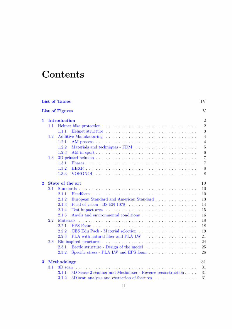
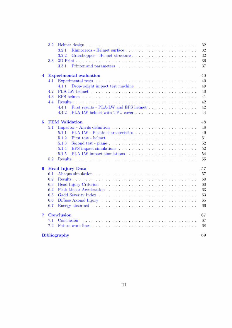
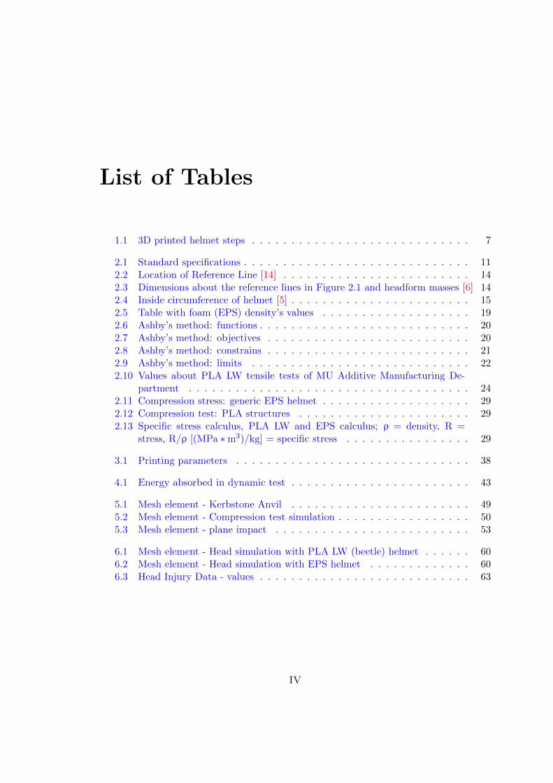
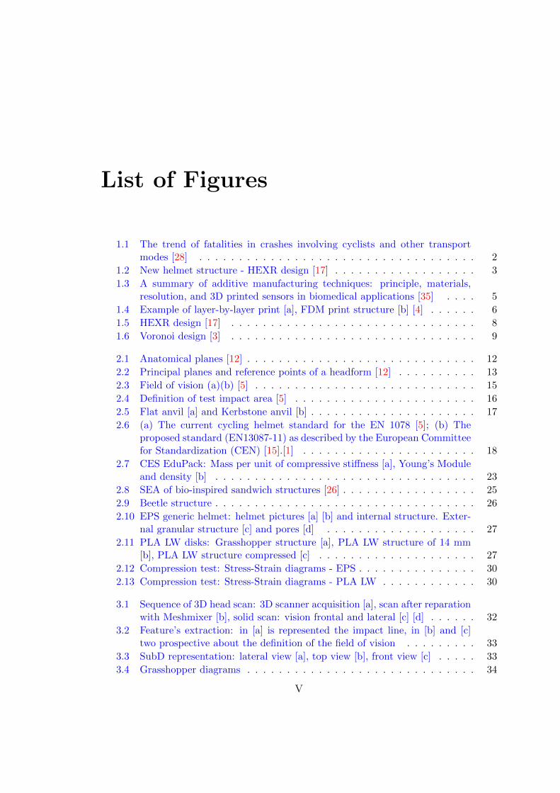
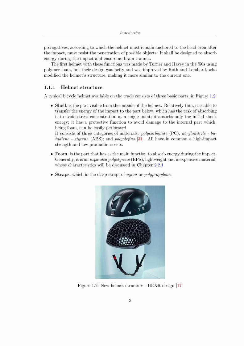
Introduction
prerogatives according to which the helmet must remain anchored to the head even afterthe impact must resist the penetration of possible objects It shall be designed to absorbenergy during the impact and ensure no brain trauma
The first helmet with these functions was made by Turner and Havey in the rsquo50s usingpolymer foam but their design was hefty and was improved by Roth and Lombard whomodified the helmetrsquos structure making it more similar to the current one
111 Helmet structure
A typical bicycle helmet available on the trade consists of three basic parts in Figure 12
bull Shell is the part visible from the outside of the helmet Relatively thin it is able totransfer the energy of the impact to the part below which has the task of absorbingit to avoid stress concentration at a single point it absorbs only the initial shockenergy it has a protective function to avoid damage to the internal part whichbeing foam can be easily perforatedIt consists of three categories of materials polycarbonate (PC) acrylonitrile - bu-tadiene - styrene (ABS) and polyolefins [31] All have in common a high-impactstrength and low production costs
bull Foam is the part that has as the main function to absorb energy during the impactGenerally it is an expanded polystyrene (EPS) lightweight and inexpensive materialwhose characteristics will be discussed in Chapter 221
bull Straps which is the clasp strap of nylon or polypropylene
Figure 12 New helmet structure - HEXR design [17]
3
Introduction
12 Additive Manufacturing
Additive Manufacturing (AM) is a manufacturing process that leads to the 3D printingof a product through 6 main steps Usually the two terms AM and 3D Printing areinterchanged but do not have the same meaning If AM indicates the entire productionprocess the other refers simply to the actual operation The techniquersquos name suggests acontrast with the classic subtractive production in which a block of material the productthat it is possible to achieve is subtracted through the 3D model pre-set In AM howeverthe material is added layer by layer consistent with the 3D model created
Among the advantages of using this new technology it is possible to create objects ina single solution with unique and complex shapes with a wide range of materials with-out worrying about waste production (excluding any media) Especially in applicationswith metallic powders this allows cost savings but also few problems for disposal andpollution as there is the possibility of recycling the powder that is not used during theproduction process making the process green In addition production times are consid-erably lower the times and costs of realization depend only on the size of the piece andnot on its geometric complexity The problems of AM concern the size of the objects tobe created because they depend on the size of the printer you use just as it is limitedalways in correlation with the printer used the choice of material
121 AM process
As previously announced Additive Manufacturing consists of 6 different steps for therealization
bull 3D model modelling it is carried out through Computer Aided Design (CAD)software
bull Generating the stl file for AM a standard language called Standard Triangu-lation Language (STL) is used With this language the model is modified and theinternal and external surfaces are converted into triangles of different sizes
bull Model orientation and support generation the format stl is imported intoa modelling software (eg Simplify 3D) The model will be arranged so that thesupports generated to support the object are as few as possible The supports canbe placed to avoid that the body is in contact with the work platform Avoidingtheir positioning in areas that need unique surface finishes is necessary as theirremoval increases roughness
bull Slicing it is the realization of the different sections that will constitute the modelthat will be printed The sections are created using parallel planes that we haveparallel at the normal to the z-axis the planes will be spaced apart by a quantitythat depends on the machinersquos resolution and the parameters imposed
bull 3D Printing import of the document into the 3D printer that layer after layerwill make the object
4
Introduction
bull Subject and treatment Once the printing is completed the object will be ob-tained with any media It will require cleaning removal of supports and treatmentsbased on the refinement of the surface
122 Materials and techniques - FDM
The additive manufacturing techniques currently on the market maybe classified accord-ing to the type of source material and can be grouped into three different categories1 Additive manufacturing techniques using liquid materials2 Additive manufacturing techniques using solid materials3 Additive manufacturing techniques using powdered materialsThe following paragraph describes in detail one of the manufacturing techniques an ad-ditive called Fused Deposition Modeling (FDM) also called melted deposition this beingthe technique used to produce the components of the case of study
Figure 13 A summary of additive manufacturing techniques principle materialsresolution and 3D printed sensors in biomedical applications [35]
FDM printing is one of the most common additive manufacturing technologies itallows the realisation of thermoplastic polymer objects that are heated and deposited tocreate an object The polymer filament is unrolled from the coil using two toothed wheelsthat push and withdraw the material from the extrusion nozzle the latter is crossed by
5
Introduction
the filament and deposits the material to build layer after layer the object Before theextrusion nozzle a heating block is positioned to control and adjust the filament temper-ature above the melting point escaping the material An excessively high temperaturewould cause a casting process that would compromise the machining accuracy a low tem-perature would prevent the filament from adhering to the already deposited layer Theextruders move in the XY plane and draw material from two coils (one for the supportsand one for the structure) depositing the material for the first layer Then the platformlowers to allow the realization of the second layer etc is the technique layer-by-layer
[a] [b]
Figure 14 Example of layer-by-layer print [a] FDM print structure [b] [4]
Once the processing is completed it proceeds with the removal of the supports thisactivity usually favoured by the different colours used for the two materials consists oftwo phases initially takes place a coarse removal carried out manually then the remainingmaterial in case it is water-soluble as that used for the development of the thesis isdissolved in water The work platform instead is characterised by lower temperaturesto encourage a rapid hardening of the newly deposited material Another parameter tobe established is the thickness of the layer which influences the time of realisation ofthe object and the quality of the finished product Generally the printing times of theobject vary from a few hours to full days depending on the size of the workpiece and theresolution chosen
123 AM in sport
As described by Novak [27] rdquosporting products are typically mass-produced to suit nor-mative population physical characteristics such as athlete heights weights foot sizes andlimb lengthsrdquo The Nike industry began to introduce 3D printing in the sport produc-ing shin guards bags and studs for football shoes The intuition was that to produceobjects with costs and times smaller than the classical production Currently the com-panies that have inserted 3D printing technologies are many to create unique piecestailored for sports through reverse engineering with ultralight composites Meier et al[21] describe the industries and their respective products from Nike with spike plate
6
Introduction
for cleats to Adidas with midsole for running shoe New Balance with plate and solefor running Burton with snowboard binding Redbull and Proto3000 surfboards Themain explanation of these productions lies as already mentioned in shorter productiontimes and costs the reduction of the weight and thickness of the products the increaseof the flexibility thanks to used techniques and materials the possibility of creating andmodifying complex designs
13 3D printed helmets
131 Phases
Phases about the production of the 3D helmet
PHASE CONTENT
1 3D Scan - In contrast to the limited number of sizes provided bymainstream helmet brands the creation of the personal
helmet begins with a fitting of the head with a specific app(for Hexr helmet)
- The data is then sent to the servers where a helmet isautomatically generated
2 Structure -Design
Realization of a structure in order to absorb the energy ofthe impact
Materials- Polyamide-11 made from 100 castor bean oil the most
sustainable bicycle helmet (Hexr)- Carbon and fiberglass resin with a polystyrene cover
(Voronoi)
3 Industrial3D printing
machines
- Using a technology known as Selective Laser Sintering(SLS) layer upon layer by using high-powered and
ultra-fine lasers to melt portions of consecutive layers ofpowder with a thickness of 01mm (Hexr)
4 Assembly - Assembling outer shell chin straps padding
Table 11 3D printed helmet steps
7
Introduction
132 HEXR
Scientists at University College London developed the HEXR helmet Figure 15 a 3Dprinted bicycle helmet with a honeycomb structureWhere University College London LondonDesigner Jamie Cook founded HEXR rdquoafter observing energy impacts are different de-pending upon surface areas This led him to do extensive research on improving bicyclehelmet technologyrdquo [17]How is it made The first step to realizing the helmet design is to scan the head usinga 3D scanner Once the scan is obtained thanks to the measurements the drawing isdefined The honeycomb structure is realized through a print with selective laser sinteringtechnology The helmet is produced layer upon layer the process is accurate and employsabout 24 hoursMaterial Polyamide-11 made from 100 castor bean oil The use of this materialmakes the helmet on the market more eco-sustainable being bio-sustainable and beingproduced by a production process with little use of water and limited treatmentsApp to scan the head cycling helmet creation process themselves at home (for App-Store) with a fitting cup to scan perfectly the head
[a] [b]
Figure 15 HEXR design [17]
133 VORONOI
The Voronoi Figure 16 the helmet was designed through a program with parametricdesign which respected a bio-inspired structure This inspiration was taken from theconformation of the animal bone and the typical turtle shellWhere Nanjing ChinaDesigner Yuefeng Zhou Zhecheng Xu Haiwei WangHow is it made The Voronoi helmet was made through a parameterized design withthe use of an unusual mesh The goal of the structure was to use a minimum amount ofmaterial and have a high energy absorption in this way it is possible to get a light and
8
Introduction
effective productMaterial The main materials used for the creation of the helmet shell are carbon kevlarand fiberglass resin with a polystyrene lining The final product is going to be availablein 3 sizes and different colours
Figure 16 Voronoi design [3]
9
Chapter 2
State of the art
21 Standards
The specification about the materials specific tests methods manufacturing to realize ahelmet shall be drawn up by the following standards
- American Society for Testing and Materials (ASTM) is a globally recognized leaderin the development and supply of international standards The World Trade Organiza-tion Technical Barriers legislate it to Trade (TBT) Committee
- The European Committee for standardization (CEN) composted by the nationalbody of Austria Belgium Bulgaria Croatia Cyprus Czech Republic Denmark EstoniaFinland Former Yugoslav Republic of Macedonia France Germany Greece HungaryIceland Ireland Italy Latvia Lithuania Luxembourg Malta Netherlands NorwayPoland Portugal Romania Slovakia Slovenia Spain Sweden Switzerland Turkey andUnited Kingdom
In this study the standard specifications show in the Table 25 will be taken intoaccount the first column contains the Standard name in the designation column theletter with the first number classifies the specification and the second number identifiesthe year when they were published or the year when the last revision was realized
211 Headform
Before realizing a helmet it is necessary to define the headform It is the geometricalrepresentation of the head without facial features and ears but the fundamental axis isrepresented
Planes definitions
bull Basic plane an anatomical plane that includes the superior rim of the externalauditory meatuses (upper edge of the external openings of the ear) and the inferiormargin of the orbit (the lowest point of the floor of the eye socket)
10
State of the art
STANDARD DESIGNATION CONTENT
Standard specifica-tion for headforms
F2220-15 This specification identifies the head-forms used for testing protective head-gear in individual ASTM Internationaltest methods and performance stan-dards [12]
Standard specifi-cation for helmetsused in recreationalbicycling or rollerskating
F1447-18 This specification recognizes the desir-ability of lightweight construction andventilation however it is a perfor-mance standard and is not intended torestrict design [13]
Standard test meth-ods for equipmentand procedures usedin evaluating theperformance charac-teristics of protectiveheadgear
F1446-20 These test methods specify equipmentand procedures used for testing pro-tective headgear Individual ASTMperformance standards (standard spec-ifications) will use these proceduresand equipment Test conditions pass-fail criteria and other performance re-quirements will be specified in the in-dividual performance standards [14]
Headforms for use inthe testing of protec-tive helmets
BS EN 9602006 This European Standard specifies thedimensional and constructional detailsof headforms for use in the testing ofprotective helmets [6]
Helmets for pedal cy-clists and for usersof skateboards androller skates
EN 10782012+A1 This European Standard specifies re-quirements and test methods for hel-mets worn by users of pedal cyclesskateboards and roller skates Require-ments and the corresponding methodsof test are given for the following- construction including field of vision- shock absorbing properties- retention system properties includingchin strap and fastening devices- marking and information [5]
Table 21 Standard specifications
bull Coronal plane an anatomical plane perpendicular to both the basic and midsagittalplanes and passing through the superior rims of the right and left external auditorymeatuses The transverse plane corresponds to the coronal plane
11
State of the art
bull Midsagittal plane an anatomical plane perpendicular to the basic plane and con-taining the midpoint of the line connecting the notches of the right and left inferiororbital ridges and the midpoint of the line connecting the superior rims of the rightand left external auditory meatuses [12]
Figure 21 Anatomical planes [12]
Planes and reference points
In agreement with the Standard BS EN 960 [6] it is possible to define different charac-teristic planes like shown in Figure 22
bull Reference plane for a given headform when erect the horizontal plane located ata vertical distance rsquoyrsquo measured down the central vertical axis from the centre ofthe crown All horizontal datum levels are quoted relative to this plane
bull AArdquo plane for a given headform the horizontal transverse plane is located at avertical distance 127 mm above and parallel to the reference plane This plane isdeemed to correspond to the level of the lower edge of the headband of a helmetIt is the basis upon which the size designation of a helmet may be specified
bull Central vertical axis vertical axis lying along the intersection of the vertical longi-tudinal plane and the vertical transverse plane
bull Centre of gravity of the three-quarter headform - point A for a given headform thepoint on the central vertical axis located at a vertical distance 127 mm above thereference plane
12
State of the art
bull Centre of gravity of the full headform - point G for a given headform the point onthe central vertical axis located at a vertical distance rsquozrsquo below the reference plane
bull Geometric centre - point R for a given headform the point on the central verticalaxis located at its intersection with the reference plane
Figure 22 Principal planes and reference points of a headform [12]
212 European Standard and American Standard
Location of gravity centre
Between the European Standard and American Standard there are differences the firstfor the location of the gravity centre
bull BS EN 960 the centre of gravity is located within a 10 mm radius of Point G
bull ASTM F1447 centre of gravity of the headform must be within a 10 vertical conefrom the centre of impact and lie within a rectangular area 28 by 128 mm
13
State of the art
The size of the head and helmet
bull ASTM F2220 to measure the external dimension for full headform the distancefrom the reference plane to the top of the headform There are different dimensionsF2220 (A if the measure is 897 mm minus C with 93 mm minus E with 96 mm minus J with1025 mm minusM with 107 mm) Then with this classification it is possible to extractthe dimension of xyz (mm) with the following Table 22
Table 22 Location of Reference Line [14]
bull BS EN 960 to obtain the size designation and the headform masses this Standardconsiders the measure of xyz (mm) in Figure 21 The possible designation are 21from 445 to 645 some of these are shown in the Table 23
Thanks to the size designation with the Standard BS EN 1078 there is the possibility todefine the inside circumference of the helmet and this it is shown in the following Table24
Table 23 Dimensions about the reference lines in Figure 21 and headform masses [6]
213 Field of vision - BS EN 1078
Apply a load of 50 N on the crown of the helmet in order to stabilize the helmet on theheadform To avoid having an occultation of the visual field Figure 23 it is better tofollow this angle measures [5]
bull horizontally min 105 from the longitudinal vertical median plane to the leftand right hand sides
bull upwards min 25 from the reference plane
bull downwards min 45 from the basic plane
14
State of the art
Table 24 Inside circumference of helmet [5]
Figure 23 Field of vision (a)(b) [5]
214 Test impact area
Standard EN 1078 will be considered for this study which defines the parameters helpfulin performing the shock absorption test The drop test impact consists of an impact ontwo anvils of flat surface or kerbstone
In the Standard is specified the Test Area where the impact is to be performed Thefirst thing is to apply a vertical load of 50 N on the crown of the helmet in order to
15
State of the art
stabilize the helmet on the headform [5]1 Draw the AArdquo line (in the AArsquo plane) on the helmet2 Draw a line on the helmet parallel to and approximately 20 mm above the AArdquo line(for use as an angular measurement datum line)3 Mark the helmet at points B1 and B2 These points are the sideways horizontalprojection of point B onto the outer surface of the helmet4 Draw a line RRrsquo on the helmet passing through B1 and B2 the line being angled 10
upwards toward the front of the helmet relative to the datum line drawn in d) The areaabove the line drawn in f) is the test area for impacts on the flat anvil The area abovethe line RWArdquo is the test area for impacts on to the kerbstone anvil
Figure 24 Definition of test impact area [5]
215 Anvils and environmental conditions
EN 1078
During the validation process each of the 30 helmet target points was impacted ex-perimentally and numerically under three environmental conditions (-20C +50C andhumidity)
The impact should never exceed 250 g for impacts with velocities corresponding to 542ms on a flat anvil and 457 ms on a kerbstone anvil These are theoretically equivalentto 1497 mm and 1064 mm drop heights respectively [5] About the characteristics of theanvils according to EN 1078 these depend on the type in the case of
bull Flat anvil it has a circular form with a diameter of 130 plusmn 3 mm with 25 mm ofthick
16
State of the art
bull Kerbstone anvil face inclined at 525 plusmn 25 to the vertical and edge with aradius of 15 plusmn 05mm The height shall be not less than 50 mm and the lengthnot less than 125 mm [5]
According with the regalement EN 1078 [5] it has been possible to realize the volumes inthis work the Flat anvil has a diameter of 130 mm and a height of 25 mm the kerbstoneanvil has a horizontal edge of 130 mm a height of 51 mm a length of 126 mm and theedge that impacts the helmet has a radius of 15 mm The anvils are represented in Figure25
[a] [b]
Figure 25 Flat anvil [a] and Kerbstone anvil [b]
EN 13087-11 (Proposal)
A proposal of November 2018 (EN 13087-11) talks about oblique impact tests (Rotationaltest method) [15] Define a method to measure rotational energy absorption in tangentialimpacts in short duration impact situations the velocity considered by Adanty et al [1]is 65 ms The same anvils of the Standard EN 1078 are used the flat anvil and theKerbstone anvil but the difference is the vertical drop towards an impact angle between30-60 the degree considered by Adanty et al [1] is 45
Three different rotations are considered [34]
bull Rotation around X-axis contact point on the side of the helmet resulting in arotation around X-axis Initial position of the headform X- Y- and Z-axis 0
bull Rotation around Y-axis Contact point on the upper part of the helmet resultingin a rotation around Y-axis Initial position of the headform X- Y- and Z-axis 0
bull Rotation around Z-axis Contact point on the upper part of the helmet resultingin a rotation around Y-axis Initial position of the headform X- and Z-axis 0 and65 around Y-axis
17
State of the art
Figure 26 (a) The current cycling helmet standard for the EN 1078 [5] (b) Theproposed standard (EN13087-11) as described by the European Committee for
Standardization (CEN) [15][1]
22 Materials
221 EPS Foam
As mentioned in Chapter 13 the material most commonly used for making the helmetis the EPS Mustafa et al [25] analysed the EPS with four different density values of 50kgm3 64 kgm3 80 kgm3 and 100 kgm3 rdquoThe drop impact simulation model wasused to test the impact attenuation of the helmet with different densities The drop testwas performed on four impact locations top front and sidesrdquo
The impact velocity of the helmet and headform was set at 544 ms The lowestpeak linear acceleration was recorded at the top location and a density of 64 kgm3 with14814 g This study sets out to determine the effect of the user-centered helmet designwith different foam densities (from 50 kgm3 to 100 kgm3) on the impact attenuationof the bicycle helmet
Kroeker et al [19] tested the helmets at three impact speeds 30 plusmn 001 ms 63 plusmn002 ms and 78 plusmn 001 ms
They established the mean value about bulk density in a helmet with EPS foam is666 considering HIC and Peak Acceleration test The global range is between 64 kgm3
and 75 kgm3
Kroeker et al [20] established the foam for kids helmets is 64-88 kgm3 and for thetraditional helmets is 60-100 kgm3
Trzaskalska et al [36] controlled the influence of polymer liner density on energy ab-sorption during impact They discovered the best properties have samples whose densityis between 54 to 60 kgm3
Cui et al [10] considered the density of each layer from the values of 25 50 60 80and 100 kgm3 and they realize a 45 grades side impact and normal crown impact Theresult is a density of 64 kgm3
Wei et al [38] discovered from their test results that EPS has a buffer layer density
18
State of the art
of 60 kgm3 is the most reasonable
Foam densityrsquos values - Literature
Authors Densityrsquos values
Mustafa et al [25] 64Kroeker et al [19] 64 - 75Kroeker et al [20] 60-100 (traditional) and 64-88 (kids)
Trzaskalska et al [36] 54 - 60Cui et al [10] 54Wei et al [38] 60
Table 25 Table with foam (EPS) densityrsquos values
The other are mean values obtained by CES EduPackrsquos program about this material
- Density ρ = 6451kgm3
- Youngrsquos Module E = 275 MPa
- Poissonrsquos ratio ν = 0275
- Yieldrsquos stress σ= 09 MPa
- Elongation at fracture = 45
222 CES Edu Pack - Material selection
CES Edupack software was used to satisfy the idea of creating a lightweight helmetby printing it in 3D and having the possibility to insert the desired characteristics ofthe material and therefore select it To make a choice I used level 3 of engineering(advanced) selecting the following criteria of the material bio-material biodegradablea polymer of concentration 20 - 100 which complies with the rsquoEuropean Restrictionon Hazardous Substances (Rohs) standardsrsquo regarding the composition of the materialensuring that it does not contain a high percentage of toxic substances compared to theestablished percentage In addition it must have proper durability in contact with coldwater (imagining a possible rain) and rsquogoodrsquo durability to UV radiation
According to Ashbyrsquos method [2] to select a material it is possible to follow thefollowing steps
1 Establish the function of the product What does the component doThe helmet is an instrumental use to protect the head during an impact this characteristicdepends on materials and qualities It can prevent an injury which depends on materialsand design because it has to be of the right head size It would be comfortable becauseit must be worn and it must give security to the person wearing it (by design) In thefollowing Table 26 the analysis of the functions
19
State of the art
Ranking Function description Depends on
1 Head protection (energy absorbing) Material2 Head protection (energy absorbing) Design3 Head protection (injury prevention) Material4 Head protection (injury prevention) Design5 Comfortable Material6 Comfortable Process
Table 26 Ashbyrsquos method functions
2 The objectives that are targets for the design the material is to bemaximised or minimisedTo manufacture and market a product objectives such as minimizing weight cost orenvironmental impact must be considered In the following Table 27 the analysis of theobjectives
Ranking Title Objectives description
1 Mass Minimize The mass has to be thesame or lower
2 Cost Minimize everyone should have theopportunity to buy it
3 CO2 footprint Minimize CO2 emission
4 Corrosion Minimize high strength because itcan be in contact with the water
5 Pleasant to touch Maximize it is not a rough materialbecause it has to put on and put off
by hands
6 Refractive index Minimize it must not reflect light
Table 27 Ashbyrsquos method objectives
3 Definition of constrains What essential conditions must be meetEstablish constraints is essential to complete the function of the instrument Examplesof constrains are Table 28
4 The limits characteristic independent of the material that does not influencethe physical properties In the following Table 29 the analysis of the limits
20
State of the art
Title Loading case Constraintsdescription
Material index(Max-Min)
Stiffness Column in compression Tie in tension
Mass Min
Stiffness Column in compression Tie in tension
Cost Min
Stiffness Column in compression Tie in tension
CO2 Min
Strength Column in compression Tie in tension
Mass Min
Strength Column in compression Tie in tension
Cost Min
Strength Column in compression Tie in tension
CO2 Min
Table 28 Ashbyrsquos method constrains
223 PLA with natural fiber and PLA LW
Initially the best material that met the desired criteria was searched From this study itwas found that the material closest to having the required characteristics is the PLA 30natural fiber as shown in the Figure 27 which shows the graphs obtained relating tothe relationships between Youngrsquos Module and density the objective to reduce the massper unit of compressive stiffness and strength to reduce the CO2 footprint per unit ofstiffness and strength and mass per unit of compressive strength
Performance index IR
The stiffness criterion has the following characteristics
m = A lowast L lowast ρ (21)
ε =σ
E=
FA
E(22)
A =F
ε lowast E(23)
21
State of the art
Ranking Title Function description
1 Biocompatibility It is the ability of a material the abilityof the material not to cause any local or
systemic adverse response in therecipient of the material
2 Biodegrability Biodegradable material do notbiodegradable under anaerobic conditions
3 Biomaterials - all The terms is used for biological naturalbio-derived bio-inspired material
4 RoHS (EU) Compliantgrades
Restriction of the use of certin prohibitessubstances (mercury cadmium
hexavalent chromium)
5 Polymer 20-100 (from the table with Plasticpolymers)
6 UV Resistance at UV sunlight
Table 29 Ashbyrsquos method limits
A =F lowast L lowast ρε lowast E
(24)
With fixed variables- F (the load) L (the length)With variables that depend on the material- E (Youngrsquos Module) ρ (density)
In general when a chart is created the distribution of the mass is represented in thefollowing modality like in Figure 27 [b] where the materials above the line have a lowermass while those below a greater mass
Following the results of the CES Edupack program that had selected the PLA withnatural fibers as the best the first print of the helmet was made with this materialusing as support the PVA Initially the result seemed satisfactory the helmet had a highdefinition but a fundamental problem was found by reducing the helmet in the water toallow the supports of PVA to dissolve In the act of diving in fact after ten minutessome parts of the helmet especially the front and rear have disintegrated making thehelmet unusable Because of this problem it was necessary to change the material
22
State of the art
[a]
[b]
Figure 27 CES EduPack Mass per unit of compressive stiffness [a] Youngrsquos Moduleand density [b]
Further investigations carried out by the Mondragon Unibertsitatea Additive Man-ufacturing Department revealed a new material the PLA Low Weight which during3D printing allows to obtain a weight of 65 lower than that which could be obtainedfrom the classic PLA as reported in the technical sheet of the filament produced by thecompany Colorfabb [7]
The investigation team of the Composite Department carried out tensile tests withsamples 3D printed at different temperatures as suggested by the manufacturer to obtainthe technical characteristics The temperatures examined are 200 220 250 260The datasheet shows the density can have values between 04 - 124 gcm3 the bed has
23
State of the art
to have a temperature between 50 - 60 the printing speed has to have values between40 - 80 mms This typology of PLA is expandible so much that rdquoAt around 230 thismaterial will start foaming increasing its volume by nearly three timesrdquo [7]
T[C] Section [mm2] Volumen [mm3] Mass [g] ρ[kgm3] E [Nmm2]
200 42235 1030117 12 1165 328807
220 43805 1655821 18 1087 265795
250 52412 1948139 17 873 178058
260 59655 1454377 12 825 117047
Table 210 Values about PLA LW tensile tests of MU Additive ManufacturingDepartment
From the tests that have been carried out on the material at different temperaturesthe printed sample is better at 250 with a volume of 1948139 mm3 and a section of52412 mm2 as shown in Table 210 For this reason the specific of the material thathave been taken into consideration are the following
- Density ρ = 873 kgm3
- Youngrsquos Module E = 1750 MPa
- Poissonrsquos ratio ν = 033
- Yieldrsquos stress σ = 2948 MPa
- Elongation at fracture = 491
23 Bio-inspired structures
When we talk about bio-inspired structures to nature we refer to structures that allowobtaining a low weight for the model that is realized and excellent absorption energy dur-ing the impact Recently the structures that have been most used in the biomimetic fieldare the rdquocolumns structures sandwich structures plates honeycomb and foamsrdquo[26]but aiming to achieve a structure increasingly with high absorption energy new struc-tures derived from plants and animals such as beetle horsetail turtle bird beak havebeen analyzed The first to create multi-cells tubes helicoidal structures the second tomulti-corner tubes [26]
The authors analyze the specific energy absorbed (SEA) by bio-inspired sandwichstructures per unit mass which can be derived from the following equation
EA(d) =
int dmax
0F (x)dx (25)
SEA(d) =EA(d)
m(26)
24
State of the art
Where EA is the energy absorption rdquomainly used to evaluate an energy absorberrsquosability to dissipate crushing energy through plastic deformationrdquo F(x) is the crashingforce dmax is the effective deformation distance [26]
What derived from their investigations is that having regard to a density of between0 and 1000 kgm3 the volumetric energy absorbed is higher for the beetle-inspired struc-tures than the others as shown in Figure 28 Based on this consideration it was chosento draw the helmet following this geometry
Figure 28 SEA of bio-inspired sandwich structures [26]
231 Beetle structure - Design of the model
To develop and increase lightweight high-strength and optimize bio-mimetic functionaland structural materials the trabecular structure of the beetle elytron is studied Thesingle structure is realized following the requirements cited by Zhang et al [39]
To realize the beetlersquos structure it is not enough to have information about the lengthof the side of the hexagon and the thickness but it is also necessary to take into accountthe relationship between the diameter of the circumferences present on the vertices ofthe hexagon and the measurement of the side The representation of a single cell is inFigure 29 It is shown in [a] a general structure with an edge of 12 mm circumferencersquosdiameter of 6 mm and thickness of 16 mm in [b] is shown the height of 20 mm
For the construction of the helmet a thickness of 12 and 16 mm was used the imageconcerns a proportion between the length of the hexagon side and the diameter of the
25
State of the art
circumference The side (distance between the centers of two circumferences) is twice thediameter measurement
[a] [b]
Figure 29 Beetle structure
232 Specific stress - PLA LW and EPS foam
To test the beetle structures compression tests were investigated The PLA LW structurewas inserted in a rsquodiskrsquo with a diameter of 100 mm and a height of 20 mm The area andthe volume of the disk is correspondingly 7854 mm2 and 157 10 mm3 The structuresexamined have different dimensions the edge L (distance between two centers of thecircumferences) had the following measures 9 10 12 14 16 mm the thickness of thecircumferences and edges are respectively of 16 mm for every structure and 12 mm forthe structure with L = 16 mm
The test was carried out with the Hoytom HM-D Testing Machine with capacitiesbetween 5 and 100 kN The test models were subjected to displacement loading at a rateof 1 mmmin as referenced by Chen et al[18] with a cylindrical specimen The specificstress of the structures was compared with the specific stress of a generic EPS helmetthe photos about it are shown in Figure 210 The EPS helmet structure is granular withpores inside The different grains dimension and these pores can be the reason for whichthe Stressrsquos values are between two values 07 and 116 MPa
Four parts of the EPS helmet were considered in the test the dimension and relativecharacteristic are in the Table 211 where m = mass A = area F = load ρ = densityR = stress Rρ = specific stress To calculate the values of stress about PLA structuresand EPS foam compression test graphs were been analyzed The stress value for eachstructure was calculated considering the single load the single area and the averagedensity value (14055 [kgm3])
The stress values of the PLA structures (Figure 211) and other characteristic valuesare in Table 212 where m = mass A = area F = load ρ = density
26
State of the art
[a] [b]
[c] [d]
Figure 210 EPS generic helmet helmet pictures [a] [b] and internal structureExternal granular structure [c] and pores [d]
[a] [b] [c]
Figure 211 PLA LW disks Grasshopper structure [a] PLA LW structure of 14 mm[b] PLA LW structure compressed [c]
27
State of the art
The results of the load-displacement graphs are affected by the geometry of the diskthe target is to valid for any shape or size for this is preferred to realize a diagramthat depends from σ (or stress) and the deformation ε (or strain) which can be definedrespectively as
σ =F
A0(27)
ε =l minus l0l
(28)
where F is the load during the test A0 is the area l0 is the initial length and l is thelength when the load is applied The areas considered for the EPS cube is reported inTable 211 in the second column the areas of the PLA structure is 7854 mm2 like thearea of the circumscribed disk
The values compared are shown in Table 213 and the graphs obtained by Matlabcode to analyze the recorded data of the compression machine are in Figure 213 and inFigure 212
Considering that the data provided by the compression machine are subject to noiseand disturbances it was decided to convert the original curve into polynomial type curvesthat allow obtaining the best interpolating curve for the data in question To obtain themit was divided the recorded data into two groups the first part from 0 until the end ofthe linear part and the second when the curve becomes linear again The best-fitting (inthe least-squares sense) was performed using the polyfit and polyval functions of MatlabThe first returns the coefficients of the p(x) with n degree the second evaluates p(x) ateach point in x The polynomial formula p(x) is shown in the Equation 29
pn(x) = anxn + anminus1x
nminus1 + + a2x2 + a1x+ a0 (29)
where a0 an are constants and x is the indeterminate The choice of the degree ofthe polynomial was made based on the criterion of wanting to obtain linear curves thatrespected the elastic trend at the beginning of the graph For this reason the degree ofthe polynomial is 1 Subsequently I searched through the intersection of the two lines forthe point that is equivalent to the maximum stress that marks the end of linearity
This value for EPS and PLA LW is the R [MPa] in the Table 213 The average stressvalue for PLA LW is 139 MPa and for EPS is 094 MPa The specific stress (Rρ) is 18MPa lowast m3)kg for the EPS found in CES 669 MPa lowast m3)kg for the EPS foam of thegeneric helmet and for PLA LW is 1161 MPa lowastm3)kg an intermediate value betweenthe two which is what we wanted to achieve
28
State of the art
m [g] A [mm2] F [N] ρ [kgm3]
EPS (CES) 50
16 9234 1063 13864
18 879 593 13651
21 858 833 14237
24 864 564 14468
Average value 14055
Table 211 Compression stress generic EPS helmet
L [mm] t [mm] m [g] F [N] ρ [kgm3]
9 16 214 7250 1363
10 16 192 5560 12467
12 16 201 8190 13051
14 12 138 8000 8961
Average value 12027
Table 212 Compression test PLA structures
PLA LW structure EPS structureρ= 12027kgm3 ρ= 14055kgm3
Edge [mm] R [MPa] Rρ103 Number R [MPa] Rρ103
EPS (CES) 09 18
9 173 1269 1 116 824
10 139 1114 2 08 568
12 138 1057 3 105 746
14 108 1205 4 077 540
Average value 139 1161 094 669
Table 213 Specific stress calculus PLA LW and EPS calculus ρ = density R = stressRρ [(MPa lowastm3)kg] = specific stress
29
State of the art
Figure 212 Compression test Stress-Strain diagrams - EPS
Figure 213 Compression test Stress-Strain diagrams - PLA LW
30
Chapter 3
Methodology
31 3D scan
311 3D Sense 2 scanner and Meshmixer - Reverse reconstruction
Standardized measures were not taken into account for making the helmet but the sizewas obtained through a 3D scan of my head
The scanner used is 3D Sense 2 by 3D Systems which has a minimum scanningvolume of 20 x 20 x 20 cm and a maximum scanning volume of 300 x 300 x 300 cmTo scan my person I was helped to get a full view at 360 at an appropriate distanceReal-time visualization of the captured images was shown through 3D Sense softwareThe idea of scanning the head with the scanner refers to the methodology used by Wanget al [30] They used a reverse reconstruction functional for me to realize the helmetsurface made to measure my head and like them a silicone pool cap was used to makescanning as smooth as possible The authors claim the head scan rdquocan also be used toobtain information about the objectrsquos surface which is then reconstructed utilizing thecomputerrsquos three-dimensional model via reverse modelling softwarerdquo [30] that in my caseis Autodesk Meshmixer
The files it was could get from the scan were stl obj and ply format they wereexported to obj to work in the next step with Autodesk Meshmixer that allowed tomodify and homogenize the 3D image obtained from the scan
In Meshmixer through the selection and delete commands the superfluous parts weredeleted that had been acquired and with the inspector and the DrawDraw2 commandsthe vertices were moved locally along a pre-defined direction and with Smooth the surfacemore homogeneous was made The sequence of steps is shown in the Figure 31
312 3D scan analysis and extraction of features
In Chapter 2 the directives imposed by the BS EN 960 Standard were examined concern-ing the definition of the helmet and the measures to be respected in the field of visionand the part of the helmet was to carry out impact tests
In Figure 32 the features defined complying with the Standardrsquos rules are repre-sented To define these features the software NX was used The angle in the subfigure
31
Methodology
[a] [b] [c] [d]
Figure 31 Sequence of 3D head scan 3D scanner acquisition [a] scan after reparationwith Meshmixer [b] solid scan vision frontal and lateral [c] [d]
[b] is bigger than 105 (as defined by the Standard) while the degree in the subfigure [c]is 25 By defining the construction lines to be respected of the helmetit was necessary todraw the design of the surface not using the software NX but changing with Rhinocerosto create a SubD or SubDivision surface
32 Helmet design
321 Rhinoceros - Helmet surface
After realizing a rsquocleanrsquo Wang et al [30] subdivide with lines and then sectors the headto create the surface of the helmet They used the technique of NURBS a Non UniformRational Basis-Splines which mathematically models a 3D geometry while thanks tothe Rhinoceros 3D organic shapes was draw SubD surfaces These geometries allow tosplit the mesh into small polygons and consist of lines with which easily the shape ofthe object can be modified with a surface already created changing the position of aline automatically the remaining part of the geometry adapts to the changes With thistechnique the rsquosurface basersquo of the helmet was realized with the size of my head Therepresentation of the realized SubD is in Figure 33
322 Grasshopper - Helmet structure
The next idea is the creation on the surface of the beetle structure with different di-mensions modelling the helmet that is not a linear surface It was decided not to buildthe structure with a software CAD because to model an already complex structure on acurved surface would mean to model a cell for a cell
To solve this obstacle a Rhinoceros plug-in was used Grasshopper GH idealized byRobert McNeel and associates creators of Rhinoceros Using GH does not mean drawinggeometries by connecting points and drawing tools because it is based on algorithmicmodelling used in architecture and engineering for 3D modelling
The modelling takes place through a node diagram that the software will convert intoa code-algorithm in GH it is possible to define the variables and parameters and inRhinoceros in real-time it is possible to view the object GH allows for varying the
32
Methodology
[a] [b]
[c]
Figure 32 Featurersquos extraction in [a] is represented the impact line in [b] and [c] twoprospective about the definition of the field of vision
[a] [b] [c]
Figure 33 SubD representation lateral view [a] top view [b] front view [c]
geometry to your liking by varying a simple parameter of the diagram as everything willbe remodelled according to the change made
In the following Figure 34 it is shown an example of a structure that was used fordistinct subgroups of helmet areas The idea was to insert smaller cells in the frontal andlateral zone and larger ones in the upper area In the first image [a] is shown the part of
33
Methodology
the helpful diagram to create the beetle structure to establish the size of the cells andthe extrusion the second image [b] contains the part of the diagram with which I appliedthe structure previously created to the SubD
The structure used to place and adapt the beetle structure to the surface is theSrfMorph while the yellow rsquowindowrsquo that contains numbers serves to select the parts ofthe surface where to apply the geometry created In accord with the GH diagram in
[a]
[b]
Figure 34 Grasshopper diagrams
Figure 34 [a] it is possible to see the steps executed to realize the structure Initially inthe xy-plane a hexagonal grid was drawn through the Hexgrid command in which youcan input the length of the hexagon edge and the number of grid elements (selected bytrial) Then the circumferences was drawn in proportion to the hexagon dimensions asspecified in the Chapter 2 and shown in Figure 35 [a] In figure [b] the rsquocutrsquo made atthe circumferences is visible this subdivision was necessary for printing purposes In thelast photo [c] the structure highlighted in green in [b] was extruded setting a distance
34
Methodology
of 20 mm
[a] [b] [c]
Figure 35 Construction sequence of the geometry of the helmet
In the diagram in Figure 34 [b] there is the application of the structure created bi-dimensionally to the SubD surface of the helmet visible by unlocking the SubD commandof the diagram and in Figure 36 [a] Upper this the referential geometry of the group ofsurfaces was superimposed where it was to be applied the newly created structure (visiblein darker red) the SubD indices are in the yellow box of the diagram
Through the SrfMorph command the location of the structure was granted In Figure36 [b] at the darkest red of the figure [a] with the above command it was possible toplace the structure
[a] [b]
Figure 36 Application of the geometry created to the helmet surface
Overall the diagrams with specific structures are five one for the front two equal forthe side parts one for the top shown in the previous Figure 36 and one for the back
The hexagons in the structure have a dimension varying between 8 mm and 14 mmof side the largest is found at the top later at the back in the sides and the smallest atthe front In Figure 36 [b] the presence of not only hexagonal structures is visible Thegeometry used does not allow the homogeneous arrangement on the entire surface andrequires different structures Automatically the choice of GH to optimize the structurewas to insert quadrilateral
As described above the helmet has different dimensions of the structure divided asvisible in Figure 36 in a quadrilateral This causes a discontinuity between zones withdifferent sizes due to the geometry of the construction
To eliminate this problem and realize the design homogeneous grids were inserted
35
Methodology
in the affected areas as shown in Figure 37 This insertion however proved to beinteresting and strategic researching in this regard studies were realized to demonstratethe insertion of a rectangular grid inside the hexagon grid was helpful for the transmissionof stress in the structure As cited by Sun et al [40] rdquothe mechanical properties of thesesandwich structures are often limited by local failures such as face-core debonding or corecollapserdquo Carrying out compression tests have effectively demonstrated that the insertionof the grid allows rdquoprovided increased stiffness specific stiffness energy absorption andcritical loadrdquo [41] As shown in the graphic [c] of the Figure 37 the honeycomb structuregives a force of 7 kN while with a grid the value is 11 kN and with the combinationexceeds 22 kN In addition in the left front a plaque to customize the helmet wasprepared Figure 37 [a]
[a] [b]
[c]
Figure 37 Grid in the helmet [a] hybrid structure with hexagons and grid [b] [40]compression test results of the hybrid structure [c] [41]
33 3D Print
After having achieved the CAD (Computer Aided Design) of the helmet in order tobe printed it must be converted and saved in format STL (Standard TriangulationLanguage) - Binary compatible with the printing machine and useful for transformingsolid object surfaces into triangles The steps to be taken are the following
bull CAD file realization
bull CAD export in format STL to Simplify 3D the software that shows slider layersand then- rotate and position the object according to geometry and the positioning of any
36
Methodology
supports- setting printing parameters- item manual andor automatic positioning of supports- slider display layers
bull import file gcode to printer
331 Printer and parameters
The program used to visualize how the helmet slices layers before sending it to the printerand to set the parameters is as anticipated Simplify 3D
To make the printing not being a flat geometry it is necessary to place the supportsThe idea was to use water-based supports that the helmet would automatically dissolveonce placed in the water After testing different types of water-soluble PVA the choicefell on eSun 3D Printing Filament PVA (water-soluble support) Before choosing theoptimal position for printing several tests were carried out and to decrease the numberof the supports significantly and allows an optimal printing of the outer part an emptyrsquospherersquo that self-sustains below the helmet was placed as shown in Figure 38
In the image [a] you can see the first print position tried with which an external partof the helmet very damaged was obtained because of the contact supports-helmet In [b]the empty rsquospherersquo is shown to optimize the number of supports and in the last photo [c]there is the full version at the end of print
[a] [b] [c]
Figure 38 Printing supports
The printer that has been used for printing is the Raise 3D Pro2 with double extrudersand nozzles of variable size from 02 mm to 1 mm after some test prints with the PLALW and the structure in created the size that allowed me to have a good compromisebetween printing time and accuracy was 06 mm Using 04 mm the printing time wasexcessive even if having the smaller nozzle diameter means having more precision withthe 08 mm nozzle the quality of the structure was not excellent as seen in Figure 38[a]
Another factor that had to be taken into account is the characteristic of the PLA-LWto expand As the printing temperature and the printer used vary the expansion andcharacteristics of the material change The use of the 06 mm nozzle associated with
37
Methodology
Parameter Left extruder Right extruder
01cm Material 01cm PVA 01cm PLA LW
Extruder toolbox index Tool 0 Tool 1
Nozzle diameter 06 mm 06 mm
Extrusion multiplier 1 05
Extrusion width Auto (072 mm) 05 mm
Layer x
Infill Rectilinear - 50
Supports (Automatic and not) Infill 50
Temperature 210 250
General parameters
Primary layer height 03 mm Top solid layer 4
Bottom solid layer 2 Outline 2
Heated bad 60 Speed 40 mms
Table 31 Printing parameters
Raise 3D allowed me to get good results The choice of this printer was not random ithas in fact the characteristic of making extremely precise prints The Raise has accuracyin placing the object on the printing bed of 078 microns on the xy axis and a resolutionfor layers of 001 mm
The final version of the helmet is visible in Figure 39 and it is possible to compare itwith the preview version in Rhinoceros in Figure 310
38
Methodology
[a] [b]
[c]
Figure 39 Views of the helmet
[a] [b]
Figure 310 Views of the helmet (GH version)
39
Chapter 4
Experimental evaluation
41 Experimental tests
411 Drop-weight impact test machine
In order to calculate the contact force peak and the difference of energy absorbed duringthe impact between the reference helmet and helmet with the beetle structure in PLA-LW dynamic impact tests were carried out using the Fractovis Plus an impact testmachine
In this way it is possible to monitor the evolution of the above variables from theinitial to the final instant of the impact The machine can withstand a load with a rangevariable from 2 to 70 kg with a maximum speed of 46 ms and a maximum height of1 m The values chosen for the test are the following 5 kg weight maximum speed andmaximum height The Anvil that was used is a disc diameter of 60 mm
As shown in Figure 41 and explained by Crupi et al [37] the machine consists ofa sensor capable of recording the speed before impact the impactor that can have avariable mass (a weight of 5 kg in my test) a system to guarantee that there are nomultiple impacts after the first and that work as a shock absorber and clamping systemwhere the object to be tested is placed
The tests that have been carried out are in total four two related to the helmetoptimized with PLA-LW and two with two generic helmets of different brand in EPS
42 PLA LW helmet
To perform the dynamic test on the helmet of PLA considering the difficulty of printingit was helpful to use a test helmet with imperfections to understand where the impactwas concentrated in a single part or distributed The images of Figure 42 show a helmetwith not well defined edges and inaccurate print but exactly localizes the impact zoneThanks to this test it was possible to take into account only one helmet area shown inFigure 43 to have the exact curve of the structure bio-inspired with PLA-LW
40
Experimental evaluation
Figure 41 Drop-weight impact test machine [37]
[a] [b]
Figure 42 Test 1 PLA-LW helmet
43 EPS helmet
To carry out dynamic tests and extract the technical characteristics of the helmettwohelmets were bought in a sports store both EPS and being on the market both certifiedThe brands of the two helmets are DTB and VAN|RYSEL and the average weight ofthe two is 223 g Two different helmets have been chosen to have a more certain andclear classification of the characteristics They are shown in Figure 44 and Figure 45
41
Experimental evaluation
[a] [b]
Figure 43 Test 2 PLA-LW helmet
[a] [b] [c]
Figure 44 Test 3 EPS helmet
[a] [b] [c]
Figure 45 Test 4 EPS helmet
44 Results
441 First results - PLA-LW and EPS helmet
Figure 46 shows two types of trends related to the two different models of the helmetThe force evaluated for PLA-LW has higher force peaks but is more concentrated and
42
Experimental evaluation
propagates less than EPS The graph shows the peaks of each curve highlighted with a redcircle In tests 1 and 2 for the PLA-LW as mentioned earlier the values are higher about7301 N for the complete helmet and 3996 N for the portion of helmet This difference isdue to the inaccuracy of the first full helmet during the printing phase In Figure 42 itis visible the low homogeneity and precision Therefore the first test with full helmet wasused only to define the area of interest of the impact which turns out to be localized Forthe other two EPS curves the values are only slightly lower compared to the PLA-LWequal to 3620 N and 3295 N but the trend is much more distributed
Figure 46 Dynamic machine test - Force
With the data obtained from the impact machine it was possible calculate not exclu-sively the value of force but itrsquos also possible to view the energy curves A resume aboutthe values and energy of the force is in the following Table 41
Test Peak force [N] Peak energy [J]
Test 1 - PLA LW (inaccurate) 730130
Test 2 - PLA LW (portion of helmet) 399643
Test 3 - EPS (DTB helmet) 362007 509
Test 4 - EPS (VAN|RYSEL helmet) 329546 4198
Test 5 - PLA with TPU 45421 5022
Table 41 Energy absorbed in dynamic test
43
Experimental evaluation
442 PLA-LW helmet with TPU cover
As it is possible to see in Figure 47 and as highlighted the first tests concerning thebio-inspired structure and the PLA-LW are far from my expectations considering thelittle distribution of force in comparison with the EPS foam and consequently a smallamount of energy absorbed
Figure 47 Dynamic machine test - Energy
To improve this impact damping factor the idea was to create a cover for the helmetin flexible TPU trying to absorb impact energy The TPU used is a flexible material ofthe brand Ninjaflex used in sports by the application in helmets and shoes to cushionbumps during the game Generally in the helmets (baseball helmet for example) theTPU is inserted internally in contact with the head In my case the TPU structurein addition to creating a shock-absorbing and durable cover creates a custom cover thehelmet and for the person This cover was also made with the Raise 3D printer
As shown in the Figure 48 [a] the infill of the part in contact with the helmet hasa percentage of 100 the filling of the other part of the structure is not complete butonly 15 and the internal structure is hexagonal to recall that of the helmet The desireto insert a structure with a rsquoraisedrsquo geometry is for visual and aesthetic reasons as youhave the feeling of greater protection and not filled is inspired by the machine CitroenCaptus whose bumpers (Airbump) are full of air The failure to realize empty structuresis due to the need to place any internal supports not removable
The idea was to create a cover that allow you to see of the internal structure of thehelmet and that protect specific areas the front the two sides the top and the posteriorWhat which was thought for this reason was to create the shape of a flower with four
44
Experimental evaluation
petals Figure 48 [b]In this way to perform dynamic impact tests as shown in Figure 49 [a] the cover was
positioned at the top of the helmet and the impact was performed in the centre of thersquoflowerrsquo which corresponds to the higher upper part where the structure has larger cellsize The impact parameters are the same as those used in previous impacts 5 kg weightmaximum speed and maximum height The Anvil that was used is a disc diameter of60 mm In photo [b] it is evident the difference between the structure that received theimpact with protection (left) and without protection (right) Without protection duringthe impact there was a perforation of the structure with a concentration of force at a locallevel as you can see in the Figure 46 in the case of TPU the impactor did not perforateand crossed the structure thanks to the cover of TPU that cushioned the shock At themoment of impact the impactor bounced
[a] [b]
Figure 48 TPU cover
[a] [b]
Figure 49 PLA-LW with TPU - dynamic impact [a] and differences between thehelmet with TPU and without TPU cover [b]
45
Experimental evaluation
The Figure 410 includes the diagrams relative to the dynamic impacts In [a] thereare already analyzed EPS results in [b] a comparison between the test on the portionof helmet in PLA LW with and without the TPU cover in [c] the overall comparison ofcurves shows a much more similar EPS trend if the TPU is placed above the structure inPLA LW to soften the blow and absorb the same energy [d]
46
[a]
[c]
[d]
Figure 410 Comparison between PLA-LW with TPU and EPS
Chapter 5
FEM Validation
51 Impactor - Anvils definition
Before to start to work in Abaqus it was necessary to search in the literature the materialwith which the anvil was been realized Milne et al [23] established the densityrsquos valuethe Youngrsquos Module and Poissonrsquos ratio for the Flat and Kerbstone Anvil
- Density ρ = 7800 kgm3
- Youngrsquos Module E = 200000 MPa
- Poissonrsquos ratio ν = 03
Inserting the data in the CES EduPack program specifying the mechanical andphysical properties the material corresponding to these characteristics is Stainless steelaustenitic (ASTM F1586) medium-hard
Initially the proposal was to create a conservative system to evaluate the absorptionenergies values and apply this value to a vibration system but the helmet needs dampingto be realized it was impossible to use a system without losses in this modality Thisis why a numerical calculation was carried out by performing two types of simulationsexplicit dynamic step and static step
The idea to realize the theoretical impact is to regard the movement of the anviland not the helmetrsquos movement which is fixed The velocity is the same cited in thenormative EN 1078 542 ms for the Flat anvil and 457 ms for the Kerbstone anvil
In performing the simulations It was given more relevance and perform tests withthe Kerbstone Anvil This choice was done because the geometry with which it is beenrealized (following as defined in the legislation) allows the helmet to be more subjectedto stress this involves the definition of higher stress limits compared to the Flat Anvil
The mesh size that has been used is the same in the case of the simulation of thehelmet optimized in PLA-LW and the full helmet in EPS of 7 mm The impactor isconsidered as a Discrete rigid body with its specific Reference Point (RP) like shownin Figure 51 for this reason it is not a solid but it is composted only by shells Inthe same image [b] there is the FEM representation of the model and in Table 51 thecharacteristic of FEM with quadrilateral (R3D4) and triangular elements (R3D3)
48
FEM Validation
Object Elementnumber
Elements Shape Geometricorder
Global size[mm]
Kerbstone 230 Quadrilateral - R3D4 Linear 7
Kerbstone 8 Triangular - R3D3 Linear 7
Table 51 Mesh element - Kerbstone Anvil
[a] [b]
Figure 51 Kerbstone anvil in the simulation like discrete rigid body [a] and FEMelements [b]
511 PLA LW - Plastic characteristics
The PLA-LW as explained in the Chapter 2 is new material on the market and producedby the only Colorfabb company for this reason few tests have been carried out to defineits technical characteristics and through tensile tests of the 3D printed specimens it waspossible to define an elastic limit as reported in the Table 210
In the context of simulations to reproduce the impact and deformation of the helmetis also necessary to consider the plastic characteristics of the material Not possessingany reference value in this regard tests were performed through a Static Step initiallyand then an Explicit Dynamic Step in Abaqus
The structure chosen to consider as a reference it is one of the structures previouslysubjected to the compression test having the side L=14 mm As for the reproduction ofthe compression disks initially they were reproduced according to the geometry of theHoytom HM-D Testing Machine considering the bodies mentioned above as discrete 3Drigid discrete The measure was the diameter of 200 mm and the height of 20 mm
After an initial analysis it was observed that the computational time of the simulationprogram was very high so it was decided to change the geometry to have a rsquodisk-surfacesrsquo(equally 3D rigid-discrete) which allowed me to have a smaller number of nodes for themesh and consequently a better computational time The representation of the opti-mized structure in PLA-LW and the disks used for simulated compression is in Figure 52
49
FEM Validation
[a] [b]
Figure 52 Representation of the samples used for the simulation of the compressiontest In Figure [a] the disks of the Hoytom HM-D Testing Machine in figure [b] the
representation of the same as simple surfaces
As shown in Figure 52 the disks are considered 3D discrete hard bodies so it waschosen for both a point the reference point RP where to apply the characteristics relatedto the two bodies As for the compression test it was established
bull the movement of a disk and fixed the second through a boundary condition impos-ing an Encastre therefore unable to move and rotate in xyz directions
bull for the opposite disk the boundary condition relative to the 15 mm displacementwas applied which is the parameter that it was observed to determine the end ofthe compression with the machine This shift is shown by the orange arrow in figure[b]
bull between the upper surface and the disk e the disk with the lower surface it wasinitialized a general contact with normal behaviour through rsquohardrsquo contact andtangential behaviour with a coefficient of friction of 02 with directionality imposedon rsquoisotropicrsquo
The next step was to define the mesh of the components whose parameters are shown inTable 52 while the representation of the FEM is in Figure 53 with the representationof the simulation and real compression test
Object Elementsnumber
Typology Geometricorder
Globalsize [mm]
Disk (14mm) 80910 hexaedral - C3D8R Linear 07
Impact disks 206 quadrilateral - R3D4 Linear 20
Impact disks 6 triangular - R3D3 Linear 20
Table 52 Mesh element - Compression test simulation
As previously announced a static simulation was initially performed with a StaticStep with Step Time equal to 900 (obtained going to consider the speed of 1 mmmin of
50
FEM Validation
[a]
[b] [c]
Figure 53 FEM representation [a] and compression test simulation [b] and realcompression [c]
the compression test and the displacement of 15 mm) However the complex geometryof the structure and the high time set by Step Time did not allow a correct definitionof the parameters of the plastic characteristics of the material the simulation was notable to continue once reached a Step Time of approximately 220 That is why it waschanged by choosing an Explicit Dynamic step
Leaving all the parameters of the boundary conditions unchanged the Step Time wasmodified imposing it to 001 The ability of the explicit dynamic to work with non-linearand contacting structures allowed me to achieve results The results obtained are shownin Figure 54 with the blue curve and were obtained through the iteration of differentPlastic Strain and Yield Stress values in Abaqus while the red line is the result of thereal compression test a similar curve trend was obtained but it is not possible to obtainthe same curve taking into account problems of printing inaccuracy
512 First test - helmet
The initial idea was to perform a simulation imposing the speed of 457 ms to theimpactor tie the helmet in EPS and PLA and compare the absorbed energies Theproblem it was encountered is related to the mesh of the helmet optimized in PLA andwith minimum dimensions of the elements and distinct elements it was not able to solveit
51
FEM Validation
[a]
YieldStress
PlasticStrain
1 47 0
2 7 001
3 75 005
4 10 01
5 108 1
6 115 15
7 12 2
[b]
Figure 54 Representation of the two curves related to the simulation in Abaqus of thecompression test and the data obtained from the real test to obtain the plastic
characteristics of the material
513 Second test - plane
The first solution is the one shown in Figure 55 To realize the simulation it was realizeda section of the helmet to involve a smaller number of elements and nodes Again thesimulation for the EPS helmet was successful while the simulation with the bio-inspiredstructure was interrupted by excessive distortion of elements
The previous images show the impact is very localized in the impacted area and theidea to achieve a complete simulation is not to consider a curved portion of the helmetbut a plane In this way it was possible to solve the problem and obtain a completesimulation for the bio-inspired structure
FEM element
Below in Table 53 there is the definition of the elements used for the PLA-LW and EPSplane in the simulation to simulate the impact and to control the energy-absorbing whilethe anvil characteristics are described in Table 51
514 EPS impact simulations
In order to proceed with the simulation it was imposed some boundary conditions thatregard ties and forces
bull the movement of the plane is fixed through an Encastre therefore unable to moveand rotate in xyz directions
52
FEM Validation
[a]
[b]
Figure 55 Impact simulation parts of EPS and PLA helmet
Object Elementnumber
Elements Shape Geometricorder
Plane (PLA) 38896 Tetrahedral -C3D10M
Quadratic
Plane (EPS) 2100 Hexahedral - C3D8R Linear
Table 53 Mesh element - plane impact
bull to create the impact it was set a speed of 457 ms at the reference point RP of therigid body which is the impactor Kerbstone Anvil shown in Figure 56
bull between the upper surface of the plane and the impactor it was initialized a Sur-face to Surface contact with normal behaviour through rsquohardrsquo contact and tangen-tial behaviour with a coefficient of friction of 02 with directionality imposed onrsquoisotropicrsquo
bull the rotation in x y z relative to the RP of the rigid discrete impactor body is locked
53
FEM Validation
In addition it was characterized the plane in the part of the materials with the char-acteristic values of the EPS mentioned in Chapter 221 The Von Mises Stress valueapparently low is relative to the Yield Stress of the EPS material equal to 09 MPa
Figure 56 EPS Boundary conditions and Load
515 PLA LW impact simulations
As also required in the case of the EPS plane in order to proceed with the simulationsome boundary conditions were imposed that regard ties and forces
bull the movement of the plane is fixed through an Encastre therefore unable to moveand rotate in xyz directions
bull to create the impact a speed of 457 ms was set at the reference point RP of therigid body which is the impactor Kerbstone Anvil shown in Figure 58
bull between the upper surface of the plane and the impactor it was initialized a Sur-face to Surface contact with normal behaviour through rsquohardrsquo contact and tangen-tial behaviour with a coefficient of friction of 02 with directionality imposed onrsquoisotropicrsquo
bull the rotation in x y z relative to the RP of the rigid discrete impactor body is locked
In addition the plane was characterized in the part of the materials with the characteristicvalues of the PLA mentioned in the Chapter 223 and 511
Figure 58 Boundary conditions and Load
54
FEM Validation
[a]
[b]
Figure 57 EPS impact simulation
52 Results
In Figures 59 and 57 it is shown how the structure in PLA LW has a more concentratedstress distribution of the structure unlike EPS The maximum value for the Von Misesstress is 09 MPa in EPS structure and 3634 MPa in PLA LW structure Once thesimulations were obtained the next step was to go and compare the energies absorbed bythe two structures The energy calculated by Abaqus that has been taken into account isPlastic Dissipation To make a comparison the data of the two energies were representedin a single graph
What emerges from the graph is that about the impact made with the KerbstoneAnvil the energy absorption is more excellent although only slightly for the PLA LWthan for the EPS From the graph in Figure 510 a value of 41 J is shown for the EPSand 51 J for the PLA LW
55
[a]
[b]
Figure 59 PLA impact simulation
[a]
Figure 510 EPS and PLA LW energy comparison - Abaqus simulation
Chapter 6
Head Injury Data
For the statistical analysis the injuries related to the accident data were categorised intothe following types and levels based on the details of the medical report [11] about theEN 1078
bull Head Injury Criterion (HIC)
bull Peak Linear Acceleration (PLAc)
bull Gadd Severity Injury (GSI)
bull Diffuse axonal injuries (DAI)
61 Abaqus simulation
Until now the purpose of the simulations has been to determine which between the twomaterials and the two structures of EPS and PLA LW could absorb more energy duringthe impact but no simulations have been carried out in compliance with BS EN 1078on the helmet impact tests To calculate the injuries listed in the previous paragraphhowever we need the acceleration values in the three directions related to the subjectrsquoshead
To realize it the scan of my head already rsquocleanrsquo was considered of which it has beencalculated the inertia thanks to the automatic SolidWorks calculation and evaluated theweight with the Table 24 the structure of the helmet was placed for the EPS and thePLA LW over the head as shown in Figure 61 Also this time being able to mesh theentire helmet in PLA LW was impossible due to the excessive distortion of some elementsduring the simulation so it has been tried to make a section of the structures of thehelmet and results were obtained
57
Head Injury Data
[a] [b]
Figure 61 My scan head - CAD [a] head imported in Abaqus[b]
Initially the simulation had these characteristics as shown in the following Figure62 considering the helmet was not sectioned As explained earlier it was not possibleto get to simulation in the case of the optimized structure in PLA LW for this reasononly a part of the helmet was considered in both cases shown in Figure 63
[a]
Figure 62 Simulation based on BS EN 1078
58
Head Injury Data
[a] [b]
Figure 63 Simulation based on BS EN 1078 with head
In order to proceed with the simulation some boundary conditions that regard tiesand forces have have imposed
bull two reference points RP were created the first in the inertia centre of the headthe second relating to the Kerbstone Anvil which is a discrete rigid body
bull in the reference point RP of the head in the definition of the engineering features5 kg was inserted for the weight and an inertia I11 = 564464E+07 gmm2 I22 =460654E+07gmm2 I33 = 187302E+07gmm2
bull to simulate the impact it was set a speed of 457 ms at the reference point RP ofthe head in z-axis direction
bull a general contact with normal behaviour through rsquohardrsquo contact and tangentialbehaviour with a coefficient of friction of 02
bull between the upper surface of the helmet and the impactor it has been initializeda Surface to Surface contact with normal behaviour through rsquohardrsquo contact andtangential behaviour with a coefficient of friction of 02 with directionality imposedon rsquoisotropicrsquo
bull the movement between the Kerbstone anvil and the helmet is fixed through anEncastre therefore unable to move and rotate in xyz directions
bull the rotation in x y z relative to the RP of the rigid discrete impactor body is locked
FEM element
As reported in Table 53 the portion of the helmet in EPS has used a mesh with hexahe-dral elements of linear order For the structure (beetle) of PLA LW given the geometry
59
Head Injury Data
complexity it was necessary to use a quadratic order of tetrahedra For the mesh of thehead instead in both simulations have been used quadrilateral elements of linear orderas reported in the Tables 61 and 62
Object Elementnumber
Elements Shape Geometricorder
Head 3755 Quadrilateral - R3D4 Linear
Head 34542 Quadrilateral - R3D3 Linear
Helmet (PLA) 272302 Tetrahedral -C3D10M
Quadratic
Table 61 Mesh element - Head simulation with PLA LW (beetle) helmet
Object Elementnumber
Elements Shape Geometricorder
Head 3755 Quadrilateral - R3D4 Linear
Head 34542 Quadrilateral - R3D3 Linear
Helmet (EPS) 72280 Hexahedral - C3D8R Linear
Table 62 Mesh element - Head simulation with EPS helmet
62 Results
Figure 64 represents the simulation in line with BS EN 1078 concerning the helmet inEPS [a] and the helmet with bio-inspired structure in PLA LW For both simulationsVan Misesrsquo stress has Yield Stress values in the case of EPS which is 09 MPa and theplastic behaviour combination of PLA LW [b]
In the case of head and Kerbstone Anvil stress was not assessed as they were previ-ously defined as discrete rigid bodies
63 Head Injury Criterion
The HIC quantifies head impact severity by incorporating time of acceleration exposureand acceleration magnitude it is calculated in post-processing phase with the followingEquation 61
HIC15 =
[1
(t1 minus t2)
int t2
t1
a(t)dt
]25(t2 minus t1) (61)
60
Head Injury Data
[a]
[b]
Figure 64 Results simulation based on BS EN 1078 with sectioned head
For this analysis a(t) is the acceleration calculated in the centre of mass of the head(corresponding to the reference point RP) expressed in g and the time interval (t2 minus t1)was chosen to maximize HIC over a maximum duration of 15 ms
Matlab and the trapz function were used to calculate the HIC to integrate accelerationover time t2 and t1 were considered initial and final times of the simulation t1 = 0 sand t2 = 10 s time less than 15 s
HIC value of 198 was obtained for EPS and 87 for PLA LW Considering the Hayeset al [16] document about the HIC values and the graph in Figure 65 developed bythe author it is possible to find the percentages related to the different injury AIS1 -AIS6 which correspond respectively to lower and higher severity while in Figure 66 therelative fatality to every value of AIS is shown The values obtained for the HIC andother criteria are shown in Table 63 The HIC value for EPS is 198 for PLA LW it is
61
Head Injury Data
Figure 65 Head injury risk curves based on HIC values [16]
Figure 66 The abbreviated injury score versus fatality rate [16]
87 Analyzing the data and comparing them with the curves of the Figure 65 I obtain
bull a percentage between 20 - 30 of AIS 1 for EPS 10 - 20 for PLA LW
bull a percentage between 10 - 20 of AIS 2 for EPS and 0 - 10 for PLA LW
bull for AIS 3 AIS 4 AIS 5 AIS 6 the percentages for both structures is between 0 -10
Comparing these percentages with the fatality rate of Figure 66 it is clear there is a riskof Moderate and Minor fatality in the case of EPS and PLA LW as all values are between0 and 30
62
Head Injury Data
HIC PLA [g] GSI E [J]
EPS 198 97 361 37723
PLA LW 87 75 169 44102
Table 63 Head Injury Data - values
64 Peak Linear Acceleration
The resultant linear acceleration versus time curve was calculated according to Equation62
γ(t) =radicγ2x(t) + γ2y(t) + γ2z (t) (62)
where
bull γ(t) is the resultant linear acceleration (g)
bull γx(t) is the linear acceleration in x axes (g)
bull γy(t) is the linear acceleration in y axes (g)
bull γz(t)is the linear acceleration in z axes (g)
The value of the impact should never exceed 250g [9] Cripton at all [9] in their studyexamined a helmet with expanded polystyrene (EPS) Figure 68 shows maximum HIC forhelmeted and unhelmeted drops from all heights For each drop height helmets reducedHIC relative to unhelmeted drops IARV value is 180g The acceleration in the two casesis shown in Figure 67 and the maximum values are 97g for EPS and 75g for PLA LWas reported in Table 63 The two values considering a maximum value calculated byCripton [9] of 180g are amply optimal and comply with the standard of 250g
65 Gadd Severity Index
Gadd proposed the Severity Index Criteria shown in Equation 63 Following this crite-rion the GSI values that are over 1000 produce serious internal head injury [33]
GSI =
int t1
0a(t)25dt (63)
Where
bull a is the linear acceleration (g)
bull t is the duration of the impact (s)
I calculated the GSI with the function trapz between 0 and t and the resulting valuesare 361 for the EPS and 169 for the PLA LW which comply with the limit
63
Head Injury Data
Figure 67 Peak accelerations for both helmets
Figure 68 Peak accelerations for both helmeted and unhelmeted drops Numbers overbars indicate peak acceleration For 2 m drop height results stated are the mean value
calculated from three drops [9]
64
Head Injury Data
66 Diffuse Axonal Injury
DAI cases covered all incidences in which neurological injuries occurred as well as con-cussion unconsciousness and coma
In order to assess the risk of head trauma in terms of diffuse axonal injury (DAI)Milne et al [23] defined a model based head injury criteria as follows obtaining theresults in Figure 69
bull 50 risk of moderate neurological injury (DAI1+) Brain Von Mises shearing stressof 28 kPa
bull 50 risk of severe neurological injury (DAI2+) Brain Von Mises shearing stressof 53 kPa
[a]
[b]
Figure 69 Peak intra-cerebral shearing stress computed with the helmet model coupledto the human head model for all impact points (a) Flat anvil (b) Kerbstone anvil [23]
65
Head Injury Data
67 Energy absorbed
In Figure 52 during the impact test between the kerbstone Anvil and the plan with thebio-inspired structure in PLA LW and EPS it was found that the PLA LW althoughwith a small difference of 10 J absorbed more energy in comparison with the EPS Whenthe test is carried out in compliance with BS EN 1078 and the head with a speed of 457ms (corresponding to the kerbstone Anvil) as shown in Figure 610 also in this casethe PLA LW with the optimized helmet structure manages to absorb more energy (evenif the difference is very low) compared to the EPS The maximum energy value in PLALW is 44102 J of EPS is 37723 J
Figure 610 Energy absorption - BS EN 1078
66
Chapter 7
Conclusion
71 Conclusion
In this thesis work a bicycle helmet with a bio-inspired structure in PLA LW and 3Dprinted was created The initial approach was to introduce an innovative aspect tostandard EPS helmets not using foam but a polymer with new geometries able toabsorb much energy during the impact For this reason the beetle structure has beenpreferred relying solely on the hypothesis encountered in the literature of its quality inabsorbing energy
Combining the new material of the PLA LW and beetle structure has made possiblethe development of new material satisfactory characteristics have been obtained sincethe first tests The two materials were first subjected to tensile tests to determine theirspecific stress in these the PLA LW had positive results
Subsequent dynamic physical tests were carried out on 3D printed helmet models andon reference helmets in EPS to calculate the absorption energy in both cases at the timeof impact These resulted in energy absorption of the beetle structure in PLA LW withthe application of a TPU cover almost equal to that of EPS about 50J To validate withfinite element analysis the two models an explicit dynamic step was used in AbaqusSimulations showed that the PLA LW structure absorbs a higher amount of energy thanthe EPS the higher is 50 J and the EPS 40J
Finally positive results have also been obtained in calculating the head injury datasimulating according to BS EN 1078 with the use of impactor helmet and head Theacceleration values for both the structures were inferior to 220g precisely for the PLALW was 75g and for the EPS 97g The same applies to the calculation of HIC and GSI(maximum acceptable value of 1000) where the values are 87 and 169 in the case of PLALW and 361 and 198 in EPS For all tests therefore greater efficiency of the structure inPLA LW has been obtained Positive results also in the simulation of the energy absorbedduring the impact as the value referring to the EPS was 35J and that of the PLA LWwas 45J
67
Conclusion
72 Future work lines
The positive results obtained can be considered as a starting point for further tests andsimulations to ensure the safety of the helmet and compliance with the regulations butbefore getting improvements and continue testing changes are required
bull the beetle structure of the helmet made with GH adapts to the SubD withoutallowing to have a homogeneous distribution it would be appropriate to have moreregular hexagonal geometries
bull the mesh of the helmet is too complex and does not allow to perform the simulationprobably to use a more regular structure would have a mesh accordingly moreregular and the simulation would be successful
bull the uneven helmet structure has so many defects that the print is imperfect andthis can change the results of the impact tests the structure should be improved
bull the printing time varies from 4 to 5 days it should be improved
bull the TPU helmet cover is too big for the RAISE printing plan it is necessary togenerate a new geometry
bull the TPU cover it must be fixed on the helmet
bull in the calculation of the DAI it is necessary to have the definition of the brain andthe head should not be considered as a rigid body
bull in the injury calculation the helmet without protection was considered with theTPU cover the result will be better
bull air flow analysis
The comments mentioned are only considerations and problems that I gained duringmy thesis and which should be improved but I am sure that these changes and improve-ments from design to printing and simulations can make the helmet a good product
68
Bibliography
[1] K Adanty J M Clark A Post Thomas Blaine H and M D Gilchrist Comparingtwo proposed protocols to test the oblique response of cycling helmets to fall impactsInternational Journal of Crashworthiness 6648 ndash 663 2020
[2] MF Ashby YJM Brechetb D Cebona and L Salvoc Selection strategies formaterials and processes Materials and Design 2004
[3] M Aysha El casco de bicicleta voronoi impreso en 3d mas seguro y ligero https
www3dnativescomen3d-printed-bicycle-helmet-voronoi-190820204
[4] H Bikas P Stavropoulos and G Chryssolouris Additive manufacturing methodsand modelling approaches a critical review The International Journal of AdvancedManufacturing Technology 83389ndash405 2016
[5] British Standards BSI Helmets for pedal cyclists and for users of skateboards androller skates - BS EN 1078 2012
[6] British Standards BSI Headforms for use in the testing of protective helmets BSEN 960 2020
[7] ColorFabb Colorfabb lw-pla 2019 httpscolorfabbcommedia
datasheetstdscolorfabbTDS_E_ColorFabb_LW-PLApdf
[8] V G Coronado T Haileyesus J M Bell T A Cheng JHaarbauer-Krupa M RLionbarger J Flores-Herrera L C McGuire and J Gilchrist Trends in sports andrecreation-related traumatic brain injuries treated in us emergency departments thenational electronic injury surveillance system-all injury program (neiss-aip) 2001-2012 J Head Trauma Rehabil 30185ndash197 2015
[9] P A Cripton D M Dressler D Stuart Cameron A Christopher R and D RichardsBicycle helmets are highly effective at preventing head injury during head impactHead-form accelerations and injury criteria for helmeted and unhelmeted impactsAccident Analysis and Prevention 701ndash7 2014
[10] L Cui M A Forero R and M D Gilchrist Optimisation of energy absorbingliner for equestrian helmets UCD School of Electrical Electronic and MechanicalEngineering University College Dublin Belfield Dublin4 Ireland 2020
[11] C Deck N Bourdet F Meyer and R Willinger Protection performance of bicyclehelmets Journal of safety research pages 67ndash77 2019
[12] Committee F08 Specification for headforms F2220 ASTM International 2015
[13] Committee F08 Specification for helmets used in recreational bicycling or rollerskating F1447 ASTM International 2018
[14] Committee F08 Test methods for equipment and procedures used in evaluating theperformance F1446 ASTM International 2020
69
Bibliography
[15] P Halldin Shock absorption including measuring CENTC 158 Working Group11 2018
[16] W C Hayes M S Erickson and E D Power Forensic injury biomechanics Annualreview of biomedical engineering pages 55ndash86 2007
[17] HEXR httpshexrcom
[18] C Jinxiang Z Xiaoming O Yoji S Kazuya G Zhensheng and P LongchengThe deformation mode and strengthening mechanism of compression in the beetleelytron plate Materials and Design 131481ndash186 2017
[19] S Kroeker M Ozkul A De Marco S Bonin and GP Siegmund Density variationin the expanded polystyrene eps foam of bicycle helmets and its influence on impactperformance Journal of biomechanical engineering 2019
[20] S G Kroeker SJ Bonin A L DeMarco C A Good and G P Siegmund Agedoes not affect the material properties of expanded polystyrene liners in field-usedbicycle helmets Journal of biomechanical engineering 2016
[21] M Meier K H Tan M K Lim and L Chung Unlocking innovation in the sportindustry through additive manufacturing Business Process Management Journa2018
[22] N J Mills and A Gilchrist The effectiveness of foams in bicycle and motorcyclehelmets Accident Analysis Prevention 23153 ndash 163 1991
[23] G Milne C Deck R P Carreira Q Allinne and R Willinger Development andvalidation of a bicycle helmet assessment of head injury risk under standard impactconditions Computer methods in biomechanics and biomedical engineering 15 Suppl1309 ndash 310 2012
[24] Y Mosleh S J Vander B Depreitere and J Ivens Novel composite foam conceptfor head protection in oblique impacts Adv Eng Mater (Advanced EngineeringMaterials) 10 2017
[25] H Mustafa T Y Pang T Ellena and S H Nasir Impact attenuation of user-centred bicycle helmet design with different foam densities J Phys Conf Ser(Journal of Physics Conference Series) 1150 2019
[26] S H Ngoc and L Guoxing A review of recent research on bio-inspired structuresand materials for energy absorption applications Composites Part 181 2020
[27] J I Novak and A R Novak Is additive manufacturing improving performance insports a systematic review Sport engineering and technology 13 2020
[28] European Road Safety Observatory European road safety observatory facts and fig-ures - cyclists - 2020 December 2020 httpseceuropaeutransportroad_
safetysitesdefaultfilesfacts_figures_cyclists_final_20210323pdf
[29] New York City Departments of Health Parks Mental Hygiene Transportation Recre-ation and the New York City Police Department Bicyclist fatalities and seriousinjuries in new york city 2005
[30] W Pengwen Y Jing H Yanan H Jiaofei and F Xiaoyang Innovative designof a helmet based on reverse engineering and 3d printing Alexandria EngineeringJournal 603445ndash3453 2021
[31] S G Piland T E Gould M Jesunathadas J S Wiggins O McNair and V CShane Protective helmets in sports Materials in Sports Equipment 3 2019
70
Bibliography
[32] K Schmitt P F Niederer M H Muser and F Walz Trauma biomechanicsSpringer Berlin Heidelberg 2010
[33] David Sepelveda Lopez A Biomechanical Analysis of Bicycle Helmets using FEMPhD thesis 2019 Bachelor thesis
[34] H Stigson Bicycle Helmets 2020 Tested by Folksam PhD thesis 2020 PhDAssociate Professor Traffic Safety Research
[35] H Tao K Sudip N Anindya and X Yongzhao 3d printed sensors for biomedicalapplications A review sensor 2019
[36] M Trzaskalska and R Chwastek Damping properties and density of helmet linersmade of expanded polystyrene (eps) Archives of Metallurgy and Materials 66 2020
[37] Crupi V Epasto G and Guglielmino E Impact response of aluminum foam sand-wiches for light-weight ship structures Metals 198ndash112 2020
[38] W Wei-cai F Dong-ming and L Yuan-xin Study on impact energy absorbing per-formance of eps buffer layer of motorcycle helmet Proceedings - 2013 InternationalConference on Mechanical and Automation Engineering MAEE 2013
[39] Z Xiaoming C Jinxiang O Yoji Z Peiwei X Xiaobing and Y Xindi Influence ofhoneycomb dimensions and forming methods on the compressive properties of beetleelytron plates Journal of Sandwich Structures and Materials 2228ndash39 2020
[40] S Zhi L Dong Z Weisheng S Shanshan and G Xu Topological optimization ofbiomimetic sandwich structures with hybrid core and cfrp face sheets CompositesScience and Technology 14279ndash90 2017
[41] S Zhi S Shanshan G Xu H Xiaozhi and C Haoran On compressive propertiesof composite sandwich structures with grid reinforced honeycomb core CompositesPart B 94245ndash252 2016
71
- List of Tables
- List of Figures
- Introduction
-
- Helmet bike protection
-
- Helmet structure
-
- Additive Manufacturing
-
- AM process
- Materials and techniques - FDM
- AM in sport
-
- 3D printed helmets
-
- Phases
- HEXR
- VORONOI
-
- State of the art
-
- Standards
-
- Headform
- European Standard and American Standard
- Field of vision - BS EN 1078
- Test impact area
- Anvils and environmental conditions
-
- Materials
-
- EPS Foam
- CES Edu Pack - Material selection
- PLA with natural fiber and PLA LW
-
- Bio-inspired structures
-
- Beetle structure - Design of the model
- Specific stress - PLA LW and EPS foam
-
- Methodology
-
- 3D scan
-
- 3D Sense 2 scanner and Meshmixer - Reverse reconstruction
- 3D scan analysis and extraction of features
-
- Helmet design
-
- Rhinoceros - Helmet surface
- Grasshopper - Helmet structure
-
- 3D Print
-
- Printer and parameters
-
- Experimental evaluation
-
- Experimental tests
-
- Drop-weight impact test machine
-
- PLA LW helmet
- EPS helmet
- Results
-
- First results - PLA-LW and EPS helmet
- PLA-LW helmet with TPU cover
-
- FEM Validation
-
- Impactor - Anvils definition
-
- PLA LW - Plastic characteristics
- First test - helmet
- Second test - plane
- EPS impact simulations
- PLA LW impact simulations
-
- Results
-
- Head Injury Data
-
- Abaqus simulation
- Results
- Head Injury Criterion
- Peak Linear Acceleration
- Gadd Severity Index
- Diffuse Axonal Injury
- Energy absorbed
-
- Conclusion
-
- Conclusion
- Future work lines
-
- Bibliography
-
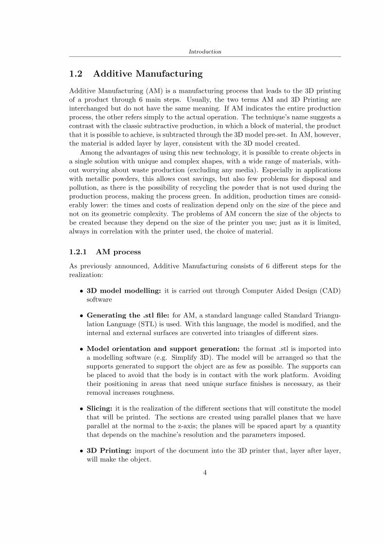
Introduction
12 Additive Manufacturing
Additive Manufacturing (AM) is a manufacturing process that leads to the 3D printingof a product through 6 main steps Usually the two terms AM and 3D Printing areinterchanged but do not have the same meaning If AM indicates the entire productionprocess the other refers simply to the actual operation The techniquersquos name suggests acontrast with the classic subtractive production in which a block of material the productthat it is possible to achieve is subtracted through the 3D model pre-set In AM howeverthe material is added layer by layer consistent with the 3D model created
Among the advantages of using this new technology it is possible to create objects ina single solution with unique and complex shapes with a wide range of materials with-out worrying about waste production (excluding any media) Especially in applicationswith metallic powders this allows cost savings but also few problems for disposal andpollution as there is the possibility of recycling the powder that is not used during theproduction process making the process green In addition production times are consid-erably lower the times and costs of realization depend only on the size of the piece andnot on its geometric complexity The problems of AM concern the size of the objects tobe created because they depend on the size of the printer you use just as it is limitedalways in correlation with the printer used the choice of material
121 AM process
As previously announced Additive Manufacturing consists of 6 different steps for therealization
bull 3D model modelling it is carried out through Computer Aided Design (CAD)software
bull Generating the stl file for AM a standard language called Standard Triangu-lation Language (STL) is used With this language the model is modified and theinternal and external surfaces are converted into triangles of different sizes
bull Model orientation and support generation the format stl is imported intoa modelling software (eg Simplify 3D) The model will be arranged so that thesupports generated to support the object are as few as possible The supports canbe placed to avoid that the body is in contact with the work platform Avoidingtheir positioning in areas that need unique surface finishes is necessary as theirremoval increases roughness
bull Slicing it is the realization of the different sections that will constitute the modelthat will be printed The sections are created using parallel planes that we haveparallel at the normal to the z-axis the planes will be spaced apart by a quantitythat depends on the machinersquos resolution and the parameters imposed
bull 3D Printing import of the document into the 3D printer that layer after layerwill make the object
4
Introduction
bull Subject and treatment Once the printing is completed the object will be ob-tained with any media It will require cleaning removal of supports and treatmentsbased on the refinement of the surface
122 Materials and techniques - FDM
The additive manufacturing techniques currently on the market maybe classified accord-ing to the type of source material and can be grouped into three different categories1 Additive manufacturing techniques using liquid materials2 Additive manufacturing techniques using solid materials3 Additive manufacturing techniques using powdered materialsThe following paragraph describes in detail one of the manufacturing techniques an ad-ditive called Fused Deposition Modeling (FDM) also called melted deposition this beingthe technique used to produce the components of the case of study
Figure 13 A summary of additive manufacturing techniques principle materialsresolution and 3D printed sensors in biomedical applications [35]
FDM printing is one of the most common additive manufacturing technologies itallows the realisation of thermoplastic polymer objects that are heated and deposited tocreate an object The polymer filament is unrolled from the coil using two toothed wheelsthat push and withdraw the material from the extrusion nozzle the latter is crossed by
5
Introduction
the filament and deposits the material to build layer after layer the object Before theextrusion nozzle a heating block is positioned to control and adjust the filament temper-ature above the melting point escaping the material An excessively high temperaturewould cause a casting process that would compromise the machining accuracy a low tem-perature would prevent the filament from adhering to the already deposited layer Theextruders move in the XY plane and draw material from two coils (one for the supportsand one for the structure) depositing the material for the first layer Then the platformlowers to allow the realization of the second layer etc is the technique layer-by-layer
[a] [b]
Figure 14 Example of layer-by-layer print [a] FDM print structure [b] [4]
Once the processing is completed it proceeds with the removal of the supports thisactivity usually favoured by the different colours used for the two materials consists oftwo phases initially takes place a coarse removal carried out manually then the remainingmaterial in case it is water-soluble as that used for the development of the thesis isdissolved in water The work platform instead is characterised by lower temperaturesto encourage a rapid hardening of the newly deposited material Another parameter tobe established is the thickness of the layer which influences the time of realisation ofthe object and the quality of the finished product Generally the printing times of theobject vary from a few hours to full days depending on the size of the workpiece and theresolution chosen
123 AM in sport
As described by Novak [27] rdquosporting products are typically mass-produced to suit nor-mative population physical characteristics such as athlete heights weights foot sizes andlimb lengthsrdquo The Nike industry began to introduce 3D printing in the sport produc-ing shin guards bags and studs for football shoes The intuition was that to produceobjects with costs and times smaller than the classical production Currently the com-panies that have inserted 3D printing technologies are many to create unique piecestailored for sports through reverse engineering with ultralight composites Meier et al[21] describe the industries and their respective products from Nike with spike plate
6
Introduction
for cleats to Adidas with midsole for running shoe New Balance with plate and solefor running Burton with snowboard binding Redbull and Proto3000 surfboards Themain explanation of these productions lies as already mentioned in shorter productiontimes and costs the reduction of the weight and thickness of the products the increaseof the flexibility thanks to used techniques and materials the possibility of creating andmodifying complex designs
13 3D printed helmets
131 Phases
Phases about the production of the 3D helmet
PHASE CONTENT
1 3D Scan - In contrast to the limited number of sizes provided bymainstream helmet brands the creation of the personal
helmet begins with a fitting of the head with a specific app(for Hexr helmet)
- The data is then sent to the servers where a helmet isautomatically generated
2 Structure -Design
Realization of a structure in order to absorb the energy ofthe impact
Materials- Polyamide-11 made from 100 castor bean oil the most
sustainable bicycle helmet (Hexr)- Carbon and fiberglass resin with a polystyrene cover
(Voronoi)
3 Industrial3D printing
machines
- Using a technology known as Selective Laser Sintering(SLS) layer upon layer by using high-powered and
ultra-fine lasers to melt portions of consecutive layers ofpowder with a thickness of 01mm (Hexr)
4 Assembly - Assembling outer shell chin straps padding
Table 11 3D printed helmet steps
7
Introduction
132 HEXR
Scientists at University College London developed the HEXR helmet Figure 15 a 3Dprinted bicycle helmet with a honeycomb structureWhere University College London LondonDesigner Jamie Cook founded HEXR rdquoafter observing energy impacts are different de-pending upon surface areas This led him to do extensive research on improving bicyclehelmet technologyrdquo [17]How is it made The first step to realizing the helmet design is to scan the head usinga 3D scanner Once the scan is obtained thanks to the measurements the drawing isdefined The honeycomb structure is realized through a print with selective laser sinteringtechnology The helmet is produced layer upon layer the process is accurate and employsabout 24 hoursMaterial Polyamide-11 made from 100 castor bean oil The use of this materialmakes the helmet on the market more eco-sustainable being bio-sustainable and beingproduced by a production process with little use of water and limited treatmentsApp to scan the head cycling helmet creation process themselves at home (for App-Store) with a fitting cup to scan perfectly the head
[a] [b]
Figure 15 HEXR design [17]
133 VORONOI
The Voronoi Figure 16 the helmet was designed through a program with parametricdesign which respected a bio-inspired structure This inspiration was taken from theconformation of the animal bone and the typical turtle shellWhere Nanjing ChinaDesigner Yuefeng Zhou Zhecheng Xu Haiwei WangHow is it made The Voronoi helmet was made through a parameterized design withthe use of an unusual mesh The goal of the structure was to use a minimum amount ofmaterial and have a high energy absorption in this way it is possible to get a light and
8
Introduction
effective productMaterial The main materials used for the creation of the helmet shell are carbon kevlarand fiberglass resin with a polystyrene lining The final product is going to be availablein 3 sizes and different colours
Figure 16 Voronoi design [3]
9
Chapter 2
State of the art
21 Standards
The specification about the materials specific tests methods manufacturing to realize ahelmet shall be drawn up by the following standards
- American Society for Testing and Materials (ASTM) is a globally recognized leaderin the development and supply of international standards The World Trade Organiza-tion Technical Barriers legislate it to Trade (TBT) Committee
- The European Committee for standardization (CEN) composted by the nationalbody of Austria Belgium Bulgaria Croatia Cyprus Czech Republic Denmark EstoniaFinland Former Yugoslav Republic of Macedonia France Germany Greece HungaryIceland Ireland Italy Latvia Lithuania Luxembourg Malta Netherlands NorwayPoland Portugal Romania Slovakia Slovenia Spain Sweden Switzerland Turkey andUnited Kingdom
In this study the standard specifications show in the Table 25 will be taken intoaccount the first column contains the Standard name in the designation column theletter with the first number classifies the specification and the second number identifiesthe year when they were published or the year when the last revision was realized
211 Headform
Before realizing a helmet it is necessary to define the headform It is the geometricalrepresentation of the head without facial features and ears but the fundamental axis isrepresented
Planes definitions
bull Basic plane an anatomical plane that includes the superior rim of the externalauditory meatuses (upper edge of the external openings of the ear) and the inferiormargin of the orbit (the lowest point of the floor of the eye socket)
10
State of the art
STANDARD DESIGNATION CONTENT
Standard specifica-tion for headforms
F2220-15 This specification identifies the head-forms used for testing protective head-gear in individual ASTM Internationaltest methods and performance stan-dards [12]
Standard specifi-cation for helmetsused in recreationalbicycling or rollerskating
F1447-18 This specification recognizes the desir-ability of lightweight construction andventilation however it is a perfor-mance standard and is not intended torestrict design [13]
Standard test meth-ods for equipmentand procedures usedin evaluating theperformance charac-teristics of protectiveheadgear
F1446-20 These test methods specify equipmentand procedures used for testing pro-tective headgear Individual ASTMperformance standards (standard spec-ifications) will use these proceduresand equipment Test conditions pass-fail criteria and other performance re-quirements will be specified in the in-dividual performance standards [14]
Headforms for use inthe testing of protec-tive helmets
BS EN 9602006 This European Standard specifies thedimensional and constructional detailsof headforms for use in the testing ofprotective helmets [6]
Helmets for pedal cy-clists and for usersof skateboards androller skates
EN 10782012+A1 This European Standard specifies re-quirements and test methods for hel-mets worn by users of pedal cyclesskateboards and roller skates Require-ments and the corresponding methodsof test are given for the following- construction including field of vision- shock absorbing properties- retention system properties includingchin strap and fastening devices- marking and information [5]
Table 21 Standard specifications
bull Coronal plane an anatomical plane perpendicular to both the basic and midsagittalplanes and passing through the superior rims of the right and left external auditorymeatuses The transverse plane corresponds to the coronal plane
11
State of the art
bull Midsagittal plane an anatomical plane perpendicular to the basic plane and con-taining the midpoint of the line connecting the notches of the right and left inferiororbital ridges and the midpoint of the line connecting the superior rims of the rightand left external auditory meatuses [12]
Figure 21 Anatomical planes [12]
Planes and reference points
In agreement with the Standard BS EN 960 [6] it is possible to define different charac-teristic planes like shown in Figure 22
bull Reference plane for a given headform when erect the horizontal plane located ata vertical distance rsquoyrsquo measured down the central vertical axis from the centre ofthe crown All horizontal datum levels are quoted relative to this plane
bull AArdquo plane for a given headform the horizontal transverse plane is located at avertical distance 127 mm above and parallel to the reference plane This plane isdeemed to correspond to the level of the lower edge of the headband of a helmetIt is the basis upon which the size designation of a helmet may be specified
bull Central vertical axis vertical axis lying along the intersection of the vertical longi-tudinal plane and the vertical transverse plane
bull Centre of gravity of the three-quarter headform - point A for a given headform thepoint on the central vertical axis located at a vertical distance 127 mm above thereference plane
12
State of the art
bull Centre of gravity of the full headform - point G for a given headform the point onthe central vertical axis located at a vertical distance rsquozrsquo below the reference plane
bull Geometric centre - point R for a given headform the point on the central verticalaxis located at its intersection with the reference plane
Figure 22 Principal planes and reference points of a headform [12]
212 European Standard and American Standard
Location of gravity centre
Between the European Standard and American Standard there are differences the firstfor the location of the gravity centre
bull BS EN 960 the centre of gravity is located within a 10 mm radius of Point G
bull ASTM F1447 centre of gravity of the headform must be within a 10 vertical conefrom the centre of impact and lie within a rectangular area 28 by 128 mm
13
State of the art
The size of the head and helmet
bull ASTM F2220 to measure the external dimension for full headform the distancefrom the reference plane to the top of the headform There are different dimensionsF2220 (A if the measure is 897 mm minus C with 93 mm minus E with 96 mm minus J with1025 mm minusM with 107 mm) Then with this classification it is possible to extractthe dimension of xyz (mm) with the following Table 22
Table 22 Location of Reference Line [14]
bull BS EN 960 to obtain the size designation and the headform masses this Standardconsiders the measure of xyz (mm) in Figure 21 The possible designation are 21from 445 to 645 some of these are shown in the Table 23
Thanks to the size designation with the Standard BS EN 1078 there is the possibility todefine the inside circumference of the helmet and this it is shown in the following Table24
Table 23 Dimensions about the reference lines in Figure 21 and headform masses [6]
213 Field of vision - BS EN 1078
Apply a load of 50 N on the crown of the helmet in order to stabilize the helmet on theheadform To avoid having an occultation of the visual field Figure 23 it is better tofollow this angle measures [5]
bull horizontally min 105 from the longitudinal vertical median plane to the leftand right hand sides
bull upwards min 25 from the reference plane
bull downwards min 45 from the basic plane
14
State of the art
Table 24 Inside circumference of helmet [5]
Figure 23 Field of vision (a)(b) [5]
214 Test impact area
Standard EN 1078 will be considered for this study which defines the parameters helpfulin performing the shock absorption test The drop test impact consists of an impact ontwo anvils of flat surface or kerbstone
In the Standard is specified the Test Area where the impact is to be performed Thefirst thing is to apply a vertical load of 50 N on the crown of the helmet in order to
15
State of the art
stabilize the helmet on the headform [5]1 Draw the AArdquo line (in the AArsquo plane) on the helmet2 Draw a line on the helmet parallel to and approximately 20 mm above the AArdquo line(for use as an angular measurement datum line)3 Mark the helmet at points B1 and B2 These points are the sideways horizontalprojection of point B onto the outer surface of the helmet4 Draw a line RRrsquo on the helmet passing through B1 and B2 the line being angled 10
upwards toward the front of the helmet relative to the datum line drawn in d) The areaabove the line drawn in f) is the test area for impacts on the flat anvil The area abovethe line RWArdquo is the test area for impacts on to the kerbstone anvil
Figure 24 Definition of test impact area [5]
215 Anvils and environmental conditions
EN 1078
During the validation process each of the 30 helmet target points was impacted ex-perimentally and numerically under three environmental conditions (-20C +50C andhumidity)
The impact should never exceed 250 g for impacts with velocities corresponding to 542ms on a flat anvil and 457 ms on a kerbstone anvil These are theoretically equivalentto 1497 mm and 1064 mm drop heights respectively [5] About the characteristics of theanvils according to EN 1078 these depend on the type in the case of
bull Flat anvil it has a circular form with a diameter of 130 plusmn 3 mm with 25 mm ofthick
16
State of the art
bull Kerbstone anvil face inclined at 525 plusmn 25 to the vertical and edge with aradius of 15 plusmn 05mm The height shall be not less than 50 mm and the lengthnot less than 125 mm [5]
According with the regalement EN 1078 [5] it has been possible to realize the volumes inthis work the Flat anvil has a diameter of 130 mm and a height of 25 mm the kerbstoneanvil has a horizontal edge of 130 mm a height of 51 mm a length of 126 mm and theedge that impacts the helmet has a radius of 15 mm The anvils are represented in Figure25
[a] [b]
Figure 25 Flat anvil [a] and Kerbstone anvil [b]
EN 13087-11 (Proposal)
A proposal of November 2018 (EN 13087-11) talks about oblique impact tests (Rotationaltest method) [15] Define a method to measure rotational energy absorption in tangentialimpacts in short duration impact situations the velocity considered by Adanty et al [1]is 65 ms The same anvils of the Standard EN 1078 are used the flat anvil and theKerbstone anvil but the difference is the vertical drop towards an impact angle between30-60 the degree considered by Adanty et al [1] is 45
Three different rotations are considered [34]
bull Rotation around X-axis contact point on the side of the helmet resulting in arotation around X-axis Initial position of the headform X- Y- and Z-axis 0
bull Rotation around Y-axis Contact point on the upper part of the helmet resultingin a rotation around Y-axis Initial position of the headform X- Y- and Z-axis 0
bull Rotation around Z-axis Contact point on the upper part of the helmet resultingin a rotation around Y-axis Initial position of the headform X- and Z-axis 0 and65 around Y-axis
17
State of the art
Figure 26 (a) The current cycling helmet standard for the EN 1078 [5] (b) Theproposed standard (EN13087-11) as described by the European Committee for
Standardization (CEN) [15][1]
22 Materials
221 EPS Foam
As mentioned in Chapter 13 the material most commonly used for making the helmetis the EPS Mustafa et al [25] analysed the EPS with four different density values of 50kgm3 64 kgm3 80 kgm3 and 100 kgm3 rdquoThe drop impact simulation model wasused to test the impact attenuation of the helmet with different densities The drop testwas performed on four impact locations top front and sidesrdquo
The impact velocity of the helmet and headform was set at 544 ms The lowestpeak linear acceleration was recorded at the top location and a density of 64 kgm3 with14814 g This study sets out to determine the effect of the user-centered helmet designwith different foam densities (from 50 kgm3 to 100 kgm3) on the impact attenuationof the bicycle helmet
Kroeker et al [19] tested the helmets at three impact speeds 30 plusmn 001 ms 63 plusmn002 ms and 78 plusmn 001 ms
They established the mean value about bulk density in a helmet with EPS foam is666 considering HIC and Peak Acceleration test The global range is between 64 kgm3
and 75 kgm3
Kroeker et al [20] established the foam for kids helmets is 64-88 kgm3 and for thetraditional helmets is 60-100 kgm3
Trzaskalska et al [36] controlled the influence of polymer liner density on energy ab-sorption during impact They discovered the best properties have samples whose densityis between 54 to 60 kgm3
Cui et al [10] considered the density of each layer from the values of 25 50 60 80and 100 kgm3 and they realize a 45 grades side impact and normal crown impact Theresult is a density of 64 kgm3
Wei et al [38] discovered from their test results that EPS has a buffer layer density
18
State of the art
of 60 kgm3 is the most reasonable
Foam densityrsquos values - Literature
Authors Densityrsquos values
Mustafa et al [25] 64Kroeker et al [19] 64 - 75Kroeker et al [20] 60-100 (traditional) and 64-88 (kids)
Trzaskalska et al [36] 54 - 60Cui et al [10] 54Wei et al [38] 60
Table 25 Table with foam (EPS) densityrsquos values
The other are mean values obtained by CES EduPackrsquos program about this material
- Density ρ = 6451kgm3
- Youngrsquos Module E = 275 MPa
- Poissonrsquos ratio ν = 0275
- Yieldrsquos stress σ= 09 MPa
- Elongation at fracture = 45
222 CES Edu Pack - Material selection
CES Edupack software was used to satisfy the idea of creating a lightweight helmetby printing it in 3D and having the possibility to insert the desired characteristics ofthe material and therefore select it To make a choice I used level 3 of engineering(advanced) selecting the following criteria of the material bio-material biodegradablea polymer of concentration 20 - 100 which complies with the rsquoEuropean Restrictionon Hazardous Substances (Rohs) standardsrsquo regarding the composition of the materialensuring that it does not contain a high percentage of toxic substances compared to theestablished percentage In addition it must have proper durability in contact with coldwater (imagining a possible rain) and rsquogoodrsquo durability to UV radiation
According to Ashbyrsquos method [2] to select a material it is possible to follow thefollowing steps
1 Establish the function of the product What does the component doThe helmet is an instrumental use to protect the head during an impact this characteristicdepends on materials and qualities It can prevent an injury which depends on materialsand design because it has to be of the right head size It would be comfortable becauseit must be worn and it must give security to the person wearing it (by design) In thefollowing Table 26 the analysis of the functions
19
State of the art
Ranking Function description Depends on
1 Head protection (energy absorbing) Material2 Head protection (energy absorbing) Design3 Head protection (injury prevention) Material4 Head protection (injury prevention) Design5 Comfortable Material6 Comfortable Process
Table 26 Ashbyrsquos method functions
2 The objectives that are targets for the design the material is to bemaximised or minimisedTo manufacture and market a product objectives such as minimizing weight cost orenvironmental impact must be considered In the following Table 27 the analysis of theobjectives
Ranking Title Objectives description
1 Mass Minimize The mass has to be thesame or lower
2 Cost Minimize everyone should have theopportunity to buy it
3 CO2 footprint Minimize CO2 emission
4 Corrosion Minimize high strength because itcan be in contact with the water
5 Pleasant to touch Maximize it is not a rough materialbecause it has to put on and put off
by hands
6 Refractive index Minimize it must not reflect light
Table 27 Ashbyrsquos method objectives
3 Definition of constrains What essential conditions must be meetEstablish constraints is essential to complete the function of the instrument Examplesof constrains are Table 28
4 The limits characteristic independent of the material that does not influencethe physical properties In the following Table 29 the analysis of the limits
20
State of the art
Title Loading case Constraintsdescription
Material index(Max-Min)
Stiffness Column in compression Tie in tension
Mass Min
Stiffness Column in compression Tie in tension
Cost Min
Stiffness Column in compression Tie in tension
CO2 Min
Strength Column in compression Tie in tension
Mass Min
Strength Column in compression Tie in tension
Cost Min
Strength Column in compression Tie in tension
CO2 Min
Table 28 Ashbyrsquos method constrains
223 PLA with natural fiber and PLA LW
Initially the best material that met the desired criteria was searched From this study itwas found that the material closest to having the required characteristics is the PLA 30natural fiber as shown in the Figure 27 which shows the graphs obtained relating tothe relationships between Youngrsquos Module and density the objective to reduce the massper unit of compressive stiffness and strength to reduce the CO2 footprint per unit ofstiffness and strength and mass per unit of compressive strength
Performance index IR
The stiffness criterion has the following characteristics
m = A lowast L lowast ρ (21)
ε =σ
E=
FA
E(22)
A =F
ε lowast E(23)
21
State of the art
Ranking Title Function description
1 Biocompatibility It is the ability of a material the abilityof the material not to cause any local or
systemic adverse response in therecipient of the material
2 Biodegrability Biodegradable material do notbiodegradable under anaerobic conditions
3 Biomaterials - all The terms is used for biological naturalbio-derived bio-inspired material
4 RoHS (EU) Compliantgrades
Restriction of the use of certin prohibitessubstances (mercury cadmium
hexavalent chromium)
5 Polymer 20-100 (from the table with Plasticpolymers)
6 UV Resistance at UV sunlight
Table 29 Ashbyrsquos method limits
A =F lowast L lowast ρε lowast E
(24)
With fixed variables- F (the load) L (the length)With variables that depend on the material- E (Youngrsquos Module) ρ (density)
In general when a chart is created the distribution of the mass is represented in thefollowing modality like in Figure 27 [b] where the materials above the line have a lowermass while those below a greater mass
Following the results of the CES Edupack program that had selected the PLA withnatural fibers as the best the first print of the helmet was made with this materialusing as support the PVA Initially the result seemed satisfactory the helmet had a highdefinition but a fundamental problem was found by reducing the helmet in the water toallow the supports of PVA to dissolve In the act of diving in fact after ten minutessome parts of the helmet especially the front and rear have disintegrated making thehelmet unusable Because of this problem it was necessary to change the material
22
State of the art
[a]
[b]
Figure 27 CES EduPack Mass per unit of compressive stiffness [a] Youngrsquos Moduleand density [b]
Further investigations carried out by the Mondragon Unibertsitatea Additive Man-ufacturing Department revealed a new material the PLA Low Weight which during3D printing allows to obtain a weight of 65 lower than that which could be obtainedfrom the classic PLA as reported in the technical sheet of the filament produced by thecompany Colorfabb [7]
The investigation team of the Composite Department carried out tensile tests withsamples 3D printed at different temperatures as suggested by the manufacturer to obtainthe technical characteristics The temperatures examined are 200 220 250 260The datasheet shows the density can have values between 04 - 124 gcm3 the bed has
23
State of the art
to have a temperature between 50 - 60 the printing speed has to have values between40 - 80 mms This typology of PLA is expandible so much that rdquoAt around 230 thismaterial will start foaming increasing its volume by nearly three timesrdquo [7]
T[C] Section [mm2] Volumen [mm3] Mass [g] ρ[kgm3] E [Nmm2]
200 42235 1030117 12 1165 328807
220 43805 1655821 18 1087 265795
250 52412 1948139 17 873 178058
260 59655 1454377 12 825 117047
Table 210 Values about PLA LW tensile tests of MU Additive ManufacturingDepartment
From the tests that have been carried out on the material at different temperaturesthe printed sample is better at 250 with a volume of 1948139 mm3 and a section of52412 mm2 as shown in Table 210 For this reason the specific of the material thathave been taken into consideration are the following
- Density ρ = 873 kgm3
- Youngrsquos Module E = 1750 MPa
- Poissonrsquos ratio ν = 033
- Yieldrsquos stress σ = 2948 MPa
- Elongation at fracture = 491
23 Bio-inspired structures
When we talk about bio-inspired structures to nature we refer to structures that allowobtaining a low weight for the model that is realized and excellent absorption energy dur-ing the impact Recently the structures that have been most used in the biomimetic fieldare the rdquocolumns structures sandwich structures plates honeycomb and foamsrdquo[26]but aiming to achieve a structure increasingly with high absorption energy new struc-tures derived from plants and animals such as beetle horsetail turtle bird beak havebeen analyzed The first to create multi-cells tubes helicoidal structures the second tomulti-corner tubes [26]
The authors analyze the specific energy absorbed (SEA) by bio-inspired sandwichstructures per unit mass which can be derived from the following equation
EA(d) =
int dmax
0F (x)dx (25)
SEA(d) =EA(d)
m(26)
24
State of the art
Where EA is the energy absorption rdquomainly used to evaluate an energy absorberrsquosability to dissipate crushing energy through plastic deformationrdquo F(x) is the crashingforce dmax is the effective deformation distance [26]
What derived from their investigations is that having regard to a density of between0 and 1000 kgm3 the volumetric energy absorbed is higher for the beetle-inspired struc-tures than the others as shown in Figure 28 Based on this consideration it was chosento draw the helmet following this geometry
Figure 28 SEA of bio-inspired sandwich structures [26]
231 Beetle structure - Design of the model
To develop and increase lightweight high-strength and optimize bio-mimetic functionaland structural materials the trabecular structure of the beetle elytron is studied Thesingle structure is realized following the requirements cited by Zhang et al [39]
To realize the beetlersquos structure it is not enough to have information about the lengthof the side of the hexagon and the thickness but it is also necessary to take into accountthe relationship between the diameter of the circumferences present on the vertices ofthe hexagon and the measurement of the side The representation of a single cell is inFigure 29 It is shown in [a] a general structure with an edge of 12 mm circumferencersquosdiameter of 6 mm and thickness of 16 mm in [b] is shown the height of 20 mm
For the construction of the helmet a thickness of 12 and 16 mm was used the imageconcerns a proportion between the length of the hexagon side and the diameter of the
25
State of the art
circumference The side (distance between the centers of two circumferences) is twice thediameter measurement
[a] [b]
Figure 29 Beetle structure
232 Specific stress - PLA LW and EPS foam
To test the beetle structures compression tests were investigated The PLA LW structurewas inserted in a rsquodiskrsquo with a diameter of 100 mm and a height of 20 mm The area andthe volume of the disk is correspondingly 7854 mm2 and 157 10 mm3 The structuresexamined have different dimensions the edge L (distance between two centers of thecircumferences) had the following measures 9 10 12 14 16 mm the thickness of thecircumferences and edges are respectively of 16 mm for every structure and 12 mm forthe structure with L = 16 mm
The test was carried out with the Hoytom HM-D Testing Machine with capacitiesbetween 5 and 100 kN The test models were subjected to displacement loading at a rateof 1 mmmin as referenced by Chen et al[18] with a cylindrical specimen The specificstress of the structures was compared with the specific stress of a generic EPS helmetthe photos about it are shown in Figure 210 The EPS helmet structure is granular withpores inside The different grains dimension and these pores can be the reason for whichthe Stressrsquos values are between two values 07 and 116 MPa
Four parts of the EPS helmet were considered in the test the dimension and relativecharacteristic are in the Table 211 where m = mass A = area F = load ρ = densityR = stress Rρ = specific stress To calculate the values of stress about PLA structuresand EPS foam compression test graphs were been analyzed The stress value for eachstructure was calculated considering the single load the single area and the averagedensity value (14055 [kgm3])
The stress values of the PLA structures (Figure 211) and other characteristic valuesare in Table 212 where m = mass A = area F = load ρ = density
26
State of the art
[a] [b]
[c] [d]
Figure 210 EPS generic helmet helmet pictures [a] [b] and internal structureExternal granular structure [c] and pores [d]
[a] [b] [c]
Figure 211 PLA LW disks Grasshopper structure [a] PLA LW structure of 14 mm[b] PLA LW structure compressed [c]
27
State of the art
The results of the load-displacement graphs are affected by the geometry of the diskthe target is to valid for any shape or size for this is preferred to realize a diagramthat depends from σ (or stress) and the deformation ε (or strain) which can be definedrespectively as
σ =F
A0(27)
ε =l minus l0l
(28)
where F is the load during the test A0 is the area l0 is the initial length and l is thelength when the load is applied The areas considered for the EPS cube is reported inTable 211 in the second column the areas of the PLA structure is 7854 mm2 like thearea of the circumscribed disk
The values compared are shown in Table 213 and the graphs obtained by Matlabcode to analyze the recorded data of the compression machine are in Figure 213 and inFigure 212
Considering that the data provided by the compression machine are subject to noiseand disturbances it was decided to convert the original curve into polynomial type curvesthat allow obtaining the best interpolating curve for the data in question To obtain themit was divided the recorded data into two groups the first part from 0 until the end ofthe linear part and the second when the curve becomes linear again The best-fitting (inthe least-squares sense) was performed using the polyfit and polyval functions of MatlabThe first returns the coefficients of the p(x) with n degree the second evaluates p(x) ateach point in x The polynomial formula p(x) is shown in the Equation 29
pn(x) = anxn + anminus1x
nminus1 + + a2x2 + a1x+ a0 (29)
where a0 an are constants and x is the indeterminate The choice of the degree ofthe polynomial was made based on the criterion of wanting to obtain linear curves thatrespected the elastic trend at the beginning of the graph For this reason the degree ofthe polynomial is 1 Subsequently I searched through the intersection of the two lines forthe point that is equivalent to the maximum stress that marks the end of linearity
This value for EPS and PLA LW is the R [MPa] in the Table 213 The average stressvalue for PLA LW is 139 MPa and for EPS is 094 MPa The specific stress (Rρ) is 18MPa lowast m3)kg for the EPS found in CES 669 MPa lowast m3)kg for the EPS foam of thegeneric helmet and for PLA LW is 1161 MPa lowastm3)kg an intermediate value betweenthe two which is what we wanted to achieve
28
State of the art
m [g] A [mm2] F [N] ρ [kgm3]
EPS (CES) 50
16 9234 1063 13864
18 879 593 13651
21 858 833 14237
24 864 564 14468
Average value 14055
Table 211 Compression stress generic EPS helmet
L [mm] t [mm] m [g] F [N] ρ [kgm3]
9 16 214 7250 1363
10 16 192 5560 12467
12 16 201 8190 13051
14 12 138 8000 8961
Average value 12027
Table 212 Compression test PLA structures
PLA LW structure EPS structureρ= 12027kgm3 ρ= 14055kgm3
Edge [mm] R [MPa] Rρ103 Number R [MPa] Rρ103
EPS (CES) 09 18
9 173 1269 1 116 824
10 139 1114 2 08 568
12 138 1057 3 105 746
14 108 1205 4 077 540
Average value 139 1161 094 669
Table 213 Specific stress calculus PLA LW and EPS calculus ρ = density R = stressRρ [(MPa lowastm3)kg] = specific stress
29
State of the art
Figure 212 Compression test Stress-Strain diagrams - EPS
Figure 213 Compression test Stress-Strain diagrams - PLA LW
30
Chapter 3
Methodology
31 3D scan
311 3D Sense 2 scanner and Meshmixer - Reverse reconstruction
Standardized measures were not taken into account for making the helmet but the sizewas obtained through a 3D scan of my head
The scanner used is 3D Sense 2 by 3D Systems which has a minimum scanningvolume of 20 x 20 x 20 cm and a maximum scanning volume of 300 x 300 x 300 cmTo scan my person I was helped to get a full view at 360 at an appropriate distanceReal-time visualization of the captured images was shown through 3D Sense softwareThe idea of scanning the head with the scanner refers to the methodology used by Wanget al [30] They used a reverse reconstruction functional for me to realize the helmetsurface made to measure my head and like them a silicone pool cap was used to makescanning as smooth as possible The authors claim the head scan rdquocan also be used toobtain information about the objectrsquos surface which is then reconstructed utilizing thecomputerrsquos three-dimensional model via reverse modelling softwarerdquo [30] that in my caseis Autodesk Meshmixer
The files it was could get from the scan were stl obj and ply format they wereexported to obj to work in the next step with Autodesk Meshmixer that allowed tomodify and homogenize the 3D image obtained from the scan
In Meshmixer through the selection and delete commands the superfluous parts weredeleted that had been acquired and with the inspector and the DrawDraw2 commandsthe vertices were moved locally along a pre-defined direction and with Smooth the surfacemore homogeneous was made The sequence of steps is shown in the Figure 31
312 3D scan analysis and extraction of features
In Chapter 2 the directives imposed by the BS EN 960 Standard were examined concern-ing the definition of the helmet and the measures to be respected in the field of visionand the part of the helmet was to carry out impact tests
In Figure 32 the features defined complying with the Standardrsquos rules are repre-sented To define these features the software NX was used The angle in the subfigure
31
Methodology
[a] [b] [c] [d]
Figure 31 Sequence of 3D head scan 3D scanner acquisition [a] scan after reparationwith Meshmixer [b] solid scan vision frontal and lateral [c] [d]
[b] is bigger than 105 (as defined by the Standard) while the degree in the subfigure [c]is 25 By defining the construction lines to be respected of the helmetit was necessary todraw the design of the surface not using the software NX but changing with Rhinocerosto create a SubD or SubDivision surface
32 Helmet design
321 Rhinoceros - Helmet surface
After realizing a rsquocleanrsquo Wang et al [30] subdivide with lines and then sectors the headto create the surface of the helmet They used the technique of NURBS a Non UniformRational Basis-Splines which mathematically models a 3D geometry while thanks tothe Rhinoceros 3D organic shapes was draw SubD surfaces These geometries allow tosplit the mesh into small polygons and consist of lines with which easily the shape ofthe object can be modified with a surface already created changing the position of aline automatically the remaining part of the geometry adapts to the changes With thistechnique the rsquosurface basersquo of the helmet was realized with the size of my head Therepresentation of the realized SubD is in Figure 33
322 Grasshopper - Helmet structure
The next idea is the creation on the surface of the beetle structure with different di-mensions modelling the helmet that is not a linear surface It was decided not to buildthe structure with a software CAD because to model an already complex structure on acurved surface would mean to model a cell for a cell
To solve this obstacle a Rhinoceros plug-in was used Grasshopper GH idealized byRobert McNeel and associates creators of Rhinoceros Using GH does not mean drawinggeometries by connecting points and drawing tools because it is based on algorithmicmodelling used in architecture and engineering for 3D modelling
The modelling takes place through a node diagram that the software will convert intoa code-algorithm in GH it is possible to define the variables and parameters and inRhinoceros in real-time it is possible to view the object GH allows for varying the
32
Methodology
[a] [b]
[c]
Figure 32 Featurersquos extraction in [a] is represented the impact line in [b] and [c] twoprospective about the definition of the field of vision
[a] [b] [c]
Figure 33 SubD representation lateral view [a] top view [b] front view [c]
geometry to your liking by varying a simple parameter of the diagram as everything willbe remodelled according to the change made
In the following Figure 34 it is shown an example of a structure that was used fordistinct subgroups of helmet areas The idea was to insert smaller cells in the frontal andlateral zone and larger ones in the upper area In the first image [a] is shown the part of
33
Methodology
the helpful diagram to create the beetle structure to establish the size of the cells andthe extrusion the second image [b] contains the part of the diagram with which I appliedthe structure previously created to the SubD
The structure used to place and adapt the beetle structure to the surface is theSrfMorph while the yellow rsquowindowrsquo that contains numbers serves to select the parts ofthe surface where to apply the geometry created In accord with the GH diagram in
[a]
[b]
Figure 34 Grasshopper diagrams
Figure 34 [a] it is possible to see the steps executed to realize the structure Initially inthe xy-plane a hexagonal grid was drawn through the Hexgrid command in which youcan input the length of the hexagon edge and the number of grid elements (selected bytrial) Then the circumferences was drawn in proportion to the hexagon dimensions asspecified in the Chapter 2 and shown in Figure 35 [a] In figure [b] the rsquocutrsquo made atthe circumferences is visible this subdivision was necessary for printing purposes In thelast photo [c] the structure highlighted in green in [b] was extruded setting a distance
34
Methodology
of 20 mm
[a] [b] [c]
Figure 35 Construction sequence of the geometry of the helmet
In the diagram in Figure 34 [b] there is the application of the structure created bi-dimensionally to the SubD surface of the helmet visible by unlocking the SubD commandof the diagram and in Figure 36 [a] Upper this the referential geometry of the group ofsurfaces was superimposed where it was to be applied the newly created structure (visiblein darker red) the SubD indices are in the yellow box of the diagram
Through the SrfMorph command the location of the structure was granted In Figure36 [b] at the darkest red of the figure [a] with the above command it was possible toplace the structure
[a] [b]
Figure 36 Application of the geometry created to the helmet surface
Overall the diagrams with specific structures are five one for the front two equal forthe side parts one for the top shown in the previous Figure 36 and one for the back
The hexagons in the structure have a dimension varying between 8 mm and 14 mmof side the largest is found at the top later at the back in the sides and the smallest atthe front In Figure 36 [b] the presence of not only hexagonal structures is visible Thegeometry used does not allow the homogeneous arrangement on the entire surface andrequires different structures Automatically the choice of GH to optimize the structurewas to insert quadrilateral
As described above the helmet has different dimensions of the structure divided asvisible in Figure 36 in a quadrilateral This causes a discontinuity between zones withdifferent sizes due to the geometry of the construction
To eliminate this problem and realize the design homogeneous grids were inserted
35
Methodology
in the affected areas as shown in Figure 37 This insertion however proved to beinteresting and strategic researching in this regard studies were realized to demonstratethe insertion of a rectangular grid inside the hexagon grid was helpful for the transmissionof stress in the structure As cited by Sun et al [40] rdquothe mechanical properties of thesesandwich structures are often limited by local failures such as face-core debonding or corecollapserdquo Carrying out compression tests have effectively demonstrated that the insertionof the grid allows rdquoprovided increased stiffness specific stiffness energy absorption andcritical loadrdquo [41] As shown in the graphic [c] of the Figure 37 the honeycomb structuregives a force of 7 kN while with a grid the value is 11 kN and with the combinationexceeds 22 kN In addition in the left front a plaque to customize the helmet wasprepared Figure 37 [a]
[a] [b]
[c]
Figure 37 Grid in the helmet [a] hybrid structure with hexagons and grid [b] [40]compression test results of the hybrid structure [c] [41]
33 3D Print
After having achieved the CAD (Computer Aided Design) of the helmet in order tobe printed it must be converted and saved in format STL (Standard TriangulationLanguage) - Binary compatible with the printing machine and useful for transformingsolid object surfaces into triangles The steps to be taken are the following
bull CAD file realization
bull CAD export in format STL to Simplify 3D the software that shows slider layersand then- rotate and position the object according to geometry and the positioning of any
36
Methodology
supports- setting printing parameters- item manual andor automatic positioning of supports- slider display layers
bull import file gcode to printer
331 Printer and parameters
The program used to visualize how the helmet slices layers before sending it to the printerand to set the parameters is as anticipated Simplify 3D
To make the printing not being a flat geometry it is necessary to place the supportsThe idea was to use water-based supports that the helmet would automatically dissolveonce placed in the water After testing different types of water-soluble PVA the choicefell on eSun 3D Printing Filament PVA (water-soluble support) Before choosing theoptimal position for printing several tests were carried out and to decrease the numberof the supports significantly and allows an optimal printing of the outer part an emptyrsquospherersquo that self-sustains below the helmet was placed as shown in Figure 38
In the image [a] you can see the first print position tried with which an external partof the helmet very damaged was obtained because of the contact supports-helmet In [b]the empty rsquospherersquo is shown to optimize the number of supports and in the last photo [c]there is the full version at the end of print
[a] [b] [c]
Figure 38 Printing supports
The printer that has been used for printing is the Raise 3D Pro2 with double extrudersand nozzles of variable size from 02 mm to 1 mm after some test prints with the PLALW and the structure in created the size that allowed me to have a good compromisebetween printing time and accuracy was 06 mm Using 04 mm the printing time wasexcessive even if having the smaller nozzle diameter means having more precision withthe 08 mm nozzle the quality of the structure was not excellent as seen in Figure 38[a]
Another factor that had to be taken into account is the characteristic of the PLA-LWto expand As the printing temperature and the printer used vary the expansion andcharacteristics of the material change The use of the 06 mm nozzle associated with
37
Methodology
Parameter Left extruder Right extruder
01cm Material 01cm PVA 01cm PLA LW
Extruder toolbox index Tool 0 Tool 1
Nozzle diameter 06 mm 06 mm
Extrusion multiplier 1 05
Extrusion width Auto (072 mm) 05 mm
Layer x
Infill Rectilinear - 50
Supports (Automatic and not) Infill 50
Temperature 210 250
General parameters
Primary layer height 03 mm Top solid layer 4
Bottom solid layer 2 Outline 2
Heated bad 60 Speed 40 mms
Table 31 Printing parameters
Raise 3D allowed me to get good results The choice of this printer was not random ithas in fact the characteristic of making extremely precise prints The Raise has accuracyin placing the object on the printing bed of 078 microns on the xy axis and a resolutionfor layers of 001 mm
The final version of the helmet is visible in Figure 39 and it is possible to compare itwith the preview version in Rhinoceros in Figure 310
38
Methodology
[a] [b]
[c]
Figure 39 Views of the helmet
[a] [b]
Figure 310 Views of the helmet (GH version)
39
Chapter 4
Experimental evaluation
41 Experimental tests
411 Drop-weight impact test machine
In order to calculate the contact force peak and the difference of energy absorbed duringthe impact between the reference helmet and helmet with the beetle structure in PLA-LW dynamic impact tests were carried out using the Fractovis Plus an impact testmachine
In this way it is possible to monitor the evolution of the above variables from theinitial to the final instant of the impact The machine can withstand a load with a rangevariable from 2 to 70 kg with a maximum speed of 46 ms and a maximum height of1 m The values chosen for the test are the following 5 kg weight maximum speed andmaximum height The Anvil that was used is a disc diameter of 60 mm
As shown in Figure 41 and explained by Crupi et al [37] the machine consists ofa sensor capable of recording the speed before impact the impactor that can have avariable mass (a weight of 5 kg in my test) a system to guarantee that there are nomultiple impacts after the first and that work as a shock absorber and clamping systemwhere the object to be tested is placed
The tests that have been carried out are in total four two related to the helmetoptimized with PLA-LW and two with two generic helmets of different brand in EPS
42 PLA LW helmet
To perform the dynamic test on the helmet of PLA considering the difficulty of printingit was helpful to use a test helmet with imperfections to understand where the impactwas concentrated in a single part or distributed The images of Figure 42 show a helmetwith not well defined edges and inaccurate print but exactly localizes the impact zoneThanks to this test it was possible to take into account only one helmet area shown inFigure 43 to have the exact curve of the structure bio-inspired with PLA-LW
40
Experimental evaluation
Figure 41 Drop-weight impact test machine [37]
[a] [b]
Figure 42 Test 1 PLA-LW helmet
43 EPS helmet
To carry out dynamic tests and extract the technical characteristics of the helmettwohelmets were bought in a sports store both EPS and being on the market both certifiedThe brands of the two helmets are DTB and VAN|RYSEL and the average weight ofthe two is 223 g Two different helmets have been chosen to have a more certain andclear classification of the characteristics They are shown in Figure 44 and Figure 45
41
Experimental evaluation
[a] [b]
Figure 43 Test 2 PLA-LW helmet
[a] [b] [c]
Figure 44 Test 3 EPS helmet
[a] [b] [c]
Figure 45 Test 4 EPS helmet
44 Results
441 First results - PLA-LW and EPS helmet
Figure 46 shows two types of trends related to the two different models of the helmetThe force evaluated for PLA-LW has higher force peaks but is more concentrated and
42
Experimental evaluation
propagates less than EPS The graph shows the peaks of each curve highlighted with a redcircle In tests 1 and 2 for the PLA-LW as mentioned earlier the values are higher about7301 N for the complete helmet and 3996 N for the portion of helmet This difference isdue to the inaccuracy of the first full helmet during the printing phase In Figure 42 itis visible the low homogeneity and precision Therefore the first test with full helmet wasused only to define the area of interest of the impact which turns out to be localized Forthe other two EPS curves the values are only slightly lower compared to the PLA-LWequal to 3620 N and 3295 N but the trend is much more distributed
Figure 46 Dynamic machine test - Force
With the data obtained from the impact machine it was possible calculate not exclu-sively the value of force but itrsquos also possible to view the energy curves A resume aboutthe values and energy of the force is in the following Table 41
Test Peak force [N] Peak energy [J]
Test 1 - PLA LW (inaccurate) 730130
Test 2 - PLA LW (portion of helmet) 399643
Test 3 - EPS (DTB helmet) 362007 509
Test 4 - EPS (VAN|RYSEL helmet) 329546 4198
Test 5 - PLA with TPU 45421 5022
Table 41 Energy absorbed in dynamic test
43
Experimental evaluation
442 PLA-LW helmet with TPU cover
As it is possible to see in Figure 47 and as highlighted the first tests concerning thebio-inspired structure and the PLA-LW are far from my expectations considering thelittle distribution of force in comparison with the EPS foam and consequently a smallamount of energy absorbed
Figure 47 Dynamic machine test - Energy
To improve this impact damping factor the idea was to create a cover for the helmetin flexible TPU trying to absorb impact energy The TPU used is a flexible material ofthe brand Ninjaflex used in sports by the application in helmets and shoes to cushionbumps during the game Generally in the helmets (baseball helmet for example) theTPU is inserted internally in contact with the head In my case the TPU structurein addition to creating a shock-absorbing and durable cover creates a custom cover thehelmet and for the person This cover was also made with the Raise 3D printer
As shown in the Figure 48 [a] the infill of the part in contact with the helmet hasa percentage of 100 the filling of the other part of the structure is not complete butonly 15 and the internal structure is hexagonal to recall that of the helmet The desireto insert a structure with a rsquoraisedrsquo geometry is for visual and aesthetic reasons as youhave the feeling of greater protection and not filled is inspired by the machine CitroenCaptus whose bumpers (Airbump) are full of air The failure to realize empty structuresis due to the need to place any internal supports not removable
The idea was to create a cover that allow you to see of the internal structure of thehelmet and that protect specific areas the front the two sides the top and the posteriorWhat which was thought for this reason was to create the shape of a flower with four
44
Experimental evaluation
petals Figure 48 [b]In this way to perform dynamic impact tests as shown in Figure 49 [a] the cover was
positioned at the top of the helmet and the impact was performed in the centre of thersquoflowerrsquo which corresponds to the higher upper part where the structure has larger cellsize The impact parameters are the same as those used in previous impacts 5 kg weightmaximum speed and maximum height The Anvil that was used is a disc diameter of60 mm In photo [b] it is evident the difference between the structure that received theimpact with protection (left) and without protection (right) Without protection duringthe impact there was a perforation of the structure with a concentration of force at a locallevel as you can see in the Figure 46 in the case of TPU the impactor did not perforateand crossed the structure thanks to the cover of TPU that cushioned the shock At themoment of impact the impactor bounced
[a] [b]
Figure 48 TPU cover
[a] [b]
Figure 49 PLA-LW with TPU - dynamic impact [a] and differences between thehelmet with TPU and without TPU cover [b]
45
Experimental evaluation
The Figure 410 includes the diagrams relative to the dynamic impacts In [a] thereare already analyzed EPS results in [b] a comparison between the test on the portionof helmet in PLA LW with and without the TPU cover in [c] the overall comparison ofcurves shows a much more similar EPS trend if the TPU is placed above the structure inPLA LW to soften the blow and absorb the same energy [d]
46
[a]
[c]
[d]
Figure 410 Comparison between PLA-LW with TPU and EPS
Chapter 5
FEM Validation
51 Impactor - Anvils definition
Before to start to work in Abaqus it was necessary to search in the literature the materialwith which the anvil was been realized Milne et al [23] established the densityrsquos valuethe Youngrsquos Module and Poissonrsquos ratio for the Flat and Kerbstone Anvil
- Density ρ = 7800 kgm3
- Youngrsquos Module E = 200000 MPa
- Poissonrsquos ratio ν = 03
Inserting the data in the CES EduPack program specifying the mechanical andphysical properties the material corresponding to these characteristics is Stainless steelaustenitic (ASTM F1586) medium-hard
Initially the proposal was to create a conservative system to evaluate the absorptionenergies values and apply this value to a vibration system but the helmet needs dampingto be realized it was impossible to use a system without losses in this modality Thisis why a numerical calculation was carried out by performing two types of simulationsexplicit dynamic step and static step
The idea to realize the theoretical impact is to regard the movement of the anviland not the helmetrsquos movement which is fixed The velocity is the same cited in thenormative EN 1078 542 ms for the Flat anvil and 457 ms for the Kerbstone anvil
In performing the simulations It was given more relevance and perform tests withthe Kerbstone Anvil This choice was done because the geometry with which it is beenrealized (following as defined in the legislation) allows the helmet to be more subjectedto stress this involves the definition of higher stress limits compared to the Flat Anvil
The mesh size that has been used is the same in the case of the simulation of thehelmet optimized in PLA-LW and the full helmet in EPS of 7 mm The impactor isconsidered as a Discrete rigid body with its specific Reference Point (RP) like shownin Figure 51 for this reason it is not a solid but it is composted only by shells Inthe same image [b] there is the FEM representation of the model and in Table 51 thecharacteristic of FEM with quadrilateral (R3D4) and triangular elements (R3D3)
48
FEM Validation
Object Elementnumber
Elements Shape Geometricorder
Global size[mm]
Kerbstone 230 Quadrilateral - R3D4 Linear 7
Kerbstone 8 Triangular - R3D3 Linear 7
Table 51 Mesh element - Kerbstone Anvil
[a] [b]
Figure 51 Kerbstone anvil in the simulation like discrete rigid body [a] and FEMelements [b]
511 PLA LW - Plastic characteristics
The PLA-LW as explained in the Chapter 2 is new material on the market and producedby the only Colorfabb company for this reason few tests have been carried out to defineits technical characteristics and through tensile tests of the 3D printed specimens it waspossible to define an elastic limit as reported in the Table 210
In the context of simulations to reproduce the impact and deformation of the helmetis also necessary to consider the plastic characteristics of the material Not possessingany reference value in this regard tests were performed through a Static Step initiallyand then an Explicit Dynamic Step in Abaqus
The structure chosen to consider as a reference it is one of the structures previouslysubjected to the compression test having the side L=14 mm As for the reproduction ofthe compression disks initially they were reproduced according to the geometry of theHoytom HM-D Testing Machine considering the bodies mentioned above as discrete 3Drigid discrete The measure was the diameter of 200 mm and the height of 20 mm
After an initial analysis it was observed that the computational time of the simulationprogram was very high so it was decided to change the geometry to have a rsquodisk-surfacesrsquo(equally 3D rigid-discrete) which allowed me to have a smaller number of nodes for themesh and consequently a better computational time The representation of the opti-mized structure in PLA-LW and the disks used for simulated compression is in Figure 52
49
FEM Validation
[a] [b]
Figure 52 Representation of the samples used for the simulation of the compressiontest In Figure [a] the disks of the Hoytom HM-D Testing Machine in figure [b] the
representation of the same as simple surfaces
As shown in Figure 52 the disks are considered 3D discrete hard bodies so it waschosen for both a point the reference point RP where to apply the characteristics relatedto the two bodies As for the compression test it was established
bull the movement of a disk and fixed the second through a boundary condition impos-ing an Encastre therefore unable to move and rotate in xyz directions
bull for the opposite disk the boundary condition relative to the 15 mm displacementwas applied which is the parameter that it was observed to determine the end ofthe compression with the machine This shift is shown by the orange arrow in figure[b]
bull between the upper surface and the disk e the disk with the lower surface it wasinitialized a general contact with normal behaviour through rsquohardrsquo contact andtangential behaviour with a coefficient of friction of 02 with directionality imposedon rsquoisotropicrsquo
The next step was to define the mesh of the components whose parameters are shown inTable 52 while the representation of the FEM is in Figure 53 with the representationof the simulation and real compression test
Object Elementsnumber
Typology Geometricorder
Globalsize [mm]
Disk (14mm) 80910 hexaedral - C3D8R Linear 07
Impact disks 206 quadrilateral - R3D4 Linear 20
Impact disks 6 triangular - R3D3 Linear 20
Table 52 Mesh element - Compression test simulation
As previously announced a static simulation was initially performed with a StaticStep with Step Time equal to 900 (obtained going to consider the speed of 1 mmmin of
50
FEM Validation
[a]
[b] [c]
Figure 53 FEM representation [a] and compression test simulation [b] and realcompression [c]
the compression test and the displacement of 15 mm) However the complex geometryof the structure and the high time set by Step Time did not allow a correct definitionof the parameters of the plastic characteristics of the material the simulation was notable to continue once reached a Step Time of approximately 220 That is why it waschanged by choosing an Explicit Dynamic step
Leaving all the parameters of the boundary conditions unchanged the Step Time wasmodified imposing it to 001 The ability of the explicit dynamic to work with non-linearand contacting structures allowed me to achieve results The results obtained are shownin Figure 54 with the blue curve and were obtained through the iteration of differentPlastic Strain and Yield Stress values in Abaqus while the red line is the result of thereal compression test a similar curve trend was obtained but it is not possible to obtainthe same curve taking into account problems of printing inaccuracy
512 First test - helmet
The initial idea was to perform a simulation imposing the speed of 457 ms to theimpactor tie the helmet in EPS and PLA and compare the absorbed energies Theproblem it was encountered is related to the mesh of the helmet optimized in PLA andwith minimum dimensions of the elements and distinct elements it was not able to solveit
51
FEM Validation
[a]
YieldStress
PlasticStrain
1 47 0
2 7 001
3 75 005
4 10 01
5 108 1
6 115 15
7 12 2
[b]
Figure 54 Representation of the two curves related to the simulation in Abaqus of thecompression test and the data obtained from the real test to obtain the plastic
characteristics of the material
513 Second test - plane
The first solution is the one shown in Figure 55 To realize the simulation it was realizeda section of the helmet to involve a smaller number of elements and nodes Again thesimulation for the EPS helmet was successful while the simulation with the bio-inspiredstructure was interrupted by excessive distortion of elements
The previous images show the impact is very localized in the impacted area and theidea to achieve a complete simulation is not to consider a curved portion of the helmetbut a plane In this way it was possible to solve the problem and obtain a completesimulation for the bio-inspired structure
FEM element
Below in Table 53 there is the definition of the elements used for the PLA-LW and EPSplane in the simulation to simulate the impact and to control the energy-absorbing whilethe anvil characteristics are described in Table 51
514 EPS impact simulations
In order to proceed with the simulation it was imposed some boundary conditions thatregard ties and forces
bull the movement of the plane is fixed through an Encastre therefore unable to moveand rotate in xyz directions
52
FEM Validation
[a]
[b]
Figure 55 Impact simulation parts of EPS and PLA helmet
Object Elementnumber
Elements Shape Geometricorder
Plane (PLA) 38896 Tetrahedral -C3D10M
Quadratic
Plane (EPS) 2100 Hexahedral - C3D8R Linear
Table 53 Mesh element - plane impact
bull to create the impact it was set a speed of 457 ms at the reference point RP of therigid body which is the impactor Kerbstone Anvil shown in Figure 56
bull between the upper surface of the plane and the impactor it was initialized a Sur-face to Surface contact with normal behaviour through rsquohardrsquo contact and tangen-tial behaviour with a coefficient of friction of 02 with directionality imposed onrsquoisotropicrsquo
bull the rotation in x y z relative to the RP of the rigid discrete impactor body is locked
53
FEM Validation
In addition it was characterized the plane in the part of the materials with the char-acteristic values of the EPS mentioned in Chapter 221 The Von Mises Stress valueapparently low is relative to the Yield Stress of the EPS material equal to 09 MPa
Figure 56 EPS Boundary conditions and Load
515 PLA LW impact simulations
As also required in the case of the EPS plane in order to proceed with the simulationsome boundary conditions were imposed that regard ties and forces
bull the movement of the plane is fixed through an Encastre therefore unable to moveand rotate in xyz directions
bull to create the impact a speed of 457 ms was set at the reference point RP of therigid body which is the impactor Kerbstone Anvil shown in Figure 58
bull between the upper surface of the plane and the impactor it was initialized a Sur-face to Surface contact with normal behaviour through rsquohardrsquo contact and tangen-tial behaviour with a coefficient of friction of 02 with directionality imposed onrsquoisotropicrsquo
bull the rotation in x y z relative to the RP of the rigid discrete impactor body is locked
In addition the plane was characterized in the part of the materials with the characteristicvalues of the PLA mentioned in the Chapter 223 and 511
Figure 58 Boundary conditions and Load
54
FEM Validation
[a]
[b]
Figure 57 EPS impact simulation
52 Results
In Figures 59 and 57 it is shown how the structure in PLA LW has a more concentratedstress distribution of the structure unlike EPS The maximum value for the Von Misesstress is 09 MPa in EPS structure and 3634 MPa in PLA LW structure Once thesimulations were obtained the next step was to go and compare the energies absorbed bythe two structures The energy calculated by Abaqus that has been taken into account isPlastic Dissipation To make a comparison the data of the two energies were representedin a single graph
What emerges from the graph is that about the impact made with the KerbstoneAnvil the energy absorption is more excellent although only slightly for the PLA LWthan for the EPS From the graph in Figure 510 a value of 41 J is shown for the EPSand 51 J for the PLA LW
55
[a]
[b]
Figure 59 PLA impact simulation
[a]
Figure 510 EPS and PLA LW energy comparison - Abaqus simulation
Chapter 6
Head Injury Data
For the statistical analysis the injuries related to the accident data were categorised intothe following types and levels based on the details of the medical report [11] about theEN 1078
bull Head Injury Criterion (HIC)
bull Peak Linear Acceleration (PLAc)
bull Gadd Severity Injury (GSI)
bull Diffuse axonal injuries (DAI)
61 Abaqus simulation
Until now the purpose of the simulations has been to determine which between the twomaterials and the two structures of EPS and PLA LW could absorb more energy duringthe impact but no simulations have been carried out in compliance with BS EN 1078on the helmet impact tests To calculate the injuries listed in the previous paragraphhowever we need the acceleration values in the three directions related to the subjectrsquoshead
To realize it the scan of my head already rsquocleanrsquo was considered of which it has beencalculated the inertia thanks to the automatic SolidWorks calculation and evaluated theweight with the Table 24 the structure of the helmet was placed for the EPS and thePLA LW over the head as shown in Figure 61 Also this time being able to mesh theentire helmet in PLA LW was impossible due to the excessive distortion of some elementsduring the simulation so it has been tried to make a section of the structures of thehelmet and results were obtained
57
Head Injury Data
[a] [b]
Figure 61 My scan head - CAD [a] head imported in Abaqus[b]
Initially the simulation had these characteristics as shown in the following Figure62 considering the helmet was not sectioned As explained earlier it was not possibleto get to simulation in the case of the optimized structure in PLA LW for this reasononly a part of the helmet was considered in both cases shown in Figure 63
[a]
Figure 62 Simulation based on BS EN 1078
58
Head Injury Data
[a] [b]
Figure 63 Simulation based on BS EN 1078 with head
In order to proceed with the simulation some boundary conditions that regard tiesand forces have have imposed
bull two reference points RP were created the first in the inertia centre of the headthe second relating to the Kerbstone Anvil which is a discrete rigid body
bull in the reference point RP of the head in the definition of the engineering features5 kg was inserted for the weight and an inertia I11 = 564464E+07 gmm2 I22 =460654E+07gmm2 I33 = 187302E+07gmm2
bull to simulate the impact it was set a speed of 457 ms at the reference point RP ofthe head in z-axis direction
bull a general contact with normal behaviour through rsquohardrsquo contact and tangentialbehaviour with a coefficient of friction of 02
bull between the upper surface of the helmet and the impactor it has been initializeda Surface to Surface contact with normal behaviour through rsquohardrsquo contact andtangential behaviour with a coefficient of friction of 02 with directionality imposedon rsquoisotropicrsquo
bull the movement between the Kerbstone anvil and the helmet is fixed through anEncastre therefore unable to move and rotate in xyz directions
bull the rotation in x y z relative to the RP of the rigid discrete impactor body is locked
FEM element
As reported in Table 53 the portion of the helmet in EPS has used a mesh with hexahe-dral elements of linear order For the structure (beetle) of PLA LW given the geometry
59
Head Injury Data
complexity it was necessary to use a quadratic order of tetrahedra For the mesh of thehead instead in both simulations have been used quadrilateral elements of linear orderas reported in the Tables 61 and 62
Object Elementnumber
Elements Shape Geometricorder
Head 3755 Quadrilateral - R3D4 Linear
Head 34542 Quadrilateral - R3D3 Linear
Helmet (PLA) 272302 Tetrahedral -C3D10M
Quadratic
Table 61 Mesh element - Head simulation with PLA LW (beetle) helmet
Object Elementnumber
Elements Shape Geometricorder
Head 3755 Quadrilateral - R3D4 Linear
Head 34542 Quadrilateral - R3D3 Linear
Helmet (EPS) 72280 Hexahedral - C3D8R Linear
Table 62 Mesh element - Head simulation with EPS helmet
62 Results
Figure 64 represents the simulation in line with BS EN 1078 concerning the helmet inEPS [a] and the helmet with bio-inspired structure in PLA LW For both simulationsVan Misesrsquo stress has Yield Stress values in the case of EPS which is 09 MPa and theplastic behaviour combination of PLA LW [b]
In the case of head and Kerbstone Anvil stress was not assessed as they were previ-ously defined as discrete rigid bodies
63 Head Injury Criterion
The HIC quantifies head impact severity by incorporating time of acceleration exposureand acceleration magnitude it is calculated in post-processing phase with the followingEquation 61
HIC15 =
[1
(t1 minus t2)
int t2
t1
a(t)dt
]25(t2 minus t1) (61)
60
Head Injury Data
[a]
[b]
Figure 64 Results simulation based on BS EN 1078 with sectioned head
For this analysis a(t) is the acceleration calculated in the centre of mass of the head(corresponding to the reference point RP) expressed in g and the time interval (t2 minus t1)was chosen to maximize HIC over a maximum duration of 15 ms
Matlab and the trapz function were used to calculate the HIC to integrate accelerationover time t2 and t1 were considered initial and final times of the simulation t1 = 0 sand t2 = 10 s time less than 15 s
HIC value of 198 was obtained for EPS and 87 for PLA LW Considering the Hayeset al [16] document about the HIC values and the graph in Figure 65 developed bythe author it is possible to find the percentages related to the different injury AIS1 -AIS6 which correspond respectively to lower and higher severity while in Figure 66 therelative fatality to every value of AIS is shown The values obtained for the HIC andother criteria are shown in Table 63 The HIC value for EPS is 198 for PLA LW it is
61
Head Injury Data
Figure 65 Head injury risk curves based on HIC values [16]
Figure 66 The abbreviated injury score versus fatality rate [16]
87 Analyzing the data and comparing them with the curves of the Figure 65 I obtain
bull a percentage between 20 - 30 of AIS 1 for EPS 10 - 20 for PLA LW
bull a percentage between 10 - 20 of AIS 2 for EPS and 0 - 10 for PLA LW
bull for AIS 3 AIS 4 AIS 5 AIS 6 the percentages for both structures is between 0 -10
Comparing these percentages with the fatality rate of Figure 66 it is clear there is a riskof Moderate and Minor fatality in the case of EPS and PLA LW as all values are between0 and 30
62
Head Injury Data
HIC PLA [g] GSI E [J]
EPS 198 97 361 37723
PLA LW 87 75 169 44102
Table 63 Head Injury Data - values
64 Peak Linear Acceleration
The resultant linear acceleration versus time curve was calculated according to Equation62
γ(t) =radicγ2x(t) + γ2y(t) + γ2z (t) (62)
where
bull γ(t) is the resultant linear acceleration (g)
bull γx(t) is the linear acceleration in x axes (g)
bull γy(t) is the linear acceleration in y axes (g)
bull γz(t)is the linear acceleration in z axes (g)
The value of the impact should never exceed 250g [9] Cripton at all [9] in their studyexamined a helmet with expanded polystyrene (EPS) Figure 68 shows maximum HIC forhelmeted and unhelmeted drops from all heights For each drop height helmets reducedHIC relative to unhelmeted drops IARV value is 180g The acceleration in the two casesis shown in Figure 67 and the maximum values are 97g for EPS and 75g for PLA LWas reported in Table 63 The two values considering a maximum value calculated byCripton [9] of 180g are amply optimal and comply with the standard of 250g
65 Gadd Severity Index
Gadd proposed the Severity Index Criteria shown in Equation 63 Following this crite-rion the GSI values that are over 1000 produce serious internal head injury [33]
GSI =
int t1
0a(t)25dt (63)
Where
bull a is the linear acceleration (g)
bull t is the duration of the impact (s)
I calculated the GSI with the function trapz between 0 and t and the resulting valuesare 361 for the EPS and 169 for the PLA LW which comply with the limit
63
Head Injury Data
Figure 67 Peak accelerations for both helmets
Figure 68 Peak accelerations for both helmeted and unhelmeted drops Numbers overbars indicate peak acceleration For 2 m drop height results stated are the mean value
calculated from three drops [9]
64
Head Injury Data
66 Diffuse Axonal Injury
DAI cases covered all incidences in which neurological injuries occurred as well as con-cussion unconsciousness and coma
In order to assess the risk of head trauma in terms of diffuse axonal injury (DAI)Milne et al [23] defined a model based head injury criteria as follows obtaining theresults in Figure 69
bull 50 risk of moderate neurological injury (DAI1+) Brain Von Mises shearing stressof 28 kPa
bull 50 risk of severe neurological injury (DAI2+) Brain Von Mises shearing stressof 53 kPa
[a]
[b]
Figure 69 Peak intra-cerebral shearing stress computed with the helmet model coupledto the human head model for all impact points (a) Flat anvil (b) Kerbstone anvil [23]
65
Head Injury Data
67 Energy absorbed
In Figure 52 during the impact test between the kerbstone Anvil and the plan with thebio-inspired structure in PLA LW and EPS it was found that the PLA LW althoughwith a small difference of 10 J absorbed more energy in comparison with the EPS Whenthe test is carried out in compliance with BS EN 1078 and the head with a speed of 457ms (corresponding to the kerbstone Anvil) as shown in Figure 610 also in this casethe PLA LW with the optimized helmet structure manages to absorb more energy (evenif the difference is very low) compared to the EPS The maximum energy value in PLALW is 44102 J of EPS is 37723 J
Figure 610 Energy absorption - BS EN 1078
66
Chapter 7
Conclusion
71 Conclusion
In this thesis work a bicycle helmet with a bio-inspired structure in PLA LW and 3Dprinted was created The initial approach was to introduce an innovative aspect tostandard EPS helmets not using foam but a polymer with new geometries able toabsorb much energy during the impact For this reason the beetle structure has beenpreferred relying solely on the hypothesis encountered in the literature of its quality inabsorbing energy
Combining the new material of the PLA LW and beetle structure has made possiblethe development of new material satisfactory characteristics have been obtained sincethe first tests The two materials were first subjected to tensile tests to determine theirspecific stress in these the PLA LW had positive results
Subsequent dynamic physical tests were carried out on 3D printed helmet models andon reference helmets in EPS to calculate the absorption energy in both cases at the timeof impact These resulted in energy absorption of the beetle structure in PLA LW withthe application of a TPU cover almost equal to that of EPS about 50J To validate withfinite element analysis the two models an explicit dynamic step was used in AbaqusSimulations showed that the PLA LW structure absorbs a higher amount of energy thanthe EPS the higher is 50 J and the EPS 40J
Finally positive results have also been obtained in calculating the head injury datasimulating according to BS EN 1078 with the use of impactor helmet and head Theacceleration values for both the structures were inferior to 220g precisely for the PLALW was 75g and for the EPS 97g The same applies to the calculation of HIC and GSI(maximum acceptable value of 1000) where the values are 87 and 169 in the case of PLALW and 361 and 198 in EPS For all tests therefore greater efficiency of the structure inPLA LW has been obtained Positive results also in the simulation of the energy absorbedduring the impact as the value referring to the EPS was 35J and that of the PLA LWwas 45J
67
Conclusion
72 Future work lines
The positive results obtained can be considered as a starting point for further tests andsimulations to ensure the safety of the helmet and compliance with the regulations butbefore getting improvements and continue testing changes are required
bull the beetle structure of the helmet made with GH adapts to the SubD withoutallowing to have a homogeneous distribution it would be appropriate to have moreregular hexagonal geometries
bull the mesh of the helmet is too complex and does not allow to perform the simulationprobably to use a more regular structure would have a mesh accordingly moreregular and the simulation would be successful
bull the uneven helmet structure has so many defects that the print is imperfect andthis can change the results of the impact tests the structure should be improved
bull the printing time varies from 4 to 5 days it should be improved
bull the TPU helmet cover is too big for the RAISE printing plan it is necessary togenerate a new geometry
bull the TPU cover it must be fixed on the helmet
bull in the calculation of the DAI it is necessary to have the definition of the brain andthe head should not be considered as a rigid body
bull in the injury calculation the helmet without protection was considered with theTPU cover the result will be better
bull air flow analysis
The comments mentioned are only considerations and problems that I gained duringmy thesis and which should be improved but I am sure that these changes and improve-ments from design to printing and simulations can make the helmet a good product
68
Bibliography
[1] K Adanty J M Clark A Post Thomas Blaine H and M D Gilchrist Comparingtwo proposed protocols to test the oblique response of cycling helmets to fall impactsInternational Journal of Crashworthiness 6648 ndash 663 2020
[2] MF Ashby YJM Brechetb D Cebona and L Salvoc Selection strategies formaterials and processes Materials and Design 2004
[3] M Aysha El casco de bicicleta voronoi impreso en 3d mas seguro y ligero https
www3dnativescomen3d-printed-bicycle-helmet-voronoi-190820204
[4] H Bikas P Stavropoulos and G Chryssolouris Additive manufacturing methodsand modelling approaches a critical review The International Journal of AdvancedManufacturing Technology 83389ndash405 2016
[5] British Standards BSI Helmets for pedal cyclists and for users of skateboards androller skates - BS EN 1078 2012
[6] British Standards BSI Headforms for use in the testing of protective helmets BSEN 960 2020
[7] ColorFabb Colorfabb lw-pla 2019 httpscolorfabbcommedia
datasheetstdscolorfabbTDS_E_ColorFabb_LW-PLApdf
[8] V G Coronado T Haileyesus J M Bell T A Cheng JHaarbauer-Krupa M RLionbarger J Flores-Herrera L C McGuire and J Gilchrist Trends in sports andrecreation-related traumatic brain injuries treated in us emergency departments thenational electronic injury surveillance system-all injury program (neiss-aip) 2001-2012 J Head Trauma Rehabil 30185ndash197 2015
[9] P A Cripton D M Dressler D Stuart Cameron A Christopher R and D RichardsBicycle helmets are highly effective at preventing head injury during head impactHead-form accelerations and injury criteria for helmeted and unhelmeted impactsAccident Analysis and Prevention 701ndash7 2014
[10] L Cui M A Forero R and M D Gilchrist Optimisation of energy absorbingliner for equestrian helmets UCD School of Electrical Electronic and MechanicalEngineering University College Dublin Belfield Dublin4 Ireland 2020
[11] C Deck N Bourdet F Meyer and R Willinger Protection performance of bicyclehelmets Journal of safety research pages 67ndash77 2019
[12] Committee F08 Specification for headforms F2220 ASTM International 2015
[13] Committee F08 Specification for helmets used in recreational bicycling or rollerskating F1447 ASTM International 2018
[14] Committee F08 Test methods for equipment and procedures used in evaluating theperformance F1446 ASTM International 2020
69
Bibliography
[15] P Halldin Shock absorption including measuring CENTC 158 Working Group11 2018
[16] W C Hayes M S Erickson and E D Power Forensic injury biomechanics Annualreview of biomedical engineering pages 55ndash86 2007
[17] HEXR httpshexrcom
[18] C Jinxiang Z Xiaoming O Yoji S Kazuya G Zhensheng and P LongchengThe deformation mode and strengthening mechanism of compression in the beetleelytron plate Materials and Design 131481ndash186 2017
[19] S Kroeker M Ozkul A De Marco S Bonin and GP Siegmund Density variationin the expanded polystyrene eps foam of bicycle helmets and its influence on impactperformance Journal of biomechanical engineering 2019
[20] S G Kroeker SJ Bonin A L DeMarco C A Good and G P Siegmund Agedoes not affect the material properties of expanded polystyrene liners in field-usedbicycle helmets Journal of biomechanical engineering 2016
[21] M Meier K H Tan M K Lim and L Chung Unlocking innovation in the sportindustry through additive manufacturing Business Process Management Journa2018
[22] N J Mills and A Gilchrist The effectiveness of foams in bicycle and motorcyclehelmets Accident Analysis Prevention 23153 ndash 163 1991
[23] G Milne C Deck R P Carreira Q Allinne and R Willinger Development andvalidation of a bicycle helmet assessment of head injury risk under standard impactconditions Computer methods in biomechanics and biomedical engineering 15 Suppl1309 ndash 310 2012
[24] Y Mosleh S J Vander B Depreitere and J Ivens Novel composite foam conceptfor head protection in oblique impacts Adv Eng Mater (Advanced EngineeringMaterials) 10 2017
[25] H Mustafa T Y Pang T Ellena and S H Nasir Impact attenuation of user-centred bicycle helmet design with different foam densities J Phys Conf Ser(Journal of Physics Conference Series) 1150 2019
[26] S H Ngoc and L Guoxing A review of recent research on bio-inspired structuresand materials for energy absorption applications Composites Part 181 2020
[27] J I Novak and A R Novak Is additive manufacturing improving performance insports a systematic review Sport engineering and technology 13 2020
[28] European Road Safety Observatory European road safety observatory facts and fig-ures - cyclists - 2020 December 2020 httpseceuropaeutransportroad_
safetysitesdefaultfilesfacts_figures_cyclists_final_20210323pdf
[29] New York City Departments of Health Parks Mental Hygiene Transportation Recre-ation and the New York City Police Department Bicyclist fatalities and seriousinjuries in new york city 2005
[30] W Pengwen Y Jing H Yanan H Jiaofei and F Xiaoyang Innovative designof a helmet based on reverse engineering and 3d printing Alexandria EngineeringJournal 603445ndash3453 2021
[31] S G Piland T E Gould M Jesunathadas J S Wiggins O McNair and V CShane Protective helmets in sports Materials in Sports Equipment 3 2019
70
Bibliography
[32] K Schmitt P F Niederer M H Muser and F Walz Trauma biomechanicsSpringer Berlin Heidelberg 2010
[33] David Sepelveda Lopez A Biomechanical Analysis of Bicycle Helmets using FEMPhD thesis 2019 Bachelor thesis
[34] H Stigson Bicycle Helmets 2020 Tested by Folksam PhD thesis 2020 PhDAssociate Professor Traffic Safety Research
[35] H Tao K Sudip N Anindya and X Yongzhao 3d printed sensors for biomedicalapplications A review sensor 2019
[36] M Trzaskalska and R Chwastek Damping properties and density of helmet linersmade of expanded polystyrene (eps) Archives of Metallurgy and Materials 66 2020
[37] Crupi V Epasto G and Guglielmino E Impact response of aluminum foam sand-wiches for light-weight ship structures Metals 198ndash112 2020
[38] W Wei-cai F Dong-ming and L Yuan-xin Study on impact energy absorbing per-formance of eps buffer layer of motorcycle helmet Proceedings - 2013 InternationalConference on Mechanical and Automation Engineering MAEE 2013
[39] Z Xiaoming C Jinxiang O Yoji Z Peiwei X Xiaobing and Y Xindi Influence ofhoneycomb dimensions and forming methods on the compressive properties of beetleelytron plates Journal of Sandwich Structures and Materials 2228ndash39 2020
[40] S Zhi L Dong Z Weisheng S Shanshan and G Xu Topological optimization ofbiomimetic sandwich structures with hybrid core and cfrp face sheets CompositesScience and Technology 14279ndash90 2017
[41] S Zhi S Shanshan G Xu H Xiaozhi and C Haoran On compressive propertiesof composite sandwich structures with grid reinforced honeycomb core CompositesPart B 94245ndash252 2016
71
- List of Tables
- List of Figures
- Introduction
-
- Helmet bike protection
-
- Helmet structure
-
- Additive Manufacturing
-
- AM process
- Materials and techniques - FDM
- AM in sport
-
- 3D printed helmets
-
- Phases
- HEXR
- VORONOI
-
- State of the art
-
- Standards
-
- Headform
- European Standard and American Standard
- Field of vision - BS EN 1078
- Test impact area
- Anvils and environmental conditions
-
- Materials
-
- EPS Foam
- CES Edu Pack - Material selection
- PLA with natural fiber and PLA LW
-
- Bio-inspired structures
-
- Beetle structure - Design of the model
- Specific stress - PLA LW and EPS foam
-
- Methodology
-
- 3D scan
-
- 3D Sense 2 scanner and Meshmixer - Reverse reconstruction
- 3D scan analysis and extraction of features
-
- Helmet design
-
- Rhinoceros - Helmet surface
- Grasshopper - Helmet structure
-
- 3D Print
-
- Printer and parameters
-
- Experimental evaluation
-
- Experimental tests
-
- Drop-weight impact test machine
-
- PLA LW helmet
- EPS helmet
- Results
-
- First results - PLA-LW and EPS helmet
- PLA-LW helmet with TPU cover
-
- FEM Validation
-
- Impactor - Anvils definition
-
- PLA LW - Plastic characteristics
- First test - helmet
- Second test - plane
- EPS impact simulations
- PLA LW impact simulations
-
- Results
-
- Head Injury Data
-
- Abaqus simulation
- Results
- Head Injury Criterion
- Peak Linear Acceleration
- Gadd Severity Index
- Diffuse Axonal Injury
- Energy absorbed
-
- Conclusion
-
- Conclusion
- Future work lines
-
- Bibliography
-
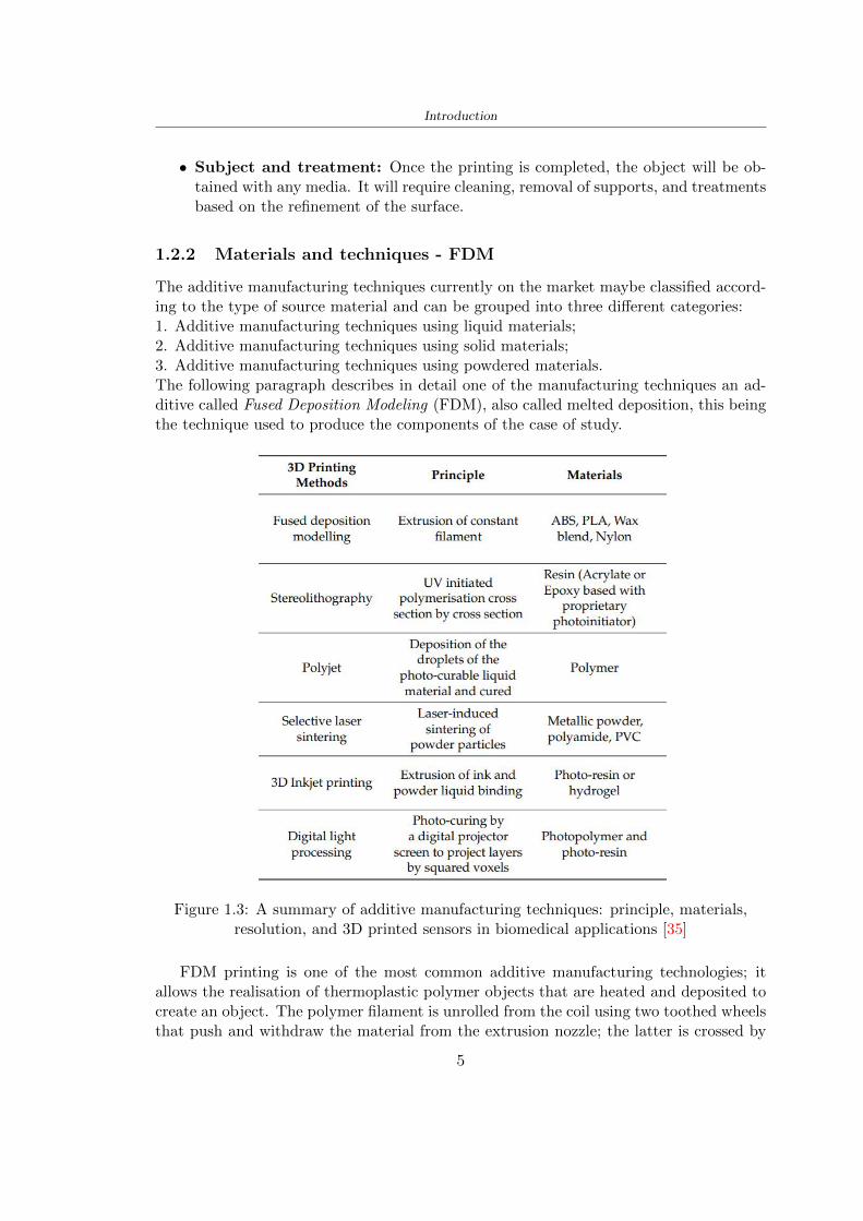
Introduction
the filament and deposits the material to build layer after layer the object Before theextrusion nozzle a heating block is positioned to control and adjust the filament temper-ature above the melting point escaping the material An excessively high temperaturewould cause a casting process that would compromise the machining accuracy a low tem-perature would prevent the filament from adhering to the already deposited layer Theextruders move in the XY plane and draw material from two coils (one for the supportsand one for the structure) depositing the material for the first layer Then the platformlowers to allow the realization of the second layer etc is the technique layer-by-layer
[a] [b]
Figure 14 Example of layer-by-layer print [a] FDM print structure [b] [4]
Once the processing is completed it proceeds with the removal of the supports thisactivity usually favoured by the different colours used for the two materials consists oftwo phases initially takes place a coarse removal carried out manually then the remainingmaterial in case it is water-soluble as that used for the development of the thesis isdissolved in water The work platform instead is characterised by lower temperaturesto encourage a rapid hardening of the newly deposited material Another parameter tobe established is the thickness of the layer which influences the time of realisation ofthe object and the quality of the finished product Generally the printing times of theobject vary from a few hours to full days depending on the size of the workpiece and theresolution chosen
123 AM in sport
As described by Novak [27] rdquosporting products are typically mass-produced to suit nor-mative population physical characteristics such as athlete heights weights foot sizes andlimb lengthsrdquo The Nike industry began to introduce 3D printing in the sport produc-ing shin guards bags and studs for football shoes The intuition was that to produceobjects with costs and times smaller than the classical production Currently the com-panies that have inserted 3D printing technologies are many to create unique piecestailored for sports through reverse engineering with ultralight composites Meier et al[21] describe the industries and their respective products from Nike with spike plate
6
Introduction
for cleats to Adidas with midsole for running shoe New Balance with plate and solefor running Burton with snowboard binding Redbull and Proto3000 surfboards Themain explanation of these productions lies as already mentioned in shorter productiontimes and costs the reduction of the weight and thickness of the products the increaseof the flexibility thanks to used techniques and materials the possibility of creating andmodifying complex designs
13 3D printed helmets
131 Phases
Phases about the production of the 3D helmet
PHASE CONTENT
1 3D Scan - In contrast to the limited number of sizes provided bymainstream helmet brands the creation of the personal
helmet begins with a fitting of the head with a specific app(for Hexr helmet)
- The data is then sent to the servers where a helmet isautomatically generated
2 Structure -Design
Realization of a structure in order to absorb the energy ofthe impact
Materials- Polyamide-11 made from 100 castor bean oil the most
sustainable bicycle helmet (Hexr)- Carbon and fiberglass resin with a polystyrene cover
(Voronoi)
3 Industrial3D printing
machines
- Using a technology known as Selective Laser Sintering(SLS) layer upon layer by using high-powered and
ultra-fine lasers to melt portions of consecutive layers ofpowder with a thickness of 01mm (Hexr)
4 Assembly - Assembling outer shell chin straps padding
Table 11 3D printed helmet steps
7
Introduction
132 HEXR
Scientists at University College London developed the HEXR helmet Figure 15 a 3Dprinted bicycle helmet with a honeycomb structureWhere University College London LondonDesigner Jamie Cook founded HEXR rdquoafter observing energy impacts are different de-pending upon surface areas This led him to do extensive research on improving bicyclehelmet technologyrdquo [17]How is it made The first step to realizing the helmet design is to scan the head usinga 3D scanner Once the scan is obtained thanks to the measurements the drawing isdefined The honeycomb structure is realized through a print with selective laser sinteringtechnology The helmet is produced layer upon layer the process is accurate and employsabout 24 hoursMaterial Polyamide-11 made from 100 castor bean oil The use of this materialmakes the helmet on the market more eco-sustainable being bio-sustainable and beingproduced by a production process with little use of water and limited treatmentsApp to scan the head cycling helmet creation process themselves at home (for App-Store) with a fitting cup to scan perfectly the head
[a] [b]
Figure 15 HEXR design [17]
133 VORONOI
The Voronoi Figure 16 the helmet was designed through a program with parametricdesign which respected a bio-inspired structure This inspiration was taken from theconformation of the animal bone and the typical turtle shellWhere Nanjing ChinaDesigner Yuefeng Zhou Zhecheng Xu Haiwei WangHow is it made The Voronoi helmet was made through a parameterized design withthe use of an unusual mesh The goal of the structure was to use a minimum amount ofmaterial and have a high energy absorption in this way it is possible to get a light and
8
Introduction
effective productMaterial The main materials used for the creation of the helmet shell are carbon kevlarand fiberglass resin with a polystyrene lining The final product is going to be availablein 3 sizes and different colours
Figure 16 Voronoi design [3]
9
Chapter 2
State of the art
21 Standards
The specification about the materials specific tests methods manufacturing to realize ahelmet shall be drawn up by the following standards
- American Society for Testing and Materials (ASTM) is a globally recognized leaderin the development and supply of international standards The World Trade Organiza-tion Technical Barriers legislate it to Trade (TBT) Committee
- The European Committee for standardization (CEN) composted by the nationalbody of Austria Belgium Bulgaria Croatia Cyprus Czech Republic Denmark EstoniaFinland Former Yugoslav Republic of Macedonia France Germany Greece HungaryIceland Ireland Italy Latvia Lithuania Luxembourg Malta Netherlands NorwayPoland Portugal Romania Slovakia Slovenia Spain Sweden Switzerland Turkey andUnited Kingdom
In this study the standard specifications show in the Table 25 will be taken intoaccount the first column contains the Standard name in the designation column theletter with the first number classifies the specification and the second number identifiesthe year when they were published or the year when the last revision was realized
211 Headform
Before realizing a helmet it is necessary to define the headform It is the geometricalrepresentation of the head without facial features and ears but the fundamental axis isrepresented
Planes definitions
bull Basic plane an anatomical plane that includes the superior rim of the externalauditory meatuses (upper edge of the external openings of the ear) and the inferiormargin of the orbit (the lowest point of the floor of the eye socket)
10
State of the art
STANDARD DESIGNATION CONTENT
Standard specifica-tion for headforms
F2220-15 This specification identifies the head-forms used for testing protective head-gear in individual ASTM Internationaltest methods and performance stan-dards [12]
Standard specifi-cation for helmetsused in recreationalbicycling or rollerskating
F1447-18 This specification recognizes the desir-ability of lightweight construction andventilation however it is a perfor-mance standard and is not intended torestrict design [13]
Standard test meth-ods for equipmentand procedures usedin evaluating theperformance charac-teristics of protectiveheadgear
F1446-20 These test methods specify equipmentand procedures used for testing pro-tective headgear Individual ASTMperformance standards (standard spec-ifications) will use these proceduresand equipment Test conditions pass-fail criteria and other performance re-quirements will be specified in the in-dividual performance standards [14]
Headforms for use inthe testing of protec-tive helmets
BS EN 9602006 This European Standard specifies thedimensional and constructional detailsof headforms for use in the testing ofprotective helmets [6]
Helmets for pedal cy-clists and for usersof skateboards androller skates
EN 10782012+A1 This European Standard specifies re-quirements and test methods for hel-mets worn by users of pedal cyclesskateboards and roller skates Require-ments and the corresponding methodsof test are given for the following- construction including field of vision- shock absorbing properties- retention system properties includingchin strap and fastening devices- marking and information [5]
Table 21 Standard specifications
bull Coronal plane an anatomical plane perpendicular to both the basic and midsagittalplanes and passing through the superior rims of the right and left external auditorymeatuses The transverse plane corresponds to the coronal plane
11
State of the art
bull Midsagittal plane an anatomical plane perpendicular to the basic plane and con-taining the midpoint of the line connecting the notches of the right and left inferiororbital ridges and the midpoint of the line connecting the superior rims of the rightand left external auditory meatuses [12]
Figure 21 Anatomical planes [12]
Planes and reference points
In agreement with the Standard BS EN 960 [6] it is possible to define different charac-teristic planes like shown in Figure 22
bull Reference plane for a given headform when erect the horizontal plane located ata vertical distance rsquoyrsquo measured down the central vertical axis from the centre ofthe crown All horizontal datum levels are quoted relative to this plane
bull AArdquo plane for a given headform the horizontal transverse plane is located at avertical distance 127 mm above and parallel to the reference plane This plane isdeemed to correspond to the level of the lower edge of the headband of a helmetIt is the basis upon which the size designation of a helmet may be specified
bull Central vertical axis vertical axis lying along the intersection of the vertical longi-tudinal plane and the vertical transverse plane
bull Centre of gravity of the three-quarter headform - point A for a given headform thepoint on the central vertical axis located at a vertical distance 127 mm above thereference plane
12
State of the art
bull Centre of gravity of the full headform - point G for a given headform the point onthe central vertical axis located at a vertical distance rsquozrsquo below the reference plane
bull Geometric centre - point R for a given headform the point on the central verticalaxis located at its intersection with the reference plane
Figure 22 Principal planes and reference points of a headform [12]
212 European Standard and American Standard
Location of gravity centre
Between the European Standard and American Standard there are differences the firstfor the location of the gravity centre
bull BS EN 960 the centre of gravity is located within a 10 mm radius of Point G
bull ASTM F1447 centre of gravity of the headform must be within a 10 vertical conefrom the centre of impact and lie within a rectangular area 28 by 128 mm
13
State of the art
The size of the head and helmet
bull ASTM F2220 to measure the external dimension for full headform the distancefrom the reference plane to the top of the headform There are different dimensionsF2220 (A if the measure is 897 mm minus C with 93 mm minus E with 96 mm minus J with1025 mm minusM with 107 mm) Then with this classification it is possible to extractthe dimension of xyz (mm) with the following Table 22
Table 22 Location of Reference Line [14]
bull BS EN 960 to obtain the size designation and the headform masses this Standardconsiders the measure of xyz (mm) in Figure 21 The possible designation are 21from 445 to 645 some of these are shown in the Table 23
Thanks to the size designation with the Standard BS EN 1078 there is the possibility todefine the inside circumference of the helmet and this it is shown in the following Table24
Table 23 Dimensions about the reference lines in Figure 21 and headform masses [6]
213 Field of vision - BS EN 1078
Apply a load of 50 N on the crown of the helmet in order to stabilize the helmet on theheadform To avoid having an occultation of the visual field Figure 23 it is better tofollow this angle measures [5]
bull horizontally min 105 from the longitudinal vertical median plane to the leftand right hand sides
bull upwards min 25 from the reference plane
bull downwards min 45 from the basic plane
14
State of the art
Table 24 Inside circumference of helmet [5]
Figure 23 Field of vision (a)(b) [5]
214 Test impact area
Standard EN 1078 will be considered for this study which defines the parameters helpfulin performing the shock absorption test The drop test impact consists of an impact ontwo anvils of flat surface or kerbstone
In the Standard is specified the Test Area where the impact is to be performed Thefirst thing is to apply a vertical load of 50 N on the crown of the helmet in order to
15
State of the art
stabilize the helmet on the headform [5]1 Draw the AArdquo line (in the AArsquo plane) on the helmet2 Draw a line on the helmet parallel to and approximately 20 mm above the AArdquo line(for use as an angular measurement datum line)3 Mark the helmet at points B1 and B2 These points are the sideways horizontalprojection of point B onto the outer surface of the helmet4 Draw a line RRrsquo on the helmet passing through B1 and B2 the line being angled 10
upwards toward the front of the helmet relative to the datum line drawn in d) The areaabove the line drawn in f) is the test area for impacts on the flat anvil The area abovethe line RWArdquo is the test area for impacts on to the kerbstone anvil
Figure 24 Definition of test impact area [5]
215 Anvils and environmental conditions
EN 1078
During the validation process each of the 30 helmet target points was impacted ex-perimentally and numerically under three environmental conditions (-20C +50C andhumidity)
The impact should never exceed 250 g for impacts with velocities corresponding to 542ms on a flat anvil and 457 ms on a kerbstone anvil These are theoretically equivalentto 1497 mm and 1064 mm drop heights respectively [5] About the characteristics of theanvils according to EN 1078 these depend on the type in the case of
bull Flat anvil it has a circular form with a diameter of 130 plusmn 3 mm with 25 mm ofthick
16
State of the art
bull Kerbstone anvil face inclined at 525 plusmn 25 to the vertical and edge with aradius of 15 plusmn 05mm The height shall be not less than 50 mm and the lengthnot less than 125 mm [5]
According with the regalement EN 1078 [5] it has been possible to realize the volumes inthis work the Flat anvil has a diameter of 130 mm and a height of 25 mm the kerbstoneanvil has a horizontal edge of 130 mm a height of 51 mm a length of 126 mm and theedge that impacts the helmet has a radius of 15 mm The anvils are represented in Figure25
[a] [b]
Figure 25 Flat anvil [a] and Kerbstone anvil [b]
EN 13087-11 (Proposal)
A proposal of November 2018 (EN 13087-11) talks about oblique impact tests (Rotationaltest method) [15] Define a method to measure rotational energy absorption in tangentialimpacts in short duration impact situations the velocity considered by Adanty et al [1]is 65 ms The same anvils of the Standard EN 1078 are used the flat anvil and theKerbstone anvil but the difference is the vertical drop towards an impact angle between30-60 the degree considered by Adanty et al [1] is 45
Three different rotations are considered [34]
bull Rotation around X-axis contact point on the side of the helmet resulting in arotation around X-axis Initial position of the headform X- Y- and Z-axis 0
bull Rotation around Y-axis Contact point on the upper part of the helmet resultingin a rotation around Y-axis Initial position of the headform X- Y- and Z-axis 0
bull Rotation around Z-axis Contact point on the upper part of the helmet resultingin a rotation around Y-axis Initial position of the headform X- and Z-axis 0 and65 around Y-axis
17
State of the art
Figure 26 (a) The current cycling helmet standard for the EN 1078 [5] (b) Theproposed standard (EN13087-11) as described by the European Committee for
Standardization (CEN) [15][1]
22 Materials
221 EPS Foam
As mentioned in Chapter 13 the material most commonly used for making the helmetis the EPS Mustafa et al [25] analysed the EPS with four different density values of 50kgm3 64 kgm3 80 kgm3 and 100 kgm3 rdquoThe drop impact simulation model wasused to test the impact attenuation of the helmet with different densities The drop testwas performed on four impact locations top front and sidesrdquo
The impact velocity of the helmet and headform was set at 544 ms The lowestpeak linear acceleration was recorded at the top location and a density of 64 kgm3 with14814 g This study sets out to determine the effect of the user-centered helmet designwith different foam densities (from 50 kgm3 to 100 kgm3) on the impact attenuationof the bicycle helmet
Kroeker et al [19] tested the helmets at three impact speeds 30 plusmn 001 ms 63 plusmn002 ms and 78 plusmn 001 ms
They established the mean value about bulk density in a helmet with EPS foam is666 considering HIC and Peak Acceleration test The global range is between 64 kgm3
and 75 kgm3
Kroeker et al [20] established the foam for kids helmets is 64-88 kgm3 and for thetraditional helmets is 60-100 kgm3
Trzaskalska et al [36] controlled the influence of polymer liner density on energy ab-sorption during impact They discovered the best properties have samples whose densityis between 54 to 60 kgm3
Cui et al [10] considered the density of each layer from the values of 25 50 60 80and 100 kgm3 and they realize a 45 grades side impact and normal crown impact Theresult is a density of 64 kgm3
Wei et al [38] discovered from their test results that EPS has a buffer layer density
18
State of the art
of 60 kgm3 is the most reasonable
Foam densityrsquos values - Literature
Authors Densityrsquos values
Mustafa et al [25] 64Kroeker et al [19] 64 - 75Kroeker et al [20] 60-100 (traditional) and 64-88 (kids)
Trzaskalska et al [36] 54 - 60Cui et al [10] 54Wei et al [38] 60
Table 25 Table with foam (EPS) densityrsquos values
The other are mean values obtained by CES EduPackrsquos program about this material
- Density ρ = 6451kgm3
- Youngrsquos Module E = 275 MPa
- Poissonrsquos ratio ν = 0275
- Yieldrsquos stress σ= 09 MPa
- Elongation at fracture = 45
222 CES Edu Pack - Material selection
CES Edupack software was used to satisfy the idea of creating a lightweight helmetby printing it in 3D and having the possibility to insert the desired characteristics ofthe material and therefore select it To make a choice I used level 3 of engineering(advanced) selecting the following criteria of the material bio-material biodegradablea polymer of concentration 20 - 100 which complies with the rsquoEuropean Restrictionon Hazardous Substances (Rohs) standardsrsquo regarding the composition of the materialensuring that it does not contain a high percentage of toxic substances compared to theestablished percentage In addition it must have proper durability in contact with coldwater (imagining a possible rain) and rsquogoodrsquo durability to UV radiation
According to Ashbyrsquos method [2] to select a material it is possible to follow thefollowing steps
1 Establish the function of the product What does the component doThe helmet is an instrumental use to protect the head during an impact this characteristicdepends on materials and qualities It can prevent an injury which depends on materialsand design because it has to be of the right head size It would be comfortable becauseit must be worn and it must give security to the person wearing it (by design) In thefollowing Table 26 the analysis of the functions
19
State of the art
Ranking Function description Depends on
1 Head protection (energy absorbing) Material2 Head protection (energy absorbing) Design3 Head protection (injury prevention) Material4 Head protection (injury prevention) Design5 Comfortable Material6 Comfortable Process
Table 26 Ashbyrsquos method functions
2 The objectives that are targets for the design the material is to bemaximised or minimisedTo manufacture and market a product objectives such as minimizing weight cost orenvironmental impact must be considered In the following Table 27 the analysis of theobjectives
Ranking Title Objectives description
1 Mass Minimize The mass has to be thesame or lower
2 Cost Minimize everyone should have theopportunity to buy it
3 CO2 footprint Minimize CO2 emission
4 Corrosion Minimize high strength because itcan be in contact with the water
5 Pleasant to touch Maximize it is not a rough materialbecause it has to put on and put off
by hands
6 Refractive index Minimize it must not reflect light
Table 27 Ashbyrsquos method objectives
3 Definition of constrains What essential conditions must be meetEstablish constraints is essential to complete the function of the instrument Examplesof constrains are Table 28
4 The limits characteristic independent of the material that does not influencethe physical properties In the following Table 29 the analysis of the limits
20
State of the art
Title Loading case Constraintsdescription
Material index(Max-Min)
Stiffness Column in compression Tie in tension
Mass Min
Stiffness Column in compression Tie in tension
Cost Min
Stiffness Column in compression Tie in tension
CO2 Min
Strength Column in compression Tie in tension
Mass Min
Strength Column in compression Tie in tension
Cost Min
Strength Column in compression Tie in tension
CO2 Min
Table 28 Ashbyrsquos method constrains
223 PLA with natural fiber and PLA LW
Initially the best material that met the desired criteria was searched From this study itwas found that the material closest to having the required characteristics is the PLA 30natural fiber as shown in the Figure 27 which shows the graphs obtained relating tothe relationships between Youngrsquos Module and density the objective to reduce the massper unit of compressive stiffness and strength to reduce the CO2 footprint per unit ofstiffness and strength and mass per unit of compressive strength
Performance index IR
The stiffness criterion has the following characteristics
m = A lowast L lowast ρ (21)
ε =σ
E=
FA
E(22)
A =F
ε lowast E(23)
21
State of the art
Ranking Title Function description
1 Biocompatibility It is the ability of a material the abilityof the material not to cause any local or
systemic adverse response in therecipient of the material
2 Biodegrability Biodegradable material do notbiodegradable under anaerobic conditions
3 Biomaterials - all The terms is used for biological naturalbio-derived bio-inspired material
4 RoHS (EU) Compliantgrades
Restriction of the use of certin prohibitessubstances (mercury cadmium
hexavalent chromium)
5 Polymer 20-100 (from the table with Plasticpolymers)
6 UV Resistance at UV sunlight
Table 29 Ashbyrsquos method limits
A =F lowast L lowast ρε lowast E
(24)
With fixed variables- F (the load) L (the length)With variables that depend on the material- E (Youngrsquos Module) ρ (density)
In general when a chart is created the distribution of the mass is represented in thefollowing modality like in Figure 27 [b] where the materials above the line have a lowermass while those below a greater mass
Following the results of the CES Edupack program that had selected the PLA withnatural fibers as the best the first print of the helmet was made with this materialusing as support the PVA Initially the result seemed satisfactory the helmet had a highdefinition but a fundamental problem was found by reducing the helmet in the water toallow the supports of PVA to dissolve In the act of diving in fact after ten minutessome parts of the helmet especially the front and rear have disintegrated making thehelmet unusable Because of this problem it was necessary to change the material
22
State of the art
[a]
[b]
Figure 27 CES EduPack Mass per unit of compressive stiffness [a] Youngrsquos Moduleand density [b]
Further investigations carried out by the Mondragon Unibertsitatea Additive Man-ufacturing Department revealed a new material the PLA Low Weight which during3D printing allows to obtain a weight of 65 lower than that which could be obtainedfrom the classic PLA as reported in the technical sheet of the filament produced by thecompany Colorfabb [7]
The investigation team of the Composite Department carried out tensile tests withsamples 3D printed at different temperatures as suggested by the manufacturer to obtainthe technical characteristics The temperatures examined are 200 220 250 260The datasheet shows the density can have values between 04 - 124 gcm3 the bed has
23
State of the art
to have a temperature between 50 - 60 the printing speed has to have values between40 - 80 mms This typology of PLA is expandible so much that rdquoAt around 230 thismaterial will start foaming increasing its volume by nearly three timesrdquo [7]
T[C] Section [mm2] Volumen [mm3] Mass [g] ρ[kgm3] E [Nmm2]
200 42235 1030117 12 1165 328807
220 43805 1655821 18 1087 265795
250 52412 1948139 17 873 178058
260 59655 1454377 12 825 117047
Table 210 Values about PLA LW tensile tests of MU Additive ManufacturingDepartment
From the tests that have been carried out on the material at different temperaturesthe printed sample is better at 250 with a volume of 1948139 mm3 and a section of52412 mm2 as shown in Table 210 For this reason the specific of the material thathave been taken into consideration are the following
- Density ρ = 873 kgm3
- Youngrsquos Module E = 1750 MPa
- Poissonrsquos ratio ν = 033
- Yieldrsquos stress σ = 2948 MPa
- Elongation at fracture = 491
23 Bio-inspired structures
When we talk about bio-inspired structures to nature we refer to structures that allowobtaining a low weight for the model that is realized and excellent absorption energy dur-ing the impact Recently the structures that have been most used in the biomimetic fieldare the rdquocolumns structures sandwich structures plates honeycomb and foamsrdquo[26]but aiming to achieve a structure increasingly with high absorption energy new struc-tures derived from plants and animals such as beetle horsetail turtle bird beak havebeen analyzed The first to create multi-cells tubes helicoidal structures the second tomulti-corner tubes [26]
The authors analyze the specific energy absorbed (SEA) by bio-inspired sandwichstructures per unit mass which can be derived from the following equation
EA(d) =
int dmax
0F (x)dx (25)
SEA(d) =EA(d)
m(26)
24
State of the art
Where EA is the energy absorption rdquomainly used to evaluate an energy absorberrsquosability to dissipate crushing energy through plastic deformationrdquo F(x) is the crashingforce dmax is the effective deformation distance [26]
What derived from their investigations is that having regard to a density of between0 and 1000 kgm3 the volumetric energy absorbed is higher for the beetle-inspired struc-tures than the others as shown in Figure 28 Based on this consideration it was chosento draw the helmet following this geometry
Figure 28 SEA of bio-inspired sandwich structures [26]
231 Beetle structure - Design of the model
To develop and increase lightweight high-strength and optimize bio-mimetic functionaland structural materials the trabecular structure of the beetle elytron is studied Thesingle structure is realized following the requirements cited by Zhang et al [39]
To realize the beetlersquos structure it is not enough to have information about the lengthof the side of the hexagon and the thickness but it is also necessary to take into accountthe relationship between the diameter of the circumferences present on the vertices ofthe hexagon and the measurement of the side The representation of a single cell is inFigure 29 It is shown in [a] a general structure with an edge of 12 mm circumferencersquosdiameter of 6 mm and thickness of 16 mm in [b] is shown the height of 20 mm
For the construction of the helmet a thickness of 12 and 16 mm was used the imageconcerns a proportion between the length of the hexagon side and the diameter of the
25
State of the art
circumference The side (distance between the centers of two circumferences) is twice thediameter measurement
[a] [b]
Figure 29 Beetle structure
232 Specific stress - PLA LW and EPS foam
To test the beetle structures compression tests were investigated The PLA LW structurewas inserted in a rsquodiskrsquo with a diameter of 100 mm and a height of 20 mm The area andthe volume of the disk is correspondingly 7854 mm2 and 157 10 mm3 The structuresexamined have different dimensions the edge L (distance between two centers of thecircumferences) had the following measures 9 10 12 14 16 mm the thickness of thecircumferences and edges are respectively of 16 mm for every structure and 12 mm forthe structure with L = 16 mm
The test was carried out with the Hoytom HM-D Testing Machine with capacitiesbetween 5 and 100 kN The test models were subjected to displacement loading at a rateof 1 mmmin as referenced by Chen et al[18] with a cylindrical specimen The specificstress of the structures was compared with the specific stress of a generic EPS helmetthe photos about it are shown in Figure 210 The EPS helmet structure is granular withpores inside The different grains dimension and these pores can be the reason for whichthe Stressrsquos values are between two values 07 and 116 MPa
Four parts of the EPS helmet were considered in the test the dimension and relativecharacteristic are in the Table 211 where m = mass A = area F = load ρ = densityR = stress Rρ = specific stress To calculate the values of stress about PLA structuresand EPS foam compression test graphs were been analyzed The stress value for eachstructure was calculated considering the single load the single area and the averagedensity value (14055 [kgm3])
The stress values of the PLA structures (Figure 211) and other characteristic valuesare in Table 212 where m = mass A = area F = load ρ = density
26
State of the art
[a] [b]
[c] [d]
Figure 210 EPS generic helmet helmet pictures [a] [b] and internal structureExternal granular structure [c] and pores [d]
[a] [b] [c]
Figure 211 PLA LW disks Grasshopper structure [a] PLA LW structure of 14 mm[b] PLA LW structure compressed [c]
27
State of the art
The results of the load-displacement graphs are affected by the geometry of the diskthe target is to valid for any shape or size for this is preferred to realize a diagramthat depends from σ (or stress) and the deformation ε (or strain) which can be definedrespectively as
σ =F
A0(27)
ε =l minus l0l
(28)
where F is the load during the test A0 is the area l0 is the initial length and l is thelength when the load is applied The areas considered for the EPS cube is reported inTable 211 in the second column the areas of the PLA structure is 7854 mm2 like thearea of the circumscribed disk
The values compared are shown in Table 213 and the graphs obtained by Matlabcode to analyze the recorded data of the compression machine are in Figure 213 and inFigure 212
Considering that the data provided by the compression machine are subject to noiseand disturbances it was decided to convert the original curve into polynomial type curvesthat allow obtaining the best interpolating curve for the data in question To obtain themit was divided the recorded data into two groups the first part from 0 until the end ofthe linear part and the second when the curve becomes linear again The best-fitting (inthe least-squares sense) was performed using the polyfit and polyval functions of MatlabThe first returns the coefficients of the p(x) with n degree the second evaluates p(x) ateach point in x The polynomial formula p(x) is shown in the Equation 29
pn(x) = anxn + anminus1x
nminus1 + + a2x2 + a1x+ a0 (29)
where a0 an are constants and x is the indeterminate The choice of the degree ofthe polynomial was made based on the criterion of wanting to obtain linear curves thatrespected the elastic trend at the beginning of the graph For this reason the degree ofthe polynomial is 1 Subsequently I searched through the intersection of the two lines forthe point that is equivalent to the maximum stress that marks the end of linearity
This value for EPS and PLA LW is the R [MPa] in the Table 213 The average stressvalue for PLA LW is 139 MPa and for EPS is 094 MPa The specific stress (Rρ) is 18MPa lowast m3)kg for the EPS found in CES 669 MPa lowast m3)kg for the EPS foam of thegeneric helmet and for PLA LW is 1161 MPa lowastm3)kg an intermediate value betweenthe two which is what we wanted to achieve
28
State of the art
m [g] A [mm2] F [N] ρ [kgm3]
EPS (CES) 50
16 9234 1063 13864
18 879 593 13651
21 858 833 14237
24 864 564 14468
Average value 14055
Table 211 Compression stress generic EPS helmet
L [mm] t [mm] m [g] F [N] ρ [kgm3]
9 16 214 7250 1363
10 16 192 5560 12467
12 16 201 8190 13051
14 12 138 8000 8961
Average value 12027
Table 212 Compression test PLA structures
PLA LW structure EPS structureρ= 12027kgm3 ρ= 14055kgm3
Edge [mm] R [MPa] Rρ103 Number R [MPa] Rρ103
EPS (CES) 09 18
9 173 1269 1 116 824
10 139 1114 2 08 568
12 138 1057 3 105 746
14 108 1205 4 077 540
Average value 139 1161 094 669
Table 213 Specific stress calculus PLA LW and EPS calculus ρ = density R = stressRρ [(MPa lowastm3)kg] = specific stress
29
State of the art
Figure 212 Compression test Stress-Strain diagrams - EPS
Figure 213 Compression test Stress-Strain diagrams - PLA LW
30
Chapter 3
Methodology
31 3D scan
311 3D Sense 2 scanner and Meshmixer - Reverse reconstruction
Standardized measures were not taken into account for making the helmet but the sizewas obtained through a 3D scan of my head
The scanner used is 3D Sense 2 by 3D Systems which has a minimum scanningvolume of 20 x 20 x 20 cm and a maximum scanning volume of 300 x 300 x 300 cmTo scan my person I was helped to get a full view at 360 at an appropriate distanceReal-time visualization of the captured images was shown through 3D Sense softwareThe idea of scanning the head with the scanner refers to the methodology used by Wanget al [30] They used a reverse reconstruction functional for me to realize the helmetsurface made to measure my head and like them a silicone pool cap was used to makescanning as smooth as possible The authors claim the head scan rdquocan also be used toobtain information about the objectrsquos surface which is then reconstructed utilizing thecomputerrsquos three-dimensional model via reverse modelling softwarerdquo [30] that in my caseis Autodesk Meshmixer
The files it was could get from the scan were stl obj and ply format they wereexported to obj to work in the next step with Autodesk Meshmixer that allowed tomodify and homogenize the 3D image obtained from the scan
In Meshmixer through the selection and delete commands the superfluous parts weredeleted that had been acquired and with the inspector and the DrawDraw2 commandsthe vertices were moved locally along a pre-defined direction and with Smooth the surfacemore homogeneous was made The sequence of steps is shown in the Figure 31
312 3D scan analysis and extraction of features
In Chapter 2 the directives imposed by the BS EN 960 Standard were examined concern-ing the definition of the helmet and the measures to be respected in the field of visionand the part of the helmet was to carry out impact tests
In Figure 32 the features defined complying with the Standardrsquos rules are repre-sented To define these features the software NX was used The angle in the subfigure
31
Methodology
[a] [b] [c] [d]
Figure 31 Sequence of 3D head scan 3D scanner acquisition [a] scan after reparationwith Meshmixer [b] solid scan vision frontal and lateral [c] [d]
[b] is bigger than 105 (as defined by the Standard) while the degree in the subfigure [c]is 25 By defining the construction lines to be respected of the helmetit was necessary todraw the design of the surface not using the software NX but changing with Rhinocerosto create a SubD or SubDivision surface
32 Helmet design
321 Rhinoceros - Helmet surface
After realizing a rsquocleanrsquo Wang et al [30] subdivide with lines and then sectors the headto create the surface of the helmet They used the technique of NURBS a Non UniformRational Basis-Splines which mathematically models a 3D geometry while thanks tothe Rhinoceros 3D organic shapes was draw SubD surfaces These geometries allow tosplit the mesh into small polygons and consist of lines with which easily the shape ofthe object can be modified with a surface already created changing the position of aline automatically the remaining part of the geometry adapts to the changes With thistechnique the rsquosurface basersquo of the helmet was realized with the size of my head Therepresentation of the realized SubD is in Figure 33
322 Grasshopper - Helmet structure
The next idea is the creation on the surface of the beetle structure with different di-mensions modelling the helmet that is not a linear surface It was decided not to buildthe structure with a software CAD because to model an already complex structure on acurved surface would mean to model a cell for a cell
To solve this obstacle a Rhinoceros plug-in was used Grasshopper GH idealized byRobert McNeel and associates creators of Rhinoceros Using GH does not mean drawinggeometries by connecting points and drawing tools because it is based on algorithmicmodelling used in architecture and engineering for 3D modelling
The modelling takes place through a node diagram that the software will convert intoa code-algorithm in GH it is possible to define the variables and parameters and inRhinoceros in real-time it is possible to view the object GH allows for varying the
32
Methodology
[a] [b]
[c]
Figure 32 Featurersquos extraction in [a] is represented the impact line in [b] and [c] twoprospective about the definition of the field of vision
[a] [b] [c]
Figure 33 SubD representation lateral view [a] top view [b] front view [c]
geometry to your liking by varying a simple parameter of the diagram as everything willbe remodelled according to the change made
In the following Figure 34 it is shown an example of a structure that was used fordistinct subgroups of helmet areas The idea was to insert smaller cells in the frontal andlateral zone and larger ones in the upper area In the first image [a] is shown the part of
33
Methodology
the helpful diagram to create the beetle structure to establish the size of the cells andthe extrusion the second image [b] contains the part of the diagram with which I appliedthe structure previously created to the SubD
The structure used to place and adapt the beetle structure to the surface is theSrfMorph while the yellow rsquowindowrsquo that contains numbers serves to select the parts ofthe surface where to apply the geometry created In accord with the GH diagram in
[a]
[b]
Figure 34 Grasshopper diagrams
Figure 34 [a] it is possible to see the steps executed to realize the structure Initially inthe xy-plane a hexagonal grid was drawn through the Hexgrid command in which youcan input the length of the hexagon edge and the number of grid elements (selected bytrial) Then the circumferences was drawn in proportion to the hexagon dimensions asspecified in the Chapter 2 and shown in Figure 35 [a] In figure [b] the rsquocutrsquo made atthe circumferences is visible this subdivision was necessary for printing purposes In thelast photo [c] the structure highlighted in green in [b] was extruded setting a distance
34
Methodology
of 20 mm
[a] [b] [c]
Figure 35 Construction sequence of the geometry of the helmet
In the diagram in Figure 34 [b] there is the application of the structure created bi-dimensionally to the SubD surface of the helmet visible by unlocking the SubD commandof the diagram and in Figure 36 [a] Upper this the referential geometry of the group ofsurfaces was superimposed where it was to be applied the newly created structure (visiblein darker red) the SubD indices are in the yellow box of the diagram
Through the SrfMorph command the location of the structure was granted In Figure36 [b] at the darkest red of the figure [a] with the above command it was possible toplace the structure
[a] [b]
Figure 36 Application of the geometry created to the helmet surface
Overall the diagrams with specific structures are five one for the front two equal forthe side parts one for the top shown in the previous Figure 36 and one for the back
The hexagons in the structure have a dimension varying between 8 mm and 14 mmof side the largest is found at the top later at the back in the sides and the smallest atthe front In Figure 36 [b] the presence of not only hexagonal structures is visible Thegeometry used does not allow the homogeneous arrangement on the entire surface andrequires different structures Automatically the choice of GH to optimize the structurewas to insert quadrilateral
As described above the helmet has different dimensions of the structure divided asvisible in Figure 36 in a quadrilateral This causes a discontinuity between zones withdifferent sizes due to the geometry of the construction
To eliminate this problem and realize the design homogeneous grids were inserted
35
Methodology
in the affected areas as shown in Figure 37 This insertion however proved to beinteresting and strategic researching in this regard studies were realized to demonstratethe insertion of a rectangular grid inside the hexagon grid was helpful for the transmissionof stress in the structure As cited by Sun et al [40] rdquothe mechanical properties of thesesandwich structures are often limited by local failures such as face-core debonding or corecollapserdquo Carrying out compression tests have effectively demonstrated that the insertionof the grid allows rdquoprovided increased stiffness specific stiffness energy absorption andcritical loadrdquo [41] As shown in the graphic [c] of the Figure 37 the honeycomb structuregives a force of 7 kN while with a grid the value is 11 kN and with the combinationexceeds 22 kN In addition in the left front a plaque to customize the helmet wasprepared Figure 37 [a]
[a] [b]
[c]
Figure 37 Grid in the helmet [a] hybrid structure with hexagons and grid [b] [40]compression test results of the hybrid structure [c] [41]
33 3D Print
After having achieved the CAD (Computer Aided Design) of the helmet in order tobe printed it must be converted and saved in format STL (Standard TriangulationLanguage) - Binary compatible with the printing machine and useful for transformingsolid object surfaces into triangles The steps to be taken are the following
bull CAD file realization
bull CAD export in format STL to Simplify 3D the software that shows slider layersand then- rotate and position the object according to geometry and the positioning of any
36
Methodology
supports- setting printing parameters- item manual andor automatic positioning of supports- slider display layers
bull import file gcode to printer
331 Printer and parameters
The program used to visualize how the helmet slices layers before sending it to the printerand to set the parameters is as anticipated Simplify 3D
To make the printing not being a flat geometry it is necessary to place the supportsThe idea was to use water-based supports that the helmet would automatically dissolveonce placed in the water After testing different types of water-soluble PVA the choicefell on eSun 3D Printing Filament PVA (water-soluble support) Before choosing theoptimal position for printing several tests were carried out and to decrease the numberof the supports significantly and allows an optimal printing of the outer part an emptyrsquospherersquo that self-sustains below the helmet was placed as shown in Figure 38
In the image [a] you can see the first print position tried with which an external partof the helmet very damaged was obtained because of the contact supports-helmet In [b]the empty rsquospherersquo is shown to optimize the number of supports and in the last photo [c]there is the full version at the end of print
[a] [b] [c]
Figure 38 Printing supports
The printer that has been used for printing is the Raise 3D Pro2 with double extrudersand nozzles of variable size from 02 mm to 1 mm after some test prints with the PLALW and the structure in created the size that allowed me to have a good compromisebetween printing time and accuracy was 06 mm Using 04 mm the printing time wasexcessive even if having the smaller nozzle diameter means having more precision withthe 08 mm nozzle the quality of the structure was not excellent as seen in Figure 38[a]
Another factor that had to be taken into account is the characteristic of the PLA-LWto expand As the printing temperature and the printer used vary the expansion andcharacteristics of the material change The use of the 06 mm nozzle associated with
37
Methodology
Parameter Left extruder Right extruder
01cm Material 01cm PVA 01cm PLA LW
Extruder toolbox index Tool 0 Tool 1
Nozzle diameter 06 mm 06 mm
Extrusion multiplier 1 05
Extrusion width Auto (072 mm) 05 mm
Layer x
Infill Rectilinear - 50
Supports (Automatic and not) Infill 50
Temperature 210 250
General parameters
Primary layer height 03 mm Top solid layer 4
Bottom solid layer 2 Outline 2
Heated bad 60 Speed 40 mms
Table 31 Printing parameters
Raise 3D allowed me to get good results The choice of this printer was not random ithas in fact the characteristic of making extremely precise prints The Raise has accuracyin placing the object on the printing bed of 078 microns on the xy axis and a resolutionfor layers of 001 mm
The final version of the helmet is visible in Figure 39 and it is possible to compare itwith the preview version in Rhinoceros in Figure 310
38
Methodology
[a] [b]
[c]
Figure 39 Views of the helmet
[a] [b]
Figure 310 Views of the helmet (GH version)
39
Chapter 4
Experimental evaluation
41 Experimental tests
411 Drop-weight impact test machine
In order to calculate the contact force peak and the difference of energy absorbed duringthe impact between the reference helmet and helmet with the beetle structure in PLA-LW dynamic impact tests were carried out using the Fractovis Plus an impact testmachine
In this way it is possible to monitor the evolution of the above variables from theinitial to the final instant of the impact The machine can withstand a load with a rangevariable from 2 to 70 kg with a maximum speed of 46 ms and a maximum height of1 m The values chosen for the test are the following 5 kg weight maximum speed andmaximum height The Anvil that was used is a disc diameter of 60 mm
As shown in Figure 41 and explained by Crupi et al [37] the machine consists ofa sensor capable of recording the speed before impact the impactor that can have avariable mass (a weight of 5 kg in my test) a system to guarantee that there are nomultiple impacts after the first and that work as a shock absorber and clamping systemwhere the object to be tested is placed
The tests that have been carried out are in total four two related to the helmetoptimized with PLA-LW and two with two generic helmets of different brand in EPS
42 PLA LW helmet
To perform the dynamic test on the helmet of PLA considering the difficulty of printingit was helpful to use a test helmet with imperfections to understand where the impactwas concentrated in a single part or distributed The images of Figure 42 show a helmetwith not well defined edges and inaccurate print but exactly localizes the impact zoneThanks to this test it was possible to take into account only one helmet area shown inFigure 43 to have the exact curve of the structure bio-inspired with PLA-LW
40
Experimental evaluation
Figure 41 Drop-weight impact test machine [37]
[a] [b]
Figure 42 Test 1 PLA-LW helmet
43 EPS helmet
To carry out dynamic tests and extract the technical characteristics of the helmettwohelmets were bought in a sports store both EPS and being on the market both certifiedThe brands of the two helmets are DTB and VAN|RYSEL and the average weight ofthe two is 223 g Two different helmets have been chosen to have a more certain andclear classification of the characteristics They are shown in Figure 44 and Figure 45
41
Experimental evaluation
[a] [b]
Figure 43 Test 2 PLA-LW helmet
[a] [b] [c]
Figure 44 Test 3 EPS helmet
[a] [b] [c]
Figure 45 Test 4 EPS helmet
44 Results
441 First results - PLA-LW and EPS helmet
Figure 46 shows two types of trends related to the two different models of the helmetThe force evaluated for PLA-LW has higher force peaks but is more concentrated and
42
Experimental evaluation
propagates less than EPS The graph shows the peaks of each curve highlighted with a redcircle In tests 1 and 2 for the PLA-LW as mentioned earlier the values are higher about7301 N for the complete helmet and 3996 N for the portion of helmet This difference isdue to the inaccuracy of the first full helmet during the printing phase In Figure 42 itis visible the low homogeneity and precision Therefore the first test with full helmet wasused only to define the area of interest of the impact which turns out to be localized Forthe other two EPS curves the values are only slightly lower compared to the PLA-LWequal to 3620 N and 3295 N but the trend is much more distributed
Figure 46 Dynamic machine test - Force
With the data obtained from the impact machine it was possible calculate not exclu-sively the value of force but itrsquos also possible to view the energy curves A resume aboutthe values and energy of the force is in the following Table 41
Test Peak force [N] Peak energy [J]
Test 1 - PLA LW (inaccurate) 730130
Test 2 - PLA LW (portion of helmet) 399643
Test 3 - EPS (DTB helmet) 362007 509
Test 4 - EPS (VAN|RYSEL helmet) 329546 4198
Test 5 - PLA with TPU 45421 5022
Table 41 Energy absorbed in dynamic test
43
Experimental evaluation
442 PLA-LW helmet with TPU cover
As it is possible to see in Figure 47 and as highlighted the first tests concerning thebio-inspired structure and the PLA-LW are far from my expectations considering thelittle distribution of force in comparison with the EPS foam and consequently a smallamount of energy absorbed
Figure 47 Dynamic machine test - Energy
To improve this impact damping factor the idea was to create a cover for the helmetin flexible TPU trying to absorb impact energy The TPU used is a flexible material ofthe brand Ninjaflex used in sports by the application in helmets and shoes to cushionbumps during the game Generally in the helmets (baseball helmet for example) theTPU is inserted internally in contact with the head In my case the TPU structurein addition to creating a shock-absorbing and durable cover creates a custom cover thehelmet and for the person This cover was also made with the Raise 3D printer
As shown in the Figure 48 [a] the infill of the part in contact with the helmet hasa percentage of 100 the filling of the other part of the structure is not complete butonly 15 and the internal structure is hexagonal to recall that of the helmet The desireto insert a structure with a rsquoraisedrsquo geometry is for visual and aesthetic reasons as youhave the feeling of greater protection and not filled is inspired by the machine CitroenCaptus whose bumpers (Airbump) are full of air The failure to realize empty structuresis due to the need to place any internal supports not removable
The idea was to create a cover that allow you to see of the internal structure of thehelmet and that protect specific areas the front the two sides the top and the posteriorWhat which was thought for this reason was to create the shape of a flower with four
44
Experimental evaluation
petals Figure 48 [b]In this way to perform dynamic impact tests as shown in Figure 49 [a] the cover was
positioned at the top of the helmet and the impact was performed in the centre of thersquoflowerrsquo which corresponds to the higher upper part where the structure has larger cellsize The impact parameters are the same as those used in previous impacts 5 kg weightmaximum speed and maximum height The Anvil that was used is a disc diameter of60 mm In photo [b] it is evident the difference between the structure that received theimpact with protection (left) and without protection (right) Without protection duringthe impact there was a perforation of the structure with a concentration of force at a locallevel as you can see in the Figure 46 in the case of TPU the impactor did not perforateand crossed the structure thanks to the cover of TPU that cushioned the shock At themoment of impact the impactor bounced
[a] [b]
Figure 48 TPU cover
[a] [b]
Figure 49 PLA-LW with TPU - dynamic impact [a] and differences between thehelmet with TPU and without TPU cover [b]
45
Experimental evaluation
The Figure 410 includes the diagrams relative to the dynamic impacts In [a] thereare already analyzed EPS results in [b] a comparison between the test on the portionof helmet in PLA LW with and without the TPU cover in [c] the overall comparison ofcurves shows a much more similar EPS trend if the TPU is placed above the structure inPLA LW to soften the blow and absorb the same energy [d]
46
[a]
[c]
[d]
Figure 410 Comparison between PLA-LW with TPU and EPS
Chapter 5
FEM Validation
51 Impactor - Anvils definition
Before to start to work in Abaqus it was necessary to search in the literature the materialwith which the anvil was been realized Milne et al [23] established the densityrsquos valuethe Youngrsquos Module and Poissonrsquos ratio for the Flat and Kerbstone Anvil
- Density ρ = 7800 kgm3
- Youngrsquos Module E = 200000 MPa
- Poissonrsquos ratio ν = 03
Inserting the data in the CES EduPack program specifying the mechanical andphysical properties the material corresponding to these characteristics is Stainless steelaustenitic (ASTM F1586) medium-hard
Initially the proposal was to create a conservative system to evaluate the absorptionenergies values and apply this value to a vibration system but the helmet needs dampingto be realized it was impossible to use a system without losses in this modality Thisis why a numerical calculation was carried out by performing two types of simulationsexplicit dynamic step and static step
The idea to realize the theoretical impact is to regard the movement of the anviland not the helmetrsquos movement which is fixed The velocity is the same cited in thenormative EN 1078 542 ms for the Flat anvil and 457 ms for the Kerbstone anvil
In performing the simulations It was given more relevance and perform tests withthe Kerbstone Anvil This choice was done because the geometry with which it is beenrealized (following as defined in the legislation) allows the helmet to be more subjectedto stress this involves the definition of higher stress limits compared to the Flat Anvil
The mesh size that has been used is the same in the case of the simulation of thehelmet optimized in PLA-LW and the full helmet in EPS of 7 mm The impactor isconsidered as a Discrete rigid body with its specific Reference Point (RP) like shownin Figure 51 for this reason it is not a solid but it is composted only by shells Inthe same image [b] there is the FEM representation of the model and in Table 51 thecharacteristic of FEM with quadrilateral (R3D4) and triangular elements (R3D3)
48
FEM Validation
Object Elementnumber
Elements Shape Geometricorder
Global size[mm]
Kerbstone 230 Quadrilateral - R3D4 Linear 7
Kerbstone 8 Triangular - R3D3 Linear 7
Table 51 Mesh element - Kerbstone Anvil
[a] [b]
Figure 51 Kerbstone anvil in the simulation like discrete rigid body [a] and FEMelements [b]
511 PLA LW - Plastic characteristics
The PLA-LW as explained in the Chapter 2 is new material on the market and producedby the only Colorfabb company for this reason few tests have been carried out to defineits technical characteristics and through tensile tests of the 3D printed specimens it waspossible to define an elastic limit as reported in the Table 210
In the context of simulations to reproduce the impact and deformation of the helmetis also necessary to consider the plastic characteristics of the material Not possessingany reference value in this regard tests were performed through a Static Step initiallyand then an Explicit Dynamic Step in Abaqus
The structure chosen to consider as a reference it is one of the structures previouslysubjected to the compression test having the side L=14 mm As for the reproduction ofthe compression disks initially they were reproduced according to the geometry of theHoytom HM-D Testing Machine considering the bodies mentioned above as discrete 3Drigid discrete The measure was the diameter of 200 mm and the height of 20 mm
After an initial analysis it was observed that the computational time of the simulationprogram was very high so it was decided to change the geometry to have a rsquodisk-surfacesrsquo(equally 3D rigid-discrete) which allowed me to have a smaller number of nodes for themesh and consequently a better computational time The representation of the opti-mized structure in PLA-LW and the disks used for simulated compression is in Figure 52
49
FEM Validation
[a] [b]
Figure 52 Representation of the samples used for the simulation of the compressiontest In Figure [a] the disks of the Hoytom HM-D Testing Machine in figure [b] the
representation of the same as simple surfaces
As shown in Figure 52 the disks are considered 3D discrete hard bodies so it waschosen for both a point the reference point RP where to apply the characteristics relatedto the two bodies As for the compression test it was established
bull the movement of a disk and fixed the second through a boundary condition impos-ing an Encastre therefore unable to move and rotate in xyz directions
bull for the opposite disk the boundary condition relative to the 15 mm displacementwas applied which is the parameter that it was observed to determine the end ofthe compression with the machine This shift is shown by the orange arrow in figure[b]
bull between the upper surface and the disk e the disk with the lower surface it wasinitialized a general contact with normal behaviour through rsquohardrsquo contact andtangential behaviour with a coefficient of friction of 02 with directionality imposedon rsquoisotropicrsquo
The next step was to define the mesh of the components whose parameters are shown inTable 52 while the representation of the FEM is in Figure 53 with the representationof the simulation and real compression test
Object Elementsnumber
Typology Geometricorder
Globalsize [mm]
Disk (14mm) 80910 hexaedral - C3D8R Linear 07
Impact disks 206 quadrilateral - R3D4 Linear 20
Impact disks 6 triangular - R3D3 Linear 20
Table 52 Mesh element - Compression test simulation
As previously announced a static simulation was initially performed with a StaticStep with Step Time equal to 900 (obtained going to consider the speed of 1 mmmin of
50
FEM Validation
[a]
[b] [c]
Figure 53 FEM representation [a] and compression test simulation [b] and realcompression [c]
the compression test and the displacement of 15 mm) However the complex geometryof the structure and the high time set by Step Time did not allow a correct definitionof the parameters of the plastic characteristics of the material the simulation was notable to continue once reached a Step Time of approximately 220 That is why it waschanged by choosing an Explicit Dynamic step
Leaving all the parameters of the boundary conditions unchanged the Step Time wasmodified imposing it to 001 The ability of the explicit dynamic to work with non-linearand contacting structures allowed me to achieve results The results obtained are shownin Figure 54 with the blue curve and were obtained through the iteration of differentPlastic Strain and Yield Stress values in Abaqus while the red line is the result of thereal compression test a similar curve trend was obtained but it is not possible to obtainthe same curve taking into account problems of printing inaccuracy
512 First test - helmet
The initial idea was to perform a simulation imposing the speed of 457 ms to theimpactor tie the helmet in EPS and PLA and compare the absorbed energies Theproblem it was encountered is related to the mesh of the helmet optimized in PLA andwith minimum dimensions of the elements and distinct elements it was not able to solveit
51
FEM Validation
[a]
YieldStress
PlasticStrain
1 47 0
2 7 001
3 75 005
4 10 01
5 108 1
6 115 15
7 12 2
[b]
Figure 54 Representation of the two curves related to the simulation in Abaqus of thecompression test and the data obtained from the real test to obtain the plastic
characteristics of the material
513 Second test - plane
The first solution is the one shown in Figure 55 To realize the simulation it was realizeda section of the helmet to involve a smaller number of elements and nodes Again thesimulation for the EPS helmet was successful while the simulation with the bio-inspiredstructure was interrupted by excessive distortion of elements
The previous images show the impact is very localized in the impacted area and theidea to achieve a complete simulation is not to consider a curved portion of the helmetbut a plane In this way it was possible to solve the problem and obtain a completesimulation for the bio-inspired structure
FEM element
Below in Table 53 there is the definition of the elements used for the PLA-LW and EPSplane in the simulation to simulate the impact and to control the energy-absorbing whilethe anvil characteristics are described in Table 51
514 EPS impact simulations
In order to proceed with the simulation it was imposed some boundary conditions thatregard ties and forces
bull the movement of the plane is fixed through an Encastre therefore unable to moveand rotate in xyz directions
52
FEM Validation
[a]
[b]
Figure 55 Impact simulation parts of EPS and PLA helmet
Object Elementnumber
Elements Shape Geometricorder
Plane (PLA) 38896 Tetrahedral -C3D10M
Quadratic
Plane (EPS) 2100 Hexahedral - C3D8R Linear
Table 53 Mesh element - plane impact
bull to create the impact it was set a speed of 457 ms at the reference point RP of therigid body which is the impactor Kerbstone Anvil shown in Figure 56
bull between the upper surface of the plane and the impactor it was initialized a Sur-face to Surface contact with normal behaviour through rsquohardrsquo contact and tangen-tial behaviour with a coefficient of friction of 02 with directionality imposed onrsquoisotropicrsquo
bull the rotation in x y z relative to the RP of the rigid discrete impactor body is locked
53
FEM Validation
In addition it was characterized the plane in the part of the materials with the char-acteristic values of the EPS mentioned in Chapter 221 The Von Mises Stress valueapparently low is relative to the Yield Stress of the EPS material equal to 09 MPa
Figure 56 EPS Boundary conditions and Load
515 PLA LW impact simulations
As also required in the case of the EPS plane in order to proceed with the simulationsome boundary conditions were imposed that regard ties and forces
bull the movement of the plane is fixed through an Encastre therefore unable to moveand rotate in xyz directions
bull to create the impact a speed of 457 ms was set at the reference point RP of therigid body which is the impactor Kerbstone Anvil shown in Figure 58
bull between the upper surface of the plane and the impactor it was initialized a Sur-face to Surface contact with normal behaviour through rsquohardrsquo contact and tangen-tial behaviour with a coefficient of friction of 02 with directionality imposed onrsquoisotropicrsquo
bull the rotation in x y z relative to the RP of the rigid discrete impactor body is locked
In addition the plane was characterized in the part of the materials with the characteristicvalues of the PLA mentioned in the Chapter 223 and 511
Figure 58 Boundary conditions and Load
54
FEM Validation
[a]
[b]
Figure 57 EPS impact simulation
52 Results
In Figures 59 and 57 it is shown how the structure in PLA LW has a more concentratedstress distribution of the structure unlike EPS The maximum value for the Von Misesstress is 09 MPa in EPS structure and 3634 MPa in PLA LW structure Once thesimulations were obtained the next step was to go and compare the energies absorbed bythe two structures The energy calculated by Abaqus that has been taken into account isPlastic Dissipation To make a comparison the data of the two energies were representedin a single graph
What emerges from the graph is that about the impact made with the KerbstoneAnvil the energy absorption is more excellent although only slightly for the PLA LWthan for the EPS From the graph in Figure 510 a value of 41 J is shown for the EPSand 51 J for the PLA LW
55
[a]
[b]
Figure 59 PLA impact simulation
[a]
Figure 510 EPS and PLA LW energy comparison - Abaqus simulation
Chapter 6
Head Injury Data
For the statistical analysis the injuries related to the accident data were categorised intothe following types and levels based on the details of the medical report [11] about theEN 1078
bull Head Injury Criterion (HIC)
bull Peak Linear Acceleration (PLAc)
bull Gadd Severity Injury (GSI)
bull Diffuse axonal injuries (DAI)
61 Abaqus simulation
Until now the purpose of the simulations has been to determine which between the twomaterials and the two structures of EPS and PLA LW could absorb more energy duringthe impact but no simulations have been carried out in compliance with BS EN 1078on the helmet impact tests To calculate the injuries listed in the previous paragraphhowever we need the acceleration values in the three directions related to the subjectrsquoshead
To realize it the scan of my head already rsquocleanrsquo was considered of which it has beencalculated the inertia thanks to the automatic SolidWorks calculation and evaluated theweight with the Table 24 the structure of the helmet was placed for the EPS and thePLA LW over the head as shown in Figure 61 Also this time being able to mesh theentire helmet in PLA LW was impossible due to the excessive distortion of some elementsduring the simulation so it has been tried to make a section of the structures of thehelmet and results were obtained
57
Head Injury Data
[a] [b]
Figure 61 My scan head - CAD [a] head imported in Abaqus[b]
Initially the simulation had these characteristics as shown in the following Figure62 considering the helmet was not sectioned As explained earlier it was not possibleto get to simulation in the case of the optimized structure in PLA LW for this reasononly a part of the helmet was considered in both cases shown in Figure 63
[a]
Figure 62 Simulation based on BS EN 1078
58
Head Injury Data
[a] [b]
Figure 63 Simulation based on BS EN 1078 with head
In order to proceed with the simulation some boundary conditions that regard tiesand forces have have imposed
bull two reference points RP were created the first in the inertia centre of the headthe second relating to the Kerbstone Anvil which is a discrete rigid body
bull in the reference point RP of the head in the definition of the engineering features5 kg was inserted for the weight and an inertia I11 = 564464E+07 gmm2 I22 =460654E+07gmm2 I33 = 187302E+07gmm2
bull to simulate the impact it was set a speed of 457 ms at the reference point RP ofthe head in z-axis direction
bull a general contact with normal behaviour through rsquohardrsquo contact and tangentialbehaviour with a coefficient of friction of 02
bull between the upper surface of the helmet and the impactor it has been initializeda Surface to Surface contact with normal behaviour through rsquohardrsquo contact andtangential behaviour with a coefficient of friction of 02 with directionality imposedon rsquoisotropicrsquo
bull the movement between the Kerbstone anvil and the helmet is fixed through anEncastre therefore unable to move and rotate in xyz directions
bull the rotation in x y z relative to the RP of the rigid discrete impactor body is locked
FEM element
As reported in Table 53 the portion of the helmet in EPS has used a mesh with hexahe-dral elements of linear order For the structure (beetle) of PLA LW given the geometry
59
Head Injury Data
complexity it was necessary to use a quadratic order of tetrahedra For the mesh of thehead instead in both simulations have been used quadrilateral elements of linear orderas reported in the Tables 61 and 62
Object Elementnumber
Elements Shape Geometricorder
Head 3755 Quadrilateral - R3D4 Linear
Head 34542 Quadrilateral - R3D3 Linear
Helmet (PLA) 272302 Tetrahedral -C3D10M
Quadratic
Table 61 Mesh element - Head simulation with PLA LW (beetle) helmet
Object Elementnumber
Elements Shape Geometricorder
Head 3755 Quadrilateral - R3D4 Linear
Head 34542 Quadrilateral - R3D3 Linear
Helmet (EPS) 72280 Hexahedral - C3D8R Linear
Table 62 Mesh element - Head simulation with EPS helmet
62 Results
Figure 64 represents the simulation in line with BS EN 1078 concerning the helmet inEPS [a] and the helmet with bio-inspired structure in PLA LW For both simulationsVan Misesrsquo stress has Yield Stress values in the case of EPS which is 09 MPa and theplastic behaviour combination of PLA LW [b]
In the case of head and Kerbstone Anvil stress was not assessed as they were previ-ously defined as discrete rigid bodies
63 Head Injury Criterion
The HIC quantifies head impact severity by incorporating time of acceleration exposureand acceleration magnitude it is calculated in post-processing phase with the followingEquation 61
HIC15 =
[1
(t1 minus t2)
int t2
t1
a(t)dt
]25(t2 minus t1) (61)
60
Head Injury Data
[a]
[b]
Figure 64 Results simulation based on BS EN 1078 with sectioned head
For this analysis a(t) is the acceleration calculated in the centre of mass of the head(corresponding to the reference point RP) expressed in g and the time interval (t2 minus t1)was chosen to maximize HIC over a maximum duration of 15 ms
Matlab and the trapz function were used to calculate the HIC to integrate accelerationover time t2 and t1 were considered initial and final times of the simulation t1 = 0 sand t2 = 10 s time less than 15 s
HIC value of 198 was obtained for EPS and 87 for PLA LW Considering the Hayeset al [16] document about the HIC values and the graph in Figure 65 developed bythe author it is possible to find the percentages related to the different injury AIS1 -AIS6 which correspond respectively to lower and higher severity while in Figure 66 therelative fatality to every value of AIS is shown The values obtained for the HIC andother criteria are shown in Table 63 The HIC value for EPS is 198 for PLA LW it is
61
Head Injury Data
Figure 65 Head injury risk curves based on HIC values [16]
Figure 66 The abbreviated injury score versus fatality rate [16]
87 Analyzing the data and comparing them with the curves of the Figure 65 I obtain
bull a percentage between 20 - 30 of AIS 1 for EPS 10 - 20 for PLA LW
bull a percentage between 10 - 20 of AIS 2 for EPS and 0 - 10 for PLA LW
bull for AIS 3 AIS 4 AIS 5 AIS 6 the percentages for both structures is between 0 -10
Comparing these percentages with the fatality rate of Figure 66 it is clear there is a riskof Moderate and Minor fatality in the case of EPS and PLA LW as all values are between0 and 30
62
Head Injury Data
HIC PLA [g] GSI E [J]
EPS 198 97 361 37723
PLA LW 87 75 169 44102
Table 63 Head Injury Data - values
64 Peak Linear Acceleration
The resultant linear acceleration versus time curve was calculated according to Equation62
γ(t) =radicγ2x(t) + γ2y(t) + γ2z (t) (62)
where
bull γ(t) is the resultant linear acceleration (g)
bull γx(t) is the linear acceleration in x axes (g)
bull γy(t) is the linear acceleration in y axes (g)
bull γz(t)is the linear acceleration in z axes (g)
The value of the impact should never exceed 250g [9] Cripton at all [9] in their studyexamined a helmet with expanded polystyrene (EPS) Figure 68 shows maximum HIC forhelmeted and unhelmeted drops from all heights For each drop height helmets reducedHIC relative to unhelmeted drops IARV value is 180g The acceleration in the two casesis shown in Figure 67 and the maximum values are 97g for EPS and 75g for PLA LWas reported in Table 63 The two values considering a maximum value calculated byCripton [9] of 180g are amply optimal and comply with the standard of 250g
65 Gadd Severity Index
Gadd proposed the Severity Index Criteria shown in Equation 63 Following this crite-rion the GSI values that are over 1000 produce serious internal head injury [33]
GSI =
int t1
0a(t)25dt (63)
Where
bull a is the linear acceleration (g)
bull t is the duration of the impact (s)
I calculated the GSI with the function trapz between 0 and t and the resulting valuesare 361 for the EPS and 169 for the PLA LW which comply with the limit
63
Head Injury Data
Figure 67 Peak accelerations for both helmets
Figure 68 Peak accelerations for both helmeted and unhelmeted drops Numbers overbars indicate peak acceleration For 2 m drop height results stated are the mean value
calculated from three drops [9]
64
Head Injury Data
66 Diffuse Axonal Injury
DAI cases covered all incidences in which neurological injuries occurred as well as con-cussion unconsciousness and coma
In order to assess the risk of head trauma in terms of diffuse axonal injury (DAI)Milne et al [23] defined a model based head injury criteria as follows obtaining theresults in Figure 69
bull 50 risk of moderate neurological injury (DAI1+) Brain Von Mises shearing stressof 28 kPa
bull 50 risk of severe neurological injury (DAI2+) Brain Von Mises shearing stressof 53 kPa
[a]
[b]
Figure 69 Peak intra-cerebral shearing stress computed with the helmet model coupledto the human head model for all impact points (a) Flat anvil (b) Kerbstone anvil [23]
65
Head Injury Data
67 Energy absorbed
In Figure 52 during the impact test between the kerbstone Anvil and the plan with thebio-inspired structure in PLA LW and EPS it was found that the PLA LW althoughwith a small difference of 10 J absorbed more energy in comparison with the EPS Whenthe test is carried out in compliance with BS EN 1078 and the head with a speed of 457ms (corresponding to the kerbstone Anvil) as shown in Figure 610 also in this casethe PLA LW with the optimized helmet structure manages to absorb more energy (evenif the difference is very low) compared to the EPS The maximum energy value in PLALW is 44102 J of EPS is 37723 J
Figure 610 Energy absorption - BS EN 1078
66
Chapter 7
Conclusion
71 Conclusion
In this thesis work a bicycle helmet with a bio-inspired structure in PLA LW and 3Dprinted was created The initial approach was to introduce an innovative aspect tostandard EPS helmets not using foam but a polymer with new geometries able toabsorb much energy during the impact For this reason the beetle structure has beenpreferred relying solely on the hypothesis encountered in the literature of its quality inabsorbing energy
Combining the new material of the PLA LW and beetle structure has made possiblethe development of new material satisfactory characteristics have been obtained sincethe first tests The two materials were first subjected to tensile tests to determine theirspecific stress in these the PLA LW had positive results
Subsequent dynamic physical tests were carried out on 3D printed helmet models andon reference helmets in EPS to calculate the absorption energy in both cases at the timeof impact These resulted in energy absorption of the beetle structure in PLA LW withthe application of a TPU cover almost equal to that of EPS about 50J To validate withfinite element analysis the two models an explicit dynamic step was used in AbaqusSimulations showed that the PLA LW structure absorbs a higher amount of energy thanthe EPS the higher is 50 J and the EPS 40J
Finally positive results have also been obtained in calculating the head injury datasimulating according to BS EN 1078 with the use of impactor helmet and head Theacceleration values for both the structures were inferior to 220g precisely for the PLALW was 75g and for the EPS 97g The same applies to the calculation of HIC and GSI(maximum acceptable value of 1000) where the values are 87 and 169 in the case of PLALW and 361 and 198 in EPS For all tests therefore greater efficiency of the structure inPLA LW has been obtained Positive results also in the simulation of the energy absorbedduring the impact as the value referring to the EPS was 35J and that of the PLA LWwas 45J
67
Conclusion
72 Future work lines
The positive results obtained can be considered as a starting point for further tests andsimulations to ensure the safety of the helmet and compliance with the regulations butbefore getting improvements and continue testing changes are required
bull the beetle structure of the helmet made with GH adapts to the SubD withoutallowing to have a homogeneous distribution it would be appropriate to have moreregular hexagonal geometries
bull the mesh of the helmet is too complex and does not allow to perform the simulationprobably to use a more regular structure would have a mesh accordingly moreregular and the simulation would be successful
bull the uneven helmet structure has so many defects that the print is imperfect andthis can change the results of the impact tests the structure should be improved
bull the printing time varies from 4 to 5 days it should be improved
bull the TPU helmet cover is too big for the RAISE printing plan it is necessary togenerate a new geometry
bull the TPU cover it must be fixed on the helmet
bull in the calculation of the DAI it is necessary to have the definition of the brain andthe head should not be considered as a rigid body
bull in the injury calculation the helmet without protection was considered with theTPU cover the result will be better
bull air flow analysis
The comments mentioned are only considerations and problems that I gained duringmy thesis and which should be improved but I am sure that these changes and improve-ments from design to printing and simulations can make the helmet a good product
68
Bibliography
[1] K Adanty J M Clark A Post Thomas Blaine H and M D Gilchrist Comparingtwo proposed protocols to test the oblique response of cycling helmets to fall impactsInternational Journal of Crashworthiness 6648 ndash 663 2020
[2] MF Ashby YJM Brechetb D Cebona and L Salvoc Selection strategies formaterials and processes Materials and Design 2004
[3] M Aysha El casco de bicicleta voronoi impreso en 3d mas seguro y ligero https
www3dnativescomen3d-printed-bicycle-helmet-voronoi-190820204
[4] H Bikas P Stavropoulos and G Chryssolouris Additive manufacturing methodsand modelling approaches a critical review The International Journal of AdvancedManufacturing Technology 83389ndash405 2016
[5] British Standards BSI Helmets for pedal cyclists and for users of skateboards androller skates - BS EN 1078 2012
[6] British Standards BSI Headforms for use in the testing of protective helmets BSEN 960 2020
[7] ColorFabb Colorfabb lw-pla 2019 httpscolorfabbcommedia
datasheetstdscolorfabbTDS_E_ColorFabb_LW-PLApdf
[8] V G Coronado T Haileyesus J M Bell T A Cheng JHaarbauer-Krupa M RLionbarger J Flores-Herrera L C McGuire and J Gilchrist Trends in sports andrecreation-related traumatic brain injuries treated in us emergency departments thenational electronic injury surveillance system-all injury program (neiss-aip) 2001-2012 J Head Trauma Rehabil 30185ndash197 2015
[9] P A Cripton D M Dressler D Stuart Cameron A Christopher R and D RichardsBicycle helmets are highly effective at preventing head injury during head impactHead-form accelerations and injury criteria for helmeted and unhelmeted impactsAccident Analysis and Prevention 701ndash7 2014
[10] L Cui M A Forero R and M D Gilchrist Optimisation of energy absorbingliner for equestrian helmets UCD School of Electrical Electronic and MechanicalEngineering University College Dublin Belfield Dublin4 Ireland 2020
[11] C Deck N Bourdet F Meyer and R Willinger Protection performance of bicyclehelmets Journal of safety research pages 67ndash77 2019
[12] Committee F08 Specification for headforms F2220 ASTM International 2015
[13] Committee F08 Specification for helmets used in recreational bicycling or rollerskating F1447 ASTM International 2018
[14] Committee F08 Test methods for equipment and procedures used in evaluating theperformance F1446 ASTM International 2020
69
Bibliography
[15] P Halldin Shock absorption including measuring CENTC 158 Working Group11 2018
[16] W C Hayes M S Erickson and E D Power Forensic injury biomechanics Annualreview of biomedical engineering pages 55ndash86 2007
[17] HEXR httpshexrcom
[18] C Jinxiang Z Xiaoming O Yoji S Kazuya G Zhensheng and P LongchengThe deformation mode and strengthening mechanism of compression in the beetleelytron plate Materials and Design 131481ndash186 2017
[19] S Kroeker M Ozkul A De Marco S Bonin and GP Siegmund Density variationin the expanded polystyrene eps foam of bicycle helmets and its influence on impactperformance Journal of biomechanical engineering 2019
[20] S G Kroeker SJ Bonin A L DeMarco C A Good and G P Siegmund Agedoes not affect the material properties of expanded polystyrene liners in field-usedbicycle helmets Journal of biomechanical engineering 2016
[21] M Meier K H Tan M K Lim and L Chung Unlocking innovation in the sportindustry through additive manufacturing Business Process Management Journa2018
[22] N J Mills and A Gilchrist The effectiveness of foams in bicycle and motorcyclehelmets Accident Analysis Prevention 23153 ndash 163 1991
[23] G Milne C Deck R P Carreira Q Allinne and R Willinger Development andvalidation of a bicycle helmet assessment of head injury risk under standard impactconditions Computer methods in biomechanics and biomedical engineering 15 Suppl1309 ndash 310 2012
[24] Y Mosleh S J Vander B Depreitere and J Ivens Novel composite foam conceptfor head protection in oblique impacts Adv Eng Mater (Advanced EngineeringMaterials) 10 2017
[25] H Mustafa T Y Pang T Ellena and S H Nasir Impact attenuation of user-centred bicycle helmet design with different foam densities J Phys Conf Ser(Journal of Physics Conference Series) 1150 2019
[26] S H Ngoc and L Guoxing A review of recent research on bio-inspired structuresand materials for energy absorption applications Composites Part 181 2020
[27] J I Novak and A R Novak Is additive manufacturing improving performance insports a systematic review Sport engineering and technology 13 2020
[28] European Road Safety Observatory European road safety observatory facts and fig-ures - cyclists - 2020 December 2020 httpseceuropaeutransportroad_
safetysitesdefaultfilesfacts_figures_cyclists_final_20210323pdf
[29] New York City Departments of Health Parks Mental Hygiene Transportation Recre-ation and the New York City Police Department Bicyclist fatalities and seriousinjuries in new york city 2005
[30] W Pengwen Y Jing H Yanan H Jiaofei and F Xiaoyang Innovative designof a helmet based on reverse engineering and 3d printing Alexandria EngineeringJournal 603445ndash3453 2021
[31] S G Piland T E Gould M Jesunathadas J S Wiggins O McNair and V CShane Protective helmets in sports Materials in Sports Equipment 3 2019
70
Bibliography
[32] K Schmitt P F Niederer M H Muser and F Walz Trauma biomechanicsSpringer Berlin Heidelberg 2010
[33] David Sepelveda Lopez A Biomechanical Analysis of Bicycle Helmets using FEMPhD thesis 2019 Bachelor thesis
[34] H Stigson Bicycle Helmets 2020 Tested by Folksam PhD thesis 2020 PhDAssociate Professor Traffic Safety Research
[35] H Tao K Sudip N Anindya and X Yongzhao 3d printed sensors for biomedicalapplications A review sensor 2019
[36] M Trzaskalska and R Chwastek Damping properties and density of helmet linersmade of expanded polystyrene (eps) Archives of Metallurgy and Materials 66 2020
[37] Crupi V Epasto G and Guglielmino E Impact response of aluminum foam sand-wiches for light-weight ship structures Metals 198ndash112 2020
[38] W Wei-cai F Dong-ming and L Yuan-xin Study on impact energy absorbing per-formance of eps buffer layer of motorcycle helmet Proceedings - 2013 InternationalConference on Mechanical and Automation Engineering MAEE 2013
[39] Z Xiaoming C Jinxiang O Yoji Z Peiwei X Xiaobing and Y Xindi Influence ofhoneycomb dimensions and forming methods on the compressive properties of beetleelytron plates Journal of Sandwich Structures and Materials 2228ndash39 2020
[40] S Zhi L Dong Z Weisheng S Shanshan and G Xu Topological optimization ofbiomimetic sandwich structures with hybrid core and cfrp face sheets CompositesScience and Technology 14279ndash90 2017
[41] S Zhi S Shanshan G Xu H Xiaozhi and C Haoran On compressive propertiesof composite sandwich structures with grid reinforced honeycomb core CompositesPart B 94245ndash252 2016
71
- List of Tables
- List of Figures
- Introduction
-
- Helmet bike protection
-
- Helmet structure
-
- Additive Manufacturing
-
- AM process
- Materials and techniques - FDM
- AM in sport
-
- 3D printed helmets
-
- Phases
- HEXR
- VORONOI
-
- State of the art
-
- Standards
-
- Headform
- European Standard and American Standard
- Field of vision - BS EN 1078
- Test impact area
- Anvils and environmental conditions
-
- Materials
-
- EPS Foam
- CES Edu Pack - Material selection
- PLA with natural fiber and PLA LW
-
- Bio-inspired structures
-
- Beetle structure - Design of the model
- Specific stress - PLA LW and EPS foam
-
- Methodology
-
- 3D scan
-
- 3D Sense 2 scanner and Meshmixer - Reverse reconstruction
- 3D scan analysis and extraction of features
-
- Helmet design
-
- Rhinoceros - Helmet surface
- Grasshopper - Helmet structure
-
- 3D Print
-
- Printer and parameters
-
- Experimental evaluation
-
- Experimental tests
-
- Drop-weight impact test machine
-
- PLA LW helmet
- EPS helmet
- Results
-
- First results - PLA-LW and EPS helmet
- PLA-LW helmet with TPU cover
-
- FEM Validation
-
- Impactor - Anvils definition
-
- PLA LW - Plastic characteristics
- First test - helmet
- Second test - plane
- EPS impact simulations
- PLA LW impact simulations
-
- Results
-
- Head Injury Data
-
- Abaqus simulation
- Results
- Head Injury Criterion
- Peak Linear Acceleration
- Gadd Severity Index
- Diffuse Axonal Injury
- Energy absorbed
-
- Conclusion
-
- Conclusion
- Future work lines
-
- Bibliography
-
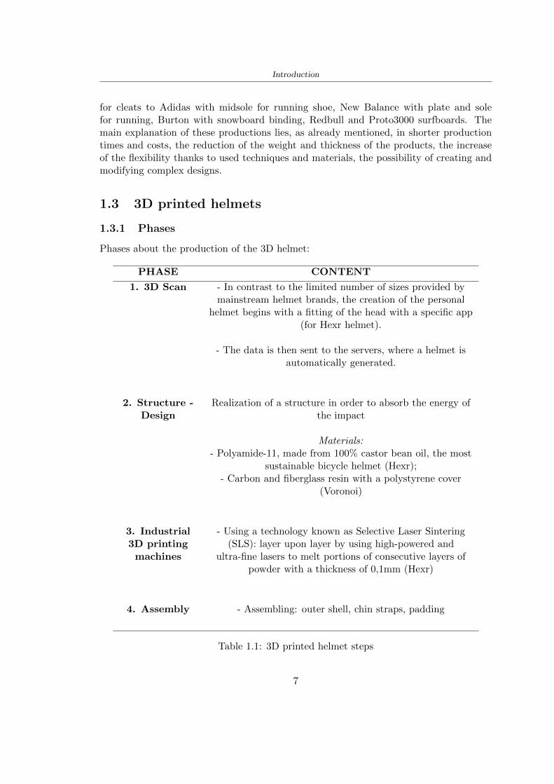
Introduction
for cleats to Adidas with midsole for running shoe New Balance with plate and solefor running Burton with snowboard binding Redbull and Proto3000 surfboards Themain explanation of these productions lies as already mentioned in shorter productiontimes and costs the reduction of the weight and thickness of the products the increaseof the flexibility thanks to used techniques and materials the possibility of creating andmodifying complex designs
13 3D printed helmets
131 Phases
Phases about the production of the 3D helmet
PHASE CONTENT
1 3D Scan - In contrast to the limited number of sizes provided bymainstream helmet brands the creation of the personal
helmet begins with a fitting of the head with a specific app(for Hexr helmet)
- The data is then sent to the servers where a helmet isautomatically generated
2 Structure -Design
Realization of a structure in order to absorb the energy ofthe impact
Materials- Polyamide-11 made from 100 castor bean oil the most
sustainable bicycle helmet (Hexr)- Carbon and fiberglass resin with a polystyrene cover
(Voronoi)
3 Industrial3D printing
machines
- Using a technology known as Selective Laser Sintering(SLS) layer upon layer by using high-powered and
ultra-fine lasers to melt portions of consecutive layers ofpowder with a thickness of 01mm (Hexr)
4 Assembly - Assembling outer shell chin straps padding
Table 11 3D printed helmet steps
7
Introduction
132 HEXR
Scientists at University College London developed the HEXR helmet Figure 15 a 3Dprinted bicycle helmet with a honeycomb structureWhere University College London LondonDesigner Jamie Cook founded HEXR rdquoafter observing energy impacts are different de-pending upon surface areas This led him to do extensive research on improving bicyclehelmet technologyrdquo [17]How is it made The first step to realizing the helmet design is to scan the head usinga 3D scanner Once the scan is obtained thanks to the measurements the drawing isdefined The honeycomb structure is realized through a print with selective laser sinteringtechnology The helmet is produced layer upon layer the process is accurate and employsabout 24 hoursMaterial Polyamide-11 made from 100 castor bean oil The use of this materialmakes the helmet on the market more eco-sustainable being bio-sustainable and beingproduced by a production process with little use of water and limited treatmentsApp to scan the head cycling helmet creation process themselves at home (for App-Store) with a fitting cup to scan perfectly the head
[a] [b]
Figure 15 HEXR design [17]
133 VORONOI
The Voronoi Figure 16 the helmet was designed through a program with parametricdesign which respected a bio-inspired structure This inspiration was taken from theconformation of the animal bone and the typical turtle shellWhere Nanjing ChinaDesigner Yuefeng Zhou Zhecheng Xu Haiwei WangHow is it made The Voronoi helmet was made through a parameterized design withthe use of an unusual mesh The goal of the structure was to use a minimum amount ofmaterial and have a high energy absorption in this way it is possible to get a light and
8
Introduction
effective productMaterial The main materials used for the creation of the helmet shell are carbon kevlarand fiberglass resin with a polystyrene lining The final product is going to be availablein 3 sizes and different colours
Figure 16 Voronoi design [3]
9
Chapter 2
State of the art
21 Standards
The specification about the materials specific tests methods manufacturing to realize ahelmet shall be drawn up by the following standards
- American Society for Testing and Materials (ASTM) is a globally recognized leaderin the development and supply of international standards The World Trade Organiza-tion Technical Barriers legislate it to Trade (TBT) Committee
- The European Committee for standardization (CEN) composted by the nationalbody of Austria Belgium Bulgaria Croatia Cyprus Czech Republic Denmark EstoniaFinland Former Yugoslav Republic of Macedonia France Germany Greece HungaryIceland Ireland Italy Latvia Lithuania Luxembourg Malta Netherlands NorwayPoland Portugal Romania Slovakia Slovenia Spain Sweden Switzerland Turkey andUnited Kingdom
In this study the standard specifications show in the Table 25 will be taken intoaccount the first column contains the Standard name in the designation column theletter with the first number classifies the specification and the second number identifiesthe year when they were published or the year when the last revision was realized
211 Headform
Before realizing a helmet it is necessary to define the headform It is the geometricalrepresentation of the head without facial features and ears but the fundamental axis isrepresented
Planes definitions
bull Basic plane an anatomical plane that includes the superior rim of the externalauditory meatuses (upper edge of the external openings of the ear) and the inferiormargin of the orbit (the lowest point of the floor of the eye socket)
10
State of the art
STANDARD DESIGNATION CONTENT
Standard specifica-tion for headforms
F2220-15 This specification identifies the head-forms used for testing protective head-gear in individual ASTM Internationaltest methods and performance stan-dards [12]
Standard specifi-cation for helmetsused in recreationalbicycling or rollerskating
F1447-18 This specification recognizes the desir-ability of lightweight construction andventilation however it is a perfor-mance standard and is not intended torestrict design [13]
Standard test meth-ods for equipmentand procedures usedin evaluating theperformance charac-teristics of protectiveheadgear
F1446-20 These test methods specify equipmentand procedures used for testing pro-tective headgear Individual ASTMperformance standards (standard spec-ifications) will use these proceduresand equipment Test conditions pass-fail criteria and other performance re-quirements will be specified in the in-dividual performance standards [14]
Headforms for use inthe testing of protec-tive helmets
BS EN 9602006 This European Standard specifies thedimensional and constructional detailsof headforms for use in the testing ofprotective helmets [6]
Helmets for pedal cy-clists and for usersof skateboards androller skates
EN 10782012+A1 This European Standard specifies re-quirements and test methods for hel-mets worn by users of pedal cyclesskateboards and roller skates Require-ments and the corresponding methodsof test are given for the following- construction including field of vision- shock absorbing properties- retention system properties includingchin strap and fastening devices- marking and information [5]
Table 21 Standard specifications
bull Coronal plane an anatomical plane perpendicular to both the basic and midsagittalplanes and passing through the superior rims of the right and left external auditorymeatuses The transverse plane corresponds to the coronal plane
11
State of the art
bull Midsagittal plane an anatomical plane perpendicular to the basic plane and con-taining the midpoint of the line connecting the notches of the right and left inferiororbital ridges and the midpoint of the line connecting the superior rims of the rightand left external auditory meatuses [12]
Figure 21 Anatomical planes [12]
Planes and reference points
In agreement with the Standard BS EN 960 [6] it is possible to define different charac-teristic planes like shown in Figure 22
bull Reference plane for a given headform when erect the horizontal plane located ata vertical distance rsquoyrsquo measured down the central vertical axis from the centre ofthe crown All horizontal datum levels are quoted relative to this plane
bull AArdquo plane for a given headform the horizontal transverse plane is located at avertical distance 127 mm above and parallel to the reference plane This plane isdeemed to correspond to the level of the lower edge of the headband of a helmetIt is the basis upon which the size designation of a helmet may be specified
bull Central vertical axis vertical axis lying along the intersection of the vertical longi-tudinal plane and the vertical transverse plane
bull Centre of gravity of the three-quarter headform - point A for a given headform thepoint on the central vertical axis located at a vertical distance 127 mm above thereference plane
12
State of the art
bull Centre of gravity of the full headform - point G for a given headform the point onthe central vertical axis located at a vertical distance rsquozrsquo below the reference plane
bull Geometric centre - point R for a given headform the point on the central verticalaxis located at its intersection with the reference plane
Figure 22 Principal planes and reference points of a headform [12]
212 European Standard and American Standard
Location of gravity centre
Between the European Standard and American Standard there are differences the firstfor the location of the gravity centre
bull BS EN 960 the centre of gravity is located within a 10 mm radius of Point G
bull ASTM F1447 centre of gravity of the headform must be within a 10 vertical conefrom the centre of impact and lie within a rectangular area 28 by 128 mm
13
State of the art
The size of the head and helmet
bull ASTM F2220 to measure the external dimension for full headform the distancefrom the reference plane to the top of the headform There are different dimensionsF2220 (A if the measure is 897 mm minus C with 93 mm minus E with 96 mm minus J with1025 mm minusM with 107 mm) Then with this classification it is possible to extractthe dimension of xyz (mm) with the following Table 22
Table 22 Location of Reference Line [14]
bull BS EN 960 to obtain the size designation and the headform masses this Standardconsiders the measure of xyz (mm) in Figure 21 The possible designation are 21from 445 to 645 some of these are shown in the Table 23
Thanks to the size designation with the Standard BS EN 1078 there is the possibility todefine the inside circumference of the helmet and this it is shown in the following Table24
Table 23 Dimensions about the reference lines in Figure 21 and headform masses [6]
213 Field of vision - BS EN 1078
Apply a load of 50 N on the crown of the helmet in order to stabilize the helmet on theheadform To avoid having an occultation of the visual field Figure 23 it is better tofollow this angle measures [5]
bull horizontally min 105 from the longitudinal vertical median plane to the leftand right hand sides
bull upwards min 25 from the reference plane
bull downwards min 45 from the basic plane
14
State of the art
Table 24 Inside circumference of helmet [5]
Figure 23 Field of vision (a)(b) [5]
214 Test impact area
Standard EN 1078 will be considered for this study which defines the parameters helpfulin performing the shock absorption test The drop test impact consists of an impact ontwo anvils of flat surface or kerbstone
In the Standard is specified the Test Area where the impact is to be performed Thefirst thing is to apply a vertical load of 50 N on the crown of the helmet in order to
15
State of the art
stabilize the helmet on the headform [5]1 Draw the AArdquo line (in the AArsquo plane) on the helmet2 Draw a line on the helmet parallel to and approximately 20 mm above the AArdquo line(for use as an angular measurement datum line)3 Mark the helmet at points B1 and B2 These points are the sideways horizontalprojection of point B onto the outer surface of the helmet4 Draw a line RRrsquo on the helmet passing through B1 and B2 the line being angled 10
upwards toward the front of the helmet relative to the datum line drawn in d) The areaabove the line drawn in f) is the test area for impacts on the flat anvil The area abovethe line RWArdquo is the test area for impacts on to the kerbstone anvil
Figure 24 Definition of test impact area [5]
215 Anvils and environmental conditions
EN 1078
During the validation process each of the 30 helmet target points was impacted ex-perimentally and numerically under three environmental conditions (-20C +50C andhumidity)
The impact should never exceed 250 g for impacts with velocities corresponding to 542ms on a flat anvil and 457 ms on a kerbstone anvil These are theoretically equivalentto 1497 mm and 1064 mm drop heights respectively [5] About the characteristics of theanvils according to EN 1078 these depend on the type in the case of
bull Flat anvil it has a circular form with a diameter of 130 plusmn 3 mm with 25 mm ofthick
16
State of the art
bull Kerbstone anvil face inclined at 525 plusmn 25 to the vertical and edge with aradius of 15 plusmn 05mm The height shall be not less than 50 mm and the lengthnot less than 125 mm [5]
According with the regalement EN 1078 [5] it has been possible to realize the volumes inthis work the Flat anvil has a diameter of 130 mm and a height of 25 mm the kerbstoneanvil has a horizontal edge of 130 mm a height of 51 mm a length of 126 mm and theedge that impacts the helmet has a radius of 15 mm The anvils are represented in Figure25
[a] [b]
Figure 25 Flat anvil [a] and Kerbstone anvil [b]
EN 13087-11 (Proposal)
A proposal of November 2018 (EN 13087-11) talks about oblique impact tests (Rotationaltest method) [15] Define a method to measure rotational energy absorption in tangentialimpacts in short duration impact situations the velocity considered by Adanty et al [1]is 65 ms The same anvils of the Standard EN 1078 are used the flat anvil and theKerbstone anvil but the difference is the vertical drop towards an impact angle between30-60 the degree considered by Adanty et al [1] is 45
Three different rotations are considered [34]
bull Rotation around X-axis contact point on the side of the helmet resulting in arotation around X-axis Initial position of the headform X- Y- and Z-axis 0
bull Rotation around Y-axis Contact point on the upper part of the helmet resultingin a rotation around Y-axis Initial position of the headform X- Y- and Z-axis 0
bull Rotation around Z-axis Contact point on the upper part of the helmet resultingin a rotation around Y-axis Initial position of the headform X- and Z-axis 0 and65 around Y-axis
17
State of the art
Figure 26 (a) The current cycling helmet standard for the EN 1078 [5] (b) Theproposed standard (EN13087-11) as described by the European Committee for
Standardization (CEN) [15][1]
22 Materials
221 EPS Foam
As mentioned in Chapter 13 the material most commonly used for making the helmetis the EPS Mustafa et al [25] analysed the EPS with four different density values of 50kgm3 64 kgm3 80 kgm3 and 100 kgm3 rdquoThe drop impact simulation model wasused to test the impact attenuation of the helmet with different densities The drop testwas performed on four impact locations top front and sidesrdquo
The impact velocity of the helmet and headform was set at 544 ms The lowestpeak linear acceleration was recorded at the top location and a density of 64 kgm3 with14814 g This study sets out to determine the effect of the user-centered helmet designwith different foam densities (from 50 kgm3 to 100 kgm3) on the impact attenuationof the bicycle helmet
Kroeker et al [19] tested the helmets at three impact speeds 30 plusmn 001 ms 63 plusmn002 ms and 78 plusmn 001 ms
They established the mean value about bulk density in a helmet with EPS foam is666 considering HIC and Peak Acceleration test The global range is between 64 kgm3
and 75 kgm3
Kroeker et al [20] established the foam for kids helmets is 64-88 kgm3 and for thetraditional helmets is 60-100 kgm3
Trzaskalska et al [36] controlled the influence of polymer liner density on energy ab-sorption during impact They discovered the best properties have samples whose densityis between 54 to 60 kgm3
Cui et al [10] considered the density of each layer from the values of 25 50 60 80and 100 kgm3 and they realize a 45 grades side impact and normal crown impact Theresult is a density of 64 kgm3
Wei et al [38] discovered from their test results that EPS has a buffer layer density
18
State of the art
of 60 kgm3 is the most reasonable
Foam densityrsquos values - Literature
Authors Densityrsquos values
Mustafa et al [25] 64Kroeker et al [19] 64 - 75Kroeker et al [20] 60-100 (traditional) and 64-88 (kids)
Trzaskalska et al [36] 54 - 60Cui et al [10] 54Wei et al [38] 60
Table 25 Table with foam (EPS) densityrsquos values
The other are mean values obtained by CES EduPackrsquos program about this material
- Density ρ = 6451kgm3
- Youngrsquos Module E = 275 MPa
- Poissonrsquos ratio ν = 0275
- Yieldrsquos stress σ= 09 MPa
- Elongation at fracture = 45
222 CES Edu Pack - Material selection
CES Edupack software was used to satisfy the idea of creating a lightweight helmetby printing it in 3D and having the possibility to insert the desired characteristics ofthe material and therefore select it To make a choice I used level 3 of engineering(advanced) selecting the following criteria of the material bio-material biodegradablea polymer of concentration 20 - 100 which complies with the rsquoEuropean Restrictionon Hazardous Substances (Rohs) standardsrsquo regarding the composition of the materialensuring that it does not contain a high percentage of toxic substances compared to theestablished percentage In addition it must have proper durability in contact with coldwater (imagining a possible rain) and rsquogoodrsquo durability to UV radiation
According to Ashbyrsquos method [2] to select a material it is possible to follow thefollowing steps
1 Establish the function of the product What does the component doThe helmet is an instrumental use to protect the head during an impact this characteristicdepends on materials and qualities It can prevent an injury which depends on materialsand design because it has to be of the right head size It would be comfortable becauseit must be worn and it must give security to the person wearing it (by design) In thefollowing Table 26 the analysis of the functions
19
State of the art
Ranking Function description Depends on
1 Head protection (energy absorbing) Material2 Head protection (energy absorbing) Design3 Head protection (injury prevention) Material4 Head protection (injury prevention) Design5 Comfortable Material6 Comfortable Process
Table 26 Ashbyrsquos method functions
2 The objectives that are targets for the design the material is to bemaximised or minimisedTo manufacture and market a product objectives such as minimizing weight cost orenvironmental impact must be considered In the following Table 27 the analysis of theobjectives
Ranking Title Objectives description
1 Mass Minimize The mass has to be thesame or lower
2 Cost Minimize everyone should have theopportunity to buy it
3 CO2 footprint Minimize CO2 emission
4 Corrosion Minimize high strength because itcan be in contact with the water
5 Pleasant to touch Maximize it is not a rough materialbecause it has to put on and put off
by hands
6 Refractive index Minimize it must not reflect light
Table 27 Ashbyrsquos method objectives
3 Definition of constrains What essential conditions must be meetEstablish constraints is essential to complete the function of the instrument Examplesof constrains are Table 28
4 The limits characteristic independent of the material that does not influencethe physical properties In the following Table 29 the analysis of the limits
20
State of the art
Title Loading case Constraintsdescription
Material index(Max-Min)
Stiffness Column in compression Tie in tension
Mass Min
Stiffness Column in compression Tie in tension
Cost Min
Stiffness Column in compression Tie in tension
CO2 Min
Strength Column in compression Tie in tension
Mass Min
Strength Column in compression Tie in tension
Cost Min
Strength Column in compression Tie in tension
CO2 Min
Table 28 Ashbyrsquos method constrains
223 PLA with natural fiber and PLA LW
Initially the best material that met the desired criteria was searched From this study itwas found that the material closest to having the required characteristics is the PLA 30natural fiber as shown in the Figure 27 which shows the graphs obtained relating tothe relationships between Youngrsquos Module and density the objective to reduce the massper unit of compressive stiffness and strength to reduce the CO2 footprint per unit ofstiffness and strength and mass per unit of compressive strength
Performance index IR
The stiffness criterion has the following characteristics
m = A lowast L lowast ρ (21)
ε =σ
E=
FA
E(22)
A =F
ε lowast E(23)
21
State of the art
Ranking Title Function description
1 Biocompatibility It is the ability of a material the abilityof the material not to cause any local or
systemic adverse response in therecipient of the material
2 Biodegrability Biodegradable material do notbiodegradable under anaerobic conditions
3 Biomaterials - all The terms is used for biological naturalbio-derived bio-inspired material
4 RoHS (EU) Compliantgrades
Restriction of the use of certin prohibitessubstances (mercury cadmium
hexavalent chromium)
5 Polymer 20-100 (from the table with Plasticpolymers)
6 UV Resistance at UV sunlight
Table 29 Ashbyrsquos method limits
A =F lowast L lowast ρε lowast E
(24)
With fixed variables- F (the load) L (the length)With variables that depend on the material- E (Youngrsquos Module) ρ (density)
In general when a chart is created the distribution of the mass is represented in thefollowing modality like in Figure 27 [b] where the materials above the line have a lowermass while those below a greater mass
Following the results of the CES Edupack program that had selected the PLA withnatural fibers as the best the first print of the helmet was made with this materialusing as support the PVA Initially the result seemed satisfactory the helmet had a highdefinition but a fundamental problem was found by reducing the helmet in the water toallow the supports of PVA to dissolve In the act of diving in fact after ten minutessome parts of the helmet especially the front and rear have disintegrated making thehelmet unusable Because of this problem it was necessary to change the material
22
State of the art
[a]
[b]
Figure 27 CES EduPack Mass per unit of compressive stiffness [a] Youngrsquos Moduleand density [b]
Further investigations carried out by the Mondragon Unibertsitatea Additive Man-ufacturing Department revealed a new material the PLA Low Weight which during3D printing allows to obtain a weight of 65 lower than that which could be obtainedfrom the classic PLA as reported in the technical sheet of the filament produced by thecompany Colorfabb [7]
The investigation team of the Composite Department carried out tensile tests withsamples 3D printed at different temperatures as suggested by the manufacturer to obtainthe technical characteristics The temperatures examined are 200 220 250 260The datasheet shows the density can have values between 04 - 124 gcm3 the bed has
23
State of the art
to have a temperature between 50 - 60 the printing speed has to have values between40 - 80 mms This typology of PLA is expandible so much that rdquoAt around 230 thismaterial will start foaming increasing its volume by nearly three timesrdquo [7]
T[C] Section [mm2] Volumen [mm3] Mass [g] ρ[kgm3] E [Nmm2]
200 42235 1030117 12 1165 328807
220 43805 1655821 18 1087 265795
250 52412 1948139 17 873 178058
260 59655 1454377 12 825 117047
Table 210 Values about PLA LW tensile tests of MU Additive ManufacturingDepartment
From the tests that have been carried out on the material at different temperaturesthe printed sample is better at 250 with a volume of 1948139 mm3 and a section of52412 mm2 as shown in Table 210 For this reason the specific of the material thathave been taken into consideration are the following
- Density ρ = 873 kgm3
- Youngrsquos Module E = 1750 MPa
- Poissonrsquos ratio ν = 033
- Yieldrsquos stress σ = 2948 MPa
- Elongation at fracture = 491
23 Bio-inspired structures
When we talk about bio-inspired structures to nature we refer to structures that allowobtaining a low weight for the model that is realized and excellent absorption energy dur-ing the impact Recently the structures that have been most used in the biomimetic fieldare the rdquocolumns structures sandwich structures plates honeycomb and foamsrdquo[26]but aiming to achieve a structure increasingly with high absorption energy new struc-tures derived from plants and animals such as beetle horsetail turtle bird beak havebeen analyzed The first to create multi-cells tubes helicoidal structures the second tomulti-corner tubes [26]
The authors analyze the specific energy absorbed (SEA) by bio-inspired sandwichstructures per unit mass which can be derived from the following equation
EA(d) =
int dmax
0F (x)dx (25)
SEA(d) =EA(d)
m(26)
24
State of the art
Where EA is the energy absorption rdquomainly used to evaluate an energy absorberrsquosability to dissipate crushing energy through plastic deformationrdquo F(x) is the crashingforce dmax is the effective deformation distance [26]
What derived from their investigations is that having regard to a density of between0 and 1000 kgm3 the volumetric energy absorbed is higher for the beetle-inspired struc-tures than the others as shown in Figure 28 Based on this consideration it was chosento draw the helmet following this geometry
Figure 28 SEA of bio-inspired sandwich structures [26]
231 Beetle structure - Design of the model
To develop and increase lightweight high-strength and optimize bio-mimetic functionaland structural materials the trabecular structure of the beetle elytron is studied Thesingle structure is realized following the requirements cited by Zhang et al [39]
To realize the beetlersquos structure it is not enough to have information about the lengthof the side of the hexagon and the thickness but it is also necessary to take into accountthe relationship between the diameter of the circumferences present on the vertices ofthe hexagon and the measurement of the side The representation of a single cell is inFigure 29 It is shown in [a] a general structure with an edge of 12 mm circumferencersquosdiameter of 6 mm and thickness of 16 mm in [b] is shown the height of 20 mm
For the construction of the helmet a thickness of 12 and 16 mm was used the imageconcerns a proportion between the length of the hexagon side and the diameter of the
25
State of the art
circumference The side (distance between the centers of two circumferences) is twice thediameter measurement
[a] [b]
Figure 29 Beetle structure
232 Specific stress - PLA LW and EPS foam
To test the beetle structures compression tests were investigated The PLA LW structurewas inserted in a rsquodiskrsquo with a diameter of 100 mm and a height of 20 mm The area andthe volume of the disk is correspondingly 7854 mm2 and 157 10 mm3 The structuresexamined have different dimensions the edge L (distance between two centers of thecircumferences) had the following measures 9 10 12 14 16 mm the thickness of thecircumferences and edges are respectively of 16 mm for every structure and 12 mm forthe structure with L = 16 mm
The test was carried out with the Hoytom HM-D Testing Machine with capacitiesbetween 5 and 100 kN The test models were subjected to displacement loading at a rateof 1 mmmin as referenced by Chen et al[18] with a cylindrical specimen The specificstress of the structures was compared with the specific stress of a generic EPS helmetthe photos about it are shown in Figure 210 The EPS helmet structure is granular withpores inside The different grains dimension and these pores can be the reason for whichthe Stressrsquos values are between two values 07 and 116 MPa
Four parts of the EPS helmet were considered in the test the dimension and relativecharacteristic are in the Table 211 where m = mass A = area F = load ρ = densityR = stress Rρ = specific stress To calculate the values of stress about PLA structuresand EPS foam compression test graphs were been analyzed The stress value for eachstructure was calculated considering the single load the single area and the averagedensity value (14055 [kgm3])
The stress values of the PLA structures (Figure 211) and other characteristic valuesare in Table 212 where m = mass A = area F = load ρ = density
26
State of the art
[a] [b]
[c] [d]
Figure 210 EPS generic helmet helmet pictures [a] [b] and internal structureExternal granular structure [c] and pores [d]
[a] [b] [c]
Figure 211 PLA LW disks Grasshopper structure [a] PLA LW structure of 14 mm[b] PLA LW structure compressed [c]
27
State of the art
The results of the load-displacement graphs are affected by the geometry of the diskthe target is to valid for any shape or size for this is preferred to realize a diagramthat depends from σ (or stress) and the deformation ε (or strain) which can be definedrespectively as
σ =F
A0(27)
ε =l minus l0l
(28)
where F is the load during the test A0 is the area l0 is the initial length and l is thelength when the load is applied The areas considered for the EPS cube is reported inTable 211 in the second column the areas of the PLA structure is 7854 mm2 like thearea of the circumscribed disk
The values compared are shown in Table 213 and the graphs obtained by Matlabcode to analyze the recorded data of the compression machine are in Figure 213 and inFigure 212
Considering that the data provided by the compression machine are subject to noiseand disturbances it was decided to convert the original curve into polynomial type curvesthat allow obtaining the best interpolating curve for the data in question To obtain themit was divided the recorded data into two groups the first part from 0 until the end ofthe linear part and the second when the curve becomes linear again The best-fitting (inthe least-squares sense) was performed using the polyfit and polyval functions of MatlabThe first returns the coefficients of the p(x) with n degree the second evaluates p(x) ateach point in x The polynomial formula p(x) is shown in the Equation 29
pn(x) = anxn + anminus1x
nminus1 + + a2x2 + a1x+ a0 (29)
where a0 an are constants and x is the indeterminate The choice of the degree ofthe polynomial was made based on the criterion of wanting to obtain linear curves thatrespected the elastic trend at the beginning of the graph For this reason the degree ofthe polynomial is 1 Subsequently I searched through the intersection of the two lines forthe point that is equivalent to the maximum stress that marks the end of linearity
This value for EPS and PLA LW is the R [MPa] in the Table 213 The average stressvalue for PLA LW is 139 MPa and for EPS is 094 MPa The specific stress (Rρ) is 18MPa lowast m3)kg for the EPS found in CES 669 MPa lowast m3)kg for the EPS foam of thegeneric helmet and for PLA LW is 1161 MPa lowastm3)kg an intermediate value betweenthe two which is what we wanted to achieve
28
State of the art
m [g] A [mm2] F [N] ρ [kgm3]
EPS (CES) 50
16 9234 1063 13864
18 879 593 13651
21 858 833 14237
24 864 564 14468
Average value 14055
Table 211 Compression stress generic EPS helmet
L [mm] t [mm] m [g] F [N] ρ [kgm3]
9 16 214 7250 1363
10 16 192 5560 12467
12 16 201 8190 13051
14 12 138 8000 8961
Average value 12027
Table 212 Compression test PLA structures
PLA LW structure EPS structureρ= 12027kgm3 ρ= 14055kgm3
Edge [mm] R [MPa] Rρ103 Number R [MPa] Rρ103
EPS (CES) 09 18
9 173 1269 1 116 824
10 139 1114 2 08 568
12 138 1057 3 105 746
14 108 1205 4 077 540
Average value 139 1161 094 669
Table 213 Specific stress calculus PLA LW and EPS calculus ρ = density R = stressRρ [(MPa lowastm3)kg] = specific stress
29
State of the art
Figure 212 Compression test Stress-Strain diagrams - EPS
Figure 213 Compression test Stress-Strain diagrams - PLA LW
30
Chapter 3
Methodology
31 3D scan
311 3D Sense 2 scanner and Meshmixer - Reverse reconstruction
Standardized measures were not taken into account for making the helmet but the sizewas obtained through a 3D scan of my head
The scanner used is 3D Sense 2 by 3D Systems which has a minimum scanningvolume of 20 x 20 x 20 cm and a maximum scanning volume of 300 x 300 x 300 cmTo scan my person I was helped to get a full view at 360 at an appropriate distanceReal-time visualization of the captured images was shown through 3D Sense softwareThe idea of scanning the head with the scanner refers to the methodology used by Wanget al [30] They used a reverse reconstruction functional for me to realize the helmetsurface made to measure my head and like them a silicone pool cap was used to makescanning as smooth as possible The authors claim the head scan rdquocan also be used toobtain information about the objectrsquos surface which is then reconstructed utilizing thecomputerrsquos three-dimensional model via reverse modelling softwarerdquo [30] that in my caseis Autodesk Meshmixer
The files it was could get from the scan were stl obj and ply format they wereexported to obj to work in the next step with Autodesk Meshmixer that allowed tomodify and homogenize the 3D image obtained from the scan
In Meshmixer through the selection and delete commands the superfluous parts weredeleted that had been acquired and with the inspector and the DrawDraw2 commandsthe vertices were moved locally along a pre-defined direction and with Smooth the surfacemore homogeneous was made The sequence of steps is shown in the Figure 31
312 3D scan analysis and extraction of features
In Chapter 2 the directives imposed by the BS EN 960 Standard were examined concern-ing the definition of the helmet and the measures to be respected in the field of visionand the part of the helmet was to carry out impact tests
In Figure 32 the features defined complying with the Standardrsquos rules are repre-sented To define these features the software NX was used The angle in the subfigure
31
Methodology
[a] [b] [c] [d]
Figure 31 Sequence of 3D head scan 3D scanner acquisition [a] scan after reparationwith Meshmixer [b] solid scan vision frontal and lateral [c] [d]
[b] is bigger than 105 (as defined by the Standard) while the degree in the subfigure [c]is 25 By defining the construction lines to be respected of the helmetit was necessary todraw the design of the surface not using the software NX but changing with Rhinocerosto create a SubD or SubDivision surface
32 Helmet design
321 Rhinoceros - Helmet surface
After realizing a rsquocleanrsquo Wang et al [30] subdivide with lines and then sectors the headto create the surface of the helmet They used the technique of NURBS a Non UniformRational Basis-Splines which mathematically models a 3D geometry while thanks tothe Rhinoceros 3D organic shapes was draw SubD surfaces These geometries allow tosplit the mesh into small polygons and consist of lines with which easily the shape ofthe object can be modified with a surface already created changing the position of aline automatically the remaining part of the geometry adapts to the changes With thistechnique the rsquosurface basersquo of the helmet was realized with the size of my head Therepresentation of the realized SubD is in Figure 33
322 Grasshopper - Helmet structure
The next idea is the creation on the surface of the beetle structure with different di-mensions modelling the helmet that is not a linear surface It was decided not to buildthe structure with a software CAD because to model an already complex structure on acurved surface would mean to model a cell for a cell
To solve this obstacle a Rhinoceros plug-in was used Grasshopper GH idealized byRobert McNeel and associates creators of Rhinoceros Using GH does not mean drawinggeometries by connecting points and drawing tools because it is based on algorithmicmodelling used in architecture and engineering for 3D modelling
The modelling takes place through a node diagram that the software will convert intoa code-algorithm in GH it is possible to define the variables and parameters and inRhinoceros in real-time it is possible to view the object GH allows for varying the
32
Methodology
[a] [b]
[c]
Figure 32 Featurersquos extraction in [a] is represented the impact line in [b] and [c] twoprospective about the definition of the field of vision
[a] [b] [c]
Figure 33 SubD representation lateral view [a] top view [b] front view [c]
geometry to your liking by varying a simple parameter of the diagram as everything willbe remodelled according to the change made
In the following Figure 34 it is shown an example of a structure that was used fordistinct subgroups of helmet areas The idea was to insert smaller cells in the frontal andlateral zone and larger ones in the upper area In the first image [a] is shown the part of
33
Methodology
the helpful diagram to create the beetle structure to establish the size of the cells andthe extrusion the second image [b] contains the part of the diagram with which I appliedthe structure previously created to the SubD
The structure used to place and adapt the beetle structure to the surface is theSrfMorph while the yellow rsquowindowrsquo that contains numbers serves to select the parts ofthe surface where to apply the geometry created In accord with the GH diagram in
[a]
[b]
Figure 34 Grasshopper diagrams
Figure 34 [a] it is possible to see the steps executed to realize the structure Initially inthe xy-plane a hexagonal grid was drawn through the Hexgrid command in which youcan input the length of the hexagon edge and the number of grid elements (selected bytrial) Then the circumferences was drawn in proportion to the hexagon dimensions asspecified in the Chapter 2 and shown in Figure 35 [a] In figure [b] the rsquocutrsquo made atthe circumferences is visible this subdivision was necessary for printing purposes In thelast photo [c] the structure highlighted in green in [b] was extruded setting a distance
34
Methodology
of 20 mm
[a] [b] [c]
Figure 35 Construction sequence of the geometry of the helmet
In the diagram in Figure 34 [b] there is the application of the structure created bi-dimensionally to the SubD surface of the helmet visible by unlocking the SubD commandof the diagram and in Figure 36 [a] Upper this the referential geometry of the group ofsurfaces was superimposed where it was to be applied the newly created structure (visiblein darker red) the SubD indices are in the yellow box of the diagram
Through the SrfMorph command the location of the structure was granted In Figure36 [b] at the darkest red of the figure [a] with the above command it was possible toplace the structure
[a] [b]
Figure 36 Application of the geometry created to the helmet surface
Overall the diagrams with specific structures are five one for the front two equal forthe side parts one for the top shown in the previous Figure 36 and one for the back
The hexagons in the structure have a dimension varying between 8 mm and 14 mmof side the largest is found at the top later at the back in the sides and the smallest atthe front In Figure 36 [b] the presence of not only hexagonal structures is visible Thegeometry used does not allow the homogeneous arrangement on the entire surface andrequires different structures Automatically the choice of GH to optimize the structurewas to insert quadrilateral
As described above the helmet has different dimensions of the structure divided asvisible in Figure 36 in a quadrilateral This causes a discontinuity between zones withdifferent sizes due to the geometry of the construction
To eliminate this problem and realize the design homogeneous grids were inserted
35
Methodology
in the affected areas as shown in Figure 37 This insertion however proved to beinteresting and strategic researching in this regard studies were realized to demonstratethe insertion of a rectangular grid inside the hexagon grid was helpful for the transmissionof stress in the structure As cited by Sun et al [40] rdquothe mechanical properties of thesesandwich structures are often limited by local failures such as face-core debonding or corecollapserdquo Carrying out compression tests have effectively demonstrated that the insertionof the grid allows rdquoprovided increased stiffness specific stiffness energy absorption andcritical loadrdquo [41] As shown in the graphic [c] of the Figure 37 the honeycomb structuregives a force of 7 kN while with a grid the value is 11 kN and with the combinationexceeds 22 kN In addition in the left front a plaque to customize the helmet wasprepared Figure 37 [a]
[a] [b]
[c]
Figure 37 Grid in the helmet [a] hybrid structure with hexagons and grid [b] [40]compression test results of the hybrid structure [c] [41]
33 3D Print
After having achieved the CAD (Computer Aided Design) of the helmet in order tobe printed it must be converted and saved in format STL (Standard TriangulationLanguage) - Binary compatible with the printing machine and useful for transformingsolid object surfaces into triangles The steps to be taken are the following
bull CAD file realization
bull CAD export in format STL to Simplify 3D the software that shows slider layersand then- rotate and position the object according to geometry and the positioning of any
36
Methodology
supports- setting printing parameters- item manual andor automatic positioning of supports- slider display layers
bull import file gcode to printer
331 Printer and parameters
The program used to visualize how the helmet slices layers before sending it to the printerand to set the parameters is as anticipated Simplify 3D
To make the printing not being a flat geometry it is necessary to place the supportsThe idea was to use water-based supports that the helmet would automatically dissolveonce placed in the water After testing different types of water-soluble PVA the choicefell on eSun 3D Printing Filament PVA (water-soluble support) Before choosing theoptimal position for printing several tests were carried out and to decrease the numberof the supports significantly and allows an optimal printing of the outer part an emptyrsquospherersquo that self-sustains below the helmet was placed as shown in Figure 38
In the image [a] you can see the first print position tried with which an external partof the helmet very damaged was obtained because of the contact supports-helmet In [b]the empty rsquospherersquo is shown to optimize the number of supports and in the last photo [c]there is the full version at the end of print
[a] [b] [c]
Figure 38 Printing supports
The printer that has been used for printing is the Raise 3D Pro2 with double extrudersand nozzles of variable size from 02 mm to 1 mm after some test prints with the PLALW and the structure in created the size that allowed me to have a good compromisebetween printing time and accuracy was 06 mm Using 04 mm the printing time wasexcessive even if having the smaller nozzle diameter means having more precision withthe 08 mm nozzle the quality of the structure was not excellent as seen in Figure 38[a]
Another factor that had to be taken into account is the characteristic of the PLA-LWto expand As the printing temperature and the printer used vary the expansion andcharacteristics of the material change The use of the 06 mm nozzle associated with
37
Methodology
Parameter Left extruder Right extruder
01cm Material 01cm PVA 01cm PLA LW
Extruder toolbox index Tool 0 Tool 1
Nozzle diameter 06 mm 06 mm
Extrusion multiplier 1 05
Extrusion width Auto (072 mm) 05 mm
Layer x
Infill Rectilinear - 50
Supports (Automatic and not) Infill 50
Temperature 210 250
General parameters
Primary layer height 03 mm Top solid layer 4
Bottom solid layer 2 Outline 2
Heated bad 60 Speed 40 mms
Table 31 Printing parameters
Raise 3D allowed me to get good results The choice of this printer was not random ithas in fact the characteristic of making extremely precise prints The Raise has accuracyin placing the object on the printing bed of 078 microns on the xy axis and a resolutionfor layers of 001 mm
The final version of the helmet is visible in Figure 39 and it is possible to compare itwith the preview version in Rhinoceros in Figure 310
38
Methodology
[a] [b]
[c]
Figure 39 Views of the helmet
[a] [b]
Figure 310 Views of the helmet (GH version)
39
Chapter 4
Experimental evaluation
41 Experimental tests
411 Drop-weight impact test machine
In order to calculate the contact force peak and the difference of energy absorbed duringthe impact between the reference helmet and helmet with the beetle structure in PLA-LW dynamic impact tests were carried out using the Fractovis Plus an impact testmachine
In this way it is possible to monitor the evolution of the above variables from theinitial to the final instant of the impact The machine can withstand a load with a rangevariable from 2 to 70 kg with a maximum speed of 46 ms and a maximum height of1 m The values chosen for the test are the following 5 kg weight maximum speed andmaximum height The Anvil that was used is a disc diameter of 60 mm
As shown in Figure 41 and explained by Crupi et al [37] the machine consists ofa sensor capable of recording the speed before impact the impactor that can have avariable mass (a weight of 5 kg in my test) a system to guarantee that there are nomultiple impacts after the first and that work as a shock absorber and clamping systemwhere the object to be tested is placed
The tests that have been carried out are in total four two related to the helmetoptimized with PLA-LW and two with two generic helmets of different brand in EPS
42 PLA LW helmet
To perform the dynamic test on the helmet of PLA considering the difficulty of printingit was helpful to use a test helmet with imperfections to understand where the impactwas concentrated in a single part or distributed The images of Figure 42 show a helmetwith not well defined edges and inaccurate print but exactly localizes the impact zoneThanks to this test it was possible to take into account only one helmet area shown inFigure 43 to have the exact curve of the structure bio-inspired with PLA-LW
40
Experimental evaluation
Figure 41 Drop-weight impact test machine [37]
[a] [b]
Figure 42 Test 1 PLA-LW helmet
43 EPS helmet
To carry out dynamic tests and extract the technical characteristics of the helmettwohelmets were bought in a sports store both EPS and being on the market both certifiedThe brands of the two helmets are DTB and VAN|RYSEL and the average weight ofthe two is 223 g Two different helmets have been chosen to have a more certain andclear classification of the characteristics They are shown in Figure 44 and Figure 45
41
Experimental evaluation
[a] [b]
Figure 43 Test 2 PLA-LW helmet
[a] [b] [c]
Figure 44 Test 3 EPS helmet
[a] [b] [c]
Figure 45 Test 4 EPS helmet
44 Results
441 First results - PLA-LW and EPS helmet
Figure 46 shows two types of trends related to the two different models of the helmetThe force evaluated for PLA-LW has higher force peaks but is more concentrated and
42
Experimental evaluation
propagates less than EPS The graph shows the peaks of each curve highlighted with a redcircle In tests 1 and 2 for the PLA-LW as mentioned earlier the values are higher about7301 N for the complete helmet and 3996 N for the portion of helmet This difference isdue to the inaccuracy of the first full helmet during the printing phase In Figure 42 itis visible the low homogeneity and precision Therefore the first test with full helmet wasused only to define the area of interest of the impact which turns out to be localized Forthe other two EPS curves the values are only slightly lower compared to the PLA-LWequal to 3620 N and 3295 N but the trend is much more distributed
Figure 46 Dynamic machine test - Force
With the data obtained from the impact machine it was possible calculate not exclu-sively the value of force but itrsquos also possible to view the energy curves A resume aboutthe values and energy of the force is in the following Table 41
Test Peak force [N] Peak energy [J]
Test 1 - PLA LW (inaccurate) 730130
Test 2 - PLA LW (portion of helmet) 399643
Test 3 - EPS (DTB helmet) 362007 509
Test 4 - EPS (VAN|RYSEL helmet) 329546 4198
Test 5 - PLA with TPU 45421 5022
Table 41 Energy absorbed in dynamic test
43
Experimental evaluation
442 PLA-LW helmet with TPU cover
As it is possible to see in Figure 47 and as highlighted the first tests concerning thebio-inspired structure and the PLA-LW are far from my expectations considering thelittle distribution of force in comparison with the EPS foam and consequently a smallamount of energy absorbed
Figure 47 Dynamic machine test - Energy
To improve this impact damping factor the idea was to create a cover for the helmetin flexible TPU trying to absorb impact energy The TPU used is a flexible material ofthe brand Ninjaflex used in sports by the application in helmets and shoes to cushionbumps during the game Generally in the helmets (baseball helmet for example) theTPU is inserted internally in contact with the head In my case the TPU structurein addition to creating a shock-absorbing and durable cover creates a custom cover thehelmet and for the person This cover was also made with the Raise 3D printer
As shown in the Figure 48 [a] the infill of the part in contact with the helmet hasa percentage of 100 the filling of the other part of the structure is not complete butonly 15 and the internal structure is hexagonal to recall that of the helmet The desireto insert a structure with a rsquoraisedrsquo geometry is for visual and aesthetic reasons as youhave the feeling of greater protection and not filled is inspired by the machine CitroenCaptus whose bumpers (Airbump) are full of air The failure to realize empty structuresis due to the need to place any internal supports not removable
The idea was to create a cover that allow you to see of the internal structure of thehelmet and that protect specific areas the front the two sides the top and the posteriorWhat which was thought for this reason was to create the shape of a flower with four
44
Experimental evaluation
petals Figure 48 [b]In this way to perform dynamic impact tests as shown in Figure 49 [a] the cover was
positioned at the top of the helmet and the impact was performed in the centre of thersquoflowerrsquo which corresponds to the higher upper part where the structure has larger cellsize The impact parameters are the same as those used in previous impacts 5 kg weightmaximum speed and maximum height The Anvil that was used is a disc diameter of60 mm In photo [b] it is evident the difference between the structure that received theimpact with protection (left) and without protection (right) Without protection duringthe impact there was a perforation of the structure with a concentration of force at a locallevel as you can see in the Figure 46 in the case of TPU the impactor did not perforateand crossed the structure thanks to the cover of TPU that cushioned the shock At themoment of impact the impactor bounced
[a] [b]
Figure 48 TPU cover
[a] [b]
Figure 49 PLA-LW with TPU - dynamic impact [a] and differences between thehelmet with TPU and without TPU cover [b]
45
Experimental evaluation
The Figure 410 includes the diagrams relative to the dynamic impacts In [a] thereare already analyzed EPS results in [b] a comparison between the test on the portionof helmet in PLA LW with and without the TPU cover in [c] the overall comparison ofcurves shows a much more similar EPS trend if the TPU is placed above the structure inPLA LW to soften the blow and absorb the same energy [d]
46
[a]
[c]
[d]
Figure 410 Comparison between PLA-LW with TPU and EPS
Chapter 5
FEM Validation
51 Impactor - Anvils definition
Before to start to work in Abaqus it was necessary to search in the literature the materialwith which the anvil was been realized Milne et al [23] established the densityrsquos valuethe Youngrsquos Module and Poissonrsquos ratio for the Flat and Kerbstone Anvil
- Density ρ = 7800 kgm3
- Youngrsquos Module E = 200000 MPa
- Poissonrsquos ratio ν = 03
Inserting the data in the CES EduPack program specifying the mechanical andphysical properties the material corresponding to these characteristics is Stainless steelaustenitic (ASTM F1586) medium-hard
Initially the proposal was to create a conservative system to evaluate the absorptionenergies values and apply this value to a vibration system but the helmet needs dampingto be realized it was impossible to use a system without losses in this modality Thisis why a numerical calculation was carried out by performing two types of simulationsexplicit dynamic step and static step
The idea to realize the theoretical impact is to regard the movement of the anviland not the helmetrsquos movement which is fixed The velocity is the same cited in thenormative EN 1078 542 ms for the Flat anvil and 457 ms for the Kerbstone anvil
In performing the simulations It was given more relevance and perform tests withthe Kerbstone Anvil This choice was done because the geometry with which it is beenrealized (following as defined in the legislation) allows the helmet to be more subjectedto stress this involves the definition of higher stress limits compared to the Flat Anvil
The mesh size that has been used is the same in the case of the simulation of thehelmet optimized in PLA-LW and the full helmet in EPS of 7 mm The impactor isconsidered as a Discrete rigid body with its specific Reference Point (RP) like shownin Figure 51 for this reason it is not a solid but it is composted only by shells Inthe same image [b] there is the FEM representation of the model and in Table 51 thecharacteristic of FEM with quadrilateral (R3D4) and triangular elements (R3D3)
48
FEM Validation
Object Elementnumber
Elements Shape Geometricorder
Global size[mm]
Kerbstone 230 Quadrilateral - R3D4 Linear 7
Kerbstone 8 Triangular - R3D3 Linear 7
Table 51 Mesh element - Kerbstone Anvil
[a] [b]
Figure 51 Kerbstone anvil in the simulation like discrete rigid body [a] and FEMelements [b]
511 PLA LW - Plastic characteristics
The PLA-LW as explained in the Chapter 2 is new material on the market and producedby the only Colorfabb company for this reason few tests have been carried out to defineits technical characteristics and through tensile tests of the 3D printed specimens it waspossible to define an elastic limit as reported in the Table 210
In the context of simulations to reproduce the impact and deformation of the helmetis also necessary to consider the plastic characteristics of the material Not possessingany reference value in this regard tests were performed through a Static Step initiallyand then an Explicit Dynamic Step in Abaqus
The structure chosen to consider as a reference it is one of the structures previouslysubjected to the compression test having the side L=14 mm As for the reproduction ofthe compression disks initially they were reproduced according to the geometry of theHoytom HM-D Testing Machine considering the bodies mentioned above as discrete 3Drigid discrete The measure was the diameter of 200 mm and the height of 20 mm
After an initial analysis it was observed that the computational time of the simulationprogram was very high so it was decided to change the geometry to have a rsquodisk-surfacesrsquo(equally 3D rigid-discrete) which allowed me to have a smaller number of nodes for themesh and consequently a better computational time The representation of the opti-mized structure in PLA-LW and the disks used for simulated compression is in Figure 52
49
FEM Validation
[a] [b]
Figure 52 Representation of the samples used for the simulation of the compressiontest In Figure [a] the disks of the Hoytom HM-D Testing Machine in figure [b] the
representation of the same as simple surfaces
As shown in Figure 52 the disks are considered 3D discrete hard bodies so it waschosen for both a point the reference point RP where to apply the characteristics relatedto the two bodies As for the compression test it was established
bull the movement of a disk and fixed the second through a boundary condition impos-ing an Encastre therefore unable to move and rotate in xyz directions
bull for the opposite disk the boundary condition relative to the 15 mm displacementwas applied which is the parameter that it was observed to determine the end ofthe compression with the machine This shift is shown by the orange arrow in figure[b]
bull between the upper surface and the disk e the disk with the lower surface it wasinitialized a general contact with normal behaviour through rsquohardrsquo contact andtangential behaviour with a coefficient of friction of 02 with directionality imposedon rsquoisotropicrsquo
The next step was to define the mesh of the components whose parameters are shown inTable 52 while the representation of the FEM is in Figure 53 with the representationof the simulation and real compression test
Object Elementsnumber
Typology Geometricorder
Globalsize [mm]
Disk (14mm) 80910 hexaedral - C3D8R Linear 07
Impact disks 206 quadrilateral - R3D4 Linear 20
Impact disks 6 triangular - R3D3 Linear 20
Table 52 Mesh element - Compression test simulation
As previously announced a static simulation was initially performed with a StaticStep with Step Time equal to 900 (obtained going to consider the speed of 1 mmmin of
50
FEM Validation
[a]
[b] [c]
Figure 53 FEM representation [a] and compression test simulation [b] and realcompression [c]
the compression test and the displacement of 15 mm) However the complex geometryof the structure and the high time set by Step Time did not allow a correct definitionof the parameters of the plastic characteristics of the material the simulation was notable to continue once reached a Step Time of approximately 220 That is why it waschanged by choosing an Explicit Dynamic step
Leaving all the parameters of the boundary conditions unchanged the Step Time wasmodified imposing it to 001 The ability of the explicit dynamic to work with non-linearand contacting structures allowed me to achieve results The results obtained are shownin Figure 54 with the blue curve and were obtained through the iteration of differentPlastic Strain and Yield Stress values in Abaqus while the red line is the result of thereal compression test a similar curve trend was obtained but it is not possible to obtainthe same curve taking into account problems of printing inaccuracy
512 First test - helmet
The initial idea was to perform a simulation imposing the speed of 457 ms to theimpactor tie the helmet in EPS and PLA and compare the absorbed energies Theproblem it was encountered is related to the mesh of the helmet optimized in PLA andwith minimum dimensions of the elements and distinct elements it was not able to solveit
51
FEM Validation
[a]
YieldStress
PlasticStrain
1 47 0
2 7 001
3 75 005
4 10 01
5 108 1
6 115 15
7 12 2
[b]
Figure 54 Representation of the two curves related to the simulation in Abaqus of thecompression test and the data obtained from the real test to obtain the plastic
characteristics of the material
513 Second test - plane
The first solution is the one shown in Figure 55 To realize the simulation it was realizeda section of the helmet to involve a smaller number of elements and nodes Again thesimulation for the EPS helmet was successful while the simulation with the bio-inspiredstructure was interrupted by excessive distortion of elements
The previous images show the impact is very localized in the impacted area and theidea to achieve a complete simulation is not to consider a curved portion of the helmetbut a plane In this way it was possible to solve the problem and obtain a completesimulation for the bio-inspired structure
FEM element
Below in Table 53 there is the definition of the elements used for the PLA-LW and EPSplane in the simulation to simulate the impact and to control the energy-absorbing whilethe anvil characteristics are described in Table 51
514 EPS impact simulations
In order to proceed with the simulation it was imposed some boundary conditions thatregard ties and forces
bull the movement of the plane is fixed through an Encastre therefore unable to moveand rotate in xyz directions
52
FEM Validation
[a]
[b]
Figure 55 Impact simulation parts of EPS and PLA helmet
Object Elementnumber
Elements Shape Geometricorder
Plane (PLA) 38896 Tetrahedral -C3D10M
Quadratic
Plane (EPS) 2100 Hexahedral - C3D8R Linear
Table 53 Mesh element - plane impact
bull to create the impact it was set a speed of 457 ms at the reference point RP of therigid body which is the impactor Kerbstone Anvil shown in Figure 56
bull between the upper surface of the plane and the impactor it was initialized a Sur-face to Surface contact with normal behaviour through rsquohardrsquo contact and tangen-tial behaviour with a coefficient of friction of 02 with directionality imposed onrsquoisotropicrsquo
bull the rotation in x y z relative to the RP of the rigid discrete impactor body is locked
53
FEM Validation
In addition it was characterized the plane in the part of the materials with the char-acteristic values of the EPS mentioned in Chapter 221 The Von Mises Stress valueapparently low is relative to the Yield Stress of the EPS material equal to 09 MPa
Figure 56 EPS Boundary conditions and Load
515 PLA LW impact simulations
As also required in the case of the EPS plane in order to proceed with the simulationsome boundary conditions were imposed that regard ties and forces
bull the movement of the plane is fixed through an Encastre therefore unable to moveand rotate in xyz directions
bull to create the impact a speed of 457 ms was set at the reference point RP of therigid body which is the impactor Kerbstone Anvil shown in Figure 58
bull between the upper surface of the plane and the impactor it was initialized a Sur-face to Surface contact with normal behaviour through rsquohardrsquo contact and tangen-tial behaviour with a coefficient of friction of 02 with directionality imposed onrsquoisotropicrsquo
bull the rotation in x y z relative to the RP of the rigid discrete impactor body is locked
In addition the plane was characterized in the part of the materials with the characteristicvalues of the PLA mentioned in the Chapter 223 and 511
Figure 58 Boundary conditions and Load
54
FEM Validation
[a]
[b]
Figure 57 EPS impact simulation
52 Results
In Figures 59 and 57 it is shown how the structure in PLA LW has a more concentratedstress distribution of the structure unlike EPS The maximum value for the Von Misesstress is 09 MPa in EPS structure and 3634 MPa in PLA LW structure Once thesimulations were obtained the next step was to go and compare the energies absorbed bythe two structures The energy calculated by Abaqus that has been taken into account isPlastic Dissipation To make a comparison the data of the two energies were representedin a single graph
What emerges from the graph is that about the impact made with the KerbstoneAnvil the energy absorption is more excellent although only slightly for the PLA LWthan for the EPS From the graph in Figure 510 a value of 41 J is shown for the EPSand 51 J for the PLA LW
55
[a]
[b]
Figure 59 PLA impact simulation
[a]
Figure 510 EPS and PLA LW energy comparison - Abaqus simulation
Chapter 6
Head Injury Data
For the statistical analysis the injuries related to the accident data were categorised intothe following types and levels based on the details of the medical report [11] about theEN 1078
bull Head Injury Criterion (HIC)
bull Peak Linear Acceleration (PLAc)
bull Gadd Severity Injury (GSI)
bull Diffuse axonal injuries (DAI)
61 Abaqus simulation
Until now the purpose of the simulations has been to determine which between the twomaterials and the two structures of EPS and PLA LW could absorb more energy duringthe impact but no simulations have been carried out in compliance with BS EN 1078on the helmet impact tests To calculate the injuries listed in the previous paragraphhowever we need the acceleration values in the three directions related to the subjectrsquoshead
To realize it the scan of my head already rsquocleanrsquo was considered of which it has beencalculated the inertia thanks to the automatic SolidWorks calculation and evaluated theweight with the Table 24 the structure of the helmet was placed for the EPS and thePLA LW over the head as shown in Figure 61 Also this time being able to mesh theentire helmet in PLA LW was impossible due to the excessive distortion of some elementsduring the simulation so it has been tried to make a section of the structures of thehelmet and results were obtained
57
Head Injury Data
[a] [b]
Figure 61 My scan head - CAD [a] head imported in Abaqus[b]
Initially the simulation had these characteristics as shown in the following Figure62 considering the helmet was not sectioned As explained earlier it was not possibleto get to simulation in the case of the optimized structure in PLA LW for this reasononly a part of the helmet was considered in both cases shown in Figure 63
[a]
Figure 62 Simulation based on BS EN 1078
58
Head Injury Data
[a] [b]
Figure 63 Simulation based on BS EN 1078 with head
In order to proceed with the simulation some boundary conditions that regard tiesand forces have have imposed
bull two reference points RP were created the first in the inertia centre of the headthe second relating to the Kerbstone Anvil which is a discrete rigid body
bull in the reference point RP of the head in the definition of the engineering features5 kg was inserted for the weight and an inertia I11 = 564464E+07 gmm2 I22 =460654E+07gmm2 I33 = 187302E+07gmm2
bull to simulate the impact it was set a speed of 457 ms at the reference point RP ofthe head in z-axis direction
bull a general contact with normal behaviour through rsquohardrsquo contact and tangentialbehaviour with a coefficient of friction of 02
bull between the upper surface of the helmet and the impactor it has been initializeda Surface to Surface contact with normal behaviour through rsquohardrsquo contact andtangential behaviour with a coefficient of friction of 02 with directionality imposedon rsquoisotropicrsquo
bull the movement between the Kerbstone anvil and the helmet is fixed through anEncastre therefore unable to move and rotate in xyz directions
bull the rotation in x y z relative to the RP of the rigid discrete impactor body is locked
FEM element
As reported in Table 53 the portion of the helmet in EPS has used a mesh with hexahe-dral elements of linear order For the structure (beetle) of PLA LW given the geometry
59
Head Injury Data
complexity it was necessary to use a quadratic order of tetrahedra For the mesh of thehead instead in both simulations have been used quadrilateral elements of linear orderas reported in the Tables 61 and 62
Object Elementnumber
Elements Shape Geometricorder
Head 3755 Quadrilateral - R3D4 Linear
Head 34542 Quadrilateral - R3D3 Linear
Helmet (PLA) 272302 Tetrahedral -C3D10M
Quadratic
Table 61 Mesh element - Head simulation with PLA LW (beetle) helmet
Object Elementnumber
Elements Shape Geometricorder
Head 3755 Quadrilateral - R3D4 Linear
Head 34542 Quadrilateral - R3D3 Linear
Helmet (EPS) 72280 Hexahedral - C3D8R Linear
Table 62 Mesh element - Head simulation with EPS helmet
62 Results
Figure 64 represents the simulation in line with BS EN 1078 concerning the helmet inEPS [a] and the helmet with bio-inspired structure in PLA LW For both simulationsVan Misesrsquo stress has Yield Stress values in the case of EPS which is 09 MPa and theplastic behaviour combination of PLA LW [b]
In the case of head and Kerbstone Anvil stress was not assessed as they were previ-ously defined as discrete rigid bodies
63 Head Injury Criterion
The HIC quantifies head impact severity by incorporating time of acceleration exposureand acceleration magnitude it is calculated in post-processing phase with the followingEquation 61
HIC15 =
[1
(t1 minus t2)
int t2
t1
a(t)dt
]25(t2 minus t1) (61)
60
Head Injury Data
[a]
[b]
Figure 64 Results simulation based on BS EN 1078 with sectioned head
For this analysis a(t) is the acceleration calculated in the centre of mass of the head(corresponding to the reference point RP) expressed in g and the time interval (t2 minus t1)was chosen to maximize HIC over a maximum duration of 15 ms
Matlab and the trapz function were used to calculate the HIC to integrate accelerationover time t2 and t1 were considered initial and final times of the simulation t1 = 0 sand t2 = 10 s time less than 15 s
HIC value of 198 was obtained for EPS and 87 for PLA LW Considering the Hayeset al [16] document about the HIC values and the graph in Figure 65 developed bythe author it is possible to find the percentages related to the different injury AIS1 -AIS6 which correspond respectively to lower and higher severity while in Figure 66 therelative fatality to every value of AIS is shown The values obtained for the HIC andother criteria are shown in Table 63 The HIC value for EPS is 198 for PLA LW it is
61
Head Injury Data
Figure 65 Head injury risk curves based on HIC values [16]
Figure 66 The abbreviated injury score versus fatality rate [16]
87 Analyzing the data and comparing them with the curves of the Figure 65 I obtain
bull a percentage between 20 - 30 of AIS 1 for EPS 10 - 20 for PLA LW
bull a percentage between 10 - 20 of AIS 2 for EPS and 0 - 10 for PLA LW
bull for AIS 3 AIS 4 AIS 5 AIS 6 the percentages for both structures is between 0 -10
Comparing these percentages with the fatality rate of Figure 66 it is clear there is a riskof Moderate and Minor fatality in the case of EPS and PLA LW as all values are between0 and 30
62
Head Injury Data
HIC PLA [g] GSI E [J]
EPS 198 97 361 37723
PLA LW 87 75 169 44102
Table 63 Head Injury Data - values
64 Peak Linear Acceleration
The resultant linear acceleration versus time curve was calculated according to Equation62
γ(t) =radicγ2x(t) + γ2y(t) + γ2z (t) (62)
where
bull γ(t) is the resultant linear acceleration (g)
bull γx(t) is the linear acceleration in x axes (g)
bull γy(t) is the linear acceleration in y axes (g)
bull γz(t)is the linear acceleration in z axes (g)
The value of the impact should never exceed 250g [9] Cripton at all [9] in their studyexamined a helmet with expanded polystyrene (EPS) Figure 68 shows maximum HIC forhelmeted and unhelmeted drops from all heights For each drop height helmets reducedHIC relative to unhelmeted drops IARV value is 180g The acceleration in the two casesis shown in Figure 67 and the maximum values are 97g for EPS and 75g for PLA LWas reported in Table 63 The two values considering a maximum value calculated byCripton [9] of 180g are amply optimal and comply with the standard of 250g
65 Gadd Severity Index
Gadd proposed the Severity Index Criteria shown in Equation 63 Following this crite-rion the GSI values that are over 1000 produce serious internal head injury [33]
GSI =
int t1
0a(t)25dt (63)
Where
bull a is the linear acceleration (g)
bull t is the duration of the impact (s)
I calculated the GSI with the function trapz between 0 and t and the resulting valuesare 361 for the EPS and 169 for the PLA LW which comply with the limit
63
Head Injury Data
Figure 67 Peak accelerations for both helmets
Figure 68 Peak accelerations for both helmeted and unhelmeted drops Numbers overbars indicate peak acceleration For 2 m drop height results stated are the mean value
calculated from three drops [9]
64
Head Injury Data
66 Diffuse Axonal Injury
DAI cases covered all incidences in which neurological injuries occurred as well as con-cussion unconsciousness and coma
In order to assess the risk of head trauma in terms of diffuse axonal injury (DAI)Milne et al [23] defined a model based head injury criteria as follows obtaining theresults in Figure 69
bull 50 risk of moderate neurological injury (DAI1+) Brain Von Mises shearing stressof 28 kPa
bull 50 risk of severe neurological injury (DAI2+) Brain Von Mises shearing stressof 53 kPa
[a]
[b]
Figure 69 Peak intra-cerebral shearing stress computed with the helmet model coupledto the human head model for all impact points (a) Flat anvil (b) Kerbstone anvil [23]
65
Head Injury Data
67 Energy absorbed
In Figure 52 during the impact test between the kerbstone Anvil and the plan with thebio-inspired structure in PLA LW and EPS it was found that the PLA LW althoughwith a small difference of 10 J absorbed more energy in comparison with the EPS Whenthe test is carried out in compliance with BS EN 1078 and the head with a speed of 457ms (corresponding to the kerbstone Anvil) as shown in Figure 610 also in this casethe PLA LW with the optimized helmet structure manages to absorb more energy (evenif the difference is very low) compared to the EPS The maximum energy value in PLALW is 44102 J of EPS is 37723 J
Figure 610 Energy absorption - BS EN 1078
66
Chapter 7
Conclusion
71 Conclusion
In this thesis work a bicycle helmet with a bio-inspired structure in PLA LW and 3Dprinted was created The initial approach was to introduce an innovative aspect tostandard EPS helmets not using foam but a polymer with new geometries able toabsorb much energy during the impact For this reason the beetle structure has beenpreferred relying solely on the hypothesis encountered in the literature of its quality inabsorbing energy
Combining the new material of the PLA LW and beetle structure has made possiblethe development of new material satisfactory characteristics have been obtained sincethe first tests The two materials were first subjected to tensile tests to determine theirspecific stress in these the PLA LW had positive results
Subsequent dynamic physical tests were carried out on 3D printed helmet models andon reference helmets in EPS to calculate the absorption energy in both cases at the timeof impact These resulted in energy absorption of the beetle structure in PLA LW withthe application of a TPU cover almost equal to that of EPS about 50J To validate withfinite element analysis the two models an explicit dynamic step was used in AbaqusSimulations showed that the PLA LW structure absorbs a higher amount of energy thanthe EPS the higher is 50 J and the EPS 40J
Finally positive results have also been obtained in calculating the head injury datasimulating according to BS EN 1078 with the use of impactor helmet and head Theacceleration values for both the structures were inferior to 220g precisely for the PLALW was 75g and for the EPS 97g The same applies to the calculation of HIC and GSI(maximum acceptable value of 1000) where the values are 87 and 169 in the case of PLALW and 361 and 198 in EPS For all tests therefore greater efficiency of the structure inPLA LW has been obtained Positive results also in the simulation of the energy absorbedduring the impact as the value referring to the EPS was 35J and that of the PLA LWwas 45J
67
Conclusion
72 Future work lines
The positive results obtained can be considered as a starting point for further tests andsimulations to ensure the safety of the helmet and compliance with the regulations butbefore getting improvements and continue testing changes are required
bull the beetle structure of the helmet made with GH adapts to the SubD withoutallowing to have a homogeneous distribution it would be appropriate to have moreregular hexagonal geometries
bull the mesh of the helmet is too complex and does not allow to perform the simulationprobably to use a more regular structure would have a mesh accordingly moreregular and the simulation would be successful
bull the uneven helmet structure has so many defects that the print is imperfect andthis can change the results of the impact tests the structure should be improved
bull the printing time varies from 4 to 5 days it should be improved
bull the TPU helmet cover is too big for the RAISE printing plan it is necessary togenerate a new geometry
bull the TPU cover it must be fixed on the helmet
bull in the calculation of the DAI it is necessary to have the definition of the brain andthe head should not be considered as a rigid body
bull in the injury calculation the helmet without protection was considered with theTPU cover the result will be better
bull air flow analysis
The comments mentioned are only considerations and problems that I gained duringmy thesis and which should be improved but I am sure that these changes and improve-ments from design to printing and simulations can make the helmet a good product
68
Bibliography
[1] K Adanty J M Clark A Post Thomas Blaine H and M D Gilchrist Comparingtwo proposed protocols to test the oblique response of cycling helmets to fall impactsInternational Journal of Crashworthiness 6648 ndash 663 2020
[2] MF Ashby YJM Brechetb D Cebona and L Salvoc Selection strategies formaterials and processes Materials and Design 2004
[3] M Aysha El casco de bicicleta voronoi impreso en 3d mas seguro y ligero https
www3dnativescomen3d-printed-bicycle-helmet-voronoi-190820204
[4] H Bikas P Stavropoulos and G Chryssolouris Additive manufacturing methodsand modelling approaches a critical review The International Journal of AdvancedManufacturing Technology 83389ndash405 2016
[5] British Standards BSI Helmets for pedal cyclists and for users of skateboards androller skates - BS EN 1078 2012
[6] British Standards BSI Headforms for use in the testing of protective helmets BSEN 960 2020
[7] ColorFabb Colorfabb lw-pla 2019 httpscolorfabbcommedia
datasheetstdscolorfabbTDS_E_ColorFabb_LW-PLApdf
[8] V G Coronado T Haileyesus J M Bell T A Cheng JHaarbauer-Krupa M RLionbarger J Flores-Herrera L C McGuire and J Gilchrist Trends in sports andrecreation-related traumatic brain injuries treated in us emergency departments thenational electronic injury surveillance system-all injury program (neiss-aip) 2001-2012 J Head Trauma Rehabil 30185ndash197 2015
[9] P A Cripton D M Dressler D Stuart Cameron A Christopher R and D RichardsBicycle helmets are highly effective at preventing head injury during head impactHead-form accelerations and injury criteria for helmeted and unhelmeted impactsAccident Analysis and Prevention 701ndash7 2014
[10] L Cui M A Forero R and M D Gilchrist Optimisation of energy absorbingliner for equestrian helmets UCD School of Electrical Electronic and MechanicalEngineering University College Dublin Belfield Dublin4 Ireland 2020
[11] C Deck N Bourdet F Meyer and R Willinger Protection performance of bicyclehelmets Journal of safety research pages 67ndash77 2019
[12] Committee F08 Specification for headforms F2220 ASTM International 2015
[13] Committee F08 Specification for helmets used in recreational bicycling or rollerskating F1447 ASTM International 2018
[14] Committee F08 Test methods for equipment and procedures used in evaluating theperformance F1446 ASTM International 2020
69
Bibliography
[15] P Halldin Shock absorption including measuring CENTC 158 Working Group11 2018
[16] W C Hayes M S Erickson and E D Power Forensic injury biomechanics Annualreview of biomedical engineering pages 55ndash86 2007
[17] HEXR httpshexrcom
[18] C Jinxiang Z Xiaoming O Yoji S Kazuya G Zhensheng and P LongchengThe deformation mode and strengthening mechanism of compression in the beetleelytron plate Materials and Design 131481ndash186 2017
[19] S Kroeker M Ozkul A De Marco S Bonin and GP Siegmund Density variationin the expanded polystyrene eps foam of bicycle helmets and its influence on impactperformance Journal of biomechanical engineering 2019
[20] S G Kroeker SJ Bonin A L DeMarco C A Good and G P Siegmund Agedoes not affect the material properties of expanded polystyrene liners in field-usedbicycle helmets Journal of biomechanical engineering 2016
[21] M Meier K H Tan M K Lim and L Chung Unlocking innovation in the sportindustry through additive manufacturing Business Process Management Journa2018
[22] N J Mills and A Gilchrist The effectiveness of foams in bicycle and motorcyclehelmets Accident Analysis Prevention 23153 ndash 163 1991
[23] G Milne C Deck R P Carreira Q Allinne and R Willinger Development andvalidation of a bicycle helmet assessment of head injury risk under standard impactconditions Computer methods in biomechanics and biomedical engineering 15 Suppl1309 ndash 310 2012
[24] Y Mosleh S J Vander B Depreitere and J Ivens Novel composite foam conceptfor head protection in oblique impacts Adv Eng Mater (Advanced EngineeringMaterials) 10 2017
[25] H Mustafa T Y Pang T Ellena and S H Nasir Impact attenuation of user-centred bicycle helmet design with different foam densities J Phys Conf Ser(Journal of Physics Conference Series) 1150 2019
[26] S H Ngoc and L Guoxing A review of recent research on bio-inspired structuresand materials for energy absorption applications Composites Part 181 2020
[27] J I Novak and A R Novak Is additive manufacturing improving performance insports a systematic review Sport engineering and technology 13 2020
[28] European Road Safety Observatory European road safety observatory facts and fig-ures - cyclists - 2020 December 2020 httpseceuropaeutransportroad_
safetysitesdefaultfilesfacts_figures_cyclists_final_20210323pdf
[29] New York City Departments of Health Parks Mental Hygiene Transportation Recre-ation and the New York City Police Department Bicyclist fatalities and seriousinjuries in new york city 2005
[30] W Pengwen Y Jing H Yanan H Jiaofei and F Xiaoyang Innovative designof a helmet based on reverse engineering and 3d printing Alexandria EngineeringJournal 603445ndash3453 2021
[31] S G Piland T E Gould M Jesunathadas J S Wiggins O McNair and V CShane Protective helmets in sports Materials in Sports Equipment 3 2019
70
Bibliography
[32] K Schmitt P F Niederer M H Muser and F Walz Trauma biomechanicsSpringer Berlin Heidelberg 2010
[33] David Sepelveda Lopez A Biomechanical Analysis of Bicycle Helmets using FEMPhD thesis 2019 Bachelor thesis
[34] H Stigson Bicycle Helmets 2020 Tested by Folksam PhD thesis 2020 PhDAssociate Professor Traffic Safety Research
[35] H Tao K Sudip N Anindya and X Yongzhao 3d printed sensors for biomedicalapplications A review sensor 2019
[36] M Trzaskalska and R Chwastek Damping properties and density of helmet linersmade of expanded polystyrene (eps) Archives of Metallurgy and Materials 66 2020
[37] Crupi V Epasto G and Guglielmino E Impact response of aluminum foam sand-wiches for light-weight ship structures Metals 198ndash112 2020
[38] W Wei-cai F Dong-ming and L Yuan-xin Study on impact energy absorbing per-formance of eps buffer layer of motorcycle helmet Proceedings - 2013 InternationalConference on Mechanical and Automation Engineering MAEE 2013
[39] Z Xiaoming C Jinxiang O Yoji Z Peiwei X Xiaobing and Y Xindi Influence ofhoneycomb dimensions and forming methods on the compressive properties of beetleelytron plates Journal of Sandwich Structures and Materials 2228ndash39 2020
[40] S Zhi L Dong Z Weisheng S Shanshan and G Xu Topological optimization ofbiomimetic sandwich structures with hybrid core and cfrp face sheets CompositesScience and Technology 14279ndash90 2017
[41] S Zhi S Shanshan G Xu H Xiaozhi and C Haoran On compressive propertiesof composite sandwich structures with grid reinforced honeycomb core CompositesPart B 94245ndash252 2016
71
- List of Tables
- List of Figures
- Introduction
-
- Helmet bike protection
-
- Helmet structure
-
- Additive Manufacturing
-
- AM process
- Materials and techniques - FDM
- AM in sport
-
- 3D printed helmets
-
- Phases
- HEXR
- VORONOI
-
- State of the art
-
- Standards
-
- Headform
- European Standard and American Standard
- Field of vision - BS EN 1078
- Test impact area
- Anvils and environmental conditions
-
- Materials
-
- EPS Foam
- CES Edu Pack - Material selection
- PLA with natural fiber and PLA LW
-
- Bio-inspired structures
-
- Beetle structure - Design of the model
- Specific stress - PLA LW and EPS foam
-
- Methodology
-
- 3D scan
-
- 3D Sense 2 scanner and Meshmixer - Reverse reconstruction
- 3D scan analysis and extraction of features
-
- Helmet design
-
- Rhinoceros - Helmet surface
- Grasshopper - Helmet structure
-
- 3D Print
-
- Printer and parameters
-
- Experimental evaluation
-
- Experimental tests
-
- Drop-weight impact test machine
-
- PLA LW helmet
- EPS helmet
- Results
-
- First results - PLA-LW and EPS helmet
- PLA-LW helmet with TPU cover
-
- FEM Validation
-
- Impactor - Anvils definition
-
- PLA LW - Plastic characteristics
- First test - helmet
- Second test - plane
- EPS impact simulations
- PLA LW impact simulations
-
- Results
-
- Head Injury Data
-
- Abaqus simulation
- Results
- Head Injury Criterion
- Peak Linear Acceleration
- Gadd Severity Index
- Diffuse Axonal Injury
- Energy absorbed
-
- Conclusion
-
- Conclusion
- Future work lines
-
- Bibliography
-
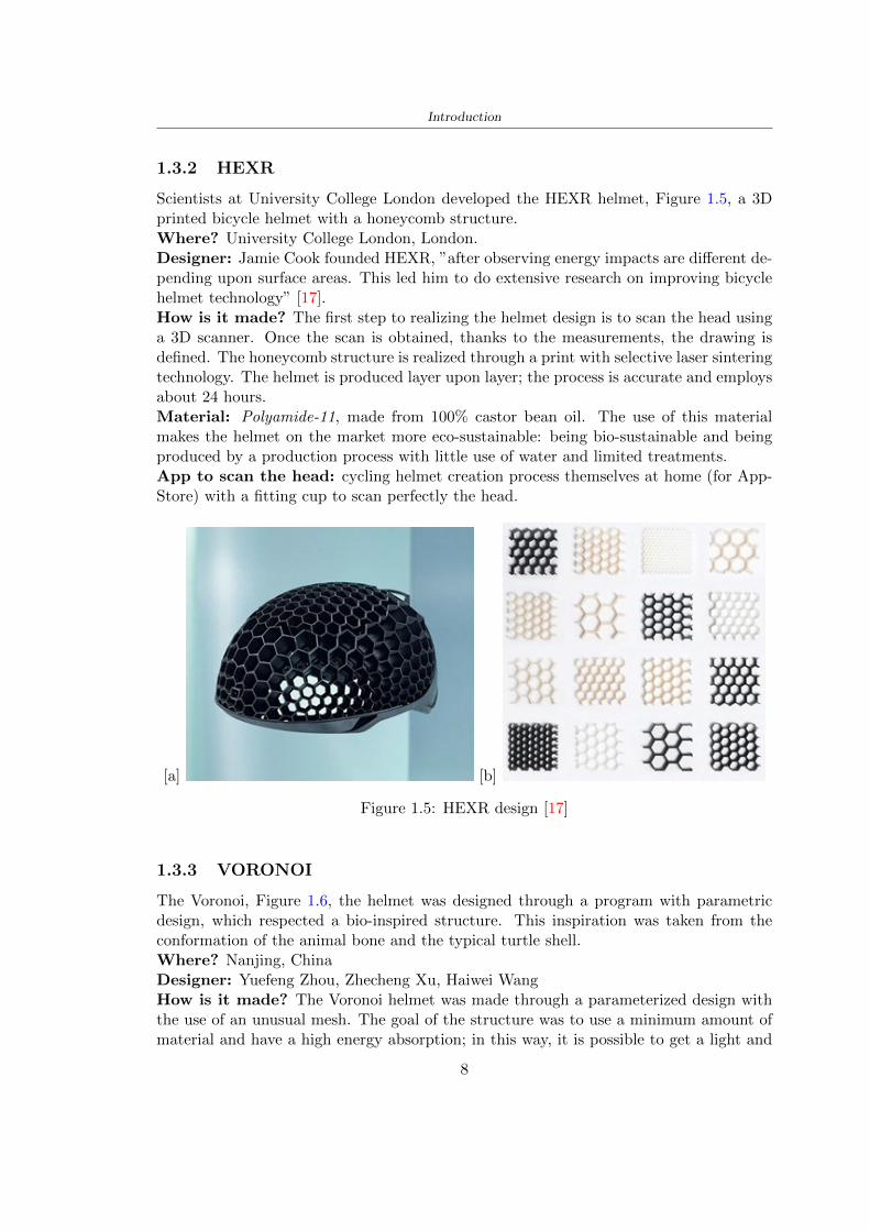
Introduction
132 HEXR
Scientists at University College London developed the HEXR helmet Figure 15 a 3Dprinted bicycle helmet with a honeycomb structureWhere University College London LondonDesigner Jamie Cook founded HEXR rdquoafter observing energy impacts are different de-pending upon surface areas This led him to do extensive research on improving bicyclehelmet technologyrdquo [17]How is it made The first step to realizing the helmet design is to scan the head usinga 3D scanner Once the scan is obtained thanks to the measurements the drawing isdefined The honeycomb structure is realized through a print with selective laser sinteringtechnology The helmet is produced layer upon layer the process is accurate and employsabout 24 hoursMaterial Polyamide-11 made from 100 castor bean oil The use of this materialmakes the helmet on the market more eco-sustainable being bio-sustainable and beingproduced by a production process with little use of water and limited treatmentsApp to scan the head cycling helmet creation process themselves at home (for App-Store) with a fitting cup to scan perfectly the head
[a] [b]
Figure 15 HEXR design [17]
133 VORONOI
The Voronoi Figure 16 the helmet was designed through a program with parametricdesign which respected a bio-inspired structure This inspiration was taken from theconformation of the animal bone and the typical turtle shellWhere Nanjing ChinaDesigner Yuefeng Zhou Zhecheng Xu Haiwei WangHow is it made The Voronoi helmet was made through a parameterized design withthe use of an unusual mesh The goal of the structure was to use a minimum amount ofmaterial and have a high energy absorption in this way it is possible to get a light and
8
Introduction
effective productMaterial The main materials used for the creation of the helmet shell are carbon kevlarand fiberglass resin with a polystyrene lining The final product is going to be availablein 3 sizes and different colours
Figure 16 Voronoi design [3]
9
Chapter 2
State of the art
21 Standards
The specification about the materials specific tests methods manufacturing to realize ahelmet shall be drawn up by the following standards
- American Society for Testing and Materials (ASTM) is a globally recognized leaderin the development and supply of international standards The World Trade Organiza-tion Technical Barriers legislate it to Trade (TBT) Committee
- The European Committee for standardization (CEN) composted by the nationalbody of Austria Belgium Bulgaria Croatia Cyprus Czech Republic Denmark EstoniaFinland Former Yugoslav Republic of Macedonia France Germany Greece HungaryIceland Ireland Italy Latvia Lithuania Luxembourg Malta Netherlands NorwayPoland Portugal Romania Slovakia Slovenia Spain Sweden Switzerland Turkey andUnited Kingdom
In this study the standard specifications show in the Table 25 will be taken intoaccount the first column contains the Standard name in the designation column theletter with the first number classifies the specification and the second number identifiesthe year when they were published or the year when the last revision was realized
211 Headform
Before realizing a helmet it is necessary to define the headform It is the geometricalrepresentation of the head without facial features and ears but the fundamental axis isrepresented
Planes definitions
bull Basic plane an anatomical plane that includes the superior rim of the externalauditory meatuses (upper edge of the external openings of the ear) and the inferiormargin of the orbit (the lowest point of the floor of the eye socket)
10
State of the art
STANDARD DESIGNATION CONTENT
Standard specifica-tion for headforms
F2220-15 This specification identifies the head-forms used for testing protective head-gear in individual ASTM Internationaltest methods and performance stan-dards [12]
Standard specifi-cation for helmetsused in recreationalbicycling or rollerskating
F1447-18 This specification recognizes the desir-ability of lightweight construction andventilation however it is a perfor-mance standard and is not intended torestrict design [13]
Standard test meth-ods for equipmentand procedures usedin evaluating theperformance charac-teristics of protectiveheadgear
F1446-20 These test methods specify equipmentand procedures used for testing pro-tective headgear Individual ASTMperformance standards (standard spec-ifications) will use these proceduresand equipment Test conditions pass-fail criteria and other performance re-quirements will be specified in the in-dividual performance standards [14]
Headforms for use inthe testing of protec-tive helmets
BS EN 9602006 This European Standard specifies thedimensional and constructional detailsof headforms for use in the testing ofprotective helmets [6]
Helmets for pedal cy-clists and for usersof skateboards androller skates
EN 10782012+A1 This European Standard specifies re-quirements and test methods for hel-mets worn by users of pedal cyclesskateboards and roller skates Require-ments and the corresponding methodsof test are given for the following- construction including field of vision- shock absorbing properties- retention system properties includingchin strap and fastening devices- marking and information [5]
Table 21 Standard specifications
bull Coronal plane an anatomical plane perpendicular to both the basic and midsagittalplanes and passing through the superior rims of the right and left external auditorymeatuses The transverse plane corresponds to the coronal plane
11
State of the art
bull Midsagittal plane an anatomical plane perpendicular to the basic plane and con-taining the midpoint of the line connecting the notches of the right and left inferiororbital ridges and the midpoint of the line connecting the superior rims of the rightand left external auditory meatuses [12]
Figure 21 Anatomical planes [12]
Planes and reference points
In agreement with the Standard BS EN 960 [6] it is possible to define different charac-teristic planes like shown in Figure 22
bull Reference plane for a given headform when erect the horizontal plane located ata vertical distance rsquoyrsquo measured down the central vertical axis from the centre ofthe crown All horizontal datum levels are quoted relative to this plane
bull AArdquo plane for a given headform the horizontal transverse plane is located at avertical distance 127 mm above and parallel to the reference plane This plane isdeemed to correspond to the level of the lower edge of the headband of a helmetIt is the basis upon which the size designation of a helmet may be specified
bull Central vertical axis vertical axis lying along the intersection of the vertical longi-tudinal plane and the vertical transverse plane
bull Centre of gravity of the three-quarter headform - point A for a given headform thepoint on the central vertical axis located at a vertical distance 127 mm above thereference plane
12
State of the art
bull Centre of gravity of the full headform - point G for a given headform the point onthe central vertical axis located at a vertical distance rsquozrsquo below the reference plane
bull Geometric centre - point R for a given headform the point on the central verticalaxis located at its intersection with the reference plane
Figure 22 Principal planes and reference points of a headform [12]
212 European Standard and American Standard
Location of gravity centre
Between the European Standard and American Standard there are differences the firstfor the location of the gravity centre
bull BS EN 960 the centre of gravity is located within a 10 mm radius of Point G
bull ASTM F1447 centre of gravity of the headform must be within a 10 vertical conefrom the centre of impact and lie within a rectangular area 28 by 128 mm
13
State of the art
The size of the head and helmet
bull ASTM F2220 to measure the external dimension for full headform the distancefrom the reference plane to the top of the headform There are different dimensionsF2220 (A if the measure is 897 mm minus C with 93 mm minus E with 96 mm minus J with1025 mm minusM with 107 mm) Then with this classification it is possible to extractthe dimension of xyz (mm) with the following Table 22
Table 22 Location of Reference Line [14]
bull BS EN 960 to obtain the size designation and the headform masses this Standardconsiders the measure of xyz (mm) in Figure 21 The possible designation are 21from 445 to 645 some of these are shown in the Table 23
Thanks to the size designation with the Standard BS EN 1078 there is the possibility todefine the inside circumference of the helmet and this it is shown in the following Table24
Table 23 Dimensions about the reference lines in Figure 21 and headform masses [6]
213 Field of vision - BS EN 1078
Apply a load of 50 N on the crown of the helmet in order to stabilize the helmet on theheadform To avoid having an occultation of the visual field Figure 23 it is better tofollow this angle measures [5]
bull horizontally min 105 from the longitudinal vertical median plane to the leftand right hand sides
bull upwards min 25 from the reference plane
bull downwards min 45 from the basic plane
14
State of the art
Table 24 Inside circumference of helmet [5]
Figure 23 Field of vision (a)(b) [5]
214 Test impact area
Standard EN 1078 will be considered for this study which defines the parameters helpfulin performing the shock absorption test The drop test impact consists of an impact ontwo anvils of flat surface or kerbstone
In the Standard is specified the Test Area where the impact is to be performed Thefirst thing is to apply a vertical load of 50 N on the crown of the helmet in order to
15
State of the art
stabilize the helmet on the headform [5]1 Draw the AArdquo line (in the AArsquo plane) on the helmet2 Draw a line on the helmet parallel to and approximately 20 mm above the AArdquo line(for use as an angular measurement datum line)3 Mark the helmet at points B1 and B2 These points are the sideways horizontalprojection of point B onto the outer surface of the helmet4 Draw a line RRrsquo on the helmet passing through B1 and B2 the line being angled 10
upwards toward the front of the helmet relative to the datum line drawn in d) The areaabove the line drawn in f) is the test area for impacts on the flat anvil The area abovethe line RWArdquo is the test area for impacts on to the kerbstone anvil
Figure 24 Definition of test impact area [5]
215 Anvils and environmental conditions
EN 1078
During the validation process each of the 30 helmet target points was impacted ex-perimentally and numerically under three environmental conditions (-20C +50C andhumidity)
The impact should never exceed 250 g for impacts with velocities corresponding to 542ms on a flat anvil and 457 ms on a kerbstone anvil These are theoretically equivalentto 1497 mm and 1064 mm drop heights respectively [5] About the characteristics of theanvils according to EN 1078 these depend on the type in the case of
bull Flat anvil it has a circular form with a diameter of 130 plusmn 3 mm with 25 mm ofthick
16
State of the art
bull Kerbstone anvil face inclined at 525 plusmn 25 to the vertical and edge with aradius of 15 plusmn 05mm The height shall be not less than 50 mm and the lengthnot less than 125 mm [5]
According with the regalement EN 1078 [5] it has been possible to realize the volumes inthis work the Flat anvil has a diameter of 130 mm and a height of 25 mm the kerbstoneanvil has a horizontal edge of 130 mm a height of 51 mm a length of 126 mm and theedge that impacts the helmet has a radius of 15 mm The anvils are represented in Figure25
[a] [b]
Figure 25 Flat anvil [a] and Kerbstone anvil [b]
EN 13087-11 (Proposal)
A proposal of November 2018 (EN 13087-11) talks about oblique impact tests (Rotationaltest method) [15] Define a method to measure rotational energy absorption in tangentialimpacts in short duration impact situations the velocity considered by Adanty et al [1]is 65 ms The same anvils of the Standard EN 1078 are used the flat anvil and theKerbstone anvil but the difference is the vertical drop towards an impact angle between30-60 the degree considered by Adanty et al [1] is 45
Three different rotations are considered [34]
bull Rotation around X-axis contact point on the side of the helmet resulting in arotation around X-axis Initial position of the headform X- Y- and Z-axis 0
bull Rotation around Y-axis Contact point on the upper part of the helmet resultingin a rotation around Y-axis Initial position of the headform X- Y- and Z-axis 0
bull Rotation around Z-axis Contact point on the upper part of the helmet resultingin a rotation around Y-axis Initial position of the headform X- and Z-axis 0 and65 around Y-axis
17
State of the art
Figure 26 (a) The current cycling helmet standard for the EN 1078 [5] (b) Theproposed standard (EN13087-11) as described by the European Committee for
Standardization (CEN) [15][1]
22 Materials
221 EPS Foam
As mentioned in Chapter 13 the material most commonly used for making the helmetis the EPS Mustafa et al [25] analysed the EPS with four different density values of 50kgm3 64 kgm3 80 kgm3 and 100 kgm3 rdquoThe drop impact simulation model wasused to test the impact attenuation of the helmet with different densities The drop testwas performed on four impact locations top front and sidesrdquo
The impact velocity of the helmet and headform was set at 544 ms The lowestpeak linear acceleration was recorded at the top location and a density of 64 kgm3 with14814 g This study sets out to determine the effect of the user-centered helmet designwith different foam densities (from 50 kgm3 to 100 kgm3) on the impact attenuationof the bicycle helmet
Kroeker et al [19] tested the helmets at three impact speeds 30 plusmn 001 ms 63 plusmn002 ms and 78 plusmn 001 ms
They established the mean value about bulk density in a helmet with EPS foam is666 considering HIC and Peak Acceleration test The global range is between 64 kgm3
and 75 kgm3
Kroeker et al [20] established the foam for kids helmets is 64-88 kgm3 and for thetraditional helmets is 60-100 kgm3
Trzaskalska et al [36] controlled the influence of polymer liner density on energy ab-sorption during impact They discovered the best properties have samples whose densityis between 54 to 60 kgm3
Cui et al [10] considered the density of each layer from the values of 25 50 60 80and 100 kgm3 and they realize a 45 grades side impact and normal crown impact Theresult is a density of 64 kgm3
Wei et al [38] discovered from their test results that EPS has a buffer layer density
18
State of the art
of 60 kgm3 is the most reasonable
Foam densityrsquos values - Literature
Authors Densityrsquos values
Mustafa et al [25] 64Kroeker et al [19] 64 - 75Kroeker et al [20] 60-100 (traditional) and 64-88 (kids)
Trzaskalska et al [36] 54 - 60Cui et al [10] 54Wei et al [38] 60
Table 25 Table with foam (EPS) densityrsquos values
The other are mean values obtained by CES EduPackrsquos program about this material
- Density ρ = 6451kgm3
- Youngrsquos Module E = 275 MPa
- Poissonrsquos ratio ν = 0275
- Yieldrsquos stress σ= 09 MPa
- Elongation at fracture = 45
222 CES Edu Pack - Material selection
CES Edupack software was used to satisfy the idea of creating a lightweight helmetby printing it in 3D and having the possibility to insert the desired characteristics ofthe material and therefore select it To make a choice I used level 3 of engineering(advanced) selecting the following criteria of the material bio-material biodegradablea polymer of concentration 20 - 100 which complies with the rsquoEuropean Restrictionon Hazardous Substances (Rohs) standardsrsquo regarding the composition of the materialensuring that it does not contain a high percentage of toxic substances compared to theestablished percentage In addition it must have proper durability in contact with coldwater (imagining a possible rain) and rsquogoodrsquo durability to UV radiation
According to Ashbyrsquos method [2] to select a material it is possible to follow thefollowing steps
1 Establish the function of the product What does the component doThe helmet is an instrumental use to protect the head during an impact this characteristicdepends on materials and qualities It can prevent an injury which depends on materialsand design because it has to be of the right head size It would be comfortable becauseit must be worn and it must give security to the person wearing it (by design) In thefollowing Table 26 the analysis of the functions
19
State of the art
Ranking Function description Depends on
1 Head protection (energy absorbing) Material2 Head protection (energy absorbing) Design3 Head protection (injury prevention) Material4 Head protection (injury prevention) Design5 Comfortable Material6 Comfortable Process
Table 26 Ashbyrsquos method functions
2 The objectives that are targets for the design the material is to bemaximised or minimisedTo manufacture and market a product objectives such as minimizing weight cost orenvironmental impact must be considered In the following Table 27 the analysis of theobjectives
Ranking Title Objectives description
1 Mass Minimize The mass has to be thesame or lower
2 Cost Minimize everyone should have theopportunity to buy it
3 CO2 footprint Minimize CO2 emission
4 Corrosion Minimize high strength because itcan be in contact with the water
5 Pleasant to touch Maximize it is not a rough materialbecause it has to put on and put off
by hands
6 Refractive index Minimize it must not reflect light
Table 27 Ashbyrsquos method objectives
3 Definition of constrains What essential conditions must be meetEstablish constraints is essential to complete the function of the instrument Examplesof constrains are Table 28
4 The limits characteristic independent of the material that does not influencethe physical properties In the following Table 29 the analysis of the limits
20
State of the art
Title Loading case Constraintsdescription
Material index(Max-Min)
Stiffness Column in compression Tie in tension
Mass Min
Stiffness Column in compression Tie in tension
Cost Min
Stiffness Column in compression Tie in tension
CO2 Min
Strength Column in compression Tie in tension
Mass Min
Strength Column in compression Tie in tension
Cost Min
Strength Column in compression Tie in tension
CO2 Min
Table 28 Ashbyrsquos method constrains
223 PLA with natural fiber and PLA LW
Initially the best material that met the desired criteria was searched From this study itwas found that the material closest to having the required characteristics is the PLA 30natural fiber as shown in the Figure 27 which shows the graphs obtained relating tothe relationships between Youngrsquos Module and density the objective to reduce the massper unit of compressive stiffness and strength to reduce the CO2 footprint per unit ofstiffness and strength and mass per unit of compressive strength
Performance index IR
The stiffness criterion has the following characteristics
m = A lowast L lowast ρ (21)
ε =σ
E=
FA
E(22)
A =F
ε lowast E(23)
21
State of the art
Ranking Title Function description
1 Biocompatibility It is the ability of a material the abilityof the material not to cause any local or
systemic adverse response in therecipient of the material
2 Biodegrability Biodegradable material do notbiodegradable under anaerobic conditions
3 Biomaterials - all The terms is used for biological naturalbio-derived bio-inspired material
4 RoHS (EU) Compliantgrades
Restriction of the use of certin prohibitessubstances (mercury cadmium
hexavalent chromium)
5 Polymer 20-100 (from the table with Plasticpolymers)
6 UV Resistance at UV sunlight
Table 29 Ashbyrsquos method limits
A =F lowast L lowast ρε lowast E
(24)
With fixed variables- F (the load) L (the length)With variables that depend on the material- E (Youngrsquos Module) ρ (density)
In general when a chart is created the distribution of the mass is represented in thefollowing modality like in Figure 27 [b] where the materials above the line have a lowermass while those below a greater mass
Following the results of the CES Edupack program that had selected the PLA withnatural fibers as the best the first print of the helmet was made with this materialusing as support the PVA Initially the result seemed satisfactory the helmet had a highdefinition but a fundamental problem was found by reducing the helmet in the water toallow the supports of PVA to dissolve In the act of diving in fact after ten minutessome parts of the helmet especially the front and rear have disintegrated making thehelmet unusable Because of this problem it was necessary to change the material
22
State of the art
[a]
[b]
Figure 27 CES EduPack Mass per unit of compressive stiffness [a] Youngrsquos Moduleand density [b]
Further investigations carried out by the Mondragon Unibertsitatea Additive Man-ufacturing Department revealed a new material the PLA Low Weight which during3D printing allows to obtain a weight of 65 lower than that which could be obtainedfrom the classic PLA as reported in the technical sheet of the filament produced by thecompany Colorfabb [7]
The investigation team of the Composite Department carried out tensile tests withsamples 3D printed at different temperatures as suggested by the manufacturer to obtainthe technical characteristics The temperatures examined are 200 220 250 260The datasheet shows the density can have values between 04 - 124 gcm3 the bed has
23
State of the art
to have a temperature between 50 - 60 the printing speed has to have values between40 - 80 mms This typology of PLA is expandible so much that rdquoAt around 230 thismaterial will start foaming increasing its volume by nearly three timesrdquo [7]
T[C] Section [mm2] Volumen [mm3] Mass [g] ρ[kgm3] E [Nmm2]
200 42235 1030117 12 1165 328807
220 43805 1655821 18 1087 265795
250 52412 1948139 17 873 178058
260 59655 1454377 12 825 117047
Table 210 Values about PLA LW tensile tests of MU Additive ManufacturingDepartment
From the tests that have been carried out on the material at different temperaturesthe printed sample is better at 250 with a volume of 1948139 mm3 and a section of52412 mm2 as shown in Table 210 For this reason the specific of the material thathave been taken into consideration are the following
- Density ρ = 873 kgm3
- Youngrsquos Module E = 1750 MPa
- Poissonrsquos ratio ν = 033
- Yieldrsquos stress σ = 2948 MPa
- Elongation at fracture = 491
23 Bio-inspired structures
When we talk about bio-inspired structures to nature we refer to structures that allowobtaining a low weight for the model that is realized and excellent absorption energy dur-ing the impact Recently the structures that have been most used in the biomimetic fieldare the rdquocolumns structures sandwich structures plates honeycomb and foamsrdquo[26]but aiming to achieve a structure increasingly with high absorption energy new struc-tures derived from plants and animals such as beetle horsetail turtle bird beak havebeen analyzed The first to create multi-cells tubes helicoidal structures the second tomulti-corner tubes [26]
The authors analyze the specific energy absorbed (SEA) by bio-inspired sandwichstructures per unit mass which can be derived from the following equation
EA(d) =
int dmax
0F (x)dx (25)
SEA(d) =EA(d)
m(26)
24
State of the art
Where EA is the energy absorption rdquomainly used to evaluate an energy absorberrsquosability to dissipate crushing energy through plastic deformationrdquo F(x) is the crashingforce dmax is the effective deformation distance [26]
What derived from their investigations is that having regard to a density of between0 and 1000 kgm3 the volumetric energy absorbed is higher for the beetle-inspired struc-tures than the others as shown in Figure 28 Based on this consideration it was chosento draw the helmet following this geometry
Figure 28 SEA of bio-inspired sandwich structures [26]
231 Beetle structure - Design of the model
To develop and increase lightweight high-strength and optimize bio-mimetic functionaland structural materials the trabecular structure of the beetle elytron is studied Thesingle structure is realized following the requirements cited by Zhang et al [39]
To realize the beetlersquos structure it is not enough to have information about the lengthof the side of the hexagon and the thickness but it is also necessary to take into accountthe relationship between the diameter of the circumferences present on the vertices ofthe hexagon and the measurement of the side The representation of a single cell is inFigure 29 It is shown in [a] a general structure with an edge of 12 mm circumferencersquosdiameter of 6 mm and thickness of 16 mm in [b] is shown the height of 20 mm
For the construction of the helmet a thickness of 12 and 16 mm was used the imageconcerns a proportion between the length of the hexagon side and the diameter of the
25
State of the art
circumference The side (distance between the centers of two circumferences) is twice thediameter measurement
[a] [b]
Figure 29 Beetle structure
232 Specific stress - PLA LW and EPS foam
To test the beetle structures compression tests were investigated The PLA LW structurewas inserted in a rsquodiskrsquo with a diameter of 100 mm and a height of 20 mm The area andthe volume of the disk is correspondingly 7854 mm2 and 157 10 mm3 The structuresexamined have different dimensions the edge L (distance between two centers of thecircumferences) had the following measures 9 10 12 14 16 mm the thickness of thecircumferences and edges are respectively of 16 mm for every structure and 12 mm forthe structure with L = 16 mm
The test was carried out with the Hoytom HM-D Testing Machine with capacitiesbetween 5 and 100 kN The test models were subjected to displacement loading at a rateof 1 mmmin as referenced by Chen et al[18] with a cylindrical specimen The specificstress of the structures was compared with the specific stress of a generic EPS helmetthe photos about it are shown in Figure 210 The EPS helmet structure is granular withpores inside The different grains dimension and these pores can be the reason for whichthe Stressrsquos values are between two values 07 and 116 MPa
Four parts of the EPS helmet were considered in the test the dimension and relativecharacteristic are in the Table 211 where m = mass A = area F = load ρ = densityR = stress Rρ = specific stress To calculate the values of stress about PLA structuresand EPS foam compression test graphs were been analyzed The stress value for eachstructure was calculated considering the single load the single area and the averagedensity value (14055 [kgm3])
The stress values of the PLA structures (Figure 211) and other characteristic valuesare in Table 212 where m = mass A = area F = load ρ = density
26
State of the art
[a] [b]
[c] [d]
Figure 210 EPS generic helmet helmet pictures [a] [b] and internal structureExternal granular structure [c] and pores [d]
[a] [b] [c]
Figure 211 PLA LW disks Grasshopper structure [a] PLA LW structure of 14 mm[b] PLA LW structure compressed [c]
27
State of the art
The results of the load-displacement graphs are affected by the geometry of the diskthe target is to valid for any shape or size for this is preferred to realize a diagramthat depends from σ (or stress) and the deformation ε (or strain) which can be definedrespectively as
σ =F
A0(27)
ε =l minus l0l
(28)
where F is the load during the test A0 is the area l0 is the initial length and l is thelength when the load is applied The areas considered for the EPS cube is reported inTable 211 in the second column the areas of the PLA structure is 7854 mm2 like thearea of the circumscribed disk
The values compared are shown in Table 213 and the graphs obtained by Matlabcode to analyze the recorded data of the compression machine are in Figure 213 and inFigure 212
Considering that the data provided by the compression machine are subject to noiseand disturbances it was decided to convert the original curve into polynomial type curvesthat allow obtaining the best interpolating curve for the data in question To obtain themit was divided the recorded data into two groups the first part from 0 until the end ofthe linear part and the second when the curve becomes linear again The best-fitting (inthe least-squares sense) was performed using the polyfit and polyval functions of MatlabThe first returns the coefficients of the p(x) with n degree the second evaluates p(x) ateach point in x The polynomial formula p(x) is shown in the Equation 29
pn(x) = anxn + anminus1x
nminus1 + + a2x2 + a1x+ a0 (29)
where a0 an are constants and x is the indeterminate The choice of the degree ofthe polynomial was made based on the criterion of wanting to obtain linear curves thatrespected the elastic trend at the beginning of the graph For this reason the degree ofthe polynomial is 1 Subsequently I searched through the intersection of the two lines forthe point that is equivalent to the maximum stress that marks the end of linearity
This value for EPS and PLA LW is the R [MPa] in the Table 213 The average stressvalue for PLA LW is 139 MPa and for EPS is 094 MPa The specific stress (Rρ) is 18MPa lowast m3)kg for the EPS found in CES 669 MPa lowast m3)kg for the EPS foam of thegeneric helmet and for PLA LW is 1161 MPa lowastm3)kg an intermediate value betweenthe two which is what we wanted to achieve
28
State of the art
m [g] A [mm2] F [N] ρ [kgm3]
EPS (CES) 50
16 9234 1063 13864
18 879 593 13651
21 858 833 14237
24 864 564 14468
Average value 14055
Table 211 Compression stress generic EPS helmet
L [mm] t [mm] m [g] F [N] ρ [kgm3]
9 16 214 7250 1363
10 16 192 5560 12467
12 16 201 8190 13051
14 12 138 8000 8961
Average value 12027
Table 212 Compression test PLA structures
PLA LW structure EPS structureρ= 12027kgm3 ρ= 14055kgm3
Edge [mm] R [MPa] Rρ103 Number R [MPa] Rρ103
EPS (CES) 09 18
9 173 1269 1 116 824
10 139 1114 2 08 568
12 138 1057 3 105 746
14 108 1205 4 077 540
Average value 139 1161 094 669
Table 213 Specific stress calculus PLA LW and EPS calculus ρ = density R = stressRρ [(MPa lowastm3)kg] = specific stress
29
State of the art
Figure 212 Compression test Stress-Strain diagrams - EPS
Figure 213 Compression test Stress-Strain diagrams - PLA LW
30
Chapter 3
Methodology
31 3D scan
311 3D Sense 2 scanner and Meshmixer - Reverse reconstruction
Standardized measures were not taken into account for making the helmet but the sizewas obtained through a 3D scan of my head
The scanner used is 3D Sense 2 by 3D Systems which has a minimum scanningvolume of 20 x 20 x 20 cm and a maximum scanning volume of 300 x 300 x 300 cmTo scan my person I was helped to get a full view at 360 at an appropriate distanceReal-time visualization of the captured images was shown through 3D Sense softwareThe idea of scanning the head with the scanner refers to the methodology used by Wanget al [30] They used a reverse reconstruction functional for me to realize the helmetsurface made to measure my head and like them a silicone pool cap was used to makescanning as smooth as possible The authors claim the head scan rdquocan also be used toobtain information about the objectrsquos surface which is then reconstructed utilizing thecomputerrsquos three-dimensional model via reverse modelling softwarerdquo [30] that in my caseis Autodesk Meshmixer
The files it was could get from the scan were stl obj and ply format they wereexported to obj to work in the next step with Autodesk Meshmixer that allowed tomodify and homogenize the 3D image obtained from the scan
In Meshmixer through the selection and delete commands the superfluous parts weredeleted that had been acquired and with the inspector and the DrawDraw2 commandsthe vertices were moved locally along a pre-defined direction and with Smooth the surfacemore homogeneous was made The sequence of steps is shown in the Figure 31
312 3D scan analysis and extraction of features
In Chapter 2 the directives imposed by the BS EN 960 Standard were examined concern-ing the definition of the helmet and the measures to be respected in the field of visionand the part of the helmet was to carry out impact tests
In Figure 32 the features defined complying with the Standardrsquos rules are repre-sented To define these features the software NX was used The angle in the subfigure
31
Methodology
[a] [b] [c] [d]
Figure 31 Sequence of 3D head scan 3D scanner acquisition [a] scan after reparationwith Meshmixer [b] solid scan vision frontal and lateral [c] [d]
[b] is bigger than 105 (as defined by the Standard) while the degree in the subfigure [c]is 25 By defining the construction lines to be respected of the helmetit was necessary todraw the design of the surface not using the software NX but changing with Rhinocerosto create a SubD or SubDivision surface
32 Helmet design
321 Rhinoceros - Helmet surface
After realizing a rsquocleanrsquo Wang et al [30] subdivide with lines and then sectors the headto create the surface of the helmet They used the technique of NURBS a Non UniformRational Basis-Splines which mathematically models a 3D geometry while thanks tothe Rhinoceros 3D organic shapes was draw SubD surfaces These geometries allow tosplit the mesh into small polygons and consist of lines with which easily the shape ofthe object can be modified with a surface already created changing the position of aline automatically the remaining part of the geometry adapts to the changes With thistechnique the rsquosurface basersquo of the helmet was realized with the size of my head Therepresentation of the realized SubD is in Figure 33
322 Grasshopper - Helmet structure
The next idea is the creation on the surface of the beetle structure with different di-mensions modelling the helmet that is not a linear surface It was decided not to buildthe structure with a software CAD because to model an already complex structure on acurved surface would mean to model a cell for a cell
To solve this obstacle a Rhinoceros plug-in was used Grasshopper GH idealized byRobert McNeel and associates creators of Rhinoceros Using GH does not mean drawinggeometries by connecting points and drawing tools because it is based on algorithmicmodelling used in architecture and engineering for 3D modelling
The modelling takes place through a node diagram that the software will convert intoa code-algorithm in GH it is possible to define the variables and parameters and inRhinoceros in real-time it is possible to view the object GH allows for varying the
32
Methodology
[a] [b]
[c]
Figure 32 Featurersquos extraction in [a] is represented the impact line in [b] and [c] twoprospective about the definition of the field of vision
[a] [b] [c]
Figure 33 SubD representation lateral view [a] top view [b] front view [c]
geometry to your liking by varying a simple parameter of the diagram as everything willbe remodelled according to the change made
In the following Figure 34 it is shown an example of a structure that was used fordistinct subgroups of helmet areas The idea was to insert smaller cells in the frontal andlateral zone and larger ones in the upper area In the first image [a] is shown the part of
33
Methodology
the helpful diagram to create the beetle structure to establish the size of the cells andthe extrusion the second image [b] contains the part of the diagram with which I appliedthe structure previously created to the SubD
The structure used to place and adapt the beetle structure to the surface is theSrfMorph while the yellow rsquowindowrsquo that contains numbers serves to select the parts ofthe surface where to apply the geometry created In accord with the GH diagram in
[a]
[b]
Figure 34 Grasshopper diagrams
Figure 34 [a] it is possible to see the steps executed to realize the structure Initially inthe xy-plane a hexagonal grid was drawn through the Hexgrid command in which youcan input the length of the hexagon edge and the number of grid elements (selected bytrial) Then the circumferences was drawn in proportion to the hexagon dimensions asspecified in the Chapter 2 and shown in Figure 35 [a] In figure [b] the rsquocutrsquo made atthe circumferences is visible this subdivision was necessary for printing purposes In thelast photo [c] the structure highlighted in green in [b] was extruded setting a distance
34
Methodology
of 20 mm
[a] [b] [c]
Figure 35 Construction sequence of the geometry of the helmet
In the diagram in Figure 34 [b] there is the application of the structure created bi-dimensionally to the SubD surface of the helmet visible by unlocking the SubD commandof the diagram and in Figure 36 [a] Upper this the referential geometry of the group ofsurfaces was superimposed where it was to be applied the newly created structure (visiblein darker red) the SubD indices are in the yellow box of the diagram
Through the SrfMorph command the location of the structure was granted In Figure36 [b] at the darkest red of the figure [a] with the above command it was possible toplace the structure
[a] [b]
Figure 36 Application of the geometry created to the helmet surface
Overall the diagrams with specific structures are five one for the front two equal forthe side parts one for the top shown in the previous Figure 36 and one for the back
The hexagons in the structure have a dimension varying between 8 mm and 14 mmof side the largest is found at the top later at the back in the sides and the smallest atthe front In Figure 36 [b] the presence of not only hexagonal structures is visible Thegeometry used does not allow the homogeneous arrangement on the entire surface andrequires different structures Automatically the choice of GH to optimize the structurewas to insert quadrilateral
As described above the helmet has different dimensions of the structure divided asvisible in Figure 36 in a quadrilateral This causes a discontinuity between zones withdifferent sizes due to the geometry of the construction
To eliminate this problem and realize the design homogeneous grids were inserted
35
Methodology
in the affected areas as shown in Figure 37 This insertion however proved to beinteresting and strategic researching in this regard studies were realized to demonstratethe insertion of a rectangular grid inside the hexagon grid was helpful for the transmissionof stress in the structure As cited by Sun et al [40] rdquothe mechanical properties of thesesandwich structures are often limited by local failures such as face-core debonding or corecollapserdquo Carrying out compression tests have effectively demonstrated that the insertionof the grid allows rdquoprovided increased stiffness specific stiffness energy absorption andcritical loadrdquo [41] As shown in the graphic [c] of the Figure 37 the honeycomb structuregives a force of 7 kN while with a grid the value is 11 kN and with the combinationexceeds 22 kN In addition in the left front a plaque to customize the helmet wasprepared Figure 37 [a]
[a] [b]
[c]
Figure 37 Grid in the helmet [a] hybrid structure with hexagons and grid [b] [40]compression test results of the hybrid structure [c] [41]
33 3D Print
After having achieved the CAD (Computer Aided Design) of the helmet in order tobe printed it must be converted and saved in format STL (Standard TriangulationLanguage) - Binary compatible with the printing machine and useful for transformingsolid object surfaces into triangles The steps to be taken are the following
bull CAD file realization
bull CAD export in format STL to Simplify 3D the software that shows slider layersand then- rotate and position the object according to geometry and the positioning of any
36
Methodology
supports- setting printing parameters- item manual andor automatic positioning of supports- slider display layers
bull import file gcode to printer
331 Printer and parameters
The program used to visualize how the helmet slices layers before sending it to the printerand to set the parameters is as anticipated Simplify 3D
To make the printing not being a flat geometry it is necessary to place the supportsThe idea was to use water-based supports that the helmet would automatically dissolveonce placed in the water After testing different types of water-soluble PVA the choicefell on eSun 3D Printing Filament PVA (water-soluble support) Before choosing theoptimal position for printing several tests were carried out and to decrease the numberof the supports significantly and allows an optimal printing of the outer part an emptyrsquospherersquo that self-sustains below the helmet was placed as shown in Figure 38
In the image [a] you can see the first print position tried with which an external partof the helmet very damaged was obtained because of the contact supports-helmet In [b]the empty rsquospherersquo is shown to optimize the number of supports and in the last photo [c]there is the full version at the end of print
[a] [b] [c]
Figure 38 Printing supports
The printer that has been used for printing is the Raise 3D Pro2 with double extrudersand nozzles of variable size from 02 mm to 1 mm after some test prints with the PLALW and the structure in created the size that allowed me to have a good compromisebetween printing time and accuracy was 06 mm Using 04 mm the printing time wasexcessive even if having the smaller nozzle diameter means having more precision withthe 08 mm nozzle the quality of the structure was not excellent as seen in Figure 38[a]
Another factor that had to be taken into account is the characteristic of the PLA-LWto expand As the printing temperature and the printer used vary the expansion andcharacteristics of the material change The use of the 06 mm nozzle associated with
37
Methodology
Parameter Left extruder Right extruder
01cm Material 01cm PVA 01cm PLA LW
Extruder toolbox index Tool 0 Tool 1
Nozzle diameter 06 mm 06 mm
Extrusion multiplier 1 05
Extrusion width Auto (072 mm) 05 mm
Layer x
Infill Rectilinear - 50
Supports (Automatic and not) Infill 50
Temperature 210 250
General parameters
Primary layer height 03 mm Top solid layer 4
Bottom solid layer 2 Outline 2
Heated bad 60 Speed 40 mms
Table 31 Printing parameters
Raise 3D allowed me to get good results The choice of this printer was not random ithas in fact the characteristic of making extremely precise prints The Raise has accuracyin placing the object on the printing bed of 078 microns on the xy axis and a resolutionfor layers of 001 mm
The final version of the helmet is visible in Figure 39 and it is possible to compare itwith the preview version in Rhinoceros in Figure 310
38
Methodology
[a] [b]
[c]
Figure 39 Views of the helmet
[a] [b]
Figure 310 Views of the helmet (GH version)
39
Chapter 4
Experimental evaluation
41 Experimental tests
411 Drop-weight impact test machine
In order to calculate the contact force peak and the difference of energy absorbed duringthe impact between the reference helmet and helmet with the beetle structure in PLA-LW dynamic impact tests were carried out using the Fractovis Plus an impact testmachine
In this way it is possible to monitor the evolution of the above variables from theinitial to the final instant of the impact The machine can withstand a load with a rangevariable from 2 to 70 kg with a maximum speed of 46 ms and a maximum height of1 m The values chosen for the test are the following 5 kg weight maximum speed andmaximum height The Anvil that was used is a disc diameter of 60 mm
As shown in Figure 41 and explained by Crupi et al [37] the machine consists ofa sensor capable of recording the speed before impact the impactor that can have avariable mass (a weight of 5 kg in my test) a system to guarantee that there are nomultiple impacts after the first and that work as a shock absorber and clamping systemwhere the object to be tested is placed
The tests that have been carried out are in total four two related to the helmetoptimized with PLA-LW and two with two generic helmets of different brand in EPS
42 PLA LW helmet
To perform the dynamic test on the helmet of PLA considering the difficulty of printingit was helpful to use a test helmet with imperfections to understand where the impactwas concentrated in a single part or distributed The images of Figure 42 show a helmetwith not well defined edges and inaccurate print but exactly localizes the impact zoneThanks to this test it was possible to take into account only one helmet area shown inFigure 43 to have the exact curve of the structure bio-inspired with PLA-LW
40
Experimental evaluation
Figure 41 Drop-weight impact test machine [37]
[a] [b]
Figure 42 Test 1 PLA-LW helmet
43 EPS helmet
To carry out dynamic tests and extract the technical characteristics of the helmettwohelmets were bought in a sports store both EPS and being on the market both certifiedThe brands of the two helmets are DTB and VAN|RYSEL and the average weight ofthe two is 223 g Two different helmets have been chosen to have a more certain andclear classification of the characteristics They are shown in Figure 44 and Figure 45
41
Experimental evaluation
[a] [b]
Figure 43 Test 2 PLA-LW helmet
[a] [b] [c]
Figure 44 Test 3 EPS helmet
[a] [b] [c]
Figure 45 Test 4 EPS helmet
44 Results
441 First results - PLA-LW and EPS helmet
Figure 46 shows two types of trends related to the two different models of the helmetThe force evaluated for PLA-LW has higher force peaks but is more concentrated and
42
Experimental evaluation
propagates less than EPS The graph shows the peaks of each curve highlighted with a redcircle In tests 1 and 2 for the PLA-LW as mentioned earlier the values are higher about7301 N for the complete helmet and 3996 N for the portion of helmet This difference isdue to the inaccuracy of the first full helmet during the printing phase In Figure 42 itis visible the low homogeneity and precision Therefore the first test with full helmet wasused only to define the area of interest of the impact which turns out to be localized Forthe other two EPS curves the values are only slightly lower compared to the PLA-LWequal to 3620 N and 3295 N but the trend is much more distributed
Figure 46 Dynamic machine test - Force
With the data obtained from the impact machine it was possible calculate not exclu-sively the value of force but itrsquos also possible to view the energy curves A resume aboutthe values and energy of the force is in the following Table 41
Test Peak force [N] Peak energy [J]
Test 1 - PLA LW (inaccurate) 730130
Test 2 - PLA LW (portion of helmet) 399643
Test 3 - EPS (DTB helmet) 362007 509
Test 4 - EPS (VAN|RYSEL helmet) 329546 4198
Test 5 - PLA with TPU 45421 5022
Table 41 Energy absorbed in dynamic test
43
Experimental evaluation
442 PLA-LW helmet with TPU cover
As it is possible to see in Figure 47 and as highlighted the first tests concerning thebio-inspired structure and the PLA-LW are far from my expectations considering thelittle distribution of force in comparison with the EPS foam and consequently a smallamount of energy absorbed
Figure 47 Dynamic machine test - Energy
To improve this impact damping factor the idea was to create a cover for the helmetin flexible TPU trying to absorb impact energy The TPU used is a flexible material ofthe brand Ninjaflex used in sports by the application in helmets and shoes to cushionbumps during the game Generally in the helmets (baseball helmet for example) theTPU is inserted internally in contact with the head In my case the TPU structurein addition to creating a shock-absorbing and durable cover creates a custom cover thehelmet and for the person This cover was also made with the Raise 3D printer
As shown in the Figure 48 [a] the infill of the part in contact with the helmet hasa percentage of 100 the filling of the other part of the structure is not complete butonly 15 and the internal structure is hexagonal to recall that of the helmet The desireto insert a structure with a rsquoraisedrsquo geometry is for visual and aesthetic reasons as youhave the feeling of greater protection and not filled is inspired by the machine CitroenCaptus whose bumpers (Airbump) are full of air The failure to realize empty structuresis due to the need to place any internal supports not removable
The idea was to create a cover that allow you to see of the internal structure of thehelmet and that protect specific areas the front the two sides the top and the posteriorWhat which was thought for this reason was to create the shape of a flower with four
44
Experimental evaluation
petals Figure 48 [b]In this way to perform dynamic impact tests as shown in Figure 49 [a] the cover was
positioned at the top of the helmet and the impact was performed in the centre of thersquoflowerrsquo which corresponds to the higher upper part where the structure has larger cellsize The impact parameters are the same as those used in previous impacts 5 kg weightmaximum speed and maximum height The Anvil that was used is a disc diameter of60 mm In photo [b] it is evident the difference between the structure that received theimpact with protection (left) and without protection (right) Without protection duringthe impact there was a perforation of the structure with a concentration of force at a locallevel as you can see in the Figure 46 in the case of TPU the impactor did not perforateand crossed the structure thanks to the cover of TPU that cushioned the shock At themoment of impact the impactor bounced
[a] [b]
Figure 48 TPU cover
[a] [b]
Figure 49 PLA-LW with TPU - dynamic impact [a] and differences between thehelmet with TPU and without TPU cover [b]
45
Experimental evaluation
The Figure 410 includes the diagrams relative to the dynamic impacts In [a] thereare already analyzed EPS results in [b] a comparison between the test on the portionof helmet in PLA LW with and without the TPU cover in [c] the overall comparison ofcurves shows a much more similar EPS trend if the TPU is placed above the structure inPLA LW to soften the blow and absorb the same energy [d]
46
[a]
[c]
[d]
Figure 410 Comparison between PLA-LW with TPU and EPS
Chapter 5
FEM Validation
51 Impactor - Anvils definition
Before to start to work in Abaqus it was necessary to search in the literature the materialwith which the anvil was been realized Milne et al [23] established the densityrsquos valuethe Youngrsquos Module and Poissonrsquos ratio for the Flat and Kerbstone Anvil
- Density ρ = 7800 kgm3
- Youngrsquos Module E = 200000 MPa
- Poissonrsquos ratio ν = 03
Inserting the data in the CES EduPack program specifying the mechanical andphysical properties the material corresponding to these characteristics is Stainless steelaustenitic (ASTM F1586) medium-hard
Initially the proposal was to create a conservative system to evaluate the absorptionenergies values and apply this value to a vibration system but the helmet needs dampingto be realized it was impossible to use a system without losses in this modality Thisis why a numerical calculation was carried out by performing two types of simulationsexplicit dynamic step and static step
The idea to realize the theoretical impact is to regard the movement of the anviland not the helmetrsquos movement which is fixed The velocity is the same cited in thenormative EN 1078 542 ms for the Flat anvil and 457 ms for the Kerbstone anvil
In performing the simulations It was given more relevance and perform tests withthe Kerbstone Anvil This choice was done because the geometry with which it is beenrealized (following as defined in the legislation) allows the helmet to be more subjectedto stress this involves the definition of higher stress limits compared to the Flat Anvil
The mesh size that has been used is the same in the case of the simulation of thehelmet optimized in PLA-LW and the full helmet in EPS of 7 mm The impactor isconsidered as a Discrete rigid body with its specific Reference Point (RP) like shownin Figure 51 for this reason it is not a solid but it is composted only by shells Inthe same image [b] there is the FEM representation of the model and in Table 51 thecharacteristic of FEM with quadrilateral (R3D4) and triangular elements (R3D3)
48
FEM Validation
Object Elementnumber
Elements Shape Geometricorder
Global size[mm]
Kerbstone 230 Quadrilateral - R3D4 Linear 7
Kerbstone 8 Triangular - R3D3 Linear 7
Table 51 Mesh element - Kerbstone Anvil
[a] [b]
Figure 51 Kerbstone anvil in the simulation like discrete rigid body [a] and FEMelements [b]
511 PLA LW - Plastic characteristics
The PLA-LW as explained in the Chapter 2 is new material on the market and producedby the only Colorfabb company for this reason few tests have been carried out to defineits technical characteristics and through tensile tests of the 3D printed specimens it waspossible to define an elastic limit as reported in the Table 210
In the context of simulations to reproduce the impact and deformation of the helmetis also necessary to consider the plastic characteristics of the material Not possessingany reference value in this regard tests were performed through a Static Step initiallyand then an Explicit Dynamic Step in Abaqus
The structure chosen to consider as a reference it is one of the structures previouslysubjected to the compression test having the side L=14 mm As for the reproduction ofthe compression disks initially they were reproduced according to the geometry of theHoytom HM-D Testing Machine considering the bodies mentioned above as discrete 3Drigid discrete The measure was the diameter of 200 mm and the height of 20 mm
After an initial analysis it was observed that the computational time of the simulationprogram was very high so it was decided to change the geometry to have a rsquodisk-surfacesrsquo(equally 3D rigid-discrete) which allowed me to have a smaller number of nodes for themesh and consequently a better computational time The representation of the opti-mized structure in PLA-LW and the disks used for simulated compression is in Figure 52
49
FEM Validation
[a] [b]
Figure 52 Representation of the samples used for the simulation of the compressiontest In Figure [a] the disks of the Hoytom HM-D Testing Machine in figure [b] the
representation of the same as simple surfaces
As shown in Figure 52 the disks are considered 3D discrete hard bodies so it waschosen for both a point the reference point RP where to apply the characteristics relatedto the two bodies As for the compression test it was established
bull the movement of a disk and fixed the second through a boundary condition impos-ing an Encastre therefore unable to move and rotate in xyz directions
bull for the opposite disk the boundary condition relative to the 15 mm displacementwas applied which is the parameter that it was observed to determine the end ofthe compression with the machine This shift is shown by the orange arrow in figure[b]
bull between the upper surface and the disk e the disk with the lower surface it wasinitialized a general contact with normal behaviour through rsquohardrsquo contact andtangential behaviour with a coefficient of friction of 02 with directionality imposedon rsquoisotropicrsquo
The next step was to define the mesh of the components whose parameters are shown inTable 52 while the representation of the FEM is in Figure 53 with the representationof the simulation and real compression test
Object Elementsnumber
Typology Geometricorder
Globalsize [mm]
Disk (14mm) 80910 hexaedral - C3D8R Linear 07
Impact disks 206 quadrilateral - R3D4 Linear 20
Impact disks 6 triangular - R3D3 Linear 20
Table 52 Mesh element - Compression test simulation
As previously announced a static simulation was initially performed with a StaticStep with Step Time equal to 900 (obtained going to consider the speed of 1 mmmin of
50
FEM Validation
[a]
[b] [c]
Figure 53 FEM representation [a] and compression test simulation [b] and realcompression [c]
the compression test and the displacement of 15 mm) However the complex geometryof the structure and the high time set by Step Time did not allow a correct definitionof the parameters of the plastic characteristics of the material the simulation was notable to continue once reached a Step Time of approximately 220 That is why it waschanged by choosing an Explicit Dynamic step
Leaving all the parameters of the boundary conditions unchanged the Step Time wasmodified imposing it to 001 The ability of the explicit dynamic to work with non-linearand contacting structures allowed me to achieve results The results obtained are shownin Figure 54 with the blue curve and were obtained through the iteration of differentPlastic Strain and Yield Stress values in Abaqus while the red line is the result of thereal compression test a similar curve trend was obtained but it is not possible to obtainthe same curve taking into account problems of printing inaccuracy
512 First test - helmet
The initial idea was to perform a simulation imposing the speed of 457 ms to theimpactor tie the helmet in EPS and PLA and compare the absorbed energies Theproblem it was encountered is related to the mesh of the helmet optimized in PLA andwith minimum dimensions of the elements and distinct elements it was not able to solveit
51
FEM Validation
[a]
YieldStress
PlasticStrain
1 47 0
2 7 001
3 75 005
4 10 01
5 108 1
6 115 15
7 12 2
[b]
Figure 54 Representation of the two curves related to the simulation in Abaqus of thecompression test and the data obtained from the real test to obtain the plastic
characteristics of the material
513 Second test - plane
The first solution is the one shown in Figure 55 To realize the simulation it was realizeda section of the helmet to involve a smaller number of elements and nodes Again thesimulation for the EPS helmet was successful while the simulation with the bio-inspiredstructure was interrupted by excessive distortion of elements
The previous images show the impact is very localized in the impacted area and theidea to achieve a complete simulation is not to consider a curved portion of the helmetbut a plane In this way it was possible to solve the problem and obtain a completesimulation for the bio-inspired structure
FEM element
Below in Table 53 there is the definition of the elements used for the PLA-LW and EPSplane in the simulation to simulate the impact and to control the energy-absorbing whilethe anvil characteristics are described in Table 51
514 EPS impact simulations
In order to proceed with the simulation it was imposed some boundary conditions thatregard ties and forces
bull the movement of the plane is fixed through an Encastre therefore unable to moveand rotate in xyz directions
52
FEM Validation
[a]
[b]
Figure 55 Impact simulation parts of EPS and PLA helmet
Object Elementnumber
Elements Shape Geometricorder
Plane (PLA) 38896 Tetrahedral -C3D10M
Quadratic
Plane (EPS) 2100 Hexahedral - C3D8R Linear
Table 53 Mesh element - plane impact
bull to create the impact it was set a speed of 457 ms at the reference point RP of therigid body which is the impactor Kerbstone Anvil shown in Figure 56
bull between the upper surface of the plane and the impactor it was initialized a Sur-face to Surface contact with normal behaviour through rsquohardrsquo contact and tangen-tial behaviour with a coefficient of friction of 02 with directionality imposed onrsquoisotropicrsquo
bull the rotation in x y z relative to the RP of the rigid discrete impactor body is locked
53
FEM Validation
In addition it was characterized the plane in the part of the materials with the char-acteristic values of the EPS mentioned in Chapter 221 The Von Mises Stress valueapparently low is relative to the Yield Stress of the EPS material equal to 09 MPa
Figure 56 EPS Boundary conditions and Load
515 PLA LW impact simulations
As also required in the case of the EPS plane in order to proceed with the simulationsome boundary conditions were imposed that regard ties and forces
bull the movement of the plane is fixed through an Encastre therefore unable to moveand rotate in xyz directions
bull to create the impact a speed of 457 ms was set at the reference point RP of therigid body which is the impactor Kerbstone Anvil shown in Figure 58
bull between the upper surface of the plane and the impactor it was initialized a Sur-face to Surface contact with normal behaviour through rsquohardrsquo contact and tangen-tial behaviour with a coefficient of friction of 02 with directionality imposed onrsquoisotropicrsquo
bull the rotation in x y z relative to the RP of the rigid discrete impactor body is locked
In addition the plane was characterized in the part of the materials with the characteristicvalues of the PLA mentioned in the Chapter 223 and 511
Figure 58 Boundary conditions and Load
54
FEM Validation
[a]
[b]
Figure 57 EPS impact simulation
52 Results
In Figures 59 and 57 it is shown how the structure in PLA LW has a more concentratedstress distribution of the structure unlike EPS The maximum value for the Von Misesstress is 09 MPa in EPS structure and 3634 MPa in PLA LW structure Once thesimulations were obtained the next step was to go and compare the energies absorbed bythe two structures The energy calculated by Abaqus that has been taken into account isPlastic Dissipation To make a comparison the data of the two energies were representedin a single graph
What emerges from the graph is that about the impact made with the KerbstoneAnvil the energy absorption is more excellent although only slightly for the PLA LWthan for the EPS From the graph in Figure 510 a value of 41 J is shown for the EPSand 51 J for the PLA LW
55
[a]
[b]
Figure 59 PLA impact simulation
[a]
Figure 510 EPS and PLA LW energy comparison - Abaqus simulation
Chapter 6
Head Injury Data
For the statistical analysis the injuries related to the accident data were categorised intothe following types and levels based on the details of the medical report [11] about theEN 1078
bull Head Injury Criterion (HIC)
bull Peak Linear Acceleration (PLAc)
bull Gadd Severity Injury (GSI)
bull Diffuse axonal injuries (DAI)
61 Abaqus simulation
Until now the purpose of the simulations has been to determine which between the twomaterials and the two structures of EPS and PLA LW could absorb more energy duringthe impact but no simulations have been carried out in compliance with BS EN 1078on the helmet impact tests To calculate the injuries listed in the previous paragraphhowever we need the acceleration values in the three directions related to the subjectrsquoshead
To realize it the scan of my head already rsquocleanrsquo was considered of which it has beencalculated the inertia thanks to the automatic SolidWorks calculation and evaluated theweight with the Table 24 the structure of the helmet was placed for the EPS and thePLA LW over the head as shown in Figure 61 Also this time being able to mesh theentire helmet in PLA LW was impossible due to the excessive distortion of some elementsduring the simulation so it has been tried to make a section of the structures of thehelmet and results were obtained
57
Head Injury Data
[a] [b]
Figure 61 My scan head - CAD [a] head imported in Abaqus[b]
Initially the simulation had these characteristics as shown in the following Figure62 considering the helmet was not sectioned As explained earlier it was not possibleto get to simulation in the case of the optimized structure in PLA LW for this reasononly a part of the helmet was considered in both cases shown in Figure 63
[a]
Figure 62 Simulation based on BS EN 1078
58
Head Injury Data
[a] [b]
Figure 63 Simulation based on BS EN 1078 with head
In order to proceed with the simulation some boundary conditions that regard tiesand forces have have imposed
bull two reference points RP were created the first in the inertia centre of the headthe second relating to the Kerbstone Anvil which is a discrete rigid body
bull in the reference point RP of the head in the definition of the engineering features5 kg was inserted for the weight and an inertia I11 = 564464E+07 gmm2 I22 =460654E+07gmm2 I33 = 187302E+07gmm2
bull to simulate the impact it was set a speed of 457 ms at the reference point RP ofthe head in z-axis direction
bull a general contact with normal behaviour through rsquohardrsquo contact and tangentialbehaviour with a coefficient of friction of 02
bull between the upper surface of the helmet and the impactor it has been initializeda Surface to Surface contact with normal behaviour through rsquohardrsquo contact andtangential behaviour with a coefficient of friction of 02 with directionality imposedon rsquoisotropicrsquo
bull the movement between the Kerbstone anvil and the helmet is fixed through anEncastre therefore unable to move and rotate in xyz directions
bull the rotation in x y z relative to the RP of the rigid discrete impactor body is locked
FEM element
As reported in Table 53 the portion of the helmet in EPS has used a mesh with hexahe-dral elements of linear order For the structure (beetle) of PLA LW given the geometry
59
Head Injury Data
complexity it was necessary to use a quadratic order of tetrahedra For the mesh of thehead instead in both simulations have been used quadrilateral elements of linear orderas reported in the Tables 61 and 62
Object Elementnumber
Elements Shape Geometricorder
Head 3755 Quadrilateral - R3D4 Linear
Head 34542 Quadrilateral - R3D3 Linear
Helmet (PLA) 272302 Tetrahedral -C3D10M
Quadratic
Table 61 Mesh element - Head simulation with PLA LW (beetle) helmet
Object Elementnumber
Elements Shape Geometricorder
Head 3755 Quadrilateral - R3D4 Linear
Head 34542 Quadrilateral - R3D3 Linear
Helmet (EPS) 72280 Hexahedral - C3D8R Linear
Table 62 Mesh element - Head simulation with EPS helmet
62 Results
Figure 64 represents the simulation in line with BS EN 1078 concerning the helmet inEPS [a] and the helmet with bio-inspired structure in PLA LW For both simulationsVan Misesrsquo stress has Yield Stress values in the case of EPS which is 09 MPa and theplastic behaviour combination of PLA LW [b]
In the case of head and Kerbstone Anvil stress was not assessed as they were previ-ously defined as discrete rigid bodies
63 Head Injury Criterion
The HIC quantifies head impact severity by incorporating time of acceleration exposureand acceleration magnitude it is calculated in post-processing phase with the followingEquation 61
HIC15 =
[1
(t1 minus t2)
int t2
t1
a(t)dt
]25(t2 minus t1) (61)
60
Head Injury Data
[a]
[b]
Figure 64 Results simulation based on BS EN 1078 with sectioned head
For this analysis a(t) is the acceleration calculated in the centre of mass of the head(corresponding to the reference point RP) expressed in g and the time interval (t2 minus t1)was chosen to maximize HIC over a maximum duration of 15 ms
Matlab and the trapz function were used to calculate the HIC to integrate accelerationover time t2 and t1 were considered initial and final times of the simulation t1 = 0 sand t2 = 10 s time less than 15 s
HIC value of 198 was obtained for EPS and 87 for PLA LW Considering the Hayeset al [16] document about the HIC values and the graph in Figure 65 developed bythe author it is possible to find the percentages related to the different injury AIS1 -AIS6 which correspond respectively to lower and higher severity while in Figure 66 therelative fatality to every value of AIS is shown The values obtained for the HIC andother criteria are shown in Table 63 The HIC value for EPS is 198 for PLA LW it is
61
Head Injury Data
Figure 65 Head injury risk curves based on HIC values [16]
Figure 66 The abbreviated injury score versus fatality rate [16]
87 Analyzing the data and comparing them with the curves of the Figure 65 I obtain
bull a percentage between 20 - 30 of AIS 1 for EPS 10 - 20 for PLA LW
bull a percentage between 10 - 20 of AIS 2 for EPS and 0 - 10 for PLA LW
bull for AIS 3 AIS 4 AIS 5 AIS 6 the percentages for both structures is between 0 -10
Comparing these percentages with the fatality rate of Figure 66 it is clear there is a riskof Moderate and Minor fatality in the case of EPS and PLA LW as all values are between0 and 30
62
Head Injury Data
HIC PLA [g] GSI E [J]
EPS 198 97 361 37723
PLA LW 87 75 169 44102
Table 63 Head Injury Data - values
64 Peak Linear Acceleration
The resultant linear acceleration versus time curve was calculated according to Equation62
γ(t) =radicγ2x(t) + γ2y(t) + γ2z (t) (62)
where
bull γ(t) is the resultant linear acceleration (g)
bull γx(t) is the linear acceleration in x axes (g)
bull γy(t) is the linear acceleration in y axes (g)
bull γz(t)is the linear acceleration in z axes (g)
The value of the impact should never exceed 250g [9] Cripton at all [9] in their studyexamined a helmet with expanded polystyrene (EPS) Figure 68 shows maximum HIC forhelmeted and unhelmeted drops from all heights For each drop height helmets reducedHIC relative to unhelmeted drops IARV value is 180g The acceleration in the two casesis shown in Figure 67 and the maximum values are 97g for EPS and 75g for PLA LWas reported in Table 63 The two values considering a maximum value calculated byCripton [9] of 180g are amply optimal and comply with the standard of 250g
65 Gadd Severity Index
Gadd proposed the Severity Index Criteria shown in Equation 63 Following this crite-rion the GSI values that are over 1000 produce serious internal head injury [33]
GSI =
int t1
0a(t)25dt (63)
Where
bull a is the linear acceleration (g)
bull t is the duration of the impact (s)
I calculated the GSI with the function trapz between 0 and t and the resulting valuesare 361 for the EPS and 169 for the PLA LW which comply with the limit
63
Head Injury Data
Figure 67 Peak accelerations for both helmets
Figure 68 Peak accelerations for both helmeted and unhelmeted drops Numbers overbars indicate peak acceleration For 2 m drop height results stated are the mean value
calculated from three drops [9]
64
Head Injury Data
66 Diffuse Axonal Injury
DAI cases covered all incidences in which neurological injuries occurred as well as con-cussion unconsciousness and coma
In order to assess the risk of head trauma in terms of diffuse axonal injury (DAI)Milne et al [23] defined a model based head injury criteria as follows obtaining theresults in Figure 69
bull 50 risk of moderate neurological injury (DAI1+) Brain Von Mises shearing stressof 28 kPa
bull 50 risk of severe neurological injury (DAI2+) Brain Von Mises shearing stressof 53 kPa
[a]
[b]
Figure 69 Peak intra-cerebral shearing stress computed with the helmet model coupledto the human head model for all impact points (a) Flat anvil (b) Kerbstone anvil [23]
65
Head Injury Data
67 Energy absorbed
In Figure 52 during the impact test between the kerbstone Anvil and the plan with thebio-inspired structure in PLA LW and EPS it was found that the PLA LW althoughwith a small difference of 10 J absorbed more energy in comparison with the EPS Whenthe test is carried out in compliance with BS EN 1078 and the head with a speed of 457ms (corresponding to the kerbstone Anvil) as shown in Figure 610 also in this casethe PLA LW with the optimized helmet structure manages to absorb more energy (evenif the difference is very low) compared to the EPS The maximum energy value in PLALW is 44102 J of EPS is 37723 J
Figure 610 Energy absorption - BS EN 1078
66
Chapter 7
Conclusion
71 Conclusion
In this thesis work a bicycle helmet with a bio-inspired structure in PLA LW and 3Dprinted was created The initial approach was to introduce an innovative aspect tostandard EPS helmets not using foam but a polymer with new geometries able toabsorb much energy during the impact For this reason the beetle structure has beenpreferred relying solely on the hypothesis encountered in the literature of its quality inabsorbing energy
Combining the new material of the PLA LW and beetle structure has made possiblethe development of new material satisfactory characteristics have been obtained sincethe first tests The two materials were first subjected to tensile tests to determine theirspecific stress in these the PLA LW had positive results
Subsequent dynamic physical tests were carried out on 3D printed helmet models andon reference helmets in EPS to calculate the absorption energy in both cases at the timeof impact These resulted in energy absorption of the beetle structure in PLA LW withthe application of a TPU cover almost equal to that of EPS about 50J To validate withfinite element analysis the two models an explicit dynamic step was used in AbaqusSimulations showed that the PLA LW structure absorbs a higher amount of energy thanthe EPS the higher is 50 J and the EPS 40J
Finally positive results have also been obtained in calculating the head injury datasimulating according to BS EN 1078 with the use of impactor helmet and head Theacceleration values for both the structures were inferior to 220g precisely for the PLALW was 75g and for the EPS 97g The same applies to the calculation of HIC and GSI(maximum acceptable value of 1000) where the values are 87 and 169 in the case of PLALW and 361 and 198 in EPS For all tests therefore greater efficiency of the structure inPLA LW has been obtained Positive results also in the simulation of the energy absorbedduring the impact as the value referring to the EPS was 35J and that of the PLA LWwas 45J
67
Conclusion
72 Future work lines
The positive results obtained can be considered as a starting point for further tests andsimulations to ensure the safety of the helmet and compliance with the regulations butbefore getting improvements and continue testing changes are required
bull the beetle structure of the helmet made with GH adapts to the SubD withoutallowing to have a homogeneous distribution it would be appropriate to have moreregular hexagonal geometries
bull the mesh of the helmet is too complex and does not allow to perform the simulationprobably to use a more regular structure would have a mesh accordingly moreregular and the simulation would be successful
bull the uneven helmet structure has so many defects that the print is imperfect andthis can change the results of the impact tests the structure should be improved
bull the printing time varies from 4 to 5 days it should be improved
bull the TPU helmet cover is too big for the RAISE printing plan it is necessary togenerate a new geometry
bull the TPU cover it must be fixed on the helmet
bull in the calculation of the DAI it is necessary to have the definition of the brain andthe head should not be considered as a rigid body
bull in the injury calculation the helmet without protection was considered with theTPU cover the result will be better
bull air flow analysis
The comments mentioned are only considerations and problems that I gained duringmy thesis and which should be improved but I am sure that these changes and improve-ments from design to printing and simulations can make the helmet a good product
68
Bibliography
[1] K Adanty J M Clark A Post Thomas Blaine H and M D Gilchrist Comparingtwo proposed protocols to test the oblique response of cycling helmets to fall impactsInternational Journal of Crashworthiness 6648 ndash 663 2020
[2] MF Ashby YJM Brechetb D Cebona and L Salvoc Selection strategies formaterials and processes Materials and Design 2004
[3] M Aysha El casco de bicicleta voronoi impreso en 3d mas seguro y ligero https
www3dnativescomen3d-printed-bicycle-helmet-voronoi-190820204
[4] H Bikas P Stavropoulos and G Chryssolouris Additive manufacturing methodsand modelling approaches a critical review The International Journal of AdvancedManufacturing Technology 83389ndash405 2016
[5] British Standards BSI Helmets for pedal cyclists and for users of skateboards androller skates - BS EN 1078 2012
[6] British Standards BSI Headforms for use in the testing of protective helmets BSEN 960 2020
[7] ColorFabb Colorfabb lw-pla 2019 httpscolorfabbcommedia
datasheetstdscolorfabbTDS_E_ColorFabb_LW-PLApdf
[8] V G Coronado T Haileyesus J M Bell T A Cheng JHaarbauer-Krupa M RLionbarger J Flores-Herrera L C McGuire and J Gilchrist Trends in sports andrecreation-related traumatic brain injuries treated in us emergency departments thenational electronic injury surveillance system-all injury program (neiss-aip) 2001-2012 J Head Trauma Rehabil 30185ndash197 2015
[9] P A Cripton D M Dressler D Stuart Cameron A Christopher R and D RichardsBicycle helmets are highly effective at preventing head injury during head impactHead-form accelerations and injury criteria for helmeted and unhelmeted impactsAccident Analysis and Prevention 701ndash7 2014
[10] L Cui M A Forero R and M D Gilchrist Optimisation of energy absorbingliner for equestrian helmets UCD School of Electrical Electronic and MechanicalEngineering University College Dublin Belfield Dublin4 Ireland 2020
[11] C Deck N Bourdet F Meyer and R Willinger Protection performance of bicyclehelmets Journal of safety research pages 67ndash77 2019
[12] Committee F08 Specification for headforms F2220 ASTM International 2015
[13] Committee F08 Specification for helmets used in recreational bicycling or rollerskating F1447 ASTM International 2018
[14] Committee F08 Test methods for equipment and procedures used in evaluating theperformance F1446 ASTM International 2020
69
Bibliography
[15] P Halldin Shock absorption including measuring CENTC 158 Working Group11 2018
[16] W C Hayes M S Erickson and E D Power Forensic injury biomechanics Annualreview of biomedical engineering pages 55ndash86 2007
[17] HEXR httpshexrcom
[18] C Jinxiang Z Xiaoming O Yoji S Kazuya G Zhensheng and P LongchengThe deformation mode and strengthening mechanism of compression in the beetleelytron plate Materials and Design 131481ndash186 2017
[19] S Kroeker M Ozkul A De Marco S Bonin and GP Siegmund Density variationin the expanded polystyrene eps foam of bicycle helmets and its influence on impactperformance Journal of biomechanical engineering 2019
[20] S G Kroeker SJ Bonin A L DeMarco C A Good and G P Siegmund Agedoes not affect the material properties of expanded polystyrene liners in field-usedbicycle helmets Journal of biomechanical engineering 2016
[21] M Meier K H Tan M K Lim and L Chung Unlocking innovation in the sportindustry through additive manufacturing Business Process Management Journa2018
[22] N J Mills and A Gilchrist The effectiveness of foams in bicycle and motorcyclehelmets Accident Analysis Prevention 23153 ndash 163 1991
[23] G Milne C Deck R P Carreira Q Allinne and R Willinger Development andvalidation of a bicycle helmet assessment of head injury risk under standard impactconditions Computer methods in biomechanics and biomedical engineering 15 Suppl1309 ndash 310 2012
[24] Y Mosleh S J Vander B Depreitere and J Ivens Novel composite foam conceptfor head protection in oblique impacts Adv Eng Mater (Advanced EngineeringMaterials) 10 2017
[25] H Mustafa T Y Pang T Ellena and S H Nasir Impact attenuation of user-centred bicycle helmet design with different foam densities J Phys Conf Ser(Journal of Physics Conference Series) 1150 2019
[26] S H Ngoc and L Guoxing A review of recent research on bio-inspired structuresand materials for energy absorption applications Composites Part 181 2020
[27] J I Novak and A R Novak Is additive manufacturing improving performance insports a systematic review Sport engineering and technology 13 2020
[28] European Road Safety Observatory European road safety observatory facts and fig-ures - cyclists - 2020 December 2020 httpseceuropaeutransportroad_
safetysitesdefaultfilesfacts_figures_cyclists_final_20210323pdf
[29] New York City Departments of Health Parks Mental Hygiene Transportation Recre-ation and the New York City Police Department Bicyclist fatalities and seriousinjuries in new york city 2005
[30] W Pengwen Y Jing H Yanan H Jiaofei and F Xiaoyang Innovative designof a helmet based on reverse engineering and 3d printing Alexandria EngineeringJournal 603445ndash3453 2021
[31] S G Piland T E Gould M Jesunathadas J S Wiggins O McNair and V CShane Protective helmets in sports Materials in Sports Equipment 3 2019
70
Bibliography
[32] K Schmitt P F Niederer M H Muser and F Walz Trauma biomechanicsSpringer Berlin Heidelberg 2010
[33] David Sepelveda Lopez A Biomechanical Analysis of Bicycle Helmets using FEMPhD thesis 2019 Bachelor thesis
[34] H Stigson Bicycle Helmets 2020 Tested by Folksam PhD thesis 2020 PhDAssociate Professor Traffic Safety Research
[35] H Tao K Sudip N Anindya and X Yongzhao 3d printed sensors for biomedicalapplications A review sensor 2019
[36] M Trzaskalska and R Chwastek Damping properties and density of helmet linersmade of expanded polystyrene (eps) Archives of Metallurgy and Materials 66 2020
[37] Crupi V Epasto G and Guglielmino E Impact response of aluminum foam sand-wiches for light-weight ship structures Metals 198ndash112 2020
[38] W Wei-cai F Dong-ming and L Yuan-xin Study on impact energy absorbing per-formance of eps buffer layer of motorcycle helmet Proceedings - 2013 InternationalConference on Mechanical and Automation Engineering MAEE 2013
[39] Z Xiaoming C Jinxiang O Yoji Z Peiwei X Xiaobing and Y Xindi Influence ofhoneycomb dimensions and forming methods on the compressive properties of beetleelytron plates Journal of Sandwich Structures and Materials 2228ndash39 2020
[40] S Zhi L Dong Z Weisheng S Shanshan and G Xu Topological optimization ofbiomimetic sandwich structures with hybrid core and cfrp face sheets CompositesScience and Technology 14279ndash90 2017
[41] S Zhi S Shanshan G Xu H Xiaozhi and C Haoran On compressive propertiesof composite sandwich structures with grid reinforced honeycomb core CompositesPart B 94245ndash252 2016
71
- List of Tables
- List of Figures
- Introduction
-
- Helmet bike protection
-
- Helmet structure
-
- Additive Manufacturing
-
- AM process
- Materials and techniques - FDM
- AM in sport
-
- 3D printed helmets
-
- Phases
- HEXR
- VORONOI
-
- State of the art
-
- Standards
-
- Headform
- European Standard and American Standard
- Field of vision - BS EN 1078
- Test impact area
- Anvils and environmental conditions
-
- Materials
-
- EPS Foam
- CES Edu Pack - Material selection
- PLA with natural fiber and PLA LW
-
- Bio-inspired structures
-
- Beetle structure - Design of the model
- Specific stress - PLA LW and EPS foam
-
- Methodology
-
- 3D scan
-
- 3D Sense 2 scanner and Meshmixer - Reverse reconstruction
- 3D scan analysis and extraction of features
-
- Helmet design
-
- Rhinoceros - Helmet surface
- Grasshopper - Helmet structure
-
- 3D Print
-
- Printer and parameters
-
- Experimental evaluation
-
- Experimental tests
-
- Drop-weight impact test machine
-
- PLA LW helmet
- EPS helmet
- Results
-
- First results - PLA-LW and EPS helmet
- PLA-LW helmet with TPU cover
-
- FEM Validation
-
- Impactor - Anvils definition
-
- PLA LW - Plastic characteristics
- First test - helmet
- Second test - plane
- EPS impact simulations
- PLA LW impact simulations
-
- Results
-
- Head Injury Data
-
- Abaqus simulation
- Results
- Head Injury Criterion
- Peak Linear Acceleration
- Gadd Severity Index
- Diffuse Axonal Injury
- Energy absorbed
-
- Conclusion
-
- Conclusion
- Future work lines
-
- Bibliography
-
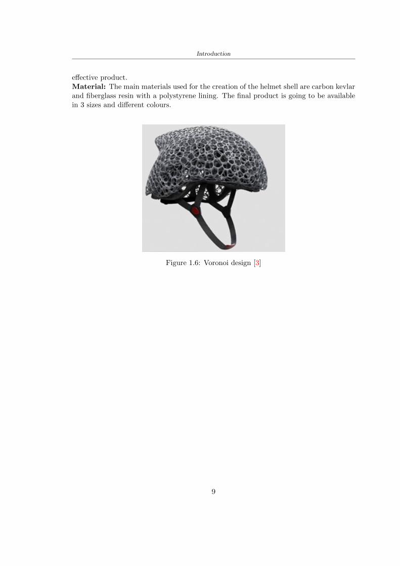
Introduction
effective productMaterial The main materials used for the creation of the helmet shell are carbon kevlarand fiberglass resin with a polystyrene lining The final product is going to be availablein 3 sizes and different colours
Figure 16 Voronoi design [3]
9
Chapter 2
State of the art
21 Standards
The specification about the materials specific tests methods manufacturing to realize ahelmet shall be drawn up by the following standards
- American Society for Testing and Materials (ASTM) is a globally recognized leaderin the development and supply of international standards The World Trade Organiza-tion Technical Barriers legislate it to Trade (TBT) Committee
- The European Committee for standardization (CEN) composted by the nationalbody of Austria Belgium Bulgaria Croatia Cyprus Czech Republic Denmark EstoniaFinland Former Yugoslav Republic of Macedonia France Germany Greece HungaryIceland Ireland Italy Latvia Lithuania Luxembourg Malta Netherlands NorwayPoland Portugal Romania Slovakia Slovenia Spain Sweden Switzerland Turkey andUnited Kingdom
In this study the standard specifications show in the Table 25 will be taken intoaccount the first column contains the Standard name in the designation column theletter with the first number classifies the specification and the second number identifiesthe year when they were published or the year when the last revision was realized
211 Headform
Before realizing a helmet it is necessary to define the headform It is the geometricalrepresentation of the head without facial features and ears but the fundamental axis isrepresented
Planes definitions
bull Basic plane an anatomical plane that includes the superior rim of the externalauditory meatuses (upper edge of the external openings of the ear) and the inferiormargin of the orbit (the lowest point of the floor of the eye socket)
10
State of the art
STANDARD DESIGNATION CONTENT
Standard specifica-tion for headforms
F2220-15 This specification identifies the head-forms used for testing protective head-gear in individual ASTM Internationaltest methods and performance stan-dards [12]
Standard specifi-cation for helmetsused in recreationalbicycling or rollerskating
F1447-18 This specification recognizes the desir-ability of lightweight construction andventilation however it is a perfor-mance standard and is not intended torestrict design [13]
Standard test meth-ods for equipmentand procedures usedin evaluating theperformance charac-teristics of protectiveheadgear
F1446-20 These test methods specify equipmentand procedures used for testing pro-tective headgear Individual ASTMperformance standards (standard spec-ifications) will use these proceduresand equipment Test conditions pass-fail criteria and other performance re-quirements will be specified in the in-dividual performance standards [14]
Headforms for use inthe testing of protec-tive helmets
BS EN 9602006 This European Standard specifies thedimensional and constructional detailsof headforms for use in the testing ofprotective helmets [6]
Helmets for pedal cy-clists and for usersof skateboards androller skates
EN 10782012+A1 This European Standard specifies re-quirements and test methods for hel-mets worn by users of pedal cyclesskateboards and roller skates Require-ments and the corresponding methodsof test are given for the following- construction including field of vision- shock absorbing properties- retention system properties includingchin strap and fastening devices- marking and information [5]
Table 21 Standard specifications
bull Coronal plane an anatomical plane perpendicular to both the basic and midsagittalplanes and passing through the superior rims of the right and left external auditorymeatuses The transverse plane corresponds to the coronal plane
11
State of the art
bull Midsagittal plane an anatomical plane perpendicular to the basic plane and con-taining the midpoint of the line connecting the notches of the right and left inferiororbital ridges and the midpoint of the line connecting the superior rims of the rightand left external auditory meatuses [12]
Figure 21 Anatomical planes [12]
Planes and reference points
In agreement with the Standard BS EN 960 [6] it is possible to define different charac-teristic planes like shown in Figure 22
bull Reference plane for a given headform when erect the horizontal plane located ata vertical distance rsquoyrsquo measured down the central vertical axis from the centre ofthe crown All horizontal datum levels are quoted relative to this plane
bull AArdquo plane for a given headform the horizontal transverse plane is located at avertical distance 127 mm above and parallel to the reference plane This plane isdeemed to correspond to the level of the lower edge of the headband of a helmetIt is the basis upon which the size designation of a helmet may be specified
bull Central vertical axis vertical axis lying along the intersection of the vertical longi-tudinal plane and the vertical transverse plane
bull Centre of gravity of the three-quarter headform - point A for a given headform thepoint on the central vertical axis located at a vertical distance 127 mm above thereference plane
12
State of the art
bull Centre of gravity of the full headform - point G for a given headform the point onthe central vertical axis located at a vertical distance rsquozrsquo below the reference plane
bull Geometric centre - point R for a given headform the point on the central verticalaxis located at its intersection with the reference plane
Figure 22 Principal planes and reference points of a headform [12]
212 European Standard and American Standard
Location of gravity centre
Between the European Standard and American Standard there are differences the firstfor the location of the gravity centre
bull BS EN 960 the centre of gravity is located within a 10 mm radius of Point G
bull ASTM F1447 centre of gravity of the headform must be within a 10 vertical conefrom the centre of impact and lie within a rectangular area 28 by 128 mm
13
State of the art
The size of the head and helmet
bull ASTM F2220 to measure the external dimension for full headform the distancefrom the reference plane to the top of the headform There are different dimensionsF2220 (A if the measure is 897 mm minus C with 93 mm minus E with 96 mm minus J with1025 mm minusM with 107 mm) Then with this classification it is possible to extractthe dimension of xyz (mm) with the following Table 22
Table 22 Location of Reference Line [14]
bull BS EN 960 to obtain the size designation and the headform masses this Standardconsiders the measure of xyz (mm) in Figure 21 The possible designation are 21from 445 to 645 some of these are shown in the Table 23
Thanks to the size designation with the Standard BS EN 1078 there is the possibility todefine the inside circumference of the helmet and this it is shown in the following Table24
Table 23 Dimensions about the reference lines in Figure 21 and headform masses [6]
213 Field of vision - BS EN 1078
Apply a load of 50 N on the crown of the helmet in order to stabilize the helmet on theheadform To avoid having an occultation of the visual field Figure 23 it is better tofollow this angle measures [5]
bull horizontally min 105 from the longitudinal vertical median plane to the leftand right hand sides
bull upwards min 25 from the reference plane
bull downwards min 45 from the basic plane
14
State of the art
Table 24 Inside circumference of helmet [5]
Figure 23 Field of vision (a)(b) [5]
214 Test impact area
Standard EN 1078 will be considered for this study which defines the parameters helpfulin performing the shock absorption test The drop test impact consists of an impact ontwo anvils of flat surface or kerbstone
In the Standard is specified the Test Area where the impact is to be performed Thefirst thing is to apply a vertical load of 50 N on the crown of the helmet in order to
15
State of the art
stabilize the helmet on the headform [5]1 Draw the AArdquo line (in the AArsquo plane) on the helmet2 Draw a line on the helmet parallel to and approximately 20 mm above the AArdquo line(for use as an angular measurement datum line)3 Mark the helmet at points B1 and B2 These points are the sideways horizontalprojection of point B onto the outer surface of the helmet4 Draw a line RRrsquo on the helmet passing through B1 and B2 the line being angled 10
upwards toward the front of the helmet relative to the datum line drawn in d) The areaabove the line drawn in f) is the test area for impacts on the flat anvil The area abovethe line RWArdquo is the test area for impacts on to the kerbstone anvil
Figure 24 Definition of test impact area [5]
215 Anvils and environmental conditions
EN 1078
During the validation process each of the 30 helmet target points was impacted ex-perimentally and numerically under three environmental conditions (-20C +50C andhumidity)
The impact should never exceed 250 g for impacts with velocities corresponding to 542ms on a flat anvil and 457 ms on a kerbstone anvil These are theoretically equivalentto 1497 mm and 1064 mm drop heights respectively [5] About the characteristics of theanvils according to EN 1078 these depend on the type in the case of
bull Flat anvil it has a circular form with a diameter of 130 plusmn 3 mm with 25 mm ofthick
16
State of the art
bull Kerbstone anvil face inclined at 525 plusmn 25 to the vertical and edge with aradius of 15 plusmn 05mm The height shall be not less than 50 mm and the lengthnot less than 125 mm [5]
According with the regalement EN 1078 [5] it has been possible to realize the volumes inthis work the Flat anvil has a diameter of 130 mm and a height of 25 mm the kerbstoneanvil has a horizontal edge of 130 mm a height of 51 mm a length of 126 mm and theedge that impacts the helmet has a radius of 15 mm The anvils are represented in Figure25
[a] [b]
Figure 25 Flat anvil [a] and Kerbstone anvil [b]
EN 13087-11 (Proposal)
A proposal of November 2018 (EN 13087-11) talks about oblique impact tests (Rotationaltest method) [15] Define a method to measure rotational energy absorption in tangentialimpacts in short duration impact situations the velocity considered by Adanty et al [1]is 65 ms The same anvils of the Standard EN 1078 are used the flat anvil and theKerbstone anvil but the difference is the vertical drop towards an impact angle between30-60 the degree considered by Adanty et al [1] is 45
Three different rotations are considered [34]
bull Rotation around X-axis contact point on the side of the helmet resulting in arotation around X-axis Initial position of the headform X- Y- and Z-axis 0
bull Rotation around Y-axis Contact point on the upper part of the helmet resultingin a rotation around Y-axis Initial position of the headform X- Y- and Z-axis 0
bull Rotation around Z-axis Contact point on the upper part of the helmet resultingin a rotation around Y-axis Initial position of the headform X- and Z-axis 0 and65 around Y-axis
17
State of the art
Figure 26 (a) The current cycling helmet standard for the EN 1078 [5] (b) Theproposed standard (EN13087-11) as described by the European Committee for
Standardization (CEN) [15][1]
22 Materials
221 EPS Foam
As mentioned in Chapter 13 the material most commonly used for making the helmetis the EPS Mustafa et al [25] analysed the EPS with four different density values of 50kgm3 64 kgm3 80 kgm3 and 100 kgm3 rdquoThe drop impact simulation model wasused to test the impact attenuation of the helmet with different densities The drop testwas performed on four impact locations top front and sidesrdquo
The impact velocity of the helmet and headform was set at 544 ms The lowestpeak linear acceleration was recorded at the top location and a density of 64 kgm3 with14814 g This study sets out to determine the effect of the user-centered helmet designwith different foam densities (from 50 kgm3 to 100 kgm3) on the impact attenuationof the bicycle helmet
Kroeker et al [19] tested the helmets at three impact speeds 30 plusmn 001 ms 63 plusmn002 ms and 78 plusmn 001 ms
They established the mean value about bulk density in a helmet with EPS foam is666 considering HIC and Peak Acceleration test The global range is between 64 kgm3
and 75 kgm3
Kroeker et al [20] established the foam for kids helmets is 64-88 kgm3 and for thetraditional helmets is 60-100 kgm3
Trzaskalska et al [36] controlled the influence of polymer liner density on energy ab-sorption during impact They discovered the best properties have samples whose densityis between 54 to 60 kgm3
Cui et al [10] considered the density of each layer from the values of 25 50 60 80and 100 kgm3 and they realize a 45 grades side impact and normal crown impact Theresult is a density of 64 kgm3
Wei et al [38] discovered from their test results that EPS has a buffer layer density
18
State of the art
of 60 kgm3 is the most reasonable
Foam densityrsquos values - Literature
Authors Densityrsquos values
Mustafa et al [25] 64Kroeker et al [19] 64 - 75Kroeker et al [20] 60-100 (traditional) and 64-88 (kids)
Trzaskalska et al [36] 54 - 60Cui et al [10] 54Wei et al [38] 60
Table 25 Table with foam (EPS) densityrsquos values
The other are mean values obtained by CES EduPackrsquos program about this material
- Density ρ = 6451kgm3
- Youngrsquos Module E = 275 MPa
- Poissonrsquos ratio ν = 0275
- Yieldrsquos stress σ= 09 MPa
- Elongation at fracture = 45
222 CES Edu Pack - Material selection
CES Edupack software was used to satisfy the idea of creating a lightweight helmetby printing it in 3D and having the possibility to insert the desired characteristics ofthe material and therefore select it To make a choice I used level 3 of engineering(advanced) selecting the following criteria of the material bio-material biodegradablea polymer of concentration 20 - 100 which complies with the rsquoEuropean Restrictionon Hazardous Substances (Rohs) standardsrsquo regarding the composition of the materialensuring that it does not contain a high percentage of toxic substances compared to theestablished percentage In addition it must have proper durability in contact with coldwater (imagining a possible rain) and rsquogoodrsquo durability to UV radiation
According to Ashbyrsquos method [2] to select a material it is possible to follow thefollowing steps
1 Establish the function of the product What does the component doThe helmet is an instrumental use to protect the head during an impact this characteristicdepends on materials and qualities It can prevent an injury which depends on materialsand design because it has to be of the right head size It would be comfortable becauseit must be worn and it must give security to the person wearing it (by design) In thefollowing Table 26 the analysis of the functions
19
State of the art
Ranking Function description Depends on
1 Head protection (energy absorbing) Material2 Head protection (energy absorbing) Design3 Head protection (injury prevention) Material4 Head protection (injury prevention) Design5 Comfortable Material6 Comfortable Process
Table 26 Ashbyrsquos method functions
2 The objectives that are targets for the design the material is to bemaximised or minimisedTo manufacture and market a product objectives such as minimizing weight cost orenvironmental impact must be considered In the following Table 27 the analysis of theobjectives
Ranking Title Objectives description
1 Mass Minimize The mass has to be thesame or lower
2 Cost Minimize everyone should have theopportunity to buy it
3 CO2 footprint Minimize CO2 emission
4 Corrosion Minimize high strength because itcan be in contact with the water
5 Pleasant to touch Maximize it is not a rough materialbecause it has to put on and put off
by hands
6 Refractive index Minimize it must not reflect light
Table 27 Ashbyrsquos method objectives
3 Definition of constrains What essential conditions must be meetEstablish constraints is essential to complete the function of the instrument Examplesof constrains are Table 28
4 The limits characteristic independent of the material that does not influencethe physical properties In the following Table 29 the analysis of the limits
20
State of the art
Title Loading case Constraintsdescription
Material index(Max-Min)
Stiffness Column in compression Tie in tension
Mass Min
Stiffness Column in compression Tie in tension
Cost Min
Stiffness Column in compression Tie in tension
CO2 Min
Strength Column in compression Tie in tension
Mass Min
Strength Column in compression Tie in tension
Cost Min
Strength Column in compression Tie in tension
CO2 Min
Table 28 Ashbyrsquos method constrains
223 PLA with natural fiber and PLA LW
Initially the best material that met the desired criteria was searched From this study itwas found that the material closest to having the required characteristics is the PLA 30natural fiber as shown in the Figure 27 which shows the graphs obtained relating tothe relationships between Youngrsquos Module and density the objective to reduce the massper unit of compressive stiffness and strength to reduce the CO2 footprint per unit ofstiffness and strength and mass per unit of compressive strength
Performance index IR
The stiffness criterion has the following characteristics
m = A lowast L lowast ρ (21)
ε =σ
E=
FA
E(22)
A =F
ε lowast E(23)
21
State of the art
Ranking Title Function description
1 Biocompatibility It is the ability of a material the abilityof the material not to cause any local or
systemic adverse response in therecipient of the material
2 Biodegrability Biodegradable material do notbiodegradable under anaerobic conditions
3 Biomaterials - all The terms is used for biological naturalbio-derived bio-inspired material
4 RoHS (EU) Compliantgrades
Restriction of the use of certin prohibitessubstances (mercury cadmium
hexavalent chromium)
5 Polymer 20-100 (from the table with Plasticpolymers)
6 UV Resistance at UV sunlight
Table 29 Ashbyrsquos method limits
A =F lowast L lowast ρε lowast E
(24)
With fixed variables- F (the load) L (the length)With variables that depend on the material- E (Youngrsquos Module) ρ (density)
In general when a chart is created the distribution of the mass is represented in thefollowing modality like in Figure 27 [b] where the materials above the line have a lowermass while those below a greater mass
Following the results of the CES Edupack program that had selected the PLA withnatural fibers as the best the first print of the helmet was made with this materialusing as support the PVA Initially the result seemed satisfactory the helmet had a highdefinition but a fundamental problem was found by reducing the helmet in the water toallow the supports of PVA to dissolve In the act of diving in fact after ten minutessome parts of the helmet especially the front and rear have disintegrated making thehelmet unusable Because of this problem it was necessary to change the material
22
State of the art
[a]
[b]
Figure 27 CES EduPack Mass per unit of compressive stiffness [a] Youngrsquos Moduleand density [b]
Further investigations carried out by the Mondragon Unibertsitatea Additive Man-ufacturing Department revealed a new material the PLA Low Weight which during3D printing allows to obtain a weight of 65 lower than that which could be obtainedfrom the classic PLA as reported in the technical sheet of the filament produced by thecompany Colorfabb [7]
The investigation team of the Composite Department carried out tensile tests withsamples 3D printed at different temperatures as suggested by the manufacturer to obtainthe technical characteristics The temperatures examined are 200 220 250 260The datasheet shows the density can have values between 04 - 124 gcm3 the bed has
23
State of the art
to have a temperature between 50 - 60 the printing speed has to have values between40 - 80 mms This typology of PLA is expandible so much that rdquoAt around 230 thismaterial will start foaming increasing its volume by nearly three timesrdquo [7]
T[C] Section [mm2] Volumen [mm3] Mass [g] ρ[kgm3] E [Nmm2]
200 42235 1030117 12 1165 328807
220 43805 1655821 18 1087 265795
250 52412 1948139 17 873 178058
260 59655 1454377 12 825 117047
Table 210 Values about PLA LW tensile tests of MU Additive ManufacturingDepartment
From the tests that have been carried out on the material at different temperaturesthe printed sample is better at 250 with a volume of 1948139 mm3 and a section of52412 mm2 as shown in Table 210 For this reason the specific of the material thathave been taken into consideration are the following
- Density ρ = 873 kgm3
- Youngrsquos Module E = 1750 MPa
- Poissonrsquos ratio ν = 033
- Yieldrsquos stress σ = 2948 MPa
- Elongation at fracture = 491
23 Bio-inspired structures
When we talk about bio-inspired structures to nature we refer to structures that allowobtaining a low weight for the model that is realized and excellent absorption energy dur-ing the impact Recently the structures that have been most used in the biomimetic fieldare the rdquocolumns structures sandwich structures plates honeycomb and foamsrdquo[26]but aiming to achieve a structure increasingly with high absorption energy new struc-tures derived from plants and animals such as beetle horsetail turtle bird beak havebeen analyzed The first to create multi-cells tubes helicoidal structures the second tomulti-corner tubes [26]
The authors analyze the specific energy absorbed (SEA) by bio-inspired sandwichstructures per unit mass which can be derived from the following equation
EA(d) =
int dmax
0F (x)dx (25)
SEA(d) =EA(d)
m(26)
24
State of the art
Where EA is the energy absorption rdquomainly used to evaluate an energy absorberrsquosability to dissipate crushing energy through plastic deformationrdquo F(x) is the crashingforce dmax is the effective deformation distance [26]
What derived from their investigations is that having regard to a density of between0 and 1000 kgm3 the volumetric energy absorbed is higher for the beetle-inspired struc-tures than the others as shown in Figure 28 Based on this consideration it was chosento draw the helmet following this geometry
Figure 28 SEA of bio-inspired sandwich structures [26]
231 Beetle structure - Design of the model
To develop and increase lightweight high-strength and optimize bio-mimetic functionaland structural materials the trabecular structure of the beetle elytron is studied Thesingle structure is realized following the requirements cited by Zhang et al [39]
To realize the beetlersquos structure it is not enough to have information about the lengthof the side of the hexagon and the thickness but it is also necessary to take into accountthe relationship between the diameter of the circumferences present on the vertices ofthe hexagon and the measurement of the side The representation of a single cell is inFigure 29 It is shown in [a] a general structure with an edge of 12 mm circumferencersquosdiameter of 6 mm and thickness of 16 mm in [b] is shown the height of 20 mm
For the construction of the helmet a thickness of 12 and 16 mm was used the imageconcerns a proportion between the length of the hexagon side and the diameter of the
25
State of the art
circumference The side (distance between the centers of two circumferences) is twice thediameter measurement
[a] [b]
Figure 29 Beetle structure
232 Specific stress - PLA LW and EPS foam
To test the beetle structures compression tests were investigated The PLA LW structurewas inserted in a rsquodiskrsquo with a diameter of 100 mm and a height of 20 mm The area andthe volume of the disk is correspondingly 7854 mm2 and 157 10 mm3 The structuresexamined have different dimensions the edge L (distance between two centers of thecircumferences) had the following measures 9 10 12 14 16 mm the thickness of thecircumferences and edges are respectively of 16 mm for every structure and 12 mm forthe structure with L = 16 mm
The test was carried out with the Hoytom HM-D Testing Machine with capacitiesbetween 5 and 100 kN The test models were subjected to displacement loading at a rateof 1 mmmin as referenced by Chen et al[18] with a cylindrical specimen The specificstress of the structures was compared with the specific stress of a generic EPS helmetthe photos about it are shown in Figure 210 The EPS helmet structure is granular withpores inside The different grains dimension and these pores can be the reason for whichthe Stressrsquos values are between two values 07 and 116 MPa
Four parts of the EPS helmet were considered in the test the dimension and relativecharacteristic are in the Table 211 where m = mass A = area F = load ρ = densityR = stress Rρ = specific stress To calculate the values of stress about PLA structuresand EPS foam compression test graphs were been analyzed The stress value for eachstructure was calculated considering the single load the single area and the averagedensity value (14055 [kgm3])
The stress values of the PLA structures (Figure 211) and other characteristic valuesare in Table 212 where m = mass A = area F = load ρ = density
26
State of the art
[a] [b]
[c] [d]
Figure 210 EPS generic helmet helmet pictures [a] [b] and internal structureExternal granular structure [c] and pores [d]
[a] [b] [c]
Figure 211 PLA LW disks Grasshopper structure [a] PLA LW structure of 14 mm[b] PLA LW structure compressed [c]
27
State of the art
The results of the load-displacement graphs are affected by the geometry of the diskthe target is to valid for any shape or size for this is preferred to realize a diagramthat depends from σ (or stress) and the deformation ε (or strain) which can be definedrespectively as
σ =F
A0(27)
ε =l minus l0l
(28)
where F is the load during the test A0 is the area l0 is the initial length and l is thelength when the load is applied The areas considered for the EPS cube is reported inTable 211 in the second column the areas of the PLA structure is 7854 mm2 like thearea of the circumscribed disk
The values compared are shown in Table 213 and the graphs obtained by Matlabcode to analyze the recorded data of the compression machine are in Figure 213 and inFigure 212
Considering that the data provided by the compression machine are subject to noiseand disturbances it was decided to convert the original curve into polynomial type curvesthat allow obtaining the best interpolating curve for the data in question To obtain themit was divided the recorded data into two groups the first part from 0 until the end ofthe linear part and the second when the curve becomes linear again The best-fitting (inthe least-squares sense) was performed using the polyfit and polyval functions of MatlabThe first returns the coefficients of the p(x) with n degree the second evaluates p(x) ateach point in x The polynomial formula p(x) is shown in the Equation 29
pn(x) = anxn + anminus1x
nminus1 + + a2x2 + a1x+ a0 (29)
where a0 an are constants and x is the indeterminate The choice of the degree ofthe polynomial was made based on the criterion of wanting to obtain linear curves thatrespected the elastic trend at the beginning of the graph For this reason the degree ofthe polynomial is 1 Subsequently I searched through the intersection of the two lines forthe point that is equivalent to the maximum stress that marks the end of linearity
This value for EPS and PLA LW is the R [MPa] in the Table 213 The average stressvalue for PLA LW is 139 MPa and for EPS is 094 MPa The specific stress (Rρ) is 18MPa lowast m3)kg for the EPS found in CES 669 MPa lowast m3)kg for the EPS foam of thegeneric helmet and for PLA LW is 1161 MPa lowastm3)kg an intermediate value betweenthe two which is what we wanted to achieve
28
State of the art
m [g] A [mm2] F [N] ρ [kgm3]
EPS (CES) 50
16 9234 1063 13864
18 879 593 13651
21 858 833 14237
24 864 564 14468
Average value 14055
Table 211 Compression stress generic EPS helmet
L [mm] t [mm] m [g] F [N] ρ [kgm3]
9 16 214 7250 1363
10 16 192 5560 12467
12 16 201 8190 13051
14 12 138 8000 8961
Average value 12027
Table 212 Compression test PLA structures
PLA LW structure EPS structureρ= 12027kgm3 ρ= 14055kgm3
Edge [mm] R [MPa] Rρ103 Number R [MPa] Rρ103
EPS (CES) 09 18
9 173 1269 1 116 824
10 139 1114 2 08 568
12 138 1057 3 105 746
14 108 1205 4 077 540
Average value 139 1161 094 669
Table 213 Specific stress calculus PLA LW and EPS calculus ρ = density R = stressRρ [(MPa lowastm3)kg] = specific stress
29
State of the art
Figure 212 Compression test Stress-Strain diagrams - EPS
Figure 213 Compression test Stress-Strain diagrams - PLA LW
30
Chapter 3
Methodology
31 3D scan
311 3D Sense 2 scanner and Meshmixer - Reverse reconstruction
Standardized measures were not taken into account for making the helmet but the sizewas obtained through a 3D scan of my head
The scanner used is 3D Sense 2 by 3D Systems which has a minimum scanningvolume of 20 x 20 x 20 cm and a maximum scanning volume of 300 x 300 x 300 cmTo scan my person I was helped to get a full view at 360 at an appropriate distanceReal-time visualization of the captured images was shown through 3D Sense softwareThe idea of scanning the head with the scanner refers to the methodology used by Wanget al [30] They used a reverse reconstruction functional for me to realize the helmetsurface made to measure my head and like them a silicone pool cap was used to makescanning as smooth as possible The authors claim the head scan rdquocan also be used toobtain information about the objectrsquos surface which is then reconstructed utilizing thecomputerrsquos three-dimensional model via reverse modelling softwarerdquo [30] that in my caseis Autodesk Meshmixer
The files it was could get from the scan were stl obj and ply format they wereexported to obj to work in the next step with Autodesk Meshmixer that allowed tomodify and homogenize the 3D image obtained from the scan
In Meshmixer through the selection and delete commands the superfluous parts weredeleted that had been acquired and with the inspector and the DrawDraw2 commandsthe vertices were moved locally along a pre-defined direction and with Smooth the surfacemore homogeneous was made The sequence of steps is shown in the Figure 31
312 3D scan analysis and extraction of features
In Chapter 2 the directives imposed by the BS EN 960 Standard were examined concern-ing the definition of the helmet and the measures to be respected in the field of visionand the part of the helmet was to carry out impact tests
In Figure 32 the features defined complying with the Standardrsquos rules are repre-sented To define these features the software NX was used The angle in the subfigure
31
Methodology
[a] [b] [c] [d]
Figure 31 Sequence of 3D head scan 3D scanner acquisition [a] scan after reparationwith Meshmixer [b] solid scan vision frontal and lateral [c] [d]
[b] is bigger than 105 (as defined by the Standard) while the degree in the subfigure [c]is 25 By defining the construction lines to be respected of the helmetit was necessary todraw the design of the surface not using the software NX but changing with Rhinocerosto create a SubD or SubDivision surface
32 Helmet design
321 Rhinoceros - Helmet surface
After realizing a rsquocleanrsquo Wang et al [30] subdivide with lines and then sectors the headto create the surface of the helmet They used the technique of NURBS a Non UniformRational Basis-Splines which mathematically models a 3D geometry while thanks tothe Rhinoceros 3D organic shapes was draw SubD surfaces These geometries allow tosplit the mesh into small polygons and consist of lines with which easily the shape ofthe object can be modified with a surface already created changing the position of aline automatically the remaining part of the geometry adapts to the changes With thistechnique the rsquosurface basersquo of the helmet was realized with the size of my head Therepresentation of the realized SubD is in Figure 33
322 Grasshopper - Helmet structure
The next idea is the creation on the surface of the beetle structure with different di-mensions modelling the helmet that is not a linear surface It was decided not to buildthe structure with a software CAD because to model an already complex structure on acurved surface would mean to model a cell for a cell
To solve this obstacle a Rhinoceros plug-in was used Grasshopper GH idealized byRobert McNeel and associates creators of Rhinoceros Using GH does not mean drawinggeometries by connecting points and drawing tools because it is based on algorithmicmodelling used in architecture and engineering for 3D modelling
The modelling takes place through a node diagram that the software will convert intoa code-algorithm in GH it is possible to define the variables and parameters and inRhinoceros in real-time it is possible to view the object GH allows for varying the
32
Methodology
[a] [b]
[c]
Figure 32 Featurersquos extraction in [a] is represented the impact line in [b] and [c] twoprospective about the definition of the field of vision
[a] [b] [c]
Figure 33 SubD representation lateral view [a] top view [b] front view [c]
geometry to your liking by varying a simple parameter of the diagram as everything willbe remodelled according to the change made
In the following Figure 34 it is shown an example of a structure that was used fordistinct subgroups of helmet areas The idea was to insert smaller cells in the frontal andlateral zone and larger ones in the upper area In the first image [a] is shown the part of
33
Methodology
the helpful diagram to create the beetle structure to establish the size of the cells andthe extrusion the second image [b] contains the part of the diagram with which I appliedthe structure previously created to the SubD
The structure used to place and adapt the beetle structure to the surface is theSrfMorph while the yellow rsquowindowrsquo that contains numbers serves to select the parts ofthe surface where to apply the geometry created In accord with the GH diagram in
[a]
[b]
Figure 34 Grasshopper diagrams
Figure 34 [a] it is possible to see the steps executed to realize the structure Initially inthe xy-plane a hexagonal grid was drawn through the Hexgrid command in which youcan input the length of the hexagon edge and the number of grid elements (selected bytrial) Then the circumferences was drawn in proportion to the hexagon dimensions asspecified in the Chapter 2 and shown in Figure 35 [a] In figure [b] the rsquocutrsquo made atthe circumferences is visible this subdivision was necessary for printing purposes In thelast photo [c] the structure highlighted in green in [b] was extruded setting a distance
34
Methodology
of 20 mm
[a] [b] [c]
Figure 35 Construction sequence of the geometry of the helmet
In the diagram in Figure 34 [b] there is the application of the structure created bi-dimensionally to the SubD surface of the helmet visible by unlocking the SubD commandof the diagram and in Figure 36 [a] Upper this the referential geometry of the group ofsurfaces was superimposed where it was to be applied the newly created structure (visiblein darker red) the SubD indices are in the yellow box of the diagram
Through the SrfMorph command the location of the structure was granted In Figure36 [b] at the darkest red of the figure [a] with the above command it was possible toplace the structure
[a] [b]
Figure 36 Application of the geometry created to the helmet surface
Overall the diagrams with specific structures are five one for the front two equal forthe side parts one for the top shown in the previous Figure 36 and one for the back
The hexagons in the structure have a dimension varying between 8 mm and 14 mmof side the largest is found at the top later at the back in the sides and the smallest atthe front In Figure 36 [b] the presence of not only hexagonal structures is visible Thegeometry used does not allow the homogeneous arrangement on the entire surface andrequires different structures Automatically the choice of GH to optimize the structurewas to insert quadrilateral
As described above the helmet has different dimensions of the structure divided asvisible in Figure 36 in a quadrilateral This causes a discontinuity between zones withdifferent sizes due to the geometry of the construction
To eliminate this problem and realize the design homogeneous grids were inserted
35
Methodology
in the affected areas as shown in Figure 37 This insertion however proved to beinteresting and strategic researching in this regard studies were realized to demonstratethe insertion of a rectangular grid inside the hexagon grid was helpful for the transmissionof stress in the structure As cited by Sun et al [40] rdquothe mechanical properties of thesesandwich structures are often limited by local failures such as face-core debonding or corecollapserdquo Carrying out compression tests have effectively demonstrated that the insertionof the grid allows rdquoprovided increased stiffness specific stiffness energy absorption andcritical loadrdquo [41] As shown in the graphic [c] of the Figure 37 the honeycomb structuregives a force of 7 kN while with a grid the value is 11 kN and with the combinationexceeds 22 kN In addition in the left front a plaque to customize the helmet wasprepared Figure 37 [a]
[a] [b]
[c]
Figure 37 Grid in the helmet [a] hybrid structure with hexagons and grid [b] [40]compression test results of the hybrid structure [c] [41]
33 3D Print
After having achieved the CAD (Computer Aided Design) of the helmet in order tobe printed it must be converted and saved in format STL (Standard TriangulationLanguage) - Binary compatible with the printing machine and useful for transformingsolid object surfaces into triangles The steps to be taken are the following
bull CAD file realization
bull CAD export in format STL to Simplify 3D the software that shows slider layersand then- rotate and position the object according to geometry and the positioning of any
36
Methodology
supports- setting printing parameters- item manual andor automatic positioning of supports- slider display layers
bull import file gcode to printer
331 Printer and parameters
The program used to visualize how the helmet slices layers before sending it to the printerand to set the parameters is as anticipated Simplify 3D
To make the printing not being a flat geometry it is necessary to place the supportsThe idea was to use water-based supports that the helmet would automatically dissolveonce placed in the water After testing different types of water-soluble PVA the choicefell on eSun 3D Printing Filament PVA (water-soluble support) Before choosing theoptimal position for printing several tests were carried out and to decrease the numberof the supports significantly and allows an optimal printing of the outer part an emptyrsquospherersquo that self-sustains below the helmet was placed as shown in Figure 38
In the image [a] you can see the first print position tried with which an external partof the helmet very damaged was obtained because of the contact supports-helmet In [b]the empty rsquospherersquo is shown to optimize the number of supports and in the last photo [c]there is the full version at the end of print
[a] [b] [c]
Figure 38 Printing supports
The printer that has been used for printing is the Raise 3D Pro2 with double extrudersand nozzles of variable size from 02 mm to 1 mm after some test prints with the PLALW and the structure in created the size that allowed me to have a good compromisebetween printing time and accuracy was 06 mm Using 04 mm the printing time wasexcessive even if having the smaller nozzle diameter means having more precision withthe 08 mm nozzle the quality of the structure was not excellent as seen in Figure 38[a]
Another factor that had to be taken into account is the characteristic of the PLA-LWto expand As the printing temperature and the printer used vary the expansion andcharacteristics of the material change The use of the 06 mm nozzle associated with
37
Methodology
Parameter Left extruder Right extruder
01cm Material 01cm PVA 01cm PLA LW
Extruder toolbox index Tool 0 Tool 1
Nozzle diameter 06 mm 06 mm
Extrusion multiplier 1 05
Extrusion width Auto (072 mm) 05 mm
Layer x
Infill Rectilinear - 50
Supports (Automatic and not) Infill 50
Temperature 210 250
General parameters
Primary layer height 03 mm Top solid layer 4
Bottom solid layer 2 Outline 2
Heated bad 60 Speed 40 mms
Table 31 Printing parameters
Raise 3D allowed me to get good results The choice of this printer was not random ithas in fact the characteristic of making extremely precise prints The Raise has accuracyin placing the object on the printing bed of 078 microns on the xy axis and a resolutionfor layers of 001 mm
The final version of the helmet is visible in Figure 39 and it is possible to compare itwith the preview version in Rhinoceros in Figure 310
38
Methodology
[a] [b]
[c]
Figure 39 Views of the helmet
[a] [b]
Figure 310 Views of the helmet (GH version)
39
Chapter 4
Experimental evaluation
41 Experimental tests
411 Drop-weight impact test machine
In order to calculate the contact force peak and the difference of energy absorbed duringthe impact between the reference helmet and helmet with the beetle structure in PLA-LW dynamic impact tests were carried out using the Fractovis Plus an impact testmachine
In this way it is possible to monitor the evolution of the above variables from theinitial to the final instant of the impact The machine can withstand a load with a rangevariable from 2 to 70 kg with a maximum speed of 46 ms and a maximum height of1 m The values chosen for the test are the following 5 kg weight maximum speed andmaximum height The Anvil that was used is a disc diameter of 60 mm
As shown in Figure 41 and explained by Crupi et al [37] the machine consists ofa sensor capable of recording the speed before impact the impactor that can have avariable mass (a weight of 5 kg in my test) a system to guarantee that there are nomultiple impacts after the first and that work as a shock absorber and clamping systemwhere the object to be tested is placed
The tests that have been carried out are in total four two related to the helmetoptimized with PLA-LW and two with two generic helmets of different brand in EPS
42 PLA LW helmet
To perform the dynamic test on the helmet of PLA considering the difficulty of printingit was helpful to use a test helmet with imperfections to understand where the impactwas concentrated in a single part or distributed The images of Figure 42 show a helmetwith not well defined edges and inaccurate print but exactly localizes the impact zoneThanks to this test it was possible to take into account only one helmet area shown inFigure 43 to have the exact curve of the structure bio-inspired with PLA-LW
40
Experimental evaluation
Figure 41 Drop-weight impact test machine [37]
[a] [b]
Figure 42 Test 1 PLA-LW helmet
43 EPS helmet
To carry out dynamic tests and extract the technical characteristics of the helmettwohelmets were bought in a sports store both EPS and being on the market both certifiedThe brands of the two helmets are DTB and VAN|RYSEL and the average weight ofthe two is 223 g Two different helmets have been chosen to have a more certain andclear classification of the characteristics They are shown in Figure 44 and Figure 45
41
Experimental evaluation
[a] [b]
Figure 43 Test 2 PLA-LW helmet
[a] [b] [c]
Figure 44 Test 3 EPS helmet
[a] [b] [c]
Figure 45 Test 4 EPS helmet
44 Results
441 First results - PLA-LW and EPS helmet
Figure 46 shows two types of trends related to the two different models of the helmetThe force evaluated for PLA-LW has higher force peaks but is more concentrated and
42
Experimental evaluation
propagates less than EPS The graph shows the peaks of each curve highlighted with a redcircle In tests 1 and 2 for the PLA-LW as mentioned earlier the values are higher about7301 N for the complete helmet and 3996 N for the portion of helmet This difference isdue to the inaccuracy of the first full helmet during the printing phase In Figure 42 itis visible the low homogeneity and precision Therefore the first test with full helmet wasused only to define the area of interest of the impact which turns out to be localized Forthe other two EPS curves the values are only slightly lower compared to the PLA-LWequal to 3620 N and 3295 N but the trend is much more distributed
Figure 46 Dynamic machine test - Force
With the data obtained from the impact machine it was possible calculate not exclu-sively the value of force but itrsquos also possible to view the energy curves A resume aboutthe values and energy of the force is in the following Table 41
Test Peak force [N] Peak energy [J]
Test 1 - PLA LW (inaccurate) 730130
Test 2 - PLA LW (portion of helmet) 399643
Test 3 - EPS (DTB helmet) 362007 509
Test 4 - EPS (VAN|RYSEL helmet) 329546 4198
Test 5 - PLA with TPU 45421 5022
Table 41 Energy absorbed in dynamic test
43
Experimental evaluation
442 PLA-LW helmet with TPU cover
As it is possible to see in Figure 47 and as highlighted the first tests concerning thebio-inspired structure and the PLA-LW are far from my expectations considering thelittle distribution of force in comparison with the EPS foam and consequently a smallamount of energy absorbed
Figure 47 Dynamic machine test - Energy
To improve this impact damping factor the idea was to create a cover for the helmetin flexible TPU trying to absorb impact energy The TPU used is a flexible material ofthe brand Ninjaflex used in sports by the application in helmets and shoes to cushionbumps during the game Generally in the helmets (baseball helmet for example) theTPU is inserted internally in contact with the head In my case the TPU structurein addition to creating a shock-absorbing and durable cover creates a custom cover thehelmet and for the person This cover was also made with the Raise 3D printer
As shown in the Figure 48 [a] the infill of the part in contact with the helmet hasa percentage of 100 the filling of the other part of the structure is not complete butonly 15 and the internal structure is hexagonal to recall that of the helmet The desireto insert a structure with a rsquoraisedrsquo geometry is for visual and aesthetic reasons as youhave the feeling of greater protection and not filled is inspired by the machine CitroenCaptus whose bumpers (Airbump) are full of air The failure to realize empty structuresis due to the need to place any internal supports not removable
The idea was to create a cover that allow you to see of the internal structure of thehelmet and that protect specific areas the front the two sides the top and the posteriorWhat which was thought for this reason was to create the shape of a flower with four
44
Experimental evaluation
petals Figure 48 [b]In this way to perform dynamic impact tests as shown in Figure 49 [a] the cover was
positioned at the top of the helmet and the impact was performed in the centre of thersquoflowerrsquo which corresponds to the higher upper part where the structure has larger cellsize The impact parameters are the same as those used in previous impacts 5 kg weightmaximum speed and maximum height The Anvil that was used is a disc diameter of60 mm In photo [b] it is evident the difference between the structure that received theimpact with protection (left) and without protection (right) Without protection duringthe impact there was a perforation of the structure with a concentration of force at a locallevel as you can see in the Figure 46 in the case of TPU the impactor did not perforateand crossed the structure thanks to the cover of TPU that cushioned the shock At themoment of impact the impactor bounced
[a] [b]
Figure 48 TPU cover
[a] [b]
Figure 49 PLA-LW with TPU - dynamic impact [a] and differences between thehelmet with TPU and without TPU cover [b]
45
Experimental evaluation
The Figure 410 includes the diagrams relative to the dynamic impacts In [a] thereare already analyzed EPS results in [b] a comparison between the test on the portionof helmet in PLA LW with and without the TPU cover in [c] the overall comparison ofcurves shows a much more similar EPS trend if the TPU is placed above the structure inPLA LW to soften the blow and absorb the same energy [d]
46
[a]
[c]
[d]
Figure 410 Comparison between PLA-LW with TPU and EPS
Chapter 5
FEM Validation
51 Impactor - Anvils definition
Before to start to work in Abaqus it was necessary to search in the literature the materialwith which the anvil was been realized Milne et al [23] established the densityrsquos valuethe Youngrsquos Module and Poissonrsquos ratio for the Flat and Kerbstone Anvil
- Density ρ = 7800 kgm3
- Youngrsquos Module E = 200000 MPa
- Poissonrsquos ratio ν = 03
Inserting the data in the CES EduPack program specifying the mechanical andphysical properties the material corresponding to these characteristics is Stainless steelaustenitic (ASTM F1586) medium-hard
Initially the proposal was to create a conservative system to evaluate the absorptionenergies values and apply this value to a vibration system but the helmet needs dampingto be realized it was impossible to use a system without losses in this modality Thisis why a numerical calculation was carried out by performing two types of simulationsexplicit dynamic step and static step
The idea to realize the theoretical impact is to regard the movement of the anviland not the helmetrsquos movement which is fixed The velocity is the same cited in thenormative EN 1078 542 ms for the Flat anvil and 457 ms for the Kerbstone anvil
In performing the simulations It was given more relevance and perform tests withthe Kerbstone Anvil This choice was done because the geometry with which it is beenrealized (following as defined in the legislation) allows the helmet to be more subjectedto stress this involves the definition of higher stress limits compared to the Flat Anvil
The mesh size that has been used is the same in the case of the simulation of thehelmet optimized in PLA-LW and the full helmet in EPS of 7 mm The impactor isconsidered as a Discrete rigid body with its specific Reference Point (RP) like shownin Figure 51 for this reason it is not a solid but it is composted only by shells Inthe same image [b] there is the FEM representation of the model and in Table 51 thecharacteristic of FEM with quadrilateral (R3D4) and triangular elements (R3D3)
48
FEM Validation
Object Elementnumber
Elements Shape Geometricorder
Global size[mm]
Kerbstone 230 Quadrilateral - R3D4 Linear 7
Kerbstone 8 Triangular - R3D3 Linear 7
Table 51 Mesh element - Kerbstone Anvil
[a] [b]
Figure 51 Kerbstone anvil in the simulation like discrete rigid body [a] and FEMelements [b]
511 PLA LW - Plastic characteristics
The PLA-LW as explained in the Chapter 2 is new material on the market and producedby the only Colorfabb company for this reason few tests have been carried out to defineits technical characteristics and through tensile tests of the 3D printed specimens it waspossible to define an elastic limit as reported in the Table 210
In the context of simulations to reproduce the impact and deformation of the helmetis also necessary to consider the plastic characteristics of the material Not possessingany reference value in this regard tests were performed through a Static Step initiallyand then an Explicit Dynamic Step in Abaqus
The structure chosen to consider as a reference it is one of the structures previouslysubjected to the compression test having the side L=14 mm As for the reproduction ofthe compression disks initially they were reproduced according to the geometry of theHoytom HM-D Testing Machine considering the bodies mentioned above as discrete 3Drigid discrete The measure was the diameter of 200 mm and the height of 20 mm
After an initial analysis it was observed that the computational time of the simulationprogram was very high so it was decided to change the geometry to have a rsquodisk-surfacesrsquo(equally 3D rigid-discrete) which allowed me to have a smaller number of nodes for themesh and consequently a better computational time The representation of the opti-mized structure in PLA-LW and the disks used for simulated compression is in Figure 52
49
FEM Validation
[a] [b]
Figure 52 Representation of the samples used for the simulation of the compressiontest In Figure [a] the disks of the Hoytom HM-D Testing Machine in figure [b] the
representation of the same as simple surfaces
As shown in Figure 52 the disks are considered 3D discrete hard bodies so it waschosen for both a point the reference point RP where to apply the characteristics relatedto the two bodies As for the compression test it was established
bull the movement of a disk and fixed the second through a boundary condition impos-ing an Encastre therefore unable to move and rotate in xyz directions
bull for the opposite disk the boundary condition relative to the 15 mm displacementwas applied which is the parameter that it was observed to determine the end ofthe compression with the machine This shift is shown by the orange arrow in figure[b]
bull between the upper surface and the disk e the disk with the lower surface it wasinitialized a general contact with normal behaviour through rsquohardrsquo contact andtangential behaviour with a coefficient of friction of 02 with directionality imposedon rsquoisotropicrsquo
The next step was to define the mesh of the components whose parameters are shown inTable 52 while the representation of the FEM is in Figure 53 with the representationof the simulation and real compression test
Object Elementsnumber
Typology Geometricorder
Globalsize [mm]
Disk (14mm) 80910 hexaedral - C3D8R Linear 07
Impact disks 206 quadrilateral - R3D4 Linear 20
Impact disks 6 triangular - R3D3 Linear 20
Table 52 Mesh element - Compression test simulation
As previously announced a static simulation was initially performed with a StaticStep with Step Time equal to 900 (obtained going to consider the speed of 1 mmmin of
50
FEM Validation
[a]
[b] [c]
Figure 53 FEM representation [a] and compression test simulation [b] and realcompression [c]
the compression test and the displacement of 15 mm) However the complex geometryof the structure and the high time set by Step Time did not allow a correct definitionof the parameters of the plastic characteristics of the material the simulation was notable to continue once reached a Step Time of approximately 220 That is why it waschanged by choosing an Explicit Dynamic step
Leaving all the parameters of the boundary conditions unchanged the Step Time wasmodified imposing it to 001 The ability of the explicit dynamic to work with non-linearand contacting structures allowed me to achieve results The results obtained are shownin Figure 54 with the blue curve and were obtained through the iteration of differentPlastic Strain and Yield Stress values in Abaqus while the red line is the result of thereal compression test a similar curve trend was obtained but it is not possible to obtainthe same curve taking into account problems of printing inaccuracy
512 First test - helmet
The initial idea was to perform a simulation imposing the speed of 457 ms to theimpactor tie the helmet in EPS and PLA and compare the absorbed energies Theproblem it was encountered is related to the mesh of the helmet optimized in PLA andwith minimum dimensions of the elements and distinct elements it was not able to solveit
51
FEM Validation
[a]
YieldStress
PlasticStrain
1 47 0
2 7 001
3 75 005
4 10 01
5 108 1
6 115 15
7 12 2
[b]
Figure 54 Representation of the two curves related to the simulation in Abaqus of thecompression test and the data obtained from the real test to obtain the plastic
characteristics of the material
513 Second test - plane
The first solution is the one shown in Figure 55 To realize the simulation it was realizeda section of the helmet to involve a smaller number of elements and nodes Again thesimulation for the EPS helmet was successful while the simulation with the bio-inspiredstructure was interrupted by excessive distortion of elements
The previous images show the impact is very localized in the impacted area and theidea to achieve a complete simulation is not to consider a curved portion of the helmetbut a plane In this way it was possible to solve the problem and obtain a completesimulation for the bio-inspired structure
FEM element
Below in Table 53 there is the definition of the elements used for the PLA-LW and EPSplane in the simulation to simulate the impact and to control the energy-absorbing whilethe anvil characteristics are described in Table 51
514 EPS impact simulations
In order to proceed with the simulation it was imposed some boundary conditions thatregard ties and forces
bull the movement of the plane is fixed through an Encastre therefore unable to moveand rotate in xyz directions
52
FEM Validation
[a]
[b]
Figure 55 Impact simulation parts of EPS and PLA helmet
Object Elementnumber
Elements Shape Geometricorder
Plane (PLA) 38896 Tetrahedral -C3D10M
Quadratic
Plane (EPS) 2100 Hexahedral - C3D8R Linear
Table 53 Mesh element - plane impact
bull to create the impact it was set a speed of 457 ms at the reference point RP of therigid body which is the impactor Kerbstone Anvil shown in Figure 56
bull between the upper surface of the plane and the impactor it was initialized a Sur-face to Surface contact with normal behaviour through rsquohardrsquo contact and tangen-tial behaviour with a coefficient of friction of 02 with directionality imposed onrsquoisotropicrsquo
bull the rotation in x y z relative to the RP of the rigid discrete impactor body is locked
53
FEM Validation
In addition it was characterized the plane in the part of the materials with the char-acteristic values of the EPS mentioned in Chapter 221 The Von Mises Stress valueapparently low is relative to the Yield Stress of the EPS material equal to 09 MPa
Figure 56 EPS Boundary conditions and Load
515 PLA LW impact simulations
As also required in the case of the EPS plane in order to proceed with the simulationsome boundary conditions were imposed that regard ties and forces
bull the movement of the plane is fixed through an Encastre therefore unable to moveand rotate in xyz directions
bull to create the impact a speed of 457 ms was set at the reference point RP of therigid body which is the impactor Kerbstone Anvil shown in Figure 58
bull between the upper surface of the plane and the impactor it was initialized a Sur-face to Surface contact with normal behaviour through rsquohardrsquo contact and tangen-tial behaviour with a coefficient of friction of 02 with directionality imposed onrsquoisotropicrsquo
bull the rotation in x y z relative to the RP of the rigid discrete impactor body is locked
In addition the plane was characterized in the part of the materials with the characteristicvalues of the PLA mentioned in the Chapter 223 and 511
Figure 58 Boundary conditions and Load
54
FEM Validation
[a]
[b]
Figure 57 EPS impact simulation
52 Results
In Figures 59 and 57 it is shown how the structure in PLA LW has a more concentratedstress distribution of the structure unlike EPS The maximum value for the Von Misesstress is 09 MPa in EPS structure and 3634 MPa in PLA LW structure Once thesimulations were obtained the next step was to go and compare the energies absorbed bythe two structures The energy calculated by Abaqus that has been taken into account isPlastic Dissipation To make a comparison the data of the two energies were representedin a single graph
What emerges from the graph is that about the impact made with the KerbstoneAnvil the energy absorption is more excellent although only slightly for the PLA LWthan for the EPS From the graph in Figure 510 a value of 41 J is shown for the EPSand 51 J for the PLA LW
55
[a]
[b]
Figure 59 PLA impact simulation
[a]
Figure 510 EPS and PLA LW energy comparison - Abaqus simulation
Chapter 6
Head Injury Data
For the statistical analysis the injuries related to the accident data were categorised intothe following types and levels based on the details of the medical report [11] about theEN 1078
bull Head Injury Criterion (HIC)
bull Peak Linear Acceleration (PLAc)
bull Gadd Severity Injury (GSI)
bull Diffuse axonal injuries (DAI)
61 Abaqus simulation
Until now the purpose of the simulations has been to determine which between the twomaterials and the two structures of EPS and PLA LW could absorb more energy duringthe impact but no simulations have been carried out in compliance with BS EN 1078on the helmet impact tests To calculate the injuries listed in the previous paragraphhowever we need the acceleration values in the three directions related to the subjectrsquoshead
To realize it the scan of my head already rsquocleanrsquo was considered of which it has beencalculated the inertia thanks to the automatic SolidWorks calculation and evaluated theweight with the Table 24 the structure of the helmet was placed for the EPS and thePLA LW over the head as shown in Figure 61 Also this time being able to mesh theentire helmet in PLA LW was impossible due to the excessive distortion of some elementsduring the simulation so it has been tried to make a section of the structures of thehelmet and results were obtained
57
Head Injury Data
[a] [b]
Figure 61 My scan head - CAD [a] head imported in Abaqus[b]
Initially the simulation had these characteristics as shown in the following Figure62 considering the helmet was not sectioned As explained earlier it was not possibleto get to simulation in the case of the optimized structure in PLA LW for this reasononly a part of the helmet was considered in both cases shown in Figure 63
[a]
Figure 62 Simulation based on BS EN 1078
58
Head Injury Data
[a] [b]
Figure 63 Simulation based on BS EN 1078 with head
In order to proceed with the simulation some boundary conditions that regard tiesand forces have have imposed
bull two reference points RP were created the first in the inertia centre of the headthe second relating to the Kerbstone Anvil which is a discrete rigid body
bull in the reference point RP of the head in the definition of the engineering features5 kg was inserted for the weight and an inertia I11 = 564464E+07 gmm2 I22 =460654E+07gmm2 I33 = 187302E+07gmm2
bull to simulate the impact it was set a speed of 457 ms at the reference point RP ofthe head in z-axis direction
bull a general contact with normal behaviour through rsquohardrsquo contact and tangentialbehaviour with a coefficient of friction of 02
bull between the upper surface of the helmet and the impactor it has been initializeda Surface to Surface contact with normal behaviour through rsquohardrsquo contact andtangential behaviour with a coefficient of friction of 02 with directionality imposedon rsquoisotropicrsquo
bull the movement between the Kerbstone anvil and the helmet is fixed through anEncastre therefore unable to move and rotate in xyz directions
bull the rotation in x y z relative to the RP of the rigid discrete impactor body is locked
FEM element
As reported in Table 53 the portion of the helmet in EPS has used a mesh with hexahe-dral elements of linear order For the structure (beetle) of PLA LW given the geometry
59
Head Injury Data
complexity it was necessary to use a quadratic order of tetrahedra For the mesh of thehead instead in both simulations have been used quadrilateral elements of linear orderas reported in the Tables 61 and 62
Object Elementnumber
Elements Shape Geometricorder
Head 3755 Quadrilateral - R3D4 Linear
Head 34542 Quadrilateral - R3D3 Linear
Helmet (PLA) 272302 Tetrahedral -C3D10M
Quadratic
Table 61 Mesh element - Head simulation with PLA LW (beetle) helmet
Object Elementnumber
Elements Shape Geometricorder
Head 3755 Quadrilateral - R3D4 Linear
Head 34542 Quadrilateral - R3D3 Linear
Helmet (EPS) 72280 Hexahedral - C3D8R Linear
Table 62 Mesh element - Head simulation with EPS helmet
62 Results
Figure 64 represents the simulation in line with BS EN 1078 concerning the helmet inEPS [a] and the helmet with bio-inspired structure in PLA LW For both simulationsVan Misesrsquo stress has Yield Stress values in the case of EPS which is 09 MPa and theplastic behaviour combination of PLA LW [b]
In the case of head and Kerbstone Anvil stress was not assessed as they were previ-ously defined as discrete rigid bodies
63 Head Injury Criterion
The HIC quantifies head impact severity by incorporating time of acceleration exposureand acceleration magnitude it is calculated in post-processing phase with the followingEquation 61
HIC15 =
[1
(t1 minus t2)
int t2
t1
a(t)dt
]25(t2 minus t1) (61)
60
Head Injury Data
[a]
[b]
Figure 64 Results simulation based on BS EN 1078 with sectioned head
For this analysis a(t) is the acceleration calculated in the centre of mass of the head(corresponding to the reference point RP) expressed in g and the time interval (t2 minus t1)was chosen to maximize HIC over a maximum duration of 15 ms
Matlab and the trapz function were used to calculate the HIC to integrate accelerationover time t2 and t1 were considered initial and final times of the simulation t1 = 0 sand t2 = 10 s time less than 15 s
HIC value of 198 was obtained for EPS and 87 for PLA LW Considering the Hayeset al [16] document about the HIC values and the graph in Figure 65 developed bythe author it is possible to find the percentages related to the different injury AIS1 -AIS6 which correspond respectively to lower and higher severity while in Figure 66 therelative fatality to every value of AIS is shown The values obtained for the HIC andother criteria are shown in Table 63 The HIC value for EPS is 198 for PLA LW it is
61
Head Injury Data
Figure 65 Head injury risk curves based on HIC values [16]
Figure 66 The abbreviated injury score versus fatality rate [16]
87 Analyzing the data and comparing them with the curves of the Figure 65 I obtain
bull a percentage between 20 - 30 of AIS 1 for EPS 10 - 20 for PLA LW
bull a percentage between 10 - 20 of AIS 2 for EPS and 0 - 10 for PLA LW
bull for AIS 3 AIS 4 AIS 5 AIS 6 the percentages for both structures is between 0 -10
Comparing these percentages with the fatality rate of Figure 66 it is clear there is a riskof Moderate and Minor fatality in the case of EPS and PLA LW as all values are between0 and 30
62
Head Injury Data
HIC PLA [g] GSI E [J]
EPS 198 97 361 37723
PLA LW 87 75 169 44102
Table 63 Head Injury Data - values
64 Peak Linear Acceleration
The resultant linear acceleration versus time curve was calculated according to Equation62
γ(t) =radicγ2x(t) + γ2y(t) + γ2z (t) (62)
where
bull γ(t) is the resultant linear acceleration (g)
bull γx(t) is the linear acceleration in x axes (g)
bull γy(t) is the linear acceleration in y axes (g)
bull γz(t)is the linear acceleration in z axes (g)
The value of the impact should never exceed 250g [9] Cripton at all [9] in their studyexamined a helmet with expanded polystyrene (EPS) Figure 68 shows maximum HIC forhelmeted and unhelmeted drops from all heights For each drop height helmets reducedHIC relative to unhelmeted drops IARV value is 180g The acceleration in the two casesis shown in Figure 67 and the maximum values are 97g for EPS and 75g for PLA LWas reported in Table 63 The two values considering a maximum value calculated byCripton [9] of 180g are amply optimal and comply with the standard of 250g
65 Gadd Severity Index
Gadd proposed the Severity Index Criteria shown in Equation 63 Following this crite-rion the GSI values that are over 1000 produce serious internal head injury [33]
GSI =
int t1
0a(t)25dt (63)
Where
bull a is the linear acceleration (g)
bull t is the duration of the impact (s)
I calculated the GSI with the function trapz between 0 and t and the resulting valuesare 361 for the EPS and 169 for the PLA LW which comply with the limit
63
Head Injury Data
Figure 67 Peak accelerations for both helmets
Figure 68 Peak accelerations for both helmeted and unhelmeted drops Numbers overbars indicate peak acceleration For 2 m drop height results stated are the mean value
calculated from three drops [9]
64
Head Injury Data
66 Diffuse Axonal Injury
DAI cases covered all incidences in which neurological injuries occurred as well as con-cussion unconsciousness and coma
In order to assess the risk of head trauma in terms of diffuse axonal injury (DAI)Milne et al [23] defined a model based head injury criteria as follows obtaining theresults in Figure 69
bull 50 risk of moderate neurological injury (DAI1+) Brain Von Mises shearing stressof 28 kPa
bull 50 risk of severe neurological injury (DAI2+) Brain Von Mises shearing stressof 53 kPa
[a]
[b]
Figure 69 Peak intra-cerebral shearing stress computed with the helmet model coupledto the human head model for all impact points (a) Flat anvil (b) Kerbstone anvil [23]
65
Head Injury Data
67 Energy absorbed
In Figure 52 during the impact test between the kerbstone Anvil and the plan with thebio-inspired structure in PLA LW and EPS it was found that the PLA LW althoughwith a small difference of 10 J absorbed more energy in comparison with the EPS Whenthe test is carried out in compliance with BS EN 1078 and the head with a speed of 457ms (corresponding to the kerbstone Anvil) as shown in Figure 610 also in this casethe PLA LW with the optimized helmet structure manages to absorb more energy (evenif the difference is very low) compared to the EPS The maximum energy value in PLALW is 44102 J of EPS is 37723 J
Figure 610 Energy absorption - BS EN 1078
66
Chapter 7
Conclusion
71 Conclusion
In this thesis work a bicycle helmet with a bio-inspired structure in PLA LW and 3Dprinted was created The initial approach was to introduce an innovative aspect tostandard EPS helmets not using foam but a polymer with new geometries able toabsorb much energy during the impact For this reason the beetle structure has beenpreferred relying solely on the hypothesis encountered in the literature of its quality inabsorbing energy
Combining the new material of the PLA LW and beetle structure has made possiblethe development of new material satisfactory characteristics have been obtained sincethe first tests The two materials were first subjected to tensile tests to determine theirspecific stress in these the PLA LW had positive results
Subsequent dynamic physical tests were carried out on 3D printed helmet models andon reference helmets in EPS to calculate the absorption energy in both cases at the timeof impact These resulted in energy absorption of the beetle structure in PLA LW withthe application of a TPU cover almost equal to that of EPS about 50J To validate withfinite element analysis the two models an explicit dynamic step was used in AbaqusSimulations showed that the PLA LW structure absorbs a higher amount of energy thanthe EPS the higher is 50 J and the EPS 40J
Finally positive results have also been obtained in calculating the head injury datasimulating according to BS EN 1078 with the use of impactor helmet and head Theacceleration values for both the structures were inferior to 220g precisely for the PLALW was 75g and for the EPS 97g The same applies to the calculation of HIC and GSI(maximum acceptable value of 1000) where the values are 87 and 169 in the case of PLALW and 361 and 198 in EPS For all tests therefore greater efficiency of the structure inPLA LW has been obtained Positive results also in the simulation of the energy absorbedduring the impact as the value referring to the EPS was 35J and that of the PLA LWwas 45J
67
Conclusion
72 Future work lines
The positive results obtained can be considered as a starting point for further tests andsimulations to ensure the safety of the helmet and compliance with the regulations butbefore getting improvements and continue testing changes are required
bull the beetle structure of the helmet made with GH adapts to the SubD withoutallowing to have a homogeneous distribution it would be appropriate to have moreregular hexagonal geometries
bull the mesh of the helmet is too complex and does not allow to perform the simulationprobably to use a more regular structure would have a mesh accordingly moreregular and the simulation would be successful
bull the uneven helmet structure has so many defects that the print is imperfect andthis can change the results of the impact tests the structure should be improved
bull the printing time varies from 4 to 5 days it should be improved
bull the TPU helmet cover is too big for the RAISE printing plan it is necessary togenerate a new geometry
bull the TPU cover it must be fixed on the helmet
bull in the calculation of the DAI it is necessary to have the definition of the brain andthe head should not be considered as a rigid body
bull in the injury calculation the helmet without protection was considered with theTPU cover the result will be better
bull air flow analysis
The comments mentioned are only considerations and problems that I gained duringmy thesis and which should be improved but I am sure that these changes and improve-ments from design to printing and simulations can make the helmet a good product
68
Bibliography
[1] K Adanty J M Clark A Post Thomas Blaine H and M D Gilchrist Comparingtwo proposed protocols to test the oblique response of cycling helmets to fall impactsInternational Journal of Crashworthiness 6648 ndash 663 2020
[2] MF Ashby YJM Brechetb D Cebona and L Salvoc Selection strategies formaterials and processes Materials and Design 2004
[3] M Aysha El casco de bicicleta voronoi impreso en 3d mas seguro y ligero https
www3dnativescomen3d-printed-bicycle-helmet-voronoi-190820204
[4] H Bikas P Stavropoulos and G Chryssolouris Additive manufacturing methodsand modelling approaches a critical review The International Journal of AdvancedManufacturing Technology 83389ndash405 2016
[5] British Standards BSI Helmets for pedal cyclists and for users of skateboards androller skates - BS EN 1078 2012
[6] British Standards BSI Headforms for use in the testing of protective helmets BSEN 960 2020
[7] ColorFabb Colorfabb lw-pla 2019 httpscolorfabbcommedia
datasheetstdscolorfabbTDS_E_ColorFabb_LW-PLApdf
[8] V G Coronado T Haileyesus J M Bell T A Cheng JHaarbauer-Krupa M RLionbarger J Flores-Herrera L C McGuire and J Gilchrist Trends in sports andrecreation-related traumatic brain injuries treated in us emergency departments thenational electronic injury surveillance system-all injury program (neiss-aip) 2001-2012 J Head Trauma Rehabil 30185ndash197 2015
[9] P A Cripton D M Dressler D Stuart Cameron A Christopher R and D RichardsBicycle helmets are highly effective at preventing head injury during head impactHead-form accelerations and injury criteria for helmeted and unhelmeted impactsAccident Analysis and Prevention 701ndash7 2014
[10] L Cui M A Forero R and M D Gilchrist Optimisation of energy absorbingliner for equestrian helmets UCD School of Electrical Electronic and MechanicalEngineering University College Dublin Belfield Dublin4 Ireland 2020
[11] C Deck N Bourdet F Meyer and R Willinger Protection performance of bicyclehelmets Journal of safety research pages 67ndash77 2019
[12] Committee F08 Specification for headforms F2220 ASTM International 2015
[13] Committee F08 Specification for helmets used in recreational bicycling or rollerskating F1447 ASTM International 2018
[14] Committee F08 Test methods for equipment and procedures used in evaluating theperformance F1446 ASTM International 2020
69
Bibliography
[15] P Halldin Shock absorption including measuring CENTC 158 Working Group11 2018
[16] W C Hayes M S Erickson and E D Power Forensic injury biomechanics Annualreview of biomedical engineering pages 55ndash86 2007
[17] HEXR httpshexrcom
[18] C Jinxiang Z Xiaoming O Yoji S Kazuya G Zhensheng and P LongchengThe deformation mode and strengthening mechanism of compression in the beetleelytron plate Materials and Design 131481ndash186 2017
[19] S Kroeker M Ozkul A De Marco S Bonin and GP Siegmund Density variationin the expanded polystyrene eps foam of bicycle helmets and its influence on impactperformance Journal of biomechanical engineering 2019
[20] S G Kroeker SJ Bonin A L DeMarco C A Good and G P Siegmund Agedoes not affect the material properties of expanded polystyrene liners in field-usedbicycle helmets Journal of biomechanical engineering 2016
[21] M Meier K H Tan M K Lim and L Chung Unlocking innovation in the sportindustry through additive manufacturing Business Process Management Journa2018
[22] N J Mills and A Gilchrist The effectiveness of foams in bicycle and motorcyclehelmets Accident Analysis Prevention 23153 ndash 163 1991
[23] G Milne C Deck R P Carreira Q Allinne and R Willinger Development andvalidation of a bicycle helmet assessment of head injury risk under standard impactconditions Computer methods in biomechanics and biomedical engineering 15 Suppl1309 ndash 310 2012
[24] Y Mosleh S J Vander B Depreitere and J Ivens Novel composite foam conceptfor head protection in oblique impacts Adv Eng Mater (Advanced EngineeringMaterials) 10 2017
[25] H Mustafa T Y Pang T Ellena and S H Nasir Impact attenuation of user-centred bicycle helmet design with different foam densities J Phys Conf Ser(Journal of Physics Conference Series) 1150 2019
[26] S H Ngoc and L Guoxing A review of recent research on bio-inspired structuresand materials for energy absorption applications Composites Part 181 2020
[27] J I Novak and A R Novak Is additive manufacturing improving performance insports a systematic review Sport engineering and technology 13 2020
[28] European Road Safety Observatory European road safety observatory facts and fig-ures - cyclists - 2020 December 2020 httpseceuropaeutransportroad_
safetysitesdefaultfilesfacts_figures_cyclists_final_20210323pdf
[29] New York City Departments of Health Parks Mental Hygiene Transportation Recre-ation and the New York City Police Department Bicyclist fatalities and seriousinjuries in new york city 2005
[30] W Pengwen Y Jing H Yanan H Jiaofei and F Xiaoyang Innovative designof a helmet based on reverse engineering and 3d printing Alexandria EngineeringJournal 603445ndash3453 2021
[31] S G Piland T E Gould M Jesunathadas J S Wiggins O McNair and V CShane Protective helmets in sports Materials in Sports Equipment 3 2019
70
Bibliography
[32] K Schmitt P F Niederer M H Muser and F Walz Trauma biomechanicsSpringer Berlin Heidelberg 2010
[33] David Sepelveda Lopez A Biomechanical Analysis of Bicycle Helmets using FEMPhD thesis 2019 Bachelor thesis
[34] H Stigson Bicycle Helmets 2020 Tested by Folksam PhD thesis 2020 PhDAssociate Professor Traffic Safety Research
[35] H Tao K Sudip N Anindya and X Yongzhao 3d printed sensors for biomedicalapplications A review sensor 2019
[36] M Trzaskalska and R Chwastek Damping properties and density of helmet linersmade of expanded polystyrene (eps) Archives of Metallurgy and Materials 66 2020
[37] Crupi V Epasto G and Guglielmino E Impact response of aluminum foam sand-wiches for light-weight ship structures Metals 198ndash112 2020
[38] W Wei-cai F Dong-ming and L Yuan-xin Study on impact energy absorbing per-formance of eps buffer layer of motorcycle helmet Proceedings - 2013 InternationalConference on Mechanical and Automation Engineering MAEE 2013
[39] Z Xiaoming C Jinxiang O Yoji Z Peiwei X Xiaobing and Y Xindi Influence ofhoneycomb dimensions and forming methods on the compressive properties of beetleelytron plates Journal of Sandwich Structures and Materials 2228ndash39 2020
[40] S Zhi L Dong Z Weisheng S Shanshan and G Xu Topological optimization ofbiomimetic sandwich structures with hybrid core and cfrp face sheets CompositesScience and Technology 14279ndash90 2017
[41] S Zhi S Shanshan G Xu H Xiaozhi and C Haoran On compressive propertiesof composite sandwich structures with grid reinforced honeycomb core CompositesPart B 94245ndash252 2016
71
- List of Tables
- List of Figures
- Introduction
-
- Helmet bike protection
-
- Helmet structure
-
- Additive Manufacturing
-
- AM process
- Materials and techniques - FDM
- AM in sport
-
- 3D printed helmets
-
- Phases
- HEXR
- VORONOI
-
- State of the art
-
- Standards
-
- Headform
- European Standard and American Standard
- Field of vision - BS EN 1078
- Test impact area
- Anvils and environmental conditions
-
- Materials
-
- EPS Foam
- CES Edu Pack - Material selection
- PLA with natural fiber and PLA LW
-
- Bio-inspired structures
-
- Beetle structure - Design of the model
- Specific stress - PLA LW and EPS foam
-
- Methodology
-
- 3D scan
-
- 3D Sense 2 scanner and Meshmixer - Reverse reconstruction
- 3D scan analysis and extraction of features
-
- Helmet design
-
- Rhinoceros - Helmet surface
- Grasshopper - Helmet structure
-
- 3D Print
-
- Printer and parameters
-
- Experimental evaluation
-
- Experimental tests
-
- Drop-weight impact test machine
-
- PLA LW helmet
- EPS helmet
- Results
-
- First results - PLA-LW and EPS helmet
- PLA-LW helmet with TPU cover
-
- FEM Validation
-
- Impactor - Anvils definition
-
- PLA LW - Plastic characteristics
- First test - helmet
- Second test - plane
- EPS impact simulations
- PLA LW impact simulations
-
- Results
-
- Head Injury Data
-
- Abaqus simulation
- Results
- Head Injury Criterion
- Peak Linear Acceleration
- Gadd Severity Index
- Diffuse Axonal Injury
- Energy absorbed
-
- Conclusion
-
- Conclusion
- Future work lines
-
- Bibliography
-
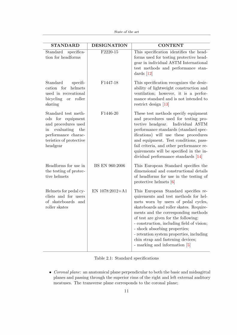
State of the art
STANDARD DESIGNATION CONTENT
Standard specifica-tion for headforms
F2220-15 This specification identifies the head-forms used for testing protective head-gear in individual ASTM Internationaltest methods and performance stan-dards [12]
Standard specifi-cation for helmetsused in recreationalbicycling or rollerskating
F1447-18 This specification recognizes the desir-ability of lightweight construction andventilation however it is a perfor-mance standard and is not intended torestrict design [13]
Standard test meth-ods for equipmentand procedures usedin evaluating theperformance charac-teristics of protectiveheadgear
F1446-20 These test methods specify equipmentand procedures used for testing pro-tective headgear Individual ASTMperformance standards (standard spec-ifications) will use these proceduresand equipment Test conditions pass-fail criteria and other performance re-quirements will be specified in the in-dividual performance standards [14]
Headforms for use inthe testing of protec-tive helmets
BS EN 9602006 This European Standard specifies thedimensional and constructional detailsof headforms for use in the testing ofprotective helmets [6]
Helmets for pedal cy-clists and for usersof skateboards androller skates
EN 10782012+A1 This European Standard specifies re-quirements and test methods for hel-mets worn by users of pedal cyclesskateboards and roller skates Require-ments and the corresponding methodsof test are given for the following- construction including field of vision- shock absorbing properties- retention system properties includingchin strap and fastening devices- marking and information [5]
Table 21 Standard specifications
bull Coronal plane an anatomical plane perpendicular to both the basic and midsagittalplanes and passing through the superior rims of the right and left external auditorymeatuses The transverse plane corresponds to the coronal plane
11
State of the art
bull Midsagittal plane an anatomical plane perpendicular to the basic plane and con-taining the midpoint of the line connecting the notches of the right and left inferiororbital ridges and the midpoint of the line connecting the superior rims of the rightand left external auditory meatuses [12]
Figure 21 Anatomical planes [12]
Planes and reference points
In agreement with the Standard BS EN 960 [6] it is possible to define different charac-teristic planes like shown in Figure 22
bull Reference plane for a given headform when erect the horizontal plane located ata vertical distance rsquoyrsquo measured down the central vertical axis from the centre ofthe crown All horizontal datum levels are quoted relative to this plane
bull AArdquo plane for a given headform the horizontal transverse plane is located at avertical distance 127 mm above and parallel to the reference plane This plane isdeemed to correspond to the level of the lower edge of the headband of a helmetIt is the basis upon which the size designation of a helmet may be specified
bull Central vertical axis vertical axis lying along the intersection of the vertical longi-tudinal plane and the vertical transverse plane
bull Centre of gravity of the three-quarter headform - point A for a given headform thepoint on the central vertical axis located at a vertical distance 127 mm above thereference plane
12
State of the art
bull Centre of gravity of the full headform - point G for a given headform the point onthe central vertical axis located at a vertical distance rsquozrsquo below the reference plane
bull Geometric centre - point R for a given headform the point on the central verticalaxis located at its intersection with the reference plane
Figure 22 Principal planes and reference points of a headform [12]
212 European Standard and American Standard
Location of gravity centre
Between the European Standard and American Standard there are differences the firstfor the location of the gravity centre
bull BS EN 960 the centre of gravity is located within a 10 mm radius of Point G
bull ASTM F1447 centre of gravity of the headform must be within a 10 vertical conefrom the centre of impact and lie within a rectangular area 28 by 128 mm
13
State of the art
The size of the head and helmet
bull ASTM F2220 to measure the external dimension for full headform the distancefrom the reference plane to the top of the headform There are different dimensionsF2220 (A if the measure is 897 mm minus C with 93 mm minus E with 96 mm minus J with1025 mm minusM with 107 mm) Then with this classification it is possible to extractthe dimension of xyz (mm) with the following Table 22
Table 22 Location of Reference Line [14]
bull BS EN 960 to obtain the size designation and the headform masses this Standardconsiders the measure of xyz (mm) in Figure 21 The possible designation are 21from 445 to 645 some of these are shown in the Table 23
Thanks to the size designation with the Standard BS EN 1078 there is the possibility todefine the inside circumference of the helmet and this it is shown in the following Table24
Table 23 Dimensions about the reference lines in Figure 21 and headform masses [6]
213 Field of vision - BS EN 1078
Apply a load of 50 N on the crown of the helmet in order to stabilize the helmet on theheadform To avoid having an occultation of the visual field Figure 23 it is better tofollow this angle measures [5]
bull horizontally min 105 from the longitudinal vertical median plane to the leftand right hand sides
bull upwards min 25 from the reference plane
bull downwards min 45 from the basic plane
14
State of the art
Table 24 Inside circumference of helmet [5]
Figure 23 Field of vision (a)(b) [5]
214 Test impact area
Standard EN 1078 will be considered for this study which defines the parameters helpfulin performing the shock absorption test The drop test impact consists of an impact ontwo anvils of flat surface or kerbstone
In the Standard is specified the Test Area where the impact is to be performed Thefirst thing is to apply a vertical load of 50 N on the crown of the helmet in order to
15
State of the art
stabilize the helmet on the headform [5]1 Draw the AArdquo line (in the AArsquo plane) on the helmet2 Draw a line on the helmet parallel to and approximately 20 mm above the AArdquo line(for use as an angular measurement datum line)3 Mark the helmet at points B1 and B2 These points are the sideways horizontalprojection of point B onto the outer surface of the helmet4 Draw a line RRrsquo on the helmet passing through B1 and B2 the line being angled 10
upwards toward the front of the helmet relative to the datum line drawn in d) The areaabove the line drawn in f) is the test area for impacts on the flat anvil The area abovethe line RWArdquo is the test area for impacts on to the kerbstone anvil
Figure 24 Definition of test impact area [5]
215 Anvils and environmental conditions
EN 1078
During the validation process each of the 30 helmet target points was impacted ex-perimentally and numerically under three environmental conditions (-20C +50C andhumidity)
The impact should never exceed 250 g for impacts with velocities corresponding to 542ms on a flat anvil and 457 ms on a kerbstone anvil These are theoretically equivalentto 1497 mm and 1064 mm drop heights respectively [5] About the characteristics of theanvils according to EN 1078 these depend on the type in the case of
bull Flat anvil it has a circular form with a diameter of 130 plusmn 3 mm with 25 mm ofthick
16
State of the art
bull Kerbstone anvil face inclined at 525 plusmn 25 to the vertical and edge with aradius of 15 plusmn 05mm The height shall be not less than 50 mm and the lengthnot less than 125 mm [5]
According with the regalement EN 1078 [5] it has been possible to realize the volumes inthis work the Flat anvil has a diameter of 130 mm and a height of 25 mm the kerbstoneanvil has a horizontal edge of 130 mm a height of 51 mm a length of 126 mm and theedge that impacts the helmet has a radius of 15 mm The anvils are represented in Figure25
[a] [b]
Figure 25 Flat anvil [a] and Kerbstone anvil [b]
EN 13087-11 (Proposal)
A proposal of November 2018 (EN 13087-11) talks about oblique impact tests (Rotationaltest method) [15] Define a method to measure rotational energy absorption in tangentialimpacts in short duration impact situations the velocity considered by Adanty et al [1]is 65 ms The same anvils of the Standard EN 1078 are used the flat anvil and theKerbstone anvil but the difference is the vertical drop towards an impact angle between30-60 the degree considered by Adanty et al [1] is 45
Three different rotations are considered [34]
bull Rotation around X-axis contact point on the side of the helmet resulting in arotation around X-axis Initial position of the headform X- Y- and Z-axis 0
bull Rotation around Y-axis Contact point on the upper part of the helmet resultingin a rotation around Y-axis Initial position of the headform X- Y- and Z-axis 0
bull Rotation around Z-axis Contact point on the upper part of the helmet resultingin a rotation around Y-axis Initial position of the headform X- and Z-axis 0 and65 around Y-axis
17
State of the art
Figure 26 (a) The current cycling helmet standard for the EN 1078 [5] (b) Theproposed standard (EN13087-11) as described by the European Committee for
Standardization (CEN) [15][1]
22 Materials
221 EPS Foam
As mentioned in Chapter 13 the material most commonly used for making the helmetis the EPS Mustafa et al [25] analysed the EPS with four different density values of 50kgm3 64 kgm3 80 kgm3 and 100 kgm3 rdquoThe drop impact simulation model wasused to test the impact attenuation of the helmet with different densities The drop testwas performed on four impact locations top front and sidesrdquo
The impact velocity of the helmet and headform was set at 544 ms The lowestpeak linear acceleration was recorded at the top location and a density of 64 kgm3 with14814 g This study sets out to determine the effect of the user-centered helmet designwith different foam densities (from 50 kgm3 to 100 kgm3) on the impact attenuationof the bicycle helmet
Kroeker et al [19] tested the helmets at three impact speeds 30 plusmn 001 ms 63 plusmn002 ms and 78 plusmn 001 ms
They established the mean value about bulk density in a helmet with EPS foam is666 considering HIC and Peak Acceleration test The global range is between 64 kgm3
and 75 kgm3
Kroeker et al [20] established the foam for kids helmets is 64-88 kgm3 and for thetraditional helmets is 60-100 kgm3
Trzaskalska et al [36] controlled the influence of polymer liner density on energy ab-sorption during impact They discovered the best properties have samples whose densityis between 54 to 60 kgm3
Cui et al [10] considered the density of each layer from the values of 25 50 60 80and 100 kgm3 and they realize a 45 grades side impact and normal crown impact Theresult is a density of 64 kgm3
Wei et al [38] discovered from their test results that EPS has a buffer layer density
18
State of the art
of 60 kgm3 is the most reasonable
Foam densityrsquos values - Literature
Authors Densityrsquos values
Mustafa et al [25] 64Kroeker et al [19] 64 - 75Kroeker et al [20] 60-100 (traditional) and 64-88 (kids)
Trzaskalska et al [36] 54 - 60Cui et al [10] 54Wei et al [38] 60
Table 25 Table with foam (EPS) densityrsquos values
The other are mean values obtained by CES EduPackrsquos program about this material
- Density ρ = 6451kgm3
- Youngrsquos Module E = 275 MPa
- Poissonrsquos ratio ν = 0275
- Yieldrsquos stress σ= 09 MPa
- Elongation at fracture = 45
222 CES Edu Pack - Material selection
CES Edupack software was used to satisfy the idea of creating a lightweight helmetby printing it in 3D and having the possibility to insert the desired characteristics ofthe material and therefore select it To make a choice I used level 3 of engineering(advanced) selecting the following criteria of the material bio-material biodegradablea polymer of concentration 20 - 100 which complies with the rsquoEuropean Restrictionon Hazardous Substances (Rohs) standardsrsquo regarding the composition of the materialensuring that it does not contain a high percentage of toxic substances compared to theestablished percentage In addition it must have proper durability in contact with coldwater (imagining a possible rain) and rsquogoodrsquo durability to UV radiation
According to Ashbyrsquos method [2] to select a material it is possible to follow thefollowing steps
1 Establish the function of the product What does the component doThe helmet is an instrumental use to protect the head during an impact this characteristicdepends on materials and qualities It can prevent an injury which depends on materialsand design because it has to be of the right head size It would be comfortable becauseit must be worn and it must give security to the person wearing it (by design) In thefollowing Table 26 the analysis of the functions
19
State of the art
Ranking Function description Depends on
1 Head protection (energy absorbing) Material2 Head protection (energy absorbing) Design3 Head protection (injury prevention) Material4 Head protection (injury prevention) Design5 Comfortable Material6 Comfortable Process
Table 26 Ashbyrsquos method functions
2 The objectives that are targets for the design the material is to bemaximised or minimisedTo manufacture and market a product objectives such as minimizing weight cost orenvironmental impact must be considered In the following Table 27 the analysis of theobjectives
Ranking Title Objectives description
1 Mass Minimize The mass has to be thesame or lower
2 Cost Minimize everyone should have theopportunity to buy it
3 CO2 footprint Minimize CO2 emission
4 Corrosion Minimize high strength because itcan be in contact with the water
5 Pleasant to touch Maximize it is not a rough materialbecause it has to put on and put off
by hands
6 Refractive index Minimize it must not reflect light
Table 27 Ashbyrsquos method objectives
3 Definition of constrains What essential conditions must be meetEstablish constraints is essential to complete the function of the instrument Examplesof constrains are Table 28
4 The limits characteristic independent of the material that does not influencethe physical properties In the following Table 29 the analysis of the limits
20
State of the art
Title Loading case Constraintsdescription
Material index(Max-Min)
Stiffness Column in compression Tie in tension
Mass Min
Stiffness Column in compression Tie in tension
Cost Min
Stiffness Column in compression Tie in tension
CO2 Min
Strength Column in compression Tie in tension
Mass Min
Strength Column in compression Tie in tension
Cost Min
Strength Column in compression Tie in tension
CO2 Min
Table 28 Ashbyrsquos method constrains
223 PLA with natural fiber and PLA LW
Initially the best material that met the desired criteria was searched From this study itwas found that the material closest to having the required characteristics is the PLA 30natural fiber as shown in the Figure 27 which shows the graphs obtained relating tothe relationships between Youngrsquos Module and density the objective to reduce the massper unit of compressive stiffness and strength to reduce the CO2 footprint per unit ofstiffness and strength and mass per unit of compressive strength
Performance index IR
The stiffness criterion has the following characteristics
m = A lowast L lowast ρ (21)
ε =σ
E=
FA
E(22)
A =F
ε lowast E(23)
21
State of the art
Ranking Title Function description
1 Biocompatibility It is the ability of a material the abilityof the material not to cause any local or
systemic adverse response in therecipient of the material
2 Biodegrability Biodegradable material do notbiodegradable under anaerobic conditions
3 Biomaterials - all The terms is used for biological naturalbio-derived bio-inspired material
4 RoHS (EU) Compliantgrades
Restriction of the use of certin prohibitessubstances (mercury cadmium
hexavalent chromium)
5 Polymer 20-100 (from the table with Plasticpolymers)
6 UV Resistance at UV sunlight
Table 29 Ashbyrsquos method limits
A =F lowast L lowast ρε lowast E
(24)
With fixed variables- F (the load) L (the length)With variables that depend on the material- E (Youngrsquos Module) ρ (density)
In general when a chart is created the distribution of the mass is represented in thefollowing modality like in Figure 27 [b] where the materials above the line have a lowermass while those below a greater mass
Following the results of the CES Edupack program that had selected the PLA withnatural fibers as the best the first print of the helmet was made with this materialusing as support the PVA Initially the result seemed satisfactory the helmet had a highdefinition but a fundamental problem was found by reducing the helmet in the water toallow the supports of PVA to dissolve In the act of diving in fact after ten minutessome parts of the helmet especially the front and rear have disintegrated making thehelmet unusable Because of this problem it was necessary to change the material
22
State of the art
[a]
[b]
Figure 27 CES EduPack Mass per unit of compressive stiffness [a] Youngrsquos Moduleand density [b]
Further investigations carried out by the Mondragon Unibertsitatea Additive Man-ufacturing Department revealed a new material the PLA Low Weight which during3D printing allows to obtain a weight of 65 lower than that which could be obtainedfrom the classic PLA as reported in the technical sheet of the filament produced by thecompany Colorfabb [7]
The investigation team of the Composite Department carried out tensile tests withsamples 3D printed at different temperatures as suggested by the manufacturer to obtainthe technical characteristics The temperatures examined are 200 220 250 260The datasheet shows the density can have values between 04 - 124 gcm3 the bed has
23
State of the art
to have a temperature between 50 - 60 the printing speed has to have values between40 - 80 mms This typology of PLA is expandible so much that rdquoAt around 230 thismaterial will start foaming increasing its volume by nearly three timesrdquo [7]
T[C] Section [mm2] Volumen [mm3] Mass [g] ρ[kgm3] E [Nmm2]
200 42235 1030117 12 1165 328807
220 43805 1655821 18 1087 265795
250 52412 1948139 17 873 178058
260 59655 1454377 12 825 117047
Table 210 Values about PLA LW tensile tests of MU Additive ManufacturingDepartment
From the tests that have been carried out on the material at different temperaturesthe printed sample is better at 250 with a volume of 1948139 mm3 and a section of52412 mm2 as shown in Table 210 For this reason the specific of the material thathave been taken into consideration are the following
- Density ρ = 873 kgm3
- Youngrsquos Module E = 1750 MPa
- Poissonrsquos ratio ν = 033
- Yieldrsquos stress σ = 2948 MPa
- Elongation at fracture = 491
23 Bio-inspired structures
When we talk about bio-inspired structures to nature we refer to structures that allowobtaining a low weight for the model that is realized and excellent absorption energy dur-ing the impact Recently the structures that have been most used in the biomimetic fieldare the rdquocolumns structures sandwich structures plates honeycomb and foamsrdquo[26]but aiming to achieve a structure increasingly with high absorption energy new struc-tures derived from plants and animals such as beetle horsetail turtle bird beak havebeen analyzed The first to create multi-cells tubes helicoidal structures the second tomulti-corner tubes [26]
The authors analyze the specific energy absorbed (SEA) by bio-inspired sandwichstructures per unit mass which can be derived from the following equation
EA(d) =
int dmax
0F (x)dx (25)
SEA(d) =EA(d)
m(26)
24
State of the art
Where EA is the energy absorption rdquomainly used to evaluate an energy absorberrsquosability to dissipate crushing energy through plastic deformationrdquo F(x) is the crashingforce dmax is the effective deformation distance [26]
What derived from their investigations is that having regard to a density of between0 and 1000 kgm3 the volumetric energy absorbed is higher for the beetle-inspired struc-tures than the others as shown in Figure 28 Based on this consideration it was chosento draw the helmet following this geometry
Figure 28 SEA of bio-inspired sandwich structures [26]
231 Beetle structure - Design of the model
To develop and increase lightweight high-strength and optimize bio-mimetic functionaland structural materials the trabecular structure of the beetle elytron is studied Thesingle structure is realized following the requirements cited by Zhang et al [39]
To realize the beetlersquos structure it is not enough to have information about the lengthof the side of the hexagon and the thickness but it is also necessary to take into accountthe relationship between the diameter of the circumferences present on the vertices ofthe hexagon and the measurement of the side The representation of a single cell is inFigure 29 It is shown in [a] a general structure with an edge of 12 mm circumferencersquosdiameter of 6 mm and thickness of 16 mm in [b] is shown the height of 20 mm
For the construction of the helmet a thickness of 12 and 16 mm was used the imageconcerns a proportion between the length of the hexagon side and the diameter of the
25
State of the art
circumference The side (distance between the centers of two circumferences) is twice thediameter measurement
[a] [b]
Figure 29 Beetle structure
232 Specific stress - PLA LW and EPS foam
To test the beetle structures compression tests were investigated The PLA LW structurewas inserted in a rsquodiskrsquo with a diameter of 100 mm and a height of 20 mm The area andthe volume of the disk is correspondingly 7854 mm2 and 157 10 mm3 The structuresexamined have different dimensions the edge L (distance between two centers of thecircumferences) had the following measures 9 10 12 14 16 mm the thickness of thecircumferences and edges are respectively of 16 mm for every structure and 12 mm forthe structure with L = 16 mm
The test was carried out with the Hoytom HM-D Testing Machine with capacitiesbetween 5 and 100 kN The test models were subjected to displacement loading at a rateof 1 mmmin as referenced by Chen et al[18] with a cylindrical specimen The specificstress of the structures was compared with the specific stress of a generic EPS helmetthe photos about it are shown in Figure 210 The EPS helmet structure is granular withpores inside The different grains dimension and these pores can be the reason for whichthe Stressrsquos values are between two values 07 and 116 MPa
Four parts of the EPS helmet were considered in the test the dimension and relativecharacteristic are in the Table 211 where m = mass A = area F = load ρ = densityR = stress Rρ = specific stress To calculate the values of stress about PLA structuresand EPS foam compression test graphs were been analyzed The stress value for eachstructure was calculated considering the single load the single area and the averagedensity value (14055 [kgm3])
The stress values of the PLA structures (Figure 211) and other characteristic valuesare in Table 212 where m = mass A = area F = load ρ = density
26
State of the art
[a] [b]
[c] [d]
Figure 210 EPS generic helmet helmet pictures [a] [b] and internal structureExternal granular structure [c] and pores [d]
[a] [b] [c]
Figure 211 PLA LW disks Grasshopper structure [a] PLA LW structure of 14 mm[b] PLA LW structure compressed [c]
27
State of the art
The results of the load-displacement graphs are affected by the geometry of the diskthe target is to valid for any shape or size for this is preferred to realize a diagramthat depends from σ (or stress) and the deformation ε (or strain) which can be definedrespectively as
σ =F
A0(27)
ε =l minus l0l
(28)
where F is the load during the test A0 is the area l0 is the initial length and l is thelength when the load is applied The areas considered for the EPS cube is reported inTable 211 in the second column the areas of the PLA structure is 7854 mm2 like thearea of the circumscribed disk
The values compared are shown in Table 213 and the graphs obtained by Matlabcode to analyze the recorded data of the compression machine are in Figure 213 and inFigure 212
Considering that the data provided by the compression machine are subject to noiseand disturbances it was decided to convert the original curve into polynomial type curvesthat allow obtaining the best interpolating curve for the data in question To obtain themit was divided the recorded data into two groups the first part from 0 until the end ofthe linear part and the second when the curve becomes linear again The best-fitting (inthe least-squares sense) was performed using the polyfit and polyval functions of MatlabThe first returns the coefficients of the p(x) with n degree the second evaluates p(x) ateach point in x The polynomial formula p(x) is shown in the Equation 29
pn(x) = anxn + anminus1x
nminus1 + + a2x2 + a1x+ a0 (29)
where a0 an are constants and x is the indeterminate The choice of the degree ofthe polynomial was made based on the criterion of wanting to obtain linear curves thatrespected the elastic trend at the beginning of the graph For this reason the degree ofthe polynomial is 1 Subsequently I searched through the intersection of the two lines forthe point that is equivalent to the maximum stress that marks the end of linearity
This value for EPS and PLA LW is the R [MPa] in the Table 213 The average stressvalue for PLA LW is 139 MPa and for EPS is 094 MPa The specific stress (Rρ) is 18MPa lowast m3)kg for the EPS found in CES 669 MPa lowast m3)kg for the EPS foam of thegeneric helmet and for PLA LW is 1161 MPa lowastm3)kg an intermediate value betweenthe two which is what we wanted to achieve
28
State of the art
m [g] A [mm2] F [N] ρ [kgm3]
EPS (CES) 50
16 9234 1063 13864
18 879 593 13651
21 858 833 14237
24 864 564 14468
Average value 14055
Table 211 Compression stress generic EPS helmet
L [mm] t [mm] m [g] F [N] ρ [kgm3]
9 16 214 7250 1363
10 16 192 5560 12467
12 16 201 8190 13051
14 12 138 8000 8961
Average value 12027
Table 212 Compression test PLA structures
PLA LW structure EPS structureρ= 12027kgm3 ρ= 14055kgm3
Edge [mm] R [MPa] Rρ103 Number R [MPa] Rρ103
EPS (CES) 09 18
9 173 1269 1 116 824
10 139 1114 2 08 568
12 138 1057 3 105 746
14 108 1205 4 077 540
Average value 139 1161 094 669
Table 213 Specific stress calculus PLA LW and EPS calculus ρ = density R = stressRρ [(MPa lowastm3)kg] = specific stress
29
State of the art
Figure 212 Compression test Stress-Strain diagrams - EPS
Figure 213 Compression test Stress-Strain diagrams - PLA LW
30
Chapter 3
Methodology
31 3D scan
311 3D Sense 2 scanner and Meshmixer - Reverse reconstruction
Standardized measures were not taken into account for making the helmet but the sizewas obtained through a 3D scan of my head
The scanner used is 3D Sense 2 by 3D Systems which has a minimum scanningvolume of 20 x 20 x 20 cm and a maximum scanning volume of 300 x 300 x 300 cmTo scan my person I was helped to get a full view at 360 at an appropriate distanceReal-time visualization of the captured images was shown through 3D Sense softwareThe idea of scanning the head with the scanner refers to the methodology used by Wanget al [30] They used a reverse reconstruction functional for me to realize the helmetsurface made to measure my head and like them a silicone pool cap was used to makescanning as smooth as possible The authors claim the head scan rdquocan also be used toobtain information about the objectrsquos surface which is then reconstructed utilizing thecomputerrsquos three-dimensional model via reverse modelling softwarerdquo [30] that in my caseis Autodesk Meshmixer
The files it was could get from the scan were stl obj and ply format they wereexported to obj to work in the next step with Autodesk Meshmixer that allowed tomodify and homogenize the 3D image obtained from the scan
In Meshmixer through the selection and delete commands the superfluous parts weredeleted that had been acquired and with the inspector and the DrawDraw2 commandsthe vertices were moved locally along a pre-defined direction and with Smooth the surfacemore homogeneous was made The sequence of steps is shown in the Figure 31
312 3D scan analysis and extraction of features
In Chapter 2 the directives imposed by the BS EN 960 Standard were examined concern-ing the definition of the helmet and the measures to be respected in the field of visionand the part of the helmet was to carry out impact tests
In Figure 32 the features defined complying with the Standardrsquos rules are repre-sented To define these features the software NX was used The angle in the subfigure
31
Methodology
[a] [b] [c] [d]
Figure 31 Sequence of 3D head scan 3D scanner acquisition [a] scan after reparationwith Meshmixer [b] solid scan vision frontal and lateral [c] [d]
[b] is bigger than 105 (as defined by the Standard) while the degree in the subfigure [c]is 25 By defining the construction lines to be respected of the helmetit was necessary todraw the design of the surface not using the software NX but changing with Rhinocerosto create a SubD or SubDivision surface
32 Helmet design
321 Rhinoceros - Helmet surface
After realizing a rsquocleanrsquo Wang et al [30] subdivide with lines and then sectors the headto create the surface of the helmet They used the technique of NURBS a Non UniformRational Basis-Splines which mathematically models a 3D geometry while thanks tothe Rhinoceros 3D organic shapes was draw SubD surfaces These geometries allow tosplit the mesh into small polygons and consist of lines with which easily the shape ofthe object can be modified with a surface already created changing the position of aline automatically the remaining part of the geometry adapts to the changes With thistechnique the rsquosurface basersquo of the helmet was realized with the size of my head Therepresentation of the realized SubD is in Figure 33
322 Grasshopper - Helmet structure
The next idea is the creation on the surface of the beetle structure with different di-mensions modelling the helmet that is not a linear surface It was decided not to buildthe structure with a software CAD because to model an already complex structure on acurved surface would mean to model a cell for a cell
To solve this obstacle a Rhinoceros plug-in was used Grasshopper GH idealized byRobert McNeel and associates creators of Rhinoceros Using GH does not mean drawinggeometries by connecting points and drawing tools because it is based on algorithmicmodelling used in architecture and engineering for 3D modelling
The modelling takes place through a node diagram that the software will convert intoa code-algorithm in GH it is possible to define the variables and parameters and inRhinoceros in real-time it is possible to view the object GH allows for varying the
32
Methodology
[a] [b]
[c]
Figure 32 Featurersquos extraction in [a] is represented the impact line in [b] and [c] twoprospective about the definition of the field of vision
[a] [b] [c]
Figure 33 SubD representation lateral view [a] top view [b] front view [c]
geometry to your liking by varying a simple parameter of the diagram as everything willbe remodelled according to the change made
In the following Figure 34 it is shown an example of a structure that was used fordistinct subgroups of helmet areas The idea was to insert smaller cells in the frontal andlateral zone and larger ones in the upper area In the first image [a] is shown the part of
33
Methodology
the helpful diagram to create the beetle structure to establish the size of the cells andthe extrusion the second image [b] contains the part of the diagram with which I appliedthe structure previously created to the SubD
The structure used to place and adapt the beetle structure to the surface is theSrfMorph while the yellow rsquowindowrsquo that contains numbers serves to select the parts ofthe surface where to apply the geometry created In accord with the GH diagram in
[a]
[b]
Figure 34 Grasshopper diagrams
Figure 34 [a] it is possible to see the steps executed to realize the structure Initially inthe xy-plane a hexagonal grid was drawn through the Hexgrid command in which youcan input the length of the hexagon edge and the number of grid elements (selected bytrial) Then the circumferences was drawn in proportion to the hexagon dimensions asspecified in the Chapter 2 and shown in Figure 35 [a] In figure [b] the rsquocutrsquo made atthe circumferences is visible this subdivision was necessary for printing purposes In thelast photo [c] the structure highlighted in green in [b] was extruded setting a distance
34
Methodology
of 20 mm
[a] [b] [c]
Figure 35 Construction sequence of the geometry of the helmet
In the diagram in Figure 34 [b] there is the application of the structure created bi-dimensionally to the SubD surface of the helmet visible by unlocking the SubD commandof the diagram and in Figure 36 [a] Upper this the referential geometry of the group ofsurfaces was superimposed where it was to be applied the newly created structure (visiblein darker red) the SubD indices are in the yellow box of the diagram
Through the SrfMorph command the location of the structure was granted In Figure36 [b] at the darkest red of the figure [a] with the above command it was possible toplace the structure
[a] [b]
Figure 36 Application of the geometry created to the helmet surface
Overall the diagrams with specific structures are five one for the front two equal forthe side parts one for the top shown in the previous Figure 36 and one for the back
The hexagons in the structure have a dimension varying between 8 mm and 14 mmof side the largest is found at the top later at the back in the sides and the smallest atthe front In Figure 36 [b] the presence of not only hexagonal structures is visible Thegeometry used does not allow the homogeneous arrangement on the entire surface andrequires different structures Automatically the choice of GH to optimize the structurewas to insert quadrilateral
As described above the helmet has different dimensions of the structure divided asvisible in Figure 36 in a quadrilateral This causes a discontinuity between zones withdifferent sizes due to the geometry of the construction
To eliminate this problem and realize the design homogeneous grids were inserted
35
Methodology
in the affected areas as shown in Figure 37 This insertion however proved to beinteresting and strategic researching in this regard studies were realized to demonstratethe insertion of a rectangular grid inside the hexagon grid was helpful for the transmissionof stress in the structure As cited by Sun et al [40] rdquothe mechanical properties of thesesandwich structures are often limited by local failures such as face-core debonding or corecollapserdquo Carrying out compression tests have effectively demonstrated that the insertionof the grid allows rdquoprovided increased stiffness specific stiffness energy absorption andcritical loadrdquo [41] As shown in the graphic [c] of the Figure 37 the honeycomb structuregives a force of 7 kN while with a grid the value is 11 kN and with the combinationexceeds 22 kN In addition in the left front a plaque to customize the helmet wasprepared Figure 37 [a]
[a] [b]
[c]
Figure 37 Grid in the helmet [a] hybrid structure with hexagons and grid [b] [40]compression test results of the hybrid structure [c] [41]
33 3D Print
After having achieved the CAD (Computer Aided Design) of the helmet in order tobe printed it must be converted and saved in format STL (Standard TriangulationLanguage) - Binary compatible with the printing machine and useful for transformingsolid object surfaces into triangles The steps to be taken are the following
bull CAD file realization
bull CAD export in format STL to Simplify 3D the software that shows slider layersand then- rotate and position the object according to geometry and the positioning of any
36
Methodology
supports- setting printing parameters- item manual andor automatic positioning of supports- slider display layers
bull import file gcode to printer
331 Printer and parameters
The program used to visualize how the helmet slices layers before sending it to the printerand to set the parameters is as anticipated Simplify 3D
To make the printing not being a flat geometry it is necessary to place the supportsThe idea was to use water-based supports that the helmet would automatically dissolveonce placed in the water After testing different types of water-soluble PVA the choicefell on eSun 3D Printing Filament PVA (water-soluble support) Before choosing theoptimal position for printing several tests were carried out and to decrease the numberof the supports significantly and allows an optimal printing of the outer part an emptyrsquospherersquo that self-sustains below the helmet was placed as shown in Figure 38
In the image [a] you can see the first print position tried with which an external partof the helmet very damaged was obtained because of the contact supports-helmet In [b]the empty rsquospherersquo is shown to optimize the number of supports and in the last photo [c]there is the full version at the end of print
[a] [b] [c]
Figure 38 Printing supports
The printer that has been used for printing is the Raise 3D Pro2 with double extrudersand nozzles of variable size from 02 mm to 1 mm after some test prints with the PLALW and the structure in created the size that allowed me to have a good compromisebetween printing time and accuracy was 06 mm Using 04 mm the printing time wasexcessive even if having the smaller nozzle diameter means having more precision withthe 08 mm nozzle the quality of the structure was not excellent as seen in Figure 38[a]
Another factor that had to be taken into account is the characteristic of the PLA-LWto expand As the printing temperature and the printer used vary the expansion andcharacteristics of the material change The use of the 06 mm nozzle associated with
37
Methodology
Parameter Left extruder Right extruder
01cm Material 01cm PVA 01cm PLA LW
Extruder toolbox index Tool 0 Tool 1
Nozzle diameter 06 mm 06 mm
Extrusion multiplier 1 05
Extrusion width Auto (072 mm) 05 mm
Layer x
Infill Rectilinear - 50
Supports (Automatic and not) Infill 50
Temperature 210 250
General parameters
Primary layer height 03 mm Top solid layer 4
Bottom solid layer 2 Outline 2
Heated bad 60 Speed 40 mms
Table 31 Printing parameters
Raise 3D allowed me to get good results The choice of this printer was not random ithas in fact the characteristic of making extremely precise prints The Raise has accuracyin placing the object on the printing bed of 078 microns on the xy axis and a resolutionfor layers of 001 mm
The final version of the helmet is visible in Figure 39 and it is possible to compare itwith the preview version in Rhinoceros in Figure 310
38
Methodology
[a] [b]
[c]
Figure 39 Views of the helmet
[a] [b]
Figure 310 Views of the helmet (GH version)
39
Chapter 4
Experimental evaluation
41 Experimental tests
411 Drop-weight impact test machine
In order to calculate the contact force peak and the difference of energy absorbed duringthe impact between the reference helmet and helmet with the beetle structure in PLA-LW dynamic impact tests were carried out using the Fractovis Plus an impact testmachine
In this way it is possible to monitor the evolution of the above variables from theinitial to the final instant of the impact The machine can withstand a load with a rangevariable from 2 to 70 kg with a maximum speed of 46 ms and a maximum height of1 m The values chosen for the test are the following 5 kg weight maximum speed andmaximum height The Anvil that was used is a disc diameter of 60 mm
As shown in Figure 41 and explained by Crupi et al [37] the machine consists ofa sensor capable of recording the speed before impact the impactor that can have avariable mass (a weight of 5 kg in my test) a system to guarantee that there are nomultiple impacts after the first and that work as a shock absorber and clamping systemwhere the object to be tested is placed
The tests that have been carried out are in total four two related to the helmetoptimized with PLA-LW and two with two generic helmets of different brand in EPS
42 PLA LW helmet
To perform the dynamic test on the helmet of PLA considering the difficulty of printingit was helpful to use a test helmet with imperfections to understand where the impactwas concentrated in a single part or distributed The images of Figure 42 show a helmetwith not well defined edges and inaccurate print but exactly localizes the impact zoneThanks to this test it was possible to take into account only one helmet area shown inFigure 43 to have the exact curve of the structure bio-inspired with PLA-LW
40
Experimental evaluation
Figure 41 Drop-weight impact test machine [37]
[a] [b]
Figure 42 Test 1 PLA-LW helmet
43 EPS helmet
To carry out dynamic tests and extract the technical characteristics of the helmettwohelmets were bought in a sports store both EPS and being on the market both certifiedThe brands of the two helmets are DTB and VAN|RYSEL and the average weight ofthe two is 223 g Two different helmets have been chosen to have a more certain andclear classification of the characteristics They are shown in Figure 44 and Figure 45
41
Experimental evaluation
[a] [b]
Figure 43 Test 2 PLA-LW helmet
[a] [b] [c]
Figure 44 Test 3 EPS helmet
[a] [b] [c]
Figure 45 Test 4 EPS helmet
44 Results
441 First results - PLA-LW and EPS helmet
Figure 46 shows two types of trends related to the two different models of the helmetThe force evaluated for PLA-LW has higher force peaks but is more concentrated and
42
Experimental evaluation
propagates less than EPS The graph shows the peaks of each curve highlighted with a redcircle In tests 1 and 2 for the PLA-LW as mentioned earlier the values are higher about7301 N for the complete helmet and 3996 N for the portion of helmet This difference isdue to the inaccuracy of the first full helmet during the printing phase In Figure 42 itis visible the low homogeneity and precision Therefore the first test with full helmet wasused only to define the area of interest of the impact which turns out to be localized Forthe other two EPS curves the values are only slightly lower compared to the PLA-LWequal to 3620 N and 3295 N but the trend is much more distributed
Figure 46 Dynamic machine test - Force
With the data obtained from the impact machine it was possible calculate not exclu-sively the value of force but itrsquos also possible to view the energy curves A resume aboutthe values and energy of the force is in the following Table 41
Test Peak force [N] Peak energy [J]
Test 1 - PLA LW (inaccurate) 730130
Test 2 - PLA LW (portion of helmet) 399643
Test 3 - EPS (DTB helmet) 362007 509
Test 4 - EPS (VAN|RYSEL helmet) 329546 4198
Test 5 - PLA with TPU 45421 5022
Table 41 Energy absorbed in dynamic test
43
Experimental evaluation
442 PLA-LW helmet with TPU cover
As it is possible to see in Figure 47 and as highlighted the first tests concerning thebio-inspired structure and the PLA-LW are far from my expectations considering thelittle distribution of force in comparison with the EPS foam and consequently a smallamount of energy absorbed
Figure 47 Dynamic machine test - Energy
To improve this impact damping factor the idea was to create a cover for the helmetin flexible TPU trying to absorb impact energy The TPU used is a flexible material ofthe brand Ninjaflex used in sports by the application in helmets and shoes to cushionbumps during the game Generally in the helmets (baseball helmet for example) theTPU is inserted internally in contact with the head In my case the TPU structurein addition to creating a shock-absorbing and durable cover creates a custom cover thehelmet and for the person This cover was also made with the Raise 3D printer
As shown in the Figure 48 [a] the infill of the part in contact with the helmet hasa percentage of 100 the filling of the other part of the structure is not complete butonly 15 and the internal structure is hexagonal to recall that of the helmet The desireto insert a structure with a rsquoraisedrsquo geometry is for visual and aesthetic reasons as youhave the feeling of greater protection and not filled is inspired by the machine CitroenCaptus whose bumpers (Airbump) are full of air The failure to realize empty structuresis due to the need to place any internal supports not removable
The idea was to create a cover that allow you to see of the internal structure of thehelmet and that protect specific areas the front the two sides the top and the posteriorWhat which was thought for this reason was to create the shape of a flower with four
44
Experimental evaluation
petals Figure 48 [b]In this way to perform dynamic impact tests as shown in Figure 49 [a] the cover was
positioned at the top of the helmet and the impact was performed in the centre of thersquoflowerrsquo which corresponds to the higher upper part where the structure has larger cellsize The impact parameters are the same as those used in previous impacts 5 kg weightmaximum speed and maximum height The Anvil that was used is a disc diameter of60 mm In photo [b] it is evident the difference between the structure that received theimpact with protection (left) and without protection (right) Without protection duringthe impact there was a perforation of the structure with a concentration of force at a locallevel as you can see in the Figure 46 in the case of TPU the impactor did not perforateand crossed the structure thanks to the cover of TPU that cushioned the shock At themoment of impact the impactor bounced
[a] [b]
Figure 48 TPU cover
[a] [b]
Figure 49 PLA-LW with TPU - dynamic impact [a] and differences between thehelmet with TPU and without TPU cover [b]
45
Experimental evaluation
The Figure 410 includes the diagrams relative to the dynamic impacts In [a] thereare already analyzed EPS results in [b] a comparison between the test on the portionof helmet in PLA LW with and without the TPU cover in [c] the overall comparison ofcurves shows a much more similar EPS trend if the TPU is placed above the structure inPLA LW to soften the blow and absorb the same energy [d]
46
[a]
[c]
[d]
Figure 410 Comparison between PLA-LW with TPU and EPS
Chapter 5
FEM Validation
51 Impactor - Anvils definition
Before to start to work in Abaqus it was necessary to search in the literature the materialwith which the anvil was been realized Milne et al [23] established the densityrsquos valuethe Youngrsquos Module and Poissonrsquos ratio for the Flat and Kerbstone Anvil
- Density ρ = 7800 kgm3
- Youngrsquos Module E = 200000 MPa
- Poissonrsquos ratio ν = 03
Inserting the data in the CES EduPack program specifying the mechanical andphysical properties the material corresponding to these characteristics is Stainless steelaustenitic (ASTM F1586) medium-hard
Initially the proposal was to create a conservative system to evaluate the absorptionenergies values and apply this value to a vibration system but the helmet needs dampingto be realized it was impossible to use a system without losses in this modality Thisis why a numerical calculation was carried out by performing two types of simulationsexplicit dynamic step and static step
The idea to realize the theoretical impact is to regard the movement of the anviland not the helmetrsquos movement which is fixed The velocity is the same cited in thenormative EN 1078 542 ms for the Flat anvil and 457 ms for the Kerbstone anvil
In performing the simulations It was given more relevance and perform tests withthe Kerbstone Anvil This choice was done because the geometry with which it is beenrealized (following as defined in the legislation) allows the helmet to be more subjectedto stress this involves the definition of higher stress limits compared to the Flat Anvil
The mesh size that has been used is the same in the case of the simulation of thehelmet optimized in PLA-LW and the full helmet in EPS of 7 mm The impactor isconsidered as a Discrete rigid body with its specific Reference Point (RP) like shownin Figure 51 for this reason it is not a solid but it is composted only by shells Inthe same image [b] there is the FEM representation of the model and in Table 51 thecharacteristic of FEM with quadrilateral (R3D4) and triangular elements (R3D3)
48
FEM Validation
Object Elementnumber
Elements Shape Geometricorder
Global size[mm]
Kerbstone 230 Quadrilateral - R3D4 Linear 7
Kerbstone 8 Triangular - R3D3 Linear 7
Table 51 Mesh element - Kerbstone Anvil
[a] [b]
Figure 51 Kerbstone anvil in the simulation like discrete rigid body [a] and FEMelements [b]
511 PLA LW - Plastic characteristics
The PLA-LW as explained in the Chapter 2 is new material on the market and producedby the only Colorfabb company for this reason few tests have been carried out to defineits technical characteristics and through tensile tests of the 3D printed specimens it waspossible to define an elastic limit as reported in the Table 210
In the context of simulations to reproduce the impact and deformation of the helmetis also necessary to consider the plastic characteristics of the material Not possessingany reference value in this regard tests were performed through a Static Step initiallyand then an Explicit Dynamic Step in Abaqus
The structure chosen to consider as a reference it is one of the structures previouslysubjected to the compression test having the side L=14 mm As for the reproduction ofthe compression disks initially they were reproduced according to the geometry of theHoytom HM-D Testing Machine considering the bodies mentioned above as discrete 3Drigid discrete The measure was the diameter of 200 mm and the height of 20 mm
After an initial analysis it was observed that the computational time of the simulationprogram was very high so it was decided to change the geometry to have a rsquodisk-surfacesrsquo(equally 3D rigid-discrete) which allowed me to have a smaller number of nodes for themesh and consequently a better computational time The representation of the opti-mized structure in PLA-LW and the disks used for simulated compression is in Figure 52
49
FEM Validation
[a] [b]
Figure 52 Representation of the samples used for the simulation of the compressiontest In Figure [a] the disks of the Hoytom HM-D Testing Machine in figure [b] the
representation of the same as simple surfaces
As shown in Figure 52 the disks are considered 3D discrete hard bodies so it waschosen for both a point the reference point RP where to apply the characteristics relatedto the two bodies As for the compression test it was established
bull the movement of a disk and fixed the second through a boundary condition impos-ing an Encastre therefore unable to move and rotate in xyz directions
bull for the opposite disk the boundary condition relative to the 15 mm displacementwas applied which is the parameter that it was observed to determine the end ofthe compression with the machine This shift is shown by the orange arrow in figure[b]
bull between the upper surface and the disk e the disk with the lower surface it wasinitialized a general contact with normal behaviour through rsquohardrsquo contact andtangential behaviour with a coefficient of friction of 02 with directionality imposedon rsquoisotropicrsquo
The next step was to define the mesh of the components whose parameters are shown inTable 52 while the representation of the FEM is in Figure 53 with the representationof the simulation and real compression test
Object Elementsnumber
Typology Geometricorder
Globalsize [mm]
Disk (14mm) 80910 hexaedral - C3D8R Linear 07
Impact disks 206 quadrilateral - R3D4 Linear 20
Impact disks 6 triangular - R3D3 Linear 20
Table 52 Mesh element - Compression test simulation
As previously announced a static simulation was initially performed with a StaticStep with Step Time equal to 900 (obtained going to consider the speed of 1 mmmin of
50
FEM Validation
[a]
[b] [c]
Figure 53 FEM representation [a] and compression test simulation [b] and realcompression [c]
the compression test and the displacement of 15 mm) However the complex geometryof the structure and the high time set by Step Time did not allow a correct definitionof the parameters of the plastic characteristics of the material the simulation was notable to continue once reached a Step Time of approximately 220 That is why it waschanged by choosing an Explicit Dynamic step
Leaving all the parameters of the boundary conditions unchanged the Step Time wasmodified imposing it to 001 The ability of the explicit dynamic to work with non-linearand contacting structures allowed me to achieve results The results obtained are shownin Figure 54 with the blue curve and were obtained through the iteration of differentPlastic Strain and Yield Stress values in Abaqus while the red line is the result of thereal compression test a similar curve trend was obtained but it is not possible to obtainthe same curve taking into account problems of printing inaccuracy
512 First test - helmet
The initial idea was to perform a simulation imposing the speed of 457 ms to theimpactor tie the helmet in EPS and PLA and compare the absorbed energies Theproblem it was encountered is related to the mesh of the helmet optimized in PLA andwith minimum dimensions of the elements and distinct elements it was not able to solveit
51
FEM Validation
[a]
YieldStress
PlasticStrain
1 47 0
2 7 001
3 75 005
4 10 01
5 108 1
6 115 15
7 12 2
[b]
Figure 54 Representation of the two curves related to the simulation in Abaqus of thecompression test and the data obtained from the real test to obtain the plastic
characteristics of the material
513 Second test - plane
The first solution is the one shown in Figure 55 To realize the simulation it was realizeda section of the helmet to involve a smaller number of elements and nodes Again thesimulation for the EPS helmet was successful while the simulation with the bio-inspiredstructure was interrupted by excessive distortion of elements
The previous images show the impact is very localized in the impacted area and theidea to achieve a complete simulation is not to consider a curved portion of the helmetbut a plane In this way it was possible to solve the problem and obtain a completesimulation for the bio-inspired structure
FEM element
Below in Table 53 there is the definition of the elements used for the PLA-LW and EPSplane in the simulation to simulate the impact and to control the energy-absorbing whilethe anvil characteristics are described in Table 51
514 EPS impact simulations
In order to proceed with the simulation it was imposed some boundary conditions thatregard ties and forces
bull the movement of the plane is fixed through an Encastre therefore unable to moveand rotate in xyz directions
52
FEM Validation
[a]
[b]
Figure 55 Impact simulation parts of EPS and PLA helmet
Object Elementnumber
Elements Shape Geometricorder
Plane (PLA) 38896 Tetrahedral -C3D10M
Quadratic
Plane (EPS) 2100 Hexahedral - C3D8R Linear
Table 53 Mesh element - plane impact
bull to create the impact it was set a speed of 457 ms at the reference point RP of therigid body which is the impactor Kerbstone Anvil shown in Figure 56
bull between the upper surface of the plane and the impactor it was initialized a Sur-face to Surface contact with normal behaviour through rsquohardrsquo contact and tangen-tial behaviour with a coefficient of friction of 02 with directionality imposed onrsquoisotropicrsquo
bull the rotation in x y z relative to the RP of the rigid discrete impactor body is locked
53
FEM Validation
In addition it was characterized the plane in the part of the materials with the char-acteristic values of the EPS mentioned in Chapter 221 The Von Mises Stress valueapparently low is relative to the Yield Stress of the EPS material equal to 09 MPa
Figure 56 EPS Boundary conditions and Load
515 PLA LW impact simulations
As also required in the case of the EPS plane in order to proceed with the simulationsome boundary conditions were imposed that regard ties and forces
bull the movement of the plane is fixed through an Encastre therefore unable to moveand rotate in xyz directions
bull to create the impact a speed of 457 ms was set at the reference point RP of therigid body which is the impactor Kerbstone Anvil shown in Figure 58
bull between the upper surface of the plane and the impactor it was initialized a Sur-face to Surface contact with normal behaviour through rsquohardrsquo contact and tangen-tial behaviour with a coefficient of friction of 02 with directionality imposed onrsquoisotropicrsquo
bull the rotation in x y z relative to the RP of the rigid discrete impactor body is locked
In addition the plane was characterized in the part of the materials with the characteristicvalues of the PLA mentioned in the Chapter 223 and 511
Figure 58 Boundary conditions and Load
54
FEM Validation
[a]
[b]
Figure 57 EPS impact simulation
52 Results
In Figures 59 and 57 it is shown how the structure in PLA LW has a more concentratedstress distribution of the structure unlike EPS The maximum value for the Von Misesstress is 09 MPa in EPS structure and 3634 MPa in PLA LW structure Once thesimulations were obtained the next step was to go and compare the energies absorbed bythe two structures The energy calculated by Abaqus that has been taken into account isPlastic Dissipation To make a comparison the data of the two energies were representedin a single graph
What emerges from the graph is that about the impact made with the KerbstoneAnvil the energy absorption is more excellent although only slightly for the PLA LWthan for the EPS From the graph in Figure 510 a value of 41 J is shown for the EPSand 51 J for the PLA LW
55
[a]
[b]
Figure 59 PLA impact simulation
[a]
Figure 510 EPS and PLA LW energy comparison - Abaqus simulation
Chapter 6
Head Injury Data
For the statistical analysis the injuries related to the accident data were categorised intothe following types and levels based on the details of the medical report [11] about theEN 1078
bull Head Injury Criterion (HIC)
bull Peak Linear Acceleration (PLAc)
bull Gadd Severity Injury (GSI)
bull Diffuse axonal injuries (DAI)
61 Abaqus simulation
Until now the purpose of the simulations has been to determine which between the twomaterials and the two structures of EPS and PLA LW could absorb more energy duringthe impact but no simulations have been carried out in compliance with BS EN 1078on the helmet impact tests To calculate the injuries listed in the previous paragraphhowever we need the acceleration values in the three directions related to the subjectrsquoshead
To realize it the scan of my head already rsquocleanrsquo was considered of which it has beencalculated the inertia thanks to the automatic SolidWorks calculation and evaluated theweight with the Table 24 the structure of the helmet was placed for the EPS and thePLA LW over the head as shown in Figure 61 Also this time being able to mesh theentire helmet in PLA LW was impossible due to the excessive distortion of some elementsduring the simulation so it has been tried to make a section of the structures of thehelmet and results were obtained
57
Head Injury Data
[a] [b]
Figure 61 My scan head - CAD [a] head imported in Abaqus[b]
Initially the simulation had these characteristics as shown in the following Figure62 considering the helmet was not sectioned As explained earlier it was not possibleto get to simulation in the case of the optimized structure in PLA LW for this reasononly a part of the helmet was considered in both cases shown in Figure 63
[a]
Figure 62 Simulation based on BS EN 1078
58
Head Injury Data
[a] [b]
Figure 63 Simulation based on BS EN 1078 with head
In order to proceed with the simulation some boundary conditions that regard tiesand forces have have imposed
bull two reference points RP were created the first in the inertia centre of the headthe second relating to the Kerbstone Anvil which is a discrete rigid body
bull in the reference point RP of the head in the definition of the engineering features5 kg was inserted for the weight and an inertia I11 = 564464E+07 gmm2 I22 =460654E+07gmm2 I33 = 187302E+07gmm2
bull to simulate the impact it was set a speed of 457 ms at the reference point RP ofthe head in z-axis direction
bull a general contact with normal behaviour through rsquohardrsquo contact and tangentialbehaviour with a coefficient of friction of 02
bull between the upper surface of the helmet and the impactor it has been initializeda Surface to Surface contact with normal behaviour through rsquohardrsquo contact andtangential behaviour with a coefficient of friction of 02 with directionality imposedon rsquoisotropicrsquo
bull the movement between the Kerbstone anvil and the helmet is fixed through anEncastre therefore unable to move and rotate in xyz directions
bull the rotation in x y z relative to the RP of the rigid discrete impactor body is locked
FEM element
As reported in Table 53 the portion of the helmet in EPS has used a mesh with hexahe-dral elements of linear order For the structure (beetle) of PLA LW given the geometry
59
Head Injury Data
complexity it was necessary to use a quadratic order of tetrahedra For the mesh of thehead instead in both simulations have been used quadrilateral elements of linear orderas reported in the Tables 61 and 62
Object Elementnumber
Elements Shape Geometricorder
Head 3755 Quadrilateral - R3D4 Linear
Head 34542 Quadrilateral - R3D3 Linear
Helmet (PLA) 272302 Tetrahedral -C3D10M
Quadratic
Table 61 Mesh element - Head simulation with PLA LW (beetle) helmet
Object Elementnumber
Elements Shape Geometricorder
Head 3755 Quadrilateral - R3D4 Linear
Head 34542 Quadrilateral - R3D3 Linear
Helmet (EPS) 72280 Hexahedral - C3D8R Linear
Table 62 Mesh element - Head simulation with EPS helmet
62 Results
Figure 64 represents the simulation in line with BS EN 1078 concerning the helmet inEPS [a] and the helmet with bio-inspired structure in PLA LW For both simulationsVan Misesrsquo stress has Yield Stress values in the case of EPS which is 09 MPa and theplastic behaviour combination of PLA LW [b]
In the case of head and Kerbstone Anvil stress was not assessed as they were previ-ously defined as discrete rigid bodies
63 Head Injury Criterion
The HIC quantifies head impact severity by incorporating time of acceleration exposureand acceleration magnitude it is calculated in post-processing phase with the followingEquation 61
HIC15 =
[1
(t1 minus t2)
int t2
t1
a(t)dt
]25(t2 minus t1) (61)
60
Head Injury Data
[a]
[b]
Figure 64 Results simulation based on BS EN 1078 with sectioned head
For this analysis a(t) is the acceleration calculated in the centre of mass of the head(corresponding to the reference point RP) expressed in g and the time interval (t2 minus t1)was chosen to maximize HIC over a maximum duration of 15 ms
Matlab and the trapz function were used to calculate the HIC to integrate accelerationover time t2 and t1 were considered initial and final times of the simulation t1 = 0 sand t2 = 10 s time less than 15 s
HIC value of 198 was obtained for EPS and 87 for PLA LW Considering the Hayeset al [16] document about the HIC values and the graph in Figure 65 developed bythe author it is possible to find the percentages related to the different injury AIS1 -AIS6 which correspond respectively to lower and higher severity while in Figure 66 therelative fatality to every value of AIS is shown The values obtained for the HIC andother criteria are shown in Table 63 The HIC value for EPS is 198 for PLA LW it is
61
Head Injury Data
Figure 65 Head injury risk curves based on HIC values [16]
Figure 66 The abbreviated injury score versus fatality rate [16]
87 Analyzing the data and comparing them with the curves of the Figure 65 I obtain
bull a percentage between 20 - 30 of AIS 1 for EPS 10 - 20 for PLA LW
bull a percentage between 10 - 20 of AIS 2 for EPS and 0 - 10 for PLA LW
bull for AIS 3 AIS 4 AIS 5 AIS 6 the percentages for both structures is between 0 -10
Comparing these percentages with the fatality rate of Figure 66 it is clear there is a riskof Moderate and Minor fatality in the case of EPS and PLA LW as all values are between0 and 30
62
Head Injury Data
HIC PLA [g] GSI E [J]
EPS 198 97 361 37723
PLA LW 87 75 169 44102
Table 63 Head Injury Data - values
64 Peak Linear Acceleration
The resultant linear acceleration versus time curve was calculated according to Equation62
γ(t) =radicγ2x(t) + γ2y(t) + γ2z (t) (62)
where
bull γ(t) is the resultant linear acceleration (g)
bull γx(t) is the linear acceleration in x axes (g)
bull γy(t) is the linear acceleration in y axes (g)
bull γz(t)is the linear acceleration in z axes (g)
The value of the impact should never exceed 250g [9] Cripton at all [9] in their studyexamined a helmet with expanded polystyrene (EPS) Figure 68 shows maximum HIC forhelmeted and unhelmeted drops from all heights For each drop height helmets reducedHIC relative to unhelmeted drops IARV value is 180g The acceleration in the two casesis shown in Figure 67 and the maximum values are 97g for EPS and 75g for PLA LWas reported in Table 63 The two values considering a maximum value calculated byCripton [9] of 180g are amply optimal and comply with the standard of 250g
65 Gadd Severity Index
Gadd proposed the Severity Index Criteria shown in Equation 63 Following this crite-rion the GSI values that are over 1000 produce serious internal head injury [33]
GSI =
int t1
0a(t)25dt (63)
Where
bull a is the linear acceleration (g)
bull t is the duration of the impact (s)
I calculated the GSI with the function trapz between 0 and t and the resulting valuesare 361 for the EPS and 169 for the PLA LW which comply with the limit
63
Head Injury Data
Figure 67 Peak accelerations for both helmets
Figure 68 Peak accelerations for both helmeted and unhelmeted drops Numbers overbars indicate peak acceleration For 2 m drop height results stated are the mean value
calculated from three drops [9]
64
Head Injury Data
66 Diffuse Axonal Injury
DAI cases covered all incidences in which neurological injuries occurred as well as con-cussion unconsciousness and coma
In order to assess the risk of head trauma in terms of diffuse axonal injury (DAI)Milne et al [23] defined a model based head injury criteria as follows obtaining theresults in Figure 69
bull 50 risk of moderate neurological injury (DAI1+) Brain Von Mises shearing stressof 28 kPa
bull 50 risk of severe neurological injury (DAI2+) Brain Von Mises shearing stressof 53 kPa
[a]
[b]
Figure 69 Peak intra-cerebral shearing stress computed with the helmet model coupledto the human head model for all impact points (a) Flat anvil (b) Kerbstone anvil [23]
65
Head Injury Data
67 Energy absorbed
In Figure 52 during the impact test between the kerbstone Anvil and the plan with thebio-inspired structure in PLA LW and EPS it was found that the PLA LW althoughwith a small difference of 10 J absorbed more energy in comparison with the EPS Whenthe test is carried out in compliance with BS EN 1078 and the head with a speed of 457ms (corresponding to the kerbstone Anvil) as shown in Figure 610 also in this casethe PLA LW with the optimized helmet structure manages to absorb more energy (evenif the difference is very low) compared to the EPS The maximum energy value in PLALW is 44102 J of EPS is 37723 J
Figure 610 Energy absorption - BS EN 1078
66
Chapter 7
Conclusion
71 Conclusion
In this thesis work a bicycle helmet with a bio-inspired structure in PLA LW and 3Dprinted was created The initial approach was to introduce an innovative aspect tostandard EPS helmets not using foam but a polymer with new geometries able toabsorb much energy during the impact For this reason the beetle structure has beenpreferred relying solely on the hypothesis encountered in the literature of its quality inabsorbing energy
Combining the new material of the PLA LW and beetle structure has made possiblethe development of new material satisfactory characteristics have been obtained sincethe first tests The two materials were first subjected to tensile tests to determine theirspecific stress in these the PLA LW had positive results
Subsequent dynamic physical tests were carried out on 3D printed helmet models andon reference helmets in EPS to calculate the absorption energy in both cases at the timeof impact These resulted in energy absorption of the beetle structure in PLA LW withthe application of a TPU cover almost equal to that of EPS about 50J To validate withfinite element analysis the two models an explicit dynamic step was used in AbaqusSimulations showed that the PLA LW structure absorbs a higher amount of energy thanthe EPS the higher is 50 J and the EPS 40J
Finally positive results have also been obtained in calculating the head injury datasimulating according to BS EN 1078 with the use of impactor helmet and head Theacceleration values for both the structures were inferior to 220g precisely for the PLALW was 75g and for the EPS 97g The same applies to the calculation of HIC and GSI(maximum acceptable value of 1000) where the values are 87 and 169 in the case of PLALW and 361 and 198 in EPS For all tests therefore greater efficiency of the structure inPLA LW has been obtained Positive results also in the simulation of the energy absorbedduring the impact as the value referring to the EPS was 35J and that of the PLA LWwas 45J
67
Conclusion
72 Future work lines
The positive results obtained can be considered as a starting point for further tests andsimulations to ensure the safety of the helmet and compliance with the regulations butbefore getting improvements and continue testing changes are required
bull the beetle structure of the helmet made with GH adapts to the SubD withoutallowing to have a homogeneous distribution it would be appropriate to have moreregular hexagonal geometries
bull the mesh of the helmet is too complex and does not allow to perform the simulationprobably to use a more regular structure would have a mesh accordingly moreregular and the simulation would be successful
bull the uneven helmet structure has so many defects that the print is imperfect andthis can change the results of the impact tests the structure should be improved
bull the printing time varies from 4 to 5 days it should be improved
bull the TPU helmet cover is too big for the RAISE printing plan it is necessary togenerate a new geometry
bull the TPU cover it must be fixed on the helmet
bull in the calculation of the DAI it is necessary to have the definition of the brain andthe head should not be considered as a rigid body
bull in the injury calculation the helmet without protection was considered with theTPU cover the result will be better
bull air flow analysis
The comments mentioned are only considerations and problems that I gained duringmy thesis and which should be improved but I am sure that these changes and improve-ments from design to printing and simulations can make the helmet a good product
68
Bibliography
[1] K Adanty J M Clark A Post Thomas Blaine H and M D Gilchrist Comparingtwo proposed protocols to test the oblique response of cycling helmets to fall impactsInternational Journal of Crashworthiness 6648 ndash 663 2020
[2] MF Ashby YJM Brechetb D Cebona and L Salvoc Selection strategies formaterials and processes Materials and Design 2004
[3] M Aysha El casco de bicicleta voronoi impreso en 3d mas seguro y ligero https
www3dnativescomen3d-printed-bicycle-helmet-voronoi-190820204
[4] H Bikas P Stavropoulos and G Chryssolouris Additive manufacturing methodsand modelling approaches a critical review The International Journal of AdvancedManufacturing Technology 83389ndash405 2016
[5] British Standards BSI Helmets for pedal cyclists and for users of skateboards androller skates - BS EN 1078 2012
[6] British Standards BSI Headforms for use in the testing of protective helmets BSEN 960 2020
[7] ColorFabb Colorfabb lw-pla 2019 httpscolorfabbcommedia
datasheetstdscolorfabbTDS_E_ColorFabb_LW-PLApdf
[8] V G Coronado T Haileyesus J M Bell T A Cheng JHaarbauer-Krupa M RLionbarger J Flores-Herrera L C McGuire and J Gilchrist Trends in sports andrecreation-related traumatic brain injuries treated in us emergency departments thenational electronic injury surveillance system-all injury program (neiss-aip) 2001-2012 J Head Trauma Rehabil 30185ndash197 2015
[9] P A Cripton D M Dressler D Stuart Cameron A Christopher R and D RichardsBicycle helmets are highly effective at preventing head injury during head impactHead-form accelerations and injury criteria for helmeted and unhelmeted impactsAccident Analysis and Prevention 701ndash7 2014
[10] L Cui M A Forero R and M D Gilchrist Optimisation of energy absorbingliner for equestrian helmets UCD School of Electrical Electronic and MechanicalEngineering University College Dublin Belfield Dublin4 Ireland 2020
[11] C Deck N Bourdet F Meyer and R Willinger Protection performance of bicyclehelmets Journal of safety research pages 67ndash77 2019
[12] Committee F08 Specification for headforms F2220 ASTM International 2015
[13] Committee F08 Specification for helmets used in recreational bicycling or rollerskating F1447 ASTM International 2018
[14] Committee F08 Test methods for equipment and procedures used in evaluating theperformance F1446 ASTM International 2020
69
Bibliography
[15] P Halldin Shock absorption including measuring CENTC 158 Working Group11 2018
[16] W C Hayes M S Erickson and E D Power Forensic injury biomechanics Annualreview of biomedical engineering pages 55ndash86 2007
[17] HEXR httpshexrcom
[18] C Jinxiang Z Xiaoming O Yoji S Kazuya G Zhensheng and P LongchengThe deformation mode and strengthening mechanism of compression in the beetleelytron plate Materials and Design 131481ndash186 2017
[19] S Kroeker M Ozkul A De Marco S Bonin and GP Siegmund Density variationin the expanded polystyrene eps foam of bicycle helmets and its influence on impactperformance Journal of biomechanical engineering 2019
[20] S G Kroeker SJ Bonin A L DeMarco C A Good and G P Siegmund Agedoes not affect the material properties of expanded polystyrene liners in field-usedbicycle helmets Journal of biomechanical engineering 2016
[21] M Meier K H Tan M K Lim and L Chung Unlocking innovation in the sportindustry through additive manufacturing Business Process Management Journa2018
[22] N J Mills and A Gilchrist The effectiveness of foams in bicycle and motorcyclehelmets Accident Analysis Prevention 23153 ndash 163 1991
[23] G Milne C Deck R P Carreira Q Allinne and R Willinger Development andvalidation of a bicycle helmet assessment of head injury risk under standard impactconditions Computer methods in biomechanics and biomedical engineering 15 Suppl1309 ndash 310 2012
[24] Y Mosleh S J Vander B Depreitere and J Ivens Novel composite foam conceptfor head protection in oblique impacts Adv Eng Mater (Advanced EngineeringMaterials) 10 2017
[25] H Mustafa T Y Pang T Ellena and S H Nasir Impact attenuation of user-centred bicycle helmet design with different foam densities J Phys Conf Ser(Journal of Physics Conference Series) 1150 2019
[26] S H Ngoc and L Guoxing A review of recent research on bio-inspired structuresand materials for energy absorption applications Composites Part 181 2020
[27] J I Novak and A R Novak Is additive manufacturing improving performance insports a systematic review Sport engineering and technology 13 2020
[28] European Road Safety Observatory European road safety observatory facts and fig-ures - cyclists - 2020 December 2020 httpseceuropaeutransportroad_
safetysitesdefaultfilesfacts_figures_cyclists_final_20210323pdf
[29] New York City Departments of Health Parks Mental Hygiene Transportation Recre-ation and the New York City Police Department Bicyclist fatalities and seriousinjuries in new york city 2005
[30] W Pengwen Y Jing H Yanan H Jiaofei and F Xiaoyang Innovative designof a helmet based on reverse engineering and 3d printing Alexandria EngineeringJournal 603445ndash3453 2021
[31] S G Piland T E Gould M Jesunathadas J S Wiggins O McNair and V CShane Protective helmets in sports Materials in Sports Equipment 3 2019
70
Bibliography
[32] K Schmitt P F Niederer M H Muser and F Walz Trauma biomechanicsSpringer Berlin Heidelberg 2010
[33] David Sepelveda Lopez A Biomechanical Analysis of Bicycle Helmets using FEMPhD thesis 2019 Bachelor thesis
[34] H Stigson Bicycle Helmets 2020 Tested by Folksam PhD thesis 2020 PhDAssociate Professor Traffic Safety Research
[35] H Tao K Sudip N Anindya and X Yongzhao 3d printed sensors for biomedicalapplications A review sensor 2019
[36] M Trzaskalska and R Chwastek Damping properties and density of helmet linersmade of expanded polystyrene (eps) Archives of Metallurgy and Materials 66 2020
[37] Crupi V Epasto G and Guglielmino E Impact response of aluminum foam sand-wiches for light-weight ship structures Metals 198ndash112 2020
[38] W Wei-cai F Dong-ming and L Yuan-xin Study on impact energy absorbing per-formance of eps buffer layer of motorcycle helmet Proceedings - 2013 InternationalConference on Mechanical and Automation Engineering MAEE 2013
[39] Z Xiaoming C Jinxiang O Yoji Z Peiwei X Xiaobing and Y Xindi Influence ofhoneycomb dimensions and forming methods on the compressive properties of beetleelytron plates Journal of Sandwich Structures and Materials 2228ndash39 2020
[40] S Zhi L Dong Z Weisheng S Shanshan and G Xu Topological optimization ofbiomimetic sandwich structures with hybrid core and cfrp face sheets CompositesScience and Technology 14279ndash90 2017
[41] S Zhi S Shanshan G Xu H Xiaozhi and C Haoran On compressive propertiesof composite sandwich structures with grid reinforced honeycomb core CompositesPart B 94245ndash252 2016
71
- List of Tables
- List of Figures
- Introduction
-
- Helmet bike protection
-
- Helmet structure
-
- Additive Manufacturing
-
- AM process
- Materials and techniques - FDM
- AM in sport
-
- 3D printed helmets
-
- Phases
- HEXR
- VORONOI
-
- State of the art
-
- Standards
-
- Headform
- European Standard and American Standard
- Field of vision - BS EN 1078
- Test impact area
- Anvils and environmental conditions
-
- Materials
-
- EPS Foam
- CES Edu Pack - Material selection
- PLA with natural fiber and PLA LW
-
- Bio-inspired structures
-
- Beetle structure - Design of the model
- Specific stress - PLA LW and EPS foam
-
- Methodology
-
- 3D scan
-
- 3D Sense 2 scanner and Meshmixer - Reverse reconstruction
- 3D scan analysis and extraction of features
-
- Helmet design
-
- Rhinoceros - Helmet surface
- Grasshopper - Helmet structure
-
- 3D Print
-
- Printer and parameters
-
- Experimental evaluation
-
- Experimental tests
-
- Drop-weight impact test machine
-
- PLA LW helmet
- EPS helmet
- Results
-
- First results - PLA-LW and EPS helmet
- PLA-LW helmet with TPU cover
-
- FEM Validation
-
- Impactor - Anvils definition
-
- PLA LW - Plastic characteristics
- First test - helmet
- Second test - plane
- EPS impact simulations
- PLA LW impact simulations
-
- Results
-
- Head Injury Data
-
- Abaqus simulation
- Results
- Head Injury Criterion
- Peak Linear Acceleration
- Gadd Severity Index
- Diffuse Axonal Injury
- Energy absorbed
-
- Conclusion
-
- Conclusion
- Future work lines
-
- Bibliography
-
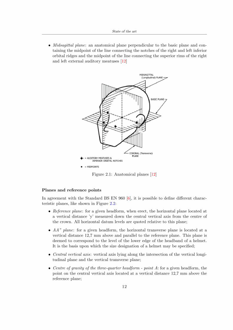
State of the art
bull Midsagittal plane an anatomical plane perpendicular to the basic plane and con-taining the midpoint of the line connecting the notches of the right and left inferiororbital ridges and the midpoint of the line connecting the superior rims of the rightand left external auditory meatuses [12]
Figure 21 Anatomical planes [12]
Planes and reference points
In agreement with the Standard BS EN 960 [6] it is possible to define different charac-teristic planes like shown in Figure 22
bull Reference plane for a given headform when erect the horizontal plane located ata vertical distance rsquoyrsquo measured down the central vertical axis from the centre ofthe crown All horizontal datum levels are quoted relative to this plane
bull AArdquo plane for a given headform the horizontal transverse plane is located at avertical distance 127 mm above and parallel to the reference plane This plane isdeemed to correspond to the level of the lower edge of the headband of a helmetIt is the basis upon which the size designation of a helmet may be specified
bull Central vertical axis vertical axis lying along the intersection of the vertical longi-tudinal plane and the vertical transverse plane
bull Centre of gravity of the three-quarter headform - point A for a given headform thepoint on the central vertical axis located at a vertical distance 127 mm above thereference plane
12
State of the art
bull Centre of gravity of the full headform - point G for a given headform the point onthe central vertical axis located at a vertical distance rsquozrsquo below the reference plane
bull Geometric centre - point R for a given headform the point on the central verticalaxis located at its intersection with the reference plane
Figure 22 Principal planes and reference points of a headform [12]
212 European Standard and American Standard
Location of gravity centre
Between the European Standard and American Standard there are differences the firstfor the location of the gravity centre
bull BS EN 960 the centre of gravity is located within a 10 mm radius of Point G
bull ASTM F1447 centre of gravity of the headform must be within a 10 vertical conefrom the centre of impact and lie within a rectangular area 28 by 128 mm
13
State of the art
The size of the head and helmet
bull ASTM F2220 to measure the external dimension for full headform the distancefrom the reference plane to the top of the headform There are different dimensionsF2220 (A if the measure is 897 mm minus C with 93 mm minus E with 96 mm minus J with1025 mm minusM with 107 mm) Then with this classification it is possible to extractthe dimension of xyz (mm) with the following Table 22
Table 22 Location of Reference Line [14]
bull BS EN 960 to obtain the size designation and the headform masses this Standardconsiders the measure of xyz (mm) in Figure 21 The possible designation are 21from 445 to 645 some of these are shown in the Table 23
Thanks to the size designation with the Standard BS EN 1078 there is the possibility todefine the inside circumference of the helmet and this it is shown in the following Table24
Table 23 Dimensions about the reference lines in Figure 21 and headform masses [6]
213 Field of vision - BS EN 1078
Apply a load of 50 N on the crown of the helmet in order to stabilize the helmet on theheadform To avoid having an occultation of the visual field Figure 23 it is better tofollow this angle measures [5]
bull horizontally min 105 from the longitudinal vertical median plane to the leftand right hand sides
bull upwards min 25 from the reference plane
bull downwards min 45 from the basic plane
14
State of the art
Table 24 Inside circumference of helmet [5]
Figure 23 Field of vision (a)(b) [5]
214 Test impact area
Standard EN 1078 will be considered for this study which defines the parameters helpfulin performing the shock absorption test The drop test impact consists of an impact ontwo anvils of flat surface or kerbstone
In the Standard is specified the Test Area where the impact is to be performed Thefirst thing is to apply a vertical load of 50 N on the crown of the helmet in order to
15
State of the art
stabilize the helmet on the headform [5]1 Draw the AArdquo line (in the AArsquo plane) on the helmet2 Draw a line on the helmet parallel to and approximately 20 mm above the AArdquo line(for use as an angular measurement datum line)3 Mark the helmet at points B1 and B2 These points are the sideways horizontalprojection of point B onto the outer surface of the helmet4 Draw a line RRrsquo on the helmet passing through B1 and B2 the line being angled 10
upwards toward the front of the helmet relative to the datum line drawn in d) The areaabove the line drawn in f) is the test area for impacts on the flat anvil The area abovethe line RWArdquo is the test area for impacts on to the kerbstone anvil
Figure 24 Definition of test impact area [5]
215 Anvils and environmental conditions
EN 1078
During the validation process each of the 30 helmet target points was impacted ex-perimentally and numerically under three environmental conditions (-20C +50C andhumidity)
The impact should never exceed 250 g for impacts with velocities corresponding to 542ms on a flat anvil and 457 ms on a kerbstone anvil These are theoretically equivalentto 1497 mm and 1064 mm drop heights respectively [5] About the characteristics of theanvils according to EN 1078 these depend on the type in the case of
bull Flat anvil it has a circular form with a diameter of 130 plusmn 3 mm with 25 mm ofthick
16
State of the art
bull Kerbstone anvil face inclined at 525 plusmn 25 to the vertical and edge with aradius of 15 plusmn 05mm The height shall be not less than 50 mm and the lengthnot less than 125 mm [5]
According with the regalement EN 1078 [5] it has been possible to realize the volumes inthis work the Flat anvil has a diameter of 130 mm and a height of 25 mm the kerbstoneanvil has a horizontal edge of 130 mm a height of 51 mm a length of 126 mm and theedge that impacts the helmet has a radius of 15 mm The anvils are represented in Figure25
[a] [b]
Figure 25 Flat anvil [a] and Kerbstone anvil [b]
EN 13087-11 (Proposal)
A proposal of November 2018 (EN 13087-11) talks about oblique impact tests (Rotationaltest method) [15] Define a method to measure rotational energy absorption in tangentialimpacts in short duration impact situations the velocity considered by Adanty et al [1]is 65 ms The same anvils of the Standard EN 1078 are used the flat anvil and theKerbstone anvil but the difference is the vertical drop towards an impact angle between30-60 the degree considered by Adanty et al [1] is 45
Three different rotations are considered [34]
bull Rotation around X-axis contact point on the side of the helmet resulting in arotation around X-axis Initial position of the headform X- Y- and Z-axis 0
bull Rotation around Y-axis Contact point on the upper part of the helmet resultingin a rotation around Y-axis Initial position of the headform X- Y- and Z-axis 0
bull Rotation around Z-axis Contact point on the upper part of the helmet resultingin a rotation around Y-axis Initial position of the headform X- and Z-axis 0 and65 around Y-axis
17
State of the art
Figure 26 (a) The current cycling helmet standard for the EN 1078 [5] (b) Theproposed standard (EN13087-11) as described by the European Committee for
Standardization (CEN) [15][1]
22 Materials
221 EPS Foam
As mentioned in Chapter 13 the material most commonly used for making the helmetis the EPS Mustafa et al [25] analysed the EPS with four different density values of 50kgm3 64 kgm3 80 kgm3 and 100 kgm3 rdquoThe drop impact simulation model wasused to test the impact attenuation of the helmet with different densities The drop testwas performed on four impact locations top front and sidesrdquo
The impact velocity of the helmet and headform was set at 544 ms The lowestpeak linear acceleration was recorded at the top location and a density of 64 kgm3 with14814 g This study sets out to determine the effect of the user-centered helmet designwith different foam densities (from 50 kgm3 to 100 kgm3) on the impact attenuationof the bicycle helmet
Kroeker et al [19] tested the helmets at three impact speeds 30 plusmn 001 ms 63 plusmn002 ms and 78 plusmn 001 ms
They established the mean value about bulk density in a helmet with EPS foam is666 considering HIC and Peak Acceleration test The global range is between 64 kgm3
and 75 kgm3
Kroeker et al [20] established the foam for kids helmets is 64-88 kgm3 and for thetraditional helmets is 60-100 kgm3
Trzaskalska et al [36] controlled the influence of polymer liner density on energy ab-sorption during impact They discovered the best properties have samples whose densityis between 54 to 60 kgm3
Cui et al [10] considered the density of each layer from the values of 25 50 60 80and 100 kgm3 and they realize a 45 grades side impact and normal crown impact Theresult is a density of 64 kgm3
Wei et al [38] discovered from their test results that EPS has a buffer layer density
18
State of the art
of 60 kgm3 is the most reasonable
Foam densityrsquos values - Literature
Authors Densityrsquos values
Mustafa et al [25] 64Kroeker et al [19] 64 - 75Kroeker et al [20] 60-100 (traditional) and 64-88 (kids)
Trzaskalska et al [36] 54 - 60Cui et al [10] 54Wei et al [38] 60
Table 25 Table with foam (EPS) densityrsquos values
The other are mean values obtained by CES EduPackrsquos program about this material
- Density ρ = 6451kgm3
- Youngrsquos Module E = 275 MPa
- Poissonrsquos ratio ν = 0275
- Yieldrsquos stress σ= 09 MPa
- Elongation at fracture = 45
222 CES Edu Pack - Material selection
CES Edupack software was used to satisfy the idea of creating a lightweight helmetby printing it in 3D and having the possibility to insert the desired characteristics ofthe material and therefore select it To make a choice I used level 3 of engineering(advanced) selecting the following criteria of the material bio-material biodegradablea polymer of concentration 20 - 100 which complies with the rsquoEuropean Restrictionon Hazardous Substances (Rohs) standardsrsquo regarding the composition of the materialensuring that it does not contain a high percentage of toxic substances compared to theestablished percentage In addition it must have proper durability in contact with coldwater (imagining a possible rain) and rsquogoodrsquo durability to UV radiation
According to Ashbyrsquos method [2] to select a material it is possible to follow thefollowing steps
1 Establish the function of the product What does the component doThe helmet is an instrumental use to protect the head during an impact this characteristicdepends on materials and qualities It can prevent an injury which depends on materialsand design because it has to be of the right head size It would be comfortable becauseit must be worn and it must give security to the person wearing it (by design) In thefollowing Table 26 the analysis of the functions
19
State of the art
Ranking Function description Depends on
1 Head protection (energy absorbing) Material2 Head protection (energy absorbing) Design3 Head protection (injury prevention) Material4 Head protection (injury prevention) Design5 Comfortable Material6 Comfortable Process
Table 26 Ashbyrsquos method functions
2 The objectives that are targets for the design the material is to bemaximised or minimisedTo manufacture and market a product objectives such as minimizing weight cost orenvironmental impact must be considered In the following Table 27 the analysis of theobjectives
Ranking Title Objectives description
1 Mass Minimize The mass has to be thesame or lower
2 Cost Minimize everyone should have theopportunity to buy it
3 CO2 footprint Minimize CO2 emission
4 Corrosion Minimize high strength because itcan be in contact with the water
5 Pleasant to touch Maximize it is not a rough materialbecause it has to put on and put off
by hands
6 Refractive index Minimize it must not reflect light
Table 27 Ashbyrsquos method objectives
3 Definition of constrains What essential conditions must be meetEstablish constraints is essential to complete the function of the instrument Examplesof constrains are Table 28
4 The limits characteristic independent of the material that does not influencethe physical properties In the following Table 29 the analysis of the limits
20
State of the art
Title Loading case Constraintsdescription
Material index(Max-Min)
Stiffness Column in compression Tie in tension
Mass Min
Stiffness Column in compression Tie in tension
Cost Min
Stiffness Column in compression Tie in tension
CO2 Min
Strength Column in compression Tie in tension
Mass Min
Strength Column in compression Tie in tension
Cost Min
Strength Column in compression Tie in tension
CO2 Min
Table 28 Ashbyrsquos method constrains
223 PLA with natural fiber and PLA LW
Initially the best material that met the desired criteria was searched From this study itwas found that the material closest to having the required characteristics is the PLA 30natural fiber as shown in the Figure 27 which shows the graphs obtained relating tothe relationships between Youngrsquos Module and density the objective to reduce the massper unit of compressive stiffness and strength to reduce the CO2 footprint per unit ofstiffness and strength and mass per unit of compressive strength
Performance index IR
The stiffness criterion has the following characteristics
m = A lowast L lowast ρ (21)
ε =σ
E=
FA
E(22)
A =F
ε lowast E(23)
21
State of the art
Ranking Title Function description
1 Biocompatibility It is the ability of a material the abilityof the material not to cause any local or
systemic adverse response in therecipient of the material
2 Biodegrability Biodegradable material do notbiodegradable under anaerobic conditions
3 Biomaterials - all The terms is used for biological naturalbio-derived bio-inspired material
4 RoHS (EU) Compliantgrades
Restriction of the use of certin prohibitessubstances (mercury cadmium
hexavalent chromium)
5 Polymer 20-100 (from the table with Plasticpolymers)
6 UV Resistance at UV sunlight
Table 29 Ashbyrsquos method limits
A =F lowast L lowast ρε lowast E
(24)
With fixed variables- F (the load) L (the length)With variables that depend on the material- E (Youngrsquos Module) ρ (density)
In general when a chart is created the distribution of the mass is represented in thefollowing modality like in Figure 27 [b] where the materials above the line have a lowermass while those below a greater mass
Following the results of the CES Edupack program that had selected the PLA withnatural fibers as the best the first print of the helmet was made with this materialusing as support the PVA Initially the result seemed satisfactory the helmet had a highdefinition but a fundamental problem was found by reducing the helmet in the water toallow the supports of PVA to dissolve In the act of diving in fact after ten minutessome parts of the helmet especially the front and rear have disintegrated making thehelmet unusable Because of this problem it was necessary to change the material
22
State of the art
[a]
[b]
Figure 27 CES EduPack Mass per unit of compressive stiffness [a] Youngrsquos Moduleand density [b]
Further investigations carried out by the Mondragon Unibertsitatea Additive Man-ufacturing Department revealed a new material the PLA Low Weight which during3D printing allows to obtain a weight of 65 lower than that which could be obtainedfrom the classic PLA as reported in the technical sheet of the filament produced by thecompany Colorfabb [7]
The investigation team of the Composite Department carried out tensile tests withsamples 3D printed at different temperatures as suggested by the manufacturer to obtainthe technical characteristics The temperatures examined are 200 220 250 260The datasheet shows the density can have values between 04 - 124 gcm3 the bed has
23
State of the art
to have a temperature between 50 - 60 the printing speed has to have values between40 - 80 mms This typology of PLA is expandible so much that rdquoAt around 230 thismaterial will start foaming increasing its volume by nearly three timesrdquo [7]
T[C] Section [mm2] Volumen [mm3] Mass [g] ρ[kgm3] E [Nmm2]
200 42235 1030117 12 1165 328807
220 43805 1655821 18 1087 265795
250 52412 1948139 17 873 178058
260 59655 1454377 12 825 117047
Table 210 Values about PLA LW tensile tests of MU Additive ManufacturingDepartment
From the tests that have been carried out on the material at different temperaturesthe printed sample is better at 250 with a volume of 1948139 mm3 and a section of52412 mm2 as shown in Table 210 For this reason the specific of the material thathave been taken into consideration are the following
- Density ρ = 873 kgm3
- Youngrsquos Module E = 1750 MPa
- Poissonrsquos ratio ν = 033
- Yieldrsquos stress σ = 2948 MPa
- Elongation at fracture = 491
23 Bio-inspired structures
When we talk about bio-inspired structures to nature we refer to structures that allowobtaining a low weight for the model that is realized and excellent absorption energy dur-ing the impact Recently the structures that have been most used in the biomimetic fieldare the rdquocolumns structures sandwich structures plates honeycomb and foamsrdquo[26]but aiming to achieve a structure increasingly with high absorption energy new struc-tures derived from plants and animals such as beetle horsetail turtle bird beak havebeen analyzed The first to create multi-cells tubes helicoidal structures the second tomulti-corner tubes [26]
The authors analyze the specific energy absorbed (SEA) by bio-inspired sandwichstructures per unit mass which can be derived from the following equation
EA(d) =
int dmax
0F (x)dx (25)
SEA(d) =EA(d)
m(26)
24
State of the art
Where EA is the energy absorption rdquomainly used to evaluate an energy absorberrsquosability to dissipate crushing energy through plastic deformationrdquo F(x) is the crashingforce dmax is the effective deformation distance [26]
What derived from their investigations is that having regard to a density of between0 and 1000 kgm3 the volumetric energy absorbed is higher for the beetle-inspired struc-tures than the others as shown in Figure 28 Based on this consideration it was chosento draw the helmet following this geometry
Figure 28 SEA of bio-inspired sandwich structures [26]
231 Beetle structure - Design of the model
To develop and increase lightweight high-strength and optimize bio-mimetic functionaland structural materials the trabecular structure of the beetle elytron is studied Thesingle structure is realized following the requirements cited by Zhang et al [39]
To realize the beetlersquos structure it is not enough to have information about the lengthof the side of the hexagon and the thickness but it is also necessary to take into accountthe relationship between the diameter of the circumferences present on the vertices ofthe hexagon and the measurement of the side The representation of a single cell is inFigure 29 It is shown in [a] a general structure with an edge of 12 mm circumferencersquosdiameter of 6 mm and thickness of 16 mm in [b] is shown the height of 20 mm
For the construction of the helmet a thickness of 12 and 16 mm was used the imageconcerns a proportion between the length of the hexagon side and the diameter of the
25
State of the art
circumference The side (distance between the centers of two circumferences) is twice thediameter measurement
[a] [b]
Figure 29 Beetle structure
232 Specific stress - PLA LW and EPS foam
To test the beetle structures compression tests were investigated The PLA LW structurewas inserted in a rsquodiskrsquo with a diameter of 100 mm and a height of 20 mm The area andthe volume of the disk is correspondingly 7854 mm2 and 157 10 mm3 The structuresexamined have different dimensions the edge L (distance between two centers of thecircumferences) had the following measures 9 10 12 14 16 mm the thickness of thecircumferences and edges are respectively of 16 mm for every structure and 12 mm forthe structure with L = 16 mm
The test was carried out with the Hoytom HM-D Testing Machine with capacitiesbetween 5 and 100 kN The test models were subjected to displacement loading at a rateof 1 mmmin as referenced by Chen et al[18] with a cylindrical specimen The specificstress of the structures was compared with the specific stress of a generic EPS helmetthe photos about it are shown in Figure 210 The EPS helmet structure is granular withpores inside The different grains dimension and these pores can be the reason for whichthe Stressrsquos values are between two values 07 and 116 MPa
Four parts of the EPS helmet were considered in the test the dimension and relativecharacteristic are in the Table 211 where m = mass A = area F = load ρ = densityR = stress Rρ = specific stress To calculate the values of stress about PLA structuresand EPS foam compression test graphs were been analyzed The stress value for eachstructure was calculated considering the single load the single area and the averagedensity value (14055 [kgm3])
The stress values of the PLA structures (Figure 211) and other characteristic valuesare in Table 212 where m = mass A = area F = load ρ = density
26
State of the art
[a] [b]
[c] [d]
Figure 210 EPS generic helmet helmet pictures [a] [b] and internal structureExternal granular structure [c] and pores [d]
[a] [b] [c]
Figure 211 PLA LW disks Grasshopper structure [a] PLA LW structure of 14 mm[b] PLA LW structure compressed [c]
27
State of the art
The results of the load-displacement graphs are affected by the geometry of the diskthe target is to valid for any shape or size for this is preferred to realize a diagramthat depends from σ (or stress) and the deformation ε (or strain) which can be definedrespectively as
σ =F
A0(27)
ε =l minus l0l
(28)
where F is the load during the test A0 is the area l0 is the initial length and l is thelength when the load is applied The areas considered for the EPS cube is reported inTable 211 in the second column the areas of the PLA structure is 7854 mm2 like thearea of the circumscribed disk
The values compared are shown in Table 213 and the graphs obtained by Matlabcode to analyze the recorded data of the compression machine are in Figure 213 and inFigure 212
Considering that the data provided by the compression machine are subject to noiseand disturbances it was decided to convert the original curve into polynomial type curvesthat allow obtaining the best interpolating curve for the data in question To obtain themit was divided the recorded data into two groups the first part from 0 until the end ofthe linear part and the second when the curve becomes linear again The best-fitting (inthe least-squares sense) was performed using the polyfit and polyval functions of MatlabThe first returns the coefficients of the p(x) with n degree the second evaluates p(x) ateach point in x The polynomial formula p(x) is shown in the Equation 29
pn(x) = anxn + anminus1x
nminus1 + + a2x2 + a1x+ a0 (29)
where a0 an are constants and x is the indeterminate The choice of the degree ofthe polynomial was made based on the criterion of wanting to obtain linear curves thatrespected the elastic trend at the beginning of the graph For this reason the degree ofthe polynomial is 1 Subsequently I searched through the intersection of the two lines forthe point that is equivalent to the maximum stress that marks the end of linearity
This value for EPS and PLA LW is the R [MPa] in the Table 213 The average stressvalue for PLA LW is 139 MPa and for EPS is 094 MPa The specific stress (Rρ) is 18MPa lowast m3)kg for the EPS found in CES 669 MPa lowast m3)kg for the EPS foam of thegeneric helmet and for PLA LW is 1161 MPa lowastm3)kg an intermediate value betweenthe two which is what we wanted to achieve
28
State of the art
m [g] A [mm2] F [N] ρ [kgm3]
EPS (CES) 50
16 9234 1063 13864
18 879 593 13651
21 858 833 14237
24 864 564 14468
Average value 14055
Table 211 Compression stress generic EPS helmet
L [mm] t [mm] m [g] F [N] ρ [kgm3]
9 16 214 7250 1363
10 16 192 5560 12467
12 16 201 8190 13051
14 12 138 8000 8961
Average value 12027
Table 212 Compression test PLA structures
PLA LW structure EPS structureρ= 12027kgm3 ρ= 14055kgm3
Edge [mm] R [MPa] Rρ103 Number R [MPa] Rρ103
EPS (CES) 09 18
9 173 1269 1 116 824
10 139 1114 2 08 568
12 138 1057 3 105 746
14 108 1205 4 077 540
Average value 139 1161 094 669
Table 213 Specific stress calculus PLA LW and EPS calculus ρ = density R = stressRρ [(MPa lowastm3)kg] = specific stress
29
State of the art
Figure 212 Compression test Stress-Strain diagrams - EPS
Figure 213 Compression test Stress-Strain diagrams - PLA LW
30
Chapter 3
Methodology
31 3D scan
311 3D Sense 2 scanner and Meshmixer - Reverse reconstruction
Standardized measures were not taken into account for making the helmet but the sizewas obtained through a 3D scan of my head
The scanner used is 3D Sense 2 by 3D Systems which has a minimum scanningvolume of 20 x 20 x 20 cm and a maximum scanning volume of 300 x 300 x 300 cmTo scan my person I was helped to get a full view at 360 at an appropriate distanceReal-time visualization of the captured images was shown through 3D Sense softwareThe idea of scanning the head with the scanner refers to the methodology used by Wanget al [30] They used a reverse reconstruction functional for me to realize the helmetsurface made to measure my head and like them a silicone pool cap was used to makescanning as smooth as possible The authors claim the head scan rdquocan also be used toobtain information about the objectrsquos surface which is then reconstructed utilizing thecomputerrsquos three-dimensional model via reverse modelling softwarerdquo [30] that in my caseis Autodesk Meshmixer
The files it was could get from the scan were stl obj and ply format they wereexported to obj to work in the next step with Autodesk Meshmixer that allowed tomodify and homogenize the 3D image obtained from the scan
In Meshmixer through the selection and delete commands the superfluous parts weredeleted that had been acquired and with the inspector and the DrawDraw2 commandsthe vertices were moved locally along a pre-defined direction and with Smooth the surfacemore homogeneous was made The sequence of steps is shown in the Figure 31
312 3D scan analysis and extraction of features
In Chapter 2 the directives imposed by the BS EN 960 Standard were examined concern-ing the definition of the helmet and the measures to be respected in the field of visionand the part of the helmet was to carry out impact tests
In Figure 32 the features defined complying with the Standardrsquos rules are repre-sented To define these features the software NX was used The angle in the subfigure
31
Methodology
[a] [b] [c] [d]
Figure 31 Sequence of 3D head scan 3D scanner acquisition [a] scan after reparationwith Meshmixer [b] solid scan vision frontal and lateral [c] [d]
[b] is bigger than 105 (as defined by the Standard) while the degree in the subfigure [c]is 25 By defining the construction lines to be respected of the helmetit was necessary todraw the design of the surface not using the software NX but changing with Rhinocerosto create a SubD or SubDivision surface
32 Helmet design
321 Rhinoceros - Helmet surface
After realizing a rsquocleanrsquo Wang et al [30] subdivide with lines and then sectors the headto create the surface of the helmet They used the technique of NURBS a Non UniformRational Basis-Splines which mathematically models a 3D geometry while thanks tothe Rhinoceros 3D organic shapes was draw SubD surfaces These geometries allow tosplit the mesh into small polygons and consist of lines with which easily the shape ofthe object can be modified with a surface already created changing the position of aline automatically the remaining part of the geometry adapts to the changes With thistechnique the rsquosurface basersquo of the helmet was realized with the size of my head Therepresentation of the realized SubD is in Figure 33
322 Grasshopper - Helmet structure
The next idea is the creation on the surface of the beetle structure with different di-mensions modelling the helmet that is not a linear surface It was decided not to buildthe structure with a software CAD because to model an already complex structure on acurved surface would mean to model a cell for a cell
To solve this obstacle a Rhinoceros plug-in was used Grasshopper GH idealized byRobert McNeel and associates creators of Rhinoceros Using GH does not mean drawinggeometries by connecting points and drawing tools because it is based on algorithmicmodelling used in architecture and engineering for 3D modelling
The modelling takes place through a node diagram that the software will convert intoa code-algorithm in GH it is possible to define the variables and parameters and inRhinoceros in real-time it is possible to view the object GH allows for varying the
32
Methodology
[a] [b]
[c]
Figure 32 Featurersquos extraction in [a] is represented the impact line in [b] and [c] twoprospective about the definition of the field of vision
[a] [b] [c]
Figure 33 SubD representation lateral view [a] top view [b] front view [c]
geometry to your liking by varying a simple parameter of the diagram as everything willbe remodelled according to the change made
In the following Figure 34 it is shown an example of a structure that was used fordistinct subgroups of helmet areas The idea was to insert smaller cells in the frontal andlateral zone and larger ones in the upper area In the first image [a] is shown the part of
33
Methodology
the helpful diagram to create the beetle structure to establish the size of the cells andthe extrusion the second image [b] contains the part of the diagram with which I appliedthe structure previously created to the SubD
The structure used to place and adapt the beetle structure to the surface is theSrfMorph while the yellow rsquowindowrsquo that contains numbers serves to select the parts ofthe surface where to apply the geometry created In accord with the GH diagram in
[a]
[b]
Figure 34 Grasshopper diagrams
Figure 34 [a] it is possible to see the steps executed to realize the structure Initially inthe xy-plane a hexagonal grid was drawn through the Hexgrid command in which youcan input the length of the hexagon edge and the number of grid elements (selected bytrial) Then the circumferences was drawn in proportion to the hexagon dimensions asspecified in the Chapter 2 and shown in Figure 35 [a] In figure [b] the rsquocutrsquo made atthe circumferences is visible this subdivision was necessary for printing purposes In thelast photo [c] the structure highlighted in green in [b] was extruded setting a distance
34
Methodology
of 20 mm
[a] [b] [c]
Figure 35 Construction sequence of the geometry of the helmet
In the diagram in Figure 34 [b] there is the application of the structure created bi-dimensionally to the SubD surface of the helmet visible by unlocking the SubD commandof the diagram and in Figure 36 [a] Upper this the referential geometry of the group ofsurfaces was superimposed where it was to be applied the newly created structure (visiblein darker red) the SubD indices are in the yellow box of the diagram
Through the SrfMorph command the location of the structure was granted In Figure36 [b] at the darkest red of the figure [a] with the above command it was possible toplace the structure
[a] [b]
Figure 36 Application of the geometry created to the helmet surface
Overall the diagrams with specific structures are five one for the front two equal forthe side parts one for the top shown in the previous Figure 36 and one for the back
The hexagons in the structure have a dimension varying between 8 mm and 14 mmof side the largest is found at the top later at the back in the sides and the smallest atthe front In Figure 36 [b] the presence of not only hexagonal structures is visible Thegeometry used does not allow the homogeneous arrangement on the entire surface andrequires different structures Automatically the choice of GH to optimize the structurewas to insert quadrilateral
As described above the helmet has different dimensions of the structure divided asvisible in Figure 36 in a quadrilateral This causes a discontinuity between zones withdifferent sizes due to the geometry of the construction
To eliminate this problem and realize the design homogeneous grids were inserted
35
Methodology
in the affected areas as shown in Figure 37 This insertion however proved to beinteresting and strategic researching in this regard studies were realized to demonstratethe insertion of a rectangular grid inside the hexagon grid was helpful for the transmissionof stress in the structure As cited by Sun et al [40] rdquothe mechanical properties of thesesandwich structures are often limited by local failures such as face-core debonding or corecollapserdquo Carrying out compression tests have effectively demonstrated that the insertionof the grid allows rdquoprovided increased stiffness specific stiffness energy absorption andcritical loadrdquo [41] As shown in the graphic [c] of the Figure 37 the honeycomb structuregives a force of 7 kN while with a grid the value is 11 kN and with the combinationexceeds 22 kN In addition in the left front a plaque to customize the helmet wasprepared Figure 37 [a]
[a] [b]
[c]
Figure 37 Grid in the helmet [a] hybrid structure with hexagons and grid [b] [40]compression test results of the hybrid structure [c] [41]
33 3D Print
After having achieved the CAD (Computer Aided Design) of the helmet in order tobe printed it must be converted and saved in format STL (Standard TriangulationLanguage) - Binary compatible with the printing machine and useful for transformingsolid object surfaces into triangles The steps to be taken are the following
bull CAD file realization
bull CAD export in format STL to Simplify 3D the software that shows slider layersand then- rotate and position the object according to geometry and the positioning of any
36
Methodology
supports- setting printing parameters- item manual andor automatic positioning of supports- slider display layers
bull import file gcode to printer
331 Printer and parameters
The program used to visualize how the helmet slices layers before sending it to the printerand to set the parameters is as anticipated Simplify 3D
To make the printing not being a flat geometry it is necessary to place the supportsThe idea was to use water-based supports that the helmet would automatically dissolveonce placed in the water After testing different types of water-soluble PVA the choicefell on eSun 3D Printing Filament PVA (water-soluble support) Before choosing theoptimal position for printing several tests were carried out and to decrease the numberof the supports significantly and allows an optimal printing of the outer part an emptyrsquospherersquo that self-sustains below the helmet was placed as shown in Figure 38
In the image [a] you can see the first print position tried with which an external partof the helmet very damaged was obtained because of the contact supports-helmet In [b]the empty rsquospherersquo is shown to optimize the number of supports and in the last photo [c]there is the full version at the end of print
[a] [b] [c]
Figure 38 Printing supports
The printer that has been used for printing is the Raise 3D Pro2 with double extrudersand nozzles of variable size from 02 mm to 1 mm after some test prints with the PLALW and the structure in created the size that allowed me to have a good compromisebetween printing time and accuracy was 06 mm Using 04 mm the printing time wasexcessive even if having the smaller nozzle diameter means having more precision withthe 08 mm nozzle the quality of the structure was not excellent as seen in Figure 38[a]
Another factor that had to be taken into account is the characteristic of the PLA-LWto expand As the printing temperature and the printer used vary the expansion andcharacteristics of the material change The use of the 06 mm nozzle associated with
37
Methodology
Parameter Left extruder Right extruder
01cm Material 01cm PVA 01cm PLA LW
Extruder toolbox index Tool 0 Tool 1
Nozzle diameter 06 mm 06 mm
Extrusion multiplier 1 05
Extrusion width Auto (072 mm) 05 mm
Layer x
Infill Rectilinear - 50
Supports (Automatic and not) Infill 50
Temperature 210 250
General parameters
Primary layer height 03 mm Top solid layer 4
Bottom solid layer 2 Outline 2
Heated bad 60 Speed 40 mms
Table 31 Printing parameters
Raise 3D allowed me to get good results The choice of this printer was not random ithas in fact the characteristic of making extremely precise prints The Raise has accuracyin placing the object on the printing bed of 078 microns on the xy axis and a resolutionfor layers of 001 mm
The final version of the helmet is visible in Figure 39 and it is possible to compare itwith the preview version in Rhinoceros in Figure 310
38
Methodology
[a] [b]
[c]
Figure 39 Views of the helmet
[a] [b]
Figure 310 Views of the helmet (GH version)
39
Chapter 4
Experimental evaluation
41 Experimental tests
411 Drop-weight impact test machine
In order to calculate the contact force peak and the difference of energy absorbed duringthe impact between the reference helmet and helmet with the beetle structure in PLA-LW dynamic impact tests were carried out using the Fractovis Plus an impact testmachine
In this way it is possible to monitor the evolution of the above variables from theinitial to the final instant of the impact The machine can withstand a load with a rangevariable from 2 to 70 kg with a maximum speed of 46 ms and a maximum height of1 m The values chosen for the test are the following 5 kg weight maximum speed andmaximum height The Anvil that was used is a disc diameter of 60 mm
As shown in Figure 41 and explained by Crupi et al [37] the machine consists ofa sensor capable of recording the speed before impact the impactor that can have avariable mass (a weight of 5 kg in my test) a system to guarantee that there are nomultiple impacts after the first and that work as a shock absorber and clamping systemwhere the object to be tested is placed
The tests that have been carried out are in total four two related to the helmetoptimized with PLA-LW and two with two generic helmets of different brand in EPS
42 PLA LW helmet
To perform the dynamic test on the helmet of PLA considering the difficulty of printingit was helpful to use a test helmet with imperfections to understand where the impactwas concentrated in a single part or distributed The images of Figure 42 show a helmetwith not well defined edges and inaccurate print but exactly localizes the impact zoneThanks to this test it was possible to take into account only one helmet area shown inFigure 43 to have the exact curve of the structure bio-inspired with PLA-LW
40
Experimental evaluation
Figure 41 Drop-weight impact test machine [37]
[a] [b]
Figure 42 Test 1 PLA-LW helmet
43 EPS helmet
To carry out dynamic tests and extract the technical characteristics of the helmettwohelmets were bought in a sports store both EPS and being on the market both certifiedThe brands of the two helmets are DTB and VAN|RYSEL and the average weight ofthe two is 223 g Two different helmets have been chosen to have a more certain andclear classification of the characteristics They are shown in Figure 44 and Figure 45
41
Experimental evaluation
[a] [b]
Figure 43 Test 2 PLA-LW helmet
[a] [b] [c]
Figure 44 Test 3 EPS helmet
[a] [b] [c]
Figure 45 Test 4 EPS helmet
44 Results
441 First results - PLA-LW and EPS helmet
Figure 46 shows two types of trends related to the two different models of the helmetThe force evaluated for PLA-LW has higher force peaks but is more concentrated and
42
Experimental evaluation
propagates less than EPS The graph shows the peaks of each curve highlighted with a redcircle In tests 1 and 2 for the PLA-LW as mentioned earlier the values are higher about7301 N for the complete helmet and 3996 N for the portion of helmet This difference isdue to the inaccuracy of the first full helmet during the printing phase In Figure 42 itis visible the low homogeneity and precision Therefore the first test with full helmet wasused only to define the area of interest of the impact which turns out to be localized Forthe other two EPS curves the values are only slightly lower compared to the PLA-LWequal to 3620 N and 3295 N but the trend is much more distributed
Figure 46 Dynamic machine test - Force
With the data obtained from the impact machine it was possible calculate not exclu-sively the value of force but itrsquos also possible to view the energy curves A resume aboutthe values and energy of the force is in the following Table 41
Test Peak force [N] Peak energy [J]
Test 1 - PLA LW (inaccurate) 730130
Test 2 - PLA LW (portion of helmet) 399643
Test 3 - EPS (DTB helmet) 362007 509
Test 4 - EPS (VAN|RYSEL helmet) 329546 4198
Test 5 - PLA with TPU 45421 5022
Table 41 Energy absorbed in dynamic test
43
Experimental evaluation
442 PLA-LW helmet with TPU cover
As it is possible to see in Figure 47 and as highlighted the first tests concerning thebio-inspired structure and the PLA-LW are far from my expectations considering thelittle distribution of force in comparison with the EPS foam and consequently a smallamount of energy absorbed
Figure 47 Dynamic machine test - Energy
To improve this impact damping factor the idea was to create a cover for the helmetin flexible TPU trying to absorb impact energy The TPU used is a flexible material ofthe brand Ninjaflex used in sports by the application in helmets and shoes to cushionbumps during the game Generally in the helmets (baseball helmet for example) theTPU is inserted internally in contact with the head In my case the TPU structurein addition to creating a shock-absorbing and durable cover creates a custom cover thehelmet and for the person This cover was also made with the Raise 3D printer
As shown in the Figure 48 [a] the infill of the part in contact with the helmet hasa percentage of 100 the filling of the other part of the structure is not complete butonly 15 and the internal structure is hexagonal to recall that of the helmet The desireto insert a structure with a rsquoraisedrsquo geometry is for visual and aesthetic reasons as youhave the feeling of greater protection and not filled is inspired by the machine CitroenCaptus whose bumpers (Airbump) are full of air The failure to realize empty structuresis due to the need to place any internal supports not removable
The idea was to create a cover that allow you to see of the internal structure of thehelmet and that protect specific areas the front the two sides the top and the posteriorWhat which was thought for this reason was to create the shape of a flower with four
44
Experimental evaluation
petals Figure 48 [b]In this way to perform dynamic impact tests as shown in Figure 49 [a] the cover was
positioned at the top of the helmet and the impact was performed in the centre of thersquoflowerrsquo which corresponds to the higher upper part where the structure has larger cellsize The impact parameters are the same as those used in previous impacts 5 kg weightmaximum speed and maximum height The Anvil that was used is a disc diameter of60 mm In photo [b] it is evident the difference between the structure that received theimpact with protection (left) and without protection (right) Without protection duringthe impact there was a perforation of the structure with a concentration of force at a locallevel as you can see in the Figure 46 in the case of TPU the impactor did not perforateand crossed the structure thanks to the cover of TPU that cushioned the shock At themoment of impact the impactor bounced
[a] [b]
Figure 48 TPU cover
[a] [b]
Figure 49 PLA-LW with TPU - dynamic impact [a] and differences between thehelmet with TPU and without TPU cover [b]
45
Experimental evaluation
The Figure 410 includes the diagrams relative to the dynamic impacts In [a] thereare already analyzed EPS results in [b] a comparison between the test on the portionof helmet in PLA LW with and without the TPU cover in [c] the overall comparison ofcurves shows a much more similar EPS trend if the TPU is placed above the structure inPLA LW to soften the blow and absorb the same energy [d]
46
[a]
[c]
[d]
Figure 410 Comparison between PLA-LW with TPU and EPS
Chapter 5
FEM Validation
51 Impactor - Anvils definition
Before to start to work in Abaqus it was necessary to search in the literature the materialwith which the anvil was been realized Milne et al [23] established the densityrsquos valuethe Youngrsquos Module and Poissonrsquos ratio for the Flat and Kerbstone Anvil
- Density ρ = 7800 kgm3
- Youngrsquos Module E = 200000 MPa
- Poissonrsquos ratio ν = 03
Inserting the data in the CES EduPack program specifying the mechanical andphysical properties the material corresponding to these characteristics is Stainless steelaustenitic (ASTM F1586) medium-hard
Initially the proposal was to create a conservative system to evaluate the absorptionenergies values and apply this value to a vibration system but the helmet needs dampingto be realized it was impossible to use a system without losses in this modality Thisis why a numerical calculation was carried out by performing two types of simulationsexplicit dynamic step and static step
The idea to realize the theoretical impact is to regard the movement of the anviland not the helmetrsquos movement which is fixed The velocity is the same cited in thenormative EN 1078 542 ms for the Flat anvil and 457 ms for the Kerbstone anvil
In performing the simulations It was given more relevance and perform tests withthe Kerbstone Anvil This choice was done because the geometry with which it is beenrealized (following as defined in the legislation) allows the helmet to be more subjectedto stress this involves the definition of higher stress limits compared to the Flat Anvil
The mesh size that has been used is the same in the case of the simulation of thehelmet optimized in PLA-LW and the full helmet in EPS of 7 mm The impactor isconsidered as a Discrete rigid body with its specific Reference Point (RP) like shownin Figure 51 for this reason it is not a solid but it is composted only by shells Inthe same image [b] there is the FEM representation of the model and in Table 51 thecharacteristic of FEM with quadrilateral (R3D4) and triangular elements (R3D3)
48
FEM Validation
Object Elementnumber
Elements Shape Geometricorder
Global size[mm]
Kerbstone 230 Quadrilateral - R3D4 Linear 7
Kerbstone 8 Triangular - R3D3 Linear 7
Table 51 Mesh element - Kerbstone Anvil
[a] [b]
Figure 51 Kerbstone anvil in the simulation like discrete rigid body [a] and FEMelements [b]
511 PLA LW - Plastic characteristics
The PLA-LW as explained in the Chapter 2 is new material on the market and producedby the only Colorfabb company for this reason few tests have been carried out to defineits technical characteristics and through tensile tests of the 3D printed specimens it waspossible to define an elastic limit as reported in the Table 210
In the context of simulations to reproduce the impact and deformation of the helmetis also necessary to consider the plastic characteristics of the material Not possessingany reference value in this regard tests were performed through a Static Step initiallyand then an Explicit Dynamic Step in Abaqus
The structure chosen to consider as a reference it is one of the structures previouslysubjected to the compression test having the side L=14 mm As for the reproduction ofthe compression disks initially they were reproduced according to the geometry of theHoytom HM-D Testing Machine considering the bodies mentioned above as discrete 3Drigid discrete The measure was the diameter of 200 mm and the height of 20 mm
After an initial analysis it was observed that the computational time of the simulationprogram was very high so it was decided to change the geometry to have a rsquodisk-surfacesrsquo(equally 3D rigid-discrete) which allowed me to have a smaller number of nodes for themesh and consequently a better computational time The representation of the opti-mized structure in PLA-LW and the disks used for simulated compression is in Figure 52
49
FEM Validation
[a] [b]
Figure 52 Representation of the samples used for the simulation of the compressiontest In Figure [a] the disks of the Hoytom HM-D Testing Machine in figure [b] the
representation of the same as simple surfaces
As shown in Figure 52 the disks are considered 3D discrete hard bodies so it waschosen for both a point the reference point RP where to apply the characteristics relatedto the two bodies As for the compression test it was established
bull the movement of a disk and fixed the second through a boundary condition impos-ing an Encastre therefore unable to move and rotate in xyz directions
bull for the opposite disk the boundary condition relative to the 15 mm displacementwas applied which is the parameter that it was observed to determine the end ofthe compression with the machine This shift is shown by the orange arrow in figure[b]
bull between the upper surface and the disk e the disk with the lower surface it wasinitialized a general contact with normal behaviour through rsquohardrsquo contact andtangential behaviour with a coefficient of friction of 02 with directionality imposedon rsquoisotropicrsquo
The next step was to define the mesh of the components whose parameters are shown inTable 52 while the representation of the FEM is in Figure 53 with the representationof the simulation and real compression test
Object Elementsnumber
Typology Geometricorder
Globalsize [mm]
Disk (14mm) 80910 hexaedral - C3D8R Linear 07
Impact disks 206 quadrilateral - R3D4 Linear 20
Impact disks 6 triangular - R3D3 Linear 20
Table 52 Mesh element - Compression test simulation
As previously announced a static simulation was initially performed with a StaticStep with Step Time equal to 900 (obtained going to consider the speed of 1 mmmin of
50
FEM Validation
[a]
[b] [c]
Figure 53 FEM representation [a] and compression test simulation [b] and realcompression [c]
the compression test and the displacement of 15 mm) However the complex geometryof the structure and the high time set by Step Time did not allow a correct definitionof the parameters of the plastic characteristics of the material the simulation was notable to continue once reached a Step Time of approximately 220 That is why it waschanged by choosing an Explicit Dynamic step
Leaving all the parameters of the boundary conditions unchanged the Step Time wasmodified imposing it to 001 The ability of the explicit dynamic to work with non-linearand contacting structures allowed me to achieve results The results obtained are shownin Figure 54 with the blue curve and were obtained through the iteration of differentPlastic Strain and Yield Stress values in Abaqus while the red line is the result of thereal compression test a similar curve trend was obtained but it is not possible to obtainthe same curve taking into account problems of printing inaccuracy
512 First test - helmet
The initial idea was to perform a simulation imposing the speed of 457 ms to theimpactor tie the helmet in EPS and PLA and compare the absorbed energies Theproblem it was encountered is related to the mesh of the helmet optimized in PLA andwith minimum dimensions of the elements and distinct elements it was not able to solveit
51
FEM Validation
[a]
YieldStress
PlasticStrain
1 47 0
2 7 001
3 75 005
4 10 01
5 108 1
6 115 15
7 12 2
[b]
Figure 54 Representation of the two curves related to the simulation in Abaqus of thecompression test and the data obtained from the real test to obtain the plastic
characteristics of the material
513 Second test - plane
The first solution is the one shown in Figure 55 To realize the simulation it was realizeda section of the helmet to involve a smaller number of elements and nodes Again thesimulation for the EPS helmet was successful while the simulation with the bio-inspiredstructure was interrupted by excessive distortion of elements
The previous images show the impact is very localized in the impacted area and theidea to achieve a complete simulation is not to consider a curved portion of the helmetbut a plane In this way it was possible to solve the problem and obtain a completesimulation for the bio-inspired structure
FEM element
Below in Table 53 there is the definition of the elements used for the PLA-LW and EPSplane in the simulation to simulate the impact and to control the energy-absorbing whilethe anvil characteristics are described in Table 51
514 EPS impact simulations
In order to proceed with the simulation it was imposed some boundary conditions thatregard ties and forces
bull the movement of the plane is fixed through an Encastre therefore unable to moveand rotate in xyz directions
52
FEM Validation
[a]
[b]
Figure 55 Impact simulation parts of EPS and PLA helmet
Object Elementnumber
Elements Shape Geometricorder
Plane (PLA) 38896 Tetrahedral -C3D10M
Quadratic
Plane (EPS) 2100 Hexahedral - C3D8R Linear
Table 53 Mesh element - plane impact
bull to create the impact it was set a speed of 457 ms at the reference point RP of therigid body which is the impactor Kerbstone Anvil shown in Figure 56
bull between the upper surface of the plane and the impactor it was initialized a Sur-face to Surface contact with normal behaviour through rsquohardrsquo contact and tangen-tial behaviour with a coefficient of friction of 02 with directionality imposed onrsquoisotropicrsquo
bull the rotation in x y z relative to the RP of the rigid discrete impactor body is locked
53
FEM Validation
In addition it was characterized the plane in the part of the materials with the char-acteristic values of the EPS mentioned in Chapter 221 The Von Mises Stress valueapparently low is relative to the Yield Stress of the EPS material equal to 09 MPa
Figure 56 EPS Boundary conditions and Load
515 PLA LW impact simulations
As also required in the case of the EPS plane in order to proceed with the simulationsome boundary conditions were imposed that regard ties and forces
bull the movement of the plane is fixed through an Encastre therefore unable to moveand rotate in xyz directions
bull to create the impact a speed of 457 ms was set at the reference point RP of therigid body which is the impactor Kerbstone Anvil shown in Figure 58
bull between the upper surface of the plane and the impactor it was initialized a Sur-face to Surface contact with normal behaviour through rsquohardrsquo contact and tangen-tial behaviour with a coefficient of friction of 02 with directionality imposed onrsquoisotropicrsquo
bull the rotation in x y z relative to the RP of the rigid discrete impactor body is locked
In addition the plane was characterized in the part of the materials with the characteristicvalues of the PLA mentioned in the Chapter 223 and 511
Figure 58 Boundary conditions and Load
54
FEM Validation
[a]
[b]
Figure 57 EPS impact simulation
52 Results
In Figures 59 and 57 it is shown how the structure in PLA LW has a more concentratedstress distribution of the structure unlike EPS The maximum value for the Von Misesstress is 09 MPa in EPS structure and 3634 MPa in PLA LW structure Once thesimulations were obtained the next step was to go and compare the energies absorbed bythe two structures The energy calculated by Abaqus that has been taken into account isPlastic Dissipation To make a comparison the data of the two energies were representedin a single graph
What emerges from the graph is that about the impact made with the KerbstoneAnvil the energy absorption is more excellent although only slightly for the PLA LWthan for the EPS From the graph in Figure 510 a value of 41 J is shown for the EPSand 51 J for the PLA LW
55
[a]
[b]
Figure 59 PLA impact simulation
[a]
Figure 510 EPS and PLA LW energy comparison - Abaqus simulation
Chapter 6
Head Injury Data
For the statistical analysis the injuries related to the accident data were categorised intothe following types and levels based on the details of the medical report [11] about theEN 1078
bull Head Injury Criterion (HIC)
bull Peak Linear Acceleration (PLAc)
bull Gadd Severity Injury (GSI)
bull Diffuse axonal injuries (DAI)
61 Abaqus simulation
Until now the purpose of the simulations has been to determine which between the twomaterials and the two structures of EPS and PLA LW could absorb more energy duringthe impact but no simulations have been carried out in compliance with BS EN 1078on the helmet impact tests To calculate the injuries listed in the previous paragraphhowever we need the acceleration values in the three directions related to the subjectrsquoshead
To realize it the scan of my head already rsquocleanrsquo was considered of which it has beencalculated the inertia thanks to the automatic SolidWorks calculation and evaluated theweight with the Table 24 the structure of the helmet was placed for the EPS and thePLA LW over the head as shown in Figure 61 Also this time being able to mesh theentire helmet in PLA LW was impossible due to the excessive distortion of some elementsduring the simulation so it has been tried to make a section of the structures of thehelmet and results were obtained
57
Head Injury Data
[a] [b]
Figure 61 My scan head - CAD [a] head imported in Abaqus[b]
Initially the simulation had these characteristics as shown in the following Figure62 considering the helmet was not sectioned As explained earlier it was not possibleto get to simulation in the case of the optimized structure in PLA LW for this reasononly a part of the helmet was considered in both cases shown in Figure 63
[a]
Figure 62 Simulation based on BS EN 1078
58
Head Injury Data
[a] [b]
Figure 63 Simulation based on BS EN 1078 with head
In order to proceed with the simulation some boundary conditions that regard tiesand forces have have imposed
bull two reference points RP were created the first in the inertia centre of the headthe second relating to the Kerbstone Anvil which is a discrete rigid body
bull in the reference point RP of the head in the definition of the engineering features5 kg was inserted for the weight and an inertia I11 = 564464E+07 gmm2 I22 =460654E+07gmm2 I33 = 187302E+07gmm2
bull to simulate the impact it was set a speed of 457 ms at the reference point RP ofthe head in z-axis direction
bull a general contact with normal behaviour through rsquohardrsquo contact and tangentialbehaviour with a coefficient of friction of 02
bull between the upper surface of the helmet and the impactor it has been initializeda Surface to Surface contact with normal behaviour through rsquohardrsquo contact andtangential behaviour with a coefficient of friction of 02 with directionality imposedon rsquoisotropicrsquo
bull the movement between the Kerbstone anvil and the helmet is fixed through anEncastre therefore unable to move and rotate in xyz directions
bull the rotation in x y z relative to the RP of the rigid discrete impactor body is locked
FEM element
As reported in Table 53 the portion of the helmet in EPS has used a mesh with hexahe-dral elements of linear order For the structure (beetle) of PLA LW given the geometry
59
Head Injury Data
complexity it was necessary to use a quadratic order of tetrahedra For the mesh of thehead instead in both simulations have been used quadrilateral elements of linear orderas reported in the Tables 61 and 62
Object Elementnumber
Elements Shape Geometricorder
Head 3755 Quadrilateral - R3D4 Linear
Head 34542 Quadrilateral - R3D3 Linear
Helmet (PLA) 272302 Tetrahedral -C3D10M
Quadratic
Table 61 Mesh element - Head simulation with PLA LW (beetle) helmet
Object Elementnumber
Elements Shape Geometricorder
Head 3755 Quadrilateral - R3D4 Linear
Head 34542 Quadrilateral - R3D3 Linear
Helmet (EPS) 72280 Hexahedral - C3D8R Linear
Table 62 Mesh element - Head simulation with EPS helmet
62 Results
Figure 64 represents the simulation in line with BS EN 1078 concerning the helmet inEPS [a] and the helmet with bio-inspired structure in PLA LW For both simulationsVan Misesrsquo stress has Yield Stress values in the case of EPS which is 09 MPa and theplastic behaviour combination of PLA LW [b]
In the case of head and Kerbstone Anvil stress was not assessed as they were previ-ously defined as discrete rigid bodies
63 Head Injury Criterion
The HIC quantifies head impact severity by incorporating time of acceleration exposureand acceleration magnitude it is calculated in post-processing phase with the followingEquation 61
HIC15 =
[1
(t1 minus t2)
int t2
t1
a(t)dt
]25(t2 minus t1) (61)
60
Head Injury Data
[a]
[b]
Figure 64 Results simulation based on BS EN 1078 with sectioned head
For this analysis a(t) is the acceleration calculated in the centre of mass of the head(corresponding to the reference point RP) expressed in g and the time interval (t2 minus t1)was chosen to maximize HIC over a maximum duration of 15 ms
Matlab and the trapz function were used to calculate the HIC to integrate accelerationover time t2 and t1 were considered initial and final times of the simulation t1 = 0 sand t2 = 10 s time less than 15 s
HIC value of 198 was obtained for EPS and 87 for PLA LW Considering the Hayeset al [16] document about the HIC values and the graph in Figure 65 developed bythe author it is possible to find the percentages related to the different injury AIS1 -AIS6 which correspond respectively to lower and higher severity while in Figure 66 therelative fatality to every value of AIS is shown The values obtained for the HIC andother criteria are shown in Table 63 The HIC value for EPS is 198 for PLA LW it is
61
Head Injury Data
Figure 65 Head injury risk curves based on HIC values [16]
Figure 66 The abbreviated injury score versus fatality rate [16]
87 Analyzing the data and comparing them with the curves of the Figure 65 I obtain
bull a percentage between 20 - 30 of AIS 1 for EPS 10 - 20 for PLA LW
bull a percentage between 10 - 20 of AIS 2 for EPS and 0 - 10 for PLA LW
bull for AIS 3 AIS 4 AIS 5 AIS 6 the percentages for both structures is between 0 -10
Comparing these percentages with the fatality rate of Figure 66 it is clear there is a riskof Moderate and Minor fatality in the case of EPS and PLA LW as all values are between0 and 30
62
Head Injury Data
HIC PLA [g] GSI E [J]
EPS 198 97 361 37723
PLA LW 87 75 169 44102
Table 63 Head Injury Data - values
64 Peak Linear Acceleration
The resultant linear acceleration versus time curve was calculated according to Equation62
γ(t) =radicγ2x(t) + γ2y(t) + γ2z (t) (62)
where
bull γ(t) is the resultant linear acceleration (g)
bull γx(t) is the linear acceleration in x axes (g)
bull γy(t) is the linear acceleration in y axes (g)
bull γz(t)is the linear acceleration in z axes (g)
The value of the impact should never exceed 250g [9] Cripton at all [9] in their studyexamined a helmet with expanded polystyrene (EPS) Figure 68 shows maximum HIC forhelmeted and unhelmeted drops from all heights For each drop height helmets reducedHIC relative to unhelmeted drops IARV value is 180g The acceleration in the two casesis shown in Figure 67 and the maximum values are 97g for EPS and 75g for PLA LWas reported in Table 63 The two values considering a maximum value calculated byCripton [9] of 180g are amply optimal and comply with the standard of 250g
65 Gadd Severity Index
Gadd proposed the Severity Index Criteria shown in Equation 63 Following this crite-rion the GSI values that are over 1000 produce serious internal head injury [33]
GSI =
int t1
0a(t)25dt (63)
Where
bull a is the linear acceleration (g)
bull t is the duration of the impact (s)
I calculated the GSI with the function trapz between 0 and t and the resulting valuesare 361 for the EPS and 169 for the PLA LW which comply with the limit
63
Head Injury Data
Figure 67 Peak accelerations for both helmets
Figure 68 Peak accelerations for both helmeted and unhelmeted drops Numbers overbars indicate peak acceleration For 2 m drop height results stated are the mean value
calculated from three drops [9]
64
Head Injury Data
66 Diffuse Axonal Injury
DAI cases covered all incidences in which neurological injuries occurred as well as con-cussion unconsciousness and coma
In order to assess the risk of head trauma in terms of diffuse axonal injury (DAI)Milne et al [23] defined a model based head injury criteria as follows obtaining theresults in Figure 69
bull 50 risk of moderate neurological injury (DAI1+) Brain Von Mises shearing stressof 28 kPa
bull 50 risk of severe neurological injury (DAI2+) Brain Von Mises shearing stressof 53 kPa
[a]
[b]
Figure 69 Peak intra-cerebral shearing stress computed with the helmet model coupledto the human head model for all impact points (a) Flat anvil (b) Kerbstone anvil [23]
65
Head Injury Data
67 Energy absorbed
In Figure 52 during the impact test between the kerbstone Anvil and the plan with thebio-inspired structure in PLA LW and EPS it was found that the PLA LW althoughwith a small difference of 10 J absorbed more energy in comparison with the EPS Whenthe test is carried out in compliance with BS EN 1078 and the head with a speed of 457ms (corresponding to the kerbstone Anvil) as shown in Figure 610 also in this casethe PLA LW with the optimized helmet structure manages to absorb more energy (evenif the difference is very low) compared to the EPS The maximum energy value in PLALW is 44102 J of EPS is 37723 J
Figure 610 Energy absorption - BS EN 1078
66
Chapter 7
Conclusion
71 Conclusion
In this thesis work a bicycle helmet with a bio-inspired structure in PLA LW and 3Dprinted was created The initial approach was to introduce an innovative aspect tostandard EPS helmets not using foam but a polymer with new geometries able toabsorb much energy during the impact For this reason the beetle structure has beenpreferred relying solely on the hypothesis encountered in the literature of its quality inabsorbing energy
Combining the new material of the PLA LW and beetle structure has made possiblethe development of new material satisfactory characteristics have been obtained sincethe first tests The two materials were first subjected to tensile tests to determine theirspecific stress in these the PLA LW had positive results
Subsequent dynamic physical tests were carried out on 3D printed helmet models andon reference helmets in EPS to calculate the absorption energy in both cases at the timeof impact These resulted in energy absorption of the beetle structure in PLA LW withthe application of a TPU cover almost equal to that of EPS about 50J To validate withfinite element analysis the two models an explicit dynamic step was used in AbaqusSimulations showed that the PLA LW structure absorbs a higher amount of energy thanthe EPS the higher is 50 J and the EPS 40J
Finally positive results have also been obtained in calculating the head injury datasimulating according to BS EN 1078 with the use of impactor helmet and head Theacceleration values for both the structures were inferior to 220g precisely for the PLALW was 75g and for the EPS 97g The same applies to the calculation of HIC and GSI(maximum acceptable value of 1000) where the values are 87 and 169 in the case of PLALW and 361 and 198 in EPS For all tests therefore greater efficiency of the structure inPLA LW has been obtained Positive results also in the simulation of the energy absorbedduring the impact as the value referring to the EPS was 35J and that of the PLA LWwas 45J
67
Conclusion
72 Future work lines
The positive results obtained can be considered as a starting point for further tests andsimulations to ensure the safety of the helmet and compliance with the regulations butbefore getting improvements and continue testing changes are required
bull the beetle structure of the helmet made with GH adapts to the SubD withoutallowing to have a homogeneous distribution it would be appropriate to have moreregular hexagonal geometries
bull the mesh of the helmet is too complex and does not allow to perform the simulationprobably to use a more regular structure would have a mesh accordingly moreregular and the simulation would be successful
bull the uneven helmet structure has so many defects that the print is imperfect andthis can change the results of the impact tests the structure should be improved
bull the printing time varies from 4 to 5 days it should be improved
bull the TPU helmet cover is too big for the RAISE printing plan it is necessary togenerate a new geometry
bull the TPU cover it must be fixed on the helmet
bull in the calculation of the DAI it is necessary to have the definition of the brain andthe head should not be considered as a rigid body
bull in the injury calculation the helmet without protection was considered with theTPU cover the result will be better
bull air flow analysis
The comments mentioned are only considerations and problems that I gained duringmy thesis and which should be improved but I am sure that these changes and improve-ments from design to printing and simulations can make the helmet a good product
68
Bibliography
[1] K Adanty J M Clark A Post Thomas Blaine H and M D Gilchrist Comparingtwo proposed protocols to test the oblique response of cycling helmets to fall impactsInternational Journal of Crashworthiness 6648 ndash 663 2020
[2] MF Ashby YJM Brechetb D Cebona and L Salvoc Selection strategies formaterials and processes Materials and Design 2004
[3] M Aysha El casco de bicicleta voronoi impreso en 3d mas seguro y ligero https
www3dnativescomen3d-printed-bicycle-helmet-voronoi-190820204
[4] H Bikas P Stavropoulos and G Chryssolouris Additive manufacturing methodsand modelling approaches a critical review The International Journal of AdvancedManufacturing Technology 83389ndash405 2016
[5] British Standards BSI Helmets for pedal cyclists and for users of skateboards androller skates - BS EN 1078 2012
[6] British Standards BSI Headforms for use in the testing of protective helmets BSEN 960 2020
[7] ColorFabb Colorfabb lw-pla 2019 httpscolorfabbcommedia
datasheetstdscolorfabbTDS_E_ColorFabb_LW-PLApdf
[8] V G Coronado T Haileyesus J M Bell T A Cheng JHaarbauer-Krupa M RLionbarger J Flores-Herrera L C McGuire and J Gilchrist Trends in sports andrecreation-related traumatic brain injuries treated in us emergency departments thenational electronic injury surveillance system-all injury program (neiss-aip) 2001-2012 J Head Trauma Rehabil 30185ndash197 2015
[9] P A Cripton D M Dressler D Stuart Cameron A Christopher R and D RichardsBicycle helmets are highly effective at preventing head injury during head impactHead-form accelerations and injury criteria for helmeted and unhelmeted impactsAccident Analysis and Prevention 701ndash7 2014
[10] L Cui M A Forero R and M D Gilchrist Optimisation of energy absorbingliner for equestrian helmets UCD School of Electrical Electronic and MechanicalEngineering University College Dublin Belfield Dublin4 Ireland 2020
[11] C Deck N Bourdet F Meyer and R Willinger Protection performance of bicyclehelmets Journal of safety research pages 67ndash77 2019
[12] Committee F08 Specification for headforms F2220 ASTM International 2015
[13] Committee F08 Specification for helmets used in recreational bicycling or rollerskating F1447 ASTM International 2018
[14] Committee F08 Test methods for equipment and procedures used in evaluating theperformance F1446 ASTM International 2020
69
Bibliography
[15] P Halldin Shock absorption including measuring CENTC 158 Working Group11 2018
[16] W C Hayes M S Erickson and E D Power Forensic injury biomechanics Annualreview of biomedical engineering pages 55ndash86 2007
[17] HEXR httpshexrcom
[18] C Jinxiang Z Xiaoming O Yoji S Kazuya G Zhensheng and P LongchengThe deformation mode and strengthening mechanism of compression in the beetleelytron plate Materials and Design 131481ndash186 2017
[19] S Kroeker M Ozkul A De Marco S Bonin and GP Siegmund Density variationin the expanded polystyrene eps foam of bicycle helmets and its influence on impactperformance Journal of biomechanical engineering 2019
[20] S G Kroeker SJ Bonin A L DeMarco C A Good and G P Siegmund Agedoes not affect the material properties of expanded polystyrene liners in field-usedbicycle helmets Journal of biomechanical engineering 2016
[21] M Meier K H Tan M K Lim and L Chung Unlocking innovation in the sportindustry through additive manufacturing Business Process Management Journa2018
[22] N J Mills and A Gilchrist The effectiveness of foams in bicycle and motorcyclehelmets Accident Analysis Prevention 23153 ndash 163 1991
[23] G Milne C Deck R P Carreira Q Allinne and R Willinger Development andvalidation of a bicycle helmet assessment of head injury risk under standard impactconditions Computer methods in biomechanics and biomedical engineering 15 Suppl1309 ndash 310 2012
[24] Y Mosleh S J Vander B Depreitere and J Ivens Novel composite foam conceptfor head protection in oblique impacts Adv Eng Mater (Advanced EngineeringMaterials) 10 2017
[25] H Mustafa T Y Pang T Ellena and S H Nasir Impact attenuation of user-centred bicycle helmet design with different foam densities J Phys Conf Ser(Journal of Physics Conference Series) 1150 2019
[26] S H Ngoc and L Guoxing A review of recent research on bio-inspired structuresand materials for energy absorption applications Composites Part 181 2020
[27] J I Novak and A R Novak Is additive manufacturing improving performance insports a systematic review Sport engineering and technology 13 2020
[28] European Road Safety Observatory European road safety observatory facts and fig-ures - cyclists - 2020 December 2020 httpseceuropaeutransportroad_
safetysitesdefaultfilesfacts_figures_cyclists_final_20210323pdf
[29] New York City Departments of Health Parks Mental Hygiene Transportation Recre-ation and the New York City Police Department Bicyclist fatalities and seriousinjuries in new york city 2005
[30] W Pengwen Y Jing H Yanan H Jiaofei and F Xiaoyang Innovative designof a helmet based on reverse engineering and 3d printing Alexandria EngineeringJournal 603445ndash3453 2021
[31] S G Piland T E Gould M Jesunathadas J S Wiggins O McNair and V CShane Protective helmets in sports Materials in Sports Equipment 3 2019
70
Bibliography
[32] K Schmitt P F Niederer M H Muser and F Walz Trauma biomechanicsSpringer Berlin Heidelberg 2010
[33] David Sepelveda Lopez A Biomechanical Analysis of Bicycle Helmets using FEMPhD thesis 2019 Bachelor thesis
[34] H Stigson Bicycle Helmets 2020 Tested by Folksam PhD thesis 2020 PhDAssociate Professor Traffic Safety Research
[35] H Tao K Sudip N Anindya and X Yongzhao 3d printed sensors for biomedicalapplications A review sensor 2019
[36] M Trzaskalska and R Chwastek Damping properties and density of helmet linersmade of expanded polystyrene (eps) Archives of Metallurgy and Materials 66 2020
[37] Crupi V Epasto G and Guglielmino E Impact response of aluminum foam sand-wiches for light-weight ship structures Metals 198ndash112 2020
[38] W Wei-cai F Dong-ming and L Yuan-xin Study on impact energy absorbing per-formance of eps buffer layer of motorcycle helmet Proceedings - 2013 InternationalConference on Mechanical and Automation Engineering MAEE 2013
[39] Z Xiaoming C Jinxiang O Yoji Z Peiwei X Xiaobing and Y Xindi Influence ofhoneycomb dimensions and forming methods on the compressive properties of beetleelytron plates Journal of Sandwich Structures and Materials 2228ndash39 2020
[40] S Zhi L Dong Z Weisheng S Shanshan and G Xu Topological optimization ofbiomimetic sandwich structures with hybrid core and cfrp face sheets CompositesScience and Technology 14279ndash90 2017
[41] S Zhi S Shanshan G Xu H Xiaozhi and C Haoran On compressive propertiesof composite sandwich structures with grid reinforced honeycomb core CompositesPart B 94245ndash252 2016
71
- List of Tables
- List of Figures
- Introduction
-
- Helmet bike protection
-
- Helmet structure
-
- Additive Manufacturing
-
- AM process
- Materials and techniques - FDM
- AM in sport
-
- 3D printed helmets
-
- Phases
- HEXR
- VORONOI
-
- State of the art
-
- Standards
-
- Headform
- European Standard and American Standard
- Field of vision - BS EN 1078
- Test impact area
- Anvils and environmental conditions
-
- Materials
-
- EPS Foam
- CES Edu Pack - Material selection
- PLA with natural fiber and PLA LW
-
- Bio-inspired structures
-
- Beetle structure - Design of the model
- Specific stress - PLA LW and EPS foam
-
- Methodology
-
- 3D scan
-
- 3D Sense 2 scanner and Meshmixer - Reverse reconstruction
- 3D scan analysis and extraction of features
-
- Helmet design
-
- Rhinoceros - Helmet surface
- Grasshopper - Helmet structure
-
- 3D Print
-
- Printer and parameters
-
- Experimental evaluation
-
- Experimental tests
-
- Drop-weight impact test machine
-
- PLA LW helmet
- EPS helmet
- Results
-
- First results - PLA-LW and EPS helmet
- PLA-LW helmet with TPU cover
-
- FEM Validation
-
- Impactor - Anvils definition
-
- PLA LW - Plastic characteristics
- First test - helmet
- Second test - plane
- EPS impact simulations
- PLA LW impact simulations
-
- Results
-
- Head Injury Data
-
- Abaqus simulation
- Results
- Head Injury Criterion
- Peak Linear Acceleration
- Gadd Severity Index
- Diffuse Axonal Injury
- Energy absorbed
-
- Conclusion
-
- Conclusion
- Future work lines
-
- Bibliography
-
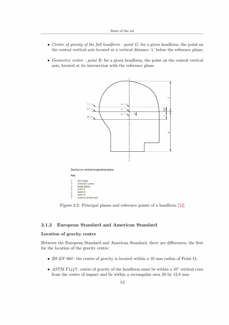
State of the art
bull Centre of gravity of the full headform - point G for a given headform the point onthe central vertical axis located at a vertical distance rsquozrsquo below the reference plane
bull Geometric centre - point R for a given headform the point on the central verticalaxis located at its intersection with the reference plane
Figure 22 Principal planes and reference points of a headform [12]
212 European Standard and American Standard
Location of gravity centre
Between the European Standard and American Standard there are differences the firstfor the location of the gravity centre
bull BS EN 960 the centre of gravity is located within a 10 mm radius of Point G
bull ASTM F1447 centre of gravity of the headform must be within a 10 vertical conefrom the centre of impact and lie within a rectangular area 28 by 128 mm
13
State of the art
The size of the head and helmet
bull ASTM F2220 to measure the external dimension for full headform the distancefrom the reference plane to the top of the headform There are different dimensionsF2220 (A if the measure is 897 mm minus C with 93 mm minus E with 96 mm minus J with1025 mm minusM with 107 mm) Then with this classification it is possible to extractthe dimension of xyz (mm) with the following Table 22
Table 22 Location of Reference Line [14]
bull BS EN 960 to obtain the size designation and the headform masses this Standardconsiders the measure of xyz (mm) in Figure 21 The possible designation are 21from 445 to 645 some of these are shown in the Table 23
Thanks to the size designation with the Standard BS EN 1078 there is the possibility todefine the inside circumference of the helmet and this it is shown in the following Table24
Table 23 Dimensions about the reference lines in Figure 21 and headform masses [6]
213 Field of vision - BS EN 1078
Apply a load of 50 N on the crown of the helmet in order to stabilize the helmet on theheadform To avoid having an occultation of the visual field Figure 23 it is better tofollow this angle measures [5]
bull horizontally min 105 from the longitudinal vertical median plane to the leftand right hand sides
bull upwards min 25 from the reference plane
bull downwards min 45 from the basic plane
14
State of the art
Table 24 Inside circumference of helmet [5]
Figure 23 Field of vision (a)(b) [5]
214 Test impact area
Standard EN 1078 will be considered for this study which defines the parameters helpfulin performing the shock absorption test The drop test impact consists of an impact ontwo anvils of flat surface or kerbstone
In the Standard is specified the Test Area where the impact is to be performed Thefirst thing is to apply a vertical load of 50 N on the crown of the helmet in order to
15
State of the art
stabilize the helmet on the headform [5]1 Draw the AArdquo line (in the AArsquo plane) on the helmet2 Draw a line on the helmet parallel to and approximately 20 mm above the AArdquo line(for use as an angular measurement datum line)3 Mark the helmet at points B1 and B2 These points are the sideways horizontalprojection of point B onto the outer surface of the helmet4 Draw a line RRrsquo on the helmet passing through B1 and B2 the line being angled 10
upwards toward the front of the helmet relative to the datum line drawn in d) The areaabove the line drawn in f) is the test area for impacts on the flat anvil The area abovethe line RWArdquo is the test area for impacts on to the kerbstone anvil
Figure 24 Definition of test impact area [5]
215 Anvils and environmental conditions
EN 1078
During the validation process each of the 30 helmet target points was impacted ex-perimentally and numerically under three environmental conditions (-20C +50C andhumidity)
The impact should never exceed 250 g for impacts with velocities corresponding to 542ms on a flat anvil and 457 ms on a kerbstone anvil These are theoretically equivalentto 1497 mm and 1064 mm drop heights respectively [5] About the characteristics of theanvils according to EN 1078 these depend on the type in the case of
bull Flat anvil it has a circular form with a diameter of 130 plusmn 3 mm with 25 mm ofthick
16
State of the art
bull Kerbstone anvil face inclined at 525 plusmn 25 to the vertical and edge with aradius of 15 plusmn 05mm The height shall be not less than 50 mm and the lengthnot less than 125 mm [5]
According with the regalement EN 1078 [5] it has been possible to realize the volumes inthis work the Flat anvil has a diameter of 130 mm and a height of 25 mm the kerbstoneanvil has a horizontal edge of 130 mm a height of 51 mm a length of 126 mm and theedge that impacts the helmet has a radius of 15 mm The anvils are represented in Figure25
[a] [b]
Figure 25 Flat anvil [a] and Kerbstone anvil [b]
EN 13087-11 (Proposal)
A proposal of November 2018 (EN 13087-11) talks about oblique impact tests (Rotationaltest method) [15] Define a method to measure rotational energy absorption in tangentialimpacts in short duration impact situations the velocity considered by Adanty et al [1]is 65 ms The same anvils of the Standard EN 1078 are used the flat anvil and theKerbstone anvil but the difference is the vertical drop towards an impact angle between30-60 the degree considered by Adanty et al [1] is 45
Three different rotations are considered [34]
bull Rotation around X-axis contact point on the side of the helmet resulting in arotation around X-axis Initial position of the headform X- Y- and Z-axis 0
bull Rotation around Y-axis Contact point on the upper part of the helmet resultingin a rotation around Y-axis Initial position of the headform X- Y- and Z-axis 0
bull Rotation around Z-axis Contact point on the upper part of the helmet resultingin a rotation around Y-axis Initial position of the headform X- and Z-axis 0 and65 around Y-axis
17
State of the art
Figure 26 (a) The current cycling helmet standard for the EN 1078 [5] (b) Theproposed standard (EN13087-11) as described by the European Committee for
Standardization (CEN) [15][1]
22 Materials
221 EPS Foam
As mentioned in Chapter 13 the material most commonly used for making the helmetis the EPS Mustafa et al [25] analysed the EPS with four different density values of 50kgm3 64 kgm3 80 kgm3 and 100 kgm3 rdquoThe drop impact simulation model wasused to test the impact attenuation of the helmet with different densities The drop testwas performed on four impact locations top front and sidesrdquo
The impact velocity of the helmet and headform was set at 544 ms The lowestpeak linear acceleration was recorded at the top location and a density of 64 kgm3 with14814 g This study sets out to determine the effect of the user-centered helmet designwith different foam densities (from 50 kgm3 to 100 kgm3) on the impact attenuationof the bicycle helmet
Kroeker et al [19] tested the helmets at three impact speeds 30 plusmn 001 ms 63 plusmn002 ms and 78 plusmn 001 ms
They established the mean value about bulk density in a helmet with EPS foam is666 considering HIC and Peak Acceleration test The global range is between 64 kgm3
and 75 kgm3
Kroeker et al [20] established the foam for kids helmets is 64-88 kgm3 and for thetraditional helmets is 60-100 kgm3
Trzaskalska et al [36] controlled the influence of polymer liner density on energy ab-sorption during impact They discovered the best properties have samples whose densityis between 54 to 60 kgm3
Cui et al [10] considered the density of each layer from the values of 25 50 60 80and 100 kgm3 and they realize a 45 grades side impact and normal crown impact Theresult is a density of 64 kgm3
Wei et al [38] discovered from their test results that EPS has a buffer layer density
18
State of the art
of 60 kgm3 is the most reasonable
Foam densityrsquos values - Literature
Authors Densityrsquos values
Mustafa et al [25] 64Kroeker et al [19] 64 - 75Kroeker et al [20] 60-100 (traditional) and 64-88 (kids)
Trzaskalska et al [36] 54 - 60Cui et al [10] 54Wei et al [38] 60
Table 25 Table with foam (EPS) densityrsquos values
The other are mean values obtained by CES EduPackrsquos program about this material
- Density ρ = 6451kgm3
- Youngrsquos Module E = 275 MPa
- Poissonrsquos ratio ν = 0275
- Yieldrsquos stress σ= 09 MPa
- Elongation at fracture = 45
222 CES Edu Pack - Material selection
CES Edupack software was used to satisfy the idea of creating a lightweight helmetby printing it in 3D and having the possibility to insert the desired characteristics ofthe material and therefore select it To make a choice I used level 3 of engineering(advanced) selecting the following criteria of the material bio-material biodegradablea polymer of concentration 20 - 100 which complies with the rsquoEuropean Restrictionon Hazardous Substances (Rohs) standardsrsquo regarding the composition of the materialensuring that it does not contain a high percentage of toxic substances compared to theestablished percentage In addition it must have proper durability in contact with coldwater (imagining a possible rain) and rsquogoodrsquo durability to UV radiation
According to Ashbyrsquos method [2] to select a material it is possible to follow thefollowing steps
1 Establish the function of the product What does the component doThe helmet is an instrumental use to protect the head during an impact this characteristicdepends on materials and qualities It can prevent an injury which depends on materialsand design because it has to be of the right head size It would be comfortable becauseit must be worn and it must give security to the person wearing it (by design) In thefollowing Table 26 the analysis of the functions
19
State of the art
Ranking Function description Depends on
1 Head protection (energy absorbing) Material2 Head protection (energy absorbing) Design3 Head protection (injury prevention) Material4 Head protection (injury prevention) Design5 Comfortable Material6 Comfortable Process
Table 26 Ashbyrsquos method functions
2 The objectives that are targets for the design the material is to bemaximised or minimisedTo manufacture and market a product objectives such as minimizing weight cost orenvironmental impact must be considered In the following Table 27 the analysis of theobjectives
Ranking Title Objectives description
1 Mass Minimize The mass has to be thesame or lower
2 Cost Minimize everyone should have theopportunity to buy it
3 CO2 footprint Minimize CO2 emission
4 Corrosion Minimize high strength because itcan be in contact with the water
5 Pleasant to touch Maximize it is not a rough materialbecause it has to put on and put off
by hands
6 Refractive index Minimize it must not reflect light
Table 27 Ashbyrsquos method objectives
3 Definition of constrains What essential conditions must be meetEstablish constraints is essential to complete the function of the instrument Examplesof constrains are Table 28
4 The limits characteristic independent of the material that does not influencethe physical properties In the following Table 29 the analysis of the limits
20
State of the art
Title Loading case Constraintsdescription
Material index(Max-Min)
Stiffness Column in compression Tie in tension
Mass Min
Stiffness Column in compression Tie in tension
Cost Min
Stiffness Column in compression Tie in tension
CO2 Min
Strength Column in compression Tie in tension
Mass Min
Strength Column in compression Tie in tension
Cost Min
Strength Column in compression Tie in tension
CO2 Min
Table 28 Ashbyrsquos method constrains
223 PLA with natural fiber and PLA LW
Initially the best material that met the desired criteria was searched From this study itwas found that the material closest to having the required characteristics is the PLA 30natural fiber as shown in the Figure 27 which shows the graphs obtained relating tothe relationships between Youngrsquos Module and density the objective to reduce the massper unit of compressive stiffness and strength to reduce the CO2 footprint per unit ofstiffness and strength and mass per unit of compressive strength
Performance index IR
The stiffness criterion has the following characteristics
m = A lowast L lowast ρ (21)
ε =σ
E=
FA
E(22)
A =F
ε lowast E(23)
21
State of the art
Ranking Title Function description
1 Biocompatibility It is the ability of a material the abilityof the material not to cause any local or
systemic adverse response in therecipient of the material
2 Biodegrability Biodegradable material do notbiodegradable under anaerobic conditions
3 Biomaterials - all The terms is used for biological naturalbio-derived bio-inspired material
4 RoHS (EU) Compliantgrades
Restriction of the use of certin prohibitessubstances (mercury cadmium
hexavalent chromium)
5 Polymer 20-100 (from the table with Plasticpolymers)
6 UV Resistance at UV sunlight
Table 29 Ashbyrsquos method limits
A =F lowast L lowast ρε lowast E
(24)
With fixed variables- F (the load) L (the length)With variables that depend on the material- E (Youngrsquos Module) ρ (density)
In general when a chart is created the distribution of the mass is represented in thefollowing modality like in Figure 27 [b] where the materials above the line have a lowermass while those below a greater mass
Following the results of the CES Edupack program that had selected the PLA withnatural fibers as the best the first print of the helmet was made with this materialusing as support the PVA Initially the result seemed satisfactory the helmet had a highdefinition but a fundamental problem was found by reducing the helmet in the water toallow the supports of PVA to dissolve In the act of diving in fact after ten minutessome parts of the helmet especially the front and rear have disintegrated making thehelmet unusable Because of this problem it was necessary to change the material
22
State of the art
[a]
[b]
Figure 27 CES EduPack Mass per unit of compressive stiffness [a] Youngrsquos Moduleand density [b]
Further investigations carried out by the Mondragon Unibertsitatea Additive Man-ufacturing Department revealed a new material the PLA Low Weight which during3D printing allows to obtain a weight of 65 lower than that which could be obtainedfrom the classic PLA as reported in the technical sheet of the filament produced by thecompany Colorfabb [7]
The investigation team of the Composite Department carried out tensile tests withsamples 3D printed at different temperatures as suggested by the manufacturer to obtainthe technical characteristics The temperatures examined are 200 220 250 260The datasheet shows the density can have values between 04 - 124 gcm3 the bed has
23
State of the art
to have a temperature between 50 - 60 the printing speed has to have values between40 - 80 mms This typology of PLA is expandible so much that rdquoAt around 230 thismaterial will start foaming increasing its volume by nearly three timesrdquo [7]
T[C] Section [mm2] Volumen [mm3] Mass [g] ρ[kgm3] E [Nmm2]
200 42235 1030117 12 1165 328807
220 43805 1655821 18 1087 265795
250 52412 1948139 17 873 178058
260 59655 1454377 12 825 117047
Table 210 Values about PLA LW tensile tests of MU Additive ManufacturingDepartment
From the tests that have been carried out on the material at different temperaturesthe printed sample is better at 250 with a volume of 1948139 mm3 and a section of52412 mm2 as shown in Table 210 For this reason the specific of the material thathave been taken into consideration are the following
- Density ρ = 873 kgm3
- Youngrsquos Module E = 1750 MPa
- Poissonrsquos ratio ν = 033
- Yieldrsquos stress σ = 2948 MPa
- Elongation at fracture = 491
23 Bio-inspired structures
When we talk about bio-inspired structures to nature we refer to structures that allowobtaining a low weight for the model that is realized and excellent absorption energy dur-ing the impact Recently the structures that have been most used in the biomimetic fieldare the rdquocolumns structures sandwich structures plates honeycomb and foamsrdquo[26]but aiming to achieve a structure increasingly with high absorption energy new struc-tures derived from plants and animals such as beetle horsetail turtle bird beak havebeen analyzed The first to create multi-cells tubes helicoidal structures the second tomulti-corner tubes [26]
The authors analyze the specific energy absorbed (SEA) by bio-inspired sandwichstructures per unit mass which can be derived from the following equation
EA(d) =
int dmax
0F (x)dx (25)
SEA(d) =EA(d)
m(26)
24
State of the art
Where EA is the energy absorption rdquomainly used to evaluate an energy absorberrsquosability to dissipate crushing energy through plastic deformationrdquo F(x) is the crashingforce dmax is the effective deformation distance [26]
What derived from their investigations is that having regard to a density of between0 and 1000 kgm3 the volumetric energy absorbed is higher for the beetle-inspired struc-tures than the others as shown in Figure 28 Based on this consideration it was chosento draw the helmet following this geometry
Figure 28 SEA of bio-inspired sandwich structures [26]
231 Beetle structure - Design of the model
To develop and increase lightweight high-strength and optimize bio-mimetic functionaland structural materials the trabecular structure of the beetle elytron is studied Thesingle structure is realized following the requirements cited by Zhang et al [39]
To realize the beetlersquos structure it is not enough to have information about the lengthof the side of the hexagon and the thickness but it is also necessary to take into accountthe relationship between the diameter of the circumferences present on the vertices ofthe hexagon and the measurement of the side The representation of a single cell is inFigure 29 It is shown in [a] a general structure with an edge of 12 mm circumferencersquosdiameter of 6 mm and thickness of 16 mm in [b] is shown the height of 20 mm
For the construction of the helmet a thickness of 12 and 16 mm was used the imageconcerns a proportion between the length of the hexagon side and the diameter of the
25
State of the art
circumference The side (distance between the centers of two circumferences) is twice thediameter measurement
[a] [b]
Figure 29 Beetle structure
232 Specific stress - PLA LW and EPS foam
To test the beetle structures compression tests were investigated The PLA LW structurewas inserted in a rsquodiskrsquo with a diameter of 100 mm and a height of 20 mm The area andthe volume of the disk is correspondingly 7854 mm2 and 157 10 mm3 The structuresexamined have different dimensions the edge L (distance between two centers of thecircumferences) had the following measures 9 10 12 14 16 mm the thickness of thecircumferences and edges are respectively of 16 mm for every structure and 12 mm forthe structure with L = 16 mm
The test was carried out with the Hoytom HM-D Testing Machine with capacitiesbetween 5 and 100 kN The test models were subjected to displacement loading at a rateof 1 mmmin as referenced by Chen et al[18] with a cylindrical specimen The specificstress of the structures was compared with the specific stress of a generic EPS helmetthe photos about it are shown in Figure 210 The EPS helmet structure is granular withpores inside The different grains dimension and these pores can be the reason for whichthe Stressrsquos values are between two values 07 and 116 MPa
Four parts of the EPS helmet were considered in the test the dimension and relativecharacteristic are in the Table 211 where m = mass A = area F = load ρ = densityR = stress Rρ = specific stress To calculate the values of stress about PLA structuresand EPS foam compression test graphs were been analyzed The stress value for eachstructure was calculated considering the single load the single area and the averagedensity value (14055 [kgm3])
The stress values of the PLA structures (Figure 211) and other characteristic valuesare in Table 212 where m = mass A = area F = load ρ = density
26
State of the art
[a] [b]
[c] [d]
Figure 210 EPS generic helmet helmet pictures [a] [b] and internal structureExternal granular structure [c] and pores [d]
[a] [b] [c]
Figure 211 PLA LW disks Grasshopper structure [a] PLA LW structure of 14 mm[b] PLA LW structure compressed [c]
27
State of the art
The results of the load-displacement graphs are affected by the geometry of the diskthe target is to valid for any shape or size for this is preferred to realize a diagramthat depends from σ (or stress) and the deformation ε (or strain) which can be definedrespectively as
σ =F
A0(27)
ε =l minus l0l
(28)
where F is the load during the test A0 is the area l0 is the initial length and l is thelength when the load is applied The areas considered for the EPS cube is reported inTable 211 in the second column the areas of the PLA structure is 7854 mm2 like thearea of the circumscribed disk
The values compared are shown in Table 213 and the graphs obtained by Matlabcode to analyze the recorded data of the compression machine are in Figure 213 and inFigure 212
Considering that the data provided by the compression machine are subject to noiseand disturbances it was decided to convert the original curve into polynomial type curvesthat allow obtaining the best interpolating curve for the data in question To obtain themit was divided the recorded data into two groups the first part from 0 until the end ofthe linear part and the second when the curve becomes linear again The best-fitting (inthe least-squares sense) was performed using the polyfit and polyval functions of MatlabThe first returns the coefficients of the p(x) with n degree the second evaluates p(x) ateach point in x The polynomial formula p(x) is shown in the Equation 29
pn(x) = anxn + anminus1x
nminus1 + + a2x2 + a1x+ a0 (29)
where a0 an are constants and x is the indeterminate The choice of the degree ofthe polynomial was made based on the criterion of wanting to obtain linear curves thatrespected the elastic trend at the beginning of the graph For this reason the degree ofthe polynomial is 1 Subsequently I searched through the intersection of the two lines forthe point that is equivalent to the maximum stress that marks the end of linearity
This value for EPS and PLA LW is the R [MPa] in the Table 213 The average stressvalue for PLA LW is 139 MPa and for EPS is 094 MPa The specific stress (Rρ) is 18MPa lowast m3)kg for the EPS found in CES 669 MPa lowast m3)kg for the EPS foam of thegeneric helmet and for PLA LW is 1161 MPa lowastm3)kg an intermediate value betweenthe two which is what we wanted to achieve
28
State of the art
m [g] A [mm2] F [N] ρ [kgm3]
EPS (CES) 50
16 9234 1063 13864
18 879 593 13651
21 858 833 14237
24 864 564 14468
Average value 14055
Table 211 Compression stress generic EPS helmet
L [mm] t [mm] m [g] F [N] ρ [kgm3]
9 16 214 7250 1363
10 16 192 5560 12467
12 16 201 8190 13051
14 12 138 8000 8961
Average value 12027
Table 212 Compression test PLA structures
PLA LW structure EPS structureρ= 12027kgm3 ρ= 14055kgm3
Edge [mm] R [MPa] Rρ103 Number R [MPa] Rρ103
EPS (CES) 09 18
9 173 1269 1 116 824
10 139 1114 2 08 568
12 138 1057 3 105 746
14 108 1205 4 077 540
Average value 139 1161 094 669
Table 213 Specific stress calculus PLA LW and EPS calculus ρ = density R = stressRρ [(MPa lowastm3)kg] = specific stress
29
State of the art
Figure 212 Compression test Stress-Strain diagrams - EPS
Figure 213 Compression test Stress-Strain diagrams - PLA LW
30
Chapter 3
Methodology
31 3D scan
311 3D Sense 2 scanner and Meshmixer - Reverse reconstruction
Standardized measures were not taken into account for making the helmet but the sizewas obtained through a 3D scan of my head
The scanner used is 3D Sense 2 by 3D Systems which has a minimum scanningvolume of 20 x 20 x 20 cm and a maximum scanning volume of 300 x 300 x 300 cmTo scan my person I was helped to get a full view at 360 at an appropriate distanceReal-time visualization of the captured images was shown through 3D Sense softwareThe idea of scanning the head with the scanner refers to the methodology used by Wanget al [30] They used a reverse reconstruction functional for me to realize the helmetsurface made to measure my head and like them a silicone pool cap was used to makescanning as smooth as possible The authors claim the head scan rdquocan also be used toobtain information about the objectrsquos surface which is then reconstructed utilizing thecomputerrsquos three-dimensional model via reverse modelling softwarerdquo [30] that in my caseis Autodesk Meshmixer
The files it was could get from the scan were stl obj and ply format they wereexported to obj to work in the next step with Autodesk Meshmixer that allowed tomodify and homogenize the 3D image obtained from the scan
In Meshmixer through the selection and delete commands the superfluous parts weredeleted that had been acquired and with the inspector and the DrawDraw2 commandsthe vertices were moved locally along a pre-defined direction and with Smooth the surfacemore homogeneous was made The sequence of steps is shown in the Figure 31
312 3D scan analysis and extraction of features
In Chapter 2 the directives imposed by the BS EN 960 Standard were examined concern-ing the definition of the helmet and the measures to be respected in the field of visionand the part of the helmet was to carry out impact tests
In Figure 32 the features defined complying with the Standardrsquos rules are repre-sented To define these features the software NX was used The angle in the subfigure
31
Methodology
[a] [b] [c] [d]
Figure 31 Sequence of 3D head scan 3D scanner acquisition [a] scan after reparationwith Meshmixer [b] solid scan vision frontal and lateral [c] [d]
[b] is bigger than 105 (as defined by the Standard) while the degree in the subfigure [c]is 25 By defining the construction lines to be respected of the helmetit was necessary todraw the design of the surface not using the software NX but changing with Rhinocerosto create a SubD or SubDivision surface
32 Helmet design
321 Rhinoceros - Helmet surface
After realizing a rsquocleanrsquo Wang et al [30] subdivide with lines and then sectors the headto create the surface of the helmet They used the technique of NURBS a Non UniformRational Basis-Splines which mathematically models a 3D geometry while thanks tothe Rhinoceros 3D organic shapes was draw SubD surfaces These geometries allow tosplit the mesh into small polygons and consist of lines with which easily the shape ofthe object can be modified with a surface already created changing the position of aline automatically the remaining part of the geometry adapts to the changes With thistechnique the rsquosurface basersquo of the helmet was realized with the size of my head Therepresentation of the realized SubD is in Figure 33
322 Grasshopper - Helmet structure
The next idea is the creation on the surface of the beetle structure with different di-mensions modelling the helmet that is not a linear surface It was decided not to buildthe structure with a software CAD because to model an already complex structure on acurved surface would mean to model a cell for a cell
To solve this obstacle a Rhinoceros plug-in was used Grasshopper GH idealized byRobert McNeel and associates creators of Rhinoceros Using GH does not mean drawinggeometries by connecting points and drawing tools because it is based on algorithmicmodelling used in architecture and engineering for 3D modelling
The modelling takes place through a node diagram that the software will convert intoa code-algorithm in GH it is possible to define the variables and parameters and inRhinoceros in real-time it is possible to view the object GH allows for varying the
32
Methodology
[a] [b]
[c]
Figure 32 Featurersquos extraction in [a] is represented the impact line in [b] and [c] twoprospective about the definition of the field of vision
[a] [b] [c]
Figure 33 SubD representation lateral view [a] top view [b] front view [c]
geometry to your liking by varying a simple parameter of the diagram as everything willbe remodelled according to the change made
In the following Figure 34 it is shown an example of a structure that was used fordistinct subgroups of helmet areas The idea was to insert smaller cells in the frontal andlateral zone and larger ones in the upper area In the first image [a] is shown the part of
33
Methodology
the helpful diagram to create the beetle structure to establish the size of the cells andthe extrusion the second image [b] contains the part of the diagram with which I appliedthe structure previously created to the SubD
The structure used to place and adapt the beetle structure to the surface is theSrfMorph while the yellow rsquowindowrsquo that contains numbers serves to select the parts ofthe surface where to apply the geometry created In accord with the GH diagram in
[a]
[b]
Figure 34 Grasshopper diagrams
Figure 34 [a] it is possible to see the steps executed to realize the structure Initially inthe xy-plane a hexagonal grid was drawn through the Hexgrid command in which youcan input the length of the hexagon edge and the number of grid elements (selected bytrial) Then the circumferences was drawn in proportion to the hexagon dimensions asspecified in the Chapter 2 and shown in Figure 35 [a] In figure [b] the rsquocutrsquo made atthe circumferences is visible this subdivision was necessary for printing purposes In thelast photo [c] the structure highlighted in green in [b] was extruded setting a distance
34
Methodology
of 20 mm
[a] [b] [c]
Figure 35 Construction sequence of the geometry of the helmet
In the diagram in Figure 34 [b] there is the application of the structure created bi-dimensionally to the SubD surface of the helmet visible by unlocking the SubD commandof the diagram and in Figure 36 [a] Upper this the referential geometry of the group ofsurfaces was superimposed where it was to be applied the newly created structure (visiblein darker red) the SubD indices are in the yellow box of the diagram
Through the SrfMorph command the location of the structure was granted In Figure36 [b] at the darkest red of the figure [a] with the above command it was possible toplace the structure
[a] [b]
Figure 36 Application of the geometry created to the helmet surface
Overall the diagrams with specific structures are five one for the front two equal forthe side parts one for the top shown in the previous Figure 36 and one for the back
The hexagons in the structure have a dimension varying between 8 mm and 14 mmof side the largest is found at the top later at the back in the sides and the smallest atthe front In Figure 36 [b] the presence of not only hexagonal structures is visible Thegeometry used does not allow the homogeneous arrangement on the entire surface andrequires different structures Automatically the choice of GH to optimize the structurewas to insert quadrilateral
As described above the helmet has different dimensions of the structure divided asvisible in Figure 36 in a quadrilateral This causes a discontinuity between zones withdifferent sizes due to the geometry of the construction
To eliminate this problem and realize the design homogeneous grids were inserted
35
Methodology
in the affected areas as shown in Figure 37 This insertion however proved to beinteresting and strategic researching in this regard studies were realized to demonstratethe insertion of a rectangular grid inside the hexagon grid was helpful for the transmissionof stress in the structure As cited by Sun et al [40] rdquothe mechanical properties of thesesandwich structures are often limited by local failures such as face-core debonding or corecollapserdquo Carrying out compression tests have effectively demonstrated that the insertionof the grid allows rdquoprovided increased stiffness specific stiffness energy absorption andcritical loadrdquo [41] As shown in the graphic [c] of the Figure 37 the honeycomb structuregives a force of 7 kN while with a grid the value is 11 kN and with the combinationexceeds 22 kN In addition in the left front a plaque to customize the helmet wasprepared Figure 37 [a]
[a] [b]
[c]
Figure 37 Grid in the helmet [a] hybrid structure with hexagons and grid [b] [40]compression test results of the hybrid structure [c] [41]
33 3D Print
After having achieved the CAD (Computer Aided Design) of the helmet in order tobe printed it must be converted and saved in format STL (Standard TriangulationLanguage) - Binary compatible with the printing machine and useful for transformingsolid object surfaces into triangles The steps to be taken are the following
bull CAD file realization
bull CAD export in format STL to Simplify 3D the software that shows slider layersand then- rotate and position the object according to geometry and the positioning of any
36
Methodology
supports- setting printing parameters- item manual andor automatic positioning of supports- slider display layers
bull import file gcode to printer
331 Printer and parameters
The program used to visualize how the helmet slices layers before sending it to the printerand to set the parameters is as anticipated Simplify 3D
To make the printing not being a flat geometry it is necessary to place the supportsThe idea was to use water-based supports that the helmet would automatically dissolveonce placed in the water After testing different types of water-soluble PVA the choicefell on eSun 3D Printing Filament PVA (water-soluble support) Before choosing theoptimal position for printing several tests were carried out and to decrease the numberof the supports significantly and allows an optimal printing of the outer part an emptyrsquospherersquo that self-sustains below the helmet was placed as shown in Figure 38
In the image [a] you can see the first print position tried with which an external partof the helmet very damaged was obtained because of the contact supports-helmet In [b]the empty rsquospherersquo is shown to optimize the number of supports and in the last photo [c]there is the full version at the end of print
[a] [b] [c]
Figure 38 Printing supports
The printer that has been used for printing is the Raise 3D Pro2 with double extrudersand nozzles of variable size from 02 mm to 1 mm after some test prints with the PLALW and the structure in created the size that allowed me to have a good compromisebetween printing time and accuracy was 06 mm Using 04 mm the printing time wasexcessive even if having the smaller nozzle diameter means having more precision withthe 08 mm nozzle the quality of the structure was not excellent as seen in Figure 38[a]
Another factor that had to be taken into account is the characteristic of the PLA-LWto expand As the printing temperature and the printer used vary the expansion andcharacteristics of the material change The use of the 06 mm nozzle associated with
37
Methodology
Parameter Left extruder Right extruder
01cm Material 01cm PVA 01cm PLA LW
Extruder toolbox index Tool 0 Tool 1
Nozzle diameter 06 mm 06 mm
Extrusion multiplier 1 05
Extrusion width Auto (072 mm) 05 mm
Layer x
Infill Rectilinear - 50
Supports (Automatic and not) Infill 50
Temperature 210 250
General parameters
Primary layer height 03 mm Top solid layer 4
Bottom solid layer 2 Outline 2
Heated bad 60 Speed 40 mms
Table 31 Printing parameters
Raise 3D allowed me to get good results The choice of this printer was not random ithas in fact the characteristic of making extremely precise prints The Raise has accuracyin placing the object on the printing bed of 078 microns on the xy axis and a resolutionfor layers of 001 mm
The final version of the helmet is visible in Figure 39 and it is possible to compare itwith the preview version in Rhinoceros in Figure 310
38
Methodology
[a] [b]
[c]
Figure 39 Views of the helmet
[a] [b]
Figure 310 Views of the helmet (GH version)
39
Chapter 4
Experimental evaluation
41 Experimental tests
411 Drop-weight impact test machine
In order to calculate the contact force peak and the difference of energy absorbed duringthe impact between the reference helmet and helmet with the beetle structure in PLA-LW dynamic impact tests were carried out using the Fractovis Plus an impact testmachine
In this way it is possible to monitor the evolution of the above variables from theinitial to the final instant of the impact The machine can withstand a load with a rangevariable from 2 to 70 kg with a maximum speed of 46 ms and a maximum height of1 m The values chosen for the test are the following 5 kg weight maximum speed andmaximum height The Anvil that was used is a disc diameter of 60 mm
As shown in Figure 41 and explained by Crupi et al [37] the machine consists ofa sensor capable of recording the speed before impact the impactor that can have avariable mass (a weight of 5 kg in my test) a system to guarantee that there are nomultiple impacts after the first and that work as a shock absorber and clamping systemwhere the object to be tested is placed
The tests that have been carried out are in total four two related to the helmetoptimized with PLA-LW and two with two generic helmets of different brand in EPS
42 PLA LW helmet
To perform the dynamic test on the helmet of PLA considering the difficulty of printingit was helpful to use a test helmet with imperfections to understand where the impactwas concentrated in a single part or distributed The images of Figure 42 show a helmetwith not well defined edges and inaccurate print but exactly localizes the impact zoneThanks to this test it was possible to take into account only one helmet area shown inFigure 43 to have the exact curve of the structure bio-inspired with PLA-LW
40
Experimental evaluation
Figure 41 Drop-weight impact test machine [37]
[a] [b]
Figure 42 Test 1 PLA-LW helmet
43 EPS helmet
To carry out dynamic tests and extract the technical characteristics of the helmettwohelmets were bought in a sports store both EPS and being on the market both certifiedThe brands of the two helmets are DTB and VAN|RYSEL and the average weight ofthe two is 223 g Two different helmets have been chosen to have a more certain andclear classification of the characteristics They are shown in Figure 44 and Figure 45
41
Experimental evaluation
[a] [b]
Figure 43 Test 2 PLA-LW helmet
[a] [b] [c]
Figure 44 Test 3 EPS helmet
[a] [b] [c]
Figure 45 Test 4 EPS helmet
44 Results
441 First results - PLA-LW and EPS helmet
Figure 46 shows two types of trends related to the two different models of the helmetThe force evaluated for PLA-LW has higher force peaks but is more concentrated and
42
Experimental evaluation
propagates less than EPS The graph shows the peaks of each curve highlighted with a redcircle In tests 1 and 2 for the PLA-LW as mentioned earlier the values are higher about7301 N for the complete helmet and 3996 N for the portion of helmet This difference isdue to the inaccuracy of the first full helmet during the printing phase In Figure 42 itis visible the low homogeneity and precision Therefore the first test with full helmet wasused only to define the area of interest of the impact which turns out to be localized Forthe other two EPS curves the values are only slightly lower compared to the PLA-LWequal to 3620 N and 3295 N but the trend is much more distributed
Figure 46 Dynamic machine test - Force
With the data obtained from the impact machine it was possible calculate not exclu-sively the value of force but itrsquos also possible to view the energy curves A resume aboutthe values and energy of the force is in the following Table 41
Test Peak force [N] Peak energy [J]
Test 1 - PLA LW (inaccurate) 730130
Test 2 - PLA LW (portion of helmet) 399643
Test 3 - EPS (DTB helmet) 362007 509
Test 4 - EPS (VAN|RYSEL helmet) 329546 4198
Test 5 - PLA with TPU 45421 5022
Table 41 Energy absorbed in dynamic test
43
Experimental evaluation
442 PLA-LW helmet with TPU cover
As it is possible to see in Figure 47 and as highlighted the first tests concerning thebio-inspired structure and the PLA-LW are far from my expectations considering thelittle distribution of force in comparison with the EPS foam and consequently a smallamount of energy absorbed
Figure 47 Dynamic machine test - Energy
To improve this impact damping factor the idea was to create a cover for the helmetin flexible TPU trying to absorb impact energy The TPU used is a flexible material ofthe brand Ninjaflex used in sports by the application in helmets and shoes to cushionbumps during the game Generally in the helmets (baseball helmet for example) theTPU is inserted internally in contact with the head In my case the TPU structurein addition to creating a shock-absorbing and durable cover creates a custom cover thehelmet and for the person This cover was also made with the Raise 3D printer
As shown in the Figure 48 [a] the infill of the part in contact with the helmet hasa percentage of 100 the filling of the other part of the structure is not complete butonly 15 and the internal structure is hexagonal to recall that of the helmet The desireto insert a structure with a rsquoraisedrsquo geometry is for visual and aesthetic reasons as youhave the feeling of greater protection and not filled is inspired by the machine CitroenCaptus whose bumpers (Airbump) are full of air The failure to realize empty structuresis due to the need to place any internal supports not removable
The idea was to create a cover that allow you to see of the internal structure of thehelmet and that protect specific areas the front the two sides the top and the posteriorWhat which was thought for this reason was to create the shape of a flower with four
44
Experimental evaluation
petals Figure 48 [b]In this way to perform dynamic impact tests as shown in Figure 49 [a] the cover was
positioned at the top of the helmet and the impact was performed in the centre of thersquoflowerrsquo which corresponds to the higher upper part where the structure has larger cellsize The impact parameters are the same as those used in previous impacts 5 kg weightmaximum speed and maximum height The Anvil that was used is a disc diameter of60 mm In photo [b] it is evident the difference between the structure that received theimpact with protection (left) and without protection (right) Without protection duringthe impact there was a perforation of the structure with a concentration of force at a locallevel as you can see in the Figure 46 in the case of TPU the impactor did not perforateand crossed the structure thanks to the cover of TPU that cushioned the shock At themoment of impact the impactor bounced
[a] [b]
Figure 48 TPU cover
[a] [b]
Figure 49 PLA-LW with TPU - dynamic impact [a] and differences between thehelmet with TPU and without TPU cover [b]
45
Experimental evaluation
The Figure 410 includes the diagrams relative to the dynamic impacts In [a] thereare already analyzed EPS results in [b] a comparison between the test on the portionof helmet in PLA LW with and without the TPU cover in [c] the overall comparison ofcurves shows a much more similar EPS trend if the TPU is placed above the structure inPLA LW to soften the blow and absorb the same energy [d]
46
[a]
[c]
[d]
Figure 410 Comparison between PLA-LW with TPU and EPS
Chapter 5
FEM Validation
51 Impactor - Anvils definition
Before to start to work in Abaqus it was necessary to search in the literature the materialwith which the anvil was been realized Milne et al [23] established the densityrsquos valuethe Youngrsquos Module and Poissonrsquos ratio for the Flat and Kerbstone Anvil
- Density ρ = 7800 kgm3
- Youngrsquos Module E = 200000 MPa
- Poissonrsquos ratio ν = 03
Inserting the data in the CES EduPack program specifying the mechanical andphysical properties the material corresponding to these characteristics is Stainless steelaustenitic (ASTM F1586) medium-hard
Initially the proposal was to create a conservative system to evaluate the absorptionenergies values and apply this value to a vibration system but the helmet needs dampingto be realized it was impossible to use a system without losses in this modality Thisis why a numerical calculation was carried out by performing two types of simulationsexplicit dynamic step and static step
The idea to realize the theoretical impact is to regard the movement of the anviland not the helmetrsquos movement which is fixed The velocity is the same cited in thenormative EN 1078 542 ms for the Flat anvil and 457 ms for the Kerbstone anvil
In performing the simulations It was given more relevance and perform tests withthe Kerbstone Anvil This choice was done because the geometry with which it is beenrealized (following as defined in the legislation) allows the helmet to be more subjectedto stress this involves the definition of higher stress limits compared to the Flat Anvil
The mesh size that has been used is the same in the case of the simulation of thehelmet optimized in PLA-LW and the full helmet in EPS of 7 mm The impactor isconsidered as a Discrete rigid body with its specific Reference Point (RP) like shownin Figure 51 for this reason it is not a solid but it is composted only by shells Inthe same image [b] there is the FEM representation of the model and in Table 51 thecharacteristic of FEM with quadrilateral (R3D4) and triangular elements (R3D3)
48
FEM Validation
Object Elementnumber
Elements Shape Geometricorder
Global size[mm]
Kerbstone 230 Quadrilateral - R3D4 Linear 7
Kerbstone 8 Triangular - R3D3 Linear 7
Table 51 Mesh element - Kerbstone Anvil
[a] [b]
Figure 51 Kerbstone anvil in the simulation like discrete rigid body [a] and FEMelements [b]
511 PLA LW - Plastic characteristics
The PLA-LW as explained in the Chapter 2 is new material on the market and producedby the only Colorfabb company for this reason few tests have been carried out to defineits technical characteristics and through tensile tests of the 3D printed specimens it waspossible to define an elastic limit as reported in the Table 210
In the context of simulations to reproduce the impact and deformation of the helmetis also necessary to consider the plastic characteristics of the material Not possessingany reference value in this regard tests were performed through a Static Step initiallyand then an Explicit Dynamic Step in Abaqus
The structure chosen to consider as a reference it is one of the structures previouslysubjected to the compression test having the side L=14 mm As for the reproduction ofthe compression disks initially they were reproduced according to the geometry of theHoytom HM-D Testing Machine considering the bodies mentioned above as discrete 3Drigid discrete The measure was the diameter of 200 mm and the height of 20 mm
After an initial analysis it was observed that the computational time of the simulationprogram was very high so it was decided to change the geometry to have a rsquodisk-surfacesrsquo(equally 3D rigid-discrete) which allowed me to have a smaller number of nodes for themesh and consequently a better computational time The representation of the opti-mized structure in PLA-LW and the disks used for simulated compression is in Figure 52
49
FEM Validation
[a] [b]
Figure 52 Representation of the samples used for the simulation of the compressiontest In Figure [a] the disks of the Hoytom HM-D Testing Machine in figure [b] the
representation of the same as simple surfaces
As shown in Figure 52 the disks are considered 3D discrete hard bodies so it waschosen for both a point the reference point RP where to apply the characteristics relatedto the two bodies As for the compression test it was established
bull the movement of a disk and fixed the second through a boundary condition impos-ing an Encastre therefore unable to move and rotate in xyz directions
bull for the opposite disk the boundary condition relative to the 15 mm displacementwas applied which is the parameter that it was observed to determine the end ofthe compression with the machine This shift is shown by the orange arrow in figure[b]
bull between the upper surface and the disk e the disk with the lower surface it wasinitialized a general contact with normal behaviour through rsquohardrsquo contact andtangential behaviour with a coefficient of friction of 02 with directionality imposedon rsquoisotropicrsquo
The next step was to define the mesh of the components whose parameters are shown inTable 52 while the representation of the FEM is in Figure 53 with the representationof the simulation and real compression test
Object Elementsnumber
Typology Geometricorder
Globalsize [mm]
Disk (14mm) 80910 hexaedral - C3D8R Linear 07
Impact disks 206 quadrilateral - R3D4 Linear 20
Impact disks 6 triangular - R3D3 Linear 20
Table 52 Mesh element - Compression test simulation
As previously announced a static simulation was initially performed with a StaticStep with Step Time equal to 900 (obtained going to consider the speed of 1 mmmin of
50
FEM Validation
[a]
[b] [c]
Figure 53 FEM representation [a] and compression test simulation [b] and realcompression [c]
the compression test and the displacement of 15 mm) However the complex geometryof the structure and the high time set by Step Time did not allow a correct definitionof the parameters of the plastic characteristics of the material the simulation was notable to continue once reached a Step Time of approximately 220 That is why it waschanged by choosing an Explicit Dynamic step
Leaving all the parameters of the boundary conditions unchanged the Step Time wasmodified imposing it to 001 The ability of the explicit dynamic to work with non-linearand contacting structures allowed me to achieve results The results obtained are shownin Figure 54 with the blue curve and were obtained through the iteration of differentPlastic Strain and Yield Stress values in Abaqus while the red line is the result of thereal compression test a similar curve trend was obtained but it is not possible to obtainthe same curve taking into account problems of printing inaccuracy
512 First test - helmet
The initial idea was to perform a simulation imposing the speed of 457 ms to theimpactor tie the helmet in EPS and PLA and compare the absorbed energies Theproblem it was encountered is related to the mesh of the helmet optimized in PLA andwith minimum dimensions of the elements and distinct elements it was not able to solveit
51
FEM Validation
[a]
YieldStress
PlasticStrain
1 47 0
2 7 001
3 75 005
4 10 01
5 108 1
6 115 15
7 12 2
[b]
Figure 54 Representation of the two curves related to the simulation in Abaqus of thecompression test and the data obtained from the real test to obtain the plastic
characteristics of the material
513 Second test - plane
The first solution is the one shown in Figure 55 To realize the simulation it was realizeda section of the helmet to involve a smaller number of elements and nodes Again thesimulation for the EPS helmet was successful while the simulation with the bio-inspiredstructure was interrupted by excessive distortion of elements
The previous images show the impact is very localized in the impacted area and theidea to achieve a complete simulation is not to consider a curved portion of the helmetbut a plane In this way it was possible to solve the problem and obtain a completesimulation for the bio-inspired structure
FEM element
Below in Table 53 there is the definition of the elements used for the PLA-LW and EPSplane in the simulation to simulate the impact and to control the energy-absorbing whilethe anvil characteristics are described in Table 51
514 EPS impact simulations
In order to proceed with the simulation it was imposed some boundary conditions thatregard ties and forces
bull the movement of the plane is fixed through an Encastre therefore unable to moveand rotate in xyz directions
52
FEM Validation
[a]
[b]
Figure 55 Impact simulation parts of EPS and PLA helmet
Object Elementnumber
Elements Shape Geometricorder
Plane (PLA) 38896 Tetrahedral -C3D10M
Quadratic
Plane (EPS) 2100 Hexahedral - C3D8R Linear
Table 53 Mesh element - plane impact
bull to create the impact it was set a speed of 457 ms at the reference point RP of therigid body which is the impactor Kerbstone Anvil shown in Figure 56
bull between the upper surface of the plane and the impactor it was initialized a Sur-face to Surface contact with normal behaviour through rsquohardrsquo contact and tangen-tial behaviour with a coefficient of friction of 02 with directionality imposed onrsquoisotropicrsquo
bull the rotation in x y z relative to the RP of the rigid discrete impactor body is locked
53
FEM Validation
In addition it was characterized the plane in the part of the materials with the char-acteristic values of the EPS mentioned in Chapter 221 The Von Mises Stress valueapparently low is relative to the Yield Stress of the EPS material equal to 09 MPa
Figure 56 EPS Boundary conditions and Load
515 PLA LW impact simulations
As also required in the case of the EPS plane in order to proceed with the simulationsome boundary conditions were imposed that regard ties and forces
bull the movement of the plane is fixed through an Encastre therefore unable to moveand rotate in xyz directions
bull to create the impact a speed of 457 ms was set at the reference point RP of therigid body which is the impactor Kerbstone Anvil shown in Figure 58
bull between the upper surface of the plane and the impactor it was initialized a Sur-face to Surface contact with normal behaviour through rsquohardrsquo contact and tangen-tial behaviour with a coefficient of friction of 02 with directionality imposed onrsquoisotropicrsquo
bull the rotation in x y z relative to the RP of the rigid discrete impactor body is locked
In addition the plane was characterized in the part of the materials with the characteristicvalues of the PLA mentioned in the Chapter 223 and 511
Figure 58 Boundary conditions and Load
54
FEM Validation
[a]
[b]
Figure 57 EPS impact simulation
52 Results
In Figures 59 and 57 it is shown how the structure in PLA LW has a more concentratedstress distribution of the structure unlike EPS The maximum value for the Von Misesstress is 09 MPa in EPS structure and 3634 MPa in PLA LW structure Once thesimulations were obtained the next step was to go and compare the energies absorbed bythe two structures The energy calculated by Abaqus that has been taken into account isPlastic Dissipation To make a comparison the data of the two energies were representedin a single graph
What emerges from the graph is that about the impact made with the KerbstoneAnvil the energy absorption is more excellent although only slightly for the PLA LWthan for the EPS From the graph in Figure 510 a value of 41 J is shown for the EPSand 51 J for the PLA LW
55
[a]
[b]
Figure 59 PLA impact simulation
[a]
Figure 510 EPS and PLA LW energy comparison - Abaqus simulation
Chapter 6
Head Injury Data
For the statistical analysis the injuries related to the accident data were categorised intothe following types and levels based on the details of the medical report [11] about theEN 1078
bull Head Injury Criterion (HIC)
bull Peak Linear Acceleration (PLAc)
bull Gadd Severity Injury (GSI)
bull Diffuse axonal injuries (DAI)
61 Abaqus simulation
Until now the purpose of the simulations has been to determine which between the twomaterials and the two structures of EPS and PLA LW could absorb more energy duringthe impact but no simulations have been carried out in compliance with BS EN 1078on the helmet impact tests To calculate the injuries listed in the previous paragraphhowever we need the acceleration values in the three directions related to the subjectrsquoshead
To realize it the scan of my head already rsquocleanrsquo was considered of which it has beencalculated the inertia thanks to the automatic SolidWorks calculation and evaluated theweight with the Table 24 the structure of the helmet was placed for the EPS and thePLA LW over the head as shown in Figure 61 Also this time being able to mesh theentire helmet in PLA LW was impossible due to the excessive distortion of some elementsduring the simulation so it has been tried to make a section of the structures of thehelmet and results were obtained
57
Head Injury Data
[a] [b]
Figure 61 My scan head - CAD [a] head imported in Abaqus[b]
Initially the simulation had these characteristics as shown in the following Figure62 considering the helmet was not sectioned As explained earlier it was not possibleto get to simulation in the case of the optimized structure in PLA LW for this reasononly a part of the helmet was considered in both cases shown in Figure 63
[a]
Figure 62 Simulation based on BS EN 1078
58
Head Injury Data
[a] [b]
Figure 63 Simulation based on BS EN 1078 with head
In order to proceed with the simulation some boundary conditions that regard tiesand forces have have imposed
bull two reference points RP were created the first in the inertia centre of the headthe second relating to the Kerbstone Anvil which is a discrete rigid body
bull in the reference point RP of the head in the definition of the engineering features5 kg was inserted for the weight and an inertia I11 = 564464E+07 gmm2 I22 =460654E+07gmm2 I33 = 187302E+07gmm2
bull to simulate the impact it was set a speed of 457 ms at the reference point RP ofthe head in z-axis direction
bull a general contact with normal behaviour through rsquohardrsquo contact and tangentialbehaviour with a coefficient of friction of 02
bull between the upper surface of the helmet and the impactor it has been initializeda Surface to Surface contact with normal behaviour through rsquohardrsquo contact andtangential behaviour with a coefficient of friction of 02 with directionality imposedon rsquoisotropicrsquo
bull the movement between the Kerbstone anvil and the helmet is fixed through anEncastre therefore unable to move and rotate in xyz directions
bull the rotation in x y z relative to the RP of the rigid discrete impactor body is locked
FEM element
As reported in Table 53 the portion of the helmet in EPS has used a mesh with hexahe-dral elements of linear order For the structure (beetle) of PLA LW given the geometry
59
Head Injury Data
complexity it was necessary to use a quadratic order of tetrahedra For the mesh of thehead instead in both simulations have been used quadrilateral elements of linear orderas reported in the Tables 61 and 62
Object Elementnumber
Elements Shape Geometricorder
Head 3755 Quadrilateral - R3D4 Linear
Head 34542 Quadrilateral - R3D3 Linear
Helmet (PLA) 272302 Tetrahedral -C3D10M
Quadratic
Table 61 Mesh element - Head simulation with PLA LW (beetle) helmet
Object Elementnumber
Elements Shape Geometricorder
Head 3755 Quadrilateral - R3D4 Linear
Head 34542 Quadrilateral - R3D3 Linear
Helmet (EPS) 72280 Hexahedral - C3D8R Linear
Table 62 Mesh element - Head simulation with EPS helmet
62 Results
Figure 64 represents the simulation in line with BS EN 1078 concerning the helmet inEPS [a] and the helmet with bio-inspired structure in PLA LW For both simulationsVan Misesrsquo stress has Yield Stress values in the case of EPS which is 09 MPa and theplastic behaviour combination of PLA LW [b]
In the case of head and Kerbstone Anvil stress was not assessed as they were previ-ously defined as discrete rigid bodies
63 Head Injury Criterion
The HIC quantifies head impact severity by incorporating time of acceleration exposureand acceleration magnitude it is calculated in post-processing phase with the followingEquation 61
HIC15 =
[1
(t1 minus t2)
int t2
t1
a(t)dt
]25(t2 minus t1) (61)
60
Head Injury Data
[a]
[b]
Figure 64 Results simulation based on BS EN 1078 with sectioned head
For this analysis a(t) is the acceleration calculated in the centre of mass of the head(corresponding to the reference point RP) expressed in g and the time interval (t2 minus t1)was chosen to maximize HIC over a maximum duration of 15 ms
Matlab and the trapz function were used to calculate the HIC to integrate accelerationover time t2 and t1 were considered initial and final times of the simulation t1 = 0 sand t2 = 10 s time less than 15 s
HIC value of 198 was obtained for EPS and 87 for PLA LW Considering the Hayeset al [16] document about the HIC values and the graph in Figure 65 developed bythe author it is possible to find the percentages related to the different injury AIS1 -AIS6 which correspond respectively to lower and higher severity while in Figure 66 therelative fatality to every value of AIS is shown The values obtained for the HIC andother criteria are shown in Table 63 The HIC value for EPS is 198 for PLA LW it is
61
Head Injury Data
Figure 65 Head injury risk curves based on HIC values [16]
Figure 66 The abbreviated injury score versus fatality rate [16]
87 Analyzing the data and comparing them with the curves of the Figure 65 I obtain
bull a percentage between 20 - 30 of AIS 1 for EPS 10 - 20 for PLA LW
bull a percentage between 10 - 20 of AIS 2 for EPS and 0 - 10 for PLA LW
bull for AIS 3 AIS 4 AIS 5 AIS 6 the percentages for both structures is between 0 -10
Comparing these percentages with the fatality rate of Figure 66 it is clear there is a riskof Moderate and Minor fatality in the case of EPS and PLA LW as all values are between0 and 30
62
Head Injury Data
HIC PLA [g] GSI E [J]
EPS 198 97 361 37723
PLA LW 87 75 169 44102
Table 63 Head Injury Data - values
64 Peak Linear Acceleration
The resultant linear acceleration versus time curve was calculated according to Equation62
γ(t) =radicγ2x(t) + γ2y(t) + γ2z (t) (62)
where
bull γ(t) is the resultant linear acceleration (g)
bull γx(t) is the linear acceleration in x axes (g)
bull γy(t) is the linear acceleration in y axes (g)
bull γz(t)is the linear acceleration in z axes (g)
The value of the impact should never exceed 250g [9] Cripton at all [9] in their studyexamined a helmet with expanded polystyrene (EPS) Figure 68 shows maximum HIC forhelmeted and unhelmeted drops from all heights For each drop height helmets reducedHIC relative to unhelmeted drops IARV value is 180g The acceleration in the two casesis shown in Figure 67 and the maximum values are 97g for EPS and 75g for PLA LWas reported in Table 63 The two values considering a maximum value calculated byCripton [9] of 180g are amply optimal and comply with the standard of 250g
65 Gadd Severity Index
Gadd proposed the Severity Index Criteria shown in Equation 63 Following this crite-rion the GSI values that are over 1000 produce serious internal head injury [33]
GSI =
int t1
0a(t)25dt (63)
Where
bull a is the linear acceleration (g)
bull t is the duration of the impact (s)
I calculated the GSI with the function trapz between 0 and t and the resulting valuesare 361 for the EPS and 169 for the PLA LW which comply with the limit
63
Head Injury Data
Figure 67 Peak accelerations for both helmets
Figure 68 Peak accelerations for both helmeted and unhelmeted drops Numbers overbars indicate peak acceleration For 2 m drop height results stated are the mean value
calculated from three drops [9]
64
Head Injury Data
66 Diffuse Axonal Injury
DAI cases covered all incidences in which neurological injuries occurred as well as con-cussion unconsciousness and coma
In order to assess the risk of head trauma in terms of diffuse axonal injury (DAI)Milne et al [23] defined a model based head injury criteria as follows obtaining theresults in Figure 69
bull 50 risk of moderate neurological injury (DAI1+) Brain Von Mises shearing stressof 28 kPa
bull 50 risk of severe neurological injury (DAI2+) Brain Von Mises shearing stressof 53 kPa
[a]
[b]
Figure 69 Peak intra-cerebral shearing stress computed with the helmet model coupledto the human head model for all impact points (a) Flat anvil (b) Kerbstone anvil [23]
65
Head Injury Data
67 Energy absorbed
In Figure 52 during the impact test between the kerbstone Anvil and the plan with thebio-inspired structure in PLA LW and EPS it was found that the PLA LW althoughwith a small difference of 10 J absorbed more energy in comparison with the EPS Whenthe test is carried out in compliance with BS EN 1078 and the head with a speed of 457ms (corresponding to the kerbstone Anvil) as shown in Figure 610 also in this casethe PLA LW with the optimized helmet structure manages to absorb more energy (evenif the difference is very low) compared to the EPS The maximum energy value in PLALW is 44102 J of EPS is 37723 J
Figure 610 Energy absorption - BS EN 1078
66
Chapter 7
Conclusion
71 Conclusion
In this thesis work a bicycle helmet with a bio-inspired structure in PLA LW and 3Dprinted was created The initial approach was to introduce an innovative aspect tostandard EPS helmets not using foam but a polymer with new geometries able toabsorb much energy during the impact For this reason the beetle structure has beenpreferred relying solely on the hypothesis encountered in the literature of its quality inabsorbing energy
Combining the new material of the PLA LW and beetle structure has made possiblethe development of new material satisfactory characteristics have been obtained sincethe first tests The two materials were first subjected to tensile tests to determine theirspecific stress in these the PLA LW had positive results
Subsequent dynamic physical tests were carried out on 3D printed helmet models andon reference helmets in EPS to calculate the absorption energy in both cases at the timeof impact These resulted in energy absorption of the beetle structure in PLA LW withthe application of a TPU cover almost equal to that of EPS about 50J To validate withfinite element analysis the two models an explicit dynamic step was used in AbaqusSimulations showed that the PLA LW structure absorbs a higher amount of energy thanthe EPS the higher is 50 J and the EPS 40J
Finally positive results have also been obtained in calculating the head injury datasimulating according to BS EN 1078 with the use of impactor helmet and head Theacceleration values for both the structures were inferior to 220g precisely for the PLALW was 75g and for the EPS 97g The same applies to the calculation of HIC and GSI(maximum acceptable value of 1000) where the values are 87 and 169 in the case of PLALW and 361 and 198 in EPS For all tests therefore greater efficiency of the structure inPLA LW has been obtained Positive results also in the simulation of the energy absorbedduring the impact as the value referring to the EPS was 35J and that of the PLA LWwas 45J
67
Conclusion
72 Future work lines
The positive results obtained can be considered as a starting point for further tests andsimulations to ensure the safety of the helmet and compliance with the regulations butbefore getting improvements and continue testing changes are required
bull the beetle structure of the helmet made with GH adapts to the SubD withoutallowing to have a homogeneous distribution it would be appropriate to have moreregular hexagonal geometries
bull the mesh of the helmet is too complex and does not allow to perform the simulationprobably to use a more regular structure would have a mesh accordingly moreregular and the simulation would be successful
bull the uneven helmet structure has so many defects that the print is imperfect andthis can change the results of the impact tests the structure should be improved
bull the printing time varies from 4 to 5 days it should be improved
bull the TPU helmet cover is too big for the RAISE printing plan it is necessary togenerate a new geometry
bull the TPU cover it must be fixed on the helmet
bull in the calculation of the DAI it is necessary to have the definition of the brain andthe head should not be considered as a rigid body
bull in the injury calculation the helmet without protection was considered with theTPU cover the result will be better
bull air flow analysis
The comments mentioned are only considerations and problems that I gained duringmy thesis and which should be improved but I am sure that these changes and improve-ments from design to printing and simulations can make the helmet a good product
68
Bibliography
[1] K Adanty J M Clark A Post Thomas Blaine H and M D Gilchrist Comparingtwo proposed protocols to test the oblique response of cycling helmets to fall impactsInternational Journal of Crashworthiness 6648 ndash 663 2020
[2] MF Ashby YJM Brechetb D Cebona and L Salvoc Selection strategies formaterials and processes Materials and Design 2004
[3] M Aysha El casco de bicicleta voronoi impreso en 3d mas seguro y ligero https
www3dnativescomen3d-printed-bicycle-helmet-voronoi-190820204
[4] H Bikas P Stavropoulos and G Chryssolouris Additive manufacturing methodsand modelling approaches a critical review The International Journal of AdvancedManufacturing Technology 83389ndash405 2016
[5] British Standards BSI Helmets for pedal cyclists and for users of skateboards androller skates - BS EN 1078 2012
[6] British Standards BSI Headforms for use in the testing of protective helmets BSEN 960 2020
[7] ColorFabb Colorfabb lw-pla 2019 httpscolorfabbcommedia
datasheetstdscolorfabbTDS_E_ColorFabb_LW-PLApdf
[8] V G Coronado T Haileyesus J M Bell T A Cheng JHaarbauer-Krupa M RLionbarger J Flores-Herrera L C McGuire and J Gilchrist Trends in sports andrecreation-related traumatic brain injuries treated in us emergency departments thenational electronic injury surveillance system-all injury program (neiss-aip) 2001-2012 J Head Trauma Rehabil 30185ndash197 2015
[9] P A Cripton D M Dressler D Stuart Cameron A Christopher R and D RichardsBicycle helmets are highly effective at preventing head injury during head impactHead-form accelerations and injury criteria for helmeted and unhelmeted impactsAccident Analysis and Prevention 701ndash7 2014
[10] L Cui M A Forero R and M D Gilchrist Optimisation of energy absorbingliner for equestrian helmets UCD School of Electrical Electronic and MechanicalEngineering University College Dublin Belfield Dublin4 Ireland 2020
[11] C Deck N Bourdet F Meyer and R Willinger Protection performance of bicyclehelmets Journal of safety research pages 67ndash77 2019
[12] Committee F08 Specification for headforms F2220 ASTM International 2015
[13] Committee F08 Specification for helmets used in recreational bicycling or rollerskating F1447 ASTM International 2018
[14] Committee F08 Test methods for equipment and procedures used in evaluating theperformance F1446 ASTM International 2020
69
Bibliography
[15] P Halldin Shock absorption including measuring CENTC 158 Working Group11 2018
[16] W C Hayes M S Erickson and E D Power Forensic injury biomechanics Annualreview of biomedical engineering pages 55ndash86 2007
[17] HEXR httpshexrcom
[18] C Jinxiang Z Xiaoming O Yoji S Kazuya G Zhensheng and P LongchengThe deformation mode and strengthening mechanism of compression in the beetleelytron plate Materials and Design 131481ndash186 2017
[19] S Kroeker M Ozkul A De Marco S Bonin and GP Siegmund Density variationin the expanded polystyrene eps foam of bicycle helmets and its influence on impactperformance Journal of biomechanical engineering 2019
[20] S G Kroeker SJ Bonin A L DeMarco C A Good and G P Siegmund Agedoes not affect the material properties of expanded polystyrene liners in field-usedbicycle helmets Journal of biomechanical engineering 2016
[21] M Meier K H Tan M K Lim and L Chung Unlocking innovation in the sportindustry through additive manufacturing Business Process Management Journa2018
[22] N J Mills and A Gilchrist The effectiveness of foams in bicycle and motorcyclehelmets Accident Analysis Prevention 23153 ndash 163 1991
[23] G Milne C Deck R P Carreira Q Allinne and R Willinger Development andvalidation of a bicycle helmet assessment of head injury risk under standard impactconditions Computer methods in biomechanics and biomedical engineering 15 Suppl1309 ndash 310 2012
[24] Y Mosleh S J Vander B Depreitere and J Ivens Novel composite foam conceptfor head protection in oblique impacts Adv Eng Mater (Advanced EngineeringMaterials) 10 2017
[25] H Mustafa T Y Pang T Ellena and S H Nasir Impact attenuation of user-centred bicycle helmet design with different foam densities J Phys Conf Ser(Journal of Physics Conference Series) 1150 2019
[26] S H Ngoc and L Guoxing A review of recent research on bio-inspired structuresand materials for energy absorption applications Composites Part 181 2020
[27] J I Novak and A R Novak Is additive manufacturing improving performance insports a systematic review Sport engineering and technology 13 2020
[28] European Road Safety Observatory European road safety observatory facts and fig-ures - cyclists - 2020 December 2020 httpseceuropaeutransportroad_
safetysitesdefaultfilesfacts_figures_cyclists_final_20210323pdf
[29] New York City Departments of Health Parks Mental Hygiene Transportation Recre-ation and the New York City Police Department Bicyclist fatalities and seriousinjuries in new york city 2005
[30] W Pengwen Y Jing H Yanan H Jiaofei and F Xiaoyang Innovative designof a helmet based on reverse engineering and 3d printing Alexandria EngineeringJournal 603445ndash3453 2021
[31] S G Piland T E Gould M Jesunathadas J S Wiggins O McNair and V CShane Protective helmets in sports Materials in Sports Equipment 3 2019
70
Bibliography
[32] K Schmitt P F Niederer M H Muser and F Walz Trauma biomechanicsSpringer Berlin Heidelberg 2010
[33] David Sepelveda Lopez A Biomechanical Analysis of Bicycle Helmets using FEMPhD thesis 2019 Bachelor thesis
[34] H Stigson Bicycle Helmets 2020 Tested by Folksam PhD thesis 2020 PhDAssociate Professor Traffic Safety Research
[35] H Tao K Sudip N Anindya and X Yongzhao 3d printed sensors for biomedicalapplications A review sensor 2019
[36] M Trzaskalska and R Chwastek Damping properties and density of helmet linersmade of expanded polystyrene (eps) Archives of Metallurgy and Materials 66 2020
[37] Crupi V Epasto G and Guglielmino E Impact response of aluminum foam sand-wiches for light-weight ship structures Metals 198ndash112 2020
[38] W Wei-cai F Dong-ming and L Yuan-xin Study on impact energy absorbing per-formance of eps buffer layer of motorcycle helmet Proceedings - 2013 InternationalConference on Mechanical and Automation Engineering MAEE 2013
[39] Z Xiaoming C Jinxiang O Yoji Z Peiwei X Xiaobing and Y Xindi Influence ofhoneycomb dimensions and forming methods on the compressive properties of beetleelytron plates Journal of Sandwich Structures and Materials 2228ndash39 2020
[40] S Zhi L Dong Z Weisheng S Shanshan and G Xu Topological optimization ofbiomimetic sandwich structures with hybrid core and cfrp face sheets CompositesScience and Technology 14279ndash90 2017
[41] S Zhi S Shanshan G Xu H Xiaozhi and C Haoran On compressive propertiesof composite sandwich structures with grid reinforced honeycomb core CompositesPart B 94245ndash252 2016
71
- List of Tables
- List of Figures
- Introduction
-
- Helmet bike protection
-
- Helmet structure
-
- Additive Manufacturing
-
- AM process
- Materials and techniques - FDM
- AM in sport
-
- 3D printed helmets
-
- Phases
- HEXR
- VORONOI
-
- State of the art
-
- Standards
-
- Headform
- European Standard and American Standard
- Field of vision - BS EN 1078
- Test impact area
- Anvils and environmental conditions
-
- Materials
-
- EPS Foam
- CES Edu Pack - Material selection
- PLA with natural fiber and PLA LW
-
- Bio-inspired structures
-
- Beetle structure - Design of the model
- Specific stress - PLA LW and EPS foam
-
- Methodology
-
- 3D scan
-
- 3D Sense 2 scanner and Meshmixer - Reverse reconstruction
- 3D scan analysis and extraction of features
-
- Helmet design
-
- Rhinoceros - Helmet surface
- Grasshopper - Helmet structure
-
- 3D Print
-
- Printer and parameters
-
- Experimental evaluation
-
- Experimental tests
-
- Drop-weight impact test machine
-
- PLA LW helmet
- EPS helmet
- Results
-
- First results - PLA-LW and EPS helmet
- PLA-LW helmet with TPU cover
-
- FEM Validation
-
- Impactor - Anvils definition
-
- PLA LW - Plastic characteristics
- First test - helmet
- Second test - plane
- EPS impact simulations
- PLA LW impact simulations
-
- Results
-
- Head Injury Data
-
- Abaqus simulation
- Results
- Head Injury Criterion
- Peak Linear Acceleration
- Gadd Severity Index
- Diffuse Axonal Injury
- Energy absorbed
-
- Conclusion
-
- Conclusion
- Future work lines
-
- Bibliography
-
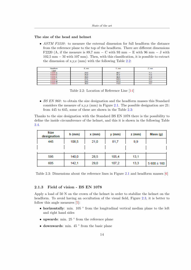
State of the art
The size of the head and helmet
bull ASTM F2220 to measure the external dimension for full headform the distancefrom the reference plane to the top of the headform There are different dimensionsF2220 (A if the measure is 897 mm minus C with 93 mm minus E with 96 mm minus J with1025 mm minusM with 107 mm) Then with this classification it is possible to extractthe dimension of xyz (mm) with the following Table 22
Table 22 Location of Reference Line [14]
bull BS EN 960 to obtain the size designation and the headform masses this Standardconsiders the measure of xyz (mm) in Figure 21 The possible designation are 21from 445 to 645 some of these are shown in the Table 23
Thanks to the size designation with the Standard BS EN 1078 there is the possibility todefine the inside circumference of the helmet and this it is shown in the following Table24
Table 23 Dimensions about the reference lines in Figure 21 and headform masses [6]
213 Field of vision - BS EN 1078
Apply a load of 50 N on the crown of the helmet in order to stabilize the helmet on theheadform To avoid having an occultation of the visual field Figure 23 it is better tofollow this angle measures [5]
bull horizontally min 105 from the longitudinal vertical median plane to the leftand right hand sides
bull upwards min 25 from the reference plane
bull downwards min 45 from the basic plane
14
State of the art
Table 24 Inside circumference of helmet [5]
Figure 23 Field of vision (a)(b) [5]
214 Test impact area
Standard EN 1078 will be considered for this study which defines the parameters helpfulin performing the shock absorption test The drop test impact consists of an impact ontwo anvils of flat surface or kerbstone
In the Standard is specified the Test Area where the impact is to be performed Thefirst thing is to apply a vertical load of 50 N on the crown of the helmet in order to
15
State of the art
stabilize the helmet on the headform [5]1 Draw the AArdquo line (in the AArsquo plane) on the helmet2 Draw a line on the helmet parallel to and approximately 20 mm above the AArdquo line(for use as an angular measurement datum line)3 Mark the helmet at points B1 and B2 These points are the sideways horizontalprojection of point B onto the outer surface of the helmet4 Draw a line RRrsquo on the helmet passing through B1 and B2 the line being angled 10
upwards toward the front of the helmet relative to the datum line drawn in d) The areaabove the line drawn in f) is the test area for impacts on the flat anvil The area abovethe line RWArdquo is the test area for impacts on to the kerbstone anvil
Figure 24 Definition of test impact area [5]
215 Anvils and environmental conditions
EN 1078
During the validation process each of the 30 helmet target points was impacted ex-perimentally and numerically under three environmental conditions (-20C +50C andhumidity)
The impact should never exceed 250 g for impacts with velocities corresponding to 542ms on a flat anvil and 457 ms on a kerbstone anvil These are theoretically equivalentto 1497 mm and 1064 mm drop heights respectively [5] About the characteristics of theanvils according to EN 1078 these depend on the type in the case of
bull Flat anvil it has a circular form with a diameter of 130 plusmn 3 mm with 25 mm ofthick
16
State of the art
bull Kerbstone anvil face inclined at 525 plusmn 25 to the vertical and edge with aradius of 15 plusmn 05mm The height shall be not less than 50 mm and the lengthnot less than 125 mm [5]
According with the regalement EN 1078 [5] it has been possible to realize the volumes inthis work the Flat anvil has a diameter of 130 mm and a height of 25 mm the kerbstoneanvil has a horizontal edge of 130 mm a height of 51 mm a length of 126 mm and theedge that impacts the helmet has a radius of 15 mm The anvils are represented in Figure25
[a] [b]
Figure 25 Flat anvil [a] and Kerbstone anvil [b]
EN 13087-11 (Proposal)
A proposal of November 2018 (EN 13087-11) talks about oblique impact tests (Rotationaltest method) [15] Define a method to measure rotational energy absorption in tangentialimpacts in short duration impact situations the velocity considered by Adanty et al [1]is 65 ms The same anvils of the Standard EN 1078 are used the flat anvil and theKerbstone anvil but the difference is the vertical drop towards an impact angle between30-60 the degree considered by Adanty et al [1] is 45
Three different rotations are considered [34]
bull Rotation around X-axis contact point on the side of the helmet resulting in arotation around X-axis Initial position of the headform X- Y- and Z-axis 0
bull Rotation around Y-axis Contact point on the upper part of the helmet resultingin a rotation around Y-axis Initial position of the headform X- Y- and Z-axis 0
bull Rotation around Z-axis Contact point on the upper part of the helmet resultingin a rotation around Y-axis Initial position of the headform X- and Z-axis 0 and65 around Y-axis
17
State of the art
Figure 26 (a) The current cycling helmet standard for the EN 1078 [5] (b) Theproposed standard (EN13087-11) as described by the European Committee for
Standardization (CEN) [15][1]
22 Materials
221 EPS Foam
As mentioned in Chapter 13 the material most commonly used for making the helmetis the EPS Mustafa et al [25] analysed the EPS with four different density values of 50kgm3 64 kgm3 80 kgm3 and 100 kgm3 rdquoThe drop impact simulation model wasused to test the impact attenuation of the helmet with different densities The drop testwas performed on four impact locations top front and sidesrdquo
The impact velocity of the helmet and headform was set at 544 ms The lowestpeak linear acceleration was recorded at the top location and a density of 64 kgm3 with14814 g This study sets out to determine the effect of the user-centered helmet designwith different foam densities (from 50 kgm3 to 100 kgm3) on the impact attenuationof the bicycle helmet
Kroeker et al [19] tested the helmets at three impact speeds 30 plusmn 001 ms 63 plusmn002 ms and 78 plusmn 001 ms
They established the mean value about bulk density in a helmet with EPS foam is666 considering HIC and Peak Acceleration test The global range is between 64 kgm3
and 75 kgm3
Kroeker et al [20] established the foam for kids helmets is 64-88 kgm3 and for thetraditional helmets is 60-100 kgm3
Trzaskalska et al [36] controlled the influence of polymer liner density on energy ab-sorption during impact They discovered the best properties have samples whose densityis between 54 to 60 kgm3
Cui et al [10] considered the density of each layer from the values of 25 50 60 80and 100 kgm3 and they realize a 45 grades side impact and normal crown impact Theresult is a density of 64 kgm3
Wei et al [38] discovered from their test results that EPS has a buffer layer density
18
State of the art
of 60 kgm3 is the most reasonable
Foam densityrsquos values - Literature
Authors Densityrsquos values
Mustafa et al [25] 64Kroeker et al [19] 64 - 75Kroeker et al [20] 60-100 (traditional) and 64-88 (kids)
Trzaskalska et al [36] 54 - 60Cui et al [10] 54Wei et al [38] 60
Table 25 Table with foam (EPS) densityrsquos values
The other are mean values obtained by CES EduPackrsquos program about this material
- Density ρ = 6451kgm3
- Youngrsquos Module E = 275 MPa
- Poissonrsquos ratio ν = 0275
- Yieldrsquos stress σ= 09 MPa
- Elongation at fracture = 45
222 CES Edu Pack - Material selection
CES Edupack software was used to satisfy the idea of creating a lightweight helmetby printing it in 3D and having the possibility to insert the desired characteristics ofthe material and therefore select it To make a choice I used level 3 of engineering(advanced) selecting the following criteria of the material bio-material biodegradablea polymer of concentration 20 - 100 which complies with the rsquoEuropean Restrictionon Hazardous Substances (Rohs) standardsrsquo regarding the composition of the materialensuring that it does not contain a high percentage of toxic substances compared to theestablished percentage In addition it must have proper durability in contact with coldwater (imagining a possible rain) and rsquogoodrsquo durability to UV radiation
According to Ashbyrsquos method [2] to select a material it is possible to follow thefollowing steps
1 Establish the function of the product What does the component doThe helmet is an instrumental use to protect the head during an impact this characteristicdepends on materials and qualities It can prevent an injury which depends on materialsand design because it has to be of the right head size It would be comfortable becauseit must be worn and it must give security to the person wearing it (by design) In thefollowing Table 26 the analysis of the functions
19
State of the art
Ranking Function description Depends on
1 Head protection (energy absorbing) Material2 Head protection (energy absorbing) Design3 Head protection (injury prevention) Material4 Head protection (injury prevention) Design5 Comfortable Material6 Comfortable Process
Table 26 Ashbyrsquos method functions
2 The objectives that are targets for the design the material is to bemaximised or minimisedTo manufacture and market a product objectives such as minimizing weight cost orenvironmental impact must be considered In the following Table 27 the analysis of theobjectives
Ranking Title Objectives description
1 Mass Minimize The mass has to be thesame or lower
2 Cost Minimize everyone should have theopportunity to buy it
3 CO2 footprint Minimize CO2 emission
4 Corrosion Minimize high strength because itcan be in contact with the water
5 Pleasant to touch Maximize it is not a rough materialbecause it has to put on and put off
by hands
6 Refractive index Minimize it must not reflect light
Table 27 Ashbyrsquos method objectives
3 Definition of constrains What essential conditions must be meetEstablish constraints is essential to complete the function of the instrument Examplesof constrains are Table 28
4 The limits characteristic independent of the material that does not influencethe physical properties In the following Table 29 the analysis of the limits
20
State of the art
Title Loading case Constraintsdescription
Material index(Max-Min)
Stiffness Column in compression Tie in tension
Mass Min
Stiffness Column in compression Tie in tension
Cost Min
Stiffness Column in compression Tie in tension
CO2 Min
Strength Column in compression Tie in tension
Mass Min
Strength Column in compression Tie in tension
Cost Min
Strength Column in compression Tie in tension
CO2 Min
Table 28 Ashbyrsquos method constrains
223 PLA with natural fiber and PLA LW
Initially the best material that met the desired criteria was searched From this study itwas found that the material closest to having the required characteristics is the PLA 30natural fiber as shown in the Figure 27 which shows the graphs obtained relating tothe relationships between Youngrsquos Module and density the objective to reduce the massper unit of compressive stiffness and strength to reduce the CO2 footprint per unit ofstiffness and strength and mass per unit of compressive strength
Performance index IR
The stiffness criterion has the following characteristics
m = A lowast L lowast ρ (21)
ε =σ
E=
FA
E(22)
A =F
ε lowast E(23)
21
State of the art
Ranking Title Function description
1 Biocompatibility It is the ability of a material the abilityof the material not to cause any local or
systemic adverse response in therecipient of the material
2 Biodegrability Biodegradable material do notbiodegradable under anaerobic conditions
3 Biomaterials - all The terms is used for biological naturalbio-derived bio-inspired material
4 RoHS (EU) Compliantgrades
Restriction of the use of certin prohibitessubstances (mercury cadmium
hexavalent chromium)
5 Polymer 20-100 (from the table with Plasticpolymers)
6 UV Resistance at UV sunlight
Table 29 Ashbyrsquos method limits
A =F lowast L lowast ρε lowast E
(24)
With fixed variables- F (the load) L (the length)With variables that depend on the material- E (Youngrsquos Module) ρ (density)
In general when a chart is created the distribution of the mass is represented in thefollowing modality like in Figure 27 [b] where the materials above the line have a lowermass while those below a greater mass
Following the results of the CES Edupack program that had selected the PLA withnatural fibers as the best the first print of the helmet was made with this materialusing as support the PVA Initially the result seemed satisfactory the helmet had a highdefinition but a fundamental problem was found by reducing the helmet in the water toallow the supports of PVA to dissolve In the act of diving in fact after ten minutessome parts of the helmet especially the front and rear have disintegrated making thehelmet unusable Because of this problem it was necessary to change the material
22
State of the art
[a]
[b]
Figure 27 CES EduPack Mass per unit of compressive stiffness [a] Youngrsquos Moduleand density [b]
Further investigations carried out by the Mondragon Unibertsitatea Additive Man-ufacturing Department revealed a new material the PLA Low Weight which during3D printing allows to obtain a weight of 65 lower than that which could be obtainedfrom the classic PLA as reported in the technical sheet of the filament produced by thecompany Colorfabb [7]
The investigation team of the Composite Department carried out tensile tests withsamples 3D printed at different temperatures as suggested by the manufacturer to obtainthe technical characteristics The temperatures examined are 200 220 250 260The datasheet shows the density can have values between 04 - 124 gcm3 the bed has
23
State of the art
to have a temperature between 50 - 60 the printing speed has to have values between40 - 80 mms This typology of PLA is expandible so much that rdquoAt around 230 thismaterial will start foaming increasing its volume by nearly three timesrdquo [7]
T[C] Section [mm2] Volumen [mm3] Mass [g] ρ[kgm3] E [Nmm2]
200 42235 1030117 12 1165 328807
220 43805 1655821 18 1087 265795
250 52412 1948139 17 873 178058
260 59655 1454377 12 825 117047
Table 210 Values about PLA LW tensile tests of MU Additive ManufacturingDepartment
From the tests that have been carried out on the material at different temperaturesthe printed sample is better at 250 with a volume of 1948139 mm3 and a section of52412 mm2 as shown in Table 210 For this reason the specific of the material thathave been taken into consideration are the following
- Density ρ = 873 kgm3
- Youngrsquos Module E = 1750 MPa
- Poissonrsquos ratio ν = 033
- Yieldrsquos stress σ = 2948 MPa
- Elongation at fracture = 491
23 Bio-inspired structures
When we talk about bio-inspired structures to nature we refer to structures that allowobtaining a low weight for the model that is realized and excellent absorption energy dur-ing the impact Recently the structures that have been most used in the biomimetic fieldare the rdquocolumns structures sandwich structures plates honeycomb and foamsrdquo[26]but aiming to achieve a structure increasingly with high absorption energy new struc-tures derived from plants and animals such as beetle horsetail turtle bird beak havebeen analyzed The first to create multi-cells tubes helicoidal structures the second tomulti-corner tubes [26]
The authors analyze the specific energy absorbed (SEA) by bio-inspired sandwichstructures per unit mass which can be derived from the following equation
EA(d) =
int dmax
0F (x)dx (25)
SEA(d) =EA(d)
m(26)
24
State of the art
Where EA is the energy absorption rdquomainly used to evaluate an energy absorberrsquosability to dissipate crushing energy through plastic deformationrdquo F(x) is the crashingforce dmax is the effective deformation distance [26]
What derived from their investigations is that having regard to a density of between0 and 1000 kgm3 the volumetric energy absorbed is higher for the beetle-inspired struc-tures than the others as shown in Figure 28 Based on this consideration it was chosento draw the helmet following this geometry
Figure 28 SEA of bio-inspired sandwich structures [26]
231 Beetle structure - Design of the model
To develop and increase lightweight high-strength and optimize bio-mimetic functionaland structural materials the trabecular structure of the beetle elytron is studied Thesingle structure is realized following the requirements cited by Zhang et al [39]
To realize the beetlersquos structure it is not enough to have information about the lengthof the side of the hexagon and the thickness but it is also necessary to take into accountthe relationship between the diameter of the circumferences present on the vertices ofthe hexagon and the measurement of the side The representation of a single cell is inFigure 29 It is shown in [a] a general structure with an edge of 12 mm circumferencersquosdiameter of 6 mm and thickness of 16 mm in [b] is shown the height of 20 mm
For the construction of the helmet a thickness of 12 and 16 mm was used the imageconcerns a proportion between the length of the hexagon side and the diameter of the
25
State of the art
circumference The side (distance between the centers of two circumferences) is twice thediameter measurement
[a] [b]
Figure 29 Beetle structure
232 Specific stress - PLA LW and EPS foam
To test the beetle structures compression tests were investigated The PLA LW structurewas inserted in a rsquodiskrsquo with a diameter of 100 mm and a height of 20 mm The area andthe volume of the disk is correspondingly 7854 mm2 and 157 10 mm3 The structuresexamined have different dimensions the edge L (distance between two centers of thecircumferences) had the following measures 9 10 12 14 16 mm the thickness of thecircumferences and edges are respectively of 16 mm for every structure and 12 mm forthe structure with L = 16 mm
The test was carried out with the Hoytom HM-D Testing Machine with capacitiesbetween 5 and 100 kN The test models were subjected to displacement loading at a rateof 1 mmmin as referenced by Chen et al[18] with a cylindrical specimen The specificstress of the structures was compared with the specific stress of a generic EPS helmetthe photos about it are shown in Figure 210 The EPS helmet structure is granular withpores inside The different grains dimension and these pores can be the reason for whichthe Stressrsquos values are between two values 07 and 116 MPa
Four parts of the EPS helmet were considered in the test the dimension and relativecharacteristic are in the Table 211 where m = mass A = area F = load ρ = densityR = stress Rρ = specific stress To calculate the values of stress about PLA structuresand EPS foam compression test graphs were been analyzed The stress value for eachstructure was calculated considering the single load the single area and the averagedensity value (14055 [kgm3])
The stress values of the PLA structures (Figure 211) and other characteristic valuesare in Table 212 where m = mass A = area F = load ρ = density
26
State of the art
[a] [b]
[c] [d]
Figure 210 EPS generic helmet helmet pictures [a] [b] and internal structureExternal granular structure [c] and pores [d]
[a] [b] [c]
Figure 211 PLA LW disks Grasshopper structure [a] PLA LW structure of 14 mm[b] PLA LW structure compressed [c]
27
State of the art
The results of the load-displacement graphs are affected by the geometry of the diskthe target is to valid for any shape or size for this is preferred to realize a diagramthat depends from σ (or stress) and the deformation ε (or strain) which can be definedrespectively as
σ =F
A0(27)
ε =l minus l0l
(28)
where F is the load during the test A0 is the area l0 is the initial length and l is thelength when the load is applied The areas considered for the EPS cube is reported inTable 211 in the second column the areas of the PLA structure is 7854 mm2 like thearea of the circumscribed disk
The values compared are shown in Table 213 and the graphs obtained by Matlabcode to analyze the recorded data of the compression machine are in Figure 213 and inFigure 212
Considering that the data provided by the compression machine are subject to noiseand disturbances it was decided to convert the original curve into polynomial type curvesthat allow obtaining the best interpolating curve for the data in question To obtain themit was divided the recorded data into two groups the first part from 0 until the end ofthe linear part and the second when the curve becomes linear again The best-fitting (inthe least-squares sense) was performed using the polyfit and polyval functions of MatlabThe first returns the coefficients of the p(x) with n degree the second evaluates p(x) ateach point in x The polynomial formula p(x) is shown in the Equation 29
pn(x) = anxn + anminus1x
nminus1 + + a2x2 + a1x+ a0 (29)
where a0 an are constants and x is the indeterminate The choice of the degree ofthe polynomial was made based on the criterion of wanting to obtain linear curves thatrespected the elastic trend at the beginning of the graph For this reason the degree ofthe polynomial is 1 Subsequently I searched through the intersection of the two lines forthe point that is equivalent to the maximum stress that marks the end of linearity
This value for EPS and PLA LW is the R [MPa] in the Table 213 The average stressvalue for PLA LW is 139 MPa and for EPS is 094 MPa The specific stress (Rρ) is 18MPa lowast m3)kg for the EPS found in CES 669 MPa lowast m3)kg for the EPS foam of thegeneric helmet and for PLA LW is 1161 MPa lowastm3)kg an intermediate value betweenthe two which is what we wanted to achieve
28
State of the art
m [g] A [mm2] F [N] ρ [kgm3]
EPS (CES) 50
16 9234 1063 13864
18 879 593 13651
21 858 833 14237
24 864 564 14468
Average value 14055
Table 211 Compression stress generic EPS helmet
L [mm] t [mm] m [g] F [N] ρ [kgm3]
9 16 214 7250 1363
10 16 192 5560 12467
12 16 201 8190 13051
14 12 138 8000 8961
Average value 12027
Table 212 Compression test PLA structures
PLA LW structure EPS structureρ= 12027kgm3 ρ= 14055kgm3
Edge [mm] R [MPa] Rρ103 Number R [MPa] Rρ103
EPS (CES) 09 18
9 173 1269 1 116 824
10 139 1114 2 08 568
12 138 1057 3 105 746
14 108 1205 4 077 540
Average value 139 1161 094 669
Table 213 Specific stress calculus PLA LW and EPS calculus ρ = density R = stressRρ [(MPa lowastm3)kg] = specific stress
29
State of the art
Figure 212 Compression test Stress-Strain diagrams - EPS
Figure 213 Compression test Stress-Strain diagrams - PLA LW
30
Chapter 3
Methodology
31 3D scan
311 3D Sense 2 scanner and Meshmixer - Reverse reconstruction
Standardized measures were not taken into account for making the helmet but the sizewas obtained through a 3D scan of my head
The scanner used is 3D Sense 2 by 3D Systems which has a minimum scanningvolume of 20 x 20 x 20 cm and a maximum scanning volume of 300 x 300 x 300 cmTo scan my person I was helped to get a full view at 360 at an appropriate distanceReal-time visualization of the captured images was shown through 3D Sense softwareThe idea of scanning the head with the scanner refers to the methodology used by Wanget al [30] They used a reverse reconstruction functional for me to realize the helmetsurface made to measure my head and like them a silicone pool cap was used to makescanning as smooth as possible The authors claim the head scan rdquocan also be used toobtain information about the objectrsquos surface which is then reconstructed utilizing thecomputerrsquos three-dimensional model via reverse modelling softwarerdquo [30] that in my caseis Autodesk Meshmixer
The files it was could get from the scan were stl obj and ply format they wereexported to obj to work in the next step with Autodesk Meshmixer that allowed tomodify and homogenize the 3D image obtained from the scan
In Meshmixer through the selection and delete commands the superfluous parts weredeleted that had been acquired and with the inspector and the DrawDraw2 commandsthe vertices were moved locally along a pre-defined direction and with Smooth the surfacemore homogeneous was made The sequence of steps is shown in the Figure 31
312 3D scan analysis and extraction of features
In Chapter 2 the directives imposed by the BS EN 960 Standard were examined concern-ing the definition of the helmet and the measures to be respected in the field of visionand the part of the helmet was to carry out impact tests
In Figure 32 the features defined complying with the Standardrsquos rules are repre-sented To define these features the software NX was used The angle in the subfigure
31
Methodology
[a] [b] [c] [d]
Figure 31 Sequence of 3D head scan 3D scanner acquisition [a] scan after reparationwith Meshmixer [b] solid scan vision frontal and lateral [c] [d]
[b] is bigger than 105 (as defined by the Standard) while the degree in the subfigure [c]is 25 By defining the construction lines to be respected of the helmetit was necessary todraw the design of the surface not using the software NX but changing with Rhinocerosto create a SubD or SubDivision surface
32 Helmet design
321 Rhinoceros - Helmet surface
After realizing a rsquocleanrsquo Wang et al [30] subdivide with lines and then sectors the headto create the surface of the helmet They used the technique of NURBS a Non UniformRational Basis-Splines which mathematically models a 3D geometry while thanks tothe Rhinoceros 3D organic shapes was draw SubD surfaces These geometries allow tosplit the mesh into small polygons and consist of lines with which easily the shape ofthe object can be modified with a surface already created changing the position of aline automatically the remaining part of the geometry adapts to the changes With thistechnique the rsquosurface basersquo of the helmet was realized with the size of my head Therepresentation of the realized SubD is in Figure 33
322 Grasshopper - Helmet structure
The next idea is the creation on the surface of the beetle structure with different di-mensions modelling the helmet that is not a linear surface It was decided not to buildthe structure with a software CAD because to model an already complex structure on acurved surface would mean to model a cell for a cell
To solve this obstacle a Rhinoceros plug-in was used Grasshopper GH idealized byRobert McNeel and associates creators of Rhinoceros Using GH does not mean drawinggeometries by connecting points and drawing tools because it is based on algorithmicmodelling used in architecture and engineering for 3D modelling
The modelling takes place through a node diagram that the software will convert intoa code-algorithm in GH it is possible to define the variables and parameters and inRhinoceros in real-time it is possible to view the object GH allows for varying the
32
Methodology
[a] [b]
[c]
Figure 32 Featurersquos extraction in [a] is represented the impact line in [b] and [c] twoprospective about the definition of the field of vision
[a] [b] [c]
Figure 33 SubD representation lateral view [a] top view [b] front view [c]
geometry to your liking by varying a simple parameter of the diagram as everything willbe remodelled according to the change made
In the following Figure 34 it is shown an example of a structure that was used fordistinct subgroups of helmet areas The idea was to insert smaller cells in the frontal andlateral zone and larger ones in the upper area In the first image [a] is shown the part of
33
Methodology
the helpful diagram to create the beetle structure to establish the size of the cells andthe extrusion the second image [b] contains the part of the diagram with which I appliedthe structure previously created to the SubD
The structure used to place and adapt the beetle structure to the surface is theSrfMorph while the yellow rsquowindowrsquo that contains numbers serves to select the parts ofthe surface where to apply the geometry created In accord with the GH diagram in
[a]
[b]
Figure 34 Grasshopper diagrams
Figure 34 [a] it is possible to see the steps executed to realize the structure Initially inthe xy-plane a hexagonal grid was drawn through the Hexgrid command in which youcan input the length of the hexagon edge and the number of grid elements (selected bytrial) Then the circumferences was drawn in proportion to the hexagon dimensions asspecified in the Chapter 2 and shown in Figure 35 [a] In figure [b] the rsquocutrsquo made atthe circumferences is visible this subdivision was necessary for printing purposes In thelast photo [c] the structure highlighted in green in [b] was extruded setting a distance
34
Methodology
of 20 mm
[a] [b] [c]
Figure 35 Construction sequence of the geometry of the helmet
In the diagram in Figure 34 [b] there is the application of the structure created bi-dimensionally to the SubD surface of the helmet visible by unlocking the SubD commandof the diagram and in Figure 36 [a] Upper this the referential geometry of the group ofsurfaces was superimposed where it was to be applied the newly created structure (visiblein darker red) the SubD indices are in the yellow box of the diagram
Through the SrfMorph command the location of the structure was granted In Figure36 [b] at the darkest red of the figure [a] with the above command it was possible toplace the structure
[a] [b]
Figure 36 Application of the geometry created to the helmet surface
Overall the diagrams with specific structures are five one for the front two equal forthe side parts one for the top shown in the previous Figure 36 and one for the back
The hexagons in the structure have a dimension varying between 8 mm and 14 mmof side the largest is found at the top later at the back in the sides and the smallest atthe front In Figure 36 [b] the presence of not only hexagonal structures is visible Thegeometry used does not allow the homogeneous arrangement on the entire surface andrequires different structures Automatically the choice of GH to optimize the structurewas to insert quadrilateral
As described above the helmet has different dimensions of the structure divided asvisible in Figure 36 in a quadrilateral This causes a discontinuity between zones withdifferent sizes due to the geometry of the construction
To eliminate this problem and realize the design homogeneous grids were inserted
35
Methodology
in the affected areas as shown in Figure 37 This insertion however proved to beinteresting and strategic researching in this regard studies were realized to demonstratethe insertion of a rectangular grid inside the hexagon grid was helpful for the transmissionof stress in the structure As cited by Sun et al [40] rdquothe mechanical properties of thesesandwich structures are often limited by local failures such as face-core debonding or corecollapserdquo Carrying out compression tests have effectively demonstrated that the insertionof the grid allows rdquoprovided increased stiffness specific stiffness energy absorption andcritical loadrdquo [41] As shown in the graphic [c] of the Figure 37 the honeycomb structuregives a force of 7 kN while with a grid the value is 11 kN and with the combinationexceeds 22 kN In addition in the left front a plaque to customize the helmet wasprepared Figure 37 [a]
[a] [b]
[c]
Figure 37 Grid in the helmet [a] hybrid structure with hexagons and grid [b] [40]compression test results of the hybrid structure [c] [41]
33 3D Print
After having achieved the CAD (Computer Aided Design) of the helmet in order tobe printed it must be converted and saved in format STL (Standard TriangulationLanguage) - Binary compatible with the printing machine and useful for transformingsolid object surfaces into triangles The steps to be taken are the following
bull CAD file realization
bull CAD export in format STL to Simplify 3D the software that shows slider layersand then- rotate and position the object according to geometry and the positioning of any
36
Methodology
supports- setting printing parameters- item manual andor automatic positioning of supports- slider display layers
bull import file gcode to printer
331 Printer and parameters
The program used to visualize how the helmet slices layers before sending it to the printerand to set the parameters is as anticipated Simplify 3D
To make the printing not being a flat geometry it is necessary to place the supportsThe idea was to use water-based supports that the helmet would automatically dissolveonce placed in the water After testing different types of water-soluble PVA the choicefell on eSun 3D Printing Filament PVA (water-soluble support) Before choosing theoptimal position for printing several tests were carried out and to decrease the numberof the supports significantly and allows an optimal printing of the outer part an emptyrsquospherersquo that self-sustains below the helmet was placed as shown in Figure 38
In the image [a] you can see the first print position tried with which an external partof the helmet very damaged was obtained because of the contact supports-helmet In [b]the empty rsquospherersquo is shown to optimize the number of supports and in the last photo [c]there is the full version at the end of print
[a] [b] [c]
Figure 38 Printing supports
The printer that has been used for printing is the Raise 3D Pro2 with double extrudersand nozzles of variable size from 02 mm to 1 mm after some test prints with the PLALW and the structure in created the size that allowed me to have a good compromisebetween printing time and accuracy was 06 mm Using 04 mm the printing time wasexcessive even if having the smaller nozzle diameter means having more precision withthe 08 mm nozzle the quality of the structure was not excellent as seen in Figure 38[a]
Another factor that had to be taken into account is the characteristic of the PLA-LWto expand As the printing temperature and the printer used vary the expansion andcharacteristics of the material change The use of the 06 mm nozzle associated with
37
Methodology
Parameter Left extruder Right extruder
01cm Material 01cm PVA 01cm PLA LW
Extruder toolbox index Tool 0 Tool 1
Nozzle diameter 06 mm 06 mm
Extrusion multiplier 1 05
Extrusion width Auto (072 mm) 05 mm
Layer x
Infill Rectilinear - 50
Supports (Automatic and not) Infill 50
Temperature 210 250
General parameters
Primary layer height 03 mm Top solid layer 4
Bottom solid layer 2 Outline 2
Heated bad 60 Speed 40 mms
Table 31 Printing parameters
Raise 3D allowed me to get good results The choice of this printer was not random ithas in fact the characteristic of making extremely precise prints The Raise has accuracyin placing the object on the printing bed of 078 microns on the xy axis and a resolutionfor layers of 001 mm
The final version of the helmet is visible in Figure 39 and it is possible to compare itwith the preview version in Rhinoceros in Figure 310
38
Methodology
[a] [b]
[c]
Figure 39 Views of the helmet
[a] [b]
Figure 310 Views of the helmet (GH version)
39
Chapter 4
Experimental evaluation
41 Experimental tests
411 Drop-weight impact test machine
In order to calculate the contact force peak and the difference of energy absorbed duringthe impact between the reference helmet and helmet with the beetle structure in PLA-LW dynamic impact tests were carried out using the Fractovis Plus an impact testmachine
In this way it is possible to monitor the evolution of the above variables from theinitial to the final instant of the impact The machine can withstand a load with a rangevariable from 2 to 70 kg with a maximum speed of 46 ms and a maximum height of1 m The values chosen for the test are the following 5 kg weight maximum speed andmaximum height The Anvil that was used is a disc diameter of 60 mm
As shown in Figure 41 and explained by Crupi et al [37] the machine consists ofa sensor capable of recording the speed before impact the impactor that can have avariable mass (a weight of 5 kg in my test) a system to guarantee that there are nomultiple impacts after the first and that work as a shock absorber and clamping systemwhere the object to be tested is placed
The tests that have been carried out are in total four two related to the helmetoptimized with PLA-LW and two with two generic helmets of different brand in EPS
42 PLA LW helmet
To perform the dynamic test on the helmet of PLA considering the difficulty of printingit was helpful to use a test helmet with imperfections to understand where the impactwas concentrated in a single part or distributed The images of Figure 42 show a helmetwith not well defined edges and inaccurate print but exactly localizes the impact zoneThanks to this test it was possible to take into account only one helmet area shown inFigure 43 to have the exact curve of the structure bio-inspired with PLA-LW
40
Experimental evaluation
Figure 41 Drop-weight impact test machine [37]
[a] [b]
Figure 42 Test 1 PLA-LW helmet
43 EPS helmet
To carry out dynamic tests and extract the technical characteristics of the helmettwohelmets were bought in a sports store both EPS and being on the market both certifiedThe brands of the two helmets are DTB and VAN|RYSEL and the average weight ofthe two is 223 g Two different helmets have been chosen to have a more certain andclear classification of the characteristics They are shown in Figure 44 and Figure 45
41
Experimental evaluation
[a] [b]
Figure 43 Test 2 PLA-LW helmet
[a] [b] [c]
Figure 44 Test 3 EPS helmet
[a] [b] [c]
Figure 45 Test 4 EPS helmet
44 Results
441 First results - PLA-LW and EPS helmet
Figure 46 shows two types of trends related to the two different models of the helmetThe force evaluated for PLA-LW has higher force peaks but is more concentrated and
42
Experimental evaluation
propagates less than EPS The graph shows the peaks of each curve highlighted with a redcircle In tests 1 and 2 for the PLA-LW as mentioned earlier the values are higher about7301 N for the complete helmet and 3996 N for the portion of helmet This difference isdue to the inaccuracy of the first full helmet during the printing phase In Figure 42 itis visible the low homogeneity and precision Therefore the first test with full helmet wasused only to define the area of interest of the impact which turns out to be localized Forthe other two EPS curves the values are only slightly lower compared to the PLA-LWequal to 3620 N and 3295 N but the trend is much more distributed
Figure 46 Dynamic machine test - Force
With the data obtained from the impact machine it was possible calculate not exclu-sively the value of force but itrsquos also possible to view the energy curves A resume aboutthe values and energy of the force is in the following Table 41
Test Peak force [N] Peak energy [J]
Test 1 - PLA LW (inaccurate) 730130
Test 2 - PLA LW (portion of helmet) 399643
Test 3 - EPS (DTB helmet) 362007 509
Test 4 - EPS (VAN|RYSEL helmet) 329546 4198
Test 5 - PLA with TPU 45421 5022
Table 41 Energy absorbed in dynamic test
43
Experimental evaluation
442 PLA-LW helmet with TPU cover
As it is possible to see in Figure 47 and as highlighted the first tests concerning thebio-inspired structure and the PLA-LW are far from my expectations considering thelittle distribution of force in comparison with the EPS foam and consequently a smallamount of energy absorbed
Figure 47 Dynamic machine test - Energy
To improve this impact damping factor the idea was to create a cover for the helmetin flexible TPU trying to absorb impact energy The TPU used is a flexible material ofthe brand Ninjaflex used in sports by the application in helmets and shoes to cushionbumps during the game Generally in the helmets (baseball helmet for example) theTPU is inserted internally in contact with the head In my case the TPU structurein addition to creating a shock-absorbing and durable cover creates a custom cover thehelmet and for the person This cover was also made with the Raise 3D printer
As shown in the Figure 48 [a] the infill of the part in contact with the helmet hasa percentage of 100 the filling of the other part of the structure is not complete butonly 15 and the internal structure is hexagonal to recall that of the helmet The desireto insert a structure with a rsquoraisedrsquo geometry is for visual and aesthetic reasons as youhave the feeling of greater protection and not filled is inspired by the machine CitroenCaptus whose bumpers (Airbump) are full of air The failure to realize empty structuresis due to the need to place any internal supports not removable
The idea was to create a cover that allow you to see of the internal structure of thehelmet and that protect specific areas the front the two sides the top and the posteriorWhat which was thought for this reason was to create the shape of a flower with four
44
Experimental evaluation
petals Figure 48 [b]In this way to perform dynamic impact tests as shown in Figure 49 [a] the cover was
positioned at the top of the helmet and the impact was performed in the centre of thersquoflowerrsquo which corresponds to the higher upper part where the structure has larger cellsize The impact parameters are the same as those used in previous impacts 5 kg weightmaximum speed and maximum height The Anvil that was used is a disc diameter of60 mm In photo [b] it is evident the difference between the structure that received theimpact with protection (left) and without protection (right) Without protection duringthe impact there was a perforation of the structure with a concentration of force at a locallevel as you can see in the Figure 46 in the case of TPU the impactor did not perforateand crossed the structure thanks to the cover of TPU that cushioned the shock At themoment of impact the impactor bounced
[a] [b]
Figure 48 TPU cover
[a] [b]
Figure 49 PLA-LW with TPU - dynamic impact [a] and differences between thehelmet with TPU and without TPU cover [b]
45
Experimental evaluation
The Figure 410 includes the diagrams relative to the dynamic impacts In [a] thereare already analyzed EPS results in [b] a comparison between the test on the portionof helmet in PLA LW with and without the TPU cover in [c] the overall comparison ofcurves shows a much more similar EPS trend if the TPU is placed above the structure inPLA LW to soften the blow and absorb the same energy [d]
46
[a]
[c]
[d]
Figure 410 Comparison between PLA-LW with TPU and EPS
Chapter 5
FEM Validation
51 Impactor - Anvils definition
Before to start to work in Abaqus it was necessary to search in the literature the materialwith which the anvil was been realized Milne et al [23] established the densityrsquos valuethe Youngrsquos Module and Poissonrsquos ratio for the Flat and Kerbstone Anvil
- Density ρ = 7800 kgm3
- Youngrsquos Module E = 200000 MPa
- Poissonrsquos ratio ν = 03
Inserting the data in the CES EduPack program specifying the mechanical andphysical properties the material corresponding to these characteristics is Stainless steelaustenitic (ASTM F1586) medium-hard
Initially the proposal was to create a conservative system to evaluate the absorptionenergies values and apply this value to a vibration system but the helmet needs dampingto be realized it was impossible to use a system without losses in this modality Thisis why a numerical calculation was carried out by performing two types of simulationsexplicit dynamic step and static step
The idea to realize the theoretical impact is to regard the movement of the anviland not the helmetrsquos movement which is fixed The velocity is the same cited in thenormative EN 1078 542 ms for the Flat anvil and 457 ms for the Kerbstone anvil
In performing the simulations It was given more relevance and perform tests withthe Kerbstone Anvil This choice was done because the geometry with which it is beenrealized (following as defined in the legislation) allows the helmet to be more subjectedto stress this involves the definition of higher stress limits compared to the Flat Anvil
The mesh size that has been used is the same in the case of the simulation of thehelmet optimized in PLA-LW and the full helmet in EPS of 7 mm The impactor isconsidered as a Discrete rigid body with its specific Reference Point (RP) like shownin Figure 51 for this reason it is not a solid but it is composted only by shells Inthe same image [b] there is the FEM representation of the model and in Table 51 thecharacteristic of FEM with quadrilateral (R3D4) and triangular elements (R3D3)
48
FEM Validation
Object Elementnumber
Elements Shape Geometricorder
Global size[mm]
Kerbstone 230 Quadrilateral - R3D4 Linear 7
Kerbstone 8 Triangular - R3D3 Linear 7
Table 51 Mesh element - Kerbstone Anvil
[a] [b]
Figure 51 Kerbstone anvil in the simulation like discrete rigid body [a] and FEMelements [b]
511 PLA LW - Plastic characteristics
The PLA-LW as explained in the Chapter 2 is new material on the market and producedby the only Colorfabb company for this reason few tests have been carried out to defineits technical characteristics and through tensile tests of the 3D printed specimens it waspossible to define an elastic limit as reported in the Table 210
In the context of simulations to reproduce the impact and deformation of the helmetis also necessary to consider the plastic characteristics of the material Not possessingany reference value in this regard tests were performed through a Static Step initiallyand then an Explicit Dynamic Step in Abaqus
The structure chosen to consider as a reference it is one of the structures previouslysubjected to the compression test having the side L=14 mm As for the reproduction ofthe compression disks initially they were reproduced according to the geometry of theHoytom HM-D Testing Machine considering the bodies mentioned above as discrete 3Drigid discrete The measure was the diameter of 200 mm and the height of 20 mm
After an initial analysis it was observed that the computational time of the simulationprogram was very high so it was decided to change the geometry to have a rsquodisk-surfacesrsquo(equally 3D rigid-discrete) which allowed me to have a smaller number of nodes for themesh and consequently a better computational time The representation of the opti-mized structure in PLA-LW and the disks used for simulated compression is in Figure 52
49
FEM Validation
[a] [b]
Figure 52 Representation of the samples used for the simulation of the compressiontest In Figure [a] the disks of the Hoytom HM-D Testing Machine in figure [b] the
representation of the same as simple surfaces
As shown in Figure 52 the disks are considered 3D discrete hard bodies so it waschosen for both a point the reference point RP where to apply the characteristics relatedto the two bodies As for the compression test it was established
bull the movement of a disk and fixed the second through a boundary condition impos-ing an Encastre therefore unable to move and rotate in xyz directions
bull for the opposite disk the boundary condition relative to the 15 mm displacementwas applied which is the parameter that it was observed to determine the end ofthe compression with the machine This shift is shown by the orange arrow in figure[b]
bull between the upper surface and the disk e the disk with the lower surface it wasinitialized a general contact with normal behaviour through rsquohardrsquo contact andtangential behaviour with a coefficient of friction of 02 with directionality imposedon rsquoisotropicrsquo
The next step was to define the mesh of the components whose parameters are shown inTable 52 while the representation of the FEM is in Figure 53 with the representationof the simulation and real compression test
Object Elementsnumber
Typology Geometricorder
Globalsize [mm]
Disk (14mm) 80910 hexaedral - C3D8R Linear 07
Impact disks 206 quadrilateral - R3D4 Linear 20
Impact disks 6 triangular - R3D3 Linear 20
Table 52 Mesh element - Compression test simulation
As previously announced a static simulation was initially performed with a StaticStep with Step Time equal to 900 (obtained going to consider the speed of 1 mmmin of
50
FEM Validation
[a]
[b] [c]
Figure 53 FEM representation [a] and compression test simulation [b] and realcompression [c]
the compression test and the displacement of 15 mm) However the complex geometryof the structure and the high time set by Step Time did not allow a correct definitionof the parameters of the plastic characteristics of the material the simulation was notable to continue once reached a Step Time of approximately 220 That is why it waschanged by choosing an Explicit Dynamic step
Leaving all the parameters of the boundary conditions unchanged the Step Time wasmodified imposing it to 001 The ability of the explicit dynamic to work with non-linearand contacting structures allowed me to achieve results The results obtained are shownin Figure 54 with the blue curve and were obtained through the iteration of differentPlastic Strain and Yield Stress values in Abaqus while the red line is the result of thereal compression test a similar curve trend was obtained but it is not possible to obtainthe same curve taking into account problems of printing inaccuracy
512 First test - helmet
The initial idea was to perform a simulation imposing the speed of 457 ms to theimpactor tie the helmet in EPS and PLA and compare the absorbed energies Theproblem it was encountered is related to the mesh of the helmet optimized in PLA andwith minimum dimensions of the elements and distinct elements it was not able to solveit
51
FEM Validation
[a]
YieldStress
PlasticStrain
1 47 0
2 7 001
3 75 005
4 10 01
5 108 1
6 115 15
7 12 2
[b]
Figure 54 Representation of the two curves related to the simulation in Abaqus of thecompression test and the data obtained from the real test to obtain the plastic
characteristics of the material
513 Second test - plane
The first solution is the one shown in Figure 55 To realize the simulation it was realizeda section of the helmet to involve a smaller number of elements and nodes Again thesimulation for the EPS helmet was successful while the simulation with the bio-inspiredstructure was interrupted by excessive distortion of elements
The previous images show the impact is very localized in the impacted area and theidea to achieve a complete simulation is not to consider a curved portion of the helmetbut a plane In this way it was possible to solve the problem and obtain a completesimulation for the bio-inspired structure
FEM element
Below in Table 53 there is the definition of the elements used for the PLA-LW and EPSplane in the simulation to simulate the impact and to control the energy-absorbing whilethe anvil characteristics are described in Table 51
514 EPS impact simulations
In order to proceed with the simulation it was imposed some boundary conditions thatregard ties and forces
bull the movement of the plane is fixed through an Encastre therefore unable to moveand rotate in xyz directions
52
FEM Validation
[a]
[b]
Figure 55 Impact simulation parts of EPS and PLA helmet
Object Elementnumber
Elements Shape Geometricorder
Plane (PLA) 38896 Tetrahedral -C3D10M
Quadratic
Plane (EPS) 2100 Hexahedral - C3D8R Linear
Table 53 Mesh element - plane impact
bull to create the impact it was set a speed of 457 ms at the reference point RP of therigid body which is the impactor Kerbstone Anvil shown in Figure 56
bull between the upper surface of the plane and the impactor it was initialized a Sur-face to Surface contact with normal behaviour through rsquohardrsquo contact and tangen-tial behaviour with a coefficient of friction of 02 with directionality imposed onrsquoisotropicrsquo
bull the rotation in x y z relative to the RP of the rigid discrete impactor body is locked
53
FEM Validation
In addition it was characterized the plane in the part of the materials with the char-acteristic values of the EPS mentioned in Chapter 221 The Von Mises Stress valueapparently low is relative to the Yield Stress of the EPS material equal to 09 MPa
Figure 56 EPS Boundary conditions and Load
515 PLA LW impact simulations
As also required in the case of the EPS plane in order to proceed with the simulationsome boundary conditions were imposed that regard ties and forces
bull the movement of the plane is fixed through an Encastre therefore unable to moveand rotate in xyz directions
bull to create the impact a speed of 457 ms was set at the reference point RP of therigid body which is the impactor Kerbstone Anvil shown in Figure 58
bull between the upper surface of the plane and the impactor it was initialized a Sur-face to Surface contact with normal behaviour through rsquohardrsquo contact and tangen-tial behaviour with a coefficient of friction of 02 with directionality imposed onrsquoisotropicrsquo
bull the rotation in x y z relative to the RP of the rigid discrete impactor body is locked
In addition the plane was characterized in the part of the materials with the characteristicvalues of the PLA mentioned in the Chapter 223 and 511
Figure 58 Boundary conditions and Load
54
FEM Validation
[a]
[b]
Figure 57 EPS impact simulation
52 Results
In Figures 59 and 57 it is shown how the structure in PLA LW has a more concentratedstress distribution of the structure unlike EPS The maximum value for the Von Misesstress is 09 MPa in EPS structure and 3634 MPa in PLA LW structure Once thesimulations were obtained the next step was to go and compare the energies absorbed bythe two structures The energy calculated by Abaqus that has been taken into account isPlastic Dissipation To make a comparison the data of the two energies were representedin a single graph
What emerges from the graph is that about the impact made with the KerbstoneAnvil the energy absorption is more excellent although only slightly for the PLA LWthan for the EPS From the graph in Figure 510 a value of 41 J is shown for the EPSand 51 J for the PLA LW
55
[a]
[b]
Figure 59 PLA impact simulation
[a]
Figure 510 EPS and PLA LW energy comparison - Abaqus simulation
Chapter 6
Head Injury Data
For the statistical analysis the injuries related to the accident data were categorised intothe following types and levels based on the details of the medical report [11] about theEN 1078
bull Head Injury Criterion (HIC)
bull Peak Linear Acceleration (PLAc)
bull Gadd Severity Injury (GSI)
bull Diffuse axonal injuries (DAI)
61 Abaqus simulation
Until now the purpose of the simulations has been to determine which between the twomaterials and the two structures of EPS and PLA LW could absorb more energy duringthe impact but no simulations have been carried out in compliance with BS EN 1078on the helmet impact tests To calculate the injuries listed in the previous paragraphhowever we need the acceleration values in the three directions related to the subjectrsquoshead
To realize it the scan of my head already rsquocleanrsquo was considered of which it has beencalculated the inertia thanks to the automatic SolidWorks calculation and evaluated theweight with the Table 24 the structure of the helmet was placed for the EPS and thePLA LW over the head as shown in Figure 61 Also this time being able to mesh theentire helmet in PLA LW was impossible due to the excessive distortion of some elementsduring the simulation so it has been tried to make a section of the structures of thehelmet and results were obtained
57
Head Injury Data
[a] [b]
Figure 61 My scan head - CAD [a] head imported in Abaqus[b]
Initially the simulation had these characteristics as shown in the following Figure62 considering the helmet was not sectioned As explained earlier it was not possibleto get to simulation in the case of the optimized structure in PLA LW for this reasononly a part of the helmet was considered in both cases shown in Figure 63
[a]
Figure 62 Simulation based on BS EN 1078
58
Head Injury Data
[a] [b]
Figure 63 Simulation based on BS EN 1078 with head
In order to proceed with the simulation some boundary conditions that regard tiesand forces have have imposed
bull two reference points RP were created the first in the inertia centre of the headthe second relating to the Kerbstone Anvil which is a discrete rigid body
bull in the reference point RP of the head in the definition of the engineering features5 kg was inserted for the weight and an inertia I11 = 564464E+07 gmm2 I22 =460654E+07gmm2 I33 = 187302E+07gmm2
bull to simulate the impact it was set a speed of 457 ms at the reference point RP ofthe head in z-axis direction
bull a general contact with normal behaviour through rsquohardrsquo contact and tangentialbehaviour with a coefficient of friction of 02
bull between the upper surface of the helmet and the impactor it has been initializeda Surface to Surface contact with normal behaviour through rsquohardrsquo contact andtangential behaviour with a coefficient of friction of 02 with directionality imposedon rsquoisotropicrsquo
bull the movement between the Kerbstone anvil and the helmet is fixed through anEncastre therefore unable to move and rotate in xyz directions
bull the rotation in x y z relative to the RP of the rigid discrete impactor body is locked
FEM element
As reported in Table 53 the portion of the helmet in EPS has used a mesh with hexahe-dral elements of linear order For the structure (beetle) of PLA LW given the geometry
59
Head Injury Data
complexity it was necessary to use a quadratic order of tetrahedra For the mesh of thehead instead in both simulations have been used quadrilateral elements of linear orderas reported in the Tables 61 and 62
Object Elementnumber
Elements Shape Geometricorder
Head 3755 Quadrilateral - R3D4 Linear
Head 34542 Quadrilateral - R3D3 Linear
Helmet (PLA) 272302 Tetrahedral -C3D10M
Quadratic
Table 61 Mesh element - Head simulation with PLA LW (beetle) helmet
Object Elementnumber
Elements Shape Geometricorder
Head 3755 Quadrilateral - R3D4 Linear
Head 34542 Quadrilateral - R3D3 Linear
Helmet (EPS) 72280 Hexahedral - C3D8R Linear
Table 62 Mesh element - Head simulation with EPS helmet
62 Results
Figure 64 represents the simulation in line with BS EN 1078 concerning the helmet inEPS [a] and the helmet with bio-inspired structure in PLA LW For both simulationsVan Misesrsquo stress has Yield Stress values in the case of EPS which is 09 MPa and theplastic behaviour combination of PLA LW [b]
In the case of head and Kerbstone Anvil stress was not assessed as they were previ-ously defined as discrete rigid bodies
63 Head Injury Criterion
The HIC quantifies head impact severity by incorporating time of acceleration exposureand acceleration magnitude it is calculated in post-processing phase with the followingEquation 61
HIC15 =
[1
(t1 minus t2)
int t2
t1
a(t)dt
]25(t2 minus t1) (61)
60
Head Injury Data
[a]
[b]
Figure 64 Results simulation based on BS EN 1078 with sectioned head
For this analysis a(t) is the acceleration calculated in the centre of mass of the head(corresponding to the reference point RP) expressed in g and the time interval (t2 minus t1)was chosen to maximize HIC over a maximum duration of 15 ms
Matlab and the trapz function were used to calculate the HIC to integrate accelerationover time t2 and t1 were considered initial and final times of the simulation t1 = 0 sand t2 = 10 s time less than 15 s
HIC value of 198 was obtained for EPS and 87 for PLA LW Considering the Hayeset al [16] document about the HIC values and the graph in Figure 65 developed bythe author it is possible to find the percentages related to the different injury AIS1 -AIS6 which correspond respectively to lower and higher severity while in Figure 66 therelative fatality to every value of AIS is shown The values obtained for the HIC andother criteria are shown in Table 63 The HIC value for EPS is 198 for PLA LW it is
61
Head Injury Data
Figure 65 Head injury risk curves based on HIC values [16]
Figure 66 The abbreviated injury score versus fatality rate [16]
87 Analyzing the data and comparing them with the curves of the Figure 65 I obtain
bull a percentage between 20 - 30 of AIS 1 for EPS 10 - 20 for PLA LW
bull a percentage between 10 - 20 of AIS 2 for EPS and 0 - 10 for PLA LW
bull for AIS 3 AIS 4 AIS 5 AIS 6 the percentages for both structures is between 0 -10
Comparing these percentages with the fatality rate of Figure 66 it is clear there is a riskof Moderate and Minor fatality in the case of EPS and PLA LW as all values are between0 and 30
62
Head Injury Data
HIC PLA [g] GSI E [J]
EPS 198 97 361 37723
PLA LW 87 75 169 44102
Table 63 Head Injury Data - values
64 Peak Linear Acceleration
The resultant linear acceleration versus time curve was calculated according to Equation62
γ(t) =radicγ2x(t) + γ2y(t) + γ2z (t) (62)
where
bull γ(t) is the resultant linear acceleration (g)
bull γx(t) is the linear acceleration in x axes (g)
bull γy(t) is the linear acceleration in y axes (g)
bull γz(t)is the linear acceleration in z axes (g)
The value of the impact should never exceed 250g [9] Cripton at all [9] in their studyexamined a helmet with expanded polystyrene (EPS) Figure 68 shows maximum HIC forhelmeted and unhelmeted drops from all heights For each drop height helmets reducedHIC relative to unhelmeted drops IARV value is 180g The acceleration in the two casesis shown in Figure 67 and the maximum values are 97g for EPS and 75g for PLA LWas reported in Table 63 The two values considering a maximum value calculated byCripton [9] of 180g are amply optimal and comply with the standard of 250g
65 Gadd Severity Index
Gadd proposed the Severity Index Criteria shown in Equation 63 Following this crite-rion the GSI values that are over 1000 produce serious internal head injury [33]
GSI =
int t1
0a(t)25dt (63)
Where
bull a is the linear acceleration (g)
bull t is the duration of the impact (s)
I calculated the GSI with the function trapz between 0 and t and the resulting valuesare 361 for the EPS and 169 for the PLA LW which comply with the limit
63
Head Injury Data
Figure 67 Peak accelerations for both helmets
Figure 68 Peak accelerations for both helmeted and unhelmeted drops Numbers overbars indicate peak acceleration For 2 m drop height results stated are the mean value
calculated from three drops [9]
64
Head Injury Data
66 Diffuse Axonal Injury
DAI cases covered all incidences in which neurological injuries occurred as well as con-cussion unconsciousness and coma
In order to assess the risk of head trauma in terms of diffuse axonal injury (DAI)Milne et al [23] defined a model based head injury criteria as follows obtaining theresults in Figure 69
bull 50 risk of moderate neurological injury (DAI1+) Brain Von Mises shearing stressof 28 kPa
bull 50 risk of severe neurological injury (DAI2+) Brain Von Mises shearing stressof 53 kPa
[a]
[b]
Figure 69 Peak intra-cerebral shearing stress computed with the helmet model coupledto the human head model for all impact points (a) Flat anvil (b) Kerbstone anvil [23]
65
Head Injury Data
67 Energy absorbed
In Figure 52 during the impact test between the kerbstone Anvil and the plan with thebio-inspired structure in PLA LW and EPS it was found that the PLA LW althoughwith a small difference of 10 J absorbed more energy in comparison with the EPS Whenthe test is carried out in compliance with BS EN 1078 and the head with a speed of 457ms (corresponding to the kerbstone Anvil) as shown in Figure 610 also in this casethe PLA LW with the optimized helmet structure manages to absorb more energy (evenif the difference is very low) compared to the EPS The maximum energy value in PLALW is 44102 J of EPS is 37723 J
Figure 610 Energy absorption - BS EN 1078
66
Chapter 7
Conclusion
71 Conclusion
In this thesis work a bicycle helmet with a bio-inspired structure in PLA LW and 3Dprinted was created The initial approach was to introduce an innovative aspect tostandard EPS helmets not using foam but a polymer with new geometries able toabsorb much energy during the impact For this reason the beetle structure has beenpreferred relying solely on the hypothesis encountered in the literature of its quality inabsorbing energy
Combining the new material of the PLA LW and beetle structure has made possiblethe development of new material satisfactory characteristics have been obtained sincethe first tests The two materials were first subjected to tensile tests to determine theirspecific stress in these the PLA LW had positive results
Subsequent dynamic physical tests were carried out on 3D printed helmet models andon reference helmets in EPS to calculate the absorption energy in both cases at the timeof impact These resulted in energy absorption of the beetle structure in PLA LW withthe application of a TPU cover almost equal to that of EPS about 50J To validate withfinite element analysis the two models an explicit dynamic step was used in AbaqusSimulations showed that the PLA LW structure absorbs a higher amount of energy thanthe EPS the higher is 50 J and the EPS 40J
Finally positive results have also been obtained in calculating the head injury datasimulating according to BS EN 1078 with the use of impactor helmet and head Theacceleration values for both the structures were inferior to 220g precisely for the PLALW was 75g and for the EPS 97g The same applies to the calculation of HIC and GSI(maximum acceptable value of 1000) where the values are 87 and 169 in the case of PLALW and 361 and 198 in EPS For all tests therefore greater efficiency of the structure inPLA LW has been obtained Positive results also in the simulation of the energy absorbedduring the impact as the value referring to the EPS was 35J and that of the PLA LWwas 45J
67
Conclusion
72 Future work lines
The positive results obtained can be considered as a starting point for further tests andsimulations to ensure the safety of the helmet and compliance with the regulations butbefore getting improvements and continue testing changes are required
bull the beetle structure of the helmet made with GH adapts to the SubD withoutallowing to have a homogeneous distribution it would be appropriate to have moreregular hexagonal geometries
bull the mesh of the helmet is too complex and does not allow to perform the simulationprobably to use a more regular structure would have a mesh accordingly moreregular and the simulation would be successful
bull the uneven helmet structure has so many defects that the print is imperfect andthis can change the results of the impact tests the structure should be improved
bull the printing time varies from 4 to 5 days it should be improved
bull the TPU helmet cover is too big for the RAISE printing plan it is necessary togenerate a new geometry
bull the TPU cover it must be fixed on the helmet
bull in the calculation of the DAI it is necessary to have the definition of the brain andthe head should not be considered as a rigid body
bull in the injury calculation the helmet without protection was considered with theTPU cover the result will be better
bull air flow analysis
The comments mentioned are only considerations and problems that I gained duringmy thesis and which should be improved but I am sure that these changes and improve-ments from design to printing and simulations can make the helmet a good product
68
Bibliography
[1] K Adanty J M Clark A Post Thomas Blaine H and M D Gilchrist Comparingtwo proposed protocols to test the oblique response of cycling helmets to fall impactsInternational Journal of Crashworthiness 6648 ndash 663 2020
[2] MF Ashby YJM Brechetb D Cebona and L Salvoc Selection strategies formaterials and processes Materials and Design 2004
[3] M Aysha El casco de bicicleta voronoi impreso en 3d mas seguro y ligero https
www3dnativescomen3d-printed-bicycle-helmet-voronoi-190820204
[4] H Bikas P Stavropoulos and G Chryssolouris Additive manufacturing methodsand modelling approaches a critical review The International Journal of AdvancedManufacturing Technology 83389ndash405 2016
[5] British Standards BSI Helmets for pedal cyclists and for users of skateboards androller skates - BS EN 1078 2012
[6] British Standards BSI Headforms for use in the testing of protective helmets BSEN 960 2020
[7] ColorFabb Colorfabb lw-pla 2019 httpscolorfabbcommedia
datasheetstdscolorfabbTDS_E_ColorFabb_LW-PLApdf
[8] V G Coronado T Haileyesus J M Bell T A Cheng JHaarbauer-Krupa M RLionbarger J Flores-Herrera L C McGuire and J Gilchrist Trends in sports andrecreation-related traumatic brain injuries treated in us emergency departments thenational electronic injury surveillance system-all injury program (neiss-aip) 2001-2012 J Head Trauma Rehabil 30185ndash197 2015
[9] P A Cripton D M Dressler D Stuart Cameron A Christopher R and D RichardsBicycle helmets are highly effective at preventing head injury during head impactHead-form accelerations and injury criteria for helmeted and unhelmeted impactsAccident Analysis and Prevention 701ndash7 2014
[10] L Cui M A Forero R and M D Gilchrist Optimisation of energy absorbingliner for equestrian helmets UCD School of Electrical Electronic and MechanicalEngineering University College Dublin Belfield Dublin4 Ireland 2020
[11] C Deck N Bourdet F Meyer and R Willinger Protection performance of bicyclehelmets Journal of safety research pages 67ndash77 2019
[12] Committee F08 Specification for headforms F2220 ASTM International 2015
[13] Committee F08 Specification for helmets used in recreational bicycling or rollerskating F1447 ASTM International 2018
[14] Committee F08 Test methods for equipment and procedures used in evaluating theperformance F1446 ASTM International 2020
69
Bibliography
[15] P Halldin Shock absorption including measuring CENTC 158 Working Group11 2018
[16] W C Hayes M S Erickson and E D Power Forensic injury biomechanics Annualreview of biomedical engineering pages 55ndash86 2007
[17] HEXR httpshexrcom
[18] C Jinxiang Z Xiaoming O Yoji S Kazuya G Zhensheng and P LongchengThe deformation mode and strengthening mechanism of compression in the beetleelytron plate Materials and Design 131481ndash186 2017
[19] S Kroeker M Ozkul A De Marco S Bonin and GP Siegmund Density variationin the expanded polystyrene eps foam of bicycle helmets and its influence on impactperformance Journal of biomechanical engineering 2019
[20] S G Kroeker SJ Bonin A L DeMarco C A Good and G P Siegmund Agedoes not affect the material properties of expanded polystyrene liners in field-usedbicycle helmets Journal of biomechanical engineering 2016
[21] M Meier K H Tan M K Lim and L Chung Unlocking innovation in the sportindustry through additive manufacturing Business Process Management Journa2018
[22] N J Mills and A Gilchrist The effectiveness of foams in bicycle and motorcyclehelmets Accident Analysis Prevention 23153 ndash 163 1991
[23] G Milne C Deck R P Carreira Q Allinne and R Willinger Development andvalidation of a bicycle helmet assessment of head injury risk under standard impactconditions Computer methods in biomechanics and biomedical engineering 15 Suppl1309 ndash 310 2012
[24] Y Mosleh S J Vander B Depreitere and J Ivens Novel composite foam conceptfor head protection in oblique impacts Adv Eng Mater (Advanced EngineeringMaterials) 10 2017
[25] H Mustafa T Y Pang T Ellena and S H Nasir Impact attenuation of user-centred bicycle helmet design with different foam densities J Phys Conf Ser(Journal of Physics Conference Series) 1150 2019
[26] S H Ngoc and L Guoxing A review of recent research on bio-inspired structuresand materials for energy absorption applications Composites Part 181 2020
[27] J I Novak and A R Novak Is additive manufacturing improving performance insports a systematic review Sport engineering and technology 13 2020
[28] European Road Safety Observatory European road safety observatory facts and fig-ures - cyclists - 2020 December 2020 httpseceuropaeutransportroad_
safetysitesdefaultfilesfacts_figures_cyclists_final_20210323pdf
[29] New York City Departments of Health Parks Mental Hygiene Transportation Recre-ation and the New York City Police Department Bicyclist fatalities and seriousinjuries in new york city 2005
[30] W Pengwen Y Jing H Yanan H Jiaofei and F Xiaoyang Innovative designof a helmet based on reverse engineering and 3d printing Alexandria EngineeringJournal 603445ndash3453 2021
[31] S G Piland T E Gould M Jesunathadas J S Wiggins O McNair and V CShane Protective helmets in sports Materials in Sports Equipment 3 2019
70
Bibliography
[32] K Schmitt P F Niederer M H Muser and F Walz Trauma biomechanicsSpringer Berlin Heidelberg 2010
[33] David Sepelveda Lopez A Biomechanical Analysis of Bicycle Helmets using FEMPhD thesis 2019 Bachelor thesis
[34] H Stigson Bicycle Helmets 2020 Tested by Folksam PhD thesis 2020 PhDAssociate Professor Traffic Safety Research
[35] H Tao K Sudip N Anindya and X Yongzhao 3d printed sensors for biomedicalapplications A review sensor 2019
[36] M Trzaskalska and R Chwastek Damping properties and density of helmet linersmade of expanded polystyrene (eps) Archives of Metallurgy and Materials 66 2020
[37] Crupi V Epasto G and Guglielmino E Impact response of aluminum foam sand-wiches for light-weight ship structures Metals 198ndash112 2020
[38] W Wei-cai F Dong-ming and L Yuan-xin Study on impact energy absorbing per-formance of eps buffer layer of motorcycle helmet Proceedings - 2013 InternationalConference on Mechanical and Automation Engineering MAEE 2013
[39] Z Xiaoming C Jinxiang O Yoji Z Peiwei X Xiaobing and Y Xindi Influence ofhoneycomb dimensions and forming methods on the compressive properties of beetleelytron plates Journal of Sandwich Structures and Materials 2228ndash39 2020
[40] S Zhi L Dong Z Weisheng S Shanshan and G Xu Topological optimization ofbiomimetic sandwich structures with hybrid core and cfrp face sheets CompositesScience and Technology 14279ndash90 2017
[41] S Zhi S Shanshan G Xu H Xiaozhi and C Haoran On compressive propertiesof composite sandwich structures with grid reinforced honeycomb core CompositesPart B 94245ndash252 2016
71
- List of Tables
- List of Figures
- Introduction
-
- Helmet bike protection
-
- Helmet structure
-
- Additive Manufacturing
-
- AM process
- Materials and techniques - FDM
- AM in sport
-
- 3D printed helmets
-
- Phases
- HEXR
- VORONOI
-
- State of the art
-
- Standards
-
- Headform
- European Standard and American Standard
- Field of vision - BS EN 1078
- Test impact area
- Anvils and environmental conditions
-
- Materials
-
- EPS Foam
- CES Edu Pack - Material selection
- PLA with natural fiber and PLA LW
-
- Bio-inspired structures
-
- Beetle structure - Design of the model
- Specific stress - PLA LW and EPS foam
-
- Methodology
-
- 3D scan
-
- 3D Sense 2 scanner and Meshmixer - Reverse reconstruction
- 3D scan analysis and extraction of features
-
- Helmet design
-
- Rhinoceros - Helmet surface
- Grasshopper - Helmet structure
-
- 3D Print
-
- Printer and parameters
-
- Experimental evaluation
-
- Experimental tests
-
- Drop-weight impact test machine
-
- PLA LW helmet
- EPS helmet
- Results
-
- First results - PLA-LW and EPS helmet
- PLA-LW helmet with TPU cover
-
- FEM Validation
-
- Impactor - Anvils definition
-
- PLA LW - Plastic characteristics
- First test - helmet
- Second test - plane
- EPS impact simulations
- PLA LW impact simulations
-
- Results
-
- Head Injury Data
-
- Abaqus simulation
- Results
- Head Injury Criterion
- Peak Linear Acceleration
- Gadd Severity Index
- Diffuse Axonal Injury
- Energy absorbed
-
- Conclusion
-
- Conclusion
- Future work lines
-
- Bibliography
-
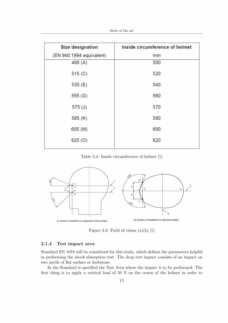
State of the art
Table 24 Inside circumference of helmet [5]
Figure 23 Field of vision (a)(b) [5]
214 Test impact area
Standard EN 1078 will be considered for this study which defines the parameters helpfulin performing the shock absorption test The drop test impact consists of an impact ontwo anvils of flat surface or kerbstone
In the Standard is specified the Test Area where the impact is to be performed Thefirst thing is to apply a vertical load of 50 N on the crown of the helmet in order to
15
State of the art
stabilize the helmet on the headform [5]1 Draw the AArdquo line (in the AArsquo plane) on the helmet2 Draw a line on the helmet parallel to and approximately 20 mm above the AArdquo line(for use as an angular measurement datum line)3 Mark the helmet at points B1 and B2 These points are the sideways horizontalprojection of point B onto the outer surface of the helmet4 Draw a line RRrsquo on the helmet passing through B1 and B2 the line being angled 10
upwards toward the front of the helmet relative to the datum line drawn in d) The areaabove the line drawn in f) is the test area for impacts on the flat anvil The area abovethe line RWArdquo is the test area for impacts on to the kerbstone anvil
Figure 24 Definition of test impact area [5]
215 Anvils and environmental conditions
EN 1078
During the validation process each of the 30 helmet target points was impacted ex-perimentally and numerically under three environmental conditions (-20C +50C andhumidity)
The impact should never exceed 250 g for impacts with velocities corresponding to 542ms on a flat anvil and 457 ms on a kerbstone anvil These are theoretically equivalentto 1497 mm and 1064 mm drop heights respectively [5] About the characteristics of theanvils according to EN 1078 these depend on the type in the case of
bull Flat anvil it has a circular form with a diameter of 130 plusmn 3 mm with 25 mm ofthick
16
State of the art
bull Kerbstone anvil face inclined at 525 plusmn 25 to the vertical and edge with aradius of 15 plusmn 05mm The height shall be not less than 50 mm and the lengthnot less than 125 mm [5]
According with the regalement EN 1078 [5] it has been possible to realize the volumes inthis work the Flat anvil has a diameter of 130 mm and a height of 25 mm the kerbstoneanvil has a horizontal edge of 130 mm a height of 51 mm a length of 126 mm and theedge that impacts the helmet has a radius of 15 mm The anvils are represented in Figure25
[a] [b]
Figure 25 Flat anvil [a] and Kerbstone anvil [b]
EN 13087-11 (Proposal)
A proposal of November 2018 (EN 13087-11) talks about oblique impact tests (Rotationaltest method) [15] Define a method to measure rotational energy absorption in tangentialimpacts in short duration impact situations the velocity considered by Adanty et al [1]is 65 ms The same anvils of the Standard EN 1078 are used the flat anvil and theKerbstone anvil but the difference is the vertical drop towards an impact angle between30-60 the degree considered by Adanty et al [1] is 45
Three different rotations are considered [34]
bull Rotation around X-axis contact point on the side of the helmet resulting in arotation around X-axis Initial position of the headform X- Y- and Z-axis 0
bull Rotation around Y-axis Contact point on the upper part of the helmet resultingin a rotation around Y-axis Initial position of the headform X- Y- and Z-axis 0
bull Rotation around Z-axis Contact point on the upper part of the helmet resultingin a rotation around Y-axis Initial position of the headform X- and Z-axis 0 and65 around Y-axis
17
State of the art
Figure 26 (a) The current cycling helmet standard for the EN 1078 [5] (b) Theproposed standard (EN13087-11) as described by the European Committee for
Standardization (CEN) [15][1]
22 Materials
221 EPS Foam
As mentioned in Chapter 13 the material most commonly used for making the helmetis the EPS Mustafa et al [25] analysed the EPS with four different density values of 50kgm3 64 kgm3 80 kgm3 and 100 kgm3 rdquoThe drop impact simulation model wasused to test the impact attenuation of the helmet with different densities The drop testwas performed on four impact locations top front and sidesrdquo
The impact velocity of the helmet and headform was set at 544 ms The lowestpeak linear acceleration was recorded at the top location and a density of 64 kgm3 with14814 g This study sets out to determine the effect of the user-centered helmet designwith different foam densities (from 50 kgm3 to 100 kgm3) on the impact attenuationof the bicycle helmet
Kroeker et al [19] tested the helmets at three impact speeds 30 plusmn 001 ms 63 plusmn002 ms and 78 plusmn 001 ms
They established the mean value about bulk density in a helmet with EPS foam is666 considering HIC and Peak Acceleration test The global range is between 64 kgm3
and 75 kgm3
Kroeker et al [20] established the foam for kids helmets is 64-88 kgm3 and for thetraditional helmets is 60-100 kgm3
Trzaskalska et al [36] controlled the influence of polymer liner density on energy ab-sorption during impact They discovered the best properties have samples whose densityis between 54 to 60 kgm3
Cui et al [10] considered the density of each layer from the values of 25 50 60 80and 100 kgm3 and they realize a 45 grades side impact and normal crown impact Theresult is a density of 64 kgm3
Wei et al [38] discovered from their test results that EPS has a buffer layer density
18
State of the art
of 60 kgm3 is the most reasonable
Foam densityrsquos values - Literature
Authors Densityrsquos values
Mustafa et al [25] 64Kroeker et al [19] 64 - 75Kroeker et al [20] 60-100 (traditional) and 64-88 (kids)
Trzaskalska et al [36] 54 - 60Cui et al [10] 54Wei et al [38] 60
Table 25 Table with foam (EPS) densityrsquos values
The other are mean values obtained by CES EduPackrsquos program about this material
- Density ρ = 6451kgm3
- Youngrsquos Module E = 275 MPa
- Poissonrsquos ratio ν = 0275
- Yieldrsquos stress σ= 09 MPa
- Elongation at fracture = 45
222 CES Edu Pack - Material selection
CES Edupack software was used to satisfy the idea of creating a lightweight helmetby printing it in 3D and having the possibility to insert the desired characteristics ofthe material and therefore select it To make a choice I used level 3 of engineering(advanced) selecting the following criteria of the material bio-material biodegradablea polymer of concentration 20 - 100 which complies with the rsquoEuropean Restrictionon Hazardous Substances (Rohs) standardsrsquo regarding the composition of the materialensuring that it does not contain a high percentage of toxic substances compared to theestablished percentage In addition it must have proper durability in contact with coldwater (imagining a possible rain) and rsquogoodrsquo durability to UV radiation
According to Ashbyrsquos method [2] to select a material it is possible to follow thefollowing steps
1 Establish the function of the product What does the component doThe helmet is an instrumental use to protect the head during an impact this characteristicdepends on materials and qualities It can prevent an injury which depends on materialsand design because it has to be of the right head size It would be comfortable becauseit must be worn and it must give security to the person wearing it (by design) In thefollowing Table 26 the analysis of the functions
19
State of the art
Ranking Function description Depends on
1 Head protection (energy absorbing) Material2 Head protection (energy absorbing) Design3 Head protection (injury prevention) Material4 Head protection (injury prevention) Design5 Comfortable Material6 Comfortable Process
Table 26 Ashbyrsquos method functions
2 The objectives that are targets for the design the material is to bemaximised or minimisedTo manufacture and market a product objectives such as minimizing weight cost orenvironmental impact must be considered In the following Table 27 the analysis of theobjectives
Ranking Title Objectives description
1 Mass Minimize The mass has to be thesame or lower
2 Cost Minimize everyone should have theopportunity to buy it
3 CO2 footprint Minimize CO2 emission
4 Corrosion Minimize high strength because itcan be in contact with the water
5 Pleasant to touch Maximize it is not a rough materialbecause it has to put on and put off
by hands
6 Refractive index Minimize it must not reflect light
Table 27 Ashbyrsquos method objectives
3 Definition of constrains What essential conditions must be meetEstablish constraints is essential to complete the function of the instrument Examplesof constrains are Table 28
4 The limits characteristic independent of the material that does not influencethe physical properties In the following Table 29 the analysis of the limits
20
State of the art
Title Loading case Constraintsdescription
Material index(Max-Min)
Stiffness Column in compression Tie in tension
Mass Min
Stiffness Column in compression Tie in tension
Cost Min
Stiffness Column in compression Tie in tension
CO2 Min
Strength Column in compression Tie in tension
Mass Min
Strength Column in compression Tie in tension
Cost Min
Strength Column in compression Tie in tension
CO2 Min
Table 28 Ashbyrsquos method constrains
223 PLA with natural fiber and PLA LW
Initially the best material that met the desired criteria was searched From this study itwas found that the material closest to having the required characteristics is the PLA 30natural fiber as shown in the Figure 27 which shows the graphs obtained relating tothe relationships between Youngrsquos Module and density the objective to reduce the massper unit of compressive stiffness and strength to reduce the CO2 footprint per unit ofstiffness and strength and mass per unit of compressive strength
Performance index IR
The stiffness criterion has the following characteristics
m = A lowast L lowast ρ (21)
ε =σ
E=
FA
E(22)
A =F
ε lowast E(23)
21
State of the art
Ranking Title Function description
1 Biocompatibility It is the ability of a material the abilityof the material not to cause any local or
systemic adverse response in therecipient of the material
2 Biodegrability Biodegradable material do notbiodegradable under anaerobic conditions
3 Biomaterials - all The terms is used for biological naturalbio-derived bio-inspired material
4 RoHS (EU) Compliantgrades
Restriction of the use of certin prohibitessubstances (mercury cadmium
hexavalent chromium)
5 Polymer 20-100 (from the table with Plasticpolymers)
6 UV Resistance at UV sunlight
Table 29 Ashbyrsquos method limits
A =F lowast L lowast ρε lowast E
(24)
With fixed variables- F (the load) L (the length)With variables that depend on the material- E (Youngrsquos Module) ρ (density)
In general when a chart is created the distribution of the mass is represented in thefollowing modality like in Figure 27 [b] where the materials above the line have a lowermass while those below a greater mass
Following the results of the CES Edupack program that had selected the PLA withnatural fibers as the best the first print of the helmet was made with this materialusing as support the PVA Initially the result seemed satisfactory the helmet had a highdefinition but a fundamental problem was found by reducing the helmet in the water toallow the supports of PVA to dissolve In the act of diving in fact after ten minutessome parts of the helmet especially the front and rear have disintegrated making thehelmet unusable Because of this problem it was necessary to change the material
22
State of the art
[a]
[b]
Figure 27 CES EduPack Mass per unit of compressive stiffness [a] Youngrsquos Moduleand density [b]
Further investigations carried out by the Mondragon Unibertsitatea Additive Man-ufacturing Department revealed a new material the PLA Low Weight which during3D printing allows to obtain a weight of 65 lower than that which could be obtainedfrom the classic PLA as reported in the technical sheet of the filament produced by thecompany Colorfabb [7]
The investigation team of the Composite Department carried out tensile tests withsamples 3D printed at different temperatures as suggested by the manufacturer to obtainthe technical characteristics The temperatures examined are 200 220 250 260The datasheet shows the density can have values between 04 - 124 gcm3 the bed has
23
State of the art
to have a temperature between 50 - 60 the printing speed has to have values between40 - 80 mms This typology of PLA is expandible so much that rdquoAt around 230 thismaterial will start foaming increasing its volume by nearly three timesrdquo [7]
T[C] Section [mm2] Volumen [mm3] Mass [g] ρ[kgm3] E [Nmm2]
200 42235 1030117 12 1165 328807
220 43805 1655821 18 1087 265795
250 52412 1948139 17 873 178058
260 59655 1454377 12 825 117047
Table 210 Values about PLA LW tensile tests of MU Additive ManufacturingDepartment
From the tests that have been carried out on the material at different temperaturesthe printed sample is better at 250 with a volume of 1948139 mm3 and a section of52412 mm2 as shown in Table 210 For this reason the specific of the material thathave been taken into consideration are the following
- Density ρ = 873 kgm3
- Youngrsquos Module E = 1750 MPa
- Poissonrsquos ratio ν = 033
- Yieldrsquos stress σ = 2948 MPa
- Elongation at fracture = 491
23 Bio-inspired structures
When we talk about bio-inspired structures to nature we refer to structures that allowobtaining a low weight for the model that is realized and excellent absorption energy dur-ing the impact Recently the structures that have been most used in the biomimetic fieldare the rdquocolumns structures sandwich structures plates honeycomb and foamsrdquo[26]but aiming to achieve a structure increasingly with high absorption energy new struc-tures derived from plants and animals such as beetle horsetail turtle bird beak havebeen analyzed The first to create multi-cells tubes helicoidal structures the second tomulti-corner tubes [26]
The authors analyze the specific energy absorbed (SEA) by bio-inspired sandwichstructures per unit mass which can be derived from the following equation
EA(d) =
int dmax
0F (x)dx (25)
SEA(d) =EA(d)
m(26)
24
State of the art
Where EA is the energy absorption rdquomainly used to evaluate an energy absorberrsquosability to dissipate crushing energy through plastic deformationrdquo F(x) is the crashingforce dmax is the effective deformation distance [26]
What derived from their investigations is that having regard to a density of between0 and 1000 kgm3 the volumetric energy absorbed is higher for the beetle-inspired struc-tures than the others as shown in Figure 28 Based on this consideration it was chosento draw the helmet following this geometry
Figure 28 SEA of bio-inspired sandwich structures [26]
231 Beetle structure - Design of the model
To develop and increase lightweight high-strength and optimize bio-mimetic functionaland structural materials the trabecular structure of the beetle elytron is studied Thesingle structure is realized following the requirements cited by Zhang et al [39]
To realize the beetlersquos structure it is not enough to have information about the lengthof the side of the hexagon and the thickness but it is also necessary to take into accountthe relationship between the diameter of the circumferences present on the vertices ofthe hexagon and the measurement of the side The representation of a single cell is inFigure 29 It is shown in [a] a general structure with an edge of 12 mm circumferencersquosdiameter of 6 mm and thickness of 16 mm in [b] is shown the height of 20 mm
For the construction of the helmet a thickness of 12 and 16 mm was used the imageconcerns a proportion between the length of the hexagon side and the diameter of the
25
State of the art
circumference The side (distance between the centers of two circumferences) is twice thediameter measurement
[a] [b]
Figure 29 Beetle structure
232 Specific stress - PLA LW and EPS foam
To test the beetle structures compression tests were investigated The PLA LW structurewas inserted in a rsquodiskrsquo with a diameter of 100 mm and a height of 20 mm The area andthe volume of the disk is correspondingly 7854 mm2 and 157 10 mm3 The structuresexamined have different dimensions the edge L (distance between two centers of thecircumferences) had the following measures 9 10 12 14 16 mm the thickness of thecircumferences and edges are respectively of 16 mm for every structure and 12 mm forthe structure with L = 16 mm
The test was carried out with the Hoytom HM-D Testing Machine with capacitiesbetween 5 and 100 kN The test models were subjected to displacement loading at a rateof 1 mmmin as referenced by Chen et al[18] with a cylindrical specimen The specificstress of the structures was compared with the specific stress of a generic EPS helmetthe photos about it are shown in Figure 210 The EPS helmet structure is granular withpores inside The different grains dimension and these pores can be the reason for whichthe Stressrsquos values are between two values 07 and 116 MPa
Four parts of the EPS helmet were considered in the test the dimension and relativecharacteristic are in the Table 211 where m = mass A = area F = load ρ = densityR = stress Rρ = specific stress To calculate the values of stress about PLA structuresand EPS foam compression test graphs were been analyzed The stress value for eachstructure was calculated considering the single load the single area and the averagedensity value (14055 [kgm3])
The stress values of the PLA structures (Figure 211) and other characteristic valuesare in Table 212 where m = mass A = area F = load ρ = density
26
State of the art
[a] [b]
[c] [d]
Figure 210 EPS generic helmet helmet pictures [a] [b] and internal structureExternal granular structure [c] and pores [d]
[a] [b] [c]
Figure 211 PLA LW disks Grasshopper structure [a] PLA LW structure of 14 mm[b] PLA LW structure compressed [c]
27
State of the art
The results of the load-displacement graphs are affected by the geometry of the diskthe target is to valid for any shape or size for this is preferred to realize a diagramthat depends from σ (or stress) and the deformation ε (or strain) which can be definedrespectively as
σ =F
A0(27)
ε =l minus l0l
(28)
where F is the load during the test A0 is the area l0 is the initial length and l is thelength when the load is applied The areas considered for the EPS cube is reported inTable 211 in the second column the areas of the PLA structure is 7854 mm2 like thearea of the circumscribed disk
The values compared are shown in Table 213 and the graphs obtained by Matlabcode to analyze the recorded data of the compression machine are in Figure 213 and inFigure 212
Considering that the data provided by the compression machine are subject to noiseand disturbances it was decided to convert the original curve into polynomial type curvesthat allow obtaining the best interpolating curve for the data in question To obtain themit was divided the recorded data into two groups the first part from 0 until the end ofthe linear part and the second when the curve becomes linear again The best-fitting (inthe least-squares sense) was performed using the polyfit and polyval functions of MatlabThe first returns the coefficients of the p(x) with n degree the second evaluates p(x) ateach point in x The polynomial formula p(x) is shown in the Equation 29
pn(x) = anxn + anminus1x
nminus1 + + a2x2 + a1x+ a0 (29)
where a0 an are constants and x is the indeterminate The choice of the degree ofthe polynomial was made based on the criterion of wanting to obtain linear curves thatrespected the elastic trend at the beginning of the graph For this reason the degree ofthe polynomial is 1 Subsequently I searched through the intersection of the two lines forthe point that is equivalent to the maximum stress that marks the end of linearity
This value for EPS and PLA LW is the R [MPa] in the Table 213 The average stressvalue for PLA LW is 139 MPa and for EPS is 094 MPa The specific stress (Rρ) is 18MPa lowast m3)kg for the EPS found in CES 669 MPa lowast m3)kg for the EPS foam of thegeneric helmet and for PLA LW is 1161 MPa lowastm3)kg an intermediate value betweenthe two which is what we wanted to achieve
28
State of the art
m [g] A [mm2] F [N] ρ [kgm3]
EPS (CES) 50
16 9234 1063 13864
18 879 593 13651
21 858 833 14237
24 864 564 14468
Average value 14055
Table 211 Compression stress generic EPS helmet
L [mm] t [mm] m [g] F [N] ρ [kgm3]
9 16 214 7250 1363
10 16 192 5560 12467
12 16 201 8190 13051
14 12 138 8000 8961
Average value 12027
Table 212 Compression test PLA structures
PLA LW structure EPS structureρ= 12027kgm3 ρ= 14055kgm3
Edge [mm] R [MPa] Rρ103 Number R [MPa] Rρ103
EPS (CES) 09 18
9 173 1269 1 116 824
10 139 1114 2 08 568
12 138 1057 3 105 746
14 108 1205 4 077 540
Average value 139 1161 094 669
Table 213 Specific stress calculus PLA LW and EPS calculus ρ = density R = stressRρ [(MPa lowastm3)kg] = specific stress
29
State of the art
Figure 212 Compression test Stress-Strain diagrams - EPS
Figure 213 Compression test Stress-Strain diagrams - PLA LW
30
Chapter 3
Methodology
31 3D scan
311 3D Sense 2 scanner and Meshmixer - Reverse reconstruction
Standardized measures were not taken into account for making the helmet but the sizewas obtained through a 3D scan of my head
The scanner used is 3D Sense 2 by 3D Systems which has a minimum scanningvolume of 20 x 20 x 20 cm and a maximum scanning volume of 300 x 300 x 300 cmTo scan my person I was helped to get a full view at 360 at an appropriate distanceReal-time visualization of the captured images was shown through 3D Sense softwareThe idea of scanning the head with the scanner refers to the methodology used by Wanget al [30] They used a reverse reconstruction functional for me to realize the helmetsurface made to measure my head and like them a silicone pool cap was used to makescanning as smooth as possible The authors claim the head scan rdquocan also be used toobtain information about the objectrsquos surface which is then reconstructed utilizing thecomputerrsquos three-dimensional model via reverse modelling softwarerdquo [30] that in my caseis Autodesk Meshmixer
The files it was could get from the scan were stl obj and ply format they wereexported to obj to work in the next step with Autodesk Meshmixer that allowed tomodify and homogenize the 3D image obtained from the scan
In Meshmixer through the selection and delete commands the superfluous parts weredeleted that had been acquired and with the inspector and the DrawDraw2 commandsthe vertices were moved locally along a pre-defined direction and with Smooth the surfacemore homogeneous was made The sequence of steps is shown in the Figure 31
312 3D scan analysis and extraction of features
In Chapter 2 the directives imposed by the BS EN 960 Standard were examined concern-ing the definition of the helmet and the measures to be respected in the field of visionand the part of the helmet was to carry out impact tests
In Figure 32 the features defined complying with the Standardrsquos rules are repre-sented To define these features the software NX was used The angle in the subfigure
31
Methodology
[a] [b] [c] [d]
Figure 31 Sequence of 3D head scan 3D scanner acquisition [a] scan after reparationwith Meshmixer [b] solid scan vision frontal and lateral [c] [d]
[b] is bigger than 105 (as defined by the Standard) while the degree in the subfigure [c]is 25 By defining the construction lines to be respected of the helmetit was necessary todraw the design of the surface not using the software NX but changing with Rhinocerosto create a SubD or SubDivision surface
32 Helmet design
321 Rhinoceros - Helmet surface
After realizing a rsquocleanrsquo Wang et al [30] subdivide with lines and then sectors the headto create the surface of the helmet They used the technique of NURBS a Non UniformRational Basis-Splines which mathematically models a 3D geometry while thanks tothe Rhinoceros 3D organic shapes was draw SubD surfaces These geometries allow tosplit the mesh into small polygons and consist of lines with which easily the shape ofthe object can be modified with a surface already created changing the position of aline automatically the remaining part of the geometry adapts to the changes With thistechnique the rsquosurface basersquo of the helmet was realized with the size of my head Therepresentation of the realized SubD is in Figure 33
322 Grasshopper - Helmet structure
The next idea is the creation on the surface of the beetle structure with different di-mensions modelling the helmet that is not a linear surface It was decided not to buildthe structure with a software CAD because to model an already complex structure on acurved surface would mean to model a cell for a cell
To solve this obstacle a Rhinoceros plug-in was used Grasshopper GH idealized byRobert McNeel and associates creators of Rhinoceros Using GH does not mean drawinggeometries by connecting points and drawing tools because it is based on algorithmicmodelling used in architecture and engineering for 3D modelling
The modelling takes place through a node diagram that the software will convert intoa code-algorithm in GH it is possible to define the variables and parameters and inRhinoceros in real-time it is possible to view the object GH allows for varying the
32
Methodology
[a] [b]
[c]
Figure 32 Featurersquos extraction in [a] is represented the impact line in [b] and [c] twoprospective about the definition of the field of vision
[a] [b] [c]
Figure 33 SubD representation lateral view [a] top view [b] front view [c]
geometry to your liking by varying a simple parameter of the diagram as everything willbe remodelled according to the change made
In the following Figure 34 it is shown an example of a structure that was used fordistinct subgroups of helmet areas The idea was to insert smaller cells in the frontal andlateral zone and larger ones in the upper area In the first image [a] is shown the part of
33
Methodology
the helpful diagram to create the beetle structure to establish the size of the cells andthe extrusion the second image [b] contains the part of the diagram with which I appliedthe structure previously created to the SubD
The structure used to place and adapt the beetle structure to the surface is theSrfMorph while the yellow rsquowindowrsquo that contains numbers serves to select the parts ofthe surface where to apply the geometry created In accord with the GH diagram in
[a]
[b]
Figure 34 Grasshopper diagrams
Figure 34 [a] it is possible to see the steps executed to realize the structure Initially inthe xy-plane a hexagonal grid was drawn through the Hexgrid command in which youcan input the length of the hexagon edge and the number of grid elements (selected bytrial) Then the circumferences was drawn in proportion to the hexagon dimensions asspecified in the Chapter 2 and shown in Figure 35 [a] In figure [b] the rsquocutrsquo made atthe circumferences is visible this subdivision was necessary for printing purposes In thelast photo [c] the structure highlighted in green in [b] was extruded setting a distance
34
Methodology
of 20 mm
[a] [b] [c]
Figure 35 Construction sequence of the geometry of the helmet
In the diagram in Figure 34 [b] there is the application of the structure created bi-dimensionally to the SubD surface of the helmet visible by unlocking the SubD commandof the diagram and in Figure 36 [a] Upper this the referential geometry of the group ofsurfaces was superimposed where it was to be applied the newly created structure (visiblein darker red) the SubD indices are in the yellow box of the diagram
Through the SrfMorph command the location of the structure was granted In Figure36 [b] at the darkest red of the figure [a] with the above command it was possible toplace the structure
[a] [b]
Figure 36 Application of the geometry created to the helmet surface
Overall the diagrams with specific structures are five one for the front two equal forthe side parts one for the top shown in the previous Figure 36 and one for the back
The hexagons in the structure have a dimension varying between 8 mm and 14 mmof side the largest is found at the top later at the back in the sides and the smallest atthe front In Figure 36 [b] the presence of not only hexagonal structures is visible Thegeometry used does not allow the homogeneous arrangement on the entire surface andrequires different structures Automatically the choice of GH to optimize the structurewas to insert quadrilateral
As described above the helmet has different dimensions of the structure divided asvisible in Figure 36 in a quadrilateral This causes a discontinuity between zones withdifferent sizes due to the geometry of the construction
To eliminate this problem and realize the design homogeneous grids were inserted
35
Methodology
in the affected areas as shown in Figure 37 This insertion however proved to beinteresting and strategic researching in this regard studies were realized to demonstratethe insertion of a rectangular grid inside the hexagon grid was helpful for the transmissionof stress in the structure As cited by Sun et al [40] rdquothe mechanical properties of thesesandwich structures are often limited by local failures such as face-core debonding or corecollapserdquo Carrying out compression tests have effectively demonstrated that the insertionof the grid allows rdquoprovided increased stiffness specific stiffness energy absorption andcritical loadrdquo [41] As shown in the graphic [c] of the Figure 37 the honeycomb structuregives a force of 7 kN while with a grid the value is 11 kN and with the combinationexceeds 22 kN In addition in the left front a plaque to customize the helmet wasprepared Figure 37 [a]
[a] [b]
[c]
Figure 37 Grid in the helmet [a] hybrid structure with hexagons and grid [b] [40]compression test results of the hybrid structure [c] [41]
33 3D Print
After having achieved the CAD (Computer Aided Design) of the helmet in order tobe printed it must be converted and saved in format STL (Standard TriangulationLanguage) - Binary compatible with the printing machine and useful for transformingsolid object surfaces into triangles The steps to be taken are the following
bull CAD file realization
bull CAD export in format STL to Simplify 3D the software that shows slider layersand then- rotate and position the object according to geometry and the positioning of any
36
Methodology
supports- setting printing parameters- item manual andor automatic positioning of supports- slider display layers
bull import file gcode to printer
331 Printer and parameters
The program used to visualize how the helmet slices layers before sending it to the printerand to set the parameters is as anticipated Simplify 3D
To make the printing not being a flat geometry it is necessary to place the supportsThe idea was to use water-based supports that the helmet would automatically dissolveonce placed in the water After testing different types of water-soluble PVA the choicefell on eSun 3D Printing Filament PVA (water-soluble support) Before choosing theoptimal position for printing several tests were carried out and to decrease the numberof the supports significantly and allows an optimal printing of the outer part an emptyrsquospherersquo that self-sustains below the helmet was placed as shown in Figure 38
In the image [a] you can see the first print position tried with which an external partof the helmet very damaged was obtained because of the contact supports-helmet In [b]the empty rsquospherersquo is shown to optimize the number of supports and in the last photo [c]there is the full version at the end of print
[a] [b] [c]
Figure 38 Printing supports
The printer that has been used for printing is the Raise 3D Pro2 with double extrudersand nozzles of variable size from 02 mm to 1 mm after some test prints with the PLALW and the structure in created the size that allowed me to have a good compromisebetween printing time and accuracy was 06 mm Using 04 mm the printing time wasexcessive even if having the smaller nozzle diameter means having more precision withthe 08 mm nozzle the quality of the structure was not excellent as seen in Figure 38[a]
Another factor that had to be taken into account is the characteristic of the PLA-LWto expand As the printing temperature and the printer used vary the expansion andcharacteristics of the material change The use of the 06 mm nozzle associated with
37
Methodology
Parameter Left extruder Right extruder
01cm Material 01cm PVA 01cm PLA LW
Extruder toolbox index Tool 0 Tool 1
Nozzle diameter 06 mm 06 mm
Extrusion multiplier 1 05
Extrusion width Auto (072 mm) 05 mm
Layer x
Infill Rectilinear - 50
Supports (Automatic and not) Infill 50
Temperature 210 250
General parameters
Primary layer height 03 mm Top solid layer 4
Bottom solid layer 2 Outline 2
Heated bad 60 Speed 40 mms
Table 31 Printing parameters
Raise 3D allowed me to get good results The choice of this printer was not random ithas in fact the characteristic of making extremely precise prints The Raise has accuracyin placing the object on the printing bed of 078 microns on the xy axis and a resolutionfor layers of 001 mm
The final version of the helmet is visible in Figure 39 and it is possible to compare itwith the preview version in Rhinoceros in Figure 310
38
Methodology
[a] [b]
[c]
Figure 39 Views of the helmet
[a] [b]
Figure 310 Views of the helmet (GH version)
39
Chapter 4
Experimental evaluation
41 Experimental tests
411 Drop-weight impact test machine
In order to calculate the contact force peak and the difference of energy absorbed duringthe impact between the reference helmet and helmet with the beetle structure in PLA-LW dynamic impact tests were carried out using the Fractovis Plus an impact testmachine
In this way it is possible to monitor the evolution of the above variables from theinitial to the final instant of the impact The machine can withstand a load with a rangevariable from 2 to 70 kg with a maximum speed of 46 ms and a maximum height of1 m The values chosen for the test are the following 5 kg weight maximum speed andmaximum height The Anvil that was used is a disc diameter of 60 mm
As shown in Figure 41 and explained by Crupi et al [37] the machine consists ofa sensor capable of recording the speed before impact the impactor that can have avariable mass (a weight of 5 kg in my test) a system to guarantee that there are nomultiple impacts after the first and that work as a shock absorber and clamping systemwhere the object to be tested is placed
The tests that have been carried out are in total four two related to the helmetoptimized with PLA-LW and two with two generic helmets of different brand in EPS
42 PLA LW helmet
To perform the dynamic test on the helmet of PLA considering the difficulty of printingit was helpful to use a test helmet with imperfections to understand where the impactwas concentrated in a single part or distributed The images of Figure 42 show a helmetwith not well defined edges and inaccurate print but exactly localizes the impact zoneThanks to this test it was possible to take into account only one helmet area shown inFigure 43 to have the exact curve of the structure bio-inspired with PLA-LW
40
Experimental evaluation
Figure 41 Drop-weight impact test machine [37]
[a] [b]
Figure 42 Test 1 PLA-LW helmet
43 EPS helmet
To carry out dynamic tests and extract the technical characteristics of the helmettwohelmets were bought in a sports store both EPS and being on the market both certifiedThe brands of the two helmets are DTB and VAN|RYSEL and the average weight ofthe two is 223 g Two different helmets have been chosen to have a more certain andclear classification of the characteristics They are shown in Figure 44 and Figure 45
41
Experimental evaluation
[a] [b]
Figure 43 Test 2 PLA-LW helmet
[a] [b] [c]
Figure 44 Test 3 EPS helmet
[a] [b] [c]
Figure 45 Test 4 EPS helmet
44 Results
441 First results - PLA-LW and EPS helmet
Figure 46 shows two types of trends related to the two different models of the helmetThe force evaluated for PLA-LW has higher force peaks but is more concentrated and
42
Experimental evaluation
propagates less than EPS The graph shows the peaks of each curve highlighted with a redcircle In tests 1 and 2 for the PLA-LW as mentioned earlier the values are higher about7301 N for the complete helmet and 3996 N for the portion of helmet This difference isdue to the inaccuracy of the first full helmet during the printing phase In Figure 42 itis visible the low homogeneity and precision Therefore the first test with full helmet wasused only to define the area of interest of the impact which turns out to be localized Forthe other two EPS curves the values are only slightly lower compared to the PLA-LWequal to 3620 N and 3295 N but the trend is much more distributed
Figure 46 Dynamic machine test - Force
With the data obtained from the impact machine it was possible calculate not exclu-sively the value of force but itrsquos also possible to view the energy curves A resume aboutthe values and energy of the force is in the following Table 41
Test Peak force [N] Peak energy [J]
Test 1 - PLA LW (inaccurate) 730130
Test 2 - PLA LW (portion of helmet) 399643
Test 3 - EPS (DTB helmet) 362007 509
Test 4 - EPS (VAN|RYSEL helmet) 329546 4198
Test 5 - PLA with TPU 45421 5022
Table 41 Energy absorbed in dynamic test
43
Experimental evaluation
442 PLA-LW helmet with TPU cover
As it is possible to see in Figure 47 and as highlighted the first tests concerning thebio-inspired structure and the PLA-LW are far from my expectations considering thelittle distribution of force in comparison with the EPS foam and consequently a smallamount of energy absorbed
Figure 47 Dynamic machine test - Energy
To improve this impact damping factor the idea was to create a cover for the helmetin flexible TPU trying to absorb impact energy The TPU used is a flexible material ofthe brand Ninjaflex used in sports by the application in helmets and shoes to cushionbumps during the game Generally in the helmets (baseball helmet for example) theTPU is inserted internally in contact with the head In my case the TPU structurein addition to creating a shock-absorbing and durable cover creates a custom cover thehelmet and for the person This cover was also made with the Raise 3D printer
As shown in the Figure 48 [a] the infill of the part in contact with the helmet hasa percentage of 100 the filling of the other part of the structure is not complete butonly 15 and the internal structure is hexagonal to recall that of the helmet The desireto insert a structure with a rsquoraisedrsquo geometry is for visual and aesthetic reasons as youhave the feeling of greater protection and not filled is inspired by the machine CitroenCaptus whose bumpers (Airbump) are full of air The failure to realize empty structuresis due to the need to place any internal supports not removable
The idea was to create a cover that allow you to see of the internal structure of thehelmet and that protect specific areas the front the two sides the top and the posteriorWhat which was thought for this reason was to create the shape of a flower with four
44
Experimental evaluation
petals Figure 48 [b]In this way to perform dynamic impact tests as shown in Figure 49 [a] the cover was
positioned at the top of the helmet and the impact was performed in the centre of thersquoflowerrsquo which corresponds to the higher upper part where the structure has larger cellsize The impact parameters are the same as those used in previous impacts 5 kg weightmaximum speed and maximum height The Anvil that was used is a disc diameter of60 mm In photo [b] it is evident the difference between the structure that received theimpact with protection (left) and without protection (right) Without protection duringthe impact there was a perforation of the structure with a concentration of force at a locallevel as you can see in the Figure 46 in the case of TPU the impactor did not perforateand crossed the structure thanks to the cover of TPU that cushioned the shock At themoment of impact the impactor bounced
[a] [b]
Figure 48 TPU cover
[a] [b]
Figure 49 PLA-LW with TPU - dynamic impact [a] and differences between thehelmet with TPU and without TPU cover [b]
45
Experimental evaluation
The Figure 410 includes the diagrams relative to the dynamic impacts In [a] thereare already analyzed EPS results in [b] a comparison between the test on the portionof helmet in PLA LW with and without the TPU cover in [c] the overall comparison ofcurves shows a much more similar EPS trend if the TPU is placed above the structure inPLA LW to soften the blow and absorb the same energy [d]
46
[a]
[c]
[d]
Figure 410 Comparison between PLA-LW with TPU and EPS
Chapter 5
FEM Validation
51 Impactor - Anvils definition
Before to start to work in Abaqus it was necessary to search in the literature the materialwith which the anvil was been realized Milne et al [23] established the densityrsquos valuethe Youngrsquos Module and Poissonrsquos ratio for the Flat and Kerbstone Anvil
- Density ρ = 7800 kgm3
- Youngrsquos Module E = 200000 MPa
- Poissonrsquos ratio ν = 03
Inserting the data in the CES EduPack program specifying the mechanical andphysical properties the material corresponding to these characteristics is Stainless steelaustenitic (ASTM F1586) medium-hard
Initially the proposal was to create a conservative system to evaluate the absorptionenergies values and apply this value to a vibration system but the helmet needs dampingto be realized it was impossible to use a system without losses in this modality Thisis why a numerical calculation was carried out by performing two types of simulationsexplicit dynamic step and static step
The idea to realize the theoretical impact is to regard the movement of the anviland not the helmetrsquos movement which is fixed The velocity is the same cited in thenormative EN 1078 542 ms for the Flat anvil and 457 ms for the Kerbstone anvil
In performing the simulations It was given more relevance and perform tests withthe Kerbstone Anvil This choice was done because the geometry with which it is beenrealized (following as defined in the legislation) allows the helmet to be more subjectedto stress this involves the definition of higher stress limits compared to the Flat Anvil
The mesh size that has been used is the same in the case of the simulation of thehelmet optimized in PLA-LW and the full helmet in EPS of 7 mm The impactor isconsidered as a Discrete rigid body with its specific Reference Point (RP) like shownin Figure 51 for this reason it is not a solid but it is composted only by shells Inthe same image [b] there is the FEM representation of the model and in Table 51 thecharacteristic of FEM with quadrilateral (R3D4) and triangular elements (R3D3)
48
FEM Validation
Object Elementnumber
Elements Shape Geometricorder
Global size[mm]
Kerbstone 230 Quadrilateral - R3D4 Linear 7
Kerbstone 8 Triangular - R3D3 Linear 7
Table 51 Mesh element - Kerbstone Anvil
[a] [b]
Figure 51 Kerbstone anvil in the simulation like discrete rigid body [a] and FEMelements [b]
511 PLA LW - Plastic characteristics
The PLA-LW as explained in the Chapter 2 is new material on the market and producedby the only Colorfabb company for this reason few tests have been carried out to defineits technical characteristics and through tensile tests of the 3D printed specimens it waspossible to define an elastic limit as reported in the Table 210
In the context of simulations to reproduce the impact and deformation of the helmetis also necessary to consider the plastic characteristics of the material Not possessingany reference value in this regard tests were performed through a Static Step initiallyand then an Explicit Dynamic Step in Abaqus
The structure chosen to consider as a reference it is one of the structures previouslysubjected to the compression test having the side L=14 mm As for the reproduction ofthe compression disks initially they were reproduced according to the geometry of theHoytom HM-D Testing Machine considering the bodies mentioned above as discrete 3Drigid discrete The measure was the diameter of 200 mm and the height of 20 mm
After an initial analysis it was observed that the computational time of the simulationprogram was very high so it was decided to change the geometry to have a rsquodisk-surfacesrsquo(equally 3D rigid-discrete) which allowed me to have a smaller number of nodes for themesh and consequently a better computational time The representation of the opti-mized structure in PLA-LW and the disks used for simulated compression is in Figure 52
49
FEM Validation
[a] [b]
Figure 52 Representation of the samples used for the simulation of the compressiontest In Figure [a] the disks of the Hoytom HM-D Testing Machine in figure [b] the
representation of the same as simple surfaces
As shown in Figure 52 the disks are considered 3D discrete hard bodies so it waschosen for both a point the reference point RP where to apply the characteristics relatedto the two bodies As for the compression test it was established
bull the movement of a disk and fixed the second through a boundary condition impos-ing an Encastre therefore unable to move and rotate in xyz directions
bull for the opposite disk the boundary condition relative to the 15 mm displacementwas applied which is the parameter that it was observed to determine the end ofthe compression with the machine This shift is shown by the orange arrow in figure[b]
bull between the upper surface and the disk e the disk with the lower surface it wasinitialized a general contact with normal behaviour through rsquohardrsquo contact andtangential behaviour with a coefficient of friction of 02 with directionality imposedon rsquoisotropicrsquo
The next step was to define the mesh of the components whose parameters are shown inTable 52 while the representation of the FEM is in Figure 53 with the representationof the simulation and real compression test
Object Elementsnumber
Typology Geometricorder
Globalsize [mm]
Disk (14mm) 80910 hexaedral - C3D8R Linear 07
Impact disks 206 quadrilateral - R3D4 Linear 20
Impact disks 6 triangular - R3D3 Linear 20
Table 52 Mesh element - Compression test simulation
As previously announced a static simulation was initially performed with a StaticStep with Step Time equal to 900 (obtained going to consider the speed of 1 mmmin of
50
FEM Validation
[a]
[b] [c]
Figure 53 FEM representation [a] and compression test simulation [b] and realcompression [c]
the compression test and the displacement of 15 mm) However the complex geometryof the structure and the high time set by Step Time did not allow a correct definitionof the parameters of the plastic characteristics of the material the simulation was notable to continue once reached a Step Time of approximately 220 That is why it waschanged by choosing an Explicit Dynamic step
Leaving all the parameters of the boundary conditions unchanged the Step Time wasmodified imposing it to 001 The ability of the explicit dynamic to work with non-linearand contacting structures allowed me to achieve results The results obtained are shownin Figure 54 with the blue curve and were obtained through the iteration of differentPlastic Strain and Yield Stress values in Abaqus while the red line is the result of thereal compression test a similar curve trend was obtained but it is not possible to obtainthe same curve taking into account problems of printing inaccuracy
512 First test - helmet
The initial idea was to perform a simulation imposing the speed of 457 ms to theimpactor tie the helmet in EPS and PLA and compare the absorbed energies Theproblem it was encountered is related to the mesh of the helmet optimized in PLA andwith minimum dimensions of the elements and distinct elements it was not able to solveit
51
FEM Validation
[a]
YieldStress
PlasticStrain
1 47 0
2 7 001
3 75 005
4 10 01
5 108 1
6 115 15
7 12 2
[b]
Figure 54 Representation of the two curves related to the simulation in Abaqus of thecompression test and the data obtained from the real test to obtain the plastic
characteristics of the material
513 Second test - plane
The first solution is the one shown in Figure 55 To realize the simulation it was realizeda section of the helmet to involve a smaller number of elements and nodes Again thesimulation for the EPS helmet was successful while the simulation with the bio-inspiredstructure was interrupted by excessive distortion of elements
The previous images show the impact is very localized in the impacted area and theidea to achieve a complete simulation is not to consider a curved portion of the helmetbut a plane In this way it was possible to solve the problem and obtain a completesimulation for the bio-inspired structure
FEM element
Below in Table 53 there is the definition of the elements used for the PLA-LW and EPSplane in the simulation to simulate the impact and to control the energy-absorbing whilethe anvil characteristics are described in Table 51
514 EPS impact simulations
In order to proceed with the simulation it was imposed some boundary conditions thatregard ties and forces
bull the movement of the plane is fixed through an Encastre therefore unable to moveand rotate in xyz directions
52
FEM Validation
[a]
[b]
Figure 55 Impact simulation parts of EPS and PLA helmet
Object Elementnumber
Elements Shape Geometricorder
Plane (PLA) 38896 Tetrahedral -C3D10M
Quadratic
Plane (EPS) 2100 Hexahedral - C3D8R Linear
Table 53 Mesh element - plane impact
bull to create the impact it was set a speed of 457 ms at the reference point RP of therigid body which is the impactor Kerbstone Anvil shown in Figure 56
bull between the upper surface of the plane and the impactor it was initialized a Sur-face to Surface contact with normal behaviour through rsquohardrsquo contact and tangen-tial behaviour with a coefficient of friction of 02 with directionality imposed onrsquoisotropicrsquo
bull the rotation in x y z relative to the RP of the rigid discrete impactor body is locked
53
FEM Validation
In addition it was characterized the plane in the part of the materials with the char-acteristic values of the EPS mentioned in Chapter 221 The Von Mises Stress valueapparently low is relative to the Yield Stress of the EPS material equal to 09 MPa
Figure 56 EPS Boundary conditions and Load
515 PLA LW impact simulations
As also required in the case of the EPS plane in order to proceed with the simulationsome boundary conditions were imposed that regard ties and forces
bull the movement of the plane is fixed through an Encastre therefore unable to moveand rotate in xyz directions
bull to create the impact a speed of 457 ms was set at the reference point RP of therigid body which is the impactor Kerbstone Anvil shown in Figure 58
bull between the upper surface of the plane and the impactor it was initialized a Sur-face to Surface contact with normal behaviour through rsquohardrsquo contact and tangen-tial behaviour with a coefficient of friction of 02 with directionality imposed onrsquoisotropicrsquo
bull the rotation in x y z relative to the RP of the rigid discrete impactor body is locked
In addition the plane was characterized in the part of the materials with the characteristicvalues of the PLA mentioned in the Chapter 223 and 511
Figure 58 Boundary conditions and Load
54
FEM Validation
[a]
[b]
Figure 57 EPS impact simulation
52 Results
In Figures 59 and 57 it is shown how the structure in PLA LW has a more concentratedstress distribution of the structure unlike EPS The maximum value for the Von Misesstress is 09 MPa in EPS structure and 3634 MPa in PLA LW structure Once thesimulations were obtained the next step was to go and compare the energies absorbed bythe two structures The energy calculated by Abaqus that has been taken into account isPlastic Dissipation To make a comparison the data of the two energies were representedin a single graph
What emerges from the graph is that about the impact made with the KerbstoneAnvil the energy absorption is more excellent although only slightly for the PLA LWthan for the EPS From the graph in Figure 510 a value of 41 J is shown for the EPSand 51 J for the PLA LW
55
[a]
[b]
Figure 59 PLA impact simulation
[a]
Figure 510 EPS and PLA LW energy comparison - Abaqus simulation
Chapter 6
Head Injury Data
For the statistical analysis the injuries related to the accident data were categorised intothe following types and levels based on the details of the medical report [11] about theEN 1078
bull Head Injury Criterion (HIC)
bull Peak Linear Acceleration (PLAc)
bull Gadd Severity Injury (GSI)
bull Diffuse axonal injuries (DAI)
61 Abaqus simulation
Until now the purpose of the simulations has been to determine which between the twomaterials and the two structures of EPS and PLA LW could absorb more energy duringthe impact but no simulations have been carried out in compliance with BS EN 1078on the helmet impact tests To calculate the injuries listed in the previous paragraphhowever we need the acceleration values in the three directions related to the subjectrsquoshead
To realize it the scan of my head already rsquocleanrsquo was considered of which it has beencalculated the inertia thanks to the automatic SolidWorks calculation and evaluated theweight with the Table 24 the structure of the helmet was placed for the EPS and thePLA LW over the head as shown in Figure 61 Also this time being able to mesh theentire helmet in PLA LW was impossible due to the excessive distortion of some elementsduring the simulation so it has been tried to make a section of the structures of thehelmet and results were obtained
57
Head Injury Data
[a] [b]
Figure 61 My scan head - CAD [a] head imported in Abaqus[b]
Initially the simulation had these characteristics as shown in the following Figure62 considering the helmet was not sectioned As explained earlier it was not possibleto get to simulation in the case of the optimized structure in PLA LW for this reasononly a part of the helmet was considered in both cases shown in Figure 63
[a]
Figure 62 Simulation based on BS EN 1078
58
Head Injury Data
[a] [b]
Figure 63 Simulation based on BS EN 1078 with head
In order to proceed with the simulation some boundary conditions that regard tiesand forces have have imposed
bull two reference points RP were created the first in the inertia centre of the headthe second relating to the Kerbstone Anvil which is a discrete rigid body
bull in the reference point RP of the head in the definition of the engineering features5 kg was inserted for the weight and an inertia I11 = 564464E+07 gmm2 I22 =460654E+07gmm2 I33 = 187302E+07gmm2
bull to simulate the impact it was set a speed of 457 ms at the reference point RP ofthe head in z-axis direction
bull a general contact with normal behaviour through rsquohardrsquo contact and tangentialbehaviour with a coefficient of friction of 02
bull between the upper surface of the helmet and the impactor it has been initializeda Surface to Surface contact with normal behaviour through rsquohardrsquo contact andtangential behaviour with a coefficient of friction of 02 with directionality imposedon rsquoisotropicrsquo
bull the movement between the Kerbstone anvil and the helmet is fixed through anEncastre therefore unable to move and rotate in xyz directions
bull the rotation in x y z relative to the RP of the rigid discrete impactor body is locked
FEM element
As reported in Table 53 the portion of the helmet in EPS has used a mesh with hexahe-dral elements of linear order For the structure (beetle) of PLA LW given the geometry
59
Head Injury Data
complexity it was necessary to use a quadratic order of tetrahedra For the mesh of thehead instead in both simulations have been used quadrilateral elements of linear orderas reported in the Tables 61 and 62
Object Elementnumber
Elements Shape Geometricorder
Head 3755 Quadrilateral - R3D4 Linear
Head 34542 Quadrilateral - R3D3 Linear
Helmet (PLA) 272302 Tetrahedral -C3D10M
Quadratic
Table 61 Mesh element - Head simulation with PLA LW (beetle) helmet
Object Elementnumber
Elements Shape Geometricorder
Head 3755 Quadrilateral - R3D4 Linear
Head 34542 Quadrilateral - R3D3 Linear
Helmet (EPS) 72280 Hexahedral - C3D8R Linear
Table 62 Mesh element - Head simulation with EPS helmet
62 Results
Figure 64 represents the simulation in line with BS EN 1078 concerning the helmet inEPS [a] and the helmet with bio-inspired structure in PLA LW For both simulationsVan Misesrsquo stress has Yield Stress values in the case of EPS which is 09 MPa and theplastic behaviour combination of PLA LW [b]
In the case of head and Kerbstone Anvil stress was not assessed as they were previ-ously defined as discrete rigid bodies
63 Head Injury Criterion
The HIC quantifies head impact severity by incorporating time of acceleration exposureand acceleration magnitude it is calculated in post-processing phase with the followingEquation 61
HIC15 =
[1
(t1 minus t2)
int t2
t1
a(t)dt
]25(t2 minus t1) (61)
60
Head Injury Data
[a]
[b]
Figure 64 Results simulation based on BS EN 1078 with sectioned head
For this analysis a(t) is the acceleration calculated in the centre of mass of the head(corresponding to the reference point RP) expressed in g and the time interval (t2 minus t1)was chosen to maximize HIC over a maximum duration of 15 ms
Matlab and the trapz function were used to calculate the HIC to integrate accelerationover time t2 and t1 were considered initial and final times of the simulation t1 = 0 sand t2 = 10 s time less than 15 s
HIC value of 198 was obtained for EPS and 87 for PLA LW Considering the Hayeset al [16] document about the HIC values and the graph in Figure 65 developed bythe author it is possible to find the percentages related to the different injury AIS1 -AIS6 which correspond respectively to lower and higher severity while in Figure 66 therelative fatality to every value of AIS is shown The values obtained for the HIC andother criteria are shown in Table 63 The HIC value for EPS is 198 for PLA LW it is
61
Head Injury Data
Figure 65 Head injury risk curves based on HIC values [16]
Figure 66 The abbreviated injury score versus fatality rate [16]
87 Analyzing the data and comparing them with the curves of the Figure 65 I obtain
bull a percentage between 20 - 30 of AIS 1 for EPS 10 - 20 for PLA LW
bull a percentage between 10 - 20 of AIS 2 for EPS and 0 - 10 for PLA LW
bull for AIS 3 AIS 4 AIS 5 AIS 6 the percentages for both structures is between 0 -10
Comparing these percentages with the fatality rate of Figure 66 it is clear there is a riskof Moderate and Minor fatality in the case of EPS and PLA LW as all values are between0 and 30
62
Head Injury Data
HIC PLA [g] GSI E [J]
EPS 198 97 361 37723
PLA LW 87 75 169 44102
Table 63 Head Injury Data - values
64 Peak Linear Acceleration
The resultant linear acceleration versus time curve was calculated according to Equation62
γ(t) =radicγ2x(t) + γ2y(t) + γ2z (t) (62)
where
bull γ(t) is the resultant linear acceleration (g)
bull γx(t) is the linear acceleration in x axes (g)
bull γy(t) is the linear acceleration in y axes (g)
bull γz(t)is the linear acceleration in z axes (g)
The value of the impact should never exceed 250g [9] Cripton at all [9] in their studyexamined a helmet with expanded polystyrene (EPS) Figure 68 shows maximum HIC forhelmeted and unhelmeted drops from all heights For each drop height helmets reducedHIC relative to unhelmeted drops IARV value is 180g The acceleration in the two casesis shown in Figure 67 and the maximum values are 97g for EPS and 75g for PLA LWas reported in Table 63 The two values considering a maximum value calculated byCripton [9] of 180g are amply optimal and comply with the standard of 250g
65 Gadd Severity Index
Gadd proposed the Severity Index Criteria shown in Equation 63 Following this crite-rion the GSI values that are over 1000 produce serious internal head injury [33]
GSI =
int t1
0a(t)25dt (63)
Where
bull a is the linear acceleration (g)
bull t is the duration of the impact (s)
I calculated the GSI with the function trapz between 0 and t and the resulting valuesare 361 for the EPS and 169 for the PLA LW which comply with the limit
63
Head Injury Data
Figure 67 Peak accelerations for both helmets
Figure 68 Peak accelerations for both helmeted and unhelmeted drops Numbers overbars indicate peak acceleration For 2 m drop height results stated are the mean value
calculated from three drops [9]
64
Head Injury Data
66 Diffuse Axonal Injury
DAI cases covered all incidences in which neurological injuries occurred as well as con-cussion unconsciousness and coma
In order to assess the risk of head trauma in terms of diffuse axonal injury (DAI)Milne et al [23] defined a model based head injury criteria as follows obtaining theresults in Figure 69
bull 50 risk of moderate neurological injury (DAI1+) Brain Von Mises shearing stressof 28 kPa
bull 50 risk of severe neurological injury (DAI2+) Brain Von Mises shearing stressof 53 kPa
[a]
[b]
Figure 69 Peak intra-cerebral shearing stress computed with the helmet model coupledto the human head model for all impact points (a) Flat anvil (b) Kerbstone anvil [23]
65
Head Injury Data
67 Energy absorbed
In Figure 52 during the impact test between the kerbstone Anvil and the plan with thebio-inspired structure in PLA LW and EPS it was found that the PLA LW althoughwith a small difference of 10 J absorbed more energy in comparison with the EPS Whenthe test is carried out in compliance with BS EN 1078 and the head with a speed of 457ms (corresponding to the kerbstone Anvil) as shown in Figure 610 also in this casethe PLA LW with the optimized helmet structure manages to absorb more energy (evenif the difference is very low) compared to the EPS The maximum energy value in PLALW is 44102 J of EPS is 37723 J
Figure 610 Energy absorption - BS EN 1078
66
Chapter 7
Conclusion
71 Conclusion
In this thesis work a bicycle helmet with a bio-inspired structure in PLA LW and 3Dprinted was created The initial approach was to introduce an innovative aspect tostandard EPS helmets not using foam but a polymer with new geometries able toabsorb much energy during the impact For this reason the beetle structure has beenpreferred relying solely on the hypothesis encountered in the literature of its quality inabsorbing energy
Combining the new material of the PLA LW and beetle structure has made possiblethe development of new material satisfactory characteristics have been obtained sincethe first tests The two materials were first subjected to tensile tests to determine theirspecific stress in these the PLA LW had positive results
Subsequent dynamic physical tests were carried out on 3D printed helmet models andon reference helmets in EPS to calculate the absorption energy in both cases at the timeof impact These resulted in energy absorption of the beetle structure in PLA LW withthe application of a TPU cover almost equal to that of EPS about 50J To validate withfinite element analysis the two models an explicit dynamic step was used in AbaqusSimulations showed that the PLA LW structure absorbs a higher amount of energy thanthe EPS the higher is 50 J and the EPS 40J
Finally positive results have also been obtained in calculating the head injury datasimulating according to BS EN 1078 with the use of impactor helmet and head Theacceleration values for both the structures were inferior to 220g precisely for the PLALW was 75g and for the EPS 97g The same applies to the calculation of HIC and GSI(maximum acceptable value of 1000) where the values are 87 and 169 in the case of PLALW and 361 and 198 in EPS For all tests therefore greater efficiency of the structure inPLA LW has been obtained Positive results also in the simulation of the energy absorbedduring the impact as the value referring to the EPS was 35J and that of the PLA LWwas 45J
67
Conclusion
72 Future work lines
The positive results obtained can be considered as a starting point for further tests andsimulations to ensure the safety of the helmet and compliance with the regulations butbefore getting improvements and continue testing changes are required
bull the beetle structure of the helmet made with GH adapts to the SubD withoutallowing to have a homogeneous distribution it would be appropriate to have moreregular hexagonal geometries
bull the mesh of the helmet is too complex and does not allow to perform the simulationprobably to use a more regular structure would have a mesh accordingly moreregular and the simulation would be successful
bull the uneven helmet structure has so many defects that the print is imperfect andthis can change the results of the impact tests the structure should be improved
bull the printing time varies from 4 to 5 days it should be improved
bull the TPU helmet cover is too big for the RAISE printing plan it is necessary togenerate a new geometry
bull the TPU cover it must be fixed on the helmet
bull in the calculation of the DAI it is necessary to have the definition of the brain andthe head should not be considered as a rigid body
bull in the injury calculation the helmet without protection was considered with theTPU cover the result will be better
bull air flow analysis
The comments mentioned are only considerations and problems that I gained duringmy thesis and which should be improved but I am sure that these changes and improve-ments from design to printing and simulations can make the helmet a good product
68
Bibliography
[1] K Adanty J M Clark A Post Thomas Blaine H and M D Gilchrist Comparingtwo proposed protocols to test the oblique response of cycling helmets to fall impactsInternational Journal of Crashworthiness 6648 ndash 663 2020
[2] MF Ashby YJM Brechetb D Cebona and L Salvoc Selection strategies formaterials and processes Materials and Design 2004
[3] M Aysha El casco de bicicleta voronoi impreso en 3d mas seguro y ligero https
www3dnativescomen3d-printed-bicycle-helmet-voronoi-190820204
[4] H Bikas P Stavropoulos and G Chryssolouris Additive manufacturing methodsand modelling approaches a critical review The International Journal of AdvancedManufacturing Technology 83389ndash405 2016
[5] British Standards BSI Helmets for pedal cyclists and for users of skateboards androller skates - BS EN 1078 2012
[6] British Standards BSI Headforms for use in the testing of protective helmets BSEN 960 2020
[7] ColorFabb Colorfabb lw-pla 2019 httpscolorfabbcommedia
datasheetstdscolorfabbTDS_E_ColorFabb_LW-PLApdf
[8] V G Coronado T Haileyesus J M Bell T A Cheng JHaarbauer-Krupa M RLionbarger J Flores-Herrera L C McGuire and J Gilchrist Trends in sports andrecreation-related traumatic brain injuries treated in us emergency departments thenational electronic injury surveillance system-all injury program (neiss-aip) 2001-2012 J Head Trauma Rehabil 30185ndash197 2015
[9] P A Cripton D M Dressler D Stuart Cameron A Christopher R and D RichardsBicycle helmets are highly effective at preventing head injury during head impactHead-form accelerations and injury criteria for helmeted and unhelmeted impactsAccident Analysis and Prevention 701ndash7 2014
[10] L Cui M A Forero R and M D Gilchrist Optimisation of energy absorbingliner for equestrian helmets UCD School of Electrical Electronic and MechanicalEngineering University College Dublin Belfield Dublin4 Ireland 2020
[11] C Deck N Bourdet F Meyer and R Willinger Protection performance of bicyclehelmets Journal of safety research pages 67ndash77 2019
[12] Committee F08 Specification for headforms F2220 ASTM International 2015
[13] Committee F08 Specification for helmets used in recreational bicycling or rollerskating F1447 ASTM International 2018
[14] Committee F08 Test methods for equipment and procedures used in evaluating theperformance F1446 ASTM International 2020
69
Bibliography
[15] P Halldin Shock absorption including measuring CENTC 158 Working Group11 2018
[16] W C Hayes M S Erickson and E D Power Forensic injury biomechanics Annualreview of biomedical engineering pages 55ndash86 2007
[17] HEXR httpshexrcom
[18] C Jinxiang Z Xiaoming O Yoji S Kazuya G Zhensheng and P LongchengThe deformation mode and strengthening mechanism of compression in the beetleelytron plate Materials and Design 131481ndash186 2017
[19] S Kroeker M Ozkul A De Marco S Bonin and GP Siegmund Density variationin the expanded polystyrene eps foam of bicycle helmets and its influence on impactperformance Journal of biomechanical engineering 2019
[20] S G Kroeker SJ Bonin A L DeMarco C A Good and G P Siegmund Agedoes not affect the material properties of expanded polystyrene liners in field-usedbicycle helmets Journal of biomechanical engineering 2016
[21] M Meier K H Tan M K Lim and L Chung Unlocking innovation in the sportindustry through additive manufacturing Business Process Management Journa2018
[22] N J Mills and A Gilchrist The effectiveness of foams in bicycle and motorcyclehelmets Accident Analysis Prevention 23153 ndash 163 1991
[23] G Milne C Deck R P Carreira Q Allinne and R Willinger Development andvalidation of a bicycle helmet assessment of head injury risk under standard impactconditions Computer methods in biomechanics and biomedical engineering 15 Suppl1309 ndash 310 2012
[24] Y Mosleh S J Vander B Depreitere and J Ivens Novel composite foam conceptfor head protection in oblique impacts Adv Eng Mater (Advanced EngineeringMaterials) 10 2017
[25] H Mustafa T Y Pang T Ellena and S H Nasir Impact attenuation of user-centred bicycle helmet design with different foam densities J Phys Conf Ser(Journal of Physics Conference Series) 1150 2019
[26] S H Ngoc and L Guoxing A review of recent research on bio-inspired structuresand materials for energy absorption applications Composites Part 181 2020
[27] J I Novak and A R Novak Is additive manufacturing improving performance insports a systematic review Sport engineering and technology 13 2020
[28] European Road Safety Observatory European road safety observatory facts and fig-ures - cyclists - 2020 December 2020 httpseceuropaeutransportroad_
safetysitesdefaultfilesfacts_figures_cyclists_final_20210323pdf
[29] New York City Departments of Health Parks Mental Hygiene Transportation Recre-ation and the New York City Police Department Bicyclist fatalities and seriousinjuries in new york city 2005
[30] W Pengwen Y Jing H Yanan H Jiaofei and F Xiaoyang Innovative designof a helmet based on reverse engineering and 3d printing Alexandria EngineeringJournal 603445ndash3453 2021
[31] S G Piland T E Gould M Jesunathadas J S Wiggins O McNair and V CShane Protective helmets in sports Materials in Sports Equipment 3 2019
70
Bibliography
[32] K Schmitt P F Niederer M H Muser and F Walz Trauma biomechanicsSpringer Berlin Heidelberg 2010
[33] David Sepelveda Lopez A Biomechanical Analysis of Bicycle Helmets using FEMPhD thesis 2019 Bachelor thesis
[34] H Stigson Bicycle Helmets 2020 Tested by Folksam PhD thesis 2020 PhDAssociate Professor Traffic Safety Research
[35] H Tao K Sudip N Anindya and X Yongzhao 3d printed sensors for biomedicalapplications A review sensor 2019
[36] M Trzaskalska and R Chwastek Damping properties and density of helmet linersmade of expanded polystyrene (eps) Archives of Metallurgy and Materials 66 2020
[37] Crupi V Epasto G and Guglielmino E Impact response of aluminum foam sand-wiches for light-weight ship structures Metals 198ndash112 2020
[38] W Wei-cai F Dong-ming and L Yuan-xin Study on impact energy absorbing per-formance of eps buffer layer of motorcycle helmet Proceedings - 2013 InternationalConference on Mechanical and Automation Engineering MAEE 2013
[39] Z Xiaoming C Jinxiang O Yoji Z Peiwei X Xiaobing and Y Xindi Influence ofhoneycomb dimensions and forming methods on the compressive properties of beetleelytron plates Journal of Sandwich Structures and Materials 2228ndash39 2020
[40] S Zhi L Dong Z Weisheng S Shanshan and G Xu Topological optimization ofbiomimetic sandwich structures with hybrid core and cfrp face sheets CompositesScience and Technology 14279ndash90 2017
[41] S Zhi S Shanshan G Xu H Xiaozhi and C Haoran On compressive propertiesof composite sandwich structures with grid reinforced honeycomb core CompositesPart B 94245ndash252 2016
71
- List of Tables
- List of Figures
- Introduction
-
- Helmet bike protection
-
- Helmet structure
-
- Additive Manufacturing
-
- AM process
- Materials and techniques - FDM
- AM in sport
-
- 3D printed helmets
-
- Phases
- HEXR
- VORONOI
-
- State of the art
-
- Standards
-
- Headform
- European Standard and American Standard
- Field of vision - BS EN 1078
- Test impact area
- Anvils and environmental conditions
-
- Materials
-
- EPS Foam
- CES Edu Pack - Material selection
- PLA with natural fiber and PLA LW
-
- Bio-inspired structures
-
- Beetle structure - Design of the model
- Specific stress - PLA LW and EPS foam
-
- Methodology
-
- 3D scan
-
- 3D Sense 2 scanner and Meshmixer - Reverse reconstruction
- 3D scan analysis and extraction of features
-
- Helmet design
-
- Rhinoceros - Helmet surface
- Grasshopper - Helmet structure
-
- 3D Print
-
- Printer and parameters
-
- Experimental evaluation
-
- Experimental tests
-
- Drop-weight impact test machine
-
- PLA LW helmet
- EPS helmet
- Results
-
- First results - PLA-LW and EPS helmet
- PLA-LW helmet with TPU cover
-
- FEM Validation
-
- Impactor - Anvils definition
-
- PLA LW - Plastic characteristics
- First test - helmet
- Second test - plane
- EPS impact simulations
- PLA LW impact simulations
-
- Results
-
- Head Injury Data
-
- Abaqus simulation
- Results
- Head Injury Criterion
- Peak Linear Acceleration
- Gadd Severity Index
- Diffuse Axonal Injury
- Energy absorbed
-
- Conclusion
-
- Conclusion
- Future work lines
-
- Bibliography
-
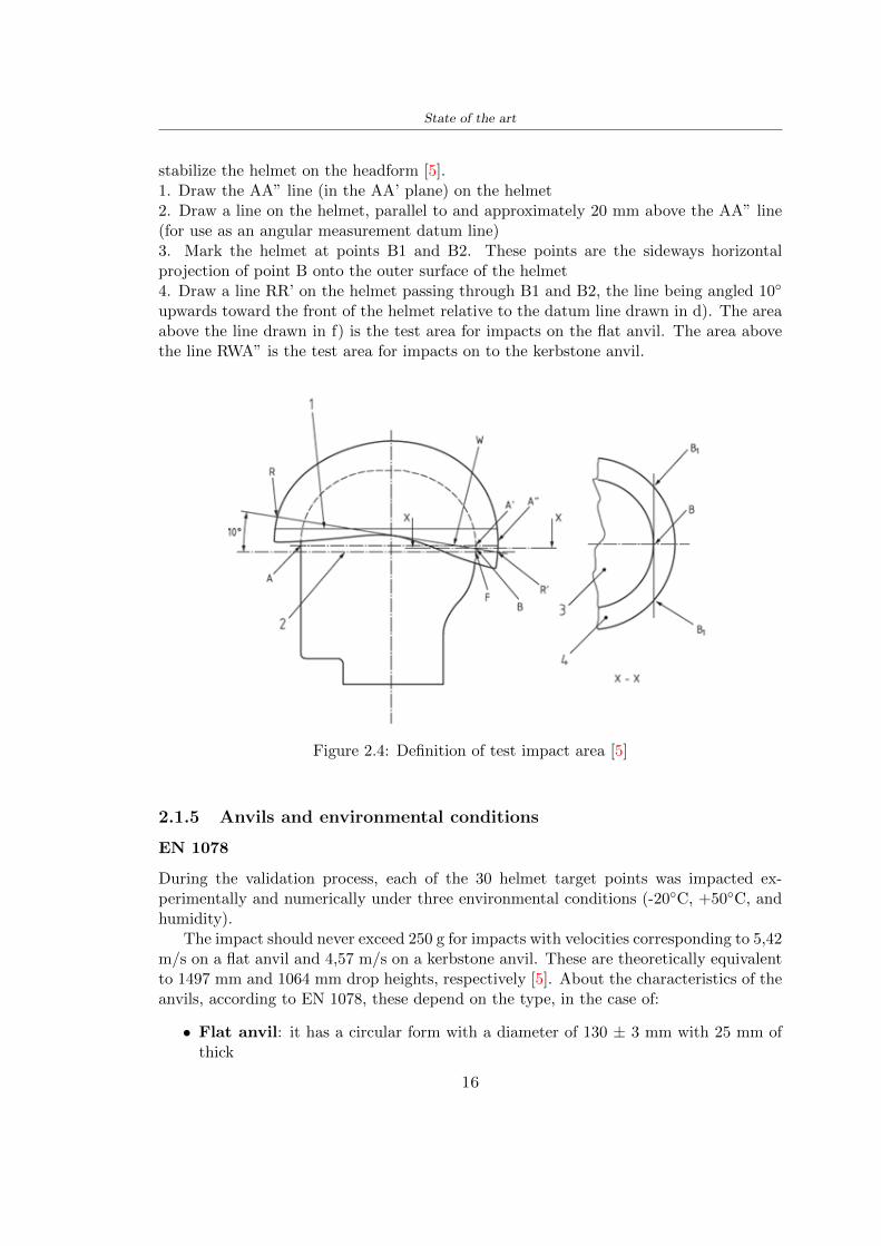
State of the art
stabilize the helmet on the headform [5]1 Draw the AArdquo line (in the AArsquo plane) on the helmet2 Draw a line on the helmet parallel to and approximately 20 mm above the AArdquo line(for use as an angular measurement datum line)3 Mark the helmet at points B1 and B2 These points are the sideways horizontalprojection of point B onto the outer surface of the helmet4 Draw a line RRrsquo on the helmet passing through B1 and B2 the line being angled 10
upwards toward the front of the helmet relative to the datum line drawn in d) The areaabove the line drawn in f) is the test area for impacts on the flat anvil The area abovethe line RWArdquo is the test area for impacts on to the kerbstone anvil
Figure 24 Definition of test impact area [5]
215 Anvils and environmental conditions
EN 1078
During the validation process each of the 30 helmet target points was impacted ex-perimentally and numerically under three environmental conditions (-20C +50C andhumidity)
The impact should never exceed 250 g for impacts with velocities corresponding to 542ms on a flat anvil and 457 ms on a kerbstone anvil These are theoretically equivalentto 1497 mm and 1064 mm drop heights respectively [5] About the characteristics of theanvils according to EN 1078 these depend on the type in the case of
bull Flat anvil it has a circular form with a diameter of 130 plusmn 3 mm with 25 mm ofthick
16
State of the art
bull Kerbstone anvil face inclined at 525 plusmn 25 to the vertical and edge with aradius of 15 plusmn 05mm The height shall be not less than 50 mm and the lengthnot less than 125 mm [5]
According with the regalement EN 1078 [5] it has been possible to realize the volumes inthis work the Flat anvil has a diameter of 130 mm and a height of 25 mm the kerbstoneanvil has a horizontal edge of 130 mm a height of 51 mm a length of 126 mm and theedge that impacts the helmet has a radius of 15 mm The anvils are represented in Figure25
[a] [b]
Figure 25 Flat anvil [a] and Kerbstone anvil [b]
EN 13087-11 (Proposal)
A proposal of November 2018 (EN 13087-11) talks about oblique impact tests (Rotationaltest method) [15] Define a method to measure rotational energy absorption in tangentialimpacts in short duration impact situations the velocity considered by Adanty et al [1]is 65 ms The same anvils of the Standard EN 1078 are used the flat anvil and theKerbstone anvil but the difference is the vertical drop towards an impact angle between30-60 the degree considered by Adanty et al [1] is 45
Three different rotations are considered [34]
bull Rotation around X-axis contact point on the side of the helmet resulting in arotation around X-axis Initial position of the headform X- Y- and Z-axis 0
bull Rotation around Y-axis Contact point on the upper part of the helmet resultingin a rotation around Y-axis Initial position of the headform X- Y- and Z-axis 0
bull Rotation around Z-axis Contact point on the upper part of the helmet resultingin a rotation around Y-axis Initial position of the headform X- and Z-axis 0 and65 around Y-axis
17
State of the art
Figure 26 (a) The current cycling helmet standard for the EN 1078 [5] (b) Theproposed standard (EN13087-11) as described by the European Committee for
Standardization (CEN) [15][1]
22 Materials
221 EPS Foam
As mentioned in Chapter 13 the material most commonly used for making the helmetis the EPS Mustafa et al [25] analysed the EPS with four different density values of 50kgm3 64 kgm3 80 kgm3 and 100 kgm3 rdquoThe drop impact simulation model wasused to test the impact attenuation of the helmet with different densities The drop testwas performed on four impact locations top front and sidesrdquo
The impact velocity of the helmet and headform was set at 544 ms The lowestpeak linear acceleration was recorded at the top location and a density of 64 kgm3 with14814 g This study sets out to determine the effect of the user-centered helmet designwith different foam densities (from 50 kgm3 to 100 kgm3) on the impact attenuationof the bicycle helmet
Kroeker et al [19] tested the helmets at three impact speeds 30 plusmn 001 ms 63 plusmn002 ms and 78 plusmn 001 ms
They established the mean value about bulk density in a helmet with EPS foam is666 considering HIC and Peak Acceleration test The global range is between 64 kgm3
and 75 kgm3
Kroeker et al [20] established the foam for kids helmets is 64-88 kgm3 and for thetraditional helmets is 60-100 kgm3
Trzaskalska et al [36] controlled the influence of polymer liner density on energy ab-sorption during impact They discovered the best properties have samples whose densityis between 54 to 60 kgm3
Cui et al [10] considered the density of each layer from the values of 25 50 60 80and 100 kgm3 and they realize a 45 grades side impact and normal crown impact Theresult is a density of 64 kgm3
Wei et al [38] discovered from their test results that EPS has a buffer layer density
18
State of the art
of 60 kgm3 is the most reasonable
Foam densityrsquos values - Literature
Authors Densityrsquos values
Mustafa et al [25] 64Kroeker et al [19] 64 - 75Kroeker et al [20] 60-100 (traditional) and 64-88 (kids)
Trzaskalska et al [36] 54 - 60Cui et al [10] 54Wei et al [38] 60
Table 25 Table with foam (EPS) densityrsquos values
The other are mean values obtained by CES EduPackrsquos program about this material
- Density ρ = 6451kgm3
- Youngrsquos Module E = 275 MPa
- Poissonrsquos ratio ν = 0275
- Yieldrsquos stress σ= 09 MPa
- Elongation at fracture = 45
222 CES Edu Pack - Material selection
CES Edupack software was used to satisfy the idea of creating a lightweight helmetby printing it in 3D and having the possibility to insert the desired characteristics ofthe material and therefore select it To make a choice I used level 3 of engineering(advanced) selecting the following criteria of the material bio-material biodegradablea polymer of concentration 20 - 100 which complies with the rsquoEuropean Restrictionon Hazardous Substances (Rohs) standardsrsquo regarding the composition of the materialensuring that it does not contain a high percentage of toxic substances compared to theestablished percentage In addition it must have proper durability in contact with coldwater (imagining a possible rain) and rsquogoodrsquo durability to UV radiation
According to Ashbyrsquos method [2] to select a material it is possible to follow thefollowing steps
1 Establish the function of the product What does the component doThe helmet is an instrumental use to protect the head during an impact this characteristicdepends on materials and qualities It can prevent an injury which depends on materialsand design because it has to be of the right head size It would be comfortable becauseit must be worn and it must give security to the person wearing it (by design) In thefollowing Table 26 the analysis of the functions
19
State of the art
Ranking Function description Depends on
1 Head protection (energy absorbing) Material2 Head protection (energy absorbing) Design3 Head protection (injury prevention) Material4 Head protection (injury prevention) Design5 Comfortable Material6 Comfortable Process
Table 26 Ashbyrsquos method functions
2 The objectives that are targets for the design the material is to bemaximised or minimisedTo manufacture and market a product objectives such as minimizing weight cost orenvironmental impact must be considered In the following Table 27 the analysis of theobjectives
Ranking Title Objectives description
1 Mass Minimize The mass has to be thesame or lower
2 Cost Minimize everyone should have theopportunity to buy it
3 CO2 footprint Minimize CO2 emission
4 Corrosion Minimize high strength because itcan be in contact with the water
5 Pleasant to touch Maximize it is not a rough materialbecause it has to put on and put off
by hands
6 Refractive index Minimize it must not reflect light
Table 27 Ashbyrsquos method objectives
3 Definition of constrains What essential conditions must be meetEstablish constraints is essential to complete the function of the instrument Examplesof constrains are Table 28
4 The limits characteristic independent of the material that does not influencethe physical properties In the following Table 29 the analysis of the limits
20
State of the art
Title Loading case Constraintsdescription
Material index(Max-Min)
Stiffness Column in compression Tie in tension
Mass Min
Stiffness Column in compression Tie in tension
Cost Min
Stiffness Column in compression Tie in tension
CO2 Min
Strength Column in compression Tie in tension
Mass Min
Strength Column in compression Tie in tension
Cost Min
Strength Column in compression Tie in tension
CO2 Min
Table 28 Ashbyrsquos method constrains
223 PLA with natural fiber and PLA LW
Initially the best material that met the desired criteria was searched From this study itwas found that the material closest to having the required characteristics is the PLA 30natural fiber as shown in the Figure 27 which shows the graphs obtained relating tothe relationships between Youngrsquos Module and density the objective to reduce the massper unit of compressive stiffness and strength to reduce the CO2 footprint per unit ofstiffness and strength and mass per unit of compressive strength
Performance index IR
The stiffness criterion has the following characteristics
m = A lowast L lowast ρ (21)
ε =σ
E=
FA
E(22)
A =F
ε lowast E(23)
21
State of the art
Ranking Title Function description
1 Biocompatibility It is the ability of a material the abilityof the material not to cause any local or
systemic adverse response in therecipient of the material
2 Biodegrability Biodegradable material do notbiodegradable under anaerobic conditions
3 Biomaterials - all The terms is used for biological naturalbio-derived bio-inspired material
4 RoHS (EU) Compliantgrades
Restriction of the use of certin prohibitessubstances (mercury cadmium
hexavalent chromium)
5 Polymer 20-100 (from the table with Plasticpolymers)
6 UV Resistance at UV sunlight
Table 29 Ashbyrsquos method limits
A =F lowast L lowast ρε lowast E
(24)
With fixed variables- F (the load) L (the length)With variables that depend on the material- E (Youngrsquos Module) ρ (density)
In general when a chart is created the distribution of the mass is represented in thefollowing modality like in Figure 27 [b] where the materials above the line have a lowermass while those below a greater mass
Following the results of the CES Edupack program that had selected the PLA withnatural fibers as the best the first print of the helmet was made with this materialusing as support the PVA Initially the result seemed satisfactory the helmet had a highdefinition but a fundamental problem was found by reducing the helmet in the water toallow the supports of PVA to dissolve In the act of diving in fact after ten minutessome parts of the helmet especially the front and rear have disintegrated making thehelmet unusable Because of this problem it was necessary to change the material
22
State of the art
[a]
[b]
Figure 27 CES EduPack Mass per unit of compressive stiffness [a] Youngrsquos Moduleand density [b]
Further investigations carried out by the Mondragon Unibertsitatea Additive Man-ufacturing Department revealed a new material the PLA Low Weight which during3D printing allows to obtain a weight of 65 lower than that which could be obtainedfrom the classic PLA as reported in the technical sheet of the filament produced by thecompany Colorfabb [7]
The investigation team of the Composite Department carried out tensile tests withsamples 3D printed at different temperatures as suggested by the manufacturer to obtainthe technical characteristics The temperatures examined are 200 220 250 260The datasheet shows the density can have values between 04 - 124 gcm3 the bed has
23
State of the art
to have a temperature between 50 - 60 the printing speed has to have values between40 - 80 mms This typology of PLA is expandible so much that rdquoAt around 230 thismaterial will start foaming increasing its volume by nearly three timesrdquo [7]
T[C] Section [mm2] Volumen [mm3] Mass [g] ρ[kgm3] E [Nmm2]
200 42235 1030117 12 1165 328807
220 43805 1655821 18 1087 265795
250 52412 1948139 17 873 178058
260 59655 1454377 12 825 117047
Table 210 Values about PLA LW tensile tests of MU Additive ManufacturingDepartment
From the tests that have been carried out on the material at different temperaturesthe printed sample is better at 250 with a volume of 1948139 mm3 and a section of52412 mm2 as shown in Table 210 For this reason the specific of the material thathave been taken into consideration are the following
- Density ρ = 873 kgm3
- Youngrsquos Module E = 1750 MPa
- Poissonrsquos ratio ν = 033
- Yieldrsquos stress σ = 2948 MPa
- Elongation at fracture = 491
23 Bio-inspired structures
When we talk about bio-inspired structures to nature we refer to structures that allowobtaining a low weight for the model that is realized and excellent absorption energy dur-ing the impact Recently the structures that have been most used in the biomimetic fieldare the rdquocolumns structures sandwich structures plates honeycomb and foamsrdquo[26]but aiming to achieve a structure increasingly with high absorption energy new struc-tures derived from plants and animals such as beetle horsetail turtle bird beak havebeen analyzed The first to create multi-cells tubes helicoidal structures the second tomulti-corner tubes [26]
The authors analyze the specific energy absorbed (SEA) by bio-inspired sandwichstructures per unit mass which can be derived from the following equation
EA(d) =
int dmax
0F (x)dx (25)
SEA(d) =EA(d)
m(26)
24
State of the art
Where EA is the energy absorption rdquomainly used to evaluate an energy absorberrsquosability to dissipate crushing energy through plastic deformationrdquo F(x) is the crashingforce dmax is the effective deformation distance [26]
What derived from their investigations is that having regard to a density of between0 and 1000 kgm3 the volumetric energy absorbed is higher for the beetle-inspired struc-tures than the others as shown in Figure 28 Based on this consideration it was chosento draw the helmet following this geometry
Figure 28 SEA of bio-inspired sandwich structures [26]
231 Beetle structure - Design of the model
To develop and increase lightweight high-strength and optimize bio-mimetic functionaland structural materials the trabecular structure of the beetle elytron is studied Thesingle structure is realized following the requirements cited by Zhang et al [39]
To realize the beetlersquos structure it is not enough to have information about the lengthof the side of the hexagon and the thickness but it is also necessary to take into accountthe relationship between the diameter of the circumferences present on the vertices ofthe hexagon and the measurement of the side The representation of a single cell is inFigure 29 It is shown in [a] a general structure with an edge of 12 mm circumferencersquosdiameter of 6 mm and thickness of 16 mm in [b] is shown the height of 20 mm
For the construction of the helmet a thickness of 12 and 16 mm was used the imageconcerns a proportion between the length of the hexagon side and the diameter of the
25
State of the art
circumference The side (distance between the centers of two circumferences) is twice thediameter measurement
[a] [b]
Figure 29 Beetle structure
232 Specific stress - PLA LW and EPS foam
To test the beetle structures compression tests were investigated The PLA LW structurewas inserted in a rsquodiskrsquo with a diameter of 100 mm and a height of 20 mm The area andthe volume of the disk is correspondingly 7854 mm2 and 157 10 mm3 The structuresexamined have different dimensions the edge L (distance between two centers of thecircumferences) had the following measures 9 10 12 14 16 mm the thickness of thecircumferences and edges are respectively of 16 mm for every structure and 12 mm forthe structure with L = 16 mm
The test was carried out with the Hoytom HM-D Testing Machine with capacitiesbetween 5 and 100 kN The test models were subjected to displacement loading at a rateof 1 mmmin as referenced by Chen et al[18] with a cylindrical specimen The specificstress of the structures was compared with the specific stress of a generic EPS helmetthe photos about it are shown in Figure 210 The EPS helmet structure is granular withpores inside The different grains dimension and these pores can be the reason for whichthe Stressrsquos values are between two values 07 and 116 MPa
Four parts of the EPS helmet were considered in the test the dimension and relativecharacteristic are in the Table 211 where m = mass A = area F = load ρ = densityR = stress Rρ = specific stress To calculate the values of stress about PLA structuresand EPS foam compression test graphs were been analyzed The stress value for eachstructure was calculated considering the single load the single area and the averagedensity value (14055 [kgm3])
The stress values of the PLA structures (Figure 211) and other characteristic valuesare in Table 212 where m = mass A = area F = load ρ = density
26
State of the art
[a] [b]
[c] [d]
Figure 210 EPS generic helmet helmet pictures [a] [b] and internal structureExternal granular structure [c] and pores [d]
[a] [b] [c]
Figure 211 PLA LW disks Grasshopper structure [a] PLA LW structure of 14 mm[b] PLA LW structure compressed [c]
27
State of the art
The results of the load-displacement graphs are affected by the geometry of the diskthe target is to valid for any shape or size for this is preferred to realize a diagramthat depends from σ (or stress) and the deformation ε (or strain) which can be definedrespectively as
σ =F
A0(27)
ε =l minus l0l
(28)
where F is the load during the test A0 is the area l0 is the initial length and l is thelength when the load is applied The areas considered for the EPS cube is reported inTable 211 in the second column the areas of the PLA structure is 7854 mm2 like thearea of the circumscribed disk
The values compared are shown in Table 213 and the graphs obtained by Matlabcode to analyze the recorded data of the compression machine are in Figure 213 and inFigure 212
Considering that the data provided by the compression machine are subject to noiseand disturbances it was decided to convert the original curve into polynomial type curvesthat allow obtaining the best interpolating curve for the data in question To obtain themit was divided the recorded data into two groups the first part from 0 until the end ofthe linear part and the second when the curve becomes linear again The best-fitting (inthe least-squares sense) was performed using the polyfit and polyval functions of MatlabThe first returns the coefficients of the p(x) with n degree the second evaluates p(x) ateach point in x The polynomial formula p(x) is shown in the Equation 29
pn(x) = anxn + anminus1x
nminus1 + + a2x2 + a1x+ a0 (29)
where a0 an are constants and x is the indeterminate The choice of the degree ofthe polynomial was made based on the criterion of wanting to obtain linear curves thatrespected the elastic trend at the beginning of the graph For this reason the degree ofthe polynomial is 1 Subsequently I searched through the intersection of the two lines forthe point that is equivalent to the maximum stress that marks the end of linearity
This value for EPS and PLA LW is the R [MPa] in the Table 213 The average stressvalue for PLA LW is 139 MPa and for EPS is 094 MPa The specific stress (Rρ) is 18MPa lowast m3)kg for the EPS found in CES 669 MPa lowast m3)kg for the EPS foam of thegeneric helmet and for PLA LW is 1161 MPa lowastm3)kg an intermediate value betweenthe two which is what we wanted to achieve
28
State of the art
m [g] A [mm2] F [N] ρ [kgm3]
EPS (CES) 50
16 9234 1063 13864
18 879 593 13651
21 858 833 14237
24 864 564 14468
Average value 14055
Table 211 Compression stress generic EPS helmet
L [mm] t [mm] m [g] F [N] ρ [kgm3]
9 16 214 7250 1363
10 16 192 5560 12467
12 16 201 8190 13051
14 12 138 8000 8961
Average value 12027
Table 212 Compression test PLA structures
PLA LW structure EPS structureρ= 12027kgm3 ρ= 14055kgm3
Edge [mm] R [MPa] Rρ103 Number R [MPa] Rρ103
EPS (CES) 09 18
9 173 1269 1 116 824
10 139 1114 2 08 568
12 138 1057 3 105 746
14 108 1205 4 077 540
Average value 139 1161 094 669
Table 213 Specific stress calculus PLA LW and EPS calculus ρ = density R = stressRρ [(MPa lowastm3)kg] = specific stress
29
State of the art
Figure 212 Compression test Stress-Strain diagrams - EPS
Figure 213 Compression test Stress-Strain diagrams - PLA LW
30
Chapter 3
Methodology
31 3D scan
311 3D Sense 2 scanner and Meshmixer - Reverse reconstruction
Standardized measures were not taken into account for making the helmet but the sizewas obtained through a 3D scan of my head
The scanner used is 3D Sense 2 by 3D Systems which has a minimum scanningvolume of 20 x 20 x 20 cm and a maximum scanning volume of 300 x 300 x 300 cmTo scan my person I was helped to get a full view at 360 at an appropriate distanceReal-time visualization of the captured images was shown through 3D Sense softwareThe idea of scanning the head with the scanner refers to the methodology used by Wanget al [30] They used a reverse reconstruction functional for me to realize the helmetsurface made to measure my head and like them a silicone pool cap was used to makescanning as smooth as possible The authors claim the head scan rdquocan also be used toobtain information about the objectrsquos surface which is then reconstructed utilizing thecomputerrsquos three-dimensional model via reverse modelling softwarerdquo [30] that in my caseis Autodesk Meshmixer
The files it was could get from the scan were stl obj and ply format they wereexported to obj to work in the next step with Autodesk Meshmixer that allowed tomodify and homogenize the 3D image obtained from the scan
In Meshmixer through the selection and delete commands the superfluous parts weredeleted that had been acquired and with the inspector and the DrawDraw2 commandsthe vertices were moved locally along a pre-defined direction and with Smooth the surfacemore homogeneous was made The sequence of steps is shown in the Figure 31
312 3D scan analysis and extraction of features
In Chapter 2 the directives imposed by the BS EN 960 Standard were examined concern-ing the definition of the helmet and the measures to be respected in the field of visionand the part of the helmet was to carry out impact tests
In Figure 32 the features defined complying with the Standardrsquos rules are repre-sented To define these features the software NX was used The angle in the subfigure
31
Methodology
[a] [b] [c] [d]
Figure 31 Sequence of 3D head scan 3D scanner acquisition [a] scan after reparationwith Meshmixer [b] solid scan vision frontal and lateral [c] [d]
[b] is bigger than 105 (as defined by the Standard) while the degree in the subfigure [c]is 25 By defining the construction lines to be respected of the helmetit was necessary todraw the design of the surface not using the software NX but changing with Rhinocerosto create a SubD or SubDivision surface
32 Helmet design
321 Rhinoceros - Helmet surface
After realizing a rsquocleanrsquo Wang et al [30] subdivide with lines and then sectors the headto create the surface of the helmet They used the technique of NURBS a Non UniformRational Basis-Splines which mathematically models a 3D geometry while thanks tothe Rhinoceros 3D organic shapes was draw SubD surfaces These geometries allow tosplit the mesh into small polygons and consist of lines with which easily the shape ofthe object can be modified with a surface already created changing the position of aline automatically the remaining part of the geometry adapts to the changes With thistechnique the rsquosurface basersquo of the helmet was realized with the size of my head Therepresentation of the realized SubD is in Figure 33
322 Grasshopper - Helmet structure
The next idea is the creation on the surface of the beetle structure with different di-mensions modelling the helmet that is not a linear surface It was decided not to buildthe structure with a software CAD because to model an already complex structure on acurved surface would mean to model a cell for a cell
To solve this obstacle a Rhinoceros plug-in was used Grasshopper GH idealized byRobert McNeel and associates creators of Rhinoceros Using GH does not mean drawinggeometries by connecting points and drawing tools because it is based on algorithmicmodelling used in architecture and engineering for 3D modelling
The modelling takes place through a node diagram that the software will convert intoa code-algorithm in GH it is possible to define the variables and parameters and inRhinoceros in real-time it is possible to view the object GH allows for varying the
32
Methodology
[a] [b]
[c]
Figure 32 Featurersquos extraction in [a] is represented the impact line in [b] and [c] twoprospective about the definition of the field of vision
[a] [b] [c]
Figure 33 SubD representation lateral view [a] top view [b] front view [c]
geometry to your liking by varying a simple parameter of the diagram as everything willbe remodelled according to the change made
In the following Figure 34 it is shown an example of a structure that was used fordistinct subgroups of helmet areas The idea was to insert smaller cells in the frontal andlateral zone and larger ones in the upper area In the first image [a] is shown the part of
33
Methodology
the helpful diagram to create the beetle structure to establish the size of the cells andthe extrusion the second image [b] contains the part of the diagram with which I appliedthe structure previously created to the SubD
The structure used to place and adapt the beetle structure to the surface is theSrfMorph while the yellow rsquowindowrsquo that contains numbers serves to select the parts ofthe surface where to apply the geometry created In accord with the GH diagram in
[a]
[b]
Figure 34 Grasshopper diagrams
Figure 34 [a] it is possible to see the steps executed to realize the structure Initially inthe xy-plane a hexagonal grid was drawn through the Hexgrid command in which youcan input the length of the hexagon edge and the number of grid elements (selected bytrial) Then the circumferences was drawn in proportion to the hexagon dimensions asspecified in the Chapter 2 and shown in Figure 35 [a] In figure [b] the rsquocutrsquo made atthe circumferences is visible this subdivision was necessary for printing purposes In thelast photo [c] the structure highlighted in green in [b] was extruded setting a distance
34
Methodology
of 20 mm
[a] [b] [c]
Figure 35 Construction sequence of the geometry of the helmet
In the diagram in Figure 34 [b] there is the application of the structure created bi-dimensionally to the SubD surface of the helmet visible by unlocking the SubD commandof the diagram and in Figure 36 [a] Upper this the referential geometry of the group ofsurfaces was superimposed where it was to be applied the newly created structure (visiblein darker red) the SubD indices are in the yellow box of the diagram
Through the SrfMorph command the location of the structure was granted In Figure36 [b] at the darkest red of the figure [a] with the above command it was possible toplace the structure
[a] [b]
Figure 36 Application of the geometry created to the helmet surface
Overall the diagrams with specific structures are five one for the front two equal forthe side parts one for the top shown in the previous Figure 36 and one for the back
The hexagons in the structure have a dimension varying between 8 mm and 14 mmof side the largest is found at the top later at the back in the sides and the smallest atthe front In Figure 36 [b] the presence of not only hexagonal structures is visible Thegeometry used does not allow the homogeneous arrangement on the entire surface andrequires different structures Automatically the choice of GH to optimize the structurewas to insert quadrilateral
As described above the helmet has different dimensions of the structure divided asvisible in Figure 36 in a quadrilateral This causes a discontinuity between zones withdifferent sizes due to the geometry of the construction
To eliminate this problem and realize the design homogeneous grids were inserted
35
Methodology
in the affected areas as shown in Figure 37 This insertion however proved to beinteresting and strategic researching in this regard studies were realized to demonstratethe insertion of a rectangular grid inside the hexagon grid was helpful for the transmissionof stress in the structure As cited by Sun et al [40] rdquothe mechanical properties of thesesandwich structures are often limited by local failures such as face-core debonding or corecollapserdquo Carrying out compression tests have effectively demonstrated that the insertionof the grid allows rdquoprovided increased stiffness specific stiffness energy absorption andcritical loadrdquo [41] As shown in the graphic [c] of the Figure 37 the honeycomb structuregives a force of 7 kN while with a grid the value is 11 kN and with the combinationexceeds 22 kN In addition in the left front a plaque to customize the helmet wasprepared Figure 37 [a]
[a] [b]
[c]
Figure 37 Grid in the helmet [a] hybrid structure with hexagons and grid [b] [40]compression test results of the hybrid structure [c] [41]
33 3D Print
After having achieved the CAD (Computer Aided Design) of the helmet in order tobe printed it must be converted and saved in format STL (Standard TriangulationLanguage) - Binary compatible with the printing machine and useful for transformingsolid object surfaces into triangles The steps to be taken are the following
bull CAD file realization
bull CAD export in format STL to Simplify 3D the software that shows slider layersand then- rotate and position the object according to geometry and the positioning of any
36
Methodology
supports- setting printing parameters- item manual andor automatic positioning of supports- slider display layers
bull import file gcode to printer
331 Printer and parameters
The program used to visualize how the helmet slices layers before sending it to the printerand to set the parameters is as anticipated Simplify 3D
To make the printing not being a flat geometry it is necessary to place the supportsThe idea was to use water-based supports that the helmet would automatically dissolveonce placed in the water After testing different types of water-soluble PVA the choicefell on eSun 3D Printing Filament PVA (water-soluble support) Before choosing theoptimal position for printing several tests were carried out and to decrease the numberof the supports significantly and allows an optimal printing of the outer part an emptyrsquospherersquo that self-sustains below the helmet was placed as shown in Figure 38
In the image [a] you can see the first print position tried with which an external partof the helmet very damaged was obtained because of the contact supports-helmet In [b]the empty rsquospherersquo is shown to optimize the number of supports and in the last photo [c]there is the full version at the end of print
[a] [b] [c]
Figure 38 Printing supports
The printer that has been used for printing is the Raise 3D Pro2 with double extrudersand nozzles of variable size from 02 mm to 1 mm after some test prints with the PLALW and the structure in created the size that allowed me to have a good compromisebetween printing time and accuracy was 06 mm Using 04 mm the printing time wasexcessive even if having the smaller nozzle diameter means having more precision withthe 08 mm nozzle the quality of the structure was not excellent as seen in Figure 38[a]
Another factor that had to be taken into account is the characteristic of the PLA-LWto expand As the printing temperature and the printer used vary the expansion andcharacteristics of the material change The use of the 06 mm nozzle associated with
37
Methodology
Parameter Left extruder Right extruder
01cm Material 01cm PVA 01cm PLA LW
Extruder toolbox index Tool 0 Tool 1
Nozzle diameter 06 mm 06 mm
Extrusion multiplier 1 05
Extrusion width Auto (072 mm) 05 mm
Layer x
Infill Rectilinear - 50
Supports (Automatic and not) Infill 50
Temperature 210 250
General parameters
Primary layer height 03 mm Top solid layer 4
Bottom solid layer 2 Outline 2
Heated bad 60 Speed 40 mms
Table 31 Printing parameters
Raise 3D allowed me to get good results The choice of this printer was not random ithas in fact the characteristic of making extremely precise prints The Raise has accuracyin placing the object on the printing bed of 078 microns on the xy axis and a resolutionfor layers of 001 mm
The final version of the helmet is visible in Figure 39 and it is possible to compare itwith the preview version in Rhinoceros in Figure 310
38
Methodology
[a] [b]
[c]
Figure 39 Views of the helmet
[a] [b]
Figure 310 Views of the helmet (GH version)
39
Chapter 4
Experimental evaluation
41 Experimental tests
411 Drop-weight impact test machine
In order to calculate the contact force peak and the difference of energy absorbed duringthe impact between the reference helmet and helmet with the beetle structure in PLA-LW dynamic impact tests were carried out using the Fractovis Plus an impact testmachine
In this way it is possible to monitor the evolution of the above variables from theinitial to the final instant of the impact The machine can withstand a load with a rangevariable from 2 to 70 kg with a maximum speed of 46 ms and a maximum height of1 m The values chosen for the test are the following 5 kg weight maximum speed andmaximum height The Anvil that was used is a disc diameter of 60 mm
As shown in Figure 41 and explained by Crupi et al [37] the machine consists ofa sensor capable of recording the speed before impact the impactor that can have avariable mass (a weight of 5 kg in my test) a system to guarantee that there are nomultiple impacts after the first and that work as a shock absorber and clamping systemwhere the object to be tested is placed
The tests that have been carried out are in total four two related to the helmetoptimized with PLA-LW and two with two generic helmets of different brand in EPS
42 PLA LW helmet
To perform the dynamic test on the helmet of PLA considering the difficulty of printingit was helpful to use a test helmet with imperfections to understand where the impactwas concentrated in a single part or distributed The images of Figure 42 show a helmetwith not well defined edges and inaccurate print but exactly localizes the impact zoneThanks to this test it was possible to take into account only one helmet area shown inFigure 43 to have the exact curve of the structure bio-inspired with PLA-LW
40
Experimental evaluation
Figure 41 Drop-weight impact test machine [37]
[a] [b]
Figure 42 Test 1 PLA-LW helmet
43 EPS helmet
To carry out dynamic tests and extract the technical characteristics of the helmettwohelmets were bought in a sports store both EPS and being on the market both certifiedThe brands of the two helmets are DTB and VAN|RYSEL and the average weight ofthe two is 223 g Two different helmets have been chosen to have a more certain andclear classification of the characteristics They are shown in Figure 44 and Figure 45
41
Experimental evaluation
[a] [b]
Figure 43 Test 2 PLA-LW helmet
[a] [b] [c]
Figure 44 Test 3 EPS helmet
[a] [b] [c]
Figure 45 Test 4 EPS helmet
44 Results
441 First results - PLA-LW and EPS helmet
Figure 46 shows two types of trends related to the two different models of the helmetThe force evaluated for PLA-LW has higher force peaks but is more concentrated and
42
Experimental evaluation
propagates less than EPS The graph shows the peaks of each curve highlighted with a redcircle In tests 1 and 2 for the PLA-LW as mentioned earlier the values are higher about7301 N for the complete helmet and 3996 N for the portion of helmet This difference isdue to the inaccuracy of the first full helmet during the printing phase In Figure 42 itis visible the low homogeneity and precision Therefore the first test with full helmet wasused only to define the area of interest of the impact which turns out to be localized Forthe other two EPS curves the values are only slightly lower compared to the PLA-LWequal to 3620 N and 3295 N but the trend is much more distributed
Figure 46 Dynamic machine test - Force
With the data obtained from the impact machine it was possible calculate not exclu-sively the value of force but itrsquos also possible to view the energy curves A resume aboutthe values and energy of the force is in the following Table 41
Test Peak force [N] Peak energy [J]
Test 1 - PLA LW (inaccurate) 730130
Test 2 - PLA LW (portion of helmet) 399643
Test 3 - EPS (DTB helmet) 362007 509
Test 4 - EPS (VAN|RYSEL helmet) 329546 4198
Test 5 - PLA with TPU 45421 5022
Table 41 Energy absorbed in dynamic test
43
Experimental evaluation
442 PLA-LW helmet with TPU cover
As it is possible to see in Figure 47 and as highlighted the first tests concerning thebio-inspired structure and the PLA-LW are far from my expectations considering thelittle distribution of force in comparison with the EPS foam and consequently a smallamount of energy absorbed
Figure 47 Dynamic machine test - Energy
To improve this impact damping factor the idea was to create a cover for the helmetin flexible TPU trying to absorb impact energy The TPU used is a flexible material ofthe brand Ninjaflex used in sports by the application in helmets and shoes to cushionbumps during the game Generally in the helmets (baseball helmet for example) theTPU is inserted internally in contact with the head In my case the TPU structurein addition to creating a shock-absorbing and durable cover creates a custom cover thehelmet and for the person This cover was also made with the Raise 3D printer
As shown in the Figure 48 [a] the infill of the part in contact with the helmet hasa percentage of 100 the filling of the other part of the structure is not complete butonly 15 and the internal structure is hexagonal to recall that of the helmet The desireto insert a structure with a rsquoraisedrsquo geometry is for visual and aesthetic reasons as youhave the feeling of greater protection and not filled is inspired by the machine CitroenCaptus whose bumpers (Airbump) are full of air The failure to realize empty structuresis due to the need to place any internal supports not removable
The idea was to create a cover that allow you to see of the internal structure of thehelmet and that protect specific areas the front the two sides the top and the posteriorWhat which was thought for this reason was to create the shape of a flower with four
44
Experimental evaluation
petals Figure 48 [b]In this way to perform dynamic impact tests as shown in Figure 49 [a] the cover was
positioned at the top of the helmet and the impact was performed in the centre of thersquoflowerrsquo which corresponds to the higher upper part where the structure has larger cellsize The impact parameters are the same as those used in previous impacts 5 kg weightmaximum speed and maximum height The Anvil that was used is a disc diameter of60 mm In photo [b] it is evident the difference between the structure that received theimpact with protection (left) and without protection (right) Without protection duringthe impact there was a perforation of the structure with a concentration of force at a locallevel as you can see in the Figure 46 in the case of TPU the impactor did not perforateand crossed the structure thanks to the cover of TPU that cushioned the shock At themoment of impact the impactor bounced
[a] [b]
Figure 48 TPU cover
[a] [b]
Figure 49 PLA-LW with TPU - dynamic impact [a] and differences between thehelmet with TPU and without TPU cover [b]
45
Experimental evaluation
The Figure 410 includes the diagrams relative to the dynamic impacts In [a] thereare already analyzed EPS results in [b] a comparison between the test on the portionof helmet in PLA LW with and without the TPU cover in [c] the overall comparison ofcurves shows a much more similar EPS trend if the TPU is placed above the structure inPLA LW to soften the blow and absorb the same energy [d]
46
[a]
[c]
[d]
Figure 410 Comparison between PLA-LW with TPU and EPS
Chapter 5
FEM Validation
51 Impactor - Anvils definition
Before to start to work in Abaqus it was necessary to search in the literature the materialwith which the anvil was been realized Milne et al [23] established the densityrsquos valuethe Youngrsquos Module and Poissonrsquos ratio for the Flat and Kerbstone Anvil
- Density ρ = 7800 kgm3
- Youngrsquos Module E = 200000 MPa
- Poissonrsquos ratio ν = 03
Inserting the data in the CES EduPack program specifying the mechanical andphysical properties the material corresponding to these characteristics is Stainless steelaustenitic (ASTM F1586) medium-hard
Initially the proposal was to create a conservative system to evaluate the absorptionenergies values and apply this value to a vibration system but the helmet needs dampingto be realized it was impossible to use a system without losses in this modality Thisis why a numerical calculation was carried out by performing two types of simulationsexplicit dynamic step and static step
The idea to realize the theoretical impact is to regard the movement of the anviland not the helmetrsquos movement which is fixed The velocity is the same cited in thenormative EN 1078 542 ms for the Flat anvil and 457 ms for the Kerbstone anvil
In performing the simulations It was given more relevance and perform tests withthe Kerbstone Anvil This choice was done because the geometry with which it is beenrealized (following as defined in the legislation) allows the helmet to be more subjectedto stress this involves the definition of higher stress limits compared to the Flat Anvil
The mesh size that has been used is the same in the case of the simulation of thehelmet optimized in PLA-LW and the full helmet in EPS of 7 mm The impactor isconsidered as a Discrete rigid body with its specific Reference Point (RP) like shownin Figure 51 for this reason it is not a solid but it is composted only by shells Inthe same image [b] there is the FEM representation of the model and in Table 51 thecharacteristic of FEM with quadrilateral (R3D4) and triangular elements (R3D3)
48
FEM Validation
Object Elementnumber
Elements Shape Geometricorder
Global size[mm]
Kerbstone 230 Quadrilateral - R3D4 Linear 7
Kerbstone 8 Triangular - R3D3 Linear 7
Table 51 Mesh element - Kerbstone Anvil
[a] [b]
Figure 51 Kerbstone anvil in the simulation like discrete rigid body [a] and FEMelements [b]
511 PLA LW - Plastic characteristics
The PLA-LW as explained in the Chapter 2 is new material on the market and producedby the only Colorfabb company for this reason few tests have been carried out to defineits technical characteristics and through tensile tests of the 3D printed specimens it waspossible to define an elastic limit as reported in the Table 210
In the context of simulations to reproduce the impact and deformation of the helmetis also necessary to consider the plastic characteristics of the material Not possessingany reference value in this regard tests were performed through a Static Step initiallyand then an Explicit Dynamic Step in Abaqus
The structure chosen to consider as a reference it is one of the structures previouslysubjected to the compression test having the side L=14 mm As for the reproduction ofthe compression disks initially they were reproduced according to the geometry of theHoytom HM-D Testing Machine considering the bodies mentioned above as discrete 3Drigid discrete The measure was the diameter of 200 mm and the height of 20 mm
After an initial analysis it was observed that the computational time of the simulationprogram was very high so it was decided to change the geometry to have a rsquodisk-surfacesrsquo(equally 3D rigid-discrete) which allowed me to have a smaller number of nodes for themesh and consequently a better computational time The representation of the opti-mized structure in PLA-LW and the disks used for simulated compression is in Figure 52
49
FEM Validation
[a] [b]
Figure 52 Representation of the samples used for the simulation of the compressiontest In Figure [a] the disks of the Hoytom HM-D Testing Machine in figure [b] the
representation of the same as simple surfaces
As shown in Figure 52 the disks are considered 3D discrete hard bodies so it waschosen for both a point the reference point RP where to apply the characteristics relatedto the two bodies As for the compression test it was established
bull the movement of a disk and fixed the second through a boundary condition impos-ing an Encastre therefore unable to move and rotate in xyz directions
bull for the opposite disk the boundary condition relative to the 15 mm displacementwas applied which is the parameter that it was observed to determine the end ofthe compression with the machine This shift is shown by the orange arrow in figure[b]
bull between the upper surface and the disk e the disk with the lower surface it wasinitialized a general contact with normal behaviour through rsquohardrsquo contact andtangential behaviour with a coefficient of friction of 02 with directionality imposedon rsquoisotropicrsquo
The next step was to define the mesh of the components whose parameters are shown inTable 52 while the representation of the FEM is in Figure 53 with the representationof the simulation and real compression test
Object Elementsnumber
Typology Geometricorder
Globalsize [mm]
Disk (14mm) 80910 hexaedral - C3D8R Linear 07
Impact disks 206 quadrilateral - R3D4 Linear 20
Impact disks 6 triangular - R3D3 Linear 20
Table 52 Mesh element - Compression test simulation
As previously announced a static simulation was initially performed with a StaticStep with Step Time equal to 900 (obtained going to consider the speed of 1 mmmin of
50
FEM Validation
[a]
[b] [c]
Figure 53 FEM representation [a] and compression test simulation [b] and realcompression [c]
the compression test and the displacement of 15 mm) However the complex geometryof the structure and the high time set by Step Time did not allow a correct definitionof the parameters of the plastic characteristics of the material the simulation was notable to continue once reached a Step Time of approximately 220 That is why it waschanged by choosing an Explicit Dynamic step
Leaving all the parameters of the boundary conditions unchanged the Step Time wasmodified imposing it to 001 The ability of the explicit dynamic to work with non-linearand contacting structures allowed me to achieve results The results obtained are shownin Figure 54 with the blue curve and were obtained through the iteration of differentPlastic Strain and Yield Stress values in Abaqus while the red line is the result of thereal compression test a similar curve trend was obtained but it is not possible to obtainthe same curve taking into account problems of printing inaccuracy
512 First test - helmet
The initial idea was to perform a simulation imposing the speed of 457 ms to theimpactor tie the helmet in EPS and PLA and compare the absorbed energies Theproblem it was encountered is related to the mesh of the helmet optimized in PLA andwith minimum dimensions of the elements and distinct elements it was not able to solveit
51
FEM Validation
[a]
YieldStress
PlasticStrain
1 47 0
2 7 001
3 75 005
4 10 01
5 108 1
6 115 15
7 12 2
[b]
Figure 54 Representation of the two curves related to the simulation in Abaqus of thecompression test and the data obtained from the real test to obtain the plastic
characteristics of the material
513 Second test - plane
The first solution is the one shown in Figure 55 To realize the simulation it was realizeda section of the helmet to involve a smaller number of elements and nodes Again thesimulation for the EPS helmet was successful while the simulation with the bio-inspiredstructure was interrupted by excessive distortion of elements
The previous images show the impact is very localized in the impacted area and theidea to achieve a complete simulation is not to consider a curved portion of the helmetbut a plane In this way it was possible to solve the problem and obtain a completesimulation for the bio-inspired structure
FEM element
Below in Table 53 there is the definition of the elements used for the PLA-LW and EPSplane in the simulation to simulate the impact and to control the energy-absorbing whilethe anvil characteristics are described in Table 51
514 EPS impact simulations
In order to proceed with the simulation it was imposed some boundary conditions thatregard ties and forces
bull the movement of the plane is fixed through an Encastre therefore unable to moveand rotate in xyz directions
52
FEM Validation
[a]
[b]
Figure 55 Impact simulation parts of EPS and PLA helmet
Object Elementnumber
Elements Shape Geometricorder
Plane (PLA) 38896 Tetrahedral -C3D10M
Quadratic
Plane (EPS) 2100 Hexahedral - C3D8R Linear
Table 53 Mesh element - plane impact
bull to create the impact it was set a speed of 457 ms at the reference point RP of therigid body which is the impactor Kerbstone Anvil shown in Figure 56
bull between the upper surface of the plane and the impactor it was initialized a Sur-face to Surface contact with normal behaviour through rsquohardrsquo contact and tangen-tial behaviour with a coefficient of friction of 02 with directionality imposed onrsquoisotropicrsquo
bull the rotation in x y z relative to the RP of the rigid discrete impactor body is locked
53
FEM Validation
In addition it was characterized the plane in the part of the materials with the char-acteristic values of the EPS mentioned in Chapter 221 The Von Mises Stress valueapparently low is relative to the Yield Stress of the EPS material equal to 09 MPa
Figure 56 EPS Boundary conditions and Load
515 PLA LW impact simulations
As also required in the case of the EPS plane in order to proceed with the simulationsome boundary conditions were imposed that regard ties and forces
bull the movement of the plane is fixed through an Encastre therefore unable to moveand rotate in xyz directions
bull to create the impact a speed of 457 ms was set at the reference point RP of therigid body which is the impactor Kerbstone Anvil shown in Figure 58
bull between the upper surface of the plane and the impactor it was initialized a Sur-face to Surface contact with normal behaviour through rsquohardrsquo contact and tangen-tial behaviour with a coefficient of friction of 02 with directionality imposed onrsquoisotropicrsquo
bull the rotation in x y z relative to the RP of the rigid discrete impactor body is locked
In addition the plane was characterized in the part of the materials with the characteristicvalues of the PLA mentioned in the Chapter 223 and 511
Figure 58 Boundary conditions and Load
54
FEM Validation
[a]
[b]
Figure 57 EPS impact simulation
52 Results
In Figures 59 and 57 it is shown how the structure in PLA LW has a more concentratedstress distribution of the structure unlike EPS The maximum value for the Von Misesstress is 09 MPa in EPS structure and 3634 MPa in PLA LW structure Once thesimulations were obtained the next step was to go and compare the energies absorbed bythe two structures The energy calculated by Abaqus that has been taken into account isPlastic Dissipation To make a comparison the data of the two energies were representedin a single graph
What emerges from the graph is that about the impact made with the KerbstoneAnvil the energy absorption is more excellent although only slightly for the PLA LWthan for the EPS From the graph in Figure 510 a value of 41 J is shown for the EPSand 51 J for the PLA LW
55
[a]
[b]
Figure 59 PLA impact simulation
[a]
Figure 510 EPS and PLA LW energy comparison - Abaqus simulation
Chapter 6
Head Injury Data
For the statistical analysis the injuries related to the accident data were categorised intothe following types and levels based on the details of the medical report [11] about theEN 1078
bull Head Injury Criterion (HIC)
bull Peak Linear Acceleration (PLAc)
bull Gadd Severity Injury (GSI)
bull Diffuse axonal injuries (DAI)
61 Abaqus simulation
Until now the purpose of the simulations has been to determine which between the twomaterials and the two structures of EPS and PLA LW could absorb more energy duringthe impact but no simulations have been carried out in compliance with BS EN 1078on the helmet impact tests To calculate the injuries listed in the previous paragraphhowever we need the acceleration values in the three directions related to the subjectrsquoshead
To realize it the scan of my head already rsquocleanrsquo was considered of which it has beencalculated the inertia thanks to the automatic SolidWorks calculation and evaluated theweight with the Table 24 the structure of the helmet was placed for the EPS and thePLA LW over the head as shown in Figure 61 Also this time being able to mesh theentire helmet in PLA LW was impossible due to the excessive distortion of some elementsduring the simulation so it has been tried to make a section of the structures of thehelmet and results were obtained
57
Head Injury Data
[a] [b]
Figure 61 My scan head - CAD [a] head imported in Abaqus[b]
Initially the simulation had these characteristics as shown in the following Figure62 considering the helmet was not sectioned As explained earlier it was not possibleto get to simulation in the case of the optimized structure in PLA LW for this reasononly a part of the helmet was considered in both cases shown in Figure 63
[a]
Figure 62 Simulation based on BS EN 1078
58
Head Injury Data
[a] [b]
Figure 63 Simulation based on BS EN 1078 with head
In order to proceed with the simulation some boundary conditions that regard tiesand forces have have imposed
bull two reference points RP were created the first in the inertia centre of the headthe second relating to the Kerbstone Anvil which is a discrete rigid body
bull in the reference point RP of the head in the definition of the engineering features5 kg was inserted for the weight and an inertia I11 = 564464E+07 gmm2 I22 =460654E+07gmm2 I33 = 187302E+07gmm2
bull to simulate the impact it was set a speed of 457 ms at the reference point RP ofthe head in z-axis direction
bull a general contact with normal behaviour through rsquohardrsquo contact and tangentialbehaviour with a coefficient of friction of 02
bull between the upper surface of the helmet and the impactor it has been initializeda Surface to Surface contact with normal behaviour through rsquohardrsquo contact andtangential behaviour with a coefficient of friction of 02 with directionality imposedon rsquoisotropicrsquo
bull the movement between the Kerbstone anvil and the helmet is fixed through anEncastre therefore unable to move and rotate in xyz directions
bull the rotation in x y z relative to the RP of the rigid discrete impactor body is locked
FEM element
As reported in Table 53 the portion of the helmet in EPS has used a mesh with hexahe-dral elements of linear order For the structure (beetle) of PLA LW given the geometry
59
Head Injury Data
complexity it was necessary to use a quadratic order of tetrahedra For the mesh of thehead instead in both simulations have been used quadrilateral elements of linear orderas reported in the Tables 61 and 62
Object Elementnumber
Elements Shape Geometricorder
Head 3755 Quadrilateral - R3D4 Linear
Head 34542 Quadrilateral - R3D3 Linear
Helmet (PLA) 272302 Tetrahedral -C3D10M
Quadratic
Table 61 Mesh element - Head simulation with PLA LW (beetle) helmet
Object Elementnumber
Elements Shape Geometricorder
Head 3755 Quadrilateral - R3D4 Linear
Head 34542 Quadrilateral - R3D3 Linear
Helmet (EPS) 72280 Hexahedral - C3D8R Linear
Table 62 Mesh element - Head simulation with EPS helmet
62 Results
Figure 64 represents the simulation in line with BS EN 1078 concerning the helmet inEPS [a] and the helmet with bio-inspired structure in PLA LW For both simulationsVan Misesrsquo stress has Yield Stress values in the case of EPS which is 09 MPa and theplastic behaviour combination of PLA LW [b]
In the case of head and Kerbstone Anvil stress was not assessed as they were previ-ously defined as discrete rigid bodies
63 Head Injury Criterion
The HIC quantifies head impact severity by incorporating time of acceleration exposureand acceleration magnitude it is calculated in post-processing phase with the followingEquation 61
HIC15 =
[1
(t1 minus t2)
int t2
t1
a(t)dt
]25(t2 minus t1) (61)
60
Head Injury Data
[a]
[b]
Figure 64 Results simulation based on BS EN 1078 with sectioned head
For this analysis a(t) is the acceleration calculated in the centre of mass of the head(corresponding to the reference point RP) expressed in g and the time interval (t2 minus t1)was chosen to maximize HIC over a maximum duration of 15 ms
Matlab and the trapz function were used to calculate the HIC to integrate accelerationover time t2 and t1 were considered initial and final times of the simulation t1 = 0 sand t2 = 10 s time less than 15 s
HIC value of 198 was obtained for EPS and 87 for PLA LW Considering the Hayeset al [16] document about the HIC values and the graph in Figure 65 developed bythe author it is possible to find the percentages related to the different injury AIS1 -AIS6 which correspond respectively to lower and higher severity while in Figure 66 therelative fatality to every value of AIS is shown The values obtained for the HIC andother criteria are shown in Table 63 The HIC value for EPS is 198 for PLA LW it is
61
Head Injury Data
Figure 65 Head injury risk curves based on HIC values [16]
Figure 66 The abbreviated injury score versus fatality rate [16]
87 Analyzing the data and comparing them with the curves of the Figure 65 I obtain
bull a percentage between 20 - 30 of AIS 1 for EPS 10 - 20 for PLA LW
bull a percentage between 10 - 20 of AIS 2 for EPS and 0 - 10 for PLA LW
bull for AIS 3 AIS 4 AIS 5 AIS 6 the percentages for both structures is between 0 -10
Comparing these percentages with the fatality rate of Figure 66 it is clear there is a riskof Moderate and Minor fatality in the case of EPS and PLA LW as all values are between0 and 30
62
Head Injury Data
HIC PLA [g] GSI E [J]
EPS 198 97 361 37723
PLA LW 87 75 169 44102
Table 63 Head Injury Data - values
64 Peak Linear Acceleration
The resultant linear acceleration versus time curve was calculated according to Equation62
γ(t) =radicγ2x(t) + γ2y(t) + γ2z (t) (62)
where
bull γ(t) is the resultant linear acceleration (g)
bull γx(t) is the linear acceleration in x axes (g)
bull γy(t) is the linear acceleration in y axes (g)
bull γz(t)is the linear acceleration in z axes (g)
The value of the impact should never exceed 250g [9] Cripton at all [9] in their studyexamined a helmet with expanded polystyrene (EPS) Figure 68 shows maximum HIC forhelmeted and unhelmeted drops from all heights For each drop height helmets reducedHIC relative to unhelmeted drops IARV value is 180g The acceleration in the two casesis shown in Figure 67 and the maximum values are 97g for EPS and 75g for PLA LWas reported in Table 63 The two values considering a maximum value calculated byCripton [9] of 180g are amply optimal and comply with the standard of 250g
65 Gadd Severity Index
Gadd proposed the Severity Index Criteria shown in Equation 63 Following this crite-rion the GSI values that are over 1000 produce serious internal head injury [33]
GSI =
int t1
0a(t)25dt (63)
Where
bull a is the linear acceleration (g)
bull t is the duration of the impact (s)
I calculated the GSI with the function trapz between 0 and t and the resulting valuesare 361 for the EPS and 169 for the PLA LW which comply with the limit
63
Head Injury Data
Figure 67 Peak accelerations for both helmets
Figure 68 Peak accelerations for both helmeted and unhelmeted drops Numbers overbars indicate peak acceleration For 2 m drop height results stated are the mean value
calculated from three drops [9]
64
Head Injury Data
66 Diffuse Axonal Injury
DAI cases covered all incidences in which neurological injuries occurred as well as con-cussion unconsciousness and coma
In order to assess the risk of head trauma in terms of diffuse axonal injury (DAI)Milne et al [23] defined a model based head injury criteria as follows obtaining theresults in Figure 69
bull 50 risk of moderate neurological injury (DAI1+) Brain Von Mises shearing stressof 28 kPa
bull 50 risk of severe neurological injury (DAI2+) Brain Von Mises shearing stressof 53 kPa
[a]
[b]
Figure 69 Peak intra-cerebral shearing stress computed with the helmet model coupledto the human head model for all impact points (a) Flat anvil (b) Kerbstone anvil [23]
65
Head Injury Data
67 Energy absorbed
In Figure 52 during the impact test between the kerbstone Anvil and the plan with thebio-inspired structure in PLA LW and EPS it was found that the PLA LW althoughwith a small difference of 10 J absorbed more energy in comparison with the EPS Whenthe test is carried out in compliance with BS EN 1078 and the head with a speed of 457ms (corresponding to the kerbstone Anvil) as shown in Figure 610 also in this casethe PLA LW with the optimized helmet structure manages to absorb more energy (evenif the difference is very low) compared to the EPS The maximum energy value in PLALW is 44102 J of EPS is 37723 J
Figure 610 Energy absorption - BS EN 1078
66
Chapter 7
Conclusion
71 Conclusion
In this thesis work a bicycle helmet with a bio-inspired structure in PLA LW and 3Dprinted was created The initial approach was to introduce an innovative aspect tostandard EPS helmets not using foam but a polymer with new geometries able toabsorb much energy during the impact For this reason the beetle structure has beenpreferred relying solely on the hypothesis encountered in the literature of its quality inabsorbing energy
Combining the new material of the PLA LW and beetle structure has made possiblethe development of new material satisfactory characteristics have been obtained sincethe first tests The two materials were first subjected to tensile tests to determine theirspecific stress in these the PLA LW had positive results
Subsequent dynamic physical tests were carried out on 3D printed helmet models andon reference helmets in EPS to calculate the absorption energy in both cases at the timeof impact These resulted in energy absorption of the beetle structure in PLA LW withthe application of a TPU cover almost equal to that of EPS about 50J To validate withfinite element analysis the two models an explicit dynamic step was used in AbaqusSimulations showed that the PLA LW structure absorbs a higher amount of energy thanthe EPS the higher is 50 J and the EPS 40J
Finally positive results have also been obtained in calculating the head injury datasimulating according to BS EN 1078 with the use of impactor helmet and head Theacceleration values for both the structures were inferior to 220g precisely for the PLALW was 75g and for the EPS 97g The same applies to the calculation of HIC and GSI(maximum acceptable value of 1000) where the values are 87 and 169 in the case of PLALW and 361 and 198 in EPS For all tests therefore greater efficiency of the structure inPLA LW has been obtained Positive results also in the simulation of the energy absorbedduring the impact as the value referring to the EPS was 35J and that of the PLA LWwas 45J
67
Conclusion
72 Future work lines
The positive results obtained can be considered as a starting point for further tests andsimulations to ensure the safety of the helmet and compliance with the regulations butbefore getting improvements and continue testing changes are required
bull the beetle structure of the helmet made with GH adapts to the SubD withoutallowing to have a homogeneous distribution it would be appropriate to have moreregular hexagonal geometries
bull the mesh of the helmet is too complex and does not allow to perform the simulationprobably to use a more regular structure would have a mesh accordingly moreregular and the simulation would be successful
bull the uneven helmet structure has so many defects that the print is imperfect andthis can change the results of the impact tests the structure should be improved
bull the printing time varies from 4 to 5 days it should be improved
bull the TPU helmet cover is too big for the RAISE printing plan it is necessary togenerate a new geometry
bull the TPU cover it must be fixed on the helmet
bull in the calculation of the DAI it is necessary to have the definition of the brain andthe head should not be considered as a rigid body
bull in the injury calculation the helmet without protection was considered with theTPU cover the result will be better
bull air flow analysis
The comments mentioned are only considerations and problems that I gained duringmy thesis and which should be improved but I am sure that these changes and improve-ments from design to printing and simulations can make the helmet a good product
68
Bibliography
[1] K Adanty J M Clark A Post Thomas Blaine H and M D Gilchrist Comparingtwo proposed protocols to test the oblique response of cycling helmets to fall impactsInternational Journal of Crashworthiness 6648 ndash 663 2020
[2] MF Ashby YJM Brechetb D Cebona and L Salvoc Selection strategies formaterials and processes Materials and Design 2004
[3] M Aysha El casco de bicicleta voronoi impreso en 3d mas seguro y ligero https
www3dnativescomen3d-printed-bicycle-helmet-voronoi-190820204
[4] H Bikas P Stavropoulos and G Chryssolouris Additive manufacturing methodsand modelling approaches a critical review The International Journal of AdvancedManufacturing Technology 83389ndash405 2016
[5] British Standards BSI Helmets for pedal cyclists and for users of skateboards androller skates - BS EN 1078 2012
[6] British Standards BSI Headforms for use in the testing of protective helmets BSEN 960 2020
[7] ColorFabb Colorfabb lw-pla 2019 httpscolorfabbcommedia
datasheetstdscolorfabbTDS_E_ColorFabb_LW-PLApdf
[8] V G Coronado T Haileyesus J M Bell T A Cheng JHaarbauer-Krupa M RLionbarger J Flores-Herrera L C McGuire and J Gilchrist Trends in sports andrecreation-related traumatic brain injuries treated in us emergency departments thenational electronic injury surveillance system-all injury program (neiss-aip) 2001-2012 J Head Trauma Rehabil 30185ndash197 2015
[9] P A Cripton D M Dressler D Stuart Cameron A Christopher R and D RichardsBicycle helmets are highly effective at preventing head injury during head impactHead-form accelerations and injury criteria for helmeted and unhelmeted impactsAccident Analysis and Prevention 701ndash7 2014
[10] L Cui M A Forero R and M D Gilchrist Optimisation of energy absorbingliner for equestrian helmets UCD School of Electrical Electronic and MechanicalEngineering University College Dublin Belfield Dublin4 Ireland 2020
[11] C Deck N Bourdet F Meyer and R Willinger Protection performance of bicyclehelmets Journal of safety research pages 67ndash77 2019
[12] Committee F08 Specification for headforms F2220 ASTM International 2015
[13] Committee F08 Specification for helmets used in recreational bicycling or rollerskating F1447 ASTM International 2018
[14] Committee F08 Test methods for equipment and procedures used in evaluating theperformance F1446 ASTM International 2020
69
Bibliography
[15] P Halldin Shock absorption including measuring CENTC 158 Working Group11 2018
[16] W C Hayes M S Erickson and E D Power Forensic injury biomechanics Annualreview of biomedical engineering pages 55ndash86 2007
[17] HEXR httpshexrcom
[18] C Jinxiang Z Xiaoming O Yoji S Kazuya G Zhensheng and P LongchengThe deformation mode and strengthening mechanism of compression in the beetleelytron plate Materials and Design 131481ndash186 2017
[19] S Kroeker M Ozkul A De Marco S Bonin and GP Siegmund Density variationin the expanded polystyrene eps foam of bicycle helmets and its influence on impactperformance Journal of biomechanical engineering 2019
[20] S G Kroeker SJ Bonin A L DeMarco C A Good and G P Siegmund Agedoes not affect the material properties of expanded polystyrene liners in field-usedbicycle helmets Journal of biomechanical engineering 2016
[21] M Meier K H Tan M K Lim and L Chung Unlocking innovation in the sportindustry through additive manufacturing Business Process Management Journa2018
[22] N J Mills and A Gilchrist The effectiveness of foams in bicycle and motorcyclehelmets Accident Analysis Prevention 23153 ndash 163 1991
[23] G Milne C Deck R P Carreira Q Allinne and R Willinger Development andvalidation of a bicycle helmet assessment of head injury risk under standard impactconditions Computer methods in biomechanics and biomedical engineering 15 Suppl1309 ndash 310 2012
[24] Y Mosleh S J Vander B Depreitere and J Ivens Novel composite foam conceptfor head protection in oblique impacts Adv Eng Mater (Advanced EngineeringMaterials) 10 2017
[25] H Mustafa T Y Pang T Ellena and S H Nasir Impact attenuation of user-centred bicycle helmet design with different foam densities J Phys Conf Ser(Journal of Physics Conference Series) 1150 2019
[26] S H Ngoc and L Guoxing A review of recent research on bio-inspired structuresand materials for energy absorption applications Composites Part 181 2020
[27] J I Novak and A R Novak Is additive manufacturing improving performance insports a systematic review Sport engineering and technology 13 2020
[28] European Road Safety Observatory European road safety observatory facts and fig-ures - cyclists - 2020 December 2020 httpseceuropaeutransportroad_
safetysitesdefaultfilesfacts_figures_cyclists_final_20210323pdf
[29] New York City Departments of Health Parks Mental Hygiene Transportation Recre-ation and the New York City Police Department Bicyclist fatalities and seriousinjuries in new york city 2005
[30] W Pengwen Y Jing H Yanan H Jiaofei and F Xiaoyang Innovative designof a helmet based on reverse engineering and 3d printing Alexandria EngineeringJournal 603445ndash3453 2021
[31] S G Piland T E Gould M Jesunathadas J S Wiggins O McNair and V CShane Protective helmets in sports Materials in Sports Equipment 3 2019
70
Bibliography
[32] K Schmitt P F Niederer M H Muser and F Walz Trauma biomechanicsSpringer Berlin Heidelberg 2010
[33] David Sepelveda Lopez A Biomechanical Analysis of Bicycle Helmets using FEMPhD thesis 2019 Bachelor thesis
[34] H Stigson Bicycle Helmets 2020 Tested by Folksam PhD thesis 2020 PhDAssociate Professor Traffic Safety Research
[35] H Tao K Sudip N Anindya and X Yongzhao 3d printed sensors for biomedicalapplications A review sensor 2019
[36] M Trzaskalska and R Chwastek Damping properties and density of helmet linersmade of expanded polystyrene (eps) Archives of Metallurgy and Materials 66 2020
[37] Crupi V Epasto G and Guglielmino E Impact response of aluminum foam sand-wiches for light-weight ship structures Metals 198ndash112 2020
[38] W Wei-cai F Dong-ming and L Yuan-xin Study on impact energy absorbing per-formance of eps buffer layer of motorcycle helmet Proceedings - 2013 InternationalConference on Mechanical and Automation Engineering MAEE 2013
[39] Z Xiaoming C Jinxiang O Yoji Z Peiwei X Xiaobing and Y Xindi Influence ofhoneycomb dimensions and forming methods on the compressive properties of beetleelytron plates Journal of Sandwich Structures and Materials 2228ndash39 2020
[40] S Zhi L Dong Z Weisheng S Shanshan and G Xu Topological optimization ofbiomimetic sandwich structures with hybrid core and cfrp face sheets CompositesScience and Technology 14279ndash90 2017
[41] S Zhi S Shanshan G Xu H Xiaozhi and C Haoran On compressive propertiesof composite sandwich structures with grid reinforced honeycomb core CompositesPart B 94245ndash252 2016
71
- List of Tables
- List of Figures
- Introduction
-
- Helmet bike protection
-
- Helmet structure
-
- Additive Manufacturing
-
- AM process
- Materials and techniques - FDM
- AM in sport
-
- 3D printed helmets
-
- Phases
- HEXR
- VORONOI
-
- State of the art
-
- Standards
-
- Headform
- European Standard and American Standard
- Field of vision - BS EN 1078
- Test impact area
- Anvils and environmental conditions
-
- Materials
-
- EPS Foam
- CES Edu Pack - Material selection
- PLA with natural fiber and PLA LW
-
- Bio-inspired structures
-
- Beetle structure - Design of the model
- Specific stress - PLA LW and EPS foam
-
- Methodology
-
- 3D scan
-
- 3D Sense 2 scanner and Meshmixer - Reverse reconstruction
- 3D scan analysis and extraction of features
-
- Helmet design
-
- Rhinoceros - Helmet surface
- Grasshopper - Helmet structure
-
- 3D Print
-
- Printer and parameters
-
- Experimental evaluation
-
- Experimental tests
-
- Drop-weight impact test machine
-
- PLA LW helmet
- EPS helmet
- Results
-
- First results - PLA-LW and EPS helmet
- PLA-LW helmet with TPU cover
-
- FEM Validation
-
- Impactor - Anvils definition
-
- PLA LW - Plastic characteristics
- First test - helmet
- Second test - plane
- EPS impact simulations
- PLA LW impact simulations
-
- Results
-
- Head Injury Data
-
- Abaqus simulation
- Results
- Head Injury Criterion
- Peak Linear Acceleration
- Gadd Severity Index
- Diffuse Axonal Injury
- Energy absorbed
-
- Conclusion
-
- Conclusion
- Future work lines
-
- Bibliography
-
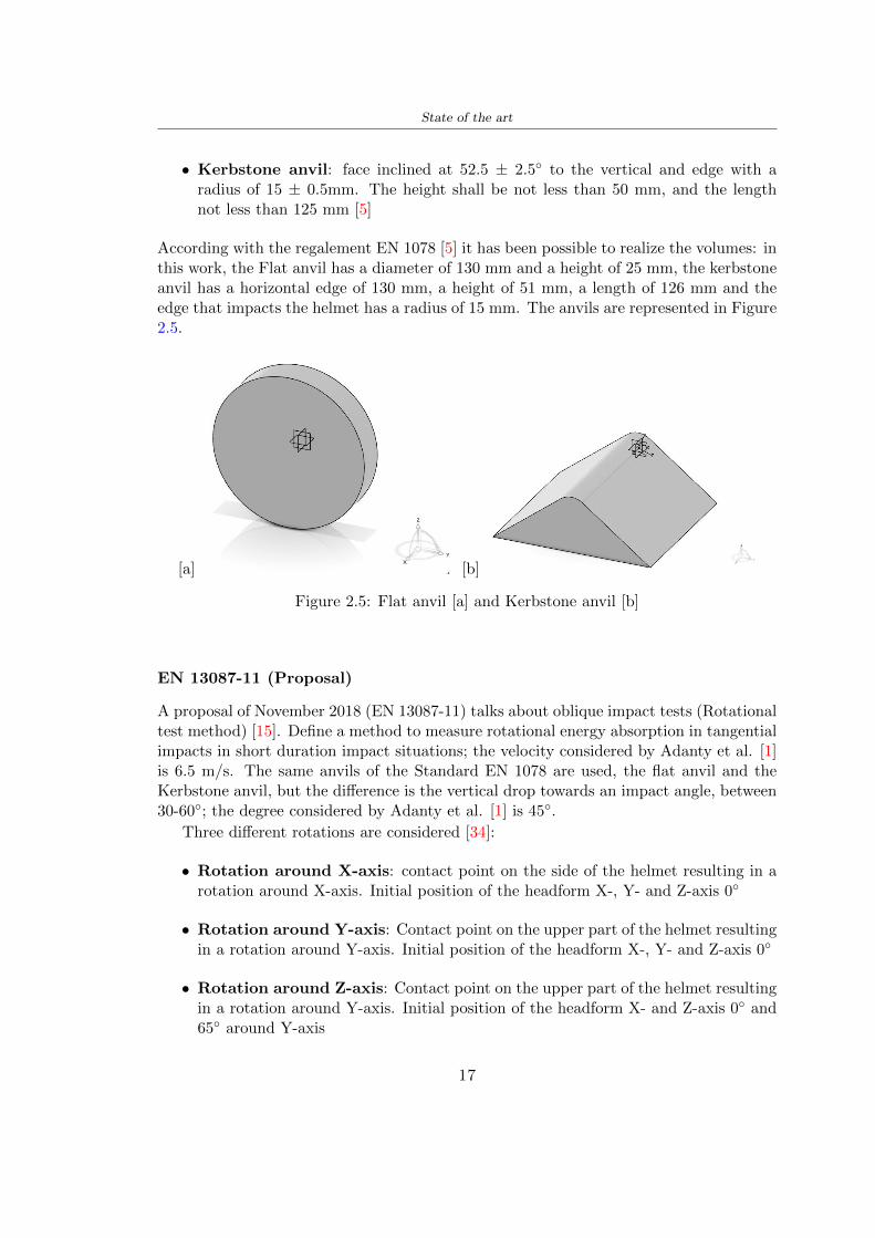
State of the art
bull Kerbstone anvil face inclined at 525 plusmn 25 to the vertical and edge with aradius of 15 plusmn 05mm The height shall be not less than 50 mm and the lengthnot less than 125 mm [5]
According with the regalement EN 1078 [5] it has been possible to realize the volumes inthis work the Flat anvil has a diameter of 130 mm and a height of 25 mm the kerbstoneanvil has a horizontal edge of 130 mm a height of 51 mm a length of 126 mm and theedge that impacts the helmet has a radius of 15 mm The anvils are represented in Figure25
[a] [b]
Figure 25 Flat anvil [a] and Kerbstone anvil [b]
EN 13087-11 (Proposal)
A proposal of November 2018 (EN 13087-11) talks about oblique impact tests (Rotationaltest method) [15] Define a method to measure rotational energy absorption in tangentialimpacts in short duration impact situations the velocity considered by Adanty et al [1]is 65 ms The same anvils of the Standard EN 1078 are used the flat anvil and theKerbstone anvil but the difference is the vertical drop towards an impact angle between30-60 the degree considered by Adanty et al [1] is 45
Three different rotations are considered [34]
bull Rotation around X-axis contact point on the side of the helmet resulting in arotation around X-axis Initial position of the headform X- Y- and Z-axis 0
bull Rotation around Y-axis Contact point on the upper part of the helmet resultingin a rotation around Y-axis Initial position of the headform X- Y- and Z-axis 0
bull Rotation around Z-axis Contact point on the upper part of the helmet resultingin a rotation around Y-axis Initial position of the headform X- and Z-axis 0 and65 around Y-axis
17
State of the art
Figure 26 (a) The current cycling helmet standard for the EN 1078 [5] (b) Theproposed standard (EN13087-11) as described by the European Committee for
Standardization (CEN) [15][1]
22 Materials
221 EPS Foam
As mentioned in Chapter 13 the material most commonly used for making the helmetis the EPS Mustafa et al [25] analysed the EPS with four different density values of 50kgm3 64 kgm3 80 kgm3 and 100 kgm3 rdquoThe drop impact simulation model wasused to test the impact attenuation of the helmet with different densities The drop testwas performed on four impact locations top front and sidesrdquo
The impact velocity of the helmet and headform was set at 544 ms The lowestpeak linear acceleration was recorded at the top location and a density of 64 kgm3 with14814 g This study sets out to determine the effect of the user-centered helmet designwith different foam densities (from 50 kgm3 to 100 kgm3) on the impact attenuationof the bicycle helmet
Kroeker et al [19] tested the helmets at three impact speeds 30 plusmn 001 ms 63 plusmn002 ms and 78 plusmn 001 ms
They established the mean value about bulk density in a helmet with EPS foam is666 considering HIC and Peak Acceleration test The global range is between 64 kgm3
and 75 kgm3
Kroeker et al [20] established the foam for kids helmets is 64-88 kgm3 and for thetraditional helmets is 60-100 kgm3
Trzaskalska et al [36] controlled the influence of polymer liner density on energy ab-sorption during impact They discovered the best properties have samples whose densityis between 54 to 60 kgm3
Cui et al [10] considered the density of each layer from the values of 25 50 60 80and 100 kgm3 and they realize a 45 grades side impact and normal crown impact Theresult is a density of 64 kgm3
Wei et al [38] discovered from their test results that EPS has a buffer layer density
18
State of the art
of 60 kgm3 is the most reasonable
Foam densityrsquos values - Literature
Authors Densityrsquos values
Mustafa et al [25] 64Kroeker et al [19] 64 - 75Kroeker et al [20] 60-100 (traditional) and 64-88 (kids)
Trzaskalska et al [36] 54 - 60Cui et al [10] 54Wei et al [38] 60
Table 25 Table with foam (EPS) densityrsquos values
The other are mean values obtained by CES EduPackrsquos program about this material
- Density ρ = 6451kgm3
- Youngrsquos Module E = 275 MPa
- Poissonrsquos ratio ν = 0275
- Yieldrsquos stress σ= 09 MPa
- Elongation at fracture = 45
222 CES Edu Pack - Material selection
CES Edupack software was used to satisfy the idea of creating a lightweight helmetby printing it in 3D and having the possibility to insert the desired characteristics ofthe material and therefore select it To make a choice I used level 3 of engineering(advanced) selecting the following criteria of the material bio-material biodegradablea polymer of concentration 20 - 100 which complies with the rsquoEuropean Restrictionon Hazardous Substances (Rohs) standardsrsquo regarding the composition of the materialensuring that it does not contain a high percentage of toxic substances compared to theestablished percentage In addition it must have proper durability in contact with coldwater (imagining a possible rain) and rsquogoodrsquo durability to UV radiation
According to Ashbyrsquos method [2] to select a material it is possible to follow thefollowing steps
1 Establish the function of the product What does the component doThe helmet is an instrumental use to protect the head during an impact this characteristicdepends on materials and qualities It can prevent an injury which depends on materialsand design because it has to be of the right head size It would be comfortable becauseit must be worn and it must give security to the person wearing it (by design) In thefollowing Table 26 the analysis of the functions
19
State of the art
Ranking Function description Depends on
1 Head protection (energy absorbing) Material2 Head protection (energy absorbing) Design3 Head protection (injury prevention) Material4 Head protection (injury prevention) Design5 Comfortable Material6 Comfortable Process
Table 26 Ashbyrsquos method functions
2 The objectives that are targets for the design the material is to bemaximised or minimisedTo manufacture and market a product objectives such as minimizing weight cost orenvironmental impact must be considered In the following Table 27 the analysis of theobjectives
Ranking Title Objectives description
1 Mass Minimize The mass has to be thesame or lower
2 Cost Minimize everyone should have theopportunity to buy it
3 CO2 footprint Minimize CO2 emission
4 Corrosion Minimize high strength because itcan be in contact with the water
5 Pleasant to touch Maximize it is not a rough materialbecause it has to put on and put off
by hands
6 Refractive index Minimize it must not reflect light
Table 27 Ashbyrsquos method objectives
3 Definition of constrains What essential conditions must be meetEstablish constraints is essential to complete the function of the instrument Examplesof constrains are Table 28
4 The limits characteristic independent of the material that does not influencethe physical properties In the following Table 29 the analysis of the limits
20
State of the art
Title Loading case Constraintsdescription
Material index(Max-Min)
Stiffness Column in compression Tie in tension
Mass Min
Stiffness Column in compression Tie in tension
Cost Min
Stiffness Column in compression Tie in tension
CO2 Min
Strength Column in compression Tie in tension
Mass Min
Strength Column in compression Tie in tension
Cost Min
Strength Column in compression Tie in tension
CO2 Min
Table 28 Ashbyrsquos method constrains
223 PLA with natural fiber and PLA LW
Initially the best material that met the desired criteria was searched From this study itwas found that the material closest to having the required characteristics is the PLA 30natural fiber as shown in the Figure 27 which shows the graphs obtained relating tothe relationships between Youngrsquos Module and density the objective to reduce the massper unit of compressive stiffness and strength to reduce the CO2 footprint per unit ofstiffness and strength and mass per unit of compressive strength
Performance index IR
The stiffness criterion has the following characteristics
m = A lowast L lowast ρ (21)
ε =σ
E=
FA
E(22)
A =F
ε lowast E(23)
21
State of the art
Ranking Title Function description
1 Biocompatibility It is the ability of a material the abilityof the material not to cause any local or
systemic adverse response in therecipient of the material
2 Biodegrability Biodegradable material do notbiodegradable under anaerobic conditions
3 Biomaterials - all The terms is used for biological naturalbio-derived bio-inspired material
4 RoHS (EU) Compliantgrades
Restriction of the use of certin prohibitessubstances (mercury cadmium
hexavalent chromium)
5 Polymer 20-100 (from the table with Plasticpolymers)
6 UV Resistance at UV sunlight
Table 29 Ashbyrsquos method limits
A =F lowast L lowast ρε lowast E
(24)
With fixed variables- F (the load) L (the length)With variables that depend on the material- E (Youngrsquos Module) ρ (density)
In general when a chart is created the distribution of the mass is represented in thefollowing modality like in Figure 27 [b] where the materials above the line have a lowermass while those below a greater mass
Following the results of the CES Edupack program that had selected the PLA withnatural fibers as the best the first print of the helmet was made with this materialusing as support the PVA Initially the result seemed satisfactory the helmet had a highdefinition but a fundamental problem was found by reducing the helmet in the water toallow the supports of PVA to dissolve In the act of diving in fact after ten minutessome parts of the helmet especially the front and rear have disintegrated making thehelmet unusable Because of this problem it was necessary to change the material
22
State of the art
[a]
[b]
Figure 27 CES EduPack Mass per unit of compressive stiffness [a] Youngrsquos Moduleand density [b]
Further investigations carried out by the Mondragon Unibertsitatea Additive Man-ufacturing Department revealed a new material the PLA Low Weight which during3D printing allows to obtain a weight of 65 lower than that which could be obtainedfrom the classic PLA as reported in the technical sheet of the filament produced by thecompany Colorfabb [7]
The investigation team of the Composite Department carried out tensile tests withsamples 3D printed at different temperatures as suggested by the manufacturer to obtainthe technical characteristics The temperatures examined are 200 220 250 260The datasheet shows the density can have values between 04 - 124 gcm3 the bed has
23
State of the art
to have a temperature between 50 - 60 the printing speed has to have values between40 - 80 mms This typology of PLA is expandible so much that rdquoAt around 230 thismaterial will start foaming increasing its volume by nearly three timesrdquo [7]
T[C] Section [mm2] Volumen [mm3] Mass [g] ρ[kgm3] E [Nmm2]
200 42235 1030117 12 1165 328807
220 43805 1655821 18 1087 265795
250 52412 1948139 17 873 178058
260 59655 1454377 12 825 117047
Table 210 Values about PLA LW tensile tests of MU Additive ManufacturingDepartment
From the tests that have been carried out on the material at different temperaturesthe printed sample is better at 250 with a volume of 1948139 mm3 and a section of52412 mm2 as shown in Table 210 For this reason the specific of the material thathave been taken into consideration are the following
- Density ρ = 873 kgm3
- Youngrsquos Module E = 1750 MPa
- Poissonrsquos ratio ν = 033
- Yieldrsquos stress σ = 2948 MPa
- Elongation at fracture = 491
23 Bio-inspired structures
When we talk about bio-inspired structures to nature we refer to structures that allowobtaining a low weight for the model that is realized and excellent absorption energy dur-ing the impact Recently the structures that have been most used in the biomimetic fieldare the rdquocolumns structures sandwich structures plates honeycomb and foamsrdquo[26]but aiming to achieve a structure increasingly with high absorption energy new struc-tures derived from plants and animals such as beetle horsetail turtle bird beak havebeen analyzed The first to create multi-cells tubes helicoidal structures the second tomulti-corner tubes [26]
The authors analyze the specific energy absorbed (SEA) by bio-inspired sandwichstructures per unit mass which can be derived from the following equation
EA(d) =
int dmax
0F (x)dx (25)
SEA(d) =EA(d)
m(26)
24
State of the art
Where EA is the energy absorption rdquomainly used to evaluate an energy absorberrsquosability to dissipate crushing energy through plastic deformationrdquo F(x) is the crashingforce dmax is the effective deformation distance [26]
What derived from their investigations is that having regard to a density of between0 and 1000 kgm3 the volumetric energy absorbed is higher for the beetle-inspired struc-tures than the others as shown in Figure 28 Based on this consideration it was chosento draw the helmet following this geometry
Figure 28 SEA of bio-inspired sandwich structures [26]
231 Beetle structure - Design of the model
To develop and increase lightweight high-strength and optimize bio-mimetic functionaland structural materials the trabecular structure of the beetle elytron is studied Thesingle structure is realized following the requirements cited by Zhang et al [39]
To realize the beetlersquos structure it is not enough to have information about the lengthof the side of the hexagon and the thickness but it is also necessary to take into accountthe relationship between the diameter of the circumferences present on the vertices ofthe hexagon and the measurement of the side The representation of a single cell is inFigure 29 It is shown in [a] a general structure with an edge of 12 mm circumferencersquosdiameter of 6 mm and thickness of 16 mm in [b] is shown the height of 20 mm
For the construction of the helmet a thickness of 12 and 16 mm was used the imageconcerns a proportion between the length of the hexagon side and the diameter of the
25
State of the art
circumference The side (distance between the centers of two circumferences) is twice thediameter measurement
[a] [b]
Figure 29 Beetle structure
232 Specific stress - PLA LW and EPS foam
To test the beetle structures compression tests were investigated The PLA LW structurewas inserted in a rsquodiskrsquo with a diameter of 100 mm and a height of 20 mm The area andthe volume of the disk is correspondingly 7854 mm2 and 157 10 mm3 The structuresexamined have different dimensions the edge L (distance between two centers of thecircumferences) had the following measures 9 10 12 14 16 mm the thickness of thecircumferences and edges are respectively of 16 mm for every structure and 12 mm forthe structure with L = 16 mm
The test was carried out with the Hoytom HM-D Testing Machine with capacitiesbetween 5 and 100 kN The test models were subjected to displacement loading at a rateof 1 mmmin as referenced by Chen et al[18] with a cylindrical specimen The specificstress of the structures was compared with the specific stress of a generic EPS helmetthe photos about it are shown in Figure 210 The EPS helmet structure is granular withpores inside The different grains dimension and these pores can be the reason for whichthe Stressrsquos values are between two values 07 and 116 MPa
Four parts of the EPS helmet were considered in the test the dimension and relativecharacteristic are in the Table 211 where m = mass A = area F = load ρ = densityR = stress Rρ = specific stress To calculate the values of stress about PLA structuresand EPS foam compression test graphs were been analyzed The stress value for eachstructure was calculated considering the single load the single area and the averagedensity value (14055 [kgm3])
The stress values of the PLA structures (Figure 211) and other characteristic valuesare in Table 212 where m = mass A = area F = load ρ = density
26
State of the art
[a] [b]
[c] [d]
Figure 210 EPS generic helmet helmet pictures [a] [b] and internal structureExternal granular structure [c] and pores [d]
[a] [b] [c]
Figure 211 PLA LW disks Grasshopper structure [a] PLA LW structure of 14 mm[b] PLA LW structure compressed [c]
27
State of the art
The results of the load-displacement graphs are affected by the geometry of the diskthe target is to valid for any shape or size for this is preferred to realize a diagramthat depends from σ (or stress) and the deformation ε (or strain) which can be definedrespectively as
σ =F
A0(27)
ε =l minus l0l
(28)
where F is the load during the test A0 is the area l0 is the initial length and l is thelength when the load is applied The areas considered for the EPS cube is reported inTable 211 in the second column the areas of the PLA structure is 7854 mm2 like thearea of the circumscribed disk
The values compared are shown in Table 213 and the graphs obtained by Matlabcode to analyze the recorded data of the compression machine are in Figure 213 and inFigure 212
Considering that the data provided by the compression machine are subject to noiseand disturbances it was decided to convert the original curve into polynomial type curvesthat allow obtaining the best interpolating curve for the data in question To obtain themit was divided the recorded data into two groups the first part from 0 until the end ofthe linear part and the second when the curve becomes linear again The best-fitting (inthe least-squares sense) was performed using the polyfit and polyval functions of MatlabThe first returns the coefficients of the p(x) with n degree the second evaluates p(x) ateach point in x The polynomial formula p(x) is shown in the Equation 29
pn(x) = anxn + anminus1x
nminus1 + + a2x2 + a1x+ a0 (29)
where a0 an are constants and x is the indeterminate The choice of the degree ofthe polynomial was made based on the criterion of wanting to obtain linear curves thatrespected the elastic trend at the beginning of the graph For this reason the degree ofthe polynomial is 1 Subsequently I searched through the intersection of the two lines forthe point that is equivalent to the maximum stress that marks the end of linearity
This value for EPS and PLA LW is the R [MPa] in the Table 213 The average stressvalue for PLA LW is 139 MPa and for EPS is 094 MPa The specific stress (Rρ) is 18MPa lowast m3)kg for the EPS found in CES 669 MPa lowast m3)kg for the EPS foam of thegeneric helmet and for PLA LW is 1161 MPa lowastm3)kg an intermediate value betweenthe two which is what we wanted to achieve
28
State of the art
m [g] A [mm2] F [N] ρ [kgm3]
EPS (CES) 50
16 9234 1063 13864
18 879 593 13651
21 858 833 14237
24 864 564 14468
Average value 14055
Table 211 Compression stress generic EPS helmet
L [mm] t [mm] m [g] F [N] ρ [kgm3]
9 16 214 7250 1363
10 16 192 5560 12467
12 16 201 8190 13051
14 12 138 8000 8961
Average value 12027
Table 212 Compression test PLA structures
PLA LW structure EPS structureρ= 12027kgm3 ρ= 14055kgm3
Edge [mm] R [MPa] Rρ103 Number R [MPa] Rρ103
EPS (CES) 09 18
9 173 1269 1 116 824
10 139 1114 2 08 568
12 138 1057 3 105 746
14 108 1205 4 077 540
Average value 139 1161 094 669
Table 213 Specific stress calculus PLA LW and EPS calculus ρ = density R = stressRρ [(MPa lowastm3)kg] = specific stress
29
State of the art
Figure 212 Compression test Stress-Strain diagrams - EPS
Figure 213 Compression test Stress-Strain diagrams - PLA LW
30
Chapter 3
Methodology
31 3D scan
311 3D Sense 2 scanner and Meshmixer - Reverse reconstruction
Standardized measures were not taken into account for making the helmet but the sizewas obtained through a 3D scan of my head
The scanner used is 3D Sense 2 by 3D Systems which has a minimum scanningvolume of 20 x 20 x 20 cm and a maximum scanning volume of 300 x 300 x 300 cmTo scan my person I was helped to get a full view at 360 at an appropriate distanceReal-time visualization of the captured images was shown through 3D Sense softwareThe idea of scanning the head with the scanner refers to the methodology used by Wanget al [30] They used a reverse reconstruction functional for me to realize the helmetsurface made to measure my head and like them a silicone pool cap was used to makescanning as smooth as possible The authors claim the head scan rdquocan also be used toobtain information about the objectrsquos surface which is then reconstructed utilizing thecomputerrsquos three-dimensional model via reverse modelling softwarerdquo [30] that in my caseis Autodesk Meshmixer
The files it was could get from the scan were stl obj and ply format they wereexported to obj to work in the next step with Autodesk Meshmixer that allowed tomodify and homogenize the 3D image obtained from the scan
In Meshmixer through the selection and delete commands the superfluous parts weredeleted that had been acquired and with the inspector and the DrawDraw2 commandsthe vertices were moved locally along a pre-defined direction and with Smooth the surfacemore homogeneous was made The sequence of steps is shown in the Figure 31
312 3D scan analysis and extraction of features
In Chapter 2 the directives imposed by the BS EN 960 Standard were examined concern-ing the definition of the helmet and the measures to be respected in the field of visionand the part of the helmet was to carry out impact tests
In Figure 32 the features defined complying with the Standardrsquos rules are repre-sented To define these features the software NX was used The angle in the subfigure
31
Methodology
[a] [b] [c] [d]
Figure 31 Sequence of 3D head scan 3D scanner acquisition [a] scan after reparationwith Meshmixer [b] solid scan vision frontal and lateral [c] [d]
[b] is bigger than 105 (as defined by the Standard) while the degree in the subfigure [c]is 25 By defining the construction lines to be respected of the helmetit was necessary todraw the design of the surface not using the software NX but changing with Rhinocerosto create a SubD or SubDivision surface
32 Helmet design
321 Rhinoceros - Helmet surface
After realizing a rsquocleanrsquo Wang et al [30] subdivide with lines and then sectors the headto create the surface of the helmet They used the technique of NURBS a Non UniformRational Basis-Splines which mathematically models a 3D geometry while thanks tothe Rhinoceros 3D organic shapes was draw SubD surfaces These geometries allow tosplit the mesh into small polygons and consist of lines with which easily the shape ofthe object can be modified with a surface already created changing the position of aline automatically the remaining part of the geometry adapts to the changes With thistechnique the rsquosurface basersquo of the helmet was realized with the size of my head Therepresentation of the realized SubD is in Figure 33
322 Grasshopper - Helmet structure
The next idea is the creation on the surface of the beetle structure with different di-mensions modelling the helmet that is not a linear surface It was decided not to buildthe structure with a software CAD because to model an already complex structure on acurved surface would mean to model a cell for a cell
To solve this obstacle a Rhinoceros plug-in was used Grasshopper GH idealized byRobert McNeel and associates creators of Rhinoceros Using GH does not mean drawinggeometries by connecting points and drawing tools because it is based on algorithmicmodelling used in architecture and engineering for 3D modelling
The modelling takes place through a node diagram that the software will convert intoa code-algorithm in GH it is possible to define the variables and parameters and inRhinoceros in real-time it is possible to view the object GH allows for varying the
32
Methodology
[a] [b]
[c]
Figure 32 Featurersquos extraction in [a] is represented the impact line in [b] and [c] twoprospective about the definition of the field of vision
[a] [b] [c]
Figure 33 SubD representation lateral view [a] top view [b] front view [c]
geometry to your liking by varying a simple parameter of the diagram as everything willbe remodelled according to the change made
In the following Figure 34 it is shown an example of a structure that was used fordistinct subgroups of helmet areas The idea was to insert smaller cells in the frontal andlateral zone and larger ones in the upper area In the first image [a] is shown the part of
33
Methodology
the helpful diagram to create the beetle structure to establish the size of the cells andthe extrusion the second image [b] contains the part of the diagram with which I appliedthe structure previously created to the SubD
The structure used to place and adapt the beetle structure to the surface is theSrfMorph while the yellow rsquowindowrsquo that contains numbers serves to select the parts ofthe surface where to apply the geometry created In accord with the GH diagram in
[a]
[b]
Figure 34 Grasshopper diagrams
Figure 34 [a] it is possible to see the steps executed to realize the structure Initially inthe xy-plane a hexagonal grid was drawn through the Hexgrid command in which youcan input the length of the hexagon edge and the number of grid elements (selected bytrial) Then the circumferences was drawn in proportion to the hexagon dimensions asspecified in the Chapter 2 and shown in Figure 35 [a] In figure [b] the rsquocutrsquo made atthe circumferences is visible this subdivision was necessary for printing purposes In thelast photo [c] the structure highlighted in green in [b] was extruded setting a distance
34
Methodology
of 20 mm
[a] [b] [c]
Figure 35 Construction sequence of the geometry of the helmet
In the diagram in Figure 34 [b] there is the application of the structure created bi-dimensionally to the SubD surface of the helmet visible by unlocking the SubD commandof the diagram and in Figure 36 [a] Upper this the referential geometry of the group ofsurfaces was superimposed where it was to be applied the newly created structure (visiblein darker red) the SubD indices are in the yellow box of the diagram
Through the SrfMorph command the location of the structure was granted In Figure36 [b] at the darkest red of the figure [a] with the above command it was possible toplace the structure
[a] [b]
Figure 36 Application of the geometry created to the helmet surface
Overall the diagrams with specific structures are five one for the front two equal forthe side parts one for the top shown in the previous Figure 36 and one for the back
The hexagons in the structure have a dimension varying between 8 mm and 14 mmof side the largest is found at the top later at the back in the sides and the smallest atthe front In Figure 36 [b] the presence of not only hexagonal structures is visible Thegeometry used does not allow the homogeneous arrangement on the entire surface andrequires different structures Automatically the choice of GH to optimize the structurewas to insert quadrilateral
As described above the helmet has different dimensions of the structure divided asvisible in Figure 36 in a quadrilateral This causes a discontinuity between zones withdifferent sizes due to the geometry of the construction
To eliminate this problem and realize the design homogeneous grids were inserted
35
Methodology
in the affected areas as shown in Figure 37 This insertion however proved to beinteresting and strategic researching in this regard studies were realized to demonstratethe insertion of a rectangular grid inside the hexagon grid was helpful for the transmissionof stress in the structure As cited by Sun et al [40] rdquothe mechanical properties of thesesandwich structures are often limited by local failures such as face-core debonding or corecollapserdquo Carrying out compression tests have effectively demonstrated that the insertionof the grid allows rdquoprovided increased stiffness specific stiffness energy absorption andcritical loadrdquo [41] As shown in the graphic [c] of the Figure 37 the honeycomb structuregives a force of 7 kN while with a grid the value is 11 kN and with the combinationexceeds 22 kN In addition in the left front a plaque to customize the helmet wasprepared Figure 37 [a]
[a] [b]
[c]
Figure 37 Grid in the helmet [a] hybrid structure with hexagons and grid [b] [40]compression test results of the hybrid structure [c] [41]
33 3D Print
After having achieved the CAD (Computer Aided Design) of the helmet in order tobe printed it must be converted and saved in format STL (Standard TriangulationLanguage) - Binary compatible with the printing machine and useful for transformingsolid object surfaces into triangles The steps to be taken are the following
bull CAD file realization
bull CAD export in format STL to Simplify 3D the software that shows slider layersand then- rotate and position the object according to geometry and the positioning of any
36
Methodology
supports- setting printing parameters- item manual andor automatic positioning of supports- slider display layers
bull import file gcode to printer
331 Printer and parameters
The program used to visualize how the helmet slices layers before sending it to the printerand to set the parameters is as anticipated Simplify 3D
To make the printing not being a flat geometry it is necessary to place the supportsThe idea was to use water-based supports that the helmet would automatically dissolveonce placed in the water After testing different types of water-soluble PVA the choicefell on eSun 3D Printing Filament PVA (water-soluble support) Before choosing theoptimal position for printing several tests were carried out and to decrease the numberof the supports significantly and allows an optimal printing of the outer part an emptyrsquospherersquo that self-sustains below the helmet was placed as shown in Figure 38
In the image [a] you can see the first print position tried with which an external partof the helmet very damaged was obtained because of the contact supports-helmet In [b]the empty rsquospherersquo is shown to optimize the number of supports and in the last photo [c]there is the full version at the end of print
[a] [b] [c]
Figure 38 Printing supports
The printer that has been used for printing is the Raise 3D Pro2 with double extrudersand nozzles of variable size from 02 mm to 1 mm after some test prints with the PLALW and the structure in created the size that allowed me to have a good compromisebetween printing time and accuracy was 06 mm Using 04 mm the printing time wasexcessive even if having the smaller nozzle diameter means having more precision withthe 08 mm nozzle the quality of the structure was not excellent as seen in Figure 38[a]
Another factor that had to be taken into account is the characteristic of the PLA-LWto expand As the printing temperature and the printer used vary the expansion andcharacteristics of the material change The use of the 06 mm nozzle associated with
37
Methodology
Parameter Left extruder Right extruder
01cm Material 01cm PVA 01cm PLA LW
Extruder toolbox index Tool 0 Tool 1
Nozzle diameter 06 mm 06 mm
Extrusion multiplier 1 05
Extrusion width Auto (072 mm) 05 mm
Layer x
Infill Rectilinear - 50
Supports (Automatic and not) Infill 50
Temperature 210 250
General parameters
Primary layer height 03 mm Top solid layer 4
Bottom solid layer 2 Outline 2
Heated bad 60 Speed 40 mms
Table 31 Printing parameters
Raise 3D allowed me to get good results The choice of this printer was not random ithas in fact the characteristic of making extremely precise prints The Raise has accuracyin placing the object on the printing bed of 078 microns on the xy axis and a resolutionfor layers of 001 mm
The final version of the helmet is visible in Figure 39 and it is possible to compare itwith the preview version in Rhinoceros in Figure 310
38
Methodology
[a] [b]
[c]
Figure 39 Views of the helmet
[a] [b]
Figure 310 Views of the helmet (GH version)
39
Chapter 4
Experimental evaluation
41 Experimental tests
411 Drop-weight impact test machine
In order to calculate the contact force peak and the difference of energy absorbed duringthe impact between the reference helmet and helmet with the beetle structure in PLA-LW dynamic impact tests were carried out using the Fractovis Plus an impact testmachine
In this way it is possible to monitor the evolution of the above variables from theinitial to the final instant of the impact The machine can withstand a load with a rangevariable from 2 to 70 kg with a maximum speed of 46 ms and a maximum height of1 m The values chosen for the test are the following 5 kg weight maximum speed andmaximum height The Anvil that was used is a disc diameter of 60 mm
As shown in Figure 41 and explained by Crupi et al [37] the machine consists ofa sensor capable of recording the speed before impact the impactor that can have avariable mass (a weight of 5 kg in my test) a system to guarantee that there are nomultiple impacts after the first and that work as a shock absorber and clamping systemwhere the object to be tested is placed
The tests that have been carried out are in total four two related to the helmetoptimized with PLA-LW and two with two generic helmets of different brand in EPS
42 PLA LW helmet
To perform the dynamic test on the helmet of PLA considering the difficulty of printingit was helpful to use a test helmet with imperfections to understand where the impactwas concentrated in a single part or distributed The images of Figure 42 show a helmetwith not well defined edges and inaccurate print but exactly localizes the impact zoneThanks to this test it was possible to take into account only one helmet area shown inFigure 43 to have the exact curve of the structure bio-inspired with PLA-LW
40
Experimental evaluation
Figure 41 Drop-weight impact test machine [37]
[a] [b]
Figure 42 Test 1 PLA-LW helmet
43 EPS helmet
To carry out dynamic tests and extract the technical characteristics of the helmettwohelmets were bought in a sports store both EPS and being on the market both certifiedThe brands of the two helmets are DTB and VAN|RYSEL and the average weight ofthe two is 223 g Two different helmets have been chosen to have a more certain andclear classification of the characteristics They are shown in Figure 44 and Figure 45
41
Experimental evaluation
[a] [b]
Figure 43 Test 2 PLA-LW helmet
[a] [b] [c]
Figure 44 Test 3 EPS helmet
[a] [b] [c]
Figure 45 Test 4 EPS helmet
44 Results
441 First results - PLA-LW and EPS helmet
Figure 46 shows two types of trends related to the two different models of the helmetThe force evaluated for PLA-LW has higher force peaks but is more concentrated and
42
Experimental evaluation
propagates less than EPS The graph shows the peaks of each curve highlighted with a redcircle In tests 1 and 2 for the PLA-LW as mentioned earlier the values are higher about7301 N for the complete helmet and 3996 N for the portion of helmet This difference isdue to the inaccuracy of the first full helmet during the printing phase In Figure 42 itis visible the low homogeneity and precision Therefore the first test with full helmet wasused only to define the area of interest of the impact which turns out to be localized Forthe other two EPS curves the values are only slightly lower compared to the PLA-LWequal to 3620 N and 3295 N but the trend is much more distributed
Figure 46 Dynamic machine test - Force
With the data obtained from the impact machine it was possible calculate not exclu-sively the value of force but itrsquos also possible to view the energy curves A resume aboutthe values and energy of the force is in the following Table 41
Test Peak force [N] Peak energy [J]
Test 1 - PLA LW (inaccurate) 730130
Test 2 - PLA LW (portion of helmet) 399643
Test 3 - EPS (DTB helmet) 362007 509
Test 4 - EPS (VAN|RYSEL helmet) 329546 4198
Test 5 - PLA with TPU 45421 5022
Table 41 Energy absorbed in dynamic test
43
Experimental evaluation
442 PLA-LW helmet with TPU cover
As it is possible to see in Figure 47 and as highlighted the first tests concerning thebio-inspired structure and the PLA-LW are far from my expectations considering thelittle distribution of force in comparison with the EPS foam and consequently a smallamount of energy absorbed
Figure 47 Dynamic machine test - Energy
To improve this impact damping factor the idea was to create a cover for the helmetin flexible TPU trying to absorb impact energy The TPU used is a flexible material ofthe brand Ninjaflex used in sports by the application in helmets and shoes to cushionbumps during the game Generally in the helmets (baseball helmet for example) theTPU is inserted internally in contact with the head In my case the TPU structurein addition to creating a shock-absorbing and durable cover creates a custom cover thehelmet and for the person This cover was also made with the Raise 3D printer
As shown in the Figure 48 [a] the infill of the part in contact with the helmet hasa percentage of 100 the filling of the other part of the structure is not complete butonly 15 and the internal structure is hexagonal to recall that of the helmet The desireto insert a structure with a rsquoraisedrsquo geometry is for visual and aesthetic reasons as youhave the feeling of greater protection and not filled is inspired by the machine CitroenCaptus whose bumpers (Airbump) are full of air The failure to realize empty structuresis due to the need to place any internal supports not removable
The idea was to create a cover that allow you to see of the internal structure of thehelmet and that protect specific areas the front the two sides the top and the posteriorWhat which was thought for this reason was to create the shape of a flower with four
44
Experimental evaluation
petals Figure 48 [b]In this way to perform dynamic impact tests as shown in Figure 49 [a] the cover was
positioned at the top of the helmet and the impact was performed in the centre of thersquoflowerrsquo which corresponds to the higher upper part where the structure has larger cellsize The impact parameters are the same as those used in previous impacts 5 kg weightmaximum speed and maximum height The Anvil that was used is a disc diameter of60 mm In photo [b] it is evident the difference between the structure that received theimpact with protection (left) and without protection (right) Without protection duringthe impact there was a perforation of the structure with a concentration of force at a locallevel as you can see in the Figure 46 in the case of TPU the impactor did not perforateand crossed the structure thanks to the cover of TPU that cushioned the shock At themoment of impact the impactor bounced
[a] [b]
Figure 48 TPU cover
[a] [b]
Figure 49 PLA-LW with TPU - dynamic impact [a] and differences between thehelmet with TPU and without TPU cover [b]
45
Experimental evaluation
The Figure 410 includes the diagrams relative to the dynamic impacts In [a] thereare already analyzed EPS results in [b] a comparison between the test on the portionof helmet in PLA LW with and without the TPU cover in [c] the overall comparison ofcurves shows a much more similar EPS trend if the TPU is placed above the structure inPLA LW to soften the blow and absorb the same energy [d]
46
[a]
[c]
[d]
Figure 410 Comparison between PLA-LW with TPU and EPS
Chapter 5
FEM Validation
51 Impactor - Anvils definition
Before to start to work in Abaqus it was necessary to search in the literature the materialwith which the anvil was been realized Milne et al [23] established the densityrsquos valuethe Youngrsquos Module and Poissonrsquos ratio for the Flat and Kerbstone Anvil
- Density ρ = 7800 kgm3
- Youngrsquos Module E = 200000 MPa
- Poissonrsquos ratio ν = 03
Inserting the data in the CES EduPack program specifying the mechanical andphysical properties the material corresponding to these characteristics is Stainless steelaustenitic (ASTM F1586) medium-hard
Initially the proposal was to create a conservative system to evaluate the absorptionenergies values and apply this value to a vibration system but the helmet needs dampingto be realized it was impossible to use a system without losses in this modality Thisis why a numerical calculation was carried out by performing two types of simulationsexplicit dynamic step and static step
The idea to realize the theoretical impact is to regard the movement of the anviland not the helmetrsquos movement which is fixed The velocity is the same cited in thenormative EN 1078 542 ms for the Flat anvil and 457 ms for the Kerbstone anvil
In performing the simulations It was given more relevance and perform tests withthe Kerbstone Anvil This choice was done because the geometry with which it is beenrealized (following as defined in the legislation) allows the helmet to be more subjectedto stress this involves the definition of higher stress limits compared to the Flat Anvil
The mesh size that has been used is the same in the case of the simulation of thehelmet optimized in PLA-LW and the full helmet in EPS of 7 mm The impactor isconsidered as a Discrete rigid body with its specific Reference Point (RP) like shownin Figure 51 for this reason it is not a solid but it is composted only by shells Inthe same image [b] there is the FEM representation of the model and in Table 51 thecharacteristic of FEM with quadrilateral (R3D4) and triangular elements (R3D3)
48
FEM Validation
Object Elementnumber
Elements Shape Geometricorder
Global size[mm]
Kerbstone 230 Quadrilateral - R3D4 Linear 7
Kerbstone 8 Triangular - R3D3 Linear 7
Table 51 Mesh element - Kerbstone Anvil
[a] [b]
Figure 51 Kerbstone anvil in the simulation like discrete rigid body [a] and FEMelements [b]
511 PLA LW - Plastic characteristics
The PLA-LW as explained in the Chapter 2 is new material on the market and producedby the only Colorfabb company for this reason few tests have been carried out to defineits technical characteristics and through tensile tests of the 3D printed specimens it waspossible to define an elastic limit as reported in the Table 210
In the context of simulations to reproduce the impact and deformation of the helmetis also necessary to consider the plastic characteristics of the material Not possessingany reference value in this regard tests were performed through a Static Step initiallyand then an Explicit Dynamic Step in Abaqus
The structure chosen to consider as a reference it is one of the structures previouslysubjected to the compression test having the side L=14 mm As for the reproduction ofthe compression disks initially they were reproduced according to the geometry of theHoytom HM-D Testing Machine considering the bodies mentioned above as discrete 3Drigid discrete The measure was the diameter of 200 mm and the height of 20 mm
After an initial analysis it was observed that the computational time of the simulationprogram was very high so it was decided to change the geometry to have a rsquodisk-surfacesrsquo(equally 3D rigid-discrete) which allowed me to have a smaller number of nodes for themesh and consequently a better computational time The representation of the opti-mized structure in PLA-LW and the disks used for simulated compression is in Figure 52
49
FEM Validation
[a] [b]
Figure 52 Representation of the samples used for the simulation of the compressiontest In Figure [a] the disks of the Hoytom HM-D Testing Machine in figure [b] the
representation of the same as simple surfaces
As shown in Figure 52 the disks are considered 3D discrete hard bodies so it waschosen for both a point the reference point RP where to apply the characteristics relatedto the two bodies As for the compression test it was established
bull the movement of a disk and fixed the second through a boundary condition impos-ing an Encastre therefore unable to move and rotate in xyz directions
bull for the opposite disk the boundary condition relative to the 15 mm displacementwas applied which is the parameter that it was observed to determine the end ofthe compression with the machine This shift is shown by the orange arrow in figure[b]
bull between the upper surface and the disk e the disk with the lower surface it wasinitialized a general contact with normal behaviour through rsquohardrsquo contact andtangential behaviour with a coefficient of friction of 02 with directionality imposedon rsquoisotropicrsquo
The next step was to define the mesh of the components whose parameters are shown inTable 52 while the representation of the FEM is in Figure 53 with the representationof the simulation and real compression test
Object Elementsnumber
Typology Geometricorder
Globalsize [mm]
Disk (14mm) 80910 hexaedral - C3D8R Linear 07
Impact disks 206 quadrilateral - R3D4 Linear 20
Impact disks 6 triangular - R3D3 Linear 20
Table 52 Mesh element - Compression test simulation
As previously announced a static simulation was initially performed with a StaticStep with Step Time equal to 900 (obtained going to consider the speed of 1 mmmin of
50
FEM Validation
[a]
[b] [c]
Figure 53 FEM representation [a] and compression test simulation [b] and realcompression [c]
the compression test and the displacement of 15 mm) However the complex geometryof the structure and the high time set by Step Time did not allow a correct definitionof the parameters of the plastic characteristics of the material the simulation was notable to continue once reached a Step Time of approximately 220 That is why it waschanged by choosing an Explicit Dynamic step
Leaving all the parameters of the boundary conditions unchanged the Step Time wasmodified imposing it to 001 The ability of the explicit dynamic to work with non-linearand contacting structures allowed me to achieve results The results obtained are shownin Figure 54 with the blue curve and were obtained through the iteration of differentPlastic Strain and Yield Stress values in Abaqus while the red line is the result of thereal compression test a similar curve trend was obtained but it is not possible to obtainthe same curve taking into account problems of printing inaccuracy
512 First test - helmet
The initial idea was to perform a simulation imposing the speed of 457 ms to theimpactor tie the helmet in EPS and PLA and compare the absorbed energies Theproblem it was encountered is related to the mesh of the helmet optimized in PLA andwith minimum dimensions of the elements and distinct elements it was not able to solveit
51
FEM Validation
[a]
YieldStress
PlasticStrain
1 47 0
2 7 001
3 75 005
4 10 01
5 108 1
6 115 15
7 12 2
[b]
Figure 54 Representation of the two curves related to the simulation in Abaqus of thecompression test and the data obtained from the real test to obtain the plastic
characteristics of the material
513 Second test - plane
The first solution is the one shown in Figure 55 To realize the simulation it was realizeda section of the helmet to involve a smaller number of elements and nodes Again thesimulation for the EPS helmet was successful while the simulation with the bio-inspiredstructure was interrupted by excessive distortion of elements
The previous images show the impact is very localized in the impacted area and theidea to achieve a complete simulation is not to consider a curved portion of the helmetbut a plane In this way it was possible to solve the problem and obtain a completesimulation for the bio-inspired structure
FEM element
Below in Table 53 there is the definition of the elements used for the PLA-LW and EPSplane in the simulation to simulate the impact and to control the energy-absorbing whilethe anvil characteristics are described in Table 51
514 EPS impact simulations
In order to proceed with the simulation it was imposed some boundary conditions thatregard ties and forces
bull the movement of the plane is fixed through an Encastre therefore unable to moveand rotate in xyz directions
52
FEM Validation
[a]
[b]
Figure 55 Impact simulation parts of EPS and PLA helmet
Object Elementnumber
Elements Shape Geometricorder
Plane (PLA) 38896 Tetrahedral -C3D10M
Quadratic
Plane (EPS) 2100 Hexahedral - C3D8R Linear
Table 53 Mesh element - plane impact
bull to create the impact it was set a speed of 457 ms at the reference point RP of therigid body which is the impactor Kerbstone Anvil shown in Figure 56
bull between the upper surface of the plane and the impactor it was initialized a Sur-face to Surface contact with normal behaviour through rsquohardrsquo contact and tangen-tial behaviour with a coefficient of friction of 02 with directionality imposed onrsquoisotropicrsquo
bull the rotation in x y z relative to the RP of the rigid discrete impactor body is locked
53
FEM Validation
In addition it was characterized the plane in the part of the materials with the char-acteristic values of the EPS mentioned in Chapter 221 The Von Mises Stress valueapparently low is relative to the Yield Stress of the EPS material equal to 09 MPa
Figure 56 EPS Boundary conditions and Load
515 PLA LW impact simulations
As also required in the case of the EPS plane in order to proceed with the simulationsome boundary conditions were imposed that regard ties and forces
bull the movement of the plane is fixed through an Encastre therefore unable to moveand rotate in xyz directions
bull to create the impact a speed of 457 ms was set at the reference point RP of therigid body which is the impactor Kerbstone Anvil shown in Figure 58
bull between the upper surface of the plane and the impactor it was initialized a Sur-face to Surface contact with normal behaviour through rsquohardrsquo contact and tangen-tial behaviour with a coefficient of friction of 02 with directionality imposed onrsquoisotropicrsquo
bull the rotation in x y z relative to the RP of the rigid discrete impactor body is locked
In addition the plane was characterized in the part of the materials with the characteristicvalues of the PLA mentioned in the Chapter 223 and 511
Figure 58 Boundary conditions and Load
54
FEM Validation
[a]
[b]
Figure 57 EPS impact simulation
52 Results
In Figures 59 and 57 it is shown how the structure in PLA LW has a more concentratedstress distribution of the structure unlike EPS The maximum value for the Von Misesstress is 09 MPa in EPS structure and 3634 MPa in PLA LW structure Once thesimulations were obtained the next step was to go and compare the energies absorbed bythe two structures The energy calculated by Abaqus that has been taken into account isPlastic Dissipation To make a comparison the data of the two energies were representedin a single graph
What emerges from the graph is that about the impact made with the KerbstoneAnvil the energy absorption is more excellent although only slightly for the PLA LWthan for the EPS From the graph in Figure 510 a value of 41 J is shown for the EPSand 51 J for the PLA LW
55
[a]
[b]
Figure 59 PLA impact simulation
[a]
Figure 510 EPS and PLA LW energy comparison - Abaqus simulation
Chapter 6
Head Injury Data
For the statistical analysis the injuries related to the accident data were categorised intothe following types and levels based on the details of the medical report [11] about theEN 1078
bull Head Injury Criterion (HIC)
bull Peak Linear Acceleration (PLAc)
bull Gadd Severity Injury (GSI)
bull Diffuse axonal injuries (DAI)
61 Abaqus simulation
Until now the purpose of the simulations has been to determine which between the twomaterials and the two structures of EPS and PLA LW could absorb more energy duringthe impact but no simulations have been carried out in compliance with BS EN 1078on the helmet impact tests To calculate the injuries listed in the previous paragraphhowever we need the acceleration values in the three directions related to the subjectrsquoshead
To realize it the scan of my head already rsquocleanrsquo was considered of which it has beencalculated the inertia thanks to the automatic SolidWorks calculation and evaluated theweight with the Table 24 the structure of the helmet was placed for the EPS and thePLA LW over the head as shown in Figure 61 Also this time being able to mesh theentire helmet in PLA LW was impossible due to the excessive distortion of some elementsduring the simulation so it has been tried to make a section of the structures of thehelmet and results were obtained
57
Head Injury Data
[a] [b]
Figure 61 My scan head - CAD [a] head imported in Abaqus[b]
Initially the simulation had these characteristics as shown in the following Figure62 considering the helmet was not sectioned As explained earlier it was not possibleto get to simulation in the case of the optimized structure in PLA LW for this reasononly a part of the helmet was considered in both cases shown in Figure 63
[a]
Figure 62 Simulation based on BS EN 1078
58
Head Injury Data
[a] [b]
Figure 63 Simulation based on BS EN 1078 with head
In order to proceed with the simulation some boundary conditions that regard tiesand forces have have imposed
bull two reference points RP were created the first in the inertia centre of the headthe second relating to the Kerbstone Anvil which is a discrete rigid body
bull in the reference point RP of the head in the definition of the engineering features5 kg was inserted for the weight and an inertia I11 = 564464E+07 gmm2 I22 =460654E+07gmm2 I33 = 187302E+07gmm2
bull to simulate the impact it was set a speed of 457 ms at the reference point RP ofthe head in z-axis direction
bull a general contact with normal behaviour through rsquohardrsquo contact and tangentialbehaviour with a coefficient of friction of 02
bull between the upper surface of the helmet and the impactor it has been initializeda Surface to Surface contact with normal behaviour through rsquohardrsquo contact andtangential behaviour with a coefficient of friction of 02 with directionality imposedon rsquoisotropicrsquo
bull the movement between the Kerbstone anvil and the helmet is fixed through anEncastre therefore unable to move and rotate in xyz directions
bull the rotation in x y z relative to the RP of the rigid discrete impactor body is locked
FEM element
As reported in Table 53 the portion of the helmet in EPS has used a mesh with hexahe-dral elements of linear order For the structure (beetle) of PLA LW given the geometry
59
Head Injury Data
complexity it was necessary to use a quadratic order of tetrahedra For the mesh of thehead instead in both simulations have been used quadrilateral elements of linear orderas reported in the Tables 61 and 62
Object Elementnumber
Elements Shape Geometricorder
Head 3755 Quadrilateral - R3D4 Linear
Head 34542 Quadrilateral - R3D3 Linear
Helmet (PLA) 272302 Tetrahedral -C3D10M
Quadratic
Table 61 Mesh element - Head simulation with PLA LW (beetle) helmet
Object Elementnumber
Elements Shape Geometricorder
Head 3755 Quadrilateral - R3D4 Linear
Head 34542 Quadrilateral - R3D3 Linear
Helmet (EPS) 72280 Hexahedral - C3D8R Linear
Table 62 Mesh element - Head simulation with EPS helmet
62 Results
Figure 64 represents the simulation in line with BS EN 1078 concerning the helmet inEPS [a] and the helmet with bio-inspired structure in PLA LW For both simulationsVan Misesrsquo stress has Yield Stress values in the case of EPS which is 09 MPa and theplastic behaviour combination of PLA LW [b]
In the case of head and Kerbstone Anvil stress was not assessed as they were previ-ously defined as discrete rigid bodies
63 Head Injury Criterion
The HIC quantifies head impact severity by incorporating time of acceleration exposureand acceleration magnitude it is calculated in post-processing phase with the followingEquation 61
HIC15 =
[1
(t1 minus t2)
int t2
t1
a(t)dt
]25(t2 minus t1) (61)
60
Head Injury Data
[a]
[b]
Figure 64 Results simulation based on BS EN 1078 with sectioned head
For this analysis a(t) is the acceleration calculated in the centre of mass of the head(corresponding to the reference point RP) expressed in g and the time interval (t2 minus t1)was chosen to maximize HIC over a maximum duration of 15 ms
Matlab and the trapz function were used to calculate the HIC to integrate accelerationover time t2 and t1 were considered initial and final times of the simulation t1 = 0 sand t2 = 10 s time less than 15 s
HIC value of 198 was obtained for EPS and 87 for PLA LW Considering the Hayeset al [16] document about the HIC values and the graph in Figure 65 developed bythe author it is possible to find the percentages related to the different injury AIS1 -AIS6 which correspond respectively to lower and higher severity while in Figure 66 therelative fatality to every value of AIS is shown The values obtained for the HIC andother criteria are shown in Table 63 The HIC value for EPS is 198 for PLA LW it is
61
Head Injury Data
Figure 65 Head injury risk curves based on HIC values [16]
Figure 66 The abbreviated injury score versus fatality rate [16]
87 Analyzing the data and comparing them with the curves of the Figure 65 I obtain
bull a percentage between 20 - 30 of AIS 1 for EPS 10 - 20 for PLA LW
bull a percentage between 10 - 20 of AIS 2 for EPS and 0 - 10 for PLA LW
bull for AIS 3 AIS 4 AIS 5 AIS 6 the percentages for both structures is between 0 -10
Comparing these percentages with the fatality rate of Figure 66 it is clear there is a riskof Moderate and Minor fatality in the case of EPS and PLA LW as all values are between0 and 30
62
Head Injury Data
HIC PLA [g] GSI E [J]
EPS 198 97 361 37723
PLA LW 87 75 169 44102
Table 63 Head Injury Data - values
64 Peak Linear Acceleration
The resultant linear acceleration versus time curve was calculated according to Equation62
γ(t) =radicγ2x(t) + γ2y(t) + γ2z (t) (62)
where
bull γ(t) is the resultant linear acceleration (g)
bull γx(t) is the linear acceleration in x axes (g)
bull γy(t) is the linear acceleration in y axes (g)
bull γz(t)is the linear acceleration in z axes (g)
The value of the impact should never exceed 250g [9] Cripton at all [9] in their studyexamined a helmet with expanded polystyrene (EPS) Figure 68 shows maximum HIC forhelmeted and unhelmeted drops from all heights For each drop height helmets reducedHIC relative to unhelmeted drops IARV value is 180g The acceleration in the two casesis shown in Figure 67 and the maximum values are 97g for EPS and 75g for PLA LWas reported in Table 63 The two values considering a maximum value calculated byCripton [9] of 180g are amply optimal and comply with the standard of 250g
65 Gadd Severity Index
Gadd proposed the Severity Index Criteria shown in Equation 63 Following this crite-rion the GSI values that are over 1000 produce serious internal head injury [33]
GSI =
int t1
0a(t)25dt (63)
Where
bull a is the linear acceleration (g)
bull t is the duration of the impact (s)
I calculated the GSI with the function trapz between 0 and t and the resulting valuesare 361 for the EPS and 169 for the PLA LW which comply with the limit
63
Head Injury Data
Figure 67 Peak accelerations for both helmets
Figure 68 Peak accelerations for both helmeted and unhelmeted drops Numbers overbars indicate peak acceleration For 2 m drop height results stated are the mean value
calculated from three drops [9]
64
Head Injury Data
66 Diffuse Axonal Injury
DAI cases covered all incidences in which neurological injuries occurred as well as con-cussion unconsciousness and coma
In order to assess the risk of head trauma in terms of diffuse axonal injury (DAI)Milne et al [23] defined a model based head injury criteria as follows obtaining theresults in Figure 69
bull 50 risk of moderate neurological injury (DAI1+) Brain Von Mises shearing stressof 28 kPa
bull 50 risk of severe neurological injury (DAI2+) Brain Von Mises shearing stressof 53 kPa
[a]
[b]
Figure 69 Peak intra-cerebral shearing stress computed with the helmet model coupledto the human head model for all impact points (a) Flat anvil (b) Kerbstone anvil [23]
65
Head Injury Data
67 Energy absorbed
In Figure 52 during the impact test between the kerbstone Anvil and the plan with thebio-inspired structure in PLA LW and EPS it was found that the PLA LW althoughwith a small difference of 10 J absorbed more energy in comparison with the EPS Whenthe test is carried out in compliance with BS EN 1078 and the head with a speed of 457ms (corresponding to the kerbstone Anvil) as shown in Figure 610 also in this casethe PLA LW with the optimized helmet structure manages to absorb more energy (evenif the difference is very low) compared to the EPS The maximum energy value in PLALW is 44102 J of EPS is 37723 J
Figure 610 Energy absorption - BS EN 1078
66
Chapter 7
Conclusion
71 Conclusion
In this thesis work a bicycle helmet with a bio-inspired structure in PLA LW and 3Dprinted was created The initial approach was to introduce an innovative aspect tostandard EPS helmets not using foam but a polymer with new geometries able toabsorb much energy during the impact For this reason the beetle structure has beenpreferred relying solely on the hypothesis encountered in the literature of its quality inabsorbing energy
Combining the new material of the PLA LW and beetle structure has made possiblethe development of new material satisfactory characteristics have been obtained sincethe first tests The two materials were first subjected to tensile tests to determine theirspecific stress in these the PLA LW had positive results
Subsequent dynamic physical tests were carried out on 3D printed helmet models andon reference helmets in EPS to calculate the absorption energy in both cases at the timeof impact These resulted in energy absorption of the beetle structure in PLA LW withthe application of a TPU cover almost equal to that of EPS about 50J To validate withfinite element analysis the two models an explicit dynamic step was used in AbaqusSimulations showed that the PLA LW structure absorbs a higher amount of energy thanthe EPS the higher is 50 J and the EPS 40J
Finally positive results have also been obtained in calculating the head injury datasimulating according to BS EN 1078 with the use of impactor helmet and head Theacceleration values for both the structures were inferior to 220g precisely for the PLALW was 75g and for the EPS 97g The same applies to the calculation of HIC and GSI(maximum acceptable value of 1000) where the values are 87 and 169 in the case of PLALW and 361 and 198 in EPS For all tests therefore greater efficiency of the structure inPLA LW has been obtained Positive results also in the simulation of the energy absorbedduring the impact as the value referring to the EPS was 35J and that of the PLA LWwas 45J
67
Conclusion
72 Future work lines
The positive results obtained can be considered as a starting point for further tests andsimulations to ensure the safety of the helmet and compliance with the regulations butbefore getting improvements and continue testing changes are required
bull the beetle structure of the helmet made with GH adapts to the SubD withoutallowing to have a homogeneous distribution it would be appropriate to have moreregular hexagonal geometries
bull the mesh of the helmet is too complex and does not allow to perform the simulationprobably to use a more regular structure would have a mesh accordingly moreregular and the simulation would be successful
bull the uneven helmet structure has so many defects that the print is imperfect andthis can change the results of the impact tests the structure should be improved
bull the printing time varies from 4 to 5 days it should be improved
bull the TPU helmet cover is too big for the RAISE printing plan it is necessary togenerate a new geometry
bull the TPU cover it must be fixed on the helmet
bull in the calculation of the DAI it is necessary to have the definition of the brain andthe head should not be considered as a rigid body
bull in the injury calculation the helmet without protection was considered with theTPU cover the result will be better
bull air flow analysis
The comments mentioned are only considerations and problems that I gained duringmy thesis and which should be improved but I am sure that these changes and improve-ments from design to printing and simulations can make the helmet a good product
68
Bibliography
[1] K Adanty J M Clark A Post Thomas Blaine H and M D Gilchrist Comparingtwo proposed protocols to test the oblique response of cycling helmets to fall impactsInternational Journal of Crashworthiness 6648 ndash 663 2020
[2] MF Ashby YJM Brechetb D Cebona and L Salvoc Selection strategies formaterials and processes Materials and Design 2004
[3] M Aysha El casco de bicicleta voronoi impreso en 3d mas seguro y ligero https
www3dnativescomen3d-printed-bicycle-helmet-voronoi-190820204
[4] H Bikas P Stavropoulos and G Chryssolouris Additive manufacturing methodsand modelling approaches a critical review The International Journal of AdvancedManufacturing Technology 83389ndash405 2016
[5] British Standards BSI Helmets for pedal cyclists and for users of skateboards androller skates - BS EN 1078 2012
[6] British Standards BSI Headforms for use in the testing of protective helmets BSEN 960 2020
[7] ColorFabb Colorfabb lw-pla 2019 httpscolorfabbcommedia
datasheetstdscolorfabbTDS_E_ColorFabb_LW-PLApdf
[8] V G Coronado T Haileyesus J M Bell T A Cheng JHaarbauer-Krupa M RLionbarger J Flores-Herrera L C McGuire and J Gilchrist Trends in sports andrecreation-related traumatic brain injuries treated in us emergency departments thenational electronic injury surveillance system-all injury program (neiss-aip) 2001-2012 J Head Trauma Rehabil 30185ndash197 2015
[9] P A Cripton D M Dressler D Stuart Cameron A Christopher R and D RichardsBicycle helmets are highly effective at preventing head injury during head impactHead-form accelerations and injury criteria for helmeted and unhelmeted impactsAccident Analysis and Prevention 701ndash7 2014
[10] L Cui M A Forero R and M D Gilchrist Optimisation of energy absorbingliner for equestrian helmets UCD School of Electrical Electronic and MechanicalEngineering University College Dublin Belfield Dublin4 Ireland 2020
[11] C Deck N Bourdet F Meyer and R Willinger Protection performance of bicyclehelmets Journal of safety research pages 67ndash77 2019
[12] Committee F08 Specification for headforms F2220 ASTM International 2015
[13] Committee F08 Specification for helmets used in recreational bicycling or rollerskating F1447 ASTM International 2018
[14] Committee F08 Test methods for equipment and procedures used in evaluating theperformance F1446 ASTM International 2020
69
Bibliography
[15] P Halldin Shock absorption including measuring CENTC 158 Working Group11 2018
[16] W C Hayes M S Erickson and E D Power Forensic injury biomechanics Annualreview of biomedical engineering pages 55ndash86 2007
[17] HEXR httpshexrcom
[18] C Jinxiang Z Xiaoming O Yoji S Kazuya G Zhensheng and P LongchengThe deformation mode and strengthening mechanism of compression in the beetleelytron plate Materials and Design 131481ndash186 2017
[19] S Kroeker M Ozkul A De Marco S Bonin and GP Siegmund Density variationin the expanded polystyrene eps foam of bicycle helmets and its influence on impactperformance Journal of biomechanical engineering 2019
[20] S G Kroeker SJ Bonin A L DeMarco C A Good and G P Siegmund Agedoes not affect the material properties of expanded polystyrene liners in field-usedbicycle helmets Journal of biomechanical engineering 2016
[21] M Meier K H Tan M K Lim and L Chung Unlocking innovation in the sportindustry through additive manufacturing Business Process Management Journa2018
[22] N J Mills and A Gilchrist The effectiveness of foams in bicycle and motorcyclehelmets Accident Analysis Prevention 23153 ndash 163 1991
[23] G Milne C Deck R P Carreira Q Allinne and R Willinger Development andvalidation of a bicycle helmet assessment of head injury risk under standard impactconditions Computer methods in biomechanics and biomedical engineering 15 Suppl1309 ndash 310 2012
[24] Y Mosleh S J Vander B Depreitere and J Ivens Novel composite foam conceptfor head protection in oblique impacts Adv Eng Mater (Advanced EngineeringMaterials) 10 2017
[25] H Mustafa T Y Pang T Ellena and S H Nasir Impact attenuation of user-centred bicycle helmet design with different foam densities J Phys Conf Ser(Journal of Physics Conference Series) 1150 2019
[26] S H Ngoc and L Guoxing A review of recent research on bio-inspired structuresand materials for energy absorption applications Composites Part 181 2020
[27] J I Novak and A R Novak Is additive manufacturing improving performance insports a systematic review Sport engineering and technology 13 2020
[28] European Road Safety Observatory European road safety observatory facts and fig-ures - cyclists - 2020 December 2020 httpseceuropaeutransportroad_
safetysitesdefaultfilesfacts_figures_cyclists_final_20210323pdf
[29] New York City Departments of Health Parks Mental Hygiene Transportation Recre-ation and the New York City Police Department Bicyclist fatalities and seriousinjuries in new york city 2005
[30] W Pengwen Y Jing H Yanan H Jiaofei and F Xiaoyang Innovative designof a helmet based on reverse engineering and 3d printing Alexandria EngineeringJournal 603445ndash3453 2021
[31] S G Piland T E Gould M Jesunathadas J S Wiggins O McNair and V CShane Protective helmets in sports Materials in Sports Equipment 3 2019
70
Bibliography
[32] K Schmitt P F Niederer M H Muser and F Walz Trauma biomechanicsSpringer Berlin Heidelberg 2010
[33] David Sepelveda Lopez A Biomechanical Analysis of Bicycle Helmets using FEMPhD thesis 2019 Bachelor thesis
[34] H Stigson Bicycle Helmets 2020 Tested by Folksam PhD thesis 2020 PhDAssociate Professor Traffic Safety Research
[35] H Tao K Sudip N Anindya and X Yongzhao 3d printed sensors for biomedicalapplications A review sensor 2019
[36] M Trzaskalska and R Chwastek Damping properties and density of helmet linersmade of expanded polystyrene (eps) Archives of Metallurgy and Materials 66 2020
[37] Crupi V Epasto G and Guglielmino E Impact response of aluminum foam sand-wiches for light-weight ship structures Metals 198ndash112 2020
[38] W Wei-cai F Dong-ming and L Yuan-xin Study on impact energy absorbing per-formance of eps buffer layer of motorcycle helmet Proceedings - 2013 InternationalConference on Mechanical and Automation Engineering MAEE 2013
[39] Z Xiaoming C Jinxiang O Yoji Z Peiwei X Xiaobing and Y Xindi Influence ofhoneycomb dimensions and forming methods on the compressive properties of beetleelytron plates Journal of Sandwich Structures and Materials 2228ndash39 2020
[40] S Zhi L Dong Z Weisheng S Shanshan and G Xu Topological optimization ofbiomimetic sandwich structures with hybrid core and cfrp face sheets CompositesScience and Technology 14279ndash90 2017
[41] S Zhi S Shanshan G Xu H Xiaozhi and C Haoran On compressive propertiesof composite sandwich structures with grid reinforced honeycomb core CompositesPart B 94245ndash252 2016
71
- List of Tables
- List of Figures
- Introduction
-
- Helmet bike protection
-
- Helmet structure
-
- Additive Manufacturing
-
- AM process
- Materials and techniques - FDM
- AM in sport
-
- 3D printed helmets
-
- Phases
- HEXR
- VORONOI
-
- State of the art
-
- Standards
-
- Headform
- European Standard and American Standard
- Field of vision - BS EN 1078
- Test impact area
- Anvils and environmental conditions
-
- Materials
-
- EPS Foam
- CES Edu Pack - Material selection
- PLA with natural fiber and PLA LW
-
- Bio-inspired structures
-
- Beetle structure - Design of the model
- Specific stress - PLA LW and EPS foam
-
- Methodology
-
- 3D scan
-
- 3D Sense 2 scanner and Meshmixer - Reverse reconstruction
- 3D scan analysis and extraction of features
-
- Helmet design
-
- Rhinoceros - Helmet surface
- Grasshopper - Helmet structure
-
- 3D Print
-
- Printer and parameters
-
- Experimental evaluation
-
- Experimental tests
-
- Drop-weight impact test machine
-
- PLA LW helmet
- EPS helmet
- Results
-
- First results - PLA-LW and EPS helmet
- PLA-LW helmet with TPU cover
-
- FEM Validation
-
- Impactor - Anvils definition
-
- PLA LW - Plastic characteristics
- First test - helmet
- Second test - plane
- EPS impact simulations
- PLA LW impact simulations
-
- Results
-
- Head Injury Data
-
- Abaqus simulation
- Results
- Head Injury Criterion
- Peak Linear Acceleration
- Gadd Severity Index
- Diffuse Axonal Injury
- Energy absorbed
-
- Conclusion
-
- Conclusion
- Future work lines
-
- Bibliography
-
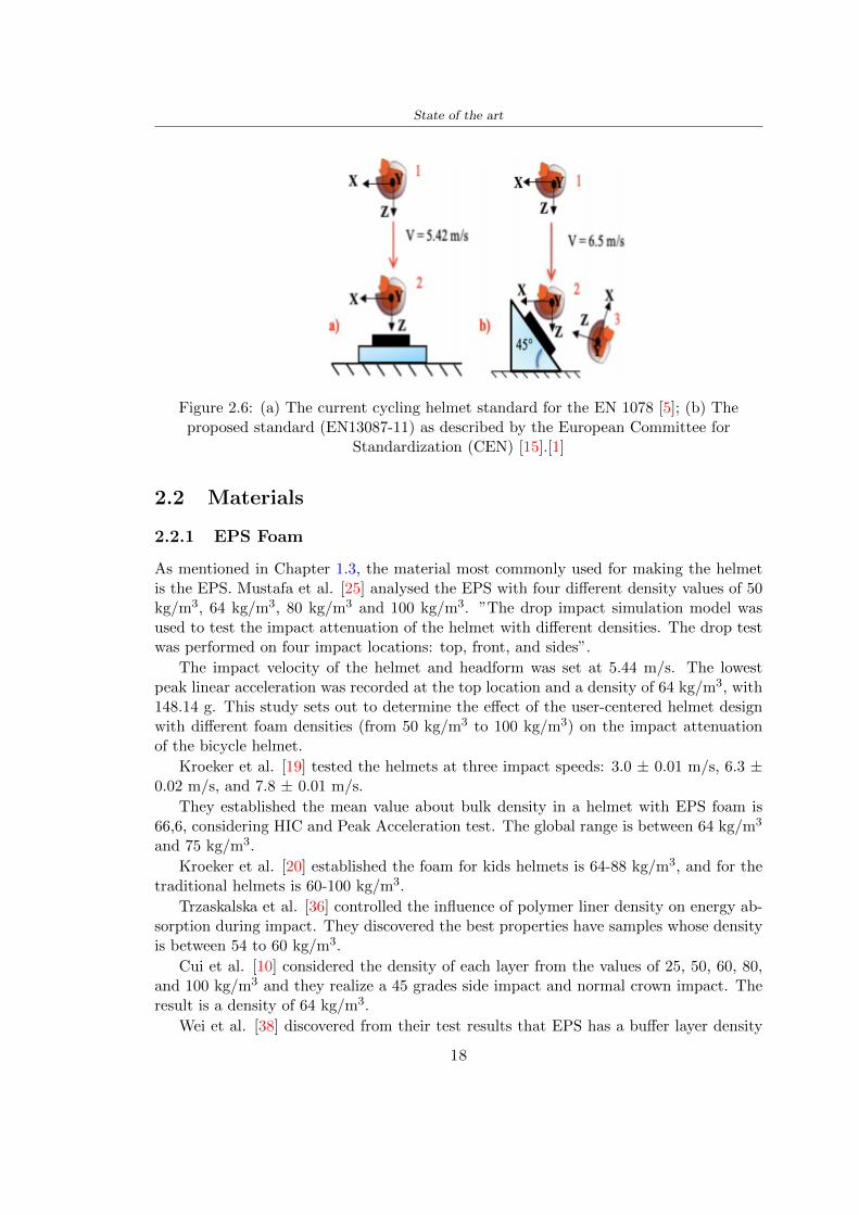
State of the art
Figure 26 (a) The current cycling helmet standard for the EN 1078 [5] (b) Theproposed standard (EN13087-11) as described by the European Committee for
Standardization (CEN) [15][1]
22 Materials
221 EPS Foam
As mentioned in Chapter 13 the material most commonly used for making the helmetis the EPS Mustafa et al [25] analysed the EPS with four different density values of 50kgm3 64 kgm3 80 kgm3 and 100 kgm3 rdquoThe drop impact simulation model wasused to test the impact attenuation of the helmet with different densities The drop testwas performed on four impact locations top front and sidesrdquo
The impact velocity of the helmet and headform was set at 544 ms The lowestpeak linear acceleration was recorded at the top location and a density of 64 kgm3 with14814 g This study sets out to determine the effect of the user-centered helmet designwith different foam densities (from 50 kgm3 to 100 kgm3) on the impact attenuationof the bicycle helmet
Kroeker et al [19] tested the helmets at three impact speeds 30 plusmn 001 ms 63 plusmn002 ms and 78 plusmn 001 ms
They established the mean value about bulk density in a helmet with EPS foam is666 considering HIC and Peak Acceleration test The global range is between 64 kgm3
and 75 kgm3
Kroeker et al [20] established the foam for kids helmets is 64-88 kgm3 and for thetraditional helmets is 60-100 kgm3
Trzaskalska et al [36] controlled the influence of polymer liner density on energy ab-sorption during impact They discovered the best properties have samples whose densityis between 54 to 60 kgm3
Cui et al [10] considered the density of each layer from the values of 25 50 60 80and 100 kgm3 and they realize a 45 grades side impact and normal crown impact Theresult is a density of 64 kgm3
Wei et al [38] discovered from their test results that EPS has a buffer layer density
18
State of the art
of 60 kgm3 is the most reasonable
Foam densityrsquos values - Literature
Authors Densityrsquos values
Mustafa et al [25] 64Kroeker et al [19] 64 - 75Kroeker et al [20] 60-100 (traditional) and 64-88 (kids)
Trzaskalska et al [36] 54 - 60Cui et al [10] 54Wei et al [38] 60
Table 25 Table with foam (EPS) densityrsquos values
The other are mean values obtained by CES EduPackrsquos program about this material
- Density ρ = 6451kgm3
- Youngrsquos Module E = 275 MPa
- Poissonrsquos ratio ν = 0275
- Yieldrsquos stress σ= 09 MPa
- Elongation at fracture = 45
222 CES Edu Pack - Material selection
CES Edupack software was used to satisfy the idea of creating a lightweight helmetby printing it in 3D and having the possibility to insert the desired characteristics ofthe material and therefore select it To make a choice I used level 3 of engineering(advanced) selecting the following criteria of the material bio-material biodegradablea polymer of concentration 20 - 100 which complies with the rsquoEuropean Restrictionon Hazardous Substances (Rohs) standardsrsquo regarding the composition of the materialensuring that it does not contain a high percentage of toxic substances compared to theestablished percentage In addition it must have proper durability in contact with coldwater (imagining a possible rain) and rsquogoodrsquo durability to UV radiation
According to Ashbyrsquos method [2] to select a material it is possible to follow thefollowing steps
1 Establish the function of the product What does the component doThe helmet is an instrumental use to protect the head during an impact this characteristicdepends on materials and qualities It can prevent an injury which depends on materialsand design because it has to be of the right head size It would be comfortable becauseit must be worn and it must give security to the person wearing it (by design) In thefollowing Table 26 the analysis of the functions
19
State of the art
Ranking Function description Depends on
1 Head protection (energy absorbing) Material2 Head protection (energy absorbing) Design3 Head protection (injury prevention) Material4 Head protection (injury prevention) Design5 Comfortable Material6 Comfortable Process
Table 26 Ashbyrsquos method functions
2 The objectives that are targets for the design the material is to bemaximised or minimisedTo manufacture and market a product objectives such as minimizing weight cost orenvironmental impact must be considered In the following Table 27 the analysis of theobjectives
Ranking Title Objectives description
1 Mass Minimize The mass has to be thesame or lower
2 Cost Minimize everyone should have theopportunity to buy it
3 CO2 footprint Minimize CO2 emission
4 Corrosion Minimize high strength because itcan be in contact with the water
5 Pleasant to touch Maximize it is not a rough materialbecause it has to put on and put off
by hands
6 Refractive index Minimize it must not reflect light
Table 27 Ashbyrsquos method objectives
3 Definition of constrains What essential conditions must be meetEstablish constraints is essential to complete the function of the instrument Examplesof constrains are Table 28
4 The limits characteristic independent of the material that does not influencethe physical properties In the following Table 29 the analysis of the limits
20
State of the art
Title Loading case Constraintsdescription
Material index(Max-Min)
Stiffness Column in compression Tie in tension
Mass Min
Stiffness Column in compression Tie in tension
Cost Min
Stiffness Column in compression Tie in tension
CO2 Min
Strength Column in compression Tie in tension
Mass Min
Strength Column in compression Tie in tension
Cost Min
Strength Column in compression Tie in tension
CO2 Min
Table 28 Ashbyrsquos method constrains
223 PLA with natural fiber and PLA LW
Initially the best material that met the desired criteria was searched From this study itwas found that the material closest to having the required characteristics is the PLA 30natural fiber as shown in the Figure 27 which shows the graphs obtained relating tothe relationships between Youngrsquos Module and density the objective to reduce the massper unit of compressive stiffness and strength to reduce the CO2 footprint per unit ofstiffness and strength and mass per unit of compressive strength
Performance index IR
The stiffness criterion has the following characteristics
m = A lowast L lowast ρ (21)
ε =σ
E=
FA
E(22)
A =F
ε lowast E(23)
21
State of the art
Ranking Title Function description
1 Biocompatibility It is the ability of a material the abilityof the material not to cause any local or
systemic adverse response in therecipient of the material
2 Biodegrability Biodegradable material do notbiodegradable under anaerobic conditions
3 Biomaterials - all The terms is used for biological naturalbio-derived bio-inspired material
4 RoHS (EU) Compliantgrades
Restriction of the use of certin prohibitessubstances (mercury cadmium
hexavalent chromium)
5 Polymer 20-100 (from the table with Plasticpolymers)
6 UV Resistance at UV sunlight
Table 29 Ashbyrsquos method limits
A =F lowast L lowast ρε lowast E
(24)
With fixed variables- F (the load) L (the length)With variables that depend on the material- E (Youngrsquos Module) ρ (density)
In general when a chart is created the distribution of the mass is represented in thefollowing modality like in Figure 27 [b] where the materials above the line have a lowermass while those below a greater mass
Following the results of the CES Edupack program that had selected the PLA withnatural fibers as the best the first print of the helmet was made with this materialusing as support the PVA Initially the result seemed satisfactory the helmet had a highdefinition but a fundamental problem was found by reducing the helmet in the water toallow the supports of PVA to dissolve In the act of diving in fact after ten minutessome parts of the helmet especially the front and rear have disintegrated making thehelmet unusable Because of this problem it was necessary to change the material
22
State of the art
[a]
[b]
Figure 27 CES EduPack Mass per unit of compressive stiffness [a] Youngrsquos Moduleand density [b]
Further investigations carried out by the Mondragon Unibertsitatea Additive Man-ufacturing Department revealed a new material the PLA Low Weight which during3D printing allows to obtain a weight of 65 lower than that which could be obtainedfrom the classic PLA as reported in the technical sheet of the filament produced by thecompany Colorfabb [7]
The investigation team of the Composite Department carried out tensile tests withsamples 3D printed at different temperatures as suggested by the manufacturer to obtainthe technical characteristics The temperatures examined are 200 220 250 260The datasheet shows the density can have values between 04 - 124 gcm3 the bed has
23
State of the art
to have a temperature between 50 - 60 the printing speed has to have values between40 - 80 mms This typology of PLA is expandible so much that rdquoAt around 230 thismaterial will start foaming increasing its volume by nearly three timesrdquo [7]
T[C] Section [mm2] Volumen [mm3] Mass [g] ρ[kgm3] E [Nmm2]
200 42235 1030117 12 1165 328807
220 43805 1655821 18 1087 265795
250 52412 1948139 17 873 178058
260 59655 1454377 12 825 117047
Table 210 Values about PLA LW tensile tests of MU Additive ManufacturingDepartment
From the tests that have been carried out on the material at different temperaturesthe printed sample is better at 250 with a volume of 1948139 mm3 and a section of52412 mm2 as shown in Table 210 For this reason the specific of the material thathave been taken into consideration are the following
- Density ρ = 873 kgm3
- Youngrsquos Module E = 1750 MPa
- Poissonrsquos ratio ν = 033
- Yieldrsquos stress σ = 2948 MPa
- Elongation at fracture = 491
23 Bio-inspired structures
When we talk about bio-inspired structures to nature we refer to structures that allowobtaining a low weight for the model that is realized and excellent absorption energy dur-ing the impact Recently the structures that have been most used in the biomimetic fieldare the rdquocolumns structures sandwich structures plates honeycomb and foamsrdquo[26]but aiming to achieve a structure increasingly with high absorption energy new struc-tures derived from plants and animals such as beetle horsetail turtle bird beak havebeen analyzed The first to create multi-cells tubes helicoidal structures the second tomulti-corner tubes [26]
The authors analyze the specific energy absorbed (SEA) by bio-inspired sandwichstructures per unit mass which can be derived from the following equation
EA(d) =
int dmax
0F (x)dx (25)
SEA(d) =EA(d)
m(26)
24
State of the art
Where EA is the energy absorption rdquomainly used to evaluate an energy absorberrsquosability to dissipate crushing energy through plastic deformationrdquo F(x) is the crashingforce dmax is the effective deformation distance [26]
What derived from their investigations is that having regard to a density of between0 and 1000 kgm3 the volumetric energy absorbed is higher for the beetle-inspired struc-tures than the others as shown in Figure 28 Based on this consideration it was chosento draw the helmet following this geometry
Figure 28 SEA of bio-inspired sandwich structures [26]
231 Beetle structure - Design of the model
To develop and increase lightweight high-strength and optimize bio-mimetic functionaland structural materials the trabecular structure of the beetle elytron is studied Thesingle structure is realized following the requirements cited by Zhang et al [39]
To realize the beetlersquos structure it is not enough to have information about the lengthof the side of the hexagon and the thickness but it is also necessary to take into accountthe relationship between the diameter of the circumferences present on the vertices ofthe hexagon and the measurement of the side The representation of a single cell is inFigure 29 It is shown in [a] a general structure with an edge of 12 mm circumferencersquosdiameter of 6 mm and thickness of 16 mm in [b] is shown the height of 20 mm
For the construction of the helmet a thickness of 12 and 16 mm was used the imageconcerns a proportion between the length of the hexagon side and the diameter of the
25
State of the art
circumference The side (distance between the centers of two circumferences) is twice thediameter measurement
[a] [b]
Figure 29 Beetle structure
232 Specific stress - PLA LW and EPS foam
To test the beetle structures compression tests were investigated The PLA LW structurewas inserted in a rsquodiskrsquo with a diameter of 100 mm and a height of 20 mm The area andthe volume of the disk is correspondingly 7854 mm2 and 157 10 mm3 The structuresexamined have different dimensions the edge L (distance between two centers of thecircumferences) had the following measures 9 10 12 14 16 mm the thickness of thecircumferences and edges are respectively of 16 mm for every structure and 12 mm forthe structure with L = 16 mm
The test was carried out with the Hoytom HM-D Testing Machine with capacitiesbetween 5 and 100 kN The test models were subjected to displacement loading at a rateof 1 mmmin as referenced by Chen et al[18] with a cylindrical specimen The specificstress of the structures was compared with the specific stress of a generic EPS helmetthe photos about it are shown in Figure 210 The EPS helmet structure is granular withpores inside The different grains dimension and these pores can be the reason for whichthe Stressrsquos values are between two values 07 and 116 MPa
Four parts of the EPS helmet were considered in the test the dimension and relativecharacteristic are in the Table 211 where m = mass A = area F = load ρ = densityR = stress Rρ = specific stress To calculate the values of stress about PLA structuresand EPS foam compression test graphs were been analyzed The stress value for eachstructure was calculated considering the single load the single area and the averagedensity value (14055 [kgm3])
The stress values of the PLA structures (Figure 211) and other characteristic valuesare in Table 212 where m = mass A = area F = load ρ = density
26
State of the art
[a] [b]
[c] [d]
Figure 210 EPS generic helmet helmet pictures [a] [b] and internal structureExternal granular structure [c] and pores [d]
[a] [b] [c]
Figure 211 PLA LW disks Grasshopper structure [a] PLA LW structure of 14 mm[b] PLA LW structure compressed [c]
27
State of the art
The results of the load-displacement graphs are affected by the geometry of the diskthe target is to valid for any shape or size for this is preferred to realize a diagramthat depends from σ (or stress) and the deformation ε (or strain) which can be definedrespectively as
σ =F
A0(27)
ε =l minus l0l
(28)
where F is the load during the test A0 is the area l0 is the initial length and l is thelength when the load is applied The areas considered for the EPS cube is reported inTable 211 in the second column the areas of the PLA structure is 7854 mm2 like thearea of the circumscribed disk
The values compared are shown in Table 213 and the graphs obtained by Matlabcode to analyze the recorded data of the compression machine are in Figure 213 and inFigure 212
Considering that the data provided by the compression machine are subject to noiseand disturbances it was decided to convert the original curve into polynomial type curvesthat allow obtaining the best interpolating curve for the data in question To obtain themit was divided the recorded data into two groups the first part from 0 until the end ofthe linear part and the second when the curve becomes linear again The best-fitting (inthe least-squares sense) was performed using the polyfit and polyval functions of MatlabThe first returns the coefficients of the p(x) with n degree the second evaluates p(x) ateach point in x The polynomial formula p(x) is shown in the Equation 29
pn(x) = anxn + anminus1x
nminus1 + + a2x2 + a1x+ a0 (29)
where a0 an are constants and x is the indeterminate The choice of the degree ofthe polynomial was made based on the criterion of wanting to obtain linear curves thatrespected the elastic trend at the beginning of the graph For this reason the degree ofthe polynomial is 1 Subsequently I searched through the intersection of the two lines forthe point that is equivalent to the maximum stress that marks the end of linearity
This value for EPS and PLA LW is the R [MPa] in the Table 213 The average stressvalue for PLA LW is 139 MPa and for EPS is 094 MPa The specific stress (Rρ) is 18MPa lowast m3)kg for the EPS found in CES 669 MPa lowast m3)kg for the EPS foam of thegeneric helmet and for PLA LW is 1161 MPa lowastm3)kg an intermediate value betweenthe two which is what we wanted to achieve
28
State of the art
m [g] A [mm2] F [N] ρ [kgm3]
EPS (CES) 50
16 9234 1063 13864
18 879 593 13651
21 858 833 14237
24 864 564 14468
Average value 14055
Table 211 Compression stress generic EPS helmet
L [mm] t [mm] m [g] F [N] ρ [kgm3]
9 16 214 7250 1363
10 16 192 5560 12467
12 16 201 8190 13051
14 12 138 8000 8961
Average value 12027
Table 212 Compression test PLA structures
PLA LW structure EPS structureρ= 12027kgm3 ρ= 14055kgm3
Edge [mm] R [MPa] Rρ103 Number R [MPa] Rρ103
EPS (CES) 09 18
9 173 1269 1 116 824
10 139 1114 2 08 568
12 138 1057 3 105 746
14 108 1205 4 077 540
Average value 139 1161 094 669
Table 213 Specific stress calculus PLA LW and EPS calculus ρ = density R = stressRρ [(MPa lowastm3)kg] = specific stress
29
State of the art
Figure 212 Compression test Stress-Strain diagrams - EPS
Figure 213 Compression test Stress-Strain diagrams - PLA LW
30
Chapter 3
Methodology
31 3D scan
311 3D Sense 2 scanner and Meshmixer - Reverse reconstruction
Standardized measures were not taken into account for making the helmet but the sizewas obtained through a 3D scan of my head
The scanner used is 3D Sense 2 by 3D Systems which has a minimum scanningvolume of 20 x 20 x 20 cm and a maximum scanning volume of 300 x 300 x 300 cmTo scan my person I was helped to get a full view at 360 at an appropriate distanceReal-time visualization of the captured images was shown through 3D Sense softwareThe idea of scanning the head with the scanner refers to the methodology used by Wanget al [30] They used a reverse reconstruction functional for me to realize the helmetsurface made to measure my head and like them a silicone pool cap was used to makescanning as smooth as possible The authors claim the head scan rdquocan also be used toobtain information about the objectrsquos surface which is then reconstructed utilizing thecomputerrsquos three-dimensional model via reverse modelling softwarerdquo [30] that in my caseis Autodesk Meshmixer
The files it was could get from the scan were stl obj and ply format they wereexported to obj to work in the next step with Autodesk Meshmixer that allowed tomodify and homogenize the 3D image obtained from the scan
In Meshmixer through the selection and delete commands the superfluous parts weredeleted that had been acquired and with the inspector and the DrawDraw2 commandsthe vertices were moved locally along a pre-defined direction and with Smooth the surfacemore homogeneous was made The sequence of steps is shown in the Figure 31
312 3D scan analysis and extraction of features
In Chapter 2 the directives imposed by the BS EN 960 Standard were examined concern-ing the definition of the helmet and the measures to be respected in the field of visionand the part of the helmet was to carry out impact tests
In Figure 32 the features defined complying with the Standardrsquos rules are repre-sented To define these features the software NX was used The angle in the subfigure
31
Methodology
[a] [b] [c] [d]
Figure 31 Sequence of 3D head scan 3D scanner acquisition [a] scan after reparationwith Meshmixer [b] solid scan vision frontal and lateral [c] [d]
[b] is bigger than 105 (as defined by the Standard) while the degree in the subfigure [c]is 25 By defining the construction lines to be respected of the helmetit was necessary todraw the design of the surface not using the software NX but changing with Rhinocerosto create a SubD or SubDivision surface
32 Helmet design
321 Rhinoceros - Helmet surface
After realizing a rsquocleanrsquo Wang et al [30] subdivide with lines and then sectors the headto create the surface of the helmet They used the technique of NURBS a Non UniformRational Basis-Splines which mathematically models a 3D geometry while thanks tothe Rhinoceros 3D organic shapes was draw SubD surfaces These geometries allow tosplit the mesh into small polygons and consist of lines with which easily the shape ofthe object can be modified with a surface already created changing the position of aline automatically the remaining part of the geometry adapts to the changes With thistechnique the rsquosurface basersquo of the helmet was realized with the size of my head Therepresentation of the realized SubD is in Figure 33
322 Grasshopper - Helmet structure
The next idea is the creation on the surface of the beetle structure with different di-mensions modelling the helmet that is not a linear surface It was decided not to buildthe structure with a software CAD because to model an already complex structure on acurved surface would mean to model a cell for a cell
To solve this obstacle a Rhinoceros plug-in was used Grasshopper GH idealized byRobert McNeel and associates creators of Rhinoceros Using GH does not mean drawinggeometries by connecting points and drawing tools because it is based on algorithmicmodelling used in architecture and engineering for 3D modelling
The modelling takes place through a node diagram that the software will convert intoa code-algorithm in GH it is possible to define the variables and parameters and inRhinoceros in real-time it is possible to view the object GH allows for varying the
32
Methodology
[a] [b]
[c]
Figure 32 Featurersquos extraction in [a] is represented the impact line in [b] and [c] twoprospective about the definition of the field of vision
[a] [b] [c]
Figure 33 SubD representation lateral view [a] top view [b] front view [c]
geometry to your liking by varying a simple parameter of the diagram as everything willbe remodelled according to the change made
In the following Figure 34 it is shown an example of a structure that was used fordistinct subgroups of helmet areas The idea was to insert smaller cells in the frontal andlateral zone and larger ones in the upper area In the first image [a] is shown the part of
33
Methodology
the helpful diagram to create the beetle structure to establish the size of the cells andthe extrusion the second image [b] contains the part of the diagram with which I appliedthe structure previously created to the SubD
The structure used to place and adapt the beetle structure to the surface is theSrfMorph while the yellow rsquowindowrsquo that contains numbers serves to select the parts ofthe surface where to apply the geometry created In accord with the GH diagram in
[a]
[b]
Figure 34 Grasshopper diagrams
Figure 34 [a] it is possible to see the steps executed to realize the structure Initially inthe xy-plane a hexagonal grid was drawn through the Hexgrid command in which youcan input the length of the hexagon edge and the number of grid elements (selected bytrial) Then the circumferences was drawn in proportion to the hexagon dimensions asspecified in the Chapter 2 and shown in Figure 35 [a] In figure [b] the rsquocutrsquo made atthe circumferences is visible this subdivision was necessary for printing purposes In thelast photo [c] the structure highlighted in green in [b] was extruded setting a distance
34
Methodology
of 20 mm
[a] [b] [c]
Figure 35 Construction sequence of the geometry of the helmet
In the diagram in Figure 34 [b] there is the application of the structure created bi-dimensionally to the SubD surface of the helmet visible by unlocking the SubD commandof the diagram and in Figure 36 [a] Upper this the referential geometry of the group ofsurfaces was superimposed where it was to be applied the newly created structure (visiblein darker red) the SubD indices are in the yellow box of the diagram
Through the SrfMorph command the location of the structure was granted In Figure36 [b] at the darkest red of the figure [a] with the above command it was possible toplace the structure
[a] [b]
Figure 36 Application of the geometry created to the helmet surface
Overall the diagrams with specific structures are five one for the front two equal forthe side parts one for the top shown in the previous Figure 36 and one for the back
The hexagons in the structure have a dimension varying between 8 mm and 14 mmof side the largest is found at the top later at the back in the sides and the smallest atthe front In Figure 36 [b] the presence of not only hexagonal structures is visible Thegeometry used does not allow the homogeneous arrangement on the entire surface andrequires different structures Automatically the choice of GH to optimize the structurewas to insert quadrilateral
As described above the helmet has different dimensions of the structure divided asvisible in Figure 36 in a quadrilateral This causes a discontinuity between zones withdifferent sizes due to the geometry of the construction
To eliminate this problem and realize the design homogeneous grids were inserted
35
Methodology
in the affected areas as shown in Figure 37 This insertion however proved to beinteresting and strategic researching in this regard studies were realized to demonstratethe insertion of a rectangular grid inside the hexagon grid was helpful for the transmissionof stress in the structure As cited by Sun et al [40] rdquothe mechanical properties of thesesandwich structures are often limited by local failures such as face-core debonding or corecollapserdquo Carrying out compression tests have effectively demonstrated that the insertionof the grid allows rdquoprovided increased stiffness specific stiffness energy absorption andcritical loadrdquo [41] As shown in the graphic [c] of the Figure 37 the honeycomb structuregives a force of 7 kN while with a grid the value is 11 kN and with the combinationexceeds 22 kN In addition in the left front a plaque to customize the helmet wasprepared Figure 37 [a]
[a] [b]
[c]
Figure 37 Grid in the helmet [a] hybrid structure with hexagons and grid [b] [40]compression test results of the hybrid structure [c] [41]
33 3D Print
After having achieved the CAD (Computer Aided Design) of the helmet in order tobe printed it must be converted and saved in format STL (Standard TriangulationLanguage) - Binary compatible with the printing machine and useful for transformingsolid object surfaces into triangles The steps to be taken are the following
bull CAD file realization
bull CAD export in format STL to Simplify 3D the software that shows slider layersand then- rotate and position the object according to geometry and the positioning of any
36
Methodology
supports- setting printing parameters- item manual andor automatic positioning of supports- slider display layers
bull import file gcode to printer
331 Printer and parameters
The program used to visualize how the helmet slices layers before sending it to the printerand to set the parameters is as anticipated Simplify 3D
To make the printing not being a flat geometry it is necessary to place the supportsThe idea was to use water-based supports that the helmet would automatically dissolveonce placed in the water After testing different types of water-soluble PVA the choicefell on eSun 3D Printing Filament PVA (water-soluble support) Before choosing theoptimal position for printing several tests were carried out and to decrease the numberof the supports significantly and allows an optimal printing of the outer part an emptyrsquospherersquo that self-sustains below the helmet was placed as shown in Figure 38
In the image [a] you can see the first print position tried with which an external partof the helmet very damaged was obtained because of the contact supports-helmet In [b]the empty rsquospherersquo is shown to optimize the number of supports and in the last photo [c]there is the full version at the end of print
[a] [b] [c]
Figure 38 Printing supports
The printer that has been used for printing is the Raise 3D Pro2 with double extrudersand nozzles of variable size from 02 mm to 1 mm after some test prints with the PLALW and the structure in created the size that allowed me to have a good compromisebetween printing time and accuracy was 06 mm Using 04 mm the printing time wasexcessive even if having the smaller nozzle diameter means having more precision withthe 08 mm nozzle the quality of the structure was not excellent as seen in Figure 38[a]
Another factor that had to be taken into account is the characteristic of the PLA-LWto expand As the printing temperature and the printer used vary the expansion andcharacteristics of the material change The use of the 06 mm nozzle associated with
37
Methodology
Parameter Left extruder Right extruder
01cm Material 01cm PVA 01cm PLA LW
Extruder toolbox index Tool 0 Tool 1
Nozzle diameter 06 mm 06 mm
Extrusion multiplier 1 05
Extrusion width Auto (072 mm) 05 mm
Layer x
Infill Rectilinear - 50
Supports (Automatic and not) Infill 50
Temperature 210 250
General parameters
Primary layer height 03 mm Top solid layer 4
Bottom solid layer 2 Outline 2
Heated bad 60 Speed 40 mms
Table 31 Printing parameters
Raise 3D allowed me to get good results The choice of this printer was not random ithas in fact the characteristic of making extremely precise prints The Raise has accuracyin placing the object on the printing bed of 078 microns on the xy axis and a resolutionfor layers of 001 mm
The final version of the helmet is visible in Figure 39 and it is possible to compare itwith the preview version in Rhinoceros in Figure 310
38
Methodology
[a] [b]
[c]
Figure 39 Views of the helmet
[a] [b]
Figure 310 Views of the helmet (GH version)
39
Chapter 4
Experimental evaluation
41 Experimental tests
411 Drop-weight impact test machine
In order to calculate the contact force peak and the difference of energy absorbed duringthe impact between the reference helmet and helmet with the beetle structure in PLA-LW dynamic impact tests were carried out using the Fractovis Plus an impact testmachine
In this way it is possible to monitor the evolution of the above variables from theinitial to the final instant of the impact The machine can withstand a load with a rangevariable from 2 to 70 kg with a maximum speed of 46 ms and a maximum height of1 m The values chosen for the test are the following 5 kg weight maximum speed andmaximum height The Anvil that was used is a disc diameter of 60 mm
As shown in Figure 41 and explained by Crupi et al [37] the machine consists ofa sensor capable of recording the speed before impact the impactor that can have avariable mass (a weight of 5 kg in my test) a system to guarantee that there are nomultiple impacts after the first and that work as a shock absorber and clamping systemwhere the object to be tested is placed
The tests that have been carried out are in total four two related to the helmetoptimized with PLA-LW and two with two generic helmets of different brand in EPS
42 PLA LW helmet
To perform the dynamic test on the helmet of PLA considering the difficulty of printingit was helpful to use a test helmet with imperfections to understand where the impactwas concentrated in a single part or distributed The images of Figure 42 show a helmetwith not well defined edges and inaccurate print but exactly localizes the impact zoneThanks to this test it was possible to take into account only one helmet area shown inFigure 43 to have the exact curve of the structure bio-inspired with PLA-LW
40
Experimental evaluation
Figure 41 Drop-weight impact test machine [37]
[a] [b]
Figure 42 Test 1 PLA-LW helmet
43 EPS helmet
To carry out dynamic tests and extract the technical characteristics of the helmettwohelmets were bought in a sports store both EPS and being on the market both certifiedThe brands of the two helmets are DTB and VAN|RYSEL and the average weight ofthe two is 223 g Two different helmets have been chosen to have a more certain andclear classification of the characteristics They are shown in Figure 44 and Figure 45
41
Experimental evaluation
[a] [b]
Figure 43 Test 2 PLA-LW helmet
[a] [b] [c]
Figure 44 Test 3 EPS helmet
[a] [b] [c]
Figure 45 Test 4 EPS helmet
44 Results
441 First results - PLA-LW and EPS helmet
Figure 46 shows two types of trends related to the two different models of the helmetThe force evaluated for PLA-LW has higher force peaks but is more concentrated and
42
Experimental evaluation
propagates less than EPS The graph shows the peaks of each curve highlighted with a redcircle In tests 1 and 2 for the PLA-LW as mentioned earlier the values are higher about7301 N for the complete helmet and 3996 N for the portion of helmet This difference isdue to the inaccuracy of the first full helmet during the printing phase In Figure 42 itis visible the low homogeneity and precision Therefore the first test with full helmet wasused only to define the area of interest of the impact which turns out to be localized Forthe other two EPS curves the values are only slightly lower compared to the PLA-LWequal to 3620 N and 3295 N but the trend is much more distributed
Figure 46 Dynamic machine test - Force
With the data obtained from the impact machine it was possible calculate not exclu-sively the value of force but itrsquos also possible to view the energy curves A resume aboutthe values and energy of the force is in the following Table 41
Test Peak force [N] Peak energy [J]
Test 1 - PLA LW (inaccurate) 730130
Test 2 - PLA LW (portion of helmet) 399643
Test 3 - EPS (DTB helmet) 362007 509
Test 4 - EPS (VAN|RYSEL helmet) 329546 4198
Test 5 - PLA with TPU 45421 5022
Table 41 Energy absorbed in dynamic test
43
Experimental evaluation
442 PLA-LW helmet with TPU cover
As it is possible to see in Figure 47 and as highlighted the first tests concerning thebio-inspired structure and the PLA-LW are far from my expectations considering thelittle distribution of force in comparison with the EPS foam and consequently a smallamount of energy absorbed
Figure 47 Dynamic machine test - Energy
To improve this impact damping factor the idea was to create a cover for the helmetin flexible TPU trying to absorb impact energy The TPU used is a flexible material ofthe brand Ninjaflex used in sports by the application in helmets and shoes to cushionbumps during the game Generally in the helmets (baseball helmet for example) theTPU is inserted internally in contact with the head In my case the TPU structurein addition to creating a shock-absorbing and durable cover creates a custom cover thehelmet and for the person This cover was also made with the Raise 3D printer
As shown in the Figure 48 [a] the infill of the part in contact with the helmet hasa percentage of 100 the filling of the other part of the structure is not complete butonly 15 and the internal structure is hexagonal to recall that of the helmet The desireto insert a structure with a rsquoraisedrsquo geometry is for visual and aesthetic reasons as youhave the feeling of greater protection and not filled is inspired by the machine CitroenCaptus whose bumpers (Airbump) are full of air The failure to realize empty structuresis due to the need to place any internal supports not removable
The idea was to create a cover that allow you to see of the internal structure of thehelmet and that protect specific areas the front the two sides the top and the posteriorWhat which was thought for this reason was to create the shape of a flower with four
44
Experimental evaluation
petals Figure 48 [b]In this way to perform dynamic impact tests as shown in Figure 49 [a] the cover was
positioned at the top of the helmet and the impact was performed in the centre of thersquoflowerrsquo which corresponds to the higher upper part where the structure has larger cellsize The impact parameters are the same as those used in previous impacts 5 kg weightmaximum speed and maximum height The Anvil that was used is a disc diameter of60 mm In photo [b] it is evident the difference between the structure that received theimpact with protection (left) and without protection (right) Without protection duringthe impact there was a perforation of the structure with a concentration of force at a locallevel as you can see in the Figure 46 in the case of TPU the impactor did not perforateand crossed the structure thanks to the cover of TPU that cushioned the shock At themoment of impact the impactor bounced
[a] [b]
Figure 48 TPU cover
[a] [b]
Figure 49 PLA-LW with TPU - dynamic impact [a] and differences between thehelmet with TPU and without TPU cover [b]
45
Experimental evaluation
The Figure 410 includes the diagrams relative to the dynamic impacts In [a] thereare already analyzed EPS results in [b] a comparison between the test on the portionof helmet in PLA LW with and without the TPU cover in [c] the overall comparison ofcurves shows a much more similar EPS trend if the TPU is placed above the structure inPLA LW to soften the blow and absorb the same energy [d]
46
[a]
[c]
[d]
Figure 410 Comparison between PLA-LW with TPU and EPS
Chapter 5
FEM Validation
51 Impactor - Anvils definition
Before to start to work in Abaqus it was necessary to search in the literature the materialwith which the anvil was been realized Milne et al [23] established the densityrsquos valuethe Youngrsquos Module and Poissonrsquos ratio for the Flat and Kerbstone Anvil
- Density ρ = 7800 kgm3
- Youngrsquos Module E = 200000 MPa
- Poissonrsquos ratio ν = 03
Inserting the data in the CES EduPack program specifying the mechanical andphysical properties the material corresponding to these characteristics is Stainless steelaustenitic (ASTM F1586) medium-hard
Initially the proposal was to create a conservative system to evaluate the absorptionenergies values and apply this value to a vibration system but the helmet needs dampingto be realized it was impossible to use a system without losses in this modality Thisis why a numerical calculation was carried out by performing two types of simulationsexplicit dynamic step and static step
The idea to realize the theoretical impact is to regard the movement of the anviland not the helmetrsquos movement which is fixed The velocity is the same cited in thenormative EN 1078 542 ms for the Flat anvil and 457 ms for the Kerbstone anvil
In performing the simulations It was given more relevance and perform tests withthe Kerbstone Anvil This choice was done because the geometry with which it is beenrealized (following as defined in the legislation) allows the helmet to be more subjectedto stress this involves the definition of higher stress limits compared to the Flat Anvil
The mesh size that has been used is the same in the case of the simulation of thehelmet optimized in PLA-LW and the full helmet in EPS of 7 mm The impactor isconsidered as a Discrete rigid body with its specific Reference Point (RP) like shownin Figure 51 for this reason it is not a solid but it is composted only by shells Inthe same image [b] there is the FEM representation of the model and in Table 51 thecharacteristic of FEM with quadrilateral (R3D4) and triangular elements (R3D3)
48
FEM Validation
Object Elementnumber
Elements Shape Geometricorder
Global size[mm]
Kerbstone 230 Quadrilateral - R3D4 Linear 7
Kerbstone 8 Triangular - R3D3 Linear 7
Table 51 Mesh element - Kerbstone Anvil
[a] [b]
Figure 51 Kerbstone anvil in the simulation like discrete rigid body [a] and FEMelements [b]
511 PLA LW - Plastic characteristics
The PLA-LW as explained in the Chapter 2 is new material on the market and producedby the only Colorfabb company for this reason few tests have been carried out to defineits technical characteristics and through tensile tests of the 3D printed specimens it waspossible to define an elastic limit as reported in the Table 210
In the context of simulations to reproduce the impact and deformation of the helmetis also necessary to consider the plastic characteristics of the material Not possessingany reference value in this regard tests were performed through a Static Step initiallyand then an Explicit Dynamic Step in Abaqus
The structure chosen to consider as a reference it is one of the structures previouslysubjected to the compression test having the side L=14 mm As for the reproduction ofthe compression disks initially they were reproduced according to the geometry of theHoytom HM-D Testing Machine considering the bodies mentioned above as discrete 3Drigid discrete The measure was the diameter of 200 mm and the height of 20 mm
After an initial analysis it was observed that the computational time of the simulationprogram was very high so it was decided to change the geometry to have a rsquodisk-surfacesrsquo(equally 3D rigid-discrete) which allowed me to have a smaller number of nodes for themesh and consequently a better computational time The representation of the opti-mized structure in PLA-LW and the disks used for simulated compression is in Figure 52
49
FEM Validation
[a] [b]
Figure 52 Representation of the samples used for the simulation of the compressiontest In Figure [a] the disks of the Hoytom HM-D Testing Machine in figure [b] the
representation of the same as simple surfaces
As shown in Figure 52 the disks are considered 3D discrete hard bodies so it waschosen for both a point the reference point RP where to apply the characteristics relatedto the two bodies As for the compression test it was established
bull the movement of a disk and fixed the second through a boundary condition impos-ing an Encastre therefore unable to move and rotate in xyz directions
bull for the opposite disk the boundary condition relative to the 15 mm displacementwas applied which is the parameter that it was observed to determine the end ofthe compression with the machine This shift is shown by the orange arrow in figure[b]
bull between the upper surface and the disk e the disk with the lower surface it wasinitialized a general contact with normal behaviour through rsquohardrsquo contact andtangential behaviour with a coefficient of friction of 02 with directionality imposedon rsquoisotropicrsquo
The next step was to define the mesh of the components whose parameters are shown inTable 52 while the representation of the FEM is in Figure 53 with the representationof the simulation and real compression test
Object Elementsnumber
Typology Geometricorder
Globalsize [mm]
Disk (14mm) 80910 hexaedral - C3D8R Linear 07
Impact disks 206 quadrilateral - R3D4 Linear 20
Impact disks 6 triangular - R3D3 Linear 20
Table 52 Mesh element - Compression test simulation
As previously announced a static simulation was initially performed with a StaticStep with Step Time equal to 900 (obtained going to consider the speed of 1 mmmin of
50
FEM Validation
[a]
[b] [c]
Figure 53 FEM representation [a] and compression test simulation [b] and realcompression [c]
the compression test and the displacement of 15 mm) However the complex geometryof the structure and the high time set by Step Time did not allow a correct definitionof the parameters of the plastic characteristics of the material the simulation was notable to continue once reached a Step Time of approximately 220 That is why it waschanged by choosing an Explicit Dynamic step
Leaving all the parameters of the boundary conditions unchanged the Step Time wasmodified imposing it to 001 The ability of the explicit dynamic to work with non-linearand contacting structures allowed me to achieve results The results obtained are shownin Figure 54 with the blue curve and were obtained through the iteration of differentPlastic Strain and Yield Stress values in Abaqus while the red line is the result of thereal compression test a similar curve trend was obtained but it is not possible to obtainthe same curve taking into account problems of printing inaccuracy
512 First test - helmet
The initial idea was to perform a simulation imposing the speed of 457 ms to theimpactor tie the helmet in EPS and PLA and compare the absorbed energies Theproblem it was encountered is related to the mesh of the helmet optimized in PLA andwith minimum dimensions of the elements and distinct elements it was not able to solveit
51
FEM Validation
[a]
YieldStress
PlasticStrain
1 47 0
2 7 001
3 75 005
4 10 01
5 108 1
6 115 15
7 12 2
[b]
Figure 54 Representation of the two curves related to the simulation in Abaqus of thecompression test and the data obtained from the real test to obtain the plastic
characteristics of the material
513 Second test - plane
The first solution is the one shown in Figure 55 To realize the simulation it was realizeda section of the helmet to involve a smaller number of elements and nodes Again thesimulation for the EPS helmet was successful while the simulation with the bio-inspiredstructure was interrupted by excessive distortion of elements
The previous images show the impact is very localized in the impacted area and theidea to achieve a complete simulation is not to consider a curved portion of the helmetbut a plane In this way it was possible to solve the problem and obtain a completesimulation for the bio-inspired structure
FEM element
Below in Table 53 there is the definition of the elements used for the PLA-LW and EPSplane in the simulation to simulate the impact and to control the energy-absorbing whilethe anvil characteristics are described in Table 51
514 EPS impact simulations
In order to proceed with the simulation it was imposed some boundary conditions thatregard ties and forces
bull the movement of the plane is fixed through an Encastre therefore unable to moveand rotate in xyz directions
52
FEM Validation
[a]
[b]
Figure 55 Impact simulation parts of EPS and PLA helmet
Object Elementnumber
Elements Shape Geometricorder
Plane (PLA) 38896 Tetrahedral -C3D10M
Quadratic
Plane (EPS) 2100 Hexahedral - C3D8R Linear
Table 53 Mesh element - plane impact
bull to create the impact it was set a speed of 457 ms at the reference point RP of therigid body which is the impactor Kerbstone Anvil shown in Figure 56
bull between the upper surface of the plane and the impactor it was initialized a Sur-face to Surface contact with normal behaviour through rsquohardrsquo contact and tangen-tial behaviour with a coefficient of friction of 02 with directionality imposed onrsquoisotropicrsquo
bull the rotation in x y z relative to the RP of the rigid discrete impactor body is locked
53
FEM Validation
In addition it was characterized the plane in the part of the materials with the char-acteristic values of the EPS mentioned in Chapter 221 The Von Mises Stress valueapparently low is relative to the Yield Stress of the EPS material equal to 09 MPa
Figure 56 EPS Boundary conditions and Load
515 PLA LW impact simulations
As also required in the case of the EPS plane in order to proceed with the simulationsome boundary conditions were imposed that regard ties and forces
bull the movement of the plane is fixed through an Encastre therefore unable to moveand rotate in xyz directions
bull to create the impact a speed of 457 ms was set at the reference point RP of therigid body which is the impactor Kerbstone Anvil shown in Figure 58
bull between the upper surface of the plane and the impactor it was initialized a Sur-face to Surface contact with normal behaviour through rsquohardrsquo contact and tangen-tial behaviour with a coefficient of friction of 02 with directionality imposed onrsquoisotropicrsquo
bull the rotation in x y z relative to the RP of the rigid discrete impactor body is locked
In addition the plane was characterized in the part of the materials with the characteristicvalues of the PLA mentioned in the Chapter 223 and 511
Figure 58 Boundary conditions and Load
54
FEM Validation
[a]
[b]
Figure 57 EPS impact simulation
52 Results
In Figures 59 and 57 it is shown how the structure in PLA LW has a more concentratedstress distribution of the structure unlike EPS The maximum value for the Von Misesstress is 09 MPa in EPS structure and 3634 MPa in PLA LW structure Once thesimulations were obtained the next step was to go and compare the energies absorbed bythe two structures The energy calculated by Abaqus that has been taken into account isPlastic Dissipation To make a comparison the data of the two energies were representedin a single graph
What emerges from the graph is that about the impact made with the KerbstoneAnvil the energy absorption is more excellent although only slightly for the PLA LWthan for the EPS From the graph in Figure 510 a value of 41 J is shown for the EPSand 51 J for the PLA LW
55
[a]
[b]
Figure 59 PLA impact simulation
[a]
Figure 510 EPS and PLA LW energy comparison - Abaqus simulation
Chapter 6
Head Injury Data
For the statistical analysis the injuries related to the accident data were categorised intothe following types and levels based on the details of the medical report [11] about theEN 1078
bull Head Injury Criterion (HIC)
bull Peak Linear Acceleration (PLAc)
bull Gadd Severity Injury (GSI)
bull Diffuse axonal injuries (DAI)
61 Abaqus simulation
Until now the purpose of the simulations has been to determine which between the twomaterials and the two structures of EPS and PLA LW could absorb more energy duringthe impact but no simulations have been carried out in compliance with BS EN 1078on the helmet impact tests To calculate the injuries listed in the previous paragraphhowever we need the acceleration values in the three directions related to the subjectrsquoshead
To realize it the scan of my head already rsquocleanrsquo was considered of which it has beencalculated the inertia thanks to the automatic SolidWorks calculation and evaluated theweight with the Table 24 the structure of the helmet was placed for the EPS and thePLA LW over the head as shown in Figure 61 Also this time being able to mesh theentire helmet in PLA LW was impossible due to the excessive distortion of some elementsduring the simulation so it has been tried to make a section of the structures of thehelmet and results were obtained
57
Head Injury Data
[a] [b]
Figure 61 My scan head - CAD [a] head imported in Abaqus[b]
Initially the simulation had these characteristics as shown in the following Figure62 considering the helmet was not sectioned As explained earlier it was not possibleto get to simulation in the case of the optimized structure in PLA LW for this reasononly a part of the helmet was considered in both cases shown in Figure 63
[a]
Figure 62 Simulation based on BS EN 1078
58
Head Injury Data
[a] [b]
Figure 63 Simulation based on BS EN 1078 with head
In order to proceed with the simulation some boundary conditions that regard tiesand forces have have imposed
bull two reference points RP were created the first in the inertia centre of the headthe second relating to the Kerbstone Anvil which is a discrete rigid body
bull in the reference point RP of the head in the definition of the engineering features5 kg was inserted for the weight and an inertia I11 = 564464E+07 gmm2 I22 =460654E+07gmm2 I33 = 187302E+07gmm2
bull to simulate the impact it was set a speed of 457 ms at the reference point RP ofthe head in z-axis direction
bull a general contact with normal behaviour through rsquohardrsquo contact and tangentialbehaviour with a coefficient of friction of 02
bull between the upper surface of the helmet and the impactor it has been initializeda Surface to Surface contact with normal behaviour through rsquohardrsquo contact andtangential behaviour with a coefficient of friction of 02 with directionality imposedon rsquoisotropicrsquo
bull the movement between the Kerbstone anvil and the helmet is fixed through anEncastre therefore unable to move and rotate in xyz directions
bull the rotation in x y z relative to the RP of the rigid discrete impactor body is locked
FEM element
As reported in Table 53 the portion of the helmet in EPS has used a mesh with hexahe-dral elements of linear order For the structure (beetle) of PLA LW given the geometry
59
Head Injury Data
complexity it was necessary to use a quadratic order of tetrahedra For the mesh of thehead instead in both simulations have been used quadrilateral elements of linear orderas reported in the Tables 61 and 62
Object Elementnumber
Elements Shape Geometricorder
Head 3755 Quadrilateral - R3D4 Linear
Head 34542 Quadrilateral - R3D3 Linear
Helmet (PLA) 272302 Tetrahedral -C3D10M
Quadratic
Table 61 Mesh element - Head simulation with PLA LW (beetle) helmet
Object Elementnumber
Elements Shape Geometricorder
Head 3755 Quadrilateral - R3D4 Linear
Head 34542 Quadrilateral - R3D3 Linear
Helmet (EPS) 72280 Hexahedral - C3D8R Linear
Table 62 Mesh element - Head simulation with EPS helmet
62 Results
Figure 64 represents the simulation in line with BS EN 1078 concerning the helmet inEPS [a] and the helmet with bio-inspired structure in PLA LW For both simulationsVan Misesrsquo stress has Yield Stress values in the case of EPS which is 09 MPa and theplastic behaviour combination of PLA LW [b]
In the case of head and Kerbstone Anvil stress was not assessed as they were previ-ously defined as discrete rigid bodies
63 Head Injury Criterion
The HIC quantifies head impact severity by incorporating time of acceleration exposureand acceleration magnitude it is calculated in post-processing phase with the followingEquation 61
HIC15 =
[1
(t1 minus t2)
int t2
t1
a(t)dt
]25(t2 minus t1) (61)
60
Head Injury Data
[a]
[b]
Figure 64 Results simulation based on BS EN 1078 with sectioned head
For this analysis a(t) is the acceleration calculated in the centre of mass of the head(corresponding to the reference point RP) expressed in g and the time interval (t2 minus t1)was chosen to maximize HIC over a maximum duration of 15 ms
Matlab and the trapz function were used to calculate the HIC to integrate accelerationover time t2 and t1 were considered initial and final times of the simulation t1 = 0 sand t2 = 10 s time less than 15 s
HIC value of 198 was obtained for EPS and 87 for PLA LW Considering the Hayeset al [16] document about the HIC values and the graph in Figure 65 developed bythe author it is possible to find the percentages related to the different injury AIS1 -AIS6 which correspond respectively to lower and higher severity while in Figure 66 therelative fatality to every value of AIS is shown The values obtained for the HIC andother criteria are shown in Table 63 The HIC value for EPS is 198 for PLA LW it is
61
Head Injury Data
Figure 65 Head injury risk curves based on HIC values [16]
Figure 66 The abbreviated injury score versus fatality rate [16]
87 Analyzing the data and comparing them with the curves of the Figure 65 I obtain
bull a percentage between 20 - 30 of AIS 1 for EPS 10 - 20 for PLA LW
bull a percentage between 10 - 20 of AIS 2 for EPS and 0 - 10 for PLA LW
bull for AIS 3 AIS 4 AIS 5 AIS 6 the percentages for both structures is between 0 -10
Comparing these percentages with the fatality rate of Figure 66 it is clear there is a riskof Moderate and Minor fatality in the case of EPS and PLA LW as all values are between0 and 30
62
Head Injury Data
HIC PLA [g] GSI E [J]
EPS 198 97 361 37723
PLA LW 87 75 169 44102
Table 63 Head Injury Data - values
64 Peak Linear Acceleration
The resultant linear acceleration versus time curve was calculated according to Equation62
γ(t) =radicγ2x(t) + γ2y(t) + γ2z (t) (62)
where
bull γ(t) is the resultant linear acceleration (g)
bull γx(t) is the linear acceleration in x axes (g)
bull γy(t) is the linear acceleration in y axes (g)
bull γz(t)is the linear acceleration in z axes (g)
The value of the impact should never exceed 250g [9] Cripton at all [9] in their studyexamined a helmet with expanded polystyrene (EPS) Figure 68 shows maximum HIC forhelmeted and unhelmeted drops from all heights For each drop height helmets reducedHIC relative to unhelmeted drops IARV value is 180g The acceleration in the two casesis shown in Figure 67 and the maximum values are 97g for EPS and 75g for PLA LWas reported in Table 63 The two values considering a maximum value calculated byCripton [9] of 180g are amply optimal and comply with the standard of 250g
65 Gadd Severity Index
Gadd proposed the Severity Index Criteria shown in Equation 63 Following this crite-rion the GSI values that are over 1000 produce serious internal head injury [33]
GSI =
int t1
0a(t)25dt (63)
Where
bull a is the linear acceleration (g)
bull t is the duration of the impact (s)
I calculated the GSI with the function trapz between 0 and t and the resulting valuesare 361 for the EPS and 169 for the PLA LW which comply with the limit
63
Head Injury Data
Figure 67 Peak accelerations for both helmets
Figure 68 Peak accelerations for both helmeted and unhelmeted drops Numbers overbars indicate peak acceleration For 2 m drop height results stated are the mean value
calculated from three drops [9]
64
Head Injury Data
66 Diffuse Axonal Injury
DAI cases covered all incidences in which neurological injuries occurred as well as con-cussion unconsciousness and coma
In order to assess the risk of head trauma in terms of diffuse axonal injury (DAI)Milne et al [23] defined a model based head injury criteria as follows obtaining theresults in Figure 69
bull 50 risk of moderate neurological injury (DAI1+) Brain Von Mises shearing stressof 28 kPa
bull 50 risk of severe neurological injury (DAI2+) Brain Von Mises shearing stressof 53 kPa
[a]
[b]
Figure 69 Peak intra-cerebral shearing stress computed with the helmet model coupledto the human head model for all impact points (a) Flat anvil (b) Kerbstone anvil [23]
65
Head Injury Data
67 Energy absorbed
In Figure 52 during the impact test between the kerbstone Anvil and the plan with thebio-inspired structure in PLA LW and EPS it was found that the PLA LW althoughwith a small difference of 10 J absorbed more energy in comparison with the EPS Whenthe test is carried out in compliance with BS EN 1078 and the head with a speed of 457ms (corresponding to the kerbstone Anvil) as shown in Figure 610 also in this casethe PLA LW with the optimized helmet structure manages to absorb more energy (evenif the difference is very low) compared to the EPS The maximum energy value in PLALW is 44102 J of EPS is 37723 J
Figure 610 Energy absorption - BS EN 1078
66
Chapter 7
Conclusion
71 Conclusion
In this thesis work a bicycle helmet with a bio-inspired structure in PLA LW and 3Dprinted was created The initial approach was to introduce an innovative aspect tostandard EPS helmets not using foam but a polymer with new geometries able toabsorb much energy during the impact For this reason the beetle structure has beenpreferred relying solely on the hypothesis encountered in the literature of its quality inabsorbing energy
Combining the new material of the PLA LW and beetle structure has made possiblethe development of new material satisfactory characteristics have been obtained sincethe first tests The two materials were first subjected to tensile tests to determine theirspecific stress in these the PLA LW had positive results
Subsequent dynamic physical tests were carried out on 3D printed helmet models andon reference helmets in EPS to calculate the absorption energy in both cases at the timeof impact These resulted in energy absorption of the beetle structure in PLA LW withthe application of a TPU cover almost equal to that of EPS about 50J To validate withfinite element analysis the two models an explicit dynamic step was used in AbaqusSimulations showed that the PLA LW structure absorbs a higher amount of energy thanthe EPS the higher is 50 J and the EPS 40J
Finally positive results have also been obtained in calculating the head injury datasimulating according to BS EN 1078 with the use of impactor helmet and head Theacceleration values for both the structures were inferior to 220g precisely for the PLALW was 75g and for the EPS 97g The same applies to the calculation of HIC and GSI(maximum acceptable value of 1000) where the values are 87 and 169 in the case of PLALW and 361 and 198 in EPS For all tests therefore greater efficiency of the structure inPLA LW has been obtained Positive results also in the simulation of the energy absorbedduring the impact as the value referring to the EPS was 35J and that of the PLA LWwas 45J
67
Conclusion
72 Future work lines
The positive results obtained can be considered as a starting point for further tests andsimulations to ensure the safety of the helmet and compliance with the regulations butbefore getting improvements and continue testing changes are required
bull the beetle structure of the helmet made with GH adapts to the SubD withoutallowing to have a homogeneous distribution it would be appropriate to have moreregular hexagonal geometries
bull the mesh of the helmet is too complex and does not allow to perform the simulationprobably to use a more regular structure would have a mesh accordingly moreregular and the simulation would be successful
bull the uneven helmet structure has so many defects that the print is imperfect andthis can change the results of the impact tests the structure should be improved
bull the printing time varies from 4 to 5 days it should be improved
bull the TPU helmet cover is too big for the RAISE printing plan it is necessary togenerate a new geometry
bull the TPU cover it must be fixed on the helmet
bull in the calculation of the DAI it is necessary to have the definition of the brain andthe head should not be considered as a rigid body
bull in the injury calculation the helmet without protection was considered with theTPU cover the result will be better
bull air flow analysis
The comments mentioned are only considerations and problems that I gained duringmy thesis and which should be improved but I am sure that these changes and improve-ments from design to printing and simulations can make the helmet a good product
68
Bibliography
[1] K Adanty J M Clark A Post Thomas Blaine H and M D Gilchrist Comparingtwo proposed protocols to test the oblique response of cycling helmets to fall impactsInternational Journal of Crashworthiness 6648 ndash 663 2020
[2] MF Ashby YJM Brechetb D Cebona and L Salvoc Selection strategies formaterials and processes Materials and Design 2004
[3] M Aysha El casco de bicicleta voronoi impreso en 3d mas seguro y ligero https
www3dnativescomen3d-printed-bicycle-helmet-voronoi-190820204
[4] H Bikas P Stavropoulos and G Chryssolouris Additive manufacturing methodsand modelling approaches a critical review The International Journal of AdvancedManufacturing Technology 83389ndash405 2016
[5] British Standards BSI Helmets for pedal cyclists and for users of skateboards androller skates - BS EN 1078 2012
[6] British Standards BSI Headforms for use in the testing of protective helmets BSEN 960 2020
[7] ColorFabb Colorfabb lw-pla 2019 httpscolorfabbcommedia
datasheetstdscolorfabbTDS_E_ColorFabb_LW-PLApdf
[8] V G Coronado T Haileyesus J M Bell T A Cheng JHaarbauer-Krupa M RLionbarger J Flores-Herrera L C McGuire and J Gilchrist Trends in sports andrecreation-related traumatic brain injuries treated in us emergency departments thenational electronic injury surveillance system-all injury program (neiss-aip) 2001-2012 J Head Trauma Rehabil 30185ndash197 2015
[9] P A Cripton D M Dressler D Stuart Cameron A Christopher R and D RichardsBicycle helmets are highly effective at preventing head injury during head impactHead-form accelerations and injury criteria for helmeted and unhelmeted impactsAccident Analysis and Prevention 701ndash7 2014
[10] L Cui M A Forero R and M D Gilchrist Optimisation of energy absorbingliner for equestrian helmets UCD School of Electrical Electronic and MechanicalEngineering University College Dublin Belfield Dublin4 Ireland 2020
[11] C Deck N Bourdet F Meyer and R Willinger Protection performance of bicyclehelmets Journal of safety research pages 67ndash77 2019
[12] Committee F08 Specification for headforms F2220 ASTM International 2015
[13] Committee F08 Specification for helmets used in recreational bicycling or rollerskating F1447 ASTM International 2018
[14] Committee F08 Test methods for equipment and procedures used in evaluating theperformance F1446 ASTM International 2020
69
Bibliography
[15] P Halldin Shock absorption including measuring CENTC 158 Working Group11 2018
[16] W C Hayes M S Erickson and E D Power Forensic injury biomechanics Annualreview of biomedical engineering pages 55ndash86 2007
[17] HEXR httpshexrcom
[18] C Jinxiang Z Xiaoming O Yoji S Kazuya G Zhensheng and P LongchengThe deformation mode and strengthening mechanism of compression in the beetleelytron plate Materials and Design 131481ndash186 2017
[19] S Kroeker M Ozkul A De Marco S Bonin and GP Siegmund Density variationin the expanded polystyrene eps foam of bicycle helmets and its influence on impactperformance Journal of biomechanical engineering 2019
[20] S G Kroeker SJ Bonin A L DeMarco C A Good and G P Siegmund Agedoes not affect the material properties of expanded polystyrene liners in field-usedbicycle helmets Journal of biomechanical engineering 2016
[21] M Meier K H Tan M K Lim and L Chung Unlocking innovation in the sportindustry through additive manufacturing Business Process Management Journa2018
[22] N J Mills and A Gilchrist The effectiveness of foams in bicycle and motorcyclehelmets Accident Analysis Prevention 23153 ndash 163 1991
[23] G Milne C Deck R P Carreira Q Allinne and R Willinger Development andvalidation of a bicycle helmet assessment of head injury risk under standard impactconditions Computer methods in biomechanics and biomedical engineering 15 Suppl1309 ndash 310 2012
[24] Y Mosleh S J Vander B Depreitere and J Ivens Novel composite foam conceptfor head protection in oblique impacts Adv Eng Mater (Advanced EngineeringMaterials) 10 2017
[25] H Mustafa T Y Pang T Ellena and S H Nasir Impact attenuation of user-centred bicycle helmet design with different foam densities J Phys Conf Ser(Journal of Physics Conference Series) 1150 2019
[26] S H Ngoc and L Guoxing A review of recent research on bio-inspired structuresand materials for energy absorption applications Composites Part 181 2020
[27] J I Novak and A R Novak Is additive manufacturing improving performance insports a systematic review Sport engineering and technology 13 2020
[28] European Road Safety Observatory European road safety observatory facts and fig-ures - cyclists - 2020 December 2020 httpseceuropaeutransportroad_
safetysitesdefaultfilesfacts_figures_cyclists_final_20210323pdf
[29] New York City Departments of Health Parks Mental Hygiene Transportation Recre-ation and the New York City Police Department Bicyclist fatalities and seriousinjuries in new york city 2005
[30] W Pengwen Y Jing H Yanan H Jiaofei and F Xiaoyang Innovative designof a helmet based on reverse engineering and 3d printing Alexandria EngineeringJournal 603445ndash3453 2021
[31] S G Piland T E Gould M Jesunathadas J S Wiggins O McNair and V CShane Protective helmets in sports Materials in Sports Equipment 3 2019
70
Bibliography
[32] K Schmitt P F Niederer M H Muser and F Walz Trauma biomechanicsSpringer Berlin Heidelberg 2010
[33] David Sepelveda Lopez A Biomechanical Analysis of Bicycle Helmets using FEMPhD thesis 2019 Bachelor thesis
[34] H Stigson Bicycle Helmets 2020 Tested by Folksam PhD thesis 2020 PhDAssociate Professor Traffic Safety Research
[35] H Tao K Sudip N Anindya and X Yongzhao 3d printed sensors for biomedicalapplications A review sensor 2019
[36] M Trzaskalska and R Chwastek Damping properties and density of helmet linersmade of expanded polystyrene (eps) Archives of Metallurgy and Materials 66 2020
[37] Crupi V Epasto G and Guglielmino E Impact response of aluminum foam sand-wiches for light-weight ship structures Metals 198ndash112 2020
[38] W Wei-cai F Dong-ming and L Yuan-xin Study on impact energy absorbing per-formance of eps buffer layer of motorcycle helmet Proceedings - 2013 InternationalConference on Mechanical and Automation Engineering MAEE 2013
[39] Z Xiaoming C Jinxiang O Yoji Z Peiwei X Xiaobing and Y Xindi Influence ofhoneycomb dimensions and forming methods on the compressive properties of beetleelytron plates Journal of Sandwich Structures and Materials 2228ndash39 2020
[40] S Zhi L Dong Z Weisheng S Shanshan and G Xu Topological optimization ofbiomimetic sandwich structures with hybrid core and cfrp face sheets CompositesScience and Technology 14279ndash90 2017
[41] S Zhi S Shanshan G Xu H Xiaozhi and C Haoran On compressive propertiesof composite sandwich structures with grid reinforced honeycomb core CompositesPart B 94245ndash252 2016
71
- List of Tables
- List of Figures
- Introduction
-
- Helmet bike protection
-
- Helmet structure
-
- Additive Manufacturing
-
- AM process
- Materials and techniques - FDM
- AM in sport
-
- 3D printed helmets
-
- Phases
- HEXR
- VORONOI
-
- State of the art
-
- Standards
-
- Headform
- European Standard and American Standard
- Field of vision - BS EN 1078
- Test impact area
- Anvils and environmental conditions
-
- Materials
-
- EPS Foam
- CES Edu Pack - Material selection
- PLA with natural fiber and PLA LW
-
- Bio-inspired structures
-
- Beetle structure - Design of the model
- Specific stress - PLA LW and EPS foam
-
- Methodology
-
- 3D scan
-
- 3D Sense 2 scanner and Meshmixer - Reverse reconstruction
- 3D scan analysis and extraction of features
-
- Helmet design
-
- Rhinoceros - Helmet surface
- Grasshopper - Helmet structure
-
- 3D Print
-
- Printer and parameters
-
- Experimental evaluation
-
- Experimental tests
-
- Drop-weight impact test machine
-
- PLA LW helmet
- EPS helmet
- Results
-
- First results - PLA-LW and EPS helmet
- PLA-LW helmet with TPU cover
-
- FEM Validation
-
- Impactor - Anvils definition
-
- PLA LW - Plastic characteristics
- First test - helmet
- Second test - plane
- EPS impact simulations
- PLA LW impact simulations
-
- Results
-
- Head Injury Data
-
- Abaqus simulation
- Results
- Head Injury Criterion
- Peak Linear Acceleration
- Gadd Severity Index
- Diffuse Axonal Injury
- Energy absorbed
-
- Conclusion
-
- Conclusion
- Future work lines
-
- Bibliography
-
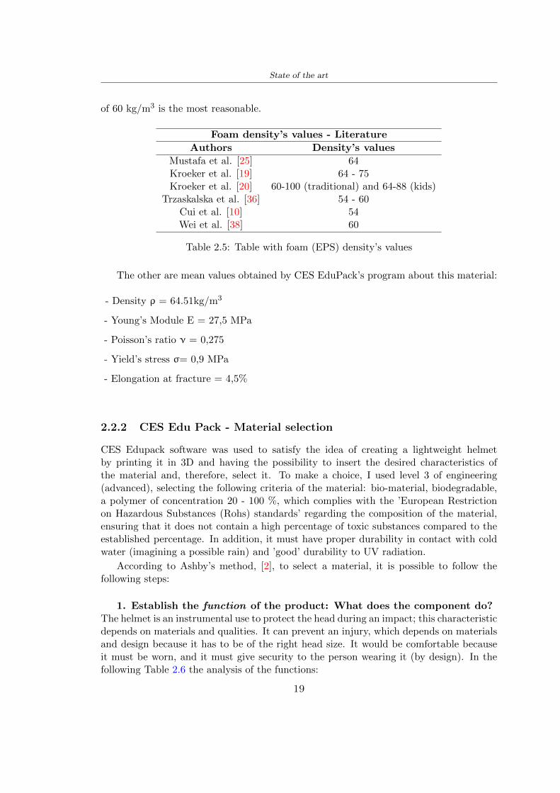
State of the art
of 60 kgm3 is the most reasonable
Foam densityrsquos values - Literature
Authors Densityrsquos values
Mustafa et al [25] 64Kroeker et al [19] 64 - 75Kroeker et al [20] 60-100 (traditional) and 64-88 (kids)
Trzaskalska et al [36] 54 - 60Cui et al [10] 54Wei et al [38] 60
Table 25 Table with foam (EPS) densityrsquos values
The other are mean values obtained by CES EduPackrsquos program about this material
- Density ρ = 6451kgm3
- Youngrsquos Module E = 275 MPa
- Poissonrsquos ratio ν = 0275
- Yieldrsquos stress σ= 09 MPa
- Elongation at fracture = 45
222 CES Edu Pack - Material selection
CES Edupack software was used to satisfy the idea of creating a lightweight helmetby printing it in 3D and having the possibility to insert the desired characteristics ofthe material and therefore select it To make a choice I used level 3 of engineering(advanced) selecting the following criteria of the material bio-material biodegradablea polymer of concentration 20 - 100 which complies with the rsquoEuropean Restrictionon Hazardous Substances (Rohs) standardsrsquo regarding the composition of the materialensuring that it does not contain a high percentage of toxic substances compared to theestablished percentage In addition it must have proper durability in contact with coldwater (imagining a possible rain) and rsquogoodrsquo durability to UV radiation
According to Ashbyrsquos method [2] to select a material it is possible to follow thefollowing steps
1 Establish the function of the product What does the component doThe helmet is an instrumental use to protect the head during an impact this characteristicdepends on materials and qualities It can prevent an injury which depends on materialsand design because it has to be of the right head size It would be comfortable becauseit must be worn and it must give security to the person wearing it (by design) In thefollowing Table 26 the analysis of the functions
19
State of the art
Ranking Function description Depends on
1 Head protection (energy absorbing) Material2 Head protection (energy absorbing) Design3 Head protection (injury prevention) Material4 Head protection (injury prevention) Design5 Comfortable Material6 Comfortable Process
Table 26 Ashbyrsquos method functions
2 The objectives that are targets for the design the material is to bemaximised or minimisedTo manufacture and market a product objectives such as minimizing weight cost orenvironmental impact must be considered In the following Table 27 the analysis of theobjectives
Ranking Title Objectives description
1 Mass Minimize The mass has to be thesame or lower
2 Cost Minimize everyone should have theopportunity to buy it
3 CO2 footprint Minimize CO2 emission
4 Corrosion Minimize high strength because itcan be in contact with the water
5 Pleasant to touch Maximize it is not a rough materialbecause it has to put on and put off
by hands
6 Refractive index Minimize it must not reflect light
Table 27 Ashbyrsquos method objectives
3 Definition of constrains What essential conditions must be meetEstablish constraints is essential to complete the function of the instrument Examplesof constrains are Table 28
4 The limits characteristic independent of the material that does not influencethe physical properties In the following Table 29 the analysis of the limits
20
State of the art
Title Loading case Constraintsdescription
Material index(Max-Min)
Stiffness Column in compression Tie in tension
Mass Min
Stiffness Column in compression Tie in tension
Cost Min
Stiffness Column in compression Tie in tension
CO2 Min
Strength Column in compression Tie in tension
Mass Min
Strength Column in compression Tie in tension
Cost Min
Strength Column in compression Tie in tension
CO2 Min
Table 28 Ashbyrsquos method constrains
223 PLA with natural fiber and PLA LW
Initially the best material that met the desired criteria was searched From this study itwas found that the material closest to having the required characteristics is the PLA 30natural fiber as shown in the Figure 27 which shows the graphs obtained relating tothe relationships between Youngrsquos Module and density the objective to reduce the massper unit of compressive stiffness and strength to reduce the CO2 footprint per unit ofstiffness and strength and mass per unit of compressive strength
Performance index IR
The stiffness criterion has the following characteristics
m = A lowast L lowast ρ (21)
ε =σ
E=
FA
E(22)
A =F
ε lowast E(23)
21
State of the art
Ranking Title Function description
1 Biocompatibility It is the ability of a material the abilityof the material not to cause any local or
systemic adverse response in therecipient of the material
2 Biodegrability Biodegradable material do notbiodegradable under anaerobic conditions
3 Biomaterials - all The terms is used for biological naturalbio-derived bio-inspired material
4 RoHS (EU) Compliantgrades
Restriction of the use of certin prohibitessubstances (mercury cadmium
hexavalent chromium)
5 Polymer 20-100 (from the table with Plasticpolymers)
6 UV Resistance at UV sunlight
Table 29 Ashbyrsquos method limits
A =F lowast L lowast ρε lowast E
(24)
With fixed variables- F (the load) L (the length)With variables that depend on the material- E (Youngrsquos Module) ρ (density)
In general when a chart is created the distribution of the mass is represented in thefollowing modality like in Figure 27 [b] where the materials above the line have a lowermass while those below a greater mass
Following the results of the CES Edupack program that had selected the PLA withnatural fibers as the best the first print of the helmet was made with this materialusing as support the PVA Initially the result seemed satisfactory the helmet had a highdefinition but a fundamental problem was found by reducing the helmet in the water toallow the supports of PVA to dissolve In the act of diving in fact after ten minutessome parts of the helmet especially the front and rear have disintegrated making thehelmet unusable Because of this problem it was necessary to change the material
22
State of the art
[a]
[b]
Figure 27 CES EduPack Mass per unit of compressive stiffness [a] Youngrsquos Moduleand density [b]
Further investigations carried out by the Mondragon Unibertsitatea Additive Man-ufacturing Department revealed a new material the PLA Low Weight which during3D printing allows to obtain a weight of 65 lower than that which could be obtainedfrom the classic PLA as reported in the technical sheet of the filament produced by thecompany Colorfabb [7]
The investigation team of the Composite Department carried out tensile tests withsamples 3D printed at different temperatures as suggested by the manufacturer to obtainthe technical characteristics The temperatures examined are 200 220 250 260The datasheet shows the density can have values between 04 - 124 gcm3 the bed has
23
State of the art
to have a temperature between 50 - 60 the printing speed has to have values between40 - 80 mms This typology of PLA is expandible so much that rdquoAt around 230 thismaterial will start foaming increasing its volume by nearly three timesrdquo [7]
T[C] Section [mm2] Volumen [mm3] Mass [g] ρ[kgm3] E [Nmm2]
200 42235 1030117 12 1165 328807
220 43805 1655821 18 1087 265795
250 52412 1948139 17 873 178058
260 59655 1454377 12 825 117047
Table 210 Values about PLA LW tensile tests of MU Additive ManufacturingDepartment
From the tests that have been carried out on the material at different temperaturesthe printed sample is better at 250 with a volume of 1948139 mm3 and a section of52412 mm2 as shown in Table 210 For this reason the specific of the material thathave been taken into consideration are the following
- Density ρ = 873 kgm3
- Youngrsquos Module E = 1750 MPa
- Poissonrsquos ratio ν = 033
- Yieldrsquos stress σ = 2948 MPa
- Elongation at fracture = 491
23 Bio-inspired structures
When we talk about bio-inspired structures to nature we refer to structures that allowobtaining a low weight for the model that is realized and excellent absorption energy dur-ing the impact Recently the structures that have been most used in the biomimetic fieldare the rdquocolumns structures sandwich structures plates honeycomb and foamsrdquo[26]but aiming to achieve a structure increasingly with high absorption energy new struc-tures derived from plants and animals such as beetle horsetail turtle bird beak havebeen analyzed The first to create multi-cells tubes helicoidal structures the second tomulti-corner tubes [26]
The authors analyze the specific energy absorbed (SEA) by bio-inspired sandwichstructures per unit mass which can be derived from the following equation
EA(d) =
int dmax
0F (x)dx (25)
SEA(d) =EA(d)
m(26)
24
State of the art
Where EA is the energy absorption rdquomainly used to evaluate an energy absorberrsquosability to dissipate crushing energy through plastic deformationrdquo F(x) is the crashingforce dmax is the effective deformation distance [26]
What derived from their investigations is that having regard to a density of between0 and 1000 kgm3 the volumetric energy absorbed is higher for the beetle-inspired struc-tures than the others as shown in Figure 28 Based on this consideration it was chosento draw the helmet following this geometry
Figure 28 SEA of bio-inspired sandwich structures [26]
231 Beetle structure - Design of the model
To develop and increase lightweight high-strength and optimize bio-mimetic functionaland structural materials the trabecular structure of the beetle elytron is studied Thesingle structure is realized following the requirements cited by Zhang et al [39]
To realize the beetlersquos structure it is not enough to have information about the lengthof the side of the hexagon and the thickness but it is also necessary to take into accountthe relationship between the diameter of the circumferences present on the vertices ofthe hexagon and the measurement of the side The representation of a single cell is inFigure 29 It is shown in [a] a general structure with an edge of 12 mm circumferencersquosdiameter of 6 mm and thickness of 16 mm in [b] is shown the height of 20 mm
For the construction of the helmet a thickness of 12 and 16 mm was used the imageconcerns a proportion between the length of the hexagon side and the diameter of the
25
State of the art
circumference The side (distance between the centers of two circumferences) is twice thediameter measurement
[a] [b]
Figure 29 Beetle structure
232 Specific stress - PLA LW and EPS foam
To test the beetle structures compression tests were investigated The PLA LW structurewas inserted in a rsquodiskrsquo with a diameter of 100 mm and a height of 20 mm The area andthe volume of the disk is correspondingly 7854 mm2 and 157 10 mm3 The structuresexamined have different dimensions the edge L (distance between two centers of thecircumferences) had the following measures 9 10 12 14 16 mm the thickness of thecircumferences and edges are respectively of 16 mm for every structure and 12 mm forthe structure with L = 16 mm
The test was carried out with the Hoytom HM-D Testing Machine with capacitiesbetween 5 and 100 kN The test models were subjected to displacement loading at a rateof 1 mmmin as referenced by Chen et al[18] with a cylindrical specimen The specificstress of the structures was compared with the specific stress of a generic EPS helmetthe photos about it are shown in Figure 210 The EPS helmet structure is granular withpores inside The different grains dimension and these pores can be the reason for whichthe Stressrsquos values are between two values 07 and 116 MPa
Four parts of the EPS helmet were considered in the test the dimension and relativecharacteristic are in the Table 211 where m = mass A = area F = load ρ = densityR = stress Rρ = specific stress To calculate the values of stress about PLA structuresand EPS foam compression test graphs were been analyzed The stress value for eachstructure was calculated considering the single load the single area and the averagedensity value (14055 [kgm3])
The stress values of the PLA structures (Figure 211) and other characteristic valuesare in Table 212 where m = mass A = area F = load ρ = density
26
State of the art
[a] [b]
[c] [d]
Figure 210 EPS generic helmet helmet pictures [a] [b] and internal structureExternal granular structure [c] and pores [d]
[a] [b] [c]
Figure 211 PLA LW disks Grasshopper structure [a] PLA LW structure of 14 mm[b] PLA LW structure compressed [c]
27
State of the art
The results of the load-displacement graphs are affected by the geometry of the diskthe target is to valid for any shape or size for this is preferred to realize a diagramthat depends from σ (or stress) and the deformation ε (or strain) which can be definedrespectively as
σ =F
A0(27)
ε =l minus l0l
(28)
where F is the load during the test A0 is the area l0 is the initial length and l is thelength when the load is applied The areas considered for the EPS cube is reported inTable 211 in the second column the areas of the PLA structure is 7854 mm2 like thearea of the circumscribed disk
The values compared are shown in Table 213 and the graphs obtained by Matlabcode to analyze the recorded data of the compression machine are in Figure 213 and inFigure 212
Considering that the data provided by the compression machine are subject to noiseand disturbances it was decided to convert the original curve into polynomial type curvesthat allow obtaining the best interpolating curve for the data in question To obtain themit was divided the recorded data into two groups the first part from 0 until the end ofthe linear part and the second when the curve becomes linear again The best-fitting (inthe least-squares sense) was performed using the polyfit and polyval functions of MatlabThe first returns the coefficients of the p(x) with n degree the second evaluates p(x) ateach point in x The polynomial formula p(x) is shown in the Equation 29
pn(x) = anxn + anminus1x
nminus1 + + a2x2 + a1x+ a0 (29)
where a0 an are constants and x is the indeterminate The choice of the degree ofthe polynomial was made based on the criterion of wanting to obtain linear curves thatrespected the elastic trend at the beginning of the graph For this reason the degree ofthe polynomial is 1 Subsequently I searched through the intersection of the two lines forthe point that is equivalent to the maximum stress that marks the end of linearity
This value for EPS and PLA LW is the R [MPa] in the Table 213 The average stressvalue for PLA LW is 139 MPa and for EPS is 094 MPa The specific stress (Rρ) is 18MPa lowast m3)kg for the EPS found in CES 669 MPa lowast m3)kg for the EPS foam of thegeneric helmet and for PLA LW is 1161 MPa lowastm3)kg an intermediate value betweenthe two which is what we wanted to achieve
28
State of the art
m [g] A [mm2] F [N] ρ [kgm3]
EPS (CES) 50
16 9234 1063 13864
18 879 593 13651
21 858 833 14237
24 864 564 14468
Average value 14055
Table 211 Compression stress generic EPS helmet
L [mm] t [mm] m [g] F [N] ρ [kgm3]
9 16 214 7250 1363
10 16 192 5560 12467
12 16 201 8190 13051
14 12 138 8000 8961
Average value 12027
Table 212 Compression test PLA structures
PLA LW structure EPS structureρ= 12027kgm3 ρ= 14055kgm3
Edge [mm] R [MPa] Rρ103 Number R [MPa] Rρ103
EPS (CES) 09 18
9 173 1269 1 116 824
10 139 1114 2 08 568
12 138 1057 3 105 746
14 108 1205 4 077 540
Average value 139 1161 094 669
Table 213 Specific stress calculus PLA LW and EPS calculus ρ = density R = stressRρ [(MPa lowastm3)kg] = specific stress
29
State of the art
Figure 212 Compression test Stress-Strain diagrams - EPS
Figure 213 Compression test Stress-Strain diagrams - PLA LW
30
Chapter 3
Methodology
31 3D scan
311 3D Sense 2 scanner and Meshmixer - Reverse reconstruction
Standardized measures were not taken into account for making the helmet but the sizewas obtained through a 3D scan of my head
The scanner used is 3D Sense 2 by 3D Systems which has a minimum scanningvolume of 20 x 20 x 20 cm and a maximum scanning volume of 300 x 300 x 300 cmTo scan my person I was helped to get a full view at 360 at an appropriate distanceReal-time visualization of the captured images was shown through 3D Sense softwareThe idea of scanning the head with the scanner refers to the methodology used by Wanget al [30] They used a reverse reconstruction functional for me to realize the helmetsurface made to measure my head and like them a silicone pool cap was used to makescanning as smooth as possible The authors claim the head scan rdquocan also be used toobtain information about the objectrsquos surface which is then reconstructed utilizing thecomputerrsquos three-dimensional model via reverse modelling softwarerdquo [30] that in my caseis Autodesk Meshmixer
The files it was could get from the scan were stl obj and ply format they wereexported to obj to work in the next step with Autodesk Meshmixer that allowed tomodify and homogenize the 3D image obtained from the scan
In Meshmixer through the selection and delete commands the superfluous parts weredeleted that had been acquired and with the inspector and the DrawDraw2 commandsthe vertices were moved locally along a pre-defined direction and with Smooth the surfacemore homogeneous was made The sequence of steps is shown in the Figure 31
312 3D scan analysis and extraction of features
In Chapter 2 the directives imposed by the BS EN 960 Standard were examined concern-ing the definition of the helmet and the measures to be respected in the field of visionand the part of the helmet was to carry out impact tests
In Figure 32 the features defined complying with the Standardrsquos rules are repre-sented To define these features the software NX was used The angle in the subfigure
31
Methodology
[a] [b] [c] [d]
Figure 31 Sequence of 3D head scan 3D scanner acquisition [a] scan after reparationwith Meshmixer [b] solid scan vision frontal and lateral [c] [d]
[b] is bigger than 105 (as defined by the Standard) while the degree in the subfigure [c]is 25 By defining the construction lines to be respected of the helmetit was necessary todraw the design of the surface not using the software NX but changing with Rhinocerosto create a SubD or SubDivision surface
32 Helmet design
321 Rhinoceros - Helmet surface
After realizing a rsquocleanrsquo Wang et al [30] subdivide with lines and then sectors the headto create the surface of the helmet They used the technique of NURBS a Non UniformRational Basis-Splines which mathematically models a 3D geometry while thanks tothe Rhinoceros 3D organic shapes was draw SubD surfaces These geometries allow tosplit the mesh into small polygons and consist of lines with which easily the shape ofthe object can be modified with a surface already created changing the position of aline automatically the remaining part of the geometry adapts to the changes With thistechnique the rsquosurface basersquo of the helmet was realized with the size of my head Therepresentation of the realized SubD is in Figure 33
322 Grasshopper - Helmet structure
The next idea is the creation on the surface of the beetle structure with different di-mensions modelling the helmet that is not a linear surface It was decided not to buildthe structure with a software CAD because to model an already complex structure on acurved surface would mean to model a cell for a cell
To solve this obstacle a Rhinoceros plug-in was used Grasshopper GH idealized byRobert McNeel and associates creators of Rhinoceros Using GH does not mean drawinggeometries by connecting points and drawing tools because it is based on algorithmicmodelling used in architecture and engineering for 3D modelling
The modelling takes place through a node diagram that the software will convert intoa code-algorithm in GH it is possible to define the variables and parameters and inRhinoceros in real-time it is possible to view the object GH allows for varying the
32
Methodology
[a] [b]
[c]
Figure 32 Featurersquos extraction in [a] is represented the impact line in [b] and [c] twoprospective about the definition of the field of vision
[a] [b] [c]
Figure 33 SubD representation lateral view [a] top view [b] front view [c]
geometry to your liking by varying a simple parameter of the diagram as everything willbe remodelled according to the change made
In the following Figure 34 it is shown an example of a structure that was used fordistinct subgroups of helmet areas The idea was to insert smaller cells in the frontal andlateral zone and larger ones in the upper area In the first image [a] is shown the part of
33
Methodology
the helpful diagram to create the beetle structure to establish the size of the cells andthe extrusion the second image [b] contains the part of the diagram with which I appliedthe structure previously created to the SubD
The structure used to place and adapt the beetle structure to the surface is theSrfMorph while the yellow rsquowindowrsquo that contains numbers serves to select the parts ofthe surface where to apply the geometry created In accord with the GH diagram in
[a]
[b]
Figure 34 Grasshopper diagrams
Figure 34 [a] it is possible to see the steps executed to realize the structure Initially inthe xy-plane a hexagonal grid was drawn through the Hexgrid command in which youcan input the length of the hexagon edge and the number of grid elements (selected bytrial) Then the circumferences was drawn in proportion to the hexagon dimensions asspecified in the Chapter 2 and shown in Figure 35 [a] In figure [b] the rsquocutrsquo made atthe circumferences is visible this subdivision was necessary for printing purposes In thelast photo [c] the structure highlighted in green in [b] was extruded setting a distance
34
Methodology
of 20 mm
[a] [b] [c]
Figure 35 Construction sequence of the geometry of the helmet
In the diagram in Figure 34 [b] there is the application of the structure created bi-dimensionally to the SubD surface of the helmet visible by unlocking the SubD commandof the diagram and in Figure 36 [a] Upper this the referential geometry of the group ofsurfaces was superimposed where it was to be applied the newly created structure (visiblein darker red) the SubD indices are in the yellow box of the diagram
Through the SrfMorph command the location of the structure was granted In Figure36 [b] at the darkest red of the figure [a] with the above command it was possible toplace the structure
[a] [b]
Figure 36 Application of the geometry created to the helmet surface
Overall the diagrams with specific structures are five one for the front two equal forthe side parts one for the top shown in the previous Figure 36 and one for the back
The hexagons in the structure have a dimension varying between 8 mm and 14 mmof side the largest is found at the top later at the back in the sides and the smallest atthe front In Figure 36 [b] the presence of not only hexagonal structures is visible Thegeometry used does not allow the homogeneous arrangement on the entire surface andrequires different structures Automatically the choice of GH to optimize the structurewas to insert quadrilateral
As described above the helmet has different dimensions of the structure divided asvisible in Figure 36 in a quadrilateral This causes a discontinuity between zones withdifferent sizes due to the geometry of the construction
To eliminate this problem and realize the design homogeneous grids were inserted
35
Methodology
in the affected areas as shown in Figure 37 This insertion however proved to beinteresting and strategic researching in this regard studies were realized to demonstratethe insertion of a rectangular grid inside the hexagon grid was helpful for the transmissionof stress in the structure As cited by Sun et al [40] rdquothe mechanical properties of thesesandwich structures are often limited by local failures such as face-core debonding or corecollapserdquo Carrying out compression tests have effectively demonstrated that the insertionof the grid allows rdquoprovided increased stiffness specific stiffness energy absorption andcritical loadrdquo [41] As shown in the graphic [c] of the Figure 37 the honeycomb structuregives a force of 7 kN while with a grid the value is 11 kN and with the combinationexceeds 22 kN In addition in the left front a plaque to customize the helmet wasprepared Figure 37 [a]
[a] [b]
[c]
Figure 37 Grid in the helmet [a] hybrid structure with hexagons and grid [b] [40]compression test results of the hybrid structure [c] [41]
33 3D Print
After having achieved the CAD (Computer Aided Design) of the helmet in order tobe printed it must be converted and saved in format STL (Standard TriangulationLanguage) - Binary compatible with the printing machine and useful for transformingsolid object surfaces into triangles The steps to be taken are the following
bull CAD file realization
bull CAD export in format STL to Simplify 3D the software that shows slider layersand then- rotate and position the object according to geometry and the positioning of any
36
Methodology
supports- setting printing parameters- item manual andor automatic positioning of supports- slider display layers
bull import file gcode to printer
331 Printer and parameters
The program used to visualize how the helmet slices layers before sending it to the printerand to set the parameters is as anticipated Simplify 3D
To make the printing not being a flat geometry it is necessary to place the supportsThe idea was to use water-based supports that the helmet would automatically dissolveonce placed in the water After testing different types of water-soluble PVA the choicefell on eSun 3D Printing Filament PVA (water-soluble support) Before choosing theoptimal position for printing several tests were carried out and to decrease the numberof the supports significantly and allows an optimal printing of the outer part an emptyrsquospherersquo that self-sustains below the helmet was placed as shown in Figure 38
In the image [a] you can see the first print position tried with which an external partof the helmet very damaged was obtained because of the contact supports-helmet In [b]the empty rsquospherersquo is shown to optimize the number of supports and in the last photo [c]there is the full version at the end of print
[a] [b] [c]
Figure 38 Printing supports
The printer that has been used for printing is the Raise 3D Pro2 with double extrudersand nozzles of variable size from 02 mm to 1 mm after some test prints with the PLALW and the structure in created the size that allowed me to have a good compromisebetween printing time and accuracy was 06 mm Using 04 mm the printing time wasexcessive even if having the smaller nozzle diameter means having more precision withthe 08 mm nozzle the quality of the structure was not excellent as seen in Figure 38[a]
Another factor that had to be taken into account is the characteristic of the PLA-LWto expand As the printing temperature and the printer used vary the expansion andcharacteristics of the material change The use of the 06 mm nozzle associated with
37
Methodology
Parameter Left extruder Right extruder
01cm Material 01cm PVA 01cm PLA LW
Extruder toolbox index Tool 0 Tool 1
Nozzle diameter 06 mm 06 mm
Extrusion multiplier 1 05
Extrusion width Auto (072 mm) 05 mm
Layer x
Infill Rectilinear - 50
Supports (Automatic and not) Infill 50
Temperature 210 250
General parameters
Primary layer height 03 mm Top solid layer 4
Bottom solid layer 2 Outline 2
Heated bad 60 Speed 40 mms
Table 31 Printing parameters
Raise 3D allowed me to get good results The choice of this printer was not random ithas in fact the characteristic of making extremely precise prints The Raise has accuracyin placing the object on the printing bed of 078 microns on the xy axis and a resolutionfor layers of 001 mm
The final version of the helmet is visible in Figure 39 and it is possible to compare itwith the preview version in Rhinoceros in Figure 310
38
Methodology
[a] [b]
[c]
Figure 39 Views of the helmet
[a] [b]
Figure 310 Views of the helmet (GH version)
39
Chapter 4
Experimental evaluation
41 Experimental tests
411 Drop-weight impact test machine
In order to calculate the contact force peak and the difference of energy absorbed duringthe impact between the reference helmet and helmet with the beetle structure in PLA-LW dynamic impact tests were carried out using the Fractovis Plus an impact testmachine
In this way it is possible to monitor the evolution of the above variables from theinitial to the final instant of the impact The machine can withstand a load with a rangevariable from 2 to 70 kg with a maximum speed of 46 ms and a maximum height of1 m The values chosen for the test are the following 5 kg weight maximum speed andmaximum height The Anvil that was used is a disc diameter of 60 mm
As shown in Figure 41 and explained by Crupi et al [37] the machine consists ofa sensor capable of recording the speed before impact the impactor that can have avariable mass (a weight of 5 kg in my test) a system to guarantee that there are nomultiple impacts after the first and that work as a shock absorber and clamping systemwhere the object to be tested is placed
The tests that have been carried out are in total four two related to the helmetoptimized with PLA-LW and two with two generic helmets of different brand in EPS
42 PLA LW helmet
To perform the dynamic test on the helmet of PLA considering the difficulty of printingit was helpful to use a test helmet with imperfections to understand where the impactwas concentrated in a single part or distributed The images of Figure 42 show a helmetwith not well defined edges and inaccurate print but exactly localizes the impact zoneThanks to this test it was possible to take into account only one helmet area shown inFigure 43 to have the exact curve of the structure bio-inspired with PLA-LW
40
Experimental evaluation
Figure 41 Drop-weight impact test machine [37]
[a] [b]
Figure 42 Test 1 PLA-LW helmet
43 EPS helmet
To carry out dynamic tests and extract the technical characteristics of the helmettwohelmets were bought in a sports store both EPS and being on the market both certifiedThe brands of the two helmets are DTB and VAN|RYSEL and the average weight ofthe two is 223 g Two different helmets have been chosen to have a more certain andclear classification of the characteristics They are shown in Figure 44 and Figure 45
41
Experimental evaluation
[a] [b]
Figure 43 Test 2 PLA-LW helmet
[a] [b] [c]
Figure 44 Test 3 EPS helmet
[a] [b] [c]
Figure 45 Test 4 EPS helmet
44 Results
441 First results - PLA-LW and EPS helmet
Figure 46 shows two types of trends related to the two different models of the helmetThe force evaluated for PLA-LW has higher force peaks but is more concentrated and
42
Experimental evaluation
propagates less than EPS The graph shows the peaks of each curve highlighted with a redcircle In tests 1 and 2 for the PLA-LW as mentioned earlier the values are higher about7301 N for the complete helmet and 3996 N for the portion of helmet This difference isdue to the inaccuracy of the first full helmet during the printing phase In Figure 42 itis visible the low homogeneity and precision Therefore the first test with full helmet wasused only to define the area of interest of the impact which turns out to be localized Forthe other two EPS curves the values are only slightly lower compared to the PLA-LWequal to 3620 N and 3295 N but the trend is much more distributed
Figure 46 Dynamic machine test - Force
With the data obtained from the impact machine it was possible calculate not exclu-sively the value of force but itrsquos also possible to view the energy curves A resume aboutthe values and energy of the force is in the following Table 41
Test Peak force [N] Peak energy [J]
Test 1 - PLA LW (inaccurate) 730130
Test 2 - PLA LW (portion of helmet) 399643
Test 3 - EPS (DTB helmet) 362007 509
Test 4 - EPS (VAN|RYSEL helmet) 329546 4198
Test 5 - PLA with TPU 45421 5022
Table 41 Energy absorbed in dynamic test
43
Experimental evaluation
442 PLA-LW helmet with TPU cover
As it is possible to see in Figure 47 and as highlighted the first tests concerning thebio-inspired structure and the PLA-LW are far from my expectations considering thelittle distribution of force in comparison with the EPS foam and consequently a smallamount of energy absorbed
Figure 47 Dynamic machine test - Energy
To improve this impact damping factor the idea was to create a cover for the helmetin flexible TPU trying to absorb impact energy The TPU used is a flexible material ofthe brand Ninjaflex used in sports by the application in helmets and shoes to cushionbumps during the game Generally in the helmets (baseball helmet for example) theTPU is inserted internally in contact with the head In my case the TPU structurein addition to creating a shock-absorbing and durable cover creates a custom cover thehelmet and for the person This cover was also made with the Raise 3D printer
As shown in the Figure 48 [a] the infill of the part in contact with the helmet hasa percentage of 100 the filling of the other part of the structure is not complete butonly 15 and the internal structure is hexagonal to recall that of the helmet The desireto insert a structure with a rsquoraisedrsquo geometry is for visual and aesthetic reasons as youhave the feeling of greater protection and not filled is inspired by the machine CitroenCaptus whose bumpers (Airbump) are full of air The failure to realize empty structuresis due to the need to place any internal supports not removable
The idea was to create a cover that allow you to see of the internal structure of thehelmet and that protect specific areas the front the two sides the top and the posteriorWhat which was thought for this reason was to create the shape of a flower with four
44
Experimental evaluation
petals Figure 48 [b]In this way to perform dynamic impact tests as shown in Figure 49 [a] the cover was
positioned at the top of the helmet and the impact was performed in the centre of thersquoflowerrsquo which corresponds to the higher upper part where the structure has larger cellsize The impact parameters are the same as those used in previous impacts 5 kg weightmaximum speed and maximum height The Anvil that was used is a disc diameter of60 mm In photo [b] it is evident the difference between the structure that received theimpact with protection (left) and without protection (right) Without protection duringthe impact there was a perforation of the structure with a concentration of force at a locallevel as you can see in the Figure 46 in the case of TPU the impactor did not perforateand crossed the structure thanks to the cover of TPU that cushioned the shock At themoment of impact the impactor bounced
[a] [b]
Figure 48 TPU cover
[a] [b]
Figure 49 PLA-LW with TPU - dynamic impact [a] and differences between thehelmet with TPU and without TPU cover [b]
45
Experimental evaluation
The Figure 410 includes the diagrams relative to the dynamic impacts In [a] thereare already analyzed EPS results in [b] a comparison between the test on the portionof helmet in PLA LW with and without the TPU cover in [c] the overall comparison ofcurves shows a much more similar EPS trend if the TPU is placed above the structure inPLA LW to soften the blow and absorb the same energy [d]
46
[a]
[c]
[d]
Figure 410 Comparison between PLA-LW with TPU and EPS
Chapter 5
FEM Validation
51 Impactor - Anvils definition
Before to start to work in Abaqus it was necessary to search in the literature the materialwith which the anvil was been realized Milne et al [23] established the densityrsquos valuethe Youngrsquos Module and Poissonrsquos ratio for the Flat and Kerbstone Anvil
- Density ρ = 7800 kgm3
- Youngrsquos Module E = 200000 MPa
- Poissonrsquos ratio ν = 03
Inserting the data in the CES EduPack program specifying the mechanical andphysical properties the material corresponding to these characteristics is Stainless steelaustenitic (ASTM F1586) medium-hard
Initially the proposal was to create a conservative system to evaluate the absorptionenergies values and apply this value to a vibration system but the helmet needs dampingto be realized it was impossible to use a system without losses in this modality Thisis why a numerical calculation was carried out by performing two types of simulationsexplicit dynamic step and static step
The idea to realize the theoretical impact is to regard the movement of the anviland not the helmetrsquos movement which is fixed The velocity is the same cited in thenormative EN 1078 542 ms for the Flat anvil and 457 ms for the Kerbstone anvil
In performing the simulations It was given more relevance and perform tests withthe Kerbstone Anvil This choice was done because the geometry with which it is beenrealized (following as defined in the legislation) allows the helmet to be more subjectedto stress this involves the definition of higher stress limits compared to the Flat Anvil
The mesh size that has been used is the same in the case of the simulation of thehelmet optimized in PLA-LW and the full helmet in EPS of 7 mm The impactor isconsidered as a Discrete rigid body with its specific Reference Point (RP) like shownin Figure 51 for this reason it is not a solid but it is composted only by shells Inthe same image [b] there is the FEM representation of the model and in Table 51 thecharacteristic of FEM with quadrilateral (R3D4) and triangular elements (R3D3)
48
FEM Validation
Object Elementnumber
Elements Shape Geometricorder
Global size[mm]
Kerbstone 230 Quadrilateral - R3D4 Linear 7
Kerbstone 8 Triangular - R3D3 Linear 7
Table 51 Mesh element - Kerbstone Anvil
[a] [b]
Figure 51 Kerbstone anvil in the simulation like discrete rigid body [a] and FEMelements [b]
511 PLA LW - Plastic characteristics
The PLA-LW as explained in the Chapter 2 is new material on the market and producedby the only Colorfabb company for this reason few tests have been carried out to defineits technical characteristics and through tensile tests of the 3D printed specimens it waspossible to define an elastic limit as reported in the Table 210
In the context of simulations to reproduce the impact and deformation of the helmetis also necessary to consider the plastic characteristics of the material Not possessingany reference value in this regard tests were performed through a Static Step initiallyand then an Explicit Dynamic Step in Abaqus
The structure chosen to consider as a reference it is one of the structures previouslysubjected to the compression test having the side L=14 mm As for the reproduction ofthe compression disks initially they were reproduced according to the geometry of theHoytom HM-D Testing Machine considering the bodies mentioned above as discrete 3Drigid discrete The measure was the diameter of 200 mm and the height of 20 mm
After an initial analysis it was observed that the computational time of the simulationprogram was very high so it was decided to change the geometry to have a rsquodisk-surfacesrsquo(equally 3D rigid-discrete) which allowed me to have a smaller number of nodes for themesh and consequently a better computational time The representation of the opti-mized structure in PLA-LW and the disks used for simulated compression is in Figure 52
49
FEM Validation
[a] [b]
Figure 52 Representation of the samples used for the simulation of the compressiontest In Figure [a] the disks of the Hoytom HM-D Testing Machine in figure [b] the
representation of the same as simple surfaces
As shown in Figure 52 the disks are considered 3D discrete hard bodies so it waschosen for both a point the reference point RP where to apply the characteristics relatedto the two bodies As for the compression test it was established
bull the movement of a disk and fixed the second through a boundary condition impos-ing an Encastre therefore unable to move and rotate in xyz directions
bull for the opposite disk the boundary condition relative to the 15 mm displacementwas applied which is the parameter that it was observed to determine the end ofthe compression with the machine This shift is shown by the orange arrow in figure[b]
bull between the upper surface and the disk e the disk with the lower surface it wasinitialized a general contact with normal behaviour through rsquohardrsquo contact andtangential behaviour with a coefficient of friction of 02 with directionality imposedon rsquoisotropicrsquo
The next step was to define the mesh of the components whose parameters are shown inTable 52 while the representation of the FEM is in Figure 53 with the representationof the simulation and real compression test
Object Elementsnumber
Typology Geometricorder
Globalsize [mm]
Disk (14mm) 80910 hexaedral - C3D8R Linear 07
Impact disks 206 quadrilateral - R3D4 Linear 20
Impact disks 6 triangular - R3D3 Linear 20
Table 52 Mesh element - Compression test simulation
As previously announced a static simulation was initially performed with a StaticStep with Step Time equal to 900 (obtained going to consider the speed of 1 mmmin of
50
FEM Validation
[a]
[b] [c]
Figure 53 FEM representation [a] and compression test simulation [b] and realcompression [c]
the compression test and the displacement of 15 mm) However the complex geometryof the structure and the high time set by Step Time did not allow a correct definitionof the parameters of the plastic characteristics of the material the simulation was notable to continue once reached a Step Time of approximately 220 That is why it waschanged by choosing an Explicit Dynamic step
Leaving all the parameters of the boundary conditions unchanged the Step Time wasmodified imposing it to 001 The ability of the explicit dynamic to work with non-linearand contacting structures allowed me to achieve results The results obtained are shownin Figure 54 with the blue curve and were obtained through the iteration of differentPlastic Strain and Yield Stress values in Abaqus while the red line is the result of thereal compression test a similar curve trend was obtained but it is not possible to obtainthe same curve taking into account problems of printing inaccuracy
512 First test - helmet
The initial idea was to perform a simulation imposing the speed of 457 ms to theimpactor tie the helmet in EPS and PLA and compare the absorbed energies Theproblem it was encountered is related to the mesh of the helmet optimized in PLA andwith minimum dimensions of the elements and distinct elements it was not able to solveit
51
FEM Validation
[a]
YieldStress
PlasticStrain
1 47 0
2 7 001
3 75 005
4 10 01
5 108 1
6 115 15
7 12 2
[b]
Figure 54 Representation of the two curves related to the simulation in Abaqus of thecompression test and the data obtained from the real test to obtain the plastic
characteristics of the material
513 Second test - plane
The first solution is the one shown in Figure 55 To realize the simulation it was realizeda section of the helmet to involve a smaller number of elements and nodes Again thesimulation for the EPS helmet was successful while the simulation with the bio-inspiredstructure was interrupted by excessive distortion of elements
The previous images show the impact is very localized in the impacted area and theidea to achieve a complete simulation is not to consider a curved portion of the helmetbut a plane In this way it was possible to solve the problem and obtain a completesimulation for the bio-inspired structure
FEM element
Below in Table 53 there is the definition of the elements used for the PLA-LW and EPSplane in the simulation to simulate the impact and to control the energy-absorbing whilethe anvil characteristics are described in Table 51
514 EPS impact simulations
In order to proceed with the simulation it was imposed some boundary conditions thatregard ties and forces
bull the movement of the plane is fixed through an Encastre therefore unable to moveand rotate in xyz directions
52
FEM Validation
[a]
[b]
Figure 55 Impact simulation parts of EPS and PLA helmet
Object Elementnumber
Elements Shape Geometricorder
Plane (PLA) 38896 Tetrahedral -C3D10M
Quadratic
Plane (EPS) 2100 Hexahedral - C3D8R Linear
Table 53 Mesh element - plane impact
bull to create the impact it was set a speed of 457 ms at the reference point RP of therigid body which is the impactor Kerbstone Anvil shown in Figure 56
bull between the upper surface of the plane and the impactor it was initialized a Sur-face to Surface contact with normal behaviour through rsquohardrsquo contact and tangen-tial behaviour with a coefficient of friction of 02 with directionality imposed onrsquoisotropicrsquo
bull the rotation in x y z relative to the RP of the rigid discrete impactor body is locked
53
FEM Validation
In addition it was characterized the plane in the part of the materials with the char-acteristic values of the EPS mentioned in Chapter 221 The Von Mises Stress valueapparently low is relative to the Yield Stress of the EPS material equal to 09 MPa
Figure 56 EPS Boundary conditions and Load
515 PLA LW impact simulations
As also required in the case of the EPS plane in order to proceed with the simulationsome boundary conditions were imposed that regard ties and forces
bull the movement of the plane is fixed through an Encastre therefore unable to moveand rotate in xyz directions
bull to create the impact a speed of 457 ms was set at the reference point RP of therigid body which is the impactor Kerbstone Anvil shown in Figure 58
bull between the upper surface of the plane and the impactor it was initialized a Sur-face to Surface contact with normal behaviour through rsquohardrsquo contact and tangen-tial behaviour with a coefficient of friction of 02 with directionality imposed onrsquoisotropicrsquo
bull the rotation in x y z relative to the RP of the rigid discrete impactor body is locked
In addition the plane was characterized in the part of the materials with the characteristicvalues of the PLA mentioned in the Chapter 223 and 511
Figure 58 Boundary conditions and Load
54
FEM Validation
[a]
[b]
Figure 57 EPS impact simulation
52 Results
In Figures 59 and 57 it is shown how the structure in PLA LW has a more concentratedstress distribution of the structure unlike EPS The maximum value for the Von Misesstress is 09 MPa in EPS structure and 3634 MPa in PLA LW structure Once thesimulations were obtained the next step was to go and compare the energies absorbed bythe two structures The energy calculated by Abaqus that has been taken into account isPlastic Dissipation To make a comparison the data of the two energies were representedin a single graph
What emerges from the graph is that about the impact made with the KerbstoneAnvil the energy absorption is more excellent although only slightly for the PLA LWthan for the EPS From the graph in Figure 510 a value of 41 J is shown for the EPSand 51 J for the PLA LW
55
[a]
[b]
Figure 59 PLA impact simulation
[a]
Figure 510 EPS and PLA LW energy comparison - Abaqus simulation
Chapter 6
Head Injury Data
For the statistical analysis the injuries related to the accident data were categorised intothe following types and levels based on the details of the medical report [11] about theEN 1078
bull Head Injury Criterion (HIC)
bull Peak Linear Acceleration (PLAc)
bull Gadd Severity Injury (GSI)
bull Diffuse axonal injuries (DAI)
61 Abaqus simulation
Until now the purpose of the simulations has been to determine which between the twomaterials and the two structures of EPS and PLA LW could absorb more energy duringthe impact but no simulations have been carried out in compliance with BS EN 1078on the helmet impact tests To calculate the injuries listed in the previous paragraphhowever we need the acceleration values in the three directions related to the subjectrsquoshead
To realize it the scan of my head already rsquocleanrsquo was considered of which it has beencalculated the inertia thanks to the automatic SolidWorks calculation and evaluated theweight with the Table 24 the structure of the helmet was placed for the EPS and thePLA LW over the head as shown in Figure 61 Also this time being able to mesh theentire helmet in PLA LW was impossible due to the excessive distortion of some elementsduring the simulation so it has been tried to make a section of the structures of thehelmet and results were obtained
57
Head Injury Data
[a] [b]
Figure 61 My scan head - CAD [a] head imported in Abaqus[b]
Initially the simulation had these characteristics as shown in the following Figure62 considering the helmet was not sectioned As explained earlier it was not possibleto get to simulation in the case of the optimized structure in PLA LW for this reasononly a part of the helmet was considered in both cases shown in Figure 63
[a]
Figure 62 Simulation based on BS EN 1078
58
Head Injury Data
[a] [b]
Figure 63 Simulation based on BS EN 1078 with head
In order to proceed with the simulation some boundary conditions that regard tiesand forces have have imposed
bull two reference points RP were created the first in the inertia centre of the headthe second relating to the Kerbstone Anvil which is a discrete rigid body
bull in the reference point RP of the head in the definition of the engineering features5 kg was inserted for the weight and an inertia I11 = 564464E+07 gmm2 I22 =460654E+07gmm2 I33 = 187302E+07gmm2
bull to simulate the impact it was set a speed of 457 ms at the reference point RP ofthe head in z-axis direction
bull a general contact with normal behaviour through rsquohardrsquo contact and tangentialbehaviour with a coefficient of friction of 02
bull between the upper surface of the helmet and the impactor it has been initializeda Surface to Surface contact with normal behaviour through rsquohardrsquo contact andtangential behaviour with a coefficient of friction of 02 with directionality imposedon rsquoisotropicrsquo
bull the movement between the Kerbstone anvil and the helmet is fixed through anEncastre therefore unable to move and rotate in xyz directions
bull the rotation in x y z relative to the RP of the rigid discrete impactor body is locked
FEM element
As reported in Table 53 the portion of the helmet in EPS has used a mesh with hexahe-dral elements of linear order For the structure (beetle) of PLA LW given the geometry
59
Head Injury Data
complexity it was necessary to use a quadratic order of tetrahedra For the mesh of thehead instead in both simulations have been used quadrilateral elements of linear orderas reported in the Tables 61 and 62
Object Elementnumber
Elements Shape Geometricorder
Head 3755 Quadrilateral - R3D4 Linear
Head 34542 Quadrilateral - R3D3 Linear
Helmet (PLA) 272302 Tetrahedral -C3D10M
Quadratic
Table 61 Mesh element - Head simulation with PLA LW (beetle) helmet
Object Elementnumber
Elements Shape Geometricorder
Head 3755 Quadrilateral - R3D4 Linear
Head 34542 Quadrilateral - R3D3 Linear
Helmet (EPS) 72280 Hexahedral - C3D8R Linear
Table 62 Mesh element - Head simulation with EPS helmet
62 Results
Figure 64 represents the simulation in line with BS EN 1078 concerning the helmet inEPS [a] and the helmet with bio-inspired structure in PLA LW For both simulationsVan Misesrsquo stress has Yield Stress values in the case of EPS which is 09 MPa and theplastic behaviour combination of PLA LW [b]
In the case of head and Kerbstone Anvil stress was not assessed as they were previ-ously defined as discrete rigid bodies
63 Head Injury Criterion
The HIC quantifies head impact severity by incorporating time of acceleration exposureand acceleration magnitude it is calculated in post-processing phase with the followingEquation 61
HIC15 =
[1
(t1 minus t2)
int t2
t1
a(t)dt
]25(t2 minus t1) (61)
60
Head Injury Data
[a]
[b]
Figure 64 Results simulation based on BS EN 1078 with sectioned head
For this analysis a(t) is the acceleration calculated in the centre of mass of the head(corresponding to the reference point RP) expressed in g and the time interval (t2 minus t1)was chosen to maximize HIC over a maximum duration of 15 ms
Matlab and the trapz function were used to calculate the HIC to integrate accelerationover time t2 and t1 were considered initial and final times of the simulation t1 = 0 sand t2 = 10 s time less than 15 s
HIC value of 198 was obtained for EPS and 87 for PLA LW Considering the Hayeset al [16] document about the HIC values and the graph in Figure 65 developed bythe author it is possible to find the percentages related to the different injury AIS1 -AIS6 which correspond respectively to lower and higher severity while in Figure 66 therelative fatality to every value of AIS is shown The values obtained for the HIC andother criteria are shown in Table 63 The HIC value for EPS is 198 for PLA LW it is
61
Head Injury Data
Figure 65 Head injury risk curves based on HIC values [16]
Figure 66 The abbreviated injury score versus fatality rate [16]
87 Analyzing the data and comparing them with the curves of the Figure 65 I obtain
bull a percentage between 20 - 30 of AIS 1 for EPS 10 - 20 for PLA LW
bull a percentage between 10 - 20 of AIS 2 for EPS and 0 - 10 for PLA LW
bull for AIS 3 AIS 4 AIS 5 AIS 6 the percentages for both structures is between 0 -10
Comparing these percentages with the fatality rate of Figure 66 it is clear there is a riskof Moderate and Minor fatality in the case of EPS and PLA LW as all values are between0 and 30
62
Head Injury Data
HIC PLA [g] GSI E [J]
EPS 198 97 361 37723
PLA LW 87 75 169 44102
Table 63 Head Injury Data - values
64 Peak Linear Acceleration
The resultant linear acceleration versus time curve was calculated according to Equation62
γ(t) =radicγ2x(t) + γ2y(t) + γ2z (t) (62)
where
bull γ(t) is the resultant linear acceleration (g)
bull γx(t) is the linear acceleration in x axes (g)
bull γy(t) is the linear acceleration in y axes (g)
bull γz(t)is the linear acceleration in z axes (g)
The value of the impact should never exceed 250g [9] Cripton at all [9] in their studyexamined a helmet with expanded polystyrene (EPS) Figure 68 shows maximum HIC forhelmeted and unhelmeted drops from all heights For each drop height helmets reducedHIC relative to unhelmeted drops IARV value is 180g The acceleration in the two casesis shown in Figure 67 and the maximum values are 97g for EPS and 75g for PLA LWas reported in Table 63 The two values considering a maximum value calculated byCripton [9] of 180g are amply optimal and comply with the standard of 250g
65 Gadd Severity Index
Gadd proposed the Severity Index Criteria shown in Equation 63 Following this crite-rion the GSI values that are over 1000 produce serious internal head injury [33]
GSI =
int t1
0a(t)25dt (63)
Where
bull a is the linear acceleration (g)
bull t is the duration of the impact (s)
I calculated the GSI with the function trapz between 0 and t and the resulting valuesare 361 for the EPS and 169 for the PLA LW which comply with the limit
63
Head Injury Data
Figure 67 Peak accelerations for both helmets
Figure 68 Peak accelerations for both helmeted and unhelmeted drops Numbers overbars indicate peak acceleration For 2 m drop height results stated are the mean value
calculated from three drops [9]
64
Head Injury Data
66 Diffuse Axonal Injury
DAI cases covered all incidences in which neurological injuries occurred as well as con-cussion unconsciousness and coma
In order to assess the risk of head trauma in terms of diffuse axonal injury (DAI)Milne et al [23] defined a model based head injury criteria as follows obtaining theresults in Figure 69
bull 50 risk of moderate neurological injury (DAI1+) Brain Von Mises shearing stressof 28 kPa
bull 50 risk of severe neurological injury (DAI2+) Brain Von Mises shearing stressof 53 kPa
[a]
[b]
Figure 69 Peak intra-cerebral shearing stress computed with the helmet model coupledto the human head model for all impact points (a) Flat anvil (b) Kerbstone anvil [23]
65
Head Injury Data
67 Energy absorbed
In Figure 52 during the impact test between the kerbstone Anvil and the plan with thebio-inspired structure in PLA LW and EPS it was found that the PLA LW althoughwith a small difference of 10 J absorbed more energy in comparison with the EPS Whenthe test is carried out in compliance with BS EN 1078 and the head with a speed of 457ms (corresponding to the kerbstone Anvil) as shown in Figure 610 also in this casethe PLA LW with the optimized helmet structure manages to absorb more energy (evenif the difference is very low) compared to the EPS The maximum energy value in PLALW is 44102 J of EPS is 37723 J
Figure 610 Energy absorption - BS EN 1078
66
Chapter 7
Conclusion
71 Conclusion
In this thesis work a bicycle helmet with a bio-inspired structure in PLA LW and 3Dprinted was created The initial approach was to introduce an innovative aspect tostandard EPS helmets not using foam but a polymer with new geometries able toabsorb much energy during the impact For this reason the beetle structure has beenpreferred relying solely on the hypothesis encountered in the literature of its quality inabsorbing energy
Combining the new material of the PLA LW and beetle structure has made possiblethe development of new material satisfactory characteristics have been obtained sincethe first tests The two materials were first subjected to tensile tests to determine theirspecific stress in these the PLA LW had positive results
Subsequent dynamic physical tests were carried out on 3D printed helmet models andon reference helmets in EPS to calculate the absorption energy in both cases at the timeof impact These resulted in energy absorption of the beetle structure in PLA LW withthe application of a TPU cover almost equal to that of EPS about 50J To validate withfinite element analysis the two models an explicit dynamic step was used in AbaqusSimulations showed that the PLA LW structure absorbs a higher amount of energy thanthe EPS the higher is 50 J and the EPS 40J
Finally positive results have also been obtained in calculating the head injury datasimulating according to BS EN 1078 with the use of impactor helmet and head Theacceleration values for both the structures were inferior to 220g precisely for the PLALW was 75g and for the EPS 97g The same applies to the calculation of HIC and GSI(maximum acceptable value of 1000) where the values are 87 and 169 in the case of PLALW and 361 and 198 in EPS For all tests therefore greater efficiency of the structure inPLA LW has been obtained Positive results also in the simulation of the energy absorbedduring the impact as the value referring to the EPS was 35J and that of the PLA LWwas 45J
67
Conclusion
72 Future work lines
The positive results obtained can be considered as a starting point for further tests andsimulations to ensure the safety of the helmet and compliance with the regulations butbefore getting improvements and continue testing changes are required
bull the beetle structure of the helmet made with GH adapts to the SubD withoutallowing to have a homogeneous distribution it would be appropriate to have moreregular hexagonal geometries
bull the mesh of the helmet is too complex and does not allow to perform the simulationprobably to use a more regular structure would have a mesh accordingly moreregular and the simulation would be successful
bull the uneven helmet structure has so many defects that the print is imperfect andthis can change the results of the impact tests the structure should be improved
bull the printing time varies from 4 to 5 days it should be improved
bull the TPU helmet cover is too big for the RAISE printing plan it is necessary togenerate a new geometry
bull the TPU cover it must be fixed on the helmet
bull in the calculation of the DAI it is necessary to have the definition of the brain andthe head should not be considered as a rigid body
bull in the injury calculation the helmet without protection was considered with theTPU cover the result will be better
bull air flow analysis
The comments mentioned are only considerations and problems that I gained duringmy thesis and which should be improved but I am sure that these changes and improve-ments from design to printing and simulations can make the helmet a good product
68
Bibliography
[1] K Adanty J M Clark A Post Thomas Blaine H and M D Gilchrist Comparingtwo proposed protocols to test the oblique response of cycling helmets to fall impactsInternational Journal of Crashworthiness 6648 ndash 663 2020
[2] MF Ashby YJM Brechetb D Cebona and L Salvoc Selection strategies formaterials and processes Materials and Design 2004
[3] M Aysha El casco de bicicleta voronoi impreso en 3d mas seguro y ligero https
www3dnativescomen3d-printed-bicycle-helmet-voronoi-190820204
[4] H Bikas P Stavropoulos and G Chryssolouris Additive manufacturing methodsand modelling approaches a critical review The International Journal of AdvancedManufacturing Technology 83389ndash405 2016
[5] British Standards BSI Helmets for pedal cyclists and for users of skateboards androller skates - BS EN 1078 2012
[6] British Standards BSI Headforms for use in the testing of protective helmets BSEN 960 2020
[7] ColorFabb Colorfabb lw-pla 2019 httpscolorfabbcommedia
datasheetstdscolorfabbTDS_E_ColorFabb_LW-PLApdf
[8] V G Coronado T Haileyesus J M Bell T A Cheng JHaarbauer-Krupa M RLionbarger J Flores-Herrera L C McGuire and J Gilchrist Trends in sports andrecreation-related traumatic brain injuries treated in us emergency departments thenational electronic injury surveillance system-all injury program (neiss-aip) 2001-2012 J Head Trauma Rehabil 30185ndash197 2015
[9] P A Cripton D M Dressler D Stuart Cameron A Christopher R and D RichardsBicycle helmets are highly effective at preventing head injury during head impactHead-form accelerations and injury criteria for helmeted and unhelmeted impactsAccident Analysis and Prevention 701ndash7 2014
[10] L Cui M A Forero R and M D Gilchrist Optimisation of energy absorbingliner for equestrian helmets UCD School of Electrical Electronic and MechanicalEngineering University College Dublin Belfield Dublin4 Ireland 2020
[11] C Deck N Bourdet F Meyer and R Willinger Protection performance of bicyclehelmets Journal of safety research pages 67ndash77 2019
[12] Committee F08 Specification for headforms F2220 ASTM International 2015
[13] Committee F08 Specification for helmets used in recreational bicycling or rollerskating F1447 ASTM International 2018
[14] Committee F08 Test methods for equipment and procedures used in evaluating theperformance F1446 ASTM International 2020
69
Bibliography
[15] P Halldin Shock absorption including measuring CENTC 158 Working Group11 2018
[16] W C Hayes M S Erickson and E D Power Forensic injury biomechanics Annualreview of biomedical engineering pages 55ndash86 2007
[17] HEXR httpshexrcom
[18] C Jinxiang Z Xiaoming O Yoji S Kazuya G Zhensheng and P LongchengThe deformation mode and strengthening mechanism of compression in the beetleelytron plate Materials and Design 131481ndash186 2017
[19] S Kroeker M Ozkul A De Marco S Bonin and GP Siegmund Density variationin the expanded polystyrene eps foam of bicycle helmets and its influence on impactperformance Journal of biomechanical engineering 2019
[20] S G Kroeker SJ Bonin A L DeMarco C A Good and G P Siegmund Agedoes not affect the material properties of expanded polystyrene liners in field-usedbicycle helmets Journal of biomechanical engineering 2016
[21] M Meier K H Tan M K Lim and L Chung Unlocking innovation in the sportindustry through additive manufacturing Business Process Management Journa2018
[22] N J Mills and A Gilchrist The effectiveness of foams in bicycle and motorcyclehelmets Accident Analysis Prevention 23153 ndash 163 1991
[23] G Milne C Deck R P Carreira Q Allinne and R Willinger Development andvalidation of a bicycle helmet assessment of head injury risk under standard impactconditions Computer methods in biomechanics and biomedical engineering 15 Suppl1309 ndash 310 2012
[24] Y Mosleh S J Vander B Depreitere and J Ivens Novel composite foam conceptfor head protection in oblique impacts Adv Eng Mater (Advanced EngineeringMaterials) 10 2017
[25] H Mustafa T Y Pang T Ellena and S H Nasir Impact attenuation of user-centred bicycle helmet design with different foam densities J Phys Conf Ser(Journal of Physics Conference Series) 1150 2019
[26] S H Ngoc and L Guoxing A review of recent research on bio-inspired structuresand materials for energy absorption applications Composites Part 181 2020
[27] J I Novak and A R Novak Is additive manufacturing improving performance insports a systematic review Sport engineering and technology 13 2020
[28] European Road Safety Observatory European road safety observatory facts and fig-ures - cyclists - 2020 December 2020 httpseceuropaeutransportroad_
safetysitesdefaultfilesfacts_figures_cyclists_final_20210323pdf
[29] New York City Departments of Health Parks Mental Hygiene Transportation Recre-ation and the New York City Police Department Bicyclist fatalities and seriousinjuries in new york city 2005
[30] W Pengwen Y Jing H Yanan H Jiaofei and F Xiaoyang Innovative designof a helmet based on reverse engineering and 3d printing Alexandria EngineeringJournal 603445ndash3453 2021
[31] S G Piland T E Gould M Jesunathadas J S Wiggins O McNair and V CShane Protective helmets in sports Materials in Sports Equipment 3 2019
70
Bibliography
[32] K Schmitt P F Niederer M H Muser and F Walz Trauma biomechanicsSpringer Berlin Heidelberg 2010
[33] David Sepelveda Lopez A Biomechanical Analysis of Bicycle Helmets using FEMPhD thesis 2019 Bachelor thesis
[34] H Stigson Bicycle Helmets 2020 Tested by Folksam PhD thesis 2020 PhDAssociate Professor Traffic Safety Research
[35] H Tao K Sudip N Anindya and X Yongzhao 3d printed sensors for biomedicalapplications A review sensor 2019
[36] M Trzaskalska and R Chwastek Damping properties and density of helmet linersmade of expanded polystyrene (eps) Archives of Metallurgy and Materials 66 2020
[37] Crupi V Epasto G and Guglielmino E Impact response of aluminum foam sand-wiches for light-weight ship structures Metals 198ndash112 2020
[38] W Wei-cai F Dong-ming and L Yuan-xin Study on impact energy absorbing per-formance of eps buffer layer of motorcycle helmet Proceedings - 2013 InternationalConference on Mechanical and Automation Engineering MAEE 2013
[39] Z Xiaoming C Jinxiang O Yoji Z Peiwei X Xiaobing and Y Xindi Influence ofhoneycomb dimensions and forming methods on the compressive properties of beetleelytron plates Journal of Sandwich Structures and Materials 2228ndash39 2020
[40] S Zhi L Dong Z Weisheng S Shanshan and G Xu Topological optimization ofbiomimetic sandwich structures with hybrid core and cfrp face sheets CompositesScience and Technology 14279ndash90 2017
[41] S Zhi S Shanshan G Xu H Xiaozhi and C Haoran On compressive propertiesof composite sandwich structures with grid reinforced honeycomb core CompositesPart B 94245ndash252 2016
71
- List of Tables
- List of Figures
- Introduction
-
- Helmet bike protection
-
- Helmet structure
-
- Additive Manufacturing
-
- AM process
- Materials and techniques - FDM
- AM in sport
-
- 3D printed helmets
-
- Phases
- HEXR
- VORONOI
-
- State of the art
-
- Standards
-
- Headform
- European Standard and American Standard
- Field of vision - BS EN 1078
- Test impact area
- Anvils and environmental conditions
-
- Materials
-
- EPS Foam
- CES Edu Pack - Material selection
- PLA with natural fiber and PLA LW
-
- Bio-inspired structures
-
- Beetle structure - Design of the model
- Specific stress - PLA LW and EPS foam
-
- Methodology
-
- 3D scan
-
- 3D Sense 2 scanner and Meshmixer - Reverse reconstruction
- 3D scan analysis and extraction of features
-
- Helmet design
-
- Rhinoceros - Helmet surface
- Grasshopper - Helmet structure
-
- 3D Print
-
- Printer and parameters
-
- Experimental evaluation
-
- Experimental tests
-
- Drop-weight impact test machine
-
- PLA LW helmet
- EPS helmet
- Results
-
- First results - PLA-LW and EPS helmet
- PLA-LW helmet with TPU cover
-
- FEM Validation
-
- Impactor - Anvils definition
-
- PLA LW - Plastic characteristics
- First test - helmet
- Second test - plane
- EPS impact simulations
- PLA LW impact simulations
-
- Results
-
- Head Injury Data
-
- Abaqus simulation
- Results
- Head Injury Criterion
- Peak Linear Acceleration
- Gadd Severity Index
- Diffuse Axonal Injury
- Energy absorbed
-
- Conclusion
-
- Conclusion
- Future work lines
-
- Bibliography
-
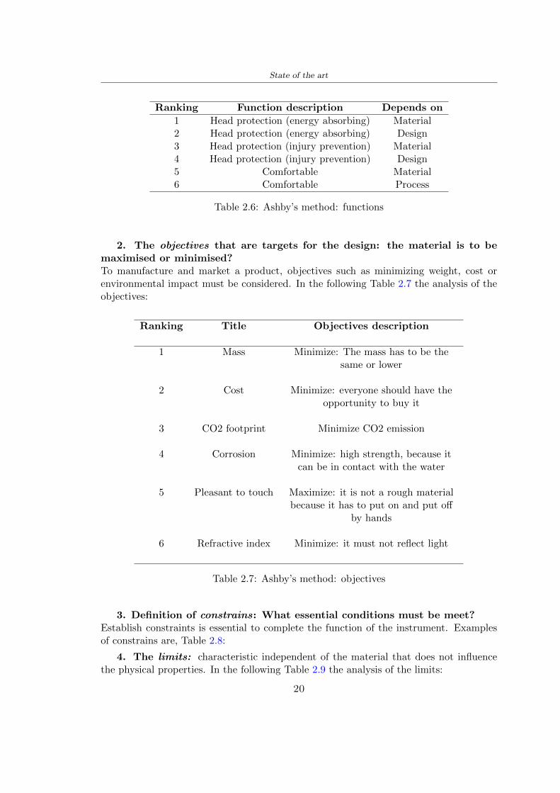
State of the art
Ranking Function description Depends on
1 Head protection (energy absorbing) Material2 Head protection (energy absorbing) Design3 Head protection (injury prevention) Material4 Head protection (injury prevention) Design5 Comfortable Material6 Comfortable Process
Table 26 Ashbyrsquos method functions
2 The objectives that are targets for the design the material is to bemaximised or minimisedTo manufacture and market a product objectives such as minimizing weight cost orenvironmental impact must be considered In the following Table 27 the analysis of theobjectives
Ranking Title Objectives description
1 Mass Minimize The mass has to be thesame or lower
2 Cost Minimize everyone should have theopportunity to buy it
3 CO2 footprint Minimize CO2 emission
4 Corrosion Minimize high strength because itcan be in contact with the water
5 Pleasant to touch Maximize it is not a rough materialbecause it has to put on and put off
by hands
6 Refractive index Minimize it must not reflect light
Table 27 Ashbyrsquos method objectives
3 Definition of constrains What essential conditions must be meetEstablish constraints is essential to complete the function of the instrument Examplesof constrains are Table 28
4 The limits characteristic independent of the material that does not influencethe physical properties In the following Table 29 the analysis of the limits
20
State of the art
Title Loading case Constraintsdescription
Material index(Max-Min)
Stiffness Column in compression Tie in tension
Mass Min
Stiffness Column in compression Tie in tension
Cost Min
Stiffness Column in compression Tie in tension
CO2 Min
Strength Column in compression Tie in tension
Mass Min
Strength Column in compression Tie in tension
Cost Min
Strength Column in compression Tie in tension
CO2 Min
Table 28 Ashbyrsquos method constrains
223 PLA with natural fiber and PLA LW
Initially the best material that met the desired criteria was searched From this study itwas found that the material closest to having the required characteristics is the PLA 30natural fiber as shown in the Figure 27 which shows the graphs obtained relating tothe relationships between Youngrsquos Module and density the objective to reduce the massper unit of compressive stiffness and strength to reduce the CO2 footprint per unit ofstiffness and strength and mass per unit of compressive strength
Performance index IR
The stiffness criterion has the following characteristics
m = A lowast L lowast ρ (21)
ε =σ
E=
FA
E(22)
A =F
ε lowast E(23)
21
State of the art
Ranking Title Function description
1 Biocompatibility It is the ability of a material the abilityof the material not to cause any local or
systemic adverse response in therecipient of the material
2 Biodegrability Biodegradable material do notbiodegradable under anaerobic conditions
3 Biomaterials - all The terms is used for biological naturalbio-derived bio-inspired material
4 RoHS (EU) Compliantgrades
Restriction of the use of certin prohibitessubstances (mercury cadmium
hexavalent chromium)
5 Polymer 20-100 (from the table with Plasticpolymers)
6 UV Resistance at UV sunlight
Table 29 Ashbyrsquos method limits
A =F lowast L lowast ρε lowast E
(24)
With fixed variables- F (the load) L (the length)With variables that depend on the material- E (Youngrsquos Module) ρ (density)
In general when a chart is created the distribution of the mass is represented in thefollowing modality like in Figure 27 [b] where the materials above the line have a lowermass while those below a greater mass
Following the results of the CES Edupack program that had selected the PLA withnatural fibers as the best the first print of the helmet was made with this materialusing as support the PVA Initially the result seemed satisfactory the helmet had a highdefinition but a fundamental problem was found by reducing the helmet in the water toallow the supports of PVA to dissolve In the act of diving in fact after ten minutessome parts of the helmet especially the front and rear have disintegrated making thehelmet unusable Because of this problem it was necessary to change the material
22
State of the art
[a]
[b]
Figure 27 CES EduPack Mass per unit of compressive stiffness [a] Youngrsquos Moduleand density [b]
Further investigations carried out by the Mondragon Unibertsitatea Additive Man-ufacturing Department revealed a new material the PLA Low Weight which during3D printing allows to obtain a weight of 65 lower than that which could be obtainedfrom the classic PLA as reported in the technical sheet of the filament produced by thecompany Colorfabb [7]
The investigation team of the Composite Department carried out tensile tests withsamples 3D printed at different temperatures as suggested by the manufacturer to obtainthe technical characteristics The temperatures examined are 200 220 250 260The datasheet shows the density can have values between 04 - 124 gcm3 the bed has
23
State of the art
to have a temperature between 50 - 60 the printing speed has to have values between40 - 80 mms This typology of PLA is expandible so much that rdquoAt around 230 thismaterial will start foaming increasing its volume by nearly three timesrdquo [7]
T[C] Section [mm2] Volumen [mm3] Mass [g] ρ[kgm3] E [Nmm2]
200 42235 1030117 12 1165 328807
220 43805 1655821 18 1087 265795
250 52412 1948139 17 873 178058
260 59655 1454377 12 825 117047
Table 210 Values about PLA LW tensile tests of MU Additive ManufacturingDepartment
From the tests that have been carried out on the material at different temperaturesthe printed sample is better at 250 with a volume of 1948139 mm3 and a section of52412 mm2 as shown in Table 210 For this reason the specific of the material thathave been taken into consideration are the following
- Density ρ = 873 kgm3
- Youngrsquos Module E = 1750 MPa
- Poissonrsquos ratio ν = 033
- Yieldrsquos stress σ = 2948 MPa
- Elongation at fracture = 491
23 Bio-inspired structures
When we talk about bio-inspired structures to nature we refer to structures that allowobtaining a low weight for the model that is realized and excellent absorption energy dur-ing the impact Recently the structures that have been most used in the biomimetic fieldare the rdquocolumns structures sandwich structures plates honeycomb and foamsrdquo[26]but aiming to achieve a structure increasingly with high absorption energy new struc-tures derived from plants and animals such as beetle horsetail turtle bird beak havebeen analyzed The first to create multi-cells tubes helicoidal structures the second tomulti-corner tubes [26]
The authors analyze the specific energy absorbed (SEA) by bio-inspired sandwichstructures per unit mass which can be derived from the following equation
EA(d) =
int dmax
0F (x)dx (25)
SEA(d) =EA(d)
m(26)
24
State of the art
Where EA is the energy absorption rdquomainly used to evaluate an energy absorberrsquosability to dissipate crushing energy through plastic deformationrdquo F(x) is the crashingforce dmax is the effective deformation distance [26]
What derived from their investigations is that having regard to a density of between0 and 1000 kgm3 the volumetric energy absorbed is higher for the beetle-inspired struc-tures than the others as shown in Figure 28 Based on this consideration it was chosento draw the helmet following this geometry
Figure 28 SEA of bio-inspired sandwich structures [26]
231 Beetle structure - Design of the model
To develop and increase lightweight high-strength and optimize bio-mimetic functionaland structural materials the trabecular structure of the beetle elytron is studied Thesingle structure is realized following the requirements cited by Zhang et al [39]
To realize the beetlersquos structure it is not enough to have information about the lengthof the side of the hexagon and the thickness but it is also necessary to take into accountthe relationship between the diameter of the circumferences present on the vertices ofthe hexagon and the measurement of the side The representation of a single cell is inFigure 29 It is shown in [a] a general structure with an edge of 12 mm circumferencersquosdiameter of 6 mm and thickness of 16 mm in [b] is shown the height of 20 mm
For the construction of the helmet a thickness of 12 and 16 mm was used the imageconcerns a proportion between the length of the hexagon side and the diameter of the
25
State of the art
circumference The side (distance between the centers of two circumferences) is twice thediameter measurement
[a] [b]
Figure 29 Beetle structure
232 Specific stress - PLA LW and EPS foam
To test the beetle structures compression tests were investigated The PLA LW structurewas inserted in a rsquodiskrsquo with a diameter of 100 mm and a height of 20 mm The area andthe volume of the disk is correspondingly 7854 mm2 and 157 10 mm3 The structuresexamined have different dimensions the edge L (distance between two centers of thecircumferences) had the following measures 9 10 12 14 16 mm the thickness of thecircumferences and edges are respectively of 16 mm for every structure and 12 mm forthe structure with L = 16 mm
The test was carried out with the Hoytom HM-D Testing Machine with capacitiesbetween 5 and 100 kN The test models were subjected to displacement loading at a rateof 1 mmmin as referenced by Chen et al[18] with a cylindrical specimen The specificstress of the structures was compared with the specific stress of a generic EPS helmetthe photos about it are shown in Figure 210 The EPS helmet structure is granular withpores inside The different grains dimension and these pores can be the reason for whichthe Stressrsquos values are between two values 07 and 116 MPa
Four parts of the EPS helmet were considered in the test the dimension and relativecharacteristic are in the Table 211 where m = mass A = area F = load ρ = densityR = stress Rρ = specific stress To calculate the values of stress about PLA structuresand EPS foam compression test graphs were been analyzed The stress value for eachstructure was calculated considering the single load the single area and the averagedensity value (14055 [kgm3])
The stress values of the PLA structures (Figure 211) and other characteristic valuesare in Table 212 where m = mass A = area F = load ρ = density
26
State of the art
[a] [b]
[c] [d]
Figure 210 EPS generic helmet helmet pictures [a] [b] and internal structureExternal granular structure [c] and pores [d]
[a] [b] [c]
Figure 211 PLA LW disks Grasshopper structure [a] PLA LW structure of 14 mm[b] PLA LW structure compressed [c]
27
State of the art
The results of the load-displacement graphs are affected by the geometry of the diskthe target is to valid for any shape or size for this is preferred to realize a diagramthat depends from σ (or stress) and the deformation ε (or strain) which can be definedrespectively as
σ =F
A0(27)
ε =l minus l0l
(28)
where F is the load during the test A0 is the area l0 is the initial length and l is thelength when the load is applied The areas considered for the EPS cube is reported inTable 211 in the second column the areas of the PLA structure is 7854 mm2 like thearea of the circumscribed disk
The values compared are shown in Table 213 and the graphs obtained by Matlabcode to analyze the recorded data of the compression machine are in Figure 213 and inFigure 212
Considering that the data provided by the compression machine are subject to noiseand disturbances it was decided to convert the original curve into polynomial type curvesthat allow obtaining the best interpolating curve for the data in question To obtain themit was divided the recorded data into two groups the first part from 0 until the end ofthe linear part and the second when the curve becomes linear again The best-fitting (inthe least-squares sense) was performed using the polyfit and polyval functions of MatlabThe first returns the coefficients of the p(x) with n degree the second evaluates p(x) ateach point in x The polynomial formula p(x) is shown in the Equation 29
pn(x) = anxn + anminus1x
nminus1 + + a2x2 + a1x+ a0 (29)
where a0 an are constants and x is the indeterminate The choice of the degree ofthe polynomial was made based on the criterion of wanting to obtain linear curves thatrespected the elastic trend at the beginning of the graph For this reason the degree ofthe polynomial is 1 Subsequently I searched through the intersection of the two lines forthe point that is equivalent to the maximum stress that marks the end of linearity
This value for EPS and PLA LW is the R [MPa] in the Table 213 The average stressvalue for PLA LW is 139 MPa and for EPS is 094 MPa The specific stress (Rρ) is 18MPa lowast m3)kg for the EPS found in CES 669 MPa lowast m3)kg for the EPS foam of thegeneric helmet and for PLA LW is 1161 MPa lowastm3)kg an intermediate value betweenthe two which is what we wanted to achieve
28
State of the art
m [g] A [mm2] F [N] ρ [kgm3]
EPS (CES) 50
16 9234 1063 13864
18 879 593 13651
21 858 833 14237
24 864 564 14468
Average value 14055
Table 211 Compression stress generic EPS helmet
L [mm] t [mm] m [g] F [N] ρ [kgm3]
9 16 214 7250 1363
10 16 192 5560 12467
12 16 201 8190 13051
14 12 138 8000 8961
Average value 12027
Table 212 Compression test PLA structures
PLA LW structure EPS structureρ= 12027kgm3 ρ= 14055kgm3
Edge [mm] R [MPa] Rρ103 Number R [MPa] Rρ103
EPS (CES) 09 18
9 173 1269 1 116 824
10 139 1114 2 08 568
12 138 1057 3 105 746
14 108 1205 4 077 540
Average value 139 1161 094 669
Table 213 Specific stress calculus PLA LW and EPS calculus ρ = density R = stressRρ [(MPa lowastm3)kg] = specific stress
29
State of the art
Figure 212 Compression test Stress-Strain diagrams - EPS
Figure 213 Compression test Stress-Strain diagrams - PLA LW
30
Chapter 3
Methodology
31 3D scan
311 3D Sense 2 scanner and Meshmixer - Reverse reconstruction
Standardized measures were not taken into account for making the helmet but the sizewas obtained through a 3D scan of my head
The scanner used is 3D Sense 2 by 3D Systems which has a minimum scanningvolume of 20 x 20 x 20 cm and a maximum scanning volume of 300 x 300 x 300 cmTo scan my person I was helped to get a full view at 360 at an appropriate distanceReal-time visualization of the captured images was shown through 3D Sense softwareThe idea of scanning the head with the scanner refers to the methodology used by Wanget al [30] They used a reverse reconstruction functional for me to realize the helmetsurface made to measure my head and like them a silicone pool cap was used to makescanning as smooth as possible The authors claim the head scan rdquocan also be used toobtain information about the objectrsquos surface which is then reconstructed utilizing thecomputerrsquos three-dimensional model via reverse modelling softwarerdquo [30] that in my caseis Autodesk Meshmixer
The files it was could get from the scan were stl obj and ply format they wereexported to obj to work in the next step with Autodesk Meshmixer that allowed tomodify and homogenize the 3D image obtained from the scan
In Meshmixer through the selection and delete commands the superfluous parts weredeleted that had been acquired and with the inspector and the DrawDraw2 commandsthe vertices were moved locally along a pre-defined direction and with Smooth the surfacemore homogeneous was made The sequence of steps is shown in the Figure 31
312 3D scan analysis and extraction of features
In Chapter 2 the directives imposed by the BS EN 960 Standard were examined concern-ing the definition of the helmet and the measures to be respected in the field of visionand the part of the helmet was to carry out impact tests
In Figure 32 the features defined complying with the Standardrsquos rules are repre-sented To define these features the software NX was used The angle in the subfigure
31
Methodology
[a] [b] [c] [d]
Figure 31 Sequence of 3D head scan 3D scanner acquisition [a] scan after reparationwith Meshmixer [b] solid scan vision frontal and lateral [c] [d]
[b] is bigger than 105 (as defined by the Standard) while the degree in the subfigure [c]is 25 By defining the construction lines to be respected of the helmetit was necessary todraw the design of the surface not using the software NX but changing with Rhinocerosto create a SubD or SubDivision surface
32 Helmet design
321 Rhinoceros - Helmet surface
After realizing a rsquocleanrsquo Wang et al [30] subdivide with lines and then sectors the headto create the surface of the helmet They used the technique of NURBS a Non UniformRational Basis-Splines which mathematically models a 3D geometry while thanks tothe Rhinoceros 3D organic shapes was draw SubD surfaces These geometries allow tosplit the mesh into small polygons and consist of lines with which easily the shape ofthe object can be modified with a surface already created changing the position of aline automatically the remaining part of the geometry adapts to the changes With thistechnique the rsquosurface basersquo of the helmet was realized with the size of my head Therepresentation of the realized SubD is in Figure 33
322 Grasshopper - Helmet structure
The next idea is the creation on the surface of the beetle structure with different di-mensions modelling the helmet that is not a linear surface It was decided not to buildthe structure with a software CAD because to model an already complex structure on acurved surface would mean to model a cell for a cell
To solve this obstacle a Rhinoceros plug-in was used Grasshopper GH idealized byRobert McNeel and associates creators of Rhinoceros Using GH does not mean drawinggeometries by connecting points and drawing tools because it is based on algorithmicmodelling used in architecture and engineering for 3D modelling
The modelling takes place through a node diagram that the software will convert intoa code-algorithm in GH it is possible to define the variables and parameters and inRhinoceros in real-time it is possible to view the object GH allows for varying the
32
Methodology
[a] [b]
[c]
Figure 32 Featurersquos extraction in [a] is represented the impact line in [b] and [c] twoprospective about the definition of the field of vision
[a] [b] [c]
Figure 33 SubD representation lateral view [a] top view [b] front view [c]
geometry to your liking by varying a simple parameter of the diagram as everything willbe remodelled according to the change made
In the following Figure 34 it is shown an example of a structure that was used fordistinct subgroups of helmet areas The idea was to insert smaller cells in the frontal andlateral zone and larger ones in the upper area In the first image [a] is shown the part of
33
Methodology
the helpful diagram to create the beetle structure to establish the size of the cells andthe extrusion the second image [b] contains the part of the diagram with which I appliedthe structure previously created to the SubD
The structure used to place and adapt the beetle structure to the surface is theSrfMorph while the yellow rsquowindowrsquo that contains numbers serves to select the parts ofthe surface where to apply the geometry created In accord with the GH diagram in
[a]
[b]
Figure 34 Grasshopper diagrams
Figure 34 [a] it is possible to see the steps executed to realize the structure Initially inthe xy-plane a hexagonal grid was drawn through the Hexgrid command in which youcan input the length of the hexagon edge and the number of grid elements (selected bytrial) Then the circumferences was drawn in proportion to the hexagon dimensions asspecified in the Chapter 2 and shown in Figure 35 [a] In figure [b] the rsquocutrsquo made atthe circumferences is visible this subdivision was necessary for printing purposes In thelast photo [c] the structure highlighted in green in [b] was extruded setting a distance
34
Methodology
of 20 mm
[a] [b] [c]
Figure 35 Construction sequence of the geometry of the helmet
In the diagram in Figure 34 [b] there is the application of the structure created bi-dimensionally to the SubD surface of the helmet visible by unlocking the SubD commandof the diagram and in Figure 36 [a] Upper this the referential geometry of the group ofsurfaces was superimposed where it was to be applied the newly created structure (visiblein darker red) the SubD indices are in the yellow box of the diagram
Through the SrfMorph command the location of the structure was granted In Figure36 [b] at the darkest red of the figure [a] with the above command it was possible toplace the structure
[a] [b]
Figure 36 Application of the geometry created to the helmet surface
Overall the diagrams with specific structures are five one for the front two equal forthe side parts one for the top shown in the previous Figure 36 and one for the back
The hexagons in the structure have a dimension varying between 8 mm and 14 mmof side the largest is found at the top later at the back in the sides and the smallest atthe front In Figure 36 [b] the presence of not only hexagonal structures is visible Thegeometry used does not allow the homogeneous arrangement on the entire surface andrequires different structures Automatically the choice of GH to optimize the structurewas to insert quadrilateral
As described above the helmet has different dimensions of the structure divided asvisible in Figure 36 in a quadrilateral This causes a discontinuity between zones withdifferent sizes due to the geometry of the construction
To eliminate this problem and realize the design homogeneous grids were inserted
35
Methodology
in the affected areas as shown in Figure 37 This insertion however proved to beinteresting and strategic researching in this regard studies were realized to demonstratethe insertion of a rectangular grid inside the hexagon grid was helpful for the transmissionof stress in the structure As cited by Sun et al [40] rdquothe mechanical properties of thesesandwich structures are often limited by local failures such as face-core debonding or corecollapserdquo Carrying out compression tests have effectively demonstrated that the insertionof the grid allows rdquoprovided increased stiffness specific stiffness energy absorption andcritical loadrdquo [41] As shown in the graphic [c] of the Figure 37 the honeycomb structuregives a force of 7 kN while with a grid the value is 11 kN and with the combinationexceeds 22 kN In addition in the left front a plaque to customize the helmet wasprepared Figure 37 [a]
[a] [b]
[c]
Figure 37 Grid in the helmet [a] hybrid structure with hexagons and grid [b] [40]compression test results of the hybrid structure [c] [41]
33 3D Print
After having achieved the CAD (Computer Aided Design) of the helmet in order tobe printed it must be converted and saved in format STL (Standard TriangulationLanguage) - Binary compatible with the printing machine and useful for transformingsolid object surfaces into triangles The steps to be taken are the following
bull CAD file realization
bull CAD export in format STL to Simplify 3D the software that shows slider layersand then- rotate and position the object according to geometry and the positioning of any
36
Methodology
supports- setting printing parameters- item manual andor automatic positioning of supports- slider display layers
bull import file gcode to printer
331 Printer and parameters
The program used to visualize how the helmet slices layers before sending it to the printerand to set the parameters is as anticipated Simplify 3D
To make the printing not being a flat geometry it is necessary to place the supportsThe idea was to use water-based supports that the helmet would automatically dissolveonce placed in the water After testing different types of water-soluble PVA the choicefell on eSun 3D Printing Filament PVA (water-soluble support) Before choosing theoptimal position for printing several tests were carried out and to decrease the numberof the supports significantly and allows an optimal printing of the outer part an emptyrsquospherersquo that self-sustains below the helmet was placed as shown in Figure 38
In the image [a] you can see the first print position tried with which an external partof the helmet very damaged was obtained because of the contact supports-helmet In [b]the empty rsquospherersquo is shown to optimize the number of supports and in the last photo [c]there is the full version at the end of print
[a] [b] [c]
Figure 38 Printing supports
The printer that has been used for printing is the Raise 3D Pro2 with double extrudersand nozzles of variable size from 02 mm to 1 mm after some test prints with the PLALW and the structure in created the size that allowed me to have a good compromisebetween printing time and accuracy was 06 mm Using 04 mm the printing time wasexcessive even if having the smaller nozzle diameter means having more precision withthe 08 mm nozzle the quality of the structure was not excellent as seen in Figure 38[a]
Another factor that had to be taken into account is the characteristic of the PLA-LWto expand As the printing temperature and the printer used vary the expansion andcharacteristics of the material change The use of the 06 mm nozzle associated with
37
Methodology
Parameter Left extruder Right extruder
01cm Material 01cm PVA 01cm PLA LW
Extruder toolbox index Tool 0 Tool 1
Nozzle diameter 06 mm 06 mm
Extrusion multiplier 1 05
Extrusion width Auto (072 mm) 05 mm
Layer x
Infill Rectilinear - 50
Supports (Automatic and not) Infill 50
Temperature 210 250
General parameters
Primary layer height 03 mm Top solid layer 4
Bottom solid layer 2 Outline 2
Heated bad 60 Speed 40 mms
Table 31 Printing parameters
Raise 3D allowed me to get good results The choice of this printer was not random ithas in fact the characteristic of making extremely precise prints The Raise has accuracyin placing the object on the printing bed of 078 microns on the xy axis and a resolutionfor layers of 001 mm
The final version of the helmet is visible in Figure 39 and it is possible to compare itwith the preview version in Rhinoceros in Figure 310
38
Methodology
[a] [b]
[c]
Figure 39 Views of the helmet
[a] [b]
Figure 310 Views of the helmet (GH version)
39
Chapter 4
Experimental evaluation
41 Experimental tests
411 Drop-weight impact test machine
In order to calculate the contact force peak and the difference of energy absorbed duringthe impact between the reference helmet and helmet with the beetle structure in PLA-LW dynamic impact tests were carried out using the Fractovis Plus an impact testmachine
In this way it is possible to monitor the evolution of the above variables from theinitial to the final instant of the impact The machine can withstand a load with a rangevariable from 2 to 70 kg with a maximum speed of 46 ms and a maximum height of1 m The values chosen for the test are the following 5 kg weight maximum speed andmaximum height The Anvil that was used is a disc diameter of 60 mm
As shown in Figure 41 and explained by Crupi et al [37] the machine consists ofa sensor capable of recording the speed before impact the impactor that can have avariable mass (a weight of 5 kg in my test) a system to guarantee that there are nomultiple impacts after the first and that work as a shock absorber and clamping systemwhere the object to be tested is placed
The tests that have been carried out are in total four two related to the helmetoptimized with PLA-LW and two with two generic helmets of different brand in EPS
42 PLA LW helmet
To perform the dynamic test on the helmet of PLA considering the difficulty of printingit was helpful to use a test helmet with imperfections to understand where the impactwas concentrated in a single part or distributed The images of Figure 42 show a helmetwith not well defined edges and inaccurate print but exactly localizes the impact zoneThanks to this test it was possible to take into account only one helmet area shown inFigure 43 to have the exact curve of the structure bio-inspired with PLA-LW
40
Experimental evaluation
Figure 41 Drop-weight impact test machine [37]
[a] [b]
Figure 42 Test 1 PLA-LW helmet
43 EPS helmet
To carry out dynamic tests and extract the technical characteristics of the helmettwohelmets were bought in a sports store both EPS and being on the market both certifiedThe brands of the two helmets are DTB and VAN|RYSEL and the average weight ofthe two is 223 g Two different helmets have been chosen to have a more certain andclear classification of the characteristics They are shown in Figure 44 and Figure 45
41
Experimental evaluation
[a] [b]
Figure 43 Test 2 PLA-LW helmet
[a] [b] [c]
Figure 44 Test 3 EPS helmet
[a] [b] [c]
Figure 45 Test 4 EPS helmet
44 Results
441 First results - PLA-LW and EPS helmet
Figure 46 shows two types of trends related to the two different models of the helmetThe force evaluated for PLA-LW has higher force peaks but is more concentrated and
42
Experimental evaluation
propagates less than EPS The graph shows the peaks of each curve highlighted with a redcircle In tests 1 and 2 for the PLA-LW as mentioned earlier the values are higher about7301 N for the complete helmet and 3996 N for the portion of helmet This difference isdue to the inaccuracy of the first full helmet during the printing phase In Figure 42 itis visible the low homogeneity and precision Therefore the first test with full helmet wasused only to define the area of interest of the impact which turns out to be localized Forthe other two EPS curves the values are only slightly lower compared to the PLA-LWequal to 3620 N and 3295 N but the trend is much more distributed
Figure 46 Dynamic machine test - Force
With the data obtained from the impact machine it was possible calculate not exclu-sively the value of force but itrsquos also possible to view the energy curves A resume aboutthe values and energy of the force is in the following Table 41
Test Peak force [N] Peak energy [J]
Test 1 - PLA LW (inaccurate) 730130
Test 2 - PLA LW (portion of helmet) 399643
Test 3 - EPS (DTB helmet) 362007 509
Test 4 - EPS (VAN|RYSEL helmet) 329546 4198
Test 5 - PLA with TPU 45421 5022
Table 41 Energy absorbed in dynamic test
43
Experimental evaluation
442 PLA-LW helmet with TPU cover
As it is possible to see in Figure 47 and as highlighted the first tests concerning thebio-inspired structure and the PLA-LW are far from my expectations considering thelittle distribution of force in comparison with the EPS foam and consequently a smallamount of energy absorbed
Figure 47 Dynamic machine test - Energy
To improve this impact damping factor the idea was to create a cover for the helmetin flexible TPU trying to absorb impact energy The TPU used is a flexible material ofthe brand Ninjaflex used in sports by the application in helmets and shoes to cushionbumps during the game Generally in the helmets (baseball helmet for example) theTPU is inserted internally in contact with the head In my case the TPU structurein addition to creating a shock-absorbing and durable cover creates a custom cover thehelmet and for the person This cover was also made with the Raise 3D printer
As shown in the Figure 48 [a] the infill of the part in contact with the helmet hasa percentage of 100 the filling of the other part of the structure is not complete butonly 15 and the internal structure is hexagonal to recall that of the helmet The desireto insert a structure with a rsquoraisedrsquo geometry is for visual and aesthetic reasons as youhave the feeling of greater protection and not filled is inspired by the machine CitroenCaptus whose bumpers (Airbump) are full of air The failure to realize empty structuresis due to the need to place any internal supports not removable
The idea was to create a cover that allow you to see of the internal structure of thehelmet and that protect specific areas the front the two sides the top and the posteriorWhat which was thought for this reason was to create the shape of a flower with four
44
Experimental evaluation
petals Figure 48 [b]In this way to perform dynamic impact tests as shown in Figure 49 [a] the cover was
positioned at the top of the helmet and the impact was performed in the centre of thersquoflowerrsquo which corresponds to the higher upper part where the structure has larger cellsize The impact parameters are the same as those used in previous impacts 5 kg weightmaximum speed and maximum height The Anvil that was used is a disc diameter of60 mm In photo [b] it is evident the difference between the structure that received theimpact with protection (left) and without protection (right) Without protection duringthe impact there was a perforation of the structure with a concentration of force at a locallevel as you can see in the Figure 46 in the case of TPU the impactor did not perforateand crossed the structure thanks to the cover of TPU that cushioned the shock At themoment of impact the impactor bounced
[a] [b]
Figure 48 TPU cover
[a] [b]
Figure 49 PLA-LW with TPU - dynamic impact [a] and differences between thehelmet with TPU and without TPU cover [b]
45
Experimental evaluation
The Figure 410 includes the diagrams relative to the dynamic impacts In [a] thereare already analyzed EPS results in [b] a comparison between the test on the portionof helmet in PLA LW with and without the TPU cover in [c] the overall comparison ofcurves shows a much more similar EPS trend if the TPU is placed above the structure inPLA LW to soften the blow and absorb the same energy [d]
46
[a]
[c]
[d]
Figure 410 Comparison between PLA-LW with TPU and EPS
Chapter 5
FEM Validation
51 Impactor - Anvils definition
Before to start to work in Abaqus it was necessary to search in the literature the materialwith which the anvil was been realized Milne et al [23] established the densityrsquos valuethe Youngrsquos Module and Poissonrsquos ratio for the Flat and Kerbstone Anvil
- Density ρ = 7800 kgm3
- Youngrsquos Module E = 200000 MPa
- Poissonrsquos ratio ν = 03
Inserting the data in the CES EduPack program specifying the mechanical andphysical properties the material corresponding to these characteristics is Stainless steelaustenitic (ASTM F1586) medium-hard
Initially the proposal was to create a conservative system to evaluate the absorptionenergies values and apply this value to a vibration system but the helmet needs dampingto be realized it was impossible to use a system without losses in this modality Thisis why a numerical calculation was carried out by performing two types of simulationsexplicit dynamic step and static step
The idea to realize the theoretical impact is to regard the movement of the anviland not the helmetrsquos movement which is fixed The velocity is the same cited in thenormative EN 1078 542 ms for the Flat anvil and 457 ms for the Kerbstone anvil
In performing the simulations It was given more relevance and perform tests withthe Kerbstone Anvil This choice was done because the geometry with which it is beenrealized (following as defined in the legislation) allows the helmet to be more subjectedto stress this involves the definition of higher stress limits compared to the Flat Anvil
The mesh size that has been used is the same in the case of the simulation of thehelmet optimized in PLA-LW and the full helmet in EPS of 7 mm The impactor isconsidered as a Discrete rigid body with its specific Reference Point (RP) like shownin Figure 51 for this reason it is not a solid but it is composted only by shells Inthe same image [b] there is the FEM representation of the model and in Table 51 thecharacteristic of FEM with quadrilateral (R3D4) and triangular elements (R3D3)
48
FEM Validation
Object Elementnumber
Elements Shape Geometricorder
Global size[mm]
Kerbstone 230 Quadrilateral - R3D4 Linear 7
Kerbstone 8 Triangular - R3D3 Linear 7
Table 51 Mesh element - Kerbstone Anvil
[a] [b]
Figure 51 Kerbstone anvil in the simulation like discrete rigid body [a] and FEMelements [b]
511 PLA LW - Plastic characteristics
The PLA-LW as explained in the Chapter 2 is new material on the market and producedby the only Colorfabb company for this reason few tests have been carried out to defineits technical characteristics and through tensile tests of the 3D printed specimens it waspossible to define an elastic limit as reported in the Table 210
In the context of simulations to reproduce the impact and deformation of the helmetis also necessary to consider the plastic characteristics of the material Not possessingany reference value in this regard tests were performed through a Static Step initiallyand then an Explicit Dynamic Step in Abaqus
The structure chosen to consider as a reference it is one of the structures previouslysubjected to the compression test having the side L=14 mm As for the reproduction ofthe compression disks initially they were reproduced according to the geometry of theHoytom HM-D Testing Machine considering the bodies mentioned above as discrete 3Drigid discrete The measure was the diameter of 200 mm and the height of 20 mm
After an initial analysis it was observed that the computational time of the simulationprogram was very high so it was decided to change the geometry to have a rsquodisk-surfacesrsquo(equally 3D rigid-discrete) which allowed me to have a smaller number of nodes for themesh and consequently a better computational time The representation of the opti-mized structure in PLA-LW and the disks used for simulated compression is in Figure 52
49
FEM Validation
[a] [b]
Figure 52 Representation of the samples used for the simulation of the compressiontest In Figure [a] the disks of the Hoytom HM-D Testing Machine in figure [b] the
representation of the same as simple surfaces
As shown in Figure 52 the disks are considered 3D discrete hard bodies so it waschosen for both a point the reference point RP where to apply the characteristics relatedto the two bodies As for the compression test it was established
bull the movement of a disk and fixed the second through a boundary condition impos-ing an Encastre therefore unable to move and rotate in xyz directions
bull for the opposite disk the boundary condition relative to the 15 mm displacementwas applied which is the parameter that it was observed to determine the end ofthe compression with the machine This shift is shown by the orange arrow in figure[b]
bull between the upper surface and the disk e the disk with the lower surface it wasinitialized a general contact with normal behaviour through rsquohardrsquo contact andtangential behaviour with a coefficient of friction of 02 with directionality imposedon rsquoisotropicrsquo
The next step was to define the mesh of the components whose parameters are shown inTable 52 while the representation of the FEM is in Figure 53 with the representationof the simulation and real compression test
Object Elementsnumber
Typology Geometricorder
Globalsize [mm]
Disk (14mm) 80910 hexaedral - C3D8R Linear 07
Impact disks 206 quadrilateral - R3D4 Linear 20
Impact disks 6 triangular - R3D3 Linear 20
Table 52 Mesh element - Compression test simulation
As previously announced a static simulation was initially performed with a StaticStep with Step Time equal to 900 (obtained going to consider the speed of 1 mmmin of
50
FEM Validation
[a]
[b] [c]
Figure 53 FEM representation [a] and compression test simulation [b] and realcompression [c]
the compression test and the displacement of 15 mm) However the complex geometryof the structure and the high time set by Step Time did not allow a correct definitionof the parameters of the plastic characteristics of the material the simulation was notable to continue once reached a Step Time of approximately 220 That is why it waschanged by choosing an Explicit Dynamic step
Leaving all the parameters of the boundary conditions unchanged the Step Time wasmodified imposing it to 001 The ability of the explicit dynamic to work with non-linearand contacting structures allowed me to achieve results The results obtained are shownin Figure 54 with the blue curve and were obtained through the iteration of differentPlastic Strain and Yield Stress values in Abaqus while the red line is the result of thereal compression test a similar curve trend was obtained but it is not possible to obtainthe same curve taking into account problems of printing inaccuracy
512 First test - helmet
The initial idea was to perform a simulation imposing the speed of 457 ms to theimpactor tie the helmet in EPS and PLA and compare the absorbed energies Theproblem it was encountered is related to the mesh of the helmet optimized in PLA andwith minimum dimensions of the elements and distinct elements it was not able to solveit
51
FEM Validation
[a]
YieldStress
PlasticStrain
1 47 0
2 7 001
3 75 005
4 10 01
5 108 1
6 115 15
7 12 2
[b]
Figure 54 Representation of the two curves related to the simulation in Abaqus of thecompression test and the data obtained from the real test to obtain the plastic
characteristics of the material
513 Second test - plane
The first solution is the one shown in Figure 55 To realize the simulation it was realizeda section of the helmet to involve a smaller number of elements and nodes Again thesimulation for the EPS helmet was successful while the simulation with the bio-inspiredstructure was interrupted by excessive distortion of elements
The previous images show the impact is very localized in the impacted area and theidea to achieve a complete simulation is not to consider a curved portion of the helmetbut a plane In this way it was possible to solve the problem and obtain a completesimulation for the bio-inspired structure
FEM element
Below in Table 53 there is the definition of the elements used for the PLA-LW and EPSplane in the simulation to simulate the impact and to control the energy-absorbing whilethe anvil characteristics are described in Table 51
514 EPS impact simulations
In order to proceed with the simulation it was imposed some boundary conditions thatregard ties and forces
bull the movement of the plane is fixed through an Encastre therefore unable to moveand rotate in xyz directions
52
FEM Validation
[a]
[b]
Figure 55 Impact simulation parts of EPS and PLA helmet
Object Elementnumber
Elements Shape Geometricorder
Plane (PLA) 38896 Tetrahedral -C3D10M
Quadratic
Plane (EPS) 2100 Hexahedral - C3D8R Linear
Table 53 Mesh element - plane impact
bull to create the impact it was set a speed of 457 ms at the reference point RP of therigid body which is the impactor Kerbstone Anvil shown in Figure 56
bull between the upper surface of the plane and the impactor it was initialized a Sur-face to Surface contact with normal behaviour through rsquohardrsquo contact and tangen-tial behaviour with a coefficient of friction of 02 with directionality imposed onrsquoisotropicrsquo
bull the rotation in x y z relative to the RP of the rigid discrete impactor body is locked
53
FEM Validation
In addition it was characterized the plane in the part of the materials with the char-acteristic values of the EPS mentioned in Chapter 221 The Von Mises Stress valueapparently low is relative to the Yield Stress of the EPS material equal to 09 MPa
Figure 56 EPS Boundary conditions and Load
515 PLA LW impact simulations
As also required in the case of the EPS plane in order to proceed with the simulationsome boundary conditions were imposed that regard ties and forces
bull the movement of the plane is fixed through an Encastre therefore unable to moveand rotate in xyz directions
bull to create the impact a speed of 457 ms was set at the reference point RP of therigid body which is the impactor Kerbstone Anvil shown in Figure 58
bull between the upper surface of the plane and the impactor it was initialized a Sur-face to Surface contact with normal behaviour through rsquohardrsquo contact and tangen-tial behaviour with a coefficient of friction of 02 with directionality imposed onrsquoisotropicrsquo
bull the rotation in x y z relative to the RP of the rigid discrete impactor body is locked
In addition the plane was characterized in the part of the materials with the characteristicvalues of the PLA mentioned in the Chapter 223 and 511
Figure 58 Boundary conditions and Load
54
FEM Validation
[a]
[b]
Figure 57 EPS impact simulation
52 Results
In Figures 59 and 57 it is shown how the structure in PLA LW has a more concentratedstress distribution of the structure unlike EPS The maximum value for the Von Misesstress is 09 MPa in EPS structure and 3634 MPa in PLA LW structure Once thesimulations were obtained the next step was to go and compare the energies absorbed bythe two structures The energy calculated by Abaqus that has been taken into account isPlastic Dissipation To make a comparison the data of the two energies were representedin a single graph
What emerges from the graph is that about the impact made with the KerbstoneAnvil the energy absorption is more excellent although only slightly for the PLA LWthan for the EPS From the graph in Figure 510 a value of 41 J is shown for the EPSand 51 J for the PLA LW
55
[a]
[b]
Figure 59 PLA impact simulation
[a]
Figure 510 EPS and PLA LW energy comparison - Abaqus simulation
Chapter 6
Head Injury Data
For the statistical analysis the injuries related to the accident data were categorised intothe following types and levels based on the details of the medical report [11] about theEN 1078
bull Head Injury Criterion (HIC)
bull Peak Linear Acceleration (PLAc)
bull Gadd Severity Injury (GSI)
bull Diffuse axonal injuries (DAI)
61 Abaqus simulation
Until now the purpose of the simulations has been to determine which between the twomaterials and the two structures of EPS and PLA LW could absorb more energy duringthe impact but no simulations have been carried out in compliance with BS EN 1078on the helmet impact tests To calculate the injuries listed in the previous paragraphhowever we need the acceleration values in the three directions related to the subjectrsquoshead
To realize it the scan of my head already rsquocleanrsquo was considered of which it has beencalculated the inertia thanks to the automatic SolidWorks calculation and evaluated theweight with the Table 24 the structure of the helmet was placed for the EPS and thePLA LW over the head as shown in Figure 61 Also this time being able to mesh theentire helmet in PLA LW was impossible due to the excessive distortion of some elementsduring the simulation so it has been tried to make a section of the structures of thehelmet and results were obtained
57
Head Injury Data
[a] [b]
Figure 61 My scan head - CAD [a] head imported in Abaqus[b]
Initially the simulation had these characteristics as shown in the following Figure62 considering the helmet was not sectioned As explained earlier it was not possibleto get to simulation in the case of the optimized structure in PLA LW for this reasononly a part of the helmet was considered in both cases shown in Figure 63
[a]
Figure 62 Simulation based on BS EN 1078
58
Head Injury Data
[a] [b]
Figure 63 Simulation based on BS EN 1078 with head
In order to proceed with the simulation some boundary conditions that regard tiesand forces have have imposed
bull two reference points RP were created the first in the inertia centre of the headthe second relating to the Kerbstone Anvil which is a discrete rigid body
bull in the reference point RP of the head in the definition of the engineering features5 kg was inserted for the weight and an inertia I11 = 564464E+07 gmm2 I22 =460654E+07gmm2 I33 = 187302E+07gmm2
bull to simulate the impact it was set a speed of 457 ms at the reference point RP ofthe head in z-axis direction
bull a general contact with normal behaviour through rsquohardrsquo contact and tangentialbehaviour with a coefficient of friction of 02
bull between the upper surface of the helmet and the impactor it has been initializeda Surface to Surface contact with normal behaviour through rsquohardrsquo contact andtangential behaviour with a coefficient of friction of 02 with directionality imposedon rsquoisotropicrsquo
bull the movement between the Kerbstone anvil and the helmet is fixed through anEncastre therefore unable to move and rotate in xyz directions
bull the rotation in x y z relative to the RP of the rigid discrete impactor body is locked
FEM element
As reported in Table 53 the portion of the helmet in EPS has used a mesh with hexahe-dral elements of linear order For the structure (beetle) of PLA LW given the geometry
59
Head Injury Data
complexity it was necessary to use a quadratic order of tetrahedra For the mesh of thehead instead in both simulations have been used quadrilateral elements of linear orderas reported in the Tables 61 and 62
Object Elementnumber
Elements Shape Geometricorder
Head 3755 Quadrilateral - R3D4 Linear
Head 34542 Quadrilateral - R3D3 Linear
Helmet (PLA) 272302 Tetrahedral -C3D10M
Quadratic
Table 61 Mesh element - Head simulation with PLA LW (beetle) helmet
Object Elementnumber
Elements Shape Geometricorder
Head 3755 Quadrilateral - R3D4 Linear
Head 34542 Quadrilateral - R3D3 Linear
Helmet (EPS) 72280 Hexahedral - C3D8R Linear
Table 62 Mesh element - Head simulation with EPS helmet
62 Results
Figure 64 represents the simulation in line with BS EN 1078 concerning the helmet inEPS [a] and the helmet with bio-inspired structure in PLA LW For both simulationsVan Misesrsquo stress has Yield Stress values in the case of EPS which is 09 MPa and theplastic behaviour combination of PLA LW [b]
In the case of head and Kerbstone Anvil stress was not assessed as they were previ-ously defined as discrete rigid bodies
63 Head Injury Criterion
The HIC quantifies head impact severity by incorporating time of acceleration exposureand acceleration magnitude it is calculated in post-processing phase with the followingEquation 61
HIC15 =
[1
(t1 minus t2)
int t2
t1
a(t)dt
]25(t2 minus t1) (61)
60
Head Injury Data
[a]
[b]
Figure 64 Results simulation based on BS EN 1078 with sectioned head
For this analysis a(t) is the acceleration calculated in the centre of mass of the head(corresponding to the reference point RP) expressed in g and the time interval (t2 minus t1)was chosen to maximize HIC over a maximum duration of 15 ms
Matlab and the trapz function were used to calculate the HIC to integrate accelerationover time t2 and t1 were considered initial and final times of the simulation t1 = 0 sand t2 = 10 s time less than 15 s
HIC value of 198 was obtained for EPS and 87 for PLA LW Considering the Hayeset al [16] document about the HIC values and the graph in Figure 65 developed bythe author it is possible to find the percentages related to the different injury AIS1 -AIS6 which correspond respectively to lower and higher severity while in Figure 66 therelative fatality to every value of AIS is shown The values obtained for the HIC andother criteria are shown in Table 63 The HIC value for EPS is 198 for PLA LW it is
61
Head Injury Data
Figure 65 Head injury risk curves based on HIC values [16]
Figure 66 The abbreviated injury score versus fatality rate [16]
87 Analyzing the data and comparing them with the curves of the Figure 65 I obtain
bull a percentage between 20 - 30 of AIS 1 for EPS 10 - 20 for PLA LW
bull a percentage between 10 - 20 of AIS 2 for EPS and 0 - 10 for PLA LW
bull for AIS 3 AIS 4 AIS 5 AIS 6 the percentages for both structures is between 0 -10
Comparing these percentages with the fatality rate of Figure 66 it is clear there is a riskof Moderate and Minor fatality in the case of EPS and PLA LW as all values are between0 and 30
62
Head Injury Data
HIC PLA [g] GSI E [J]
EPS 198 97 361 37723
PLA LW 87 75 169 44102
Table 63 Head Injury Data - values
64 Peak Linear Acceleration
The resultant linear acceleration versus time curve was calculated according to Equation62
γ(t) =radicγ2x(t) + γ2y(t) + γ2z (t) (62)
where
bull γ(t) is the resultant linear acceleration (g)
bull γx(t) is the linear acceleration in x axes (g)
bull γy(t) is the linear acceleration in y axes (g)
bull γz(t)is the linear acceleration in z axes (g)
The value of the impact should never exceed 250g [9] Cripton at all [9] in their studyexamined a helmet with expanded polystyrene (EPS) Figure 68 shows maximum HIC forhelmeted and unhelmeted drops from all heights For each drop height helmets reducedHIC relative to unhelmeted drops IARV value is 180g The acceleration in the two casesis shown in Figure 67 and the maximum values are 97g for EPS and 75g for PLA LWas reported in Table 63 The two values considering a maximum value calculated byCripton [9] of 180g are amply optimal and comply with the standard of 250g
65 Gadd Severity Index
Gadd proposed the Severity Index Criteria shown in Equation 63 Following this crite-rion the GSI values that are over 1000 produce serious internal head injury [33]
GSI =
int t1
0a(t)25dt (63)
Where
bull a is the linear acceleration (g)
bull t is the duration of the impact (s)
I calculated the GSI with the function trapz between 0 and t and the resulting valuesare 361 for the EPS and 169 for the PLA LW which comply with the limit
63
Head Injury Data
Figure 67 Peak accelerations for both helmets
Figure 68 Peak accelerations for both helmeted and unhelmeted drops Numbers overbars indicate peak acceleration For 2 m drop height results stated are the mean value
calculated from three drops [9]
64
Head Injury Data
66 Diffuse Axonal Injury
DAI cases covered all incidences in which neurological injuries occurred as well as con-cussion unconsciousness and coma
In order to assess the risk of head trauma in terms of diffuse axonal injury (DAI)Milne et al [23] defined a model based head injury criteria as follows obtaining theresults in Figure 69
bull 50 risk of moderate neurological injury (DAI1+) Brain Von Mises shearing stressof 28 kPa
bull 50 risk of severe neurological injury (DAI2+) Brain Von Mises shearing stressof 53 kPa
[a]
[b]
Figure 69 Peak intra-cerebral shearing stress computed with the helmet model coupledto the human head model for all impact points (a) Flat anvil (b) Kerbstone anvil [23]
65
Head Injury Data
67 Energy absorbed
In Figure 52 during the impact test between the kerbstone Anvil and the plan with thebio-inspired structure in PLA LW and EPS it was found that the PLA LW althoughwith a small difference of 10 J absorbed more energy in comparison with the EPS Whenthe test is carried out in compliance with BS EN 1078 and the head with a speed of 457ms (corresponding to the kerbstone Anvil) as shown in Figure 610 also in this casethe PLA LW with the optimized helmet structure manages to absorb more energy (evenif the difference is very low) compared to the EPS The maximum energy value in PLALW is 44102 J of EPS is 37723 J
Figure 610 Energy absorption - BS EN 1078
66
Chapter 7
Conclusion
71 Conclusion
In this thesis work a bicycle helmet with a bio-inspired structure in PLA LW and 3Dprinted was created The initial approach was to introduce an innovative aspect tostandard EPS helmets not using foam but a polymer with new geometries able toabsorb much energy during the impact For this reason the beetle structure has beenpreferred relying solely on the hypothesis encountered in the literature of its quality inabsorbing energy
Combining the new material of the PLA LW and beetle structure has made possiblethe development of new material satisfactory characteristics have been obtained sincethe first tests The two materials were first subjected to tensile tests to determine theirspecific stress in these the PLA LW had positive results
Subsequent dynamic physical tests were carried out on 3D printed helmet models andon reference helmets in EPS to calculate the absorption energy in both cases at the timeof impact These resulted in energy absorption of the beetle structure in PLA LW withthe application of a TPU cover almost equal to that of EPS about 50J To validate withfinite element analysis the two models an explicit dynamic step was used in AbaqusSimulations showed that the PLA LW structure absorbs a higher amount of energy thanthe EPS the higher is 50 J and the EPS 40J
Finally positive results have also been obtained in calculating the head injury datasimulating according to BS EN 1078 with the use of impactor helmet and head Theacceleration values for both the structures were inferior to 220g precisely for the PLALW was 75g and for the EPS 97g The same applies to the calculation of HIC and GSI(maximum acceptable value of 1000) where the values are 87 and 169 in the case of PLALW and 361 and 198 in EPS For all tests therefore greater efficiency of the structure inPLA LW has been obtained Positive results also in the simulation of the energy absorbedduring the impact as the value referring to the EPS was 35J and that of the PLA LWwas 45J
67
Conclusion
72 Future work lines
The positive results obtained can be considered as a starting point for further tests andsimulations to ensure the safety of the helmet and compliance with the regulations butbefore getting improvements and continue testing changes are required
bull the beetle structure of the helmet made with GH adapts to the SubD withoutallowing to have a homogeneous distribution it would be appropriate to have moreregular hexagonal geometries
bull the mesh of the helmet is too complex and does not allow to perform the simulationprobably to use a more regular structure would have a mesh accordingly moreregular and the simulation would be successful
bull the uneven helmet structure has so many defects that the print is imperfect andthis can change the results of the impact tests the structure should be improved
bull the printing time varies from 4 to 5 days it should be improved
bull the TPU helmet cover is too big for the RAISE printing plan it is necessary togenerate a new geometry
bull the TPU cover it must be fixed on the helmet
bull in the calculation of the DAI it is necessary to have the definition of the brain andthe head should not be considered as a rigid body
bull in the injury calculation the helmet without protection was considered with theTPU cover the result will be better
bull air flow analysis
The comments mentioned are only considerations and problems that I gained duringmy thesis and which should be improved but I am sure that these changes and improve-ments from design to printing and simulations can make the helmet a good product
68
Bibliography
[1] K Adanty J M Clark A Post Thomas Blaine H and M D Gilchrist Comparingtwo proposed protocols to test the oblique response of cycling helmets to fall impactsInternational Journal of Crashworthiness 6648 ndash 663 2020
[2] MF Ashby YJM Brechetb D Cebona and L Salvoc Selection strategies formaterials and processes Materials and Design 2004
[3] M Aysha El casco de bicicleta voronoi impreso en 3d mas seguro y ligero https
www3dnativescomen3d-printed-bicycle-helmet-voronoi-190820204
[4] H Bikas P Stavropoulos and G Chryssolouris Additive manufacturing methodsand modelling approaches a critical review The International Journal of AdvancedManufacturing Technology 83389ndash405 2016
[5] British Standards BSI Helmets for pedal cyclists and for users of skateboards androller skates - BS EN 1078 2012
[6] British Standards BSI Headforms for use in the testing of protective helmets BSEN 960 2020
[7] ColorFabb Colorfabb lw-pla 2019 httpscolorfabbcommedia
datasheetstdscolorfabbTDS_E_ColorFabb_LW-PLApdf
[8] V G Coronado T Haileyesus J M Bell T A Cheng JHaarbauer-Krupa M RLionbarger J Flores-Herrera L C McGuire and J Gilchrist Trends in sports andrecreation-related traumatic brain injuries treated in us emergency departments thenational electronic injury surveillance system-all injury program (neiss-aip) 2001-2012 J Head Trauma Rehabil 30185ndash197 2015
[9] P A Cripton D M Dressler D Stuart Cameron A Christopher R and D RichardsBicycle helmets are highly effective at preventing head injury during head impactHead-form accelerations and injury criteria for helmeted and unhelmeted impactsAccident Analysis and Prevention 701ndash7 2014
[10] L Cui M A Forero R and M D Gilchrist Optimisation of energy absorbingliner for equestrian helmets UCD School of Electrical Electronic and MechanicalEngineering University College Dublin Belfield Dublin4 Ireland 2020
[11] C Deck N Bourdet F Meyer and R Willinger Protection performance of bicyclehelmets Journal of safety research pages 67ndash77 2019
[12] Committee F08 Specification for headforms F2220 ASTM International 2015
[13] Committee F08 Specification for helmets used in recreational bicycling or rollerskating F1447 ASTM International 2018
[14] Committee F08 Test methods for equipment and procedures used in evaluating theperformance F1446 ASTM International 2020
69
Bibliography
[15] P Halldin Shock absorption including measuring CENTC 158 Working Group11 2018
[16] W C Hayes M S Erickson and E D Power Forensic injury biomechanics Annualreview of biomedical engineering pages 55ndash86 2007
[17] HEXR httpshexrcom
[18] C Jinxiang Z Xiaoming O Yoji S Kazuya G Zhensheng and P LongchengThe deformation mode and strengthening mechanism of compression in the beetleelytron plate Materials and Design 131481ndash186 2017
[19] S Kroeker M Ozkul A De Marco S Bonin and GP Siegmund Density variationin the expanded polystyrene eps foam of bicycle helmets and its influence on impactperformance Journal of biomechanical engineering 2019
[20] S G Kroeker SJ Bonin A L DeMarco C A Good and G P Siegmund Agedoes not affect the material properties of expanded polystyrene liners in field-usedbicycle helmets Journal of biomechanical engineering 2016
[21] M Meier K H Tan M K Lim and L Chung Unlocking innovation in the sportindustry through additive manufacturing Business Process Management Journa2018
[22] N J Mills and A Gilchrist The effectiveness of foams in bicycle and motorcyclehelmets Accident Analysis Prevention 23153 ndash 163 1991
[23] G Milne C Deck R P Carreira Q Allinne and R Willinger Development andvalidation of a bicycle helmet assessment of head injury risk under standard impactconditions Computer methods in biomechanics and biomedical engineering 15 Suppl1309 ndash 310 2012
[24] Y Mosleh S J Vander B Depreitere and J Ivens Novel composite foam conceptfor head protection in oblique impacts Adv Eng Mater (Advanced EngineeringMaterials) 10 2017
[25] H Mustafa T Y Pang T Ellena and S H Nasir Impact attenuation of user-centred bicycle helmet design with different foam densities J Phys Conf Ser(Journal of Physics Conference Series) 1150 2019
[26] S H Ngoc and L Guoxing A review of recent research on bio-inspired structuresand materials for energy absorption applications Composites Part 181 2020
[27] J I Novak and A R Novak Is additive manufacturing improving performance insports a systematic review Sport engineering and technology 13 2020
[28] European Road Safety Observatory European road safety observatory facts and fig-ures - cyclists - 2020 December 2020 httpseceuropaeutransportroad_
safetysitesdefaultfilesfacts_figures_cyclists_final_20210323pdf
[29] New York City Departments of Health Parks Mental Hygiene Transportation Recre-ation and the New York City Police Department Bicyclist fatalities and seriousinjuries in new york city 2005
[30] W Pengwen Y Jing H Yanan H Jiaofei and F Xiaoyang Innovative designof a helmet based on reverse engineering and 3d printing Alexandria EngineeringJournal 603445ndash3453 2021
[31] S G Piland T E Gould M Jesunathadas J S Wiggins O McNair and V CShane Protective helmets in sports Materials in Sports Equipment 3 2019
70
Bibliography
[32] K Schmitt P F Niederer M H Muser and F Walz Trauma biomechanicsSpringer Berlin Heidelberg 2010
[33] David Sepelveda Lopez A Biomechanical Analysis of Bicycle Helmets using FEMPhD thesis 2019 Bachelor thesis
[34] H Stigson Bicycle Helmets 2020 Tested by Folksam PhD thesis 2020 PhDAssociate Professor Traffic Safety Research
[35] H Tao K Sudip N Anindya and X Yongzhao 3d printed sensors for biomedicalapplications A review sensor 2019
[36] M Trzaskalska and R Chwastek Damping properties and density of helmet linersmade of expanded polystyrene (eps) Archives of Metallurgy and Materials 66 2020
[37] Crupi V Epasto G and Guglielmino E Impact response of aluminum foam sand-wiches for light-weight ship structures Metals 198ndash112 2020
[38] W Wei-cai F Dong-ming and L Yuan-xin Study on impact energy absorbing per-formance of eps buffer layer of motorcycle helmet Proceedings - 2013 InternationalConference on Mechanical and Automation Engineering MAEE 2013
[39] Z Xiaoming C Jinxiang O Yoji Z Peiwei X Xiaobing and Y Xindi Influence ofhoneycomb dimensions and forming methods on the compressive properties of beetleelytron plates Journal of Sandwich Structures and Materials 2228ndash39 2020
[40] S Zhi L Dong Z Weisheng S Shanshan and G Xu Topological optimization ofbiomimetic sandwich structures with hybrid core and cfrp face sheets CompositesScience and Technology 14279ndash90 2017
[41] S Zhi S Shanshan G Xu H Xiaozhi and C Haoran On compressive propertiesof composite sandwich structures with grid reinforced honeycomb core CompositesPart B 94245ndash252 2016
71
- List of Tables
- List of Figures
- Introduction
-
- Helmet bike protection
-
- Helmet structure
-
- Additive Manufacturing
-
- AM process
- Materials and techniques - FDM
- AM in sport
-
- 3D printed helmets
-
- Phases
- HEXR
- VORONOI
-
- State of the art
-
- Standards
-
- Headform
- European Standard and American Standard
- Field of vision - BS EN 1078
- Test impact area
- Anvils and environmental conditions
-
- Materials
-
- EPS Foam
- CES Edu Pack - Material selection
- PLA with natural fiber and PLA LW
-
- Bio-inspired structures
-
- Beetle structure - Design of the model
- Specific stress - PLA LW and EPS foam
-
- Methodology
-
- 3D scan
-
- 3D Sense 2 scanner and Meshmixer - Reverse reconstruction
- 3D scan analysis and extraction of features
-
- Helmet design
-
- Rhinoceros - Helmet surface
- Grasshopper - Helmet structure
-
- 3D Print
-
- Printer and parameters
-
- Experimental evaluation
-
- Experimental tests
-
- Drop-weight impact test machine
-
- PLA LW helmet
- EPS helmet
- Results
-
- First results - PLA-LW and EPS helmet
- PLA-LW helmet with TPU cover
-
- FEM Validation
-
- Impactor - Anvils definition
-
- PLA LW - Plastic characteristics
- First test - helmet
- Second test - plane
- EPS impact simulations
- PLA LW impact simulations
-
- Results
-
- Head Injury Data
-
- Abaqus simulation
- Results
- Head Injury Criterion
- Peak Linear Acceleration
- Gadd Severity Index
- Diffuse Axonal Injury
- Energy absorbed
-
- Conclusion
-
- Conclusion
- Future work lines
-
- Bibliography
-
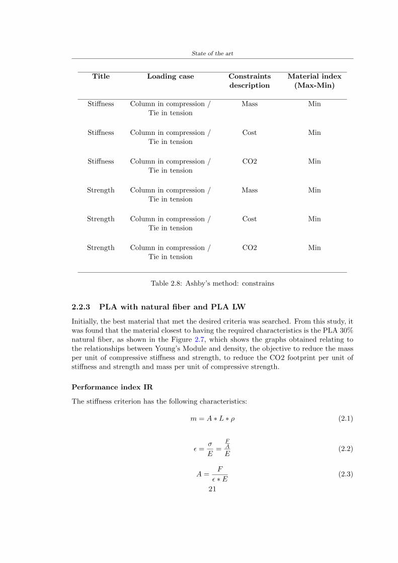
State of the art
Title Loading case Constraintsdescription
Material index(Max-Min)
Stiffness Column in compression Tie in tension
Mass Min
Stiffness Column in compression Tie in tension
Cost Min
Stiffness Column in compression Tie in tension
CO2 Min
Strength Column in compression Tie in tension
Mass Min
Strength Column in compression Tie in tension
Cost Min
Strength Column in compression Tie in tension
CO2 Min
Table 28 Ashbyrsquos method constrains
223 PLA with natural fiber and PLA LW
Initially the best material that met the desired criteria was searched From this study itwas found that the material closest to having the required characteristics is the PLA 30natural fiber as shown in the Figure 27 which shows the graphs obtained relating tothe relationships between Youngrsquos Module and density the objective to reduce the massper unit of compressive stiffness and strength to reduce the CO2 footprint per unit ofstiffness and strength and mass per unit of compressive strength
Performance index IR
The stiffness criterion has the following characteristics
m = A lowast L lowast ρ (21)
ε =σ
E=
FA
E(22)
A =F
ε lowast E(23)
21
State of the art
Ranking Title Function description
1 Biocompatibility It is the ability of a material the abilityof the material not to cause any local or
systemic adverse response in therecipient of the material
2 Biodegrability Biodegradable material do notbiodegradable under anaerobic conditions
3 Biomaterials - all The terms is used for biological naturalbio-derived bio-inspired material
4 RoHS (EU) Compliantgrades
Restriction of the use of certin prohibitessubstances (mercury cadmium
hexavalent chromium)
5 Polymer 20-100 (from the table with Plasticpolymers)
6 UV Resistance at UV sunlight
Table 29 Ashbyrsquos method limits
A =F lowast L lowast ρε lowast E
(24)
With fixed variables- F (the load) L (the length)With variables that depend on the material- E (Youngrsquos Module) ρ (density)
In general when a chart is created the distribution of the mass is represented in thefollowing modality like in Figure 27 [b] where the materials above the line have a lowermass while those below a greater mass
Following the results of the CES Edupack program that had selected the PLA withnatural fibers as the best the first print of the helmet was made with this materialusing as support the PVA Initially the result seemed satisfactory the helmet had a highdefinition but a fundamental problem was found by reducing the helmet in the water toallow the supports of PVA to dissolve In the act of diving in fact after ten minutessome parts of the helmet especially the front and rear have disintegrated making thehelmet unusable Because of this problem it was necessary to change the material
22
State of the art
[a]
[b]
Figure 27 CES EduPack Mass per unit of compressive stiffness [a] Youngrsquos Moduleand density [b]
Further investigations carried out by the Mondragon Unibertsitatea Additive Man-ufacturing Department revealed a new material the PLA Low Weight which during3D printing allows to obtain a weight of 65 lower than that which could be obtainedfrom the classic PLA as reported in the technical sheet of the filament produced by thecompany Colorfabb [7]
The investigation team of the Composite Department carried out tensile tests withsamples 3D printed at different temperatures as suggested by the manufacturer to obtainthe technical characteristics The temperatures examined are 200 220 250 260The datasheet shows the density can have values between 04 - 124 gcm3 the bed has
23
State of the art
to have a temperature between 50 - 60 the printing speed has to have values between40 - 80 mms This typology of PLA is expandible so much that rdquoAt around 230 thismaterial will start foaming increasing its volume by nearly three timesrdquo [7]
T[C] Section [mm2] Volumen [mm3] Mass [g] ρ[kgm3] E [Nmm2]
200 42235 1030117 12 1165 328807
220 43805 1655821 18 1087 265795
250 52412 1948139 17 873 178058
260 59655 1454377 12 825 117047
Table 210 Values about PLA LW tensile tests of MU Additive ManufacturingDepartment
From the tests that have been carried out on the material at different temperaturesthe printed sample is better at 250 with a volume of 1948139 mm3 and a section of52412 mm2 as shown in Table 210 For this reason the specific of the material thathave been taken into consideration are the following
- Density ρ = 873 kgm3
- Youngrsquos Module E = 1750 MPa
- Poissonrsquos ratio ν = 033
- Yieldrsquos stress σ = 2948 MPa
- Elongation at fracture = 491
23 Bio-inspired structures
When we talk about bio-inspired structures to nature we refer to structures that allowobtaining a low weight for the model that is realized and excellent absorption energy dur-ing the impact Recently the structures that have been most used in the biomimetic fieldare the rdquocolumns structures sandwich structures plates honeycomb and foamsrdquo[26]but aiming to achieve a structure increasingly with high absorption energy new struc-tures derived from plants and animals such as beetle horsetail turtle bird beak havebeen analyzed The first to create multi-cells tubes helicoidal structures the second tomulti-corner tubes [26]
The authors analyze the specific energy absorbed (SEA) by bio-inspired sandwichstructures per unit mass which can be derived from the following equation
EA(d) =
int dmax
0F (x)dx (25)
SEA(d) =EA(d)
m(26)
24
State of the art
Where EA is the energy absorption rdquomainly used to evaluate an energy absorberrsquosability to dissipate crushing energy through plastic deformationrdquo F(x) is the crashingforce dmax is the effective deformation distance [26]
What derived from their investigations is that having regard to a density of between0 and 1000 kgm3 the volumetric energy absorbed is higher for the beetle-inspired struc-tures than the others as shown in Figure 28 Based on this consideration it was chosento draw the helmet following this geometry
Figure 28 SEA of bio-inspired sandwich structures [26]
231 Beetle structure - Design of the model
To develop and increase lightweight high-strength and optimize bio-mimetic functionaland structural materials the trabecular structure of the beetle elytron is studied Thesingle structure is realized following the requirements cited by Zhang et al [39]
To realize the beetlersquos structure it is not enough to have information about the lengthof the side of the hexagon and the thickness but it is also necessary to take into accountthe relationship between the diameter of the circumferences present on the vertices ofthe hexagon and the measurement of the side The representation of a single cell is inFigure 29 It is shown in [a] a general structure with an edge of 12 mm circumferencersquosdiameter of 6 mm and thickness of 16 mm in [b] is shown the height of 20 mm
For the construction of the helmet a thickness of 12 and 16 mm was used the imageconcerns a proportion between the length of the hexagon side and the diameter of the
25
State of the art
circumference The side (distance between the centers of two circumferences) is twice thediameter measurement
[a] [b]
Figure 29 Beetle structure
232 Specific stress - PLA LW and EPS foam
To test the beetle structures compression tests were investigated The PLA LW structurewas inserted in a rsquodiskrsquo with a diameter of 100 mm and a height of 20 mm The area andthe volume of the disk is correspondingly 7854 mm2 and 157 10 mm3 The structuresexamined have different dimensions the edge L (distance between two centers of thecircumferences) had the following measures 9 10 12 14 16 mm the thickness of thecircumferences and edges are respectively of 16 mm for every structure and 12 mm forthe structure with L = 16 mm
The test was carried out with the Hoytom HM-D Testing Machine with capacitiesbetween 5 and 100 kN The test models were subjected to displacement loading at a rateof 1 mmmin as referenced by Chen et al[18] with a cylindrical specimen The specificstress of the structures was compared with the specific stress of a generic EPS helmetthe photos about it are shown in Figure 210 The EPS helmet structure is granular withpores inside The different grains dimension and these pores can be the reason for whichthe Stressrsquos values are between two values 07 and 116 MPa
Four parts of the EPS helmet were considered in the test the dimension and relativecharacteristic are in the Table 211 where m = mass A = area F = load ρ = densityR = stress Rρ = specific stress To calculate the values of stress about PLA structuresand EPS foam compression test graphs were been analyzed The stress value for eachstructure was calculated considering the single load the single area and the averagedensity value (14055 [kgm3])
The stress values of the PLA structures (Figure 211) and other characteristic valuesare in Table 212 where m = mass A = area F = load ρ = density
26
State of the art
[a] [b]
[c] [d]
Figure 210 EPS generic helmet helmet pictures [a] [b] and internal structureExternal granular structure [c] and pores [d]
[a] [b] [c]
Figure 211 PLA LW disks Grasshopper structure [a] PLA LW structure of 14 mm[b] PLA LW structure compressed [c]
27
State of the art
The results of the load-displacement graphs are affected by the geometry of the diskthe target is to valid for any shape or size for this is preferred to realize a diagramthat depends from σ (or stress) and the deformation ε (or strain) which can be definedrespectively as
σ =F
A0(27)
ε =l minus l0l
(28)
where F is the load during the test A0 is the area l0 is the initial length and l is thelength when the load is applied The areas considered for the EPS cube is reported inTable 211 in the second column the areas of the PLA structure is 7854 mm2 like thearea of the circumscribed disk
The values compared are shown in Table 213 and the graphs obtained by Matlabcode to analyze the recorded data of the compression machine are in Figure 213 and inFigure 212
Considering that the data provided by the compression machine are subject to noiseand disturbances it was decided to convert the original curve into polynomial type curvesthat allow obtaining the best interpolating curve for the data in question To obtain themit was divided the recorded data into two groups the first part from 0 until the end ofthe linear part and the second when the curve becomes linear again The best-fitting (inthe least-squares sense) was performed using the polyfit and polyval functions of MatlabThe first returns the coefficients of the p(x) with n degree the second evaluates p(x) ateach point in x The polynomial formula p(x) is shown in the Equation 29
pn(x) = anxn + anminus1x
nminus1 + + a2x2 + a1x+ a0 (29)
where a0 an are constants and x is the indeterminate The choice of the degree ofthe polynomial was made based on the criterion of wanting to obtain linear curves thatrespected the elastic trend at the beginning of the graph For this reason the degree ofthe polynomial is 1 Subsequently I searched through the intersection of the two lines forthe point that is equivalent to the maximum stress that marks the end of linearity
This value for EPS and PLA LW is the R [MPa] in the Table 213 The average stressvalue for PLA LW is 139 MPa and for EPS is 094 MPa The specific stress (Rρ) is 18MPa lowast m3)kg for the EPS found in CES 669 MPa lowast m3)kg for the EPS foam of thegeneric helmet and for PLA LW is 1161 MPa lowastm3)kg an intermediate value betweenthe two which is what we wanted to achieve
28
State of the art
m [g] A [mm2] F [N] ρ [kgm3]
EPS (CES) 50
16 9234 1063 13864
18 879 593 13651
21 858 833 14237
24 864 564 14468
Average value 14055
Table 211 Compression stress generic EPS helmet
L [mm] t [mm] m [g] F [N] ρ [kgm3]
9 16 214 7250 1363
10 16 192 5560 12467
12 16 201 8190 13051
14 12 138 8000 8961
Average value 12027
Table 212 Compression test PLA structures
PLA LW structure EPS structureρ= 12027kgm3 ρ= 14055kgm3
Edge [mm] R [MPa] Rρ103 Number R [MPa] Rρ103
EPS (CES) 09 18
9 173 1269 1 116 824
10 139 1114 2 08 568
12 138 1057 3 105 746
14 108 1205 4 077 540
Average value 139 1161 094 669
Table 213 Specific stress calculus PLA LW and EPS calculus ρ = density R = stressRρ [(MPa lowastm3)kg] = specific stress
29
State of the art
Figure 212 Compression test Stress-Strain diagrams - EPS
Figure 213 Compression test Stress-Strain diagrams - PLA LW
30
Chapter 3
Methodology
31 3D scan
311 3D Sense 2 scanner and Meshmixer - Reverse reconstruction
Standardized measures were not taken into account for making the helmet but the sizewas obtained through a 3D scan of my head
The scanner used is 3D Sense 2 by 3D Systems which has a minimum scanningvolume of 20 x 20 x 20 cm and a maximum scanning volume of 300 x 300 x 300 cmTo scan my person I was helped to get a full view at 360 at an appropriate distanceReal-time visualization of the captured images was shown through 3D Sense softwareThe idea of scanning the head with the scanner refers to the methodology used by Wanget al [30] They used a reverse reconstruction functional for me to realize the helmetsurface made to measure my head and like them a silicone pool cap was used to makescanning as smooth as possible The authors claim the head scan rdquocan also be used toobtain information about the objectrsquos surface which is then reconstructed utilizing thecomputerrsquos three-dimensional model via reverse modelling softwarerdquo [30] that in my caseis Autodesk Meshmixer
The files it was could get from the scan were stl obj and ply format they wereexported to obj to work in the next step with Autodesk Meshmixer that allowed tomodify and homogenize the 3D image obtained from the scan
In Meshmixer through the selection and delete commands the superfluous parts weredeleted that had been acquired and with the inspector and the DrawDraw2 commandsthe vertices were moved locally along a pre-defined direction and with Smooth the surfacemore homogeneous was made The sequence of steps is shown in the Figure 31
312 3D scan analysis and extraction of features
In Chapter 2 the directives imposed by the BS EN 960 Standard were examined concern-ing the definition of the helmet and the measures to be respected in the field of visionand the part of the helmet was to carry out impact tests
In Figure 32 the features defined complying with the Standardrsquos rules are repre-sented To define these features the software NX was used The angle in the subfigure
31
Methodology
[a] [b] [c] [d]
Figure 31 Sequence of 3D head scan 3D scanner acquisition [a] scan after reparationwith Meshmixer [b] solid scan vision frontal and lateral [c] [d]
[b] is bigger than 105 (as defined by the Standard) while the degree in the subfigure [c]is 25 By defining the construction lines to be respected of the helmetit was necessary todraw the design of the surface not using the software NX but changing with Rhinocerosto create a SubD or SubDivision surface
32 Helmet design
321 Rhinoceros - Helmet surface
After realizing a rsquocleanrsquo Wang et al [30] subdivide with lines and then sectors the headto create the surface of the helmet They used the technique of NURBS a Non UniformRational Basis-Splines which mathematically models a 3D geometry while thanks tothe Rhinoceros 3D organic shapes was draw SubD surfaces These geometries allow tosplit the mesh into small polygons and consist of lines with which easily the shape ofthe object can be modified with a surface already created changing the position of aline automatically the remaining part of the geometry adapts to the changes With thistechnique the rsquosurface basersquo of the helmet was realized with the size of my head Therepresentation of the realized SubD is in Figure 33
322 Grasshopper - Helmet structure
The next idea is the creation on the surface of the beetle structure with different di-mensions modelling the helmet that is not a linear surface It was decided not to buildthe structure with a software CAD because to model an already complex structure on acurved surface would mean to model a cell for a cell
To solve this obstacle a Rhinoceros plug-in was used Grasshopper GH idealized byRobert McNeel and associates creators of Rhinoceros Using GH does not mean drawinggeometries by connecting points and drawing tools because it is based on algorithmicmodelling used in architecture and engineering for 3D modelling
The modelling takes place through a node diagram that the software will convert intoa code-algorithm in GH it is possible to define the variables and parameters and inRhinoceros in real-time it is possible to view the object GH allows for varying the
32
Methodology
[a] [b]
[c]
Figure 32 Featurersquos extraction in [a] is represented the impact line in [b] and [c] twoprospective about the definition of the field of vision
[a] [b] [c]
Figure 33 SubD representation lateral view [a] top view [b] front view [c]
geometry to your liking by varying a simple parameter of the diagram as everything willbe remodelled according to the change made
In the following Figure 34 it is shown an example of a structure that was used fordistinct subgroups of helmet areas The idea was to insert smaller cells in the frontal andlateral zone and larger ones in the upper area In the first image [a] is shown the part of
33
Methodology
the helpful diagram to create the beetle structure to establish the size of the cells andthe extrusion the second image [b] contains the part of the diagram with which I appliedthe structure previously created to the SubD
The structure used to place and adapt the beetle structure to the surface is theSrfMorph while the yellow rsquowindowrsquo that contains numbers serves to select the parts ofthe surface where to apply the geometry created In accord with the GH diagram in
[a]
[b]
Figure 34 Grasshopper diagrams
Figure 34 [a] it is possible to see the steps executed to realize the structure Initially inthe xy-plane a hexagonal grid was drawn through the Hexgrid command in which youcan input the length of the hexagon edge and the number of grid elements (selected bytrial) Then the circumferences was drawn in proportion to the hexagon dimensions asspecified in the Chapter 2 and shown in Figure 35 [a] In figure [b] the rsquocutrsquo made atthe circumferences is visible this subdivision was necessary for printing purposes In thelast photo [c] the structure highlighted in green in [b] was extruded setting a distance
34
Methodology
of 20 mm
[a] [b] [c]
Figure 35 Construction sequence of the geometry of the helmet
In the diagram in Figure 34 [b] there is the application of the structure created bi-dimensionally to the SubD surface of the helmet visible by unlocking the SubD commandof the diagram and in Figure 36 [a] Upper this the referential geometry of the group ofsurfaces was superimposed where it was to be applied the newly created structure (visiblein darker red) the SubD indices are in the yellow box of the diagram
Through the SrfMorph command the location of the structure was granted In Figure36 [b] at the darkest red of the figure [a] with the above command it was possible toplace the structure
[a] [b]
Figure 36 Application of the geometry created to the helmet surface
Overall the diagrams with specific structures are five one for the front two equal forthe side parts one for the top shown in the previous Figure 36 and one for the back
The hexagons in the structure have a dimension varying between 8 mm and 14 mmof side the largest is found at the top later at the back in the sides and the smallest atthe front In Figure 36 [b] the presence of not only hexagonal structures is visible Thegeometry used does not allow the homogeneous arrangement on the entire surface andrequires different structures Automatically the choice of GH to optimize the structurewas to insert quadrilateral
As described above the helmet has different dimensions of the structure divided asvisible in Figure 36 in a quadrilateral This causes a discontinuity between zones withdifferent sizes due to the geometry of the construction
To eliminate this problem and realize the design homogeneous grids were inserted
35
Methodology
in the affected areas as shown in Figure 37 This insertion however proved to beinteresting and strategic researching in this regard studies were realized to demonstratethe insertion of a rectangular grid inside the hexagon grid was helpful for the transmissionof stress in the structure As cited by Sun et al [40] rdquothe mechanical properties of thesesandwich structures are often limited by local failures such as face-core debonding or corecollapserdquo Carrying out compression tests have effectively demonstrated that the insertionof the grid allows rdquoprovided increased stiffness specific stiffness energy absorption andcritical loadrdquo [41] As shown in the graphic [c] of the Figure 37 the honeycomb structuregives a force of 7 kN while with a grid the value is 11 kN and with the combinationexceeds 22 kN In addition in the left front a plaque to customize the helmet wasprepared Figure 37 [a]
[a] [b]
[c]
Figure 37 Grid in the helmet [a] hybrid structure with hexagons and grid [b] [40]compression test results of the hybrid structure [c] [41]
33 3D Print
After having achieved the CAD (Computer Aided Design) of the helmet in order tobe printed it must be converted and saved in format STL (Standard TriangulationLanguage) - Binary compatible with the printing machine and useful for transformingsolid object surfaces into triangles The steps to be taken are the following
bull CAD file realization
bull CAD export in format STL to Simplify 3D the software that shows slider layersand then- rotate and position the object according to geometry and the positioning of any
36
Methodology
supports- setting printing parameters- item manual andor automatic positioning of supports- slider display layers
bull import file gcode to printer
331 Printer and parameters
The program used to visualize how the helmet slices layers before sending it to the printerand to set the parameters is as anticipated Simplify 3D
To make the printing not being a flat geometry it is necessary to place the supportsThe idea was to use water-based supports that the helmet would automatically dissolveonce placed in the water After testing different types of water-soluble PVA the choicefell on eSun 3D Printing Filament PVA (water-soluble support) Before choosing theoptimal position for printing several tests were carried out and to decrease the numberof the supports significantly and allows an optimal printing of the outer part an emptyrsquospherersquo that self-sustains below the helmet was placed as shown in Figure 38
In the image [a] you can see the first print position tried with which an external partof the helmet very damaged was obtained because of the contact supports-helmet In [b]the empty rsquospherersquo is shown to optimize the number of supports and in the last photo [c]there is the full version at the end of print
[a] [b] [c]
Figure 38 Printing supports
The printer that has been used for printing is the Raise 3D Pro2 with double extrudersand nozzles of variable size from 02 mm to 1 mm after some test prints with the PLALW and the structure in created the size that allowed me to have a good compromisebetween printing time and accuracy was 06 mm Using 04 mm the printing time wasexcessive even if having the smaller nozzle diameter means having more precision withthe 08 mm nozzle the quality of the structure was not excellent as seen in Figure 38[a]
Another factor that had to be taken into account is the characteristic of the PLA-LWto expand As the printing temperature and the printer used vary the expansion andcharacteristics of the material change The use of the 06 mm nozzle associated with
37
Methodology
Parameter Left extruder Right extruder
01cm Material 01cm PVA 01cm PLA LW
Extruder toolbox index Tool 0 Tool 1
Nozzle diameter 06 mm 06 mm
Extrusion multiplier 1 05
Extrusion width Auto (072 mm) 05 mm
Layer x
Infill Rectilinear - 50
Supports (Automatic and not) Infill 50
Temperature 210 250
General parameters
Primary layer height 03 mm Top solid layer 4
Bottom solid layer 2 Outline 2
Heated bad 60 Speed 40 mms
Table 31 Printing parameters
Raise 3D allowed me to get good results The choice of this printer was not random ithas in fact the characteristic of making extremely precise prints The Raise has accuracyin placing the object on the printing bed of 078 microns on the xy axis and a resolutionfor layers of 001 mm
The final version of the helmet is visible in Figure 39 and it is possible to compare itwith the preview version in Rhinoceros in Figure 310
38
Methodology
[a] [b]
[c]
Figure 39 Views of the helmet
[a] [b]
Figure 310 Views of the helmet (GH version)
39
Chapter 4
Experimental evaluation
41 Experimental tests
411 Drop-weight impact test machine
In order to calculate the contact force peak and the difference of energy absorbed duringthe impact between the reference helmet and helmet with the beetle structure in PLA-LW dynamic impact tests were carried out using the Fractovis Plus an impact testmachine
In this way it is possible to monitor the evolution of the above variables from theinitial to the final instant of the impact The machine can withstand a load with a rangevariable from 2 to 70 kg with a maximum speed of 46 ms and a maximum height of1 m The values chosen for the test are the following 5 kg weight maximum speed andmaximum height The Anvil that was used is a disc diameter of 60 mm
As shown in Figure 41 and explained by Crupi et al [37] the machine consists ofa sensor capable of recording the speed before impact the impactor that can have avariable mass (a weight of 5 kg in my test) a system to guarantee that there are nomultiple impacts after the first and that work as a shock absorber and clamping systemwhere the object to be tested is placed
The tests that have been carried out are in total four two related to the helmetoptimized with PLA-LW and two with two generic helmets of different brand in EPS
42 PLA LW helmet
To perform the dynamic test on the helmet of PLA considering the difficulty of printingit was helpful to use a test helmet with imperfections to understand where the impactwas concentrated in a single part or distributed The images of Figure 42 show a helmetwith not well defined edges and inaccurate print but exactly localizes the impact zoneThanks to this test it was possible to take into account only one helmet area shown inFigure 43 to have the exact curve of the structure bio-inspired with PLA-LW
40
Experimental evaluation
Figure 41 Drop-weight impact test machine [37]
[a] [b]
Figure 42 Test 1 PLA-LW helmet
43 EPS helmet
To carry out dynamic tests and extract the technical characteristics of the helmettwohelmets were bought in a sports store both EPS and being on the market both certifiedThe brands of the two helmets are DTB and VAN|RYSEL and the average weight ofthe two is 223 g Two different helmets have been chosen to have a more certain andclear classification of the characteristics They are shown in Figure 44 and Figure 45
41
Experimental evaluation
[a] [b]
Figure 43 Test 2 PLA-LW helmet
[a] [b] [c]
Figure 44 Test 3 EPS helmet
[a] [b] [c]
Figure 45 Test 4 EPS helmet
44 Results
441 First results - PLA-LW and EPS helmet
Figure 46 shows two types of trends related to the two different models of the helmetThe force evaluated for PLA-LW has higher force peaks but is more concentrated and
42
Experimental evaluation
propagates less than EPS The graph shows the peaks of each curve highlighted with a redcircle In tests 1 and 2 for the PLA-LW as mentioned earlier the values are higher about7301 N for the complete helmet and 3996 N for the portion of helmet This difference isdue to the inaccuracy of the first full helmet during the printing phase In Figure 42 itis visible the low homogeneity and precision Therefore the first test with full helmet wasused only to define the area of interest of the impact which turns out to be localized Forthe other two EPS curves the values are only slightly lower compared to the PLA-LWequal to 3620 N and 3295 N but the trend is much more distributed
Figure 46 Dynamic machine test - Force
With the data obtained from the impact machine it was possible calculate not exclu-sively the value of force but itrsquos also possible to view the energy curves A resume aboutthe values and energy of the force is in the following Table 41
Test Peak force [N] Peak energy [J]
Test 1 - PLA LW (inaccurate) 730130
Test 2 - PLA LW (portion of helmet) 399643
Test 3 - EPS (DTB helmet) 362007 509
Test 4 - EPS (VAN|RYSEL helmet) 329546 4198
Test 5 - PLA with TPU 45421 5022
Table 41 Energy absorbed in dynamic test
43
Experimental evaluation
442 PLA-LW helmet with TPU cover
As it is possible to see in Figure 47 and as highlighted the first tests concerning thebio-inspired structure and the PLA-LW are far from my expectations considering thelittle distribution of force in comparison with the EPS foam and consequently a smallamount of energy absorbed
Figure 47 Dynamic machine test - Energy
To improve this impact damping factor the idea was to create a cover for the helmetin flexible TPU trying to absorb impact energy The TPU used is a flexible material ofthe brand Ninjaflex used in sports by the application in helmets and shoes to cushionbumps during the game Generally in the helmets (baseball helmet for example) theTPU is inserted internally in contact with the head In my case the TPU structurein addition to creating a shock-absorbing and durable cover creates a custom cover thehelmet and for the person This cover was also made with the Raise 3D printer
As shown in the Figure 48 [a] the infill of the part in contact with the helmet hasa percentage of 100 the filling of the other part of the structure is not complete butonly 15 and the internal structure is hexagonal to recall that of the helmet The desireto insert a structure with a rsquoraisedrsquo geometry is for visual and aesthetic reasons as youhave the feeling of greater protection and not filled is inspired by the machine CitroenCaptus whose bumpers (Airbump) are full of air The failure to realize empty structuresis due to the need to place any internal supports not removable
The idea was to create a cover that allow you to see of the internal structure of thehelmet and that protect specific areas the front the two sides the top and the posteriorWhat which was thought for this reason was to create the shape of a flower with four
44
Experimental evaluation
petals Figure 48 [b]In this way to perform dynamic impact tests as shown in Figure 49 [a] the cover was
positioned at the top of the helmet and the impact was performed in the centre of thersquoflowerrsquo which corresponds to the higher upper part where the structure has larger cellsize The impact parameters are the same as those used in previous impacts 5 kg weightmaximum speed and maximum height The Anvil that was used is a disc diameter of60 mm In photo [b] it is evident the difference between the structure that received theimpact with protection (left) and without protection (right) Without protection duringthe impact there was a perforation of the structure with a concentration of force at a locallevel as you can see in the Figure 46 in the case of TPU the impactor did not perforateand crossed the structure thanks to the cover of TPU that cushioned the shock At themoment of impact the impactor bounced
[a] [b]
Figure 48 TPU cover
[a] [b]
Figure 49 PLA-LW with TPU - dynamic impact [a] and differences between thehelmet with TPU and without TPU cover [b]
45
Experimental evaluation
The Figure 410 includes the diagrams relative to the dynamic impacts In [a] thereare already analyzed EPS results in [b] a comparison between the test on the portionof helmet in PLA LW with and without the TPU cover in [c] the overall comparison ofcurves shows a much more similar EPS trend if the TPU is placed above the structure inPLA LW to soften the blow and absorb the same energy [d]
46
[a]
[c]
[d]
Figure 410 Comparison between PLA-LW with TPU and EPS
Chapter 5
FEM Validation
51 Impactor - Anvils definition
Before to start to work in Abaqus it was necessary to search in the literature the materialwith which the anvil was been realized Milne et al [23] established the densityrsquos valuethe Youngrsquos Module and Poissonrsquos ratio for the Flat and Kerbstone Anvil
- Density ρ = 7800 kgm3
- Youngrsquos Module E = 200000 MPa
- Poissonrsquos ratio ν = 03
Inserting the data in the CES EduPack program specifying the mechanical andphysical properties the material corresponding to these characteristics is Stainless steelaustenitic (ASTM F1586) medium-hard
Initially the proposal was to create a conservative system to evaluate the absorptionenergies values and apply this value to a vibration system but the helmet needs dampingto be realized it was impossible to use a system without losses in this modality Thisis why a numerical calculation was carried out by performing two types of simulationsexplicit dynamic step and static step
The idea to realize the theoretical impact is to regard the movement of the anviland not the helmetrsquos movement which is fixed The velocity is the same cited in thenormative EN 1078 542 ms for the Flat anvil and 457 ms for the Kerbstone anvil
In performing the simulations It was given more relevance and perform tests withthe Kerbstone Anvil This choice was done because the geometry with which it is beenrealized (following as defined in the legislation) allows the helmet to be more subjectedto stress this involves the definition of higher stress limits compared to the Flat Anvil
The mesh size that has been used is the same in the case of the simulation of thehelmet optimized in PLA-LW and the full helmet in EPS of 7 mm The impactor isconsidered as a Discrete rigid body with its specific Reference Point (RP) like shownin Figure 51 for this reason it is not a solid but it is composted only by shells Inthe same image [b] there is the FEM representation of the model and in Table 51 thecharacteristic of FEM with quadrilateral (R3D4) and triangular elements (R3D3)
48
FEM Validation
Object Elementnumber
Elements Shape Geometricorder
Global size[mm]
Kerbstone 230 Quadrilateral - R3D4 Linear 7
Kerbstone 8 Triangular - R3D3 Linear 7
Table 51 Mesh element - Kerbstone Anvil
[a] [b]
Figure 51 Kerbstone anvil in the simulation like discrete rigid body [a] and FEMelements [b]
511 PLA LW - Plastic characteristics
The PLA-LW as explained in the Chapter 2 is new material on the market and producedby the only Colorfabb company for this reason few tests have been carried out to defineits technical characteristics and through tensile tests of the 3D printed specimens it waspossible to define an elastic limit as reported in the Table 210
In the context of simulations to reproduce the impact and deformation of the helmetis also necessary to consider the plastic characteristics of the material Not possessingany reference value in this regard tests were performed through a Static Step initiallyand then an Explicit Dynamic Step in Abaqus
The structure chosen to consider as a reference it is one of the structures previouslysubjected to the compression test having the side L=14 mm As for the reproduction ofthe compression disks initially they were reproduced according to the geometry of theHoytom HM-D Testing Machine considering the bodies mentioned above as discrete 3Drigid discrete The measure was the diameter of 200 mm and the height of 20 mm
After an initial analysis it was observed that the computational time of the simulationprogram was very high so it was decided to change the geometry to have a rsquodisk-surfacesrsquo(equally 3D rigid-discrete) which allowed me to have a smaller number of nodes for themesh and consequently a better computational time The representation of the opti-mized structure in PLA-LW and the disks used for simulated compression is in Figure 52
49
FEM Validation
[a] [b]
Figure 52 Representation of the samples used for the simulation of the compressiontest In Figure [a] the disks of the Hoytom HM-D Testing Machine in figure [b] the
representation of the same as simple surfaces
As shown in Figure 52 the disks are considered 3D discrete hard bodies so it waschosen for both a point the reference point RP where to apply the characteristics relatedto the two bodies As for the compression test it was established
bull the movement of a disk and fixed the second through a boundary condition impos-ing an Encastre therefore unable to move and rotate in xyz directions
bull for the opposite disk the boundary condition relative to the 15 mm displacementwas applied which is the parameter that it was observed to determine the end ofthe compression with the machine This shift is shown by the orange arrow in figure[b]
bull between the upper surface and the disk e the disk with the lower surface it wasinitialized a general contact with normal behaviour through rsquohardrsquo contact andtangential behaviour with a coefficient of friction of 02 with directionality imposedon rsquoisotropicrsquo
The next step was to define the mesh of the components whose parameters are shown inTable 52 while the representation of the FEM is in Figure 53 with the representationof the simulation and real compression test
Object Elementsnumber
Typology Geometricorder
Globalsize [mm]
Disk (14mm) 80910 hexaedral - C3D8R Linear 07
Impact disks 206 quadrilateral - R3D4 Linear 20
Impact disks 6 triangular - R3D3 Linear 20
Table 52 Mesh element - Compression test simulation
As previously announced a static simulation was initially performed with a StaticStep with Step Time equal to 900 (obtained going to consider the speed of 1 mmmin of
50
FEM Validation
[a]
[b] [c]
Figure 53 FEM representation [a] and compression test simulation [b] and realcompression [c]
the compression test and the displacement of 15 mm) However the complex geometryof the structure and the high time set by Step Time did not allow a correct definitionof the parameters of the plastic characteristics of the material the simulation was notable to continue once reached a Step Time of approximately 220 That is why it waschanged by choosing an Explicit Dynamic step
Leaving all the parameters of the boundary conditions unchanged the Step Time wasmodified imposing it to 001 The ability of the explicit dynamic to work with non-linearand contacting structures allowed me to achieve results The results obtained are shownin Figure 54 with the blue curve and were obtained through the iteration of differentPlastic Strain and Yield Stress values in Abaqus while the red line is the result of thereal compression test a similar curve trend was obtained but it is not possible to obtainthe same curve taking into account problems of printing inaccuracy
512 First test - helmet
The initial idea was to perform a simulation imposing the speed of 457 ms to theimpactor tie the helmet in EPS and PLA and compare the absorbed energies Theproblem it was encountered is related to the mesh of the helmet optimized in PLA andwith minimum dimensions of the elements and distinct elements it was not able to solveit
51
FEM Validation
[a]
YieldStress
PlasticStrain
1 47 0
2 7 001
3 75 005
4 10 01
5 108 1
6 115 15
7 12 2
[b]
Figure 54 Representation of the two curves related to the simulation in Abaqus of thecompression test and the data obtained from the real test to obtain the plastic
characteristics of the material
513 Second test - plane
The first solution is the one shown in Figure 55 To realize the simulation it was realizeda section of the helmet to involve a smaller number of elements and nodes Again thesimulation for the EPS helmet was successful while the simulation with the bio-inspiredstructure was interrupted by excessive distortion of elements
The previous images show the impact is very localized in the impacted area and theidea to achieve a complete simulation is not to consider a curved portion of the helmetbut a plane In this way it was possible to solve the problem and obtain a completesimulation for the bio-inspired structure
FEM element
Below in Table 53 there is the definition of the elements used for the PLA-LW and EPSplane in the simulation to simulate the impact and to control the energy-absorbing whilethe anvil characteristics are described in Table 51
514 EPS impact simulations
In order to proceed with the simulation it was imposed some boundary conditions thatregard ties and forces
bull the movement of the plane is fixed through an Encastre therefore unable to moveand rotate in xyz directions
52
FEM Validation
[a]
[b]
Figure 55 Impact simulation parts of EPS and PLA helmet
Object Elementnumber
Elements Shape Geometricorder
Plane (PLA) 38896 Tetrahedral -C3D10M
Quadratic
Plane (EPS) 2100 Hexahedral - C3D8R Linear
Table 53 Mesh element - plane impact
bull to create the impact it was set a speed of 457 ms at the reference point RP of therigid body which is the impactor Kerbstone Anvil shown in Figure 56
bull between the upper surface of the plane and the impactor it was initialized a Sur-face to Surface contact with normal behaviour through rsquohardrsquo contact and tangen-tial behaviour with a coefficient of friction of 02 with directionality imposed onrsquoisotropicrsquo
bull the rotation in x y z relative to the RP of the rigid discrete impactor body is locked
53
FEM Validation
In addition it was characterized the plane in the part of the materials with the char-acteristic values of the EPS mentioned in Chapter 221 The Von Mises Stress valueapparently low is relative to the Yield Stress of the EPS material equal to 09 MPa
Figure 56 EPS Boundary conditions and Load
515 PLA LW impact simulations
As also required in the case of the EPS plane in order to proceed with the simulationsome boundary conditions were imposed that regard ties and forces
bull the movement of the plane is fixed through an Encastre therefore unable to moveand rotate in xyz directions
bull to create the impact a speed of 457 ms was set at the reference point RP of therigid body which is the impactor Kerbstone Anvil shown in Figure 58
bull between the upper surface of the plane and the impactor it was initialized a Sur-face to Surface contact with normal behaviour through rsquohardrsquo contact and tangen-tial behaviour with a coefficient of friction of 02 with directionality imposed onrsquoisotropicrsquo
bull the rotation in x y z relative to the RP of the rigid discrete impactor body is locked
In addition the plane was characterized in the part of the materials with the characteristicvalues of the PLA mentioned in the Chapter 223 and 511
Figure 58 Boundary conditions and Load
54
FEM Validation
[a]
[b]
Figure 57 EPS impact simulation
52 Results
In Figures 59 and 57 it is shown how the structure in PLA LW has a more concentratedstress distribution of the structure unlike EPS The maximum value for the Von Misesstress is 09 MPa in EPS structure and 3634 MPa in PLA LW structure Once thesimulations were obtained the next step was to go and compare the energies absorbed bythe two structures The energy calculated by Abaqus that has been taken into account isPlastic Dissipation To make a comparison the data of the two energies were representedin a single graph
What emerges from the graph is that about the impact made with the KerbstoneAnvil the energy absorption is more excellent although only slightly for the PLA LWthan for the EPS From the graph in Figure 510 a value of 41 J is shown for the EPSand 51 J for the PLA LW
55
[a]
[b]
Figure 59 PLA impact simulation
[a]
Figure 510 EPS and PLA LW energy comparison - Abaqus simulation
Chapter 6
Head Injury Data
For the statistical analysis the injuries related to the accident data were categorised intothe following types and levels based on the details of the medical report [11] about theEN 1078
bull Head Injury Criterion (HIC)
bull Peak Linear Acceleration (PLAc)
bull Gadd Severity Injury (GSI)
bull Diffuse axonal injuries (DAI)
61 Abaqus simulation
Until now the purpose of the simulations has been to determine which between the twomaterials and the two structures of EPS and PLA LW could absorb more energy duringthe impact but no simulations have been carried out in compliance with BS EN 1078on the helmet impact tests To calculate the injuries listed in the previous paragraphhowever we need the acceleration values in the three directions related to the subjectrsquoshead
To realize it the scan of my head already rsquocleanrsquo was considered of which it has beencalculated the inertia thanks to the automatic SolidWorks calculation and evaluated theweight with the Table 24 the structure of the helmet was placed for the EPS and thePLA LW over the head as shown in Figure 61 Also this time being able to mesh theentire helmet in PLA LW was impossible due to the excessive distortion of some elementsduring the simulation so it has been tried to make a section of the structures of thehelmet and results were obtained
57
Head Injury Data
[a] [b]
Figure 61 My scan head - CAD [a] head imported in Abaqus[b]
Initially the simulation had these characteristics as shown in the following Figure62 considering the helmet was not sectioned As explained earlier it was not possibleto get to simulation in the case of the optimized structure in PLA LW for this reasononly a part of the helmet was considered in both cases shown in Figure 63
[a]
Figure 62 Simulation based on BS EN 1078
58
Head Injury Data
[a] [b]
Figure 63 Simulation based on BS EN 1078 with head
In order to proceed with the simulation some boundary conditions that regard tiesand forces have have imposed
bull two reference points RP were created the first in the inertia centre of the headthe second relating to the Kerbstone Anvil which is a discrete rigid body
bull in the reference point RP of the head in the definition of the engineering features5 kg was inserted for the weight and an inertia I11 = 564464E+07 gmm2 I22 =460654E+07gmm2 I33 = 187302E+07gmm2
bull to simulate the impact it was set a speed of 457 ms at the reference point RP ofthe head in z-axis direction
bull a general contact with normal behaviour through rsquohardrsquo contact and tangentialbehaviour with a coefficient of friction of 02
bull between the upper surface of the helmet and the impactor it has been initializeda Surface to Surface contact with normal behaviour through rsquohardrsquo contact andtangential behaviour with a coefficient of friction of 02 with directionality imposedon rsquoisotropicrsquo
bull the movement between the Kerbstone anvil and the helmet is fixed through anEncastre therefore unable to move and rotate in xyz directions
bull the rotation in x y z relative to the RP of the rigid discrete impactor body is locked
FEM element
As reported in Table 53 the portion of the helmet in EPS has used a mesh with hexahe-dral elements of linear order For the structure (beetle) of PLA LW given the geometry
59
Head Injury Data
complexity it was necessary to use a quadratic order of tetrahedra For the mesh of thehead instead in both simulations have been used quadrilateral elements of linear orderas reported in the Tables 61 and 62
Object Elementnumber
Elements Shape Geometricorder
Head 3755 Quadrilateral - R3D4 Linear
Head 34542 Quadrilateral - R3D3 Linear
Helmet (PLA) 272302 Tetrahedral -C3D10M
Quadratic
Table 61 Mesh element - Head simulation with PLA LW (beetle) helmet
Object Elementnumber
Elements Shape Geometricorder
Head 3755 Quadrilateral - R3D4 Linear
Head 34542 Quadrilateral - R3D3 Linear
Helmet (EPS) 72280 Hexahedral - C3D8R Linear
Table 62 Mesh element - Head simulation with EPS helmet
62 Results
Figure 64 represents the simulation in line with BS EN 1078 concerning the helmet inEPS [a] and the helmet with bio-inspired structure in PLA LW For both simulationsVan Misesrsquo stress has Yield Stress values in the case of EPS which is 09 MPa and theplastic behaviour combination of PLA LW [b]
In the case of head and Kerbstone Anvil stress was not assessed as they were previ-ously defined as discrete rigid bodies
63 Head Injury Criterion
The HIC quantifies head impact severity by incorporating time of acceleration exposureand acceleration magnitude it is calculated in post-processing phase with the followingEquation 61
HIC15 =
[1
(t1 minus t2)
int t2
t1
a(t)dt
]25(t2 minus t1) (61)
60
Head Injury Data
[a]
[b]
Figure 64 Results simulation based on BS EN 1078 with sectioned head
For this analysis a(t) is the acceleration calculated in the centre of mass of the head(corresponding to the reference point RP) expressed in g and the time interval (t2 minus t1)was chosen to maximize HIC over a maximum duration of 15 ms
Matlab and the trapz function were used to calculate the HIC to integrate accelerationover time t2 and t1 were considered initial and final times of the simulation t1 = 0 sand t2 = 10 s time less than 15 s
HIC value of 198 was obtained for EPS and 87 for PLA LW Considering the Hayeset al [16] document about the HIC values and the graph in Figure 65 developed bythe author it is possible to find the percentages related to the different injury AIS1 -AIS6 which correspond respectively to lower and higher severity while in Figure 66 therelative fatality to every value of AIS is shown The values obtained for the HIC andother criteria are shown in Table 63 The HIC value for EPS is 198 for PLA LW it is
61
Head Injury Data
Figure 65 Head injury risk curves based on HIC values [16]
Figure 66 The abbreviated injury score versus fatality rate [16]
87 Analyzing the data and comparing them with the curves of the Figure 65 I obtain
bull a percentage between 20 - 30 of AIS 1 for EPS 10 - 20 for PLA LW
bull a percentage between 10 - 20 of AIS 2 for EPS and 0 - 10 for PLA LW
bull for AIS 3 AIS 4 AIS 5 AIS 6 the percentages for both structures is between 0 -10
Comparing these percentages with the fatality rate of Figure 66 it is clear there is a riskof Moderate and Minor fatality in the case of EPS and PLA LW as all values are between0 and 30
62
Head Injury Data
HIC PLA [g] GSI E [J]
EPS 198 97 361 37723
PLA LW 87 75 169 44102
Table 63 Head Injury Data - values
64 Peak Linear Acceleration
The resultant linear acceleration versus time curve was calculated according to Equation62
γ(t) =radicγ2x(t) + γ2y(t) + γ2z (t) (62)
where
bull γ(t) is the resultant linear acceleration (g)
bull γx(t) is the linear acceleration in x axes (g)
bull γy(t) is the linear acceleration in y axes (g)
bull γz(t)is the linear acceleration in z axes (g)
The value of the impact should never exceed 250g [9] Cripton at all [9] in their studyexamined a helmet with expanded polystyrene (EPS) Figure 68 shows maximum HIC forhelmeted and unhelmeted drops from all heights For each drop height helmets reducedHIC relative to unhelmeted drops IARV value is 180g The acceleration in the two casesis shown in Figure 67 and the maximum values are 97g for EPS and 75g for PLA LWas reported in Table 63 The two values considering a maximum value calculated byCripton [9] of 180g are amply optimal and comply with the standard of 250g
65 Gadd Severity Index
Gadd proposed the Severity Index Criteria shown in Equation 63 Following this crite-rion the GSI values that are over 1000 produce serious internal head injury [33]
GSI =
int t1
0a(t)25dt (63)
Where
bull a is the linear acceleration (g)
bull t is the duration of the impact (s)
I calculated the GSI with the function trapz between 0 and t and the resulting valuesare 361 for the EPS and 169 for the PLA LW which comply with the limit
63
Head Injury Data
Figure 67 Peak accelerations for both helmets
Figure 68 Peak accelerations for both helmeted and unhelmeted drops Numbers overbars indicate peak acceleration For 2 m drop height results stated are the mean value
calculated from three drops [9]
64
Head Injury Data
66 Diffuse Axonal Injury
DAI cases covered all incidences in which neurological injuries occurred as well as con-cussion unconsciousness and coma
In order to assess the risk of head trauma in terms of diffuse axonal injury (DAI)Milne et al [23] defined a model based head injury criteria as follows obtaining theresults in Figure 69
bull 50 risk of moderate neurological injury (DAI1+) Brain Von Mises shearing stressof 28 kPa
bull 50 risk of severe neurological injury (DAI2+) Brain Von Mises shearing stressof 53 kPa
[a]
[b]
Figure 69 Peak intra-cerebral shearing stress computed with the helmet model coupledto the human head model for all impact points (a) Flat anvil (b) Kerbstone anvil [23]
65
Head Injury Data
67 Energy absorbed
In Figure 52 during the impact test between the kerbstone Anvil and the plan with thebio-inspired structure in PLA LW and EPS it was found that the PLA LW althoughwith a small difference of 10 J absorbed more energy in comparison with the EPS Whenthe test is carried out in compliance with BS EN 1078 and the head with a speed of 457ms (corresponding to the kerbstone Anvil) as shown in Figure 610 also in this casethe PLA LW with the optimized helmet structure manages to absorb more energy (evenif the difference is very low) compared to the EPS The maximum energy value in PLALW is 44102 J of EPS is 37723 J
Figure 610 Energy absorption - BS EN 1078
66
Chapter 7
Conclusion
71 Conclusion
In this thesis work a bicycle helmet with a bio-inspired structure in PLA LW and 3Dprinted was created The initial approach was to introduce an innovative aspect tostandard EPS helmets not using foam but a polymer with new geometries able toabsorb much energy during the impact For this reason the beetle structure has beenpreferred relying solely on the hypothesis encountered in the literature of its quality inabsorbing energy
Combining the new material of the PLA LW and beetle structure has made possiblethe development of new material satisfactory characteristics have been obtained sincethe first tests The two materials were first subjected to tensile tests to determine theirspecific stress in these the PLA LW had positive results
Subsequent dynamic physical tests were carried out on 3D printed helmet models andon reference helmets in EPS to calculate the absorption energy in both cases at the timeof impact These resulted in energy absorption of the beetle structure in PLA LW withthe application of a TPU cover almost equal to that of EPS about 50J To validate withfinite element analysis the two models an explicit dynamic step was used in AbaqusSimulations showed that the PLA LW structure absorbs a higher amount of energy thanthe EPS the higher is 50 J and the EPS 40J
Finally positive results have also been obtained in calculating the head injury datasimulating according to BS EN 1078 with the use of impactor helmet and head Theacceleration values for both the structures were inferior to 220g precisely for the PLALW was 75g and for the EPS 97g The same applies to the calculation of HIC and GSI(maximum acceptable value of 1000) where the values are 87 and 169 in the case of PLALW and 361 and 198 in EPS For all tests therefore greater efficiency of the structure inPLA LW has been obtained Positive results also in the simulation of the energy absorbedduring the impact as the value referring to the EPS was 35J and that of the PLA LWwas 45J
67
Conclusion
72 Future work lines
The positive results obtained can be considered as a starting point for further tests andsimulations to ensure the safety of the helmet and compliance with the regulations butbefore getting improvements and continue testing changes are required
bull the beetle structure of the helmet made with GH adapts to the SubD withoutallowing to have a homogeneous distribution it would be appropriate to have moreregular hexagonal geometries
bull the mesh of the helmet is too complex and does not allow to perform the simulationprobably to use a more regular structure would have a mesh accordingly moreregular and the simulation would be successful
bull the uneven helmet structure has so many defects that the print is imperfect andthis can change the results of the impact tests the structure should be improved
bull the printing time varies from 4 to 5 days it should be improved
bull the TPU helmet cover is too big for the RAISE printing plan it is necessary togenerate a new geometry
bull the TPU cover it must be fixed on the helmet
bull in the calculation of the DAI it is necessary to have the definition of the brain andthe head should not be considered as a rigid body
bull in the injury calculation the helmet without protection was considered with theTPU cover the result will be better
bull air flow analysis
The comments mentioned are only considerations and problems that I gained duringmy thesis and which should be improved but I am sure that these changes and improve-ments from design to printing and simulations can make the helmet a good product
68
Bibliography
[1] K Adanty J M Clark A Post Thomas Blaine H and M D Gilchrist Comparingtwo proposed protocols to test the oblique response of cycling helmets to fall impactsInternational Journal of Crashworthiness 6648 ndash 663 2020
[2] MF Ashby YJM Brechetb D Cebona and L Salvoc Selection strategies formaterials and processes Materials and Design 2004
[3] M Aysha El casco de bicicleta voronoi impreso en 3d mas seguro y ligero https
www3dnativescomen3d-printed-bicycle-helmet-voronoi-190820204
[4] H Bikas P Stavropoulos and G Chryssolouris Additive manufacturing methodsand modelling approaches a critical review The International Journal of AdvancedManufacturing Technology 83389ndash405 2016
[5] British Standards BSI Helmets for pedal cyclists and for users of skateboards androller skates - BS EN 1078 2012
[6] British Standards BSI Headforms for use in the testing of protective helmets BSEN 960 2020
[7] ColorFabb Colorfabb lw-pla 2019 httpscolorfabbcommedia
datasheetstdscolorfabbTDS_E_ColorFabb_LW-PLApdf
[8] V G Coronado T Haileyesus J M Bell T A Cheng JHaarbauer-Krupa M RLionbarger J Flores-Herrera L C McGuire and J Gilchrist Trends in sports andrecreation-related traumatic brain injuries treated in us emergency departments thenational electronic injury surveillance system-all injury program (neiss-aip) 2001-2012 J Head Trauma Rehabil 30185ndash197 2015
[9] P A Cripton D M Dressler D Stuart Cameron A Christopher R and D RichardsBicycle helmets are highly effective at preventing head injury during head impactHead-form accelerations and injury criteria for helmeted and unhelmeted impactsAccident Analysis and Prevention 701ndash7 2014
[10] L Cui M A Forero R and M D Gilchrist Optimisation of energy absorbingliner for equestrian helmets UCD School of Electrical Electronic and MechanicalEngineering University College Dublin Belfield Dublin4 Ireland 2020
[11] C Deck N Bourdet F Meyer and R Willinger Protection performance of bicyclehelmets Journal of safety research pages 67ndash77 2019
[12] Committee F08 Specification for headforms F2220 ASTM International 2015
[13] Committee F08 Specification for helmets used in recreational bicycling or rollerskating F1447 ASTM International 2018
[14] Committee F08 Test methods for equipment and procedures used in evaluating theperformance F1446 ASTM International 2020
69
Bibliography
[15] P Halldin Shock absorption including measuring CENTC 158 Working Group11 2018
[16] W C Hayes M S Erickson and E D Power Forensic injury biomechanics Annualreview of biomedical engineering pages 55ndash86 2007
[17] HEXR httpshexrcom
[18] C Jinxiang Z Xiaoming O Yoji S Kazuya G Zhensheng and P LongchengThe deformation mode and strengthening mechanism of compression in the beetleelytron plate Materials and Design 131481ndash186 2017
[19] S Kroeker M Ozkul A De Marco S Bonin and GP Siegmund Density variationin the expanded polystyrene eps foam of bicycle helmets and its influence on impactperformance Journal of biomechanical engineering 2019
[20] S G Kroeker SJ Bonin A L DeMarco C A Good and G P Siegmund Agedoes not affect the material properties of expanded polystyrene liners in field-usedbicycle helmets Journal of biomechanical engineering 2016
[21] M Meier K H Tan M K Lim and L Chung Unlocking innovation in the sportindustry through additive manufacturing Business Process Management Journa2018
[22] N J Mills and A Gilchrist The effectiveness of foams in bicycle and motorcyclehelmets Accident Analysis Prevention 23153 ndash 163 1991
[23] G Milne C Deck R P Carreira Q Allinne and R Willinger Development andvalidation of a bicycle helmet assessment of head injury risk under standard impactconditions Computer methods in biomechanics and biomedical engineering 15 Suppl1309 ndash 310 2012
[24] Y Mosleh S J Vander B Depreitere and J Ivens Novel composite foam conceptfor head protection in oblique impacts Adv Eng Mater (Advanced EngineeringMaterials) 10 2017
[25] H Mustafa T Y Pang T Ellena and S H Nasir Impact attenuation of user-centred bicycle helmet design with different foam densities J Phys Conf Ser(Journal of Physics Conference Series) 1150 2019
[26] S H Ngoc and L Guoxing A review of recent research on bio-inspired structuresand materials for energy absorption applications Composites Part 181 2020
[27] J I Novak and A R Novak Is additive manufacturing improving performance insports a systematic review Sport engineering and technology 13 2020
[28] European Road Safety Observatory European road safety observatory facts and fig-ures - cyclists - 2020 December 2020 httpseceuropaeutransportroad_
safetysitesdefaultfilesfacts_figures_cyclists_final_20210323pdf
[29] New York City Departments of Health Parks Mental Hygiene Transportation Recre-ation and the New York City Police Department Bicyclist fatalities and seriousinjuries in new york city 2005
[30] W Pengwen Y Jing H Yanan H Jiaofei and F Xiaoyang Innovative designof a helmet based on reverse engineering and 3d printing Alexandria EngineeringJournal 603445ndash3453 2021
[31] S G Piland T E Gould M Jesunathadas J S Wiggins O McNair and V CShane Protective helmets in sports Materials in Sports Equipment 3 2019
70
Bibliography
[32] K Schmitt P F Niederer M H Muser and F Walz Trauma biomechanicsSpringer Berlin Heidelberg 2010
[33] David Sepelveda Lopez A Biomechanical Analysis of Bicycle Helmets using FEMPhD thesis 2019 Bachelor thesis
[34] H Stigson Bicycle Helmets 2020 Tested by Folksam PhD thesis 2020 PhDAssociate Professor Traffic Safety Research
[35] H Tao K Sudip N Anindya and X Yongzhao 3d printed sensors for biomedicalapplications A review sensor 2019
[36] M Trzaskalska and R Chwastek Damping properties and density of helmet linersmade of expanded polystyrene (eps) Archives of Metallurgy and Materials 66 2020
[37] Crupi V Epasto G and Guglielmino E Impact response of aluminum foam sand-wiches for light-weight ship structures Metals 198ndash112 2020
[38] W Wei-cai F Dong-ming and L Yuan-xin Study on impact energy absorbing per-formance of eps buffer layer of motorcycle helmet Proceedings - 2013 InternationalConference on Mechanical and Automation Engineering MAEE 2013
[39] Z Xiaoming C Jinxiang O Yoji Z Peiwei X Xiaobing and Y Xindi Influence ofhoneycomb dimensions and forming methods on the compressive properties of beetleelytron plates Journal of Sandwich Structures and Materials 2228ndash39 2020
[40] S Zhi L Dong Z Weisheng S Shanshan and G Xu Topological optimization ofbiomimetic sandwich structures with hybrid core and cfrp face sheets CompositesScience and Technology 14279ndash90 2017
[41] S Zhi S Shanshan G Xu H Xiaozhi and C Haoran On compressive propertiesof composite sandwich structures with grid reinforced honeycomb core CompositesPart B 94245ndash252 2016
71
- List of Tables
- List of Figures
- Introduction
-
- Helmet bike protection
-
- Helmet structure
-
- Additive Manufacturing
-
- AM process
- Materials and techniques - FDM
- AM in sport
-
- 3D printed helmets
-
- Phases
- HEXR
- VORONOI
-
- State of the art
-
- Standards
-
- Headform
- European Standard and American Standard
- Field of vision - BS EN 1078
- Test impact area
- Anvils and environmental conditions
-
- Materials
-
- EPS Foam
- CES Edu Pack - Material selection
- PLA with natural fiber and PLA LW
-
- Bio-inspired structures
-
- Beetle structure - Design of the model
- Specific stress - PLA LW and EPS foam
-
- Methodology
-
- 3D scan
-
- 3D Sense 2 scanner and Meshmixer - Reverse reconstruction
- 3D scan analysis and extraction of features
-
- Helmet design
-
- Rhinoceros - Helmet surface
- Grasshopper - Helmet structure
-
- 3D Print
-
- Printer and parameters
-
- Experimental evaluation
-
- Experimental tests
-
- Drop-weight impact test machine
-
- PLA LW helmet
- EPS helmet
- Results
-
- First results - PLA-LW and EPS helmet
- PLA-LW helmet with TPU cover
-
- FEM Validation
-
- Impactor - Anvils definition
-
- PLA LW - Plastic characteristics
- First test - helmet
- Second test - plane
- EPS impact simulations
- PLA LW impact simulations
-
- Results
-
- Head Injury Data
-
- Abaqus simulation
- Results
- Head Injury Criterion
- Peak Linear Acceleration
- Gadd Severity Index
- Diffuse Axonal Injury
- Energy absorbed
-
- Conclusion
-
- Conclusion
- Future work lines
-
- Bibliography
-
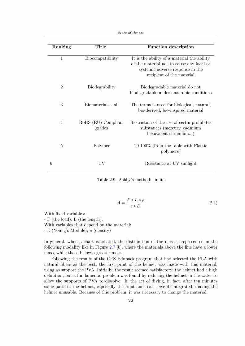
State of the art
Ranking Title Function description
1 Biocompatibility It is the ability of a material the abilityof the material not to cause any local or
systemic adverse response in therecipient of the material
2 Biodegrability Biodegradable material do notbiodegradable under anaerobic conditions
3 Biomaterials - all The terms is used for biological naturalbio-derived bio-inspired material
4 RoHS (EU) Compliantgrades
Restriction of the use of certin prohibitessubstances (mercury cadmium
hexavalent chromium)
5 Polymer 20-100 (from the table with Plasticpolymers)
6 UV Resistance at UV sunlight
Table 29 Ashbyrsquos method limits
A =F lowast L lowast ρε lowast E
(24)
With fixed variables- F (the load) L (the length)With variables that depend on the material- E (Youngrsquos Module) ρ (density)
In general when a chart is created the distribution of the mass is represented in thefollowing modality like in Figure 27 [b] where the materials above the line have a lowermass while those below a greater mass
Following the results of the CES Edupack program that had selected the PLA withnatural fibers as the best the first print of the helmet was made with this materialusing as support the PVA Initially the result seemed satisfactory the helmet had a highdefinition but a fundamental problem was found by reducing the helmet in the water toallow the supports of PVA to dissolve In the act of diving in fact after ten minutessome parts of the helmet especially the front and rear have disintegrated making thehelmet unusable Because of this problem it was necessary to change the material
22
State of the art
[a]
[b]
Figure 27 CES EduPack Mass per unit of compressive stiffness [a] Youngrsquos Moduleand density [b]
Further investigations carried out by the Mondragon Unibertsitatea Additive Man-ufacturing Department revealed a new material the PLA Low Weight which during3D printing allows to obtain a weight of 65 lower than that which could be obtainedfrom the classic PLA as reported in the technical sheet of the filament produced by thecompany Colorfabb [7]
The investigation team of the Composite Department carried out tensile tests withsamples 3D printed at different temperatures as suggested by the manufacturer to obtainthe technical characteristics The temperatures examined are 200 220 250 260The datasheet shows the density can have values between 04 - 124 gcm3 the bed has
23
State of the art
to have a temperature between 50 - 60 the printing speed has to have values between40 - 80 mms This typology of PLA is expandible so much that rdquoAt around 230 thismaterial will start foaming increasing its volume by nearly three timesrdquo [7]
T[C] Section [mm2] Volumen [mm3] Mass [g] ρ[kgm3] E [Nmm2]
200 42235 1030117 12 1165 328807
220 43805 1655821 18 1087 265795
250 52412 1948139 17 873 178058
260 59655 1454377 12 825 117047
Table 210 Values about PLA LW tensile tests of MU Additive ManufacturingDepartment
From the tests that have been carried out on the material at different temperaturesthe printed sample is better at 250 with a volume of 1948139 mm3 and a section of52412 mm2 as shown in Table 210 For this reason the specific of the material thathave been taken into consideration are the following
- Density ρ = 873 kgm3
- Youngrsquos Module E = 1750 MPa
- Poissonrsquos ratio ν = 033
- Yieldrsquos stress σ = 2948 MPa
- Elongation at fracture = 491
23 Bio-inspired structures
When we talk about bio-inspired structures to nature we refer to structures that allowobtaining a low weight for the model that is realized and excellent absorption energy dur-ing the impact Recently the structures that have been most used in the biomimetic fieldare the rdquocolumns structures sandwich structures plates honeycomb and foamsrdquo[26]but aiming to achieve a structure increasingly with high absorption energy new struc-tures derived from plants and animals such as beetle horsetail turtle bird beak havebeen analyzed The first to create multi-cells tubes helicoidal structures the second tomulti-corner tubes [26]
The authors analyze the specific energy absorbed (SEA) by bio-inspired sandwichstructures per unit mass which can be derived from the following equation
EA(d) =
int dmax
0F (x)dx (25)
SEA(d) =EA(d)
m(26)
24
State of the art
Where EA is the energy absorption rdquomainly used to evaluate an energy absorberrsquosability to dissipate crushing energy through plastic deformationrdquo F(x) is the crashingforce dmax is the effective deformation distance [26]
What derived from their investigations is that having regard to a density of between0 and 1000 kgm3 the volumetric energy absorbed is higher for the beetle-inspired struc-tures than the others as shown in Figure 28 Based on this consideration it was chosento draw the helmet following this geometry
Figure 28 SEA of bio-inspired sandwich structures [26]
231 Beetle structure - Design of the model
To develop and increase lightweight high-strength and optimize bio-mimetic functionaland structural materials the trabecular structure of the beetle elytron is studied Thesingle structure is realized following the requirements cited by Zhang et al [39]
To realize the beetlersquos structure it is not enough to have information about the lengthof the side of the hexagon and the thickness but it is also necessary to take into accountthe relationship between the diameter of the circumferences present on the vertices ofthe hexagon and the measurement of the side The representation of a single cell is inFigure 29 It is shown in [a] a general structure with an edge of 12 mm circumferencersquosdiameter of 6 mm and thickness of 16 mm in [b] is shown the height of 20 mm
For the construction of the helmet a thickness of 12 and 16 mm was used the imageconcerns a proportion between the length of the hexagon side and the diameter of the
25
State of the art
circumference The side (distance between the centers of two circumferences) is twice thediameter measurement
[a] [b]
Figure 29 Beetle structure
232 Specific stress - PLA LW and EPS foam
To test the beetle structures compression tests were investigated The PLA LW structurewas inserted in a rsquodiskrsquo with a diameter of 100 mm and a height of 20 mm The area andthe volume of the disk is correspondingly 7854 mm2 and 157 10 mm3 The structuresexamined have different dimensions the edge L (distance between two centers of thecircumferences) had the following measures 9 10 12 14 16 mm the thickness of thecircumferences and edges are respectively of 16 mm for every structure and 12 mm forthe structure with L = 16 mm
The test was carried out with the Hoytom HM-D Testing Machine with capacitiesbetween 5 and 100 kN The test models were subjected to displacement loading at a rateof 1 mmmin as referenced by Chen et al[18] with a cylindrical specimen The specificstress of the structures was compared with the specific stress of a generic EPS helmetthe photos about it are shown in Figure 210 The EPS helmet structure is granular withpores inside The different grains dimension and these pores can be the reason for whichthe Stressrsquos values are between two values 07 and 116 MPa
Four parts of the EPS helmet were considered in the test the dimension and relativecharacteristic are in the Table 211 where m = mass A = area F = load ρ = densityR = stress Rρ = specific stress To calculate the values of stress about PLA structuresand EPS foam compression test graphs were been analyzed The stress value for eachstructure was calculated considering the single load the single area and the averagedensity value (14055 [kgm3])
The stress values of the PLA structures (Figure 211) and other characteristic valuesare in Table 212 where m = mass A = area F = load ρ = density
26
State of the art
[a] [b]
[c] [d]
Figure 210 EPS generic helmet helmet pictures [a] [b] and internal structureExternal granular structure [c] and pores [d]
[a] [b] [c]
Figure 211 PLA LW disks Grasshopper structure [a] PLA LW structure of 14 mm[b] PLA LW structure compressed [c]
27
State of the art
The results of the load-displacement graphs are affected by the geometry of the diskthe target is to valid for any shape or size for this is preferred to realize a diagramthat depends from σ (or stress) and the deformation ε (or strain) which can be definedrespectively as
σ =F
A0(27)
ε =l minus l0l
(28)
where F is the load during the test A0 is the area l0 is the initial length and l is thelength when the load is applied The areas considered for the EPS cube is reported inTable 211 in the second column the areas of the PLA structure is 7854 mm2 like thearea of the circumscribed disk
The values compared are shown in Table 213 and the graphs obtained by Matlabcode to analyze the recorded data of the compression machine are in Figure 213 and inFigure 212
Considering that the data provided by the compression machine are subject to noiseand disturbances it was decided to convert the original curve into polynomial type curvesthat allow obtaining the best interpolating curve for the data in question To obtain themit was divided the recorded data into two groups the first part from 0 until the end ofthe linear part and the second when the curve becomes linear again The best-fitting (inthe least-squares sense) was performed using the polyfit and polyval functions of MatlabThe first returns the coefficients of the p(x) with n degree the second evaluates p(x) ateach point in x The polynomial formula p(x) is shown in the Equation 29
pn(x) = anxn + anminus1x
nminus1 + + a2x2 + a1x+ a0 (29)
where a0 an are constants and x is the indeterminate The choice of the degree ofthe polynomial was made based on the criterion of wanting to obtain linear curves thatrespected the elastic trend at the beginning of the graph For this reason the degree ofthe polynomial is 1 Subsequently I searched through the intersection of the two lines forthe point that is equivalent to the maximum stress that marks the end of linearity
This value for EPS and PLA LW is the R [MPa] in the Table 213 The average stressvalue for PLA LW is 139 MPa and for EPS is 094 MPa The specific stress (Rρ) is 18MPa lowast m3)kg for the EPS found in CES 669 MPa lowast m3)kg for the EPS foam of thegeneric helmet and for PLA LW is 1161 MPa lowastm3)kg an intermediate value betweenthe two which is what we wanted to achieve
28
State of the art
m [g] A [mm2] F [N] ρ [kgm3]
EPS (CES) 50
16 9234 1063 13864
18 879 593 13651
21 858 833 14237
24 864 564 14468
Average value 14055
Table 211 Compression stress generic EPS helmet
L [mm] t [mm] m [g] F [N] ρ [kgm3]
9 16 214 7250 1363
10 16 192 5560 12467
12 16 201 8190 13051
14 12 138 8000 8961
Average value 12027
Table 212 Compression test PLA structures
PLA LW structure EPS structureρ= 12027kgm3 ρ= 14055kgm3
Edge [mm] R [MPa] Rρ103 Number R [MPa] Rρ103
EPS (CES) 09 18
9 173 1269 1 116 824
10 139 1114 2 08 568
12 138 1057 3 105 746
14 108 1205 4 077 540
Average value 139 1161 094 669
Table 213 Specific stress calculus PLA LW and EPS calculus ρ = density R = stressRρ [(MPa lowastm3)kg] = specific stress
29
State of the art
Figure 212 Compression test Stress-Strain diagrams - EPS
Figure 213 Compression test Stress-Strain diagrams - PLA LW
30
Chapter 3
Methodology
31 3D scan
311 3D Sense 2 scanner and Meshmixer - Reverse reconstruction
Standardized measures were not taken into account for making the helmet but the sizewas obtained through a 3D scan of my head
The scanner used is 3D Sense 2 by 3D Systems which has a minimum scanningvolume of 20 x 20 x 20 cm and a maximum scanning volume of 300 x 300 x 300 cmTo scan my person I was helped to get a full view at 360 at an appropriate distanceReal-time visualization of the captured images was shown through 3D Sense softwareThe idea of scanning the head with the scanner refers to the methodology used by Wanget al [30] They used a reverse reconstruction functional for me to realize the helmetsurface made to measure my head and like them a silicone pool cap was used to makescanning as smooth as possible The authors claim the head scan rdquocan also be used toobtain information about the objectrsquos surface which is then reconstructed utilizing thecomputerrsquos three-dimensional model via reverse modelling softwarerdquo [30] that in my caseis Autodesk Meshmixer
The files it was could get from the scan were stl obj and ply format they wereexported to obj to work in the next step with Autodesk Meshmixer that allowed tomodify and homogenize the 3D image obtained from the scan
In Meshmixer through the selection and delete commands the superfluous parts weredeleted that had been acquired and with the inspector and the DrawDraw2 commandsthe vertices were moved locally along a pre-defined direction and with Smooth the surfacemore homogeneous was made The sequence of steps is shown in the Figure 31
312 3D scan analysis and extraction of features
In Chapter 2 the directives imposed by the BS EN 960 Standard were examined concern-ing the definition of the helmet and the measures to be respected in the field of visionand the part of the helmet was to carry out impact tests
In Figure 32 the features defined complying with the Standardrsquos rules are repre-sented To define these features the software NX was used The angle in the subfigure
31
Methodology
[a] [b] [c] [d]
Figure 31 Sequence of 3D head scan 3D scanner acquisition [a] scan after reparationwith Meshmixer [b] solid scan vision frontal and lateral [c] [d]
[b] is bigger than 105 (as defined by the Standard) while the degree in the subfigure [c]is 25 By defining the construction lines to be respected of the helmetit was necessary todraw the design of the surface not using the software NX but changing with Rhinocerosto create a SubD or SubDivision surface
32 Helmet design
321 Rhinoceros - Helmet surface
After realizing a rsquocleanrsquo Wang et al [30] subdivide with lines and then sectors the headto create the surface of the helmet They used the technique of NURBS a Non UniformRational Basis-Splines which mathematically models a 3D geometry while thanks tothe Rhinoceros 3D organic shapes was draw SubD surfaces These geometries allow tosplit the mesh into small polygons and consist of lines with which easily the shape ofthe object can be modified with a surface already created changing the position of aline automatically the remaining part of the geometry adapts to the changes With thistechnique the rsquosurface basersquo of the helmet was realized with the size of my head Therepresentation of the realized SubD is in Figure 33
322 Grasshopper - Helmet structure
The next idea is the creation on the surface of the beetle structure with different di-mensions modelling the helmet that is not a linear surface It was decided not to buildthe structure with a software CAD because to model an already complex structure on acurved surface would mean to model a cell for a cell
To solve this obstacle a Rhinoceros plug-in was used Grasshopper GH idealized byRobert McNeel and associates creators of Rhinoceros Using GH does not mean drawinggeometries by connecting points and drawing tools because it is based on algorithmicmodelling used in architecture and engineering for 3D modelling
The modelling takes place through a node diagram that the software will convert intoa code-algorithm in GH it is possible to define the variables and parameters and inRhinoceros in real-time it is possible to view the object GH allows for varying the
32
Methodology
[a] [b]
[c]
Figure 32 Featurersquos extraction in [a] is represented the impact line in [b] and [c] twoprospective about the definition of the field of vision
[a] [b] [c]
Figure 33 SubD representation lateral view [a] top view [b] front view [c]
geometry to your liking by varying a simple parameter of the diagram as everything willbe remodelled according to the change made
In the following Figure 34 it is shown an example of a structure that was used fordistinct subgroups of helmet areas The idea was to insert smaller cells in the frontal andlateral zone and larger ones in the upper area In the first image [a] is shown the part of
33
Methodology
the helpful diagram to create the beetle structure to establish the size of the cells andthe extrusion the second image [b] contains the part of the diagram with which I appliedthe structure previously created to the SubD
The structure used to place and adapt the beetle structure to the surface is theSrfMorph while the yellow rsquowindowrsquo that contains numbers serves to select the parts ofthe surface where to apply the geometry created In accord with the GH diagram in
[a]
[b]
Figure 34 Grasshopper diagrams
Figure 34 [a] it is possible to see the steps executed to realize the structure Initially inthe xy-plane a hexagonal grid was drawn through the Hexgrid command in which youcan input the length of the hexagon edge and the number of grid elements (selected bytrial) Then the circumferences was drawn in proportion to the hexagon dimensions asspecified in the Chapter 2 and shown in Figure 35 [a] In figure [b] the rsquocutrsquo made atthe circumferences is visible this subdivision was necessary for printing purposes In thelast photo [c] the structure highlighted in green in [b] was extruded setting a distance
34
Methodology
of 20 mm
[a] [b] [c]
Figure 35 Construction sequence of the geometry of the helmet
In the diagram in Figure 34 [b] there is the application of the structure created bi-dimensionally to the SubD surface of the helmet visible by unlocking the SubD commandof the diagram and in Figure 36 [a] Upper this the referential geometry of the group ofsurfaces was superimposed where it was to be applied the newly created structure (visiblein darker red) the SubD indices are in the yellow box of the diagram
Through the SrfMorph command the location of the structure was granted In Figure36 [b] at the darkest red of the figure [a] with the above command it was possible toplace the structure
[a] [b]
Figure 36 Application of the geometry created to the helmet surface
Overall the diagrams with specific structures are five one for the front two equal forthe side parts one for the top shown in the previous Figure 36 and one for the back
The hexagons in the structure have a dimension varying between 8 mm and 14 mmof side the largest is found at the top later at the back in the sides and the smallest atthe front In Figure 36 [b] the presence of not only hexagonal structures is visible Thegeometry used does not allow the homogeneous arrangement on the entire surface andrequires different structures Automatically the choice of GH to optimize the structurewas to insert quadrilateral
As described above the helmet has different dimensions of the structure divided asvisible in Figure 36 in a quadrilateral This causes a discontinuity between zones withdifferent sizes due to the geometry of the construction
To eliminate this problem and realize the design homogeneous grids were inserted
35
Methodology
in the affected areas as shown in Figure 37 This insertion however proved to beinteresting and strategic researching in this regard studies were realized to demonstratethe insertion of a rectangular grid inside the hexagon grid was helpful for the transmissionof stress in the structure As cited by Sun et al [40] rdquothe mechanical properties of thesesandwich structures are often limited by local failures such as face-core debonding or corecollapserdquo Carrying out compression tests have effectively demonstrated that the insertionof the grid allows rdquoprovided increased stiffness specific stiffness energy absorption andcritical loadrdquo [41] As shown in the graphic [c] of the Figure 37 the honeycomb structuregives a force of 7 kN while with a grid the value is 11 kN and with the combinationexceeds 22 kN In addition in the left front a plaque to customize the helmet wasprepared Figure 37 [a]
[a] [b]
[c]
Figure 37 Grid in the helmet [a] hybrid structure with hexagons and grid [b] [40]compression test results of the hybrid structure [c] [41]
33 3D Print
After having achieved the CAD (Computer Aided Design) of the helmet in order tobe printed it must be converted and saved in format STL (Standard TriangulationLanguage) - Binary compatible with the printing machine and useful for transformingsolid object surfaces into triangles The steps to be taken are the following
bull CAD file realization
bull CAD export in format STL to Simplify 3D the software that shows slider layersand then- rotate and position the object according to geometry and the positioning of any
36
Methodology
supports- setting printing parameters- item manual andor automatic positioning of supports- slider display layers
bull import file gcode to printer
331 Printer and parameters
The program used to visualize how the helmet slices layers before sending it to the printerand to set the parameters is as anticipated Simplify 3D
To make the printing not being a flat geometry it is necessary to place the supportsThe idea was to use water-based supports that the helmet would automatically dissolveonce placed in the water After testing different types of water-soluble PVA the choicefell on eSun 3D Printing Filament PVA (water-soluble support) Before choosing theoptimal position for printing several tests were carried out and to decrease the numberof the supports significantly and allows an optimal printing of the outer part an emptyrsquospherersquo that self-sustains below the helmet was placed as shown in Figure 38
In the image [a] you can see the first print position tried with which an external partof the helmet very damaged was obtained because of the contact supports-helmet In [b]the empty rsquospherersquo is shown to optimize the number of supports and in the last photo [c]there is the full version at the end of print
[a] [b] [c]
Figure 38 Printing supports
The printer that has been used for printing is the Raise 3D Pro2 with double extrudersand nozzles of variable size from 02 mm to 1 mm after some test prints with the PLALW and the structure in created the size that allowed me to have a good compromisebetween printing time and accuracy was 06 mm Using 04 mm the printing time wasexcessive even if having the smaller nozzle diameter means having more precision withthe 08 mm nozzle the quality of the structure was not excellent as seen in Figure 38[a]
Another factor that had to be taken into account is the characteristic of the PLA-LWto expand As the printing temperature and the printer used vary the expansion andcharacteristics of the material change The use of the 06 mm nozzle associated with
37
Methodology
Parameter Left extruder Right extruder
01cm Material 01cm PVA 01cm PLA LW
Extruder toolbox index Tool 0 Tool 1
Nozzle diameter 06 mm 06 mm
Extrusion multiplier 1 05
Extrusion width Auto (072 mm) 05 mm
Layer x
Infill Rectilinear - 50
Supports (Automatic and not) Infill 50
Temperature 210 250
General parameters
Primary layer height 03 mm Top solid layer 4
Bottom solid layer 2 Outline 2
Heated bad 60 Speed 40 mms
Table 31 Printing parameters
Raise 3D allowed me to get good results The choice of this printer was not random ithas in fact the characteristic of making extremely precise prints The Raise has accuracyin placing the object on the printing bed of 078 microns on the xy axis and a resolutionfor layers of 001 mm
The final version of the helmet is visible in Figure 39 and it is possible to compare itwith the preview version in Rhinoceros in Figure 310
38
Methodology
[a] [b]
[c]
Figure 39 Views of the helmet
[a] [b]
Figure 310 Views of the helmet (GH version)
39
Chapter 4
Experimental evaluation
41 Experimental tests
411 Drop-weight impact test machine
In order to calculate the contact force peak and the difference of energy absorbed duringthe impact between the reference helmet and helmet with the beetle structure in PLA-LW dynamic impact tests were carried out using the Fractovis Plus an impact testmachine
In this way it is possible to monitor the evolution of the above variables from theinitial to the final instant of the impact The machine can withstand a load with a rangevariable from 2 to 70 kg with a maximum speed of 46 ms and a maximum height of1 m The values chosen for the test are the following 5 kg weight maximum speed andmaximum height The Anvil that was used is a disc diameter of 60 mm
As shown in Figure 41 and explained by Crupi et al [37] the machine consists ofa sensor capable of recording the speed before impact the impactor that can have avariable mass (a weight of 5 kg in my test) a system to guarantee that there are nomultiple impacts after the first and that work as a shock absorber and clamping systemwhere the object to be tested is placed
The tests that have been carried out are in total four two related to the helmetoptimized with PLA-LW and two with two generic helmets of different brand in EPS
42 PLA LW helmet
To perform the dynamic test on the helmet of PLA considering the difficulty of printingit was helpful to use a test helmet with imperfections to understand where the impactwas concentrated in a single part or distributed The images of Figure 42 show a helmetwith not well defined edges and inaccurate print but exactly localizes the impact zoneThanks to this test it was possible to take into account only one helmet area shown inFigure 43 to have the exact curve of the structure bio-inspired with PLA-LW
40
Experimental evaluation
Figure 41 Drop-weight impact test machine [37]
[a] [b]
Figure 42 Test 1 PLA-LW helmet
43 EPS helmet
To carry out dynamic tests and extract the technical characteristics of the helmettwohelmets were bought in a sports store both EPS and being on the market both certifiedThe brands of the two helmets are DTB and VAN|RYSEL and the average weight ofthe two is 223 g Two different helmets have been chosen to have a more certain andclear classification of the characteristics They are shown in Figure 44 and Figure 45
41
Experimental evaluation
[a] [b]
Figure 43 Test 2 PLA-LW helmet
[a] [b] [c]
Figure 44 Test 3 EPS helmet
[a] [b] [c]
Figure 45 Test 4 EPS helmet
44 Results
441 First results - PLA-LW and EPS helmet
Figure 46 shows two types of trends related to the two different models of the helmetThe force evaluated for PLA-LW has higher force peaks but is more concentrated and
42
Experimental evaluation
propagates less than EPS The graph shows the peaks of each curve highlighted with a redcircle In tests 1 and 2 for the PLA-LW as mentioned earlier the values are higher about7301 N for the complete helmet and 3996 N for the portion of helmet This difference isdue to the inaccuracy of the first full helmet during the printing phase In Figure 42 itis visible the low homogeneity and precision Therefore the first test with full helmet wasused only to define the area of interest of the impact which turns out to be localized Forthe other two EPS curves the values are only slightly lower compared to the PLA-LWequal to 3620 N and 3295 N but the trend is much more distributed
Figure 46 Dynamic machine test - Force
With the data obtained from the impact machine it was possible calculate not exclu-sively the value of force but itrsquos also possible to view the energy curves A resume aboutthe values and energy of the force is in the following Table 41
Test Peak force [N] Peak energy [J]
Test 1 - PLA LW (inaccurate) 730130
Test 2 - PLA LW (portion of helmet) 399643
Test 3 - EPS (DTB helmet) 362007 509
Test 4 - EPS (VAN|RYSEL helmet) 329546 4198
Test 5 - PLA with TPU 45421 5022
Table 41 Energy absorbed in dynamic test
43
Experimental evaluation
442 PLA-LW helmet with TPU cover
As it is possible to see in Figure 47 and as highlighted the first tests concerning thebio-inspired structure and the PLA-LW are far from my expectations considering thelittle distribution of force in comparison with the EPS foam and consequently a smallamount of energy absorbed
Figure 47 Dynamic machine test - Energy
To improve this impact damping factor the idea was to create a cover for the helmetin flexible TPU trying to absorb impact energy The TPU used is a flexible material ofthe brand Ninjaflex used in sports by the application in helmets and shoes to cushionbumps during the game Generally in the helmets (baseball helmet for example) theTPU is inserted internally in contact with the head In my case the TPU structurein addition to creating a shock-absorbing and durable cover creates a custom cover thehelmet and for the person This cover was also made with the Raise 3D printer
As shown in the Figure 48 [a] the infill of the part in contact with the helmet hasa percentage of 100 the filling of the other part of the structure is not complete butonly 15 and the internal structure is hexagonal to recall that of the helmet The desireto insert a structure with a rsquoraisedrsquo geometry is for visual and aesthetic reasons as youhave the feeling of greater protection and not filled is inspired by the machine CitroenCaptus whose bumpers (Airbump) are full of air The failure to realize empty structuresis due to the need to place any internal supports not removable
The idea was to create a cover that allow you to see of the internal structure of thehelmet and that protect specific areas the front the two sides the top and the posteriorWhat which was thought for this reason was to create the shape of a flower with four
44
Experimental evaluation
petals Figure 48 [b]In this way to perform dynamic impact tests as shown in Figure 49 [a] the cover was
positioned at the top of the helmet and the impact was performed in the centre of thersquoflowerrsquo which corresponds to the higher upper part where the structure has larger cellsize The impact parameters are the same as those used in previous impacts 5 kg weightmaximum speed and maximum height The Anvil that was used is a disc diameter of60 mm In photo [b] it is evident the difference between the structure that received theimpact with protection (left) and without protection (right) Without protection duringthe impact there was a perforation of the structure with a concentration of force at a locallevel as you can see in the Figure 46 in the case of TPU the impactor did not perforateand crossed the structure thanks to the cover of TPU that cushioned the shock At themoment of impact the impactor bounced
[a] [b]
Figure 48 TPU cover
[a] [b]
Figure 49 PLA-LW with TPU - dynamic impact [a] and differences between thehelmet with TPU and without TPU cover [b]
45
Experimental evaluation
The Figure 410 includes the diagrams relative to the dynamic impacts In [a] thereare already analyzed EPS results in [b] a comparison between the test on the portionof helmet in PLA LW with and without the TPU cover in [c] the overall comparison ofcurves shows a much more similar EPS trend if the TPU is placed above the structure inPLA LW to soften the blow and absorb the same energy [d]
46
[a]
[c]
[d]
Figure 410 Comparison between PLA-LW with TPU and EPS
Chapter 5
FEM Validation
51 Impactor - Anvils definition
Before to start to work in Abaqus it was necessary to search in the literature the materialwith which the anvil was been realized Milne et al [23] established the densityrsquos valuethe Youngrsquos Module and Poissonrsquos ratio for the Flat and Kerbstone Anvil
- Density ρ = 7800 kgm3
- Youngrsquos Module E = 200000 MPa
- Poissonrsquos ratio ν = 03
Inserting the data in the CES EduPack program specifying the mechanical andphysical properties the material corresponding to these characteristics is Stainless steelaustenitic (ASTM F1586) medium-hard
Initially the proposal was to create a conservative system to evaluate the absorptionenergies values and apply this value to a vibration system but the helmet needs dampingto be realized it was impossible to use a system without losses in this modality Thisis why a numerical calculation was carried out by performing two types of simulationsexplicit dynamic step and static step
The idea to realize the theoretical impact is to regard the movement of the anviland not the helmetrsquos movement which is fixed The velocity is the same cited in thenormative EN 1078 542 ms for the Flat anvil and 457 ms for the Kerbstone anvil
In performing the simulations It was given more relevance and perform tests withthe Kerbstone Anvil This choice was done because the geometry with which it is beenrealized (following as defined in the legislation) allows the helmet to be more subjectedto stress this involves the definition of higher stress limits compared to the Flat Anvil
The mesh size that has been used is the same in the case of the simulation of thehelmet optimized in PLA-LW and the full helmet in EPS of 7 mm The impactor isconsidered as a Discrete rigid body with its specific Reference Point (RP) like shownin Figure 51 for this reason it is not a solid but it is composted only by shells Inthe same image [b] there is the FEM representation of the model and in Table 51 thecharacteristic of FEM with quadrilateral (R3D4) and triangular elements (R3D3)
48
FEM Validation
Object Elementnumber
Elements Shape Geometricorder
Global size[mm]
Kerbstone 230 Quadrilateral - R3D4 Linear 7
Kerbstone 8 Triangular - R3D3 Linear 7
Table 51 Mesh element - Kerbstone Anvil
[a] [b]
Figure 51 Kerbstone anvil in the simulation like discrete rigid body [a] and FEMelements [b]
511 PLA LW - Plastic characteristics
The PLA-LW as explained in the Chapter 2 is new material on the market and producedby the only Colorfabb company for this reason few tests have been carried out to defineits technical characteristics and through tensile tests of the 3D printed specimens it waspossible to define an elastic limit as reported in the Table 210
In the context of simulations to reproduce the impact and deformation of the helmetis also necessary to consider the plastic characteristics of the material Not possessingany reference value in this regard tests were performed through a Static Step initiallyand then an Explicit Dynamic Step in Abaqus
The structure chosen to consider as a reference it is one of the structures previouslysubjected to the compression test having the side L=14 mm As for the reproduction ofthe compression disks initially they were reproduced according to the geometry of theHoytom HM-D Testing Machine considering the bodies mentioned above as discrete 3Drigid discrete The measure was the diameter of 200 mm and the height of 20 mm
After an initial analysis it was observed that the computational time of the simulationprogram was very high so it was decided to change the geometry to have a rsquodisk-surfacesrsquo(equally 3D rigid-discrete) which allowed me to have a smaller number of nodes for themesh and consequently a better computational time The representation of the opti-mized structure in PLA-LW and the disks used for simulated compression is in Figure 52
49
FEM Validation
[a] [b]
Figure 52 Representation of the samples used for the simulation of the compressiontest In Figure [a] the disks of the Hoytom HM-D Testing Machine in figure [b] the
representation of the same as simple surfaces
As shown in Figure 52 the disks are considered 3D discrete hard bodies so it waschosen for both a point the reference point RP where to apply the characteristics relatedto the two bodies As for the compression test it was established
bull the movement of a disk and fixed the second through a boundary condition impos-ing an Encastre therefore unable to move and rotate in xyz directions
bull for the opposite disk the boundary condition relative to the 15 mm displacementwas applied which is the parameter that it was observed to determine the end ofthe compression with the machine This shift is shown by the orange arrow in figure[b]
bull between the upper surface and the disk e the disk with the lower surface it wasinitialized a general contact with normal behaviour through rsquohardrsquo contact andtangential behaviour with a coefficient of friction of 02 with directionality imposedon rsquoisotropicrsquo
The next step was to define the mesh of the components whose parameters are shown inTable 52 while the representation of the FEM is in Figure 53 with the representationof the simulation and real compression test
Object Elementsnumber
Typology Geometricorder
Globalsize [mm]
Disk (14mm) 80910 hexaedral - C3D8R Linear 07
Impact disks 206 quadrilateral - R3D4 Linear 20
Impact disks 6 triangular - R3D3 Linear 20
Table 52 Mesh element - Compression test simulation
As previously announced a static simulation was initially performed with a StaticStep with Step Time equal to 900 (obtained going to consider the speed of 1 mmmin of
50
FEM Validation
[a]
[b] [c]
Figure 53 FEM representation [a] and compression test simulation [b] and realcompression [c]
the compression test and the displacement of 15 mm) However the complex geometryof the structure and the high time set by Step Time did not allow a correct definitionof the parameters of the plastic characteristics of the material the simulation was notable to continue once reached a Step Time of approximately 220 That is why it waschanged by choosing an Explicit Dynamic step
Leaving all the parameters of the boundary conditions unchanged the Step Time wasmodified imposing it to 001 The ability of the explicit dynamic to work with non-linearand contacting structures allowed me to achieve results The results obtained are shownin Figure 54 with the blue curve and were obtained through the iteration of differentPlastic Strain and Yield Stress values in Abaqus while the red line is the result of thereal compression test a similar curve trend was obtained but it is not possible to obtainthe same curve taking into account problems of printing inaccuracy
512 First test - helmet
The initial idea was to perform a simulation imposing the speed of 457 ms to theimpactor tie the helmet in EPS and PLA and compare the absorbed energies Theproblem it was encountered is related to the mesh of the helmet optimized in PLA andwith minimum dimensions of the elements and distinct elements it was not able to solveit
51
FEM Validation
[a]
YieldStress
PlasticStrain
1 47 0
2 7 001
3 75 005
4 10 01
5 108 1
6 115 15
7 12 2
[b]
Figure 54 Representation of the two curves related to the simulation in Abaqus of thecompression test and the data obtained from the real test to obtain the plastic
characteristics of the material
513 Second test - plane
The first solution is the one shown in Figure 55 To realize the simulation it was realizeda section of the helmet to involve a smaller number of elements and nodes Again thesimulation for the EPS helmet was successful while the simulation with the bio-inspiredstructure was interrupted by excessive distortion of elements
The previous images show the impact is very localized in the impacted area and theidea to achieve a complete simulation is not to consider a curved portion of the helmetbut a plane In this way it was possible to solve the problem and obtain a completesimulation for the bio-inspired structure
FEM element
Below in Table 53 there is the definition of the elements used for the PLA-LW and EPSplane in the simulation to simulate the impact and to control the energy-absorbing whilethe anvil characteristics are described in Table 51
514 EPS impact simulations
In order to proceed with the simulation it was imposed some boundary conditions thatregard ties and forces
bull the movement of the plane is fixed through an Encastre therefore unable to moveand rotate in xyz directions
52
FEM Validation
[a]
[b]
Figure 55 Impact simulation parts of EPS and PLA helmet
Object Elementnumber
Elements Shape Geometricorder
Plane (PLA) 38896 Tetrahedral -C3D10M
Quadratic
Plane (EPS) 2100 Hexahedral - C3D8R Linear
Table 53 Mesh element - plane impact
bull to create the impact it was set a speed of 457 ms at the reference point RP of therigid body which is the impactor Kerbstone Anvil shown in Figure 56
bull between the upper surface of the plane and the impactor it was initialized a Sur-face to Surface contact with normal behaviour through rsquohardrsquo contact and tangen-tial behaviour with a coefficient of friction of 02 with directionality imposed onrsquoisotropicrsquo
bull the rotation in x y z relative to the RP of the rigid discrete impactor body is locked
53
FEM Validation
In addition it was characterized the plane in the part of the materials with the char-acteristic values of the EPS mentioned in Chapter 221 The Von Mises Stress valueapparently low is relative to the Yield Stress of the EPS material equal to 09 MPa
Figure 56 EPS Boundary conditions and Load
515 PLA LW impact simulations
As also required in the case of the EPS plane in order to proceed with the simulationsome boundary conditions were imposed that regard ties and forces
bull the movement of the plane is fixed through an Encastre therefore unable to moveand rotate in xyz directions
bull to create the impact a speed of 457 ms was set at the reference point RP of therigid body which is the impactor Kerbstone Anvil shown in Figure 58
bull between the upper surface of the plane and the impactor it was initialized a Sur-face to Surface contact with normal behaviour through rsquohardrsquo contact and tangen-tial behaviour with a coefficient of friction of 02 with directionality imposed onrsquoisotropicrsquo
bull the rotation in x y z relative to the RP of the rigid discrete impactor body is locked
In addition the plane was characterized in the part of the materials with the characteristicvalues of the PLA mentioned in the Chapter 223 and 511
Figure 58 Boundary conditions and Load
54
FEM Validation
[a]
[b]
Figure 57 EPS impact simulation
52 Results
In Figures 59 and 57 it is shown how the structure in PLA LW has a more concentratedstress distribution of the structure unlike EPS The maximum value for the Von Misesstress is 09 MPa in EPS structure and 3634 MPa in PLA LW structure Once thesimulations were obtained the next step was to go and compare the energies absorbed bythe two structures The energy calculated by Abaqus that has been taken into account isPlastic Dissipation To make a comparison the data of the two energies were representedin a single graph
What emerges from the graph is that about the impact made with the KerbstoneAnvil the energy absorption is more excellent although only slightly for the PLA LWthan for the EPS From the graph in Figure 510 a value of 41 J is shown for the EPSand 51 J for the PLA LW
55
[a]
[b]
Figure 59 PLA impact simulation
[a]
Figure 510 EPS and PLA LW energy comparison - Abaqus simulation
Chapter 6
Head Injury Data
For the statistical analysis the injuries related to the accident data were categorised intothe following types and levels based on the details of the medical report [11] about theEN 1078
bull Head Injury Criterion (HIC)
bull Peak Linear Acceleration (PLAc)
bull Gadd Severity Injury (GSI)
bull Diffuse axonal injuries (DAI)
61 Abaqus simulation
Until now the purpose of the simulations has been to determine which between the twomaterials and the two structures of EPS and PLA LW could absorb more energy duringthe impact but no simulations have been carried out in compliance with BS EN 1078on the helmet impact tests To calculate the injuries listed in the previous paragraphhowever we need the acceleration values in the three directions related to the subjectrsquoshead
To realize it the scan of my head already rsquocleanrsquo was considered of which it has beencalculated the inertia thanks to the automatic SolidWorks calculation and evaluated theweight with the Table 24 the structure of the helmet was placed for the EPS and thePLA LW over the head as shown in Figure 61 Also this time being able to mesh theentire helmet in PLA LW was impossible due to the excessive distortion of some elementsduring the simulation so it has been tried to make a section of the structures of thehelmet and results were obtained
57
Head Injury Data
[a] [b]
Figure 61 My scan head - CAD [a] head imported in Abaqus[b]
Initially the simulation had these characteristics as shown in the following Figure62 considering the helmet was not sectioned As explained earlier it was not possibleto get to simulation in the case of the optimized structure in PLA LW for this reasononly a part of the helmet was considered in both cases shown in Figure 63
[a]
Figure 62 Simulation based on BS EN 1078
58
Head Injury Data
[a] [b]
Figure 63 Simulation based on BS EN 1078 with head
In order to proceed with the simulation some boundary conditions that regard tiesand forces have have imposed
bull two reference points RP were created the first in the inertia centre of the headthe second relating to the Kerbstone Anvil which is a discrete rigid body
bull in the reference point RP of the head in the definition of the engineering features5 kg was inserted for the weight and an inertia I11 = 564464E+07 gmm2 I22 =460654E+07gmm2 I33 = 187302E+07gmm2
bull to simulate the impact it was set a speed of 457 ms at the reference point RP ofthe head in z-axis direction
bull a general contact with normal behaviour through rsquohardrsquo contact and tangentialbehaviour with a coefficient of friction of 02
bull between the upper surface of the helmet and the impactor it has been initializeda Surface to Surface contact with normal behaviour through rsquohardrsquo contact andtangential behaviour with a coefficient of friction of 02 with directionality imposedon rsquoisotropicrsquo
bull the movement between the Kerbstone anvil and the helmet is fixed through anEncastre therefore unable to move and rotate in xyz directions
bull the rotation in x y z relative to the RP of the rigid discrete impactor body is locked
FEM element
As reported in Table 53 the portion of the helmet in EPS has used a mesh with hexahe-dral elements of linear order For the structure (beetle) of PLA LW given the geometry
59
Head Injury Data
complexity it was necessary to use a quadratic order of tetrahedra For the mesh of thehead instead in both simulations have been used quadrilateral elements of linear orderas reported in the Tables 61 and 62
Object Elementnumber
Elements Shape Geometricorder
Head 3755 Quadrilateral - R3D4 Linear
Head 34542 Quadrilateral - R3D3 Linear
Helmet (PLA) 272302 Tetrahedral -C3D10M
Quadratic
Table 61 Mesh element - Head simulation with PLA LW (beetle) helmet
Object Elementnumber
Elements Shape Geometricorder
Head 3755 Quadrilateral - R3D4 Linear
Head 34542 Quadrilateral - R3D3 Linear
Helmet (EPS) 72280 Hexahedral - C3D8R Linear
Table 62 Mesh element - Head simulation with EPS helmet
62 Results
Figure 64 represents the simulation in line with BS EN 1078 concerning the helmet inEPS [a] and the helmet with bio-inspired structure in PLA LW For both simulationsVan Misesrsquo stress has Yield Stress values in the case of EPS which is 09 MPa and theplastic behaviour combination of PLA LW [b]
In the case of head and Kerbstone Anvil stress was not assessed as they were previ-ously defined as discrete rigid bodies
63 Head Injury Criterion
The HIC quantifies head impact severity by incorporating time of acceleration exposureand acceleration magnitude it is calculated in post-processing phase with the followingEquation 61
HIC15 =
[1
(t1 minus t2)
int t2
t1
a(t)dt
]25(t2 minus t1) (61)
60
Head Injury Data
[a]
[b]
Figure 64 Results simulation based on BS EN 1078 with sectioned head
For this analysis a(t) is the acceleration calculated in the centre of mass of the head(corresponding to the reference point RP) expressed in g and the time interval (t2 minus t1)was chosen to maximize HIC over a maximum duration of 15 ms
Matlab and the trapz function were used to calculate the HIC to integrate accelerationover time t2 and t1 were considered initial and final times of the simulation t1 = 0 sand t2 = 10 s time less than 15 s
HIC value of 198 was obtained for EPS and 87 for PLA LW Considering the Hayeset al [16] document about the HIC values and the graph in Figure 65 developed bythe author it is possible to find the percentages related to the different injury AIS1 -AIS6 which correspond respectively to lower and higher severity while in Figure 66 therelative fatality to every value of AIS is shown The values obtained for the HIC andother criteria are shown in Table 63 The HIC value for EPS is 198 for PLA LW it is
61
Head Injury Data
Figure 65 Head injury risk curves based on HIC values [16]
Figure 66 The abbreviated injury score versus fatality rate [16]
87 Analyzing the data and comparing them with the curves of the Figure 65 I obtain
bull a percentage between 20 - 30 of AIS 1 for EPS 10 - 20 for PLA LW
bull a percentage between 10 - 20 of AIS 2 for EPS and 0 - 10 for PLA LW
bull for AIS 3 AIS 4 AIS 5 AIS 6 the percentages for both structures is between 0 -10
Comparing these percentages with the fatality rate of Figure 66 it is clear there is a riskof Moderate and Minor fatality in the case of EPS and PLA LW as all values are between0 and 30
62
Head Injury Data
HIC PLA [g] GSI E [J]
EPS 198 97 361 37723
PLA LW 87 75 169 44102
Table 63 Head Injury Data - values
64 Peak Linear Acceleration
The resultant linear acceleration versus time curve was calculated according to Equation62
γ(t) =radicγ2x(t) + γ2y(t) + γ2z (t) (62)
where
bull γ(t) is the resultant linear acceleration (g)
bull γx(t) is the linear acceleration in x axes (g)
bull γy(t) is the linear acceleration in y axes (g)
bull γz(t)is the linear acceleration in z axes (g)
The value of the impact should never exceed 250g [9] Cripton at all [9] in their studyexamined a helmet with expanded polystyrene (EPS) Figure 68 shows maximum HIC forhelmeted and unhelmeted drops from all heights For each drop height helmets reducedHIC relative to unhelmeted drops IARV value is 180g The acceleration in the two casesis shown in Figure 67 and the maximum values are 97g for EPS and 75g for PLA LWas reported in Table 63 The two values considering a maximum value calculated byCripton [9] of 180g are amply optimal and comply with the standard of 250g
65 Gadd Severity Index
Gadd proposed the Severity Index Criteria shown in Equation 63 Following this crite-rion the GSI values that are over 1000 produce serious internal head injury [33]
GSI =
int t1
0a(t)25dt (63)
Where
bull a is the linear acceleration (g)
bull t is the duration of the impact (s)
I calculated the GSI with the function trapz between 0 and t and the resulting valuesare 361 for the EPS and 169 for the PLA LW which comply with the limit
63
Head Injury Data
Figure 67 Peak accelerations for both helmets
Figure 68 Peak accelerations for both helmeted and unhelmeted drops Numbers overbars indicate peak acceleration For 2 m drop height results stated are the mean value
calculated from three drops [9]
64
Head Injury Data
66 Diffuse Axonal Injury
DAI cases covered all incidences in which neurological injuries occurred as well as con-cussion unconsciousness and coma
In order to assess the risk of head trauma in terms of diffuse axonal injury (DAI)Milne et al [23] defined a model based head injury criteria as follows obtaining theresults in Figure 69
bull 50 risk of moderate neurological injury (DAI1+) Brain Von Mises shearing stressof 28 kPa
bull 50 risk of severe neurological injury (DAI2+) Brain Von Mises shearing stressof 53 kPa
[a]
[b]
Figure 69 Peak intra-cerebral shearing stress computed with the helmet model coupledto the human head model for all impact points (a) Flat anvil (b) Kerbstone anvil [23]
65
Head Injury Data
67 Energy absorbed
In Figure 52 during the impact test between the kerbstone Anvil and the plan with thebio-inspired structure in PLA LW and EPS it was found that the PLA LW althoughwith a small difference of 10 J absorbed more energy in comparison with the EPS Whenthe test is carried out in compliance with BS EN 1078 and the head with a speed of 457ms (corresponding to the kerbstone Anvil) as shown in Figure 610 also in this casethe PLA LW with the optimized helmet structure manages to absorb more energy (evenif the difference is very low) compared to the EPS The maximum energy value in PLALW is 44102 J of EPS is 37723 J
Figure 610 Energy absorption - BS EN 1078
66
Chapter 7
Conclusion
71 Conclusion
In this thesis work a bicycle helmet with a bio-inspired structure in PLA LW and 3Dprinted was created The initial approach was to introduce an innovative aspect tostandard EPS helmets not using foam but a polymer with new geometries able toabsorb much energy during the impact For this reason the beetle structure has beenpreferred relying solely on the hypothesis encountered in the literature of its quality inabsorbing energy
Combining the new material of the PLA LW and beetle structure has made possiblethe development of new material satisfactory characteristics have been obtained sincethe first tests The two materials were first subjected to tensile tests to determine theirspecific stress in these the PLA LW had positive results
Subsequent dynamic physical tests were carried out on 3D printed helmet models andon reference helmets in EPS to calculate the absorption energy in both cases at the timeof impact These resulted in energy absorption of the beetle structure in PLA LW withthe application of a TPU cover almost equal to that of EPS about 50J To validate withfinite element analysis the two models an explicit dynamic step was used in AbaqusSimulations showed that the PLA LW structure absorbs a higher amount of energy thanthe EPS the higher is 50 J and the EPS 40J
Finally positive results have also been obtained in calculating the head injury datasimulating according to BS EN 1078 with the use of impactor helmet and head Theacceleration values for both the structures were inferior to 220g precisely for the PLALW was 75g and for the EPS 97g The same applies to the calculation of HIC and GSI(maximum acceptable value of 1000) where the values are 87 and 169 in the case of PLALW and 361 and 198 in EPS For all tests therefore greater efficiency of the structure inPLA LW has been obtained Positive results also in the simulation of the energy absorbedduring the impact as the value referring to the EPS was 35J and that of the PLA LWwas 45J
67
Conclusion
72 Future work lines
The positive results obtained can be considered as a starting point for further tests andsimulations to ensure the safety of the helmet and compliance with the regulations butbefore getting improvements and continue testing changes are required
bull the beetle structure of the helmet made with GH adapts to the SubD withoutallowing to have a homogeneous distribution it would be appropriate to have moreregular hexagonal geometries
bull the mesh of the helmet is too complex and does not allow to perform the simulationprobably to use a more regular structure would have a mesh accordingly moreregular and the simulation would be successful
bull the uneven helmet structure has so many defects that the print is imperfect andthis can change the results of the impact tests the structure should be improved
bull the printing time varies from 4 to 5 days it should be improved
bull the TPU helmet cover is too big for the RAISE printing plan it is necessary togenerate a new geometry
bull the TPU cover it must be fixed on the helmet
bull in the calculation of the DAI it is necessary to have the definition of the brain andthe head should not be considered as a rigid body
bull in the injury calculation the helmet without protection was considered with theTPU cover the result will be better
bull air flow analysis
The comments mentioned are only considerations and problems that I gained duringmy thesis and which should be improved but I am sure that these changes and improve-ments from design to printing and simulations can make the helmet a good product
68
Bibliography
[1] K Adanty J M Clark A Post Thomas Blaine H and M D Gilchrist Comparingtwo proposed protocols to test the oblique response of cycling helmets to fall impactsInternational Journal of Crashworthiness 6648 ndash 663 2020
[2] MF Ashby YJM Brechetb D Cebona and L Salvoc Selection strategies formaterials and processes Materials and Design 2004
[3] M Aysha El casco de bicicleta voronoi impreso en 3d mas seguro y ligero https
www3dnativescomen3d-printed-bicycle-helmet-voronoi-190820204
[4] H Bikas P Stavropoulos and G Chryssolouris Additive manufacturing methodsand modelling approaches a critical review The International Journal of AdvancedManufacturing Technology 83389ndash405 2016
[5] British Standards BSI Helmets for pedal cyclists and for users of skateboards androller skates - BS EN 1078 2012
[6] British Standards BSI Headforms for use in the testing of protective helmets BSEN 960 2020
[7] ColorFabb Colorfabb lw-pla 2019 httpscolorfabbcommedia
datasheetstdscolorfabbTDS_E_ColorFabb_LW-PLApdf
[8] V G Coronado T Haileyesus J M Bell T A Cheng JHaarbauer-Krupa M RLionbarger J Flores-Herrera L C McGuire and J Gilchrist Trends in sports andrecreation-related traumatic brain injuries treated in us emergency departments thenational electronic injury surveillance system-all injury program (neiss-aip) 2001-2012 J Head Trauma Rehabil 30185ndash197 2015
[9] P A Cripton D M Dressler D Stuart Cameron A Christopher R and D RichardsBicycle helmets are highly effective at preventing head injury during head impactHead-form accelerations and injury criteria for helmeted and unhelmeted impactsAccident Analysis and Prevention 701ndash7 2014
[10] L Cui M A Forero R and M D Gilchrist Optimisation of energy absorbingliner for equestrian helmets UCD School of Electrical Electronic and MechanicalEngineering University College Dublin Belfield Dublin4 Ireland 2020
[11] C Deck N Bourdet F Meyer and R Willinger Protection performance of bicyclehelmets Journal of safety research pages 67ndash77 2019
[12] Committee F08 Specification for headforms F2220 ASTM International 2015
[13] Committee F08 Specification for helmets used in recreational bicycling or rollerskating F1447 ASTM International 2018
[14] Committee F08 Test methods for equipment and procedures used in evaluating theperformance F1446 ASTM International 2020
69
Bibliography
[15] P Halldin Shock absorption including measuring CENTC 158 Working Group11 2018
[16] W C Hayes M S Erickson and E D Power Forensic injury biomechanics Annualreview of biomedical engineering pages 55ndash86 2007
[17] HEXR httpshexrcom
[18] C Jinxiang Z Xiaoming O Yoji S Kazuya G Zhensheng and P LongchengThe deformation mode and strengthening mechanism of compression in the beetleelytron plate Materials and Design 131481ndash186 2017
[19] S Kroeker M Ozkul A De Marco S Bonin and GP Siegmund Density variationin the expanded polystyrene eps foam of bicycle helmets and its influence on impactperformance Journal of biomechanical engineering 2019
[20] S G Kroeker SJ Bonin A L DeMarco C A Good and G P Siegmund Agedoes not affect the material properties of expanded polystyrene liners in field-usedbicycle helmets Journal of biomechanical engineering 2016
[21] M Meier K H Tan M K Lim and L Chung Unlocking innovation in the sportindustry through additive manufacturing Business Process Management Journa2018
[22] N J Mills and A Gilchrist The effectiveness of foams in bicycle and motorcyclehelmets Accident Analysis Prevention 23153 ndash 163 1991
[23] G Milne C Deck R P Carreira Q Allinne and R Willinger Development andvalidation of a bicycle helmet assessment of head injury risk under standard impactconditions Computer methods in biomechanics and biomedical engineering 15 Suppl1309 ndash 310 2012
[24] Y Mosleh S J Vander B Depreitere and J Ivens Novel composite foam conceptfor head protection in oblique impacts Adv Eng Mater (Advanced EngineeringMaterials) 10 2017
[25] H Mustafa T Y Pang T Ellena and S H Nasir Impact attenuation of user-centred bicycle helmet design with different foam densities J Phys Conf Ser(Journal of Physics Conference Series) 1150 2019
[26] S H Ngoc and L Guoxing A review of recent research on bio-inspired structuresand materials for energy absorption applications Composites Part 181 2020
[27] J I Novak and A R Novak Is additive manufacturing improving performance insports a systematic review Sport engineering and technology 13 2020
[28] European Road Safety Observatory European road safety observatory facts and fig-ures - cyclists - 2020 December 2020 httpseceuropaeutransportroad_
safetysitesdefaultfilesfacts_figures_cyclists_final_20210323pdf
[29] New York City Departments of Health Parks Mental Hygiene Transportation Recre-ation and the New York City Police Department Bicyclist fatalities and seriousinjuries in new york city 2005
[30] W Pengwen Y Jing H Yanan H Jiaofei and F Xiaoyang Innovative designof a helmet based on reverse engineering and 3d printing Alexandria EngineeringJournal 603445ndash3453 2021
[31] S G Piland T E Gould M Jesunathadas J S Wiggins O McNair and V CShane Protective helmets in sports Materials in Sports Equipment 3 2019
70
Bibliography
[32] K Schmitt P F Niederer M H Muser and F Walz Trauma biomechanicsSpringer Berlin Heidelberg 2010
[33] David Sepelveda Lopez A Biomechanical Analysis of Bicycle Helmets using FEMPhD thesis 2019 Bachelor thesis
[34] H Stigson Bicycle Helmets 2020 Tested by Folksam PhD thesis 2020 PhDAssociate Professor Traffic Safety Research
[35] H Tao K Sudip N Anindya and X Yongzhao 3d printed sensors for biomedicalapplications A review sensor 2019
[36] M Trzaskalska and R Chwastek Damping properties and density of helmet linersmade of expanded polystyrene (eps) Archives of Metallurgy and Materials 66 2020
[37] Crupi V Epasto G and Guglielmino E Impact response of aluminum foam sand-wiches for light-weight ship structures Metals 198ndash112 2020
[38] W Wei-cai F Dong-ming and L Yuan-xin Study on impact energy absorbing per-formance of eps buffer layer of motorcycle helmet Proceedings - 2013 InternationalConference on Mechanical and Automation Engineering MAEE 2013
[39] Z Xiaoming C Jinxiang O Yoji Z Peiwei X Xiaobing and Y Xindi Influence ofhoneycomb dimensions and forming methods on the compressive properties of beetleelytron plates Journal of Sandwich Structures and Materials 2228ndash39 2020
[40] S Zhi L Dong Z Weisheng S Shanshan and G Xu Topological optimization ofbiomimetic sandwich structures with hybrid core and cfrp face sheets CompositesScience and Technology 14279ndash90 2017
[41] S Zhi S Shanshan G Xu H Xiaozhi and C Haoran On compressive propertiesof composite sandwich structures with grid reinforced honeycomb core CompositesPart B 94245ndash252 2016
71
- List of Tables
- List of Figures
- Introduction
-
- Helmet bike protection
-
- Helmet structure
-
- Additive Manufacturing
-
- AM process
- Materials and techniques - FDM
- AM in sport
-
- 3D printed helmets
-
- Phases
- HEXR
- VORONOI
-
- State of the art
-
- Standards
-
- Headform
- European Standard and American Standard
- Field of vision - BS EN 1078
- Test impact area
- Anvils and environmental conditions
-
- Materials
-
- EPS Foam
- CES Edu Pack - Material selection
- PLA with natural fiber and PLA LW
-
- Bio-inspired structures
-
- Beetle structure - Design of the model
- Specific stress - PLA LW and EPS foam
-
- Methodology
-
- 3D scan
-
- 3D Sense 2 scanner and Meshmixer - Reverse reconstruction
- 3D scan analysis and extraction of features
-
- Helmet design
-
- Rhinoceros - Helmet surface
- Grasshopper - Helmet structure
-
- 3D Print
-
- Printer and parameters
-
- Experimental evaluation
-
- Experimental tests
-
- Drop-weight impact test machine
-
- PLA LW helmet
- EPS helmet
- Results
-
- First results - PLA-LW and EPS helmet
- PLA-LW helmet with TPU cover
-
- FEM Validation
-
- Impactor - Anvils definition
-
- PLA LW - Plastic characteristics
- First test - helmet
- Second test - plane
- EPS impact simulations
- PLA LW impact simulations
-
- Results
-
- Head Injury Data
-
- Abaqus simulation
- Results
- Head Injury Criterion
- Peak Linear Acceleration
- Gadd Severity Index
- Diffuse Axonal Injury
- Energy absorbed
-
- Conclusion
-
- Conclusion
- Future work lines
-
- Bibliography
-
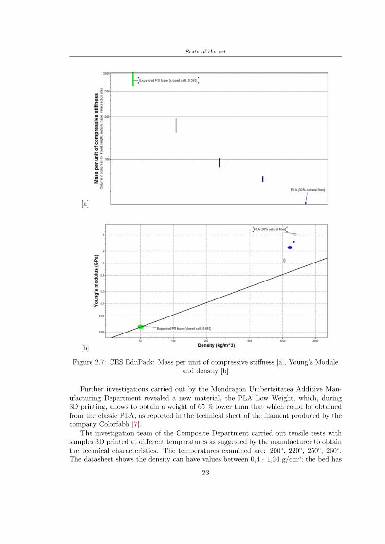
State of the art
[a]
[b]
Figure 27 CES EduPack Mass per unit of compressive stiffness [a] Youngrsquos Moduleand density [b]
Further investigations carried out by the Mondragon Unibertsitatea Additive Man-ufacturing Department revealed a new material the PLA Low Weight which during3D printing allows to obtain a weight of 65 lower than that which could be obtainedfrom the classic PLA as reported in the technical sheet of the filament produced by thecompany Colorfabb [7]
The investigation team of the Composite Department carried out tensile tests withsamples 3D printed at different temperatures as suggested by the manufacturer to obtainthe technical characteristics The temperatures examined are 200 220 250 260The datasheet shows the density can have values between 04 - 124 gcm3 the bed has
23
State of the art
to have a temperature between 50 - 60 the printing speed has to have values between40 - 80 mms This typology of PLA is expandible so much that rdquoAt around 230 thismaterial will start foaming increasing its volume by nearly three timesrdquo [7]
T[C] Section [mm2] Volumen [mm3] Mass [g] ρ[kgm3] E [Nmm2]
200 42235 1030117 12 1165 328807
220 43805 1655821 18 1087 265795
250 52412 1948139 17 873 178058
260 59655 1454377 12 825 117047
Table 210 Values about PLA LW tensile tests of MU Additive ManufacturingDepartment
From the tests that have been carried out on the material at different temperaturesthe printed sample is better at 250 with a volume of 1948139 mm3 and a section of52412 mm2 as shown in Table 210 For this reason the specific of the material thathave been taken into consideration are the following
- Density ρ = 873 kgm3
- Youngrsquos Module E = 1750 MPa
- Poissonrsquos ratio ν = 033
- Yieldrsquos stress σ = 2948 MPa
- Elongation at fracture = 491
23 Bio-inspired structures
When we talk about bio-inspired structures to nature we refer to structures that allowobtaining a low weight for the model that is realized and excellent absorption energy dur-ing the impact Recently the structures that have been most used in the biomimetic fieldare the rdquocolumns structures sandwich structures plates honeycomb and foamsrdquo[26]but aiming to achieve a structure increasingly with high absorption energy new struc-tures derived from plants and animals such as beetle horsetail turtle bird beak havebeen analyzed The first to create multi-cells tubes helicoidal structures the second tomulti-corner tubes [26]
The authors analyze the specific energy absorbed (SEA) by bio-inspired sandwichstructures per unit mass which can be derived from the following equation
EA(d) =
int dmax
0F (x)dx (25)
SEA(d) =EA(d)
m(26)
24
State of the art
Where EA is the energy absorption rdquomainly used to evaluate an energy absorberrsquosability to dissipate crushing energy through plastic deformationrdquo F(x) is the crashingforce dmax is the effective deformation distance [26]
What derived from their investigations is that having regard to a density of between0 and 1000 kgm3 the volumetric energy absorbed is higher for the beetle-inspired struc-tures than the others as shown in Figure 28 Based on this consideration it was chosento draw the helmet following this geometry
Figure 28 SEA of bio-inspired sandwich structures [26]
231 Beetle structure - Design of the model
To develop and increase lightweight high-strength and optimize bio-mimetic functionaland structural materials the trabecular structure of the beetle elytron is studied Thesingle structure is realized following the requirements cited by Zhang et al [39]
To realize the beetlersquos structure it is not enough to have information about the lengthof the side of the hexagon and the thickness but it is also necessary to take into accountthe relationship between the diameter of the circumferences present on the vertices ofthe hexagon and the measurement of the side The representation of a single cell is inFigure 29 It is shown in [a] a general structure with an edge of 12 mm circumferencersquosdiameter of 6 mm and thickness of 16 mm in [b] is shown the height of 20 mm
For the construction of the helmet a thickness of 12 and 16 mm was used the imageconcerns a proportion between the length of the hexagon side and the diameter of the
25
State of the art
circumference The side (distance between the centers of two circumferences) is twice thediameter measurement
[a] [b]
Figure 29 Beetle structure
232 Specific stress - PLA LW and EPS foam
To test the beetle structures compression tests were investigated The PLA LW structurewas inserted in a rsquodiskrsquo with a diameter of 100 mm and a height of 20 mm The area andthe volume of the disk is correspondingly 7854 mm2 and 157 10 mm3 The structuresexamined have different dimensions the edge L (distance between two centers of thecircumferences) had the following measures 9 10 12 14 16 mm the thickness of thecircumferences and edges are respectively of 16 mm for every structure and 12 mm forthe structure with L = 16 mm
The test was carried out with the Hoytom HM-D Testing Machine with capacitiesbetween 5 and 100 kN The test models were subjected to displacement loading at a rateof 1 mmmin as referenced by Chen et al[18] with a cylindrical specimen The specificstress of the structures was compared with the specific stress of a generic EPS helmetthe photos about it are shown in Figure 210 The EPS helmet structure is granular withpores inside The different grains dimension and these pores can be the reason for whichthe Stressrsquos values are between two values 07 and 116 MPa
Four parts of the EPS helmet were considered in the test the dimension and relativecharacteristic are in the Table 211 where m = mass A = area F = load ρ = densityR = stress Rρ = specific stress To calculate the values of stress about PLA structuresand EPS foam compression test graphs were been analyzed The stress value for eachstructure was calculated considering the single load the single area and the averagedensity value (14055 [kgm3])
The stress values of the PLA structures (Figure 211) and other characteristic valuesare in Table 212 where m = mass A = area F = load ρ = density
26
State of the art
[a] [b]
[c] [d]
Figure 210 EPS generic helmet helmet pictures [a] [b] and internal structureExternal granular structure [c] and pores [d]
[a] [b] [c]
Figure 211 PLA LW disks Grasshopper structure [a] PLA LW structure of 14 mm[b] PLA LW structure compressed [c]
27
State of the art
The results of the load-displacement graphs are affected by the geometry of the diskthe target is to valid for any shape or size for this is preferred to realize a diagramthat depends from σ (or stress) and the deformation ε (or strain) which can be definedrespectively as
σ =F
A0(27)
ε =l minus l0l
(28)
where F is the load during the test A0 is the area l0 is the initial length and l is thelength when the load is applied The areas considered for the EPS cube is reported inTable 211 in the second column the areas of the PLA structure is 7854 mm2 like thearea of the circumscribed disk
The values compared are shown in Table 213 and the graphs obtained by Matlabcode to analyze the recorded data of the compression machine are in Figure 213 and inFigure 212
Considering that the data provided by the compression machine are subject to noiseand disturbances it was decided to convert the original curve into polynomial type curvesthat allow obtaining the best interpolating curve for the data in question To obtain themit was divided the recorded data into two groups the first part from 0 until the end ofthe linear part and the second when the curve becomes linear again The best-fitting (inthe least-squares sense) was performed using the polyfit and polyval functions of MatlabThe first returns the coefficients of the p(x) with n degree the second evaluates p(x) ateach point in x The polynomial formula p(x) is shown in the Equation 29
pn(x) = anxn + anminus1x
nminus1 + + a2x2 + a1x+ a0 (29)
where a0 an are constants and x is the indeterminate The choice of the degree ofthe polynomial was made based on the criterion of wanting to obtain linear curves thatrespected the elastic trend at the beginning of the graph For this reason the degree ofthe polynomial is 1 Subsequently I searched through the intersection of the two lines forthe point that is equivalent to the maximum stress that marks the end of linearity
This value for EPS and PLA LW is the R [MPa] in the Table 213 The average stressvalue for PLA LW is 139 MPa and for EPS is 094 MPa The specific stress (Rρ) is 18MPa lowast m3)kg for the EPS found in CES 669 MPa lowast m3)kg for the EPS foam of thegeneric helmet and for PLA LW is 1161 MPa lowastm3)kg an intermediate value betweenthe two which is what we wanted to achieve
28
State of the art
m [g] A [mm2] F [N] ρ [kgm3]
EPS (CES) 50
16 9234 1063 13864
18 879 593 13651
21 858 833 14237
24 864 564 14468
Average value 14055
Table 211 Compression stress generic EPS helmet
L [mm] t [mm] m [g] F [N] ρ [kgm3]
9 16 214 7250 1363
10 16 192 5560 12467
12 16 201 8190 13051
14 12 138 8000 8961
Average value 12027
Table 212 Compression test PLA structures
PLA LW structure EPS structureρ= 12027kgm3 ρ= 14055kgm3
Edge [mm] R [MPa] Rρ103 Number R [MPa] Rρ103
EPS (CES) 09 18
9 173 1269 1 116 824
10 139 1114 2 08 568
12 138 1057 3 105 746
14 108 1205 4 077 540
Average value 139 1161 094 669
Table 213 Specific stress calculus PLA LW and EPS calculus ρ = density R = stressRρ [(MPa lowastm3)kg] = specific stress
29
State of the art
Figure 212 Compression test Stress-Strain diagrams - EPS
Figure 213 Compression test Stress-Strain diagrams - PLA LW
30
Chapter 3
Methodology
31 3D scan
311 3D Sense 2 scanner and Meshmixer - Reverse reconstruction
Standardized measures were not taken into account for making the helmet but the sizewas obtained through a 3D scan of my head
The scanner used is 3D Sense 2 by 3D Systems which has a minimum scanningvolume of 20 x 20 x 20 cm and a maximum scanning volume of 300 x 300 x 300 cmTo scan my person I was helped to get a full view at 360 at an appropriate distanceReal-time visualization of the captured images was shown through 3D Sense softwareThe idea of scanning the head with the scanner refers to the methodology used by Wanget al [30] They used a reverse reconstruction functional for me to realize the helmetsurface made to measure my head and like them a silicone pool cap was used to makescanning as smooth as possible The authors claim the head scan rdquocan also be used toobtain information about the objectrsquos surface which is then reconstructed utilizing thecomputerrsquos three-dimensional model via reverse modelling softwarerdquo [30] that in my caseis Autodesk Meshmixer
The files it was could get from the scan were stl obj and ply format they wereexported to obj to work in the next step with Autodesk Meshmixer that allowed tomodify and homogenize the 3D image obtained from the scan
In Meshmixer through the selection and delete commands the superfluous parts weredeleted that had been acquired and with the inspector and the DrawDraw2 commandsthe vertices were moved locally along a pre-defined direction and with Smooth the surfacemore homogeneous was made The sequence of steps is shown in the Figure 31
312 3D scan analysis and extraction of features
In Chapter 2 the directives imposed by the BS EN 960 Standard were examined concern-ing the definition of the helmet and the measures to be respected in the field of visionand the part of the helmet was to carry out impact tests
In Figure 32 the features defined complying with the Standardrsquos rules are repre-sented To define these features the software NX was used The angle in the subfigure
31
Methodology
[a] [b] [c] [d]
Figure 31 Sequence of 3D head scan 3D scanner acquisition [a] scan after reparationwith Meshmixer [b] solid scan vision frontal and lateral [c] [d]
[b] is bigger than 105 (as defined by the Standard) while the degree in the subfigure [c]is 25 By defining the construction lines to be respected of the helmetit was necessary todraw the design of the surface not using the software NX but changing with Rhinocerosto create a SubD or SubDivision surface
32 Helmet design
321 Rhinoceros - Helmet surface
After realizing a rsquocleanrsquo Wang et al [30] subdivide with lines and then sectors the headto create the surface of the helmet They used the technique of NURBS a Non UniformRational Basis-Splines which mathematically models a 3D geometry while thanks tothe Rhinoceros 3D organic shapes was draw SubD surfaces These geometries allow tosplit the mesh into small polygons and consist of lines with which easily the shape ofthe object can be modified with a surface already created changing the position of aline automatically the remaining part of the geometry adapts to the changes With thistechnique the rsquosurface basersquo of the helmet was realized with the size of my head Therepresentation of the realized SubD is in Figure 33
322 Grasshopper - Helmet structure
The next idea is the creation on the surface of the beetle structure with different di-mensions modelling the helmet that is not a linear surface It was decided not to buildthe structure with a software CAD because to model an already complex structure on acurved surface would mean to model a cell for a cell
To solve this obstacle a Rhinoceros plug-in was used Grasshopper GH idealized byRobert McNeel and associates creators of Rhinoceros Using GH does not mean drawinggeometries by connecting points and drawing tools because it is based on algorithmicmodelling used in architecture and engineering for 3D modelling
The modelling takes place through a node diagram that the software will convert intoa code-algorithm in GH it is possible to define the variables and parameters and inRhinoceros in real-time it is possible to view the object GH allows for varying the
32
Methodology
[a] [b]
[c]
Figure 32 Featurersquos extraction in [a] is represented the impact line in [b] and [c] twoprospective about the definition of the field of vision
[a] [b] [c]
Figure 33 SubD representation lateral view [a] top view [b] front view [c]
geometry to your liking by varying a simple parameter of the diagram as everything willbe remodelled according to the change made
In the following Figure 34 it is shown an example of a structure that was used fordistinct subgroups of helmet areas The idea was to insert smaller cells in the frontal andlateral zone and larger ones in the upper area In the first image [a] is shown the part of
33
Methodology
the helpful diagram to create the beetle structure to establish the size of the cells andthe extrusion the second image [b] contains the part of the diagram with which I appliedthe structure previously created to the SubD
The structure used to place and adapt the beetle structure to the surface is theSrfMorph while the yellow rsquowindowrsquo that contains numbers serves to select the parts ofthe surface where to apply the geometry created In accord with the GH diagram in
[a]
[b]
Figure 34 Grasshopper diagrams
Figure 34 [a] it is possible to see the steps executed to realize the structure Initially inthe xy-plane a hexagonal grid was drawn through the Hexgrid command in which youcan input the length of the hexagon edge and the number of grid elements (selected bytrial) Then the circumferences was drawn in proportion to the hexagon dimensions asspecified in the Chapter 2 and shown in Figure 35 [a] In figure [b] the rsquocutrsquo made atthe circumferences is visible this subdivision was necessary for printing purposes In thelast photo [c] the structure highlighted in green in [b] was extruded setting a distance
34
Methodology
of 20 mm
[a] [b] [c]
Figure 35 Construction sequence of the geometry of the helmet
In the diagram in Figure 34 [b] there is the application of the structure created bi-dimensionally to the SubD surface of the helmet visible by unlocking the SubD commandof the diagram and in Figure 36 [a] Upper this the referential geometry of the group ofsurfaces was superimposed where it was to be applied the newly created structure (visiblein darker red) the SubD indices are in the yellow box of the diagram
Through the SrfMorph command the location of the structure was granted In Figure36 [b] at the darkest red of the figure [a] with the above command it was possible toplace the structure
[a] [b]
Figure 36 Application of the geometry created to the helmet surface
Overall the diagrams with specific structures are five one for the front two equal forthe side parts one for the top shown in the previous Figure 36 and one for the back
The hexagons in the structure have a dimension varying between 8 mm and 14 mmof side the largest is found at the top later at the back in the sides and the smallest atthe front In Figure 36 [b] the presence of not only hexagonal structures is visible Thegeometry used does not allow the homogeneous arrangement on the entire surface andrequires different structures Automatically the choice of GH to optimize the structurewas to insert quadrilateral
As described above the helmet has different dimensions of the structure divided asvisible in Figure 36 in a quadrilateral This causes a discontinuity between zones withdifferent sizes due to the geometry of the construction
To eliminate this problem and realize the design homogeneous grids were inserted
35
Methodology
in the affected areas as shown in Figure 37 This insertion however proved to beinteresting and strategic researching in this regard studies were realized to demonstratethe insertion of a rectangular grid inside the hexagon grid was helpful for the transmissionof stress in the structure As cited by Sun et al [40] rdquothe mechanical properties of thesesandwich structures are often limited by local failures such as face-core debonding or corecollapserdquo Carrying out compression tests have effectively demonstrated that the insertionof the grid allows rdquoprovided increased stiffness specific stiffness energy absorption andcritical loadrdquo [41] As shown in the graphic [c] of the Figure 37 the honeycomb structuregives a force of 7 kN while with a grid the value is 11 kN and with the combinationexceeds 22 kN In addition in the left front a plaque to customize the helmet wasprepared Figure 37 [a]
[a] [b]
[c]
Figure 37 Grid in the helmet [a] hybrid structure with hexagons and grid [b] [40]compression test results of the hybrid structure [c] [41]
33 3D Print
After having achieved the CAD (Computer Aided Design) of the helmet in order tobe printed it must be converted and saved in format STL (Standard TriangulationLanguage) - Binary compatible with the printing machine and useful for transformingsolid object surfaces into triangles The steps to be taken are the following
bull CAD file realization
bull CAD export in format STL to Simplify 3D the software that shows slider layersand then- rotate and position the object according to geometry and the positioning of any
36
Methodology
supports- setting printing parameters- item manual andor automatic positioning of supports- slider display layers
bull import file gcode to printer
331 Printer and parameters
The program used to visualize how the helmet slices layers before sending it to the printerand to set the parameters is as anticipated Simplify 3D
To make the printing not being a flat geometry it is necessary to place the supportsThe idea was to use water-based supports that the helmet would automatically dissolveonce placed in the water After testing different types of water-soluble PVA the choicefell on eSun 3D Printing Filament PVA (water-soluble support) Before choosing theoptimal position for printing several tests were carried out and to decrease the numberof the supports significantly and allows an optimal printing of the outer part an emptyrsquospherersquo that self-sustains below the helmet was placed as shown in Figure 38
In the image [a] you can see the first print position tried with which an external partof the helmet very damaged was obtained because of the contact supports-helmet In [b]the empty rsquospherersquo is shown to optimize the number of supports and in the last photo [c]there is the full version at the end of print
[a] [b] [c]
Figure 38 Printing supports
The printer that has been used for printing is the Raise 3D Pro2 with double extrudersand nozzles of variable size from 02 mm to 1 mm after some test prints with the PLALW and the structure in created the size that allowed me to have a good compromisebetween printing time and accuracy was 06 mm Using 04 mm the printing time wasexcessive even if having the smaller nozzle diameter means having more precision withthe 08 mm nozzle the quality of the structure was not excellent as seen in Figure 38[a]
Another factor that had to be taken into account is the characteristic of the PLA-LWto expand As the printing temperature and the printer used vary the expansion andcharacteristics of the material change The use of the 06 mm nozzle associated with
37
Methodology
Parameter Left extruder Right extruder
01cm Material 01cm PVA 01cm PLA LW
Extruder toolbox index Tool 0 Tool 1
Nozzle diameter 06 mm 06 mm
Extrusion multiplier 1 05
Extrusion width Auto (072 mm) 05 mm
Layer x
Infill Rectilinear - 50
Supports (Automatic and not) Infill 50
Temperature 210 250
General parameters
Primary layer height 03 mm Top solid layer 4
Bottom solid layer 2 Outline 2
Heated bad 60 Speed 40 mms
Table 31 Printing parameters
Raise 3D allowed me to get good results The choice of this printer was not random ithas in fact the characteristic of making extremely precise prints The Raise has accuracyin placing the object on the printing bed of 078 microns on the xy axis and a resolutionfor layers of 001 mm
The final version of the helmet is visible in Figure 39 and it is possible to compare itwith the preview version in Rhinoceros in Figure 310
38
Methodology
[a] [b]
[c]
Figure 39 Views of the helmet
[a] [b]
Figure 310 Views of the helmet (GH version)
39
Chapter 4
Experimental evaluation
41 Experimental tests
411 Drop-weight impact test machine
In order to calculate the contact force peak and the difference of energy absorbed duringthe impact between the reference helmet and helmet with the beetle structure in PLA-LW dynamic impact tests were carried out using the Fractovis Plus an impact testmachine
In this way it is possible to monitor the evolution of the above variables from theinitial to the final instant of the impact The machine can withstand a load with a rangevariable from 2 to 70 kg with a maximum speed of 46 ms and a maximum height of1 m The values chosen for the test are the following 5 kg weight maximum speed andmaximum height The Anvil that was used is a disc diameter of 60 mm
As shown in Figure 41 and explained by Crupi et al [37] the machine consists ofa sensor capable of recording the speed before impact the impactor that can have avariable mass (a weight of 5 kg in my test) a system to guarantee that there are nomultiple impacts after the first and that work as a shock absorber and clamping systemwhere the object to be tested is placed
The tests that have been carried out are in total four two related to the helmetoptimized with PLA-LW and two with two generic helmets of different brand in EPS
42 PLA LW helmet
To perform the dynamic test on the helmet of PLA considering the difficulty of printingit was helpful to use a test helmet with imperfections to understand where the impactwas concentrated in a single part or distributed The images of Figure 42 show a helmetwith not well defined edges and inaccurate print but exactly localizes the impact zoneThanks to this test it was possible to take into account only one helmet area shown inFigure 43 to have the exact curve of the structure bio-inspired with PLA-LW
40
Experimental evaluation
Figure 41 Drop-weight impact test machine [37]
[a] [b]
Figure 42 Test 1 PLA-LW helmet
43 EPS helmet
To carry out dynamic tests and extract the technical characteristics of the helmettwohelmets were bought in a sports store both EPS and being on the market both certifiedThe brands of the two helmets are DTB and VAN|RYSEL and the average weight ofthe two is 223 g Two different helmets have been chosen to have a more certain andclear classification of the characteristics They are shown in Figure 44 and Figure 45
41
Experimental evaluation
[a] [b]
Figure 43 Test 2 PLA-LW helmet
[a] [b] [c]
Figure 44 Test 3 EPS helmet
[a] [b] [c]
Figure 45 Test 4 EPS helmet
44 Results
441 First results - PLA-LW and EPS helmet
Figure 46 shows two types of trends related to the two different models of the helmetThe force evaluated for PLA-LW has higher force peaks but is more concentrated and
42
Experimental evaluation
propagates less than EPS The graph shows the peaks of each curve highlighted with a redcircle In tests 1 and 2 for the PLA-LW as mentioned earlier the values are higher about7301 N for the complete helmet and 3996 N for the portion of helmet This difference isdue to the inaccuracy of the first full helmet during the printing phase In Figure 42 itis visible the low homogeneity and precision Therefore the first test with full helmet wasused only to define the area of interest of the impact which turns out to be localized Forthe other two EPS curves the values are only slightly lower compared to the PLA-LWequal to 3620 N and 3295 N but the trend is much more distributed
Figure 46 Dynamic machine test - Force
With the data obtained from the impact machine it was possible calculate not exclu-sively the value of force but itrsquos also possible to view the energy curves A resume aboutthe values and energy of the force is in the following Table 41
Test Peak force [N] Peak energy [J]
Test 1 - PLA LW (inaccurate) 730130
Test 2 - PLA LW (portion of helmet) 399643
Test 3 - EPS (DTB helmet) 362007 509
Test 4 - EPS (VAN|RYSEL helmet) 329546 4198
Test 5 - PLA with TPU 45421 5022
Table 41 Energy absorbed in dynamic test
43
Experimental evaluation
442 PLA-LW helmet with TPU cover
As it is possible to see in Figure 47 and as highlighted the first tests concerning thebio-inspired structure and the PLA-LW are far from my expectations considering thelittle distribution of force in comparison with the EPS foam and consequently a smallamount of energy absorbed
Figure 47 Dynamic machine test - Energy
To improve this impact damping factor the idea was to create a cover for the helmetin flexible TPU trying to absorb impact energy The TPU used is a flexible material ofthe brand Ninjaflex used in sports by the application in helmets and shoes to cushionbumps during the game Generally in the helmets (baseball helmet for example) theTPU is inserted internally in contact with the head In my case the TPU structurein addition to creating a shock-absorbing and durable cover creates a custom cover thehelmet and for the person This cover was also made with the Raise 3D printer
As shown in the Figure 48 [a] the infill of the part in contact with the helmet hasa percentage of 100 the filling of the other part of the structure is not complete butonly 15 and the internal structure is hexagonal to recall that of the helmet The desireto insert a structure with a rsquoraisedrsquo geometry is for visual and aesthetic reasons as youhave the feeling of greater protection and not filled is inspired by the machine CitroenCaptus whose bumpers (Airbump) are full of air The failure to realize empty structuresis due to the need to place any internal supports not removable
The idea was to create a cover that allow you to see of the internal structure of thehelmet and that protect specific areas the front the two sides the top and the posteriorWhat which was thought for this reason was to create the shape of a flower with four
44
Experimental evaluation
petals Figure 48 [b]In this way to perform dynamic impact tests as shown in Figure 49 [a] the cover was
positioned at the top of the helmet and the impact was performed in the centre of thersquoflowerrsquo which corresponds to the higher upper part where the structure has larger cellsize The impact parameters are the same as those used in previous impacts 5 kg weightmaximum speed and maximum height The Anvil that was used is a disc diameter of60 mm In photo [b] it is evident the difference between the structure that received theimpact with protection (left) and without protection (right) Without protection duringthe impact there was a perforation of the structure with a concentration of force at a locallevel as you can see in the Figure 46 in the case of TPU the impactor did not perforateand crossed the structure thanks to the cover of TPU that cushioned the shock At themoment of impact the impactor bounced
[a] [b]
Figure 48 TPU cover
[a] [b]
Figure 49 PLA-LW with TPU - dynamic impact [a] and differences between thehelmet with TPU and without TPU cover [b]
45
Experimental evaluation
The Figure 410 includes the diagrams relative to the dynamic impacts In [a] thereare already analyzed EPS results in [b] a comparison between the test on the portionof helmet in PLA LW with and without the TPU cover in [c] the overall comparison ofcurves shows a much more similar EPS trend if the TPU is placed above the structure inPLA LW to soften the blow and absorb the same energy [d]
46
[a]
[c]
[d]
Figure 410 Comparison between PLA-LW with TPU and EPS
Chapter 5
FEM Validation
51 Impactor - Anvils definition
Before to start to work in Abaqus it was necessary to search in the literature the materialwith which the anvil was been realized Milne et al [23] established the densityrsquos valuethe Youngrsquos Module and Poissonrsquos ratio for the Flat and Kerbstone Anvil
- Density ρ = 7800 kgm3
- Youngrsquos Module E = 200000 MPa
- Poissonrsquos ratio ν = 03
Inserting the data in the CES EduPack program specifying the mechanical andphysical properties the material corresponding to these characteristics is Stainless steelaustenitic (ASTM F1586) medium-hard
Initially the proposal was to create a conservative system to evaluate the absorptionenergies values and apply this value to a vibration system but the helmet needs dampingto be realized it was impossible to use a system without losses in this modality Thisis why a numerical calculation was carried out by performing two types of simulationsexplicit dynamic step and static step
The idea to realize the theoretical impact is to regard the movement of the anviland not the helmetrsquos movement which is fixed The velocity is the same cited in thenormative EN 1078 542 ms for the Flat anvil and 457 ms for the Kerbstone anvil
In performing the simulations It was given more relevance and perform tests withthe Kerbstone Anvil This choice was done because the geometry with which it is beenrealized (following as defined in the legislation) allows the helmet to be more subjectedto stress this involves the definition of higher stress limits compared to the Flat Anvil
The mesh size that has been used is the same in the case of the simulation of thehelmet optimized in PLA-LW and the full helmet in EPS of 7 mm The impactor isconsidered as a Discrete rigid body with its specific Reference Point (RP) like shownin Figure 51 for this reason it is not a solid but it is composted only by shells Inthe same image [b] there is the FEM representation of the model and in Table 51 thecharacteristic of FEM with quadrilateral (R3D4) and triangular elements (R3D3)
48
FEM Validation
Object Elementnumber
Elements Shape Geometricorder
Global size[mm]
Kerbstone 230 Quadrilateral - R3D4 Linear 7
Kerbstone 8 Triangular - R3D3 Linear 7
Table 51 Mesh element - Kerbstone Anvil
[a] [b]
Figure 51 Kerbstone anvil in the simulation like discrete rigid body [a] and FEMelements [b]
511 PLA LW - Plastic characteristics
The PLA-LW as explained in the Chapter 2 is new material on the market and producedby the only Colorfabb company for this reason few tests have been carried out to defineits technical characteristics and through tensile tests of the 3D printed specimens it waspossible to define an elastic limit as reported in the Table 210
In the context of simulations to reproduce the impact and deformation of the helmetis also necessary to consider the plastic characteristics of the material Not possessingany reference value in this regard tests were performed through a Static Step initiallyand then an Explicit Dynamic Step in Abaqus
The structure chosen to consider as a reference it is one of the structures previouslysubjected to the compression test having the side L=14 mm As for the reproduction ofthe compression disks initially they were reproduced according to the geometry of theHoytom HM-D Testing Machine considering the bodies mentioned above as discrete 3Drigid discrete The measure was the diameter of 200 mm and the height of 20 mm
After an initial analysis it was observed that the computational time of the simulationprogram was very high so it was decided to change the geometry to have a rsquodisk-surfacesrsquo(equally 3D rigid-discrete) which allowed me to have a smaller number of nodes for themesh and consequently a better computational time The representation of the opti-mized structure in PLA-LW and the disks used for simulated compression is in Figure 52
49
FEM Validation
[a] [b]
Figure 52 Representation of the samples used for the simulation of the compressiontest In Figure [a] the disks of the Hoytom HM-D Testing Machine in figure [b] the
representation of the same as simple surfaces
As shown in Figure 52 the disks are considered 3D discrete hard bodies so it waschosen for both a point the reference point RP where to apply the characteristics relatedto the two bodies As for the compression test it was established
bull the movement of a disk and fixed the second through a boundary condition impos-ing an Encastre therefore unable to move and rotate in xyz directions
bull for the opposite disk the boundary condition relative to the 15 mm displacementwas applied which is the parameter that it was observed to determine the end ofthe compression with the machine This shift is shown by the orange arrow in figure[b]
bull between the upper surface and the disk e the disk with the lower surface it wasinitialized a general contact with normal behaviour through rsquohardrsquo contact andtangential behaviour with a coefficient of friction of 02 with directionality imposedon rsquoisotropicrsquo
The next step was to define the mesh of the components whose parameters are shown inTable 52 while the representation of the FEM is in Figure 53 with the representationof the simulation and real compression test
Object Elementsnumber
Typology Geometricorder
Globalsize [mm]
Disk (14mm) 80910 hexaedral - C3D8R Linear 07
Impact disks 206 quadrilateral - R3D4 Linear 20
Impact disks 6 triangular - R3D3 Linear 20
Table 52 Mesh element - Compression test simulation
As previously announced a static simulation was initially performed with a StaticStep with Step Time equal to 900 (obtained going to consider the speed of 1 mmmin of
50
FEM Validation
[a]
[b] [c]
Figure 53 FEM representation [a] and compression test simulation [b] and realcompression [c]
the compression test and the displacement of 15 mm) However the complex geometryof the structure and the high time set by Step Time did not allow a correct definitionof the parameters of the plastic characteristics of the material the simulation was notable to continue once reached a Step Time of approximately 220 That is why it waschanged by choosing an Explicit Dynamic step
Leaving all the parameters of the boundary conditions unchanged the Step Time wasmodified imposing it to 001 The ability of the explicit dynamic to work with non-linearand contacting structures allowed me to achieve results The results obtained are shownin Figure 54 with the blue curve and were obtained through the iteration of differentPlastic Strain and Yield Stress values in Abaqus while the red line is the result of thereal compression test a similar curve trend was obtained but it is not possible to obtainthe same curve taking into account problems of printing inaccuracy
512 First test - helmet
The initial idea was to perform a simulation imposing the speed of 457 ms to theimpactor tie the helmet in EPS and PLA and compare the absorbed energies Theproblem it was encountered is related to the mesh of the helmet optimized in PLA andwith minimum dimensions of the elements and distinct elements it was not able to solveit
51
FEM Validation
[a]
YieldStress
PlasticStrain
1 47 0
2 7 001
3 75 005
4 10 01
5 108 1
6 115 15
7 12 2
[b]
Figure 54 Representation of the two curves related to the simulation in Abaqus of thecompression test and the data obtained from the real test to obtain the plastic
characteristics of the material
513 Second test - plane
The first solution is the one shown in Figure 55 To realize the simulation it was realizeda section of the helmet to involve a smaller number of elements and nodes Again thesimulation for the EPS helmet was successful while the simulation with the bio-inspiredstructure was interrupted by excessive distortion of elements
The previous images show the impact is very localized in the impacted area and theidea to achieve a complete simulation is not to consider a curved portion of the helmetbut a plane In this way it was possible to solve the problem and obtain a completesimulation for the bio-inspired structure
FEM element
Below in Table 53 there is the definition of the elements used for the PLA-LW and EPSplane in the simulation to simulate the impact and to control the energy-absorbing whilethe anvil characteristics are described in Table 51
514 EPS impact simulations
In order to proceed with the simulation it was imposed some boundary conditions thatregard ties and forces
bull the movement of the plane is fixed through an Encastre therefore unable to moveand rotate in xyz directions
52
FEM Validation
[a]
[b]
Figure 55 Impact simulation parts of EPS and PLA helmet
Object Elementnumber
Elements Shape Geometricorder
Plane (PLA) 38896 Tetrahedral -C3D10M
Quadratic
Plane (EPS) 2100 Hexahedral - C3D8R Linear
Table 53 Mesh element - plane impact
bull to create the impact it was set a speed of 457 ms at the reference point RP of therigid body which is the impactor Kerbstone Anvil shown in Figure 56
bull between the upper surface of the plane and the impactor it was initialized a Sur-face to Surface contact with normal behaviour through rsquohardrsquo contact and tangen-tial behaviour with a coefficient of friction of 02 with directionality imposed onrsquoisotropicrsquo
bull the rotation in x y z relative to the RP of the rigid discrete impactor body is locked
53
FEM Validation
In addition it was characterized the plane in the part of the materials with the char-acteristic values of the EPS mentioned in Chapter 221 The Von Mises Stress valueapparently low is relative to the Yield Stress of the EPS material equal to 09 MPa
Figure 56 EPS Boundary conditions and Load
515 PLA LW impact simulations
As also required in the case of the EPS plane in order to proceed with the simulationsome boundary conditions were imposed that regard ties and forces
bull the movement of the plane is fixed through an Encastre therefore unable to moveand rotate in xyz directions
bull to create the impact a speed of 457 ms was set at the reference point RP of therigid body which is the impactor Kerbstone Anvil shown in Figure 58
bull between the upper surface of the plane and the impactor it was initialized a Sur-face to Surface contact with normal behaviour through rsquohardrsquo contact and tangen-tial behaviour with a coefficient of friction of 02 with directionality imposed onrsquoisotropicrsquo
bull the rotation in x y z relative to the RP of the rigid discrete impactor body is locked
In addition the plane was characterized in the part of the materials with the characteristicvalues of the PLA mentioned in the Chapter 223 and 511
Figure 58 Boundary conditions and Load
54
FEM Validation
[a]
[b]
Figure 57 EPS impact simulation
52 Results
In Figures 59 and 57 it is shown how the structure in PLA LW has a more concentratedstress distribution of the structure unlike EPS The maximum value for the Von Misesstress is 09 MPa in EPS structure and 3634 MPa in PLA LW structure Once thesimulations were obtained the next step was to go and compare the energies absorbed bythe two structures The energy calculated by Abaqus that has been taken into account isPlastic Dissipation To make a comparison the data of the two energies were representedin a single graph
What emerges from the graph is that about the impact made with the KerbstoneAnvil the energy absorption is more excellent although only slightly for the PLA LWthan for the EPS From the graph in Figure 510 a value of 41 J is shown for the EPSand 51 J for the PLA LW
55
[a]
[b]
Figure 59 PLA impact simulation
[a]
Figure 510 EPS and PLA LW energy comparison - Abaqus simulation
Chapter 6
Head Injury Data
For the statistical analysis the injuries related to the accident data were categorised intothe following types and levels based on the details of the medical report [11] about theEN 1078
bull Head Injury Criterion (HIC)
bull Peak Linear Acceleration (PLAc)
bull Gadd Severity Injury (GSI)
bull Diffuse axonal injuries (DAI)
61 Abaqus simulation
Until now the purpose of the simulations has been to determine which between the twomaterials and the two structures of EPS and PLA LW could absorb more energy duringthe impact but no simulations have been carried out in compliance with BS EN 1078on the helmet impact tests To calculate the injuries listed in the previous paragraphhowever we need the acceleration values in the three directions related to the subjectrsquoshead
To realize it the scan of my head already rsquocleanrsquo was considered of which it has beencalculated the inertia thanks to the automatic SolidWorks calculation and evaluated theweight with the Table 24 the structure of the helmet was placed for the EPS and thePLA LW over the head as shown in Figure 61 Also this time being able to mesh theentire helmet in PLA LW was impossible due to the excessive distortion of some elementsduring the simulation so it has been tried to make a section of the structures of thehelmet and results were obtained
57
Head Injury Data
[a] [b]
Figure 61 My scan head - CAD [a] head imported in Abaqus[b]
Initially the simulation had these characteristics as shown in the following Figure62 considering the helmet was not sectioned As explained earlier it was not possibleto get to simulation in the case of the optimized structure in PLA LW for this reasononly a part of the helmet was considered in both cases shown in Figure 63
[a]
Figure 62 Simulation based on BS EN 1078
58
Head Injury Data
[a] [b]
Figure 63 Simulation based on BS EN 1078 with head
In order to proceed with the simulation some boundary conditions that regard tiesand forces have have imposed
bull two reference points RP were created the first in the inertia centre of the headthe second relating to the Kerbstone Anvil which is a discrete rigid body
bull in the reference point RP of the head in the definition of the engineering features5 kg was inserted for the weight and an inertia I11 = 564464E+07 gmm2 I22 =460654E+07gmm2 I33 = 187302E+07gmm2
bull to simulate the impact it was set a speed of 457 ms at the reference point RP ofthe head in z-axis direction
bull a general contact with normal behaviour through rsquohardrsquo contact and tangentialbehaviour with a coefficient of friction of 02
bull between the upper surface of the helmet and the impactor it has been initializeda Surface to Surface contact with normal behaviour through rsquohardrsquo contact andtangential behaviour with a coefficient of friction of 02 with directionality imposedon rsquoisotropicrsquo
bull the movement between the Kerbstone anvil and the helmet is fixed through anEncastre therefore unable to move and rotate in xyz directions
bull the rotation in x y z relative to the RP of the rigid discrete impactor body is locked
FEM element
As reported in Table 53 the portion of the helmet in EPS has used a mesh with hexahe-dral elements of linear order For the structure (beetle) of PLA LW given the geometry
59
Head Injury Data
complexity it was necessary to use a quadratic order of tetrahedra For the mesh of thehead instead in both simulations have been used quadrilateral elements of linear orderas reported in the Tables 61 and 62
Object Elementnumber
Elements Shape Geometricorder
Head 3755 Quadrilateral - R3D4 Linear
Head 34542 Quadrilateral - R3D3 Linear
Helmet (PLA) 272302 Tetrahedral -C3D10M
Quadratic
Table 61 Mesh element - Head simulation with PLA LW (beetle) helmet
Object Elementnumber
Elements Shape Geometricorder
Head 3755 Quadrilateral - R3D4 Linear
Head 34542 Quadrilateral - R3D3 Linear
Helmet (EPS) 72280 Hexahedral - C3D8R Linear
Table 62 Mesh element - Head simulation with EPS helmet
62 Results
Figure 64 represents the simulation in line with BS EN 1078 concerning the helmet inEPS [a] and the helmet with bio-inspired structure in PLA LW For both simulationsVan Misesrsquo stress has Yield Stress values in the case of EPS which is 09 MPa and theplastic behaviour combination of PLA LW [b]
In the case of head and Kerbstone Anvil stress was not assessed as they were previ-ously defined as discrete rigid bodies
63 Head Injury Criterion
The HIC quantifies head impact severity by incorporating time of acceleration exposureand acceleration magnitude it is calculated in post-processing phase with the followingEquation 61
HIC15 =
[1
(t1 minus t2)
int t2
t1
a(t)dt
]25(t2 minus t1) (61)
60
Head Injury Data
[a]
[b]
Figure 64 Results simulation based on BS EN 1078 with sectioned head
For this analysis a(t) is the acceleration calculated in the centre of mass of the head(corresponding to the reference point RP) expressed in g and the time interval (t2 minus t1)was chosen to maximize HIC over a maximum duration of 15 ms
Matlab and the trapz function were used to calculate the HIC to integrate accelerationover time t2 and t1 were considered initial and final times of the simulation t1 = 0 sand t2 = 10 s time less than 15 s
HIC value of 198 was obtained for EPS and 87 for PLA LW Considering the Hayeset al [16] document about the HIC values and the graph in Figure 65 developed bythe author it is possible to find the percentages related to the different injury AIS1 -AIS6 which correspond respectively to lower and higher severity while in Figure 66 therelative fatality to every value of AIS is shown The values obtained for the HIC andother criteria are shown in Table 63 The HIC value for EPS is 198 for PLA LW it is
61
Head Injury Data
Figure 65 Head injury risk curves based on HIC values [16]
Figure 66 The abbreviated injury score versus fatality rate [16]
87 Analyzing the data and comparing them with the curves of the Figure 65 I obtain
bull a percentage between 20 - 30 of AIS 1 for EPS 10 - 20 for PLA LW
bull a percentage between 10 - 20 of AIS 2 for EPS and 0 - 10 for PLA LW
bull for AIS 3 AIS 4 AIS 5 AIS 6 the percentages for both structures is between 0 -10
Comparing these percentages with the fatality rate of Figure 66 it is clear there is a riskof Moderate and Minor fatality in the case of EPS and PLA LW as all values are between0 and 30
62
Head Injury Data
HIC PLA [g] GSI E [J]
EPS 198 97 361 37723
PLA LW 87 75 169 44102
Table 63 Head Injury Data - values
64 Peak Linear Acceleration
The resultant linear acceleration versus time curve was calculated according to Equation62
γ(t) =radicγ2x(t) + γ2y(t) + γ2z (t) (62)
where
bull γ(t) is the resultant linear acceleration (g)
bull γx(t) is the linear acceleration in x axes (g)
bull γy(t) is the linear acceleration in y axes (g)
bull γz(t)is the linear acceleration in z axes (g)
The value of the impact should never exceed 250g [9] Cripton at all [9] in their studyexamined a helmet with expanded polystyrene (EPS) Figure 68 shows maximum HIC forhelmeted and unhelmeted drops from all heights For each drop height helmets reducedHIC relative to unhelmeted drops IARV value is 180g The acceleration in the two casesis shown in Figure 67 and the maximum values are 97g for EPS and 75g for PLA LWas reported in Table 63 The two values considering a maximum value calculated byCripton [9] of 180g are amply optimal and comply with the standard of 250g
65 Gadd Severity Index
Gadd proposed the Severity Index Criteria shown in Equation 63 Following this crite-rion the GSI values that are over 1000 produce serious internal head injury [33]
GSI =
int t1
0a(t)25dt (63)
Where
bull a is the linear acceleration (g)
bull t is the duration of the impact (s)
I calculated the GSI with the function trapz between 0 and t and the resulting valuesare 361 for the EPS and 169 for the PLA LW which comply with the limit
63
Head Injury Data
Figure 67 Peak accelerations for both helmets
Figure 68 Peak accelerations for both helmeted and unhelmeted drops Numbers overbars indicate peak acceleration For 2 m drop height results stated are the mean value
calculated from three drops [9]
64
Head Injury Data
66 Diffuse Axonal Injury
DAI cases covered all incidences in which neurological injuries occurred as well as con-cussion unconsciousness and coma
In order to assess the risk of head trauma in terms of diffuse axonal injury (DAI)Milne et al [23] defined a model based head injury criteria as follows obtaining theresults in Figure 69
bull 50 risk of moderate neurological injury (DAI1+) Brain Von Mises shearing stressof 28 kPa
bull 50 risk of severe neurological injury (DAI2+) Brain Von Mises shearing stressof 53 kPa
[a]
[b]
Figure 69 Peak intra-cerebral shearing stress computed with the helmet model coupledto the human head model for all impact points (a) Flat anvil (b) Kerbstone anvil [23]
65
Head Injury Data
67 Energy absorbed
In Figure 52 during the impact test between the kerbstone Anvil and the plan with thebio-inspired structure in PLA LW and EPS it was found that the PLA LW althoughwith a small difference of 10 J absorbed more energy in comparison with the EPS Whenthe test is carried out in compliance with BS EN 1078 and the head with a speed of 457ms (corresponding to the kerbstone Anvil) as shown in Figure 610 also in this casethe PLA LW with the optimized helmet structure manages to absorb more energy (evenif the difference is very low) compared to the EPS The maximum energy value in PLALW is 44102 J of EPS is 37723 J
Figure 610 Energy absorption - BS EN 1078
66
Chapter 7
Conclusion
71 Conclusion
In this thesis work a bicycle helmet with a bio-inspired structure in PLA LW and 3Dprinted was created The initial approach was to introduce an innovative aspect tostandard EPS helmets not using foam but a polymer with new geometries able toabsorb much energy during the impact For this reason the beetle structure has beenpreferred relying solely on the hypothesis encountered in the literature of its quality inabsorbing energy
Combining the new material of the PLA LW and beetle structure has made possiblethe development of new material satisfactory characteristics have been obtained sincethe first tests The two materials were first subjected to tensile tests to determine theirspecific stress in these the PLA LW had positive results
Subsequent dynamic physical tests were carried out on 3D printed helmet models andon reference helmets in EPS to calculate the absorption energy in both cases at the timeof impact These resulted in energy absorption of the beetle structure in PLA LW withthe application of a TPU cover almost equal to that of EPS about 50J To validate withfinite element analysis the two models an explicit dynamic step was used in AbaqusSimulations showed that the PLA LW structure absorbs a higher amount of energy thanthe EPS the higher is 50 J and the EPS 40J
Finally positive results have also been obtained in calculating the head injury datasimulating according to BS EN 1078 with the use of impactor helmet and head Theacceleration values for both the structures were inferior to 220g precisely for the PLALW was 75g and for the EPS 97g The same applies to the calculation of HIC and GSI(maximum acceptable value of 1000) where the values are 87 and 169 in the case of PLALW and 361 and 198 in EPS For all tests therefore greater efficiency of the structure inPLA LW has been obtained Positive results also in the simulation of the energy absorbedduring the impact as the value referring to the EPS was 35J and that of the PLA LWwas 45J
67
Conclusion
72 Future work lines
The positive results obtained can be considered as a starting point for further tests andsimulations to ensure the safety of the helmet and compliance with the regulations butbefore getting improvements and continue testing changes are required
bull the beetle structure of the helmet made with GH adapts to the SubD withoutallowing to have a homogeneous distribution it would be appropriate to have moreregular hexagonal geometries
bull the mesh of the helmet is too complex and does not allow to perform the simulationprobably to use a more regular structure would have a mesh accordingly moreregular and the simulation would be successful
bull the uneven helmet structure has so many defects that the print is imperfect andthis can change the results of the impact tests the structure should be improved
bull the printing time varies from 4 to 5 days it should be improved
bull the TPU helmet cover is too big for the RAISE printing plan it is necessary togenerate a new geometry
bull the TPU cover it must be fixed on the helmet
bull in the calculation of the DAI it is necessary to have the definition of the brain andthe head should not be considered as a rigid body
bull in the injury calculation the helmet without protection was considered with theTPU cover the result will be better
bull air flow analysis
The comments mentioned are only considerations and problems that I gained duringmy thesis and which should be improved but I am sure that these changes and improve-ments from design to printing and simulations can make the helmet a good product
68
Bibliography
[1] K Adanty J M Clark A Post Thomas Blaine H and M D Gilchrist Comparingtwo proposed protocols to test the oblique response of cycling helmets to fall impactsInternational Journal of Crashworthiness 6648 ndash 663 2020
[2] MF Ashby YJM Brechetb D Cebona and L Salvoc Selection strategies formaterials and processes Materials and Design 2004
[3] M Aysha El casco de bicicleta voronoi impreso en 3d mas seguro y ligero https
www3dnativescomen3d-printed-bicycle-helmet-voronoi-190820204
[4] H Bikas P Stavropoulos and G Chryssolouris Additive manufacturing methodsand modelling approaches a critical review The International Journal of AdvancedManufacturing Technology 83389ndash405 2016
[5] British Standards BSI Helmets for pedal cyclists and for users of skateboards androller skates - BS EN 1078 2012
[6] British Standards BSI Headforms for use in the testing of protective helmets BSEN 960 2020
[7] ColorFabb Colorfabb lw-pla 2019 httpscolorfabbcommedia
datasheetstdscolorfabbTDS_E_ColorFabb_LW-PLApdf
[8] V G Coronado T Haileyesus J M Bell T A Cheng JHaarbauer-Krupa M RLionbarger J Flores-Herrera L C McGuire and J Gilchrist Trends in sports andrecreation-related traumatic brain injuries treated in us emergency departments thenational electronic injury surveillance system-all injury program (neiss-aip) 2001-2012 J Head Trauma Rehabil 30185ndash197 2015
[9] P A Cripton D M Dressler D Stuart Cameron A Christopher R and D RichardsBicycle helmets are highly effective at preventing head injury during head impactHead-form accelerations and injury criteria for helmeted and unhelmeted impactsAccident Analysis and Prevention 701ndash7 2014
[10] L Cui M A Forero R and M D Gilchrist Optimisation of energy absorbingliner for equestrian helmets UCD School of Electrical Electronic and MechanicalEngineering University College Dublin Belfield Dublin4 Ireland 2020
[11] C Deck N Bourdet F Meyer and R Willinger Protection performance of bicyclehelmets Journal of safety research pages 67ndash77 2019
[12] Committee F08 Specification for headforms F2220 ASTM International 2015
[13] Committee F08 Specification for helmets used in recreational bicycling or rollerskating F1447 ASTM International 2018
[14] Committee F08 Test methods for equipment and procedures used in evaluating theperformance F1446 ASTM International 2020
69
Bibliography
[15] P Halldin Shock absorption including measuring CENTC 158 Working Group11 2018
[16] W C Hayes M S Erickson and E D Power Forensic injury biomechanics Annualreview of biomedical engineering pages 55ndash86 2007
[17] HEXR httpshexrcom
[18] C Jinxiang Z Xiaoming O Yoji S Kazuya G Zhensheng and P LongchengThe deformation mode and strengthening mechanism of compression in the beetleelytron plate Materials and Design 131481ndash186 2017
[19] S Kroeker M Ozkul A De Marco S Bonin and GP Siegmund Density variationin the expanded polystyrene eps foam of bicycle helmets and its influence on impactperformance Journal of biomechanical engineering 2019
[20] S G Kroeker SJ Bonin A L DeMarco C A Good and G P Siegmund Agedoes not affect the material properties of expanded polystyrene liners in field-usedbicycle helmets Journal of biomechanical engineering 2016
[21] M Meier K H Tan M K Lim and L Chung Unlocking innovation in the sportindustry through additive manufacturing Business Process Management Journa2018
[22] N J Mills and A Gilchrist The effectiveness of foams in bicycle and motorcyclehelmets Accident Analysis Prevention 23153 ndash 163 1991
[23] G Milne C Deck R P Carreira Q Allinne and R Willinger Development andvalidation of a bicycle helmet assessment of head injury risk under standard impactconditions Computer methods in biomechanics and biomedical engineering 15 Suppl1309 ndash 310 2012
[24] Y Mosleh S J Vander B Depreitere and J Ivens Novel composite foam conceptfor head protection in oblique impacts Adv Eng Mater (Advanced EngineeringMaterials) 10 2017
[25] H Mustafa T Y Pang T Ellena and S H Nasir Impact attenuation of user-centred bicycle helmet design with different foam densities J Phys Conf Ser(Journal of Physics Conference Series) 1150 2019
[26] S H Ngoc and L Guoxing A review of recent research on bio-inspired structuresand materials for energy absorption applications Composites Part 181 2020
[27] J I Novak and A R Novak Is additive manufacturing improving performance insports a systematic review Sport engineering and technology 13 2020
[28] European Road Safety Observatory European road safety observatory facts and fig-ures - cyclists - 2020 December 2020 httpseceuropaeutransportroad_
safetysitesdefaultfilesfacts_figures_cyclists_final_20210323pdf
[29] New York City Departments of Health Parks Mental Hygiene Transportation Recre-ation and the New York City Police Department Bicyclist fatalities and seriousinjuries in new york city 2005
[30] W Pengwen Y Jing H Yanan H Jiaofei and F Xiaoyang Innovative designof a helmet based on reverse engineering and 3d printing Alexandria EngineeringJournal 603445ndash3453 2021
[31] S G Piland T E Gould M Jesunathadas J S Wiggins O McNair and V CShane Protective helmets in sports Materials in Sports Equipment 3 2019
70
Bibliography
[32] K Schmitt P F Niederer M H Muser and F Walz Trauma biomechanicsSpringer Berlin Heidelberg 2010
[33] David Sepelveda Lopez A Biomechanical Analysis of Bicycle Helmets using FEMPhD thesis 2019 Bachelor thesis
[34] H Stigson Bicycle Helmets 2020 Tested by Folksam PhD thesis 2020 PhDAssociate Professor Traffic Safety Research
[35] H Tao K Sudip N Anindya and X Yongzhao 3d printed sensors for biomedicalapplications A review sensor 2019
[36] M Trzaskalska and R Chwastek Damping properties and density of helmet linersmade of expanded polystyrene (eps) Archives of Metallurgy and Materials 66 2020
[37] Crupi V Epasto G and Guglielmino E Impact response of aluminum foam sand-wiches for light-weight ship structures Metals 198ndash112 2020
[38] W Wei-cai F Dong-ming and L Yuan-xin Study on impact energy absorbing per-formance of eps buffer layer of motorcycle helmet Proceedings - 2013 InternationalConference on Mechanical and Automation Engineering MAEE 2013
[39] Z Xiaoming C Jinxiang O Yoji Z Peiwei X Xiaobing and Y Xindi Influence ofhoneycomb dimensions and forming methods on the compressive properties of beetleelytron plates Journal of Sandwich Structures and Materials 2228ndash39 2020
[40] S Zhi L Dong Z Weisheng S Shanshan and G Xu Topological optimization ofbiomimetic sandwich structures with hybrid core and cfrp face sheets CompositesScience and Technology 14279ndash90 2017
[41] S Zhi S Shanshan G Xu H Xiaozhi and C Haoran On compressive propertiesof composite sandwich structures with grid reinforced honeycomb core CompositesPart B 94245ndash252 2016
71
- List of Tables
- List of Figures
- Introduction
-
- Helmet bike protection
-
- Helmet structure
-
- Additive Manufacturing
-
- AM process
- Materials and techniques - FDM
- AM in sport
-
- 3D printed helmets
-
- Phases
- HEXR
- VORONOI
-
- State of the art
-
- Standards
-
- Headform
- European Standard and American Standard
- Field of vision - BS EN 1078
- Test impact area
- Anvils and environmental conditions
-
- Materials
-
- EPS Foam
- CES Edu Pack - Material selection
- PLA with natural fiber and PLA LW
-
- Bio-inspired structures
-
- Beetle structure - Design of the model
- Specific stress - PLA LW and EPS foam
-
- Methodology
-
- 3D scan
-
- 3D Sense 2 scanner and Meshmixer - Reverse reconstruction
- 3D scan analysis and extraction of features
-
- Helmet design
-
- Rhinoceros - Helmet surface
- Grasshopper - Helmet structure
-
- 3D Print
-
- Printer and parameters
-
- Experimental evaluation
-
- Experimental tests
-
- Drop-weight impact test machine
-
- PLA LW helmet
- EPS helmet
- Results
-
- First results - PLA-LW and EPS helmet
- PLA-LW helmet with TPU cover
-
- FEM Validation
-
- Impactor - Anvils definition
-
- PLA LW - Plastic characteristics
- First test - helmet
- Second test - plane
- EPS impact simulations
- PLA LW impact simulations
-
- Results
-
- Head Injury Data
-
- Abaqus simulation
- Results
- Head Injury Criterion
- Peak Linear Acceleration
- Gadd Severity Index
- Diffuse Axonal Injury
- Energy absorbed
-
- Conclusion
-
- Conclusion
- Future work lines
-
- Bibliography
-
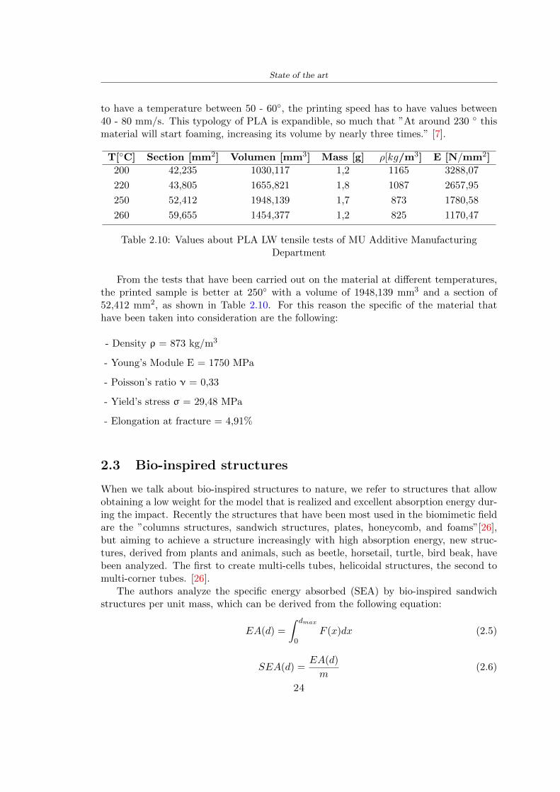
State of the art
Where EA is the energy absorption rdquomainly used to evaluate an energy absorberrsquosability to dissipate crushing energy through plastic deformationrdquo F(x) is the crashingforce dmax is the effective deformation distance [26]
What derived from their investigations is that having regard to a density of between0 and 1000 kgm3 the volumetric energy absorbed is higher for the beetle-inspired struc-tures than the others as shown in Figure 28 Based on this consideration it was chosento draw the helmet following this geometry
Figure 28 SEA of bio-inspired sandwich structures [26]
231 Beetle structure - Design of the model
To develop and increase lightweight high-strength and optimize bio-mimetic functionaland structural materials the trabecular structure of the beetle elytron is studied Thesingle structure is realized following the requirements cited by Zhang et al [39]
To realize the beetlersquos structure it is not enough to have information about the lengthof the side of the hexagon and the thickness but it is also necessary to take into accountthe relationship between the diameter of the circumferences present on the vertices ofthe hexagon and the measurement of the side The representation of a single cell is inFigure 29 It is shown in [a] a general structure with an edge of 12 mm circumferencersquosdiameter of 6 mm and thickness of 16 mm in [b] is shown the height of 20 mm
For the construction of the helmet a thickness of 12 and 16 mm was used the imageconcerns a proportion between the length of the hexagon side and the diameter of the
25
State of the art
circumference The side (distance between the centers of two circumferences) is twice thediameter measurement
[a] [b]
Figure 29 Beetle structure
232 Specific stress - PLA LW and EPS foam
To test the beetle structures compression tests were investigated The PLA LW structurewas inserted in a rsquodiskrsquo with a diameter of 100 mm and a height of 20 mm The area andthe volume of the disk is correspondingly 7854 mm2 and 157 10 mm3 The structuresexamined have different dimensions the edge L (distance between two centers of thecircumferences) had the following measures 9 10 12 14 16 mm the thickness of thecircumferences and edges are respectively of 16 mm for every structure and 12 mm forthe structure with L = 16 mm
The test was carried out with the Hoytom HM-D Testing Machine with capacitiesbetween 5 and 100 kN The test models were subjected to displacement loading at a rateof 1 mmmin as referenced by Chen et al[18] with a cylindrical specimen The specificstress of the structures was compared with the specific stress of a generic EPS helmetthe photos about it are shown in Figure 210 The EPS helmet structure is granular withpores inside The different grains dimension and these pores can be the reason for whichthe Stressrsquos values are between two values 07 and 116 MPa
Four parts of the EPS helmet were considered in the test the dimension and relativecharacteristic are in the Table 211 where m = mass A = area F = load ρ = densityR = stress Rρ = specific stress To calculate the values of stress about PLA structuresand EPS foam compression test graphs were been analyzed The stress value for eachstructure was calculated considering the single load the single area and the averagedensity value (14055 [kgm3])
The stress values of the PLA structures (Figure 211) and other characteristic valuesare in Table 212 where m = mass A = area F = load ρ = density
26
State of the art
[a] [b]
[c] [d]
Figure 210 EPS generic helmet helmet pictures [a] [b] and internal structureExternal granular structure [c] and pores [d]
[a] [b] [c]
Figure 211 PLA LW disks Grasshopper structure [a] PLA LW structure of 14 mm[b] PLA LW structure compressed [c]
27
State of the art
The results of the load-displacement graphs are affected by the geometry of the diskthe target is to valid for any shape or size for this is preferred to realize a diagramthat depends from σ (or stress) and the deformation ε (or strain) which can be definedrespectively as
σ =F
A0(27)
ε =l minus l0l
(28)
where F is the load during the test A0 is the area l0 is the initial length and l is thelength when the load is applied The areas considered for the EPS cube is reported inTable 211 in the second column the areas of the PLA structure is 7854 mm2 like thearea of the circumscribed disk
The values compared are shown in Table 213 and the graphs obtained by Matlabcode to analyze the recorded data of the compression machine are in Figure 213 and inFigure 212
Considering that the data provided by the compression machine are subject to noiseand disturbances it was decided to convert the original curve into polynomial type curvesthat allow obtaining the best interpolating curve for the data in question To obtain themit was divided the recorded data into two groups the first part from 0 until the end ofthe linear part and the second when the curve becomes linear again The best-fitting (inthe least-squares sense) was performed using the polyfit and polyval functions of MatlabThe first returns the coefficients of the p(x) with n degree the second evaluates p(x) ateach point in x The polynomial formula p(x) is shown in the Equation 29
pn(x) = anxn + anminus1x
nminus1 + + a2x2 + a1x+ a0 (29)
where a0 an are constants and x is the indeterminate The choice of the degree ofthe polynomial was made based on the criterion of wanting to obtain linear curves thatrespected the elastic trend at the beginning of the graph For this reason the degree ofthe polynomial is 1 Subsequently I searched through the intersection of the two lines forthe point that is equivalent to the maximum stress that marks the end of linearity
This value for EPS and PLA LW is the R [MPa] in the Table 213 The average stressvalue for PLA LW is 139 MPa and for EPS is 094 MPa The specific stress (Rρ) is 18MPa lowast m3)kg for the EPS found in CES 669 MPa lowast m3)kg for the EPS foam of thegeneric helmet and for PLA LW is 1161 MPa lowastm3)kg an intermediate value betweenthe two which is what we wanted to achieve
28
State of the art
m [g] A [mm2] F [N] ρ [kgm3]
EPS (CES) 50
16 9234 1063 13864
18 879 593 13651
21 858 833 14237
24 864 564 14468
Average value 14055
Table 211 Compression stress generic EPS helmet
L [mm] t [mm] m [g] F [N] ρ [kgm3]
9 16 214 7250 1363
10 16 192 5560 12467
12 16 201 8190 13051
14 12 138 8000 8961
Average value 12027
Table 212 Compression test PLA structures
PLA LW structure EPS structureρ= 12027kgm3 ρ= 14055kgm3
Edge [mm] R [MPa] Rρ103 Number R [MPa] Rρ103
EPS (CES) 09 18
9 173 1269 1 116 824
10 139 1114 2 08 568
12 138 1057 3 105 746
14 108 1205 4 077 540
Average value 139 1161 094 669
Table 213 Specific stress calculus PLA LW and EPS calculus ρ = density R = stressRρ [(MPa lowastm3)kg] = specific stress
29
State of the art
Figure 212 Compression test Stress-Strain diagrams - EPS
Figure 213 Compression test Stress-Strain diagrams - PLA LW
30
Chapter 3
Methodology
31 3D scan
311 3D Sense 2 scanner and Meshmixer - Reverse reconstruction
Standardized measures were not taken into account for making the helmet but the sizewas obtained through a 3D scan of my head
The scanner used is 3D Sense 2 by 3D Systems which has a minimum scanningvolume of 20 x 20 x 20 cm and a maximum scanning volume of 300 x 300 x 300 cmTo scan my person I was helped to get a full view at 360 at an appropriate distanceReal-time visualization of the captured images was shown through 3D Sense softwareThe idea of scanning the head with the scanner refers to the methodology used by Wanget al [30] They used a reverse reconstruction functional for me to realize the helmetsurface made to measure my head and like them a silicone pool cap was used to makescanning as smooth as possible The authors claim the head scan rdquocan also be used toobtain information about the objectrsquos surface which is then reconstructed utilizing thecomputerrsquos three-dimensional model via reverse modelling softwarerdquo [30] that in my caseis Autodesk Meshmixer
The files it was could get from the scan were stl obj and ply format they wereexported to obj to work in the next step with Autodesk Meshmixer that allowed tomodify and homogenize the 3D image obtained from the scan
In Meshmixer through the selection and delete commands the superfluous parts weredeleted that had been acquired and with the inspector and the DrawDraw2 commandsthe vertices were moved locally along a pre-defined direction and with Smooth the surfacemore homogeneous was made The sequence of steps is shown in the Figure 31
312 3D scan analysis and extraction of features
In Chapter 2 the directives imposed by the BS EN 960 Standard were examined concern-ing the definition of the helmet and the measures to be respected in the field of visionand the part of the helmet was to carry out impact tests
In Figure 32 the features defined complying with the Standardrsquos rules are repre-sented To define these features the software NX was used The angle in the subfigure
31
Methodology
[a] [b] [c] [d]
Figure 31 Sequence of 3D head scan 3D scanner acquisition [a] scan after reparationwith Meshmixer [b] solid scan vision frontal and lateral [c] [d]
[b] is bigger than 105 (as defined by the Standard) while the degree in the subfigure [c]is 25 By defining the construction lines to be respected of the helmetit was necessary todraw the design of the surface not using the software NX but changing with Rhinocerosto create a SubD or SubDivision surface
32 Helmet design
321 Rhinoceros - Helmet surface
After realizing a rsquocleanrsquo Wang et al [30] subdivide with lines and then sectors the headto create the surface of the helmet They used the technique of NURBS a Non UniformRational Basis-Splines which mathematically models a 3D geometry while thanks tothe Rhinoceros 3D organic shapes was draw SubD surfaces These geometries allow tosplit the mesh into small polygons and consist of lines with which easily the shape ofthe object can be modified with a surface already created changing the position of aline automatically the remaining part of the geometry adapts to the changes With thistechnique the rsquosurface basersquo of the helmet was realized with the size of my head Therepresentation of the realized SubD is in Figure 33
322 Grasshopper - Helmet structure
The next idea is the creation on the surface of the beetle structure with different di-mensions modelling the helmet that is not a linear surface It was decided not to buildthe structure with a software CAD because to model an already complex structure on acurved surface would mean to model a cell for a cell
To solve this obstacle a Rhinoceros plug-in was used Grasshopper GH idealized byRobert McNeel and associates creators of Rhinoceros Using GH does not mean drawinggeometries by connecting points and drawing tools because it is based on algorithmicmodelling used in architecture and engineering for 3D modelling
The modelling takes place through a node diagram that the software will convert intoa code-algorithm in GH it is possible to define the variables and parameters and inRhinoceros in real-time it is possible to view the object GH allows for varying the
32
Methodology
[a] [b]
[c]
Figure 32 Featurersquos extraction in [a] is represented the impact line in [b] and [c] twoprospective about the definition of the field of vision
[a] [b] [c]
Figure 33 SubD representation lateral view [a] top view [b] front view [c]
geometry to your liking by varying a simple parameter of the diagram as everything willbe remodelled according to the change made
In the following Figure 34 it is shown an example of a structure that was used fordistinct subgroups of helmet areas The idea was to insert smaller cells in the frontal andlateral zone and larger ones in the upper area In the first image [a] is shown the part of
33
Methodology
the helpful diagram to create the beetle structure to establish the size of the cells andthe extrusion the second image [b] contains the part of the diagram with which I appliedthe structure previously created to the SubD
The structure used to place and adapt the beetle structure to the surface is theSrfMorph while the yellow rsquowindowrsquo that contains numbers serves to select the parts ofthe surface where to apply the geometry created In accord with the GH diagram in
[a]
[b]
Figure 34 Grasshopper diagrams
Figure 34 [a] it is possible to see the steps executed to realize the structure Initially inthe xy-plane a hexagonal grid was drawn through the Hexgrid command in which youcan input the length of the hexagon edge and the number of grid elements (selected bytrial) Then the circumferences was drawn in proportion to the hexagon dimensions asspecified in the Chapter 2 and shown in Figure 35 [a] In figure [b] the rsquocutrsquo made atthe circumferences is visible this subdivision was necessary for printing purposes In thelast photo [c] the structure highlighted in green in [b] was extruded setting a distance
34
Methodology
of 20 mm
[a] [b] [c]
Figure 35 Construction sequence of the geometry of the helmet
In the diagram in Figure 34 [b] there is the application of the structure created bi-dimensionally to the SubD surface of the helmet visible by unlocking the SubD commandof the diagram and in Figure 36 [a] Upper this the referential geometry of the group ofsurfaces was superimposed where it was to be applied the newly created structure (visiblein darker red) the SubD indices are in the yellow box of the diagram
Through the SrfMorph command the location of the structure was granted In Figure36 [b] at the darkest red of the figure [a] with the above command it was possible toplace the structure
[a] [b]
Figure 36 Application of the geometry created to the helmet surface
Overall the diagrams with specific structures are five one for the front two equal forthe side parts one for the top shown in the previous Figure 36 and one for the back
The hexagons in the structure have a dimension varying between 8 mm and 14 mmof side the largest is found at the top later at the back in the sides and the smallest atthe front In Figure 36 [b] the presence of not only hexagonal structures is visible Thegeometry used does not allow the homogeneous arrangement on the entire surface andrequires different structures Automatically the choice of GH to optimize the structurewas to insert quadrilateral
As described above the helmet has different dimensions of the structure divided asvisible in Figure 36 in a quadrilateral This causes a discontinuity between zones withdifferent sizes due to the geometry of the construction
To eliminate this problem and realize the design homogeneous grids were inserted
35
Methodology
in the affected areas as shown in Figure 37 This insertion however proved to beinteresting and strategic researching in this regard studies were realized to demonstratethe insertion of a rectangular grid inside the hexagon grid was helpful for the transmissionof stress in the structure As cited by Sun et al [40] rdquothe mechanical properties of thesesandwich structures are often limited by local failures such as face-core debonding or corecollapserdquo Carrying out compression tests have effectively demonstrated that the insertionof the grid allows rdquoprovided increased stiffness specific stiffness energy absorption andcritical loadrdquo [41] As shown in the graphic [c] of the Figure 37 the honeycomb structuregives a force of 7 kN while with a grid the value is 11 kN and with the combinationexceeds 22 kN In addition in the left front a plaque to customize the helmet wasprepared Figure 37 [a]
[a] [b]
[c]
Figure 37 Grid in the helmet [a] hybrid structure with hexagons and grid [b] [40]compression test results of the hybrid structure [c] [41]
33 3D Print
After having achieved the CAD (Computer Aided Design) of the helmet in order tobe printed it must be converted and saved in format STL (Standard TriangulationLanguage) - Binary compatible with the printing machine and useful for transformingsolid object surfaces into triangles The steps to be taken are the following
bull CAD file realization
bull CAD export in format STL to Simplify 3D the software that shows slider layersand then- rotate and position the object according to geometry and the positioning of any
36
Methodology
supports- setting printing parameters- item manual andor automatic positioning of supports- slider display layers
bull import file gcode to printer
331 Printer and parameters
The program used to visualize how the helmet slices layers before sending it to the printerand to set the parameters is as anticipated Simplify 3D
To make the printing not being a flat geometry it is necessary to place the supportsThe idea was to use water-based supports that the helmet would automatically dissolveonce placed in the water After testing different types of water-soluble PVA the choicefell on eSun 3D Printing Filament PVA (water-soluble support) Before choosing theoptimal position for printing several tests were carried out and to decrease the numberof the supports significantly and allows an optimal printing of the outer part an emptyrsquospherersquo that self-sustains below the helmet was placed as shown in Figure 38
In the image [a] you can see the first print position tried with which an external partof the helmet very damaged was obtained because of the contact supports-helmet In [b]the empty rsquospherersquo is shown to optimize the number of supports and in the last photo [c]there is the full version at the end of print
[a] [b] [c]
Figure 38 Printing supports
The printer that has been used for printing is the Raise 3D Pro2 with double extrudersand nozzles of variable size from 02 mm to 1 mm after some test prints with the PLALW and the structure in created the size that allowed me to have a good compromisebetween printing time and accuracy was 06 mm Using 04 mm the printing time wasexcessive even if having the smaller nozzle diameter means having more precision withthe 08 mm nozzle the quality of the structure was not excellent as seen in Figure 38[a]
Another factor that had to be taken into account is the characteristic of the PLA-LWto expand As the printing temperature and the printer used vary the expansion andcharacteristics of the material change The use of the 06 mm nozzle associated with
37
Methodology
Parameter Left extruder Right extruder
01cm Material 01cm PVA 01cm PLA LW
Extruder toolbox index Tool 0 Tool 1
Nozzle diameter 06 mm 06 mm
Extrusion multiplier 1 05
Extrusion width Auto (072 mm) 05 mm
Layer x
Infill Rectilinear - 50
Supports (Automatic and not) Infill 50
Temperature 210 250
General parameters
Primary layer height 03 mm Top solid layer 4
Bottom solid layer 2 Outline 2
Heated bad 60 Speed 40 mms
Table 31 Printing parameters
Raise 3D allowed me to get good results The choice of this printer was not random ithas in fact the characteristic of making extremely precise prints The Raise has accuracyin placing the object on the printing bed of 078 microns on the xy axis and a resolutionfor layers of 001 mm
The final version of the helmet is visible in Figure 39 and it is possible to compare itwith the preview version in Rhinoceros in Figure 310
38
Methodology
[a] [b]
[c]
Figure 39 Views of the helmet
[a] [b]
Figure 310 Views of the helmet (GH version)
39
Chapter 4
Experimental evaluation
41 Experimental tests
411 Drop-weight impact test machine
In order to calculate the contact force peak and the difference of energy absorbed duringthe impact between the reference helmet and helmet with the beetle structure in PLA-LW dynamic impact tests were carried out using the Fractovis Plus an impact testmachine
In this way it is possible to monitor the evolution of the above variables from theinitial to the final instant of the impact The machine can withstand a load with a rangevariable from 2 to 70 kg with a maximum speed of 46 ms and a maximum height of1 m The values chosen for the test are the following 5 kg weight maximum speed andmaximum height The Anvil that was used is a disc diameter of 60 mm
As shown in Figure 41 and explained by Crupi et al [37] the machine consists ofa sensor capable of recording the speed before impact the impactor that can have avariable mass (a weight of 5 kg in my test) a system to guarantee that there are nomultiple impacts after the first and that work as a shock absorber and clamping systemwhere the object to be tested is placed
The tests that have been carried out are in total four two related to the helmetoptimized with PLA-LW and two with two generic helmets of different brand in EPS
42 PLA LW helmet
To perform the dynamic test on the helmet of PLA considering the difficulty of printingit was helpful to use a test helmet with imperfections to understand where the impactwas concentrated in a single part or distributed The images of Figure 42 show a helmetwith not well defined edges and inaccurate print but exactly localizes the impact zoneThanks to this test it was possible to take into account only one helmet area shown inFigure 43 to have the exact curve of the structure bio-inspired with PLA-LW
40
Experimental evaluation
Figure 41 Drop-weight impact test machine [37]
[a] [b]
Figure 42 Test 1 PLA-LW helmet
43 EPS helmet
To carry out dynamic tests and extract the technical characteristics of the helmettwohelmets were bought in a sports store both EPS and being on the market both certifiedThe brands of the two helmets are DTB and VAN|RYSEL and the average weight ofthe two is 223 g Two different helmets have been chosen to have a more certain andclear classification of the characteristics They are shown in Figure 44 and Figure 45
41
Experimental evaluation
[a] [b]
Figure 43 Test 2 PLA-LW helmet
[a] [b] [c]
Figure 44 Test 3 EPS helmet
[a] [b] [c]
Figure 45 Test 4 EPS helmet
44 Results
441 First results - PLA-LW and EPS helmet
Figure 46 shows two types of trends related to the two different models of the helmetThe force evaluated for PLA-LW has higher force peaks but is more concentrated and
42
Experimental evaluation
propagates less than EPS The graph shows the peaks of each curve highlighted with a redcircle In tests 1 and 2 for the PLA-LW as mentioned earlier the values are higher about7301 N for the complete helmet and 3996 N for the portion of helmet This difference isdue to the inaccuracy of the first full helmet during the printing phase In Figure 42 itis visible the low homogeneity and precision Therefore the first test with full helmet wasused only to define the area of interest of the impact which turns out to be localized Forthe other two EPS curves the values are only slightly lower compared to the PLA-LWequal to 3620 N and 3295 N but the trend is much more distributed
Figure 46 Dynamic machine test - Force
With the data obtained from the impact machine it was possible calculate not exclu-sively the value of force but itrsquos also possible to view the energy curves A resume aboutthe values and energy of the force is in the following Table 41
Test Peak force [N] Peak energy [J]
Test 1 - PLA LW (inaccurate) 730130
Test 2 - PLA LW (portion of helmet) 399643
Test 3 - EPS (DTB helmet) 362007 509
Test 4 - EPS (VAN|RYSEL helmet) 329546 4198
Test 5 - PLA with TPU 45421 5022
Table 41 Energy absorbed in dynamic test
43
Experimental evaluation
442 PLA-LW helmet with TPU cover
As it is possible to see in Figure 47 and as highlighted the first tests concerning thebio-inspired structure and the PLA-LW are far from my expectations considering thelittle distribution of force in comparison with the EPS foam and consequently a smallamount of energy absorbed
Figure 47 Dynamic machine test - Energy
To improve this impact damping factor the idea was to create a cover for the helmetin flexible TPU trying to absorb impact energy The TPU used is a flexible material ofthe brand Ninjaflex used in sports by the application in helmets and shoes to cushionbumps during the game Generally in the helmets (baseball helmet for example) theTPU is inserted internally in contact with the head In my case the TPU structurein addition to creating a shock-absorbing and durable cover creates a custom cover thehelmet and for the person This cover was also made with the Raise 3D printer
As shown in the Figure 48 [a] the infill of the part in contact with the helmet hasa percentage of 100 the filling of the other part of the structure is not complete butonly 15 and the internal structure is hexagonal to recall that of the helmet The desireto insert a structure with a rsquoraisedrsquo geometry is for visual and aesthetic reasons as youhave the feeling of greater protection and not filled is inspired by the machine CitroenCaptus whose bumpers (Airbump) are full of air The failure to realize empty structuresis due to the need to place any internal supports not removable
The idea was to create a cover that allow you to see of the internal structure of thehelmet and that protect specific areas the front the two sides the top and the posteriorWhat which was thought for this reason was to create the shape of a flower with four
44
Experimental evaluation
petals Figure 48 [b]In this way to perform dynamic impact tests as shown in Figure 49 [a] the cover was
positioned at the top of the helmet and the impact was performed in the centre of thersquoflowerrsquo which corresponds to the higher upper part where the structure has larger cellsize The impact parameters are the same as those used in previous impacts 5 kg weightmaximum speed and maximum height The Anvil that was used is a disc diameter of60 mm In photo [b] it is evident the difference between the structure that received theimpact with protection (left) and without protection (right) Without protection duringthe impact there was a perforation of the structure with a concentration of force at a locallevel as you can see in the Figure 46 in the case of TPU the impactor did not perforateand crossed the structure thanks to the cover of TPU that cushioned the shock At themoment of impact the impactor bounced
[a] [b]
Figure 48 TPU cover
[a] [b]
Figure 49 PLA-LW with TPU - dynamic impact [a] and differences between thehelmet with TPU and without TPU cover [b]
45
Experimental evaluation
The Figure 410 includes the diagrams relative to the dynamic impacts In [a] thereare already analyzed EPS results in [b] a comparison between the test on the portionof helmet in PLA LW with and without the TPU cover in [c] the overall comparison ofcurves shows a much more similar EPS trend if the TPU is placed above the structure inPLA LW to soften the blow and absorb the same energy [d]
46
[a]
[c]
[d]
Figure 410 Comparison between PLA-LW with TPU and EPS
Chapter 5
FEM Validation
51 Impactor - Anvils definition
Before to start to work in Abaqus it was necessary to search in the literature the materialwith which the anvil was been realized Milne et al [23] established the densityrsquos valuethe Youngrsquos Module and Poissonrsquos ratio for the Flat and Kerbstone Anvil
- Density ρ = 7800 kgm3
- Youngrsquos Module E = 200000 MPa
- Poissonrsquos ratio ν = 03
Inserting the data in the CES EduPack program specifying the mechanical andphysical properties the material corresponding to these characteristics is Stainless steelaustenitic (ASTM F1586) medium-hard
Initially the proposal was to create a conservative system to evaluate the absorptionenergies values and apply this value to a vibration system but the helmet needs dampingto be realized it was impossible to use a system without losses in this modality Thisis why a numerical calculation was carried out by performing two types of simulationsexplicit dynamic step and static step
The idea to realize the theoretical impact is to regard the movement of the anviland not the helmetrsquos movement which is fixed The velocity is the same cited in thenormative EN 1078 542 ms for the Flat anvil and 457 ms for the Kerbstone anvil
In performing the simulations It was given more relevance and perform tests withthe Kerbstone Anvil This choice was done because the geometry with which it is beenrealized (following as defined in the legislation) allows the helmet to be more subjectedto stress this involves the definition of higher stress limits compared to the Flat Anvil
The mesh size that has been used is the same in the case of the simulation of thehelmet optimized in PLA-LW and the full helmet in EPS of 7 mm The impactor isconsidered as a Discrete rigid body with its specific Reference Point (RP) like shownin Figure 51 for this reason it is not a solid but it is composted only by shells Inthe same image [b] there is the FEM representation of the model and in Table 51 thecharacteristic of FEM with quadrilateral (R3D4) and triangular elements (R3D3)
48
FEM Validation
Object Elementnumber
Elements Shape Geometricorder
Global size[mm]
Kerbstone 230 Quadrilateral - R3D4 Linear 7
Kerbstone 8 Triangular - R3D3 Linear 7
Table 51 Mesh element - Kerbstone Anvil
[a] [b]
Figure 51 Kerbstone anvil in the simulation like discrete rigid body [a] and FEMelements [b]
511 PLA LW - Plastic characteristics
The PLA-LW as explained in the Chapter 2 is new material on the market and producedby the only Colorfabb company for this reason few tests have been carried out to defineits technical characteristics and through tensile tests of the 3D printed specimens it waspossible to define an elastic limit as reported in the Table 210
In the context of simulations to reproduce the impact and deformation of the helmetis also necessary to consider the plastic characteristics of the material Not possessingany reference value in this regard tests were performed through a Static Step initiallyand then an Explicit Dynamic Step in Abaqus
The structure chosen to consider as a reference it is one of the structures previouslysubjected to the compression test having the side L=14 mm As for the reproduction ofthe compression disks initially they were reproduced according to the geometry of theHoytom HM-D Testing Machine considering the bodies mentioned above as discrete 3Drigid discrete The measure was the diameter of 200 mm and the height of 20 mm
After an initial analysis it was observed that the computational time of the simulationprogram was very high so it was decided to change the geometry to have a rsquodisk-surfacesrsquo(equally 3D rigid-discrete) which allowed me to have a smaller number of nodes for themesh and consequently a better computational time The representation of the opti-mized structure in PLA-LW and the disks used for simulated compression is in Figure 52
49
FEM Validation
[a] [b]
Figure 52 Representation of the samples used for the simulation of the compressiontest In Figure [a] the disks of the Hoytom HM-D Testing Machine in figure [b] the
representation of the same as simple surfaces
As shown in Figure 52 the disks are considered 3D discrete hard bodies so it waschosen for both a point the reference point RP where to apply the characteristics relatedto the two bodies As for the compression test it was established
bull the movement of a disk and fixed the second through a boundary condition impos-ing an Encastre therefore unable to move and rotate in xyz directions
bull for the opposite disk the boundary condition relative to the 15 mm displacementwas applied which is the parameter that it was observed to determine the end ofthe compression with the machine This shift is shown by the orange arrow in figure[b]
bull between the upper surface and the disk e the disk with the lower surface it wasinitialized a general contact with normal behaviour through rsquohardrsquo contact andtangential behaviour with a coefficient of friction of 02 with directionality imposedon rsquoisotropicrsquo
The next step was to define the mesh of the components whose parameters are shown inTable 52 while the representation of the FEM is in Figure 53 with the representationof the simulation and real compression test
Object Elementsnumber
Typology Geometricorder
Globalsize [mm]
Disk (14mm) 80910 hexaedral - C3D8R Linear 07
Impact disks 206 quadrilateral - R3D4 Linear 20
Impact disks 6 triangular - R3D3 Linear 20
Table 52 Mesh element - Compression test simulation
As previously announced a static simulation was initially performed with a StaticStep with Step Time equal to 900 (obtained going to consider the speed of 1 mmmin of
50
FEM Validation
[a]
[b] [c]
Figure 53 FEM representation [a] and compression test simulation [b] and realcompression [c]
the compression test and the displacement of 15 mm) However the complex geometryof the structure and the high time set by Step Time did not allow a correct definitionof the parameters of the plastic characteristics of the material the simulation was notable to continue once reached a Step Time of approximately 220 That is why it waschanged by choosing an Explicit Dynamic step
Leaving all the parameters of the boundary conditions unchanged the Step Time wasmodified imposing it to 001 The ability of the explicit dynamic to work with non-linearand contacting structures allowed me to achieve results The results obtained are shownin Figure 54 with the blue curve and were obtained through the iteration of differentPlastic Strain and Yield Stress values in Abaqus while the red line is the result of thereal compression test a similar curve trend was obtained but it is not possible to obtainthe same curve taking into account problems of printing inaccuracy
512 First test - helmet
The initial idea was to perform a simulation imposing the speed of 457 ms to theimpactor tie the helmet in EPS and PLA and compare the absorbed energies Theproblem it was encountered is related to the mesh of the helmet optimized in PLA andwith minimum dimensions of the elements and distinct elements it was not able to solveit
51
FEM Validation
[a]
YieldStress
PlasticStrain
1 47 0
2 7 001
3 75 005
4 10 01
5 108 1
6 115 15
7 12 2
[b]
Figure 54 Representation of the two curves related to the simulation in Abaqus of thecompression test and the data obtained from the real test to obtain the plastic
characteristics of the material
513 Second test - plane
The first solution is the one shown in Figure 55 To realize the simulation it was realizeda section of the helmet to involve a smaller number of elements and nodes Again thesimulation for the EPS helmet was successful while the simulation with the bio-inspiredstructure was interrupted by excessive distortion of elements
The previous images show the impact is very localized in the impacted area and theidea to achieve a complete simulation is not to consider a curved portion of the helmetbut a plane In this way it was possible to solve the problem and obtain a completesimulation for the bio-inspired structure
FEM element
Below in Table 53 there is the definition of the elements used for the PLA-LW and EPSplane in the simulation to simulate the impact and to control the energy-absorbing whilethe anvil characteristics are described in Table 51
514 EPS impact simulations
In order to proceed with the simulation it was imposed some boundary conditions thatregard ties and forces
bull the movement of the plane is fixed through an Encastre therefore unable to moveand rotate in xyz directions
52
FEM Validation
[a]
[b]
Figure 55 Impact simulation parts of EPS and PLA helmet
Object Elementnumber
Elements Shape Geometricorder
Plane (PLA) 38896 Tetrahedral -C3D10M
Quadratic
Plane (EPS) 2100 Hexahedral - C3D8R Linear
Table 53 Mesh element - plane impact
bull to create the impact it was set a speed of 457 ms at the reference point RP of therigid body which is the impactor Kerbstone Anvil shown in Figure 56
bull between the upper surface of the plane and the impactor it was initialized a Sur-face to Surface contact with normal behaviour through rsquohardrsquo contact and tangen-tial behaviour with a coefficient of friction of 02 with directionality imposed onrsquoisotropicrsquo
bull the rotation in x y z relative to the RP of the rigid discrete impactor body is locked
53
FEM Validation
In addition it was characterized the plane in the part of the materials with the char-acteristic values of the EPS mentioned in Chapter 221 The Von Mises Stress valueapparently low is relative to the Yield Stress of the EPS material equal to 09 MPa
Figure 56 EPS Boundary conditions and Load
515 PLA LW impact simulations
As also required in the case of the EPS plane in order to proceed with the simulationsome boundary conditions were imposed that regard ties and forces
bull the movement of the plane is fixed through an Encastre therefore unable to moveand rotate in xyz directions
bull to create the impact a speed of 457 ms was set at the reference point RP of therigid body which is the impactor Kerbstone Anvil shown in Figure 58
bull between the upper surface of the plane and the impactor it was initialized a Sur-face to Surface contact with normal behaviour through rsquohardrsquo contact and tangen-tial behaviour with a coefficient of friction of 02 with directionality imposed onrsquoisotropicrsquo
bull the rotation in x y z relative to the RP of the rigid discrete impactor body is locked
In addition the plane was characterized in the part of the materials with the characteristicvalues of the PLA mentioned in the Chapter 223 and 511
Figure 58 Boundary conditions and Load
54
FEM Validation
[a]
[b]
Figure 57 EPS impact simulation
52 Results
In Figures 59 and 57 it is shown how the structure in PLA LW has a more concentratedstress distribution of the structure unlike EPS The maximum value for the Von Misesstress is 09 MPa in EPS structure and 3634 MPa in PLA LW structure Once thesimulations were obtained the next step was to go and compare the energies absorbed bythe two structures The energy calculated by Abaqus that has been taken into account isPlastic Dissipation To make a comparison the data of the two energies were representedin a single graph
What emerges from the graph is that about the impact made with the KerbstoneAnvil the energy absorption is more excellent although only slightly for the PLA LWthan for the EPS From the graph in Figure 510 a value of 41 J is shown for the EPSand 51 J for the PLA LW
55
[a]
[b]
Figure 59 PLA impact simulation
[a]
Figure 510 EPS and PLA LW energy comparison - Abaqus simulation
Chapter 6
Head Injury Data
For the statistical analysis the injuries related to the accident data were categorised intothe following types and levels based on the details of the medical report [11] about theEN 1078
bull Head Injury Criterion (HIC)
bull Peak Linear Acceleration (PLAc)
bull Gadd Severity Injury (GSI)
bull Diffuse axonal injuries (DAI)
61 Abaqus simulation
Until now the purpose of the simulations has been to determine which between the twomaterials and the two structures of EPS and PLA LW could absorb more energy duringthe impact but no simulations have been carried out in compliance with BS EN 1078on the helmet impact tests To calculate the injuries listed in the previous paragraphhowever we need the acceleration values in the three directions related to the subjectrsquoshead
To realize it the scan of my head already rsquocleanrsquo was considered of which it has beencalculated the inertia thanks to the automatic SolidWorks calculation and evaluated theweight with the Table 24 the structure of the helmet was placed for the EPS and thePLA LW over the head as shown in Figure 61 Also this time being able to mesh theentire helmet in PLA LW was impossible due to the excessive distortion of some elementsduring the simulation so it has been tried to make a section of the structures of thehelmet and results were obtained
57
Head Injury Data
[a] [b]
Figure 61 My scan head - CAD [a] head imported in Abaqus[b]
Initially the simulation had these characteristics as shown in the following Figure62 considering the helmet was not sectioned As explained earlier it was not possibleto get to simulation in the case of the optimized structure in PLA LW for this reasononly a part of the helmet was considered in both cases shown in Figure 63
[a]
Figure 62 Simulation based on BS EN 1078
58
Head Injury Data
[a] [b]
Figure 63 Simulation based on BS EN 1078 with head
In order to proceed with the simulation some boundary conditions that regard tiesand forces have have imposed
bull two reference points RP were created the first in the inertia centre of the headthe second relating to the Kerbstone Anvil which is a discrete rigid body
bull in the reference point RP of the head in the definition of the engineering features5 kg was inserted for the weight and an inertia I11 = 564464E+07 gmm2 I22 =460654E+07gmm2 I33 = 187302E+07gmm2
bull to simulate the impact it was set a speed of 457 ms at the reference point RP ofthe head in z-axis direction
bull a general contact with normal behaviour through rsquohardrsquo contact and tangentialbehaviour with a coefficient of friction of 02
bull between the upper surface of the helmet and the impactor it has been initializeda Surface to Surface contact with normal behaviour through rsquohardrsquo contact andtangential behaviour with a coefficient of friction of 02 with directionality imposedon rsquoisotropicrsquo
bull the movement between the Kerbstone anvil and the helmet is fixed through anEncastre therefore unable to move and rotate in xyz directions
bull the rotation in x y z relative to the RP of the rigid discrete impactor body is locked
FEM element
As reported in Table 53 the portion of the helmet in EPS has used a mesh with hexahe-dral elements of linear order For the structure (beetle) of PLA LW given the geometry
59
Head Injury Data
complexity it was necessary to use a quadratic order of tetrahedra For the mesh of thehead instead in both simulations have been used quadrilateral elements of linear orderas reported in the Tables 61 and 62
Object Elementnumber
Elements Shape Geometricorder
Head 3755 Quadrilateral - R3D4 Linear
Head 34542 Quadrilateral - R3D3 Linear
Helmet (PLA) 272302 Tetrahedral -C3D10M
Quadratic
Table 61 Mesh element - Head simulation with PLA LW (beetle) helmet
Object Elementnumber
Elements Shape Geometricorder
Head 3755 Quadrilateral - R3D4 Linear
Head 34542 Quadrilateral - R3D3 Linear
Helmet (EPS) 72280 Hexahedral - C3D8R Linear
Table 62 Mesh element - Head simulation with EPS helmet
62 Results
Figure 64 represents the simulation in line with BS EN 1078 concerning the helmet inEPS [a] and the helmet with bio-inspired structure in PLA LW For both simulationsVan Misesrsquo stress has Yield Stress values in the case of EPS which is 09 MPa and theplastic behaviour combination of PLA LW [b]
In the case of head and Kerbstone Anvil stress was not assessed as they were previ-ously defined as discrete rigid bodies
63 Head Injury Criterion
The HIC quantifies head impact severity by incorporating time of acceleration exposureand acceleration magnitude it is calculated in post-processing phase with the followingEquation 61
HIC15 =
[1
(t1 minus t2)
int t2
t1
a(t)dt
]25(t2 minus t1) (61)
60
Head Injury Data
[a]
[b]
Figure 64 Results simulation based on BS EN 1078 with sectioned head
For this analysis a(t) is the acceleration calculated in the centre of mass of the head(corresponding to the reference point RP) expressed in g and the time interval (t2 minus t1)was chosen to maximize HIC over a maximum duration of 15 ms
Matlab and the trapz function were used to calculate the HIC to integrate accelerationover time t2 and t1 were considered initial and final times of the simulation t1 = 0 sand t2 = 10 s time less than 15 s
HIC value of 198 was obtained for EPS and 87 for PLA LW Considering the Hayeset al [16] document about the HIC values and the graph in Figure 65 developed bythe author it is possible to find the percentages related to the different injury AIS1 -AIS6 which correspond respectively to lower and higher severity while in Figure 66 therelative fatality to every value of AIS is shown The values obtained for the HIC andother criteria are shown in Table 63 The HIC value for EPS is 198 for PLA LW it is
61
Head Injury Data
Figure 65 Head injury risk curves based on HIC values [16]
Figure 66 The abbreviated injury score versus fatality rate [16]
87 Analyzing the data and comparing them with the curves of the Figure 65 I obtain
bull a percentage between 20 - 30 of AIS 1 for EPS 10 - 20 for PLA LW
bull a percentage between 10 - 20 of AIS 2 for EPS and 0 - 10 for PLA LW
bull for AIS 3 AIS 4 AIS 5 AIS 6 the percentages for both structures is between 0 -10
Comparing these percentages with the fatality rate of Figure 66 it is clear there is a riskof Moderate and Minor fatality in the case of EPS and PLA LW as all values are between0 and 30
62
Head Injury Data
HIC PLA [g] GSI E [J]
EPS 198 97 361 37723
PLA LW 87 75 169 44102
Table 63 Head Injury Data - values
64 Peak Linear Acceleration
The resultant linear acceleration versus time curve was calculated according to Equation62
γ(t) =radicγ2x(t) + γ2y(t) + γ2z (t) (62)
where
bull γ(t) is the resultant linear acceleration (g)
bull γx(t) is the linear acceleration in x axes (g)
bull γy(t) is the linear acceleration in y axes (g)
bull γz(t)is the linear acceleration in z axes (g)
The value of the impact should never exceed 250g [9] Cripton at all [9] in their studyexamined a helmet with expanded polystyrene (EPS) Figure 68 shows maximum HIC forhelmeted and unhelmeted drops from all heights For each drop height helmets reducedHIC relative to unhelmeted drops IARV value is 180g The acceleration in the two casesis shown in Figure 67 and the maximum values are 97g for EPS and 75g for PLA LWas reported in Table 63 The two values considering a maximum value calculated byCripton [9] of 180g are amply optimal and comply with the standard of 250g
65 Gadd Severity Index
Gadd proposed the Severity Index Criteria shown in Equation 63 Following this crite-rion the GSI values that are over 1000 produce serious internal head injury [33]
GSI =
int t1
0a(t)25dt (63)
Where
bull a is the linear acceleration (g)
bull t is the duration of the impact (s)
I calculated the GSI with the function trapz between 0 and t and the resulting valuesare 361 for the EPS and 169 for the PLA LW which comply with the limit
63
Head Injury Data
Figure 67 Peak accelerations for both helmets
Figure 68 Peak accelerations for both helmeted and unhelmeted drops Numbers overbars indicate peak acceleration For 2 m drop height results stated are the mean value
calculated from three drops [9]
64
Head Injury Data
66 Diffuse Axonal Injury
DAI cases covered all incidences in which neurological injuries occurred as well as con-cussion unconsciousness and coma
In order to assess the risk of head trauma in terms of diffuse axonal injury (DAI)Milne et al [23] defined a model based head injury criteria as follows obtaining theresults in Figure 69
bull 50 risk of moderate neurological injury (DAI1+) Brain Von Mises shearing stressof 28 kPa
bull 50 risk of severe neurological injury (DAI2+) Brain Von Mises shearing stressof 53 kPa
[a]
[b]
Figure 69 Peak intra-cerebral shearing stress computed with the helmet model coupledto the human head model for all impact points (a) Flat anvil (b) Kerbstone anvil [23]
65
Head Injury Data
67 Energy absorbed
In Figure 52 during the impact test between the kerbstone Anvil and the plan with thebio-inspired structure in PLA LW and EPS it was found that the PLA LW althoughwith a small difference of 10 J absorbed more energy in comparison with the EPS Whenthe test is carried out in compliance with BS EN 1078 and the head with a speed of 457ms (corresponding to the kerbstone Anvil) as shown in Figure 610 also in this casethe PLA LW with the optimized helmet structure manages to absorb more energy (evenif the difference is very low) compared to the EPS The maximum energy value in PLALW is 44102 J of EPS is 37723 J
Figure 610 Energy absorption - BS EN 1078
66
Chapter 7
Conclusion
71 Conclusion
In this thesis work a bicycle helmet with a bio-inspired structure in PLA LW and 3Dprinted was created The initial approach was to introduce an innovative aspect tostandard EPS helmets not using foam but a polymer with new geometries able toabsorb much energy during the impact For this reason the beetle structure has beenpreferred relying solely on the hypothesis encountered in the literature of its quality inabsorbing energy
Combining the new material of the PLA LW and beetle structure has made possiblethe development of new material satisfactory characteristics have been obtained sincethe first tests The two materials were first subjected to tensile tests to determine theirspecific stress in these the PLA LW had positive results
Subsequent dynamic physical tests were carried out on 3D printed helmet models andon reference helmets in EPS to calculate the absorption energy in both cases at the timeof impact These resulted in energy absorption of the beetle structure in PLA LW withthe application of a TPU cover almost equal to that of EPS about 50J To validate withfinite element analysis the two models an explicit dynamic step was used in AbaqusSimulations showed that the PLA LW structure absorbs a higher amount of energy thanthe EPS the higher is 50 J and the EPS 40J
Finally positive results have also been obtained in calculating the head injury datasimulating according to BS EN 1078 with the use of impactor helmet and head Theacceleration values for both the structures were inferior to 220g precisely for the PLALW was 75g and for the EPS 97g The same applies to the calculation of HIC and GSI(maximum acceptable value of 1000) where the values are 87 and 169 in the case of PLALW and 361 and 198 in EPS For all tests therefore greater efficiency of the structure inPLA LW has been obtained Positive results also in the simulation of the energy absorbedduring the impact as the value referring to the EPS was 35J and that of the PLA LWwas 45J
67
Conclusion
72 Future work lines
The positive results obtained can be considered as a starting point for further tests andsimulations to ensure the safety of the helmet and compliance with the regulations butbefore getting improvements and continue testing changes are required
bull the beetle structure of the helmet made with GH adapts to the SubD withoutallowing to have a homogeneous distribution it would be appropriate to have moreregular hexagonal geometries
bull the mesh of the helmet is too complex and does not allow to perform the simulationprobably to use a more regular structure would have a mesh accordingly moreregular and the simulation would be successful
bull the uneven helmet structure has so many defects that the print is imperfect andthis can change the results of the impact tests the structure should be improved
bull the printing time varies from 4 to 5 days it should be improved
bull the TPU helmet cover is too big for the RAISE printing plan it is necessary togenerate a new geometry
bull the TPU cover it must be fixed on the helmet
bull in the calculation of the DAI it is necessary to have the definition of the brain andthe head should not be considered as a rigid body
bull in the injury calculation the helmet without protection was considered with theTPU cover the result will be better
bull air flow analysis
The comments mentioned are only considerations and problems that I gained duringmy thesis and which should be improved but I am sure that these changes and improve-ments from design to printing and simulations can make the helmet a good product
68
Bibliography
[1] K Adanty J M Clark A Post Thomas Blaine H and M D Gilchrist Comparingtwo proposed protocols to test the oblique response of cycling helmets to fall impactsInternational Journal of Crashworthiness 6648 ndash 663 2020
[2] MF Ashby YJM Brechetb D Cebona and L Salvoc Selection strategies formaterials and processes Materials and Design 2004
[3] M Aysha El casco de bicicleta voronoi impreso en 3d mas seguro y ligero https
www3dnativescomen3d-printed-bicycle-helmet-voronoi-190820204
[4] H Bikas P Stavropoulos and G Chryssolouris Additive manufacturing methodsand modelling approaches a critical review The International Journal of AdvancedManufacturing Technology 83389ndash405 2016
[5] British Standards BSI Helmets for pedal cyclists and for users of skateboards androller skates - BS EN 1078 2012
[6] British Standards BSI Headforms for use in the testing of protective helmets BSEN 960 2020
[7] ColorFabb Colorfabb lw-pla 2019 httpscolorfabbcommedia
datasheetstdscolorfabbTDS_E_ColorFabb_LW-PLApdf
[8] V G Coronado T Haileyesus J M Bell T A Cheng JHaarbauer-Krupa M RLionbarger J Flores-Herrera L C McGuire and J Gilchrist Trends in sports andrecreation-related traumatic brain injuries treated in us emergency departments thenational electronic injury surveillance system-all injury program (neiss-aip) 2001-2012 J Head Trauma Rehabil 30185ndash197 2015
[9] P A Cripton D M Dressler D Stuart Cameron A Christopher R and D RichardsBicycle helmets are highly effective at preventing head injury during head impactHead-form accelerations and injury criteria for helmeted and unhelmeted impactsAccident Analysis and Prevention 701ndash7 2014
[10] L Cui M A Forero R and M D Gilchrist Optimisation of energy absorbingliner for equestrian helmets UCD School of Electrical Electronic and MechanicalEngineering University College Dublin Belfield Dublin4 Ireland 2020
[11] C Deck N Bourdet F Meyer and R Willinger Protection performance of bicyclehelmets Journal of safety research pages 67ndash77 2019
[12] Committee F08 Specification for headforms F2220 ASTM International 2015
[13] Committee F08 Specification for helmets used in recreational bicycling or rollerskating F1447 ASTM International 2018
[14] Committee F08 Test methods for equipment and procedures used in evaluating theperformance F1446 ASTM International 2020
69
Bibliography
[15] P Halldin Shock absorption including measuring CENTC 158 Working Group11 2018
[16] W C Hayes M S Erickson and E D Power Forensic injury biomechanics Annualreview of biomedical engineering pages 55ndash86 2007
[17] HEXR httpshexrcom
[18] C Jinxiang Z Xiaoming O Yoji S Kazuya G Zhensheng and P LongchengThe deformation mode and strengthening mechanism of compression in the beetleelytron plate Materials and Design 131481ndash186 2017
[19] S Kroeker M Ozkul A De Marco S Bonin and GP Siegmund Density variationin the expanded polystyrene eps foam of bicycle helmets and its influence on impactperformance Journal of biomechanical engineering 2019
[20] S G Kroeker SJ Bonin A L DeMarco C A Good and G P Siegmund Agedoes not affect the material properties of expanded polystyrene liners in field-usedbicycle helmets Journal of biomechanical engineering 2016
[21] M Meier K H Tan M K Lim and L Chung Unlocking innovation in the sportindustry through additive manufacturing Business Process Management Journa2018
[22] N J Mills and A Gilchrist The effectiveness of foams in bicycle and motorcyclehelmets Accident Analysis Prevention 23153 ndash 163 1991
[23] G Milne C Deck R P Carreira Q Allinne and R Willinger Development andvalidation of a bicycle helmet assessment of head injury risk under standard impactconditions Computer methods in biomechanics and biomedical engineering 15 Suppl1309 ndash 310 2012
[24] Y Mosleh S J Vander B Depreitere and J Ivens Novel composite foam conceptfor head protection in oblique impacts Adv Eng Mater (Advanced EngineeringMaterials) 10 2017
[25] H Mustafa T Y Pang T Ellena and S H Nasir Impact attenuation of user-centred bicycle helmet design with different foam densities J Phys Conf Ser(Journal of Physics Conference Series) 1150 2019
[26] S H Ngoc and L Guoxing A review of recent research on bio-inspired structuresand materials for energy absorption applications Composites Part 181 2020
[27] J I Novak and A R Novak Is additive manufacturing improving performance insports a systematic review Sport engineering and technology 13 2020
[28] European Road Safety Observatory European road safety observatory facts and fig-ures - cyclists - 2020 December 2020 httpseceuropaeutransportroad_
safetysitesdefaultfilesfacts_figures_cyclists_final_20210323pdf
[29] New York City Departments of Health Parks Mental Hygiene Transportation Recre-ation and the New York City Police Department Bicyclist fatalities and seriousinjuries in new york city 2005
[30] W Pengwen Y Jing H Yanan H Jiaofei and F Xiaoyang Innovative designof a helmet based on reverse engineering and 3d printing Alexandria EngineeringJournal 603445ndash3453 2021
[31] S G Piland T E Gould M Jesunathadas J S Wiggins O McNair and V CShane Protective helmets in sports Materials in Sports Equipment 3 2019
70
Bibliography
[32] K Schmitt P F Niederer M H Muser and F Walz Trauma biomechanicsSpringer Berlin Heidelberg 2010
[33] David Sepelveda Lopez A Biomechanical Analysis of Bicycle Helmets using FEMPhD thesis 2019 Bachelor thesis
[34] H Stigson Bicycle Helmets 2020 Tested by Folksam PhD thesis 2020 PhDAssociate Professor Traffic Safety Research
[35] H Tao K Sudip N Anindya and X Yongzhao 3d printed sensors for biomedicalapplications A review sensor 2019
[36] M Trzaskalska and R Chwastek Damping properties and density of helmet linersmade of expanded polystyrene (eps) Archives of Metallurgy and Materials 66 2020
[37] Crupi V Epasto G and Guglielmino E Impact response of aluminum foam sand-wiches for light-weight ship structures Metals 198ndash112 2020
[38] W Wei-cai F Dong-ming and L Yuan-xin Study on impact energy absorbing per-formance of eps buffer layer of motorcycle helmet Proceedings - 2013 InternationalConference on Mechanical and Automation Engineering MAEE 2013
[39] Z Xiaoming C Jinxiang O Yoji Z Peiwei X Xiaobing and Y Xindi Influence ofhoneycomb dimensions and forming methods on the compressive properties of beetleelytron plates Journal of Sandwich Structures and Materials 2228ndash39 2020
[40] S Zhi L Dong Z Weisheng S Shanshan and G Xu Topological optimization ofbiomimetic sandwich structures with hybrid core and cfrp face sheets CompositesScience and Technology 14279ndash90 2017
[41] S Zhi S Shanshan G Xu H Xiaozhi and C Haoran On compressive propertiesof composite sandwich structures with grid reinforced honeycomb core CompositesPart B 94245ndash252 2016
71
- List of Tables
- List of Figures
- Introduction
-
- Helmet bike protection
-
- Helmet structure
-
- Additive Manufacturing
-
- AM process
- Materials and techniques - FDM
- AM in sport
-
- 3D printed helmets
-
- Phases
- HEXR
- VORONOI
-
- State of the art
-
- Standards
-
- Headform
- European Standard and American Standard
- Field of vision - BS EN 1078
- Test impact area
- Anvils and environmental conditions
-
- Materials
-
- EPS Foam
- CES Edu Pack - Material selection
- PLA with natural fiber and PLA LW
-
- Bio-inspired structures
-
- Beetle structure - Design of the model
- Specific stress - PLA LW and EPS foam
-
- Methodology
-
- 3D scan
-
- 3D Sense 2 scanner and Meshmixer - Reverse reconstruction
- 3D scan analysis and extraction of features
-
- Helmet design
-
- Rhinoceros - Helmet surface
- Grasshopper - Helmet structure
-
- 3D Print
-
- Printer and parameters
-
- Experimental evaluation
-
- Experimental tests
-
- Drop-weight impact test machine
-
- PLA LW helmet
- EPS helmet
- Results
-
- First results - PLA-LW and EPS helmet
- PLA-LW helmet with TPU cover
-
- FEM Validation
-
- Impactor - Anvils definition
-
- PLA LW - Plastic characteristics
- First test - helmet
- Second test - plane
- EPS impact simulations
- PLA LW impact simulations
-
- Results
-
- Head Injury Data
-
- Abaqus simulation
- Results
- Head Injury Criterion
- Peak Linear Acceleration
- Gadd Severity Index
- Diffuse Axonal Injury
- Energy absorbed
-
- Conclusion
-
- Conclusion
- Future work lines
-
- Bibliography
-
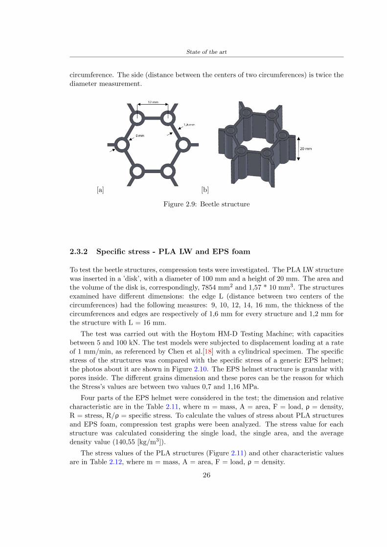
State of the art
circumference The side (distance between the centers of two circumferences) is twice thediameter measurement
[a] [b]
Figure 29 Beetle structure
232 Specific stress - PLA LW and EPS foam
To test the beetle structures compression tests were investigated The PLA LW structurewas inserted in a rsquodiskrsquo with a diameter of 100 mm and a height of 20 mm The area andthe volume of the disk is correspondingly 7854 mm2 and 157 10 mm3 The structuresexamined have different dimensions the edge L (distance between two centers of thecircumferences) had the following measures 9 10 12 14 16 mm the thickness of thecircumferences and edges are respectively of 16 mm for every structure and 12 mm forthe structure with L = 16 mm
The test was carried out with the Hoytom HM-D Testing Machine with capacitiesbetween 5 and 100 kN The test models were subjected to displacement loading at a rateof 1 mmmin as referenced by Chen et al[18] with a cylindrical specimen The specificstress of the structures was compared with the specific stress of a generic EPS helmetthe photos about it are shown in Figure 210 The EPS helmet structure is granular withpores inside The different grains dimension and these pores can be the reason for whichthe Stressrsquos values are between two values 07 and 116 MPa
Four parts of the EPS helmet were considered in the test the dimension and relativecharacteristic are in the Table 211 where m = mass A = area F = load ρ = densityR = stress Rρ = specific stress To calculate the values of stress about PLA structuresand EPS foam compression test graphs were been analyzed The stress value for eachstructure was calculated considering the single load the single area and the averagedensity value (14055 [kgm3])
The stress values of the PLA structures (Figure 211) and other characteristic valuesare in Table 212 where m = mass A = area F = load ρ = density
26
State of the art
[a] [b]
[c] [d]
Figure 210 EPS generic helmet helmet pictures [a] [b] and internal structureExternal granular structure [c] and pores [d]
[a] [b] [c]
Figure 211 PLA LW disks Grasshopper structure [a] PLA LW structure of 14 mm[b] PLA LW structure compressed [c]
27
State of the art
The results of the load-displacement graphs are affected by the geometry of the diskthe target is to valid for any shape or size for this is preferred to realize a diagramthat depends from σ (or stress) and the deformation ε (or strain) which can be definedrespectively as
σ =F
A0(27)
ε =l minus l0l
(28)
where F is the load during the test A0 is the area l0 is the initial length and l is thelength when the load is applied The areas considered for the EPS cube is reported inTable 211 in the second column the areas of the PLA structure is 7854 mm2 like thearea of the circumscribed disk
The values compared are shown in Table 213 and the graphs obtained by Matlabcode to analyze the recorded data of the compression machine are in Figure 213 and inFigure 212
Considering that the data provided by the compression machine are subject to noiseand disturbances it was decided to convert the original curve into polynomial type curvesthat allow obtaining the best interpolating curve for the data in question To obtain themit was divided the recorded data into two groups the first part from 0 until the end ofthe linear part and the second when the curve becomes linear again The best-fitting (inthe least-squares sense) was performed using the polyfit and polyval functions of MatlabThe first returns the coefficients of the p(x) with n degree the second evaluates p(x) ateach point in x The polynomial formula p(x) is shown in the Equation 29
pn(x) = anxn + anminus1x
nminus1 + + a2x2 + a1x+ a0 (29)
where a0 an are constants and x is the indeterminate The choice of the degree ofthe polynomial was made based on the criterion of wanting to obtain linear curves thatrespected the elastic trend at the beginning of the graph For this reason the degree ofthe polynomial is 1 Subsequently I searched through the intersection of the two lines forthe point that is equivalent to the maximum stress that marks the end of linearity
This value for EPS and PLA LW is the R [MPa] in the Table 213 The average stressvalue for PLA LW is 139 MPa and for EPS is 094 MPa The specific stress (Rρ) is 18MPa lowast m3)kg for the EPS found in CES 669 MPa lowast m3)kg for the EPS foam of thegeneric helmet and for PLA LW is 1161 MPa lowastm3)kg an intermediate value betweenthe two which is what we wanted to achieve
28
State of the art
m [g] A [mm2] F [N] ρ [kgm3]
EPS (CES) 50
16 9234 1063 13864
18 879 593 13651
21 858 833 14237
24 864 564 14468
Average value 14055
Table 211 Compression stress generic EPS helmet
L [mm] t [mm] m [g] F [N] ρ [kgm3]
9 16 214 7250 1363
10 16 192 5560 12467
12 16 201 8190 13051
14 12 138 8000 8961
Average value 12027
Table 212 Compression test PLA structures
PLA LW structure EPS structureρ= 12027kgm3 ρ= 14055kgm3
Edge [mm] R [MPa] Rρ103 Number R [MPa] Rρ103
EPS (CES) 09 18
9 173 1269 1 116 824
10 139 1114 2 08 568
12 138 1057 3 105 746
14 108 1205 4 077 540
Average value 139 1161 094 669
Table 213 Specific stress calculus PLA LW and EPS calculus ρ = density R = stressRρ [(MPa lowastm3)kg] = specific stress
29
State of the art
Figure 212 Compression test Stress-Strain diagrams - EPS
Figure 213 Compression test Stress-Strain diagrams - PLA LW
30
Chapter 3
Methodology
31 3D scan
311 3D Sense 2 scanner and Meshmixer - Reverse reconstruction
Standardized measures were not taken into account for making the helmet but the sizewas obtained through a 3D scan of my head
The scanner used is 3D Sense 2 by 3D Systems which has a minimum scanningvolume of 20 x 20 x 20 cm and a maximum scanning volume of 300 x 300 x 300 cmTo scan my person I was helped to get a full view at 360 at an appropriate distanceReal-time visualization of the captured images was shown through 3D Sense softwareThe idea of scanning the head with the scanner refers to the methodology used by Wanget al [30] They used a reverse reconstruction functional for me to realize the helmetsurface made to measure my head and like them a silicone pool cap was used to makescanning as smooth as possible The authors claim the head scan rdquocan also be used toobtain information about the objectrsquos surface which is then reconstructed utilizing thecomputerrsquos three-dimensional model via reverse modelling softwarerdquo [30] that in my caseis Autodesk Meshmixer
The files it was could get from the scan were stl obj and ply format they wereexported to obj to work in the next step with Autodesk Meshmixer that allowed tomodify and homogenize the 3D image obtained from the scan
In Meshmixer through the selection and delete commands the superfluous parts weredeleted that had been acquired and with the inspector and the DrawDraw2 commandsthe vertices were moved locally along a pre-defined direction and with Smooth the surfacemore homogeneous was made The sequence of steps is shown in the Figure 31
312 3D scan analysis and extraction of features
In Chapter 2 the directives imposed by the BS EN 960 Standard were examined concern-ing the definition of the helmet and the measures to be respected in the field of visionand the part of the helmet was to carry out impact tests
In Figure 32 the features defined complying with the Standardrsquos rules are repre-sented To define these features the software NX was used The angle in the subfigure
31
Methodology
[a] [b] [c] [d]
Figure 31 Sequence of 3D head scan 3D scanner acquisition [a] scan after reparationwith Meshmixer [b] solid scan vision frontal and lateral [c] [d]
[b] is bigger than 105 (as defined by the Standard) while the degree in the subfigure [c]is 25 By defining the construction lines to be respected of the helmetit was necessary todraw the design of the surface not using the software NX but changing with Rhinocerosto create a SubD or SubDivision surface
32 Helmet design
321 Rhinoceros - Helmet surface
After realizing a rsquocleanrsquo Wang et al [30] subdivide with lines and then sectors the headto create the surface of the helmet They used the technique of NURBS a Non UniformRational Basis-Splines which mathematically models a 3D geometry while thanks tothe Rhinoceros 3D organic shapes was draw SubD surfaces These geometries allow tosplit the mesh into small polygons and consist of lines with which easily the shape ofthe object can be modified with a surface already created changing the position of aline automatically the remaining part of the geometry adapts to the changes With thistechnique the rsquosurface basersquo of the helmet was realized with the size of my head Therepresentation of the realized SubD is in Figure 33
322 Grasshopper - Helmet structure
The next idea is the creation on the surface of the beetle structure with different di-mensions modelling the helmet that is not a linear surface It was decided not to buildthe structure with a software CAD because to model an already complex structure on acurved surface would mean to model a cell for a cell
To solve this obstacle a Rhinoceros plug-in was used Grasshopper GH idealized byRobert McNeel and associates creators of Rhinoceros Using GH does not mean drawinggeometries by connecting points and drawing tools because it is based on algorithmicmodelling used in architecture and engineering for 3D modelling
The modelling takes place through a node diagram that the software will convert intoa code-algorithm in GH it is possible to define the variables and parameters and inRhinoceros in real-time it is possible to view the object GH allows for varying the
32
Methodology
[a] [b]
[c]
Figure 32 Featurersquos extraction in [a] is represented the impact line in [b] and [c] twoprospective about the definition of the field of vision
[a] [b] [c]
Figure 33 SubD representation lateral view [a] top view [b] front view [c]
geometry to your liking by varying a simple parameter of the diagram as everything willbe remodelled according to the change made
In the following Figure 34 it is shown an example of a structure that was used fordistinct subgroups of helmet areas The idea was to insert smaller cells in the frontal andlateral zone and larger ones in the upper area In the first image [a] is shown the part of
33
Methodology
the helpful diagram to create the beetle structure to establish the size of the cells andthe extrusion the second image [b] contains the part of the diagram with which I appliedthe structure previously created to the SubD
The structure used to place and adapt the beetle structure to the surface is theSrfMorph while the yellow rsquowindowrsquo that contains numbers serves to select the parts ofthe surface where to apply the geometry created In accord with the GH diagram in
[a]
[b]
Figure 34 Grasshopper diagrams
Figure 34 [a] it is possible to see the steps executed to realize the structure Initially inthe xy-plane a hexagonal grid was drawn through the Hexgrid command in which youcan input the length of the hexagon edge and the number of grid elements (selected bytrial) Then the circumferences was drawn in proportion to the hexagon dimensions asspecified in the Chapter 2 and shown in Figure 35 [a] In figure [b] the rsquocutrsquo made atthe circumferences is visible this subdivision was necessary for printing purposes In thelast photo [c] the structure highlighted in green in [b] was extruded setting a distance
34
Methodology
of 20 mm
[a] [b] [c]
Figure 35 Construction sequence of the geometry of the helmet
In the diagram in Figure 34 [b] there is the application of the structure created bi-dimensionally to the SubD surface of the helmet visible by unlocking the SubD commandof the diagram and in Figure 36 [a] Upper this the referential geometry of the group ofsurfaces was superimposed where it was to be applied the newly created structure (visiblein darker red) the SubD indices are in the yellow box of the diagram
Through the SrfMorph command the location of the structure was granted In Figure36 [b] at the darkest red of the figure [a] with the above command it was possible toplace the structure
[a] [b]
Figure 36 Application of the geometry created to the helmet surface
Overall the diagrams with specific structures are five one for the front two equal forthe side parts one for the top shown in the previous Figure 36 and one for the back
The hexagons in the structure have a dimension varying between 8 mm and 14 mmof side the largest is found at the top later at the back in the sides and the smallest atthe front In Figure 36 [b] the presence of not only hexagonal structures is visible Thegeometry used does not allow the homogeneous arrangement on the entire surface andrequires different structures Automatically the choice of GH to optimize the structurewas to insert quadrilateral
As described above the helmet has different dimensions of the structure divided asvisible in Figure 36 in a quadrilateral This causes a discontinuity between zones withdifferent sizes due to the geometry of the construction
To eliminate this problem and realize the design homogeneous grids were inserted
35
Methodology
in the affected areas as shown in Figure 37 This insertion however proved to beinteresting and strategic researching in this regard studies were realized to demonstratethe insertion of a rectangular grid inside the hexagon grid was helpful for the transmissionof stress in the structure As cited by Sun et al [40] rdquothe mechanical properties of thesesandwich structures are often limited by local failures such as face-core debonding or corecollapserdquo Carrying out compression tests have effectively demonstrated that the insertionof the grid allows rdquoprovided increased stiffness specific stiffness energy absorption andcritical loadrdquo [41] As shown in the graphic [c] of the Figure 37 the honeycomb structuregives a force of 7 kN while with a grid the value is 11 kN and with the combinationexceeds 22 kN In addition in the left front a plaque to customize the helmet wasprepared Figure 37 [a]
[a] [b]
[c]
Figure 37 Grid in the helmet [a] hybrid structure with hexagons and grid [b] [40]compression test results of the hybrid structure [c] [41]
33 3D Print
After having achieved the CAD (Computer Aided Design) of the helmet in order tobe printed it must be converted and saved in format STL (Standard TriangulationLanguage) - Binary compatible with the printing machine and useful for transformingsolid object surfaces into triangles The steps to be taken are the following
bull CAD file realization
bull CAD export in format STL to Simplify 3D the software that shows slider layersand then- rotate and position the object according to geometry and the positioning of any
36
Methodology
supports- setting printing parameters- item manual andor automatic positioning of supports- slider display layers
bull import file gcode to printer
331 Printer and parameters
The program used to visualize how the helmet slices layers before sending it to the printerand to set the parameters is as anticipated Simplify 3D
To make the printing not being a flat geometry it is necessary to place the supportsThe idea was to use water-based supports that the helmet would automatically dissolveonce placed in the water After testing different types of water-soluble PVA the choicefell on eSun 3D Printing Filament PVA (water-soluble support) Before choosing theoptimal position for printing several tests were carried out and to decrease the numberof the supports significantly and allows an optimal printing of the outer part an emptyrsquospherersquo that self-sustains below the helmet was placed as shown in Figure 38
In the image [a] you can see the first print position tried with which an external partof the helmet very damaged was obtained because of the contact supports-helmet In [b]the empty rsquospherersquo is shown to optimize the number of supports and in the last photo [c]there is the full version at the end of print
[a] [b] [c]
Figure 38 Printing supports
The printer that has been used for printing is the Raise 3D Pro2 with double extrudersand nozzles of variable size from 02 mm to 1 mm after some test prints with the PLALW and the structure in created the size that allowed me to have a good compromisebetween printing time and accuracy was 06 mm Using 04 mm the printing time wasexcessive even if having the smaller nozzle diameter means having more precision withthe 08 mm nozzle the quality of the structure was not excellent as seen in Figure 38[a]
Another factor that had to be taken into account is the characteristic of the PLA-LWto expand As the printing temperature and the printer used vary the expansion andcharacteristics of the material change The use of the 06 mm nozzle associated with
37
Methodology
Parameter Left extruder Right extruder
01cm Material 01cm PVA 01cm PLA LW
Extruder toolbox index Tool 0 Tool 1
Nozzle diameter 06 mm 06 mm
Extrusion multiplier 1 05
Extrusion width Auto (072 mm) 05 mm
Layer x
Infill Rectilinear - 50
Supports (Automatic and not) Infill 50
Temperature 210 250
General parameters
Primary layer height 03 mm Top solid layer 4
Bottom solid layer 2 Outline 2
Heated bad 60 Speed 40 mms
Table 31 Printing parameters
Raise 3D allowed me to get good results The choice of this printer was not random ithas in fact the characteristic of making extremely precise prints The Raise has accuracyin placing the object on the printing bed of 078 microns on the xy axis and a resolutionfor layers of 001 mm
The final version of the helmet is visible in Figure 39 and it is possible to compare itwith the preview version in Rhinoceros in Figure 310
38
Methodology
[a] [b]
[c]
Figure 39 Views of the helmet
[a] [b]
Figure 310 Views of the helmet (GH version)
39
Chapter 4
Experimental evaluation
41 Experimental tests
411 Drop-weight impact test machine
In order to calculate the contact force peak and the difference of energy absorbed duringthe impact between the reference helmet and helmet with the beetle structure in PLA-LW dynamic impact tests were carried out using the Fractovis Plus an impact testmachine
In this way it is possible to monitor the evolution of the above variables from theinitial to the final instant of the impact The machine can withstand a load with a rangevariable from 2 to 70 kg with a maximum speed of 46 ms and a maximum height of1 m The values chosen for the test are the following 5 kg weight maximum speed andmaximum height The Anvil that was used is a disc diameter of 60 mm
As shown in Figure 41 and explained by Crupi et al [37] the machine consists ofa sensor capable of recording the speed before impact the impactor that can have avariable mass (a weight of 5 kg in my test) a system to guarantee that there are nomultiple impacts after the first and that work as a shock absorber and clamping systemwhere the object to be tested is placed
The tests that have been carried out are in total four two related to the helmetoptimized with PLA-LW and two with two generic helmets of different brand in EPS
42 PLA LW helmet
To perform the dynamic test on the helmet of PLA considering the difficulty of printingit was helpful to use a test helmet with imperfections to understand where the impactwas concentrated in a single part or distributed The images of Figure 42 show a helmetwith not well defined edges and inaccurate print but exactly localizes the impact zoneThanks to this test it was possible to take into account only one helmet area shown inFigure 43 to have the exact curve of the structure bio-inspired with PLA-LW
40
Experimental evaluation
Figure 41 Drop-weight impact test machine [37]
[a] [b]
Figure 42 Test 1 PLA-LW helmet
43 EPS helmet
To carry out dynamic tests and extract the technical characteristics of the helmettwohelmets were bought in a sports store both EPS and being on the market both certifiedThe brands of the two helmets are DTB and VAN|RYSEL and the average weight ofthe two is 223 g Two different helmets have been chosen to have a more certain andclear classification of the characteristics They are shown in Figure 44 and Figure 45
41
Experimental evaluation
[a] [b]
Figure 43 Test 2 PLA-LW helmet
[a] [b] [c]
Figure 44 Test 3 EPS helmet
[a] [b] [c]
Figure 45 Test 4 EPS helmet
44 Results
441 First results - PLA-LW and EPS helmet
Figure 46 shows two types of trends related to the two different models of the helmetThe force evaluated for PLA-LW has higher force peaks but is more concentrated and
42
Experimental evaluation
propagates less than EPS The graph shows the peaks of each curve highlighted with a redcircle In tests 1 and 2 for the PLA-LW as mentioned earlier the values are higher about7301 N for the complete helmet and 3996 N for the portion of helmet This difference isdue to the inaccuracy of the first full helmet during the printing phase In Figure 42 itis visible the low homogeneity and precision Therefore the first test with full helmet wasused only to define the area of interest of the impact which turns out to be localized Forthe other two EPS curves the values are only slightly lower compared to the PLA-LWequal to 3620 N and 3295 N but the trend is much more distributed
Figure 46 Dynamic machine test - Force
With the data obtained from the impact machine it was possible calculate not exclu-sively the value of force but itrsquos also possible to view the energy curves A resume aboutthe values and energy of the force is in the following Table 41
Test Peak force [N] Peak energy [J]
Test 1 - PLA LW (inaccurate) 730130
Test 2 - PLA LW (portion of helmet) 399643
Test 3 - EPS (DTB helmet) 362007 509
Test 4 - EPS (VAN|RYSEL helmet) 329546 4198
Test 5 - PLA with TPU 45421 5022
Table 41 Energy absorbed in dynamic test
43
Experimental evaluation
442 PLA-LW helmet with TPU cover
As it is possible to see in Figure 47 and as highlighted the first tests concerning thebio-inspired structure and the PLA-LW are far from my expectations considering thelittle distribution of force in comparison with the EPS foam and consequently a smallamount of energy absorbed
Figure 47 Dynamic machine test - Energy
To improve this impact damping factor the idea was to create a cover for the helmetin flexible TPU trying to absorb impact energy The TPU used is a flexible material ofthe brand Ninjaflex used in sports by the application in helmets and shoes to cushionbumps during the game Generally in the helmets (baseball helmet for example) theTPU is inserted internally in contact with the head In my case the TPU structurein addition to creating a shock-absorbing and durable cover creates a custom cover thehelmet and for the person This cover was also made with the Raise 3D printer
As shown in the Figure 48 [a] the infill of the part in contact with the helmet hasa percentage of 100 the filling of the other part of the structure is not complete butonly 15 and the internal structure is hexagonal to recall that of the helmet The desireto insert a structure with a rsquoraisedrsquo geometry is for visual and aesthetic reasons as youhave the feeling of greater protection and not filled is inspired by the machine CitroenCaptus whose bumpers (Airbump) are full of air The failure to realize empty structuresis due to the need to place any internal supports not removable
The idea was to create a cover that allow you to see of the internal structure of thehelmet and that protect specific areas the front the two sides the top and the posteriorWhat which was thought for this reason was to create the shape of a flower with four
44
Experimental evaluation
petals Figure 48 [b]In this way to perform dynamic impact tests as shown in Figure 49 [a] the cover was
positioned at the top of the helmet and the impact was performed in the centre of thersquoflowerrsquo which corresponds to the higher upper part where the structure has larger cellsize The impact parameters are the same as those used in previous impacts 5 kg weightmaximum speed and maximum height The Anvil that was used is a disc diameter of60 mm In photo [b] it is evident the difference between the structure that received theimpact with protection (left) and without protection (right) Without protection duringthe impact there was a perforation of the structure with a concentration of force at a locallevel as you can see in the Figure 46 in the case of TPU the impactor did not perforateand crossed the structure thanks to the cover of TPU that cushioned the shock At themoment of impact the impactor bounced
[a] [b]
Figure 48 TPU cover
[a] [b]
Figure 49 PLA-LW with TPU - dynamic impact [a] and differences between thehelmet with TPU and without TPU cover [b]
45
Experimental evaluation
The Figure 410 includes the diagrams relative to the dynamic impacts In [a] thereare already analyzed EPS results in [b] a comparison between the test on the portionof helmet in PLA LW with and without the TPU cover in [c] the overall comparison ofcurves shows a much more similar EPS trend if the TPU is placed above the structure inPLA LW to soften the blow and absorb the same energy [d]
46
[a]
[c]
[d]
Figure 410 Comparison between PLA-LW with TPU and EPS
Chapter 5
FEM Validation
51 Impactor - Anvils definition
Before to start to work in Abaqus it was necessary to search in the literature the materialwith which the anvil was been realized Milne et al [23] established the densityrsquos valuethe Youngrsquos Module and Poissonrsquos ratio for the Flat and Kerbstone Anvil
- Density ρ = 7800 kgm3
- Youngrsquos Module E = 200000 MPa
- Poissonrsquos ratio ν = 03
Inserting the data in the CES EduPack program specifying the mechanical andphysical properties the material corresponding to these characteristics is Stainless steelaustenitic (ASTM F1586) medium-hard
Initially the proposal was to create a conservative system to evaluate the absorptionenergies values and apply this value to a vibration system but the helmet needs dampingto be realized it was impossible to use a system without losses in this modality Thisis why a numerical calculation was carried out by performing two types of simulationsexplicit dynamic step and static step
The idea to realize the theoretical impact is to regard the movement of the anviland not the helmetrsquos movement which is fixed The velocity is the same cited in thenormative EN 1078 542 ms for the Flat anvil and 457 ms for the Kerbstone anvil
In performing the simulations It was given more relevance and perform tests withthe Kerbstone Anvil This choice was done because the geometry with which it is beenrealized (following as defined in the legislation) allows the helmet to be more subjectedto stress this involves the definition of higher stress limits compared to the Flat Anvil
The mesh size that has been used is the same in the case of the simulation of thehelmet optimized in PLA-LW and the full helmet in EPS of 7 mm The impactor isconsidered as a Discrete rigid body with its specific Reference Point (RP) like shownin Figure 51 for this reason it is not a solid but it is composted only by shells Inthe same image [b] there is the FEM representation of the model and in Table 51 thecharacteristic of FEM with quadrilateral (R3D4) and triangular elements (R3D3)
48
FEM Validation
Object Elementnumber
Elements Shape Geometricorder
Global size[mm]
Kerbstone 230 Quadrilateral - R3D4 Linear 7
Kerbstone 8 Triangular - R3D3 Linear 7
Table 51 Mesh element - Kerbstone Anvil
[a] [b]
Figure 51 Kerbstone anvil in the simulation like discrete rigid body [a] and FEMelements [b]
511 PLA LW - Plastic characteristics
The PLA-LW as explained in the Chapter 2 is new material on the market and producedby the only Colorfabb company for this reason few tests have been carried out to defineits technical characteristics and through tensile tests of the 3D printed specimens it waspossible to define an elastic limit as reported in the Table 210
In the context of simulations to reproduce the impact and deformation of the helmetis also necessary to consider the plastic characteristics of the material Not possessingany reference value in this regard tests were performed through a Static Step initiallyand then an Explicit Dynamic Step in Abaqus
The structure chosen to consider as a reference it is one of the structures previouslysubjected to the compression test having the side L=14 mm As for the reproduction ofthe compression disks initially they were reproduced according to the geometry of theHoytom HM-D Testing Machine considering the bodies mentioned above as discrete 3Drigid discrete The measure was the diameter of 200 mm and the height of 20 mm
After an initial analysis it was observed that the computational time of the simulationprogram was very high so it was decided to change the geometry to have a rsquodisk-surfacesrsquo(equally 3D rigid-discrete) which allowed me to have a smaller number of nodes for themesh and consequently a better computational time The representation of the opti-mized structure in PLA-LW and the disks used for simulated compression is in Figure 52
49
FEM Validation
[a] [b]
Figure 52 Representation of the samples used for the simulation of the compressiontest In Figure [a] the disks of the Hoytom HM-D Testing Machine in figure [b] the
representation of the same as simple surfaces
As shown in Figure 52 the disks are considered 3D discrete hard bodies so it waschosen for both a point the reference point RP where to apply the characteristics relatedto the two bodies As for the compression test it was established
bull the movement of a disk and fixed the second through a boundary condition impos-ing an Encastre therefore unable to move and rotate in xyz directions
bull for the opposite disk the boundary condition relative to the 15 mm displacementwas applied which is the parameter that it was observed to determine the end ofthe compression with the machine This shift is shown by the orange arrow in figure[b]
bull between the upper surface and the disk e the disk with the lower surface it wasinitialized a general contact with normal behaviour through rsquohardrsquo contact andtangential behaviour with a coefficient of friction of 02 with directionality imposedon rsquoisotropicrsquo
The next step was to define the mesh of the components whose parameters are shown inTable 52 while the representation of the FEM is in Figure 53 with the representationof the simulation and real compression test
Object Elementsnumber
Typology Geometricorder
Globalsize [mm]
Disk (14mm) 80910 hexaedral - C3D8R Linear 07
Impact disks 206 quadrilateral - R3D4 Linear 20
Impact disks 6 triangular - R3D3 Linear 20
Table 52 Mesh element - Compression test simulation
As previously announced a static simulation was initially performed with a StaticStep with Step Time equal to 900 (obtained going to consider the speed of 1 mmmin of
50
FEM Validation
[a]
[b] [c]
Figure 53 FEM representation [a] and compression test simulation [b] and realcompression [c]
the compression test and the displacement of 15 mm) However the complex geometryof the structure and the high time set by Step Time did not allow a correct definitionof the parameters of the plastic characteristics of the material the simulation was notable to continue once reached a Step Time of approximately 220 That is why it waschanged by choosing an Explicit Dynamic step
Leaving all the parameters of the boundary conditions unchanged the Step Time wasmodified imposing it to 001 The ability of the explicit dynamic to work with non-linearand contacting structures allowed me to achieve results The results obtained are shownin Figure 54 with the blue curve and were obtained through the iteration of differentPlastic Strain and Yield Stress values in Abaqus while the red line is the result of thereal compression test a similar curve trend was obtained but it is not possible to obtainthe same curve taking into account problems of printing inaccuracy
512 First test - helmet
The initial idea was to perform a simulation imposing the speed of 457 ms to theimpactor tie the helmet in EPS and PLA and compare the absorbed energies Theproblem it was encountered is related to the mesh of the helmet optimized in PLA andwith minimum dimensions of the elements and distinct elements it was not able to solveit
51
FEM Validation
[a]
YieldStress
PlasticStrain
1 47 0
2 7 001
3 75 005
4 10 01
5 108 1
6 115 15
7 12 2
[b]
Figure 54 Representation of the two curves related to the simulation in Abaqus of thecompression test and the data obtained from the real test to obtain the plastic
characteristics of the material
513 Second test - plane
The first solution is the one shown in Figure 55 To realize the simulation it was realizeda section of the helmet to involve a smaller number of elements and nodes Again thesimulation for the EPS helmet was successful while the simulation with the bio-inspiredstructure was interrupted by excessive distortion of elements
The previous images show the impact is very localized in the impacted area and theidea to achieve a complete simulation is not to consider a curved portion of the helmetbut a plane In this way it was possible to solve the problem and obtain a completesimulation for the bio-inspired structure
FEM element
Below in Table 53 there is the definition of the elements used for the PLA-LW and EPSplane in the simulation to simulate the impact and to control the energy-absorbing whilethe anvil characteristics are described in Table 51
514 EPS impact simulations
In order to proceed with the simulation it was imposed some boundary conditions thatregard ties and forces
bull the movement of the plane is fixed through an Encastre therefore unable to moveand rotate in xyz directions
52
FEM Validation
[a]
[b]
Figure 55 Impact simulation parts of EPS and PLA helmet
Object Elementnumber
Elements Shape Geometricorder
Plane (PLA) 38896 Tetrahedral -C3D10M
Quadratic
Plane (EPS) 2100 Hexahedral - C3D8R Linear
Table 53 Mesh element - plane impact
bull to create the impact it was set a speed of 457 ms at the reference point RP of therigid body which is the impactor Kerbstone Anvil shown in Figure 56
bull between the upper surface of the plane and the impactor it was initialized a Sur-face to Surface contact with normal behaviour through rsquohardrsquo contact and tangen-tial behaviour with a coefficient of friction of 02 with directionality imposed onrsquoisotropicrsquo
bull the rotation in x y z relative to the RP of the rigid discrete impactor body is locked
53
FEM Validation
In addition it was characterized the plane in the part of the materials with the char-acteristic values of the EPS mentioned in Chapter 221 The Von Mises Stress valueapparently low is relative to the Yield Stress of the EPS material equal to 09 MPa
Figure 56 EPS Boundary conditions and Load
515 PLA LW impact simulations
As also required in the case of the EPS plane in order to proceed with the simulationsome boundary conditions were imposed that regard ties and forces
bull the movement of the plane is fixed through an Encastre therefore unable to moveand rotate in xyz directions
bull to create the impact a speed of 457 ms was set at the reference point RP of therigid body which is the impactor Kerbstone Anvil shown in Figure 58
bull between the upper surface of the plane and the impactor it was initialized a Sur-face to Surface contact with normal behaviour through rsquohardrsquo contact and tangen-tial behaviour with a coefficient of friction of 02 with directionality imposed onrsquoisotropicrsquo
bull the rotation in x y z relative to the RP of the rigid discrete impactor body is locked
In addition the plane was characterized in the part of the materials with the characteristicvalues of the PLA mentioned in the Chapter 223 and 511
Figure 58 Boundary conditions and Load
54
FEM Validation
[a]
[b]
Figure 57 EPS impact simulation
52 Results
In Figures 59 and 57 it is shown how the structure in PLA LW has a more concentratedstress distribution of the structure unlike EPS The maximum value for the Von Misesstress is 09 MPa in EPS structure and 3634 MPa in PLA LW structure Once thesimulations were obtained the next step was to go and compare the energies absorbed bythe two structures The energy calculated by Abaqus that has been taken into account isPlastic Dissipation To make a comparison the data of the two energies were representedin a single graph
What emerges from the graph is that about the impact made with the KerbstoneAnvil the energy absorption is more excellent although only slightly for the PLA LWthan for the EPS From the graph in Figure 510 a value of 41 J is shown for the EPSand 51 J for the PLA LW
55
[a]
[b]
Figure 59 PLA impact simulation
[a]
Figure 510 EPS and PLA LW energy comparison - Abaqus simulation
Chapter 6
Head Injury Data
For the statistical analysis the injuries related to the accident data were categorised intothe following types and levels based on the details of the medical report [11] about theEN 1078
bull Head Injury Criterion (HIC)
bull Peak Linear Acceleration (PLAc)
bull Gadd Severity Injury (GSI)
bull Diffuse axonal injuries (DAI)
61 Abaqus simulation
Until now the purpose of the simulations has been to determine which between the twomaterials and the two structures of EPS and PLA LW could absorb more energy duringthe impact but no simulations have been carried out in compliance with BS EN 1078on the helmet impact tests To calculate the injuries listed in the previous paragraphhowever we need the acceleration values in the three directions related to the subjectrsquoshead
To realize it the scan of my head already rsquocleanrsquo was considered of which it has beencalculated the inertia thanks to the automatic SolidWorks calculation and evaluated theweight with the Table 24 the structure of the helmet was placed for the EPS and thePLA LW over the head as shown in Figure 61 Also this time being able to mesh theentire helmet in PLA LW was impossible due to the excessive distortion of some elementsduring the simulation so it has been tried to make a section of the structures of thehelmet and results were obtained
57
Head Injury Data
[a] [b]
Figure 61 My scan head - CAD [a] head imported in Abaqus[b]
Initially the simulation had these characteristics as shown in the following Figure62 considering the helmet was not sectioned As explained earlier it was not possibleto get to simulation in the case of the optimized structure in PLA LW for this reasononly a part of the helmet was considered in both cases shown in Figure 63
[a]
Figure 62 Simulation based on BS EN 1078
58
Head Injury Data
[a] [b]
Figure 63 Simulation based on BS EN 1078 with head
In order to proceed with the simulation some boundary conditions that regard tiesand forces have have imposed
bull two reference points RP were created the first in the inertia centre of the headthe second relating to the Kerbstone Anvil which is a discrete rigid body
bull in the reference point RP of the head in the definition of the engineering features5 kg was inserted for the weight and an inertia I11 = 564464E+07 gmm2 I22 =460654E+07gmm2 I33 = 187302E+07gmm2
bull to simulate the impact it was set a speed of 457 ms at the reference point RP ofthe head in z-axis direction
bull a general contact with normal behaviour through rsquohardrsquo contact and tangentialbehaviour with a coefficient of friction of 02
bull between the upper surface of the helmet and the impactor it has been initializeda Surface to Surface contact with normal behaviour through rsquohardrsquo contact andtangential behaviour with a coefficient of friction of 02 with directionality imposedon rsquoisotropicrsquo
bull the movement between the Kerbstone anvil and the helmet is fixed through anEncastre therefore unable to move and rotate in xyz directions
bull the rotation in x y z relative to the RP of the rigid discrete impactor body is locked
FEM element
As reported in Table 53 the portion of the helmet in EPS has used a mesh with hexahe-dral elements of linear order For the structure (beetle) of PLA LW given the geometry
59
Head Injury Data
complexity it was necessary to use a quadratic order of tetrahedra For the mesh of thehead instead in both simulations have been used quadrilateral elements of linear orderas reported in the Tables 61 and 62
Object Elementnumber
Elements Shape Geometricorder
Head 3755 Quadrilateral - R3D4 Linear
Head 34542 Quadrilateral - R3D3 Linear
Helmet (PLA) 272302 Tetrahedral -C3D10M
Quadratic
Table 61 Mesh element - Head simulation with PLA LW (beetle) helmet
Object Elementnumber
Elements Shape Geometricorder
Head 3755 Quadrilateral - R3D4 Linear
Head 34542 Quadrilateral - R3D3 Linear
Helmet (EPS) 72280 Hexahedral - C3D8R Linear
Table 62 Mesh element - Head simulation with EPS helmet
62 Results
Figure 64 represents the simulation in line with BS EN 1078 concerning the helmet inEPS [a] and the helmet with bio-inspired structure in PLA LW For both simulationsVan Misesrsquo stress has Yield Stress values in the case of EPS which is 09 MPa and theplastic behaviour combination of PLA LW [b]
In the case of head and Kerbstone Anvil stress was not assessed as they were previ-ously defined as discrete rigid bodies
63 Head Injury Criterion
The HIC quantifies head impact severity by incorporating time of acceleration exposureand acceleration magnitude it is calculated in post-processing phase with the followingEquation 61
HIC15 =
[1
(t1 minus t2)
int t2
t1
a(t)dt
]25(t2 minus t1) (61)
60
Head Injury Data
[a]
[b]
Figure 64 Results simulation based on BS EN 1078 with sectioned head
For this analysis a(t) is the acceleration calculated in the centre of mass of the head(corresponding to the reference point RP) expressed in g and the time interval (t2 minus t1)was chosen to maximize HIC over a maximum duration of 15 ms
Matlab and the trapz function were used to calculate the HIC to integrate accelerationover time t2 and t1 were considered initial and final times of the simulation t1 = 0 sand t2 = 10 s time less than 15 s
HIC value of 198 was obtained for EPS and 87 for PLA LW Considering the Hayeset al [16] document about the HIC values and the graph in Figure 65 developed bythe author it is possible to find the percentages related to the different injury AIS1 -AIS6 which correspond respectively to lower and higher severity while in Figure 66 therelative fatality to every value of AIS is shown The values obtained for the HIC andother criteria are shown in Table 63 The HIC value for EPS is 198 for PLA LW it is
61
Head Injury Data
Figure 65 Head injury risk curves based on HIC values [16]
Figure 66 The abbreviated injury score versus fatality rate [16]
87 Analyzing the data and comparing them with the curves of the Figure 65 I obtain
bull a percentage between 20 - 30 of AIS 1 for EPS 10 - 20 for PLA LW
bull a percentage between 10 - 20 of AIS 2 for EPS and 0 - 10 for PLA LW
bull for AIS 3 AIS 4 AIS 5 AIS 6 the percentages for both structures is between 0 -10
Comparing these percentages with the fatality rate of Figure 66 it is clear there is a riskof Moderate and Minor fatality in the case of EPS and PLA LW as all values are between0 and 30
62
Head Injury Data
HIC PLA [g] GSI E [J]
EPS 198 97 361 37723
PLA LW 87 75 169 44102
Table 63 Head Injury Data - values
64 Peak Linear Acceleration
The resultant linear acceleration versus time curve was calculated according to Equation62
γ(t) =radicγ2x(t) + γ2y(t) + γ2z (t) (62)
where
bull γ(t) is the resultant linear acceleration (g)
bull γx(t) is the linear acceleration in x axes (g)
bull γy(t) is the linear acceleration in y axes (g)
bull γz(t)is the linear acceleration in z axes (g)
The value of the impact should never exceed 250g [9] Cripton at all [9] in their studyexamined a helmet with expanded polystyrene (EPS) Figure 68 shows maximum HIC forhelmeted and unhelmeted drops from all heights For each drop height helmets reducedHIC relative to unhelmeted drops IARV value is 180g The acceleration in the two casesis shown in Figure 67 and the maximum values are 97g for EPS and 75g for PLA LWas reported in Table 63 The two values considering a maximum value calculated byCripton [9] of 180g are amply optimal and comply with the standard of 250g
65 Gadd Severity Index
Gadd proposed the Severity Index Criteria shown in Equation 63 Following this crite-rion the GSI values that are over 1000 produce serious internal head injury [33]
GSI =
int t1
0a(t)25dt (63)
Where
bull a is the linear acceleration (g)
bull t is the duration of the impact (s)
I calculated the GSI with the function trapz between 0 and t and the resulting valuesare 361 for the EPS and 169 for the PLA LW which comply with the limit
63
Head Injury Data
Figure 67 Peak accelerations for both helmets
Figure 68 Peak accelerations for both helmeted and unhelmeted drops Numbers overbars indicate peak acceleration For 2 m drop height results stated are the mean value
calculated from three drops [9]
64
Head Injury Data
66 Diffuse Axonal Injury
DAI cases covered all incidences in which neurological injuries occurred as well as con-cussion unconsciousness and coma
In order to assess the risk of head trauma in terms of diffuse axonal injury (DAI)Milne et al [23] defined a model based head injury criteria as follows obtaining theresults in Figure 69
bull 50 risk of moderate neurological injury (DAI1+) Brain Von Mises shearing stressof 28 kPa
bull 50 risk of severe neurological injury (DAI2+) Brain Von Mises shearing stressof 53 kPa
[a]
[b]
Figure 69 Peak intra-cerebral shearing stress computed with the helmet model coupledto the human head model for all impact points (a) Flat anvil (b) Kerbstone anvil [23]
65
Head Injury Data
67 Energy absorbed
In Figure 52 during the impact test between the kerbstone Anvil and the plan with thebio-inspired structure in PLA LW and EPS it was found that the PLA LW althoughwith a small difference of 10 J absorbed more energy in comparison with the EPS Whenthe test is carried out in compliance with BS EN 1078 and the head with a speed of 457ms (corresponding to the kerbstone Anvil) as shown in Figure 610 also in this casethe PLA LW with the optimized helmet structure manages to absorb more energy (evenif the difference is very low) compared to the EPS The maximum energy value in PLALW is 44102 J of EPS is 37723 J
Figure 610 Energy absorption - BS EN 1078
66
Chapter 7
Conclusion
71 Conclusion
In this thesis work a bicycle helmet with a bio-inspired structure in PLA LW and 3Dprinted was created The initial approach was to introduce an innovative aspect tostandard EPS helmets not using foam but a polymer with new geometries able toabsorb much energy during the impact For this reason the beetle structure has beenpreferred relying solely on the hypothesis encountered in the literature of its quality inabsorbing energy
Combining the new material of the PLA LW and beetle structure has made possiblethe development of new material satisfactory characteristics have been obtained sincethe first tests The two materials were first subjected to tensile tests to determine theirspecific stress in these the PLA LW had positive results
Subsequent dynamic physical tests were carried out on 3D printed helmet models andon reference helmets in EPS to calculate the absorption energy in both cases at the timeof impact These resulted in energy absorption of the beetle structure in PLA LW withthe application of a TPU cover almost equal to that of EPS about 50J To validate withfinite element analysis the two models an explicit dynamic step was used in AbaqusSimulations showed that the PLA LW structure absorbs a higher amount of energy thanthe EPS the higher is 50 J and the EPS 40J
Finally positive results have also been obtained in calculating the head injury datasimulating according to BS EN 1078 with the use of impactor helmet and head Theacceleration values for both the structures were inferior to 220g precisely for the PLALW was 75g and for the EPS 97g The same applies to the calculation of HIC and GSI(maximum acceptable value of 1000) where the values are 87 and 169 in the case of PLALW and 361 and 198 in EPS For all tests therefore greater efficiency of the structure inPLA LW has been obtained Positive results also in the simulation of the energy absorbedduring the impact as the value referring to the EPS was 35J and that of the PLA LWwas 45J
67
Conclusion
72 Future work lines
The positive results obtained can be considered as a starting point for further tests andsimulations to ensure the safety of the helmet and compliance with the regulations butbefore getting improvements and continue testing changes are required
bull the beetle structure of the helmet made with GH adapts to the SubD withoutallowing to have a homogeneous distribution it would be appropriate to have moreregular hexagonal geometries
bull the mesh of the helmet is too complex and does not allow to perform the simulationprobably to use a more regular structure would have a mesh accordingly moreregular and the simulation would be successful
bull the uneven helmet structure has so many defects that the print is imperfect andthis can change the results of the impact tests the structure should be improved
bull the printing time varies from 4 to 5 days it should be improved
bull the TPU helmet cover is too big for the RAISE printing plan it is necessary togenerate a new geometry
bull the TPU cover it must be fixed on the helmet
bull in the calculation of the DAI it is necessary to have the definition of the brain andthe head should not be considered as a rigid body
bull in the injury calculation the helmet without protection was considered with theTPU cover the result will be better
bull air flow analysis
The comments mentioned are only considerations and problems that I gained duringmy thesis and which should be improved but I am sure that these changes and improve-ments from design to printing and simulations can make the helmet a good product
68
Bibliography
[1] K Adanty J M Clark A Post Thomas Blaine H and M D Gilchrist Comparingtwo proposed protocols to test the oblique response of cycling helmets to fall impactsInternational Journal of Crashworthiness 6648 ndash 663 2020
[2] MF Ashby YJM Brechetb D Cebona and L Salvoc Selection strategies formaterials and processes Materials and Design 2004
[3] M Aysha El casco de bicicleta voronoi impreso en 3d mas seguro y ligero https
www3dnativescomen3d-printed-bicycle-helmet-voronoi-190820204
[4] H Bikas P Stavropoulos and G Chryssolouris Additive manufacturing methodsand modelling approaches a critical review The International Journal of AdvancedManufacturing Technology 83389ndash405 2016
[5] British Standards BSI Helmets for pedal cyclists and for users of skateboards androller skates - BS EN 1078 2012
[6] British Standards BSI Headforms for use in the testing of protective helmets BSEN 960 2020
[7] ColorFabb Colorfabb lw-pla 2019 httpscolorfabbcommedia
datasheetstdscolorfabbTDS_E_ColorFabb_LW-PLApdf
[8] V G Coronado T Haileyesus J M Bell T A Cheng JHaarbauer-Krupa M RLionbarger J Flores-Herrera L C McGuire and J Gilchrist Trends in sports andrecreation-related traumatic brain injuries treated in us emergency departments thenational electronic injury surveillance system-all injury program (neiss-aip) 2001-2012 J Head Trauma Rehabil 30185ndash197 2015
[9] P A Cripton D M Dressler D Stuart Cameron A Christopher R and D RichardsBicycle helmets are highly effective at preventing head injury during head impactHead-form accelerations and injury criteria for helmeted and unhelmeted impactsAccident Analysis and Prevention 701ndash7 2014
[10] L Cui M A Forero R and M D Gilchrist Optimisation of energy absorbingliner for equestrian helmets UCD School of Electrical Electronic and MechanicalEngineering University College Dublin Belfield Dublin4 Ireland 2020
[11] C Deck N Bourdet F Meyer and R Willinger Protection performance of bicyclehelmets Journal of safety research pages 67ndash77 2019
[12] Committee F08 Specification for headforms F2220 ASTM International 2015
[13] Committee F08 Specification for helmets used in recreational bicycling or rollerskating F1447 ASTM International 2018
[14] Committee F08 Test methods for equipment and procedures used in evaluating theperformance F1446 ASTM International 2020
69
Bibliography
[15] P Halldin Shock absorption including measuring CENTC 158 Working Group11 2018
[16] W C Hayes M S Erickson and E D Power Forensic injury biomechanics Annualreview of biomedical engineering pages 55ndash86 2007
[17] HEXR httpshexrcom
[18] C Jinxiang Z Xiaoming O Yoji S Kazuya G Zhensheng and P LongchengThe deformation mode and strengthening mechanism of compression in the beetleelytron plate Materials and Design 131481ndash186 2017
[19] S Kroeker M Ozkul A De Marco S Bonin and GP Siegmund Density variationin the expanded polystyrene eps foam of bicycle helmets and its influence on impactperformance Journal of biomechanical engineering 2019
[20] S G Kroeker SJ Bonin A L DeMarco C A Good and G P Siegmund Agedoes not affect the material properties of expanded polystyrene liners in field-usedbicycle helmets Journal of biomechanical engineering 2016
[21] M Meier K H Tan M K Lim and L Chung Unlocking innovation in the sportindustry through additive manufacturing Business Process Management Journa2018
[22] N J Mills and A Gilchrist The effectiveness of foams in bicycle and motorcyclehelmets Accident Analysis Prevention 23153 ndash 163 1991
[23] G Milne C Deck R P Carreira Q Allinne and R Willinger Development andvalidation of a bicycle helmet assessment of head injury risk under standard impactconditions Computer methods in biomechanics and biomedical engineering 15 Suppl1309 ndash 310 2012
[24] Y Mosleh S J Vander B Depreitere and J Ivens Novel composite foam conceptfor head protection in oblique impacts Adv Eng Mater (Advanced EngineeringMaterials) 10 2017
[25] H Mustafa T Y Pang T Ellena and S H Nasir Impact attenuation of user-centred bicycle helmet design with different foam densities J Phys Conf Ser(Journal of Physics Conference Series) 1150 2019
[26] S H Ngoc and L Guoxing A review of recent research on bio-inspired structuresand materials for energy absorption applications Composites Part 181 2020
[27] J I Novak and A R Novak Is additive manufacturing improving performance insports a systematic review Sport engineering and technology 13 2020
[28] European Road Safety Observatory European road safety observatory facts and fig-ures - cyclists - 2020 December 2020 httpseceuropaeutransportroad_
safetysitesdefaultfilesfacts_figures_cyclists_final_20210323pdf
[29] New York City Departments of Health Parks Mental Hygiene Transportation Recre-ation and the New York City Police Department Bicyclist fatalities and seriousinjuries in new york city 2005
[30] W Pengwen Y Jing H Yanan H Jiaofei and F Xiaoyang Innovative designof a helmet based on reverse engineering and 3d printing Alexandria EngineeringJournal 603445ndash3453 2021
[31] S G Piland T E Gould M Jesunathadas J S Wiggins O McNair and V CShane Protective helmets in sports Materials in Sports Equipment 3 2019
70
Bibliography
[32] K Schmitt P F Niederer M H Muser and F Walz Trauma biomechanicsSpringer Berlin Heidelberg 2010
[33] David Sepelveda Lopez A Biomechanical Analysis of Bicycle Helmets using FEMPhD thesis 2019 Bachelor thesis
[34] H Stigson Bicycle Helmets 2020 Tested by Folksam PhD thesis 2020 PhDAssociate Professor Traffic Safety Research
[35] H Tao K Sudip N Anindya and X Yongzhao 3d printed sensors for biomedicalapplications A review sensor 2019
[36] M Trzaskalska and R Chwastek Damping properties and density of helmet linersmade of expanded polystyrene (eps) Archives of Metallurgy and Materials 66 2020
[37] Crupi V Epasto G and Guglielmino E Impact response of aluminum foam sand-wiches for light-weight ship structures Metals 198ndash112 2020
[38] W Wei-cai F Dong-ming and L Yuan-xin Study on impact energy absorbing per-formance of eps buffer layer of motorcycle helmet Proceedings - 2013 InternationalConference on Mechanical and Automation Engineering MAEE 2013
[39] Z Xiaoming C Jinxiang O Yoji Z Peiwei X Xiaobing and Y Xindi Influence ofhoneycomb dimensions and forming methods on the compressive properties of beetleelytron plates Journal of Sandwich Structures and Materials 2228ndash39 2020
[40] S Zhi L Dong Z Weisheng S Shanshan and G Xu Topological optimization ofbiomimetic sandwich structures with hybrid core and cfrp face sheets CompositesScience and Technology 14279ndash90 2017
[41] S Zhi S Shanshan G Xu H Xiaozhi and C Haoran On compressive propertiesof composite sandwich structures with grid reinforced honeycomb core CompositesPart B 94245ndash252 2016
71
- List of Tables
- List of Figures
- Introduction
-
- Helmet bike protection
-
- Helmet structure
-
- Additive Manufacturing
-
- AM process
- Materials and techniques - FDM
- AM in sport
-
- 3D printed helmets
-
- Phases
- HEXR
- VORONOI
-
- State of the art
-
- Standards
-
- Headform
- European Standard and American Standard
- Field of vision - BS EN 1078
- Test impact area
- Anvils and environmental conditions
-
- Materials
-
- EPS Foam
- CES Edu Pack - Material selection
- PLA with natural fiber and PLA LW
-
- Bio-inspired structures
-
- Beetle structure - Design of the model
- Specific stress - PLA LW and EPS foam
-
- Methodology
-
- 3D scan
-
- 3D Sense 2 scanner and Meshmixer - Reverse reconstruction
- 3D scan analysis and extraction of features
-
- Helmet design
-
- Rhinoceros - Helmet surface
- Grasshopper - Helmet structure
-
- 3D Print
-
- Printer and parameters
-
- Experimental evaluation
-
- Experimental tests
-
- Drop-weight impact test machine
-
- PLA LW helmet
- EPS helmet
- Results
-
- First results - PLA-LW and EPS helmet
- PLA-LW helmet with TPU cover
-
- FEM Validation
-
- Impactor - Anvils definition
-
- PLA LW - Plastic characteristics
- First test - helmet
- Second test - plane
- EPS impact simulations
- PLA LW impact simulations
-
- Results
-
- Head Injury Data
-
- Abaqus simulation
- Results
- Head Injury Criterion
- Peak Linear Acceleration
- Gadd Severity Index
- Diffuse Axonal Injury
- Energy absorbed
-
- Conclusion
-
- Conclusion
- Future work lines
-
- Bibliography
-
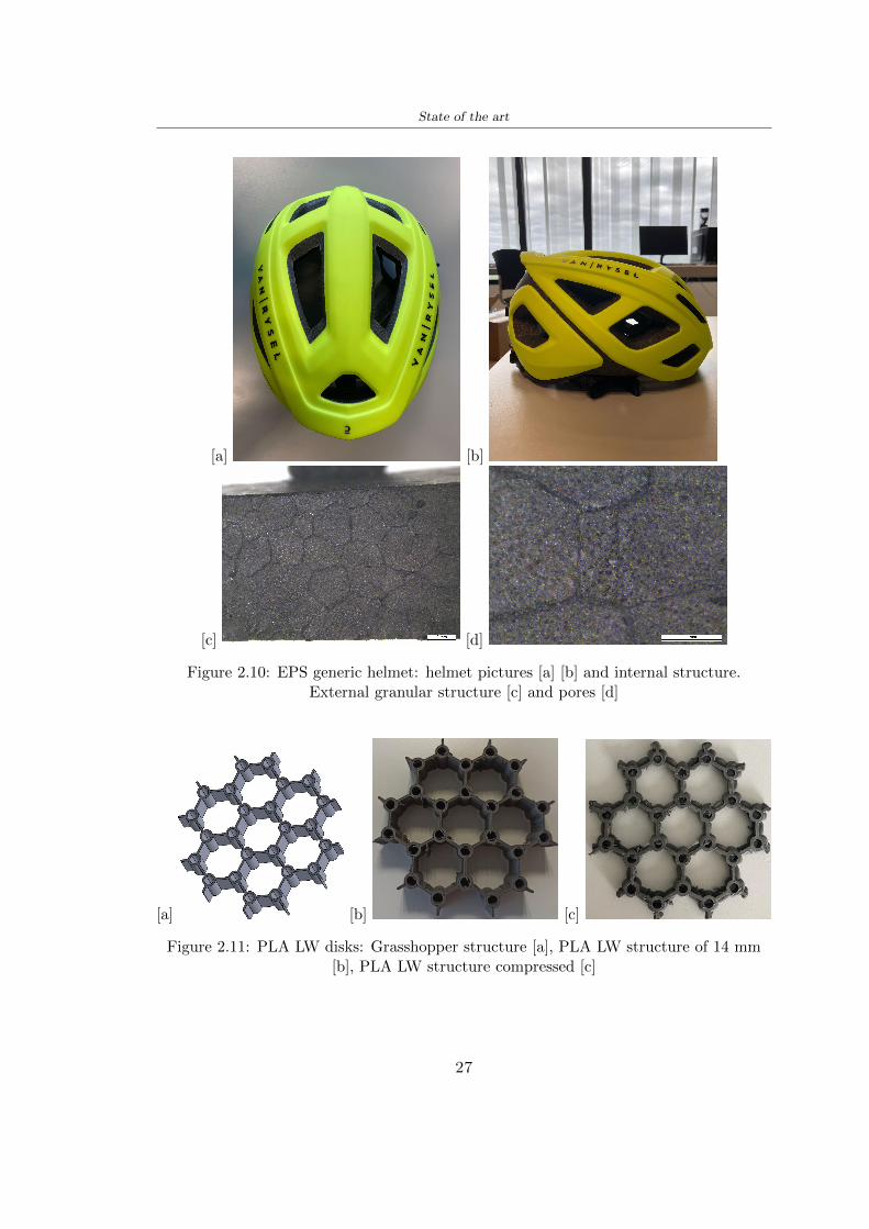
State of the art
[a] [b]
[c] [d]
Figure 210 EPS generic helmet helmet pictures [a] [b] and internal structureExternal granular structure [c] and pores [d]
[a] [b] [c]
Figure 211 PLA LW disks Grasshopper structure [a] PLA LW structure of 14 mm[b] PLA LW structure compressed [c]
27
State of the art
The results of the load-displacement graphs are affected by the geometry of the diskthe target is to valid for any shape or size for this is preferred to realize a diagramthat depends from σ (or stress) and the deformation ε (or strain) which can be definedrespectively as
σ =F
A0(27)
ε =l minus l0l
(28)
where F is the load during the test A0 is the area l0 is the initial length and l is thelength when the load is applied The areas considered for the EPS cube is reported inTable 211 in the second column the areas of the PLA structure is 7854 mm2 like thearea of the circumscribed disk
The values compared are shown in Table 213 and the graphs obtained by Matlabcode to analyze the recorded data of the compression machine are in Figure 213 and inFigure 212
Considering that the data provided by the compression machine are subject to noiseand disturbances it was decided to convert the original curve into polynomial type curvesthat allow obtaining the best interpolating curve for the data in question To obtain themit was divided the recorded data into two groups the first part from 0 until the end ofthe linear part and the second when the curve becomes linear again The best-fitting (inthe least-squares sense) was performed using the polyfit and polyval functions of MatlabThe first returns the coefficients of the p(x) with n degree the second evaluates p(x) ateach point in x The polynomial formula p(x) is shown in the Equation 29
pn(x) = anxn + anminus1x
nminus1 + + a2x2 + a1x+ a0 (29)
where a0 an are constants and x is the indeterminate The choice of the degree ofthe polynomial was made based on the criterion of wanting to obtain linear curves thatrespected the elastic trend at the beginning of the graph For this reason the degree ofthe polynomial is 1 Subsequently I searched through the intersection of the two lines forthe point that is equivalent to the maximum stress that marks the end of linearity
This value for EPS and PLA LW is the R [MPa] in the Table 213 The average stressvalue for PLA LW is 139 MPa and for EPS is 094 MPa The specific stress (Rρ) is 18MPa lowast m3)kg for the EPS found in CES 669 MPa lowast m3)kg for the EPS foam of thegeneric helmet and for PLA LW is 1161 MPa lowastm3)kg an intermediate value betweenthe two which is what we wanted to achieve
28
State of the art
m [g] A [mm2] F [N] ρ [kgm3]
EPS (CES) 50
16 9234 1063 13864
18 879 593 13651
21 858 833 14237
24 864 564 14468
Average value 14055
Table 211 Compression stress generic EPS helmet
L [mm] t [mm] m [g] F [N] ρ [kgm3]
9 16 214 7250 1363
10 16 192 5560 12467
12 16 201 8190 13051
14 12 138 8000 8961
Average value 12027
Table 212 Compression test PLA structures
PLA LW structure EPS structureρ= 12027kgm3 ρ= 14055kgm3
Edge [mm] R [MPa] Rρ103 Number R [MPa] Rρ103
EPS (CES) 09 18
9 173 1269 1 116 824
10 139 1114 2 08 568
12 138 1057 3 105 746
14 108 1205 4 077 540
Average value 139 1161 094 669
Table 213 Specific stress calculus PLA LW and EPS calculus ρ = density R = stressRρ [(MPa lowastm3)kg] = specific stress
29
State of the art
Figure 212 Compression test Stress-Strain diagrams - EPS
Figure 213 Compression test Stress-Strain diagrams - PLA LW
30
Chapter 3
Methodology
31 3D scan
311 3D Sense 2 scanner and Meshmixer - Reverse reconstruction
Standardized measures were not taken into account for making the helmet but the sizewas obtained through a 3D scan of my head
The scanner used is 3D Sense 2 by 3D Systems which has a minimum scanningvolume of 20 x 20 x 20 cm and a maximum scanning volume of 300 x 300 x 300 cmTo scan my person I was helped to get a full view at 360 at an appropriate distanceReal-time visualization of the captured images was shown through 3D Sense softwareThe idea of scanning the head with the scanner refers to the methodology used by Wanget al [30] They used a reverse reconstruction functional for me to realize the helmetsurface made to measure my head and like them a silicone pool cap was used to makescanning as smooth as possible The authors claim the head scan rdquocan also be used toobtain information about the objectrsquos surface which is then reconstructed utilizing thecomputerrsquos three-dimensional model via reverse modelling softwarerdquo [30] that in my caseis Autodesk Meshmixer
The files it was could get from the scan were stl obj and ply format they wereexported to obj to work in the next step with Autodesk Meshmixer that allowed tomodify and homogenize the 3D image obtained from the scan
In Meshmixer through the selection and delete commands the superfluous parts weredeleted that had been acquired and with the inspector and the DrawDraw2 commandsthe vertices were moved locally along a pre-defined direction and with Smooth the surfacemore homogeneous was made The sequence of steps is shown in the Figure 31
312 3D scan analysis and extraction of features
In Chapter 2 the directives imposed by the BS EN 960 Standard were examined concern-ing the definition of the helmet and the measures to be respected in the field of visionand the part of the helmet was to carry out impact tests
In Figure 32 the features defined complying with the Standardrsquos rules are repre-sented To define these features the software NX was used The angle in the subfigure
31
Methodology
[a] [b] [c] [d]
Figure 31 Sequence of 3D head scan 3D scanner acquisition [a] scan after reparationwith Meshmixer [b] solid scan vision frontal and lateral [c] [d]
[b] is bigger than 105 (as defined by the Standard) while the degree in the subfigure [c]is 25 By defining the construction lines to be respected of the helmetit was necessary todraw the design of the surface not using the software NX but changing with Rhinocerosto create a SubD or SubDivision surface
32 Helmet design
321 Rhinoceros - Helmet surface
After realizing a rsquocleanrsquo Wang et al [30] subdivide with lines and then sectors the headto create the surface of the helmet They used the technique of NURBS a Non UniformRational Basis-Splines which mathematically models a 3D geometry while thanks tothe Rhinoceros 3D organic shapes was draw SubD surfaces These geometries allow tosplit the mesh into small polygons and consist of lines with which easily the shape ofthe object can be modified with a surface already created changing the position of aline automatically the remaining part of the geometry adapts to the changes With thistechnique the rsquosurface basersquo of the helmet was realized with the size of my head Therepresentation of the realized SubD is in Figure 33
322 Grasshopper - Helmet structure
The next idea is the creation on the surface of the beetle structure with different di-mensions modelling the helmet that is not a linear surface It was decided not to buildthe structure with a software CAD because to model an already complex structure on acurved surface would mean to model a cell for a cell
To solve this obstacle a Rhinoceros plug-in was used Grasshopper GH idealized byRobert McNeel and associates creators of Rhinoceros Using GH does not mean drawinggeometries by connecting points and drawing tools because it is based on algorithmicmodelling used in architecture and engineering for 3D modelling
The modelling takes place through a node diagram that the software will convert intoa code-algorithm in GH it is possible to define the variables and parameters and inRhinoceros in real-time it is possible to view the object GH allows for varying the
32
Methodology
[a] [b]
[c]
Figure 32 Featurersquos extraction in [a] is represented the impact line in [b] and [c] twoprospective about the definition of the field of vision
[a] [b] [c]
Figure 33 SubD representation lateral view [a] top view [b] front view [c]
geometry to your liking by varying a simple parameter of the diagram as everything willbe remodelled according to the change made
In the following Figure 34 it is shown an example of a structure that was used fordistinct subgroups of helmet areas The idea was to insert smaller cells in the frontal andlateral zone and larger ones in the upper area In the first image [a] is shown the part of
33
Methodology
the helpful diagram to create the beetle structure to establish the size of the cells andthe extrusion the second image [b] contains the part of the diagram with which I appliedthe structure previously created to the SubD
The structure used to place and adapt the beetle structure to the surface is theSrfMorph while the yellow rsquowindowrsquo that contains numbers serves to select the parts ofthe surface where to apply the geometry created In accord with the GH diagram in
[a]
[b]
Figure 34 Grasshopper diagrams
Figure 34 [a] it is possible to see the steps executed to realize the structure Initially inthe xy-plane a hexagonal grid was drawn through the Hexgrid command in which youcan input the length of the hexagon edge and the number of grid elements (selected bytrial) Then the circumferences was drawn in proportion to the hexagon dimensions asspecified in the Chapter 2 and shown in Figure 35 [a] In figure [b] the rsquocutrsquo made atthe circumferences is visible this subdivision was necessary for printing purposes In thelast photo [c] the structure highlighted in green in [b] was extruded setting a distance
34
Methodology
of 20 mm
[a] [b] [c]
Figure 35 Construction sequence of the geometry of the helmet
In the diagram in Figure 34 [b] there is the application of the structure created bi-dimensionally to the SubD surface of the helmet visible by unlocking the SubD commandof the diagram and in Figure 36 [a] Upper this the referential geometry of the group ofsurfaces was superimposed where it was to be applied the newly created structure (visiblein darker red) the SubD indices are in the yellow box of the diagram
Through the SrfMorph command the location of the structure was granted In Figure36 [b] at the darkest red of the figure [a] with the above command it was possible toplace the structure
[a] [b]
Figure 36 Application of the geometry created to the helmet surface
Overall the diagrams with specific structures are five one for the front two equal forthe side parts one for the top shown in the previous Figure 36 and one for the back
The hexagons in the structure have a dimension varying between 8 mm and 14 mmof side the largest is found at the top later at the back in the sides and the smallest atthe front In Figure 36 [b] the presence of not only hexagonal structures is visible Thegeometry used does not allow the homogeneous arrangement on the entire surface andrequires different structures Automatically the choice of GH to optimize the structurewas to insert quadrilateral
As described above the helmet has different dimensions of the structure divided asvisible in Figure 36 in a quadrilateral This causes a discontinuity between zones withdifferent sizes due to the geometry of the construction
To eliminate this problem and realize the design homogeneous grids were inserted
35
Methodology
in the affected areas as shown in Figure 37 This insertion however proved to beinteresting and strategic researching in this regard studies were realized to demonstratethe insertion of a rectangular grid inside the hexagon grid was helpful for the transmissionof stress in the structure As cited by Sun et al [40] rdquothe mechanical properties of thesesandwich structures are often limited by local failures such as face-core debonding or corecollapserdquo Carrying out compression tests have effectively demonstrated that the insertionof the grid allows rdquoprovided increased stiffness specific stiffness energy absorption andcritical loadrdquo [41] As shown in the graphic [c] of the Figure 37 the honeycomb structuregives a force of 7 kN while with a grid the value is 11 kN and with the combinationexceeds 22 kN In addition in the left front a plaque to customize the helmet wasprepared Figure 37 [a]
[a] [b]
[c]
Figure 37 Grid in the helmet [a] hybrid structure with hexagons and grid [b] [40]compression test results of the hybrid structure [c] [41]
33 3D Print
After having achieved the CAD (Computer Aided Design) of the helmet in order tobe printed it must be converted and saved in format STL (Standard TriangulationLanguage) - Binary compatible with the printing machine and useful for transformingsolid object surfaces into triangles The steps to be taken are the following
bull CAD file realization
bull CAD export in format STL to Simplify 3D the software that shows slider layersand then- rotate and position the object according to geometry and the positioning of any
36
Methodology
supports- setting printing parameters- item manual andor automatic positioning of supports- slider display layers
bull import file gcode to printer
331 Printer and parameters
The program used to visualize how the helmet slices layers before sending it to the printerand to set the parameters is as anticipated Simplify 3D
To make the printing not being a flat geometry it is necessary to place the supportsThe idea was to use water-based supports that the helmet would automatically dissolveonce placed in the water After testing different types of water-soluble PVA the choicefell on eSun 3D Printing Filament PVA (water-soluble support) Before choosing theoptimal position for printing several tests were carried out and to decrease the numberof the supports significantly and allows an optimal printing of the outer part an emptyrsquospherersquo that self-sustains below the helmet was placed as shown in Figure 38
In the image [a] you can see the first print position tried with which an external partof the helmet very damaged was obtained because of the contact supports-helmet In [b]the empty rsquospherersquo is shown to optimize the number of supports and in the last photo [c]there is the full version at the end of print
[a] [b] [c]
Figure 38 Printing supports
The printer that has been used for printing is the Raise 3D Pro2 with double extrudersand nozzles of variable size from 02 mm to 1 mm after some test prints with the PLALW and the structure in created the size that allowed me to have a good compromisebetween printing time and accuracy was 06 mm Using 04 mm the printing time wasexcessive even if having the smaller nozzle diameter means having more precision withthe 08 mm nozzle the quality of the structure was not excellent as seen in Figure 38[a]
Another factor that had to be taken into account is the characteristic of the PLA-LWto expand As the printing temperature and the printer used vary the expansion andcharacteristics of the material change The use of the 06 mm nozzle associated with
37
Methodology
Parameter Left extruder Right extruder
01cm Material 01cm PVA 01cm PLA LW
Extruder toolbox index Tool 0 Tool 1
Nozzle diameter 06 mm 06 mm
Extrusion multiplier 1 05
Extrusion width Auto (072 mm) 05 mm
Layer x
Infill Rectilinear - 50
Supports (Automatic and not) Infill 50
Temperature 210 250
General parameters
Primary layer height 03 mm Top solid layer 4
Bottom solid layer 2 Outline 2
Heated bad 60 Speed 40 mms
Table 31 Printing parameters
Raise 3D allowed me to get good results The choice of this printer was not random ithas in fact the characteristic of making extremely precise prints The Raise has accuracyin placing the object on the printing bed of 078 microns on the xy axis and a resolutionfor layers of 001 mm
The final version of the helmet is visible in Figure 39 and it is possible to compare itwith the preview version in Rhinoceros in Figure 310
38
Methodology
[a] [b]
[c]
Figure 39 Views of the helmet
[a] [b]
Figure 310 Views of the helmet (GH version)
39
Chapter 4
Experimental evaluation
41 Experimental tests
411 Drop-weight impact test machine
In order to calculate the contact force peak and the difference of energy absorbed duringthe impact between the reference helmet and helmet with the beetle structure in PLA-LW dynamic impact tests were carried out using the Fractovis Plus an impact testmachine
In this way it is possible to monitor the evolution of the above variables from theinitial to the final instant of the impact The machine can withstand a load with a rangevariable from 2 to 70 kg with a maximum speed of 46 ms and a maximum height of1 m The values chosen for the test are the following 5 kg weight maximum speed andmaximum height The Anvil that was used is a disc diameter of 60 mm
As shown in Figure 41 and explained by Crupi et al [37] the machine consists ofa sensor capable of recording the speed before impact the impactor that can have avariable mass (a weight of 5 kg in my test) a system to guarantee that there are nomultiple impacts after the first and that work as a shock absorber and clamping systemwhere the object to be tested is placed
The tests that have been carried out are in total four two related to the helmetoptimized with PLA-LW and two with two generic helmets of different brand in EPS
42 PLA LW helmet
To perform the dynamic test on the helmet of PLA considering the difficulty of printingit was helpful to use a test helmet with imperfections to understand where the impactwas concentrated in a single part or distributed The images of Figure 42 show a helmetwith not well defined edges and inaccurate print but exactly localizes the impact zoneThanks to this test it was possible to take into account only one helmet area shown inFigure 43 to have the exact curve of the structure bio-inspired with PLA-LW
40
Experimental evaluation
Figure 41 Drop-weight impact test machine [37]
[a] [b]
Figure 42 Test 1 PLA-LW helmet
43 EPS helmet
To carry out dynamic tests and extract the technical characteristics of the helmettwohelmets were bought in a sports store both EPS and being on the market both certifiedThe brands of the two helmets are DTB and VAN|RYSEL and the average weight ofthe two is 223 g Two different helmets have been chosen to have a more certain andclear classification of the characteristics They are shown in Figure 44 and Figure 45
41
Experimental evaluation
[a] [b]
Figure 43 Test 2 PLA-LW helmet
[a] [b] [c]
Figure 44 Test 3 EPS helmet
[a] [b] [c]
Figure 45 Test 4 EPS helmet
44 Results
441 First results - PLA-LW and EPS helmet
Figure 46 shows two types of trends related to the two different models of the helmetThe force evaluated for PLA-LW has higher force peaks but is more concentrated and
42
Experimental evaluation
propagates less than EPS The graph shows the peaks of each curve highlighted with a redcircle In tests 1 and 2 for the PLA-LW as mentioned earlier the values are higher about7301 N for the complete helmet and 3996 N for the portion of helmet This difference isdue to the inaccuracy of the first full helmet during the printing phase In Figure 42 itis visible the low homogeneity and precision Therefore the first test with full helmet wasused only to define the area of interest of the impact which turns out to be localized Forthe other two EPS curves the values are only slightly lower compared to the PLA-LWequal to 3620 N and 3295 N but the trend is much more distributed
Figure 46 Dynamic machine test - Force
With the data obtained from the impact machine it was possible calculate not exclu-sively the value of force but itrsquos also possible to view the energy curves A resume aboutthe values and energy of the force is in the following Table 41
Test Peak force [N] Peak energy [J]
Test 1 - PLA LW (inaccurate) 730130
Test 2 - PLA LW (portion of helmet) 399643
Test 3 - EPS (DTB helmet) 362007 509
Test 4 - EPS (VAN|RYSEL helmet) 329546 4198
Test 5 - PLA with TPU 45421 5022
Table 41 Energy absorbed in dynamic test
43
Experimental evaluation
442 PLA-LW helmet with TPU cover
As it is possible to see in Figure 47 and as highlighted the first tests concerning thebio-inspired structure and the PLA-LW are far from my expectations considering thelittle distribution of force in comparison with the EPS foam and consequently a smallamount of energy absorbed
Figure 47 Dynamic machine test - Energy
To improve this impact damping factor the idea was to create a cover for the helmetin flexible TPU trying to absorb impact energy The TPU used is a flexible material ofthe brand Ninjaflex used in sports by the application in helmets and shoes to cushionbumps during the game Generally in the helmets (baseball helmet for example) theTPU is inserted internally in contact with the head In my case the TPU structurein addition to creating a shock-absorbing and durable cover creates a custom cover thehelmet and for the person This cover was also made with the Raise 3D printer
As shown in the Figure 48 [a] the infill of the part in contact with the helmet hasa percentage of 100 the filling of the other part of the structure is not complete butonly 15 and the internal structure is hexagonal to recall that of the helmet The desireto insert a structure with a rsquoraisedrsquo geometry is for visual and aesthetic reasons as youhave the feeling of greater protection and not filled is inspired by the machine CitroenCaptus whose bumpers (Airbump) are full of air The failure to realize empty structuresis due to the need to place any internal supports not removable
The idea was to create a cover that allow you to see of the internal structure of thehelmet and that protect specific areas the front the two sides the top and the posteriorWhat which was thought for this reason was to create the shape of a flower with four
44
Experimental evaluation
petals Figure 48 [b]In this way to perform dynamic impact tests as shown in Figure 49 [a] the cover was
positioned at the top of the helmet and the impact was performed in the centre of thersquoflowerrsquo which corresponds to the higher upper part where the structure has larger cellsize The impact parameters are the same as those used in previous impacts 5 kg weightmaximum speed and maximum height The Anvil that was used is a disc diameter of60 mm In photo [b] it is evident the difference between the structure that received theimpact with protection (left) and without protection (right) Without protection duringthe impact there was a perforation of the structure with a concentration of force at a locallevel as you can see in the Figure 46 in the case of TPU the impactor did not perforateand crossed the structure thanks to the cover of TPU that cushioned the shock At themoment of impact the impactor bounced
[a] [b]
Figure 48 TPU cover
[a] [b]
Figure 49 PLA-LW with TPU - dynamic impact [a] and differences between thehelmet with TPU and without TPU cover [b]
45
Experimental evaluation
The Figure 410 includes the diagrams relative to the dynamic impacts In [a] thereare already analyzed EPS results in [b] a comparison between the test on the portionof helmet in PLA LW with and without the TPU cover in [c] the overall comparison ofcurves shows a much more similar EPS trend if the TPU is placed above the structure inPLA LW to soften the blow and absorb the same energy [d]
46
[a]
[c]
[d]
Figure 410 Comparison between PLA-LW with TPU and EPS
Chapter 5
FEM Validation
51 Impactor - Anvils definition
Before to start to work in Abaqus it was necessary to search in the literature the materialwith which the anvil was been realized Milne et al [23] established the densityrsquos valuethe Youngrsquos Module and Poissonrsquos ratio for the Flat and Kerbstone Anvil
- Density ρ = 7800 kgm3
- Youngrsquos Module E = 200000 MPa
- Poissonrsquos ratio ν = 03
Inserting the data in the CES EduPack program specifying the mechanical andphysical properties the material corresponding to these characteristics is Stainless steelaustenitic (ASTM F1586) medium-hard
Initially the proposal was to create a conservative system to evaluate the absorptionenergies values and apply this value to a vibration system but the helmet needs dampingto be realized it was impossible to use a system without losses in this modality Thisis why a numerical calculation was carried out by performing two types of simulationsexplicit dynamic step and static step
The idea to realize the theoretical impact is to regard the movement of the anviland not the helmetrsquos movement which is fixed The velocity is the same cited in thenormative EN 1078 542 ms for the Flat anvil and 457 ms for the Kerbstone anvil
In performing the simulations It was given more relevance and perform tests withthe Kerbstone Anvil This choice was done because the geometry with which it is beenrealized (following as defined in the legislation) allows the helmet to be more subjectedto stress this involves the definition of higher stress limits compared to the Flat Anvil
The mesh size that has been used is the same in the case of the simulation of thehelmet optimized in PLA-LW and the full helmet in EPS of 7 mm The impactor isconsidered as a Discrete rigid body with its specific Reference Point (RP) like shownin Figure 51 for this reason it is not a solid but it is composted only by shells Inthe same image [b] there is the FEM representation of the model and in Table 51 thecharacteristic of FEM with quadrilateral (R3D4) and triangular elements (R3D3)
48
FEM Validation
Object Elementnumber
Elements Shape Geometricorder
Global size[mm]
Kerbstone 230 Quadrilateral - R3D4 Linear 7
Kerbstone 8 Triangular - R3D3 Linear 7
Table 51 Mesh element - Kerbstone Anvil
[a] [b]
Figure 51 Kerbstone anvil in the simulation like discrete rigid body [a] and FEMelements [b]
511 PLA LW - Plastic characteristics
The PLA-LW as explained in the Chapter 2 is new material on the market and producedby the only Colorfabb company for this reason few tests have been carried out to defineits technical characteristics and through tensile tests of the 3D printed specimens it waspossible to define an elastic limit as reported in the Table 210
In the context of simulations to reproduce the impact and deformation of the helmetis also necessary to consider the plastic characteristics of the material Not possessingany reference value in this regard tests were performed through a Static Step initiallyand then an Explicit Dynamic Step in Abaqus
The structure chosen to consider as a reference it is one of the structures previouslysubjected to the compression test having the side L=14 mm As for the reproduction ofthe compression disks initially they were reproduced according to the geometry of theHoytom HM-D Testing Machine considering the bodies mentioned above as discrete 3Drigid discrete The measure was the diameter of 200 mm and the height of 20 mm
After an initial analysis it was observed that the computational time of the simulationprogram was very high so it was decided to change the geometry to have a rsquodisk-surfacesrsquo(equally 3D rigid-discrete) which allowed me to have a smaller number of nodes for themesh and consequently a better computational time The representation of the opti-mized structure in PLA-LW and the disks used for simulated compression is in Figure 52
49
FEM Validation
[a] [b]
Figure 52 Representation of the samples used for the simulation of the compressiontest In Figure [a] the disks of the Hoytom HM-D Testing Machine in figure [b] the
representation of the same as simple surfaces
As shown in Figure 52 the disks are considered 3D discrete hard bodies so it waschosen for both a point the reference point RP where to apply the characteristics relatedto the two bodies As for the compression test it was established
bull the movement of a disk and fixed the second through a boundary condition impos-ing an Encastre therefore unable to move and rotate in xyz directions
bull for the opposite disk the boundary condition relative to the 15 mm displacementwas applied which is the parameter that it was observed to determine the end ofthe compression with the machine This shift is shown by the orange arrow in figure[b]
bull between the upper surface and the disk e the disk with the lower surface it wasinitialized a general contact with normal behaviour through rsquohardrsquo contact andtangential behaviour with a coefficient of friction of 02 with directionality imposedon rsquoisotropicrsquo
The next step was to define the mesh of the components whose parameters are shown inTable 52 while the representation of the FEM is in Figure 53 with the representationof the simulation and real compression test
Object Elementsnumber
Typology Geometricorder
Globalsize [mm]
Disk (14mm) 80910 hexaedral - C3D8R Linear 07
Impact disks 206 quadrilateral - R3D4 Linear 20
Impact disks 6 triangular - R3D3 Linear 20
Table 52 Mesh element - Compression test simulation
As previously announced a static simulation was initially performed with a StaticStep with Step Time equal to 900 (obtained going to consider the speed of 1 mmmin of
50
FEM Validation
[a]
[b] [c]
Figure 53 FEM representation [a] and compression test simulation [b] and realcompression [c]
the compression test and the displacement of 15 mm) However the complex geometryof the structure and the high time set by Step Time did not allow a correct definitionof the parameters of the plastic characteristics of the material the simulation was notable to continue once reached a Step Time of approximately 220 That is why it waschanged by choosing an Explicit Dynamic step
Leaving all the parameters of the boundary conditions unchanged the Step Time wasmodified imposing it to 001 The ability of the explicit dynamic to work with non-linearand contacting structures allowed me to achieve results The results obtained are shownin Figure 54 with the blue curve and were obtained through the iteration of differentPlastic Strain and Yield Stress values in Abaqus while the red line is the result of thereal compression test a similar curve trend was obtained but it is not possible to obtainthe same curve taking into account problems of printing inaccuracy
512 First test - helmet
The initial idea was to perform a simulation imposing the speed of 457 ms to theimpactor tie the helmet in EPS and PLA and compare the absorbed energies Theproblem it was encountered is related to the mesh of the helmet optimized in PLA andwith minimum dimensions of the elements and distinct elements it was not able to solveit
51
FEM Validation
[a]
YieldStress
PlasticStrain
1 47 0
2 7 001
3 75 005
4 10 01
5 108 1
6 115 15
7 12 2
[b]
Figure 54 Representation of the two curves related to the simulation in Abaqus of thecompression test and the data obtained from the real test to obtain the plastic
characteristics of the material
513 Second test - plane
The first solution is the one shown in Figure 55 To realize the simulation it was realizeda section of the helmet to involve a smaller number of elements and nodes Again thesimulation for the EPS helmet was successful while the simulation with the bio-inspiredstructure was interrupted by excessive distortion of elements
The previous images show the impact is very localized in the impacted area and theidea to achieve a complete simulation is not to consider a curved portion of the helmetbut a plane In this way it was possible to solve the problem and obtain a completesimulation for the bio-inspired structure
FEM element
Below in Table 53 there is the definition of the elements used for the PLA-LW and EPSplane in the simulation to simulate the impact and to control the energy-absorbing whilethe anvil characteristics are described in Table 51
514 EPS impact simulations
In order to proceed with the simulation it was imposed some boundary conditions thatregard ties and forces
bull the movement of the plane is fixed through an Encastre therefore unable to moveand rotate in xyz directions
52
FEM Validation
[a]
[b]
Figure 55 Impact simulation parts of EPS and PLA helmet
Object Elementnumber
Elements Shape Geometricorder
Plane (PLA) 38896 Tetrahedral -C3D10M
Quadratic
Plane (EPS) 2100 Hexahedral - C3D8R Linear
Table 53 Mesh element - plane impact
bull to create the impact it was set a speed of 457 ms at the reference point RP of therigid body which is the impactor Kerbstone Anvil shown in Figure 56
bull between the upper surface of the plane and the impactor it was initialized a Sur-face to Surface contact with normal behaviour through rsquohardrsquo contact and tangen-tial behaviour with a coefficient of friction of 02 with directionality imposed onrsquoisotropicrsquo
bull the rotation in x y z relative to the RP of the rigid discrete impactor body is locked
53
FEM Validation
In addition it was characterized the plane in the part of the materials with the char-acteristic values of the EPS mentioned in Chapter 221 The Von Mises Stress valueapparently low is relative to the Yield Stress of the EPS material equal to 09 MPa
Figure 56 EPS Boundary conditions and Load
515 PLA LW impact simulations
As also required in the case of the EPS plane in order to proceed with the simulationsome boundary conditions were imposed that regard ties and forces
bull the movement of the plane is fixed through an Encastre therefore unable to moveand rotate in xyz directions
bull to create the impact a speed of 457 ms was set at the reference point RP of therigid body which is the impactor Kerbstone Anvil shown in Figure 58
bull between the upper surface of the plane and the impactor it was initialized a Sur-face to Surface contact with normal behaviour through rsquohardrsquo contact and tangen-tial behaviour with a coefficient of friction of 02 with directionality imposed onrsquoisotropicrsquo
bull the rotation in x y z relative to the RP of the rigid discrete impactor body is locked
In addition the plane was characterized in the part of the materials with the characteristicvalues of the PLA mentioned in the Chapter 223 and 511
Figure 58 Boundary conditions and Load
54
FEM Validation
[a]
[b]
Figure 57 EPS impact simulation
52 Results
In Figures 59 and 57 it is shown how the structure in PLA LW has a more concentratedstress distribution of the structure unlike EPS The maximum value for the Von Misesstress is 09 MPa in EPS structure and 3634 MPa in PLA LW structure Once thesimulations were obtained the next step was to go and compare the energies absorbed bythe two structures The energy calculated by Abaqus that has been taken into account isPlastic Dissipation To make a comparison the data of the two energies were representedin a single graph
What emerges from the graph is that about the impact made with the KerbstoneAnvil the energy absorption is more excellent although only slightly for the PLA LWthan for the EPS From the graph in Figure 510 a value of 41 J is shown for the EPSand 51 J for the PLA LW
55
[a]
[b]
Figure 59 PLA impact simulation
[a]
Figure 510 EPS and PLA LW energy comparison - Abaqus simulation
Chapter 6
Head Injury Data
For the statistical analysis the injuries related to the accident data were categorised intothe following types and levels based on the details of the medical report [11] about theEN 1078
bull Head Injury Criterion (HIC)
bull Peak Linear Acceleration (PLAc)
bull Gadd Severity Injury (GSI)
bull Diffuse axonal injuries (DAI)
61 Abaqus simulation
Until now the purpose of the simulations has been to determine which between the twomaterials and the two structures of EPS and PLA LW could absorb more energy duringthe impact but no simulations have been carried out in compliance with BS EN 1078on the helmet impact tests To calculate the injuries listed in the previous paragraphhowever we need the acceleration values in the three directions related to the subjectrsquoshead
To realize it the scan of my head already rsquocleanrsquo was considered of which it has beencalculated the inertia thanks to the automatic SolidWorks calculation and evaluated theweight with the Table 24 the structure of the helmet was placed for the EPS and thePLA LW over the head as shown in Figure 61 Also this time being able to mesh theentire helmet in PLA LW was impossible due to the excessive distortion of some elementsduring the simulation so it has been tried to make a section of the structures of thehelmet and results were obtained
57
Head Injury Data
[a] [b]
Figure 61 My scan head - CAD [a] head imported in Abaqus[b]
Initially the simulation had these characteristics as shown in the following Figure62 considering the helmet was not sectioned As explained earlier it was not possibleto get to simulation in the case of the optimized structure in PLA LW for this reasononly a part of the helmet was considered in both cases shown in Figure 63
[a]
Figure 62 Simulation based on BS EN 1078
58
Head Injury Data
[a] [b]
Figure 63 Simulation based on BS EN 1078 with head
In order to proceed with the simulation some boundary conditions that regard tiesand forces have have imposed
bull two reference points RP were created the first in the inertia centre of the headthe second relating to the Kerbstone Anvil which is a discrete rigid body
bull in the reference point RP of the head in the definition of the engineering features5 kg was inserted for the weight and an inertia I11 = 564464E+07 gmm2 I22 =460654E+07gmm2 I33 = 187302E+07gmm2
bull to simulate the impact it was set a speed of 457 ms at the reference point RP ofthe head in z-axis direction
bull a general contact with normal behaviour through rsquohardrsquo contact and tangentialbehaviour with a coefficient of friction of 02
bull between the upper surface of the helmet and the impactor it has been initializeda Surface to Surface contact with normal behaviour through rsquohardrsquo contact andtangential behaviour with a coefficient of friction of 02 with directionality imposedon rsquoisotropicrsquo
bull the movement between the Kerbstone anvil and the helmet is fixed through anEncastre therefore unable to move and rotate in xyz directions
bull the rotation in x y z relative to the RP of the rigid discrete impactor body is locked
FEM element
As reported in Table 53 the portion of the helmet in EPS has used a mesh with hexahe-dral elements of linear order For the structure (beetle) of PLA LW given the geometry
59
Head Injury Data
complexity it was necessary to use a quadratic order of tetrahedra For the mesh of thehead instead in both simulations have been used quadrilateral elements of linear orderas reported in the Tables 61 and 62
Object Elementnumber
Elements Shape Geometricorder
Head 3755 Quadrilateral - R3D4 Linear
Head 34542 Quadrilateral - R3D3 Linear
Helmet (PLA) 272302 Tetrahedral -C3D10M
Quadratic
Table 61 Mesh element - Head simulation with PLA LW (beetle) helmet
Object Elementnumber
Elements Shape Geometricorder
Head 3755 Quadrilateral - R3D4 Linear
Head 34542 Quadrilateral - R3D3 Linear
Helmet (EPS) 72280 Hexahedral - C3D8R Linear
Table 62 Mesh element - Head simulation with EPS helmet
62 Results
Figure 64 represents the simulation in line with BS EN 1078 concerning the helmet inEPS [a] and the helmet with bio-inspired structure in PLA LW For both simulationsVan Misesrsquo stress has Yield Stress values in the case of EPS which is 09 MPa and theplastic behaviour combination of PLA LW [b]
In the case of head and Kerbstone Anvil stress was not assessed as they were previ-ously defined as discrete rigid bodies
63 Head Injury Criterion
The HIC quantifies head impact severity by incorporating time of acceleration exposureand acceleration magnitude it is calculated in post-processing phase with the followingEquation 61
HIC15 =
[1
(t1 minus t2)
int t2
t1
a(t)dt
]25(t2 minus t1) (61)
60
Head Injury Data
[a]
[b]
Figure 64 Results simulation based on BS EN 1078 with sectioned head
For this analysis a(t) is the acceleration calculated in the centre of mass of the head(corresponding to the reference point RP) expressed in g and the time interval (t2 minus t1)was chosen to maximize HIC over a maximum duration of 15 ms
Matlab and the trapz function were used to calculate the HIC to integrate accelerationover time t2 and t1 were considered initial and final times of the simulation t1 = 0 sand t2 = 10 s time less than 15 s
HIC value of 198 was obtained for EPS and 87 for PLA LW Considering the Hayeset al [16] document about the HIC values and the graph in Figure 65 developed bythe author it is possible to find the percentages related to the different injury AIS1 -AIS6 which correspond respectively to lower and higher severity while in Figure 66 therelative fatality to every value of AIS is shown The values obtained for the HIC andother criteria are shown in Table 63 The HIC value for EPS is 198 for PLA LW it is
61
Head Injury Data
Figure 65 Head injury risk curves based on HIC values [16]
Figure 66 The abbreviated injury score versus fatality rate [16]
87 Analyzing the data and comparing them with the curves of the Figure 65 I obtain
bull a percentage between 20 - 30 of AIS 1 for EPS 10 - 20 for PLA LW
bull a percentage between 10 - 20 of AIS 2 for EPS and 0 - 10 for PLA LW
bull for AIS 3 AIS 4 AIS 5 AIS 6 the percentages for both structures is between 0 -10
Comparing these percentages with the fatality rate of Figure 66 it is clear there is a riskof Moderate and Minor fatality in the case of EPS and PLA LW as all values are between0 and 30
62
Head Injury Data
HIC PLA [g] GSI E [J]
EPS 198 97 361 37723
PLA LW 87 75 169 44102
Table 63 Head Injury Data - values
64 Peak Linear Acceleration
The resultant linear acceleration versus time curve was calculated according to Equation62
γ(t) =radicγ2x(t) + γ2y(t) + γ2z (t) (62)
where
bull γ(t) is the resultant linear acceleration (g)
bull γx(t) is the linear acceleration in x axes (g)
bull γy(t) is the linear acceleration in y axes (g)
bull γz(t)is the linear acceleration in z axes (g)
The value of the impact should never exceed 250g [9] Cripton at all [9] in their studyexamined a helmet with expanded polystyrene (EPS) Figure 68 shows maximum HIC forhelmeted and unhelmeted drops from all heights For each drop height helmets reducedHIC relative to unhelmeted drops IARV value is 180g The acceleration in the two casesis shown in Figure 67 and the maximum values are 97g for EPS and 75g for PLA LWas reported in Table 63 The two values considering a maximum value calculated byCripton [9] of 180g are amply optimal and comply with the standard of 250g
65 Gadd Severity Index
Gadd proposed the Severity Index Criteria shown in Equation 63 Following this crite-rion the GSI values that are over 1000 produce serious internal head injury [33]
GSI =
int t1
0a(t)25dt (63)
Where
bull a is the linear acceleration (g)
bull t is the duration of the impact (s)
I calculated the GSI with the function trapz between 0 and t and the resulting valuesare 361 for the EPS and 169 for the PLA LW which comply with the limit
63
Head Injury Data
Figure 67 Peak accelerations for both helmets
Figure 68 Peak accelerations for both helmeted and unhelmeted drops Numbers overbars indicate peak acceleration For 2 m drop height results stated are the mean value
calculated from three drops [9]
64
Head Injury Data
66 Diffuse Axonal Injury
DAI cases covered all incidences in which neurological injuries occurred as well as con-cussion unconsciousness and coma
In order to assess the risk of head trauma in terms of diffuse axonal injury (DAI)Milne et al [23] defined a model based head injury criteria as follows obtaining theresults in Figure 69
bull 50 risk of moderate neurological injury (DAI1+) Brain Von Mises shearing stressof 28 kPa
bull 50 risk of severe neurological injury (DAI2+) Brain Von Mises shearing stressof 53 kPa
[a]
[b]
Figure 69 Peak intra-cerebral shearing stress computed with the helmet model coupledto the human head model for all impact points (a) Flat anvil (b) Kerbstone anvil [23]
65
Head Injury Data
67 Energy absorbed
In Figure 52 during the impact test between the kerbstone Anvil and the plan with thebio-inspired structure in PLA LW and EPS it was found that the PLA LW althoughwith a small difference of 10 J absorbed more energy in comparison with the EPS Whenthe test is carried out in compliance with BS EN 1078 and the head with a speed of 457ms (corresponding to the kerbstone Anvil) as shown in Figure 610 also in this casethe PLA LW with the optimized helmet structure manages to absorb more energy (evenif the difference is very low) compared to the EPS The maximum energy value in PLALW is 44102 J of EPS is 37723 J
Figure 610 Energy absorption - BS EN 1078
66
Chapter 7
Conclusion
71 Conclusion
In this thesis work a bicycle helmet with a bio-inspired structure in PLA LW and 3Dprinted was created The initial approach was to introduce an innovative aspect tostandard EPS helmets not using foam but a polymer with new geometries able toabsorb much energy during the impact For this reason the beetle structure has beenpreferred relying solely on the hypothesis encountered in the literature of its quality inabsorbing energy
Combining the new material of the PLA LW and beetle structure has made possiblethe development of new material satisfactory characteristics have been obtained sincethe first tests The two materials were first subjected to tensile tests to determine theirspecific stress in these the PLA LW had positive results
Subsequent dynamic physical tests were carried out on 3D printed helmet models andon reference helmets in EPS to calculate the absorption energy in both cases at the timeof impact These resulted in energy absorption of the beetle structure in PLA LW withthe application of a TPU cover almost equal to that of EPS about 50J To validate withfinite element analysis the two models an explicit dynamic step was used in AbaqusSimulations showed that the PLA LW structure absorbs a higher amount of energy thanthe EPS the higher is 50 J and the EPS 40J
Finally positive results have also been obtained in calculating the head injury datasimulating according to BS EN 1078 with the use of impactor helmet and head Theacceleration values for both the structures were inferior to 220g precisely for the PLALW was 75g and for the EPS 97g The same applies to the calculation of HIC and GSI(maximum acceptable value of 1000) where the values are 87 and 169 in the case of PLALW and 361 and 198 in EPS For all tests therefore greater efficiency of the structure inPLA LW has been obtained Positive results also in the simulation of the energy absorbedduring the impact as the value referring to the EPS was 35J and that of the PLA LWwas 45J
67
Conclusion
72 Future work lines
The positive results obtained can be considered as a starting point for further tests andsimulations to ensure the safety of the helmet and compliance with the regulations butbefore getting improvements and continue testing changes are required
bull the beetle structure of the helmet made with GH adapts to the SubD withoutallowing to have a homogeneous distribution it would be appropriate to have moreregular hexagonal geometries
bull the mesh of the helmet is too complex and does not allow to perform the simulationprobably to use a more regular structure would have a mesh accordingly moreregular and the simulation would be successful
bull the uneven helmet structure has so many defects that the print is imperfect andthis can change the results of the impact tests the structure should be improved
bull the printing time varies from 4 to 5 days it should be improved
bull the TPU helmet cover is too big for the RAISE printing plan it is necessary togenerate a new geometry
bull the TPU cover it must be fixed on the helmet
bull in the calculation of the DAI it is necessary to have the definition of the brain andthe head should not be considered as a rigid body
bull in the injury calculation the helmet without protection was considered with theTPU cover the result will be better
bull air flow analysis
The comments mentioned are only considerations and problems that I gained duringmy thesis and which should be improved but I am sure that these changes and improve-ments from design to printing and simulations can make the helmet a good product
68
Bibliography
[1] K Adanty J M Clark A Post Thomas Blaine H and M D Gilchrist Comparingtwo proposed protocols to test the oblique response of cycling helmets to fall impactsInternational Journal of Crashworthiness 6648 ndash 663 2020
[2] MF Ashby YJM Brechetb D Cebona and L Salvoc Selection strategies formaterials and processes Materials and Design 2004
[3] M Aysha El casco de bicicleta voronoi impreso en 3d mas seguro y ligero https
www3dnativescomen3d-printed-bicycle-helmet-voronoi-190820204
[4] H Bikas P Stavropoulos and G Chryssolouris Additive manufacturing methodsand modelling approaches a critical review The International Journal of AdvancedManufacturing Technology 83389ndash405 2016
[5] British Standards BSI Helmets for pedal cyclists and for users of skateboards androller skates - BS EN 1078 2012
[6] British Standards BSI Headforms for use in the testing of protective helmets BSEN 960 2020
[7] ColorFabb Colorfabb lw-pla 2019 httpscolorfabbcommedia
datasheetstdscolorfabbTDS_E_ColorFabb_LW-PLApdf
[8] V G Coronado T Haileyesus J M Bell T A Cheng JHaarbauer-Krupa M RLionbarger J Flores-Herrera L C McGuire and J Gilchrist Trends in sports andrecreation-related traumatic brain injuries treated in us emergency departments thenational electronic injury surveillance system-all injury program (neiss-aip) 2001-2012 J Head Trauma Rehabil 30185ndash197 2015
[9] P A Cripton D M Dressler D Stuart Cameron A Christopher R and D RichardsBicycle helmets are highly effective at preventing head injury during head impactHead-form accelerations and injury criteria for helmeted and unhelmeted impactsAccident Analysis and Prevention 701ndash7 2014
[10] L Cui M A Forero R and M D Gilchrist Optimisation of energy absorbingliner for equestrian helmets UCD School of Electrical Electronic and MechanicalEngineering University College Dublin Belfield Dublin4 Ireland 2020
[11] C Deck N Bourdet F Meyer and R Willinger Protection performance of bicyclehelmets Journal of safety research pages 67ndash77 2019
[12] Committee F08 Specification for headforms F2220 ASTM International 2015
[13] Committee F08 Specification for helmets used in recreational bicycling or rollerskating F1447 ASTM International 2018
[14] Committee F08 Test methods for equipment and procedures used in evaluating theperformance F1446 ASTM International 2020
69
Bibliography
[15] P Halldin Shock absorption including measuring CENTC 158 Working Group11 2018
[16] W C Hayes M S Erickson and E D Power Forensic injury biomechanics Annualreview of biomedical engineering pages 55ndash86 2007
[17] HEXR httpshexrcom
[18] C Jinxiang Z Xiaoming O Yoji S Kazuya G Zhensheng and P LongchengThe deformation mode and strengthening mechanism of compression in the beetleelytron plate Materials and Design 131481ndash186 2017
[19] S Kroeker M Ozkul A De Marco S Bonin and GP Siegmund Density variationin the expanded polystyrene eps foam of bicycle helmets and its influence on impactperformance Journal of biomechanical engineering 2019
[20] S G Kroeker SJ Bonin A L DeMarco C A Good and G P Siegmund Agedoes not affect the material properties of expanded polystyrene liners in field-usedbicycle helmets Journal of biomechanical engineering 2016
[21] M Meier K H Tan M K Lim and L Chung Unlocking innovation in the sportindustry through additive manufacturing Business Process Management Journa2018
[22] N J Mills and A Gilchrist The effectiveness of foams in bicycle and motorcyclehelmets Accident Analysis Prevention 23153 ndash 163 1991
[23] G Milne C Deck R P Carreira Q Allinne and R Willinger Development andvalidation of a bicycle helmet assessment of head injury risk under standard impactconditions Computer methods in biomechanics and biomedical engineering 15 Suppl1309 ndash 310 2012
[24] Y Mosleh S J Vander B Depreitere and J Ivens Novel composite foam conceptfor head protection in oblique impacts Adv Eng Mater (Advanced EngineeringMaterials) 10 2017
[25] H Mustafa T Y Pang T Ellena and S H Nasir Impact attenuation of user-centred bicycle helmet design with different foam densities J Phys Conf Ser(Journal of Physics Conference Series) 1150 2019
[26] S H Ngoc and L Guoxing A review of recent research on bio-inspired structuresand materials for energy absorption applications Composites Part 181 2020
[27] J I Novak and A R Novak Is additive manufacturing improving performance insports a systematic review Sport engineering and technology 13 2020
[28] European Road Safety Observatory European road safety observatory facts and fig-ures - cyclists - 2020 December 2020 httpseceuropaeutransportroad_
safetysitesdefaultfilesfacts_figures_cyclists_final_20210323pdf
[29] New York City Departments of Health Parks Mental Hygiene Transportation Recre-ation and the New York City Police Department Bicyclist fatalities and seriousinjuries in new york city 2005
[30] W Pengwen Y Jing H Yanan H Jiaofei and F Xiaoyang Innovative designof a helmet based on reverse engineering and 3d printing Alexandria EngineeringJournal 603445ndash3453 2021
[31] S G Piland T E Gould M Jesunathadas J S Wiggins O McNair and V CShane Protective helmets in sports Materials in Sports Equipment 3 2019
70
Bibliography
[32] K Schmitt P F Niederer M H Muser and F Walz Trauma biomechanicsSpringer Berlin Heidelberg 2010
[33] David Sepelveda Lopez A Biomechanical Analysis of Bicycle Helmets using FEMPhD thesis 2019 Bachelor thesis
[34] H Stigson Bicycle Helmets 2020 Tested by Folksam PhD thesis 2020 PhDAssociate Professor Traffic Safety Research
[35] H Tao K Sudip N Anindya and X Yongzhao 3d printed sensors for biomedicalapplications A review sensor 2019
[36] M Trzaskalska and R Chwastek Damping properties and density of helmet linersmade of expanded polystyrene (eps) Archives of Metallurgy and Materials 66 2020
[37] Crupi V Epasto G and Guglielmino E Impact response of aluminum foam sand-wiches for light-weight ship structures Metals 198ndash112 2020
[38] W Wei-cai F Dong-ming and L Yuan-xin Study on impact energy absorbing per-formance of eps buffer layer of motorcycle helmet Proceedings - 2013 InternationalConference on Mechanical and Automation Engineering MAEE 2013
[39] Z Xiaoming C Jinxiang O Yoji Z Peiwei X Xiaobing and Y Xindi Influence ofhoneycomb dimensions and forming methods on the compressive properties of beetleelytron plates Journal of Sandwich Structures and Materials 2228ndash39 2020
[40] S Zhi L Dong Z Weisheng S Shanshan and G Xu Topological optimization ofbiomimetic sandwich structures with hybrid core and cfrp face sheets CompositesScience and Technology 14279ndash90 2017
[41] S Zhi S Shanshan G Xu H Xiaozhi and C Haoran On compressive propertiesof composite sandwich structures with grid reinforced honeycomb core CompositesPart B 94245ndash252 2016
71
- List of Tables
- List of Figures
- Introduction
-
- Helmet bike protection
-
- Helmet structure
-
- Additive Manufacturing
-
- AM process
- Materials and techniques - FDM
- AM in sport
-
- 3D printed helmets
-
- Phases
- HEXR
- VORONOI
-
- State of the art
-
- Standards
-
- Headform
- European Standard and American Standard
- Field of vision - BS EN 1078
- Test impact area
- Anvils and environmental conditions
-
- Materials
-
- EPS Foam
- CES Edu Pack - Material selection
- PLA with natural fiber and PLA LW
-
- Bio-inspired structures
-
- Beetle structure - Design of the model
- Specific stress - PLA LW and EPS foam
-
- Methodology
-
- 3D scan
-
- 3D Sense 2 scanner and Meshmixer - Reverse reconstruction
- 3D scan analysis and extraction of features
-
- Helmet design
-
- Rhinoceros - Helmet surface
- Grasshopper - Helmet structure
-
- 3D Print
-
- Printer and parameters
-
- Experimental evaluation
-
- Experimental tests
-
- Drop-weight impact test machine
-
- PLA LW helmet
- EPS helmet
- Results
-
- First results - PLA-LW and EPS helmet
- PLA-LW helmet with TPU cover
-
- FEM Validation
-
- Impactor - Anvils definition
-
- PLA LW - Plastic characteristics
- First test - helmet
- Second test - plane
- EPS impact simulations
- PLA LW impact simulations
-
- Results
-
- Head Injury Data
-
- Abaqus simulation
- Results
- Head Injury Criterion
- Peak Linear Acceleration
- Gadd Severity Index
- Diffuse Axonal Injury
- Energy absorbed
-
- Conclusion
-
- Conclusion
- Future work lines
-
- Bibliography
-
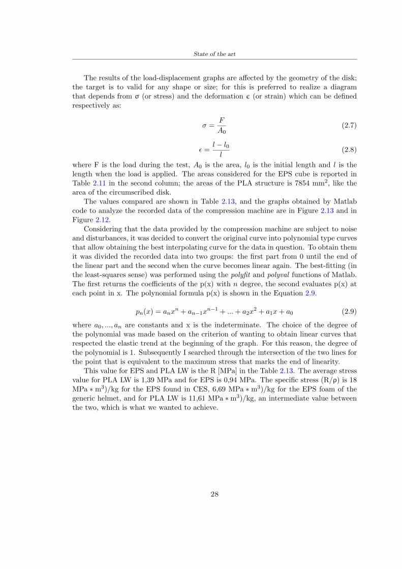
State of the art
The results of the load-displacement graphs are affected by the geometry of the diskthe target is to valid for any shape or size for this is preferred to realize a diagramthat depends from σ (or stress) and the deformation ε (or strain) which can be definedrespectively as
σ =F
A0(27)
ε =l minus l0l
(28)
where F is the load during the test A0 is the area l0 is the initial length and l is thelength when the load is applied The areas considered for the EPS cube is reported inTable 211 in the second column the areas of the PLA structure is 7854 mm2 like thearea of the circumscribed disk
The values compared are shown in Table 213 and the graphs obtained by Matlabcode to analyze the recorded data of the compression machine are in Figure 213 and inFigure 212
Considering that the data provided by the compression machine are subject to noiseand disturbances it was decided to convert the original curve into polynomial type curvesthat allow obtaining the best interpolating curve for the data in question To obtain themit was divided the recorded data into two groups the first part from 0 until the end ofthe linear part and the second when the curve becomes linear again The best-fitting (inthe least-squares sense) was performed using the polyfit and polyval functions of MatlabThe first returns the coefficients of the p(x) with n degree the second evaluates p(x) ateach point in x The polynomial formula p(x) is shown in the Equation 29
pn(x) = anxn + anminus1x
nminus1 + + a2x2 + a1x+ a0 (29)
where a0 an are constants and x is the indeterminate The choice of the degree ofthe polynomial was made based on the criterion of wanting to obtain linear curves thatrespected the elastic trend at the beginning of the graph For this reason the degree ofthe polynomial is 1 Subsequently I searched through the intersection of the two lines forthe point that is equivalent to the maximum stress that marks the end of linearity
This value for EPS and PLA LW is the R [MPa] in the Table 213 The average stressvalue for PLA LW is 139 MPa and for EPS is 094 MPa The specific stress (Rρ) is 18MPa lowast m3)kg for the EPS found in CES 669 MPa lowast m3)kg for the EPS foam of thegeneric helmet and for PLA LW is 1161 MPa lowastm3)kg an intermediate value betweenthe two which is what we wanted to achieve
28
State of the art
m [g] A [mm2] F [N] ρ [kgm3]
EPS (CES) 50
16 9234 1063 13864
18 879 593 13651
21 858 833 14237
24 864 564 14468
Average value 14055
Table 211 Compression stress generic EPS helmet
L [mm] t [mm] m [g] F [N] ρ [kgm3]
9 16 214 7250 1363
10 16 192 5560 12467
12 16 201 8190 13051
14 12 138 8000 8961
Average value 12027
Table 212 Compression test PLA structures
PLA LW structure EPS structureρ= 12027kgm3 ρ= 14055kgm3
Edge [mm] R [MPa] Rρ103 Number R [MPa] Rρ103
EPS (CES) 09 18
9 173 1269 1 116 824
10 139 1114 2 08 568
12 138 1057 3 105 746
14 108 1205 4 077 540
Average value 139 1161 094 669
Table 213 Specific stress calculus PLA LW and EPS calculus ρ = density R = stressRρ [(MPa lowastm3)kg] = specific stress
29
State of the art
Figure 212 Compression test Stress-Strain diagrams - EPS
Figure 213 Compression test Stress-Strain diagrams - PLA LW
30
Chapter 3
Methodology
31 3D scan
311 3D Sense 2 scanner and Meshmixer - Reverse reconstruction
Standardized measures were not taken into account for making the helmet but the sizewas obtained through a 3D scan of my head
The scanner used is 3D Sense 2 by 3D Systems which has a minimum scanningvolume of 20 x 20 x 20 cm and a maximum scanning volume of 300 x 300 x 300 cmTo scan my person I was helped to get a full view at 360 at an appropriate distanceReal-time visualization of the captured images was shown through 3D Sense softwareThe idea of scanning the head with the scanner refers to the methodology used by Wanget al [30] They used a reverse reconstruction functional for me to realize the helmetsurface made to measure my head and like them a silicone pool cap was used to makescanning as smooth as possible The authors claim the head scan rdquocan also be used toobtain information about the objectrsquos surface which is then reconstructed utilizing thecomputerrsquos three-dimensional model via reverse modelling softwarerdquo [30] that in my caseis Autodesk Meshmixer
The files it was could get from the scan were stl obj and ply format they wereexported to obj to work in the next step with Autodesk Meshmixer that allowed tomodify and homogenize the 3D image obtained from the scan
In Meshmixer through the selection and delete commands the superfluous parts weredeleted that had been acquired and with the inspector and the DrawDraw2 commandsthe vertices were moved locally along a pre-defined direction and with Smooth the surfacemore homogeneous was made The sequence of steps is shown in the Figure 31
312 3D scan analysis and extraction of features
In Chapter 2 the directives imposed by the BS EN 960 Standard were examined concern-ing the definition of the helmet and the measures to be respected in the field of visionand the part of the helmet was to carry out impact tests
In Figure 32 the features defined complying with the Standardrsquos rules are repre-sented To define these features the software NX was used The angle in the subfigure
31
Methodology
[a] [b] [c] [d]
Figure 31 Sequence of 3D head scan 3D scanner acquisition [a] scan after reparationwith Meshmixer [b] solid scan vision frontal and lateral [c] [d]
[b] is bigger than 105 (as defined by the Standard) while the degree in the subfigure [c]is 25 By defining the construction lines to be respected of the helmetit was necessary todraw the design of the surface not using the software NX but changing with Rhinocerosto create a SubD or SubDivision surface
32 Helmet design
321 Rhinoceros - Helmet surface
After realizing a rsquocleanrsquo Wang et al [30] subdivide with lines and then sectors the headto create the surface of the helmet They used the technique of NURBS a Non UniformRational Basis-Splines which mathematically models a 3D geometry while thanks tothe Rhinoceros 3D organic shapes was draw SubD surfaces These geometries allow tosplit the mesh into small polygons and consist of lines with which easily the shape ofthe object can be modified with a surface already created changing the position of aline automatically the remaining part of the geometry adapts to the changes With thistechnique the rsquosurface basersquo of the helmet was realized with the size of my head Therepresentation of the realized SubD is in Figure 33
322 Grasshopper - Helmet structure
The next idea is the creation on the surface of the beetle structure with different di-mensions modelling the helmet that is not a linear surface It was decided not to buildthe structure with a software CAD because to model an already complex structure on acurved surface would mean to model a cell for a cell
To solve this obstacle a Rhinoceros plug-in was used Grasshopper GH idealized byRobert McNeel and associates creators of Rhinoceros Using GH does not mean drawinggeometries by connecting points and drawing tools because it is based on algorithmicmodelling used in architecture and engineering for 3D modelling
The modelling takes place through a node diagram that the software will convert intoa code-algorithm in GH it is possible to define the variables and parameters and inRhinoceros in real-time it is possible to view the object GH allows for varying the
32
Methodology
[a] [b]
[c]
Figure 32 Featurersquos extraction in [a] is represented the impact line in [b] and [c] twoprospective about the definition of the field of vision
[a] [b] [c]
Figure 33 SubD representation lateral view [a] top view [b] front view [c]
geometry to your liking by varying a simple parameter of the diagram as everything willbe remodelled according to the change made
In the following Figure 34 it is shown an example of a structure that was used fordistinct subgroups of helmet areas The idea was to insert smaller cells in the frontal andlateral zone and larger ones in the upper area In the first image [a] is shown the part of
33
Methodology
the helpful diagram to create the beetle structure to establish the size of the cells andthe extrusion the second image [b] contains the part of the diagram with which I appliedthe structure previously created to the SubD
The structure used to place and adapt the beetle structure to the surface is theSrfMorph while the yellow rsquowindowrsquo that contains numbers serves to select the parts ofthe surface where to apply the geometry created In accord with the GH diagram in
[a]
[b]
Figure 34 Grasshopper diagrams
Figure 34 [a] it is possible to see the steps executed to realize the structure Initially inthe xy-plane a hexagonal grid was drawn through the Hexgrid command in which youcan input the length of the hexagon edge and the number of grid elements (selected bytrial) Then the circumferences was drawn in proportion to the hexagon dimensions asspecified in the Chapter 2 and shown in Figure 35 [a] In figure [b] the rsquocutrsquo made atthe circumferences is visible this subdivision was necessary for printing purposes In thelast photo [c] the structure highlighted in green in [b] was extruded setting a distance
34
Methodology
of 20 mm
[a] [b] [c]
Figure 35 Construction sequence of the geometry of the helmet
In the diagram in Figure 34 [b] there is the application of the structure created bi-dimensionally to the SubD surface of the helmet visible by unlocking the SubD commandof the diagram and in Figure 36 [a] Upper this the referential geometry of the group ofsurfaces was superimposed where it was to be applied the newly created structure (visiblein darker red) the SubD indices are in the yellow box of the diagram
Through the SrfMorph command the location of the structure was granted In Figure36 [b] at the darkest red of the figure [a] with the above command it was possible toplace the structure
[a] [b]
Figure 36 Application of the geometry created to the helmet surface
Overall the diagrams with specific structures are five one for the front two equal forthe side parts one for the top shown in the previous Figure 36 and one for the back
The hexagons in the structure have a dimension varying between 8 mm and 14 mmof side the largest is found at the top later at the back in the sides and the smallest atthe front In Figure 36 [b] the presence of not only hexagonal structures is visible Thegeometry used does not allow the homogeneous arrangement on the entire surface andrequires different structures Automatically the choice of GH to optimize the structurewas to insert quadrilateral
As described above the helmet has different dimensions of the structure divided asvisible in Figure 36 in a quadrilateral This causes a discontinuity between zones withdifferent sizes due to the geometry of the construction
To eliminate this problem and realize the design homogeneous grids were inserted
35
Methodology
in the affected areas as shown in Figure 37 This insertion however proved to beinteresting and strategic researching in this regard studies were realized to demonstratethe insertion of a rectangular grid inside the hexagon grid was helpful for the transmissionof stress in the structure As cited by Sun et al [40] rdquothe mechanical properties of thesesandwich structures are often limited by local failures such as face-core debonding or corecollapserdquo Carrying out compression tests have effectively demonstrated that the insertionof the grid allows rdquoprovided increased stiffness specific stiffness energy absorption andcritical loadrdquo [41] As shown in the graphic [c] of the Figure 37 the honeycomb structuregives a force of 7 kN while with a grid the value is 11 kN and with the combinationexceeds 22 kN In addition in the left front a plaque to customize the helmet wasprepared Figure 37 [a]
[a] [b]
[c]
Figure 37 Grid in the helmet [a] hybrid structure with hexagons and grid [b] [40]compression test results of the hybrid structure [c] [41]
33 3D Print
After having achieved the CAD (Computer Aided Design) of the helmet in order tobe printed it must be converted and saved in format STL (Standard TriangulationLanguage) - Binary compatible with the printing machine and useful for transformingsolid object surfaces into triangles The steps to be taken are the following
bull CAD file realization
bull CAD export in format STL to Simplify 3D the software that shows slider layersand then- rotate and position the object according to geometry and the positioning of any
36
Methodology
supports- setting printing parameters- item manual andor automatic positioning of supports- slider display layers
bull import file gcode to printer
331 Printer and parameters
The program used to visualize how the helmet slices layers before sending it to the printerand to set the parameters is as anticipated Simplify 3D
To make the printing not being a flat geometry it is necessary to place the supportsThe idea was to use water-based supports that the helmet would automatically dissolveonce placed in the water After testing different types of water-soluble PVA the choicefell on eSun 3D Printing Filament PVA (water-soluble support) Before choosing theoptimal position for printing several tests were carried out and to decrease the numberof the supports significantly and allows an optimal printing of the outer part an emptyrsquospherersquo that self-sustains below the helmet was placed as shown in Figure 38
In the image [a] you can see the first print position tried with which an external partof the helmet very damaged was obtained because of the contact supports-helmet In [b]the empty rsquospherersquo is shown to optimize the number of supports and in the last photo [c]there is the full version at the end of print
[a] [b] [c]
Figure 38 Printing supports
The printer that has been used for printing is the Raise 3D Pro2 with double extrudersand nozzles of variable size from 02 mm to 1 mm after some test prints with the PLALW and the structure in created the size that allowed me to have a good compromisebetween printing time and accuracy was 06 mm Using 04 mm the printing time wasexcessive even if having the smaller nozzle diameter means having more precision withthe 08 mm nozzle the quality of the structure was not excellent as seen in Figure 38[a]
Another factor that had to be taken into account is the characteristic of the PLA-LWto expand As the printing temperature and the printer used vary the expansion andcharacteristics of the material change The use of the 06 mm nozzle associated with
37
Methodology
Parameter Left extruder Right extruder
01cm Material 01cm PVA 01cm PLA LW
Extruder toolbox index Tool 0 Tool 1
Nozzle diameter 06 mm 06 mm
Extrusion multiplier 1 05
Extrusion width Auto (072 mm) 05 mm
Layer x
Infill Rectilinear - 50
Supports (Automatic and not) Infill 50
Temperature 210 250
General parameters
Primary layer height 03 mm Top solid layer 4
Bottom solid layer 2 Outline 2
Heated bad 60 Speed 40 mms
Table 31 Printing parameters
Raise 3D allowed me to get good results The choice of this printer was not random ithas in fact the characteristic of making extremely precise prints The Raise has accuracyin placing the object on the printing bed of 078 microns on the xy axis and a resolutionfor layers of 001 mm
The final version of the helmet is visible in Figure 39 and it is possible to compare itwith the preview version in Rhinoceros in Figure 310
38
Methodology
[a] [b]
[c]
Figure 39 Views of the helmet
[a] [b]
Figure 310 Views of the helmet (GH version)
39
Chapter 4
Experimental evaluation
41 Experimental tests
411 Drop-weight impact test machine
In order to calculate the contact force peak and the difference of energy absorbed duringthe impact between the reference helmet and helmet with the beetle structure in PLA-LW dynamic impact tests were carried out using the Fractovis Plus an impact testmachine
In this way it is possible to monitor the evolution of the above variables from theinitial to the final instant of the impact The machine can withstand a load with a rangevariable from 2 to 70 kg with a maximum speed of 46 ms and a maximum height of1 m The values chosen for the test are the following 5 kg weight maximum speed andmaximum height The Anvil that was used is a disc diameter of 60 mm
As shown in Figure 41 and explained by Crupi et al [37] the machine consists ofa sensor capable of recording the speed before impact the impactor that can have avariable mass (a weight of 5 kg in my test) a system to guarantee that there are nomultiple impacts after the first and that work as a shock absorber and clamping systemwhere the object to be tested is placed
The tests that have been carried out are in total four two related to the helmetoptimized with PLA-LW and two with two generic helmets of different brand in EPS
42 PLA LW helmet
To perform the dynamic test on the helmet of PLA considering the difficulty of printingit was helpful to use a test helmet with imperfections to understand where the impactwas concentrated in a single part or distributed The images of Figure 42 show a helmetwith not well defined edges and inaccurate print but exactly localizes the impact zoneThanks to this test it was possible to take into account only one helmet area shown inFigure 43 to have the exact curve of the structure bio-inspired with PLA-LW
40
Experimental evaluation
Figure 41 Drop-weight impact test machine [37]
[a] [b]
Figure 42 Test 1 PLA-LW helmet
43 EPS helmet
To carry out dynamic tests and extract the technical characteristics of the helmettwohelmets were bought in a sports store both EPS and being on the market both certifiedThe brands of the two helmets are DTB and VAN|RYSEL and the average weight ofthe two is 223 g Two different helmets have been chosen to have a more certain andclear classification of the characteristics They are shown in Figure 44 and Figure 45
41
Experimental evaluation
[a] [b]
Figure 43 Test 2 PLA-LW helmet
[a] [b] [c]
Figure 44 Test 3 EPS helmet
[a] [b] [c]
Figure 45 Test 4 EPS helmet
44 Results
441 First results - PLA-LW and EPS helmet
Figure 46 shows two types of trends related to the two different models of the helmetThe force evaluated for PLA-LW has higher force peaks but is more concentrated and
42
Experimental evaluation
propagates less than EPS The graph shows the peaks of each curve highlighted with a redcircle In tests 1 and 2 for the PLA-LW as mentioned earlier the values are higher about7301 N for the complete helmet and 3996 N for the portion of helmet This difference isdue to the inaccuracy of the first full helmet during the printing phase In Figure 42 itis visible the low homogeneity and precision Therefore the first test with full helmet wasused only to define the area of interest of the impact which turns out to be localized Forthe other two EPS curves the values are only slightly lower compared to the PLA-LWequal to 3620 N and 3295 N but the trend is much more distributed
Figure 46 Dynamic machine test - Force
With the data obtained from the impact machine it was possible calculate not exclu-sively the value of force but itrsquos also possible to view the energy curves A resume aboutthe values and energy of the force is in the following Table 41
Test Peak force [N] Peak energy [J]
Test 1 - PLA LW (inaccurate) 730130
Test 2 - PLA LW (portion of helmet) 399643
Test 3 - EPS (DTB helmet) 362007 509
Test 4 - EPS (VAN|RYSEL helmet) 329546 4198
Test 5 - PLA with TPU 45421 5022
Table 41 Energy absorbed in dynamic test
43
Experimental evaluation
442 PLA-LW helmet with TPU cover
As it is possible to see in Figure 47 and as highlighted the first tests concerning thebio-inspired structure and the PLA-LW are far from my expectations considering thelittle distribution of force in comparison with the EPS foam and consequently a smallamount of energy absorbed
Figure 47 Dynamic machine test - Energy
To improve this impact damping factor the idea was to create a cover for the helmetin flexible TPU trying to absorb impact energy The TPU used is a flexible material ofthe brand Ninjaflex used in sports by the application in helmets and shoes to cushionbumps during the game Generally in the helmets (baseball helmet for example) theTPU is inserted internally in contact with the head In my case the TPU structurein addition to creating a shock-absorbing and durable cover creates a custom cover thehelmet and for the person This cover was also made with the Raise 3D printer
As shown in the Figure 48 [a] the infill of the part in contact with the helmet hasa percentage of 100 the filling of the other part of the structure is not complete butonly 15 and the internal structure is hexagonal to recall that of the helmet The desireto insert a structure with a rsquoraisedrsquo geometry is for visual and aesthetic reasons as youhave the feeling of greater protection and not filled is inspired by the machine CitroenCaptus whose bumpers (Airbump) are full of air The failure to realize empty structuresis due to the need to place any internal supports not removable
The idea was to create a cover that allow you to see of the internal structure of thehelmet and that protect specific areas the front the two sides the top and the posteriorWhat which was thought for this reason was to create the shape of a flower with four
44
Experimental evaluation
petals Figure 48 [b]In this way to perform dynamic impact tests as shown in Figure 49 [a] the cover was
positioned at the top of the helmet and the impact was performed in the centre of thersquoflowerrsquo which corresponds to the higher upper part where the structure has larger cellsize The impact parameters are the same as those used in previous impacts 5 kg weightmaximum speed and maximum height The Anvil that was used is a disc diameter of60 mm In photo [b] it is evident the difference between the structure that received theimpact with protection (left) and without protection (right) Without protection duringthe impact there was a perforation of the structure with a concentration of force at a locallevel as you can see in the Figure 46 in the case of TPU the impactor did not perforateand crossed the structure thanks to the cover of TPU that cushioned the shock At themoment of impact the impactor bounced
[a] [b]
Figure 48 TPU cover
[a] [b]
Figure 49 PLA-LW with TPU - dynamic impact [a] and differences between thehelmet with TPU and without TPU cover [b]
45
Experimental evaluation
The Figure 410 includes the diagrams relative to the dynamic impacts In [a] thereare already analyzed EPS results in [b] a comparison between the test on the portionof helmet in PLA LW with and without the TPU cover in [c] the overall comparison ofcurves shows a much more similar EPS trend if the TPU is placed above the structure inPLA LW to soften the blow and absorb the same energy [d]
46
[a]
[c]
[d]
Figure 410 Comparison between PLA-LW with TPU and EPS
Chapter 5
FEM Validation
51 Impactor - Anvils definition
Before to start to work in Abaqus it was necessary to search in the literature the materialwith which the anvil was been realized Milne et al [23] established the densityrsquos valuethe Youngrsquos Module and Poissonrsquos ratio for the Flat and Kerbstone Anvil
- Density ρ = 7800 kgm3
- Youngrsquos Module E = 200000 MPa
- Poissonrsquos ratio ν = 03
Inserting the data in the CES EduPack program specifying the mechanical andphysical properties the material corresponding to these characteristics is Stainless steelaustenitic (ASTM F1586) medium-hard
Initially the proposal was to create a conservative system to evaluate the absorptionenergies values and apply this value to a vibration system but the helmet needs dampingto be realized it was impossible to use a system without losses in this modality Thisis why a numerical calculation was carried out by performing two types of simulationsexplicit dynamic step and static step
The idea to realize the theoretical impact is to regard the movement of the anviland not the helmetrsquos movement which is fixed The velocity is the same cited in thenormative EN 1078 542 ms for the Flat anvil and 457 ms for the Kerbstone anvil
In performing the simulations It was given more relevance and perform tests withthe Kerbstone Anvil This choice was done because the geometry with which it is beenrealized (following as defined in the legislation) allows the helmet to be more subjectedto stress this involves the definition of higher stress limits compared to the Flat Anvil
The mesh size that has been used is the same in the case of the simulation of thehelmet optimized in PLA-LW and the full helmet in EPS of 7 mm The impactor isconsidered as a Discrete rigid body with its specific Reference Point (RP) like shownin Figure 51 for this reason it is not a solid but it is composted only by shells Inthe same image [b] there is the FEM representation of the model and in Table 51 thecharacteristic of FEM with quadrilateral (R3D4) and triangular elements (R3D3)
48
FEM Validation
Object Elementnumber
Elements Shape Geometricorder
Global size[mm]
Kerbstone 230 Quadrilateral - R3D4 Linear 7
Kerbstone 8 Triangular - R3D3 Linear 7
Table 51 Mesh element - Kerbstone Anvil
[a] [b]
Figure 51 Kerbstone anvil in the simulation like discrete rigid body [a] and FEMelements [b]
511 PLA LW - Plastic characteristics
The PLA-LW as explained in the Chapter 2 is new material on the market and producedby the only Colorfabb company for this reason few tests have been carried out to defineits technical characteristics and through tensile tests of the 3D printed specimens it waspossible to define an elastic limit as reported in the Table 210
In the context of simulations to reproduce the impact and deformation of the helmetis also necessary to consider the plastic characteristics of the material Not possessingany reference value in this regard tests were performed through a Static Step initiallyand then an Explicit Dynamic Step in Abaqus
The structure chosen to consider as a reference it is one of the structures previouslysubjected to the compression test having the side L=14 mm As for the reproduction ofthe compression disks initially they were reproduced according to the geometry of theHoytom HM-D Testing Machine considering the bodies mentioned above as discrete 3Drigid discrete The measure was the diameter of 200 mm and the height of 20 mm
After an initial analysis it was observed that the computational time of the simulationprogram was very high so it was decided to change the geometry to have a rsquodisk-surfacesrsquo(equally 3D rigid-discrete) which allowed me to have a smaller number of nodes for themesh and consequently a better computational time The representation of the opti-mized structure in PLA-LW and the disks used for simulated compression is in Figure 52
49
FEM Validation
[a] [b]
Figure 52 Representation of the samples used for the simulation of the compressiontest In Figure [a] the disks of the Hoytom HM-D Testing Machine in figure [b] the
representation of the same as simple surfaces
As shown in Figure 52 the disks are considered 3D discrete hard bodies so it waschosen for both a point the reference point RP where to apply the characteristics relatedto the two bodies As for the compression test it was established
bull the movement of a disk and fixed the second through a boundary condition impos-ing an Encastre therefore unable to move and rotate in xyz directions
bull for the opposite disk the boundary condition relative to the 15 mm displacementwas applied which is the parameter that it was observed to determine the end ofthe compression with the machine This shift is shown by the orange arrow in figure[b]
bull between the upper surface and the disk e the disk with the lower surface it wasinitialized a general contact with normal behaviour through rsquohardrsquo contact andtangential behaviour with a coefficient of friction of 02 with directionality imposedon rsquoisotropicrsquo
The next step was to define the mesh of the components whose parameters are shown inTable 52 while the representation of the FEM is in Figure 53 with the representationof the simulation and real compression test
Object Elementsnumber
Typology Geometricorder
Globalsize [mm]
Disk (14mm) 80910 hexaedral - C3D8R Linear 07
Impact disks 206 quadrilateral - R3D4 Linear 20
Impact disks 6 triangular - R3D3 Linear 20
Table 52 Mesh element - Compression test simulation
As previously announced a static simulation was initially performed with a StaticStep with Step Time equal to 900 (obtained going to consider the speed of 1 mmmin of
50
FEM Validation
[a]
[b] [c]
Figure 53 FEM representation [a] and compression test simulation [b] and realcompression [c]
the compression test and the displacement of 15 mm) However the complex geometryof the structure and the high time set by Step Time did not allow a correct definitionof the parameters of the plastic characteristics of the material the simulation was notable to continue once reached a Step Time of approximately 220 That is why it waschanged by choosing an Explicit Dynamic step
Leaving all the parameters of the boundary conditions unchanged the Step Time wasmodified imposing it to 001 The ability of the explicit dynamic to work with non-linearand contacting structures allowed me to achieve results The results obtained are shownin Figure 54 with the blue curve and were obtained through the iteration of differentPlastic Strain and Yield Stress values in Abaqus while the red line is the result of thereal compression test a similar curve trend was obtained but it is not possible to obtainthe same curve taking into account problems of printing inaccuracy
512 First test - helmet
The initial idea was to perform a simulation imposing the speed of 457 ms to theimpactor tie the helmet in EPS and PLA and compare the absorbed energies Theproblem it was encountered is related to the mesh of the helmet optimized in PLA andwith minimum dimensions of the elements and distinct elements it was not able to solveit
51
FEM Validation
[a]
YieldStress
PlasticStrain
1 47 0
2 7 001
3 75 005
4 10 01
5 108 1
6 115 15
7 12 2
[b]
Figure 54 Representation of the two curves related to the simulation in Abaqus of thecompression test and the data obtained from the real test to obtain the plastic
characteristics of the material
513 Second test - plane
The first solution is the one shown in Figure 55 To realize the simulation it was realizeda section of the helmet to involve a smaller number of elements and nodes Again thesimulation for the EPS helmet was successful while the simulation with the bio-inspiredstructure was interrupted by excessive distortion of elements
The previous images show the impact is very localized in the impacted area and theidea to achieve a complete simulation is not to consider a curved portion of the helmetbut a plane In this way it was possible to solve the problem and obtain a completesimulation for the bio-inspired structure
FEM element
Below in Table 53 there is the definition of the elements used for the PLA-LW and EPSplane in the simulation to simulate the impact and to control the energy-absorbing whilethe anvil characteristics are described in Table 51
514 EPS impact simulations
In order to proceed with the simulation it was imposed some boundary conditions thatregard ties and forces
bull the movement of the plane is fixed through an Encastre therefore unable to moveand rotate in xyz directions
52
FEM Validation
[a]
[b]
Figure 55 Impact simulation parts of EPS and PLA helmet
Object Elementnumber
Elements Shape Geometricorder
Plane (PLA) 38896 Tetrahedral -C3D10M
Quadratic
Plane (EPS) 2100 Hexahedral - C3D8R Linear
Table 53 Mesh element - plane impact
bull to create the impact it was set a speed of 457 ms at the reference point RP of therigid body which is the impactor Kerbstone Anvil shown in Figure 56
bull between the upper surface of the plane and the impactor it was initialized a Sur-face to Surface contact with normal behaviour through rsquohardrsquo contact and tangen-tial behaviour with a coefficient of friction of 02 with directionality imposed onrsquoisotropicrsquo
bull the rotation in x y z relative to the RP of the rigid discrete impactor body is locked
53
FEM Validation
In addition it was characterized the plane in the part of the materials with the char-acteristic values of the EPS mentioned in Chapter 221 The Von Mises Stress valueapparently low is relative to the Yield Stress of the EPS material equal to 09 MPa
Figure 56 EPS Boundary conditions and Load
515 PLA LW impact simulations
As also required in the case of the EPS plane in order to proceed with the simulationsome boundary conditions were imposed that regard ties and forces
bull the movement of the plane is fixed through an Encastre therefore unable to moveand rotate in xyz directions
bull to create the impact a speed of 457 ms was set at the reference point RP of therigid body which is the impactor Kerbstone Anvil shown in Figure 58
bull between the upper surface of the plane and the impactor it was initialized a Sur-face to Surface contact with normal behaviour through rsquohardrsquo contact and tangen-tial behaviour with a coefficient of friction of 02 with directionality imposed onrsquoisotropicrsquo
bull the rotation in x y z relative to the RP of the rigid discrete impactor body is locked
In addition the plane was characterized in the part of the materials with the characteristicvalues of the PLA mentioned in the Chapter 223 and 511
Figure 58 Boundary conditions and Load
54
FEM Validation
[a]
[b]
Figure 57 EPS impact simulation
52 Results
In Figures 59 and 57 it is shown how the structure in PLA LW has a more concentratedstress distribution of the structure unlike EPS The maximum value for the Von Misesstress is 09 MPa in EPS structure and 3634 MPa in PLA LW structure Once thesimulations were obtained the next step was to go and compare the energies absorbed bythe two structures The energy calculated by Abaqus that has been taken into account isPlastic Dissipation To make a comparison the data of the two energies were representedin a single graph
What emerges from the graph is that about the impact made with the KerbstoneAnvil the energy absorption is more excellent although only slightly for the PLA LWthan for the EPS From the graph in Figure 510 a value of 41 J is shown for the EPSand 51 J for the PLA LW
55
[a]
[b]
Figure 59 PLA impact simulation
[a]
Figure 510 EPS and PLA LW energy comparison - Abaqus simulation
Chapter 6
Head Injury Data
For the statistical analysis the injuries related to the accident data were categorised intothe following types and levels based on the details of the medical report [11] about theEN 1078
bull Head Injury Criterion (HIC)
bull Peak Linear Acceleration (PLAc)
bull Gadd Severity Injury (GSI)
bull Diffuse axonal injuries (DAI)
61 Abaqus simulation
Until now the purpose of the simulations has been to determine which between the twomaterials and the two structures of EPS and PLA LW could absorb more energy duringthe impact but no simulations have been carried out in compliance with BS EN 1078on the helmet impact tests To calculate the injuries listed in the previous paragraphhowever we need the acceleration values in the three directions related to the subjectrsquoshead
To realize it the scan of my head already rsquocleanrsquo was considered of which it has beencalculated the inertia thanks to the automatic SolidWorks calculation and evaluated theweight with the Table 24 the structure of the helmet was placed for the EPS and thePLA LW over the head as shown in Figure 61 Also this time being able to mesh theentire helmet in PLA LW was impossible due to the excessive distortion of some elementsduring the simulation so it has been tried to make a section of the structures of thehelmet and results were obtained
57
Head Injury Data
[a] [b]
Figure 61 My scan head - CAD [a] head imported in Abaqus[b]
Initially the simulation had these characteristics as shown in the following Figure62 considering the helmet was not sectioned As explained earlier it was not possibleto get to simulation in the case of the optimized structure in PLA LW for this reasononly a part of the helmet was considered in both cases shown in Figure 63
[a]
Figure 62 Simulation based on BS EN 1078
58
Head Injury Data
[a] [b]
Figure 63 Simulation based on BS EN 1078 with head
In order to proceed with the simulation some boundary conditions that regard tiesand forces have have imposed
bull two reference points RP were created the first in the inertia centre of the headthe second relating to the Kerbstone Anvil which is a discrete rigid body
bull in the reference point RP of the head in the definition of the engineering features5 kg was inserted for the weight and an inertia I11 = 564464E+07 gmm2 I22 =460654E+07gmm2 I33 = 187302E+07gmm2
bull to simulate the impact it was set a speed of 457 ms at the reference point RP ofthe head in z-axis direction
bull a general contact with normal behaviour through rsquohardrsquo contact and tangentialbehaviour with a coefficient of friction of 02
bull between the upper surface of the helmet and the impactor it has been initializeda Surface to Surface contact with normal behaviour through rsquohardrsquo contact andtangential behaviour with a coefficient of friction of 02 with directionality imposedon rsquoisotropicrsquo
bull the movement between the Kerbstone anvil and the helmet is fixed through anEncastre therefore unable to move and rotate in xyz directions
bull the rotation in x y z relative to the RP of the rigid discrete impactor body is locked
FEM element
As reported in Table 53 the portion of the helmet in EPS has used a mesh with hexahe-dral elements of linear order For the structure (beetle) of PLA LW given the geometry
59
Head Injury Data
complexity it was necessary to use a quadratic order of tetrahedra For the mesh of thehead instead in both simulations have been used quadrilateral elements of linear orderas reported in the Tables 61 and 62
Object Elementnumber
Elements Shape Geometricorder
Head 3755 Quadrilateral - R3D4 Linear
Head 34542 Quadrilateral - R3D3 Linear
Helmet (PLA) 272302 Tetrahedral -C3D10M
Quadratic
Table 61 Mesh element - Head simulation with PLA LW (beetle) helmet
Object Elementnumber
Elements Shape Geometricorder
Head 3755 Quadrilateral - R3D4 Linear
Head 34542 Quadrilateral - R3D3 Linear
Helmet (EPS) 72280 Hexahedral - C3D8R Linear
Table 62 Mesh element - Head simulation with EPS helmet
62 Results
Figure 64 represents the simulation in line with BS EN 1078 concerning the helmet inEPS [a] and the helmet with bio-inspired structure in PLA LW For both simulationsVan Misesrsquo stress has Yield Stress values in the case of EPS which is 09 MPa and theplastic behaviour combination of PLA LW [b]
In the case of head and Kerbstone Anvil stress was not assessed as they were previ-ously defined as discrete rigid bodies
63 Head Injury Criterion
The HIC quantifies head impact severity by incorporating time of acceleration exposureand acceleration magnitude it is calculated in post-processing phase with the followingEquation 61
HIC15 =
[1
(t1 minus t2)
int t2
t1
a(t)dt
]25(t2 minus t1) (61)
60
Head Injury Data
[a]
[b]
Figure 64 Results simulation based on BS EN 1078 with sectioned head
For this analysis a(t) is the acceleration calculated in the centre of mass of the head(corresponding to the reference point RP) expressed in g and the time interval (t2 minus t1)was chosen to maximize HIC over a maximum duration of 15 ms
Matlab and the trapz function were used to calculate the HIC to integrate accelerationover time t2 and t1 were considered initial and final times of the simulation t1 = 0 sand t2 = 10 s time less than 15 s
HIC value of 198 was obtained for EPS and 87 for PLA LW Considering the Hayeset al [16] document about the HIC values and the graph in Figure 65 developed bythe author it is possible to find the percentages related to the different injury AIS1 -AIS6 which correspond respectively to lower and higher severity while in Figure 66 therelative fatality to every value of AIS is shown The values obtained for the HIC andother criteria are shown in Table 63 The HIC value for EPS is 198 for PLA LW it is
61
Head Injury Data
Figure 65 Head injury risk curves based on HIC values [16]
Figure 66 The abbreviated injury score versus fatality rate [16]
87 Analyzing the data and comparing them with the curves of the Figure 65 I obtain
bull a percentage between 20 - 30 of AIS 1 for EPS 10 - 20 for PLA LW
bull a percentage between 10 - 20 of AIS 2 for EPS and 0 - 10 for PLA LW
bull for AIS 3 AIS 4 AIS 5 AIS 6 the percentages for both structures is between 0 -10
Comparing these percentages with the fatality rate of Figure 66 it is clear there is a riskof Moderate and Minor fatality in the case of EPS and PLA LW as all values are between0 and 30
62
Head Injury Data
HIC PLA [g] GSI E [J]
EPS 198 97 361 37723
PLA LW 87 75 169 44102
Table 63 Head Injury Data - values
64 Peak Linear Acceleration
The resultant linear acceleration versus time curve was calculated according to Equation62
γ(t) =radicγ2x(t) + γ2y(t) + γ2z (t) (62)
where
bull γ(t) is the resultant linear acceleration (g)
bull γx(t) is the linear acceleration in x axes (g)
bull γy(t) is the linear acceleration in y axes (g)
bull γz(t)is the linear acceleration in z axes (g)
The value of the impact should never exceed 250g [9] Cripton at all [9] in their studyexamined a helmet with expanded polystyrene (EPS) Figure 68 shows maximum HIC forhelmeted and unhelmeted drops from all heights For each drop height helmets reducedHIC relative to unhelmeted drops IARV value is 180g The acceleration in the two casesis shown in Figure 67 and the maximum values are 97g for EPS and 75g for PLA LWas reported in Table 63 The two values considering a maximum value calculated byCripton [9] of 180g are amply optimal and comply with the standard of 250g
65 Gadd Severity Index
Gadd proposed the Severity Index Criteria shown in Equation 63 Following this crite-rion the GSI values that are over 1000 produce serious internal head injury [33]
GSI =
int t1
0a(t)25dt (63)
Where
bull a is the linear acceleration (g)
bull t is the duration of the impact (s)
I calculated the GSI with the function trapz between 0 and t and the resulting valuesare 361 for the EPS and 169 for the PLA LW which comply with the limit
63
Head Injury Data
Figure 67 Peak accelerations for both helmets
Figure 68 Peak accelerations for both helmeted and unhelmeted drops Numbers overbars indicate peak acceleration For 2 m drop height results stated are the mean value
calculated from three drops [9]
64
Head Injury Data
66 Diffuse Axonal Injury
DAI cases covered all incidences in which neurological injuries occurred as well as con-cussion unconsciousness and coma
In order to assess the risk of head trauma in terms of diffuse axonal injury (DAI)Milne et al [23] defined a model based head injury criteria as follows obtaining theresults in Figure 69
bull 50 risk of moderate neurological injury (DAI1+) Brain Von Mises shearing stressof 28 kPa
bull 50 risk of severe neurological injury (DAI2+) Brain Von Mises shearing stressof 53 kPa
[a]
[b]
Figure 69 Peak intra-cerebral shearing stress computed with the helmet model coupledto the human head model for all impact points (a) Flat anvil (b) Kerbstone anvil [23]
65
Head Injury Data
67 Energy absorbed
In Figure 52 during the impact test between the kerbstone Anvil and the plan with thebio-inspired structure in PLA LW and EPS it was found that the PLA LW althoughwith a small difference of 10 J absorbed more energy in comparison with the EPS Whenthe test is carried out in compliance with BS EN 1078 and the head with a speed of 457ms (corresponding to the kerbstone Anvil) as shown in Figure 610 also in this casethe PLA LW with the optimized helmet structure manages to absorb more energy (evenif the difference is very low) compared to the EPS The maximum energy value in PLALW is 44102 J of EPS is 37723 J
Figure 610 Energy absorption - BS EN 1078
66
Chapter 7
Conclusion
71 Conclusion
In this thesis work a bicycle helmet with a bio-inspired structure in PLA LW and 3Dprinted was created The initial approach was to introduce an innovative aspect tostandard EPS helmets not using foam but a polymer with new geometries able toabsorb much energy during the impact For this reason the beetle structure has beenpreferred relying solely on the hypothesis encountered in the literature of its quality inabsorbing energy
Combining the new material of the PLA LW and beetle structure has made possiblethe development of new material satisfactory characteristics have been obtained sincethe first tests The two materials were first subjected to tensile tests to determine theirspecific stress in these the PLA LW had positive results
Subsequent dynamic physical tests were carried out on 3D printed helmet models andon reference helmets in EPS to calculate the absorption energy in both cases at the timeof impact These resulted in energy absorption of the beetle structure in PLA LW withthe application of a TPU cover almost equal to that of EPS about 50J To validate withfinite element analysis the two models an explicit dynamic step was used in AbaqusSimulations showed that the PLA LW structure absorbs a higher amount of energy thanthe EPS the higher is 50 J and the EPS 40J
Finally positive results have also been obtained in calculating the head injury datasimulating according to BS EN 1078 with the use of impactor helmet and head Theacceleration values for both the structures were inferior to 220g precisely for the PLALW was 75g and for the EPS 97g The same applies to the calculation of HIC and GSI(maximum acceptable value of 1000) where the values are 87 and 169 in the case of PLALW and 361 and 198 in EPS For all tests therefore greater efficiency of the structure inPLA LW has been obtained Positive results also in the simulation of the energy absorbedduring the impact as the value referring to the EPS was 35J and that of the PLA LWwas 45J
67
Conclusion
72 Future work lines
The positive results obtained can be considered as a starting point for further tests andsimulations to ensure the safety of the helmet and compliance with the regulations butbefore getting improvements and continue testing changes are required
bull the beetle structure of the helmet made with GH adapts to the SubD withoutallowing to have a homogeneous distribution it would be appropriate to have moreregular hexagonal geometries
bull the mesh of the helmet is too complex and does not allow to perform the simulationprobably to use a more regular structure would have a mesh accordingly moreregular and the simulation would be successful
bull the uneven helmet structure has so many defects that the print is imperfect andthis can change the results of the impact tests the structure should be improved
bull the printing time varies from 4 to 5 days it should be improved
bull the TPU helmet cover is too big for the RAISE printing plan it is necessary togenerate a new geometry
bull the TPU cover it must be fixed on the helmet
bull in the calculation of the DAI it is necessary to have the definition of the brain andthe head should not be considered as a rigid body
bull in the injury calculation the helmet without protection was considered with theTPU cover the result will be better
bull air flow analysis
The comments mentioned are only considerations and problems that I gained duringmy thesis and which should be improved but I am sure that these changes and improve-ments from design to printing and simulations can make the helmet a good product
68
Bibliography
[1] K Adanty J M Clark A Post Thomas Blaine H and M D Gilchrist Comparingtwo proposed protocols to test the oblique response of cycling helmets to fall impactsInternational Journal of Crashworthiness 6648 ndash 663 2020
[2] MF Ashby YJM Brechetb D Cebona and L Salvoc Selection strategies formaterials and processes Materials and Design 2004
[3] M Aysha El casco de bicicleta voronoi impreso en 3d mas seguro y ligero https
www3dnativescomen3d-printed-bicycle-helmet-voronoi-190820204
[4] H Bikas P Stavropoulos and G Chryssolouris Additive manufacturing methodsand modelling approaches a critical review The International Journal of AdvancedManufacturing Technology 83389ndash405 2016
[5] British Standards BSI Helmets for pedal cyclists and for users of skateboards androller skates - BS EN 1078 2012
[6] British Standards BSI Headforms for use in the testing of protective helmets BSEN 960 2020
[7] ColorFabb Colorfabb lw-pla 2019 httpscolorfabbcommedia
datasheetstdscolorfabbTDS_E_ColorFabb_LW-PLApdf
[8] V G Coronado T Haileyesus J M Bell T A Cheng JHaarbauer-Krupa M RLionbarger J Flores-Herrera L C McGuire and J Gilchrist Trends in sports andrecreation-related traumatic brain injuries treated in us emergency departments thenational electronic injury surveillance system-all injury program (neiss-aip) 2001-2012 J Head Trauma Rehabil 30185ndash197 2015
[9] P A Cripton D M Dressler D Stuart Cameron A Christopher R and D RichardsBicycle helmets are highly effective at preventing head injury during head impactHead-form accelerations and injury criteria for helmeted and unhelmeted impactsAccident Analysis and Prevention 701ndash7 2014
[10] L Cui M A Forero R and M D Gilchrist Optimisation of energy absorbingliner for equestrian helmets UCD School of Electrical Electronic and MechanicalEngineering University College Dublin Belfield Dublin4 Ireland 2020
[11] C Deck N Bourdet F Meyer and R Willinger Protection performance of bicyclehelmets Journal of safety research pages 67ndash77 2019
[12] Committee F08 Specification for headforms F2220 ASTM International 2015
[13] Committee F08 Specification for helmets used in recreational bicycling or rollerskating F1447 ASTM International 2018
[14] Committee F08 Test methods for equipment and procedures used in evaluating theperformance F1446 ASTM International 2020
69
Bibliography
[15] P Halldin Shock absorption including measuring CENTC 158 Working Group11 2018
[16] W C Hayes M S Erickson and E D Power Forensic injury biomechanics Annualreview of biomedical engineering pages 55ndash86 2007
[17] HEXR httpshexrcom
[18] C Jinxiang Z Xiaoming O Yoji S Kazuya G Zhensheng and P LongchengThe deformation mode and strengthening mechanism of compression in the beetleelytron plate Materials and Design 131481ndash186 2017
[19] S Kroeker M Ozkul A De Marco S Bonin and GP Siegmund Density variationin the expanded polystyrene eps foam of bicycle helmets and its influence on impactperformance Journal of biomechanical engineering 2019
[20] S G Kroeker SJ Bonin A L DeMarco C A Good and G P Siegmund Agedoes not affect the material properties of expanded polystyrene liners in field-usedbicycle helmets Journal of biomechanical engineering 2016
[21] M Meier K H Tan M K Lim and L Chung Unlocking innovation in the sportindustry through additive manufacturing Business Process Management Journa2018
[22] N J Mills and A Gilchrist The effectiveness of foams in bicycle and motorcyclehelmets Accident Analysis Prevention 23153 ndash 163 1991
[23] G Milne C Deck R P Carreira Q Allinne and R Willinger Development andvalidation of a bicycle helmet assessment of head injury risk under standard impactconditions Computer methods in biomechanics and biomedical engineering 15 Suppl1309 ndash 310 2012
[24] Y Mosleh S J Vander B Depreitere and J Ivens Novel composite foam conceptfor head protection in oblique impacts Adv Eng Mater (Advanced EngineeringMaterials) 10 2017
[25] H Mustafa T Y Pang T Ellena and S H Nasir Impact attenuation of user-centred bicycle helmet design with different foam densities J Phys Conf Ser(Journal of Physics Conference Series) 1150 2019
[26] S H Ngoc and L Guoxing A review of recent research on bio-inspired structuresand materials for energy absorption applications Composites Part 181 2020
[27] J I Novak and A R Novak Is additive manufacturing improving performance insports a systematic review Sport engineering and technology 13 2020
[28] European Road Safety Observatory European road safety observatory facts and fig-ures - cyclists - 2020 December 2020 httpseceuropaeutransportroad_
safetysitesdefaultfilesfacts_figures_cyclists_final_20210323pdf
[29] New York City Departments of Health Parks Mental Hygiene Transportation Recre-ation and the New York City Police Department Bicyclist fatalities and seriousinjuries in new york city 2005
[30] W Pengwen Y Jing H Yanan H Jiaofei and F Xiaoyang Innovative designof a helmet based on reverse engineering and 3d printing Alexandria EngineeringJournal 603445ndash3453 2021
[31] S G Piland T E Gould M Jesunathadas J S Wiggins O McNair and V CShane Protective helmets in sports Materials in Sports Equipment 3 2019
70
Bibliography
[32] K Schmitt P F Niederer M H Muser and F Walz Trauma biomechanicsSpringer Berlin Heidelberg 2010
[33] David Sepelveda Lopez A Biomechanical Analysis of Bicycle Helmets using FEMPhD thesis 2019 Bachelor thesis
[34] H Stigson Bicycle Helmets 2020 Tested by Folksam PhD thesis 2020 PhDAssociate Professor Traffic Safety Research
[35] H Tao K Sudip N Anindya and X Yongzhao 3d printed sensors for biomedicalapplications A review sensor 2019
[36] M Trzaskalska and R Chwastek Damping properties and density of helmet linersmade of expanded polystyrene (eps) Archives of Metallurgy and Materials 66 2020
[37] Crupi V Epasto G and Guglielmino E Impact response of aluminum foam sand-wiches for light-weight ship structures Metals 198ndash112 2020
[38] W Wei-cai F Dong-ming and L Yuan-xin Study on impact energy absorbing per-formance of eps buffer layer of motorcycle helmet Proceedings - 2013 InternationalConference on Mechanical and Automation Engineering MAEE 2013
[39] Z Xiaoming C Jinxiang O Yoji Z Peiwei X Xiaobing and Y Xindi Influence ofhoneycomb dimensions and forming methods on the compressive properties of beetleelytron plates Journal of Sandwich Structures and Materials 2228ndash39 2020
[40] S Zhi L Dong Z Weisheng S Shanshan and G Xu Topological optimization ofbiomimetic sandwich structures with hybrid core and cfrp face sheets CompositesScience and Technology 14279ndash90 2017
[41] S Zhi S Shanshan G Xu H Xiaozhi and C Haoran On compressive propertiesof composite sandwich structures with grid reinforced honeycomb core CompositesPart B 94245ndash252 2016
71
- List of Tables
- List of Figures
- Introduction
-
- Helmet bike protection
-
- Helmet structure
-
- Additive Manufacturing
-
- AM process
- Materials and techniques - FDM
- AM in sport
-
- 3D printed helmets
-
- Phases
- HEXR
- VORONOI
-
- State of the art
-
- Standards
-
- Headform
- European Standard and American Standard
- Field of vision - BS EN 1078
- Test impact area
- Anvils and environmental conditions
-
- Materials
-
- EPS Foam
- CES Edu Pack - Material selection
- PLA with natural fiber and PLA LW
-
- Bio-inspired structures
-
- Beetle structure - Design of the model
- Specific stress - PLA LW and EPS foam
-
- Methodology
-
- 3D scan
-
- 3D Sense 2 scanner and Meshmixer - Reverse reconstruction
- 3D scan analysis and extraction of features
-
- Helmet design
-
- Rhinoceros - Helmet surface
- Grasshopper - Helmet structure
-
- 3D Print
-
- Printer and parameters
-
- Experimental evaluation
-
- Experimental tests
-
- Drop-weight impact test machine
-
- PLA LW helmet
- EPS helmet
- Results
-
- First results - PLA-LW and EPS helmet
- PLA-LW helmet with TPU cover
-
- FEM Validation
-
- Impactor - Anvils definition
-
- PLA LW - Plastic characteristics
- First test - helmet
- Second test - plane
- EPS impact simulations
- PLA LW impact simulations
-
- Results
-
- Head Injury Data
-
- Abaqus simulation
- Results
- Head Injury Criterion
- Peak Linear Acceleration
- Gadd Severity Index
- Diffuse Axonal Injury
- Energy absorbed
-
- Conclusion
-
- Conclusion
- Future work lines
-
- Bibliography
-
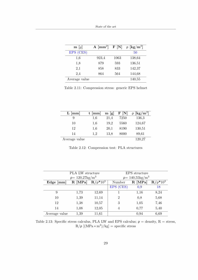
State of the art
m [g] A [mm2] F [N] ρ [kgm3]
EPS (CES) 50
16 9234 1063 13864
18 879 593 13651
21 858 833 14237
24 864 564 14468
Average value 14055
Table 211 Compression stress generic EPS helmet
L [mm] t [mm] m [g] F [N] ρ [kgm3]
9 16 214 7250 1363
10 16 192 5560 12467
12 16 201 8190 13051
14 12 138 8000 8961
Average value 12027
Table 212 Compression test PLA structures
PLA LW structure EPS structureρ= 12027kgm3 ρ= 14055kgm3
Edge [mm] R [MPa] Rρ103 Number R [MPa] Rρ103
EPS (CES) 09 18
9 173 1269 1 116 824
10 139 1114 2 08 568
12 138 1057 3 105 746
14 108 1205 4 077 540
Average value 139 1161 094 669
Table 213 Specific stress calculus PLA LW and EPS calculus ρ = density R = stressRρ [(MPa lowastm3)kg] = specific stress
29
State of the art
Figure 212 Compression test Stress-Strain diagrams - EPS
Figure 213 Compression test Stress-Strain diagrams - PLA LW
30
Chapter 3
Methodology
31 3D scan
311 3D Sense 2 scanner and Meshmixer - Reverse reconstruction
Standardized measures were not taken into account for making the helmet but the sizewas obtained through a 3D scan of my head
The scanner used is 3D Sense 2 by 3D Systems which has a minimum scanningvolume of 20 x 20 x 20 cm and a maximum scanning volume of 300 x 300 x 300 cmTo scan my person I was helped to get a full view at 360 at an appropriate distanceReal-time visualization of the captured images was shown through 3D Sense softwareThe idea of scanning the head with the scanner refers to the methodology used by Wanget al [30] They used a reverse reconstruction functional for me to realize the helmetsurface made to measure my head and like them a silicone pool cap was used to makescanning as smooth as possible The authors claim the head scan rdquocan also be used toobtain information about the objectrsquos surface which is then reconstructed utilizing thecomputerrsquos three-dimensional model via reverse modelling softwarerdquo [30] that in my caseis Autodesk Meshmixer
The files it was could get from the scan were stl obj and ply format they wereexported to obj to work in the next step with Autodesk Meshmixer that allowed tomodify and homogenize the 3D image obtained from the scan
In Meshmixer through the selection and delete commands the superfluous parts weredeleted that had been acquired and with the inspector and the DrawDraw2 commandsthe vertices were moved locally along a pre-defined direction and with Smooth the surfacemore homogeneous was made The sequence of steps is shown in the Figure 31
312 3D scan analysis and extraction of features
In Chapter 2 the directives imposed by the BS EN 960 Standard were examined concern-ing the definition of the helmet and the measures to be respected in the field of visionand the part of the helmet was to carry out impact tests
In Figure 32 the features defined complying with the Standardrsquos rules are repre-sented To define these features the software NX was used The angle in the subfigure
31
Methodology
[a] [b] [c] [d]
Figure 31 Sequence of 3D head scan 3D scanner acquisition [a] scan after reparationwith Meshmixer [b] solid scan vision frontal and lateral [c] [d]
[b] is bigger than 105 (as defined by the Standard) while the degree in the subfigure [c]is 25 By defining the construction lines to be respected of the helmetit was necessary todraw the design of the surface not using the software NX but changing with Rhinocerosto create a SubD or SubDivision surface
32 Helmet design
321 Rhinoceros - Helmet surface
After realizing a rsquocleanrsquo Wang et al [30] subdivide with lines and then sectors the headto create the surface of the helmet They used the technique of NURBS a Non UniformRational Basis-Splines which mathematically models a 3D geometry while thanks tothe Rhinoceros 3D organic shapes was draw SubD surfaces These geometries allow tosplit the mesh into small polygons and consist of lines with which easily the shape ofthe object can be modified with a surface already created changing the position of aline automatically the remaining part of the geometry adapts to the changes With thistechnique the rsquosurface basersquo of the helmet was realized with the size of my head Therepresentation of the realized SubD is in Figure 33
322 Grasshopper - Helmet structure
The next idea is the creation on the surface of the beetle structure with different di-mensions modelling the helmet that is not a linear surface It was decided not to buildthe structure with a software CAD because to model an already complex structure on acurved surface would mean to model a cell for a cell
To solve this obstacle a Rhinoceros plug-in was used Grasshopper GH idealized byRobert McNeel and associates creators of Rhinoceros Using GH does not mean drawinggeometries by connecting points and drawing tools because it is based on algorithmicmodelling used in architecture and engineering for 3D modelling
The modelling takes place through a node diagram that the software will convert intoa code-algorithm in GH it is possible to define the variables and parameters and inRhinoceros in real-time it is possible to view the object GH allows for varying the
32
Methodology
[a] [b]
[c]
Figure 32 Featurersquos extraction in [a] is represented the impact line in [b] and [c] twoprospective about the definition of the field of vision
[a] [b] [c]
Figure 33 SubD representation lateral view [a] top view [b] front view [c]
geometry to your liking by varying a simple parameter of the diagram as everything willbe remodelled according to the change made
In the following Figure 34 it is shown an example of a structure that was used fordistinct subgroups of helmet areas The idea was to insert smaller cells in the frontal andlateral zone and larger ones in the upper area In the first image [a] is shown the part of
33
Methodology
the helpful diagram to create the beetle structure to establish the size of the cells andthe extrusion the second image [b] contains the part of the diagram with which I appliedthe structure previously created to the SubD
The structure used to place and adapt the beetle structure to the surface is theSrfMorph while the yellow rsquowindowrsquo that contains numbers serves to select the parts ofthe surface where to apply the geometry created In accord with the GH diagram in
[a]
[b]
Figure 34 Grasshopper diagrams
Figure 34 [a] it is possible to see the steps executed to realize the structure Initially inthe xy-plane a hexagonal grid was drawn through the Hexgrid command in which youcan input the length of the hexagon edge and the number of grid elements (selected bytrial) Then the circumferences was drawn in proportion to the hexagon dimensions asspecified in the Chapter 2 and shown in Figure 35 [a] In figure [b] the rsquocutrsquo made atthe circumferences is visible this subdivision was necessary for printing purposes In thelast photo [c] the structure highlighted in green in [b] was extruded setting a distance
34
Methodology
of 20 mm
[a] [b] [c]
Figure 35 Construction sequence of the geometry of the helmet
In the diagram in Figure 34 [b] there is the application of the structure created bi-dimensionally to the SubD surface of the helmet visible by unlocking the SubD commandof the diagram and in Figure 36 [a] Upper this the referential geometry of the group ofsurfaces was superimposed where it was to be applied the newly created structure (visiblein darker red) the SubD indices are in the yellow box of the diagram
Through the SrfMorph command the location of the structure was granted In Figure36 [b] at the darkest red of the figure [a] with the above command it was possible toplace the structure
[a] [b]
Figure 36 Application of the geometry created to the helmet surface
Overall the diagrams with specific structures are five one for the front two equal forthe side parts one for the top shown in the previous Figure 36 and one for the back
The hexagons in the structure have a dimension varying between 8 mm and 14 mmof side the largest is found at the top later at the back in the sides and the smallest atthe front In Figure 36 [b] the presence of not only hexagonal structures is visible Thegeometry used does not allow the homogeneous arrangement on the entire surface andrequires different structures Automatically the choice of GH to optimize the structurewas to insert quadrilateral
As described above the helmet has different dimensions of the structure divided asvisible in Figure 36 in a quadrilateral This causes a discontinuity between zones withdifferent sizes due to the geometry of the construction
To eliminate this problem and realize the design homogeneous grids were inserted
35
Methodology
in the affected areas as shown in Figure 37 This insertion however proved to beinteresting and strategic researching in this regard studies were realized to demonstratethe insertion of a rectangular grid inside the hexagon grid was helpful for the transmissionof stress in the structure As cited by Sun et al [40] rdquothe mechanical properties of thesesandwich structures are often limited by local failures such as face-core debonding or corecollapserdquo Carrying out compression tests have effectively demonstrated that the insertionof the grid allows rdquoprovided increased stiffness specific stiffness energy absorption andcritical loadrdquo [41] As shown in the graphic [c] of the Figure 37 the honeycomb structuregives a force of 7 kN while with a grid the value is 11 kN and with the combinationexceeds 22 kN In addition in the left front a plaque to customize the helmet wasprepared Figure 37 [a]
[a] [b]
[c]
Figure 37 Grid in the helmet [a] hybrid structure with hexagons and grid [b] [40]compression test results of the hybrid structure [c] [41]
33 3D Print
After having achieved the CAD (Computer Aided Design) of the helmet in order tobe printed it must be converted and saved in format STL (Standard TriangulationLanguage) - Binary compatible with the printing machine and useful for transformingsolid object surfaces into triangles The steps to be taken are the following
bull CAD file realization
bull CAD export in format STL to Simplify 3D the software that shows slider layersand then- rotate and position the object according to geometry and the positioning of any
36
Methodology
supports- setting printing parameters- item manual andor automatic positioning of supports- slider display layers
bull import file gcode to printer
331 Printer and parameters
The program used to visualize how the helmet slices layers before sending it to the printerand to set the parameters is as anticipated Simplify 3D
To make the printing not being a flat geometry it is necessary to place the supportsThe idea was to use water-based supports that the helmet would automatically dissolveonce placed in the water After testing different types of water-soluble PVA the choicefell on eSun 3D Printing Filament PVA (water-soluble support) Before choosing theoptimal position for printing several tests were carried out and to decrease the numberof the supports significantly and allows an optimal printing of the outer part an emptyrsquospherersquo that self-sustains below the helmet was placed as shown in Figure 38
In the image [a] you can see the first print position tried with which an external partof the helmet very damaged was obtained because of the contact supports-helmet In [b]the empty rsquospherersquo is shown to optimize the number of supports and in the last photo [c]there is the full version at the end of print
[a] [b] [c]
Figure 38 Printing supports
The printer that has been used for printing is the Raise 3D Pro2 with double extrudersand nozzles of variable size from 02 mm to 1 mm after some test prints with the PLALW and the structure in created the size that allowed me to have a good compromisebetween printing time and accuracy was 06 mm Using 04 mm the printing time wasexcessive even if having the smaller nozzle diameter means having more precision withthe 08 mm nozzle the quality of the structure was not excellent as seen in Figure 38[a]
Another factor that had to be taken into account is the characteristic of the PLA-LWto expand As the printing temperature and the printer used vary the expansion andcharacteristics of the material change The use of the 06 mm nozzle associated with
37
Methodology
Parameter Left extruder Right extruder
01cm Material 01cm PVA 01cm PLA LW
Extruder toolbox index Tool 0 Tool 1
Nozzle diameter 06 mm 06 mm
Extrusion multiplier 1 05
Extrusion width Auto (072 mm) 05 mm
Layer x
Infill Rectilinear - 50
Supports (Automatic and not) Infill 50
Temperature 210 250
General parameters
Primary layer height 03 mm Top solid layer 4
Bottom solid layer 2 Outline 2
Heated bad 60 Speed 40 mms
Table 31 Printing parameters
Raise 3D allowed me to get good results The choice of this printer was not random ithas in fact the characteristic of making extremely precise prints The Raise has accuracyin placing the object on the printing bed of 078 microns on the xy axis and a resolutionfor layers of 001 mm
The final version of the helmet is visible in Figure 39 and it is possible to compare itwith the preview version in Rhinoceros in Figure 310
38
Methodology
[a] [b]
[c]
Figure 39 Views of the helmet
[a] [b]
Figure 310 Views of the helmet (GH version)
39
Chapter 4
Experimental evaluation
41 Experimental tests
411 Drop-weight impact test machine
In order to calculate the contact force peak and the difference of energy absorbed duringthe impact between the reference helmet and helmet with the beetle structure in PLA-LW dynamic impact tests were carried out using the Fractovis Plus an impact testmachine
In this way it is possible to monitor the evolution of the above variables from theinitial to the final instant of the impact The machine can withstand a load with a rangevariable from 2 to 70 kg with a maximum speed of 46 ms and a maximum height of1 m The values chosen for the test are the following 5 kg weight maximum speed andmaximum height The Anvil that was used is a disc diameter of 60 mm
As shown in Figure 41 and explained by Crupi et al [37] the machine consists ofa sensor capable of recording the speed before impact the impactor that can have avariable mass (a weight of 5 kg in my test) a system to guarantee that there are nomultiple impacts after the first and that work as a shock absorber and clamping systemwhere the object to be tested is placed
The tests that have been carried out are in total four two related to the helmetoptimized with PLA-LW and two with two generic helmets of different brand in EPS
42 PLA LW helmet
To perform the dynamic test on the helmet of PLA considering the difficulty of printingit was helpful to use a test helmet with imperfections to understand where the impactwas concentrated in a single part or distributed The images of Figure 42 show a helmetwith not well defined edges and inaccurate print but exactly localizes the impact zoneThanks to this test it was possible to take into account only one helmet area shown inFigure 43 to have the exact curve of the structure bio-inspired with PLA-LW
40
Experimental evaluation
Figure 41 Drop-weight impact test machine [37]
[a] [b]
Figure 42 Test 1 PLA-LW helmet
43 EPS helmet
To carry out dynamic tests and extract the technical characteristics of the helmettwohelmets were bought in a sports store both EPS and being on the market both certifiedThe brands of the two helmets are DTB and VAN|RYSEL and the average weight ofthe two is 223 g Two different helmets have been chosen to have a more certain andclear classification of the characteristics They are shown in Figure 44 and Figure 45
41
Experimental evaluation
[a] [b]
Figure 43 Test 2 PLA-LW helmet
[a] [b] [c]
Figure 44 Test 3 EPS helmet
[a] [b] [c]
Figure 45 Test 4 EPS helmet
44 Results
441 First results - PLA-LW and EPS helmet
Figure 46 shows two types of trends related to the two different models of the helmetThe force evaluated for PLA-LW has higher force peaks but is more concentrated and
42
Experimental evaluation
propagates less than EPS The graph shows the peaks of each curve highlighted with a redcircle In tests 1 and 2 for the PLA-LW as mentioned earlier the values are higher about7301 N for the complete helmet and 3996 N for the portion of helmet This difference isdue to the inaccuracy of the first full helmet during the printing phase In Figure 42 itis visible the low homogeneity and precision Therefore the first test with full helmet wasused only to define the area of interest of the impact which turns out to be localized Forthe other two EPS curves the values are only slightly lower compared to the PLA-LWequal to 3620 N and 3295 N but the trend is much more distributed
Figure 46 Dynamic machine test - Force
With the data obtained from the impact machine it was possible calculate not exclu-sively the value of force but itrsquos also possible to view the energy curves A resume aboutthe values and energy of the force is in the following Table 41
Test Peak force [N] Peak energy [J]
Test 1 - PLA LW (inaccurate) 730130
Test 2 - PLA LW (portion of helmet) 399643
Test 3 - EPS (DTB helmet) 362007 509
Test 4 - EPS (VAN|RYSEL helmet) 329546 4198
Test 5 - PLA with TPU 45421 5022
Table 41 Energy absorbed in dynamic test
43
Experimental evaluation
442 PLA-LW helmet with TPU cover
As it is possible to see in Figure 47 and as highlighted the first tests concerning thebio-inspired structure and the PLA-LW are far from my expectations considering thelittle distribution of force in comparison with the EPS foam and consequently a smallamount of energy absorbed
Figure 47 Dynamic machine test - Energy
To improve this impact damping factor the idea was to create a cover for the helmetin flexible TPU trying to absorb impact energy The TPU used is a flexible material ofthe brand Ninjaflex used in sports by the application in helmets and shoes to cushionbumps during the game Generally in the helmets (baseball helmet for example) theTPU is inserted internally in contact with the head In my case the TPU structurein addition to creating a shock-absorbing and durable cover creates a custom cover thehelmet and for the person This cover was also made with the Raise 3D printer
As shown in the Figure 48 [a] the infill of the part in contact with the helmet hasa percentage of 100 the filling of the other part of the structure is not complete butonly 15 and the internal structure is hexagonal to recall that of the helmet The desireto insert a structure with a rsquoraisedrsquo geometry is for visual and aesthetic reasons as youhave the feeling of greater protection and not filled is inspired by the machine CitroenCaptus whose bumpers (Airbump) are full of air The failure to realize empty structuresis due to the need to place any internal supports not removable
The idea was to create a cover that allow you to see of the internal structure of thehelmet and that protect specific areas the front the two sides the top and the posteriorWhat which was thought for this reason was to create the shape of a flower with four
44
Experimental evaluation
petals Figure 48 [b]In this way to perform dynamic impact tests as shown in Figure 49 [a] the cover was
positioned at the top of the helmet and the impact was performed in the centre of thersquoflowerrsquo which corresponds to the higher upper part where the structure has larger cellsize The impact parameters are the same as those used in previous impacts 5 kg weightmaximum speed and maximum height The Anvil that was used is a disc diameter of60 mm In photo [b] it is evident the difference between the structure that received theimpact with protection (left) and without protection (right) Without protection duringthe impact there was a perforation of the structure with a concentration of force at a locallevel as you can see in the Figure 46 in the case of TPU the impactor did not perforateand crossed the structure thanks to the cover of TPU that cushioned the shock At themoment of impact the impactor bounced
[a] [b]
Figure 48 TPU cover
[a] [b]
Figure 49 PLA-LW with TPU - dynamic impact [a] and differences between thehelmet with TPU and without TPU cover [b]
45
Experimental evaluation
The Figure 410 includes the diagrams relative to the dynamic impacts In [a] thereare already analyzed EPS results in [b] a comparison between the test on the portionof helmet in PLA LW with and without the TPU cover in [c] the overall comparison ofcurves shows a much more similar EPS trend if the TPU is placed above the structure inPLA LW to soften the blow and absorb the same energy [d]
46
[a]
[c]
[d]
Figure 410 Comparison between PLA-LW with TPU and EPS
Chapter 5
FEM Validation
51 Impactor - Anvils definition
Before to start to work in Abaqus it was necessary to search in the literature the materialwith which the anvil was been realized Milne et al [23] established the densityrsquos valuethe Youngrsquos Module and Poissonrsquos ratio for the Flat and Kerbstone Anvil
- Density ρ = 7800 kgm3
- Youngrsquos Module E = 200000 MPa
- Poissonrsquos ratio ν = 03
Inserting the data in the CES EduPack program specifying the mechanical andphysical properties the material corresponding to these characteristics is Stainless steelaustenitic (ASTM F1586) medium-hard
Initially the proposal was to create a conservative system to evaluate the absorptionenergies values and apply this value to a vibration system but the helmet needs dampingto be realized it was impossible to use a system without losses in this modality Thisis why a numerical calculation was carried out by performing two types of simulationsexplicit dynamic step and static step
The idea to realize the theoretical impact is to regard the movement of the anviland not the helmetrsquos movement which is fixed The velocity is the same cited in thenormative EN 1078 542 ms for the Flat anvil and 457 ms for the Kerbstone anvil
In performing the simulations It was given more relevance and perform tests withthe Kerbstone Anvil This choice was done because the geometry with which it is beenrealized (following as defined in the legislation) allows the helmet to be more subjectedto stress this involves the definition of higher stress limits compared to the Flat Anvil
The mesh size that has been used is the same in the case of the simulation of thehelmet optimized in PLA-LW and the full helmet in EPS of 7 mm The impactor isconsidered as a Discrete rigid body with its specific Reference Point (RP) like shownin Figure 51 for this reason it is not a solid but it is composted only by shells Inthe same image [b] there is the FEM representation of the model and in Table 51 thecharacteristic of FEM with quadrilateral (R3D4) and triangular elements (R3D3)
48
FEM Validation
Object Elementnumber
Elements Shape Geometricorder
Global size[mm]
Kerbstone 230 Quadrilateral - R3D4 Linear 7
Kerbstone 8 Triangular - R3D3 Linear 7
Table 51 Mesh element - Kerbstone Anvil
[a] [b]
Figure 51 Kerbstone anvil in the simulation like discrete rigid body [a] and FEMelements [b]
511 PLA LW - Plastic characteristics
The PLA-LW as explained in the Chapter 2 is new material on the market and producedby the only Colorfabb company for this reason few tests have been carried out to defineits technical characteristics and through tensile tests of the 3D printed specimens it waspossible to define an elastic limit as reported in the Table 210
In the context of simulations to reproduce the impact and deformation of the helmetis also necessary to consider the plastic characteristics of the material Not possessingany reference value in this regard tests were performed through a Static Step initiallyand then an Explicit Dynamic Step in Abaqus
The structure chosen to consider as a reference it is one of the structures previouslysubjected to the compression test having the side L=14 mm As for the reproduction ofthe compression disks initially they were reproduced according to the geometry of theHoytom HM-D Testing Machine considering the bodies mentioned above as discrete 3Drigid discrete The measure was the diameter of 200 mm and the height of 20 mm
After an initial analysis it was observed that the computational time of the simulationprogram was very high so it was decided to change the geometry to have a rsquodisk-surfacesrsquo(equally 3D rigid-discrete) which allowed me to have a smaller number of nodes for themesh and consequently a better computational time The representation of the opti-mized structure in PLA-LW and the disks used for simulated compression is in Figure 52
49
FEM Validation
[a] [b]
Figure 52 Representation of the samples used for the simulation of the compressiontest In Figure [a] the disks of the Hoytom HM-D Testing Machine in figure [b] the
representation of the same as simple surfaces
As shown in Figure 52 the disks are considered 3D discrete hard bodies so it waschosen for both a point the reference point RP where to apply the characteristics relatedto the two bodies As for the compression test it was established
bull the movement of a disk and fixed the second through a boundary condition impos-ing an Encastre therefore unable to move and rotate in xyz directions
bull for the opposite disk the boundary condition relative to the 15 mm displacementwas applied which is the parameter that it was observed to determine the end ofthe compression with the machine This shift is shown by the orange arrow in figure[b]
bull between the upper surface and the disk e the disk with the lower surface it wasinitialized a general contact with normal behaviour through rsquohardrsquo contact andtangential behaviour with a coefficient of friction of 02 with directionality imposedon rsquoisotropicrsquo
The next step was to define the mesh of the components whose parameters are shown inTable 52 while the representation of the FEM is in Figure 53 with the representationof the simulation and real compression test
Object Elementsnumber
Typology Geometricorder
Globalsize [mm]
Disk (14mm) 80910 hexaedral - C3D8R Linear 07
Impact disks 206 quadrilateral - R3D4 Linear 20
Impact disks 6 triangular - R3D3 Linear 20
Table 52 Mesh element - Compression test simulation
As previously announced a static simulation was initially performed with a StaticStep with Step Time equal to 900 (obtained going to consider the speed of 1 mmmin of
50
FEM Validation
[a]
[b] [c]
Figure 53 FEM representation [a] and compression test simulation [b] and realcompression [c]
the compression test and the displacement of 15 mm) However the complex geometryof the structure and the high time set by Step Time did not allow a correct definitionof the parameters of the plastic characteristics of the material the simulation was notable to continue once reached a Step Time of approximately 220 That is why it waschanged by choosing an Explicit Dynamic step
Leaving all the parameters of the boundary conditions unchanged the Step Time wasmodified imposing it to 001 The ability of the explicit dynamic to work with non-linearand contacting structures allowed me to achieve results The results obtained are shownin Figure 54 with the blue curve and were obtained through the iteration of differentPlastic Strain and Yield Stress values in Abaqus while the red line is the result of thereal compression test a similar curve trend was obtained but it is not possible to obtainthe same curve taking into account problems of printing inaccuracy
512 First test - helmet
The initial idea was to perform a simulation imposing the speed of 457 ms to theimpactor tie the helmet in EPS and PLA and compare the absorbed energies Theproblem it was encountered is related to the mesh of the helmet optimized in PLA andwith minimum dimensions of the elements and distinct elements it was not able to solveit
51
FEM Validation
[a]
YieldStress
PlasticStrain
1 47 0
2 7 001
3 75 005
4 10 01
5 108 1
6 115 15
7 12 2
[b]
Figure 54 Representation of the two curves related to the simulation in Abaqus of thecompression test and the data obtained from the real test to obtain the plastic
characteristics of the material
513 Second test - plane
The first solution is the one shown in Figure 55 To realize the simulation it was realizeda section of the helmet to involve a smaller number of elements and nodes Again thesimulation for the EPS helmet was successful while the simulation with the bio-inspiredstructure was interrupted by excessive distortion of elements
The previous images show the impact is very localized in the impacted area and theidea to achieve a complete simulation is not to consider a curved portion of the helmetbut a plane In this way it was possible to solve the problem and obtain a completesimulation for the bio-inspired structure
FEM element
Below in Table 53 there is the definition of the elements used for the PLA-LW and EPSplane in the simulation to simulate the impact and to control the energy-absorbing whilethe anvil characteristics are described in Table 51
514 EPS impact simulations
In order to proceed with the simulation it was imposed some boundary conditions thatregard ties and forces
bull the movement of the plane is fixed through an Encastre therefore unable to moveand rotate in xyz directions
52
FEM Validation
[a]
[b]
Figure 55 Impact simulation parts of EPS and PLA helmet
Object Elementnumber
Elements Shape Geometricorder
Plane (PLA) 38896 Tetrahedral -C3D10M
Quadratic
Plane (EPS) 2100 Hexahedral - C3D8R Linear
Table 53 Mesh element - plane impact
bull to create the impact it was set a speed of 457 ms at the reference point RP of therigid body which is the impactor Kerbstone Anvil shown in Figure 56
bull between the upper surface of the plane and the impactor it was initialized a Sur-face to Surface contact with normal behaviour through rsquohardrsquo contact and tangen-tial behaviour with a coefficient of friction of 02 with directionality imposed onrsquoisotropicrsquo
bull the rotation in x y z relative to the RP of the rigid discrete impactor body is locked
53
FEM Validation
In addition it was characterized the plane in the part of the materials with the char-acteristic values of the EPS mentioned in Chapter 221 The Von Mises Stress valueapparently low is relative to the Yield Stress of the EPS material equal to 09 MPa
Figure 56 EPS Boundary conditions and Load
515 PLA LW impact simulations
As also required in the case of the EPS plane in order to proceed with the simulationsome boundary conditions were imposed that regard ties and forces
bull the movement of the plane is fixed through an Encastre therefore unable to moveand rotate in xyz directions
bull to create the impact a speed of 457 ms was set at the reference point RP of therigid body which is the impactor Kerbstone Anvil shown in Figure 58
bull between the upper surface of the plane and the impactor it was initialized a Sur-face to Surface contact with normal behaviour through rsquohardrsquo contact and tangen-tial behaviour with a coefficient of friction of 02 with directionality imposed onrsquoisotropicrsquo
bull the rotation in x y z relative to the RP of the rigid discrete impactor body is locked
In addition the plane was characterized in the part of the materials with the characteristicvalues of the PLA mentioned in the Chapter 223 and 511
Figure 58 Boundary conditions and Load
54
FEM Validation
[a]
[b]
Figure 57 EPS impact simulation
52 Results
In Figures 59 and 57 it is shown how the structure in PLA LW has a more concentratedstress distribution of the structure unlike EPS The maximum value for the Von Misesstress is 09 MPa in EPS structure and 3634 MPa in PLA LW structure Once thesimulations were obtained the next step was to go and compare the energies absorbed bythe two structures The energy calculated by Abaqus that has been taken into account isPlastic Dissipation To make a comparison the data of the two energies were representedin a single graph
What emerges from the graph is that about the impact made with the KerbstoneAnvil the energy absorption is more excellent although only slightly for the PLA LWthan for the EPS From the graph in Figure 510 a value of 41 J is shown for the EPSand 51 J for the PLA LW
55
[a]
[b]
Figure 59 PLA impact simulation
[a]
Figure 510 EPS and PLA LW energy comparison - Abaqus simulation
Chapter 6
Head Injury Data
For the statistical analysis the injuries related to the accident data were categorised intothe following types and levels based on the details of the medical report [11] about theEN 1078
bull Head Injury Criterion (HIC)
bull Peak Linear Acceleration (PLAc)
bull Gadd Severity Injury (GSI)
bull Diffuse axonal injuries (DAI)
61 Abaqus simulation
Until now the purpose of the simulations has been to determine which between the twomaterials and the two structures of EPS and PLA LW could absorb more energy duringthe impact but no simulations have been carried out in compliance with BS EN 1078on the helmet impact tests To calculate the injuries listed in the previous paragraphhowever we need the acceleration values in the three directions related to the subjectrsquoshead
To realize it the scan of my head already rsquocleanrsquo was considered of which it has beencalculated the inertia thanks to the automatic SolidWorks calculation and evaluated theweight with the Table 24 the structure of the helmet was placed for the EPS and thePLA LW over the head as shown in Figure 61 Also this time being able to mesh theentire helmet in PLA LW was impossible due to the excessive distortion of some elementsduring the simulation so it has been tried to make a section of the structures of thehelmet and results were obtained
57
Head Injury Data
[a] [b]
Figure 61 My scan head - CAD [a] head imported in Abaqus[b]
Initially the simulation had these characteristics as shown in the following Figure62 considering the helmet was not sectioned As explained earlier it was not possibleto get to simulation in the case of the optimized structure in PLA LW for this reasononly a part of the helmet was considered in both cases shown in Figure 63
[a]
Figure 62 Simulation based on BS EN 1078
58
Head Injury Data
[a] [b]
Figure 63 Simulation based on BS EN 1078 with head
In order to proceed with the simulation some boundary conditions that regard tiesand forces have have imposed
bull two reference points RP were created the first in the inertia centre of the headthe second relating to the Kerbstone Anvil which is a discrete rigid body
bull in the reference point RP of the head in the definition of the engineering features5 kg was inserted for the weight and an inertia I11 = 564464E+07 gmm2 I22 =460654E+07gmm2 I33 = 187302E+07gmm2
bull to simulate the impact it was set a speed of 457 ms at the reference point RP ofthe head in z-axis direction
bull a general contact with normal behaviour through rsquohardrsquo contact and tangentialbehaviour with a coefficient of friction of 02
bull between the upper surface of the helmet and the impactor it has been initializeda Surface to Surface contact with normal behaviour through rsquohardrsquo contact andtangential behaviour with a coefficient of friction of 02 with directionality imposedon rsquoisotropicrsquo
bull the movement between the Kerbstone anvil and the helmet is fixed through anEncastre therefore unable to move and rotate in xyz directions
bull the rotation in x y z relative to the RP of the rigid discrete impactor body is locked
FEM element
As reported in Table 53 the portion of the helmet in EPS has used a mesh with hexahe-dral elements of linear order For the structure (beetle) of PLA LW given the geometry
59
Head Injury Data
complexity it was necessary to use a quadratic order of tetrahedra For the mesh of thehead instead in both simulations have been used quadrilateral elements of linear orderas reported in the Tables 61 and 62
Object Elementnumber
Elements Shape Geometricorder
Head 3755 Quadrilateral - R3D4 Linear
Head 34542 Quadrilateral - R3D3 Linear
Helmet (PLA) 272302 Tetrahedral -C3D10M
Quadratic
Table 61 Mesh element - Head simulation with PLA LW (beetle) helmet
Object Elementnumber
Elements Shape Geometricorder
Head 3755 Quadrilateral - R3D4 Linear
Head 34542 Quadrilateral - R3D3 Linear
Helmet (EPS) 72280 Hexahedral - C3D8R Linear
Table 62 Mesh element - Head simulation with EPS helmet
62 Results
Figure 64 represents the simulation in line with BS EN 1078 concerning the helmet inEPS [a] and the helmet with bio-inspired structure in PLA LW For both simulationsVan Misesrsquo stress has Yield Stress values in the case of EPS which is 09 MPa and theplastic behaviour combination of PLA LW [b]
In the case of head and Kerbstone Anvil stress was not assessed as they were previ-ously defined as discrete rigid bodies
63 Head Injury Criterion
The HIC quantifies head impact severity by incorporating time of acceleration exposureand acceleration magnitude it is calculated in post-processing phase with the followingEquation 61
HIC15 =
[1
(t1 minus t2)
int t2
t1
a(t)dt
]25(t2 minus t1) (61)
60
Head Injury Data
[a]
[b]
Figure 64 Results simulation based on BS EN 1078 with sectioned head
For this analysis a(t) is the acceleration calculated in the centre of mass of the head(corresponding to the reference point RP) expressed in g and the time interval (t2 minus t1)was chosen to maximize HIC over a maximum duration of 15 ms
Matlab and the trapz function were used to calculate the HIC to integrate accelerationover time t2 and t1 were considered initial and final times of the simulation t1 = 0 sand t2 = 10 s time less than 15 s
HIC value of 198 was obtained for EPS and 87 for PLA LW Considering the Hayeset al [16] document about the HIC values and the graph in Figure 65 developed bythe author it is possible to find the percentages related to the different injury AIS1 -AIS6 which correspond respectively to lower and higher severity while in Figure 66 therelative fatality to every value of AIS is shown The values obtained for the HIC andother criteria are shown in Table 63 The HIC value for EPS is 198 for PLA LW it is
61
Head Injury Data
Figure 65 Head injury risk curves based on HIC values [16]
Figure 66 The abbreviated injury score versus fatality rate [16]
87 Analyzing the data and comparing them with the curves of the Figure 65 I obtain
bull a percentage between 20 - 30 of AIS 1 for EPS 10 - 20 for PLA LW
bull a percentage between 10 - 20 of AIS 2 for EPS and 0 - 10 for PLA LW
bull for AIS 3 AIS 4 AIS 5 AIS 6 the percentages for both structures is between 0 -10
Comparing these percentages with the fatality rate of Figure 66 it is clear there is a riskof Moderate and Minor fatality in the case of EPS and PLA LW as all values are between0 and 30
62
Head Injury Data
HIC PLA [g] GSI E [J]
EPS 198 97 361 37723
PLA LW 87 75 169 44102
Table 63 Head Injury Data - values
64 Peak Linear Acceleration
The resultant linear acceleration versus time curve was calculated according to Equation62
γ(t) =radicγ2x(t) + γ2y(t) + γ2z (t) (62)
where
bull γ(t) is the resultant linear acceleration (g)
bull γx(t) is the linear acceleration in x axes (g)
bull γy(t) is the linear acceleration in y axes (g)
bull γz(t)is the linear acceleration in z axes (g)
The value of the impact should never exceed 250g [9] Cripton at all [9] in their studyexamined a helmet with expanded polystyrene (EPS) Figure 68 shows maximum HIC forhelmeted and unhelmeted drops from all heights For each drop height helmets reducedHIC relative to unhelmeted drops IARV value is 180g The acceleration in the two casesis shown in Figure 67 and the maximum values are 97g for EPS and 75g for PLA LWas reported in Table 63 The two values considering a maximum value calculated byCripton [9] of 180g are amply optimal and comply with the standard of 250g
65 Gadd Severity Index
Gadd proposed the Severity Index Criteria shown in Equation 63 Following this crite-rion the GSI values that are over 1000 produce serious internal head injury [33]
GSI =
int t1
0a(t)25dt (63)
Where
bull a is the linear acceleration (g)
bull t is the duration of the impact (s)
I calculated the GSI with the function trapz between 0 and t and the resulting valuesare 361 for the EPS and 169 for the PLA LW which comply with the limit
63
Head Injury Data
Figure 67 Peak accelerations for both helmets
Figure 68 Peak accelerations for both helmeted and unhelmeted drops Numbers overbars indicate peak acceleration For 2 m drop height results stated are the mean value
calculated from three drops [9]
64
Head Injury Data
66 Diffuse Axonal Injury
DAI cases covered all incidences in which neurological injuries occurred as well as con-cussion unconsciousness and coma
In order to assess the risk of head trauma in terms of diffuse axonal injury (DAI)Milne et al [23] defined a model based head injury criteria as follows obtaining theresults in Figure 69
bull 50 risk of moderate neurological injury (DAI1+) Brain Von Mises shearing stressof 28 kPa
bull 50 risk of severe neurological injury (DAI2+) Brain Von Mises shearing stressof 53 kPa
[a]
[b]
Figure 69 Peak intra-cerebral shearing stress computed with the helmet model coupledto the human head model for all impact points (a) Flat anvil (b) Kerbstone anvil [23]
65
Head Injury Data
67 Energy absorbed
In Figure 52 during the impact test between the kerbstone Anvil and the plan with thebio-inspired structure in PLA LW and EPS it was found that the PLA LW althoughwith a small difference of 10 J absorbed more energy in comparison with the EPS Whenthe test is carried out in compliance with BS EN 1078 and the head with a speed of 457ms (corresponding to the kerbstone Anvil) as shown in Figure 610 also in this casethe PLA LW with the optimized helmet structure manages to absorb more energy (evenif the difference is very low) compared to the EPS The maximum energy value in PLALW is 44102 J of EPS is 37723 J
Figure 610 Energy absorption - BS EN 1078
66
Chapter 7
Conclusion
71 Conclusion
In this thesis work a bicycle helmet with a bio-inspired structure in PLA LW and 3Dprinted was created The initial approach was to introduce an innovative aspect tostandard EPS helmets not using foam but a polymer with new geometries able toabsorb much energy during the impact For this reason the beetle structure has beenpreferred relying solely on the hypothesis encountered in the literature of its quality inabsorbing energy
Combining the new material of the PLA LW and beetle structure has made possiblethe development of new material satisfactory characteristics have been obtained sincethe first tests The two materials were first subjected to tensile tests to determine theirspecific stress in these the PLA LW had positive results
Subsequent dynamic physical tests were carried out on 3D printed helmet models andon reference helmets in EPS to calculate the absorption energy in both cases at the timeof impact These resulted in energy absorption of the beetle structure in PLA LW withthe application of a TPU cover almost equal to that of EPS about 50J To validate withfinite element analysis the two models an explicit dynamic step was used in AbaqusSimulations showed that the PLA LW structure absorbs a higher amount of energy thanthe EPS the higher is 50 J and the EPS 40J
Finally positive results have also been obtained in calculating the head injury datasimulating according to BS EN 1078 with the use of impactor helmet and head Theacceleration values for both the structures were inferior to 220g precisely for the PLALW was 75g and for the EPS 97g The same applies to the calculation of HIC and GSI(maximum acceptable value of 1000) where the values are 87 and 169 in the case of PLALW and 361 and 198 in EPS For all tests therefore greater efficiency of the structure inPLA LW has been obtained Positive results also in the simulation of the energy absorbedduring the impact as the value referring to the EPS was 35J and that of the PLA LWwas 45J
67
Conclusion
72 Future work lines
The positive results obtained can be considered as a starting point for further tests andsimulations to ensure the safety of the helmet and compliance with the regulations butbefore getting improvements and continue testing changes are required
bull the beetle structure of the helmet made with GH adapts to the SubD withoutallowing to have a homogeneous distribution it would be appropriate to have moreregular hexagonal geometries
bull the mesh of the helmet is too complex and does not allow to perform the simulationprobably to use a more regular structure would have a mesh accordingly moreregular and the simulation would be successful
bull the uneven helmet structure has so many defects that the print is imperfect andthis can change the results of the impact tests the structure should be improved
bull the printing time varies from 4 to 5 days it should be improved
bull the TPU helmet cover is too big for the RAISE printing plan it is necessary togenerate a new geometry
bull the TPU cover it must be fixed on the helmet
bull in the calculation of the DAI it is necessary to have the definition of the brain andthe head should not be considered as a rigid body
bull in the injury calculation the helmet without protection was considered with theTPU cover the result will be better
bull air flow analysis
The comments mentioned are only considerations and problems that I gained duringmy thesis and which should be improved but I am sure that these changes and improve-ments from design to printing and simulations can make the helmet a good product
68
Bibliography
[1] K Adanty J M Clark A Post Thomas Blaine H and M D Gilchrist Comparingtwo proposed protocols to test the oblique response of cycling helmets to fall impactsInternational Journal of Crashworthiness 6648 ndash 663 2020
[2] MF Ashby YJM Brechetb D Cebona and L Salvoc Selection strategies formaterials and processes Materials and Design 2004
[3] M Aysha El casco de bicicleta voronoi impreso en 3d mas seguro y ligero https
www3dnativescomen3d-printed-bicycle-helmet-voronoi-190820204
[4] H Bikas P Stavropoulos and G Chryssolouris Additive manufacturing methodsand modelling approaches a critical review The International Journal of AdvancedManufacturing Technology 83389ndash405 2016
[5] British Standards BSI Helmets for pedal cyclists and for users of skateboards androller skates - BS EN 1078 2012
[6] British Standards BSI Headforms for use in the testing of protective helmets BSEN 960 2020
[7] ColorFabb Colorfabb lw-pla 2019 httpscolorfabbcommedia
datasheetstdscolorfabbTDS_E_ColorFabb_LW-PLApdf
[8] V G Coronado T Haileyesus J M Bell T A Cheng JHaarbauer-Krupa M RLionbarger J Flores-Herrera L C McGuire and J Gilchrist Trends in sports andrecreation-related traumatic brain injuries treated in us emergency departments thenational electronic injury surveillance system-all injury program (neiss-aip) 2001-2012 J Head Trauma Rehabil 30185ndash197 2015
[9] P A Cripton D M Dressler D Stuart Cameron A Christopher R and D RichardsBicycle helmets are highly effective at preventing head injury during head impactHead-form accelerations and injury criteria for helmeted and unhelmeted impactsAccident Analysis and Prevention 701ndash7 2014
[10] L Cui M A Forero R and M D Gilchrist Optimisation of energy absorbingliner for equestrian helmets UCD School of Electrical Electronic and MechanicalEngineering University College Dublin Belfield Dublin4 Ireland 2020
[11] C Deck N Bourdet F Meyer and R Willinger Protection performance of bicyclehelmets Journal of safety research pages 67ndash77 2019
[12] Committee F08 Specification for headforms F2220 ASTM International 2015
[13] Committee F08 Specification for helmets used in recreational bicycling or rollerskating F1447 ASTM International 2018
[14] Committee F08 Test methods for equipment and procedures used in evaluating theperformance F1446 ASTM International 2020
69
Bibliography
[15] P Halldin Shock absorption including measuring CENTC 158 Working Group11 2018
[16] W C Hayes M S Erickson and E D Power Forensic injury biomechanics Annualreview of biomedical engineering pages 55ndash86 2007
[17] HEXR httpshexrcom
[18] C Jinxiang Z Xiaoming O Yoji S Kazuya G Zhensheng and P LongchengThe deformation mode and strengthening mechanism of compression in the beetleelytron plate Materials and Design 131481ndash186 2017
[19] S Kroeker M Ozkul A De Marco S Bonin and GP Siegmund Density variationin the expanded polystyrene eps foam of bicycle helmets and its influence on impactperformance Journal of biomechanical engineering 2019
[20] S G Kroeker SJ Bonin A L DeMarco C A Good and G P Siegmund Agedoes not affect the material properties of expanded polystyrene liners in field-usedbicycle helmets Journal of biomechanical engineering 2016
[21] M Meier K H Tan M K Lim and L Chung Unlocking innovation in the sportindustry through additive manufacturing Business Process Management Journa2018
[22] N J Mills and A Gilchrist The effectiveness of foams in bicycle and motorcyclehelmets Accident Analysis Prevention 23153 ndash 163 1991
[23] G Milne C Deck R P Carreira Q Allinne and R Willinger Development andvalidation of a bicycle helmet assessment of head injury risk under standard impactconditions Computer methods in biomechanics and biomedical engineering 15 Suppl1309 ndash 310 2012
[24] Y Mosleh S J Vander B Depreitere and J Ivens Novel composite foam conceptfor head protection in oblique impacts Adv Eng Mater (Advanced EngineeringMaterials) 10 2017
[25] H Mustafa T Y Pang T Ellena and S H Nasir Impact attenuation of user-centred bicycle helmet design with different foam densities J Phys Conf Ser(Journal of Physics Conference Series) 1150 2019
[26] S H Ngoc and L Guoxing A review of recent research on bio-inspired structuresand materials for energy absorption applications Composites Part 181 2020
[27] J I Novak and A R Novak Is additive manufacturing improving performance insports a systematic review Sport engineering and technology 13 2020
[28] European Road Safety Observatory European road safety observatory facts and fig-ures - cyclists - 2020 December 2020 httpseceuropaeutransportroad_
safetysitesdefaultfilesfacts_figures_cyclists_final_20210323pdf
[29] New York City Departments of Health Parks Mental Hygiene Transportation Recre-ation and the New York City Police Department Bicyclist fatalities and seriousinjuries in new york city 2005
[30] W Pengwen Y Jing H Yanan H Jiaofei and F Xiaoyang Innovative designof a helmet based on reverse engineering and 3d printing Alexandria EngineeringJournal 603445ndash3453 2021
[31] S G Piland T E Gould M Jesunathadas J S Wiggins O McNair and V CShane Protective helmets in sports Materials in Sports Equipment 3 2019
70
Bibliography
[32] K Schmitt P F Niederer M H Muser and F Walz Trauma biomechanicsSpringer Berlin Heidelberg 2010
[33] David Sepelveda Lopez A Biomechanical Analysis of Bicycle Helmets using FEMPhD thesis 2019 Bachelor thesis
[34] H Stigson Bicycle Helmets 2020 Tested by Folksam PhD thesis 2020 PhDAssociate Professor Traffic Safety Research
[35] H Tao K Sudip N Anindya and X Yongzhao 3d printed sensors for biomedicalapplications A review sensor 2019
[36] M Trzaskalska and R Chwastek Damping properties and density of helmet linersmade of expanded polystyrene (eps) Archives of Metallurgy and Materials 66 2020
[37] Crupi V Epasto G and Guglielmino E Impact response of aluminum foam sand-wiches for light-weight ship structures Metals 198ndash112 2020
[38] W Wei-cai F Dong-ming and L Yuan-xin Study on impact energy absorbing per-formance of eps buffer layer of motorcycle helmet Proceedings - 2013 InternationalConference on Mechanical and Automation Engineering MAEE 2013
[39] Z Xiaoming C Jinxiang O Yoji Z Peiwei X Xiaobing and Y Xindi Influence ofhoneycomb dimensions and forming methods on the compressive properties of beetleelytron plates Journal of Sandwich Structures and Materials 2228ndash39 2020
[40] S Zhi L Dong Z Weisheng S Shanshan and G Xu Topological optimization ofbiomimetic sandwich structures with hybrid core and cfrp face sheets CompositesScience and Technology 14279ndash90 2017
[41] S Zhi S Shanshan G Xu H Xiaozhi and C Haoran On compressive propertiesof composite sandwich structures with grid reinforced honeycomb core CompositesPart B 94245ndash252 2016
71
- List of Tables
- List of Figures
- Introduction
-
- Helmet bike protection
-
- Helmet structure
-
- Additive Manufacturing
-
- AM process
- Materials and techniques - FDM
- AM in sport
-
- 3D printed helmets
-
- Phases
- HEXR
- VORONOI
-
- State of the art
-
- Standards
-
- Headform
- European Standard and American Standard
- Field of vision - BS EN 1078
- Test impact area
- Anvils and environmental conditions
-
- Materials
-
- EPS Foam
- CES Edu Pack - Material selection
- PLA with natural fiber and PLA LW
-
- Bio-inspired structures
-
- Beetle structure - Design of the model
- Specific stress - PLA LW and EPS foam
-
- Methodology
-
- 3D scan
-
- 3D Sense 2 scanner and Meshmixer - Reverse reconstruction
- 3D scan analysis and extraction of features
-
- Helmet design
-
- Rhinoceros - Helmet surface
- Grasshopper - Helmet structure
-
- 3D Print
-
- Printer and parameters
-
- Experimental evaluation
-
- Experimental tests
-
- Drop-weight impact test machine
-
- PLA LW helmet
- EPS helmet
- Results
-
- First results - PLA-LW and EPS helmet
- PLA-LW helmet with TPU cover
-
- FEM Validation
-
- Impactor - Anvils definition
-
- PLA LW - Plastic characteristics
- First test - helmet
- Second test - plane
- EPS impact simulations
- PLA LW impact simulations
-
- Results
-
- Head Injury Data
-
- Abaqus simulation
- Results
- Head Injury Criterion
- Peak Linear Acceleration
- Gadd Severity Index
- Diffuse Axonal Injury
- Energy absorbed
-
- Conclusion
-
- Conclusion
- Future work lines
-
- Bibliography
-
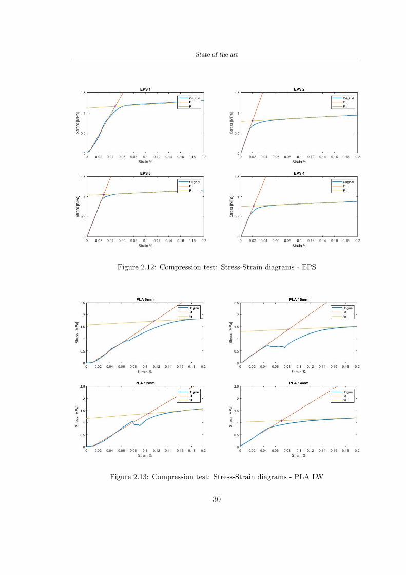
State of the art
Figure 212 Compression test Stress-Strain diagrams - EPS
Figure 213 Compression test Stress-Strain diagrams - PLA LW
30
Chapter 3
Methodology
31 3D scan
311 3D Sense 2 scanner and Meshmixer - Reverse reconstruction
Standardized measures were not taken into account for making the helmet but the sizewas obtained through a 3D scan of my head
The scanner used is 3D Sense 2 by 3D Systems which has a minimum scanningvolume of 20 x 20 x 20 cm and a maximum scanning volume of 300 x 300 x 300 cmTo scan my person I was helped to get a full view at 360 at an appropriate distanceReal-time visualization of the captured images was shown through 3D Sense softwareThe idea of scanning the head with the scanner refers to the methodology used by Wanget al [30] They used a reverse reconstruction functional for me to realize the helmetsurface made to measure my head and like them a silicone pool cap was used to makescanning as smooth as possible The authors claim the head scan rdquocan also be used toobtain information about the objectrsquos surface which is then reconstructed utilizing thecomputerrsquos three-dimensional model via reverse modelling softwarerdquo [30] that in my caseis Autodesk Meshmixer
The files it was could get from the scan were stl obj and ply format they wereexported to obj to work in the next step with Autodesk Meshmixer that allowed tomodify and homogenize the 3D image obtained from the scan
In Meshmixer through the selection and delete commands the superfluous parts weredeleted that had been acquired and with the inspector and the DrawDraw2 commandsthe vertices were moved locally along a pre-defined direction and with Smooth the surfacemore homogeneous was made The sequence of steps is shown in the Figure 31
312 3D scan analysis and extraction of features
In Chapter 2 the directives imposed by the BS EN 960 Standard were examined concern-ing the definition of the helmet and the measures to be respected in the field of visionand the part of the helmet was to carry out impact tests
In Figure 32 the features defined complying with the Standardrsquos rules are repre-sented To define these features the software NX was used The angle in the subfigure
31
Methodology
[a] [b] [c] [d]
Figure 31 Sequence of 3D head scan 3D scanner acquisition [a] scan after reparationwith Meshmixer [b] solid scan vision frontal and lateral [c] [d]
[b] is bigger than 105 (as defined by the Standard) while the degree in the subfigure [c]is 25 By defining the construction lines to be respected of the helmetit was necessary todraw the design of the surface not using the software NX but changing with Rhinocerosto create a SubD or SubDivision surface
32 Helmet design
321 Rhinoceros - Helmet surface
After realizing a rsquocleanrsquo Wang et al [30] subdivide with lines and then sectors the headto create the surface of the helmet They used the technique of NURBS a Non UniformRational Basis-Splines which mathematically models a 3D geometry while thanks tothe Rhinoceros 3D organic shapes was draw SubD surfaces These geometries allow tosplit the mesh into small polygons and consist of lines with which easily the shape ofthe object can be modified with a surface already created changing the position of aline automatically the remaining part of the geometry adapts to the changes With thistechnique the rsquosurface basersquo of the helmet was realized with the size of my head Therepresentation of the realized SubD is in Figure 33
322 Grasshopper - Helmet structure
The next idea is the creation on the surface of the beetle structure with different di-mensions modelling the helmet that is not a linear surface It was decided not to buildthe structure with a software CAD because to model an already complex structure on acurved surface would mean to model a cell for a cell
To solve this obstacle a Rhinoceros plug-in was used Grasshopper GH idealized byRobert McNeel and associates creators of Rhinoceros Using GH does not mean drawinggeometries by connecting points and drawing tools because it is based on algorithmicmodelling used in architecture and engineering for 3D modelling
The modelling takes place through a node diagram that the software will convert intoa code-algorithm in GH it is possible to define the variables and parameters and inRhinoceros in real-time it is possible to view the object GH allows for varying the
32
Methodology
[a] [b]
[c]
Figure 32 Featurersquos extraction in [a] is represented the impact line in [b] and [c] twoprospective about the definition of the field of vision
[a] [b] [c]
Figure 33 SubD representation lateral view [a] top view [b] front view [c]
geometry to your liking by varying a simple parameter of the diagram as everything willbe remodelled according to the change made
In the following Figure 34 it is shown an example of a structure that was used fordistinct subgroups of helmet areas The idea was to insert smaller cells in the frontal andlateral zone and larger ones in the upper area In the first image [a] is shown the part of
33
Methodology
the helpful diagram to create the beetle structure to establish the size of the cells andthe extrusion the second image [b] contains the part of the diagram with which I appliedthe structure previously created to the SubD
The structure used to place and adapt the beetle structure to the surface is theSrfMorph while the yellow rsquowindowrsquo that contains numbers serves to select the parts ofthe surface where to apply the geometry created In accord with the GH diagram in
[a]
[b]
Figure 34 Grasshopper diagrams
Figure 34 [a] it is possible to see the steps executed to realize the structure Initially inthe xy-plane a hexagonal grid was drawn through the Hexgrid command in which youcan input the length of the hexagon edge and the number of grid elements (selected bytrial) Then the circumferences was drawn in proportion to the hexagon dimensions asspecified in the Chapter 2 and shown in Figure 35 [a] In figure [b] the rsquocutrsquo made atthe circumferences is visible this subdivision was necessary for printing purposes In thelast photo [c] the structure highlighted in green in [b] was extruded setting a distance
34
Methodology
of 20 mm
[a] [b] [c]
Figure 35 Construction sequence of the geometry of the helmet
In the diagram in Figure 34 [b] there is the application of the structure created bi-dimensionally to the SubD surface of the helmet visible by unlocking the SubD commandof the diagram and in Figure 36 [a] Upper this the referential geometry of the group ofsurfaces was superimposed where it was to be applied the newly created structure (visiblein darker red) the SubD indices are in the yellow box of the diagram
Through the SrfMorph command the location of the structure was granted In Figure36 [b] at the darkest red of the figure [a] with the above command it was possible toplace the structure
[a] [b]
Figure 36 Application of the geometry created to the helmet surface
Overall the diagrams with specific structures are five one for the front two equal forthe side parts one for the top shown in the previous Figure 36 and one for the back
The hexagons in the structure have a dimension varying between 8 mm and 14 mmof side the largest is found at the top later at the back in the sides and the smallest atthe front In Figure 36 [b] the presence of not only hexagonal structures is visible Thegeometry used does not allow the homogeneous arrangement on the entire surface andrequires different structures Automatically the choice of GH to optimize the structurewas to insert quadrilateral
As described above the helmet has different dimensions of the structure divided asvisible in Figure 36 in a quadrilateral This causes a discontinuity between zones withdifferent sizes due to the geometry of the construction
To eliminate this problem and realize the design homogeneous grids were inserted
35
Methodology
in the affected areas as shown in Figure 37 This insertion however proved to beinteresting and strategic researching in this regard studies were realized to demonstratethe insertion of a rectangular grid inside the hexagon grid was helpful for the transmissionof stress in the structure As cited by Sun et al [40] rdquothe mechanical properties of thesesandwich structures are often limited by local failures such as face-core debonding or corecollapserdquo Carrying out compression tests have effectively demonstrated that the insertionof the grid allows rdquoprovided increased stiffness specific stiffness energy absorption andcritical loadrdquo [41] As shown in the graphic [c] of the Figure 37 the honeycomb structuregives a force of 7 kN while with a grid the value is 11 kN and with the combinationexceeds 22 kN In addition in the left front a plaque to customize the helmet wasprepared Figure 37 [a]
[a] [b]
[c]
Figure 37 Grid in the helmet [a] hybrid structure with hexagons and grid [b] [40]compression test results of the hybrid structure [c] [41]
33 3D Print
After having achieved the CAD (Computer Aided Design) of the helmet in order tobe printed it must be converted and saved in format STL (Standard TriangulationLanguage) - Binary compatible with the printing machine and useful for transformingsolid object surfaces into triangles The steps to be taken are the following
bull CAD file realization
bull CAD export in format STL to Simplify 3D the software that shows slider layersand then- rotate and position the object according to geometry and the positioning of any
36
Methodology
supports- setting printing parameters- item manual andor automatic positioning of supports- slider display layers
bull import file gcode to printer
331 Printer and parameters
The program used to visualize how the helmet slices layers before sending it to the printerand to set the parameters is as anticipated Simplify 3D
To make the printing not being a flat geometry it is necessary to place the supportsThe idea was to use water-based supports that the helmet would automatically dissolveonce placed in the water After testing different types of water-soluble PVA the choicefell on eSun 3D Printing Filament PVA (water-soluble support) Before choosing theoptimal position for printing several tests were carried out and to decrease the numberof the supports significantly and allows an optimal printing of the outer part an emptyrsquospherersquo that self-sustains below the helmet was placed as shown in Figure 38
In the image [a] you can see the first print position tried with which an external partof the helmet very damaged was obtained because of the contact supports-helmet In [b]the empty rsquospherersquo is shown to optimize the number of supports and in the last photo [c]there is the full version at the end of print
[a] [b] [c]
Figure 38 Printing supports
The printer that has been used for printing is the Raise 3D Pro2 with double extrudersand nozzles of variable size from 02 mm to 1 mm after some test prints with the PLALW and the structure in created the size that allowed me to have a good compromisebetween printing time and accuracy was 06 mm Using 04 mm the printing time wasexcessive even if having the smaller nozzle diameter means having more precision withthe 08 mm nozzle the quality of the structure was not excellent as seen in Figure 38[a]
Another factor that had to be taken into account is the characteristic of the PLA-LWto expand As the printing temperature and the printer used vary the expansion andcharacteristics of the material change The use of the 06 mm nozzle associated with
37
Methodology
Parameter Left extruder Right extruder
01cm Material 01cm PVA 01cm PLA LW
Extruder toolbox index Tool 0 Tool 1
Nozzle diameter 06 mm 06 mm
Extrusion multiplier 1 05
Extrusion width Auto (072 mm) 05 mm
Layer x
Infill Rectilinear - 50
Supports (Automatic and not) Infill 50
Temperature 210 250
General parameters
Primary layer height 03 mm Top solid layer 4
Bottom solid layer 2 Outline 2
Heated bad 60 Speed 40 mms
Table 31 Printing parameters
Raise 3D allowed me to get good results The choice of this printer was not random ithas in fact the characteristic of making extremely precise prints The Raise has accuracyin placing the object on the printing bed of 078 microns on the xy axis and a resolutionfor layers of 001 mm
The final version of the helmet is visible in Figure 39 and it is possible to compare itwith the preview version in Rhinoceros in Figure 310
38
Methodology
[a] [b]
[c]
Figure 39 Views of the helmet
[a] [b]
Figure 310 Views of the helmet (GH version)
39
Chapter 4
Experimental evaluation
41 Experimental tests
411 Drop-weight impact test machine
In order to calculate the contact force peak and the difference of energy absorbed duringthe impact between the reference helmet and helmet with the beetle structure in PLA-LW dynamic impact tests were carried out using the Fractovis Plus an impact testmachine
In this way it is possible to monitor the evolution of the above variables from theinitial to the final instant of the impact The machine can withstand a load with a rangevariable from 2 to 70 kg with a maximum speed of 46 ms and a maximum height of1 m The values chosen for the test are the following 5 kg weight maximum speed andmaximum height The Anvil that was used is a disc diameter of 60 mm
As shown in Figure 41 and explained by Crupi et al [37] the machine consists ofa sensor capable of recording the speed before impact the impactor that can have avariable mass (a weight of 5 kg in my test) a system to guarantee that there are nomultiple impacts after the first and that work as a shock absorber and clamping systemwhere the object to be tested is placed
The tests that have been carried out are in total four two related to the helmetoptimized with PLA-LW and two with two generic helmets of different brand in EPS
42 PLA LW helmet
To perform the dynamic test on the helmet of PLA considering the difficulty of printingit was helpful to use a test helmet with imperfections to understand where the impactwas concentrated in a single part or distributed The images of Figure 42 show a helmetwith not well defined edges and inaccurate print but exactly localizes the impact zoneThanks to this test it was possible to take into account only one helmet area shown inFigure 43 to have the exact curve of the structure bio-inspired with PLA-LW
40
Experimental evaluation
Figure 41 Drop-weight impact test machine [37]
[a] [b]
Figure 42 Test 1 PLA-LW helmet
43 EPS helmet
To carry out dynamic tests and extract the technical characteristics of the helmettwohelmets were bought in a sports store both EPS and being on the market both certifiedThe brands of the two helmets are DTB and VAN|RYSEL and the average weight ofthe two is 223 g Two different helmets have been chosen to have a more certain andclear classification of the characteristics They are shown in Figure 44 and Figure 45
41
Experimental evaluation
[a] [b]
Figure 43 Test 2 PLA-LW helmet
[a] [b] [c]
Figure 44 Test 3 EPS helmet
[a] [b] [c]
Figure 45 Test 4 EPS helmet
44 Results
441 First results - PLA-LW and EPS helmet
Figure 46 shows two types of trends related to the two different models of the helmetThe force evaluated for PLA-LW has higher force peaks but is more concentrated and
42
Experimental evaluation
propagates less than EPS The graph shows the peaks of each curve highlighted with a redcircle In tests 1 and 2 for the PLA-LW as mentioned earlier the values are higher about7301 N for the complete helmet and 3996 N for the portion of helmet This difference isdue to the inaccuracy of the first full helmet during the printing phase In Figure 42 itis visible the low homogeneity and precision Therefore the first test with full helmet wasused only to define the area of interest of the impact which turns out to be localized Forthe other two EPS curves the values are only slightly lower compared to the PLA-LWequal to 3620 N and 3295 N but the trend is much more distributed
Figure 46 Dynamic machine test - Force
With the data obtained from the impact machine it was possible calculate not exclu-sively the value of force but itrsquos also possible to view the energy curves A resume aboutthe values and energy of the force is in the following Table 41
Test Peak force [N] Peak energy [J]
Test 1 - PLA LW (inaccurate) 730130
Test 2 - PLA LW (portion of helmet) 399643
Test 3 - EPS (DTB helmet) 362007 509
Test 4 - EPS (VAN|RYSEL helmet) 329546 4198
Test 5 - PLA with TPU 45421 5022
Table 41 Energy absorbed in dynamic test
43
Experimental evaluation
442 PLA-LW helmet with TPU cover
As it is possible to see in Figure 47 and as highlighted the first tests concerning thebio-inspired structure and the PLA-LW are far from my expectations considering thelittle distribution of force in comparison with the EPS foam and consequently a smallamount of energy absorbed
Figure 47 Dynamic machine test - Energy
To improve this impact damping factor the idea was to create a cover for the helmetin flexible TPU trying to absorb impact energy The TPU used is a flexible material ofthe brand Ninjaflex used in sports by the application in helmets and shoes to cushionbumps during the game Generally in the helmets (baseball helmet for example) theTPU is inserted internally in contact with the head In my case the TPU structurein addition to creating a shock-absorbing and durable cover creates a custom cover thehelmet and for the person This cover was also made with the Raise 3D printer
As shown in the Figure 48 [a] the infill of the part in contact with the helmet hasa percentage of 100 the filling of the other part of the structure is not complete butonly 15 and the internal structure is hexagonal to recall that of the helmet The desireto insert a structure with a rsquoraisedrsquo geometry is for visual and aesthetic reasons as youhave the feeling of greater protection and not filled is inspired by the machine CitroenCaptus whose bumpers (Airbump) are full of air The failure to realize empty structuresis due to the need to place any internal supports not removable
The idea was to create a cover that allow you to see of the internal structure of thehelmet and that protect specific areas the front the two sides the top and the posteriorWhat which was thought for this reason was to create the shape of a flower with four
44
Experimental evaluation
petals Figure 48 [b]In this way to perform dynamic impact tests as shown in Figure 49 [a] the cover was
positioned at the top of the helmet and the impact was performed in the centre of thersquoflowerrsquo which corresponds to the higher upper part where the structure has larger cellsize The impact parameters are the same as those used in previous impacts 5 kg weightmaximum speed and maximum height The Anvil that was used is a disc diameter of60 mm In photo [b] it is evident the difference between the structure that received theimpact with protection (left) and without protection (right) Without protection duringthe impact there was a perforation of the structure with a concentration of force at a locallevel as you can see in the Figure 46 in the case of TPU the impactor did not perforateand crossed the structure thanks to the cover of TPU that cushioned the shock At themoment of impact the impactor bounced
[a] [b]
Figure 48 TPU cover
[a] [b]
Figure 49 PLA-LW with TPU - dynamic impact [a] and differences between thehelmet with TPU and without TPU cover [b]
45
Experimental evaluation
The Figure 410 includes the diagrams relative to the dynamic impacts In [a] thereare already analyzed EPS results in [b] a comparison between the test on the portionof helmet in PLA LW with and without the TPU cover in [c] the overall comparison ofcurves shows a much more similar EPS trend if the TPU is placed above the structure inPLA LW to soften the blow and absorb the same energy [d]
46
[a]
[c]
[d]
Figure 410 Comparison between PLA-LW with TPU and EPS
Chapter 5
FEM Validation
51 Impactor - Anvils definition
Before to start to work in Abaqus it was necessary to search in the literature the materialwith which the anvil was been realized Milne et al [23] established the densityrsquos valuethe Youngrsquos Module and Poissonrsquos ratio for the Flat and Kerbstone Anvil
- Density ρ = 7800 kgm3
- Youngrsquos Module E = 200000 MPa
- Poissonrsquos ratio ν = 03
Inserting the data in the CES EduPack program specifying the mechanical andphysical properties the material corresponding to these characteristics is Stainless steelaustenitic (ASTM F1586) medium-hard
Initially the proposal was to create a conservative system to evaluate the absorptionenergies values and apply this value to a vibration system but the helmet needs dampingto be realized it was impossible to use a system without losses in this modality Thisis why a numerical calculation was carried out by performing two types of simulationsexplicit dynamic step and static step
The idea to realize the theoretical impact is to regard the movement of the anviland not the helmetrsquos movement which is fixed The velocity is the same cited in thenormative EN 1078 542 ms for the Flat anvil and 457 ms for the Kerbstone anvil
In performing the simulations It was given more relevance and perform tests withthe Kerbstone Anvil This choice was done because the geometry with which it is beenrealized (following as defined in the legislation) allows the helmet to be more subjectedto stress this involves the definition of higher stress limits compared to the Flat Anvil
The mesh size that has been used is the same in the case of the simulation of thehelmet optimized in PLA-LW and the full helmet in EPS of 7 mm The impactor isconsidered as a Discrete rigid body with its specific Reference Point (RP) like shownin Figure 51 for this reason it is not a solid but it is composted only by shells Inthe same image [b] there is the FEM representation of the model and in Table 51 thecharacteristic of FEM with quadrilateral (R3D4) and triangular elements (R3D3)
48
FEM Validation
Object Elementnumber
Elements Shape Geometricorder
Global size[mm]
Kerbstone 230 Quadrilateral - R3D4 Linear 7
Kerbstone 8 Triangular - R3D3 Linear 7
Table 51 Mesh element - Kerbstone Anvil
[a] [b]
Figure 51 Kerbstone anvil in the simulation like discrete rigid body [a] and FEMelements [b]
511 PLA LW - Plastic characteristics
The PLA-LW as explained in the Chapter 2 is new material on the market and producedby the only Colorfabb company for this reason few tests have been carried out to defineits technical characteristics and through tensile tests of the 3D printed specimens it waspossible to define an elastic limit as reported in the Table 210
In the context of simulations to reproduce the impact and deformation of the helmetis also necessary to consider the plastic characteristics of the material Not possessingany reference value in this regard tests were performed through a Static Step initiallyand then an Explicit Dynamic Step in Abaqus
The structure chosen to consider as a reference it is one of the structures previouslysubjected to the compression test having the side L=14 mm As for the reproduction ofthe compression disks initially they were reproduced according to the geometry of theHoytom HM-D Testing Machine considering the bodies mentioned above as discrete 3Drigid discrete The measure was the diameter of 200 mm and the height of 20 mm
After an initial analysis it was observed that the computational time of the simulationprogram was very high so it was decided to change the geometry to have a rsquodisk-surfacesrsquo(equally 3D rigid-discrete) which allowed me to have a smaller number of nodes for themesh and consequently a better computational time The representation of the opti-mized structure in PLA-LW and the disks used for simulated compression is in Figure 52
49
FEM Validation
[a] [b]
Figure 52 Representation of the samples used for the simulation of the compressiontest In Figure [a] the disks of the Hoytom HM-D Testing Machine in figure [b] the
representation of the same as simple surfaces
As shown in Figure 52 the disks are considered 3D discrete hard bodies so it waschosen for both a point the reference point RP where to apply the characteristics relatedto the two bodies As for the compression test it was established
bull the movement of a disk and fixed the second through a boundary condition impos-ing an Encastre therefore unable to move and rotate in xyz directions
bull for the opposite disk the boundary condition relative to the 15 mm displacementwas applied which is the parameter that it was observed to determine the end ofthe compression with the machine This shift is shown by the orange arrow in figure[b]
bull between the upper surface and the disk e the disk with the lower surface it wasinitialized a general contact with normal behaviour through rsquohardrsquo contact andtangential behaviour with a coefficient of friction of 02 with directionality imposedon rsquoisotropicrsquo
The next step was to define the mesh of the components whose parameters are shown inTable 52 while the representation of the FEM is in Figure 53 with the representationof the simulation and real compression test
Object Elementsnumber
Typology Geometricorder
Globalsize [mm]
Disk (14mm) 80910 hexaedral - C3D8R Linear 07
Impact disks 206 quadrilateral - R3D4 Linear 20
Impact disks 6 triangular - R3D3 Linear 20
Table 52 Mesh element - Compression test simulation
As previously announced a static simulation was initially performed with a StaticStep with Step Time equal to 900 (obtained going to consider the speed of 1 mmmin of
50
FEM Validation
[a]
[b] [c]
Figure 53 FEM representation [a] and compression test simulation [b] and realcompression [c]
the compression test and the displacement of 15 mm) However the complex geometryof the structure and the high time set by Step Time did not allow a correct definitionof the parameters of the plastic characteristics of the material the simulation was notable to continue once reached a Step Time of approximately 220 That is why it waschanged by choosing an Explicit Dynamic step
Leaving all the parameters of the boundary conditions unchanged the Step Time wasmodified imposing it to 001 The ability of the explicit dynamic to work with non-linearand contacting structures allowed me to achieve results The results obtained are shownin Figure 54 with the blue curve and were obtained through the iteration of differentPlastic Strain and Yield Stress values in Abaqus while the red line is the result of thereal compression test a similar curve trend was obtained but it is not possible to obtainthe same curve taking into account problems of printing inaccuracy
512 First test - helmet
The initial idea was to perform a simulation imposing the speed of 457 ms to theimpactor tie the helmet in EPS and PLA and compare the absorbed energies Theproblem it was encountered is related to the mesh of the helmet optimized in PLA andwith minimum dimensions of the elements and distinct elements it was not able to solveit
51
FEM Validation
[a]
YieldStress
PlasticStrain
1 47 0
2 7 001
3 75 005
4 10 01
5 108 1
6 115 15
7 12 2
[b]
Figure 54 Representation of the two curves related to the simulation in Abaqus of thecompression test and the data obtained from the real test to obtain the plastic
characteristics of the material
513 Second test - plane
The first solution is the one shown in Figure 55 To realize the simulation it was realizeda section of the helmet to involve a smaller number of elements and nodes Again thesimulation for the EPS helmet was successful while the simulation with the bio-inspiredstructure was interrupted by excessive distortion of elements
The previous images show the impact is very localized in the impacted area and theidea to achieve a complete simulation is not to consider a curved portion of the helmetbut a plane In this way it was possible to solve the problem and obtain a completesimulation for the bio-inspired structure
FEM element
Below in Table 53 there is the definition of the elements used for the PLA-LW and EPSplane in the simulation to simulate the impact and to control the energy-absorbing whilethe anvil characteristics are described in Table 51
514 EPS impact simulations
In order to proceed with the simulation it was imposed some boundary conditions thatregard ties and forces
bull the movement of the plane is fixed through an Encastre therefore unable to moveand rotate in xyz directions
52
FEM Validation
[a]
[b]
Figure 55 Impact simulation parts of EPS and PLA helmet
Object Elementnumber
Elements Shape Geometricorder
Plane (PLA) 38896 Tetrahedral -C3D10M
Quadratic
Plane (EPS) 2100 Hexahedral - C3D8R Linear
Table 53 Mesh element - plane impact
bull to create the impact it was set a speed of 457 ms at the reference point RP of therigid body which is the impactor Kerbstone Anvil shown in Figure 56
bull between the upper surface of the plane and the impactor it was initialized a Sur-face to Surface contact with normal behaviour through rsquohardrsquo contact and tangen-tial behaviour with a coefficient of friction of 02 with directionality imposed onrsquoisotropicrsquo
bull the rotation in x y z relative to the RP of the rigid discrete impactor body is locked
53
FEM Validation
In addition it was characterized the plane in the part of the materials with the char-acteristic values of the EPS mentioned in Chapter 221 The Von Mises Stress valueapparently low is relative to the Yield Stress of the EPS material equal to 09 MPa
Figure 56 EPS Boundary conditions and Load
515 PLA LW impact simulations
As also required in the case of the EPS plane in order to proceed with the simulationsome boundary conditions were imposed that regard ties and forces
bull the movement of the plane is fixed through an Encastre therefore unable to moveand rotate in xyz directions
bull to create the impact a speed of 457 ms was set at the reference point RP of therigid body which is the impactor Kerbstone Anvil shown in Figure 58
bull between the upper surface of the plane and the impactor it was initialized a Sur-face to Surface contact with normal behaviour through rsquohardrsquo contact and tangen-tial behaviour with a coefficient of friction of 02 with directionality imposed onrsquoisotropicrsquo
bull the rotation in x y z relative to the RP of the rigid discrete impactor body is locked
In addition the plane was characterized in the part of the materials with the characteristicvalues of the PLA mentioned in the Chapter 223 and 511
Figure 58 Boundary conditions and Load
54
FEM Validation
[a]
[b]
Figure 57 EPS impact simulation
52 Results
In Figures 59 and 57 it is shown how the structure in PLA LW has a more concentratedstress distribution of the structure unlike EPS The maximum value for the Von Misesstress is 09 MPa in EPS structure and 3634 MPa in PLA LW structure Once thesimulations were obtained the next step was to go and compare the energies absorbed bythe two structures The energy calculated by Abaqus that has been taken into account isPlastic Dissipation To make a comparison the data of the two energies were representedin a single graph
What emerges from the graph is that about the impact made with the KerbstoneAnvil the energy absorption is more excellent although only slightly for the PLA LWthan for the EPS From the graph in Figure 510 a value of 41 J is shown for the EPSand 51 J for the PLA LW
55
[a]
[b]
Figure 59 PLA impact simulation
[a]
Figure 510 EPS and PLA LW energy comparison - Abaqus simulation
Chapter 6
Head Injury Data
For the statistical analysis the injuries related to the accident data were categorised intothe following types and levels based on the details of the medical report [11] about theEN 1078
bull Head Injury Criterion (HIC)
bull Peak Linear Acceleration (PLAc)
bull Gadd Severity Injury (GSI)
bull Diffuse axonal injuries (DAI)
61 Abaqus simulation
Until now the purpose of the simulations has been to determine which between the twomaterials and the two structures of EPS and PLA LW could absorb more energy duringthe impact but no simulations have been carried out in compliance with BS EN 1078on the helmet impact tests To calculate the injuries listed in the previous paragraphhowever we need the acceleration values in the three directions related to the subjectrsquoshead
To realize it the scan of my head already rsquocleanrsquo was considered of which it has beencalculated the inertia thanks to the automatic SolidWorks calculation and evaluated theweight with the Table 24 the structure of the helmet was placed for the EPS and thePLA LW over the head as shown in Figure 61 Also this time being able to mesh theentire helmet in PLA LW was impossible due to the excessive distortion of some elementsduring the simulation so it has been tried to make a section of the structures of thehelmet and results were obtained
57
Head Injury Data
[a] [b]
Figure 61 My scan head - CAD [a] head imported in Abaqus[b]
Initially the simulation had these characteristics as shown in the following Figure62 considering the helmet was not sectioned As explained earlier it was not possibleto get to simulation in the case of the optimized structure in PLA LW for this reasononly a part of the helmet was considered in both cases shown in Figure 63
[a]
Figure 62 Simulation based on BS EN 1078
58
Head Injury Data
[a] [b]
Figure 63 Simulation based on BS EN 1078 with head
In order to proceed with the simulation some boundary conditions that regard tiesand forces have have imposed
bull two reference points RP were created the first in the inertia centre of the headthe second relating to the Kerbstone Anvil which is a discrete rigid body
bull in the reference point RP of the head in the definition of the engineering features5 kg was inserted for the weight and an inertia I11 = 564464E+07 gmm2 I22 =460654E+07gmm2 I33 = 187302E+07gmm2
bull to simulate the impact it was set a speed of 457 ms at the reference point RP ofthe head in z-axis direction
bull a general contact with normal behaviour through rsquohardrsquo contact and tangentialbehaviour with a coefficient of friction of 02
bull between the upper surface of the helmet and the impactor it has been initializeda Surface to Surface contact with normal behaviour through rsquohardrsquo contact andtangential behaviour with a coefficient of friction of 02 with directionality imposedon rsquoisotropicrsquo
bull the movement between the Kerbstone anvil and the helmet is fixed through anEncastre therefore unable to move and rotate in xyz directions
bull the rotation in x y z relative to the RP of the rigid discrete impactor body is locked
FEM element
As reported in Table 53 the portion of the helmet in EPS has used a mesh with hexahe-dral elements of linear order For the structure (beetle) of PLA LW given the geometry
59
Head Injury Data
complexity it was necessary to use a quadratic order of tetrahedra For the mesh of thehead instead in both simulations have been used quadrilateral elements of linear orderas reported in the Tables 61 and 62
Object Elementnumber
Elements Shape Geometricorder
Head 3755 Quadrilateral - R3D4 Linear
Head 34542 Quadrilateral - R3D3 Linear
Helmet (PLA) 272302 Tetrahedral -C3D10M
Quadratic
Table 61 Mesh element - Head simulation with PLA LW (beetle) helmet
Object Elementnumber
Elements Shape Geometricorder
Head 3755 Quadrilateral - R3D4 Linear
Head 34542 Quadrilateral - R3D3 Linear
Helmet (EPS) 72280 Hexahedral - C3D8R Linear
Table 62 Mesh element - Head simulation with EPS helmet
62 Results
Figure 64 represents the simulation in line with BS EN 1078 concerning the helmet inEPS [a] and the helmet with bio-inspired structure in PLA LW For both simulationsVan Misesrsquo stress has Yield Stress values in the case of EPS which is 09 MPa and theplastic behaviour combination of PLA LW [b]
In the case of head and Kerbstone Anvil stress was not assessed as they were previ-ously defined as discrete rigid bodies
63 Head Injury Criterion
The HIC quantifies head impact severity by incorporating time of acceleration exposureand acceleration magnitude it is calculated in post-processing phase with the followingEquation 61
HIC15 =
[1
(t1 minus t2)
int t2
t1
a(t)dt
]25(t2 minus t1) (61)
60
Head Injury Data
[a]
[b]
Figure 64 Results simulation based on BS EN 1078 with sectioned head
For this analysis a(t) is the acceleration calculated in the centre of mass of the head(corresponding to the reference point RP) expressed in g and the time interval (t2 minus t1)was chosen to maximize HIC over a maximum duration of 15 ms
Matlab and the trapz function were used to calculate the HIC to integrate accelerationover time t2 and t1 were considered initial and final times of the simulation t1 = 0 sand t2 = 10 s time less than 15 s
HIC value of 198 was obtained for EPS and 87 for PLA LW Considering the Hayeset al [16] document about the HIC values and the graph in Figure 65 developed bythe author it is possible to find the percentages related to the different injury AIS1 -AIS6 which correspond respectively to lower and higher severity while in Figure 66 therelative fatality to every value of AIS is shown The values obtained for the HIC andother criteria are shown in Table 63 The HIC value for EPS is 198 for PLA LW it is
61
Head Injury Data
Figure 65 Head injury risk curves based on HIC values [16]
Figure 66 The abbreviated injury score versus fatality rate [16]
87 Analyzing the data and comparing them with the curves of the Figure 65 I obtain
bull a percentage between 20 - 30 of AIS 1 for EPS 10 - 20 for PLA LW
bull a percentage between 10 - 20 of AIS 2 for EPS and 0 - 10 for PLA LW
bull for AIS 3 AIS 4 AIS 5 AIS 6 the percentages for both structures is between 0 -10
Comparing these percentages with the fatality rate of Figure 66 it is clear there is a riskof Moderate and Minor fatality in the case of EPS and PLA LW as all values are between0 and 30
62
Head Injury Data
HIC PLA [g] GSI E [J]
EPS 198 97 361 37723
PLA LW 87 75 169 44102
Table 63 Head Injury Data - values
64 Peak Linear Acceleration
The resultant linear acceleration versus time curve was calculated according to Equation62
γ(t) =radicγ2x(t) + γ2y(t) + γ2z (t) (62)
where
bull γ(t) is the resultant linear acceleration (g)
bull γx(t) is the linear acceleration in x axes (g)
bull γy(t) is the linear acceleration in y axes (g)
bull γz(t)is the linear acceleration in z axes (g)
The value of the impact should never exceed 250g [9] Cripton at all [9] in their studyexamined a helmet with expanded polystyrene (EPS) Figure 68 shows maximum HIC forhelmeted and unhelmeted drops from all heights For each drop height helmets reducedHIC relative to unhelmeted drops IARV value is 180g The acceleration in the two casesis shown in Figure 67 and the maximum values are 97g for EPS and 75g for PLA LWas reported in Table 63 The two values considering a maximum value calculated byCripton [9] of 180g are amply optimal and comply with the standard of 250g
65 Gadd Severity Index
Gadd proposed the Severity Index Criteria shown in Equation 63 Following this crite-rion the GSI values that are over 1000 produce serious internal head injury [33]
GSI =
int t1
0a(t)25dt (63)
Where
bull a is the linear acceleration (g)
bull t is the duration of the impact (s)
I calculated the GSI with the function trapz between 0 and t and the resulting valuesare 361 for the EPS and 169 for the PLA LW which comply with the limit
63
Head Injury Data
Figure 67 Peak accelerations for both helmets
Figure 68 Peak accelerations for both helmeted and unhelmeted drops Numbers overbars indicate peak acceleration For 2 m drop height results stated are the mean value
calculated from three drops [9]
64
Head Injury Data
66 Diffuse Axonal Injury
DAI cases covered all incidences in which neurological injuries occurred as well as con-cussion unconsciousness and coma
In order to assess the risk of head trauma in terms of diffuse axonal injury (DAI)Milne et al [23] defined a model based head injury criteria as follows obtaining theresults in Figure 69
bull 50 risk of moderate neurological injury (DAI1+) Brain Von Mises shearing stressof 28 kPa
bull 50 risk of severe neurological injury (DAI2+) Brain Von Mises shearing stressof 53 kPa
[a]
[b]
Figure 69 Peak intra-cerebral shearing stress computed with the helmet model coupledto the human head model for all impact points (a) Flat anvil (b) Kerbstone anvil [23]
65
Head Injury Data
67 Energy absorbed
In Figure 52 during the impact test between the kerbstone Anvil and the plan with thebio-inspired structure in PLA LW and EPS it was found that the PLA LW althoughwith a small difference of 10 J absorbed more energy in comparison with the EPS Whenthe test is carried out in compliance with BS EN 1078 and the head with a speed of 457ms (corresponding to the kerbstone Anvil) as shown in Figure 610 also in this casethe PLA LW with the optimized helmet structure manages to absorb more energy (evenif the difference is very low) compared to the EPS The maximum energy value in PLALW is 44102 J of EPS is 37723 J
Figure 610 Energy absorption - BS EN 1078
66
Chapter 7
Conclusion
71 Conclusion
In this thesis work a bicycle helmet with a bio-inspired structure in PLA LW and 3Dprinted was created The initial approach was to introduce an innovative aspect tostandard EPS helmets not using foam but a polymer with new geometries able toabsorb much energy during the impact For this reason the beetle structure has beenpreferred relying solely on the hypothesis encountered in the literature of its quality inabsorbing energy
Combining the new material of the PLA LW and beetle structure has made possiblethe development of new material satisfactory characteristics have been obtained sincethe first tests The two materials were first subjected to tensile tests to determine theirspecific stress in these the PLA LW had positive results
Subsequent dynamic physical tests were carried out on 3D printed helmet models andon reference helmets in EPS to calculate the absorption energy in both cases at the timeof impact These resulted in energy absorption of the beetle structure in PLA LW withthe application of a TPU cover almost equal to that of EPS about 50J To validate withfinite element analysis the two models an explicit dynamic step was used in AbaqusSimulations showed that the PLA LW structure absorbs a higher amount of energy thanthe EPS the higher is 50 J and the EPS 40J
Finally positive results have also been obtained in calculating the head injury datasimulating according to BS EN 1078 with the use of impactor helmet and head Theacceleration values for both the structures were inferior to 220g precisely for the PLALW was 75g and for the EPS 97g The same applies to the calculation of HIC and GSI(maximum acceptable value of 1000) where the values are 87 and 169 in the case of PLALW and 361 and 198 in EPS For all tests therefore greater efficiency of the structure inPLA LW has been obtained Positive results also in the simulation of the energy absorbedduring the impact as the value referring to the EPS was 35J and that of the PLA LWwas 45J
67
Conclusion
72 Future work lines
The positive results obtained can be considered as a starting point for further tests andsimulations to ensure the safety of the helmet and compliance with the regulations butbefore getting improvements and continue testing changes are required
bull the beetle structure of the helmet made with GH adapts to the SubD withoutallowing to have a homogeneous distribution it would be appropriate to have moreregular hexagonal geometries
bull the mesh of the helmet is too complex and does not allow to perform the simulationprobably to use a more regular structure would have a mesh accordingly moreregular and the simulation would be successful
bull the uneven helmet structure has so many defects that the print is imperfect andthis can change the results of the impact tests the structure should be improved
bull the printing time varies from 4 to 5 days it should be improved
bull the TPU helmet cover is too big for the RAISE printing plan it is necessary togenerate a new geometry
bull the TPU cover it must be fixed on the helmet
bull in the calculation of the DAI it is necessary to have the definition of the brain andthe head should not be considered as a rigid body
bull in the injury calculation the helmet without protection was considered with theTPU cover the result will be better
bull air flow analysis
The comments mentioned are only considerations and problems that I gained duringmy thesis and which should be improved but I am sure that these changes and improve-ments from design to printing and simulations can make the helmet a good product
68
Bibliography
[1] K Adanty J M Clark A Post Thomas Blaine H and M D Gilchrist Comparingtwo proposed protocols to test the oblique response of cycling helmets to fall impactsInternational Journal of Crashworthiness 6648 ndash 663 2020
[2] MF Ashby YJM Brechetb D Cebona and L Salvoc Selection strategies formaterials and processes Materials and Design 2004
[3] M Aysha El casco de bicicleta voronoi impreso en 3d mas seguro y ligero https
www3dnativescomen3d-printed-bicycle-helmet-voronoi-190820204
[4] H Bikas P Stavropoulos and G Chryssolouris Additive manufacturing methodsand modelling approaches a critical review The International Journal of AdvancedManufacturing Technology 83389ndash405 2016
[5] British Standards BSI Helmets for pedal cyclists and for users of skateboards androller skates - BS EN 1078 2012
[6] British Standards BSI Headforms for use in the testing of protective helmets BSEN 960 2020
[7] ColorFabb Colorfabb lw-pla 2019 httpscolorfabbcommedia
datasheetstdscolorfabbTDS_E_ColorFabb_LW-PLApdf
[8] V G Coronado T Haileyesus J M Bell T A Cheng JHaarbauer-Krupa M RLionbarger J Flores-Herrera L C McGuire and J Gilchrist Trends in sports andrecreation-related traumatic brain injuries treated in us emergency departments thenational electronic injury surveillance system-all injury program (neiss-aip) 2001-2012 J Head Trauma Rehabil 30185ndash197 2015
[9] P A Cripton D M Dressler D Stuart Cameron A Christopher R and D RichardsBicycle helmets are highly effective at preventing head injury during head impactHead-form accelerations and injury criteria for helmeted and unhelmeted impactsAccident Analysis and Prevention 701ndash7 2014
[10] L Cui M A Forero R and M D Gilchrist Optimisation of energy absorbingliner for equestrian helmets UCD School of Electrical Electronic and MechanicalEngineering University College Dublin Belfield Dublin4 Ireland 2020
[11] C Deck N Bourdet F Meyer and R Willinger Protection performance of bicyclehelmets Journal of safety research pages 67ndash77 2019
[12] Committee F08 Specification for headforms F2220 ASTM International 2015
[13] Committee F08 Specification for helmets used in recreational bicycling or rollerskating F1447 ASTM International 2018
[14] Committee F08 Test methods for equipment and procedures used in evaluating theperformance F1446 ASTM International 2020
69
Bibliography
[15] P Halldin Shock absorption including measuring CENTC 158 Working Group11 2018
[16] W C Hayes M S Erickson and E D Power Forensic injury biomechanics Annualreview of biomedical engineering pages 55ndash86 2007
[17] HEXR httpshexrcom
[18] C Jinxiang Z Xiaoming O Yoji S Kazuya G Zhensheng and P LongchengThe deformation mode and strengthening mechanism of compression in the beetleelytron plate Materials and Design 131481ndash186 2017
[19] S Kroeker M Ozkul A De Marco S Bonin and GP Siegmund Density variationin the expanded polystyrene eps foam of bicycle helmets and its influence on impactperformance Journal of biomechanical engineering 2019
[20] S G Kroeker SJ Bonin A L DeMarco C A Good and G P Siegmund Agedoes not affect the material properties of expanded polystyrene liners in field-usedbicycle helmets Journal of biomechanical engineering 2016
[21] M Meier K H Tan M K Lim and L Chung Unlocking innovation in the sportindustry through additive manufacturing Business Process Management Journa2018
[22] N J Mills and A Gilchrist The effectiveness of foams in bicycle and motorcyclehelmets Accident Analysis Prevention 23153 ndash 163 1991
[23] G Milne C Deck R P Carreira Q Allinne and R Willinger Development andvalidation of a bicycle helmet assessment of head injury risk under standard impactconditions Computer methods in biomechanics and biomedical engineering 15 Suppl1309 ndash 310 2012
[24] Y Mosleh S J Vander B Depreitere and J Ivens Novel composite foam conceptfor head protection in oblique impacts Adv Eng Mater (Advanced EngineeringMaterials) 10 2017
[25] H Mustafa T Y Pang T Ellena and S H Nasir Impact attenuation of user-centred bicycle helmet design with different foam densities J Phys Conf Ser(Journal of Physics Conference Series) 1150 2019
[26] S H Ngoc and L Guoxing A review of recent research on bio-inspired structuresand materials for energy absorption applications Composites Part 181 2020
[27] J I Novak and A R Novak Is additive manufacturing improving performance insports a systematic review Sport engineering and technology 13 2020
[28] European Road Safety Observatory European road safety observatory facts and fig-ures - cyclists - 2020 December 2020 httpseceuropaeutransportroad_
safetysitesdefaultfilesfacts_figures_cyclists_final_20210323pdf
[29] New York City Departments of Health Parks Mental Hygiene Transportation Recre-ation and the New York City Police Department Bicyclist fatalities and seriousinjuries in new york city 2005
[30] W Pengwen Y Jing H Yanan H Jiaofei and F Xiaoyang Innovative designof a helmet based on reverse engineering and 3d printing Alexandria EngineeringJournal 603445ndash3453 2021
[31] S G Piland T E Gould M Jesunathadas J S Wiggins O McNair and V CShane Protective helmets in sports Materials in Sports Equipment 3 2019
70
Bibliography
[32] K Schmitt P F Niederer M H Muser and F Walz Trauma biomechanicsSpringer Berlin Heidelberg 2010
[33] David Sepelveda Lopez A Biomechanical Analysis of Bicycle Helmets using FEMPhD thesis 2019 Bachelor thesis
[34] H Stigson Bicycle Helmets 2020 Tested by Folksam PhD thesis 2020 PhDAssociate Professor Traffic Safety Research
[35] H Tao K Sudip N Anindya and X Yongzhao 3d printed sensors for biomedicalapplications A review sensor 2019
[36] M Trzaskalska and R Chwastek Damping properties and density of helmet linersmade of expanded polystyrene (eps) Archives of Metallurgy and Materials 66 2020
[37] Crupi V Epasto G and Guglielmino E Impact response of aluminum foam sand-wiches for light-weight ship structures Metals 198ndash112 2020
[38] W Wei-cai F Dong-ming and L Yuan-xin Study on impact energy absorbing per-formance of eps buffer layer of motorcycle helmet Proceedings - 2013 InternationalConference on Mechanical and Automation Engineering MAEE 2013
[39] Z Xiaoming C Jinxiang O Yoji Z Peiwei X Xiaobing and Y Xindi Influence ofhoneycomb dimensions and forming methods on the compressive properties of beetleelytron plates Journal of Sandwich Structures and Materials 2228ndash39 2020
[40] S Zhi L Dong Z Weisheng S Shanshan and G Xu Topological optimization ofbiomimetic sandwich structures with hybrid core and cfrp face sheets CompositesScience and Technology 14279ndash90 2017
[41] S Zhi S Shanshan G Xu H Xiaozhi and C Haoran On compressive propertiesof composite sandwich structures with grid reinforced honeycomb core CompositesPart B 94245ndash252 2016
71
- List of Tables
- List of Figures
- Introduction
-
- Helmet bike protection
-
- Helmet structure
-
- Additive Manufacturing
-
- AM process
- Materials and techniques - FDM
- AM in sport
-
- 3D printed helmets
-
- Phases
- HEXR
- VORONOI
-
- State of the art
-
- Standards
-
- Headform
- European Standard and American Standard
- Field of vision - BS EN 1078
- Test impact area
- Anvils and environmental conditions
-
- Materials
-
- EPS Foam
- CES Edu Pack - Material selection
- PLA with natural fiber and PLA LW
-
- Bio-inspired structures
-
- Beetle structure - Design of the model
- Specific stress - PLA LW and EPS foam
-
- Methodology
-
- 3D scan
-
- 3D Sense 2 scanner and Meshmixer - Reverse reconstruction
- 3D scan analysis and extraction of features
-
- Helmet design
-
- Rhinoceros - Helmet surface
- Grasshopper - Helmet structure
-
- 3D Print
-
- Printer and parameters
-
- Experimental evaluation
-
- Experimental tests
-
- Drop-weight impact test machine
-
- PLA LW helmet
- EPS helmet
- Results
-
- First results - PLA-LW and EPS helmet
- PLA-LW helmet with TPU cover
-
- FEM Validation
-
- Impactor - Anvils definition
-
- PLA LW - Plastic characteristics
- First test - helmet
- Second test - plane
- EPS impact simulations
- PLA LW impact simulations
-
- Results
-
- Head Injury Data
-
- Abaqus simulation
- Results
- Head Injury Criterion
- Peak Linear Acceleration
- Gadd Severity Index
- Diffuse Axonal Injury
- Energy absorbed
-
- Conclusion
-
- Conclusion
- Future work lines
-
- Bibliography
-
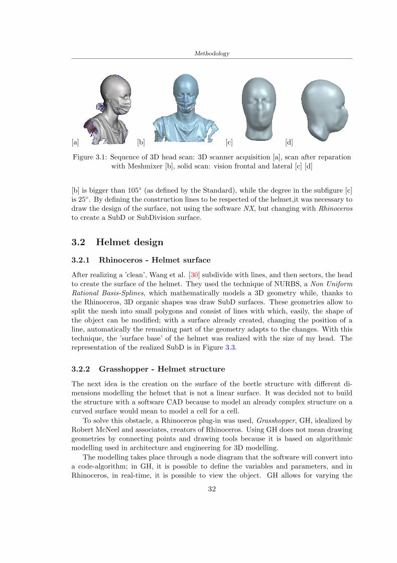
Methodology
[a] [b] [c] [d]
Figure 31 Sequence of 3D head scan 3D scanner acquisition [a] scan after reparationwith Meshmixer [b] solid scan vision frontal and lateral [c] [d]
[b] is bigger than 105 (as defined by the Standard) while the degree in the subfigure [c]is 25 By defining the construction lines to be respected of the helmetit was necessary todraw the design of the surface not using the software NX but changing with Rhinocerosto create a SubD or SubDivision surface
32 Helmet design
321 Rhinoceros - Helmet surface
After realizing a rsquocleanrsquo Wang et al [30] subdivide with lines and then sectors the headto create the surface of the helmet They used the technique of NURBS a Non UniformRational Basis-Splines which mathematically models a 3D geometry while thanks tothe Rhinoceros 3D organic shapes was draw SubD surfaces These geometries allow tosplit the mesh into small polygons and consist of lines with which easily the shape ofthe object can be modified with a surface already created changing the position of aline automatically the remaining part of the geometry adapts to the changes With thistechnique the rsquosurface basersquo of the helmet was realized with the size of my head Therepresentation of the realized SubD is in Figure 33
322 Grasshopper - Helmet structure
The next idea is the creation on the surface of the beetle structure with different di-mensions modelling the helmet that is not a linear surface It was decided not to buildthe structure with a software CAD because to model an already complex structure on acurved surface would mean to model a cell for a cell
To solve this obstacle a Rhinoceros plug-in was used Grasshopper GH idealized byRobert McNeel and associates creators of Rhinoceros Using GH does not mean drawinggeometries by connecting points and drawing tools because it is based on algorithmicmodelling used in architecture and engineering for 3D modelling
The modelling takes place through a node diagram that the software will convert intoa code-algorithm in GH it is possible to define the variables and parameters and inRhinoceros in real-time it is possible to view the object GH allows for varying the
32
Methodology
[a] [b]
[c]
Figure 32 Featurersquos extraction in [a] is represented the impact line in [b] and [c] twoprospective about the definition of the field of vision
[a] [b] [c]
Figure 33 SubD representation lateral view [a] top view [b] front view [c]
geometry to your liking by varying a simple parameter of the diagram as everything willbe remodelled according to the change made
In the following Figure 34 it is shown an example of a structure that was used fordistinct subgroups of helmet areas The idea was to insert smaller cells in the frontal andlateral zone and larger ones in the upper area In the first image [a] is shown the part of
33
Methodology
the helpful diagram to create the beetle structure to establish the size of the cells andthe extrusion the second image [b] contains the part of the diagram with which I appliedthe structure previously created to the SubD
The structure used to place and adapt the beetle structure to the surface is theSrfMorph while the yellow rsquowindowrsquo that contains numbers serves to select the parts ofthe surface where to apply the geometry created In accord with the GH diagram in
[a]
[b]
Figure 34 Grasshopper diagrams
Figure 34 [a] it is possible to see the steps executed to realize the structure Initially inthe xy-plane a hexagonal grid was drawn through the Hexgrid command in which youcan input the length of the hexagon edge and the number of grid elements (selected bytrial) Then the circumferences was drawn in proportion to the hexagon dimensions asspecified in the Chapter 2 and shown in Figure 35 [a] In figure [b] the rsquocutrsquo made atthe circumferences is visible this subdivision was necessary for printing purposes In thelast photo [c] the structure highlighted in green in [b] was extruded setting a distance
34
Methodology
of 20 mm
[a] [b] [c]
Figure 35 Construction sequence of the geometry of the helmet
In the diagram in Figure 34 [b] there is the application of the structure created bi-dimensionally to the SubD surface of the helmet visible by unlocking the SubD commandof the diagram and in Figure 36 [a] Upper this the referential geometry of the group ofsurfaces was superimposed where it was to be applied the newly created structure (visiblein darker red) the SubD indices are in the yellow box of the diagram
Through the SrfMorph command the location of the structure was granted In Figure36 [b] at the darkest red of the figure [a] with the above command it was possible toplace the structure
[a] [b]
Figure 36 Application of the geometry created to the helmet surface
Overall the diagrams with specific structures are five one for the front two equal forthe side parts one for the top shown in the previous Figure 36 and one for the back
The hexagons in the structure have a dimension varying between 8 mm and 14 mmof side the largest is found at the top later at the back in the sides and the smallest atthe front In Figure 36 [b] the presence of not only hexagonal structures is visible Thegeometry used does not allow the homogeneous arrangement on the entire surface andrequires different structures Automatically the choice of GH to optimize the structurewas to insert quadrilateral
As described above the helmet has different dimensions of the structure divided asvisible in Figure 36 in a quadrilateral This causes a discontinuity between zones withdifferent sizes due to the geometry of the construction
To eliminate this problem and realize the design homogeneous grids were inserted
35
Methodology
in the affected areas as shown in Figure 37 This insertion however proved to beinteresting and strategic researching in this regard studies were realized to demonstratethe insertion of a rectangular grid inside the hexagon grid was helpful for the transmissionof stress in the structure As cited by Sun et al [40] rdquothe mechanical properties of thesesandwich structures are often limited by local failures such as face-core debonding or corecollapserdquo Carrying out compression tests have effectively demonstrated that the insertionof the grid allows rdquoprovided increased stiffness specific stiffness energy absorption andcritical loadrdquo [41] As shown in the graphic [c] of the Figure 37 the honeycomb structuregives a force of 7 kN while with a grid the value is 11 kN and with the combinationexceeds 22 kN In addition in the left front a plaque to customize the helmet wasprepared Figure 37 [a]
[a] [b]
[c]
Figure 37 Grid in the helmet [a] hybrid structure with hexagons and grid [b] [40]compression test results of the hybrid structure [c] [41]
33 3D Print
After having achieved the CAD (Computer Aided Design) of the helmet in order tobe printed it must be converted and saved in format STL (Standard TriangulationLanguage) - Binary compatible with the printing machine and useful for transformingsolid object surfaces into triangles The steps to be taken are the following
bull CAD file realization
bull CAD export in format STL to Simplify 3D the software that shows slider layersand then- rotate and position the object according to geometry and the positioning of any
36
Methodology
supports- setting printing parameters- item manual andor automatic positioning of supports- slider display layers
bull import file gcode to printer
331 Printer and parameters
The program used to visualize how the helmet slices layers before sending it to the printerand to set the parameters is as anticipated Simplify 3D
To make the printing not being a flat geometry it is necessary to place the supportsThe idea was to use water-based supports that the helmet would automatically dissolveonce placed in the water After testing different types of water-soluble PVA the choicefell on eSun 3D Printing Filament PVA (water-soluble support) Before choosing theoptimal position for printing several tests were carried out and to decrease the numberof the supports significantly and allows an optimal printing of the outer part an emptyrsquospherersquo that self-sustains below the helmet was placed as shown in Figure 38
In the image [a] you can see the first print position tried with which an external partof the helmet very damaged was obtained because of the contact supports-helmet In [b]the empty rsquospherersquo is shown to optimize the number of supports and in the last photo [c]there is the full version at the end of print
[a] [b] [c]
Figure 38 Printing supports
The printer that has been used for printing is the Raise 3D Pro2 with double extrudersand nozzles of variable size from 02 mm to 1 mm after some test prints with the PLALW and the structure in created the size that allowed me to have a good compromisebetween printing time and accuracy was 06 mm Using 04 mm the printing time wasexcessive even if having the smaller nozzle diameter means having more precision withthe 08 mm nozzle the quality of the structure was not excellent as seen in Figure 38[a]
Another factor that had to be taken into account is the characteristic of the PLA-LWto expand As the printing temperature and the printer used vary the expansion andcharacteristics of the material change The use of the 06 mm nozzle associated with
37
Methodology
Parameter Left extruder Right extruder
01cm Material 01cm PVA 01cm PLA LW
Extruder toolbox index Tool 0 Tool 1
Nozzle diameter 06 mm 06 mm
Extrusion multiplier 1 05
Extrusion width Auto (072 mm) 05 mm
Layer x
Infill Rectilinear - 50
Supports (Automatic and not) Infill 50
Temperature 210 250
General parameters
Primary layer height 03 mm Top solid layer 4
Bottom solid layer 2 Outline 2
Heated bad 60 Speed 40 mms
Table 31 Printing parameters
Raise 3D allowed me to get good results The choice of this printer was not random ithas in fact the characteristic of making extremely precise prints The Raise has accuracyin placing the object on the printing bed of 078 microns on the xy axis and a resolutionfor layers of 001 mm
The final version of the helmet is visible in Figure 39 and it is possible to compare itwith the preview version in Rhinoceros in Figure 310
38
Methodology
[a] [b]
[c]
Figure 39 Views of the helmet
[a] [b]
Figure 310 Views of the helmet (GH version)
39
Chapter 4
Experimental evaluation
41 Experimental tests
411 Drop-weight impact test machine
In order to calculate the contact force peak and the difference of energy absorbed duringthe impact between the reference helmet and helmet with the beetle structure in PLA-LW dynamic impact tests were carried out using the Fractovis Plus an impact testmachine
In this way it is possible to monitor the evolution of the above variables from theinitial to the final instant of the impact The machine can withstand a load with a rangevariable from 2 to 70 kg with a maximum speed of 46 ms and a maximum height of1 m The values chosen for the test are the following 5 kg weight maximum speed andmaximum height The Anvil that was used is a disc diameter of 60 mm
As shown in Figure 41 and explained by Crupi et al [37] the machine consists ofa sensor capable of recording the speed before impact the impactor that can have avariable mass (a weight of 5 kg in my test) a system to guarantee that there are nomultiple impacts after the first and that work as a shock absorber and clamping systemwhere the object to be tested is placed
The tests that have been carried out are in total four two related to the helmetoptimized with PLA-LW and two with two generic helmets of different brand in EPS
42 PLA LW helmet
To perform the dynamic test on the helmet of PLA considering the difficulty of printingit was helpful to use a test helmet with imperfections to understand where the impactwas concentrated in a single part or distributed The images of Figure 42 show a helmetwith not well defined edges and inaccurate print but exactly localizes the impact zoneThanks to this test it was possible to take into account only one helmet area shown inFigure 43 to have the exact curve of the structure bio-inspired with PLA-LW
40
Experimental evaluation
Figure 41 Drop-weight impact test machine [37]
[a] [b]
Figure 42 Test 1 PLA-LW helmet
43 EPS helmet
To carry out dynamic tests and extract the technical characteristics of the helmettwohelmets were bought in a sports store both EPS and being on the market both certifiedThe brands of the two helmets are DTB and VAN|RYSEL and the average weight ofthe two is 223 g Two different helmets have been chosen to have a more certain andclear classification of the characteristics They are shown in Figure 44 and Figure 45
41
Experimental evaluation
[a] [b]
Figure 43 Test 2 PLA-LW helmet
[a] [b] [c]
Figure 44 Test 3 EPS helmet
[a] [b] [c]
Figure 45 Test 4 EPS helmet
44 Results
441 First results - PLA-LW and EPS helmet
Figure 46 shows two types of trends related to the two different models of the helmetThe force evaluated for PLA-LW has higher force peaks but is more concentrated and
42
Experimental evaluation
propagates less than EPS The graph shows the peaks of each curve highlighted with a redcircle In tests 1 and 2 for the PLA-LW as mentioned earlier the values are higher about7301 N for the complete helmet and 3996 N for the portion of helmet This difference isdue to the inaccuracy of the first full helmet during the printing phase In Figure 42 itis visible the low homogeneity and precision Therefore the first test with full helmet wasused only to define the area of interest of the impact which turns out to be localized Forthe other two EPS curves the values are only slightly lower compared to the PLA-LWequal to 3620 N and 3295 N but the trend is much more distributed
Figure 46 Dynamic machine test - Force
With the data obtained from the impact machine it was possible calculate not exclu-sively the value of force but itrsquos also possible to view the energy curves A resume aboutthe values and energy of the force is in the following Table 41
Test Peak force [N] Peak energy [J]
Test 1 - PLA LW (inaccurate) 730130
Test 2 - PLA LW (portion of helmet) 399643
Test 3 - EPS (DTB helmet) 362007 509
Test 4 - EPS (VAN|RYSEL helmet) 329546 4198
Test 5 - PLA with TPU 45421 5022
Table 41 Energy absorbed in dynamic test
43
Experimental evaluation
442 PLA-LW helmet with TPU cover
As it is possible to see in Figure 47 and as highlighted the first tests concerning thebio-inspired structure and the PLA-LW are far from my expectations considering thelittle distribution of force in comparison with the EPS foam and consequently a smallamount of energy absorbed
Figure 47 Dynamic machine test - Energy
To improve this impact damping factor the idea was to create a cover for the helmetin flexible TPU trying to absorb impact energy The TPU used is a flexible material ofthe brand Ninjaflex used in sports by the application in helmets and shoes to cushionbumps during the game Generally in the helmets (baseball helmet for example) theTPU is inserted internally in contact with the head In my case the TPU structurein addition to creating a shock-absorbing and durable cover creates a custom cover thehelmet and for the person This cover was also made with the Raise 3D printer
As shown in the Figure 48 [a] the infill of the part in contact with the helmet hasa percentage of 100 the filling of the other part of the structure is not complete butonly 15 and the internal structure is hexagonal to recall that of the helmet The desireto insert a structure with a rsquoraisedrsquo geometry is for visual and aesthetic reasons as youhave the feeling of greater protection and not filled is inspired by the machine CitroenCaptus whose bumpers (Airbump) are full of air The failure to realize empty structuresis due to the need to place any internal supports not removable
The idea was to create a cover that allow you to see of the internal structure of thehelmet and that protect specific areas the front the two sides the top and the posteriorWhat which was thought for this reason was to create the shape of a flower with four
44
Experimental evaluation
petals Figure 48 [b]In this way to perform dynamic impact tests as shown in Figure 49 [a] the cover was
positioned at the top of the helmet and the impact was performed in the centre of thersquoflowerrsquo which corresponds to the higher upper part where the structure has larger cellsize The impact parameters are the same as those used in previous impacts 5 kg weightmaximum speed and maximum height The Anvil that was used is a disc diameter of60 mm In photo [b] it is evident the difference between the structure that received theimpact with protection (left) and without protection (right) Without protection duringthe impact there was a perforation of the structure with a concentration of force at a locallevel as you can see in the Figure 46 in the case of TPU the impactor did not perforateand crossed the structure thanks to the cover of TPU that cushioned the shock At themoment of impact the impactor bounced
[a] [b]
Figure 48 TPU cover
[a] [b]
Figure 49 PLA-LW with TPU - dynamic impact [a] and differences between thehelmet with TPU and without TPU cover [b]
45
Experimental evaluation
The Figure 410 includes the diagrams relative to the dynamic impacts In [a] thereare already analyzed EPS results in [b] a comparison between the test on the portionof helmet in PLA LW with and without the TPU cover in [c] the overall comparison ofcurves shows a much more similar EPS trend if the TPU is placed above the structure inPLA LW to soften the blow and absorb the same energy [d]
46
[a]
[c]
[d]
Figure 410 Comparison between PLA-LW with TPU and EPS
Chapter 5
FEM Validation
51 Impactor - Anvils definition
Before to start to work in Abaqus it was necessary to search in the literature the materialwith which the anvil was been realized Milne et al [23] established the densityrsquos valuethe Youngrsquos Module and Poissonrsquos ratio for the Flat and Kerbstone Anvil
- Density ρ = 7800 kgm3
- Youngrsquos Module E = 200000 MPa
- Poissonrsquos ratio ν = 03
Inserting the data in the CES EduPack program specifying the mechanical andphysical properties the material corresponding to these characteristics is Stainless steelaustenitic (ASTM F1586) medium-hard
Initially the proposal was to create a conservative system to evaluate the absorptionenergies values and apply this value to a vibration system but the helmet needs dampingto be realized it was impossible to use a system without losses in this modality Thisis why a numerical calculation was carried out by performing two types of simulationsexplicit dynamic step and static step
The idea to realize the theoretical impact is to regard the movement of the anviland not the helmetrsquos movement which is fixed The velocity is the same cited in thenormative EN 1078 542 ms for the Flat anvil and 457 ms for the Kerbstone anvil
In performing the simulations It was given more relevance and perform tests withthe Kerbstone Anvil This choice was done because the geometry with which it is beenrealized (following as defined in the legislation) allows the helmet to be more subjectedto stress this involves the definition of higher stress limits compared to the Flat Anvil
The mesh size that has been used is the same in the case of the simulation of thehelmet optimized in PLA-LW and the full helmet in EPS of 7 mm The impactor isconsidered as a Discrete rigid body with its specific Reference Point (RP) like shownin Figure 51 for this reason it is not a solid but it is composted only by shells Inthe same image [b] there is the FEM representation of the model and in Table 51 thecharacteristic of FEM with quadrilateral (R3D4) and triangular elements (R3D3)
48
FEM Validation
Object Elementnumber
Elements Shape Geometricorder
Global size[mm]
Kerbstone 230 Quadrilateral - R3D4 Linear 7
Kerbstone 8 Triangular - R3D3 Linear 7
Table 51 Mesh element - Kerbstone Anvil
[a] [b]
Figure 51 Kerbstone anvil in the simulation like discrete rigid body [a] and FEMelements [b]
511 PLA LW - Plastic characteristics
The PLA-LW as explained in the Chapter 2 is new material on the market and producedby the only Colorfabb company for this reason few tests have been carried out to defineits technical characteristics and through tensile tests of the 3D printed specimens it waspossible to define an elastic limit as reported in the Table 210
In the context of simulations to reproduce the impact and deformation of the helmetis also necessary to consider the plastic characteristics of the material Not possessingany reference value in this regard tests were performed through a Static Step initiallyand then an Explicit Dynamic Step in Abaqus
The structure chosen to consider as a reference it is one of the structures previouslysubjected to the compression test having the side L=14 mm As for the reproduction ofthe compression disks initially they were reproduced according to the geometry of theHoytom HM-D Testing Machine considering the bodies mentioned above as discrete 3Drigid discrete The measure was the diameter of 200 mm and the height of 20 mm
After an initial analysis it was observed that the computational time of the simulationprogram was very high so it was decided to change the geometry to have a rsquodisk-surfacesrsquo(equally 3D rigid-discrete) which allowed me to have a smaller number of nodes for themesh and consequently a better computational time The representation of the opti-mized structure in PLA-LW and the disks used for simulated compression is in Figure 52
49
FEM Validation
[a] [b]
Figure 52 Representation of the samples used for the simulation of the compressiontest In Figure [a] the disks of the Hoytom HM-D Testing Machine in figure [b] the
representation of the same as simple surfaces
As shown in Figure 52 the disks are considered 3D discrete hard bodies so it waschosen for both a point the reference point RP where to apply the characteristics relatedto the two bodies As for the compression test it was established
bull the movement of a disk and fixed the second through a boundary condition impos-ing an Encastre therefore unable to move and rotate in xyz directions
bull for the opposite disk the boundary condition relative to the 15 mm displacementwas applied which is the parameter that it was observed to determine the end ofthe compression with the machine This shift is shown by the orange arrow in figure[b]
bull between the upper surface and the disk e the disk with the lower surface it wasinitialized a general contact with normal behaviour through rsquohardrsquo contact andtangential behaviour with a coefficient of friction of 02 with directionality imposedon rsquoisotropicrsquo
The next step was to define the mesh of the components whose parameters are shown inTable 52 while the representation of the FEM is in Figure 53 with the representationof the simulation and real compression test
Object Elementsnumber
Typology Geometricorder
Globalsize [mm]
Disk (14mm) 80910 hexaedral - C3D8R Linear 07
Impact disks 206 quadrilateral - R3D4 Linear 20
Impact disks 6 triangular - R3D3 Linear 20
Table 52 Mesh element - Compression test simulation
As previously announced a static simulation was initially performed with a StaticStep with Step Time equal to 900 (obtained going to consider the speed of 1 mmmin of
50
FEM Validation
[a]
[b] [c]
Figure 53 FEM representation [a] and compression test simulation [b] and realcompression [c]
the compression test and the displacement of 15 mm) However the complex geometryof the structure and the high time set by Step Time did not allow a correct definitionof the parameters of the plastic characteristics of the material the simulation was notable to continue once reached a Step Time of approximately 220 That is why it waschanged by choosing an Explicit Dynamic step
Leaving all the parameters of the boundary conditions unchanged the Step Time wasmodified imposing it to 001 The ability of the explicit dynamic to work with non-linearand contacting structures allowed me to achieve results The results obtained are shownin Figure 54 with the blue curve and were obtained through the iteration of differentPlastic Strain and Yield Stress values in Abaqus while the red line is the result of thereal compression test a similar curve trend was obtained but it is not possible to obtainthe same curve taking into account problems of printing inaccuracy
512 First test - helmet
The initial idea was to perform a simulation imposing the speed of 457 ms to theimpactor tie the helmet in EPS and PLA and compare the absorbed energies Theproblem it was encountered is related to the mesh of the helmet optimized in PLA andwith minimum dimensions of the elements and distinct elements it was not able to solveit
51
FEM Validation
[a]
YieldStress
PlasticStrain
1 47 0
2 7 001
3 75 005
4 10 01
5 108 1
6 115 15
7 12 2
[b]
Figure 54 Representation of the two curves related to the simulation in Abaqus of thecompression test and the data obtained from the real test to obtain the plastic
characteristics of the material
513 Second test - plane
The first solution is the one shown in Figure 55 To realize the simulation it was realizeda section of the helmet to involve a smaller number of elements and nodes Again thesimulation for the EPS helmet was successful while the simulation with the bio-inspiredstructure was interrupted by excessive distortion of elements
The previous images show the impact is very localized in the impacted area and theidea to achieve a complete simulation is not to consider a curved portion of the helmetbut a plane In this way it was possible to solve the problem and obtain a completesimulation for the bio-inspired structure
FEM element
Below in Table 53 there is the definition of the elements used for the PLA-LW and EPSplane in the simulation to simulate the impact and to control the energy-absorbing whilethe anvil characteristics are described in Table 51
514 EPS impact simulations
In order to proceed with the simulation it was imposed some boundary conditions thatregard ties and forces
bull the movement of the plane is fixed through an Encastre therefore unable to moveand rotate in xyz directions
52
FEM Validation
[a]
[b]
Figure 55 Impact simulation parts of EPS and PLA helmet
Object Elementnumber
Elements Shape Geometricorder
Plane (PLA) 38896 Tetrahedral -C3D10M
Quadratic
Plane (EPS) 2100 Hexahedral - C3D8R Linear
Table 53 Mesh element - plane impact
bull to create the impact it was set a speed of 457 ms at the reference point RP of therigid body which is the impactor Kerbstone Anvil shown in Figure 56
bull between the upper surface of the plane and the impactor it was initialized a Sur-face to Surface contact with normal behaviour through rsquohardrsquo contact and tangen-tial behaviour with a coefficient of friction of 02 with directionality imposed onrsquoisotropicrsquo
bull the rotation in x y z relative to the RP of the rigid discrete impactor body is locked
53
FEM Validation
In addition it was characterized the plane in the part of the materials with the char-acteristic values of the EPS mentioned in Chapter 221 The Von Mises Stress valueapparently low is relative to the Yield Stress of the EPS material equal to 09 MPa
Figure 56 EPS Boundary conditions and Load
515 PLA LW impact simulations
As also required in the case of the EPS plane in order to proceed with the simulationsome boundary conditions were imposed that regard ties and forces
bull the movement of the plane is fixed through an Encastre therefore unable to moveand rotate in xyz directions
bull to create the impact a speed of 457 ms was set at the reference point RP of therigid body which is the impactor Kerbstone Anvil shown in Figure 58
bull between the upper surface of the plane and the impactor it was initialized a Sur-face to Surface contact with normal behaviour through rsquohardrsquo contact and tangen-tial behaviour with a coefficient of friction of 02 with directionality imposed onrsquoisotropicrsquo
bull the rotation in x y z relative to the RP of the rigid discrete impactor body is locked
In addition the plane was characterized in the part of the materials with the characteristicvalues of the PLA mentioned in the Chapter 223 and 511
Figure 58 Boundary conditions and Load
54
FEM Validation
[a]
[b]
Figure 57 EPS impact simulation
52 Results
In Figures 59 and 57 it is shown how the structure in PLA LW has a more concentratedstress distribution of the structure unlike EPS The maximum value for the Von Misesstress is 09 MPa in EPS structure and 3634 MPa in PLA LW structure Once thesimulations were obtained the next step was to go and compare the energies absorbed bythe two structures The energy calculated by Abaqus that has been taken into account isPlastic Dissipation To make a comparison the data of the two energies were representedin a single graph
What emerges from the graph is that about the impact made with the KerbstoneAnvil the energy absorption is more excellent although only slightly for the PLA LWthan for the EPS From the graph in Figure 510 a value of 41 J is shown for the EPSand 51 J for the PLA LW
55
[a]
[b]
Figure 59 PLA impact simulation
[a]
Figure 510 EPS and PLA LW energy comparison - Abaqus simulation
Chapter 6
Head Injury Data
For the statistical analysis the injuries related to the accident data were categorised intothe following types and levels based on the details of the medical report [11] about theEN 1078
bull Head Injury Criterion (HIC)
bull Peak Linear Acceleration (PLAc)
bull Gadd Severity Injury (GSI)
bull Diffuse axonal injuries (DAI)
61 Abaqus simulation
Until now the purpose of the simulations has been to determine which between the twomaterials and the two structures of EPS and PLA LW could absorb more energy duringthe impact but no simulations have been carried out in compliance with BS EN 1078on the helmet impact tests To calculate the injuries listed in the previous paragraphhowever we need the acceleration values in the three directions related to the subjectrsquoshead
To realize it the scan of my head already rsquocleanrsquo was considered of which it has beencalculated the inertia thanks to the automatic SolidWorks calculation and evaluated theweight with the Table 24 the structure of the helmet was placed for the EPS and thePLA LW over the head as shown in Figure 61 Also this time being able to mesh theentire helmet in PLA LW was impossible due to the excessive distortion of some elementsduring the simulation so it has been tried to make a section of the structures of thehelmet and results were obtained
57
Head Injury Data
[a] [b]
Figure 61 My scan head - CAD [a] head imported in Abaqus[b]
Initially the simulation had these characteristics as shown in the following Figure62 considering the helmet was not sectioned As explained earlier it was not possibleto get to simulation in the case of the optimized structure in PLA LW for this reasononly a part of the helmet was considered in both cases shown in Figure 63
[a]
Figure 62 Simulation based on BS EN 1078
58
Head Injury Data
[a] [b]
Figure 63 Simulation based on BS EN 1078 with head
In order to proceed with the simulation some boundary conditions that regard tiesand forces have have imposed
bull two reference points RP were created the first in the inertia centre of the headthe second relating to the Kerbstone Anvil which is a discrete rigid body
bull in the reference point RP of the head in the definition of the engineering features5 kg was inserted for the weight and an inertia I11 = 564464E+07 gmm2 I22 =460654E+07gmm2 I33 = 187302E+07gmm2
bull to simulate the impact it was set a speed of 457 ms at the reference point RP ofthe head in z-axis direction
bull a general contact with normal behaviour through rsquohardrsquo contact and tangentialbehaviour with a coefficient of friction of 02
bull between the upper surface of the helmet and the impactor it has been initializeda Surface to Surface contact with normal behaviour through rsquohardrsquo contact andtangential behaviour with a coefficient of friction of 02 with directionality imposedon rsquoisotropicrsquo
bull the movement between the Kerbstone anvil and the helmet is fixed through anEncastre therefore unable to move and rotate in xyz directions
bull the rotation in x y z relative to the RP of the rigid discrete impactor body is locked
FEM element
As reported in Table 53 the portion of the helmet in EPS has used a mesh with hexahe-dral elements of linear order For the structure (beetle) of PLA LW given the geometry
59
Head Injury Data
complexity it was necessary to use a quadratic order of tetrahedra For the mesh of thehead instead in both simulations have been used quadrilateral elements of linear orderas reported in the Tables 61 and 62
Object Elementnumber
Elements Shape Geometricorder
Head 3755 Quadrilateral - R3D4 Linear
Head 34542 Quadrilateral - R3D3 Linear
Helmet (PLA) 272302 Tetrahedral -C3D10M
Quadratic
Table 61 Mesh element - Head simulation with PLA LW (beetle) helmet
Object Elementnumber
Elements Shape Geometricorder
Head 3755 Quadrilateral - R3D4 Linear
Head 34542 Quadrilateral - R3D3 Linear
Helmet (EPS) 72280 Hexahedral - C3D8R Linear
Table 62 Mesh element - Head simulation with EPS helmet
62 Results
Figure 64 represents the simulation in line with BS EN 1078 concerning the helmet inEPS [a] and the helmet with bio-inspired structure in PLA LW For both simulationsVan Misesrsquo stress has Yield Stress values in the case of EPS which is 09 MPa and theplastic behaviour combination of PLA LW [b]
In the case of head and Kerbstone Anvil stress was not assessed as they were previ-ously defined as discrete rigid bodies
63 Head Injury Criterion
The HIC quantifies head impact severity by incorporating time of acceleration exposureand acceleration magnitude it is calculated in post-processing phase with the followingEquation 61
HIC15 =
[1
(t1 minus t2)
int t2
t1
a(t)dt
]25(t2 minus t1) (61)
60
Head Injury Data
[a]
[b]
Figure 64 Results simulation based on BS EN 1078 with sectioned head
For this analysis a(t) is the acceleration calculated in the centre of mass of the head(corresponding to the reference point RP) expressed in g and the time interval (t2 minus t1)was chosen to maximize HIC over a maximum duration of 15 ms
Matlab and the trapz function were used to calculate the HIC to integrate accelerationover time t2 and t1 were considered initial and final times of the simulation t1 = 0 sand t2 = 10 s time less than 15 s
HIC value of 198 was obtained for EPS and 87 for PLA LW Considering the Hayeset al [16] document about the HIC values and the graph in Figure 65 developed bythe author it is possible to find the percentages related to the different injury AIS1 -AIS6 which correspond respectively to lower and higher severity while in Figure 66 therelative fatality to every value of AIS is shown The values obtained for the HIC andother criteria are shown in Table 63 The HIC value for EPS is 198 for PLA LW it is
61
Head Injury Data
Figure 65 Head injury risk curves based on HIC values [16]
Figure 66 The abbreviated injury score versus fatality rate [16]
87 Analyzing the data and comparing them with the curves of the Figure 65 I obtain
bull a percentage between 20 - 30 of AIS 1 for EPS 10 - 20 for PLA LW
bull a percentage between 10 - 20 of AIS 2 for EPS and 0 - 10 for PLA LW
bull for AIS 3 AIS 4 AIS 5 AIS 6 the percentages for both structures is between 0 -10
Comparing these percentages with the fatality rate of Figure 66 it is clear there is a riskof Moderate and Minor fatality in the case of EPS and PLA LW as all values are between0 and 30
62
Head Injury Data
HIC PLA [g] GSI E [J]
EPS 198 97 361 37723
PLA LW 87 75 169 44102
Table 63 Head Injury Data - values
64 Peak Linear Acceleration
The resultant linear acceleration versus time curve was calculated according to Equation62
γ(t) =radicγ2x(t) + γ2y(t) + γ2z (t) (62)
where
bull γ(t) is the resultant linear acceleration (g)
bull γx(t) is the linear acceleration in x axes (g)
bull γy(t) is the linear acceleration in y axes (g)
bull γz(t)is the linear acceleration in z axes (g)
The value of the impact should never exceed 250g [9] Cripton at all [9] in their studyexamined a helmet with expanded polystyrene (EPS) Figure 68 shows maximum HIC forhelmeted and unhelmeted drops from all heights For each drop height helmets reducedHIC relative to unhelmeted drops IARV value is 180g The acceleration in the two casesis shown in Figure 67 and the maximum values are 97g for EPS and 75g for PLA LWas reported in Table 63 The two values considering a maximum value calculated byCripton [9] of 180g are amply optimal and comply with the standard of 250g
65 Gadd Severity Index
Gadd proposed the Severity Index Criteria shown in Equation 63 Following this crite-rion the GSI values that are over 1000 produce serious internal head injury [33]
GSI =
int t1
0a(t)25dt (63)
Where
bull a is the linear acceleration (g)
bull t is the duration of the impact (s)
I calculated the GSI with the function trapz between 0 and t and the resulting valuesare 361 for the EPS and 169 for the PLA LW which comply with the limit
63
Head Injury Data
Figure 67 Peak accelerations for both helmets
Figure 68 Peak accelerations for both helmeted and unhelmeted drops Numbers overbars indicate peak acceleration For 2 m drop height results stated are the mean value
calculated from three drops [9]
64
Head Injury Data
66 Diffuse Axonal Injury
DAI cases covered all incidences in which neurological injuries occurred as well as con-cussion unconsciousness and coma
In order to assess the risk of head trauma in terms of diffuse axonal injury (DAI)Milne et al [23] defined a model based head injury criteria as follows obtaining theresults in Figure 69
bull 50 risk of moderate neurological injury (DAI1+) Brain Von Mises shearing stressof 28 kPa
bull 50 risk of severe neurological injury (DAI2+) Brain Von Mises shearing stressof 53 kPa
[a]
[b]
Figure 69 Peak intra-cerebral shearing stress computed with the helmet model coupledto the human head model for all impact points (a) Flat anvil (b) Kerbstone anvil [23]
65
Head Injury Data
67 Energy absorbed
In Figure 52 during the impact test between the kerbstone Anvil and the plan with thebio-inspired structure in PLA LW and EPS it was found that the PLA LW althoughwith a small difference of 10 J absorbed more energy in comparison with the EPS Whenthe test is carried out in compliance with BS EN 1078 and the head with a speed of 457ms (corresponding to the kerbstone Anvil) as shown in Figure 610 also in this casethe PLA LW with the optimized helmet structure manages to absorb more energy (evenif the difference is very low) compared to the EPS The maximum energy value in PLALW is 44102 J of EPS is 37723 J
Figure 610 Energy absorption - BS EN 1078
66
Chapter 7
Conclusion
71 Conclusion
In this thesis work a bicycle helmet with a bio-inspired structure in PLA LW and 3Dprinted was created The initial approach was to introduce an innovative aspect tostandard EPS helmets not using foam but a polymer with new geometries able toabsorb much energy during the impact For this reason the beetle structure has beenpreferred relying solely on the hypothesis encountered in the literature of its quality inabsorbing energy
Combining the new material of the PLA LW and beetle structure has made possiblethe development of new material satisfactory characteristics have been obtained sincethe first tests The two materials were first subjected to tensile tests to determine theirspecific stress in these the PLA LW had positive results
Subsequent dynamic physical tests were carried out on 3D printed helmet models andon reference helmets in EPS to calculate the absorption energy in both cases at the timeof impact These resulted in energy absorption of the beetle structure in PLA LW withthe application of a TPU cover almost equal to that of EPS about 50J To validate withfinite element analysis the two models an explicit dynamic step was used in AbaqusSimulations showed that the PLA LW structure absorbs a higher amount of energy thanthe EPS the higher is 50 J and the EPS 40J
Finally positive results have also been obtained in calculating the head injury datasimulating according to BS EN 1078 with the use of impactor helmet and head Theacceleration values for both the structures were inferior to 220g precisely for the PLALW was 75g and for the EPS 97g The same applies to the calculation of HIC and GSI(maximum acceptable value of 1000) where the values are 87 and 169 in the case of PLALW and 361 and 198 in EPS For all tests therefore greater efficiency of the structure inPLA LW has been obtained Positive results also in the simulation of the energy absorbedduring the impact as the value referring to the EPS was 35J and that of the PLA LWwas 45J
67
Conclusion
72 Future work lines
The positive results obtained can be considered as a starting point for further tests andsimulations to ensure the safety of the helmet and compliance with the regulations butbefore getting improvements and continue testing changes are required
bull the beetle structure of the helmet made with GH adapts to the SubD withoutallowing to have a homogeneous distribution it would be appropriate to have moreregular hexagonal geometries
bull the mesh of the helmet is too complex and does not allow to perform the simulationprobably to use a more regular structure would have a mesh accordingly moreregular and the simulation would be successful
bull the uneven helmet structure has so many defects that the print is imperfect andthis can change the results of the impact tests the structure should be improved
bull the printing time varies from 4 to 5 days it should be improved
bull the TPU helmet cover is too big for the RAISE printing plan it is necessary togenerate a new geometry
bull the TPU cover it must be fixed on the helmet
bull in the calculation of the DAI it is necessary to have the definition of the brain andthe head should not be considered as a rigid body
bull in the injury calculation the helmet without protection was considered with theTPU cover the result will be better
bull air flow analysis
The comments mentioned are only considerations and problems that I gained duringmy thesis and which should be improved but I am sure that these changes and improve-ments from design to printing and simulations can make the helmet a good product
68
Bibliography
[1] K Adanty J M Clark A Post Thomas Blaine H and M D Gilchrist Comparingtwo proposed protocols to test the oblique response of cycling helmets to fall impactsInternational Journal of Crashworthiness 6648 ndash 663 2020
[2] MF Ashby YJM Brechetb D Cebona and L Salvoc Selection strategies formaterials and processes Materials and Design 2004
[3] M Aysha El casco de bicicleta voronoi impreso en 3d mas seguro y ligero https
www3dnativescomen3d-printed-bicycle-helmet-voronoi-190820204
[4] H Bikas P Stavropoulos and G Chryssolouris Additive manufacturing methodsand modelling approaches a critical review The International Journal of AdvancedManufacturing Technology 83389ndash405 2016
[5] British Standards BSI Helmets for pedal cyclists and for users of skateboards androller skates - BS EN 1078 2012
[6] British Standards BSI Headforms for use in the testing of protective helmets BSEN 960 2020
[7] ColorFabb Colorfabb lw-pla 2019 httpscolorfabbcommedia
datasheetstdscolorfabbTDS_E_ColorFabb_LW-PLApdf
[8] V G Coronado T Haileyesus J M Bell T A Cheng JHaarbauer-Krupa M RLionbarger J Flores-Herrera L C McGuire and J Gilchrist Trends in sports andrecreation-related traumatic brain injuries treated in us emergency departments thenational electronic injury surveillance system-all injury program (neiss-aip) 2001-2012 J Head Trauma Rehabil 30185ndash197 2015
[9] P A Cripton D M Dressler D Stuart Cameron A Christopher R and D RichardsBicycle helmets are highly effective at preventing head injury during head impactHead-form accelerations and injury criteria for helmeted and unhelmeted impactsAccident Analysis and Prevention 701ndash7 2014
[10] L Cui M A Forero R and M D Gilchrist Optimisation of energy absorbingliner for equestrian helmets UCD School of Electrical Electronic and MechanicalEngineering University College Dublin Belfield Dublin4 Ireland 2020
[11] C Deck N Bourdet F Meyer and R Willinger Protection performance of bicyclehelmets Journal of safety research pages 67ndash77 2019
[12] Committee F08 Specification for headforms F2220 ASTM International 2015
[13] Committee F08 Specification for helmets used in recreational bicycling or rollerskating F1447 ASTM International 2018
[14] Committee F08 Test methods for equipment and procedures used in evaluating theperformance F1446 ASTM International 2020
69
Bibliography
[15] P Halldin Shock absorption including measuring CENTC 158 Working Group11 2018
[16] W C Hayes M S Erickson and E D Power Forensic injury biomechanics Annualreview of biomedical engineering pages 55ndash86 2007
[17] HEXR httpshexrcom
[18] C Jinxiang Z Xiaoming O Yoji S Kazuya G Zhensheng and P LongchengThe deformation mode and strengthening mechanism of compression in the beetleelytron plate Materials and Design 131481ndash186 2017
[19] S Kroeker M Ozkul A De Marco S Bonin and GP Siegmund Density variationin the expanded polystyrene eps foam of bicycle helmets and its influence on impactperformance Journal of biomechanical engineering 2019
[20] S G Kroeker SJ Bonin A L DeMarco C A Good and G P Siegmund Agedoes not affect the material properties of expanded polystyrene liners in field-usedbicycle helmets Journal of biomechanical engineering 2016
[21] M Meier K H Tan M K Lim and L Chung Unlocking innovation in the sportindustry through additive manufacturing Business Process Management Journa2018
[22] N J Mills and A Gilchrist The effectiveness of foams in bicycle and motorcyclehelmets Accident Analysis Prevention 23153 ndash 163 1991
[23] G Milne C Deck R P Carreira Q Allinne and R Willinger Development andvalidation of a bicycle helmet assessment of head injury risk under standard impactconditions Computer methods in biomechanics and biomedical engineering 15 Suppl1309 ndash 310 2012
[24] Y Mosleh S J Vander B Depreitere and J Ivens Novel composite foam conceptfor head protection in oblique impacts Adv Eng Mater (Advanced EngineeringMaterials) 10 2017
[25] H Mustafa T Y Pang T Ellena and S H Nasir Impact attenuation of user-centred bicycle helmet design with different foam densities J Phys Conf Ser(Journal of Physics Conference Series) 1150 2019
[26] S H Ngoc and L Guoxing A review of recent research on bio-inspired structuresand materials for energy absorption applications Composites Part 181 2020
[27] J I Novak and A R Novak Is additive manufacturing improving performance insports a systematic review Sport engineering and technology 13 2020
[28] European Road Safety Observatory European road safety observatory facts and fig-ures - cyclists - 2020 December 2020 httpseceuropaeutransportroad_
safetysitesdefaultfilesfacts_figures_cyclists_final_20210323pdf
[29] New York City Departments of Health Parks Mental Hygiene Transportation Recre-ation and the New York City Police Department Bicyclist fatalities and seriousinjuries in new york city 2005
[30] W Pengwen Y Jing H Yanan H Jiaofei and F Xiaoyang Innovative designof a helmet based on reverse engineering and 3d printing Alexandria EngineeringJournal 603445ndash3453 2021
[31] S G Piland T E Gould M Jesunathadas J S Wiggins O McNair and V CShane Protective helmets in sports Materials in Sports Equipment 3 2019
70
Bibliography
[32] K Schmitt P F Niederer M H Muser and F Walz Trauma biomechanicsSpringer Berlin Heidelberg 2010
[33] David Sepelveda Lopez A Biomechanical Analysis of Bicycle Helmets using FEMPhD thesis 2019 Bachelor thesis
[34] H Stigson Bicycle Helmets 2020 Tested by Folksam PhD thesis 2020 PhDAssociate Professor Traffic Safety Research
[35] H Tao K Sudip N Anindya and X Yongzhao 3d printed sensors for biomedicalapplications A review sensor 2019
[36] M Trzaskalska and R Chwastek Damping properties and density of helmet linersmade of expanded polystyrene (eps) Archives of Metallurgy and Materials 66 2020
[37] Crupi V Epasto G and Guglielmino E Impact response of aluminum foam sand-wiches for light-weight ship structures Metals 198ndash112 2020
[38] W Wei-cai F Dong-ming and L Yuan-xin Study on impact energy absorbing per-formance of eps buffer layer of motorcycle helmet Proceedings - 2013 InternationalConference on Mechanical and Automation Engineering MAEE 2013
[39] Z Xiaoming C Jinxiang O Yoji Z Peiwei X Xiaobing and Y Xindi Influence ofhoneycomb dimensions and forming methods on the compressive properties of beetleelytron plates Journal of Sandwich Structures and Materials 2228ndash39 2020
[40] S Zhi L Dong Z Weisheng S Shanshan and G Xu Topological optimization ofbiomimetic sandwich structures with hybrid core and cfrp face sheets CompositesScience and Technology 14279ndash90 2017
[41] S Zhi S Shanshan G Xu H Xiaozhi and C Haoran On compressive propertiesof composite sandwich structures with grid reinforced honeycomb core CompositesPart B 94245ndash252 2016
71
- List of Tables
- List of Figures
- Introduction
-
- Helmet bike protection
-
- Helmet structure
-
- Additive Manufacturing
-
- AM process
- Materials and techniques - FDM
- AM in sport
-
- 3D printed helmets
-
- Phases
- HEXR
- VORONOI
-
- State of the art
-
- Standards
-
- Headform
- European Standard and American Standard
- Field of vision - BS EN 1078
- Test impact area
- Anvils and environmental conditions
-
- Materials
-
- EPS Foam
- CES Edu Pack - Material selection
- PLA with natural fiber and PLA LW
-
- Bio-inspired structures
-
- Beetle structure - Design of the model
- Specific stress - PLA LW and EPS foam
-
- Methodology
-
- 3D scan
-
- 3D Sense 2 scanner and Meshmixer - Reverse reconstruction
- 3D scan analysis and extraction of features
-
- Helmet design
-
- Rhinoceros - Helmet surface
- Grasshopper - Helmet structure
-
- 3D Print
-
- Printer and parameters
-
- Experimental evaluation
-
- Experimental tests
-
- Drop-weight impact test machine
-
- PLA LW helmet
- EPS helmet
- Results
-
- First results - PLA-LW and EPS helmet
- PLA-LW helmet with TPU cover
-
- FEM Validation
-
- Impactor - Anvils definition
-
- PLA LW - Plastic characteristics
- First test - helmet
- Second test - plane
- EPS impact simulations
- PLA LW impact simulations
-
- Results
-
- Head Injury Data
-
- Abaqus simulation
- Results
- Head Injury Criterion
- Peak Linear Acceleration
- Gadd Severity Index
- Diffuse Axonal Injury
- Energy absorbed
-
- Conclusion
-
- Conclusion
- Future work lines
-
- Bibliography
-
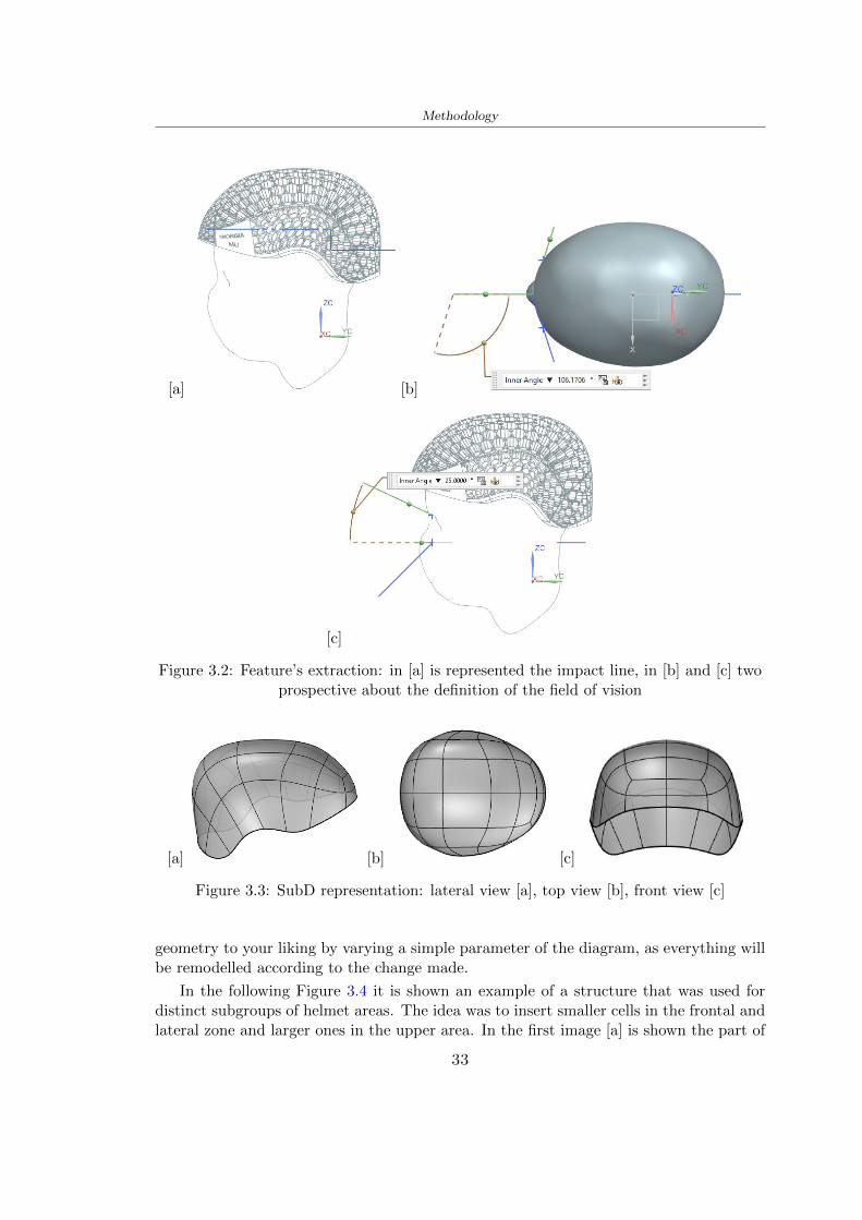
Methodology
[a] [b]
[c]
Figure 32 Featurersquos extraction in [a] is represented the impact line in [b] and [c] twoprospective about the definition of the field of vision
[a] [b] [c]
Figure 33 SubD representation lateral view [a] top view [b] front view [c]
geometry to your liking by varying a simple parameter of the diagram as everything willbe remodelled according to the change made
In the following Figure 34 it is shown an example of a structure that was used fordistinct subgroups of helmet areas The idea was to insert smaller cells in the frontal andlateral zone and larger ones in the upper area In the first image [a] is shown the part of
33
Methodology
the helpful diagram to create the beetle structure to establish the size of the cells andthe extrusion the second image [b] contains the part of the diagram with which I appliedthe structure previously created to the SubD
The structure used to place and adapt the beetle structure to the surface is theSrfMorph while the yellow rsquowindowrsquo that contains numbers serves to select the parts ofthe surface where to apply the geometry created In accord with the GH diagram in
[a]
[b]
Figure 34 Grasshopper diagrams
Figure 34 [a] it is possible to see the steps executed to realize the structure Initially inthe xy-plane a hexagonal grid was drawn through the Hexgrid command in which youcan input the length of the hexagon edge and the number of grid elements (selected bytrial) Then the circumferences was drawn in proportion to the hexagon dimensions asspecified in the Chapter 2 and shown in Figure 35 [a] In figure [b] the rsquocutrsquo made atthe circumferences is visible this subdivision was necessary for printing purposes In thelast photo [c] the structure highlighted in green in [b] was extruded setting a distance
34
Methodology
of 20 mm
[a] [b] [c]
Figure 35 Construction sequence of the geometry of the helmet
In the diagram in Figure 34 [b] there is the application of the structure created bi-dimensionally to the SubD surface of the helmet visible by unlocking the SubD commandof the diagram and in Figure 36 [a] Upper this the referential geometry of the group ofsurfaces was superimposed where it was to be applied the newly created structure (visiblein darker red) the SubD indices are in the yellow box of the diagram
Through the SrfMorph command the location of the structure was granted In Figure36 [b] at the darkest red of the figure [a] with the above command it was possible toplace the structure
[a] [b]
Figure 36 Application of the geometry created to the helmet surface
Overall the diagrams with specific structures are five one for the front two equal forthe side parts one for the top shown in the previous Figure 36 and one for the back
The hexagons in the structure have a dimension varying between 8 mm and 14 mmof side the largest is found at the top later at the back in the sides and the smallest atthe front In Figure 36 [b] the presence of not only hexagonal structures is visible Thegeometry used does not allow the homogeneous arrangement on the entire surface andrequires different structures Automatically the choice of GH to optimize the structurewas to insert quadrilateral
As described above the helmet has different dimensions of the structure divided asvisible in Figure 36 in a quadrilateral This causes a discontinuity between zones withdifferent sizes due to the geometry of the construction
To eliminate this problem and realize the design homogeneous grids were inserted
35
Methodology
in the affected areas as shown in Figure 37 This insertion however proved to beinteresting and strategic researching in this regard studies were realized to demonstratethe insertion of a rectangular grid inside the hexagon grid was helpful for the transmissionof stress in the structure As cited by Sun et al [40] rdquothe mechanical properties of thesesandwich structures are often limited by local failures such as face-core debonding or corecollapserdquo Carrying out compression tests have effectively demonstrated that the insertionof the grid allows rdquoprovided increased stiffness specific stiffness energy absorption andcritical loadrdquo [41] As shown in the graphic [c] of the Figure 37 the honeycomb structuregives a force of 7 kN while with a grid the value is 11 kN and with the combinationexceeds 22 kN In addition in the left front a plaque to customize the helmet wasprepared Figure 37 [a]
[a] [b]
[c]
Figure 37 Grid in the helmet [a] hybrid structure with hexagons and grid [b] [40]compression test results of the hybrid structure [c] [41]
33 3D Print
After having achieved the CAD (Computer Aided Design) of the helmet in order tobe printed it must be converted and saved in format STL (Standard TriangulationLanguage) - Binary compatible with the printing machine and useful for transformingsolid object surfaces into triangles The steps to be taken are the following
bull CAD file realization
bull CAD export in format STL to Simplify 3D the software that shows slider layersand then- rotate and position the object according to geometry and the positioning of any
36
Methodology
supports- setting printing parameters- item manual andor automatic positioning of supports- slider display layers
bull import file gcode to printer
331 Printer and parameters
The program used to visualize how the helmet slices layers before sending it to the printerand to set the parameters is as anticipated Simplify 3D
To make the printing not being a flat geometry it is necessary to place the supportsThe idea was to use water-based supports that the helmet would automatically dissolveonce placed in the water After testing different types of water-soluble PVA the choicefell on eSun 3D Printing Filament PVA (water-soluble support) Before choosing theoptimal position for printing several tests were carried out and to decrease the numberof the supports significantly and allows an optimal printing of the outer part an emptyrsquospherersquo that self-sustains below the helmet was placed as shown in Figure 38
In the image [a] you can see the first print position tried with which an external partof the helmet very damaged was obtained because of the contact supports-helmet In [b]the empty rsquospherersquo is shown to optimize the number of supports and in the last photo [c]there is the full version at the end of print
[a] [b] [c]
Figure 38 Printing supports
The printer that has been used for printing is the Raise 3D Pro2 with double extrudersand nozzles of variable size from 02 mm to 1 mm after some test prints with the PLALW and the structure in created the size that allowed me to have a good compromisebetween printing time and accuracy was 06 mm Using 04 mm the printing time wasexcessive even if having the smaller nozzle diameter means having more precision withthe 08 mm nozzle the quality of the structure was not excellent as seen in Figure 38[a]
Another factor that had to be taken into account is the characteristic of the PLA-LWto expand As the printing temperature and the printer used vary the expansion andcharacteristics of the material change The use of the 06 mm nozzle associated with
37
Methodology
Parameter Left extruder Right extruder
01cm Material 01cm PVA 01cm PLA LW
Extruder toolbox index Tool 0 Tool 1
Nozzle diameter 06 mm 06 mm
Extrusion multiplier 1 05
Extrusion width Auto (072 mm) 05 mm
Layer x
Infill Rectilinear - 50
Supports (Automatic and not) Infill 50
Temperature 210 250
General parameters
Primary layer height 03 mm Top solid layer 4
Bottom solid layer 2 Outline 2
Heated bad 60 Speed 40 mms
Table 31 Printing parameters
Raise 3D allowed me to get good results The choice of this printer was not random ithas in fact the characteristic of making extremely precise prints The Raise has accuracyin placing the object on the printing bed of 078 microns on the xy axis and a resolutionfor layers of 001 mm
The final version of the helmet is visible in Figure 39 and it is possible to compare itwith the preview version in Rhinoceros in Figure 310
38
Methodology
[a] [b]
[c]
Figure 39 Views of the helmet
[a] [b]
Figure 310 Views of the helmet (GH version)
39
Chapter 4
Experimental evaluation
41 Experimental tests
411 Drop-weight impact test machine
In order to calculate the contact force peak and the difference of energy absorbed duringthe impact between the reference helmet and helmet with the beetle structure in PLA-LW dynamic impact tests were carried out using the Fractovis Plus an impact testmachine
In this way it is possible to monitor the evolution of the above variables from theinitial to the final instant of the impact The machine can withstand a load with a rangevariable from 2 to 70 kg with a maximum speed of 46 ms and a maximum height of1 m The values chosen for the test are the following 5 kg weight maximum speed andmaximum height The Anvil that was used is a disc diameter of 60 mm
As shown in Figure 41 and explained by Crupi et al [37] the machine consists ofa sensor capable of recording the speed before impact the impactor that can have avariable mass (a weight of 5 kg in my test) a system to guarantee that there are nomultiple impacts after the first and that work as a shock absorber and clamping systemwhere the object to be tested is placed
The tests that have been carried out are in total four two related to the helmetoptimized with PLA-LW and two with two generic helmets of different brand in EPS
42 PLA LW helmet
To perform the dynamic test on the helmet of PLA considering the difficulty of printingit was helpful to use a test helmet with imperfections to understand where the impactwas concentrated in a single part or distributed The images of Figure 42 show a helmetwith not well defined edges and inaccurate print but exactly localizes the impact zoneThanks to this test it was possible to take into account only one helmet area shown inFigure 43 to have the exact curve of the structure bio-inspired with PLA-LW
40
Experimental evaluation
Figure 41 Drop-weight impact test machine [37]
[a] [b]
Figure 42 Test 1 PLA-LW helmet
43 EPS helmet
To carry out dynamic tests and extract the technical characteristics of the helmettwohelmets were bought in a sports store both EPS and being on the market both certifiedThe brands of the two helmets are DTB and VAN|RYSEL and the average weight ofthe two is 223 g Two different helmets have been chosen to have a more certain andclear classification of the characteristics They are shown in Figure 44 and Figure 45
41
Experimental evaluation
[a] [b]
Figure 43 Test 2 PLA-LW helmet
[a] [b] [c]
Figure 44 Test 3 EPS helmet
[a] [b] [c]
Figure 45 Test 4 EPS helmet
44 Results
441 First results - PLA-LW and EPS helmet
Figure 46 shows two types of trends related to the two different models of the helmetThe force evaluated for PLA-LW has higher force peaks but is more concentrated and
42
Experimental evaluation
propagates less than EPS The graph shows the peaks of each curve highlighted with a redcircle In tests 1 and 2 for the PLA-LW as mentioned earlier the values are higher about7301 N for the complete helmet and 3996 N for the portion of helmet This difference isdue to the inaccuracy of the first full helmet during the printing phase In Figure 42 itis visible the low homogeneity and precision Therefore the first test with full helmet wasused only to define the area of interest of the impact which turns out to be localized Forthe other two EPS curves the values are only slightly lower compared to the PLA-LWequal to 3620 N and 3295 N but the trend is much more distributed
Figure 46 Dynamic machine test - Force
With the data obtained from the impact machine it was possible calculate not exclu-sively the value of force but itrsquos also possible to view the energy curves A resume aboutthe values and energy of the force is in the following Table 41
Test Peak force [N] Peak energy [J]
Test 1 - PLA LW (inaccurate) 730130
Test 2 - PLA LW (portion of helmet) 399643
Test 3 - EPS (DTB helmet) 362007 509
Test 4 - EPS (VAN|RYSEL helmet) 329546 4198
Test 5 - PLA with TPU 45421 5022
Table 41 Energy absorbed in dynamic test
43
Experimental evaluation
442 PLA-LW helmet with TPU cover
As it is possible to see in Figure 47 and as highlighted the first tests concerning thebio-inspired structure and the PLA-LW are far from my expectations considering thelittle distribution of force in comparison with the EPS foam and consequently a smallamount of energy absorbed
Figure 47 Dynamic machine test - Energy
To improve this impact damping factor the idea was to create a cover for the helmetin flexible TPU trying to absorb impact energy The TPU used is a flexible material ofthe brand Ninjaflex used in sports by the application in helmets and shoes to cushionbumps during the game Generally in the helmets (baseball helmet for example) theTPU is inserted internally in contact with the head In my case the TPU structurein addition to creating a shock-absorbing and durable cover creates a custom cover thehelmet and for the person This cover was also made with the Raise 3D printer
As shown in the Figure 48 [a] the infill of the part in contact with the helmet hasa percentage of 100 the filling of the other part of the structure is not complete butonly 15 and the internal structure is hexagonal to recall that of the helmet The desireto insert a structure with a rsquoraisedrsquo geometry is for visual and aesthetic reasons as youhave the feeling of greater protection and not filled is inspired by the machine CitroenCaptus whose bumpers (Airbump) are full of air The failure to realize empty structuresis due to the need to place any internal supports not removable
The idea was to create a cover that allow you to see of the internal structure of thehelmet and that protect specific areas the front the two sides the top and the posteriorWhat which was thought for this reason was to create the shape of a flower with four
44
Experimental evaluation
petals Figure 48 [b]In this way to perform dynamic impact tests as shown in Figure 49 [a] the cover was
positioned at the top of the helmet and the impact was performed in the centre of thersquoflowerrsquo which corresponds to the higher upper part where the structure has larger cellsize The impact parameters are the same as those used in previous impacts 5 kg weightmaximum speed and maximum height The Anvil that was used is a disc diameter of60 mm In photo [b] it is evident the difference between the structure that received theimpact with protection (left) and without protection (right) Without protection duringthe impact there was a perforation of the structure with a concentration of force at a locallevel as you can see in the Figure 46 in the case of TPU the impactor did not perforateand crossed the structure thanks to the cover of TPU that cushioned the shock At themoment of impact the impactor bounced
[a] [b]
Figure 48 TPU cover
[a] [b]
Figure 49 PLA-LW with TPU - dynamic impact [a] and differences between thehelmet with TPU and without TPU cover [b]
45
Experimental evaluation
The Figure 410 includes the diagrams relative to the dynamic impacts In [a] thereare already analyzed EPS results in [b] a comparison between the test on the portionof helmet in PLA LW with and without the TPU cover in [c] the overall comparison ofcurves shows a much more similar EPS trend if the TPU is placed above the structure inPLA LW to soften the blow and absorb the same energy [d]
46
[a]
[c]
[d]
Figure 410 Comparison between PLA-LW with TPU and EPS
Chapter 5
FEM Validation
51 Impactor - Anvils definition
Before to start to work in Abaqus it was necessary to search in the literature the materialwith which the anvil was been realized Milne et al [23] established the densityrsquos valuethe Youngrsquos Module and Poissonrsquos ratio for the Flat and Kerbstone Anvil
- Density ρ = 7800 kgm3
- Youngrsquos Module E = 200000 MPa
- Poissonrsquos ratio ν = 03
Inserting the data in the CES EduPack program specifying the mechanical andphysical properties the material corresponding to these characteristics is Stainless steelaustenitic (ASTM F1586) medium-hard
Initially the proposal was to create a conservative system to evaluate the absorptionenergies values and apply this value to a vibration system but the helmet needs dampingto be realized it was impossible to use a system without losses in this modality Thisis why a numerical calculation was carried out by performing two types of simulationsexplicit dynamic step and static step
The idea to realize the theoretical impact is to regard the movement of the anviland not the helmetrsquos movement which is fixed The velocity is the same cited in thenormative EN 1078 542 ms for the Flat anvil and 457 ms for the Kerbstone anvil
In performing the simulations It was given more relevance and perform tests withthe Kerbstone Anvil This choice was done because the geometry with which it is beenrealized (following as defined in the legislation) allows the helmet to be more subjectedto stress this involves the definition of higher stress limits compared to the Flat Anvil
The mesh size that has been used is the same in the case of the simulation of thehelmet optimized in PLA-LW and the full helmet in EPS of 7 mm The impactor isconsidered as a Discrete rigid body with its specific Reference Point (RP) like shownin Figure 51 for this reason it is not a solid but it is composted only by shells Inthe same image [b] there is the FEM representation of the model and in Table 51 thecharacteristic of FEM with quadrilateral (R3D4) and triangular elements (R3D3)
48
FEM Validation
Object Elementnumber
Elements Shape Geometricorder
Global size[mm]
Kerbstone 230 Quadrilateral - R3D4 Linear 7
Kerbstone 8 Triangular - R3D3 Linear 7
Table 51 Mesh element - Kerbstone Anvil
[a] [b]
Figure 51 Kerbstone anvil in the simulation like discrete rigid body [a] and FEMelements [b]
511 PLA LW - Plastic characteristics
The PLA-LW as explained in the Chapter 2 is new material on the market and producedby the only Colorfabb company for this reason few tests have been carried out to defineits technical characteristics and through tensile tests of the 3D printed specimens it waspossible to define an elastic limit as reported in the Table 210
In the context of simulations to reproduce the impact and deformation of the helmetis also necessary to consider the plastic characteristics of the material Not possessingany reference value in this regard tests were performed through a Static Step initiallyand then an Explicit Dynamic Step in Abaqus
The structure chosen to consider as a reference it is one of the structures previouslysubjected to the compression test having the side L=14 mm As for the reproduction ofthe compression disks initially they were reproduced according to the geometry of theHoytom HM-D Testing Machine considering the bodies mentioned above as discrete 3Drigid discrete The measure was the diameter of 200 mm and the height of 20 mm
After an initial analysis it was observed that the computational time of the simulationprogram was very high so it was decided to change the geometry to have a rsquodisk-surfacesrsquo(equally 3D rigid-discrete) which allowed me to have a smaller number of nodes for themesh and consequently a better computational time The representation of the opti-mized structure in PLA-LW and the disks used for simulated compression is in Figure 52
49
FEM Validation
[a] [b]
Figure 52 Representation of the samples used for the simulation of the compressiontest In Figure [a] the disks of the Hoytom HM-D Testing Machine in figure [b] the
representation of the same as simple surfaces
As shown in Figure 52 the disks are considered 3D discrete hard bodies so it waschosen for both a point the reference point RP where to apply the characteristics relatedto the two bodies As for the compression test it was established
bull the movement of a disk and fixed the second through a boundary condition impos-ing an Encastre therefore unable to move and rotate in xyz directions
bull for the opposite disk the boundary condition relative to the 15 mm displacementwas applied which is the parameter that it was observed to determine the end ofthe compression with the machine This shift is shown by the orange arrow in figure[b]
bull between the upper surface and the disk e the disk with the lower surface it wasinitialized a general contact with normal behaviour through rsquohardrsquo contact andtangential behaviour with a coefficient of friction of 02 with directionality imposedon rsquoisotropicrsquo
The next step was to define the mesh of the components whose parameters are shown inTable 52 while the representation of the FEM is in Figure 53 with the representationof the simulation and real compression test
Object Elementsnumber
Typology Geometricorder
Globalsize [mm]
Disk (14mm) 80910 hexaedral - C3D8R Linear 07
Impact disks 206 quadrilateral - R3D4 Linear 20
Impact disks 6 triangular - R3D3 Linear 20
Table 52 Mesh element - Compression test simulation
As previously announced a static simulation was initially performed with a StaticStep with Step Time equal to 900 (obtained going to consider the speed of 1 mmmin of
50
FEM Validation
[a]
[b] [c]
Figure 53 FEM representation [a] and compression test simulation [b] and realcompression [c]
the compression test and the displacement of 15 mm) However the complex geometryof the structure and the high time set by Step Time did not allow a correct definitionof the parameters of the plastic characteristics of the material the simulation was notable to continue once reached a Step Time of approximately 220 That is why it waschanged by choosing an Explicit Dynamic step
Leaving all the parameters of the boundary conditions unchanged the Step Time wasmodified imposing it to 001 The ability of the explicit dynamic to work with non-linearand contacting structures allowed me to achieve results The results obtained are shownin Figure 54 with the blue curve and were obtained through the iteration of differentPlastic Strain and Yield Stress values in Abaqus while the red line is the result of thereal compression test a similar curve trend was obtained but it is not possible to obtainthe same curve taking into account problems of printing inaccuracy
512 First test - helmet
The initial idea was to perform a simulation imposing the speed of 457 ms to theimpactor tie the helmet in EPS and PLA and compare the absorbed energies Theproblem it was encountered is related to the mesh of the helmet optimized in PLA andwith minimum dimensions of the elements and distinct elements it was not able to solveit
51
FEM Validation
[a]
YieldStress
PlasticStrain
1 47 0
2 7 001
3 75 005
4 10 01
5 108 1
6 115 15
7 12 2
[b]
Figure 54 Representation of the two curves related to the simulation in Abaqus of thecompression test and the data obtained from the real test to obtain the plastic
characteristics of the material
513 Second test - plane
The first solution is the one shown in Figure 55 To realize the simulation it was realizeda section of the helmet to involve a smaller number of elements and nodes Again thesimulation for the EPS helmet was successful while the simulation with the bio-inspiredstructure was interrupted by excessive distortion of elements
The previous images show the impact is very localized in the impacted area and theidea to achieve a complete simulation is not to consider a curved portion of the helmetbut a plane In this way it was possible to solve the problem and obtain a completesimulation for the bio-inspired structure
FEM element
Below in Table 53 there is the definition of the elements used for the PLA-LW and EPSplane in the simulation to simulate the impact and to control the energy-absorbing whilethe anvil characteristics are described in Table 51
514 EPS impact simulations
In order to proceed with the simulation it was imposed some boundary conditions thatregard ties and forces
bull the movement of the plane is fixed through an Encastre therefore unable to moveand rotate in xyz directions
52
FEM Validation
[a]
[b]
Figure 55 Impact simulation parts of EPS and PLA helmet
Object Elementnumber
Elements Shape Geometricorder
Plane (PLA) 38896 Tetrahedral -C3D10M
Quadratic
Plane (EPS) 2100 Hexahedral - C3D8R Linear
Table 53 Mesh element - plane impact
bull to create the impact it was set a speed of 457 ms at the reference point RP of therigid body which is the impactor Kerbstone Anvil shown in Figure 56
bull between the upper surface of the plane and the impactor it was initialized a Sur-face to Surface contact with normal behaviour through rsquohardrsquo contact and tangen-tial behaviour with a coefficient of friction of 02 with directionality imposed onrsquoisotropicrsquo
bull the rotation in x y z relative to the RP of the rigid discrete impactor body is locked
53
FEM Validation
In addition it was characterized the plane in the part of the materials with the char-acteristic values of the EPS mentioned in Chapter 221 The Von Mises Stress valueapparently low is relative to the Yield Stress of the EPS material equal to 09 MPa
Figure 56 EPS Boundary conditions and Load
515 PLA LW impact simulations
As also required in the case of the EPS plane in order to proceed with the simulationsome boundary conditions were imposed that regard ties and forces
bull the movement of the plane is fixed through an Encastre therefore unable to moveand rotate in xyz directions
bull to create the impact a speed of 457 ms was set at the reference point RP of therigid body which is the impactor Kerbstone Anvil shown in Figure 58
bull between the upper surface of the plane and the impactor it was initialized a Sur-face to Surface contact with normal behaviour through rsquohardrsquo contact and tangen-tial behaviour with a coefficient of friction of 02 with directionality imposed onrsquoisotropicrsquo
bull the rotation in x y z relative to the RP of the rigid discrete impactor body is locked
In addition the plane was characterized in the part of the materials with the characteristicvalues of the PLA mentioned in the Chapter 223 and 511
Figure 58 Boundary conditions and Load
54
FEM Validation
[a]
[b]
Figure 57 EPS impact simulation
52 Results
In Figures 59 and 57 it is shown how the structure in PLA LW has a more concentratedstress distribution of the structure unlike EPS The maximum value for the Von Misesstress is 09 MPa in EPS structure and 3634 MPa in PLA LW structure Once thesimulations were obtained the next step was to go and compare the energies absorbed bythe two structures The energy calculated by Abaqus that has been taken into account isPlastic Dissipation To make a comparison the data of the two energies were representedin a single graph
What emerges from the graph is that about the impact made with the KerbstoneAnvil the energy absorption is more excellent although only slightly for the PLA LWthan for the EPS From the graph in Figure 510 a value of 41 J is shown for the EPSand 51 J for the PLA LW
55
[a]
[b]
Figure 59 PLA impact simulation
[a]
Figure 510 EPS and PLA LW energy comparison - Abaqus simulation
Chapter 6
Head Injury Data
For the statistical analysis the injuries related to the accident data were categorised intothe following types and levels based on the details of the medical report [11] about theEN 1078
bull Head Injury Criterion (HIC)
bull Peak Linear Acceleration (PLAc)
bull Gadd Severity Injury (GSI)
bull Diffuse axonal injuries (DAI)
61 Abaqus simulation
Until now the purpose of the simulations has been to determine which between the twomaterials and the two structures of EPS and PLA LW could absorb more energy duringthe impact but no simulations have been carried out in compliance with BS EN 1078on the helmet impact tests To calculate the injuries listed in the previous paragraphhowever we need the acceleration values in the three directions related to the subjectrsquoshead
To realize it the scan of my head already rsquocleanrsquo was considered of which it has beencalculated the inertia thanks to the automatic SolidWorks calculation and evaluated theweight with the Table 24 the structure of the helmet was placed for the EPS and thePLA LW over the head as shown in Figure 61 Also this time being able to mesh theentire helmet in PLA LW was impossible due to the excessive distortion of some elementsduring the simulation so it has been tried to make a section of the structures of thehelmet and results were obtained
57
Head Injury Data
[a] [b]
Figure 61 My scan head - CAD [a] head imported in Abaqus[b]
Initially the simulation had these characteristics as shown in the following Figure62 considering the helmet was not sectioned As explained earlier it was not possibleto get to simulation in the case of the optimized structure in PLA LW for this reasononly a part of the helmet was considered in both cases shown in Figure 63
[a]
Figure 62 Simulation based on BS EN 1078
58
Head Injury Data
[a] [b]
Figure 63 Simulation based on BS EN 1078 with head
In order to proceed with the simulation some boundary conditions that regard tiesand forces have have imposed
bull two reference points RP were created the first in the inertia centre of the headthe second relating to the Kerbstone Anvil which is a discrete rigid body
bull in the reference point RP of the head in the definition of the engineering features5 kg was inserted for the weight and an inertia I11 = 564464E+07 gmm2 I22 =460654E+07gmm2 I33 = 187302E+07gmm2
bull to simulate the impact it was set a speed of 457 ms at the reference point RP ofthe head in z-axis direction
bull a general contact with normal behaviour through rsquohardrsquo contact and tangentialbehaviour with a coefficient of friction of 02
bull between the upper surface of the helmet and the impactor it has been initializeda Surface to Surface contact with normal behaviour through rsquohardrsquo contact andtangential behaviour with a coefficient of friction of 02 with directionality imposedon rsquoisotropicrsquo
bull the movement between the Kerbstone anvil and the helmet is fixed through anEncastre therefore unable to move and rotate in xyz directions
bull the rotation in x y z relative to the RP of the rigid discrete impactor body is locked
FEM element
As reported in Table 53 the portion of the helmet in EPS has used a mesh with hexahe-dral elements of linear order For the structure (beetle) of PLA LW given the geometry
59
Head Injury Data
complexity it was necessary to use a quadratic order of tetrahedra For the mesh of thehead instead in both simulations have been used quadrilateral elements of linear orderas reported in the Tables 61 and 62
Object Elementnumber
Elements Shape Geometricorder
Head 3755 Quadrilateral - R3D4 Linear
Head 34542 Quadrilateral - R3D3 Linear
Helmet (PLA) 272302 Tetrahedral -C3D10M
Quadratic
Table 61 Mesh element - Head simulation with PLA LW (beetle) helmet
Object Elementnumber
Elements Shape Geometricorder
Head 3755 Quadrilateral - R3D4 Linear
Head 34542 Quadrilateral - R3D3 Linear
Helmet (EPS) 72280 Hexahedral - C3D8R Linear
Table 62 Mesh element - Head simulation with EPS helmet
62 Results
Figure 64 represents the simulation in line with BS EN 1078 concerning the helmet inEPS [a] and the helmet with bio-inspired structure in PLA LW For both simulationsVan Misesrsquo stress has Yield Stress values in the case of EPS which is 09 MPa and theplastic behaviour combination of PLA LW [b]
In the case of head and Kerbstone Anvil stress was not assessed as they were previ-ously defined as discrete rigid bodies
63 Head Injury Criterion
The HIC quantifies head impact severity by incorporating time of acceleration exposureand acceleration magnitude it is calculated in post-processing phase with the followingEquation 61
HIC15 =
[1
(t1 minus t2)
int t2
t1
a(t)dt
]25(t2 minus t1) (61)
60
Head Injury Data
[a]
[b]
Figure 64 Results simulation based on BS EN 1078 with sectioned head
For this analysis a(t) is the acceleration calculated in the centre of mass of the head(corresponding to the reference point RP) expressed in g and the time interval (t2 minus t1)was chosen to maximize HIC over a maximum duration of 15 ms
Matlab and the trapz function were used to calculate the HIC to integrate accelerationover time t2 and t1 were considered initial and final times of the simulation t1 = 0 sand t2 = 10 s time less than 15 s
HIC value of 198 was obtained for EPS and 87 for PLA LW Considering the Hayeset al [16] document about the HIC values and the graph in Figure 65 developed bythe author it is possible to find the percentages related to the different injury AIS1 -AIS6 which correspond respectively to lower and higher severity while in Figure 66 therelative fatality to every value of AIS is shown The values obtained for the HIC andother criteria are shown in Table 63 The HIC value for EPS is 198 for PLA LW it is
61
Head Injury Data
Figure 65 Head injury risk curves based on HIC values [16]
Figure 66 The abbreviated injury score versus fatality rate [16]
87 Analyzing the data and comparing them with the curves of the Figure 65 I obtain
bull a percentage between 20 - 30 of AIS 1 for EPS 10 - 20 for PLA LW
bull a percentage between 10 - 20 of AIS 2 for EPS and 0 - 10 for PLA LW
bull for AIS 3 AIS 4 AIS 5 AIS 6 the percentages for both structures is between 0 -10
Comparing these percentages with the fatality rate of Figure 66 it is clear there is a riskof Moderate and Minor fatality in the case of EPS and PLA LW as all values are between0 and 30
62
Head Injury Data
HIC PLA [g] GSI E [J]
EPS 198 97 361 37723
PLA LW 87 75 169 44102
Table 63 Head Injury Data - values
64 Peak Linear Acceleration
The resultant linear acceleration versus time curve was calculated according to Equation62
γ(t) =radicγ2x(t) + γ2y(t) + γ2z (t) (62)
where
bull γ(t) is the resultant linear acceleration (g)
bull γx(t) is the linear acceleration in x axes (g)
bull γy(t) is the linear acceleration in y axes (g)
bull γz(t)is the linear acceleration in z axes (g)
The value of the impact should never exceed 250g [9] Cripton at all [9] in their studyexamined a helmet with expanded polystyrene (EPS) Figure 68 shows maximum HIC forhelmeted and unhelmeted drops from all heights For each drop height helmets reducedHIC relative to unhelmeted drops IARV value is 180g The acceleration in the two casesis shown in Figure 67 and the maximum values are 97g for EPS and 75g for PLA LWas reported in Table 63 The two values considering a maximum value calculated byCripton [9] of 180g are amply optimal and comply with the standard of 250g
65 Gadd Severity Index
Gadd proposed the Severity Index Criteria shown in Equation 63 Following this crite-rion the GSI values that are over 1000 produce serious internal head injury [33]
GSI =
int t1
0a(t)25dt (63)
Where
bull a is the linear acceleration (g)
bull t is the duration of the impact (s)
I calculated the GSI with the function trapz between 0 and t and the resulting valuesare 361 for the EPS and 169 for the PLA LW which comply with the limit
63
Head Injury Data
Figure 67 Peak accelerations for both helmets
Figure 68 Peak accelerations for both helmeted and unhelmeted drops Numbers overbars indicate peak acceleration For 2 m drop height results stated are the mean value
calculated from three drops [9]
64
Head Injury Data
66 Diffuse Axonal Injury
DAI cases covered all incidences in which neurological injuries occurred as well as con-cussion unconsciousness and coma
In order to assess the risk of head trauma in terms of diffuse axonal injury (DAI)Milne et al [23] defined a model based head injury criteria as follows obtaining theresults in Figure 69
bull 50 risk of moderate neurological injury (DAI1+) Brain Von Mises shearing stressof 28 kPa
bull 50 risk of severe neurological injury (DAI2+) Brain Von Mises shearing stressof 53 kPa
[a]
[b]
Figure 69 Peak intra-cerebral shearing stress computed with the helmet model coupledto the human head model for all impact points (a) Flat anvil (b) Kerbstone anvil [23]
65
Head Injury Data
67 Energy absorbed
In Figure 52 during the impact test between the kerbstone Anvil and the plan with thebio-inspired structure in PLA LW and EPS it was found that the PLA LW althoughwith a small difference of 10 J absorbed more energy in comparison with the EPS Whenthe test is carried out in compliance with BS EN 1078 and the head with a speed of 457ms (corresponding to the kerbstone Anvil) as shown in Figure 610 also in this casethe PLA LW with the optimized helmet structure manages to absorb more energy (evenif the difference is very low) compared to the EPS The maximum energy value in PLALW is 44102 J of EPS is 37723 J
Figure 610 Energy absorption - BS EN 1078
66
Chapter 7
Conclusion
71 Conclusion
In this thesis work a bicycle helmet with a bio-inspired structure in PLA LW and 3Dprinted was created The initial approach was to introduce an innovative aspect tostandard EPS helmets not using foam but a polymer with new geometries able toabsorb much energy during the impact For this reason the beetle structure has beenpreferred relying solely on the hypothesis encountered in the literature of its quality inabsorbing energy
Combining the new material of the PLA LW and beetle structure has made possiblethe development of new material satisfactory characteristics have been obtained sincethe first tests The two materials were first subjected to tensile tests to determine theirspecific stress in these the PLA LW had positive results
Subsequent dynamic physical tests were carried out on 3D printed helmet models andon reference helmets in EPS to calculate the absorption energy in both cases at the timeof impact These resulted in energy absorption of the beetle structure in PLA LW withthe application of a TPU cover almost equal to that of EPS about 50J To validate withfinite element analysis the two models an explicit dynamic step was used in AbaqusSimulations showed that the PLA LW structure absorbs a higher amount of energy thanthe EPS the higher is 50 J and the EPS 40J
Finally positive results have also been obtained in calculating the head injury datasimulating according to BS EN 1078 with the use of impactor helmet and head Theacceleration values for both the structures were inferior to 220g precisely for the PLALW was 75g and for the EPS 97g The same applies to the calculation of HIC and GSI(maximum acceptable value of 1000) where the values are 87 and 169 in the case of PLALW and 361 and 198 in EPS For all tests therefore greater efficiency of the structure inPLA LW has been obtained Positive results also in the simulation of the energy absorbedduring the impact as the value referring to the EPS was 35J and that of the PLA LWwas 45J
67
Conclusion
72 Future work lines
The positive results obtained can be considered as a starting point for further tests andsimulations to ensure the safety of the helmet and compliance with the regulations butbefore getting improvements and continue testing changes are required
bull the beetle structure of the helmet made with GH adapts to the SubD withoutallowing to have a homogeneous distribution it would be appropriate to have moreregular hexagonal geometries
bull the mesh of the helmet is too complex and does not allow to perform the simulationprobably to use a more regular structure would have a mesh accordingly moreregular and the simulation would be successful
bull the uneven helmet structure has so many defects that the print is imperfect andthis can change the results of the impact tests the structure should be improved
bull the printing time varies from 4 to 5 days it should be improved
bull the TPU helmet cover is too big for the RAISE printing plan it is necessary togenerate a new geometry
bull the TPU cover it must be fixed on the helmet
bull in the calculation of the DAI it is necessary to have the definition of the brain andthe head should not be considered as a rigid body
bull in the injury calculation the helmet without protection was considered with theTPU cover the result will be better
bull air flow analysis
The comments mentioned are only considerations and problems that I gained duringmy thesis and which should be improved but I am sure that these changes and improve-ments from design to printing and simulations can make the helmet a good product
68
Bibliography
[1] K Adanty J M Clark A Post Thomas Blaine H and M D Gilchrist Comparingtwo proposed protocols to test the oblique response of cycling helmets to fall impactsInternational Journal of Crashworthiness 6648 ndash 663 2020
[2] MF Ashby YJM Brechetb D Cebona and L Salvoc Selection strategies formaterials and processes Materials and Design 2004
[3] M Aysha El casco de bicicleta voronoi impreso en 3d mas seguro y ligero https
www3dnativescomen3d-printed-bicycle-helmet-voronoi-190820204
[4] H Bikas P Stavropoulos and G Chryssolouris Additive manufacturing methodsand modelling approaches a critical review The International Journal of AdvancedManufacturing Technology 83389ndash405 2016
[5] British Standards BSI Helmets for pedal cyclists and for users of skateboards androller skates - BS EN 1078 2012
[6] British Standards BSI Headforms for use in the testing of protective helmets BSEN 960 2020
[7] ColorFabb Colorfabb lw-pla 2019 httpscolorfabbcommedia
datasheetstdscolorfabbTDS_E_ColorFabb_LW-PLApdf
[8] V G Coronado T Haileyesus J M Bell T A Cheng JHaarbauer-Krupa M RLionbarger J Flores-Herrera L C McGuire and J Gilchrist Trends in sports andrecreation-related traumatic brain injuries treated in us emergency departments thenational electronic injury surveillance system-all injury program (neiss-aip) 2001-2012 J Head Trauma Rehabil 30185ndash197 2015
[9] P A Cripton D M Dressler D Stuart Cameron A Christopher R and D RichardsBicycle helmets are highly effective at preventing head injury during head impactHead-form accelerations and injury criteria for helmeted and unhelmeted impactsAccident Analysis and Prevention 701ndash7 2014
[10] L Cui M A Forero R and M D Gilchrist Optimisation of energy absorbingliner for equestrian helmets UCD School of Electrical Electronic and MechanicalEngineering University College Dublin Belfield Dublin4 Ireland 2020
[11] C Deck N Bourdet F Meyer and R Willinger Protection performance of bicyclehelmets Journal of safety research pages 67ndash77 2019
[12] Committee F08 Specification for headforms F2220 ASTM International 2015
[13] Committee F08 Specification for helmets used in recreational bicycling or rollerskating F1447 ASTM International 2018
[14] Committee F08 Test methods for equipment and procedures used in evaluating theperformance F1446 ASTM International 2020
69
Bibliography
[15] P Halldin Shock absorption including measuring CENTC 158 Working Group11 2018
[16] W C Hayes M S Erickson and E D Power Forensic injury biomechanics Annualreview of biomedical engineering pages 55ndash86 2007
[17] HEXR httpshexrcom
[18] C Jinxiang Z Xiaoming O Yoji S Kazuya G Zhensheng and P LongchengThe deformation mode and strengthening mechanism of compression in the beetleelytron plate Materials and Design 131481ndash186 2017
[19] S Kroeker M Ozkul A De Marco S Bonin and GP Siegmund Density variationin the expanded polystyrene eps foam of bicycle helmets and its influence on impactperformance Journal of biomechanical engineering 2019
[20] S G Kroeker SJ Bonin A L DeMarco C A Good and G P Siegmund Agedoes not affect the material properties of expanded polystyrene liners in field-usedbicycle helmets Journal of biomechanical engineering 2016
[21] M Meier K H Tan M K Lim and L Chung Unlocking innovation in the sportindustry through additive manufacturing Business Process Management Journa2018
[22] N J Mills and A Gilchrist The effectiveness of foams in bicycle and motorcyclehelmets Accident Analysis Prevention 23153 ndash 163 1991
[23] G Milne C Deck R P Carreira Q Allinne and R Willinger Development andvalidation of a bicycle helmet assessment of head injury risk under standard impactconditions Computer methods in biomechanics and biomedical engineering 15 Suppl1309 ndash 310 2012
[24] Y Mosleh S J Vander B Depreitere and J Ivens Novel composite foam conceptfor head protection in oblique impacts Adv Eng Mater (Advanced EngineeringMaterials) 10 2017
[25] H Mustafa T Y Pang T Ellena and S H Nasir Impact attenuation of user-centred bicycle helmet design with different foam densities J Phys Conf Ser(Journal of Physics Conference Series) 1150 2019
[26] S H Ngoc and L Guoxing A review of recent research on bio-inspired structuresand materials for energy absorption applications Composites Part 181 2020
[27] J I Novak and A R Novak Is additive manufacturing improving performance insports a systematic review Sport engineering and technology 13 2020
[28] European Road Safety Observatory European road safety observatory facts and fig-ures - cyclists - 2020 December 2020 httpseceuropaeutransportroad_
safetysitesdefaultfilesfacts_figures_cyclists_final_20210323pdf
[29] New York City Departments of Health Parks Mental Hygiene Transportation Recre-ation and the New York City Police Department Bicyclist fatalities and seriousinjuries in new york city 2005
[30] W Pengwen Y Jing H Yanan H Jiaofei and F Xiaoyang Innovative designof a helmet based on reverse engineering and 3d printing Alexandria EngineeringJournal 603445ndash3453 2021
[31] S G Piland T E Gould M Jesunathadas J S Wiggins O McNair and V CShane Protective helmets in sports Materials in Sports Equipment 3 2019
70
Bibliography
[32] K Schmitt P F Niederer M H Muser and F Walz Trauma biomechanicsSpringer Berlin Heidelberg 2010
[33] David Sepelveda Lopez A Biomechanical Analysis of Bicycle Helmets using FEMPhD thesis 2019 Bachelor thesis
[34] H Stigson Bicycle Helmets 2020 Tested by Folksam PhD thesis 2020 PhDAssociate Professor Traffic Safety Research
[35] H Tao K Sudip N Anindya and X Yongzhao 3d printed sensors for biomedicalapplications A review sensor 2019
[36] M Trzaskalska and R Chwastek Damping properties and density of helmet linersmade of expanded polystyrene (eps) Archives of Metallurgy and Materials 66 2020
[37] Crupi V Epasto G and Guglielmino E Impact response of aluminum foam sand-wiches for light-weight ship structures Metals 198ndash112 2020
[38] W Wei-cai F Dong-ming and L Yuan-xin Study on impact energy absorbing per-formance of eps buffer layer of motorcycle helmet Proceedings - 2013 InternationalConference on Mechanical and Automation Engineering MAEE 2013
[39] Z Xiaoming C Jinxiang O Yoji Z Peiwei X Xiaobing and Y Xindi Influence ofhoneycomb dimensions and forming methods on the compressive properties of beetleelytron plates Journal of Sandwich Structures and Materials 2228ndash39 2020
[40] S Zhi L Dong Z Weisheng S Shanshan and G Xu Topological optimization ofbiomimetic sandwich structures with hybrid core and cfrp face sheets CompositesScience and Technology 14279ndash90 2017
[41] S Zhi S Shanshan G Xu H Xiaozhi and C Haoran On compressive propertiesof composite sandwich structures with grid reinforced honeycomb core CompositesPart B 94245ndash252 2016
71
- List of Tables
- List of Figures
- Introduction
-
- Helmet bike protection
-
- Helmet structure
-
- Additive Manufacturing
-
- AM process
- Materials and techniques - FDM
- AM in sport
-
- 3D printed helmets
-
- Phases
- HEXR
- VORONOI
-
- State of the art
-
- Standards
-
- Headform
- European Standard and American Standard
- Field of vision - BS EN 1078
- Test impact area
- Anvils and environmental conditions
-
- Materials
-
- EPS Foam
- CES Edu Pack - Material selection
- PLA with natural fiber and PLA LW
-
- Bio-inspired structures
-
- Beetle structure - Design of the model
- Specific stress - PLA LW and EPS foam
-
- Methodology
-
- 3D scan
-
- 3D Sense 2 scanner and Meshmixer - Reverse reconstruction
- 3D scan analysis and extraction of features
-
- Helmet design
-
- Rhinoceros - Helmet surface
- Grasshopper - Helmet structure
-
- 3D Print
-
- Printer and parameters
-
- Experimental evaluation
-
- Experimental tests
-
- Drop-weight impact test machine
-
- PLA LW helmet
- EPS helmet
- Results
-
- First results - PLA-LW and EPS helmet
- PLA-LW helmet with TPU cover
-
- FEM Validation
-
- Impactor - Anvils definition
-
- PLA LW - Plastic characteristics
- First test - helmet
- Second test - plane
- EPS impact simulations
- PLA LW impact simulations
-
- Results
-
- Head Injury Data
-
- Abaqus simulation
- Results
- Head Injury Criterion
- Peak Linear Acceleration
- Gadd Severity Index
- Diffuse Axonal Injury
- Energy absorbed
-
- Conclusion
-
- Conclusion
- Future work lines
-
- Bibliography
-
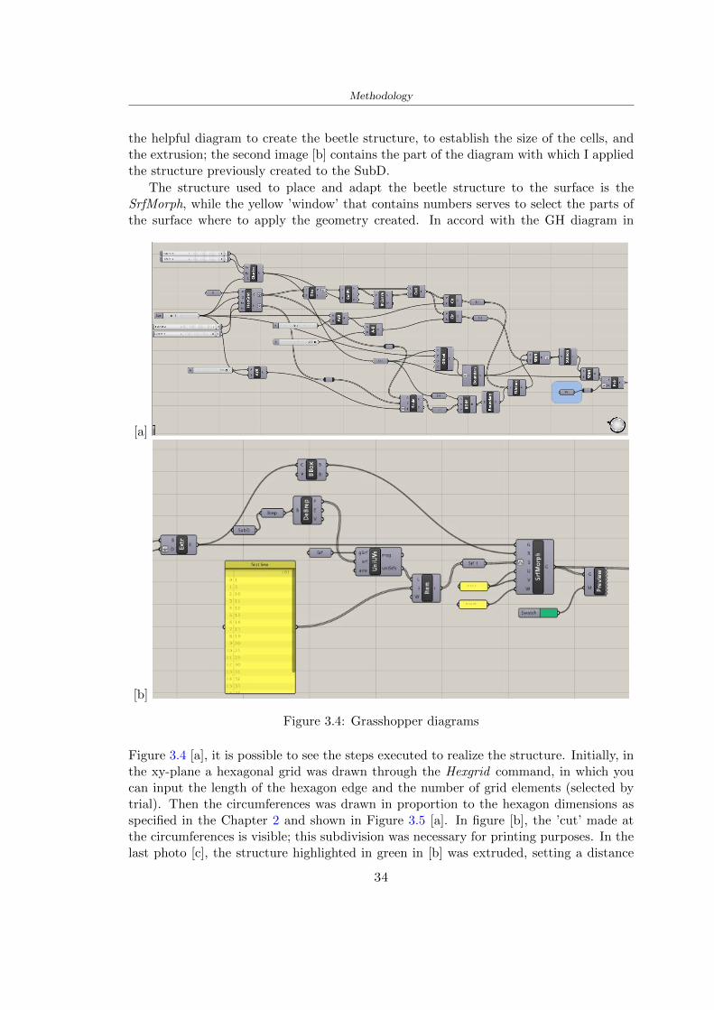
Methodology
the helpful diagram to create the beetle structure to establish the size of the cells andthe extrusion the second image [b] contains the part of the diagram with which I appliedthe structure previously created to the SubD
The structure used to place and adapt the beetle structure to the surface is theSrfMorph while the yellow rsquowindowrsquo that contains numbers serves to select the parts ofthe surface where to apply the geometry created In accord with the GH diagram in
[a]
[b]
Figure 34 Grasshopper diagrams
Figure 34 [a] it is possible to see the steps executed to realize the structure Initially inthe xy-plane a hexagonal grid was drawn through the Hexgrid command in which youcan input the length of the hexagon edge and the number of grid elements (selected bytrial) Then the circumferences was drawn in proportion to the hexagon dimensions asspecified in the Chapter 2 and shown in Figure 35 [a] In figure [b] the rsquocutrsquo made atthe circumferences is visible this subdivision was necessary for printing purposes In thelast photo [c] the structure highlighted in green in [b] was extruded setting a distance
34
Methodology
of 20 mm
[a] [b] [c]
Figure 35 Construction sequence of the geometry of the helmet
In the diagram in Figure 34 [b] there is the application of the structure created bi-dimensionally to the SubD surface of the helmet visible by unlocking the SubD commandof the diagram and in Figure 36 [a] Upper this the referential geometry of the group ofsurfaces was superimposed where it was to be applied the newly created structure (visiblein darker red) the SubD indices are in the yellow box of the diagram
Through the SrfMorph command the location of the structure was granted In Figure36 [b] at the darkest red of the figure [a] with the above command it was possible toplace the structure
[a] [b]
Figure 36 Application of the geometry created to the helmet surface
Overall the diagrams with specific structures are five one for the front two equal forthe side parts one for the top shown in the previous Figure 36 and one for the back
The hexagons in the structure have a dimension varying between 8 mm and 14 mmof side the largest is found at the top later at the back in the sides and the smallest atthe front In Figure 36 [b] the presence of not only hexagonal structures is visible Thegeometry used does not allow the homogeneous arrangement on the entire surface andrequires different structures Automatically the choice of GH to optimize the structurewas to insert quadrilateral
As described above the helmet has different dimensions of the structure divided asvisible in Figure 36 in a quadrilateral This causes a discontinuity between zones withdifferent sizes due to the geometry of the construction
To eliminate this problem and realize the design homogeneous grids were inserted
35
Methodology
in the affected areas as shown in Figure 37 This insertion however proved to beinteresting and strategic researching in this regard studies were realized to demonstratethe insertion of a rectangular grid inside the hexagon grid was helpful for the transmissionof stress in the structure As cited by Sun et al [40] rdquothe mechanical properties of thesesandwich structures are often limited by local failures such as face-core debonding or corecollapserdquo Carrying out compression tests have effectively demonstrated that the insertionof the grid allows rdquoprovided increased stiffness specific stiffness energy absorption andcritical loadrdquo [41] As shown in the graphic [c] of the Figure 37 the honeycomb structuregives a force of 7 kN while with a grid the value is 11 kN and with the combinationexceeds 22 kN In addition in the left front a plaque to customize the helmet wasprepared Figure 37 [a]
[a] [b]
[c]
Figure 37 Grid in the helmet [a] hybrid structure with hexagons and grid [b] [40]compression test results of the hybrid structure [c] [41]
33 3D Print
After having achieved the CAD (Computer Aided Design) of the helmet in order tobe printed it must be converted and saved in format STL (Standard TriangulationLanguage) - Binary compatible with the printing machine and useful for transformingsolid object surfaces into triangles The steps to be taken are the following
bull CAD file realization
bull CAD export in format STL to Simplify 3D the software that shows slider layersand then- rotate and position the object according to geometry and the positioning of any
36
Methodology
supports- setting printing parameters- item manual andor automatic positioning of supports- slider display layers
bull import file gcode to printer
331 Printer and parameters
The program used to visualize how the helmet slices layers before sending it to the printerand to set the parameters is as anticipated Simplify 3D
To make the printing not being a flat geometry it is necessary to place the supportsThe idea was to use water-based supports that the helmet would automatically dissolveonce placed in the water After testing different types of water-soluble PVA the choicefell on eSun 3D Printing Filament PVA (water-soluble support) Before choosing theoptimal position for printing several tests were carried out and to decrease the numberof the supports significantly and allows an optimal printing of the outer part an emptyrsquospherersquo that self-sustains below the helmet was placed as shown in Figure 38
In the image [a] you can see the first print position tried with which an external partof the helmet very damaged was obtained because of the contact supports-helmet In [b]the empty rsquospherersquo is shown to optimize the number of supports and in the last photo [c]there is the full version at the end of print
[a] [b] [c]
Figure 38 Printing supports
The printer that has been used for printing is the Raise 3D Pro2 with double extrudersand nozzles of variable size from 02 mm to 1 mm after some test prints with the PLALW and the structure in created the size that allowed me to have a good compromisebetween printing time and accuracy was 06 mm Using 04 mm the printing time wasexcessive even if having the smaller nozzle diameter means having more precision withthe 08 mm nozzle the quality of the structure was not excellent as seen in Figure 38[a]
Another factor that had to be taken into account is the characteristic of the PLA-LWto expand As the printing temperature and the printer used vary the expansion andcharacteristics of the material change The use of the 06 mm nozzle associated with
37
Methodology
Parameter Left extruder Right extruder
01cm Material 01cm PVA 01cm PLA LW
Extruder toolbox index Tool 0 Tool 1
Nozzle diameter 06 mm 06 mm
Extrusion multiplier 1 05
Extrusion width Auto (072 mm) 05 mm
Layer x
Infill Rectilinear - 50
Supports (Automatic and not) Infill 50
Temperature 210 250
General parameters
Primary layer height 03 mm Top solid layer 4
Bottom solid layer 2 Outline 2
Heated bad 60 Speed 40 mms
Table 31 Printing parameters
Raise 3D allowed me to get good results The choice of this printer was not random ithas in fact the characteristic of making extremely precise prints The Raise has accuracyin placing the object on the printing bed of 078 microns on the xy axis and a resolutionfor layers of 001 mm
The final version of the helmet is visible in Figure 39 and it is possible to compare itwith the preview version in Rhinoceros in Figure 310
38
Methodology
[a] [b]
[c]
Figure 39 Views of the helmet
[a] [b]
Figure 310 Views of the helmet (GH version)
39
Chapter 4
Experimental evaluation
41 Experimental tests
411 Drop-weight impact test machine
In order to calculate the contact force peak and the difference of energy absorbed duringthe impact between the reference helmet and helmet with the beetle structure in PLA-LW dynamic impact tests were carried out using the Fractovis Plus an impact testmachine
In this way it is possible to monitor the evolution of the above variables from theinitial to the final instant of the impact The machine can withstand a load with a rangevariable from 2 to 70 kg with a maximum speed of 46 ms and a maximum height of1 m The values chosen for the test are the following 5 kg weight maximum speed andmaximum height The Anvil that was used is a disc diameter of 60 mm
As shown in Figure 41 and explained by Crupi et al [37] the machine consists ofa sensor capable of recording the speed before impact the impactor that can have avariable mass (a weight of 5 kg in my test) a system to guarantee that there are nomultiple impacts after the first and that work as a shock absorber and clamping systemwhere the object to be tested is placed
The tests that have been carried out are in total four two related to the helmetoptimized with PLA-LW and two with two generic helmets of different brand in EPS
42 PLA LW helmet
To perform the dynamic test on the helmet of PLA considering the difficulty of printingit was helpful to use a test helmet with imperfections to understand where the impactwas concentrated in a single part or distributed The images of Figure 42 show a helmetwith not well defined edges and inaccurate print but exactly localizes the impact zoneThanks to this test it was possible to take into account only one helmet area shown inFigure 43 to have the exact curve of the structure bio-inspired with PLA-LW
40
Experimental evaluation
Figure 41 Drop-weight impact test machine [37]
[a] [b]
Figure 42 Test 1 PLA-LW helmet
43 EPS helmet
To carry out dynamic tests and extract the technical characteristics of the helmettwohelmets were bought in a sports store both EPS and being on the market both certifiedThe brands of the two helmets are DTB and VAN|RYSEL and the average weight ofthe two is 223 g Two different helmets have been chosen to have a more certain andclear classification of the characteristics They are shown in Figure 44 and Figure 45
41
Experimental evaluation
[a] [b]
Figure 43 Test 2 PLA-LW helmet
[a] [b] [c]
Figure 44 Test 3 EPS helmet
[a] [b] [c]
Figure 45 Test 4 EPS helmet
44 Results
441 First results - PLA-LW and EPS helmet
Figure 46 shows two types of trends related to the two different models of the helmetThe force evaluated for PLA-LW has higher force peaks but is more concentrated and
42
Experimental evaluation
propagates less than EPS The graph shows the peaks of each curve highlighted with a redcircle In tests 1 and 2 for the PLA-LW as mentioned earlier the values are higher about7301 N for the complete helmet and 3996 N for the portion of helmet This difference isdue to the inaccuracy of the first full helmet during the printing phase In Figure 42 itis visible the low homogeneity and precision Therefore the first test with full helmet wasused only to define the area of interest of the impact which turns out to be localized Forthe other two EPS curves the values are only slightly lower compared to the PLA-LWequal to 3620 N and 3295 N but the trend is much more distributed
Figure 46 Dynamic machine test - Force
With the data obtained from the impact machine it was possible calculate not exclu-sively the value of force but itrsquos also possible to view the energy curves A resume aboutthe values and energy of the force is in the following Table 41
Test Peak force [N] Peak energy [J]
Test 1 - PLA LW (inaccurate) 730130
Test 2 - PLA LW (portion of helmet) 399643
Test 3 - EPS (DTB helmet) 362007 509
Test 4 - EPS (VAN|RYSEL helmet) 329546 4198
Test 5 - PLA with TPU 45421 5022
Table 41 Energy absorbed in dynamic test
43
Experimental evaluation
442 PLA-LW helmet with TPU cover
As it is possible to see in Figure 47 and as highlighted the first tests concerning thebio-inspired structure and the PLA-LW are far from my expectations considering thelittle distribution of force in comparison with the EPS foam and consequently a smallamount of energy absorbed
Figure 47 Dynamic machine test - Energy
To improve this impact damping factor the idea was to create a cover for the helmetin flexible TPU trying to absorb impact energy The TPU used is a flexible material ofthe brand Ninjaflex used in sports by the application in helmets and shoes to cushionbumps during the game Generally in the helmets (baseball helmet for example) theTPU is inserted internally in contact with the head In my case the TPU structurein addition to creating a shock-absorbing and durable cover creates a custom cover thehelmet and for the person This cover was also made with the Raise 3D printer
As shown in the Figure 48 [a] the infill of the part in contact with the helmet hasa percentage of 100 the filling of the other part of the structure is not complete butonly 15 and the internal structure is hexagonal to recall that of the helmet The desireto insert a structure with a rsquoraisedrsquo geometry is for visual and aesthetic reasons as youhave the feeling of greater protection and not filled is inspired by the machine CitroenCaptus whose bumpers (Airbump) are full of air The failure to realize empty structuresis due to the need to place any internal supports not removable
The idea was to create a cover that allow you to see of the internal structure of thehelmet and that protect specific areas the front the two sides the top and the posteriorWhat which was thought for this reason was to create the shape of a flower with four
44
Experimental evaluation
petals Figure 48 [b]In this way to perform dynamic impact tests as shown in Figure 49 [a] the cover was
positioned at the top of the helmet and the impact was performed in the centre of thersquoflowerrsquo which corresponds to the higher upper part where the structure has larger cellsize The impact parameters are the same as those used in previous impacts 5 kg weightmaximum speed and maximum height The Anvil that was used is a disc diameter of60 mm In photo [b] it is evident the difference between the structure that received theimpact with protection (left) and without protection (right) Without protection duringthe impact there was a perforation of the structure with a concentration of force at a locallevel as you can see in the Figure 46 in the case of TPU the impactor did not perforateand crossed the structure thanks to the cover of TPU that cushioned the shock At themoment of impact the impactor bounced
[a] [b]
Figure 48 TPU cover
[a] [b]
Figure 49 PLA-LW with TPU - dynamic impact [a] and differences between thehelmet with TPU and without TPU cover [b]
45
Experimental evaluation
The Figure 410 includes the diagrams relative to the dynamic impacts In [a] thereare already analyzed EPS results in [b] a comparison between the test on the portionof helmet in PLA LW with and without the TPU cover in [c] the overall comparison ofcurves shows a much more similar EPS trend if the TPU is placed above the structure inPLA LW to soften the blow and absorb the same energy [d]
46
[a]
[c]
[d]
Figure 410 Comparison between PLA-LW with TPU and EPS
Chapter 5
FEM Validation
51 Impactor - Anvils definition
Before to start to work in Abaqus it was necessary to search in the literature the materialwith which the anvil was been realized Milne et al [23] established the densityrsquos valuethe Youngrsquos Module and Poissonrsquos ratio for the Flat and Kerbstone Anvil
- Density ρ = 7800 kgm3
- Youngrsquos Module E = 200000 MPa
- Poissonrsquos ratio ν = 03
Inserting the data in the CES EduPack program specifying the mechanical andphysical properties the material corresponding to these characteristics is Stainless steelaustenitic (ASTM F1586) medium-hard
Initially the proposal was to create a conservative system to evaluate the absorptionenergies values and apply this value to a vibration system but the helmet needs dampingto be realized it was impossible to use a system without losses in this modality Thisis why a numerical calculation was carried out by performing two types of simulationsexplicit dynamic step and static step
The idea to realize the theoretical impact is to regard the movement of the anviland not the helmetrsquos movement which is fixed The velocity is the same cited in thenormative EN 1078 542 ms for the Flat anvil and 457 ms for the Kerbstone anvil
In performing the simulations It was given more relevance and perform tests withthe Kerbstone Anvil This choice was done because the geometry with which it is beenrealized (following as defined in the legislation) allows the helmet to be more subjectedto stress this involves the definition of higher stress limits compared to the Flat Anvil
The mesh size that has been used is the same in the case of the simulation of thehelmet optimized in PLA-LW and the full helmet in EPS of 7 mm The impactor isconsidered as a Discrete rigid body with its specific Reference Point (RP) like shownin Figure 51 for this reason it is not a solid but it is composted only by shells Inthe same image [b] there is the FEM representation of the model and in Table 51 thecharacteristic of FEM with quadrilateral (R3D4) and triangular elements (R3D3)
48
FEM Validation
Object Elementnumber
Elements Shape Geometricorder
Global size[mm]
Kerbstone 230 Quadrilateral - R3D4 Linear 7
Kerbstone 8 Triangular - R3D3 Linear 7
Table 51 Mesh element - Kerbstone Anvil
[a] [b]
Figure 51 Kerbstone anvil in the simulation like discrete rigid body [a] and FEMelements [b]
511 PLA LW - Plastic characteristics
The PLA-LW as explained in the Chapter 2 is new material on the market and producedby the only Colorfabb company for this reason few tests have been carried out to defineits technical characteristics and through tensile tests of the 3D printed specimens it waspossible to define an elastic limit as reported in the Table 210
In the context of simulations to reproduce the impact and deformation of the helmetis also necessary to consider the plastic characteristics of the material Not possessingany reference value in this regard tests were performed through a Static Step initiallyand then an Explicit Dynamic Step in Abaqus
The structure chosen to consider as a reference it is one of the structures previouslysubjected to the compression test having the side L=14 mm As for the reproduction ofthe compression disks initially they were reproduced according to the geometry of theHoytom HM-D Testing Machine considering the bodies mentioned above as discrete 3Drigid discrete The measure was the diameter of 200 mm and the height of 20 mm
After an initial analysis it was observed that the computational time of the simulationprogram was very high so it was decided to change the geometry to have a rsquodisk-surfacesrsquo(equally 3D rigid-discrete) which allowed me to have a smaller number of nodes for themesh and consequently a better computational time The representation of the opti-mized structure in PLA-LW and the disks used for simulated compression is in Figure 52
49
FEM Validation
[a] [b]
Figure 52 Representation of the samples used for the simulation of the compressiontest In Figure [a] the disks of the Hoytom HM-D Testing Machine in figure [b] the
representation of the same as simple surfaces
As shown in Figure 52 the disks are considered 3D discrete hard bodies so it waschosen for both a point the reference point RP where to apply the characteristics relatedto the two bodies As for the compression test it was established
bull the movement of a disk and fixed the second through a boundary condition impos-ing an Encastre therefore unable to move and rotate in xyz directions
bull for the opposite disk the boundary condition relative to the 15 mm displacementwas applied which is the parameter that it was observed to determine the end ofthe compression with the machine This shift is shown by the orange arrow in figure[b]
bull between the upper surface and the disk e the disk with the lower surface it wasinitialized a general contact with normal behaviour through rsquohardrsquo contact andtangential behaviour with a coefficient of friction of 02 with directionality imposedon rsquoisotropicrsquo
The next step was to define the mesh of the components whose parameters are shown inTable 52 while the representation of the FEM is in Figure 53 with the representationof the simulation and real compression test
Object Elementsnumber
Typology Geometricorder
Globalsize [mm]
Disk (14mm) 80910 hexaedral - C3D8R Linear 07
Impact disks 206 quadrilateral - R3D4 Linear 20
Impact disks 6 triangular - R3D3 Linear 20
Table 52 Mesh element - Compression test simulation
As previously announced a static simulation was initially performed with a StaticStep with Step Time equal to 900 (obtained going to consider the speed of 1 mmmin of
50
FEM Validation
[a]
[b] [c]
Figure 53 FEM representation [a] and compression test simulation [b] and realcompression [c]
the compression test and the displacement of 15 mm) However the complex geometryof the structure and the high time set by Step Time did not allow a correct definitionof the parameters of the plastic characteristics of the material the simulation was notable to continue once reached a Step Time of approximately 220 That is why it waschanged by choosing an Explicit Dynamic step
Leaving all the parameters of the boundary conditions unchanged the Step Time wasmodified imposing it to 001 The ability of the explicit dynamic to work with non-linearand contacting structures allowed me to achieve results The results obtained are shownin Figure 54 with the blue curve and were obtained through the iteration of differentPlastic Strain and Yield Stress values in Abaqus while the red line is the result of thereal compression test a similar curve trend was obtained but it is not possible to obtainthe same curve taking into account problems of printing inaccuracy
512 First test - helmet
The initial idea was to perform a simulation imposing the speed of 457 ms to theimpactor tie the helmet in EPS and PLA and compare the absorbed energies Theproblem it was encountered is related to the mesh of the helmet optimized in PLA andwith minimum dimensions of the elements and distinct elements it was not able to solveit
51
FEM Validation
[a]
YieldStress
PlasticStrain
1 47 0
2 7 001
3 75 005
4 10 01
5 108 1
6 115 15
7 12 2
[b]
Figure 54 Representation of the two curves related to the simulation in Abaqus of thecompression test and the data obtained from the real test to obtain the plastic
characteristics of the material
513 Second test - plane
The first solution is the one shown in Figure 55 To realize the simulation it was realizeda section of the helmet to involve a smaller number of elements and nodes Again thesimulation for the EPS helmet was successful while the simulation with the bio-inspiredstructure was interrupted by excessive distortion of elements
The previous images show the impact is very localized in the impacted area and theidea to achieve a complete simulation is not to consider a curved portion of the helmetbut a plane In this way it was possible to solve the problem and obtain a completesimulation for the bio-inspired structure
FEM element
Below in Table 53 there is the definition of the elements used for the PLA-LW and EPSplane in the simulation to simulate the impact and to control the energy-absorbing whilethe anvil characteristics are described in Table 51
514 EPS impact simulations
In order to proceed with the simulation it was imposed some boundary conditions thatregard ties and forces
bull the movement of the plane is fixed through an Encastre therefore unable to moveand rotate in xyz directions
52
FEM Validation
[a]
[b]
Figure 55 Impact simulation parts of EPS and PLA helmet
Object Elementnumber
Elements Shape Geometricorder
Plane (PLA) 38896 Tetrahedral -C3D10M
Quadratic
Plane (EPS) 2100 Hexahedral - C3D8R Linear
Table 53 Mesh element - plane impact
bull to create the impact it was set a speed of 457 ms at the reference point RP of therigid body which is the impactor Kerbstone Anvil shown in Figure 56
bull between the upper surface of the plane and the impactor it was initialized a Sur-face to Surface contact with normal behaviour through rsquohardrsquo contact and tangen-tial behaviour with a coefficient of friction of 02 with directionality imposed onrsquoisotropicrsquo
bull the rotation in x y z relative to the RP of the rigid discrete impactor body is locked
53
FEM Validation
In addition it was characterized the plane in the part of the materials with the char-acteristic values of the EPS mentioned in Chapter 221 The Von Mises Stress valueapparently low is relative to the Yield Stress of the EPS material equal to 09 MPa
Figure 56 EPS Boundary conditions and Load
515 PLA LW impact simulations
As also required in the case of the EPS plane in order to proceed with the simulationsome boundary conditions were imposed that regard ties and forces
bull the movement of the plane is fixed through an Encastre therefore unable to moveand rotate in xyz directions
bull to create the impact a speed of 457 ms was set at the reference point RP of therigid body which is the impactor Kerbstone Anvil shown in Figure 58
bull between the upper surface of the plane and the impactor it was initialized a Sur-face to Surface contact with normal behaviour through rsquohardrsquo contact and tangen-tial behaviour with a coefficient of friction of 02 with directionality imposed onrsquoisotropicrsquo
bull the rotation in x y z relative to the RP of the rigid discrete impactor body is locked
In addition the plane was characterized in the part of the materials with the characteristicvalues of the PLA mentioned in the Chapter 223 and 511
Figure 58 Boundary conditions and Load
54
FEM Validation
[a]
[b]
Figure 57 EPS impact simulation
52 Results
In Figures 59 and 57 it is shown how the structure in PLA LW has a more concentratedstress distribution of the structure unlike EPS The maximum value for the Von Misesstress is 09 MPa in EPS structure and 3634 MPa in PLA LW structure Once thesimulations were obtained the next step was to go and compare the energies absorbed bythe two structures The energy calculated by Abaqus that has been taken into account isPlastic Dissipation To make a comparison the data of the two energies were representedin a single graph
What emerges from the graph is that about the impact made with the KerbstoneAnvil the energy absorption is more excellent although only slightly for the PLA LWthan for the EPS From the graph in Figure 510 a value of 41 J is shown for the EPSand 51 J for the PLA LW
55
[a]
[b]
Figure 59 PLA impact simulation
[a]
Figure 510 EPS and PLA LW energy comparison - Abaqus simulation
Chapter 6
Head Injury Data
For the statistical analysis the injuries related to the accident data were categorised intothe following types and levels based on the details of the medical report [11] about theEN 1078
bull Head Injury Criterion (HIC)
bull Peak Linear Acceleration (PLAc)
bull Gadd Severity Injury (GSI)
bull Diffuse axonal injuries (DAI)
61 Abaqus simulation
Until now the purpose of the simulations has been to determine which between the twomaterials and the two structures of EPS and PLA LW could absorb more energy duringthe impact but no simulations have been carried out in compliance with BS EN 1078on the helmet impact tests To calculate the injuries listed in the previous paragraphhowever we need the acceleration values in the three directions related to the subjectrsquoshead
To realize it the scan of my head already rsquocleanrsquo was considered of which it has beencalculated the inertia thanks to the automatic SolidWorks calculation and evaluated theweight with the Table 24 the structure of the helmet was placed for the EPS and thePLA LW over the head as shown in Figure 61 Also this time being able to mesh theentire helmet in PLA LW was impossible due to the excessive distortion of some elementsduring the simulation so it has been tried to make a section of the structures of thehelmet and results were obtained
57
Head Injury Data
[a] [b]
Figure 61 My scan head - CAD [a] head imported in Abaqus[b]
Initially the simulation had these characteristics as shown in the following Figure62 considering the helmet was not sectioned As explained earlier it was not possibleto get to simulation in the case of the optimized structure in PLA LW for this reasononly a part of the helmet was considered in both cases shown in Figure 63
[a]
Figure 62 Simulation based on BS EN 1078
58
Head Injury Data
[a] [b]
Figure 63 Simulation based on BS EN 1078 with head
In order to proceed with the simulation some boundary conditions that regard tiesand forces have have imposed
bull two reference points RP were created the first in the inertia centre of the headthe second relating to the Kerbstone Anvil which is a discrete rigid body
bull in the reference point RP of the head in the definition of the engineering features5 kg was inserted for the weight and an inertia I11 = 564464E+07 gmm2 I22 =460654E+07gmm2 I33 = 187302E+07gmm2
bull to simulate the impact it was set a speed of 457 ms at the reference point RP ofthe head in z-axis direction
bull a general contact with normal behaviour through rsquohardrsquo contact and tangentialbehaviour with a coefficient of friction of 02
bull between the upper surface of the helmet and the impactor it has been initializeda Surface to Surface contact with normal behaviour through rsquohardrsquo contact andtangential behaviour with a coefficient of friction of 02 with directionality imposedon rsquoisotropicrsquo
bull the movement between the Kerbstone anvil and the helmet is fixed through anEncastre therefore unable to move and rotate in xyz directions
bull the rotation in x y z relative to the RP of the rigid discrete impactor body is locked
FEM element
As reported in Table 53 the portion of the helmet in EPS has used a mesh with hexahe-dral elements of linear order For the structure (beetle) of PLA LW given the geometry
59
Head Injury Data
complexity it was necessary to use a quadratic order of tetrahedra For the mesh of thehead instead in both simulations have been used quadrilateral elements of linear orderas reported in the Tables 61 and 62
Object Elementnumber
Elements Shape Geometricorder
Head 3755 Quadrilateral - R3D4 Linear
Head 34542 Quadrilateral - R3D3 Linear
Helmet (PLA) 272302 Tetrahedral -C3D10M
Quadratic
Table 61 Mesh element - Head simulation with PLA LW (beetle) helmet
Object Elementnumber
Elements Shape Geometricorder
Head 3755 Quadrilateral - R3D4 Linear
Head 34542 Quadrilateral - R3D3 Linear
Helmet (EPS) 72280 Hexahedral - C3D8R Linear
Table 62 Mesh element - Head simulation with EPS helmet
62 Results
Figure 64 represents the simulation in line with BS EN 1078 concerning the helmet inEPS [a] and the helmet with bio-inspired structure in PLA LW For both simulationsVan Misesrsquo stress has Yield Stress values in the case of EPS which is 09 MPa and theplastic behaviour combination of PLA LW [b]
In the case of head and Kerbstone Anvil stress was not assessed as they were previ-ously defined as discrete rigid bodies
63 Head Injury Criterion
The HIC quantifies head impact severity by incorporating time of acceleration exposureand acceleration magnitude it is calculated in post-processing phase with the followingEquation 61
HIC15 =
[1
(t1 minus t2)
int t2
t1
a(t)dt
]25(t2 minus t1) (61)
60
Head Injury Data
[a]
[b]
Figure 64 Results simulation based on BS EN 1078 with sectioned head
For this analysis a(t) is the acceleration calculated in the centre of mass of the head(corresponding to the reference point RP) expressed in g and the time interval (t2 minus t1)was chosen to maximize HIC over a maximum duration of 15 ms
Matlab and the trapz function were used to calculate the HIC to integrate accelerationover time t2 and t1 were considered initial and final times of the simulation t1 = 0 sand t2 = 10 s time less than 15 s
HIC value of 198 was obtained for EPS and 87 for PLA LW Considering the Hayeset al [16] document about the HIC values and the graph in Figure 65 developed bythe author it is possible to find the percentages related to the different injury AIS1 -AIS6 which correspond respectively to lower and higher severity while in Figure 66 therelative fatality to every value of AIS is shown The values obtained for the HIC andother criteria are shown in Table 63 The HIC value for EPS is 198 for PLA LW it is
61
Head Injury Data
Figure 65 Head injury risk curves based on HIC values [16]
Figure 66 The abbreviated injury score versus fatality rate [16]
87 Analyzing the data and comparing them with the curves of the Figure 65 I obtain
bull a percentage between 20 - 30 of AIS 1 for EPS 10 - 20 for PLA LW
bull a percentage between 10 - 20 of AIS 2 for EPS and 0 - 10 for PLA LW
bull for AIS 3 AIS 4 AIS 5 AIS 6 the percentages for both structures is between 0 -10
Comparing these percentages with the fatality rate of Figure 66 it is clear there is a riskof Moderate and Minor fatality in the case of EPS and PLA LW as all values are between0 and 30
62
Head Injury Data
HIC PLA [g] GSI E [J]
EPS 198 97 361 37723
PLA LW 87 75 169 44102
Table 63 Head Injury Data - values
64 Peak Linear Acceleration
The resultant linear acceleration versus time curve was calculated according to Equation62
γ(t) =radicγ2x(t) + γ2y(t) + γ2z (t) (62)
where
bull γ(t) is the resultant linear acceleration (g)
bull γx(t) is the linear acceleration in x axes (g)
bull γy(t) is the linear acceleration in y axes (g)
bull γz(t)is the linear acceleration in z axes (g)
The value of the impact should never exceed 250g [9] Cripton at all [9] in their studyexamined a helmet with expanded polystyrene (EPS) Figure 68 shows maximum HIC forhelmeted and unhelmeted drops from all heights For each drop height helmets reducedHIC relative to unhelmeted drops IARV value is 180g The acceleration in the two casesis shown in Figure 67 and the maximum values are 97g for EPS and 75g for PLA LWas reported in Table 63 The two values considering a maximum value calculated byCripton [9] of 180g are amply optimal and comply with the standard of 250g
65 Gadd Severity Index
Gadd proposed the Severity Index Criteria shown in Equation 63 Following this crite-rion the GSI values that are over 1000 produce serious internal head injury [33]
GSI =
int t1
0a(t)25dt (63)
Where
bull a is the linear acceleration (g)
bull t is the duration of the impact (s)
I calculated the GSI with the function trapz between 0 and t and the resulting valuesare 361 for the EPS and 169 for the PLA LW which comply with the limit
63
Head Injury Data
Figure 67 Peak accelerations for both helmets
Figure 68 Peak accelerations for both helmeted and unhelmeted drops Numbers overbars indicate peak acceleration For 2 m drop height results stated are the mean value
calculated from three drops [9]
64
Head Injury Data
66 Diffuse Axonal Injury
DAI cases covered all incidences in which neurological injuries occurred as well as con-cussion unconsciousness and coma
In order to assess the risk of head trauma in terms of diffuse axonal injury (DAI)Milne et al [23] defined a model based head injury criteria as follows obtaining theresults in Figure 69
bull 50 risk of moderate neurological injury (DAI1+) Brain Von Mises shearing stressof 28 kPa
bull 50 risk of severe neurological injury (DAI2+) Brain Von Mises shearing stressof 53 kPa
[a]
[b]
Figure 69 Peak intra-cerebral shearing stress computed with the helmet model coupledto the human head model for all impact points (a) Flat anvil (b) Kerbstone anvil [23]
65
Head Injury Data
67 Energy absorbed
In Figure 52 during the impact test between the kerbstone Anvil and the plan with thebio-inspired structure in PLA LW and EPS it was found that the PLA LW althoughwith a small difference of 10 J absorbed more energy in comparison with the EPS Whenthe test is carried out in compliance with BS EN 1078 and the head with a speed of 457ms (corresponding to the kerbstone Anvil) as shown in Figure 610 also in this casethe PLA LW with the optimized helmet structure manages to absorb more energy (evenif the difference is very low) compared to the EPS The maximum energy value in PLALW is 44102 J of EPS is 37723 J
Figure 610 Energy absorption - BS EN 1078
66
Chapter 7
Conclusion
71 Conclusion
In this thesis work a bicycle helmet with a bio-inspired structure in PLA LW and 3Dprinted was created The initial approach was to introduce an innovative aspect tostandard EPS helmets not using foam but a polymer with new geometries able toabsorb much energy during the impact For this reason the beetle structure has beenpreferred relying solely on the hypothesis encountered in the literature of its quality inabsorbing energy
Combining the new material of the PLA LW and beetle structure has made possiblethe development of new material satisfactory characteristics have been obtained sincethe first tests The two materials were first subjected to tensile tests to determine theirspecific stress in these the PLA LW had positive results
Subsequent dynamic physical tests were carried out on 3D printed helmet models andon reference helmets in EPS to calculate the absorption energy in both cases at the timeof impact These resulted in energy absorption of the beetle structure in PLA LW withthe application of a TPU cover almost equal to that of EPS about 50J To validate withfinite element analysis the two models an explicit dynamic step was used in AbaqusSimulations showed that the PLA LW structure absorbs a higher amount of energy thanthe EPS the higher is 50 J and the EPS 40J
Finally positive results have also been obtained in calculating the head injury datasimulating according to BS EN 1078 with the use of impactor helmet and head Theacceleration values for both the structures were inferior to 220g precisely for the PLALW was 75g and for the EPS 97g The same applies to the calculation of HIC and GSI(maximum acceptable value of 1000) where the values are 87 and 169 in the case of PLALW and 361 and 198 in EPS For all tests therefore greater efficiency of the structure inPLA LW has been obtained Positive results also in the simulation of the energy absorbedduring the impact as the value referring to the EPS was 35J and that of the PLA LWwas 45J
67
Conclusion
72 Future work lines
The positive results obtained can be considered as a starting point for further tests andsimulations to ensure the safety of the helmet and compliance with the regulations butbefore getting improvements and continue testing changes are required
bull the beetle structure of the helmet made with GH adapts to the SubD withoutallowing to have a homogeneous distribution it would be appropriate to have moreregular hexagonal geometries
bull the mesh of the helmet is too complex and does not allow to perform the simulationprobably to use a more regular structure would have a mesh accordingly moreregular and the simulation would be successful
bull the uneven helmet structure has so many defects that the print is imperfect andthis can change the results of the impact tests the structure should be improved
bull the printing time varies from 4 to 5 days it should be improved
bull the TPU helmet cover is too big for the RAISE printing plan it is necessary togenerate a new geometry
bull the TPU cover it must be fixed on the helmet
bull in the calculation of the DAI it is necessary to have the definition of the brain andthe head should not be considered as a rigid body
bull in the injury calculation the helmet without protection was considered with theTPU cover the result will be better
bull air flow analysis
The comments mentioned are only considerations and problems that I gained duringmy thesis and which should be improved but I am sure that these changes and improve-ments from design to printing and simulations can make the helmet a good product
68
Bibliography
[1] K Adanty J M Clark A Post Thomas Blaine H and M D Gilchrist Comparingtwo proposed protocols to test the oblique response of cycling helmets to fall impactsInternational Journal of Crashworthiness 6648 ndash 663 2020
[2] MF Ashby YJM Brechetb D Cebona and L Salvoc Selection strategies formaterials and processes Materials and Design 2004
[3] M Aysha El casco de bicicleta voronoi impreso en 3d mas seguro y ligero https
www3dnativescomen3d-printed-bicycle-helmet-voronoi-190820204
[4] H Bikas P Stavropoulos and G Chryssolouris Additive manufacturing methodsand modelling approaches a critical review The International Journal of AdvancedManufacturing Technology 83389ndash405 2016
[5] British Standards BSI Helmets for pedal cyclists and for users of skateboards androller skates - BS EN 1078 2012
[6] British Standards BSI Headforms for use in the testing of protective helmets BSEN 960 2020
[7] ColorFabb Colorfabb lw-pla 2019 httpscolorfabbcommedia
datasheetstdscolorfabbTDS_E_ColorFabb_LW-PLApdf
[8] V G Coronado T Haileyesus J M Bell T A Cheng JHaarbauer-Krupa M RLionbarger J Flores-Herrera L C McGuire and J Gilchrist Trends in sports andrecreation-related traumatic brain injuries treated in us emergency departments thenational electronic injury surveillance system-all injury program (neiss-aip) 2001-2012 J Head Trauma Rehabil 30185ndash197 2015
[9] P A Cripton D M Dressler D Stuart Cameron A Christopher R and D RichardsBicycle helmets are highly effective at preventing head injury during head impactHead-form accelerations and injury criteria for helmeted and unhelmeted impactsAccident Analysis and Prevention 701ndash7 2014
[10] L Cui M A Forero R and M D Gilchrist Optimisation of energy absorbingliner for equestrian helmets UCD School of Electrical Electronic and MechanicalEngineering University College Dublin Belfield Dublin4 Ireland 2020
[11] C Deck N Bourdet F Meyer and R Willinger Protection performance of bicyclehelmets Journal of safety research pages 67ndash77 2019
[12] Committee F08 Specification for headforms F2220 ASTM International 2015
[13] Committee F08 Specification for helmets used in recreational bicycling or rollerskating F1447 ASTM International 2018
[14] Committee F08 Test methods for equipment and procedures used in evaluating theperformance F1446 ASTM International 2020
69
Bibliography
[15] P Halldin Shock absorption including measuring CENTC 158 Working Group11 2018
[16] W C Hayes M S Erickson and E D Power Forensic injury biomechanics Annualreview of biomedical engineering pages 55ndash86 2007
[17] HEXR httpshexrcom
[18] C Jinxiang Z Xiaoming O Yoji S Kazuya G Zhensheng and P LongchengThe deformation mode and strengthening mechanism of compression in the beetleelytron plate Materials and Design 131481ndash186 2017
[19] S Kroeker M Ozkul A De Marco S Bonin and GP Siegmund Density variationin the expanded polystyrene eps foam of bicycle helmets and its influence on impactperformance Journal of biomechanical engineering 2019
[20] S G Kroeker SJ Bonin A L DeMarco C A Good and G P Siegmund Agedoes not affect the material properties of expanded polystyrene liners in field-usedbicycle helmets Journal of biomechanical engineering 2016
[21] M Meier K H Tan M K Lim and L Chung Unlocking innovation in the sportindustry through additive manufacturing Business Process Management Journa2018
[22] N J Mills and A Gilchrist The effectiveness of foams in bicycle and motorcyclehelmets Accident Analysis Prevention 23153 ndash 163 1991
[23] G Milne C Deck R P Carreira Q Allinne and R Willinger Development andvalidation of a bicycle helmet assessment of head injury risk under standard impactconditions Computer methods in biomechanics and biomedical engineering 15 Suppl1309 ndash 310 2012
[24] Y Mosleh S J Vander B Depreitere and J Ivens Novel composite foam conceptfor head protection in oblique impacts Adv Eng Mater (Advanced EngineeringMaterials) 10 2017
[25] H Mustafa T Y Pang T Ellena and S H Nasir Impact attenuation of user-centred bicycle helmet design with different foam densities J Phys Conf Ser(Journal of Physics Conference Series) 1150 2019
[26] S H Ngoc and L Guoxing A review of recent research on bio-inspired structuresand materials for energy absorption applications Composites Part 181 2020
[27] J I Novak and A R Novak Is additive manufacturing improving performance insports a systematic review Sport engineering and technology 13 2020
[28] European Road Safety Observatory European road safety observatory facts and fig-ures - cyclists - 2020 December 2020 httpseceuropaeutransportroad_
safetysitesdefaultfilesfacts_figures_cyclists_final_20210323pdf
[29] New York City Departments of Health Parks Mental Hygiene Transportation Recre-ation and the New York City Police Department Bicyclist fatalities and seriousinjuries in new york city 2005
[30] W Pengwen Y Jing H Yanan H Jiaofei and F Xiaoyang Innovative designof a helmet based on reverse engineering and 3d printing Alexandria EngineeringJournal 603445ndash3453 2021
[31] S G Piland T E Gould M Jesunathadas J S Wiggins O McNair and V CShane Protective helmets in sports Materials in Sports Equipment 3 2019
70
Bibliography
[32] K Schmitt P F Niederer M H Muser and F Walz Trauma biomechanicsSpringer Berlin Heidelberg 2010
[33] David Sepelveda Lopez A Biomechanical Analysis of Bicycle Helmets using FEMPhD thesis 2019 Bachelor thesis
[34] H Stigson Bicycle Helmets 2020 Tested by Folksam PhD thesis 2020 PhDAssociate Professor Traffic Safety Research
[35] H Tao K Sudip N Anindya and X Yongzhao 3d printed sensors for biomedicalapplications A review sensor 2019
[36] M Trzaskalska and R Chwastek Damping properties and density of helmet linersmade of expanded polystyrene (eps) Archives of Metallurgy and Materials 66 2020
[37] Crupi V Epasto G and Guglielmino E Impact response of aluminum foam sand-wiches for light-weight ship structures Metals 198ndash112 2020
[38] W Wei-cai F Dong-ming and L Yuan-xin Study on impact energy absorbing per-formance of eps buffer layer of motorcycle helmet Proceedings - 2013 InternationalConference on Mechanical and Automation Engineering MAEE 2013
[39] Z Xiaoming C Jinxiang O Yoji Z Peiwei X Xiaobing and Y Xindi Influence ofhoneycomb dimensions and forming methods on the compressive properties of beetleelytron plates Journal of Sandwich Structures and Materials 2228ndash39 2020
[40] S Zhi L Dong Z Weisheng S Shanshan and G Xu Topological optimization ofbiomimetic sandwich structures with hybrid core and cfrp face sheets CompositesScience and Technology 14279ndash90 2017
[41] S Zhi S Shanshan G Xu H Xiaozhi and C Haoran On compressive propertiesof composite sandwich structures with grid reinforced honeycomb core CompositesPart B 94245ndash252 2016
71
- List of Tables
- List of Figures
- Introduction
-
- Helmet bike protection
-
- Helmet structure
-
- Additive Manufacturing
-
- AM process
- Materials and techniques - FDM
- AM in sport
-
- 3D printed helmets
-
- Phases
- HEXR
- VORONOI
-
- State of the art
-
- Standards
-
- Headform
- European Standard and American Standard
- Field of vision - BS EN 1078
- Test impact area
- Anvils and environmental conditions
-
- Materials
-
- EPS Foam
- CES Edu Pack - Material selection
- PLA with natural fiber and PLA LW
-
- Bio-inspired structures
-
- Beetle structure - Design of the model
- Specific stress - PLA LW and EPS foam
-
- Methodology
-
- 3D scan
-
- 3D Sense 2 scanner and Meshmixer - Reverse reconstruction
- 3D scan analysis and extraction of features
-
- Helmet design
-
- Rhinoceros - Helmet surface
- Grasshopper - Helmet structure
-
- 3D Print
-
- Printer and parameters
-
- Experimental evaluation
-
- Experimental tests
-
- Drop-weight impact test machine
-
- PLA LW helmet
- EPS helmet
- Results
-
- First results - PLA-LW and EPS helmet
- PLA-LW helmet with TPU cover
-
- FEM Validation
-
- Impactor - Anvils definition
-
- PLA LW - Plastic characteristics
- First test - helmet
- Second test - plane
- EPS impact simulations
- PLA LW impact simulations
-
- Results
-
- Head Injury Data
-
- Abaqus simulation
- Results
- Head Injury Criterion
- Peak Linear Acceleration
- Gadd Severity Index
- Diffuse Axonal Injury
- Energy absorbed
-
- Conclusion
-
- Conclusion
- Future work lines
-
- Bibliography
-
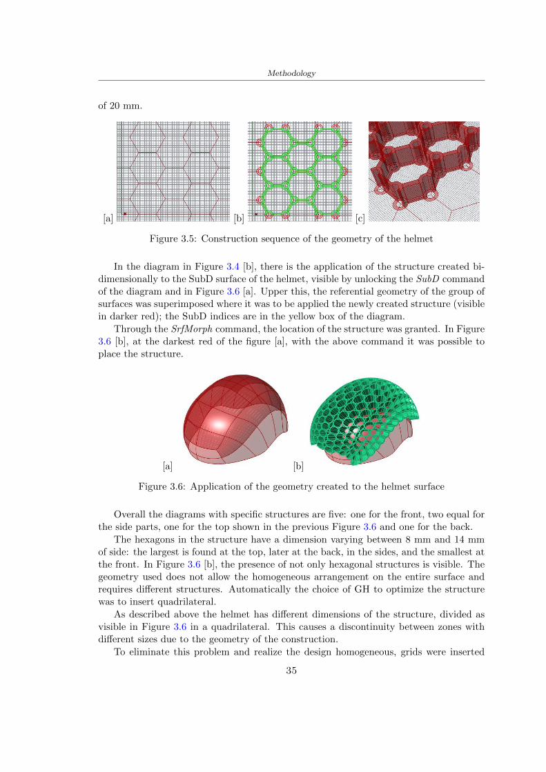
Methodology
of 20 mm
[a] [b] [c]
Figure 35 Construction sequence of the geometry of the helmet
In the diagram in Figure 34 [b] there is the application of the structure created bi-dimensionally to the SubD surface of the helmet visible by unlocking the SubD commandof the diagram and in Figure 36 [a] Upper this the referential geometry of the group ofsurfaces was superimposed where it was to be applied the newly created structure (visiblein darker red) the SubD indices are in the yellow box of the diagram
Through the SrfMorph command the location of the structure was granted In Figure36 [b] at the darkest red of the figure [a] with the above command it was possible toplace the structure
[a] [b]
Figure 36 Application of the geometry created to the helmet surface
Overall the diagrams with specific structures are five one for the front two equal forthe side parts one for the top shown in the previous Figure 36 and one for the back
The hexagons in the structure have a dimension varying between 8 mm and 14 mmof side the largest is found at the top later at the back in the sides and the smallest atthe front In Figure 36 [b] the presence of not only hexagonal structures is visible Thegeometry used does not allow the homogeneous arrangement on the entire surface andrequires different structures Automatically the choice of GH to optimize the structurewas to insert quadrilateral
As described above the helmet has different dimensions of the structure divided asvisible in Figure 36 in a quadrilateral This causes a discontinuity between zones withdifferent sizes due to the geometry of the construction
To eliminate this problem and realize the design homogeneous grids were inserted
35
Methodology
in the affected areas as shown in Figure 37 This insertion however proved to beinteresting and strategic researching in this regard studies were realized to demonstratethe insertion of a rectangular grid inside the hexagon grid was helpful for the transmissionof stress in the structure As cited by Sun et al [40] rdquothe mechanical properties of thesesandwich structures are often limited by local failures such as face-core debonding or corecollapserdquo Carrying out compression tests have effectively demonstrated that the insertionof the grid allows rdquoprovided increased stiffness specific stiffness energy absorption andcritical loadrdquo [41] As shown in the graphic [c] of the Figure 37 the honeycomb structuregives a force of 7 kN while with a grid the value is 11 kN and with the combinationexceeds 22 kN In addition in the left front a plaque to customize the helmet wasprepared Figure 37 [a]
[a] [b]
[c]
Figure 37 Grid in the helmet [a] hybrid structure with hexagons and grid [b] [40]compression test results of the hybrid structure [c] [41]
33 3D Print
After having achieved the CAD (Computer Aided Design) of the helmet in order tobe printed it must be converted and saved in format STL (Standard TriangulationLanguage) - Binary compatible with the printing machine and useful for transformingsolid object surfaces into triangles The steps to be taken are the following
bull CAD file realization
bull CAD export in format STL to Simplify 3D the software that shows slider layersand then- rotate and position the object according to geometry and the positioning of any
36
Methodology
supports- setting printing parameters- item manual andor automatic positioning of supports- slider display layers
bull import file gcode to printer
331 Printer and parameters
The program used to visualize how the helmet slices layers before sending it to the printerand to set the parameters is as anticipated Simplify 3D
To make the printing not being a flat geometry it is necessary to place the supportsThe idea was to use water-based supports that the helmet would automatically dissolveonce placed in the water After testing different types of water-soluble PVA the choicefell on eSun 3D Printing Filament PVA (water-soluble support) Before choosing theoptimal position for printing several tests were carried out and to decrease the numberof the supports significantly and allows an optimal printing of the outer part an emptyrsquospherersquo that self-sustains below the helmet was placed as shown in Figure 38
In the image [a] you can see the first print position tried with which an external partof the helmet very damaged was obtained because of the contact supports-helmet In [b]the empty rsquospherersquo is shown to optimize the number of supports and in the last photo [c]there is the full version at the end of print
[a] [b] [c]
Figure 38 Printing supports
The printer that has been used for printing is the Raise 3D Pro2 with double extrudersand nozzles of variable size from 02 mm to 1 mm after some test prints with the PLALW and the structure in created the size that allowed me to have a good compromisebetween printing time and accuracy was 06 mm Using 04 mm the printing time wasexcessive even if having the smaller nozzle diameter means having more precision withthe 08 mm nozzle the quality of the structure was not excellent as seen in Figure 38[a]
Another factor that had to be taken into account is the characteristic of the PLA-LWto expand As the printing temperature and the printer used vary the expansion andcharacteristics of the material change The use of the 06 mm nozzle associated with
37
Methodology
Parameter Left extruder Right extruder
01cm Material 01cm PVA 01cm PLA LW
Extruder toolbox index Tool 0 Tool 1
Nozzle diameter 06 mm 06 mm
Extrusion multiplier 1 05
Extrusion width Auto (072 mm) 05 mm
Layer x
Infill Rectilinear - 50
Supports (Automatic and not) Infill 50
Temperature 210 250
General parameters
Primary layer height 03 mm Top solid layer 4
Bottom solid layer 2 Outline 2
Heated bad 60 Speed 40 mms
Table 31 Printing parameters
Raise 3D allowed me to get good results The choice of this printer was not random ithas in fact the characteristic of making extremely precise prints The Raise has accuracyin placing the object on the printing bed of 078 microns on the xy axis and a resolutionfor layers of 001 mm
The final version of the helmet is visible in Figure 39 and it is possible to compare itwith the preview version in Rhinoceros in Figure 310
38
Methodology
[a] [b]
[c]
Figure 39 Views of the helmet
[a] [b]
Figure 310 Views of the helmet (GH version)
39
Chapter 4
Experimental evaluation
41 Experimental tests
411 Drop-weight impact test machine
In order to calculate the contact force peak and the difference of energy absorbed duringthe impact between the reference helmet and helmet with the beetle structure in PLA-LW dynamic impact tests were carried out using the Fractovis Plus an impact testmachine
In this way it is possible to monitor the evolution of the above variables from theinitial to the final instant of the impact The machine can withstand a load with a rangevariable from 2 to 70 kg with a maximum speed of 46 ms and a maximum height of1 m The values chosen for the test are the following 5 kg weight maximum speed andmaximum height The Anvil that was used is a disc diameter of 60 mm
As shown in Figure 41 and explained by Crupi et al [37] the machine consists ofa sensor capable of recording the speed before impact the impactor that can have avariable mass (a weight of 5 kg in my test) a system to guarantee that there are nomultiple impacts after the first and that work as a shock absorber and clamping systemwhere the object to be tested is placed
The tests that have been carried out are in total four two related to the helmetoptimized with PLA-LW and two with two generic helmets of different brand in EPS
42 PLA LW helmet
To perform the dynamic test on the helmet of PLA considering the difficulty of printingit was helpful to use a test helmet with imperfections to understand where the impactwas concentrated in a single part or distributed The images of Figure 42 show a helmetwith not well defined edges and inaccurate print but exactly localizes the impact zoneThanks to this test it was possible to take into account only one helmet area shown inFigure 43 to have the exact curve of the structure bio-inspired with PLA-LW
40
Experimental evaluation
Figure 41 Drop-weight impact test machine [37]
[a] [b]
Figure 42 Test 1 PLA-LW helmet
43 EPS helmet
To carry out dynamic tests and extract the technical characteristics of the helmettwohelmets were bought in a sports store both EPS and being on the market both certifiedThe brands of the two helmets are DTB and VAN|RYSEL and the average weight ofthe two is 223 g Two different helmets have been chosen to have a more certain andclear classification of the characteristics They are shown in Figure 44 and Figure 45
41
Experimental evaluation
[a] [b]
Figure 43 Test 2 PLA-LW helmet
[a] [b] [c]
Figure 44 Test 3 EPS helmet
[a] [b] [c]
Figure 45 Test 4 EPS helmet
44 Results
441 First results - PLA-LW and EPS helmet
Figure 46 shows two types of trends related to the two different models of the helmetThe force evaluated for PLA-LW has higher force peaks but is more concentrated and
42
Experimental evaluation
propagates less than EPS The graph shows the peaks of each curve highlighted with a redcircle In tests 1 and 2 for the PLA-LW as mentioned earlier the values are higher about7301 N for the complete helmet and 3996 N for the portion of helmet This difference isdue to the inaccuracy of the first full helmet during the printing phase In Figure 42 itis visible the low homogeneity and precision Therefore the first test with full helmet wasused only to define the area of interest of the impact which turns out to be localized Forthe other two EPS curves the values are only slightly lower compared to the PLA-LWequal to 3620 N and 3295 N but the trend is much more distributed
Figure 46 Dynamic machine test - Force
With the data obtained from the impact machine it was possible calculate not exclu-sively the value of force but itrsquos also possible to view the energy curves A resume aboutthe values and energy of the force is in the following Table 41
Test Peak force [N] Peak energy [J]
Test 1 - PLA LW (inaccurate) 730130
Test 2 - PLA LW (portion of helmet) 399643
Test 3 - EPS (DTB helmet) 362007 509
Test 4 - EPS (VAN|RYSEL helmet) 329546 4198
Test 5 - PLA with TPU 45421 5022
Table 41 Energy absorbed in dynamic test
43
Experimental evaluation
442 PLA-LW helmet with TPU cover
As it is possible to see in Figure 47 and as highlighted the first tests concerning thebio-inspired structure and the PLA-LW are far from my expectations considering thelittle distribution of force in comparison with the EPS foam and consequently a smallamount of energy absorbed
Figure 47 Dynamic machine test - Energy
To improve this impact damping factor the idea was to create a cover for the helmetin flexible TPU trying to absorb impact energy The TPU used is a flexible material ofthe brand Ninjaflex used in sports by the application in helmets and shoes to cushionbumps during the game Generally in the helmets (baseball helmet for example) theTPU is inserted internally in contact with the head In my case the TPU structurein addition to creating a shock-absorbing and durable cover creates a custom cover thehelmet and for the person This cover was also made with the Raise 3D printer
As shown in the Figure 48 [a] the infill of the part in contact with the helmet hasa percentage of 100 the filling of the other part of the structure is not complete butonly 15 and the internal structure is hexagonal to recall that of the helmet The desireto insert a structure with a rsquoraisedrsquo geometry is for visual and aesthetic reasons as youhave the feeling of greater protection and not filled is inspired by the machine CitroenCaptus whose bumpers (Airbump) are full of air The failure to realize empty structuresis due to the need to place any internal supports not removable
The idea was to create a cover that allow you to see of the internal structure of thehelmet and that protect specific areas the front the two sides the top and the posteriorWhat which was thought for this reason was to create the shape of a flower with four
44
Experimental evaluation
petals Figure 48 [b]In this way to perform dynamic impact tests as shown in Figure 49 [a] the cover was
positioned at the top of the helmet and the impact was performed in the centre of thersquoflowerrsquo which corresponds to the higher upper part where the structure has larger cellsize The impact parameters are the same as those used in previous impacts 5 kg weightmaximum speed and maximum height The Anvil that was used is a disc diameter of60 mm In photo [b] it is evident the difference between the structure that received theimpact with protection (left) and without protection (right) Without protection duringthe impact there was a perforation of the structure with a concentration of force at a locallevel as you can see in the Figure 46 in the case of TPU the impactor did not perforateand crossed the structure thanks to the cover of TPU that cushioned the shock At themoment of impact the impactor bounced
[a] [b]
Figure 48 TPU cover
[a] [b]
Figure 49 PLA-LW with TPU - dynamic impact [a] and differences between thehelmet with TPU and without TPU cover [b]
45
Experimental evaluation
The Figure 410 includes the diagrams relative to the dynamic impacts In [a] thereare already analyzed EPS results in [b] a comparison between the test on the portionof helmet in PLA LW with and without the TPU cover in [c] the overall comparison ofcurves shows a much more similar EPS trend if the TPU is placed above the structure inPLA LW to soften the blow and absorb the same energy [d]
46
[a]
[c]
[d]
Figure 410 Comparison between PLA-LW with TPU and EPS
Chapter 5
FEM Validation
51 Impactor - Anvils definition
Before to start to work in Abaqus it was necessary to search in the literature the materialwith which the anvil was been realized Milne et al [23] established the densityrsquos valuethe Youngrsquos Module and Poissonrsquos ratio for the Flat and Kerbstone Anvil
- Density ρ = 7800 kgm3
- Youngrsquos Module E = 200000 MPa
- Poissonrsquos ratio ν = 03
Inserting the data in the CES EduPack program specifying the mechanical andphysical properties the material corresponding to these characteristics is Stainless steelaustenitic (ASTM F1586) medium-hard
Initially the proposal was to create a conservative system to evaluate the absorptionenergies values and apply this value to a vibration system but the helmet needs dampingto be realized it was impossible to use a system without losses in this modality Thisis why a numerical calculation was carried out by performing two types of simulationsexplicit dynamic step and static step
The idea to realize the theoretical impact is to regard the movement of the anviland not the helmetrsquos movement which is fixed The velocity is the same cited in thenormative EN 1078 542 ms for the Flat anvil and 457 ms for the Kerbstone anvil
In performing the simulations It was given more relevance and perform tests withthe Kerbstone Anvil This choice was done because the geometry with which it is beenrealized (following as defined in the legislation) allows the helmet to be more subjectedto stress this involves the definition of higher stress limits compared to the Flat Anvil
The mesh size that has been used is the same in the case of the simulation of thehelmet optimized in PLA-LW and the full helmet in EPS of 7 mm The impactor isconsidered as a Discrete rigid body with its specific Reference Point (RP) like shownin Figure 51 for this reason it is not a solid but it is composted only by shells Inthe same image [b] there is the FEM representation of the model and in Table 51 thecharacteristic of FEM with quadrilateral (R3D4) and triangular elements (R3D3)
48
FEM Validation
Object Elementnumber
Elements Shape Geometricorder
Global size[mm]
Kerbstone 230 Quadrilateral - R3D4 Linear 7
Kerbstone 8 Triangular - R3D3 Linear 7
Table 51 Mesh element - Kerbstone Anvil
[a] [b]
Figure 51 Kerbstone anvil in the simulation like discrete rigid body [a] and FEMelements [b]
511 PLA LW - Plastic characteristics
The PLA-LW as explained in the Chapter 2 is new material on the market and producedby the only Colorfabb company for this reason few tests have been carried out to defineits technical characteristics and through tensile tests of the 3D printed specimens it waspossible to define an elastic limit as reported in the Table 210
In the context of simulations to reproduce the impact and deformation of the helmetis also necessary to consider the plastic characteristics of the material Not possessingany reference value in this regard tests were performed through a Static Step initiallyand then an Explicit Dynamic Step in Abaqus
The structure chosen to consider as a reference it is one of the structures previouslysubjected to the compression test having the side L=14 mm As for the reproduction ofthe compression disks initially they were reproduced according to the geometry of theHoytom HM-D Testing Machine considering the bodies mentioned above as discrete 3Drigid discrete The measure was the diameter of 200 mm and the height of 20 mm
After an initial analysis it was observed that the computational time of the simulationprogram was very high so it was decided to change the geometry to have a rsquodisk-surfacesrsquo(equally 3D rigid-discrete) which allowed me to have a smaller number of nodes for themesh and consequently a better computational time The representation of the opti-mized structure in PLA-LW and the disks used for simulated compression is in Figure 52
49
FEM Validation
[a] [b]
Figure 52 Representation of the samples used for the simulation of the compressiontest In Figure [a] the disks of the Hoytom HM-D Testing Machine in figure [b] the
representation of the same as simple surfaces
As shown in Figure 52 the disks are considered 3D discrete hard bodies so it waschosen for both a point the reference point RP where to apply the characteristics relatedto the two bodies As for the compression test it was established
bull the movement of a disk and fixed the second through a boundary condition impos-ing an Encastre therefore unable to move and rotate in xyz directions
bull for the opposite disk the boundary condition relative to the 15 mm displacementwas applied which is the parameter that it was observed to determine the end ofthe compression with the machine This shift is shown by the orange arrow in figure[b]
bull between the upper surface and the disk e the disk with the lower surface it wasinitialized a general contact with normal behaviour through rsquohardrsquo contact andtangential behaviour with a coefficient of friction of 02 with directionality imposedon rsquoisotropicrsquo
The next step was to define the mesh of the components whose parameters are shown inTable 52 while the representation of the FEM is in Figure 53 with the representationof the simulation and real compression test
Object Elementsnumber
Typology Geometricorder
Globalsize [mm]
Disk (14mm) 80910 hexaedral - C3D8R Linear 07
Impact disks 206 quadrilateral - R3D4 Linear 20
Impact disks 6 triangular - R3D3 Linear 20
Table 52 Mesh element - Compression test simulation
As previously announced a static simulation was initially performed with a StaticStep with Step Time equal to 900 (obtained going to consider the speed of 1 mmmin of
50
FEM Validation
[a]
[b] [c]
Figure 53 FEM representation [a] and compression test simulation [b] and realcompression [c]
the compression test and the displacement of 15 mm) However the complex geometryof the structure and the high time set by Step Time did not allow a correct definitionof the parameters of the plastic characteristics of the material the simulation was notable to continue once reached a Step Time of approximately 220 That is why it waschanged by choosing an Explicit Dynamic step
Leaving all the parameters of the boundary conditions unchanged the Step Time wasmodified imposing it to 001 The ability of the explicit dynamic to work with non-linearand contacting structures allowed me to achieve results The results obtained are shownin Figure 54 with the blue curve and were obtained through the iteration of differentPlastic Strain and Yield Stress values in Abaqus while the red line is the result of thereal compression test a similar curve trend was obtained but it is not possible to obtainthe same curve taking into account problems of printing inaccuracy
512 First test - helmet
The initial idea was to perform a simulation imposing the speed of 457 ms to theimpactor tie the helmet in EPS and PLA and compare the absorbed energies Theproblem it was encountered is related to the mesh of the helmet optimized in PLA andwith minimum dimensions of the elements and distinct elements it was not able to solveit
51
FEM Validation
[a]
YieldStress
PlasticStrain
1 47 0
2 7 001
3 75 005
4 10 01
5 108 1
6 115 15
7 12 2
[b]
Figure 54 Representation of the two curves related to the simulation in Abaqus of thecompression test and the data obtained from the real test to obtain the plastic
characteristics of the material
513 Second test - plane
The first solution is the one shown in Figure 55 To realize the simulation it was realizeda section of the helmet to involve a smaller number of elements and nodes Again thesimulation for the EPS helmet was successful while the simulation with the bio-inspiredstructure was interrupted by excessive distortion of elements
The previous images show the impact is very localized in the impacted area and theidea to achieve a complete simulation is not to consider a curved portion of the helmetbut a plane In this way it was possible to solve the problem and obtain a completesimulation for the bio-inspired structure
FEM element
Below in Table 53 there is the definition of the elements used for the PLA-LW and EPSplane in the simulation to simulate the impact and to control the energy-absorbing whilethe anvil characteristics are described in Table 51
514 EPS impact simulations
In order to proceed with the simulation it was imposed some boundary conditions thatregard ties and forces
bull the movement of the plane is fixed through an Encastre therefore unable to moveand rotate in xyz directions
52
FEM Validation
[a]
[b]
Figure 55 Impact simulation parts of EPS and PLA helmet
Object Elementnumber
Elements Shape Geometricorder
Plane (PLA) 38896 Tetrahedral -C3D10M
Quadratic
Plane (EPS) 2100 Hexahedral - C3D8R Linear
Table 53 Mesh element - plane impact
bull to create the impact it was set a speed of 457 ms at the reference point RP of therigid body which is the impactor Kerbstone Anvil shown in Figure 56
bull between the upper surface of the plane and the impactor it was initialized a Sur-face to Surface contact with normal behaviour through rsquohardrsquo contact and tangen-tial behaviour with a coefficient of friction of 02 with directionality imposed onrsquoisotropicrsquo
bull the rotation in x y z relative to the RP of the rigid discrete impactor body is locked
53
FEM Validation
In addition it was characterized the plane in the part of the materials with the char-acteristic values of the EPS mentioned in Chapter 221 The Von Mises Stress valueapparently low is relative to the Yield Stress of the EPS material equal to 09 MPa
Figure 56 EPS Boundary conditions and Load
515 PLA LW impact simulations
As also required in the case of the EPS plane in order to proceed with the simulationsome boundary conditions were imposed that regard ties and forces
bull the movement of the plane is fixed through an Encastre therefore unable to moveand rotate in xyz directions
bull to create the impact a speed of 457 ms was set at the reference point RP of therigid body which is the impactor Kerbstone Anvil shown in Figure 58
bull between the upper surface of the plane and the impactor it was initialized a Sur-face to Surface contact with normal behaviour through rsquohardrsquo contact and tangen-tial behaviour with a coefficient of friction of 02 with directionality imposed onrsquoisotropicrsquo
bull the rotation in x y z relative to the RP of the rigid discrete impactor body is locked
In addition the plane was characterized in the part of the materials with the characteristicvalues of the PLA mentioned in the Chapter 223 and 511
Figure 58 Boundary conditions and Load
54
FEM Validation
[a]
[b]
Figure 57 EPS impact simulation
52 Results
In Figures 59 and 57 it is shown how the structure in PLA LW has a more concentratedstress distribution of the structure unlike EPS The maximum value for the Von Misesstress is 09 MPa in EPS structure and 3634 MPa in PLA LW structure Once thesimulations were obtained the next step was to go and compare the energies absorbed bythe two structures The energy calculated by Abaqus that has been taken into account isPlastic Dissipation To make a comparison the data of the two energies were representedin a single graph
What emerges from the graph is that about the impact made with the KerbstoneAnvil the energy absorption is more excellent although only slightly for the PLA LWthan for the EPS From the graph in Figure 510 a value of 41 J is shown for the EPSand 51 J for the PLA LW
55
[a]
[b]
Figure 59 PLA impact simulation
[a]
Figure 510 EPS and PLA LW energy comparison - Abaqus simulation
Chapter 6
Head Injury Data
For the statistical analysis the injuries related to the accident data were categorised intothe following types and levels based on the details of the medical report [11] about theEN 1078
bull Head Injury Criterion (HIC)
bull Peak Linear Acceleration (PLAc)
bull Gadd Severity Injury (GSI)
bull Diffuse axonal injuries (DAI)
61 Abaqus simulation
Until now the purpose of the simulations has been to determine which between the twomaterials and the two structures of EPS and PLA LW could absorb more energy duringthe impact but no simulations have been carried out in compliance with BS EN 1078on the helmet impact tests To calculate the injuries listed in the previous paragraphhowever we need the acceleration values in the three directions related to the subjectrsquoshead
To realize it the scan of my head already rsquocleanrsquo was considered of which it has beencalculated the inertia thanks to the automatic SolidWorks calculation and evaluated theweight with the Table 24 the structure of the helmet was placed for the EPS and thePLA LW over the head as shown in Figure 61 Also this time being able to mesh theentire helmet in PLA LW was impossible due to the excessive distortion of some elementsduring the simulation so it has been tried to make a section of the structures of thehelmet and results were obtained
57
Head Injury Data
[a] [b]
Figure 61 My scan head - CAD [a] head imported in Abaqus[b]
Initially the simulation had these characteristics as shown in the following Figure62 considering the helmet was not sectioned As explained earlier it was not possibleto get to simulation in the case of the optimized structure in PLA LW for this reasononly a part of the helmet was considered in both cases shown in Figure 63
[a]
Figure 62 Simulation based on BS EN 1078
58
Head Injury Data
[a] [b]
Figure 63 Simulation based on BS EN 1078 with head
In order to proceed with the simulation some boundary conditions that regard tiesand forces have have imposed
bull two reference points RP were created the first in the inertia centre of the headthe second relating to the Kerbstone Anvil which is a discrete rigid body
bull in the reference point RP of the head in the definition of the engineering features5 kg was inserted for the weight and an inertia I11 = 564464E+07 gmm2 I22 =460654E+07gmm2 I33 = 187302E+07gmm2
bull to simulate the impact it was set a speed of 457 ms at the reference point RP ofthe head in z-axis direction
bull a general contact with normal behaviour through rsquohardrsquo contact and tangentialbehaviour with a coefficient of friction of 02
bull between the upper surface of the helmet and the impactor it has been initializeda Surface to Surface contact with normal behaviour through rsquohardrsquo contact andtangential behaviour with a coefficient of friction of 02 with directionality imposedon rsquoisotropicrsquo
bull the movement between the Kerbstone anvil and the helmet is fixed through anEncastre therefore unable to move and rotate in xyz directions
bull the rotation in x y z relative to the RP of the rigid discrete impactor body is locked
FEM element
As reported in Table 53 the portion of the helmet in EPS has used a mesh with hexahe-dral elements of linear order For the structure (beetle) of PLA LW given the geometry
59
Head Injury Data
complexity it was necessary to use a quadratic order of tetrahedra For the mesh of thehead instead in both simulations have been used quadrilateral elements of linear orderas reported in the Tables 61 and 62
Object Elementnumber
Elements Shape Geometricorder
Head 3755 Quadrilateral - R3D4 Linear
Head 34542 Quadrilateral - R3D3 Linear
Helmet (PLA) 272302 Tetrahedral -C3D10M
Quadratic
Table 61 Mesh element - Head simulation with PLA LW (beetle) helmet
Object Elementnumber
Elements Shape Geometricorder
Head 3755 Quadrilateral - R3D4 Linear
Head 34542 Quadrilateral - R3D3 Linear
Helmet (EPS) 72280 Hexahedral - C3D8R Linear
Table 62 Mesh element - Head simulation with EPS helmet
62 Results
Figure 64 represents the simulation in line with BS EN 1078 concerning the helmet inEPS [a] and the helmet with bio-inspired structure in PLA LW For both simulationsVan Misesrsquo stress has Yield Stress values in the case of EPS which is 09 MPa and theplastic behaviour combination of PLA LW [b]
In the case of head and Kerbstone Anvil stress was not assessed as they were previ-ously defined as discrete rigid bodies
63 Head Injury Criterion
The HIC quantifies head impact severity by incorporating time of acceleration exposureand acceleration magnitude it is calculated in post-processing phase with the followingEquation 61
HIC15 =
[1
(t1 minus t2)
int t2
t1
a(t)dt
]25(t2 minus t1) (61)
60
Head Injury Data
[a]
[b]
Figure 64 Results simulation based on BS EN 1078 with sectioned head
For this analysis a(t) is the acceleration calculated in the centre of mass of the head(corresponding to the reference point RP) expressed in g and the time interval (t2 minus t1)was chosen to maximize HIC over a maximum duration of 15 ms
Matlab and the trapz function were used to calculate the HIC to integrate accelerationover time t2 and t1 were considered initial and final times of the simulation t1 = 0 sand t2 = 10 s time less than 15 s
HIC value of 198 was obtained for EPS and 87 for PLA LW Considering the Hayeset al [16] document about the HIC values and the graph in Figure 65 developed bythe author it is possible to find the percentages related to the different injury AIS1 -AIS6 which correspond respectively to lower and higher severity while in Figure 66 therelative fatality to every value of AIS is shown The values obtained for the HIC andother criteria are shown in Table 63 The HIC value for EPS is 198 for PLA LW it is
61
Head Injury Data
Figure 65 Head injury risk curves based on HIC values [16]
Figure 66 The abbreviated injury score versus fatality rate [16]
87 Analyzing the data and comparing them with the curves of the Figure 65 I obtain
bull a percentage between 20 - 30 of AIS 1 for EPS 10 - 20 for PLA LW
bull a percentage between 10 - 20 of AIS 2 for EPS and 0 - 10 for PLA LW
bull for AIS 3 AIS 4 AIS 5 AIS 6 the percentages for both structures is between 0 -10
Comparing these percentages with the fatality rate of Figure 66 it is clear there is a riskof Moderate and Minor fatality in the case of EPS and PLA LW as all values are between0 and 30
62
Head Injury Data
HIC PLA [g] GSI E [J]
EPS 198 97 361 37723
PLA LW 87 75 169 44102
Table 63 Head Injury Data - values
64 Peak Linear Acceleration
The resultant linear acceleration versus time curve was calculated according to Equation62
γ(t) =radicγ2x(t) + γ2y(t) + γ2z (t) (62)
where
bull γ(t) is the resultant linear acceleration (g)
bull γx(t) is the linear acceleration in x axes (g)
bull γy(t) is the linear acceleration in y axes (g)
bull γz(t)is the linear acceleration in z axes (g)
The value of the impact should never exceed 250g [9] Cripton at all [9] in their studyexamined a helmet with expanded polystyrene (EPS) Figure 68 shows maximum HIC forhelmeted and unhelmeted drops from all heights For each drop height helmets reducedHIC relative to unhelmeted drops IARV value is 180g The acceleration in the two casesis shown in Figure 67 and the maximum values are 97g for EPS and 75g for PLA LWas reported in Table 63 The two values considering a maximum value calculated byCripton [9] of 180g are amply optimal and comply with the standard of 250g
65 Gadd Severity Index
Gadd proposed the Severity Index Criteria shown in Equation 63 Following this crite-rion the GSI values that are over 1000 produce serious internal head injury [33]
GSI =
int t1
0a(t)25dt (63)
Where
bull a is the linear acceleration (g)
bull t is the duration of the impact (s)
I calculated the GSI with the function trapz between 0 and t and the resulting valuesare 361 for the EPS and 169 for the PLA LW which comply with the limit
63
Head Injury Data
Figure 67 Peak accelerations for both helmets
Figure 68 Peak accelerations for both helmeted and unhelmeted drops Numbers overbars indicate peak acceleration For 2 m drop height results stated are the mean value
calculated from three drops [9]
64
Head Injury Data
66 Diffuse Axonal Injury
DAI cases covered all incidences in which neurological injuries occurred as well as con-cussion unconsciousness and coma
In order to assess the risk of head trauma in terms of diffuse axonal injury (DAI)Milne et al [23] defined a model based head injury criteria as follows obtaining theresults in Figure 69
bull 50 risk of moderate neurological injury (DAI1+) Brain Von Mises shearing stressof 28 kPa
bull 50 risk of severe neurological injury (DAI2+) Brain Von Mises shearing stressof 53 kPa
[a]
[b]
Figure 69 Peak intra-cerebral shearing stress computed with the helmet model coupledto the human head model for all impact points (a) Flat anvil (b) Kerbstone anvil [23]
65
Head Injury Data
67 Energy absorbed
In Figure 52 during the impact test between the kerbstone Anvil and the plan with thebio-inspired structure in PLA LW and EPS it was found that the PLA LW althoughwith a small difference of 10 J absorbed more energy in comparison with the EPS Whenthe test is carried out in compliance with BS EN 1078 and the head with a speed of 457ms (corresponding to the kerbstone Anvil) as shown in Figure 610 also in this casethe PLA LW with the optimized helmet structure manages to absorb more energy (evenif the difference is very low) compared to the EPS The maximum energy value in PLALW is 44102 J of EPS is 37723 J
Figure 610 Energy absorption - BS EN 1078
66
Chapter 7
Conclusion
71 Conclusion
In this thesis work a bicycle helmet with a bio-inspired structure in PLA LW and 3Dprinted was created The initial approach was to introduce an innovative aspect tostandard EPS helmets not using foam but a polymer with new geometries able toabsorb much energy during the impact For this reason the beetle structure has beenpreferred relying solely on the hypothesis encountered in the literature of its quality inabsorbing energy
Combining the new material of the PLA LW and beetle structure has made possiblethe development of new material satisfactory characteristics have been obtained sincethe first tests The two materials were first subjected to tensile tests to determine theirspecific stress in these the PLA LW had positive results
Subsequent dynamic physical tests were carried out on 3D printed helmet models andon reference helmets in EPS to calculate the absorption energy in both cases at the timeof impact These resulted in energy absorption of the beetle structure in PLA LW withthe application of a TPU cover almost equal to that of EPS about 50J To validate withfinite element analysis the two models an explicit dynamic step was used in AbaqusSimulations showed that the PLA LW structure absorbs a higher amount of energy thanthe EPS the higher is 50 J and the EPS 40J
Finally positive results have also been obtained in calculating the head injury datasimulating according to BS EN 1078 with the use of impactor helmet and head Theacceleration values for both the structures were inferior to 220g precisely for the PLALW was 75g and for the EPS 97g The same applies to the calculation of HIC and GSI(maximum acceptable value of 1000) where the values are 87 and 169 in the case of PLALW and 361 and 198 in EPS For all tests therefore greater efficiency of the structure inPLA LW has been obtained Positive results also in the simulation of the energy absorbedduring the impact as the value referring to the EPS was 35J and that of the PLA LWwas 45J
67
Conclusion
72 Future work lines
The positive results obtained can be considered as a starting point for further tests andsimulations to ensure the safety of the helmet and compliance with the regulations butbefore getting improvements and continue testing changes are required
bull the beetle structure of the helmet made with GH adapts to the SubD withoutallowing to have a homogeneous distribution it would be appropriate to have moreregular hexagonal geometries
bull the mesh of the helmet is too complex and does not allow to perform the simulationprobably to use a more regular structure would have a mesh accordingly moreregular and the simulation would be successful
bull the uneven helmet structure has so many defects that the print is imperfect andthis can change the results of the impact tests the structure should be improved
bull the printing time varies from 4 to 5 days it should be improved
bull the TPU helmet cover is too big for the RAISE printing plan it is necessary togenerate a new geometry
bull the TPU cover it must be fixed on the helmet
bull in the calculation of the DAI it is necessary to have the definition of the brain andthe head should not be considered as a rigid body
bull in the injury calculation the helmet without protection was considered with theTPU cover the result will be better
bull air flow analysis
The comments mentioned are only considerations and problems that I gained duringmy thesis and which should be improved but I am sure that these changes and improve-ments from design to printing and simulations can make the helmet a good product
68
Bibliography
[1] K Adanty J M Clark A Post Thomas Blaine H and M D Gilchrist Comparingtwo proposed protocols to test the oblique response of cycling helmets to fall impactsInternational Journal of Crashworthiness 6648 ndash 663 2020
[2] MF Ashby YJM Brechetb D Cebona and L Salvoc Selection strategies formaterials and processes Materials and Design 2004
[3] M Aysha El casco de bicicleta voronoi impreso en 3d mas seguro y ligero https
www3dnativescomen3d-printed-bicycle-helmet-voronoi-190820204
[4] H Bikas P Stavropoulos and G Chryssolouris Additive manufacturing methodsand modelling approaches a critical review The International Journal of AdvancedManufacturing Technology 83389ndash405 2016
[5] British Standards BSI Helmets for pedal cyclists and for users of skateboards androller skates - BS EN 1078 2012
[6] British Standards BSI Headforms for use in the testing of protective helmets BSEN 960 2020
[7] ColorFabb Colorfabb lw-pla 2019 httpscolorfabbcommedia
datasheetstdscolorfabbTDS_E_ColorFabb_LW-PLApdf
[8] V G Coronado T Haileyesus J M Bell T A Cheng JHaarbauer-Krupa M RLionbarger J Flores-Herrera L C McGuire and J Gilchrist Trends in sports andrecreation-related traumatic brain injuries treated in us emergency departments thenational electronic injury surveillance system-all injury program (neiss-aip) 2001-2012 J Head Trauma Rehabil 30185ndash197 2015
[9] P A Cripton D M Dressler D Stuart Cameron A Christopher R and D RichardsBicycle helmets are highly effective at preventing head injury during head impactHead-form accelerations and injury criteria for helmeted and unhelmeted impactsAccident Analysis and Prevention 701ndash7 2014
[10] L Cui M A Forero R and M D Gilchrist Optimisation of energy absorbingliner for equestrian helmets UCD School of Electrical Electronic and MechanicalEngineering University College Dublin Belfield Dublin4 Ireland 2020
[11] C Deck N Bourdet F Meyer and R Willinger Protection performance of bicyclehelmets Journal of safety research pages 67ndash77 2019
[12] Committee F08 Specification for headforms F2220 ASTM International 2015
[13] Committee F08 Specification for helmets used in recreational bicycling or rollerskating F1447 ASTM International 2018
[14] Committee F08 Test methods for equipment and procedures used in evaluating theperformance F1446 ASTM International 2020
69
Bibliography
[15] P Halldin Shock absorption including measuring CENTC 158 Working Group11 2018
[16] W C Hayes M S Erickson and E D Power Forensic injury biomechanics Annualreview of biomedical engineering pages 55ndash86 2007
[17] HEXR httpshexrcom
[18] C Jinxiang Z Xiaoming O Yoji S Kazuya G Zhensheng and P LongchengThe deformation mode and strengthening mechanism of compression in the beetleelytron plate Materials and Design 131481ndash186 2017
[19] S Kroeker M Ozkul A De Marco S Bonin and GP Siegmund Density variationin the expanded polystyrene eps foam of bicycle helmets and its influence on impactperformance Journal of biomechanical engineering 2019
[20] S G Kroeker SJ Bonin A L DeMarco C A Good and G P Siegmund Agedoes not affect the material properties of expanded polystyrene liners in field-usedbicycle helmets Journal of biomechanical engineering 2016
[21] M Meier K H Tan M K Lim and L Chung Unlocking innovation in the sportindustry through additive manufacturing Business Process Management Journa2018
[22] N J Mills and A Gilchrist The effectiveness of foams in bicycle and motorcyclehelmets Accident Analysis Prevention 23153 ndash 163 1991
[23] G Milne C Deck R P Carreira Q Allinne and R Willinger Development andvalidation of a bicycle helmet assessment of head injury risk under standard impactconditions Computer methods in biomechanics and biomedical engineering 15 Suppl1309 ndash 310 2012
[24] Y Mosleh S J Vander B Depreitere and J Ivens Novel composite foam conceptfor head protection in oblique impacts Adv Eng Mater (Advanced EngineeringMaterials) 10 2017
[25] H Mustafa T Y Pang T Ellena and S H Nasir Impact attenuation of user-centred bicycle helmet design with different foam densities J Phys Conf Ser(Journal of Physics Conference Series) 1150 2019
[26] S H Ngoc and L Guoxing A review of recent research on bio-inspired structuresand materials for energy absorption applications Composites Part 181 2020
[27] J I Novak and A R Novak Is additive manufacturing improving performance insports a systematic review Sport engineering and technology 13 2020
[28] European Road Safety Observatory European road safety observatory facts and fig-ures - cyclists - 2020 December 2020 httpseceuropaeutransportroad_
safetysitesdefaultfilesfacts_figures_cyclists_final_20210323pdf
[29] New York City Departments of Health Parks Mental Hygiene Transportation Recre-ation and the New York City Police Department Bicyclist fatalities and seriousinjuries in new york city 2005
[30] W Pengwen Y Jing H Yanan H Jiaofei and F Xiaoyang Innovative designof a helmet based on reverse engineering and 3d printing Alexandria EngineeringJournal 603445ndash3453 2021
[31] S G Piland T E Gould M Jesunathadas J S Wiggins O McNair and V CShane Protective helmets in sports Materials in Sports Equipment 3 2019
70
Bibliography
[32] K Schmitt P F Niederer M H Muser and F Walz Trauma biomechanicsSpringer Berlin Heidelberg 2010
[33] David Sepelveda Lopez A Biomechanical Analysis of Bicycle Helmets using FEMPhD thesis 2019 Bachelor thesis
[34] H Stigson Bicycle Helmets 2020 Tested by Folksam PhD thesis 2020 PhDAssociate Professor Traffic Safety Research
[35] H Tao K Sudip N Anindya and X Yongzhao 3d printed sensors for biomedicalapplications A review sensor 2019
[36] M Trzaskalska and R Chwastek Damping properties and density of helmet linersmade of expanded polystyrene (eps) Archives of Metallurgy and Materials 66 2020
[37] Crupi V Epasto G and Guglielmino E Impact response of aluminum foam sand-wiches for light-weight ship structures Metals 198ndash112 2020
[38] W Wei-cai F Dong-ming and L Yuan-xin Study on impact energy absorbing per-formance of eps buffer layer of motorcycle helmet Proceedings - 2013 InternationalConference on Mechanical and Automation Engineering MAEE 2013
[39] Z Xiaoming C Jinxiang O Yoji Z Peiwei X Xiaobing and Y Xindi Influence ofhoneycomb dimensions and forming methods on the compressive properties of beetleelytron plates Journal of Sandwich Structures and Materials 2228ndash39 2020
[40] S Zhi L Dong Z Weisheng S Shanshan and G Xu Topological optimization ofbiomimetic sandwich structures with hybrid core and cfrp face sheets CompositesScience and Technology 14279ndash90 2017
[41] S Zhi S Shanshan G Xu H Xiaozhi and C Haoran On compressive propertiesof composite sandwich structures with grid reinforced honeycomb core CompositesPart B 94245ndash252 2016
71
- List of Tables
- List of Figures
- Introduction
-
- Helmet bike protection
-
- Helmet structure
-
- Additive Manufacturing
-
- AM process
- Materials and techniques - FDM
- AM in sport
-
- 3D printed helmets
-
- Phases
- HEXR
- VORONOI
-
- State of the art
-
- Standards
-
- Headform
- European Standard and American Standard
- Field of vision - BS EN 1078
- Test impact area
- Anvils and environmental conditions
-
- Materials
-
- EPS Foam
- CES Edu Pack - Material selection
- PLA with natural fiber and PLA LW
-
- Bio-inspired structures
-
- Beetle structure - Design of the model
- Specific stress - PLA LW and EPS foam
-
- Methodology
-
- 3D scan
-
- 3D Sense 2 scanner and Meshmixer - Reverse reconstruction
- 3D scan analysis and extraction of features
-
- Helmet design
-
- Rhinoceros - Helmet surface
- Grasshopper - Helmet structure
-
- 3D Print
-
- Printer and parameters
-
- Experimental evaluation
-
- Experimental tests
-
- Drop-weight impact test machine
-
- PLA LW helmet
- EPS helmet
- Results
-
- First results - PLA-LW and EPS helmet
- PLA-LW helmet with TPU cover
-
- FEM Validation
-
- Impactor - Anvils definition
-
- PLA LW - Plastic characteristics
- First test - helmet
- Second test - plane
- EPS impact simulations
- PLA LW impact simulations
-
- Results
-
- Head Injury Data
-
- Abaqus simulation
- Results
- Head Injury Criterion
- Peak Linear Acceleration
- Gadd Severity Index
- Diffuse Axonal Injury
- Energy absorbed
-
- Conclusion
-
- Conclusion
- Future work lines
-
- Bibliography
-
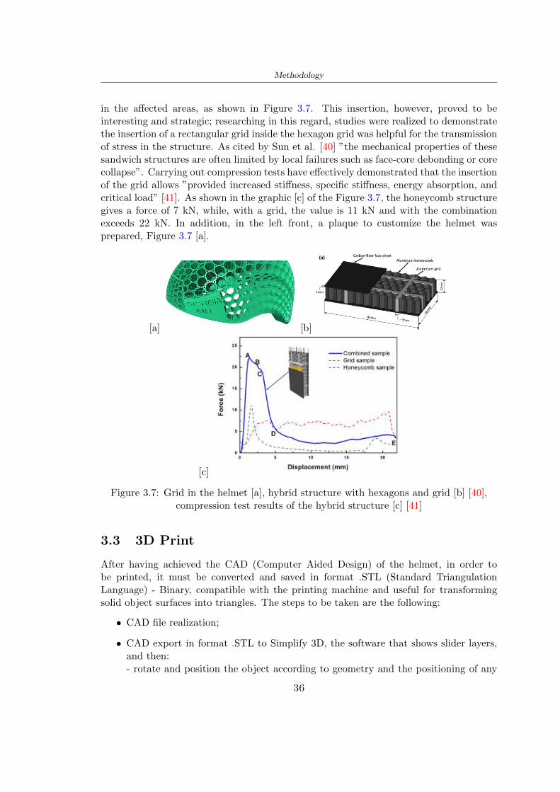
Methodology
in the affected areas as shown in Figure 37 This insertion however proved to beinteresting and strategic researching in this regard studies were realized to demonstratethe insertion of a rectangular grid inside the hexagon grid was helpful for the transmissionof stress in the structure As cited by Sun et al [40] rdquothe mechanical properties of thesesandwich structures are often limited by local failures such as face-core debonding or corecollapserdquo Carrying out compression tests have effectively demonstrated that the insertionof the grid allows rdquoprovided increased stiffness specific stiffness energy absorption andcritical loadrdquo [41] As shown in the graphic [c] of the Figure 37 the honeycomb structuregives a force of 7 kN while with a grid the value is 11 kN and with the combinationexceeds 22 kN In addition in the left front a plaque to customize the helmet wasprepared Figure 37 [a]
[a] [b]
[c]
Figure 37 Grid in the helmet [a] hybrid structure with hexagons and grid [b] [40]compression test results of the hybrid structure [c] [41]
33 3D Print
After having achieved the CAD (Computer Aided Design) of the helmet in order tobe printed it must be converted and saved in format STL (Standard TriangulationLanguage) - Binary compatible with the printing machine and useful for transformingsolid object surfaces into triangles The steps to be taken are the following
bull CAD file realization
bull CAD export in format STL to Simplify 3D the software that shows slider layersand then- rotate and position the object according to geometry and the positioning of any
36
Methodology
supports- setting printing parameters- item manual andor automatic positioning of supports- slider display layers
bull import file gcode to printer
331 Printer and parameters
The program used to visualize how the helmet slices layers before sending it to the printerand to set the parameters is as anticipated Simplify 3D
To make the printing not being a flat geometry it is necessary to place the supportsThe idea was to use water-based supports that the helmet would automatically dissolveonce placed in the water After testing different types of water-soluble PVA the choicefell on eSun 3D Printing Filament PVA (water-soluble support) Before choosing theoptimal position for printing several tests were carried out and to decrease the numberof the supports significantly and allows an optimal printing of the outer part an emptyrsquospherersquo that self-sustains below the helmet was placed as shown in Figure 38
In the image [a] you can see the first print position tried with which an external partof the helmet very damaged was obtained because of the contact supports-helmet In [b]the empty rsquospherersquo is shown to optimize the number of supports and in the last photo [c]there is the full version at the end of print
[a] [b] [c]
Figure 38 Printing supports
The printer that has been used for printing is the Raise 3D Pro2 with double extrudersand nozzles of variable size from 02 mm to 1 mm after some test prints with the PLALW and the structure in created the size that allowed me to have a good compromisebetween printing time and accuracy was 06 mm Using 04 mm the printing time wasexcessive even if having the smaller nozzle diameter means having more precision withthe 08 mm nozzle the quality of the structure was not excellent as seen in Figure 38[a]
Another factor that had to be taken into account is the characteristic of the PLA-LWto expand As the printing temperature and the printer used vary the expansion andcharacteristics of the material change The use of the 06 mm nozzle associated with
37
Methodology
Parameter Left extruder Right extruder
01cm Material 01cm PVA 01cm PLA LW
Extruder toolbox index Tool 0 Tool 1
Nozzle diameter 06 mm 06 mm
Extrusion multiplier 1 05
Extrusion width Auto (072 mm) 05 mm
Layer x
Infill Rectilinear - 50
Supports (Automatic and not) Infill 50
Temperature 210 250
General parameters
Primary layer height 03 mm Top solid layer 4
Bottom solid layer 2 Outline 2
Heated bad 60 Speed 40 mms
Table 31 Printing parameters
Raise 3D allowed me to get good results The choice of this printer was not random ithas in fact the characteristic of making extremely precise prints The Raise has accuracyin placing the object on the printing bed of 078 microns on the xy axis and a resolutionfor layers of 001 mm
The final version of the helmet is visible in Figure 39 and it is possible to compare itwith the preview version in Rhinoceros in Figure 310
38
Methodology
[a] [b]
[c]
Figure 39 Views of the helmet
[a] [b]
Figure 310 Views of the helmet (GH version)
39
Chapter 4
Experimental evaluation
41 Experimental tests
411 Drop-weight impact test machine
In order to calculate the contact force peak and the difference of energy absorbed duringthe impact between the reference helmet and helmet with the beetle structure in PLA-LW dynamic impact tests were carried out using the Fractovis Plus an impact testmachine
In this way it is possible to monitor the evolution of the above variables from theinitial to the final instant of the impact The machine can withstand a load with a rangevariable from 2 to 70 kg with a maximum speed of 46 ms and a maximum height of1 m The values chosen for the test are the following 5 kg weight maximum speed andmaximum height The Anvil that was used is a disc diameter of 60 mm
As shown in Figure 41 and explained by Crupi et al [37] the machine consists ofa sensor capable of recording the speed before impact the impactor that can have avariable mass (a weight of 5 kg in my test) a system to guarantee that there are nomultiple impacts after the first and that work as a shock absorber and clamping systemwhere the object to be tested is placed
The tests that have been carried out are in total four two related to the helmetoptimized with PLA-LW and two with two generic helmets of different brand in EPS
42 PLA LW helmet
To perform the dynamic test on the helmet of PLA considering the difficulty of printingit was helpful to use a test helmet with imperfections to understand where the impactwas concentrated in a single part or distributed The images of Figure 42 show a helmetwith not well defined edges and inaccurate print but exactly localizes the impact zoneThanks to this test it was possible to take into account only one helmet area shown inFigure 43 to have the exact curve of the structure bio-inspired with PLA-LW
40
Experimental evaluation
Figure 41 Drop-weight impact test machine [37]
[a] [b]
Figure 42 Test 1 PLA-LW helmet
43 EPS helmet
To carry out dynamic tests and extract the technical characteristics of the helmettwohelmets were bought in a sports store both EPS and being on the market both certifiedThe brands of the two helmets are DTB and VAN|RYSEL and the average weight ofthe two is 223 g Two different helmets have been chosen to have a more certain andclear classification of the characteristics They are shown in Figure 44 and Figure 45
41
Experimental evaluation
[a] [b]
Figure 43 Test 2 PLA-LW helmet
[a] [b] [c]
Figure 44 Test 3 EPS helmet
[a] [b] [c]
Figure 45 Test 4 EPS helmet
44 Results
441 First results - PLA-LW and EPS helmet
Figure 46 shows two types of trends related to the two different models of the helmetThe force evaluated for PLA-LW has higher force peaks but is more concentrated and
42
Experimental evaluation
propagates less than EPS The graph shows the peaks of each curve highlighted with a redcircle In tests 1 and 2 for the PLA-LW as mentioned earlier the values are higher about7301 N for the complete helmet and 3996 N for the portion of helmet This difference isdue to the inaccuracy of the first full helmet during the printing phase In Figure 42 itis visible the low homogeneity and precision Therefore the first test with full helmet wasused only to define the area of interest of the impact which turns out to be localized Forthe other two EPS curves the values are only slightly lower compared to the PLA-LWequal to 3620 N and 3295 N but the trend is much more distributed
Figure 46 Dynamic machine test - Force
With the data obtained from the impact machine it was possible calculate not exclu-sively the value of force but itrsquos also possible to view the energy curves A resume aboutthe values and energy of the force is in the following Table 41
Test Peak force [N] Peak energy [J]
Test 1 - PLA LW (inaccurate) 730130
Test 2 - PLA LW (portion of helmet) 399643
Test 3 - EPS (DTB helmet) 362007 509
Test 4 - EPS (VAN|RYSEL helmet) 329546 4198
Test 5 - PLA with TPU 45421 5022
Table 41 Energy absorbed in dynamic test
43
Experimental evaluation
442 PLA-LW helmet with TPU cover
As it is possible to see in Figure 47 and as highlighted the first tests concerning thebio-inspired structure and the PLA-LW are far from my expectations considering thelittle distribution of force in comparison with the EPS foam and consequently a smallamount of energy absorbed
Figure 47 Dynamic machine test - Energy
To improve this impact damping factor the idea was to create a cover for the helmetin flexible TPU trying to absorb impact energy The TPU used is a flexible material ofthe brand Ninjaflex used in sports by the application in helmets and shoes to cushionbumps during the game Generally in the helmets (baseball helmet for example) theTPU is inserted internally in contact with the head In my case the TPU structurein addition to creating a shock-absorbing and durable cover creates a custom cover thehelmet and for the person This cover was also made with the Raise 3D printer
As shown in the Figure 48 [a] the infill of the part in contact with the helmet hasa percentage of 100 the filling of the other part of the structure is not complete butonly 15 and the internal structure is hexagonal to recall that of the helmet The desireto insert a structure with a rsquoraisedrsquo geometry is for visual and aesthetic reasons as youhave the feeling of greater protection and not filled is inspired by the machine CitroenCaptus whose bumpers (Airbump) are full of air The failure to realize empty structuresis due to the need to place any internal supports not removable
The idea was to create a cover that allow you to see of the internal structure of thehelmet and that protect specific areas the front the two sides the top and the posteriorWhat which was thought for this reason was to create the shape of a flower with four
44
Experimental evaluation
petals Figure 48 [b]In this way to perform dynamic impact tests as shown in Figure 49 [a] the cover was
positioned at the top of the helmet and the impact was performed in the centre of thersquoflowerrsquo which corresponds to the higher upper part where the structure has larger cellsize The impact parameters are the same as those used in previous impacts 5 kg weightmaximum speed and maximum height The Anvil that was used is a disc diameter of60 mm In photo [b] it is evident the difference between the structure that received theimpact with protection (left) and without protection (right) Without protection duringthe impact there was a perforation of the structure with a concentration of force at a locallevel as you can see in the Figure 46 in the case of TPU the impactor did not perforateand crossed the structure thanks to the cover of TPU that cushioned the shock At themoment of impact the impactor bounced
[a] [b]
Figure 48 TPU cover
[a] [b]
Figure 49 PLA-LW with TPU - dynamic impact [a] and differences between thehelmet with TPU and without TPU cover [b]
45
Experimental evaluation
The Figure 410 includes the diagrams relative to the dynamic impacts In [a] thereare already analyzed EPS results in [b] a comparison between the test on the portionof helmet in PLA LW with and without the TPU cover in [c] the overall comparison ofcurves shows a much more similar EPS trend if the TPU is placed above the structure inPLA LW to soften the blow and absorb the same energy [d]
46
[a]
[c]
[d]
Figure 410 Comparison between PLA-LW with TPU and EPS
Chapter 5
FEM Validation
51 Impactor - Anvils definition
Before to start to work in Abaqus it was necessary to search in the literature the materialwith which the anvil was been realized Milne et al [23] established the densityrsquos valuethe Youngrsquos Module and Poissonrsquos ratio for the Flat and Kerbstone Anvil
- Density ρ = 7800 kgm3
- Youngrsquos Module E = 200000 MPa
- Poissonrsquos ratio ν = 03
Inserting the data in the CES EduPack program specifying the mechanical andphysical properties the material corresponding to these characteristics is Stainless steelaustenitic (ASTM F1586) medium-hard
Initially the proposal was to create a conservative system to evaluate the absorptionenergies values and apply this value to a vibration system but the helmet needs dampingto be realized it was impossible to use a system without losses in this modality Thisis why a numerical calculation was carried out by performing two types of simulationsexplicit dynamic step and static step
The idea to realize the theoretical impact is to regard the movement of the anviland not the helmetrsquos movement which is fixed The velocity is the same cited in thenormative EN 1078 542 ms for the Flat anvil and 457 ms for the Kerbstone anvil
In performing the simulations It was given more relevance and perform tests withthe Kerbstone Anvil This choice was done because the geometry with which it is beenrealized (following as defined in the legislation) allows the helmet to be more subjectedto stress this involves the definition of higher stress limits compared to the Flat Anvil
The mesh size that has been used is the same in the case of the simulation of thehelmet optimized in PLA-LW and the full helmet in EPS of 7 mm The impactor isconsidered as a Discrete rigid body with its specific Reference Point (RP) like shownin Figure 51 for this reason it is not a solid but it is composted only by shells Inthe same image [b] there is the FEM representation of the model and in Table 51 thecharacteristic of FEM with quadrilateral (R3D4) and triangular elements (R3D3)
48
FEM Validation
Object Elementnumber
Elements Shape Geometricorder
Global size[mm]
Kerbstone 230 Quadrilateral - R3D4 Linear 7
Kerbstone 8 Triangular - R3D3 Linear 7
Table 51 Mesh element - Kerbstone Anvil
[a] [b]
Figure 51 Kerbstone anvil in the simulation like discrete rigid body [a] and FEMelements [b]
511 PLA LW - Plastic characteristics
The PLA-LW as explained in the Chapter 2 is new material on the market and producedby the only Colorfabb company for this reason few tests have been carried out to defineits technical characteristics and through tensile tests of the 3D printed specimens it waspossible to define an elastic limit as reported in the Table 210
In the context of simulations to reproduce the impact and deformation of the helmetis also necessary to consider the plastic characteristics of the material Not possessingany reference value in this regard tests were performed through a Static Step initiallyand then an Explicit Dynamic Step in Abaqus
The structure chosen to consider as a reference it is one of the structures previouslysubjected to the compression test having the side L=14 mm As for the reproduction ofthe compression disks initially they were reproduced according to the geometry of theHoytom HM-D Testing Machine considering the bodies mentioned above as discrete 3Drigid discrete The measure was the diameter of 200 mm and the height of 20 mm
After an initial analysis it was observed that the computational time of the simulationprogram was very high so it was decided to change the geometry to have a rsquodisk-surfacesrsquo(equally 3D rigid-discrete) which allowed me to have a smaller number of nodes for themesh and consequently a better computational time The representation of the opti-mized structure in PLA-LW and the disks used for simulated compression is in Figure 52
49
FEM Validation
[a] [b]
Figure 52 Representation of the samples used for the simulation of the compressiontest In Figure [a] the disks of the Hoytom HM-D Testing Machine in figure [b] the
representation of the same as simple surfaces
As shown in Figure 52 the disks are considered 3D discrete hard bodies so it waschosen for both a point the reference point RP where to apply the characteristics relatedto the two bodies As for the compression test it was established
bull the movement of a disk and fixed the second through a boundary condition impos-ing an Encastre therefore unable to move and rotate in xyz directions
bull for the opposite disk the boundary condition relative to the 15 mm displacementwas applied which is the parameter that it was observed to determine the end ofthe compression with the machine This shift is shown by the orange arrow in figure[b]
bull between the upper surface and the disk e the disk with the lower surface it wasinitialized a general contact with normal behaviour through rsquohardrsquo contact andtangential behaviour with a coefficient of friction of 02 with directionality imposedon rsquoisotropicrsquo
The next step was to define the mesh of the components whose parameters are shown inTable 52 while the representation of the FEM is in Figure 53 with the representationof the simulation and real compression test
Object Elementsnumber
Typology Geometricorder
Globalsize [mm]
Disk (14mm) 80910 hexaedral - C3D8R Linear 07
Impact disks 206 quadrilateral - R3D4 Linear 20
Impact disks 6 triangular - R3D3 Linear 20
Table 52 Mesh element - Compression test simulation
As previously announced a static simulation was initially performed with a StaticStep with Step Time equal to 900 (obtained going to consider the speed of 1 mmmin of
50
FEM Validation
[a]
[b] [c]
Figure 53 FEM representation [a] and compression test simulation [b] and realcompression [c]
the compression test and the displacement of 15 mm) However the complex geometryof the structure and the high time set by Step Time did not allow a correct definitionof the parameters of the plastic characteristics of the material the simulation was notable to continue once reached a Step Time of approximately 220 That is why it waschanged by choosing an Explicit Dynamic step
Leaving all the parameters of the boundary conditions unchanged the Step Time wasmodified imposing it to 001 The ability of the explicit dynamic to work with non-linearand contacting structures allowed me to achieve results The results obtained are shownin Figure 54 with the blue curve and were obtained through the iteration of differentPlastic Strain and Yield Stress values in Abaqus while the red line is the result of thereal compression test a similar curve trend was obtained but it is not possible to obtainthe same curve taking into account problems of printing inaccuracy
512 First test - helmet
The initial idea was to perform a simulation imposing the speed of 457 ms to theimpactor tie the helmet in EPS and PLA and compare the absorbed energies Theproblem it was encountered is related to the mesh of the helmet optimized in PLA andwith minimum dimensions of the elements and distinct elements it was not able to solveit
51
FEM Validation
[a]
YieldStress
PlasticStrain
1 47 0
2 7 001
3 75 005
4 10 01
5 108 1
6 115 15
7 12 2
[b]
Figure 54 Representation of the two curves related to the simulation in Abaqus of thecompression test and the data obtained from the real test to obtain the plastic
characteristics of the material
513 Second test - plane
The first solution is the one shown in Figure 55 To realize the simulation it was realizeda section of the helmet to involve a smaller number of elements and nodes Again thesimulation for the EPS helmet was successful while the simulation with the bio-inspiredstructure was interrupted by excessive distortion of elements
The previous images show the impact is very localized in the impacted area and theidea to achieve a complete simulation is not to consider a curved portion of the helmetbut a plane In this way it was possible to solve the problem and obtain a completesimulation for the bio-inspired structure
FEM element
Below in Table 53 there is the definition of the elements used for the PLA-LW and EPSplane in the simulation to simulate the impact and to control the energy-absorbing whilethe anvil characteristics are described in Table 51
514 EPS impact simulations
In order to proceed with the simulation it was imposed some boundary conditions thatregard ties and forces
bull the movement of the plane is fixed through an Encastre therefore unable to moveand rotate in xyz directions
52
FEM Validation
[a]
[b]
Figure 55 Impact simulation parts of EPS and PLA helmet
Object Elementnumber
Elements Shape Geometricorder
Plane (PLA) 38896 Tetrahedral -C3D10M
Quadratic
Plane (EPS) 2100 Hexahedral - C3D8R Linear
Table 53 Mesh element - plane impact
bull to create the impact it was set a speed of 457 ms at the reference point RP of therigid body which is the impactor Kerbstone Anvil shown in Figure 56
bull between the upper surface of the plane and the impactor it was initialized a Sur-face to Surface contact with normal behaviour through rsquohardrsquo contact and tangen-tial behaviour with a coefficient of friction of 02 with directionality imposed onrsquoisotropicrsquo
bull the rotation in x y z relative to the RP of the rigid discrete impactor body is locked
53
FEM Validation
In addition it was characterized the plane in the part of the materials with the char-acteristic values of the EPS mentioned in Chapter 221 The Von Mises Stress valueapparently low is relative to the Yield Stress of the EPS material equal to 09 MPa
Figure 56 EPS Boundary conditions and Load
515 PLA LW impact simulations
As also required in the case of the EPS plane in order to proceed with the simulationsome boundary conditions were imposed that regard ties and forces
bull the movement of the plane is fixed through an Encastre therefore unable to moveand rotate in xyz directions
bull to create the impact a speed of 457 ms was set at the reference point RP of therigid body which is the impactor Kerbstone Anvil shown in Figure 58
bull between the upper surface of the plane and the impactor it was initialized a Sur-face to Surface contact with normal behaviour through rsquohardrsquo contact and tangen-tial behaviour with a coefficient of friction of 02 with directionality imposed onrsquoisotropicrsquo
bull the rotation in x y z relative to the RP of the rigid discrete impactor body is locked
In addition the plane was characterized in the part of the materials with the characteristicvalues of the PLA mentioned in the Chapter 223 and 511
Figure 58 Boundary conditions and Load
54
FEM Validation
[a]
[b]
Figure 57 EPS impact simulation
52 Results
In Figures 59 and 57 it is shown how the structure in PLA LW has a more concentratedstress distribution of the structure unlike EPS The maximum value for the Von Misesstress is 09 MPa in EPS structure and 3634 MPa in PLA LW structure Once thesimulations were obtained the next step was to go and compare the energies absorbed bythe two structures The energy calculated by Abaqus that has been taken into account isPlastic Dissipation To make a comparison the data of the two energies were representedin a single graph
What emerges from the graph is that about the impact made with the KerbstoneAnvil the energy absorption is more excellent although only slightly for the PLA LWthan for the EPS From the graph in Figure 510 a value of 41 J is shown for the EPSand 51 J for the PLA LW
55
[a]
[b]
Figure 59 PLA impact simulation
[a]
Figure 510 EPS and PLA LW energy comparison - Abaqus simulation
Chapter 6
Head Injury Data
For the statistical analysis the injuries related to the accident data were categorised intothe following types and levels based on the details of the medical report [11] about theEN 1078
bull Head Injury Criterion (HIC)
bull Peak Linear Acceleration (PLAc)
bull Gadd Severity Injury (GSI)
bull Diffuse axonal injuries (DAI)
61 Abaqus simulation
Until now the purpose of the simulations has been to determine which between the twomaterials and the two structures of EPS and PLA LW could absorb more energy duringthe impact but no simulations have been carried out in compliance with BS EN 1078on the helmet impact tests To calculate the injuries listed in the previous paragraphhowever we need the acceleration values in the three directions related to the subjectrsquoshead
To realize it the scan of my head already rsquocleanrsquo was considered of which it has beencalculated the inertia thanks to the automatic SolidWorks calculation and evaluated theweight with the Table 24 the structure of the helmet was placed for the EPS and thePLA LW over the head as shown in Figure 61 Also this time being able to mesh theentire helmet in PLA LW was impossible due to the excessive distortion of some elementsduring the simulation so it has been tried to make a section of the structures of thehelmet and results were obtained
57
Head Injury Data
[a] [b]
Figure 61 My scan head - CAD [a] head imported in Abaqus[b]
Initially the simulation had these characteristics as shown in the following Figure62 considering the helmet was not sectioned As explained earlier it was not possibleto get to simulation in the case of the optimized structure in PLA LW for this reasononly a part of the helmet was considered in both cases shown in Figure 63
[a]
Figure 62 Simulation based on BS EN 1078
58
Head Injury Data
[a] [b]
Figure 63 Simulation based on BS EN 1078 with head
In order to proceed with the simulation some boundary conditions that regard tiesand forces have have imposed
bull two reference points RP were created the first in the inertia centre of the headthe second relating to the Kerbstone Anvil which is a discrete rigid body
bull in the reference point RP of the head in the definition of the engineering features5 kg was inserted for the weight and an inertia I11 = 564464E+07 gmm2 I22 =460654E+07gmm2 I33 = 187302E+07gmm2
bull to simulate the impact it was set a speed of 457 ms at the reference point RP ofthe head in z-axis direction
bull a general contact with normal behaviour through rsquohardrsquo contact and tangentialbehaviour with a coefficient of friction of 02
bull between the upper surface of the helmet and the impactor it has been initializeda Surface to Surface contact with normal behaviour through rsquohardrsquo contact andtangential behaviour with a coefficient of friction of 02 with directionality imposedon rsquoisotropicrsquo
bull the movement between the Kerbstone anvil and the helmet is fixed through anEncastre therefore unable to move and rotate in xyz directions
bull the rotation in x y z relative to the RP of the rigid discrete impactor body is locked
FEM element
As reported in Table 53 the portion of the helmet in EPS has used a mesh with hexahe-dral elements of linear order For the structure (beetle) of PLA LW given the geometry
59
Head Injury Data
complexity it was necessary to use a quadratic order of tetrahedra For the mesh of thehead instead in both simulations have been used quadrilateral elements of linear orderas reported in the Tables 61 and 62
Object Elementnumber
Elements Shape Geometricorder
Head 3755 Quadrilateral - R3D4 Linear
Head 34542 Quadrilateral - R3D3 Linear
Helmet (PLA) 272302 Tetrahedral -C3D10M
Quadratic
Table 61 Mesh element - Head simulation with PLA LW (beetle) helmet
Object Elementnumber
Elements Shape Geometricorder
Head 3755 Quadrilateral - R3D4 Linear
Head 34542 Quadrilateral - R3D3 Linear
Helmet (EPS) 72280 Hexahedral - C3D8R Linear
Table 62 Mesh element - Head simulation with EPS helmet
62 Results
Figure 64 represents the simulation in line with BS EN 1078 concerning the helmet inEPS [a] and the helmet with bio-inspired structure in PLA LW For both simulationsVan Misesrsquo stress has Yield Stress values in the case of EPS which is 09 MPa and theplastic behaviour combination of PLA LW [b]
In the case of head and Kerbstone Anvil stress was not assessed as they were previ-ously defined as discrete rigid bodies
63 Head Injury Criterion
The HIC quantifies head impact severity by incorporating time of acceleration exposureand acceleration magnitude it is calculated in post-processing phase with the followingEquation 61
HIC15 =
[1
(t1 minus t2)
int t2
t1
a(t)dt
]25(t2 minus t1) (61)
60
Head Injury Data
[a]
[b]
Figure 64 Results simulation based on BS EN 1078 with sectioned head
For this analysis a(t) is the acceleration calculated in the centre of mass of the head(corresponding to the reference point RP) expressed in g and the time interval (t2 minus t1)was chosen to maximize HIC over a maximum duration of 15 ms
Matlab and the trapz function were used to calculate the HIC to integrate accelerationover time t2 and t1 were considered initial and final times of the simulation t1 = 0 sand t2 = 10 s time less than 15 s
HIC value of 198 was obtained for EPS and 87 for PLA LW Considering the Hayeset al [16] document about the HIC values and the graph in Figure 65 developed bythe author it is possible to find the percentages related to the different injury AIS1 -AIS6 which correspond respectively to lower and higher severity while in Figure 66 therelative fatality to every value of AIS is shown The values obtained for the HIC andother criteria are shown in Table 63 The HIC value for EPS is 198 for PLA LW it is
61
Head Injury Data
Figure 65 Head injury risk curves based on HIC values [16]
Figure 66 The abbreviated injury score versus fatality rate [16]
87 Analyzing the data and comparing them with the curves of the Figure 65 I obtain
bull a percentage between 20 - 30 of AIS 1 for EPS 10 - 20 for PLA LW
bull a percentage between 10 - 20 of AIS 2 for EPS and 0 - 10 for PLA LW
bull for AIS 3 AIS 4 AIS 5 AIS 6 the percentages for both structures is between 0 -10
Comparing these percentages with the fatality rate of Figure 66 it is clear there is a riskof Moderate and Minor fatality in the case of EPS and PLA LW as all values are between0 and 30
62
Head Injury Data
HIC PLA [g] GSI E [J]
EPS 198 97 361 37723
PLA LW 87 75 169 44102
Table 63 Head Injury Data - values
64 Peak Linear Acceleration
The resultant linear acceleration versus time curve was calculated according to Equation62
γ(t) =radicγ2x(t) + γ2y(t) + γ2z (t) (62)
where
bull γ(t) is the resultant linear acceleration (g)
bull γx(t) is the linear acceleration in x axes (g)
bull γy(t) is the linear acceleration in y axes (g)
bull γz(t)is the linear acceleration in z axes (g)
The value of the impact should never exceed 250g [9] Cripton at all [9] in their studyexamined a helmet with expanded polystyrene (EPS) Figure 68 shows maximum HIC forhelmeted and unhelmeted drops from all heights For each drop height helmets reducedHIC relative to unhelmeted drops IARV value is 180g The acceleration in the two casesis shown in Figure 67 and the maximum values are 97g for EPS and 75g for PLA LWas reported in Table 63 The two values considering a maximum value calculated byCripton [9] of 180g are amply optimal and comply with the standard of 250g
65 Gadd Severity Index
Gadd proposed the Severity Index Criteria shown in Equation 63 Following this crite-rion the GSI values that are over 1000 produce serious internal head injury [33]
GSI =
int t1
0a(t)25dt (63)
Where
bull a is the linear acceleration (g)
bull t is the duration of the impact (s)
I calculated the GSI with the function trapz between 0 and t and the resulting valuesare 361 for the EPS and 169 for the PLA LW which comply with the limit
63
Head Injury Data
Figure 67 Peak accelerations for both helmets
Figure 68 Peak accelerations for both helmeted and unhelmeted drops Numbers overbars indicate peak acceleration For 2 m drop height results stated are the mean value
calculated from three drops [9]
64
Head Injury Data
66 Diffuse Axonal Injury
DAI cases covered all incidences in which neurological injuries occurred as well as con-cussion unconsciousness and coma
In order to assess the risk of head trauma in terms of diffuse axonal injury (DAI)Milne et al [23] defined a model based head injury criteria as follows obtaining theresults in Figure 69
bull 50 risk of moderate neurological injury (DAI1+) Brain Von Mises shearing stressof 28 kPa
bull 50 risk of severe neurological injury (DAI2+) Brain Von Mises shearing stressof 53 kPa
[a]
[b]
Figure 69 Peak intra-cerebral shearing stress computed with the helmet model coupledto the human head model for all impact points (a) Flat anvil (b) Kerbstone anvil [23]
65
Head Injury Data
67 Energy absorbed
In Figure 52 during the impact test between the kerbstone Anvil and the plan with thebio-inspired structure in PLA LW and EPS it was found that the PLA LW althoughwith a small difference of 10 J absorbed more energy in comparison with the EPS Whenthe test is carried out in compliance with BS EN 1078 and the head with a speed of 457ms (corresponding to the kerbstone Anvil) as shown in Figure 610 also in this casethe PLA LW with the optimized helmet structure manages to absorb more energy (evenif the difference is very low) compared to the EPS The maximum energy value in PLALW is 44102 J of EPS is 37723 J
Figure 610 Energy absorption - BS EN 1078
66
Chapter 7
Conclusion
71 Conclusion
In this thesis work a bicycle helmet with a bio-inspired structure in PLA LW and 3Dprinted was created The initial approach was to introduce an innovative aspect tostandard EPS helmets not using foam but a polymer with new geometries able toabsorb much energy during the impact For this reason the beetle structure has beenpreferred relying solely on the hypothesis encountered in the literature of its quality inabsorbing energy
Combining the new material of the PLA LW and beetle structure has made possiblethe development of new material satisfactory characteristics have been obtained sincethe first tests The two materials were first subjected to tensile tests to determine theirspecific stress in these the PLA LW had positive results
Subsequent dynamic physical tests were carried out on 3D printed helmet models andon reference helmets in EPS to calculate the absorption energy in both cases at the timeof impact These resulted in energy absorption of the beetle structure in PLA LW withthe application of a TPU cover almost equal to that of EPS about 50J To validate withfinite element analysis the two models an explicit dynamic step was used in AbaqusSimulations showed that the PLA LW structure absorbs a higher amount of energy thanthe EPS the higher is 50 J and the EPS 40J
Finally positive results have also been obtained in calculating the head injury datasimulating according to BS EN 1078 with the use of impactor helmet and head Theacceleration values for both the structures were inferior to 220g precisely for the PLALW was 75g and for the EPS 97g The same applies to the calculation of HIC and GSI(maximum acceptable value of 1000) where the values are 87 and 169 in the case of PLALW and 361 and 198 in EPS For all tests therefore greater efficiency of the structure inPLA LW has been obtained Positive results also in the simulation of the energy absorbedduring the impact as the value referring to the EPS was 35J and that of the PLA LWwas 45J
67
Conclusion
72 Future work lines
The positive results obtained can be considered as a starting point for further tests andsimulations to ensure the safety of the helmet and compliance with the regulations butbefore getting improvements and continue testing changes are required
bull the beetle structure of the helmet made with GH adapts to the SubD withoutallowing to have a homogeneous distribution it would be appropriate to have moreregular hexagonal geometries
bull the mesh of the helmet is too complex and does not allow to perform the simulationprobably to use a more regular structure would have a mesh accordingly moreregular and the simulation would be successful
bull the uneven helmet structure has so many defects that the print is imperfect andthis can change the results of the impact tests the structure should be improved
bull the printing time varies from 4 to 5 days it should be improved
bull the TPU helmet cover is too big for the RAISE printing plan it is necessary togenerate a new geometry
bull the TPU cover it must be fixed on the helmet
bull in the calculation of the DAI it is necessary to have the definition of the brain andthe head should not be considered as a rigid body
bull in the injury calculation the helmet without protection was considered with theTPU cover the result will be better
bull air flow analysis
The comments mentioned are only considerations and problems that I gained duringmy thesis and which should be improved but I am sure that these changes and improve-ments from design to printing and simulations can make the helmet a good product
68
Bibliography
[1] K Adanty J M Clark A Post Thomas Blaine H and M D Gilchrist Comparingtwo proposed protocols to test the oblique response of cycling helmets to fall impactsInternational Journal of Crashworthiness 6648 ndash 663 2020
[2] MF Ashby YJM Brechetb D Cebona and L Salvoc Selection strategies formaterials and processes Materials and Design 2004
[3] M Aysha El casco de bicicleta voronoi impreso en 3d mas seguro y ligero https
www3dnativescomen3d-printed-bicycle-helmet-voronoi-190820204
[4] H Bikas P Stavropoulos and G Chryssolouris Additive manufacturing methodsand modelling approaches a critical review The International Journal of AdvancedManufacturing Technology 83389ndash405 2016
[5] British Standards BSI Helmets for pedal cyclists and for users of skateboards androller skates - BS EN 1078 2012
[6] British Standards BSI Headforms for use in the testing of protective helmets BSEN 960 2020
[7] ColorFabb Colorfabb lw-pla 2019 httpscolorfabbcommedia
datasheetstdscolorfabbTDS_E_ColorFabb_LW-PLApdf
[8] V G Coronado T Haileyesus J M Bell T A Cheng JHaarbauer-Krupa M RLionbarger J Flores-Herrera L C McGuire and J Gilchrist Trends in sports andrecreation-related traumatic brain injuries treated in us emergency departments thenational electronic injury surveillance system-all injury program (neiss-aip) 2001-2012 J Head Trauma Rehabil 30185ndash197 2015
[9] P A Cripton D M Dressler D Stuart Cameron A Christopher R and D RichardsBicycle helmets are highly effective at preventing head injury during head impactHead-form accelerations and injury criteria for helmeted and unhelmeted impactsAccident Analysis and Prevention 701ndash7 2014
[10] L Cui M A Forero R and M D Gilchrist Optimisation of energy absorbingliner for equestrian helmets UCD School of Electrical Electronic and MechanicalEngineering University College Dublin Belfield Dublin4 Ireland 2020
[11] C Deck N Bourdet F Meyer and R Willinger Protection performance of bicyclehelmets Journal of safety research pages 67ndash77 2019
[12] Committee F08 Specification for headforms F2220 ASTM International 2015
[13] Committee F08 Specification for helmets used in recreational bicycling or rollerskating F1447 ASTM International 2018
[14] Committee F08 Test methods for equipment and procedures used in evaluating theperformance F1446 ASTM International 2020
69
Bibliography
[15] P Halldin Shock absorption including measuring CENTC 158 Working Group11 2018
[16] W C Hayes M S Erickson and E D Power Forensic injury biomechanics Annualreview of biomedical engineering pages 55ndash86 2007
[17] HEXR httpshexrcom
[18] C Jinxiang Z Xiaoming O Yoji S Kazuya G Zhensheng and P LongchengThe deformation mode and strengthening mechanism of compression in the beetleelytron plate Materials and Design 131481ndash186 2017
[19] S Kroeker M Ozkul A De Marco S Bonin and GP Siegmund Density variationin the expanded polystyrene eps foam of bicycle helmets and its influence on impactperformance Journal of biomechanical engineering 2019
[20] S G Kroeker SJ Bonin A L DeMarco C A Good and G P Siegmund Agedoes not affect the material properties of expanded polystyrene liners in field-usedbicycle helmets Journal of biomechanical engineering 2016
[21] M Meier K H Tan M K Lim and L Chung Unlocking innovation in the sportindustry through additive manufacturing Business Process Management Journa2018
[22] N J Mills and A Gilchrist The effectiveness of foams in bicycle and motorcyclehelmets Accident Analysis Prevention 23153 ndash 163 1991
[23] G Milne C Deck R P Carreira Q Allinne and R Willinger Development andvalidation of a bicycle helmet assessment of head injury risk under standard impactconditions Computer methods in biomechanics and biomedical engineering 15 Suppl1309 ndash 310 2012
[24] Y Mosleh S J Vander B Depreitere and J Ivens Novel composite foam conceptfor head protection in oblique impacts Adv Eng Mater (Advanced EngineeringMaterials) 10 2017
[25] H Mustafa T Y Pang T Ellena and S H Nasir Impact attenuation of user-centred bicycle helmet design with different foam densities J Phys Conf Ser(Journal of Physics Conference Series) 1150 2019
[26] S H Ngoc and L Guoxing A review of recent research on bio-inspired structuresand materials for energy absorption applications Composites Part 181 2020
[27] J I Novak and A R Novak Is additive manufacturing improving performance insports a systematic review Sport engineering and technology 13 2020
[28] European Road Safety Observatory European road safety observatory facts and fig-ures - cyclists - 2020 December 2020 httpseceuropaeutransportroad_
safetysitesdefaultfilesfacts_figures_cyclists_final_20210323pdf
[29] New York City Departments of Health Parks Mental Hygiene Transportation Recre-ation and the New York City Police Department Bicyclist fatalities and seriousinjuries in new york city 2005
[30] W Pengwen Y Jing H Yanan H Jiaofei and F Xiaoyang Innovative designof a helmet based on reverse engineering and 3d printing Alexandria EngineeringJournal 603445ndash3453 2021
[31] S G Piland T E Gould M Jesunathadas J S Wiggins O McNair and V CShane Protective helmets in sports Materials in Sports Equipment 3 2019
70
Bibliography
[32] K Schmitt P F Niederer M H Muser and F Walz Trauma biomechanicsSpringer Berlin Heidelberg 2010
[33] David Sepelveda Lopez A Biomechanical Analysis of Bicycle Helmets using FEMPhD thesis 2019 Bachelor thesis
[34] H Stigson Bicycle Helmets 2020 Tested by Folksam PhD thesis 2020 PhDAssociate Professor Traffic Safety Research
[35] H Tao K Sudip N Anindya and X Yongzhao 3d printed sensors for biomedicalapplications A review sensor 2019
[36] M Trzaskalska and R Chwastek Damping properties and density of helmet linersmade of expanded polystyrene (eps) Archives of Metallurgy and Materials 66 2020
[37] Crupi V Epasto G and Guglielmino E Impact response of aluminum foam sand-wiches for light-weight ship structures Metals 198ndash112 2020
[38] W Wei-cai F Dong-ming and L Yuan-xin Study on impact energy absorbing per-formance of eps buffer layer of motorcycle helmet Proceedings - 2013 InternationalConference on Mechanical and Automation Engineering MAEE 2013
[39] Z Xiaoming C Jinxiang O Yoji Z Peiwei X Xiaobing and Y Xindi Influence ofhoneycomb dimensions and forming methods on the compressive properties of beetleelytron plates Journal of Sandwich Structures and Materials 2228ndash39 2020
[40] S Zhi L Dong Z Weisheng S Shanshan and G Xu Topological optimization ofbiomimetic sandwich structures with hybrid core and cfrp face sheets CompositesScience and Technology 14279ndash90 2017
[41] S Zhi S Shanshan G Xu H Xiaozhi and C Haoran On compressive propertiesof composite sandwich structures with grid reinforced honeycomb core CompositesPart B 94245ndash252 2016
71
- List of Tables
- List of Figures
- Introduction
-
- Helmet bike protection
-
- Helmet structure
-
- Additive Manufacturing
-
- AM process
- Materials and techniques - FDM
- AM in sport
-
- 3D printed helmets
-
- Phases
- HEXR
- VORONOI
-
- State of the art
-
- Standards
-
- Headform
- European Standard and American Standard
- Field of vision - BS EN 1078
- Test impact area
- Anvils and environmental conditions
-
- Materials
-
- EPS Foam
- CES Edu Pack - Material selection
- PLA with natural fiber and PLA LW
-
- Bio-inspired structures
-
- Beetle structure - Design of the model
- Specific stress - PLA LW and EPS foam
-
- Methodology
-
- 3D scan
-
- 3D Sense 2 scanner and Meshmixer - Reverse reconstruction
- 3D scan analysis and extraction of features
-
- Helmet design
-
- Rhinoceros - Helmet surface
- Grasshopper - Helmet structure
-
- 3D Print
-
- Printer and parameters
-
- Experimental evaluation
-
- Experimental tests
-
- Drop-weight impact test machine
-
- PLA LW helmet
- EPS helmet
- Results
-
- First results - PLA-LW and EPS helmet
- PLA-LW helmet with TPU cover
-
- FEM Validation
-
- Impactor - Anvils definition
-
- PLA LW - Plastic characteristics
- First test - helmet
- Second test - plane
- EPS impact simulations
- PLA LW impact simulations
-
- Results
-
- Head Injury Data
-
- Abaqus simulation
- Results
- Head Injury Criterion
- Peak Linear Acceleration
- Gadd Severity Index
- Diffuse Axonal Injury
- Energy absorbed
-
- Conclusion
-
- Conclusion
- Future work lines
-
- Bibliography
-
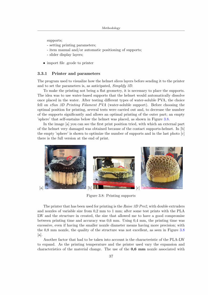
Methodology
supports- setting printing parameters- item manual andor automatic positioning of supports- slider display layers
bull import file gcode to printer
331 Printer and parameters
The program used to visualize how the helmet slices layers before sending it to the printerand to set the parameters is as anticipated Simplify 3D
To make the printing not being a flat geometry it is necessary to place the supportsThe idea was to use water-based supports that the helmet would automatically dissolveonce placed in the water After testing different types of water-soluble PVA the choicefell on eSun 3D Printing Filament PVA (water-soluble support) Before choosing theoptimal position for printing several tests were carried out and to decrease the numberof the supports significantly and allows an optimal printing of the outer part an emptyrsquospherersquo that self-sustains below the helmet was placed as shown in Figure 38
In the image [a] you can see the first print position tried with which an external partof the helmet very damaged was obtained because of the contact supports-helmet In [b]the empty rsquospherersquo is shown to optimize the number of supports and in the last photo [c]there is the full version at the end of print
[a] [b] [c]
Figure 38 Printing supports
The printer that has been used for printing is the Raise 3D Pro2 with double extrudersand nozzles of variable size from 02 mm to 1 mm after some test prints with the PLALW and the structure in created the size that allowed me to have a good compromisebetween printing time and accuracy was 06 mm Using 04 mm the printing time wasexcessive even if having the smaller nozzle diameter means having more precision withthe 08 mm nozzle the quality of the structure was not excellent as seen in Figure 38[a]
Another factor that had to be taken into account is the characteristic of the PLA-LWto expand As the printing temperature and the printer used vary the expansion andcharacteristics of the material change The use of the 06 mm nozzle associated with
37
Methodology
Parameter Left extruder Right extruder
01cm Material 01cm PVA 01cm PLA LW
Extruder toolbox index Tool 0 Tool 1
Nozzle diameter 06 mm 06 mm
Extrusion multiplier 1 05
Extrusion width Auto (072 mm) 05 mm
Layer x
Infill Rectilinear - 50
Supports (Automatic and not) Infill 50
Temperature 210 250
General parameters
Primary layer height 03 mm Top solid layer 4
Bottom solid layer 2 Outline 2
Heated bad 60 Speed 40 mms
Table 31 Printing parameters
Raise 3D allowed me to get good results The choice of this printer was not random ithas in fact the characteristic of making extremely precise prints The Raise has accuracyin placing the object on the printing bed of 078 microns on the xy axis and a resolutionfor layers of 001 mm
The final version of the helmet is visible in Figure 39 and it is possible to compare itwith the preview version in Rhinoceros in Figure 310
38
Methodology
[a] [b]
[c]
Figure 39 Views of the helmet
[a] [b]
Figure 310 Views of the helmet (GH version)
39
Chapter 4
Experimental evaluation
41 Experimental tests
411 Drop-weight impact test machine
In order to calculate the contact force peak and the difference of energy absorbed duringthe impact between the reference helmet and helmet with the beetle structure in PLA-LW dynamic impact tests were carried out using the Fractovis Plus an impact testmachine
In this way it is possible to monitor the evolution of the above variables from theinitial to the final instant of the impact The machine can withstand a load with a rangevariable from 2 to 70 kg with a maximum speed of 46 ms and a maximum height of1 m The values chosen for the test are the following 5 kg weight maximum speed andmaximum height The Anvil that was used is a disc diameter of 60 mm
As shown in Figure 41 and explained by Crupi et al [37] the machine consists ofa sensor capable of recording the speed before impact the impactor that can have avariable mass (a weight of 5 kg in my test) a system to guarantee that there are nomultiple impacts after the first and that work as a shock absorber and clamping systemwhere the object to be tested is placed
The tests that have been carried out are in total four two related to the helmetoptimized with PLA-LW and two with two generic helmets of different brand in EPS
42 PLA LW helmet
To perform the dynamic test on the helmet of PLA considering the difficulty of printingit was helpful to use a test helmet with imperfections to understand where the impactwas concentrated in a single part or distributed The images of Figure 42 show a helmetwith not well defined edges and inaccurate print but exactly localizes the impact zoneThanks to this test it was possible to take into account only one helmet area shown inFigure 43 to have the exact curve of the structure bio-inspired with PLA-LW
40
Experimental evaluation
Figure 41 Drop-weight impact test machine [37]
[a] [b]
Figure 42 Test 1 PLA-LW helmet
43 EPS helmet
To carry out dynamic tests and extract the technical characteristics of the helmettwohelmets were bought in a sports store both EPS and being on the market both certifiedThe brands of the two helmets are DTB and VAN|RYSEL and the average weight ofthe two is 223 g Two different helmets have been chosen to have a more certain andclear classification of the characteristics They are shown in Figure 44 and Figure 45
41
Experimental evaluation
[a] [b]
Figure 43 Test 2 PLA-LW helmet
[a] [b] [c]
Figure 44 Test 3 EPS helmet
[a] [b] [c]
Figure 45 Test 4 EPS helmet
44 Results
441 First results - PLA-LW and EPS helmet
Figure 46 shows two types of trends related to the two different models of the helmetThe force evaluated for PLA-LW has higher force peaks but is more concentrated and
42
Experimental evaluation
propagates less than EPS The graph shows the peaks of each curve highlighted with a redcircle In tests 1 and 2 for the PLA-LW as mentioned earlier the values are higher about7301 N for the complete helmet and 3996 N for the portion of helmet This difference isdue to the inaccuracy of the first full helmet during the printing phase In Figure 42 itis visible the low homogeneity and precision Therefore the first test with full helmet wasused only to define the area of interest of the impact which turns out to be localized Forthe other two EPS curves the values are only slightly lower compared to the PLA-LWequal to 3620 N and 3295 N but the trend is much more distributed
Figure 46 Dynamic machine test - Force
With the data obtained from the impact machine it was possible calculate not exclu-sively the value of force but itrsquos also possible to view the energy curves A resume aboutthe values and energy of the force is in the following Table 41
Test Peak force [N] Peak energy [J]
Test 1 - PLA LW (inaccurate) 730130
Test 2 - PLA LW (portion of helmet) 399643
Test 3 - EPS (DTB helmet) 362007 509
Test 4 - EPS (VAN|RYSEL helmet) 329546 4198
Test 5 - PLA with TPU 45421 5022
Table 41 Energy absorbed in dynamic test
43
Experimental evaluation
442 PLA-LW helmet with TPU cover
As it is possible to see in Figure 47 and as highlighted the first tests concerning thebio-inspired structure and the PLA-LW are far from my expectations considering thelittle distribution of force in comparison with the EPS foam and consequently a smallamount of energy absorbed
Figure 47 Dynamic machine test - Energy
To improve this impact damping factor the idea was to create a cover for the helmetin flexible TPU trying to absorb impact energy The TPU used is a flexible material ofthe brand Ninjaflex used in sports by the application in helmets and shoes to cushionbumps during the game Generally in the helmets (baseball helmet for example) theTPU is inserted internally in contact with the head In my case the TPU structurein addition to creating a shock-absorbing and durable cover creates a custom cover thehelmet and for the person This cover was also made with the Raise 3D printer
As shown in the Figure 48 [a] the infill of the part in contact with the helmet hasa percentage of 100 the filling of the other part of the structure is not complete butonly 15 and the internal structure is hexagonal to recall that of the helmet The desireto insert a structure with a rsquoraisedrsquo geometry is for visual and aesthetic reasons as youhave the feeling of greater protection and not filled is inspired by the machine CitroenCaptus whose bumpers (Airbump) are full of air The failure to realize empty structuresis due to the need to place any internal supports not removable
The idea was to create a cover that allow you to see of the internal structure of thehelmet and that protect specific areas the front the two sides the top and the posteriorWhat which was thought for this reason was to create the shape of a flower with four
44
Experimental evaluation
petals Figure 48 [b]In this way to perform dynamic impact tests as shown in Figure 49 [a] the cover was
positioned at the top of the helmet and the impact was performed in the centre of thersquoflowerrsquo which corresponds to the higher upper part where the structure has larger cellsize The impact parameters are the same as those used in previous impacts 5 kg weightmaximum speed and maximum height The Anvil that was used is a disc diameter of60 mm In photo [b] it is evident the difference between the structure that received theimpact with protection (left) and without protection (right) Without protection duringthe impact there was a perforation of the structure with a concentration of force at a locallevel as you can see in the Figure 46 in the case of TPU the impactor did not perforateand crossed the structure thanks to the cover of TPU that cushioned the shock At themoment of impact the impactor bounced
[a] [b]
Figure 48 TPU cover
[a] [b]
Figure 49 PLA-LW with TPU - dynamic impact [a] and differences between thehelmet with TPU and without TPU cover [b]
45
Experimental evaluation
The Figure 410 includes the diagrams relative to the dynamic impacts In [a] thereare already analyzed EPS results in [b] a comparison between the test on the portionof helmet in PLA LW with and without the TPU cover in [c] the overall comparison ofcurves shows a much more similar EPS trend if the TPU is placed above the structure inPLA LW to soften the blow and absorb the same energy [d]
46
[a]
[c]
[d]
Figure 410 Comparison between PLA-LW with TPU and EPS
Chapter 5
FEM Validation
51 Impactor - Anvils definition
Before to start to work in Abaqus it was necessary to search in the literature the materialwith which the anvil was been realized Milne et al [23] established the densityrsquos valuethe Youngrsquos Module and Poissonrsquos ratio for the Flat and Kerbstone Anvil
- Density ρ = 7800 kgm3
- Youngrsquos Module E = 200000 MPa
- Poissonrsquos ratio ν = 03
Inserting the data in the CES EduPack program specifying the mechanical andphysical properties the material corresponding to these characteristics is Stainless steelaustenitic (ASTM F1586) medium-hard
Initially the proposal was to create a conservative system to evaluate the absorptionenergies values and apply this value to a vibration system but the helmet needs dampingto be realized it was impossible to use a system without losses in this modality Thisis why a numerical calculation was carried out by performing two types of simulationsexplicit dynamic step and static step
The idea to realize the theoretical impact is to regard the movement of the anviland not the helmetrsquos movement which is fixed The velocity is the same cited in thenormative EN 1078 542 ms for the Flat anvil and 457 ms for the Kerbstone anvil
In performing the simulations It was given more relevance and perform tests withthe Kerbstone Anvil This choice was done because the geometry with which it is beenrealized (following as defined in the legislation) allows the helmet to be more subjectedto stress this involves the definition of higher stress limits compared to the Flat Anvil
The mesh size that has been used is the same in the case of the simulation of thehelmet optimized in PLA-LW and the full helmet in EPS of 7 mm The impactor isconsidered as a Discrete rigid body with its specific Reference Point (RP) like shownin Figure 51 for this reason it is not a solid but it is composted only by shells Inthe same image [b] there is the FEM representation of the model and in Table 51 thecharacteristic of FEM with quadrilateral (R3D4) and triangular elements (R3D3)
48
FEM Validation
Object Elementnumber
Elements Shape Geometricorder
Global size[mm]
Kerbstone 230 Quadrilateral - R3D4 Linear 7
Kerbstone 8 Triangular - R3D3 Linear 7
Table 51 Mesh element - Kerbstone Anvil
[a] [b]
Figure 51 Kerbstone anvil in the simulation like discrete rigid body [a] and FEMelements [b]
511 PLA LW - Plastic characteristics
The PLA-LW as explained in the Chapter 2 is new material on the market and producedby the only Colorfabb company for this reason few tests have been carried out to defineits technical characteristics and through tensile tests of the 3D printed specimens it waspossible to define an elastic limit as reported in the Table 210
In the context of simulations to reproduce the impact and deformation of the helmetis also necessary to consider the plastic characteristics of the material Not possessingany reference value in this regard tests were performed through a Static Step initiallyand then an Explicit Dynamic Step in Abaqus
The structure chosen to consider as a reference it is one of the structures previouslysubjected to the compression test having the side L=14 mm As for the reproduction ofthe compression disks initially they were reproduced according to the geometry of theHoytom HM-D Testing Machine considering the bodies mentioned above as discrete 3Drigid discrete The measure was the diameter of 200 mm and the height of 20 mm
After an initial analysis it was observed that the computational time of the simulationprogram was very high so it was decided to change the geometry to have a rsquodisk-surfacesrsquo(equally 3D rigid-discrete) which allowed me to have a smaller number of nodes for themesh and consequently a better computational time The representation of the opti-mized structure in PLA-LW and the disks used for simulated compression is in Figure 52
49
FEM Validation
[a] [b]
Figure 52 Representation of the samples used for the simulation of the compressiontest In Figure [a] the disks of the Hoytom HM-D Testing Machine in figure [b] the
representation of the same as simple surfaces
As shown in Figure 52 the disks are considered 3D discrete hard bodies so it waschosen for both a point the reference point RP where to apply the characteristics relatedto the two bodies As for the compression test it was established
bull the movement of a disk and fixed the second through a boundary condition impos-ing an Encastre therefore unable to move and rotate in xyz directions
bull for the opposite disk the boundary condition relative to the 15 mm displacementwas applied which is the parameter that it was observed to determine the end ofthe compression with the machine This shift is shown by the orange arrow in figure[b]
bull between the upper surface and the disk e the disk with the lower surface it wasinitialized a general contact with normal behaviour through rsquohardrsquo contact andtangential behaviour with a coefficient of friction of 02 with directionality imposedon rsquoisotropicrsquo
The next step was to define the mesh of the components whose parameters are shown inTable 52 while the representation of the FEM is in Figure 53 with the representationof the simulation and real compression test
Object Elementsnumber
Typology Geometricorder
Globalsize [mm]
Disk (14mm) 80910 hexaedral - C3D8R Linear 07
Impact disks 206 quadrilateral - R3D4 Linear 20
Impact disks 6 triangular - R3D3 Linear 20
Table 52 Mesh element - Compression test simulation
As previously announced a static simulation was initially performed with a StaticStep with Step Time equal to 900 (obtained going to consider the speed of 1 mmmin of
50
FEM Validation
[a]
[b] [c]
Figure 53 FEM representation [a] and compression test simulation [b] and realcompression [c]
the compression test and the displacement of 15 mm) However the complex geometryof the structure and the high time set by Step Time did not allow a correct definitionof the parameters of the plastic characteristics of the material the simulation was notable to continue once reached a Step Time of approximately 220 That is why it waschanged by choosing an Explicit Dynamic step
Leaving all the parameters of the boundary conditions unchanged the Step Time wasmodified imposing it to 001 The ability of the explicit dynamic to work with non-linearand contacting structures allowed me to achieve results The results obtained are shownin Figure 54 with the blue curve and were obtained through the iteration of differentPlastic Strain and Yield Stress values in Abaqus while the red line is the result of thereal compression test a similar curve trend was obtained but it is not possible to obtainthe same curve taking into account problems of printing inaccuracy
512 First test - helmet
The initial idea was to perform a simulation imposing the speed of 457 ms to theimpactor tie the helmet in EPS and PLA and compare the absorbed energies Theproblem it was encountered is related to the mesh of the helmet optimized in PLA andwith minimum dimensions of the elements and distinct elements it was not able to solveit
51
FEM Validation
[a]
YieldStress
PlasticStrain
1 47 0
2 7 001
3 75 005
4 10 01
5 108 1
6 115 15
7 12 2
[b]
Figure 54 Representation of the two curves related to the simulation in Abaqus of thecompression test and the data obtained from the real test to obtain the plastic
characteristics of the material
513 Second test - plane
The first solution is the one shown in Figure 55 To realize the simulation it was realizeda section of the helmet to involve a smaller number of elements and nodes Again thesimulation for the EPS helmet was successful while the simulation with the bio-inspiredstructure was interrupted by excessive distortion of elements
The previous images show the impact is very localized in the impacted area and theidea to achieve a complete simulation is not to consider a curved portion of the helmetbut a plane In this way it was possible to solve the problem and obtain a completesimulation for the bio-inspired structure
FEM element
Below in Table 53 there is the definition of the elements used for the PLA-LW and EPSplane in the simulation to simulate the impact and to control the energy-absorbing whilethe anvil characteristics are described in Table 51
514 EPS impact simulations
In order to proceed with the simulation it was imposed some boundary conditions thatregard ties and forces
bull the movement of the plane is fixed through an Encastre therefore unable to moveand rotate in xyz directions
52
FEM Validation
[a]
[b]
Figure 55 Impact simulation parts of EPS and PLA helmet
Object Elementnumber
Elements Shape Geometricorder
Plane (PLA) 38896 Tetrahedral -C3D10M
Quadratic
Plane (EPS) 2100 Hexahedral - C3D8R Linear
Table 53 Mesh element - plane impact
bull to create the impact it was set a speed of 457 ms at the reference point RP of therigid body which is the impactor Kerbstone Anvil shown in Figure 56
bull between the upper surface of the plane and the impactor it was initialized a Sur-face to Surface contact with normal behaviour through rsquohardrsquo contact and tangen-tial behaviour with a coefficient of friction of 02 with directionality imposed onrsquoisotropicrsquo
bull the rotation in x y z relative to the RP of the rigid discrete impactor body is locked
53
FEM Validation
In addition it was characterized the plane in the part of the materials with the char-acteristic values of the EPS mentioned in Chapter 221 The Von Mises Stress valueapparently low is relative to the Yield Stress of the EPS material equal to 09 MPa
Figure 56 EPS Boundary conditions and Load
515 PLA LW impact simulations
As also required in the case of the EPS plane in order to proceed with the simulationsome boundary conditions were imposed that regard ties and forces
bull the movement of the plane is fixed through an Encastre therefore unable to moveand rotate in xyz directions
bull to create the impact a speed of 457 ms was set at the reference point RP of therigid body which is the impactor Kerbstone Anvil shown in Figure 58
bull between the upper surface of the plane and the impactor it was initialized a Sur-face to Surface contact with normal behaviour through rsquohardrsquo contact and tangen-tial behaviour with a coefficient of friction of 02 with directionality imposed onrsquoisotropicrsquo
bull the rotation in x y z relative to the RP of the rigid discrete impactor body is locked
In addition the plane was characterized in the part of the materials with the characteristicvalues of the PLA mentioned in the Chapter 223 and 511
Figure 58 Boundary conditions and Load
54
FEM Validation
[a]
[b]
Figure 57 EPS impact simulation
52 Results
In Figures 59 and 57 it is shown how the structure in PLA LW has a more concentratedstress distribution of the structure unlike EPS The maximum value for the Von Misesstress is 09 MPa in EPS structure and 3634 MPa in PLA LW structure Once thesimulations were obtained the next step was to go and compare the energies absorbed bythe two structures The energy calculated by Abaqus that has been taken into account isPlastic Dissipation To make a comparison the data of the two energies were representedin a single graph
What emerges from the graph is that about the impact made with the KerbstoneAnvil the energy absorption is more excellent although only slightly for the PLA LWthan for the EPS From the graph in Figure 510 a value of 41 J is shown for the EPSand 51 J for the PLA LW
55
[a]
[b]
Figure 59 PLA impact simulation
[a]
Figure 510 EPS and PLA LW energy comparison - Abaqus simulation
Chapter 6
Head Injury Data
For the statistical analysis the injuries related to the accident data were categorised intothe following types and levels based on the details of the medical report [11] about theEN 1078
bull Head Injury Criterion (HIC)
bull Peak Linear Acceleration (PLAc)
bull Gadd Severity Injury (GSI)
bull Diffuse axonal injuries (DAI)
61 Abaqus simulation
Until now the purpose of the simulations has been to determine which between the twomaterials and the two structures of EPS and PLA LW could absorb more energy duringthe impact but no simulations have been carried out in compliance with BS EN 1078on the helmet impact tests To calculate the injuries listed in the previous paragraphhowever we need the acceleration values in the three directions related to the subjectrsquoshead
To realize it the scan of my head already rsquocleanrsquo was considered of which it has beencalculated the inertia thanks to the automatic SolidWorks calculation and evaluated theweight with the Table 24 the structure of the helmet was placed for the EPS and thePLA LW over the head as shown in Figure 61 Also this time being able to mesh theentire helmet in PLA LW was impossible due to the excessive distortion of some elementsduring the simulation so it has been tried to make a section of the structures of thehelmet and results were obtained
57
Head Injury Data
[a] [b]
Figure 61 My scan head - CAD [a] head imported in Abaqus[b]
Initially the simulation had these characteristics as shown in the following Figure62 considering the helmet was not sectioned As explained earlier it was not possibleto get to simulation in the case of the optimized structure in PLA LW for this reasononly a part of the helmet was considered in both cases shown in Figure 63
[a]
Figure 62 Simulation based on BS EN 1078
58
Head Injury Data
[a] [b]
Figure 63 Simulation based on BS EN 1078 with head
In order to proceed with the simulation some boundary conditions that regard tiesand forces have have imposed
bull two reference points RP were created the first in the inertia centre of the headthe second relating to the Kerbstone Anvil which is a discrete rigid body
bull in the reference point RP of the head in the definition of the engineering features5 kg was inserted for the weight and an inertia I11 = 564464E+07 gmm2 I22 =460654E+07gmm2 I33 = 187302E+07gmm2
bull to simulate the impact it was set a speed of 457 ms at the reference point RP ofthe head in z-axis direction
bull a general contact with normal behaviour through rsquohardrsquo contact and tangentialbehaviour with a coefficient of friction of 02
bull between the upper surface of the helmet and the impactor it has been initializeda Surface to Surface contact with normal behaviour through rsquohardrsquo contact andtangential behaviour with a coefficient of friction of 02 with directionality imposedon rsquoisotropicrsquo
bull the movement between the Kerbstone anvil and the helmet is fixed through anEncastre therefore unable to move and rotate in xyz directions
bull the rotation in x y z relative to the RP of the rigid discrete impactor body is locked
FEM element
As reported in Table 53 the portion of the helmet in EPS has used a mesh with hexahe-dral elements of linear order For the structure (beetle) of PLA LW given the geometry
59
Head Injury Data
complexity it was necessary to use a quadratic order of tetrahedra For the mesh of thehead instead in both simulations have been used quadrilateral elements of linear orderas reported in the Tables 61 and 62
Object Elementnumber
Elements Shape Geometricorder
Head 3755 Quadrilateral - R3D4 Linear
Head 34542 Quadrilateral - R3D3 Linear
Helmet (PLA) 272302 Tetrahedral -C3D10M
Quadratic
Table 61 Mesh element - Head simulation with PLA LW (beetle) helmet
Object Elementnumber
Elements Shape Geometricorder
Head 3755 Quadrilateral - R3D4 Linear
Head 34542 Quadrilateral - R3D3 Linear
Helmet (EPS) 72280 Hexahedral - C3D8R Linear
Table 62 Mesh element - Head simulation with EPS helmet
62 Results
Figure 64 represents the simulation in line with BS EN 1078 concerning the helmet inEPS [a] and the helmet with bio-inspired structure in PLA LW For both simulationsVan Misesrsquo stress has Yield Stress values in the case of EPS which is 09 MPa and theplastic behaviour combination of PLA LW [b]
In the case of head and Kerbstone Anvil stress was not assessed as they were previ-ously defined as discrete rigid bodies
63 Head Injury Criterion
The HIC quantifies head impact severity by incorporating time of acceleration exposureand acceleration magnitude it is calculated in post-processing phase with the followingEquation 61
HIC15 =
[1
(t1 minus t2)
int t2
t1
a(t)dt
]25(t2 minus t1) (61)
60
Head Injury Data
[a]
[b]
Figure 64 Results simulation based on BS EN 1078 with sectioned head
For this analysis a(t) is the acceleration calculated in the centre of mass of the head(corresponding to the reference point RP) expressed in g and the time interval (t2 minus t1)was chosen to maximize HIC over a maximum duration of 15 ms
Matlab and the trapz function were used to calculate the HIC to integrate accelerationover time t2 and t1 were considered initial and final times of the simulation t1 = 0 sand t2 = 10 s time less than 15 s
HIC value of 198 was obtained for EPS and 87 for PLA LW Considering the Hayeset al [16] document about the HIC values and the graph in Figure 65 developed bythe author it is possible to find the percentages related to the different injury AIS1 -AIS6 which correspond respectively to lower and higher severity while in Figure 66 therelative fatality to every value of AIS is shown The values obtained for the HIC andother criteria are shown in Table 63 The HIC value for EPS is 198 for PLA LW it is
61
Head Injury Data
Figure 65 Head injury risk curves based on HIC values [16]
Figure 66 The abbreviated injury score versus fatality rate [16]
87 Analyzing the data and comparing them with the curves of the Figure 65 I obtain
bull a percentage between 20 - 30 of AIS 1 for EPS 10 - 20 for PLA LW
bull a percentage between 10 - 20 of AIS 2 for EPS and 0 - 10 for PLA LW
bull for AIS 3 AIS 4 AIS 5 AIS 6 the percentages for both structures is between 0 -10
Comparing these percentages with the fatality rate of Figure 66 it is clear there is a riskof Moderate and Minor fatality in the case of EPS and PLA LW as all values are between0 and 30
62
Head Injury Data
HIC PLA [g] GSI E [J]
EPS 198 97 361 37723
PLA LW 87 75 169 44102
Table 63 Head Injury Data - values
64 Peak Linear Acceleration
The resultant linear acceleration versus time curve was calculated according to Equation62
γ(t) =radicγ2x(t) + γ2y(t) + γ2z (t) (62)
where
bull γ(t) is the resultant linear acceleration (g)
bull γx(t) is the linear acceleration in x axes (g)
bull γy(t) is the linear acceleration in y axes (g)
bull γz(t)is the linear acceleration in z axes (g)
The value of the impact should never exceed 250g [9] Cripton at all [9] in their studyexamined a helmet with expanded polystyrene (EPS) Figure 68 shows maximum HIC forhelmeted and unhelmeted drops from all heights For each drop height helmets reducedHIC relative to unhelmeted drops IARV value is 180g The acceleration in the two casesis shown in Figure 67 and the maximum values are 97g for EPS and 75g for PLA LWas reported in Table 63 The two values considering a maximum value calculated byCripton [9] of 180g are amply optimal and comply with the standard of 250g
65 Gadd Severity Index
Gadd proposed the Severity Index Criteria shown in Equation 63 Following this crite-rion the GSI values that are over 1000 produce serious internal head injury [33]
GSI =
int t1
0a(t)25dt (63)
Where
bull a is the linear acceleration (g)
bull t is the duration of the impact (s)
I calculated the GSI with the function trapz between 0 and t and the resulting valuesare 361 for the EPS and 169 for the PLA LW which comply with the limit
63
Head Injury Data
Figure 67 Peak accelerations for both helmets
Figure 68 Peak accelerations for both helmeted and unhelmeted drops Numbers overbars indicate peak acceleration For 2 m drop height results stated are the mean value
calculated from three drops [9]
64
Head Injury Data
66 Diffuse Axonal Injury
DAI cases covered all incidences in which neurological injuries occurred as well as con-cussion unconsciousness and coma
In order to assess the risk of head trauma in terms of diffuse axonal injury (DAI)Milne et al [23] defined a model based head injury criteria as follows obtaining theresults in Figure 69
bull 50 risk of moderate neurological injury (DAI1+) Brain Von Mises shearing stressof 28 kPa
bull 50 risk of severe neurological injury (DAI2+) Brain Von Mises shearing stressof 53 kPa
[a]
[b]
Figure 69 Peak intra-cerebral shearing stress computed with the helmet model coupledto the human head model for all impact points (a) Flat anvil (b) Kerbstone anvil [23]
65
Head Injury Data
67 Energy absorbed
In Figure 52 during the impact test between the kerbstone Anvil and the plan with thebio-inspired structure in PLA LW and EPS it was found that the PLA LW althoughwith a small difference of 10 J absorbed more energy in comparison with the EPS Whenthe test is carried out in compliance with BS EN 1078 and the head with a speed of 457ms (corresponding to the kerbstone Anvil) as shown in Figure 610 also in this casethe PLA LW with the optimized helmet structure manages to absorb more energy (evenif the difference is very low) compared to the EPS The maximum energy value in PLALW is 44102 J of EPS is 37723 J
Figure 610 Energy absorption - BS EN 1078
66
Chapter 7
Conclusion
71 Conclusion
In this thesis work a bicycle helmet with a bio-inspired structure in PLA LW and 3Dprinted was created The initial approach was to introduce an innovative aspect tostandard EPS helmets not using foam but a polymer with new geometries able toabsorb much energy during the impact For this reason the beetle structure has beenpreferred relying solely on the hypothesis encountered in the literature of its quality inabsorbing energy
Combining the new material of the PLA LW and beetle structure has made possiblethe development of new material satisfactory characteristics have been obtained sincethe first tests The two materials were first subjected to tensile tests to determine theirspecific stress in these the PLA LW had positive results
Subsequent dynamic physical tests were carried out on 3D printed helmet models andon reference helmets in EPS to calculate the absorption energy in both cases at the timeof impact These resulted in energy absorption of the beetle structure in PLA LW withthe application of a TPU cover almost equal to that of EPS about 50J To validate withfinite element analysis the two models an explicit dynamic step was used in AbaqusSimulations showed that the PLA LW structure absorbs a higher amount of energy thanthe EPS the higher is 50 J and the EPS 40J
Finally positive results have also been obtained in calculating the head injury datasimulating according to BS EN 1078 with the use of impactor helmet and head Theacceleration values for both the structures were inferior to 220g precisely for the PLALW was 75g and for the EPS 97g The same applies to the calculation of HIC and GSI(maximum acceptable value of 1000) where the values are 87 and 169 in the case of PLALW and 361 and 198 in EPS For all tests therefore greater efficiency of the structure inPLA LW has been obtained Positive results also in the simulation of the energy absorbedduring the impact as the value referring to the EPS was 35J and that of the PLA LWwas 45J
67
Conclusion
72 Future work lines
The positive results obtained can be considered as a starting point for further tests andsimulations to ensure the safety of the helmet and compliance with the regulations butbefore getting improvements and continue testing changes are required
bull the beetle structure of the helmet made with GH adapts to the SubD withoutallowing to have a homogeneous distribution it would be appropriate to have moreregular hexagonal geometries
bull the mesh of the helmet is too complex and does not allow to perform the simulationprobably to use a more regular structure would have a mesh accordingly moreregular and the simulation would be successful
bull the uneven helmet structure has so many defects that the print is imperfect andthis can change the results of the impact tests the structure should be improved
bull the printing time varies from 4 to 5 days it should be improved
bull the TPU helmet cover is too big for the RAISE printing plan it is necessary togenerate a new geometry
bull the TPU cover it must be fixed on the helmet
bull in the calculation of the DAI it is necessary to have the definition of the brain andthe head should not be considered as a rigid body
bull in the injury calculation the helmet without protection was considered with theTPU cover the result will be better
bull air flow analysis
The comments mentioned are only considerations and problems that I gained duringmy thesis and which should be improved but I am sure that these changes and improve-ments from design to printing and simulations can make the helmet a good product
68
Bibliography
[1] K Adanty J M Clark A Post Thomas Blaine H and M D Gilchrist Comparingtwo proposed protocols to test the oblique response of cycling helmets to fall impactsInternational Journal of Crashworthiness 6648 ndash 663 2020
[2] MF Ashby YJM Brechetb D Cebona and L Salvoc Selection strategies formaterials and processes Materials and Design 2004
[3] M Aysha El casco de bicicleta voronoi impreso en 3d mas seguro y ligero https
www3dnativescomen3d-printed-bicycle-helmet-voronoi-190820204
[4] H Bikas P Stavropoulos and G Chryssolouris Additive manufacturing methodsand modelling approaches a critical review The International Journal of AdvancedManufacturing Technology 83389ndash405 2016
[5] British Standards BSI Helmets for pedal cyclists and for users of skateboards androller skates - BS EN 1078 2012
[6] British Standards BSI Headforms for use in the testing of protective helmets BSEN 960 2020
[7] ColorFabb Colorfabb lw-pla 2019 httpscolorfabbcommedia
datasheetstdscolorfabbTDS_E_ColorFabb_LW-PLApdf
[8] V G Coronado T Haileyesus J M Bell T A Cheng JHaarbauer-Krupa M RLionbarger J Flores-Herrera L C McGuire and J Gilchrist Trends in sports andrecreation-related traumatic brain injuries treated in us emergency departments thenational electronic injury surveillance system-all injury program (neiss-aip) 2001-2012 J Head Trauma Rehabil 30185ndash197 2015
[9] P A Cripton D M Dressler D Stuart Cameron A Christopher R and D RichardsBicycle helmets are highly effective at preventing head injury during head impactHead-form accelerations and injury criteria for helmeted and unhelmeted impactsAccident Analysis and Prevention 701ndash7 2014
[10] L Cui M A Forero R and M D Gilchrist Optimisation of energy absorbingliner for equestrian helmets UCD School of Electrical Electronic and MechanicalEngineering University College Dublin Belfield Dublin4 Ireland 2020
[11] C Deck N Bourdet F Meyer and R Willinger Protection performance of bicyclehelmets Journal of safety research pages 67ndash77 2019
[12] Committee F08 Specification for headforms F2220 ASTM International 2015
[13] Committee F08 Specification for helmets used in recreational bicycling or rollerskating F1447 ASTM International 2018
[14] Committee F08 Test methods for equipment and procedures used in evaluating theperformance F1446 ASTM International 2020
69
Bibliography
[15] P Halldin Shock absorption including measuring CENTC 158 Working Group11 2018
[16] W C Hayes M S Erickson and E D Power Forensic injury biomechanics Annualreview of biomedical engineering pages 55ndash86 2007
[17] HEXR httpshexrcom
[18] C Jinxiang Z Xiaoming O Yoji S Kazuya G Zhensheng and P LongchengThe deformation mode and strengthening mechanism of compression in the beetleelytron plate Materials and Design 131481ndash186 2017
[19] S Kroeker M Ozkul A De Marco S Bonin and GP Siegmund Density variationin the expanded polystyrene eps foam of bicycle helmets and its influence on impactperformance Journal of biomechanical engineering 2019
[20] S G Kroeker SJ Bonin A L DeMarco C A Good and G P Siegmund Agedoes not affect the material properties of expanded polystyrene liners in field-usedbicycle helmets Journal of biomechanical engineering 2016
[21] M Meier K H Tan M K Lim and L Chung Unlocking innovation in the sportindustry through additive manufacturing Business Process Management Journa2018
[22] N J Mills and A Gilchrist The effectiveness of foams in bicycle and motorcyclehelmets Accident Analysis Prevention 23153 ndash 163 1991
[23] G Milne C Deck R P Carreira Q Allinne and R Willinger Development andvalidation of a bicycle helmet assessment of head injury risk under standard impactconditions Computer methods in biomechanics and biomedical engineering 15 Suppl1309 ndash 310 2012
[24] Y Mosleh S J Vander B Depreitere and J Ivens Novel composite foam conceptfor head protection in oblique impacts Adv Eng Mater (Advanced EngineeringMaterials) 10 2017
[25] H Mustafa T Y Pang T Ellena and S H Nasir Impact attenuation of user-centred bicycle helmet design with different foam densities J Phys Conf Ser(Journal of Physics Conference Series) 1150 2019
[26] S H Ngoc and L Guoxing A review of recent research on bio-inspired structuresand materials for energy absorption applications Composites Part 181 2020
[27] J I Novak and A R Novak Is additive manufacturing improving performance insports a systematic review Sport engineering and technology 13 2020
[28] European Road Safety Observatory European road safety observatory facts and fig-ures - cyclists - 2020 December 2020 httpseceuropaeutransportroad_
safetysitesdefaultfilesfacts_figures_cyclists_final_20210323pdf
[29] New York City Departments of Health Parks Mental Hygiene Transportation Recre-ation and the New York City Police Department Bicyclist fatalities and seriousinjuries in new york city 2005
[30] W Pengwen Y Jing H Yanan H Jiaofei and F Xiaoyang Innovative designof a helmet based on reverse engineering and 3d printing Alexandria EngineeringJournal 603445ndash3453 2021
[31] S G Piland T E Gould M Jesunathadas J S Wiggins O McNair and V CShane Protective helmets in sports Materials in Sports Equipment 3 2019
70
Bibliography
[32] K Schmitt P F Niederer M H Muser and F Walz Trauma biomechanicsSpringer Berlin Heidelberg 2010
[33] David Sepelveda Lopez A Biomechanical Analysis of Bicycle Helmets using FEMPhD thesis 2019 Bachelor thesis
[34] H Stigson Bicycle Helmets 2020 Tested by Folksam PhD thesis 2020 PhDAssociate Professor Traffic Safety Research
[35] H Tao K Sudip N Anindya and X Yongzhao 3d printed sensors for biomedicalapplications A review sensor 2019
[36] M Trzaskalska and R Chwastek Damping properties and density of helmet linersmade of expanded polystyrene (eps) Archives of Metallurgy and Materials 66 2020
[37] Crupi V Epasto G and Guglielmino E Impact response of aluminum foam sand-wiches for light-weight ship structures Metals 198ndash112 2020
[38] W Wei-cai F Dong-ming and L Yuan-xin Study on impact energy absorbing per-formance of eps buffer layer of motorcycle helmet Proceedings - 2013 InternationalConference on Mechanical and Automation Engineering MAEE 2013
[39] Z Xiaoming C Jinxiang O Yoji Z Peiwei X Xiaobing and Y Xindi Influence ofhoneycomb dimensions and forming methods on the compressive properties of beetleelytron plates Journal of Sandwich Structures and Materials 2228ndash39 2020
[40] S Zhi L Dong Z Weisheng S Shanshan and G Xu Topological optimization ofbiomimetic sandwich structures with hybrid core and cfrp face sheets CompositesScience and Technology 14279ndash90 2017
[41] S Zhi S Shanshan G Xu H Xiaozhi and C Haoran On compressive propertiesof composite sandwich structures with grid reinforced honeycomb core CompositesPart B 94245ndash252 2016
71
- List of Tables
- List of Figures
- Introduction
-
- Helmet bike protection
-
- Helmet structure
-
- Additive Manufacturing
-
- AM process
- Materials and techniques - FDM
- AM in sport
-
- 3D printed helmets
-
- Phases
- HEXR
- VORONOI
-
- State of the art
-
- Standards
-
- Headform
- European Standard and American Standard
- Field of vision - BS EN 1078
- Test impact area
- Anvils and environmental conditions
-
- Materials
-
- EPS Foam
- CES Edu Pack - Material selection
- PLA with natural fiber and PLA LW
-
- Bio-inspired structures
-
- Beetle structure - Design of the model
- Specific stress - PLA LW and EPS foam
-
- Methodology
-
- 3D scan
-
- 3D Sense 2 scanner and Meshmixer - Reverse reconstruction
- 3D scan analysis and extraction of features
-
- Helmet design
-
- Rhinoceros - Helmet surface
- Grasshopper - Helmet structure
-
- 3D Print
-
- Printer and parameters
-
- Experimental evaluation
-
- Experimental tests
-
- Drop-weight impact test machine
-
- PLA LW helmet
- EPS helmet
- Results
-
- First results - PLA-LW and EPS helmet
- PLA-LW helmet with TPU cover
-
- FEM Validation
-
- Impactor - Anvils definition
-
- PLA LW - Plastic characteristics
- First test - helmet
- Second test - plane
- EPS impact simulations
- PLA LW impact simulations
-
- Results
-
- Head Injury Data
-
- Abaqus simulation
- Results
- Head Injury Criterion
- Peak Linear Acceleration
- Gadd Severity Index
- Diffuse Axonal Injury
- Energy absorbed
-
- Conclusion
-
- Conclusion
- Future work lines
-
- Bibliography
-
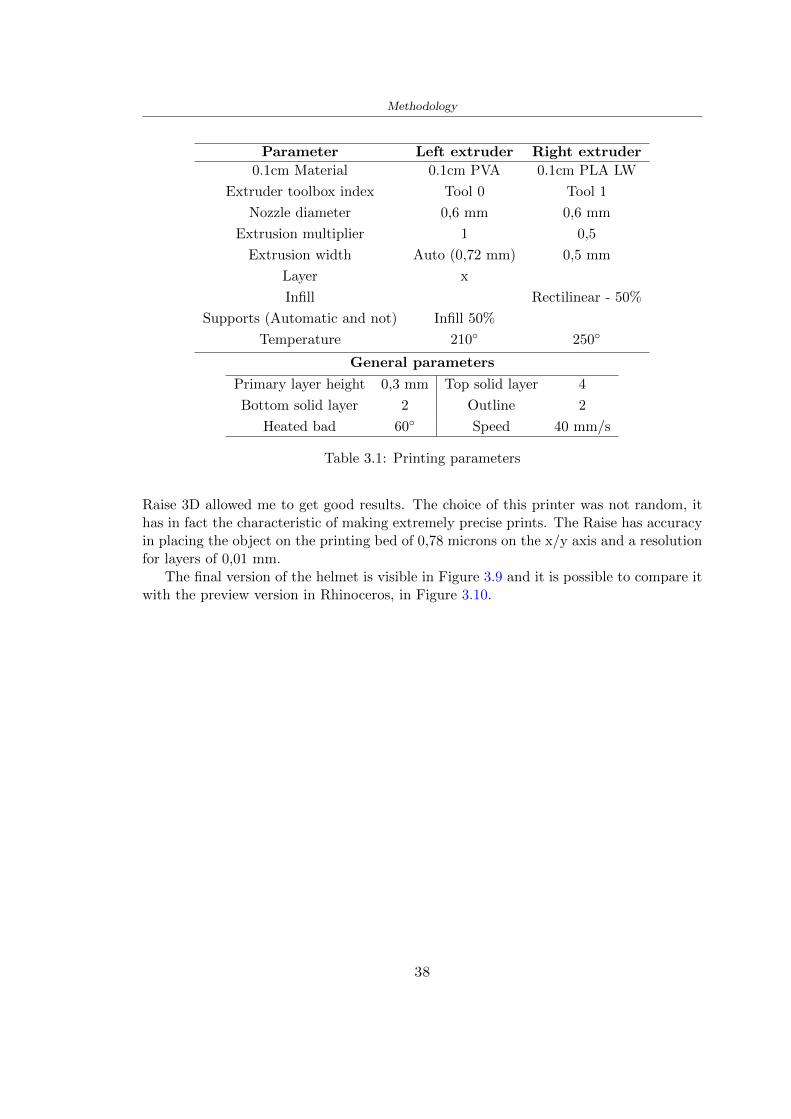
Methodology
Parameter Left extruder Right extruder
01cm Material 01cm PVA 01cm PLA LW
Extruder toolbox index Tool 0 Tool 1
Nozzle diameter 06 mm 06 mm
Extrusion multiplier 1 05
Extrusion width Auto (072 mm) 05 mm
Layer x
Infill Rectilinear - 50
Supports (Automatic and not) Infill 50
Temperature 210 250
General parameters
Primary layer height 03 mm Top solid layer 4
Bottom solid layer 2 Outline 2
Heated bad 60 Speed 40 mms
Table 31 Printing parameters
Raise 3D allowed me to get good results The choice of this printer was not random ithas in fact the characteristic of making extremely precise prints The Raise has accuracyin placing the object on the printing bed of 078 microns on the xy axis and a resolutionfor layers of 001 mm
The final version of the helmet is visible in Figure 39 and it is possible to compare itwith the preview version in Rhinoceros in Figure 310
38
Methodology
[a] [b]
[c]
Figure 39 Views of the helmet
[a] [b]
Figure 310 Views of the helmet (GH version)
39
Chapter 4
Experimental evaluation
41 Experimental tests
411 Drop-weight impact test machine
In order to calculate the contact force peak and the difference of energy absorbed duringthe impact between the reference helmet and helmet with the beetle structure in PLA-LW dynamic impact tests were carried out using the Fractovis Plus an impact testmachine
In this way it is possible to monitor the evolution of the above variables from theinitial to the final instant of the impact The machine can withstand a load with a rangevariable from 2 to 70 kg with a maximum speed of 46 ms and a maximum height of1 m The values chosen for the test are the following 5 kg weight maximum speed andmaximum height The Anvil that was used is a disc diameter of 60 mm
As shown in Figure 41 and explained by Crupi et al [37] the machine consists ofa sensor capable of recording the speed before impact the impactor that can have avariable mass (a weight of 5 kg in my test) a system to guarantee that there are nomultiple impacts after the first and that work as a shock absorber and clamping systemwhere the object to be tested is placed
The tests that have been carried out are in total four two related to the helmetoptimized with PLA-LW and two with two generic helmets of different brand in EPS
42 PLA LW helmet
To perform the dynamic test on the helmet of PLA considering the difficulty of printingit was helpful to use a test helmet with imperfections to understand where the impactwas concentrated in a single part or distributed The images of Figure 42 show a helmetwith not well defined edges and inaccurate print but exactly localizes the impact zoneThanks to this test it was possible to take into account only one helmet area shown inFigure 43 to have the exact curve of the structure bio-inspired with PLA-LW
40
Experimental evaluation
Figure 41 Drop-weight impact test machine [37]
[a] [b]
Figure 42 Test 1 PLA-LW helmet
43 EPS helmet
To carry out dynamic tests and extract the technical characteristics of the helmettwohelmets were bought in a sports store both EPS and being on the market both certifiedThe brands of the two helmets are DTB and VAN|RYSEL and the average weight ofthe two is 223 g Two different helmets have been chosen to have a more certain andclear classification of the characteristics They are shown in Figure 44 and Figure 45
41
Experimental evaluation
[a] [b]
Figure 43 Test 2 PLA-LW helmet
[a] [b] [c]
Figure 44 Test 3 EPS helmet
[a] [b] [c]
Figure 45 Test 4 EPS helmet
44 Results
441 First results - PLA-LW and EPS helmet
Figure 46 shows two types of trends related to the two different models of the helmetThe force evaluated for PLA-LW has higher force peaks but is more concentrated and
42
Experimental evaluation
propagates less than EPS The graph shows the peaks of each curve highlighted with a redcircle In tests 1 and 2 for the PLA-LW as mentioned earlier the values are higher about7301 N for the complete helmet and 3996 N for the portion of helmet This difference isdue to the inaccuracy of the first full helmet during the printing phase In Figure 42 itis visible the low homogeneity and precision Therefore the first test with full helmet wasused only to define the area of interest of the impact which turns out to be localized Forthe other two EPS curves the values are only slightly lower compared to the PLA-LWequal to 3620 N and 3295 N but the trend is much more distributed
Figure 46 Dynamic machine test - Force
With the data obtained from the impact machine it was possible calculate not exclu-sively the value of force but itrsquos also possible to view the energy curves A resume aboutthe values and energy of the force is in the following Table 41
Test Peak force [N] Peak energy [J]
Test 1 - PLA LW (inaccurate) 730130
Test 2 - PLA LW (portion of helmet) 399643
Test 3 - EPS (DTB helmet) 362007 509
Test 4 - EPS (VAN|RYSEL helmet) 329546 4198
Test 5 - PLA with TPU 45421 5022
Table 41 Energy absorbed in dynamic test
43
Experimental evaluation
442 PLA-LW helmet with TPU cover
As it is possible to see in Figure 47 and as highlighted the first tests concerning thebio-inspired structure and the PLA-LW are far from my expectations considering thelittle distribution of force in comparison with the EPS foam and consequently a smallamount of energy absorbed
Figure 47 Dynamic machine test - Energy
To improve this impact damping factor the idea was to create a cover for the helmetin flexible TPU trying to absorb impact energy The TPU used is a flexible material ofthe brand Ninjaflex used in sports by the application in helmets and shoes to cushionbumps during the game Generally in the helmets (baseball helmet for example) theTPU is inserted internally in contact with the head In my case the TPU structurein addition to creating a shock-absorbing and durable cover creates a custom cover thehelmet and for the person This cover was also made with the Raise 3D printer
As shown in the Figure 48 [a] the infill of the part in contact with the helmet hasa percentage of 100 the filling of the other part of the structure is not complete butonly 15 and the internal structure is hexagonal to recall that of the helmet The desireto insert a structure with a rsquoraisedrsquo geometry is for visual and aesthetic reasons as youhave the feeling of greater protection and not filled is inspired by the machine CitroenCaptus whose bumpers (Airbump) are full of air The failure to realize empty structuresis due to the need to place any internal supports not removable
The idea was to create a cover that allow you to see of the internal structure of thehelmet and that protect specific areas the front the two sides the top and the posteriorWhat which was thought for this reason was to create the shape of a flower with four
44
Experimental evaluation
petals Figure 48 [b]In this way to perform dynamic impact tests as shown in Figure 49 [a] the cover was
positioned at the top of the helmet and the impact was performed in the centre of thersquoflowerrsquo which corresponds to the higher upper part where the structure has larger cellsize The impact parameters are the same as those used in previous impacts 5 kg weightmaximum speed and maximum height The Anvil that was used is a disc diameter of60 mm In photo [b] it is evident the difference between the structure that received theimpact with protection (left) and without protection (right) Without protection duringthe impact there was a perforation of the structure with a concentration of force at a locallevel as you can see in the Figure 46 in the case of TPU the impactor did not perforateand crossed the structure thanks to the cover of TPU that cushioned the shock At themoment of impact the impactor bounced
[a] [b]
Figure 48 TPU cover
[a] [b]
Figure 49 PLA-LW with TPU - dynamic impact [a] and differences between thehelmet with TPU and without TPU cover [b]
45
Experimental evaluation
The Figure 410 includes the diagrams relative to the dynamic impacts In [a] thereare already analyzed EPS results in [b] a comparison between the test on the portionof helmet in PLA LW with and without the TPU cover in [c] the overall comparison ofcurves shows a much more similar EPS trend if the TPU is placed above the structure inPLA LW to soften the blow and absorb the same energy [d]
46
[a]
[c]
[d]
Figure 410 Comparison between PLA-LW with TPU and EPS
Chapter 5
FEM Validation
51 Impactor - Anvils definition
Before to start to work in Abaqus it was necessary to search in the literature the materialwith which the anvil was been realized Milne et al [23] established the densityrsquos valuethe Youngrsquos Module and Poissonrsquos ratio for the Flat and Kerbstone Anvil
- Density ρ = 7800 kgm3
- Youngrsquos Module E = 200000 MPa
- Poissonrsquos ratio ν = 03
Inserting the data in the CES EduPack program specifying the mechanical andphysical properties the material corresponding to these characteristics is Stainless steelaustenitic (ASTM F1586) medium-hard
Initially the proposal was to create a conservative system to evaluate the absorptionenergies values and apply this value to a vibration system but the helmet needs dampingto be realized it was impossible to use a system without losses in this modality Thisis why a numerical calculation was carried out by performing two types of simulationsexplicit dynamic step and static step
The idea to realize the theoretical impact is to regard the movement of the anviland not the helmetrsquos movement which is fixed The velocity is the same cited in thenormative EN 1078 542 ms for the Flat anvil and 457 ms for the Kerbstone anvil
In performing the simulations It was given more relevance and perform tests withthe Kerbstone Anvil This choice was done because the geometry with which it is beenrealized (following as defined in the legislation) allows the helmet to be more subjectedto stress this involves the definition of higher stress limits compared to the Flat Anvil
The mesh size that has been used is the same in the case of the simulation of thehelmet optimized in PLA-LW and the full helmet in EPS of 7 mm The impactor isconsidered as a Discrete rigid body with its specific Reference Point (RP) like shownin Figure 51 for this reason it is not a solid but it is composted only by shells Inthe same image [b] there is the FEM representation of the model and in Table 51 thecharacteristic of FEM with quadrilateral (R3D4) and triangular elements (R3D3)
48
FEM Validation
Object Elementnumber
Elements Shape Geometricorder
Global size[mm]
Kerbstone 230 Quadrilateral - R3D4 Linear 7
Kerbstone 8 Triangular - R3D3 Linear 7
Table 51 Mesh element - Kerbstone Anvil
[a] [b]
Figure 51 Kerbstone anvil in the simulation like discrete rigid body [a] and FEMelements [b]
511 PLA LW - Plastic characteristics
The PLA-LW as explained in the Chapter 2 is new material on the market and producedby the only Colorfabb company for this reason few tests have been carried out to defineits technical characteristics and through tensile tests of the 3D printed specimens it waspossible to define an elastic limit as reported in the Table 210
In the context of simulations to reproduce the impact and deformation of the helmetis also necessary to consider the plastic characteristics of the material Not possessingany reference value in this regard tests were performed through a Static Step initiallyand then an Explicit Dynamic Step in Abaqus
The structure chosen to consider as a reference it is one of the structures previouslysubjected to the compression test having the side L=14 mm As for the reproduction ofthe compression disks initially they were reproduced according to the geometry of theHoytom HM-D Testing Machine considering the bodies mentioned above as discrete 3Drigid discrete The measure was the diameter of 200 mm and the height of 20 mm
After an initial analysis it was observed that the computational time of the simulationprogram was very high so it was decided to change the geometry to have a rsquodisk-surfacesrsquo(equally 3D rigid-discrete) which allowed me to have a smaller number of nodes for themesh and consequently a better computational time The representation of the opti-mized structure in PLA-LW and the disks used for simulated compression is in Figure 52
49
FEM Validation
[a] [b]
Figure 52 Representation of the samples used for the simulation of the compressiontest In Figure [a] the disks of the Hoytom HM-D Testing Machine in figure [b] the
representation of the same as simple surfaces
As shown in Figure 52 the disks are considered 3D discrete hard bodies so it waschosen for both a point the reference point RP where to apply the characteristics relatedto the two bodies As for the compression test it was established
bull the movement of a disk and fixed the second through a boundary condition impos-ing an Encastre therefore unable to move and rotate in xyz directions
bull for the opposite disk the boundary condition relative to the 15 mm displacementwas applied which is the parameter that it was observed to determine the end ofthe compression with the machine This shift is shown by the orange arrow in figure[b]
bull between the upper surface and the disk e the disk with the lower surface it wasinitialized a general contact with normal behaviour through rsquohardrsquo contact andtangential behaviour with a coefficient of friction of 02 with directionality imposedon rsquoisotropicrsquo
The next step was to define the mesh of the components whose parameters are shown inTable 52 while the representation of the FEM is in Figure 53 with the representationof the simulation and real compression test
Object Elementsnumber
Typology Geometricorder
Globalsize [mm]
Disk (14mm) 80910 hexaedral - C3D8R Linear 07
Impact disks 206 quadrilateral - R3D4 Linear 20
Impact disks 6 triangular - R3D3 Linear 20
Table 52 Mesh element - Compression test simulation
As previously announced a static simulation was initially performed with a StaticStep with Step Time equal to 900 (obtained going to consider the speed of 1 mmmin of
50
FEM Validation
[a]
[b] [c]
Figure 53 FEM representation [a] and compression test simulation [b] and realcompression [c]
the compression test and the displacement of 15 mm) However the complex geometryof the structure and the high time set by Step Time did not allow a correct definitionof the parameters of the plastic characteristics of the material the simulation was notable to continue once reached a Step Time of approximately 220 That is why it waschanged by choosing an Explicit Dynamic step
Leaving all the parameters of the boundary conditions unchanged the Step Time wasmodified imposing it to 001 The ability of the explicit dynamic to work with non-linearand contacting structures allowed me to achieve results The results obtained are shownin Figure 54 with the blue curve and were obtained through the iteration of differentPlastic Strain and Yield Stress values in Abaqus while the red line is the result of thereal compression test a similar curve trend was obtained but it is not possible to obtainthe same curve taking into account problems of printing inaccuracy
512 First test - helmet
The initial idea was to perform a simulation imposing the speed of 457 ms to theimpactor tie the helmet in EPS and PLA and compare the absorbed energies Theproblem it was encountered is related to the mesh of the helmet optimized in PLA andwith minimum dimensions of the elements and distinct elements it was not able to solveit
51
FEM Validation
[a]
YieldStress
PlasticStrain
1 47 0
2 7 001
3 75 005
4 10 01
5 108 1
6 115 15
7 12 2
[b]
Figure 54 Representation of the two curves related to the simulation in Abaqus of thecompression test and the data obtained from the real test to obtain the plastic
characteristics of the material
513 Second test - plane
The first solution is the one shown in Figure 55 To realize the simulation it was realizeda section of the helmet to involve a smaller number of elements and nodes Again thesimulation for the EPS helmet was successful while the simulation with the bio-inspiredstructure was interrupted by excessive distortion of elements
The previous images show the impact is very localized in the impacted area and theidea to achieve a complete simulation is not to consider a curved portion of the helmetbut a plane In this way it was possible to solve the problem and obtain a completesimulation for the bio-inspired structure
FEM element
Below in Table 53 there is the definition of the elements used for the PLA-LW and EPSplane in the simulation to simulate the impact and to control the energy-absorbing whilethe anvil characteristics are described in Table 51
514 EPS impact simulations
In order to proceed with the simulation it was imposed some boundary conditions thatregard ties and forces
bull the movement of the plane is fixed through an Encastre therefore unable to moveand rotate in xyz directions
52
FEM Validation
[a]
[b]
Figure 55 Impact simulation parts of EPS and PLA helmet
Object Elementnumber
Elements Shape Geometricorder
Plane (PLA) 38896 Tetrahedral -C3D10M
Quadratic
Plane (EPS) 2100 Hexahedral - C3D8R Linear
Table 53 Mesh element - plane impact
bull to create the impact it was set a speed of 457 ms at the reference point RP of therigid body which is the impactor Kerbstone Anvil shown in Figure 56
bull between the upper surface of the plane and the impactor it was initialized a Sur-face to Surface contact with normal behaviour through rsquohardrsquo contact and tangen-tial behaviour with a coefficient of friction of 02 with directionality imposed onrsquoisotropicrsquo
bull the rotation in x y z relative to the RP of the rigid discrete impactor body is locked
53
FEM Validation
In addition it was characterized the plane in the part of the materials with the char-acteristic values of the EPS mentioned in Chapter 221 The Von Mises Stress valueapparently low is relative to the Yield Stress of the EPS material equal to 09 MPa
Figure 56 EPS Boundary conditions and Load
515 PLA LW impact simulations
As also required in the case of the EPS plane in order to proceed with the simulationsome boundary conditions were imposed that regard ties and forces
bull the movement of the plane is fixed through an Encastre therefore unable to moveand rotate in xyz directions
bull to create the impact a speed of 457 ms was set at the reference point RP of therigid body which is the impactor Kerbstone Anvil shown in Figure 58
bull between the upper surface of the plane and the impactor it was initialized a Sur-face to Surface contact with normal behaviour through rsquohardrsquo contact and tangen-tial behaviour with a coefficient of friction of 02 with directionality imposed onrsquoisotropicrsquo
bull the rotation in x y z relative to the RP of the rigid discrete impactor body is locked
In addition the plane was characterized in the part of the materials with the characteristicvalues of the PLA mentioned in the Chapter 223 and 511
Figure 58 Boundary conditions and Load
54
FEM Validation
[a]
[b]
Figure 57 EPS impact simulation
52 Results
In Figures 59 and 57 it is shown how the structure in PLA LW has a more concentratedstress distribution of the structure unlike EPS The maximum value for the Von Misesstress is 09 MPa in EPS structure and 3634 MPa in PLA LW structure Once thesimulations were obtained the next step was to go and compare the energies absorbed bythe two structures The energy calculated by Abaqus that has been taken into account isPlastic Dissipation To make a comparison the data of the two energies were representedin a single graph
What emerges from the graph is that about the impact made with the KerbstoneAnvil the energy absorption is more excellent although only slightly for the PLA LWthan for the EPS From the graph in Figure 510 a value of 41 J is shown for the EPSand 51 J for the PLA LW
55
[a]
[b]
Figure 59 PLA impact simulation
[a]
Figure 510 EPS and PLA LW energy comparison - Abaqus simulation
Chapter 6
Head Injury Data
For the statistical analysis the injuries related to the accident data were categorised intothe following types and levels based on the details of the medical report [11] about theEN 1078
bull Head Injury Criterion (HIC)
bull Peak Linear Acceleration (PLAc)
bull Gadd Severity Injury (GSI)
bull Diffuse axonal injuries (DAI)
61 Abaqus simulation
Until now the purpose of the simulations has been to determine which between the twomaterials and the two structures of EPS and PLA LW could absorb more energy duringthe impact but no simulations have been carried out in compliance with BS EN 1078on the helmet impact tests To calculate the injuries listed in the previous paragraphhowever we need the acceleration values in the three directions related to the subjectrsquoshead
To realize it the scan of my head already rsquocleanrsquo was considered of which it has beencalculated the inertia thanks to the automatic SolidWorks calculation and evaluated theweight with the Table 24 the structure of the helmet was placed for the EPS and thePLA LW over the head as shown in Figure 61 Also this time being able to mesh theentire helmet in PLA LW was impossible due to the excessive distortion of some elementsduring the simulation so it has been tried to make a section of the structures of thehelmet and results were obtained
57
Head Injury Data
[a] [b]
Figure 61 My scan head - CAD [a] head imported in Abaqus[b]
Initially the simulation had these characteristics as shown in the following Figure62 considering the helmet was not sectioned As explained earlier it was not possibleto get to simulation in the case of the optimized structure in PLA LW for this reasononly a part of the helmet was considered in both cases shown in Figure 63
[a]
Figure 62 Simulation based on BS EN 1078
58
Head Injury Data
[a] [b]
Figure 63 Simulation based on BS EN 1078 with head
In order to proceed with the simulation some boundary conditions that regard tiesand forces have have imposed
bull two reference points RP were created the first in the inertia centre of the headthe second relating to the Kerbstone Anvil which is a discrete rigid body
bull in the reference point RP of the head in the definition of the engineering features5 kg was inserted for the weight and an inertia I11 = 564464E+07 gmm2 I22 =460654E+07gmm2 I33 = 187302E+07gmm2
bull to simulate the impact it was set a speed of 457 ms at the reference point RP ofthe head in z-axis direction
bull a general contact with normal behaviour through rsquohardrsquo contact and tangentialbehaviour with a coefficient of friction of 02
bull between the upper surface of the helmet and the impactor it has been initializeda Surface to Surface contact with normal behaviour through rsquohardrsquo contact andtangential behaviour with a coefficient of friction of 02 with directionality imposedon rsquoisotropicrsquo
bull the movement between the Kerbstone anvil and the helmet is fixed through anEncastre therefore unable to move and rotate in xyz directions
bull the rotation in x y z relative to the RP of the rigid discrete impactor body is locked
FEM element
As reported in Table 53 the portion of the helmet in EPS has used a mesh with hexahe-dral elements of linear order For the structure (beetle) of PLA LW given the geometry
59
Head Injury Data
complexity it was necessary to use a quadratic order of tetrahedra For the mesh of thehead instead in both simulations have been used quadrilateral elements of linear orderas reported in the Tables 61 and 62
Object Elementnumber
Elements Shape Geometricorder
Head 3755 Quadrilateral - R3D4 Linear
Head 34542 Quadrilateral - R3D3 Linear
Helmet (PLA) 272302 Tetrahedral -C3D10M
Quadratic
Table 61 Mesh element - Head simulation with PLA LW (beetle) helmet
Object Elementnumber
Elements Shape Geometricorder
Head 3755 Quadrilateral - R3D4 Linear
Head 34542 Quadrilateral - R3D3 Linear
Helmet (EPS) 72280 Hexahedral - C3D8R Linear
Table 62 Mesh element - Head simulation with EPS helmet
62 Results
Figure 64 represents the simulation in line with BS EN 1078 concerning the helmet inEPS [a] and the helmet with bio-inspired structure in PLA LW For both simulationsVan Misesrsquo stress has Yield Stress values in the case of EPS which is 09 MPa and theplastic behaviour combination of PLA LW [b]
In the case of head and Kerbstone Anvil stress was not assessed as they were previ-ously defined as discrete rigid bodies
63 Head Injury Criterion
The HIC quantifies head impact severity by incorporating time of acceleration exposureand acceleration magnitude it is calculated in post-processing phase with the followingEquation 61
HIC15 =
[1
(t1 minus t2)
int t2
t1
a(t)dt
]25(t2 minus t1) (61)
60
Head Injury Data
[a]
[b]
Figure 64 Results simulation based on BS EN 1078 with sectioned head
For this analysis a(t) is the acceleration calculated in the centre of mass of the head(corresponding to the reference point RP) expressed in g and the time interval (t2 minus t1)was chosen to maximize HIC over a maximum duration of 15 ms
Matlab and the trapz function were used to calculate the HIC to integrate accelerationover time t2 and t1 were considered initial and final times of the simulation t1 = 0 sand t2 = 10 s time less than 15 s
HIC value of 198 was obtained for EPS and 87 for PLA LW Considering the Hayeset al [16] document about the HIC values and the graph in Figure 65 developed bythe author it is possible to find the percentages related to the different injury AIS1 -AIS6 which correspond respectively to lower and higher severity while in Figure 66 therelative fatality to every value of AIS is shown The values obtained for the HIC andother criteria are shown in Table 63 The HIC value for EPS is 198 for PLA LW it is
61
Head Injury Data
Figure 65 Head injury risk curves based on HIC values [16]
Figure 66 The abbreviated injury score versus fatality rate [16]
87 Analyzing the data and comparing them with the curves of the Figure 65 I obtain
bull a percentage between 20 - 30 of AIS 1 for EPS 10 - 20 for PLA LW
bull a percentage between 10 - 20 of AIS 2 for EPS and 0 - 10 for PLA LW
bull for AIS 3 AIS 4 AIS 5 AIS 6 the percentages for both structures is between 0 -10
Comparing these percentages with the fatality rate of Figure 66 it is clear there is a riskof Moderate and Minor fatality in the case of EPS and PLA LW as all values are between0 and 30
62
Head Injury Data
HIC PLA [g] GSI E [J]
EPS 198 97 361 37723
PLA LW 87 75 169 44102
Table 63 Head Injury Data - values
64 Peak Linear Acceleration
The resultant linear acceleration versus time curve was calculated according to Equation62
γ(t) =radicγ2x(t) + γ2y(t) + γ2z (t) (62)
where
bull γ(t) is the resultant linear acceleration (g)
bull γx(t) is the linear acceleration in x axes (g)
bull γy(t) is the linear acceleration in y axes (g)
bull γz(t)is the linear acceleration in z axes (g)
The value of the impact should never exceed 250g [9] Cripton at all [9] in their studyexamined a helmet with expanded polystyrene (EPS) Figure 68 shows maximum HIC forhelmeted and unhelmeted drops from all heights For each drop height helmets reducedHIC relative to unhelmeted drops IARV value is 180g The acceleration in the two casesis shown in Figure 67 and the maximum values are 97g for EPS and 75g for PLA LWas reported in Table 63 The two values considering a maximum value calculated byCripton [9] of 180g are amply optimal and comply with the standard of 250g
65 Gadd Severity Index
Gadd proposed the Severity Index Criteria shown in Equation 63 Following this crite-rion the GSI values that are over 1000 produce serious internal head injury [33]
GSI =
int t1
0a(t)25dt (63)
Where
bull a is the linear acceleration (g)
bull t is the duration of the impact (s)
I calculated the GSI with the function trapz between 0 and t and the resulting valuesare 361 for the EPS and 169 for the PLA LW which comply with the limit
63
Head Injury Data
Figure 67 Peak accelerations for both helmets
Figure 68 Peak accelerations for both helmeted and unhelmeted drops Numbers overbars indicate peak acceleration For 2 m drop height results stated are the mean value
calculated from three drops [9]
64
Head Injury Data
66 Diffuse Axonal Injury
DAI cases covered all incidences in which neurological injuries occurred as well as con-cussion unconsciousness and coma
In order to assess the risk of head trauma in terms of diffuse axonal injury (DAI)Milne et al [23] defined a model based head injury criteria as follows obtaining theresults in Figure 69
bull 50 risk of moderate neurological injury (DAI1+) Brain Von Mises shearing stressof 28 kPa
bull 50 risk of severe neurological injury (DAI2+) Brain Von Mises shearing stressof 53 kPa
[a]
[b]
Figure 69 Peak intra-cerebral shearing stress computed with the helmet model coupledto the human head model for all impact points (a) Flat anvil (b) Kerbstone anvil [23]
65
Head Injury Data
67 Energy absorbed
In Figure 52 during the impact test between the kerbstone Anvil and the plan with thebio-inspired structure in PLA LW and EPS it was found that the PLA LW althoughwith a small difference of 10 J absorbed more energy in comparison with the EPS Whenthe test is carried out in compliance with BS EN 1078 and the head with a speed of 457ms (corresponding to the kerbstone Anvil) as shown in Figure 610 also in this casethe PLA LW with the optimized helmet structure manages to absorb more energy (evenif the difference is very low) compared to the EPS The maximum energy value in PLALW is 44102 J of EPS is 37723 J
Figure 610 Energy absorption - BS EN 1078
66
Chapter 7
Conclusion
71 Conclusion
In this thesis work a bicycle helmet with a bio-inspired structure in PLA LW and 3Dprinted was created The initial approach was to introduce an innovative aspect tostandard EPS helmets not using foam but a polymer with new geometries able toabsorb much energy during the impact For this reason the beetle structure has beenpreferred relying solely on the hypothesis encountered in the literature of its quality inabsorbing energy
Combining the new material of the PLA LW and beetle structure has made possiblethe development of new material satisfactory characteristics have been obtained sincethe first tests The two materials were first subjected to tensile tests to determine theirspecific stress in these the PLA LW had positive results
Subsequent dynamic physical tests were carried out on 3D printed helmet models andon reference helmets in EPS to calculate the absorption energy in both cases at the timeof impact These resulted in energy absorption of the beetle structure in PLA LW withthe application of a TPU cover almost equal to that of EPS about 50J To validate withfinite element analysis the two models an explicit dynamic step was used in AbaqusSimulations showed that the PLA LW structure absorbs a higher amount of energy thanthe EPS the higher is 50 J and the EPS 40J
Finally positive results have also been obtained in calculating the head injury datasimulating according to BS EN 1078 with the use of impactor helmet and head Theacceleration values for both the structures were inferior to 220g precisely for the PLALW was 75g and for the EPS 97g The same applies to the calculation of HIC and GSI(maximum acceptable value of 1000) where the values are 87 and 169 in the case of PLALW and 361 and 198 in EPS For all tests therefore greater efficiency of the structure inPLA LW has been obtained Positive results also in the simulation of the energy absorbedduring the impact as the value referring to the EPS was 35J and that of the PLA LWwas 45J
67
Conclusion
72 Future work lines
The positive results obtained can be considered as a starting point for further tests andsimulations to ensure the safety of the helmet and compliance with the regulations butbefore getting improvements and continue testing changes are required
bull the beetle structure of the helmet made with GH adapts to the SubD withoutallowing to have a homogeneous distribution it would be appropriate to have moreregular hexagonal geometries
bull the mesh of the helmet is too complex and does not allow to perform the simulationprobably to use a more regular structure would have a mesh accordingly moreregular and the simulation would be successful
bull the uneven helmet structure has so many defects that the print is imperfect andthis can change the results of the impact tests the structure should be improved
bull the printing time varies from 4 to 5 days it should be improved
bull the TPU helmet cover is too big for the RAISE printing plan it is necessary togenerate a new geometry
bull the TPU cover it must be fixed on the helmet
bull in the calculation of the DAI it is necessary to have the definition of the brain andthe head should not be considered as a rigid body
bull in the injury calculation the helmet without protection was considered with theTPU cover the result will be better
bull air flow analysis
The comments mentioned are only considerations and problems that I gained duringmy thesis and which should be improved but I am sure that these changes and improve-ments from design to printing and simulations can make the helmet a good product
68
Bibliography
[1] K Adanty J M Clark A Post Thomas Blaine H and M D Gilchrist Comparingtwo proposed protocols to test the oblique response of cycling helmets to fall impactsInternational Journal of Crashworthiness 6648 ndash 663 2020
[2] MF Ashby YJM Brechetb D Cebona and L Salvoc Selection strategies formaterials and processes Materials and Design 2004
[3] M Aysha El casco de bicicleta voronoi impreso en 3d mas seguro y ligero https
www3dnativescomen3d-printed-bicycle-helmet-voronoi-190820204
[4] H Bikas P Stavropoulos and G Chryssolouris Additive manufacturing methodsand modelling approaches a critical review The International Journal of AdvancedManufacturing Technology 83389ndash405 2016
[5] British Standards BSI Helmets for pedal cyclists and for users of skateboards androller skates - BS EN 1078 2012
[6] British Standards BSI Headforms for use in the testing of protective helmets BSEN 960 2020
[7] ColorFabb Colorfabb lw-pla 2019 httpscolorfabbcommedia
datasheetstdscolorfabbTDS_E_ColorFabb_LW-PLApdf
[8] V G Coronado T Haileyesus J M Bell T A Cheng JHaarbauer-Krupa M RLionbarger J Flores-Herrera L C McGuire and J Gilchrist Trends in sports andrecreation-related traumatic brain injuries treated in us emergency departments thenational electronic injury surveillance system-all injury program (neiss-aip) 2001-2012 J Head Trauma Rehabil 30185ndash197 2015
[9] P A Cripton D M Dressler D Stuart Cameron A Christopher R and D RichardsBicycle helmets are highly effective at preventing head injury during head impactHead-form accelerations and injury criteria for helmeted and unhelmeted impactsAccident Analysis and Prevention 701ndash7 2014
[10] L Cui M A Forero R and M D Gilchrist Optimisation of energy absorbingliner for equestrian helmets UCD School of Electrical Electronic and MechanicalEngineering University College Dublin Belfield Dublin4 Ireland 2020
[11] C Deck N Bourdet F Meyer and R Willinger Protection performance of bicyclehelmets Journal of safety research pages 67ndash77 2019
[12] Committee F08 Specification for headforms F2220 ASTM International 2015
[13] Committee F08 Specification for helmets used in recreational bicycling or rollerskating F1447 ASTM International 2018
[14] Committee F08 Test methods for equipment and procedures used in evaluating theperformance F1446 ASTM International 2020
69
Bibliography
[15] P Halldin Shock absorption including measuring CENTC 158 Working Group11 2018
[16] W C Hayes M S Erickson and E D Power Forensic injury biomechanics Annualreview of biomedical engineering pages 55ndash86 2007
[17] HEXR httpshexrcom
[18] C Jinxiang Z Xiaoming O Yoji S Kazuya G Zhensheng and P LongchengThe deformation mode and strengthening mechanism of compression in the beetleelytron plate Materials and Design 131481ndash186 2017
[19] S Kroeker M Ozkul A De Marco S Bonin and GP Siegmund Density variationin the expanded polystyrene eps foam of bicycle helmets and its influence on impactperformance Journal of biomechanical engineering 2019
[20] S G Kroeker SJ Bonin A L DeMarco C A Good and G P Siegmund Agedoes not affect the material properties of expanded polystyrene liners in field-usedbicycle helmets Journal of biomechanical engineering 2016
[21] M Meier K H Tan M K Lim and L Chung Unlocking innovation in the sportindustry through additive manufacturing Business Process Management Journa2018
[22] N J Mills and A Gilchrist The effectiveness of foams in bicycle and motorcyclehelmets Accident Analysis Prevention 23153 ndash 163 1991
[23] G Milne C Deck R P Carreira Q Allinne and R Willinger Development andvalidation of a bicycle helmet assessment of head injury risk under standard impactconditions Computer methods in biomechanics and biomedical engineering 15 Suppl1309 ndash 310 2012
[24] Y Mosleh S J Vander B Depreitere and J Ivens Novel composite foam conceptfor head protection in oblique impacts Adv Eng Mater (Advanced EngineeringMaterials) 10 2017
[25] H Mustafa T Y Pang T Ellena and S H Nasir Impact attenuation of user-centred bicycle helmet design with different foam densities J Phys Conf Ser(Journal of Physics Conference Series) 1150 2019
[26] S H Ngoc and L Guoxing A review of recent research on bio-inspired structuresand materials for energy absorption applications Composites Part 181 2020
[27] J I Novak and A R Novak Is additive manufacturing improving performance insports a systematic review Sport engineering and technology 13 2020
[28] European Road Safety Observatory European road safety observatory facts and fig-ures - cyclists - 2020 December 2020 httpseceuropaeutransportroad_
safetysitesdefaultfilesfacts_figures_cyclists_final_20210323pdf
[29] New York City Departments of Health Parks Mental Hygiene Transportation Recre-ation and the New York City Police Department Bicyclist fatalities and seriousinjuries in new york city 2005
[30] W Pengwen Y Jing H Yanan H Jiaofei and F Xiaoyang Innovative designof a helmet based on reverse engineering and 3d printing Alexandria EngineeringJournal 603445ndash3453 2021
[31] S G Piland T E Gould M Jesunathadas J S Wiggins O McNair and V CShane Protective helmets in sports Materials in Sports Equipment 3 2019
70
Bibliography
[32] K Schmitt P F Niederer M H Muser and F Walz Trauma biomechanicsSpringer Berlin Heidelberg 2010
[33] David Sepelveda Lopez A Biomechanical Analysis of Bicycle Helmets using FEMPhD thesis 2019 Bachelor thesis
[34] H Stigson Bicycle Helmets 2020 Tested by Folksam PhD thesis 2020 PhDAssociate Professor Traffic Safety Research
[35] H Tao K Sudip N Anindya and X Yongzhao 3d printed sensors for biomedicalapplications A review sensor 2019
[36] M Trzaskalska and R Chwastek Damping properties and density of helmet linersmade of expanded polystyrene (eps) Archives of Metallurgy and Materials 66 2020
[37] Crupi V Epasto G and Guglielmino E Impact response of aluminum foam sand-wiches for light-weight ship structures Metals 198ndash112 2020
[38] W Wei-cai F Dong-ming and L Yuan-xin Study on impact energy absorbing per-formance of eps buffer layer of motorcycle helmet Proceedings - 2013 InternationalConference on Mechanical and Automation Engineering MAEE 2013
[39] Z Xiaoming C Jinxiang O Yoji Z Peiwei X Xiaobing and Y Xindi Influence ofhoneycomb dimensions and forming methods on the compressive properties of beetleelytron plates Journal of Sandwich Structures and Materials 2228ndash39 2020
[40] S Zhi L Dong Z Weisheng S Shanshan and G Xu Topological optimization ofbiomimetic sandwich structures with hybrid core and cfrp face sheets CompositesScience and Technology 14279ndash90 2017
[41] S Zhi S Shanshan G Xu H Xiaozhi and C Haoran On compressive propertiesof composite sandwich structures with grid reinforced honeycomb core CompositesPart B 94245ndash252 2016
71
- List of Tables
- List of Figures
- Introduction
-
- Helmet bike protection
-
- Helmet structure
-
- Additive Manufacturing
-
- AM process
- Materials and techniques - FDM
- AM in sport
-
- 3D printed helmets
-
- Phases
- HEXR
- VORONOI
-
- State of the art
-
- Standards
-
- Headform
- European Standard and American Standard
- Field of vision - BS EN 1078
- Test impact area
- Anvils and environmental conditions
-
- Materials
-
- EPS Foam
- CES Edu Pack - Material selection
- PLA with natural fiber and PLA LW
-
- Bio-inspired structures
-
- Beetle structure - Design of the model
- Specific stress - PLA LW and EPS foam
-
- Methodology
-
- 3D scan
-
- 3D Sense 2 scanner and Meshmixer - Reverse reconstruction
- 3D scan analysis and extraction of features
-
- Helmet design
-
- Rhinoceros - Helmet surface
- Grasshopper - Helmet structure
-
- 3D Print
-
- Printer and parameters
-
- Experimental evaluation
-
- Experimental tests
-
- Drop-weight impact test machine
-
- PLA LW helmet
- EPS helmet
- Results
-
- First results - PLA-LW and EPS helmet
- PLA-LW helmet with TPU cover
-
- FEM Validation
-
- Impactor - Anvils definition
-
- PLA LW - Plastic characteristics
- First test - helmet
- Second test - plane
- EPS impact simulations
- PLA LW impact simulations
-
- Results
-
- Head Injury Data
-
- Abaqus simulation
- Results
- Head Injury Criterion
- Peak Linear Acceleration
- Gadd Severity Index
- Diffuse Axonal Injury
- Energy absorbed
-
- Conclusion
-
- Conclusion
- Future work lines
-
- Bibliography
-
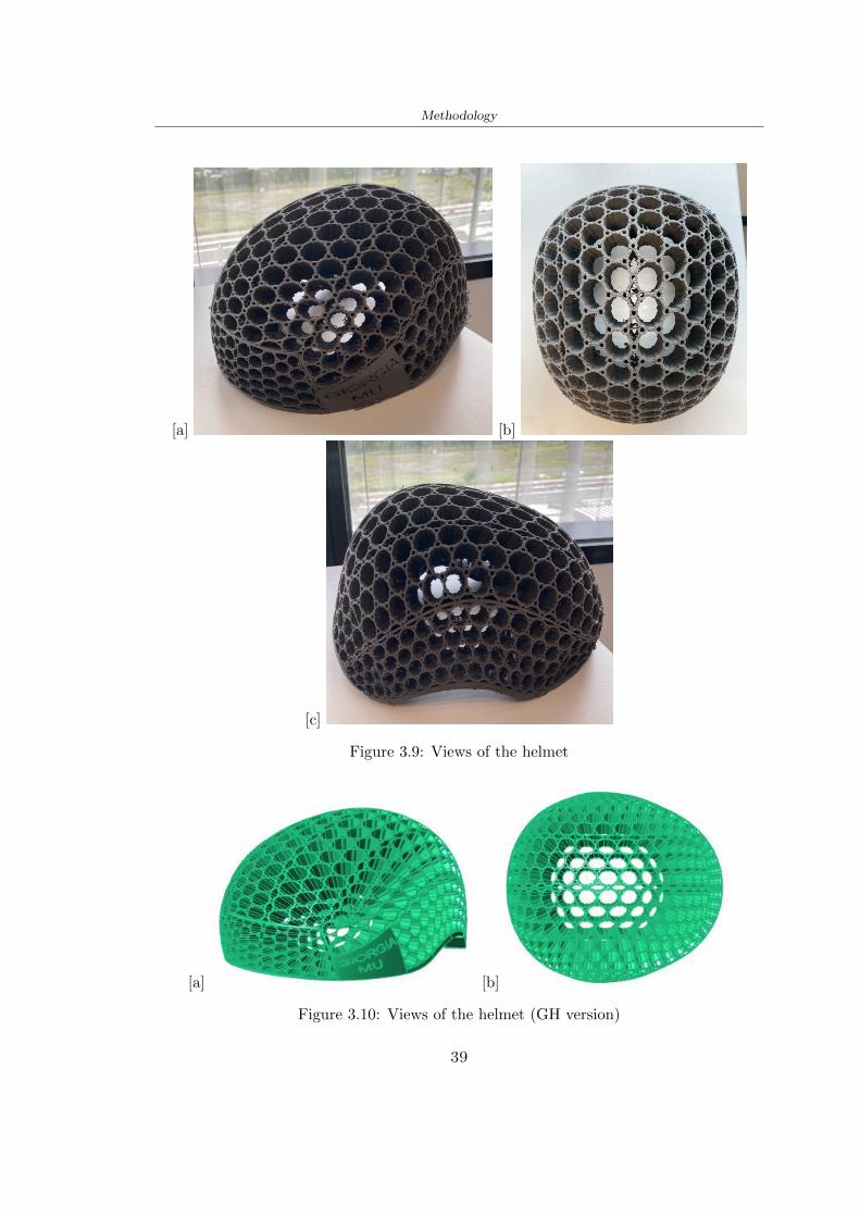
Methodology
[a] [b]
[c]
Figure 39 Views of the helmet
[a] [b]
Figure 310 Views of the helmet (GH version)
39
Chapter 4
Experimental evaluation
41 Experimental tests
411 Drop-weight impact test machine
In order to calculate the contact force peak and the difference of energy absorbed duringthe impact between the reference helmet and helmet with the beetle structure in PLA-LW dynamic impact tests were carried out using the Fractovis Plus an impact testmachine
In this way it is possible to monitor the evolution of the above variables from theinitial to the final instant of the impact The machine can withstand a load with a rangevariable from 2 to 70 kg with a maximum speed of 46 ms and a maximum height of1 m The values chosen for the test are the following 5 kg weight maximum speed andmaximum height The Anvil that was used is a disc diameter of 60 mm
As shown in Figure 41 and explained by Crupi et al [37] the machine consists ofa sensor capable of recording the speed before impact the impactor that can have avariable mass (a weight of 5 kg in my test) a system to guarantee that there are nomultiple impacts after the first and that work as a shock absorber and clamping systemwhere the object to be tested is placed
The tests that have been carried out are in total four two related to the helmetoptimized with PLA-LW and two with two generic helmets of different brand in EPS
42 PLA LW helmet
To perform the dynamic test on the helmet of PLA considering the difficulty of printingit was helpful to use a test helmet with imperfections to understand where the impactwas concentrated in a single part or distributed The images of Figure 42 show a helmetwith not well defined edges and inaccurate print but exactly localizes the impact zoneThanks to this test it was possible to take into account only one helmet area shown inFigure 43 to have the exact curve of the structure bio-inspired with PLA-LW
40
Experimental evaluation
Figure 41 Drop-weight impact test machine [37]
[a] [b]
Figure 42 Test 1 PLA-LW helmet
43 EPS helmet
To carry out dynamic tests and extract the technical characteristics of the helmettwohelmets were bought in a sports store both EPS and being on the market both certifiedThe brands of the two helmets are DTB and VAN|RYSEL and the average weight ofthe two is 223 g Two different helmets have been chosen to have a more certain andclear classification of the characteristics They are shown in Figure 44 and Figure 45
41
Experimental evaluation
[a] [b]
Figure 43 Test 2 PLA-LW helmet
[a] [b] [c]
Figure 44 Test 3 EPS helmet
[a] [b] [c]
Figure 45 Test 4 EPS helmet
44 Results
441 First results - PLA-LW and EPS helmet
Figure 46 shows two types of trends related to the two different models of the helmetThe force evaluated for PLA-LW has higher force peaks but is more concentrated and
42
Experimental evaluation
propagates less than EPS The graph shows the peaks of each curve highlighted with a redcircle In tests 1 and 2 for the PLA-LW as mentioned earlier the values are higher about7301 N for the complete helmet and 3996 N for the portion of helmet This difference isdue to the inaccuracy of the first full helmet during the printing phase In Figure 42 itis visible the low homogeneity and precision Therefore the first test with full helmet wasused only to define the area of interest of the impact which turns out to be localized Forthe other two EPS curves the values are only slightly lower compared to the PLA-LWequal to 3620 N and 3295 N but the trend is much more distributed
Figure 46 Dynamic machine test - Force
With the data obtained from the impact machine it was possible calculate not exclu-sively the value of force but itrsquos also possible to view the energy curves A resume aboutthe values and energy of the force is in the following Table 41
Test Peak force [N] Peak energy [J]
Test 1 - PLA LW (inaccurate) 730130
Test 2 - PLA LW (portion of helmet) 399643
Test 3 - EPS (DTB helmet) 362007 509
Test 4 - EPS (VAN|RYSEL helmet) 329546 4198
Test 5 - PLA with TPU 45421 5022
Table 41 Energy absorbed in dynamic test
43
Experimental evaluation
442 PLA-LW helmet with TPU cover
As it is possible to see in Figure 47 and as highlighted the first tests concerning thebio-inspired structure and the PLA-LW are far from my expectations considering thelittle distribution of force in comparison with the EPS foam and consequently a smallamount of energy absorbed
Figure 47 Dynamic machine test - Energy
To improve this impact damping factor the idea was to create a cover for the helmetin flexible TPU trying to absorb impact energy The TPU used is a flexible material ofthe brand Ninjaflex used in sports by the application in helmets and shoes to cushionbumps during the game Generally in the helmets (baseball helmet for example) theTPU is inserted internally in contact with the head In my case the TPU structurein addition to creating a shock-absorbing and durable cover creates a custom cover thehelmet and for the person This cover was also made with the Raise 3D printer
As shown in the Figure 48 [a] the infill of the part in contact with the helmet hasa percentage of 100 the filling of the other part of the structure is not complete butonly 15 and the internal structure is hexagonal to recall that of the helmet The desireto insert a structure with a rsquoraisedrsquo geometry is for visual and aesthetic reasons as youhave the feeling of greater protection and not filled is inspired by the machine CitroenCaptus whose bumpers (Airbump) are full of air The failure to realize empty structuresis due to the need to place any internal supports not removable
The idea was to create a cover that allow you to see of the internal structure of thehelmet and that protect specific areas the front the two sides the top and the posteriorWhat which was thought for this reason was to create the shape of a flower with four
44
Experimental evaluation
petals Figure 48 [b]In this way to perform dynamic impact tests as shown in Figure 49 [a] the cover was
positioned at the top of the helmet and the impact was performed in the centre of thersquoflowerrsquo which corresponds to the higher upper part where the structure has larger cellsize The impact parameters are the same as those used in previous impacts 5 kg weightmaximum speed and maximum height The Anvil that was used is a disc diameter of60 mm In photo [b] it is evident the difference between the structure that received theimpact with protection (left) and without protection (right) Without protection duringthe impact there was a perforation of the structure with a concentration of force at a locallevel as you can see in the Figure 46 in the case of TPU the impactor did not perforateand crossed the structure thanks to the cover of TPU that cushioned the shock At themoment of impact the impactor bounced
[a] [b]
Figure 48 TPU cover
[a] [b]
Figure 49 PLA-LW with TPU - dynamic impact [a] and differences between thehelmet with TPU and without TPU cover [b]
45
Experimental evaluation
The Figure 410 includes the diagrams relative to the dynamic impacts In [a] thereare already analyzed EPS results in [b] a comparison between the test on the portionof helmet in PLA LW with and without the TPU cover in [c] the overall comparison ofcurves shows a much more similar EPS trend if the TPU is placed above the structure inPLA LW to soften the blow and absorb the same energy [d]
46
[a]
[c]
[d]
Figure 410 Comparison between PLA-LW with TPU and EPS
Chapter 5
FEM Validation
51 Impactor - Anvils definition
Before to start to work in Abaqus it was necessary to search in the literature the materialwith which the anvil was been realized Milne et al [23] established the densityrsquos valuethe Youngrsquos Module and Poissonrsquos ratio for the Flat and Kerbstone Anvil
- Density ρ = 7800 kgm3
- Youngrsquos Module E = 200000 MPa
- Poissonrsquos ratio ν = 03
Inserting the data in the CES EduPack program specifying the mechanical andphysical properties the material corresponding to these characteristics is Stainless steelaustenitic (ASTM F1586) medium-hard
Initially the proposal was to create a conservative system to evaluate the absorptionenergies values and apply this value to a vibration system but the helmet needs dampingto be realized it was impossible to use a system without losses in this modality Thisis why a numerical calculation was carried out by performing two types of simulationsexplicit dynamic step and static step
The idea to realize the theoretical impact is to regard the movement of the anviland not the helmetrsquos movement which is fixed The velocity is the same cited in thenormative EN 1078 542 ms for the Flat anvil and 457 ms for the Kerbstone anvil
In performing the simulations It was given more relevance and perform tests withthe Kerbstone Anvil This choice was done because the geometry with which it is beenrealized (following as defined in the legislation) allows the helmet to be more subjectedto stress this involves the definition of higher stress limits compared to the Flat Anvil
The mesh size that has been used is the same in the case of the simulation of thehelmet optimized in PLA-LW and the full helmet in EPS of 7 mm The impactor isconsidered as a Discrete rigid body with its specific Reference Point (RP) like shownin Figure 51 for this reason it is not a solid but it is composted only by shells Inthe same image [b] there is the FEM representation of the model and in Table 51 thecharacteristic of FEM with quadrilateral (R3D4) and triangular elements (R3D3)
48
FEM Validation
Object Elementnumber
Elements Shape Geometricorder
Global size[mm]
Kerbstone 230 Quadrilateral - R3D4 Linear 7
Kerbstone 8 Triangular - R3D3 Linear 7
Table 51 Mesh element - Kerbstone Anvil
[a] [b]
Figure 51 Kerbstone anvil in the simulation like discrete rigid body [a] and FEMelements [b]
511 PLA LW - Plastic characteristics
The PLA-LW as explained in the Chapter 2 is new material on the market and producedby the only Colorfabb company for this reason few tests have been carried out to defineits technical characteristics and through tensile tests of the 3D printed specimens it waspossible to define an elastic limit as reported in the Table 210
In the context of simulations to reproduce the impact and deformation of the helmetis also necessary to consider the plastic characteristics of the material Not possessingany reference value in this regard tests were performed through a Static Step initiallyand then an Explicit Dynamic Step in Abaqus
The structure chosen to consider as a reference it is one of the structures previouslysubjected to the compression test having the side L=14 mm As for the reproduction ofthe compression disks initially they were reproduced according to the geometry of theHoytom HM-D Testing Machine considering the bodies mentioned above as discrete 3Drigid discrete The measure was the diameter of 200 mm and the height of 20 mm
After an initial analysis it was observed that the computational time of the simulationprogram was very high so it was decided to change the geometry to have a rsquodisk-surfacesrsquo(equally 3D rigid-discrete) which allowed me to have a smaller number of nodes for themesh and consequently a better computational time The representation of the opti-mized structure in PLA-LW and the disks used for simulated compression is in Figure 52
49
FEM Validation
[a] [b]
Figure 52 Representation of the samples used for the simulation of the compressiontest In Figure [a] the disks of the Hoytom HM-D Testing Machine in figure [b] the
representation of the same as simple surfaces
As shown in Figure 52 the disks are considered 3D discrete hard bodies so it waschosen for both a point the reference point RP where to apply the characteristics relatedto the two bodies As for the compression test it was established
bull the movement of a disk and fixed the second through a boundary condition impos-ing an Encastre therefore unable to move and rotate in xyz directions
bull for the opposite disk the boundary condition relative to the 15 mm displacementwas applied which is the parameter that it was observed to determine the end ofthe compression with the machine This shift is shown by the orange arrow in figure[b]
bull between the upper surface and the disk e the disk with the lower surface it wasinitialized a general contact with normal behaviour through rsquohardrsquo contact andtangential behaviour with a coefficient of friction of 02 with directionality imposedon rsquoisotropicrsquo
The next step was to define the mesh of the components whose parameters are shown inTable 52 while the representation of the FEM is in Figure 53 with the representationof the simulation and real compression test
Object Elementsnumber
Typology Geometricorder
Globalsize [mm]
Disk (14mm) 80910 hexaedral - C3D8R Linear 07
Impact disks 206 quadrilateral - R3D4 Linear 20
Impact disks 6 triangular - R3D3 Linear 20
Table 52 Mesh element - Compression test simulation
As previously announced a static simulation was initially performed with a StaticStep with Step Time equal to 900 (obtained going to consider the speed of 1 mmmin of
50
FEM Validation
[a]
[b] [c]
Figure 53 FEM representation [a] and compression test simulation [b] and realcompression [c]
the compression test and the displacement of 15 mm) However the complex geometryof the structure and the high time set by Step Time did not allow a correct definitionof the parameters of the plastic characteristics of the material the simulation was notable to continue once reached a Step Time of approximately 220 That is why it waschanged by choosing an Explicit Dynamic step
Leaving all the parameters of the boundary conditions unchanged the Step Time wasmodified imposing it to 001 The ability of the explicit dynamic to work with non-linearand contacting structures allowed me to achieve results The results obtained are shownin Figure 54 with the blue curve and were obtained through the iteration of differentPlastic Strain and Yield Stress values in Abaqus while the red line is the result of thereal compression test a similar curve trend was obtained but it is not possible to obtainthe same curve taking into account problems of printing inaccuracy
512 First test - helmet
The initial idea was to perform a simulation imposing the speed of 457 ms to theimpactor tie the helmet in EPS and PLA and compare the absorbed energies Theproblem it was encountered is related to the mesh of the helmet optimized in PLA andwith minimum dimensions of the elements and distinct elements it was not able to solveit
51
FEM Validation
[a]
YieldStress
PlasticStrain
1 47 0
2 7 001
3 75 005
4 10 01
5 108 1
6 115 15
7 12 2
[b]
Figure 54 Representation of the two curves related to the simulation in Abaqus of thecompression test and the data obtained from the real test to obtain the plastic
characteristics of the material
513 Second test - plane
The first solution is the one shown in Figure 55 To realize the simulation it was realizeda section of the helmet to involve a smaller number of elements and nodes Again thesimulation for the EPS helmet was successful while the simulation with the bio-inspiredstructure was interrupted by excessive distortion of elements
The previous images show the impact is very localized in the impacted area and theidea to achieve a complete simulation is not to consider a curved portion of the helmetbut a plane In this way it was possible to solve the problem and obtain a completesimulation for the bio-inspired structure
FEM element
Below in Table 53 there is the definition of the elements used for the PLA-LW and EPSplane in the simulation to simulate the impact and to control the energy-absorbing whilethe anvil characteristics are described in Table 51
514 EPS impact simulations
In order to proceed with the simulation it was imposed some boundary conditions thatregard ties and forces
bull the movement of the plane is fixed through an Encastre therefore unable to moveand rotate in xyz directions
52
FEM Validation
[a]
[b]
Figure 55 Impact simulation parts of EPS and PLA helmet
Object Elementnumber
Elements Shape Geometricorder
Plane (PLA) 38896 Tetrahedral -C3D10M
Quadratic
Plane (EPS) 2100 Hexahedral - C3D8R Linear
Table 53 Mesh element - plane impact
bull to create the impact it was set a speed of 457 ms at the reference point RP of therigid body which is the impactor Kerbstone Anvil shown in Figure 56
bull between the upper surface of the plane and the impactor it was initialized a Sur-face to Surface contact with normal behaviour through rsquohardrsquo contact and tangen-tial behaviour with a coefficient of friction of 02 with directionality imposed onrsquoisotropicrsquo
bull the rotation in x y z relative to the RP of the rigid discrete impactor body is locked
53
FEM Validation
In addition it was characterized the plane in the part of the materials with the char-acteristic values of the EPS mentioned in Chapter 221 The Von Mises Stress valueapparently low is relative to the Yield Stress of the EPS material equal to 09 MPa
Figure 56 EPS Boundary conditions and Load
515 PLA LW impact simulations
As also required in the case of the EPS plane in order to proceed with the simulationsome boundary conditions were imposed that regard ties and forces
bull the movement of the plane is fixed through an Encastre therefore unable to moveand rotate in xyz directions
bull to create the impact a speed of 457 ms was set at the reference point RP of therigid body which is the impactor Kerbstone Anvil shown in Figure 58
bull between the upper surface of the plane and the impactor it was initialized a Sur-face to Surface contact with normal behaviour through rsquohardrsquo contact and tangen-tial behaviour with a coefficient of friction of 02 with directionality imposed onrsquoisotropicrsquo
bull the rotation in x y z relative to the RP of the rigid discrete impactor body is locked
In addition the plane was characterized in the part of the materials with the characteristicvalues of the PLA mentioned in the Chapter 223 and 511
Figure 58 Boundary conditions and Load
54
FEM Validation
[a]
[b]
Figure 57 EPS impact simulation
52 Results
In Figures 59 and 57 it is shown how the structure in PLA LW has a more concentratedstress distribution of the structure unlike EPS The maximum value for the Von Misesstress is 09 MPa in EPS structure and 3634 MPa in PLA LW structure Once thesimulations were obtained the next step was to go and compare the energies absorbed bythe two structures The energy calculated by Abaqus that has been taken into account isPlastic Dissipation To make a comparison the data of the two energies were representedin a single graph
What emerges from the graph is that about the impact made with the KerbstoneAnvil the energy absorption is more excellent although only slightly for the PLA LWthan for the EPS From the graph in Figure 510 a value of 41 J is shown for the EPSand 51 J for the PLA LW
55
[a]
[b]
Figure 59 PLA impact simulation
[a]
Figure 510 EPS and PLA LW energy comparison - Abaqus simulation
Chapter 6
Head Injury Data
For the statistical analysis the injuries related to the accident data were categorised intothe following types and levels based on the details of the medical report [11] about theEN 1078
bull Head Injury Criterion (HIC)
bull Peak Linear Acceleration (PLAc)
bull Gadd Severity Injury (GSI)
bull Diffuse axonal injuries (DAI)
61 Abaqus simulation
Until now the purpose of the simulations has been to determine which between the twomaterials and the two structures of EPS and PLA LW could absorb more energy duringthe impact but no simulations have been carried out in compliance with BS EN 1078on the helmet impact tests To calculate the injuries listed in the previous paragraphhowever we need the acceleration values in the three directions related to the subjectrsquoshead
To realize it the scan of my head already rsquocleanrsquo was considered of which it has beencalculated the inertia thanks to the automatic SolidWorks calculation and evaluated theweight with the Table 24 the structure of the helmet was placed for the EPS and thePLA LW over the head as shown in Figure 61 Also this time being able to mesh theentire helmet in PLA LW was impossible due to the excessive distortion of some elementsduring the simulation so it has been tried to make a section of the structures of thehelmet and results were obtained
57
Head Injury Data
[a] [b]
Figure 61 My scan head - CAD [a] head imported in Abaqus[b]
Initially the simulation had these characteristics as shown in the following Figure62 considering the helmet was not sectioned As explained earlier it was not possibleto get to simulation in the case of the optimized structure in PLA LW for this reasononly a part of the helmet was considered in both cases shown in Figure 63
[a]
Figure 62 Simulation based on BS EN 1078
58
Head Injury Data
[a] [b]
Figure 63 Simulation based on BS EN 1078 with head
In order to proceed with the simulation some boundary conditions that regard tiesand forces have have imposed
bull two reference points RP were created the first in the inertia centre of the headthe second relating to the Kerbstone Anvil which is a discrete rigid body
bull in the reference point RP of the head in the definition of the engineering features5 kg was inserted for the weight and an inertia I11 = 564464E+07 gmm2 I22 =460654E+07gmm2 I33 = 187302E+07gmm2
bull to simulate the impact it was set a speed of 457 ms at the reference point RP ofthe head in z-axis direction
bull a general contact with normal behaviour through rsquohardrsquo contact and tangentialbehaviour with a coefficient of friction of 02
bull between the upper surface of the helmet and the impactor it has been initializeda Surface to Surface contact with normal behaviour through rsquohardrsquo contact andtangential behaviour with a coefficient of friction of 02 with directionality imposedon rsquoisotropicrsquo
bull the movement between the Kerbstone anvil and the helmet is fixed through anEncastre therefore unable to move and rotate in xyz directions
bull the rotation in x y z relative to the RP of the rigid discrete impactor body is locked
FEM element
As reported in Table 53 the portion of the helmet in EPS has used a mesh with hexahe-dral elements of linear order For the structure (beetle) of PLA LW given the geometry
59
Head Injury Data
complexity it was necessary to use a quadratic order of tetrahedra For the mesh of thehead instead in both simulations have been used quadrilateral elements of linear orderas reported in the Tables 61 and 62
Object Elementnumber
Elements Shape Geometricorder
Head 3755 Quadrilateral - R3D4 Linear
Head 34542 Quadrilateral - R3D3 Linear
Helmet (PLA) 272302 Tetrahedral -C3D10M
Quadratic
Table 61 Mesh element - Head simulation with PLA LW (beetle) helmet
Object Elementnumber
Elements Shape Geometricorder
Head 3755 Quadrilateral - R3D4 Linear
Head 34542 Quadrilateral - R3D3 Linear
Helmet (EPS) 72280 Hexahedral - C3D8R Linear
Table 62 Mesh element - Head simulation with EPS helmet
62 Results
Figure 64 represents the simulation in line with BS EN 1078 concerning the helmet inEPS [a] and the helmet with bio-inspired structure in PLA LW For both simulationsVan Misesrsquo stress has Yield Stress values in the case of EPS which is 09 MPa and theplastic behaviour combination of PLA LW [b]
In the case of head and Kerbstone Anvil stress was not assessed as they were previ-ously defined as discrete rigid bodies
63 Head Injury Criterion
The HIC quantifies head impact severity by incorporating time of acceleration exposureand acceleration magnitude it is calculated in post-processing phase with the followingEquation 61
HIC15 =
[1
(t1 minus t2)
int t2
t1
a(t)dt
]25(t2 minus t1) (61)
60
Head Injury Data
[a]
[b]
Figure 64 Results simulation based on BS EN 1078 with sectioned head
For this analysis a(t) is the acceleration calculated in the centre of mass of the head(corresponding to the reference point RP) expressed in g and the time interval (t2 minus t1)was chosen to maximize HIC over a maximum duration of 15 ms
Matlab and the trapz function were used to calculate the HIC to integrate accelerationover time t2 and t1 were considered initial and final times of the simulation t1 = 0 sand t2 = 10 s time less than 15 s
HIC value of 198 was obtained for EPS and 87 for PLA LW Considering the Hayeset al [16] document about the HIC values and the graph in Figure 65 developed bythe author it is possible to find the percentages related to the different injury AIS1 -AIS6 which correspond respectively to lower and higher severity while in Figure 66 therelative fatality to every value of AIS is shown The values obtained for the HIC andother criteria are shown in Table 63 The HIC value for EPS is 198 for PLA LW it is
61
Head Injury Data
Figure 65 Head injury risk curves based on HIC values [16]
Figure 66 The abbreviated injury score versus fatality rate [16]
87 Analyzing the data and comparing them with the curves of the Figure 65 I obtain
bull a percentage between 20 - 30 of AIS 1 for EPS 10 - 20 for PLA LW
bull a percentage between 10 - 20 of AIS 2 for EPS and 0 - 10 for PLA LW
bull for AIS 3 AIS 4 AIS 5 AIS 6 the percentages for both structures is between 0 -10
Comparing these percentages with the fatality rate of Figure 66 it is clear there is a riskof Moderate and Minor fatality in the case of EPS and PLA LW as all values are between0 and 30
62
Head Injury Data
HIC PLA [g] GSI E [J]
EPS 198 97 361 37723
PLA LW 87 75 169 44102
Table 63 Head Injury Data - values
64 Peak Linear Acceleration
The resultant linear acceleration versus time curve was calculated according to Equation62
γ(t) =radicγ2x(t) + γ2y(t) + γ2z (t) (62)
where
bull γ(t) is the resultant linear acceleration (g)
bull γx(t) is the linear acceleration in x axes (g)
bull γy(t) is the linear acceleration in y axes (g)
bull γz(t)is the linear acceleration in z axes (g)
The value of the impact should never exceed 250g [9] Cripton at all [9] in their studyexamined a helmet with expanded polystyrene (EPS) Figure 68 shows maximum HIC forhelmeted and unhelmeted drops from all heights For each drop height helmets reducedHIC relative to unhelmeted drops IARV value is 180g The acceleration in the two casesis shown in Figure 67 and the maximum values are 97g for EPS and 75g for PLA LWas reported in Table 63 The two values considering a maximum value calculated byCripton [9] of 180g are amply optimal and comply with the standard of 250g
65 Gadd Severity Index
Gadd proposed the Severity Index Criteria shown in Equation 63 Following this crite-rion the GSI values that are over 1000 produce serious internal head injury [33]
GSI =
int t1
0a(t)25dt (63)
Where
bull a is the linear acceleration (g)
bull t is the duration of the impact (s)
I calculated the GSI with the function trapz between 0 and t and the resulting valuesare 361 for the EPS and 169 for the PLA LW which comply with the limit
63
Head Injury Data
Figure 67 Peak accelerations for both helmets
Figure 68 Peak accelerations for both helmeted and unhelmeted drops Numbers overbars indicate peak acceleration For 2 m drop height results stated are the mean value
calculated from three drops [9]
64
Head Injury Data
66 Diffuse Axonal Injury
DAI cases covered all incidences in which neurological injuries occurred as well as con-cussion unconsciousness and coma
In order to assess the risk of head trauma in terms of diffuse axonal injury (DAI)Milne et al [23] defined a model based head injury criteria as follows obtaining theresults in Figure 69
bull 50 risk of moderate neurological injury (DAI1+) Brain Von Mises shearing stressof 28 kPa
bull 50 risk of severe neurological injury (DAI2+) Brain Von Mises shearing stressof 53 kPa
[a]
[b]
Figure 69 Peak intra-cerebral shearing stress computed with the helmet model coupledto the human head model for all impact points (a) Flat anvil (b) Kerbstone anvil [23]
65
Head Injury Data
67 Energy absorbed
In Figure 52 during the impact test between the kerbstone Anvil and the plan with thebio-inspired structure in PLA LW and EPS it was found that the PLA LW althoughwith a small difference of 10 J absorbed more energy in comparison with the EPS Whenthe test is carried out in compliance with BS EN 1078 and the head with a speed of 457ms (corresponding to the kerbstone Anvil) as shown in Figure 610 also in this casethe PLA LW with the optimized helmet structure manages to absorb more energy (evenif the difference is very low) compared to the EPS The maximum energy value in PLALW is 44102 J of EPS is 37723 J
Figure 610 Energy absorption - BS EN 1078
66
Chapter 7
Conclusion
71 Conclusion
In this thesis work a bicycle helmet with a bio-inspired structure in PLA LW and 3Dprinted was created The initial approach was to introduce an innovative aspect tostandard EPS helmets not using foam but a polymer with new geometries able toabsorb much energy during the impact For this reason the beetle structure has beenpreferred relying solely on the hypothesis encountered in the literature of its quality inabsorbing energy
Combining the new material of the PLA LW and beetle structure has made possiblethe development of new material satisfactory characteristics have been obtained sincethe first tests The two materials were first subjected to tensile tests to determine theirspecific stress in these the PLA LW had positive results
Subsequent dynamic physical tests were carried out on 3D printed helmet models andon reference helmets in EPS to calculate the absorption energy in both cases at the timeof impact These resulted in energy absorption of the beetle structure in PLA LW withthe application of a TPU cover almost equal to that of EPS about 50J To validate withfinite element analysis the two models an explicit dynamic step was used in AbaqusSimulations showed that the PLA LW structure absorbs a higher amount of energy thanthe EPS the higher is 50 J and the EPS 40J
Finally positive results have also been obtained in calculating the head injury datasimulating according to BS EN 1078 with the use of impactor helmet and head Theacceleration values for both the structures were inferior to 220g precisely for the PLALW was 75g and for the EPS 97g The same applies to the calculation of HIC and GSI(maximum acceptable value of 1000) where the values are 87 and 169 in the case of PLALW and 361 and 198 in EPS For all tests therefore greater efficiency of the structure inPLA LW has been obtained Positive results also in the simulation of the energy absorbedduring the impact as the value referring to the EPS was 35J and that of the PLA LWwas 45J
67
Conclusion
72 Future work lines
The positive results obtained can be considered as a starting point for further tests andsimulations to ensure the safety of the helmet and compliance with the regulations butbefore getting improvements and continue testing changes are required
bull the beetle structure of the helmet made with GH adapts to the SubD withoutallowing to have a homogeneous distribution it would be appropriate to have moreregular hexagonal geometries
bull the mesh of the helmet is too complex and does not allow to perform the simulationprobably to use a more regular structure would have a mesh accordingly moreregular and the simulation would be successful
bull the uneven helmet structure has so many defects that the print is imperfect andthis can change the results of the impact tests the structure should be improved
bull the printing time varies from 4 to 5 days it should be improved
bull the TPU helmet cover is too big for the RAISE printing plan it is necessary togenerate a new geometry
bull the TPU cover it must be fixed on the helmet
bull in the calculation of the DAI it is necessary to have the definition of the brain andthe head should not be considered as a rigid body
bull in the injury calculation the helmet without protection was considered with theTPU cover the result will be better
bull air flow analysis
The comments mentioned are only considerations and problems that I gained duringmy thesis and which should be improved but I am sure that these changes and improve-ments from design to printing and simulations can make the helmet a good product
68
Bibliography
[1] K Adanty J M Clark A Post Thomas Blaine H and M D Gilchrist Comparingtwo proposed protocols to test the oblique response of cycling helmets to fall impactsInternational Journal of Crashworthiness 6648 ndash 663 2020
[2] MF Ashby YJM Brechetb D Cebona and L Salvoc Selection strategies formaterials and processes Materials and Design 2004
[3] M Aysha El casco de bicicleta voronoi impreso en 3d mas seguro y ligero https
www3dnativescomen3d-printed-bicycle-helmet-voronoi-190820204
[4] H Bikas P Stavropoulos and G Chryssolouris Additive manufacturing methodsand modelling approaches a critical review The International Journal of AdvancedManufacturing Technology 83389ndash405 2016
[5] British Standards BSI Helmets for pedal cyclists and for users of skateboards androller skates - BS EN 1078 2012
[6] British Standards BSI Headforms for use in the testing of protective helmets BSEN 960 2020
[7] ColorFabb Colorfabb lw-pla 2019 httpscolorfabbcommedia
datasheetstdscolorfabbTDS_E_ColorFabb_LW-PLApdf
[8] V G Coronado T Haileyesus J M Bell T A Cheng JHaarbauer-Krupa M RLionbarger J Flores-Herrera L C McGuire and J Gilchrist Trends in sports andrecreation-related traumatic brain injuries treated in us emergency departments thenational electronic injury surveillance system-all injury program (neiss-aip) 2001-2012 J Head Trauma Rehabil 30185ndash197 2015
[9] P A Cripton D M Dressler D Stuart Cameron A Christopher R and D RichardsBicycle helmets are highly effective at preventing head injury during head impactHead-form accelerations and injury criteria for helmeted and unhelmeted impactsAccident Analysis and Prevention 701ndash7 2014
[10] L Cui M A Forero R and M D Gilchrist Optimisation of energy absorbingliner for equestrian helmets UCD School of Electrical Electronic and MechanicalEngineering University College Dublin Belfield Dublin4 Ireland 2020
[11] C Deck N Bourdet F Meyer and R Willinger Protection performance of bicyclehelmets Journal of safety research pages 67ndash77 2019
[12] Committee F08 Specification for headforms F2220 ASTM International 2015
[13] Committee F08 Specification for helmets used in recreational bicycling or rollerskating F1447 ASTM International 2018
[14] Committee F08 Test methods for equipment and procedures used in evaluating theperformance F1446 ASTM International 2020
69
Bibliography
[15] P Halldin Shock absorption including measuring CENTC 158 Working Group11 2018
[16] W C Hayes M S Erickson and E D Power Forensic injury biomechanics Annualreview of biomedical engineering pages 55ndash86 2007
[17] HEXR httpshexrcom
[18] C Jinxiang Z Xiaoming O Yoji S Kazuya G Zhensheng and P LongchengThe deformation mode and strengthening mechanism of compression in the beetleelytron plate Materials and Design 131481ndash186 2017
[19] S Kroeker M Ozkul A De Marco S Bonin and GP Siegmund Density variationin the expanded polystyrene eps foam of bicycle helmets and its influence on impactperformance Journal of biomechanical engineering 2019
[20] S G Kroeker SJ Bonin A L DeMarco C A Good and G P Siegmund Agedoes not affect the material properties of expanded polystyrene liners in field-usedbicycle helmets Journal of biomechanical engineering 2016
[21] M Meier K H Tan M K Lim and L Chung Unlocking innovation in the sportindustry through additive manufacturing Business Process Management Journa2018
[22] N J Mills and A Gilchrist The effectiveness of foams in bicycle and motorcyclehelmets Accident Analysis Prevention 23153 ndash 163 1991
[23] G Milne C Deck R P Carreira Q Allinne and R Willinger Development andvalidation of a bicycle helmet assessment of head injury risk under standard impactconditions Computer methods in biomechanics and biomedical engineering 15 Suppl1309 ndash 310 2012
[24] Y Mosleh S J Vander B Depreitere and J Ivens Novel composite foam conceptfor head protection in oblique impacts Adv Eng Mater (Advanced EngineeringMaterials) 10 2017
[25] H Mustafa T Y Pang T Ellena and S H Nasir Impact attenuation of user-centred bicycle helmet design with different foam densities J Phys Conf Ser(Journal of Physics Conference Series) 1150 2019
[26] S H Ngoc and L Guoxing A review of recent research on bio-inspired structuresand materials for energy absorption applications Composites Part 181 2020
[27] J I Novak and A R Novak Is additive manufacturing improving performance insports a systematic review Sport engineering and technology 13 2020
[28] European Road Safety Observatory European road safety observatory facts and fig-ures - cyclists - 2020 December 2020 httpseceuropaeutransportroad_
safetysitesdefaultfilesfacts_figures_cyclists_final_20210323pdf
[29] New York City Departments of Health Parks Mental Hygiene Transportation Recre-ation and the New York City Police Department Bicyclist fatalities and seriousinjuries in new york city 2005
[30] W Pengwen Y Jing H Yanan H Jiaofei and F Xiaoyang Innovative designof a helmet based on reverse engineering and 3d printing Alexandria EngineeringJournal 603445ndash3453 2021
[31] S G Piland T E Gould M Jesunathadas J S Wiggins O McNair and V CShane Protective helmets in sports Materials in Sports Equipment 3 2019
70
Bibliography
[32] K Schmitt P F Niederer M H Muser and F Walz Trauma biomechanicsSpringer Berlin Heidelberg 2010
[33] David Sepelveda Lopez A Biomechanical Analysis of Bicycle Helmets using FEMPhD thesis 2019 Bachelor thesis
[34] H Stigson Bicycle Helmets 2020 Tested by Folksam PhD thesis 2020 PhDAssociate Professor Traffic Safety Research
[35] H Tao K Sudip N Anindya and X Yongzhao 3d printed sensors for biomedicalapplications A review sensor 2019
[36] M Trzaskalska and R Chwastek Damping properties and density of helmet linersmade of expanded polystyrene (eps) Archives of Metallurgy and Materials 66 2020
[37] Crupi V Epasto G and Guglielmino E Impact response of aluminum foam sand-wiches for light-weight ship structures Metals 198ndash112 2020
[38] W Wei-cai F Dong-ming and L Yuan-xin Study on impact energy absorbing per-formance of eps buffer layer of motorcycle helmet Proceedings - 2013 InternationalConference on Mechanical and Automation Engineering MAEE 2013
[39] Z Xiaoming C Jinxiang O Yoji Z Peiwei X Xiaobing and Y Xindi Influence ofhoneycomb dimensions and forming methods on the compressive properties of beetleelytron plates Journal of Sandwich Structures and Materials 2228ndash39 2020
[40] S Zhi L Dong Z Weisheng S Shanshan and G Xu Topological optimization ofbiomimetic sandwich structures with hybrid core and cfrp face sheets CompositesScience and Technology 14279ndash90 2017
[41] S Zhi S Shanshan G Xu H Xiaozhi and C Haoran On compressive propertiesof composite sandwich structures with grid reinforced honeycomb core CompositesPart B 94245ndash252 2016
71
- List of Tables
- List of Figures
- Introduction
-
- Helmet bike protection
-
- Helmet structure
-
- Additive Manufacturing
-
- AM process
- Materials and techniques - FDM
- AM in sport
-
- 3D printed helmets
-
- Phases
- HEXR
- VORONOI
-
- State of the art
-
- Standards
-
- Headform
- European Standard and American Standard
- Field of vision - BS EN 1078
- Test impact area
- Anvils and environmental conditions
-
- Materials
-
- EPS Foam
- CES Edu Pack - Material selection
- PLA with natural fiber and PLA LW
-
- Bio-inspired structures
-
- Beetle structure - Design of the model
- Specific stress - PLA LW and EPS foam
-
- Methodology
-
- 3D scan
-
- 3D Sense 2 scanner and Meshmixer - Reverse reconstruction
- 3D scan analysis and extraction of features
-
- Helmet design
-
- Rhinoceros - Helmet surface
- Grasshopper - Helmet structure
-
- 3D Print
-
- Printer and parameters
-
- Experimental evaluation
-
- Experimental tests
-
- Drop-weight impact test machine
-
- PLA LW helmet
- EPS helmet
- Results
-
- First results - PLA-LW and EPS helmet
- PLA-LW helmet with TPU cover
-
- FEM Validation
-
- Impactor - Anvils definition
-
- PLA LW - Plastic characteristics
- First test - helmet
- Second test - plane
- EPS impact simulations
- PLA LW impact simulations
-
- Results
-
- Head Injury Data
-
- Abaqus simulation
- Results
- Head Injury Criterion
- Peak Linear Acceleration
- Gadd Severity Index
- Diffuse Axonal Injury
- Energy absorbed
-
- Conclusion
-
- Conclusion
- Future work lines
-
- Bibliography
-
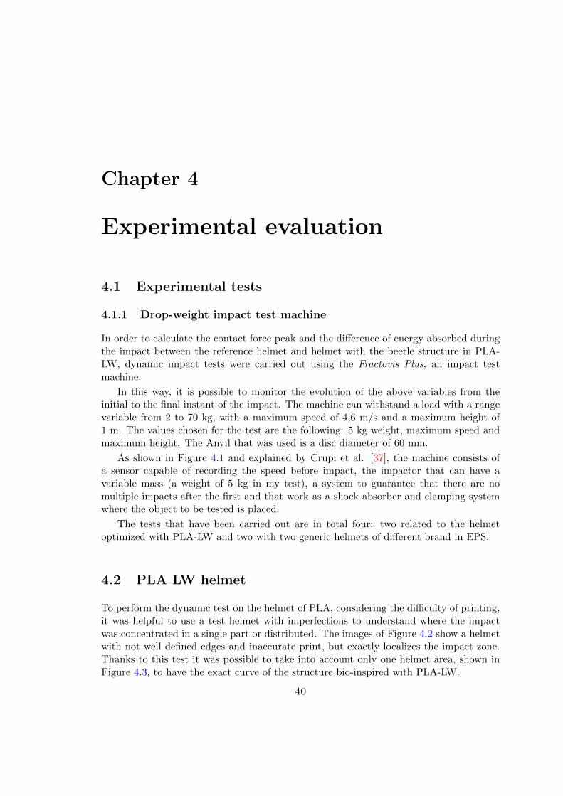
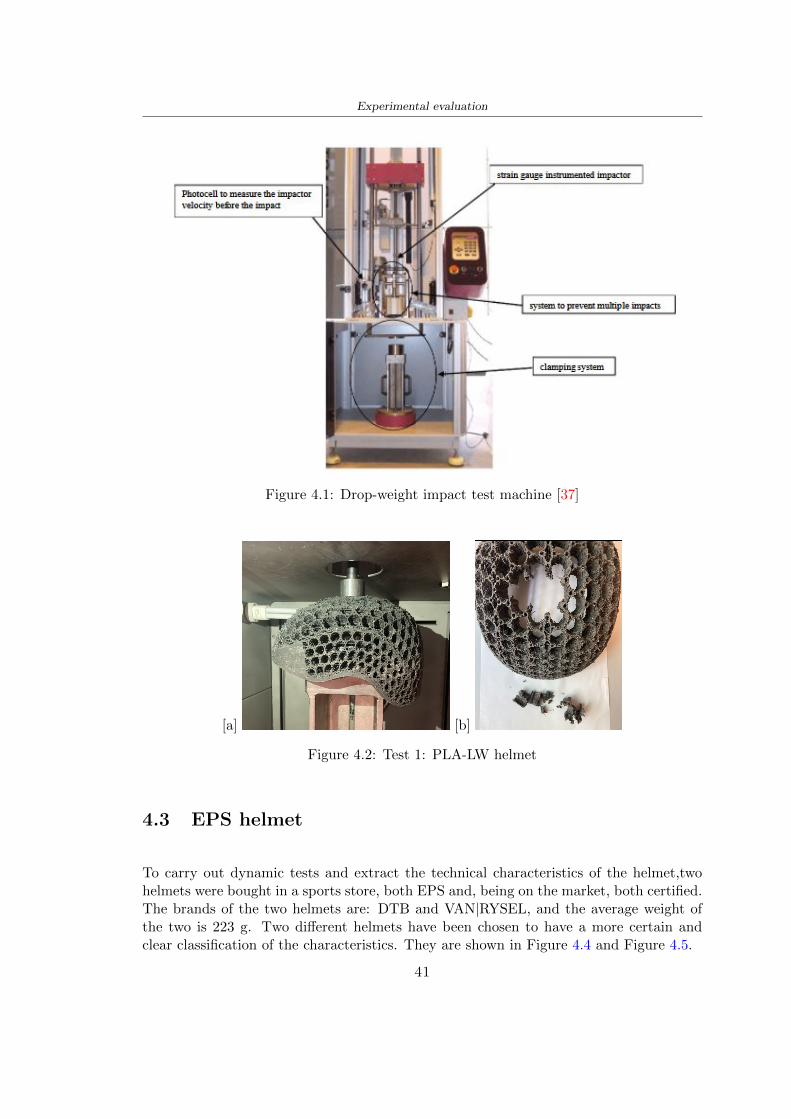
Experimental evaluation
Figure 41 Drop-weight impact test machine [37]
[a] [b]
Figure 42 Test 1 PLA-LW helmet
43 EPS helmet
To carry out dynamic tests and extract the technical characteristics of the helmettwohelmets were bought in a sports store both EPS and being on the market both certifiedThe brands of the two helmets are DTB and VAN|RYSEL and the average weight ofthe two is 223 g Two different helmets have been chosen to have a more certain andclear classification of the characteristics They are shown in Figure 44 and Figure 45
41
Experimental evaluation
[a] [b]
Figure 43 Test 2 PLA-LW helmet
[a] [b] [c]
Figure 44 Test 3 EPS helmet
[a] [b] [c]
Figure 45 Test 4 EPS helmet
44 Results
441 First results - PLA-LW and EPS helmet
Figure 46 shows two types of trends related to the two different models of the helmetThe force evaluated for PLA-LW has higher force peaks but is more concentrated and
42
Experimental evaluation
propagates less than EPS The graph shows the peaks of each curve highlighted with a redcircle In tests 1 and 2 for the PLA-LW as mentioned earlier the values are higher about7301 N for the complete helmet and 3996 N for the portion of helmet This difference isdue to the inaccuracy of the first full helmet during the printing phase In Figure 42 itis visible the low homogeneity and precision Therefore the first test with full helmet wasused only to define the area of interest of the impact which turns out to be localized Forthe other two EPS curves the values are only slightly lower compared to the PLA-LWequal to 3620 N and 3295 N but the trend is much more distributed
Figure 46 Dynamic machine test - Force
With the data obtained from the impact machine it was possible calculate not exclu-sively the value of force but itrsquos also possible to view the energy curves A resume aboutthe values and energy of the force is in the following Table 41
Test Peak force [N] Peak energy [J]
Test 1 - PLA LW (inaccurate) 730130
Test 2 - PLA LW (portion of helmet) 399643
Test 3 - EPS (DTB helmet) 362007 509
Test 4 - EPS (VAN|RYSEL helmet) 329546 4198
Test 5 - PLA with TPU 45421 5022
Table 41 Energy absorbed in dynamic test
43
Experimental evaluation
442 PLA-LW helmet with TPU cover
As it is possible to see in Figure 47 and as highlighted the first tests concerning thebio-inspired structure and the PLA-LW are far from my expectations considering thelittle distribution of force in comparison with the EPS foam and consequently a smallamount of energy absorbed
Figure 47 Dynamic machine test - Energy
To improve this impact damping factor the idea was to create a cover for the helmetin flexible TPU trying to absorb impact energy The TPU used is a flexible material ofthe brand Ninjaflex used in sports by the application in helmets and shoes to cushionbumps during the game Generally in the helmets (baseball helmet for example) theTPU is inserted internally in contact with the head In my case the TPU structurein addition to creating a shock-absorbing and durable cover creates a custom cover thehelmet and for the person This cover was also made with the Raise 3D printer
As shown in the Figure 48 [a] the infill of the part in contact with the helmet hasa percentage of 100 the filling of the other part of the structure is not complete butonly 15 and the internal structure is hexagonal to recall that of the helmet The desireto insert a structure with a rsquoraisedrsquo geometry is for visual and aesthetic reasons as youhave the feeling of greater protection and not filled is inspired by the machine CitroenCaptus whose bumpers (Airbump) are full of air The failure to realize empty structuresis due to the need to place any internal supports not removable
The idea was to create a cover that allow you to see of the internal structure of thehelmet and that protect specific areas the front the two sides the top and the posteriorWhat which was thought for this reason was to create the shape of a flower with four
44
Experimental evaluation
petals Figure 48 [b]In this way to perform dynamic impact tests as shown in Figure 49 [a] the cover was
positioned at the top of the helmet and the impact was performed in the centre of thersquoflowerrsquo which corresponds to the higher upper part where the structure has larger cellsize The impact parameters are the same as those used in previous impacts 5 kg weightmaximum speed and maximum height The Anvil that was used is a disc diameter of60 mm In photo [b] it is evident the difference between the structure that received theimpact with protection (left) and without protection (right) Without protection duringthe impact there was a perforation of the structure with a concentration of force at a locallevel as you can see in the Figure 46 in the case of TPU the impactor did not perforateand crossed the structure thanks to the cover of TPU that cushioned the shock At themoment of impact the impactor bounced
[a] [b]
Figure 48 TPU cover
[a] [b]
Figure 49 PLA-LW with TPU - dynamic impact [a] and differences between thehelmet with TPU and without TPU cover [b]
45
Experimental evaluation
The Figure 410 includes the diagrams relative to the dynamic impacts In [a] thereare already analyzed EPS results in [b] a comparison between the test on the portionof helmet in PLA LW with and without the TPU cover in [c] the overall comparison ofcurves shows a much more similar EPS trend if the TPU is placed above the structure inPLA LW to soften the blow and absorb the same energy [d]
46
[a]
[c]
[d]
Figure 410 Comparison between PLA-LW with TPU and EPS
Chapter 5
FEM Validation
51 Impactor - Anvils definition
Before to start to work in Abaqus it was necessary to search in the literature the materialwith which the anvil was been realized Milne et al [23] established the densityrsquos valuethe Youngrsquos Module and Poissonrsquos ratio for the Flat and Kerbstone Anvil
- Density ρ = 7800 kgm3
- Youngrsquos Module E = 200000 MPa
- Poissonrsquos ratio ν = 03
Inserting the data in the CES EduPack program specifying the mechanical andphysical properties the material corresponding to these characteristics is Stainless steelaustenitic (ASTM F1586) medium-hard
Initially the proposal was to create a conservative system to evaluate the absorptionenergies values and apply this value to a vibration system but the helmet needs dampingto be realized it was impossible to use a system without losses in this modality Thisis why a numerical calculation was carried out by performing two types of simulationsexplicit dynamic step and static step
The idea to realize the theoretical impact is to regard the movement of the anviland not the helmetrsquos movement which is fixed The velocity is the same cited in thenormative EN 1078 542 ms for the Flat anvil and 457 ms for the Kerbstone anvil
In performing the simulations It was given more relevance and perform tests withthe Kerbstone Anvil This choice was done because the geometry with which it is beenrealized (following as defined in the legislation) allows the helmet to be more subjectedto stress this involves the definition of higher stress limits compared to the Flat Anvil
The mesh size that has been used is the same in the case of the simulation of thehelmet optimized in PLA-LW and the full helmet in EPS of 7 mm The impactor isconsidered as a Discrete rigid body with its specific Reference Point (RP) like shownin Figure 51 for this reason it is not a solid but it is composted only by shells Inthe same image [b] there is the FEM representation of the model and in Table 51 thecharacteristic of FEM with quadrilateral (R3D4) and triangular elements (R3D3)
48
FEM Validation
Object Elementnumber
Elements Shape Geometricorder
Global size[mm]
Kerbstone 230 Quadrilateral - R3D4 Linear 7
Kerbstone 8 Triangular - R3D3 Linear 7
Table 51 Mesh element - Kerbstone Anvil
[a] [b]
Figure 51 Kerbstone anvil in the simulation like discrete rigid body [a] and FEMelements [b]
511 PLA LW - Plastic characteristics
The PLA-LW as explained in the Chapter 2 is new material on the market and producedby the only Colorfabb company for this reason few tests have been carried out to defineits technical characteristics and through tensile tests of the 3D printed specimens it waspossible to define an elastic limit as reported in the Table 210
In the context of simulations to reproduce the impact and deformation of the helmetis also necessary to consider the plastic characteristics of the material Not possessingany reference value in this regard tests were performed through a Static Step initiallyand then an Explicit Dynamic Step in Abaqus
The structure chosen to consider as a reference it is one of the structures previouslysubjected to the compression test having the side L=14 mm As for the reproduction ofthe compression disks initially they were reproduced according to the geometry of theHoytom HM-D Testing Machine considering the bodies mentioned above as discrete 3Drigid discrete The measure was the diameter of 200 mm and the height of 20 mm
After an initial analysis it was observed that the computational time of the simulationprogram was very high so it was decided to change the geometry to have a rsquodisk-surfacesrsquo(equally 3D rigid-discrete) which allowed me to have a smaller number of nodes for themesh and consequently a better computational time The representation of the opti-mized structure in PLA-LW and the disks used for simulated compression is in Figure 52
49
FEM Validation
[a] [b]
Figure 52 Representation of the samples used for the simulation of the compressiontest In Figure [a] the disks of the Hoytom HM-D Testing Machine in figure [b] the
representation of the same as simple surfaces
As shown in Figure 52 the disks are considered 3D discrete hard bodies so it waschosen for both a point the reference point RP where to apply the characteristics relatedto the two bodies As for the compression test it was established
bull the movement of a disk and fixed the second through a boundary condition impos-ing an Encastre therefore unable to move and rotate in xyz directions
bull for the opposite disk the boundary condition relative to the 15 mm displacementwas applied which is the parameter that it was observed to determine the end ofthe compression with the machine This shift is shown by the orange arrow in figure[b]
bull between the upper surface and the disk e the disk with the lower surface it wasinitialized a general contact with normal behaviour through rsquohardrsquo contact andtangential behaviour with a coefficient of friction of 02 with directionality imposedon rsquoisotropicrsquo
The next step was to define the mesh of the components whose parameters are shown inTable 52 while the representation of the FEM is in Figure 53 with the representationof the simulation and real compression test
Object Elementsnumber
Typology Geometricorder
Globalsize [mm]
Disk (14mm) 80910 hexaedral - C3D8R Linear 07
Impact disks 206 quadrilateral - R3D4 Linear 20
Impact disks 6 triangular - R3D3 Linear 20
Table 52 Mesh element - Compression test simulation
As previously announced a static simulation was initially performed with a StaticStep with Step Time equal to 900 (obtained going to consider the speed of 1 mmmin of
50
FEM Validation
[a]
[b] [c]
Figure 53 FEM representation [a] and compression test simulation [b] and realcompression [c]
the compression test and the displacement of 15 mm) However the complex geometryof the structure and the high time set by Step Time did not allow a correct definitionof the parameters of the plastic characteristics of the material the simulation was notable to continue once reached a Step Time of approximately 220 That is why it waschanged by choosing an Explicit Dynamic step
Leaving all the parameters of the boundary conditions unchanged the Step Time wasmodified imposing it to 001 The ability of the explicit dynamic to work with non-linearand contacting structures allowed me to achieve results The results obtained are shownin Figure 54 with the blue curve and were obtained through the iteration of differentPlastic Strain and Yield Stress values in Abaqus while the red line is the result of thereal compression test a similar curve trend was obtained but it is not possible to obtainthe same curve taking into account problems of printing inaccuracy
512 First test - helmet
The initial idea was to perform a simulation imposing the speed of 457 ms to theimpactor tie the helmet in EPS and PLA and compare the absorbed energies Theproblem it was encountered is related to the mesh of the helmet optimized in PLA andwith minimum dimensions of the elements and distinct elements it was not able to solveit
51
FEM Validation
[a]
YieldStress
PlasticStrain
1 47 0
2 7 001
3 75 005
4 10 01
5 108 1
6 115 15
7 12 2
[b]
Figure 54 Representation of the two curves related to the simulation in Abaqus of thecompression test and the data obtained from the real test to obtain the plastic
characteristics of the material
513 Second test - plane
The first solution is the one shown in Figure 55 To realize the simulation it was realizeda section of the helmet to involve a smaller number of elements and nodes Again thesimulation for the EPS helmet was successful while the simulation with the bio-inspiredstructure was interrupted by excessive distortion of elements
The previous images show the impact is very localized in the impacted area and theidea to achieve a complete simulation is not to consider a curved portion of the helmetbut a plane In this way it was possible to solve the problem and obtain a completesimulation for the bio-inspired structure
FEM element
Below in Table 53 there is the definition of the elements used for the PLA-LW and EPSplane in the simulation to simulate the impact and to control the energy-absorbing whilethe anvil characteristics are described in Table 51
514 EPS impact simulations
In order to proceed with the simulation it was imposed some boundary conditions thatregard ties and forces
bull the movement of the plane is fixed through an Encastre therefore unable to moveand rotate in xyz directions
52
FEM Validation
[a]
[b]
Figure 55 Impact simulation parts of EPS and PLA helmet
Object Elementnumber
Elements Shape Geometricorder
Plane (PLA) 38896 Tetrahedral -C3D10M
Quadratic
Plane (EPS) 2100 Hexahedral - C3D8R Linear
Table 53 Mesh element - plane impact
bull to create the impact it was set a speed of 457 ms at the reference point RP of therigid body which is the impactor Kerbstone Anvil shown in Figure 56
bull between the upper surface of the plane and the impactor it was initialized a Sur-face to Surface contact with normal behaviour through rsquohardrsquo contact and tangen-tial behaviour with a coefficient of friction of 02 with directionality imposed onrsquoisotropicrsquo
bull the rotation in x y z relative to the RP of the rigid discrete impactor body is locked
53
FEM Validation
In addition it was characterized the plane in the part of the materials with the char-acteristic values of the EPS mentioned in Chapter 221 The Von Mises Stress valueapparently low is relative to the Yield Stress of the EPS material equal to 09 MPa
Figure 56 EPS Boundary conditions and Load
515 PLA LW impact simulations
As also required in the case of the EPS plane in order to proceed with the simulationsome boundary conditions were imposed that regard ties and forces
bull the movement of the plane is fixed through an Encastre therefore unable to moveand rotate in xyz directions
bull to create the impact a speed of 457 ms was set at the reference point RP of therigid body which is the impactor Kerbstone Anvil shown in Figure 58
bull between the upper surface of the plane and the impactor it was initialized a Sur-face to Surface contact with normal behaviour through rsquohardrsquo contact and tangen-tial behaviour with a coefficient of friction of 02 with directionality imposed onrsquoisotropicrsquo
bull the rotation in x y z relative to the RP of the rigid discrete impactor body is locked
In addition the plane was characterized in the part of the materials with the characteristicvalues of the PLA mentioned in the Chapter 223 and 511
Figure 58 Boundary conditions and Load
54
FEM Validation
[a]
[b]
Figure 57 EPS impact simulation
52 Results
In Figures 59 and 57 it is shown how the structure in PLA LW has a more concentratedstress distribution of the structure unlike EPS The maximum value for the Von Misesstress is 09 MPa in EPS structure and 3634 MPa in PLA LW structure Once thesimulations were obtained the next step was to go and compare the energies absorbed bythe two structures The energy calculated by Abaqus that has been taken into account isPlastic Dissipation To make a comparison the data of the two energies were representedin a single graph
What emerges from the graph is that about the impact made with the KerbstoneAnvil the energy absorption is more excellent although only slightly for the PLA LWthan for the EPS From the graph in Figure 510 a value of 41 J is shown for the EPSand 51 J for the PLA LW
55
[a]
[b]
Figure 59 PLA impact simulation
[a]
Figure 510 EPS and PLA LW energy comparison - Abaqus simulation
Chapter 6
Head Injury Data
For the statistical analysis the injuries related to the accident data were categorised intothe following types and levels based on the details of the medical report [11] about theEN 1078
bull Head Injury Criterion (HIC)
bull Peak Linear Acceleration (PLAc)
bull Gadd Severity Injury (GSI)
bull Diffuse axonal injuries (DAI)
61 Abaqus simulation
Until now the purpose of the simulations has been to determine which between the twomaterials and the two structures of EPS and PLA LW could absorb more energy duringthe impact but no simulations have been carried out in compliance with BS EN 1078on the helmet impact tests To calculate the injuries listed in the previous paragraphhowever we need the acceleration values in the three directions related to the subjectrsquoshead
To realize it the scan of my head already rsquocleanrsquo was considered of which it has beencalculated the inertia thanks to the automatic SolidWorks calculation and evaluated theweight with the Table 24 the structure of the helmet was placed for the EPS and thePLA LW over the head as shown in Figure 61 Also this time being able to mesh theentire helmet in PLA LW was impossible due to the excessive distortion of some elementsduring the simulation so it has been tried to make a section of the structures of thehelmet and results were obtained
57
Head Injury Data
[a] [b]
Figure 61 My scan head - CAD [a] head imported in Abaqus[b]
Initially the simulation had these characteristics as shown in the following Figure62 considering the helmet was not sectioned As explained earlier it was not possibleto get to simulation in the case of the optimized structure in PLA LW for this reasononly a part of the helmet was considered in both cases shown in Figure 63
[a]
Figure 62 Simulation based on BS EN 1078
58
Head Injury Data
[a] [b]
Figure 63 Simulation based on BS EN 1078 with head
In order to proceed with the simulation some boundary conditions that regard tiesand forces have have imposed
bull two reference points RP were created the first in the inertia centre of the headthe second relating to the Kerbstone Anvil which is a discrete rigid body
bull in the reference point RP of the head in the definition of the engineering features5 kg was inserted for the weight and an inertia I11 = 564464E+07 gmm2 I22 =460654E+07gmm2 I33 = 187302E+07gmm2
bull to simulate the impact it was set a speed of 457 ms at the reference point RP ofthe head in z-axis direction
bull a general contact with normal behaviour through rsquohardrsquo contact and tangentialbehaviour with a coefficient of friction of 02
bull between the upper surface of the helmet and the impactor it has been initializeda Surface to Surface contact with normal behaviour through rsquohardrsquo contact andtangential behaviour with a coefficient of friction of 02 with directionality imposedon rsquoisotropicrsquo
bull the movement between the Kerbstone anvil and the helmet is fixed through anEncastre therefore unable to move and rotate in xyz directions
bull the rotation in x y z relative to the RP of the rigid discrete impactor body is locked
FEM element
As reported in Table 53 the portion of the helmet in EPS has used a mesh with hexahe-dral elements of linear order For the structure (beetle) of PLA LW given the geometry
59
Head Injury Data
complexity it was necessary to use a quadratic order of tetrahedra For the mesh of thehead instead in both simulations have been used quadrilateral elements of linear orderas reported in the Tables 61 and 62
Object Elementnumber
Elements Shape Geometricorder
Head 3755 Quadrilateral - R3D4 Linear
Head 34542 Quadrilateral - R3D3 Linear
Helmet (PLA) 272302 Tetrahedral -C3D10M
Quadratic
Table 61 Mesh element - Head simulation with PLA LW (beetle) helmet
Object Elementnumber
Elements Shape Geometricorder
Head 3755 Quadrilateral - R3D4 Linear
Head 34542 Quadrilateral - R3D3 Linear
Helmet (EPS) 72280 Hexahedral - C3D8R Linear
Table 62 Mesh element - Head simulation with EPS helmet
62 Results
Figure 64 represents the simulation in line with BS EN 1078 concerning the helmet inEPS [a] and the helmet with bio-inspired structure in PLA LW For both simulationsVan Misesrsquo stress has Yield Stress values in the case of EPS which is 09 MPa and theplastic behaviour combination of PLA LW [b]
In the case of head and Kerbstone Anvil stress was not assessed as they were previ-ously defined as discrete rigid bodies
63 Head Injury Criterion
The HIC quantifies head impact severity by incorporating time of acceleration exposureand acceleration magnitude it is calculated in post-processing phase with the followingEquation 61
HIC15 =
[1
(t1 minus t2)
int t2
t1
a(t)dt
]25(t2 minus t1) (61)
60
Head Injury Data
[a]
[b]
Figure 64 Results simulation based on BS EN 1078 with sectioned head
For this analysis a(t) is the acceleration calculated in the centre of mass of the head(corresponding to the reference point RP) expressed in g and the time interval (t2 minus t1)was chosen to maximize HIC over a maximum duration of 15 ms
Matlab and the trapz function were used to calculate the HIC to integrate accelerationover time t2 and t1 were considered initial and final times of the simulation t1 = 0 sand t2 = 10 s time less than 15 s
HIC value of 198 was obtained for EPS and 87 for PLA LW Considering the Hayeset al [16] document about the HIC values and the graph in Figure 65 developed bythe author it is possible to find the percentages related to the different injury AIS1 -AIS6 which correspond respectively to lower and higher severity while in Figure 66 therelative fatality to every value of AIS is shown The values obtained for the HIC andother criteria are shown in Table 63 The HIC value for EPS is 198 for PLA LW it is
61
Head Injury Data
Figure 65 Head injury risk curves based on HIC values [16]
Figure 66 The abbreviated injury score versus fatality rate [16]
87 Analyzing the data and comparing them with the curves of the Figure 65 I obtain
bull a percentage between 20 - 30 of AIS 1 for EPS 10 - 20 for PLA LW
bull a percentage between 10 - 20 of AIS 2 for EPS and 0 - 10 for PLA LW
bull for AIS 3 AIS 4 AIS 5 AIS 6 the percentages for both structures is between 0 -10
Comparing these percentages with the fatality rate of Figure 66 it is clear there is a riskof Moderate and Minor fatality in the case of EPS and PLA LW as all values are between0 and 30
62
Head Injury Data
HIC PLA [g] GSI E [J]
EPS 198 97 361 37723
PLA LW 87 75 169 44102
Table 63 Head Injury Data - values
64 Peak Linear Acceleration
The resultant linear acceleration versus time curve was calculated according to Equation62
γ(t) =radicγ2x(t) + γ2y(t) + γ2z (t) (62)
where
bull γ(t) is the resultant linear acceleration (g)
bull γx(t) is the linear acceleration in x axes (g)
bull γy(t) is the linear acceleration in y axes (g)
bull γz(t)is the linear acceleration in z axes (g)
The value of the impact should never exceed 250g [9] Cripton at all [9] in their studyexamined a helmet with expanded polystyrene (EPS) Figure 68 shows maximum HIC forhelmeted and unhelmeted drops from all heights For each drop height helmets reducedHIC relative to unhelmeted drops IARV value is 180g The acceleration in the two casesis shown in Figure 67 and the maximum values are 97g for EPS and 75g for PLA LWas reported in Table 63 The two values considering a maximum value calculated byCripton [9] of 180g are amply optimal and comply with the standard of 250g
65 Gadd Severity Index
Gadd proposed the Severity Index Criteria shown in Equation 63 Following this crite-rion the GSI values that are over 1000 produce serious internal head injury [33]
GSI =
int t1
0a(t)25dt (63)
Where
bull a is the linear acceleration (g)
bull t is the duration of the impact (s)
I calculated the GSI with the function trapz between 0 and t and the resulting valuesare 361 for the EPS and 169 for the PLA LW which comply with the limit
63
Head Injury Data
Figure 67 Peak accelerations for both helmets
Figure 68 Peak accelerations for both helmeted and unhelmeted drops Numbers overbars indicate peak acceleration For 2 m drop height results stated are the mean value
calculated from three drops [9]
64
Head Injury Data
66 Diffuse Axonal Injury
DAI cases covered all incidences in which neurological injuries occurred as well as con-cussion unconsciousness and coma
In order to assess the risk of head trauma in terms of diffuse axonal injury (DAI)Milne et al [23] defined a model based head injury criteria as follows obtaining theresults in Figure 69
bull 50 risk of moderate neurological injury (DAI1+) Brain Von Mises shearing stressof 28 kPa
bull 50 risk of severe neurological injury (DAI2+) Brain Von Mises shearing stressof 53 kPa
[a]
[b]
Figure 69 Peak intra-cerebral shearing stress computed with the helmet model coupledto the human head model for all impact points (a) Flat anvil (b) Kerbstone anvil [23]
65
Head Injury Data
67 Energy absorbed
In Figure 52 during the impact test between the kerbstone Anvil and the plan with thebio-inspired structure in PLA LW and EPS it was found that the PLA LW althoughwith a small difference of 10 J absorbed more energy in comparison with the EPS Whenthe test is carried out in compliance with BS EN 1078 and the head with a speed of 457ms (corresponding to the kerbstone Anvil) as shown in Figure 610 also in this casethe PLA LW with the optimized helmet structure manages to absorb more energy (evenif the difference is very low) compared to the EPS The maximum energy value in PLALW is 44102 J of EPS is 37723 J
Figure 610 Energy absorption - BS EN 1078
66
Chapter 7
Conclusion
71 Conclusion
In this thesis work a bicycle helmet with a bio-inspired structure in PLA LW and 3Dprinted was created The initial approach was to introduce an innovative aspect tostandard EPS helmets not using foam but a polymer with new geometries able toabsorb much energy during the impact For this reason the beetle structure has beenpreferred relying solely on the hypothesis encountered in the literature of its quality inabsorbing energy
Combining the new material of the PLA LW and beetle structure has made possiblethe development of new material satisfactory characteristics have been obtained sincethe first tests The two materials were first subjected to tensile tests to determine theirspecific stress in these the PLA LW had positive results
Subsequent dynamic physical tests were carried out on 3D printed helmet models andon reference helmets in EPS to calculate the absorption energy in both cases at the timeof impact These resulted in energy absorption of the beetle structure in PLA LW withthe application of a TPU cover almost equal to that of EPS about 50J To validate withfinite element analysis the two models an explicit dynamic step was used in AbaqusSimulations showed that the PLA LW structure absorbs a higher amount of energy thanthe EPS the higher is 50 J and the EPS 40J
Finally positive results have also been obtained in calculating the head injury datasimulating according to BS EN 1078 with the use of impactor helmet and head Theacceleration values for both the structures were inferior to 220g precisely for the PLALW was 75g and for the EPS 97g The same applies to the calculation of HIC and GSI(maximum acceptable value of 1000) where the values are 87 and 169 in the case of PLALW and 361 and 198 in EPS For all tests therefore greater efficiency of the structure inPLA LW has been obtained Positive results also in the simulation of the energy absorbedduring the impact as the value referring to the EPS was 35J and that of the PLA LWwas 45J
67
Conclusion
72 Future work lines
The positive results obtained can be considered as a starting point for further tests andsimulations to ensure the safety of the helmet and compliance with the regulations butbefore getting improvements and continue testing changes are required
bull the beetle structure of the helmet made with GH adapts to the SubD withoutallowing to have a homogeneous distribution it would be appropriate to have moreregular hexagonal geometries
bull the mesh of the helmet is too complex and does not allow to perform the simulationprobably to use a more regular structure would have a mesh accordingly moreregular and the simulation would be successful
bull the uneven helmet structure has so many defects that the print is imperfect andthis can change the results of the impact tests the structure should be improved
bull the printing time varies from 4 to 5 days it should be improved
bull the TPU helmet cover is too big for the RAISE printing plan it is necessary togenerate a new geometry
bull the TPU cover it must be fixed on the helmet
bull in the calculation of the DAI it is necessary to have the definition of the brain andthe head should not be considered as a rigid body
bull in the injury calculation the helmet without protection was considered with theTPU cover the result will be better
bull air flow analysis
The comments mentioned are only considerations and problems that I gained duringmy thesis and which should be improved but I am sure that these changes and improve-ments from design to printing and simulations can make the helmet a good product
68
Bibliography
[1] K Adanty J M Clark A Post Thomas Blaine H and M D Gilchrist Comparingtwo proposed protocols to test the oblique response of cycling helmets to fall impactsInternational Journal of Crashworthiness 6648 ndash 663 2020
[2] MF Ashby YJM Brechetb D Cebona and L Salvoc Selection strategies formaterials and processes Materials and Design 2004
[3] M Aysha El casco de bicicleta voronoi impreso en 3d mas seguro y ligero https
www3dnativescomen3d-printed-bicycle-helmet-voronoi-190820204
[4] H Bikas P Stavropoulos and G Chryssolouris Additive manufacturing methodsand modelling approaches a critical review The International Journal of AdvancedManufacturing Technology 83389ndash405 2016
[5] British Standards BSI Helmets for pedal cyclists and for users of skateboards androller skates - BS EN 1078 2012
[6] British Standards BSI Headforms for use in the testing of protective helmets BSEN 960 2020
[7] ColorFabb Colorfabb lw-pla 2019 httpscolorfabbcommedia
datasheetstdscolorfabbTDS_E_ColorFabb_LW-PLApdf
[8] V G Coronado T Haileyesus J M Bell T A Cheng JHaarbauer-Krupa M RLionbarger J Flores-Herrera L C McGuire and J Gilchrist Trends in sports andrecreation-related traumatic brain injuries treated in us emergency departments thenational electronic injury surveillance system-all injury program (neiss-aip) 2001-2012 J Head Trauma Rehabil 30185ndash197 2015
[9] P A Cripton D M Dressler D Stuart Cameron A Christopher R and D RichardsBicycle helmets are highly effective at preventing head injury during head impactHead-form accelerations and injury criteria for helmeted and unhelmeted impactsAccident Analysis and Prevention 701ndash7 2014
[10] L Cui M A Forero R and M D Gilchrist Optimisation of energy absorbingliner for equestrian helmets UCD School of Electrical Electronic and MechanicalEngineering University College Dublin Belfield Dublin4 Ireland 2020
[11] C Deck N Bourdet F Meyer and R Willinger Protection performance of bicyclehelmets Journal of safety research pages 67ndash77 2019
[12] Committee F08 Specification for headforms F2220 ASTM International 2015
[13] Committee F08 Specification for helmets used in recreational bicycling or rollerskating F1447 ASTM International 2018
[14] Committee F08 Test methods for equipment and procedures used in evaluating theperformance F1446 ASTM International 2020
69
Bibliography
[15] P Halldin Shock absorption including measuring CENTC 158 Working Group11 2018
[16] W C Hayes M S Erickson and E D Power Forensic injury biomechanics Annualreview of biomedical engineering pages 55ndash86 2007
[17] HEXR httpshexrcom
[18] C Jinxiang Z Xiaoming O Yoji S Kazuya G Zhensheng and P LongchengThe deformation mode and strengthening mechanism of compression in the beetleelytron plate Materials and Design 131481ndash186 2017
[19] S Kroeker M Ozkul A De Marco S Bonin and GP Siegmund Density variationin the expanded polystyrene eps foam of bicycle helmets and its influence on impactperformance Journal of biomechanical engineering 2019
[20] S G Kroeker SJ Bonin A L DeMarco C A Good and G P Siegmund Agedoes not affect the material properties of expanded polystyrene liners in field-usedbicycle helmets Journal of biomechanical engineering 2016
[21] M Meier K H Tan M K Lim and L Chung Unlocking innovation in the sportindustry through additive manufacturing Business Process Management Journa2018
[22] N J Mills and A Gilchrist The effectiveness of foams in bicycle and motorcyclehelmets Accident Analysis Prevention 23153 ndash 163 1991
[23] G Milne C Deck R P Carreira Q Allinne and R Willinger Development andvalidation of a bicycle helmet assessment of head injury risk under standard impactconditions Computer methods in biomechanics and biomedical engineering 15 Suppl1309 ndash 310 2012
[24] Y Mosleh S J Vander B Depreitere and J Ivens Novel composite foam conceptfor head protection in oblique impacts Adv Eng Mater (Advanced EngineeringMaterials) 10 2017
[25] H Mustafa T Y Pang T Ellena and S H Nasir Impact attenuation of user-centred bicycle helmet design with different foam densities J Phys Conf Ser(Journal of Physics Conference Series) 1150 2019
[26] S H Ngoc and L Guoxing A review of recent research on bio-inspired structuresand materials for energy absorption applications Composites Part 181 2020
[27] J I Novak and A R Novak Is additive manufacturing improving performance insports a systematic review Sport engineering and technology 13 2020
[28] European Road Safety Observatory European road safety observatory facts and fig-ures - cyclists - 2020 December 2020 httpseceuropaeutransportroad_
safetysitesdefaultfilesfacts_figures_cyclists_final_20210323pdf
[29] New York City Departments of Health Parks Mental Hygiene Transportation Recre-ation and the New York City Police Department Bicyclist fatalities and seriousinjuries in new york city 2005
[30] W Pengwen Y Jing H Yanan H Jiaofei and F Xiaoyang Innovative designof a helmet based on reverse engineering and 3d printing Alexandria EngineeringJournal 603445ndash3453 2021
[31] S G Piland T E Gould M Jesunathadas J S Wiggins O McNair and V CShane Protective helmets in sports Materials in Sports Equipment 3 2019
70
Bibliography
[32] K Schmitt P F Niederer M H Muser and F Walz Trauma biomechanicsSpringer Berlin Heidelberg 2010
[33] David Sepelveda Lopez A Biomechanical Analysis of Bicycle Helmets using FEMPhD thesis 2019 Bachelor thesis
[34] H Stigson Bicycle Helmets 2020 Tested by Folksam PhD thesis 2020 PhDAssociate Professor Traffic Safety Research
[35] H Tao K Sudip N Anindya and X Yongzhao 3d printed sensors for biomedicalapplications A review sensor 2019
[36] M Trzaskalska and R Chwastek Damping properties and density of helmet linersmade of expanded polystyrene (eps) Archives of Metallurgy and Materials 66 2020
[37] Crupi V Epasto G and Guglielmino E Impact response of aluminum foam sand-wiches for light-weight ship structures Metals 198ndash112 2020
[38] W Wei-cai F Dong-ming and L Yuan-xin Study on impact energy absorbing per-formance of eps buffer layer of motorcycle helmet Proceedings - 2013 InternationalConference on Mechanical and Automation Engineering MAEE 2013
[39] Z Xiaoming C Jinxiang O Yoji Z Peiwei X Xiaobing and Y Xindi Influence ofhoneycomb dimensions and forming methods on the compressive properties of beetleelytron plates Journal of Sandwich Structures and Materials 2228ndash39 2020
[40] S Zhi L Dong Z Weisheng S Shanshan and G Xu Topological optimization ofbiomimetic sandwich structures with hybrid core and cfrp face sheets CompositesScience and Technology 14279ndash90 2017
[41] S Zhi S Shanshan G Xu H Xiaozhi and C Haoran On compressive propertiesof composite sandwich structures with grid reinforced honeycomb core CompositesPart B 94245ndash252 2016
71
- List of Tables
- List of Figures
- Introduction
-
- Helmet bike protection
-
- Helmet structure
-
- Additive Manufacturing
-
- AM process
- Materials and techniques - FDM
- AM in sport
-
- 3D printed helmets
-
- Phases
- HEXR
- VORONOI
-
- State of the art
-
- Standards
-
- Headform
- European Standard and American Standard
- Field of vision - BS EN 1078
- Test impact area
- Anvils and environmental conditions
-
- Materials
-
- EPS Foam
- CES Edu Pack - Material selection
- PLA with natural fiber and PLA LW
-
- Bio-inspired structures
-
- Beetle structure - Design of the model
- Specific stress - PLA LW and EPS foam
-
- Methodology
-
- 3D scan
-
- 3D Sense 2 scanner and Meshmixer - Reverse reconstruction
- 3D scan analysis and extraction of features
-
- Helmet design
-
- Rhinoceros - Helmet surface
- Grasshopper - Helmet structure
-
- 3D Print
-
- Printer and parameters
-
- Experimental evaluation
-
- Experimental tests
-
- Drop-weight impact test machine
-
- PLA LW helmet
- EPS helmet
- Results
-
- First results - PLA-LW and EPS helmet
- PLA-LW helmet with TPU cover
-
- FEM Validation
-
- Impactor - Anvils definition
-
- PLA LW - Plastic characteristics
- First test - helmet
- Second test - plane
- EPS impact simulations
- PLA LW impact simulations
-
- Results
-
- Head Injury Data
-
- Abaqus simulation
- Results
- Head Injury Criterion
- Peak Linear Acceleration
- Gadd Severity Index
- Diffuse Axonal Injury
- Energy absorbed
-
- Conclusion
-
- Conclusion
- Future work lines
-
- Bibliography
-
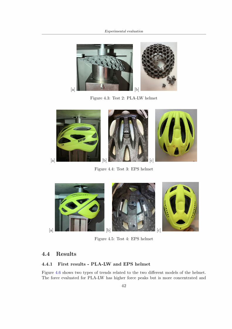
Experimental evaluation
[a] [b]
Figure 43 Test 2 PLA-LW helmet
[a] [b] [c]
Figure 44 Test 3 EPS helmet
[a] [b] [c]
Figure 45 Test 4 EPS helmet
44 Results
441 First results - PLA-LW and EPS helmet
Figure 46 shows two types of trends related to the two different models of the helmetThe force evaluated for PLA-LW has higher force peaks but is more concentrated and
42
Experimental evaluation
propagates less than EPS The graph shows the peaks of each curve highlighted with a redcircle In tests 1 and 2 for the PLA-LW as mentioned earlier the values are higher about7301 N for the complete helmet and 3996 N for the portion of helmet This difference isdue to the inaccuracy of the first full helmet during the printing phase In Figure 42 itis visible the low homogeneity and precision Therefore the first test with full helmet wasused only to define the area of interest of the impact which turns out to be localized Forthe other two EPS curves the values are only slightly lower compared to the PLA-LWequal to 3620 N and 3295 N but the trend is much more distributed
Figure 46 Dynamic machine test - Force
With the data obtained from the impact machine it was possible calculate not exclu-sively the value of force but itrsquos also possible to view the energy curves A resume aboutthe values and energy of the force is in the following Table 41
Test Peak force [N] Peak energy [J]
Test 1 - PLA LW (inaccurate) 730130
Test 2 - PLA LW (portion of helmet) 399643
Test 3 - EPS (DTB helmet) 362007 509
Test 4 - EPS (VAN|RYSEL helmet) 329546 4198
Test 5 - PLA with TPU 45421 5022
Table 41 Energy absorbed in dynamic test
43
Experimental evaluation
442 PLA-LW helmet with TPU cover
As it is possible to see in Figure 47 and as highlighted the first tests concerning thebio-inspired structure and the PLA-LW are far from my expectations considering thelittle distribution of force in comparison with the EPS foam and consequently a smallamount of energy absorbed
Figure 47 Dynamic machine test - Energy
To improve this impact damping factor the idea was to create a cover for the helmetin flexible TPU trying to absorb impact energy The TPU used is a flexible material ofthe brand Ninjaflex used in sports by the application in helmets and shoes to cushionbumps during the game Generally in the helmets (baseball helmet for example) theTPU is inserted internally in contact with the head In my case the TPU structurein addition to creating a shock-absorbing and durable cover creates a custom cover thehelmet and for the person This cover was also made with the Raise 3D printer
As shown in the Figure 48 [a] the infill of the part in contact with the helmet hasa percentage of 100 the filling of the other part of the structure is not complete butonly 15 and the internal structure is hexagonal to recall that of the helmet The desireto insert a structure with a rsquoraisedrsquo geometry is for visual and aesthetic reasons as youhave the feeling of greater protection and not filled is inspired by the machine CitroenCaptus whose bumpers (Airbump) are full of air The failure to realize empty structuresis due to the need to place any internal supports not removable
The idea was to create a cover that allow you to see of the internal structure of thehelmet and that protect specific areas the front the two sides the top and the posteriorWhat which was thought for this reason was to create the shape of a flower with four
44
Experimental evaluation
petals Figure 48 [b]In this way to perform dynamic impact tests as shown in Figure 49 [a] the cover was
positioned at the top of the helmet and the impact was performed in the centre of thersquoflowerrsquo which corresponds to the higher upper part where the structure has larger cellsize The impact parameters are the same as those used in previous impacts 5 kg weightmaximum speed and maximum height The Anvil that was used is a disc diameter of60 mm In photo [b] it is evident the difference between the structure that received theimpact with protection (left) and without protection (right) Without protection duringthe impact there was a perforation of the structure with a concentration of force at a locallevel as you can see in the Figure 46 in the case of TPU the impactor did not perforateand crossed the structure thanks to the cover of TPU that cushioned the shock At themoment of impact the impactor bounced
[a] [b]
Figure 48 TPU cover
[a] [b]
Figure 49 PLA-LW with TPU - dynamic impact [a] and differences between thehelmet with TPU and without TPU cover [b]
45
Experimental evaluation
The Figure 410 includes the diagrams relative to the dynamic impacts In [a] thereare already analyzed EPS results in [b] a comparison between the test on the portionof helmet in PLA LW with and without the TPU cover in [c] the overall comparison ofcurves shows a much more similar EPS trend if the TPU is placed above the structure inPLA LW to soften the blow and absorb the same energy [d]
46
[a]
[c]
[d]
Figure 410 Comparison between PLA-LW with TPU and EPS
Chapter 5
FEM Validation
51 Impactor - Anvils definition
Before to start to work in Abaqus it was necessary to search in the literature the materialwith which the anvil was been realized Milne et al [23] established the densityrsquos valuethe Youngrsquos Module and Poissonrsquos ratio for the Flat and Kerbstone Anvil
- Density ρ = 7800 kgm3
- Youngrsquos Module E = 200000 MPa
- Poissonrsquos ratio ν = 03
Inserting the data in the CES EduPack program specifying the mechanical andphysical properties the material corresponding to these characteristics is Stainless steelaustenitic (ASTM F1586) medium-hard
Initially the proposal was to create a conservative system to evaluate the absorptionenergies values and apply this value to a vibration system but the helmet needs dampingto be realized it was impossible to use a system without losses in this modality Thisis why a numerical calculation was carried out by performing two types of simulationsexplicit dynamic step and static step
The idea to realize the theoretical impact is to regard the movement of the anviland not the helmetrsquos movement which is fixed The velocity is the same cited in thenormative EN 1078 542 ms for the Flat anvil and 457 ms for the Kerbstone anvil
In performing the simulations It was given more relevance and perform tests withthe Kerbstone Anvil This choice was done because the geometry with which it is beenrealized (following as defined in the legislation) allows the helmet to be more subjectedto stress this involves the definition of higher stress limits compared to the Flat Anvil
The mesh size that has been used is the same in the case of the simulation of thehelmet optimized in PLA-LW and the full helmet in EPS of 7 mm The impactor isconsidered as a Discrete rigid body with its specific Reference Point (RP) like shownin Figure 51 for this reason it is not a solid but it is composted only by shells Inthe same image [b] there is the FEM representation of the model and in Table 51 thecharacteristic of FEM with quadrilateral (R3D4) and triangular elements (R3D3)
48
FEM Validation
Object Elementnumber
Elements Shape Geometricorder
Global size[mm]
Kerbstone 230 Quadrilateral - R3D4 Linear 7
Kerbstone 8 Triangular - R3D3 Linear 7
Table 51 Mesh element - Kerbstone Anvil
[a] [b]
Figure 51 Kerbstone anvil in the simulation like discrete rigid body [a] and FEMelements [b]
511 PLA LW - Plastic characteristics
The PLA-LW as explained in the Chapter 2 is new material on the market and producedby the only Colorfabb company for this reason few tests have been carried out to defineits technical characteristics and through tensile tests of the 3D printed specimens it waspossible to define an elastic limit as reported in the Table 210
In the context of simulations to reproduce the impact and deformation of the helmetis also necessary to consider the plastic characteristics of the material Not possessingany reference value in this regard tests were performed through a Static Step initiallyand then an Explicit Dynamic Step in Abaqus
The structure chosen to consider as a reference it is one of the structures previouslysubjected to the compression test having the side L=14 mm As for the reproduction ofthe compression disks initially they were reproduced according to the geometry of theHoytom HM-D Testing Machine considering the bodies mentioned above as discrete 3Drigid discrete The measure was the diameter of 200 mm and the height of 20 mm
After an initial analysis it was observed that the computational time of the simulationprogram was very high so it was decided to change the geometry to have a rsquodisk-surfacesrsquo(equally 3D rigid-discrete) which allowed me to have a smaller number of nodes for themesh and consequently a better computational time The representation of the opti-mized structure in PLA-LW and the disks used for simulated compression is in Figure 52
49
FEM Validation
[a] [b]
Figure 52 Representation of the samples used for the simulation of the compressiontest In Figure [a] the disks of the Hoytom HM-D Testing Machine in figure [b] the
representation of the same as simple surfaces
As shown in Figure 52 the disks are considered 3D discrete hard bodies so it waschosen for both a point the reference point RP where to apply the characteristics relatedto the two bodies As for the compression test it was established
bull the movement of a disk and fixed the second through a boundary condition impos-ing an Encastre therefore unable to move and rotate in xyz directions
bull for the opposite disk the boundary condition relative to the 15 mm displacementwas applied which is the parameter that it was observed to determine the end ofthe compression with the machine This shift is shown by the orange arrow in figure[b]
bull between the upper surface and the disk e the disk with the lower surface it wasinitialized a general contact with normal behaviour through rsquohardrsquo contact andtangential behaviour with a coefficient of friction of 02 with directionality imposedon rsquoisotropicrsquo
The next step was to define the mesh of the components whose parameters are shown inTable 52 while the representation of the FEM is in Figure 53 with the representationof the simulation and real compression test
Object Elementsnumber
Typology Geometricorder
Globalsize [mm]
Disk (14mm) 80910 hexaedral - C3D8R Linear 07
Impact disks 206 quadrilateral - R3D4 Linear 20
Impact disks 6 triangular - R3D3 Linear 20
Table 52 Mesh element - Compression test simulation
As previously announced a static simulation was initially performed with a StaticStep with Step Time equal to 900 (obtained going to consider the speed of 1 mmmin of
50
FEM Validation
[a]
[b] [c]
Figure 53 FEM representation [a] and compression test simulation [b] and realcompression [c]
the compression test and the displacement of 15 mm) However the complex geometryof the structure and the high time set by Step Time did not allow a correct definitionof the parameters of the plastic characteristics of the material the simulation was notable to continue once reached a Step Time of approximately 220 That is why it waschanged by choosing an Explicit Dynamic step
Leaving all the parameters of the boundary conditions unchanged the Step Time wasmodified imposing it to 001 The ability of the explicit dynamic to work with non-linearand contacting structures allowed me to achieve results The results obtained are shownin Figure 54 with the blue curve and were obtained through the iteration of differentPlastic Strain and Yield Stress values in Abaqus while the red line is the result of thereal compression test a similar curve trend was obtained but it is not possible to obtainthe same curve taking into account problems of printing inaccuracy
512 First test - helmet
The initial idea was to perform a simulation imposing the speed of 457 ms to theimpactor tie the helmet in EPS and PLA and compare the absorbed energies Theproblem it was encountered is related to the mesh of the helmet optimized in PLA andwith minimum dimensions of the elements and distinct elements it was not able to solveit
51
FEM Validation
[a]
YieldStress
PlasticStrain
1 47 0
2 7 001
3 75 005
4 10 01
5 108 1
6 115 15
7 12 2
[b]
Figure 54 Representation of the two curves related to the simulation in Abaqus of thecompression test and the data obtained from the real test to obtain the plastic
characteristics of the material
513 Second test - plane
The first solution is the one shown in Figure 55 To realize the simulation it was realizeda section of the helmet to involve a smaller number of elements and nodes Again thesimulation for the EPS helmet was successful while the simulation with the bio-inspiredstructure was interrupted by excessive distortion of elements
The previous images show the impact is very localized in the impacted area and theidea to achieve a complete simulation is not to consider a curved portion of the helmetbut a plane In this way it was possible to solve the problem and obtain a completesimulation for the bio-inspired structure
FEM element
Below in Table 53 there is the definition of the elements used for the PLA-LW and EPSplane in the simulation to simulate the impact and to control the energy-absorbing whilethe anvil characteristics are described in Table 51
514 EPS impact simulations
In order to proceed with the simulation it was imposed some boundary conditions thatregard ties and forces
bull the movement of the plane is fixed through an Encastre therefore unable to moveand rotate in xyz directions
52
FEM Validation
[a]
[b]
Figure 55 Impact simulation parts of EPS and PLA helmet
Object Elementnumber
Elements Shape Geometricorder
Plane (PLA) 38896 Tetrahedral -C3D10M
Quadratic
Plane (EPS) 2100 Hexahedral - C3D8R Linear
Table 53 Mesh element - plane impact
bull to create the impact it was set a speed of 457 ms at the reference point RP of therigid body which is the impactor Kerbstone Anvil shown in Figure 56
bull between the upper surface of the plane and the impactor it was initialized a Sur-face to Surface contact with normal behaviour through rsquohardrsquo contact and tangen-tial behaviour with a coefficient of friction of 02 with directionality imposed onrsquoisotropicrsquo
bull the rotation in x y z relative to the RP of the rigid discrete impactor body is locked
53
FEM Validation
In addition it was characterized the plane in the part of the materials with the char-acteristic values of the EPS mentioned in Chapter 221 The Von Mises Stress valueapparently low is relative to the Yield Stress of the EPS material equal to 09 MPa
Figure 56 EPS Boundary conditions and Load
515 PLA LW impact simulations
As also required in the case of the EPS plane in order to proceed with the simulationsome boundary conditions were imposed that regard ties and forces
bull the movement of the plane is fixed through an Encastre therefore unable to moveand rotate in xyz directions
bull to create the impact a speed of 457 ms was set at the reference point RP of therigid body which is the impactor Kerbstone Anvil shown in Figure 58
bull between the upper surface of the plane and the impactor it was initialized a Sur-face to Surface contact with normal behaviour through rsquohardrsquo contact and tangen-tial behaviour with a coefficient of friction of 02 with directionality imposed onrsquoisotropicrsquo
bull the rotation in x y z relative to the RP of the rigid discrete impactor body is locked
In addition the plane was characterized in the part of the materials with the characteristicvalues of the PLA mentioned in the Chapter 223 and 511
Figure 58 Boundary conditions and Load
54
FEM Validation
[a]
[b]
Figure 57 EPS impact simulation
52 Results
In Figures 59 and 57 it is shown how the structure in PLA LW has a more concentratedstress distribution of the structure unlike EPS The maximum value for the Von Misesstress is 09 MPa in EPS structure and 3634 MPa in PLA LW structure Once thesimulations were obtained the next step was to go and compare the energies absorbed bythe two structures The energy calculated by Abaqus that has been taken into account isPlastic Dissipation To make a comparison the data of the two energies were representedin a single graph
What emerges from the graph is that about the impact made with the KerbstoneAnvil the energy absorption is more excellent although only slightly for the PLA LWthan for the EPS From the graph in Figure 510 a value of 41 J is shown for the EPSand 51 J for the PLA LW
55
[a]
[b]
Figure 59 PLA impact simulation
[a]
Figure 510 EPS and PLA LW energy comparison - Abaqus simulation
Chapter 6
Head Injury Data
For the statistical analysis the injuries related to the accident data were categorised intothe following types and levels based on the details of the medical report [11] about theEN 1078
bull Head Injury Criterion (HIC)
bull Peak Linear Acceleration (PLAc)
bull Gadd Severity Injury (GSI)
bull Diffuse axonal injuries (DAI)
61 Abaqus simulation
Until now the purpose of the simulations has been to determine which between the twomaterials and the two structures of EPS and PLA LW could absorb more energy duringthe impact but no simulations have been carried out in compliance with BS EN 1078on the helmet impact tests To calculate the injuries listed in the previous paragraphhowever we need the acceleration values in the three directions related to the subjectrsquoshead
To realize it the scan of my head already rsquocleanrsquo was considered of which it has beencalculated the inertia thanks to the automatic SolidWorks calculation and evaluated theweight with the Table 24 the structure of the helmet was placed for the EPS and thePLA LW over the head as shown in Figure 61 Also this time being able to mesh theentire helmet in PLA LW was impossible due to the excessive distortion of some elementsduring the simulation so it has been tried to make a section of the structures of thehelmet and results were obtained
57
Head Injury Data
[a] [b]
Figure 61 My scan head - CAD [a] head imported in Abaqus[b]
Initially the simulation had these characteristics as shown in the following Figure62 considering the helmet was not sectioned As explained earlier it was not possibleto get to simulation in the case of the optimized structure in PLA LW for this reasononly a part of the helmet was considered in both cases shown in Figure 63
[a]
Figure 62 Simulation based on BS EN 1078
58
Head Injury Data
[a] [b]
Figure 63 Simulation based on BS EN 1078 with head
In order to proceed with the simulation some boundary conditions that regard tiesand forces have have imposed
bull two reference points RP were created the first in the inertia centre of the headthe second relating to the Kerbstone Anvil which is a discrete rigid body
bull in the reference point RP of the head in the definition of the engineering features5 kg was inserted for the weight and an inertia I11 = 564464E+07 gmm2 I22 =460654E+07gmm2 I33 = 187302E+07gmm2
bull to simulate the impact it was set a speed of 457 ms at the reference point RP ofthe head in z-axis direction
bull a general contact with normal behaviour through rsquohardrsquo contact and tangentialbehaviour with a coefficient of friction of 02
bull between the upper surface of the helmet and the impactor it has been initializeda Surface to Surface contact with normal behaviour through rsquohardrsquo contact andtangential behaviour with a coefficient of friction of 02 with directionality imposedon rsquoisotropicrsquo
bull the movement between the Kerbstone anvil and the helmet is fixed through anEncastre therefore unable to move and rotate in xyz directions
bull the rotation in x y z relative to the RP of the rigid discrete impactor body is locked
FEM element
As reported in Table 53 the portion of the helmet in EPS has used a mesh with hexahe-dral elements of linear order For the structure (beetle) of PLA LW given the geometry
59
Head Injury Data
complexity it was necessary to use a quadratic order of tetrahedra For the mesh of thehead instead in both simulations have been used quadrilateral elements of linear orderas reported in the Tables 61 and 62
Object Elementnumber
Elements Shape Geometricorder
Head 3755 Quadrilateral - R3D4 Linear
Head 34542 Quadrilateral - R3D3 Linear
Helmet (PLA) 272302 Tetrahedral -C3D10M
Quadratic
Table 61 Mesh element - Head simulation with PLA LW (beetle) helmet
Object Elementnumber
Elements Shape Geometricorder
Head 3755 Quadrilateral - R3D4 Linear
Head 34542 Quadrilateral - R3D3 Linear
Helmet (EPS) 72280 Hexahedral - C3D8R Linear
Table 62 Mesh element - Head simulation with EPS helmet
62 Results
Figure 64 represents the simulation in line with BS EN 1078 concerning the helmet inEPS [a] and the helmet with bio-inspired structure in PLA LW For both simulationsVan Misesrsquo stress has Yield Stress values in the case of EPS which is 09 MPa and theplastic behaviour combination of PLA LW [b]
In the case of head and Kerbstone Anvil stress was not assessed as they were previ-ously defined as discrete rigid bodies
63 Head Injury Criterion
The HIC quantifies head impact severity by incorporating time of acceleration exposureand acceleration magnitude it is calculated in post-processing phase with the followingEquation 61
HIC15 =
[1
(t1 minus t2)
int t2
t1
a(t)dt
]25(t2 minus t1) (61)
60
Head Injury Data
[a]
[b]
Figure 64 Results simulation based on BS EN 1078 with sectioned head
For this analysis a(t) is the acceleration calculated in the centre of mass of the head(corresponding to the reference point RP) expressed in g and the time interval (t2 minus t1)was chosen to maximize HIC over a maximum duration of 15 ms
Matlab and the trapz function were used to calculate the HIC to integrate accelerationover time t2 and t1 were considered initial and final times of the simulation t1 = 0 sand t2 = 10 s time less than 15 s
HIC value of 198 was obtained for EPS and 87 for PLA LW Considering the Hayeset al [16] document about the HIC values and the graph in Figure 65 developed bythe author it is possible to find the percentages related to the different injury AIS1 -AIS6 which correspond respectively to lower and higher severity while in Figure 66 therelative fatality to every value of AIS is shown The values obtained for the HIC andother criteria are shown in Table 63 The HIC value for EPS is 198 for PLA LW it is
61
Head Injury Data
Figure 65 Head injury risk curves based on HIC values [16]
Figure 66 The abbreviated injury score versus fatality rate [16]
87 Analyzing the data and comparing them with the curves of the Figure 65 I obtain
bull a percentage between 20 - 30 of AIS 1 for EPS 10 - 20 for PLA LW
bull a percentage between 10 - 20 of AIS 2 for EPS and 0 - 10 for PLA LW
bull for AIS 3 AIS 4 AIS 5 AIS 6 the percentages for both structures is between 0 -10
Comparing these percentages with the fatality rate of Figure 66 it is clear there is a riskof Moderate and Minor fatality in the case of EPS and PLA LW as all values are between0 and 30
62
Head Injury Data
HIC PLA [g] GSI E [J]
EPS 198 97 361 37723
PLA LW 87 75 169 44102
Table 63 Head Injury Data - values
64 Peak Linear Acceleration
The resultant linear acceleration versus time curve was calculated according to Equation62
γ(t) =radicγ2x(t) + γ2y(t) + γ2z (t) (62)
where
bull γ(t) is the resultant linear acceleration (g)
bull γx(t) is the linear acceleration in x axes (g)
bull γy(t) is the linear acceleration in y axes (g)
bull γz(t)is the linear acceleration in z axes (g)
The value of the impact should never exceed 250g [9] Cripton at all [9] in their studyexamined a helmet with expanded polystyrene (EPS) Figure 68 shows maximum HIC forhelmeted and unhelmeted drops from all heights For each drop height helmets reducedHIC relative to unhelmeted drops IARV value is 180g The acceleration in the two casesis shown in Figure 67 and the maximum values are 97g for EPS and 75g for PLA LWas reported in Table 63 The two values considering a maximum value calculated byCripton [9] of 180g are amply optimal and comply with the standard of 250g
65 Gadd Severity Index
Gadd proposed the Severity Index Criteria shown in Equation 63 Following this crite-rion the GSI values that are over 1000 produce serious internal head injury [33]
GSI =
int t1
0a(t)25dt (63)
Where
bull a is the linear acceleration (g)
bull t is the duration of the impact (s)
I calculated the GSI with the function trapz between 0 and t and the resulting valuesare 361 for the EPS and 169 for the PLA LW which comply with the limit
63
Head Injury Data
Figure 67 Peak accelerations for both helmets
Figure 68 Peak accelerations for both helmeted and unhelmeted drops Numbers overbars indicate peak acceleration For 2 m drop height results stated are the mean value
calculated from three drops [9]
64
Head Injury Data
66 Diffuse Axonal Injury
DAI cases covered all incidences in which neurological injuries occurred as well as con-cussion unconsciousness and coma
In order to assess the risk of head trauma in terms of diffuse axonal injury (DAI)Milne et al [23] defined a model based head injury criteria as follows obtaining theresults in Figure 69
bull 50 risk of moderate neurological injury (DAI1+) Brain Von Mises shearing stressof 28 kPa
bull 50 risk of severe neurological injury (DAI2+) Brain Von Mises shearing stressof 53 kPa
[a]
[b]
Figure 69 Peak intra-cerebral shearing stress computed with the helmet model coupledto the human head model for all impact points (a) Flat anvil (b) Kerbstone anvil [23]
65
Head Injury Data
67 Energy absorbed
In Figure 52 during the impact test between the kerbstone Anvil and the plan with thebio-inspired structure in PLA LW and EPS it was found that the PLA LW althoughwith a small difference of 10 J absorbed more energy in comparison with the EPS Whenthe test is carried out in compliance with BS EN 1078 and the head with a speed of 457ms (corresponding to the kerbstone Anvil) as shown in Figure 610 also in this casethe PLA LW with the optimized helmet structure manages to absorb more energy (evenif the difference is very low) compared to the EPS The maximum energy value in PLALW is 44102 J of EPS is 37723 J
Figure 610 Energy absorption - BS EN 1078
66
Chapter 7
Conclusion
71 Conclusion
In this thesis work a bicycle helmet with a bio-inspired structure in PLA LW and 3Dprinted was created The initial approach was to introduce an innovative aspect tostandard EPS helmets not using foam but a polymer with new geometries able toabsorb much energy during the impact For this reason the beetle structure has beenpreferred relying solely on the hypothesis encountered in the literature of its quality inabsorbing energy
Combining the new material of the PLA LW and beetle structure has made possiblethe development of new material satisfactory characteristics have been obtained sincethe first tests The two materials were first subjected to tensile tests to determine theirspecific stress in these the PLA LW had positive results
Subsequent dynamic physical tests were carried out on 3D printed helmet models andon reference helmets in EPS to calculate the absorption energy in both cases at the timeof impact These resulted in energy absorption of the beetle structure in PLA LW withthe application of a TPU cover almost equal to that of EPS about 50J To validate withfinite element analysis the two models an explicit dynamic step was used in AbaqusSimulations showed that the PLA LW structure absorbs a higher amount of energy thanthe EPS the higher is 50 J and the EPS 40J
Finally positive results have also been obtained in calculating the head injury datasimulating according to BS EN 1078 with the use of impactor helmet and head Theacceleration values for both the structures were inferior to 220g precisely for the PLALW was 75g and for the EPS 97g The same applies to the calculation of HIC and GSI(maximum acceptable value of 1000) where the values are 87 and 169 in the case of PLALW and 361 and 198 in EPS For all tests therefore greater efficiency of the structure inPLA LW has been obtained Positive results also in the simulation of the energy absorbedduring the impact as the value referring to the EPS was 35J and that of the PLA LWwas 45J
67
Conclusion
72 Future work lines
The positive results obtained can be considered as a starting point for further tests andsimulations to ensure the safety of the helmet and compliance with the regulations butbefore getting improvements and continue testing changes are required
bull the beetle structure of the helmet made with GH adapts to the SubD withoutallowing to have a homogeneous distribution it would be appropriate to have moreregular hexagonal geometries
bull the mesh of the helmet is too complex and does not allow to perform the simulationprobably to use a more regular structure would have a mesh accordingly moreregular and the simulation would be successful
bull the uneven helmet structure has so many defects that the print is imperfect andthis can change the results of the impact tests the structure should be improved
bull the printing time varies from 4 to 5 days it should be improved
bull the TPU helmet cover is too big for the RAISE printing plan it is necessary togenerate a new geometry
bull the TPU cover it must be fixed on the helmet
bull in the calculation of the DAI it is necessary to have the definition of the brain andthe head should not be considered as a rigid body
bull in the injury calculation the helmet without protection was considered with theTPU cover the result will be better
bull air flow analysis
The comments mentioned are only considerations and problems that I gained duringmy thesis and which should be improved but I am sure that these changes and improve-ments from design to printing and simulations can make the helmet a good product
68
Bibliography
[1] K Adanty J M Clark A Post Thomas Blaine H and M D Gilchrist Comparingtwo proposed protocols to test the oblique response of cycling helmets to fall impactsInternational Journal of Crashworthiness 6648 ndash 663 2020
[2] MF Ashby YJM Brechetb D Cebona and L Salvoc Selection strategies formaterials and processes Materials and Design 2004
[3] M Aysha El casco de bicicleta voronoi impreso en 3d mas seguro y ligero https
www3dnativescomen3d-printed-bicycle-helmet-voronoi-190820204
[4] H Bikas P Stavropoulos and G Chryssolouris Additive manufacturing methodsand modelling approaches a critical review The International Journal of AdvancedManufacturing Technology 83389ndash405 2016
[5] British Standards BSI Helmets for pedal cyclists and for users of skateboards androller skates - BS EN 1078 2012
[6] British Standards BSI Headforms for use in the testing of protective helmets BSEN 960 2020
[7] ColorFabb Colorfabb lw-pla 2019 httpscolorfabbcommedia
datasheetstdscolorfabbTDS_E_ColorFabb_LW-PLApdf
[8] V G Coronado T Haileyesus J M Bell T A Cheng JHaarbauer-Krupa M RLionbarger J Flores-Herrera L C McGuire and J Gilchrist Trends in sports andrecreation-related traumatic brain injuries treated in us emergency departments thenational electronic injury surveillance system-all injury program (neiss-aip) 2001-2012 J Head Trauma Rehabil 30185ndash197 2015
[9] P A Cripton D M Dressler D Stuart Cameron A Christopher R and D RichardsBicycle helmets are highly effective at preventing head injury during head impactHead-form accelerations and injury criteria for helmeted and unhelmeted impactsAccident Analysis and Prevention 701ndash7 2014
[10] L Cui M A Forero R and M D Gilchrist Optimisation of energy absorbingliner for equestrian helmets UCD School of Electrical Electronic and MechanicalEngineering University College Dublin Belfield Dublin4 Ireland 2020
[11] C Deck N Bourdet F Meyer and R Willinger Protection performance of bicyclehelmets Journal of safety research pages 67ndash77 2019
[12] Committee F08 Specification for headforms F2220 ASTM International 2015
[13] Committee F08 Specification for helmets used in recreational bicycling or rollerskating F1447 ASTM International 2018
[14] Committee F08 Test methods for equipment and procedures used in evaluating theperformance F1446 ASTM International 2020
69
Bibliography
[15] P Halldin Shock absorption including measuring CENTC 158 Working Group11 2018
[16] W C Hayes M S Erickson and E D Power Forensic injury biomechanics Annualreview of biomedical engineering pages 55ndash86 2007
[17] HEXR httpshexrcom
[18] C Jinxiang Z Xiaoming O Yoji S Kazuya G Zhensheng and P LongchengThe deformation mode and strengthening mechanism of compression in the beetleelytron plate Materials and Design 131481ndash186 2017
[19] S Kroeker M Ozkul A De Marco S Bonin and GP Siegmund Density variationin the expanded polystyrene eps foam of bicycle helmets and its influence on impactperformance Journal of biomechanical engineering 2019
[20] S G Kroeker SJ Bonin A L DeMarco C A Good and G P Siegmund Agedoes not affect the material properties of expanded polystyrene liners in field-usedbicycle helmets Journal of biomechanical engineering 2016
[21] M Meier K H Tan M K Lim and L Chung Unlocking innovation in the sportindustry through additive manufacturing Business Process Management Journa2018
[22] N J Mills and A Gilchrist The effectiveness of foams in bicycle and motorcyclehelmets Accident Analysis Prevention 23153 ndash 163 1991
[23] G Milne C Deck R P Carreira Q Allinne and R Willinger Development andvalidation of a bicycle helmet assessment of head injury risk under standard impactconditions Computer methods in biomechanics and biomedical engineering 15 Suppl1309 ndash 310 2012
[24] Y Mosleh S J Vander B Depreitere and J Ivens Novel composite foam conceptfor head protection in oblique impacts Adv Eng Mater (Advanced EngineeringMaterials) 10 2017
[25] H Mustafa T Y Pang T Ellena and S H Nasir Impact attenuation of user-centred bicycle helmet design with different foam densities J Phys Conf Ser(Journal of Physics Conference Series) 1150 2019
[26] S H Ngoc and L Guoxing A review of recent research on bio-inspired structuresand materials for energy absorption applications Composites Part 181 2020
[27] J I Novak and A R Novak Is additive manufacturing improving performance insports a systematic review Sport engineering and technology 13 2020
[28] European Road Safety Observatory European road safety observatory facts and fig-ures - cyclists - 2020 December 2020 httpseceuropaeutransportroad_
safetysitesdefaultfilesfacts_figures_cyclists_final_20210323pdf
[29] New York City Departments of Health Parks Mental Hygiene Transportation Recre-ation and the New York City Police Department Bicyclist fatalities and seriousinjuries in new york city 2005
[30] W Pengwen Y Jing H Yanan H Jiaofei and F Xiaoyang Innovative designof a helmet based on reverse engineering and 3d printing Alexandria EngineeringJournal 603445ndash3453 2021
[31] S G Piland T E Gould M Jesunathadas J S Wiggins O McNair and V CShane Protective helmets in sports Materials in Sports Equipment 3 2019
70
Bibliography
[32] K Schmitt P F Niederer M H Muser and F Walz Trauma biomechanicsSpringer Berlin Heidelberg 2010
[33] David Sepelveda Lopez A Biomechanical Analysis of Bicycle Helmets using FEMPhD thesis 2019 Bachelor thesis
[34] H Stigson Bicycle Helmets 2020 Tested by Folksam PhD thesis 2020 PhDAssociate Professor Traffic Safety Research
[35] H Tao K Sudip N Anindya and X Yongzhao 3d printed sensors for biomedicalapplications A review sensor 2019
[36] M Trzaskalska and R Chwastek Damping properties and density of helmet linersmade of expanded polystyrene (eps) Archives of Metallurgy and Materials 66 2020
[37] Crupi V Epasto G and Guglielmino E Impact response of aluminum foam sand-wiches for light-weight ship structures Metals 198ndash112 2020
[38] W Wei-cai F Dong-ming and L Yuan-xin Study on impact energy absorbing per-formance of eps buffer layer of motorcycle helmet Proceedings - 2013 InternationalConference on Mechanical and Automation Engineering MAEE 2013
[39] Z Xiaoming C Jinxiang O Yoji Z Peiwei X Xiaobing and Y Xindi Influence ofhoneycomb dimensions and forming methods on the compressive properties of beetleelytron plates Journal of Sandwich Structures and Materials 2228ndash39 2020
[40] S Zhi L Dong Z Weisheng S Shanshan and G Xu Topological optimization ofbiomimetic sandwich structures with hybrid core and cfrp face sheets CompositesScience and Technology 14279ndash90 2017
[41] S Zhi S Shanshan G Xu H Xiaozhi and C Haoran On compressive propertiesof composite sandwich structures with grid reinforced honeycomb core CompositesPart B 94245ndash252 2016
71
- List of Tables
- List of Figures
- Introduction
-
- Helmet bike protection
-
- Helmet structure
-
- Additive Manufacturing
-
- AM process
- Materials and techniques - FDM
- AM in sport
-
- 3D printed helmets
-
- Phases
- HEXR
- VORONOI
-
- State of the art
-
- Standards
-
- Headform
- European Standard and American Standard
- Field of vision - BS EN 1078
- Test impact area
- Anvils and environmental conditions
-
- Materials
-
- EPS Foam
- CES Edu Pack - Material selection
- PLA with natural fiber and PLA LW
-
- Bio-inspired structures
-
- Beetle structure - Design of the model
- Specific stress - PLA LW and EPS foam
-
- Methodology
-
- 3D scan
-
- 3D Sense 2 scanner and Meshmixer - Reverse reconstruction
- 3D scan analysis and extraction of features
-
- Helmet design
-
- Rhinoceros - Helmet surface
- Grasshopper - Helmet structure
-
- 3D Print
-
- Printer and parameters
-
- Experimental evaluation
-
- Experimental tests
-
- Drop-weight impact test machine
-
- PLA LW helmet
- EPS helmet
- Results
-
- First results - PLA-LW and EPS helmet
- PLA-LW helmet with TPU cover
-
- FEM Validation
-
- Impactor - Anvils definition
-
- PLA LW - Plastic characteristics
- First test - helmet
- Second test - plane
- EPS impact simulations
- PLA LW impact simulations
-
- Results
-
- Head Injury Data
-
- Abaqus simulation
- Results
- Head Injury Criterion
- Peak Linear Acceleration
- Gadd Severity Index
- Diffuse Axonal Injury
- Energy absorbed
-
- Conclusion
-
- Conclusion
- Future work lines
-
- Bibliography
-
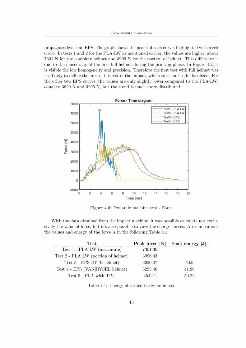
Experimental evaluation
propagates less than EPS The graph shows the peaks of each curve highlighted with a redcircle In tests 1 and 2 for the PLA-LW as mentioned earlier the values are higher about7301 N for the complete helmet and 3996 N for the portion of helmet This difference isdue to the inaccuracy of the first full helmet during the printing phase In Figure 42 itis visible the low homogeneity and precision Therefore the first test with full helmet wasused only to define the area of interest of the impact which turns out to be localized Forthe other two EPS curves the values are only slightly lower compared to the PLA-LWequal to 3620 N and 3295 N but the trend is much more distributed
Figure 46 Dynamic machine test - Force
With the data obtained from the impact machine it was possible calculate not exclu-sively the value of force but itrsquos also possible to view the energy curves A resume aboutthe values and energy of the force is in the following Table 41
Test Peak force [N] Peak energy [J]
Test 1 - PLA LW (inaccurate) 730130
Test 2 - PLA LW (portion of helmet) 399643
Test 3 - EPS (DTB helmet) 362007 509
Test 4 - EPS (VAN|RYSEL helmet) 329546 4198
Test 5 - PLA with TPU 45421 5022
Table 41 Energy absorbed in dynamic test
43
Experimental evaluation
442 PLA-LW helmet with TPU cover
As it is possible to see in Figure 47 and as highlighted the first tests concerning thebio-inspired structure and the PLA-LW are far from my expectations considering thelittle distribution of force in comparison with the EPS foam and consequently a smallamount of energy absorbed
Figure 47 Dynamic machine test - Energy
To improve this impact damping factor the idea was to create a cover for the helmetin flexible TPU trying to absorb impact energy The TPU used is a flexible material ofthe brand Ninjaflex used in sports by the application in helmets and shoes to cushionbumps during the game Generally in the helmets (baseball helmet for example) theTPU is inserted internally in contact with the head In my case the TPU structurein addition to creating a shock-absorbing and durable cover creates a custom cover thehelmet and for the person This cover was also made with the Raise 3D printer
As shown in the Figure 48 [a] the infill of the part in contact with the helmet hasa percentage of 100 the filling of the other part of the structure is not complete butonly 15 and the internal structure is hexagonal to recall that of the helmet The desireto insert a structure with a rsquoraisedrsquo geometry is for visual and aesthetic reasons as youhave the feeling of greater protection and not filled is inspired by the machine CitroenCaptus whose bumpers (Airbump) are full of air The failure to realize empty structuresis due to the need to place any internal supports not removable
The idea was to create a cover that allow you to see of the internal structure of thehelmet and that protect specific areas the front the two sides the top and the posteriorWhat which was thought for this reason was to create the shape of a flower with four
44
Experimental evaluation
petals Figure 48 [b]In this way to perform dynamic impact tests as shown in Figure 49 [a] the cover was
positioned at the top of the helmet and the impact was performed in the centre of thersquoflowerrsquo which corresponds to the higher upper part where the structure has larger cellsize The impact parameters are the same as those used in previous impacts 5 kg weightmaximum speed and maximum height The Anvil that was used is a disc diameter of60 mm In photo [b] it is evident the difference between the structure that received theimpact with protection (left) and without protection (right) Without protection duringthe impact there was a perforation of the structure with a concentration of force at a locallevel as you can see in the Figure 46 in the case of TPU the impactor did not perforateand crossed the structure thanks to the cover of TPU that cushioned the shock At themoment of impact the impactor bounced
[a] [b]
Figure 48 TPU cover
[a] [b]
Figure 49 PLA-LW with TPU - dynamic impact [a] and differences between thehelmet with TPU and without TPU cover [b]
45
Experimental evaluation
The Figure 410 includes the diagrams relative to the dynamic impacts In [a] thereare already analyzed EPS results in [b] a comparison between the test on the portionof helmet in PLA LW with and without the TPU cover in [c] the overall comparison ofcurves shows a much more similar EPS trend if the TPU is placed above the structure inPLA LW to soften the blow and absorb the same energy [d]
46
[a]
[c]
[d]
Figure 410 Comparison between PLA-LW with TPU and EPS
Chapter 5
FEM Validation
51 Impactor - Anvils definition
Before to start to work in Abaqus it was necessary to search in the literature the materialwith which the anvil was been realized Milne et al [23] established the densityrsquos valuethe Youngrsquos Module and Poissonrsquos ratio for the Flat and Kerbstone Anvil
- Density ρ = 7800 kgm3
- Youngrsquos Module E = 200000 MPa
- Poissonrsquos ratio ν = 03
Inserting the data in the CES EduPack program specifying the mechanical andphysical properties the material corresponding to these characteristics is Stainless steelaustenitic (ASTM F1586) medium-hard
Initially the proposal was to create a conservative system to evaluate the absorptionenergies values and apply this value to a vibration system but the helmet needs dampingto be realized it was impossible to use a system without losses in this modality Thisis why a numerical calculation was carried out by performing two types of simulationsexplicit dynamic step and static step
The idea to realize the theoretical impact is to regard the movement of the anviland not the helmetrsquos movement which is fixed The velocity is the same cited in thenormative EN 1078 542 ms for the Flat anvil and 457 ms for the Kerbstone anvil
In performing the simulations It was given more relevance and perform tests withthe Kerbstone Anvil This choice was done because the geometry with which it is beenrealized (following as defined in the legislation) allows the helmet to be more subjectedto stress this involves the definition of higher stress limits compared to the Flat Anvil
The mesh size that has been used is the same in the case of the simulation of thehelmet optimized in PLA-LW and the full helmet in EPS of 7 mm The impactor isconsidered as a Discrete rigid body with its specific Reference Point (RP) like shownin Figure 51 for this reason it is not a solid but it is composted only by shells Inthe same image [b] there is the FEM representation of the model and in Table 51 thecharacteristic of FEM with quadrilateral (R3D4) and triangular elements (R3D3)
48
FEM Validation
Object Elementnumber
Elements Shape Geometricorder
Global size[mm]
Kerbstone 230 Quadrilateral - R3D4 Linear 7
Kerbstone 8 Triangular - R3D3 Linear 7
Table 51 Mesh element - Kerbstone Anvil
[a] [b]
Figure 51 Kerbstone anvil in the simulation like discrete rigid body [a] and FEMelements [b]
511 PLA LW - Plastic characteristics
The PLA-LW as explained in the Chapter 2 is new material on the market and producedby the only Colorfabb company for this reason few tests have been carried out to defineits technical characteristics and through tensile tests of the 3D printed specimens it waspossible to define an elastic limit as reported in the Table 210
In the context of simulations to reproduce the impact and deformation of the helmetis also necessary to consider the plastic characteristics of the material Not possessingany reference value in this regard tests were performed through a Static Step initiallyand then an Explicit Dynamic Step in Abaqus
The structure chosen to consider as a reference it is one of the structures previouslysubjected to the compression test having the side L=14 mm As for the reproduction ofthe compression disks initially they were reproduced according to the geometry of theHoytom HM-D Testing Machine considering the bodies mentioned above as discrete 3Drigid discrete The measure was the diameter of 200 mm and the height of 20 mm
After an initial analysis it was observed that the computational time of the simulationprogram was very high so it was decided to change the geometry to have a rsquodisk-surfacesrsquo(equally 3D rigid-discrete) which allowed me to have a smaller number of nodes for themesh and consequently a better computational time The representation of the opti-mized structure in PLA-LW and the disks used for simulated compression is in Figure 52
49
FEM Validation
[a] [b]
Figure 52 Representation of the samples used for the simulation of the compressiontest In Figure [a] the disks of the Hoytom HM-D Testing Machine in figure [b] the
representation of the same as simple surfaces
As shown in Figure 52 the disks are considered 3D discrete hard bodies so it waschosen for both a point the reference point RP where to apply the characteristics relatedto the two bodies As for the compression test it was established
bull the movement of a disk and fixed the second through a boundary condition impos-ing an Encastre therefore unable to move and rotate in xyz directions
bull for the opposite disk the boundary condition relative to the 15 mm displacementwas applied which is the parameter that it was observed to determine the end ofthe compression with the machine This shift is shown by the orange arrow in figure[b]
bull between the upper surface and the disk e the disk with the lower surface it wasinitialized a general contact with normal behaviour through rsquohardrsquo contact andtangential behaviour with a coefficient of friction of 02 with directionality imposedon rsquoisotropicrsquo
The next step was to define the mesh of the components whose parameters are shown inTable 52 while the representation of the FEM is in Figure 53 with the representationof the simulation and real compression test
Object Elementsnumber
Typology Geometricorder
Globalsize [mm]
Disk (14mm) 80910 hexaedral - C3D8R Linear 07
Impact disks 206 quadrilateral - R3D4 Linear 20
Impact disks 6 triangular - R3D3 Linear 20
Table 52 Mesh element - Compression test simulation
As previously announced a static simulation was initially performed with a StaticStep with Step Time equal to 900 (obtained going to consider the speed of 1 mmmin of
50
FEM Validation
[a]
[b] [c]
Figure 53 FEM representation [a] and compression test simulation [b] and realcompression [c]
the compression test and the displacement of 15 mm) However the complex geometryof the structure and the high time set by Step Time did not allow a correct definitionof the parameters of the plastic characteristics of the material the simulation was notable to continue once reached a Step Time of approximately 220 That is why it waschanged by choosing an Explicit Dynamic step
Leaving all the parameters of the boundary conditions unchanged the Step Time wasmodified imposing it to 001 The ability of the explicit dynamic to work with non-linearand contacting structures allowed me to achieve results The results obtained are shownin Figure 54 with the blue curve and were obtained through the iteration of differentPlastic Strain and Yield Stress values in Abaqus while the red line is the result of thereal compression test a similar curve trend was obtained but it is not possible to obtainthe same curve taking into account problems of printing inaccuracy
512 First test - helmet
The initial idea was to perform a simulation imposing the speed of 457 ms to theimpactor tie the helmet in EPS and PLA and compare the absorbed energies Theproblem it was encountered is related to the mesh of the helmet optimized in PLA andwith minimum dimensions of the elements and distinct elements it was not able to solveit
51
FEM Validation
[a]
YieldStress
PlasticStrain
1 47 0
2 7 001
3 75 005
4 10 01
5 108 1
6 115 15
7 12 2
[b]
Figure 54 Representation of the two curves related to the simulation in Abaqus of thecompression test and the data obtained from the real test to obtain the plastic
characteristics of the material
513 Second test - plane
The first solution is the one shown in Figure 55 To realize the simulation it was realizeda section of the helmet to involve a smaller number of elements and nodes Again thesimulation for the EPS helmet was successful while the simulation with the bio-inspiredstructure was interrupted by excessive distortion of elements
The previous images show the impact is very localized in the impacted area and theidea to achieve a complete simulation is not to consider a curved portion of the helmetbut a plane In this way it was possible to solve the problem and obtain a completesimulation for the bio-inspired structure
FEM element
Below in Table 53 there is the definition of the elements used for the PLA-LW and EPSplane in the simulation to simulate the impact and to control the energy-absorbing whilethe anvil characteristics are described in Table 51
514 EPS impact simulations
In order to proceed with the simulation it was imposed some boundary conditions thatregard ties and forces
bull the movement of the plane is fixed through an Encastre therefore unable to moveand rotate in xyz directions
52
FEM Validation
[a]
[b]
Figure 55 Impact simulation parts of EPS and PLA helmet
Object Elementnumber
Elements Shape Geometricorder
Plane (PLA) 38896 Tetrahedral -C3D10M
Quadratic
Plane (EPS) 2100 Hexahedral - C3D8R Linear
Table 53 Mesh element - plane impact
bull to create the impact it was set a speed of 457 ms at the reference point RP of therigid body which is the impactor Kerbstone Anvil shown in Figure 56
bull between the upper surface of the plane and the impactor it was initialized a Sur-face to Surface contact with normal behaviour through rsquohardrsquo contact and tangen-tial behaviour with a coefficient of friction of 02 with directionality imposed onrsquoisotropicrsquo
bull the rotation in x y z relative to the RP of the rigid discrete impactor body is locked
53
FEM Validation
In addition it was characterized the plane in the part of the materials with the char-acteristic values of the EPS mentioned in Chapter 221 The Von Mises Stress valueapparently low is relative to the Yield Stress of the EPS material equal to 09 MPa
Figure 56 EPS Boundary conditions and Load
515 PLA LW impact simulations
As also required in the case of the EPS plane in order to proceed with the simulationsome boundary conditions were imposed that regard ties and forces
bull the movement of the plane is fixed through an Encastre therefore unable to moveand rotate in xyz directions
bull to create the impact a speed of 457 ms was set at the reference point RP of therigid body which is the impactor Kerbstone Anvil shown in Figure 58
bull between the upper surface of the plane and the impactor it was initialized a Sur-face to Surface contact with normal behaviour through rsquohardrsquo contact and tangen-tial behaviour with a coefficient of friction of 02 with directionality imposed onrsquoisotropicrsquo
bull the rotation in x y z relative to the RP of the rigid discrete impactor body is locked
In addition the plane was characterized in the part of the materials with the characteristicvalues of the PLA mentioned in the Chapter 223 and 511
Figure 58 Boundary conditions and Load
54
FEM Validation
[a]
[b]
Figure 57 EPS impact simulation
52 Results
In Figures 59 and 57 it is shown how the structure in PLA LW has a more concentratedstress distribution of the structure unlike EPS The maximum value for the Von Misesstress is 09 MPa in EPS structure and 3634 MPa in PLA LW structure Once thesimulations were obtained the next step was to go and compare the energies absorbed bythe two structures The energy calculated by Abaqus that has been taken into account isPlastic Dissipation To make a comparison the data of the two energies were representedin a single graph
What emerges from the graph is that about the impact made with the KerbstoneAnvil the energy absorption is more excellent although only slightly for the PLA LWthan for the EPS From the graph in Figure 510 a value of 41 J is shown for the EPSand 51 J for the PLA LW
55
[a]
[b]
Figure 59 PLA impact simulation
[a]
Figure 510 EPS and PLA LW energy comparison - Abaqus simulation
Chapter 6
Head Injury Data
For the statistical analysis the injuries related to the accident data were categorised intothe following types and levels based on the details of the medical report [11] about theEN 1078
bull Head Injury Criterion (HIC)
bull Peak Linear Acceleration (PLAc)
bull Gadd Severity Injury (GSI)
bull Diffuse axonal injuries (DAI)
61 Abaqus simulation
Until now the purpose of the simulations has been to determine which between the twomaterials and the two structures of EPS and PLA LW could absorb more energy duringthe impact but no simulations have been carried out in compliance with BS EN 1078on the helmet impact tests To calculate the injuries listed in the previous paragraphhowever we need the acceleration values in the three directions related to the subjectrsquoshead
To realize it the scan of my head already rsquocleanrsquo was considered of which it has beencalculated the inertia thanks to the automatic SolidWorks calculation and evaluated theweight with the Table 24 the structure of the helmet was placed for the EPS and thePLA LW over the head as shown in Figure 61 Also this time being able to mesh theentire helmet in PLA LW was impossible due to the excessive distortion of some elementsduring the simulation so it has been tried to make a section of the structures of thehelmet and results were obtained
57
Head Injury Data
[a] [b]
Figure 61 My scan head - CAD [a] head imported in Abaqus[b]
Initially the simulation had these characteristics as shown in the following Figure62 considering the helmet was not sectioned As explained earlier it was not possibleto get to simulation in the case of the optimized structure in PLA LW for this reasononly a part of the helmet was considered in both cases shown in Figure 63
[a]
Figure 62 Simulation based on BS EN 1078
58
Head Injury Data
[a] [b]
Figure 63 Simulation based on BS EN 1078 with head
In order to proceed with the simulation some boundary conditions that regard tiesand forces have have imposed
bull two reference points RP were created the first in the inertia centre of the headthe second relating to the Kerbstone Anvil which is a discrete rigid body
bull in the reference point RP of the head in the definition of the engineering features5 kg was inserted for the weight and an inertia I11 = 564464E+07 gmm2 I22 =460654E+07gmm2 I33 = 187302E+07gmm2
bull to simulate the impact it was set a speed of 457 ms at the reference point RP ofthe head in z-axis direction
bull a general contact with normal behaviour through rsquohardrsquo contact and tangentialbehaviour with a coefficient of friction of 02
bull between the upper surface of the helmet and the impactor it has been initializeda Surface to Surface contact with normal behaviour through rsquohardrsquo contact andtangential behaviour with a coefficient of friction of 02 with directionality imposedon rsquoisotropicrsquo
bull the movement between the Kerbstone anvil and the helmet is fixed through anEncastre therefore unable to move and rotate in xyz directions
bull the rotation in x y z relative to the RP of the rigid discrete impactor body is locked
FEM element
As reported in Table 53 the portion of the helmet in EPS has used a mesh with hexahe-dral elements of linear order For the structure (beetle) of PLA LW given the geometry
59
Head Injury Data
complexity it was necessary to use a quadratic order of tetrahedra For the mesh of thehead instead in both simulations have been used quadrilateral elements of linear orderas reported in the Tables 61 and 62
Object Elementnumber
Elements Shape Geometricorder
Head 3755 Quadrilateral - R3D4 Linear
Head 34542 Quadrilateral - R3D3 Linear
Helmet (PLA) 272302 Tetrahedral -C3D10M
Quadratic
Table 61 Mesh element - Head simulation with PLA LW (beetle) helmet
Object Elementnumber
Elements Shape Geometricorder
Head 3755 Quadrilateral - R3D4 Linear
Head 34542 Quadrilateral - R3D3 Linear
Helmet (EPS) 72280 Hexahedral - C3D8R Linear
Table 62 Mesh element - Head simulation with EPS helmet
62 Results
Figure 64 represents the simulation in line with BS EN 1078 concerning the helmet inEPS [a] and the helmet with bio-inspired structure in PLA LW For both simulationsVan Misesrsquo stress has Yield Stress values in the case of EPS which is 09 MPa and theplastic behaviour combination of PLA LW [b]
In the case of head and Kerbstone Anvil stress was not assessed as they were previ-ously defined as discrete rigid bodies
63 Head Injury Criterion
The HIC quantifies head impact severity by incorporating time of acceleration exposureand acceleration magnitude it is calculated in post-processing phase with the followingEquation 61
HIC15 =
[1
(t1 minus t2)
int t2
t1
a(t)dt
]25(t2 minus t1) (61)
60
Head Injury Data
[a]
[b]
Figure 64 Results simulation based on BS EN 1078 with sectioned head
For this analysis a(t) is the acceleration calculated in the centre of mass of the head(corresponding to the reference point RP) expressed in g and the time interval (t2 minus t1)was chosen to maximize HIC over a maximum duration of 15 ms
Matlab and the trapz function were used to calculate the HIC to integrate accelerationover time t2 and t1 were considered initial and final times of the simulation t1 = 0 sand t2 = 10 s time less than 15 s
HIC value of 198 was obtained for EPS and 87 for PLA LW Considering the Hayeset al [16] document about the HIC values and the graph in Figure 65 developed bythe author it is possible to find the percentages related to the different injury AIS1 -AIS6 which correspond respectively to lower and higher severity while in Figure 66 therelative fatality to every value of AIS is shown The values obtained for the HIC andother criteria are shown in Table 63 The HIC value for EPS is 198 for PLA LW it is
61
Head Injury Data
Figure 65 Head injury risk curves based on HIC values [16]
Figure 66 The abbreviated injury score versus fatality rate [16]
87 Analyzing the data and comparing them with the curves of the Figure 65 I obtain
bull a percentage between 20 - 30 of AIS 1 for EPS 10 - 20 for PLA LW
bull a percentage between 10 - 20 of AIS 2 for EPS and 0 - 10 for PLA LW
bull for AIS 3 AIS 4 AIS 5 AIS 6 the percentages for both structures is between 0 -10
Comparing these percentages with the fatality rate of Figure 66 it is clear there is a riskof Moderate and Minor fatality in the case of EPS and PLA LW as all values are between0 and 30
62
Head Injury Data
HIC PLA [g] GSI E [J]
EPS 198 97 361 37723
PLA LW 87 75 169 44102
Table 63 Head Injury Data - values
64 Peak Linear Acceleration
The resultant linear acceleration versus time curve was calculated according to Equation62
γ(t) =radicγ2x(t) + γ2y(t) + γ2z (t) (62)
where
bull γ(t) is the resultant linear acceleration (g)
bull γx(t) is the linear acceleration in x axes (g)
bull γy(t) is the linear acceleration in y axes (g)
bull γz(t)is the linear acceleration in z axes (g)
The value of the impact should never exceed 250g [9] Cripton at all [9] in their studyexamined a helmet with expanded polystyrene (EPS) Figure 68 shows maximum HIC forhelmeted and unhelmeted drops from all heights For each drop height helmets reducedHIC relative to unhelmeted drops IARV value is 180g The acceleration in the two casesis shown in Figure 67 and the maximum values are 97g for EPS and 75g for PLA LWas reported in Table 63 The two values considering a maximum value calculated byCripton [9] of 180g are amply optimal and comply with the standard of 250g
65 Gadd Severity Index
Gadd proposed the Severity Index Criteria shown in Equation 63 Following this crite-rion the GSI values that are over 1000 produce serious internal head injury [33]
GSI =
int t1
0a(t)25dt (63)
Where
bull a is the linear acceleration (g)
bull t is the duration of the impact (s)
I calculated the GSI with the function trapz between 0 and t and the resulting valuesare 361 for the EPS and 169 for the PLA LW which comply with the limit
63
Head Injury Data
Figure 67 Peak accelerations for both helmets
Figure 68 Peak accelerations for both helmeted and unhelmeted drops Numbers overbars indicate peak acceleration For 2 m drop height results stated are the mean value
calculated from three drops [9]
64
Head Injury Data
66 Diffuse Axonal Injury
DAI cases covered all incidences in which neurological injuries occurred as well as con-cussion unconsciousness and coma
In order to assess the risk of head trauma in terms of diffuse axonal injury (DAI)Milne et al [23] defined a model based head injury criteria as follows obtaining theresults in Figure 69
bull 50 risk of moderate neurological injury (DAI1+) Brain Von Mises shearing stressof 28 kPa
bull 50 risk of severe neurological injury (DAI2+) Brain Von Mises shearing stressof 53 kPa
[a]
[b]
Figure 69 Peak intra-cerebral shearing stress computed with the helmet model coupledto the human head model for all impact points (a) Flat anvil (b) Kerbstone anvil [23]
65
Head Injury Data
67 Energy absorbed
In Figure 52 during the impact test between the kerbstone Anvil and the plan with thebio-inspired structure in PLA LW and EPS it was found that the PLA LW althoughwith a small difference of 10 J absorbed more energy in comparison with the EPS Whenthe test is carried out in compliance with BS EN 1078 and the head with a speed of 457ms (corresponding to the kerbstone Anvil) as shown in Figure 610 also in this casethe PLA LW with the optimized helmet structure manages to absorb more energy (evenif the difference is very low) compared to the EPS The maximum energy value in PLALW is 44102 J of EPS is 37723 J
Figure 610 Energy absorption - BS EN 1078
66
Chapter 7
Conclusion
71 Conclusion
In this thesis work a bicycle helmet with a bio-inspired structure in PLA LW and 3Dprinted was created The initial approach was to introduce an innovative aspect tostandard EPS helmets not using foam but a polymer with new geometries able toabsorb much energy during the impact For this reason the beetle structure has beenpreferred relying solely on the hypothesis encountered in the literature of its quality inabsorbing energy
Combining the new material of the PLA LW and beetle structure has made possiblethe development of new material satisfactory characteristics have been obtained sincethe first tests The two materials were first subjected to tensile tests to determine theirspecific stress in these the PLA LW had positive results
Subsequent dynamic physical tests were carried out on 3D printed helmet models andon reference helmets in EPS to calculate the absorption energy in both cases at the timeof impact These resulted in energy absorption of the beetle structure in PLA LW withthe application of a TPU cover almost equal to that of EPS about 50J To validate withfinite element analysis the two models an explicit dynamic step was used in AbaqusSimulations showed that the PLA LW structure absorbs a higher amount of energy thanthe EPS the higher is 50 J and the EPS 40J
Finally positive results have also been obtained in calculating the head injury datasimulating according to BS EN 1078 with the use of impactor helmet and head Theacceleration values for both the structures were inferior to 220g precisely for the PLALW was 75g and for the EPS 97g The same applies to the calculation of HIC and GSI(maximum acceptable value of 1000) where the values are 87 and 169 in the case of PLALW and 361 and 198 in EPS For all tests therefore greater efficiency of the structure inPLA LW has been obtained Positive results also in the simulation of the energy absorbedduring the impact as the value referring to the EPS was 35J and that of the PLA LWwas 45J
67
Conclusion
72 Future work lines
The positive results obtained can be considered as a starting point for further tests andsimulations to ensure the safety of the helmet and compliance with the regulations butbefore getting improvements and continue testing changes are required
bull the beetle structure of the helmet made with GH adapts to the SubD withoutallowing to have a homogeneous distribution it would be appropriate to have moreregular hexagonal geometries
bull the mesh of the helmet is too complex and does not allow to perform the simulationprobably to use a more regular structure would have a mesh accordingly moreregular and the simulation would be successful
bull the uneven helmet structure has so many defects that the print is imperfect andthis can change the results of the impact tests the structure should be improved
bull the printing time varies from 4 to 5 days it should be improved
bull the TPU helmet cover is too big for the RAISE printing plan it is necessary togenerate a new geometry
bull the TPU cover it must be fixed on the helmet
bull in the calculation of the DAI it is necessary to have the definition of the brain andthe head should not be considered as a rigid body
bull in the injury calculation the helmet without protection was considered with theTPU cover the result will be better
bull air flow analysis
The comments mentioned are only considerations and problems that I gained duringmy thesis and which should be improved but I am sure that these changes and improve-ments from design to printing and simulations can make the helmet a good product
68
Bibliography
[1] K Adanty J M Clark A Post Thomas Blaine H and M D Gilchrist Comparingtwo proposed protocols to test the oblique response of cycling helmets to fall impactsInternational Journal of Crashworthiness 6648 ndash 663 2020
[2] MF Ashby YJM Brechetb D Cebona and L Salvoc Selection strategies formaterials and processes Materials and Design 2004
[3] M Aysha El casco de bicicleta voronoi impreso en 3d mas seguro y ligero https
www3dnativescomen3d-printed-bicycle-helmet-voronoi-190820204
[4] H Bikas P Stavropoulos and G Chryssolouris Additive manufacturing methodsand modelling approaches a critical review The International Journal of AdvancedManufacturing Technology 83389ndash405 2016
[5] British Standards BSI Helmets for pedal cyclists and for users of skateboards androller skates - BS EN 1078 2012
[6] British Standards BSI Headforms for use in the testing of protective helmets BSEN 960 2020
[7] ColorFabb Colorfabb lw-pla 2019 httpscolorfabbcommedia
datasheetstdscolorfabbTDS_E_ColorFabb_LW-PLApdf
[8] V G Coronado T Haileyesus J M Bell T A Cheng JHaarbauer-Krupa M RLionbarger J Flores-Herrera L C McGuire and J Gilchrist Trends in sports andrecreation-related traumatic brain injuries treated in us emergency departments thenational electronic injury surveillance system-all injury program (neiss-aip) 2001-2012 J Head Trauma Rehabil 30185ndash197 2015
[9] P A Cripton D M Dressler D Stuart Cameron A Christopher R and D RichardsBicycle helmets are highly effective at preventing head injury during head impactHead-form accelerations and injury criteria for helmeted and unhelmeted impactsAccident Analysis and Prevention 701ndash7 2014
[10] L Cui M A Forero R and M D Gilchrist Optimisation of energy absorbingliner for equestrian helmets UCD School of Electrical Electronic and MechanicalEngineering University College Dublin Belfield Dublin4 Ireland 2020
[11] C Deck N Bourdet F Meyer and R Willinger Protection performance of bicyclehelmets Journal of safety research pages 67ndash77 2019
[12] Committee F08 Specification for headforms F2220 ASTM International 2015
[13] Committee F08 Specification for helmets used in recreational bicycling or rollerskating F1447 ASTM International 2018
[14] Committee F08 Test methods for equipment and procedures used in evaluating theperformance F1446 ASTM International 2020
69
Bibliography
[15] P Halldin Shock absorption including measuring CENTC 158 Working Group11 2018
[16] W C Hayes M S Erickson and E D Power Forensic injury biomechanics Annualreview of biomedical engineering pages 55ndash86 2007
[17] HEXR httpshexrcom
[18] C Jinxiang Z Xiaoming O Yoji S Kazuya G Zhensheng and P LongchengThe deformation mode and strengthening mechanism of compression in the beetleelytron plate Materials and Design 131481ndash186 2017
[19] S Kroeker M Ozkul A De Marco S Bonin and GP Siegmund Density variationin the expanded polystyrene eps foam of bicycle helmets and its influence on impactperformance Journal of biomechanical engineering 2019
[20] S G Kroeker SJ Bonin A L DeMarco C A Good and G P Siegmund Agedoes not affect the material properties of expanded polystyrene liners in field-usedbicycle helmets Journal of biomechanical engineering 2016
[21] M Meier K H Tan M K Lim and L Chung Unlocking innovation in the sportindustry through additive manufacturing Business Process Management Journa2018
[22] N J Mills and A Gilchrist The effectiveness of foams in bicycle and motorcyclehelmets Accident Analysis Prevention 23153 ndash 163 1991
[23] G Milne C Deck R P Carreira Q Allinne and R Willinger Development andvalidation of a bicycle helmet assessment of head injury risk under standard impactconditions Computer methods in biomechanics and biomedical engineering 15 Suppl1309 ndash 310 2012
[24] Y Mosleh S J Vander B Depreitere and J Ivens Novel composite foam conceptfor head protection in oblique impacts Adv Eng Mater (Advanced EngineeringMaterials) 10 2017
[25] H Mustafa T Y Pang T Ellena and S H Nasir Impact attenuation of user-centred bicycle helmet design with different foam densities J Phys Conf Ser(Journal of Physics Conference Series) 1150 2019
[26] S H Ngoc and L Guoxing A review of recent research on bio-inspired structuresand materials for energy absorption applications Composites Part 181 2020
[27] J I Novak and A R Novak Is additive manufacturing improving performance insports a systematic review Sport engineering and technology 13 2020
[28] European Road Safety Observatory European road safety observatory facts and fig-ures - cyclists - 2020 December 2020 httpseceuropaeutransportroad_
safetysitesdefaultfilesfacts_figures_cyclists_final_20210323pdf
[29] New York City Departments of Health Parks Mental Hygiene Transportation Recre-ation and the New York City Police Department Bicyclist fatalities and seriousinjuries in new york city 2005
[30] W Pengwen Y Jing H Yanan H Jiaofei and F Xiaoyang Innovative designof a helmet based on reverse engineering and 3d printing Alexandria EngineeringJournal 603445ndash3453 2021
[31] S G Piland T E Gould M Jesunathadas J S Wiggins O McNair and V CShane Protective helmets in sports Materials in Sports Equipment 3 2019
70
Bibliography
[32] K Schmitt P F Niederer M H Muser and F Walz Trauma biomechanicsSpringer Berlin Heidelberg 2010
[33] David Sepelveda Lopez A Biomechanical Analysis of Bicycle Helmets using FEMPhD thesis 2019 Bachelor thesis
[34] H Stigson Bicycle Helmets 2020 Tested by Folksam PhD thesis 2020 PhDAssociate Professor Traffic Safety Research
[35] H Tao K Sudip N Anindya and X Yongzhao 3d printed sensors for biomedicalapplications A review sensor 2019
[36] M Trzaskalska and R Chwastek Damping properties and density of helmet linersmade of expanded polystyrene (eps) Archives of Metallurgy and Materials 66 2020
[37] Crupi V Epasto G and Guglielmino E Impact response of aluminum foam sand-wiches for light-weight ship structures Metals 198ndash112 2020
[38] W Wei-cai F Dong-ming and L Yuan-xin Study on impact energy absorbing per-formance of eps buffer layer of motorcycle helmet Proceedings - 2013 InternationalConference on Mechanical and Automation Engineering MAEE 2013
[39] Z Xiaoming C Jinxiang O Yoji Z Peiwei X Xiaobing and Y Xindi Influence ofhoneycomb dimensions and forming methods on the compressive properties of beetleelytron plates Journal of Sandwich Structures and Materials 2228ndash39 2020
[40] S Zhi L Dong Z Weisheng S Shanshan and G Xu Topological optimization ofbiomimetic sandwich structures with hybrid core and cfrp face sheets CompositesScience and Technology 14279ndash90 2017
[41] S Zhi S Shanshan G Xu H Xiaozhi and C Haoran On compressive propertiesof composite sandwich structures with grid reinforced honeycomb core CompositesPart B 94245ndash252 2016
71
- List of Tables
- List of Figures
- Introduction
-
- Helmet bike protection
-
- Helmet structure
-
- Additive Manufacturing
-
- AM process
- Materials and techniques - FDM
- AM in sport
-
- 3D printed helmets
-
- Phases
- HEXR
- VORONOI
-
- State of the art
-
- Standards
-
- Headform
- European Standard and American Standard
- Field of vision - BS EN 1078
- Test impact area
- Anvils and environmental conditions
-
- Materials
-
- EPS Foam
- CES Edu Pack - Material selection
- PLA with natural fiber and PLA LW
-
- Bio-inspired structures
-
- Beetle structure - Design of the model
- Specific stress - PLA LW and EPS foam
-
- Methodology
-
- 3D scan
-
- 3D Sense 2 scanner and Meshmixer - Reverse reconstruction
- 3D scan analysis and extraction of features
-
- Helmet design
-
- Rhinoceros - Helmet surface
- Grasshopper - Helmet structure
-
- 3D Print
-
- Printer and parameters
-
- Experimental evaluation
-
- Experimental tests
-
- Drop-weight impact test machine
-
- PLA LW helmet
- EPS helmet
- Results
-
- First results - PLA-LW and EPS helmet
- PLA-LW helmet with TPU cover
-
- FEM Validation
-
- Impactor - Anvils definition
-
- PLA LW - Plastic characteristics
- First test - helmet
- Second test - plane
- EPS impact simulations
- PLA LW impact simulations
-
- Results
-
- Head Injury Data
-
- Abaqus simulation
- Results
- Head Injury Criterion
- Peak Linear Acceleration
- Gadd Severity Index
- Diffuse Axonal Injury
- Energy absorbed
-
- Conclusion
-
- Conclusion
- Future work lines
-
- Bibliography
-
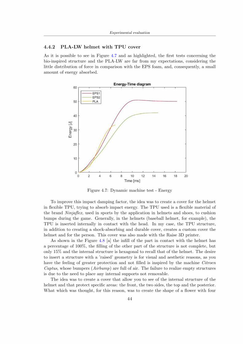
Experimental evaluation
442 PLA-LW helmet with TPU cover
As it is possible to see in Figure 47 and as highlighted the first tests concerning thebio-inspired structure and the PLA-LW are far from my expectations considering thelittle distribution of force in comparison with the EPS foam and consequently a smallamount of energy absorbed
Figure 47 Dynamic machine test - Energy
To improve this impact damping factor the idea was to create a cover for the helmetin flexible TPU trying to absorb impact energy The TPU used is a flexible material ofthe brand Ninjaflex used in sports by the application in helmets and shoes to cushionbumps during the game Generally in the helmets (baseball helmet for example) theTPU is inserted internally in contact with the head In my case the TPU structurein addition to creating a shock-absorbing and durable cover creates a custom cover thehelmet and for the person This cover was also made with the Raise 3D printer
As shown in the Figure 48 [a] the infill of the part in contact with the helmet hasa percentage of 100 the filling of the other part of the structure is not complete butonly 15 and the internal structure is hexagonal to recall that of the helmet The desireto insert a structure with a rsquoraisedrsquo geometry is for visual and aesthetic reasons as youhave the feeling of greater protection and not filled is inspired by the machine CitroenCaptus whose bumpers (Airbump) are full of air The failure to realize empty structuresis due to the need to place any internal supports not removable
The idea was to create a cover that allow you to see of the internal structure of thehelmet and that protect specific areas the front the two sides the top and the posteriorWhat which was thought for this reason was to create the shape of a flower with four
44
Experimental evaluation
petals Figure 48 [b]In this way to perform dynamic impact tests as shown in Figure 49 [a] the cover was
positioned at the top of the helmet and the impact was performed in the centre of thersquoflowerrsquo which corresponds to the higher upper part where the structure has larger cellsize The impact parameters are the same as those used in previous impacts 5 kg weightmaximum speed and maximum height The Anvil that was used is a disc diameter of60 mm In photo [b] it is evident the difference between the structure that received theimpact with protection (left) and without protection (right) Without protection duringthe impact there was a perforation of the structure with a concentration of force at a locallevel as you can see in the Figure 46 in the case of TPU the impactor did not perforateand crossed the structure thanks to the cover of TPU that cushioned the shock At themoment of impact the impactor bounced
[a] [b]
Figure 48 TPU cover
[a] [b]
Figure 49 PLA-LW with TPU - dynamic impact [a] and differences between thehelmet with TPU and without TPU cover [b]
45
Experimental evaluation
The Figure 410 includes the diagrams relative to the dynamic impacts In [a] thereare already analyzed EPS results in [b] a comparison between the test on the portionof helmet in PLA LW with and without the TPU cover in [c] the overall comparison ofcurves shows a much more similar EPS trend if the TPU is placed above the structure inPLA LW to soften the blow and absorb the same energy [d]
46
[a]
[c]
[d]
Figure 410 Comparison between PLA-LW with TPU and EPS
Chapter 5
FEM Validation
51 Impactor - Anvils definition
Before to start to work in Abaqus it was necessary to search in the literature the materialwith which the anvil was been realized Milne et al [23] established the densityrsquos valuethe Youngrsquos Module and Poissonrsquos ratio for the Flat and Kerbstone Anvil
- Density ρ = 7800 kgm3
- Youngrsquos Module E = 200000 MPa
- Poissonrsquos ratio ν = 03
Inserting the data in the CES EduPack program specifying the mechanical andphysical properties the material corresponding to these characteristics is Stainless steelaustenitic (ASTM F1586) medium-hard
Initially the proposal was to create a conservative system to evaluate the absorptionenergies values and apply this value to a vibration system but the helmet needs dampingto be realized it was impossible to use a system without losses in this modality Thisis why a numerical calculation was carried out by performing two types of simulationsexplicit dynamic step and static step
The idea to realize the theoretical impact is to regard the movement of the anviland not the helmetrsquos movement which is fixed The velocity is the same cited in thenormative EN 1078 542 ms for the Flat anvil and 457 ms for the Kerbstone anvil
In performing the simulations It was given more relevance and perform tests withthe Kerbstone Anvil This choice was done because the geometry with which it is beenrealized (following as defined in the legislation) allows the helmet to be more subjectedto stress this involves the definition of higher stress limits compared to the Flat Anvil
The mesh size that has been used is the same in the case of the simulation of thehelmet optimized in PLA-LW and the full helmet in EPS of 7 mm The impactor isconsidered as a Discrete rigid body with its specific Reference Point (RP) like shownin Figure 51 for this reason it is not a solid but it is composted only by shells Inthe same image [b] there is the FEM representation of the model and in Table 51 thecharacteristic of FEM with quadrilateral (R3D4) and triangular elements (R3D3)
48
FEM Validation
Object Elementnumber
Elements Shape Geometricorder
Global size[mm]
Kerbstone 230 Quadrilateral - R3D4 Linear 7
Kerbstone 8 Triangular - R3D3 Linear 7
Table 51 Mesh element - Kerbstone Anvil
[a] [b]
Figure 51 Kerbstone anvil in the simulation like discrete rigid body [a] and FEMelements [b]
511 PLA LW - Plastic characteristics
The PLA-LW as explained in the Chapter 2 is new material on the market and producedby the only Colorfabb company for this reason few tests have been carried out to defineits technical characteristics and through tensile tests of the 3D printed specimens it waspossible to define an elastic limit as reported in the Table 210
In the context of simulations to reproduce the impact and deformation of the helmetis also necessary to consider the plastic characteristics of the material Not possessingany reference value in this regard tests were performed through a Static Step initiallyand then an Explicit Dynamic Step in Abaqus
The structure chosen to consider as a reference it is one of the structures previouslysubjected to the compression test having the side L=14 mm As for the reproduction ofthe compression disks initially they were reproduced according to the geometry of theHoytom HM-D Testing Machine considering the bodies mentioned above as discrete 3Drigid discrete The measure was the diameter of 200 mm and the height of 20 mm
After an initial analysis it was observed that the computational time of the simulationprogram was very high so it was decided to change the geometry to have a rsquodisk-surfacesrsquo(equally 3D rigid-discrete) which allowed me to have a smaller number of nodes for themesh and consequently a better computational time The representation of the opti-mized structure in PLA-LW and the disks used for simulated compression is in Figure 52
49
FEM Validation
[a] [b]
Figure 52 Representation of the samples used for the simulation of the compressiontest In Figure [a] the disks of the Hoytom HM-D Testing Machine in figure [b] the
representation of the same as simple surfaces
As shown in Figure 52 the disks are considered 3D discrete hard bodies so it waschosen for both a point the reference point RP where to apply the characteristics relatedto the two bodies As for the compression test it was established
bull the movement of a disk and fixed the second through a boundary condition impos-ing an Encastre therefore unable to move and rotate in xyz directions
bull for the opposite disk the boundary condition relative to the 15 mm displacementwas applied which is the parameter that it was observed to determine the end ofthe compression with the machine This shift is shown by the orange arrow in figure[b]
bull between the upper surface and the disk e the disk with the lower surface it wasinitialized a general contact with normal behaviour through rsquohardrsquo contact andtangential behaviour with a coefficient of friction of 02 with directionality imposedon rsquoisotropicrsquo
The next step was to define the mesh of the components whose parameters are shown inTable 52 while the representation of the FEM is in Figure 53 with the representationof the simulation and real compression test
Object Elementsnumber
Typology Geometricorder
Globalsize [mm]
Disk (14mm) 80910 hexaedral - C3D8R Linear 07
Impact disks 206 quadrilateral - R3D4 Linear 20
Impact disks 6 triangular - R3D3 Linear 20
Table 52 Mesh element - Compression test simulation
As previously announced a static simulation was initially performed with a StaticStep with Step Time equal to 900 (obtained going to consider the speed of 1 mmmin of
50
FEM Validation
[a]
[b] [c]
Figure 53 FEM representation [a] and compression test simulation [b] and realcompression [c]
the compression test and the displacement of 15 mm) However the complex geometryof the structure and the high time set by Step Time did not allow a correct definitionof the parameters of the plastic characteristics of the material the simulation was notable to continue once reached a Step Time of approximately 220 That is why it waschanged by choosing an Explicit Dynamic step
Leaving all the parameters of the boundary conditions unchanged the Step Time wasmodified imposing it to 001 The ability of the explicit dynamic to work with non-linearand contacting structures allowed me to achieve results The results obtained are shownin Figure 54 with the blue curve and were obtained through the iteration of differentPlastic Strain and Yield Stress values in Abaqus while the red line is the result of thereal compression test a similar curve trend was obtained but it is not possible to obtainthe same curve taking into account problems of printing inaccuracy
512 First test - helmet
The initial idea was to perform a simulation imposing the speed of 457 ms to theimpactor tie the helmet in EPS and PLA and compare the absorbed energies Theproblem it was encountered is related to the mesh of the helmet optimized in PLA andwith minimum dimensions of the elements and distinct elements it was not able to solveit
51
FEM Validation
[a]
YieldStress
PlasticStrain
1 47 0
2 7 001
3 75 005
4 10 01
5 108 1
6 115 15
7 12 2
[b]
Figure 54 Representation of the two curves related to the simulation in Abaqus of thecompression test and the data obtained from the real test to obtain the plastic
characteristics of the material
513 Second test - plane
The first solution is the one shown in Figure 55 To realize the simulation it was realizeda section of the helmet to involve a smaller number of elements and nodes Again thesimulation for the EPS helmet was successful while the simulation with the bio-inspiredstructure was interrupted by excessive distortion of elements
The previous images show the impact is very localized in the impacted area and theidea to achieve a complete simulation is not to consider a curved portion of the helmetbut a plane In this way it was possible to solve the problem and obtain a completesimulation for the bio-inspired structure
FEM element
Below in Table 53 there is the definition of the elements used for the PLA-LW and EPSplane in the simulation to simulate the impact and to control the energy-absorbing whilethe anvil characteristics are described in Table 51
514 EPS impact simulations
In order to proceed with the simulation it was imposed some boundary conditions thatregard ties and forces
bull the movement of the plane is fixed through an Encastre therefore unable to moveand rotate in xyz directions
52
FEM Validation
[a]
[b]
Figure 55 Impact simulation parts of EPS and PLA helmet
Object Elementnumber
Elements Shape Geometricorder
Plane (PLA) 38896 Tetrahedral -C3D10M
Quadratic
Plane (EPS) 2100 Hexahedral - C3D8R Linear
Table 53 Mesh element - plane impact
bull to create the impact it was set a speed of 457 ms at the reference point RP of therigid body which is the impactor Kerbstone Anvil shown in Figure 56
bull between the upper surface of the plane and the impactor it was initialized a Sur-face to Surface contact with normal behaviour through rsquohardrsquo contact and tangen-tial behaviour with a coefficient of friction of 02 with directionality imposed onrsquoisotropicrsquo
bull the rotation in x y z relative to the RP of the rigid discrete impactor body is locked
53
FEM Validation
In addition it was characterized the plane in the part of the materials with the char-acteristic values of the EPS mentioned in Chapter 221 The Von Mises Stress valueapparently low is relative to the Yield Stress of the EPS material equal to 09 MPa
Figure 56 EPS Boundary conditions and Load
515 PLA LW impact simulations
As also required in the case of the EPS plane in order to proceed with the simulationsome boundary conditions were imposed that regard ties and forces
bull the movement of the plane is fixed through an Encastre therefore unable to moveand rotate in xyz directions
bull to create the impact a speed of 457 ms was set at the reference point RP of therigid body which is the impactor Kerbstone Anvil shown in Figure 58
bull between the upper surface of the plane and the impactor it was initialized a Sur-face to Surface contact with normal behaviour through rsquohardrsquo contact and tangen-tial behaviour with a coefficient of friction of 02 with directionality imposed onrsquoisotropicrsquo
bull the rotation in x y z relative to the RP of the rigid discrete impactor body is locked
In addition the plane was characterized in the part of the materials with the characteristicvalues of the PLA mentioned in the Chapter 223 and 511
Figure 58 Boundary conditions and Load
54
FEM Validation
[a]
[b]
Figure 57 EPS impact simulation
52 Results
In Figures 59 and 57 it is shown how the structure in PLA LW has a more concentratedstress distribution of the structure unlike EPS The maximum value for the Von Misesstress is 09 MPa in EPS structure and 3634 MPa in PLA LW structure Once thesimulations were obtained the next step was to go and compare the energies absorbed bythe two structures The energy calculated by Abaqus that has been taken into account isPlastic Dissipation To make a comparison the data of the two energies were representedin a single graph
What emerges from the graph is that about the impact made with the KerbstoneAnvil the energy absorption is more excellent although only slightly for the PLA LWthan for the EPS From the graph in Figure 510 a value of 41 J is shown for the EPSand 51 J for the PLA LW
55
[a]
[b]
Figure 59 PLA impact simulation
[a]
Figure 510 EPS and PLA LW energy comparison - Abaqus simulation
Chapter 6
Head Injury Data
For the statistical analysis the injuries related to the accident data were categorised intothe following types and levels based on the details of the medical report [11] about theEN 1078
bull Head Injury Criterion (HIC)
bull Peak Linear Acceleration (PLAc)
bull Gadd Severity Injury (GSI)
bull Diffuse axonal injuries (DAI)
61 Abaqus simulation
Until now the purpose of the simulations has been to determine which between the twomaterials and the two structures of EPS and PLA LW could absorb more energy duringthe impact but no simulations have been carried out in compliance with BS EN 1078on the helmet impact tests To calculate the injuries listed in the previous paragraphhowever we need the acceleration values in the three directions related to the subjectrsquoshead
To realize it the scan of my head already rsquocleanrsquo was considered of which it has beencalculated the inertia thanks to the automatic SolidWorks calculation and evaluated theweight with the Table 24 the structure of the helmet was placed for the EPS and thePLA LW over the head as shown in Figure 61 Also this time being able to mesh theentire helmet in PLA LW was impossible due to the excessive distortion of some elementsduring the simulation so it has been tried to make a section of the structures of thehelmet and results were obtained
57
Head Injury Data
[a] [b]
Figure 61 My scan head - CAD [a] head imported in Abaqus[b]
Initially the simulation had these characteristics as shown in the following Figure62 considering the helmet was not sectioned As explained earlier it was not possibleto get to simulation in the case of the optimized structure in PLA LW for this reasononly a part of the helmet was considered in both cases shown in Figure 63
[a]
Figure 62 Simulation based on BS EN 1078
58
Head Injury Data
[a] [b]
Figure 63 Simulation based on BS EN 1078 with head
In order to proceed with the simulation some boundary conditions that regard tiesand forces have have imposed
bull two reference points RP were created the first in the inertia centre of the headthe second relating to the Kerbstone Anvil which is a discrete rigid body
bull in the reference point RP of the head in the definition of the engineering features5 kg was inserted for the weight and an inertia I11 = 564464E+07 gmm2 I22 =460654E+07gmm2 I33 = 187302E+07gmm2
bull to simulate the impact it was set a speed of 457 ms at the reference point RP ofthe head in z-axis direction
bull a general contact with normal behaviour through rsquohardrsquo contact and tangentialbehaviour with a coefficient of friction of 02
bull between the upper surface of the helmet and the impactor it has been initializeda Surface to Surface contact with normal behaviour through rsquohardrsquo contact andtangential behaviour with a coefficient of friction of 02 with directionality imposedon rsquoisotropicrsquo
bull the movement between the Kerbstone anvil and the helmet is fixed through anEncastre therefore unable to move and rotate in xyz directions
bull the rotation in x y z relative to the RP of the rigid discrete impactor body is locked
FEM element
As reported in Table 53 the portion of the helmet in EPS has used a mesh with hexahe-dral elements of linear order For the structure (beetle) of PLA LW given the geometry
59
Head Injury Data
complexity it was necessary to use a quadratic order of tetrahedra For the mesh of thehead instead in both simulations have been used quadrilateral elements of linear orderas reported in the Tables 61 and 62
Object Elementnumber
Elements Shape Geometricorder
Head 3755 Quadrilateral - R3D4 Linear
Head 34542 Quadrilateral - R3D3 Linear
Helmet (PLA) 272302 Tetrahedral -C3D10M
Quadratic
Table 61 Mesh element - Head simulation with PLA LW (beetle) helmet
Object Elementnumber
Elements Shape Geometricorder
Head 3755 Quadrilateral - R3D4 Linear
Head 34542 Quadrilateral - R3D3 Linear
Helmet (EPS) 72280 Hexahedral - C3D8R Linear
Table 62 Mesh element - Head simulation with EPS helmet
62 Results
Figure 64 represents the simulation in line with BS EN 1078 concerning the helmet inEPS [a] and the helmet with bio-inspired structure in PLA LW For both simulationsVan Misesrsquo stress has Yield Stress values in the case of EPS which is 09 MPa and theplastic behaviour combination of PLA LW [b]
In the case of head and Kerbstone Anvil stress was not assessed as they were previ-ously defined as discrete rigid bodies
63 Head Injury Criterion
The HIC quantifies head impact severity by incorporating time of acceleration exposureand acceleration magnitude it is calculated in post-processing phase with the followingEquation 61
HIC15 =
[1
(t1 minus t2)
int t2
t1
a(t)dt
]25(t2 minus t1) (61)
60
Head Injury Data
[a]
[b]
Figure 64 Results simulation based on BS EN 1078 with sectioned head
For this analysis a(t) is the acceleration calculated in the centre of mass of the head(corresponding to the reference point RP) expressed in g and the time interval (t2 minus t1)was chosen to maximize HIC over a maximum duration of 15 ms
Matlab and the trapz function were used to calculate the HIC to integrate accelerationover time t2 and t1 were considered initial and final times of the simulation t1 = 0 sand t2 = 10 s time less than 15 s
HIC value of 198 was obtained for EPS and 87 for PLA LW Considering the Hayeset al [16] document about the HIC values and the graph in Figure 65 developed bythe author it is possible to find the percentages related to the different injury AIS1 -AIS6 which correspond respectively to lower and higher severity while in Figure 66 therelative fatality to every value of AIS is shown The values obtained for the HIC andother criteria are shown in Table 63 The HIC value for EPS is 198 for PLA LW it is
61
Head Injury Data
Figure 65 Head injury risk curves based on HIC values [16]
Figure 66 The abbreviated injury score versus fatality rate [16]
87 Analyzing the data and comparing them with the curves of the Figure 65 I obtain
bull a percentage between 20 - 30 of AIS 1 for EPS 10 - 20 for PLA LW
bull a percentage between 10 - 20 of AIS 2 for EPS and 0 - 10 for PLA LW
bull for AIS 3 AIS 4 AIS 5 AIS 6 the percentages for both structures is between 0 -10
Comparing these percentages with the fatality rate of Figure 66 it is clear there is a riskof Moderate and Minor fatality in the case of EPS and PLA LW as all values are between0 and 30
62
Head Injury Data
HIC PLA [g] GSI E [J]
EPS 198 97 361 37723
PLA LW 87 75 169 44102
Table 63 Head Injury Data - values
64 Peak Linear Acceleration
The resultant linear acceleration versus time curve was calculated according to Equation62
γ(t) =radicγ2x(t) + γ2y(t) + γ2z (t) (62)
where
bull γ(t) is the resultant linear acceleration (g)
bull γx(t) is the linear acceleration in x axes (g)
bull γy(t) is the linear acceleration in y axes (g)
bull γz(t)is the linear acceleration in z axes (g)
The value of the impact should never exceed 250g [9] Cripton at all [9] in their studyexamined a helmet with expanded polystyrene (EPS) Figure 68 shows maximum HIC forhelmeted and unhelmeted drops from all heights For each drop height helmets reducedHIC relative to unhelmeted drops IARV value is 180g The acceleration in the two casesis shown in Figure 67 and the maximum values are 97g for EPS and 75g for PLA LWas reported in Table 63 The two values considering a maximum value calculated byCripton [9] of 180g are amply optimal and comply with the standard of 250g
65 Gadd Severity Index
Gadd proposed the Severity Index Criteria shown in Equation 63 Following this crite-rion the GSI values that are over 1000 produce serious internal head injury [33]
GSI =
int t1
0a(t)25dt (63)
Where
bull a is the linear acceleration (g)
bull t is the duration of the impact (s)
I calculated the GSI with the function trapz between 0 and t and the resulting valuesare 361 for the EPS and 169 for the PLA LW which comply with the limit
63
Head Injury Data
Figure 67 Peak accelerations for both helmets
Figure 68 Peak accelerations for both helmeted and unhelmeted drops Numbers overbars indicate peak acceleration For 2 m drop height results stated are the mean value
calculated from three drops [9]
64
Head Injury Data
66 Diffuse Axonal Injury
DAI cases covered all incidences in which neurological injuries occurred as well as con-cussion unconsciousness and coma
In order to assess the risk of head trauma in terms of diffuse axonal injury (DAI)Milne et al [23] defined a model based head injury criteria as follows obtaining theresults in Figure 69
bull 50 risk of moderate neurological injury (DAI1+) Brain Von Mises shearing stressof 28 kPa
bull 50 risk of severe neurological injury (DAI2+) Brain Von Mises shearing stressof 53 kPa
[a]
[b]
Figure 69 Peak intra-cerebral shearing stress computed with the helmet model coupledto the human head model for all impact points (a) Flat anvil (b) Kerbstone anvil [23]
65
Head Injury Data
67 Energy absorbed
In Figure 52 during the impact test between the kerbstone Anvil and the plan with thebio-inspired structure in PLA LW and EPS it was found that the PLA LW althoughwith a small difference of 10 J absorbed more energy in comparison with the EPS Whenthe test is carried out in compliance with BS EN 1078 and the head with a speed of 457ms (corresponding to the kerbstone Anvil) as shown in Figure 610 also in this casethe PLA LW with the optimized helmet structure manages to absorb more energy (evenif the difference is very low) compared to the EPS The maximum energy value in PLALW is 44102 J of EPS is 37723 J
Figure 610 Energy absorption - BS EN 1078
66
Chapter 7
Conclusion
71 Conclusion
In this thesis work a bicycle helmet with a bio-inspired structure in PLA LW and 3Dprinted was created The initial approach was to introduce an innovative aspect tostandard EPS helmets not using foam but a polymer with new geometries able toabsorb much energy during the impact For this reason the beetle structure has beenpreferred relying solely on the hypothesis encountered in the literature of its quality inabsorbing energy
Combining the new material of the PLA LW and beetle structure has made possiblethe development of new material satisfactory characteristics have been obtained sincethe first tests The two materials were first subjected to tensile tests to determine theirspecific stress in these the PLA LW had positive results
Subsequent dynamic physical tests were carried out on 3D printed helmet models andon reference helmets in EPS to calculate the absorption energy in both cases at the timeof impact These resulted in energy absorption of the beetle structure in PLA LW withthe application of a TPU cover almost equal to that of EPS about 50J To validate withfinite element analysis the two models an explicit dynamic step was used in AbaqusSimulations showed that the PLA LW structure absorbs a higher amount of energy thanthe EPS the higher is 50 J and the EPS 40J
Finally positive results have also been obtained in calculating the head injury datasimulating according to BS EN 1078 with the use of impactor helmet and head Theacceleration values for both the structures were inferior to 220g precisely for the PLALW was 75g and for the EPS 97g The same applies to the calculation of HIC and GSI(maximum acceptable value of 1000) where the values are 87 and 169 in the case of PLALW and 361 and 198 in EPS For all tests therefore greater efficiency of the structure inPLA LW has been obtained Positive results also in the simulation of the energy absorbedduring the impact as the value referring to the EPS was 35J and that of the PLA LWwas 45J
67
Conclusion
72 Future work lines
The positive results obtained can be considered as a starting point for further tests andsimulations to ensure the safety of the helmet and compliance with the regulations butbefore getting improvements and continue testing changes are required
bull the beetle structure of the helmet made with GH adapts to the SubD withoutallowing to have a homogeneous distribution it would be appropriate to have moreregular hexagonal geometries
bull the mesh of the helmet is too complex and does not allow to perform the simulationprobably to use a more regular structure would have a mesh accordingly moreregular and the simulation would be successful
bull the uneven helmet structure has so many defects that the print is imperfect andthis can change the results of the impact tests the structure should be improved
bull the printing time varies from 4 to 5 days it should be improved
bull the TPU helmet cover is too big for the RAISE printing plan it is necessary togenerate a new geometry
bull the TPU cover it must be fixed on the helmet
bull in the calculation of the DAI it is necessary to have the definition of the brain andthe head should not be considered as a rigid body
bull in the injury calculation the helmet without protection was considered with theTPU cover the result will be better
bull air flow analysis
The comments mentioned are only considerations and problems that I gained duringmy thesis and which should be improved but I am sure that these changes and improve-ments from design to printing and simulations can make the helmet a good product
68
Bibliography
[1] K Adanty J M Clark A Post Thomas Blaine H and M D Gilchrist Comparingtwo proposed protocols to test the oblique response of cycling helmets to fall impactsInternational Journal of Crashworthiness 6648 ndash 663 2020
[2] MF Ashby YJM Brechetb D Cebona and L Salvoc Selection strategies formaterials and processes Materials and Design 2004
[3] M Aysha El casco de bicicleta voronoi impreso en 3d mas seguro y ligero https
www3dnativescomen3d-printed-bicycle-helmet-voronoi-190820204
[4] H Bikas P Stavropoulos and G Chryssolouris Additive manufacturing methodsand modelling approaches a critical review The International Journal of AdvancedManufacturing Technology 83389ndash405 2016
[5] British Standards BSI Helmets for pedal cyclists and for users of skateboards androller skates - BS EN 1078 2012
[6] British Standards BSI Headforms for use in the testing of protective helmets BSEN 960 2020
[7] ColorFabb Colorfabb lw-pla 2019 httpscolorfabbcommedia
datasheetstdscolorfabbTDS_E_ColorFabb_LW-PLApdf
[8] V G Coronado T Haileyesus J M Bell T A Cheng JHaarbauer-Krupa M RLionbarger J Flores-Herrera L C McGuire and J Gilchrist Trends in sports andrecreation-related traumatic brain injuries treated in us emergency departments thenational electronic injury surveillance system-all injury program (neiss-aip) 2001-2012 J Head Trauma Rehabil 30185ndash197 2015
[9] P A Cripton D M Dressler D Stuart Cameron A Christopher R and D RichardsBicycle helmets are highly effective at preventing head injury during head impactHead-form accelerations and injury criteria for helmeted and unhelmeted impactsAccident Analysis and Prevention 701ndash7 2014
[10] L Cui M A Forero R and M D Gilchrist Optimisation of energy absorbingliner for equestrian helmets UCD School of Electrical Electronic and MechanicalEngineering University College Dublin Belfield Dublin4 Ireland 2020
[11] C Deck N Bourdet F Meyer and R Willinger Protection performance of bicyclehelmets Journal of safety research pages 67ndash77 2019
[12] Committee F08 Specification for headforms F2220 ASTM International 2015
[13] Committee F08 Specification for helmets used in recreational bicycling or rollerskating F1447 ASTM International 2018
[14] Committee F08 Test methods for equipment and procedures used in evaluating theperformance F1446 ASTM International 2020
69
Bibliography
[15] P Halldin Shock absorption including measuring CENTC 158 Working Group11 2018
[16] W C Hayes M S Erickson and E D Power Forensic injury biomechanics Annualreview of biomedical engineering pages 55ndash86 2007
[17] HEXR httpshexrcom
[18] C Jinxiang Z Xiaoming O Yoji S Kazuya G Zhensheng and P LongchengThe deformation mode and strengthening mechanism of compression in the beetleelytron plate Materials and Design 131481ndash186 2017
[19] S Kroeker M Ozkul A De Marco S Bonin and GP Siegmund Density variationin the expanded polystyrene eps foam of bicycle helmets and its influence on impactperformance Journal of biomechanical engineering 2019
[20] S G Kroeker SJ Bonin A L DeMarco C A Good and G P Siegmund Agedoes not affect the material properties of expanded polystyrene liners in field-usedbicycle helmets Journal of biomechanical engineering 2016
[21] M Meier K H Tan M K Lim and L Chung Unlocking innovation in the sportindustry through additive manufacturing Business Process Management Journa2018
[22] N J Mills and A Gilchrist The effectiveness of foams in bicycle and motorcyclehelmets Accident Analysis Prevention 23153 ndash 163 1991
[23] G Milne C Deck R P Carreira Q Allinne and R Willinger Development andvalidation of a bicycle helmet assessment of head injury risk under standard impactconditions Computer methods in biomechanics and biomedical engineering 15 Suppl1309 ndash 310 2012
[24] Y Mosleh S J Vander B Depreitere and J Ivens Novel composite foam conceptfor head protection in oblique impacts Adv Eng Mater (Advanced EngineeringMaterials) 10 2017
[25] H Mustafa T Y Pang T Ellena and S H Nasir Impact attenuation of user-centred bicycle helmet design with different foam densities J Phys Conf Ser(Journal of Physics Conference Series) 1150 2019
[26] S H Ngoc and L Guoxing A review of recent research on bio-inspired structuresand materials for energy absorption applications Composites Part 181 2020
[27] J I Novak and A R Novak Is additive manufacturing improving performance insports a systematic review Sport engineering and technology 13 2020
[28] European Road Safety Observatory European road safety observatory facts and fig-ures - cyclists - 2020 December 2020 httpseceuropaeutransportroad_
safetysitesdefaultfilesfacts_figures_cyclists_final_20210323pdf
[29] New York City Departments of Health Parks Mental Hygiene Transportation Recre-ation and the New York City Police Department Bicyclist fatalities and seriousinjuries in new york city 2005
[30] W Pengwen Y Jing H Yanan H Jiaofei and F Xiaoyang Innovative designof a helmet based on reverse engineering and 3d printing Alexandria EngineeringJournal 603445ndash3453 2021
[31] S G Piland T E Gould M Jesunathadas J S Wiggins O McNair and V CShane Protective helmets in sports Materials in Sports Equipment 3 2019
70
Bibliography
[32] K Schmitt P F Niederer M H Muser and F Walz Trauma biomechanicsSpringer Berlin Heidelberg 2010
[33] David Sepelveda Lopez A Biomechanical Analysis of Bicycle Helmets using FEMPhD thesis 2019 Bachelor thesis
[34] H Stigson Bicycle Helmets 2020 Tested by Folksam PhD thesis 2020 PhDAssociate Professor Traffic Safety Research
[35] H Tao K Sudip N Anindya and X Yongzhao 3d printed sensors for biomedicalapplications A review sensor 2019
[36] M Trzaskalska and R Chwastek Damping properties and density of helmet linersmade of expanded polystyrene (eps) Archives of Metallurgy and Materials 66 2020
[37] Crupi V Epasto G and Guglielmino E Impact response of aluminum foam sand-wiches for light-weight ship structures Metals 198ndash112 2020
[38] W Wei-cai F Dong-ming and L Yuan-xin Study on impact energy absorbing per-formance of eps buffer layer of motorcycle helmet Proceedings - 2013 InternationalConference on Mechanical and Automation Engineering MAEE 2013
[39] Z Xiaoming C Jinxiang O Yoji Z Peiwei X Xiaobing and Y Xindi Influence ofhoneycomb dimensions and forming methods on the compressive properties of beetleelytron plates Journal of Sandwich Structures and Materials 2228ndash39 2020
[40] S Zhi L Dong Z Weisheng S Shanshan and G Xu Topological optimization ofbiomimetic sandwich structures with hybrid core and cfrp face sheets CompositesScience and Technology 14279ndash90 2017
[41] S Zhi S Shanshan G Xu H Xiaozhi and C Haoran On compressive propertiesof composite sandwich structures with grid reinforced honeycomb core CompositesPart B 94245ndash252 2016
71
- List of Tables
- List of Figures
- Introduction
-
- Helmet bike protection
-
- Helmet structure
-
- Additive Manufacturing
-
- AM process
- Materials and techniques - FDM
- AM in sport
-
- 3D printed helmets
-
- Phases
- HEXR
- VORONOI
-
- State of the art
-
- Standards
-
- Headform
- European Standard and American Standard
- Field of vision - BS EN 1078
- Test impact area
- Anvils and environmental conditions
-
- Materials
-
- EPS Foam
- CES Edu Pack - Material selection
- PLA with natural fiber and PLA LW
-
- Bio-inspired structures
-
- Beetle structure - Design of the model
- Specific stress - PLA LW and EPS foam
-
- Methodology
-
- 3D scan
-
- 3D Sense 2 scanner and Meshmixer - Reverse reconstruction
- 3D scan analysis and extraction of features
-
- Helmet design
-
- Rhinoceros - Helmet surface
- Grasshopper - Helmet structure
-
- 3D Print
-
- Printer and parameters
-
- Experimental evaluation
-
- Experimental tests
-
- Drop-weight impact test machine
-
- PLA LW helmet
- EPS helmet
- Results
-
- First results - PLA-LW and EPS helmet
- PLA-LW helmet with TPU cover
-
- FEM Validation
-
- Impactor - Anvils definition
-
- PLA LW - Plastic characteristics
- First test - helmet
- Second test - plane
- EPS impact simulations
- PLA LW impact simulations
-
- Results
-
- Head Injury Data
-
- Abaqus simulation
- Results
- Head Injury Criterion
- Peak Linear Acceleration
- Gadd Severity Index
- Diffuse Axonal Injury
- Energy absorbed
-
- Conclusion
-
- Conclusion
- Future work lines
-
- Bibliography
-
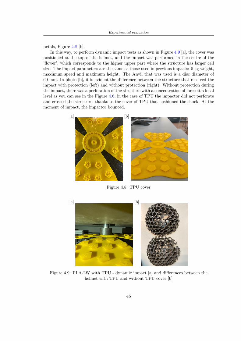
Experimental evaluation
The Figure 410 includes the diagrams relative to the dynamic impacts In [a] thereare already analyzed EPS results in [b] a comparison between the test on the portionof helmet in PLA LW with and without the TPU cover in [c] the overall comparison ofcurves shows a much more similar EPS trend if the TPU is placed above the structure inPLA LW to soften the blow and absorb the same energy [d]
46
[a]
[c]
[d]
Figure 410 Comparison between PLA-LW with TPU and EPS
Chapter 5
FEM Validation
51 Impactor - Anvils definition
Before to start to work in Abaqus it was necessary to search in the literature the materialwith which the anvil was been realized Milne et al [23] established the densityrsquos valuethe Youngrsquos Module and Poissonrsquos ratio for the Flat and Kerbstone Anvil
- Density ρ = 7800 kgm3
- Youngrsquos Module E = 200000 MPa
- Poissonrsquos ratio ν = 03
Inserting the data in the CES EduPack program specifying the mechanical andphysical properties the material corresponding to these characteristics is Stainless steelaustenitic (ASTM F1586) medium-hard
Initially the proposal was to create a conservative system to evaluate the absorptionenergies values and apply this value to a vibration system but the helmet needs dampingto be realized it was impossible to use a system without losses in this modality Thisis why a numerical calculation was carried out by performing two types of simulationsexplicit dynamic step and static step
The idea to realize the theoretical impact is to regard the movement of the anviland not the helmetrsquos movement which is fixed The velocity is the same cited in thenormative EN 1078 542 ms for the Flat anvil and 457 ms for the Kerbstone anvil
In performing the simulations It was given more relevance and perform tests withthe Kerbstone Anvil This choice was done because the geometry with which it is beenrealized (following as defined in the legislation) allows the helmet to be more subjectedto stress this involves the definition of higher stress limits compared to the Flat Anvil
The mesh size that has been used is the same in the case of the simulation of thehelmet optimized in PLA-LW and the full helmet in EPS of 7 mm The impactor isconsidered as a Discrete rigid body with its specific Reference Point (RP) like shownin Figure 51 for this reason it is not a solid but it is composted only by shells Inthe same image [b] there is the FEM representation of the model and in Table 51 thecharacteristic of FEM with quadrilateral (R3D4) and triangular elements (R3D3)
48
FEM Validation
Object Elementnumber
Elements Shape Geometricorder
Global size[mm]
Kerbstone 230 Quadrilateral - R3D4 Linear 7
Kerbstone 8 Triangular - R3D3 Linear 7
Table 51 Mesh element - Kerbstone Anvil
[a] [b]
Figure 51 Kerbstone anvil in the simulation like discrete rigid body [a] and FEMelements [b]
511 PLA LW - Plastic characteristics
The PLA-LW as explained in the Chapter 2 is new material on the market and producedby the only Colorfabb company for this reason few tests have been carried out to defineits technical characteristics and through tensile tests of the 3D printed specimens it waspossible to define an elastic limit as reported in the Table 210
In the context of simulations to reproduce the impact and deformation of the helmetis also necessary to consider the plastic characteristics of the material Not possessingany reference value in this regard tests were performed through a Static Step initiallyand then an Explicit Dynamic Step in Abaqus
The structure chosen to consider as a reference it is one of the structures previouslysubjected to the compression test having the side L=14 mm As for the reproduction ofthe compression disks initially they were reproduced according to the geometry of theHoytom HM-D Testing Machine considering the bodies mentioned above as discrete 3Drigid discrete The measure was the diameter of 200 mm and the height of 20 mm
After an initial analysis it was observed that the computational time of the simulationprogram was very high so it was decided to change the geometry to have a rsquodisk-surfacesrsquo(equally 3D rigid-discrete) which allowed me to have a smaller number of nodes for themesh and consequently a better computational time The representation of the opti-mized structure in PLA-LW and the disks used for simulated compression is in Figure 52
49
FEM Validation
[a] [b]
Figure 52 Representation of the samples used for the simulation of the compressiontest In Figure [a] the disks of the Hoytom HM-D Testing Machine in figure [b] the
representation of the same as simple surfaces
As shown in Figure 52 the disks are considered 3D discrete hard bodies so it waschosen for both a point the reference point RP where to apply the characteristics relatedto the two bodies As for the compression test it was established
bull the movement of a disk and fixed the second through a boundary condition impos-ing an Encastre therefore unable to move and rotate in xyz directions
bull for the opposite disk the boundary condition relative to the 15 mm displacementwas applied which is the parameter that it was observed to determine the end ofthe compression with the machine This shift is shown by the orange arrow in figure[b]
bull between the upper surface and the disk e the disk with the lower surface it wasinitialized a general contact with normal behaviour through rsquohardrsquo contact andtangential behaviour with a coefficient of friction of 02 with directionality imposedon rsquoisotropicrsquo
The next step was to define the mesh of the components whose parameters are shown inTable 52 while the representation of the FEM is in Figure 53 with the representationof the simulation and real compression test
Object Elementsnumber
Typology Geometricorder
Globalsize [mm]
Disk (14mm) 80910 hexaedral - C3D8R Linear 07
Impact disks 206 quadrilateral - R3D4 Linear 20
Impact disks 6 triangular - R3D3 Linear 20
Table 52 Mesh element - Compression test simulation
As previously announced a static simulation was initially performed with a StaticStep with Step Time equal to 900 (obtained going to consider the speed of 1 mmmin of
50
FEM Validation
[a]
[b] [c]
Figure 53 FEM representation [a] and compression test simulation [b] and realcompression [c]
the compression test and the displacement of 15 mm) However the complex geometryof the structure and the high time set by Step Time did not allow a correct definitionof the parameters of the plastic characteristics of the material the simulation was notable to continue once reached a Step Time of approximately 220 That is why it waschanged by choosing an Explicit Dynamic step
Leaving all the parameters of the boundary conditions unchanged the Step Time wasmodified imposing it to 001 The ability of the explicit dynamic to work with non-linearand contacting structures allowed me to achieve results The results obtained are shownin Figure 54 with the blue curve and were obtained through the iteration of differentPlastic Strain and Yield Stress values in Abaqus while the red line is the result of thereal compression test a similar curve trend was obtained but it is not possible to obtainthe same curve taking into account problems of printing inaccuracy
512 First test - helmet
The initial idea was to perform a simulation imposing the speed of 457 ms to theimpactor tie the helmet in EPS and PLA and compare the absorbed energies Theproblem it was encountered is related to the mesh of the helmet optimized in PLA andwith minimum dimensions of the elements and distinct elements it was not able to solveit
51
FEM Validation
[a]
YieldStress
PlasticStrain
1 47 0
2 7 001
3 75 005
4 10 01
5 108 1
6 115 15
7 12 2
[b]
Figure 54 Representation of the two curves related to the simulation in Abaqus of thecompression test and the data obtained from the real test to obtain the plastic
characteristics of the material
513 Second test - plane
The first solution is the one shown in Figure 55 To realize the simulation it was realizeda section of the helmet to involve a smaller number of elements and nodes Again thesimulation for the EPS helmet was successful while the simulation with the bio-inspiredstructure was interrupted by excessive distortion of elements
The previous images show the impact is very localized in the impacted area and theidea to achieve a complete simulation is not to consider a curved portion of the helmetbut a plane In this way it was possible to solve the problem and obtain a completesimulation for the bio-inspired structure
FEM element
Below in Table 53 there is the definition of the elements used for the PLA-LW and EPSplane in the simulation to simulate the impact and to control the energy-absorbing whilethe anvil characteristics are described in Table 51
514 EPS impact simulations
In order to proceed with the simulation it was imposed some boundary conditions thatregard ties and forces
bull the movement of the plane is fixed through an Encastre therefore unable to moveand rotate in xyz directions
52
FEM Validation
[a]
[b]
Figure 55 Impact simulation parts of EPS and PLA helmet
Object Elementnumber
Elements Shape Geometricorder
Plane (PLA) 38896 Tetrahedral -C3D10M
Quadratic
Plane (EPS) 2100 Hexahedral - C3D8R Linear
Table 53 Mesh element - plane impact
bull to create the impact it was set a speed of 457 ms at the reference point RP of therigid body which is the impactor Kerbstone Anvil shown in Figure 56
bull between the upper surface of the plane and the impactor it was initialized a Sur-face to Surface contact with normal behaviour through rsquohardrsquo contact and tangen-tial behaviour with a coefficient of friction of 02 with directionality imposed onrsquoisotropicrsquo
bull the rotation in x y z relative to the RP of the rigid discrete impactor body is locked
53
FEM Validation
In addition it was characterized the plane in the part of the materials with the char-acteristic values of the EPS mentioned in Chapter 221 The Von Mises Stress valueapparently low is relative to the Yield Stress of the EPS material equal to 09 MPa
Figure 56 EPS Boundary conditions and Load
515 PLA LW impact simulations
As also required in the case of the EPS plane in order to proceed with the simulationsome boundary conditions were imposed that regard ties and forces
bull the movement of the plane is fixed through an Encastre therefore unable to moveand rotate in xyz directions
bull to create the impact a speed of 457 ms was set at the reference point RP of therigid body which is the impactor Kerbstone Anvil shown in Figure 58
bull between the upper surface of the plane and the impactor it was initialized a Sur-face to Surface contact with normal behaviour through rsquohardrsquo contact and tangen-tial behaviour with a coefficient of friction of 02 with directionality imposed onrsquoisotropicrsquo
bull the rotation in x y z relative to the RP of the rigid discrete impactor body is locked
In addition the plane was characterized in the part of the materials with the characteristicvalues of the PLA mentioned in the Chapter 223 and 511
Figure 58 Boundary conditions and Load
54
FEM Validation
[a]
[b]
Figure 57 EPS impact simulation
52 Results
In Figures 59 and 57 it is shown how the structure in PLA LW has a more concentratedstress distribution of the structure unlike EPS The maximum value for the Von Misesstress is 09 MPa in EPS structure and 3634 MPa in PLA LW structure Once thesimulations were obtained the next step was to go and compare the energies absorbed bythe two structures The energy calculated by Abaqus that has been taken into account isPlastic Dissipation To make a comparison the data of the two energies were representedin a single graph
What emerges from the graph is that about the impact made with the KerbstoneAnvil the energy absorption is more excellent although only slightly for the PLA LWthan for the EPS From the graph in Figure 510 a value of 41 J is shown for the EPSand 51 J for the PLA LW
55
[a]
[b]
Figure 59 PLA impact simulation
[a]
Figure 510 EPS and PLA LW energy comparison - Abaqus simulation
Chapter 6
Head Injury Data
For the statistical analysis the injuries related to the accident data were categorised intothe following types and levels based on the details of the medical report [11] about theEN 1078
bull Head Injury Criterion (HIC)
bull Peak Linear Acceleration (PLAc)
bull Gadd Severity Injury (GSI)
bull Diffuse axonal injuries (DAI)
61 Abaqus simulation
Until now the purpose of the simulations has been to determine which between the twomaterials and the two structures of EPS and PLA LW could absorb more energy duringthe impact but no simulations have been carried out in compliance with BS EN 1078on the helmet impact tests To calculate the injuries listed in the previous paragraphhowever we need the acceleration values in the three directions related to the subjectrsquoshead
To realize it the scan of my head already rsquocleanrsquo was considered of which it has beencalculated the inertia thanks to the automatic SolidWorks calculation and evaluated theweight with the Table 24 the structure of the helmet was placed for the EPS and thePLA LW over the head as shown in Figure 61 Also this time being able to mesh theentire helmet in PLA LW was impossible due to the excessive distortion of some elementsduring the simulation so it has been tried to make a section of the structures of thehelmet and results were obtained
57
Head Injury Data
[a] [b]
Figure 61 My scan head - CAD [a] head imported in Abaqus[b]
Initially the simulation had these characteristics as shown in the following Figure62 considering the helmet was not sectioned As explained earlier it was not possibleto get to simulation in the case of the optimized structure in PLA LW for this reasononly a part of the helmet was considered in both cases shown in Figure 63
[a]
Figure 62 Simulation based on BS EN 1078
58
Head Injury Data
[a] [b]
Figure 63 Simulation based on BS EN 1078 with head
In order to proceed with the simulation some boundary conditions that regard tiesand forces have have imposed
bull two reference points RP were created the first in the inertia centre of the headthe second relating to the Kerbstone Anvil which is a discrete rigid body
bull in the reference point RP of the head in the definition of the engineering features5 kg was inserted for the weight and an inertia I11 = 564464E+07 gmm2 I22 =460654E+07gmm2 I33 = 187302E+07gmm2
bull to simulate the impact it was set a speed of 457 ms at the reference point RP ofthe head in z-axis direction
bull a general contact with normal behaviour through rsquohardrsquo contact and tangentialbehaviour with a coefficient of friction of 02
bull between the upper surface of the helmet and the impactor it has been initializeda Surface to Surface contact with normal behaviour through rsquohardrsquo contact andtangential behaviour with a coefficient of friction of 02 with directionality imposedon rsquoisotropicrsquo
bull the movement between the Kerbstone anvil and the helmet is fixed through anEncastre therefore unable to move and rotate in xyz directions
bull the rotation in x y z relative to the RP of the rigid discrete impactor body is locked
FEM element
As reported in Table 53 the portion of the helmet in EPS has used a mesh with hexahe-dral elements of linear order For the structure (beetle) of PLA LW given the geometry
59
Head Injury Data
complexity it was necessary to use a quadratic order of tetrahedra For the mesh of thehead instead in both simulations have been used quadrilateral elements of linear orderas reported in the Tables 61 and 62
Object Elementnumber
Elements Shape Geometricorder
Head 3755 Quadrilateral - R3D4 Linear
Head 34542 Quadrilateral - R3D3 Linear
Helmet (PLA) 272302 Tetrahedral -C3D10M
Quadratic
Table 61 Mesh element - Head simulation with PLA LW (beetle) helmet
Object Elementnumber
Elements Shape Geometricorder
Head 3755 Quadrilateral - R3D4 Linear
Head 34542 Quadrilateral - R3D3 Linear
Helmet (EPS) 72280 Hexahedral - C3D8R Linear
Table 62 Mesh element - Head simulation with EPS helmet
62 Results
Figure 64 represents the simulation in line with BS EN 1078 concerning the helmet inEPS [a] and the helmet with bio-inspired structure in PLA LW For both simulationsVan Misesrsquo stress has Yield Stress values in the case of EPS which is 09 MPa and theplastic behaviour combination of PLA LW [b]
In the case of head and Kerbstone Anvil stress was not assessed as they were previ-ously defined as discrete rigid bodies
63 Head Injury Criterion
The HIC quantifies head impact severity by incorporating time of acceleration exposureand acceleration magnitude it is calculated in post-processing phase with the followingEquation 61
HIC15 =
[1
(t1 minus t2)
int t2
t1
a(t)dt
]25(t2 minus t1) (61)
60
Head Injury Data
[a]
[b]
Figure 64 Results simulation based on BS EN 1078 with sectioned head
For this analysis a(t) is the acceleration calculated in the centre of mass of the head(corresponding to the reference point RP) expressed in g and the time interval (t2 minus t1)was chosen to maximize HIC over a maximum duration of 15 ms
Matlab and the trapz function were used to calculate the HIC to integrate accelerationover time t2 and t1 were considered initial and final times of the simulation t1 = 0 sand t2 = 10 s time less than 15 s
HIC value of 198 was obtained for EPS and 87 for PLA LW Considering the Hayeset al [16] document about the HIC values and the graph in Figure 65 developed bythe author it is possible to find the percentages related to the different injury AIS1 -AIS6 which correspond respectively to lower and higher severity while in Figure 66 therelative fatality to every value of AIS is shown The values obtained for the HIC andother criteria are shown in Table 63 The HIC value for EPS is 198 for PLA LW it is
61
Head Injury Data
Figure 65 Head injury risk curves based on HIC values [16]
Figure 66 The abbreviated injury score versus fatality rate [16]
87 Analyzing the data and comparing them with the curves of the Figure 65 I obtain
bull a percentage between 20 - 30 of AIS 1 for EPS 10 - 20 for PLA LW
bull a percentage between 10 - 20 of AIS 2 for EPS and 0 - 10 for PLA LW
bull for AIS 3 AIS 4 AIS 5 AIS 6 the percentages for both structures is between 0 -10
Comparing these percentages with the fatality rate of Figure 66 it is clear there is a riskof Moderate and Minor fatality in the case of EPS and PLA LW as all values are between0 and 30
62
Head Injury Data
HIC PLA [g] GSI E [J]
EPS 198 97 361 37723
PLA LW 87 75 169 44102
Table 63 Head Injury Data - values
64 Peak Linear Acceleration
The resultant linear acceleration versus time curve was calculated according to Equation62
γ(t) =radicγ2x(t) + γ2y(t) + γ2z (t) (62)
where
bull γ(t) is the resultant linear acceleration (g)
bull γx(t) is the linear acceleration in x axes (g)
bull γy(t) is the linear acceleration in y axes (g)
bull γz(t)is the linear acceleration in z axes (g)
The value of the impact should never exceed 250g [9] Cripton at all [9] in their studyexamined a helmet with expanded polystyrene (EPS) Figure 68 shows maximum HIC forhelmeted and unhelmeted drops from all heights For each drop height helmets reducedHIC relative to unhelmeted drops IARV value is 180g The acceleration in the two casesis shown in Figure 67 and the maximum values are 97g for EPS and 75g for PLA LWas reported in Table 63 The two values considering a maximum value calculated byCripton [9] of 180g are amply optimal and comply with the standard of 250g
65 Gadd Severity Index
Gadd proposed the Severity Index Criteria shown in Equation 63 Following this crite-rion the GSI values that are over 1000 produce serious internal head injury [33]
GSI =
int t1
0a(t)25dt (63)
Where
bull a is the linear acceleration (g)
bull t is the duration of the impact (s)
I calculated the GSI with the function trapz between 0 and t and the resulting valuesare 361 for the EPS and 169 for the PLA LW which comply with the limit
63
Head Injury Data
Figure 67 Peak accelerations for both helmets
Figure 68 Peak accelerations for both helmeted and unhelmeted drops Numbers overbars indicate peak acceleration For 2 m drop height results stated are the mean value
calculated from three drops [9]
64
Head Injury Data
66 Diffuse Axonal Injury
DAI cases covered all incidences in which neurological injuries occurred as well as con-cussion unconsciousness and coma
In order to assess the risk of head trauma in terms of diffuse axonal injury (DAI)Milne et al [23] defined a model based head injury criteria as follows obtaining theresults in Figure 69
bull 50 risk of moderate neurological injury (DAI1+) Brain Von Mises shearing stressof 28 kPa
bull 50 risk of severe neurological injury (DAI2+) Brain Von Mises shearing stressof 53 kPa
[a]
[b]
Figure 69 Peak intra-cerebral shearing stress computed with the helmet model coupledto the human head model for all impact points (a) Flat anvil (b) Kerbstone anvil [23]
65
Head Injury Data
67 Energy absorbed
In Figure 52 during the impact test between the kerbstone Anvil and the plan with thebio-inspired structure in PLA LW and EPS it was found that the PLA LW althoughwith a small difference of 10 J absorbed more energy in comparison with the EPS Whenthe test is carried out in compliance with BS EN 1078 and the head with a speed of 457ms (corresponding to the kerbstone Anvil) as shown in Figure 610 also in this casethe PLA LW with the optimized helmet structure manages to absorb more energy (evenif the difference is very low) compared to the EPS The maximum energy value in PLALW is 44102 J of EPS is 37723 J
Figure 610 Energy absorption - BS EN 1078
66
Chapter 7
Conclusion
71 Conclusion
In this thesis work a bicycle helmet with a bio-inspired structure in PLA LW and 3Dprinted was created The initial approach was to introduce an innovative aspect tostandard EPS helmets not using foam but a polymer with new geometries able toabsorb much energy during the impact For this reason the beetle structure has beenpreferred relying solely on the hypothesis encountered in the literature of its quality inabsorbing energy
Combining the new material of the PLA LW and beetle structure has made possiblethe development of new material satisfactory characteristics have been obtained sincethe first tests The two materials were first subjected to tensile tests to determine theirspecific stress in these the PLA LW had positive results
Subsequent dynamic physical tests were carried out on 3D printed helmet models andon reference helmets in EPS to calculate the absorption energy in both cases at the timeof impact These resulted in energy absorption of the beetle structure in PLA LW withthe application of a TPU cover almost equal to that of EPS about 50J To validate withfinite element analysis the two models an explicit dynamic step was used in AbaqusSimulations showed that the PLA LW structure absorbs a higher amount of energy thanthe EPS the higher is 50 J and the EPS 40J
Finally positive results have also been obtained in calculating the head injury datasimulating according to BS EN 1078 with the use of impactor helmet and head Theacceleration values for both the structures were inferior to 220g precisely for the PLALW was 75g and for the EPS 97g The same applies to the calculation of HIC and GSI(maximum acceptable value of 1000) where the values are 87 and 169 in the case of PLALW and 361 and 198 in EPS For all tests therefore greater efficiency of the structure inPLA LW has been obtained Positive results also in the simulation of the energy absorbedduring the impact as the value referring to the EPS was 35J and that of the PLA LWwas 45J
67
Conclusion
72 Future work lines
The positive results obtained can be considered as a starting point for further tests andsimulations to ensure the safety of the helmet and compliance with the regulations butbefore getting improvements and continue testing changes are required
bull the beetle structure of the helmet made with GH adapts to the SubD withoutallowing to have a homogeneous distribution it would be appropriate to have moreregular hexagonal geometries
bull the mesh of the helmet is too complex and does not allow to perform the simulationprobably to use a more regular structure would have a mesh accordingly moreregular and the simulation would be successful
bull the uneven helmet structure has so many defects that the print is imperfect andthis can change the results of the impact tests the structure should be improved
bull the printing time varies from 4 to 5 days it should be improved
bull the TPU helmet cover is too big for the RAISE printing plan it is necessary togenerate a new geometry
bull the TPU cover it must be fixed on the helmet
bull in the calculation of the DAI it is necessary to have the definition of the brain andthe head should not be considered as a rigid body
bull in the injury calculation the helmet without protection was considered with theTPU cover the result will be better
bull air flow analysis
The comments mentioned are only considerations and problems that I gained duringmy thesis and which should be improved but I am sure that these changes and improve-ments from design to printing and simulations can make the helmet a good product
68
Bibliography
[1] K Adanty J M Clark A Post Thomas Blaine H and M D Gilchrist Comparingtwo proposed protocols to test the oblique response of cycling helmets to fall impactsInternational Journal of Crashworthiness 6648 ndash 663 2020
[2] MF Ashby YJM Brechetb D Cebona and L Salvoc Selection strategies formaterials and processes Materials and Design 2004
[3] M Aysha El casco de bicicleta voronoi impreso en 3d mas seguro y ligero https
www3dnativescomen3d-printed-bicycle-helmet-voronoi-190820204
[4] H Bikas P Stavropoulos and G Chryssolouris Additive manufacturing methodsand modelling approaches a critical review The International Journal of AdvancedManufacturing Technology 83389ndash405 2016
[5] British Standards BSI Helmets for pedal cyclists and for users of skateboards androller skates - BS EN 1078 2012
[6] British Standards BSI Headforms for use in the testing of protective helmets BSEN 960 2020
[7] ColorFabb Colorfabb lw-pla 2019 httpscolorfabbcommedia
datasheetstdscolorfabbTDS_E_ColorFabb_LW-PLApdf
[8] V G Coronado T Haileyesus J M Bell T A Cheng JHaarbauer-Krupa M RLionbarger J Flores-Herrera L C McGuire and J Gilchrist Trends in sports andrecreation-related traumatic brain injuries treated in us emergency departments thenational electronic injury surveillance system-all injury program (neiss-aip) 2001-2012 J Head Trauma Rehabil 30185ndash197 2015
[9] P A Cripton D M Dressler D Stuart Cameron A Christopher R and D RichardsBicycle helmets are highly effective at preventing head injury during head impactHead-form accelerations and injury criteria for helmeted and unhelmeted impactsAccident Analysis and Prevention 701ndash7 2014
[10] L Cui M A Forero R and M D Gilchrist Optimisation of energy absorbingliner for equestrian helmets UCD School of Electrical Electronic and MechanicalEngineering University College Dublin Belfield Dublin4 Ireland 2020
[11] C Deck N Bourdet F Meyer and R Willinger Protection performance of bicyclehelmets Journal of safety research pages 67ndash77 2019
[12] Committee F08 Specification for headforms F2220 ASTM International 2015
[13] Committee F08 Specification for helmets used in recreational bicycling or rollerskating F1447 ASTM International 2018
[14] Committee F08 Test methods for equipment and procedures used in evaluating theperformance F1446 ASTM International 2020
69
Bibliography
[15] P Halldin Shock absorption including measuring CENTC 158 Working Group11 2018
[16] W C Hayes M S Erickson and E D Power Forensic injury biomechanics Annualreview of biomedical engineering pages 55ndash86 2007
[17] HEXR httpshexrcom
[18] C Jinxiang Z Xiaoming O Yoji S Kazuya G Zhensheng and P LongchengThe deformation mode and strengthening mechanism of compression in the beetleelytron plate Materials and Design 131481ndash186 2017
[19] S Kroeker M Ozkul A De Marco S Bonin and GP Siegmund Density variationin the expanded polystyrene eps foam of bicycle helmets and its influence on impactperformance Journal of biomechanical engineering 2019
[20] S G Kroeker SJ Bonin A L DeMarco C A Good and G P Siegmund Agedoes not affect the material properties of expanded polystyrene liners in field-usedbicycle helmets Journal of biomechanical engineering 2016
[21] M Meier K H Tan M K Lim and L Chung Unlocking innovation in the sportindustry through additive manufacturing Business Process Management Journa2018
[22] N J Mills and A Gilchrist The effectiveness of foams in bicycle and motorcyclehelmets Accident Analysis Prevention 23153 ndash 163 1991
[23] G Milne C Deck R P Carreira Q Allinne and R Willinger Development andvalidation of a bicycle helmet assessment of head injury risk under standard impactconditions Computer methods in biomechanics and biomedical engineering 15 Suppl1309 ndash 310 2012
[24] Y Mosleh S J Vander B Depreitere and J Ivens Novel composite foam conceptfor head protection in oblique impacts Adv Eng Mater (Advanced EngineeringMaterials) 10 2017
[25] H Mustafa T Y Pang T Ellena and S H Nasir Impact attenuation of user-centred bicycle helmet design with different foam densities J Phys Conf Ser(Journal of Physics Conference Series) 1150 2019
[26] S H Ngoc and L Guoxing A review of recent research on bio-inspired structuresand materials for energy absorption applications Composites Part 181 2020
[27] J I Novak and A R Novak Is additive manufacturing improving performance insports a systematic review Sport engineering and technology 13 2020
[28] European Road Safety Observatory European road safety observatory facts and fig-ures - cyclists - 2020 December 2020 httpseceuropaeutransportroad_
safetysitesdefaultfilesfacts_figures_cyclists_final_20210323pdf
[29] New York City Departments of Health Parks Mental Hygiene Transportation Recre-ation and the New York City Police Department Bicyclist fatalities and seriousinjuries in new york city 2005
[30] W Pengwen Y Jing H Yanan H Jiaofei and F Xiaoyang Innovative designof a helmet based on reverse engineering and 3d printing Alexandria EngineeringJournal 603445ndash3453 2021
[31] S G Piland T E Gould M Jesunathadas J S Wiggins O McNair and V CShane Protective helmets in sports Materials in Sports Equipment 3 2019
70
Bibliography
[32] K Schmitt P F Niederer M H Muser and F Walz Trauma biomechanicsSpringer Berlin Heidelberg 2010
[33] David Sepelveda Lopez A Biomechanical Analysis of Bicycle Helmets using FEMPhD thesis 2019 Bachelor thesis
[34] H Stigson Bicycle Helmets 2020 Tested by Folksam PhD thesis 2020 PhDAssociate Professor Traffic Safety Research
[35] H Tao K Sudip N Anindya and X Yongzhao 3d printed sensors for biomedicalapplications A review sensor 2019
[36] M Trzaskalska and R Chwastek Damping properties and density of helmet linersmade of expanded polystyrene (eps) Archives of Metallurgy and Materials 66 2020
[37] Crupi V Epasto G and Guglielmino E Impact response of aluminum foam sand-wiches for light-weight ship structures Metals 198ndash112 2020
[38] W Wei-cai F Dong-ming and L Yuan-xin Study on impact energy absorbing per-formance of eps buffer layer of motorcycle helmet Proceedings - 2013 InternationalConference on Mechanical and Automation Engineering MAEE 2013
[39] Z Xiaoming C Jinxiang O Yoji Z Peiwei X Xiaobing and Y Xindi Influence ofhoneycomb dimensions and forming methods on the compressive properties of beetleelytron plates Journal of Sandwich Structures and Materials 2228ndash39 2020
[40] S Zhi L Dong Z Weisheng S Shanshan and G Xu Topological optimization ofbiomimetic sandwich structures with hybrid core and cfrp face sheets CompositesScience and Technology 14279ndash90 2017
[41] S Zhi S Shanshan G Xu H Xiaozhi and C Haoran On compressive propertiesof composite sandwich structures with grid reinforced honeycomb core CompositesPart B 94245ndash252 2016
71
- List of Tables
- List of Figures
- Introduction
-
- Helmet bike protection
-
- Helmet structure
-
- Additive Manufacturing
-
- AM process
- Materials and techniques - FDM
- AM in sport
-
- 3D printed helmets
-
- Phases
- HEXR
- VORONOI
-
- State of the art
-
- Standards
-
- Headform
- European Standard and American Standard
- Field of vision - BS EN 1078
- Test impact area
- Anvils and environmental conditions
-
- Materials
-
- EPS Foam
- CES Edu Pack - Material selection
- PLA with natural fiber and PLA LW
-
- Bio-inspired structures
-
- Beetle structure - Design of the model
- Specific stress - PLA LW and EPS foam
-
- Methodology
-
- 3D scan
-
- 3D Sense 2 scanner and Meshmixer - Reverse reconstruction
- 3D scan analysis and extraction of features
-
- Helmet design
-
- Rhinoceros - Helmet surface
- Grasshopper - Helmet structure
-
- 3D Print
-
- Printer and parameters
-
- Experimental evaluation
-
- Experimental tests
-
- Drop-weight impact test machine
-
- PLA LW helmet
- EPS helmet
- Results
-
- First results - PLA-LW and EPS helmet
- PLA-LW helmet with TPU cover
-
- FEM Validation
-
- Impactor - Anvils definition
-
- PLA LW - Plastic characteristics
- First test - helmet
- Second test - plane
- EPS impact simulations
- PLA LW impact simulations
-
- Results
-
- Head Injury Data
-
- Abaqus simulation
- Results
- Head Injury Criterion
- Peak Linear Acceleration
- Gadd Severity Index
- Diffuse Axonal Injury
- Energy absorbed
-
- Conclusion
-
- Conclusion
- Future work lines
-
- Bibliography
-
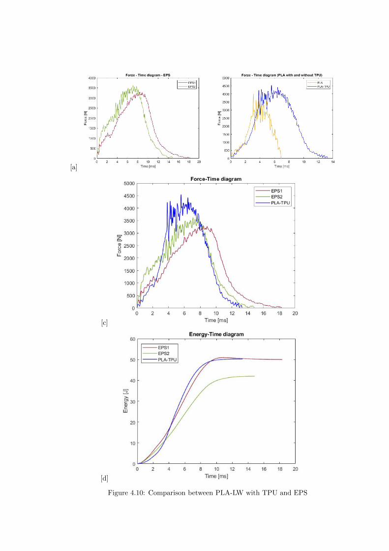
[a]
[c]
[d]
Figure 410 Comparison between PLA-LW with TPU and EPS
Chapter 5
FEM Validation
51 Impactor - Anvils definition
Before to start to work in Abaqus it was necessary to search in the literature the materialwith which the anvil was been realized Milne et al [23] established the densityrsquos valuethe Youngrsquos Module and Poissonrsquos ratio for the Flat and Kerbstone Anvil
- Density ρ = 7800 kgm3
- Youngrsquos Module E = 200000 MPa
- Poissonrsquos ratio ν = 03
Inserting the data in the CES EduPack program specifying the mechanical andphysical properties the material corresponding to these characteristics is Stainless steelaustenitic (ASTM F1586) medium-hard
Initially the proposal was to create a conservative system to evaluate the absorptionenergies values and apply this value to a vibration system but the helmet needs dampingto be realized it was impossible to use a system without losses in this modality Thisis why a numerical calculation was carried out by performing two types of simulationsexplicit dynamic step and static step
The idea to realize the theoretical impact is to regard the movement of the anviland not the helmetrsquos movement which is fixed The velocity is the same cited in thenormative EN 1078 542 ms for the Flat anvil and 457 ms for the Kerbstone anvil
In performing the simulations It was given more relevance and perform tests withthe Kerbstone Anvil This choice was done because the geometry with which it is beenrealized (following as defined in the legislation) allows the helmet to be more subjectedto stress this involves the definition of higher stress limits compared to the Flat Anvil
The mesh size that has been used is the same in the case of the simulation of thehelmet optimized in PLA-LW and the full helmet in EPS of 7 mm The impactor isconsidered as a Discrete rigid body with its specific Reference Point (RP) like shownin Figure 51 for this reason it is not a solid but it is composted only by shells Inthe same image [b] there is the FEM representation of the model and in Table 51 thecharacteristic of FEM with quadrilateral (R3D4) and triangular elements (R3D3)
48
FEM Validation
Object Elementnumber
Elements Shape Geometricorder
Global size[mm]
Kerbstone 230 Quadrilateral - R3D4 Linear 7
Kerbstone 8 Triangular - R3D3 Linear 7
Table 51 Mesh element - Kerbstone Anvil
[a] [b]
Figure 51 Kerbstone anvil in the simulation like discrete rigid body [a] and FEMelements [b]
511 PLA LW - Plastic characteristics
The PLA-LW as explained in the Chapter 2 is new material on the market and producedby the only Colorfabb company for this reason few tests have been carried out to defineits technical characteristics and through tensile tests of the 3D printed specimens it waspossible to define an elastic limit as reported in the Table 210
In the context of simulations to reproduce the impact and deformation of the helmetis also necessary to consider the plastic characteristics of the material Not possessingany reference value in this regard tests were performed through a Static Step initiallyand then an Explicit Dynamic Step in Abaqus
The structure chosen to consider as a reference it is one of the structures previouslysubjected to the compression test having the side L=14 mm As for the reproduction ofthe compression disks initially they were reproduced according to the geometry of theHoytom HM-D Testing Machine considering the bodies mentioned above as discrete 3Drigid discrete The measure was the diameter of 200 mm and the height of 20 mm
After an initial analysis it was observed that the computational time of the simulationprogram was very high so it was decided to change the geometry to have a rsquodisk-surfacesrsquo(equally 3D rigid-discrete) which allowed me to have a smaller number of nodes for themesh and consequently a better computational time The representation of the opti-mized structure in PLA-LW and the disks used for simulated compression is in Figure 52
49
FEM Validation
[a] [b]
Figure 52 Representation of the samples used for the simulation of the compressiontest In Figure [a] the disks of the Hoytom HM-D Testing Machine in figure [b] the
representation of the same as simple surfaces
As shown in Figure 52 the disks are considered 3D discrete hard bodies so it waschosen for both a point the reference point RP where to apply the characteristics relatedto the two bodies As for the compression test it was established
bull the movement of a disk and fixed the second through a boundary condition impos-ing an Encastre therefore unable to move and rotate in xyz directions
bull for the opposite disk the boundary condition relative to the 15 mm displacementwas applied which is the parameter that it was observed to determine the end ofthe compression with the machine This shift is shown by the orange arrow in figure[b]
bull between the upper surface and the disk e the disk with the lower surface it wasinitialized a general contact with normal behaviour through rsquohardrsquo contact andtangential behaviour with a coefficient of friction of 02 with directionality imposedon rsquoisotropicrsquo
The next step was to define the mesh of the components whose parameters are shown inTable 52 while the representation of the FEM is in Figure 53 with the representationof the simulation and real compression test
Object Elementsnumber
Typology Geometricorder
Globalsize [mm]
Disk (14mm) 80910 hexaedral - C3D8R Linear 07
Impact disks 206 quadrilateral - R3D4 Linear 20
Impact disks 6 triangular - R3D3 Linear 20
Table 52 Mesh element - Compression test simulation
As previously announced a static simulation was initially performed with a StaticStep with Step Time equal to 900 (obtained going to consider the speed of 1 mmmin of
50
FEM Validation
[a]
[b] [c]
Figure 53 FEM representation [a] and compression test simulation [b] and realcompression [c]
the compression test and the displacement of 15 mm) However the complex geometryof the structure and the high time set by Step Time did not allow a correct definitionof the parameters of the plastic characteristics of the material the simulation was notable to continue once reached a Step Time of approximately 220 That is why it waschanged by choosing an Explicit Dynamic step
Leaving all the parameters of the boundary conditions unchanged the Step Time wasmodified imposing it to 001 The ability of the explicit dynamic to work with non-linearand contacting structures allowed me to achieve results The results obtained are shownin Figure 54 with the blue curve and were obtained through the iteration of differentPlastic Strain and Yield Stress values in Abaqus while the red line is the result of thereal compression test a similar curve trend was obtained but it is not possible to obtainthe same curve taking into account problems of printing inaccuracy
512 First test - helmet
The initial idea was to perform a simulation imposing the speed of 457 ms to theimpactor tie the helmet in EPS and PLA and compare the absorbed energies Theproblem it was encountered is related to the mesh of the helmet optimized in PLA andwith minimum dimensions of the elements and distinct elements it was not able to solveit
51
FEM Validation
[a]
YieldStress
PlasticStrain
1 47 0
2 7 001
3 75 005
4 10 01
5 108 1
6 115 15
7 12 2
[b]
Figure 54 Representation of the two curves related to the simulation in Abaqus of thecompression test and the data obtained from the real test to obtain the plastic
characteristics of the material
513 Second test - plane
The first solution is the one shown in Figure 55 To realize the simulation it was realizeda section of the helmet to involve a smaller number of elements and nodes Again thesimulation for the EPS helmet was successful while the simulation with the bio-inspiredstructure was interrupted by excessive distortion of elements
The previous images show the impact is very localized in the impacted area and theidea to achieve a complete simulation is not to consider a curved portion of the helmetbut a plane In this way it was possible to solve the problem and obtain a completesimulation for the bio-inspired structure
FEM element
Below in Table 53 there is the definition of the elements used for the PLA-LW and EPSplane in the simulation to simulate the impact and to control the energy-absorbing whilethe anvil characteristics are described in Table 51
514 EPS impact simulations
In order to proceed with the simulation it was imposed some boundary conditions thatregard ties and forces
bull the movement of the plane is fixed through an Encastre therefore unable to moveand rotate in xyz directions
52
FEM Validation
[a]
[b]
Figure 55 Impact simulation parts of EPS and PLA helmet
Object Elementnumber
Elements Shape Geometricorder
Plane (PLA) 38896 Tetrahedral -C3D10M
Quadratic
Plane (EPS) 2100 Hexahedral - C3D8R Linear
Table 53 Mesh element - plane impact
bull to create the impact it was set a speed of 457 ms at the reference point RP of therigid body which is the impactor Kerbstone Anvil shown in Figure 56
bull between the upper surface of the plane and the impactor it was initialized a Sur-face to Surface contact with normal behaviour through rsquohardrsquo contact and tangen-tial behaviour with a coefficient of friction of 02 with directionality imposed onrsquoisotropicrsquo
bull the rotation in x y z relative to the RP of the rigid discrete impactor body is locked
53
FEM Validation
In addition it was characterized the plane in the part of the materials with the char-acteristic values of the EPS mentioned in Chapter 221 The Von Mises Stress valueapparently low is relative to the Yield Stress of the EPS material equal to 09 MPa
Figure 56 EPS Boundary conditions and Load
515 PLA LW impact simulations
As also required in the case of the EPS plane in order to proceed with the simulationsome boundary conditions were imposed that regard ties and forces
bull the movement of the plane is fixed through an Encastre therefore unable to moveand rotate in xyz directions
bull to create the impact a speed of 457 ms was set at the reference point RP of therigid body which is the impactor Kerbstone Anvil shown in Figure 58
bull between the upper surface of the plane and the impactor it was initialized a Sur-face to Surface contact with normal behaviour through rsquohardrsquo contact and tangen-tial behaviour with a coefficient of friction of 02 with directionality imposed onrsquoisotropicrsquo
bull the rotation in x y z relative to the RP of the rigid discrete impactor body is locked
In addition the plane was characterized in the part of the materials with the characteristicvalues of the PLA mentioned in the Chapter 223 and 511
Figure 58 Boundary conditions and Load
54
FEM Validation
[a]
[b]
Figure 57 EPS impact simulation
52 Results
In Figures 59 and 57 it is shown how the structure in PLA LW has a more concentratedstress distribution of the structure unlike EPS The maximum value for the Von Misesstress is 09 MPa in EPS structure and 3634 MPa in PLA LW structure Once thesimulations were obtained the next step was to go and compare the energies absorbed bythe two structures The energy calculated by Abaqus that has been taken into account isPlastic Dissipation To make a comparison the data of the two energies were representedin a single graph
What emerges from the graph is that about the impact made with the KerbstoneAnvil the energy absorption is more excellent although only slightly for the PLA LWthan for the EPS From the graph in Figure 510 a value of 41 J is shown for the EPSand 51 J for the PLA LW
55
[a]
[b]
Figure 59 PLA impact simulation
[a]
Figure 510 EPS and PLA LW energy comparison - Abaqus simulation
Chapter 6
Head Injury Data
For the statistical analysis the injuries related to the accident data were categorised intothe following types and levels based on the details of the medical report [11] about theEN 1078
bull Head Injury Criterion (HIC)
bull Peak Linear Acceleration (PLAc)
bull Gadd Severity Injury (GSI)
bull Diffuse axonal injuries (DAI)
61 Abaqus simulation
Until now the purpose of the simulations has been to determine which between the twomaterials and the two structures of EPS and PLA LW could absorb more energy duringthe impact but no simulations have been carried out in compliance with BS EN 1078on the helmet impact tests To calculate the injuries listed in the previous paragraphhowever we need the acceleration values in the three directions related to the subjectrsquoshead
To realize it the scan of my head already rsquocleanrsquo was considered of which it has beencalculated the inertia thanks to the automatic SolidWorks calculation and evaluated theweight with the Table 24 the structure of the helmet was placed for the EPS and thePLA LW over the head as shown in Figure 61 Also this time being able to mesh theentire helmet in PLA LW was impossible due to the excessive distortion of some elementsduring the simulation so it has been tried to make a section of the structures of thehelmet and results were obtained
57
Head Injury Data
[a] [b]
Figure 61 My scan head - CAD [a] head imported in Abaqus[b]
Initially the simulation had these characteristics as shown in the following Figure62 considering the helmet was not sectioned As explained earlier it was not possibleto get to simulation in the case of the optimized structure in PLA LW for this reasononly a part of the helmet was considered in both cases shown in Figure 63
[a]
Figure 62 Simulation based on BS EN 1078
58
Head Injury Data
[a] [b]
Figure 63 Simulation based on BS EN 1078 with head
In order to proceed with the simulation some boundary conditions that regard tiesand forces have have imposed
bull two reference points RP were created the first in the inertia centre of the headthe second relating to the Kerbstone Anvil which is a discrete rigid body
bull in the reference point RP of the head in the definition of the engineering features5 kg was inserted for the weight and an inertia I11 = 564464E+07 gmm2 I22 =460654E+07gmm2 I33 = 187302E+07gmm2
bull to simulate the impact it was set a speed of 457 ms at the reference point RP ofthe head in z-axis direction
bull a general contact with normal behaviour through rsquohardrsquo contact and tangentialbehaviour with a coefficient of friction of 02
bull between the upper surface of the helmet and the impactor it has been initializeda Surface to Surface contact with normal behaviour through rsquohardrsquo contact andtangential behaviour with a coefficient of friction of 02 with directionality imposedon rsquoisotropicrsquo
bull the movement between the Kerbstone anvil and the helmet is fixed through anEncastre therefore unable to move and rotate in xyz directions
bull the rotation in x y z relative to the RP of the rigid discrete impactor body is locked
FEM element
As reported in Table 53 the portion of the helmet in EPS has used a mesh with hexahe-dral elements of linear order For the structure (beetle) of PLA LW given the geometry
59
Head Injury Data
complexity it was necessary to use a quadratic order of tetrahedra For the mesh of thehead instead in both simulations have been used quadrilateral elements of linear orderas reported in the Tables 61 and 62
Object Elementnumber
Elements Shape Geometricorder
Head 3755 Quadrilateral - R3D4 Linear
Head 34542 Quadrilateral - R3D3 Linear
Helmet (PLA) 272302 Tetrahedral -C3D10M
Quadratic
Table 61 Mesh element - Head simulation with PLA LW (beetle) helmet
Object Elementnumber
Elements Shape Geometricorder
Head 3755 Quadrilateral - R3D4 Linear
Head 34542 Quadrilateral - R3D3 Linear
Helmet (EPS) 72280 Hexahedral - C3D8R Linear
Table 62 Mesh element - Head simulation with EPS helmet
62 Results
Figure 64 represents the simulation in line with BS EN 1078 concerning the helmet inEPS [a] and the helmet with bio-inspired structure in PLA LW For both simulationsVan Misesrsquo stress has Yield Stress values in the case of EPS which is 09 MPa and theplastic behaviour combination of PLA LW [b]
In the case of head and Kerbstone Anvil stress was not assessed as they were previ-ously defined as discrete rigid bodies
63 Head Injury Criterion
The HIC quantifies head impact severity by incorporating time of acceleration exposureand acceleration magnitude it is calculated in post-processing phase with the followingEquation 61
HIC15 =
[1
(t1 minus t2)
int t2
t1
a(t)dt
]25(t2 minus t1) (61)
60
Head Injury Data
[a]
[b]
Figure 64 Results simulation based on BS EN 1078 with sectioned head
For this analysis a(t) is the acceleration calculated in the centre of mass of the head(corresponding to the reference point RP) expressed in g and the time interval (t2 minus t1)was chosen to maximize HIC over a maximum duration of 15 ms
Matlab and the trapz function were used to calculate the HIC to integrate accelerationover time t2 and t1 were considered initial and final times of the simulation t1 = 0 sand t2 = 10 s time less than 15 s
HIC value of 198 was obtained for EPS and 87 for PLA LW Considering the Hayeset al [16] document about the HIC values and the graph in Figure 65 developed bythe author it is possible to find the percentages related to the different injury AIS1 -AIS6 which correspond respectively to lower and higher severity while in Figure 66 therelative fatality to every value of AIS is shown The values obtained for the HIC andother criteria are shown in Table 63 The HIC value for EPS is 198 for PLA LW it is
61
Head Injury Data
Figure 65 Head injury risk curves based on HIC values [16]
Figure 66 The abbreviated injury score versus fatality rate [16]
87 Analyzing the data and comparing them with the curves of the Figure 65 I obtain
bull a percentage between 20 - 30 of AIS 1 for EPS 10 - 20 for PLA LW
bull a percentage between 10 - 20 of AIS 2 for EPS and 0 - 10 for PLA LW
bull for AIS 3 AIS 4 AIS 5 AIS 6 the percentages for both structures is between 0 -10
Comparing these percentages with the fatality rate of Figure 66 it is clear there is a riskof Moderate and Minor fatality in the case of EPS and PLA LW as all values are between0 and 30
62
Head Injury Data
HIC PLA [g] GSI E [J]
EPS 198 97 361 37723
PLA LW 87 75 169 44102
Table 63 Head Injury Data - values
64 Peak Linear Acceleration
The resultant linear acceleration versus time curve was calculated according to Equation62
γ(t) =radicγ2x(t) + γ2y(t) + γ2z (t) (62)
where
bull γ(t) is the resultant linear acceleration (g)
bull γx(t) is the linear acceleration in x axes (g)
bull γy(t) is the linear acceleration in y axes (g)
bull γz(t)is the linear acceleration in z axes (g)
The value of the impact should never exceed 250g [9] Cripton at all [9] in their studyexamined a helmet with expanded polystyrene (EPS) Figure 68 shows maximum HIC forhelmeted and unhelmeted drops from all heights For each drop height helmets reducedHIC relative to unhelmeted drops IARV value is 180g The acceleration in the two casesis shown in Figure 67 and the maximum values are 97g for EPS and 75g for PLA LWas reported in Table 63 The two values considering a maximum value calculated byCripton [9] of 180g are amply optimal and comply with the standard of 250g
65 Gadd Severity Index
Gadd proposed the Severity Index Criteria shown in Equation 63 Following this crite-rion the GSI values that are over 1000 produce serious internal head injury [33]
GSI =
int t1
0a(t)25dt (63)
Where
bull a is the linear acceleration (g)
bull t is the duration of the impact (s)
I calculated the GSI with the function trapz between 0 and t and the resulting valuesare 361 for the EPS and 169 for the PLA LW which comply with the limit
63
Head Injury Data
Figure 67 Peak accelerations for both helmets
Figure 68 Peak accelerations for both helmeted and unhelmeted drops Numbers overbars indicate peak acceleration For 2 m drop height results stated are the mean value
calculated from three drops [9]
64
Head Injury Data
66 Diffuse Axonal Injury
DAI cases covered all incidences in which neurological injuries occurred as well as con-cussion unconsciousness and coma
In order to assess the risk of head trauma in terms of diffuse axonal injury (DAI)Milne et al [23] defined a model based head injury criteria as follows obtaining theresults in Figure 69
bull 50 risk of moderate neurological injury (DAI1+) Brain Von Mises shearing stressof 28 kPa
bull 50 risk of severe neurological injury (DAI2+) Brain Von Mises shearing stressof 53 kPa
[a]
[b]
Figure 69 Peak intra-cerebral shearing stress computed with the helmet model coupledto the human head model for all impact points (a) Flat anvil (b) Kerbstone anvil [23]
65
Head Injury Data
67 Energy absorbed
In Figure 52 during the impact test between the kerbstone Anvil and the plan with thebio-inspired structure in PLA LW and EPS it was found that the PLA LW althoughwith a small difference of 10 J absorbed more energy in comparison with the EPS Whenthe test is carried out in compliance with BS EN 1078 and the head with a speed of 457ms (corresponding to the kerbstone Anvil) as shown in Figure 610 also in this casethe PLA LW with the optimized helmet structure manages to absorb more energy (evenif the difference is very low) compared to the EPS The maximum energy value in PLALW is 44102 J of EPS is 37723 J
Figure 610 Energy absorption - BS EN 1078
66
Chapter 7
Conclusion
71 Conclusion
In this thesis work a bicycle helmet with a bio-inspired structure in PLA LW and 3Dprinted was created The initial approach was to introduce an innovative aspect tostandard EPS helmets not using foam but a polymer with new geometries able toabsorb much energy during the impact For this reason the beetle structure has beenpreferred relying solely on the hypothesis encountered in the literature of its quality inabsorbing energy
Combining the new material of the PLA LW and beetle structure has made possiblethe development of new material satisfactory characteristics have been obtained sincethe first tests The two materials were first subjected to tensile tests to determine theirspecific stress in these the PLA LW had positive results
Subsequent dynamic physical tests were carried out on 3D printed helmet models andon reference helmets in EPS to calculate the absorption energy in both cases at the timeof impact These resulted in energy absorption of the beetle structure in PLA LW withthe application of a TPU cover almost equal to that of EPS about 50J To validate withfinite element analysis the two models an explicit dynamic step was used in AbaqusSimulations showed that the PLA LW structure absorbs a higher amount of energy thanthe EPS the higher is 50 J and the EPS 40J
Finally positive results have also been obtained in calculating the head injury datasimulating according to BS EN 1078 with the use of impactor helmet and head Theacceleration values for both the structures were inferior to 220g precisely for the PLALW was 75g and for the EPS 97g The same applies to the calculation of HIC and GSI(maximum acceptable value of 1000) where the values are 87 and 169 in the case of PLALW and 361 and 198 in EPS For all tests therefore greater efficiency of the structure inPLA LW has been obtained Positive results also in the simulation of the energy absorbedduring the impact as the value referring to the EPS was 35J and that of the PLA LWwas 45J
67
Conclusion
72 Future work lines
The positive results obtained can be considered as a starting point for further tests andsimulations to ensure the safety of the helmet and compliance with the regulations butbefore getting improvements and continue testing changes are required
bull the beetle structure of the helmet made with GH adapts to the SubD withoutallowing to have a homogeneous distribution it would be appropriate to have moreregular hexagonal geometries
bull the mesh of the helmet is too complex and does not allow to perform the simulationprobably to use a more regular structure would have a mesh accordingly moreregular and the simulation would be successful
bull the uneven helmet structure has so many defects that the print is imperfect andthis can change the results of the impact tests the structure should be improved
bull the printing time varies from 4 to 5 days it should be improved
bull the TPU helmet cover is too big for the RAISE printing plan it is necessary togenerate a new geometry
bull the TPU cover it must be fixed on the helmet
bull in the calculation of the DAI it is necessary to have the definition of the brain andthe head should not be considered as a rigid body
bull in the injury calculation the helmet without protection was considered with theTPU cover the result will be better
bull air flow analysis
The comments mentioned are only considerations and problems that I gained duringmy thesis and which should be improved but I am sure that these changes and improve-ments from design to printing and simulations can make the helmet a good product
68
Bibliography
[1] K Adanty J M Clark A Post Thomas Blaine H and M D Gilchrist Comparingtwo proposed protocols to test the oblique response of cycling helmets to fall impactsInternational Journal of Crashworthiness 6648 ndash 663 2020
[2] MF Ashby YJM Brechetb D Cebona and L Salvoc Selection strategies formaterials and processes Materials and Design 2004
[3] M Aysha El casco de bicicleta voronoi impreso en 3d mas seguro y ligero https
www3dnativescomen3d-printed-bicycle-helmet-voronoi-190820204
[4] H Bikas P Stavropoulos and G Chryssolouris Additive manufacturing methodsand modelling approaches a critical review The International Journal of AdvancedManufacturing Technology 83389ndash405 2016
[5] British Standards BSI Helmets for pedal cyclists and for users of skateboards androller skates - BS EN 1078 2012
[6] British Standards BSI Headforms for use in the testing of protective helmets BSEN 960 2020
[7] ColorFabb Colorfabb lw-pla 2019 httpscolorfabbcommedia
datasheetstdscolorfabbTDS_E_ColorFabb_LW-PLApdf
[8] V G Coronado T Haileyesus J M Bell T A Cheng JHaarbauer-Krupa M RLionbarger J Flores-Herrera L C McGuire and J Gilchrist Trends in sports andrecreation-related traumatic brain injuries treated in us emergency departments thenational electronic injury surveillance system-all injury program (neiss-aip) 2001-2012 J Head Trauma Rehabil 30185ndash197 2015
[9] P A Cripton D M Dressler D Stuart Cameron A Christopher R and D RichardsBicycle helmets are highly effective at preventing head injury during head impactHead-form accelerations and injury criteria for helmeted and unhelmeted impactsAccident Analysis and Prevention 701ndash7 2014
[10] L Cui M A Forero R and M D Gilchrist Optimisation of energy absorbingliner for equestrian helmets UCD School of Electrical Electronic and MechanicalEngineering University College Dublin Belfield Dublin4 Ireland 2020
[11] C Deck N Bourdet F Meyer and R Willinger Protection performance of bicyclehelmets Journal of safety research pages 67ndash77 2019
[12] Committee F08 Specification for headforms F2220 ASTM International 2015
[13] Committee F08 Specification for helmets used in recreational bicycling or rollerskating F1447 ASTM International 2018
[14] Committee F08 Test methods for equipment and procedures used in evaluating theperformance F1446 ASTM International 2020
69
Bibliography
[15] P Halldin Shock absorption including measuring CENTC 158 Working Group11 2018
[16] W C Hayes M S Erickson and E D Power Forensic injury biomechanics Annualreview of biomedical engineering pages 55ndash86 2007
[17] HEXR httpshexrcom
[18] C Jinxiang Z Xiaoming O Yoji S Kazuya G Zhensheng and P LongchengThe deformation mode and strengthening mechanism of compression in the beetleelytron plate Materials and Design 131481ndash186 2017
[19] S Kroeker M Ozkul A De Marco S Bonin and GP Siegmund Density variationin the expanded polystyrene eps foam of bicycle helmets and its influence on impactperformance Journal of biomechanical engineering 2019
[20] S G Kroeker SJ Bonin A L DeMarco C A Good and G P Siegmund Agedoes not affect the material properties of expanded polystyrene liners in field-usedbicycle helmets Journal of biomechanical engineering 2016
[21] M Meier K H Tan M K Lim and L Chung Unlocking innovation in the sportindustry through additive manufacturing Business Process Management Journa2018
[22] N J Mills and A Gilchrist The effectiveness of foams in bicycle and motorcyclehelmets Accident Analysis Prevention 23153 ndash 163 1991
[23] G Milne C Deck R P Carreira Q Allinne and R Willinger Development andvalidation of a bicycle helmet assessment of head injury risk under standard impactconditions Computer methods in biomechanics and biomedical engineering 15 Suppl1309 ndash 310 2012
[24] Y Mosleh S J Vander B Depreitere and J Ivens Novel composite foam conceptfor head protection in oblique impacts Adv Eng Mater (Advanced EngineeringMaterials) 10 2017
[25] H Mustafa T Y Pang T Ellena and S H Nasir Impact attenuation of user-centred bicycle helmet design with different foam densities J Phys Conf Ser(Journal of Physics Conference Series) 1150 2019
[26] S H Ngoc and L Guoxing A review of recent research on bio-inspired structuresand materials for energy absorption applications Composites Part 181 2020
[27] J I Novak and A R Novak Is additive manufacturing improving performance insports a systematic review Sport engineering and technology 13 2020
[28] European Road Safety Observatory European road safety observatory facts and fig-ures - cyclists - 2020 December 2020 httpseceuropaeutransportroad_
safetysitesdefaultfilesfacts_figures_cyclists_final_20210323pdf
[29] New York City Departments of Health Parks Mental Hygiene Transportation Recre-ation and the New York City Police Department Bicyclist fatalities and seriousinjuries in new york city 2005
[30] W Pengwen Y Jing H Yanan H Jiaofei and F Xiaoyang Innovative designof a helmet based on reverse engineering and 3d printing Alexandria EngineeringJournal 603445ndash3453 2021
[31] S G Piland T E Gould M Jesunathadas J S Wiggins O McNair and V CShane Protective helmets in sports Materials in Sports Equipment 3 2019
70
Bibliography
[32] K Schmitt P F Niederer M H Muser and F Walz Trauma biomechanicsSpringer Berlin Heidelberg 2010
[33] David Sepelveda Lopez A Biomechanical Analysis of Bicycle Helmets using FEMPhD thesis 2019 Bachelor thesis
[34] H Stigson Bicycle Helmets 2020 Tested by Folksam PhD thesis 2020 PhDAssociate Professor Traffic Safety Research
[35] H Tao K Sudip N Anindya and X Yongzhao 3d printed sensors for biomedicalapplications A review sensor 2019
[36] M Trzaskalska and R Chwastek Damping properties and density of helmet linersmade of expanded polystyrene (eps) Archives of Metallurgy and Materials 66 2020
[37] Crupi V Epasto G and Guglielmino E Impact response of aluminum foam sand-wiches for light-weight ship structures Metals 198ndash112 2020
[38] W Wei-cai F Dong-ming and L Yuan-xin Study on impact energy absorbing per-formance of eps buffer layer of motorcycle helmet Proceedings - 2013 InternationalConference on Mechanical and Automation Engineering MAEE 2013
[39] Z Xiaoming C Jinxiang O Yoji Z Peiwei X Xiaobing and Y Xindi Influence ofhoneycomb dimensions and forming methods on the compressive properties of beetleelytron plates Journal of Sandwich Structures and Materials 2228ndash39 2020
[40] S Zhi L Dong Z Weisheng S Shanshan and G Xu Topological optimization ofbiomimetic sandwich structures with hybrid core and cfrp face sheets CompositesScience and Technology 14279ndash90 2017
[41] S Zhi S Shanshan G Xu H Xiaozhi and C Haoran On compressive propertiesof composite sandwich structures with grid reinforced honeycomb core CompositesPart B 94245ndash252 2016
71
- List of Tables
- List of Figures
- Introduction
-
- Helmet bike protection
-
- Helmet structure
-
- Additive Manufacturing
-
- AM process
- Materials and techniques - FDM
- AM in sport
-
- 3D printed helmets
-
- Phases
- HEXR
- VORONOI
-
- State of the art
-
- Standards
-
- Headform
- European Standard and American Standard
- Field of vision - BS EN 1078
- Test impact area
- Anvils and environmental conditions
-
- Materials
-
- EPS Foam
- CES Edu Pack - Material selection
- PLA with natural fiber and PLA LW
-
- Bio-inspired structures
-
- Beetle structure - Design of the model
- Specific stress - PLA LW and EPS foam
-
- Methodology
-
- 3D scan
-
- 3D Sense 2 scanner and Meshmixer - Reverse reconstruction
- 3D scan analysis and extraction of features
-
- Helmet design
-
- Rhinoceros - Helmet surface
- Grasshopper - Helmet structure
-
- 3D Print
-
- Printer and parameters
-
- Experimental evaluation
-
- Experimental tests
-
- Drop-weight impact test machine
-
- PLA LW helmet
- EPS helmet
- Results
-
- First results - PLA-LW and EPS helmet
- PLA-LW helmet with TPU cover
-
- FEM Validation
-
- Impactor - Anvils definition
-
- PLA LW - Plastic characteristics
- First test - helmet
- Second test - plane
- EPS impact simulations
- PLA LW impact simulations
-
- Results
-
- Head Injury Data
-
- Abaqus simulation
- Results
- Head Injury Criterion
- Peak Linear Acceleration
- Gadd Severity Index
- Diffuse Axonal Injury
- Energy absorbed
-
- Conclusion
-
- Conclusion
- Future work lines
-
- Bibliography
-
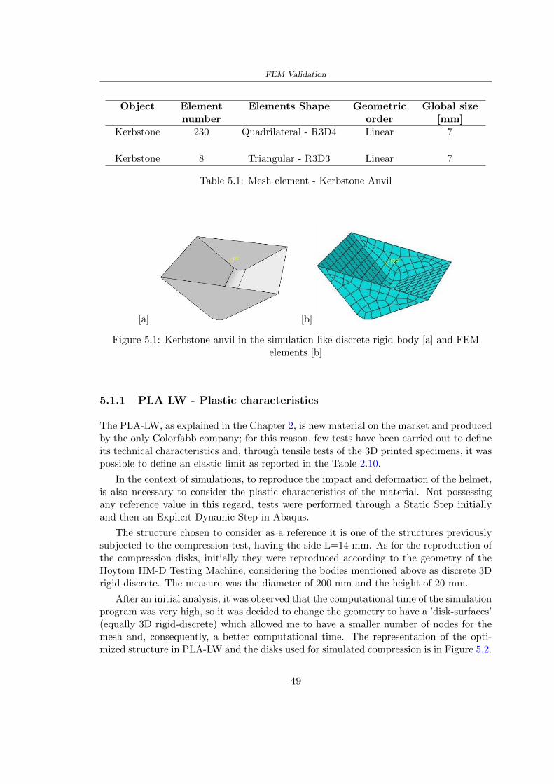
FEM Validation
Object Elementnumber
Elements Shape Geometricorder
Global size[mm]
Kerbstone 230 Quadrilateral - R3D4 Linear 7
Kerbstone 8 Triangular - R3D3 Linear 7
Table 51 Mesh element - Kerbstone Anvil
[a] [b]
Figure 51 Kerbstone anvil in the simulation like discrete rigid body [a] and FEMelements [b]
511 PLA LW - Plastic characteristics
The PLA-LW as explained in the Chapter 2 is new material on the market and producedby the only Colorfabb company for this reason few tests have been carried out to defineits technical characteristics and through tensile tests of the 3D printed specimens it waspossible to define an elastic limit as reported in the Table 210
In the context of simulations to reproduce the impact and deformation of the helmetis also necessary to consider the plastic characteristics of the material Not possessingany reference value in this regard tests were performed through a Static Step initiallyand then an Explicit Dynamic Step in Abaqus
The structure chosen to consider as a reference it is one of the structures previouslysubjected to the compression test having the side L=14 mm As for the reproduction ofthe compression disks initially they were reproduced according to the geometry of theHoytom HM-D Testing Machine considering the bodies mentioned above as discrete 3Drigid discrete The measure was the diameter of 200 mm and the height of 20 mm
After an initial analysis it was observed that the computational time of the simulationprogram was very high so it was decided to change the geometry to have a rsquodisk-surfacesrsquo(equally 3D rigid-discrete) which allowed me to have a smaller number of nodes for themesh and consequently a better computational time The representation of the opti-mized structure in PLA-LW and the disks used for simulated compression is in Figure 52
49
FEM Validation
[a] [b]
Figure 52 Representation of the samples used for the simulation of the compressiontest In Figure [a] the disks of the Hoytom HM-D Testing Machine in figure [b] the
representation of the same as simple surfaces
As shown in Figure 52 the disks are considered 3D discrete hard bodies so it waschosen for both a point the reference point RP where to apply the characteristics relatedto the two bodies As for the compression test it was established
bull the movement of a disk and fixed the second through a boundary condition impos-ing an Encastre therefore unable to move and rotate in xyz directions
bull for the opposite disk the boundary condition relative to the 15 mm displacementwas applied which is the parameter that it was observed to determine the end ofthe compression with the machine This shift is shown by the orange arrow in figure[b]
bull between the upper surface and the disk e the disk with the lower surface it wasinitialized a general contact with normal behaviour through rsquohardrsquo contact andtangential behaviour with a coefficient of friction of 02 with directionality imposedon rsquoisotropicrsquo
The next step was to define the mesh of the components whose parameters are shown inTable 52 while the representation of the FEM is in Figure 53 with the representationof the simulation and real compression test
Object Elementsnumber
Typology Geometricorder
Globalsize [mm]
Disk (14mm) 80910 hexaedral - C3D8R Linear 07
Impact disks 206 quadrilateral - R3D4 Linear 20
Impact disks 6 triangular - R3D3 Linear 20
Table 52 Mesh element - Compression test simulation
As previously announced a static simulation was initially performed with a StaticStep with Step Time equal to 900 (obtained going to consider the speed of 1 mmmin of
50
FEM Validation
[a]
[b] [c]
Figure 53 FEM representation [a] and compression test simulation [b] and realcompression [c]
the compression test and the displacement of 15 mm) However the complex geometryof the structure and the high time set by Step Time did not allow a correct definitionof the parameters of the plastic characteristics of the material the simulation was notable to continue once reached a Step Time of approximately 220 That is why it waschanged by choosing an Explicit Dynamic step
Leaving all the parameters of the boundary conditions unchanged the Step Time wasmodified imposing it to 001 The ability of the explicit dynamic to work with non-linearand contacting structures allowed me to achieve results The results obtained are shownin Figure 54 with the blue curve and were obtained through the iteration of differentPlastic Strain and Yield Stress values in Abaqus while the red line is the result of thereal compression test a similar curve trend was obtained but it is not possible to obtainthe same curve taking into account problems of printing inaccuracy
512 First test - helmet
The initial idea was to perform a simulation imposing the speed of 457 ms to theimpactor tie the helmet in EPS and PLA and compare the absorbed energies Theproblem it was encountered is related to the mesh of the helmet optimized in PLA andwith minimum dimensions of the elements and distinct elements it was not able to solveit
51
FEM Validation
[a]
YieldStress
PlasticStrain
1 47 0
2 7 001
3 75 005
4 10 01
5 108 1
6 115 15
7 12 2
[b]
Figure 54 Representation of the two curves related to the simulation in Abaqus of thecompression test and the data obtained from the real test to obtain the plastic
characteristics of the material
513 Second test - plane
The first solution is the one shown in Figure 55 To realize the simulation it was realizeda section of the helmet to involve a smaller number of elements and nodes Again thesimulation for the EPS helmet was successful while the simulation with the bio-inspiredstructure was interrupted by excessive distortion of elements
The previous images show the impact is very localized in the impacted area and theidea to achieve a complete simulation is not to consider a curved portion of the helmetbut a plane In this way it was possible to solve the problem and obtain a completesimulation for the bio-inspired structure
FEM element
Below in Table 53 there is the definition of the elements used for the PLA-LW and EPSplane in the simulation to simulate the impact and to control the energy-absorbing whilethe anvil characteristics are described in Table 51
514 EPS impact simulations
In order to proceed with the simulation it was imposed some boundary conditions thatregard ties and forces
bull the movement of the plane is fixed through an Encastre therefore unable to moveand rotate in xyz directions
52
FEM Validation
[a]
[b]
Figure 55 Impact simulation parts of EPS and PLA helmet
Object Elementnumber
Elements Shape Geometricorder
Plane (PLA) 38896 Tetrahedral -C3D10M
Quadratic
Plane (EPS) 2100 Hexahedral - C3D8R Linear
Table 53 Mesh element - plane impact
bull to create the impact it was set a speed of 457 ms at the reference point RP of therigid body which is the impactor Kerbstone Anvil shown in Figure 56
bull between the upper surface of the plane and the impactor it was initialized a Sur-face to Surface contact with normal behaviour through rsquohardrsquo contact and tangen-tial behaviour with a coefficient of friction of 02 with directionality imposed onrsquoisotropicrsquo
bull the rotation in x y z relative to the RP of the rigid discrete impactor body is locked
53
FEM Validation
In addition it was characterized the plane in the part of the materials with the char-acteristic values of the EPS mentioned in Chapter 221 The Von Mises Stress valueapparently low is relative to the Yield Stress of the EPS material equal to 09 MPa
Figure 56 EPS Boundary conditions and Load
515 PLA LW impact simulations
As also required in the case of the EPS plane in order to proceed with the simulationsome boundary conditions were imposed that regard ties and forces
bull the movement of the plane is fixed through an Encastre therefore unable to moveand rotate in xyz directions
bull to create the impact a speed of 457 ms was set at the reference point RP of therigid body which is the impactor Kerbstone Anvil shown in Figure 58
bull between the upper surface of the plane and the impactor it was initialized a Sur-face to Surface contact with normal behaviour through rsquohardrsquo contact and tangen-tial behaviour with a coefficient of friction of 02 with directionality imposed onrsquoisotropicrsquo
bull the rotation in x y z relative to the RP of the rigid discrete impactor body is locked
In addition the plane was characterized in the part of the materials with the characteristicvalues of the PLA mentioned in the Chapter 223 and 511
Figure 58 Boundary conditions and Load
54
FEM Validation
[a]
[b]
Figure 57 EPS impact simulation
52 Results
In Figures 59 and 57 it is shown how the structure in PLA LW has a more concentratedstress distribution of the structure unlike EPS The maximum value for the Von Misesstress is 09 MPa in EPS structure and 3634 MPa in PLA LW structure Once thesimulations were obtained the next step was to go and compare the energies absorbed bythe two structures The energy calculated by Abaqus that has been taken into account isPlastic Dissipation To make a comparison the data of the two energies were representedin a single graph
What emerges from the graph is that about the impact made with the KerbstoneAnvil the energy absorption is more excellent although only slightly for the PLA LWthan for the EPS From the graph in Figure 510 a value of 41 J is shown for the EPSand 51 J for the PLA LW
55
[a]
[b]
Figure 59 PLA impact simulation
[a]
Figure 510 EPS and PLA LW energy comparison - Abaqus simulation
Chapter 6
Head Injury Data
For the statistical analysis the injuries related to the accident data were categorised intothe following types and levels based on the details of the medical report [11] about theEN 1078
bull Head Injury Criterion (HIC)
bull Peak Linear Acceleration (PLAc)
bull Gadd Severity Injury (GSI)
bull Diffuse axonal injuries (DAI)
61 Abaqus simulation
Until now the purpose of the simulations has been to determine which between the twomaterials and the two structures of EPS and PLA LW could absorb more energy duringthe impact but no simulations have been carried out in compliance with BS EN 1078on the helmet impact tests To calculate the injuries listed in the previous paragraphhowever we need the acceleration values in the three directions related to the subjectrsquoshead
To realize it the scan of my head already rsquocleanrsquo was considered of which it has beencalculated the inertia thanks to the automatic SolidWorks calculation and evaluated theweight with the Table 24 the structure of the helmet was placed for the EPS and thePLA LW over the head as shown in Figure 61 Also this time being able to mesh theentire helmet in PLA LW was impossible due to the excessive distortion of some elementsduring the simulation so it has been tried to make a section of the structures of thehelmet and results were obtained
57
Head Injury Data
[a] [b]
Figure 61 My scan head - CAD [a] head imported in Abaqus[b]
Initially the simulation had these characteristics as shown in the following Figure62 considering the helmet was not sectioned As explained earlier it was not possibleto get to simulation in the case of the optimized structure in PLA LW for this reasononly a part of the helmet was considered in both cases shown in Figure 63
[a]
Figure 62 Simulation based on BS EN 1078
58
Head Injury Data
[a] [b]
Figure 63 Simulation based on BS EN 1078 with head
In order to proceed with the simulation some boundary conditions that regard tiesand forces have have imposed
bull two reference points RP were created the first in the inertia centre of the headthe second relating to the Kerbstone Anvil which is a discrete rigid body
bull in the reference point RP of the head in the definition of the engineering features5 kg was inserted for the weight and an inertia I11 = 564464E+07 gmm2 I22 =460654E+07gmm2 I33 = 187302E+07gmm2
bull to simulate the impact it was set a speed of 457 ms at the reference point RP ofthe head in z-axis direction
bull a general contact with normal behaviour through rsquohardrsquo contact and tangentialbehaviour with a coefficient of friction of 02
bull between the upper surface of the helmet and the impactor it has been initializeda Surface to Surface contact with normal behaviour through rsquohardrsquo contact andtangential behaviour with a coefficient of friction of 02 with directionality imposedon rsquoisotropicrsquo
bull the movement between the Kerbstone anvil and the helmet is fixed through anEncastre therefore unable to move and rotate in xyz directions
bull the rotation in x y z relative to the RP of the rigid discrete impactor body is locked
FEM element
As reported in Table 53 the portion of the helmet in EPS has used a mesh with hexahe-dral elements of linear order For the structure (beetle) of PLA LW given the geometry
59
Head Injury Data
complexity it was necessary to use a quadratic order of tetrahedra For the mesh of thehead instead in both simulations have been used quadrilateral elements of linear orderas reported in the Tables 61 and 62
Object Elementnumber
Elements Shape Geometricorder
Head 3755 Quadrilateral - R3D4 Linear
Head 34542 Quadrilateral - R3D3 Linear
Helmet (PLA) 272302 Tetrahedral -C3D10M
Quadratic
Table 61 Mesh element - Head simulation with PLA LW (beetle) helmet
Object Elementnumber
Elements Shape Geometricorder
Head 3755 Quadrilateral - R3D4 Linear
Head 34542 Quadrilateral - R3D3 Linear
Helmet (EPS) 72280 Hexahedral - C3D8R Linear
Table 62 Mesh element - Head simulation with EPS helmet
62 Results
Figure 64 represents the simulation in line with BS EN 1078 concerning the helmet inEPS [a] and the helmet with bio-inspired structure in PLA LW For both simulationsVan Misesrsquo stress has Yield Stress values in the case of EPS which is 09 MPa and theplastic behaviour combination of PLA LW [b]
In the case of head and Kerbstone Anvil stress was not assessed as they were previ-ously defined as discrete rigid bodies
63 Head Injury Criterion
The HIC quantifies head impact severity by incorporating time of acceleration exposureand acceleration magnitude it is calculated in post-processing phase with the followingEquation 61
HIC15 =
[1
(t1 minus t2)
int t2
t1
a(t)dt
]25(t2 minus t1) (61)
60
Head Injury Data
[a]
[b]
Figure 64 Results simulation based on BS EN 1078 with sectioned head
For this analysis a(t) is the acceleration calculated in the centre of mass of the head(corresponding to the reference point RP) expressed in g and the time interval (t2 minus t1)was chosen to maximize HIC over a maximum duration of 15 ms
Matlab and the trapz function were used to calculate the HIC to integrate accelerationover time t2 and t1 were considered initial and final times of the simulation t1 = 0 sand t2 = 10 s time less than 15 s
HIC value of 198 was obtained for EPS and 87 for PLA LW Considering the Hayeset al [16] document about the HIC values and the graph in Figure 65 developed bythe author it is possible to find the percentages related to the different injury AIS1 -AIS6 which correspond respectively to lower and higher severity while in Figure 66 therelative fatality to every value of AIS is shown The values obtained for the HIC andother criteria are shown in Table 63 The HIC value for EPS is 198 for PLA LW it is
61
Head Injury Data
Figure 65 Head injury risk curves based on HIC values [16]
Figure 66 The abbreviated injury score versus fatality rate [16]
87 Analyzing the data and comparing them with the curves of the Figure 65 I obtain
bull a percentage between 20 - 30 of AIS 1 for EPS 10 - 20 for PLA LW
bull a percentage between 10 - 20 of AIS 2 for EPS and 0 - 10 for PLA LW
bull for AIS 3 AIS 4 AIS 5 AIS 6 the percentages for both structures is between 0 -10
Comparing these percentages with the fatality rate of Figure 66 it is clear there is a riskof Moderate and Minor fatality in the case of EPS and PLA LW as all values are between0 and 30
62
Head Injury Data
HIC PLA [g] GSI E [J]
EPS 198 97 361 37723
PLA LW 87 75 169 44102
Table 63 Head Injury Data - values
64 Peak Linear Acceleration
The resultant linear acceleration versus time curve was calculated according to Equation62
γ(t) =radicγ2x(t) + γ2y(t) + γ2z (t) (62)
where
bull γ(t) is the resultant linear acceleration (g)
bull γx(t) is the linear acceleration in x axes (g)
bull γy(t) is the linear acceleration in y axes (g)
bull γz(t)is the linear acceleration in z axes (g)
The value of the impact should never exceed 250g [9] Cripton at all [9] in their studyexamined a helmet with expanded polystyrene (EPS) Figure 68 shows maximum HIC forhelmeted and unhelmeted drops from all heights For each drop height helmets reducedHIC relative to unhelmeted drops IARV value is 180g The acceleration in the two casesis shown in Figure 67 and the maximum values are 97g for EPS and 75g for PLA LWas reported in Table 63 The two values considering a maximum value calculated byCripton [9] of 180g are amply optimal and comply with the standard of 250g
65 Gadd Severity Index
Gadd proposed the Severity Index Criteria shown in Equation 63 Following this crite-rion the GSI values that are over 1000 produce serious internal head injury [33]
GSI =
int t1
0a(t)25dt (63)
Where
bull a is the linear acceleration (g)
bull t is the duration of the impact (s)
I calculated the GSI with the function trapz between 0 and t and the resulting valuesare 361 for the EPS and 169 for the PLA LW which comply with the limit
63
Head Injury Data
Figure 67 Peak accelerations for both helmets
Figure 68 Peak accelerations for both helmeted and unhelmeted drops Numbers overbars indicate peak acceleration For 2 m drop height results stated are the mean value
calculated from three drops [9]
64
Head Injury Data
66 Diffuse Axonal Injury
DAI cases covered all incidences in which neurological injuries occurred as well as con-cussion unconsciousness and coma
In order to assess the risk of head trauma in terms of diffuse axonal injury (DAI)Milne et al [23] defined a model based head injury criteria as follows obtaining theresults in Figure 69
bull 50 risk of moderate neurological injury (DAI1+) Brain Von Mises shearing stressof 28 kPa
bull 50 risk of severe neurological injury (DAI2+) Brain Von Mises shearing stressof 53 kPa
[a]
[b]
Figure 69 Peak intra-cerebral shearing stress computed with the helmet model coupledto the human head model for all impact points (a) Flat anvil (b) Kerbstone anvil [23]
65
Head Injury Data
67 Energy absorbed
In Figure 52 during the impact test between the kerbstone Anvil and the plan with thebio-inspired structure in PLA LW and EPS it was found that the PLA LW althoughwith a small difference of 10 J absorbed more energy in comparison with the EPS Whenthe test is carried out in compliance with BS EN 1078 and the head with a speed of 457ms (corresponding to the kerbstone Anvil) as shown in Figure 610 also in this casethe PLA LW with the optimized helmet structure manages to absorb more energy (evenif the difference is very low) compared to the EPS The maximum energy value in PLALW is 44102 J of EPS is 37723 J
Figure 610 Energy absorption - BS EN 1078
66
Chapter 7
Conclusion
71 Conclusion
In this thesis work a bicycle helmet with a bio-inspired structure in PLA LW and 3Dprinted was created The initial approach was to introduce an innovative aspect tostandard EPS helmets not using foam but a polymer with new geometries able toabsorb much energy during the impact For this reason the beetle structure has beenpreferred relying solely on the hypothesis encountered in the literature of its quality inabsorbing energy
Combining the new material of the PLA LW and beetle structure has made possiblethe development of new material satisfactory characteristics have been obtained sincethe first tests The two materials were first subjected to tensile tests to determine theirspecific stress in these the PLA LW had positive results
Subsequent dynamic physical tests were carried out on 3D printed helmet models andon reference helmets in EPS to calculate the absorption energy in both cases at the timeof impact These resulted in energy absorption of the beetle structure in PLA LW withthe application of a TPU cover almost equal to that of EPS about 50J To validate withfinite element analysis the two models an explicit dynamic step was used in AbaqusSimulations showed that the PLA LW structure absorbs a higher amount of energy thanthe EPS the higher is 50 J and the EPS 40J
Finally positive results have also been obtained in calculating the head injury datasimulating according to BS EN 1078 with the use of impactor helmet and head Theacceleration values for both the structures were inferior to 220g precisely for the PLALW was 75g and for the EPS 97g The same applies to the calculation of HIC and GSI(maximum acceptable value of 1000) where the values are 87 and 169 in the case of PLALW and 361 and 198 in EPS For all tests therefore greater efficiency of the structure inPLA LW has been obtained Positive results also in the simulation of the energy absorbedduring the impact as the value referring to the EPS was 35J and that of the PLA LWwas 45J
67
Conclusion
72 Future work lines
The positive results obtained can be considered as a starting point for further tests andsimulations to ensure the safety of the helmet and compliance with the regulations butbefore getting improvements and continue testing changes are required
bull the beetle structure of the helmet made with GH adapts to the SubD withoutallowing to have a homogeneous distribution it would be appropriate to have moreregular hexagonal geometries
bull the mesh of the helmet is too complex and does not allow to perform the simulationprobably to use a more regular structure would have a mesh accordingly moreregular and the simulation would be successful
bull the uneven helmet structure has so many defects that the print is imperfect andthis can change the results of the impact tests the structure should be improved
bull the printing time varies from 4 to 5 days it should be improved
bull the TPU helmet cover is too big for the RAISE printing plan it is necessary togenerate a new geometry
bull the TPU cover it must be fixed on the helmet
bull in the calculation of the DAI it is necessary to have the definition of the brain andthe head should not be considered as a rigid body
bull in the injury calculation the helmet without protection was considered with theTPU cover the result will be better
bull air flow analysis
The comments mentioned are only considerations and problems that I gained duringmy thesis and which should be improved but I am sure that these changes and improve-ments from design to printing and simulations can make the helmet a good product
68
Bibliography
[1] K Adanty J M Clark A Post Thomas Blaine H and M D Gilchrist Comparingtwo proposed protocols to test the oblique response of cycling helmets to fall impactsInternational Journal of Crashworthiness 6648 ndash 663 2020
[2] MF Ashby YJM Brechetb D Cebona and L Salvoc Selection strategies formaterials and processes Materials and Design 2004
[3] M Aysha El casco de bicicleta voronoi impreso en 3d mas seguro y ligero https
www3dnativescomen3d-printed-bicycle-helmet-voronoi-190820204
[4] H Bikas P Stavropoulos and G Chryssolouris Additive manufacturing methodsand modelling approaches a critical review The International Journal of AdvancedManufacturing Technology 83389ndash405 2016
[5] British Standards BSI Helmets for pedal cyclists and for users of skateboards androller skates - BS EN 1078 2012
[6] British Standards BSI Headforms for use in the testing of protective helmets BSEN 960 2020
[7] ColorFabb Colorfabb lw-pla 2019 httpscolorfabbcommedia
datasheetstdscolorfabbTDS_E_ColorFabb_LW-PLApdf
[8] V G Coronado T Haileyesus J M Bell T A Cheng JHaarbauer-Krupa M RLionbarger J Flores-Herrera L C McGuire and J Gilchrist Trends in sports andrecreation-related traumatic brain injuries treated in us emergency departments thenational electronic injury surveillance system-all injury program (neiss-aip) 2001-2012 J Head Trauma Rehabil 30185ndash197 2015
[9] P A Cripton D M Dressler D Stuart Cameron A Christopher R and D RichardsBicycle helmets are highly effective at preventing head injury during head impactHead-form accelerations and injury criteria for helmeted and unhelmeted impactsAccident Analysis and Prevention 701ndash7 2014
[10] L Cui M A Forero R and M D Gilchrist Optimisation of energy absorbingliner for equestrian helmets UCD School of Electrical Electronic and MechanicalEngineering University College Dublin Belfield Dublin4 Ireland 2020
[11] C Deck N Bourdet F Meyer and R Willinger Protection performance of bicyclehelmets Journal of safety research pages 67ndash77 2019
[12] Committee F08 Specification for headforms F2220 ASTM International 2015
[13] Committee F08 Specification for helmets used in recreational bicycling or rollerskating F1447 ASTM International 2018
[14] Committee F08 Test methods for equipment and procedures used in evaluating theperformance F1446 ASTM International 2020
69
Bibliography
[15] P Halldin Shock absorption including measuring CENTC 158 Working Group11 2018
[16] W C Hayes M S Erickson and E D Power Forensic injury biomechanics Annualreview of biomedical engineering pages 55ndash86 2007
[17] HEXR httpshexrcom
[18] C Jinxiang Z Xiaoming O Yoji S Kazuya G Zhensheng and P LongchengThe deformation mode and strengthening mechanism of compression in the beetleelytron plate Materials and Design 131481ndash186 2017
[19] S Kroeker M Ozkul A De Marco S Bonin and GP Siegmund Density variationin the expanded polystyrene eps foam of bicycle helmets and its influence on impactperformance Journal of biomechanical engineering 2019
[20] S G Kroeker SJ Bonin A L DeMarco C A Good and G P Siegmund Agedoes not affect the material properties of expanded polystyrene liners in field-usedbicycle helmets Journal of biomechanical engineering 2016
[21] M Meier K H Tan M K Lim and L Chung Unlocking innovation in the sportindustry through additive manufacturing Business Process Management Journa2018
[22] N J Mills and A Gilchrist The effectiveness of foams in bicycle and motorcyclehelmets Accident Analysis Prevention 23153 ndash 163 1991
[23] G Milne C Deck R P Carreira Q Allinne and R Willinger Development andvalidation of a bicycle helmet assessment of head injury risk under standard impactconditions Computer methods in biomechanics and biomedical engineering 15 Suppl1309 ndash 310 2012
[24] Y Mosleh S J Vander B Depreitere and J Ivens Novel composite foam conceptfor head protection in oblique impacts Adv Eng Mater (Advanced EngineeringMaterials) 10 2017
[25] H Mustafa T Y Pang T Ellena and S H Nasir Impact attenuation of user-centred bicycle helmet design with different foam densities J Phys Conf Ser(Journal of Physics Conference Series) 1150 2019
[26] S H Ngoc and L Guoxing A review of recent research on bio-inspired structuresand materials for energy absorption applications Composites Part 181 2020
[27] J I Novak and A R Novak Is additive manufacturing improving performance insports a systematic review Sport engineering and technology 13 2020
[28] European Road Safety Observatory European road safety observatory facts and fig-ures - cyclists - 2020 December 2020 httpseceuropaeutransportroad_
safetysitesdefaultfilesfacts_figures_cyclists_final_20210323pdf
[29] New York City Departments of Health Parks Mental Hygiene Transportation Recre-ation and the New York City Police Department Bicyclist fatalities and seriousinjuries in new york city 2005
[30] W Pengwen Y Jing H Yanan H Jiaofei and F Xiaoyang Innovative designof a helmet based on reverse engineering and 3d printing Alexandria EngineeringJournal 603445ndash3453 2021
[31] S G Piland T E Gould M Jesunathadas J S Wiggins O McNair and V CShane Protective helmets in sports Materials in Sports Equipment 3 2019
70
Bibliography
[32] K Schmitt P F Niederer M H Muser and F Walz Trauma biomechanicsSpringer Berlin Heidelberg 2010
[33] David Sepelveda Lopez A Biomechanical Analysis of Bicycle Helmets using FEMPhD thesis 2019 Bachelor thesis
[34] H Stigson Bicycle Helmets 2020 Tested by Folksam PhD thesis 2020 PhDAssociate Professor Traffic Safety Research
[35] H Tao K Sudip N Anindya and X Yongzhao 3d printed sensors for biomedicalapplications A review sensor 2019
[36] M Trzaskalska and R Chwastek Damping properties and density of helmet linersmade of expanded polystyrene (eps) Archives of Metallurgy and Materials 66 2020
[37] Crupi V Epasto G and Guglielmino E Impact response of aluminum foam sand-wiches for light-weight ship structures Metals 198ndash112 2020
[38] W Wei-cai F Dong-ming and L Yuan-xin Study on impact energy absorbing per-formance of eps buffer layer of motorcycle helmet Proceedings - 2013 InternationalConference on Mechanical and Automation Engineering MAEE 2013
[39] Z Xiaoming C Jinxiang O Yoji Z Peiwei X Xiaobing and Y Xindi Influence ofhoneycomb dimensions and forming methods on the compressive properties of beetleelytron plates Journal of Sandwich Structures and Materials 2228ndash39 2020
[40] S Zhi L Dong Z Weisheng S Shanshan and G Xu Topological optimization ofbiomimetic sandwich structures with hybrid core and cfrp face sheets CompositesScience and Technology 14279ndash90 2017
[41] S Zhi S Shanshan G Xu H Xiaozhi and C Haoran On compressive propertiesof composite sandwich structures with grid reinforced honeycomb core CompositesPart B 94245ndash252 2016
71
- List of Tables
- List of Figures
- Introduction
-
- Helmet bike protection
-
- Helmet structure
-
- Additive Manufacturing
-
- AM process
- Materials and techniques - FDM
- AM in sport
-
- 3D printed helmets
-
- Phases
- HEXR
- VORONOI
-
- State of the art
-
- Standards
-
- Headform
- European Standard and American Standard
- Field of vision - BS EN 1078
- Test impact area
- Anvils and environmental conditions
-
- Materials
-
- EPS Foam
- CES Edu Pack - Material selection
- PLA with natural fiber and PLA LW
-
- Bio-inspired structures
-
- Beetle structure - Design of the model
- Specific stress - PLA LW and EPS foam
-
- Methodology
-
- 3D scan
-
- 3D Sense 2 scanner and Meshmixer - Reverse reconstruction
- 3D scan analysis and extraction of features
-
- Helmet design
-
- Rhinoceros - Helmet surface
- Grasshopper - Helmet structure
-
- 3D Print
-
- Printer and parameters
-
- Experimental evaluation
-
- Experimental tests
-
- Drop-weight impact test machine
-
- PLA LW helmet
- EPS helmet
- Results
-
- First results - PLA-LW and EPS helmet
- PLA-LW helmet with TPU cover
-
- FEM Validation
-
- Impactor - Anvils definition
-
- PLA LW - Plastic characteristics
- First test - helmet
- Second test - plane
- EPS impact simulations
- PLA LW impact simulations
-
- Results
-
- Head Injury Data
-
- Abaqus simulation
- Results
- Head Injury Criterion
- Peak Linear Acceleration
- Gadd Severity Index
- Diffuse Axonal Injury
- Energy absorbed
-
- Conclusion
-
- Conclusion
- Future work lines
-
- Bibliography
-
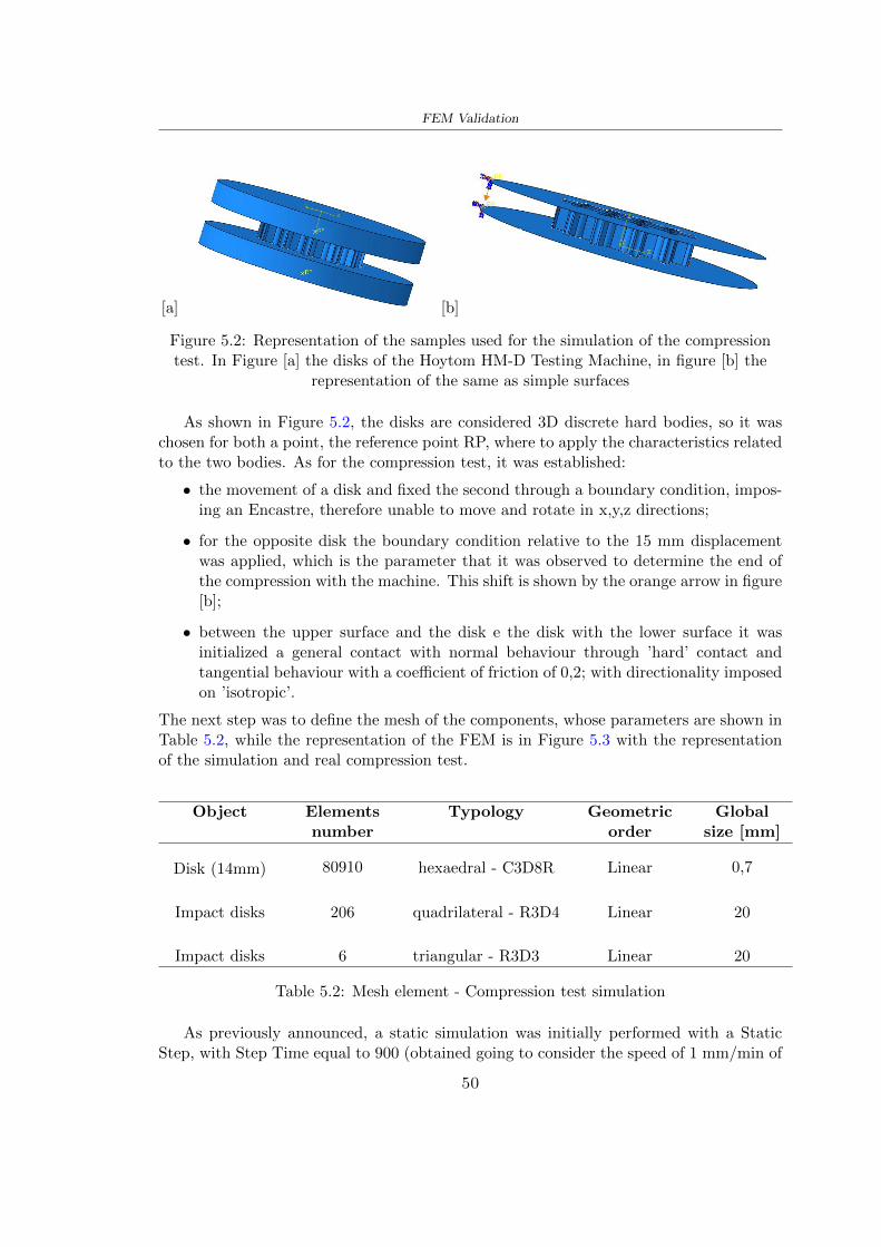
FEM Validation
[a] [b]
Figure 52 Representation of the samples used for the simulation of the compressiontest In Figure [a] the disks of the Hoytom HM-D Testing Machine in figure [b] the
representation of the same as simple surfaces
As shown in Figure 52 the disks are considered 3D discrete hard bodies so it waschosen for both a point the reference point RP where to apply the characteristics relatedto the two bodies As for the compression test it was established
bull the movement of a disk and fixed the second through a boundary condition impos-ing an Encastre therefore unable to move and rotate in xyz directions
bull for the opposite disk the boundary condition relative to the 15 mm displacementwas applied which is the parameter that it was observed to determine the end ofthe compression with the machine This shift is shown by the orange arrow in figure[b]
bull between the upper surface and the disk e the disk with the lower surface it wasinitialized a general contact with normal behaviour through rsquohardrsquo contact andtangential behaviour with a coefficient of friction of 02 with directionality imposedon rsquoisotropicrsquo
The next step was to define the mesh of the components whose parameters are shown inTable 52 while the representation of the FEM is in Figure 53 with the representationof the simulation and real compression test
Object Elementsnumber
Typology Geometricorder
Globalsize [mm]
Disk (14mm) 80910 hexaedral - C3D8R Linear 07
Impact disks 206 quadrilateral - R3D4 Linear 20
Impact disks 6 triangular - R3D3 Linear 20
Table 52 Mesh element - Compression test simulation
As previously announced a static simulation was initially performed with a StaticStep with Step Time equal to 900 (obtained going to consider the speed of 1 mmmin of
50
FEM Validation
[a]
[b] [c]
Figure 53 FEM representation [a] and compression test simulation [b] and realcompression [c]
the compression test and the displacement of 15 mm) However the complex geometryof the structure and the high time set by Step Time did not allow a correct definitionof the parameters of the plastic characteristics of the material the simulation was notable to continue once reached a Step Time of approximately 220 That is why it waschanged by choosing an Explicit Dynamic step
Leaving all the parameters of the boundary conditions unchanged the Step Time wasmodified imposing it to 001 The ability of the explicit dynamic to work with non-linearand contacting structures allowed me to achieve results The results obtained are shownin Figure 54 with the blue curve and were obtained through the iteration of differentPlastic Strain and Yield Stress values in Abaqus while the red line is the result of thereal compression test a similar curve trend was obtained but it is not possible to obtainthe same curve taking into account problems of printing inaccuracy
512 First test - helmet
The initial idea was to perform a simulation imposing the speed of 457 ms to theimpactor tie the helmet in EPS and PLA and compare the absorbed energies Theproblem it was encountered is related to the mesh of the helmet optimized in PLA andwith minimum dimensions of the elements and distinct elements it was not able to solveit
51
FEM Validation
[a]
YieldStress
PlasticStrain
1 47 0
2 7 001
3 75 005
4 10 01
5 108 1
6 115 15
7 12 2
[b]
Figure 54 Representation of the two curves related to the simulation in Abaqus of thecompression test and the data obtained from the real test to obtain the plastic
characteristics of the material
513 Second test - plane
The first solution is the one shown in Figure 55 To realize the simulation it was realizeda section of the helmet to involve a smaller number of elements and nodes Again thesimulation for the EPS helmet was successful while the simulation with the bio-inspiredstructure was interrupted by excessive distortion of elements
The previous images show the impact is very localized in the impacted area and theidea to achieve a complete simulation is not to consider a curved portion of the helmetbut a plane In this way it was possible to solve the problem and obtain a completesimulation for the bio-inspired structure
FEM element
Below in Table 53 there is the definition of the elements used for the PLA-LW and EPSplane in the simulation to simulate the impact and to control the energy-absorbing whilethe anvil characteristics are described in Table 51
514 EPS impact simulations
In order to proceed with the simulation it was imposed some boundary conditions thatregard ties and forces
bull the movement of the plane is fixed through an Encastre therefore unable to moveand rotate in xyz directions
52
FEM Validation
[a]
[b]
Figure 55 Impact simulation parts of EPS and PLA helmet
Object Elementnumber
Elements Shape Geometricorder
Plane (PLA) 38896 Tetrahedral -C3D10M
Quadratic
Plane (EPS) 2100 Hexahedral - C3D8R Linear
Table 53 Mesh element - plane impact
bull to create the impact it was set a speed of 457 ms at the reference point RP of therigid body which is the impactor Kerbstone Anvil shown in Figure 56
bull between the upper surface of the plane and the impactor it was initialized a Sur-face to Surface contact with normal behaviour through rsquohardrsquo contact and tangen-tial behaviour with a coefficient of friction of 02 with directionality imposed onrsquoisotropicrsquo
bull the rotation in x y z relative to the RP of the rigid discrete impactor body is locked
53
FEM Validation
In addition it was characterized the plane in the part of the materials with the char-acteristic values of the EPS mentioned in Chapter 221 The Von Mises Stress valueapparently low is relative to the Yield Stress of the EPS material equal to 09 MPa
Figure 56 EPS Boundary conditions and Load
515 PLA LW impact simulations
As also required in the case of the EPS plane in order to proceed with the simulationsome boundary conditions were imposed that regard ties and forces
bull the movement of the plane is fixed through an Encastre therefore unable to moveand rotate in xyz directions
bull to create the impact a speed of 457 ms was set at the reference point RP of therigid body which is the impactor Kerbstone Anvil shown in Figure 58
bull between the upper surface of the plane and the impactor it was initialized a Sur-face to Surface contact with normal behaviour through rsquohardrsquo contact and tangen-tial behaviour with a coefficient of friction of 02 with directionality imposed onrsquoisotropicrsquo
bull the rotation in x y z relative to the RP of the rigid discrete impactor body is locked
In addition the plane was characterized in the part of the materials with the characteristicvalues of the PLA mentioned in the Chapter 223 and 511
Figure 58 Boundary conditions and Load
54
FEM Validation
[a]
[b]
Figure 57 EPS impact simulation
52 Results
In Figures 59 and 57 it is shown how the structure in PLA LW has a more concentratedstress distribution of the structure unlike EPS The maximum value for the Von Misesstress is 09 MPa in EPS structure and 3634 MPa in PLA LW structure Once thesimulations were obtained the next step was to go and compare the energies absorbed bythe two structures The energy calculated by Abaqus that has been taken into account isPlastic Dissipation To make a comparison the data of the two energies were representedin a single graph
What emerges from the graph is that about the impact made with the KerbstoneAnvil the energy absorption is more excellent although only slightly for the PLA LWthan for the EPS From the graph in Figure 510 a value of 41 J is shown for the EPSand 51 J for the PLA LW
55
[a]
[b]
Figure 59 PLA impact simulation
[a]
Figure 510 EPS and PLA LW energy comparison - Abaqus simulation
Chapter 6
Head Injury Data
For the statistical analysis the injuries related to the accident data were categorised intothe following types and levels based on the details of the medical report [11] about theEN 1078
bull Head Injury Criterion (HIC)
bull Peak Linear Acceleration (PLAc)
bull Gadd Severity Injury (GSI)
bull Diffuse axonal injuries (DAI)
61 Abaqus simulation
Until now the purpose of the simulations has been to determine which between the twomaterials and the two structures of EPS and PLA LW could absorb more energy duringthe impact but no simulations have been carried out in compliance with BS EN 1078on the helmet impact tests To calculate the injuries listed in the previous paragraphhowever we need the acceleration values in the three directions related to the subjectrsquoshead
To realize it the scan of my head already rsquocleanrsquo was considered of which it has beencalculated the inertia thanks to the automatic SolidWorks calculation and evaluated theweight with the Table 24 the structure of the helmet was placed for the EPS and thePLA LW over the head as shown in Figure 61 Also this time being able to mesh theentire helmet in PLA LW was impossible due to the excessive distortion of some elementsduring the simulation so it has been tried to make a section of the structures of thehelmet and results were obtained
57
Head Injury Data
[a] [b]
Figure 61 My scan head - CAD [a] head imported in Abaqus[b]
Initially the simulation had these characteristics as shown in the following Figure62 considering the helmet was not sectioned As explained earlier it was not possibleto get to simulation in the case of the optimized structure in PLA LW for this reasononly a part of the helmet was considered in both cases shown in Figure 63
[a]
Figure 62 Simulation based on BS EN 1078
58
Head Injury Data
[a] [b]
Figure 63 Simulation based on BS EN 1078 with head
In order to proceed with the simulation some boundary conditions that regard tiesand forces have have imposed
bull two reference points RP were created the first in the inertia centre of the headthe second relating to the Kerbstone Anvil which is a discrete rigid body
bull in the reference point RP of the head in the definition of the engineering features5 kg was inserted for the weight and an inertia I11 = 564464E+07 gmm2 I22 =460654E+07gmm2 I33 = 187302E+07gmm2
bull to simulate the impact it was set a speed of 457 ms at the reference point RP ofthe head in z-axis direction
bull a general contact with normal behaviour through rsquohardrsquo contact and tangentialbehaviour with a coefficient of friction of 02
bull between the upper surface of the helmet and the impactor it has been initializeda Surface to Surface contact with normal behaviour through rsquohardrsquo contact andtangential behaviour with a coefficient of friction of 02 with directionality imposedon rsquoisotropicrsquo
bull the movement between the Kerbstone anvil and the helmet is fixed through anEncastre therefore unable to move and rotate in xyz directions
bull the rotation in x y z relative to the RP of the rigid discrete impactor body is locked
FEM element
As reported in Table 53 the portion of the helmet in EPS has used a mesh with hexahe-dral elements of linear order For the structure (beetle) of PLA LW given the geometry
59
Head Injury Data
complexity it was necessary to use a quadratic order of tetrahedra For the mesh of thehead instead in both simulations have been used quadrilateral elements of linear orderas reported in the Tables 61 and 62
Object Elementnumber
Elements Shape Geometricorder
Head 3755 Quadrilateral - R3D4 Linear
Head 34542 Quadrilateral - R3D3 Linear
Helmet (PLA) 272302 Tetrahedral -C3D10M
Quadratic
Table 61 Mesh element - Head simulation with PLA LW (beetle) helmet
Object Elementnumber
Elements Shape Geometricorder
Head 3755 Quadrilateral - R3D4 Linear
Head 34542 Quadrilateral - R3D3 Linear
Helmet (EPS) 72280 Hexahedral - C3D8R Linear
Table 62 Mesh element - Head simulation with EPS helmet
62 Results
Figure 64 represents the simulation in line with BS EN 1078 concerning the helmet inEPS [a] and the helmet with bio-inspired structure in PLA LW For both simulationsVan Misesrsquo stress has Yield Stress values in the case of EPS which is 09 MPa and theplastic behaviour combination of PLA LW [b]
In the case of head and Kerbstone Anvil stress was not assessed as they were previ-ously defined as discrete rigid bodies
63 Head Injury Criterion
The HIC quantifies head impact severity by incorporating time of acceleration exposureand acceleration magnitude it is calculated in post-processing phase with the followingEquation 61
HIC15 =
[1
(t1 minus t2)
int t2
t1
a(t)dt
]25(t2 minus t1) (61)
60
Head Injury Data
[a]
[b]
Figure 64 Results simulation based on BS EN 1078 with sectioned head
For this analysis a(t) is the acceleration calculated in the centre of mass of the head(corresponding to the reference point RP) expressed in g and the time interval (t2 minus t1)was chosen to maximize HIC over a maximum duration of 15 ms
Matlab and the trapz function were used to calculate the HIC to integrate accelerationover time t2 and t1 were considered initial and final times of the simulation t1 = 0 sand t2 = 10 s time less than 15 s
HIC value of 198 was obtained for EPS and 87 for PLA LW Considering the Hayeset al [16] document about the HIC values and the graph in Figure 65 developed bythe author it is possible to find the percentages related to the different injury AIS1 -AIS6 which correspond respectively to lower and higher severity while in Figure 66 therelative fatality to every value of AIS is shown The values obtained for the HIC andother criteria are shown in Table 63 The HIC value for EPS is 198 for PLA LW it is
61
Head Injury Data
Figure 65 Head injury risk curves based on HIC values [16]
Figure 66 The abbreviated injury score versus fatality rate [16]
87 Analyzing the data and comparing them with the curves of the Figure 65 I obtain
bull a percentage between 20 - 30 of AIS 1 for EPS 10 - 20 for PLA LW
bull a percentage between 10 - 20 of AIS 2 for EPS and 0 - 10 for PLA LW
bull for AIS 3 AIS 4 AIS 5 AIS 6 the percentages for both structures is between 0 -10
Comparing these percentages with the fatality rate of Figure 66 it is clear there is a riskof Moderate and Minor fatality in the case of EPS and PLA LW as all values are between0 and 30
62
Head Injury Data
HIC PLA [g] GSI E [J]
EPS 198 97 361 37723
PLA LW 87 75 169 44102
Table 63 Head Injury Data - values
64 Peak Linear Acceleration
The resultant linear acceleration versus time curve was calculated according to Equation62
γ(t) =radicγ2x(t) + γ2y(t) + γ2z (t) (62)
where
bull γ(t) is the resultant linear acceleration (g)
bull γx(t) is the linear acceleration in x axes (g)
bull γy(t) is the linear acceleration in y axes (g)
bull γz(t)is the linear acceleration in z axes (g)
The value of the impact should never exceed 250g [9] Cripton at all [9] in their studyexamined a helmet with expanded polystyrene (EPS) Figure 68 shows maximum HIC forhelmeted and unhelmeted drops from all heights For each drop height helmets reducedHIC relative to unhelmeted drops IARV value is 180g The acceleration in the two casesis shown in Figure 67 and the maximum values are 97g for EPS and 75g for PLA LWas reported in Table 63 The two values considering a maximum value calculated byCripton [9] of 180g are amply optimal and comply with the standard of 250g
65 Gadd Severity Index
Gadd proposed the Severity Index Criteria shown in Equation 63 Following this crite-rion the GSI values that are over 1000 produce serious internal head injury [33]
GSI =
int t1
0a(t)25dt (63)
Where
bull a is the linear acceleration (g)
bull t is the duration of the impact (s)
I calculated the GSI with the function trapz between 0 and t and the resulting valuesare 361 for the EPS and 169 for the PLA LW which comply with the limit
63
Head Injury Data
Figure 67 Peak accelerations for both helmets
Figure 68 Peak accelerations for both helmeted and unhelmeted drops Numbers overbars indicate peak acceleration For 2 m drop height results stated are the mean value
calculated from three drops [9]
64
Head Injury Data
66 Diffuse Axonal Injury
DAI cases covered all incidences in which neurological injuries occurred as well as con-cussion unconsciousness and coma
In order to assess the risk of head trauma in terms of diffuse axonal injury (DAI)Milne et al [23] defined a model based head injury criteria as follows obtaining theresults in Figure 69
bull 50 risk of moderate neurological injury (DAI1+) Brain Von Mises shearing stressof 28 kPa
bull 50 risk of severe neurological injury (DAI2+) Brain Von Mises shearing stressof 53 kPa
[a]
[b]
Figure 69 Peak intra-cerebral shearing stress computed with the helmet model coupledto the human head model for all impact points (a) Flat anvil (b) Kerbstone anvil [23]
65
Head Injury Data
67 Energy absorbed
In Figure 52 during the impact test between the kerbstone Anvil and the plan with thebio-inspired structure in PLA LW and EPS it was found that the PLA LW althoughwith a small difference of 10 J absorbed more energy in comparison with the EPS Whenthe test is carried out in compliance with BS EN 1078 and the head with a speed of 457ms (corresponding to the kerbstone Anvil) as shown in Figure 610 also in this casethe PLA LW with the optimized helmet structure manages to absorb more energy (evenif the difference is very low) compared to the EPS The maximum energy value in PLALW is 44102 J of EPS is 37723 J
Figure 610 Energy absorption - BS EN 1078
66
Chapter 7
Conclusion
71 Conclusion
In this thesis work a bicycle helmet with a bio-inspired structure in PLA LW and 3Dprinted was created The initial approach was to introduce an innovative aspect tostandard EPS helmets not using foam but a polymer with new geometries able toabsorb much energy during the impact For this reason the beetle structure has beenpreferred relying solely on the hypothesis encountered in the literature of its quality inabsorbing energy
Combining the new material of the PLA LW and beetle structure has made possiblethe development of new material satisfactory characteristics have been obtained sincethe first tests The two materials were first subjected to tensile tests to determine theirspecific stress in these the PLA LW had positive results
Subsequent dynamic physical tests were carried out on 3D printed helmet models andon reference helmets in EPS to calculate the absorption energy in both cases at the timeof impact These resulted in energy absorption of the beetle structure in PLA LW withthe application of a TPU cover almost equal to that of EPS about 50J To validate withfinite element analysis the two models an explicit dynamic step was used in AbaqusSimulations showed that the PLA LW structure absorbs a higher amount of energy thanthe EPS the higher is 50 J and the EPS 40J
Finally positive results have also been obtained in calculating the head injury datasimulating according to BS EN 1078 with the use of impactor helmet and head Theacceleration values for both the structures were inferior to 220g precisely for the PLALW was 75g and for the EPS 97g The same applies to the calculation of HIC and GSI(maximum acceptable value of 1000) where the values are 87 and 169 in the case of PLALW and 361 and 198 in EPS For all tests therefore greater efficiency of the structure inPLA LW has been obtained Positive results also in the simulation of the energy absorbedduring the impact as the value referring to the EPS was 35J and that of the PLA LWwas 45J
67
Conclusion
72 Future work lines
The positive results obtained can be considered as a starting point for further tests andsimulations to ensure the safety of the helmet and compliance with the regulations butbefore getting improvements and continue testing changes are required
bull the beetle structure of the helmet made with GH adapts to the SubD withoutallowing to have a homogeneous distribution it would be appropriate to have moreregular hexagonal geometries
bull the mesh of the helmet is too complex and does not allow to perform the simulationprobably to use a more regular structure would have a mesh accordingly moreregular and the simulation would be successful
bull the uneven helmet structure has so many defects that the print is imperfect andthis can change the results of the impact tests the structure should be improved
bull the printing time varies from 4 to 5 days it should be improved
bull the TPU helmet cover is too big for the RAISE printing plan it is necessary togenerate a new geometry
bull the TPU cover it must be fixed on the helmet
bull in the calculation of the DAI it is necessary to have the definition of the brain andthe head should not be considered as a rigid body
bull in the injury calculation the helmet without protection was considered with theTPU cover the result will be better
bull air flow analysis
The comments mentioned are only considerations and problems that I gained duringmy thesis and which should be improved but I am sure that these changes and improve-ments from design to printing and simulations can make the helmet a good product
68
Bibliography
[1] K Adanty J M Clark A Post Thomas Blaine H and M D Gilchrist Comparingtwo proposed protocols to test the oblique response of cycling helmets to fall impactsInternational Journal of Crashworthiness 6648 ndash 663 2020
[2] MF Ashby YJM Brechetb D Cebona and L Salvoc Selection strategies formaterials and processes Materials and Design 2004
[3] M Aysha El casco de bicicleta voronoi impreso en 3d mas seguro y ligero https
www3dnativescomen3d-printed-bicycle-helmet-voronoi-190820204
[4] H Bikas P Stavropoulos and G Chryssolouris Additive manufacturing methodsand modelling approaches a critical review The International Journal of AdvancedManufacturing Technology 83389ndash405 2016
[5] British Standards BSI Helmets for pedal cyclists and for users of skateboards androller skates - BS EN 1078 2012
[6] British Standards BSI Headforms for use in the testing of protective helmets BSEN 960 2020
[7] ColorFabb Colorfabb lw-pla 2019 httpscolorfabbcommedia
datasheetstdscolorfabbTDS_E_ColorFabb_LW-PLApdf
[8] V G Coronado T Haileyesus J M Bell T A Cheng JHaarbauer-Krupa M RLionbarger J Flores-Herrera L C McGuire and J Gilchrist Trends in sports andrecreation-related traumatic brain injuries treated in us emergency departments thenational electronic injury surveillance system-all injury program (neiss-aip) 2001-2012 J Head Trauma Rehabil 30185ndash197 2015
[9] P A Cripton D M Dressler D Stuart Cameron A Christopher R and D RichardsBicycle helmets are highly effective at preventing head injury during head impactHead-form accelerations and injury criteria for helmeted and unhelmeted impactsAccident Analysis and Prevention 701ndash7 2014
[10] L Cui M A Forero R and M D Gilchrist Optimisation of energy absorbingliner for equestrian helmets UCD School of Electrical Electronic and MechanicalEngineering University College Dublin Belfield Dublin4 Ireland 2020
[11] C Deck N Bourdet F Meyer and R Willinger Protection performance of bicyclehelmets Journal of safety research pages 67ndash77 2019
[12] Committee F08 Specification for headforms F2220 ASTM International 2015
[13] Committee F08 Specification for helmets used in recreational bicycling or rollerskating F1447 ASTM International 2018
[14] Committee F08 Test methods for equipment and procedures used in evaluating theperformance F1446 ASTM International 2020
69
Bibliography
[15] P Halldin Shock absorption including measuring CENTC 158 Working Group11 2018
[16] W C Hayes M S Erickson and E D Power Forensic injury biomechanics Annualreview of biomedical engineering pages 55ndash86 2007
[17] HEXR httpshexrcom
[18] C Jinxiang Z Xiaoming O Yoji S Kazuya G Zhensheng and P LongchengThe deformation mode and strengthening mechanism of compression in the beetleelytron plate Materials and Design 131481ndash186 2017
[19] S Kroeker M Ozkul A De Marco S Bonin and GP Siegmund Density variationin the expanded polystyrene eps foam of bicycle helmets and its influence on impactperformance Journal of biomechanical engineering 2019
[20] S G Kroeker SJ Bonin A L DeMarco C A Good and G P Siegmund Agedoes not affect the material properties of expanded polystyrene liners in field-usedbicycle helmets Journal of biomechanical engineering 2016
[21] M Meier K H Tan M K Lim and L Chung Unlocking innovation in the sportindustry through additive manufacturing Business Process Management Journa2018
[22] N J Mills and A Gilchrist The effectiveness of foams in bicycle and motorcyclehelmets Accident Analysis Prevention 23153 ndash 163 1991
[23] G Milne C Deck R P Carreira Q Allinne and R Willinger Development andvalidation of a bicycle helmet assessment of head injury risk under standard impactconditions Computer methods in biomechanics and biomedical engineering 15 Suppl1309 ndash 310 2012
[24] Y Mosleh S J Vander B Depreitere and J Ivens Novel composite foam conceptfor head protection in oblique impacts Adv Eng Mater (Advanced EngineeringMaterials) 10 2017
[25] H Mustafa T Y Pang T Ellena and S H Nasir Impact attenuation of user-centred bicycle helmet design with different foam densities J Phys Conf Ser(Journal of Physics Conference Series) 1150 2019
[26] S H Ngoc and L Guoxing A review of recent research on bio-inspired structuresand materials for energy absorption applications Composites Part 181 2020
[27] J I Novak and A R Novak Is additive manufacturing improving performance insports a systematic review Sport engineering and technology 13 2020
[28] European Road Safety Observatory European road safety observatory facts and fig-ures - cyclists - 2020 December 2020 httpseceuropaeutransportroad_
safetysitesdefaultfilesfacts_figures_cyclists_final_20210323pdf
[29] New York City Departments of Health Parks Mental Hygiene Transportation Recre-ation and the New York City Police Department Bicyclist fatalities and seriousinjuries in new york city 2005
[30] W Pengwen Y Jing H Yanan H Jiaofei and F Xiaoyang Innovative designof a helmet based on reverse engineering and 3d printing Alexandria EngineeringJournal 603445ndash3453 2021
[31] S G Piland T E Gould M Jesunathadas J S Wiggins O McNair and V CShane Protective helmets in sports Materials in Sports Equipment 3 2019
70
Bibliography
[32] K Schmitt P F Niederer M H Muser and F Walz Trauma biomechanicsSpringer Berlin Heidelberg 2010
[33] David Sepelveda Lopez A Biomechanical Analysis of Bicycle Helmets using FEMPhD thesis 2019 Bachelor thesis
[34] H Stigson Bicycle Helmets 2020 Tested by Folksam PhD thesis 2020 PhDAssociate Professor Traffic Safety Research
[35] H Tao K Sudip N Anindya and X Yongzhao 3d printed sensors for biomedicalapplications A review sensor 2019
[36] M Trzaskalska and R Chwastek Damping properties and density of helmet linersmade of expanded polystyrene (eps) Archives of Metallurgy and Materials 66 2020
[37] Crupi V Epasto G and Guglielmino E Impact response of aluminum foam sand-wiches for light-weight ship structures Metals 198ndash112 2020
[38] W Wei-cai F Dong-ming and L Yuan-xin Study on impact energy absorbing per-formance of eps buffer layer of motorcycle helmet Proceedings - 2013 InternationalConference on Mechanical and Automation Engineering MAEE 2013
[39] Z Xiaoming C Jinxiang O Yoji Z Peiwei X Xiaobing and Y Xindi Influence ofhoneycomb dimensions and forming methods on the compressive properties of beetleelytron plates Journal of Sandwich Structures and Materials 2228ndash39 2020
[40] S Zhi L Dong Z Weisheng S Shanshan and G Xu Topological optimization ofbiomimetic sandwich structures with hybrid core and cfrp face sheets CompositesScience and Technology 14279ndash90 2017
[41] S Zhi S Shanshan G Xu H Xiaozhi and C Haoran On compressive propertiesof composite sandwich structures with grid reinforced honeycomb core CompositesPart B 94245ndash252 2016
71
- List of Tables
- List of Figures
- Introduction
-
- Helmet bike protection
-
- Helmet structure
-
- Additive Manufacturing
-
- AM process
- Materials and techniques - FDM
- AM in sport
-
- 3D printed helmets
-
- Phases
- HEXR
- VORONOI
-
- State of the art
-
- Standards
-
- Headform
- European Standard and American Standard
- Field of vision - BS EN 1078
- Test impact area
- Anvils and environmental conditions
-
- Materials
-
- EPS Foam
- CES Edu Pack - Material selection
- PLA with natural fiber and PLA LW
-
- Bio-inspired structures
-
- Beetle structure - Design of the model
- Specific stress - PLA LW and EPS foam
-
- Methodology
-
- 3D scan
-
- 3D Sense 2 scanner and Meshmixer - Reverse reconstruction
- 3D scan analysis and extraction of features
-
- Helmet design
-
- Rhinoceros - Helmet surface
- Grasshopper - Helmet structure
-
- 3D Print
-
- Printer and parameters
-
- Experimental evaluation
-
- Experimental tests
-
- Drop-weight impact test machine
-
- PLA LW helmet
- EPS helmet
- Results
-
- First results - PLA-LW and EPS helmet
- PLA-LW helmet with TPU cover
-
- FEM Validation
-
- Impactor - Anvils definition
-
- PLA LW - Plastic characteristics
- First test - helmet
- Second test - plane
- EPS impact simulations
- PLA LW impact simulations
-
- Results
-
- Head Injury Data
-
- Abaqus simulation
- Results
- Head Injury Criterion
- Peak Linear Acceleration
- Gadd Severity Index
- Diffuse Axonal Injury
- Energy absorbed
-
- Conclusion
-
- Conclusion
- Future work lines
-
- Bibliography
-
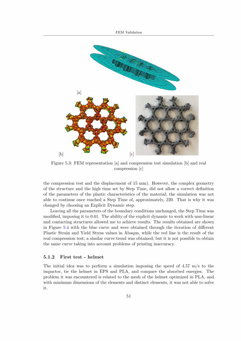
FEM Validation
[a]
[b] [c]
Figure 53 FEM representation [a] and compression test simulation [b] and realcompression [c]
the compression test and the displacement of 15 mm) However the complex geometryof the structure and the high time set by Step Time did not allow a correct definitionof the parameters of the plastic characteristics of the material the simulation was notable to continue once reached a Step Time of approximately 220 That is why it waschanged by choosing an Explicit Dynamic step
Leaving all the parameters of the boundary conditions unchanged the Step Time wasmodified imposing it to 001 The ability of the explicit dynamic to work with non-linearand contacting structures allowed me to achieve results The results obtained are shownin Figure 54 with the blue curve and were obtained through the iteration of differentPlastic Strain and Yield Stress values in Abaqus while the red line is the result of thereal compression test a similar curve trend was obtained but it is not possible to obtainthe same curve taking into account problems of printing inaccuracy
512 First test - helmet
The initial idea was to perform a simulation imposing the speed of 457 ms to theimpactor tie the helmet in EPS and PLA and compare the absorbed energies Theproblem it was encountered is related to the mesh of the helmet optimized in PLA andwith minimum dimensions of the elements and distinct elements it was not able to solveit
51
FEM Validation
[a]
YieldStress
PlasticStrain
1 47 0
2 7 001
3 75 005
4 10 01
5 108 1
6 115 15
7 12 2
[b]
Figure 54 Representation of the two curves related to the simulation in Abaqus of thecompression test and the data obtained from the real test to obtain the plastic
characteristics of the material
513 Second test - plane
The first solution is the one shown in Figure 55 To realize the simulation it was realizeda section of the helmet to involve a smaller number of elements and nodes Again thesimulation for the EPS helmet was successful while the simulation with the bio-inspiredstructure was interrupted by excessive distortion of elements
The previous images show the impact is very localized in the impacted area and theidea to achieve a complete simulation is not to consider a curved portion of the helmetbut a plane In this way it was possible to solve the problem and obtain a completesimulation for the bio-inspired structure
FEM element
Below in Table 53 there is the definition of the elements used for the PLA-LW and EPSplane in the simulation to simulate the impact and to control the energy-absorbing whilethe anvil characteristics are described in Table 51
514 EPS impact simulations
In order to proceed with the simulation it was imposed some boundary conditions thatregard ties and forces
bull the movement of the plane is fixed through an Encastre therefore unable to moveand rotate in xyz directions
52
FEM Validation
[a]
[b]
Figure 55 Impact simulation parts of EPS and PLA helmet
Object Elementnumber
Elements Shape Geometricorder
Plane (PLA) 38896 Tetrahedral -C3D10M
Quadratic
Plane (EPS) 2100 Hexahedral - C3D8R Linear
Table 53 Mesh element - plane impact
bull to create the impact it was set a speed of 457 ms at the reference point RP of therigid body which is the impactor Kerbstone Anvil shown in Figure 56
bull between the upper surface of the plane and the impactor it was initialized a Sur-face to Surface contact with normal behaviour through rsquohardrsquo contact and tangen-tial behaviour with a coefficient of friction of 02 with directionality imposed onrsquoisotropicrsquo
bull the rotation in x y z relative to the RP of the rigid discrete impactor body is locked
53
FEM Validation
In addition it was characterized the plane in the part of the materials with the char-acteristic values of the EPS mentioned in Chapter 221 The Von Mises Stress valueapparently low is relative to the Yield Stress of the EPS material equal to 09 MPa
Figure 56 EPS Boundary conditions and Load
515 PLA LW impact simulations
As also required in the case of the EPS plane in order to proceed with the simulationsome boundary conditions were imposed that regard ties and forces
bull the movement of the plane is fixed through an Encastre therefore unable to moveand rotate in xyz directions
bull to create the impact a speed of 457 ms was set at the reference point RP of therigid body which is the impactor Kerbstone Anvil shown in Figure 58
bull between the upper surface of the plane and the impactor it was initialized a Sur-face to Surface contact with normal behaviour through rsquohardrsquo contact and tangen-tial behaviour with a coefficient of friction of 02 with directionality imposed onrsquoisotropicrsquo
bull the rotation in x y z relative to the RP of the rigid discrete impactor body is locked
In addition the plane was characterized in the part of the materials with the characteristicvalues of the PLA mentioned in the Chapter 223 and 511
Figure 58 Boundary conditions and Load
54
FEM Validation
[a]
[b]
Figure 57 EPS impact simulation
52 Results
In Figures 59 and 57 it is shown how the structure in PLA LW has a more concentratedstress distribution of the structure unlike EPS The maximum value for the Von Misesstress is 09 MPa in EPS structure and 3634 MPa in PLA LW structure Once thesimulations were obtained the next step was to go and compare the energies absorbed bythe two structures The energy calculated by Abaqus that has been taken into account isPlastic Dissipation To make a comparison the data of the two energies were representedin a single graph
What emerges from the graph is that about the impact made with the KerbstoneAnvil the energy absorption is more excellent although only slightly for the PLA LWthan for the EPS From the graph in Figure 510 a value of 41 J is shown for the EPSand 51 J for the PLA LW
55
[a]
[b]
Figure 59 PLA impact simulation
[a]
Figure 510 EPS and PLA LW energy comparison - Abaqus simulation
Chapter 6
Head Injury Data
For the statistical analysis the injuries related to the accident data were categorised intothe following types and levels based on the details of the medical report [11] about theEN 1078
bull Head Injury Criterion (HIC)
bull Peak Linear Acceleration (PLAc)
bull Gadd Severity Injury (GSI)
bull Diffuse axonal injuries (DAI)
61 Abaqus simulation
Until now the purpose of the simulations has been to determine which between the twomaterials and the two structures of EPS and PLA LW could absorb more energy duringthe impact but no simulations have been carried out in compliance with BS EN 1078on the helmet impact tests To calculate the injuries listed in the previous paragraphhowever we need the acceleration values in the three directions related to the subjectrsquoshead
To realize it the scan of my head already rsquocleanrsquo was considered of which it has beencalculated the inertia thanks to the automatic SolidWorks calculation and evaluated theweight with the Table 24 the structure of the helmet was placed for the EPS and thePLA LW over the head as shown in Figure 61 Also this time being able to mesh theentire helmet in PLA LW was impossible due to the excessive distortion of some elementsduring the simulation so it has been tried to make a section of the structures of thehelmet and results were obtained
57
Head Injury Data
[a] [b]
Figure 61 My scan head - CAD [a] head imported in Abaqus[b]
Initially the simulation had these characteristics as shown in the following Figure62 considering the helmet was not sectioned As explained earlier it was not possibleto get to simulation in the case of the optimized structure in PLA LW for this reasononly a part of the helmet was considered in both cases shown in Figure 63
[a]
Figure 62 Simulation based on BS EN 1078
58
Head Injury Data
[a] [b]
Figure 63 Simulation based on BS EN 1078 with head
In order to proceed with the simulation some boundary conditions that regard tiesand forces have have imposed
bull two reference points RP were created the first in the inertia centre of the headthe second relating to the Kerbstone Anvil which is a discrete rigid body
bull in the reference point RP of the head in the definition of the engineering features5 kg was inserted for the weight and an inertia I11 = 564464E+07 gmm2 I22 =460654E+07gmm2 I33 = 187302E+07gmm2
bull to simulate the impact it was set a speed of 457 ms at the reference point RP ofthe head in z-axis direction
bull a general contact with normal behaviour through rsquohardrsquo contact and tangentialbehaviour with a coefficient of friction of 02
bull between the upper surface of the helmet and the impactor it has been initializeda Surface to Surface contact with normal behaviour through rsquohardrsquo contact andtangential behaviour with a coefficient of friction of 02 with directionality imposedon rsquoisotropicrsquo
bull the movement between the Kerbstone anvil and the helmet is fixed through anEncastre therefore unable to move and rotate in xyz directions
bull the rotation in x y z relative to the RP of the rigid discrete impactor body is locked
FEM element
As reported in Table 53 the portion of the helmet in EPS has used a mesh with hexahe-dral elements of linear order For the structure (beetle) of PLA LW given the geometry
59
Head Injury Data
complexity it was necessary to use a quadratic order of tetrahedra For the mesh of thehead instead in both simulations have been used quadrilateral elements of linear orderas reported in the Tables 61 and 62
Object Elementnumber
Elements Shape Geometricorder
Head 3755 Quadrilateral - R3D4 Linear
Head 34542 Quadrilateral - R3D3 Linear
Helmet (PLA) 272302 Tetrahedral -C3D10M
Quadratic
Table 61 Mesh element - Head simulation with PLA LW (beetle) helmet
Object Elementnumber
Elements Shape Geometricorder
Head 3755 Quadrilateral - R3D4 Linear
Head 34542 Quadrilateral - R3D3 Linear
Helmet (EPS) 72280 Hexahedral - C3D8R Linear
Table 62 Mesh element - Head simulation with EPS helmet
62 Results
Figure 64 represents the simulation in line with BS EN 1078 concerning the helmet inEPS [a] and the helmet with bio-inspired structure in PLA LW For both simulationsVan Misesrsquo stress has Yield Stress values in the case of EPS which is 09 MPa and theplastic behaviour combination of PLA LW [b]
In the case of head and Kerbstone Anvil stress was not assessed as they were previ-ously defined as discrete rigid bodies
63 Head Injury Criterion
The HIC quantifies head impact severity by incorporating time of acceleration exposureand acceleration magnitude it is calculated in post-processing phase with the followingEquation 61
HIC15 =
[1
(t1 minus t2)
int t2
t1
a(t)dt
]25(t2 minus t1) (61)
60
Head Injury Data
[a]
[b]
Figure 64 Results simulation based on BS EN 1078 with sectioned head
For this analysis a(t) is the acceleration calculated in the centre of mass of the head(corresponding to the reference point RP) expressed in g and the time interval (t2 minus t1)was chosen to maximize HIC over a maximum duration of 15 ms
Matlab and the trapz function were used to calculate the HIC to integrate accelerationover time t2 and t1 were considered initial and final times of the simulation t1 = 0 sand t2 = 10 s time less than 15 s
HIC value of 198 was obtained for EPS and 87 for PLA LW Considering the Hayeset al [16] document about the HIC values and the graph in Figure 65 developed bythe author it is possible to find the percentages related to the different injury AIS1 -AIS6 which correspond respectively to lower and higher severity while in Figure 66 therelative fatality to every value of AIS is shown The values obtained for the HIC andother criteria are shown in Table 63 The HIC value for EPS is 198 for PLA LW it is
61
Head Injury Data
Figure 65 Head injury risk curves based on HIC values [16]
Figure 66 The abbreviated injury score versus fatality rate [16]
87 Analyzing the data and comparing them with the curves of the Figure 65 I obtain
bull a percentage between 20 - 30 of AIS 1 for EPS 10 - 20 for PLA LW
bull a percentage between 10 - 20 of AIS 2 for EPS and 0 - 10 for PLA LW
bull for AIS 3 AIS 4 AIS 5 AIS 6 the percentages for both structures is between 0 -10
Comparing these percentages with the fatality rate of Figure 66 it is clear there is a riskof Moderate and Minor fatality in the case of EPS and PLA LW as all values are between0 and 30
62
Head Injury Data
HIC PLA [g] GSI E [J]
EPS 198 97 361 37723
PLA LW 87 75 169 44102
Table 63 Head Injury Data - values
64 Peak Linear Acceleration
The resultant linear acceleration versus time curve was calculated according to Equation62
γ(t) =radicγ2x(t) + γ2y(t) + γ2z (t) (62)
where
bull γ(t) is the resultant linear acceleration (g)
bull γx(t) is the linear acceleration in x axes (g)
bull γy(t) is the linear acceleration in y axes (g)
bull γz(t)is the linear acceleration in z axes (g)
The value of the impact should never exceed 250g [9] Cripton at all [9] in their studyexamined a helmet with expanded polystyrene (EPS) Figure 68 shows maximum HIC forhelmeted and unhelmeted drops from all heights For each drop height helmets reducedHIC relative to unhelmeted drops IARV value is 180g The acceleration in the two casesis shown in Figure 67 and the maximum values are 97g for EPS and 75g for PLA LWas reported in Table 63 The two values considering a maximum value calculated byCripton [9] of 180g are amply optimal and comply with the standard of 250g
65 Gadd Severity Index
Gadd proposed the Severity Index Criteria shown in Equation 63 Following this crite-rion the GSI values that are over 1000 produce serious internal head injury [33]
GSI =
int t1
0a(t)25dt (63)
Where
bull a is the linear acceleration (g)
bull t is the duration of the impact (s)
I calculated the GSI with the function trapz between 0 and t and the resulting valuesare 361 for the EPS and 169 for the PLA LW which comply with the limit
63
Head Injury Data
Figure 67 Peak accelerations for both helmets
Figure 68 Peak accelerations for both helmeted and unhelmeted drops Numbers overbars indicate peak acceleration For 2 m drop height results stated are the mean value
calculated from three drops [9]
64
Head Injury Data
66 Diffuse Axonal Injury
DAI cases covered all incidences in which neurological injuries occurred as well as con-cussion unconsciousness and coma
In order to assess the risk of head trauma in terms of diffuse axonal injury (DAI)Milne et al [23] defined a model based head injury criteria as follows obtaining theresults in Figure 69
bull 50 risk of moderate neurological injury (DAI1+) Brain Von Mises shearing stressof 28 kPa
bull 50 risk of severe neurological injury (DAI2+) Brain Von Mises shearing stressof 53 kPa
[a]
[b]
Figure 69 Peak intra-cerebral shearing stress computed with the helmet model coupledto the human head model for all impact points (a) Flat anvil (b) Kerbstone anvil [23]
65
Head Injury Data
67 Energy absorbed
In Figure 52 during the impact test between the kerbstone Anvil and the plan with thebio-inspired structure in PLA LW and EPS it was found that the PLA LW althoughwith a small difference of 10 J absorbed more energy in comparison with the EPS Whenthe test is carried out in compliance with BS EN 1078 and the head with a speed of 457ms (corresponding to the kerbstone Anvil) as shown in Figure 610 also in this casethe PLA LW with the optimized helmet structure manages to absorb more energy (evenif the difference is very low) compared to the EPS The maximum energy value in PLALW is 44102 J of EPS is 37723 J
Figure 610 Energy absorption - BS EN 1078
66
Chapter 7
Conclusion
71 Conclusion
In this thesis work a bicycle helmet with a bio-inspired structure in PLA LW and 3Dprinted was created The initial approach was to introduce an innovative aspect tostandard EPS helmets not using foam but a polymer with new geometries able toabsorb much energy during the impact For this reason the beetle structure has beenpreferred relying solely on the hypothesis encountered in the literature of its quality inabsorbing energy
Combining the new material of the PLA LW and beetle structure has made possiblethe development of new material satisfactory characteristics have been obtained sincethe first tests The two materials were first subjected to tensile tests to determine theirspecific stress in these the PLA LW had positive results
Subsequent dynamic physical tests were carried out on 3D printed helmet models andon reference helmets in EPS to calculate the absorption energy in both cases at the timeof impact These resulted in energy absorption of the beetle structure in PLA LW withthe application of a TPU cover almost equal to that of EPS about 50J To validate withfinite element analysis the two models an explicit dynamic step was used in AbaqusSimulations showed that the PLA LW structure absorbs a higher amount of energy thanthe EPS the higher is 50 J and the EPS 40J
Finally positive results have also been obtained in calculating the head injury datasimulating according to BS EN 1078 with the use of impactor helmet and head Theacceleration values for both the structures were inferior to 220g precisely for the PLALW was 75g and for the EPS 97g The same applies to the calculation of HIC and GSI(maximum acceptable value of 1000) where the values are 87 and 169 in the case of PLALW and 361 and 198 in EPS For all tests therefore greater efficiency of the structure inPLA LW has been obtained Positive results also in the simulation of the energy absorbedduring the impact as the value referring to the EPS was 35J and that of the PLA LWwas 45J
67
Conclusion
72 Future work lines
The positive results obtained can be considered as a starting point for further tests andsimulations to ensure the safety of the helmet and compliance with the regulations butbefore getting improvements and continue testing changes are required
bull the beetle structure of the helmet made with GH adapts to the SubD withoutallowing to have a homogeneous distribution it would be appropriate to have moreregular hexagonal geometries
bull the mesh of the helmet is too complex and does not allow to perform the simulationprobably to use a more regular structure would have a mesh accordingly moreregular and the simulation would be successful
bull the uneven helmet structure has so many defects that the print is imperfect andthis can change the results of the impact tests the structure should be improved
bull the printing time varies from 4 to 5 days it should be improved
bull the TPU helmet cover is too big for the RAISE printing plan it is necessary togenerate a new geometry
bull the TPU cover it must be fixed on the helmet
bull in the calculation of the DAI it is necessary to have the definition of the brain andthe head should not be considered as a rigid body
bull in the injury calculation the helmet without protection was considered with theTPU cover the result will be better
bull air flow analysis
The comments mentioned are only considerations and problems that I gained duringmy thesis and which should be improved but I am sure that these changes and improve-ments from design to printing and simulations can make the helmet a good product
68
Bibliography
[1] K Adanty J M Clark A Post Thomas Blaine H and M D Gilchrist Comparingtwo proposed protocols to test the oblique response of cycling helmets to fall impactsInternational Journal of Crashworthiness 6648 ndash 663 2020
[2] MF Ashby YJM Brechetb D Cebona and L Salvoc Selection strategies formaterials and processes Materials and Design 2004
[3] M Aysha El casco de bicicleta voronoi impreso en 3d mas seguro y ligero https
www3dnativescomen3d-printed-bicycle-helmet-voronoi-190820204
[4] H Bikas P Stavropoulos and G Chryssolouris Additive manufacturing methodsand modelling approaches a critical review The International Journal of AdvancedManufacturing Technology 83389ndash405 2016
[5] British Standards BSI Helmets for pedal cyclists and for users of skateboards androller skates - BS EN 1078 2012
[6] British Standards BSI Headforms for use in the testing of protective helmets BSEN 960 2020
[7] ColorFabb Colorfabb lw-pla 2019 httpscolorfabbcommedia
datasheetstdscolorfabbTDS_E_ColorFabb_LW-PLApdf
[8] V G Coronado T Haileyesus J M Bell T A Cheng JHaarbauer-Krupa M RLionbarger J Flores-Herrera L C McGuire and J Gilchrist Trends in sports andrecreation-related traumatic brain injuries treated in us emergency departments thenational electronic injury surveillance system-all injury program (neiss-aip) 2001-2012 J Head Trauma Rehabil 30185ndash197 2015
[9] P A Cripton D M Dressler D Stuart Cameron A Christopher R and D RichardsBicycle helmets are highly effective at preventing head injury during head impactHead-form accelerations and injury criteria for helmeted and unhelmeted impactsAccident Analysis and Prevention 701ndash7 2014
[10] L Cui M A Forero R and M D Gilchrist Optimisation of energy absorbingliner for equestrian helmets UCD School of Electrical Electronic and MechanicalEngineering University College Dublin Belfield Dublin4 Ireland 2020
[11] C Deck N Bourdet F Meyer and R Willinger Protection performance of bicyclehelmets Journal of safety research pages 67ndash77 2019
[12] Committee F08 Specification for headforms F2220 ASTM International 2015
[13] Committee F08 Specification for helmets used in recreational bicycling or rollerskating F1447 ASTM International 2018
[14] Committee F08 Test methods for equipment and procedures used in evaluating theperformance F1446 ASTM International 2020
69
Bibliography
[15] P Halldin Shock absorption including measuring CENTC 158 Working Group11 2018
[16] W C Hayes M S Erickson and E D Power Forensic injury biomechanics Annualreview of biomedical engineering pages 55ndash86 2007
[17] HEXR httpshexrcom
[18] C Jinxiang Z Xiaoming O Yoji S Kazuya G Zhensheng and P LongchengThe deformation mode and strengthening mechanism of compression in the beetleelytron plate Materials and Design 131481ndash186 2017
[19] S Kroeker M Ozkul A De Marco S Bonin and GP Siegmund Density variationin the expanded polystyrene eps foam of bicycle helmets and its influence on impactperformance Journal of biomechanical engineering 2019
[20] S G Kroeker SJ Bonin A L DeMarco C A Good and G P Siegmund Agedoes not affect the material properties of expanded polystyrene liners in field-usedbicycle helmets Journal of biomechanical engineering 2016
[21] M Meier K H Tan M K Lim and L Chung Unlocking innovation in the sportindustry through additive manufacturing Business Process Management Journa2018
[22] N J Mills and A Gilchrist The effectiveness of foams in bicycle and motorcyclehelmets Accident Analysis Prevention 23153 ndash 163 1991
[23] G Milne C Deck R P Carreira Q Allinne and R Willinger Development andvalidation of a bicycle helmet assessment of head injury risk under standard impactconditions Computer methods in biomechanics and biomedical engineering 15 Suppl1309 ndash 310 2012
[24] Y Mosleh S J Vander B Depreitere and J Ivens Novel composite foam conceptfor head protection in oblique impacts Adv Eng Mater (Advanced EngineeringMaterials) 10 2017
[25] H Mustafa T Y Pang T Ellena and S H Nasir Impact attenuation of user-centred bicycle helmet design with different foam densities J Phys Conf Ser(Journal of Physics Conference Series) 1150 2019
[26] S H Ngoc and L Guoxing A review of recent research on bio-inspired structuresand materials for energy absorption applications Composites Part 181 2020
[27] J I Novak and A R Novak Is additive manufacturing improving performance insports a systematic review Sport engineering and technology 13 2020
[28] European Road Safety Observatory European road safety observatory facts and fig-ures - cyclists - 2020 December 2020 httpseceuropaeutransportroad_
safetysitesdefaultfilesfacts_figures_cyclists_final_20210323pdf
[29] New York City Departments of Health Parks Mental Hygiene Transportation Recre-ation and the New York City Police Department Bicyclist fatalities and seriousinjuries in new york city 2005
[30] W Pengwen Y Jing H Yanan H Jiaofei and F Xiaoyang Innovative designof a helmet based on reverse engineering and 3d printing Alexandria EngineeringJournal 603445ndash3453 2021
[31] S G Piland T E Gould M Jesunathadas J S Wiggins O McNair and V CShane Protective helmets in sports Materials in Sports Equipment 3 2019
70
Bibliography
[32] K Schmitt P F Niederer M H Muser and F Walz Trauma biomechanicsSpringer Berlin Heidelberg 2010
[33] David Sepelveda Lopez A Biomechanical Analysis of Bicycle Helmets using FEMPhD thesis 2019 Bachelor thesis
[34] H Stigson Bicycle Helmets 2020 Tested by Folksam PhD thesis 2020 PhDAssociate Professor Traffic Safety Research
[35] H Tao K Sudip N Anindya and X Yongzhao 3d printed sensors for biomedicalapplications A review sensor 2019
[36] M Trzaskalska and R Chwastek Damping properties and density of helmet linersmade of expanded polystyrene (eps) Archives of Metallurgy and Materials 66 2020
[37] Crupi V Epasto G and Guglielmino E Impact response of aluminum foam sand-wiches for light-weight ship structures Metals 198ndash112 2020
[38] W Wei-cai F Dong-ming and L Yuan-xin Study on impact energy absorbing per-formance of eps buffer layer of motorcycle helmet Proceedings - 2013 InternationalConference on Mechanical and Automation Engineering MAEE 2013
[39] Z Xiaoming C Jinxiang O Yoji Z Peiwei X Xiaobing and Y Xindi Influence ofhoneycomb dimensions and forming methods on the compressive properties of beetleelytron plates Journal of Sandwich Structures and Materials 2228ndash39 2020
[40] S Zhi L Dong Z Weisheng S Shanshan and G Xu Topological optimization ofbiomimetic sandwich structures with hybrid core and cfrp face sheets CompositesScience and Technology 14279ndash90 2017
[41] S Zhi S Shanshan G Xu H Xiaozhi and C Haoran On compressive propertiesof composite sandwich structures with grid reinforced honeycomb core CompositesPart B 94245ndash252 2016
71
- List of Tables
- List of Figures
- Introduction
-
- Helmet bike protection
-
- Helmet structure
-
- Additive Manufacturing
-
- AM process
- Materials and techniques - FDM
- AM in sport
-
- 3D printed helmets
-
- Phases
- HEXR
- VORONOI
-
- State of the art
-
- Standards
-
- Headform
- European Standard and American Standard
- Field of vision - BS EN 1078
- Test impact area
- Anvils and environmental conditions
-
- Materials
-
- EPS Foam
- CES Edu Pack - Material selection
- PLA with natural fiber and PLA LW
-
- Bio-inspired structures
-
- Beetle structure - Design of the model
- Specific stress - PLA LW and EPS foam
-
- Methodology
-
- 3D scan
-
- 3D Sense 2 scanner and Meshmixer - Reverse reconstruction
- 3D scan analysis and extraction of features
-
- Helmet design
-
- Rhinoceros - Helmet surface
- Grasshopper - Helmet structure
-
- 3D Print
-
- Printer and parameters
-
- Experimental evaluation
-
- Experimental tests
-
- Drop-weight impact test machine
-
- PLA LW helmet
- EPS helmet
- Results
-
- First results - PLA-LW and EPS helmet
- PLA-LW helmet with TPU cover
-
- FEM Validation
-
- Impactor - Anvils definition
-
- PLA LW - Plastic characteristics
- First test - helmet
- Second test - plane
- EPS impact simulations
- PLA LW impact simulations
-
- Results
-
- Head Injury Data
-
- Abaqus simulation
- Results
- Head Injury Criterion
- Peak Linear Acceleration
- Gadd Severity Index
- Diffuse Axonal Injury
- Energy absorbed
-
- Conclusion
-
- Conclusion
- Future work lines
-
- Bibliography
-
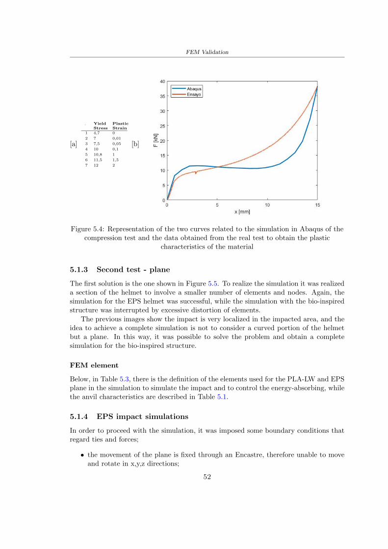
FEM Validation
[a]
YieldStress
PlasticStrain
1 47 0
2 7 001
3 75 005
4 10 01
5 108 1
6 115 15
7 12 2
[b]
Figure 54 Representation of the two curves related to the simulation in Abaqus of thecompression test and the data obtained from the real test to obtain the plastic
characteristics of the material
513 Second test - plane
The first solution is the one shown in Figure 55 To realize the simulation it was realizeda section of the helmet to involve a smaller number of elements and nodes Again thesimulation for the EPS helmet was successful while the simulation with the bio-inspiredstructure was interrupted by excessive distortion of elements
The previous images show the impact is very localized in the impacted area and theidea to achieve a complete simulation is not to consider a curved portion of the helmetbut a plane In this way it was possible to solve the problem and obtain a completesimulation for the bio-inspired structure
FEM element
Below in Table 53 there is the definition of the elements used for the PLA-LW and EPSplane in the simulation to simulate the impact and to control the energy-absorbing whilethe anvil characteristics are described in Table 51
514 EPS impact simulations
In order to proceed with the simulation it was imposed some boundary conditions thatregard ties and forces
bull the movement of the plane is fixed through an Encastre therefore unable to moveand rotate in xyz directions
52
FEM Validation
[a]
[b]
Figure 55 Impact simulation parts of EPS and PLA helmet
Object Elementnumber
Elements Shape Geometricorder
Plane (PLA) 38896 Tetrahedral -C3D10M
Quadratic
Plane (EPS) 2100 Hexahedral - C3D8R Linear
Table 53 Mesh element - plane impact
bull to create the impact it was set a speed of 457 ms at the reference point RP of therigid body which is the impactor Kerbstone Anvil shown in Figure 56
bull between the upper surface of the plane and the impactor it was initialized a Sur-face to Surface contact with normal behaviour through rsquohardrsquo contact and tangen-tial behaviour with a coefficient of friction of 02 with directionality imposed onrsquoisotropicrsquo
bull the rotation in x y z relative to the RP of the rigid discrete impactor body is locked
53
FEM Validation
In addition it was characterized the plane in the part of the materials with the char-acteristic values of the EPS mentioned in Chapter 221 The Von Mises Stress valueapparently low is relative to the Yield Stress of the EPS material equal to 09 MPa
Figure 56 EPS Boundary conditions and Load
515 PLA LW impact simulations
As also required in the case of the EPS plane in order to proceed with the simulationsome boundary conditions were imposed that regard ties and forces
bull the movement of the plane is fixed through an Encastre therefore unable to moveand rotate in xyz directions
bull to create the impact a speed of 457 ms was set at the reference point RP of therigid body which is the impactor Kerbstone Anvil shown in Figure 58
bull between the upper surface of the plane and the impactor it was initialized a Sur-face to Surface contact with normal behaviour through rsquohardrsquo contact and tangen-tial behaviour with a coefficient of friction of 02 with directionality imposed onrsquoisotropicrsquo
bull the rotation in x y z relative to the RP of the rigid discrete impactor body is locked
In addition the plane was characterized in the part of the materials with the characteristicvalues of the PLA mentioned in the Chapter 223 and 511
Figure 58 Boundary conditions and Load
54
FEM Validation
[a]
[b]
Figure 57 EPS impact simulation
52 Results
In Figures 59 and 57 it is shown how the structure in PLA LW has a more concentratedstress distribution of the structure unlike EPS The maximum value for the Von Misesstress is 09 MPa in EPS structure and 3634 MPa in PLA LW structure Once thesimulations were obtained the next step was to go and compare the energies absorbed bythe two structures The energy calculated by Abaqus that has been taken into account isPlastic Dissipation To make a comparison the data of the two energies were representedin a single graph
What emerges from the graph is that about the impact made with the KerbstoneAnvil the energy absorption is more excellent although only slightly for the PLA LWthan for the EPS From the graph in Figure 510 a value of 41 J is shown for the EPSand 51 J for the PLA LW
55
[a]
[b]
Figure 59 PLA impact simulation
[a]
Figure 510 EPS and PLA LW energy comparison - Abaqus simulation
Chapter 6
Head Injury Data
For the statistical analysis the injuries related to the accident data were categorised intothe following types and levels based on the details of the medical report [11] about theEN 1078
bull Head Injury Criterion (HIC)
bull Peak Linear Acceleration (PLAc)
bull Gadd Severity Injury (GSI)
bull Diffuse axonal injuries (DAI)
61 Abaqus simulation
Until now the purpose of the simulations has been to determine which between the twomaterials and the two structures of EPS and PLA LW could absorb more energy duringthe impact but no simulations have been carried out in compliance with BS EN 1078on the helmet impact tests To calculate the injuries listed in the previous paragraphhowever we need the acceleration values in the three directions related to the subjectrsquoshead
To realize it the scan of my head already rsquocleanrsquo was considered of which it has beencalculated the inertia thanks to the automatic SolidWorks calculation and evaluated theweight with the Table 24 the structure of the helmet was placed for the EPS and thePLA LW over the head as shown in Figure 61 Also this time being able to mesh theentire helmet in PLA LW was impossible due to the excessive distortion of some elementsduring the simulation so it has been tried to make a section of the structures of thehelmet and results were obtained
57
Head Injury Data
[a] [b]
Figure 61 My scan head - CAD [a] head imported in Abaqus[b]
Initially the simulation had these characteristics as shown in the following Figure62 considering the helmet was not sectioned As explained earlier it was not possibleto get to simulation in the case of the optimized structure in PLA LW for this reasononly a part of the helmet was considered in both cases shown in Figure 63
[a]
Figure 62 Simulation based on BS EN 1078
58
Head Injury Data
[a] [b]
Figure 63 Simulation based on BS EN 1078 with head
In order to proceed with the simulation some boundary conditions that regard tiesand forces have have imposed
bull two reference points RP were created the first in the inertia centre of the headthe second relating to the Kerbstone Anvil which is a discrete rigid body
bull in the reference point RP of the head in the definition of the engineering features5 kg was inserted for the weight and an inertia I11 = 564464E+07 gmm2 I22 =460654E+07gmm2 I33 = 187302E+07gmm2
bull to simulate the impact it was set a speed of 457 ms at the reference point RP ofthe head in z-axis direction
bull a general contact with normal behaviour through rsquohardrsquo contact and tangentialbehaviour with a coefficient of friction of 02
bull between the upper surface of the helmet and the impactor it has been initializeda Surface to Surface contact with normal behaviour through rsquohardrsquo contact andtangential behaviour with a coefficient of friction of 02 with directionality imposedon rsquoisotropicrsquo
bull the movement between the Kerbstone anvil and the helmet is fixed through anEncastre therefore unable to move and rotate in xyz directions
bull the rotation in x y z relative to the RP of the rigid discrete impactor body is locked
FEM element
As reported in Table 53 the portion of the helmet in EPS has used a mesh with hexahe-dral elements of linear order For the structure (beetle) of PLA LW given the geometry
59
Head Injury Data
complexity it was necessary to use a quadratic order of tetrahedra For the mesh of thehead instead in both simulations have been used quadrilateral elements of linear orderas reported in the Tables 61 and 62
Object Elementnumber
Elements Shape Geometricorder
Head 3755 Quadrilateral - R3D4 Linear
Head 34542 Quadrilateral - R3D3 Linear
Helmet (PLA) 272302 Tetrahedral -C3D10M
Quadratic
Table 61 Mesh element - Head simulation with PLA LW (beetle) helmet
Object Elementnumber
Elements Shape Geometricorder
Head 3755 Quadrilateral - R3D4 Linear
Head 34542 Quadrilateral - R3D3 Linear
Helmet (EPS) 72280 Hexahedral - C3D8R Linear
Table 62 Mesh element - Head simulation with EPS helmet
62 Results
Figure 64 represents the simulation in line with BS EN 1078 concerning the helmet inEPS [a] and the helmet with bio-inspired structure in PLA LW For both simulationsVan Misesrsquo stress has Yield Stress values in the case of EPS which is 09 MPa and theplastic behaviour combination of PLA LW [b]
In the case of head and Kerbstone Anvil stress was not assessed as they were previ-ously defined as discrete rigid bodies
63 Head Injury Criterion
The HIC quantifies head impact severity by incorporating time of acceleration exposureand acceleration magnitude it is calculated in post-processing phase with the followingEquation 61
HIC15 =
[1
(t1 minus t2)
int t2
t1
a(t)dt
]25(t2 minus t1) (61)
60
Head Injury Data
[a]
[b]
Figure 64 Results simulation based on BS EN 1078 with sectioned head
For this analysis a(t) is the acceleration calculated in the centre of mass of the head(corresponding to the reference point RP) expressed in g and the time interval (t2 minus t1)was chosen to maximize HIC over a maximum duration of 15 ms
Matlab and the trapz function were used to calculate the HIC to integrate accelerationover time t2 and t1 were considered initial and final times of the simulation t1 = 0 sand t2 = 10 s time less than 15 s
HIC value of 198 was obtained for EPS and 87 for PLA LW Considering the Hayeset al [16] document about the HIC values and the graph in Figure 65 developed bythe author it is possible to find the percentages related to the different injury AIS1 -AIS6 which correspond respectively to lower and higher severity while in Figure 66 therelative fatality to every value of AIS is shown The values obtained for the HIC andother criteria are shown in Table 63 The HIC value for EPS is 198 for PLA LW it is
61
Head Injury Data
Figure 65 Head injury risk curves based on HIC values [16]
Figure 66 The abbreviated injury score versus fatality rate [16]
87 Analyzing the data and comparing them with the curves of the Figure 65 I obtain
bull a percentage between 20 - 30 of AIS 1 for EPS 10 - 20 for PLA LW
bull a percentage between 10 - 20 of AIS 2 for EPS and 0 - 10 for PLA LW
bull for AIS 3 AIS 4 AIS 5 AIS 6 the percentages for both structures is between 0 -10
Comparing these percentages with the fatality rate of Figure 66 it is clear there is a riskof Moderate and Minor fatality in the case of EPS and PLA LW as all values are between0 and 30
62
Head Injury Data
HIC PLA [g] GSI E [J]
EPS 198 97 361 37723
PLA LW 87 75 169 44102
Table 63 Head Injury Data - values
64 Peak Linear Acceleration
The resultant linear acceleration versus time curve was calculated according to Equation62
γ(t) =radicγ2x(t) + γ2y(t) + γ2z (t) (62)
where
bull γ(t) is the resultant linear acceleration (g)
bull γx(t) is the linear acceleration in x axes (g)
bull γy(t) is the linear acceleration in y axes (g)
bull γz(t)is the linear acceleration in z axes (g)
The value of the impact should never exceed 250g [9] Cripton at all [9] in their studyexamined a helmet with expanded polystyrene (EPS) Figure 68 shows maximum HIC forhelmeted and unhelmeted drops from all heights For each drop height helmets reducedHIC relative to unhelmeted drops IARV value is 180g The acceleration in the two casesis shown in Figure 67 and the maximum values are 97g for EPS and 75g for PLA LWas reported in Table 63 The two values considering a maximum value calculated byCripton [9] of 180g are amply optimal and comply with the standard of 250g
65 Gadd Severity Index
Gadd proposed the Severity Index Criteria shown in Equation 63 Following this crite-rion the GSI values that are over 1000 produce serious internal head injury [33]
GSI =
int t1
0a(t)25dt (63)
Where
bull a is the linear acceleration (g)
bull t is the duration of the impact (s)
I calculated the GSI with the function trapz between 0 and t and the resulting valuesare 361 for the EPS and 169 for the PLA LW which comply with the limit
63
Head Injury Data
Figure 67 Peak accelerations for both helmets
Figure 68 Peak accelerations for both helmeted and unhelmeted drops Numbers overbars indicate peak acceleration For 2 m drop height results stated are the mean value
calculated from three drops [9]
64
Head Injury Data
66 Diffuse Axonal Injury
DAI cases covered all incidences in which neurological injuries occurred as well as con-cussion unconsciousness and coma
In order to assess the risk of head trauma in terms of diffuse axonal injury (DAI)Milne et al [23] defined a model based head injury criteria as follows obtaining theresults in Figure 69
bull 50 risk of moderate neurological injury (DAI1+) Brain Von Mises shearing stressof 28 kPa
bull 50 risk of severe neurological injury (DAI2+) Brain Von Mises shearing stressof 53 kPa
[a]
[b]
Figure 69 Peak intra-cerebral shearing stress computed with the helmet model coupledto the human head model for all impact points (a) Flat anvil (b) Kerbstone anvil [23]
65
Head Injury Data
67 Energy absorbed
In Figure 52 during the impact test between the kerbstone Anvil and the plan with thebio-inspired structure in PLA LW and EPS it was found that the PLA LW althoughwith a small difference of 10 J absorbed more energy in comparison with the EPS Whenthe test is carried out in compliance with BS EN 1078 and the head with a speed of 457ms (corresponding to the kerbstone Anvil) as shown in Figure 610 also in this casethe PLA LW with the optimized helmet structure manages to absorb more energy (evenif the difference is very low) compared to the EPS The maximum energy value in PLALW is 44102 J of EPS is 37723 J
Figure 610 Energy absorption - BS EN 1078
66
Chapter 7
Conclusion
71 Conclusion
In this thesis work a bicycle helmet with a bio-inspired structure in PLA LW and 3Dprinted was created The initial approach was to introduce an innovative aspect tostandard EPS helmets not using foam but a polymer with new geometries able toabsorb much energy during the impact For this reason the beetle structure has beenpreferred relying solely on the hypothesis encountered in the literature of its quality inabsorbing energy
Combining the new material of the PLA LW and beetle structure has made possiblethe development of new material satisfactory characteristics have been obtained sincethe first tests The two materials were first subjected to tensile tests to determine theirspecific stress in these the PLA LW had positive results
Subsequent dynamic physical tests were carried out on 3D printed helmet models andon reference helmets in EPS to calculate the absorption energy in both cases at the timeof impact These resulted in energy absorption of the beetle structure in PLA LW withthe application of a TPU cover almost equal to that of EPS about 50J To validate withfinite element analysis the two models an explicit dynamic step was used in AbaqusSimulations showed that the PLA LW structure absorbs a higher amount of energy thanthe EPS the higher is 50 J and the EPS 40J
Finally positive results have also been obtained in calculating the head injury datasimulating according to BS EN 1078 with the use of impactor helmet and head Theacceleration values for both the structures were inferior to 220g precisely for the PLALW was 75g and for the EPS 97g The same applies to the calculation of HIC and GSI(maximum acceptable value of 1000) where the values are 87 and 169 in the case of PLALW and 361 and 198 in EPS For all tests therefore greater efficiency of the structure inPLA LW has been obtained Positive results also in the simulation of the energy absorbedduring the impact as the value referring to the EPS was 35J and that of the PLA LWwas 45J
67
Conclusion
72 Future work lines
The positive results obtained can be considered as a starting point for further tests andsimulations to ensure the safety of the helmet and compliance with the regulations butbefore getting improvements and continue testing changes are required
bull the beetle structure of the helmet made with GH adapts to the SubD withoutallowing to have a homogeneous distribution it would be appropriate to have moreregular hexagonal geometries
bull the mesh of the helmet is too complex and does not allow to perform the simulationprobably to use a more regular structure would have a mesh accordingly moreregular and the simulation would be successful
bull the uneven helmet structure has so many defects that the print is imperfect andthis can change the results of the impact tests the structure should be improved
bull the printing time varies from 4 to 5 days it should be improved
bull the TPU helmet cover is too big for the RAISE printing plan it is necessary togenerate a new geometry
bull the TPU cover it must be fixed on the helmet
bull in the calculation of the DAI it is necessary to have the definition of the brain andthe head should not be considered as a rigid body
bull in the injury calculation the helmet without protection was considered with theTPU cover the result will be better
bull air flow analysis
The comments mentioned are only considerations and problems that I gained duringmy thesis and which should be improved but I am sure that these changes and improve-ments from design to printing and simulations can make the helmet a good product
68
Bibliography
[1] K Adanty J M Clark A Post Thomas Blaine H and M D Gilchrist Comparingtwo proposed protocols to test the oblique response of cycling helmets to fall impactsInternational Journal of Crashworthiness 6648 ndash 663 2020
[2] MF Ashby YJM Brechetb D Cebona and L Salvoc Selection strategies formaterials and processes Materials and Design 2004
[3] M Aysha El casco de bicicleta voronoi impreso en 3d mas seguro y ligero https
www3dnativescomen3d-printed-bicycle-helmet-voronoi-190820204
[4] H Bikas P Stavropoulos and G Chryssolouris Additive manufacturing methodsand modelling approaches a critical review The International Journal of AdvancedManufacturing Technology 83389ndash405 2016
[5] British Standards BSI Helmets for pedal cyclists and for users of skateboards androller skates - BS EN 1078 2012
[6] British Standards BSI Headforms for use in the testing of protective helmets BSEN 960 2020
[7] ColorFabb Colorfabb lw-pla 2019 httpscolorfabbcommedia
datasheetstdscolorfabbTDS_E_ColorFabb_LW-PLApdf
[8] V G Coronado T Haileyesus J M Bell T A Cheng JHaarbauer-Krupa M RLionbarger J Flores-Herrera L C McGuire and J Gilchrist Trends in sports andrecreation-related traumatic brain injuries treated in us emergency departments thenational electronic injury surveillance system-all injury program (neiss-aip) 2001-2012 J Head Trauma Rehabil 30185ndash197 2015
[9] P A Cripton D M Dressler D Stuart Cameron A Christopher R and D RichardsBicycle helmets are highly effective at preventing head injury during head impactHead-form accelerations and injury criteria for helmeted and unhelmeted impactsAccident Analysis and Prevention 701ndash7 2014
[10] L Cui M A Forero R and M D Gilchrist Optimisation of energy absorbingliner for equestrian helmets UCD School of Electrical Electronic and MechanicalEngineering University College Dublin Belfield Dublin4 Ireland 2020
[11] C Deck N Bourdet F Meyer and R Willinger Protection performance of bicyclehelmets Journal of safety research pages 67ndash77 2019
[12] Committee F08 Specification for headforms F2220 ASTM International 2015
[13] Committee F08 Specification for helmets used in recreational bicycling or rollerskating F1447 ASTM International 2018
[14] Committee F08 Test methods for equipment and procedures used in evaluating theperformance F1446 ASTM International 2020
69
Bibliography
[15] P Halldin Shock absorption including measuring CENTC 158 Working Group11 2018
[16] W C Hayes M S Erickson and E D Power Forensic injury biomechanics Annualreview of biomedical engineering pages 55ndash86 2007
[17] HEXR httpshexrcom
[18] C Jinxiang Z Xiaoming O Yoji S Kazuya G Zhensheng and P LongchengThe deformation mode and strengthening mechanism of compression in the beetleelytron plate Materials and Design 131481ndash186 2017
[19] S Kroeker M Ozkul A De Marco S Bonin and GP Siegmund Density variationin the expanded polystyrene eps foam of bicycle helmets and its influence on impactperformance Journal of biomechanical engineering 2019
[20] S G Kroeker SJ Bonin A L DeMarco C A Good and G P Siegmund Agedoes not affect the material properties of expanded polystyrene liners in field-usedbicycle helmets Journal of biomechanical engineering 2016
[21] M Meier K H Tan M K Lim and L Chung Unlocking innovation in the sportindustry through additive manufacturing Business Process Management Journa2018
[22] N J Mills and A Gilchrist The effectiveness of foams in bicycle and motorcyclehelmets Accident Analysis Prevention 23153 ndash 163 1991
[23] G Milne C Deck R P Carreira Q Allinne and R Willinger Development andvalidation of a bicycle helmet assessment of head injury risk under standard impactconditions Computer methods in biomechanics and biomedical engineering 15 Suppl1309 ndash 310 2012
[24] Y Mosleh S J Vander B Depreitere and J Ivens Novel composite foam conceptfor head protection in oblique impacts Adv Eng Mater (Advanced EngineeringMaterials) 10 2017
[25] H Mustafa T Y Pang T Ellena and S H Nasir Impact attenuation of user-centred bicycle helmet design with different foam densities J Phys Conf Ser(Journal of Physics Conference Series) 1150 2019
[26] S H Ngoc and L Guoxing A review of recent research on bio-inspired structuresand materials for energy absorption applications Composites Part 181 2020
[27] J I Novak and A R Novak Is additive manufacturing improving performance insports a systematic review Sport engineering and technology 13 2020
[28] European Road Safety Observatory European road safety observatory facts and fig-ures - cyclists - 2020 December 2020 httpseceuropaeutransportroad_
safetysitesdefaultfilesfacts_figures_cyclists_final_20210323pdf
[29] New York City Departments of Health Parks Mental Hygiene Transportation Recre-ation and the New York City Police Department Bicyclist fatalities and seriousinjuries in new york city 2005
[30] W Pengwen Y Jing H Yanan H Jiaofei and F Xiaoyang Innovative designof a helmet based on reverse engineering and 3d printing Alexandria EngineeringJournal 603445ndash3453 2021
[31] S G Piland T E Gould M Jesunathadas J S Wiggins O McNair and V CShane Protective helmets in sports Materials in Sports Equipment 3 2019
70
Bibliography
[32] K Schmitt P F Niederer M H Muser and F Walz Trauma biomechanicsSpringer Berlin Heidelberg 2010
[33] David Sepelveda Lopez A Biomechanical Analysis of Bicycle Helmets using FEMPhD thesis 2019 Bachelor thesis
[34] H Stigson Bicycle Helmets 2020 Tested by Folksam PhD thesis 2020 PhDAssociate Professor Traffic Safety Research
[35] H Tao K Sudip N Anindya and X Yongzhao 3d printed sensors for biomedicalapplications A review sensor 2019
[36] M Trzaskalska and R Chwastek Damping properties and density of helmet linersmade of expanded polystyrene (eps) Archives of Metallurgy and Materials 66 2020
[37] Crupi V Epasto G and Guglielmino E Impact response of aluminum foam sand-wiches for light-weight ship structures Metals 198ndash112 2020
[38] W Wei-cai F Dong-ming and L Yuan-xin Study on impact energy absorbing per-formance of eps buffer layer of motorcycle helmet Proceedings - 2013 InternationalConference on Mechanical and Automation Engineering MAEE 2013
[39] Z Xiaoming C Jinxiang O Yoji Z Peiwei X Xiaobing and Y Xindi Influence ofhoneycomb dimensions and forming methods on the compressive properties of beetleelytron plates Journal of Sandwich Structures and Materials 2228ndash39 2020
[40] S Zhi L Dong Z Weisheng S Shanshan and G Xu Topological optimization ofbiomimetic sandwich structures with hybrid core and cfrp face sheets CompositesScience and Technology 14279ndash90 2017
[41] S Zhi S Shanshan G Xu H Xiaozhi and C Haoran On compressive propertiesof composite sandwich structures with grid reinforced honeycomb core CompositesPart B 94245ndash252 2016
71
- List of Tables
- List of Figures
- Introduction
-
- Helmet bike protection
-
- Helmet structure
-
- Additive Manufacturing
-
- AM process
- Materials and techniques - FDM
- AM in sport
-
- 3D printed helmets
-
- Phases
- HEXR
- VORONOI
-
- State of the art
-
- Standards
-
- Headform
- European Standard and American Standard
- Field of vision - BS EN 1078
- Test impact area
- Anvils and environmental conditions
-
- Materials
-
- EPS Foam
- CES Edu Pack - Material selection
- PLA with natural fiber and PLA LW
-
- Bio-inspired structures
-
- Beetle structure - Design of the model
- Specific stress - PLA LW and EPS foam
-
- Methodology
-
- 3D scan
-
- 3D Sense 2 scanner and Meshmixer - Reverse reconstruction
- 3D scan analysis and extraction of features
-
- Helmet design
-
- Rhinoceros - Helmet surface
- Grasshopper - Helmet structure
-
- 3D Print
-
- Printer and parameters
-
- Experimental evaluation
-
- Experimental tests
-
- Drop-weight impact test machine
-
- PLA LW helmet
- EPS helmet
- Results
-
- First results - PLA-LW and EPS helmet
- PLA-LW helmet with TPU cover
-
- FEM Validation
-
- Impactor - Anvils definition
-
- PLA LW - Plastic characteristics
- First test - helmet
- Second test - plane
- EPS impact simulations
- PLA LW impact simulations
-
- Results
-
- Head Injury Data
-
- Abaqus simulation
- Results
- Head Injury Criterion
- Peak Linear Acceleration
- Gadd Severity Index
- Diffuse Axonal Injury
- Energy absorbed
-
- Conclusion
-
- Conclusion
- Future work lines
-
- Bibliography
-
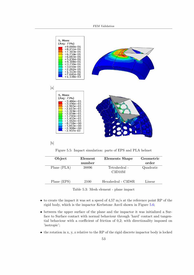
FEM Validation
[a]
[b]
Figure 55 Impact simulation parts of EPS and PLA helmet
Object Elementnumber
Elements Shape Geometricorder
Plane (PLA) 38896 Tetrahedral -C3D10M
Quadratic
Plane (EPS) 2100 Hexahedral - C3D8R Linear
Table 53 Mesh element - plane impact
bull to create the impact it was set a speed of 457 ms at the reference point RP of therigid body which is the impactor Kerbstone Anvil shown in Figure 56
bull between the upper surface of the plane and the impactor it was initialized a Sur-face to Surface contact with normal behaviour through rsquohardrsquo contact and tangen-tial behaviour with a coefficient of friction of 02 with directionality imposed onrsquoisotropicrsquo
bull the rotation in x y z relative to the RP of the rigid discrete impactor body is locked
53
FEM Validation
In addition it was characterized the plane in the part of the materials with the char-acteristic values of the EPS mentioned in Chapter 221 The Von Mises Stress valueapparently low is relative to the Yield Stress of the EPS material equal to 09 MPa
Figure 56 EPS Boundary conditions and Load
515 PLA LW impact simulations
As also required in the case of the EPS plane in order to proceed with the simulationsome boundary conditions were imposed that regard ties and forces
bull the movement of the plane is fixed through an Encastre therefore unable to moveand rotate in xyz directions
bull to create the impact a speed of 457 ms was set at the reference point RP of therigid body which is the impactor Kerbstone Anvil shown in Figure 58
bull between the upper surface of the plane and the impactor it was initialized a Sur-face to Surface contact with normal behaviour through rsquohardrsquo contact and tangen-tial behaviour with a coefficient of friction of 02 with directionality imposed onrsquoisotropicrsquo
bull the rotation in x y z relative to the RP of the rigid discrete impactor body is locked
In addition the plane was characterized in the part of the materials with the characteristicvalues of the PLA mentioned in the Chapter 223 and 511
Figure 58 Boundary conditions and Load
54
FEM Validation
[a]
[b]
Figure 57 EPS impact simulation
52 Results
In Figures 59 and 57 it is shown how the structure in PLA LW has a more concentratedstress distribution of the structure unlike EPS The maximum value for the Von Misesstress is 09 MPa in EPS structure and 3634 MPa in PLA LW structure Once thesimulations were obtained the next step was to go and compare the energies absorbed bythe two structures The energy calculated by Abaqus that has been taken into account isPlastic Dissipation To make a comparison the data of the two energies were representedin a single graph
What emerges from the graph is that about the impact made with the KerbstoneAnvil the energy absorption is more excellent although only slightly for the PLA LWthan for the EPS From the graph in Figure 510 a value of 41 J is shown for the EPSand 51 J for the PLA LW
55
[a]
[b]
Figure 59 PLA impact simulation
[a]
Figure 510 EPS and PLA LW energy comparison - Abaqus simulation
Chapter 6
Head Injury Data
For the statistical analysis the injuries related to the accident data were categorised intothe following types and levels based on the details of the medical report [11] about theEN 1078
bull Head Injury Criterion (HIC)
bull Peak Linear Acceleration (PLAc)
bull Gadd Severity Injury (GSI)
bull Diffuse axonal injuries (DAI)
61 Abaqus simulation
Until now the purpose of the simulations has been to determine which between the twomaterials and the two structures of EPS and PLA LW could absorb more energy duringthe impact but no simulations have been carried out in compliance with BS EN 1078on the helmet impact tests To calculate the injuries listed in the previous paragraphhowever we need the acceleration values in the three directions related to the subjectrsquoshead
To realize it the scan of my head already rsquocleanrsquo was considered of which it has beencalculated the inertia thanks to the automatic SolidWorks calculation and evaluated theweight with the Table 24 the structure of the helmet was placed for the EPS and thePLA LW over the head as shown in Figure 61 Also this time being able to mesh theentire helmet in PLA LW was impossible due to the excessive distortion of some elementsduring the simulation so it has been tried to make a section of the structures of thehelmet and results were obtained
57
Head Injury Data
[a] [b]
Figure 61 My scan head - CAD [a] head imported in Abaqus[b]
Initially the simulation had these characteristics as shown in the following Figure62 considering the helmet was not sectioned As explained earlier it was not possibleto get to simulation in the case of the optimized structure in PLA LW for this reasononly a part of the helmet was considered in both cases shown in Figure 63
[a]
Figure 62 Simulation based on BS EN 1078
58
Head Injury Data
[a] [b]
Figure 63 Simulation based on BS EN 1078 with head
In order to proceed with the simulation some boundary conditions that regard tiesand forces have have imposed
bull two reference points RP were created the first in the inertia centre of the headthe second relating to the Kerbstone Anvil which is a discrete rigid body
bull in the reference point RP of the head in the definition of the engineering features5 kg was inserted for the weight and an inertia I11 = 564464E+07 gmm2 I22 =460654E+07gmm2 I33 = 187302E+07gmm2
bull to simulate the impact it was set a speed of 457 ms at the reference point RP ofthe head in z-axis direction
bull a general contact with normal behaviour through rsquohardrsquo contact and tangentialbehaviour with a coefficient of friction of 02
bull between the upper surface of the helmet and the impactor it has been initializeda Surface to Surface contact with normal behaviour through rsquohardrsquo contact andtangential behaviour with a coefficient of friction of 02 with directionality imposedon rsquoisotropicrsquo
bull the movement between the Kerbstone anvil and the helmet is fixed through anEncastre therefore unable to move and rotate in xyz directions
bull the rotation in x y z relative to the RP of the rigid discrete impactor body is locked
FEM element
As reported in Table 53 the portion of the helmet in EPS has used a mesh with hexahe-dral elements of linear order For the structure (beetle) of PLA LW given the geometry
59
Head Injury Data
complexity it was necessary to use a quadratic order of tetrahedra For the mesh of thehead instead in both simulations have been used quadrilateral elements of linear orderas reported in the Tables 61 and 62
Object Elementnumber
Elements Shape Geometricorder
Head 3755 Quadrilateral - R3D4 Linear
Head 34542 Quadrilateral - R3D3 Linear
Helmet (PLA) 272302 Tetrahedral -C3D10M
Quadratic
Table 61 Mesh element - Head simulation with PLA LW (beetle) helmet
Object Elementnumber
Elements Shape Geometricorder
Head 3755 Quadrilateral - R3D4 Linear
Head 34542 Quadrilateral - R3D3 Linear
Helmet (EPS) 72280 Hexahedral - C3D8R Linear
Table 62 Mesh element - Head simulation with EPS helmet
62 Results
Figure 64 represents the simulation in line with BS EN 1078 concerning the helmet inEPS [a] and the helmet with bio-inspired structure in PLA LW For both simulationsVan Misesrsquo stress has Yield Stress values in the case of EPS which is 09 MPa and theplastic behaviour combination of PLA LW [b]
In the case of head and Kerbstone Anvil stress was not assessed as they were previ-ously defined as discrete rigid bodies
63 Head Injury Criterion
The HIC quantifies head impact severity by incorporating time of acceleration exposureand acceleration magnitude it is calculated in post-processing phase with the followingEquation 61
HIC15 =
[1
(t1 minus t2)
int t2
t1
a(t)dt
]25(t2 minus t1) (61)
60
Head Injury Data
[a]
[b]
Figure 64 Results simulation based on BS EN 1078 with sectioned head
For this analysis a(t) is the acceleration calculated in the centre of mass of the head(corresponding to the reference point RP) expressed in g and the time interval (t2 minus t1)was chosen to maximize HIC over a maximum duration of 15 ms
Matlab and the trapz function were used to calculate the HIC to integrate accelerationover time t2 and t1 were considered initial and final times of the simulation t1 = 0 sand t2 = 10 s time less than 15 s
HIC value of 198 was obtained for EPS and 87 for PLA LW Considering the Hayeset al [16] document about the HIC values and the graph in Figure 65 developed bythe author it is possible to find the percentages related to the different injury AIS1 -AIS6 which correspond respectively to lower and higher severity while in Figure 66 therelative fatality to every value of AIS is shown The values obtained for the HIC andother criteria are shown in Table 63 The HIC value for EPS is 198 for PLA LW it is
61
Head Injury Data
Figure 65 Head injury risk curves based on HIC values [16]
Figure 66 The abbreviated injury score versus fatality rate [16]
87 Analyzing the data and comparing them with the curves of the Figure 65 I obtain
bull a percentage between 20 - 30 of AIS 1 for EPS 10 - 20 for PLA LW
bull a percentage between 10 - 20 of AIS 2 for EPS and 0 - 10 for PLA LW
bull for AIS 3 AIS 4 AIS 5 AIS 6 the percentages for both structures is between 0 -10
Comparing these percentages with the fatality rate of Figure 66 it is clear there is a riskof Moderate and Minor fatality in the case of EPS and PLA LW as all values are between0 and 30
62
Head Injury Data
HIC PLA [g] GSI E [J]
EPS 198 97 361 37723
PLA LW 87 75 169 44102
Table 63 Head Injury Data - values
64 Peak Linear Acceleration
The resultant linear acceleration versus time curve was calculated according to Equation62
γ(t) =radicγ2x(t) + γ2y(t) + γ2z (t) (62)
where
bull γ(t) is the resultant linear acceleration (g)
bull γx(t) is the linear acceleration in x axes (g)
bull γy(t) is the linear acceleration in y axes (g)
bull γz(t)is the linear acceleration in z axes (g)
The value of the impact should never exceed 250g [9] Cripton at all [9] in their studyexamined a helmet with expanded polystyrene (EPS) Figure 68 shows maximum HIC forhelmeted and unhelmeted drops from all heights For each drop height helmets reducedHIC relative to unhelmeted drops IARV value is 180g The acceleration in the two casesis shown in Figure 67 and the maximum values are 97g for EPS and 75g for PLA LWas reported in Table 63 The two values considering a maximum value calculated byCripton [9] of 180g are amply optimal and comply with the standard of 250g
65 Gadd Severity Index
Gadd proposed the Severity Index Criteria shown in Equation 63 Following this crite-rion the GSI values that are over 1000 produce serious internal head injury [33]
GSI =
int t1
0a(t)25dt (63)
Where
bull a is the linear acceleration (g)
bull t is the duration of the impact (s)
I calculated the GSI with the function trapz between 0 and t and the resulting valuesare 361 for the EPS and 169 for the PLA LW which comply with the limit
63
Head Injury Data
Figure 67 Peak accelerations for both helmets
Figure 68 Peak accelerations for both helmeted and unhelmeted drops Numbers overbars indicate peak acceleration For 2 m drop height results stated are the mean value
calculated from three drops [9]
64
Head Injury Data
66 Diffuse Axonal Injury
DAI cases covered all incidences in which neurological injuries occurred as well as con-cussion unconsciousness and coma
In order to assess the risk of head trauma in terms of diffuse axonal injury (DAI)Milne et al [23] defined a model based head injury criteria as follows obtaining theresults in Figure 69
bull 50 risk of moderate neurological injury (DAI1+) Brain Von Mises shearing stressof 28 kPa
bull 50 risk of severe neurological injury (DAI2+) Brain Von Mises shearing stressof 53 kPa
[a]
[b]
Figure 69 Peak intra-cerebral shearing stress computed with the helmet model coupledto the human head model for all impact points (a) Flat anvil (b) Kerbstone anvil [23]
65
Head Injury Data
67 Energy absorbed
In Figure 52 during the impact test between the kerbstone Anvil and the plan with thebio-inspired structure in PLA LW and EPS it was found that the PLA LW althoughwith a small difference of 10 J absorbed more energy in comparison with the EPS Whenthe test is carried out in compliance with BS EN 1078 and the head with a speed of 457ms (corresponding to the kerbstone Anvil) as shown in Figure 610 also in this casethe PLA LW with the optimized helmet structure manages to absorb more energy (evenif the difference is very low) compared to the EPS The maximum energy value in PLALW is 44102 J of EPS is 37723 J
Figure 610 Energy absorption - BS EN 1078
66
Chapter 7
Conclusion
71 Conclusion
In this thesis work a bicycle helmet with a bio-inspired structure in PLA LW and 3Dprinted was created The initial approach was to introduce an innovative aspect tostandard EPS helmets not using foam but a polymer with new geometries able toabsorb much energy during the impact For this reason the beetle structure has beenpreferred relying solely on the hypothesis encountered in the literature of its quality inabsorbing energy
Combining the new material of the PLA LW and beetle structure has made possiblethe development of new material satisfactory characteristics have been obtained sincethe first tests The two materials were first subjected to tensile tests to determine theirspecific stress in these the PLA LW had positive results
Subsequent dynamic physical tests were carried out on 3D printed helmet models andon reference helmets in EPS to calculate the absorption energy in both cases at the timeof impact These resulted in energy absorption of the beetle structure in PLA LW withthe application of a TPU cover almost equal to that of EPS about 50J To validate withfinite element analysis the two models an explicit dynamic step was used in AbaqusSimulations showed that the PLA LW structure absorbs a higher amount of energy thanthe EPS the higher is 50 J and the EPS 40J
Finally positive results have also been obtained in calculating the head injury datasimulating according to BS EN 1078 with the use of impactor helmet and head Theacceleration values for both the structures were inferior to 220g precisely for the PLALW was 75g and for the EPS 97g The same applies to the calculation of HIC and GSI(maximum acceptable value of 1000) where the values are 87 and 169 in the case of PLALW and 361 and 198 in EPS For all tests therefore greater efficiency of the structure inPLA LW has been obtained Positive results also in the simulation of the energy absorbedduring the impact as the value referring to the EPS was 35J and that of the PLA LWwas 45J
67
Conclusion
72 Future work lines
The positive results obtained can be considered as a starting point for further tests andsimulations to ensure the safety of the helmet and compliance with the regulations butbefore getting improvements and continue testing changes are required
bull the beetle structure of the helmet made with GH adapts to the SubD withoutallowing to have a homogeneous distribution it would be appropriate to have moreregular hexagonal geometries
bull the mesh of the helmet is too complex and does not allow to perform the simulationprobably to use a more regular structure would have a mesh accordingly moreregular and the simulation would be successful
bull the uneven helmet structure has so many defects that the print is imperfect andthis can change the results of the impact tests the structure should be improved
bull the printing time varies from 4 to 5 days it should be improved
bull the TPU helmet cover is too big for the RAISE printing plan it is necessary togenerate a new geometry
bull the TPU cover it must be fixed on the helmet
bull in the calculation of the DAI it is necessary to have the definition of the brain andthe head should not be considered as a rigid body
bull in the injury calculation the helmet without protection was considered with theTPU cover the result will be better
bull air flow analysis
The comments mentioned are only considerations and problems that I gained duringmy thesis and which should be improved but I am sure that these changes and improve-ments from design to printing and simulations can make the helmet a good product
68
Bibliography
[1] K Adanty J M Clark A Post Thomas Blaine H and M D Gilchrist Comparingtwo proposed protocols to test the oblique response of cycling helmets to fall impactsInternational Journal of Crashworthiness 6648 ndash 663 2020
[2] MF Ashby YJM Brechetb D Cebona and L Salvoc Selection strategies formaterials and processes Materials and Design 2004
[3] M Aysha El casco de bicicleta voronoi impreso en 3d mas seguro y ligero https
www3dnativescomen3d-printed-bicycle-helmet-voronoi-190820204
[4] H Bikas P Stavropoulos and G Chryssolouris Additive manufacturing methodsand modelling approaches a critical review The International Journal of AdvancedManufacturing Technology 83389ndash405 2016
[5] British Standards BSI Helmets for pedal cyclists and for users of skateboards androller skates - BS EN 1078 2012
[6] British Standards BSI Headforms for use in the testing of protective helmets BSEN 960 2020
[7] ColorFabb Colorfabb lw-pla 2019 httpscolorfabbcommedia
datasheetstdscolorfabbTDS_E_ColorFabb_LW-PLApdf
[8] V G Coronado T Haileyesus J M Bell T A Cheng JHaarbauer-Krupa M RLionbarger J Flores-Herrera L C McGuire and J Gilchrist Trends in sports andrecreation-related traumatic brain injuries treated in us emergency departments thenational electronic injury surveillance system-all injury program (neiss-aip) 2001-2012 J Head Trauma Rehabil 30185ndash197 2015
[9] P A Cripton D M Dressler D Stuart Cameron A Christopher R and D RichardsBicycle helmets are highly effective at preventing head injury during head impactHead-form accelerations and injury criteria for helmeted and unhelmeted impactsAccident Analysis and Prevention 701ndash7 2014
[10] L Cui M A Forero R and M D Gilchrist Optimisation of energy absorbingliner for equestrian helmets UCD School of Electrical Electronic and MechanicalEngineering University College Dublin Belfield Dublin4 Ireland 2020
[11] C Deck N Bourdet F Meyer and R Willinger Protection performance of bicyclehelmets Journal of safety research pages 67ndash77 2019
[12] Committee F08 Specification for headforms F2220 ASTM International 2015
[13] Committee F08 Specification for helmets used in recreational bicycling or rollerskating F1447 ASTM International 2018
[14] Committee F08 Test methods for equipment and procedures used in evaluating theperformance F1446 ASTM International 2020
69
Bibliography
[15] P Halldin Shock absorption including measuring CENTC 158 Working Group11 2018
[16] W C Hayes M S Erickson and E D Power Forensic injury biomechanics Annualreview of biomedical engineering pages 55ndash86 2007
[17] HEXR httpshexrcom
[18] C Jinxiang Z Xiaoming O Yoji S Kazuya G Zhensheng and P LongchengThe deformation mode and strengthening mechanism of compression in the beetleelytron plate Materials and Design 131481ndash186 2017
[19] S Kroeker M Ozkul A De Marco S Bonin and GP Siegmund Density variationin the expanded polystyrene eps foam of bicycle helmets and its influence on impactperformance Journal of biomechanical engineering 2019
[20] S G Kroeker SJ Bonin A L DeMarco C A Good and G P Siegmund Agedoes not affect the material properties of expanded polystyrene liners in field-usedbicycle helmets Journal of biomechanical engineering 2016
[21] M Meier K H Tan M K Lim and L Chung Unlocking innovation in the sportindustry through additive manufacturing Business Process Management Journa2018
[22] N J Mills and A Gilchrist The effectiveness of foams in bicycle and motorcyclehelmets Accident Analysis Prevention 23153 ndash 163 1991
[23] G Milne C Deck R P Carreira Q Allinne and R Willinger Development andvalidation of a bicycle helmet assessment of head injury risk under standard impactconditions Computer methods in biomechanics and biomedical engineering 15 Suppl1309 ndash 310 2012
[24] Y Mosleh S J Vander B Depreitere and J Ivens Novel composite foam conceptfor head protection in oblique impacts Adv Eng Mater (Advanced EngineeringMaterials) 10 2017
[25] H Mustafa T Y Pang T Ellena and S H Nasir Impact attenuation of user-centred bicycle helmet design with different foam densities J Phys Conf Ser(Journal of Physics Conference Series) 1150 2019
[26] S H Ngoc and L Guoxing A review of recent research on bio-inspired structuresand materials for energy absorption applications Composites Part 181 2020
[27] J I Novak and A R Novak Is additive manufacturing improving performance insports a systematic review Sport engineering and technology 13 2020
[28] European Road Safety Observatory European road safety observatory facts and fig-ures - cyclists - 2020 December 2020 httpseceuropaeutransportroad_
safetysitesdefaultfilesfacts_figures_cyclists_final_20210323pdf
[29] New York City Departments of Health Parks Mental Hygiene Transportation Recre-ation and the New York City Police Department Bicyclist fatalities and seriousinjuries in new york city 2005
[30] W Pengwen Y Jing H Yanan H Jiaofei and F Xiaoyang Innovative designof a helmet based on reverse engineering and 3d printing Alexandria EngineeringJournal 603445ndash3453 2021
[31] S G Piland T E Gould M Jesunathadas J S Wiggins O McNair and V CShane Protective helmets in sports Materials in Sports Equipment 3 2019
70
Bibliography
[32] K Schmitt P F Niederer M H Muser and F Walz Trauma biomechanicsSpringer Berlin Heidelberg 2010
[33] David Sepelveda Lopez A Biomechanical Analysis of Bicycle Helmets using FEMPhD thesis 2019 Bachelor thesis
[34] H Stigson Bicycle Helmets 2020 Tested by Folksam PhD thesis 2020 PhDAssociate Professor Traffic Safety Research
[35] H Tao K Sudip N Anindya and X Yongzhao 3d printed sensors for biomedicalapplications A review sensor 2019
[36] M Trzaskalska and R Chwastek Damping properties and density of helmet linersmade of expanded polystyrene (eps) Archives of Metallurgy and Materials 66 2020
[37] Crupi V Epasto G and Guglielmino E Impact response of aluminum foam sand-wiches for light-weight ship structures Metals 198ndash112 2020
[38] W Wei-cai F Dong-ming and L Yuan-xin Study on impact energy absorbing per-formance of eps buffer layer of motorcycle helmet Proceedings - 2013 InternationalConference on Mechanical and Automation Engineering MAEE 2013
[39] Z Xiaoming C Jinxiang O Yoji Z Peiwei X Xiaobing and Y Xindi Influence ofhoneycomb dimensions and forming methods on the compressive properties of beetleelytron plates Journal of Sandwich Structures and Materials 2228ndash39 2020
[40] S Zhi L Dong Z Weisheng S Shanshan and G Xu Topological optimization ofbiomimetic sandwich structures with hybrid core and cfrp face sheets CompositesScience and Technology 14279ndash90 2017
[41] S Zhi S Shanshan G Xu H Xiaozhi and C Haoran On compressive propertiesof composite sandwich structures with grid reinforced honeycomb core CompositesPart B 94245ndash252 2016
71
- List of Tables
- List of Figures
- Introduction
-
- Helmet bike protection
-
- Helmet structure
-
- Additive Manufacturing
-
- AM process
- Materials and techniques - FDM
- AM in sport
-
- 3D printed helmets
-
- Phases
- HEXR
- VORONOI
-
- State of the art
-
- Standards
-
- Headform
- European Standard and American Standard
- Field of vision - BS EN 1078
- Test impact area
- Anvils and environmental conditions
-
- Materials
-
- EPS Foam
- CES Edu Pack - Material selection
- PLA with natural fiber and PLA LW
-
- Bio-inspired structures
-
- Beetle structure - Design of the model
- Specific stress - PLA LW and EPS foam
-
- Methodology
-
- 3D scan
-
- 3D Sense 2 scanner and Meshmixer - Reverse reconstruction
- 3D scan analysis and extraction of features
-
- Helmet design
-
- Rhinoceros - Helmet surface
- Grasshopper - Helmet structure
-
- 3D Print
-
- Printer and parameters
-
- Experimental evaluation
-
- Experimental tests
-
- Drop-weight impact test machine
-
- PLA LW helmet
- EPS helmet
- Results
-
- First results - PLA-LW and EPS helmet
- PLA-LW helmet with TPU cover
-
- FEM Validation
-
- Impactor - Anvils definition
-
- PLA LW - Plastic characteristics
- First test - helmet
- Second test - plane
- EPS impact simulations
- PLA LW impact simulations
-
- Results
-
- Head Injury Data
-
- Abaqus simulation
- Results
- Head Injury Criterion
- Peak Linear Acceleration
- Gadd Severity Index
- Diffuse Axonal Injury
- Energy absorbed
-
- Conclusion
-
- Conclusion
- Future work lines
-
- Bibliography
-
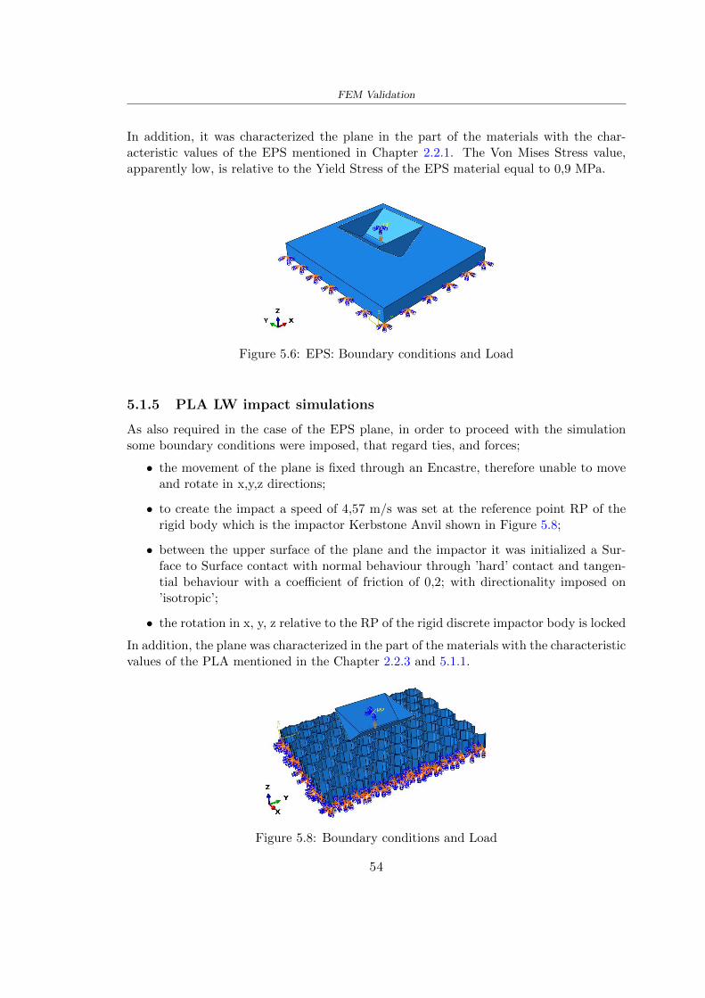
FEM Validation
In addition it was characterized the plane in the part of the materials with the char-acteristic values of the EPS mentioned in Chapter 221 The Von Mises Stress valueapparently low is relative to the Yield Stress of the EPS material equal to 09 MPa
Figure 56 EPS Boundary conditions and Load
515 PLA LW impact simulations
As also required in the case of the EPS plane in order to proceed with the simulationsome boundary conditions were imposed that regard ties and forces
bull the movement of the plane is fixed through an Encastre therefore unable to moveand rotate in xyz directions
bull to create the impact a speed of 457 ms was set at the reference point RP of therigid body which is the impactor Kerbstone Anvil shown in Figure 58
bull between the upper surface of the plane and the impactor it was initialized a Sur-face to Surface contact with normal behaviour through rsquohardrsquo contact and tangen-tial behaviour with a coefficient of friction of 02 with directionality imposed onrsquoisotropicrsquo
bull the rotation in x y z relative to the RP of the rigid discrete impactor body is locked
In addition the plane was characterized in the part of the materials with the characteristicvalues of the PLA mentioned in the Chapter 223 and 511
Figure 58 Boundary conditions and Load
54
FEM Validation
[a]
[b]
Figure 57 EPS impact simulation
52 Results
In Figures 59 and 57 it is shown how the structure in PLA LW has a more concentratedstress distribution of the structure unlike EPS The maximum value for the Von Misesstress is 09 MPa in EPS structure and 3634 MPa in PLA LW structure Once thesimulations were obtained the next step was to go and compare the energies absorbed bythe two structures The energy calculated by Abaqus that has been taken into account isPlastic Dissipation To make a comparison the data of the two energies were representedin a single graph
What emerges from the graph is that about the impact made with the KerbstoneAnvil the energy absorption is more excellent although only slightly for the PLA LWthan for the EPS From the graph in Figure 510 a value of 41 J is shown for the EPSand 51 J for the PLA LW
55
[a]
[b]
Figure 59 PLA impact simulation
[a]
Figure 510 EPS and PLA LW energy comparison - Abaqus simulation
Chapter 6
Head Injury Data
For the statistical analysis the injuries related to the accident data were categorised intothe following types and levels based on the details of the medical report [11] about theEN 1078
bull Head Injury Criterion (HIC)
bull Peak Linear Acceleration (PLAc)
bull Gadd Severity Injury (GSI)
bull Diffuse axonal injuries (DAI)
61 Abaqus simulation
Until now the purpose of the simulations has been to determine which between the twomaterials and the two structures of EPS and PLA LW could absorb more energy duringthe impact but no simulations have been carried out in compliance with BS EN 1078on the helmet impact tests To calculate the injuries listed in the previous paragraphhowever we need the acceleration values in the three directions related to the subjectrsquoshead
To realize it the scan of my head already rsquocleanrsquo was considered of which it has beencalculated the inertia thanks to the automatic SolidWorks calculation and evaluated theweight with the Table 24 the structure of the helmet was placed for the EPS and thePLA LW over the head as shown in Figure 61 Also this time being able to mesh theentire helmet in PLA LW was impossible due to the excessive distortion of some elementsduring the simulation so it has been tried to make a section of the structures of thehelmet and results were obtained
57
Head Injury Data
[a] [b]
Figure 61 My scan head - CAD [a] head imported in Abaqus[b]
Initially the simulation had these characteristics as shown in the following Figure62 considering the helmet was not sectioned As explained earlier it was not possibleto get to simulation in the case of the optimized structure in PLA LW for this reasononly a part of the helmet was considered in both cases shown in Figure 63
[a]
Figure 62 Simulation based on BS EN 1078
58
Head Injury Data
[a] [b]
Figure 63 Simulation based on BS EN 1078 with head
In order to proceed with the simulation some boundary conditions that regard tiesand forces have have imposed
bull two reference points RP were created the first in the inertia centre of the headthe second relating to the Kerbstone Anvil which is a discrete rigid body
bull in the reference point RP of the head in the definition of the engineering features5 kg was inserted for the weight and an inertia I11 = 564464E+07 gmm2 I22 =460654E+07gmm2 I33 = 187302E+07gmm2
bull to simulate the impact it was set a speed of 457 ms at the reference point RP ofthe head in z-axis direction
bull a general contact with normal behaviour through rsquohardrsquo contact and tangentialbehaviour with a coefficient of friction of 02
bull between the upper surface of the helmet and the impactor it has been initializeda Surface to Surface contact with normal behaviour through rsquohardrsquo contact andtangential behaviour with a coefficient of friction of 02 with directionality imposedon rsquoisotropicrsquo
bull the movement between the Kerbstone anvil and the helmet is fixed through anEncastre therefore unable to move and rotate in xyz directions
bull the rotation in x y z relative to the RP of the rigid discrete impactor body is locked
FEM element
As reported in Table 53 the portion of the helmet in EPS has used a mesh with hexahe-dral elements of linear order For the structure (beetle) of PLA LW given the geometry
59
Head Injury Data
complexity it was necessary to use a quadratic order of tetrahedra For the mesh of thehead instead in both simulations have been used quadrilateral elements of linear orderas reported in the Tables 61 and 62
Object Elementnumber
Elements Shape Geometricorder
Head 3755 Quadrilateral - R3D4 Linear
Head 34542 Quadrilateral - R3D3 Linear
Helmet (PLA) 272302 Tetrahedral -C3D10M
Quadratic
Table 61 Mesh element - Head simulation with PLA LW (beetle) helmet
Object Elementnumber
Elements Shape Geometricorder
Head 3755 Quadrilateral - R3D4 Linear
Head 34542 Quadrilateral - R3D3 Linear
Helmet (EPS) 72280 Hexahedral - C3D8R Linear
Table 62 Mesh element - Head simulation with EPS helmet
62 Results
Figure 64 represents the simulation in line with BS EN 1078 concerning the helmet inEPS [a] and the helmet with bio-inspired structure in PLA LW For both simulationsVan Misesrsquo stress has Yield Stress values in the case of EPS which is 09 MPa and theplastic behaviour combination of PLA LW [b]
In the case of head and Kerbstone Anvil stress was not assessed as they were previ-ously defined as discrete rigid bodies
63 Head Injury Criterion
The HIC quantifies head impact severity by incorporating time of acceleration exposureand acceleration magnitude it is calculated in post-processing phase with the followingEquation 61
HIC15 =
[1
(t1 minus t2)
int t2
t1
a(t)dt
]25(t2 minus t1) (61)
60
Head Injury Data
[a]
[b]
Figure 64 Results simulation based on BS EN 1078 with sectioned head
For this analysis a(t) is the acceleration calculated in the centre of mass of the head(corresponding to the reference point RP) expressed in g and the time interval (t2 minus t1)was chosen to maximize HIC over a maximum duration of 15 ms
Matlab and the trapz function were used to calculate the HIC to integrate accelerationover time t2 and t1 were considered initial and final times of the simulation t1 = 0 sand t2 = 10 s time less than 15 s
HIC value of 198 was obtained for EPS and 87 for PLA LW Considering the Hayeset al [16] document about the HIC values and the graph in Figure 65 developed bythe author it is possible to find the percentages related to the different injury AIS1 -AIS6 which correspond respectively to lower and higher severity while in Figure 66 therelative fatality to every value of AIS is shown The values obtained for the HIC andother criteria are shown in Table 63 The HIC value for EPS is 198 for PLA LW it is
61
Head Injury Data
Figure 65 Head injury risk curves based on HIC values [16]
Figure 66 The abbreviated injury score versus fatality rate [16]
87 Analyzing the data and comparing them with the curves of the Figure 65 I obtain
bull a percentage between 20 - 30 of AIS 1 for EPS 10 - 20 for PLA LW
bull a percentage between 10 - 20 of AIS 2 for EPS and 0 - 10 for PLA LW
bull for AIS 3 AIS 4 AIS 5 AIS 6 the percentages for both structures is between 0 -10
Comparing these percentages with the fatality rate of Figure 66 it is clear there is a riskof Moderate and Minor fatality in the case of EPS and PLA LW as all values are between0 and 30
62
Head Injury Data
HIC PLA [g] GSI E [J]
EPS 198 97 361 37723
PLA LW 87 75 169 44102
Table 63 Head Injury Data - values
64 Peak Linear Acceleration
The resultant linear acceleration versus time curve was calculated according to Equation62
γ(t) =radicγ2x(t) + γ2y(t) + γ2z (t) (62)
where
bull γ(t) is the resultant linear acceleration (g)
bull γx(t) is the linear acceleration in x axes (g)
bull γy(t) is the linear acceleration in y axes (g)
bull γz(t)is the linear acceleration in z axes (g)
The value of the impact should never exceed 250g [9] Cripton at all [9] in their studyexamined a helmet with expanded polystyrene (EPS) Figure 68 shows maximum HIC forhelmeted and unhelmeted drops from all heights For each drop height helmets reducedHIC relative to unhelmeted drops IARV value is 180g The acceleration in the two casesis shown in Figure 67 and the maximum values are 97g for EPS and 75g for PLA LWas reported in Table 63 The two values considering a maximum value calculated byCripton [9] of 180g are amply optimal and comply with the standard of 250g
65 Gadd Severity Index
Gadd proposed the Severity Index Criteria shown in Equation 63 Following this crite-rion the GSI values that are over 1000 produce serious internal head injury [33]
GSI =
int t1
0a(t)25dt (63)
Where
bull a is the linear acceleration (g)
bull t is the duration of the impact (s)
I calculated the GSI with the function trapz between 0 and t and the resulting valuesare 361 for the EPS and 169 for the PLA LW which comply with the limit
63
Head Injury Data
Figure 67 Peak accelerations for both helmets
Figure 68 Peak accelerations for both helmeted and unhelmeted drops Numbers overbars indicate peak acceleration For 2 m drop height results stated are the mean value
calculated from three drops [9]
64
Head Injury Data
66 Diffuse Axonal Injury
DAI cases covered all incidences in which neurological injuries occurred as well as con-cussion unconsciousness and coma
In order to assess the risk of head trauma in terms of diffuse axonal injury (DAI)Milne et al [23] defined a model based head injury criteria as follows obtaining theresults in Figure 69
bull 50 risk of moderate neurological injury (DAI1+) Brain Von Mises shearing stressof 28 kPa
bull 50 risk of severe neurological injury (DAI2+) Brain Von Mises shearing stressof 53 kPa
[a]
[b]
Figure 69 Peak intra-cerebral shearing stress computed with the helmet model coupledto the human head model for all impact points (a) Flat anvil (b) Kerbstone anvil [23]
65
Head Injury Data
67 Energy absorbed
In Figure 52 during the impact test between the kerbstone Anvil and the plan with thebio-inspired structure in PLA LW and EPS it was found that the PLA LW althoughwith a small difference of 10 J absorbed more energy in comparison with the EPS Whenthe test is carried out in compliance with BS EN 1078 and the head with a speed of 457ms (corresponding to the kerbstone Anvil) as shown in Figure 610 also in this casethe PLA LW with the optimized helmet structure manages to absorb more energy (evenif the difference is very low) compared to the EPS The maximum energy value in PLALW is 44102 J of EPS is 37723 J
Figure 610 Energy absorption - BS EN 1078
66
Chapter 7
Conclusion
71 Conclusion
In this thesis work a bicycle helmet with a bio-inspired structure in PLA LW and 3Dprinted was created The initial approach was to introduce an innovative aspect tostandard EPS helmets not using foam but a polymer with new geometries able toabsorb much energy during the impact For this reason the beetle structure has beenpreferred relying solely on the hypothesis encountered in the literature of its quality inabsorbing energy
Combining the new material of the PLA LW and beetle structure has made possiblethe development of new material satisfactory characteristics have been obtained sincethe first tests The two materials were first subjected to tensile tests to determine theirspecific stress in these the PLA LW had positive results
Subsequent dynamic physical tests were carried out on 3D printed helmet models andon reference helmets in EPS to calculate the absorption energy in both cases at the timeof impact These resulted in energy absorption of the beetle structure in PLA LW withthe application of a TPU cover almost equal to that of EPS about 50J To validate withfinite element analysis the two models an explicit dynamic step was used in AbaqusSimulations showed that the PLA LW structure absorbs a higher amount of energy thanthe EPS the higher is 50 J and the EPS 40J
Finally positive results have also been obtained in calculating the head injury datasimulating according to BS EN 1078 with the use of impactor helmet and head Theacceleration values for both the structures were inferior to 220g precisely for the PLALW was 75g and for the EPS 97g The same applies to the calculation of HIC and GSI(maximum acceptable value of 1000) where the values are 87 and 169 in the case of PLALW and 361 and 198 in EPS For all tests therefore greater efficiency of the structure inPLA LW has been obtained Positive results also in the simulation of the energy absorbedduring the impact as the value referring to the EPS was 35J and that of the PLA LWwas 45J
67
Conclusion
72 Future work lines
The positive results obtained can be considered as a starting point for further tests andsimulations to ensure the safety of the helmet and compliance with the regulations butbefore getting improvements and continue testing changes are required
bull the beetle structure of the helmet made with GH adapts to the SubD withoutallowing to have a homogeneous distribution it would be appropriate to have moreregular hexagonal geometries
bull the mesh of the helmet is too complex and does not allow to perform the simulationprobably to use a more regular structure would have a mesh accordingly moreregular and the simulation would be successful
bull the uneven helmet structure has so many defects that the print is imperfect andthis can change the results of the impact tests the structure should be improved
bull the printing time varies from 4 to 5 days it should be improved
bull the TPU helmet cover is too big for the RAISE printing plan it is necessary togenerate a new geometry
bull the TPU cover it must be fixed on the helmet
bull in the calculation of the DAI it is necessary to have the definition of the brain andthe head should not be considered as a rigid body
bull in the injury calculation the helmet without protection was considered with theTPU cover the result will be better
bull air flow analysis
The comments mentioned are only considerations and problems that I gained duringmy thesis and which should be improved but I am sure that these changes and improve-ments from design to printing and simulations can make the helmet a good product
68
Bibliography
[1] K Adanty J M Clark A Post Thomas Blaine H and M D Gilchrist Comparingtwo proposed protocols to test the oblique response of cycling helmets to fall impactsInternational Journal of Crashworthiness 6648 ndash 663 2020
[2] MF Ashby YJM Brechetb D Cebona and L Salvoc Selection strategies formaterials and processes Materials and Design 2004
[3] M Aysha El casco de bicicleta voronoi impreso en 3d mas seguro y ligero https
www3dnativescomen3d-printed-bicycle-helmet-voronoi-190820204
[4] H Bikas P Stavropoulos and G Chryssolouris Additive manufacturing methodsand modelling approaches a critical review The International Journal of AdvancedManufacturing Technology 83389ndash405 2016
[5] British Standards BSI Helmets for pedal cyclists and for users of skateboards androller skates - BS EN 1078 2012
[6] British Standards BSI Headforms for use in the testing of protective helmets BSEN 960 2020
[7] ColorFabb Colorfabb lw-pla 2019 httpscolorfabbcommedia
datasheetstdscolorfabbTDS_E_ColorFabb_LW-PLApdf
[8] V G Coronado T Haileyesus J M Bell T A Cheng JHaarbauer-Krupa M RLionbarger J Flores-Herrera L C McGuire and J Gilchrist Trends in sports andrecreation-related traumatic brain injuries treated in us emergency departments thenational electronic injury surveillance system-all injury program (neiss-aip) 2001-2012 J Head Trauma Rehabil 30185ndash197 2015
[9] P A Cripton D M Dressler D Stuart Cameron A Christopher R and D RichardsBicycle helmets are highly effective at preventing head injury during head impactHead-form accelerations and injury criteria for helmeted and unhelmeted impactsAccident Analysis and Prevention 701ndash7 2014
[10] L Cui M A Forero R and M D Gilchrist Optimisation of energy absorbingliner for equestrian helmets UCD School of Electrical Electronic and MechanicalEngineering University College Dublin Belfield Dublin4 Ireland 2020
[11] C Deck N Bourdet F Meyer and R Willinger Protection performance of bicyclehelmets Journal of safety research pages 67ndash77 2019
[12] Committee F08 Specification for headforms F2220 ASTM International 2015
[13] Committee F08 Specification for helmets used in recreational bicycling or rollerskating F1447 ASTM International 2018
[14] Committee F08 Test methods for equipment and procedures used in evaluating theperformance F1446 ASTM International 2020
69
Bibliography
[15] P Halldin Shock absorption including measuring CENTC 158 Working Group11 2018
[16] W C Hayes M S Erickson and E D Power Forensic injury biomechanics Annualreview of biomedical engineering pages 55ndash86 2007
[17] HEXR httpshexrcom
[18] C Jinxiang Z Xiaoming O Yoji S Kazuya G Zhensheng and P LongchengThe deformation mode and strengthening mechanism of compression in the beetleelytron plate Materials and Design 131481ndash186 2017
[19] S Kroeker M Ozkul A De Marco S Bonin and GP Siegmund Density variationin the expanded polystyrene eps foam of bicycle helmets and its influence on impactperformance Journal of biomechanical engineering 2019
[20] S G Kroeker SJ Bonin A L DeMarco C A Good and G P Siegmund Agedoes not affect the material properties of expanded polystyrene liners in field-usedbicycle helmets Journal of biomechanical engineering 2016
[21] M Meier K H Tan M K Lim and L Chung Unlocking innovation in the sportindustry through additive manufacturing Business Process Management Journa2018
[22] N J Mills and A Gilchrist The effectiveness of foams in bicycle and motorcyclehelmets Accident Analysis Prevention 23153 ndash 163 1991
[23] G Milne C Deck R P Carreira Q Allinne and R Willinger Development andvalidation of a bicycle helmet assessment of head injury risk under standard impactconditions Computer methods in biomechanics and biomedical engineering 15 Suppl1309 ndash 310 2012
[24] Y Mosleh S J Vander B Depreitere and J Ivens Novel composite foam conceptfor head protection in oblique impacts Adv Eng Mater (Advanced EngineeringMaterials) 10 2017
[25] H Mustafa T Y Pang T Ellena and S H Nasir Impact attenuation of user-centred bicycle helmet design with different foam densities J Phys Conf Ser(Journal of Physics Conference Series) 1150 2019
[26] S H Ngoc and L Guoxing A review of recent research on bio-inspired structuresand materials for energy absorption applications Composites Part 181 2020
[27] J I Novak and A R Novak Is additive manufacturing improving performance insports a systematic review Sport engineering and technology 13 2020
[28] European Road Safety Observatory European road safety observatory facts and fig-ures - cyclists - 2020 December 2020 httpseceuropaeutransportroad_
safetysitesdefaultfilesfacts_figures_cyclists_final_20210323pdf
[29] New York City Departments of Health Parks Mental Hygiene Transportation Recre-ation and the New York City Police Department Bicyclist fatalities and seriousinjuries in new york city 2005
[30] W Pengwen Y Jing H Yanan H Jiaofei and F Xiaoyang Innovative designof a helmet based on reverse engineering and 3d printing Alexandria EngineeringJournal 603445ndash3453 2021
[31] S G Piland T E Gould M Jesunathadas J S Wiggins O McNair and V CShane Protective helmets in sports Materials in Sports Equipment 3 2019
70
Bibliography
[32] K Schmitt P F Niederer M H Muser and F Walz Trauma biomechanicsSpringer Berlin Heidelberg 2010
[33] David Sepelveda Lopez A Biomechanical Analysis of Bicycle Helmets using FEMPhD thesis 2019 Bachelor thesis
[34] H Stigson Bicycle Helmets 2020 Tested by Folksam PhD thesis 2020 PhDAssociate Professor Traffic Safety Research
[35] H Tao K Sudip N Anindya and X Yongzhao 3d printed sensors for biomedicalapplications A review sensor 2019
[36] M Trzaskalska and R Chwastek Damping properties and density of helmet linersmade of expanded polystyrene (eps) Archives of Metallurgy and Materials 66 2020
[37] Crupi V Epasto G and Guglielmino E Impact response of aluminum foam sand-wiches for light-weight ship structures Metals 198ndash112 2020
[38] W Wei-cai F Dong-ming and L Yuan-xin Study on impact energy absorbing per-formance of eps buffer layer of motorcycle helmet Proceedings - 2013 InternationalConference on Mechanical and Automation Engineering MAEE 2013
[39] Z Xiaoming C Jinxiang O Yoji Z Peiwei X Xiaobing and Y Xindi Influence ofhoneycomb dimensions and forming methods on the compressive properties of beetleelytron plates Journal of Sandwich Structures and Materials 2228ndash39 2020
[40] S Zhi L Dong Z Weisheng S Shanshan and G Xu Topological optimization ofbiomimetic sandwich structures with hybrid core and cfrp face sheets CompositesScience and Technology 14279ndash90 2017
[41] S Zhi S Shanshan G Xu H Xiaozhi and C Haoran On compressive propertiesof composite sandwich structures with grid reinforced honeycomb core CompositesPart B 94245ndash252 2016
71
- List of Tables
- List of Figures
- Introduction
-
- Helmet bike protection
-
- Helmet structure
-
- Additive Manufacturing
-
- AM process
- Materials and techniques - FDM
- AM in sport
-
- 3D printed helmets
-
- Phases
- HEXR
- VORONOI
-
- State of the art
-
- Standards
-
- Headform
- European Standard and American Standard
- Field of vision - BS EN 1078
- Test impact area
- Anvils and environmental conditions
-
- Materials
-
- EPS Foam
- CES Edu Pack - Material selection
- PLA with natural fiber and PLA LW
-
- Bio-inspired structures
-
- Beetle structure - Design of the model
- Specific stress - PLA LW and EPS foam
-
- Methodology
-
- 3D scan
-
- 3D Sense 2 scanner and Meshmixer - Reverse reconstruction
- 3D scan analysis and extraction of features
-
- Helmet design
-
- Rhinoceros - Helmet surface
- Grasshopper - Helmet structure
-
- 3D Print
-
- Printer and parameters
-
- Experimental evaluation
-
- Experimental tests
-
- Drop-weight impact test machine
-
- PLA LW helmet
- EPS helmet
- Results
-
- First results - PLA-LW and EPS helmet
- PLA-LW helmet with TPU cover
-
- FEM Validation
-
- Impactor - Anvils definition
-
- PLA LW - Plastic characteristics
- First test - helmet
- Second test - plane
- EPS impact simulations
- PLA LW impact simulations
-
- Results
-
- Head Injury Data
-
- Abaqus simulation
- Results
- Head Injury Criterion
- Peak Linear Acceleration
- Gadd Severity Index
- Diffuse Axonal Injury
- Energy absorbed
-
- Conclusion
-
- Conclusion
- Future work lines
-
- Bibliography
-
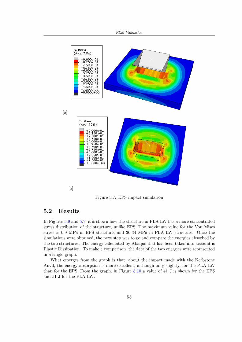
FEM Validation
[a]
[b]
Figure 57 EPS impact simulation
52 Results
In Figures 59 and 57 it is shown how the structure in PLA LW has a more concentratedstress distribution of the structure unlike EPS The maximum value for the Von Misesstress is 09 MPa in EPS structure and 3634 MPa in PLA LW structure Once thesimulations were obtained the next step was to go and compare the energies absorbed bythe two structures The energy calculated by Abaqus that has been taken into account isPlastic Dissipation To make a comparison the data of the two energies were representedin a single graph
What emerges from the graph is that about the impact made with the KerbstoneAnvil the energy absorption is more excellent although only slightly for the PLA LWthan for the EPS From the graph in Figure 510 a value of 41 J is shown for the EPSand 51 J for the PLA LW
55
[a]
[b]
Figure 59 PLA impact simulation
[a]
Figure 510 EPS and PLA LW energy comparison - Abaqus simulation
Chapter 6
Head Injury Data
For the statistical analysis the injuries related to the accident data were categorised intothe following types and levels based on the details of the medical report [11] about theEN 1078
bull Head Injury Criterion (HIC)
bull Peak Linear Acceleration (PLAc)
bull Gadd Severity Injury (GSI)
bull Diffuse axonal injuries (DAI)
61 Abaqus simulation
Until now the purpose of the simulations has been to determine which between the twomaterials and the two structures of EPS and PLA LW could absorb more energy duringthe impact but no simulations have been carried out in compliance with BS EN 1078on the helmet impact tests To calculate the injuries listed in the previous paragraphhowever we need the acceleration values in the three directions related to the subjectrsquoshead
To realize it the scan of my head already rsquocleanrsquo was considered of which it has beencalculated the inertia thanks to the automatic SolidWorks calculation and evaluated theweight with the Table 24 the structure of the helmet was placed for the EPS and thePLA LW over the head as shown in Figure 61 Also this time being able to mesh theentire helmet in PLA LW was impossible due to the excessive distortion of some elementsduring the simulation so it has been tried to make a section of the structures of thehelmet and results were obtained
57
Head Injury Data
[a] [b]
Figure 61 My scan head - CAD [a] head imported in Abaqus[b]
Initially the simulation had these characteristics as shown in the following Figure62 considering the helmet was not sectioned As explained earlier it was not possibleto get to simulation in the case of the optimized structure in PLA LW for this reasononly a part of the helmet was considered in both cases shown in Figure 63
[a]
Figure 62 Simulation based on BS EN 1078
58
Head Injury Data
[a] [b]
Figure 63 Simulation based on BS EN 1078 with head
In order to proceed with the simulation some boundary conditions that regard tiesand forces have have imposed
bull two reference points RP were created the first in the inertia centre of the headthe second relating to the Kerbstone Anvil which is a discrete rigid body
bull in the reference point RP of the head in the definition of the engineering features5 kg was inserted for the weight and an inertia I11 = 564464E+07 gmm2 I22 =460654E+07gmm2 I33 = 187302E+07gmm2
bull to simulate the impact it was set a speed of 457 ms at the reference point RP ofthe head in z-axis direction
bull a general contact with normal behaviour through rsquohardrsquo contact and tangentialbehaviour with a coefficient of friction of 02
bull between the upper surface of the helmet and the impactor it has been initializeda Surface to Surface contact with normal behaviour through rsquohardrsquo contact andtangential behaviour with a coefficient of friction of 02 with directionality imposedon rsquoisotropicrsquo
bull the movement between the Kerbstone anvil and the helmet is fixed through anEncastre therefore unable to move and rotate in xyz directions
bull the rotation in x y z relative to the RP of the rigid discrete impactor body is locked
FEM element
As reported in Table 53 the portion of the helmet in EPS has used a mesh with hexahe-dral elements of linear order For the structure (beetle) of PLA LW given the geometry
59
Head Injury Data
complexity it was necessary to use a quadratic order of tetrahedra For the mesh of thehead instead in both simulations have been used quadrilateral elements of linear orderas reported in the Tables 61 and 62
Object Elementnumber
Elements Shape Geometricorder
Head 3755 Quadrilateral - R3D4 Linear
Head 34542 Quadrilateral - R3D3 Linear
Helmet (PLA) 272302 Tetrahedral -C3D10M
Quadratic
Table 61 Mesh element - Head simulation with PLA LW (beetle) helmet
Object Elementnumber
Elements Shape Geometricorder
Head 3755 Quadrilateral - R3D4 Linear
Head 34542 Quadrilateral - R3D3 Linear
Helmet (EPS) 72280 Hexahedral - C3D8R Linear
Table 62 Mesh element - Head simulation with EPS helmet
62 Results
Figure 64 represents the simulation in line with BS EN 1078 concerning the helmet inEPS [a] and the helmet with bio-inspired structure in PLA LW For both simulationsVan Misesrsquo stress has Yield Stress values in the case of EPS which is 09 MPa and theplastic behaviour combination of PLA LW [b]
In the case of head and Kerbstone Anvil stress was not assessed as they were previ-ously defined as discrete rigid bodies
63 Head Injury Criterion
The HIC quantifies head impact severity by incorporating time of acceleration exposureand acceleration magnitude it is calculated in post-processing phase with the followingEquation 61
HIC15 =
[1
(t1 minus t2)
int t2
t1
a(t)dt
]25(t2 minus t1) (61)
60
Head Injury Data
[a]
[b]
Figure 64 Results simulation based on BS EN 1078 with sectioned head
For this analysis a(t) is the acceleration calculated in the centre of mass of the head(corresponding to the reference point RP) expressed in g and the time interval (t2 minus t1)was chosen to maximize HIC over a maximum duration of 15 ms
Matlab and the trapz function were used to calculate the HIC to integrate accelerationover time t2 and t1 were considered initial and final times of the simulation t1 = 0 sand t2 = 10 s time less than 15 s
HIC value of 198 was obtained for EPS and 87 for PLA LW Considering the Hayeset al [16] document about the HIC values and the graph in Figure 65 developed bythe author it is possible to find the percentages related to the different injury AIS1 -AIS6 which correspond respectively to lower and higher severity while in Figure 66 therelative fatality to every value of AIS is shown The values obtained for the HIC andother criteria are shown in Table 63 The HIC value for EPS is 198 for PLA LW it is
61
Head Injury Data
Figure 65 Head injury risk curves based on HIC values [16]
Figure 66 The abbreviated injury score versus fatality rate [16]
87 Analyzing the data and comparing them with the curves of the Figure 65 I obtain
bull a percentage between 20 - 30 of AIS 1 for EPS 10 - 20 for PLA LW
bull a percentage between 10 - 20 of AIS 2 for EPS and 0 - 10 for PLA LW
bull for AIS 3 AIS 4 AIS 5 AIS 6 the percentages for both structures is between 0 -10
Comparing these percentages with the fatality rate of Figure 66 it is clear there is a riskof Moderate and Minor fatality in the case of EPS and PLA LW as all values are between0 and 30
62
Head Injury Data
HIC PLA [g] GSI E [J]
EPS 198 97 361 37723
PLA LW 87 75 169 44102
Table 63 Head Injury Data - values
64 Peak Linear Acceleration
The resultant linear acceleration versus time curve was calculated according to Equation62
γ(t) =radicγ2x(t) + γ2y(t) + γ2z (t) (62)
where
bull γ(t) is the resultant linear acceleration (g)
bull γx(t) is the linear acceleration in x axes (g)
bull γy(t) is the linear acceleration in y axes (g)
bull γz(t)is the linear acceleration in z axes (g)
The value of the impact should never exceed 250g [9] Cripton at all [9] in their studyexamined a helmet with expanded polystyrene (EPS) Figure 68 shows maximum HIC forhelmeted and unhelmeted drops from all heights For each drop height helmets reducedHIC relative to unhelmeted drops IARV value is 180g The acceleration in the two casesis shown in Figure 67 and the maximum values are 97g for EPS and 75g for PLA LWas reported in Table 63 The two values considering a maximum value calculated byCripton [9] of 180g are amply optimal and comply with the standard of 250g
65 Gadd Severity Index
Gadd proposed the Severity Index Criteria shown in Equation 63 Following this crite-rion the GSI values that are over 1000 produce serious internal head injury [33]
GSI =
int t1
0a(t)25dt (63)
Where
bull a is the linear acceleration (g)
bull t is the duration of the impact (s)
I calculated the GSI with the function trapz between 0 and t and the resulting valuesare 361 for the EPS and 169 for the PLA LW which comply with the limit
63
Head Injury Data
Figure 67 Peak accelerations for both helmets
Figure 68 Peak accelerations for both helmeted and unhelmeted drops Numbers overbars indicate peak acceleration For 2 m drop height results stated are the mean value
calculated from three drops [9]
64
Head Injury Data
66 Diffuse Axonal Injury
DAI cases covered all incidences in which neurological injuries occurred as well as con-cussion unconsciousness and coma
In order to assess the risk of head trauma in terms of diffuse axonal injury (DAI)Milne et al [23] defined a model based head injury criteria as follows obtaining theresults in Figure 69
bull 50 risk of moderate neurological injury (DAI1+) Brain Von Mises shearing stressof 28 kPa
bull 50 risk of severe neurological injury (DAI2+) Brain Von Mises shearing stressof 53 kPa
[a]
[b]
Figure 69 Peak intra-cerebral shearing stress computed with the helmet model coupledto the human head model for all impact points (a) Flat anvil (b) Kerbstone anvil [23]
65
Head Injury Data
67 Energy absorbed
In Figure 52 during the impact test between the kerbstone Anvil and the plan with thebio-inspired structure in PLA LW and EPS it was found that the PLA LW althoughwith a small difference of 10 J absorbed more energy in comparison with the EPS Whenthe test is carried out in compliance with BS EN 1078 and the head with a speed of 457ms (corresponding to the kerbstone Anvil) as shown in Figure 610 also in this casethe PLA LW with the optimized helmet structure manages to absorb more energy (evenif the difference is very low) compared to the EPS The maximum energy value in PLALW is 44102 J of EPS is 37723 J
Figure 610 Energy absorption - BS EN 1078
66
Chapter 7
Conclusion
71 Conclusion
In this thesis work a bicycle helmet with a bio-inspired structure in PLA LW and 3Dprinted was created The initial approach was to introduce an innovative aspect tostandard EPS helmets not using foam but a polymer with new geometries able toabsorb much energy during the impact For this reason the beetle structure has beenpreferred relying solely on the hypothesis encountered in the literature of its quality inabsorbing energy
Combining the new material of the PLA LW and beetle structure has made possiblethe development of new material satisfactory characteristics have been obtained sincethe first tests The two materials were first subjected to tensile tests to determine theirspecific stress in these the PLA LW had positive results
Subsequent dynamic physical tests were carried out on 3D printed helmet models andon reference helmets in EPS to calculate the absorption energy in both cases at the timeof impact These resulted in energy absorption of the beetle structure in PLA LW withthe application of a TPU cover almost equal to that of EPS about 50J To validate withfinite element analysis the two models an explicit dynamic step was used in AbaqusSimulations showed that the PLA LW structure absorbs a higher amount of energy thanthe EPS the higher is 50 J and the EPS 40J
Finally positive results have also been obtained in calculating the head injury datasimulating according to BS EN 1078 with the use of impactor helmet and head Theacceleration values for both the structures were inferior to 220g precisely for the PLALW was 75g and for the EPS 97g The same applies to the calculation of HIC and GSI(maximum acceptable value of 1000) where the values are 87 and 169 in the case of PLALW and 361 and 198 in EPS For all tests therefore greater efficiency of the structure inPLA LW has been obtained Positive results also in the simulation of the energy absorbedduring the impact as the value referring to the EPS was 35J and that of the PLA LWwas 45J
67
Conclusion
72 Future work lines
The positive results obtained can be considered as a starting point for further tests andsimulations to ensure the safety of the helmet and compliance with the regulations butbefore getting improvements and continue testing changes are required
bull the beetle structure of the helmet made with GH adapts to the SubD withoutallowing to have a homogeneous distribution it would be appropriate to have moreregular hexagonal geometries
bull the mesh of the helmet is too complex and does not allow to perform the simulationprobably to use a more regular structure would have a mesh accordingly moreregular and the simulation would be successful
bull the uneven helmet structure has so many defects that the print is imperfect andthis can change the results of the impact tests the structure should be improved
bull the printing time varies from 4 to 5 days it should be improved
bull the TPU helmet cover is too big for the RAISE printing plan it is necessary togenerate a new geometry
bull the TPU cover it must be fixed on the helmet
bull in the calculation of the DAI it is necessary to have the definition of the brain andthe head should not be considered as a rigid body
bull in the injury calculation the helmet without protection was considered with theTPU cover the result will be better
bull air flow analysis
The comments mentioned are only considerations and problems that I gained duringmy thesis and which should be improved but I am sure that these changes and improve-ments from design to printing and simulations can make the helmet a good product
68
Bibliography
[1] K Adanty J M Clark A Post Thomas Blaine H and M D Gilchrist Comparingtwo proposed protocols to test the oblique response of cycling helmets to fall impactsInternational Journal of Crashworthiness 6648 ndash 663 2020
[2] MF Ashby YJM Brechetb D Cebona and L Salvoc Selection strategies formaterials and processes Materials and Design 2004
[3] M Aysha El casco de bicicleta voronoi impreso en 3d mas seguro y ligero https
www3dnativescomen3d-printed-bicycle-helmet-voronoi-190820204
[4] H Bikas P Stavropoulos and G Chryssolouris Additive manufacturing methodsand modelling approaches a critical review The International Journal of AdvancedManufacturing Technology 83389ndash405 2016
[5] British Standards BSI Helmets for pedal cyclists and for users of skateboards androller skates - BS EN 1078 2012
[6] British Standards BSI Headforms for use in the testing of protective helmets BSEN 960 2020
[7] ColorFabb Colorfabb lw-pla 2019 httpscolorfabbcommedia
datasheetstdscolorfabbTDS_E_ColorFabb_LW-PLApdf
[8] V G Coronado T Haileyesus J M Bell T A Cheng JHaarbauer-Krupa M RLionbarger J Flores-Herrera L C McGuire and J Gilchrist Trends in sports andrecreation-related traumatic brain injuries treated in us emergency departments thenational electronic injury surveillance system-all injury program (neiss-aip) 2001-2012 J Head Trauma Rehabil 30185ndash197 2015
[9] P A Cripton D M Dressler D Stuart Cameron A Christopher R and D RichardsBicycle helmets are highly effective at preventing head injury during head impactHead-form accelerations and injury criteria for helmeted and unhelmeted impactsAccident Analysis and Prevention 701ndash7 2014
[10] L Cui M A Forero R and M D Gilchrist Optimisation of energy absorbingliner for equestrian helmets UCD School of Electrical Electronic and MechanicalEngineering University College Dublin Belfield Dublin4 Ireland 2020
[11] C Deck N Bourdet F Meyer and R Willinger Protection performance of bicyclehelmets Journal of safety research pages 67ndash77 2019
[12] Committee F08 Specification for headforms F2220 ASTM International 2015
[13] Committee F08 Specification for helmets used in recreational bicycling or rollerskating F1447 ASTM International 2018
[14] Committee F08 Test methods for equipment and procedures used in evaluating theperformance F1446 ASTM International 2020
69
Bibliography
[15] P Halldin Shock absorption including measuring CENTC 158 Working Group11 2018
[16] W C Hayes M S Erickson and E D Power Forensic injury biomechanics Annualreview of biomedical engineering pages 55ndash86 2007
[17] HEXR httpshexrcom
[18] C Jinxiang Z Xiaoming O Yoji S Kazuya G Zhensheng and P LongchengThe deformation mode and strengthening mechanism of compression in the beetleelytron plate Materials and Design 131481ndash186 2017
[19] S Kroeker M Ozkul A De Marco S Bonin and GP Siegmund Density variationin the expanded polystyrene eps foam of bicycle helmets and its influence on impactperformance Journal of biomechanical engineering 2019
[20] S G Kroeker SJ Bonin A L DeMarco C A Good and G P Siegmund Agedoes not affect the material properties of expanded polystyrene liners in field-usedbicycle helmets Journal of biomechanical engineering 2016
[21] M Meier K H Tan M K Lim and L Chung Unlocking innovation in the sportindustry through additive manufacturing Business Process Management Journa2018
[22] N J Mills and A Gilchrist The effectiveness of foams in bicycle and motorcyclehelmets Accident Analysis Prevention 23153 ndash 163 1991
[23] G Milne C Deck R P Carreira Q Allinne and R Willinger Development andvalidation of a bicycle helmet assessment of head injury risk under standard impactconditions Computer methods in biomechanics and biomedical engineering 15 Suppl1309 ndash 310 2012
[24] Y Mosleh S J Vander B Depreitere and J Ivens Novel composite foam conceptfor head protection in oblique impacts Adv Eng Mater (Advanced EngineeringMaterials) 10 2017
[25] H Mustafa T Y Pang T Ellena and S H Nasir Impact attenuation of user-centred bicycle helmet design with different foam densities J Phys Conf Ser(Journal of Physics Conference Series) 1150 2019
[26] S H Ngoc and L Guoxing A review of recent research on bio-inspired structuresand materials for energy absorption applications Composites Part 181 2020
[27] J I Novak and A R Novak Is additive manufacturing improving performance insports a systematic review Sport engineering and technology 13 2020
[28] European Road Safety Observatory European road safety observatory facts and fig-ures - cyclists - 2020 December 2020 httpseceuropaeutransportroad_
safetysitesdefaultfilesfacts_figures_cyclists_final_20210323pdf
[29] New York City Departments of Health Parks Mental Hygiene Transportation Recre-ation and the New York City Police Department Bicyclist fatalities and seriousinjuries in new york city 2005
[30] W Pengwen Y Jing H Yanan H Jiaofei and F Xiaoyang Innovative designof a helmet based on reverse engineering and 3d printing Alexandria EngineeringJournal 603445ndash3453 2021
[31] S G Piland T E Gould M Jesunathadas J S Wiggins O McNair and V CShane Protective helmets in sports Materials in Sports Equipment 3 2019
70
Bibliography
[32] K Schmitt P F Niederer M H Muser and F Walz Trauma biomechanicsSpringer Berlin Heidelberg 2010
[33] David Sepelveda Lopez A Biomechanical Analysis of Bicycle Helmets using FEMPhD thesis 2019 Bachelor thesis
[34] H Stigson Bicycle Helmets 2020 Tested by Folksam PhD thesis 2020 PhDAssociate Professor Traffic Safety Research
[35] H Tao K Sudip N Anindya and X Yongzhao 3d printed sensors for biomedicalapplications A review sensor 2019
[36] M Trzaskalska and R Chwastek Damping properties and density of helmet linersmade of expanded polystyrene (eps) Archives of Metallurgy and Materials 66 2020
[37] Crupi V Epasto G and Guglielmino E Impact response of aluminum foam sand-wiches for light-weight ship structures Metals 198ndash112 2020
[38] W Wei-cai F Dong-ming and L Yuan-xin Study on impact energy absorbing per-formance of eps buffer layer of motorcycle helmet Proceedings - 2013 InternationalConference on Mechanical and Automation Engineering MAEE 2013
[39] Z Xiaoming C Jinxiang O Yoji Z Peiwei X Xiaobing and Y Xindi Influence ofhoneycomb dimensions and forming methods on the compressive properties of beetleelytron plates Journal of Sandwich Structures and Materials 2228ndash39 2020
[40] S Zhi L Dong Z Weisheng S Shanshan and G Xu Topological optimization ofbiomimetic sandwich structures with hybrid core and cfrp face sheets CompositesScience and Technology 14279ndash90 2017
[41] S Zhi S Shanshan G Xu H Xiaozhi and C Haoran On compressive propertiesof composite sandwich structures with grid reinforced honeycomb core CompositesPart B 94245ndash252 2016
71
- List of Tables
- List of Figures
- Introduction
-
- Helmet bike protection
-
- Helmet structure
-
- Additive Manufacturing
-
- AM process
- Materials and techniques - FDM
- AM in sport
-
- 3D printed helmets
-
- Phases
- HEXR
- VORONOI
-
- State of the art
-
- Standards
-
- Headform
- European Standard and American Standard
- Field of vision - BS EN 1078
- Test impact area
- Anvils and environmental conditions
-
- Materials
-
- EPS Foam
- CES Edu Pack - Material selection
- PLA with natural fiber and PLA LW
-
- Bio-inspired structures
-
- Beetle structure - Design of the model
- Specific stress - PLA LW and EPS foam
-
- Methodology
-
- 3D scan
-
- 3D Sense 2 scanner and Meshmixer - Reverse reconstruction
- 3D scan analysis and extraction of features
-
- Helmet design
-
- Rhinoceros - Helmet surface
- Grasshopper - Helmet structure
-
- 3D Print
-
- Printer and parameters
-
- Experimental evaluation
-
- Experimental tests
-
- Drop-weight impact test machine
-
- PLA LW helmet
- EPS helmet
- Results
-
- First results - PLA-LW and EPS helmet
- PLA-LW helmet with TPU cover
-
- FEM Validation
-
- Impactor - Anvils definition
-
- PLA LW - Plastic characteristics
- First test - helmet
- Second test - plane
- EPS impact simulations
- PLA LW impact simulations
-
- Results
-
- Head Injury Data
-
- Abaqus simulation
- Results
- Head Injury Criterion
- Peak Linear Acceleration
- Gadd Severity Index
- Diffuse Axonal Injury
- Energy absorbed
-
- Conclusion
-
- Conclusion
- Future work lines
-
- Bibliography
-

[a]
[b]
Figure 59 PLA impact simulation
[a]
Figure 510 EPS and PLA LW energy comparison - Abaqus simulation
Chapter 6
Head Injury Data
For the statistical analysis the injuries related to the accident data were categorised intothe following types and levels based on the details of the medical report [11] about theEN 1078
bull Head Injury Criterion (HIC)
bull Peak Linear Acceleration (PLAc)
bull Gadd Severity Injury (GSI)
bull Diffuse axonal injuries (DAI)
61 Abaqus simulation
Until now the purpose of the simulations has been to determine which between the twomaterials and the two structures of EPS and PLA LW could absorb more energy duringthe impact but no simulations have been carried out in compliance with BS EN 1078on the helmet impact tests To calculate the injuries listed in the previous paragraphhowever we need the acceleration values in the three directions related to the subjectrsquoshead
To realize it the scan of my head already rsquocleanrsquo was considered of which it has beencalculated the inertia thanks to the automatic SolidWorks calculation and evaluated theweight with the Table 24 the structure of the helmet was placed for the EPS and thePLA LW over the head as shown in Figure 61 Also this time being able to mesh theentire helmet in PLA LW was impossible due to the excessive distortion of some elementsduring the simulation so it has been tried to make a section of the structures of thehelmet and results were obtained
57
Head Injury Data
[a] [b]
Figure 61 My scan head - CAD [a] head imported in Abaqus[b]
Initially the simulation had these characteristics as shown in the following Figure62 considering the helmet was not sectioned As explained earlier it was not possibleto get to simulation in the case of the optimized structure in PLA LW for this reasononly a part of the helmet was considered in both cases shown in Figure 63
[a]
Figure 62 Simulation based on BS EN 1078
58
Head Injury Data
[a] [b]
Figure 63 Simulation based on BS EN 1078 with head
In order to proceed with the simulation some boundary conditions that regard tiesand forces have have imposed
bull two reference points RP were created the first in the inertia centre of the headthe second relating to the Kerbstone Anvil which is a discrete rigid body
bull in the reference point RP of the head in the definition of the engineering features5 kg was inserted for the weight and an inertia I11 = 564464E+07 gmm2 I22 =460654E+07gmm2 I33 = 187302E+07gmm2
bull to simulate the impact it was set a speed of 457 ms at the reference point RP ofthe head in z-axis direction
bull a general contact with normal behaviour through rsquohardrsquo contact and tangentialbehaviour with a coefficient of friction of 02
bull between the upper surface of the helmet and the impactor it has been initializeda Surface to Surface contact with normal behaviour through rsquohardrsquo contact andtangential behaviour with a coefficient of friction of 02 with directionality imposedon rsquoisotropicrsquo
bull the movement between the Kerbstone anvil and the helmet is fixed through anEncastre therefore unable to move and rotate in xyz directions
bull the rotation in x y z relative to the RP of the rigid discrete impactor body is locked
FEM element
As reported in Table 53 the portion of the helmet in EPS has used a mesh with hexahe-dral elements of linear order For the structure (beetle) of PLA LW given the geometry
59
Head Injury Data
complexity it was necessary to use a quadratic order of tetrahedra For the mesh of thehead instead in both simulations have been used quadrilateral elements of linear orderas reported in the Tables 61 and 62
Object Elementnumber
Elements Shape Geometricorder
Head 3755 Quadrilateral - R3D4 Linear
Head 34542 Quadrilateral - R3D3 Linear
Helmet (PLA) 272302 Tetrahedral -C3D10M
Quadratic
Table 61 Mesh element - Head simulation with PLA LW (beetle) helmet
Object Elementnumber
Elements Shape Geometricorder
Head 3755 Quadrilateral - R3D4 Linear
Head 34542 Quadrilateral - R3D3 Linear
Helmet (EPS) 72280 Hexahedral - C3D8R Linear
Table 62 Mesh element - Head simulation with EPS helmet
62 Results
Figure 64 represents the simulation in line with BS EN 1078 concerning the helmet inEPS [a] and the helmet with bio-inspired structure in PLA LW For both simulationsVan Misesrsquo stress has Yield Stress values in the case of EPS which is 09 MPa and theplastic behaviour combination of PLA LW [b]
In the case of head and Kerbstone Anvil stress was not assessed as they were previ-ously defined as discrete rigid bodies
63 Head Injury Criterion
The HIC quantifies head impact severity by incorporating time of acceleration exposureand acceleration magnitude it is calculated in post-processing phase with the followingEquation 61
HIC15 =
[1
(t1 minus t2)
int t2
t1
a(t)dt
]25(t2 minus t1) (61)
60
Head Injury Data
[a]
[b]
Figure 64 Results simulation based on BS EN 1078 with sectioned head
For this analysis a(t) is the acceleration calculated in the centre of mass of the head(corresponding to the reference point RP) expressed in g and the time interval (t2 minus t1)was chosen to maximize HIC over a maximum duration of 15 ms
Matlab and the trapz function were used to calculate the HIC to integrate accelerationover time t2 and t1 were considered initial and final times of the simulation t1 = 0 sand t2 = 10 s time less than 15 s
HIC value of 198 was obtained for EPS and 87 for PLA LW Considering the Hayeset al [16] document about the HIC values and the graph in Figure 65 developed bythe author it is possible to find the percentages related to the different injury AIS1 -AIS6 which correspond respectively to lower and higher severity while in Figure 66 therelative fatality to every value of AIS is shown The values obtained for the HIC andother criteria are shown in Table 63 The HIC value for EPS is 198 for PLA LW it is
61
Head Injury Data
Figure 65 Head injury risk curves based on HIC values [16]
Figure 66 The abbreviated injury score versus fatality rate [16]
87 Analyzing the data and comparing them with the curves of the Figure 65 I obtain
bull a percentage between 20 - 30 of AIS 1 for EPS 10 - 20 for PLA LW
bull a percentage between 10 - 20 of AIS 2 for EPS and 0 - 10 for PLA LW
bull for AIS 3 AIS 4 AIS 5 AIS 6 the percentages for both structures is between 0 -10
Comparing these percentages with the fatality rate of Figure 66 it is clear there is a riskof Moderate and Minor fatality in the case of EPS and PLA LW as all values are between0 and 30
62
Head Injury Data
HIC PLA [g] GSI E [J]
EPS 198 97 361 37723
PLA LW 87 75 169 44102
Table 63 Head Injury Data - values
64 Peak Linear Acceleration
The resultant linear acceleration versus time curve was calculated according to Equation62
γ(t) =radicγ2x(t) + γ2y(t) + γ2z (t) (62)
where
bull γ(t) is the resultant linear acceleration (g)
bull γx(t) is the linear acceleration in x axes (g)
bull γy(t) is the linear acceleration in y axes (g)
bull γz(t)is the linear acceleration in z axes (g)
The value of the impact should never exceed 250g [9] Cripton at all [9] in their studyexamined a helmet with expanded polystyrene (EPS) Figure 68 shows maximum HIC forhelmeted and unhelmeted drops from all heights For each drop height helmets reducedHIC relative to unhelmeted drops IARV value is 180g The acceleration in the two casesis shown in Figure 67 and the maximum values are 97g for EPS and 75g for PLA LWas reported in Table 63 The two values considering a maximum value calculated byCripton [9] of 180g are amply optimal and comply with the standard of 250g
65 Gadd Severity Index
Gadd proposed the Severity Index Criteria shown in Equation 63 Following this crite-rion the GSI values that are over 1000 produce serious internal head injury [33]
GSI =
int t1
0a(t)25dt (63)
Where
bull a is the linear acceleration (g)
bull t is the duration of the impact (s)
I calculated the GSI with the function trapz between 0 and t and the resulting valuesare 361 for the EPS and 169 for the PLA LW which comply with the limit
63
Head Injury Data
Figure 67 Peak accelerations for both helmets
Figure 68 Peak accelerations for both helmeted and unhelmeted drops Numbers overbars indicate peak acceleration For 2 m drop height results stated are the mean value
calculated from three drops [9]
64
Head Injury Data
66 Diffuse Axonal Injury
DAI cases covered all incidences in which neurological injuries occurred as well as con-cussion unconsciousness and coma
In order to assess the risk of head trauma in terms of diffuse axonal injury (DAI)Milne et al [23] defined a model based head injury criteria as follows obtaining theresults in Figure 69
bull 50 risk of moderate neurological injury (DAI1+) Brain Von Mises shearing stressof 28 kPa
bull 50 risk of severe neurological injury (DAI2+) Brain Von Mises shearing stressof 53 kPa
[a]
[b]
Figure 69 Peak intra-cerebral shearing stress computed with the helmet model coupledto the human head model for all impact points (a) Flat anvil (b) Kerbstone anvil [23]
65
Head Injury Data
67 Energy absorbed
In Figure 52 during the impact test between the kerbstone Anvil and the plan with thebio-inspired structure in PLA LW and EPS it was found that the PLA LW althoughwith a small difference of 10 J absorbed more energy in comparison with the EPS Whenthe test is carried out in compliance with BS EN 1078 and the head with a speed of 457ms (corresponding to the kerbstone Anvil) as shown in Figure 610 also in this casethe PLA LW with the optimized helmet structure manages to absorb more energy (evenif the difference is very low) compared to the EPS The maximum energy value in PLALW is 44102 J of EPS is 37723 J
Figure 610 Energy absorption - BS EN 1078
66
Chapter 7
Conclusion
71 Conclusion
In this thesis work a bicycle helmet with a bio-inspired structure in PLA LW and 3Dprinted was created The initial approach was to introduce an innovative aspect tostandard EPS helmets not using foam but a polymer with new geometries able toabsorb much energy during the impact For this reason the beetle structure has beenpreferred relying solely on the hypothesis encountered in the literature of its quality inabsorbing energy
Combining the new material of the PLA LW and beetle structure has made possiblethe development of new material satisfactory characteristics have been obtained sincethe first tests The two materials were first subjected to tensile tests to determine theirspecific stress in these the PLA LW had positive results
Subsequent dynamic physical tests were carried out on 3D printed helmet models andon reference helmets in EPS to calculate the absorption energy in both cases at the timeof impact These resulted in energy absorption of the beetle structure in PLA LW withthe application of a TPU cover almost equal to that of EPS about 50J To validate withfinite element analysis the two models an explicit dynamic step was used in AbaqusSimulations showed that the PLA LW structure absorbs a higher amount of energy thanthe EPS the higher is 50 J and the EPS 40J
Finally positive results have also been obtained in calculating the head injury datasimulating according to BS EN 1078 with the use of impactor helmet and head Theacceleration values for both the structures were inferior to 220g precisely for the PLALW was 75g and for the EPS 97g The same applies to the calculation of HIC and GSI(maximum acceptable value of 1000) where the values are 87 and 169 in the case of PLALW and 361 and 198 in EPS For all tests therefore greater efficiency of the structure inPLA LW has been obtained Positive results also in the simulation of the energy absorbedduring the impact as the value referring to the EPS was 35J and that of the PLA LWwas 45J
67
Conclusion
72 Future work lines
The positive results obtained can be considered as a starting point for further tests andsimulations to ensure the safety of the helmet and compliance with the regulations butbefore getting improvements and continue testing changes are required
bull the beetle structure of the helmet made with GH adapts to the SubD withoutallowing to have a homogeneous distribution it would be appropriate to have moreregular hexagonal geometries
bull the mesh of the helmet is too complex and does not allow to perform the simulationprobably to use a more regular structure would have a mesh accordingly moreregular and the simulation would be successful
bull the uneven helmet structure has so many defects that the print is imperfect andthis can change the results of the impact tests the structure should be improved
bull the printing time varies from 4 to 5 days it should be improved
bull the TPU helmet cover is too big for the RAISE printing plan it is necessary togenerate a new geometry
bull the TPU cover it must be fixed on the helmet
bull in the calculation of the DAI it is necessary to have the definition of the brain andthe head should not be considered as a rigid body
bull in the injury calculation the helmet without protection was considered with theTPU cover the result will be better
bull air flow analysis
The comments mentioned are only considerations and problems that I gained duringmy thesis and which should be improved but I am sure that these changes and improve-ments from design to printing and simulations can make the helmet a good product
68
Bibliography
[1] K Adanty J M Clark A Post Thomas Blaine H and M D Gilchrist Comparingtwo proposed protocols to test the oblique response of cycling helmets to fall impactsInternational Journal of Crashworthiness 6648 ndash 663 2020
[2] MF Ashby YJM Brechetb D Cebona and L Salvoc Selection strategies formaterials and processes Materials and Design 2004
[3] M Aysha El casco de bicicleta voronoi impreso en 3d mas seguro y ligero https
www3dnativescomen3d-printed-bicycle-helmet-voronoi-190820204
[4] H Bikas P Stavropoulos and G Chryssolouris Additive manufacturing methodsand modelling approaches a critical review The International Journal of AdvancedManufacturing Technology 83389ndash405 2016
[5] British Standards BSI Helmets for pedal cyclists and for users of skateboards androller skates - BS EN 1078 2012
[6] British Standards BSI Headforms for use in the testing of protective helmets BSEN 960 2020
[7] ColorFabb Colorfabb lw-pla 2019 httpscolorfabbcommedia
datasheetstdscolorfabbTDS_E_ColorFabb_LW-PLApdf
[8] V G Coronado T Haileyesus J M Bell T A Cheng JHaarbauer-Krupa M RLionbarger J Flores-Herrera L C McGuire and J Gilchrist Trends in sports andrecreation-related traumatic brain injuries treated in us emergency departments thenational electronic injury surveillance system-all injury program (neiss-aip) 2001-2012 J Head Trauma Rehabil 30185ndash197 2015
[9] P A Cripton D M Dressler D Stuart Cameron A Christopher R and D RichardsBicycle helmets are highly effective at preventing head injury during head impactHead-form accelerations and injury criteria for helmeted and unhelmeted impactsAccident Analysis and Prevention 701ndash7 2014
[10] L Cui M A Forero R and M D Gilchrist Optimisation of energy absorbingliner for equestrian helmets UCD School of Electrical Electronic and MechanicalEngineering University College Dublin Belfield Dublin4 Ireland 2020
[11] C Deck N Bourdet F Meyer and R Willinger Protection performance of bicyclehelmets Journal of safety research pages 67ndash77 2019
[12] Committee F08 Specification for headforms F2220 ASTM International 2015
[13] Committee F08 Specification for helmets used in recreational bicycling or rollerskating F1447 ASTM International 2018
[14] Committee F08 Test methods for equipment and procedures used in evaluating theperformance F1446 ASTM International 2020
69
Bibliography
[15] P Halldin Shock absorption including measuring CENTC 158 Working Group11 2018
[16] W C Hayes M S Erickson and E D Power Forensic injury biomechanics Annualreview of biomedical engineering pages 55ndash86 2007
[17] HEXR httpshexrcom
[18] C Jinxiang Z Xiaoming O Yoji S Kazuya G Zhensheng and P LongchengThe deformation mode and strengthening mechanism of compression in the beetleelytron plate Materials and Design 131481ndash186 2017
[19] S Kroeker M Ozkul A De Marco S Bonin and GP Siegmund Density variationin the expanded polystyrene eps foam of bicycle helmets and its influence on impactperformance Journal of biomechanical engineering 2019
[20] S G Kroeker SJ Bonin A L DeMarco C A Good and G P Siegmund Agedoes not affect the material properties of expanded polystyrene liners in field-usedbicycle helmets Journal of biomechanical engineering 2016
[21] M Meier K H Tan M K Lim and L Chung Unlocking innovation in the sportindustry through additive manufacturing Business Process Management Journa2018
[22] N J Mills and A Gilchrist The effectiveness of foams in bicycle and motorcyclehelmets Accident Analysis Prevention 23153 ndash 163 1991
[23] G Milne C Deck R P Carreira Q Allinne and R Willinger Development andvalidation of a bicycle helmet assessment of head injury risk under standard impactconditions Computer methods in biomechanics and biomedical engineering 15 Suppl1309 ndash 310 2012
[24] Y Mosleh S J Vander B Depreitere and J Ivens Novel composite foam conceptfor head protection in oblique impacts Adv Eng Mater (Advanced EngineeringMaterials) 10 2017
[25] H Mustafa T Y Pang T Ellena and S H Nasir Impact attenuation of user-centred bicycle helmet design with different foam densities J Phys Conf Ser(Journal of Physics Conference Series) 1150 2019
[26] S H Ngoc and L Guoxing A review of recent research on bio-inspired structuresand materials for energy absorption applications Composites Part 181 2020
[27] J I Novak and A R Novak Is additive manufacturing improving performance insports a systematic review Sport engineering and technology 13 2020
[28] European Road Safety Observatory European road safety observatory facts and fig-ures - cyclists - 2020 December 2020 httpseceuropaeutransportroad_
safetysitesdefaultfilesfacts_figures_cyclists_final_20210323pdf
[29] New York City Departments of Health Parks Mental Hygiene Transportation Recre-ation and the New York City Police Department Bicyclist fatalities and seriousinjuries in new york city 2005
[30] W Pengwen Y Jing H Yanan H Jiaofei and F Xiaoyang Innovative designof a helmet based on reverse engineering and 3d printing Alexandria EngineeringJournal 603445ndash3453 2021
[31] S G Piland T E Gould M Jesunathadas J S Wiggins O McNair and V CShane Protective helmets in sports Materials in Sports Equipment 3 2019
70
Bibliography
[32] K Schmitt P F Niederer M H Muser and F Walz Trauma biomechanicsSpringer Berlin Heidelberg 2010
[33] David Sepelveda Lopez A Biomechanical Analysis of Bicycle Helmets using FEMPhD thesis 2019 Bachelor thesis
[34] H Stigson Bicycle Helmets 2020 Tested by Folksam PhD thesis 2020 PhDAssociate Professor Traffic Safety Research
[35] H Tao K Sudip N Anindya and X Yongzhao 3d printed sensors for biomedicalapplications A review sensor 2019
[36] M Trzaskalska and R Chwastek Damping properties and density of helmet linersmade of expanded polystyrene (eps) Archives of Metallurgy and Materials 66 2020
[37] Crupi V Epasto G and Guglielmino E Impact response of aluminum foam sand-wiches for light-weight ship structures Metals 198ndash112 2020
[38] W Wei-cai F Dong-ming and L Yuan-xin Study on impact energy absorbing per-formance of eps buffer layer of motorcycle helmet Proceedings - 2013 InternationalConference on Mechanical and Automation Engineering MAEE 2013
[39] Z Xiaoming C Jinxiang O Yoji Z Peiwei X Xiaobing and Y Xindi Influence ofhoneycomb dimensions and forming methods on the compressive properties of beetleelytron plates Journal of Sandwich Structures and Materials 2228ndash39 2020
[40] S Zhi L Dong Z Weisheng S Shanshan and G Xu Topological optimization ofbiomimetic sandwich structures with hybrid core and cfrp face sheets CompositesScience and Technology 14279ndash90 2017
[41] S Zhi S Shanshan G Xu H Xiaozhi and C Haoran On compressive propertiesof composite sandwich structures with grid reinforced honeycomb core CompositesPart B 94245ndash252 2016
71
- List of Tables
- List of Figures
- Introduction
-
- Helmet bike protection
-
- Helmet structure
-
- Additive Manufacturing
-
- AM process
- Materials and techniques - FDM
- AM in sport
-
- 3D printed helmets
-
- Phases
- HEXR
- VORONOI
-
- State of the art
-
- Standards
-
- Headform
- European Standard and American Standard
- Field of vision - BS EN 1078
- Test impact area
- Anvils and environmental conditions
-
- Materials
-
- EPS Foam
- CES Edu Pack - Material selection
- PLA with natural fiber and PLA LW
-
- Bio-inspired structures
-
- Beetle structure - Design of the model
- Specific stress - PLA LW and EPS foam
-
- Methodology
-
- 3D scan
-
- 3D Sense 2 scanner and Meshmixer - Reverse reconstruction
- 3D scan analysis and extraction of features
-
- Helmet design
-
- Rhinoceros - Helmet surface
- Grasshopper - Helmet structure
-
- 3D Print
-
- Printer and parameters
-
- Experimental evaluation
-
- Experimental tests
-
- Drop-weight impact test machine
-
- PLA LW helmet
- EPS helmet
- Results
-
- First results - PLA-LW and EPS helmet
- PLA-LW helmet with TPU cover
-
- FEM Validation
-
- Impactor - Anvils definition
-
- PLA LW - Plastic characteristics
- First test - helmet
- Second test - plane
- EPS impact simulations
- PLA LW impact simulations
-
- Results
-
- Head Injury Data
-
- Abaqus simulation
- Results
- Head Injury Criterion
- Peak Linear Acceleration
- Gadd Severity Index
- Diffuse Axonal Injury
- Energy absorbed
-
- Conclusion
-
- Conclusion
- Future work lines
-
- Bibliography
-
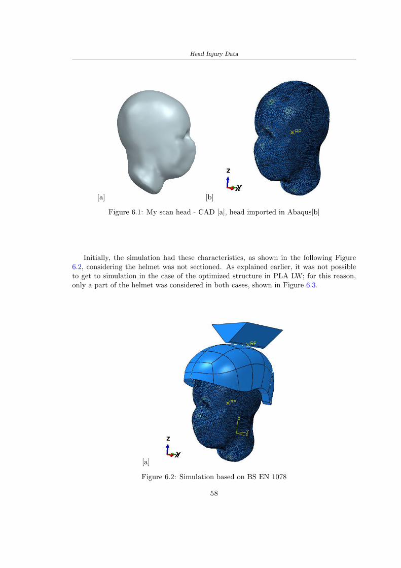
Head Injury Data
[a] [b]
Figure 61 My scan head - CAD [a] head imported in Abaqus[b]
Initially the simulation had these characteristics as shown in the following Figure62 considering the helmet was not sectioned As explained earlier it was not possibleto get to simulation in the case of the optimized structure in PLA LW for this reasononly a part of the helmet was considered in both cases shown in Figure 63
[a]
Figure 62 Simulation based on BS EN 1078
58
Head Injury Data
[a] [b]
Figure 63 Simulation based on BS EN 1078 with head
In order to proceed with the simulation some boundary conditions that regard tiesand forces have have imposed
bull two reference points RP were created the first in the inertia centre of the headthe second relating to the Kerbstone Anvil which is a discrete rigid body
bull in the reference point RP of the head in the definition of the engineering features5 kg was inserted for the weight and an inertia I11 = 564464E+07 gmm2 I22 =460654E+07gmm2 I33 = 187302E+07gmm2
bull to simulate the impact it was set a speed of 457 ms at the reference point RP ofthe head in z-axis direction
bull a general contact with normal behaviour through rsquohardrsquo contact and tangentialbehaviour with a coefficient of friction of 02
bull between the upper surface of the helmet and the impactor it has been initializeda Surface to Surface contact with normal behaviour through rsquohardrsquo contact andtangential behaviour with a coefficient of friction of 02 with directionality imposedon rsquoisotropicrsquo
bull the movement between the Kerbstone anvil and the helmet is fixed through anEncastre therefore unable to move and rotate in xyz directions
bull the rotation in x y z relative to the RP of the rigid discrete impactor body is locked
FEM element
As reported in Table 53 the portion of the helmet in EPS has used a mesh with hexahe-dral elements of linear order For the structure (beetle) of PLA LW given the geometry
59
Head Injury Data
complexity it was necessary to use a quadratic order of tetrahedra For the mesh of thehead instead in both simulations have been used quadrilateral elements of linear orderas reported in the Tables 61 and 62
Object Elementnumber
Elements Shape Geometricorder
Head 3755 Quadrilateral - R3D4 Linear
Head 34542 Quadrilateral - R3D3 Linear
Helmet (PLA) 272302 Tetrahedral -C3D10M
Quadratic
Table 61 Mesh element - Head simulation with PLA LW (beetle) helmet
Object Elementnumber
Elements Shape Geometricorder
Head 3755 Quadrilateral - R3D4 Linear
Head 34542 Quadrilateral - R3D3 Linear
Helmet (EPS) 72280 Hexahedral - C3D8R Linear
Table 62 Mesh element - Head simulation with EPS helmet
62 Results
Figure 64 represents the simulation in line with BS EN 1078 concerning the helmet inEPS [a] and the helmet with bio-inspired structure in PLA LW For both simulationsVan Misesrsquo stress has Yield Stress values in the case of EPS which is 09 MPa and theplastic behaviour combination of PLA LW [b]
In the case of head and Kerbstone Anvil stress was not assessed as they were previ-ously defined as discrete rigid bodies
63 Head Injury Criterion
The HIC quantifies head impact severity by incorporating time of acceleration exposureand acceleration magnitude it is calculated in post-processing phase with the followingEquation 61
HIC15 =
[1
(t1 minus t2)
int t2
t1
a(t)dt
]25(t2 minus t1) (61)
60
Head Injury Data
[a]
[b]
Figure 64 Results simulation based on BS EN 1078 with sectioned head
For this analysis a(t) is the acceleration calculated in the centre of mass of the head(corresponding to the reference point RP) expressed in g and the time interval (t2 minus t1)was chosen to maximize HIC over a maximum duration of 15 ms
Matlab and the trapz function were used to calculate the HIC to integrate accelerationover time t2 and t1 were considered initial and final times of the simulation t1 = 0 sand t2 = 10 s time less than 15 s
HIC value of 198 was obtained for EPS and 87 for PLA LW Considering the Hayeset al [16] document about the HIC values and the graph in Figure 65 developed bythe author it is possible to find the percentages related to the different injury AIS1 -AIS6 which correspond respectively to lower and higher severity while in Figure 66 therelative fatality to every value of AIS is shown The values obtained for the HIC andother criteria are shown in Table 63 The HIC value for EPS is 198 for PLA LW it is
61
Head Injury Data
Figure 65 Head injury risk curves based on HIC values [16]
Figure 66 The abbreviated injury score versus fatality rate [16]
87 Analyzing the data and comparing them with the curves of the Figure 65 I obtain
bull a percentage between 20 - 30 of AIS 1 for EPS 10 - 20 for PLA LW
bull a percentage between 10 - 20 of AIS 2 for EPS and 0 - 10 for PLA LW
bull for AIS 3 AIS 4 AIS 5 AIS 6 the percentages for both structures is between 0 -10
Comparing these percentages with the fatality rate of Figure 66 it is clear there is a riskof Moderate and Minor fatality in the case of EPS and PLA LW as all values are between0 and 30
62
Head Injury Data
HIC PLA [g] GSI E [J]
EPS 198 97 361 37723
PLA LW 87 75 169 44102
Table 63 Head Injury Data - values
64 Peak Linear Acceleration
The resultant linear acceleration versus time curve was calculated according to Equation62
γ(t) =radicγ2x(t) + γ2y(t) + γ2z (t) (62)
where
bull γ(t) is the resultant linear acceleration (g)
bull γx(t) is the linear acceleration in x axes (g)
bull γy(t) is the linear acceleration in y axes (g)
bull γz(t)is the linear acceleration in z axes (g)
The value of the impact should never exceed 250g [9] Cripton at all [9] in their studyexamined a helmet with expanded polystyrene (EPS) Figure 68 shows maximum HIC forhelmeted and unhelmeted drops from all heights For each drop height helmets reducedHIC relative to unhelmeted drops IARV value is 180g The acceleration in the two casesis shown in Figure 67 and the maximum values are 97g for EPS and 75g for PLA LWas reported in Table 63 The two values considering a maximum value calculated byCripton [9] of 180g are amply optimal and comply with the standard of 250g
65 Gadd Severity Index
Gadd proposed the Severity Index Criteria shown in Equation 63 Following this crite-rion the GSI values that are over 1000 produce serious internal head injury [33]
GSI =
int t1
0a(t)25dt (63)
Where
bull a is the linear acceleration (g)
bull t is the duration of the impact (s)
I calculated the GSI with the function trapz between 0 and t and the resulting valuesare 361 for the EPS and 169 for the PLA LW which comply with the limit
63
Head Injury Data
Figure 67 Peak accelerations for both helmets
Figure 68 Peak accelerations for both helmeted and unhelmeted drops Numbers overbars indicate peak acceleration For 2 m drop height results stated are the mean value
calculated from three drops [9]
64
Head Injury Data
66 Diffuse Axonal Injury
DAI cases covered all incidences in which neurological injuries occurred as well as con-cussion unconsciousness and coma
In order to assess the risk of head trauma in terms of diffuse axonal injury (DAI)Milne et al [23] defined a model based head injury criteria as follows obtaining theresults in Figure 69
bull 50 risk of moderate neurological injury (DAI1+) Brain Von Mises shearing stressof 28 kPa
bull 50 risk of severe neurological injury (DAI2+) Brain Von Mises shearing stressof 53 kPa
[a]
[b]
Figure 69 Peak intra-cerebral shearing stress computed with the helmet model coupledto the human head model for all impact points (a) Flat anvil (b) Kerbstone anvil [23]
65
Head Injury Data
67 Energy absorbed
In Figure 52 during the impact test between the kerbstone Anvil and the plan with thebio-inspired structure in PLA LW and EPS it was found that the PLA LW althoughwith a small difference of 10 J absorbed more energy in comparison with the EPS Whenthe test is carried out in compliance with BS EN 1078 and the head with a speed of 457ms (corresponding to the kerbstone Anvil) as shown in Figure 610 also in this casethe PLA LW with the optimized helmet structure manages to absorb more energy (evenif the difference is very low) compared to the EPS The maximum energy value in PLALW is 44102 J of EPS is 37723 J
Figure 610 Energy absorption - BS EN 1078
66
Chapter 7
Conclusion
71 Conclusion
In this thesis work a bicycle helmet with a bio-inspired structure in PLA LW and 3Dprinted was created The initial approach was to introduce an innovative aspect tostandard EPS helmets not using foam but a polymer with new geometries able toabsorb much energy during the impact For this reason the beetle structure has beenpreferred relying solely on the hypothesis encountered in the literature of its quality inabsorbing energy
Combining the new material of the PLA LW and beetle structure has made possiblethe development of new material satisfactory characteristics have been obtained sincethe first tests The two materials were first subjected to tensile tests to determine theirspecific stress in these the PLA LW had positive results
Subsequent dynamic physical tests were carried out on 3D printed helmet models andon reference helmets in EPS to calculate the absorption energy in both cases at the timeof impact These resulted in energy absorption of the beetle structure in PLA LW withthe application of a TPU cover almost equal to that of EPS about 50J To validate withfinite element analysis the two models an explicit dynamic step was used in AbaqusSimulations showed that the PLA LW structure absorbs a higher amount of energy thanthe EPS the higher is 50 J and the EPS 40J
Finally positive results have also been obtained in calculating the head injury datasimulating according to BS EN 1078 with the use of impactor helmet and head Theacceleration values for both the structures were inferior to 220g precisely for the PLALW was 75g and for the EPS 97g The same applies to the calculation of HIC and GSI(maximum acceptable value of 1000) where the values are 87 and 169 in the case of PLALW and 361 and 198 in EPS For all tests therefore greater efficiency of the structure inPLA LW has been obtained Positive results also in the simulation of the energy absorbedduring the impact as the value referring to the EPS was 35J and that of the PLA LWwas 45J
67
Conclusion
72 Future work lines
The positive results obtained can be considered as a starting point for further tests andsimulations to ensure the safety of the helmet and compliance with the regulations butbefore getting improvements and continue testing changes are required
bull the beetle structure of the helmet made with GH adapts to the SubD withoutallowing to have a homogeneous distribution it would be appropriate to have moreregular hexagonal geometries
bull the mesh of the helmet is too complex and does not allow to perform the simulationprobably to use a more regular structure would have a mesh accordingly moreregular and the simulation would be successful
bull the uneven helmet structure has so many defects that the print is imperfect andthis can change the results of the impact tests the structure should be improved
bull the printing time varies from 4 to 5 days it should be improved
bull the TPU helmet cover is too big for the RAISE printing plan it is necessary togenerate a new geometry
bull the TPU cover it must be fixed on the helmet
bull in the calculation of the DAI it is necessary to have the definition of the brain andthe head should not be considered as a rigid body
bull in the injury calculation the helmet without protection was considered with theTPU cover the result will be better
bull air flow analysis
The comments mentioned are only considerations and problems that I gained duringmy thesis and which should be improved but I am sure that these changes and improve-ments from design to printing and simulations can make the helmet a good product
68
Bibliography
[1] K Adanty J M Clark A Post Thomas Blaine H and M D Gilchrist Comparingtwo proposed protocols to test the oblique response of cycling helmets to fall impactsInternational Journal of Crashworthiness 6648 ndash 663 2020
[2] MF Ashby YJM Brechetb D Cebona and L Salvoc Selection strategies formaterials and processes Materials and Design 2004
[3] M Aysha El casco de bicicleta voronoi impreso en 3d mas seguro y ligero https
www3dnativescomen3d-printed-bicycle-helmet-voronoi-190820204
[4] H Bikas P Stavropoulos and G Chryssolouris Additive manufacturing methodsand modelling approaches a critical review The International Journal of AdvancedManufacturing Technology 83389ndash405 2016
[5] British Standards BSI Helmets for pedal cyclists and for users of skateboards androller skates - BS EN 1078 2012
[6] British Standards BSI Headforms for use in the testing of protective helmets BSEN 960 2020
[7] ColorFabb Colorfabb lw-pla 2019 httpscolorfabbcommedia
datasheetstdscolorfabbTDS_E_ColorFabb_LW-PLApdf
[8] V G Coronado T Haileyesus J M Bell T A Cheng JHaarbauer-Krupa M RLionbarger J Flores-Herrera L C McGuire and J Gilchrist Trends in sports andrecreation-related traumatic brain injuries treated in us emergency departments thenational electronic injury surveillance system-all injury program (neiss-aip) 2001-2012 J Head Trauma Rehabil 30185ndash197 2015
[9] P A Cripton D M Dressler D Stuart Cameron A Christopher R and D RichardsBicycle helmets are highly effective at preventing head injury during head impactHead-form accelerations and injury criteria for helmeted and unhelmeted impactsAccident Analysis and Prevention 701ndash7 2014
[10] L Cui M A Forero R and M D Gilchrist Optimisation of energy absorbingliner for equestrian helmets UCD School of Electrical Electronic and MechanicalEngineering University College Dublin Belfield Dublin4 Ireland 2020
[11] C Deck N Bourdet F Meyer and R Willinger Protection performance of bicyclehelmets Journal of safety research pages 67ndash77 2019
[12] Committee F08 Specification for headforms F2220 ASTM International 2015
[13] Committee F08 Specification for helmets used in recreational bicycling or rollerskating F1447 ASTM International 2018
[14] Committee F08 Test methods for equipment and procedures used in evaluating theperformance F1446 ASTM International 2020
69
Bibliography
[15] P Halldin Shock absorption including measuring CENTC 158 Working Group11 2018
[16] W C Hayes M S Erickson and E D Power Forensic injury biomechanics Annualreview of biomedical engineering pages 55ndash86 2007
[17] HEXR httpshexrcom
[18] C Jinxiang Z Xiaoming O Yoji S Kazuya G Zhensheng and P LongchengThe deformation mode and strengthening mechanism of compression in the beetleelytron plate Materials and Design 131481ndash186 2017
[19] S Kroeker M Ozkul A De Marco S Bonin and GP Siegmund Density variationin the expanded polystyrene eps foam of bicycle helmets and its influence on impactperformance Journal of biomechanical engineering 2019
[20] S G Kroeker SJ Bonin A L DeMarco C A Good and G P Siegmund Agedoes not affect the material properties of expanded polystyrene liners in field-usedbicycle helmets Journal of biomechanical engineering 2016
[21] M Meier K H Tan M K Lim and L Chung Unlocking innovation in the sportindustry through additive manufacturing Business Process Management Journa2018
[22] N J Mills and A Gilchrist The effectiveness of foams in bicycle and motorcyclehelmets Accident Analysis Prevention 23153 ndash 163 1991
[23] G Milne C Deck R P Carreira Q Allinne and R Willinger Development andvalidation of a bicycle helmet assessment of head injury risk under standard impactconditions Computer methods in biomechanics and biomedical engineering 15 Suppl1309 ndash 310 2012
[24] Y Mosleh S J Vander B Depreitere and J Ivens Novel composite foam conceptfor head protection in oblique impacts Adv Eng Mater (Advanced EngineeringMaterials) 10 2017
[25] H Mustafa T Y Pang T Ellena and S H Nasir Impact attenuation of user-centred bicycle helmet design with different foam densities J Phys Conf Ser(Journal of Physics Conference Series) 1150 2019
[26] S H Ngoc and L Guoxing A review of recent research on bio-inspired structuresand materials for energy absorption applications Composites Part 181 2020
[27] J I Novak and A R Novak Is additive manufacturing improving performance insports a systematic review Sport engineering and technology 13 2020
[28] European Road Safety Observatory European road safety observatory facts and fig-ures - cyclists - 2020 December 2020 httpseceuropaeutransportroad_
safetysitesdefaultfilesfacts_figures_cyclists_final_20210323pdf
[29] New York City Departments of Health Parks Mental Hygiene Transportation Recre-ation and the New York City Police Department Bicyclist fatalities and seriousinjuries in new york city 2005
[30] W Pengwen Y Jing H Yanan H Jiaofei and F Xiaoyang Innovative designof a helmet based on reverse engineering and 3d printing Alexandria EngineeringJournal 603445ndash3453 2021
[31] S G Piland T E Gould M Jesunathadas J S Wiggins O McNair and V CShane Protective helmets in sports Materials in Sports Equipment 3 2019
70
Bibliography
[32] K Schmitt P F Niederer M H Muser and F Walz Trauma biomechanicsSpringer Berlin Heidelberg 2010
[33] David Sepelveda Lopez A Biomechanical Analysis of Bicycle Helmets using FEMPhD thesis 2019 Bachelor thesis
[34] H Stigson Bicycle Helmets 2020 Tested by Folksam PhD thesis 2020 PhDAssociate Professor Traffic Safety Research
[35] H Tao K Sudip N Anindya and X Yongzhao 3d printed sensors for biomedicalapplications A review sensor 2019
[36] M Trzaskalska and R Chwastek Damping properties and density of helmet linersmade of expanded polystyrene (eps) Archives of Metallurgy and Materials 66 2020
[37] Crupi V Epasto G and Guglielmino E Impact response of aluminum foam sand-wiches for light-weight ship structures Metals 198ndash112 2020
[38] W Wei-cai F Dong-ming and L Yuan-xin Study on impact energy absorbing per-formance of eps buffer layer of motorcycle helmet Proceedings - 2013 InternationalConference on Mechanical and Automation Engineering MAEE 2013
[39] Z Xiaoming C Jinxiang O Yoji Z Peiwei X Xiaobing and Y Xindi Influence ofhoneycomb dimensions and forming methods on the compressive properties of beetleelytron plates Journal of Sandwich Structures and Materials 2228ndash39 2020
[40] S Zhi L Dong Z Weisheng S Shanshan and G Xu Topological optimization ofbiomimetic sandwich structures with hybrid core and cfrp face sheets CompositesScience and Technology 14279ndash90 2017
[41] S Zhi S Shanshan G Xu H Xiaozhi and C Haoran On compressive propertiesof composite sandwich structures with grid reinforced honeycomb core CompositesPart B 94245ndash252 2016
71
- List of Tables
- List of Figures
- Introduction
-
- Helmet bike protection
-
- Helmet structure
-
- Additive Manufacturing
-
- AM process
- Materials and techniques - FDM
- AM in sport
-
- 3D printed helmets
-
- Phases
- HEXR
- VORONOI
-
- State of the art
-
- Standards
-
- Headform
- European Standard and American Standard
- Field of vision - BS EN 1078
- Test impact area
- Anvils and environmental conditions
-
- Materials
-
- EPS Foam
- CES Edu Pack - Material selection
- PLA with natural fiber and PLA LW
-
- Bio-inspired structures
-
- Beetle structure - Design of the model
- Specific stress - PLA LW and EPS foam
-
- Methodology
-
- 3D scan
-
- 3D Sense 2 scanner and Meshmixer - Reverse reconstruction
- 3D scan analysis and extraction of features
-
- Helmet design
-
- Rhinoceros - Helmet surface
- Grasshopper - Helmet structure
-
- 3D Print
-
- Printer and parameters
-
- Experimental evaluation
-
- Experimental tests
-
- Drop-weight impact test machine
-
- PLA LW helmet
- EPS helmet
- Results
-
- First results - PLA-LW and EPS helmet
- PLA-LW helmet with TPU cover
-
- FEM Validation
-
- Impactor - Anvils definition
-
- PLA LW - Plastic characteristics
- First test - helmet
- Second test - plane
- EPS impact simulations
- PLA LW impact simulations
-
- Results
-
- Head Injury Data
-
- Abaqus simulation
- Results
- Head Injury Criterion
- Peak Linear Acceleration
- Gadd Severity Index
- Diffuse Axonal Injury
- Energy absorbed
-
- Conclusion
-
- Conclusion
- Future work lines
-
- Bibliography
-
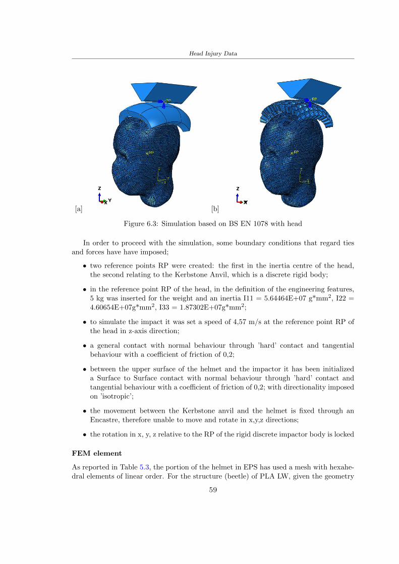
Head Injury Data
[a] [b]
Figure 63 Simulation based on BS EN 1078 with head
In order to proceed with the simulation some boundary conditions that regard tiesand forces have have imposed
bull two reference points RP were created the first in the inertia centre of the headthe second relating to the Kerbstone Anvil which is a discrete rigid body
bull in the reference point RP of the head in the definition of the engineering features5 kg was inserted for the weight and an inertia I11 = 564464E+07 gmm2 I22 =460654E+07gmm2 I33 = 187302E+07gmm2
bull to simulate the impact it was set a speed of 457 ms at the reference point RP ofthe head in z-axis direction
bull a general contact with normal behaviour through rsquohardrsquo contact and tangentialbehaviour with a coefficient of friction of 02
bull between the upper surface of the helmet and the impactor it has been initializeda Surface to Surface contact with normal behaviour through rsquohardrsquo contact andtangential behaviour with a coefficient of friction of 02 with directionality imposedon rsquoisotropicrsquo
bull the movement between the Kerbstone anvil and the helmet is fixed through anEncastre therefore unable to move and rotate in xyz directions
bull the rotation in x y z relative to the RP of the rigid discrete impactor body is locked
FEM element
As reported in Table 53 the portion of the helmet in EPS has used a mesh with hexahe-dral elements of linear order For the structure (beetle) of PLA LW given the geometry
59
Head Injury Data
complexity it was necessary to use a quadratic order of tetrahedra For the mesh of thehead instead in both simulations have been used quadrilateral elements of linear orderas reported in the Tables 61 and 62
Object Elementnumber
Elements Shape Geometricorder
Head 3755 Quadrilateral - R3D4 Linear
Head 34542 Quadrilateral - R3D3 Linear
Helmet (PLA) 272302 Tetrahedral -C3D10M
Quadratic
Table 61 Mesh element - Head simulation with PLA LW (beetle) helmet
Object Elementnumber
Elements Shape Geometricorder
Head 3755 Quadrilateral - R3D4 Linear
Head 34542 Quadrilateral - R3D3 Linear
Helmet (EPS) 72280 Hexahedral - C3D8R Linear
Table 62 Mesh element - Head simulation with EPS helmet
62 Results
Figure 64 represents the simulation in line with BS EN 1078 concerning the helmet inEPS [a] and the helmet with bio-inspired structure in PLA LW For both simulationsVan Misesrsquo stress has Yield Stress values in the case of EPS which is 09 MPa and theplastic behaviour combination of PLA LW [b]
In the case of head and Kerbstone Anvil stress was not assessed as they were previ-ously defined as discrete rigid bodies
63 Head Injury Criterion
The HIC quantifies head impact severity by incorporating time of acceleration exposureand acceleration magnitude it is calculated in post-processing phase with the followingEquation 61
HIC15 =
[1
(t1 minus t2)
int t2
t1
a(t)dt
]25(t2 minus t1) (61)
60
Head Injury Data
[a]
[b]
Figure 64 Results simulation based on BS EN 1078 with sectioned head
For this analysis a(t) is the acceleration calculated in the centre of mass of the head(corresponding to the reference point RP) expressed in g and the time interval (t2 minus t1)was chosen to maximize HIC over a maximum duration of 15 ms
Matlab and the trapz function were used to calculate the HIC to integrate accelerationover time t2 and t1 were considered initial and final times of the simulation t1 = 0 sand t2 = 10 s time less than 15 s
HIC value of 198 was obtained for EPS and 87 for PLA LW Considering the Hayeset al [16] document about the HIC values and the graph in Figure 65 developed bythe author it is possible to find the percentages related to the different injury AIS1 -AIS6 which correspond respectively to lower and higher severity while in Figure 66 therelative fatality to every value of AIS is shown The values obtained for the HIC andother criteria are shown in Table 63 The HIC value for EPS is 198 for PLA LW it is
61
Head Injury Data
Figure 65 Head injury risk curves based on HIC values [16]
Figure 66 The abbreviated injury score versus fatality rate [16]
87 Analyzing the data and comparing them with the curves of the Figure 65 I obtain
bull a percentage between 20 - 30 of AIS 1 for EPS 10 - 20 for PLA LW
bull a percentage between 10 - 20 of AIS 2 for EPS and 0 - 10 for PLA LW
bull for AIS 3 AIS 4 AIS 5 AIS 6 the percentages for both structures is between 0 -10
Comparing these percentages with the fatality rate of Figure 66 it is clear there is a riskof Moderate and Minor fatality in the case of EPS and PLA LW as all values are between0 and 30
62
Head Injury Data
HIC PLA [g] GSI E [J]
EPS 198 97 361 37723
PLA LW 87 75 169 44102
Table 63 Head Injury Data - values
64 Peak Linear Acceleration
The resultant linear acceleration versus time curve was calculated according to Equation62
γ(t) =radicγ2x(t) + γ2y(t) + γ2z (t) (62)
where
bull γ(t) is the resultant linear acceleration (g)
bull γx(t) is the linear acceleration in x axes (g)
bull γy(t) is the linear acceleration in y axes (g)
bull γz(t)is the linear acceleration in z axes (g)
The value of the impact should never exceed 250g [9] Cripton at all [9] in their studyexamined a helmet with expanded polystyrene (EPS) Figure 68 shows maximum HIC forhelmeted and unhelmeted drops from all heights For each drop height helmets reducedHIC relative to unhelmeted drops IARV value is 180g The acceleration in the two casesis shown in Figure 67 and the maximum values are 97g for EPS and 75g for PLA LWas reported in Table 63 The two values considering a maximum value calculated byCripton [9] of 180g are amply optimal and comply with the standard of 250g
65 Gadd Severity Index
Gadd proposed the Severity Index Criteria shown in Equation 63 Following this crite-rion the GSI values that are over 1000 produce serious internal head injury [33]
GSI =
int t1
0a(t)25dt (63)
Where
bull a is the linear acceleration (g)
bull t is the duration of the impact (s)
I calculated the GSI with the function trapz between 0 and t and the resulting valuesare 361 for the EPS and 169 for the PLA LW which comply with the limit
63
Head Injury Data
Figure 67 Peak accelerations for both helmets
Figure 68 Peak accelerations for both helmeted and unhelmeted drops Numbers overbars indicate peak acceleration For 2 m drop height results stated are the mean value
calculated from three drops [9]
64
Head Injury Data
66 Diffuse Axonal Injury
DAI cases covered all incidences in which neurological injuries occurred as well as con-cussion unconsciousness and coma
In order to assess the risk of head trauma in terms of diffuse axonal injury (DAI)Milne et al [23] defined a model based head injury criteria as follows obtaining theresults in Figure 69
bull 50 risk of moderate neurological injury (DAI1+) Brain Von Mises shearing stressof 28 kPa
bull 50 risk of severe neurological injury (DAI2+) Brain Von Mises shearing stressof 53 kPa
[a]
[b]
Figure 69 Peak intra-cerebral shearing stress computed with the helmet model coupledto the human head model for all impact points (a) Flat anvil (b) Kerbstone anvil [23]
65
Head Injury Data
67 Energy absorbed
In Figure 52 during the impact test between the kerbstone Anvil and the plan with thebio-inspired structure in PLA LW and EPS it was found that the PLA LW althoughwith a small difference of 10 J absorbed more energy in comparison with the EPS Whenthe test is carried out in compliance with BS EN 1078 and the head with a speed of 457ms (corresponding to the kerbstone Anvil) as shown in Figure 610 also in this casethe PLA LW with the optimized helmet structure manages to absorb more energy (evenif the difference is very low) compared to the EPS The maximum energy value in PLALW is 44102 J of EPS is 37723 J
Figure 610 Energy absorption - BS EN 1078
66
Chapter 7
Conclusion
71 Conclusion
In this thesis work a bicycle helmet with a bio-inspired structure in PLA LW and 3Dprinted was created The initial approach was to introduce an innovative aspect tostandard EPS helmets not using foam but a polymer with new geometries able toabsorb much energy during the impact For this reason the beetle structure has beenpreferred relying solely on the hypothesis encountered in the literature of its quality inabsorbing energy
Combining the new material of the PLA LW and beetle structure has made possiblethe development of new material satisfactory characteristics have been obtained sincethe first tests The two materials were first subjected to tensile tests to determine theirspecific stress in these the PLA LW had positive results
Subsequent dynamic physical tests were carried out on 3D printed helmet models andon reference helmets in EPS to calculate the absorption energy in both cases at the timeof impact These resulted in energy absorption of the beetle structure in PLA LW withthe application of a TPU cover almost equal to that of EPS about 50J To validate withfinite element analysis the two models an explicit dynamic step was used in AbaqusSimulations showed that the PLA LW structure absorbs a higher amount of energy thanthe EPS the higher is 50 J and the EPS 40J
Finally positive results have also been obtained in calculating the head injury datasimulating according to BS EN 1078 with the use of impactor helmet and head Theacceleration values for both the structures were inferior to 220g precisely for the PLALW was 75g and for the EPS 97g The same applies to the calculation of HIC and GSI(maximum acceptable value of 1000) where the values are 87 and 169 in the case of PLALW and 361 and 198 in EPS For all tests therefore greater efficiency of the structure inPLA LW has been obtained Positive results also in the simulation of the energy absorbedduring the impact as the value referring to the EPS was 35J and that of the PLA LWwas 45J
67
Conclusion
72 Future work lines
The positive results obtained can be considered as a starting point for further tests andsimulations to ensure the safety of the helmet and compliance with the regulations butbefore getting improvements and continue testing changes are required
bull the beetle structure of the helmet made with GH adapts to the SubD withoutallowing to have a homogeneous distribution it would be appropriate to have moreregular hexagonal geometries
bull the mesh of the helmet is too complex and does not allow to perform the simulationprobably to use a more regular structure would have a mesh accordingly moreregular and the simulation would be successful
bull the uneven helmet structure has so many defects that the print is imperfect andthis can change the results of the impact tests the structure should be improved
bull the printing time varies from 4 to 5 days it should be improved
bull the TPU helmet cover is too big for the RAISE printing plan it is necessary togenerate a new geometry
bull the TPU cover it must be fixed on the helmet
bull in the calculation of the DAI it is necessary to have the definition of the brain andthe head should not be considered as a rigid body
bull in the injury calculation the helmet without protection was considered with theTPU cover the result will be better
bull air flow analysis
The comments mentioned are only considerations and problems that I gained duringmy thesis and which should be improved but I am sure that these changes and improve-ments from design to printing and simulations can make the helmet a good product
68
Bibliography
[1] K Adanty J M Clark A Post Thomas Blaine H and M D Gilchrist Comparingtwo proposed protocols to test the oblique response of cycling helmets to fall impactsInternational Journal of Crashworthiness 6648 ndash 663 2020
[2] MF Ashby YJM Brechetb D Cebona and L Salvoc Selection strategies formaterials and processes Materials and Design 2004
[3] M Aysha El casco de bicicleta voronoi impreso en 3d mas seguro y ligero https
www3dnativescomen3d-printed-bicycle-helmet-voronoi-190820204
[4] H Bikas P Stavropoulos and G Chryssolouris Additive manufacturing methodsand modelling approaches a critical review The International Journal of AdvancedManufacturing Technology 83389ndash405 2016
[5] British Standards BSI Helmets for pedal cyclists and for users of skateboards androller skates - BS EN 1078 2012
[6] British Standards BSI Headforms for use in the testing of protective helmets BSEN 960 2020
[7] ColorFabb Colorfabb lw-pla 2019 httpscolorfabbcommedia
datasheetstdscolorfabbTDS_E_ColorFabb_LW-PLApdf
[8] V G Coronado T Haileyesus J M Bell T A Cheng JHaarbauer-Krupa M RLionbarger J Flores-Herrera L C McGuire and J Gilchrist Trends in sports andrecreation-related traumatic brain injuries treated in us emergency departments thenational electronic injury surveillance system-all injury program (neiss-aip) 2001-2012 J Head Trauma Rehabil 30185ndash197 2015
[9] P A Cripton D M Dressler D Stuart Cameron A Christopher R and D RichardsBicycle helmets are highly effective at preventing head injury during head impactHead-form accelerations and injury criteria for helmeted and unhelmeted impactsAccident Analysis and Prevention 701ndash7 2014
[10] L Cui M A Forero R and M D Gilchrist Optimisation of energy absorbingliner for equestrian helmets UCD School of Electrical Electronic and MechanicalEngineering University College Dublin Belfield Dublin4 Ireland 2020
[11] C Deck N Bourdet F Meyer and R Willinger Protection performance of bicyclehelmets Journal of safety research pages 67ndash77 2019
[12] Committee F08 Specification for headforms F2220 ASTM International 2015
[13] Committee F08 Specification for helmets used in recreational bicycling or rollerskating F1447 ASTM International 2018
[14] Committee F08 Test methods for equipment and procedures used in evaluating theperformance F1446 ASTM International 2020
69
Bibliography
[15] P Halldin Shock absorption including measuring CENTC 158 Working Group11 2018
[16] W C Hayes M S Erickson and E D Power Forensic injury biomechanics Annualreview of biomedical engineering pages 55ndash86 2007
[17] HEXR httpshexrcom
[18] C Jinxiang Z Xiaoming O Yoji S Kazuya G Zhensheng and P LongchengThe deformation mode and strengthening mechanism of compression in the beetleelytron plate Materials and Design 131481ndash186 2017
[19] S Kroeker M Ozkul A De Marco S Bonin and GP Siegmund Density variationin the expanded polystyrene eps foam of bicycle helmets and its influence on impactperformance Journal of biomechanical engineering 2019
[20] S G Kroeker SJ Bonin A L DeMarco C A Good and G P Siegmund Agedoes not affect the material properties of expanded polystyrene liners in field-usedbicycle helmets Journal of biomechanical engineering 2016
[21] M Meier K H Tan M K Lim and L Chung Unlocking innovation in the sportindustry through additive manufacturing Business Process Management Journa2018
[22] N J Mills and A Gilchrist The effectiveness of foams in bicycle and motorcyclehelmets Accident Analysis Prevention 23153 ndash 163 1991
[23] G Milne C Deck R P Carreira Q Allinne and R Willinger Development andvalidation of a bicycle helmet assessment of head injury risk under standard impactconditions Computer methods in biomechanics and biomedical engineering 15 Suppl1309 ndash 310 2012
[24] Y Mosleh S J Vander B Depreitere and J Ivens Novel composite foam conceptfor head protection in oblique impacts Adv Eng Mater (Advanced EngineeringMaterials) 10 2017
[25] H Mustafa T Y Pang T Ellena and S H Nasir Impact attenuation of user-centred bicycle helmet design with different foam densities J Phys Conf Ser(Journal of Physics Conference Series) 1150 2019
[26] S H Ngoc and L Guoxing A review of recent research on bio-inspired structuresand materials for energy absorption applications Composites Part 181 2020
[27] J I Novak and A R Novak Is additive manufacturing improving performance insports a systematic review Sport engineering and technology 13 2020
[28] European Road Safety Observatory European road safety observatory facts and fig-ures - cyclists - 2020 December 2020 httpseceuropaeutransportroad_
safetysitesdefaultfilesfacts_figures_cyclists_final_20210323pdf
[29] New York City Departments of Health Parks Mental Hygiene Transportation Recre-ation and the New York City Police Department Bicyclist fatalities and seriousinjuries in new york city 2005
[30] W Pengwen Y Jing H Yanan H Jiaofei and F Xiaoyang Innovative designof a helmet based on reverse engineering and 3d printing Alexandria EngineeringJournal 603445ndash3453 2021
[31] S G Piland T E Gould M Jesunathadas J S Wiggins O McNair and V CShane Protective helmets in sports Materials in Sports Equipment 3 2019
70
Bibliography
[32] K Schmitt P F Niederer M H Muser and F Walz Trauma biomechanicsSpringer Berlin Heidelberg 2010
[33] David Sepelveda Lopez A Biomechanical Analysis of Bicycle Helmets using FEMPhD thesis 2019 Bachelor thesis
[34] H Stigson Bicycle Helmets 2020 Tested by Folksam PhD thesis 2020 PhDAssociate Professor Traffic Safety Research
[35] H Tao K Sudip N Anindya and X Yongzhao 3d printed sensors for biomedicalapplications A review sensor 2019
[36] M Trzaskalska and R Chwastek Damping properties and density of helmet linersmade of expanded polystyrene (eps) Archives of Metallurgy and Materials 66 2020
[37] Crupi V Epasto G and Guglielmino E Impact response of aluminum foam sand-wiches for light-weight ship structures Metals 198ndash112 2020
[38] W Wei-cai F Dong-ming and L Yuan-xin Study on impact energy absorbing per-formance of eps buffer layer of motorcycle helmet Proceedings - 2013 InternationalConference on Mechanical and Automation Engineering MAEE 2013
[39] Z Xiaoming C Jinxiang O Yoji Z Peiwei X Xiaobing and Y Xindi Influence ofhoneycomb dimensions and forming methods on the compressive properties of beetleelytron plates Journal of Sandwich Structures and Materials 2228ndash39 2020
[40] S Zhi L Dong Z Weisheng S Shanshan and G Xu Topological optimization ofbiomimetic sandwich structures with hybrid core and cfrp face sheets CompositesScience and Technology 14279ndash90 2017
[41] S Zhi S Shanshan G Xu H Xiaozhi and C Haoran On compressive propertiesof composite sandwich structures with grid reinforced honeycomb core CompositesPart B 94245ndash252 2016
71
- List of Tables
- List of Figures
- Introduction
-
- Helmet bike protection
-
- Helmet structure
-
- Additive Manufacturing
-
- AM process
- Materials and techniques - FDM
- AM in sport
-
- 3D printed helmets
-
- Phases
- HEXR
- VORONOI
-
- State of the art
-
- Standards
-
- Headform
- European Standard and American Standard
- Field of vision - BS EN 1078
- Test impact area
- Anvils and environmental conditions
-
- Materials
-
- EPS Foam
- CES Edu Pack - Material selection
- PLA with natural fiber and PLA LW
-
- Bio-inspired structures
-
- Beetle structure - Design of the model
- Specific stress - PLA LW and EPS foam
-
- Methodology
-
- 3D scan
-
- 3D Sense 2 scanner and Meshmixer - Reverse reconstruction
- 3D scan analysis and extraction of features
-
- Helmet design
-
- Rhinoceros - Helmet surface
- Grasshopper - Helmet structure
-
- 3D Print
-
- Printer and parameters
-
- Experimental evaluation
-
- Experimental tests
-
- Drop-weight impact test machine
-
- PLA LW helmet
- EPS helmet
- Results
-
- First results - PLA-LW and EPS helmet
- PLA-LW helmet with TPU cover
-
- FEM Validation
-
- Impactor - Anvils definition
-
- PLA LW - Plastic characteristics
- First test - helmet
- Second test - plane
- EPS impact simulations
- PLA LW impact simulations
-
- Results
-
- Head Injury Data
-
- Abaqus simulation
- Results
- Head Injury Criterion
- Peak Linear Acceleration
- Gadd Severity Index
- Diffuse Axonal Injury
- Energy absorbed
-
- Conclusion
-
- Conclusion
- Future work lines
-
- Bibliography
-
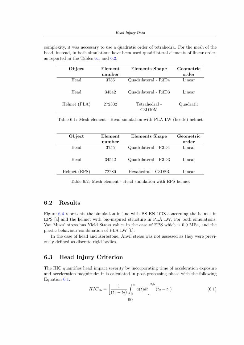
Head Injury Data
complexity it was necessary to use a quadratic order of tetrahedra For the mesh of thehead instead in both simulations have been used quadrilateral elements of linear orderas reported in the Tables 61 and 62
Object Elementnumber
Elements Shape Geometricorder
Head 3755 Quadrilateral - R3D4 Linear
Head 34542 Quadrilateral - R3D3 Linear
Helmet (PLA) 272302 Tetrahedral -C3D10M
Quadratic
Table 61 Mesh element - Head simulation with PLA LW (beetle) helmet
Object Elementnumber
Elements Shape Geometricorder
Head 3755 Quadrilateral - R3D4 Linear
Head 34542 Quadrilateral - R3D3 Linear
Helmet (EPS) 72280 Hexahedral - C3D8R Linear
Table 62 Mesh element - Head simulation with EPS helmet
62 Results
Figure 64 represents the simulation in line with BS EN 1078 concerning the helmet inEPS [a] and the helmet with bio-inspired structure in PLA LW For both simulationsVan Misesrsquo stress has Yield Stress values in the case of EPS which is 09 MPa and theplastic behaviour combination of PLA LW [b]
In the case of head and Kerbstone Anvil stress was not assessed as they were previ-ously defined as discrete rigid bodies
63 Head Injury Criterion
The HIC quantifies head impact severity by incorporating time of acceleration exposureand acceleration magnitude it is calculated in post-processing phase with the followingEquation 61
HIC15 =
[1
(t1 minus t2)
int t2
t1
a(t)dt
]25(t2 minus t1) (61)
60
Head Injury Data
[a]
[b]
Figure 64 Results simulation based on BS EN 1078 with sectioned head
For this analysis a(t) is the acceleration calculated in the centre of mass of the head(corresponding to the reference point RP) expressed in g and the time interval (t2 minus t1)was chosen to maximize HIC over a maximum duration of 15 ms
Matlab and the trapz function were used to calculate the HIC to integrate accelerationover time t2 and t1 were considered initial and final times of the simulation t1 = 0 sand t2 = 10 s time less than 15 s
HIC value of 198 was obtained for EPS and 87 for PLA LW Considering the Hayeset al [16] document about the HIC values and the graph in Figure 65 developed bythe author it is possible to find the percentages related to the different injury AIS1 -AIS6 which correspond respectively to lower and higher severity while in Figure 66 therelative fatality to every value of AIS is shown The values obtained for the HIC andother criteria are shown in Table 63 The HIC value for EPS is 198 for PLA LW it is
61
Head Injury Data
Figure 65 Head injury risk curves based on HIC values [16]
Figure 66 The abbreviated injury score versus fatality rate [16]
87 Analyzing the data and comparing them with the curves of the Figure 65 I obtain
bull a percentage between 20 - 30 of AIS 1 for EPS 10 - 20 for PLA LW
bull a percentage between 10 - 20 of AIS 2 for EPS and 0 - 10 for PLA LW
bull for AIS 3 AIS 4 AIS 5 AIS 6 the percentages for both structures is between 0 -10
Comparing these percentages with the fatality rate of Figure 66 it is clear there is a riskof Moderate and Minor fatality in the case of EPS and PLA LW as all values are between0 and 30
62
Head Injury Data
HIC PLA [g] GSI E [J]
EPS 198 97 361 37723
PLA LW 87 75 169 44102
Table 63 Head Injury Data - values
64 Peak Linear Acceleration
The resultant linear acceleration versus time curve was calculated according to Equation62
γ(t) =radicγ2x(t) + γ2y(t) + γ2z (t) (62)
where
bull γ(t) is the resultant linear acceleration (g)
bull γx(t) is the linear acceleration in x axes (g)
bull γy(t) is the linear acceleration in y axes (g)
bull γz(t)is the linear acceleration in z axes (g)
The value of the impact should never exceed 250g [9] Cripton at all [9] in their studyexamined a helmet with expanded polystyrene (EPS) Figure 68 shows maximum HIC forhelmeted and unhelmeted drops from all heights For each drop height helmets reducedHIC relative to unhelmeted drops IARV value is 180g The acceleration in the two casesis shown in Figure 67 and the maximum values are 97g for EPS and 75g for PLA LWas reported in Table 63 The two values considering a maximum value calculated byCripton [9] of 180g are amply optimal and comply with the standard of 250g
65 Gadd Severity Index
Gadd proposed the Severity Index Criteria shown in Equation 63 Following this crite-rion the GSI values that are over 1000 produce serious internal head injury [33]
GSI =
int t1
0a(t)25dt (63)
Where
bull a is the linear acceleration (g)
bull t is the duration of the impact (s)
I calculated the GSI with the function trapz between 0 and t and the resulting valuesare 361 for the EPS and 169 for the PLA LW which comply with the limit
63
Head Injury Data
Figure 67 Peak accelerations for both helmets
Figure 68 Peak accelerations for both helmeted and unhelmeted drops Numbers overbars indicate peak acceleration For 2 m drop height results stated are the mean value
calculated from three drops [9]
64
Head Injury Data
66 Diffuse Axonal Injury
DAI cases covered all incidences in which neurological injuries occurred as well as con-cussion unconsciousness and coma
In order to assess the risk of head trauma in terms of diffuse axonal injury (DAI)Milne et al [23] defined a model based head injury criteria as follows obtaining theresults in Figure 69
bull 50 risk of moderate neurological injury (DAI1+) Brain Von Mises shearing stressof 28 kPa
bull 50 risk of severe neurological injury (DAI2+) Brain Von Mises shearing stressof 53 kPa
[a]
[b]
Figure 69 Peak intra-cerebral shearing stress computed with the helmet model coupledto the human head model for all impact points (a) Flat anvil (b) Kerbstone anvil [23]
65
Head Injury Data
67 Energy absorbed
In Figure 52 during the impact test between the kerbstone Anvil and the plan with thebio-inspired structure in PLA LW and EPS it was found that the PLA LW althoughwith a small difference of 10 J absorbed more energy in comparison with the EPS Whenthe test is carried out in compliance with BS EN 1078 and the head with a speed of 457ms (corresponding to the kerbstone Anvil) as shown in Figure 610 also in this casethe PLA LW with the optimized helmet structure manages to absorb more energy (evenif the difference is very low) compared to the EPS The maximum energy value in PLALW is 44102 J of EPS is 37723 J
Figure 610 Energy absorption - BS EN 1078
66
Chapter 7
Conclusion
71 Conclusion
In this thesis work a bicycle helmet with a bio-inspired structure in PLA LW and 3Dprinted was created The initial approach was to introduce an innovative aspect tostandard EPS helmets not using foam but a polymer with new geometries able toabsorb much energy during the impact For this reason the beetle structure has beenpreferred relying solely on the hypothesis encountered in the literature of its quality inabsorbing energy
Combining the new material of the PLA LW and beetle structure has made possiblethe development of new material satisfactory characteristics have been obtained sincethe first tests The two materials were first subjected to tensile tests to determine theirspecific stress in these the PLA LW had positive results
Subsequent dynamic physical tests were carried out on 3D printed helmet models andon reference helmets in EPS to calculate the absorption energy in both cases at the timeof impact These resulted in energy absorption of the beetle structure in PLA LW withthe application of a TPU cover almost equal to that of EPS about 50J To validate withfinite element analysis the two models an explicit dynamic step was used in AbaqusSimulations showed that the PLA LW structure absorbs a higher amount of energy thanthe EPS the higher is 50 J and the EPS 40J
Finally positive results have also been obtained in calculating the head injury datasimulating according to BS EN 1078 with the use of impactor helmet and head Theacceleration values for both the structures were inferior to 220g precisely for the PLALW was 75g and for the EPS 97g The same applies to the calculation of HIC and GSI(maximum acceptable value of 1000) where the values are 87 and 169 in the case of PLALW and 361 and 198 in EPS For all tests therefore greater efficiency of the structure inPLA LW has been obtained Positive results also in the simulation of the energy absorbedduring the impact as the value referring to the EPS was 35J and that of the PLA LWwas 45J
67
Conclusion
72 Future work lines
The positive results obtained can be considered as a starting point for further tests andsimulations to ensure the safety of the helmet and compliance with the regulations butbefore getting improvements and continue testing changes are required
bull the beetle structure of the helmet made with GH adapts to the SubD withoutallowing to have a homogeneous distribution it would be appropriate to have moreregular hexagonal geometries
bull the mesh of the helmet is too complex and does not allow to perform the simulationprobably to use a more regular structure would have a mesh accordingly moreregular and the simulation would be successful
bull the uneven helmet structure has so many defects that the print is imperfect andthis can change the results of the impact tests the structure should be improved
bull the printing time varies from 4 to 5 days it should be improved
bull the TPU helmet cover is too big for the RAISE printing plan it is necessary togenerate a new geometry
bull the TPU cover it must be fixed on the helmet
bull in the calculation of the DAI it is necessary to have the definition of the brain andthe head should not be considered as a rigid body
bull in the injury calculation the helmet without protection was considered with theTPU cover the result will be better
bull air flow analysis
The comments mentioned are only considerations and problems that I gained duringmy thesis and which should be improved but I am sure that these changes and improve-ments from design to printing and simulations can make the helmet a good product
68
Bibliography
[1] K Adanty J M Clark A Post Thomas Blaine H and M D Gilchrist Comparingtwo proposed protocols to test the oblique response of cycling helmets to fall impactsInternational Journal of Crashworthiness 6648 ndash 663 2020
[2] MF Ashby YJM Brechetb D Cebona and L Salvoc Selection strategies formaterials and processes Materials and Design 2004
[3] M Aysha El casco de bicicleta voronoi impreso en 3d mas seguro y ligero https
www3dnativescomen3d-printed-bicycle-helmet-voronoi-190820204
[4] H Bikas P Stavropoulos and G Chryssolouris Additive manufacturing methodsand modelling approaches a critical review The International Journal of AdvancedManufacturing Technology 83389ndash405 2016
[5] British Standards BSI Helmets for pedal cyclists and for users of skateboards androller skates - BS EN 1078 2012
[6] British Standards BSI Headforms for use in the testing of protective helmets BSEN 960 2020
[7] ColorFabb Colorfabb lw-pla 2019 httpscolorfabbcommedia
datasheetstdscolorfabbTDS_E_ColorFabb_LW-PLApdf
[8] V G Coronado T Haileyesus J M Bell T A Cheng JHaarbauer-Krupa M RLionbarger J Flores-Herrera L C McGuire and J Gilchrist Trends in sports andrecreation-related traumatic brain injuries treated in us emergency departments thenational electronic injury surveillance system-all injury program (neiss-aip) 2001-2012 J Head Trauma Rehabil 30185ndash197 2015
[9] P A Cripton D M Dressler D Stuart Cameron A Christopher R and D RichardsBicycle helmets are highly effective at preventing head injury during head impactHead-form accelerations and injury criteria for helmeted and unhelmeted impactsAccident Analysis and Prevention 701ndash7 2014
[10] L Cui M A Forero R and M D Gilchrist Optimisation of energy absorbingliner for equestrian helmets UCD School of Electrical Electronic and MechanicalEngineering University College Dublin Belfield Dublin4 Ireland 2020
[11] C Deck N Bourdet F Meyer and R Willinger Protection performance of bicyclehelmets Journal of safety research pages 67ndash77 2019
[12] Committee F08 Specification for headforms F2220 ASTM International 2015
[13] Committee F08 Specification for helmets used in recreational bicycling or rollerskating F1447 ASTM International 2018
[14] Committee F08 Test methods for equipment and procedures used in evaluating theperformance F1446 ASTM International 2020
69
Bibliography
[15] P Halldin Shock absorption including measuring CENTC 158 Working Group11 2018
[16] W C Hayes M S Erickson and E D Power Forensic injury biomechanics Annualreview of biomedical engineering pages 55ndash86 2007
[17] HEXR httpshexrcom
[18] C Jinxiang Z Xiaoming O Yoji S Kazuya G Zhensheng and P LongchengThe deformation mode and strengthening mechanism of compression in the beetleelytron plate Materials and Design 131481ndash186 2017
[19] S Kroeker M Ozkul A De Marco S Bonin and GP Siegmund Density variationin the expanded polystyrene eps foam of bicycle helmets and its influence on impactperformance Journal of biomechanical engineering 2019
[20] S G Kroeker SJ Bonin A L DeMarco C A Good and G P Siegmund Agedoes not affect the material properties of expanded polystyrene liners in field-usedbicycle helmets Journal of biomechanical engineering 2016
[21] M Meier K H Tan M K Lim and L Chung Unlocking innovation in the sportindustry through additive manufacturing Business Process Management Journa2018
[22] N J Mills and A Gilchrist The effectiveness of foams in bicycle and motorcyclehelmets Accident Analysis Prevention 23153 ndash 163 1991
[23] G Milne C Deck R P Carreira Q Allinne and R Willinger Development andvalidation of a bicycle helmet assessment of head injury risk under standard impactconditions Computer methods in biomechanics and biomedical engineering 15 Suppl1309 ndash 310 2012
[24] Y Mosleh S J Vander B Depreitere and J Ivens Novel composite foam conceptfor head protection in oblique impacts Adv Eng Mater (Advanced EngineeringMaterials) 10 2017
[25] H Mustafa T Y Pang T Ellena and S H Nasir Impact attenuation of user-centred bicycle helmet design with different foam densities J Phys Conf Ser(Journal of Physics Conference Series) 1150 2019
[26] S H Ngoc and L Guoxing A review of recent research on bio-inspired structuresand materials for energy absorption applications Composites Part 181 2020
[27] J I Novak and A R Novak Is additive manufacturing improving performance insports a systematic review Sport engineering and technology 13 2020
[28] European Road Safety Observatory European road safety observatory facts and fig-ures - cyclists - 2020 December 2020 httpseceuropaeutransportroad_
safetysitesdefaultfilesfacts_figures_cyclists_final_20210323pdf
[29] New York City Departments of Health Parks Mental Hygiene Transportation Recre-ation and the New York City Police Department Bicyclist fatalities and seriousinjuries in new york city 2005
[30] W Pengwen Y Jing H Yanan H Jiaofei and F Xiaoyang Innovative designof a helmet based on reverse engineering and 3d printing Alexandria EngineeringJournal 603445ndash3453 2021
[31] S G Piland T E Gould M Jesunathadas J S Wiggins O McNair and V CShane Protective helmets in sports Materials in Sports Equipment 3 2019
70
Bibliography
[32] K Schmitt P F Niederer M H Muser and F Walz Trauma biomechanicsSpringer Berlin Heidelberg 2010
[33] David Sepelveda Lopez A Biomechanical Analysis of Bicycle Helmets using FEMPhD thesis 2019 Bachelor thesis
[34] H Stigson Bicycle Helmets 2020 Tested by Folksam PhD thesis 2020 PhDAssociate Professor Traffic Safety Research
[35] H Tao K Sudip N Anindya and X Yongzhao 3d printed sensors for biomedicalapplications A review sensor 2019
[36] M Trzaskalska and R Chwastek Damping properties and density of helmet linersmade of expanded polystyrene (eps) Archives of Metallurgy and Materials 66 2020
[37] Crupi V Epasto G and Guglielmino E Impact response of aluminum foam sand-wiches for light-weight ship structures Metals 198ndash112 2020
[38] W Wei-cai F Dong-ming and L Yuan-xin Study on impact energy absorbing per-formance of eps buffer layer of motorcycle helmet Proceedings - 2013 InternationalConference on Mechanical and Automation Engineering MAEE 2013
[39] Z Xiaoming C Jinxiang O Yoji Z Peiwei X Xiaobing and Y Xindi Influence ofhoneycomb dimensions and forming methods on the compressive properties of beetleelytron plates Journal of Sandwich Structures and Materials 2228ndash39 2020
[40] S Zhi L Dong Z Weisheng S Shanshan and G Xu Topological optimization ofbiomimetic sandwich structures with hybrid core and cfrp face sheets CompositesScience and Technology 14279ndash90 2017
[41] S Zhi S Shanshan G Xu H Xiaozhi and C Haoran On compressive propertiesof composite sandwich structures with grid reinforced honeycomb core CompositesPart B 94245ndash252 2016
71
- List of Tables
- List of Figures
- Introduction
-
- Helmet bike protection
-
- Helmet structure
-
- Additive Manufacturing
-
- AM process
- Materials and techniques - FDM
- AM in sport
-
- 3D printed helmets
-
- Phases
- HEXR
- VORONOI
-
- State of the art
-
- Standards
-
- Headform
- European Standard and American Standard
- Field of vision - BS EN 1078
- Test impact area
- Anvils and environmental conditions
-
- Materials
-
- EPS Foam
- CES Edu Pack - Material selection
- PLA with natural fiber and PLA LW
-
- Bio-inspired structures
-
- Beetle structure - Design of the model
- Specific stress - PLA LW and EPS foam
-
- Methodology
-
- 3D scan
-
- 3D Sense 2 scanner and Meshmixer - Reverse reconstruction
- 3D scan analysis and extraction of features
-
- Helmet design
-
- Rhinoceros - Helmet surface
- Grasshopper - Helmet structure
-
- 3D Print
-
- Printer and parameters
-
- Experimental evaluation
-
- Experimental tests
-
- Drop-weight impact test machine
-
- PLA LW helmet
- EPS helmet
- Results
-
- First results - PLA-LW and EPS helmet
- PLA-LW helmet with TPU cover
-
- FEM Validation
-
- Impactor - Anvils definition
-
- PLA LW - Plastic characteristics
- First test - helmet
- Second test - plane
- EPS impact simulations
- PLA LW impact simulations
-
- Results
-
- Head Injury Data
-
- Abaqus simulation
- Results
- Head Injury Criterion
- Peak Linear Acceleration
- Gadd Severity Index
- Diffuse Axonal Injury
- Energy absorbed
-
- Conclusion
-
- Conclusion
- Future work lines
-
- Bibliography
-
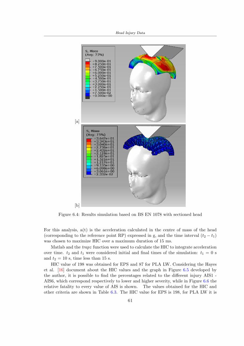
Head Injury Data
[a]
[b]
Figure 64 Results simulation based on BS EN 1078 with sectioned head
For this analysis a(t) is the acceleration calculated in the centre of mass of the head(corresponding to the reference point RP) expressed in g and the time interval (t2 minus t1)was chosen to maximize HIC over a maximum duration of 15 ms
Matlab and the trapz function were used to calculate the HIC to integrate accelerationover time t2 and t1 were considered initial and final times of the simulation t1 = 0 sand t2 = 10 s time less than 15 s
HIC value of 198 was obtained for EPS and 87 for PLA LW Considering the Hayeset al [16] document about the HIC values and the graph in Figure 65 developed bythe author it is possible to find the percentages related to the different injury AIS1 -AIS6 which correspond respectively to lower and higher severity while in Figure 66 therelative fatality to every value of AIS is shown The values obtained for the HIC andother criteria are shown in Table 63 The HIC value for EPS is 198 for PLA LW it is
61
Head Injury Data
Figure 65 Head injury risk curves based on HIC values [16]
Figure 66 The abbreviated injury score versus fatality rate [16]
87 Analyzing the data and comparing them with the curves of the Figure 65 I obtain
bull a percentage between 20 - 30 of AIS 1 for EPS 10 - 20 for PLA LW
bull a percentage between 10 - 20 of AIS 2 for EPS and 0 - 10 for PLA LW
bull for AIS 3 AIS 4 AIS 5 AIS 6 the percentages for both structures is between 0 -10
Comparing these percentages with the fatality rate of Figure 66 it is clear there is a riskof Moderate and Minor fatality in the case of EPS and PLA LW as all values are between0 and 30
62
Head Injury Data
HIC PLA [g] GSI E [J]
EPS 198 97 361 37723
PLA LW 87 75 169 44102
Table 63 Head Injury Data - values
64 Peak Linear Acceleration
The resultant linear acceleration versus time curve was calculated according to Equation62
γ(t) =radicγ2x(t) + γ2y(t) + γ2z (t) (62)
where
bull γ(t) is the resultant linear acceleration (g)
bull γx(t) is the linear acceleration in x axes (g)
bull γy(t) is the linear acceleration in y axes (g)
bull γz(t)is the linear acceleration in z axes (g)
The value of the impact should never exceed 250g [9] Cripton at all [9] in their studyexamined a helmet with expanded polystyrene (EPS) Figure 68 shows maximum HIC forhelmeted and unhelmeted drops from all heights For each drop height helmets reducedHIC relative to unhelmeted drops IARV value is 180g The acceleration in the two casesis shown in Figure 67 and the maximum values are 97g for EPS and 75g for PLA LWas reported in Table 63 The two values considering a maximum value calculated byCripton [9] of 180g are amply optimal and comply with the standard of 250g
65 Gadd Severity Index
Gadd proposed the Severity Index Criteria shown in Equation 63 Following this crite-rion the GSI values that are over 1000 produce serious internal head injury [33]
GSI =
int t1
0a(t)25dt (63)
Where
bull a is the linear acceleration (g)
bull t is the duration of the impact (s)
I calculated the GSI with the function trapz between 0 and t and the resulting valuesare 361 for the EPS and 169 for the PLA LW which comply with the limit
63
Head Injury Data
Figure 67 Peak accelerations for both helmets
Figure 68 Peak accelerations for both helmeted and unhelmeted drops Numbers overbars indicate peak acceleration For 2 m drop height results stated are the mean value
calculated from three drops [9]
64
Head Injury Data
66 Diffuse Axonal Injury
DAI cases covered all incidences in which neurological injuries occurred as well as con-cussion unconsciousness and coma
In order to assess the risk of head trauma in terms of diffuse axonal injury (DAI)Milne et al [23] defined a model based head injury criteria as follows obtaining theresults in Figure 69
bull 50 risk of moderate neurological injury (DAI1+) Brain Von Mises shearing stressof 28 kPa
bull 50 risk of severe neurological injury (DAI2+) Brain Von Mises shearing stressof 53 kPa
[a]
[b]
Figure 69 Peak intra-cerebral shearing stress computed with the helmet model coupledto the human head model for all impact points (a) Flat anvil (b) Kerbstone anvil [23]
65
Head Injury Data
67 Energy absorbed
In Figure 52 during the impact test between the kerbstone Anvil and the plan with thebio-inspired structure in PLA LW and EPS it was found that the PLA LW althoughwith a small difference of 10 J absorbed more energy in comparison with the EPS Whenthe test is carried out in compliance with BS EN 1078 and the head with a speed of 457ms (corresponding to the kerbstone Anvil) as shown in Figure 610 also in this casethe PLA LW with the optimized helmet structure manages to absorb more energy (evenif the difference is very low) compared to the EPS The maximum energy value in PLALW is 44102 J of EPS is 37723 J
Figure 610 Energy absorption - BS EN 1078
66
Chapter 7
Conclusion
71 Conclusion
In this thesis work a bicycle helmet with a bio-inspired structure in PLA LW and 3Dprinted was created The initial approach was to introduce an innovative aspect tostandard EPS helmets not using foam but a polymer with new geometries able toabsorb much energy during the impact For this reason the beetle structure has beenpreferred relying solely on the hypothesis encountered in the literature of its quality inabsorbing energy
Combining the new material of the PLA LW and beetle structure has made possiblethe development of new material satisfactory characteristics have been obtained sincethe first tests The two materials were first subjected to tensile tests to determine theirspecific stress in these the PLA LW had positive results
Subsequent dynamic physical tests were carried out on 3D printed helmet models andon reference helmets in EPS to calculate the absorption energy in both cases at the timeof impact These resulted in energy absorption of the beetle structure in PLA LW withthe application of a TPU cover almost equal to that of EPS about 50J To validate withfinite element analysis the two models an explicit dynamic step was used in AbaqusSimulations showed that the PLA LW structure absorbs a higher amount of energy thanthe EPS the higher is 50 J and the EPS 40J
Finally positive results have also been obtained in calculating the head injury datasimulating according to BS EN 1078 with the use of impactor helmet and head Theacceleration values for both the structures were inferior to 220g precisely for the PLALW was 75g and for the EPS 97g The same applies to the calculation of HIC and GSI(maximum acceptable value of 1000) where the values are 87 and 169 in the case of PLALW and 361 and 198 in EPS For all tests therefore greater efficiency of the structure inPLA LW has been obtained Positive results also in the simulation of the energy absorbedduring the impact as the value referring to the EPS was 35J and that of the PLA LWwas 45J
67
Conclusion
72 Future work lines
The positive results obtained can be considered as a starting point for further tests andsimulations to ensure the safety of the helmet and compliance with the regulations butbefore getting improvements and continue testing changes are required
bull the beetle structure of the helmet made with GH adapts to the SubD withoutallowing to have a homogeneous distribution it would be appropriate to have moreregular hexagonal geometries
bull the mesh of the helmet is too complex and does not allow to perform the simulationprobably to use a more regular structure would have a mesh accordingly moreregular and the simulation would be successful
bull the uneven helmet structure has so many defects that the print is imperfect andthis can change the results of the impact tests the structure should be improved
bull the printing time varies from 4 to 5 days it should be improved
bull the TPU helmet cover is too big for the RAISE printing plan it is necessary togenerate a new geometry
bull the TPU cover it must be fixed on the helmet
bull in the calculation of the DAI it is necessary to have the definition of the brain andthe head should not be considered as a rigid body
bull in the injury calculation the helmet without protection was considered with theTPU cover the result will be better
bull air flow analysis
The comments mentioned are only considerations and problems that I gained duringmy thesis and which should be improved but I am sure that these changes and improve-ments from design to printing and simulations can make the helmet a good product
68
Bibliography
[1] K Adanty J M Clark A Post Thomas Blaine H and M D Gilchrist Comparingtwo proposed protocols to test the oblique response of cycling helmets to fall impactsInternational Journal of Crashworthiness 6648 ndash 663 2020
[2] MF Ashby YJM Brechetb D Cebona and L Salvoc Selection strategies formaterials and processes Materials and Design 2004
[3] M Aysha El casco de bicicleta voronoi impreso en 3d mas seguro y ligero https
www3dnativescomen3d-printed-bicycle-helmet-voronoi-190820204
[4] H Bikas P Stavropoulos and G Chryssolouris Additive manufacturing methodsand modelling approaches a critical review The International Journal of AdvancedManufacturing Technology 83389ndash405 2016
[5] British Standards BSI Helmets for pedal cyclists and for users of skateboards androller skates - BS EN 1078 2012
[6] British Standards BSI Headforms for use in the testing of protective helmets BSEN 960 2020
[7] ColorFabb Colorfabb lw-pla 2019 httpscolorfabbcommedia
datasheetstdscolorfabbTDS_E_ColorFabb_LW-PLApdf
[8] V G Coronado T Haileyesus J M Bell T A Cheng JHaarbauer-Krupa M RLionbarger J Flores-Herrera L C McGuire and J Gilchrist Trends in sports andrecreation-related traumatic brain injuries treated in us emergency departments thenational electronic injury surveillance system-all injury program (neiss-aip) 2001-2012 J Head Trauma Rehabil 30185ndash197 2015
[9] P A Cripton D M Dressler D Stuart Cameron A Christopher R and D RichardsBicycle helmets are highly effective at preventing head injury during head impactHead-form accelerations and injury criteria for helmeted and unhelmeted impactsAccident Analysis and Prevention 701ndash7 2014
[10] L Cui M A Forero R and M D Gilchrist Optimisation of energy absorbingliner for equestrian helmets UCD School of Electrical Electronic and MechanicalEngineering University College Dublin Belfield Dublin4 Ireland 2020
[11] C Deck N Bourdet F Meyer and R Willinger Protection performance of bicyclehelmets Journal of safety research pages 67ndash77 2019
[12] Committee F08 Specification for headforms F2220 ASTM International 2015
[13] Committee F08 Specification for helmets used in recreational bicycling or rollerskating F1447 ASTM International 2018
[14] Committee F08 Test methods for equipment and procedures used in evaluating theperformance F1446 ASTM International 2020
69
Bibliography
[15] P Halldin Shock absorption including measuring CENTC 158 Working Group11 2018
[16] W C Hayes M S Erickson and E D Power Forensic injury biomechanics Annualreview of biomedical engineering pages 55ndash86 2007
[17] HEXR httpshexrcom
[18] C Jinxiang Z Xiaoming O Yoji S Kazuya G Zhensheng and P LongchengThe deformation mode and strengthening mechanism of compression in the beetleelytron plate Materials and Design 131481ndash186 2017
[19] S Kroeker M Ozkul A De Marco S Bonin and GP Siegmund Density variationin the expanded polystyrene eps foam of bicycle helmets and its influence on impactperformance Journal of biomechanical engineering 2019
[20] S G Kroeker SJ Bonin A L DeMarco C A Good and G P Siegmund Agedoes not affect the material properties of expanded polystyrene liners in field-usedbicycle helmets Journal of biomechanical engineering 2016
[21] M Meier K H Tan M K Lim and L Chung Unlocking innovation in the sportindustry through additive manufacturing Business Process Management Journa2018
[22] N J Mills and A Gilchrist The effectiveness of foams in bicycle and motorcyclehelmets Accident Analysis Prevention 23153 ndash 163 1991
[23] G Milne C Deck R P Carreira Q Allinne and R Willinger Development andvalidation of a bicycle helmet assessment of head injury risk under standard impactconditions Computer methods in biomechanics and biomedical engineering 15 Suppl1309 ndash 310 2012
[24] Y Mosleh S J Vander B Depreitere and J Ivens Novel composite foam conceptfor head protection in oblique impacts Adv Eng Mater (Advanced EngineeringMaterials) 10 2017
[25] H Mustafa T Y Pang T Ellena and S H Nasir Impact attenuation of user-centred bicycle helmet design with different foam densities J Phys Conf Ser(Journal of Physics Conference Series) 1150 2019
[26] S H Ngoc and L Guoxing A review of recent research on bio-inspired structuresand materials for energy absorption applications Composites Part 181 2020
[27] J I Novak and A R Novak Is additive manufacturing improving performance insports a systematic review Sport engineering and technology 13 2020
[28] European Road Safety Observatory European road safety observatory facts and fig-ures - cyclists - 2020 December 2020 httpseceuropaeutransportroad_
safetysitesdefaultfilesfacts_figures_cyclists_final_20210323pdf
[29] New York City Departments of Health Parks Mental Hygiene Transportation Recre-ation and the New York City Police Department Bicyclist fatalities and seriousinjuries in new york city 2005
[30] W Pengwen Y Jing H Yanan H Jiaofei and F Xiaoyang Innovative designof a helmet based on reverse engineering and 3d printing Alexandria EngineeringJournal 603445ndash3453 2021
[31] S G Piland T E Gould M Jesunathadas J S Wiggins O McNair and V CShane Protective helmets in sports Materials in Sports Equipment 3 2019
70
Bibliography
[32] K Schmitt P F Niederer M H Muser and F Walz Trauma biomechanicsSpringer Berlin Heidelberg 2010
[33] David Sepelveda Lopez A Biomechanical Analysis of Bicycle Helmets using FEMPhD thesis 2019 Bachelor thesis
[34] H Stigson Bicycle Helmets 2020 Tested by Folksam PhD thesis 2020 PhDAssociate Professor Traffic Safety Research
[35] H Tao K Sudip N Anindya and X Yongzhao 3d printed sensors for biomedicalapplications A review sensor 2019
[36] M Trzaskalska and R Chwastek Damping properties and density of helmet linersmade of expanded polystyrene (eps) Archives of Metallurgy and Materials 66 2020
[37] Crupi V Epasto G and Guglielmino E Impact response of aluminum foam sand-wiches for light-weight ship structures Metals 198ndash112 2020
[38] W Wei-cai F Dong-ming and L Yuan-xin Study on impact energy absorbing per-formance of eps buffer layer of motorcycle helmet Proceedings - 2013 InternationalConference on Mechanical and Automation Engineering MAEE 2013
[39] Z Xiaoming C Jinxiang O Yoji Z Peiwei X Xiaobing and Y Xindi Influence ofhoneycomb dimensions and forming methods on the compressive properties of beetleelytron plates Journal of Sandwich Structures and Materials 2228ndash39 2020
[40] S Zhi L Dong Z Weisheng S Shanshan and G Xu Topological optimization ofbiomimetic sandwich structures with hybrid core and cfrp face sheets CompositesScience and Technology 14279ndash90 2017
[41] S Zhi S Shanshan G Xu H Xiaozhi and C Haoran On compressive propertiesof composite sandwich structures with grid reinforced honeycomb core CompositesPart B 94245ndash252 2016
71
- List of Tables
- List of Figures
- Introduction
-
- Helmet bike protection
-
- Helmet structure
-
- Additive Manufacturing
-
- AM process
- Materials and techniques - FDM
- AM in sport
-
- 3D printed helmets
-
- Phases
- HEXR
- VORONOI
-
- State of the art
-
- Standards
-
- Headform
- European Standard and American Standard
- Field of vision - BS EN 1078
- Test impact area
- Anvils and environmental conditions
-
- Materials
-
- EPS Foam
- CES Edu Pack - Material selection
- PLA with natural fiber and PLA LW
-
- Bio-inspired structures
-
- Beetle structure - Design of the model
- Specific stress - PLA LW and EPS foam
-
- Methodology
-
- 3D scan
-
- 3D Sense 2 scanner and Meshmixer - Reverse reconstruction
- 3D scan analysis and extraction of features
-
- Helmet design
-
- Rhinoceros - Helmet surface
- Grasshopper - Helmet structure
-
- 3D Print
-
- Printer and parameters
-
- Experimental evaluation
-
- Experimental tests
-
- Drop-weight impact test machine
-
- PLA LW helmet
- EPS helmet
- Results
-
- First results - PLA-LW and EPS helmet
- PLA-LW helmet with TPU cover
-
- FEM Validation
-
- Impactor - Anvils definition
-
- PLA LW - Plastic characteristics
- First test - helmet
- Second test - plane
- EPS impact simulations
- PLA LW impact simulations
-
- Results
-
- Head Injury Data
-
- Abaqus simulation
- Results
- Head Injury Criterion
- Peak Linear Acceleration
- Gadd Severity Index
- Diffuse Axonal Injury
- Energy absorbed
-
- Conclusion
-
- Conclusion
- Future work lines
-
- Bibliography
-
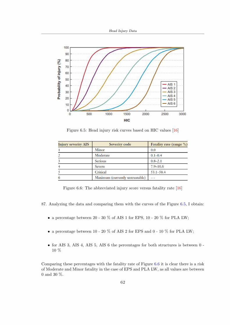
Head Injury Data
Figure 65 Head injury risk curves based on HIC values [16]
Figure 66 The abbreviated injury score versus fatality rate [16]
87 Analyzing the data and comparing them with the curves of the Figure 65 I obtain
bull a percentage between 20 - 30 of AIS 1 for EPS 10 - 20 for PLA LW
bull a percentage between 10 - 20 of AIS 2 for EPS and 0 - 10 for PLA LW
bull for AIS 3 AIS 4 AIS 5 AIS 6 the percentages for both structures is between 0 -10
Comparing these percentages with the fatality rate of Figure 66 it is clear there is a riskof Moderate and Minor fatality in the case of EPS and PLA LW as all values are between0 and 30
62
Head Injury Data
HIC PLA [g] GSI E [J]
EPS 198 97 361 37723
PLA LW 87 75 169 44102
Table 63 Head Injury Data - values
64 Peak Linear Acceleration
The resultant linear acceleration versus time curve was calculated according to Equation62
γ(t) =radicγ2x(t) + γ2y(t) + γ2z (t) (62)
where
bull γ(t) is the resultant linear acceleration (g)
bull γx(t) is the linear acceleration in x axes (g)
bull γy(t) is the linear acceleration in y axes (g)
bull γz(t)is the linear acceleration in z axes (g)
The value of the impact should never exceed 250g [9] Cripton at all [9] in their studyexamined a helmet with expanded polystyrene (EPS) Figure 68 shows maximum HIC forhelmeted and unhelmeted drops from all heights For each drop height helmets reducedHIC relative to unhelmeted drops IARV value is 180g The acceleration in the two casesis shown in Figure 67 and the maximum values are 97g for EPS and 75g for PLA LWas reported in Table 63 The two values considering a maximum value calculated byCripton [9] of 180g are amply optimal and comply with the standard of 250g
65 Gadd Severity Index
Gadd proposed the Severity Index Criteria shown in Equation 63 Following this crite-rion the GSI values that are over 1000 produce serious internal head injury [33]
GSI =
int t1
0a(t)25dt (63)
Where
bull a is the linear acceleration (g)
bull t is the duration of the impact (s)
I calculated the GSI with the function trapz between 0 and t and the resulting valuesare 361 for the EPS and 169 for the PLA LW which comply with the limit
63
Head Injury Data
Figure 67 Peak accelerations for both helmets
Figure 68 Peak accelerations for both helmeted and unhelmeted drops Numbers overbars indicate peak acceleration For 2 m drop height results stated are the mean value
calculated from three drops [9]
64
Head Injury Data
66 Diffuse Axonal Injury
DAI cases covered all incidences in which neurological injuries occurred as well as con-cussion unconsciousness and coma
In order to assess the risk of head trauma in terms of diffuse axonal injury (DAI)Milne et al [23] defined a model based head injury criteria as follows obtaining theresults in Figure 69
bull 50 risk of moderate neurological injury (DAI1+) Brain Von Mises shearing stressof 28 kPa
bull 50 risk of severe neurological injury (DAI2+) Brain Von Mises shearing stressof 53 kPa
[a]
[b]
Figure 69 Peak intra-cerebral shearing stress computed with the helmet model coupledto the human head model for all impact points (a) Flat anvil (b) Kerbstone anvil [23]
65
Head Injury Data
67 Energy absorbed
In Figure 52 during the impact test between the kerbstone Anvil and the plan with thebio-inspired structure in PLA LW and EPS it was found that the PLA LW althoughwith a small difference of 10 J absorbed more energy in comparison with the EPS Whenthe test is carried out in compliance with BS EN 1078 and the head with a speed of 457ms (corresponding to the kerbstone Anvil) as shown in Figure 610 also in this casethe PLA LW with the optimized helmet structure manages to absorb more energy (evenif the difference is very low) compared to the EPS The maximum energy value in PLALW is 44102 J of EPS is 37723 J
Figure 610 Energy absorption - BS EN 1078
66
Chapter 7
Conclusion
71 Conclusion
In this thesis work a bicycle helmet with a bio-inspired structure in PLA LW and 3Dprinted was created The initial approach was to introduce an innovative aspect tostandard EPS helmets not using foam but a polymer with new geometries able toabsorb much energy during the impact For this reason the beetle structure has beenpreferred relying solely on the hypothesis encountered in the literature of its quality inabsorbing energy
Combining the new material of the PLA LW and beetle structure has made possiblethe development of new material satisfactory characteristics have been obtained sincethe first tests The two materials were first subjected to tensile tests to determine theirspecific stress in these the PLA LW had positive results
Subsequent dynamic physical tests were carried out on 3D printed helmet models andon reference helmets in EPS to calculate the absorption energy in both cases at the timeof impact These resulted in energy absorption of the beetle structure in PLA LW withthe application of a TPU cover almost equal to that of EPS about 50J To validate withfinite element analysis the two models an explicit dynamic step was used in AbaqusSimulations showed that the PLA LW structure absorbs a higher amount of energy thanthe EPS the higher is 50 J and the EPS 40J
Finally positive results have also been obtained in calculating the head injury datasimulating according to BS EN 1078 with the use of impactor helmet and head Theacceleration values for both the structures were inferior to 220g precisely for the PLALW was 75g and for the EPS 97g The same applies to the calculation of HIC and GSI(maximum acceptable value of 1000) where the values are 87 and 169 in the case of PLALW and 361 and 198 in EPS For all tests therefore greater efficiency of the structure inPLA LW has been obtained Positive results also in the simulation of the energy absorbedduring the impact as the value referring to the EPS was 35J and that of the PLA LWwas 45J
67
Conclusion
72 Future work lines
The positive results obtained can be considered as a starting point for further tests andsimulations to ensure the safety of the helmet and compliance with the regulations butbefore getting improvements and continue testing changes are required
bull the beetle structure of the helmet made with GH adapts to the SubD withoutallowing to have a homogeneous distribution it would be appropriate to have moreregular hexagonal geometries
bull the mesh of the helmet is too complex and does not allow to perform the simulationprobably to use a more regular structure would have a mesh accordingly moreregular and the simulation would be successful
bull the uneven helmet structure has so many defects that the print is imperfect andthis can change the results of the impact tests the structure should be improved
bull the printing time varies from 4 to 5 days it should be improved
bull the TPU helmet cover is too big for the RAISE printing plan it is necessary togenerate a new geometry
bull the TPU cover it must be fixed on the helmet
bull in the calculation of the DAI it is necessary to have the definition of the brain andthe head should not be considered as a rigid body
bull in the injury calculation the helmet without protection was considered with theTPU cover the result will be better
bull air flow analysis
The comments mentioned are only considerations and problems that I gained duringmy thesis and which should be improved but I am sure that these changes and improve-ments from design to printing and simulations can make the helmet a good product
68
Bibliography
[1] K Adanty J M Clark A Post Thomas Blaine H and M D Gilchrist Comparingtwo proposed protocols to test the oblique response of cycling helmets to fall impactsInternational Journal of Crashworthiness 6648 ndash 663 2020
[2] MF Ashby YJM Brechetb D Cebona and L Salvoc Selection strategies formaterials and processes Materials and Design 2004
[3] M Aysha El casco de bicicleta voronoi impreso en 3d mas seguro y ligero https
www3dnativescomen3d-printed-bicycle-helmet-voronoi-190820204
[4] H Bikas P Stavropoulos and G Chryssolouris Additive manufacturing methodsand modelling approaches a critical review The International Journal of AdvancedManufacturing Technology 83389ndash405 2016
[5] British Standards BSI Helmets for pedal cyclists and for users of skateboards androller skates - BS EN 1078 2012
[6] British Standards BSI Headforms for use in the testing of protective helmets BSEN 960 2020
[7] ColorFabb Colorfabb lw-pla 2019 httpscolorfabbcommedia
datasheetstdscolorfabbTDS_E_ColorFabb_LW-PLApdf
[8] V G Coronado T Haileyesus J M Bell T A Cheng JHaarbauer-Krupa M RLionbarger J Flores-Herrera L C McGuire and J Gilchrist Trends in sports andrecreation-related traumatic brain injuries treated in us emergency departments thenational electronic injury surveillance system-all injury program (neiss-aip) 2001-2012 J Head Trauma Rehabil 30185ndash197 2015
[9] P A Cripton D M Dressler D Stuart Cameron A Christopher R and D RichardsBicycle helmets are highly effective at preventing head injury during head impactHead-form accelerations and injury criteria for helmeted and unhelmeted impactsAccident Analysis and Prevention 701ndash7 2014
[10] L Cui M A Forero R and M D Gilchrist Optimisation of energy absorbingliner for equestrian helmets UCD School of Electrical Electronic and MechanicalEngineering University College Dublin Belfield Dublin4 Ireland 2020
[11] C Deck N Bourdet F Meyer and R Willinger Protection performance of bicyclehelmets Journal of safety research pages 67ndash77 2019
[12] Committee F08 Specification for headforms F2220 ASTM International 2015
[13] Committee F08 Specification for helmets used in recreational bicycling or rollerskating F1447 ASTM International 2018
[14] Committee F08 Test methods for equipment and procedures used in evaluating theperformance F1446 ASTM International 2020
69
Bibliography
[15] P Halldin Shock absorption including measuring CENTC 158 Working Group11 2018
[16] W C Hayes M S Erickson and E D Power Forensic injury biomechanics Annualreview of biomedical engineering pages 55ndash86 2007
[17] HEXR httpshexrcom
[18] C Jinxiang Z Xiaoming O Yoji S Kazuya G Zhensheng and P LongchengThe deformation mode and strengthening mechanism of compression in the beetleelytron plate Materials and Design 131481ndash186 2017
[19] S Kroeker M Ozkul A De Marco S Bonin and GP Siegmund Density variationin the expanded polystyrene eps foam of bicycle helmets and its influence on impactperformance Journal of biomechanical engineering 2019
[20] S G Kroeker SJ Bonin A L DeMarco C A Good and G P Siegmund Agedoes not affect the material properties of expanded polystyrene liners in field-usedbicycle helmets Journal of biomechanical engineering 2016
[21] M Meier K H Tan M K Lim and L Chung Unlocking innovation in the sportindustry through additive manufacturing Business Process Management Journa2018
[22] N J Mills and A Gilchrist The effectiveness of foams in bicycle and motorcyclehelmets Accident Analysis Prevention 23153 ndash 163 1991
[23] G Milne C Deck R P Carreira Q Allinne and R Willinger Development andvalidation of a bicycle helmet assessment of head injury risk under standard impactconditions Computer methods in biomechanics and biomedical engineering 15 Suppl1309 ndash 310 2012
[24] Y Mosleh S J Vander B Depreitere and J Ivens Novel composite foam conceptfor head protection in oblique impacts Adv Eng Mater (Advanced EngineeringMaterials) 10 2017
[25] H Mustafa T Y Pang T Ellena and S H Nasir Impact attenuation of user-centred bicycle helmet design with different foam densities J Phys Conf Ser(Journal of Physics Conference Series) 1150 2019
[26] S H Ngoc and L Guoxing A review of recent research on bio-inspired structuresand materials for energy absorption applications Composites Part 181 2020
[27] J I Novak and A R Novak Is additive manufacturing improving performance insports a systematic review Sport engineering and technology 13 2020
[28] European Road Safety Observatory European road safety observatory facts and fig-ures - cyclists - 2020 December 2020 httpseceuropaeutransportroad_
safetysitesdefaultfilesfacts_figures_cyclists_final_20210323pdf
[29] New York City Departments of Health Parks Mental Hygiene Transportation Recre-ation and the New York City Police Department Bicyclist fatalities and seriousinjuries in new york city 2005
[30] W Pengwen Y Jing H Yanan H Jiaofei and F Xiaoyang Innovative designof a helmet based on reverse engineering and 3d printing Alexandria EngineeringJournal 603445ndash3453 2021
[31] S G Piland T E Gould M Jesunathadas J S Wiggins O McNair and V CShane Protective helmets in sports Materials in Sports Equipment 3 2019
70
Bibliography
[32] K Schmitt P F Niederer M H Muser and F Walz Trauma biomechanicsSpringer Berlin Heidelberg 2010
[33] David Sepelveda Lopez A Biomechanical Analysis of Bicycle Helmets using FEMPhD thesis 2019 Bachelor thesis
[34] H Stigson Bicycle Helmets 2020 Tested by Folksam PhD thesis 2020 PhDAssociate Professor Traffic Safety Research
[35] H Tao K Sudip N Anindya and X Yongzhao 3d printed sensors for biomedicalapplications A review sensor 2019
[36] M Trzaskalska and R Chwastek Damping properties and density of helmet linersmade of expanded polystyrene (eps) Archives of Metallurgy and Materials 66 2020
[37] Crupi V Epasto G and Guglielmino E Impact response of aluminum foam sand-wiches for light-weight ship structures Metals 198ndash112 2020
[38] W Wei-cai F Dong-ming and L Yuan-xin Study on impact energy absorbing per-formance of eps buffer layer of motorcycle helmet Proceedings - 2013 InternationalConference on Mechanical and Automation Engineering MAEE 2013
[39] Z Xiaoming C Jinxiang O Yoji Z Peiwei X Xiaobing and Y Xindi Influence ofhoneycomb dimensions and forming methods on the compressive properties of beetleelytron plates Journal of Sandwich Structures and Materials 2228ndash39 2020
[40] S Zhi L Dong Z Weisheng S Shanshan and G Xu Topological optimization ofbiomimetic sandwich structures with hybrid core and cfrp face sheets CompositesScience and Technology 14279ndash90 2017
[41] S Zhi S Shanshan G Xu H Xiaozhi and C Haoran On compressive propertiesof composite sandwich structures with grid reinforced honeycomb core CompositesPart B 94245ndash252 2016
71
- List of Tables
- List of Figures
- Introduction
-
- Helmet bike protection
-
- Helmet structure
-
- Additive Manufacturing
-
- AM process
- Materials and techniques - FDM
- AM in sport
-
- 3D printed helmets
-
- Phases
- HEXR
- VORONOI
-
- State of the art
-
- Standards
-
- Headform
- European Standard and American Standard
- Field of vision - BS EN 1078
- Test impact area
- Anvils and environmental conditions
-
- Materials
-
- EPS Foam
- CES Edu Pack - Material selection
- PLA with natural fiber and PLA LW
-
- Bio-inspired structures
-
- Beetle structure - Design of the model
- Specific stress - PLA LW and EPS foam
-
- Methodology
-
- 3D scan
-
- 3D Sense 2 scanner and Meshmixer - Reverse reconstruction
- 3D scan analysis and extraction of features
-
- Helmet design
-
- Rhinoceros - Helmet surface
- Grasshopper - Helmet structure
-
- 3D Print
-
- Printer and parameters
-
- Experimental evaluation
-
- Experimental tests
-
- Drop-weight impact test machine
-
- PLA LW helmet
- EPS helmet
- Results
-
- First results - PLA-LW and EPS helmet
- PLA-LW helmet with TPU cover
-
- FEM Validation
-
- Impactor - Anvils definition
-
- PLA LW - Plastic characteristics
- First test - helmet
- Second test - plane
- EPS impact simulations
- PLA LW impact simulations
-
- Results
-
- Head Injury Data
-
- Abaqus simulation
- Results
- Head Injury Criterion
- Peak Linear Acceleration
- Gadd Severity Index
- Diffuse Axonal Injury
- Energy absorbed
-
- Conclusion
-
- Conclusion
- Future work lines
-
- Bibliography
-
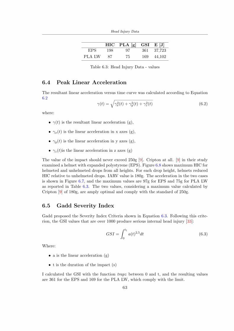
Head Injury Data
HIC PLA [g] GSI E [J]
EPS 198 97 361 37723
PLA LW 87 75 169 44102
Table 63 Head Injury Data - values
64 Peak Linear Acceleration
The resultant linear acceleration versus time curve was calculated according to Equation62
γ(t) =radicγ2x(t) + γ2y(t) + γ2z (t) (62)
where
bull γ(t) is the resultant linear acceleration (g)
bull γx(t) is the linear acceleration in x axes (g)
bull γy(t) is the linear acceleration in y axes (g)
bull γz(t)is the linear acceleration in z axes (g)
The value of the impact should never exceed 250g [9] Cripton at all [9] in their studyexamined a helmet with expanded polystyrene (EPS) Figure 68 shows maximum HIC forhelmeted and unhelmeted drops from all heights For each drop height helmets reducedHIC relative to unhelmeted drops IARV value is 180g The acceleration in the two casesis shown in Figure 67 and the maximum values are 97g for EPS and 75g for PLA LWas reported in Table 63 The two values considering a maximum value calculated byCripton [9] of 180g are amply optimal and comply with the standard of 250g
65 Gadd Severity Index
Gadd proposed the Severity Index Criteria shown in Equation 63 Following this crite-rion the GSI values that are over 1000 produce serious internal head injury [33]
GSI =
int t1
0a(t)25dt (63)
Where
bull a is the linear acceleration (g)
bull t is the duration of the impact (s)
I calculated the GSI with the function trapz between 0 and t and the resulting valuesare 361 for the EPS and 169 for the PLA LW which comply with the limit
63
Head Injury Data
Figure 67 Peak accelerations for both helmets
Figure 68 Peak accelerations for both helmeted and unhelmeted drops Numbers overbars indicate peak acceleration For 2 m drop height results stated are the mean value
calculated from three drops [9]
64
Head Injury Data
66 Diffuse Axonal Injury
DAI cases covered all incidences in which neurological injuries occurred as well as con-cussion unconsciousness and coma
In order to assess the risk of head trauma in terms of diffuse axonal injury (DAI)Milne et al [23] defined a model based head injury criteria as follows obtaining theresults in Figure 69
bull 50 risk of moderate neurological injury (DAI1+) Brain Von Mises shearing stressof 28 kPa
bull 50 risk of severe neurological injury (DAI2+) Brain Von Mises shearing stressof 53 kPa
[a]
[b]
Figure 69 Peak intra-cerebral shearing stress computed with the helmet model coupledto the human head model for all impact points (a) Flat anvil (b) Kerbstone anvil [23]
65
Head Injury Data
67 Energy absorbed
In Figure 52 during the impact test between the kerbstone Anvil and the plan with thebio-inspired structure in PLA LW and EPS it was found that the PLA LW althoughwith a small difference of 10 J absorbed more energy in comparison with the EPS Whenthe test is carried out in compliance with BS EN 1078 and the head with a speed of 457ms (corresponding to the kerbstone Anvil) as shown in Figure 610 also in this casethe PLA LW with the optimized helmet structure manages to absorb more energy (evenif the difference is very low) compared to the EPS The maximum energy value in PLALW is 44102 J of EPS is 37723 J
Figure 610 Energy absorption - BS EN 1078
66
Chapter 7
Conclusion
71 Conclusion
In this thesis work a bicycle helmet with a bio-inspired structure in PLA LW and 3Dprinted was created The initial approach was to introduce an innovative aspect tostandard EPS helmets not using foam but a polymer with new geometries able toabsorb much energy during the impact For this reason the beetle structure has beenpreferred relying solely on the hypothesis encountered in the literature of its quality inabsorbing energy
Combining the new material of the PLA LW and beetle structure has made possiblethe development of new material satisfactory characteristics have been obtained sincethe first tests The two materials were first subjected to tensile tests to determine theirspecific stress in these the PLA LW had positive results
Subsequent dynamic physical tests were carried out on 3D printed helmet models andon reference helmets in EPS to calculate the absorption energy in both cases at the timeof impact These resulted in energy absorption of the beetle structure in PLA LW withthe application of a TPU cover almost equal to that of EPS about 50J To validate withfinite element analysis the two models an explicit dynamic step was used in AbaqusSimulations showed that the PLA LW structure absorbs a higher amount of energy thanthe EPS the higher is 50 J and the EPS 40J
Finally positive results have also been obtained in calculating the head injury datasimulating according to BS EN 1078 with the use of impactor helmet and head Theacceleration values for both the structures were inferior to 220g precisely for the PLALW was 75g and for the EPS 97g The same applies to the calculation of HIC and GSI(maximum acceptable value of 1000) where the values are 87 and 169 in the case of PLALW and 361 and 198 in EPS For all tests therefore greater efficiency of the structure inPLA LW has been obtained Positive results also in the simulation of the energy absorbedduring the impact as the value referring to the EPS was 35J and that of the PLA LWwas 45J
67
Conclusion
72 Future work lines
The positive results obtained can be considered as a starting point for further tests andsimulations to ensure the safety of the helmet and compliance with the regulations butbefore getting improvements and continue testing changes are required
bull the beetle structure of the helmet made with GH adapts to the SubD withoutallowing to have a homogeneous distribution it would be appropriate to have moreregular hexagonal geometries
bull the mesh of the helmet is too complex and does not allow to perform the simulationprobably to use a more regular structure would have a mesh accordingly moreregular and the simulation would be successful
bull the uneven helmet structure has so many defects that the print is imperfect andthis can change the results of the impact tests the structure should be improved
bull the printing time varies from 4 to 5 days it should be improved
bull the TPU helmet cover is too big for the RAISE printing plan it is necessary togenerate a new geometry
bull the TPU cover it must be fixed on the helmet
bull in the calculation of the DAI it is necessary to have the definition of the brain andthe head should not be considered as a rigid body
bull in the injury calculation the helmet without protection was considered with theTPU cover the result will be better
bull air flow analysis
The comments mentioned are only considerations and problems that I gained duringmy thesis and which should be improved but I am sure that these changes and improve-ments from design to printing and simulations can make the helmet a good product
68
Bibliography
[1] K Adanty J M Clark A Post Thomas Blaine H and M D Gilchrist Comparingtwo proposed protocols to test the oblique response of cycling helmets to fall impactsInternational Journal of Crashworthiness 6648 ndash 663 2020
[2] MF Ashby YJM Brechetb D Cebona and L Salvoc Selection strategies formaterials and processes Materials and Design 2004
[3] M Aysha El casco de bicicleta voronoi impreso en 3d mas seguro y ligero https
www3dnativescomen3d-printed-bicycle-helmet-voronoi-190820204
[4] H Bikas P Stavropoulos and G Chryssolouris Additive manufacturing methodsand modelling approaches a critical review The International Journal of AdvancedManufacturing Technology 83389ndash405 2016
[5] British Standards BSI Helmets for pedal cyclists and for users of skateboards androller skates - BS EN 1078 2012
[6] British Standards BSI Headforms for use in the testing of protective helmets BSEN 960 2020
[7] ColorFabb Colorfabb lw-pla 2019 httpscolorfabbcommedia
datasheetstdscolorfabbTDS_E_ColorFabb_LW-PLApdf
[8] V G Coronado T Haileyesus J M Bell T A Cheng JHaarbauer-Krupa M RLionbarger J Flores-Herrera L C McGuire and J Gilchrist Trends in sports andrecreation-related traumatic brain injuries treated in us emergency departments thenational electronic injury surveillance system-all injury program (neiss-aip) 2001-2012 J Head Trauma Rehabil 30185ndash197 2015
[9] P A Cripton D M Dressler D Stuart Cameron A Christopher R and D RichardsBicycle helmets are highly effective at preventing head injury during head impactHead-form accelerations and injury criteria for helmeted and unhelmeted impactsAccident Analysis and Prevention 701ndash7 2014
[10] L Cui M A Forero R and M D Gilchrist Optimisation of energy absorbingliner for equestrian helmets UCD School of Electrical Electronic and MechanicalEngineering University College Dublin Belfield Dublin4 Ireland 2020
[11] C Deck N Bourdet F Meyer and R Willinger Protection performance of bicyclehelmets Journal of safety research pages 67ndash77 2019
[12] Committee F08 Specification for headforms F2220 ASTM International 2015
[13] Committee F08 Specification for helmets used in recreational bicycling or rollerskating F1447 ASTM International 2018
[14] Committee F08 Test methods for equipment and procedures used in evaluating theperformance F1446 ASTM International 2020
69
Bibliography
[15] P Halldin Shock absorption including measuring CENTC 158 Working Group11 2018
[16] W C Hayes M S Erickson and E D Power Forensic injury biomechanics Annualreview of biomedical engineering pages 55ndash86 2007
[17] HEXR httpshexrcom
[18] C Jinxiang Z Xiaoming O Yoji S Kazuya G Zhensheng and P LongchengThe deformation mode and strengthening mechanism of compression in the beetleelytron plate Materials and Design 131481ndash186 2017
[19] S Kroeker M Ozkul A De Marco S Bonin and GP Siegmund Density variationin the expanded polystyrene eps foam of bicycle helmets and its influence on impactperformance Journal of biomechanical engineering 2019
[20] S G Kroeker SJ Bonin A L DeMarco C A Good and G P Siegmund Agedoes not affect the material properties of expanded polystyrene liners in field-usedbicycle helmets Journal of biomechanical engineering 2016
[21] M Meier K H Tan M K Lim and L Chung Unlocking innovation in the sportindustry through additive manufacturing Business Process Management Journa2018
[22] N J Mills and A Gilchrist The effectiveness of foams in bicycle and motorcyclehelmets Accident Analysis Prevention 23153 ndash 163 1991
[23] G Milne C Deck R P Carreira Q Allinne and R Willinger Development andvalidation of a bicycle helmet assessment of head injury risk under standard impactconditions Computer methods in biomechanics and biomedical engineering 15 Suppl1309 ndash 310 2012
[24] Y Mosleh S J Vander B Depreitere and J Ivens Novel composite foam conceptfor head protection in oblique impacts Adv Eng Mater (Advanced EngineeringMaterials) 10 2017
[25] H Mustafa T Y Pang T Ellena and S H Nasir Impact attenuation of user-centred bicycle helmet design with different foam densities J Phys Conf Ser(Journal of Physics Conference Series) 1150 2019
[26] S H Ngoc and L Guoxing A review of recent research on bio-inspired structuresand materials for energy absorption applications Composites Part 181 2020
[27] J I Novak and A R Novak Is additive manufacturing improving performance insports a systematic review Sport engineering and technology 13 2020
[28] European Road Safety Observatory European road safety observatory facts and fig-ures - cyclists - 2020 December 2020 httpseceuropaeutransportroad_
safetysitesdefaultfilesfacts_figures_cyclists_final_20210323pdf
[29] New York City Departments of Health Parks Mental Hygiene Transportation Recre-ation and the New York City Police Department Bicyclist fatalities and seriousinjuries in new york city 2005
[30] W Pengwen Y Jing H Yanan H Jiaofei and F Xiaoyang Innovative designof a helmet based on reverse engineering and 3d printing Alexandria EngineeringJournal 603445ndash3453 2021
[31] S G Piland T E Gould M Jesunathadas J S Wiggins O McNair and V CShane Protective helmets in sports Materials in Sports Equipment 3 2019
70
Bibliography
[32] K Schmitt P F Niederer M H Muser and F Walz Trauma biomechanicsSpringer Berlin Heidelberg 2010
[33] David Sepelveda Lopez A Biomechanical Analysis of Bicycle Helmets using FEMPhD thesis 2019 Bachelor thesis
[34] H Stigson Bicycle Helmets 2020 Tested by Folksam PhD thesis 2020 PhDAssociate Professor Traffic Safety Research
[35] H Tao K Sudip N Anindya and X Yongzhao 3d printed sensors for biomedicalapplications A review sensor 2019
[36] M Trzaskalska and R Chwastek Damping properties and density of helmet linersmade of expanded polystyrene (eps) Archives of Metallurgy and Materials 66 2020
[37] Crupi V Epasto G and Guglielmino E Impact response of aluminum foam sand-wiches for light-weight ship structures Metals 198ndash112 2020
[38] W Wei-cai F Dong-ming and L Yuan-xin Study on impact energy absorbing per-formance of eps buffer layer of motorcycle helmet Proceedings - 2013 InternationalConference on Mechanical and Automation Engineering MAEE 2013
[39] Z Xiaoming C Jinxiang O Yoji Z Peiwei X Xiaobing and Y Xindi Influence ofhoneycomb dimensions and forming methods on the compressive properties of beetleelytron plates Journal of Sandwich Structures and Materials 2228ndash39 2020
[40] S Zhi L Dong Z Weisheng S Shanshan and G Xu Topological optimization ofbiomimetic sandwich structures with hybrid core and cfrp face sheets CompositesScience and Technology 14279ndash90 2017
[41] S Zhi S Shanshan G Xu H Xiaozhi and C Haoran On compressive propertiesof composite sandwich structures with grid reinforced honeycomb core CompositesPart B 94245ndash252 2016
71
- List of Tables
- List of Figures
- Introduction
-
- Helmet bike protection
-
- Helmet structure
-
- Additive Manufacturing
-
- AM process
- Materials and techniques - FDM
- AM in sport
-
- 3D printed helmets
-
- Phases
- HEXR
- VORONOI
-
- State of the art
-
- Standards
-
- Headform
- European Standard and American Standard
- Field of vision - BS EN 1078
- Test impact area
- Anvils and environmental conditions
-
- Materials
-
- EPS Foam
- CES Edu Pack - Material selection
- PLA with natural fiber and PLA LW
-
- Bio-inspired structures
-
- Beetle structure - Design of the model
- Specific stress - PLA LW and EPS foam
-
- Methodology
-
- 3D scan
-
- 3D Sense 2 scanner and Meshmixer - Reverse reconstruction
- 3D scan analysis and extraction of features
-
- Helmet design
-
- Rhinoceros - Helmet surface
- Grasshopper - Helmet structure
-
- 3D Print
-
- Printer and parameters
-
- Experimental evaluation
-
- Experimental tests
-
- Drop-weight impact test machine
-
- PLA LW helmet
- EPS helmet
- Results
-
- First results - PLA-LW and EPS helmet
- PLA-LW helmet with TPU cover
-
- FEM Validation
-
- Impactor - Anvils definition
-
- PLA LW - Plastic characteristics
- First test - helmet
- Second test - plane
- EPS impact simulations
- PLA LW impact simulations
-
- Results
-
- Head Injury Data
-
- Abaqus simulation
- Results
- Head Injury Criterion
- Peak Linear Acceleration
- Gadd Severity Index
- Diffuse Axonal Injury
- Energy absorbed
-
- Conclusion
-
- Conclusion
- Future work lines
-
- Bibliography
-
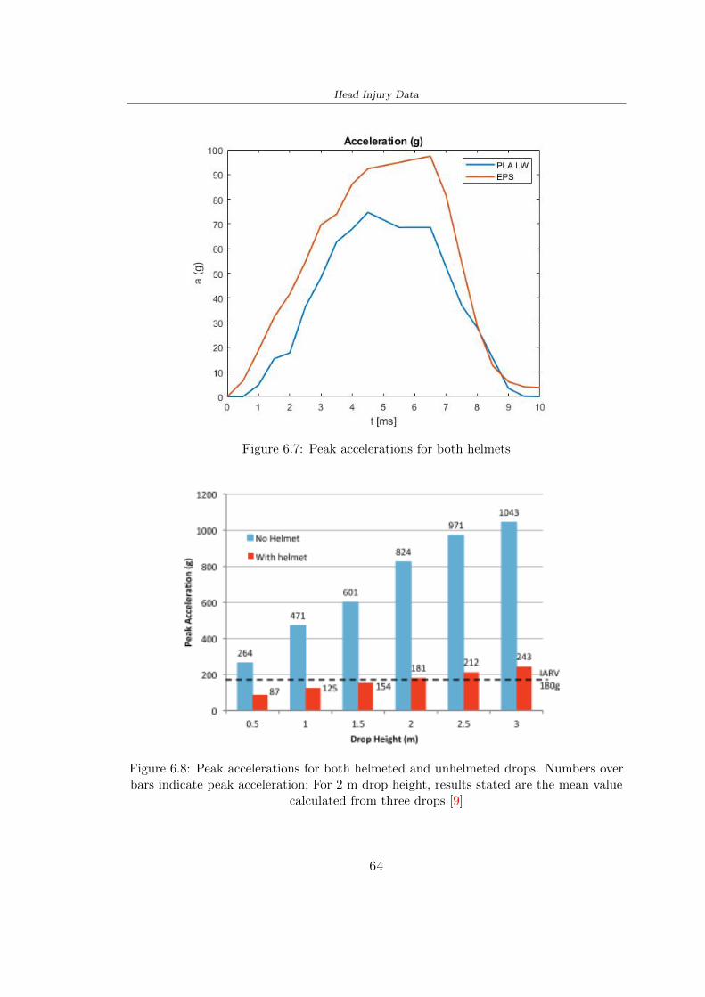
Head Injury Data
Figure 67 Peak accelerations for both helmets
Figure 68 Peak accelerations for both helmeted and unhelmeted drops Numbers overbars indicate peak acceleration For 2 m drop height results stated are the mean value
calculated from three drops [9]
64
Head Injury Data
66 Diffuse Axonal Injury
DAI cases covered all incidences in which neurological injuries occurred as well as con-cussion unconsciousness and coma
In order to assess the risk of head trauma in terms of diffuse axonal injury (DAI)Milne et al [23] defined a model based head injury criteria as follows obtaining theresults in Figure 69
bull 50 risk of moderate neurological injury (DAI1+) Brain Von Mises shearing stressof 28 kPa
bull 50 risk of severe neurological injury (DAI2+) Brain Von Mises shearing stressof 53 kPa
[a]
[b]
Figure 69 Peak intra-cerebral shearing stress computed with the helmet model coupledto the human head model for all impact points (a) Flat anvil (b) Kerbstone anvil [23]
65
Head Injury Data
67 Energy absorbed
In Figure 52 during the impact test between the kerbstone Anvil and the plan with thebio-inspired structure in PLA LW and EPS it was found that the PLA LW althoughwith a small difference of 10 J absorbed more energy in comparison with the EPS Whenthe test is carried out in compliance with BS EN 1078 and the head with a speed of 457ms (corresponding to the kerbstone Anvil) as shown in Figure 610 also in this casethe PLA LW with the optimized helmet structure manages to absorb more energy (evenif the difference is very low) compared to the EPS The maximum energy value in PLALW is 44102 J of EPS is 37723 J
Figure 610 Energy absorption - BS EN 1078
66
Chapter 7
Conclusion
71 Conclusion
In this thesis work a bicycle helmet with a bio-inspired structure in PLA LW and 3Dprinted was created The initial approach was to introduce an innovative aspect tostandard EPS helmets not using foam but a polymer with new geometries able toabsorb much energy during the impact For this reason the beetle structure has beenpreferred relying solely on the hypothesis encountered in the literature of its quality inabsorbing energy
Combining the new material of the PLA LW and beetle structure has made possiblethe development of new material satisfactory characteristics have been obtained sincethe first tests The two materials were first subjected to tensile tests to determine theirspecific stress in these the PLA LW had positive results
Subsequent dynamic physical tests were carried out on 3D printed helmet models andon reference helmets in EPS to calculate the absorption energy in both cases at the timeof impact These resulted in energy absorption of the beetle structure in PLA LW withthe application of a TPU cover almost equal to that of EPS about 50J To validate withfinite element analysis the two models an explicit dynamic step was used in AbaqusSimulations showed that the PLA LW structure absorbs a higher amount of energy thanthe EPS the higher is 50 J and the EPS 40J
Finally positive results have also been obtained in calculating the head injury datasimulating according to BS EN 1078 with the use of impactor helmet and head Theacceleration values for both the structures were inferior to 220g precisely for the PLALW was 75g and for the EPS 97g The same applies to the calculation of HIC and GSI(maximum acceptable value of 1000) where the values are 87 and 169 in the case of PLALW and 361 and 198 in EPS For all tests therefore greater efficiency of the structure inPLA LW has been obtained Positive results also in the simulation of the energy absorbedduring the impact as the value referring to the EPS was 35J and that of the PLA LWwas 45J
67
Conclusion
72 Future work lines
The positive results obtained can be considered as a starting point for further tests andsimulations to ensure the safety of the helmet and compliance with the regulations butbefore getting improvements and continue testing changes are required
bull the beetle structure of the helmet made with GH adapts to the SubD withoutallowing to have a homogeneous distribution it would be appropriate to have moreregular hexagonal geometries
bull the mesh of the helmet is too complex and does not allow to perform the simulationprobably to use a more regular structure would have a mesh accordingly moreregular and the simulation would be successful
bull the uneven helmet structure has so many defects that the print is imperfect andthis can change the results of the impact tests the structure should be improved
bull the printing time varies from 4 to 5 days it should be improved
bull the TPU helmet cover is too big for the RAISE printing plan it is necessary togenerate a new geometry
bull the TPU cover it must be fixed on the helmet
bull in the calculation of the DAI it is necessary to have the definition of the brain andthe head should not be considered as a rigid body
bull in the injury calculation the helmet without protection was considered with theTPU cover the result will be better
bull air flow analysis
The comments mentioned are only considerations and problems that I gained duringmy thesis and which should be improved but I am sure that these changes and improve-ments from design to printing and simulations can make the helmet a good product
68
Bibliography
[1] K Adanty J M Clark A Post Thomas Blaine H and M D Gilchrist Comparingtwo proposed protocols to test the oblique response of cycling helmets to fall impactsInternational Journal of Crashworthiness 6648 ndash 663 2020
[2] MF Ashby YJM Brechetb D Cebona and L Salvoc Selection strategies formaterials and processes Materials and Design 2004
[3] M Aysha El casco de bicicleta voronoi impreso en 3d mas seguro y ligero https
www3dnativescomen3d-printed-bicycle-helmet-voronoi-190820204
[4] H Bikas P Stavropoulos and G Chryssolouris Additive manufacturing methodsand modelling approaches a critical review The International Journal of AdvancedManufacturing Technology 83389ndash405 2016
[5] British Standards BSI Helmets for pedal cyclists and for users of skateboards androller skates - BS EN 1078 2012
[6] British Standards BSI Headforms for use in the testing of protective helmets BSEN 960 2020
[7] ColorFabb Colorfabb lw-pla 2019 httpscolorfabbcommedia
datasheetstdscolorfabbTDS_E_ColorFabb_LW-PLApdf
[8] V G Coronado T Haileyesus J M Bell T A Cheng JHaarbauer-Krupa M RLionbarger J Flores-Herrera L C McGuire and J Gilchrist Trends in sports andrecreation-related traumatic brain injuries treated in us emergency departments thenational electronic injury surveillance system-all injury program (neiss-aip) 2001-2012 J Head Trauma Rehabil 30185ndash197 2015
[9] P A Cripton D M Dressler D Stuart Cameron A Christopher R and D RichardsBicycle helmets are highly effective at preventing head injury during head impactHead-form accelerations and injury criteria for helmeted and unhelmeted impactsAccident Analysis and Prevention 701ndash7 2014
[10] L Cui M A Forero R and M D Gilchrist Optimisation of energy absorbingliner for equestrian helmets UCD School of Electrical Electronic and MechanicalEngineering University College Dublin Belfield Dublin4 Ireland 2020
[11] C Deck N Bourdet F Meyer and R Willinger Protection performance of bicyclehelmets Journal of safety research pages 67ndash77 2019
[12] Committee F08 Specification for headforms F2220 ASTM International 2015
[13] Committee F08 Specification for helmets used in recreational bicycling or rollerskating F1447 ASTM International 2018
[14] Committee F08 Test methods for equipment and procedures used in evaluating theperformance F1446 ASTM International 2020
69
Bibliography
[15] P Halldin Shock absorption including measuring CENTC 158 Working Group11 2018
[16] W C Hayes M S Erickson and E D Power Forensic injury biomechanics Annualreview of biomedical engineering pages 55ndash86 2007
[17] HEXR httpshexrcom
[18] C Jinxiang Z Xiaoming O Yoji S Kazuya G Zhensheng and P LongchengThe deformation mode and strengthening mechanism of compression in the beetleelytron plate Materials and Design 131481ndash186 2017
[19] S Kroeker M Ozkul A De Marco S Bonin and GP Siegmund Density variationin the expanded polystyrene eps foam of bicycle helmets and its influence on impactperformance Journal of biomechanical engineering 2019
[20] S G Kroeker SJ Bonin A L DeMarco C A Good and G P Siegmund Agedoes not affect the material properties of expanded polystyrene liners in field-usedbicycle helmets Journal of biomechanical engineering 2016
[21] M Meier K H Tan M K Lim and L Chung Unlocking innovation in the sportindustry through additive manufacturing Business Process Management Journa2018
[22] N J Mills and A Gilchrist The effectiveness of foams in bicycle and motorcyclehelmets Accident Analysis Prevention 23153 ndash 163 1991
[23] G Milne C Deck R P Carreira Q Allinne and R Willinger Development andvalidation of a bicycle helmet assessment of head injury risk under standard impactconditions Computer methods in biomechanics and biomedical engineering 15 Suppl1309 ndash 310 2012
[24] Y Mosleh S J Vander B Depreitere and J Ivens Novel composite foam conceptfor head protection in oblique impacts Adv Eng Mater (Advanced EngineeringMaterials) 10 2017
[25] H Mustafa T Y Pang T Ellena and S H Nasir Impact attenuation of user-centred bicycle helmet design with different foam densities J Phys Conf Ser(Journal of Physics Conference Series) 1150 2019
[26] S H Ngoc and L Guoxing A review of recent research on bio-inspired structuresand materials for energy absorption applications Composites Part 181 2020
[27] J I Novak and A R Novak Is additive manufacturing improving performance insports a systematic review Sport engineering and technology 13 2020
[28] European Road Safety Observatory European road safety observatory facts and fig-ures - cyclists - 2020 December 2020 httpseceuropaeutransportroad_
safetysitesdefaultfilesfacts_figures_cyclists_final_20210323pdf
[29] New York City Departments of Health Parks Mental Hygiene Transportation Recre-ation and the New York City Police Department Bicyclist fatalities and seriousinjuries in new york city 2005
[30] W Pengwen Y Jing H Yanan H Jiaofei and F Xiaoyang Innovative designof a helmet based on reverse engineering and 3d printing Alexandria EngineeringJournal 603445ndash3453 2021
[31] S G Piland T E Gould M Jesunathadas J S Wiggins O McNair and V CShane Protective helmets in sports Materials in Sports Equipment 3 2019
70
Bibliography
[32] K Schmitt P F Niederer M H Muser and F Walz Trauma biomechanicsSpringer Berlin Heidelberg 2010
[33] David Sepelveda Lopez A Biomechanical Analysis of Bicycle Helmets using FEMPhD thesis 2019 Bachelor thesis
[34] H Stigson Bicycle Helmets 2020 Tested by Folksam PhD thesis 2020 PhDAssociate Professor Traffic Safety Research
[35] H Tao K Sudip N Anindya and X Yongzhao 3d printed sensors for biomedicalapplications A review sensor 2019
[36] M Trzaskalska and R Chwastek Damping properties and density of helmet linersmade of expanded polystyrene (eps) Archives of Metallurgy and Materials 66 2020
[37] Crupi V Epasto G and Guglielmino E Impact response of aluminum foam sand-wiches for light-weight ship structures Metals 198ndash112 2020
[38] W Wei-cai F Dong-ming and L Yuan-xin Study on impact energy absorbing per-formance of eps buffer layer of motorcycle helmet Proceedings - 2013 InternationalConference on Mechanical and Automation Engineering MAEE 2013
[39] Z Xiaoming C Jinxiang O Yoji Z Peiwei X Xiaobing and Y Xindi Influence ofhoneycomb dimensions and forming methods on the compressive properties of beetleelytron plates Journal of Sandwich Structures and Materials 2228ndash39 2020
[40] S Zhi L Dong Z Weisheng S Shanshan and G Xu Topological optimization ofbiomimetic sandwich structures with hybrid core and cfrp face sheets CompositesScience and Technology 14279ndash90 2017
[41] S Zhi S Shanshan G Xu H Xiaozhi and C Haoran On compressive propertiesof composite sandwich structures with grid reinforced honeycomb core CompositesPart B 94245ndash252 2016
71
- List of Tables
- List of Figures
- Introduction
-
- Helmet bike protection
-
- Helmet structure
-
- Additive Manufacturing
-
- AM process
- Materials and techniques - FDM
- AM in sport
-
- 3D printed helmets
-
- Phases
- HEXR
- VORONOI
-
- State of the art
-
- Standards
-
- Headform
- European Standard and American Standard
- Field of vision - BS EN 1078
- Test impact area
- Anvils and environmental conditions
-
- Materials
-
- EPS Foam
- CES Edu Pack - Material selection
- PLA with natural fiber and PLA LW
-
- Bio-inspired structures
-
- Beetle structure - Design of the model
- Specific stress - PLA LW and EPS foam
-
- Methodology
-
- 3D scan
-
- 3D Sense 2 scanner and Meshmixer - Reverse reconstruction
- 3D scan analysis and extraction of features
-
- Helmet design
-
- Rhinoceros - Helmet surface
- Grasshopper - Helmet structure
-
- 3D Print
-
- Printer and parameters
-
- Experimental evaluation
-
- Experimental tests
-
- Drop-weight impact test machine
-
- PLA LW helmet
- EPS helmet
- Results
-
- First results - PLA-LW and EPS helmet
- PLA-LW helmet with TPU cover
-
- FEM Validation
-
- Impactor - Anvils definition
-
- PLA LW - Plastic characteristics
- First test - helmet
- Second test - plane
- EPS impact simulations
- PLA LW impact simulations
-
- Results
-
- Head Injury Data
-
- Abaqus simulation
- Results
- Head Injury Criterion
- Peak Linear Acceleration
- Gadd Severity Index
- Diffuse Axonal Injury
- Energy absorbed
-
- Conclusion
-
- Conclusion
- Future work lines
-
- Bibliography
-
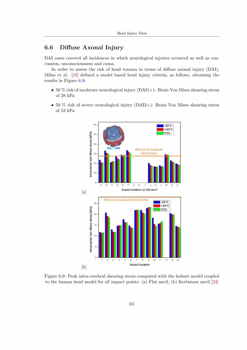
Head Injury Data
67 Energy absorbed
In Figure 52 during the impact test between the kerbstone Anvil and the plan with thebio-inspired structure in PLA LW and EPS it was found that the PLA LW althoughwith a small difference of 10 J absorbed more energy in comparison with the EPS Whenthe test is carried out in compliance with BS EN 1078 and the head with a speed of 457ms (corresponding to the kerbstone Anvil) as shown in Figure 610 also in this casethe PLA LW with the optimized helmet structure manages to absorb more energy (evenif the difference is very low) compared to the EPS The maximum energy value in PLALW is 44102 J of EPS is 37723 J
Figure 610 Energy absorption - BS EN 1078
66
Chapter 7
Conclusion
71 Conclusion
In this thesis work a bicycle helmet with a bio-inspired structure in PLA LW and 3Dprinted was created The initial approach was to introduce an innovative aspect tostandard EPS helmets not using foam but a polymer with new geometries able toabsorb much energy during the impact For this reason the beetle structure has beenpreferred relying solely on the hypothesis encountered in the literature of its quality inabsorbing energy
Combining the new material of the PLA LW and beetle structure has made possiblethe development of new material satisfactory characteristics have been obtained sincethe first tests The two materials were first subjected to tensile tests to determine theirspecific stress in these the PLA LW had positive results
Subsequent dynamic physical tests were carried out on 3D printed helmet models andon reference helmets in EPS to calculate the absorption energy in both cases at the timeof impact These resulted in energy absorption of the beetle structure in PLA LW withthe application of a TPU cover almost equal to that of EPS about 50J To validate withfinite element analysis the two models an explicit dynamic step was used in AbaqusSimulations showed that the PLA LW structure absorbs a higher amount of energy thanthe EPS the higher is 50 J and the EPS 40J
Finally positive results have also been obtained in calculating the head injury datasimulating according to BS EN 1078 with the use of impactor helmet and head Theacceleration values for both the structures were inferior to 220g precisely for the PLALW was 75g and for the EPS 97g The same applies to the calculation of HIC and GSI(maximum acceptable value of 1000) where the values are 87 and 169 in the case of PLALW and 361 and 198 in EPS For all tests therefore greater efficiency of the structure inPLA LW has been obtained Positive results also in the simulation of the energy absorbedduring the impact as the value referring to the EPS was 35J and that of the PLA LWwas 45J
67
Conclusion
72 Future work lines
The positive results obtained can be considered as a starting point for further tests andsimulations to ensure the safety of the helmet and compliance with the regulations butbefore getting improvements and continue testing changes are required
bull the beetle structure of the helmet made with GH adapts to the SubD withoutallowing to have a homogeneous distribution it would be appropriate to have moreregular hexagonal geometries
bull the mesh of the helmet is too complex and does not allow to perform the simulationprobably to use a more regular structure would have a mesh accordingly moreregular and the simulation would be successful
bull the uneven helmet structure has so many defects that the print is imperfect andthis can change the results of the impact tests the structure should be improved
bull the printing time varies from 4 to 5 days it should be improved
bull the TPU helmet cover is too big for the RAISE printing plan it is necessary togenerate a new geometry
bull the TPU cover it must be fixed on the helmet
bull in the calculation of the DAI it is necessary to have the definition of the brain andthe head should not be considered as a rigid body
bull in the injury calculation the helmet without protection was considered with theTPU cover the result will be better
bull air flow analysis
The comments mentioned are only considerations and problems that I gained duringmy thesis and which should be improved but I am sure that these changes and improve-ments from design to printing and simulations can make the helmet a good product
68
Bibliography
[1] K Adanty J M Clark A Post Thomas Blaine H and M D Gilchrist Comparingtwo proposed protocols to test the oblique response of cycling helmets to fall impactsInternational Journal of Crashworthiness 6648 ndash 663 2020
[2] MF Ashby YJM Brechetb D Cebona and L Salvoc Selection strategies formaterials and processes Materials and Design 2004
[3] M Aysha El casco de bicicleta voronoi impreso en 3d mas seguro y ligero https
www3dnativescomen3d-printed-bicycle-helmet-voronoi-190820204
[4] H Bikas P Stavropoulos and G Chryssolouris Additive manufacturing methodsand modelling approaches a critical review The International Journal of AdvancedManufacturing Technology 83389ndash405 2016
[5] British Standards BSI Helmets for pedal cyclists and for users of skateboards androller skates - BS EN 1078 2012
[6] British Standards BSI Headforms for use in the testing of protective helmets BSEN 960 2020
[7] ColorFabb Colorfabb lw-pla 2019 httpscolorfabbcommedia
datasheetstdscolorfabbTDS_E_ColorFabb_LW-PLApdf
[8] V G Coronado T Haileyesus J M Bell T A Cheng JHaarbauer-Krupa M RLionbarger J Flores-Herrera L C McGuire and J Gilchrist Trends in sports andrecreation-related traumatic brain injuries treated in us emergency departments thenational electronic injury surveillance system-all injury program (neiss-aip) 2001-2012 J Head Trauma Rehabil 30185ndash197 2015
[9] P A Cripton D M Dressler D Stuart Cameron A Christopher R and D RichardsBicycle helmets are highly effective at preventing head injury during head impactHead-form accelerations and injury criteria for helmeted and unhelmeted impactsAccident Analysis and Prevention 701ndash7 2014
[10] L Cui M A Forero R and M D Gilchrist Optimisation of energy absorbingliner for equestrian helmets UCD School of Electrical Electronic and MechanicalEngineering University College Dublin Belfield Dublin4 Ireland 2020
[11] C Deck N Bourdet F Meyer and R Willinger Protection performance of bicyclehelmets Journal of safety research pages 67ndash77 2019
[12] Committee F08 Specification for headforms F2220 ASTM International 2015
[13] Committee F08 Specification for helmets used in recreational bicycling or rollerskating F1447 ASTM International 2018
[14] Committee F08 Test methods for equipment and procedures used in evaluating theperformance F1446 ASTM International 2020
69
Bibliography
[15] P Halldin Shock absorption including measuring CENTC 158 Working Group11 2018
[16] W C Hayes M S Erickson and E D Power Forensic injury biomechanics Annualreview of biomedical engineering pages 55ndash86 2007
[17] HEXR httpshexrcom
[18] C Jinxiang Z Xiaoming O Yoji S Kazuya G Zhensheng and P LongchengThe deformation mode and strengthening mechanism of compression in the beetleelytron plate Materials and Design 131481ndash186 2017
[19] S Kroeker M Ozkul A De Marco S Bonin and GP Siegmund Density variationin the expanded polystyrene eps foam of bicycle helmets and its influence on impactperformance Journal of biomechanical engineering 2019
[20] S G Kroeker SJ Bonin A L DeMarco C A Good and G P Siegmund Agedoes not affect the material properties of expanded polystyrene liners in field-usedbicycle helmets Journal of biomechanical engineering 2016
[21] M Meier K H Tan M K Lim and L Chung Unlocking innovation in the sportindustry through additive manufacturing Business Process Management Journa2018
[22] N J Mills and A Gilchrist The effectiveness of foams in bicycle and motorcyclehelmets Accident Analysis Prevention 23153 ndash 163 1991
[23] G Milne C Deck R P Carreira Q Allinne and R Willinger Development andvalidation of a bicycle helmet assessment of head injury risk under standard impactconditions Computer methods in biomechanics and biomedical engineering 15 Suppl1309 ndash 310 2012
[24] Y Mosleh S J Vander B Depreitere and J Ivens Novel composite foam conceptfor head protection in oblique impacts Adv Eng Mater (Advanced EngineeringMaterials) 10 2017
[25] H Mustafa T Y Pang T Ellena and S H Nasir Impact attenuation of user-centred bicycle helmet design with different foam densities J Phys Conf Ser(Journal of Physics Conference Series) 1150 2019
[26] S H Ngoc and L Guoxing A review of recent research on bio-inspired structuresand materials for energy absorption applications Composites Part 181 2020
[27] J I Novak and A R Novak Is additive manufacturing improving performance insports a systematic review Sport engineering and technology 13 2020
[28] European Road Safety Observatory European road safety observatory facts and fig-ures - cyclists - 2020 December 2020 httpseceuropaeutransportroad_
safetysitesdefaultfilesfacts_figures_cyclists_final_20210323pdf
[29] New York City Departments of Health Parks Mental Hygiene Transportation Recre-ation and the New York City Police Department Bicyclist fatalities and seriousinjuries in new york city 2005
[30] W Pengwen Y Jing H Yanan H Jiaofei and F Xiaoyang Innovative designof a helmet based on reverse engineering and 3d printing Alexandria EngineeringJournal 603445ndash3453 2021
[31] S G Piland T E Gould M Jesunathadas J S Wiggins O McNair and V CShane Protective helmets in sports Materials in Sports Equipment 3 2019
70
Bibliography
[32] K Schmitt P F Niederer M H Muser and F Walz Trauma biomechanicsSpringer Berlin Heidelberg 2010
[33] David Sepelveda Lopez A Biomechanical Analysis of Bicycle Helmets using FEMPhD thesis 2019 Bachelor thesis
[34] H Stigson Bicycle Helmets 2020 Tested by Folksam PhD thesis 2020 PhDAssociate Professor Traffic Safety Research
[35] H Tao K Sudip N Anindya and X Yongzhao 3d printed sensors for biomedicalapplications A review sensor 2019
[36] M Trzaskalska and R Chwastek Damping properties and density of helmet linersmade of expanded polystyrene (eps) Archives of Metallurgy and Materials 66 2020
[37] Crupi V Epasto G and Guglielmino E Impact response of aluminum foam sand-wiches for light-weight ship structures Metals 198ndash112 2020
[38] W Wei-cai F Dong-ming and L Yuan-xin Study on impact energy absorbing per-formance of eps buffer layer of motorcycle helmet Proceedings - 2013 InternationalConference on Mechanical and Automation Engineering MAEE 2013
[39] Z Xiaoming C Jinxiang O Yoji Z Peiwei X Xiaobing and Y Xindi Influence ofhoneycomb dimensions and forming methods on the compressive properties of beetleelytron plates Journal of Sandwich Structures and Materials 2228ndash39 2020
[40] S Zhi L Dong Z Weisheng S Shanshan and G Xu Topological optimization ofbiomimetic sandwich structures with hybrid core and cfrp face sheets CompositesScience and Technology 14279ndash90 2017
[41] S Zhi S Shanshan G Xu H Xiaozhi and C Haoran On compressive propertiesof composite sandwich structures with grid reinforced honeycomb core CompositesPart B 94245ndash252 2016
71
- List of Tables
- List of Figures
- Introduction
-
- Helmet bike protection
-
- Helmet structure
-
- Additive Manufacturing
-
- AM process
- Materials and techniques - FDM
- AM in sport
-
- 3D printed helmets
-
- Phases
- HEXR
- VORONOI
-
- State of the art
-
- Standards
-
- Headform
- European Standard and American Standard
- Field of vision - BS EN 1078
- Test impact area
- Anvils and environmental conditions
-
- Materials
-
- EPS Foam
- CES Edu Pack - Material selection
- PLA with natural fiber and PLA LW
-
- Bio-inspired structures
-
- Beetle structure - Design of the model
- Specific stress - PLA LW and EPS foam
-
- Methodology
-
- 3D scan
-
- 3D Sense 2 scanner and Meshmixer - Reverse reconstruction
- 3D scan analysis and extraction of features
-
- Helmet design
-
- Rhinoceros - Helmet surface
- Grasshopper - Helmet structure
-
- 3D Print
-
- Printer and parameters
-
- Experimental evaluation
-
- Experimental tests
-
- Drop-weight impact test machine
-
- PLA LW helmet
- EPS helmet
- Results
-
- First results - PLA-LW and EPS helmet
- PLA-LW helmet with TPU cover
-
- FEM Validation
-
- Impactor - Anvils definition
-
- PLA LW - Plastic characteristics
- First test - helmet
- Second test - plane
- EPS impact simulations
- PLA LW impact simulations
-
- Results
-
- Head Injury Data
-
- Abaqus simulation
- Results
- Head Injury Criterion
- Peak Linear Acceleration
- Gadd Severity Index
- Diffuse Axonal Injury
- Energy absorbed
-
- Conclusion
-
- Conclusion
- Future work lines
-
- Bibliography
-
Bibliography
[32] K Schmitt P F Niederer M H Muser and F Walz Trauma biomechanicsSpringer Berlin Heidelberg 2010
[33] David Sepelveda Lopez A Biomechanical Analysis of Bicycle Helmets using FEMPhD thesis 2019 Bachelor thesis
[34] H Stigson Bicycle Helmets 2020 Tested by Folksam PhD thesis 2020 PhDAssociate Professor Traffic Safety Research
[35] H Tao K Sudip N Anindya and X Yongzhao 3d printed sensors for biomedicalapplications A review sensor 2019
[36] M Trzaskalska and R Chwastek Damping properties and density of helmet linersmade of expanded polystyrene (eps) Archives of Metallurgy and Materials 66 2020
[37] Crupi V Epasto G and Guglielmino E Impact response of aluminum foam sand-wiches for light-weight ship structures Metals 198ndash112 2020
[38] W Wei-cai F Dong-ming and L Yuan-xin Study on impact energy absorbing per-formance of eps buffer layer of motorcycle helmet Proceedings - 2013 InternationalConference on Mechanical and Automation Engineering MAEE 2013
[39] Z Xiaoming C Jinxiang O Yoji Z Peiwei X Xiaobing and Y Xindi Influence ofhoneycomb dimensions and forming methods on the compressive properties of beetleelytron plates Journal of Sandwich Structures and Materials 2228ndash39 2020
[40] S Zhi L Dong Z Weisheng S Shanshan and G Xu Topological optimization ofbiomimetic sandwich structures with hybrid core and cfrp face sheets CompositesScience and Technology 14279ndash90 2017
[41] S Zhi S Shanshan G Xu H Xiaozhi and C Haoran On compressive propertiesof composite sandwich structures with grid reinforced honeycomb core CompositesPart B 94245ndash252 2016
71
- List of Tables
- List of Figures
- Introduction
-
- Helmet bike protection
-
- Helmet structure
-
- Additive Manufacturing
-
- AM process
- Materials and techniques - FDM
- AM in sport
-
- 3D printed helmets
-
- Phases
- HEXR
- VORONOI
-
- State of the art
-
- Standards
-
- Headform
- European Standard and American Standard
- Field of vision - BS EN 1078
- Test impact area
- Anvils and environmental conditions
-
- Materials
-
- EPS Foam
- CES Edu Pack - Material selection
- PLA with natural fiber and PLA LW
-
- Bio-inspired structures
-
- Beetle structure - Design of the model
- Specific stress - PLA LW and EPS foam
-
- Methodology
-
- 3D scan
-
- 3D Sense 2 scanner and Meshmixer - Reverse reconstruction
- 3D scan analysis and extraction of features
-
- Helmet design
-
- Rhinoceros - Helmet surface
- Grasshopper - Helmet structure
-
- 3D Print
-
- Printer and parameters
-
- Experimental evaluation
-
- Experimental tests
-
- Drop-weight impact test machine
-
- PLA LW helmet
- EPS helmet
- Results
-
- First results - PLA-LW and EPS helmet
- PLA-LW helmet with TPU cover
-
- FEM Validation
-
- Impactor - Anvils definition
-
- PLA LW - Plastic characteristics
- First test - helmet
- Second test - plane
- EPS impact simulations
- PLA LW impact simulations
-
- Results
-
- Head Injury Data
-
- Abaqus simulation
- Results
- Head Injury Criterion
- Peak Linear Acceleration
- Gadd Severity Index
- Diffuse Axonal Injury
- Energy absorbed
-
- Conclusion
-
- Conclusion
- Future work lines
-
- Bibliography
-