OPERATION MANUAL CRAWLER CRANE - Kranlyft
401
557E-OM1202-00 OPERATION MANUAL CRAWLER CRANE Serial No. 32024 and up Unsafe use of this machine may cause serious injury or death. Operators must read this manual before operating this machine. This manual should be kept near the machine for reference and periodically reviewed by all personnel who will come into contact with it. NOTICE MAEDA has Operation Manuals written in some other languages. If a foreign language manual is necessary, contact your local distributor for availability.
-
Upload
khangminh22 -
Category
Documents
-
view
0 -
download
0
Transcript of OPERATION MANUAL CRAWLER CRANE - Kranlyft

557E-OM1202-00
OPERATION MANUAL
CRAWLER CRANE
Serial No. 32024 and up
Unsafe use of this machine may cause serious injury or death. Operators must read this manual before operating this machine. This manual should be kept near the machine for reference and periodically reviewed by all personnel who will come into contact with it.
NOTICE
MAEDA has Operation Manuals written in some other languages. If a foreign language manual is necessary, contact your local distributor for availability.


CONTENTS
ITEM Page
INTRODUCTION 1 – 1
1. INTRODUCTION 1 – 2
2. FOR SAFE USE OF MACHINE 1 – 3
3. MACHINE OVERVIEW 1 – 4
3.1 SPECIFIED OPERATIONS 1 – 4
3.2 MACHINE CONFIGURATION 1 – 4
3.3 MACHINE FUNCTIONS 1 – 5
4. QUALIFICATION FOR OPERATION 1 – 6
4.1 QUALIFICATION FOR CRANE OPERATION 1 – 6
5. TERMINOLOGY 1 – 7
5.1 DEFINITIONS OF TERMS 1 – 7
5.2 DIAGRAM OF WORKING RADIUS AND LIFTING HEIGHT 1 – 8
5.3 RATED TOTAL LOAD CHART 1 – 9
6. NECESSARY INFORMATION FOR SERVICE 1 – 12
SAFETY 2 – 1
1. BASIC PRECAUTIONS 2 – 2
1.1 PRECAUTIONS BEFORE STARTING OPERATION 2 – 2
1.2 PREPARATIONS OF SAFETY OPERATION 2 – 3
1.3 PRECAUTIONS FOR FIRE PREVENTION 2 – 5
1.4 PRECAUTIONS WHEN GETTING ON OR OFF 2 – 6
1.5 OTHER PRECAUTIONS 2 – 7
2. DRIVING RELATED PRECAUTIONS 2 – 8
2.1 PRECAUTIONS FOR JOB SITE 2 – 8
2.2 PRECAUTIONS WHEN STARTING ENGINE 2 – 11
2.3 PRECAUTIONS WHEN STARTING TO MOVE MACHINE 2 – 13
2.4 PRECAUTIONS WHEN WORKING WITH CRANE 2 – 16
3. TRANSPORT PRECAUTIONS 2 – 24
4. TOWING PRECAUTIONS 2 – 25
5. MAINTENANCE PRECAUTIONS 2 – 26
5.1 PRECAUTIONS BEFORE MAINTENANCE 2 – 26
5.2 PRECAUTIONS DURING MAINTENANCE 2 – 29
6. SAFETY LABEL LOCATIONS 2 – 33
OPERATION 3 – 1
1. MACHINE EACH SECTION 3 – 2
1.1 MACHINE EACH UNIT 3 – 2
1.2 OPERATOR’S COMPARTMENT EQUIPMENT 3 – 3
1.2.1 MACHINE MONITOR 3 – 4
1.2.2 MOMENT LIMITER RELATED SWITCH BOX 3 – 5

ITEM Page
2. EXPLANATION OF DEVICES 3 – 6
2.1 MACHINE MONITOR 3 – 6
2.1.1 BASIC OPERATION OF MACHINE MONITOR 3 – 7
2.1.2 EMERGENCY STOP ITEMS 3 – 10
2.1.3 CAUTION ITEMS 3 – 12
2.1.4 BASIC CHECK ITEMS 3 – 14
2.1.5 METER DISPLAY PORTION 3 – 15
2.1.6 MONITOR SWITCHES PORTION 3 – 21
2.1.7 HANDLING FUNCTION SWITCHES 3 – 27
2.2 SWITCHES 3 – 40
2.3 CONTROL LEVERS AND PEDALS 3 – 49
2.4 MOMENT LIMITER(OVERLOAD DETECTOR) 3 – 53
2.4 1 MOMENT LIMITER CONFIGURATION 3 – 53
2.4.2 FUNCTION MOMENT LIMITER 3 – 54
2.4.3 MOMENT LIMITER OPERATIONS 3 – 56
2.4.4 NAMES OF MOMENT LIMITER DISPLAY UNIT 3 – 58
2.4.5 MOMENT LIMITER FUNCTIONS 3 – 67
2.4.6 MOMENT LIMITER STARTING STATUS 3 – 71
2.4.7 MOMENT LIMITER WORKING ENVELOPE SETTING 3 – 71
2.4.8 PICK & CARRY / STAITIONARY MODE SELECT 3 – 72
2.4.9 MOMENT LIMITER ERROR CAUSES AND ACTIONS TO TAKEN 3 – 73
2.5 OVER HOIST DETECTOR 3 – 74
2.6 AIR CONDITIONER CONTROLS 3 – 75
2.6.1 AIR CONDITIONER CONTROL PANEL 3 – 75
2.6.2 AIR CONDITIONER OPERATION METHOD 3 – 79
2.6.3 USE AIR CONDITIONER WITH CARE 3 – 85
2.6.4 INSPECTION AND MAINTENANCE OF AIR CONDITIONER 3 – 85
2.7 RADIO 3 – 86
2.7.1 CONTROL PANEL 3 – 86
2.7.2 CONTROL OF RADIO 3 – 88
2.7.3 USE RADIO WITH CARE 3 – 90
2.8 FUSE 3 – 91
2.9 FUSIBLE LINK 3 – 92
2.10 POWER OUTLET 3 – 93
2.11 CONTROLLERS 3 – 94
2.12 WINDSHIELD 3 – 95
2.13 SLIDING DOOR 3 – 100
2.14 EMERGENCY ESCAPE HAMMER 3 – 100
2.15 CAP WITH LOCK 3 – 101
2.16 ENGINE HOOD 3 – 103
2.17 MAINTENANCE DOOR ON REAR RIGHT 3 – 104
2.18 MAINTENANCE DOOR ON REAR LEFT 3 – 104
2.19 BATTERY INSPECTION COVER 3 – 105
ITEM Page
2.20 OPERATION MANUAL STORAGE 3 – 106
2.21 CUP HOLDER 3 – 106
2.22 GREASE PUMP HOLDER 3 – 106
2.23 ASHTRAY 3 – 106
2.24 WIND-IN TYPE SEAT BELT 3 – 107
3. MACHINE OPERATIONS AND CONTROLS 3 – 108
3.1 CHECKING BEFORE OPERATION 3 – 108
3.1.1 CHECKING BEFORE STARTING ENGINE (VISIBLE CHECKS) 3 – 108
3.1.2 CHECKING BEFORE STARTING ENGINE 3 – 111
3.1.3 OPERATIONS BEFORE STARTING ENGINE 3 – 123
3.1.4 CHECKING AFTER STARTING ENGINE 3 – 125
3.2 STARTING ENGINE 3 – 128
3.2.1 NORMAL STARTING ENGINE 3 – 128
3.2.2 STARTING ENGINE IN COLD WEATHER 3 – 130
3.3 OPERATIONS AFTER STARTING ENGINE 3 – 133
3.3.1 ENGINE WARM-UP 3 – 134
3.3.2 HYDRAULIC EQUIPMENT WARM-UP 3 – 135
3.3.3 OPERATION AFTER COMPLETION OF WARM-UP OPERATION 3 – 141
3.4 STOPPING ENGINE 3 – 142
3.5 BREAKING-IN MACHINE 3 – 143
3.6 MACHINE TRAVELLING POSTURE 3 – 144
3.7 STARTING / MOVING / STOPPING MACHINE 3 – 145
3.8 STEERING MACHINE 3 – 149
3.9 SLEWING 3 – 151
3.10 WORKING MODE OPERATION 3 – 152
3.11 CAUTIONS BEFORE CRANE OPERATION 3 – 153
3.12 OPERATIONS BEFORE OPERATING THE CRANE 3 – 155
3.13 CRANE OPERATION POSTURE 3 – 157
3.14 HOOK RAISING / LOWERING OPERATION 3 – 158
3.14.1 NORMAL HOOK RAISING / LOWERING OPERATION 3 – 158
3.14.2 HIGH SPEED HOOK RAISING / LOWERING OPERATION 3 – 159
3.14.3 HOOK RAISING OPERATION BY HOOK STOWAGE SWITCH 3 – 160
3.15 BOOM DERRICKING OPERATION 3 – 161
3.16 BOOM TELESCOPING OPERATION 3 – 162
3.17 SLEWING OPERATION 3 – 163
3.18 ACCELERATION OPERATION 3 – 164
3.19 STOWAGE OPERATION OF CRANE 3 – 165
3.19.1 CRANE OPERATION FOR TEMPORARY HOOK BLOCK STOWAGE 3 – 165
3.19.2 CRANE OPERATION FOR REGULAR HOOK BLOCK STOWAGE 3 – 168
3.20 DO’S AND DON’TS DURING OPERATION 3 – 171
3.21 PICK & CARRY OPERATION 3 – 174
3.21.1 SAFETY PRECAUTIONS FOR PICK & CARRY OPERATION 3 – 174
3.21.2 POSTURE FOR PICK & CARRY OPERATION 3 – 175

ITEM Page
3.21.3 OPERATIONS DURING PICK & CARRY OPERATION 3 – 176
3.21.4 RELEASING PICK & CARRY OPERATION POSTURE 3 – 176
3.22 OPERATION OF BLADE 3 – 177
3.22.1 PRECAUTION OF BLADE OPERATION 3 – 177
3.22.2 OPERATION OF BLADE 3 – 178
3.22.3 WORKING WITH A BLADE GROUND LEVELLING 3 – 178
3.23 PARKING MACHINE 3 – 179
3.24 MACHINE INSPECTION AFTER DAILY WORK 3 – 180
3.24.1 BEFORE STOPPING ENGINE 3 – 180
3.24.2 AFTER STOPPING ENGINE 3 – 180
3.24.3 LOCKING 3 – 180
3.25 CAUTIONS IN TRAVELLING 3 – 181
4. HANDLING WIRE CABLES 3 – 184
4.1 BENCHMARK FOR REPLACING WIRE CABLES 3 – 184
4.2 WINCH WIRE ROPE FALL MODE AND RATED TOTAL LOAD 3 – 186
4.3 WHAT TO DO WITH TWISTED WINCH WIRE ROPE 3 – 187
5. TRANSPORTATION 3 – 190
5.1 LOADING / UNLOADING 3 – 191
5.1.1 LOADING 3 – 192
5.1.2 SECURING MACHINE 3 – 194
5.1.3 UNLOADING 3 – 195
5.2 LIFTING MACHINE 3 – 196
5.2.1 LIFTING THE MACHINE IN THE BOOM LOWERED POSTURE 3 – 196
5.2.2 LIFTING UP THE MACHINE IN THE BOOM RAISED POSTURE 3 – 198
5.3 TRANSPORTATION PROCEDURE 3 – 199
6. HANDLING IN COLD WEATHER 3 – 200
6.1 PREPARING FOR LOW TEMPERATURE 3 – 200
7. LONG TERM STORAGE 3 – 202
7.1 BEFORE STORAGE MACHINE 3 – 202
7.2 DURING STORAGE 3 – 202
7.3 AFTER STORAGE 3 – 202
8. TROUBLES AND ACTIONS 3 – 203
8.1 RUNNING OUT FUEL 3 – 203
8.2 PHENOMENA THAT ARE NOT FAILURES 3 – 203
8.3 METHOD FOR TOWING 3 – 204
8.4 DISCHARGED BATTERY 3 – 205
8.4.1 CAUTIONS IN BATTERY HANDLING 3 – 205
8.4.2 BATTERY REMOVAL AND INSTALLATION 3 – 206
8.4.3 CAUTIONS IN BATTERY CHARGING 3 – 207
8.4.4 STARTING ENGINE WITH BOOSTER CABLE 3 – 208
8.5 OTHER TROUBLE 3 – 210
8.5.1 ELECTRICAL SYSTEM 3 – 210
8.5.2 CHASSIS 3 – 211
8.5.3 ENGINE 3 – 212
ITEM Page
8.5.4 ELECTRONIC CONTROL SYSTEM 3 – 214
8.5.5 MOMENT LIMITER 3 – 215
8.5.6 OVER HOIST DETECTOR 3 – 216
INSPECTION AND MAINTENANCE 4 – 1
1. PRECAUTIONS REGARDING MAINTENANCE 4 – 2
2. BASIC MAINTENANCE 4 – 4
3. LEGAL INSPECTION 4 – 7
4. SAFETY CRITICAL PARTS 4 – 8
5. CONSUMABLES 4 – 9
6. OTHER COMPONENTS 4 – 10
7. USE OF FUEL, COOLANT AND LUBRICANT 4 – 11
7.1 USE OF FUEL, COOLANT AND LUBRICANTS ACCORDING TO AMBIENT TEMPERATURES
4 – 11
8. TIGHTENING TORQUE SPECIFICATIONS 4 – 13
8.1 STANDARD TIGHTENING TORQUE LIST 4 – 13
9. INSPECTION AND MAINTENANCE LIST 4 – 14
10. MAINTENANCE PROCEDURES 4 – 17
10.1 INITIAL 500-HOUR MAINTENANCE (ONLY FOR FIRST TIME MAINTENANCE OF A NEW MACHINE)
4 – 17
10.2 CHECKING BEFORE OPERATION 4 – 17
10.3 IRREGULAR MAINTENANCE 4 – 18
10.4 MAINTENANCE EVERY 50 HOURS 4 – 42
10.5 MAINTENANCE EVERY 100 HOURS 4 – 44
10.6 MAINTENANCE EVERY 250 HOURS 4 – 46
10.7 MAINTENANCE EVERY 500 HOURS 4 – 51
10.8 MAINTENANCE EVERY 1000 HOURS 4 – 60
10.9 MAINTENANCE EVERY 2000 HOURS 4 – 71
10.10 MAINTENANCE EVERY 4000 HOURS 4 – 72
10.11 MAINTENANCE EVERY 5000 HOURS 4 – 73
11. BLEEDING AIR FROM HYDRAULIC SYSTEM 4 – 76
12. METHOD FOR RELEASING PRESSURE IN HYDRAULIC CIRCUIT 4 – 80
SPECIFICATIONS 5 – 1
1. SPECIFICATION LIST 5 – 2
2. SPECIFICATION DIMENSIONAL DRAWING 5 – 4
3. RATED TOTAL LOAD CHART 5 – 5
4 WORKING RADIUS AND LIFTING HEIGHT 5 – 8
FLY-JIB 6 – 1
1.PRECAUTIONS OF FLY-JIB OPERATION 6 – 2
2.SAFETY LABEL LOCATION 6 – 4
2.1 SAFETY LABEL LOCATION AT FLY-JIB 6 – 4
3. WORKING RANGE CHART 6 – 5
4. TOTAL RATED LOAD CHART 6 – 6
5. FLY-JIB EACH SECTION 6 – 7

ITEM Page
6. FLY-JIB INSTALLATION AND STOWAGE 6 – 8
6.1 FLY-JIB INSTALLATION 6 – 9
6.2 EXTENDING NO.2 FLY-JIB 6 – 15
6.3 RETRACTIMG NO.2 FLY-JIB 6 – 15
6.4 FLY-JIB STOWAGE 6 – 16
7. HANDLING MOMENT LIMITER 6 – 20
7.1 MOMENT LIMITER DISPLAY 6 – 20
7.2 PRIOR TO USE MOMENT LIMITER, SAFETY PRECAUTIONS 6 – 22
7.3 MOMENT LIMITER FUNCTIONS 6 – 23
7.3.1 FLY-JIB MODE SWITCH DISPLAY 6 – 23
7.4 SETTING OF OPERATING CONDITIONS 6 – 24
7.4.1 FLY-JIB MODE SWITCH (FLY-JIB OPERATION) 6 – 24
8. OPERATIONS 6 – 25
9. TRANSPORTATIONS 6 – 25
10. INSPECTION AND MAINTENANCE 6 – 26
10.1 MAINTENANCE EVERY 50 HOURS 6 – 26
11. SPECIFICATIONS 6 – 27
11.1 SPECIFICATIONS 6 – 27
11.2 DIMENSIONS 6 – 27

INTRODUCTION
1. INTRODUCTION 1 – 2
2. FOR SAFE USE OF MACHINE 1 – 3
3. MACHINE OVERVIEW 1 – 4
4. QUALIFICATION FOR OPERATION 1 – 6
5. TERMINOLOGY 1 – 7
6. NECESSARY INFORMATION FOR SERVICE 1 – 12
1-1
1. INTRODUCTION
Thank you for purchasing our Crawler Crane “LC785M-8”.
This manual is a guidebook for safe and effective use of this machine.
This manual describes the procedures for proper operation and maintenance of the machine. Warnings
and precautions defined in this manual shall be observed for safety.
Many of the accidents are caused by failure to observe the basic precautions for operation, inspection
and maintenance.
Be sure to read this manual and understand the procedures for machine operation, inspection, and
maintenance thoroughly before performing any operation of this machine.
Failure to observe the basic precautions defined in this manual may lead to hazardous accidents.
Failure to use this machine properly can lead to serious personal injury or death. Operators and maintenance personnel must always read this manual prior to operation or maintenance of this machine. Keep this manual at a designated place for reference when necessary. All personnel who work with this machine are to carry out periodic reference to the manual. • Only those who have a thorough understanding of the fundamental procedures provided in
this manual are allowed to operate this machine. • Keep this manual handy for reference when necessary. • Should you lose or damage this manual, contact Maeda or our sales service agency
immediately for ordering a new manual. • This manual should always accompany this machine upon transfer of the machine to the next
owner. However, when the machine is sold to a third party without any prior advice to us, we are not liable for any warranty.
• This manual has adopted data that was available at the time of the creation of the manual.
The contents of this manual, including maintenance specifications, tightening torque, pressure, measuring method, adjustment value, and illustrations, are subject to change without notice. Machine maintenance may be subject to revisions. Always obtain the latest information from Maeda or our sales service agency before performing maintenance of this machine.
For safety instructions, see “2. For Safe Use of Machine” on page 1-3 and “Safety” on page 2-1.
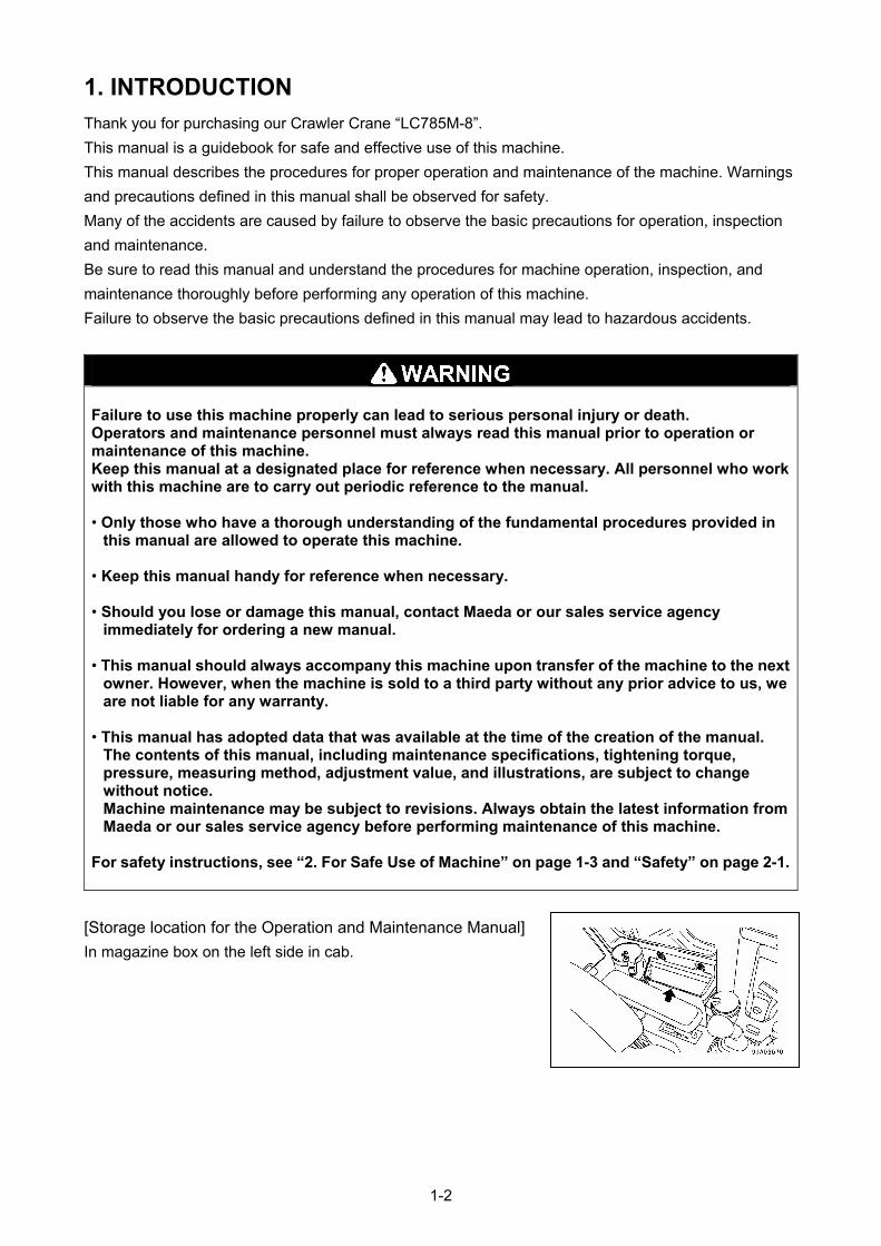
[Storage location for the Operation and Maintenance Manual]
In magazine box on the left side in cab.
1-2
2. FOR SAFE USE OF MACHINE
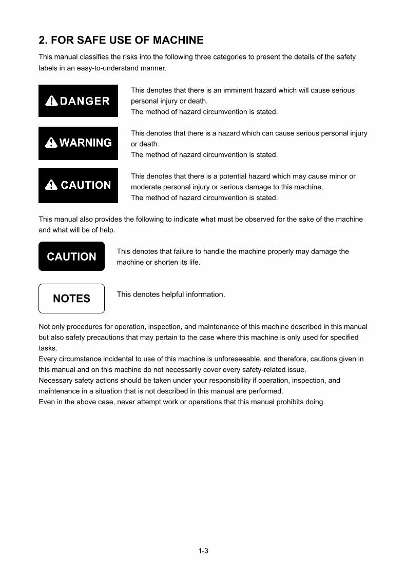
This manual classifies the risks into the following three categories to present the details of the safety
labels in an easy-to-understand manner.
This denotes that there is an imminent hazard which will cause serious
personal injury or death.
The method of hazard circumvention is stated.
This denotes that there is a hazard which can cause serious personal injury
or death.
The method of hazard circumvention is stated.
This denotes that there is a potential hazard which may cause minor or
moderate personal injury or serious damage to this machine.
The method of hazard circumvention is stated.
This manual also provides the following to indicate what must be observed for the sake of the machine
and what will be of help.
CAUTION This denotes that failure to handle the machine properly may damage the
machine or shorten its life.
1-3
This denotes helpful information.
NOTES
Not only procedures for operation, inspection, and maintenance of this machine described in this manual
but also safety precautions that may pertain to the case where this machine is only used for specified
tasks.
Every circumstance incidental to use of this machine is unforeseeable, and therefore, cautions given in
this manual and on this machine do not necessarily cover every safety-related issue.
Necessary safety actions should be taken under your responsibility if operation, inspection, and
maintenance in a situation that is not described in this manual are performed.
Even in the above case, never attempt work or operations that this manual prohibits doing.
3. MACHINE OVERVIEW
3.1 SPECIFIED OPERATIONS
This machine is for use with the operations listed below.
• Crane operation
• Pick & Carry operation
This machine is a mobile crane which consists of a crawler type carrier and an upper structure of a boom
type crane.
This self-propelled crane is capable of moving (travelling) at the worksite and lifting an object weighing
within the rated total load for normal crane operation or pick and carry operation.
3.2 MACHINE CONFIGURATION
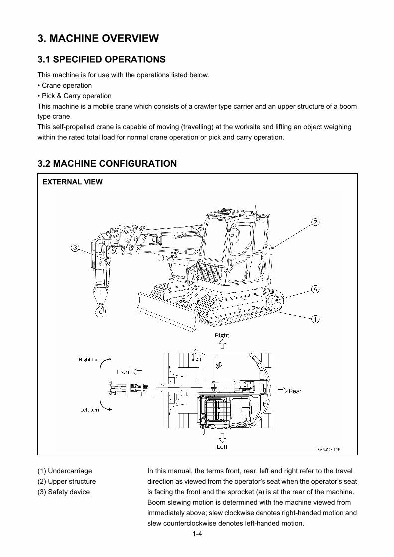
EXTERNAL VIEW
(1) Undercarriage In this manual, the terms front, rear, left and right refer to the travel
direction as viewed from the operator’s seat when the operator’s seat
is facing the front and the sprocket (a) is at the rear of the machine.
(2) Upper structure
(3) Safety device
Boom slewing motion is determined with the machine viewed from
immediately above; slew clockwise denotes right-handed motion and
slew counterclockwise denotes left-handed motion.
1-4
This machine is comprised of the units listed below.
[1] UNDERCARRIAGE
This is comprised of a travelling gear and blade.
[2] UPPER STRUCTURE (CRANE)
This is comprised of an engine, travelling operation unit, crane operation unit, telescoping system, derrick
system, slewing system, hook block, and winch system.
[3] SAFETY DEVICE
This is comprised of the following parts and devices: Over hoist detector/automatic stop device,
three-winding stop alarm/automatic stop device, moment limiter (working envelope limited), slinging rope
detachment protector, hydraulic safety valve, telescoping cylinder hydraulic automatic locking device,
derricking cylinder hydraulic automatic locking device, alarm buzzer, machine tip-over alarm device, level,
working status lamp, crane lock lever.
3.3 MACHINE FUNCTIONS
[1] UNDERCARRIAGE
• The carrier is equipped with crawlers which enables this machine to enter into rough or soft terrain.
• 2 travel lever operation enables not only direction changes, forward, backward, and right/left but pivot
and spin turns.
[2] UPPER STRUCTURE (CRANE)
• The upper structure allows continual 360 degree rotation.
• Due to extending/retracting, derricking up or down and/or swing operations of the boom, as well as raise
and lower operation of the winch, you can move the hoisted load to the designated location, subject to
staying within the rated total road and working radius.
1-5

4. QUALIFICATION FOR OPERATION
• A high incidence of occupational accidents during crane operation are reported.
Be aware that experienced engineers are no exception. • Warnings and precautions defined in this manual shall be observed for safety assurance
during operation of the machine.
4.1 QUALIFICATION FOR CRANE OPERATION
Only personnel that have obtained the required license or training stipulated by laws and regulations
applicable to the place of use are qualified to operate this machine.
Contact the relevant government office or our sales service agency for further information.
1-6
5. TERMINOLOGY
5.1 DEFINITIONS OF TERMS
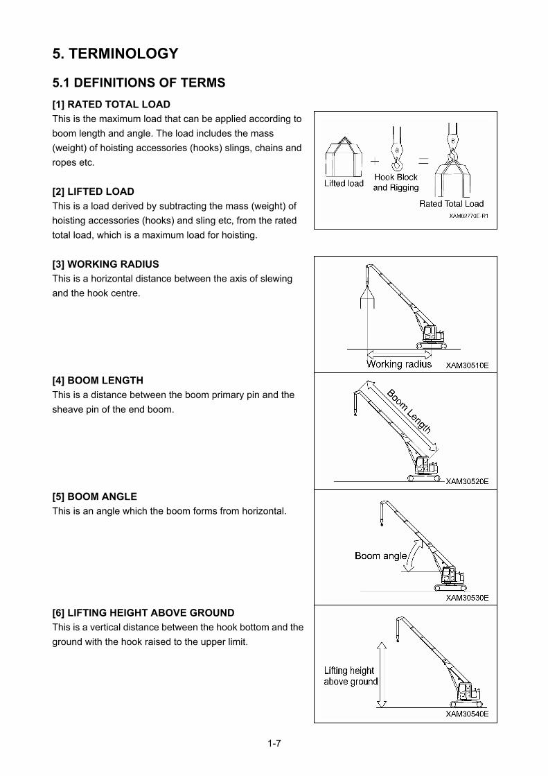
[1] RATED TOTAL LOAD
This is the maximum load that can be applied according to
boom length and angle. The load includes the mass
(weight) of hoisting accessories (hooks) slings, chains and
ropes etc.
[2] LIFTED LOAD
This is a load derived by subtracting the mass (weight) of
hoisting accessories (hooks) and sling etc, from the rated
total load, which is a maximum load for hoisting.
[3] WORKING RADIUS
This is a horizontal distance between the axis of slewing
and the hook centre.
[4] BOOM LENGTH
This is a distance between the boom primary pin and the
sheave pin of the end boom.
[5] BOOM ANGLE
This is an angle which the boom forms from horizontal.
[6] LIFTING HEIGHT ABOVE GROUND
This is a vertical distance between the hook bottom and the
ground with the hook raised to the upper limit.
1-7
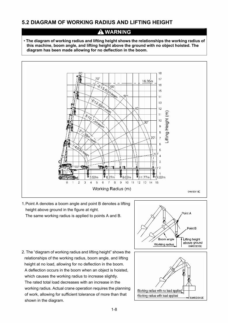
5.2 DIAGRAM OF WORKING RADIUS AND LIFTING HEIGHT
• The diagram of working radius and lifting height shows the relationships the working radius of
this machine, boom angle, and lifting height above the ground with no object hoisted. The diagram has been made allowing for no deflection in the boom.
1. Point A denotes a boom angle and point B denotes a lifting
height above ground in the figure at right.
The same working radius is applied to points A and B.
2. The “diagram of working radius and lifting height” shows the
relationships of the working radius, boom angle, and lifting
height at no load, allowing for no deflection in the boom.
A deflection occurs in the boom when an object is hoisted,
which causes the working radius to increase slightly.
The rated total load decreases with an increase in the
working radius. Actual crane operation requires the planning
of work, allowing for sufficient tolerance of more than that
shown in the diagram.
1-8
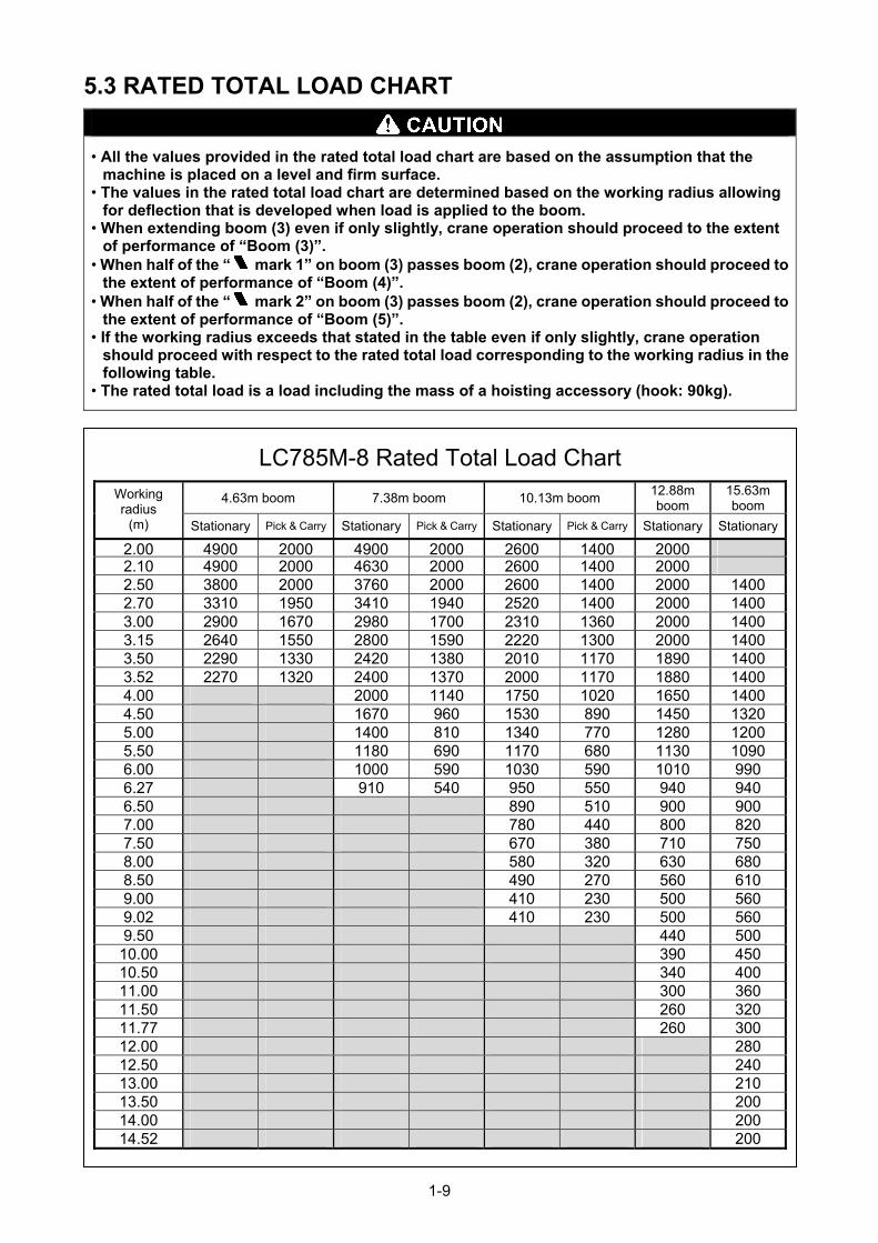
5.3 RATED TOTAL LOAD CHART
• All the values provided in the rated total load chart are based on the assumption that the machine is placed on a level and firm surface.
• The values in the rated total load chart are determined based on the working radius allowing for deflection that is developed when load is applied to the boom.
• When extending boom (3) even if only slightly, crane operation should proceed to the extent of performance of “Boom (3)”.
• When half of the “
mark 1” on boom (3) passes boom (2), crane operation should proceed tothe extent of performance of “Boom (4)”.
• When half of the “
mark 2” on boom (3) passes boom (2), crane operation should proceed tothe extent of performance of “Boom (5)”.
• If the working radius exceeds that stated in the table even if only slightly, crane operation should proceed with respect to the rated total load corresponding to the working radius in the following table.
• The rated total load is a load including the mass of a hoisting accessory (hook: 90kg).
LC785M-8 Rated Total Load Chart
4.63m boom 7.38m boom 10.13m boom 12.88m boom
15.63m boom
Working radius
(m) Stationary Pick & Carry Stationary Pick & Carry Stationary Pick & Carry Stationary Stationary
2.00 4900 2000 4900 2000 2600 1400 2000 2.10 4900 2000 4630 2000 2600 1400 2000 2.50 3800 2000 3760 2000 2600 1400 2000 14002.70 3310 1950 3410 1940 2520 1400 2000 14003.00 2900 1670 2980 1700 2310 1360 2000 14003.15 2640 1550 2800 1590 2220 1300 2000 14003.50 2290 1330 2420 1380 2010 1170 1890 14003.52 2270 1320 2400 1370 2000 1170 1880 14004.00 2000 1140 1750 1020 1650 14004.50 1670 960 1530 890 1450 13205.00 1400 810 1340 770 1280 12005.50 1180 690 1170 680 1130 10906.00 1000 590 1030 590 1010 9906.27 910 540 950 550 940 9406.50 890 510 900 9007.00 780 440 800 8207.50 670 380 710 7508.00 580 320 630 6808.50 490 270 560 6109.00 410 230 500 5609.02 410 230 500 5609.50 440 500
10.00 390 45010.50 340 40011.00 300 36011.50 260 32011.77 260 30012.00 28012.50 24013.00 21013.50 20014.00 20014.52 200
1-9
The rated total load chart provides the maximum loads that the crane is capable of hoisting objects in
parallel with the length of the boom. The loads are specified by working radius.
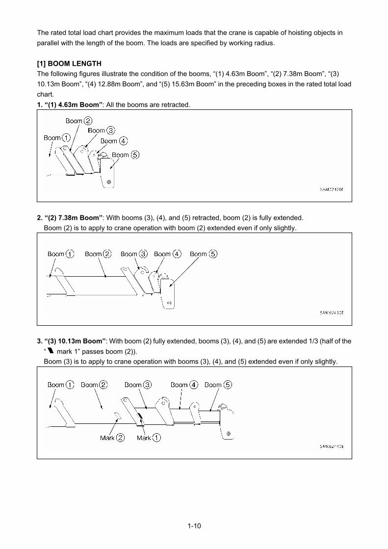
[1] BOOM LENGTH
The following figures illustrate the condition of the booms, “(1) 4.63m Boom”, “(2) 7.38m Boom”, “(3)
10.13m Boom”, “(4) 12.88m Boom”, and “(5) 15.63m Boom” in the preceding boxes in the rated total load
chart.
1. “(1) 4.63m Boom”: All the booms are retracted.
2. “(2) 7.38m Boom”: With booms (3), (4), and (5) retracted, boom (2) is fully extended.
Boom (2) is to apply to crane operation with boom (2) extended even if only slightly.
3. “(3) 10.13m Boom”: With boom (2) fully extended, booms (3), (4), and (5) are extended 1/3 (half of the
“
mark 1” passes boom (2)).
Boom (3) is to apply to crane operation with booms (3), (4), and (5) extended even if only slightly.
1-10
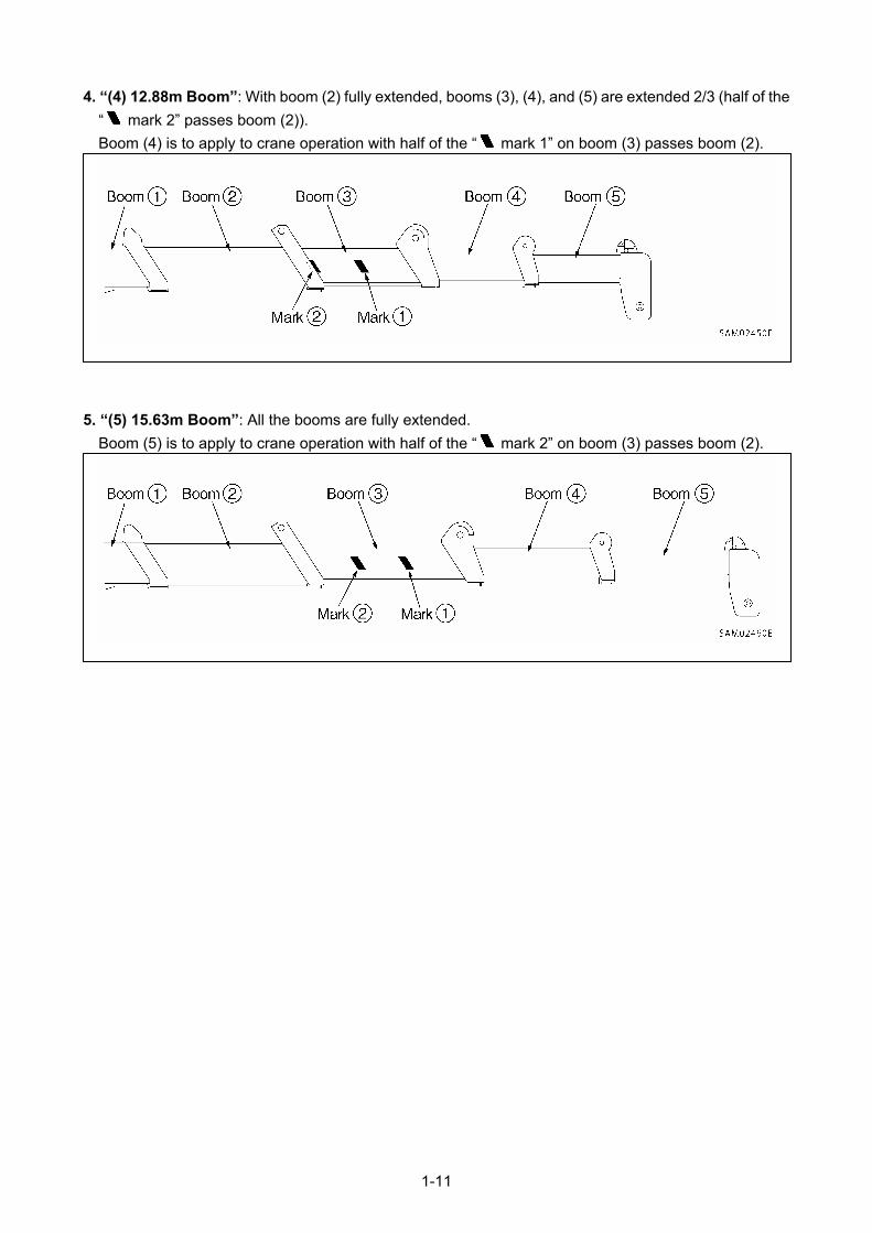
4. “(4) 12.88m Boom”: With boom (2) fully extended, booms (3), (4), and (5) are extended 2/3 (half of the
“
mark 2” passes boom (2)).
Boom (4) is to apply to crane operation with half of the “
mark 1” on boom (3) passes boom (2).
5. “(5) 15.63m Boom”: All the booms are fully extended.
Boom (5) is to apply to crane operation with half of the “
mark 2” on boom (3) passes boom (2).
1-11
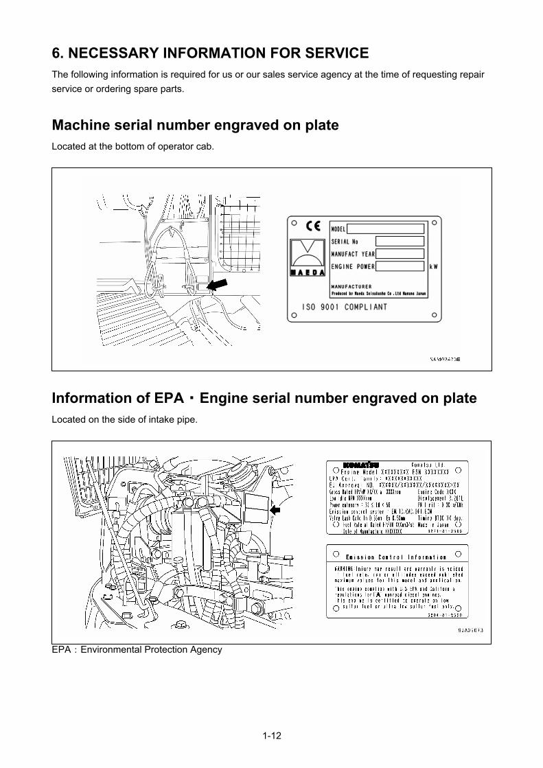
6. NECESSARY INFORMATION FOR SERVICE The following information is required for us or our sales service agency at the time of requesting repair
service or ordering spare parts.
Machine serial number engraved on plate Located at the bottom of operator cab.
Information of EPA ・ Engine serial number engraved on plate Located on the side of intake pipe.
EPA:Environmental Protection Agency
1-12

Gauges and meters To be shown at service meter section on machine monitor.
1-13

1-14

SAFETY
1. BASIC PRECAUTIONS 2 – 2
2. DRIVING RELATED PRECAUTIONS 2 – 8
3. TRANSPORT PRECAUTIONS 2 – 24
4. TOWING PRECAUTIONS 2 – 25
5. MAINTENANCE PRECAUTIONS 2 – 26
6. SAFETY LABEL LOCATIONS 2 – 33
All the safety precautions defined in this manual should always be read and observed. Failure to follow the safety precautions can cause serious personal injury or death.
2-1
1. BASIC PRECAUTIONS Failure to operate or maintain this machine properly can lead to serious personal injury or death. Be sure
to read this manual and each safety label thoroughly before performing any operation or maintenance of
this machine and observe the safety precautions.
1.1 PRECAUTIONS BEFORE STARTING OPERATION
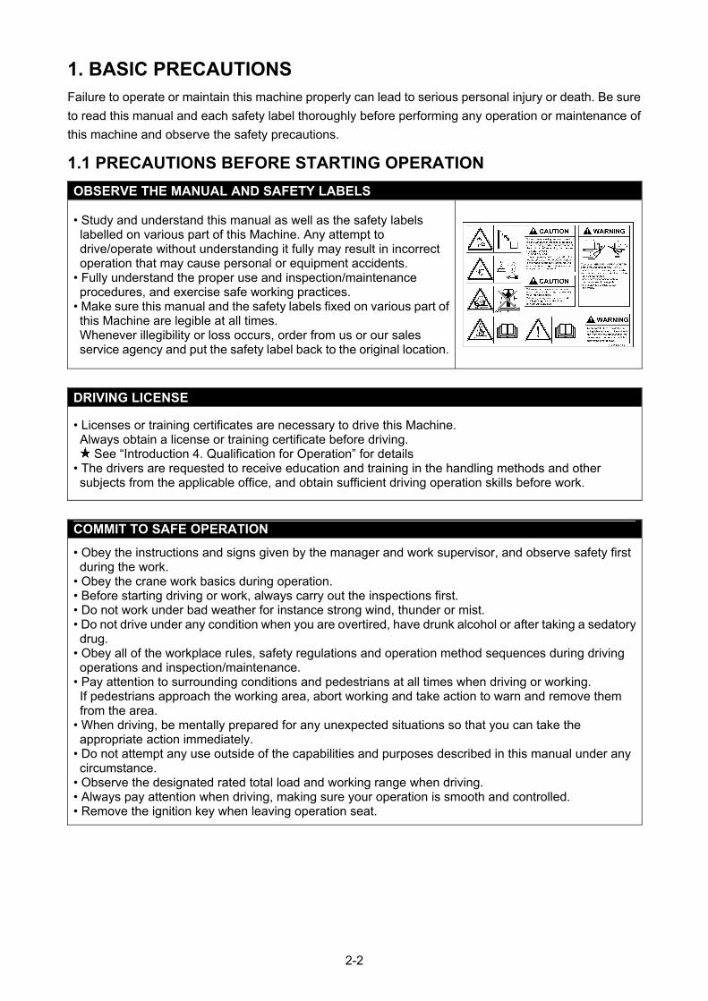
OBSERVE THE MANUAL AND SAFETY LABELS
• Study and understand this manual as well as the safety labels labelled on various part of this Machine. Any attempt to drive/operate without understanding it fully may result in incorrect operation that may cause personal or equipment accidents.
• Fully understand the proper use and inspection/maintenance procedures, and exercise safe working practices.
• Make sure this manual and the safety labels fixed on various part of this Machine are legible at all times. Whenever illegibility or loss occurs, order from us or our sales service agency and put the safety label back to the original location.
DRIVING LICENSE
• Licenses or training certificates are necessary to drive this Machine. Always obtain a license or training certificate before driving.
See “Introduction 4. Qualification for Operation” for details • The drivers are requested to receive education and training in the handling methods and other subjects from the applicable office, and obtain sufficient driving operation skills before work.
COMMIT TO SAFE OPERATION
• Obey the instructions and signs given by the manager and work supervisor, and observe safety first during the work.
• Obey the crane work basics during operation. • Before starting driving or work, always carry out the inspections first. • Do not work under bad weather for instance strong wind, thunder or mist. • Do not drive under any condition when you are overtired, have drunk alcohol or after taking a sedatory drug.
• Obey all of the workplace rules, safety regulations and operation method sequences during driving operations and inspection/maintenance.
• Pay attention to surrounding conditions and pedestrians at all times when driving or working. If pedestrians approach the working area, abort working and take action to warn and remove them from the area.
• When driving, be mentally prepared for any unexpected situations so that you can take the appropriate action immediately.
• Do not attempt any use outside of the capabilities and purposes described in this manual under any circumstance.
• Observe the designated rated total load and working range when driving. • Always pay attention when driving, making sure your operation is smooth and controlled. • Remove the ignition key when leaving operation seat.
2-2
1.2 PREPARATIONS OF SAFETY OPERATION
PROVIDE SAFETY DEVICES FOR SURE
• Check that all guards, covers, and mirrors are attached properly. Repair immediately if damaged. • Understand how to use the safety devices correctly and use properly. • Do not detach any safety device under any circumstance. Keep control to achieve proper operation at all times.
• Improper use of safety devices can lead to serious bodily accidents. • Do not rely solely on safety devices.
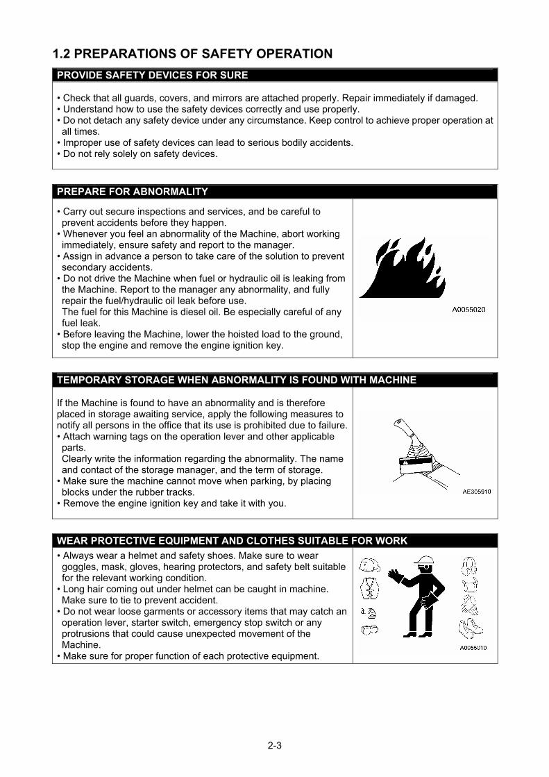
PREPARE FOR ABNORMALITY
• Carry out secure inspections and services, and be careful to prevent accidents before they happen.
• Whenever you feel an abnormality of the Machine, abort working immediately, ensure safety and report to the manager.
• Assign in advance a person to take care of the solution to prevent secondary accidents.
• Do not drive the Machine when fuel or hydraulic oil is leaking from the Machine. Report to the manager any abnormality, and fully repair the fuel/hydraulic oil leak before use. The fuel for this Machine is diesel oil. Be especially careful of any fuel leak.
• Before leaving the Machine, lower the hoisted load to the ground, stop the engine and remove the engine ignition key.
TEMPORARY STORAGE WHEN ABNORMALITY IS FOUND WITH MACHINE
If the Machine is found to have an abnormality and is therefore placed in storage awaiting service, apply the following measures to notify all persons in the office that its use is prohibited due to failure.• Attach warning tags on the operation lever and other applicable parts. Clearly write the information regarding the abnormality. The name and contact of the storage manager, and the term of storage.
• Make sure the machine cannot move when parking, by placing blocks under the rubber tracks.
• Remove the engine ignition key and take it with you.
WEAR PROTECTIVE EQUIPMENT AND CLOTHES SUITABLE FOR WORK
• Always wear a helmet and safety shoes. Make sure to wear goggles, mask, gloves, hearing protectors, and safety belt suitable for the relevant working condition.
• Long hair coming out under helmet can be caught in machine. Make sure to tie to prevent accident.
• Do not wear loose garments or accessory items that may catch an operation lever, starter switch, emergency stop switch or any protrusions that could cause unexpected movement of the Machine.
• Make sure for proper function of each protective equipment.
2-3
USE OF MACHINE THAT WAS RENTED OR PREVIOUSLY USED BY SOMEONE ELSE
Check the following subjects in writing before using any Machine that was rented or previously used by someone else. In addition, check the inspection record table for the maintenance conditions such as the periodic inspections. (1) Crane capacity (2) Crane maintenance condition (3) Behaviour and disadvantage unique to the crane (4) Other subjects that require attention when driving
(a) operating condition of the brakes, clutches and others (b) Presence/absence of lights and their condition. Check lights of rotating lamps (c) Operation condition of hook, winches, boom, outriggers and other related items
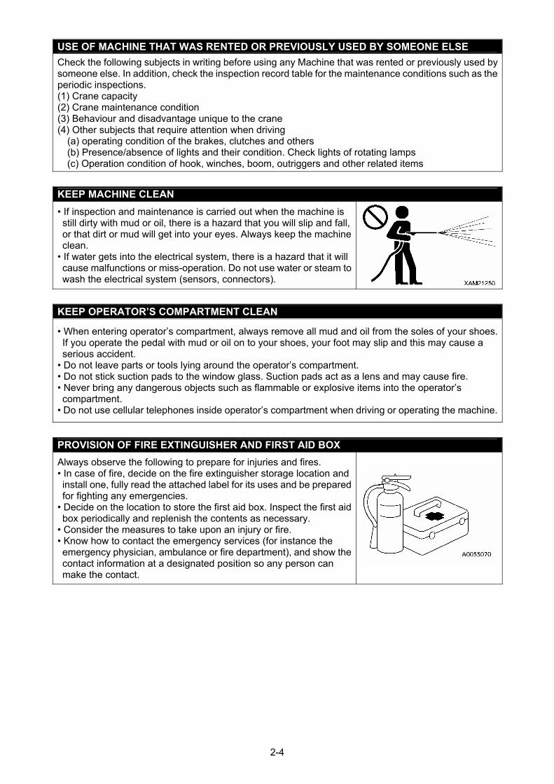
KEEP MACHINE CLEAN
• If inspection and maintenance is carried out when the machine is still dirty with mud or oil, there is a hazard that you will slip and fall, or that dirt or mud will get into your eyes. Always keep the machine clean.
• If water gets into the electrical system, there is a hazard that it will cause malfunctions or miss-operation. Do not use water or steam to wash the electrical system (sensors, connectors).
KEEP OPERATOR’S COMPARTMENT CLEAN
• When entering operator’s compartment, always remove all mud and oil from the soles of your shoes.
• Do not leave parts or tools lying around the operator’s compartment. ns and may cause fire.
• Do not use cellular telephones inside operator’s compartment when driving or operating the machine.
If you operate the pedal with mud or oil on to your shoes, your foot may slip and this may cause a serious accident.
• Do not stick suction pads to the window glass. Suction pads act as a le• Never bring any dangerous objects such as flammable or explosive items into the operator’s compartment.
PROVISION OF FIRE EXTINGUISHER AND FIRST AID BOX
Always observe the following to prepare for injuries and fires. • In case of fire, decide on the fire extinguisher storage location and
• the first aid box. Inspect the first aid
•nce the
the
install one, fully read the attached label for its uses and be prepared for fighting any emergencies. Decide on the location to storebox periodically and replenish the contents as necessary. Consider the measures to take upon an injury or fire.
• Know how to contact the emergency services (for instaemergency physician, ambulance or fire department), and show contact information at a designated position so any person can make the contact.
2-4
1.3 PRECAUTIONS FOR FIRE PREVENTION
ACTION IF FIRE OCCURS
If a fire occurs, escape from the machine as follows. • Turn starter switch OFF to stop engine. • Use the handrails and steps to get off the machine.
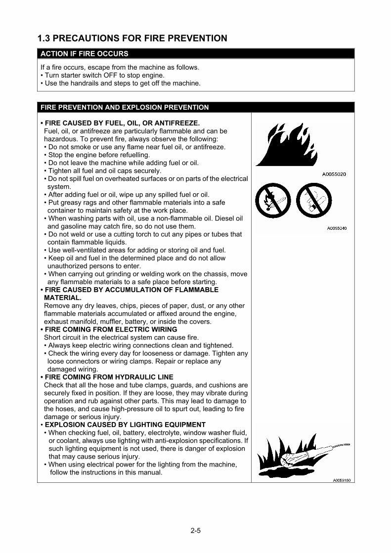
FIRE PREVENTION AND EXPLOSION PREVENTION
• FIRE CAUSED BY FUEL, OIL, OR ANTIFREEZE. Fuel, oil, or antifreeze are particularly flammable and can be hazardous. To prevent fire, always observe the following: • Do not smoke or use any flame near fuel oil, or antifreeze. • Stop the engine before refuelling. • Do not leave the machine while adding fuel or oil. • Tighten all fuel and oil caps securely. • Do not spill fuel on overheated surfaces or on parts of the electrical system.
• After adding fuel or oil, wipe up any spilled fuel or oil. • Put greasy rags and other flammable materials into a safe container to maintain safety at the work place.
• When washing parts with oil, use a non-flammable oil. Diesel oil and gasoline may catch fire, so do not use them.
• Do not weld or use a cutting torch to cut any pipes or tubes that contain flammable liquids.
• Use well-ventilated areas for adding or storing oil and fuel. • Keep oil and fuel in the determined place and do not allow unauthorized persons to enter.
• When carrying out grinding or welding work on the chassis, move any flammable materials to a safe place before starting.
• FIRE CAUSED BY ACCUMULATION OF FLAMMABLE MATERIAL. Remove any dry leaves, chips, pieces of paper, dust, or any other flammable materials accumulated or affixed around the engine, exhaust manifold, muffler, battery, or inside the covers.
• FIRE COMING FROM ELECTRIC WIRING Short circuit in the electrical system can cause fire. • Always keep electric wiring connections clean and tightened. • Check the wiring every day for looseness or damage. Tighten any loose connectors or wiring clamps. Repair or replace any damaged wiring.
• FIRE COMING FROM HYDRAULIC LINE Check that all the hose and tube clamps, guards, and cushions are securely fixed in position. If they are loose, they may vibrate during operation and rub against other parts. This may lead to damage to the hoses, and cause high-pressure oil to spurt out, leading to fire damage or serious injury.
• EXPLOSION CAUSED BY LIGHTING EQUIPMENT • When checking fuel, oil, battery, electrolyte, window washer fluid,
or coolant, always use lighting with anti-explosion specifications. If such lighting equipment is not used, there is danger of explosion that may cause serious injury.
• When using electrical power for the lighting from the machine, follow the instructions in this manual.
2-5
1.4 PRECAUTIONS WHEN GETTING ON OR OFF
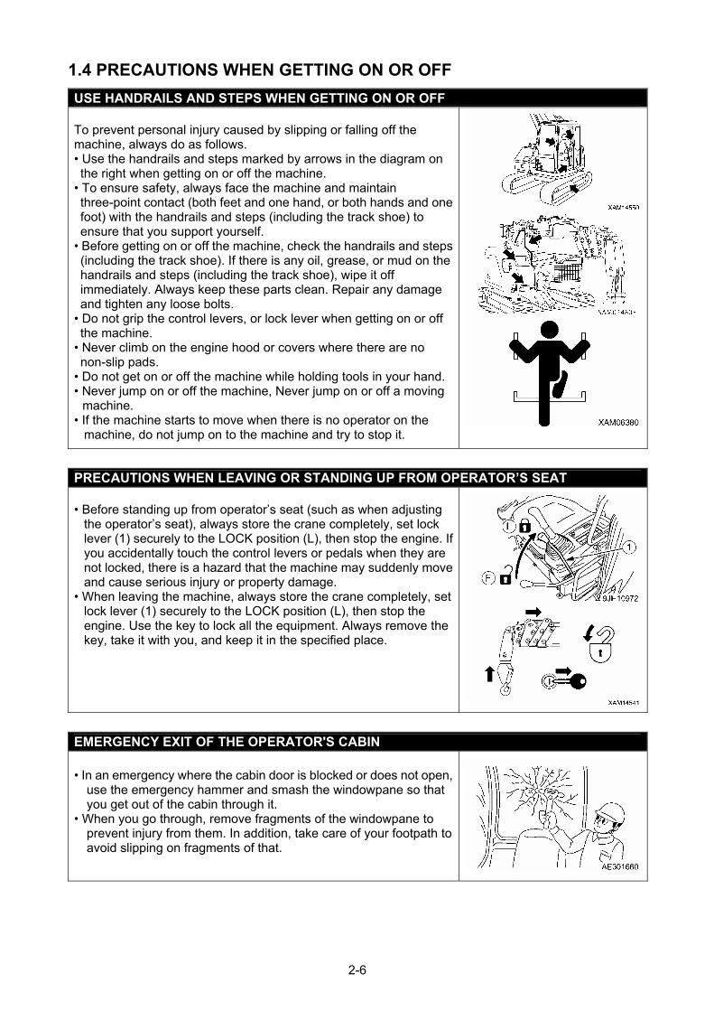
USE HANDRAILS AND STEPS WHEN GETTING ON OR OFF To prevent personal injury caused by slipping or falling off the machine, always do as follows. • Use the handrails and steps marked by arrows in the diagram on the right when getting on or off the machine.
• To ensure safety, always face the machine and maintain three-point contact (both feet and one hand, or both hands and one foot) with the handrails and steps (including the track shoe) to ensure that you support yourself.
• Before getting on or off the machine, check the handrails and steps (including the track shoe). If there is any oil, grease, or mud on the handrails and steps (including the track shoe), wipe it off immediately. Always keep these parts clean. Repair any damage and tighten any loose bolts.
• Do not grip the control levers, or lock lever when getting on or off the machine.
• Never climb on the engine hood or covers where there are no non-slip pads.
• Do not get on or off the machine while holding tools in your hand. • Never jump on or off the machine, Never jump on or off a moving
machine. • If the machine starts to move when there is no operator on the
machine, do not jump on to the machine and try to stop it.
PRECAUTIONS WHEN LEAVING OR STANDING UP FROM OPERATOR’S SEAT • Before standing up from operator’s seat (such as when adjusting
the operator’s seat), always store the crane completely, set lock lever (1) securely to the LOCK position (L), then stop the engine. If you accidentally touch the control levers or pedals when they are not locked, there is a hazard that the machine may suddenly move and cause serious injury or property damage.
• When leaving the machine, always store the crane completely, set lock lever (1) securely to the LOCK position (L), then stop the engine. Use the key to lock all the equipment. Always remove the key, take it with you, and keep it in the specified place.
EMERGENCY EXIT OF THE OPERATOR'S CABIN • In an emergency where the cabin door is blocked or does not open,
use the emergency hammer and smash the windowpane so that you get out of the cabin through it.
• When you go through, remove fragments of the windowpane to prevent injury from them. In addition, take care of your footpath to avoid slipping on fragments of that.
2-6
1.5 OTHER PRECAUTIONS
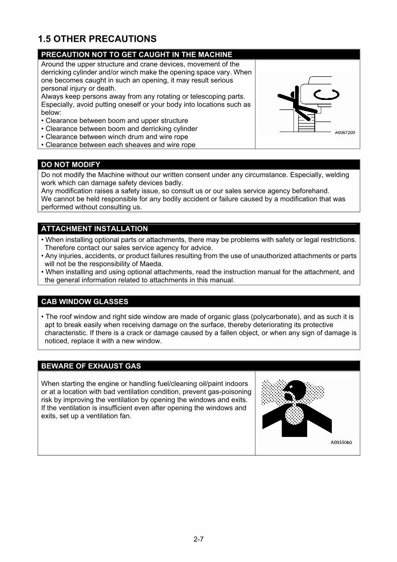
PRECAUTION NOT TO GET CAUGHT IN THE MACHINE Around the upper structure and crane devices, movement of the derricking cylinder and/or winch make the opening space vary. When one becomes caught in such an opening, it may result serious personal injury or death. Always keep persons away from any rotating or telescoping parts. Especially, avoid putting oneself or your body into locations such as below: • Clearance between boom and upper structure • Clearance between boom and derricking cylinder • Clearance between winch drum and wire rope • Clearance between each sheaves and wire rope
DO NOT MODIFY Do not modify the Machine without our written consent under any circumstance. Especially, welding work which can damage safety devices badly. Any modification raises a safety issue, so consult us or our sales service agency beforehand. We cannot be held responsible for any bodily accident or failure caused by a modification that was performed without consulting us.
ATTACHMENT INSTALLATION
• When installing optional parts or attachments, there may be problems with safety or legal restrictions. Therefore contact our sales service agency for advice.
• Any injuries, accidents, or product failures resulting from the use of unauthorized attachments or parts will not be the responsibility of Maeda.
• When installing and using optional attachments, read the instruction manual for the attachment, and the general information related to attachments in this manual.
CAB WINDOW GLASSES
• The roof window and right side window are made of organic glass (polycarbonate), and as such it is apt to break easily when receiving damage on the surface, thereby deteriorating its protective characteristic. If there is a crack or damage caused by a fallen object, or when any sign of damage is noticed, replace it with a new window.
BEWARE OF EXHAUST GAS When starting the engine or handling fuel/cleaning oil/paint indoors or at a location with bad ventilation condition, prevent gas-poisoning risk by improving the ventilation by opening the windows and exits. If the ventilation is insufficient even after opening the windows and exits, set up a ventilation fan.
2-7
2. DRIVING RELATED PRECAUTIONS
2.1 PRECAUTIONS FOR JOB SITE
SAFETY AT JOBSITE
Before starting operations, thoroughly check the area for any unusual conditions that could be dangerous. • When carrying out operations near combustible materials such as thatched roofs, dry leaves or dry grass, there is a hazard of fire, so be careful when operating.
• Check the terrain and condition of the ground at the worksite, and determine the safest method of operation. Do not operate where there is a hazard of landslides or falling rocks.
• Flatten the inclination of the working site as much as possible before starting work. • When working over the roadway, enforce a no entry zone, for instance, placing guides or surrounding with barriers, to ensure the safety of the traffic vehicles and pedestrians.
• Enforce a no entry zone to prevent people from entering the working site and apply measures to prevent people from approaching. Attempting to approach a moving Machine may result in a collision by contact or pinching, and may result in serious bodily accidents and deaths.
• When travelling or operating in shallow water or on soft ground, check the sharpness and condition of the bedrock, and the depth and speed of flow of the water before starting operations.
• Avoid travelling or operating your machine too close to the edge of cliffs, overhangs, and deep ditches. The ground may be weak in such area. If the ground collapses under the weight or vibration of the machine, there is a hazard that the machine may fall or tip over. Remember that the soil after heavy rain or blasting or after earthquakes is weak in this area.
• When working on embankments or near excavated ditches, there is a hazard that weight and vibration of the machine will cause the soil to collapse. Before starting operations, take steps to ensure that the ground is safe and to prevent the machine from rolling over or falling.
ENSURE GOOD VISIBILITY
This machine is equipped with mirrors to improve the visibility, but even with mirrors, there are places, which cannot be seen from the operator’s seat, so always be careful when operating. When operating or travelling in places with poor visibility, if it is impossible to confirm the condition of the job side or obstacle is in the area around the machine, there is danger that the machine may suffer damage or the operator may suffer serious personal injury. When operating or travelling in places with poor visibility, always observe the following items strictly. • If the visibility cannot be sufficiently assured, position a flagman if necessary. The operator should pay careful attention to the signs and follow the instruction of the flagman.
• The signals should be given only by one flagman • When working in dark places, turn on the working lamps and front lamps of the machine, and if necessary, set up additional lighting in the area.
• Stop operations if there is poor visibility, such as in fog, snow, rain, or sand storms. • Check the mirror on the machine before starting operations every day. Clean off any dirt and adjust
the view to ensure good visibility.
SIGNALMAN’S SIGNAL AND SIGNS
• Set up signs to inform of road shoulders and soft ground. If the visibility is not good, position a signalman if necessary. Operators should pay careful attention to the signs and follow the instructions from the signalman.
• Only one signalman should give signals. • Make sure that all workers understand the meaning of all signals and signs before starting work.
2-8
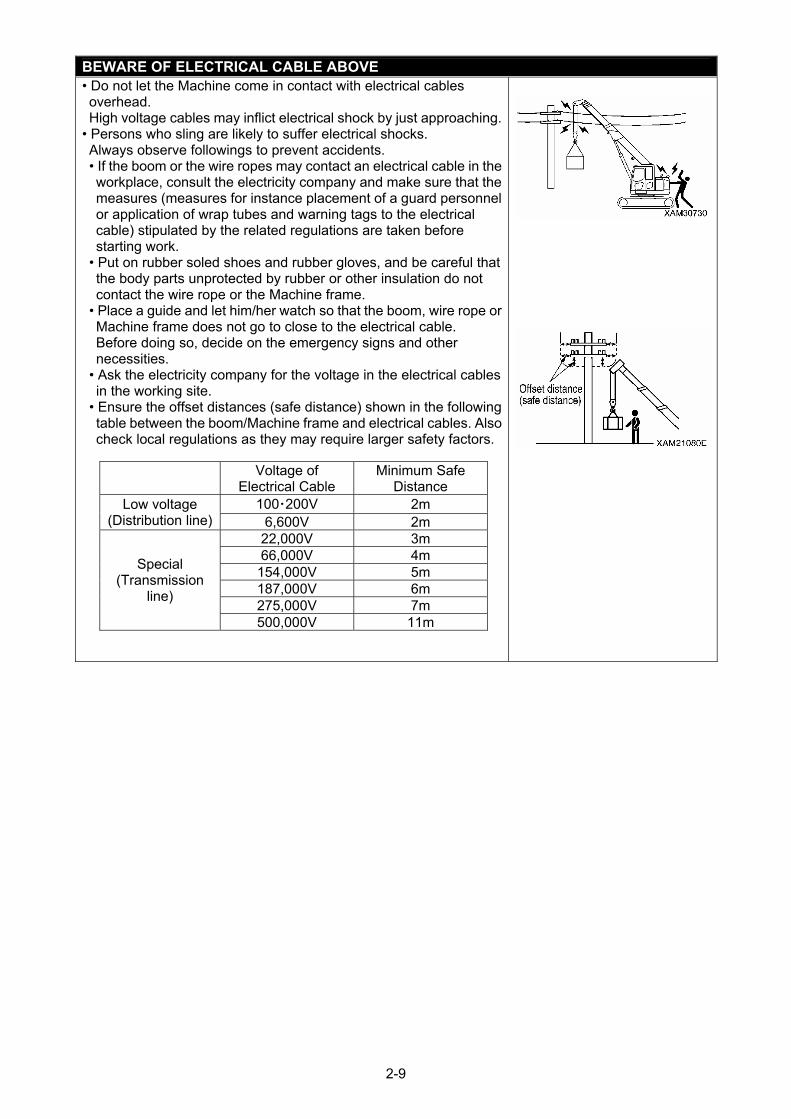
BEWARE OF ELECTRICAL CABLE ABOVE • Do not let the Machine come in contact with electrical cables overhead. High voltage cables may inflict electrical shock by just approaching.
• Persons who sling are likely to suffer electrical shocks. Always observe followings to prevent accidents. • If the boom or the wire ropes may contact an electrical cable in the workplace, consult the electricity company and make sure that the measures (measures for instance placement of a guard personnel or application of wrap tubes and warning tags to the electrical cable) stipulated by the related regulations are taken before starting work.
• Put on rubber soled shoes and rubber gloves, and be careful that the body parts unprotected by rubber or other insulation do not contact the wire rope or the Machine frame.
• Place a guide and let him/her watch so that the boom, wire rope or Machine frame does not go to close to the electrical cable. Before doing so, decide on the emergency signs and other necessities.
• Ask the electricity company for the voltage in the electrical cables in the working site.
• Ensure the offset distances (safe distance) shown in the following table between the boom/Machine frame and electrical cables. Also check local regulations as they may require larger safety factors.
Voltage of
Electrical Cable Minimum Safe
Distance 100・200V 2m Low voltage
(Distribution line) 6,600V 2m 22,000V 3m 66,000V 4m
154,000V 5m 187,000V 6m 275,000V 7m 500,000V 11m
Special (Transmission
line)
2-9
MEASURES WHEN CHARGE ACCIDENT OCCURS
If an electrical charge accident occurs, do not panic and stay calm, apply the solution in the following sequence. 1. Report
Immediately report to the electricity company or related management company, and receive instructions to stop the power transmission, emergency procedures and any related procedures.
2. Evacuation of related personnel from vicinity of Machine Remove all personnel including workers from vicinity of the Machine to prevent any secondary disasters. Personnel who suffered electrical shock by holding a sling rope, guide rope or other conductors when the Machine was charged should evacuate by his/her own effort. Do not try to help such persons. Otherwise a secondary electrical shock accident can occur.
3. Emergency procedure Take the solution by the following sequence in case of urgency where personnel received electrical shock because the Machine was charged. (1) If the Machine can be operated, immediately move the Machine away from the contact and out of
the range of the cause of the charge. Be careful not to snip the distribution power cable. (2) Evacuate the Machine completely away from the cause of the charge, make sure the Machine is
not charged, rescue the electrically shocked personnel and immediately carry to the hospital. 4. Measures to be taken after an accident
After the accident, do not put the machine back into service. Attempting to do so may cause unexpected accidents and enhances failures. Ask us or our sales service agency for repair.
CAUTIONS WHEN WORKING WITH THE CRANE IN A LOCATION WITH HIGH OUTPUT OF MICROWAVE EMISSION
Working with the crane near a high output of microwave emission equipment such as radar or TV/radio broadcast antenna may causes the crane construction to be exposed to the microwave and generates induced current, therefore it is very dangerous. In addition, the machine electronics may become disturbed. Establish grounding between the Machine frame and the ground when working in such location. In addition, slingers are requested to wear rubber boots and rubber gloves since risk of electrical shock by contacting parts such as the hook or wire exists.
BEWARE OF ASBESTOS DUST
Inhalation of air containing asbestos may result in lung cancer. This Machine does not use any asbestos, but asbestos may be contained in the wall, ceiling or other part of construction within the work area of this Machine. In addition, be careful of the followings when working with a material that may be using asbestos. • Put on designated dust free mask and/or other equipment as necessary.
• Do not use compressed air for cleaning. • Spray water when cleaning to prevent asbestos dusts from flying into air.
• Always work at a windward location when driving the Machine at a site that may contain asbestos dusts.
• Enforce a restriction zone to prevent people from entering the working site.
• Strictly observe the assigned rules related to the working site and environmental standard.
2-10
2.2 PRECAUTIONS WHEN STARTING ENGINE
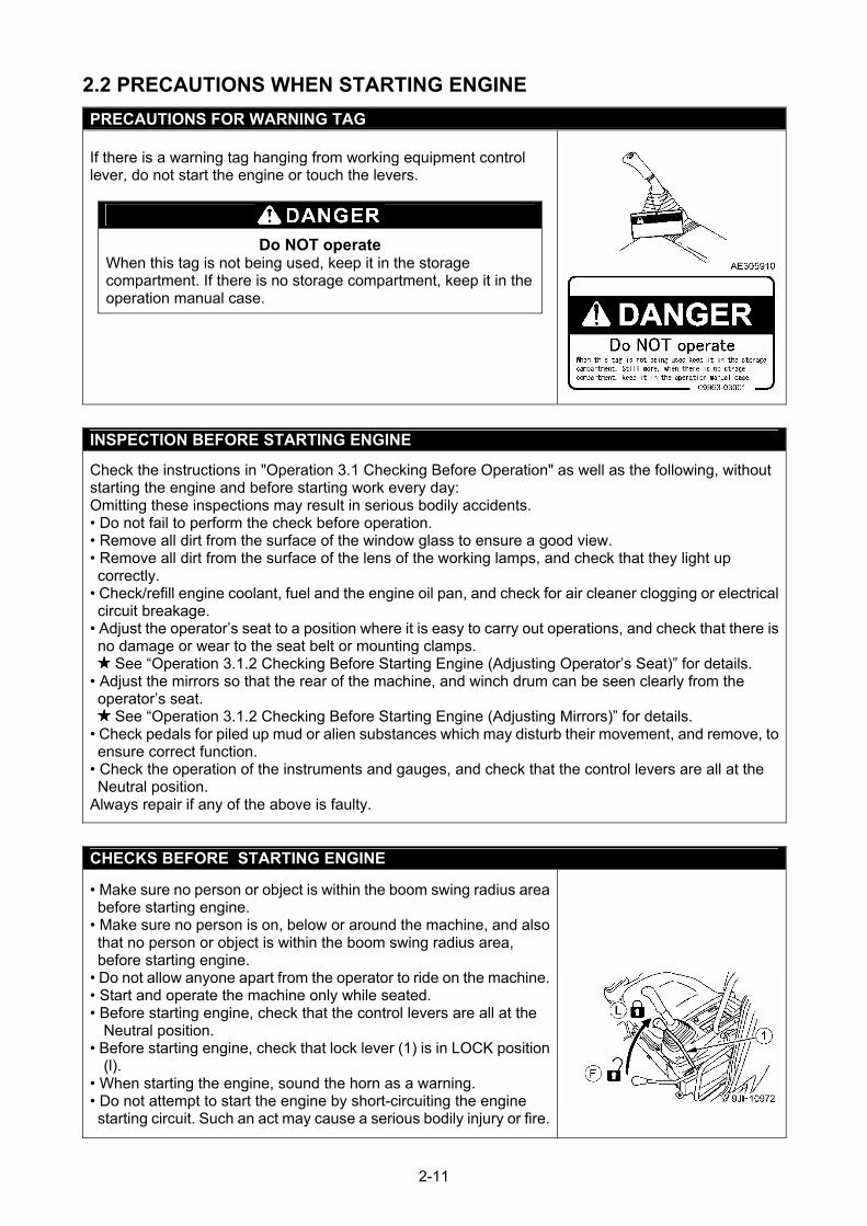
PRECAUTIONS FOR WARNING TAG If there is a warning tag hanging from working equipment control lever, do not start the engine or touch the levers.
Do NOT operate When this tag is not being used, keep it in the storage compartment. If there is no storage compartment, keep it in the operation manual case.
INSPECTION BEFORE STARTING ENGINE
Check the instructions in "Operation 3.1 Checking Before Operation" as well as the following, without starting the engine and before starting work every day: Omitting these inspections may result in serious bodily accidents. • Do not fail to perform the check before operation. • Remove all dirt from the surface of the window glass to ensure a good view. • Remove all dirt from the surface of the lens of the working lamps, and check that they light up correctly.
• Check/refill engine coolant, fuel and the engine oil pan, and check for air cleaner clogging or electrical circuit breakage.
• Adjust the operator’s seat to a position where it is easy to carry out operations, and check that there is no damage or wear to the seat belt or mounting clamps.
See “Operation 3.1.2 Checking Before Starting Engine (Adjusting Operator’s Seat)” for details. • Adjust the mirrors so that the rear of the machine, and winch drum can be seen clearly from the operator’s seat.
See “Operation 3.1.2 Checking Before Starting Engine (Adjusting Mirrors)” for details. • Check pedals for piled up mud or alien substances which may disturb their movement, and remove, to ensure correct function.
• Check the operation of the instruments and gauges, and check that the control levers are all at the Neutral position.
Always repair if any of the above is faulty.
CHECKS BEFORE STARTING ENGINE
• Make sure no person or object is within the boom swing radius area before starting engine.
• Make sure no person is on, below or around the machine, and also that no person or object is within the boom swing radius area, before starting engine.
• Do not allow anyone apart from the operator to ride on the machine.• Start and operate the machine only while seated. • Before starting engine, check that the control levers are all at the
Neutral position. • Before starting engine, check that lock lever (1) is in LOCK position
(l). • When starting the engine, sound the horn as a warning. • Do not attempt to start the engine by short-circuiting the engine starting circuit. Such an act may cause a serious bodily injury or fire.
2-11
CAUTIONS UNDER COLD WEATHER
• Remove snow from and unfreeze the swing gear, boom and winch related parts, and check the movements before work.
• Warm up the engine and hydraulics. Attempting to operate the control levers and pedals without enough warm up causes the Machine to react poorly, and may result in unexpected accidents.
• If the battery fluid is frozen, do not charge the battery or start the engine using any other power source. Such an act may cause the battery to catch fire. Before charging or starting up using other power source, unfreeze the battery fluid and check that failures such as a battery fluid leak do not exist.
• After the end of the work, wipe off and apply wraps if substances such as condensation, snow or mud are stuck to the wire harness, connector (1), switches, sensors or similar part. If the infiltrated condensation and/or similar substances freeze, the Machine may operate improperly upon its next use and cause unexpected accidents.
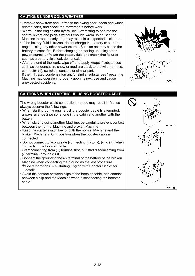
CAUTIONS WHEN STARTING UP USING BOOSTER CABLE The wrong booster cable connection method may result in fire, so always observe the followings. • When starting up the engine using a booster cable is attempted, always arrange 2 persons, one in the cabin and another with the battery.
• When starting using another Machine, be careful to prevent contact between the normal Machine and broken Machine.
• Keep the starter switch key of both the normal Machine and the broken Machine in OFF position when the booster cable is connected.
• Do not connect to wrong side [connecting (+) to (-), (-) to (+)] when connecting the booster cable.
• Start connecting from (+) terminal first, but start disconnecting from (-) terminal (ground) first.
• Connect the ground to the (-) terminal of the battery of the broken Machine when connecting the ground as the last procedure.
See “Operation 8.4.4 Starting Engine with Booster Cable” for details.
• Avoid the contact between clips of the booster cable, and contact between a clip and the Machine when disconnecting the booster cable.
2-12
2.3 PRECAUTIONS WHEN STARTING TO MOVE MACHINE
CHECKS BEFORE OPERATION
Omitting the inspections after starting the engine results in delay to notice the Machine abnormalities, and may result in bodily accidents and Machine damages. Execute inspection in a wide location with no obstacle. In addition, be sure to prevent people from approaching nearby the Machine. • Check that the movement of the machine matches the display on the control pattern card. If it does not match, replace it immediately with the correct control pattern card.
• Inspect the equipment operation conditions, Machine travelling conditions, winch winding up and down, boom derricking, and crane operation conditions such as extension, retraction and swinging.
• Inspect the sound, vibration, heat and odour of the Machine, and check for instrument errors, air leaks, oil leaks, fuel leaks, water leaks and other such factors. Be extra careful with fuel leaks.
• Always repair the broken part whenever an abnormality is found. Attempting to use without servicing may result in unexpected bodily accidents and/or Machine failures.
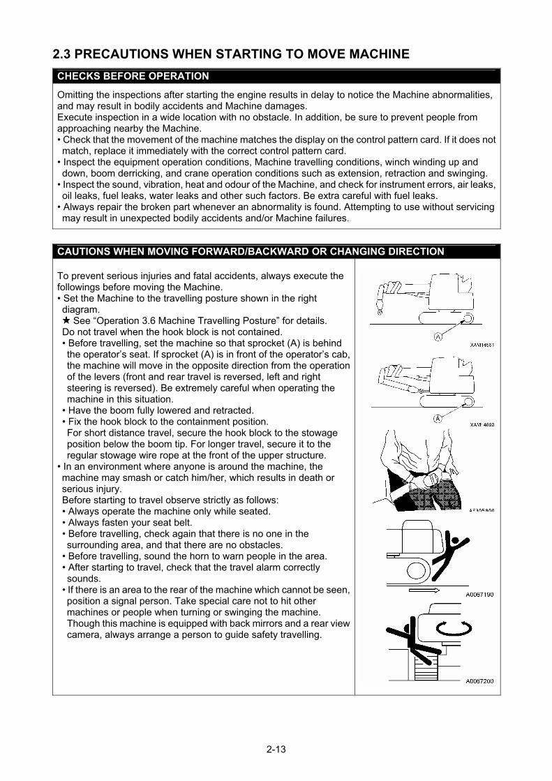
CAUTIONS WHEN MOVING FORWARD/BACKWARD OR CHANGING DIRECTION To prevent serious injuries and fatal accidents, always execute the followings before moving the Machine. • Set the Machine to the travelling posture shown in the right diagram.
See “Operation 3.6 Machine Travelling Posture” for details. Do not travel when the hook block is not contained. • Before travelling, set the machine so that sprocket (A) is behind the operator’s seat. If sprocket (A) is in front of the operator’s cab, the machine will move in the opposite direction from the operation of the levers (front and rear travel is reversed, left and right steering is reversed). Be extremely careful when operating the machine in this situation.
• Have the boom fully lowered and retracted. • Fix the hook block to the containment position. For short distance travel, secure the hook block to the stowage position below the boom tip. For longer travel, secure it to the regular stowage wire rope at the front of the upper structure.
• In an environment where anyone is around the machine, the machine may smash or catch him/her, which results in death or serious injury. Before starting to travel observe strictly as follows: • Always operate the machine only while seated. • Always fasten your seat belt. • Before travelling, check again that there is no one in the surrounding area, and that there are no obstacles.
• Before travelling, sound the horn to warn people in the area. • After starting to travel, check that the travel alarm correctly sounds.
• If there is an area to the rear of the machine which cannot be seen, position a signal person. Take special care not to hit other machines or people when turning or swinging the machine. Though this machine is equipped with back mirrors and a rear view camera, always arrange a person to guide safety travelling.
2-13
CAUTIONS WHEN TRAVELLING
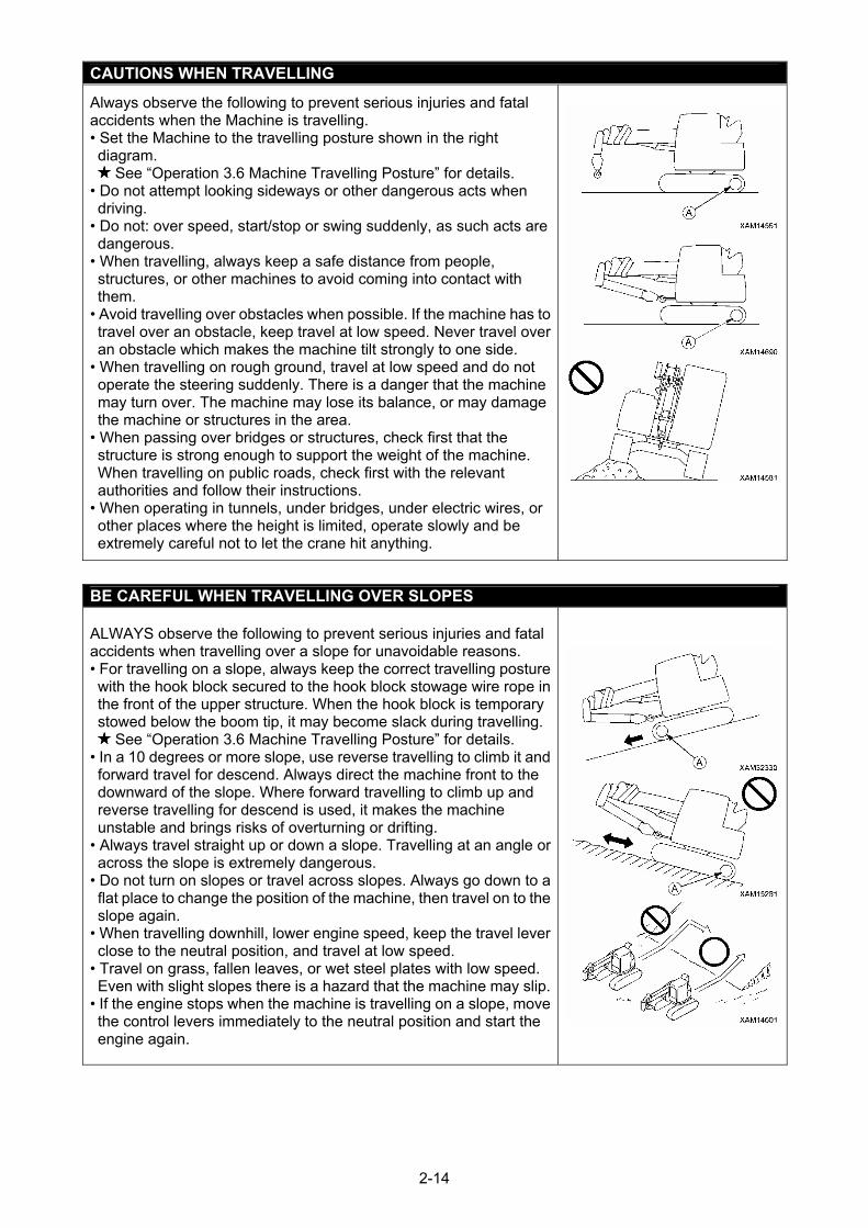
Always observe the following to prevent serious injuries and fatal accidents when the Machine is travelling. • Set the Machine to the travelling posture shown in the right diagram.
See “Operation 3.6 Machine Travelling Posture” for details. • Do not attempt looking sideways or other dangerous acts when driving.
• Do not: over speed, start/stop or swing suddenly, as such acts are dangerous.
• When travelling, always keep a safe distance from people, structures, or other machines to avoid coming into contact with them.
• Avoid travelling over obstacles when possible. If the machine has to travel over an obstacle, keep travel at low speed. Never travel over an obstacle which makes the machine tilt strongly to one side.
• When travelling on rough ground, travel at low speed and do not operate the steering suddenly. There is a danger that the machine may turn over. The machine may lose its balance, or may damage the machine or structures in the area.
• When passing over bridges or structures, check first that the structure is strong enough to support the weight of the machine. When travelling on public roads, check first with the relevant authorities and follow their instructions.
• When operating in tunnels, under bridges, under electric wires, or other places where the height is limited, operate slowly and be extremely careful not to let the crane hit anything.
BE CAREFUL WHEN TRAVELLING OVER SLOPES
ALWAYS observe the following to prevent serious injuries and fatal accidents when travelling over a slope for unavoidable reasons. • For travelling on a slope, always keep the correct travelling posture with the hook block secured to the hook block stowage wire rope in the front of the upper structure. When the hook block is temporary stowed below the boom tip, it may become slack during travelling.
See “Operation 3.6 Machine Travelling Posture” for details. • In a 10 degrees or more slope, use reverse travelling to climb it and forward travel for descend. Always direct the machine front to the downward of the slope. Where forward travelling to climb up and reverse travelling for descend is used, it makes the machine unstable and brings risks of overturning or drifting.
• Always travel straight up or down a slope. Travelling at an angle or across the slope is extremely dangerous.
• Do not turn on slopes or travel across slopes. Always go down to a flat place to change the position of the machine, then travel on to the slope again.
• When travelling downhill, lower engine speed, keep the travel lever close to the neutral position, and travel at low speed.
• Travel on grass, fallen leaves, or wet steel plates with low speed. Even with slight slopes there is a hazard that the machine may slip.
• If the engine stops when the machine is travelling on a slope, move the control levers immediately to the neutral position and start the engine again.
2-14
BE CAREFUL OF TIPPING ON UNSTABLE GROUND
Always observe the followings to prevent serious injuries and fatal accidents when travelling over unstable ground for any reason. • Do not enter any soft ground area. The Machine is difficult to remove from this type of ground. • Ground near a cliff, roadside or a deep gully may be unstable, so avoid going near such ground as much as possible. The Machine may tip or fall when the ground loosens due to mass and/or vibration of the Machine. Be especially careful that the ground may have loosened after rain, use of dynamite or earthquake.
• Avoid going near earth fills or the vicinity of excavated gutters that are instable. Crumbling caused by mass and/or vibration of the Machine may cause the Machine to tilt.
CAUTIONS WHEN SNOW COVERED OR FROZEN
Always observe the following to prevent serious injuries or fatal accidents when travelling over snow covered ground or frozen roads for any reason. • Snow covered ground and frozen roads can cause slips even when the inclination is slight, so decrease the speed when travelling and avoid starting, stopping, and swinging suddenly. Uphill and downhill are especially likely to cause slips and thus dangerous.
• The ground of a frozen road becomes soft when the air temperature rises and causes the Machine travel and other operations to be unstable. Be very careful.
• During cold weather, check that the load to be hoisted is not frozen or stuck to the ground or any other surface. Attempting to hoist without knowing the load is frozen or stuck to the ground or other surfaces is dangerous.
• Do not touch the metal surface with any part of your body, such as a finger or hand during cold weather. Attempting to contact a metal surface of the Machine under harsh cold weather may cause the skin to stick to the metal surface.
• Remove snow and/or ice from the Machine that causes the safety nameplates to be hard to read. Be especially careful to remove ice or snow that is on the boom and may fall.
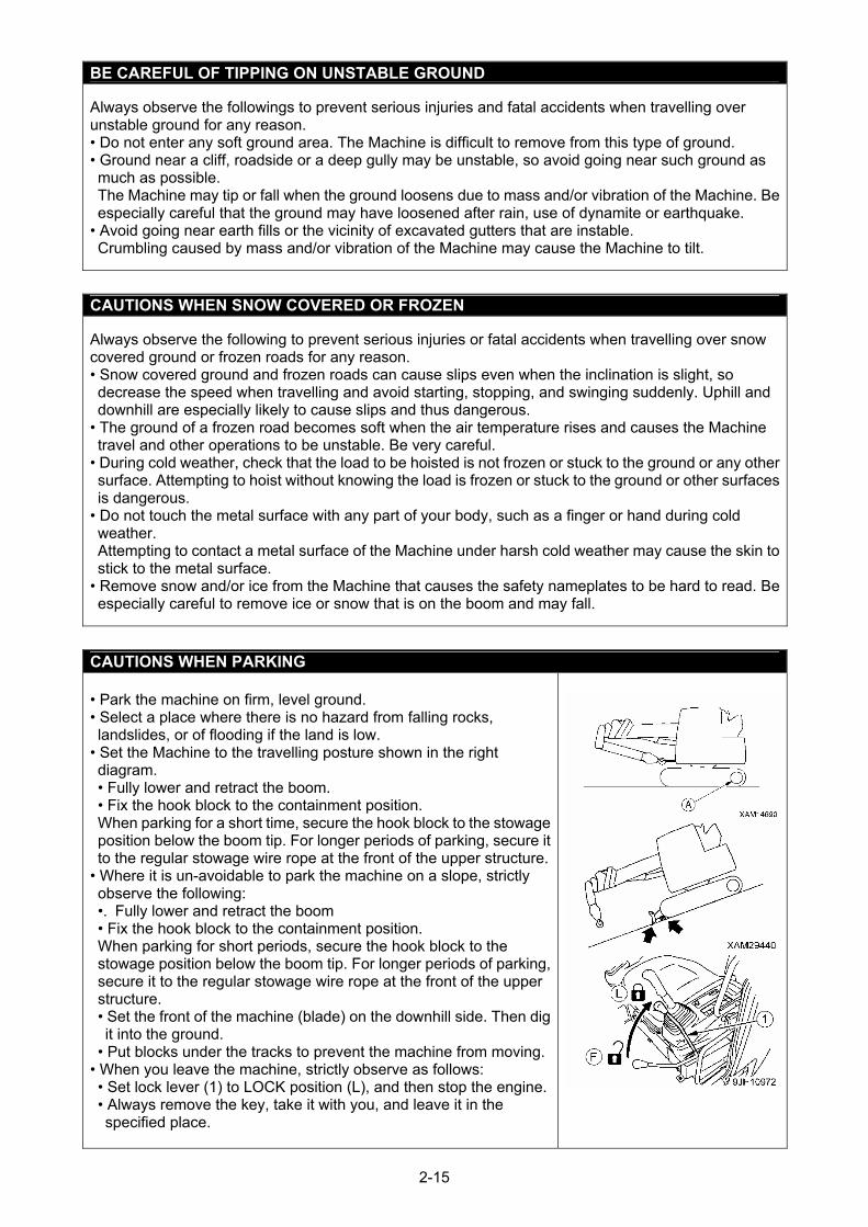
CAUTIONS WHEN PARKING
• Park the machine on firm, level ground. • Select a place where there is no hazard from falling rocks, landslides, or of flooding if the land is low.
• Set the Machine to the travelling posture shown in the right diagram. • Fully lower and retract the boom. • Fix the hook block to the containment position. When parking for a short time, secure the hook block to the stowage position below the boom tip. For longer periods of parking, secure it to the regular stowage wire rope at the front of the upper structure.
• Where it is un-avoidable to park the machine on a slope, strictly observe the following: •. Fully lower and retract the boom • Fix the hook block to the containment position. When parking for short periods, secure the hook block to the stowage position below the boom tip. For longer periods of parking, secure it to the regular stowage wire rope at the front of the upper structure.
• Set the front of the machine (blade) on the downhill side. Then dig it into the ground.
• Put blocks under the tracks to prevent the machine from moving.• When you leave the machine, strictly observe as follows: • Set lock lever (1) to LOCK position (L), and then stop the engine. • Always remove the key, take it with you, and leave it in the specified place.
2-15
2.4 PRECAUTIONS WHEN WORKING WITH CRANE
INSPECTION BEFORE STARTING WORK
Check that the safety devices and crane operate properly. • Operate each of the operation levers, pedals and switches under no load, and check that operations take place without abnormality. Repair immediately if any abnormality exists.
• Check that the safety devices such as the moment limiter, over hoist detector device and over-unwinding stop alarm device activate properly.
CAUTIONS WHEN HANDLING MOMENT LIMITER
• Use/store the moment limiter under the following ranges of ambient temperature. Temperature of use: -10 to 50 °C Storage temperature: -30 to 70 °C
• Avoid direct sunlight so that the temperature of the atmosphere surrounding the moment limiter does not exceed the above range.
• Avoid locations with a strong acid or alkaline atmosphere as much as possible. Otherwise, unexpected failures may occur.
• Avoid impact to the moment limiter body, for instance colliding with an object. Doing so may damage the case and result in failures and improper operations.
• Avoid excessive pressure to the panel sheet of the moment limiter body or pushing with a sharp object such as the tip of a screwdriver. Doing so may damage the panel sheet and could result in failures and improper operations.
• Do not remove the case cover or panel sheet from, or disassemble the moment limiter body. Doing so may damage the case and/or panel sheet and could result in failures and improper operations.
CAUTIONS WHEN SETTING UP MOMENT LIMITER
• The moment limiter calculates the moments assuming the Machine is level. If you work with the crane when the Machine is not level, warnings and alarms are not issued even when the rated total load is near. Always use the level to ensure that the machine is not at an angle.
• Before using the moment limiter, check that the boom angle display, boom length display and real load display are displayed correctly following the crane movements. Attempting to use without the correct display results in failure to obtain the correct measurement and may result in serious bodily accidents caused by reasons such as tipping over and/or breakage of the machine.
• Always make sure the fall mode setting of the moment limiter matches with the wire rope fall of the crane. Attempting to use unmatched wire rope falls may results in failure to obtain the correct measurement and could result in serious accidents caused for instance by a breakage of the wire rope.
• Do not change the setting when measuring with the moment limiter. Doing so could result in failure to obtain the correct measurement and may result in serious bodily accidents caused by reasons such as tipping over and/or breakage of the machine.
PRECAUTIONS WHEN DECIDING THE CRANE OPERATION SITE
Always place the machine on the level and solid ground. Crane operation is dangerous when the machine is placed in an area such as below: • Temporary asphalt pavements • Thin concrete pavements • Stone pavements • Where the surface looks solid but the soil under it is soft, or the soil below a pavement has been
washed by water and become hollow. • Soft ground which may collapse, is near a shoulder of a road or an excavated hole. • Slopes
2-16
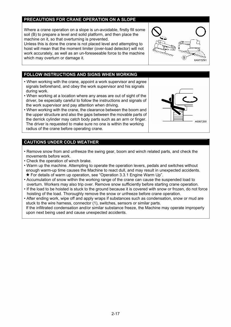
PRECAUTIONS FOR CRANE OPERATION ON A SLOPE Where a crane operation on a slope is un-avoidable, firstly fill some soil (B) to prepare a level and solid platform, and then place the machine on it, so that overturning is prevented. Unless this is done the crane is not placed level and attempting to hoist will mean that the moment limiter (over-load detector) will not work accurately, as well as an un-foreseeable force to the machine which may overturn or damage it.
FOLLOW INSTRUCTIONS AND SIGNS WHEN WORKING
• When working with the crane, appoint a work supervisor and agree signals beforehand, and obey the work supervisor and his signals during work.
• When working at a location where any areas are out of sight of the driver, be especially careful to follow the instructions and signals of the work supervisor and pay attention when driving.
• When working with the crane, the clearance between the boom and the upper structure and also the gaps between the movable parts of the derrick cylinder may catch body parts such as an arm or finger. The driver is requested to make sure no one is within the working radius of the crane before operating crane.
CAUTIONS UNDER COLD WEATHER
• Remove snow from and unfreeze the swing gear, boom and winch related parts, and check the movements before work.
• Check the operation of winch brake. • Warm up the machine. Attempting to operate the operation levers, pedals and switches without enough warm-up time causes the Machine to react dull, and may result in unexpected accidents.
For details of warm up operation, see “Operation 3.3.1 Engine Warm Up”. • Accumulation of snow within the working range of the crane can cause the suspended load to
overturn. Workers may also trip over. Remove snow sufficiently before starting crane operation. • If the load to be hoisted is stuck to the ground because it is covered with snow or frozen, do not force
hoisting of the load. Thoroughly remove the snow or unfreeze before crane operation. • After ending work, wipe off and apply wraps if substances such as condensation, snow or mud are stuck to the wire harness, connector (1), switches, sensors or similar parts. If the infiltrated condensation and/or similar substance freeze, the Machine may operate improperly upon next being used and cause unexpected accidents.
2-17
PAY ATTENTION TO WEATHER INFORMATION • During a thunderstorm, risk of lightning exists, so abort working with the crane, immediately lower the load and contain the boom.
• Exposing the hoisted load to wind causes the load to swing and the Machine to become unstable, this is dangerous. Immediately lower the load and contain the boom when the wind is causing the load to swing.
• If the maximum instantaneous wind speed is 10 m/s or greater, abort working with crane, immediately lower the load and contain the boom.
• Even when the maximum instantaneous wind speed is below 10 m/s, the bigger the hoisted load, the higher the hoisted load position, and the longer the boom, the wind effect will increases accordingly. Be very careful during work.
• When the boom is extended full or nearly full, take notice of that the winch wire ropes and electrical cable for signals are also effect by the wind. In addition, the wind speed may increase when it blows through a high-rise building. Thus, be very careful when working near high-rise buildings.
• When a load such as a steel plate that has a large area exposed to wind is being hoisted, the wind arriving from front/rear/side of the boom may cause the Machine to tip or damage the boom. Be very careful when working.
• In a condition where wind blows to the front face of the boom, the higher the boom is raised, the more you may run a risk of overturning backward. Be very careful when working in such conditions.
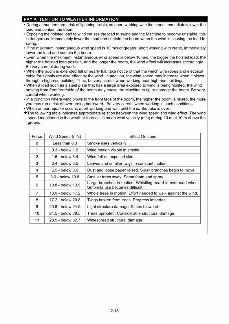
• When an earthquake occurs, abort working and wait until the earthquake is over. The following table indicates approximate relation between the wind speed and wind effect. The wind speed mentioned in the weather forecast is mean wind velocity (m/s) during 10 m at 10 m above the ground.
Force Wind Speed (m/s) Effect On Land
0 Less than 0.3 Smoke rises vertically.
1 0.3 - below 1.6 Wind motion visible in smoke.
2 1.6 - below 3.4 Wind felt on exposed skin.
3 3.4 - below 5.5 Leaves and smaller twigs in constant motion.
4 5.5 - below 8.0 Dust and loose paper raised. Small branches begin to move.
5 8.0 - below 10.8 Smaller trees sway. Some foam and spray.
6 10.8 - below 13.9 Large branches in motion. Whistling heard in overhead wires. Umbrella use becomes difficult.
7 13.9 - below 17.2 Whole trees in motion. Effort needed to walk against the wind.
8 17.2 - below 20.8 Twigs broken from trees. Progress impeded.
9 20.8 - below 24.5 Light structure damage. Slates blown off.
10 24.5 - below 28.5 Trees uprooted. Considerable structural damage.
11 28.5 - below 32.7 Widespread structural damage.
2-18
CAUTIONS WHEN SLINGING
• Check the following before hoisting a load. Attempting to hoist the load without checking may result in serious bodily accidents by dropping of the load or tipping of the crane. • Observe the values in the rated total load chart. • Hoist from the centre of gravity of the load. • Check that the wire ropes of the hook block are perpendicular to the ground. • When the load leaves the ground, stop winding up the load and check whether the load is stable.
• Before hoisting a load, always check whether the sling wire rope "retainer device" of the hook block is hanging securely If not the wire rope may leave the hook block and cause the load to fall and results in a serious accident.
• Larger sling rope angles when hoisting the load increases the force on the sling rope even when the load weight is unchanged, and can cause the sling rope to snap. Be careful when slinging in order to prevent excessive force to the sling rope.
• Do not hoist more than 1 load at a time. This could cause the hoist bracket to hit and damage the other hoisted load, the loads may move and lose balance and cause tipping, or some other cause of a serious accident. Do not hoist more than one load even if the total is within the rated total load.
• Hoisting of lengthy loads may cause the load to lose balance and is dangerous. In case of lengthy loads, hoist vertically by using a clamp, or achieve balance of the hoisted load by applying a rope to both ends of the load.
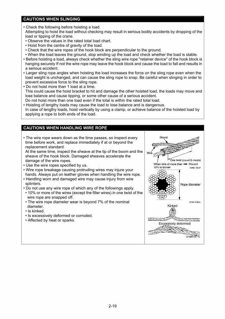
CAUTIONS WHEN HANDLING WIRE ROPE • The wire rope wears down as the time passes, so inspect every time before work, and replace immediately if at or beyond the replacement standard. At the same time, inspect the sheave at the tip of the boom and the sheave of the hook block. Damaged sheaves accelerate the damage of the wire ropes.
• Use the wire ropes specified by us. • Wire rope breakage causing protruding wires may injure your hands. Always put on leather gloves when handling the wire rope.
• Handling worn and damaged wire may cause injury from wire splinters.
• Do not use any wire rope of which any of the followings apply. • 10% or more of the wires (except the filler wires) in one twist of the wire rope are snapped off.
• The wire rope diameter wear is beyond 7% of the nominal diameter.
• Is kinked. • Is excessively deformed or corroded. • Affected by heat or sparks.
2-19
CAUTIONS WHEN WORKING WITH CRANE • The stability of the crane is determined horizontally. Although the stability also increases diagonally,
work exceeding the rated load causes the breakage of the boom or machine. The moment limiter (overload detector) must not be activated even in diagonal direction.
• Be sure to verify that the moment limiter emergency stop cancel switch is at OFF (auto) position before operating the crane. Do not attempt the crane operation when the moment limiter emergency stop cancel switch is at ON (cancel) position. The moment limiter emergency stop cancel switch is permitted to be at ON (cancel) position only when the moment limiter is in trouble or during the inspection or maintenance works.
• Pay attention to indication and warning on the moment limiter while working. • Attempting to work beyond the capacity of the Machine may cause serious accidents and failures caused by for instance tripping or fluctuation. Observe the rated total load chart when working with the crane.
• Operate the crane under slow and controlled movements. Sudden lever or accelerator operations may cause risks such as swinging or falling of the load and collision with the surroundings. Be especially careful to be slow during the swing operations.
• Determine a work supervisor for crane operation and always follow the instructions of the supervisor. Follow the instructions of the supervisor for work methods and procedures. Determine how to give signals and follow them.
• A long load is instable when hoisted and thus, dangerous. Attach a rope to the both ends of the load to make the load stable.
• Do not let people approach the working area or stand below the load, since there is a risk of the load falling and contact with the load. Doing so may result in serious bodily accidents. Also, during the work, consider the fact that the working radius increases when the load is hoisted and the boom is deflected thus.
• Work that goes beyond the machine performance will cause accidents and failures. Particularly, the crane operation must be performed based on the rated total load chart.
• Be careful to prevent the wire rope and/or hoisted load from contacting an obstacle such as a tree or steelwork when hoisting a load. If caught by an obstacle, do not forcibly wind up the hoisted load, but untangle the caught part before winding up.
• Do not pull laterally, pull toward you or hoist diagonally. Doing so may cause the crane to tip or suffer damage.
• Do not attempt to work with the crane when the view is bad due to location or weather it is dangerous.Ensure brightness by posting a work lamp or other illumination facilities in dark places. When the view is bad because of bad weather (rain, fog, and snow), abort working and wait until the weather recovers.
• Do not use for the purpose, of raising a person using the crane hook, Unless in an approved cage, check local regulations before lifting personnel.
• If the over-winding detector alarm buzzer is heard, immediately remove your hand from the winch lever. The hook block winding will then stop. Then, operate the winch lever to Down (push forward) to wind down the hook block. Also note that the hook block is raised up when the boom is extended, so be sure to allow extra clearance between the boom and the hook block during work.
• When the boom extends, the hook block is raised up. Operate the winch lever to Down (push forward) to wind down the hook block while you extend the boom.
• Whenever an overload occurs during work, lower the load, winding down the winch by setting the winch lever to Down (push forward). Do not raise or lower the boom acutely. Such attempt may cause serious accidents by tipping.
• The volume of the hydraulic oil in each of the cylinders changes depending on the temperature. By leaving idle with a load hoisted, as time passes, the oil temperature drops and the hydraulic oil volume decreases, and changes such as the boom derrick angle decrease and boom length decrease may occur. In that case, execute boom derricking operations and boom extension operations appropriately to correct.
• Do not leave the driving operation position when a load is hoisted. Lower the load and place lock lever to LOCK position before leaving the Machine.
• Keep the hook block raise up when not in use. Otherwise, persons near the load may collide the hook block.
• Operator must not leave operation seat during operation. • Any work that hoists an attachment that generates some vibration such as a VIBRO is forbidden. The
vibration of the attachment may break the winch, etc.
2-20
CAUTIONS HIGH TEMPERATURE OIL WHEN WORKING WITH CRANE
When the hydraulic oil temperature exceeds 80 degrees, high pressure hoses and seals can be damaged by heat. It may cause a burn from spouting oil. If the temperature of hydraulic oil becomes over 80 degrees, stop operation and wait until the oil cools down. Continuous hook raising / lowering operation at high working lifting height and long periods of acceleration will raise oil temperature. Take care during these operations.
CAUTIONS WHEN OPERATING WINCH
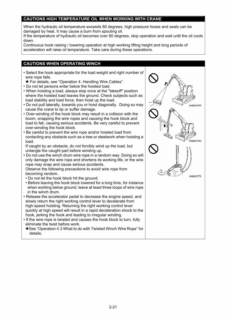
• Select the hook appropriate for the load weight and right number of wire rope falls.
For details, see “Operation 4. Handling Wire Cables”. • Do not let persons enter below the hoisted load. • When hoisting a load, always stop once at the "takeoff" position where the hoisted load leaves the ground. Check subjects such as load stability and load force, then hoist up the load.
• Do not pull laterally, towards you or hoist diagonally. Doing so may cause the crane to tip or suffer damage.
• Over-winding of the hook block may result in a collision with the boom, snapping the wire ropes and causing the hook block and load to fall, causing serious accidents. Be very careful to prevent over-winding the hook block.
• Be careful to prevent the wire rope and/or hoisted load from contacting any obstacle such as a tree or steelwork when hoisting a load. If caught by an obstacle, do not forcibly wind up the load, but untangle the caught part before winding up.
• Do not use the winch drum wire rope in a random way. Doing so will only damage the wire rope and shortens its working life, or the wire rope may snap and cause serious accidents. Observe the following precautions to avoid wire rope from becoming random. • Do not let the hook block hit the ground. • Before leaving the hook block lowered for a long time, for instance when working below ground, leave at least three loops of wire rope in the winch drum.
• Release the accelerator pedal to decrease the engine speed, and slowly return the right working control lever to decelerate from high-speed hoisting. Returning the right working control lever quickly at high speed will result in a rapid deceleration shock to the hook, jerking the hook and leading to irregular winding.
• If the wire rope is twisted and causes the hook block to turn, fully eliminate the twist before work.
See “Operation 4.3 What to do with Twisted Winch Wire Rope” for details.
2-21
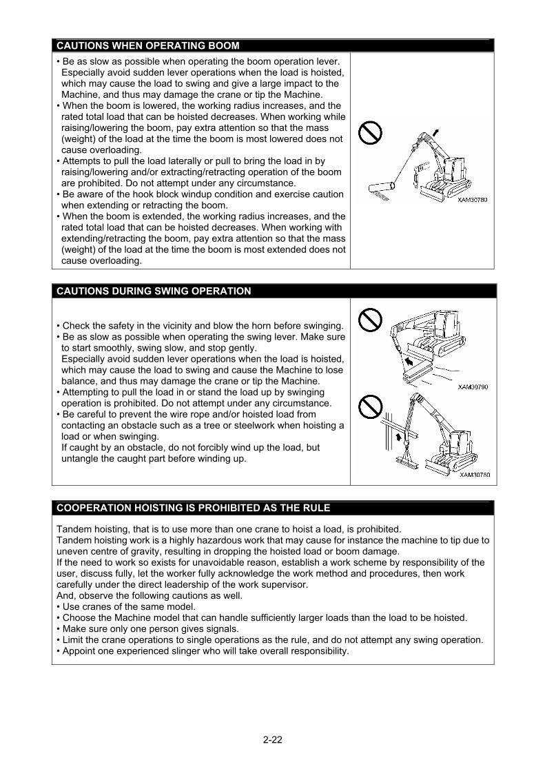
CAUTIONS WHEN OPERATING BOOM
• Be as slow as possible when operating the boom operation lever. Especially avoid sudden lever operations when the load is hoisted, which may cause the load to swing and give a large impact to the Machine, and thus may damage the crane or tip the Machine.
• When the boom is lowered, the working radius increases, and the rated total load that can be hoisted decreases. When working while raising/lowering the boom, pay extra attention so that the mass (weight) of the load at the time the boom is most lowered does not cause overloading.
• Attempts to pull the load laterally or pull to bring the load in by raising/lowering and/or extracting/retracting operation of the boom are prohibited. Do not attempt under any circumstance.
• Be aware of the hook block windup condition and exercise caution when extending or retracting the boom.
• When the boom is extended, the working radius increases, and the rated total load that can be hoisted decreases. When working with extending/retracting the boom, pay extra attention so that the mass (weight) of the load at the time the boom is most extended does not cause overloading.
CAUTIONS DURING SWING OPERATION
• Check the safety in the vicinity and blow the horn before swinging.• Be as slow as possible when operating the swing lever. Make sure to start smoothly, swing slow, and stop gently. Especially avoid sudden lever operations when the load is hoisted, which may cause the load to swing and cause the Machine to lose balance, and thus may damage the crane or tip the Machine.
• Attempting to pull the load in or stand the load up by swinging operation is prohibited. Do not attempt under any circumstance.
• Be careful to prevent the wire rope and/or hoisted load from contacting an obstacle such as a tree or steelwork when hoisting a load or when swinging. If caught by an obstacle, do not forcibly wind up the load, but untangle the caught part before winding up.
COOPERATION HOISTING IS PROHIBITED AS THE RULE
Tandem hoisting, that is to use more than one crane to hoist a load, is prohibited. Tandem hoisting work is a highly hazardous work that may cause for instance the machine to tip due to uneven centre of gravity, resulting in dropping the hoisted load or boom damage. If the need to work so exists for unavoidable reason, establish a work scheme by responsibility of the user, discuss fully, let the worker fully acknowledge the work method and procedures, then work carefully under the direct leadership of the work supervisor. And, observe the following cautions as well. • Use cranes of the same model. • Choose the Machine model that can handle sufficiently larger loads than the load to be hoisted. • Make sure only one person gives signals. • Limit the crane operations to single operations as the rule, and do not attempt any swing operation. • Appoint one experienced slinger who will take overall responsibility.
2-22
WORKING AT A SITE WITH BELOW GROUND LIFTING
• Leave at least three loops of wire rope in the winch drum when winding down the wire rope in the case of underground work or similar. This Machine is equipped with three-winding stop alarm / automatic stop device as the safety device, but even then be very careful to prevent this safety device from activating.
• Make sure signs are communicated fully. • Be especially careful with the crane operations.
SAFETY PRECAUTIONS FOR PICK & CARRY OPERATION
Pick and carry operation can be very unstable and dangerous. Where such an operation is un-avoidable, strictly observe the following. Failure to observe precautions may result in death or serious injury. • Observe the precautions specified in the operation manual:
Refer to "Operation 3.21.1 Safety Precautions for Pick and Carry Operation". • Always keep the correct posture as specified in the operation manual:
Refer to "Operation 3.21.2 Posture for Pick and Carry Operation". • The hoisted load should be within a safe load range and kept in a height near the ground. • Arrange a person to guide the machine travelling. • Remove all the obstacles in the pick and carry path and keep out all persons. • Hoisting in the boom configuration exceeding the rated length is prohibited. • The rated total load is applicable only to the optimum condition. Limit the load to a safety level based on the particular condition.
• To prevent the hoisted load from swinging in a pick and carry operation, keep the engine in low idling (low speed rotation) and keep the travel speed slow. Avoid operations such as sudden start and stop or using travel speed pedal.
• During a pick and carry operation, never attempt shifting to the travel speed selector switch to the "High" position, swinging the upper structure and/or other crane operations.
2-23
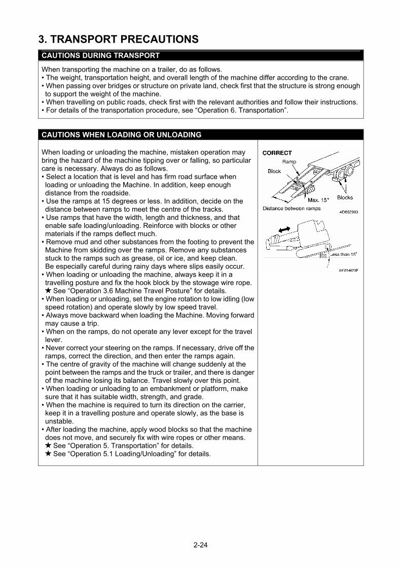
3. TRANSPORT PRECAUTIONS
CAUTIONS DURING TRANSPORT
When transporting the machine on a trailer, do as follows. • The weight, transportation height, and overall length of the machine differ according to the crane. • When passing over bridges or structure on private land, check first that the structure is strong enough to support the weight of the machine.
• When travelling on public roads, check first with the relevant authorities and follow their instructions.• For details of the transportation procedure, see “Operation 6. Transportation”.
CAUTIONS WHEN LOADING OR UNLOADING
When loading or unloading the machine, mistaken operation may bring the hazard of the machine tipping over or falling, so particular care is necessary. Always do as follows. • Select a location that is level and has firm road surface when loading or unloading the Machine. In addition, keep enough distance from the roadside.
• Use the ramps at 15 degrees or less. In addition, decide on the distance between ramps to meet the centre of the tracks.
• Use ramps that have the width, length and thickness, and that enable safe loading/unloading. Reinforce with blocks or other materials if the ramps deflect much.
• Remove mud and other substances from the footing to prevent the Machine from skidding over the ramps. Remove any substances stuck to the ramps such as grease, oil or ice, and keep clean. Be especially careful during rainy days where slips easily occur.
• When loading or unloading the machine, always keep it in a travelling posture and fix the hook block by the stowage wire rope.
See “Operation 3.6 Machine Travel Posture” for details. • When loading or unloading, set the engine rotation to low idling (low speed rotation) and operate slowly by low speed travel.
• Always move backward when loading the Machine. Moving forward may cause a trip.
• When on the ramps, do not operate any lever except for the travel lever.
• Never correct your steering on the ramps. If necessary, drive off the ramps, correct the direction, and then enter the ramps again.
• The centre of gravity of the machine will change suddenly at the point between the ramps and the truck or trailer, and there is danger of the machine losing its balance. Travel slowly over this point.
• When loading or unloading to an embankment or platform, make sure that it has suitable width, strength, and grade.
• When the machine is required to turn its direction on the carrier, keep it in a travelling posture and operate slowly, as the base is unstable.
• After loading the machine, apply wood blocks so that the machine does not move, and securely fix with wire ropes or other means.
See “Operation 5. Transportation” for details. See “Operation 5.1 Loading/Unloading” for details.
2-24
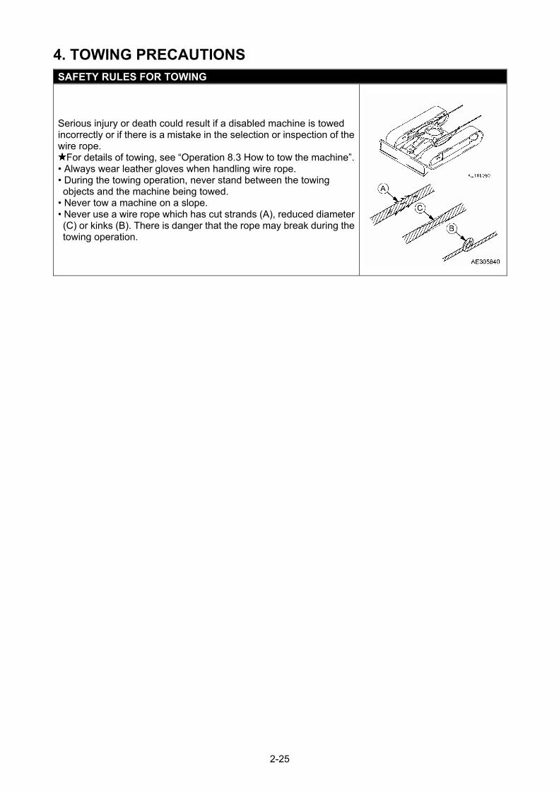
4. TOWING PRECAUTIONS SAFETY RULES FOR TOWING
Serious injury or death could result if a disabled machine is towed incorrectly or if there is a mistake in the selection or inspection of the wire rope.
For details of towing, see “Operation 8.3 How to tow the machine”.• Always wear leather gloves when handling wire rope. • During the towing operation, never stand between the towing objects and the machine being towed.
• Never tow a machine on a slope. • Never use a wire rope which has cut strands (A), reduced diameter (C) or kinks (B). There is danger that the rope may break during the towing operation.
2-25
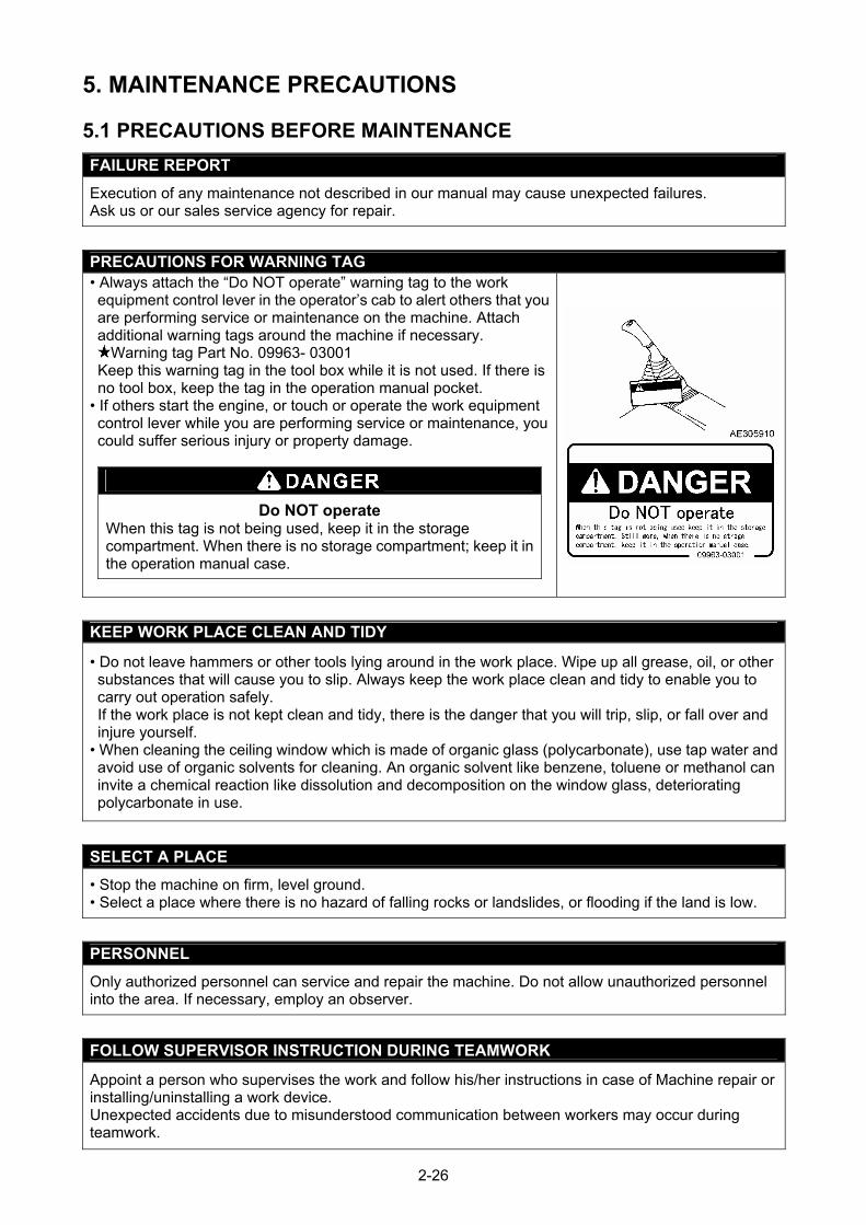
5. MAINTENANCE PRECAUTIONS
5.1 PRECAUTIONS BEFORE MAINTENANCE
FAILURE REPORT
Execution of any maintenance not described in our manual may cause unexpected failures. Ask us or our sales service agency for repair.
PRECAUTIONS FOR WARNING TAG • Always attach the “Do NOT operate” warning tag to the work equipment control lever in the operator’s cab to alert others that you are performing service or maintenance on the machine. Attach additional warning tags around the machine if necessary.
Warning tag Part No. 09963- 03001 Keep this warning tag in the tool box while it is not used. If there is no tool box, keep the tag in the operation manual pocket.
• If others start the engine, or touch or operate the work equipment control lever while you are performing service or maintenance, you could suffer serious injury or property damage.
Do NOT operate When this tag is not being used, keep it in the storage compartment. When there is no storage compartment; keep it in the operation manual case.
KEEP WORK PLACE CLEAN AND TIDY
• Do not leave hammers or other tools lying around in the work place. Wipe up all grease, oil, or other substances that will cause you to slip. Always keep the work place clean and tidy to enable you to carry out operation safely. If the work place is not kept clean and tidy, there is the danger that you will trip, slip, or fall over and injure yourself.
• When cleaning the ceiling window which is made of organic glass (polycarbonate), use tap water and avoid use of organic solvents for cleaning. An organic solvent like benzene, toluene or methanol can invite a chemical reaction like dissolution and decomposition on the window glass, deteriorating polycarbonate in use.
SELECT A PLACE
• Stop the machine on firm, level ground. • Select a place where there is no hazard of falling rocks or landslides, or flooding if the land is low.
PERSONNEL
Only authorized personnel can service and repair the machine. Do not allow unauthorized personnel into the area. If necessary, employ an observer.
FOLLOW SUPERVISOR INSTRUCTION DURING TEAMWORK
Appoint a person who supervises the work and follow his/her instructions in case of Machine repair or installing/uninstalling a work device. Unexpected accidents due to misunderstood communication between workers may occur during teamwork.
2-26
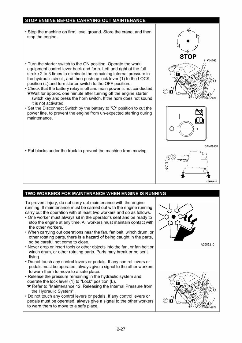
STOP ENGINE BEFORE CARRYING OUT MAINTENANCE • Stop the machine on firm, level ground. Store the crane, and then stop the engine.
• Turn the starter switch to the ON position. Operate the work equipment control lever back and forth. Left and right at the full stroke 2 to 3 times to eliminate the remaining internal pressure in the hydraulic circuit, and then push up lock lever (1) to the LOCK position (L) and turn starter switch to the OFF position.
• Check that the battery relay is off and main power is not conducted.Wait for approx. one minute after turning off the engine starter switch key and press the horn switch. If the horn does not sound, it is not activated.
• Set the Disconnect Switch by the battery to " " position to cut the power line, to prevent the engine from un-expected starting during maintenance.
• Put blocks under the track to prevent the machine from moving.
TWO WORKERS FOR MAINTENANCE WHEN ENGINE IS RUNNING
To prevent injury, do not carry out maintenance with the engine running. If maintenance must be carried out with the engine running, carry out the operation with at least two workers and do as follows. • One worker must always sit in the operator’s seat and be ready to
stop the engine at any time. All workers must maintain contact with the other workers.
• When carrying out operations near the fan, fan belt, winch drum, or other rotating parts, there is a hazard of being caught in the parts, so be careful not come to close.
• Never drop or insert tools or other objects into the fan, or fan belt or winch drum, or other rotating parts. Parts may break or be sent flying.
• Do not touch any control levers or pedals. If any control levers or pedals must be operated, always give a signal to the other workers to warn them to move to a safe place.
• Release the pressure remaining in the hydraulic system and operate the lock lever (1) to "Lock" position (L).
Refer to "Maintenance 12. Releasing the Internal Pressure from the Hydraulic System".
• Do not touch any control levers or pedals. If any control levers or pedals must be operated, always give a signal to the other workers to warn them to move to a safe place.
2-27
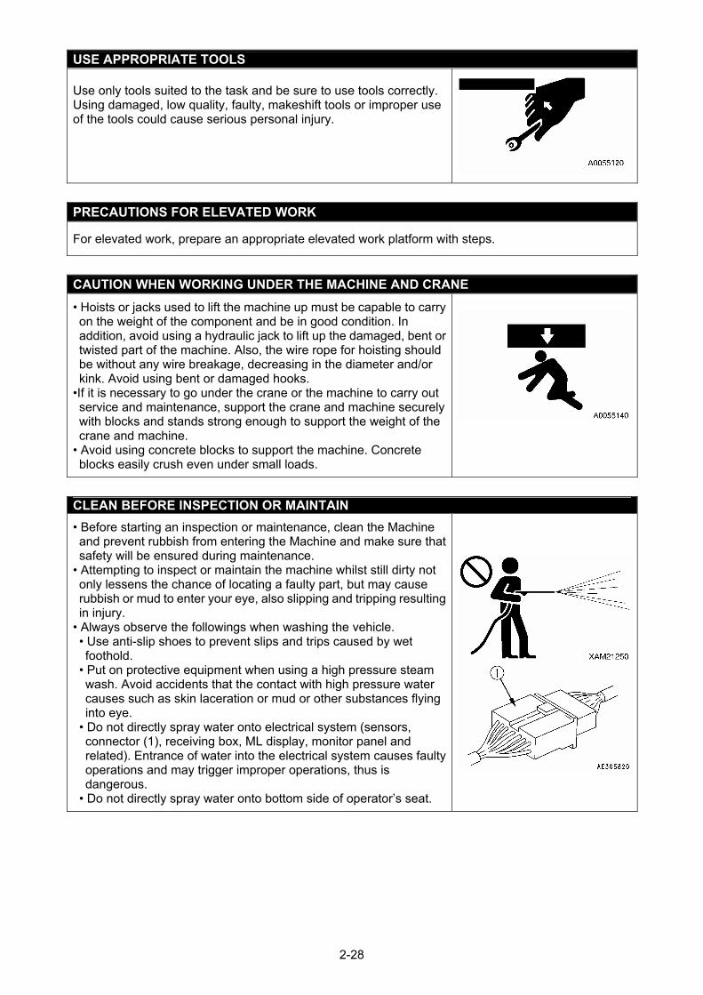
USE APPROPRIATE TOOLS Use only tools suited to the task and be sure to use tools correctly. Using damaged, low quality, faulty, makeshift tools or improper use of the tools could cause serious personal injury.
PRECAUTIONS FOR ELEVATED WORK
For elevated work, prepare an appropriate elevated work platform with steps.
CAUTION WHEN WORKING UNDER THE MACHINE AND CRANE
• Hoists or jacks used to lift the machine up must be capable to carry on the weight of the component and be in good condition. In addition, avoid using a hydraulic jack to lift up the damaged, bent or twisted part of the machine. Also, the wire rope for hoisting should be without any wire breakage, decreasing in the diameter and/or kink. Avoid using bent or damaged hooks.
•If it is necessary to go under the crane or the machine to carry out service and maintenance, support the crane and machine securely with blocks and stands strong enough to support the weight of the crane and machine.
• Avoid using concrete blocks to support the machine. Concrete blocks easily crush even under small loads.
CLEAN BEFORE INSPECTION OR MAINTAIN
• Before starting an inspection or maintenance, clean the Machine and prevent rubbish from entering the Machine and make sure that safety will be ensured during maintenance.
• Attempting to inspect or maintain the machine whilst still dirty not only lessens the chance of locating a faulty part, but may cause rubbish or mud to enter your eye, also slipping and tripping resulting in injury.
• Always observe the followings when washing the vehicle. • Use anti-slip shoes to prevent slips and trips caused by wet foothold.
• Put on protective equipment when using a high pressure steam wash. Avoid accidents that the contact with high pressure water causes such as skin laceration or mud or other substances flying into eye.
• Do not directly spray water onto electrical system (sensors, connector (1), receiving box, ML display, monitor panel and related). Entrance of water into the electrical system causes faulty operations and may trigger improper operations, thus is dangerous.
• Do not directly spray water onto bottom side of operator’s seat.
2-28
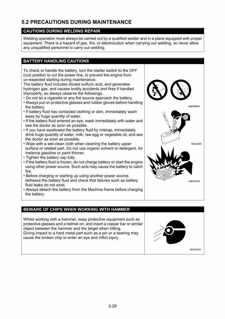
5.2 PRECAUTIONS DURING MAINTENANCE
CAUTIONS DURING WELDING REPAIR
Welding operation must always be carried out by a qualified welder and in a place equipped with proper equipment. There is a hazard of gas, fire, or electrocution when carrying out welding, so never allow any unqualified personnel to carry out welding.
BATTERY HANDLING CAUTIONS
To check or handle the battery, turn the starter switch to the OFF (cut) position to cut the power line, to prevent the engine from un-expected starting during maintenance. The battery fluid includes diluted sulfuric acid, and generates hydrogen gas, and causes bodily accidents and fires if handled improperly, so always observe the followings. • Do not let a cigarette or any fire source approach the battery. • Always put on protective glasses and rubber gloves before handling the battery.
• If battery fluid has contacted clothing or skin, immediately wash away by huge quantity of water.
• If the battery fluid entered an eye, wash immediately with water and see the doctor as soon as possible.
• If you have swallowed the battery fluid by mishap, immediately drink huge quantity of water, milk, raw egg or vegetable oil, and see the doctor as soon as possible.
• Wipe with a wet clean cloth when cleaning the battery upper surface or related part. Do not use organic solvent or detergent, for instance gasoline or paint thinner.
• Tighten the battery cap fully. • If the battery fluid is frozen, do not charge battery or start the engine using other power source. Such acts may cause the battery to catch fire.
• Before charging or starting up using another power source, defreeze the battery fluid and check that failures such as battery fluid leaks do not exist.
• Always detach the battery from the Machine frame before charging the battery.
BEWARE OF CHIPS WHEN WORKING WITH HAMMER Whilst working with a hammer, keep protective equipment such as protective glasses and a helmet on, and insert a copper bar or similar object between the hammer and the target when hitting. Giving impact to a hard metal part such as a pin or a bearing may cause the broken chip to enter an eye and inflict injury.
2-29
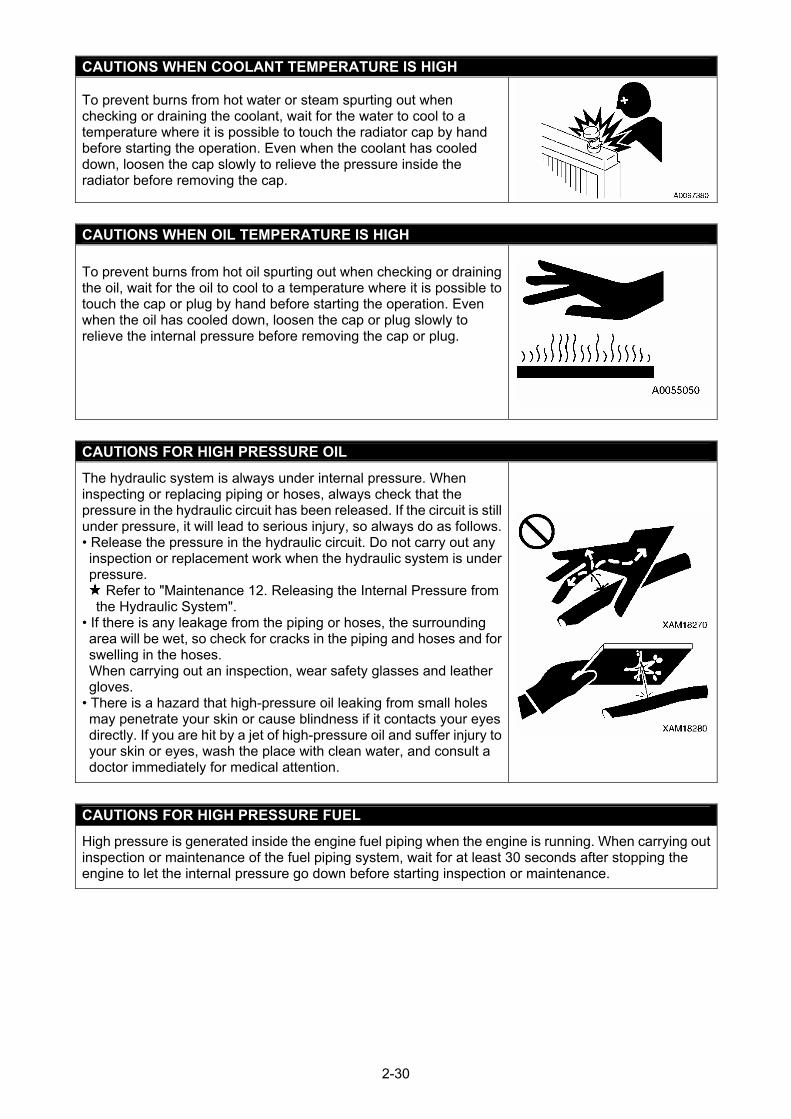
CAUTIONS WHEN COOLANT TEMPERATURE IS HIGH
To prevent burns from hot water or steam spurting out when checking or draining the coolant, wait for the water to cool to a temperature where it is possible to touch the radiator cap by hand before starting the operation. Even when the coolant has cooled down, loosen the cap slowly to relieve the pressure inside the radiator before removing the cap.
CAUTIONS WHEN OIL TEMPERATURE IS HIGH To prevent burns from hot oil spurting out when checking or draining the oil, wait for the oil to cool to a temperature where it is possible to touch the cap or plug by hand before starting the operation. Even when the oil has cooled down, loosen the cap or plug slowly to relieve the internal pressure before removing the cap or plug.
CAUTIONS FOR HIGH PRESSURE OIL
The hydraulic system is always under internal pressure. When inspecting or replacing piping or hoses, always check that the pressure in the hydraulic circuit has been released. If the circuit is still under pressure, it will lead to serious injury, so always do as follows. • Release the pressure in the hydraulic circuit. Do not carry out any inspection or replacement work when the hydraulic system is under pressure. Refer to "Maintenance 12. Releasing the Internal Pressure from
the Hydraulic System". • If there is any leakage from the piping or hoses, the surrounding area will be wet, so check for cracks in the piping and hoses and for swelling in the hoses. When carrying out an inspection, wear safety glasses and leather gloves.
• There is a hazard that high-pressure oil leaking from small holes may penetrate your skin or cause blindness if it contacts your eyes directly. If you are hit by a jet of high-pressure oil and suffer injury to your skin or eyes, wash the place with clean water, and consult a doctor immediately for medical attention.
CAUTIONS FOR HIGH PRESSURE FUEL
High pressure is generated inside the engine fuel piping when the engine is running. When carrying out inspection or maintenance of the fuel piping system, wait for at least 30 seconds after stopping the engine to let the internal pressure go down before starting inspection or maintenance.
2-30
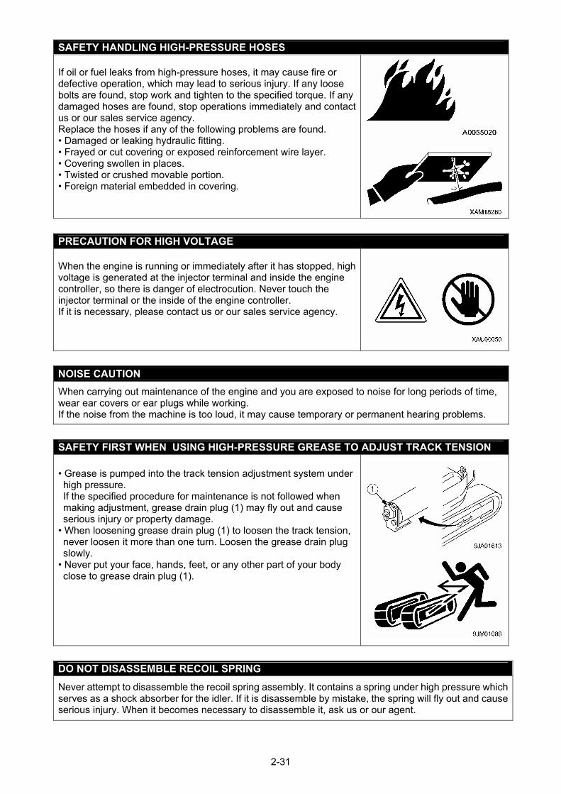
SAFETY HANDLING HIGH-PRESSURE HOSES If oil or fuel leaks from high-pressure hoses, it may cause fire or defective operation, which may lead to serious injury. If any loose bolts are found, stop work and tighten to the specified torque. If any damaged hoses are found, stop operations immediately and contact us or our sales service agency. Replace the hoses if any of the following problems are found. • Damaged or leaking hydraulic fitting. • Frayed or cut covering or exposed reinforcement wire layer. • Covering swollen in places. • Twisted or crushed movable portion. • Foreign material embedded in covering.
PRECAUTION FOR HIGH VOLTAGE When the engine is running or immediately after it has stopped, high voltage is generated at the injector terminal and inside the engine controller, so there is danger of electrocution. Never touch the injector terminal or the inside of the engine controller. If it is necessary, please contact us or our sales service agency.
NOISE CAUTION
When carrying out maintenance of the engine and you are exposed to noise for long periods of time, wear ear covers or ear plugs while working. If the noise from the machine is too loud, it may cause temporary or permanent hearing problems.
SAFETY FIRST WHEN USING HIGH-PRESSURE GREASE TO ADJUST TRACK TENSION
• Grease is pumped into the track tension adjustment system under high pressure. If the specified procedure for maintenance is not followed when making adjustment, grease drain plug (1) may fly out and cause serious injury or property damage.
• When loosening grease drain plug (1) to loosen the track tension, never loosen it more than one turn. Loosen the grease drain plug slowly.
• Never put your face, hands, feet, or any other part of your body close to grease drain plug (1).
DO NOT DISASSEMBLE RECOIL SPRING
Never attempt to disassemble the recoil spring assembly. It contains a spring under high pressure which serves as a shock absorber for the idler. If it is disassemble by mistake, the spring will fly out and cause serious injury. When it becomes necessary to disassemble it, ask us or our agent.
2-31
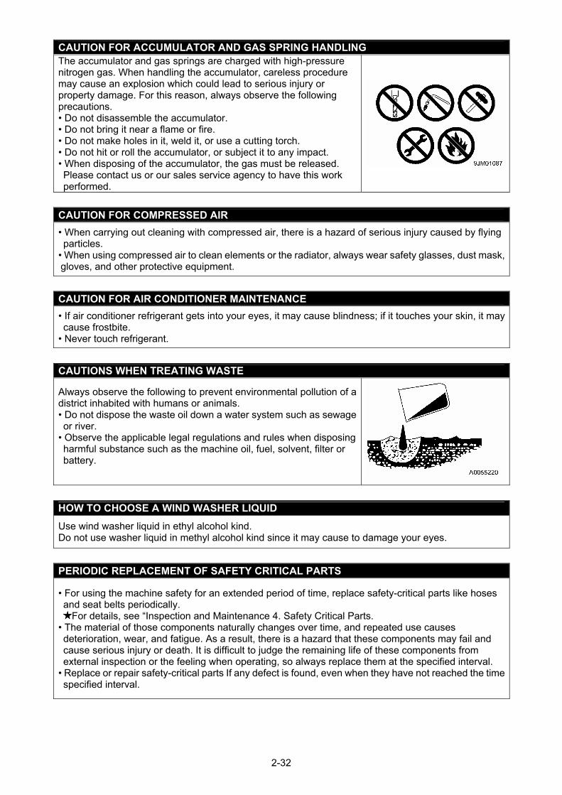
CAUTION FOR ACCUMULATOR AND GAS SPRING HANDLING The accumulator and gas springs are charged with high-pressure nitrogen gas. When handling the accumulator, careless procedure may cause an explosion which could lead to serious injury or property damage. For this reason, always observe the following precautions. • Do not disassemble the accumulator. • Do not bring it near a flame or fire. • Do not make holes in it, weld it, or use a cutting torch. • Do not hit or roll the accumulator, or subject it to any impact. • When disposing of the accumulator, the gas must be released. Please contact us or our sales service agency to have this work performed.
CAUTION FOR COMPRESSED AIR
• When carrying out cleaning with compressed air, there is a hazard of serious injury caused by flying particles.
• When using compressed air to clean elements or the radiator, always wear safety glasses, dust mask, gloves, and other protective equipment.
CAUTION FOR AIR CONDITIONER MAINTENANCE
• If air conditioner refrigerant gets into your eyes, it may cause blindness; if it touches your skin, it may cause frostbite.
• Never touch refrigerant.
CAUTIONS WHEN TREATING WASTE
Always observe the following to prevent environmental pollution of a district inhabited with humans or animals. • Do not dispose the waste oil down a water system such as sewage or river.
• Observe the applicable legal regulations and rules when disposing harmful substance such as the machine oil, fuel, solvent, filter or battery.
HOW TO CHOOSE A WIND WASHER LIQUID
Use wind washer liquid in ethyl alcohol kind. Do not use washer liquid in methyl alcohol kind since it may cause to damage your eyes.
PERIODIC REPLACEMENT OF SAFETY CRITICAL PARTS
• For using the machine safety for an extended period of time, replace safety-critical parts like hoses and seat belts periodically.
For details, see “Inspection and Maintenance 4. Safety Critical Parts. • The material of those components naturally changes over time, and repeated use causes deterioration, wear, and fatigue. As a result, there is a hazard that these components may fail and cause serious injury or death. It is difficult to judge the remaining life of these components from external inspection or the feeling when operating, so always replace them at the specified interval.
• Replace or repair safety-critical parts If any defect is found, even when they have not reached the time specified interval.
2-32
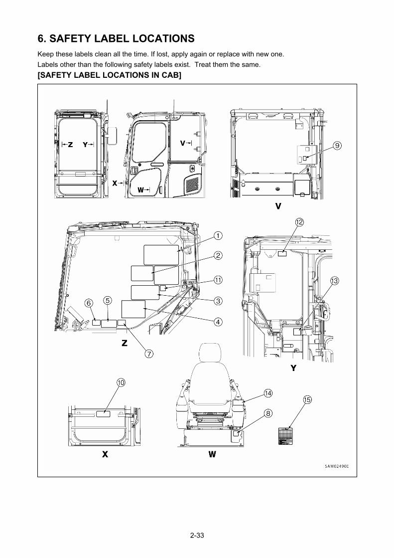
6. SAFETY LABEL LOCATIONS Keep these labels clean all the time. If lost, apply again or replace with new one.
Labels other than the following safety labels exist. Treat them the same.
[SAFETY LABEL LOCATIONS IN CAB]
2-33
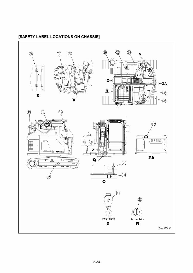
[SAFETY LABEL LOCATIONS ON CHASSIS]
2-34
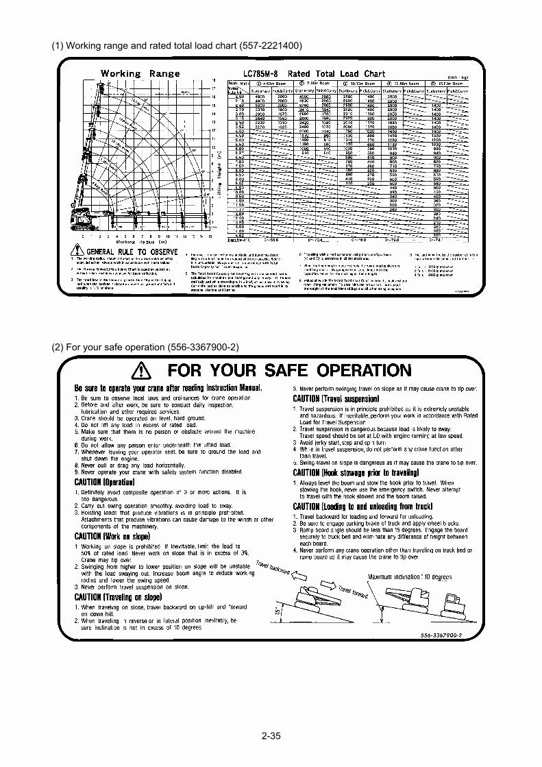
(1) Working range and rated total load chart (557-2221400)
(2) For your safe operation (556-3367900-2)
2-35
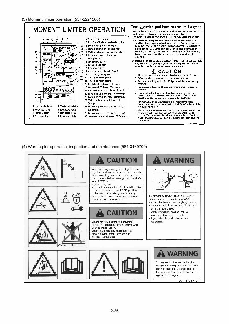
(3) Moment limiter operation (557-2221500)
(4) Warning for operation, inspection and maintenance (584-3469700)
2-36
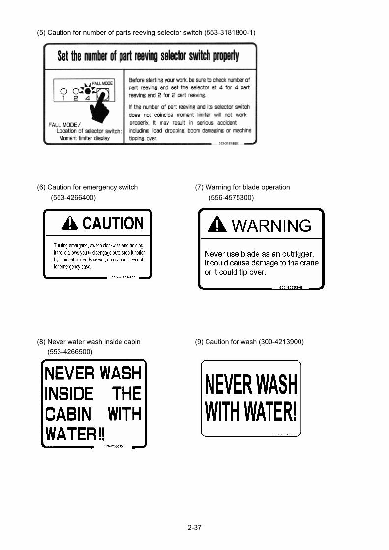
(5) Caution for number of parts reeving selector switch (553-3181800-1)
(6) Caution for emergency switch (7) Warning for blade operation
(553-4266400) (556-4575300)
(8) Never water wash inside cabin (9) Caution for wash (300-4213900)
(553-4266500)
2-37
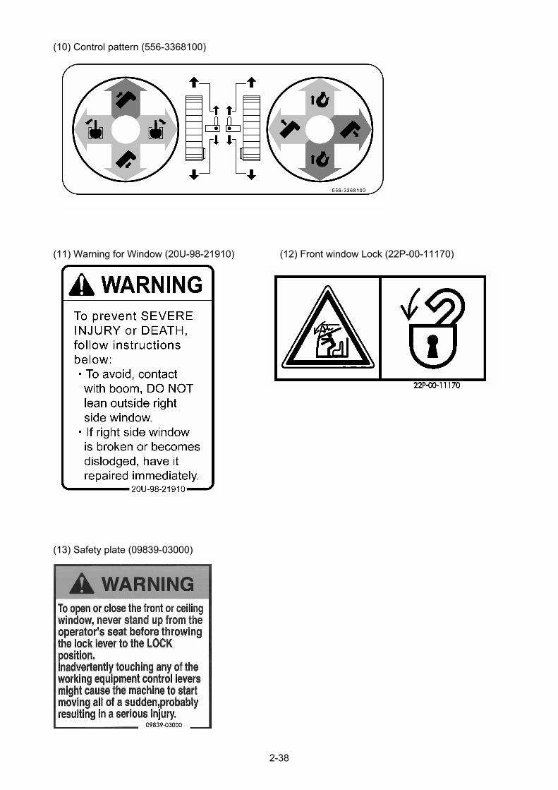
(10) Control pattern (556-3368100)
(11) Warning for Window (20U-98-21910) (12) Front window Lock (22P-00-11170)
(13) Safety plate (09839-03000)
2-38

(14) Warning tag (09963-03001)
(15) Portable Working range and rated total load chart (557-3488600)
(16) Warning for track tension adjusting (09657-A0881)
2-39

(17) Keep off swing area (09133-A1681) (18) Warning for winch (553-4267500)
(19) Lifting Position (09960-00801) (4 places) (20) Warning (553-4268000) (2 places)
(21) Machine Weight (557-4632300) (22) Do not Stand on here (584-4581700)
2-40
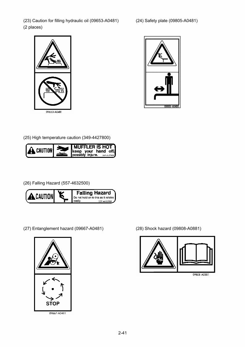
(23) Caution for filling hydraulic oil (09653-A0481) (24) Safety plate (09805-A0481)
(2 places)
(25) High temperature caution (349-4427800)
(26) Falling Hazard (557-4632500)
(27) Entanglement hazard (09667-A0481) (28) Shock hazard (09808-A0881)
2-41
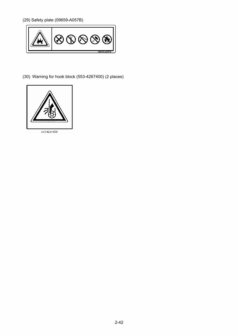
(29) Safety plate (09659-A057B)
2-42
(30) Warning for hook block (553-4267400) (2 places)

OPERATION
1. MACHINE EACH SECTION 3 – 2
2. EXPLANATION OF DEVICES 3 – 6
3. MACHINE OPERATIONS AND CONTROLS 3 – 108
4. HANDLING WIRE ROPES 3 – 184
5. TRANSPORTATION 3 – 190
6. HANDLING IN COLD WEATHER 3 – 200
7. LONG-TERM STORAGE 3 – 202
8. TROUBLES AND ACTIONS 3 – 203
3-1
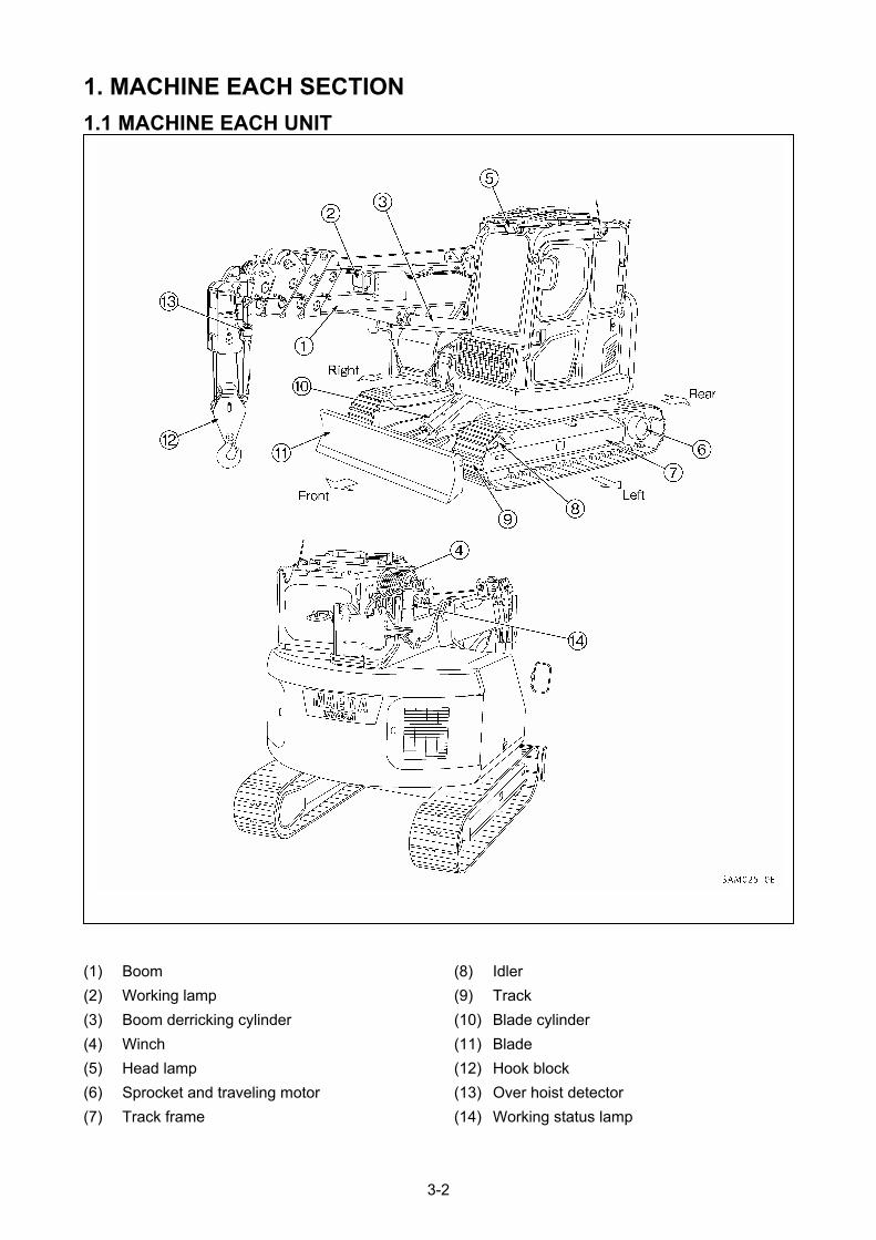
1. MACHINE EACH SECTION
1.1 MACHINE EACH UNIT
(8) Idler (1) Boom
(9) Track (2) Working lamp
(10) Blade cylinder (3) Boom derricking cylinder
(11) Blade (4) Winch
(12) Hook block (5) Head lamp
(13) Over hoist detector (6) Sprocket and traveling motor
(14) Working status lamp (7) Track frame
3-2
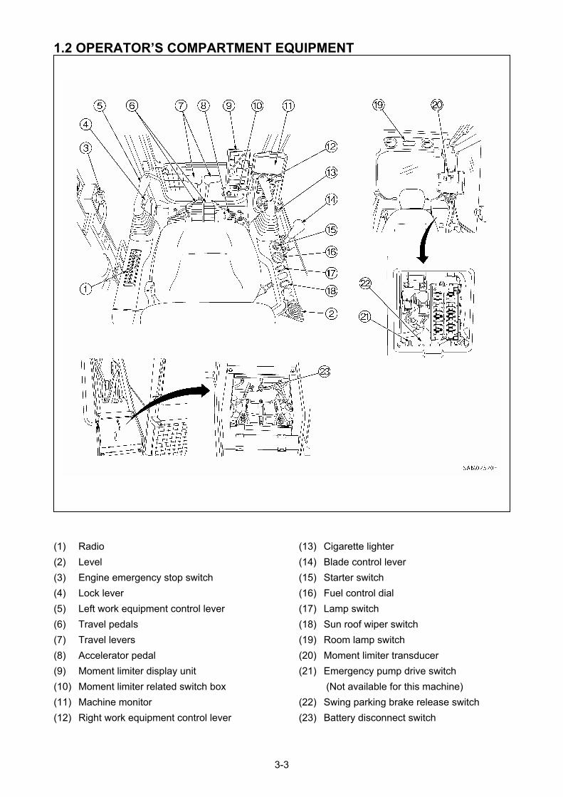
1.2 OPERATOR’S COMPARTMENT EQUIPMENT
(13) Cigarette lighter (1) Radio
(14) Blade control lever (2) Level
(15) Starter switch (3) Engine emergency stop switch
(16) Fuel control dial (4) Lock lever
(17) Lamp switch (5) Left work equipment control lever
(18) Sun roof wiper switch (6) Travel pedals
(19) Room lamp switch (7) Travel levers
(20) Moment limiter transducer (8) Accelerator pedal
(21) Emergency pump drive switch (9) Moment limiter display unit
(Not available for this machine) (10) Moment limiter related switch box
(22) Swing parking brake release switch (11) Machine monitor
(23) Battery disconnect switch (12) Right work equipment control lever
3-3
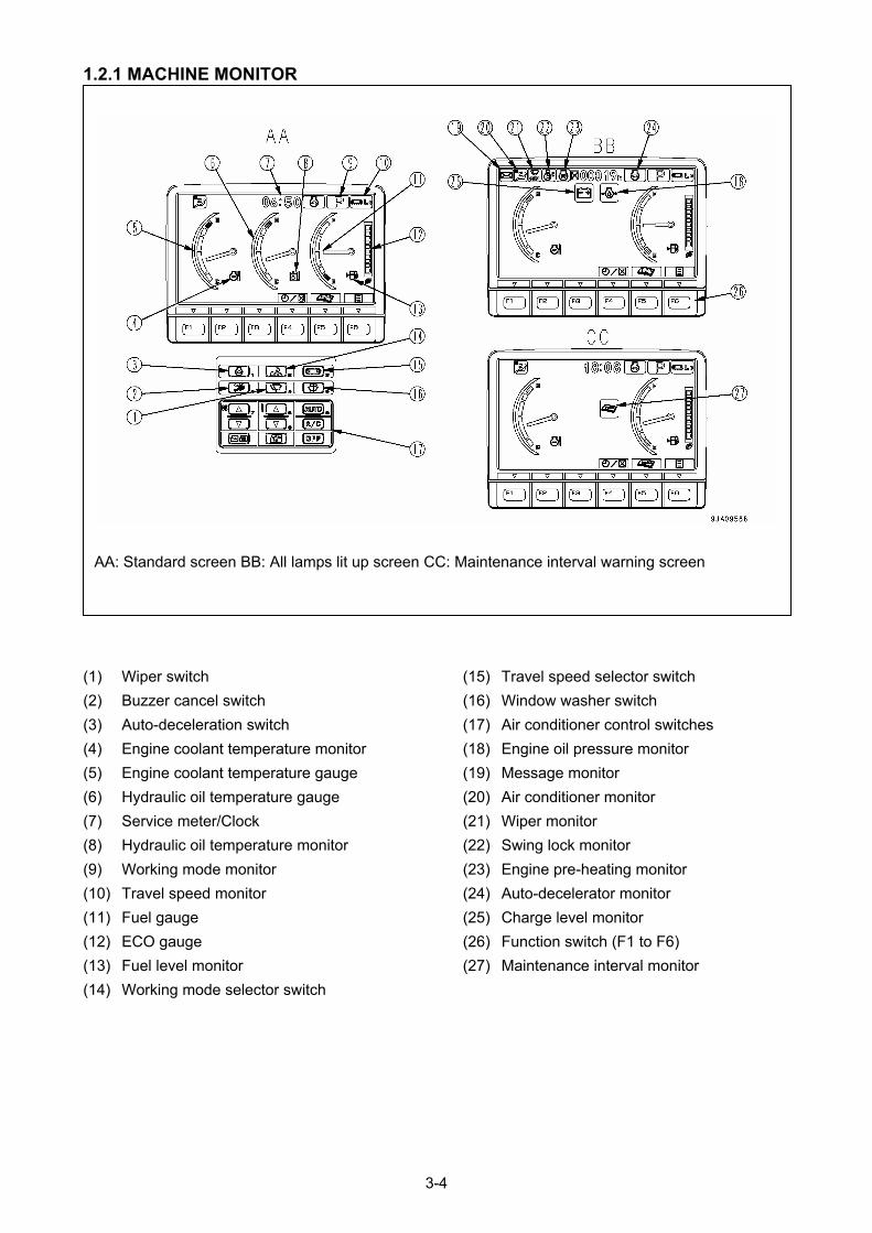
1.2.1 MACHINE MONITOR
AA: Standard screen BB: All lamps lit up screen CC: Maintenance interval warning screen
(15) Travel speed selector switch (1) Wiper switch
(16) Window washer switch (2) Buzzer cancel switch
(17) Air conditioner control switches (3) Auto-deceleration switch
(18) Engine oil pressure monitor (4) Engine coolant temperature monitor
(19) Message monitor (5) Engine coolant temperature gauge
(20) Air conditioner monitor (6) Hydraulic oil temperature gauge
(21) Wiper monitor (7) Service meter/Clock
(22) Swing lock monitor (8) Hydraulic oil temperature monitor
(23) Engine pre-heating monitor (9) Working mode monitor
(24) Auto-decelerator monitor (10) Travel speed monitor
(25) Charge level monitor (11) Fuel gauge
(26) Function switch (F1 to F6) (12) ECO gauge
(27) Maintenance interval monitor (13) Fuel level monitor
(14) Working mode selector switch
3-4
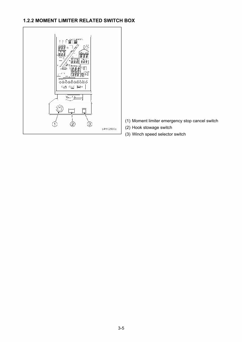
1.2.2 MOMENT LIMITER RELATED SWITCH BOX
(1) Moment limiter emergency stop cancel switch
(2) Hook stowage switch
(3) Winch speed selector switch
3-5
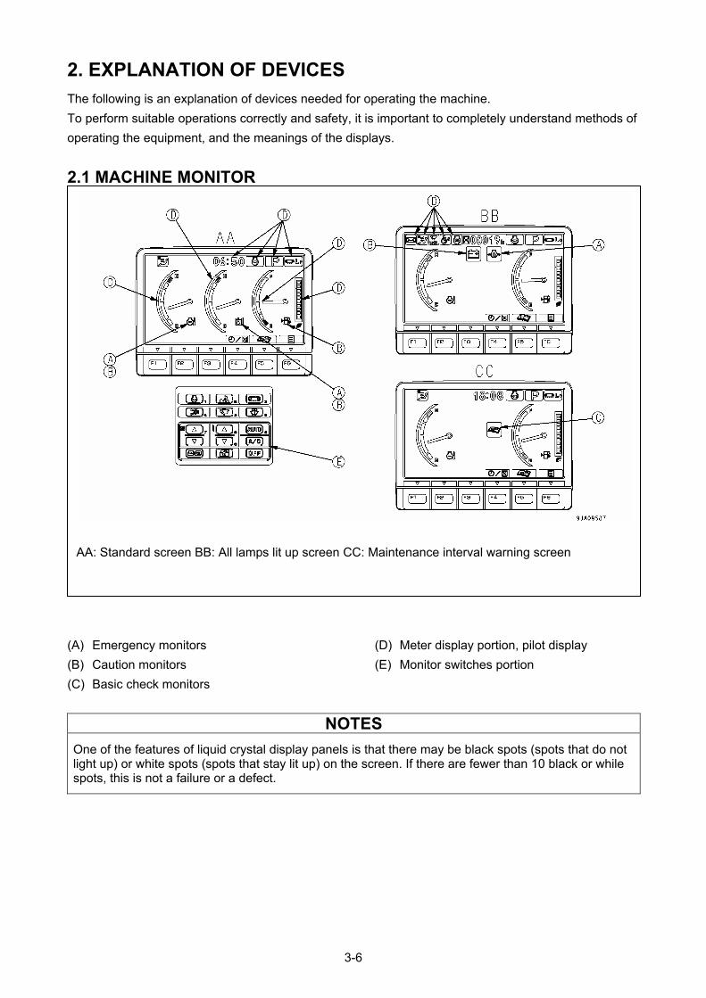
2. EXPLANATION OF DEVICES
The following is an explanation of devices needed for operating the machine.
To perform suitable operations correctly and safety, it is important to completely understand methods of
operating the equipment, and the meanings of the displays.
2.1 MACHINE MONITOR
AA: Standard screen BB: All lamps lit up screen CC: Maintenance interval warning screen
(A) Emergency monitors (D) Meter display portion, pilot display
(B) Caution monitors (E) Monitor switches portion
(C) Basic check monitors
NOTES
One of the features of liquid crystal display panels is that there may be black spots (spots that do not light up) or white spots (spots that stay lit up) on the screen. If there are fewer than 10 black or while spots, this is not a failure or a defect.
3-6
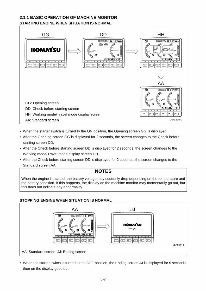
3-7
2.1.1 BASIC OPERATION OF MACHINE MONITOR STARTING ENGINE WHEN SITUATION IS NORMAL
• When the starter switch is turned to the ON position, the Opening screen GG is displayed.
• After the Opening screen GG is displayed for 2 seconds, the screen changes to the Check before
starting screen DD.
• After the Check before starting screen DD is displayed for 2 seconds, the screen changes to the
Working mode/Travel mode display screen HH.
• After the Check before starting screen DD is displayed for 2 seconds, the screen changes to the
Standard screen AA.
NOTES
When the engine is started, the battery voltage may suddenly drop depending on the temperature and the battery condition. If this happens, the display on the machine monitor may momentarily go out, but this does not indicate any abnormality.
STOPPING ENGINE WHEN SITUATION IS NORMAL
• When the starter switch is turned to the OFF position, the Ending screen JJ is displayed for 5 seconds,
then on the display goes out.
AA: Standard screen JJ: Ending screen
GG: Opening screen
DD: Check before starting screen
HH: Working mode/Travel mode display screen
AA: Standard screen
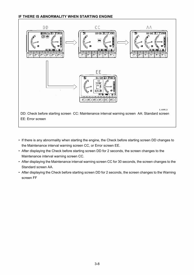
IF THERE IS ABNORMALITY WHEN STARTING ENGINE
DD: Check before starting screen CC: Maintenance interval warning screen AA: Standard screen
EE: Error screen
• If there is any abnormality when starting the engine, the Check before starting screen DD changes to
the Maintenance interval warning screen CC, or Error screen EE.
• After displaying the Check before starting screen DD for 2 seconds, the screen changes to the
Maintenance interval warning screen CC.
• After displaying the Maintenance interval warning screen CC for 30 seconds, the screen changes to the
Standard screen AA.
• After displaying the Check before starting screen DD for 2 seconds, the screen changes to the Warning
screen FF
3-8
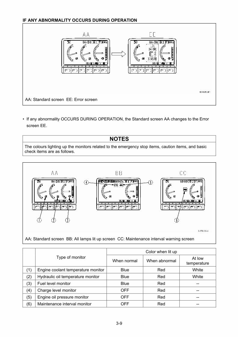
IF ANY ABNORMALITY OCCURS DURING OPERATION
• If any abnormality OCCURS DURING OPERATION, the Standard screen AA changes to the Error
screen EE.
NOTES
The colours lighting up the monitors related to the emergency stop items, caution items, and basic check items are as follows.
Color when lit up Type of monitor
When normal When abnormal At low
temperature
(1) Engine coolant temperature monitor Blue Red White
(2) Hydraulic oil temperature monitor Blue Red White
(3) Fuel level monitor Blue Red --
(4) Charge level monitor OFF Red --
(5) Engine oil pressure monitor OFF Red --
(6) Maintenance interval monitor OFF Red --
AA: Standard screen BB: All lamps lit up screen CC: Maintenance interval warning screen
AA: Standard screen EE: Error screen
3-9
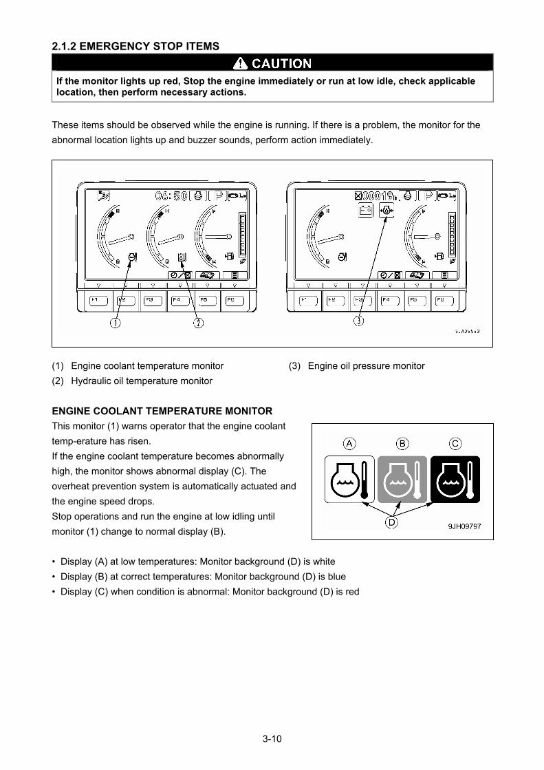
2.1.2 EMERGENCY STOP ITEMS
If the monitor lights up red, Stop the engine immediately or run at low idle, check applicable location, then perform necessary actions.
These items should be observed while the engine is running. If there is a problem, the monitor for the
abnormal location lights up and buzzer sounds, perform action immediately.
(1) Engine coolant temperature monitor (3) Engine oil pressure monitor
(2) Hydraulic oil temperature monitor
ENGINE COOLANT TEMPERATURE MONITOR
This monitor (1) warns operator that the engine coolant
temp-erature has risen.
If the engine coolant temperature becomes abnormally
high, the monitor shows abnormal display (C). The
overheat prevention system is automatically actuated and
the engine speed drops.
Stop operations and run the engine at low idling until
monitor (1) change to normal display (B).
• Display (A) at low temperatures: Monitor background (D) is white
• Display (B) at correct temperatures: Monitor background (D) is blue
• Display (C) when condition is abnormal: Monitor background (D) is red
3-10
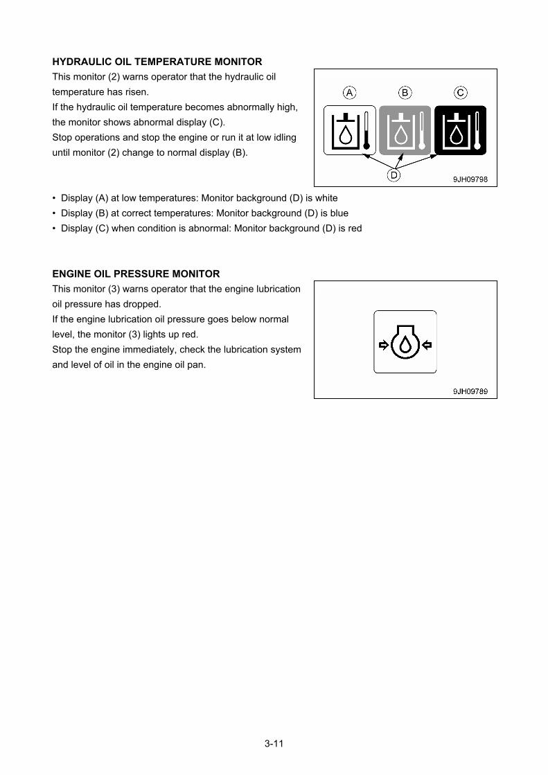
HYDRAULIC OIL TEMPERATURE MONITOR
This monitor (2) warns operator that the hydraulic oil
temperature has risen.
If the hydraulic oil temperature becomes abnormally high,
the monitor shows abnormal display (C).
Stop operations and stop the engine or run it at low idling
until monitor (2) change to normal display (B).
• Display (A) at low temperatures: Monitor background (D) is white
• Display (B) at correct temperatures: Monitor background (D) is blue
• Display (C) when condition is abnormal: Monitor background (D) is red
ENGINE OIL PRESSURE MONITOR
This monitor (3) warns operator that the engine lubrication
oil pressure has dropped.
If the engine lubrication oil pressure goes below normal
level, the monitor (3) lights up red.
Stop the engine immediately, check the lubrication system
and level of oil in the engine oil pan.
3-11
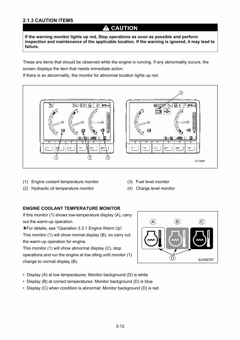
2.1.3 CAUTION ITEMS
If the warning monitor lights up red, Stop operations as soon as possible and perform inspection and maintenance of the applicable location. If the warning is ignored, it may lead to failure.
These are items that should be observed while the engine is running. If any abnormality occurs, the
screen displays the item that needs immediate action.
If there is an abnormality, the monitor for abnormal location lights up red.
(1) Engine coolant temperature monitor (3) Fuel level monitor
(2) Hydraulic oil temperature monitor (4) Charge level monitor
ENGINE COOLANT TEMPERATURE MONITOR
If this monitor (1) shows low-temperature display (A), carry
out the warm-up operation.
For details, see “Operation 3.3.1 Engine Warm Up”.
This monitor (1) will show normal display (B), so carry out
the warm-up operation for engine.
This monitor (1) will show abnormal display (C), stop
operations and run the engine at low idling until monitor (1)
change to normal display (B).
• Display (A) at low temperatures: Monitor background (D) is white
• Display (B) at correct temperatures: Monitor background (D) is blue
• Display (C) when condition is abnormal: Monitor background (D) is red
3-12
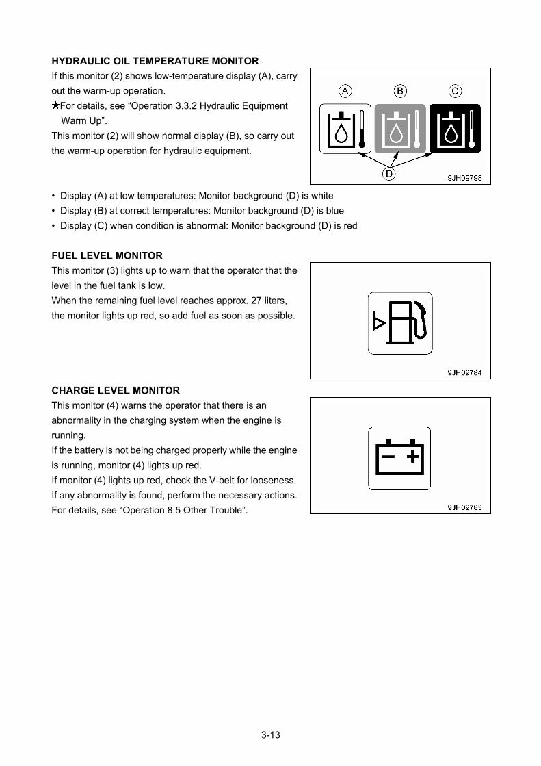
HYDRAULIC OIL TEMPERATURE MONITOR
If this monitor (2) shows low-temperature display (A), carry
out the warm-up operation.
For details, see “Operation 3.3.2 Hydraulic Equipment
Warm Up”.
This monitor (2) will show normal display (B), so carry out
the warm-up operation for hydraulic equipment.
• Display (A) at low temperatures: Monitor background (D) is white
• Display (B) at correct temperatures: Monitor background (D) is blue
• Display (C) when condition is abnormal: Monitor background (D) is red
FUEL LEVEL MONITOR
This monitor (3) lights up to warn that the operator that the
level in the fuel tank is low.
When the remaining fuel level reaches approx. 27 liters,
the monitor lights up red, so add fuel as soon as possible.
CHARGE LEVEL MONITOR
This monitor (4) warns the operator that there is an
abnormality in the charging system when the engine is
running.
If the battery is not being charged properly while the engine
is running, monitor (4) lights up red.
If monitor (4) lights up red, check the V-belt for looseness.
If any abnormality is found, perform the necessary actions.
For details, see “Operation 8.5 Other Trouble”.
3-13
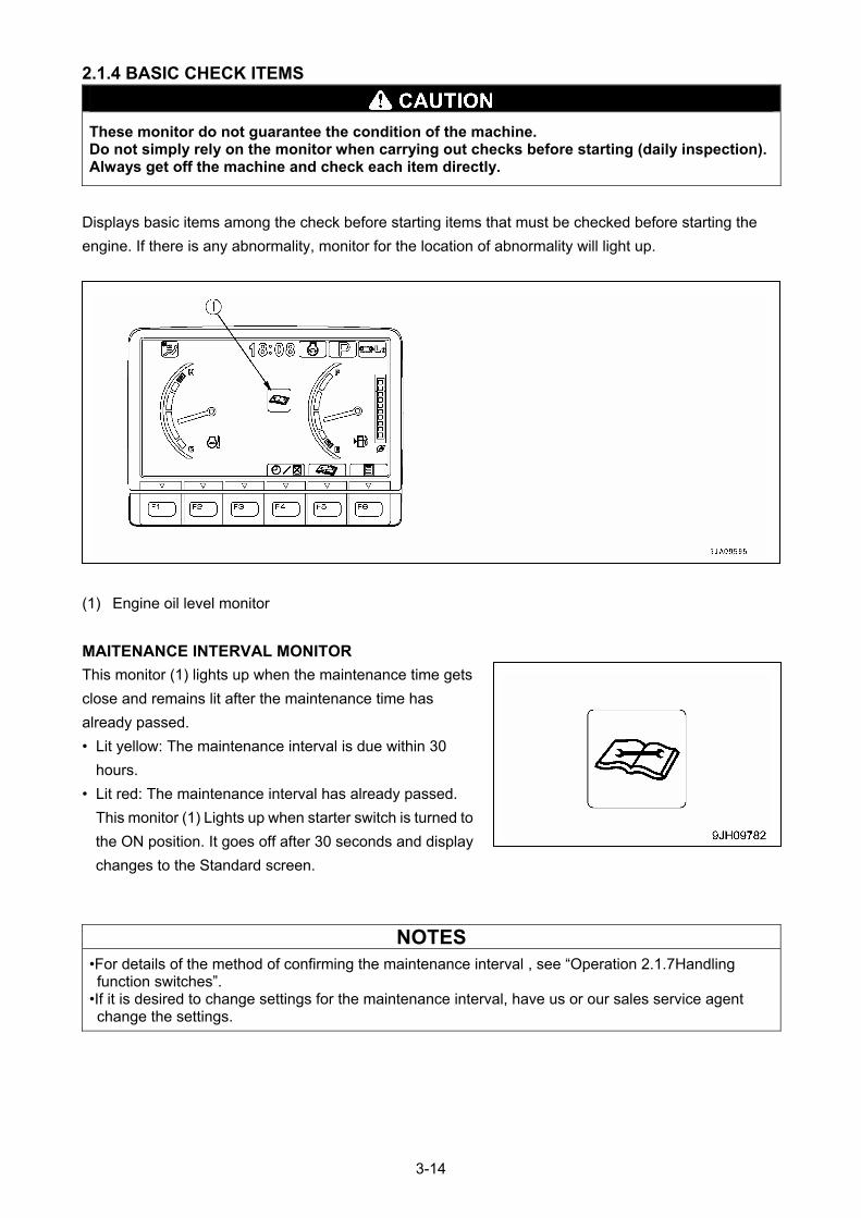
2.1.4 BASIC CHECK ITEMS
These monitor do not guarantee the condition of the machine. Do not simply rely on the monitor when carrying out checks before starting (daily inspection). Always get off the machine and check each item directly.
Displays basic items among the check before starting items that must be checked before starting the
engine. If there is any abnormality, monitor for the location of abnormality will light up.
(1) Engine oil level monitor
MAITENANCE INTERVAL MONITOR
This monitor (1) lights up when the maintenance time gets
close and remains lit after the maintenance time has
already passed.
• Lit yellow: The maintenance interval is due within 30
hours.
• Lit red: The maintenance interval has already passed.
This monitor (1) Lights up when starter switch is turned to
the ON position. It goes off after 30 seconds and display
changes to the Standard screen.
NOTES
•For details of the method of confirming the maintenance interval , see “Operation 2.1.7Handling function switches”.
•If it is desired to change settings for the maintenance interval, have us or our sales service agent change the settings.
3-14
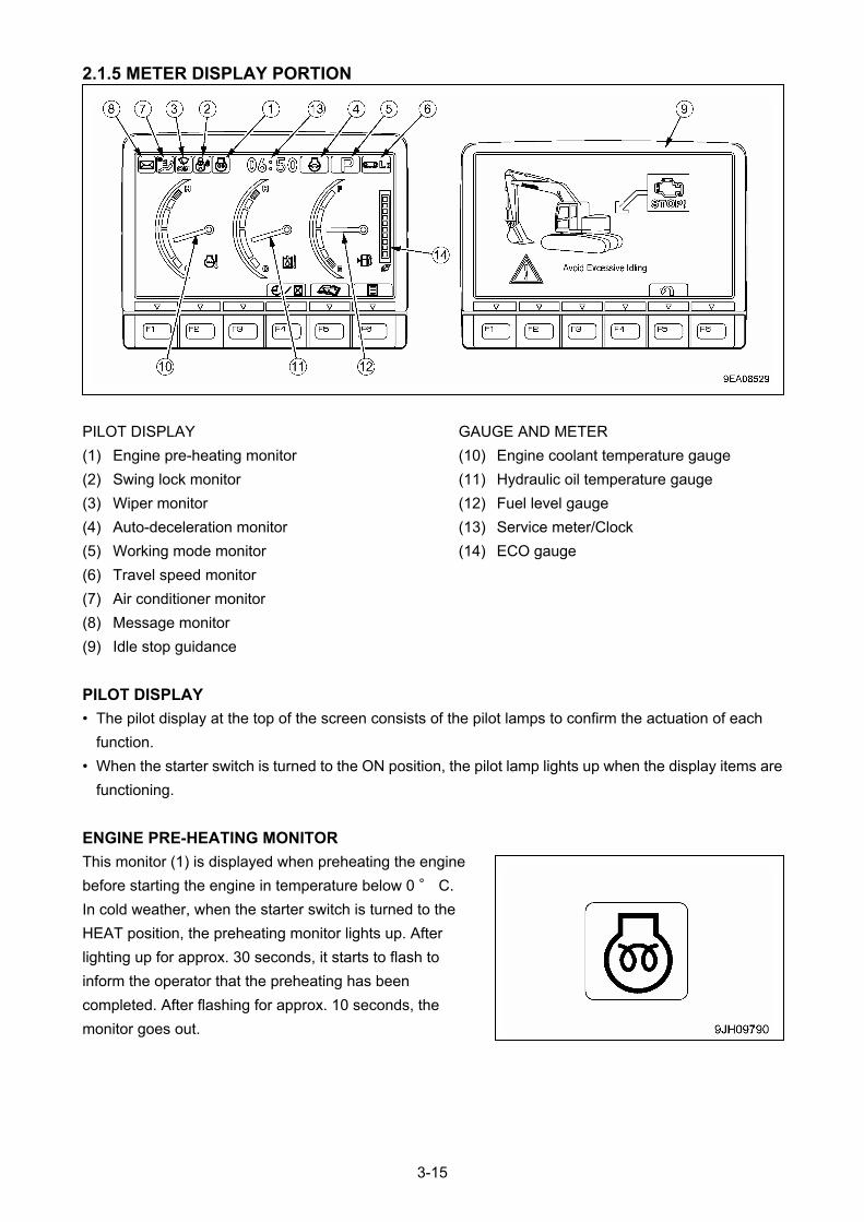
2.1.5 METER DISPLAY PORTION
GAUGE AND METER PILOT DISPLAY
(10) Engine coolant temperature gauge (1) Engine pre-heating monitor
(11) Hydraulic oil temperature gauge (2) Swing lock monitor
(12) Fuel level gauge (3) Wiper monitor
(13) Service meter/Clock (4) Auto-deceleration monitor
(14) ECO gauge (5) Working mode monitor
(6) Travel speed monitor
(7) Air conditioner monitor
(8) Message monitor
(9) Idle stop guidance
PILOT DISPLAY
• The pilot display at the top of the screen consists of the pilot lamps to confirm the actuation of each
function.
• When the starter switch is turned to the ON position, the pilot lamp lights up when the display items are
functioning.
ENGINE PRE-HEATING MONITOR
This monitor (1) is displayed when preheating the engine
before starting the engine in temperature below 0 ° C.
In cold weather, when the starter switch is turned to the
HEAT position, the preheating monitor lights up. After
lighting up for approx. 30 seconds, it starts to flash to
inform the operator that the preheating has been
completed. After flashing for approx. 10 seconds, the
monitor goes out.
3-15
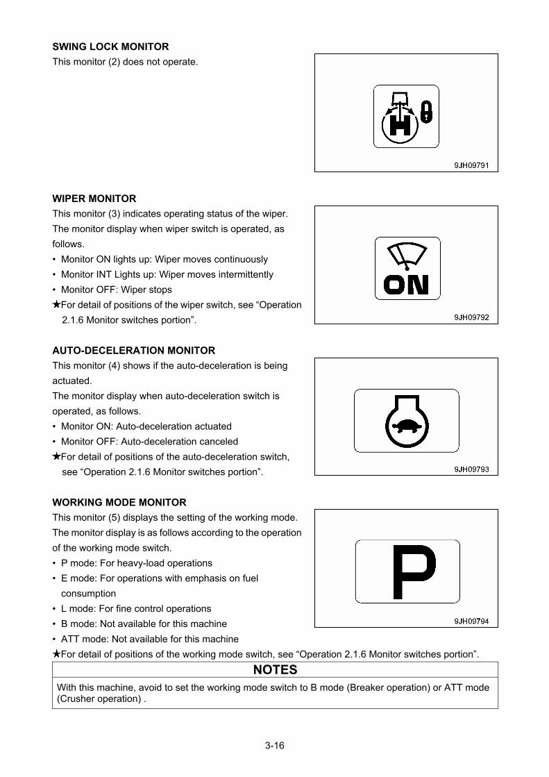
SWING LOCK MONITOR
This monitor (2) does not operate.
WIPER MONITOR
This monitor (3) indicates operating status of the wiper.
The monitor display when wiper switch is operated, as
follows.
• Monitor ON lights up: Wiper moves continuously
• Monitor INT Lights up: Wiper moves intermittently
• Monitor OFF: Wiper stops
For detail of positions of the wiper switch, see “Operation
2.1.6 Monitor switches portion”.
AUTO-DECELERATION MONITOR
This monitor (4) shows if the auto-deceleration is being
actuated.
The monitor display when auto-deceleration switch is
operated, as follows.
• Monitor ON: Auto-deceleration actuated
• Monitor OFF: Auto-deceleration canceled
For detail of positions of the auto-deceleration switch,
see “Operation 2.1.6 Monitor switches portion”.
WORKING MODE MONITOR
This monitor (5) displays the setting of the working mode.
The monitor display is as follows according to the operation
of the working mode switch.
• P mode: For heavy-load operations
• E mode: For operations with emphasis on fuel
consumption
• L mode: For fine control operations
• B mode: Not available for this machine
• ATT mode: Not available for this machine
For detail of positions of the working mode switch, see “Operation 2.1.6 Monitor switches portion”.
NOTES
With this machine, avoid to set the working mode switch to B mode (Breaker operation) or ATT mode (Crusher operation) .
3-16
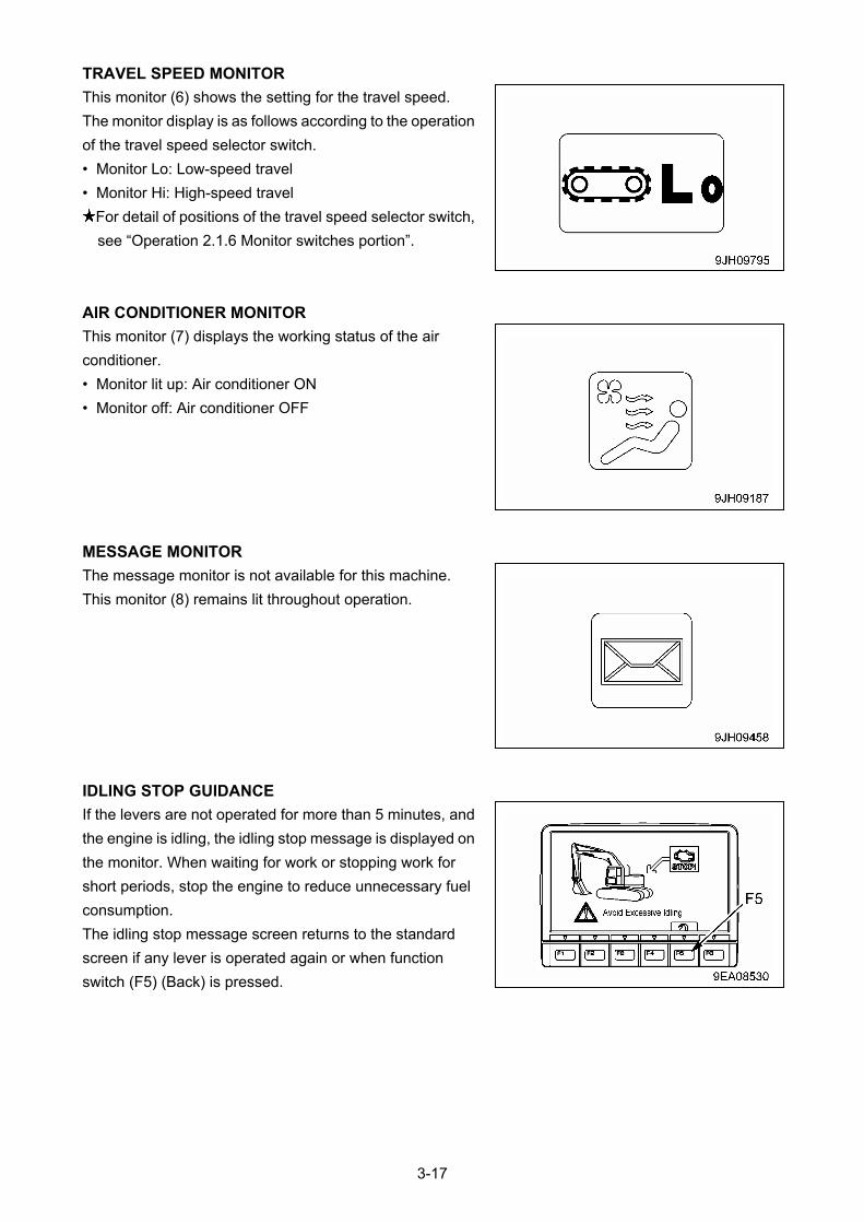
TRAVEL SPEED MONITOR
This monitor (6) shows the setting for the travel speed.
The monitor display is as follows according to the operation
of the travel speed selector switch.
• Monitor Lo: Low-speed travel
• Monitor Hi: High-speed travel
For detail of positions of the travel speed selector switch,
see “Operation 2.1.6 Monitor switches portion”.
AIR CONDITIONER MONITOR
This monitor (7) displays the working status of the air
conditioner.
• Monitor lit up: Air conditioner ON
• Monitor off: Air conditioner OFF
MESSAGE MONITOR
The message monitor is not available for this machine.
This monitor (8) remains lit throughout operation.
IDLING STOP GUIDANCE
If the levers are not operated for more than 5 minutes, and
the engine is idling, the idling stop message is displayed on
the monitor. When waiting for work or stopping work for
short periods, stop the engine to reduce unnecessary fuel
consumption.
The idling stop message screen returns to the standard
screen if any lever is operated again or when function
switch (F5) (Back) is pressed.
3-17
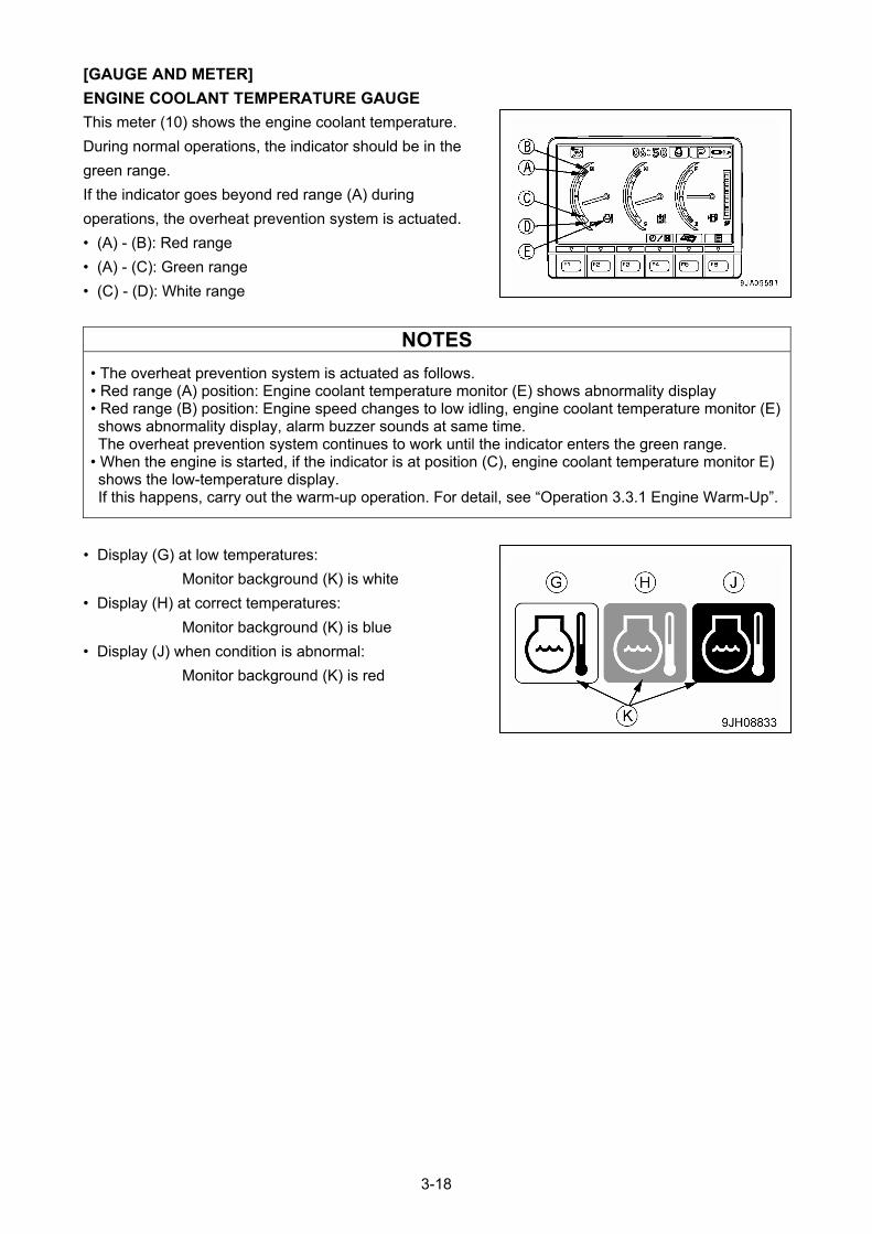
[GAUGE AND METER]
ENGINE COOLANT TEMPERATURE GAUGE
This meter (10) shows the engine coolant temperature.
During normal operations, the indicator should be in the
green range.
If the indicator goes beyond red range (A) during
operations, the overheat prevention system is actuated.
• (A) - (B): Red range
• (A) - (C): Green range
• (C) - (D): White range
NOTES
• The overheat prevention system is actuated as follows. • Red range (A) position: Engine coolant temperature monitor (E) shows abnormality display • Red range (B) position: Engine speed changes to low idling, engine coolant temperature monitor (E) shows abnormality display, alarm buzzer sounds at same time. The overheat prevention system continues to work until the indicator enters the green range.
• When the engine is started, if the indicator is at position (C), engine coolant temperature monitor E) shows the low-temperature display. If this happens, carry out the warm-up operation. For detail, see “Operation 3.3.1 Engine Warm-Up”.
• Display (G) at low temperatures:
Monitor background (K) is white
• Display (H) at correct temperatures:
Monitor background (K) is blue
• Display (J) when condition is abnormal:
Monitor background (K) is red
3-18
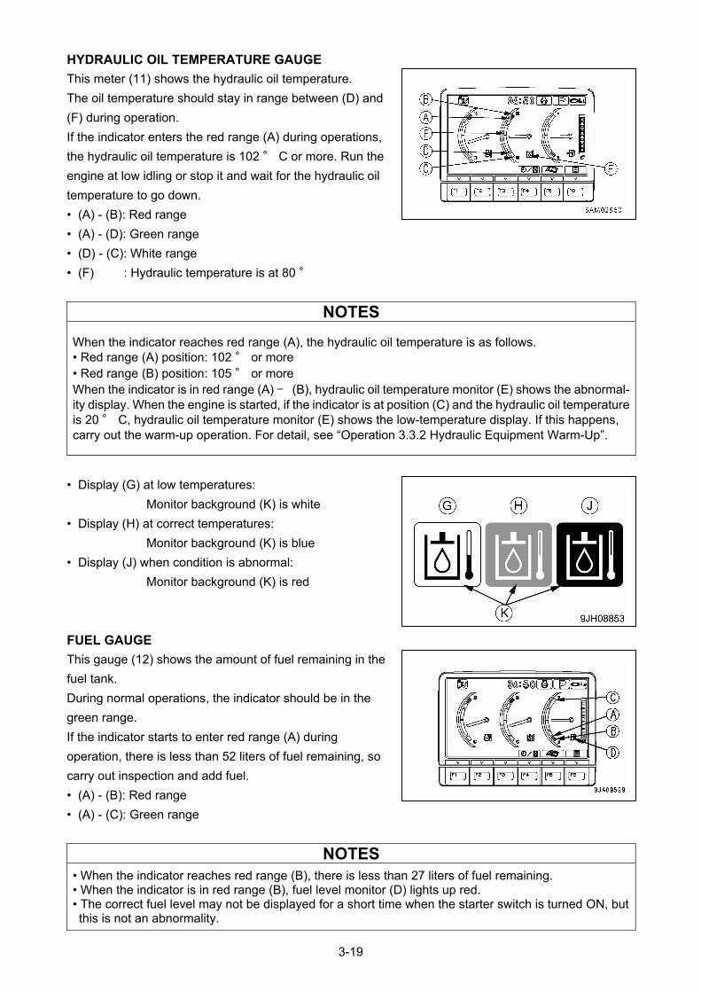
HYDRAULIC OIL TEMPERATURE GAUGE
This meter (11) shows the hydraulic oil temperature.
The oil temperature should stay in range between (D) and
(F) during operation.
If the indicator enters the red range (A) during operations,
the hydraulic oil temperature is 102 ° C or more. Run the
engine at low idling or stop it and wait for the hydraulic oil
temperature to go down.
• (A) - (B): Red range
• (A) - (D): Green range
• (D) - (C): White range
• (F) : Hydraulic temperature is at 80 °
NOTES
When the indicator reaches red range (A), the hydraulic oil temperature is as follows. • Red range (A) position: 102 ° or more • Red range (B) position: 105 ° or more When the indicator is in red range (A) – (B), hydraulic oil temperature monitor (E) shows the abnormal-ity display. When the engine is started, if the indicator is at position (C) and the hydraulic oil temperature is 20 ° C, hydraulic oil temperature monitor (E) shows the low-temperature display. If this happens, carry out the warm-up operation. For detail, see “Operation 3.3.2 Hydraulic Equipment Warm-Up”.
• Display (G) at low temperatures:
Monitor background (K) is white
• Display (H) at correct temperatures:
Monitor background (K) is blue
• Display (J) when condition is abnormal:
Monitor background (K) is red
FUEL GAUGE
This gauge (12) shows the amount of fuel remaining in the
fuel tank.
During normal operations, the indicator should be in the
green range.
If the indicator starts to enter red range (A) during
operation, there is less than 52 liters of fuel remaining, so
carry out inspection and add fuel.
• (A) - (B): Red range
• (A) - (C): Green range
NOTES
• When the indicator reaches red range (B), there is less than 27 liters of fuel remaining. • When the indicator is in red range (B), fuel level monitor (D) lights up red. • The correct fuel level may not be displayed for a short time when the starter switch is turned ON, but this is not an abnormality.
3-19
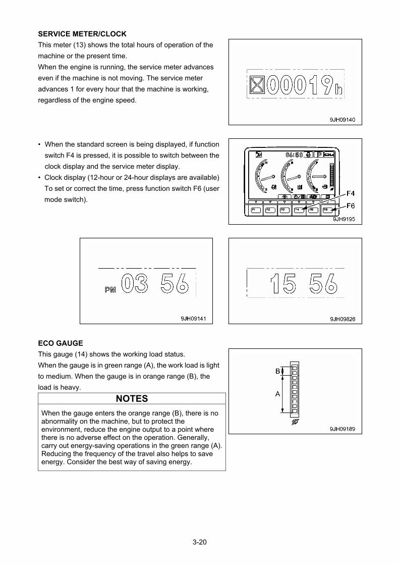
SERVICE METER/CLOCK
This meter (13) shows the total hours of operation of the
machine or the present time.
When the engine is running, the service meter advances
even if the machine is not moving. The service meter
advances 1 for every hour that the machine is working,
regardless of the engine speed.
• When the standard screen is being displayed, if function
switch F4 is pressed, it is possible to switch between the
clock display and the service meter display.
• Clock display (12-hour or 24-hour displays are available)
To set or correct the time, press function switch F6 (user
mode switch).
ECO GAUGE
This gauge (14) shows the working load status.
When the gauge is in green range (A), the work load is light
to medium. When the gauge is in orange range (B), the
load is heavy.
NOTES
When the gauge enters the orange range (B), there is no abnormality on the machine, but to protect the environment, reduce the engine output to a point where there is no adverse effect on the operation. Generally, carry out energy-saving operations in the green range (A). Reducing the frequency of the travel also helps to save energy. Consider the best way of saving energy.
3-20
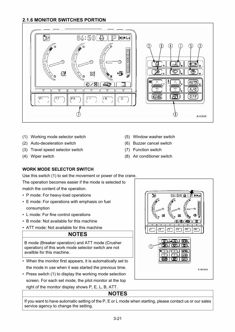
2.1.6 MONITOR SWITCHES PORTION
(5) Window washer switch (1) Working mode selector switch
(6) Buzzer cancel switch (2) Auto-deceleration switch
(7) Function switch (3) Travel speed selector switch
(8) Air conditioner switch (4) Wiper switch
WORK MODE SELECTOR SWITCH
Use this switch (1) to set the movement or power of the crane.
The operation becomes easier if the mode is selected to
match the content of the operation.
• P mode: For heavy-load operations
• E mode: For operations with emphasis on fuel
consumption
• L mode: For fine control operations
• B mode: Not available for this machine
• ATT mode: Not available for this machine
NOTES
B mode (Breaker operation) and ATT mode (Crusher operation) of this work mode selector switch are not availble for this machine.
• When the monitor first appears, it is automatically set to
the mode in use when it was started the previous time.
• Press switch (1) to display the working mode selection
screen. For each set mode, the pilot monitor at the top
right of the monitor display shows P, E, L, B, ATT.
NOTES
If you want to have automatic setting of the P, E or L mode when starting, please contact us or our sales service agency to change the setting.
3-21
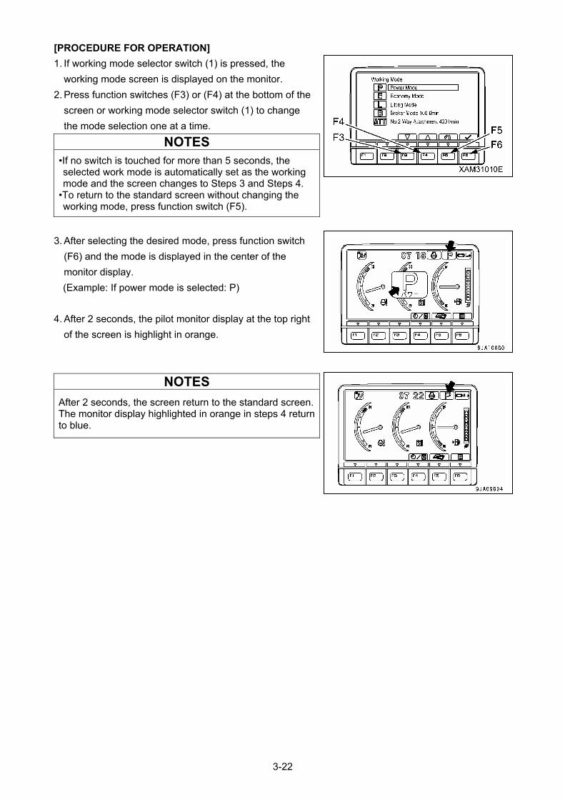
[PROCEDURE FOR OPERATION]
1. If working mode selector switch (1) is pressed, the
working mode screen is displayed on the monitor.
2. Press function switches (F3) or (F4) at the bottom of the
screen or working mode selector switch (1) to change
the mode selection one at a time.
NOTES
•If no switch is touched for more than 5 seconds, the selected work mode is automatically set as the working mode and the screen changes to Steps 3 and Steps 4.
•To return to the standard screen without changing the working mode, press function switch (F5).
3. After selecting the desired mode, press function switch
(F6) and the mode is displayed in the center of the
monitor display.
(Example: If power mode is selected: P)
4. After 2 seconds, the pilot monitor display at the top right
of the screen is highlight in orange.
NOTES
After 2 seconds, the screen return to the standard screen.The monitor display highlighted in orange in steps 4 return to blue.
3-22
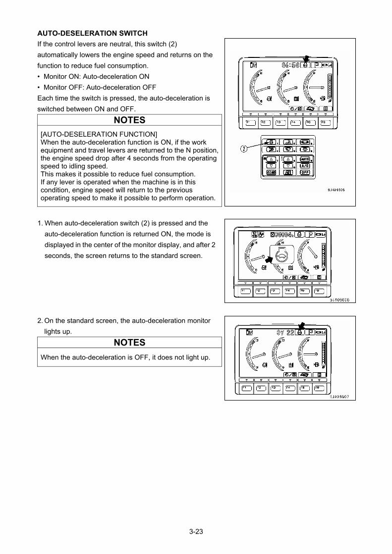
AUTO-DESELERATION SWITCH
If the control levers are neutral, this switch (2)
automatically lowers the engine speed and returns on the
function to reduce fuel consumption.
• Monitor ON: Auto-deceleration ON
• Monitor OFF: Auto-deceleration OFF
Each time the switch is pressed, the auto-deceleration is
switched between ON and OFF.
NOTES
[AUTO-DESELERATION FUNCTION] When the auto-deceleration function is ON, if the work equipment and travel levers are returned to the N position, the engine speed drop after 4 seconds from the operating speed to idling speed. This makes it possible to reduce fuel consumption. If any lever is operated when the machine is in this condition, engine speed will return to the previous operating speed to make it possible to perform operation.
1. When auto-deceleration switch (2) is pressed and the
auto-deceleration function is returned ON, the mode is
displayed in the center of the monitor display, and after 2
seconds, the screen returns to the standard screen.
2. On the standard screen, the auto-deceleration monitor
lights up.
NOTES
When the auto-deceleration is OFF, it does not light up.
3-23
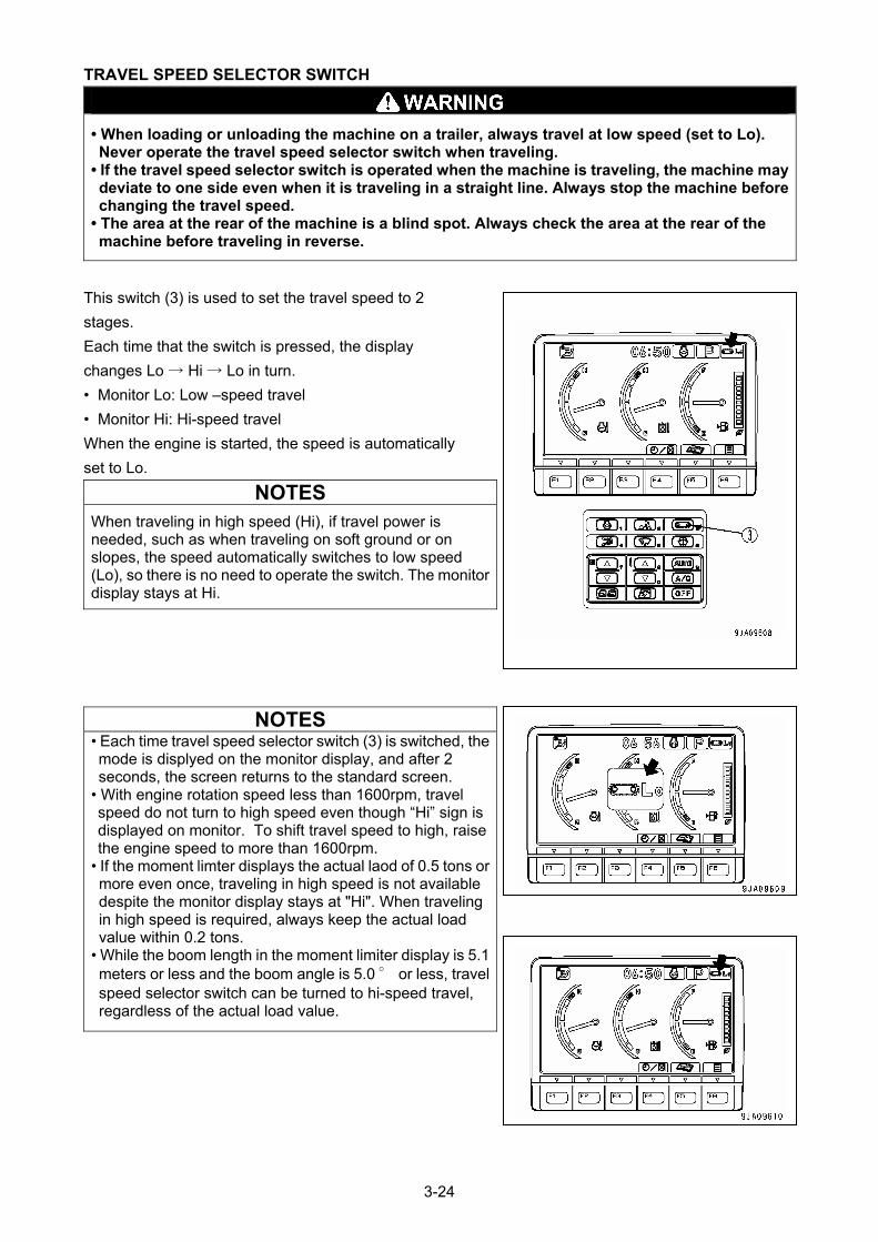
TRAVEL SPEED SELECTOR SWITCH
• When loading or unloading the machine on a trailer, always travel at low speed (set to Lo). Never operate the travel speed selector switch when traveling.
• If the travel speed selector switch is operated when the machine is traveling, the machine may deviate to one side even when it is traveling in a straight line. Always stop the machine before changing the travel speed.
• The area at the rear of the machine is a blind spot. Always check the area at the rear of the machine before traveling in reverse.
This switch (3) is used to set the travel speed to 2
stages.
Each time that the switch is pressed, the display
changes Lo → Hi → Lo in turn.
• Monitor Lo: Low –speed travel
• Monitor Hi: Hi-speed travel
When the engine is started, the speed is automatically
set to Lo.
NOTES
When traveling in high speed (Hi), if travel power is needed, such as when traveling on soft ground or on slopes, the speed automatically switches to low speed (Lo), so there is no need to operate the switch. The monitor display stays at Hi.
NOTES • Each time travel speed selector switch (3) is switched, the mode is displyed on the monitor display, and after 2 seconds, the screen returns to the standard screen.
• With engine rotation speed less than 1600rpm, travel speed do not turn to high speed even though “Hi” sign is displayed on monitor. To shift travel speed to high, raise the engine speed to more than 1600rpm.
• If the moment limter displays the actual laod of 0.5 tons or more even once, traveling in high speed is not available despite the monitor display stays at "Hi". When traveling in high speed is required, always keep the actual load value within 0.2 tons.
• While the boom length in the moment limiter display is 5.1 meters or less and the boom angle is 5.0 ° or less, travel speed selector switch can be turned to hi-speed travel, regardless of the actual load value.
3-24
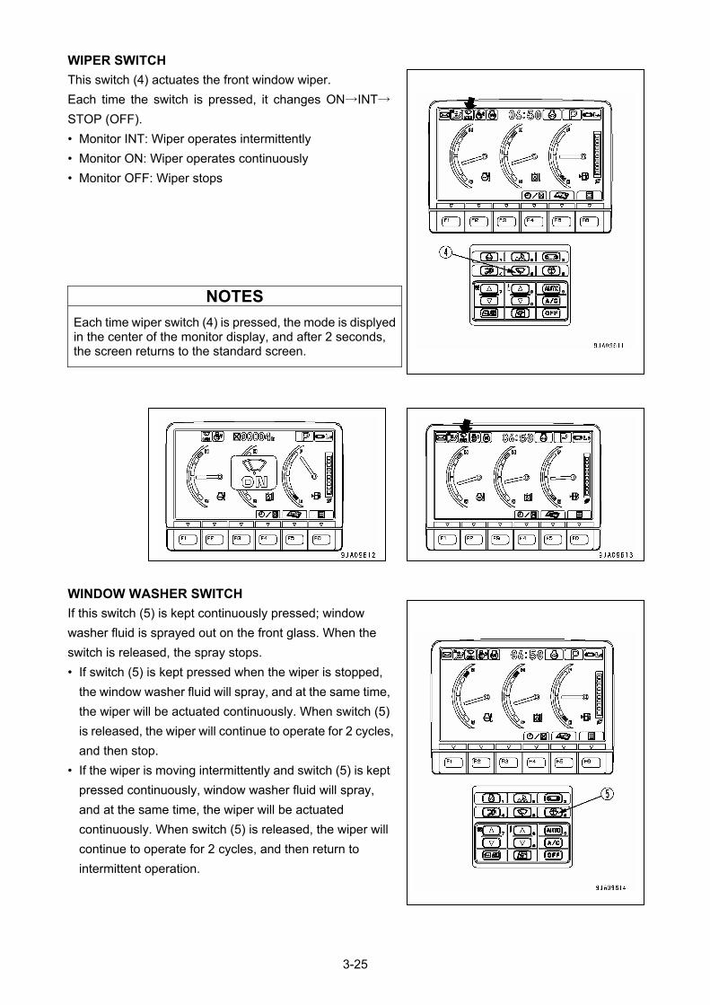
WIPER SWITCH
This switch (4) actuates the front window wiper.
Each time the switch is pressed, it changes ON→INT→
STOP (OFF).
• Monitor INT: Wiper operates intermittently
• Monitor ON: Wiper operates continuously
• Monitor OFF: Wiper stops
NOTES
Each time wiper switch (4) is pressed, the mode is displyed in the center of the monitor display, and after 2 seconds, the screen returns to the standard screen.
WINDOW WASHER SWITCH
If this switch (5) is kept continuously pressed; window
washer fluid is sprayed out on the front glass. When the
switch is released, the spray stops.
• If switch (5) is kept pressed when the wiper is stopped,
the window washer fluid will spray, and at the same time,
the wiper will be actuated continuously. When switch (5)
is released, the wiper will continue to operate for 2 cycles,
and then stop.
• If the wiper is moving intermittently and switch (5) is kept
pressed continuously, window washer fluid will spray,
and at the same time, the wiper will be actuated
continuously. When switch (5) is released, the wiper will
continue to operate for 2 cycles, and then return to
intermittent operation.
3-25
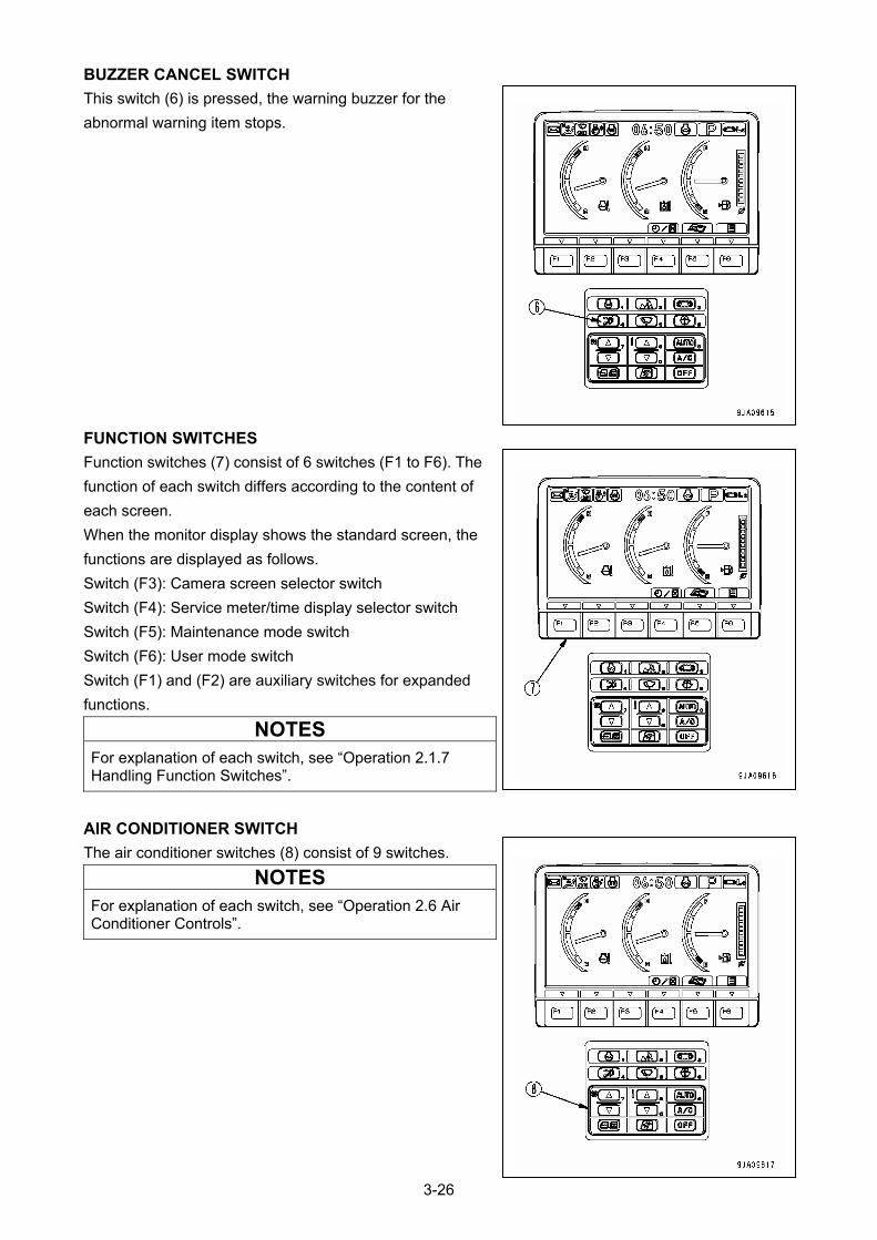
BUZZER CANCEL SWITCH
This switch (6) is pressed, the warning buzzer for the
abnormal warning item stops.
FUNCTION SWITCHES
Function switches (7) consist of 6 switches (F1 to F6). The
function of each switch differs according to the content of
each screen.
When the monitor display shows the standard screen, the
functions are displayed as follows.
Switch (F3): Camera screen selector switch
Switch (F4): Service meter/time display selector switch
Switch (F5): Maintenance mode switch
Switch (F6): User mode switch
Switch (F1) and (F2) are auxiliary switches for expanded
functions.
NOTES
For explanation of each switch, see “Operation 2.1.7 Handling Function Switches”.
AIR CONDITIONER SWITCH
The air conditioner switches (8) consist of 9 switches.
NOTES
For explanation of each switch, see “Operation 2.6 Air Conditioner Controls”.
3-26

2.1.7 HANDLING FUNCTION SWITCHES • The function switches (A) at the bottom of the
monitor display consist of 6 switches (F1 – F6). The
function of each switch differs according to the
content of each screen.
• The function of switches (A) on each screen can be
confirmed by guidance icons (B) displayed on top of
each switch.
• f there is no display in guidance icon (B), even if
switch (A) is pressed, it will not function.
• Even if guidance icon (B) is pressed, it will not
function. Press switch (A) immediately below the
guidance icon display to operate the function.
3-27
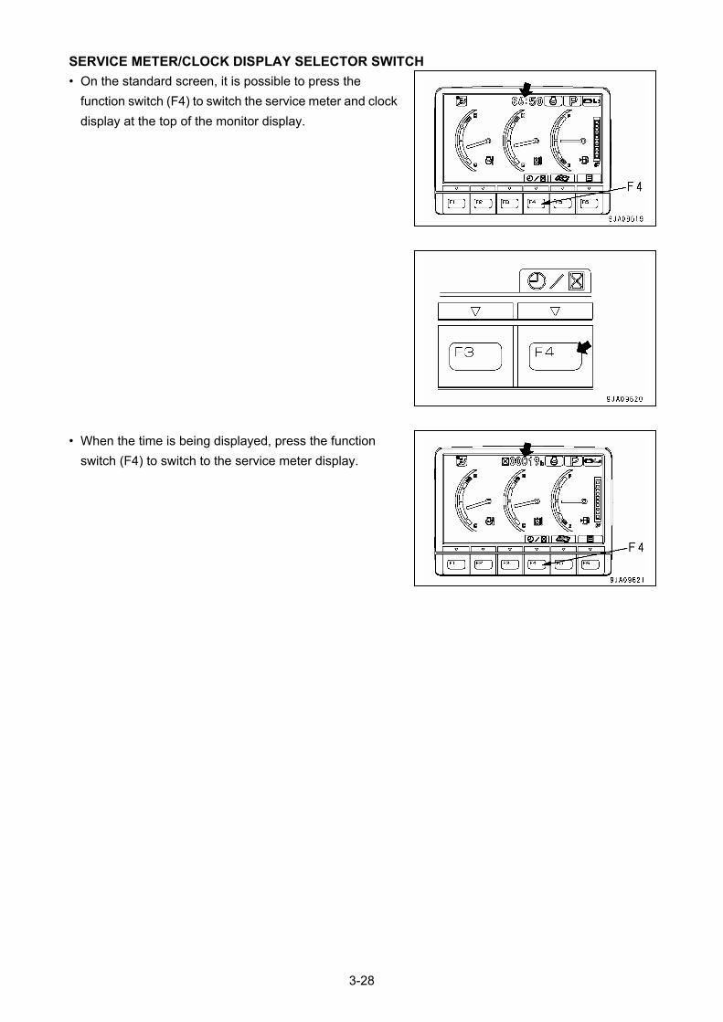
SERVICE METER/CLOCK DISPLAY SELECTOR SWITCH
• On the standard screen, it is possible to press the
function switch (F4) to switch the service meter and clock
display at the top of the monitor display.
• When the time is being displayed, press the function
switch (F4) to switch to the service meter display.
3-28
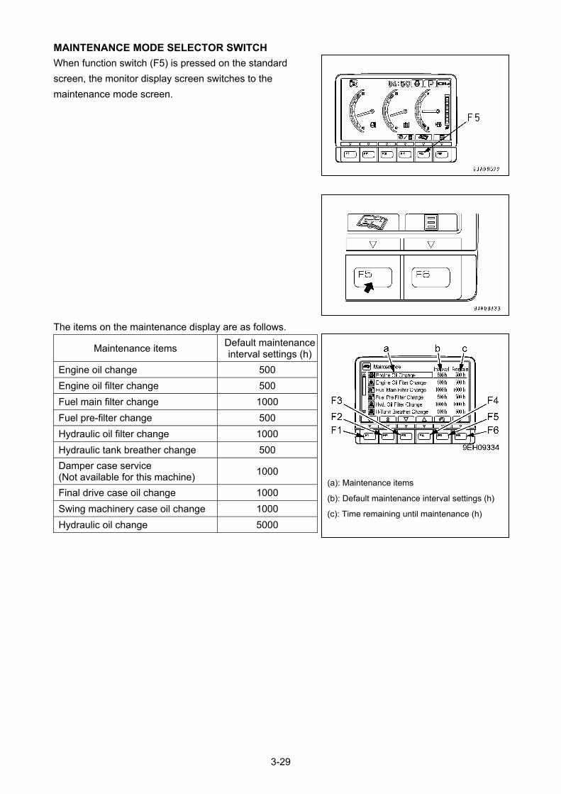
MAINTENANCE MODE SELECTOR SWITCH
When function switch (F5) is pressed on the standard
screen, the monitor display screen switches to the
maintenance mode screen.
The items on the maintenance display are as follows.
(c): Time remaining until maintenance (h)
(b): Default maintenance interval settings (h)
(a): Maintenance items
Maintenance items Default maintenance interval settings (h)
Engine oil change 500
Engine oil filter change 500
Fuel main filter change 1000
Fuel pre-filter change 500
Hydraulic oil filter change 1000
Hydraulic tank breather change 500
Damper case service (Not available for this machine)
1000
Final drive case oil change 1000
Swing machinery case oil change 1000
Hydraulic oil change 5000
3-29
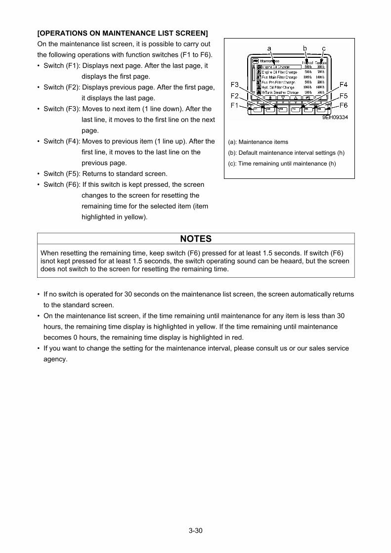
[OPERATIONS ON MAINTENANCE LIST SCREEN]
(c): Time remaining until maintenance (h)
(b): Default maintenance interval settings (h)
(a): Maintenance items
On the maintenance list screen, it is possible to carry out
the following operations with function switches (F1 to F6).
• Switch (F1): Displays next page. After the last page, it
displays the first page.
• Switch (F2): Displays previous page. After the first page,
it displays the last page.
• Switch (F3): Moves to next item (1 line down). After the
last line, it moves to the first line on the next
page.
• Switch (F4): Moves to previous item (1 line up). After the
first line, it moves to the last line on the
previous page.
• Switch (F5): Returns to standard screen.
• Switch (F6): If this switch is kept pressed, the screen
changes to the screen for resetting the
remaining time for the selected item (item
highlighted in yellow).
NOTES
When resetting the remaining time, keep switch (F6) pressed for at least 1.5 seconds. If switch (F6) isnot kept pressed for at least 1.5 seconds, the switch operating sound can be heaard, but the screen does not switch to the screen for resetting the remaining time.
• If no switch is operated for 30 seconds on the maintenance list screen, the screen automatically returns
to the standard screen.
• On the maintenance list screen, if the time remaining until maintenance for any item is less than 30
hours, the remaining time display is highlighted in yellow. If the time remaining until maintenance
becomes 0 hours, the remaining time display is highlighted in red.
• If you want to change the setting for the maintenance interval, please consult us or our sales service
agency.
3-30
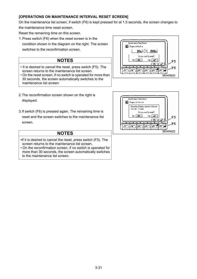
[OPERATIONS ON MAINTENANCE INTERVAL RESET SCREEN]
On the maintenance list screen, if switch (F6) is kept pressed for at 1.5 seconds, the screen changes to
the maintenance time reset screen.
Reset the remaining time on this screen.
1. Press switch (F6) when the reset screen is in the
condition shown in the diagram on the right. The screen
switches to the reconfirmation screen.
NOTES
• It is desired to cancel the reset, press switch (F5). The screen returns to the maintenance list screen.
• On the reset screen, if no switch is operated for more than 30 seconds, the screen automatically switches to the maintenance list screen.
2. The reconfirmation screen shown on the right is
displayed.
3. If switch (F6) is pressed again. The remaining time is
reset and the screen switches to the maintenance list
screen.
NOTES
•If it is desired to cancel the reset, press switch (F5). The screen returns to the maintenance list screen.
• On the reconfirmation screen, if no switch is operated for more than 30 seconds, the screen automatically switches to the maintenance list screen.
3-31
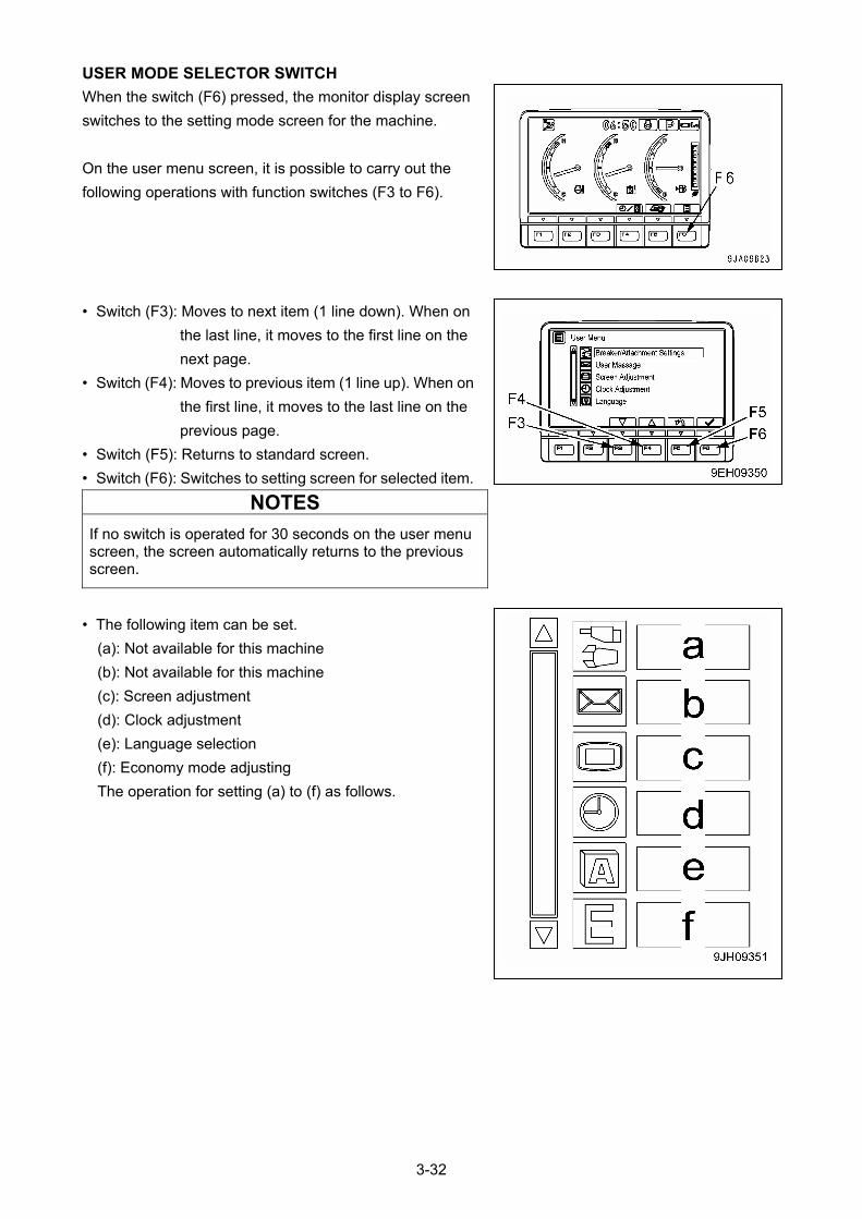
USER MODE SELECTOR SWITCH
When the switch (F6) pressed, the monitor display screen
switches to the setting mode screen for the machine.
On the user menu screen, it is possible to carry out the
following operations with function switches (F3 to F6).
• Switch (F3): Moves to next item (1 line down). When on
the last line, it moves to the first line on the
next page.
• Switch (F4): Moves to previous item (1 line up). When on
the first line, it moves to the last line on the
previous page.
• Switch (F5): Returns to standard screen.
• Switch (F6): Switches to setting screen for selected item.
NOTES
If no switch is operated for 30 seconds on the user menu screen, the screen automatically returns to the previous screen.
• The following item can be set.
(a): Not available for this machine
(b): Not available for this machine
(c): Screen adjustment
(d): Clock adjustment
(e): Language selection
(f): Economy mode adjusting
The operation for setting (a) to (f) as follows.
3-32
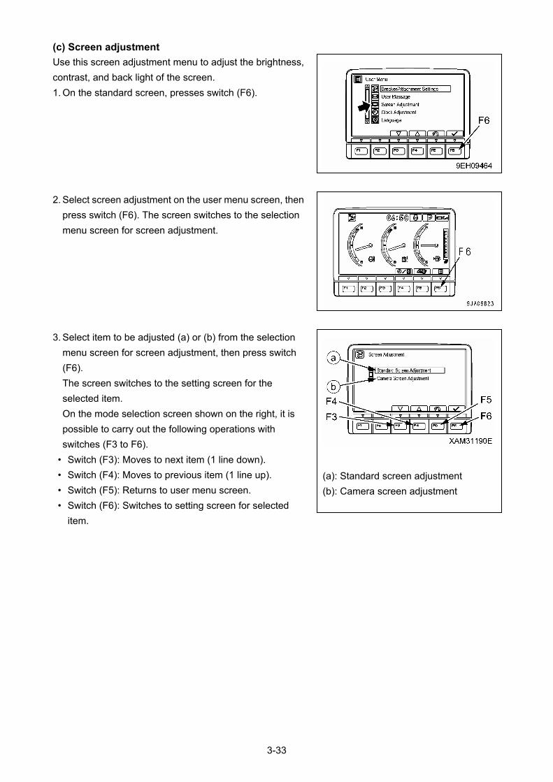
(c) Screen adjustment
Use this screen adjustment menu to adjust the brightness,
contrast, and back light of the screen.
1. On the standard screen, presses switch (F6).
2. Select screen adjustment on the user menu screen, then
press switch (F6). The screen switches to the selection
menu screen for screen adjustment.
3. Select item to be adjusted (a) or (b) from the selection
menu screen for screen adjustment, then press switch
(F6).
The screen switches to the setting screen for the
selected item.
On the mode selection screen shown on the right, it is
possible to carry out the following operations with
switches (F3 to F6).
• Switch (F3): Moves to next item (1 line down).
• Switch (F4): Moves to previous item (1 line up). (a): Standard screen adjustment
• Switch (F5): Returns to user menu screen. (b): Camera screen adjustment
• Switch (F6): Switches to setting screen for selected
item.
3-33
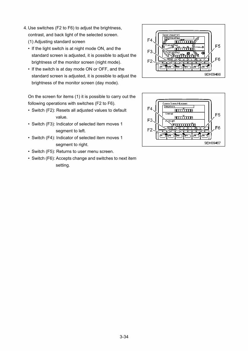
4. Use switches (F2 to F6) to adjust the brightness,
contrast, and back light of the selected screen.
(1) Adjusting standard screen
• If the light switch is at night mode ON, and the
standard screen is adjusted, it is possible to adjust the
brightness of the monitor screen (night mode).
• If the switch is at day mode ON or OFF, and the
standard screen is adjusted, it is possible to adjust the
brightness of the monitor screen (day mode).
On the screen for items (1) it is possible to carry out the
following operations with switches (F2 to F6).
• Switch (F2): Resets all adjusted values to default
value.
• Switch (F3): Indicator of selected item moves 1
segment to left.
• Switch (F4): Indicator of selected item moves 1
segment to right.
• Switch (F5): Returns to user menu screen.
• Switch (F6): Accepts change and switches to next item
setting.
3-34
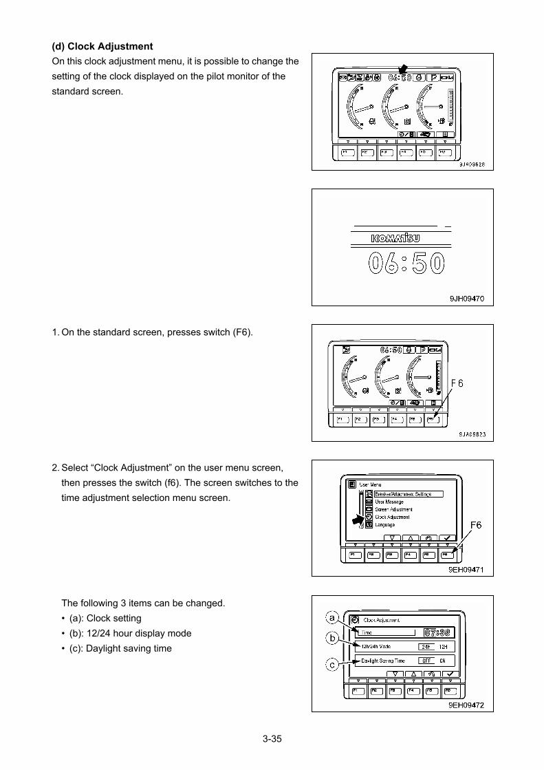
(d) Clock Adjustment
On this clock adjustment menu, it is possible to change the
setting of the clock displayed on the pilot monitor of the
standard screen.
1. On the standard screen, presses switch (F6).
2. Select “Clock Adjustment” on the user menu screen,
then presses the switch (f6). The screen switches to the
time adjustment selection menu screen.
The following 3 items can be changed.
• (a): Clock setting
• (b): 12/24 hour display mode
• (c): Daylight saving time
3-35

(a): Time
(b): Hour
(c): Minute
3. On the clock adjustment selection screen, it is possible to
carry out the following operations with switches (F3 to
F6).
[Time]
Adjust the hour setting.
(1) If “Time” (a) is not highlighted in yellow, press switch
(F6) to highlight “Time” (a) in yellow. When this is
done, hour display (b) changes to orange.
(2) Adjust hour display (b) with the switches as following.
If it is not necessary to change the hour setting,
presses switch (F6).
• Switch (F3): Time advances 1 hour.
• Switch (F4): Time goes back 1 hour.
• Switch (F5): Cancels change and returns to user
menu screen.
• Switch (F6): Accepts change and goes to setting for
minutes.
(3) When minute display (c) is highlighted in orange, operate the switches as follows to adjust minute
display (c).
(4) If it is not necessary to change the minute setting, press switch (F6). If the time has been changed,
always press switch (F6).
• Switch (F3): Time advances 1 minute.
• Switch (F4): Time goes back 1 minute.
• Switch (F5): Cancels change and returns to user menu screen.
• Switch (F6): Accepts change and goes to setting for 12/24 hour display mode minutes.
[12/24h Mode]
(a) 12h/24h Mode
(b): 24-hour display
(c): 12-hour display (am/pm
Choose either a 12-hour display (am/pm) or a 24-our
display.
(1) If “12h/24h Mode” (a) is not highlighted in yellow,
press switch (F6) to highlight “12h/24h Mode” (a) in
yellow.
(2) Change the “12h/24h Mode” with the switches as
follows.
The selected display mode (b) or (c) is highlighted in
green.
• Switch (F3): Moves 1 item to left.
• witch (F4): Moves 1 item to right.
• witch (F5): Cancels change and returns to user
menu screen.
• witch (F6): Accepts change and goes to setting for
“Daylight Saving Time” minutes.
If the setting has been changed, always press switch (F6).
3-36
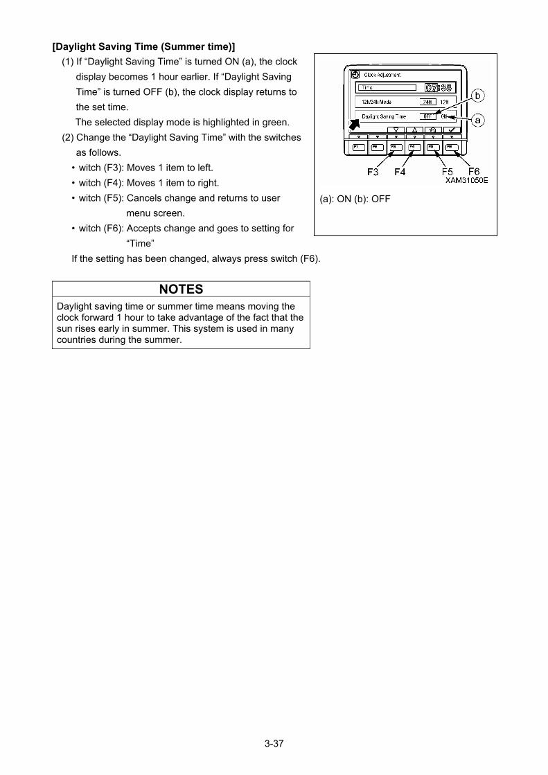
[Daylight Saving Time (Summer time)]
(a): ON (b): OFF
(1) If “Daylight Saving Time” is turned ON (a), the clock
display becomes 1 hour earlier. If “Daylight Saving
Time” is turned OFF (b), the clock display returns to
the set time.
The selected display mode is highlighted in green.
(2) Change the “Daylight Saving Time” with the switches
as follows.
• witch (F3): Moves 1 item to left.
• witch (F4): Moves 1 item to right.
• witch (F5): Cancels change and returns to user
menu screen.
• witch (F6): Accepts change and goes to setting for
“Time”
If the setting has been changed, always press switch (F6).
NOTES
Daylight saving time or summer time means moving the clock forward 1 hour to take advantage of the fact that the sun rises early in summer. This system is used in many countries during the summer.
3-37

(e) Language selection
On this language selection menu, it is possible to select the language used on the monitor display.
The languages that can be selected are as follows.
• apanese, English, Chinese, French, Spanish, Portuguese, Italian, German, Russian, Turkish,
Indonesian, Thai.
1. On the standard screen, press switch (F6).
2. Select “Language” on the user menu screen, then press
switch (F6).
The screen switches to the language selection menu
screen.
3. Select the language to use for the display, then press
switch (F6). The screen display changes to the selected
language.
• witch (F3): Moves to item below.
• witch (F4): Moves to item above.
• witch (F5): Cancels change and returns to user menu
screen.
• witch (F6): Accepts change and returns to user menu
screen.
3-38
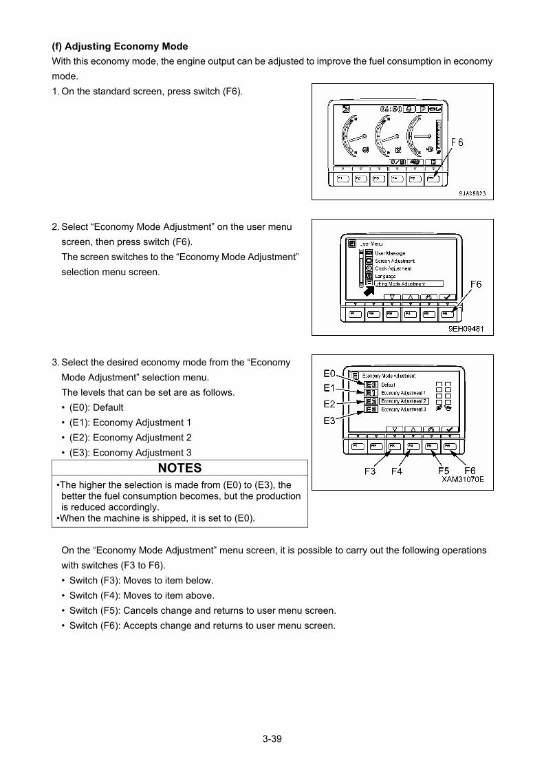
(f) Adjusting Economy Mode
With this economy mode, the engine output can be adjusted to improve the fuel consumption in economy
mode.
1. On the standard screen, press switch (F6).
2. Select “Economy Mode Adjustment” on the user menu
screen, then press switch (F6).
The screen switches to the “Economy Mode Adjustment”
selection menu screen.
3. Select the desired economy mode from the “Economy
Mode Adjustment” selection menu.
The levels that can be set are as follows.
• (E0): Default
• (E1): Economy Adjustment 1
• (E2): Economy Adjustment 2
• (E3): Economy Adjustment 3
NOTES
•The higher the selection is made from (E0) to (E3), the better the fuel consumption becomes, but the production is reduced accordingly.
•When the machine is shipped, it is set to (E0).
On the “Economy Mode Adjustment” menu screen, it is possible to carry out the following operations
with switches (F3 to F6).
• Switch (F3): Moves to item below.
• Switch (F4): Moves to item above.
• Switch (F5): Cancels change and returns to user menu screen.
• Switch (F6): Accepts change and returns to user menu screen.
3-39
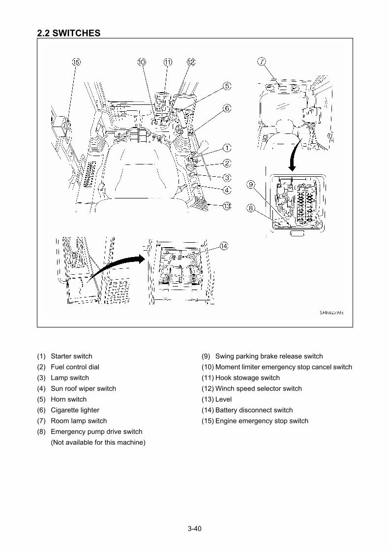
2.2 SWITCHES
(9) Swing parking brake release switch (1) Starter switch
(10) Moment limiter emergency stop cancel switch (2) Fuel control dial
(11) Hook stowage switch (3) Lamp switch
(12) Winch speed selector switch (4) Sun roof wiper switch
(13) Level (5) Horn switch
(14) Battery disconnect switch (6) Cigarette lighter
(15) Engine emergency stop switch (7) Room lamp switch
(8) Emergency pump drive switch
(Not available for this machine)
3-40
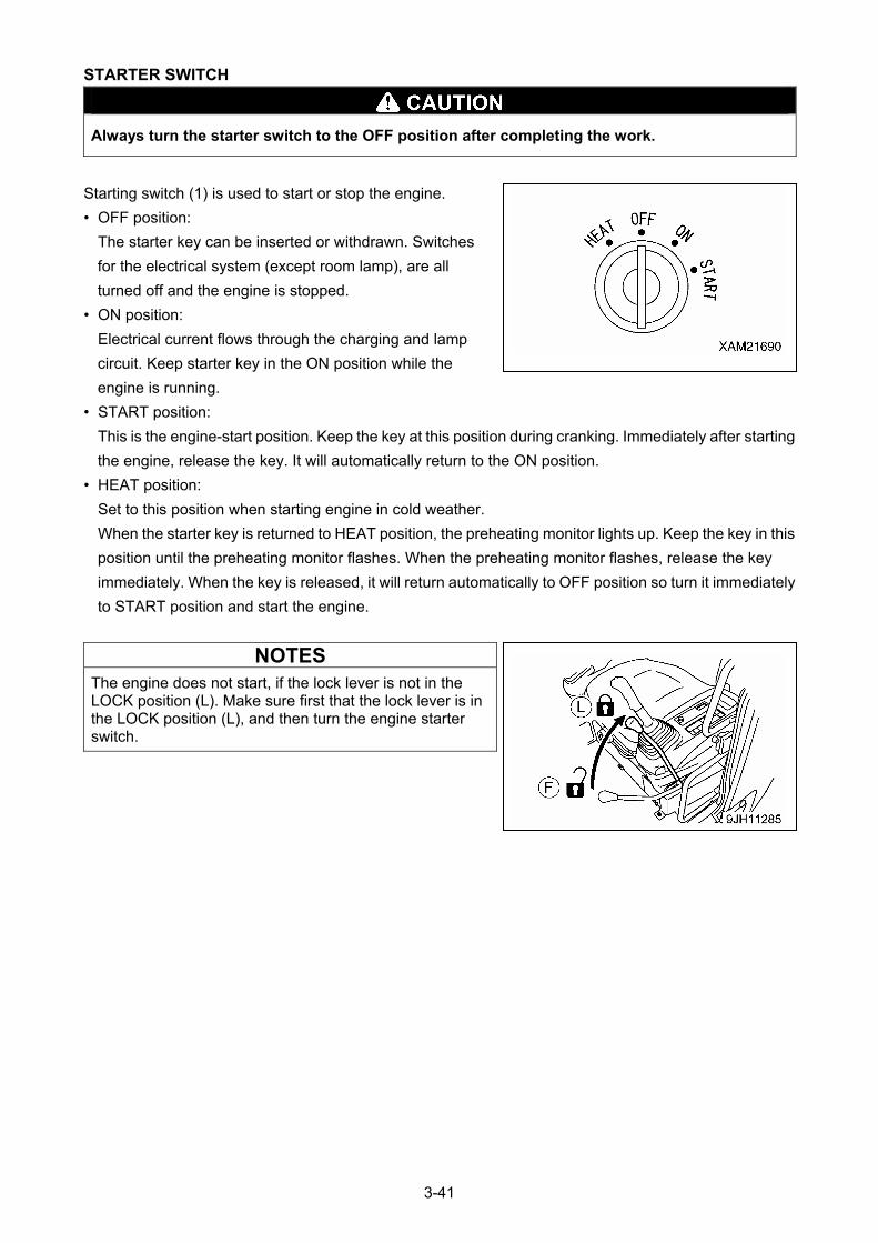
STARTER SWITCH
Always turn the starter switch to the OFF position after completing the work.
Starting switch (1) is used to start or stop the engine.
• OFF position:
The starter key can be inserted or withdrawn. Switches
for the electrical system (except room lamp), are all
turned off and the engine is stopped.
• ON position:
Electrical current flows through the charging and lamp
circuit. Keep starter key in the ON position while the
engine is running.
• START position:
This is the engine-start position. Keep the key at this position during cranking. Immediately after starting
the engine, release the key. It will automatically return to the ON position.
• HEAT position:
Set to this position when starting engine in cold weather.
When the starter key is returned to HEAT position, the preheating monitor lights up. Keep the key in this
position until the preheating monitor flashes. When the preheating monitor flashes, release the key
immediately. When the key is released, it will return automatically to OFF position so turn it immediately
to START position and start the engine.
NOTES
The engine does not start, if the lock lever is not in the LOCK position (L). Make sure first that the lock lever is in the LOCK position (L), and then turn the engine starter switch.
3-41
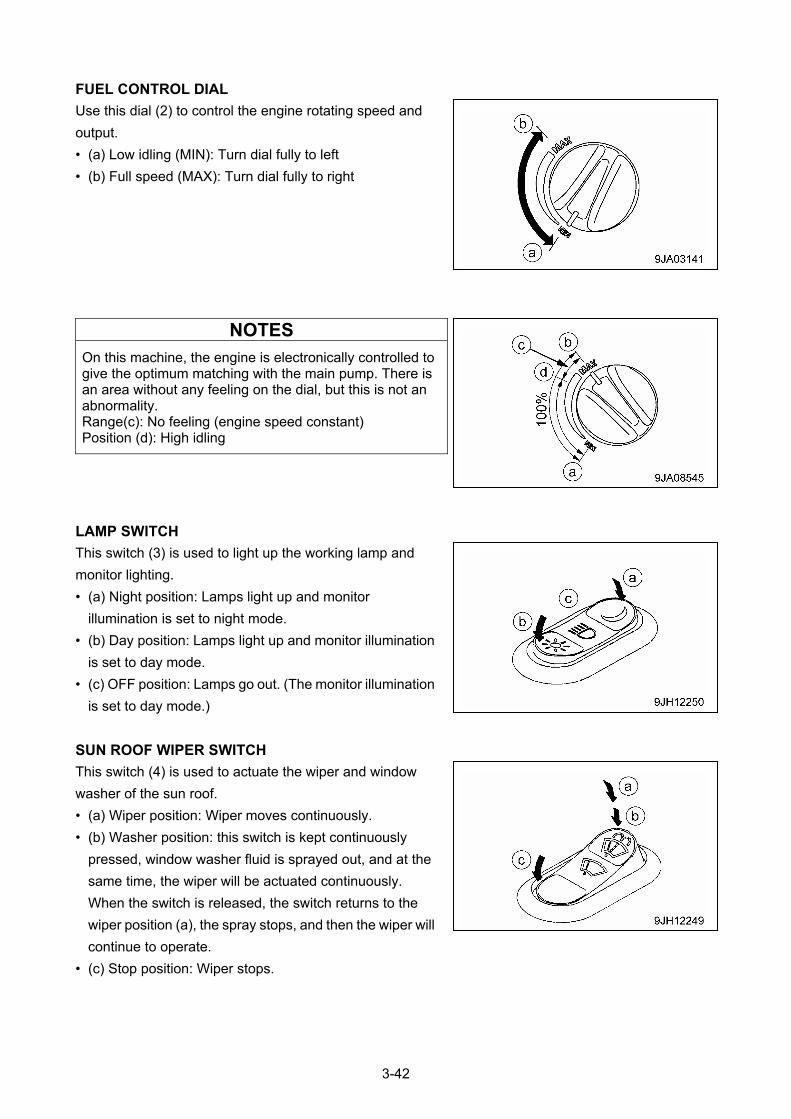
FUEL CONTROL DIAL
Use this dial (2) to control the engine rotating speed and
output.
• (a) Low idling (MIN): Turn dial fully to left
• (b) Full speed (MAX): Turn dial fully to right
NOTES
On this machine, the engine is electronically controlled to give the optimum matching with the main pump. There is an area without any feeling on the dial, but this is not an abnormality. Range(c): No feeling (engine speed constant) Position (d): High idling
LAMP SWITCH
This switch (3) is used to light up the working lamp and
monitor lighting.
• (a) Night position: Lamps light up and monitor
illumination is set to night mode.
• (b) Day position: Lamps light up and monitor illumination
is set to day mode.
• (c) OFF position: Lamps go out. (The monitor illumination
is set to day mode.)
SUN ROOF WIPER SWITCH
This switch (4) is used to actuate the wiper and window
washer of the sun roof.
• (a) Wiper position: Wiper moves continuously.
• (b) Washer position: this switch is kept continuously
pressed, window washer fluid is sprayed out, and at the
same time, the wiper will be actuated continuously.
When the switch is released, the switch returns to the
wiper position (a), the spray stops, and then the wiper will
continue to operate.
• (c) Stop position: Wiper stops.
3-42
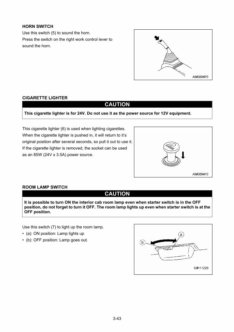
HORN SWITCH
Use this switch (5) to sound the horn.
Press the switch on the right work control lever to
sound the horn.
CIGARETTE LIGHTER
CAUTION
This cigarette lighter is for 24V. Do not use it as the power source for 12V equipment.
This cigarette lighter (6) is used when lighting cigarettes.
When the cigarette lighter is pushed in, it will return to it’s
original position after several seconds, so pull it out to use it.
If the cigarette lighter is removed, the socket can be used
as an 85W (24V x 3.5A) power source.
ROOM LAMP SWITCH
CAUTION
It is possible to turn ON the interior cab room lamp even when starter switch is in the OFF position, do not forget to turn it OFF. The room lamp lights up even when starter switch is at the OFF position.
Use this switch (7) to light up the room lamp.
• (a): ON position: Lamp lights up
• (b): OFF position: Lamp goes out.
3-43
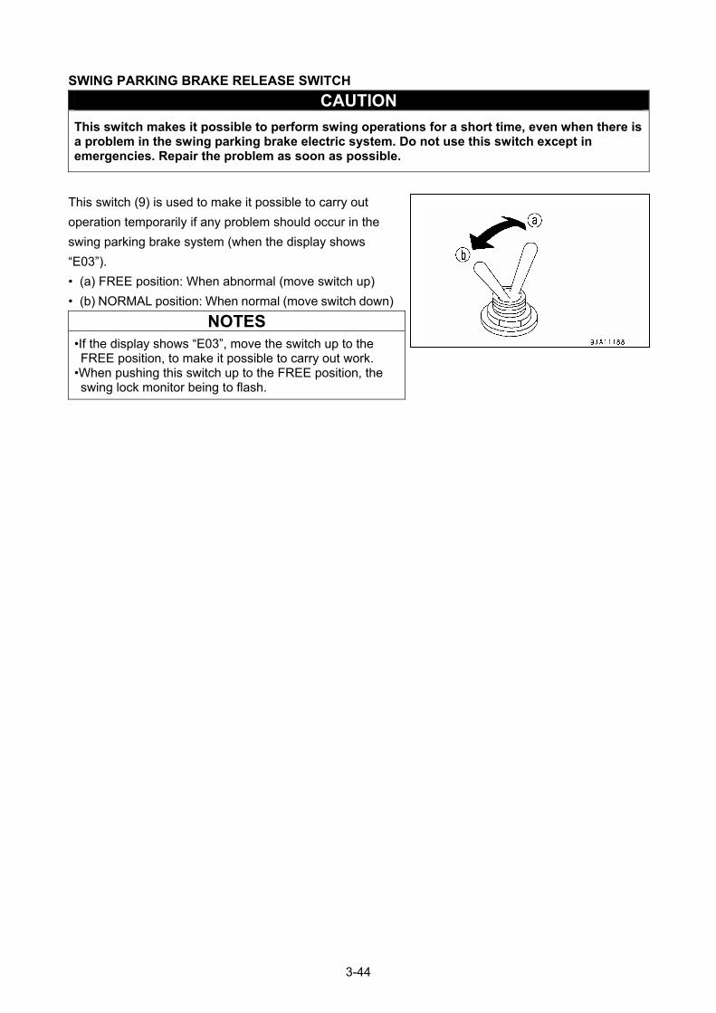
SWING PARKING BRAKE RELEASE SWITCH
CAUTION
This switch makes it possible to perform swing operations for a short time, even when there is a problem in the swing parking brake electric system. Do not use this switch except in emergencies. Repair the problem as soon as possible.
This switch (9) is used to make it possible to carry out
operation temporarily if any problem should occur in the
swing parking brake system (when the display shows
“E03”).
• (a) FREE position: When abnormal (move switch up)
• (b) NORMAL position: When normal (move switch down)
NOTES
•If the display shows “E03”, move the switch up to the FREE position, to make it possible to carry out work.
•When pushing this switch up to the FREE position, the swing lock monitor being to flash.
3-44
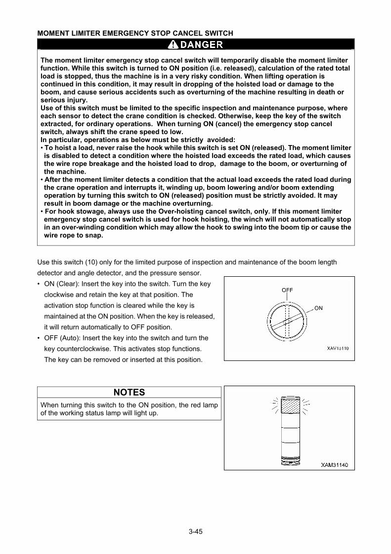
MOMENT LIMITER EMERGENCY STOP CANCEL SWITCH
The moment limiter emergency stop cancel switch will temporarily disable the moment limiter function. While this switch is turned to ON position (i.e. released), calculation of the rated total load is stopped, thus the machine is in a very risky condition. When lifting operation is continued in this condition, it may result in dropping of the hoisted load or damage to the boom, and cause serious accidents such as overturning of the machine resulting in death or serious injury. Use of this switch must be limited to the specific inspection and maintenance purpose, where each sensor to detect the crane condition is checked. Otherwise, keep the key of the switch extracted, for ordinary operations. When turning ON (cancel) the emergency stop cancel switch, always shift the crane speed to low. In particular, operations as below must be strictly avoided: • To hoist a load, never raise the hook while this switch is set ON (released). The moment limiter is disabled to detect a condition where the hoisted load exceeds the rated load, which causes the wire rope breakage and the hoisted load to drop, damage to the boom, or overturning of the machine.
• After the moment limiter detects a condition that the actual load exceeds the rated load during the crane operation and interrupts it, winding up, boom lowering and/or boom extending operation by turning this switch to ON (released) position must be strictly avoided. It may result in boom damage or the machine overturning.
• For hook stowage, always use the Over-hoisting cancel switch, only. If this moment limiter emergency stop cancel switch is used for hook hoisting, the winch will not automatically stop in an over-winding condition which may allow the hook to swing into the boom tip or cause the wire rope to snap.
Use this switch (10) only for the limited purpose of inspection and maintenance of the boom length
detector and angle detector, and the pressure sensor.
• ON (Clear): Insert the key into the switch. Turn the key
clockwise and retain the key at that position. The
activation stop function is cleared while the key is
maintained at the ON position. When the key is released,
it will return automatically to OFF position.
• OFF (Auto): Insert the key into the switch and turn the
key counterclockwise. This activates stop functions.
The key can be removed or inserted at this position.
NOTES
When turning this switch to the ON position, the red lamp of the working status lamp will light up.
3-45
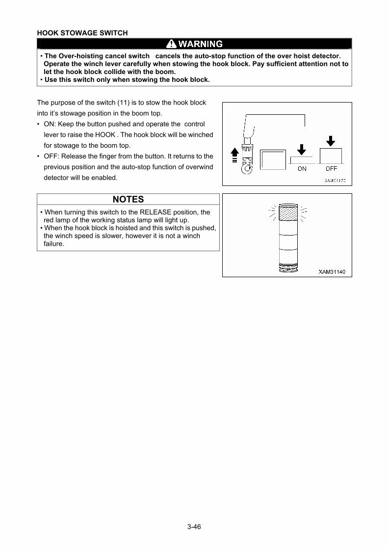
HOOK STOWAGE SWITCH
• The Over-hoisting cancel switch cancels the auto-stop function of the over hoist detector. Operate the winch lever carefully when stowing the hook block. Pay sufficient attention not to let the hook block collide with the boom.
• Use this switch only when stowing the hook block.
The purpose of the switch (11) is to stow the hook block
into it’s stowage position in the boom top.
• ON: Keep the button pushed and operate the control
lever to raise the HOOK . The hook block will be winched
for stowage to the boom top.
• OFF: Release the finger from the button. It returns to the
previous position and the auto-stop function of overwind
detector will be enabled.
NOTES
• When turning this switch to the RELEASE position, the red lamp of the working status lamp will light up.
• When the hook block is hoisted and this switch is pushed, the winch speed is slower, however it is not a winch failure.
3-46
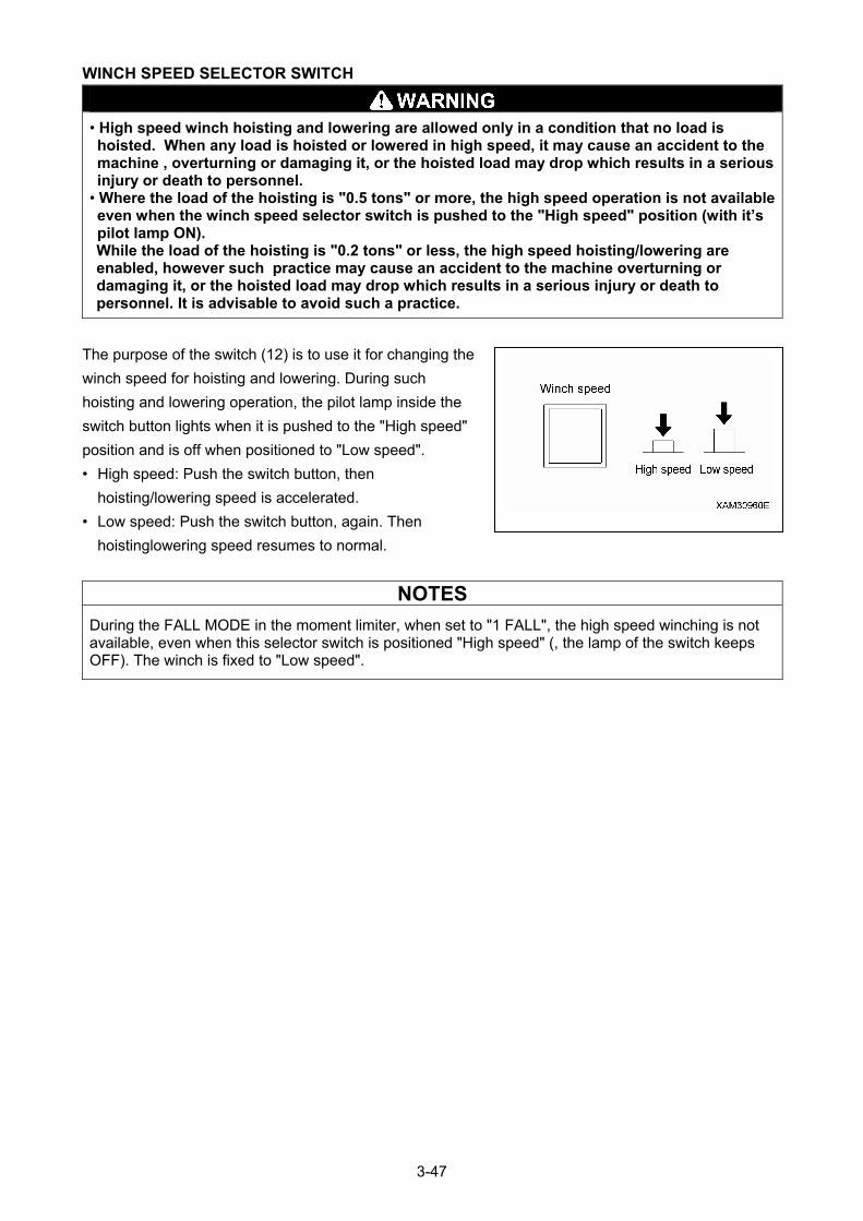
WINCH SPEED SELECTOR SWITCH
• High speed winch hoisting and lowering are allowed only in a condition that no load is hoisted. When any load is hoisted or lowered in high speed, it may cause an accident to the machine , overturning or damaging it, or the hoisted load may drop which results in a serious injury or death to personnel.
• Where the load of the hoisting is "0.5 tons" or more, the high speed operation is not available even when the winch speed selector switch is pushed to the "High speed" position (with it’s pilot lamp ON). While the load of the hoisting is "0.2 tons" or less, the high speed hoisting/lowering are enabled, however such practice may cause an accident to the machine overturning or damaging it, or the hoisted load may drop which results in a serious injury or death to personnel. It is advisable to avoid such a practice.
The purpose of the switch (12) is to use it for changing the
winch speed for hoisting and lowering. During such
hoisting and lowering operation, the pilot lamp inside the
switch button lights when it is pushed to the "High speed"
position and is off when positioned to "Low speed".
• High speed: Push the switch button, then
hoisting/lowering speed is accelerated.
• Low speed: Push the switch button, again. Then
hoistinglowering speed resumes to normal.
NOTES
During the FALL MODE in the moment limiter, when set to "1 FALL", the high speed winching is not available, even when this selector switch is positioned "High speed" (, the lamp of the switch keeps OFF). The winch is fixed to "Low speed".
3-47
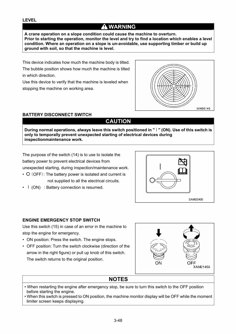
LEVEL
A crane operation on a slope condition could cause the machine to overturn. Prior to starting the operation, monitor the level and try to find a location which enables a level condition. Where an operation on a slope is un-avoidable, use supporting timber or build up ground with soil, so that the machine is level.
This device indicates how much the machine body is tilted.
The bubble position shows how much the machine is tilted
in which direction.
Use this device to verify that the machine is leveled when
stopping the machine on working area.
BATTERY DISCONNECT SWITCH
CAUTION
During normal operations, always leave this switch positioned in " " (ON). Use of this switch is only to temporally prevent unexpected starting of electrical devices during inspectionmaintenance work.
The purpose of the switch (14) is to use to isolate the
battery power to prevent electrical devices from
unexpected starting, during inspection/maintenance work.
• (OFF): The battery power is isolated and current is
not supplied to all the electrical circuits.
• (ON) : Battery connection is resumed.
ENGINE EMERGENCY STOP SWITCH
Use this switch (15) in case of an error in the machine to
stop the engine for emergency.
• ON position: Press the switch. The engine stops.
• OFF position: Turn the switch clockwise (direction of the
arrow in the right figure) or pull up knob of this switch.
The switch returns to the original position.
NOTES
• When restarting the engine after emergency stop, be sure to turn this switch to the OFF position before starting the engine.
• When this switch is pressed to ON position, the machine monitor display will be OFF while the moment limiter screen keeps displaying.
3-48
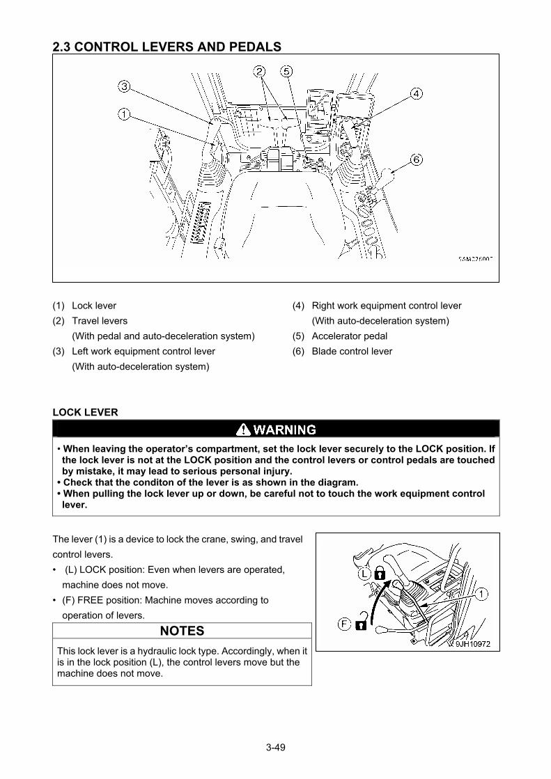
2.3 CONTROL LEVERS AND PEDALS
(4) Right work equipment control lever (1) Lock lever
(With auto-deceleration system) (2) Travel levers
(5) Accelerator pedal (With pedal and auto-deceleration system)
(6) Blade control lever (3) Left work equipment control lever
(With auto-deceleration system)
LOCK LEVER
• When leaving the operator’s compartment, set the lock lever securely to the LOCK position. If the lock lever is not at the LOCK position and the control levers or control pedals are touched by mistake, it may lead to serious personal injury.
• Check that the conditon of the lever is as shown in the diagram. • When pulling the lock lever up or down, be careful not to touch the work equipment control lever.
The lever (1) is a device to lock the crane, swing, and travel
control levers.
• (L) LOCK position: Even when levers are operated,
machine does not move.
• (F) FREE position: Machine moves according to
operation of levers.
NOTES
This lock lever is a hydraulic lock type. Accordingly, when it is in the lock position (L), the control levers move but the machine does not move.
3-49
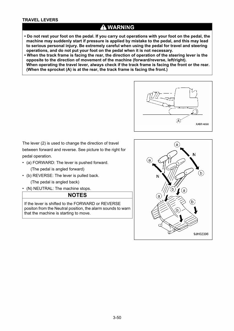
TRAVEL LEVERS
• Do not rest your foot on the pedal. If you carry out operations with your foot on the pedal, the machine may suddenly start if pressure is applied by mistake to the pedal, and this may lead to serious personal injury. Be extremely careful when using the pedal for travel and steering operations, and do not put your foot on the pedal when it is not necessary.
• When the track frame is facing the rear, the direction of operation of the steering lever is the opposite to the direction of movement of the machine (forward/reverse, left/right). When operating the travel lever, always check if the track frame is facing the front or the rear. (When the sprocket (A) is at the rear, the track frame is facing the front.)
The lever (2) is used to change the direction of travel
between forward and reverse. See picture to the right for
pedal operation.
• (a) FORWARD: The lever is pushed forward.
(The pedal is angled forward)
• (b) REVERSE: The lever is pulled back.
(The pedal is angled back)
• (N) NEUTRAL: The machine stops.
NOTES
If the lever is shifted to the FORWARD or REVERSE positon from the Neutral position, the alarm sounds to warn that the machine is starting to move.
3-50
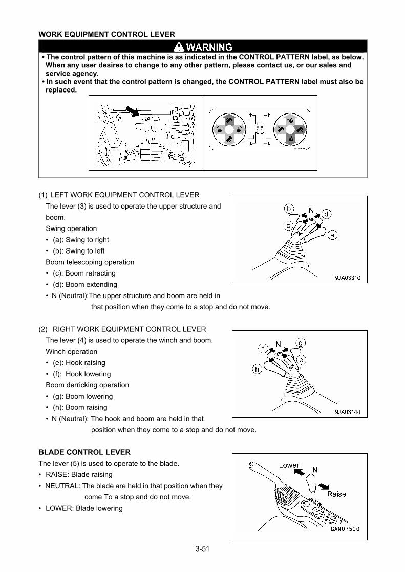
WORK EQUIPMENT CONTROL LEVER
• The control pattern of this machine is as indicated in the CONTROL PATTERN label, as below. When any user desires to change to any other pattern, please contact us, or our sales and service agency.
• In such event that the control pattern is changed, the CONTROL PATTERN label must also be replaced.
(1) LEFT WORK EQUIPMENT CONTROL LEVER
The lever (3) is used to operate the upper structure and
boom.
Swing operation
• (a): Swing to right
• (b): Swing to left
Boom telescoping operation
• (c): Boom retracting
• (d): Boom extending
• N (Neutral):The upper structure and boom are held in
that position when they come to a stop and do not move.
(2) RIGHT WORK EQUIPMENT CONTROL LEVER
The lever (4) is used to operate the winch and boom.
Winch operation
• (e): Hook raising
• (f): Hook lowering
Boom derricking operation
• (g): Boom lowering
• (h): Boom raising
• N (Neutral): The hook and boom are held in that
position when they come to a stop and do not move.
BLADE CONTROL LEVER
The lever (5) is used to operate to the blade.
• RAISE: Blade raising
• NEUTRAL: The blade are held in that position when they
come To a stop and do not move.
• LOWER: Blade lowering
3-51
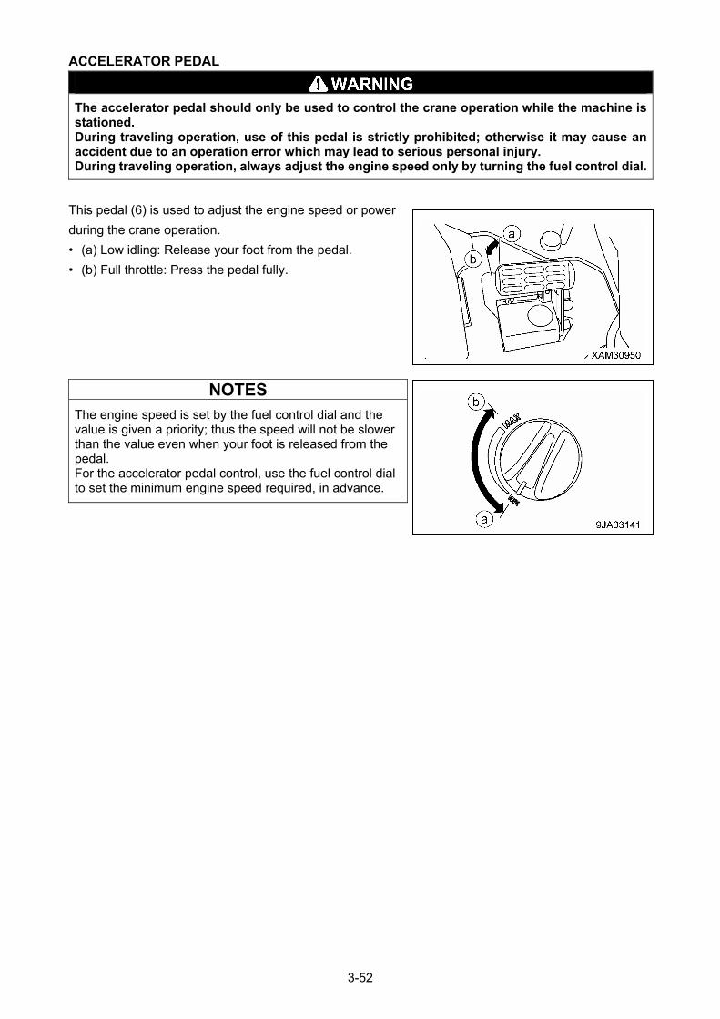
ACCELERATOR PEDAL
The accelerator pedal should only be used to control the crane operation while the machine is stationed. During traveling operation, use of this pedal is strictly prohibited; otherwise it may cause an accident due to an operation error which may lead to serious personal injury. During traveling operation, always adjust the engine speed only by turning the fuel control dial.
This pedal (6) is used to adjust the engine speed or power
during the crane operation.
• (a) Low idling: Release your foot from the pedal.
• (b) Full throttle: Press the pedal fully.
NOTES
The engine speed is set by the fuel control dial and the value is given a priority; thus the speed will not be slower than the value even when your foot is released from the pedal. For the accelerator pedal control, use the fuel control dial to set the minimum engine speed required, in advance.
3-52
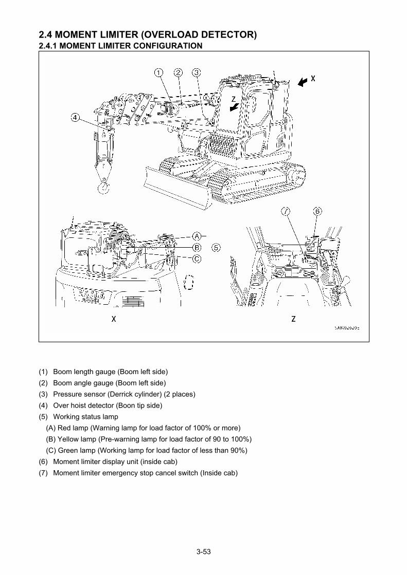
2.4 MOMENT LIMITER (OVERLOAD DETECTOR) 2.4.1 MOMENT LIMITER CONFIGURATION
(1) Boom length gauge (Boom left side)
(2) Boom angle gauge (Boom left side)
(3) Pressure sensor (Derrick cylinder) (2 places)
(4) Over hoist detector (Boon tip side)
(5) Working status lamp
(A) Red lamp (Warning lamp for load factor of 100% or more)
(B) Yellow lamp (Pre-warning lamp for load factor of 90 to 100%)
(C) Green lamp (Working lamp for load factor of less than 90%)
(6) Moment limiter display unit (inside cab)
(7) Moment limiter emergency stop cancel switch (Inside cab)
3-53
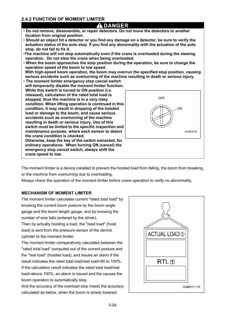
2.4.2 FUNCTION OF MOMENT LIMITER
• Do not remove, disassemble, or repair detectors. Do not move the detectors to another location from original position.
• Should an object hit a detector or you find any damage on a detector, be sure to verify the actuation status of the auto stop. If you find any abnormality with the actuation of the auto stop, do not fail to fix it.
•The machine will not stop automatically even if the crane is overloaded during the slewing operation. Do not slew the crane when being overloaded.
• When the boom approaches the stop position during the operation, be sure to change the operation speed of the boom to low speed. With high-speed boom operation, the boom may overrun the specified stop position, causing serious accidents such as overturning of the machine resulting in death or serious injury.
• The moment limiter emergency stop cancel switch will temporarily disable the moment limiter function. While this switch is turned to ON position (i.e. released), calculation of the rated total load is stopped, thus the machine is in a very risky condition. When lifting operation is continued in this condition, it may result in dropping of the hoisted load or damage to the boom, and cause serious accidents such as overturning of the machine resulting in death or serious injury. Use of this switch must be limited to the specific inspection and maintenance purpose, where each sensor to detect the crane condition is checked. Otherwise, keep the key of the switch extracted, for ordinary operations. When turning ON (cancel) the emergency stop cancel switch, always shift the crane speed to low.
The moment limiter is a device installed to prevent the hoisted load from falling, the boom from breaking,
or the machine from overturning due to overloading.
Always check the operation of the moment limiter before crane operation to verify no abnormality.
MECHANISM OF MOMENT LIMITER
The moment limiter calculates current "rated total load" by
knowing the current boom posture by the boom angle
gauge and the boom length gauge, and by knowing the
number of wire falls (entered by the driver).
Then by actually hoisting a load, the "read load" (hoist
load) is sent from the pressure sensor of the derrick
cylinder to the moment limiter.
The moment limiter comparatively calculates between the
"rated total load" computed out of the current posture and
the "real load" (hoisted load), and issues an alarm if the
result indicates the rated total load/real load=90 to 100%.
If the calculation result indicates the rated total load/real
load=above 100%, an alarm is issued and the causes the
boom operation to automatically stop.
And the accuracy of the overload stop meets the accuracy
calculated as below, when the boom is slowly lowered:
3-54
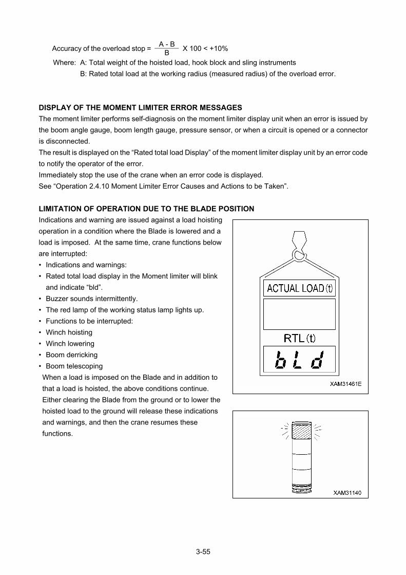
A - B
Accuracy of the overload stop = B
X 100 < +10%
Where: A: Total weight of the hoisted load, hook block and sling instruments
B: Rated total load at the working radius (measured radius) of the overload error.
DISPLAY OF THE MOMENT LIMITER ERROR MESSAGES
The moment limiter performs self-diagnosis on the moment limiter display unit when an error is issued by
the boom angle gauge, boom length gauge, pressure sensor, or when a circuit is opened or a connector
is disconnected.
The result is displayed on the “Rated total load Display” of the moment limiter display unit by an error code
to notify the operator of the error.
Immediately stop the use of the crane when an error code is displayed.
See “Operation 2.4.10 Moment Limiter Error Causes and Actions to be Taken”.
LIMITATION OF OPERATION DUE TO THE BLADE POSITION
Indications and warning are issued against a load hoisting
operation in a condition where the Blade is lowered and a
load is imposed. At the same time, crane functions below
are interrupted:
• Indications and warnings:
• Rated total load display in the Moment limiter will blink
and indicate “bld”.
• Buzzer sounds intermittently.
• The red lamp of the working status lamp lights up.
• Functions to be interrupted:
• Winch hoisting
• Winch lowering
• Boom derricking
• Boom telescoping
When a load is imposed on the Blade and in addition to
that a load is hoisted, the above conditions continue.
Either clearing the Blade from the ground or to lower the
hoisted load to the ground will release these indications
and warnings, and then the crane resumes these
functions.
3-55
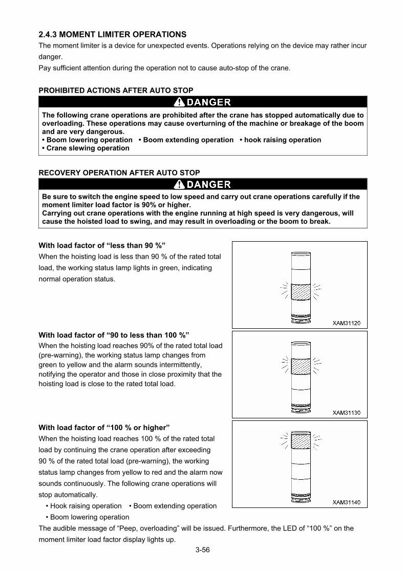
2.4.3 MOMENT LIMITER OPERATIONS The moment limiter is a device for unexpected events. Operations relying on the device may rather incur
danger.
Pay sufficient attention during the operation not to cause auto-stop of the crane.
PROHIBITED ACTIONS AFTER AUTO STOP
The following crane operations are prohibited after the crane has stopped automatically due to overloading. These operations may cause overturning of the machine or breakage of the boom and are very dangerous. • Boom lowering operation • Boom extending operation • hook raising operation • Crane slewing operation
RECOVERY OPERATION AFTER AUTO STOP
Be sure to switch the engine speed to low speed and carry out crane operations carefully if the moment limiter load factor is 90% or higher. Carrying out crane operations with the engine running at high speed is very dangerous, will cause the hoisted load to swing, and may result in overloading or the boom to break.
With load factor of “less than 90 %”
When the hoisting load is less than 90 % of the rated total
load, the working status lamp lights in green, indicating
normal operation status.
With load factor of “90 to less than 100 %” When the hoisting load reaches 90% of the rated total load (pre-warning), the working status lamp changes from green to yellow and the alarm sounds intermittently, notifying the operator and those in close proximity that the hoisting load is close to the rated total load.
With load factor of “100 % or higher”
When the hoisting load reaches 100 % of the rated total
load by continuing the crane operation after exceeding
90 % of the rated total load (pre-warning), the working
status lamp changes from yellow to red and the alarm now
sounds continuously. The following crane operations will
stop automatically.
• Hook raising operation • Boom extending operation
• Boom lowering operation
The audible message of “Peep, overloading” will be issued. Furthermore, the LED of “100 %” on the
moment limiter load factor display lights up.
3-56
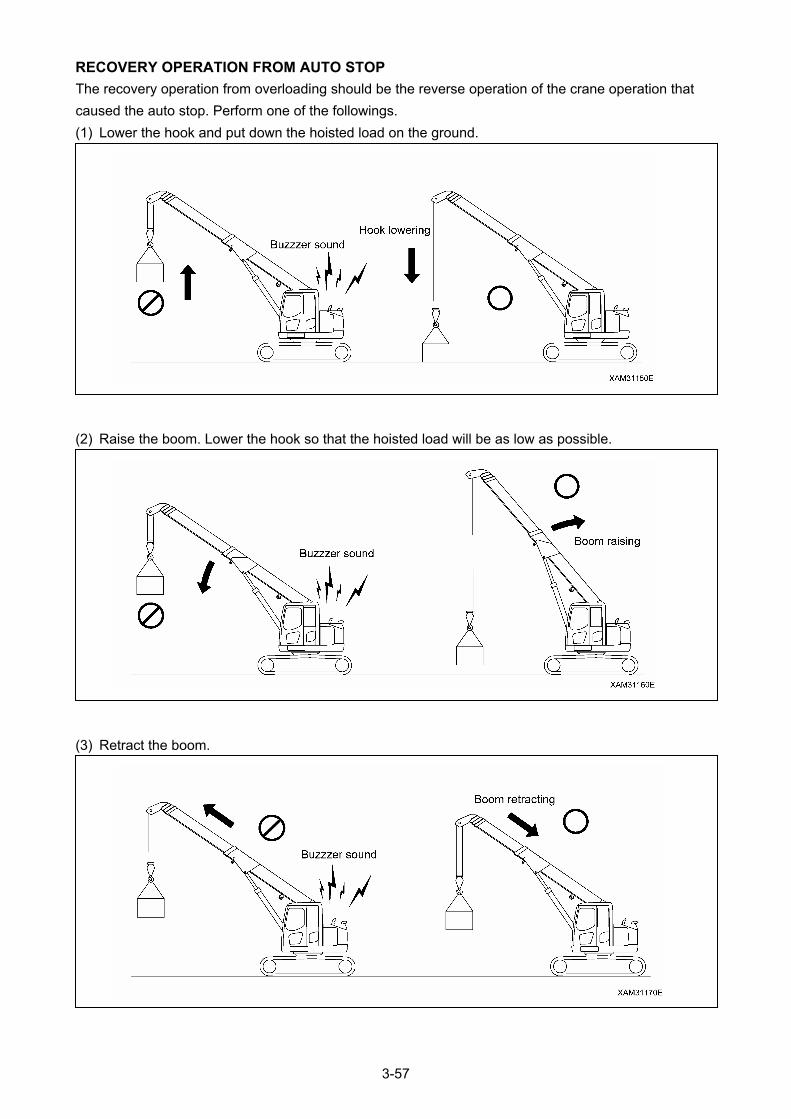
RECOVERY OPERATION FROM AUTO STOP
The recovery operation from overloading should be the reverse operation of the crane operation that
caused the auto stop. Perform one of the followings.
(1) Lower the hook and put down the hoisted load on the ground.
(2) Raise the boom. Lower the hook so that the hoisted load will be as low as possible.
(3) Retract the boom.
3-57
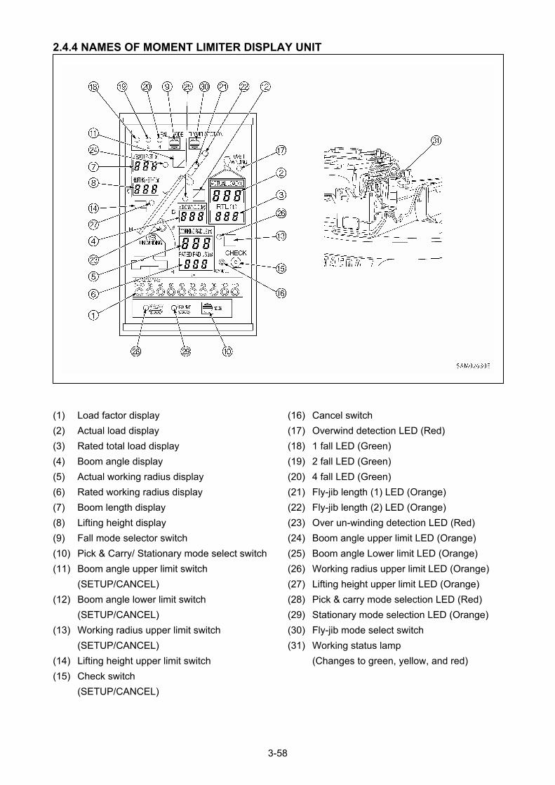
2.4.4 NAMES OF MOMENT LIMITER DISPLAY UNIT
(16) Cancel switch (1) Load factor display
(17) Overwind detection LED (Red) (2) Actual load display
(18) 1 fall LED (Green) (3) Rated total load display
(19) 2 fall LED (Green) (4) Boom angle display
(20) 4 fall LED (Green) (5) Actual working radius display
(21) Fly-jib length (1) LED (Orange) (6) Rated working radius display
(22) Fly-jib length (2) LED (Orange) (7) Boom length display
(23) Over un-winding detection LED (Red) (8) Lifting height display
(24) Boom angle upper limit LED (Orange) (9) Fall mode selector switch
(25) Boom angle Lower limit LED (Orange) (10) Pick & Carry/ Stationary mode select switch
(26) Working radius upper limit LED (Orange) (11) Boom angle upper limit switch
(27) Lifting height upper limit LED (Orange) (SETUP/CANCEL)
(28) Pick & carry mode selection LED (Red) (12) Boom angle lower limit switch
(29) Stationary mode selection LED (Orange) (SETUP/CANCEL)
(30) Fly-jib mode select switch (13) Working radius upper limit switch
(31) Working status lamp (SETUP/CANCEL)
(Changes to green, yellow, and red) (14) Lifting height upper limit switch
(15) Check switch
(SETUP/CANCEL)
3-58
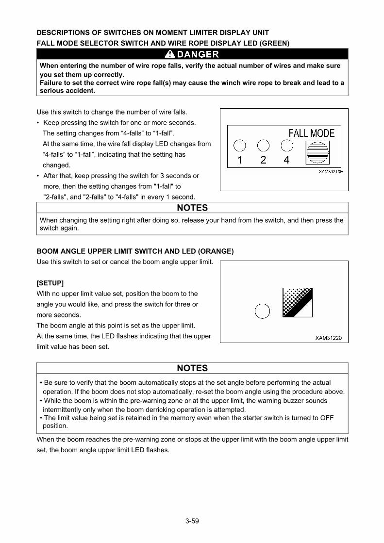
DESCRIPTIONS OF SWITCHES ON MOMENT LIMITER DISPLAY UNIT
FALL MODE SELECTOR SWITCH AND WIRE ROPE DISPLAY LED (GREEN)
When entering the number of wire rope falls, verify the actual number of wires and make sure you set them up correctly. Failure to set the correct wire rope fall(s) may cause the winch wire rope to break and lead to a serious accident.
Use this switch to change the number of wire falls.
• Keep pressing the switch for one or more seconds.
The setting changes from “4-falls” to “1-fall”.
At the same time, the wire fall display LED changes from
“4-falls” to “1-fall”, indicating that the setting has
changed.
• After that, keep pressing the switch for 3 seconds or
more, then the setting changes from "1-fall" to
"2-falls", and "2-falls" to "4-falls" in every 1 second.
NOTES
When changing the setting right after doing so, release your hand from the switch, and then press the switch again.
BOOM ANGLE UPPER LIMIT SWITCH AND LED (ORANGE)
Use this switch to set or cancel the boom angle upper limit.
[SETUP]
With no upper limit value set, position the boom to the
angle you would like, and press the switch for three or
more seconds.
The boom angle at this point is set as the upper limit.
At the same time, the LED flashes indicating that the upper
limit value has been set.
NOTES
• Be sure to verify that the boom automatically stops at the set angle before performing the actual operation. If the boom does not stop automatically, re-set the boom angle using the procedure above.
• While the boom is within the pre-warning zone or at the upper limit, the warning buzzer sounds intermittently only when the boom derricking operation is attempted.
• The limit value being set is retained in the memory even when the starter switch is turned to OFF position.
When the boom reaches the pre-warning zone or stops at the upper limit with the boom angle upper limit
set, the boom angle upper limit LED flashes.
3-59

[CANCEL]
With the upper limit value being set (LED ON), press the switch for 3 seconds or more.
The current upper limit value setting will be cleared. At the same time, the LED goes off indicating that the
upper limit value setting is cleared.
NOTES
The setting and canceling will not repeat even if you keep the switch pressed for more than three seconds. Remove your hand from the switch and press the switch again.
BOOM ANGLE LOWER LIMIT SWITCH AND LED (ORANGE)
Use this switch to set or cancel the boom angle lower limit.
[SETUP]
With no lower limit value being set, set the boom to the
angle you would like, and press the switch for three or
more seconds.
The boom angle at this point is set as the lower limit.
At the same time, the LED flashes indicating that the lower
limit value has been set.
NOTES
• Be sure to verify that the boom automatically stops at the set angle before performing the actual operation. If the boom does not stop automatically, re-set the boom angle using the procedure above.
• While the boom is within the pre-warning zone or at the lower limit, the warning buzzer sounds intermittently only when the boom lowering operation is attempted.
• The limit value being set is retained in the memory even when the starter switch is turned to OFF position.
When the boom reaches the pre-warning zone or stops at the lower limit with the boom angle lower limit
set, the boom angle lower limit LED flashes.
[CANCEL]
With the lower limit value being set (LED ON), press the switch for 3 seconds or more.
The current lower limit value setting will be cleared. At the same time, the LED goes off indicating that the
lower limit value setting is cleared.
NOTES
The setting and canceling will not repeat even if you keep the switch pressed for more than three seconds. Remove your hand from the switch and press the switch again.
3-60

WORKING RADIUS UPPER LIMIT SWITCH AND LED (ORANGE)
Use this switch to set or cancel the working radius upper limit.
[SETUP]
With no upper limit value set, set the boom to the working
radius you would like, and press the switch for three or
more seconds.
The working radius at this point is set as the upper limit.
At the same time, the LED flashes indicating that the upper
limit value has been set.
NOTES
• Be sure to verify that the boom automatically stops at the set working radius before performing the actual operation. If the boom does not stop automatically, re-set the working radius using the procedure above.
• While the boom is within the pre-warning zone or at the lower limit, the warning buzzer sounds intermittently only when the boom lowering operation is attempted.
• The limit value being set is retained in the memory even when the starter switch is turned to OFF position.
When the boom reaches the pre-warning zone or stops at the upper limit with the working radius upper
limit set, the working radius upper limit LED flashes.
[CANCEL]
With the upper limit value being set (LED ON), press the switch for 3 seconds or more.
The current upper limit value setting will be cleared. At the same time, the LED goes off indicating that the
upper limit value setting is cleared.
NOTES
The setting and canceling will not repeat even if you keep the switch pressed for more than three seconds. Remove your hand from the switch and press the switch again.
3-61
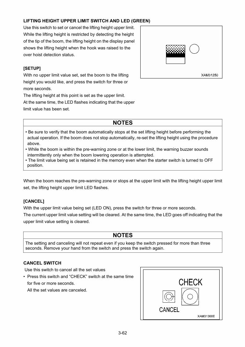
LIFTING HEIGHT UPPER LIMIT SWITCH AND LED (GREEN)
Use this switch to set or cancel the lifting height upper limit.
While the lifting height is restricted by detecting the height
of the tip of the boom, the lifting height on the display panel
shows the lifting height when the hook was raised to the
over hoist detection status.
[SETUP]
With no upper limit value set, set the boom to the lifting
height you would like, and press the switch for three or
more seconds.
The lifting height at this point is set as the upper limit.
At the same time, the LED flashes indicating that the upper
limit value has been set.
NOTES
• Be sure to verify that the boom automatically stops at the set lifting height before performing the actual operation. If the boom does not stop automatically, re-set the lifting height using the procedure above.
• While the boom is within the pre-warning zone or at the lower limit, the warning buzzer sounds intermittently only when the boom lowering operation is attempted.
• The limit value being set is retained in the memory even when the starter switch is turned to OFF position.
When the boom reaches the pre-warning zone or stops at the upper limit with the lifting height upper limit
set, the lifting height upper limit LED flashes.
[CANCEL]
With the upper limit value being set (LED ON), press the switch for three or more seconds.
The current upper limit value setting will be cleared. At the same time, the LED goes off indicating that the
upper limit value setting is cleared.
NOTES
The setting and canceling will not repeat even if you keep the switch pressed for more than three seconds. Remove your hand from the switch and press the switch again.
CANCEL SWITCH
Use this switch to cancel all the set values
• Press this switch and “CHECK” switch at the same time
for five or more seconds.
All the set values are canceled.
3-62
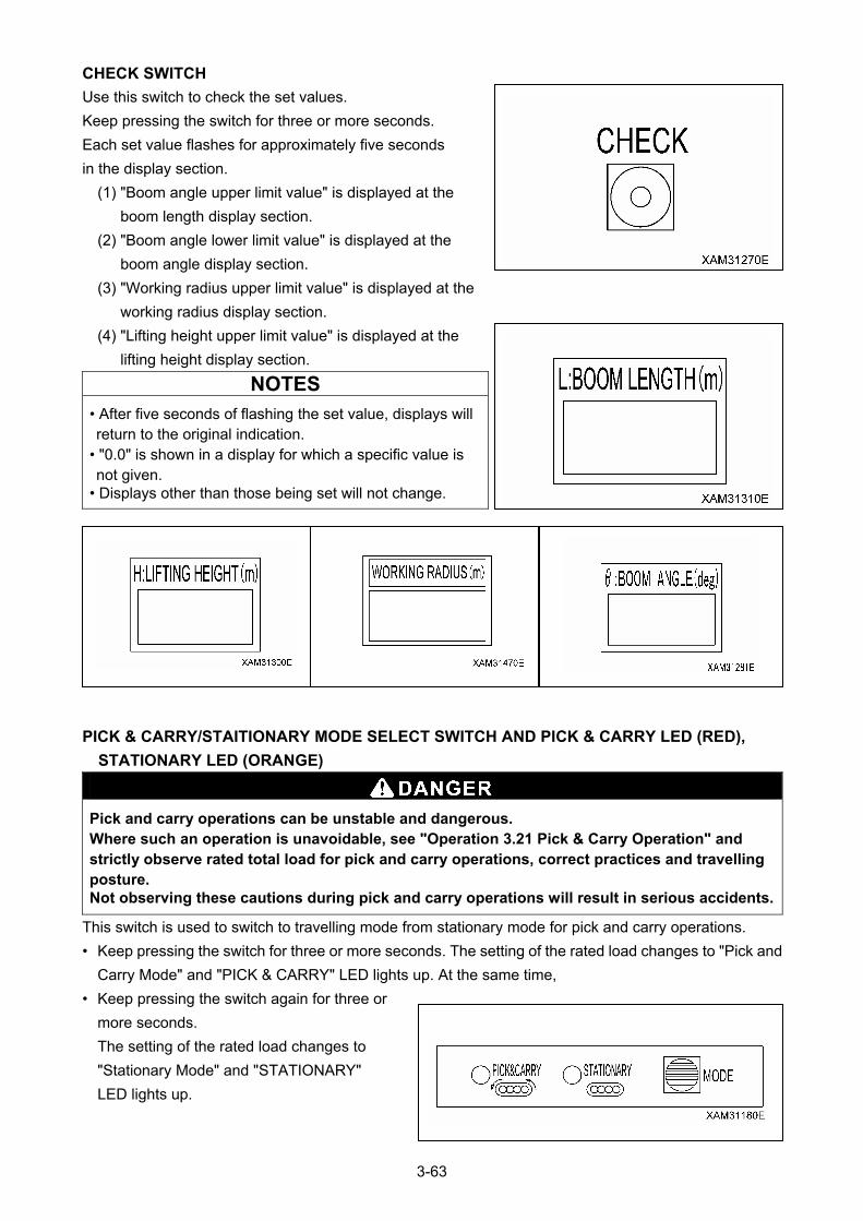
CHECK SWITCH
Use this switch to check the set values.
Keep pressing the switch for three or more seconds.
Each set value flashes for approximately five seconds
in the display section.
(1) "Boom angle upper limit value" is displayed at the
boom length display section.
(2) "Boom angle lower limit value" is displayed at the
boom angle display section.
(3) "Working radius upper limit value" is displayed at the
working radius display section.
(4) "Lifting height upper limit value" is displayed at the
lifting height display section.
NOTES
• After five seconds of flashing the set value, displays will return to the original indication.
• "0.0" is shown in a display for which a specific value is not given.
• Displays other than those being set will not change.
PICK & CARRY/STAITIONARY MODE SELECT SWITCH AND PICK & CARRY LED (RED),
STATIONARY LED (ORANGE)
Pick and carry operations can be unstable and dangerous. Where such an operation is unavoidable, see "Operation 3.21 Pick & Carry Operation" and strictly observe rated total load for pick and carry operations, correct practices and travelling posture. Not observing these cautions during pick and carry operations will result in serious accidents.
This switch is used to switch to travelling mode from stationary mode for pick and carry operations.
• Keep pressing the switch for three or more seconds. The setting of the rated load changes to "Pick and
Carry Mode" and "PICK & CARRY" LED lights up. At the same time,
• Keep pressing the switch again for three or
more seconds.
The setting of the rated load changes to
"Stationary Mode" and "STATIONARY"
LED lights up.
3-63
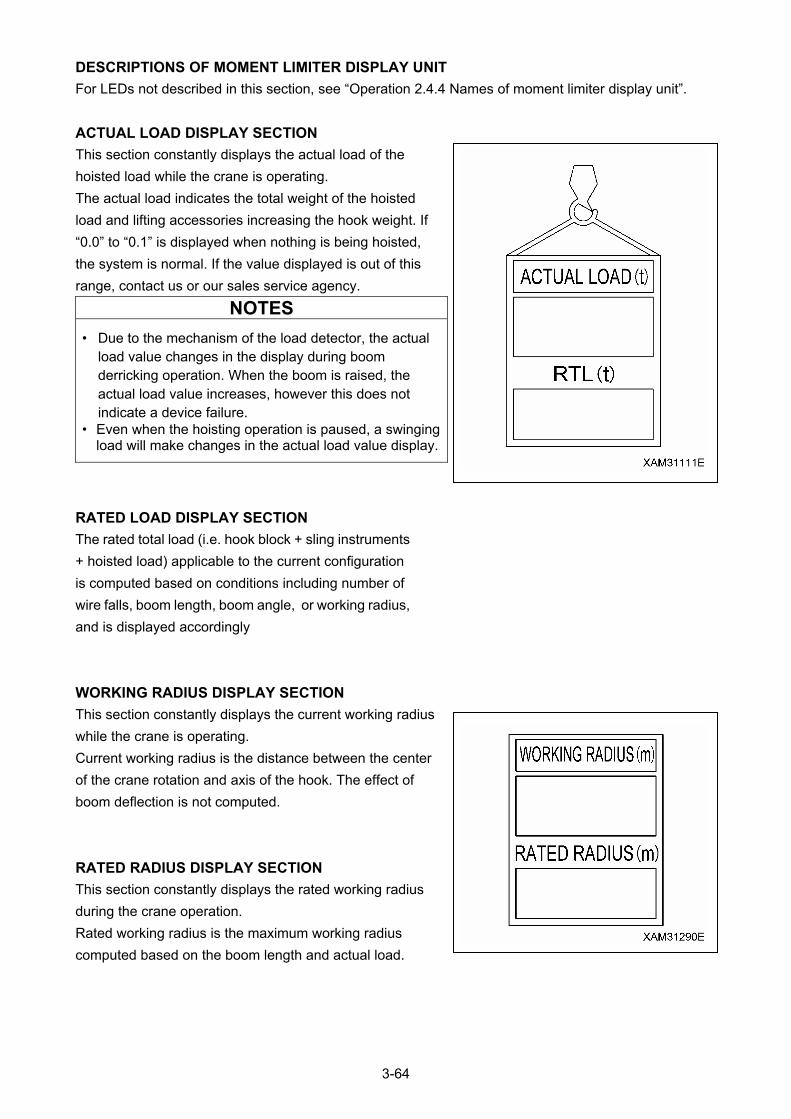
DESCRIPTIONS OF MOMENT LIMITER DISPLAY UNIT
For LEDs not described in this section, see “Operation 2.4.4 Names of moment limiter display unit”.
ACTUAL LOAD DISPLAY SECTION
This section constantly displays the actual load of the
hoisted load while the crane is operating.
The actual load indicates the total weight of the hoisted
load and lifting accessories increasing the hook weight. If
“0.0” to “0.1” is displayed when nothing is being hoisted,
the system is normal. If the value displayed is out of this
range, contact us or our sales service agency.
NOTES
• Due to the mechanism of the load detector, the actual load value changes in the display during boom derricking operation. When the boom is raised, the actual load value increases, however this does not indicate a device failure.
• Even when the hoisting operation is paused, a swinging load will make changes in the actual load value display.
RATED LOAD DISPLAY SECTION
The rated total load (i.e. hook block + sling instruments
+ hoisted load) applicable to the current configuration
is computed based on conditions including number of
wire falls, boom length, boom angle, or working radius,
and is displayed accordingly
WORKING RADIUS DISPLAY SECTION
This section constantly displays the current working radius
while the crane is operating.
Current working radius is the distance between the center
of the crane rotation and axis of the hook. The effect of
boom deflection is not computed.
RATED RADIUS DISPLAY SECTION
This section constantly displays the rated working radius
during the crane operation.
Rated working radius is the maximum working radius
computed based on the boom length and actual load.
3-64
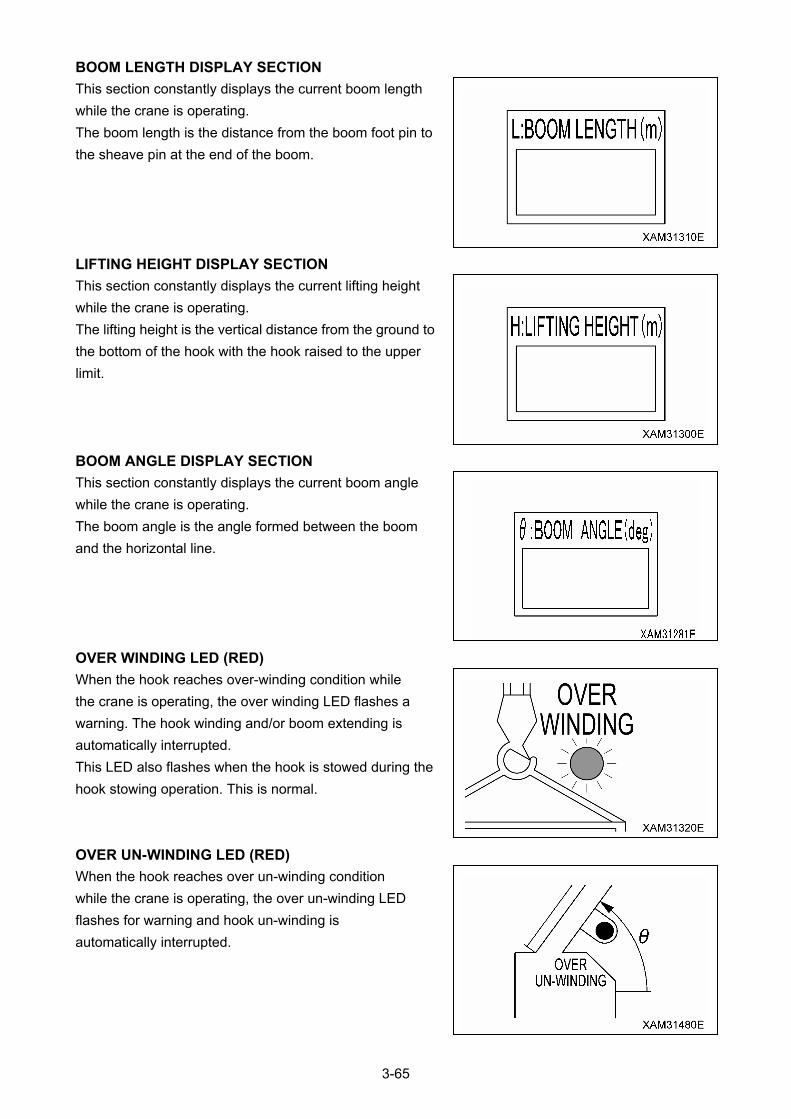
BOOM LENGTH DISPLAY SECTION
This section constantly displays the current boom length
while the crane is operating.
The boom length is the distance from the boom foot pin to
the sheave pin at the end of the boom.
LIFTING HEIGHT DISPLAY SECTION
This section constantly displays the current lifting height
while the crane is operating.
The lifting height is the vertical distance from the ground to
the bottom of the hook with the hook raised to the upper
limit.
BOOM ANGLE DISPLAY SECTION
This section constantly displays the current boom angle
while the crane is operating.
The boom angle is the angle formed between the boom
and the horizontal line.
OVER WINDING LED (RED)
When the hook reaches over-winding condition while
the crane is operating, the over winding LED flashes a
warning. The hook winding and/or boom extending is
automatically interrupted.
This LED also flashes when the hook is stowed during the
hook stowing operation. This is normal.
OVER UN-WINDING LED (RED)
When the hook reaches over un-winding condition
while the crane is operating, the over un-winding LED
flashes for warning and hook un-winding is
automatically interrupted.
3-65
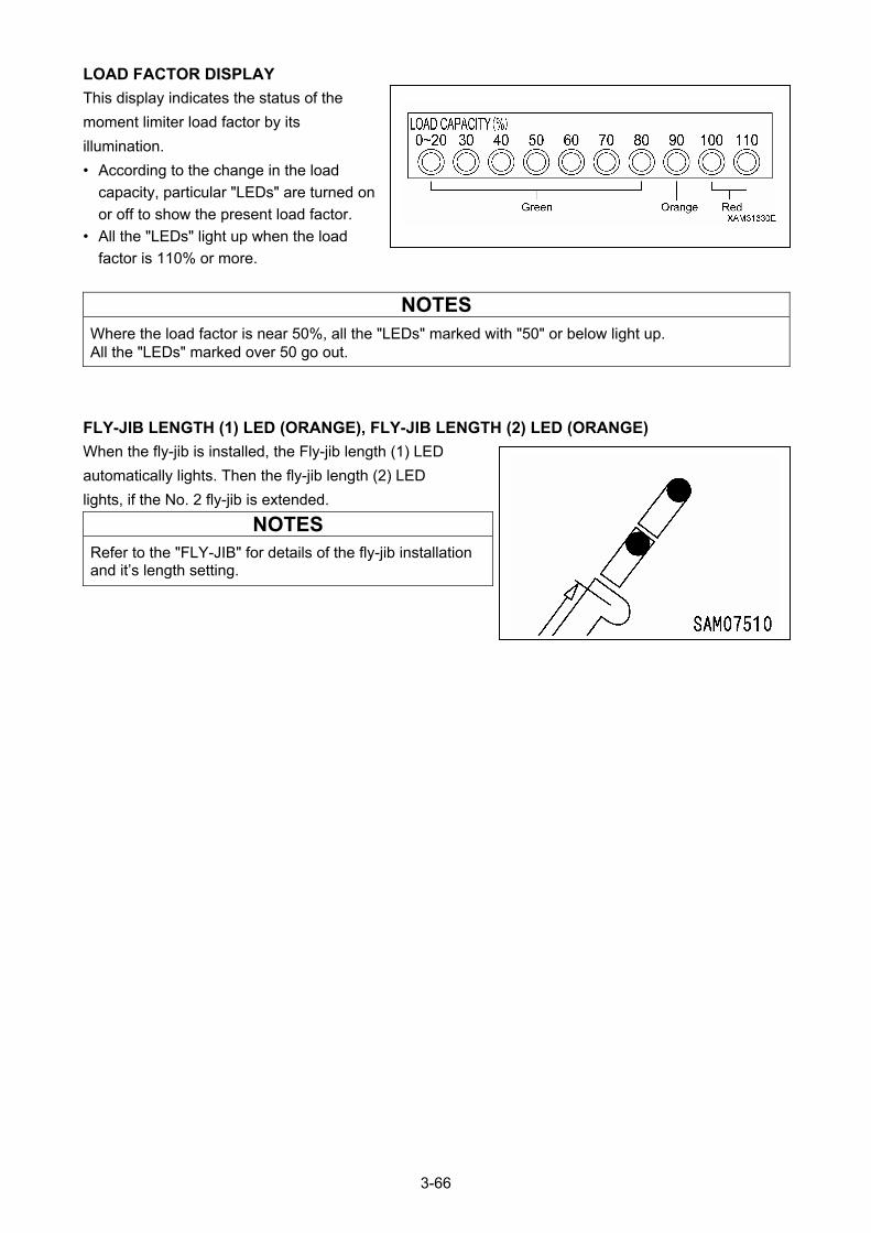
LOAD FACTOR DISPLAY
This display indicates the status of the
moment limiter load factor by its
illumination.
• According to the change in the load
capacity, particular "LEDs" are turned on
or off to show the present load factor.
• All the "LEDs" light up when the load
factor is 110% or more.
NOTES
Where the load factor is near 50%, all the "LEDs" marked with "50" or below light up. All the "LEDs" marked over 50 go out.
FLY-JIB LENGTH (1) LED (ORANGE), FLY-JIB LENGTH (2) LED (ORANGE)
When the fly-jib is installed, the Fly-jib length (1) LED
automatically lights. Then the fly-jib length (2) LED
lights, if the No. 2 fly-jib is extended.
NOTES
Refer to the "FLY-JIB" for details of the fly-jib installation and it’s length setting.
3-66

2.4.5 MOMENT LIMITER FUNCTIONS
OVERLOAD WARNING
1. SAFETY ZONE ("Actual load" is less than 90% of the
"rated total load") (Load factor is less than 90%)
• The green working status lamp lights up.
• The LEDs lights up in green if the load factor is less
than 80 %.
2. PRE-WARNING (“Actual load” is 90 to less than 100%
of the “rated total load”) (Load factor is 90 to less than
100%)
• The yellow working status lamp lights up.
• The LEDs lights up in orange and green if the load factor is 90 to less than 100%.
• The alarm bleeps intermittently.
3. LIMIT WARNING (“Actual load” is 100% or higher than the “rated total load”) (Load factor is 100% or
higher)
• The red working status lamp lights up. • The alarm bleeps continuously. • The hazardous operation of the boom stops automatically. • “Load factor 100% or more” LED (Red) lights up.
• The "Load factor 110% or more" LED (red) lights up when the load factor is 110% or more.
4. CLEARING LIMIT WARNING AUTO STOP
If the system stops automatically, promptly perform the recovery operation caused by overloading.
See “Operation 2.4.3 Function moment operations” for recovery operations.
3-67

WORKING ENVELOPE RESTRICTION WARNING
When the working envelope gets close to the set restriction value, a warning is issued to notify the
operator and those around.
The last status of the set value for the working envelope restriction is memorized even if the starter switch
is turned to the OFF position.
NOTES
• For how to set the value for working envelope restriction, see "Operation 2.3.4 Names of Moment Limiter Display Unit (Descriptions of Switches on Moment Limiter Display Unit)".
• The warning buzzer sounds only when the working envelope gets close to the set restriction value.
When the working envelope has been set, the restriction will be as follows.
1. SAFETY ZONE
• The appropriate working envelope restriction LED (green) lights up.
• The green working status lamp lights up.
2. PRE-WARNING
• The appropriate working envelope restriction LED (green) flashes.
• The alarm bleeps intermittently.
• The green working status lamp lights up.
3. LIMIT WARNING
• The appropriate working envelope restriction LED (green) flashes.
• The yellow working status lamp lights up. • The alarm bleeps continuously.
• The hazardous operation of the boom stops automatically.
3-68
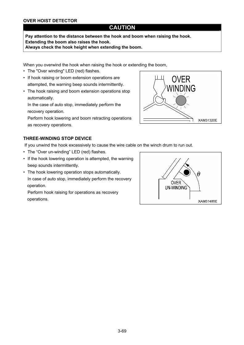
OVER HOIST DETECTOR
CAUTION
Pay attention to the distance between the hook and boom when raising the hook. Extending the boom also raises the hook. Always check the hook height when extending the boom.
When you overwind the hook when raising the hook or extending the boom,
• The "Over winding" LED (red) flashes.
• If hook raising or boom extension operations are
attempted, the warning beep sounds intermittently.
• The hook raising and boom extension operations stop
automatically.
In the case of auto stop, immediately perform the
recovery operation.
Perform hook lowering and boom retracting operations
as recovery operations.
THREE-WINDING STOP DEVICE
If you unwind the hook excessively to cause the wire cable on the winch drum to run out.
• The “Over un-winding” LED (red) flashes.
• If the hook lowering operation is attempted, the warning
beep sounds intermittently.
• The hook lowering operation stops automatically.
In case of auto stop, immediately perform the recovery
operation.
Perform hook raising for operations as recovery
operations.
3-69
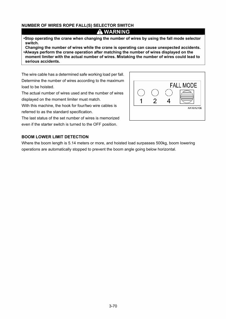
NUMBER OF WIRES ROPE FALL(S) SELECTOR SWITCH
•Stop operating the crane when changing the number of wires by using the fall mode selector switch. Changing the number of wires while the crane is operating can cause unexpected accidents.
•Always perform the crane operation after matching the number of wires displayed on the moment limiter with the actual number of wires. Mistaking the number of wires could lead to serious accidents.
The wire cable has a determined safe working load per fall.
Determine the number of wires according to the maximum
load to be hoisted.
The actual number of wires used and the number of wires
displayed on the moment limiter must match.
With this machine, the hook for four/two wire cables is
referred to as the standard specification.
The last status of the set number of wires is memorized
even if the starter switch is turned to the OFF position.
BOOM LOWER LIMIT DETECTION
Where the boom length is 5.14 meters or more, and hoisted load surpasses 500kg, boom lowering
operations are automatically stopped to prevent the boom angle going below horizontal.
3-70
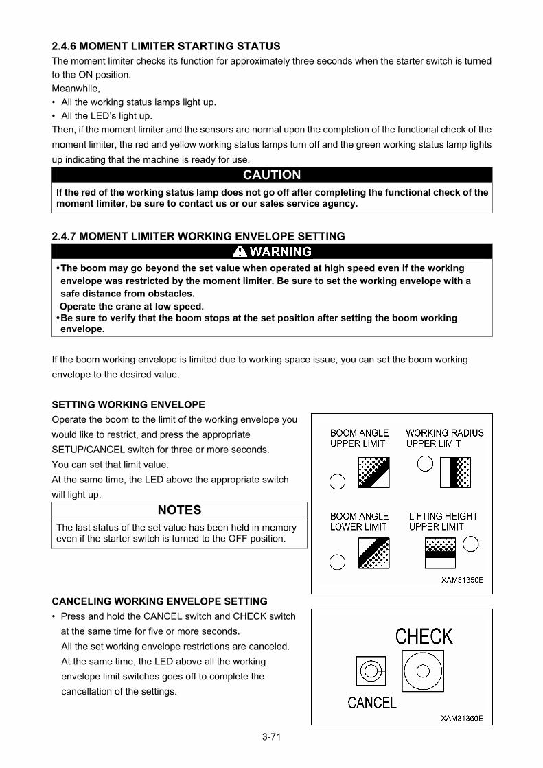
2.4.6 MOMENT LIMITER STARTING STATUS The moment limiter checks its function for approximately three seconds when the starter switch is turned
to the ON position.
Meanwhile,
• All the working status lamps light up.
• All the LED’s light up.
Then, if the moment limiter and the sensors are normal upon the completion of the functional check of the
moment limiter, the red and yellow working status lamps turn off and the green working status lamp lights
up indicating that the machine is ready for use.
CAUTION If the red of the working status lamp does not go off after completing the functional check of the moment limiter, be sure to contact us or our sales service agency.
2.4.7 MOMENT LIMITER WORKING ENVELOPE SETTING
• The boom may go beyond the set value when operated at high speed even if the working envelope was restricted by the moment limiter. Be sure to set the working envelope with a safe distance from obstacles. Operate the crane at low speed.
• Be sure to verify that the boom stops at the set position after setting the boom working envelope.
If the boom working envelope is limited due to working space issue, you can set the boom working
envelope to the desired value.
SETTING WORKING ENVELOPE
Operate the boom to the limit of the working envelope you
would like to restrict, and press the appropriate
SETUP/CANCEL switch for three or more seconds.
You can set that limit value.
At the same time, the LED above the appropriate switch
will light up.
NOTES
The last status of the set value has been held in memory even if the starter switch is turned to the OFF position.
CANCELING WORKING ENVELOPE SETTING
• Press and hold the CANCEL switch and CHECK switch
at the same time for five or more seconds.
All the set working envelope restrictions are canceled.
At the same time, the LED above all the working
envelope limit switches goes off to complete the
cancellation of the settings.
3-71
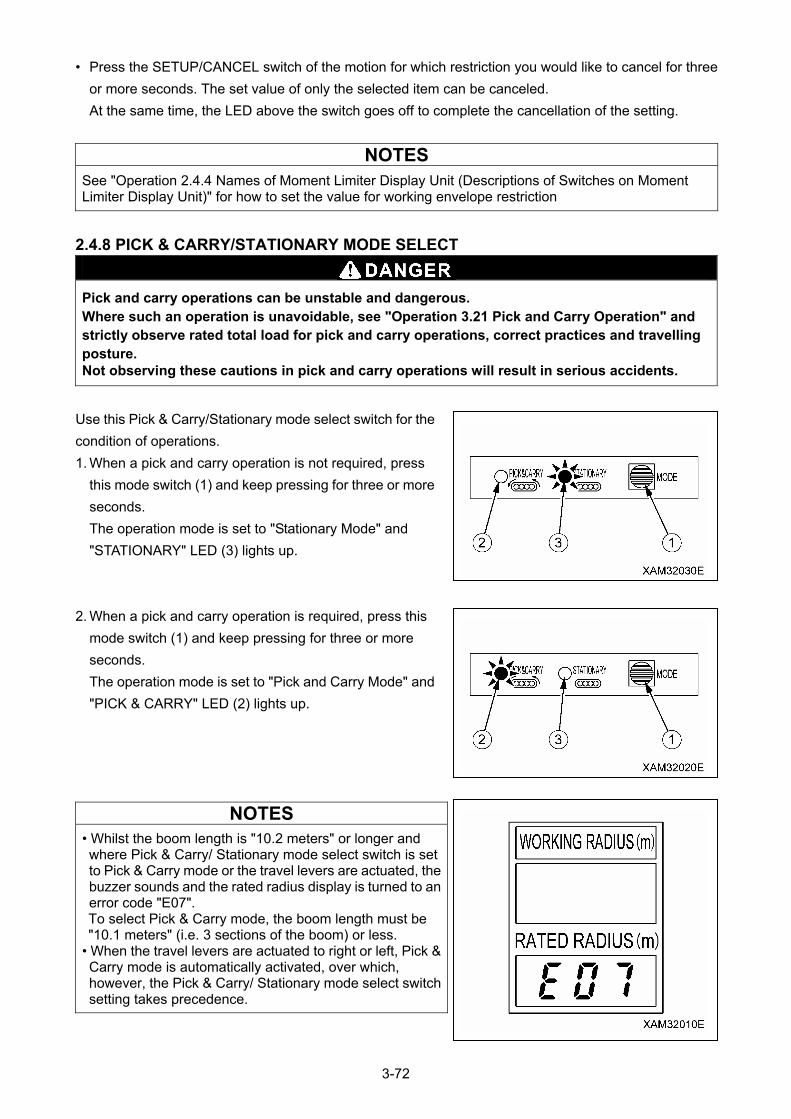
• Press the SETUP/CANCEL switch of the motion for which restriction you would like to cancel for three
or more seconds. The set value of only the selected item can be canceled.
At the same time, the LED above the switch goes off to complete the cancellation of the setting.
NOTES
See "Operation 2.4.4 Names of Moment Limiter Display Unit (Descriptions of Switches on Moment Limiter Display Unit)" for how to set the value for working envelope restriction
2.4.8 PICK & CARRY/STATIONARY MODE SELECT
Pick and carry operations can be unstable and dangerous. Where such an operation is unavoidable, see "Operation 3.21 Pick and Carry Operation" and strictly observe rated total load for pick and carry operations, correct practices and travelling posture. Not observing these cautions in pick and carry operations will result in serious accidents.
Use this Pick & Carry/Stationary mode select switch for the
condition of operations.
1. When a pick and carry operation is not required, press
this mode switch (1) and keep pressing for three or more
seconds.
The operation mode is set to "Stationary Mode" and
"STATIONARY" LED (3) lights up.
2. When a pick and carry operation is required, press this
mode switch (1) and keep pressing for three or more
seconds.
The operation mode is set to "Pick and Carry Mode" and
"PICK & CARRY" LED (2) lights up.
NOTES
• Whilst the boom length is "10.2 meters" or longer and where Pick & Carry/ Stationary mode select switch is set to Pick & Carry mode or the travel levers are actuated, the buzzer sounds and the rated radius display is turned to an error code "E07". To select Pick & Carry mode, the boom length must be "10.1 meters" (i.e. 3 sections of the boom) or less.
• When the travel levers are actuated to right or left, Pick & Carry mode is automatically activated, over which, however, the Pick & Carry/ Stationary mode select switch setting takes precedence.
3-72

2.4.9 MOMENT LIMITER ERROR CAUSES AND ACTIONS TO BE TAKEN The moment limiter displays an error code at the “Rated radius” display section on the display panel to
notify the error.
If an error code shown in the table below was displayed, contact us or our sales service agency.
Error Code Error Details Actions to Be Taken E1L
The input to pressure sensor 1 is lower than the specified value.
E1H
The input to pressure sensor 1 is higher than the specified value.
Check the installation of the pressure sensor 1.
E2L
The input to pressure sensor 2 is lower than the specified value.
E2H
The input to pressure sensor 2 is higher than the specified value.
Check the installation of the pressure sensor 2.
E3L
The input to angle detector is lower than the specified value.
E3H
The input to angle detector is higher than the specified value.
Check the installation of the angle detector.
E4L
The input to length detector is lower than the specified value.
E4H
The input to length detector is higher than the specified value.
Check the installation of the length detector.
E5L
The input to pressure sensor 5 is lower than the specified value.
E5H
The input to pressure sensor 5 is higher than the specified value.
Check the installation of the pressure sensor 5.
E04
Calibration memory error
E05
A/D Converter is not working. Pressure, angle and length data are not available to read.
Turn the starter switch to OFF, once, then to ON, again. Where an error comes again, replace the computing unit.
E07
Pick and Carry mode is selected in a disallowed area.
Cancel Pick and Carry mode, or retract the boom so that it turns into allowed area.
If any other error appears, contact us or our sales service agency for repair.
3-73
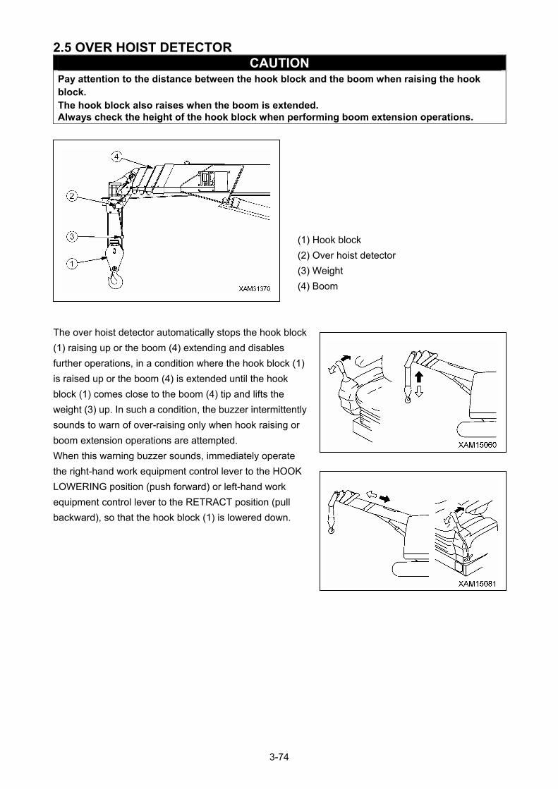
2.5 OVER HOIST DETECTOR CAUTION
Pay attention to the distance between the hook block and the boom when raising the hook block. The hook block also raises when the boom is extended. Always check the height of the hook block when performing boom extension operations.
(1) Hook block
(2) Over hoist detector
(3) Weight
(4) Boom
The over hoist detector automatically stops the hook block
(1) raising up or the boom (4) extending and disables
further operations, in a condition where the hook block (1)
is raised up or the boom (4) is extended until the hook
block (1) comes close to the boom (4) tip and lifts the
weight (3) up. In such a condition, the buzzer intermittently
sounds to warn of over-raising only when hook raising or
boom extension operations are attempted.
When this warning buzzer sounds, immediately operate
the right-hand work equipment control lever to the HOOK
LOWERING position (push forward) or left-hand work
equipment control lever to the RETRACT position (pull
backward), so that the hook block (1) is lowered down.
3-74
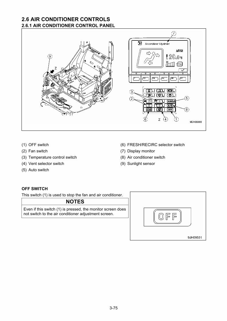
2.6 AIR CONDITIONER CONTROLS 2.6.1 AIR CONDITIONER CONTROL PANEL
(6) FRESH/RECIRC selector switch (1) OFF switch
(7) Display monitor (2) Fan switch
(8) Air conditioner switch (3) Temperature control switch
(9) Sunlight sensor (4) Vent selector switch
(5) Auto switch
OFF SWITCH
This switch (1) is used to stop the fan and air conditioner.
NOTES
Even if this switch (1) is pressed, the monitor screen does not switch to the air conditioner adjustment screen.
3-75
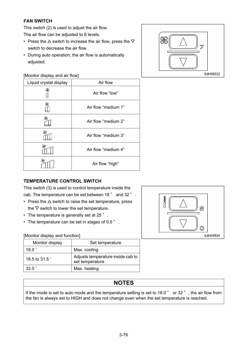
FAN SWITCH
This switch (2) is used to adjust the air flow.
The air flow can be adjusted to 6 levels.
• Press the switch to increase the air flow, press the
switch to decrease the air flow.
• During auto operation, the air flow is automatically
adjusted.
[Monitor display and air flow]
Liquid crystal display Air flow
Air flow “low”
Air flow “medium 1”
Air flow “medium 2”
Air flow “medium 3”
Air flow “medium 4”
Air flow “high”
TEMPERATURE CONTROL SWITCH
This switch (3) is used to control temperature inside the
cab. The temperature can be set between 18 ° and 32 °.
• Press the switch to raise the set temperature, press
the switch to lower the set temperature.
• The temperature is generally set at 25 °.
• The temperature can be set in stages of 0.5 °.
[Monitor display and function]
Monitor display Set temperature
18.0 ° Max. cooling
18.5 to 31.5 ° Adjusts temperature inside cab to set temperature
32.0 ° Max. heating
NOTES
If the mode is set to auto mode and the temperature setting is set to 18.0 ° or 32 °, the air flow from the fan is always set to HIGH and does not change even when the set temperature is reached.
3-76
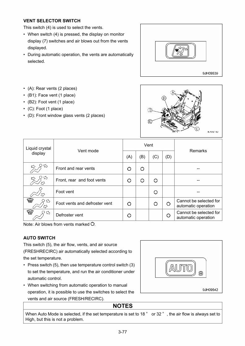
VENT SELECTOR SWITCH
This switch (4) is used to select the vents.
• When switch (4) is pressed, the display on monitor
display (7) switches and air blows out from the vents
displayed.
• During automatic operation, the vents are automatically
selected.
• (A): Rear vents (2 places)
• (B1): Face vent (1 place)
• (B2): Foot vent (1 place)
• (C): Foot (1 place)
• (D): Front window glass vents (2 places)
Vent Liquid crystal
display Vent mode
(A) (B) (C) (D)Remarks
Front and rear vents --
Front, rear and foot vents --
Foot vent --
Foot vents and defroster vent
Cannot be selected for automatic operation
Defroster vent
Cannot be selected for automatic operation
Note: Air blows from vents marked .
AUTO SWITCH
This switch (5), the air flow, vents, and air source
(FRESHRECIRC) air automatically selected according to
the set temperature.
• Press switch (5), then use temperature control switch (3)
to set the temperature, and run the air conditioner under
automatic control.
• When switching from automatic operation to manual
operation, it is possible to use the switches to select the
vents and air source (FRESH/RECIRC).
NOTES
When Auto Mode is selected, if the set temperature is set to 18 ° or 32 °, the air flow is always set to High, but this is not a problem.
3-77
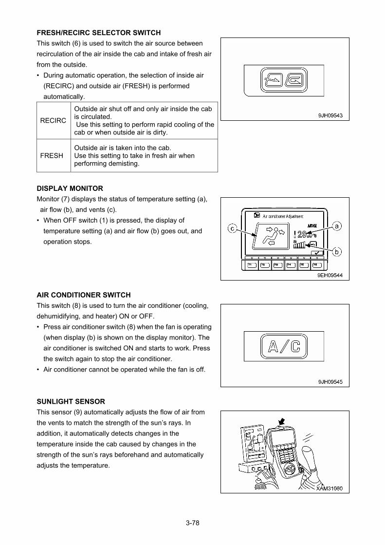
FRESH/RECIRC SELECTOR SWITCH
This switch (6) is used to switch the air source between
recirculation of the air inside the cab and intake of fresh air
from the outside.
• During automatic operation, the selection of inside air
(RECIRC) and outside air (FRESH) is performed
automatically.
RECIRC
Outside air shut off and only air inside the cab is circulated. Use this setting to perform rapid cooling of the cab or when outside air is dirty.
FRESH Outside air is taken into the cab. Use this setting to take in fresh air when performing demisting.
DISPLAY MONITOR
Monitor (7) displays the status of temperature setting (a),
air flow (b), and vents (c).
• When OFF switch (1) is pressed, the display of
temperature setting (a) and air flow (b) goes out, and
operation stops.
AIR CONDITIONER SWITCH
This switch (8) is used to turn the air conditioner (cooling,
dehumidifying, and heater) ON or OFF.
• Press air conditioner switch (8) when the fan is operating
(when display (b) is shown on the display monitor). The
air conditioner is switched ON and starts to work. Press
the switch again to stop the air conditioner.
• Air conditioner cannot be operated while the fan is off.
SUNLIGHT SENSOR
This sensor (9) automatically adjusts the flow of air from
the vents to match the strength of the sun’s rays. In
addition, it automatically detects changes in the
temperature inside the cab caused by changes in the
strength of the sun’s rays beforehand and automatically
adjusts the temperature.
3-78
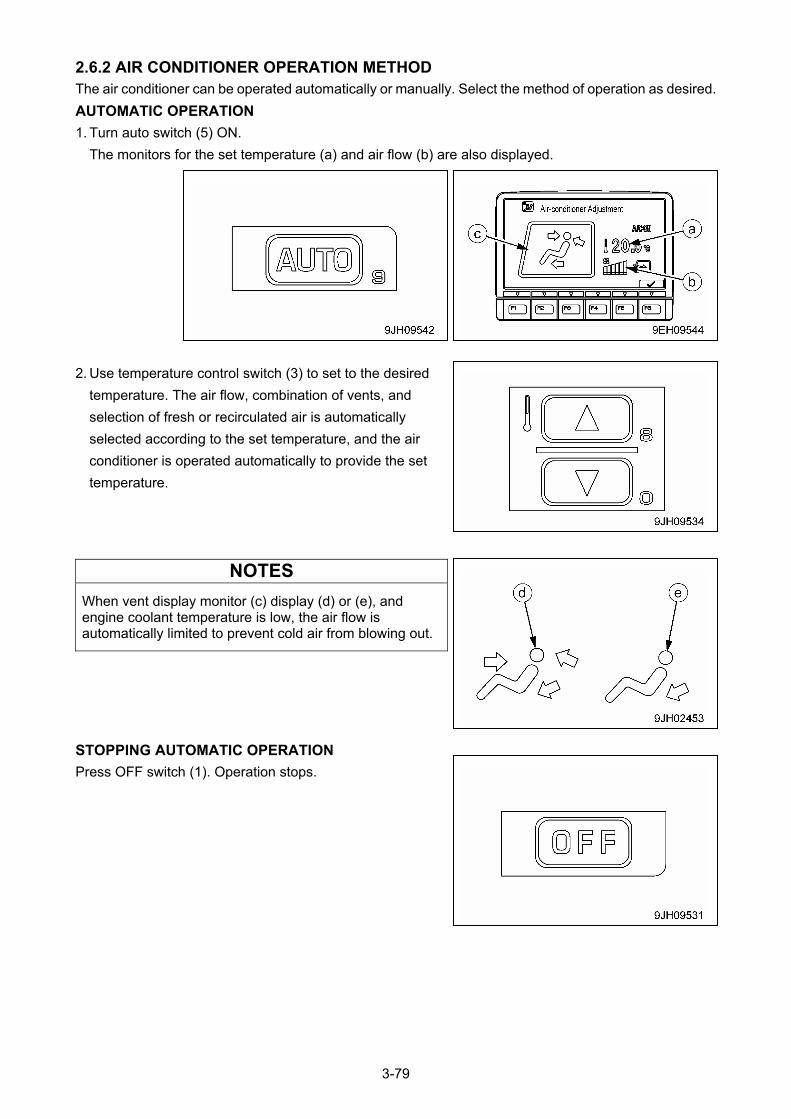
2.6.2 AIR CONDITIONER OPERATION METHOD The air conditioner can be operated automatically or manually. Select the method of operation as desired.
AUTOMATIC OPERATION
1. Turn auto switch (5) ON.
The monitors for the set temperature (a) and air flow (b) are also displayed.
2. Use temperature control switch (3) to set to the desired
temperature. The air flow, combination of vents, and
selection of fresh or recirculated air is automatically
selected according to the set temperature, and the air
conditioner is operated automatically to provide the set
temperature.
NOTES
When vent display monitor (c) display (d) or (e), and engine coolant temperature is low, the air flow is automatically limited to prevent cold air from blowing out.
STOPPING AUTOMATIC OPERATION
Press OFF switch (1). Operation stops.
3-79
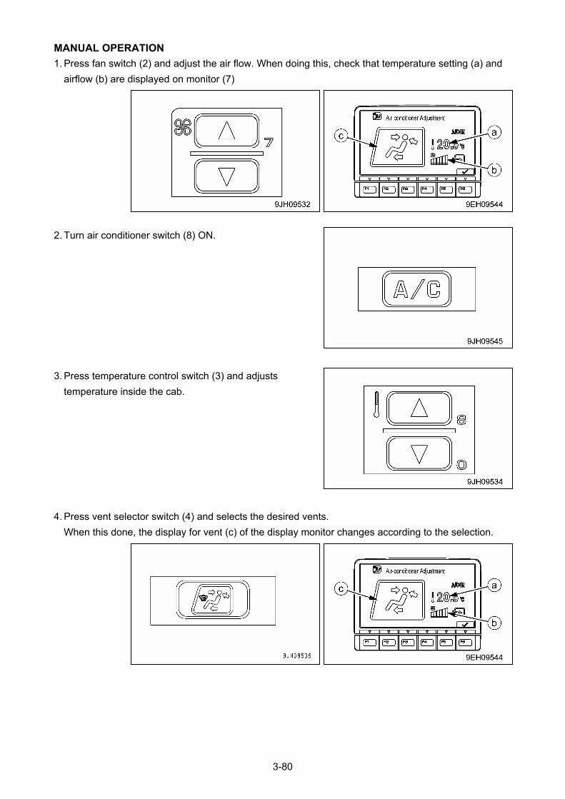
MANUAL OPERATION
1. Press fan switch (2) and adjust the air flow. When doing this, check that temperature setting (a) and
airflow (b) are displayed on monitor (7)
2. Turn air conditioner switch (8) ON.
3. Press temperature control switch (3) and adjusts
temperature inside the cab.
4. Press vent selector switch (4) and selects the desired vents.
When this done, the display for vent (c) of the display monitor changes according to the selection.
3-80

5. Press FRESH/RECIRC selector switch (6) and select
recirculation of the air inside the cab (RECIRC) or intake
of fresh air from outside (FRESH).
STOPPING MANUAL OPERATION
Presses OFF switch (1). Operation stops.
3-81
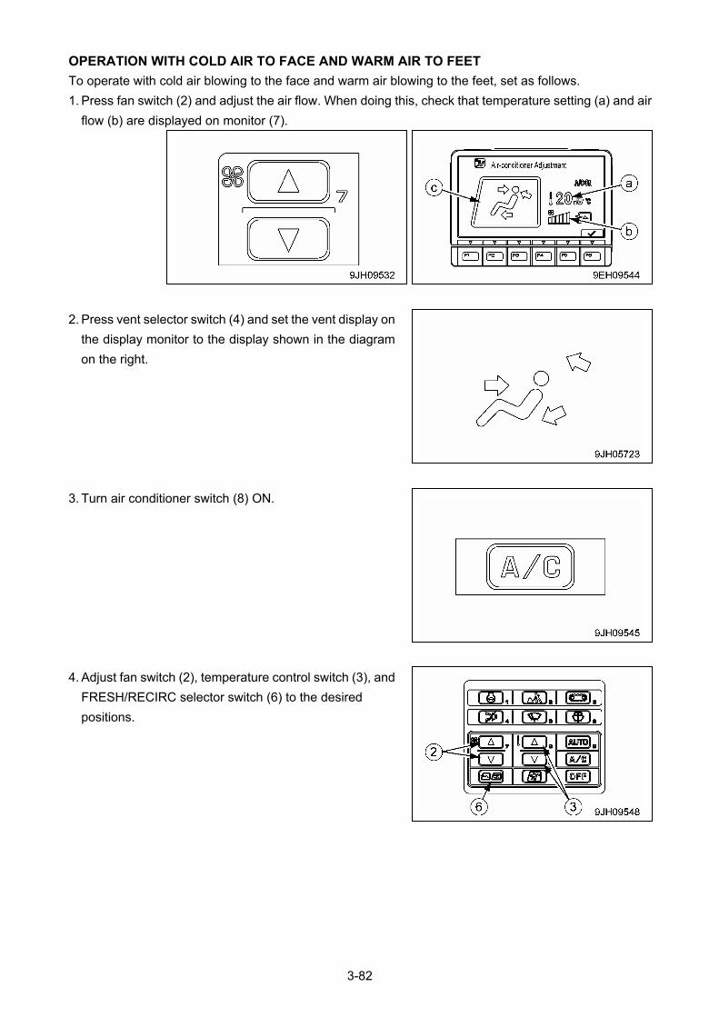
OPERATION WITH COLD AIR TO FACE AND WARM AIR TO FEET
To operate with cold air blowing to the face and warm air blowing to the feet, set as follows.
1. Press fan switch (2) and adjust the air flow. When doing this, check that temperature setting (a) and air
flow (b) are displayed on monitor (7).
2. Press vent selector switch (4) and set the vent display on
the display monitor to the display shown in the diagram
on the right.
3. Turn air conditioner switch (8) ON.
4. Adjust fan switch (2), temperature control switch (3), and
FRESH/RECIRC selector switch (6) to the desired
positions.
3-82
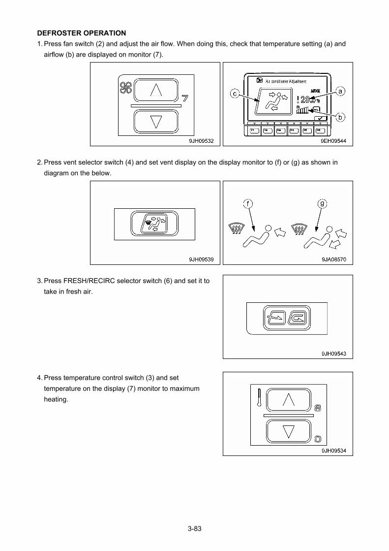
DEFROSTER OPERATION
1. Press fan switch (2) and adjust the air flow. When doing this, check that temperature setting (a) and
airflow (b) are displayed on monitor (7).
2. Press vent selector switch (4) and set vent display on the display monitor to (f) or (g) as shown in
diagram on the below.
3. Press FRESH/RECIRC selector switch (6) and set it to
take in fresh air.
4. Press temperature control switch (3) and set
temperature on the display (7) monitor to maximum
heating.
3-83
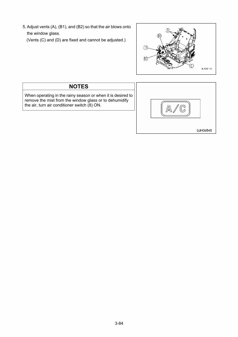
5. Adjust vents (A), (B1), and (B2) so that the air blows onto
the window glass.
(Vents (C) and (D) are fixed and cannot be adjusted.)
NOTES
When operating in the rainy season or when it is desired to remove the mist from the window glass or to dehumidify the air, turn air conditioner switch (8) ON.
3-84
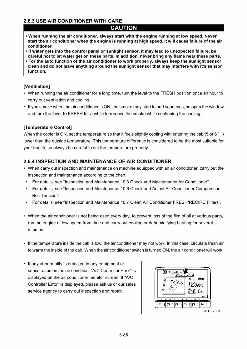
2.6.3 USE AIR CONDITIONER WITH CARE
CAUTION • When running the air conditioner, always start with the engine running at low speed. Never start the air conditioner when the engine is running at high speed. It will cause failure of the air conditioner.
• If water gets into the control panel or sunlight sensor, it may lead to unexpected failure, be careful not to let water get on these parts. In addition, never bring any flame near these parts.
• For the auto function of the air conditioner to work properly, always keep the sunlight sensor clean and do not leave anything around the sunlight sensor that may interfere with it’s sensor function.
[Ventilation]
• When running the air conditioner for a long time, turn the level to the FRESH position once an hour to
carry out ventilation and cooling.
• If you smoke when the air conditioner is ON, the smoke may start to hurt your eyes, so open the window
and turn the lever to FRESH for a while to remove the smoke while continuing the cooling.
[Temperature Control]
When the cooler is ON, set the temperature so that it feels slightly cooling with entering the cab (5 or 6 °)
lower than the outside temperature. This temperature difference is considered to be the most suitable for
your health, so always be careful to set the temperature properly.
2.6.4 INSPECTION AND MAINTENANCE OF AIR CONDITIONER • When carry out inspection and maintenance on machine equipped with an air conditioner, carry out the
inspection and maintenance according to the chart.
• For details, see “Inspection and Maintenance 10.3 Check and Maintenance Air Conditioner”.
• For details, see “Inspection and Maintenance 10.6 Check and Adjust Air Conditioner Compressor
Belt Tension”.
• For details, see “Inspection and Maintenance 10.7 Clean Air Conditioner FRESH/RECIRC Filters”.
• When the air conditioner is not being used every day, to prevent loss of the film of oil at various parts,
run the engine at low speed from time and carry out cooling or dehumidifying heating for several
minutes.
• If the temperature inside the cab is low, the air conditioner may not work. In this case, circulate fresh air
to warm the inside of the cab. When the air conditioner switch is turned ON, the air conditioner will work.
• If any abnormality is detected in any equipment or
sensor used on the air condition, “A/C Controller Error” is
displayed on the air conditioner monitor screen. If “A/C
Controller Error” is displayed, please ask us or our sales
service agency to carry out inspection and repair.
3-85
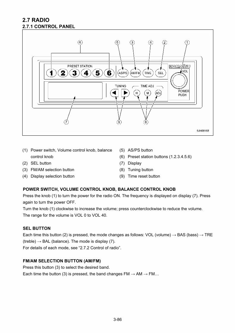
2.7 RADIO 2.7.1 CONTROL PANEL
(5) AS/PS button (1) Power switch, Volume control knob, balance
control knob (6) Preset station buttons (1.2.3.4.5.6)
(7) Display (2) SEL button
(8) Tuning button (3) FM/AM selection button
(9) Time reset button (4) Display selection button
POWER SWITCH, VOLUME CONTROL KNOB, BALANCE CONTROL KNOB
Press the knob (1) to turn the power for the radio ON. The frequency is displayed on display (7). Press
again to turn the power OFF.
Turn the knob (1) clockwise to increase the volume; press counterclockwise to reduce the volume.
The range for the volume is VOL 0 to VOL 40.
SEL BUTTON
Each time this button (2) is pressed, the mode changes as follows: VOL (volume) → BAS (bass) → TRE
(treble) → BAL (balance). The mode is display (7).
For details of each mode, see “2.7.2 Control of radio”.
FM/AM SELECTION BUTTON (AM/FM)
Press this button (3) to select the desired band.
Each time the button (3) is pressed, the band changes FM → AM → FM…
3-86
DISPLAY SELECTION BUTTON (TIME)
On this machine, priority is given to the frequency display. When the frequency is being displayed, press
button (4) and the display will show the preset time for 5 seconds. After 5 seconds pass, the display
returns automatically to the frequency display. If any button other than TIME ADJ (H, M, ADJ) is pressed
within 5 seconds, the display returns to the frequency display.
For details of the method of adjusting the time, see “2.7.2 Control of radio”.
AS/PS BUTTON
This button (5) actuates the auto store and preset scan function.
• Auto Store
If this button is kept pressed for at least 2 seconds during radio reception, it will automatically search for
6 available AM and FM stations each, starting with the lowest frequency and going up to the highest
frequency. These frequencies can then be saved in the preset memory.
• Preset Scan
If this button is pressed within 2 seconds, it is possible to select one of the already preset stations. Wait
for 6 seconds after pressing the button and then press the button again to select the next preset station.
If it is impossible to receive the preset frequency, the selection advances after 1 second to the next
preset station.
PRESET STATION BUTTONS (1, 2, 3, 4, 5, 6)
If this button has been used to decide which stations to preset, it is possible to select the desired station
at a touch. It is possible to preset 6 stations each for both AM and FM.
For details of the method of presetting the stations, see “2.7.2 Control of radio”.
NOTES
The preset button (6) can be used to save the frequency manually. To save the frequency automatically,use the Auto store button (5).
DISPLAY
This display (7) shows the reception band, frequency, press No., and time.
TIME RESET BUTTON
Use this button (8) when adjusting the time.
For details of the method of adjusting the time, see “2.7.2 Control of radio”.
H: hour M: Minute ADJ: Sets to 00 minutes
TUNING BUTTON (TUNING)
This button (9) is used to change the frequency.
For details of the method of tuning, see “2.7.2 Control of radio”.
3-87
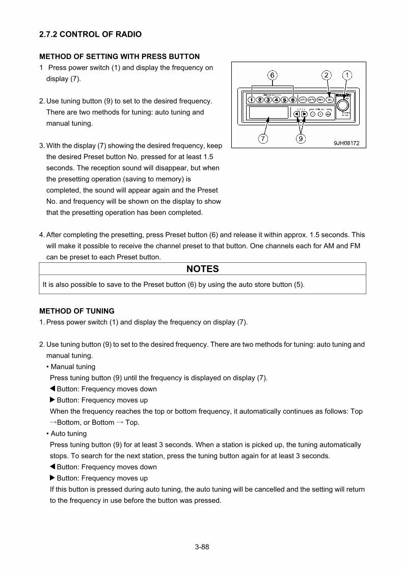
2.7.2 CONTROL OF RADIO
METHOD OF SETTING WITH PRESS BUTTON
1 Press power switch (1) and display the frequency on
display (7).
2. Use tuning button (9) to set to the desired frequency.
There are two methods for tuning: auto tuning and
manual tuning.
3. With the display (7) showing the desired frequency, keep
the desired Preset button No. pressed for at least 1.5
seconds. The reception sound will disappear, but when
the presetting operation (saving to memory) is
completed, the sound will appear again and the Preset
No. and frequency will be shown on the display to show
that the presetting operation has been completed.
4. After completing the presetting, press Preset button (6) and release it within approx. 1.5 seconds. This
will make it possible to receive the channel preset to that button. One channels each for AM and FM
can be preset to each Preset button.
NOTES
It is also possible to save to the Preset button (6) by using the auto store button (5).
METHOD OF TUNING
1. Press power switch (1) and display the frequency on display (7).
2. Use tuning button (9) to set to the desired frequency. There are two methods for tuning: auto tuning and
manual tuning.
• Manual tuning
Press tuning button (9) until the frequency is displayed on display (7).
Button: Frequency moves down
Button: Frequency moves up
When the frequency reaches the top or bottom frequency, it automatically continues as follows: Top
→Bottom, or Bottom → Top.
• Auto tuning
Press tuning button (9) for at least 3 seconds. When a station is picked up, the tuning automatically
stops. To search for the next station, press the tuning button again for at least 3 seconds.
Button: Frequency moves down
Button: Frequency moves up
If this button is pressed during auto tuning, the auto tuning will be cancelled and the setting will return
to the frequency in use before the button was pressed.
3-88
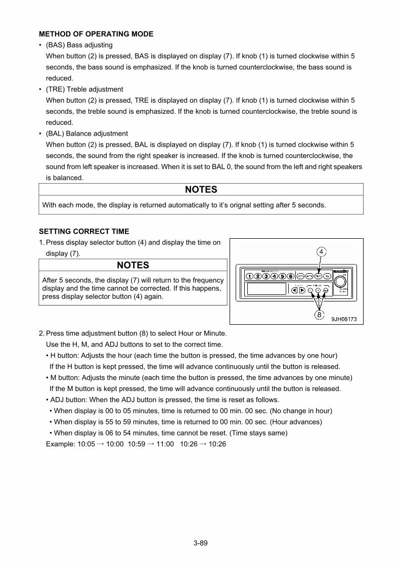
METHOD OF OPERATING MODE
• (BAS) Bass adjusting
When button (2) is pressed, BAS is displayed on display (7). If knob (1) is turned clockwise within 5
seconds, the bass sound is emphasized. If the knob is turned counterclockwise, the bass sound is
reduced.
• (TRE) Treble adjustment
When button (2) is pressed, TRE is displayed on display (7). If knob (1) is turned clockwise within 5
seconds, the treble sound is emphasized. If the knob is turned counterclockwise, the treble sound is
reduced.
• (BAL) Balance adjustment
When button (2) is pressed, BAL is displayed on display (7). If knob (1) is turned clockwise within 5
seconds, the sound from the right speaker is increased. If the knob is turned counterclockwise, the
sound from left speaker is increased. When it is set to BAL 0, the sound from the left and right speakers
is balanced.
NOTES
With each mode, the display is returned automatically to it’s orignal setting after 5 seconds.
SETTING CORRECT TIME
1. Press display selector button (4) and display the time on
display (7).
NOTES
After 5 seconds, the display (7) will return to the frequency display and the time cannot be corrected. If this happens, press display selector button (4) again.
2. Press time adjustment button (8) to select Hour or Minute.
Use the H, M, and ADJ buttons to set to the correct time.
• H button: Adjusts the hour (each time the button is pressed, the time advances by one hour)
If the H button is kept pressed, the time will advance continuously until the button is released.
• M button: Adjusts the minute (each time the button is pressed, the time advances by one minute)
If the M button is kept pressed, the time will advance continuously until the button is released.
• ADJ button: When the ADJ button is pressed, the time is reset as follows.
• When display is 00 to 05 minutes, time is returned to 00 min. 00 sec. (No change in hour)
• When display is 55 to 59 minutes, time is returned to 00 min. 00 sec. (Hour advances)
• When display is 06 to 54 minutes, time cannot be reset. (Time stays same)
Example: 10:05 → 10:00 10:59 → 11:00 10:26 → 10:26
3-89
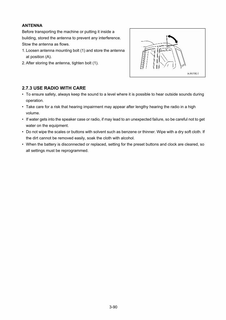
ANTENNA
Before transporting the machine or putting it inside a
building, stored the antenna to prevent any interference.
Stow the antenna as flows.
1. Loosen antenna mounting bolt (1) and store the antenna
at position (A).
2. After storing the antenna, tighten bolt (1).
2.7.3 USE RADIO WITH CARE • To ensure safety, always keep the sound to a level where it is possible to hear outside sounds during
operation.
• Take care for a risk that hearing impairment may appear after lengthy hearing the radio in a high
volume.
• If water gets into the speaker case or radio, if may lead to an unexpected failure, so be careful not to get
water on the equipment.
• Do not wipe the scales or buttons with solvent such as benzene or thinner. Wipe with a dry soft cloth. If
the dirt cannot be removed easily, soak the cloth with alcohol.
• When the battery is disconnected or replaced, setting for the preset buttons and clock are cleared, so
all settings must be reprogrammed.
3-90
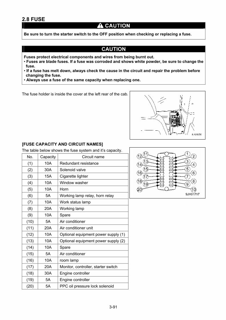
2.8 FUSE
Be sure to turn the starter switch to the OFF position when checking or replacing a fuse.
CAUTION Fuses protect electrical components and wires from being burnt out. • Fuses are blade fuses. If a fuse was corroded and shows white powder, be sure to change the fuse.
• If a fuse has melt down, always check the cause in the circuit and repair the problem before changing the fuse.
• Always use a fuse of the same capacity when replacing one.
The fuse holder is inside the cover at the left rear of the cab.
[FUSE CAPACITY AND CIRCUIT NAMES]
The table below shows the fuse system and it’s capacity.
No. Capacity Circuit name
(1) 10A Redundant resistance
(2) 30A Solenoid valve
(3) 15A Cigarette lighter
(4) 10A Window washer
(5) 10A Horn
(6) 5A Working lamp relay, horn relay
(7) 10A Work status lamp
(8) 20A Working lamp
(9) 10A Spare
(10) 5A Air conditioner
(11) 20A Air conditioner unit
(12) 10A Optional equipment power supply (1)
(13) 10A Optional equipment power supply (2)
(14) 10A Spare
(15) 5A Air conditioner
(16) 10A room lamp
(17) 20A Monitor, controller, starter switch
(18) 30A Engine controller
(19) 5A Engine controller
(20) 5A PPC oil pressure lock solenoid
3-91
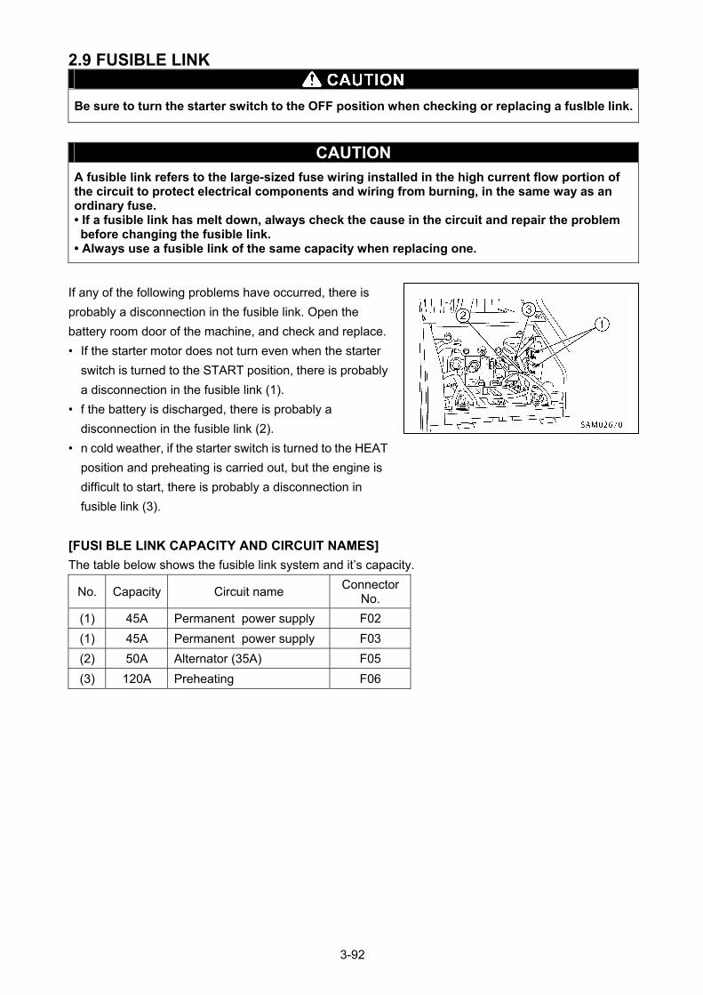
2.9 FUSIBLE LINK
Be sure to turn the starter switch to the OFF position when checking or replacing a fusIble link.
CAUTION A fusible link refers to the large-sized fuse wiring installed in the high current flow portion of the circuit to protect electrical components and wiring from burning, in the same way as an ordinary fuse. • If a fusible link has melt down, always check the cause in the circuit and repair the problem before changing the fusible link.
• Always use a fusible link of the same capacity when replacing one.
If any of the following problems have occurred, there is
probably a disconnection in the fusible link. Open the
battery room door of the machine, and check and replace.
• If the starter motor does not turn even when the starter
switch is turned to the START position, there is probably
a disconnection in the fusible link (1).
• f the battery is discharged, there is probably a
disconnection in the fusible link (2).
• n cold weather, if the starter switch is turned to the HEAT
position and preheating is carried out, but the engine is
difficult to start, there is probably a disconnection in
fusible link (3).
[FUSI BLE LINK CAPACITY AND CIRCUIT NAMES]
The table below shows the fusible link system and it’s capacity.
No. Capacity Circuit name Connector
No.
(1) 45A Permanent power supply F02
(1) 45A Permanent power supply F03
(2) 50A Alternator (35A) F05
(3) 120A Preheating F06
3-92
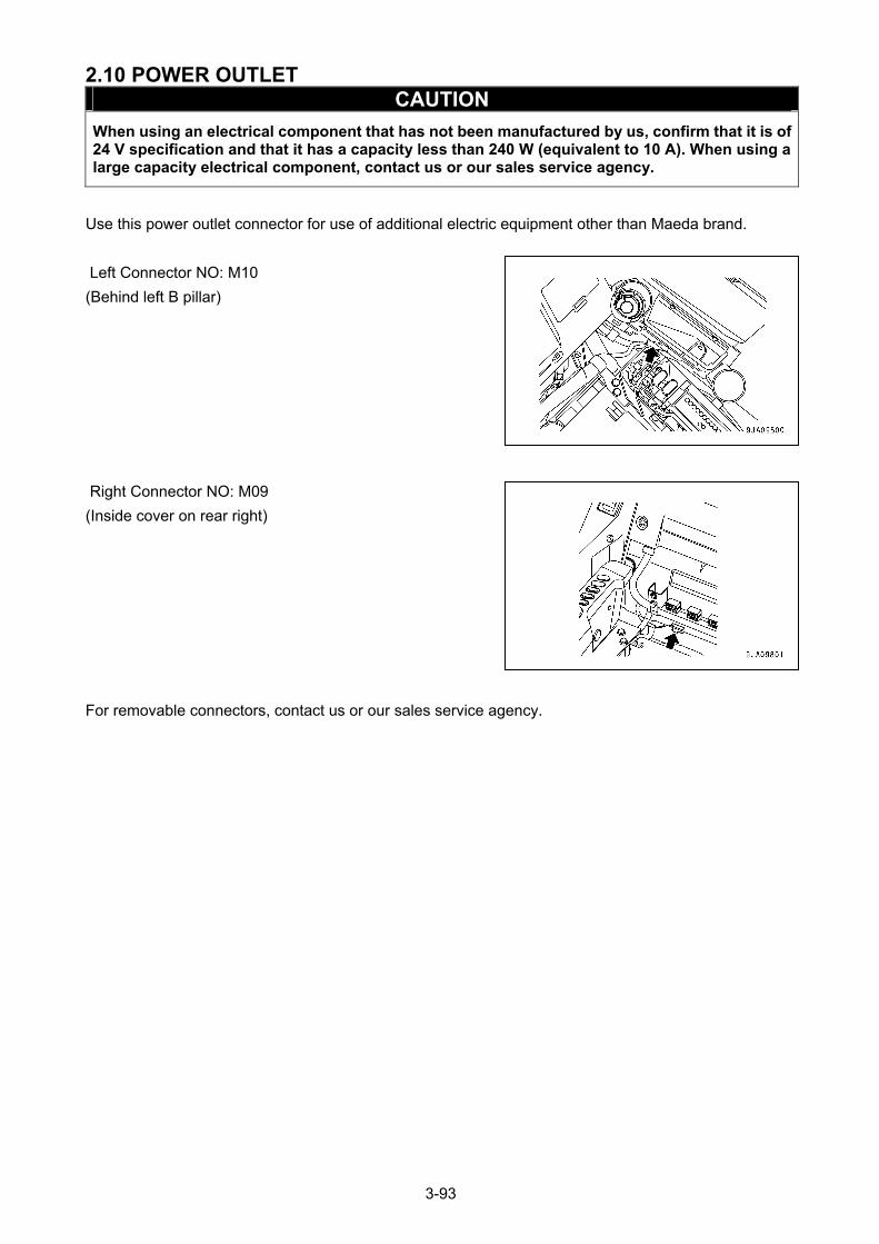
2.10 POWER OUTLET CAUTION
When using an electrical component that has not been manufactured by us, confirm that it is of 24 V specification and that it has a capacity less than 240 W (equivalent to 10 A). When using a large capacity electrical component, contact us or our sales service agency.
Use this power outlet connector for use of additional electric equipment other than Maeda brand.
Left Connector NO: M10
(Behind left B pillar)
Right Connector NO: M09
(Inside cover on rear right)
For removable connectors, contact us or our sales service agency.
3-93
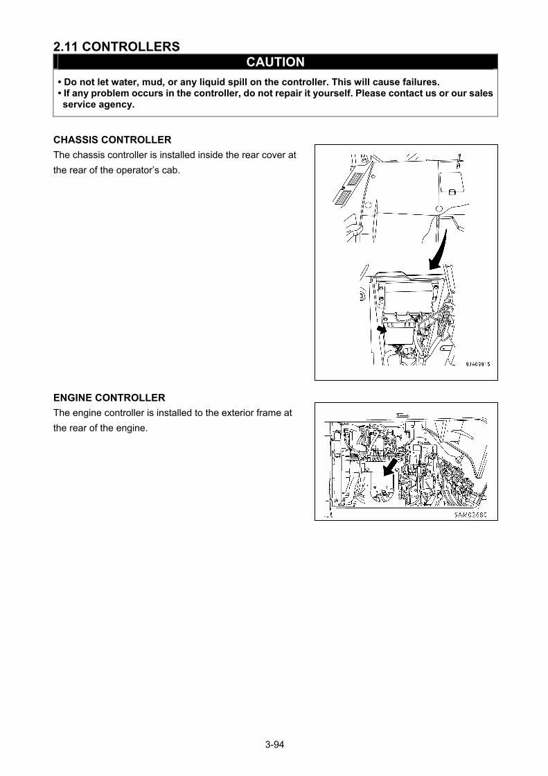
2.11 CONTROLLERS CAUTION
• Do not let water, mud, or any liquid spill on the controller. This will cause failures. • If any problem occurs in the controller, do not repair it yourself. Please contact us or our sales service agency.
CHASSIS CONTROLLER
The chassis controller is installed inside the rear cover at
the rear of the operator’s cab.
ENGINE CONTROLLER
The engine controller is installed to the exterior frame at
the rear of the engine.
3-94
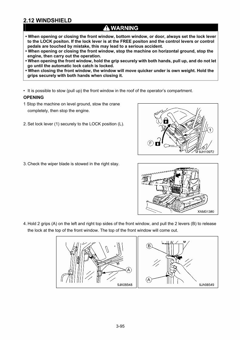
2.12 WINDSHIELD
• When opening or closing the front window, bottom window, or door, always set the lock lever to the LOCK positon. If the lock lever is at the FREE positon and the control levers or control pedals are touched by mistake, this may lead to a serious accident.
• When opening or closing the front window, stop the machine on horizontal ground, stop the engine, then carry out the operation.
• When opening the front window, hold the grip securely with both hands, pull up, and do not let go until the automatic lock catch is locked.
• When closing the front window, the window will move quicker under is own weight. Hold the grips securely with both hands when closing it.
• It is possible to stow (pull up) the front window in the roof of the operator’s compartment.
OPENING
1 Stop the machine on level ground, stow the crane
completely, then stop the engine.
2. Set lock lever (1) securely to the LOCK position (L).
3. Check the wiper blade is stowed in the right stay.
4. Hold 2 grips (A) on the left and right top sides of the front window, and pull the 2 levers (B) to release
the lock at the top of the front window. The top of the front window will come out.
3-95
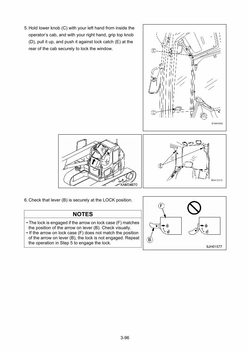
5. Hold lower knob (C) with your left hand from inside the
operator’s cab, and with your right hand, grip top knob
(D), pull it up, and push it against lock catch (E) at the
rear of the cab securely to lock the window.
6. Check that lever (B) is securely at the LOCK position.
NOTES
• The lock is engaged if the arrow on lock case (F) matches the position of the arrow on lever (B). Check visually.
• If the arrow on lock case (F) does not match the position of the arrow on lever (B), the lock is not engaged. Repeat the operation in Step 5 to engage the lock.
3-96
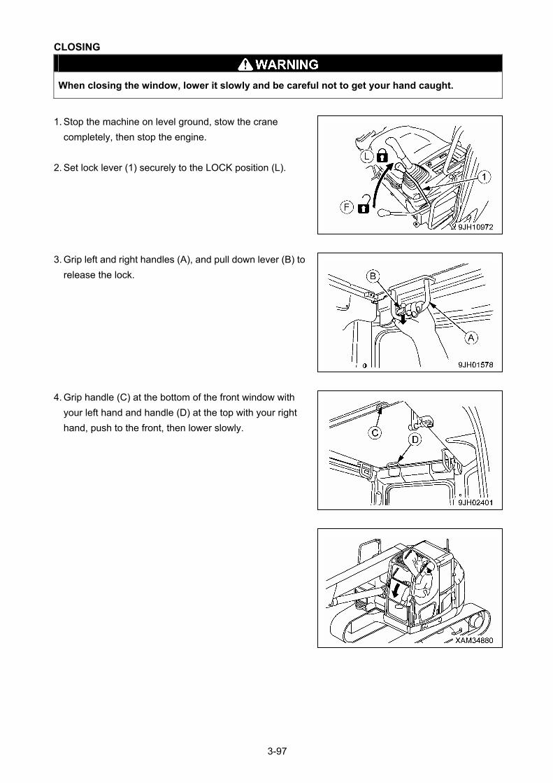
CLOSING
When closing the window, lower it slowly and be careful not to get your hand caught.
1. Stop the machine on level ground, stow the crane
completely, then stop the engine.
2. Set lock lever (1) securely to the LOCK position (L).
3. Grip left and right handles (A), and pull down lever (B) to
release the lock.
4. Grip handle (C) at the bottom of the front window with
your left hand and handle (D) at the top with your right
hand, push to the front, then lower slowly.
3-97
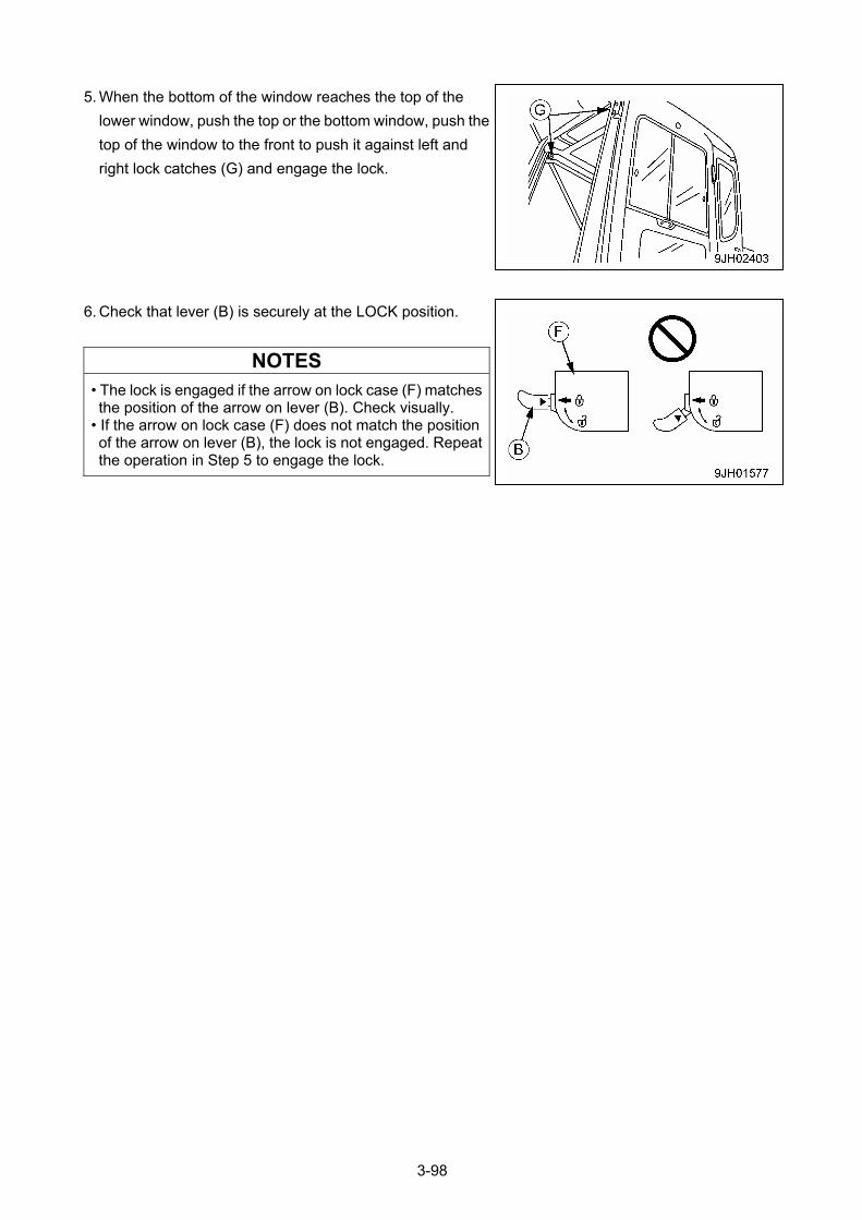
5. When the bottom of the window reaches the top of the
lower window, push the top or the bottom window, push the
top of the window to the front to push it against left and
right lock catches (G) and engage the lock.
6. Check that lever (B) is securely at the LOCK position.
NOTES
• The lock is engaged if the arrow on lock case (F) matches the position of the arrow on lever (B). Check visually.
• If the arrow on lock case (F) does not match the position of the arrow on lever (B), the lock is not engaged. Repeat the operation in Step 5 to engage the lock.
3-98
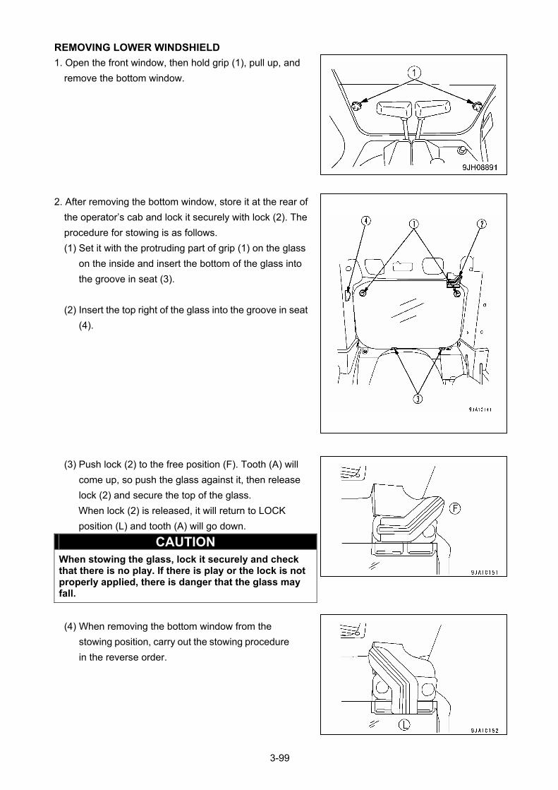
REMOVING LOWER WINDSHIELD
1. Open the front window, then hold grip (1), pull up, and
remove the bottom window.
2. After removing the bottom window, store it at the rear of
the operator’s cab and lock it securely with lock (2). The
procedure for stowing is as follows.
(1) Set it with the protruding part of grip (1) on the glass
on the inside and insert the bottom of the glass into
the groove in seat (3).
(2) Insert the top right of the glass into the groove in seat
(4).
(3) Push lock (2) to the free position (F). Tooth (A) will
come up, so push the glass against it, then release
lock (2) and secure the top of the glass.
When lock (2) is released, it will return to LOCK
position (L) and tooth (A) will go down.
CAUTION When stowing the glass, lock it securely and check that there is no play. If there is play or the lock is not properly applied, there is danger that the glass may fall.
(4) When removing the bottom window from the
stowing position, carry out the stowing procedure
in the reverse order.
3-99
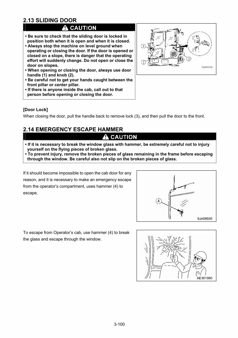
2.13 SLIDING DOOR
• Be sure to check that the sliding door is locked in position both when it is open and when it is closed.
• Always stop the machine on level ground when operating or closing the door. If the door is opened or closed on a slope, there is danger that the operating effort will suddenly change. Do not open or close the door on slopes.
• When opening or closing the door, always use door handle (1) and knob (2).
• Be careful not to get your hands caught between the front pillar or center pillar.
• If there is anyone inside the cab, call out to that person before opening or closing the door.
[Door Lock]
When closing the door, pull the handle back to remove lock (3), and then pull the door to the front.
2.14 EMERGENCY ESCAPE HAMMER
• If it is necessary to break the window glass with hammer, be extremely careful not to injury yourself on the flying pieces of broken glass.
• To prevent injury, remove the broken pieces of glass remaining in the frame before escaping through the window. Be careful also not slip on the broken pieces of glass.
If it should become impossible to open the cab door for any
reason, and it is necessary to make an emergency escape
from the operator’s compartment, uses hammer (4) to
escape.
To escape from Operator’s cab, use hammer (4) to break
the glass and escape through the window.
3-100
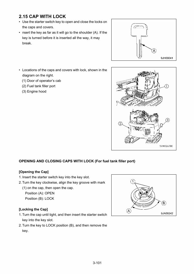
2.15 CAP WITH LOCK • Use the starter switch key to open and close the locks on
the caps and covers.
• nsert the key as far as it will go to the shoulder (A). If the
key is turned before it is inserted all the way, it may
break.
• Locations of the caps and covers with lock, shown in the
diagram on the right.
(1) Door of operator’s cab
(2) Fuel tank filler port
(3) Engine hood
OPENING AND CLOSING CAPS WITH LOCK (For fuel tank filler port)
[Opening the Cap]
1. Insert the starter switch key into the key slot.
2. Turn the key clockwise, align the key groove with mark
(1) on the cap, then open the cap.
Position (A): OPEN
Position (B): LOCK
[Locking the Cap]
1. Turn the cap until tight, and then insert the starter switch
key into the key slot.
2. Turn the key to LOCK position (B), and then remove the
key.
3-101

OPENING AND CLOSING COVERS WITH LOCK
[Opening the Cover]
1. Insert the starter switch key into the key slot.
2. Turn the key counterclockwise and open the cover by
pulling the cover grip.
Position (A): OPEN
Position (B): LOCK
[Locking the Cover]
1. Close the cover and insert the starter switch key into the
key slot.
2. Turn the key clockwise and take the key out.
3-102
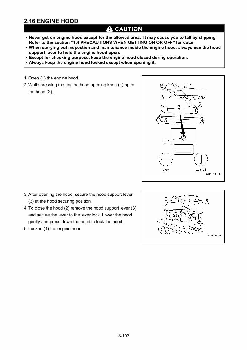
2.16 ENGINE HOOD
• Never get on engine hood except for the allowed area. It may cause you to fall by slipping.
Refer to the section “1.4 PRECAUTIONS WHEN GETTING ON OR OFF” for detail. • When carrying out inspection and maintenance inside the engine hood, always use the hood
support lever to hold the engine hood open. • Except for checking purpose, keep the engine hood closed during operation. • Always keep the engine hood locked except when opening it.
1. Open (1) the engine hood.
2. While pressing the engine hood opening knob (1) open
the hood (2).
3. After opening the hood, secure the hood support lever
(3) at the hood securing position.
4. To close the hood (2) remove the hood support lever (3)
and secure the lever to the lever lock. Lower the hood
gently and press down the hood to lock the hood.
5. Locked (1) the engine hood.
3-103
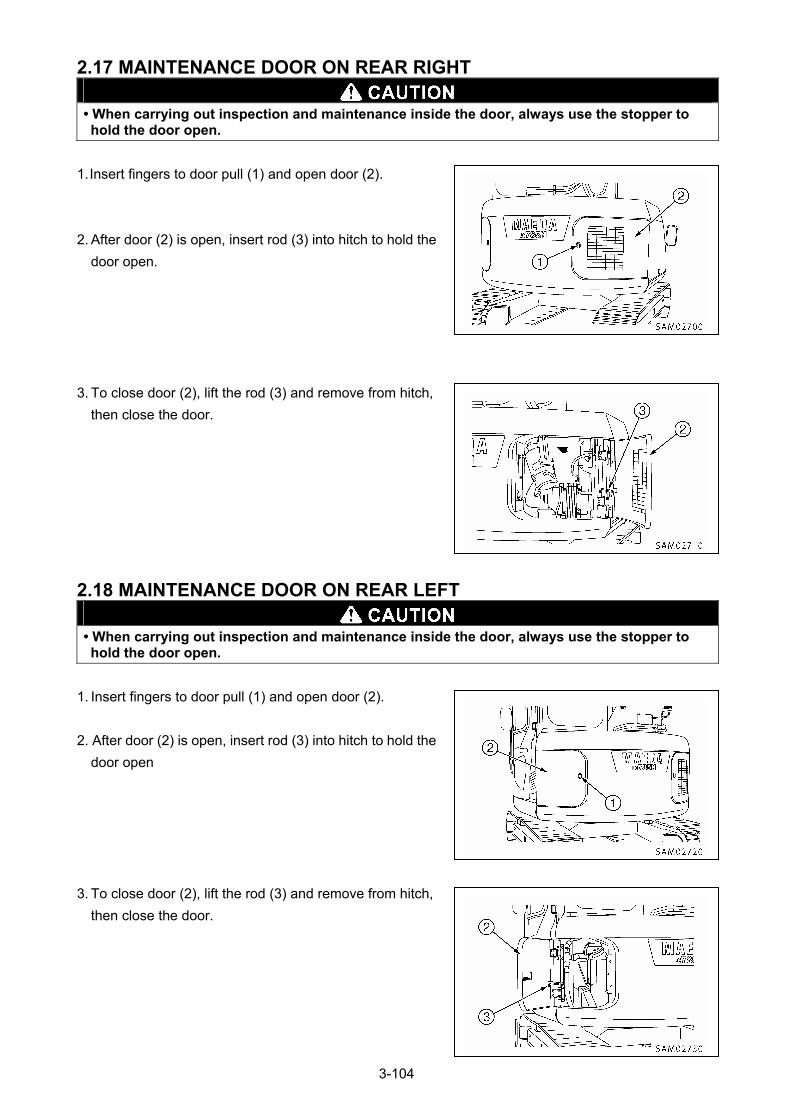
2.17 MAINTENANCE DOOR ON REAR RIGHT
• When carrying out inspection and maintenance inside the door, always use the stopper to hold the door open.
1. Insert fingers to door pull (1) and open door (2).
2. After door (2) is open, insert rod (3) into hitch to hold the
door open.
3. To close door (2), lift the rod (3) and remove from hitch,
then close the door.
2.18 MAINTENANCE DOOR ON REAR LEFT
• When carrying out inspection and maintenance inside the door, always use the stopper to hold the door open.
1. Insert fingers to door pull (1) and open door (2).
2. After door (2) is open, insert rod (3) into hitch to hold the
door open
3. To close door (2), lift the rod (3) and remove from hitch,
then close the door.
3-104
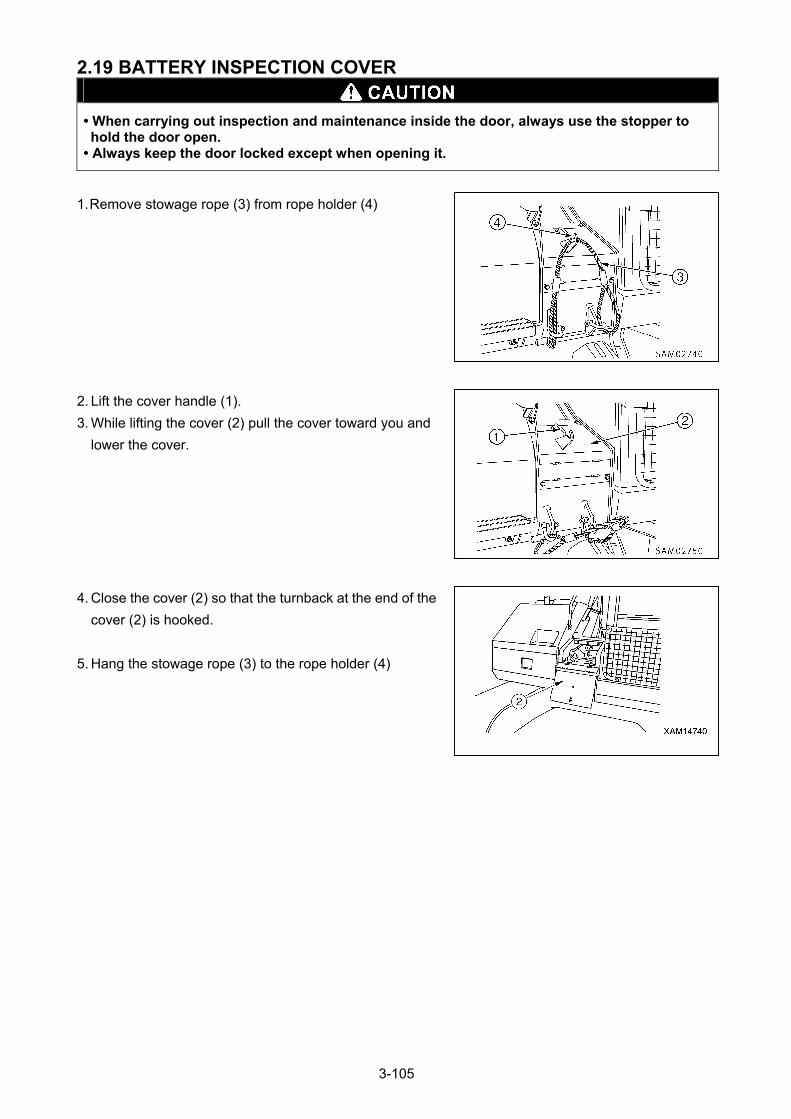
2.19 BATTERY INSPECTION COVER
• When carrying out inspection and maintenance inside the door, always use the stopper to hold the door open.
• Always keep the door locked except when opening it.
1. Remove stowage rope (3) from rope holder (4)
2. Lift the cover handle (1).
3. While lifting the cover (2) pull the cover toward you and
lower the cover.
4. Close the cover (2) so that the turnback at the end of the
cover (2) is hooked.
5. Hang the stowage rope (3) to the rope holder (4)
3-105
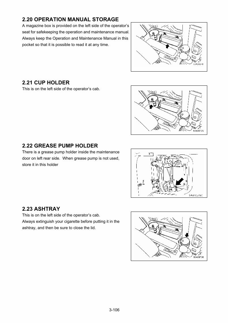
2.20 OPERATION MANUAL STORAGE A magazine box is provided on the left side of the operator’s
seat for safekeeping the operation and maintenance manual.
Always keep the Operation and Maintenance Manual in this
pocket so that it is possible to read it at any time.
2.21 CUP HOLDER This is on the left side of the operator’s cab.
2.22 GREASE PUMP HOLDER There is a grease pump holder inside the maintenance
door on left rear side. When grease pump is not used,
store it in this holder
2.23 ASHTRAY This is on the left side of the operator’s cab.
Always extinguish your cigarette before putting it in the
ashtray, and then be sure to close the lid.
3-106
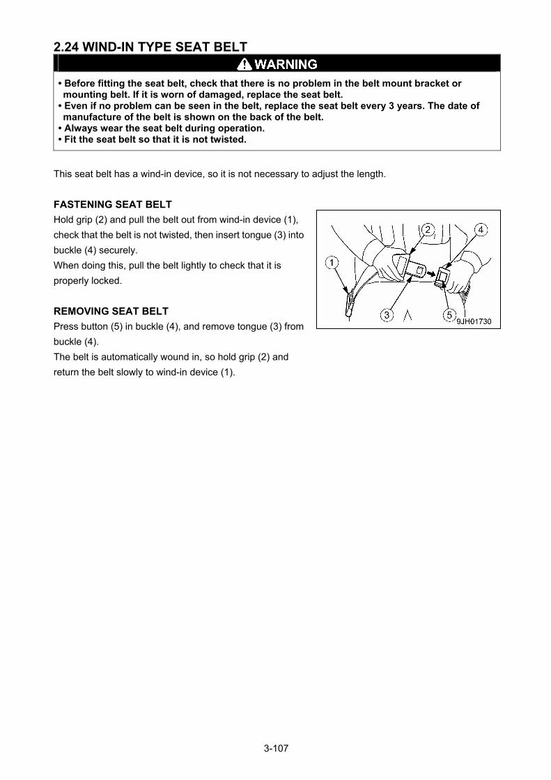
2.24 WIND-IN TYPE SEAT BELT
• Before fitting the seat belt, check that there is no problem in the belt mount bracket or mounting belt. If it is worn of damaged, replace the seat belt.
• Even if no problem can be seen in the belt, replace the seat belt every 3 years. The date of manufacture of the belt is shown on the back of the belt.
• Always wear the seat belt during operation. • Fit the seat belt so that it is not twisted.
This seat belt has a wind-in device, so it is not necessary to adjust the length.
FASTENING SEAT BELT
Hold grip (2) and pull the belt out from wind-in device (1),
check that the belt is not twisted, then insert tongue (3) into
buckle (4) securely.
When doing this, pull the belt lightly to check that it is
properly locked.
REMOVING SEAT BELT
Press button (5) in buckle (4), and remove tongue (3) from
buckle (4).
The belt is automatically wound in, so hold grip (2) and
return the belt slowly to wind-in device (1).
3-107
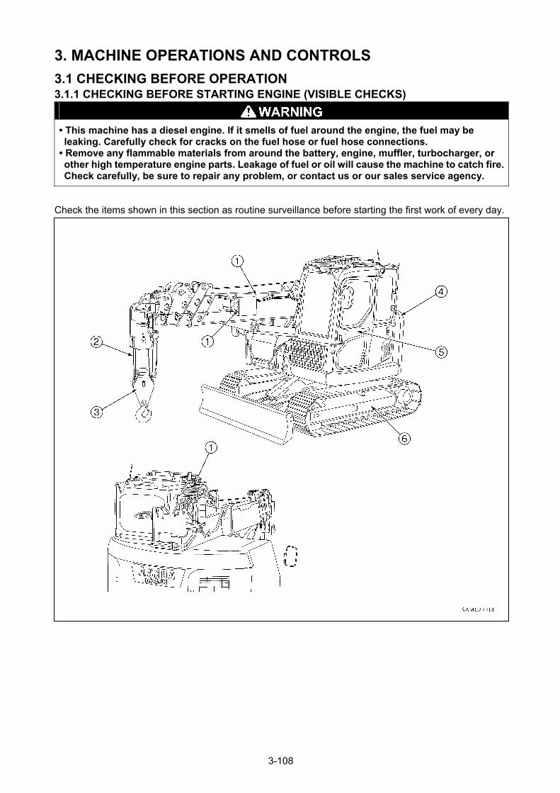
3. MACHINE OPERATIONS AND CONTROLS
3.1 CHECKING BEFORE OPERATION 3.1.1 CHECKING BEFORE STARTING ENGINE (VISIBLE CHECKS)
• This machine has a diesel engine. If it smells of fuel around the engine, the fuel may be leaking. Carefully check for cracks on the fuel hose or fuel hose connections.
• Remove any flammable materials from around the battery, engine, muffler, turbocharger, or other high temperature engine parts. Leakage of fuel or oil will cause the machine to catch fire. Check carefully, be sure to repair any problem, or contact us or our sales service agency.
Check the items shown in this section as routine surveillance before starting the first work of every day.
3-108
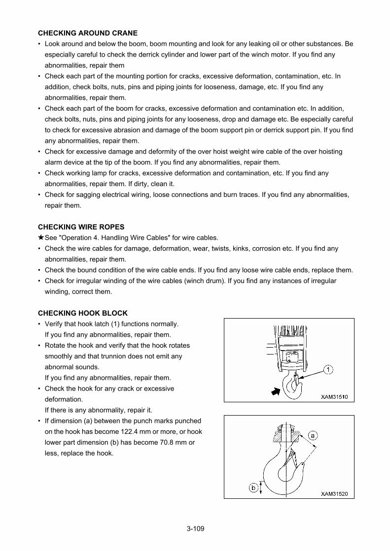
CHECKING AROUND CRANE
• Look around and below the boom, boom mounting and look for any leaking oil or other substances. Be
especially careful to check the derrick cylinder and lower part of the winch motor. If you find any
abnormalities, repair them
• Check each part of the mounting portion for cracks, excessive deformation, contamination, etc. In
addition, check bolts, nuts, pins and piping joints for looseness, damage, etc. If you find any
abnormalities, repair them.
• Check each part of the boom for cracks, excessive deformation and contamination etc. In addition,
check bolts, nuts, pins and piping joints for any looseness, drop and damage etc. Be especially careful
to check for excessive abrasion and damage of the boom support pin or derrick support pin. If you find
any abnormalities, repair them.
• Check for excessive damage and deformity of the over hoist weight wire cable of the over hoisting
alarm device at the tip of the boom. If you find any abnormalities, repair them.
• Check working lamp for cracks, excessive deformation and contamination, etc. If you find any
abnormalities, repair them. If dirty, clean it.
• Check for sagging electrical wiring, loose connections and burn traces. If you find any abnormalities,
repair them.
CHECKING WIRE ROPES
See "Operation 4. Handling Wire Cables" for wire cables.
• Check the wire cables for damage, deformation, wear, twists, kinks, corrosion etc. If you find any
abnormalities, repair them.
• Check the bound condition of the wire cable ends. If you find any loose wire cable ends, replace them.
• Check for irregular winding of the wire cables (winch drum). If you find any instances of irregular
winding, correct them.
CHECKING HOOK BLOCK
• Verify that hook latch (1) functions normally.
If you find any abnormalities, repair them.
• Rotate the hook and verify that the hook rotates
smoothly and that trunnion does not emit any
abnormal sounds.
If you find any abnormalities, repair them.
• Check the hook for any crack or excessive
deformation.
If there is any abnormality, repair it.
• If dimension (a) between the punch marks punched
on the hook has become 122.4 mm or more, or hook
lower part dimension (b) has become 70.8 mm or
less, replace the hook.
3-109
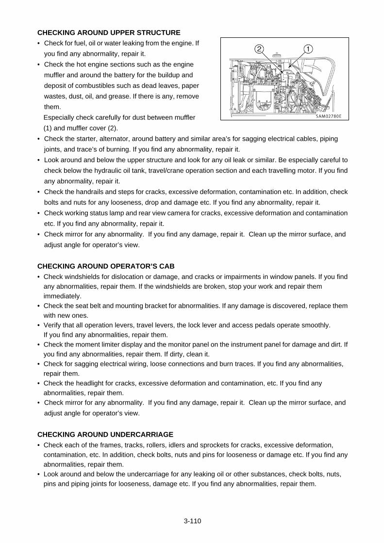
3-110
CHECKING AROUND UPPER STRUCTURE
• Check for fuel, oil or water leaking from the engine. If
you find any abnormality, repair it.
• Check the hot engine sections such as the engine
muffler and around the battery for the buildup and
deposit of combustibles such as dead leaves, paper
wastes, dust, oil, and grease. If there is any, remove
them.
Especially check carefully for dust between muffler
(1) and muffler cover (2).
• Check the starter, alternator, around battery and similar area’s for sagging electrical cables, piping
joints, and trace’s of burning. If you find any abnormality, repair it.
• Look around and below the upper structure and look for any oil leak or similar. Be especially careful to
check below the hydraulic oil tank, travel/crane operation section and each travelling motor. If you find
any abnormality, repair it.
• Check the handrails and steps for cracks, excessive deformation, contamination etc. In addition, check
bolts and nuts for any looseness, drop and damage etc. If you find any abnormality, repair it.
• Check working status lamp and rear view camera for cracks, excessive deformation and contamination
etc. If you find any abnormality, repair it.
• Check mirror for any abnormality. If you find any damage, repair it. Clean up the mirror surface, and
adjust angle for operator’s view.
CHECKING AROUND OPERATOR’S CAB
• Check windshields for dislocation or damage, and cracks or impairments in window panels. If you find
any abnormalities, repair them. If the windshields are broken, stop your work and repair them
immediately.
• Check the seat belt and mounting bracket for abnormalities. If any damage is discovered, replace them
with new ones.
• Verify that all operation levers, travel levers, the lock lever and access pedals operate smoothly.
If you find any abnormalities, repair them.
• Check the moment limiter display and the monitor panel on the instrument panel for damage and dirt. If
you find any abnormalities, repair them. If dirty, clean it.
• Check for sagging electrical wiring, loose connections and burn traces. If you find any abnormalities,
repair them.
• Check the headlight for cracks, excessive deformation and contamination, etc. If you find any
abnormalities, repair them.
• Check mirror for any abnormality. If you find any damage, repair it. Clean up the mirror surface, and
adjust angle for operator’s view.
CHECKING AROUND UNDERCARRIAGE
• Check each of the frames, tracks, rollers, idlers and sprockets for cracks, excessive deformation,
contamination, etc. In addition, check bolts, nuts and pins for looseness or damage etc. If you find any
abnormalities, repair them.
• Look around and below the undercarriage for any leaking oil or other substances, check bolts, nuts,
pins and piping joints for looseness, damage etc. If you find any abnormalities, repair them.
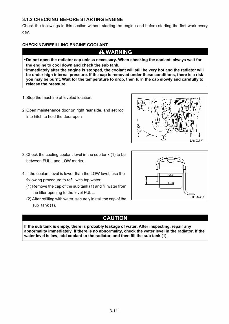
3.1.2 CHECKING BEFORE STARTING ENGINE Check the followings in this section without starting the engine and before starting the first work every
day.
CHECKING/REFILLING ENGINE COOLANT
• Do not open the radiator cap unless necessary. When checking the coolant, always wait for the engine to cool down and check the sub tank.
• Immediately after the engine is stopped, the coolant will still be very hot and the radiator will be under high internal pressure. If the cap is removed under these conditions, there is a risk you may be burnt. Wait for the temperature to drop, then turn the cap slowly and carefully to release the pressure.
1. Stop the machine at leveled location.
2. Open maintenance door on right rear side, and set rod
into hitch to hold the door open
3. Check the cooling coolant level in the sub tank (1) to be
between FULL and LOW marks.
4. If the coolant level is lower than the LOW level, use the
following procedure to refill with tap water.
(1) Remove the cap of the sub tank (1) and fill water from
the filler opening to the level FULL.
(2) After refilling with water, securely install the cap of the
sub tank (1).
CAUTION
If the sub tank is empty, there is probably leakage of water. After inspecting, repair any abnormality immediately. If there is no abnormality, check the water level in the radiator. If the water level is low, add coolant to the radiator, and then fill the sub tank (1).
3-111
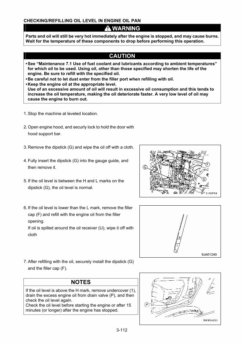
CHECKING/REFILLING OIL LEVEL IN ENGINE OIL PAN
Parts and oil will still be very hot immediately after the engine is stopped, and may cause burns. Wait for the temperature of these components to drop before performing this operation.
CAUTION • See “Maintenance 7.1 Use of fuel coolant and lubricants according to ambient temperatures” for which oil to be used. Using oil, other than those specified may shorten the life of the engine. Be sure to refill with the specified oil.
• Be careful not to let dust enter from the filler port when refilling with oil. • Keep the engine oil at the appropriate level. Use of an excessive amount of oil will result in excessive oil consumption and this tends to increase the oil temperature, making the oil deteriorate faster. A very low level of oil may cause the engine to burn out.
1. Stop the machine at leveled location.
2. Open engine hood, and securly lock to hold the door with
hood support bar.
3. Remove the dipstick (G) and wipe the oil off with a cloth.
4. Fully insert the dipstick (G) into the gauge guide, and
then remove it.
5. If the oil level is between the H and L marks on the
dipstick (G), the oil level is normal.
6. If the oil level is lower than the L mark, remove the filler
cap (F) and refill with the engine oil from the filler
opening.
If oil is spilled around the oil receiver (U), wipe it off with
cloth
7. After refilling with the oil, securely install the dipstick (G)
and the filler cap (F).
NOTES
If the oil level is above the H mark, remove undercover (1), drain the excess engine oil from drain valve (P), and then check the oil level again. Check the oil level before starting the engine or after 15 minutes (or longer) after the engine has stopped.
3-112
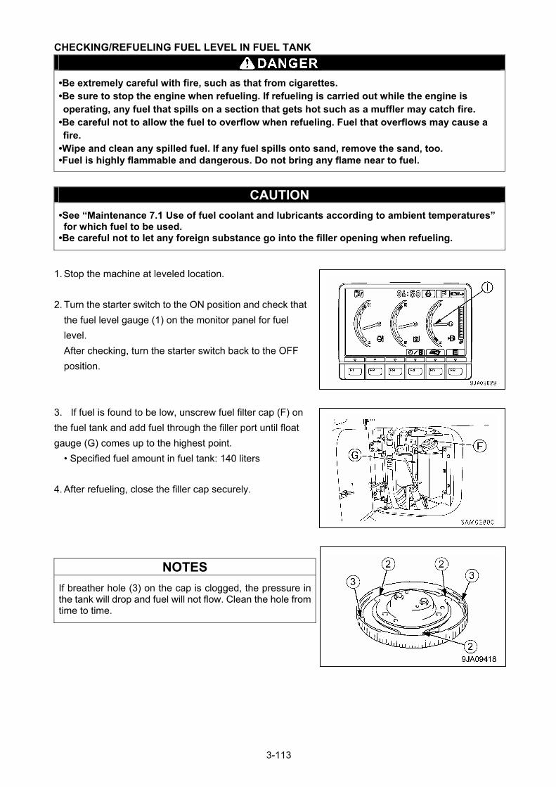
CHECKING/REFUELING FUEL LEVEL IN FUEL TANK
•Be extremely careful with fire, such as that from cigarettes. •Be sure to stop the engine when refueling. If refueling is carried out while the engine is operating, any fuel that spills on a section that gets hot such as a muffler may catch fire.
•Be careful not to allow the fuel to overflow when refueling. Fuel that overflows may cause a fire.
•Wipe and clean any spilled fuel. If any fuel spills onto sand, remove the sand, too. •Fuel is highly flammable and dangerous. Do not bring any flame near to fuel.
CAUTION
•See “Maintenance 7.1 Use of fuel coolant and lubricants according to ambient temperatures” for which fuel to be used.
•Be careful not to let any foreign substance go into the filler opening when refueling.
1. Stop the machine at leveled location.
2. Turn the starter switch to the ON position and check that
the fuel level gauge (1) on the monitor panel for fuel
level.
After checking, turn the starter switch back to the OFF
position.
3. If fuel is found to be low, unscrew fuel filter cap (F) on
the fuel tank and add fuel through the filler port until float
gauge (G) comes up to the highest point.
• Specified fuel amount in fuel tank: 140 liters
4. After refueling, close the filler cap securely.
NOTES
If breather hole (3) on the cap is clogged, the pressure in the tank will drop and fuel will not flow. Clean the hole from time to time.
3-113
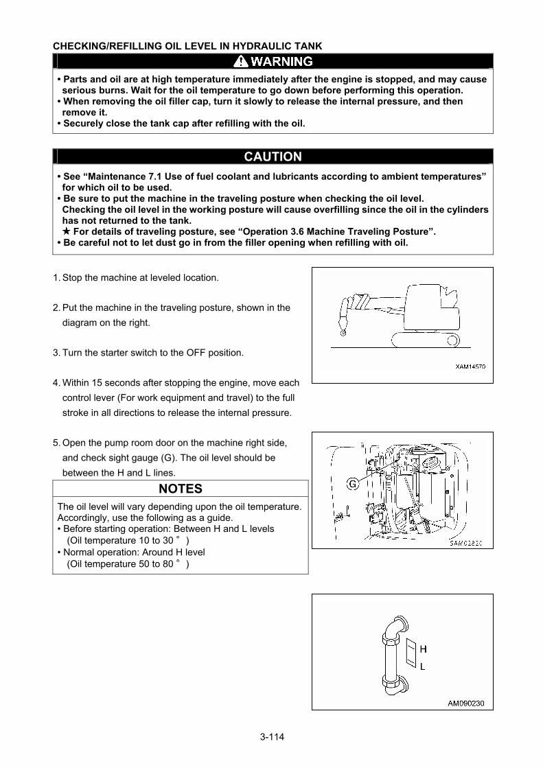
CHECKING/REFILLING OIL LEVEL IN HYDRAULIC TANK
• Parts and oil are at high temperature immediately after the engine is stopped, and may cause serious burns. Wait for the oil temperature to go down before performing this operation.
• When removing the oil filler cap, turn it slowly to release the internal pressure, and then remove it.
• Securely close the tank cap after refilling with the oil.
CAUTION
• See “Maintenance 7.1 Use of fuel coolant and lubricants according to ambient temperatures” for which oil to be used.
• Be sure to put the machine in the traveling posture when checking the oil level. Checking the oil level in the working posture will cause overfilling since the oil in the cylinders has not returned to the tank.
For details of traveling posture, see “Operation 3.6 Machine Traveling Posture”. • Be careful not to let dust go in from the filler opening when refilling with oil.
1. Stop the machine at leveled location.
2. Put the machine in the traveling posture, shown in the
diagram on the right.
3. Turn the starter switch to the OFF position.
4. Within 15 seconds after stopping the engine, move each
control lever (For work equipment and travel) to the full
stroke in all directions to release the internal pressure.
5. Open the pump room door on the machine right side,
and check sight gauge (G). The oil level should be
between the H and L lines.
NOTES
The oil level will vary depending upon the oil temperature. Accordingly, use the following as a guide. • Before starting operation: Between H and L levels
(Oil temperature 10 to 30 °) • Normal operation: Around H level
(Oil temperature 50 to 80 °)
3-114
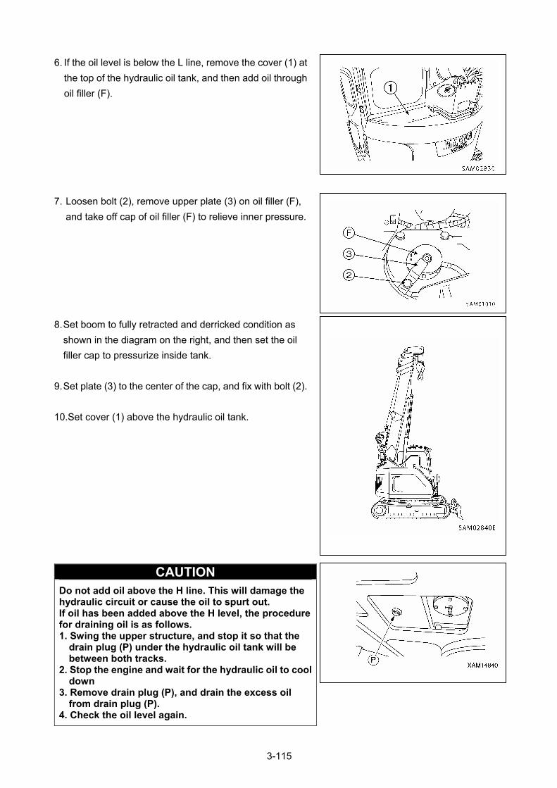
6. If the oil level is below the L line, remove the cover (1) at
the top of the hydraulic oil tank, and then add oil through
oil filler (F).
7. Loosen bolt (2), remove upper plate (3) on oil filler (F),
and take off cap of oil filler (F) to relieve inner pressure.
8. Set boom to fully retracted and derricked condition as
shown in the diagram on the right, and then set the oil
filler cap to pressurize inside tank.
9. Set plate (3) to the center of the cap, and fix with bolt (2).
10.Set cover (1) above the hydraulic oil tank.
CAUTION Do not add oil above the H line. This will damage the hydraulic circuit or cause the oil to spurt out. If oil has been added above the H level, the procedure for draining oil is as follows. 1. Swing the upper structure, and stop it so that the
drain plug (P) under the hydraulic oil tank will be between both tracks.
2. Stop the engine and wait for the hydraulic oil to cool down
3. Remove drain plug (P), and drain the excess oil from drain plug (P).
4. Check the oil level again.
3-115
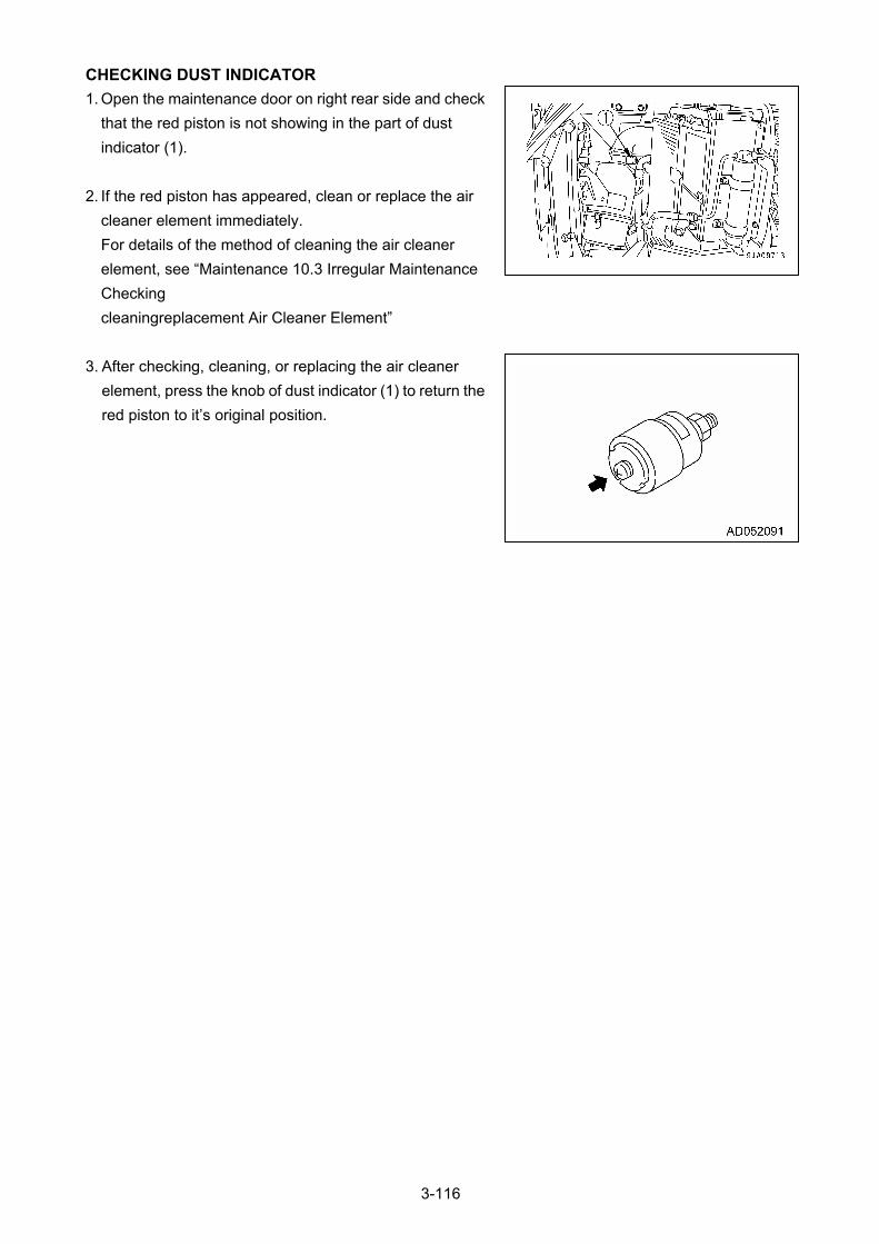
CHECKING DUST INDICATOR
1. Open the maintenance door on right rear side and check
that the red piston is not showing in the part of dust
indicator (1).
2. If the red piston has appeared, clean or replace the air
cleaner element immediately.
For details of the method of cleaning the air cleaner
element, see “Maintenance 10.3 Irregular Maintenance
Checking
cleaningreplacement Air Cleaner Element”
3. After checking, cleaning, or replacing the air cleaner
element, press the knob of dust indicator (1) to return the
red piston to it’s original position.
3-116
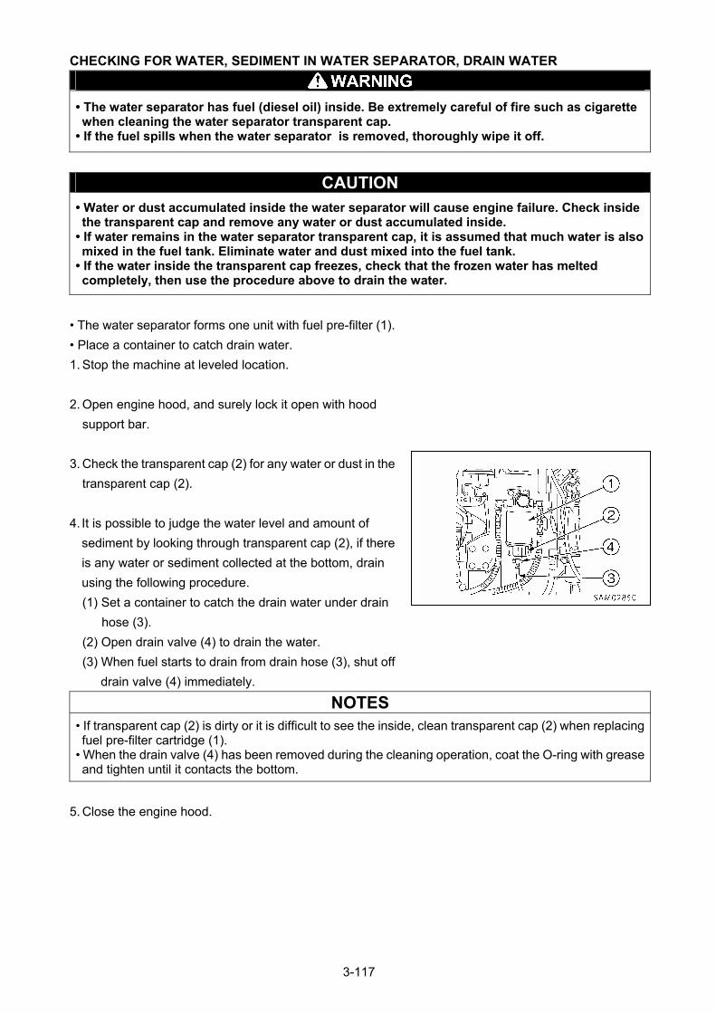
CHECKING FOR WATER, SEDIMENT IN WATER SEPARATOR, DRAIN WATER
• The water separator has fuel (diesel oil) inside. Be extremely careful of fire such as cigarette when cleaning the water separator transparent cap.
• If the fuel spills when the water separator is removed, thoroughly wipe it off.
CAUTION • Water or dust accumulated inside the water separator will cause engine failure. Check inside the transparent cap and remove any water or dust accumulated inside.
• If water remains in the water separator transparent cap, it is assumed that much water is also mixed in the fuel tank. Eliminate water and dust mixed into the fuel tank.
• If the water inside the transparent cap freezes, check that the frozen water has melted completely, then use the procedure above to drain the water.
• The water separator forms one unit with fuel pre-filter (1).
• Place a container to catch drain water.
1. Stop the machine at leveled location.
2. Open engine hood, and surely lock it open with hood
support bar.
3. Check the transparent cap (2) for any water or dust in the
transparent cap (2).
4. It is possible to judge the water level and amount of
sediment by looking through transparent cap (2), if there
is any water or sediment collected at the bottom, drain
using the following procedure.
(1) Set a container to catch the drain water under drain
hose (3).
(2) Open drain valve (4) to drain the water.
(3) When fuel starts to drain from drain hose (3), shut off
drain valve (4) immediately.
NOTES
• If transparent cap (2) is dirty or it is difficult to see the inside, clean transparent cap (2) when replacing fuel pre-filter cartridge (1).
• When the drain valve (4) has been removed during the cleaning operation, coat the O-ring with grease and tighten until it contacts the bottom.
5. Close the engine hood.
3-117
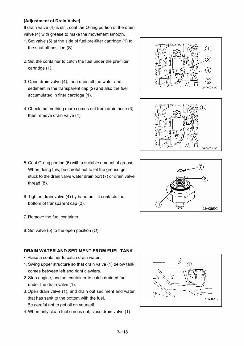
[Adjustment of Drain Valve]
If drain valve (4) is stiff, coat the O-ring portion of the drain
valve (4) with grease to make the movement smooth.
1. Set valve (5) at the side of fuel pre-filter cartridge (1) to
the shut off position (S).
2. Set the container to catch the fuel under the pre-filter
cartridge (1).
3. Open drain valve (4), then drain all the water and
sediment in the transparent cap (2) and also the fuel
accumulated in filter cartridge (1).
4. Check that nothing more comes out from drain hose (3),
then remove drain valve (4).
5. Coat O-ring portion (6) with a suitable amount of grease.
When doing this, be careful not to let the grease get
stuck to the drain valve water drain port (7) or drain valve
thread (8).
6. Tighten drain valve (4) by hand until it contacts the
bottom of transparent cap (2).
7. Remove the fuel container.
8. Set valve (5) to the open position (O).
DRAIN WATER AND SEDIMENT FROM FUEL TANK
• Plase a container to catch drain water.
1. Swing upper structure so that drain valve (1) below tank
comes between left and right clawlers.
2. Stop engine, and set container to catch drained fuel
under the drain valve (1).
3. Open drain valve (1), and drain out sediment and water
that has sank to the bottom with the fuel.
Be careful not to get oil on yourself.
4. When only clean fuel comes out, close drain valve (1).
3-118
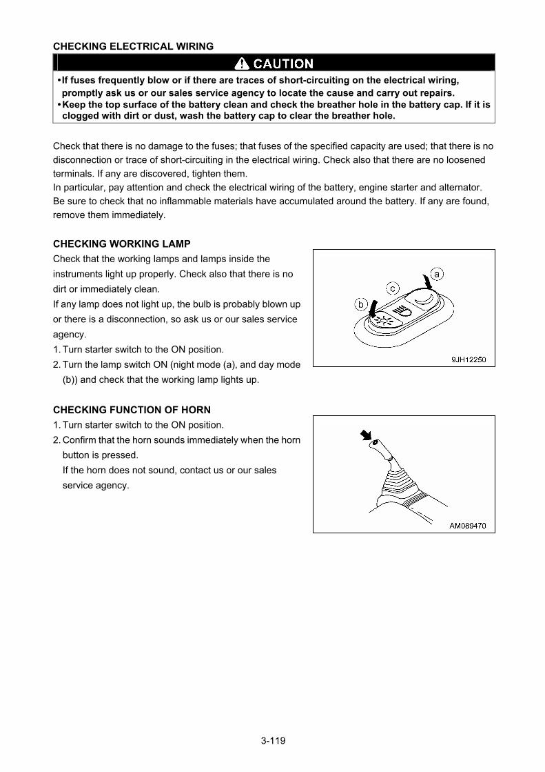
CHECKING ELECTRICAL WIRING
• If fuses frequently blow or if there are traces of short-circuiting on the electrical wiring, promptly ask us or our sales service agency to locate the cause and carry out repairs.
• Keep the top surface of the battery clean and check the breather hole in the battery cap. If it is clogged with dirt or dust, wash the battery cap to clear the breather hole.
Check that there is no damage to the fuses; that fuses of the specified capacity are used; that there is no
disconnection or trace of short-circuiting in the electrical wiring. Check also that there are no loosened
terminals. If any are discovered, tighten them.
In particular, pay attention and check the electrical wiring of the battery, engine starter and alternator.
Be sure to check that no inflammable materials have accumulated around the battery. If any are found,
remove them immediately.
CHECKING WORKING LAMP
Check that the working lamps and lamps inside the
instruments light up properly. Check also that there is no
dirt or immediately clean.
If any lamp does not light up, the bulb is probably blown up
or there is a disconnection, so ask us or our sales service
agency.
1. Turn starter switch to the ON position.
2. Turn the lamp switch ON (night mode (a), and day mode
(b)) and check that the working lamp lights up.
CHECKING FUNCTION OF HORN
1. Turn starter switch to the ON position.
2. Confirm that the horn sounds immediately when the horn
button is pressed.
If the horn does not sound, contact us or our sales
service agency.
3-119
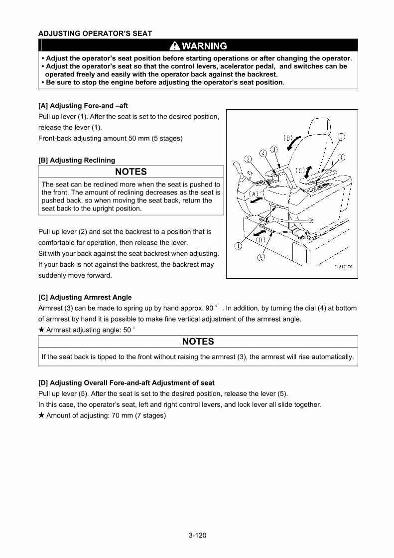
ADJUSTING OPERATOR’S SEAT
• Adjust the operator’s seat position before starting operations or after changing the operator.• Adjust the operator’s seat so that the control levers, acelerator pedal, and switches can be operated freely and easily with the operator back against the backrest.
• Be sure to stop the engine before adjusting the operator’s seat position.
[A] Adjusting Fore-and –aft
Pull up lever (1). After the seat is set to the desired position,
release the lever (1).
Front-back adjusting amount 50 mm (5 stages)
[B] Adjusting Reclining
NOTES
The seat can be reclined more when the seat is pushed to the front. The amount of reclining decreases as the seat is pushed back, so when moving the seat back, return the seat back to the upright position.
Pull up lever (2) and set the backrest to a position that is
comfortable for operation, then release the lever.
Sit with your back against the seat backrest when adjusting.
If your back is not against the backrest, the backrest may
suddenly move forward.
[C] Adjusting Armrest Angle
Armrest (3) can be made to spring up by hand approx. 90 °. In addition, by turning the dial (4) at bottom
of armrest by hand it is possible to make fine vertical adjustment of the armrest angle.
Armrest adjusting angle: 50 °
NOTES
If the seat back is tipped to the front without raising the armrest (3), the armrest will rise automatically.
[D] Adjusting Overall Fore-and-aft Adjustment of seat
Pull up lever (5). After the seat is set to the desired position, release the lever (5).
In this case, the operator’s seat, left and right control levers, and lock lever all slide together.
Amount of adjusting: 70 mm (7 stages)
3-120
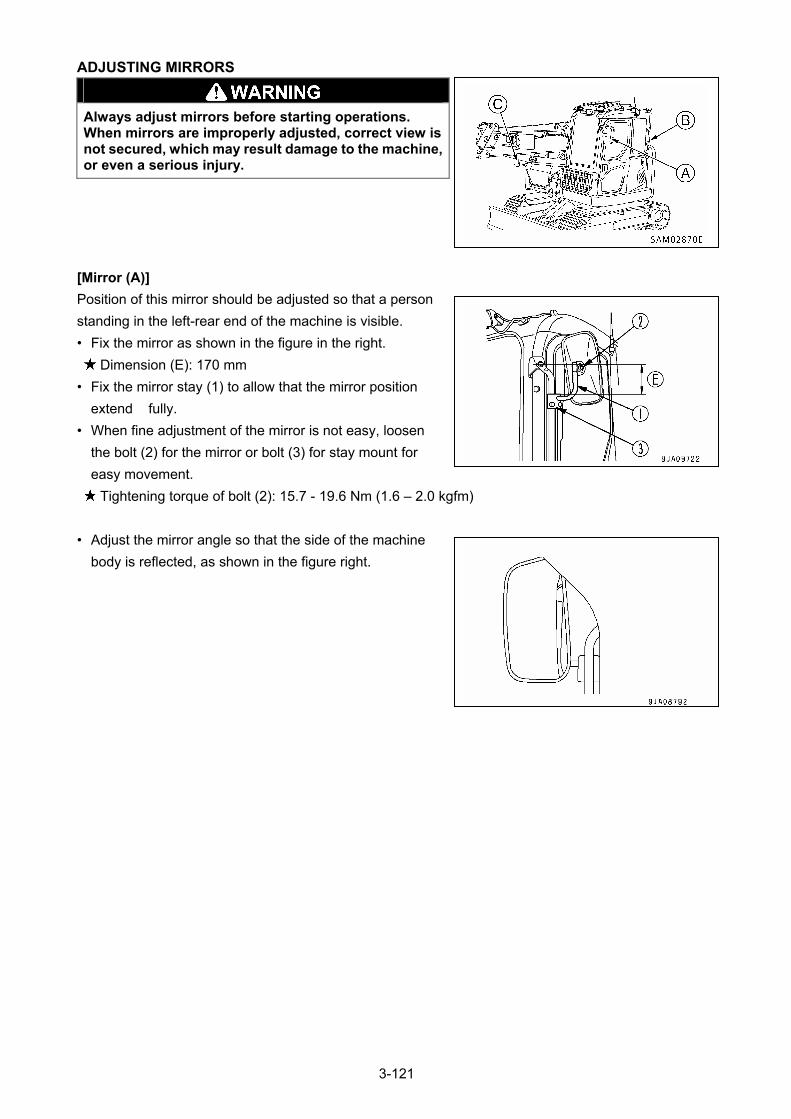
ADJUSTING MIRRORS
Always adjust mirrors before starting operations. When mirrors are improperly adjusted, correct view is not secured, which may result damage to the machine, or even a serious injury.
[Mirror (A)]
Position of this mirror should be adjusted so that a person
standing in the left-rear end of the machine is visible.
• Fix the mirror as shown in the figure in the right.
Dimension (E): 170 mm
• Fix the mirror stay (1) to allow that the mirror position
extend fully.
• When fine adjustment of the mirror is not easy, loosen
the bolt (2) for the mirror or bolt (3) for stay mount for
easy movement.
Tightening torque of bolt (2): 15.7 - 19.6 Nm (1.6 – 2.0 kgfm)
• Adjust the mirror angle so that the side of the machine
body is reflected, as shown in the figure right.
3-121
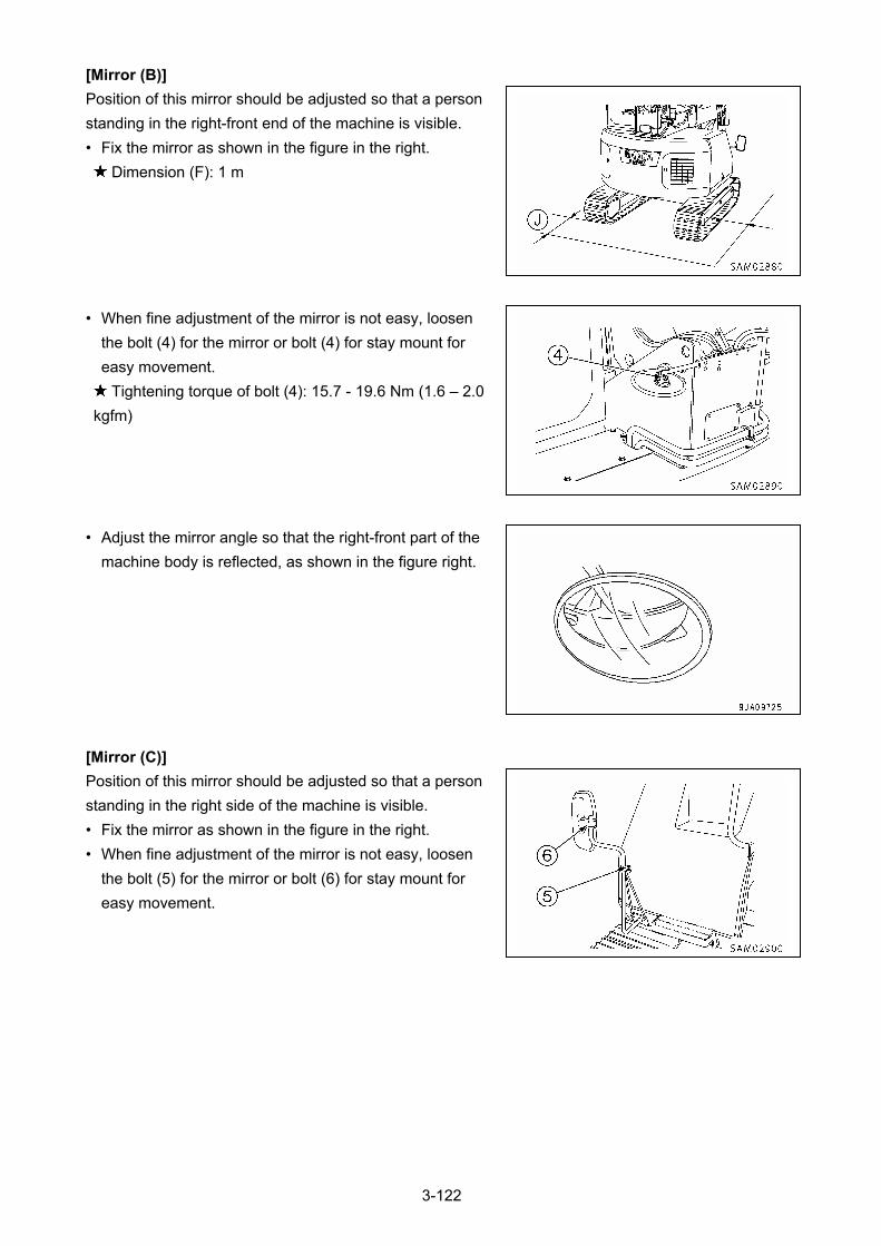
[Mirror (B)]
Position of this mirror should be adjusted so that a person
standing in the right-front end of the machine is visible.
• Fix the mirror as shown in the figure in the right.
Dimension (F): 1 m
• When fine adjustment of the mirror is not easy, loosen
the bolt (4) for the mirror or bolt (4) for stay mount for
easy movement.
Tightening torque of bolt (4): 15.7 - 19.6 Nm (1.6 – 2.0
kgfm)
• Adjust the mirror angle so that the right-front part of the
machine body is reflected, as shown in the figure right.
[Mirror (C)]
Position of this mirror should be adjusted so that a person
standing in the right side of the machine is visible.
• Fix the mirror as shown in the figure in the right.
• When fine adjustment of the mirror is not easy, loosen
the bolt (5) for the mirror or bolt (6) for stay mount for
easy movement.
3-122
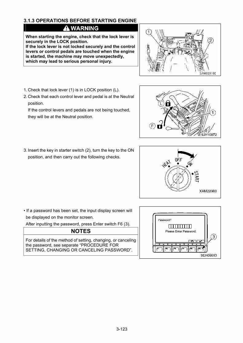
3.1.3 OPERATIONS BEFORE STARTING ENGINE
When starting the engine, check that the lock lever is securely in the LOCK position. If the lock lever is not locked securely and the control levers or control pedals are touched when the engine is started, the machine may move unexpectedly, which may lead to serious personal injury.
1. Check that lock lever (1) is in LOCK position (L).
2. Check that each control lever and pedal is at the Neutral
position.
If the control levers and pedals are not being touched,
they will be at the Neutral position.
3. Insert the key in starter switch (2), turn the key to the ON
position, and then carry out the following checks.
• If a password has been set, the input display screen will
be displayed on the monitor screen.
After inputting the password, press Enter switch F6 (3).
NOTES
For details of the method of setting, changing, or canceling the password, see separate “PROCEDURE FOR SETTING, CHANGING OR CANCELING PASSWORD”.
3-123
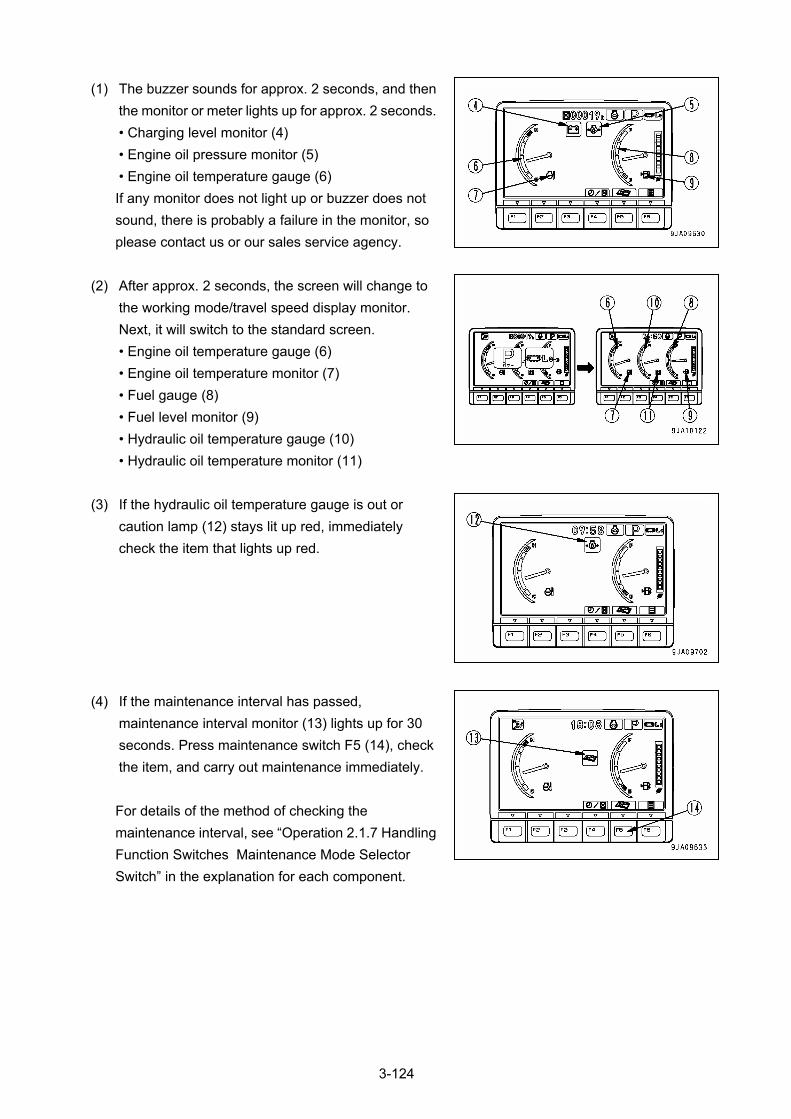
(1) The buzzer sounds for approx. 2 seconds, and then
the monitor or meter lights up for approx. 2 seconds.
• Charging level monitor (4)
• Engine oil pressure monitor (5)
• Engine oil temperature gauge (6)
If any monitor does not light up or buzzer does not
sound, there is probably a failure in the monitor, so
please contact us or our sales service agency.
(2) After approx. 2 seconds, the screen will change to
the working mode/travel speed display monitor.
Next, it will switch to the standard screen.
• Engine oil temperature gauge (6)
• Engine oil temperature monitor (7)
• Fuel gauge (8)
• Fuel level monitor (9)
• Hydraulic oil temperature gauge (10)
• Hydraulic oil temperature monitor (11)
(3) If the hydraulic oil temperature gauge is out or
caution lamp (12) stays lit up red, immediately
check the item that lights up red.
(4) If the maintenance interval has passed,
maintenance interval monitor (13) lights up for 30
seconds. Press maintenance switch F5 (14), check
the item, and carry out maintenance immediately.
For details of the method of checking the
maintenance interval, see “Operation 2.1.7 Handling
Function Switches Maintenance Mode Selector
Switch” in the explanation for each component.
3-124
3.1.4 CHECKING AFTER STARTING ENGINE Check the followings in this section after starting the engine and before starting work for the first time
every day.
CAUTION
The checkups described in this section should be carried out after starting the machine. See "Operation 3.1.3 Operations Before Starting Engine" and later to execute the engine startup, travelling operations, and crane operations.
CHECKING OF ENGINE STARTING ABILITY AND NOISE
When starting the engine, check that there are no abnormal engine noises and that the engine starts up
easily and smoothly.
Also check that there are no abnormal noises when the engine is idling or when engine revolutions
increase slightly.
• If there is an abnormal noise at the time of engine startup and if that condition continues, the engine
may be damaged.
In that case, ask us or our sales service agency to check the engine as soon as possible.
CHECKING OF ENGINE ACCELERATION AND DECELERATION
When stopping the machine during the operation, check that there is no irregular engine speed or that the
engine does not stop suddenly.
Check also that the engine speed rises smoothly when the fuel control dial is turned to the full (MAX).
• Carry out these checks in a safe place, watching out for any potential surrounding dangers.
• If the engine performs very badly at low idling speed or during acceleration, and if this condition
continues, the engine may be damaged or may not be able to recognize the operator’s driving style,
and as a result may lead to an unexpected accident.
In that case, ask us or our sales service agency to check the engine as soon as possible.
CHECKING ENGINE EXHAUST GAS COLOR, NOISE AND VIBRATION
Keep the engine idling and continue the operation without a load for about five minutes.
Verify that the engine exhaust gas color is either transparent or slightly blue. Also, check for abnormal
noises and vibrations. If you find any abnormalities, repair them.
3-125
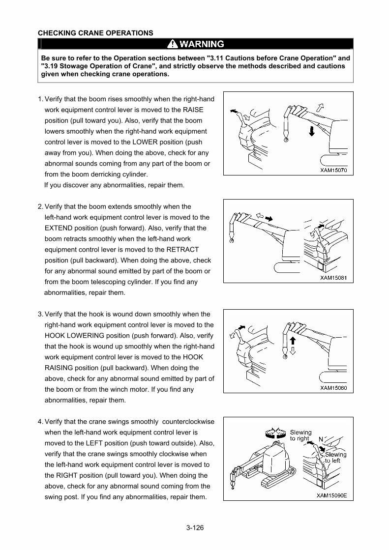
CHECKING CRANE OPERATIONS
Be sure to refer to the Operation sections between "3.11 Cautions before Crane Operation" and "3.19 Stowage Operation of Crane", and strictly observe the methods described and cautions given when checking crane operations.
1. Verify that the boom rises smoothly when the right-hand
work equipment control lever is moved to the RAISE
position (pull toward you). Also, verify that the boom
lowers smoothly when the right-hand work equipment
control lever is moved to the LOWER position (push
away from you). When doing the above, check for any
abnormal sounds coming from any part of the boom or
from the boom derricking cylinder.
If you discover any abnormalities, repair them.
2. Verify that the boom extends smoothly when the
left-hand work equipment control lever is moved to the
EXTEND position (push forward). Also, verify that the
boom retracts smoothly when the left-hand work
equipment control lever is moved to the RETRACT
position (pull backward). When doing the above, check
for any abnormal sound emitted by part of the boom or
from the boom telescoping cylinder. If you find any
abnormalities, repair them.
3. Verify that the hook is wound down smoothly when the
right-hand work equipment control lever is moved to the
HOOK LOWERING position (push forward). Also, verify
that the hook is wound up smoothly when the right-hand
work equipment control lever is moved to the HOOK
RAISING position (pull backward). When doing the
above, check for any abnormal sound emitted by part of
the boom or from the winch motor. If you find any
abnormalities, repair them.
4. Verify that the crane swings smoothly counterclockwise
when the left-hand work equipment control lever is
moved to the LEFT position (push toward outside). Also,
verify that the crane swings smoothly clockwise when
the left-hand work equipment control lever is moved to
the RIGHT position (pull toward you). When doing the
above, check for any abnormal sound coming from the
swing post. If you find any abnormalities, repair them.
3-126
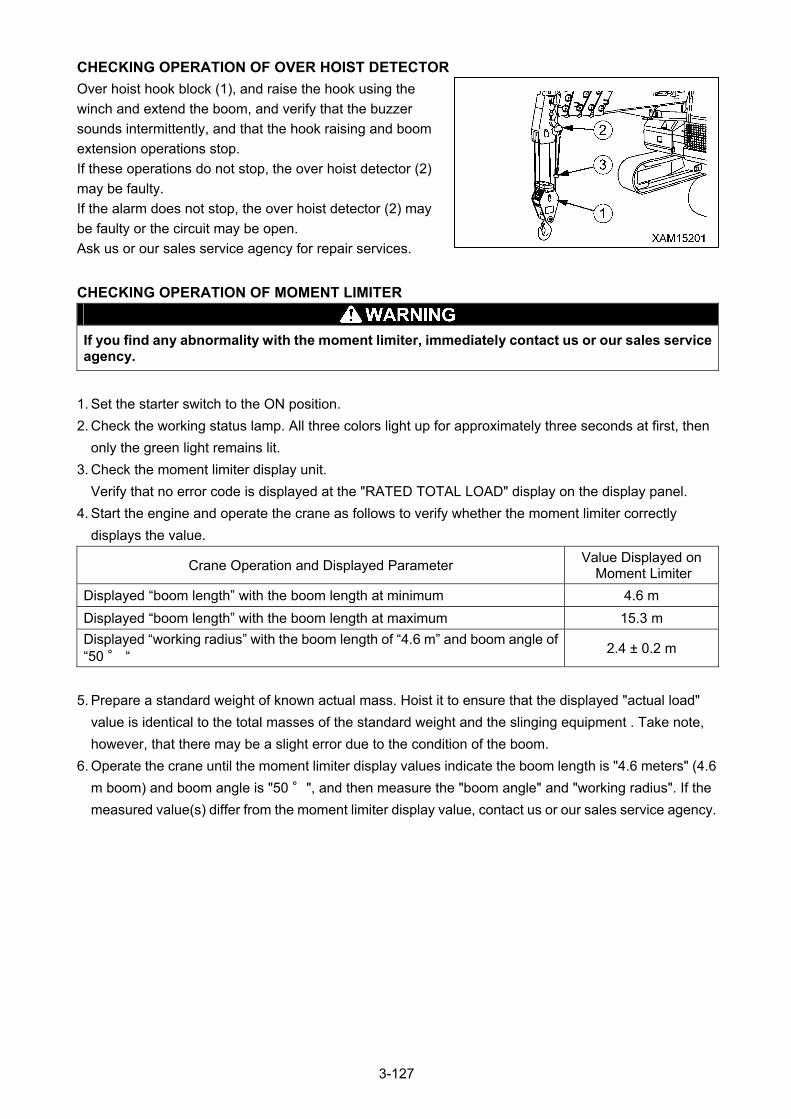
CHECKING OPERATION OF OVER HOIST DETECTOR
Over hoist hook block (1), and raise the hook using the
winch and extend the boom, and verify that the buzzer
sounds intermittently, and that the hook raising and boom
extension operations stop.
If these operations do not stop, the over hoist detector (2)
may be faulty.
If the alarm does not stop, the over hoist detector (2) may
be faulty or the circuit may be open.
Ask us or our sales service agency for repair services.
CHECKING OPERATION OF MOMENT LIMITER
If you find any abnormality with the moment limiter, immediately contact us or our sales service agency.
1. Set the starter switch to the ON position.
2. Check the working status lamp. All three colors light up for approximately three seconds at first, then
only the green light remains lit.
3. Check the moment limiter display unit.
Verify that no error code is displayed at the "RATED TOTAL LOAD" display on the display panel.
4. Start the engine and operate the crane as follows to verify whether the moment limiter correctly
displays the value.
Crane Operation and Displayed Parameter Value Displayed on
Moment Limiter
Displayed “boom length” with the boom length at minimum 4.6 m
Displayed “boom length” with the boom length at maximum 15.3 m
Displayed “working radius” with the boom length of “4.6 m” and boom angle of “50 ° “
2.4 ± 0.2 m
5. Prepare a standard weight of known actual mass. Hoist it to ensure that the displayed "actual load"
value is identical to the total masses of the standard weight and the slinging equipment . Take note,
however, that there may be a slight error due to the condition of the boom.
6. Operate the crane until the moment limiter display values indicate the boom length is "4.6 meters" (4.6
m boom) and boom angle is "50 °", and then measure the "boom angle" and "working radius". If the
measured value(s) differ from the moment limiter display value, contact us or our sales service agency.
3-127
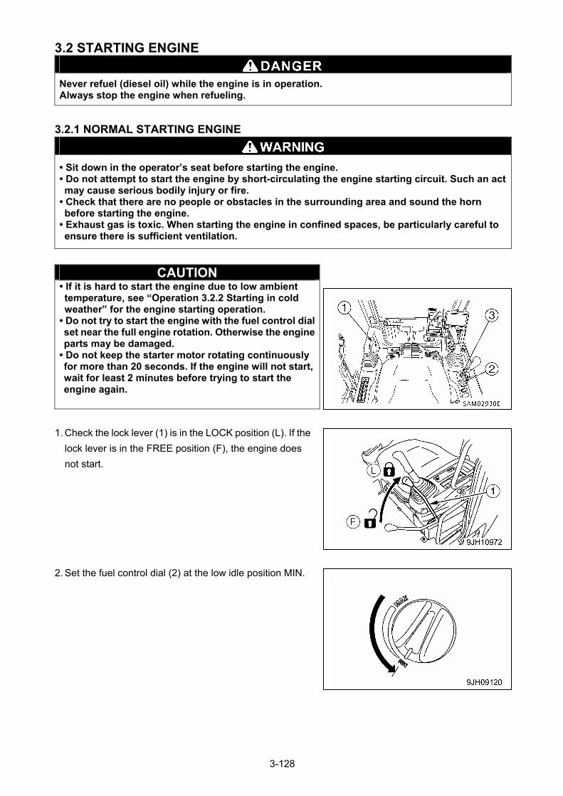
3.2 STARTING ENGINE
Never refuel (diesel oil) while the engine is in operation. Always stop the engine when refueling.
3.2.1 NORMAL STARTING ENGINE
• Sit down in the operator’s seat before starting the engine. • Do not attempt to start the engine by short-circulating the engine starting circuit. Such an act may cause serious bodily injury or fire.
• Check that there are no people or obstacles in the surrounding area and sound the horn before starting the engine.
• Exhaust gas is toxic. When starting the engine in confined spaces, be particularly careful to ensure there is sufficient ventilation.
CAUTION • If it is hard to start the engine due to low ambient temperature, see “Operation 3.2.2 Starting in cold weather” for the engine starting operation.
• Do not try to start the engine with the fuel control dial set near the full engine rotation. Otherwise the engine parts may be damaged.
• Do not keep the starter motor rotating continuously for more than 20 seconds. If the engine will not start, wait for least 2 minutes before trying to start the engine again.
1. Check the lock lever (1) is in the LOCK position (L). If the
lock lever is in the FREE position (F), the engine does
not start.
2. Set the fuel control dial (2) at the low idle position MIN.
3-128
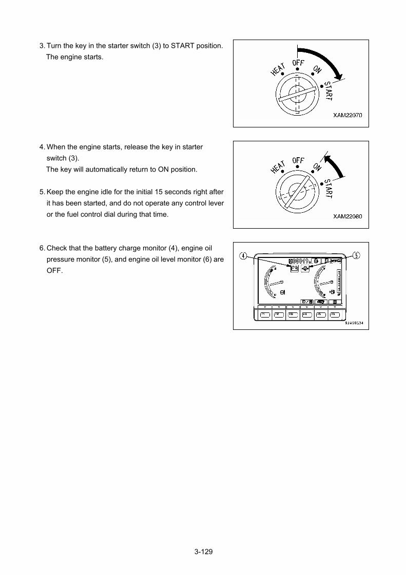
3. Turn the key in the starter switch (3) to START position.
The engine starts.
4. When the engine starts, release the key in starter
switch (3).
The key will automatically return to ON position.
5. Keep the engine idle for the initial 15 seconds right after
it has been started, and do not operate any control lever
or the fuel control dial during that time.
6. Check that the battery charge monitor (4), engine oil
pressure monitor (5), and engine oil level monitor (6) are
OFF.
3-129
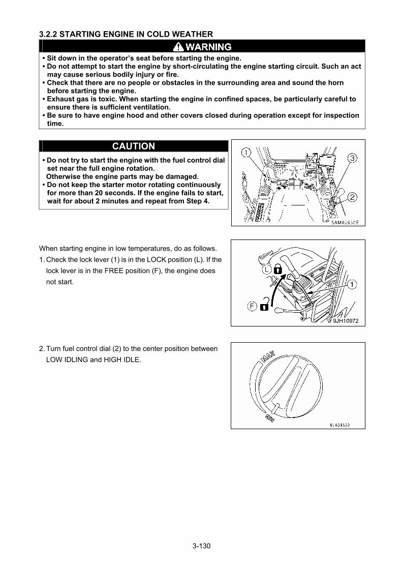
3.2.2 STARTING ENGINE IN COLD WEATHER
• Sit down in the operator’s seat before starting the engine. • Do not attempt to start the engine by short-circulating the engine starting circuit. Such an act
may cause serious bodily injury or fire. • Check that there are no people or obstacles in the surrounding area and sound the horn
before starting the engine. • Exhaust gas is toxic. When starting the engine in confined spaces, be particularly careful to
ensure there is sufficient ventilation. • Be sure to have engine hood and other covers closed during operation except for inspection
time.
CAUTION • Do not try to start the engine with the fuel control dial
set near the full engine rotation. Otherwise the engine parts may be damaged.
• Do not keep the starter motor rotating continuously for more than 20 seconds. If the engine fails to start, wait for about 2 minutes and repeat from Step 4.
When starting engine in low temperatures, do as follows.
1. Check the lock lever (1) is in the LOCK position (L). If the
lock lever is in the FREE position (F), the engine does
not start.
2. Turn fuel control dial (2) to the center position between
LOW IDLING and HIGH IDLE.
3-130
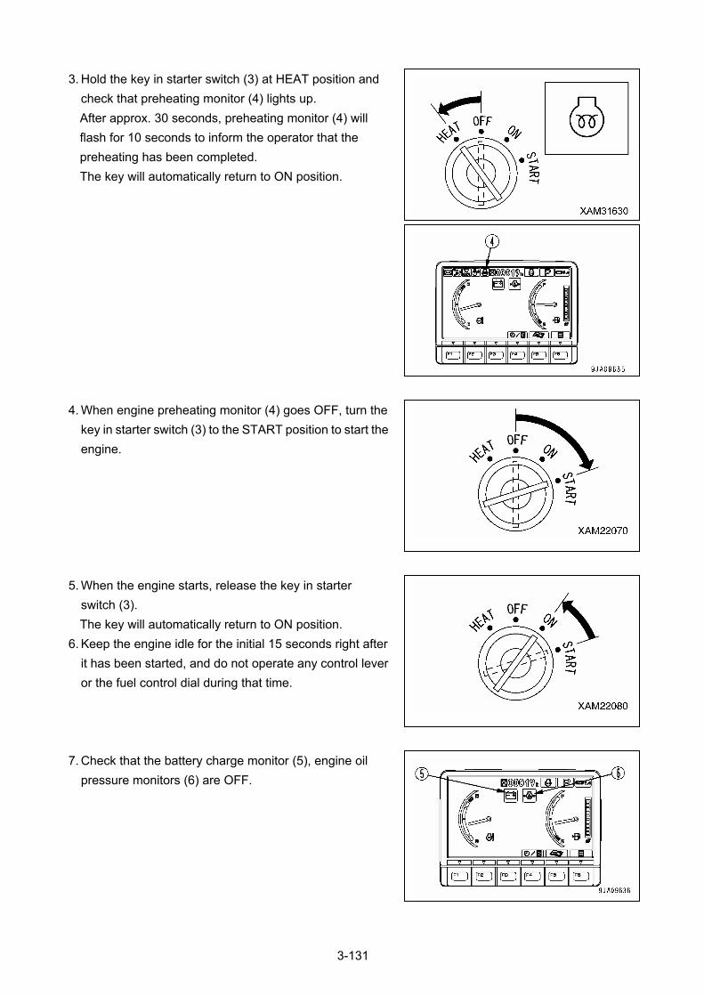
3. Hold the key in starter switch (3) at HEAT position and
check that preheating monitor (4) lights up.
After approx. 30 seconds, preheating monitor (4) will
flash for 10 seconds to inform the operator that the
preheating has been completed.
The key will automatically return to ON position.
4. When engine preheating monitor (4) goes OFF, turn the
key in starter switch (3) to the START position to start the
engine.
5. When the engine starts, release the key in starter
switch (3).
The key will automatically return to ON position.
6. Keep the engine idle for the initial 15 seconds right after
it has been started, and do not operate any control lever
or the fuel control dial during that time.
7. Check that the battery charge monitor (5), engine oil
pressure monitors (6) are OFF.
3-131

[Turbocharger Protect Function]
The turbocharger protect function is a function to protect the turbocharger by keeping the engine speed at
less than 1150 rpm immediately after the engine is started.
• When the turbocharger protect function is actuated, the engine speed is held at less than 1150 rpm,
regardless of the position of the fuel control dial.
• When the turbocharger protect function is actuated, the engine speed is held at less than 1150 rpm,
even if the fuel control dial is operated.
• When the turbocharger protect function is canceled, the engine speed is set to the speed for the
position of the fuel control dial.
• The relationship between the length of time of actuating the turbocharger protect function and the
temperature of the engine coolant is as shown in the table.
Coolant temperature Turbocharger protect time (sec.)
Above 10 ° 0
10 to -30 ° Change 0 to 20
Below -30 ° 20
3-132
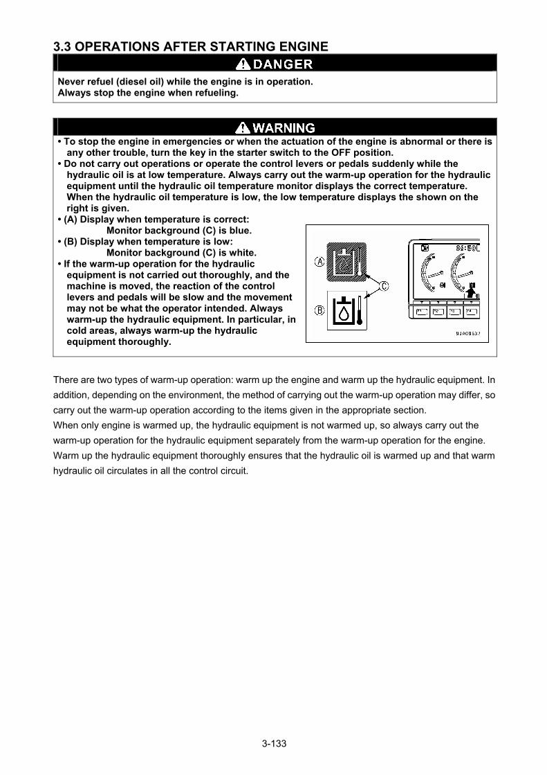
3.3 OPERATIONS AFTER STARTING ENGINE
Never refuel (diesel oil) while the engine is in operation. Always stop the engine when refueling.
• To stop the engine in emergencies or when the actuation of the engine is abnormal or there is
any other trouble, turn the key in the starter switch to the OFF position. • Do not carry out operations or operate the control levers or pedals suddenly while the
hydraulic oil is at low temperature. Always carry out the warm-up operation for the hydraulic equipment until the hydraulic oil temperature monitor displays the correct temperature. When the hydraulic oil temperature is low, the low temperature displays the shown on the right is given.
• (A) Display when temperature is correct: Monitor background (C) is blue.
• (B) Display when temperature is low: Monitor background (C) is white.
• If the warm-up operation for the hydraulic equipment is not carried out thoroughly, and the machine is moved, the reaction of the control levers and pedals will be slow and the movement may not be what the operator intended. Always warm-up the hydraulic equipment. In particular, in cold areas, always warm-up the hydraulic equipment thoroughly.
There are two types of warm-up operation: warm up the engine and warm up the hydraulic equipment. In
addition, depending on the environment, the method of carrying out the warm-up operation may differ, so
carry out the warm-up operation according to the items given in the appropriate section.
When only engine is warmed up, the hydraulic equipment is not warmed up, so always carry out the
warm-up operation for the hydraulic equipment separately from the warm-up operation for the engine.
Warm up the hydraulic equipment thoroughly ensures that the hydraulic oil is warmed up and that warm
hydraulic oil circulates in all the control circuit.
3-133
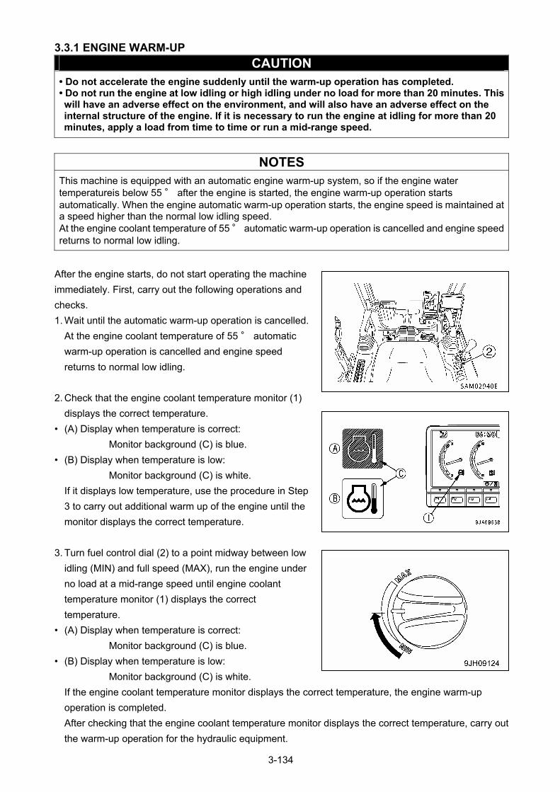
3.3.1 ENGINE WARM-UP
CAUTION • Do not accelerate the engine suddenly until the warm-up operation has completed. • Do not run the engine at low idling or high idling under no load for more than 20 minutes. This will have an adverse effect on the environment, and will also have an adverse effect on the internal structure of the engine. If it is necessary to run the engine at idling for more than 20 minutes, apply a load from time to time or run a mid-range speed.
NOTES
This machine is equipped with an automatic engine warm-up system, so if the engine water temperatureis below 55 ° after the engine is started, the engine warm-up operation starts automatically. When the engine automatic warm-up operation starts, the engine speed is maintained at a speed higher than the normal low idling speed. At the engine coolant temperature of 55 ° automatic warm-up operation is cancelled and engine speed returns to normal low idling.
After the engine starts, do not start operating the machine
immediately. First, carry out the following operations and
checks.
1. Wait until the automatic warm-up operation is cancelled.
At the engine coolant temperature of 55 ° automatic
warm-up operation is cancelled and engine speed
returns to normal low idling.
2. Check that the engine coolant temperature monitor (1)
displays the correct temperature.
• (A) Display when temperature is correct:
Monitor background (C) is blue.
• (B) Display when temperature is low:
Monitor background (C) is white.
If it displays low temperature, use the procedure in Step
3 to carry out additional warm up of the engine until the
monitor displays the correct temperature.
3. Turn fuel control dial (2) to a point midway between low
idling (MIN) and full speed (MAX), run the engine under
no load at a mid-range speed until engine coolant
temperature monitor (1) displays the correct
temperature.
• (A) Display when temperature is correct:
Monitor background (C) is blue.
• (B) Display when temperature is low:
Monitor background (C) is white.
If the engine coolant temperature monitor displays the correct temperature, the engine warm-up
operation is completed.
After checking that the engine coolant temperature monitor displays the correct temperature, carry out
the warm-up operation for the hydraulic equipment.
3-134
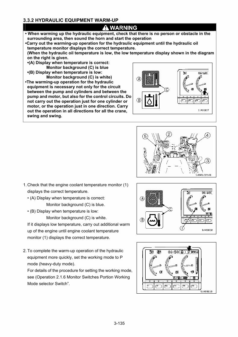
3.3.2 HYDRAULIC EQUIPMENT WARM-UP
• When warming up the hydraulic equipment, check that there is no person or obstacle in the surrounding area, then sound the horn and start the operation
•Carry out the warming-up operation for the hydraulic equipment until the hydraulic oil temperature monitor displays the correct temperature. (When the hydraulic oil temperature is low, the low temperature display shown in the diagram on the right is given. •(A) Display when temperature is correct:
Monitor background (C) is blue •(B) Display when temperature is low:
Monitor background (C) is white) •The warming-up operation for the hydraulic equipment is necessary not only for the circuit between the pump and cylinders and between the pump and motor, but also for the control circuits. Do not carry out the operation just for one cylinder or motor, or the operation just in one direction. Carry out the operation in all directions for all the crane, swing and swing.
1. Check that the engine coolant temperature monitor (1)
displays the correct temperature.
• (A) Display when temperature is correct:
Monitor background (C) is blue.
• (B) Display when temperature is low:
Monitor background (C) is white.
If it displays low temperature, carry out additional warm
up of the engine until engine coolant temperature
monitor (1) displays the correct temperature.
2. To complete the warm-up operation of the hydraulic
equipment more quickly, set the working mode to P
mode (heavy-duty mode).
For details of the procedure for setting the working mode,
see (Operation 2.1.6 Monitor Switches Portion Working
Mode selector Switch”.
3-135
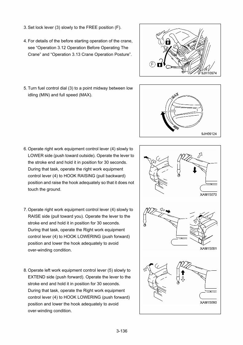
3. Set lock lever (3) slowly to the FREE position (F).
4. For details of the before starting operation of the crane,
see “Operation 3.12 Operation Before Operating The
Crane” and “Operation 3.13 Crane Operation Posture”.
5. Turn fuel control dial (3) to a point midway between low
idling (MIN) and full speed (MAX).
6. Operate right work equipment control lever (4) slowly to
LOWER side (push toward outside). Operate the lever to
the stroke end and hold it in position for 30 seconds.
During that task, operate the right work equipment
control lever (4) to HOOK RAISING (pull backward)
position and raise the hook adequately so that it does not
touch the ground.
7. Operate right work equipment control lever (4) slowly to
RAISE side (pull toward you). Operate the lever to the
stroke end and hold it in position for 30 seconds.
During that task, operate the Right work equipment
control lever (4) to HOOK LOWERING (push forward)
position and lower the hook adequately to avoid
over-winding condition.
8. Operate left work equipment control lever (5) slowly to
EXTEND side (push forward). Operate the lever to the
stroke end and hold it in position for 30 seconds.
During that task, operate the Right work equipment
control lever (4) to HOOK LOWERING (push forward)
position and lower the hook adequately to avoid
over-winding condition.
3-136
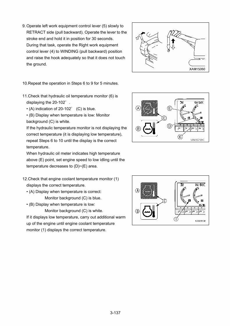
9. Operate left work equipment control lever (5) slowly to
RETRACT side (pull backward). Operate the lever to the
stroke end and hold it in position for 30 seconds.
During that task, operate the Right work equipment
control lever (4) to WINDING (pull backward) position
and raise the hook adequately so that it does not touch
the ground.
10.Repeat the operation in Steps 6 to 9 for 5 minutes.
11.Check that hydraulic oil temperature monitor (6) is
displaying the 20-102°.
• (A) indication of 20-102° (C) is blue.
• (B) Display when temperature is low: Monitor
background (C) is white.
If the hydraulic temperature monitor is not displaying the
correct temperature (it is displaying low temperature),
repeat Steps 6 to 10 until the display is the correct
temperature.
When hydraulic oil meter indicates high temperature
above (E) point, set engine speed to low idling until the
temperature decreases to (D)~(E) area.
12.Check that engine coolant temperature monitor (1)
displays the correct temperature.
• (A) Display when temperature is correct:
Monitor background (C) is blue.
• (B) Display when temperature is low:
Monitor background (C) is white.
If it displays low temperature, carry out additional warm
up of the engine until engine coolant temperature
monitor (1) displays the correct temperature.
3-137
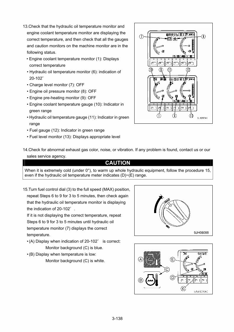
13.Check that the hydraulic oil temperature monitor and
engine coolant temperature monitor are displaying the
correct temperature, and then check that all the gauges
and caution monitors on the machine monitor are in the
following status.
• Engine coolant temperature monitor (1): Displays
correct temperature
• Hydraulic oil temperature monitor (6): indication of
20-102°
• Charge level monitor (7): OFF
• Engine oil pressure monitor (8): OFF
• Engine pre-heating monitor (9): OFF
• Engine coolant temperature gauge (10): Indicator in
green range
• Hydraulic oil temperature gauge (11): Indicator in green
range
• Fuel gauge (12): Indicator in green range
• Fuel level monitor (13): Displays appropriate level
14.Check for abnormal exhaust gas color, noise, or vibration. If any problem is found, contact us or our
sales service agency.
CAUTION When it is extremely cold (under 0°), to warm up whole hydraulic equipment, follow the procedure 15, even if the hydraulic oil temperature meter indicates (D)~(E) range.
15.Turn fuel control dial (3) to the full speed (MAX) position,
repeat Steps 6 to 9 for 3 to 5 minutes, then check again
that the hydraulic oil temperature monitor is displaying
the indication of 20-102°.
If it is not displaying the correct temperature, repeat
Steps 6 to 9 for 3 to 5 minutes until hydraulic oil
temperature monitor (7) displays the correct
temperature.
• (A) Display when indication of 20-102° is correct:
Monitor background (C) is blue.
• (B) Display when temperature is low:
Monitor background (C) is white.
3-138
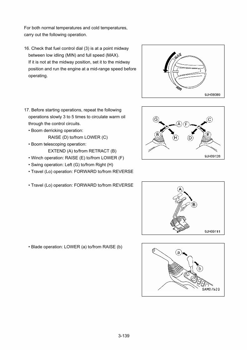
For both normal temperatures and cold temperatures,
carry out the following operation.
16. Check that fuel control dial (3) is at a point midway
between low idling (MIN) and full speed (MAX).
If it is not at the midway position, set it to the midway
position and run the engine at a mid-range speed before
operating.
17. Before starting operations, repeat the following
operations slowly 3 to 5 times to circulate warm oil
through the control circuits.
• Boom derricking operation:
RAISE (D) to/from LOWER (C)
• Boom telescoping operation:
EXTEND (A) to/from RETRACT (B)
• Winch operation: RAISE (E) to/from LOWER (F)
• Swing operation: Left (G) to/from Right (H)
• Travel (Lo) operation: FORWARD to/from REVERSE
• Travel (Lo) operation: FORWARD to/from REVERSE
• Blade operation: LOWER (a) to/from RAISE (b)
3-139

18.Check that hydraulic oil temperature monitor (6) is
displaying the correct temperature.
If the hydraulic oil temperature monitor is not displaying
the correct temperature (it is displaying low temperature),
repeat Steps 6 to 9 until the display is the correct
temperature.
• (A) Display when indication of 20-102° is correct:
Monitor background (C) is blue.
• (B) Display when temperature is low:
Monitor background (C) is white.
If the hydraulic oil temperature monitor displays the correct temperature, the hydraulic equipment
warm-up operation is completed.
After confirming that the hydraulic oil temperature monitor displays the correct temperature, carry out the
following procedure.
3-140

3.3.3 OPERATION AFTER COMPLETION OF WARM-UP OPERATION 1. Check if hydraulic oil temperature monitor (6) is
displaying indication of 20-102°, and also the hydraulic
temperature meter indicates between (D)-(E).
• (A) Display indication of 20-102°.
Monitor background (C) is blue.
• (B) Display when temperature is low:
Monitor background (C) is white.
2. Push working mode selector switch (14) of the machine
monitor to select the working mode to be used.
For details of the procedure for selecting the working
mode, see ”Operation 2.1.6 Monitor Switches portion”.
Working mode monitor display
• P mode: For heavy-duty operations
• E mode: For operations with emphasis on fuel
economy
• L mode: For operations requiring fine control
NOTES
Other operation modes, "B Mode" and "ATT mode", are not available in this machine.
3-141
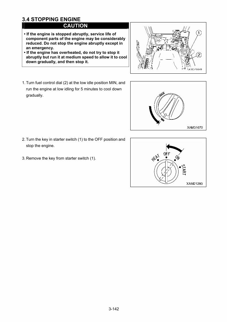
3.4 STOPPING ENGINE CAUTION
• If the engine is stopped abruptly, service life of component parts of the engine may be considerably reduced. Do not stop the engine abruptly except in an emergency.
• If the engine has overheated, do not try to stop it abruptly but run it at medium speed to allow it to cool down gradually, and then stop it.
1. Turn fuel control dial (2) at the low idle position MIN, and
run the engine at low idling for 5 minutes to cool down
gradually.
2. Turn the key in starter switch (1) to the OFF position and
stop the engine.
3. Remove the key from starter switch (1).
3-142
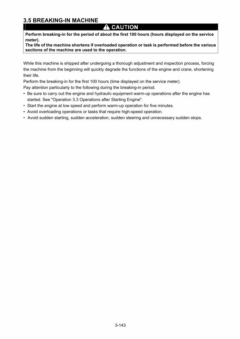
3.5 BREAKING-IN MACHINE
Perform breaking-in for the period of about the first 100 hours (hours displayed on the service meter). The life of the machine shortens if overloaded operation or task is performed before the various sections of the machine are used to the operation.
While this machine is shipped after undergoing a thorough adjustment and inspection process, forcing
the machine from the beginning will quickly degrade the functions of the engine and crane, shortening
their life.
Perform the breaking-in for the first 100 hours (time displayed on the service meter).
Pay attention particularly to the following during the breaking-in period.
• Be sure to carry out the engine and hydraulic equipment warm-up operations after the engine has
started. See "Operation 3.3 Operations after Starting Engine".
• Start the engine at low speed and perform warm-up operation for five minutes.
• Avoid overloading operations or tasks that require high-speed operation.
• Avoid sudden starting, sudden acceleration, sudden steering and unnecessary sudden stops.
3-143
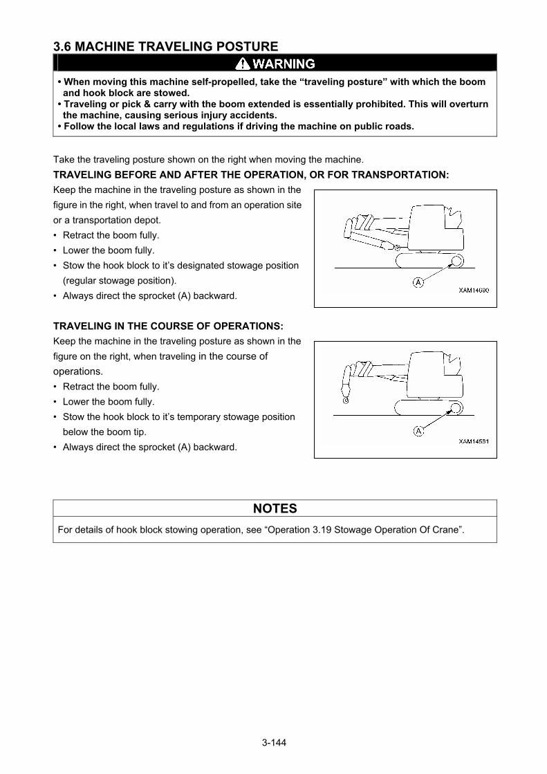
3.6 MACHINE TRAVELING POSTURE
• When moving this machine self-propelled, take the “traveling posture” with which the boom and hook block are stowed.
• Traveling or pick & carry with the boom extended is essentially prohibited. This will overturn the machine, causing serious injury accidents.
• Follow the local laws and regulations if driving the machine on public roads.
Take the traveling posture shown on the right when moving the machine.
TRAVELING BEFORE AND AFTER THE OPERATION, OR FOR TRANSPORTATION:
Keep the machine in the traveling posture as shown in the
figure in the right, when travel to and from an operation site
or a transportation depot.
• Retract the boom fully.
• Lower the boom fully.
• Stow the hook block to it’s designated stowage position
(regular stowage position).
• Always direct the sprocket (A) backward.
TRAVELING IN THE COURSE OF OPERATIONS:
Keep the machine in the traveling posture as shown in the
figure on the right, when traveling in the course of
operations.
• Retract the boom fully.
• Lower the boom fully.
• Stow the hook block to it’s temporary stowage position
below the boom tip.
• Always direct the sprocket (A) backward.
NOTES
For details of hook block stowing operation, see “Operation 3.19 Stowage Operation Of Crane”.
3-144
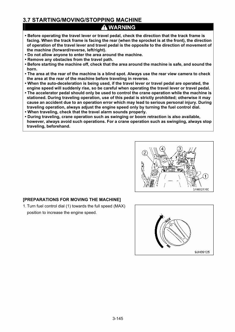
3.7 STARTING/MOVING/STOPPING MACHINE
• Before operating the travel lever or travel pedal, check the direction that the track frame is facing. When the track frame is facing the rear (when the sprocket is at the front), the direction of operation of the travel lever and travel pedal is the opposite to the direction of movement of the machine (forward/reverse, left/right).
• Do not allow anyone to enter the area around the machine. • Remove any obstacles from the travel path. • Before starting the machine off, check that the area around the machine is safe, and sound the horn.
• The area at the rear of the machine is a blind spot. Always use the rear view camera to check the area at the rear of the machine before traveling in reverse.
• When the auto-deceleration is being used, if the travel lever or travel pedal are operated, the engine speed will suddenly rise, so be careful when operating the travel lever or travel pedal.
• The accelerator pedal should only be used to control the crane operation while the machine is stationed. During traveling operation, use of this pedal is strictly prohibited; otherwise it may cause an accident due to an operation error which may lead to serious personal injury. During traveling operation, always adjust the engine speed only by turning the fuel control dial.
• When traveling, check that the travel alarm sounds properly. • During traveling, crane operation such as swinging or boom retraction is also available, however, always avoid such operations. For a crane operation such as swingiing, always stop traveling, beforehand.
[PREPARATIONS FOR MOVING THE MACHINE]
1. Turn fuel control dial (1) towards the full speed (MAX)
position to increase the engine speed.
3-145
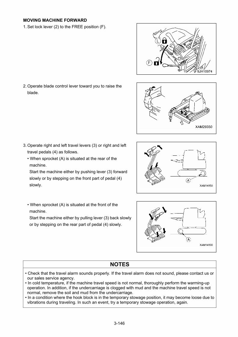
MOVING MACHINE FORWARD
1. Set lock lever (2) to the FREE position (F).
2. Operate blade control lever toward you to raise the
blade.
3. Operate right and left travel levers (3) or right and left
travel pedals (4) as follows.
• When sprocket (A) is situated at the rear of the
machine.
Start the machine either by pushing lever (3) forward
slowly or by stepping on the front part of pedal (4)
slowly.
• When sprocket (A) is situated at the front of the
machine.
Start the machine either by pulling lever (3) back slowly
or by stepping on the rear part of pedal (4) slowly.
NOTES
• Check that the travel alarm sounds properly. If the travel alarm does not sound, please contact us or our sales service agency.
• In cold temperature, if the machine travel speed is not normal, thoroughly perform the warming-up operation. In addition, if the undercarriage is clogged with mud and the machine travel speed is not normal, remove the soil and mud from the undercarriage.
• In a condition where the hook block is in the temporary stowage position, it may become loose due to vibrations during traveling. In such an event, try a temporary stowage operation, again.
3-146
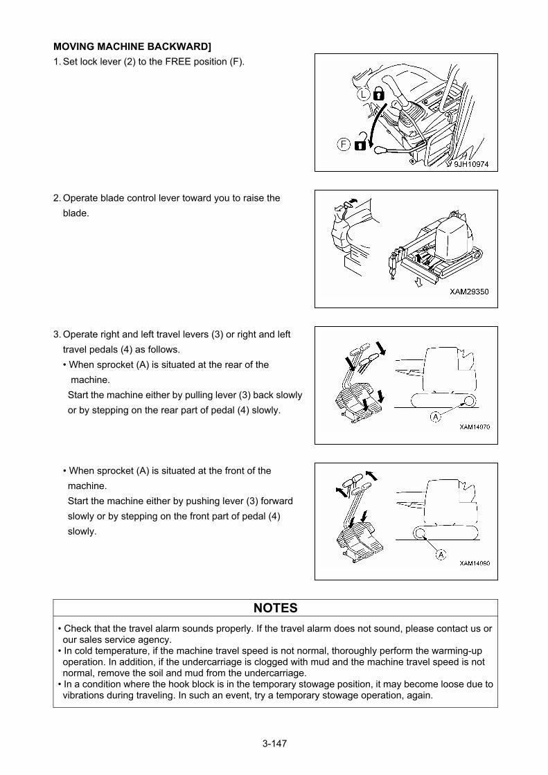
MOVING MACHINE BACKWARD]
1. Set lock lever (2) to the FREE position (F).
2. Operate blade control lever toward you to raise the
blade.
3. Operate right and left travel levers (3) or right and left
travel pedals (4) as follows.
• When sprocket (A) is situated at the rear of the
machine.
Start the machine either by pulling lever (3) back slowly
or by stepping on the rear part of pedal (4) slowly.
• When sprocket (A) is situated at the front of the
machine.
Start the machine either by pushing lever (3) forward
slowly or by stepping on the front part of pedal (4)
slowly.
NOTES
• Check that the travel alarm sounds properly. If the travel alarm does not sound, please contact us or our sales service agency.
• In cold temperature, if the machine travel speed is not normal, thoroughly perform the warming-up operation. In addition, if the undercarriage is clogged with mud and the machine travel speed is not normal, remove the soil and mud from the undercarriage.
• In a condition where the hook block is in the temporary stowage position, it may become loose due to vibrations during traveling. In such an event, try a temporary stowage operation, again.
3-147

STOPPING MACHINE
Avoid stopping suddenly. Give yourself ample room when
stopping.
• Put the left and right travel levers (3) to the NEUTRAL
position, and then stop the machine.
3-148
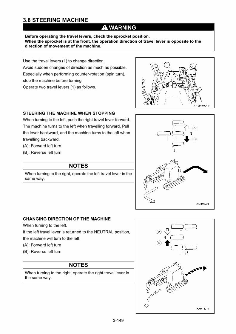
3.8 STEERING MACHINE
Before operating the travel levers, check the sprocket position. When the sprocket is at the front, the operation direction of travel lever is opposite to the direction of movement of the machine.
Use the travel levers (1) to change direction.
Avoid sudden changes of direction as much as possible.
Especially when performing counter-rotation (spin turn),
stop the machine before turning.
Operate two travel levers (1) as follows.
STEERING THE MACHINE WHEN STOPPING
When turning to the left, push the right travel lever forward.
The machine turns to the left when travelling forward. Pull
the lever backward, and the machine turns to the left when
travelling backward.
(A): Forward left turn
(B): Reverse left turn
NOTES
When turning to the right, operate the left travel lever in the same way.
CHANGING DIRECTION OF THE MACHINE
When turning to the left.
If the left travel lever is returned to the NEUTRAL position,
the machine will turn to the left.
(A): Forward left turn
(B): Reverse left turn
NOTES
When turning to the right, operate the right travel lever in the same way.
3-149
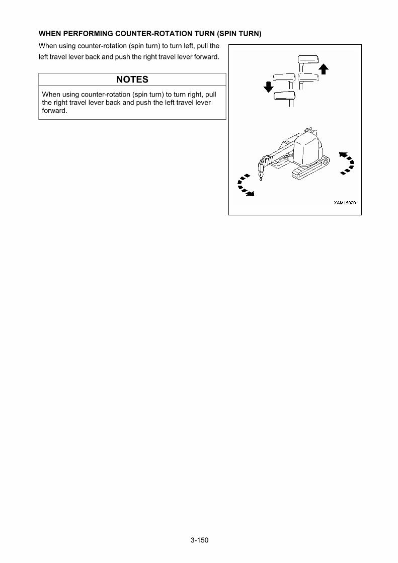
WHEN PERFORMING COUNTER-ROTATION TURN (SPIN TURN)
When using counter-rotation (spin turn) to turn left, pull the
left travel lever back and push the right travel lever forward.
NOTES
When using counter-rotation (spin turn) to turn right, pull the right travel lever back and push the left travel lever forward.
3-150
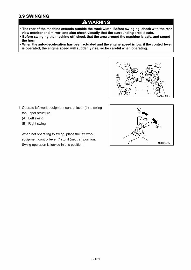
3.9 SWINGING
• The rear of the machine extends outside the track width. Before swinging, check with the rear view monitor and mirror, and also check visually that the surrounding area is safe.
• Before swinging the machine off, check that the area around the machine is safe, and sound the horn
• When the auto-deceleration has been actuated and the engine speed is low, if the control lever is operated, the engine speed will suddenly rise, so be careful when operating.
1. Operate left work equipment control lever (1) to swing
the upper structure.
(A): Left swing
(B): Right swing
When not operating to swing, place the left work
equipment control lever (1) to N (neutral) position.
Swing operation is locked in this position.
3-151
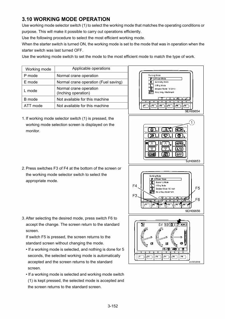
3.10 WORKING MODE OPERATION Use working mode selector switch (1) to select the working mode that matches the operating conditions or
purpose. This will make it possible to carry out operations efficiently.
Use the following procedure to select the most efficient working mode.
When the starter switch is turned ON, the working mode is set to the mode that was in operation when the
starter switch was last turned OFF.
Use the working mode switch to set the mode to the most efficient mode to match the type of work.
Working mode Applicable operations
P mode Normal crane operation
E mode Normal crane operation (Fuel saving)
L mode Normal crane operation (Inching operation)
B mode Not available for this machine
ATT mode Not available for this machine
1. If working mode selector switch (1) is pressed, the
working mode selection screen is displayed on the
monitor.
2. Press switches F3 of F4 at the bottom of the screen or
the working mode selector switch to select the
appropriate mode.
3. After selecting the desired mode, press switch F6 to
accept the change. The screen return to the standard
screen.
If switch F5 is pressed, the screen returns to the
standard screen without changing the mode.
• If a working mode is selected, and nothing is done for 5
seconds, the selected working mode is automatically
accepted and the screen returns to the standard
screen.
• If a working mode is selected and working mode switch
(1) is kept pressed, the selected mode is accepted and
the screen returns to the standard screen.
3-152
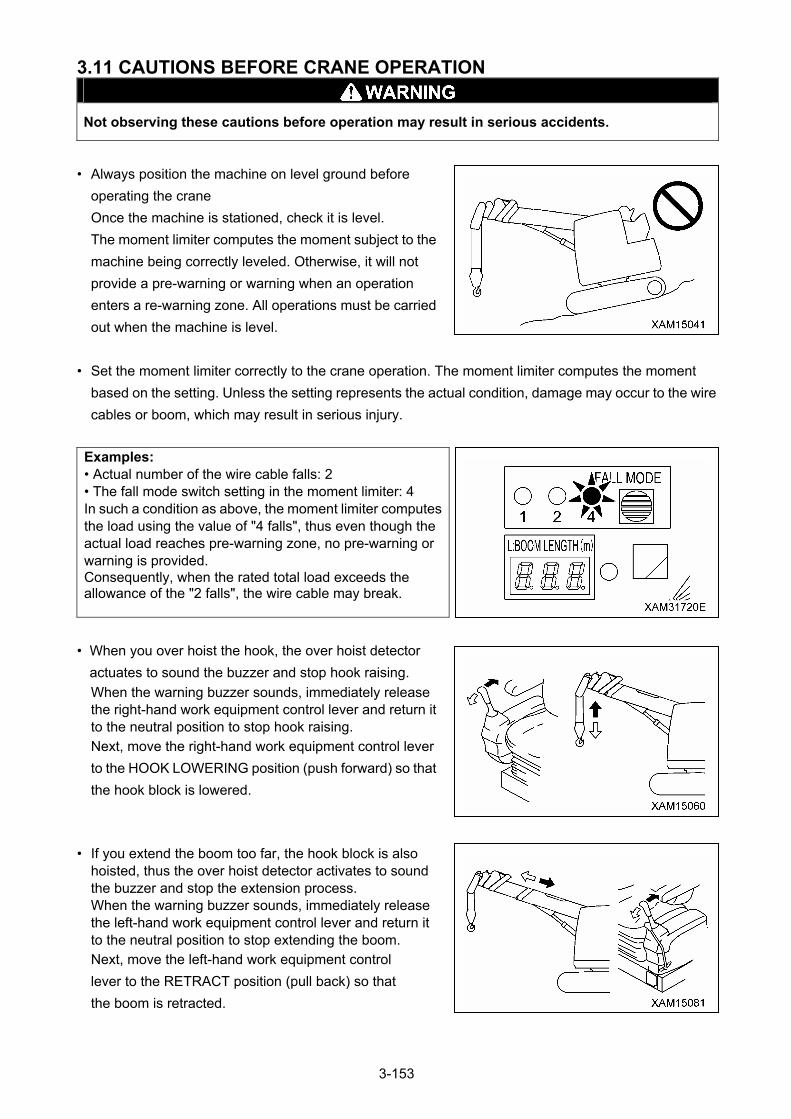
3.11 CAUTIONS BEFORE CRANE OPERATION
Not observing these cautions before operation may result in serious accidents.
• Always position the machine on level ground before
operating the crane
Once the machine is stationed, check it is level.
The moment limiter computes the moment subject to the
machine being correctly leveled. Otherwise, it will not
provide a pre-warning or warning when an operation
enters a re-warning zone. All operations must be carried
out when the machine is level.
• Set the moment limiter correctly to the crane operation. The moment limiter computes the moment
based on the setting. Unless the setting represents the actual condition, damage may occur to the wire
cables or boom, which may result in serious injury.
Examples: • Actual number of the wire cable falls: 2 • The fall mode switch setting in the moment limiter: 4 In such a condition as above, the moment limiter computes the load using the value of "4 falls", thus even though the actual load reaches pre-warning zone, no pre-warning or warning is provided. Consequently, when the rated total load exceeds the allowance of the "2 falls", the wire cable may break.
• When you over hoist the hook, the over hoist detector
actuates to sound the buzzer and stop hook raising.
When the warning buzzer sounds, immediately release the right-hand work equipment control lever and return it to the neutral position to stop hook raising. Next, move the right-hand work equipment control lever
to the HOOK LOWERING position (push forward) so that
the hook block is lowered.
• If you extend the boom too far, the hook block is also hoisted, thus the over hoist detector activates to sound the buzzer and stop the extension process. When the warning buzzer sounds, immediately release the left-hand work equipment control lever and return it to the neutral position to stop extending the boom. Next, move the left-hand work equipment control
lever to the RETRACT position (pull back) so that
the boom is retracted.
3-153

• Use the horn switch and toot the horn to warn danger to
persons nearby, when necessary, during crane
operations.
3-154
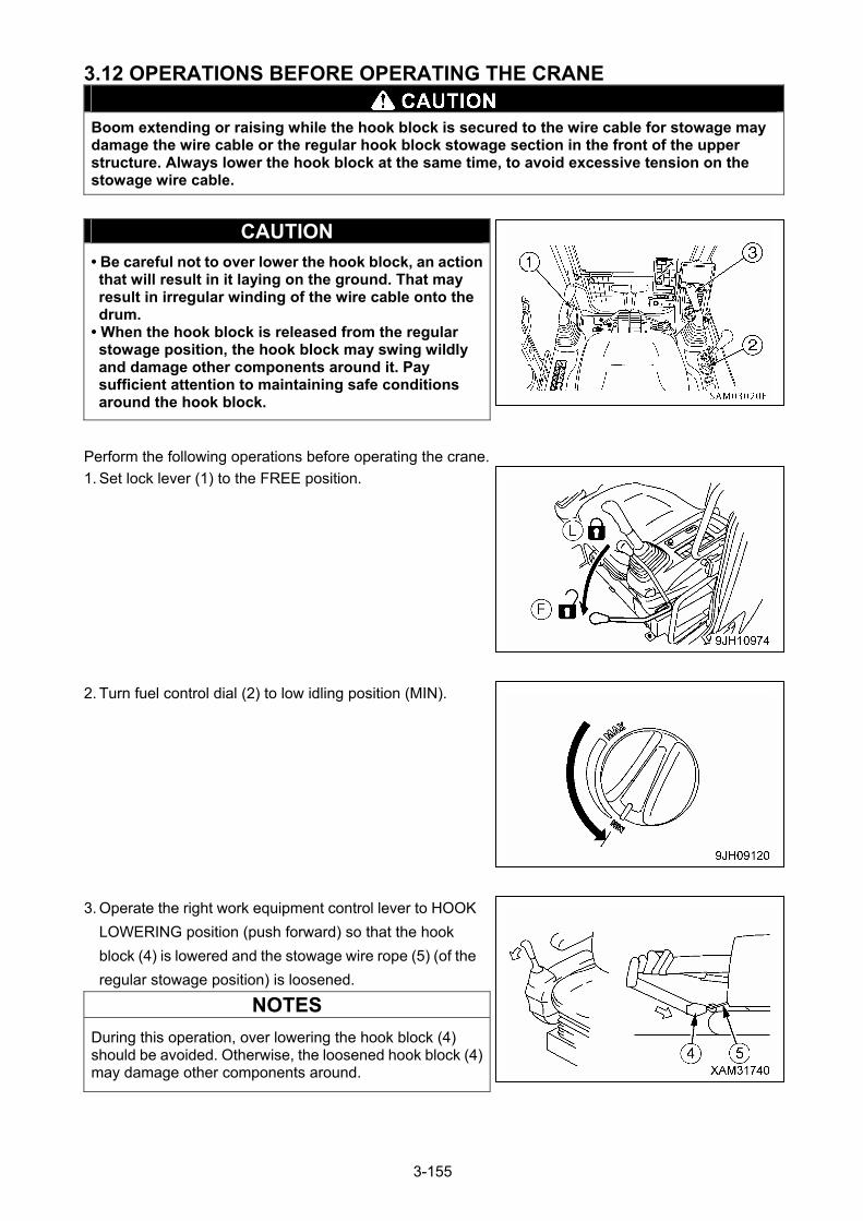
3.12 OPERATIONS BEFORE OPERATING THE CRANE
Boom extending or raising while the hook block is secured to the wire cable for stowage may damage the wire cable or the regular hook block stowage section in the front of the upper structure. Always lower the hook block at the same time, to avoid excessive tension on the stowage wire cable.
CAUTION
• Be careful not to over lower the hook block, an action that will result in it laying on the ground. That may result in irregular winding of the wire cable onto the drum.
• When the hook block is released from the regular stowage position, the hook block may swing wildly and damage other components around it. Pay sufficient attention to maintaining safe conditions around the hook block.
Perform the following operations before operating the crane.
1. Set lock lever (1) to the FREE position.
2. Turn fuel control dial (2) to low idling position (MIN).
3. Operate the right work equipment control lever to HOOK
LOWERING position (push forward) so that the hook
block (4) is lowered and the stowage wire rope (5) (of the
regular stowage position) is loosened.
NOTES
During this operation, over lowering the hook block (4) should be avoided. Otherwise, the loosened hook block (4) may damage other components around.
3-155
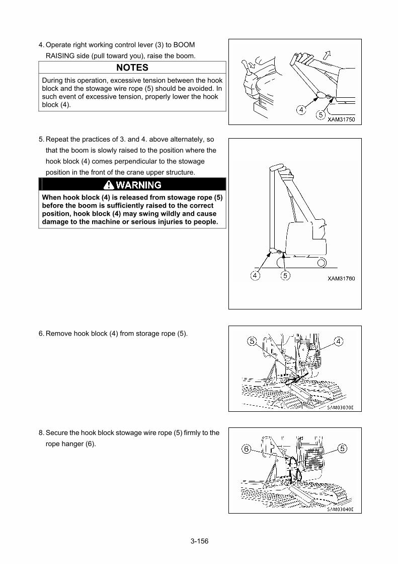
4. Operate right working control lever (3) to BOOM
RAISING side (pull toward you), raise the boom.
NOTES
During this operation, excessive tension between the hook block and the stowage wire rope (5) should be avoided. In such event of excessive tension, properly lower the hook block (4).
5. Repeat the practices of 3. and 4. above alternately, so
that the boom is slowly raised to the position where the
hook block (4) comes perpendicular to the stowage
position in the front of the crane upper structure.
When hook block (4) is released from stowage rope (5) before the boom is sufficiently raised to the correct position, hook block (4) may swing wildly and cause damage to the machine or serious injuries to people.
6. Remove hook block (4) from storage rope (5).
8. Secure the hook block stowage wire rope (5) firmly to the
rope hanger (6).
3-156
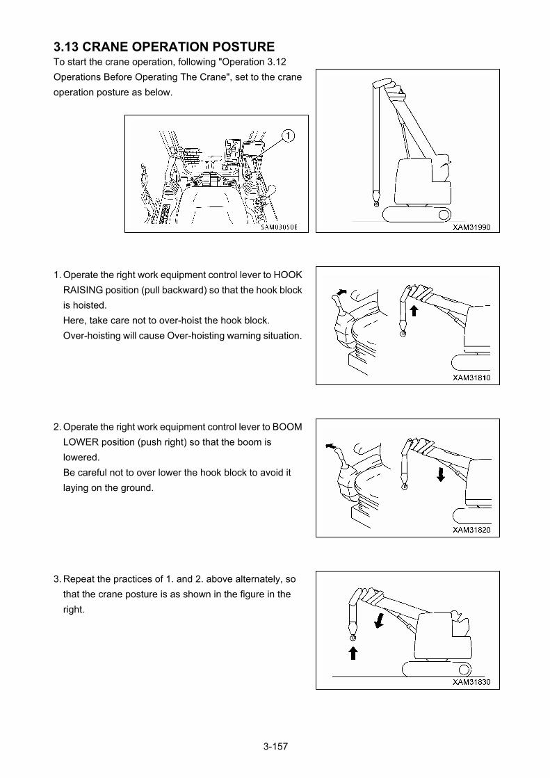
3.13 CRANE OPERATION POSTURE To start the crane operation, following "Operation 3.12
Operations Before Operating The Crane", set to the crane
operation posture as below.
1. Operate the right work equipment control lever to HOOK
RAISING position (pull backward) so that the hook block
is hoisted.
Here, take care not to over-hoist the hook block.
Over-hoisting will cause Over-hoisting warning situation.
2. Operate the right work equipment control lever to BOOM
LOWER position (push right) so that the boom is
lowered.
Be careful not to over lower the hook block to avoid it
laying on the ground.
3. Repeat the practices of 1. and 2. above alternately, so
that the crane posture is as shown in the figure in the
right.
3-157
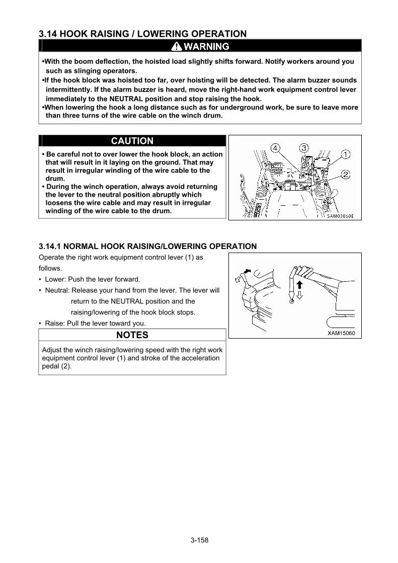
3.14 HOOK RAISING / LOWERING OPERATION
•With the boom deflection, the hoisted load slightly shifts forward. Notify workers around you such as slinging operators.
•If the hook block was hoisted too far, over hoisting will be detected. The alarm buzzer sounds intermittently. If the alarm buzzer is heard, move the right-hand work equipment control lever immediately to the NEUTRAL position and stop raising the hook.
•When lowering the hook a long distance such as for underground work, be sure to leave more than three turns of the wire cable on the winch drum.
CAUTION • Be careful not to over lower the hook block, an action that will result in it laying on the ground. That may result in irregular winding of the wire cable to the drum.
• During the winch operation, always avoid returning the lever to the neutral position abruptly which loosens the wire cable and may result in irregular winding of the wire cable to the drum.
3.14.1 NORMAL HOOK RAISING/LOWERING OPERATION
Operate the right work equipment control lever (1) as
follows.
• Lower: Push the lever forward.
• Neutral: Release your hand from the lever. The lever will
return to the NEUTRAL position and the
raising/lowering of the hook block stops.
• Raise: Pull the lever toward you.
NOTES
Adjust the winch raising/lowering speed with the right work equipment control lever (1) and stroke of the acceleration pedal (2).
3-158
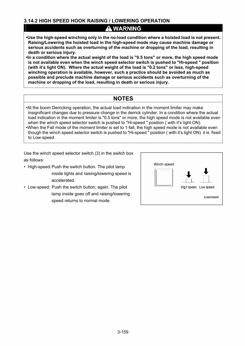
3.14.2 HIGH SPEED HOOK RAISING / LOWERING OPERATION
•Use the high-speed winching only in the no-load condition where a hoisted load is not present. Raising/Lowering the hoisted load in the high-speed mode may cause machine damage or serious accidents such as overturning of the machine or dropping of the load, resulting in death or serious injury.
•In a condition where the actual weight of the load is "0.5 tons" or more, the high speed mode is not available even when the winch speed selector switch is pushed to "Hi-speed " position (with it’s light ON). Where the actual weight of the load is "0.2 tons" or less, high-speed winching operation is available, however, such a practice should be avoided as much as possible and preclude machine damage or serious accidents such as overturning of the machine or dropping of the load, resulting in death or serious injury.
NOTES
•At the boom Derricking operation, the actual load indication in the moment limiter may make insignificant changes due to pressure change in the derrick cylinder. In a condition where the actual load indication in the moment limiter is "0.5 tons" or more, the high speed mode is not available even when the winch speed selector switch is pushed to "Hi-speed " position ( with it’s light ON).
•When the Fall mode of the moment limiter is set to 1-fall, the high speed mode is not available even though the winch speed selector switch is pushed to "Hi-speed " position ( with it’s light ON) it is fixed to Low-speed.
Use the winch speed selector switch (3) in the switch box
as follows:
• High-speed: Push the switch button. The pilot lamp
inside lights and raising/lowering speed is
accelerated.
• Low-speed: Push the switch button, again. The pilot
lamp inside goes off and raising/lowering
speed returns to normal mode.
3-159
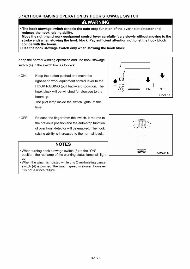
3.14.3 HOOK RAISING OPERATION BY HOOK STOWAGE SWITCH
• The hook stowage switch cancels the auto-stop function of the over hoist detector and reduces the hook raising ability. Move the right-hand work equipment control lever carefully (very slowly without moving to the stroke end) when stowing the hook block. Pay sufficient attention not to let the hook block collide with the boom.
• Use the hook stowage switch only when stowing the hook block.
Keep the normal winding operation and use hook stowage
switch (4) in the switch box as follows:
• ON: Keep the button pushed and move the
right-hand work equipment control lever to the
HOOK RAISING (pull backward) position. The
hook block will be winched for stowage to the
boom tip.
The pilot lamp inside the switch lights, at this
time.
• OFF: Release the finger from the switch. It returns to
the previous position and the auto-stop function
of over hoist detector will be enabled. The hook
raising ability is increased to the normal level..
NOTES
• When turning hook stowage switch (3) to the "ON" position, the red lamp of the working status lamp will light up.
• When the winch is hoisted while this Over-hoisting cancel switch (4) is pushed, the winch speed is slower, however it is not a winch failure.
3-160
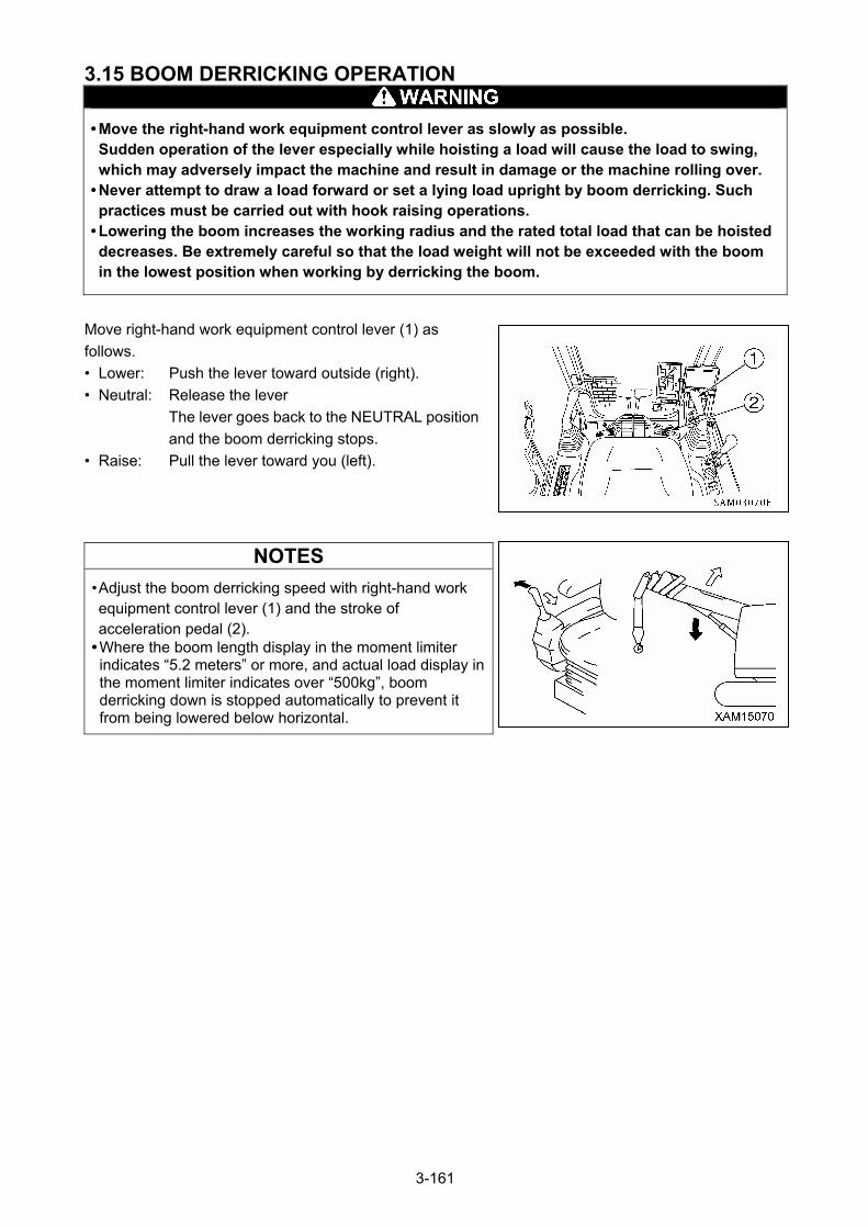
3.15 BOOM DERRICKING OPERATION
• Move the right-hand work equipment control lever as slowly as possible. Sudden operation of the lever especially while hoisting a load will cause the load to swing, which may adversely impact the machine and result in damage or the machine rolling over.
• Never attempt to draw a load forward or set a lying load upright by boom derricking. Such practices must be carried out with hook raising operations.
• Lowering the boom increases the working radius and the rated total load that can be hoisted decreases. Be extremely careful so that the load weight will not be exceeded with the boom in the lowest position when working by derricking the boom.
Move right-hand work equipment control lever (1) as
follows.
• Lower: Push the lever toward outside (right).
• Neutral: Release the lever
The lever goes back to the NEUTRAL position
and the boom derricking stops.
• Raise: Pull the lever toward you (left).
NOTES
• Adjust the boom derricking speed with right-hand work equipment control lever (1) and the stroke of acceleration pedal (2).
• Where the boom length display in the moment limiter indicates “5.2 meters” or more, and actual load display in the moment limiter indicates over “500kg”, boom derricking down is stopped automatically to prevent it from being lowered below horizontal.
3-161
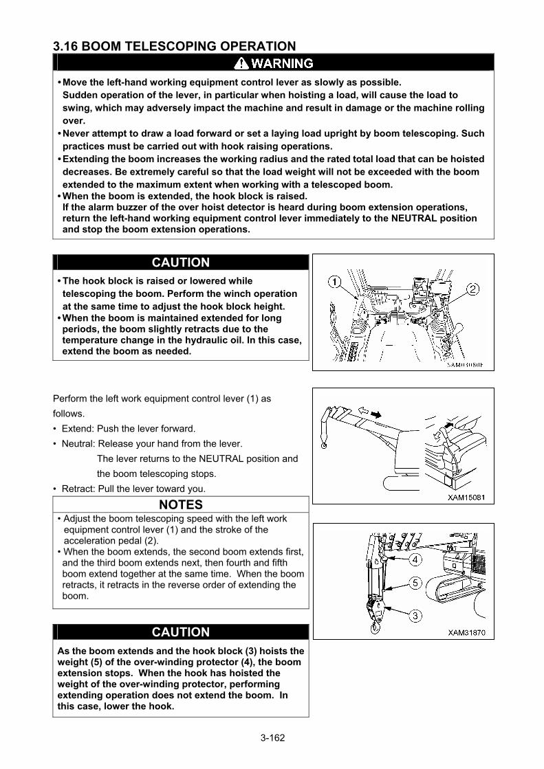
3.16 BOOM TELESCOPING OPERATION
• Move the left-hand working equipment control lever as slowly as possible. Sudden operation of the lever, in particular when hoisting a load, will cause the load to swing, which may adversely impact the machine and result in damage or the machine rolling over.
• Never attempt to draw a load forward or set a laying load upright by boom telescoping. Such practices must be carried out with hook raising operations.
• Extending the boom increases the working radius and the rated total load that can be hoisted decreases. Be extremely careful so that the load weight will not be exceeded with the boom extended to the maximum extent when working with a telescoped boom.
• When the boom is extended, the hook block is raised. If the alarm buzzer of the over hoist detector is heard during boom extension operations, return the left-hand working equipment control lever immediately to the NEUTRAL position and stop the boom extension operations.
CAUTION • The hook block is raised or lowered while telescoping the boom. Perform the winch operation at the same time to adjust the hook block height.
• When the boom is maintained extended for long periods, the boom slightly retracts due to the temperature change in the hydraulic oil. In this case, extend the boom as needed.
Perform the left work equipment control lever (1) as
follows.
• Extend: Push the lever forward.
• Neutral: Release your hand from the lever.
The lever returns to the NEUTRAL position and
the boom telescoping stops.
• Retract: Pull the lever toward you.
NOTES • Adjust the boom telescoping speed with the left work
equipment control lever (1) and the stroke of the acceleration pedal (2).
• When the boom extends, the second boom extends first, and the third boom extends next, then fourth and fifth boom extend together at the same time. When the boom retracts, it retracts in the reverse order of extending the boom.
CAUTION As the boom extends and the hook block (3) hoists the weight (5) of the over-winding protector (4), the boom extension stops. When the hook has hoisted the weight of the over-winding protector, performing extending operation does not extend the boom. In this case, lower the hook.
3-162
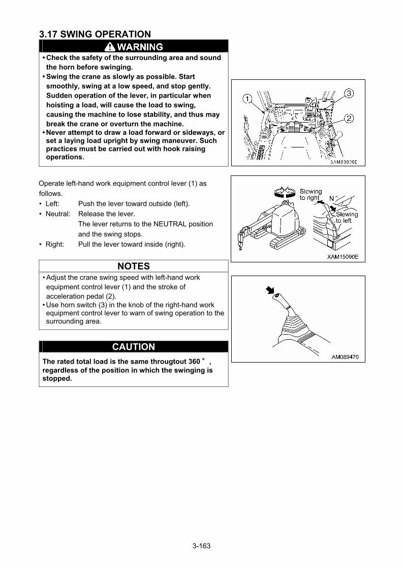
3.17 SWING OPERATION
• Check the safety of the surrounding area and sound the horn before swinging.
• Swing the crane as slowly as possible. Start smoothly, swing at a low speed, and stop gently. Sudden operation of the lever, in particular when hoisting a load, will cause the load to swing, causing the machine to lose stability, and thus may break the crane or overturn the machine.
• Never attempt to draw a load forward or sideways, or set a laying load upright by swing maneuver. Such practices must be carried out with hook raising operations.
Operate left-hand work equipment control lever (1) as
follows.
• Left: Push the lever toward outside (left).
• Neutral: Release the lever.
The lever returns to the NEUTRAL position
and the swing stops.
• Right: Pull the lever toward inside (right).
NOTES
• Adjust the crane swing speed with left-hand work equipment control lever (1) and the stroke of acceleration pedal (2).
• Use horn switch (3) in the knob of the right-hand work equipment control lever to warn of swing operation to the surrounding area.
CAUTION
The rated total load is the same througtout 360 °, regardless of the position in which the swinging is stopped.
3-163
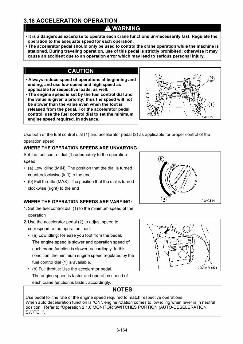
3.18 ACCELERATION OPERATION
• It is a dangerous excercise to operate each crane functions un-necessarily fast. Regulate the operation to the adequate speed for each operation.
• The accelerator pedal should only be used to control the crane operation while the machine is stationed. During traveling operation, use of this pedal is strictly prohibited; otherwise it may cause an accident due to an operation error which may lead to serious personal injury.
CAUTION
• Always reduce speed of operations at beginning and ending, and use low speed and high speed as applicable for respective loads, as well.
• The engine speed is set by the fuel control dial and the value is given a priority; thus the speed will not be slower than the value even when the foot is released from the pedal. For the accelerator pedal control, use the fuel control dial to set the minimum engine speed required, in advance.
Use both of the fuel control dial (1) and accelerator pedal (2) as applicable for proper control of the
operation speed.
WHERE THE OPERATION SPEEDS ARE UNVARYING:
Set the fuel control dial (1) adequately to the operation
speed.
• (a) Low idling (MIN): The position that the dial is turned
counterclockwise (left) to the end.
• (b) Full throttle (MAX): The position that the dial is turned
clockwise (right) to the end
WHERE THE OPERATION SPEEDS ARE VARYING:
1. Set the fuel control dial (1) to the minimum speed of the
operation
2. Use the accelerator pedal (2) to adjust speed to
correspond to the operation load.
• (a) Low idling: Release you foot from the pedal.
The engine speed is slower and operation speed of
each crane function is slower, accordingly. In this
condition, the minimum engine speed regulated by the
fuel control dial (1) is available.
• (b) Full throttle: Use the accelerator pedal.
The engine speed is faster and operation speed of
each crane function is faster, accordingly.
NOTES
Use pedal for the rate of the engine speed required to match respective operations. When auto deceleration function is “ON”, engine rotation comes to low idling when lever is in neutral position. Refer to “Operation 2.1.6 MONITOR SWITCHES PORTION (AUTO-DESELERATION SWITCH”.
3-164
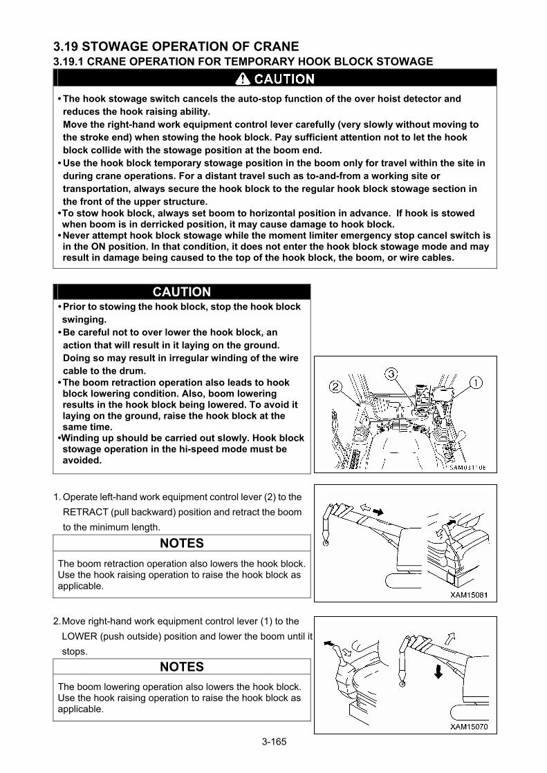
3.19 STOWAGE OPERATION OF CRANE 3.19.1 CRANE OPERATION FOR TEMPORARY HOOK BLOCK STOWAGE
• The hook stowage switch cancels the auto-stop function of the over hoist detector and reduces the hook raising ability. Move the right-hand work equipment control lever carefully (very slowly without moving to the stroke end) when stowing the hook block. Pay sufficient attention not to let the hook block collide with the stowage position at the boom end.
• Use the hook block temporary stowage position in the boom only for travel within the site in during crane operations. For a distant travel such as to-and-from a working site or transportation, always secure the hook block to the regular hook block stowage section in the front of the upper structure.
• To stow hook block, always set boom to horizontal position in advance. If hook is stowed when boom is in derricked position, it may cause damage to hook block.
• Never attempt hook block stowage while the moment limiter emergency stop cancel switch is in the ON position. In that condition, it does not enter the hook block stowage mode and may result in damage being caused to the top of the hook block, the boom, or wire cables.
CAUTION • Prior to stowing the hook block, stop the hook block swinging.
• Be careful not to over lower the hook block, an action that will result in it laying on the ground. Doing so may result in irregular winding of the wire cable to the drum.
• The boom retraction operation also leads to hook block lowering condition. Also, boom lowering results in the hook block being lowered. To avoid it laying on the ground, raise the hook block at the same time.
•Winding up should be carried out slowly. Hook block stowage operation in the hi-speed mode must be avoided.
1. Operate left-hand work equipment control lever (2) to the
RETRACT (pull backward) position and retract the boom
to the minimum length.
NOTES
The boom retraction operation also lowers the hook block. Use the hook raising operation to raise the hook block as applicable.
2. Move right-hand work equipment control lever (1) to the
LOWER (push outside) position and lower the boom until it
stops.
NOTES
The boom lowering operation also lowers the hook block. Use the hook raising operation to raise the hook block as applicable.
3-165
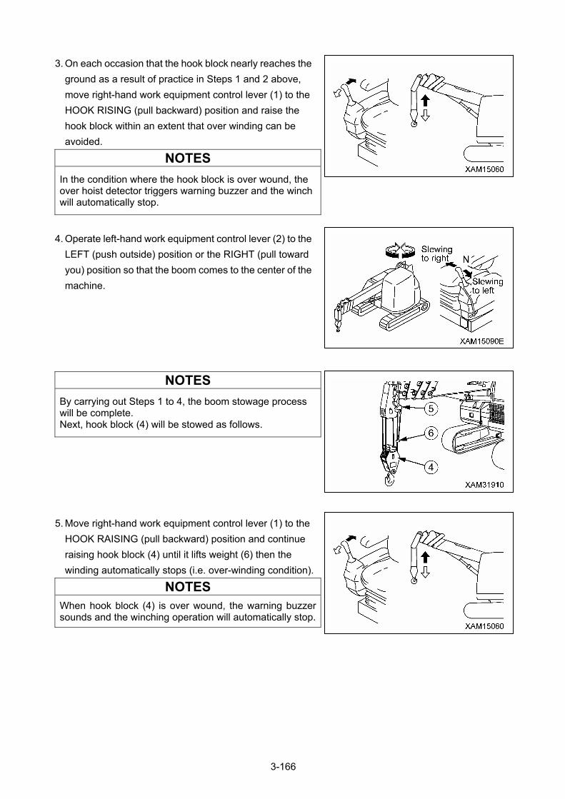
3. On each occasion that the hook block nearly reaches the
ground as a result of practice in Steps 1 and 2 above,
move right-hand work equipment control lever (1) to the
HOOK RISING (pull backward) position and raise the
hook block within an extent that over winding can be
avoided.
NOTES
In the condition where the hook block is over wound, the over hoist detector triggers warning buzzer and the winch will automatically stop.
4. Operate left-hand work equipment control lever (2) to the
LEFT (push outside) position or the RIGHT (pull toward
you) position so that the boom comes to the center of the
machine.
NOTES
By carrying out Steps 1 to 4, the boom stowage process will be complete. Next, hook block (4) will be stowed as follows.
5. Move right-hand work equipment control lever (1) to the
HOOK RAISING (pull backward) position and continue
raising hook block (4) until it lifts weight (6) then the
winding automatically stops (i.e. over-winding condition).
NOTES
When hook block (4) is over wound, the warning buzzer sounds and the winching operation will automatically stop.
3-166
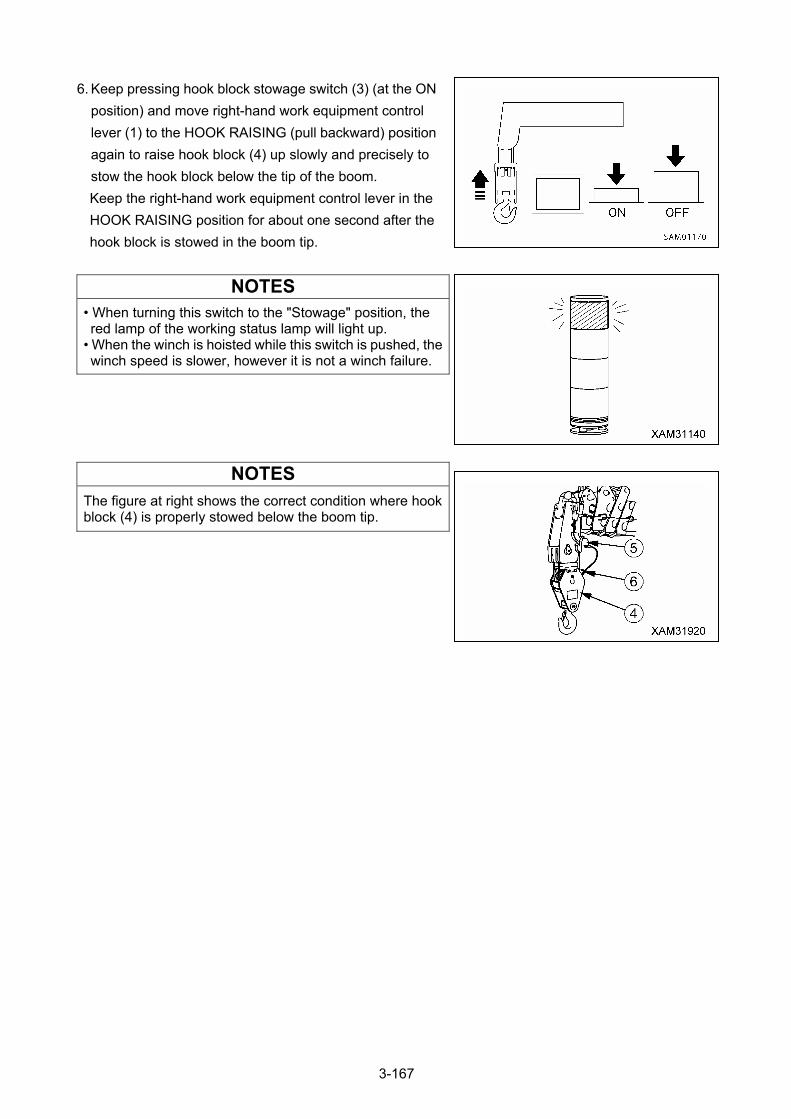
6. Keep pressing hook block stowage switch (3) (at the ON
position) and move right-hand work equipment control
lever (1) to the HOOK RAISING (pull backward) position
again to raise hook block (4) up slowly and precisely to
stow the hook block below the tip of the boom.
Keep the right-hand work equipment control lever in the
HOOK RAISING position for about one second after the
hook block is stowed in the boom tip.
NOTES
• When turning this switch to the "Stowage" position, the red lamp of the working status lamp will light up.
• When the winch is hoisted while this switch is pushed, the winch speed is slower, however it is not a winch failure.
NOTES
The figure at right shows the correct condition where hook block (4) is properly stowed below the boom tip.
3-167
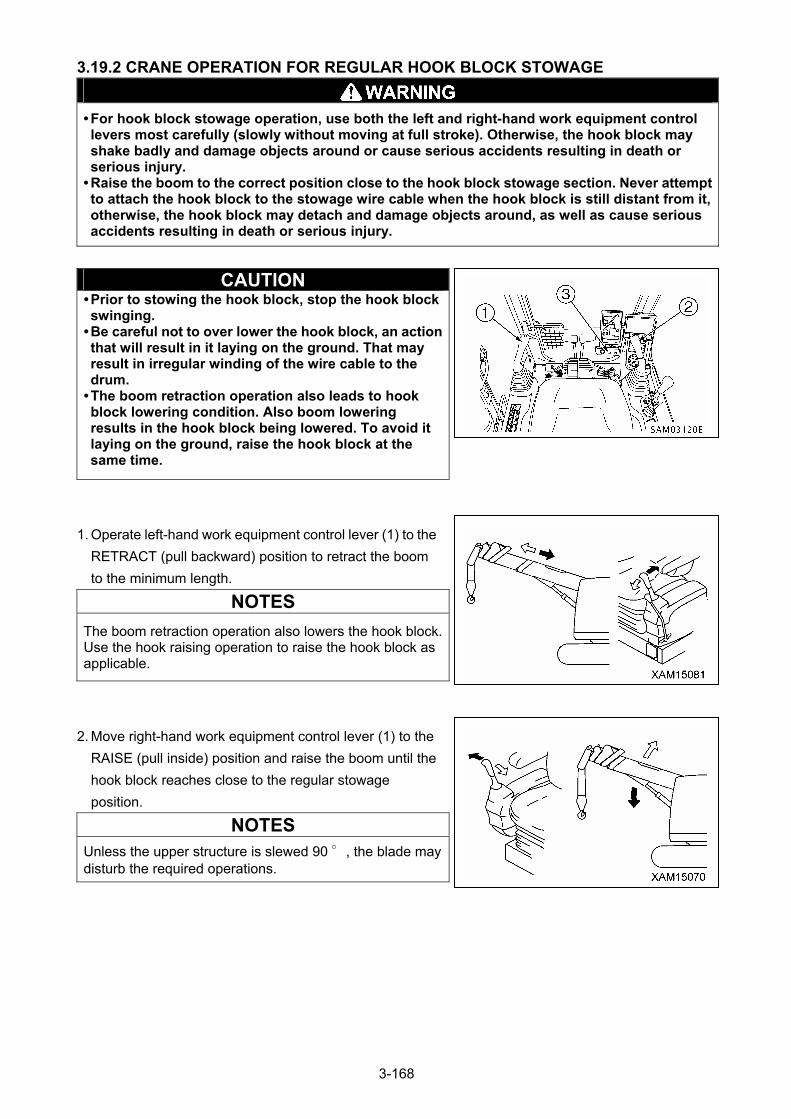
3.19.2 CRANE OPERATION FOR REGULAR HOOK BLOCK STOWAGE
• For hook block stowage operation, use both the left and right-hand work equipment control levers most carefully (slowly without moving at full stroke). Otherwise, the hook block may shake badly and damage objects around or cause serious accidents resulting in death or serious injury.
• Raise the boom to the correct position close to the hook block stowage section. Never attempt to attach the hook block to the stowage wire cable when the hook block is still distant from it, otherwise, the hook block may detach and damage objects around, as well as cause serious accidents resulting in death or serious injury.
CAUTION • Prior to stowing the hook block, stop the hook block swinging.
• Be careful not to over lower the hook block, an action that will result in it laying on the ground. That may result in irregular winding of the wire cable to the drum.
• The boom retraction operation also leads to hook block lowering condition. Also boom lowering results in the hook block being lowered. To avoid it laying on the ground, raise the hook block at the same time.
1. Operate left-hand work equipment control lever (1) to the
RETRACT (pull backward) position to retract the boom
to the minimum length.
NOTES
The boom retraction operation also lowers the hook block. Use the hook raising operation to raise the hook block as applicable.
2. Move right-hand work equipment control lever (1) to the
RAISE (pull inside) position and raise the boom until the
hook block reaches close to the regular stowage
position.
NOTES
Unless the upper structure is slewed 90 °, the blade may disturb the required operations.
3-168
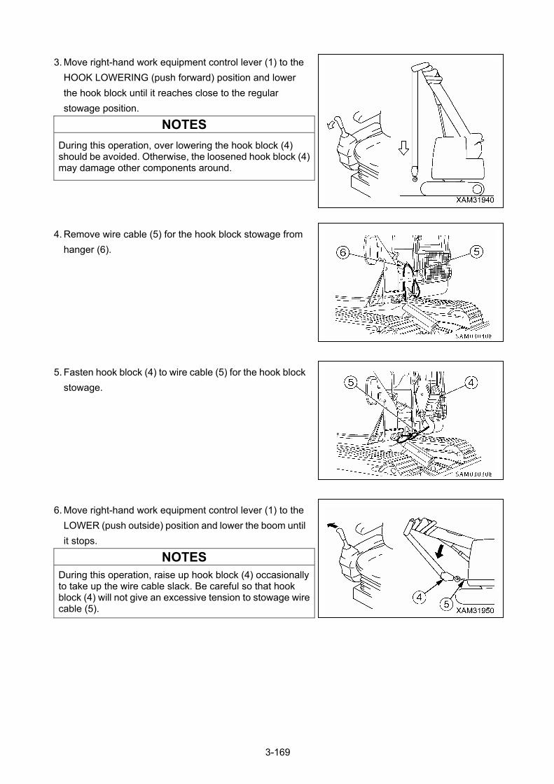
3. Move right-hand work equipment control lever (1) to the
HOOK LOWERING (push forward) position and lower
the hook block until it reaches close to the regular
stowage position.
NOTES
During this operation, over lowering the hook block (4) should be avoided. Otherwise, the loosened hook block (4) may damage other components around.
4. Remove wire cable (5) for the hook block stowage from
hanger (6).
5. Fasten hook block (4) to wire cable (5) for the hook block
stowage.
6. Move right-hand work equipment control lever (1) to the
LOWER (push outside) position and lower the boom until
it stops.
NOTES
During this operation, raise up hook block (4) occasionally to take up the wire cable slack. Be careful so that hook block (4) will not give an excessive tension to stowage wire cable (5).
3-169
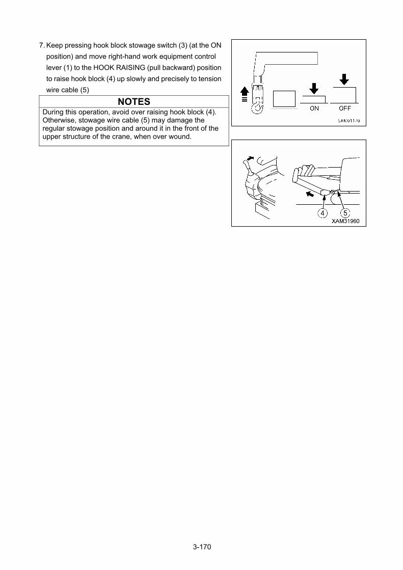
7. Keep pressing hook block stowage switch (3) (at the ON
position) and move right-hand work equipment control
lever (1) to the HOOK RAISING (pull backward) position
to raise hook block (4) up slowly and precisely to tension
wire cable (5)
NOTES During this operation, avoid over raising hook block (4). Otherwise, stowage wire cable (5) may damage the regular stowage position and around it in the front of the upper structure of the crane, when over wound.
3-170
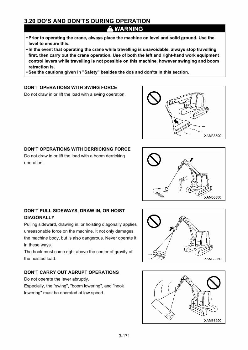
3.20 DO’S AND DON’TS DURING OPERATION
• Prior to operating the crane, always place the machine on level and solid ground. Use the level to ensure this.
• In the event that operating the crane while travelling is unavoidable, always stop travelling first, then carry out the crane operation. Use of both the left and right-hand work equipment control levers while travelling is not possible on this machine, however swinging and boom retraction is.
• See the cautions given in "Safety" besides the dos and don’ts in this section.
DON’T OPERATIONS WITH SWING FORCE
Do not draw in or lift the load with a swing operation.
DON’T OPERATIONS WITH DERRICKING FORCE
Do not draw in or lift the load with a boom derricking
operation.
DON’T PULL SIDEWAYS, DRAW IN, OR HOIST
DIAGONALLY
Pulling sideward, drawing in, or hoisting diagonally applies
unreasonable force on the machine. It not only damages
the machine body, but is also dangerous. Never operate it
in these ways.
The hook must come right above the center of gravity of
the hoisted load.
DON’T CARRY OUT ABRUPT OPERATIONS
Do not operate the lever abruptly.
Especially, the "swing", "boom lowering", and "hook
lowering" must be operated at low speed.
3-171
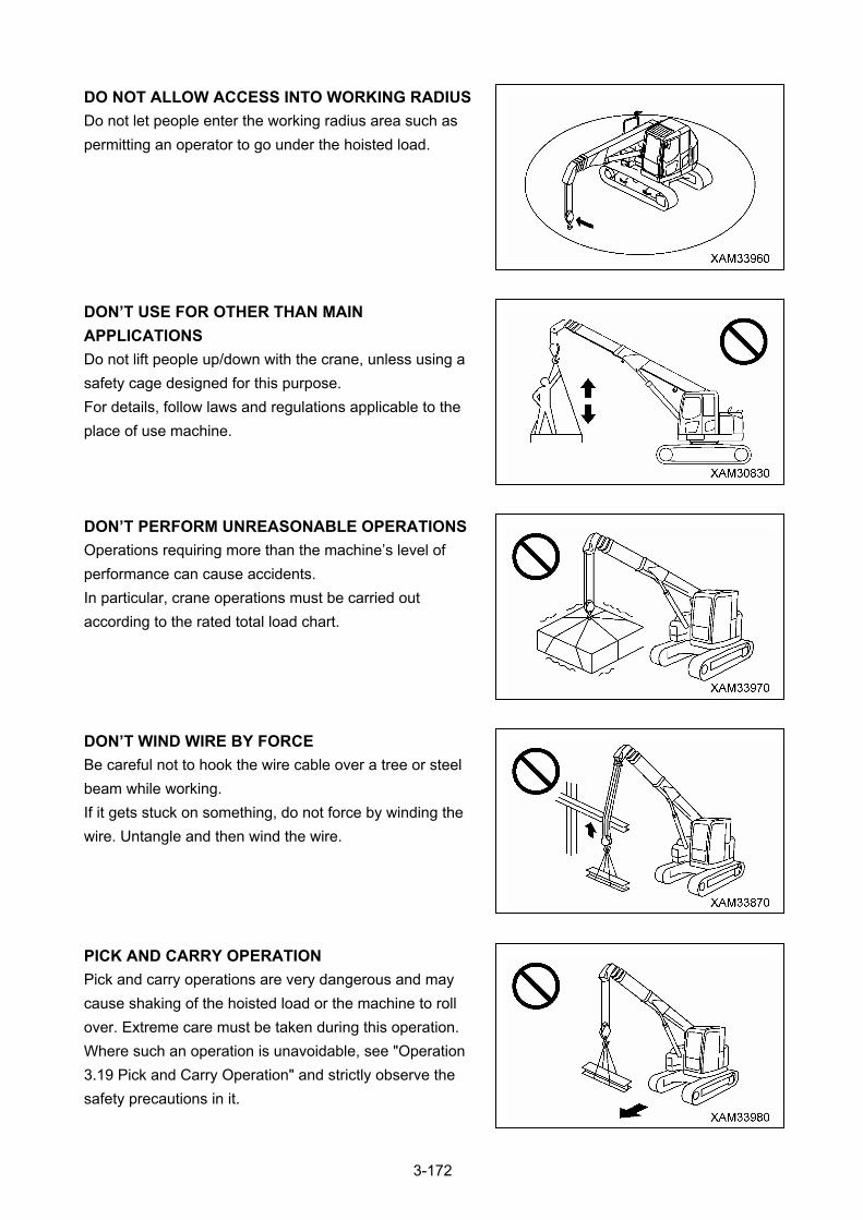
DO NOT ALLOW ACCESS INTO WORKING RADIUS
Do not let people enter the working radius area such as
permitting an operator to go under the hoisted load.
DON’T USE FOR OTHER THAN MAIN
APPLICATIONS
Do not lift people up/down with the crane, unless using a
safety cage designed for this purpose.
For details, follow laws and regulations applicable to the
place of use machine.
DON’T PERFORM UNREASONABLE OPERATIONS
Operations requiring more than the machine’s level of
performance can cause accidents.
In particular, crane operations must be carried out
according to the rated total load chart.
DON’T WIND WIRE BY FORCE
Be careful not to hook the wire cable over a tree or steel
beam while working.
If it gets stuck on something, do not force by winding the
wire. Untangle and then wind the wire.
PICK AND CARRY OPERATION
Pick and carry operations are very dangerous and may
cause shaking of the hoisted load or the machine to roll
over. Extreme care must be taken during this operation.
Where such an operation is unavoidable, see "Operation
3.19 Pick and Carry Operation" and strictly observe the
safety precautions in it.
3-172
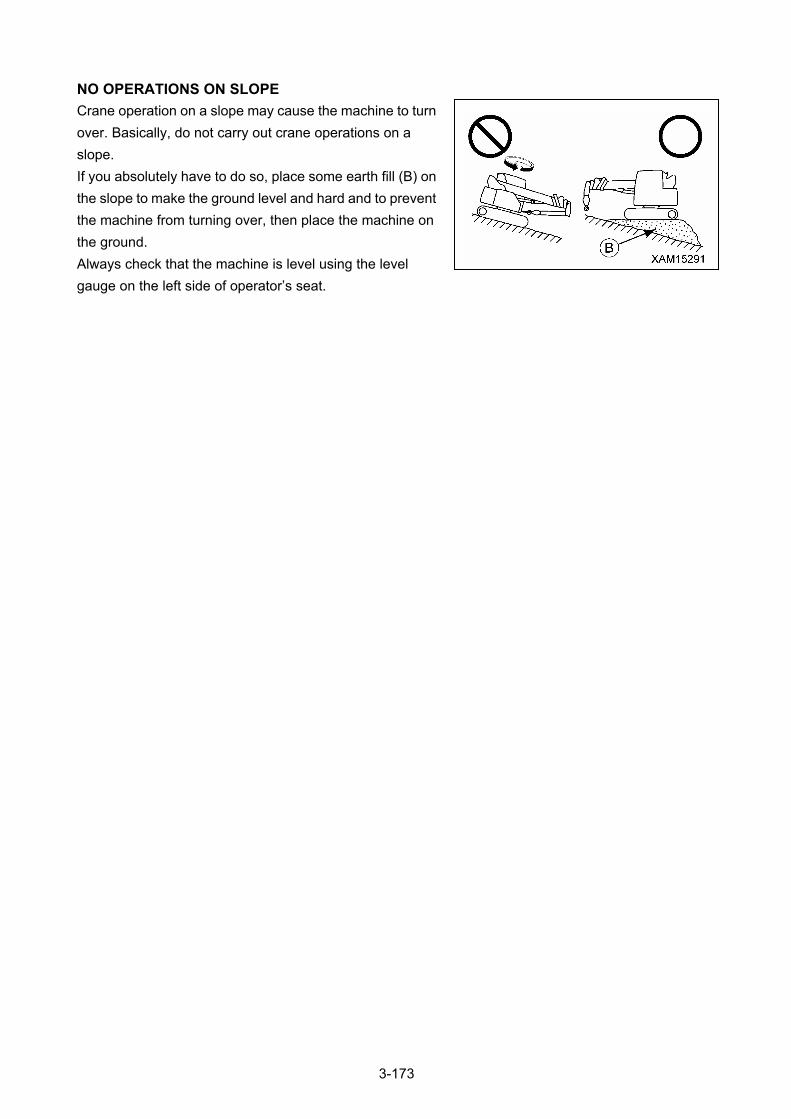
NO OPERATIONS ON SLOPE
Crane operation on a slope may cause the machine to turn
over. Basically, do not carry out crane operations on a
slope.
If you absolutely have to do so, place some earth fill (B) on
the slope to make the ground level and hard and to prevent
the machine from turning over, then place the machine on
the ground.
Always check that the machine is level using the level
gauge on the left side of operator’s seat.
3-173
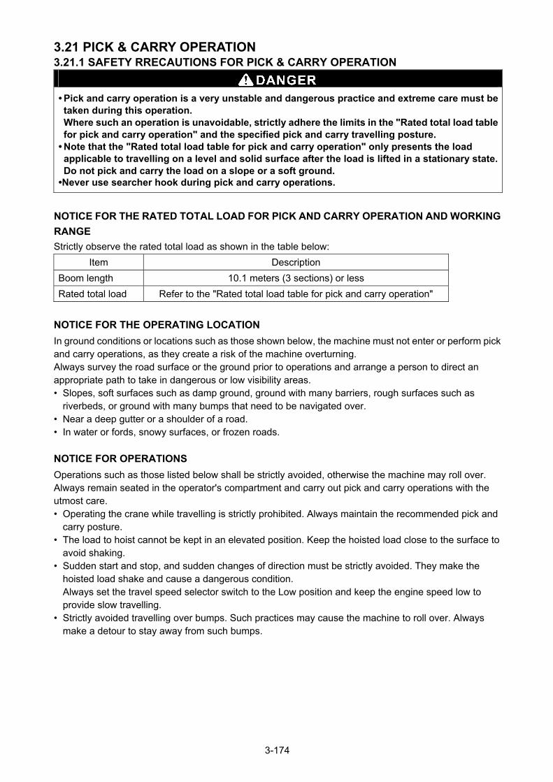
3.21 PICK & CARRY OPERATION 3.21.1 SAFETY RRECAUTIONS FOR PICK & CARRY OPERATION
• Pick and carry operation is a very unstable and dangerous practice and extreme care must be taken during this operation. Where such an operation is unavoidable, strictly adhere the limits in the "Rated total load table for pick and carry operation" and the specified pick and carry travelling posture.
• Note that the "Rated total load table for pick and carry operation" only presents the load applicable to travelling on a level and solid surface after the load is lifted in a stationary state. Do not pick and carry the load on a slope or a soft ground.
•Never use searcher hook during pick and carry operations.
NOTICE FOR THE RATED TOTAL LOAD FOR PICK AND CARRY OPERATION AND WORKING
RANGE
Strictly observe the rated total load as shown in the table below:
Item Description
Boom length 10.1 meters (3 sections) or less
Rated total load Refer to the "Rated total load table for pick and carry operation"
NOTICE FOR THE OPERATING LOCATION
In ground conditions or locations such as those shown below, the machine must not enter or perform pick and carry operations, as they create a risk of the machine overturning. Always survey the road surface or the ground prior to operations and arrange a person to direct an appropriate path to take in dangerous or low visibility areas. • Slopes, soft surfaces such as damp ground, ground with many barriers, rough surfaces such as
riverbeds, or ground with many bumps that need to be navigated over. • Near a deep gutter or a shoulder of a road. • In water or fords, snowy surfaces, or frozen roads.
NOTICE FOR OPERATIONS
Operations such as those listed below shall be strictly avoided, otherwise the machine may roll over. Always remain seated in the operator's compartment and carry out pick and carry operations with the utmost care. • Operating the crane while travelling is strictly prohibited. Always maintain the recommended pick and
carry posture. • The load to hoist cannot be kept in an elevated position. Keep the hoisted load close to the surface to
avoid shaking. • Sudden start and stop, and sudden changes of direction must be strictly avoided. They make the
hoisted load shake and cause a dangerous condition. Always set the travel speed selector switch to the Low position and keep the engine speed low to provide slow travelling.
• Strictly avoided travelling over bumps. Such practices may cause the machine to roll over. Always make a detour to stay away from such bumps.
3-174
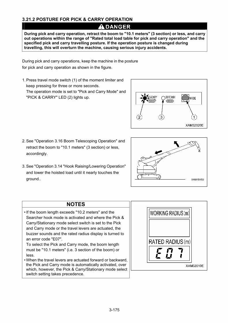
3.21.2 POSTURE FOR PICK & CARRY OPERATION
During pick and carry operation, retract the boom to "10.1 meters" (3 section) or less, and carry out operations within the range of "Rated total load table for pick and carry operation" and the specified pick and carry travelling posture. If the operation posture is changed during travelling, this will overturn the machine, causing serious injury accidents.
During pick and carry operations, keep the machine in the posture
for pick and carry operation as shown in the figure.
1. Press travel mode switch (1) of the moment limiter and
keep pressing for three or more seconds.
The operation mode is set to "Pick and Carry Mode" and
"PICK & CARRY" LED (2) lights up.
2. See "Operation 3.16 Boom Telescoping Operation" and
retract the boom to "10.1 meters" (3 section) or less,
accordingly.
3. See "Operation 3.14 "Hook Raising/Lowering Operation"
and lower the hoisted load until it nearly touches the
ground..
NOTES
• If the boom length exceeds "10.2 meters" and the Searcher hook mode is activated and where the Pick & Carry/Stationary mode select switch is set to the Pick and Carry mode or the travel levers are actuated, the buzzer sounds and the rated radius display is turned to an error code "E07". To select the Pick and Carry mode, the boom length must be "10.1 meters" (i.e. 3 section of the boom) or less.
• When the travel levers are actuated forward or backward, the Pick and Carry mode is automatically activated, over which, however, the Pick & Carry/Stationary mode select switch setting takes precedence.
3-175
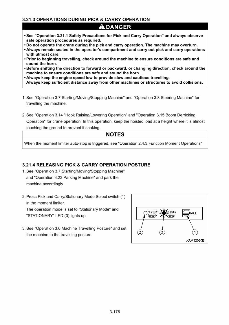
3.21.3 OPERATIONS DURING PICK & CARRY OPERATION
• See "Operation 3.21.1 Safety Precautions for Pick and Carry Operation" and always observe safe operation procedures as required.
• Do not operate the crane during the pick and carry operation. The machine may overturn. • Always remain seated in the operator's compartment and carry out pick and carry operations with utmost care.
• Prior to beginning travelling, check around the machine to ensure conditions are safe and sound the horn.
• Before shifting the direction to forward or backward, or changing direction, check around the machine to ensure conditions are safe and sound the horn.
• Always keep the engine speed low to provide slow and cautious travelling. Always keep sufficient distance away from other machines or structures to avoid collisions.
1. See "Operation 3.7 Starting/Moving/Stopping Machine" and "Operation 3.8 Steering Machine" for
travelling the machine.
2. See "Operation 3.14 "Hook Raising/Lowering Operation" and "Operation 3.15 Boom Derricking
Operation" for crane operation. In this operation, keep the hoisted load at a height where it is almost
touching the ground to prevent it shaking.
NOTES
When the moment limiter auto-stop is triggered, see "Operation 2.4.3 Function Moment Operations"
3.21.4 RELEASING PICK & CARRY OPERATION POSTURE 1. See "Operation 3.7 Starting/Moving/Stopping Machine"
and "Operation 3.23 Parking Machine" and park the
machine accordingly
2. Press Pick and Carry/Stationary Mode Select switch (1)
in the moment limiter.
The operation mode is set to "Stationary Mode" and
"STATIONARY" LED (3) lights up.
3. See "Operation 3.6 Machine Travelling Posture" and set
the machine to the travelling posture
3-176
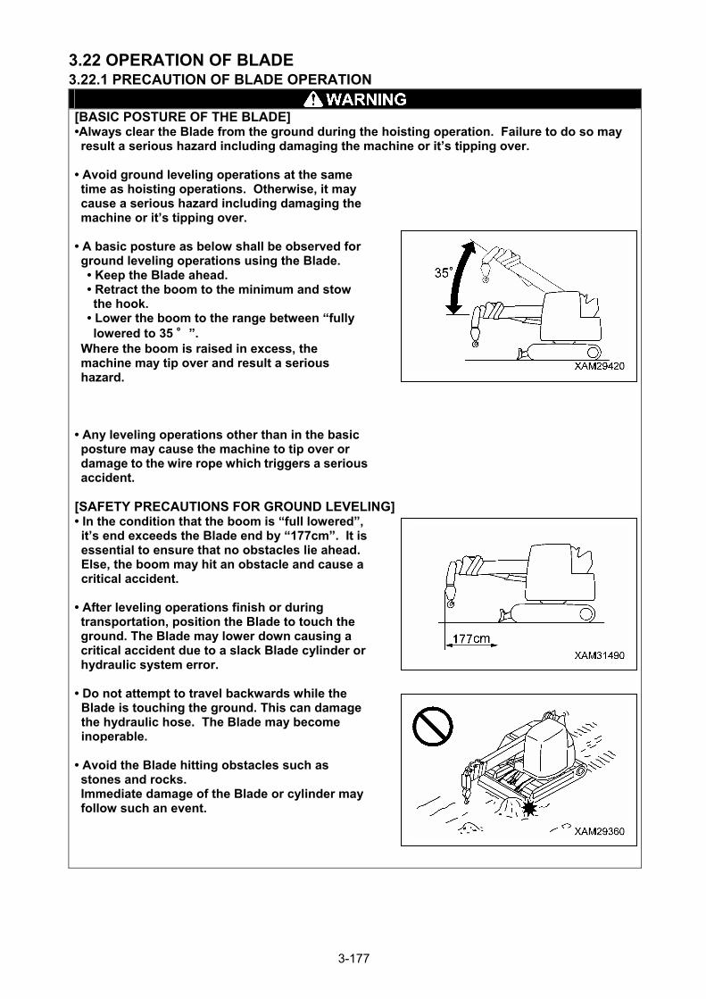
3.22 OPERATION OF BLADE 3.22.1 PRECAUTION OF BLADE OPERATION
[BASIC POSTURE OF THE BLADE] •Always clear the Blade from the ground during the hoisting operation. Failure to do so may result a serious hazard including damaging the machine or it’s tipping over.
• Avoid ground leveling operations at the same time as hoisting operations. Otherwise, it may cause a serious hazard including damaging the machine or it’s tipping over.
• A basic posture as below shall be observed for ground leveling operations using the Blade. • Keep the Blade ahead. • Retract the boom to the minimum and stow the hook.
• Lower the boom to the range between “fully lowered to 35 °”.
Where the boom is raised in excess, the machine may tip over and result a serious hazard.
• Any leveling operations other than in the basic posture may cause the machine to tip over or damage to the wire rope which triggers a serious accident.
[SAFETY PRECAUTIONS FOR GROUND LEVELING] • In the condition that the boom is “full lowered”, it’s end exceeds the Blade end by “177cm”. It is essential to ensure that no obstacles lie ahead. Else, the boom may hit an obstacle and cause a critical accident.
• After leveling operations finish or during transportation, position the Blade to touch the ground. The Blade may lower down causing a critical accident due to a slack Blade cylinder or hydraulic system error.
• Do not attempt to travel backwards while the Blade is touching the ground. This can damage the hydraulic hose. The Blade may become inoperable.
• Avoid the Blade hitting obstacles such as stones and rocks. Immediate damage of the Blade or cylinder may follow such an event.
3-177
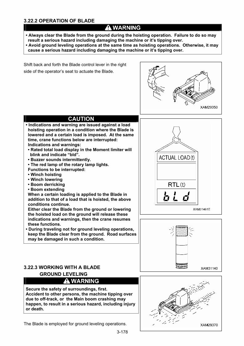
3.22.2 OPERATION OF BLADE
• Always clear the Blade from the ground during the hoisting operation. Failure to do so may result a serious hazard including damaging the machine or it’s tipping over.
• Avoid ground leveling operations at the same time as hoisting operations. Otherwise, it may cause a serious hazard including damaging the machine or it’s tipping over.
Shift back and forth the Blade control lever in the right
side of the operator’s seat to actuate the Blade.
CAUTION • Indications and warning are issued against a load hoisting operation in a condition where the Blade is lowered and a certain load is imposed. At the same time, crane functions below are interrupted: Indications and warnings: • Rated total load display in the Moment limiter will blink and indicate “bld”.
• Buzzer sounds intermittently. • The red lamp of the rotary lamp lights. Functions to be interrupted: • Winch hoisting • Winch lowering • Boom derricking • Boom extending When a certain loading is applied to the Blade in addition to that of a load that is hoisted, the above conditions continue. Either clear the Blade from the ground or lowering the hoisted load on the ground will release these indications and warnings, then the crane resumes these functions.
• During traveling not for ground leveling operations, keep the Blade clear from the ground. Road surfaces may be damaged in such a condition.
3.22.3 WORKING WITH A BLADE GROUND LEVELING
Secure the safety of surroundings, first. Accident to other persons, the machine tipping over due to off-track, or the Main boom crashing may happen, to result in a serious hazard, including injury or death.
The Blade is employed for ground leveling operations.
3-178
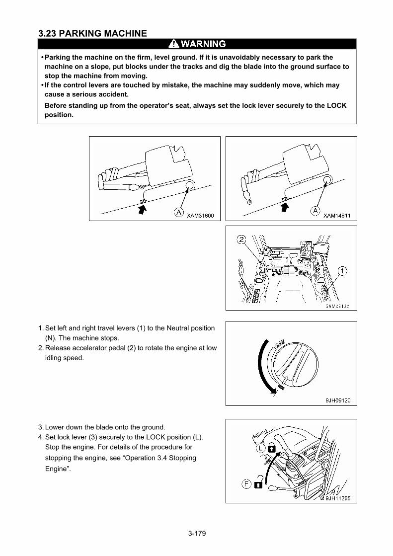
3.23 PARKING MACHINE
• Parking the machine on the firm, level ground. If it is unavoidably necessary to park the machine on a slope, put blocks under the tracks and dig the blade into the ground surface to stop the machine from moving.
• If the control levers are touched by mistake, the machine may suddenly move, which may cause a serious accident.
Before standing up from the operator’s seat, always set the lock lever securely to the LOCK position.
1. Set left and right travel levers (1) to the Neutral position
(N). The machine stops.
2. Release accelerator pedal (2) to rotate the engine at low
idling speed.
3. Lower down the blade onto the ground.
4. Set lock lever (3) securely to the LOCK position (L).
Stop the engine. For details of the procedure for
stopping the engine, see “Operation 3.4 Stopping
Engine”.
3-179
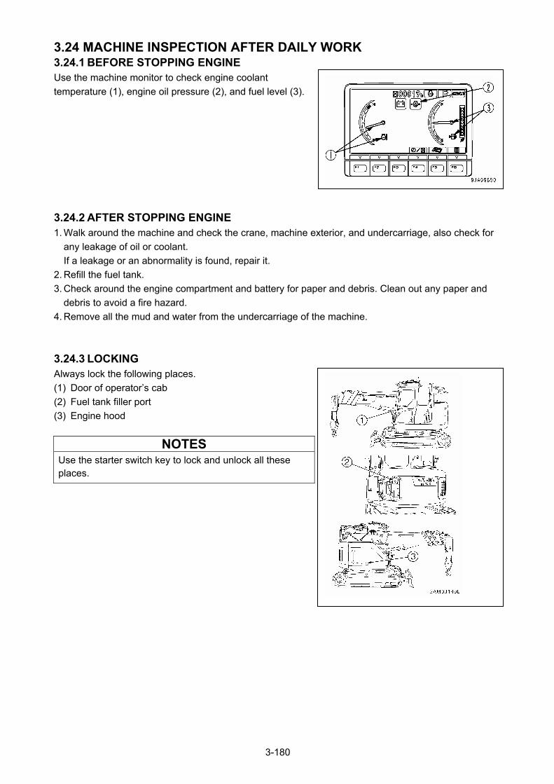
3.24 MACHINE INSPECTION AFTER DAILY WORK 3.24.1 BEFORE STOPPING ENGINE Use the machine monitor to check engine coolant
temperature (1), engine oil pressure (2), and fuel level (3).
3.24.2 AFTER STOPPING ENGINE 1. Walk around the machine and check the crane, machine exterior, and undercarriage, also check for
any leakage of oil or coolant.
If a leakage or an abnormality is found, repair it.
2. Refill the fuel tank.
3. Check around the engine compartment and battery for paper and debris. Clean out any paper and
debris to avoid a fire hazard.
4. Remove all the mud and water from the undercarriage of the machine.
3.24.3 LOCKING Always lock the following places.
(1) Door of operator’s cab
(2) Fuel tank filler port
(3) Engine hood
NOTES Use the starter switch key to lock and unlock all these places.
3-180
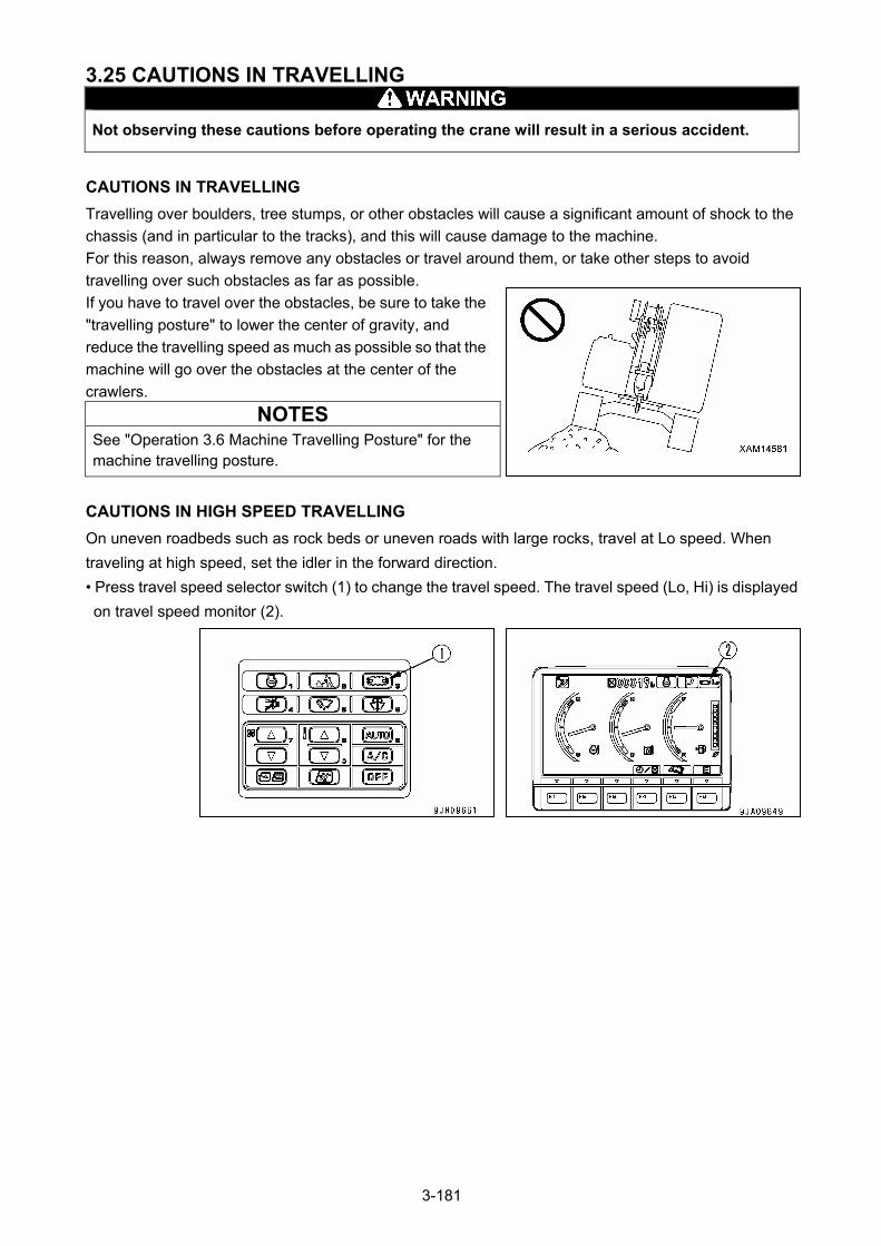
3.25 CAUTIONS IN TRAVELLING
Not observing these cautions before operating the crane will result in a serious accident.
CAUTIONS IN TRAVELLING
Travelling over boulders, tree stumps, or other obstacles will cause a significant amount of shock to the
chassis (and in particular to the tracks), and this will cause damage to the machine.
For this reason, always remove any obstacles or travel around them, or take other steps to avoid
travelling over such obstacles as far as possible.
If you have to travel over the obstacles, be sure to take the
"travelling posture" to lower the center of gravity, and
reduce the travelling speed as much as possible so that the
machine will go over the obstacles at the center of the
crawlers.
NOTES See "Operation 3.6 Machine Travelling Posture" for the machine travelling posture.
CAUTIONS IN HIGH SPEED TRAVELLING
On uneven roadbeds such as rock beds or uneven roads with large rocks, travel at Lo speed. When
traveling at high speed, set the idler in the forward direction.
• Press travel speed selector switch (1) to change the travel speed. The travel speed (Lo, Hi) is displayed
on travel speed monitor (2).
3-181
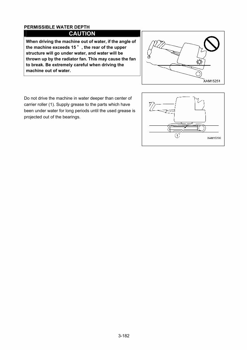
PERMISSIBLE WATER DEPTH
CAUTION When driving the machine out of water, if the angle of the machine exceeds 15 °, the rear of the upper structure will go under water, and water will be thrown up by the radiator fan. This may cause the fan to break. Be extremely careful when driving the machine out of water.
Do not drive the machine in water deeper than center of
carrier roller (1). Supply grease to the parts which have
been under water for long periods until the used grease is
projected out of the bearings.
3-182
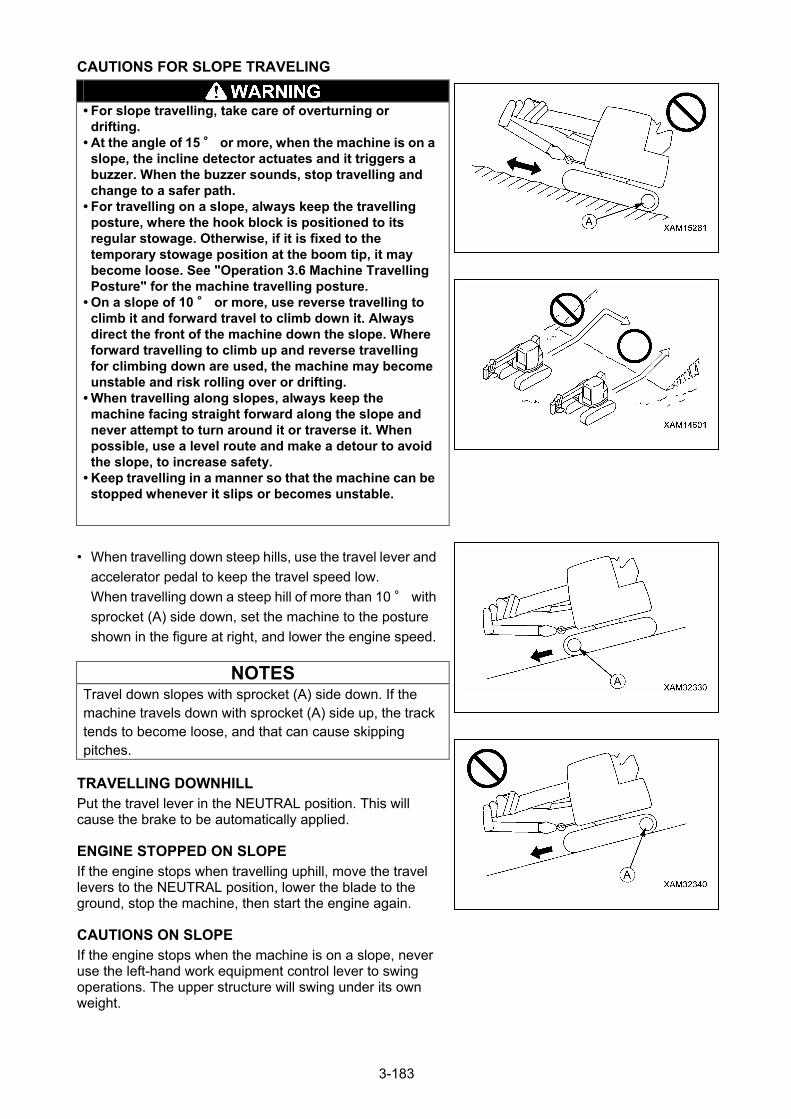
CAUTIONS FOR SLOPE TRAVELING
• For slope travelling, take care of overturning or
drifting. • At the angle of 15 ° or more, when the machine is on a
slope, the incline detector actuates and it triggers a buzzer. When the buzzer sounds, stop travelling and change to a safer path.
• For travelling on a slope, always keep the travelling posture, where the hook block is positioned to its regular stowage. Otherwise, if it is fixed to the temporary stowage position at the boom tip, it may become loose. See "Operation 3.6 Machine Travelling Posture" for the machine travelling posture.
• On a slope of 10 ° or more, use reverse travelling to climb it and forward travel to climb down it. Always direct the front of the machine down the slope. Where forward travelling to climb up and reverse travelling for climbing down are used, the machine may become unstable and risk rolling over or drifting.
• When travelling along slopes, always keep the machine facing straight forward along the slope and never attempt to turn around it or traverse it. When possible, use a level route and make a detour to avoid the slope, to increase safety.
• Keep travelling in a manner so that the machine can be stopped whenever it slips or becomes unstable.
• When travelling down steep hills, use the travel lever and
accelerator pedal to keep the travel speed low.
When travelling down a steep hill of more than 10 ° with
sprocket (A) side down, set the machine to the posture
shown in the figure at right, and lower the engine speed.
NOTES Travel down slopes with sprocket (A) side down. If the machine travels down with sprocket (A) side up, the track tends to become loose, and that can cause skipping pitches.
TRAVELLING DOWNHILL Put the travel lever in the NEUTRAL position. This will cause the brake to be automatically applied. ENGINE STOPPED ON SLOPE If the engine stops when travelling uphill, move the travel levers to the NEUTRAL position, lower the blade to the ground, stop the machine, then start the engine again. CAUTIONS ON SLOPE If the engine stops when the machine is on a slope, never use the left-hand work equipment control lever to swing operations. The upper structure will swing under its own weight.
3-183
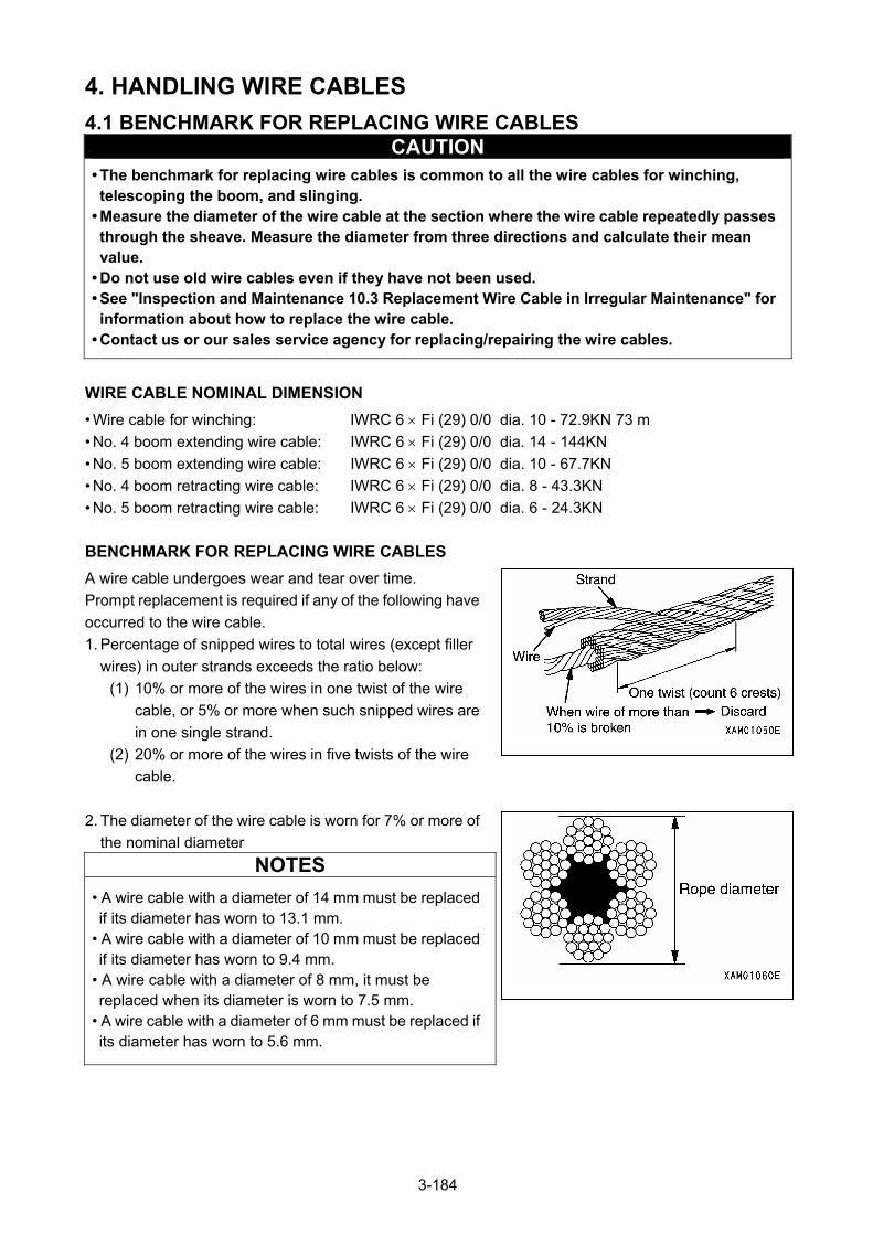
4. HANDLING WIRE CABLES
4.1 BENCHMARK FOR REPLACING WIRE CABLES CAUTION
• The benchmark for replacing wire cables is common to all the wire cables for winching, telescoping the boom, and slinging.
• Measure the diameter of the wire cable at the section where the wire cable repeatedly passes through the sheave. Measure the diameter from three directions and calculate their mean value.
• Do not use old wire cables even if they have not been used. • See "Inspection and Maintenance 10.3 Replacement Wire Cable in Irregular Maintenance" for information about how to replace the wire cable.
• Contact us or our sales service agency for replacing/repairing the wire cables.
WIRE CABLE NOMINAL DIMENSION
• Wire cable for winching: IWRC 6 Fi (29) 0/0 dia. 10 - 72.9KN 73 m
• No. 4 boom extending wire cable: IWRC 6 Fi (29) 0/0 dia. 14 - 144KN
• No. 5 boom extending wire cable: IWRC 6 Fi (29) 0/0 dia. 10 - 67.7KN
• No. 4 boom retracting wire cable: IWRC 6 Fi (29) 0/0 dia. 8 - 43.3KN
• No. 5 boom retracting wire cable: IWRC 6 Fi (29) 0/0 dia. 6 - 24.3KN
BENCHMARK FOR REPLACING WIRE CABLES
A wire cable undergoes wear and tear over time.
Prompt replacement is required if any of the following have
occurred to the wire cable.
1. Percentage of snipped wires to total wires (except filler
wires) in outer strands exceeds the ratio below:
(1) 10% or more of the wires in one twist of the wire
cable, or 5% or more when such snipped wires are
in one single strand.
(2) 20% or more of the wires in five twists of the wire
cable.
2. The diameter of the wire cable is worn for 7% or more of
the nominal diameter
NOTES
• A wire cable with a diameter of 14 mm must be replaced if its diameter has worn to 13.1 mm.
• A wire cable with a diameter of 10 mm must be replaced if its diameter has worn to 9.4 mm.
• A wire cable with a diameter of 8 mm, it must be replaced when its diameter is worn to 7.5 mm.
• A wire cable with a diameter of 6 mm must be replaced if its diameter has worn to 5.6 mm.
3-184
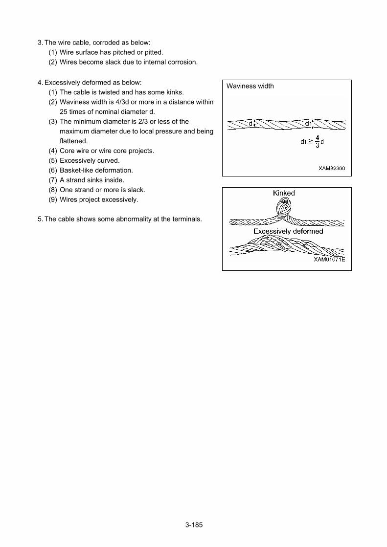
3. The wire cable, corroded as below:
(1) Wire surface has pitched or pitted.
(2) Wires become slack due to internal corrosion.
4. Excessively deformed as below: Waviness width (1) The cable is twisted and has some kinks.
(2) Waviness width is 4/3d or more in a distance within
25 times of nominal diameter d.
(3) The minimum diameter is 2/3 or less of the
maximum diameter due to local pressure and being
flattened.
(4) Core wire or wire core projects.
(5) Excessively curved.
(6) Basket-like deformation.
(7) A strand sinks inside.
(8) One strand or more is slack.
(9) Wires project excessively.
5. The cable shows some abnormality at the terminals.
3-185
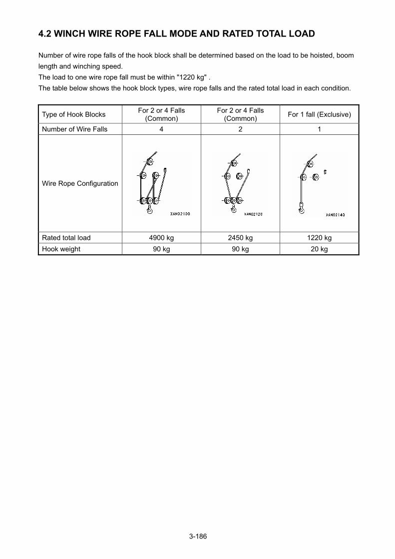
4.2 WINCH WIRE ROPE FALL MODE AND RATED TOTAL LOAD
Number of wire rope falls of the hook block shall be determined based on the load to be hoisted, boom
length and winching speed.
The load to one wire rope fall must be within "1220 kg" .
The table below shows the hook block types, wire rope falls and the rated total load in each condition.
Type of Hook Blocks For 2 or 4 Falls
(Common) For 2 or 4 Falls
(Common) For 1 fall (Exclusive)
Number of Wire Falls 4 2 1
Wire Rope Configuration
Rated total load 4900 kg 2450 kg 1220 kg
Hook weight 90 kg 90 kg 20 kg
3-186
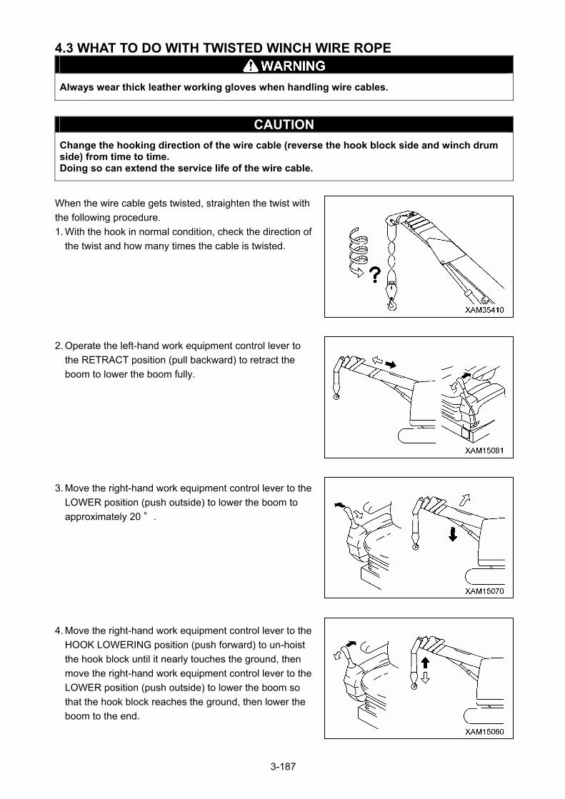
4.3 WHAT TO DO WITH TWISTED WINCH WIRE ROPE
Always wear thick leather working gloves when handling wire cables.
CAUTION
Change the hooking direction of the wire cable (reverse the hook block side and winch drum side) from time to time. Doing so can extend the service life of the wire cable.
When the wire cable gets twisted, straighten the twist with
the following procedure.
1. With the hook in normal condition, check the direction of
the twist and how many times the cable is twisted.
2. Operate the left-hand work equipment control lever to
the RETRACT position (pull backward) to retract the
boom to lower the boom fully.
3. Move the right-hand work equipment control lever to the
LOWER position (push outside) to lower the boom to
approximately 20 °.
4. Move the right-hand work equipment control lever to the
HOOK LOWERING position (push forward) to un-hoist
the hook block until it nearly touches the ground, then
move the right-hand work equipment control lever to the
LOWER position (push outside) to lower the boom so
that the hook block reaches the ground, then lower the
boom to the end.
3-187
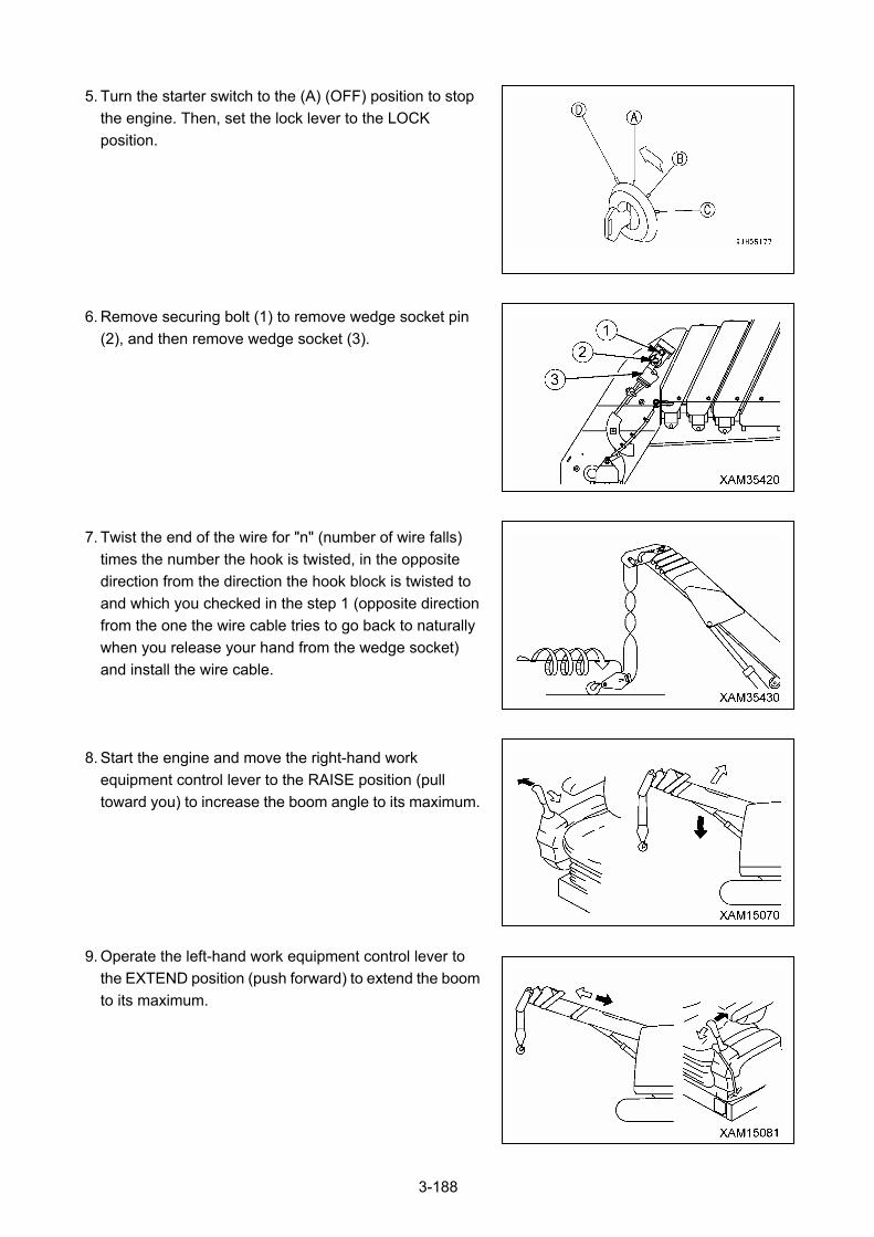
5. Turn the starter switch to the (A) (OFF) position to stop
the engine. Then, set the lock lever to the LOCK
position.
6. Remove securing bolt (1) to remove wedge socket pin
(2), and then remove wedge socket (3).
7. Twist the end of the wire for "n" (number of wire falls)
times the number the hook is twisted, in the opposite
direction from the direction the hook block is twisted to
and which you checked in the step 1 (opposite direction
from the one the wire cable tries to go back to naturally
when you release your hand from the wedge socket)
and install the wire cable.
8. Start the engine and move the right-hand work
equipment control lever to the RAISE position (pull
toward you) to increase the boom angle to its maximum.
9. Operate the left-hand work equipment control lever to
the EXTEND position (push forward) to extend the boom
to its maximum.
3-188

10. Move the right-hand work equipment control lever to
repeat RAISING/LOWERING (forward/backward) the
hook block for several times.
11. Tidily spool up the wire cable into the winch drum with
some tension applied to the cable.
12. Repeat the above procedure until the hook is no longer
twisted.
If the wire cable is still twisted after performing the
procedure above, change with a new wire cable.
3-189

5. TRANSPORTATION
When transporting the machine, observe all related laws and regulations, and be careful to ensure safety.
OBSERVATION OF ROAD TRANSPORTATION ACTS
If there are applicable local laws and regulations, observe these laws and regulations for safe
transportation.
If not, contact us or our sales service agency.
TRANSPORTATION MEASURE
Take road width, height, and weight into consideration in determining the transportation route.
To determine the transportation measure, see the weights and dimensions shown in "Specifications 1.
Main Specification Table".
3-190
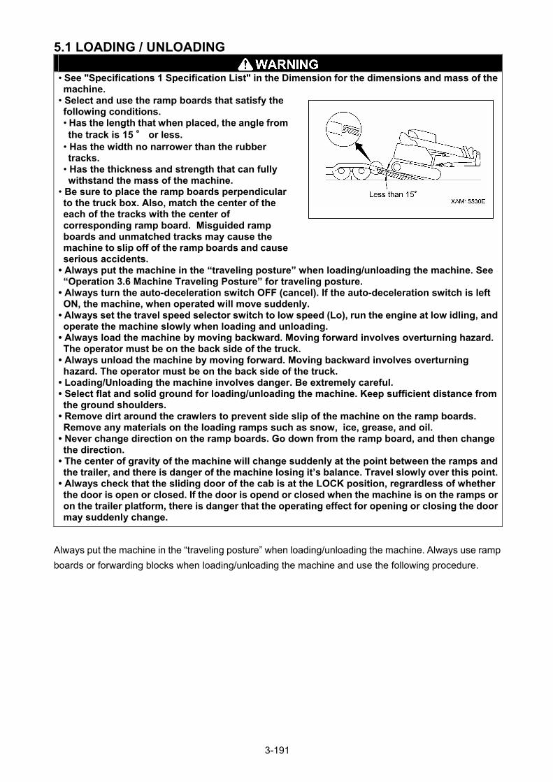
5.1 LOADING / UNLOADING
• See "Specifications 1 Specification List" in the Dimension for the dimensions and mass of the machine.
• Select and use the ramp boards that satisfy the following conditions. • Has the length that when placed, the angle from the track is 15 ° or less.
• Has the width no narrower than the rubber tracks.
• Has the thickness and strength that can fully withstand the mass of the machine.
• Be sure to place the ramp boards perpendicular to the truck box. Also, match the center of the each of the tracks with the center of corresponding ramp board. Misguided ramp boards and unmatched tracks may cause the machine to slip off of the ramp boards and cause serious accidents.
• Always put the machine in the “traveling posture” when loading/unloading the machine. See “Operation 3.6 Machine Traveling Posture” for traveling posture.
• Always turn the auto-deceleration switch OFF (cancel). If the auto-deceleration switch is left ON, the machine, when operated will move suddenly.
• Always set the travel speed selector switch to low speed (Lo), run the engine at low idling, and operate the machine slowly when loading and unloading.
• Always load the machine by moving backward. Moving forward involves overturning hazard. The operator must be on the back side of the truck.
• Always unload the machine by moving forward. Moving backward involves overturning hazard. The operator must be on the back side of the truck.
• Loading/Unloading the machine involves danger. Be extremely careful. • Select flat and solid ground for loading/unloading the machine. Keep sufficient distance from the ground shoulders.
• Remove dirt around the crawlers to prevent side slip of the machine on the ramp boards. Remove any materials on the loading ramps such as snow, ice, grease, and oil.
• Never change direction on the ramp boards. Go down from the ramp board, and then change the direction.
• The center of gravity of the machine will change suddenly at the point between the ramps and the trailer, and there is danger of the machine losing it’s balance. Travel slowly over this point.
• Always check that the sliding door of the cab is at the LOCK position, regrardless of whether the door is open or closed. If the door is opend or closed when the machine is on the ramps or on the trailer platform, there is danger that the operating effect for opening or closing the door may suddenly change.
Always put the machine in the “traveling posture” when loading/unloading the machine. Always use ramp
boards or forwarding blocks when loading/unloading the machine and use the following procedure.
3-191
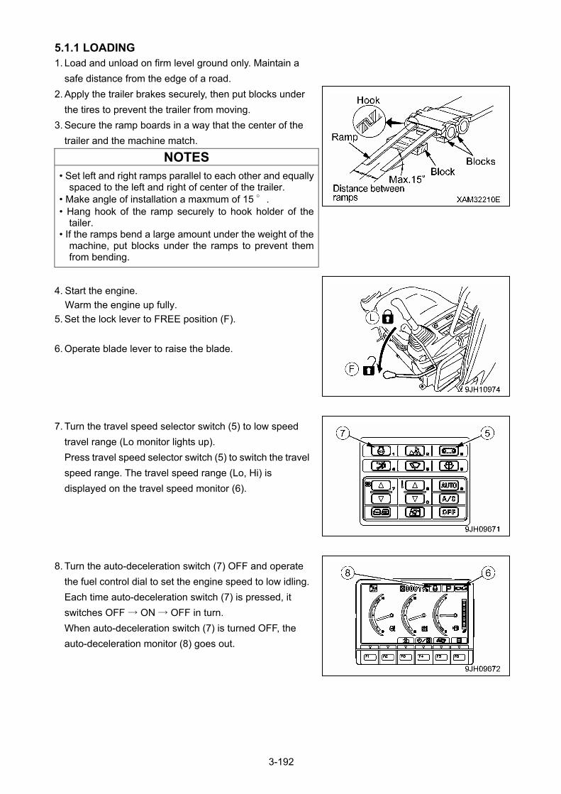
5.1.1 LOADING 1. Load and unload on firm level ground only. Maintain a
safe distance from the edge of a road.
2. Apply the trailer brakes securely, then put blocks under
the tires to prevent the trailer from moving.
3. Secure the ramp boards in a way that the center of the
trailer and the machine match.
NOTES
• Set left and right ramps parallel to each other and equally spaced to the left and right of center of the trailer.
• Make angle of installation a maxmum of 15 °. • Hang hook of the ramp securely to hook holder of the
tailer. • If the ramps bend a large amount under the weight of the
machine, put blocks under the ramps to prevent them from bending.
4. Start the engine.
Warm the engine up fully.
5. Set the lock lever to FREE position (F).
6. Operate blade lever to raise the blade.
7. Turn the travel speed selector switch (5) to low speed
travel range (Lo monitor lights up).
Press travel speed selector switch (5) to switch the travel
speed range. The travel speed range (Lo, Hi) is
displayed on the travel speed monitor (6).
8. Turn the auto-deceleration switch (7) OFF and operate
the fuel control dial to set the engine speed to low idling.
Each time auto-deceleration switch (7) is pressed, it
switches OFF → ON → OFF in turn.
When auto-deceleration switch (7) is turned OFF, the
auto-deceleration monitor (8) goes out.
3-192
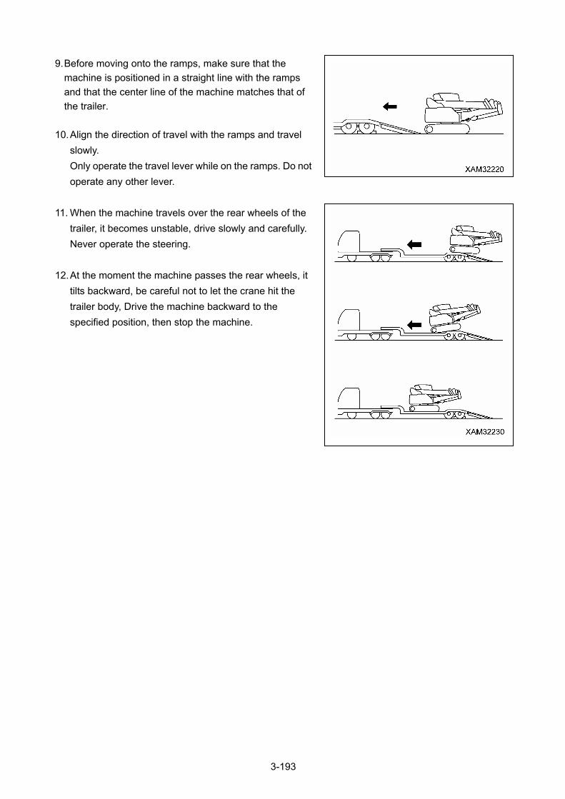
9. Before moving onto the ramps, make sure that the
machine is positioned in a straight line with the ramps
and that the center line of the machine matches that of
the trailer.
10. Align the direction of travel with the ramps and travel
slowly.
Only operate the travel lever while on the ramps. Do not
operate any other lever.
11. When the machine travels over the rear wheels of the
trailer, it becomes unstable, drive slowly and carefully.
Never operate the steering.
12. At the moment the machine passes the rear wheels, it
tilts backward, be careful not to let the crane hit the
trailer body, Drive the machine backward to the
specified position, then stop the machine.
3-193
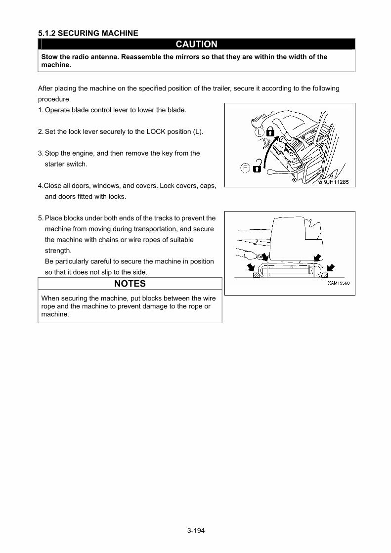
5.1.2 SECURING MACHINE
CAUTION Stow the radio antenna. Reassemble the mirrors so that they are within the width of the machine.
After placing the machine on the specified position of the trailer, secure it according to the following
procedure.
1. Operate blade control lever to lower the blade.
2. Set the lock lever securely to the LOCK position (L).
3. Stop the engine, and then remove the key from the
starter switch.
4.Close all doors, windows, and covers. Lock covers, caps,
and doors fitted with locks.
5. Place blocks under both ends of the tracks to prevent the
machine from moving during transportation, and secure
the machine with chains or wire ropes of suitable
strength.
Be particularly careful to secure the machine in position
so that it does not slip to the side.
NOTES
When securing the machine, put blocks between the wire rope and the machine to prevent damage to the rope or machine.
3-194
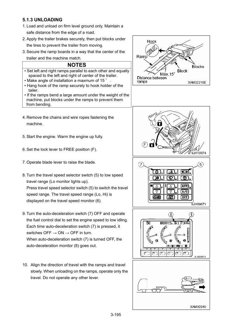
5.1.3 UNLOADING 1. Load and unload on firm level ground only. Maintain a
safe distance from the edge of a road.
2. Apply the trailer brakes securely, then put blocks under
the tires to prevent the trailer from moving.
3. Secure the ramp boards in a way that the center of the
trailer and the machine match.
NOTES • Set left and right ramps parallel to each other and equally
spaced to the left and right of center of the trailer. • Make angle of installation a maxmum of 15 °. • Hang hook of the ramp securely to hook holder of the
tailer. • If the ramps bend a large amount under the weight of the machine, put blocks under the ramps to prevent them from bending.
4. Remove the chains and wire ropes fastening the
machine.
5. Start the engine. Warm the engine up fully.
6. Set the lock lever to FREE position (F).
7. Operate blade lever to raise the blade.
8. Turn the travel speed selector switch (5) to low speed
travel range (Lo monitor lights up).
Press travel speed selector switch (5) to switch the travel
speed range. The travel speed range (Lo, Hi) is
displayed on the travel speed monitor (6).
9. Turn the auto-deceleration switch (7) OFF and operate
the fuel control dial to set the engine speed to low idling.
Each time auto-deceleration switch (7) is pressed, it
switches OFF → ON → OFF in turn.
When auto-deceleration switch (7) is turned OFF, the
auto-deceleration monitor (8) goes out.
10. Align the direction of travel with the ramps and travel
slowly. When unloading on the ramps, operate only the
travel. Do not operate any other lever.
3-195
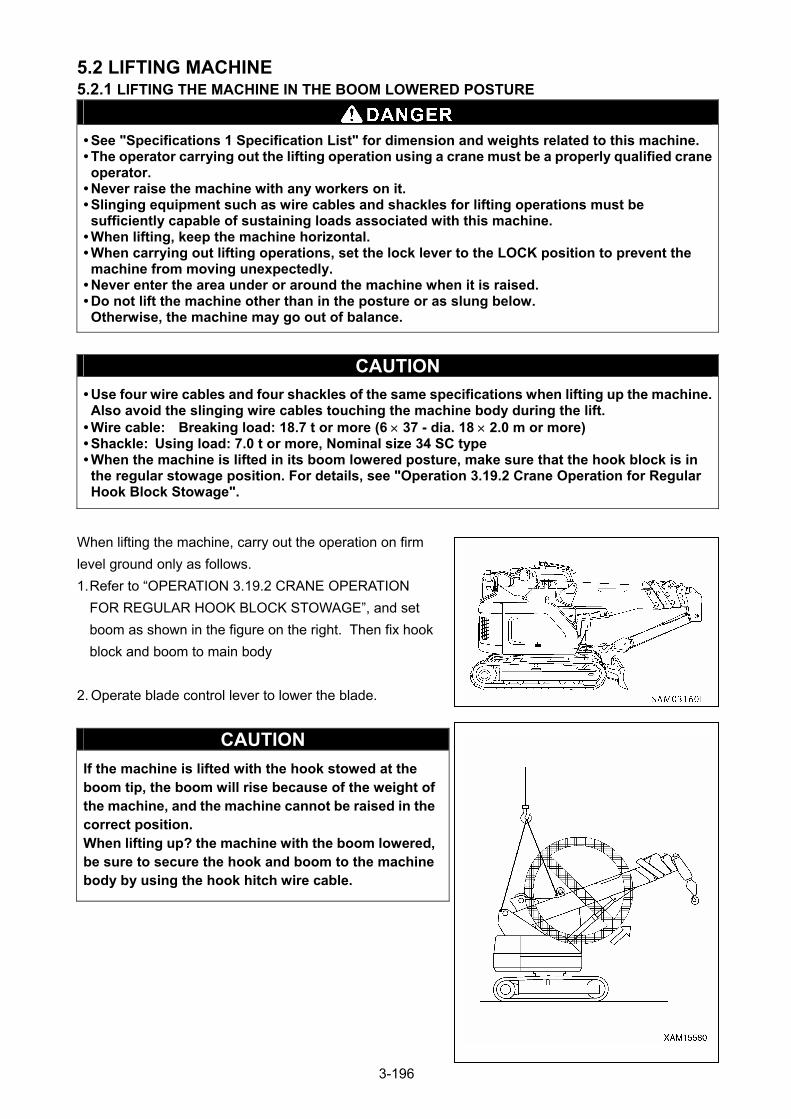
5.2 LIFTING MACHINE 5.2.1 LIFTING THE MACHINE IN THE BOOM LOWERED POSTURE
• See "Specifications 1 Specification List" for dimension and weights related to this machine. • The operator carrying out the lifting operation using a crane must be a properly qualified crane operator.
• Never raise the machine with any workers on it. • Slinging equipment such as wire cables and shackles for lifting operations must be sufficiently capable of sustaining loads associated with this machine.
• When lifting, keep the machine horizontal. • When carrying out lifting operations, set the lock lever to the LOCK position to prevent the machine from moving unexpectedly.
• Never enter the area under or around the machine when it is raised. • Do not lift the machine other than in the posture or as slung below. Otherwise, the machine may go out of balance.
CAUTION
• Use four wire cables and four shackles of the same specifications when lifting up the machine.Also avoid the slinging wire cables touching the machine body during the lift.
• Wire cable: Breaking load: 18.7 t or more (6 37 - dia. 18 2.0 m or more) • Shackle: Using load: 7.0 t or more, Nominal size 34 SC type • When the machine is lifted in its boom lowered posture, make sure that the hook block is in the regular stowage position. For details, see "Operation 3.19.2 Crane Operation for Regular Hook Block Stowage".
When lifting the machine, carry out the operation on firm
level ground only as follows.
1. Refer to “OPERATION 3.19.2 CRANE OPERATION
FOR REGULAR HOOK BLOCK STOWAGE”, and set
boom as shown in the figure on the right. Then fix hook
block and boom to main body
2. Operate blade control lever to lower the blade.
CAUTION
If the machine is lifted with the hook stowed at the boom tip, the boom will rise because of the weight of the machine, and the machine cannot be raised in the correct position. When lifting up? the machine with the boom lowered, be sure to secure the hook and boom to the machine body by using the hook hitch wire cable.
3-196
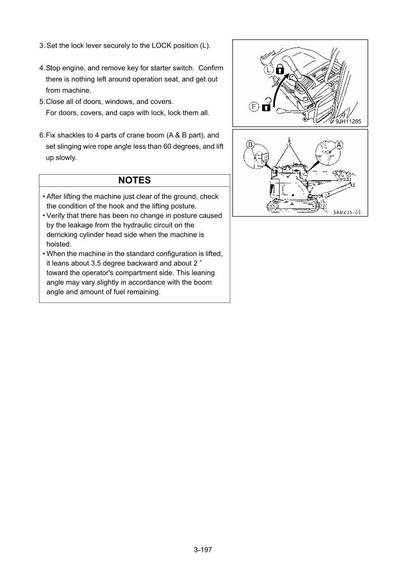
3. Set the lock lever securely to the LOCK position (L).
4. Stop engine, and remove key for starter switch. Confirm
there is nothing left around operation seat, and get out
from machine.
5. Close all of doors, windows, and covers.
For doors, covers, and caps with lock, lock them all.
6. Fix shackles to 4 parts of crane boom (A & B part), and
set slinging wire rope angle less than 60 degrees, and lift
up slowly.
NOTES
• After lifting the machine just clear of the ground, check the condition of the hook and the lifting posture.
• Verify that there has been no change in posture caused by the leakage from the hydraulic circuit on the derricking cylinder head side when the machine is hoisted.
• When the machine in the standard configuration is lifted, it leans about 3.5 degree backward and about 2 ° toward the operator's compartment side. This leaning angle may vary slightly in accordance with the boom angle and amount of fuel remaining.
3-197
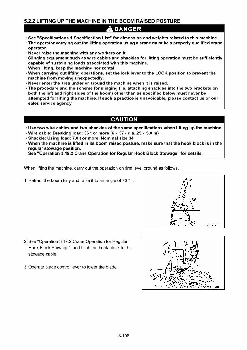
5.2.2 LIFTING UP THE MACHINE IN THE BOOM RAISED POSTURE
• See "Specifications 1 Specification List" for dimension and weights related to this machine. • The operator carrying out the lifting operation using a crane must be a properly qualified crane operator.
• Never raise the machine with any workers on it. • Slinging equipment such as wire cables and shackles for lifting operation must be sufficiently capable of sustaining loads associated with this machine.
• When lifting, keep the machine horizontal. • When carrying out lifting operations, set the lock lever to the LOCK position to prevent the machine from moving unexpectedly.
• Never enter the area under or around the machine when it is raised. • The procedure and the scheme for slinging (i.e. attaching shackles into the two brackets on both the left and right sides of the boom) other than as specified below must never be attempted for lifting the machine. If such a practice is unavoidable, please contact us or our sales service agency.
CAUTION • Use two wire cables and two shackles of the same specifications when lifting up the machine.• Wire cable: Breaking load: 36 t or more (6 37 - dia. 25 5.0 m) • Shackle: Using load: 7.0 t or more, Nominal size 34 • When the machine is lifted in its boom raised posture, make sure that the hook block is in the regular stowage position. See "Operation 3.19.2 Crane Operation for Regular Hook Block Stowage" for details.
When lifting the machine, carry out the operation on firm level ground as follows.
1. Retract the boom fully and raise it to an angle of 70 °.
2. See "Operation 3.19.2 Crane Operation for Regular
Hook Block Stowage", and hitch the hook block to the
stowage cable.
3. Operate blade control lever to lower the blade.
3-198
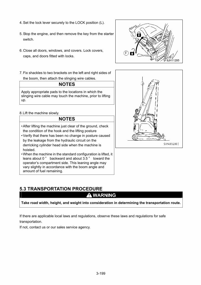
4. Set the lock lever securely to the LOCK position (L).
5. Stop the engine, and then remove the key from the starter
switch.
6. Close all doors, windows, and covers. Lock covers,
caps, and doors fitted with locks.
7. Fix shackles to two brackets on the left and right sides of
the boom, then attach the slinging wire cables.
NOTES
Apply appropriate pads to the locations in which the slinging wire cable may touch the machine, prior to lifting up.
8. Lift the machine slowly.
NOTES
• After lifting the machine just clear of the ground, check the condition of the hook and the lifting posture
• Verify that there has been no change in posture caused by the leakage from the hydraulic circuit on the derricking cylinder head side when the machine is hoisted.
• When the machine in the standard configuration is lifted, it leans about 0 ° backward and about 3.5 ° toward the operator’s compartment side. This leaning angle may vary slightly in accordance with the boom angle and amount of fuel remaining.
5.3 TRANSPORTATION PROCEDURE
Take road width, height, and weight into consideration in determining the transportation route.
If there are applicable local laws and regulations, observe these laws and regulations for safe
transportation.
If not, contact us or our sales service agency.
3-199
6. HANDLING IN COLD WEATHER
6.1 PREPARING FOR LOW TEMPERATURE In low temperatures, the machine may start to have some difficulty and the coolant may freeze. In this
case, take the following actions.
FUEL AND LUBRICANTS
Change the fuel and oil to ones with low viscosity.
See "Inspection and Maintenance 7.1 Use of Fuel, Coolant and Lubricants According to Ambient
Temperature" for the specified viscosity.
COOLING SYSTEM COOLANT
• Antifreeze is toxic. Be careful not to get it in your eyes or on your skin. If it should get in your eyes or on your skin, wash it off with large amounts of fresh water and see a doctor at once.
• When changing the coolant or when handling coolant containing antifreeze that has been drained when replacing the coolant or repairing the radiator, you should employ a specialized contractor or contact us or our sales service agency. Antifreeze is toxic. Do not let it flow into drainage ditches or spray it onto the ground surface.
• Antifreeze is flammable. Do not bring any flame close. Do not smoke when handling antifreeze.
CAUTION
Never use antifreeze with ethanol or propanol-based antifreeze.
See "Inspection and Maintenance 10.3 Rregular Maintenance (Cleaning inside of cooling system)" for the
cooling water replacement period and mixing rate of antifreeze.
3-200
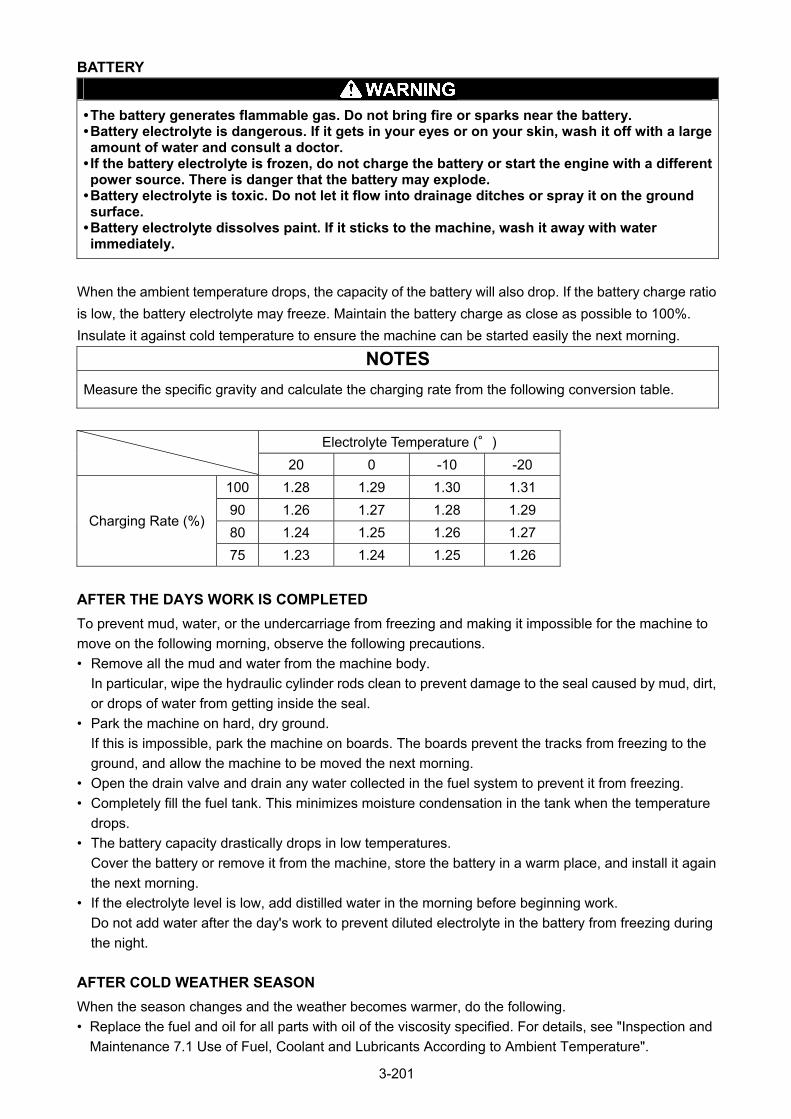
BATTERY
• The battery generates flammable gas. Do not bring fire or sparks near the battery. • Battery electrolyte is dangerous. If it gets in your eyes or on your skin, wash it off with a large amount of water and consult a doctor.
• If the battery electrolyte is frozen, do not charge the battery or start the engine with a different power source. There is danger that the battery may explode.
• Battery electrolyte is toxic. Do not let it flow into drainage ditches or spray it on the ground surface.
• Battery electrolyte dissolves paint. If it sticks to the machine, wash it away with water immediately.
When the ambient temperature drops, the capacity of the battery will also drop. If the battery charge ratio
is low, the battery electrolyte may freeze. Maintain the battery charge as close as possible to 100%.
Insulate it against cold temperature to ensure the machine can be started easily the next morning.
NOTES
Measure the specific gravity and calculate the charging rate from the following conversion table.
Electrolyte Temperature (°)
20 0 -10 -20
100 1.28 1.29 1.30 1.31
90 1.26 1.27 1.28 1.29
80 1.24 1.25 1.26 1.27 Charging Rate (%)
75 1.23 1.24 1.25 1.26
AFTER THE DAYS WORK IS COMPLETED
To prevent mud, water, or the undercarriage from freezing and making it impossible for the machine to
move on the following morning, observe the following precautions.
• Remove all the mud and water from the machine body.
In particular, wipe the hydraulic cylinder rods clean to prevent damage to the seal caused by mud, dirt,
or drops of water from getting inside the seal.
• Park the machine on hard, dry ground.
If this is impossible, park the machine on boards. The boards prevent the tracks from freezing to the
ground, and allow the machine to be moved the next morning.
• Open the drain valve and drain any water collected in the fuel system to prevent it from freezing.
• Completely fill the fuel tank. This minimizes moisture condensation in the tank when the temperature
drops.
• The battery capacity drastically drops in low temperatures.
Cover the battery or remove it from the machine, store the battery in a warm place, and install it again
the next morning.
• If the electrolyte level is low, add distilled water in the morning before beginning work.
Do not add water after the day's work to prevent diluted electrolyte in the battery from freezing during
the night.
AFTER COLD WEATHER SEASON
When the season changes and the weather becomes warmer, do the following.
• Replace the fuel and oil for all parts with oil of the viscosity specified. For details, see "Inspection and
Maintenance 7.1 Use of Fuel, Coolant and Lubricants According to Ambient Temperature".
3-201
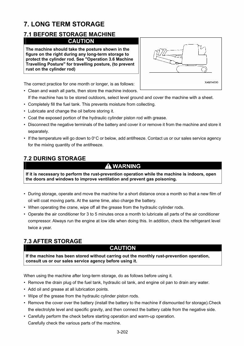
7. LONG TERM STORAGE
7.1 BEFORE STORAGE MACHINE CAUTION
The machine should take the posture shown in the figure on the right during any long-term storage to protect the cylinder rod. See "Operation 3.6 Machine Travelling Posture" for travelling posture, (to prevent rust on the cylinder rod)
The correct practice for one month or longer, is as follows:
• Clean and wash all parts, then store the machine indoors.
If the machine has to be stored outdoors, select level ground and cover the machine with a sheet.
• Completely fill the fuel tank. This prevents moisture from collecting.
• Lubricate and change the oil before storing it.
• Coat the exposed portion of the hydraulic cylinder piston rod with grease.
• Disconnect the negative terminals of the battery and cover it or remove it from the machine and store it
separately.
• If the temperature will go down to 0C or below, add antifreeze. Contact us or our sales service agency
for the mixing quantity of the antifreeze.
7.2 DURING STORAGE
If it is necessary to perform the rust-prevention operation while the machine is indoors, open the doors and windows to improve ventilation and prevent gas poisoning.
• During storage, operate and move the machine for a short distance once a month so that a new film of
oil will coat moving parts. At the same time, also charge the battery.
• When operating the crane, wipe off all the grease from the hydraulic cylinder rods.
• Operate the air conditioner for 3 to 5 minutes once a month to lubricate all parts of the air conditioner
compressor. Always run the engine at low idle when doing this. In addition, check the refrigerant level
twice a year.
7.3 AFTER STORAGE CAUTION
If the machine has been stored without carring out the monthly rust-prevention operation, consult us or our sales service agency before using it.
When using the machine after long-term storage, do as follows before using it.
• Remove the drain plug of the fuel tank, hydraulic oil tank, and engine oil pan to drain any water.
• Add oil and grease at all lubrication points.
• Wipe of the grease from the hydraulic cylinder piston rods.
• Remove the cover over the battery (install the battery to the machine if dismounted for storage).Check
the electrolyte level and specific gravity, and then connect the battery cable from the negative side.
• Carefully perform the check before starting operation and warm-up operation.
Carefully check the various parts of the machine.
3-202
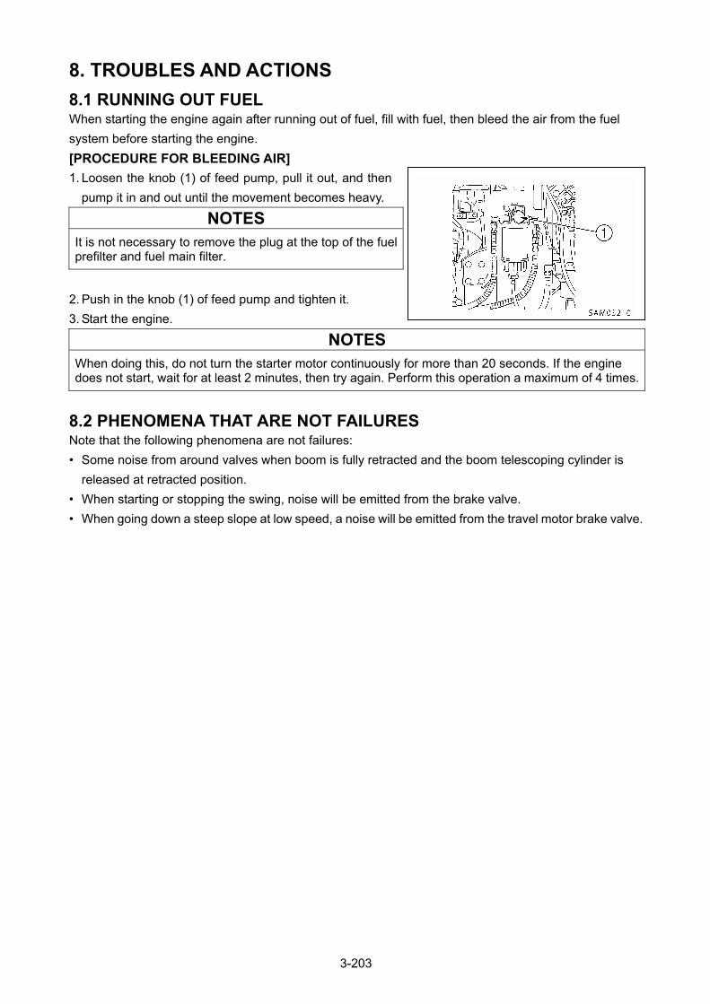
8. TROUBLES AND ACTIONS
8.1 RUNNING OUT FUEL When starting the engine again after running out of fuel, fill with fuel, then bleed the air from the fuel
system before starting the engine.
[PROCEDURE FOR BLEEDING AIR]
1. Loosen the knob (1) of feed pump, pull it out, and then
pump it in and out until the movement becomes heavy.
NOTES
It is not necessary to remove the plug at the top of the fuel prefilter and fuel main filter.
2. Push in the knob (1) of feed pump and tighten it.
3. Start the engine.
NOTES
When doing this, do not turn the starter motor continuously for more than 20 seconds. If the engine does not start, wait for at least 2 minutes, then try again. Perform this operation a maximum of 4 times.
8.2 PHENOMENA THAT ARE NOT FAILURES Note that the following phenomena are not failures:
• Some noise from around valves when boom is fully retracted and the boom telescoping cylinder is
released at retracted position.
• When starting or stopping the swing, noise will be emitted from the brake valve.
• When going down a steep slope at low speed, a noise will be emitted from the travel motor brake valve.
3-203
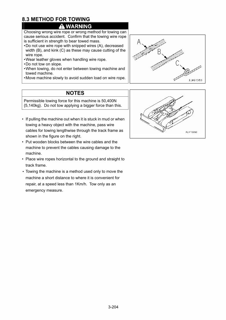
8.3 METHOD FOR TOWING
Choosing wrong wire rope or wrong method for towing can cause serious accident. Confirm that the towing wire rope is sufficient in strength to bear towed mass. • Do not use wire rope with snipped wires (A), decreased width (B), and kink (C) as these may cause cutting of the wire rope.
• Wear leather gloves when handling wire rope. • Do not tow on slope. • When towing, do not enter between towing machine and towed machine.
• Move machine slowly to avoid sudden load on wire rope.
NOTES
Permissible towing force for this machine is 50,400N {5,140kg}. Do not tow applying a bigger force than this.
• If pulling the machine out when it is stuck in mud or when
towing a heavy object with the machine, pass wire
cables for towing lengthwise through the track frame as
shown in the figure on the right.
• Put wooden blocks between the wire cables and the
machine to prevent the cables causing damage to the
machine.
• Place wire ropes horizontal to the ground and straight to
track frame.
• Towing the machine is a method used only to move the
machine a short distance to where it is convenient for
repair, at a speed less than 1Km/h. Tow only as an
emergency measure.
3-204
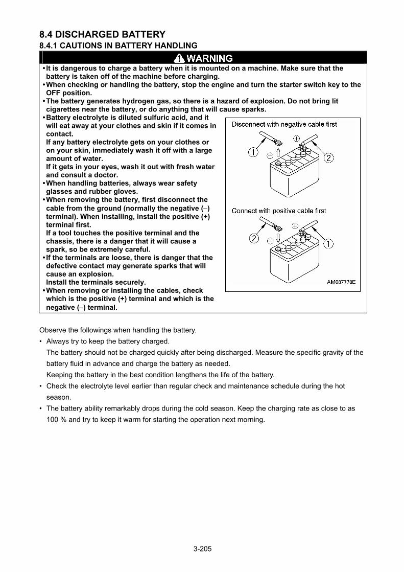
8.4 DISCHARGED BATTERY 8.4.1 CAUTIONS IN BATTERY HANDLING
• It is dangerous to charge a battery when it is mounted on a machine. Make sure that the battery is taken off of the machine before charging.
• When checking or handling the battery, stop the engine and turn the starter switch key to the OFF position.
• The battery generates hydrogen gas, so there is a hazard of explosion. Do not bring lit cigarettes near the battery, or do anything that will cause sparks.
• Battery electrolyte is diluted sulfuric acid, and it will eat away at your clothes and skin if it comes in contact. If any battery electrolyte gets on your clothes or on your skin, immediately wash it off with a large amount of water. If it gets in your eyes, wash it out with fresh water and consult a doctor.
• When handling batteries, always wear safety glasses and rubber gloves.
• When removing the battery, first disconnect the cable from the ground (normally the negative () terminal). When installing, install the positive (+) terminal first. If a tool touches the positive terminal and the chassis, there is a danger that it will cause a spark, so be extremely careful.
• If the terminals are loose, there is danger that the defective contact may generate sparks that will cause an explosion. Install the terminals securely.
• When removing or installing the cables, check which is the positive (+) terminal and which is the negative () terminal.
Observe the followings when handling the battery.
• Always try to keep the battery charged.
The battery should not be charged quickly after being discharged. Measure the specific gravity of the
battery fluid in advance and charge the battery as needed.
Keeping the battery in the best condition lengthens the life of the battery.
• Check the electrolyte level earlier than regular check and maintenance schedule during the hot
season.
• The battery ability remarkably drops during the cold season. Keep the charging rate as close to as
100 % and try to keep it warm for starting the operation next morning.
3-205
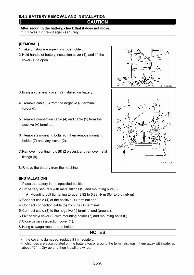
8.4.2 BATTERY REMOVAL AND INSTALLATION
CAUTION After securing the battery, check that it does not move. If it moves, tighten it again securely.
[REMOVAL]
1. Take off stowage rope from rope holder.
2. Hold handle of battery inspection cover (1), and lift the
cover (1) to open.
3. Bring up the vinyl cover (2) installed on battery.
4. Remove cable (3) from the negative (-) terminal
(ground).
5. Remove connection cable (4) and cable (5) from the
positive (+) terminal.
6. Remove 2 mounting bolts’ (6), then remove mounting
holder (7) and vinyl cover (2).
7. Remove mounting nuts (8) (2 places), and remove metal
fittings (9).
8. Rmove the battery from the machine.
[INSTALLATION]
1. Place the battery in the specified position.
2. Fix battery securely with metal fittings (9) and mounting nuts(8).
Mounting bolt tightening torque: 3.92 to 5.88 N• m (0.4 to 0.6 kgf• m)
3. Connect cable (4) at the positive (+) terminal end.
4. Connect connection cable (5) from the (+) terminal.
5. Connect cable (3) to the negative (-) terminal end (ground).
6. Fix the vinyl cover (2) with mounting holder (7) and mounting bolts (6).
7. Close battery inspection cover (1).
8. Hang stowage rope to rope holder.
NOTES
• If the cover is damaged, replace it immediately. • If chlorides are accumulated on the battery top or around the terminals, wash them away with water at about 40 °. Dry up and then install the wires.
3-206

8.4.3 CAUTIONS IN BATTERY CHARGING
When charging the battery, if the battery is not handled
correctly, there is a hazard that the battery may explode.
Always follow the instructions of "Operation 8.4.1 Cautions
in Battery Handling" and the instruction manual
accompanying the charger, and do the following.
• Flammable hydrogen gas is produced while the battery
is charged. Accordingly, remove the battery from the
machine, remove the battery caps, and charge in a well
ventilated place.
• Tighten the battery caps securely. If any battery cap is
damaged, replace it immediately.
• Set the voltage of the charger to match the voltage of the battery to be charged. If the correct voltage is
not selected, the charger may overheat and cause an explosion.
• Connect the positive (+) charger clip of the charger to the positive (+) terminal of the battery, then
connect the negative (-) charger clip of the charger to the negative (-) terminal of the battery. Be sure to
attach the clips securely.
• Set the charging current to 1/10 of the value of the rated battery capacity; when carrying out rapid
charging, set it to less than the rated battery.
If the charger current is too high, the electrolyte will leak or dry up, and this may cause the battery to
catch fire and explode.
• If the battery electrolyte is frozen, do not charge the battery or start the engine with a different power
source. The battery electrolyte may catch fire and explode.
• Do not use or charge the battery if the battery electrolyte level is below the LOWER LEVEL line. It can
cause an explosion. Check the battery electrolyte level periodically and add distilled water to bring the
electrolyte level to the UPPER LEVEL line.
3-207
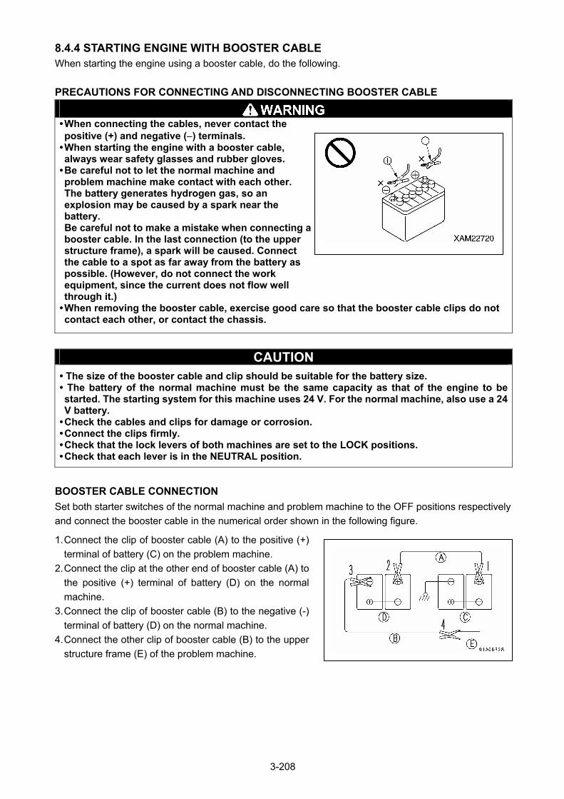
8.4.4 STARTING ENGINE WITH BOOSTER CABLE When starting the engine using a booster cable, do the following.
PRECAUTIONS FOR CONNECTING AND DISCONNECTING BOOSTER CABLE
• When connecting the cables, never contact the positive (+) and negative () terminals.
• When starting the engine with a booster cable, always wear safety glasses and rubber gloves.
• Be careful not to let the normal machine and problem machine make contact with each other. The battery generates hydrogen gas, so an explosion may be caused by a spark near the battery. Be careful not to make a mistake when connecting a booster cable. In the last connection (to the upper structure frame), a spark will be caused. Connect the cable to a spot as far away from the battery as possible. (However, do not connect the work equipment, since the current does not flow well through it.)
• When removing the booster cable, exercise good care so that the booster cable clips do not contact each other, or contact the chassis.
CAUTION • The size of the booster cable and clip should be suitable for the battery size. • The battery of the normal machine must be the same capacity as that of the engine to be started. The starting system for this machine uses 24 V. For the normal machine, also use a 24 V battery.
• Check the cables and clips for damage or corrosion. • Connect the clips firmly. • Check that the lock levers of both machines are set to the LOCK positions. • Check that each lever is in the NEUTRAL position.
BOOSTER CABLE CONNECTION
Set both starter switches of the normal machine and problem machine to the OFF positions respectively
and connect the booster cable in the numerical order shown in the following figure.
1. Connect the clip of booster cable (A) to the positive (+)
terminal of battery (C) on the problem machine.
2. Connect the clip at the other end of booster cable (A) to
the positive (+) terminal of battery (D) on the normal
machine.
3. Connect the clip of booster cable (B) to the negative (-)
terminal of battery (D) on the normal machine.
4. Connect the other clip of booster cable (B) to the upper
structure frame (E) of the problem machine.
3-208
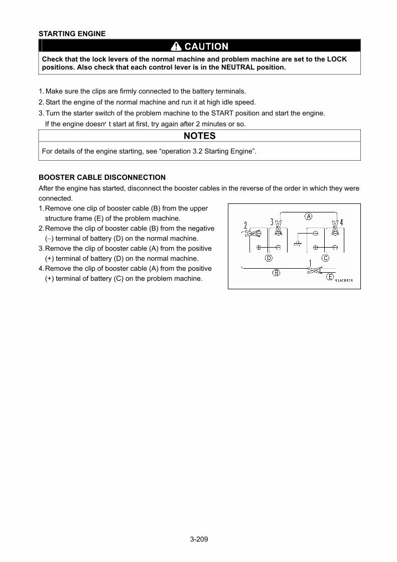
STARTING ENGINE
Check that the lock levers of the normal machine and problem machine are set to the LOCK positions. Also check that each control lever is in the NEUTRAL position.
1. Make sure the clips are firmly connected to the battery terminals.
2. Start the engine of the normal machine and run it at high idle speed.
3. Turn the starter switch of the problem machine to the START position and start the engine.
If the engine doesn’t start at first, try again after 2 minutes or so.
NOTES
For details of the engine starting, see “operation 3.2 Starting Engine”.
BOOSTER CABLE DISCONNECTION
After the engine has started, disconnect the booster cables in the reverse of the order in which they were
connected.
1. Remove one clip of booster cable (B) from the upper
structure frame (E) of the problem machine.
2. Remove the clip of booster cable (B) from the negative
() terminal of battery (D) on the normal machine.
3. Remove the clip of booster cable (A) from the positive
(+) terminal of battery (D) on the normal machine.
4. Remove the clip of booster cable (A) from the positive
(+) terminal of battery (C) on the problem machine.
3-209

8.5 OTHER TROUBLE 8.5.1 ELECTRICAL SYSTEM • : Always contact us or our sales service agency when dealing with these items.
• For causes of problems or causes that are not listed blow, contact us or our sales service agency for repair services.
Problem Main causes Remedy
Lamp does not glow brightly even when the engine runs at high speed
Lamp flickers while engine is running
• Defective wiring, deterioration of battery
• Loose fan belt • Defective alternator
Check, repair, loose terminals, disconnections, replace batteryReplace fan belt, Check tensionReplace
Charge level monitor does not go out even when engine is running
• Defective alternator • Defective wiring • Loose fan belt
Replace Check, repair Replace fan belt, Check tension
Abnormal noise is generated from alternator
• Defective alternator Replace
Starter motor does not turn when starter switch is turned to START
• Defective wiring • Defective starter motor • Insufficient battery charge
Check, repair Replace
• Charge
Pinion of starter motor keeps going and out
• Insufficient battery charge • Defective safety relay
• Charge Replace
Starter motor turns engine sluggishly
• Insufficient battery charge • Defective starter motor
• Charge Replace
Starter motor disengages before engine starts
• Defective wiring, defective ring gear and pinion
• Insufficient battery charge
Check, repair • Charge
Starter motor turns but engine does not start
• Defective engine controller power supply circuit
• Defective relay • Defective connector at engine end
• EMO switch is in “ON”
Replace
Replace Check, repair for loose, missing connector or disconnection Turn EMO switch to “OFF”
Engine pre-heating monitor does not light up
• Defective wiring • Defective heater relay • Defective monitor
Check, repair Replace Replace
Engine oil pressure monitor does not light up when engine is stopped (Starter switch at ON position)
• Defective monitor • Defective caution lamp switch• Defective oil pressure switch
Replace Replace Replace
Outside electrical heater is not warm when touched by hand
• Defective wiring • Disconnection in electric heater
• Defective operation of heater relay
Check, repair Replace
Replace
Travel alarm does not sound when travel lever is operated
• Defective wiring • Defective alarm • Defective travel PPC pressure sensor
Check, repair for loose terminals or disconnection Replace Replace
3-210

8.5.2 CHASSIS • : Always contact us or our sales service agency when dealing with these items.
• For causes of problems or causes that are not listed blow, contact us or our sales service agency for repair services.
Problem Main causes Remedy
Speed of travel, swing, boom, hook block is slow
• Lack of hydraulic oil • Add oil to reach the specified capacity, see Check Before Starting
Pump generates abnormal noise (sucking in air)
• Clogged element in hydraulic oil tank strainer, lack of oil
• Clean, see Maintenance for 5000 Hours
Excessive rise in hydraulic oil temperature
• Loose fan belt • Dirty oil cooler • Lack of hydraulic oil
Check fan belt tension, replace• Clean, see Every 500 Hours Maintenance
• Add oil to specified level, see Check Before Starting
Track comes off
Abnormal wear of sprocket • Track too loose
• Adjust track tension, see Irregular Maintenance
3-211
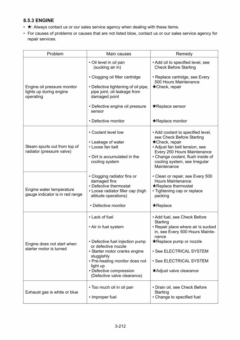
8.5.3 ENGINE • : Always contact us or our sales service agency when dealing with these items.
• For causes of problems or causes that are not listed blow, contact us or our sales service agency for repair services.
Problem Main causes Remedy
Engine oil pressure monitor lights up during engine operating
• Oil level in oil pan (sucking air in)
• Clogging oil filter cartridge • Defective tightening of oil pipe, pipe joint, oil leakage from damaged point
• Defective engine oil pressure sensor
• Defective monitor
• Add oil to specified level, see Check Before Starting
• Replace cartridge, see Every 500 Hours Maintenance Check, repair
Replace sensor
Replace monitor
Steam spurts out from top of radiator (pressure valve)
Engine water temperature gauge indicator is in red range
• Coolant level low • Leakage of water • Loose fan belt • Dirt is accumulated in the cooling system
• Clogging radiator fins or damaged fins
• Defective thermostat • Loose radiator filler cap (high altitude operations)
• Defective monitor
• Add coolant to specified level, see Check Before Starting Check, repair
• Adjust fan belt tension, see Every 250 Hours Maintenance
• Change coolant, flush inside of cooling system, see Irregular Maintenance
• Clean or repair, see Every 500 Hours Maintenance Replace thermostat
• Tightening cap or replace packing
Replace
Engine does not start when starter motor is turned
• Lack of fuel • Air in fuel system • Defective fuel injection pump or defective nozzle
• Starter motor cranks engine sluggishly
• Pre-heating monitor does not light up
• Defective compression (Defective valve clearance)
• Add fuel, see Check Before Starting
• Repair place where air is sucked in, see Every 500 Hours Mainte-nance Replace pump or nozzle
• See ELECTRICAL SYSTEM • See ELECTRICAL SYSTEM
Adjust valve clearance
Exhaust gas is white or blue • Too much oil in oil pan • Improper fuel
• Drain oil, see Check Before Starting
• Change to specified fuel
3-212

Problem Main causes Remedy
Exhaust gas sometime become black
• Clogging air cleaner element • Defective nozzle • Defective compression (Defective valve clearance)
• Defective turbocharger
• Clean or replace, see Irregular Maintenance Replace nozzle Adjust valve clearance
Clean or replace turbocharger
Combustion noise occasionally make breathing sound
• Defective nozzle Replace nozzle
Abnormal noise generated (combustion or mechanical)
• Low grade fuel being used • Overheating • Damage inside muffler • Excessive valve clearance
• Change to specified fuel • See “Engine water temperature gauge indicator is in red range” above Replace muffler Adjust valve clearance
Engine stops while in work • Clogged pre-filter, main filter • Defective engine and fuel line
• Replace filter cartridge
Check, repair
3-213

8.5.4 ELECTRONIC CONTROL SYSTEM When the user code is shown on the display portion of the
machine monitor, take the respective measure shown in
the self-diagnosis chart below.
[MACHINE MONITORING SYSTEM]
Monitor display
Failure mode Action
E02 Pump control system error Have inspection carried out immediately.
E03 Swing brake system error Have inspection carried out immediately.
E10 Engine controller power source error Engine controller drive system circuit error (engine stopped)
Have inspection carried out immediately.
E11 Engine controller system error (out put reduced to protect engine)
Operate machine to a safety posture and have inspection carried out immediately.
E14 Abnormality in throttle system Operate machine to a safety posture and have inspection carried out immediately.
E15 Engine sensor (coolant temperature, Fuel pressure, Oil pressure) system error
Operations are possible, but have inspection carried out immediately.
E0E Network error Operate machine to a safety posture and have inspection carried out immediately.
3-214
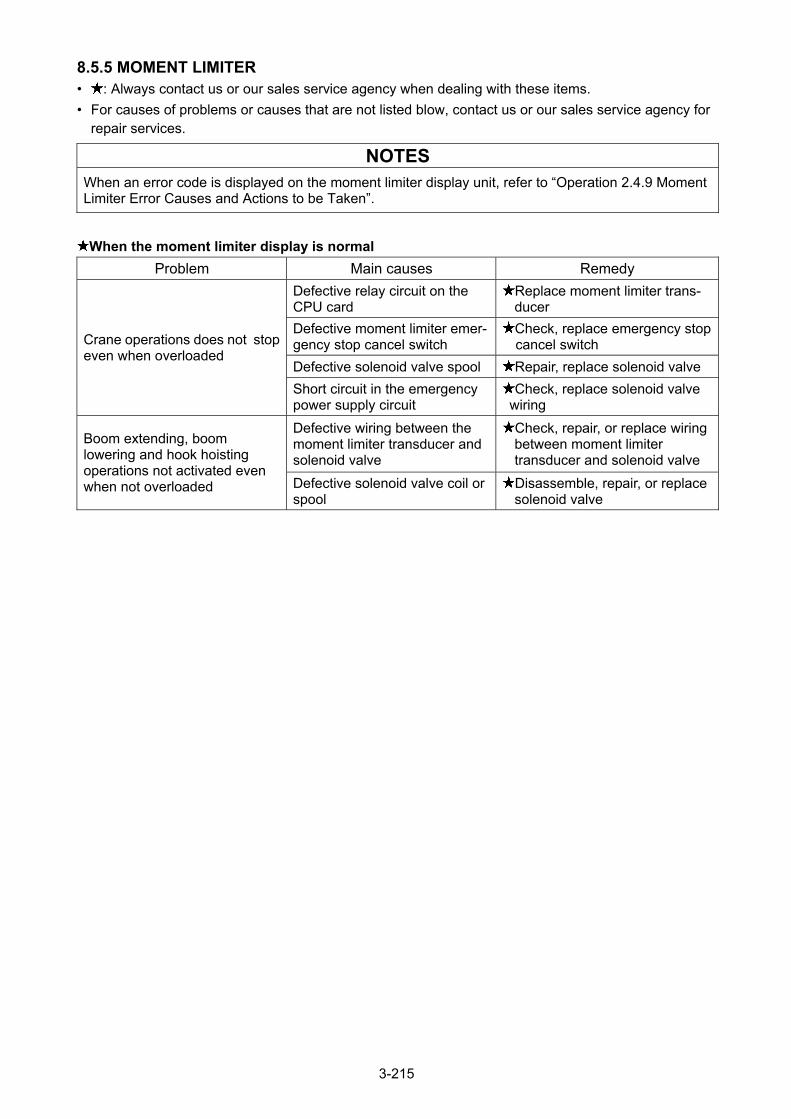
8.5.5 MOMENT LIMITER • : Always contact us or our sales service agency when dealing with these items.
• For causes of problems or causes that are not listed blow, contact us or our sales service agency for repair services.
NOTES
When an error code is displayed on the moment limiter display unit, refer to “Operation 2.4.9 Moment Limiter Error Causes and Actions to be Taken”.
When the moment limiter display is normal
Problem Main causes Remedy
Defective relay circuit on the CPU card
Replace moment limiter trans- ducer
Defective moment limiter emer-gency stop cancel switch
Check, replace emergency stop cancel switch
Defective solenoid valve spool Repair, replace solenoid valve
Crane operations does not stop even when overloaded
Short circuit in the emergency power supply circuit
Check, replace solenoid valve wiring
Defective wiring between the moment limiter transducer and solenoid valve
Check, repair, or replace wiring between moment limiter transducer and solenoid valve
Boom extending, boom lowering and hook hoisting operations not activated even when not overloaded Defective solenoid valve coil or
spool Disassemble, repair, or replace solenoid valve
3-215
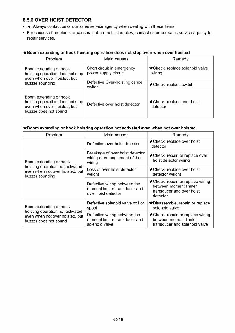
8.5.6 OVER HOIST DETECTOR • : Always contact us or our sales service agency when dealing with these items.
• For causes of problems or causes that are not listed blow, contact us or our sales service agency for repair services.
★Boom extending or hook hoisting operation does not stop even when over hoisted
Problem Main causes Remedy
Short circuit in emergency power supply circuit
Check, replace solenoid valve wiring
Boom extending or hook hoisting operation does not stop even when over hoisted, but buzzer sounding Defective Over-hoisting cancel
switch Check, replace switch
Boom extending or hook hoisting operation does not stop even when over hoisted, but buzzer does not sound
Defective over hoist detector Check, replace over hoist
detector
★Boom extending or hook hoisting operation not activated even when not over hoisted
Problem Main causes Remedy
Defective over hoist detector Check, replace over hoist
detector
Breakage of over hoist detector wiring or entanglement of the wiring
Check, repair, or replace over hoist detector wiring
Loss of over hoist detector weight
Check, replace over hoist detector weight
Boom extending or hook hoisting operation not activated even when not over hoisted, but buzzer sounding
Defective wiring between the moment limiter transducer and over hoist detector
Check, repair, or replace wiring between moment limiter transducer and over hoist detector
Defective solenoid valve coil or spool
Disassemble, repair, or replace solenoid valve Boom extending or hook
hoisting operation not activated even when not over hoisted, but buzzer does not sound
Defective wiring between the moment limiter transducer and solenoid valve
Check, repair, or replace wiring between moment limiter transducer and solenoid valve
3-216

INSPECTION AND MAINTENANCE
1. PRECAUTIONS FOR MAINTENANCE 4 – 2
2. BASIC MAINTENANCE 4 – 4
3. LEGAL INSPECTION 4 – 7
4. SAFETY CRITICAL PARTS 4 – 8
5. CONSUMABLES 4 – 9
6. OTHER COMPONENTS 4 – 10
7. USE OF FUEL, COOLANT AND LUBRICANT 4 – 11
8. TIGHTENING TORQUE SPECIFICATIONS 4 – 13
9. INSPECTION AND MAINTENANCE LIST 4 – 14
10. MAINTENANCE PROCEDURES 4 – 17
11. BLEEDING AIR FROM HYDRAULIC SYSTEM 4 – 76
12. RELEASING PRESURE METHOD IN HYDRAULIC CIRCUIT 4 – 80
4-1
1. PRECAUTIONS REGARDING MAINTENANCE
A thorough understanding of inspection and maintenance items is required in order to efficiently carry out
inspection and maintenance tasks that contribute to the safe use of this machine.
• Do not perform any inspection or maintenance tasks that are not described in this manual. Potentially serious accidents or machine failure may occur if certain tasks are performed at the discretion of the individual. In the event that it is not possible for a judgment to be made on the severity of a failure or malfunction, contact us or our sales service agency to request repairs.
• In the event that a failure or malfunction is observed while a machine is operating, or is discovered during an inspection, report it to your employer or supervisor immediately. Contact us or our sales service agency to request repairs accordingly.
• Inspection and maintenance tasks should be performed with the machine placed on firm level ground.
CHECK THE SERVICE METERS
Read the service meters daily to check for any maintenance items that have reached the obligatory maintenance period.
USE GENUINE PARTS FOR REPLACEMENT
Always use genuine Maeda parts as specified in the parts catalogue when replacing parts.
USE GENUINE GREASE
Always use genuine recommended grease. The viscosity of the grease must conform to specifications according to ambient temperature.
USE CLEAN OIL AND GREASE
Always use clean oil, grease, and containers to keep out impurities.
USE CLEAN WINDOW WASHER FLUID
Always use automobile window washer fluid, and be careful not to let any dirt get into it.
KEEP THE MACHINE CLEAN
Keep the machine clean to facilitate detection of a malfunction. In particular, keep grease nipples, breather, and oil level gauge (oil access cap) clean to prevent the ingress of impurities.
HANDLE WATER AND OIL AT ADEQUATE TEMPERATURE
Drainage, drain oil, and the oil filter will still be very hot immediately after the machine comes to a stop. For safety reasons, remove drainage, drain oil, and the filter only after they have cooled sufficiently. On the other hand, if the oil is cold, warm it to approximately 40 degrees C before draining it.
CHECK DRAIN OIL AND OIL FILTER
When replacing the oil and filter, check the drain oil and oil filter to make sure there is not an excessive amount of metal powder or foreign objects present.
CAUTIONS REGARDING LUBRICATION
Do not remove the strainer for lubrication purposes if it is attached to the filler port.
PROTECT OIL FROM IMPURITIES
Be careful to keep dirt and dust out of the oil when inspecting and replacing the oil.
ATTACH A WARNING TAG
When draining coolant and oil, always remove the starter switch key to prevention the engine from accidentally starting. In addition, be sure to attach a warning tag to the work equipment control lever.
FOLLOW SAFETY PRECAUTIONS
Safety precautions provided on the machine should always be followed when using the machine.
4-2
CAUTIONS REGARDING WELD REPAIR
• Power off the machine. (Turn OFF the starter switch.) • Do not continuously apply a voltage of 200V or greater. • Ground the machine within one meter of the welding point. • Be sure to disconnect the connectors of the moment limiting display unit and the moment limiting
converter. • Remove the negative terminal (-) of the battery. • Make sure no sealing or bearing is present between welding and grounding points. There is a possibility that sparks will damage the sealing if this warning is ignored. • Do not ground around the boom pin or the hydraulic cylinder. There is a possibility that sparks will damage the plated section if this warning is ignored.
KEEP FROM FLAME
Always clean the parts with noncombustible cleaning agent or light oil. Keep the machine away from open flames when using light oil.
KEEP THE ATTACHMENT SURFACE CLEAN
Be sure to clean the attachment surface after removing a part to which an O-ring and gasket sealing are attached and replace the part with a new one. Be sure to attach the O-ring and gasket again after cleaning.
EMPTY YOUR POCKETS
If you have to bend forward over the machine while the cover is open to carry out inspection and maintenance tasks, always empty your pockets beforehand.
ASSURE SAFE UNDERCARRIAGE
When operating the crane in a rocky location, check to see that the undercarriage is not damaged and that the nuts and bolts are not loose, cracked or suffering from abrasion. Loosen the tension of the crawler tread to a greater degree than usual.
CAUTIONS REGARDING MACHINE WASHING
• Do not direct a jet of steam at electrical parts or connectors. • Keep the operation panel dry. In particular, the underside of the operator’s seat and the area around the
battery must be protected from water. • Wash the machine with a clean cloth to rinse off any dirt or dust.
PRE- AND POST-WORK INSPECTION
Before operating the crane in muddy water, rain, snow or on the seashore, always check plugs and valves for looseness. After finishing the work, wash the machine and then check all the units for cracks and damage, and check that all nuts and bolts are tight and secure. Carry out greasing in advance. Grease the work equipment pins that are submerged in muddy water on a daily basis.
CAUTIONS REGARDING WORKING AT A DUSTY SITE
The following precautions should be observed when working at a dusty site. • When checking or replacing oil, move the machine to a clean location to avoid contamination. • Check the air cleaner frequently to ensure it does not become clogged. • Clean the radiator core more frequently to prevent it from becoming clogged. • Clean or replace the fuel filter more frequently. • Be sure to clean the electrical parts, especially the starter and alternator, to protect them from dust.
DO NOT MIX OILS
Never use or mix different types of oil from different manufacturers together under any circumstances. When replacing the currently used oil, be sure to replace all of it with new oil. Always use genuine Maeda parts when replacing parts.
4-3
2. BASIC MAINTENANCE
HANDLING OIL
• Oil is used under extremely harsh conditions (high temperature, high pressure) in the engine and working devices, which causes the oil to deteriorate over time.
Always use oil that meets the requirements stated in the operating manual, such as those for grade and operating temperature.
Be sure to carry out periodic replacement of oil irrespective of contamination in the oil. • To a machine, oil is the equivalent of human blood. Exercise due caution when handling oil, keeping
impurities (such as water, metal powder or dust) out of the oil. Most mechanical failures are attributed to the existence of impurities.
Extra caution is required to prevent impurities from entering the system when storing or lubricating the machine.
• Do not mix the oil with other oils of different grades or brands. • The quantity of oil used for refill purposes must conform to the level specified. Failure to add an adequate quantity can lead to machine failure. • In the event that oil used in the working device turns cloudy, potential intrusion of moisture or air into the
oil may be suspected. Contact us or our sales service agency. • When replacing oil, always replace the relevant filter as well. • Do not use any hydraulic oil that has not been recommended by us. Failure to follow this instruction
may cause the filters to become clogged. A small amount of oil remaining in piping and cylinders is not likely to cause problems even if mixed with other oil.
HANDLING FUEL
CAUTION Always use diesel oil for the fuel. To ensure good fuel consumption and exhaust gas characteristics, the engine mounted on this machine uses a high-pressure fuel injection device. This device requires high-precision parts and high-level lubricating properties. If, therefore, low viscosity fuel with low lubricating capabilities is used, its durability may be considerably degraded.
• The fuel pump is a precision item of equipment that becomes inoperative if fuel containing moisture or
impurities is used. Extra caution is required to prevent impurities from entering the system when storing or lubricating the
machine. • Do not remove the strainer of the filler port when replenishing fuel. • Always use fuel that meets the requirements stated in the operating manual, such as those for grade
and operating temperature. • Ensure that the fuel tank is refilled after finishing the day’s work to prevent condensation of the humid
air inside the fuel tank. Resulting in moisture entering the fuel tank. • Drain deposits and water out of the fuel tank before starting the engine or approximately 10 minutes
after replacing the fuel. • The air should be released from the circuit when the machine runs out of fuel or when a fuel filter is
replaced. • Clean the tank and fuel system if any foreign objects have entered the fuel tank.
STOCKING AND STORAGE OF OIL AND FUEL
• Stock and store oil and fuel indoors to keep impurities such as moisture or dust out of them. • If oil or fuel have to be stored for long periods in drums, lay the drums down so that their taps is below
the surface of the fuel (to prevent moisture from entering). Be sure to cover the drums with waterproof sheets if storing them outdoors.
• To prevent deterioration of oil and fuel resulting from long-term storage, employ the first-in first-out system for using oil and fuel.
4-4
HANDLING GREASE
• Grease is designed to prevent the joint from experiencing a backlash and generating noises.
• Any nipple that is not described in the Periodic Maintenance chapter is used for overhauls, and
therefore does not require the grease to be replaced.
Only grease the nipple if long-term use may hinder its smooth characteristics.
• Wipe off any old grease that has been squeezed out after greasing.
When wiping away grease extra care is required for adhesion of sand or dust will accelerate the
wearing away of the rotating part.
HANDLING THE FILTER
• A filter is an extremely important part that keeps major equipment free from impurities in oil, fuel, and
the air circuit, which prevent associated failures from occurring. Periodic replacement of the filter is
required in accordance with the operating manual.
The replacement period should be shortened in response to harsh operating environments as well as
the oil and fuel (sulfur content) used.
• Do not reuse any washed filters (cartridge type) under any circumstances.
• After replacing an oil filter, check the old filter for the existence of metal powder.
If any metal powder is discovered on the used filter, contact us or our sales service agency.
• Regarding the replacement filter, always unpack it immediately before using it.
• Always use genuine Maeda filters.
HANDLING COOLANT
• River water contains a large amount of calcium and impurities. Use of river water will result in water
sludge accumulating in the engine and radiator, which will cause a heat exchange error and lead to
overheating.
Do not use any impure water.
• When using antifreeze, be sure to follow the precautions stated in the operating manual.
• Keep antifreeze away from open flames. Antifreeze is a flammable solution.
• The mixing proportion of antifreeze varies with outside air temperature.
See "Inspection and Maintenance 10.3 Irregular Maintenance (Cleaning inside of cooling system)" for
the mixing proportions.
• In the event of overheating, replenish coolant when the engine is cold.
• Insufficient coolant may cause overheating and corrosion in the water-cooling circuit due to aeration.
HANDLING ELECTRICAL PART
• Current may leak if the electrical parts are wet or have damaged coatings, which will cause the machine
to malfunction. Exercise due caution when handling the electrical parts.
• Inspection and maintenance tasks include the checking of belt tension, belt damage, and battery fluid
level.
• Never remove and disassemble equipment (electrical parts) from the machine.
• Only optional electrical parts that accompany the machine can be installed.
• Keep electrical parts away from water when the machine is being washed or used in the rain.
• When using the machine on the seashore, keep electrical parts free of water and impurities to prevent
corrosion.
4-5
HANDLING HYDRAULIC EQUIPMENT
• Hydraulic equipment will be very hot during and immediately after operation. Hydraulic equipment
operates under high pressure.
The following precautions should be observed when carrying out inspection and maintenance tasks on
hydraulic equipment.
• Place the machine in the travelling position on a level surface to reduce the pressure on the cylinder
circuit.
• Be sure to stop the engine.
• Hydraulic oil and lubricating oil will be very hot and under high pressure immediately after equipment
comes to a stop. Carry out inspection and maintenance tasks only after the oil temperature has cooled
to a safe level. Internal pressure may still be exerted despite the temperature drop. When removing the
plugs, screws and hose joints, stand aside and loosen them gradually while releasing internal pressure.
• Be sure to release the internal pressure by releasing air from the hydraulic tank before carrying out
inspection and maintenance tasks of the hydraulic circuit.
• Inspection and maintenance tasks include checking the level of hydraulic oil and replacing filters and
hydraulic oil.
• Check the O-ring for scratches when removing the high-pressure hose. If damaged, replace the O-ring.
• It will be necessary to bleed air from the hydraulic circuit after the following tasks are carried out:
replacement and cleaning of the hydraulic oil filter element and strainer, repair and replacement of
hydraulic equipment, and replacement of hydraulic piping.
4-6
3. LEGAL INSPECTION
If periodic inspection for machine safety assurance is stipulated by laws and regulations of your country,
perform inspection complying with the inspection items listed below.
1. Make sure all safety devices are operating correctly.
2. Check the hoisting accessories including the hook block for any abnormalities.
3. Check the winch wire rope end and wire clip for damage.
4. Replace the wire rope promptly if it is damaged.
5. Check the hydraulic oil hose for oil leaks and friction flaws on the surface. Replace the hose if any
surface flaws are detected.
6. Check the structure, including the boom for cracks and deformations.
7. Check that all mounting bolts and joints are tight and secure.
8. Check whether the crane operates and stops correctly during telescoping, derricking, and when
swinging the boom.
If any checks uncover a malfunction, contact us or our sales service agency.
4-7
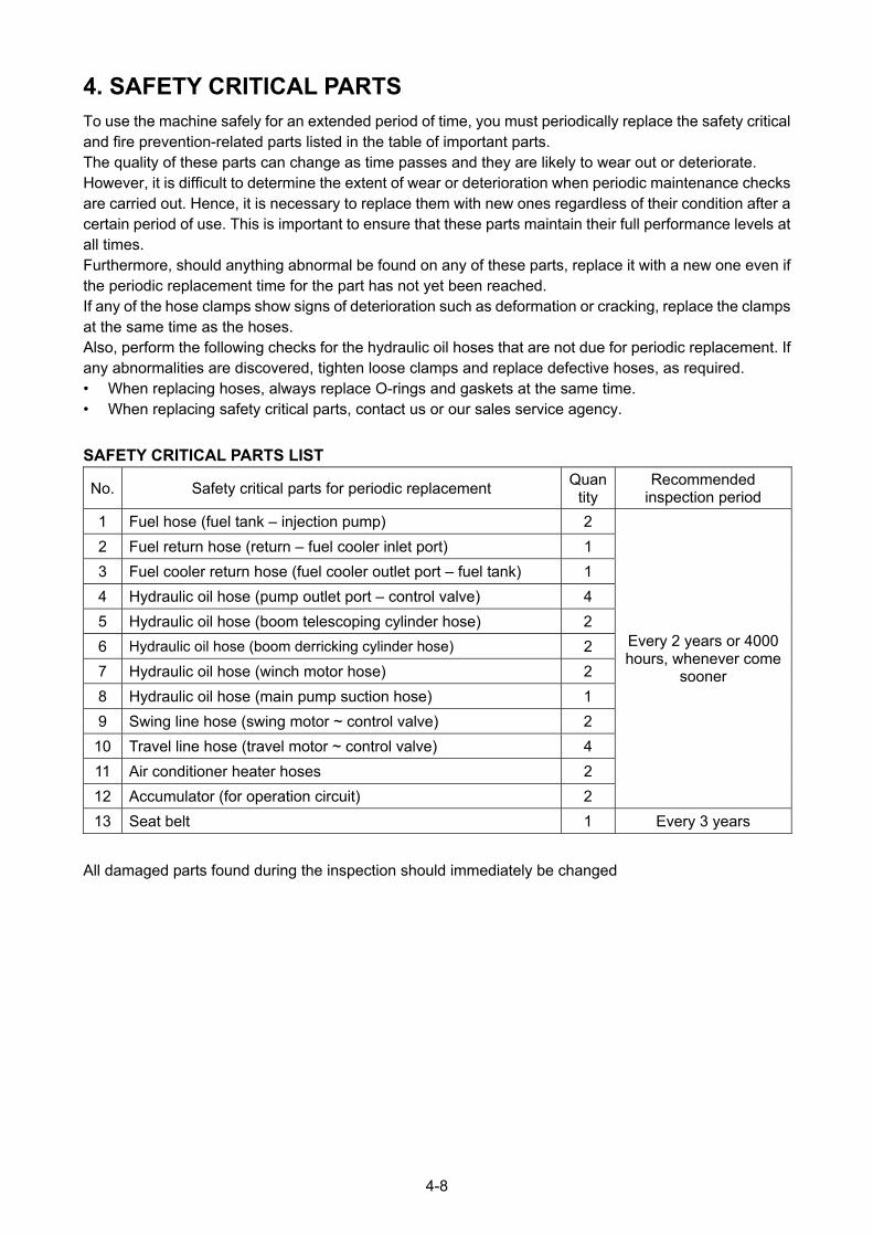
4. SAFETY CRITICAL PARTS To use the machine safely for an extended period of time, you must periodically replace the safety critical and fire prevention-related parts listed in the table of important parts. The quality of these parts can change as time passes and they are likely to wear out or deteriorate. However, it is difficult to determine the extent of wear or deterioration when periodic maintenance checks are carried out. Hence, it is necessary to replace them with new ones regardless of their condition after a certain period of use. This is important to ensure that these parts maintain their full performance levels at all times. Furthermore, should anything abnormal be found on any of these parts, replace it with a new one even if the periodic replacement time for the part has not yet been reached. If any of the hose clamps show signs of deterioration such as deformation or cracking, replace the clamps at the same time as the hoses. Also, perform the following checks for the hydraulic oil hoses that are not due for periodic replacement. If any abnormalities are discovered, tighten loose clamps and replace defective hoses, as required. • When replacing hoses, always replace O-rings and gaskets at the same time. • When replacing safety critical parts, contact us or our sales service agency.
SAFETY CRITICAL PARTS LIST
No. Safety critical parts for periodic replacement Quan
tity Recommended
inspection period
1 Fuel hose (fuel tank – injection pump) 2
2 Fuel return hose (return – fuel cooler inlet port) 1
3 Fuel cooler return hose (fuel cooler outlet port – fuel tank) 1
4 Hydraulic oil hose (pump outlet port – control valve) 4
5 Hydraulic oil hose (boom telescoping cylinder hose) 2
6 Hydraulic oil hose (boom derricking cylinder hose) 2
7 Hydraulic oil hose (winch motor hose) 2
8 Hydraulic oil hose (main pump suction hose) 1
9 Swing line hose (swing motor ~ control valve) 2
10 Travel line hose (travel motor ~ control valve) 4
11 Air conditioner heater hoses 2
12 Accumulator (for operation circuit) 2
Every 2 years or 4000 hours, whenever come
sooner
13 Seat belt 1 Every 3 years
All damaged parts found during the inspection should immediately be changed
4-8

5. CONSUMABLES
Consumables such as filter elements and wire ropes are to be replaced during each instance of periodic
maintenance, or prior to the wear limit being reached.
Correct replacement of consumables delivers increased economy of machine use.
Always use genuine Maeda parts when replacing parts.
See the parts catalogue for part numbers when ordering parts.
LIST OF CONSUMABLES
Part Replacement cycle
Engine oil filter Every 500 hrs
Fuel pre-filter Every 500 hrs
Hydraulic return filter Every 1000 hrs
Hydraulic line filter Every 1000 hrs
Main fuel filter Every 1000 hrs
Air cleaner element As required
Cylinder gasket Every 3 yrs
Boom slide plate Every 3 yrs
Winch wire rope As required or every 3 years
Boom extending wire rope As required or every 3 years
Boom retracting wire rope As required or every 3 years
Air conditioner internal filter every 1 years
Air conditioner external filter every 1 years
All damaged parts found during the inspection should immediately be changed.
* The cycles marked with a star "★" in replacement cycle are time related (not working hours).
** When replacing parts marked with a star "★", contact us or our sales service agency.
4-9
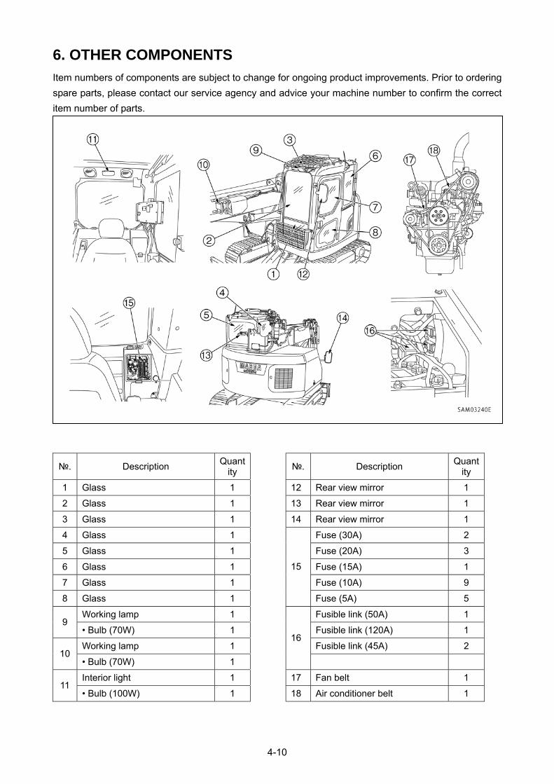
4-10
6. OTHER COMPONENTS
Item numbers of components are subject to change for ongoing product improvements. Prior to ordering
spare parts, please contact our service agency and advice your machine number to confirm the correct
item number of parts.
№. Description Quant
ity №. Description
Quantity
1 Glass 1 12 Rear view mirror 1
2 Glass 1 13 Rear view mirror 1
3 Glass 1 14 Rear view mirror 1
4 Glass 1 Fuse (30A) 2
5 Glass 1 Fuse (20A) 3
6 Glass 1 Fuse (15A) 1
7 Glass 1 Fuse (10A) 9
8 Glass 1
15
Fuse (5A) 5
Working lamp 1 Fusible link (50A) 1 9
• Bulb (70W) 1 Fusible link (120A) 1
Working lamp 1 Fusible link (45A) 2 10
• Bulb (70W) 1
16
Interior light 1 17 Fan belt 1 11
• Bulb (100W) 1 18 Air conditioner belt 1
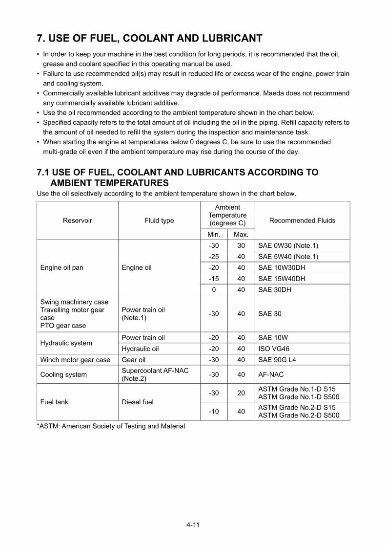
7. USE OF FUEL, COOLANT AND LUBRICANT
• In order to keep your machine in the best condition for long periods, it is recommended that the oil,
grease and coolant specified in this operating manual be used.
• Failure to use recommended oil(s) may result in reduced life or excess wear of the engine, power train
and cooling system.
• Commercially available lubricant additives may degrade oil performance. Maeda does not recommend
any commercially available lubricant additive.
• Use the oil recommended according to the ambient temperature shown in the chart below.
• Specified capacity refers to the total amount of oil including the oil in the piping. Refill capacity refers to
the amount of oil needed to refill the system during the inspection and maintenance task.
• When starting the engine at temperatures below 0 degrees C, be sure to use the recommended
multi-grade oil even if the ambient temperature may rise during the course of the day.
7.1 USE OF FUEL, COOLANT AND LUBRICANTS ACCORDING TO AMBIENT TEMPERATURES
Use the oil selectively according to the ambient temperature shown in the chart below.
Ambient Temperature (degrees C) Reservoir Fluid type
Min. Max.
Recommended Fluids
-30 30 SAE 0W30 (Note.1)
-25 40 SAE 5W40 (Note.1)
-20 40 SAE 10W30DH
-15 40 SAE 15W40DH
Engine oil pan Engine oil
0 40 SAE 30DH
Swing machinery case Travelling motor gear case PTO gear case
Power train oil (Note.1)
-30 40 SAE 30
Power train oil -20 40 SAE 10W Hydraulic system
Hydraulic oil -20 40 ISO VG46
Winch motor gear case Gear oil -30 40 SAE 90G L4
Cooling system Supercoolant AF-NAC (Note.2)
-30 40 AF-NAC
-30 20 ASTM Grade No.1-D S15 ASTM Grade No.1-D S500
Fuel tank Diesel fuel -10 40
ASTM Grade No.2-D S15 ASTM Grade No.2-D S500
*ASTM: American Society of Testing and Material
4-11
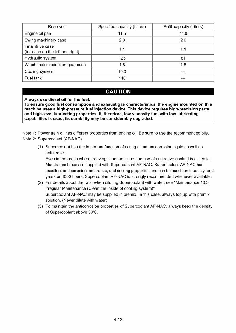
Reservoir Specified capacity (Liters) Refill capacity (Liters)
Engine oil pan 11.5 11.0
Swing machinery case 2.0 2.0
Final drive case (for each on the left and right)
1.1 1.1
Hydraulic system 125 81
Winch motor reduction gear case 1.8 1.8
Cooling system 10.0 ---
Fuel tank 140 ---
CAUTION Always use diesel oil for the fuel. To ensure good fuel consumption and exhaust gas characteristics, the engine mounted on this machine uses a high-pressure fuel injection device. This device requires high-precision parts and high-level lubricating properties. If, therefore, low viscosity fuel with low lubricating capabilities is used, its durability may be considerably degraded.
Note 1: Power train oil has different properties from engine oil. Be sure to use the recommended oils.
Note.2: Supercoolant (AF-NAC)
(1) Supercoolant has the important function of acting as an anticorrosion liquid as well as
antifreeze.
Even in the areas where freezing is not an issue, the use of antifreeze coolant is essential.
Maeda machines are supplied with Supercoolant AF-NAC. Supercoolant AF-NAC has
excellent anticorrosion, antifreeze, and cooling properties and can be used continuously for 2
years or 4000 hours. Supercoolant AF-NAC is strongly recommended whenever available.
(2) For details about the ratio when diluting Supercoolant with water, see "Maintenance 10.3
Irregular Maintenance (Clean the inside of cooling system)".
Supercoolant AF-NAC may be supplied in premix. In this case, always top up with premix
solution. (Never dilute with water)
(3) To maintain the anticorrosion properties of Supercoolant AF-NAC, always keep the density
of Supercoolant above 30%.
4-12
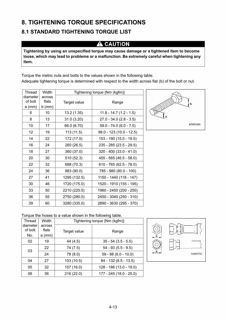
8. TIGHTENING TORQUE SPECIFICATIONS
8.1 STANDARD TIGHTENING TORQUE LIST
Tightening by using an unspecified torque may cause damage or a tightened item to become loose, which may lead to problems or a malfunction. Be extremely careful when tightening any item.
Torque the metric nuts and bolts to the values shown in the following table.
Adequate tightening torque is determined with respect to the width across flat (b) of the bolt or nut.
Tightening torque {Nm (kgfm)} Thread
diameter of bolt
a (mm)
Width across
flats
b (mm) Target value Range
6 10 13.2 (1.35) 11.8 - 14.7 (1.2 - 1.5)
8 13 31.0 (3.20) 27.0 - 34.0 (2.8 - 3.5)
10 17 66.0 (6.70) 59.0 - 74.0 (6.0 - 7.5)
12 19 113 (11.5) 98.0 - 123 (10.0 - 12.5)
14 22 172 (17.5) 153 - 190 (15.5 - 19.5)
16 24 260 (26.5) 235 - 285 (23.5 - 29.5)
18 27 360 (37.0) 320 - 400 (33.0 - 41.0)
20 30 510 (52.3) 455 - 565 (46.5 - 58.0)
22 32 688 (70.3) 610 - 765 (62.5 - 78.0)
24 36 883 (90.0) 785 - 980 (80.0 - 100)
27 41 1295 (132.5) 1150 - 1440 (118 - 147)
30 46 1720 (175.0) 1520 - 1910 (155 - 195)
33 50 2210 (225.0) 1960 - 2450 (200 - 250)
36 55 2750 (280.0) 2450 - 3040 (250 - 310)
39 60 3280 (335.0) 2890 - 3630 (295 - 370)
Torque the hoses to a value shown in the following table. Tightening torque {Nm (kgfm)} Thread
diameter of bolt
No.
Width across
flats a (mm)
Target value Range
02 19 44 (4.5) 35 - 54 (3.5 - 5.5)
22 74 (7.5) 54 - 93 (5.5 - 9.5) 03
24 78 (8.0) 59 - 98 (6.0 - 10.0)
04 27 103 (10.5) 84 - 132 (8.5 - 13.5)
05 32 157 (16.0) 128 - 186 (13.0 - 19.0)
06 36 216 (22.0) 177 - 245 (18.0 - 25.0)
4-13
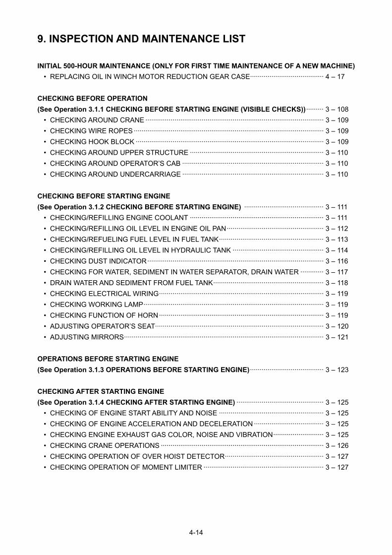
9. INSPECTION AND MAINTENANCE LIST
INITIAL 500-HOUR MAINTENANCE (ONLY FOR FIRST TIME MAINTENANCE OF A NEW MACHINE)
• REPLACING OIL IN WINCH MOTOR REDUCTION GEAR CASE······································ 4 – 17
CHECKING BEFORE OPERATION
(See Operation 3.1.1 CHECKING BEFORE STARTING ENGINE (VISIBLE CHECKS))········· 3 – 108
• CHECKING AROUND CRANE ···························································································· 3 – 109
• CHECKING WIRE ROPES ·································································································· 3 – 109
• CHECKING HOOK BLOCK ································································································· 3 – 109
• CHECKING AROUND UPPER STRUCTURE ····································································· 3 – 110
• CHECKING AROUND OPERATOR’S CAB ········································································· 3 – 110
• CHECKING AROUND UNDERCARRIAGE ········································································· 3 – 110
CHECKING BEFORE STARTING ENGINE
(See Operation 3.1.2 CHECKING BEFORE STARTING ENGINE) ········································· 3 – 111
• CHECKING/REFILLING ENGINE COOLANT ····································································· 3 – 111
• CHECKING/REFILLING OIL LEVEL IN ENGINE OIL PAN·················································· 3 – 112
• CHECKING/REFUELING FUEL LEVEL IN FUEL TANK······················································ 3 – 113
• CHECKING/REFILLING OIL LEVEL IN HYDRAULIC TANK ··············································· 3 – 114
• CHECKING DUST INDICATOR··························································································· 3 – 116
• CHECKING FOR WATER, SEDIMENT IN WATER SEPARATOR, DRAIN WATER ············ 3 – 117
• DRAIN WATER AND SEDIMENT FROM FUEL TANK························································· 3 – 118
• CHECKING ELECTRICAL WIRING····················································································· 3 – 119
• CHECKING WORKING LAMP····························································································· 3 – 119
• CHECKING FUNCTION OF HORN····················································································· 3 – 119
• ADJUSTING OPERATOR’S SEAT······················································································· 3 – 120
• ADJUSTING MIRRORS······································································································· 3 – 121
OPERATIONS BEFORE STARTING ENGINE
(See Operation 3.1.3 OPERATIONS BEFORE STARTING ENGINE)······································ 3 – 123
CHECKING AFTER STARTING ENGINE
(See Operation 3.1.4 CHECKING AFTER STARTING ENGINE) ············································· 3 – 125
• CHECKING OF ENGINE START ABILITY AND NOISE ······················································ 3 – 125
• CHECKING OF ENGINE ACCELERATION AND DECELERATION ···································· 3 – 125
• CHECKING ENGINE EXHAUST GAS COLOR, NOISE AND VIBRATION·························· 3 – 125
• CHECKING CRANE OPERATIONS ···················································································· 3 – 126
• CHECKING OPERATION OF OVER HOIST DETECTOR··················································· 3 – 127
• CHECKING OPERATION OF MOMENT LIMITER ······························································ 3 – 127
4-14
IRREGULAR MAINTENANCE
• REPLACEMENT WINCH WIRE ROPE ··············································································· 4 – 18
• CHECKING/ADJUSTING BOOM TELESCOPING WIRE ROPE········································· 4 – 24
• CHECKING, CLEANING AND REPLACING AIR CLEANER ELEMENT······························ 4 – 27
• CLEANING INSIDE OF COOLING SYSTEM ······································································ 4 – 31
• CHECKING LEVEL OF BATTERY ELECTROLYTE ···························································· 4 – 34
• CHECKING/TIGHTENING TRACK SHOE BOLTS ······························································ 4 – 36
• CHECKING/ADJUSTING TRACK TENSION······································································· 4 – 36
• CHECKING WINDOW WASHER FLUID LEVEL, ADDING FLUID ······································ 4 – 38
• CHECKING/MAINTENANCE AIR CONDITIONER ······························································ 4 – 39
• CHECKING/CLEANING/GREASING CAB SLIDE DOOR RAIL AND ROLLER··················· 4 – 40
• CHECKING GAS SPRING··································································································· 4 – 41
MAINTENANCE EVERY 50 HOURS
• GREASING MACHINE UNITS····························································································· 4 – 42
MAINTENANCE EVERY 100 HOURS
• CHECKING/REFILLING OIL IN SWING MACHINERY CASE ············································· 4 – 44
MAINTENANCE EVERY 250 HOURS
• CHECKING/REFILLING OIL IN TRAVEL MOTOR REDUCTION GEAR CASE··················· 4 – 46
• CHECKING/REFILLING OIL IN WINCH MOTOR REDUCTION GEAR CASE···················· 4 – 47
• CHECKING/ADJUSTING COOLING FAN BELT TENSION················································· 4 – 48
• CHECKING/ADJUSTING AIR COMPRESSOR BELT TENSION········································· 4 – 50
MAINTENANCE EVERY 500 HOURS
• REPLACEMENT OF ENGINE LUBRICATING OIL AND OIL FILTER CARTRIDGE ············ 4 – 51
• REPLACEMENT FUEL PRE-FILTER CARTRIDGE ···························································· 4 – 53
• CHECKING SWING PINION GREASE LEVEL, ADDING GREASE···································· 4 – 55
• GREASING SWING CIRCLE (Slew ring bearing)································································ 4 – 55
• CLEANING/CHECKING RADIATOR FINS, OIL COOLER FINS, FUEL COOLER
FINS, AND AIR CONDITIONER CONDENSER FINS·························································· 4 – 56
• CLEANING AIR CONDITIONER FRESH/RECIRC FILTERS ·············································· 4 – 57
• REPLACEMENT BREATHER ELEMENT IN HYDRAULIC TANK········································ 4 – 59
MAINTENANCE EVERY 1000 HOURS
• REPLACEMENT OIL IN SWING MACHINERY CASE························································· 4 – 60
• GREASING SWING MACHINERY BEARING ····································································· 4 – 62
• REPLACEMENT OIL IN TRAVEL MOTOR REDUCTION GEAR CASE ······························ 4 – 63
• REPLACEMENT OIL IN WINCH MOTOR REDUCTION GEAR CASE ······························· 4 – 64
• HYDRAULIC OIL RETURN FILTER CARTRIDGE REPLACEMENT··································· 4 – 66
• HYDRAULIC LINE FILTER ELEMENT REPLACEMENT····················································· 4 – 68
• REPLACEMENT FUEL MAIN FILTER CARTRIDGE ··························································· 4 – 69
• CHECKING ALL TIGHTENING POINTS OF ENGINE AIR INTAKE PIPE CLAMPS············ 4 – 70
4-15

MAINTENANCE EVERY 2000 HOURS
• CHECKING ALTERNATOR AND STARTER MOTOR·························································· 4 – 71
• CHECKING/ADJUSTING ENGINE VALVE CLEARANCE ··················································· 4 – 71
MAINTENANCE EVERY 4000 HOURS
• CHECKING WATER PUMP ································································································· 4 – 72
• REPLACEMENT ACCUMULATOR (FOR CONTROL CIRCUIT) ········································· 4 – 72
MAINTENANCE EVERY 5000 HOURS
• REPLACING HYDRAULIC TANK OIL AND CLEANING STRAINER ·································· 4 – 73
4-16

10 . MAINTENANCE PROCEDURES
10.1 INITIAL 500-HOUR MAINTENANCE (ONLY FOR FIRST TIME MAINTENANCE OF A NEW MACHINE)
Carry out the following maintenance tasks when performing maintenance on a new machine for the first
time after operating it for 500 hours.
• REPLACING OIL IN WINCH MOTOR REDUCTION GEAR CASE
For the maintenance procedure, see maintenance every 1000 hours.
10.2 CHECKING BEFORE OPERATION Inspections specified in this section are required to be completed prior to starting an engine at the start of
the day.
For the items used in the Checking Before Operation, see “9. Inspection and Maintenance List."
For the applicable parts of each of the inspection items listed in the Checking before Operation and the
inspection procedure, see “Operation 3.1 Checking/Adjusting before Starting Engine."
4-17
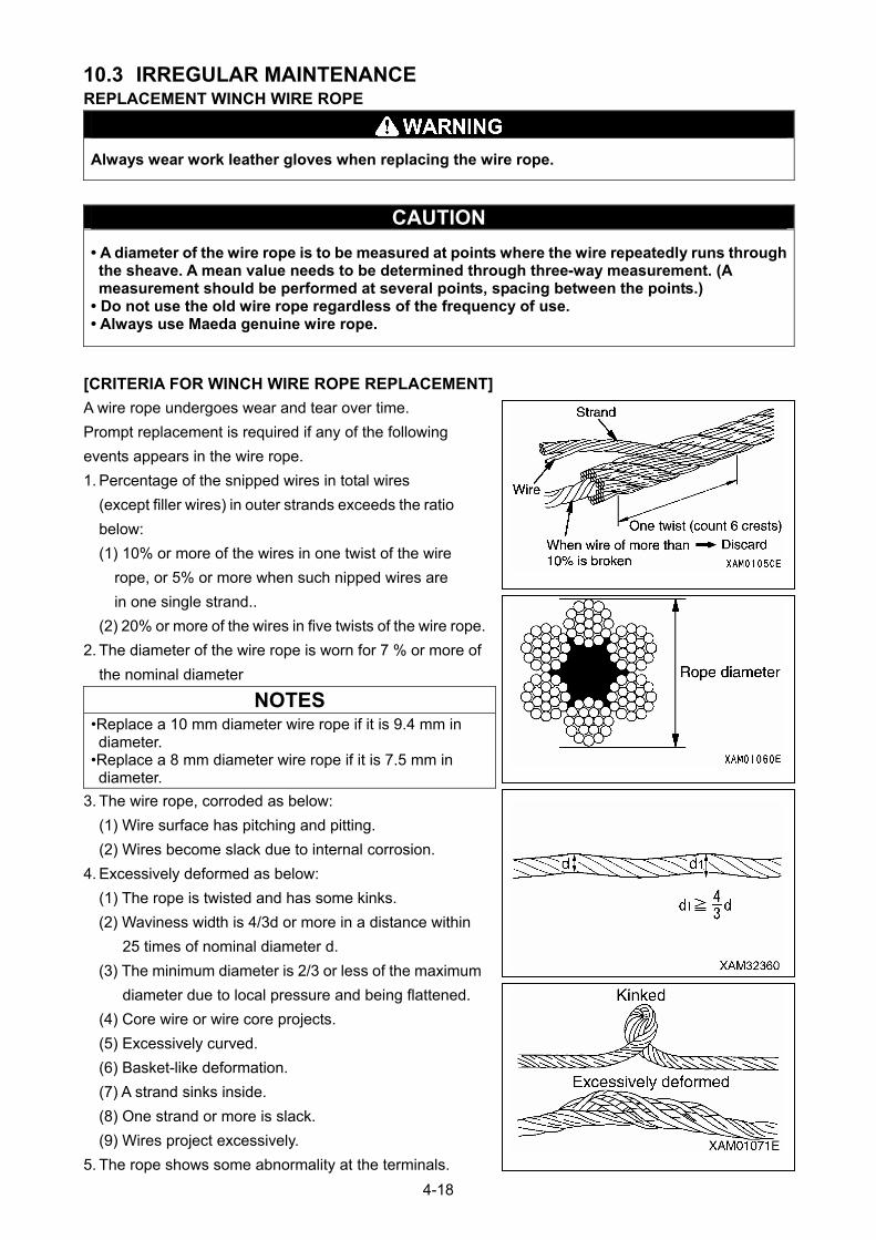
10.3 IRREGULAR MAINTENANCE REPLACEMENT WINCH WIRE ROPE
Always wear work leather gloves when replacing the wire rope.
CAUTION
• A diameter of the wire rope is to be measured at points where the wire repeatedly runs through the sheave. A mean value needs to be determined through three-way measurement. (A measurement should be performed at several points, spacing between the points.)
• Do not use the old wire rope regardless of the frequency of use. • Always use Maeda genuine wire rope.
[CRITERIA FOR WINCH WIRE ROPE REPLACEMENT]
A wire rope undergoes wear and tear over time.
Prompt replacement is required if any of the following
events appears in the wire rope.
1. Percentage of the snipped wires in total wires
(except filler wires) in outer strands exceeds the ratio
below:
(1) 10% or more of the wires in one twist of the wire
rope, or 5% or more when such nipped wires are
in one single strand..
(2) 20% or more of the wires in five twists of the wire rope.
2. The diameter of the wire rope is worn for 7 % or more of
the nominal diameter
NOTES
•Replace a 10 mm diameter wire rope if it is 9.4 mm in diameter.
•Replace a 8 mm diameter wire rope if it is 7.5 mm in diameter.
3. The wire rope, corroded as below:
(1) Wire surface has pitching and pitting.
(2) Wires become slack due to internal corrosion.
4. Excessively deformed as below:
(1) The rope is twisted and has some kinks.
(2) Waviness width is 4/3d or more in a distance within
25 times of nominal diameter d.
(3) The minimum diameter is 2/3 or less of the maximum
diameter due to local pressure and being flattened.
(4) Core wire or wire core projects.
(5) Excessively curved.
(6) Basket-like deformation.
(7) A strand sinks inside.
(8) One strand or more is slack.
(9) Wires project excessively.
5. The rope shows some abnormality at the terminals.
4-18
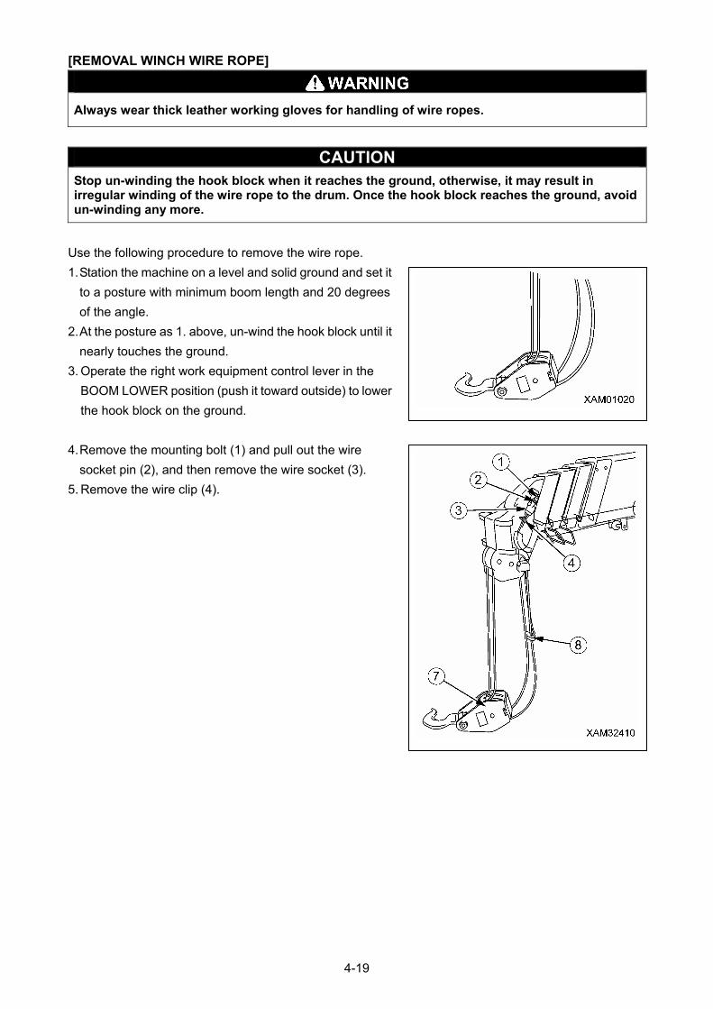
[REMOVAL WINCH WIRE ROPE]
Always wear thick leather working gloves for handling of wire ropes.
CAUTION Stop un-winding the hook block when it reaches the ground, otherwise, it may result in irregular winding of the wire rope to the drum. Once the hook block reaches the ground, avoid un-winding any more.
Use the following procedure to remove the wire rope.
1. Station the machine on a level and solid ground and set it
to a posture with minimum boom length and 20 degrees
of the angle.
2. At the posture as 1. above, un-wind the hook block until it
nearly touches the ground.
3. Operate the right work equipment control lever in the
BOOM LOWER position (push it toward outside) to lower
the hook block on the ground.
4. Remove the mounting bolt (1) and pull out the wire
socket pin (2), and then remove the wire socket (3).
5. Remove the wire clip (4).
4-19
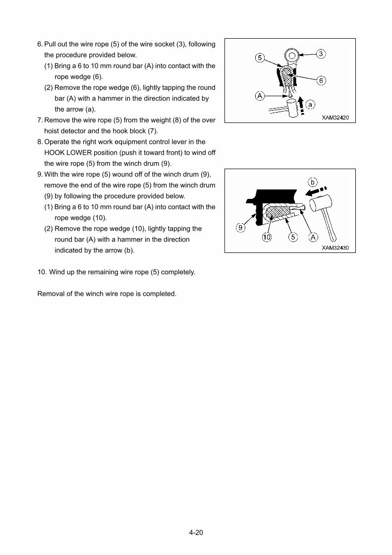
6. Pull out the wire rope (5) of the wire socket (3), following
the procedure provided below.
(1) Bring a 6 to 10 mm round bar (A) into contact with the
rope wedge (6).
(2) Remove the rope wedge (6), lightly tapping the round
bar (A) with a hammer in the direction indicated by
the arrow (a).
7. Remove the wire rope (5) from the weight (8) of the over
hoist detector and the hook block (7).
8. Operate the right work equipment control lever in the
HOOK LOWER position (push it toward front) to wind off
the wire rope (5) from the winch drum (9).
9. With the wire rope (5) wound off of the winch drum (9),
remove the end of the wire rope (5) from the winch drum
(9) by following the procedure provided below.
(1) Bring a 6 to 10 mm round bar (A) into contact with the
rope wedge (10).
(2) Remove the rope wedge (10), lightly tapping the
round bar (A) with a hammer in the direction
indicated by the arrow (b).
10. Wind up the remaining wire rope (5) completely.
Removal of the winch wire rope is completed.
4-20
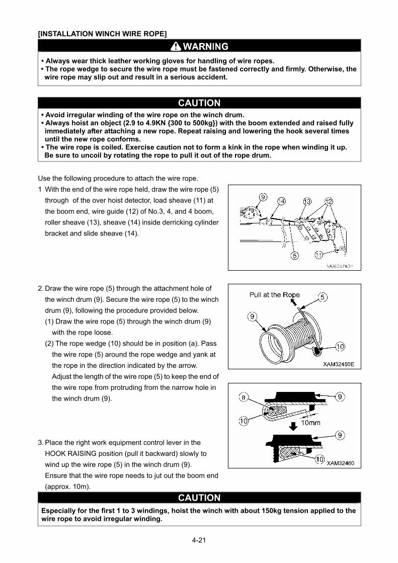
[INSTALLATION WINCH WIRE ROPE]
• Always wear thick leather working gloves for handling of wire ropes. • The rope wedge to secure the wire rope must be fastened correctly and firmly. Otherwise, the wire rope may slip out and result in a serious accident.
CAUTION • Avoid irregular winding of the wire rope on the winch drum. • Always hoist an object (2.9 to 4.9KN {300 to 500kg}) with the boom extended and raised fully immediately after attaching a new rope. Repeat raising and lowering the hook several times until the new rope conforms.
• The wire rope is coiled. Exercise caution not to form a kink in the rope when winding it up. Be sure to uncoil by rotating the rope to pull it out of the rope drum.
Use the following procedure to attach the wire rope.
1 With the end of the wire rope held, draw the wire rope (5)
through of the over hoist detector, load sheave (11) at
the boom end, wire guide (12) of No.3, 4, and 4 boom,
roller sheave (13), sheave (14) inside derricking cylinder
bracket and slide sheave (14).
2. Draw the wire rope (5) through the attachment hole of
the winch drum (9). Secure the wire rope (5) to the winch
drum (9), following the procedure provided below.
(1) Draw the wire rope (5) through the winch drum (9)
with the rope loose.
(2) The rope wedge (10) should be in position (a). Pass
the wire rope (5) around the rope wedge and yank at
the rope in the direction indicated by the arrow.
Adjust the length of the wire rope (5) to keep the end of
the wire rope from protruding from the narrow hole in
the winch drum (9).
3. Place the right work equipment control lever in the
HOOK RAISING position (pull it backward) slowly to
wind up the wire rope (5) in the winch drum (9).
Ensure that the wire rope needs to jut out the boom end
(approx. 10m).
CAUTION Especially for the first 1 to 3 windings, hoist the winch with about 150kg tension applied to the wire rope to avoid irregular winding.
4-21
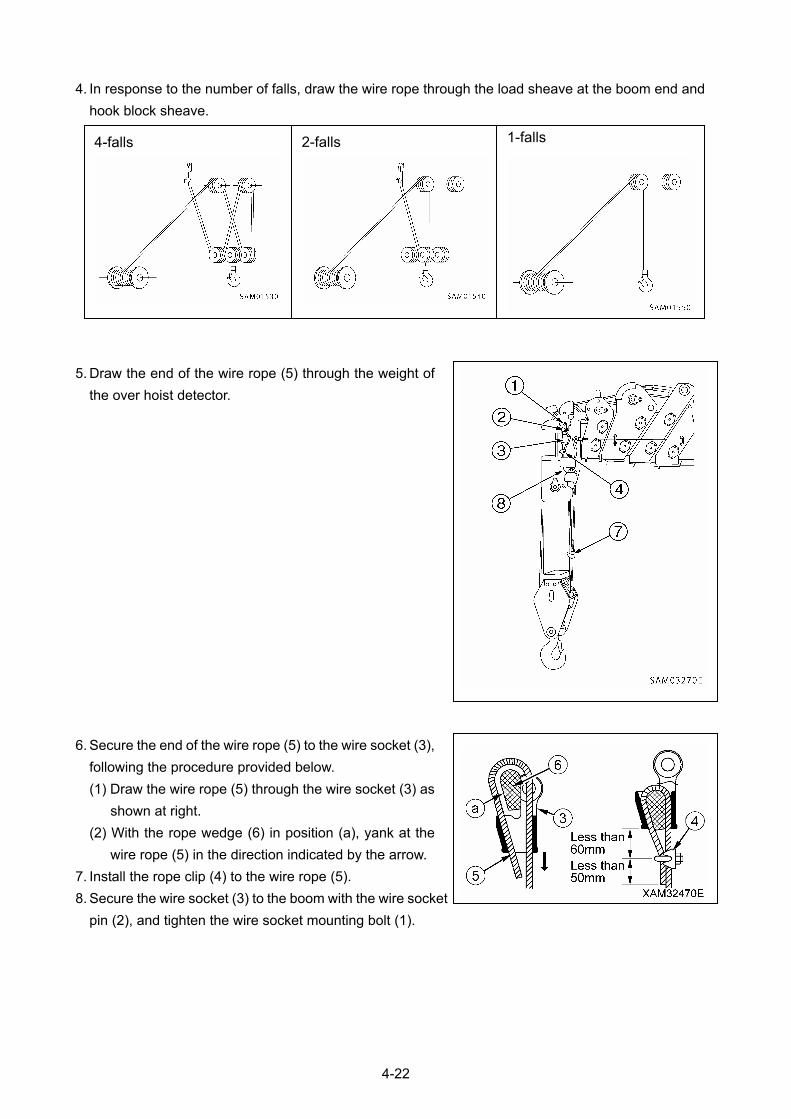
4. In response to the number of falls, draw the wire rope through the load sheave at the boom end and
hook block sheave.
1-falls 2-falls 4-falls
5. Draw the end of the wire rope (5) through the weight of
the over hoist detector.
6. Secure the end of the wire rope (5) to the wire socket (3),
following the procedure provided below.
(1) Draw the wire rope (5) through the wire socket (3) as
shown at right.
(2) With the rope wedge (6) in position (a), yank at the
wire rope (5) in the direction indicated by the arrow.
7. Install the rope clip (4) to the wire rope (5).
8. Secure the wire socket (3) to the boom with the wire socket
pin (2), and tighten the wire socket mounting bolt (1).
4-22
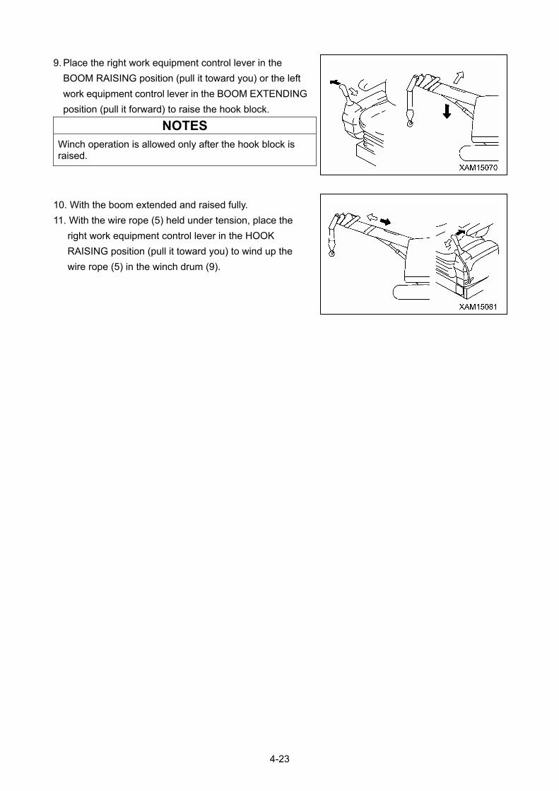
9. Place the right work equipment control lever in the
BOOM RAISING position (pull it toward you) or the left
work equipment control lever in the BOOM EXTENDING
position (pull it forward) to raise the hook block.
NOTES
Winch operation is allowed only after the hook block is raised.
10. With the boom extended and raised fully.
11. With the wire rope (5) held under tension, place the
right work equipment control lever in the HOOK
RAISING position (pull it toward you) to wind up the
wire rope (5) in the winch drum (9).
4-23
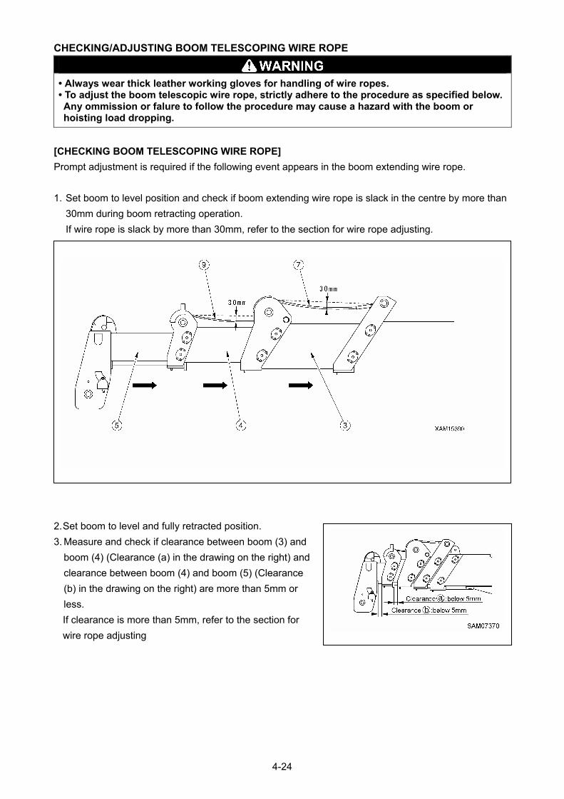
CHECKING/ADJUSTING BOOM TELESCOPING WIRE ROPE
• Always wear thick leather working gloves for handling of wire ropes. • To adjust the boom telescopic wire rope, strictly adhere to the procedure as specified below. Any ommission or falure to follow the procedure may cause a hazard with the boom or hoisting load dropping.
[CHECKING BOOM TELESCOPING WIRE ROPE]
Prompt adjustment is required if the following event appears in the boom extending wire rope.
1. Set boom to level position and check if boom extending wire rope is slack in the centre by more than
30mm during boom retracting operation.
If wire rope is slack by more than 30mm, refer to the section for wire rope adjusting.
2. Set boom to level and fully retracted position.
3. Measure and check if clearance between boom (3) and
boom (4) (Clearance (a) in the drawing on the right) and
clearance between boom (4) and boom (5) (Clearance
(b) in the drawing on the right) are more than 5mm or
less.
If clearance is more than 5mm, refer to the section for
wire rope adjusting
4-24
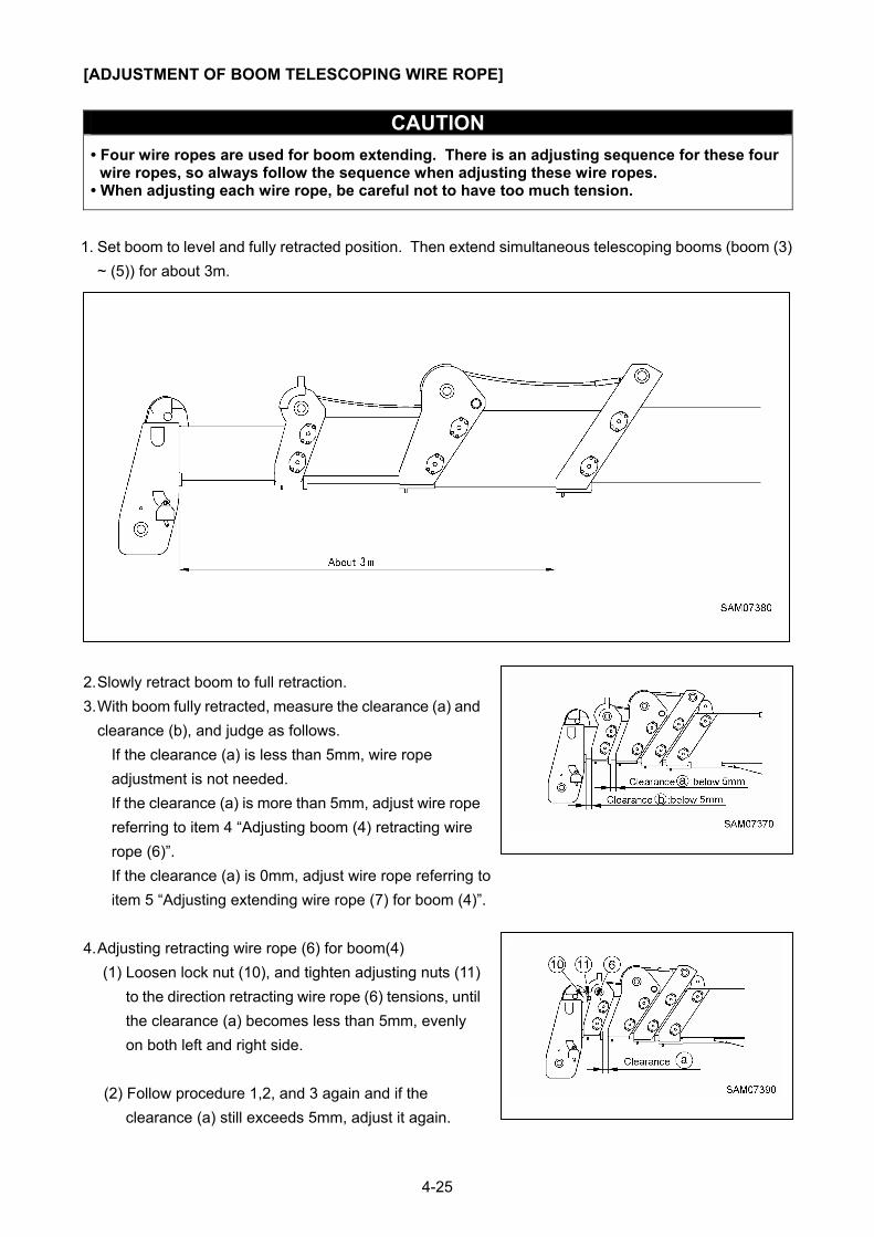
[ADJUSTMENT OF BOOM TELESCOPING WIRE ROPE]
CAUTION
• Four wire ropes are used for boom extending. There is an adjusting sequence for these four wire ropes, so always follow the sequence when adjusting these wire ropes.
• When adjusting each wire rope, be careful not to have too much tension.
1. Set boom to level and fully retracted position. Then extend simultaneous telescoping booms (boom (3)
~ (5)) for about 3m.
2. Slowly retract boom to full retraction.
3. With boom fully retracted, measure the clearance (a) and
clearance (b), and judge as follows.
If the clearance (a) is less than 5mm, wire rope
adjustment is not needed.
If the clearance (a) is more than 5mm, adjust wire rope
referring to item 4 “Adjusting boom (4) retracting wire
rope (6)”.
If the clearance (a) is 0mm, adjust wire rope referring to
item 5 “Adjusting extending wire rope (7) for boom (4)”.
4. Adjusting retracting wire rope (6) for boom(4)
(1) Loosen lock nut (10), and tighten adjusting nuts (11)
to the direction retracting wire rope (6) tensions, until
the clearance (a) becomes less than 5mm, evenly
on both left and right side.
(2) Follow procedure 1,2, and 3 again and if the
clearance (a) still exceeds 5mm, adjust it again.
4-25
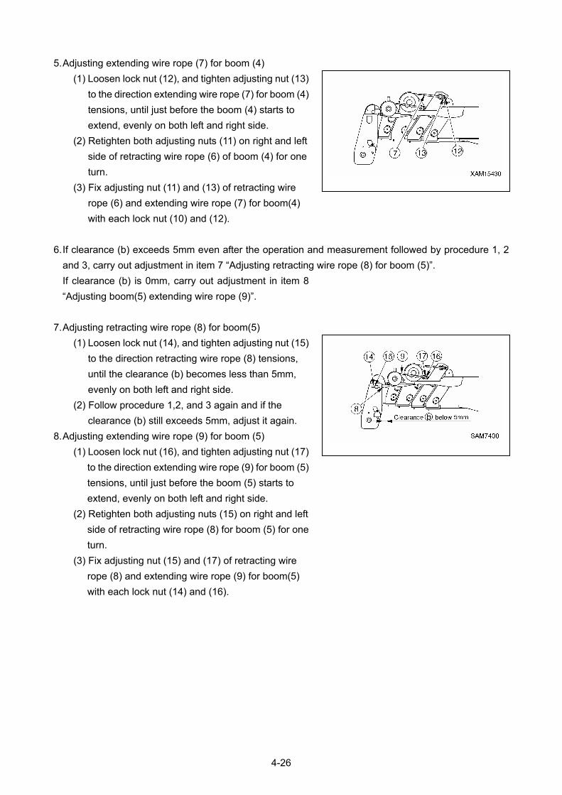
5. Adjusting extending wire rope (7) for boom (4)
(1) Loosen lock nut (12), and tighten adjusting nut (13)
to the direction extending wire rope (7) for boom (4)
tensions, until just before the boom (4) starts to
extend, evenly on both left and right side.
(2) Retighten both adjusting nuts (11) on right and left
side of retracting wire rope (6) of boom (4) for one
turn.
(3) Fix adjusting nut (11) and (13) of retracting wire
rope (6) and extending wire rope (7) for boom(4)
with each lock nut (10) and (12).
6. If clearance (b) exceeds 5mm even after the operation and measurement followed by procedure 1, 2
and 3, carry out adjustment in item 7 “Adjusting retracting wire rope (8) for boom (5)”.
If clearance (b) is 0mm, carry out adjustment in item 8
“Adjusting boom(5) extending wire rope (9)”.
7. Adjusting retracting wire rope (8) for boom(5)
(1) Loosen lock nut (14), and tighten adjusting nut (15)
to the direction retracting wire rope (8) tensions,
until the clearance (b) becomes less than 5mm,
evenly on both left and right side.
(2) Follow procedure 1,2, and 3 again and if the
clearance (b) still exceeds 5mm, adjust it again.
8. Adjusting extending wire rope (9) for boom (5)
(1) Loosen lock nut (16), and tighten adjusting nut (17)
to the direction extending wire rope (9) for boom (5)
tensions, until just before the boom (5) starts to
extend, evenly on both left and right side.
(2) Retighten both adjusting nuts (15) on right and left
side of retracting wire rope (8) for boom (5) for one
turn.
(3) Fix adjusting nut (15) and (17) of retracting wire
rope (8) and extending wire rope (9) for boom(5)
with each lock nut (14) and (16).
4-26
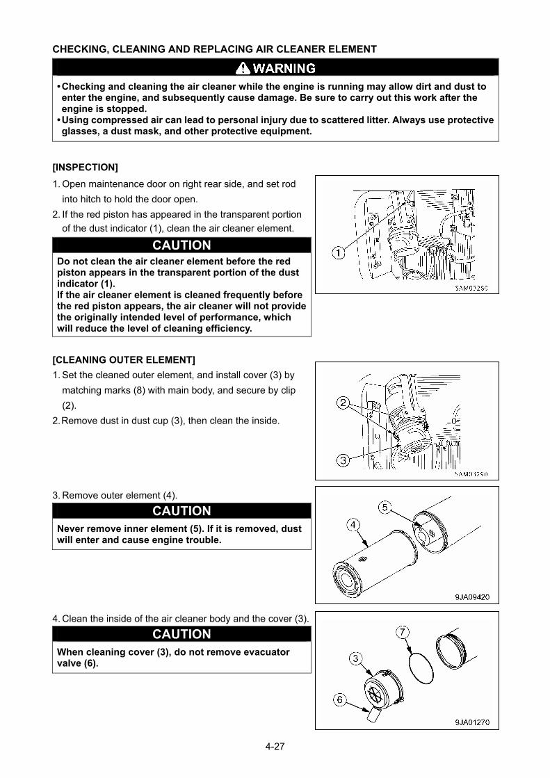
CHECKING, CLEANING AND REPLACING AIR CLEANER ELEMENT
• Checking and cleaning the air cleaner while the engine is running may allow dirt and dust to enter the engine, and subsequently cause damage. Be sure to carry out this work after the engine is stopped.
• Using compressed air can lead to personal injury due to scattered litter. Always use protective glasses, a dust mask, and other protective equipment.
[INSPECTION]
1. Open maintenance door on right rear side, and set rod
into hitch to hold the door open.
2. If the red piston has appeared in the transparent portion
of the dust indicator (1), clean the air cleaner element.
CAUTION Do not clean the air cleaner element before the red piston appears in the transparent portion of the dust indicator (1). If the air cleaner element is cleaned frequently before the red piston appears, the air cleaner will not provide the originally intended level of performance, which will reduce the level of cleaning efficiency.
[CLEANING OUTER ELEMENT]
1. Set the cleaned outer element, and install cover (3) by
matching marks (8) with main body, and secure by clip
(2).
2. Remove dust in dust cup (3), then clean the inside.
3. Remove outer element (4).
CAUTION Never remove inner element (5). If it is removed, dust will enter and cause engine trouble.
4. Clean the inside of the air cleaner body and the cover (3).
CAUTION When cleaning cover (3), do not remove evacuator valve (6).
4-27
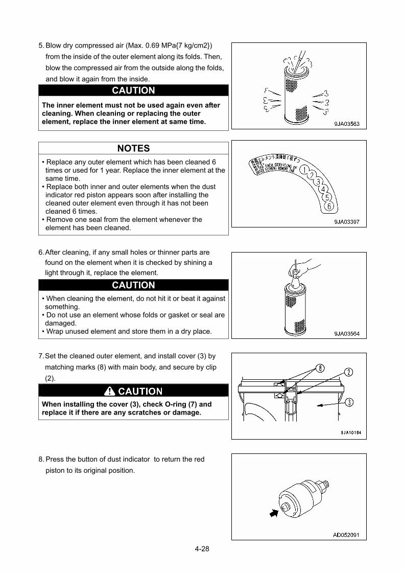
5. Blow dry compressed air (Max. 0.69 MPa{7 kg/cm2})
from the inside of the outer element along its folds. Then,
blow the compressed air from the outside along the folds,
and blow it again from the inside.
CAUTION
The inner element must not be used again even after cleaning. When cleaning or replacing the outer element, replace the inner element at same time.
NOTES
• Replace any outer element which has been cleaned 6 times or used for 1 year. Replace the inner element at the same time.
• Replace both inner and outer elements when the dust indicator red piston appears soon after installing the cleaned outer element even through it has not been cleaned 6 times.
• Remove one seal from the element whenever the element has been cleaned.
6. After cleaning, if any small holes or thinner parts are
found on the element when it is checked by shining a
light through it, replace the element.
CAUTION • When cleaning the element, do not hit it or beat it against something.
• Do not use an element whose folds or gasket or seal are damaged.
• Wrap unused element and store them in a dry place.
7. Set the cleaned outer element, and install cover (3) by
matching marks (8) with main body, and secure by clip
(2).
When installing the cover (3), check O-ring (7) and replace it if there are any scratches or damage.
8. Press the button of dust indicator to return the red
piston to its original position.
4-28
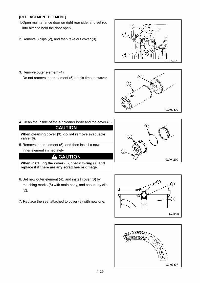
[REPLACEMENT ELEMENT]
1. Open maintenance door on right rear side, and set rod
into hitch to hold the door open.
2. Remove 3 clips (2), and then take out cover (3).
3. Remove outer element (4).
Do not remove inner element (5) at this time, however.
4. Clean the inside of the air cleaner body and the cover (3).
CAUTION When cleaning cover (3), do not remove evacuator valve (6).
5. Remove inner element (5), and then install a new
inner element immediately.
When installing the cover (3), check O-ring (7) and replace it if there are any scratches or dmage.
6. Set new outer element (4), and install cover (3) by
matching marks (8) with main body, and secure by clip
(2).
7. Replace the seal attached to cover (3) with new one.
4-29

8. Press the button of dust indicator to return the red piston
to its original position.
4-30
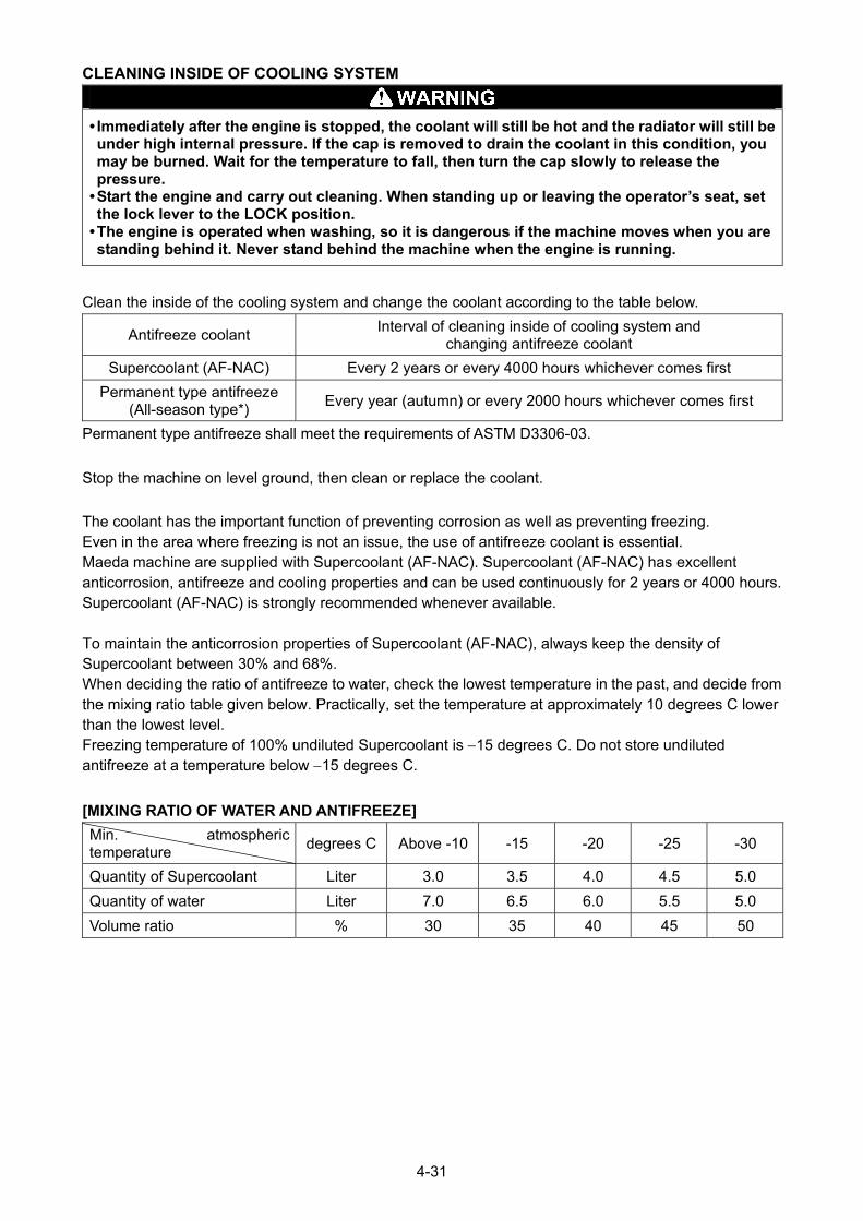
CLEANING INSIDE OF COOLING SYSTEM
• Immediately after the engine is stopped, the coolant will still be hot and the radiator will still be under high internal pressure. If the cap is removed to drain the coolant in this condition, you may be burned. Wait for the temperature to fall, then turn the cap slowly to release the pressure.
• Start the engine and carry out cleaning. When standing up or leaving the operator’s seat, set the lock lever to the LOCK position.
• The engine is operated when washing, so it is dangerous if the machine moves when you are standing behind it. Never stand behind the machine when the engine is running.
Clean the inside of the cooling system and change the coolant according to the table below.
Antifreeze coolant Interval of cleaning inside of cooling system and
changing antifreeze coolant
Supercoolant (AF-NAC) Every 2 years or every 4000 hours whichever comes first
Permanent type antifreeze (All-season type*)
Every year (autumn) or every 2000 hours whichever comes first
Permanent type antifreeze shall meet the requirements of ASTM D3306-03.
Stop the machine on level ground, then clean or replace the coolant.
The coolant has the important function of preventing corrosion as well as preventing freezing. Even in the area where freezing is not an issue, the use of antifreeze coolant is essential. Maeda machine are supplied with Supercoolant (AF-NAC). Supercoolant (AF-NAC) has excellent anticorrosion, antifreeze and cooling properties and can be used continuously for 2 years or 4000 hours. Supercoolant (AF-NAC) is strongly recommended whenever available. To maintain the anticorrosion properties of Supercoolant (AF-NAC), always keep the density of Supercoolant between 30% and 68%. When deciding the ratio of antifreeze to water, check the lowest temperature in the past, and decide from the mixing ratio table given below. Practically, set the temperature at approximately 10 degrees C lower than the lowest level. Freezing temperature of 100% undiluted Supercoolant is 15 degrees C. Do not store undiluted antifreeze at a temperature below 15 degrees C.
[MIXING RATIO OF WATER AND ANTIFREEZE]
Min. atmospheric temperature
degrees C Above -10 -15 -20 -25 -30
Quantity of Supercoolant Liter 3.0 3.5 4.0 4.5 5.0
Quantity of water Liter 7.0 6.5 6.0 5.5 5.0
Volume ratio % 30 35 40 45 50
4-31
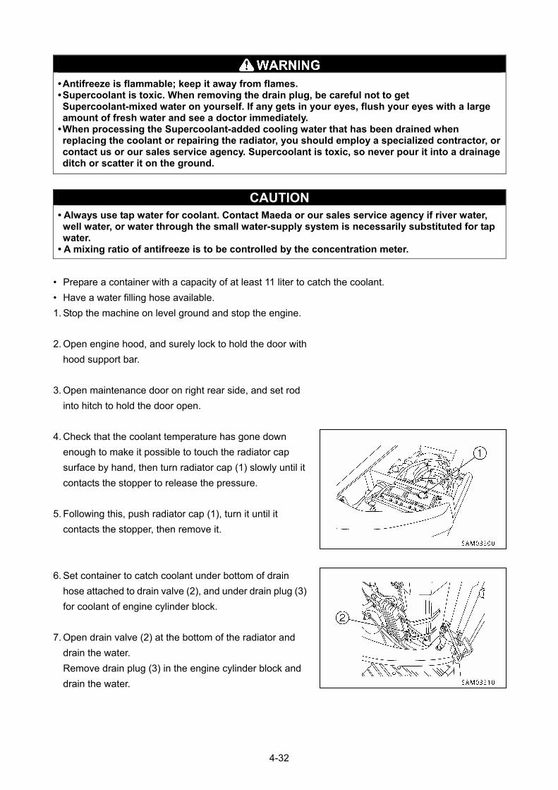
• Antifreeze is flammable; keep it away from flames. • Supercoolant is toxic. When removing the drain plug, be careful not to get Supercoolant-mixed water on yourself. If any gets in your eyes, flush your eyes with a large amount of fresh water and see a doctor immediately.
• When processing the Supercoolant-added cooling water that has been drained when replacing the coolant or repairing the radiator, you should employ a specialized contractor, or contact us or our sales service agency. Supercoolant is toxic, so never pour it into a drainage ditch or scatter it on the ground.
CAUTION • Always use tap water for coolant. Contact Maeda or our sales service agency if river water, well water, or water through the small water-supply system is necessarily substituted for tap water.
• A mixing ratio of antifreeze is to be controlled by the concentration meter.
• Prepare a container with a capacity of at least 11 liter to catch the coolant.
• Have a water filling hose available.
1. Stop the machine on level ground and stop the engine.
2. Open engine hood, and surely lock to hold the door with
hood support bar.
3. Open maintenance door on right rear side, and set rod
into hitch to hold the door open.
4. Check that the coolant temperature has gone down
enough to make it possible to touch the radiator cap
surface by hand, then turn radiator cap (1) slowly until it
contacts the stopper to release the pressure.
5. Following this, push radiator cap (1), turn it until it
contacts the stopper, then remove it.
6. Set container to catch coolant under bottom of drain
hose attached to drain valve (2), and under drain plug (3)
for coolant of engine cylinder block.
7. Open drain valve (2) at the bottom of the radiator and
drain the water.
Remove drain plug (3) in the engine cylinder block and
drain the water.
4-32
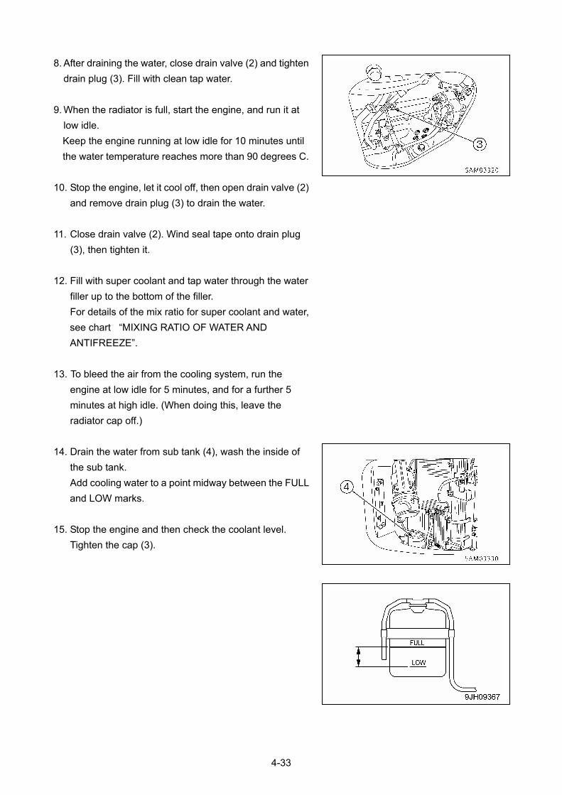
8. After draining the water, close drain valve (2) and tighten
drain plug (3). Fill with clean tap water.
9. When the radiator is full, start the engine, and run it at
low idle.
Keep the engine running at low idle for 10 minutes until
the water temperature reaches more than 90 degrees C.
10. Stop the engine, let it cool off, then open drain valve (2)
and remove drain plug (3) to drain the water.
11. Close drain valve (2). Wind seal tape onto drain plug
(3), then tighten it.
12. Fill with super coolant and tap water through the water
filler up to the bottom of the filler.
For details of the mix ratio for super coolant and water,
see chart “MIXING RATIO OF WATER AND
ANTIFREEZE”.
13. To bleed the air from the cooling system, run the
engine at low idle for 5 minutes, and for a further 5
minutes at high idle. (When doing this, leave the
radiator cap off.)
14. Drain the water from sub tank (4), wash the inside of
the sub tank.
Add cooling water to a point midway between the FULL
and LOW marks.
15. Stop the engine and then check the coolant level.
Tighten the cap (3).
4-33
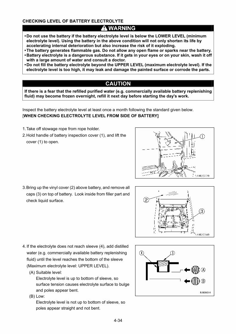
CHECKING LEVEL OF BATTERY ELECTROLYTE
• Do not use the battery if the battery electrolyte level is below the LOWER LEVEL (minimum electrolyte level). Using the battery in the above condition will not only shorten its life by accelerating internal deterioration but also increase the risk of it exploding.
• The battery generates flammable gas. Do not allow any open flame or sparks near the battery.• Battery electrolyte is a dangerous substance. If it gets in your eyes or on your skin, wash it off with a large amount of water and consult a doctor.
• Do not fill the battery electrolyte beyond the UPPER LEVEL (maximum electrolyte level). If the electrolyte level is too high, it may leak and damage the painted surface or corrode the parts.
CAUTION If there is a fear that the refilled purified water (e.g. commercially available battery replenishing fluid) may become frozen overnight, refill it next day before starting the day's work.
Inspect the battery electrolyte level at least once a month following the standard given below.
[WHEN CHECKING ELECTROLYTE LEVEL FROM SIDE OF BATTERY]
1. Take off stowage rope from rope holder.
2. Hold handle of battery inspection cover (1), and lift the
cover (1) to open.
3. Bring up the vinyl cover (2) above battery, and remove all
caps (3) on top of battery. Look inside from filler part and
check liquid surface.
4. If the electrolyte does not reach sleeve (4), add distilled
water (e.g. commercially available battery replenishing
fluid) until the level reaches the bottom of the sleeve
(Maximum electrolyte level: UPPER LEVEL).
(A) Suitable level:
Electrolyte level is up to bottom of sleeve, so
surface tension causes electrolyte surface to bulge
and poles appear bent.
(B) Low:
Electrolyte level is not up to bottom of sleeve, so
poles appear straight and not bent.
4-34

5. After refilling, close cap (1) tightly.
NOTES
If distilled water is added to above the bottom tip of the sleeve, use a syringe to remove electrolyte. Neutralize the removed fluid with sodium bicarbonate, then flush it away with a large amount of water.Or, contact us, our sales service agency or the battery manufacturer.
[WHEN IT IS POSSIBLE TO USE INDICATOR TO CHECK ELECTROLYTE LEVEL]
If it is possible to use an indicator to check the electrolyte level, follow the instructions given.
4-35
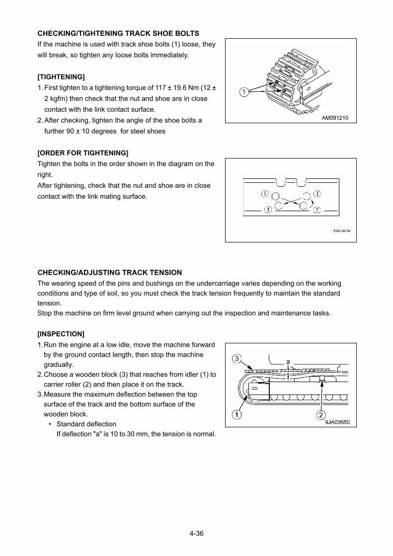
CHECKING/TIGHTENING TRACK SHOE BOLTS
If the machine is used with track shoe bolts (1) loose, they
will break, so tighten any loose bolts immediately.
[TIGHTENING]
1. First tighten to a tightening torque of 117 ± 19.6 Nm (12 ±
2 kgfm) then check that the nut and shoe are in close
contact with the link contact surface.
2. After checking, tighten the angle of the shoe bolts a
further 90 ± 10 degrees for steel shoes
[ORDER FOR TIGHTENING]
Tighten the bolts in the order shown in the diagram on the
right.
After tightening, check that the nut and shoe are in close
contact with the link mating surface.
CHECKING/ADJUSTING TRACK TENSION
The wearing speed of the pins and bushings on the undercarriage varies depending on the working
conditions and type of soil, so you must check the track tension frequently to maintain the standard
tension.
Stop the machine on firm level ground when carrying out the inspection and maintenance tasks.
[INSPECTION]
1. Run the engine at a low idle, move the machine forward
by the ground contact length, then stop the machine
gradually.
2. Choose a wooden block (3) that reaches from idler (1) to
carrier roller (2) and then place it on the track.
3. Measure the maximum deflection between the top
surface of the track and the bottom surface of the
wooden block.
• Standard deflection
If deflection "a" is 10 to 30 mm, the tension is normal.
4-36
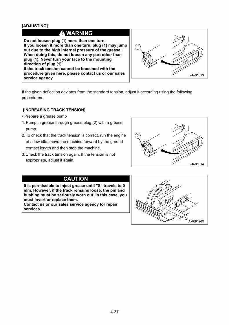
[ADJUSTING]
Do not loosen plug (1) more than one turn. If you loosen it more than one turn, plug (1) may jump out due to the high internal pressure of the grease. When doing this, do not loosen any part other than plug (1). Never turn your face to the mounting direction of plug (1). If the track tension cannot be loosened with the procedure given here, please contact us or our sales service agency.
If the given deflection deviates from the standard tension, adjust it according using the following
procedures.
[INCREASING TRACK TENSION]
• Prepare a grease pump
1. Pump in grease through grease plug (2) with a grease
pump.
2. To check that the track tension is correct, run the engine
at a low idle, move the machine forward by the ground
contact length and then stop the machine.
3. Check the track tension again. If the tension is not
appropriate, adjust it again.
CAUTION It is permissible to inject grease until "S" travels to 0 mm. However, if the track remains loose, the pin and bushing must be seriously worn out. In this case, you must invert or replace them. Contact us or our sales service agency for repair services.
4-37
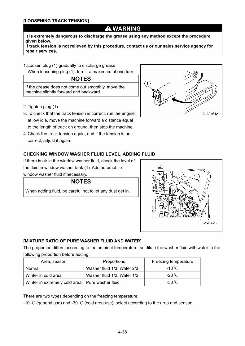
[LOOSENING TRACK TENSION]
It is extremely dangerous to discharge the grease using any method except the procedure given below. If track tension is not relieved by this procedure, contact us or our sales service agency for repair services.
1. Loosen plug (1) gradually to discharge grease.
When loosening plug (1), turn it a maximum of one turn.
NOTES
If the grease does not come out smoothly, move the machine slightly forward and backward.
2. Tighten plug (1).
3. To check that the track tension is correct, run the engine
at low idle, move the machine forward a distance equal
to the length of track on ground, then stop the machine.
4. Check the track tension again, and if the tension is not
correct, adjust it again.
CHECKING WINDOW WASHER FLUID LEVEL, ADDING FLUID
If there is air in the window washer fluid, check the level of
the fluid in window washer tank (1). Add automobile
window washer fluid if necessary.
NOTES
When adding fluid, be careful not to let any dust get in.
[MIXTURE RATIO OF PURE WASHER FLUID AND WATER]
The proportion differs according to the ambient temperature, so dilute the washer fluid with water to the
following proportion before adding.
Area, season Proportions Freezing temperature
Normal Washer fluid 1/3: Water 2/3 -10 ℃
Winter in cold area Washer fluid 1/2: Water 1/2 -20 ℃
Winter in extremely cold area Pure washer fluid -30 ℃
There are two types depending on the freezing temperature:
-10 ℃ (general use) and -30 ℃ (cold area use), select according to the area and season.
4-38
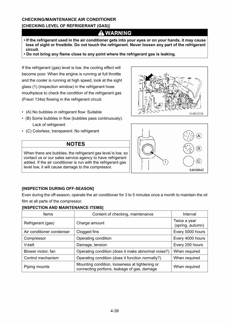
CHECKING/MAINTENANCE AIR CONDITIONER
[CHECKING LEVEL OF REFRIGERANT (GAS)]
• If the refrigerant used in the air conditioner gets into your eyes or on your hands, it may cause lose of sight or frostbite. Do not touch the refrigerant. Never loosen any part of the refrigerant circuit.
• Do not bring any flame close to any point where the refrigerant gas is leaking.
If the refrigerant (gas) level is low, the cooling effect will
become poor. When the engine is running at full throttle
and the cooler is running at high speed, look at the sight
glass (1) (inspection window) in the refrigerant hose
mouthpiece to check the condition of the refrigerant gas
(Freon 134a) flowing in the refrigerant circuit.
• (A) No bubbles in refrigerant flow: Suitable
• (B) Some bubbles in flow (bubbles pass continuously):
Lack of refrigerant
• (C) Colorless, transparent: No refrigerant
NOTES
When there are bubbles, the refrigerant gas level is low, so contact us or our sales service agency to have refrigerant added. If the air conditioner is run with the refrigerant gas level low, it will cause damage to the compressor.
[INSPECTION DURING OFF-SEASON]
Even during the off-season, operate the air conditioner for 3 to 5 minutes once a month to maintain the oil
film at all parts of the compressor.
[INSPECTION AND MAINTENANCE ITEMS]
Items Content of checking, maintenance Interval
Refrigerant (gas) Charge amount Twice a year (spring, autumn)
Air conditioner condenser Clogged fins Every 5000 hours
Compressor Operating condition Every 4000 hours
V-belt Damage, tension Every 250 hours
Blower motor, fan Operating condition (does it make abnormal noise?) When required
Control mechanism Operating condition (does it function normally?) When required
Piping mounts Mounting condition, looseness at tightening or connecting portions, leakage of gas, damage
When required
4-39
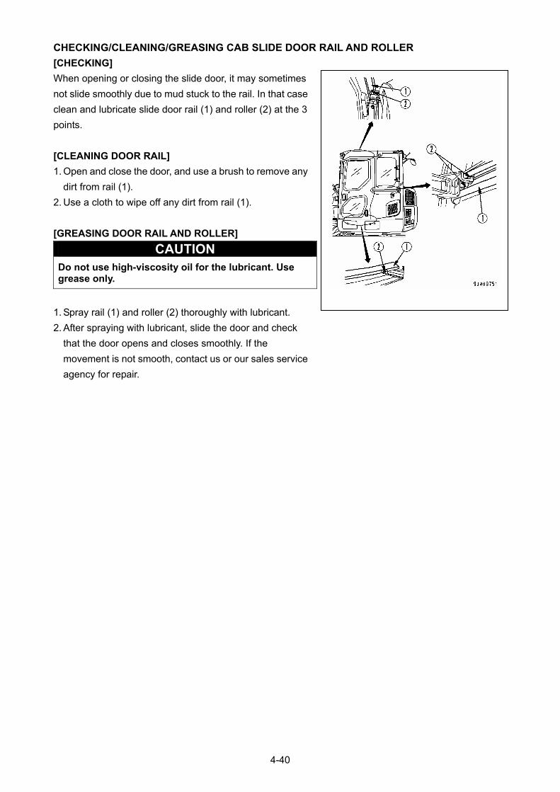
CHECKING/CLEANING/GREASING CAB SLIDE DOOR RAIL AND ROLLER
[CHECKING]
When opening or closing the slide door, it may sometimes
not slide smoothly due to mud stuck to the rail. In that case
clean and lubricate slide door rail (1) and roller (2) at the 3
points.
[CLEANING DOOR RAIL]
1. Open and close the door, and use a brush to remove any
dirt from rail (1).
2. Use a cloth to wipe off any dirt from rail (1).
[GREASING DOOR RAIL AND ROLLER]
CAUTION Do not use high-viscosity oil for the lubricant. Use grease only.
1. Spray rail (1) and roller (2) thoroughly with lubricant.
2. After spraying with lubricant, slide the door and check
that the door opens and closes smoothly. If the
movement is not smooth, contact us or our sales service
agency for repair.
4-40
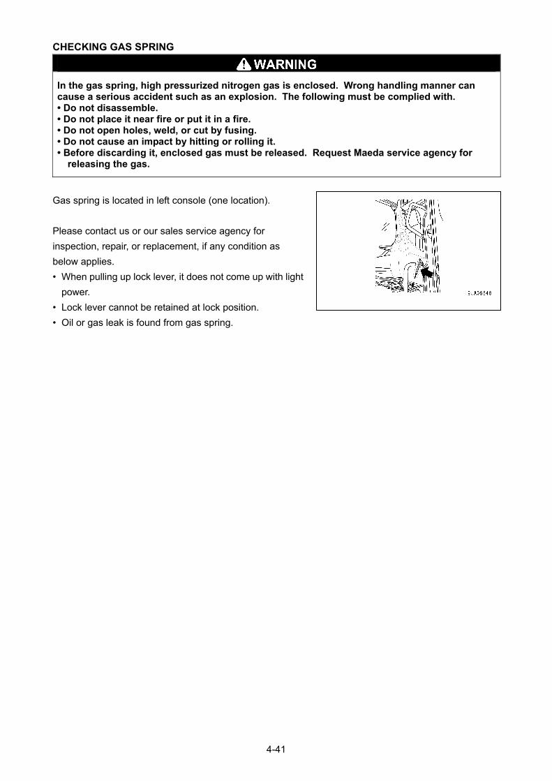
CHECKING GAS SPRING
In the gas spring, high pressurized nitrogen gas is enclosed. Wrong handling manner can cause a serious accident such as an explosion. The following must be complied with. • Do not disassemble. • Do not place it near fire or put it in a fire. • Do not open holes, weld, or cut by fusing. • Do not cause an impact by hitting or rolling it. • Before discarding it, enclosed gas must be released. Request Maeda service agency for
releasing the gas.
Gas spring is located in left console (one location).
Please contact us or our sales service agency for
inspection, repair, or replacement, if any condition as
below applies.
• When pulling up lock lever, it does not come up with light
power.
• Lock lever cannot be retained at lock position.
• Oil or gas leak is found from gas spring.
4-41

10.4 MAINTENANCE EVERY 50 HOURS GREASING MACHINE UNITS
CAUTION • Type of grease used varies with greasing points. Failure to grease properly may shorten the machine life.
• For a new machine that requires an initial running-in, grease it once every 10 hours until it has been operated for up to 100 hours.
• Use the grease specified below according to the greasing points.
№ Greasing point Grease type
1 Greasing of the derrick cylinder bottom side mounting pin 1 place
2 Greasing of the derrick cylinder rod side mounting pin 1 place
3 Greasing of the guide sheave 1 place
4 Greasing of the boom mounting pin 1 place
5 Greasing of wire support roller pin 2 places
Lithium grease
6 Greasing of the boom slide plate (upper) 8 places
7 Greasing of the boom slide plate(lower) 8 places Molybdenum grease
8 Greasing of both sides and bottom of a boom Each boom Grease for boom
9 Greasing of boom extending wire rope Greasing of the winch wire rope
5 places Rope oil
10 Greasing of the hook block 1 piece Lithium grease
1. With the use of the grease gun, grease the greasing points (No. 1 to 10) specified in the above table
through corresponding grease plugs. (See the following page.)
2. After greasing, wipe off any old grease that has been pushed out.
3. When greasing both side and bottom of a boom or a wire rope, set the left work equipment control lever
to the EXTEND position (push it forward) to extend the boom.
4. Apply red rope grease to prevent wire rope abrasion and rust formation.
With the rope surface cleaned, grease the rope using a brush.
4-42
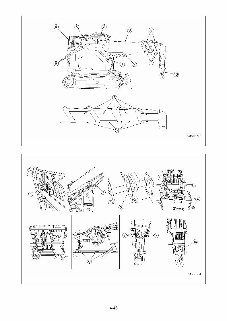
4-43
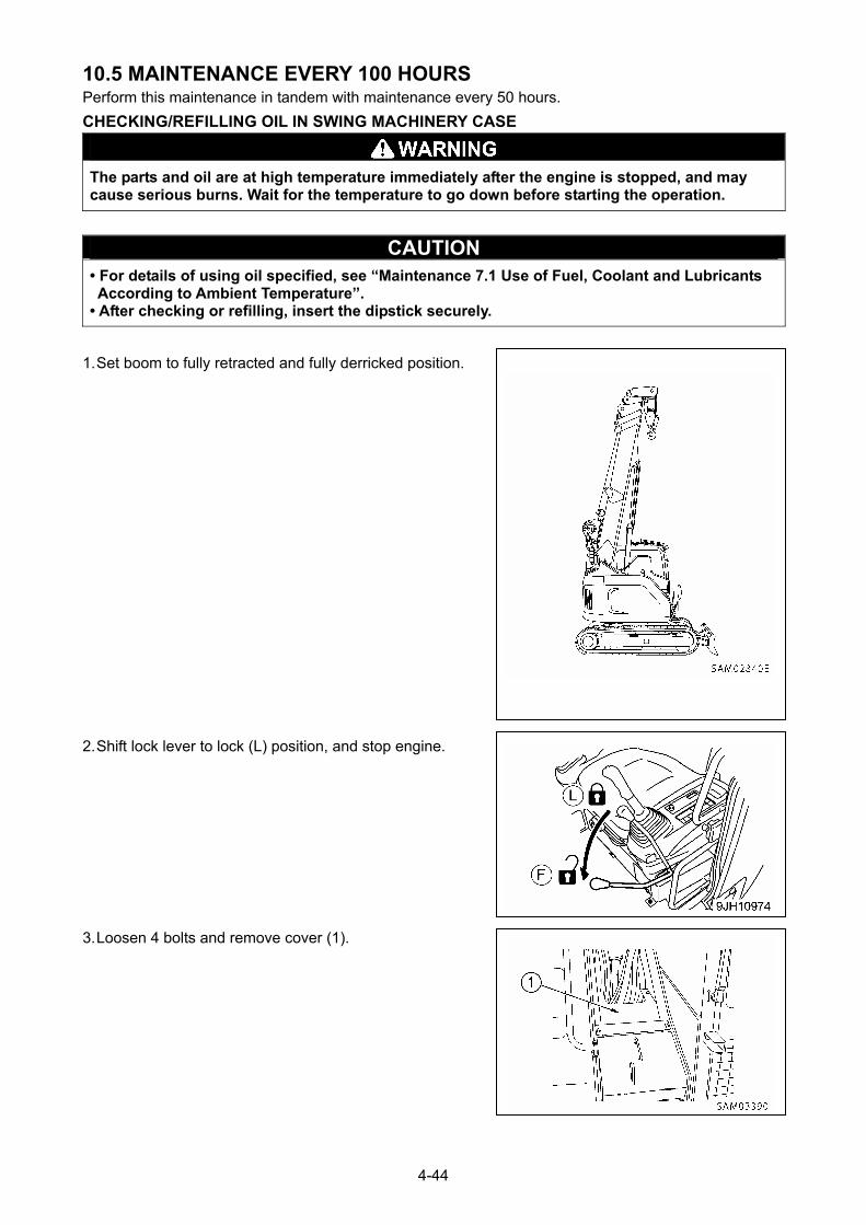
10.5 MAINTENANCE EVERY 100 HOURS Perform this maintenance in tandem with maintenance every 50 hours.
CHECKING/REFILLING OIL IN SWING MACHINERY CASE
The parts and oil are at high temperature immediately after the engine is stopped, and may cause serious burns. Wait for the temperature to go down before starting the operation.
CAUTION • For details of using oil specified, see “Maintenance 7.1 Use of Fuel, Coolant and Lubricants According to Ambient Temperature”.
• After checking or refilling, insert the dipstick securely.
1. Set boom to fully retracted and fully derricked position.
2. Shift lock lever to lock (L) position, and stop engine.
3. Loosen 4 bolts and remove cover (1).
4-44
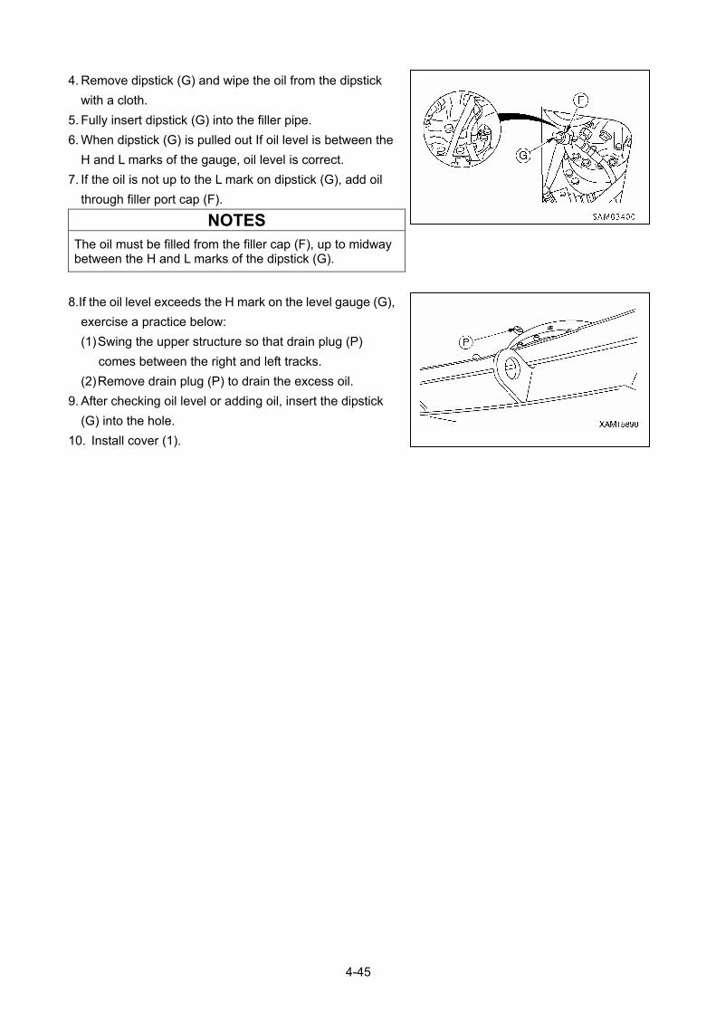
4. Remove dipstick (G) and wipe the oil from the dipstick
with a cloth.
5. Fully insert dipstick (G) into the filler pipe.
6. When dipstick (G) is pulled out If oil level is between the
H and L marks of the gauge, oil level is correct.
7. If the oil is not up to the L mark on dipstick (G), add oil
through filler port cap (F).
NOTES
The oil must be filled from the filler cap (F), up to midway between the H and L marks of the dipstick (G).
8.If the oil level exceeds the H mark on the level gauge (G),
exercise a practice below:
(1) Swing the upper structure so that drain plug (P)
comes between the right and left tracks.
(2) Remove drain plug (P) to drain the excess oil.
9. After checking oil level or adding oil, insert the dipstick
(G) into the hole.
10. Install cover (1).
4-45
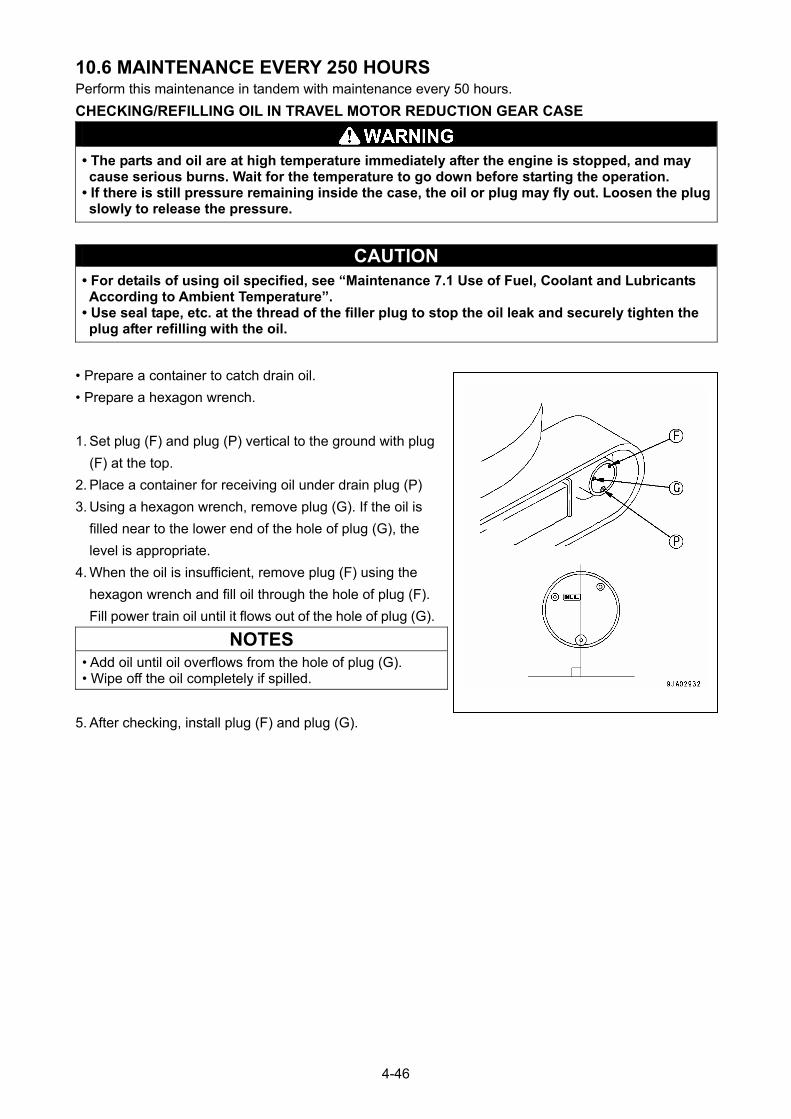
10.6 MAINTENANCE EVERY 250 HOURS Perform this maintenance in tandem with maintenance every 50 hours.
CHECKING/REFILLING OIL IN TRAVEL MOTOR REDUCTION GEAR CASE
• The parts and oil are at high temperature immediately after the engine is stopped, and may cause serious burns. Wait for the temperature to go down before starting the operation.
• If there is still pressure remaining inside the case, the oil or plug may fly out. Loosen the plug slowly to release the pressure.
CAUTION • For details of using oil specified, see “Maintenance 7.1 Use of Fuel, Coolant and Lubricants According to Ambient Temperature”.
• Use seal tape, etc. at the thread of the filler plug to stop the oil leak and securely tighten the plug after refilling with the oil.
• Prepare a container to catch drain oil.
• Prepare a hexagon wrench.
1. Set plug (F) and plug (P) vertical to the ground with plug
(F) at the top.
2. Place a container for receiving oil under drain plug (P)
3. Using a hexagon wrench, remove plug (G). If the oil is
filled near to the lower end of the hole of plug (G), the
level is appropriate.
4. When the oil is insufficient, remove plug (F) using the
hexagon wrench and fill oil through the hole of plug (F).
Fill power train oil until it flows out of the hole of plug (G).
NOTES
• Add oil until oil overflows from the hole of plug (G). • Wipe off the oil completely if spilled.
5. After checking, install plug (F) and plug (G).
4-46
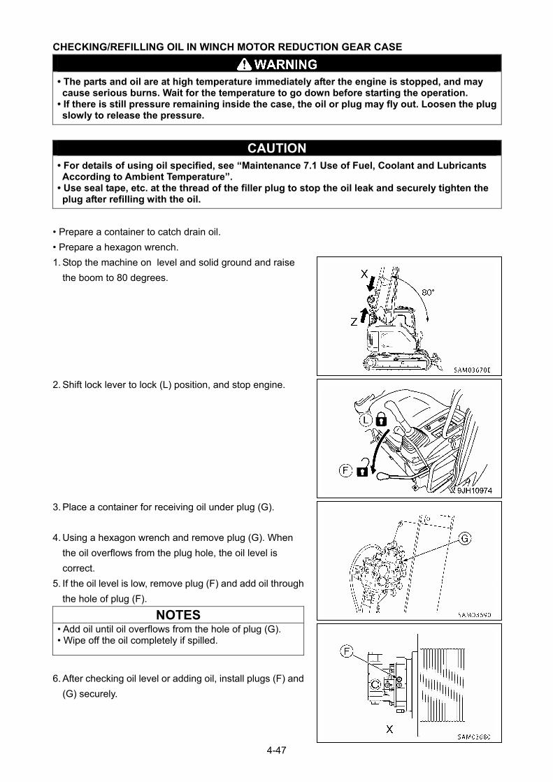
CHECKING/REFILLING OIL IN WINCH MOTOR REDUCTION GEAR CASE
• The parts and oil are at high temperature immediately after the engine is stopped, and may cause serious burns. Wait for the temperature to go down before starting the operation.
• If there is still pressure remaining inside the case, the oil or plug may fly out. Loosen the plug slowly to release the pressure.
CAUTION • For details of using oil specified, see “Maintenance 7.1 Use of Fuel, Coolant and Lubricants According to Ambient Temperature”.
• Use seal tape, etc. at the thread of the filler plug to stop the oil leak and securely tighten the plug after refilling with the oil.
• Prepare a container to catch drain oil.
• Prepare a hexagon wrench.
1. Stop the machine on level and solid ground and raise
the boom to 80 degrees.
2. Shift lock lever to lock (L) position, and stop engine.
3. Place a container for receiving oil under plug (G).
4. Using a hexagon wrench and remove plug (G). When
the oil overflows from the plug hole, the oil level is
correct.
5. If the oil level is low, remove plug (F) and add oil through
the hole of plug (F).
NOTES • Add oil until oil overflows from the hole of plug (G). • Wipe off the oil completely if spilled.
6. After checking oil level or adding oil, install plugs (F) and
(G) securely.
4-47
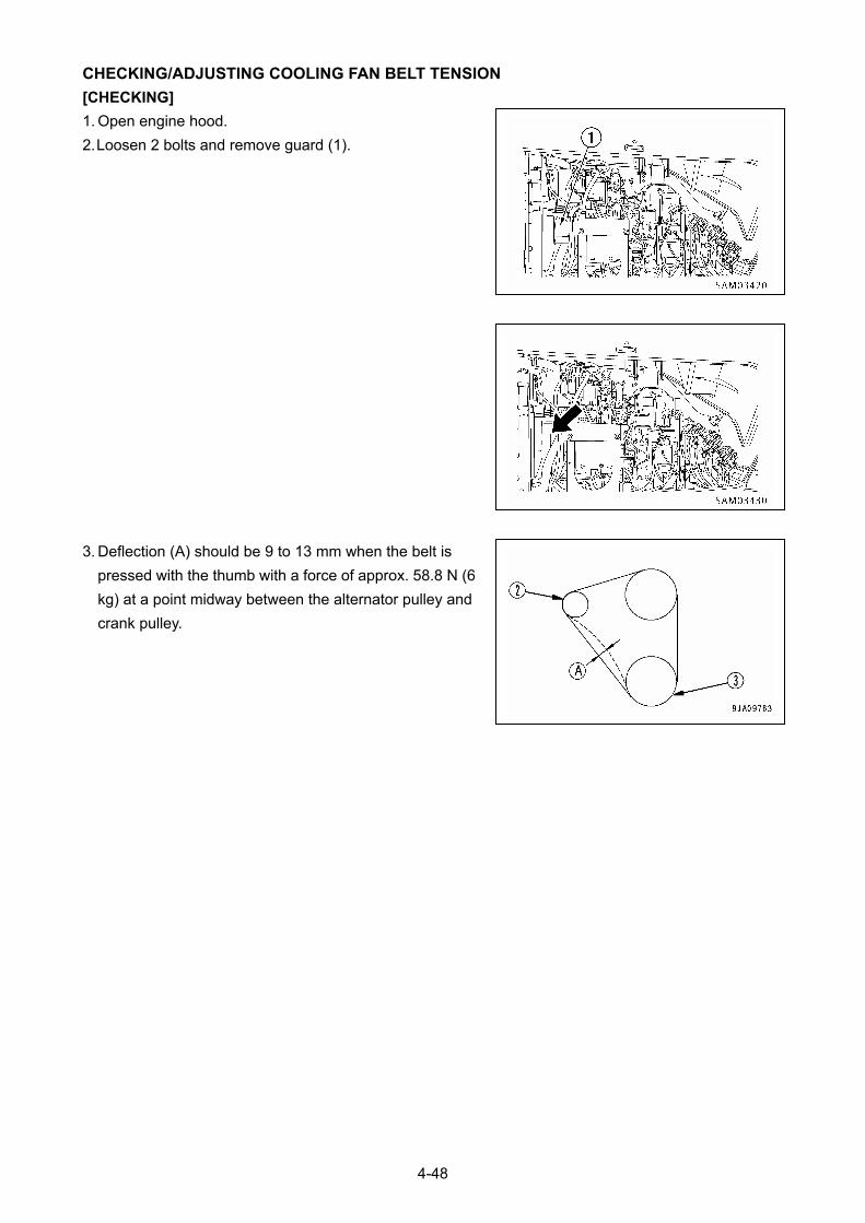
CHECKING/ADJUSTING COOLING FAN BELT TENSION
[CHECKING]
1. Open engine hood.
2. Loosen 2 bolts and remove guard (1).
3. Deflection (A) should be 9 to 13 mm when the belt is
pressed with the thumb with a force of approx. 58.8 N (6
kg) at a point midway between the alternator pulley and
crank pulley.
4-48
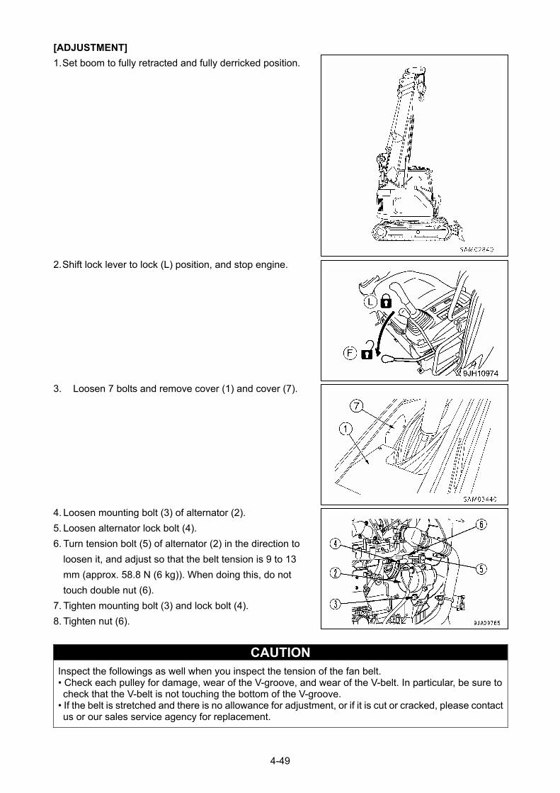
[ADJUSTMENT]
1. Set boom to fully retracted and fully derricked position.
2. Shift lock lever to lock (L) position, and stop engine.
3. Loosen 7 bolts and remove cover (1) and cover (7).
4. Loosen mounting bolt (3) of alternator (2).
5. Loosen alternator lock bolt (4).
6. Turn tension bolt (5) of alternator (2) in the direction to
loosen it, and adjust so that the belt tension is 9 to 13
mm (approx. 58.8 N (6 kg)). When doing this, do not
touch double nut (6).
7. Tighten mounting bolt (3) and lock bolt (4).
8. Tighten nut (6).
CAUTION Inspect the followings as well when you inspect the tension of the fan belt. • Check each pulley for damage, wear of the V-groove, and wear of the V-belt. In particular, be sure to check that the V-belt is not touching the bottom of the V-groove.
• If the belt is stretched and there is no allowance for adjustment, or if it is cut or cracked, please contact us or our sales service agency for replacement.
4-49
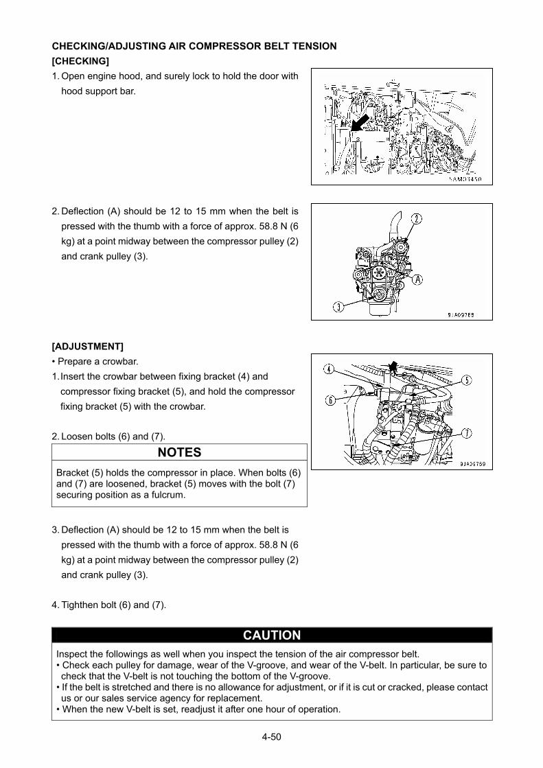
CHECKING/ADJUSTING AIR COMPRESSOR BELT TENSION
[CHECKING]
1. Open engine hood, and surely lock to hold the door with
hood support bar.
2. Deflection (A) should be 12 to 15 mm when the belt is
pressed with the thumb with a force of approx. 58.8 N (6
kg) at a point midway between the compressor pulley (2)
and crank pulley (3).
[ADJUSTMENT]
• Prepare a crowbar.
1. Insert the crowbar between fixing bracket (4) and
compressor fixing bracket (5), and hold the compressor
fixing bracket (5) with the crowbar.
2. Loosen bolts (6) and (7).
NOTES
Bracket (5) holds the compressor in place. When bolts (6) and (7) are loosened, bracket (5) moves with the bolt (7) securing position as a fulcrum.
3. Deflection (A) should be 12 to 15 mm when the belt is
pressed with the thumb with a force of approx. 58.8 N (6
kg) at a point midway between the compressor pulley (2)
and crank pulley (3).
4. Tighthen bolt (6) and (7).
CAUTION Inspect the followings as well when you inspect the tension of the air compressor belt. • Check each pulley for damage, wear of the V-groove, and wear of the V-belt. In particular, be sure to check that the V-belt is not touching the bottom of the V-groove.
• If the belt is stretched and there is no allowance for adjustment, or if it is cut or cracked, please contact us or our sales service agency for replacement.
• When the new V-belt is set, readjust it after one hour of operation.
4-50
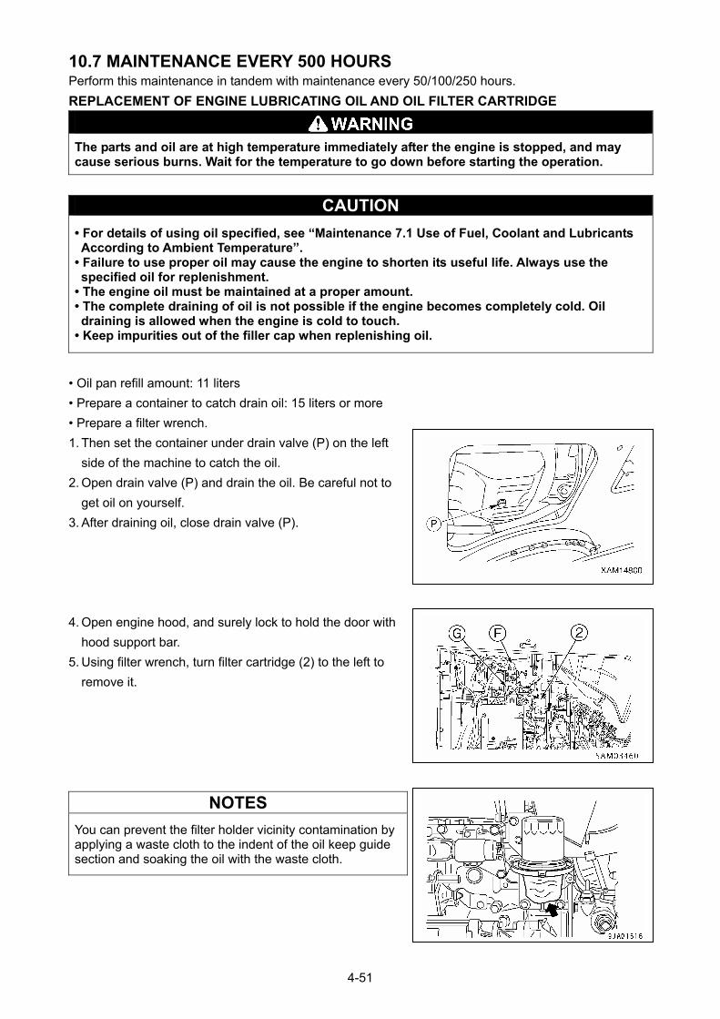
10.7 MAINTENANCE EVERY 500 HOURS Perform this maintenance in tandem with maintenance every 50/100/250 hours.
REPLACEMENT OF ENGINE LUBRICATING OIL AND OIL FILTER CARTRIDGE
The parts and oil are at high temperature immediately after the engine is stopped, and may cause serious burns. Wait for the temperature to go down before starting the operation.
CAUTION
• For details of using oil specified, see “Maintenance 7.1 Use of Fuel, Coolant and Lubricants According to Ambient Temperature”.
• Failure to use proper oil may cause the engine to shorten its useful life. Always use the specified oil for replenishment.
• The engine oil must be maintained at a proper amount. • The complete draining of oil is not possible if the engine becomes completely cold. Oil draining is allowed when the engine is cold to touch.
• Keep impurities out of the filler cap when replenishing oil.
• Oil pan refill amount: 11 liters
• Prepare a container to catch drain oil: 15 liters or more
• Prepare a filter wrench.
1. Then set the container under drain valve (P) on the left
side of the machine to catch the oil.
2. Open drain valve (P) and drain the oil. Be careful not to
get oil on yourself.
3. After draining oil, close drain valve (P).
4. Open engine hood, and surely lock to hold the door with
hood support bar.
5. Using filter wrench, turn filter cartridge (2) to the left to
remove it.
NOTES
You can prevent the filter holder vicinity contamination by applying a waste cloth to the indent of the oil keep guide section and soaking the oil with the waste cloth.
4-51

6. Clean the filter holder, fill the new filter cartridge with clean oil, coating the thread and packing portion of
the new filter cartridge with oil (or coat thinly with grease), then install.
NOTES
• Check that there is no old packing stuck to the holder. If there is any old packing stuck to the filter, it will cause leakage of oil.
7. When installing, tighten until the packing surface contacts the filter holder, then tighten a further 1/2
turn.
8. After replacing the filter cartridge, add oil through oil filler (F) until the oil level is between H and L marks
on the dipstick (G).
9. Run the engine at idle for a short time, then stop the engine, and check that the oil level is between the
H and L marks on the dipstick. For details, see “Operation 3.1.2 Checking Oil Level In Engine Oil Pan
Add Oil”.
4-52
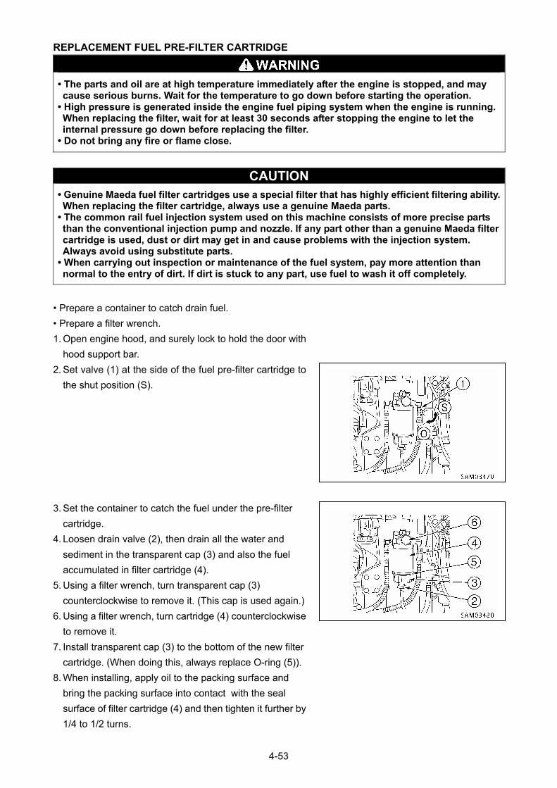
REPLACEMENT FUEL PRE-FILTER CARTRIDGE
• The parts and oil are at high temperature immediately after the engine is stopped, and may cause serious burns. Wait for the temperature to go down before starting the operation.
• High pressure is generated inside the engine fuel piping system when the engine is running. When replacing the filter, wait for at least 30 seconds after stopping the engine to let the internal pressure go down before replacing the filter.
• Do not bring any fire or flame close.
CAUTION • Genuine Maeda fuel filter cartridges use a special filter that has highly efficient filtering ability. When replacing the filter cartridge, always use a genuine Maeda parts.
• The common rail fuel injection system used on this machine consists of more precise parts than the conventional injection pump and nozzle. If any part other than a genuine Maeda filter cartridge is used, dust or dirt may get in and cause problems with the injection system. Always avoid using substitute parts.
• When carrying out inspection or maintenance of the fuel system, pay more attention than normal to the entry of dirt. If dirt is stuck to any part, use fuel to wash it off completely.
• Prepare a container to catch drain fuel.
• Prepare a filter wrench.
1. Open engine hood, and surely lock to hold the door with
hood support bar.
2. Set valve (1) at the side of the fuel pre-filter cartridge to
the shut position (S).
3. Set the container to catch the fuel under the pre-filter
cartridge.
4. Loosen drain valve (2), then drain all the water and
sediment in the transparent cap (3) and also the fuel
accumulated in filter cartridge (4).
5. Using a filter wrench, turn transparent cap (3)
counterclockwise to remove it. (This cap is used again.)
6. Using a filter wrench, turn cartridge (4) counterclockwise
to remove it.
7. Install transparent cap (3) to the bottom of the new filter
cartridge. (When doing this, always replace O-ring (5)).
8. When installing, apply oil to the packing surface and
bring the packing surface into contact with the seal
surface of filter cartridge (4) and then tighten it further by
1/4 to 1/2 turns.
4-53
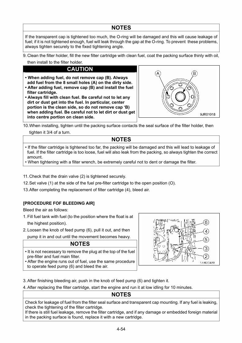
NOTES
If the transparent cap is tightened too much, the O-ring will be damaged and this will cause leakage of fuel; if it is not tightened enough, fuel will leak through the gap at the O-ring. To prevent these problems, always tighten securely to the fixed tightening angle.
9. Clean the filter holder, fill the new filter cartridge with clean fuel, coat the packing surface thinly with oil,
then install to the filter holder.
CAUTION
• When adding fuel, do not remove cap (B). Always add fuel from the 8 small holes (A) on the dirty side.
• After adding fuel, remove cap (B) and install the fuel filter cartridge.
• Always fill with clean fuel. Be careful not to let any dirt or dust get into the fuel. In particular, center portion is the clean side, so do not remove cap ‘B) when adding fuel. Be careful not to let dirt or dust get into centre portion on clean side.
10. When installing, tighten until the packing surface contacts the seal surface of the filter holder, then
tighten it 3/4 of a turn.
NOTES
• If the filter cartridge is tightened too far, the packing will be damaged and this will lead to leakage of fuel. If the filter cartridge is too loose, fuel will also leak from the packing, so always tighten the correct amount.
• When tightening with a filter wrench, be extremely careful not to dent or damage the filter.
11. Check that the drain valve (2) is tightened securely.
12. Set valve (1) at the side of the fuel pre-filter cartridge to the open position (O).
13. After completing the replacement of filter cartridge (4), bleed air.
[PROCEDURE FOF BLEEDING AIR]
Bleed the air as follows:
1. Fill fuel tank with fuel (to the position where the float is at
the highest position).
2. Loosen the knob of feed pump (6), pull it out, and then
pump it in and out until the movement becomes heavy.
NOTES
• It is not necessary to remove the plug at the top of the fuel pre-filter and fuel main filter.
• After the engine runs out of fuel, use the same procedure to operate feed pump (6) and bleed the air.
3. After finishing bleeding air, push in the knob of feed pump (6) and tighten it.
4. After replacing the filter cartridge, start the engine and run it at low idling for 10 minutes.
NOTES
Check for leakage of fuel from the filter seal surface and transparent cap mounting. If any fuel is leaking, check the tightening of the filter cartridge. If there is still fuel leakage, remove the filter cartridge, and if any damage or embedded foreign material in the packing surface is found, replace it with a new cartridge.
4-54
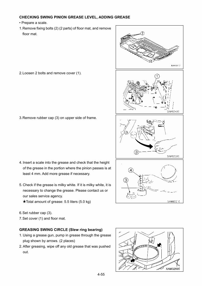
CHECKING SWING PINION GREASE LEVEL, ADDING GREASE
• Prepare a scale.
1. Remove fixing bolts (2) (2 parts) of floor mat, and remove
floor mat.
2. Loosen 2 bolts and remove cover (1).
3. Remove rubber cap (3) on upper side of frame.
4. Insert a scale into the grease and check that the height
of the grease in the portion where the pinion passes is at
least 4 mm. Add more grease if necessary.
5. Check if the grease is milky white. If it is milky white, it is
necessary to change the grease. Please contact us or
our sales service agency.
Total amount of grease: 5.5 liters (5.0 kg)
6. Set rubber cap (3).
7. Set cover (1) and floor mat.
GREASING SWING CIRCLE (Slew ring bearing)
1. Using a grease gun, pump in grease through the grease
plug shown by arrows. (2 places)
2. After greasing, wipe off any old grease that was pushed
out.
4-55
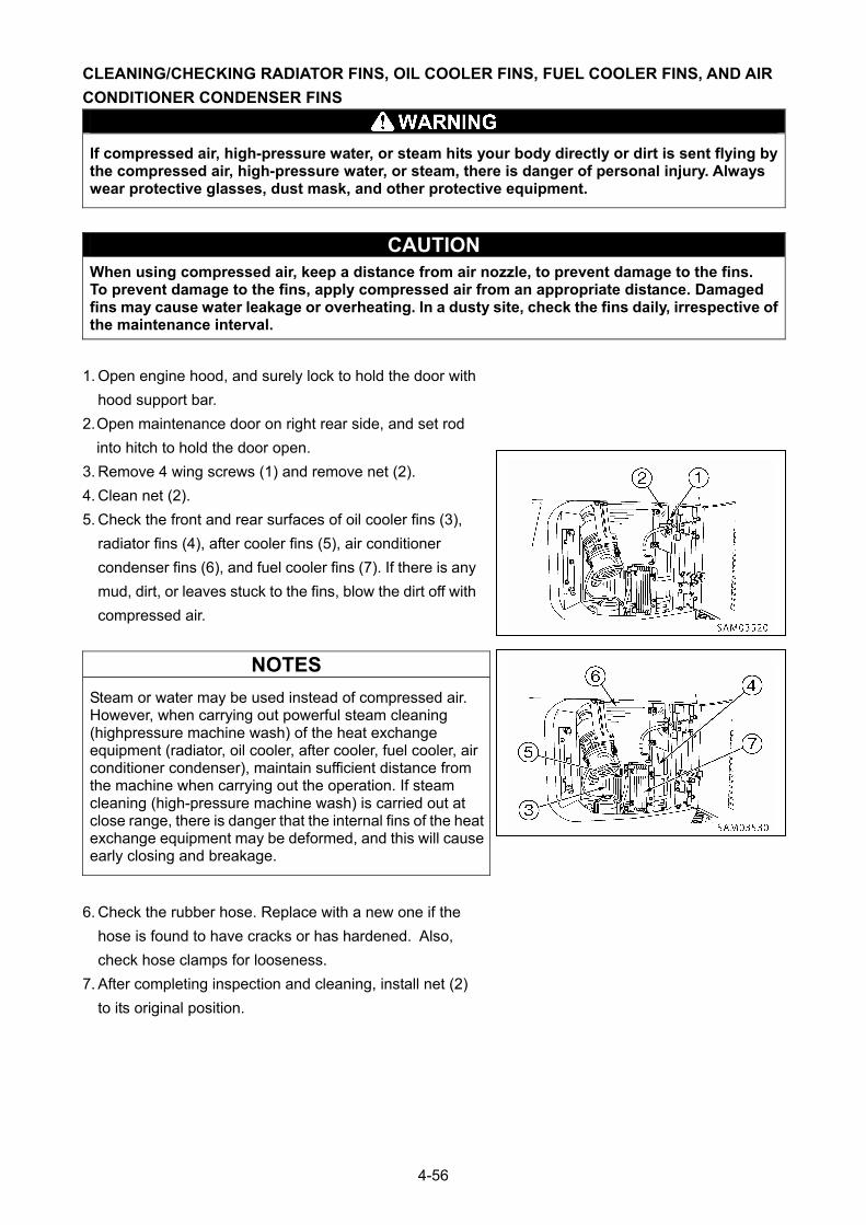
CLEANING/CHECKING RADIATOR FINS, OIL COOLER FINS, FUEL COOLER FINS, AND AIR
CONDITIONER CONDENSER FINS
If compressed air, high-pressure water, or steam hits your body directly or dirt is sent flying by the compressed air, high-pressure water, or steam, there is danger of personal injury. Always wear protective glasses, dust mask, and other protective equipment.
CAUTION When using compressed air, keep a distance from air nozzle, to prevent damage to the fins. To prevent damage to the fins, apply compressed air from an appropriate distance. Damaged fins may cause water leakage or overheating. In a dusty site, check the fins daily, irrespective of the maintenance interval.
1. Open engine hood, and surely lock to hold the door with
hood support bar.
2. Open maintenance door on right rear side, and set rod
into hitch to hold the door open.
3. Remove 4 wing screws (1) and remove net (2).
4. Clean net (2).
5. Check the front and rear surfaces of oil cooler fins (3),
radiator fins (4), after cooler fins (5), air conditioner
condenser fins (6), and fuel cooler fins (7). If there is any
mud, dirt, or leaves stuck to the fins, blow the dirt off with
compressed air.
NOTES
Steam or water may be used instead of compressed air. However, when carrying out powerful steam cleaning (highpressure machine wash) of the heat exchange equipment (radiator, oil cooler, after cooler, fuel cooler, air conditioner condenser), maintain sufficient distance from the machine when carrying out the operation. If steam cleaning (high-pressure machine wash) is carried out at close range, there is danger that the internal fins of the heat exchange equipment may be deformed, and this will cause early closing and breakage.
6. Check the rubber hose. Replace with a new one if the
hose is found to have cracks or has hardened. Also,
check hose clamps for looseness.
7. After completing inspection and cleaning, install net (2)
to its original position.
4-56
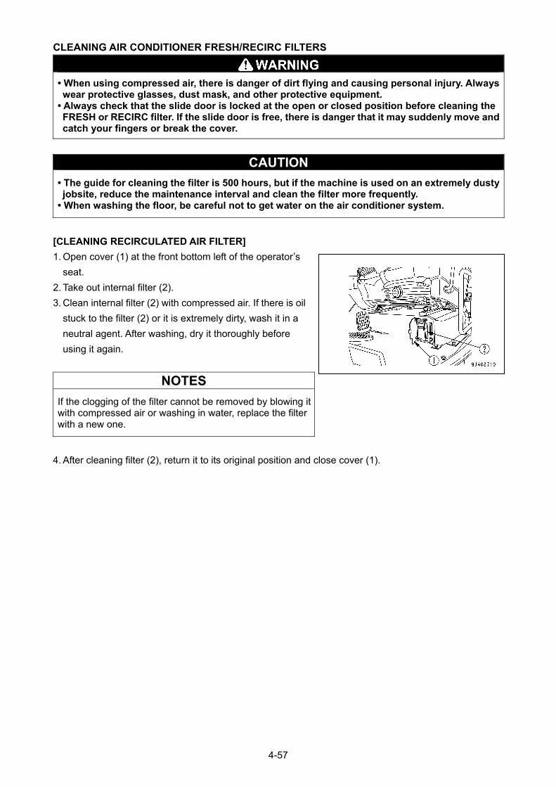
CLEANING AIR CONDITIONER FRESH/RECIRC FILTERS
• When using compressed air, there is danger of dirt flying and causing personal injury. Always wear protective glasses, dust mask, and other protective equipment.
• Always check that the slide door is locked at the open or closed position before cleaning the FRESH or RECIRC filter. If the slide door is free, there is danger that it may suddenly move and catch your fingers or break the cover.
CAUTION
• The guide for cleaning the filter is 500 hours, but if the machine is used on an extremely dusty jobsite, reduce the maintenance interval and clean the filter more frequently.
• When washing the floor, be careful not to get water on the air conditioner system.
[CLEANING RECIRCULATED AIR FILTER]
1. Open cover (1) at the front bottom left of the operator’s
seat. 2. Take out internal filter (2).
3. Clean internal filter (2) with compressed air. If there is oil
stuck to the filter (2) or it is extremely dirty, wash it in a
neutral agent. After washing, dry it thoroughly before
using it again.
NOTES
If the clogging of the filter cannot be removed by blowing it with compressed air or washing in water, replace the filter with a new one.
4. After cleaning filter (2), return it to its original position and close cover (1).
4-57
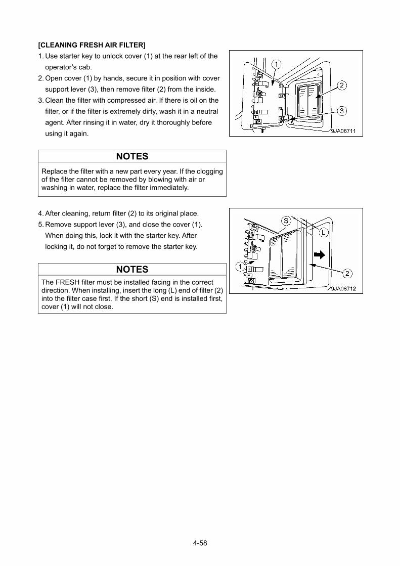
[CLEANING FRESH AIR FILTER]
1. Use starter key to unlock cover (1) at the rear left of the
operator’s cab.
2. Open cover (1) by hands, secure it in position with cover
support lever (3), then remove filter (2) from the inside.
3. Clean the filter with compressed air. If there is oil on the
filter, or if the filter is extremely dirty, wash it in a neutral
agent. After rinsing it in water, dry it thoroughly before
using it again.
NOTES
Replace the filter with a new part every year. If the clogging of the filter cannot be removed by blowing with air or washing in water, replace the filter immediately.
4. After cleaning, return filter (2) to its original place.
5. Remove support lever (3), and close the cover (1).
When doing this, lock it with the starter key. After
locking it, do not forget to remove the starter key.
NOTES
The FRESH filter must be installed facing in the correct direction. When installing, insert the long (L) end of filter (2) into the filter case first. If the short (S) end is installed first, cover (1) will not close.
4-58
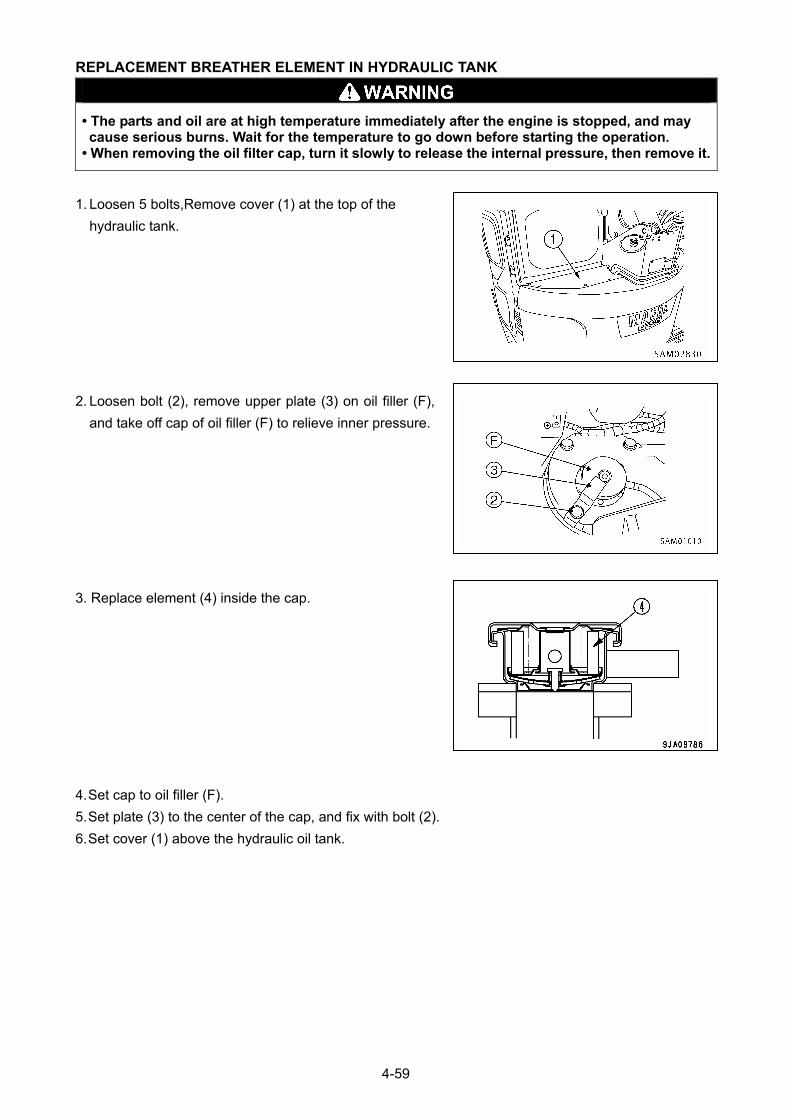
REPLACEMENT BREATHER ELEMENT IN HYDRAULIC TANK
• The parts and oil are at high temperature immediately after the engine is stopped, and may cause serious burns. Wait for the temperature to go down before starting the operation.
• When removing the oil filter cap, turn it slowly to release the internal pressure, then remove it.
1. Loosen 5 bolts,Remove cover (1) at the top of the
hydraulic tank.
2. Loosen bolt (2), remove upper plate (3) on oil filler (F),
and take off cap of oil filler (F) to relieve inner pressure.
3. Replace element (4) inside the cap.
4. Set cap to oil filler (F).
5. Set plate (3) to the center of the cap, and fix with bolt (2).
6. Set cover (1) above the hydraulic oil tank.
4-59
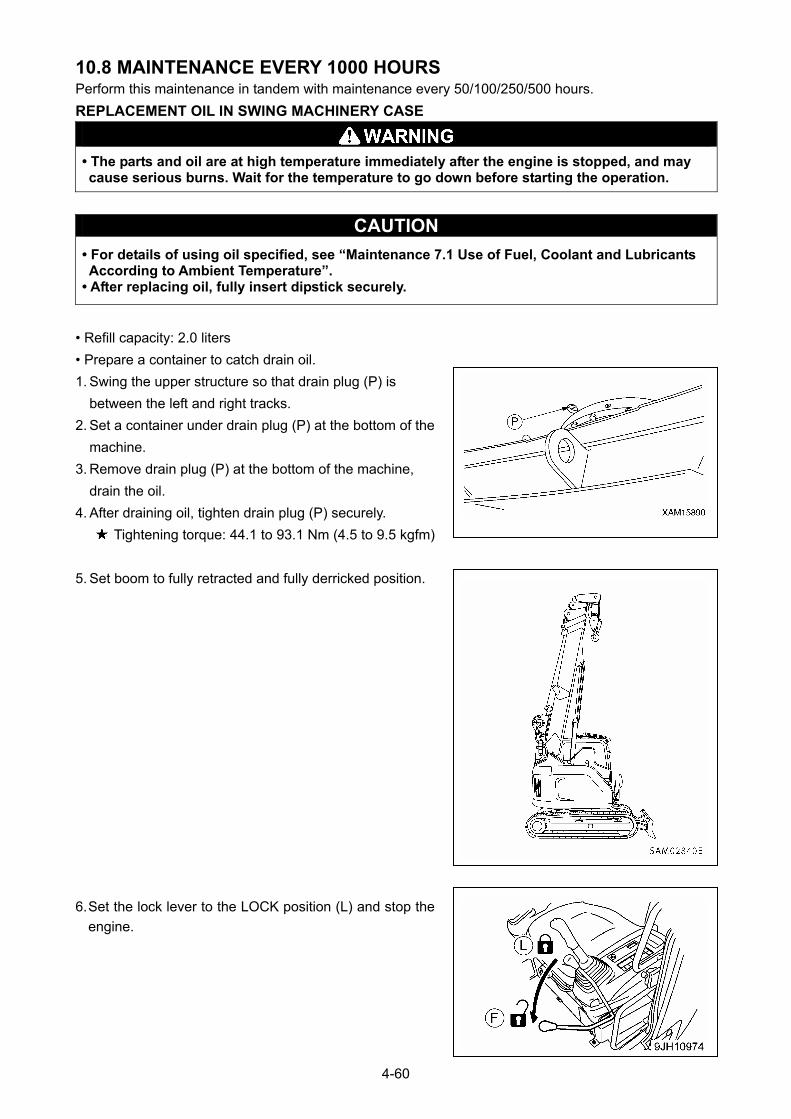
10.8 MAINTENANCE EVERY 1000 HOURS Perform this maintenance in tandem with maintenance every 50/100/250/500 hours.
REPLACEMENT OIL IN SWING MACHINERY CASE
• The parts and oil are at high temperature immediately after the engine is stopped, and may cause serious burns. Wait for the temperature to go down before starting the operation.
CAUTION
• For details of using oil specified, see “Maintenance 7.1 Use of Fuel, Coolant and Lubricants According to Ambient Temperature”.
• After replacing oil, fully insert dipstick securely.
• Refill capacity: 2.0 liters
• Prepare a container to catch drain oil.
1. Swing the upper structure so that drain plug (P) is
between the left and right tracks.
2. Set a container under drain plug (P) at the bottom of the
machine.
3. Remove drain plug (P) at the bottom of the machine,
drain the oil.
4. After draining oil, tighten drain plug (P) securely.
Tightening torque: 44.1 to 93.1 Nm (4.5 to 9.5 kgfm)
5. Set boom to fully retracted and fully derricked position.
6. Set the lock lever to the LOCK position (L) and stop the
engine.
4-60
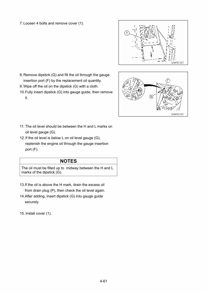
7. Loosen 4 bolts and remove cover (1).
8. Remove dipstick (G) and fill the oil through the gauge
insertion port (F) by the replacement oil quantity.
9. Wipe off the oil on the dipstick (G) with a cloth.
10. Fully insert dipstick (G) into gauge guide, then remove
it.
11. The oil level should be between the H and L marks on
oil level gauge (G).
12. If the oil level is below L on oil level gauge (G),
replenish the engine oil through the gauge insertion
port (F).
NOTES
The oil must be filled up to midway between the H and L marks of the dipstick (G).
13. If the oil is above the H mark, drain the excess oil
from drain plug (P), then check the oil level again.
14. After adding, insert dipstick (G) into gauge guide
securely.
15. Install cover (1).
4-61
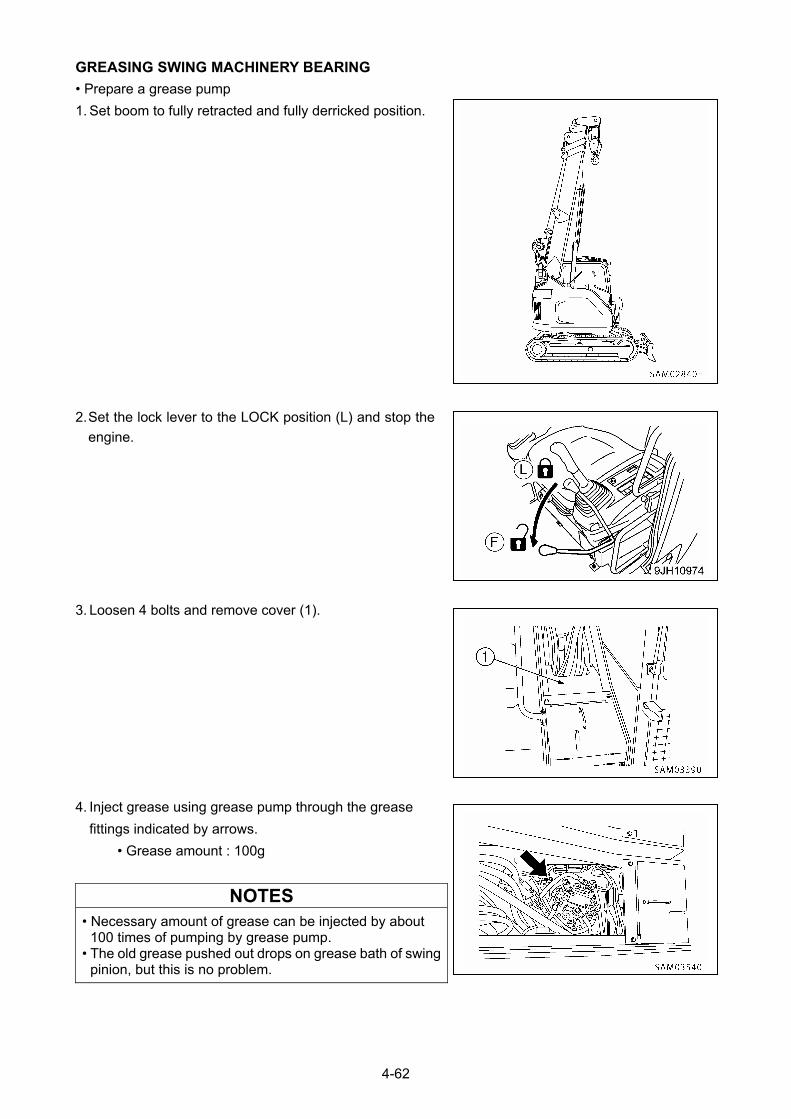
GREASING SWING MACHINERY BEARING
• Prepare a grease pump
1. Set boom to fully retracted and fully derricked position.
2. Set the lock lever to the LOCK position (L) and stop the
engine.
3. Loosen 4 bolts and remove cover (1).
4. Inject grease using grease pump through the grease
fittings indicated by arrows.
• Grease amount : 100g
NOTES
• Necessary amount of grease can be injected by about 100 times of pumping by grease pump.
• The old grease pushed out drops on grease bath of swing pinion, but this is no problem.
4-62
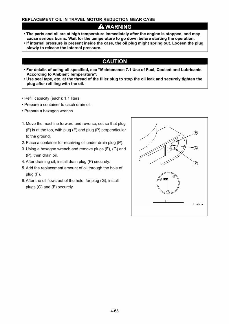
REPLACEMENT OIL IN TRAVEL MOTOR REDUCTION GEAR CASE
• The parts and oil are at high temperature immediately after the engine is stopped, and may
cause serious burns. Wait for the temperature to go down before starting the operation. • If internal pressure is present inside the case, the oil plug might spring out. Loosen the plug
slowly to release the internal pressure.
CAUTION
• For details of using oil specified, see “Maintenance 7.1 Use of Fuel, Coolant and Lubricants According to Ambient Temperature”.
• Use seal tape, etc. at the thread of the filler plug to stop the oil leak and securely tighten the plug after refilling with the oil.
• Refill capacity (each): 1.1 liters
• Prepare a container to catch drain oil.
• Prepare a hexagon wrench.
1. Move the machine forward and reverse, set so that plug
(F) is at the top, with plug (F) and plug (P) perpendicular
to the ground.
2. Place a container for receiving oil under drain plug (P).
3. Using a hexagon wrench and remove plugs (F), (G) and
(P), then drain oil.
4. After draining oil, install drain plug (P) securely.
5. Add the replacement amount of oil through the hole of
plug (F).
6. After the oil flows out of the hole, for plug (G), install
plugs (G) and (F) securely.
4-63
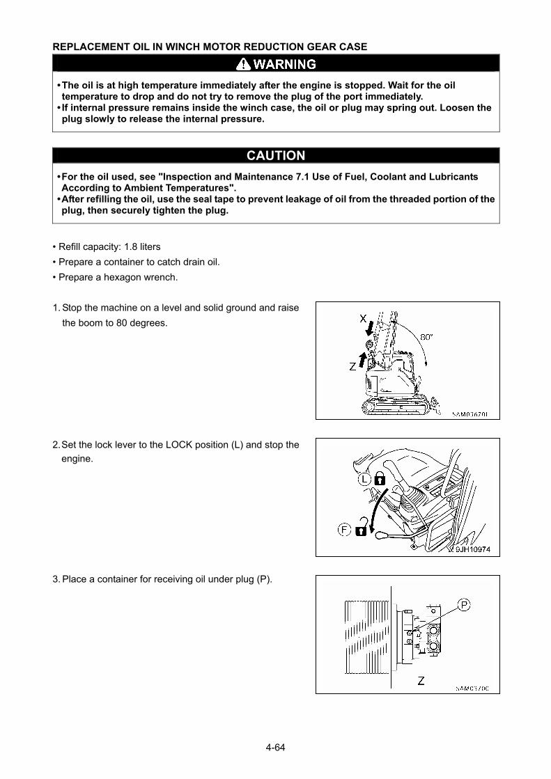
REPLACEMENT OIL IN WINCH MOTOR REDUCTION GEAR CASE
• The oil is at high temperature immediately after the engine is stopped. Wait for the oil temperature to drop and do not try to remove the plug of the port immediately.
• If internal pressure remains inside the winch case, the oil or plug may spring out. Loosen the plug slowly to release the internal pressure.
CAUTION
• For the oil used, see "Inspection and Maintenance 7.1 Use of Fuel, Coolant and Lubricants According to Ambient Temperatures".
• After refilling the oil, use the seal tape to prevent leakage of oil from the threaded portion of the plug, then securely tighten the plug.
• Refill capacity: 1.8 liters
• Prepare a container to catch drain oil.
• Prepare a hexagon wrench.
1. Stop the machine on a level and solid ground and raise
the boom to 80 degrees.
2. Set the lock lever to the LOCK position (L) and stop the
engine.
3. Place a container for receiving oil under plug (P).
4-64
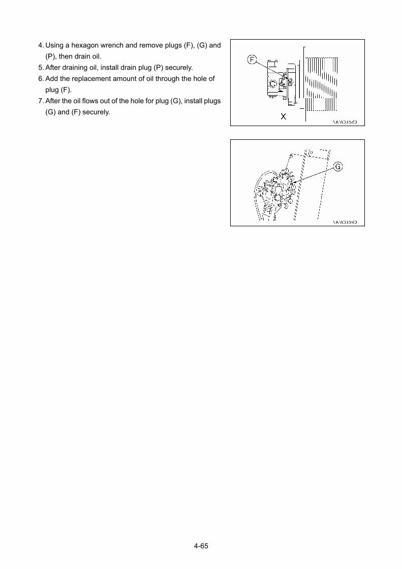
4. Using a hexagon wrench and remove plugs (F), (G) and
(P), then drain oil.
5. After draining oil, install drain plug (P) securely.
6. Add the replacement amount of oil through the hole of
plug (F).
7. After the oil flows out of the hole for plug (G), install plugs
(G) and (F) securely.
4-65
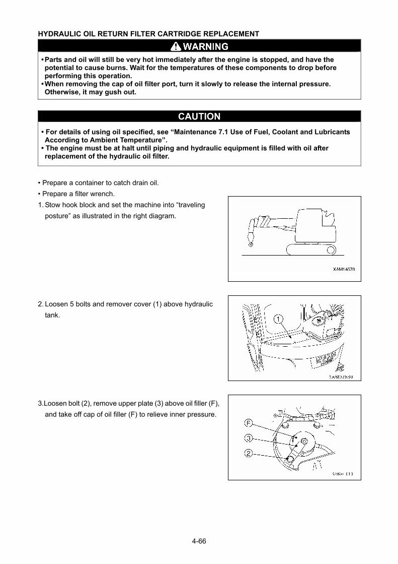
HYDRAULIC OIL RETURN FILTER CARTRIDGE REPLACEMENT
• Parts and oil will still be very hot immediately after the engine is stopped, and have the potential to cause burns. Wait for the temperatures of these components to drop before performing this operation.
• When removing the cap of oil filter port, turn it slowly to release the internal pressure. Otherwise, it may gush out.
CAUTION
• For details of using oil specified, see “Maintenance 7.1 Use of Fuel, Coolant and Lubricants According to Ambient Temperature”.
• The engine must be at halt until piping and hydraulic equipment is filled with oil after replacement of the hydraulic oil filter.
• Prepare a container to catch drain oil.
• Prepare a filter wrench.
1. Stow hook block and set the machine into “traveling
posture” as illustrated in the right diagram.
2. Loosen 5 bolts and remover cover (1) above hydraulic
tank.
3.Loosen bolt (2), remove upper plate (3) above oil filler (F),
and take off cap of oil filler (F) to relieve inner pressure.
4-66
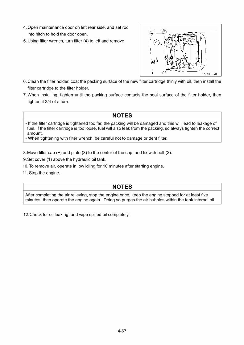
4. Open maintenance door on left rear side, and set rod
into hitch to hold the door open.
5. Using filter wrench, turn filter (4) to left and remove.
6. Clean the filter holder. coat the packing surface of the new filter cartridge thinly with oil, then install the
filter cartridge to the filter holder.
7. When installing, tighten until the packing surface contacts the seal surface of the filter holder, then
tighten it 3/4 of a turn.
NOTES
• If the filter cartridge is tightened too far, the packing will be damaged and this will lead to leakage of fuel. If the filter cartridge is too loose, fuel will also leak from the packing, so always tighten the correct amount.
• When tightening with filter wrench, be careful not to damage or dent filter.
8. Move filler cap (F) and plate (3) to the center of the cap, and fix with bolt (2).
9. Set cover (1) above the hydraulic oil tank.
10. To remove air, operate in low idling for 10 minutes after starting engine.
11. Stop the engine.
NOTES
After completing the air relieving, stop the engine once, keep the engine stopped for at least five minutes, then operate the engine again. Doing so purges the air bubbles within the tank internal oil.
12. Check for oil leaking, and wipe spilled oil completely.
4-67
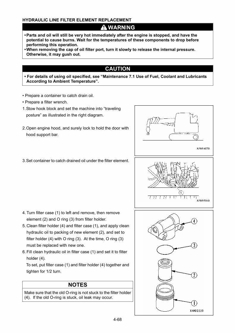
HYDRAULIC LINE FILTER ELEMENT REPLACEMENT
• Parts and oil will still be very hot immediately after the engine is stopped, and have the potential to cause burns. Wait for the temperatures of these components to drop before performing this operation.
• When removing the cap of oil filter port, turn it slowly to release the internal pressure. Otherwise, it may gush out.
CAUTION • For details of using oil specified, see “Maintenance 7.1 Use of Fuel, Coolant and Lubricants According to Ambient Temperature”.
• Prepare a container to catch drain oil.
• Prepare a filter wrench.
1. Stow hook block and set the machine into “traveling
posture” as illustrated in the right diagram.
2. Open engine hood, and surely lock to hold the door with
hood support bar.
3. Set container to catch drained oil under the filter element.
4. Turn filter case (1) to left and remove, then remove
element (2) and O ring (3) from filter holder.
5. Clean filter holder (4) and filter case (1), and apply clean
hydraulic oil to packing of new element (2), and set to
filter holder (4) with O ring (3). At the time, O ring (3)
must be replaced with new one.
6. Fill clean hydraulic oil in filter case (1) and set it to filter
holder (4).
To set, put filter case (1) and filter holder (4) together and
tighten for 1/2 turn.
NOTES
Make sure that the old O-ring is not stuck to the filter holder (4). If the old O-ring is stuck, oil leak may occur.
4-68
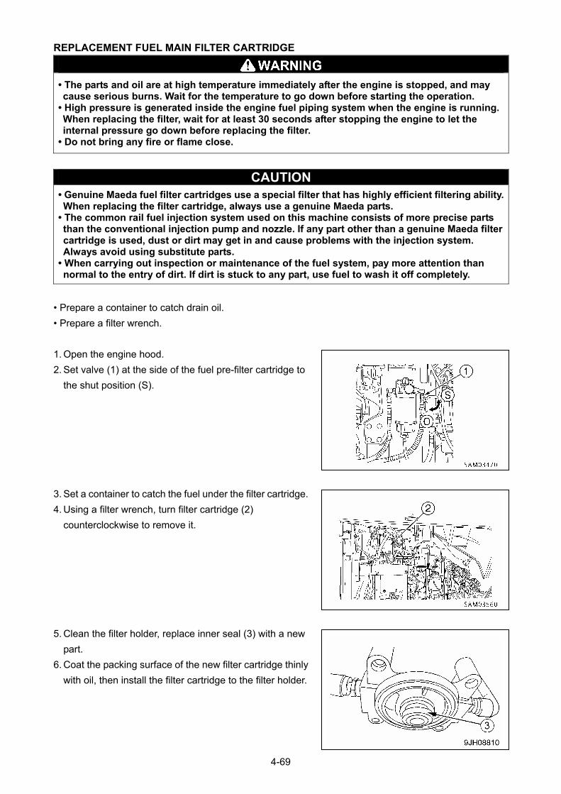
REPLACEMENT FUEL MAIN FILTER CARTRIDGE
• The parts and oil are at high temperature immediately after the engine is stopped, and may cause serious burns. Wait for the temperature to go down before starting the operation.
• High pressure is generated inside the engine fuel piping system when the engine is running. When replacing the filter, wait for at least 30 seconds after stopping the engine to let the internal pressure go down before replacing the filter.
• Do not bring any fire or flame close.
CAUTION • Genuine Maeda fuel filter cartridges use a special filter that has highly efficient filtering ability. When replacing the filter cartridge, always use a genuine Maeda parts.
• The common rail fuel injection system used on this machine consists of more precise parts than the conventional injection pump and nozzle. If any part other than a genuine Maeda filter cartridge is used, dust or dirt may get in and cause problems with the injection system. Always avoid using substitute parts.
• When carrying out inspection or maintenance of the fuel system, pay more attention than normal to the entry of dirt. If dirt is stuck to any part, use fuel to wash it off completely.
• Prepare a container to catch drain oil.
• Prepare a filter wrench.
1. Open the engine hood.
2. Set valve (1) at the side of the fuel pre-filter cartridge to
the shut position (S).
3. Set a container to catch the fuel under the filter cartridge.
4. Using a filter wrench, turn filter cartridge (2)
counterclockwise to remove it.
5. Clean the filter holder, replace inner seal (3) with a new
part.
6. Coat the packing surface of the new filter cartridge thinly
with oil, then install the filter cartridge to the filter holder.
4-69
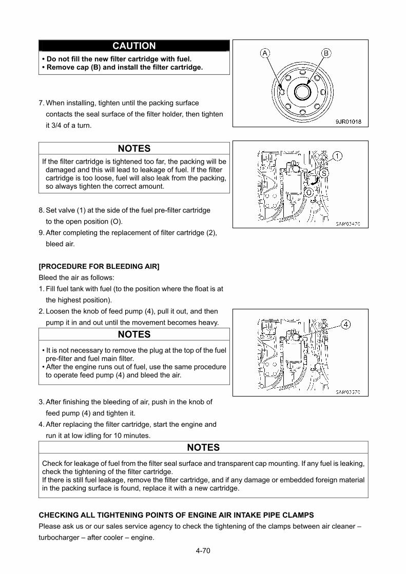
CAUTION • Do not fill the new filter cartridge with fuel. • Remove cap (B) and install the filter cartridge.
7. When installing, tighten until the packing surface
contacts the seal surface of the filter holder, then tighten
it 3/4 of a turn.
NOTES
If the filter cartridge is tightened too far, the packing will be damaged and this will lead to leakage of fuel. If the filter cartridge is too loose, fuel will also leak from the packing, so always tighten the correct amount.
8. Set valve (1) at the side of the fuel pre-filter cartridge
to the open position (O).
9. After completing the replacement of filter cartridge (2),
bleed air.
[PROCEDURE FOR BLEEDING AIR]
Bleed the air as follows:
1. Fill fuel tank with fuel (to the position where the float is at
the highest position).
2. Loosen the knob of feed pump (4), pull it out, and then
pump it in and out until the movement becomes heavy.
NOTES
• It is not necessary to remove the plug at the top of the fuel pre-filter and fuel main filter.
• After the engine runs out of fuel, use the same procedure to operate feed pump (4) and bleed the air.
3. After finishing the bleeding of air, push in the knob of
feed pump (4) and tighten it.
4. After replacing the filter cartridge, start the engine and
run it at low idling for 10 minutes.
NOTES
Check for leakage of fuel from the filter seal surface and transparent cap mounting. If any fuel is leaking, check the tightening of the filter cartridge. If there is still fuel leakage, remove the filter cartridge, and if any damage or embedded foreign material in the packing surface is found, replace it with a new cartridge.
CHECKING ALL TIGHTENING POINTS OF ENGINE AIR INTAKE PIPE CLAMPS
Please ask us or our sales service agency to check the tightening of the clamps between air cleaner –
turbocharger – after cooler – engine.
4-70

10.9 MAINTENANCE EVERY 2000 HOURS Perform this maintenance in tandem with maintenance every 50/100/250/500/1000 hours.
CHECKING ALTERNATOR AND STARTER MOTOR
The brushes may be worn or the bearing may have run out of grease, contact us or our sales service
agency for inspection and repairs.
If the engine is started frequently, have this inspection carried out every 1000 hours.
CHECKING/ADJUSTING ENGINE VALVE CLEARANCE
Special tools are needed for inspection and maintenance, please contact us or our sales service agency.
4-71
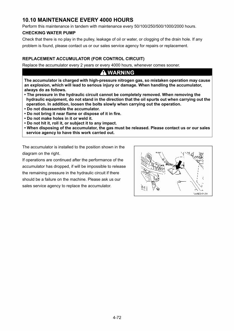
10.10 MAINTENANCE EVERY 4000 HOURS Perform this maintenance in tandem with maintenance every 50/100/250/500/1000/2000 hours.
CHECKING WATER PUMP
Check that there is no play in the pulley, leakage of oil or water, or clogging of the drain hole. If any
problem is found, please contact us or our sales service agency for repairs or replacement.
REPLACEMENT ACCUMULATOR (FOR CONTROL CIRCUIT)
Replace the accumulator every 2 years or every 4000 hours, whenever comes sooner.
The accumulator is charged with high-pressure nitrogen gas, so mistaken operation may cause an explosion, which will lead to serious injury or damage. When handling the accumulator, always do as follows. • The pressure in the hydraulic circuit cannot be completely removed. When removing the hydraulic equipment, do not stand in the direction that the oil spurts out when carrying out the operation. In addition, loosen the bolts slowly when carrying out the operation.
• Do not disassemble the accumulator. • Do not bring it near flame or dispose of it in fire. • Do not make holes in it or weld it. • Do not hit it, roll it, or subject it to any impact. • When disposing of the accumulator, the gas must be released. Please contact us or our sales service agency to have this work carried out.
The accumulator is installed to the position shown in the
diagram on the right.
If operations are continued after the performance of the
accumulator has dropped, if will be impossible to release
the remaining pressure in the hydraulic circuit if there
should be a failure on the machine. Please ask us our
sales service agency to replace the accumulator.
4-72

10.11 MAINTENANCE EVERY 5000 HOURS Perform this maintenance in tandem with maintenance every 50/100/250/500/1000 hours.
REPLACING HYDRAULIC TANK OIL AND CLEANING STRAINER
• Parts and oil are at high temperature immediately after the engine is stopped, and may cause serious burns. Wait for the oil temperature to go down before performing this operation.
• When removing the oil filler cap, turn it slowly to release the internal pressure, then remove it.• Securely close the tank cap after refilling with the oil.
CAUTION
• For details of using oil specified, see “Maintenance 7.1 Use of Fuel, Coolant and Lubricants According to Ambient Temperature”.
• Be sure to put the machine in the Travelling posture when checking the oil level. Checking the oil level in the working posture will cause overfilling since the oil in the cylinders has not returned to the tank.
For details of Travelling posture, see “Operation 3.7 Machine Travelling Posture”. • The engine must be at halt until piping and hydraulic equipment is filled with oil after replacement of the hydraulic oil filter.
• Refill capacity: 81 liters
• Prepare a container to catch drain oil.
• Prepare a filter wrench.
1. Stow hook block and set the machine into “traveling
posture” as illustrated in the right diagram.
2. Swing so that the drain plug at the bottom of the
hydraulic tank is in the middle between the left and right
tracks.
3. Set the lock lever to the LOCK position and stop the
engine.
4. Remove cover (1) at the top of the hydraulic tank.
4-73
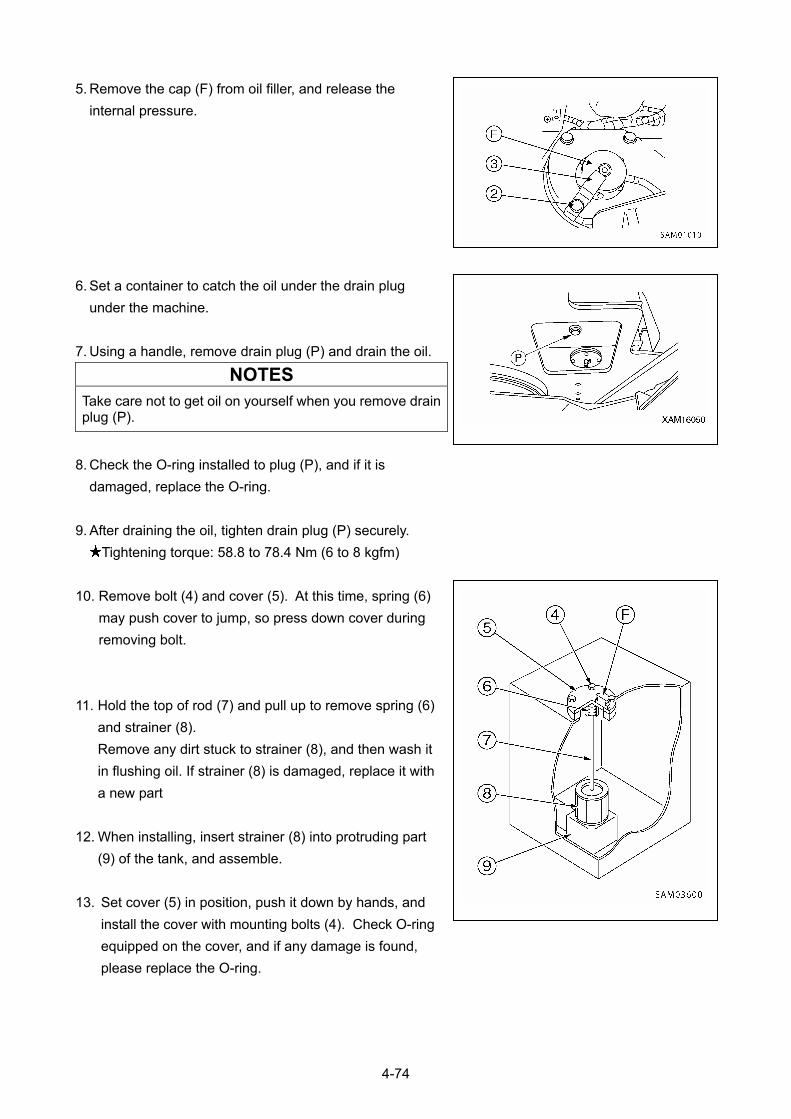
5. Remove the cap (F) from oil filler, and release the
internal pressure.
6. Set a container to catch the oil under the drain plug
under the machine.
7. Using a handle, remove drain plug (P) and drain the oil.
NOTES
Take care not to get oil on yourself when you remove drain plug (P).
8. Check the O-ring installed to plug (P), and if it is
damaged, replace the O-ring.
9. After draining the oil, tighten drain plug (P) securely.
Tightening torque: 58.8 to 78.4 Nm (6 to 8 kgfm)
10. Remove bolt (4) and cover (5). At this time, spring (6)
may push cover to jump, so press down cover during
removing bolt.
11. Hold the top of rod (7) and pull up to remove spring (6)
and strainer (8).
Remove any dirt stuck to strainer (8), and then wash it
in flushing oil. If strainer (8) is damaged, replace it with
a new part
12. When installing, insert strainer (8) into protruding part
(9) of the tank, and assemble.
13. Set cover (5) in position, push it down by hands, and
install the cover with mounting bolts (4). Check O-ring
equipped on the cover, and if any damage is found,
please replace the O-ring.
4-74
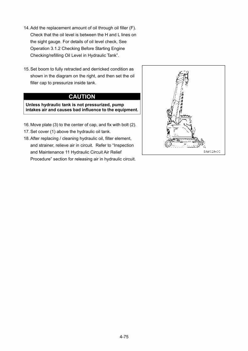
14. Add the replacement amount of oil through oil filler (F).
Check that the oil level is between the H and L lines on
the sight gauge. For details of oil level check, See
Operation 3.1.2 Checking Before Starting Engine
Checking/refilling Oil Level in Hydraulic Tank”.
15. Set boom to fully retracted and derricked condition as
shown in the diagram on the right, and then set the oil
filler cap to pressurize inside tank.
CAUTION Unless hydraulic tank is not pressurized, pump intakes air and causes bad influence to the equipment.
16. Move plate (3) to the center of cap, and fix with bolt (2).
17. Set cover (1) above the hydraulic oil tank.
18. After replacing / cleaning hydraulic oil, filter element,
and strainer, relieve air in circuit. Refer to “Inspection
and Maintenance 11 Hydraulic Circuit Air Relief
Procedure” section for releasing air in hydraulic circuit.
4-75
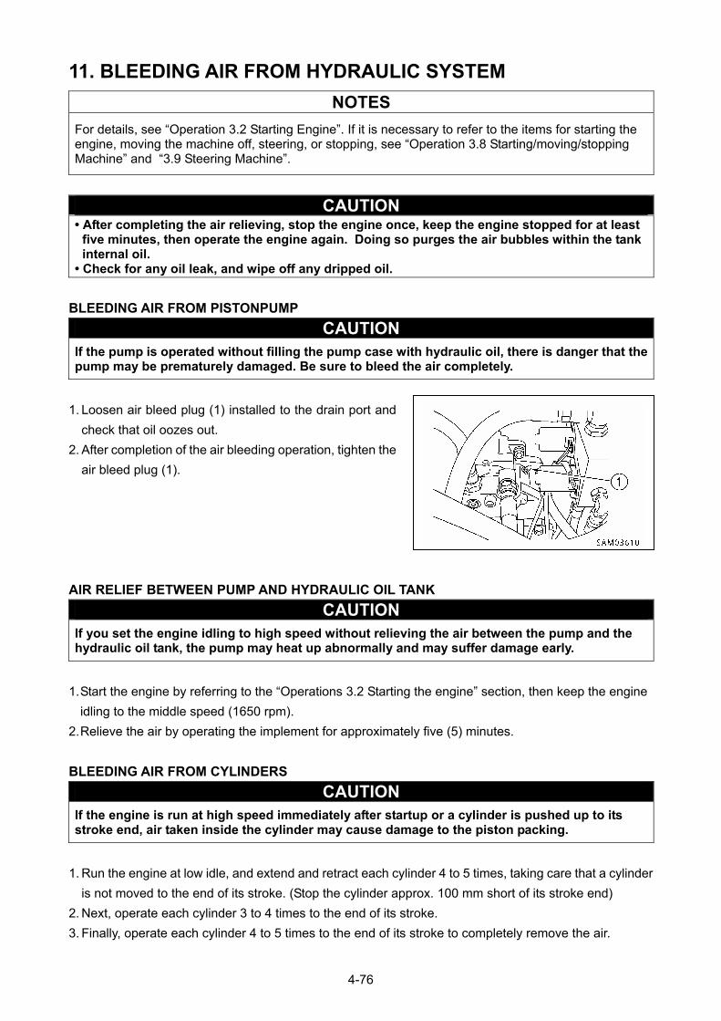
11. BLEEDING AIR FROM HYDRAULIC SYSTEM
NOTES
For details, see “Operation 3.2 Starting Engine”. If it is necessary to refer to the items for starting the engine, moving the machine off, steering, or stopping, see “Operation 3.8 Starting/moving/stopping Machine” and “3.9 Steering Machine”.
CAUTION • After completing the air relieving, stop the engine once, keep the engine stopped for at least
five minutes, then operate the engine again. Doing so purges the air bubbles within the tank internal oil.
• Check for any oil leak, and wipe off any dripped oil.
BLEEDING AIR FROM PISTONPUMP
CAUTION If the pump is operated without filling the pump case with hydraulic oil, there is danger that the pump may be prematurely damaged. Be sure to bleed the air completely.
1. Loosen air bleed plug (1) installed to the drain port and
check that oil oozes out.
2. After completion of the air bleeding operation, tighten the
air bleed plug (1).
AIR RELIEF BETWEEN PUMP AND HYDRAULIC OIL TANK
CAUTION If you set the engine idling to high speed without relieving the air between the pump and the hydraulic oil tank, the pump may heat up abnormally and may suffer damage early.
1. Start the engine by referring to the “Operations 3.2 Starting the engine” section, then keep the engine
idling to the middle speed (1650 rpm).
2. Relieve the air by operating the implement for approximately five (5) minutes.
BLEEDING AIR FROM CYLINDERS
CAUTION If the engine is run at high speed immediately after startup or a cylinder is pushed up to its stroke end, air taken inside the cylinder may cause damage to the piston packing.
1. Run the engine at low idle, and extend and retract each cylinder 4 to 5 times, taking care that a cylinder
is not moved to the end of its stroke. (Stop the cylinder approx. 100 mm short of its stroke end)
2. Next, operate each cylinder 3 to 4 times to the end of its stroke.
3. Finally, operate each cylinder 4 to 5 times to the end of its stroke to completely remove the air.
4-76
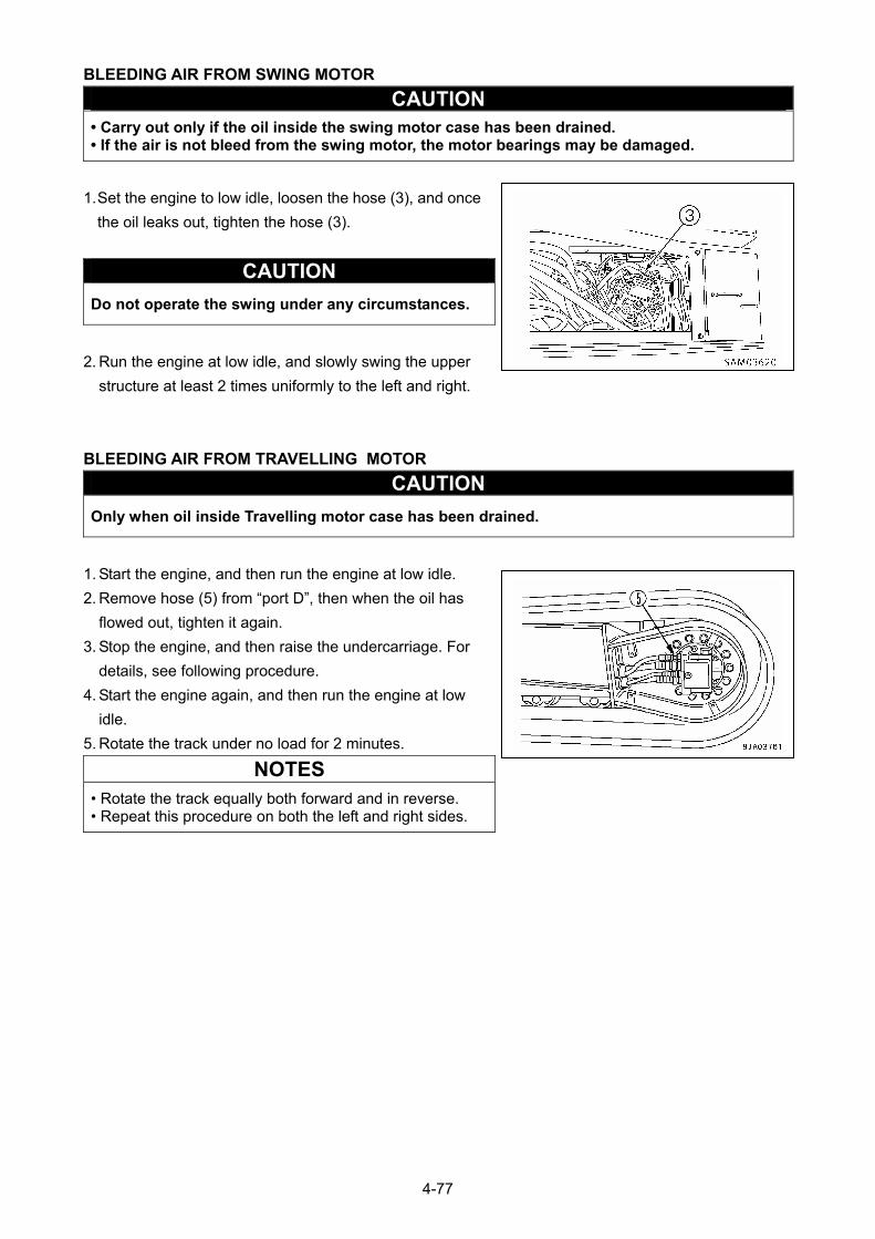
BLEEDING AIR FROM SWING MOTOR
CAUTION • Carry out only if the oil inside the swing motor case has been drained. • If the air is not bleed from the swing motor, the motor bearings may be damaged.
1. Set the engine to low idle, loosen the hose (3), and once
the oil leaks out, tighten the hose (3).
CAUTION
Do not operate the swing under any circumstances.
2. Run the engine at low idle, and slowly swing the upper
structure at least 2 times uniformly to the left and right.
BLEEDING AIR FROM TRAVELLING MOTOR
CAUTION
Only when oil inside Travelling motor case has been drained.
1. Start the engine, and then run the engine at low idle.
2. Remove hose (5) from “port D”, then when the oil has
flowed out, tighten it again.
3. Stop the engine, and then raise the undercarriage. For
details, see following procedure.
4. Start the engine again, and then run the engine at low
idle.
5. Rotate the track under no load for 2 minutes.
NOTES
• Rotate the track equally both forward and in reverse. • Repeat this procedure on both the left and right sides.
4-77
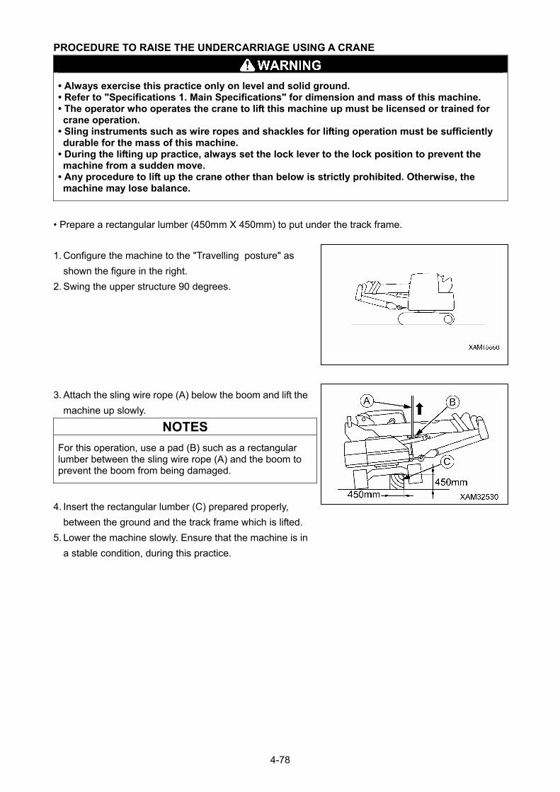
PROCEDURE TO RAISE THE UNDERCARRIAGE USING A CRANE
• Always exercise this practice only on level and solid ground. • Refer to "Specifications 1. Main Specifications" for dimension and mass of this machine. • The operator who operates the crane to lift this machine up must be licensed or trained for crane operation.
• Sling instruments such as wire ropes and shackles for lifting operation must be sufficiently durable for the mass of this machine.
• During the lifting up practice, always set the lock lever to the lock position to prevent the machine from a sudden move.
• Any procedure to lift up the crane other than below is strictly prohibited. Otherwise, the machine may lose balance.
• Prepare a rectangular lumber (450mm X 450mm) to put under the track frame.
1. Configure the machine to the "Travelling posture" as
shown the figure in the right.
2. Swing the upper structure 90 degrees.
3. Attach the sling wire rope (A) below the boom and lift the
machine up slowly.
NOTES
For this operation, use a pad (B) such as a rectangular lumber between the sling wire rope (A) and the boom to prevent the boom from being damaged.
4. Insert the rectangular lumber (C) prepared properly,
between the ground and the track frame which is lifted.
5. Lower the machine slowly. Ensure that the machine is in
a stable condition, during this practice.
4-78
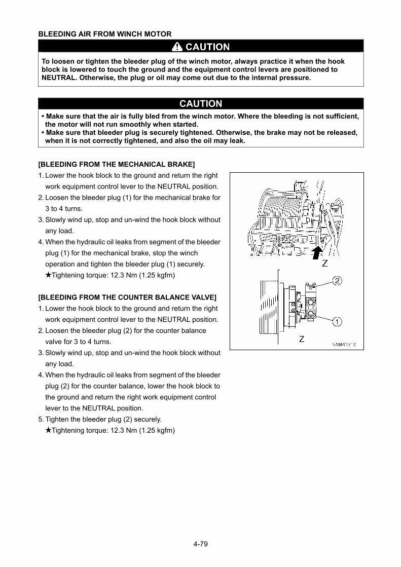
BLEEDING AIR FROM WINCH MOTOR
To loosen or tighten the bleeder plug of the winch motor, always practice it when the hook block is lowered to touch the ground and the equipment control levers are positioned to NEUTRAL. Otherwise, the plug or oil may come out due to the internal pressure.
CAUTION • Make sure that the air is fully bled from the winch motor. Where the bleeding is not sufficient, the motor will not run smoothly when started.
• Make sure that bleeder plug is securely tightened. Otherwise, the brake may not be released, when it is not correctly tightened, and also the oil may leak.
[BLEEDING FROM THE MECHANICAL BRAKE]
1. Lower the hook block to the ground and return the right
work equipment control lever to the NEUTRAL position.
2. Loosen the bleeder plug (1) for the mechanical brake for
3 to 4 turns.
3. Slowly wind up, stop and un-wind the hook block without
any load.
4. When the hydraulic oil leaks from segment of the bleeder
plug (1) for the mechanical brake, stop the winch
operation and tighten the bleeder plug (1) securely.
Tightening torque: 12.3 Nm (1.25 kgfm)
[BLEEDING FROM THE COUNTER BALANCE VALVE]
1. Lower the hook block to the ground and return the right
work equipment control lever to the NEUTRAL position.
2. Loosen the bleeder plug (2) for the counter balance
valve for 3 to 4 turns.
3. Slowly wind up, stop and un-wind the hook block without
any load.
4. When the hydraulic oil leaks from segment of the bleeder
plug (2) for the counter balance, lower the hook block to
the ground and return the right work equipment control
lever to the NEUTRAL position.
5. Tighten the bleeder plug (2) securely.
Tightening torque: 12.3 Nm (1.25 kgfm)
4-79
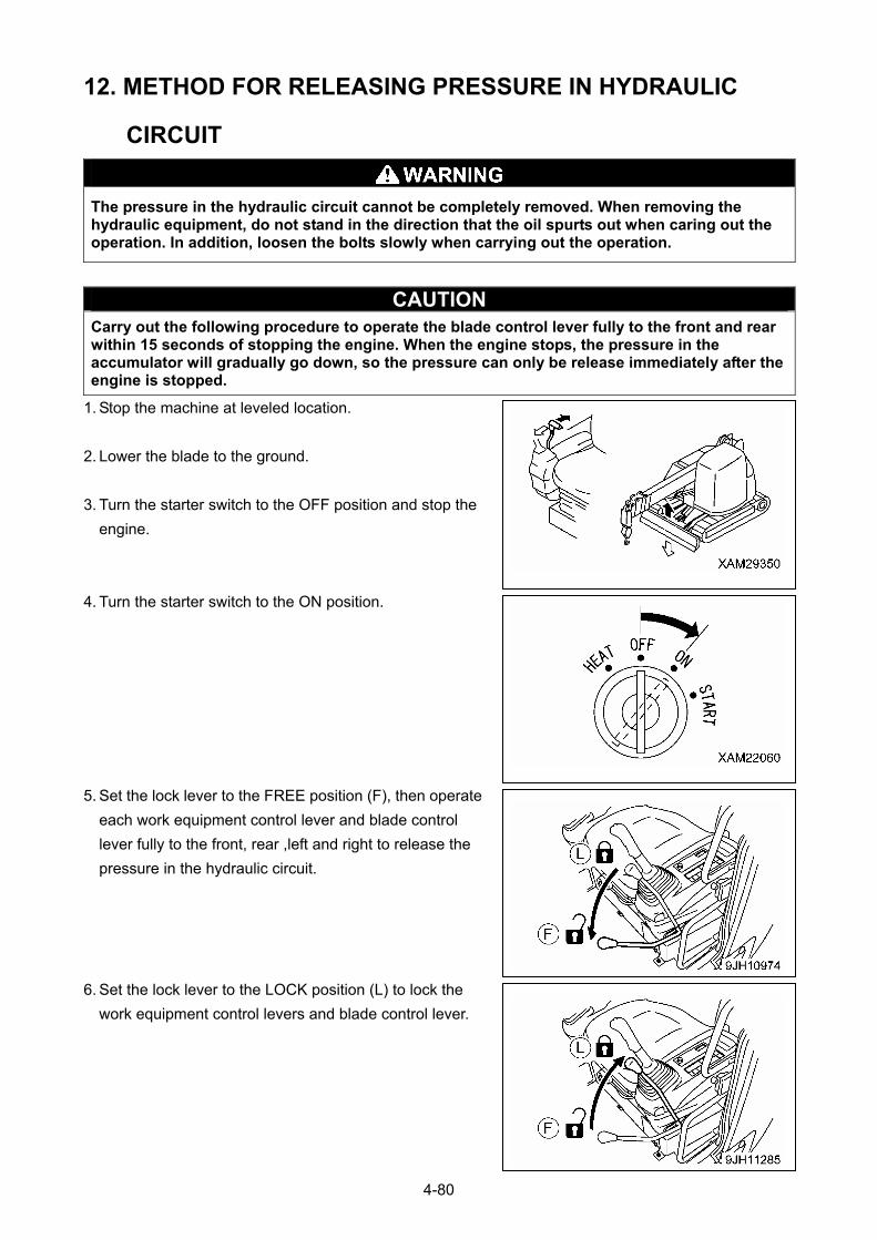
12. METHOD FOR RELEASING PRESSURE IN HYDRAULIC
CIRCUIT
The pressure in the hydraulic circuit cannot be completely removed. When removing the hydraulic equipment, do not stand in the direction that the oil spurts out when caring out the operation. In addition, loosen the bolts slowly when carrying out the operation.
CAUTION Carry out the following procedure to operate the blade control lever fully to the front and rear within 15 seconds of stopping the engine. When the engine stops, the pressure in the accumulator will gradually go down, so the pressure can only be release immediately after the engine is stopped.
1. Stop the machine at leveled location.
2. Lower the blade to the ground.
3. Turn the starter switch to the OFF position and stop the
engine.
4. Turn the starter switch to the ON position.
5. Set the lock lever to the FREE position (F), then operate
each work equipment control lever and blade control
lever fully to the front, rear ,left and right to release the
pressure in the hydraulic circuit.
6. Set the lock lever to the LOCK position (L) to lock the
work equipment control levers and blade control lever.
4-80

SPECIFICATIONS
1. SPECIFICATION LIST 5 – 2
2. SPECIFICATION DIMENSIONAL DRAWING 5 – 4
3. RATED TOTAL LOAD CHART 5 – 5
4. WORKING RADIUS AND LIFTING HEIGHT 5 – 8
5-1
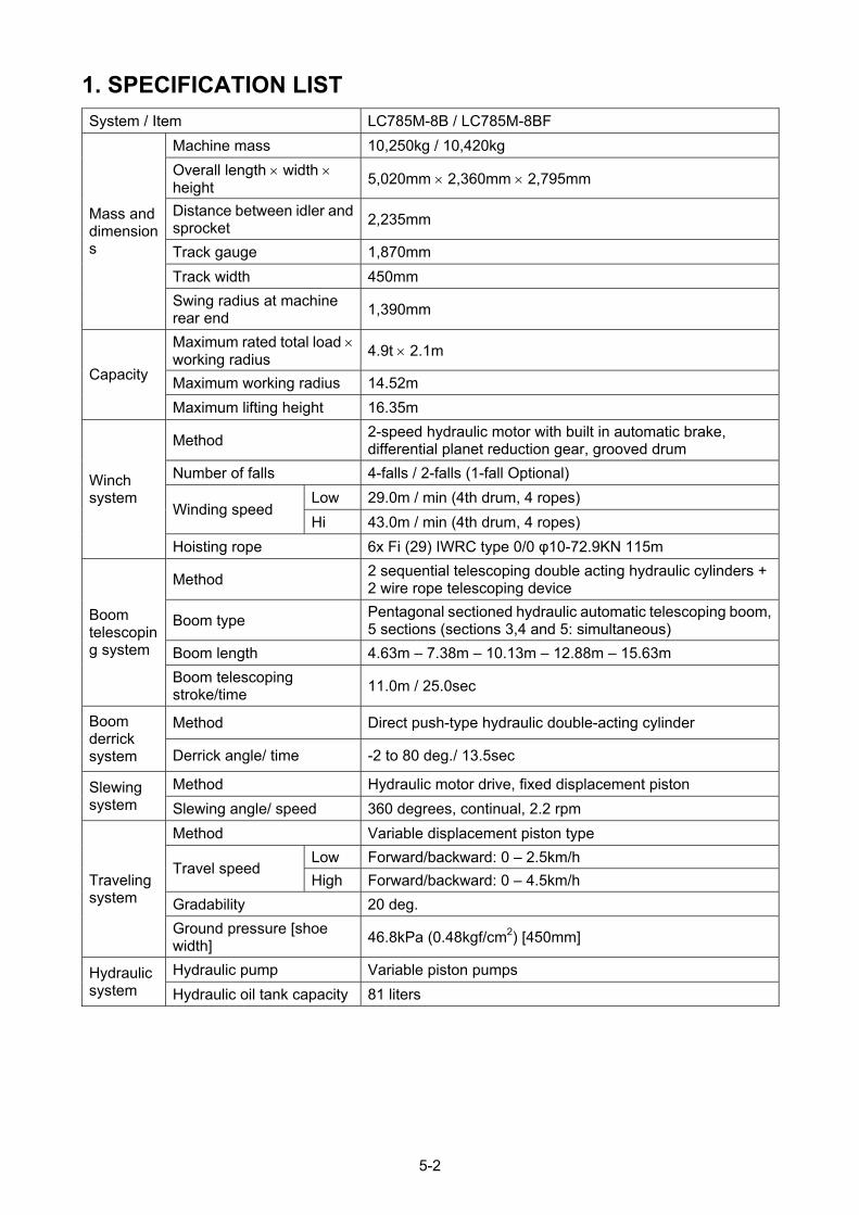
1. SPECIFICATION LIST
System / Item LC785M-8B / LC785M-8BF
Machine mass 10,250kg / 10,420kg
Overall length width height
5,020mm 2,360mm 2,795mm
Distance between idler and sprocket
2,235mm
Track gauge 1,870mm
Track width 450mm
Mass and dimensions
Swing radius at machine rear end
1,390mm
Maximum rated total load working radius
4.9t 2.1m
Maximum working radius 14.52m Capacity
Maximum lifting height 16.35m
Method 2-speed hydraulic motor with built in automatic brake, differential planet reduction gear, grooved drum
Number of falls 4-falls / 2-falls (1-fall Optional)
Low 29.0m / min (4th drum, 4 ropes) Winding speed
Hi 43.0m / min (4th drum, 4 ropes)
Winch system
Hoisting rope 6x Fi (29) IWRC type 0/0 φ10-72.9KN 115m
Method 2 sequential telescoping double acting hydraulic cylinders + 2 wire rope telescoping device
Boom type Pentagonal sectioned hydraulic automatic telescoping boom, 5 sections (sections 3,4 and 5: simultaneous)
Boom length 4.63m – 7.38m – 10.13m – 12.88m – 15.63m
Boom telescoping system
Boom telescoping stroke/time
11.0m / 25.0sec
Method Direct push-type hydraulic double-acting cylinder Boom derrick system Derrick angle/ time -2 to 80 deg./ 13.5sec
Method Hydraulic motor drive, fixed displacement piston Slewing system Slewing angle/ speed 360 degrees, continual, 2.2 rpm
Method Variable displacement piston type
Low Forward/backward: 0 – 2.5km/h Travel speed
High Forward/backward: 0 – 4.5km/h
Gradability 20 deg.
Traveling system
Ground pressure [shoe width]
46.8kPa (0.48kgf/cm2) [450mm]
Hydraulic pump Variable piston pumps Hydraulic system Hydraulic oil tank capacity 81 liters
5-2

Model KOMATSU SAA4D95LE-5
Type Vertical in-line, Water cooled, 4-cycle, Direct fuel injection type with turbo charger
Displacement 3.26 liters (3260cc)
Rated output (continuous) 41.0kW / 1,950min-1 (55PS / 1950rpm)
Engine
Fuel tank capacity Light oil / 140liters
Safety device
Overwind protections, moment limiter (with working envelope restriction), wire rope latch, hydraulic safety valve, alarm buzzer, machine body inclination alarm, working status lamp, level, control lock lever, travel lock bar, side mirror, emergency stop switch, and crane/blade interlock device
5-3
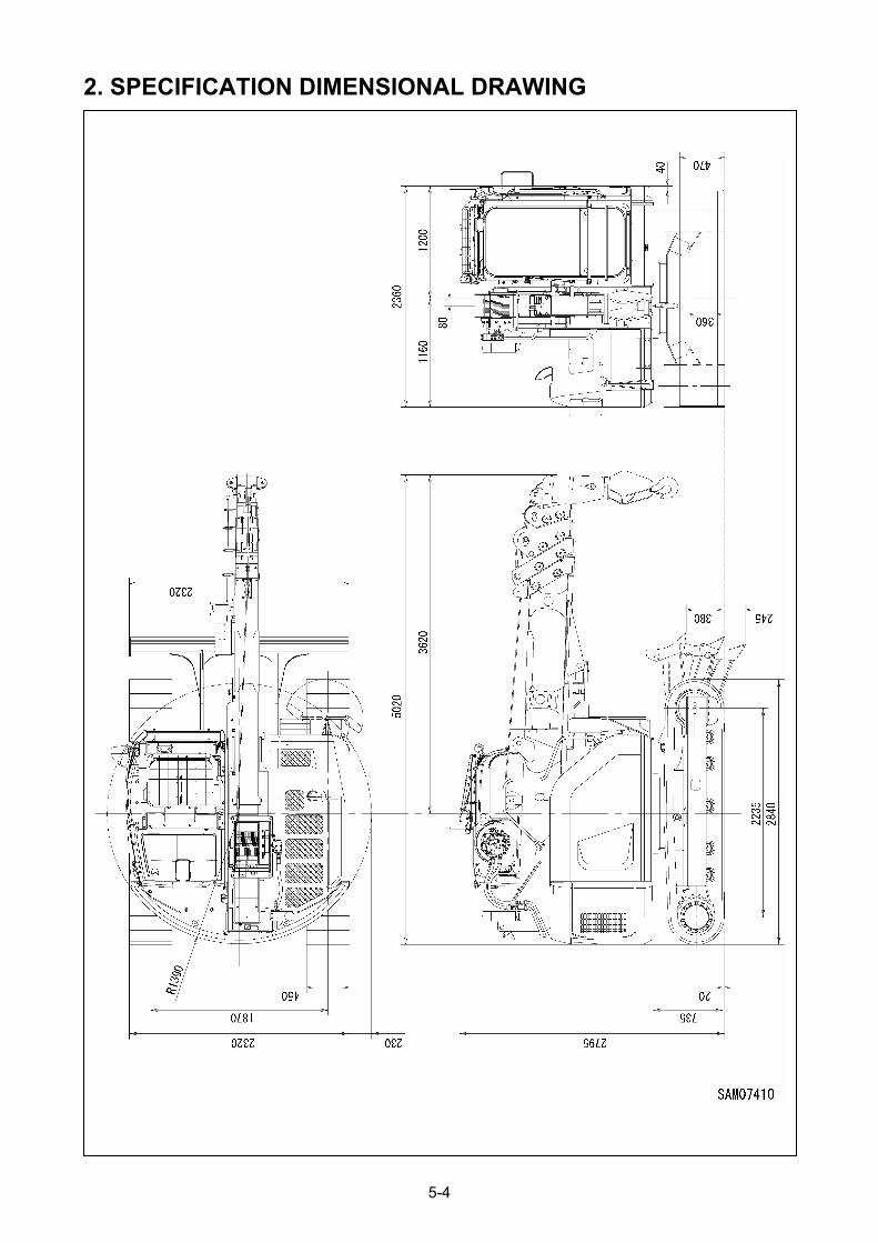
2. SPECIFICATION DIMENSIONAL DRAWING
5-4

3. RATED TOTAL LOAD CHART
RATED TOTAL LOAD CHART AT WIRE ROPE 4 FALLS
Unit: kg
4.63m Boom 7.38m Boom 10.13m Boom 12.88m Boom
15.63m Boom Working
radius (m) Stationary
Pick & Carry
StationaryPick & Carry
StationaryPick & Carry
Stationary Stationary
2.00 4900 2000 4900 2000 2600 1400 2000 2.10 4900 2000 4630 2000 2600 1400 2000 2.50 3800 2000 3760 2000 2600 1400 2000 1400 2.70 3310 1950 3410 1940 2520 1400 2000 1400 3.00 2900 1670 2980 1700 2310 1360 2000 1400 3.15 2640 1550 2800 1590 2220 1300 2000 1400 3.50 2290 1330 2420 1380 2010 1170 1890 1400 3.52 2270 1320 2400 1370 2000 1170 1880 1400 4.00 2000 1140 1750 1020 1650 1400 4.50 1670 960 1530 890 1450 1320 5.00 1400 810 1340 770 1280 1200 5.50 1180 690 1170 680 1130 1090 6.00 1000 590 1030 590 1010 990 6.27 910 540 950 550 940 940 6.50 890 510 900 900 7.00 780 440 800 820 7.50 670 380 710 750 8.00 580 320 630 680 8.50 490 270 560 610 9.00 410 230 500 560 9.02 410 230 500 560 9.50 440 500
10.00 390 450 10.50 340 400 11.00 300 360 11.50 260 320 11.77 260 300 12.00 280 12.50 240 13.00 210 13.50 200 14.00 200 14.52 200
Boom length:
4.63m Boom → Boom retracted minimum
7.38m Boom → Boom length more than 4.64m less than 7.38m
10.13m Boom → Boom length more than 7.39m less than 10.13m
12.88m Boom → Boom length more than 10.14m less than 12.88m
15.63m Boom → Boom length 12.89m or more
The Rated total load Chart is based on the actual working radius including boom deflection.
The weight of hoisting accessory (hookblock:90kg) must be included as part of the load shown in the
Rated total load Chart.
5-5

RATED TOTAL LOAD CHART AT WIRE ROPE 2 FALLS
Unit: kg
4.63m Boom 7.38m Boom 10.13m Boom 12.88m Boom
15.63m Boom Working
radius (m) Stationary
Pick & Carry
StationaryPick & Carry
StationaryPick & Carry
Stationary Stationary
2.00 2450 2000 2450 2000 2450 1400 2000 2.10 2450 2000 2450 2000 2450 1400 2000 2.50 2450 2000 2450 2000 2450 1400 2000 1400 2.70 2450 1950 2450 1940 2450 1400 2000 1400 3.00 2450 1670 2450 1700 2310 1360 2000 1400 3.15 2450 1550 2450 1590 2220 1300 2000 1400 3.50 2290 1330 2420 1380 2010 1170 1890 1400 3.52 2270 1320 2400 1370 2000 1170 1880 1400 4.00 2000 1140 1750 1020 1650 1400 4.50 1670 960 1530 890 1450 1320 5.00 1400 810 1340 770 1280 1200 5.50 1180 690 1170 680 1130 1090 6.00 1000 590 1030 590 1010 990 6.27 910 540 950 550 940 940 6.50 890 510 900 900 7.00 780 440 800 820 7.50 670 380 710 750 8.00 580 320 630 680 8.50 490 270 560 610 9.00 410 230 500 560 9.02 410 230 500 560 9.50 440 500
10.00 390 450 10.50 340 400 11.00 300 360 11.50 260 320 11.77 260 300 12.00 280 12.50 240 13.00 210 13.50 200 14.00 200 14.52 200
Boom length:
4.63m Boom → Boom retracted minimum
7.38m Boom → Boom length more than 4.64m less than 7.38m
10.13m Boom → Boom length more than 7.39m less than 10.13m
12.88m Boom → Boom length more than 10.14m less than 12.88m
15.63m Boom → Boom length 12.89m or more
The Rated total load Chart is based on the actual working radius including boom deflection.
The weight of hoisting accessory (hookblock:90kg) must be included as part of the load shown in the
Rated total load Chart.
5-6

RATED TOTAL LOAD CHART AT WIRE ROPE 1 FALL
Unit: kg
4.63m Boom 7.38m Boom 10.13m Boom 12.88m Boom
15.63m Boom Working
radius (m) Stationary
Pick & Carry
StationaryPick & Carry
StationaryPick & Carry
Stationary Stationary
2.00 1220 1220 1220 1220 1220 1220 1220 2.10 1220 1220 1220 1220 1220 1220 1220 2.50 1220 1220 1220 1220 1220 1220 1220 1220 2.70 1220 1220 1220 1220 1220 1220 1220 1220 3.00 1220 1220 1220 1220 1220 1220 1220 1220 3.15 1220 1220 1220 1220 1220 1220 1220 1220 3.50 1220 1220 1220 1220 1220 1170 1220 1220 3.52 1220 1220 1220 1220 1220 1170 1220 1220 4.00 1220 1140 1220 1020 1220 1220 4.50 1220 960 1220 890 1220 1220 5.00 1220 810 1220 770 1220 1200 5.50 1180 690 1170 680 1130 1090 6.00 1000 590 1030 590 1010 990 6.27 910 540 950 550 940 940 6.50 890 510 900 900 7.00 780 440 800 820 7.50 670 380 710 750 8.00 580 320 630 680 8.50 490 270 560 610 9.00 410 230 500 560 9.02 410 230 500 560 9.50 440 500
10.00 390 450 10.50 340 400 11.00 300 360 11.50 260 320 11.77 260 300 12.00 280 12.50 240 13.00 210 13.50 200 14.00 200 14.52 200
Boom length:
4.63m Boom → Boom retracted minimum
7.38m Boom → Boom length more than 4.64m less than 7.38m
10.13m Boom → Boom length more than 7.39m less than 10.13m
12.88m Boom → Boom length more than 10.14m less than 12.88m
15.63m Boom → Boom length 12.89m or more
The Rated total load Chart is based on the actual working radius including boom deflection.
The weight of hoisting accessory (hookblock:20kg) must be included as part of the load shown in the
Rated total load Chart.
5-7
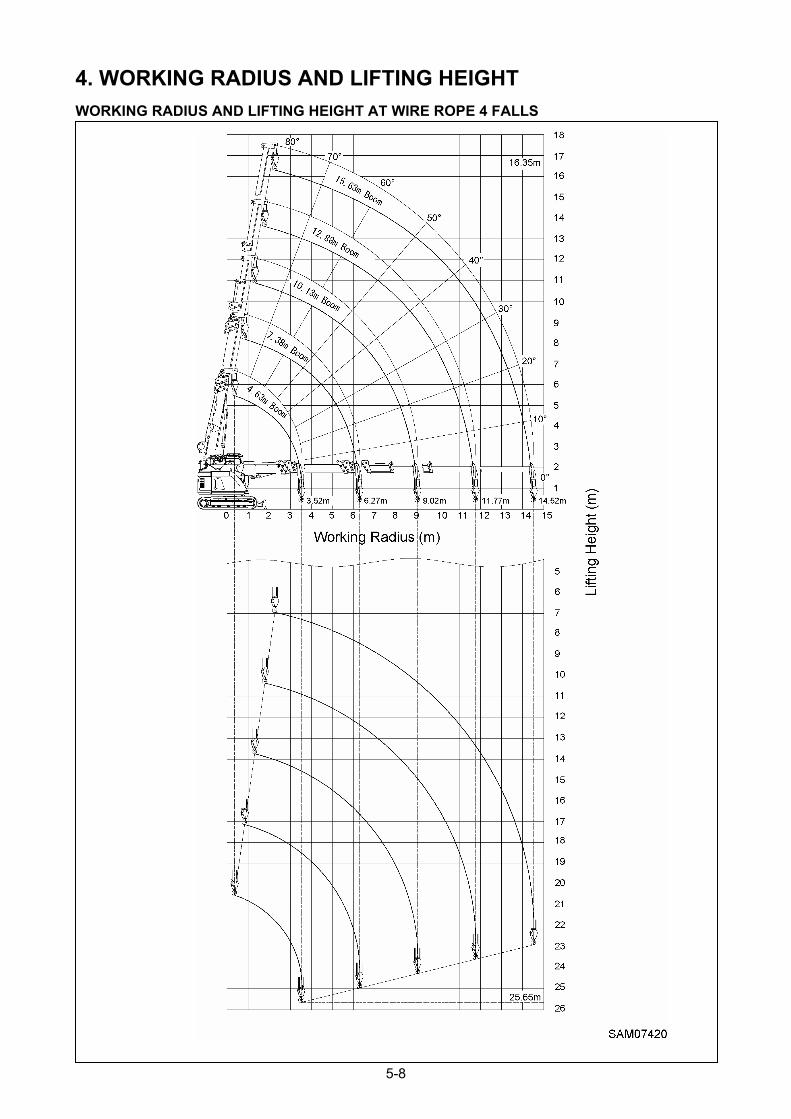
4. WORKING RADIUS AND LIFTING HEIGHT
WORKING RADIUS AND LIFTING HEIGHT AT WIRE ROPE 4 FALLS
5-8
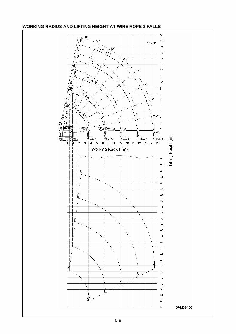
WORKING RADIUS AND LIFTING HEIGHT AT WIRE ROPE 2 FALLS
5-9
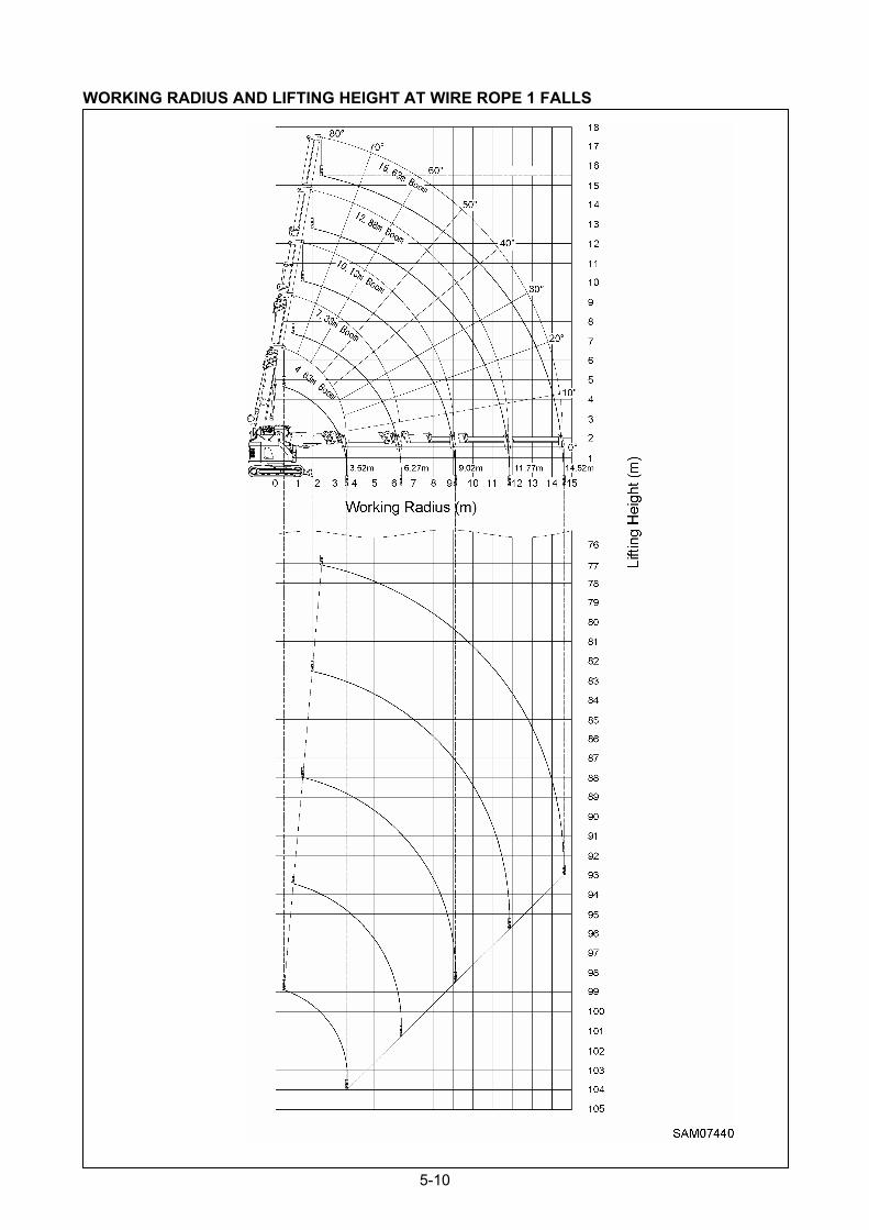
WORKING RADIUS AND LIFTING HEIGHT AT WIRE ROPE 1 FALLS
5-10

FLY-JIB
1. PRECAUTIONS OF FLY-JIB OPERATION 6 – 2
2. SAFETY LABEL LOCATION 6 – 4
3. WORKING RANGE CHART 6 – 5
4. TOTAL RATED LOAD CHART 6 – 6
5. FLY-JIB EACH SECTION 6 – 7
6. FLY-JIB INSTALLATION AND STOWAGE 6 – 8
7. HANDLING MOMENT LIMITER 6 – 20
8. OPERATIONS 6 – 25
9. TRANSPORTATIONS 6 – 25
10. INSPECTION AND MAINTENANCE 6 – 26
11. SPECIFICATIONS 6 – 27
6-1

1. PRECAUTIONS OF FLY-JIB OPERATION
• The Fly-jib is installed to the Main boom with two position pins. The Fly-jib consists of two sections and another position pin fixes the 1st and 2nd section. Prior to starting operation, always ensure these three position pins are inserted in the correct positions and secured by the linchpins. If the linchpins are not secure, the pins may drop out and the Fly-jib will collapse which may cause a serious hazard.
• Whenever the Fly-jib is installed, it is essential to re-connect the over-hoist detector harness from the Main boom detector to the Fly-jib detector. Also, always ensure the over-hoist detector of the Fly-jib is working correctly before starting operation. In the event that the over-hoist detector mis-functions, it may cause the hook or hoisted load to drop and result in a serious hazard.
• Prior to Fly-jib operations set the number of the Fly-jib sections in use on the Moment limiter whilst in Fly jib mode, then start operation. If not, a serious hazard may result including Fly-jib damage or the machine tipping over.
• The Fly-jib is stowed to the side of the Main boom and fixed to it with two position pins. When installing or stowing the fly-jib, always ensure either position pin is inserted in the correct position and secured by their linchpins. Otherwise, if any of the pins drop out, the Fly-jib will become detached from the main boom and fall off, which may cause a serious hazard.
• When the Fly-jib is stowed, always re-connect the over-hoist detector harness from the Fly-jib detector to the Main boom detector. Always ensure the over-hoist detector of the Main boom is working correctly before starting operation. In the event that the over-hoist detector mis-functions, it may cause the hook or hoisted load to drop and result in a serious hazard.
• This manual applies only to a machine with the Fly-jib attached to the Main boom. If the Fly-jib is removed from the Main boom, the Moment limiter must be reset accordingly. Contact our sales partner in every such event. If the moment limiter is not reset correctly, operation of the machine may result in a serious hazard such as machine damage or tipping over.
6-2
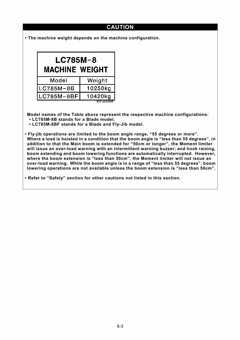
CAUTION • The machine weight depends on the machine configuration.
Model names of the Table above represent the respective machine configurations: • LC785M-8B stands for a Blade model. • LC785M-8BF stands for a Blade and Fly-Jib model.
• Fly-jib operations are limited to the boom angle range, “55 degrees or more”. Where a load is hoisted in a condition that the boom angle is “less than 55 degrees”, in addition to that the Main boom is extended for “50cm or longer”, the Moment limiter will issue an over-load warning with an intermittent warning buzzer; and hook raising, boom extending and boom lowering functions are automatically interrupted. However, where the boom extension is “less than 50cm”, the Moment limiter will not issue an over-load warning. While the boom angle is in a range of “less than 55 degrees”, boom lowering operations are not available unless the boom extension is “less than 50cm”.
• Refer to “Safety” section for other cautions not listed in this section.
6-3
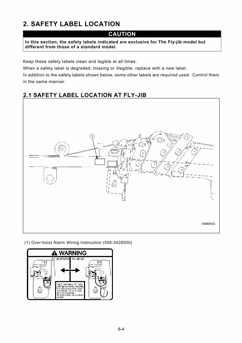
2. SAFETY LABEL LOCATION
CAUTION In this section, the safety labels indicated are exclusive for The Fly-jib model but different from those of a standard model.
Keep these safety labels clean and legible at all times.
When a safety label is degraded, missing or illegible, replace with a new label.
In addition to the safety labels shown below, some other labels are required used. Control them
in the same manner.
2.1 SAFETY LABEL LOCATION AT FLY-JIB
(1) Over-hoist Alarm Wiring Instruction (556-3428500)
6-4
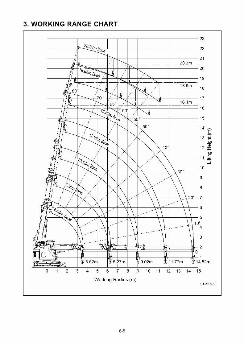
3. WORKING RANGE CHART
6-5

4. TOTAL RATED LOAD CHART
CAUTION
The total rated load is a load including the mass of a hook block (20kg).
Total rated load (kg) Boom angle (deg)
Jib length 1 section: 3.0m Jib length 2 section: 4.7m
80 430 430
70 430 430
65 330 330
60 230 230
55 130 130
6-6
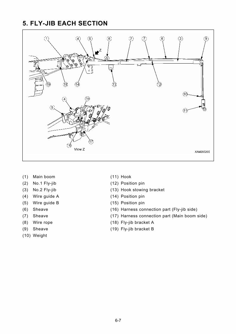
5. FLY-JIB EACH SECTION
(11) Hook (1) Main boom
(12) Position pin (2) No.1 Fly-jib
(13) Hook stowing bracket (3) No.2 Fly-jib
(14) Position pin (4) Wire guide A
(15) Position pin (5) Wire guide B
(16) Harness connection part (Fly-jib side) (6) Sheave
(17) Harness connection part (Main boom side) (7) Sheave
(18) Fly-jib bracket A (8) Wire rope
(19) Fly-jib bracket B (9) Sheave
(10) Weight
6-7

6. FLY-JIB INSTALLATION AND STOWAGE
• Fly-jib installation and stowage will require two people. Prior to operation, discuss each person’s duties in detail and follow the agreed signals during the operation. If signals are not clearly understood, it may cause an accident resulting in injury or death.
• Fly-jib installation and stowage must be practiced on solid level ground. Otherwise, the Fly-jib may turn under its own weight and cause a serious hazard.
• Fly-jib installation and stowage require a rigid stepping stool of sufficient height. An unstable stool may result in the user falling from a height and may incur serious personal harm.
• For Fly-jib installation and stowage, the Main boom angle must be within the range between “full lowered” to 4 degrees. If the Main boom angle exceeds this range, the Fly-jib may turn under its own weight and cause a serious hazard.
• The Fly-jib is installed to the Main boom with two position pins. The Fly-jib consists of two sections and another position pin fixes the 1st and 2nd sections. Prior to starting operation, always ensure these three position pins are inserted in the correct positions and secured by linchpins, as well. Otherwise, if any of the pins drops out, the Fly-jib will drop which may cause a serious hazard.
• Whenever the Fly-jib is installed, it is essential to re-connect the over-hoist detector harness from the Main boom detector to the Fly-jib detector. Always ensure the over-hoist detector of the Fly-jib is working correctly before starting operation. In the event that the over-hoist detector mis-functions, it may cause the hook or hoisted load to drop and result in a serious hazard.
• The Fly-jib is stowed to the side of the Main boom and fixed to it with two position pins. When installing or stowing the fly-jib, always ensure either position pin is inserted in the correct position and secured by their linchpins. Otherwise, if any of the pins drop out, the Fly-jib will become detached from the main boom and fall off, which may cause a serious hazard.
• When the Fly-jib is stowed, always re-connect the over-hoist detector harness from the Fly-jib detector to the Main boom detector. Always ensure the over-hoist detector of the Main boom is working correctly before starting operations. Should the over-hoist detector mis-functions, it may cause the hook or hoisted load to drop resulting in a serious hazard.
6-8
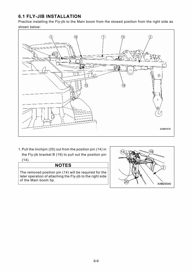
6.1 FLY-JIB INSTALLATION Practice installing the Fly-jib to the Main boom from the stowed position from the right side as
shown below:
1. Pull the linchpin (20) out from the position pin (14) in
the Fly-jib bracket B (19) to pull out the position pin
(14).
NOTES
The removed position pin (14) will be required for the later operation of attaching the Fly-jib to the right side of the Main boom tip.
6-9
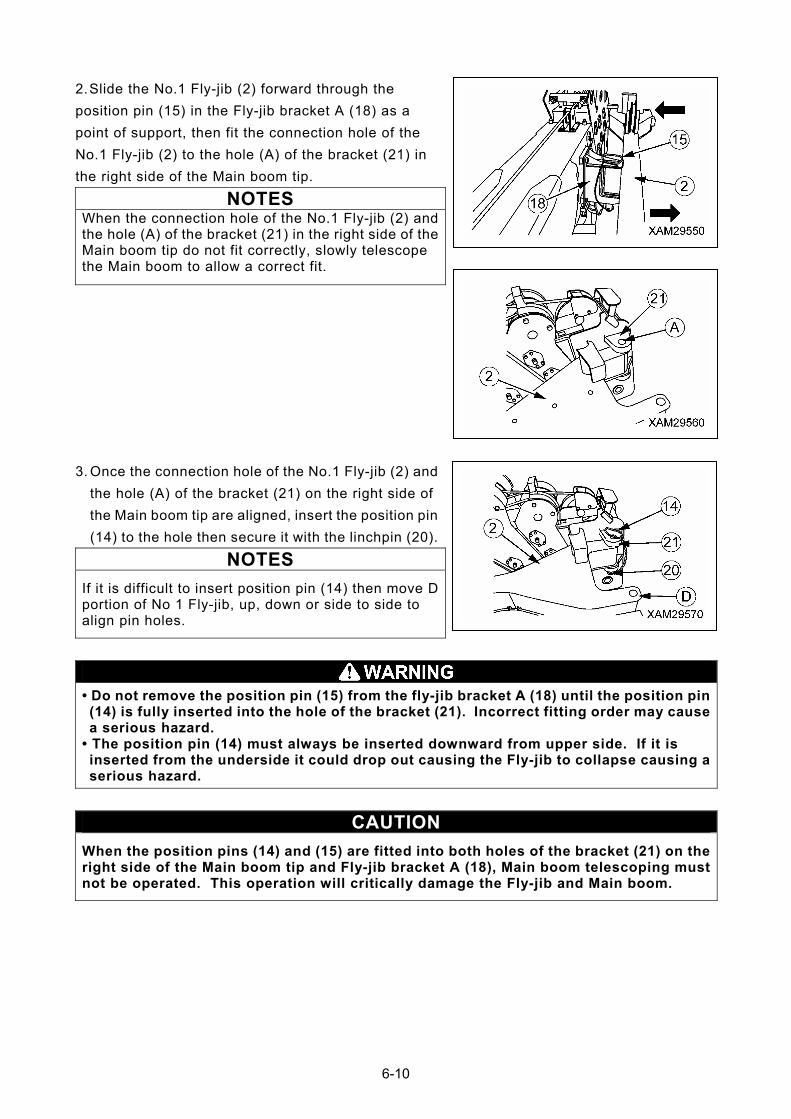
2. Slide the No.1 Fly-jib (2) forward through the
position pin (15) in the Fly-jib bracket A (18) as a
point of support, then fit the connection hole of the
No.1 Fly-jib (2) to the hole (A) of the bracket (21) in
the right side of the Main boom tip.
NOTES When the connection hole of the No.1 Fly-jib (2) and the hole (A) of the bracket (21) in the right side of the Main boom tip do not fit correctly, slowly telescope the Main boom to allow a correct fit.
3. Once the connection hole of the No.1 Fly-jib (2) and
the hole (A) of the bracket (21) on the right side of
the Main boom tip are aligned, insert the position pin
(14) to the hole then secure it with the linchpin (20).
NOTES
If it is difficult to insert position pin (14) then move D portion of No 1 Fly-jib, up, down or side to side to align pin holes.
• Do not remove the position pin (15) from the fly-jib bracket A (18) until the position pin (14) is fully inserted into the hole of the bracket (21). Incorrect fitting order may cause a serious hazard.
• The position pin (14) must always be inserted downward from upper side. If it is inserted from the underside it could drop out causing the Fly-jib to collapse causing a serious hazard.
CAUTION
When the position pins (14) and (15) are fitted into both holes of the bracket (21) on the right side of the Main boom tip and Fly-jib bracket A (18), Main boom telescoping must not be operated. This operation will critically damage the Fly-jib and Main boom.
6-10
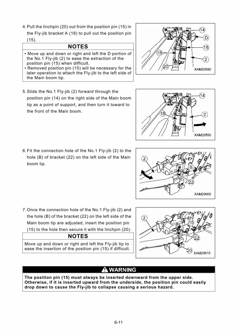
4. Pull the linchpin (20) out from the position pin (15) in
the Fly-jib bracket A (18) to pull out the position pin
(15).
NOTES
• Move up and down or right and left the D portion of the No.1 Fly-jib (2) to ease the extraction of the position pin (15) when difficult.
• Removed position pin (15) will be necessary for the later operation to attach the Fly-jib to the left side of the Main boom tip.
5. Slide the No.1 Fly-jib (2) forward through the
position pin (14) on the right side of the Main boom
tip as a point of support, and then turn it toward to
the front of the Main boom.
6. Fit the connection hole of the No.1 Fly-jib (2) to the
hole (B) of bracket (22) on the left side of the Main
boom tip.
7. Once the connection hole of the No.1 Fly-jib (2) and
the hole (B) of the bracket (22) on the left side of the
Main boom tip are adjusted, insert the position pin
(15) to the hole then secure it with the linchpin (20).
NOTES
Move up and down or right and left the Fly-jib tip to ease the insertion of the position pin (15) if difficult.
The position pin (15) must always be inserted downward from the upper side. Otherwise, if it is inserted upward from the underside, the position pin could easily drop down to cause the Fly-jib to collapse causing a serious hazard.
6-11
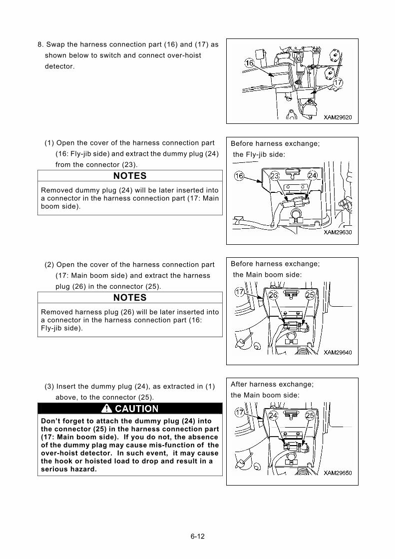
8. Swap the harness connection part (16) and (17) as
shown below to switch and connect over-hoist
detector.
(1) Open the cover of the harness connection part
(16: Fly-jib side) and extract the dummy plug (24)
from the connector (23).
Before harness exchange;
the Fly-jib side:
NOTES
Removed dummy plug (24) will be later inserted into a connector in the harness connection part (17: Main boom side).
Before harness exchange;
the Main boom side:
(2) Open the cover of the harness connection part
(17: Main boom side) and extract the harness
plug (26) in the connector (25).
NOTES
Removed harness plug (26) will be later inserted into a connector in the harness connection part (16: Fly-jib side).
After harness exchange;
the Main boom side: (3) Insert the dummy plug (24), as extracted in (1)
above, to the connector (25).
Don’t forget to attach the dummy plug (24) into the connector (25) in the harness connection part (17: Main boom side). If you do not, the absence of the dummy plag may cause mis-function of the over-hoist detector. In such event, it may cause the hook or hoisted load to drop and result in a serious hazard.
6-12
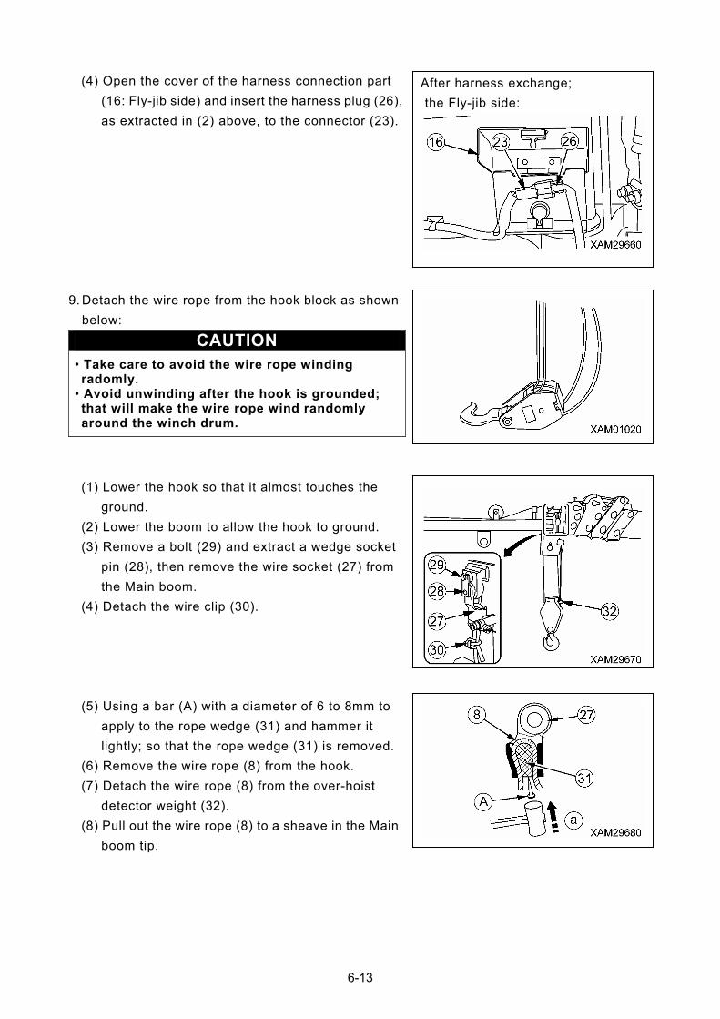
(4) Open the cover of the harness connection part
(16: Fly-jib side) and insert the harness plug (26),
as extracted in (2) above, to the connector (23).
After harness exchange;
the Fly-jib side:
9. Detach the wire rope from the hook block as shown
below:
CAUTION • Take care to avoid the wire rope winding radomly.
• Avoid unwinding after the hook is grounded; that will make the wire rope wind randomly around the winch drum.
(1) Lower the hook so that it almost touches the
ground.
(2) Lower the boom to allow the hook to ground.
(3) Remove a bolt (29) and extract a wedge socket
pin (28), then remove the wire socket (27) from
the Main boom.
(4) Detach the wire clip (30).
(5) Using a bar (A) with a diameter of 6 to 8mm to
apply to the rope wedge (31) and hammer it
lightly; so that the rope wedge (31) is removed.
(6) Remove the wire rope (8) from the hook.
(7) Detach the wire rope (8) from the over-hoist
detector weight (32).
(8) Pull out the wire rope (8) to a sheave in the Main
boom tip.
6-13
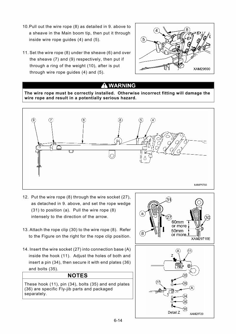
10. Pull out the wire rope (8) as detailed in 9. above to
a sheave in the Main boom tip, then put it through
inside wire rope guides (4) and (5).
11. Set the wire rope (8) under the sheave (6) and over
the sheave (7) and (9) respectively, then put if
through a ring of the weight (10), after is put
through wire rope guides (4) and (5).
The wire rope must be correctly installed. Otherwise incorrect fitting will damage the wire rope and result in a potentially serious hazard.
12. Put the wire rope (8) through the wire socket (27),
as detached in 9. above, and set the rope wedge
(31) to position (a). Pull the wire rope (8)
intensely to the direction of the arrow.
13. Attach the rope clip (30) to the wire rope (8). Refer
to the Figure on the right for the rope clip position.
14. Insert the wire socket (27) into connection base (A)
inside the hook (11). Adjust the holes of both and
insert a pin (34), then secure it with end plates (36)
and bolts (35).
NOTES
These hook (11), pin (34), bolts (35) and end plates (36) are specific Fly-jib parts and packaged separately.
6-14
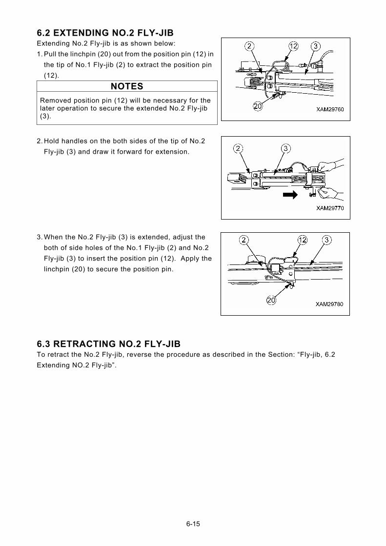
6.2 EXTENDING NO.2 FLY-JIB Extending No.2 Fly-jib is as shown below:
1. Pull the linchpin (20) out from the position pin (12) in
the tip of No.1 Fly-jib (2) to extract the position pin
(12).
NOTES
Removed position pin (12) will be necessary for the later operation to secure the extended No.2 Fly-jib (3).
2. Hold handles on the both sides of the tip of No.2
Fly-jib (3) and draw it forward for extension.
3. When the No.2 Fly-jib (3) is extended, adjust the
both of side holes of the No.1 Fly-jib (2) and No.2
Fly-jib (3) to insert the position pin (12). Apply the
linchpin (20) to secure the position pin.
6.3 RETRACTING NO.2 FLY-JIB To retract the No.2 Fly-jib, reverse the procedure as described in the Section: “Fly-jib, 6.2
Extending NO.2 Fly-jib”.
6-15
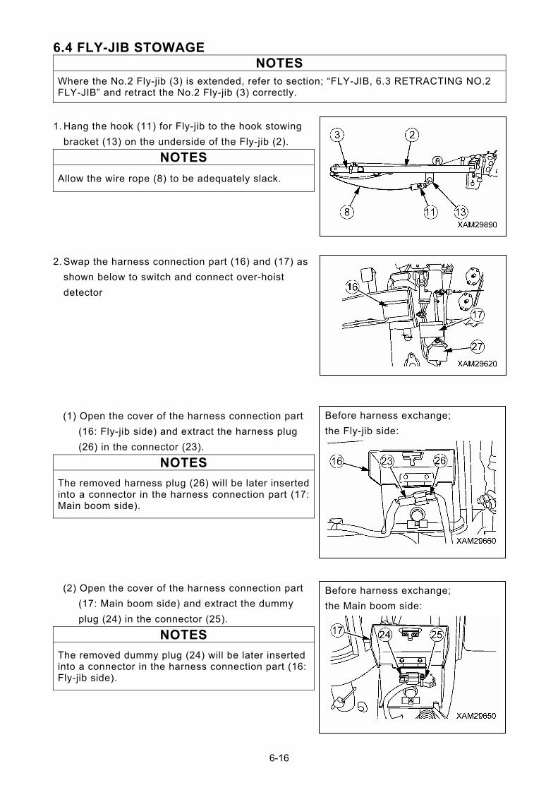
6.4 FLY-JIB STOWAGE NOTES
Where the No.2 Fly-jib (3) is extended, refer to section; “FLY-JIB, 6.3 RETRACTING NO.2 FLY-JIB” and retract the No.2 Fly-jib (3) correctly.
1. Hang the hook (11) for Fly-jib to the hook stowing
bracket (13) on the underside of the Fly-jib (2).
NOTES
Allow the wire rope (8) to be adequately slack.
2. Swap the harness connection part (16) and (17) as
shown below to switch and connect over-hoist
detector
the Fly-jib side:
Before harness exchange; (1) Open the cover of the harness connection part
(16: Fly-jib side) and extract the harness plug
(26) in the connector (23).
NOTES
The removed harness plug (26) will be later inserted into a connector in the harness connection part (17: Main boom side).
Before harness exchange;
the Main boom side:
(2) Open the cover of the harness connection part
(17: Main boom side) and extract the dummy
plug (24) in the connector (25).
NOTES
The removed dummy plug (24) will be later inserted into a connector in the harness connection part (16: Fly-jib side).
6-16
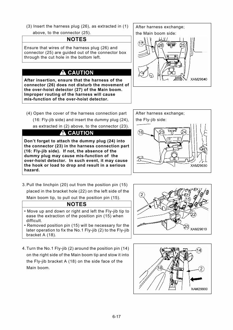
After harness exchange;
the Main boom side:
(3) Insert the harness plug (26), as extracted in (1)
above, to the connector (25).
NOTES
Ensure that wires of the harness plug (26) and connector (25) are guided out of the connector box through the cut hole in the bottom left.
After insertion, ensure that the harness of the connector (26) does not disturb the movement of the over-hoist detector (27) of the Main boom. Improper routing of the harness will cause mis-function of the over-hoist detector.
the Fly-jib side:
After harness exchange; (4) Open the cover of the harness connection part
(16: Fly-jib side) and insert the dummy plug (24),
as extracted in (2) above, to the connector (23).
Don’t forget to attach the dummy plug (24) into the connector (23) in the harness connection part (16: Fly-jib side). If not, the absence of the dummy plug may cause mis-function of the over-hoist detector. In such event, it may cause the hook or load to drop and result in a serious hazard.
3. Pull the linchpin (20) out from the position pin (15)
placed in the bracket hole (22) on the left side of the
Main boom tip, to pull out the position pin (15).
NOTES
• Move up and down or right and left the Fly-jib tip to ease the extraction of the position pin (15) when difficult.
• Removed position pin (15) will be necessary for the later operation to fix the No.1 Fly-jib (2) to the Fly-jib bracket A (18).
4. Turn the No.1 Fly-jib (2) around the position pin (14)
on the right side of the Main boom tip and stow it into
the Fly-jib bracket A (18) on the side face of the
Main boom.
6-17
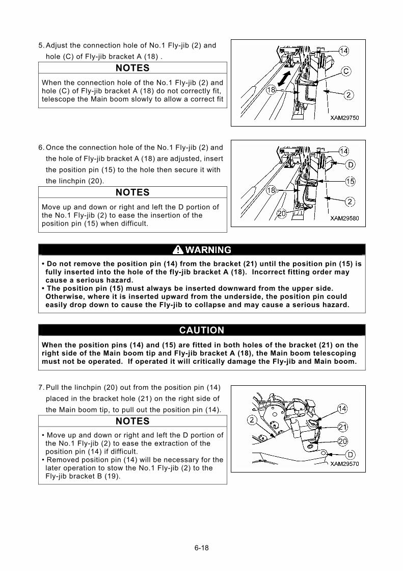
5. Adjust the connection hole of No.1 Fly-jib (2) and
hole (C) of Fly-jib bracket A (18) .
NOTES
When the connection hole of the No.1 Fly-jib (2) and hole (C) of Fly-jib bracket A (18) do not correctly fit, telescope the Main boom slowly to allow a correct fit
6. Once the connection hole of the No.1 Fly-jib (2) and
the hole of Fly-jib bracket A (18) are adjusted, insert
the position pin (15) to the hole then secure it with
the linchpin (20).
NOTES
Move up and down or right and left the D portion of the No.1 Fly-jib (2) to ease the insertion of the position pin (15) when difficult.
• Do not remove the position pin (14) from the bracket (21) until the position pin (15) is fully inserted into the hole of the fly-jib bracket A (18). Incorrect fitting order may cause a serious hazard.
• The position pin (15) must always be inserted downward from the upper side. Otherwise, where it is inserted upward from the underside, the position pin could easily drop down to cause the Fly-jib to collapse and may cause a serious hazard.
CAUTION
When the position pins (14) and (15) are fitted in both holes of the bracket (21) on the right side of the Main boom tip and Fly-jib bracket A (18), the Main boom telescoping must not be operated. If operated it will critically damage the Fly-jib and Main boom.
7. Pull the linchpin (20) out from the position pin (14)
placed in the bracket hole (21) on the right side of
the Main boom tip, to pull out the position pin (14).
NOTES
• Move up and down or right and left the D portion of the No.1 Fly-jib (2) to ease the extraction of the position pin (14) if difficult.
• Removed position pin (14) will be necessary for the later operation to stow the No.1 Fly-jib (2) to the Fly-jib bracket B (19).
6-18
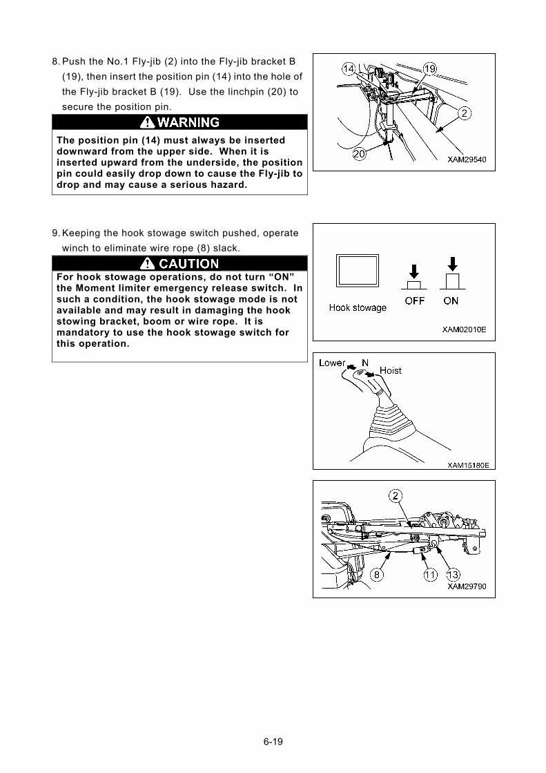
8. Push the No.1 Fly-jib (2) into the Fly-jib bracket B
(19), then insert the position pin (14) into the hole of
the Fly-jib bracket B (19). Use the linchpin (20) to
secure the position pin.
The position pin (14) must always be inserted downward from the upper side. When it is inserted upward from the underside, the position pin could easily drop down to cause the Fly-jib to drop and may cause a serious hazard.
9. Keeping the hook stowage switch pushed, operate
winch to eliminate wire rope (8) slack.
For hook stowage operations, do not turn “ON” the Moment limiter emergency release switch. In such a condition, the hook stowage mode is not available and may result in damaging the hook stowing bracket, boom or wire rope. It is mandatory to use the hook stowage switch for this operation.
6-19
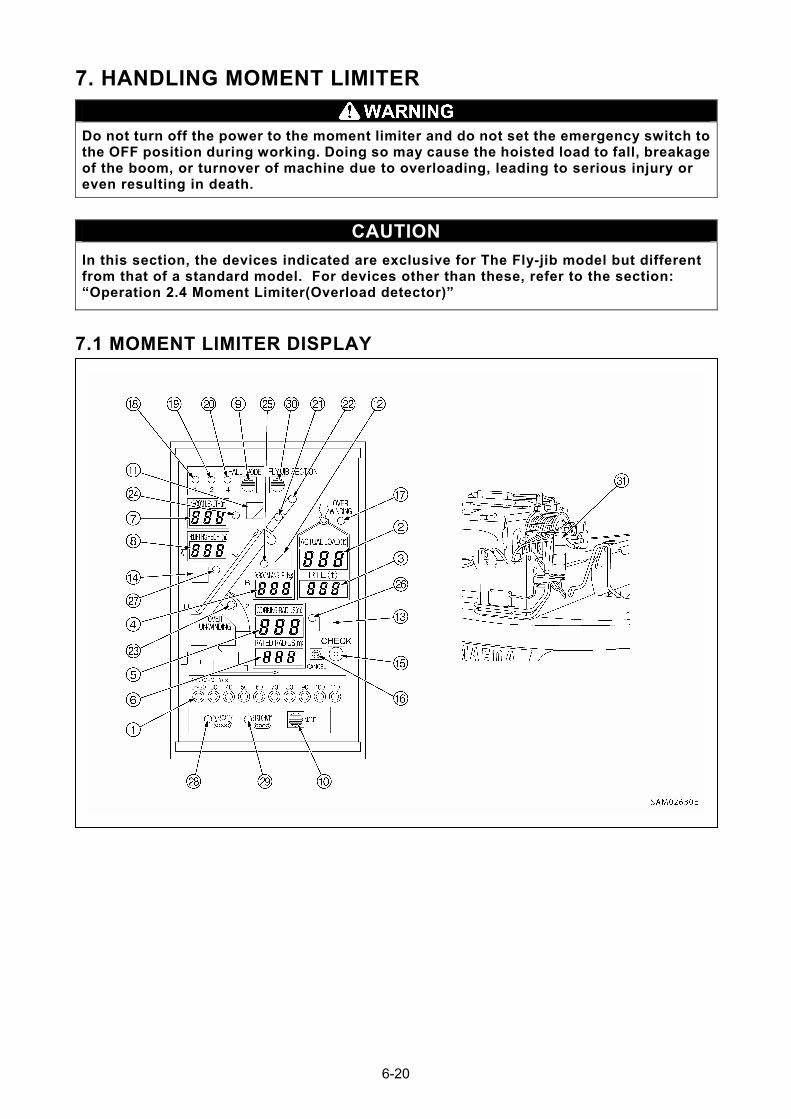
7. HANDLING MOMENT LIMITER
Do not turn off the power to the moment limiter and do not set the emergency switch to the OFF position during working. Doing so may cause the hoisted load to fall, breakage of the boom, or turnover of machine due to overloading, leading to serious injury or even resulting in death.
CAUTION
In this section, the devices indicated are exclusive for The Fly-jib model but different from that of a standard model. For devices other than these, refer to the section: “Operation 2.4 Moment Limiter(Overload detector)”
7.1 MOMENT LIMITER DISPLAY
6-20

6-21
(1) Load factor display
(2) Actual load display
(3) Rated total load display
(4) Boom angle display
(5) Actual working radius display
(6) Rated working radius display
(7) Boom length display
(8) Lifting height display
(9) Fall mode selector switch
(10) Pick & Carry/ Stationary mode select
switch
(11) Boom angle upper limit switch
(SETUP/CANCEL)
(12) Boom angle lower limit switch
(SETUP/CANCEL)
(13) Working radius upper limit switch
switch (SETUP/CANCEL)
(14) Lifting height upper limit switch
(15) Check switch
(16) Cancel switch
(17) Overwind detection LED (Red)
(18) 1 fall LED (Green)
(19) 2 fall LED (Green)
(20) 4 fall LED (Green)
(21) Fly-jib length (1) LED (Orange)
(22) Fly-jib length (2) LED (Orange)
(23) Over un-winding detection LED (Red)
(24) Boom angle upper limit LED (Orange)
(25) Boom angle Lower limit LED (Orange)
(26) Working radius upper limit LED
(Orange)
(27) Lifting height upper limit LED (Orange)
(28) Pick & carry mode selection LED (Red)
(29) Stationary mode selection LED
(Orange)
(30) Fly-jib mode select switch
(31) Working status lamp
(Changes to green, yellow, and red)
switch (SETUP/CANCEL)
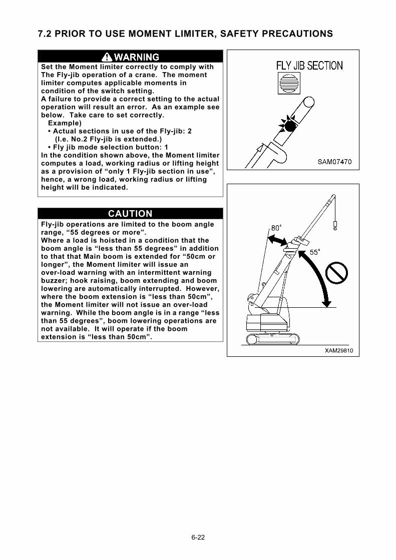
7.2 PRIOR TO USE MOMENT LIMITER, SAFETY PRECAUTIONS
Set the Moment limiter correctly to comply with The Fly-jib operation of a crane. The moment limiter computes applicable moments in condition of the switch setting. A failure to provide a correct setting to the actual operation will result an error. As an example see below. Take care to set correctly.
Example) • Actual sections in use of the Fly-jib: 2
(I.e. No.2 Fly-jib is extended.) • Fly jib mode selection button: 1
In the condition shown above, the Moment limiter computes a load, working radius or lifting height as a provision of “only 1 Fly-jib section in use”, hence, a wrong load, working radius or lifting height will be indicated.
CAUTION Fly-jib operations are limited to the boom angle range, “55 degrees or more”. Where a load is hoisted in a condition that the boom angle is “less than 55 degrees” in addition to that that Main boom is extended for “50cm or longer”, the Moment limiter will issue an over-load warning with an intermittent warning buzzer; hook raising, boom extending and boom lowering are automatically interrupted. However, where the boom extension is “less than 50cm”, the Moment limiter will not issue an over-load warning. While the boom angle is in a range “less than 55 degrees”, boom lowering operations are not available. It will operate if the boom extension is “less than 50cm”.
6-22
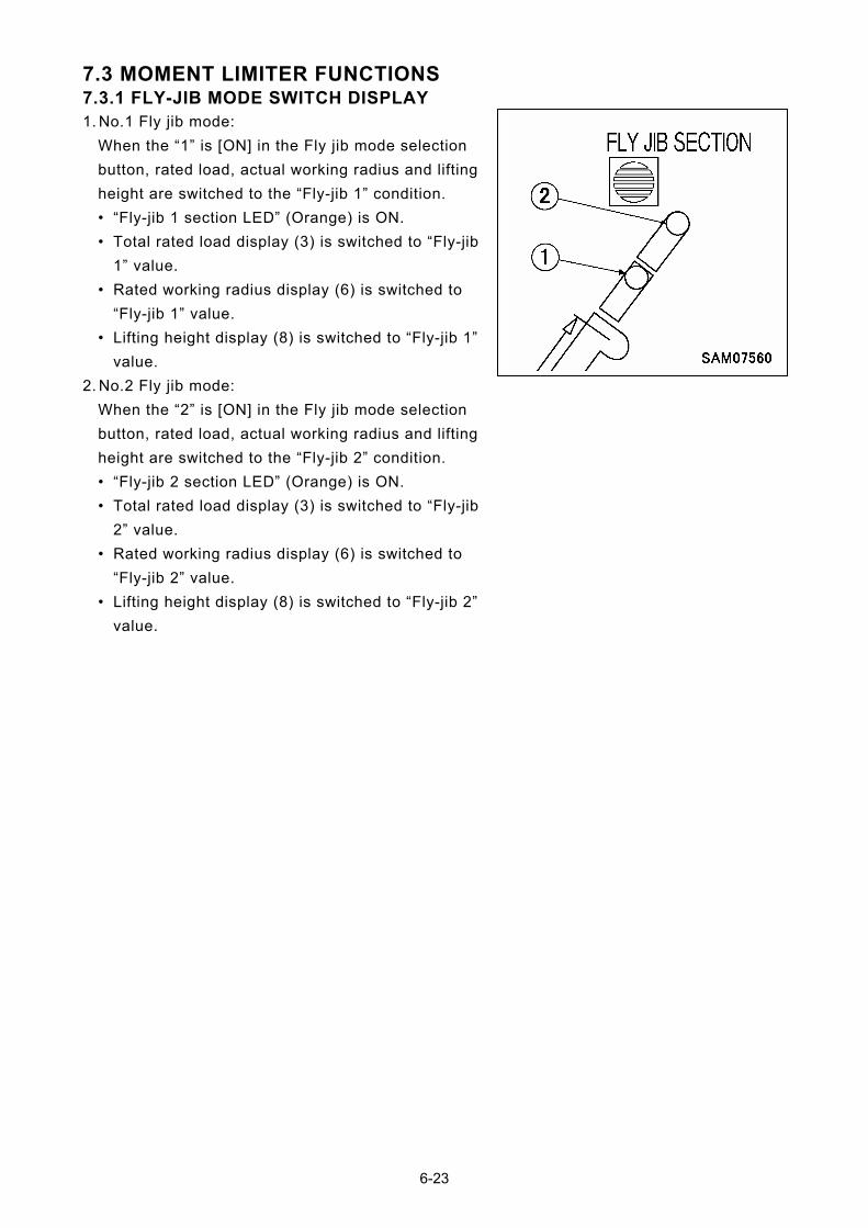
7.3 MOMENT LIMITER FUNCTIONS 7.3.1 FLY-JIB MODE SWITCH DISPLAY 1. No.1 Fly jib mode:
When the “1” is [ON] in the Fly jib mode selection
button, rated load, actual working radius and lifting
height are switched to the “Fly-jib 1” condition.
• “Fly-jib 1 section LED” (Orange) is ON.
• Total rated load display (3) is switched to “Fly-jib
1” value.
• Rated working radius display (6) is switched to
“Fly-jib 1” value.
• Lifting height display (8) is switched to “Fly-jib 1”
value.
2. No.2 Fly jib mode:
When the “2” is [ON] in the Fly jib mode selection
button, rated load, actual working radius and lifting
height are switched to the “Fly-jib 2” condition.
• “Fly-jib 2 section LED” (Orange) is ON.
• Total rated load display (3) is switched to “Fly-jib
2” value.
• Rated working radius display (6) is switched to
“Fly-jib 2” value.
• Lifting height display (8) is switched to “Fly-jib 2”
value.
6-23
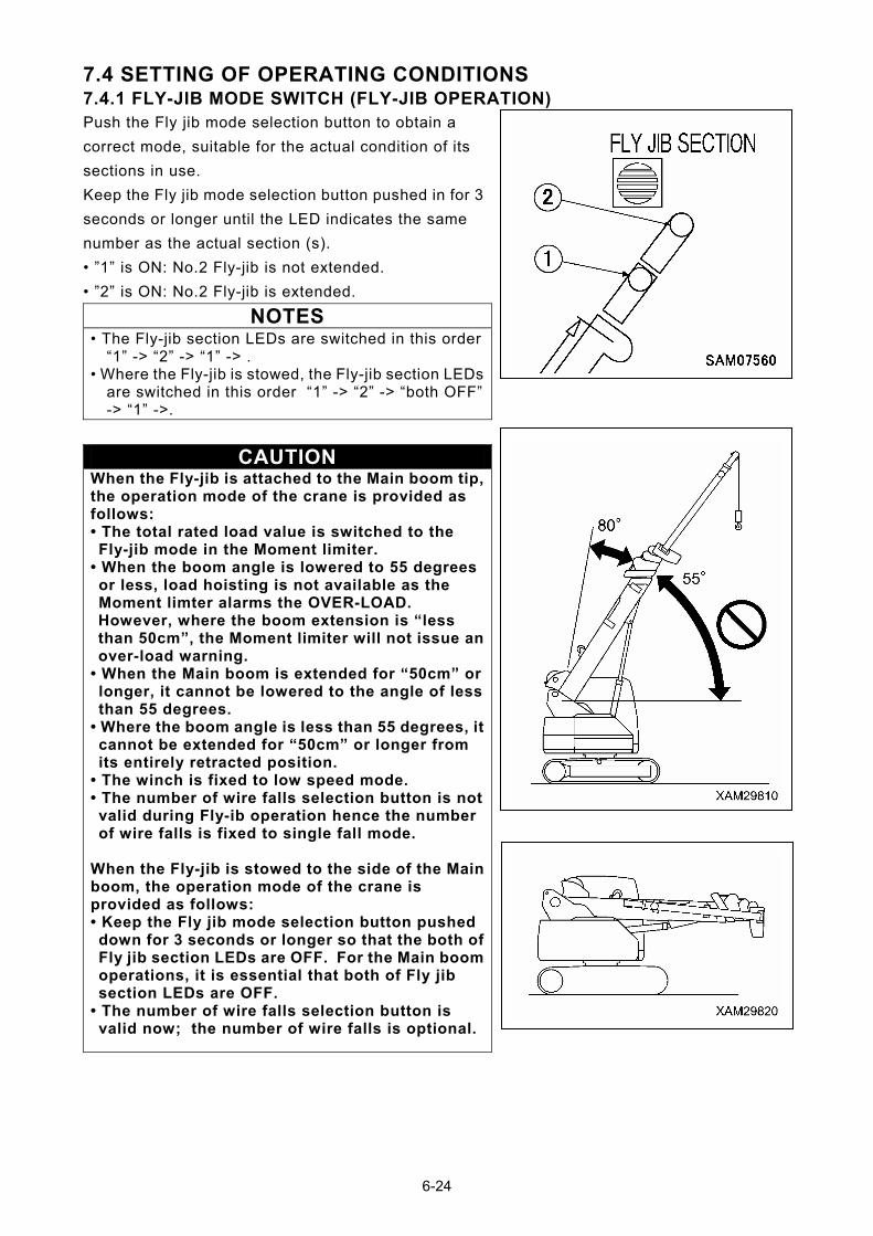
7.4 SETTING OF OPERATING CONDITIONS 7.4.1 FLY-JIB MODE SWITCH (FLY-JIB OPERATION) Push the Fly jib mode selection button to obtain a
correct mode, suitable for the actual condition of its
sections in use.
Keep the Fly jib mode selection button pushed in for 3
seconds or longer until the LED indicates the same
number as the actual section (s).
• ”1” is ON: No.2 Fly-jib is not extended.
• ”2” is ON: No.2 Fly-jib is extended.
NOTES
• The Fly-jib section LEDs are switched in this order “1” -> “2” -> “1” -> .
• Where the Fly-jib is stowed, the Fly-jib section LEDs are switched in this order “1” -> “2” -> “both OFF” -> “1” ->.
CAUTION When the Fly-jib is attached to the Main boom tip, the operation mode of the crane is provided as follows: • The total rated load value is switched to the Fly-jib mode in the Moment limiter.
• When the boom angle is lowered to 55 degrees or less, load hoisting is not available as the Moment limter alarms the OVER-LOAD. However, where the boom extension is “less than 50cm”, the Moment limiter will not issue an over-load warning.
• When the Main boom is extended for “50cm” or longer, it cannot be lowered to the angle of less than 55 degrees.
• Where the boom angle is less than 55 degrees, it cannot be extended for “50cm” or longer from its entirely retracted position.
• The winch is fixed to low speed mode. • The number of wire falls selection button is not valid during Fly-ib operation hence the number of wire falls is fixed to single fall mode.
When the Fly-jib is stowed to the side of the Main boom, the operation mode of the crane is provided as follows: • Keep the Fly jib mode selection button pushed down for 3 seconds or longer so that the both of Fly jib section LEDs are OFF. For the Main boom operations, it is essential that both of Fly jib section LEDs are OFF.
• The number of wire falls selection button is valid now; the number of wire falls is optional.
6-24
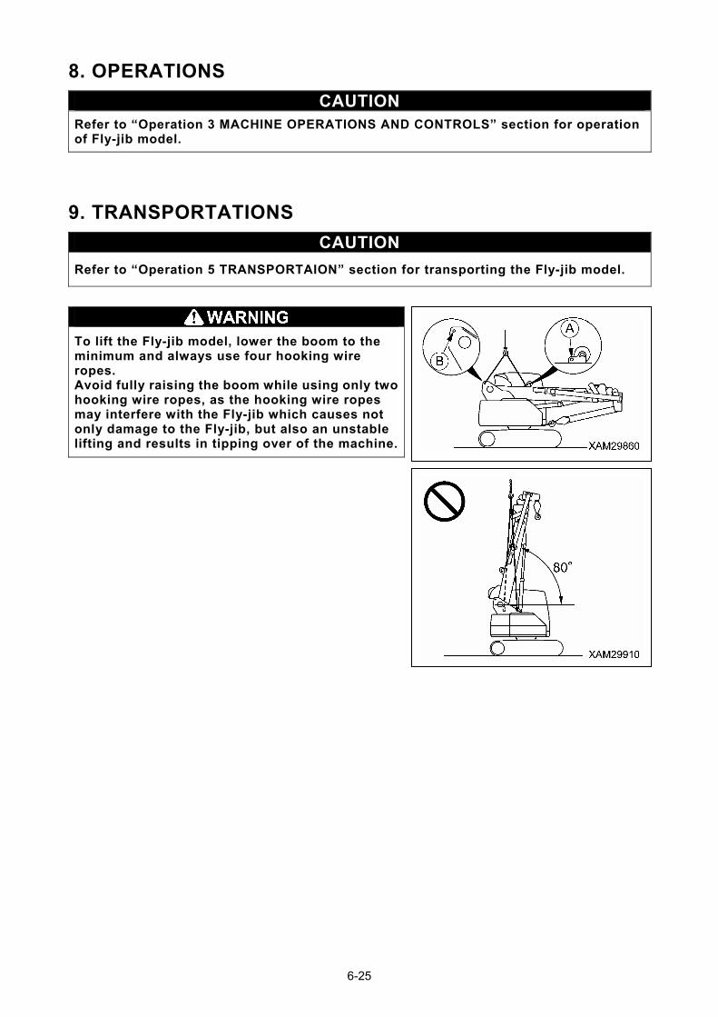
8. OPERATIONS
CAUTION Refer to “Operation 3 MACHINE OPERATIONS AND CONTROLS” section for operation of Fly-jib model.
9. TRANSPORTATIONS
CAUTION
Refer to “Operation 5 TRANSPORTAION” section for transporting the Fly-jib model.
To lift the Fly-jib model, lower the boom to the minimum and always use four hooking wire ropes. Avoid fully raising the boom while using only two hooking wire ropes, as the hooking wire ropes may interfere with the Fly-jib which causes not only damage to the Fly-jib, but also an unstable lifting and results in tipping over of the machine.
6-25
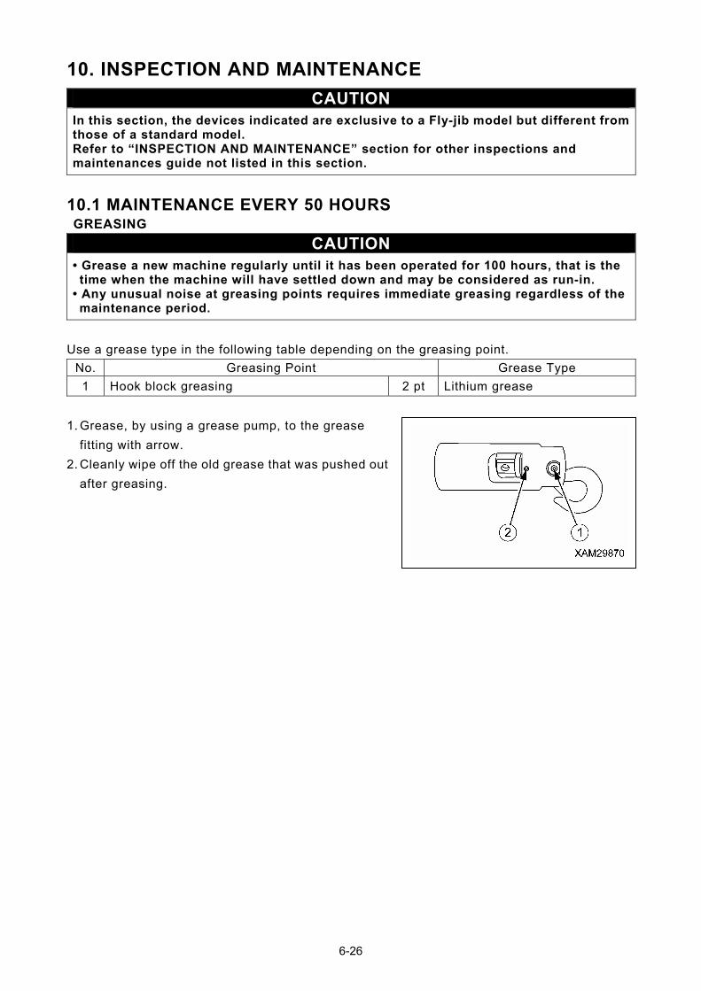
10. INSPECTION AND MAINTENANCE
CAUTION In this section, the devices indicated are exclusive to a Fly-jib model but different from those of a standard model. Refer to “INSPECTION AND MAINTENANCE” section for other inspections and maintenances guide not listed in this section.
10.1 MAINTENANCE EVERY 50 HOURS GREASING
CAUTION • Grease a new machine regularly until it has been operated for 100 hours, that is the time when the machine will have settled down and may be considered as run-in.
• Any unusual noise at greasing points requires immediate greasing regardless of the maintenance period.
Use a grease type in the following table depending on the greasing point.
No. Greasing Point Grease Type
1 Hook block greasing 2 pt Lithium grease
1. Grease, by using a grease pump, to the grease
fitting with arrow.
2. Cleanly wipe off the old grease that was pushed out
after greasing.
6-26
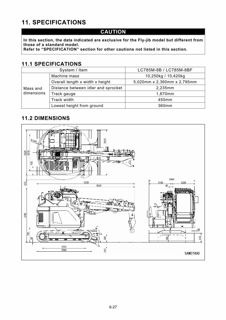
11. SPECIFICATIONS
CAUTION
In this section, the data indicated are exclusive for the Fly-jib model but different from those of a standard model. Refer to “SPECIFICATION” section for other cautions not listed in this section.
11.1 SPECIFICATIONS System / Item LC785M-8B / LC785M-8BF
Machine mass 10,250kg / 10,420kg
Overall length x width x height 5,020mm x 2,360mm x 2,795mm
Distance between idler and sprocket 2,235mm
Track gauge 1,870mm
Track width 450mm
Mass and dimensions
Lowest height from ground 360mm
11.2 DIMENSIONS
6-27

MAEDA CRAWLER CRANE LC785M-8 OPERATION MANUAL
Document No: 557E-OM1202-00
First edition: February 23, 2012
Issued by Maeda Seisakusyo Co., Ltd.
1095 Onbegawa, Shinonoi
Nagano, Nagano 388-8522,
Japan
No part of this manual can be reproduced in any from without permission