INSTALLATION & MAINTENANCE MANUAL | PENTAX pumps
8
INSTALLATION & MAINTENANCE MANUAL EN
-
Upload
khangminh22 -
Category
Documents
-
view
5 -
download
0
Transcript of INSTALLATION & MAINTENANCE MANUAL | PENTAX pumps

INSTALLATION & MAINTENANCEMANUAL
EN

INDEX PAGE
1. 1.1 2. 2.1 2.2 3. 3.1 Product nameplate 3.2 Technical spects 3.3 Inadvisable use 4. 5. Assembly and Start-up 5.1 Assembly 5.2 5.3 Wiring Diagrams 6 6.1 Maintanance and Spare parts
4445566578899
111314

1. SAFETY INSTRUCTIONS
product.
1.1 DESCRIPTION OF WARNING SYMBOLS
DANGER-
ELECTRICAL HAZARDS
of an electric.
WARNINGWARNING
-
2. GENERAL INFORMATION
maintanance of the motors & pumps .
2.2. Please refer to your sales contract for
decline any responsibility for injury to people and/or damage to property due to failure in following our
2.1 PRODUCT CHARACTERISTICSAll submersible motors have been designed to be connected to all types of radial and semi-impeller, sub-
water.
Submersible motors are asynchronous, electric motors with a squirrel cage rotor and are the so called “wet-end” types, that is to say that the winding of the motor is immersed completely under water, or un-der a water-based mix, and this acts as the motor’s internal liquid coolant.
2.2 OPERATION CONDITIONS
by nominal voltage and frequency and the external water temperature outside the motor does not exceed 25°C (77°F), according to NEMA standards.
managed has a temperature in excess of 25°C (77°F), it is possible to use these motors but the power must Table 1. Otherwise, motors
standard, 20 HP motor working with an external water temperature of 35°C (95°F), can be used to deliver maximum power of 20 x 0.80 = 16 HP.
WATER TEMPERATURE COEFFICENT of CORRECTION
25 °C (77 °F) 1.00
30 °C (86 °F) 0.90
35 °C (95 °F) 0.80
40 °C (104 °F) 0.70Standard version motors can be used with external water temperatures of up to 40°C (104°F) provided
then 0,5 m / sec in 6’’, 1 m / sec in 8’’.
-
-
-sists temperatures up to 95°C (203°F).

touches the external surface of the motor.
-
3. PRODUCT SPECIFICATION
3.1 PRODUCT NAMEPLATE
nameplate used for standard motors and the nameplate can change based on the model / product.
A - Type F - Hz K- Serial No B - kW G - RPM L- Product Code (opt.) C - HP H - Cosϕ M- Barcode (opt.) D - Voltage I - Max.Start E - Ampere J- Phase All serial numbers are marked on motor body as per as our manufacturing standards.The serial numbers represents ;
X- power in HP
warning.
150 123456 YX
TYPE 6 K 30 kW22
47.6 A 50 Hz
HP 30
min¯¹2855Speed 0.84
10Max.Start/hour 3~
Voltage 380 V +5%-10%
WATER LUBRICA TED / REWIND ABLE ST ATORO
Serial 30 987654 Prod.Code
SUBMERSIBLE MO TOR
A
BC
D
G
I
K
E
H
J
F
L
M
3.2 TECHNICAL SPECTS
Table-2 contains standard features for our motors.Please review technical catalogues and contact with customer service for more details.
Table-2Product Range Power Diameter of well5” 5.5 HP - 30 HP 150 mm or more6” 5.5 HP - 60 HP 157 mm or more7” 30 HP - 90 HP 180 mm or more8” 30 HP - 150 HP 203 mm or more10” 125 HP - 250 HP 298 mm or more
Standard PVCPE2
Voltage Range 220 V .. 1000 V 50/60Hz % +5 V .. % -10 VSpeed ~2900 rpm @ 50Hz ~3600 rpm @60HzStart DOL or Y-DSound Level ≤ 70 dB (A)
%30 Glycol - % 70 Waterwet-end (standard)
Mechanical Seal Standard Carbon-Ceramic (IP68)SIC (IP68)
5” to 8” NEMA10” Standard
Temperature Sensor
max. Axial Thrust Standard Lead Length5” All 32.0 kN 2.5m6” (5.5HP - 20HP) 15.5 kN 2.5m6” (25HP - 35HP) 25.0 kN 2.5m6” (40HP - 60HP) 30.0 kN 4m7” and 8” - All 45.0 kN 4m10” - All 60.0 kN 5m
Weight See in technical catalogues.Storage temperature -15° C to 60 °C

3.3 INADVISABLE USE
The submersible pumps and motors are not suitable for;• • • • • •
and 1.0 m/s for 10” motor types.• • • A system pressure surges higher than the one stated in the catalogue• An immersion depth exceeding 150m.• Not all submersible pumps are suitable for ;• • Storage at very low temperatures•
4 STORAGE, TRANSPORT , LIFTING, DISPOSAL
complying with the safety rules and suitable for weight, dimensions and shape of motor.
WARNING mechanical damage.
-vent misalignments and excessive bending. (Figure-4.1)
Figure-4.1
equipment and allways use the hooks on the head. (Figure-4.2)
Figure-4.2
WARNING
5 ASSEMBLY AND START-UP
WARNING
the capacity of the pump that it is connected to.
5.1 ASSEMBLY
same standards.
If you buy the pump without the motor and couple it to a motor other than those described in our catalogue, the safety of the unit must be guaranteed by the person making the coupling.
WARNING The power of the motor must be greated or at least equal to that required by the pump to which the motor is to be coupled.If you use a motor other than a stan-dard one, make sure that the axial thrust tolerated by the motor is greated than the maximum axial thrust generated by the pump.
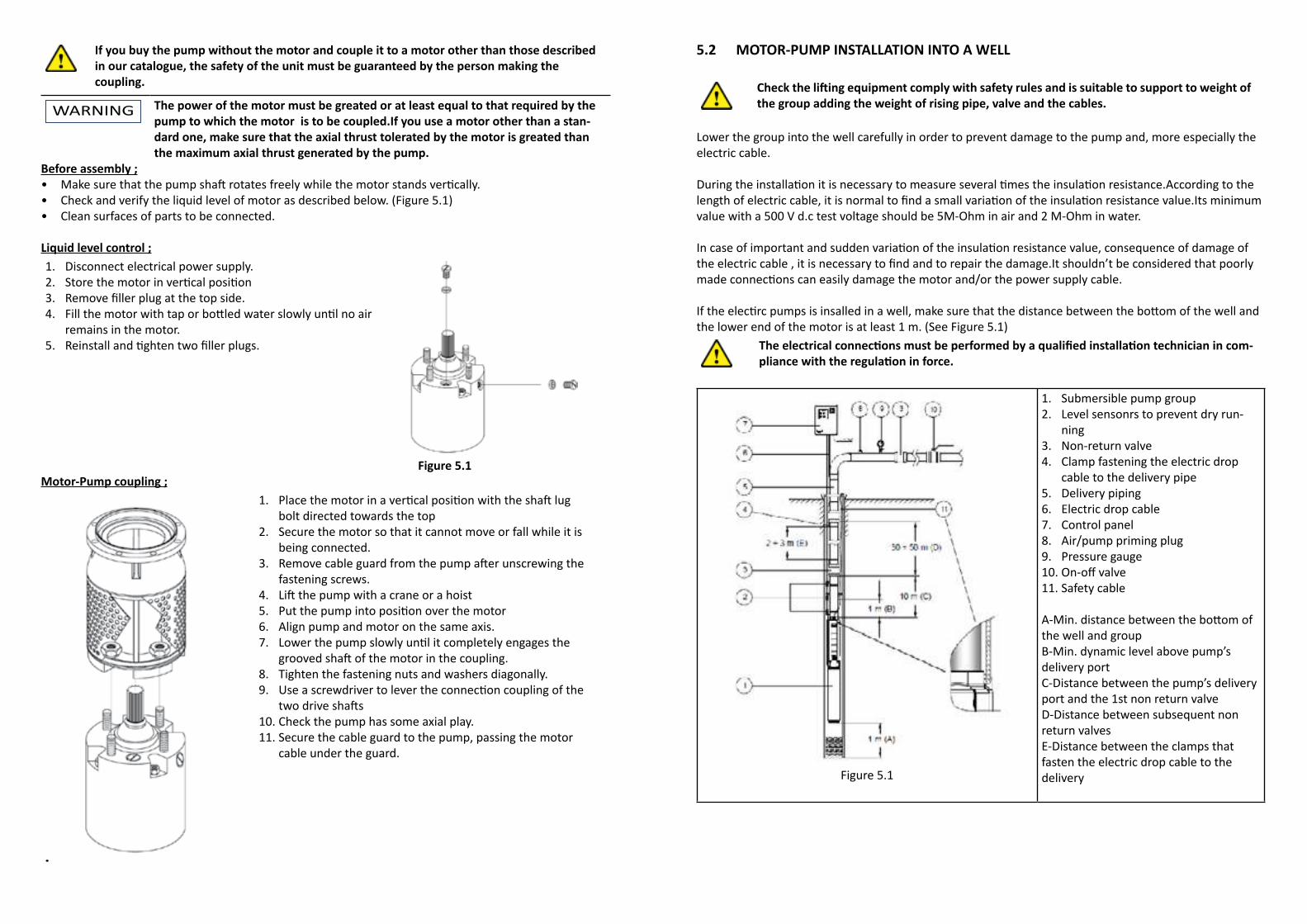
Before assembly ;• • Check and verify the liquid level of motor as described below. (Figure 5.1)• Clean surfaces of parts to be connected.
Liquid level control ;1. Disconnect electrical power supply.2. 3. 4.
remains in the motor.5.
Figure 5.1Motor-Pump coupling ;
•
1. bolt directed towards the top
2. Secure the motor so that it cannot move or fall while it is being connected.
3. fastening screws.
4. 5. 6. Align pump and motor on the same axis.7.
8. Tighten the fastening nuts and washers diagonally. 9.
10. Check the pump has some axial play.11. Secure the cable guard to the pump, passing the motor
cable under the guard.
5.2 MOTOR-PUMP INSTALLATION INTO A WELL
the group adding the weight of rising pipe, valve and the cables.
Lower the group into the well carefully in order to prevent damage to the pump and, more especially the electric cable.
value with a 500 V d.c test voltage should be 5M -Ohm in air and 2 M-Ohm in water.
the lower end of the motor is at least 1 m. (See Figure 5.1)-
Figure 5.1
1. Submersible pump group2. Level sensonrs to prevent dry run-
ning3. Non-return valve4. Clamp fastening the electric drop
cable to the delivery pipe5. Delivery piping6. Electric drop cable7. Control panel8. Air/pump priming plug9. Pressure gauge10. 11. Safety cable
the well and groupB-Min. dynamic level above pump’s delivery portC-Distance between the pump’s delivery port and the 1st non return valveD-Distance between subsequent non return valvesE-Distance between the clamps that fasten the electric drop cable to the delivery

WARNING Make sure that the supply voltages and frequencies are suited to the
The power supply cables -tal requirements.
The capacity of the cable must be in excess of the charge current; this value is equal to the nominal current of the motor for the type with three terminal wires, and is equal to 58% of the nominal current of the motor for the type with six terminals.
Voltage drops along the power supply line must be contained to within strict limits (max 5%)
The capacity of electric cables
refer to Table 5.1 for the factors to be applied according to various temperatures and check technical
Room Temperature 10°C (50°F) 1.2215°C (59°F) 1.1720°C (68°F) 1.1225°C (77°F) 1.0630°C (86°F) 1.0035°C (95°F) 0.94
40°C (104°F) 0.8745°C (113°F) 0.7950°C (122°F) 0.7155°C (131°F) 0.6160°C (140°F) 0.50
Table 5.1
5.3 WIRING DIAGRAMS
STAR DELTA (Y-D) DIRECT (DOL)
SINGLE PHASE (1PH) THREE PHASE (3PH) - DOL
Adjust the overload relay of the appliance to the value of the nominal current of the motor and start it. With an ammeter check the three phases, the amp-draw must be balanced (the maximum acceptable unbalance is 8%) and must be less than the value of the current shown on the label of the motor.
-

6. TROUBLESHOOTING
MULFUNCTION OR FAULT LIKELY CAUSES ACTION
The overload relay trips amp-draw is not bal-anced
The voltage is not the same on all 3 phases.The cable is to ground.The coil-winding is to ground.The pump or the motor are jammed.
correct.
Check the appliance and the line.Repair or replace the cable. Disassemble the motor and rewind it.Disassemble and overhaul it.
Lower head than the declared one. Leaks in delivery pipe.
Worn internal parts.Air or gas in the water.
Replace the pipe or gasket.Dismantle and overhaul. Call the manufacturer.
Delivery inadequate Impellers clogged.The level in the well becomes lower than usual.
Dismantle and overhaul.Check the capacity of the well.
assembly is irregular.The pump operates at too low a head.The water level is too close to the inlet.
Regulate the gate valve on the deliver.
pump
The assembly vibrates. Mechanical parts worn out. Dismantle and overhaul.
of the pump.
6.1 MAINTANANCE AND SPARE PARTS
-tor voltage is free.
Use only original spare parts to replace any components and review manufacturer technical catalogues.
WARNING
CHECK THE WATER LEVEL BEFORE INSTALLATION AND FILL THE MOTOR AS DESCRIBED.
1. STORE MOTOR IN VERTICAL POSITION. (1)2. MANUALLY VERIFY IF MOTOR SHAFT IS FREE TO ROTATE IN BOTH DIRECTIONS. (2)3. TO FILL THE MOTOR REMOVE (UNSCREW) FILLER PLUG AT THE TOP SIDE OF THE MOTOR
AS SHOWN (3).• FILL MOTOR WITH TAP OR BOTTLED WATER SLOWLY UNTIL ITS FULL AND NO AIR REMAINS
IN THE MOTOR.• REINSTALL AND TIGHTEN TWO FILLER PLUGS (3)4. DO NOT OPEN THE FILLER PLUG WHEN THE MOTOR IS IN HORIZONTAL POSITION.5. DO NOT CONNECT POWER SUPPLY OF MOTOR UNTIL THIS OPERATION COMPLETED.
WARNINGTO KEEP YOUR MOTOR WORKING LONGER
READ THIS MANUAL CAREFULLY BEFORE INSTALLATION