Daikin Residential Fresh Air Solution
16
A preselected installation package for air handling and outdoor units Daikin Residential Fresh Air Solution RAHU Series
-
Upload
khangminh22 -
Category
Documents
-
view
0 -
download
0
Transcript of Daikin Residential Fresh Air Solution
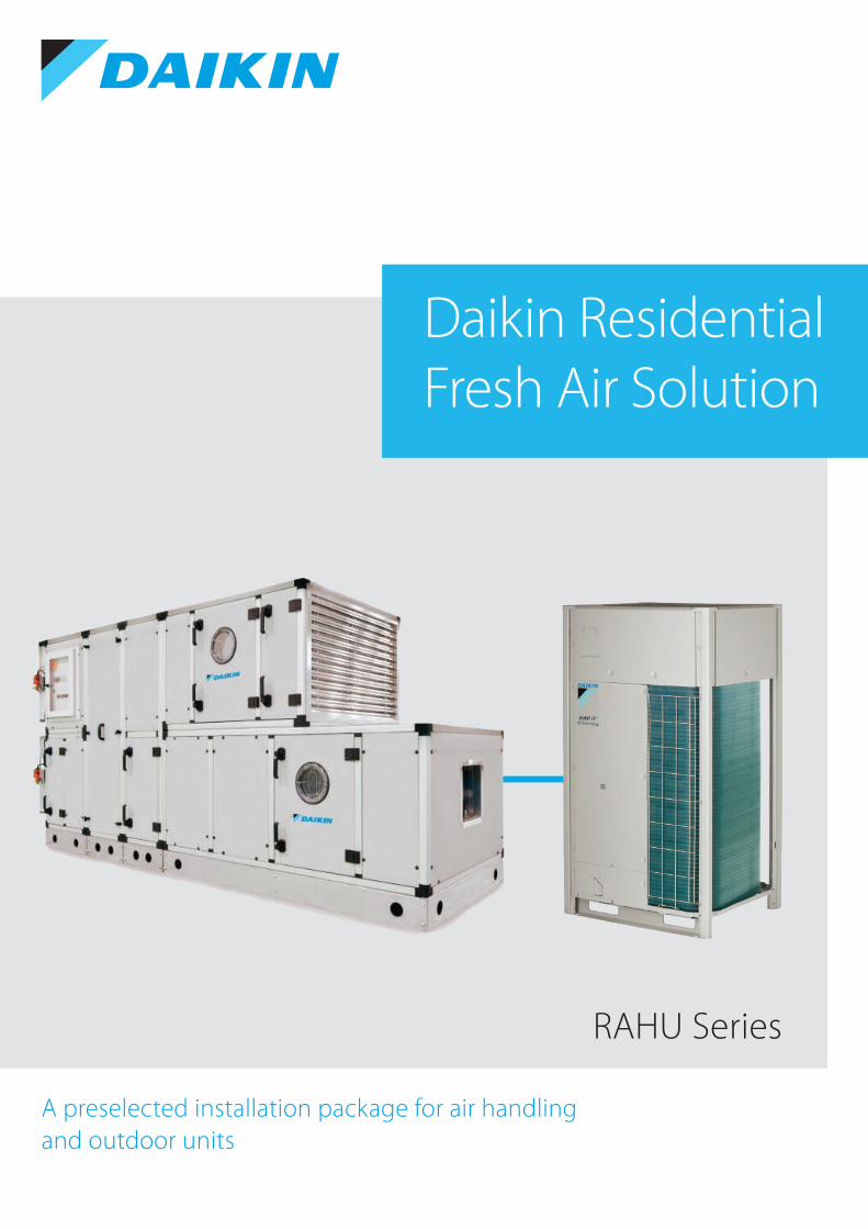
A preselected installation package for air handling and outdoor units
Daikin Residential Fresh Air Solution
RAHU Series
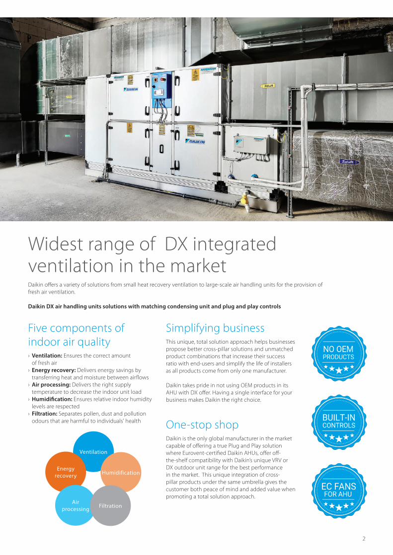
Simplifying business This unique, total solution approach helps businesses propose better cross-pillar solutions and unmatched product combinations that increase their success ratio with end-users and simplify the life of installers as all products come from only one manufacturer.
Daikin takes pride in not using OEM products in its AHU with DX o�er. Having a single interface for your business makes Daikin the right choice.
One-stop shop Daikin is the only global manufacturer in the market capable of o�ering a true Plug and Play solution where Eurovent-certi�ed Daikin AHUs, o�er o�-the-shelf compatibility with Daikin’s unique VRV or DX outdoor unit range for the best performance in the market. This unique integration of cross-pillar products under the same umbrella gives the customer both peace of mind and added value when promoting a total solution approach.
Five components of indoor air quality › Ventilation: Ensures the correct amount of fresh air
› Energy recovery: Delivers energy savings by transferring heat and moisture between air�ows
› Air processing: Delivers the right supply temperature to decrease the indoor unit load
› Ensures relative indoor humidity levels are respected
› Filtration: Separates pollen, dust and pollution odours that are harmful to individuals' health
Widest range of DX integrated ventilation in the market
Ventilation
Energy recovery Humidification
Air processing Filtration
Daikin o�ers a variety of solutions from small heat recovery ventilation to large-scale air handling units for the provision of fresh air ventilation.
Daikin DX air handling units solutions with matching condensing unit and plug and play controls
PRODUCTSNO OEM
CONTROLSBUILT-IN
FOR AHUEC FANS

AHU Frame › Structure with base frame and aluminium pro�les › Rounded pro�le as standard, meeting hygiene requirements › Double chambered pro�les type to ensure �xing screws are totally concealed and there are no projections inside the AHU
› Structure is completed with three-way connecting corners made of glass-reinforced nylon
Panels ›
› Step panels ensures a �at surface inside the unit, ensuring continuity between the panel and the pro�le
›
› Flat roof provided for FAHU to enable outdoor installation
Filters › ›
Coils › ›expanded in to aluminium �ns
›
Heat Wheel (FAHU) › Rotor matrix made of aluminum substrate with desiccant coating › High latent recovery › In-built purge sector to eliminate cross contamination › The rotor wheel outer edge, intermediate beams and purge sector equipped with adjustable brush seals
› The rotor wheel driven by a belt around the periphery which is connected to a pulley and motor
Heat Pipe (FAHU) › Heat pipes provided to precool the air and reheat the supply air in a wrap-around con�guration
›onto the �n collar to form a �rm, rigid, and complete pressure contact at all operating conditions
› The �n surface made of continuous plate type aluminum to provide maximum heat transfer e�ciency
›
Fan › Direct-drive single-inlet centrifugal fan with high-performance airfoil impeller with rotating di�user
› External rotor motor, and integral variable speed drive and control electronics
› › Motorized impeller dynamically balanced according to DIN ISO
Standard Features: ›
› Integrated protective devices• • Locked rotor protection• Phase failure detection• Motor soft start• Mains low voltage detection• Thermal overload protection for electronics and motor
Certi�ed Characteristics - Mechanical › Casing strength (CS) › Casing air leakage (CAL) › Filter bypass leakage (FBL) › Thermal transmittance of the casing (TT) › Thermal bridging factor (TBF) › Acoustical insulation of casing
Certi�ed Characteristics - Performance › Air �ow - available static pressure - power input › Octave band in-duct sound power level › Airborne sound power level › Heating capacity › Cooling capacity › Heat recovery
DX Condensing Units › High-e�ciency scroll compressor with pressure and temperature protection and quiet shut down solution
› Factory-installed �lter drier › Copper tube/aluminum �n coil with herasite �n coating › Service valves with sweat connections and easy-access gauge ports
› Contactor with lug connection › Ground lug connection › Quiet operating top discharge › Heavy-gauge galvanized-steel cabinet with attractive architectural gray powder-paint �nish with steel louver coil guard
› Top and side maintenance access
VRV Condensing Units › Incorporates VRV IV standards and technologies, VRV con�gurator,
generation of inverter compressor with back pressure control › VRV Con�gurator Software for the fastest and most accurate commissioning, con�guration and customization
› Outdoor Unit display for quick on-site settings and easy read out of errors together with the indication of service parameters for checking basic functions
› Suitable for outdoor and indoor installation, made possible as a
› Special anti-corrosion treatment of the heat exchanger provides
The provision of rust proof steel sheet on the underside of the unit gives additional protection

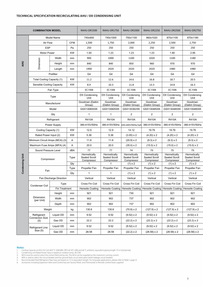
Notes MCA must be used to select the correct �eld wiring size. The MCA can be regarded as the maximum running current MFA is used to select the circuit breaker and the ground fault circuit interruptor (earth leakage circuit breaker) Accesories including Expansion Valve and Control box are Factory �tted and Thermostat or Remote control loose supplied
TECHNICAL SPECIFICATION RECIRCULATING AHU / VRV CONDENSING UNIT
Technical Specification Recirculating AHU / VRV Condensing Unit1 2 3 4 5 6
COMBINATION MODEL RAHU-VR1500 RAHU-VR1750 RAHU-VR2000 RAHU-VR2250 RAHU-VR2500 RAHU-VR2750
AH
U
Model Name 740x900 740x1000 750x1100 860x1020 870x1100 870x1180
Air Flow CFM 1,500 1,750 2,000 2,250 2,500 2,750
ESP Pa 250 250 250 250 250 250
Motor Power KW 1.0 1.23 1.23 1.23 1.8 2.95
Dim
ensi
on Width mm 900 1000 1100 1020 1100 1180
Height mm 840 840 850 960 970 970
Length mm 1780 1900 1900 1900 1860 1860
Prefilter G4 G4 G4 G4 G4 G4
Total Cooling Capacity (1) KW 11.3 13.1 15.1 17.3 19 20.8
Sensible Cooling Capacity KW 8.9 10.3 11.8 13.3 14.8 16.3
Fan Type EC FAN EC FAN EC FAN EC FAN EC FAN EC FAN
Con
dens
ing
Uni
t
Type VRV Series VRV Series VRV Series VRV Series VRV Series VRV SeriesManufacturer Daikin Daikin Daikin Daikin Daikin Daikin
Model RXQ6 RXQ6 RXYTQ8 RXYTQ8 RXYTQ8 RXYTQ8
Qty 1 1 1 1 1 1
Refrigerant R410A R410A R410A R410A R410A R410A
Power Supply 380-415V/50Hz 380-415V/50Hz 380-415V/50Hz 380-415V/50Hz 380-415V/50Hz 380-415V/50Hz
Cooling Capacity (1) KW 11.59 12.70 18.25 18.25 18.25 19.93
Rated Power Input (2) KW 5.10 5.10 6.75 6.75 6.75 6.75
Minimum Circuit Amps (MCA) (3) A 16.1 16.1 16.1 16.1 16.1 16.1
Maximum Fuse Amps (MFA) (4) A 20.0 20.0 20.0 20.0 20.0 20.0
Sound Pressure Level dBA 56 56 57 57 57 57
CompressorType
Hermetically Sealed Scroll Compressor
(Inverter)
Hermetically Sealed Scroll Compressor
(Inverter)
Hermetically Sealed Scroll Compressor
(Inverter)
Hermetically Sealed Scroll Compressor
(Inverter)
Hermetically Sealed Scroll Compressor
(Inverter)
Hermetically Sealed Scroll Compressor
(Inverter)Qty 1 1 1 1 1 1
Fan Type Propeller Fan Propeller Fan Propeller Fan Propeller Fan Propeller Fan Propeller Fan
Qty 1 1 1 1 1 1
Fan Discharge Direction Vertical Vertical Vertical Vertical Vertical Vertical
Condenser Coil
Type Cross Fin Coil Cross Fin Coil Cross Fin Coil Cross Fin Coil Cross Fin Coil Cross Fin Coil
Fin Treatment Blue Fin Coating Blue Fin Coating Blue Fin Coating Blue Fin Coating Blue Fin Coating Blue Fin Coating
Dimension
Height mm 1,657 1,657 1,685 1,685 1,685 1,685
Width mm 930 930 930 930 930 930
Depth mm 765 765 765 765 765 765
Weight kg 165 165 198 198 198 198
Field Refrigerant Pipe Size
Liquid OD mm 9.52 9.52 9.52 9.52 9.52 9.52
Gas OD mm 19.1 19.1 19.1 19.1 19.1 19.1
Notes(۱) Cooling Capacity at AHU On Coil ۱۷/۲٤ °C (DB/WB), Off Coil °۱٤C (DB) & ٤٦ °C ambient, equivalent piping length: ۷٫٥ m (horizontal)(۲) Condensing unit Rated Power Input is based on outdoor temp. ٤٦ CDB (as per ISO ۱٥۰٤۲)(۳) MCA must be used to select the correct field wiring size. The MCA can be regarded as the maximum running current(٤) MFA is used to select the circuit breaker and the ground fault circuit interruptor (earth leakage circuit breaker) (٥) Accesories including Expansion Valve & Control box are Factory fitted and Thermostat or Remote control loose supplied ٦) Maximum Piping Horizontal٥۰- meters (٥٥ meters equivalent) ۷) Maximum Piping Vertical٤۰- meters

7 8 9 10 11 12 13 14 15
RAHU-VR3000 RAHU-VR3250 RAHU-VR3500 RAHU-VR3750 RAHU-VR4000 RAHU-VR4250 RAHU-VR4500 RAHU-VR4750 RAHU-VR5000
930x1170 930x1240 990x1230 990x1290 1050x1280 1050x1430 1050x1440 1050x1460 1170x1360
3,000 3,250 3,500 3,750 4,000 4,250 4,500 4,750 5,000
250 250 250 250 250 250 250 250 250
2.95 2.95 2.68 2.5 2.5 2.5 3.35 3.35 3.35
1170 1240 1230 1290 1280 1430 1440 1460 1360
1030 1030 1090 1090 1150 1150 1150 1150 1270
1860 1860 1930 2000 2000 2000 1990 1990 1990
G4 G4 G4 G4 G4 G4 G4 G4 G4
22.8 24.6 26.5 28.2 30.2 32.7 34.4 36.1 37.6
17.7 19.2 20.7 22.2 23.7 25.1 26.6 28.1 29.6
EC FAN EC FAN EC FAN EC FAN EC FAN EC FAN EC FAN EC FAN EC FAN
VRV Series VRV Series VRV Series VRV Series VRV Series VRV Series VRV Series VRV Series VRV Series
Daikin Daikin Daikin Daikin Daikin Daikin Daikin Daikin Daikin
RXYTQ10 RXYTQ10 RXYTQ12 RXYTQ14 RXYTQ14 RXYTQ14 RXYTQ14 RXYTQ16 RXYTQ16
1 1 1 1 1 1 1 1 1
R410A R410A R410A R410A R410A R410A R410A R410A R410A
380-415V/50Hz 380-415V/50Hz 380-415V/50Hz 380-415V/50Hz 380-415V/50Hz 380-415V/50Hz 380-415V/50Hz 380-415V/50Hz 380-415V/50Hz
23.85 23.85 27.58 34.37 34.37 34.37 34.37 34.27 37.69
8.51 8.51 9.80 11.33 11.33 11.33 11.33 12.79 12.79
22.0 22.0 24.0 27.0 27.0 27.0 27.0 31.0 31.0
25.0 25.0 32.0 32.0 32.0 32.0 32.0 40.0 40.0
59 59 61 61 61 61 61 64 64
Hermetically Sealed Scroll Compressor
(Inverter)
Hermetically Sealed Scroll Compressor
(Inverter)
Hermetically Sealed Scroll Compressor
(Inverter)
Hermetically Sealed Scroll Compressor
(Inverter)
Hermetically Sealed Scroll Compressor
(Inverter)
Hermetically Sealed Scroll Compressor
(Inverter)
Hermetically Sealed Scroll Compressor
(Inverter)
Hermetically Sealed Scroll Compressor
(Inverter)
Hermetically Sealed Scroll Compressor
(Inverter)1 1 1 1 1 2 2 2 2
Propeller Fan Propeller Fan Propeller Fan Propeller Fan Propeller Fan Propeller Fan Propeller Fan Propeller Fan Propeller Fan
2 2 2 2 2 2 2 2 2
Vertical Vertical Vertical Vertical Vertical Vertical Vertical Vertical Vertical
Cross Fin Coil Cross Fin Coil Cross Fin Coil Cross Fin Coil Cross Fin Coil Cross Fin Coil Cross Fin Coil Cross Fin Coil Cross Fin Coil
Blue Fin Coating Blue Fin Coating Blue Fin Coating Blue Fin Coating Blue Fin Coating Blue Fin Coating Blue Fin Coating Blue Fin Coating Blue Fin Coating Blue Fin Coating
1,685 1,685 1,685 1,685 1,685 1,685 1,685 1,685 1,685
1,240 1,240 1,240 1,240 1,240 1,240 1,240 1,240 1,240
765 765 765 765 765 765 765 765 765
234 234 234 283 283 283 283 283 283
9.52 9.52 12.7 12.7 12.7 12.7 12.7 12.7 12.7
22.2 22.2 28.6 28.6 28.6 28.6 28.6 28.6 28.6
(٤) MFA is used to select the circuit breaker and the ground fault circuit interruptor (earth leakage circuit breaker) (٥) Accesories including Expansion Valve & Control box are Factory fitted and Thermostat or Remote control loose supplied
Notes MCA must be used to select the correct �eld wiring size. The MCA can be regarded as the maximum running current MFA is used to select the circuit breaker and the ground fault circuit interruptor (earth leakage circuit breaker) Accesories including Expansion Valve and Control box are Factory �tted and Thermostat or Remote control loose supplied
TECHNICAL SPECIFICATION RECIRCULATING AHU / DX CONDENSING UNIT
/1ph

930x1240
/1ph

TECHNICAL SPECIFICATION FRESH AIR HANDLING UNIT / VRV CONDENSING UNIT
Notes MCA must be used to select the correct �eld wiring size. The MCA can be regarded as the maximum running current MFA is used to select the circuit breaker and the ground fault circuit interruptor (earth leakage circuit breaker) Accesories including Expansion Valve and Control box are Factory �tted and Thermostat or Remote control loose supplied
620x850 620x950 680x950 690x1100
VRV Series VRV Series VRV Series VRV Series

740x1040 750x1150 690x1360 690x1430 750x1450 820x1550
VRV Series VRV Series VRV Series VRV Series VRV Series VRV Series

Notes
MCA must be used to select the correct �eld wiring size. The MCA can be regarded as the maximum running currentMFA is used to select the circuit breaker and the ground fault circuit interruptor (earth leakage circuit breaker)
Accesories including Expansion Valve and Control box are Factory �tted and Thermostat or Remote control loose supplied
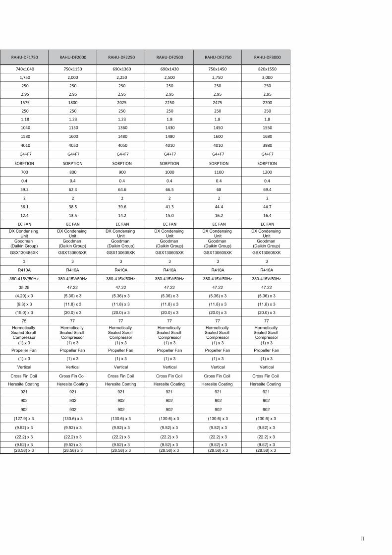
TECHNICAL SPECIFICATION FRESH AIR HANDLING UNIT / DX CONDENSING UNIT
R410AR410A
380-415V/50Hz 220-240V/50Hz/1Ph 220-240V/50Hz/1Ph
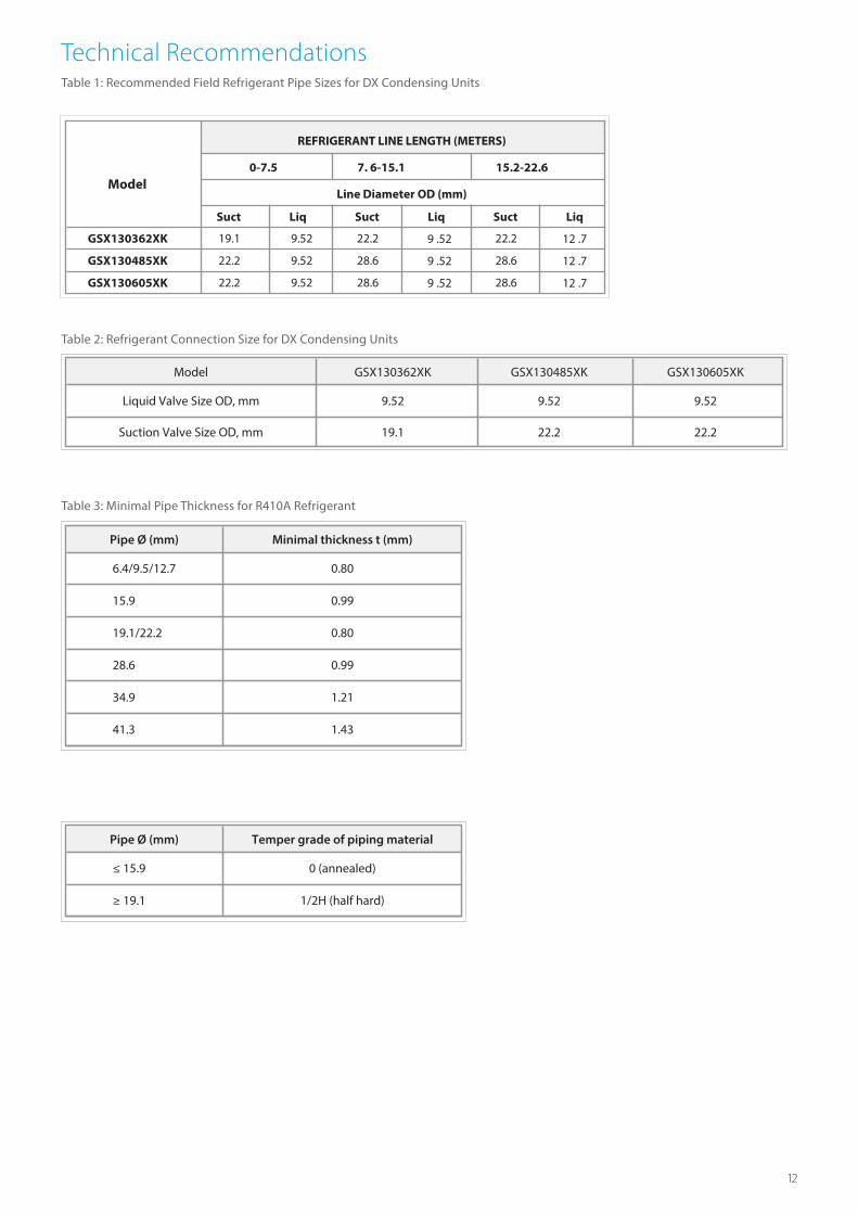
Technical RecommendationsTable 1: Recommended Field Refrigerant Pipe Sizes for DX Condensing Units
Suct Liq Suct Liq Suct Liq
GSX130362XK 19.1 9.52 22.2 9 .52 22.2 12 .7
GSX130485XK 22.2 9.52 28.6 9 .52 28.6 12 .7
GSX130605XK 22.2 9.52 28.6 9 .52 28.6 12 .7
0-7.5 7. 6-15.1 15.2-22.6
Line Diameter OD (mm)Model
REFRIGERANT LINE LENGTH (METERS)
Table 2: Refrigerant Connection Size for DX Condensing Units
Table 3: Minimal Pipe Thickness for R410A Refrigerant
Model GSX130362XK GSX130485XK GSX130605XK
Liquid Valve Size OD, mm 9.52 9.52 9.52
Suction Valve Size OD, mm 19.1 22.2 22.2
Pipe Ø (mm) Minimal thickness t (mm)
6.4/9.5/12.7
15.9
19.1/22.2
28.6
34.9
41.3
0.80
0.99
0.80
0.99
1.21
1.43
Pipe Ø (mm) Temper grade of piping material
≤ 15.9
≥ 19.1
0 (annealed)
1/2H (half hard)

INSTALLATION RECOMMENDATIONS FOR VRV CONDENSING UNITS
Make sure the space around the unit is adequate for servicing and the minimum space for air inlet and air outlet is available (refer to the �gure below and choose one of the possibilities).
INSTALLATION RECOMMENDATIONS FOR AHU
The area chosen for installation must allow for enough space around the unit for comfortably and safely carrying out installation and successive maintenance operations, including the replacement of any internal component (e.g. removal of the heat exchange coils, the �lters, …) see �gure.

INSTALLATION RECOMMENDATIONS FOR DX CONDENSING UNITS
Special consideration must be given to location of the condensing unit(s) in regard to structures, obstructions, other units, and any/all other factors that may interfere with air circulation. Where possible, the top of the unit should be completely unobstructed; however, if vertical conditions require placement beneath an obstruction
dimensions meet requirements for air circulation only. Consult all appropriate regulatory codes prior to determining �nal clearances.
Another important consideration in selecting a location for the unit(s) is the angle to obstructions. Either side adjacent the valves be placed toward the structure provided the side away from the structure maintains minimum service clearance. Corner installations are strongly discouraged.
› In case of an installation site where sides A+B+C+D have obstacles, the wall heights of sides A+C have no impact on service space dimensions. Refer to the �gure above for impact of wall heights of sides B+D on service space dimensions.
› In case of installation site where only the sides A+B have obstacles, the wall heights have no in�uence on any indicated service space dimensions
OK!OK!
AA AAA
A
CC
C COK!
OK!
OK!OK!
NOTRECOMMENDED
AA
AA AA
AAAA
B B B
B
Model Type A B C AAResidential 10" 10" 18" 20"
Light Commercial 12" 12" 18" 24"
Minimum Air ow Clearance
A B C AA
300 300 450 600
Minimum Air ow Clearance, mm

The main components of a Daikin AHU are: › Supply and return fast: Supply and return fans are used to regulate the air volume. › Air �lters: pre-�lter and bag �lter: Every AHU unit can be equipped with several types of �lters used to clean the air from little particles of dust etc.
› Device for heat recovery: These devices are used to recover cooling or heating from the return air.
› DX coils: These are the devices used for air temperature conditioning. › Electrical and Control Section: The AHU is equipped with electrical and controls section for the power input to the supply fan, return fan and the controllers including the switchgear, control components, relays, etc.
› Field Sensors: To control the air handling units the required temperature and pressure sensors will be provided.
Controller: Daikin o�ers maximum �exibility in the control and monitoring of AHU unit. Comprehensive system functions such as alarm management, time scheduling to cover all requirements associated with the operation of an air handling system.
• Main controller• I/O modules• Integration by BMS (Modbus RTU/RS485) Optional
The main controller provides the following functions• Control functions• Onboard I/O’s
I/O Modules:The I/O modules provide additional I/O points by connecting to the main controller. The types of I/O points include the following.
• Analog Outputs: 0-10VDC• Analog Inputs: NTC 10K• Digital Outputs: Potential free contacts (Non-Voltage)• Digital Inputs are: Potential free / Potential contacts (Voltage)
The number of I/O modules needed varies depending on the system con�guration.
Sensors: To control the Air Handling units the below sensors will be installed as part of AHU.
• Temperature sensor• Pressure sensor
Controls

Daikin Middle East and Africa
The present publication is drawn up by way of information only and does not constitute an o�er binding upon Daikin Middle East and Africa FZE has compiled the content of this publication to the best of its knowledge. No express or implied warranty is given for the completeness, accuracy, reliability or �tness for particular purpose of its content and the products and services presented therein. Speci�cations are subject to change without prior notice. Daikin Middle East and Africa FZE explicitly rejects any liability for any direct or indirect damage, in the broadest sense, arising from or related to the use and/or interpretation of this publication. All content is copyrighted by Daikin Middle East and Africa FZE.
www.daikinmea.com