Engineering Data - Daikin AC
76
RXYQ-TAYCU, 575 V EDUS341824-D 201806 Engineering Data Heat Pump 60 Hz
-
Upload
khangminh22 -
Category
Documents
-
view
4 -
download
0
Transcript of Engineering Data - Daikin AC

RXYQ-TAYCU, 575 V
EDUS341824-D201806
Engineering Data
Heat Pump 60 Hz


1
RXYQ-TAYCU EDUS341824-D
RXYQ-TAYCU (575 V, 60 Hz)
1. FeaturesandBenefits ................................................................................32. Nomenclature .............................................................................................43. Model Names of Indoor Unit and Outdoor Unit ..........................................7
3.1 Outdoor Units ....................................................................................73.2 Indoor Units .......................................................................................83.3 Air Treatment Equipment ..................................................................9
4. External Appearance ................................................................................104.1 Outdoor Units ..................................................................................104.2 Indoor Units .....................................................................................114.3 Air Treatment Equipment ................................................................12
5. Outdoor Unit Combination ........................................................................136. Capacity Range ........................................................................................14
6.1 Connection Ratio ............................................................................146.2 Indoor Unit Connection Capacity ....................................................15
7. Specifications ...........................................................................................167.1 RXYQ-TAYCU ................................................................................16
8. Dimensions ...............................................................................................219. Service Space ..........................................................................................2410. Center of Gravity ......................................................................................2611. Foundation Drawing .................................................................................2812. Piping Diagrams .......................................................................................2913. Wiring Diagrams .......................................................................................3114. Field Wiring ..............................................................................................3315. Electrical Characteristics ..........................................................................3616. Operation Limits .......................................................................................3717. Sound Levels (Reference Data) ...............................................................3818. Accessories ..............................................................................................43
18.1 Optional Accessories ......................................................................4319. Selection Procedure .................................................................................44
19.1 Selection Procedure ........................................................................4420. Caution Label ...........................................................................................50
20.1 RXYQ72 - 120TAYCU ....................................................................5021. Caution for Refrigerant Leaks ..................................................................59
21.1 Introduction .....................................................................................5921.2 Procedure for Checking Maximum Concentration ..........................60
2
RXYQ-TAYCU EDUS341824-D
22. Safety Devices Setting .............................................................................6222.1 FXFQ-T ...........................................................................................6222.2 FXZQ-TA .........................................................................................6222.3 FXUQ-P ..........................................................................................6222.4 FXEQ-P ...........................................................................................6222.5 FXDQ-M ..........................................................................................6322.6 FXSQ-TA ........................................................................................6322.7 FXMQ-PB ........................................................................................6322.8 FXMQ-M .........................................................................................6322.9 FXHQ-M ..........................................................................................6422.10 FXAQ-P ...........................................................................................6422.11 FXLQ-M, FXNQ-M ..........................................................................6422.12 FXTQ-TA .........................................................................................64
Appendix........................................................................................................651. Introduction ...............................................................................................66
1.1 ED Book List ...................................................................................661.2 Publication List of Engineering Data for VRV Products ..................67
2. GuideSpecifications .................................................................................692.1 GuideSpecifications .......................................................................69
3
RXYQ-TAYCU EDUS341824-D
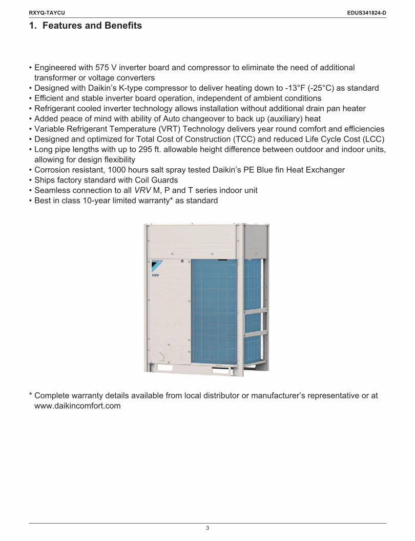
1. Features and Benefits
• Engineered with 575 V inverter board and compressor to eliminate the need of additional transformer or voltage converters
• Designed with Daikin’s K-type compressor to deliver heating down to -13°F (-25°C) as standard •Efficientandstableinverterboardoperation,independentofambientconditions• Refrigerant cooled inverter technology allows installation without additional drain pan heater• Added peace of mind with ability of Auto changeover to back up (auxiliary) heat•VariableRefrigerantTemperature(VRT)Technologydeliversyearroundcomfortandefficiencies• Designed and optimized for Total Cost of Construction (TCC) and reduced Life Cycle Cost (LCC)•Longpipelengthswithupto295ft.allowableheightdifferencebetweenoutdoorandindoorunits,allowingfordesignflexibility
•Corrosionresistant,1000hourssaltspraytestedDaikin’sPEBluefinHeatExchanger• Ships factory standard with Coil Guards• Seamless connection to all VRV M, P and T series indoor unit • Best in class 10-year limited warranty* as standard
* Complete warranty details available from local distributor or manufacturer’s representative or at www.daikincomfort.com

4
RXYQ-TAYCU EDUS341824-D
2. Nomenclature
Outdoor Unit
384QR X Y T A UYC
Standard SymbolU: United States of America
Power Supply SymbolYC: 3 phase, 575 V, 60 Hz
Indicates Minor Change Category
Indicates Major Design CategoryT:
RefrigerantQ: R410A
TypeL:
Series categoryX: Heat pumpE: Heat recovery
Unit categoryR: Outdoor unit for air cooled type
Capacity Indication in cooling72 : 72,000 Btu/h96 : 96,000 Btu/h120 : 120,000 Btu/h144 : 144,000 Btu/h168 : 158,000 Btu/h
192 : 192,000 Btu/h216 : 216,000 Btu/h240 : 240,000 Btu/h264 : 264,000 Btu/h 288 : 288,000 Btu/h
312 : 306,000 Btu/h336 : 324,000 Btu/h360 : 360,000 Btu/h384 : 368,000 Btu/h

5
RXYQ-TAYCU EDUS341824-D
Indoor Unit
M 54 VJPB UX QF
Standard symbolU: United States of America
Power supply symbolVJ: 1 phase, 208/230 V, 60 Hz
Indicates major design category
Capacity indication in cooling05: 5,800 Btu/h 18: 18,000 Btu/h 48: 48,000 Btu/h07: 7,500 Btu/h 24: 24,000 Btu/h 54: 54,000 Btu/h09: 9,500 Btu/h 30: 30,000 Btu/h 60: 60,000 Btu/h12: 12,000 Btu/h 36: 36,000 Btu/h 72: 72,000 Btu/h15: 15,000 Btu/h 42: 42,000 Btu/h 96: 96,000 Btu/h
RefrigerantQ: R410A
ShapeF: Ceiling Mounted Cassette (Round Flow with Sensing)Z: VISTA™ 2 × 2 Cassette UnitU: 4-Way Blow Ceiling-SuspendedE: One Way Blow CassetteD: Slim Ceiling Mounted DuctS: MSP Concealed Ducted UnitM: Ceiling Mounted DuctH: Ceiling SuspendedA: Wall MountedL: Floor StandingN: Concealed Floor StandingT: Air Handling Unit
Series categoryX: Inverter
Unit categoryF: Indoor Unit for Air Cooled Type
6
RXYQ-TAYCU EDUS341824-D
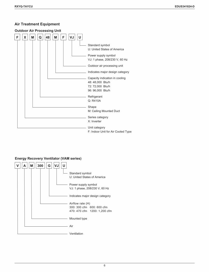
Air Treatment Equipment
M 48 VJ UM FX QF
Standard symbolU: United States of America
Power supply symbolVJ: 1 phase, 208/230 V, 60 Hz
Outdoor air processing unit
Indicates major design category
Capacity indication in cooling48: 48,000 Btu/h72: 72,000 Btu/h96: 96,000 Btu/h
RefrigerantQ: R410A
ShapeM: Ceiling Mounted Duct
Series categoryX: Inverter
Unit categoryF: Indoor Unit for Air Cooled Type
Outdoor Air Processing Unit
UG300V A M VJ
Standard symbolU: United States of America
Power supply symbolVJ: 1 phase, 208/230 V, 60 Hz
Indicates major design category
Airflow rate (H)300: 300 cfm 600: 600 cfm470: 470 cfm 1200: 1,200 cfm
Mounted type
Air
Ventilation
Energy Recovery Ventilator (VAM series)
7
RXYQ-TAYCU EDUS341824-D
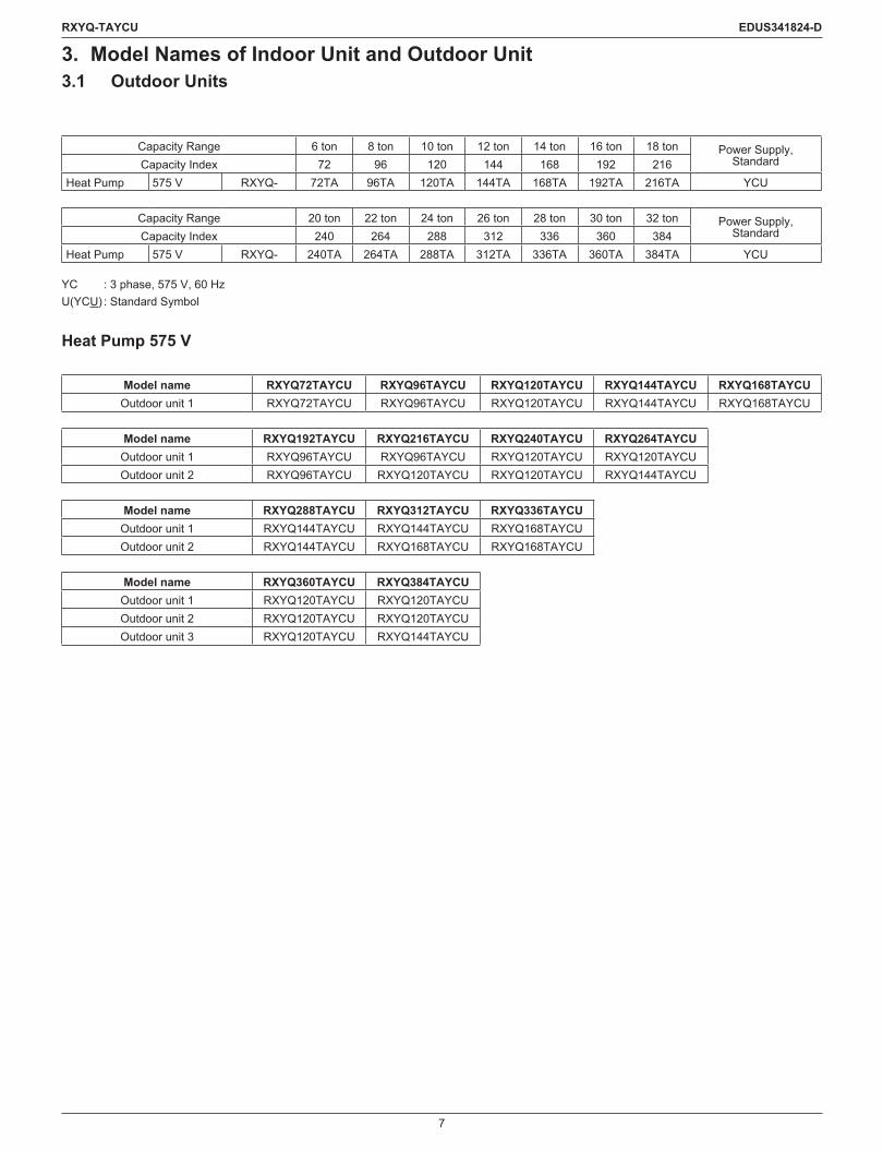
3. Model Names of Indoor Unit and Outdoor Unit3.1 Outdoor Units
Capacity Range 6 ton 8 ton 10 ton 12 ton 14 ton 16 ton 18 ton Power Supply, StandardCapacity Index 72 96 120 144 168 192 216
Heat Pump 575 V RXYQ- 72TA 96TA 120TA 144TA 168TA 192TA 216TA YCU
Capacity Range 20 ton 22 ton 24 ton 26 ton 28 ton 30 ton 32 ton Power Supply, StandardCapacity Index 240 264 288 312 336 360 384
Heat Pump 575 V RXYQ- 240TA 264TA 288TA 312TA 336TA 360TA 384TA YCU
YC : 3 phase, 575 V, 60 HzU(YCU) : Standard Symbol
Heat Pump 575 V
Model name RXYQ72TAYCU RXYQ96TAYCU RXYQ120TAYCU RXYQ144TAYCU RXYQ168TAYCUOutdoor unit 1 RXYQ72TAYCU RXYQ96TAYCU RXYQ120TAYCU RXYQ144TAYCU RXYQ168TAYCU
Model name RXYQ192TAYCU RXYQ216TAYCU RXYQ240TAYCU RXYQ264TAYCUOutdoor unit 1 RXYQ96TAYCU RXYQ96TAYCU RXYQ120TAYCU RXYQ120TAYCUOutdoor unit 2 RXYQ96TAYCU RXYQ120TAYCU RXYQ120TAYCU RXYQ144TAYCU
Model name RXYQ288TAYCU RXYQ312TAYCU RXYQ336TAYCUOutdoor unit 1 RXYQ144TAYCU RXYQ144TAYCU RXYQ168TAYCUOutdoor unit 2 RXYQ144TAYCU RXYQ168TAYCU RXYQ168TAYCU
Model name RXYQ360TAYCU RXYQ384TAYCUOutdoor unit 1 RXYQ120TAYCU RXYQ120TAYCUOutdoor unit 2 RXYQ120TAYCU RXYQ120TAYCUOutdoor unit 3 RXYQ120TAYCU RXYQ144TAYCU

8
RXYQ-TAYCU EDUS341824-D
3.2 Indoor Units
Capacity Range 0.5 ton 0.6 ton 0.8 ton 1 ton 1.25 ton 1.5 ton 2 ton 2.5 ton 3 ton 3.5 ton 4 ton 4.5 ton 5 ton 6 ton 8 ton Power Supply, StandardCapacity Index 5.8 7.5 9.5 12 15 18 20 24 30 36 42 48 54 60 72 96
Ceiling Mounted Cassette (Round Flow with Sensing) Type
FXFQ — 07T 09T 12T 15T 18T — 24T 30T 36T — 48T — — — —
VJU
VISTA™ 2 × 2 Cassette Unit FXZQ 05TA 07TA 09TA 12TA 15TA 18TA — — — — — — — — — —4-Way Blow Ceiling-Suspended Type FXUQ — — — — — — 18P 24P 30P 36P — — — — — —
One Way Blow Cassette Type FXEQ — 07P 09P 12P 15P 18P — 24P — — — — — — — —
Slim Ceiling Mounted Duct Type FXDQ — 07M 09M 12M — 18M — 24M — — — — — — — —
MSP Concealed Ducted Unit FXSQ 05TA 07TA 09TA 12TA 15TA 18TA — 24TA 30TA 36TA — 48TA 54TA — — —Ceiling Mounted Duct Type (Middle and High Static Pressure)
FXMQ — 07PB 09PB 12PB 15PB 18PB — 24PB 30PB 36PB — 48PB 54PB — — —
Ceiling Mounted Duct Type FXMQ — — — — — — — — — — — — — — 72M 96MCeiling Suspended Type FXHQ — — — 12M — — — 24M — 36M — — — — — —Wall Mounted Type FXAQ — 07P 09P 12P — 18P — 24P — — — — — — — —Floor Standing Type FXLQ — 07M 09M 12M — 18M — 24M — — — — — — — —Concealed Floor Standing Type FXNQ — 07M 09M 12M — 18M — 24M — — — — — — — —
Air Handling Unit FXTQ— — 09TA 12TA — 18TA — 24TA 30TA 36TA 42TA 48TA 54TA 60TA — — VJUA— — 09TA 12TA — 18TA — 24TA 30TA 36TA 42TA 48TA 54TA 60TA — — VJUD
VJ : 1 phase, 208/230 V, 60 HzU(VJU) : Standard Symbol

9
RXYQ-TAYCU EDUS341824-D
3.3 Air Treatment EquipmentOutdoor Air Processing Unit
Series Model Name Power Supply, StandardFXMQ 48MF 72MF 96MF VJU
VJ : 1 phase, 208/230 V, 60 HzU(VJU) : Standard Symbol
Energy Recovery Ventilator (VAM series)
Series Model Name Power Supply, StandardVAM 300G 470G 600G 1200G VJU
VJ : 1 phase, 208/230 V, 60 HzU(VJU) : Standard Symbol
10
RXYQ-TAYCU EDUS341824-D
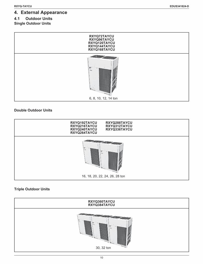
4. External Appearance4.1 Outdoor UnitsSingle Outdoor Units
RXYQ72TAYCURXYQ96TAYCU
RXYQ120TAYCURXYQ144TAYCURXYQ168TAYCU
6, 8, 10, 12, 14 ton
Double Outdoor Units
RXYQ192TAYCU RXYQ288TAYCURXYQ216TAYCU RXYQ312TAYCURXYQ240TAYCU RXYQ336TAYCURXYQ264TAYCU
16, 18, 20, 22, 24, 26, 28 ton
Triple Outdoor Units
RXYQ360TAYCURXYQ384TAYCU
30, 32 ton

11
RXYQ-TAYCU EDUS341824-D
4.2 Indoor Units
Ceilingmountedcassette(Roundflowwithsensing)type
FXFQ-T
Shown with BYCQ125B-W1
Ceiling mounted duct type
FXMQ-M
VISTA™ 2 × 2 Cassette Unit
FXZQ-TA
Shown with BYFQ60C3W1W Shown with BYFQ60C3W1S
Ceiling suspended type
FXHQ-M
4-way blow ceiling-suspended type
FXUQ-P
Wall mounted type
FXAQ-P
One way blow cassette type
FXEQ-P
Floor standing type
FXLQ-M
Slim ceiling mounted duct type
FXDQ-M
Concealedfloorstandingtype
FXNQ-M
MSP Concealed Ducted Unit
FXSQ-TA
Air handling unit
FXTQ-TA
Ceiling mounted duct type (Middle and high static pressure)
FXMQ-PB

12
RXYQ-TAYCU EDUS341824-D
4.3 Air Treatment Equipment
Outdoor air processing unit
FXMQ-MF
Energy recovery ventilator (VAM series)
VAM-G
13
RXYQ-TAYCU EDUS341824-D
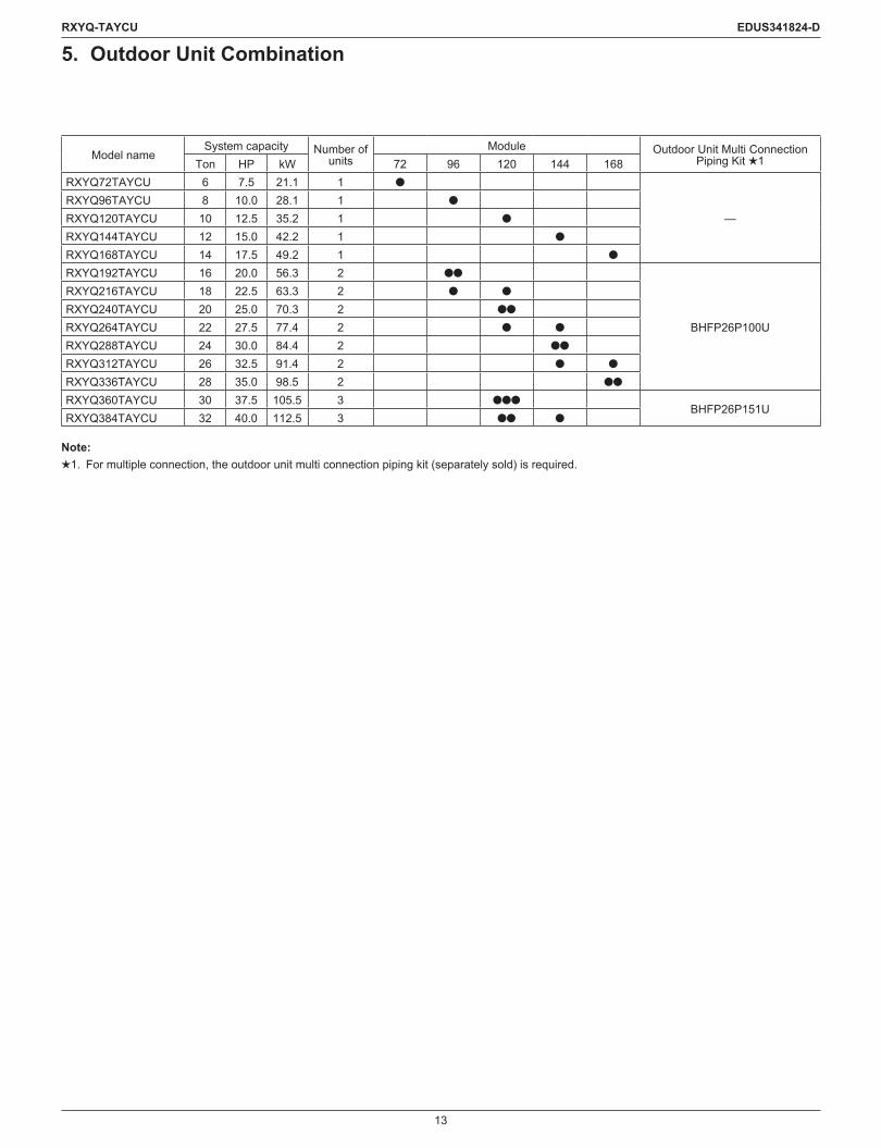
5. Outdoor Unit Combination
Model nameSystem capacity Number of
unitsModule Outdoor Unit Multi Connection
Piping Kit 1Ton HP kW 72 96 120 144 168RXYQ72TAYCU 6 7.5 21.1 1 l
—RXYQ96TAYCU 8 10.0 28.1 1 l
RXYQ120TAYCU 10 12.5 35.2 1 l
RXYQ144TAYCU 12 15.0 42.2 1 l
RXYQ168TAYCU 14 17.5 49.2 1 l
RXYQ192TAYCU 16 20.0 56.3 2 ll
BHFP26P100U
RXYQ216TAYCU 18 22.5 63.3 2 l l
RXYQ240TAYCU 20 25.0 70.3 2 ll
RXYQ264TAYCU 22 27.5 77.4 2 l l
RXYQ288TAYCU 24 30.0 84.4 2 ll
RXYQ312TAYCU 26 32.5 91.4 2 l l
RXYQ336TAYCU 28 35.0 98.5 2 ll
RXYQ360TAYCU 30 37.5 105.5 3 lllBHFP26P151U
RXYQ384TAYCU 32 40.0 112.5 3 ll l
Note:1. For multiple connection, the outdoor unit multi connection piping kit (separately sold) is required.
14
RXYQ-TAYCU EDUS341824-D
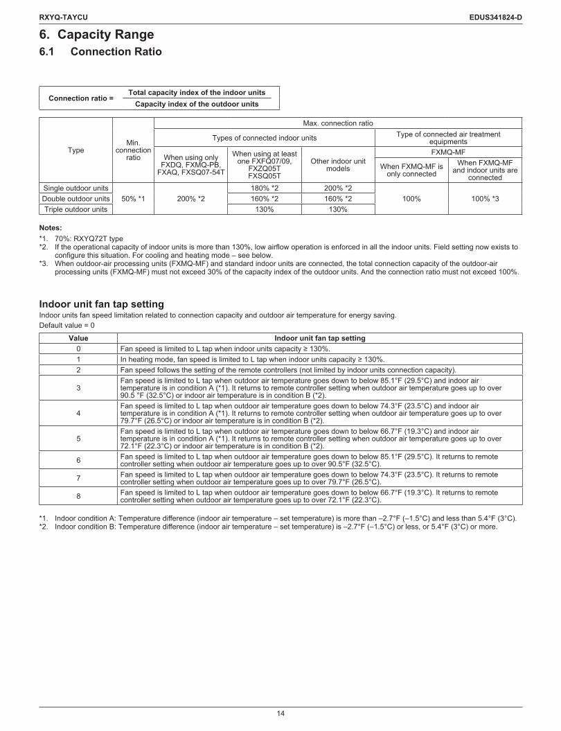
6. Capacity Range6.1 Connection Ratio
Connection ratio =Total capacity index of the indoor units
Capacity index of the outdoor units
TypeMin.
connection ratio
Max. connection ratio
Types of connected indoor units Type of connected air treatment equipments
When using only FXDQ, FXMQ-PB,
FXAQ, FXSQ07-54T
When using at least one FXFQ07/09,
FXZQ05TFXSQ05T
Other indoor unit models
FXMQ-MF
When FXMQ-MF is only connected
When FXMQ-MF and indoor units are
connectedSingle outdoor units
50% *1 200% *2180% *2 200% *2
100% 100% *3Double outdoor units 160% *2 160% *2Triple outdoor units 130% 130%
Notes:*1. 70%: RXYQ72T type*2. Iftheoperationalcapacityofindoorunitsismorethan130%,lowairflowoperationisenforcedinalltheindoorunits.Fieldsettingnowexiststo
configurethissituation.Forcoolingandheatingmode–seebelow.*3. When outdoor-air processing units (FXMQ-MF) and standard indoor units are connected, the total connection capacity of the outdoor-air
processing units (FXMQ-MF) must not exceed 30% of the capacity index of the outdoor units. And the connection ratio must not exceed 100%.
Indoor unit fan tap settingIndoor units fan speed limitation related to connection capacity and outdoor air temperature for energy saving.Default value = 0
Value Indoor unit fan tap setting0 FanspeedislimitedtoLtapwhenindoorunitscapacity≥130%.1 Inheatingmode,fanspeedislimitedtoLtapwhenindoorunitscapacity≥130%.2 Fan speed follows the setting of the remote controllers (not limited by indoor units connection capacity).
3Fan speed is limited to L tap when outdoor air temperature goes down to below 85.1°F (29.5°C) and indoor air temperature is in condition A (*1). It returns to remote controller setting when outdoor air temperature goes up to over 90.5 °F (32.5°C) or indoor air temperature is in condition B (*2).
4Fan speed is limited to L tap when outdoor air temperature goes down to below 74.3°F (23.5°C) and indoor air temperature is in condition A (*1). It returns to remote controller setting when outdoor air temperature goes up to over 79.7°F (26.5°C) or indoor air temperature is in condition B (*2).
5Fan speed is limited to L tap when outdoor air temperature goes down to below 66.7°F (19.3°C) and indoor air temperature is in condition A (*1). It returns to remote controller setting when outdoor air temperature goes up to over 72.1°F (22.3°C) or indoor air temperature is in condition B (*2).
6 Fan speed is limited to L tap when outdoor air temperature goes down to below 85.1°F (29.5°C). It returns to remote controller setting when outdoor air temperature goes up to over 90.5°F (32.5°C).
7 Fan speed is limited to L tap when outdoor air temperature goes down to below 74.3°F (23.5°C). It returns to remote controller setting when outdoor air temperature goes up to over 79.7°F (26.5°C).
8 Fan speed is limited to L tap when outdoor air temperature goes down to below 66.7°F (19.3°C). It returns to remote controller setting when outdoor air temperature goes up to over 72.1°F (22.3°C).
*1. IndoorconditionA:Temperaturedifference(indoorairtemperature–settemperature)ismorethan–2.7°F(–1.5°C)andlessthan5.4°F(3°C).*2. IndoorconditionB:Temperaturedifference(indoorairtemperature–settemperature)is–2.7°F(–1.5°C)orless,or5.4°F(3°C)ormore.
15
RXYQ-TAYCU EDUS341824-D
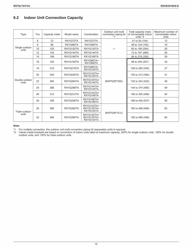
6.2 Indoor Unit Connection Capacity
Type Ton Capacity index Model name CombinationOutdoor unit multi
connection piping kit *1
Total capacity index of connectable indoor
units *2
Maximum number of connectable indoor
units
Single outdoor units
6 72 RXYQ72TA RXYQ72TA
—
51 to 93 (144) 128 96 RXYQ96TA RXYQ96TA 48 to 124 (192) 1610 120 RXYQ120TA RXYQ120TA 60 to 156 (240) 2012 144 RXYQ144TA RXYQ144TA 72 to 187 (288) 2514 168 RXYQ168TA RXYQ168TA 84 to 218 (336) 29
Double outdoor units
16 192 RXYQ192TA RXYQ96TA+ RXYQ96TA
BHFP22P100U
96 to 249 (307) 33
18 216 RXYQ216TA RXYQ96TA+ RXYQ120TA 108 to 280 (345) 37
20 240 RXYQ240TA RXYQ120TA+ RXYQ120TA 120 to 312 (384) 41
22 264 RXYQ264TA RXYQ120TA+ RXYQ144TA 132 to 343 (422) 45
24 288 RXYQ288TA RXYQ144TA+ RXYQ144TA 144 to 374 (460) 49
26 312 RXYQ312TA RXYQ144TA+ RXYQ168TA 156 to 405 (499) 54
28 336 RXYQ336TA RXYQ168TA+ RXYQ168TA 168 to 436 (537) 58
Triple outdoor units
30 360 RXYQ360TARXYQ120TA+ RXYQ120TA+ RXYQ120TA
BHFP26P151U
180 to 468 (468) 62
32 384 RXYQ384TARXYQ120TA+ RXYQ120TA+ RXYQ144TA
192 to 499 (499) 64
Note:*1. For multiple connection, the outdoor unit multi connection piping kit (separately sold) is required.*2. Values inside brackets are based on connection of indoor units rated at maximum capacity, 200% for single outdoor units, 160% for double
outdoor units, and 130% for triple outdoor units.

16
RXYQ-TAYCU EDUS341824-D
7. Specifications7.1 RXYQ-TAYCU
Model name RXYQ72TAYCU RXYQ96TAYCU RXYQ120TAYCUPower supply 3 phase, 575 V, 60 Hz 3 phase, 575 V, 60 Hz 3 phase, 575 V, 60 Hz
1 Cooling capacity
Nominal Btu/h (kW)
72,000 (21.1) 96,000 (28.1) 120,000 (35.2)Rated 69,000 (20.2) 92,000 (27.0) 114,000 (33.4)
2 Heating capacity
Nominal Btu/h (kW)
81,000 (23.7) 108,000 (31.7) 135,000 (39.6)Rated 77,000 (22.6) 103,000 (30.2) 129,000 (37.8)
Casing color Ivory white (5Y7.5/1) Ivory white (5Y7.5/1) Ivory white (5Y7.5/1)
Dimensions: (H × W × D) in. (mm)
66-11/16 × 48-7/8 × 30-3/16 (1,694 × 1,242 × 767)
66-11/16 × 48-7/8 × 30-3/16 (1,694 × 1,242 × 767)
66-11/16 × 48-7/8 × 30-3/16 (1,694 × 1,242 × 767)
Heat exchanger Crossfincoil Crossfincoil Crossfincoil
Compressor
Type Hermetically sealed scroll type Hermetically sealed scroll type Hermetically sealed scroll typeDisplacement m3/h 12.7 17.4 23.4Number of revolutions r/min 3,738 5,142 6,888Motor output × Number of units kW 3.9 × 1 5.4 × 1 7.2 × 1
Starting method Soft start Soft start Soft start
Fan
Type Propeller fan Propeller fan Propeller fanMotor output kW 0.7 × 2 0.7 × 2 0.7 × 2
Airflowrate cfm (m3/min) 7,283 (206) 7,989 (226) 7,989 (226)
Drive Direct drive Direct drive Direct drive
Connecting pipes
Liquid pipe in. (mm)
f3/8 (9.5) C1220T (Brazing connection)
f3/8 (9.5) C1220T (Brazing connection)
f1/2 (12.7) C1220T (Brazing connection)
Gas pipe in. (mm)
f3/4 (19.1) C1220T (Brazing connection)
f7/8 (22.2) C1220T (Brazing connection)
f1-1/8 (28.6) C1220T (Brazing connection)
Weight lbs (kg) 727 (330) 727 (330) 727 (330)Sound pressure level (Reference data) dB(A) 65 65 65
Sound power level (Reference data) dB 79 80 80.5
Safety devices
High pressure switch, Fan driver overload protector,
Overcurrent fuse, Inverter overload protector,
Leak detecting device
High pressure switch, Fan driver overload protector,
Overcurrent fuse, Inverter overload protector,
Leak detecting device
High pressure switch, Fan driver overload protector,
Overcurrent fuse, Inverter overload protector,
Leak detecting deviceDefrost method Deicer Deicer DeicerCapacity control % 14.8-100 12.5-100 10.7-100
RefrigerantRefrigerant name R410A R410A R410ACharge lbs (kg) 25.8 (11.7) 25.8 (11.7) 25.8 (11.7)Control Electronic expansion valve Electronic expansion valve Electronic expansion valve
Standard accessoriesInstallation manual, Operation manual,
Connection pipes, Clamps
Installation manual, Operation manual,
Connection pipes, Clamps
Installation manual, Operation manual,
Connection pipes, Clamps
Drawing No.Specification C: 4D112550A C: 4D112551A C: 4D112552ASound level C: 4D107379A C: 4D107380 C: 4D107381
Notes:1. Indoor temp.: 80°FDB (26.7°CDB), 67°FWB (19.4°CWB) / Outdoor temp.: 95°FDB (35.0°CDB)
Equivalent piping length: 25 ft. (7.6 m) for ducted indoor units, 50 ft. (15.5 m) (RXYQ72-96TA) / 75 ft. (23 m) (RXYQ120TA) for non-ducted indoorunits,leveldifference:0ft.(0m).
2. Indoor temp.: 70°FDB (21.1°CDB) / Outdoor temp.: 47°FDB (8.3°CDB), 43°FWB (6.1°CWB) Equivalent piping length: 25 ft. (7.6 m) for ducted indoor units, 50 ft. (15.5 m) (RXYQ72-96TA) / 75 ft. (23 m) (RXYQ120TA) for non-ducted indoorunits,leveldifference:0ft.(0m).

17
RXYQ-TAYCU EDUS341824-D
Model name (Combination Unit) RXYQ144TAYCU RXYQ168TAYCU RXYQ192TAYCU
Model name (Independent Unit) — — RXYQ96TAYCU RXYQ96TAYCU
Power supply 3 phase, 575 V, 60 Hz 3 phase, 575 V, 60 Hz 3 phase, 575 V, 60 Hz
1 Cooling capacity
Nominal Btu/h (kW)
144,000 (42.2) 158,000 (46.3) 192,000 (56.3)Rated 138,000 (40.4) 150,000 (44.0) 184,000 (53.9)
2 Heating capacity
Nominal Btu/h (kW)
162,000 (47.5) 188,000 (55.1) 216,000 (63.3)Rated 154,000 (45.1) 180,000 (52.8) 206,000 (60.4)
Casing color Ivory white (5Y7.5/1) Ivory white (5Y7.5/1) Ivory white (5Y7.5/1)
Dimensions: (H × W × D) in. (mm)
66-11/16 × 48-7/8 × 30-3/16 (1,694 × 1,242 × 767)
66-11/16 × 48-7/8 × 30-3/16 (1,694 × 1,242 × 767)
66-11/16 × 48-7/8 × 30-3/16 +66-11/16 × 48-7/8 × 30-3/16
(1,694 × 1,242 × 767 +1,694 × 1,242 × 767)
Heat exchanger Crossfincoil Crossfincoil Crossfincoil
Compressor
Type Hermetically sealed scroll type Hermetically sealed scroll type Hermetically sealed scroll typeDisplacement m3/h 27.7 34.1 17.7 + 17.7Number of revolutions r/min 5,214 6,420 5,214 + 5,214Motor output × Number of units kW 8.0 × 1 9.8 × 1 5.4 × 1 + 5.4 × 1
Starting method Soft start Soft start Soft start
Fan
Type Propeller fan Propeller fan Propeller fanMotor output kW 0.7 × 2 0.7 × 2 (0.7 × 2) × 2
Airflowrate cfm (m3/min) 9,480 (268) 9,480 (268) 7,989 + 7,989 (226 + 226)
Drive Direct drive Direct drive Direct drive
Connecting pipes
Liquid pipe in. (mm)
f1/2 (12.7) C1220T(Brazing connection)
f5/8 (15.9) C1220T (Brazing connection)
f5/8 (15.9) C1220T (Brazing connection)
Gas pipe in. (mm)
f1-1/8 (28.6) C1220T(Brazing connection)
f1-1/8 (28.6) C1220T (Brazing connection)
f1-1/8 (28.6) C1220T (Brazing connection)
Weight lbs (kg) 793 (360) 793 (360) 727 + 727 (330 + 330)Sound pressure level (Reference data) dB(A) 66 66 68
Sound power level (Reference data) dB 87 88 83
Safety devices
High pressure switch, Fan driver overload protector,
Overcurrent fuse, Inverter overload protector,
Leak detecting device
High pressure switch, Fan driver overload protector,
Overcurrent fuse, Inverter overload protector,
Leak detecting device
High pressure switch, Fan driver overload protector,
Overcurrent fuse, Inverter overload protector,
Leak detecting deviceDefrost method Deicer Deicer DeicerCapacity control % 13.7-100 12.1-100 6.3-100
RefrigerantRefrigerant name R410A R410A R410ACharge lbs (kg) 25.8 (11.7) 25.8 (11.7) 25.8 + 25.8 (11.7 + 11.7)Control Electronic expansion valve Electronic expansion valve Electronic expansion valve
Standard accessoriesInstallation manual, Operation manual,
Connection pipes, Clamps
Installation manual, Operation manual,
Connection pipes, Clamps
Installation manual, Operation manual,
Connection pipes, Clamps
Drawing No.Specification C: 4D112553A C: 4D112554B C: 4D112555ASound level C: 4D107382 C: 4D107383 —
Notes:1. Indoor temp.: 80°FDB (26.7°CDB), 67°FWB (19.4°CWB) / Outdoor temp.: 95°FDB (35.0°CDB)
Equivalentpipinglength:50ft.(15.5m)forductedindoorunits,100ft.(30.5m)fornon-ductedindoorunits,leveldifference:0ft.(0m).2. Indoor temp.: 70°FDB (21.1°CDB) / Outdoor temp.: 47°FDB (8.3°CDB), 43°FWB (6.1°CWB)
Equivalentpipinglength:50ft.(15.5m)forductedindoorunits,100ft.(30.5m)fornon-ductedindoorunits,leveldifference:0ft.(0m).
18
RXYQ-TAYCU EDUS341824-D
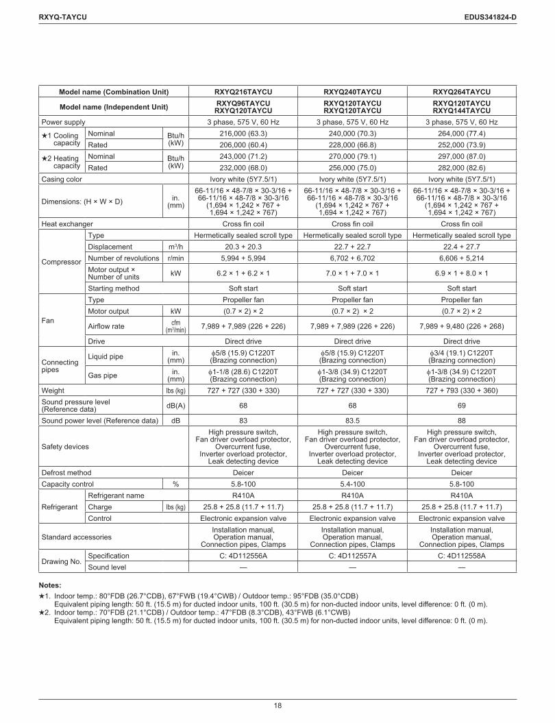
Model name (Combination Unit) RXYQ216TAYCU RXYQ240TAYCU RXYQ264TAYCU
Model name (Independent Unit) RXYQ96TAYCU RXYQ120TAYCU
RXYQ120TAYCU RXYQ120TAYCU
RXYQ120TAYCU RXYQ144TAYCU
Power supply 3 phase, 575 V, 60 Hz 3 phase, 575 V, 60 Hz 3 phase, 575 V, 60 Hz
1 Cooling capacity
Nominal Btu/h (kW)
216,000 (63.3) 240,000 (70.3) 264,000 (77.4)Rated 206,000 (60.4) 228,000 (66.8) 252,000 (73.9)
2 Heating capacity
Nominal Btu/h (kW)
243,000 (71.2) 270,000 (79.1) 297,000 (87.0)Rated 232,000 (68.0) 256,000 (75.0) 282,000 (82.6)
Casing color Ivory white (5Y7.5/1) Ivory white (5Y7.5/1) Ivory white (5Y7.5/1)
Dimensions: (H × W × D) in. (mm)
66-11/16 × 48-7/8 × 30-3/16 + 66-11/16 × 48-7/8 × 30-3/16
(1,694 × 1,242 × 767 + 1,694 × 1,242 × 767)
66-11/16 × 48-7/8 × 30-3/16 + 66-11/16 × 48-7/8 × 30-3/16
(1,694 × 1,242 × 767 + 1,694 × 1,242 × 767)
66-11/16 × 48-7/8 × 30-3/16 + 66-11/16 × 48-7/8 × 30-3/16
(1,694 × 1,242 × 767 + 1,694 × 1,242 × 767)
Heat exchanger Crossfincoil Crossfincoil Crossfincoil
Compressor
Type Hermetically sealed scroll type Hermetically sealed scroll type Hermetically sealed scroll typeDisplacement m3/h 20.3 + 20.3 22.7 + 22.7 22.4 + 27.7Number of revolutions r/min 5,994 + 5,994 6,702 + 6,702 6,606 + 5,214Motor output × Number of units kW 6.2 × 1 + 6.2 × 1 7.0 × 1 + 7.0 × 1 6.9 × 1 + 8.0 × 1
Starting method Soft start Soft start Soft start
Fan
Type Propeller fan Propeller fan Propeller fanMotor output kW (0.7 × 2) × 2 (0.7 × 2) × 2 (0.7 × 2) × 2
Airflowrate cfm (m3/min) 7,989 + 7,989 (226 + 226) 7,989 + 7,989 (226 + 226) 7,989 + 9,480 (226 + 268)
Drive Direct drive Direct drive Direct drive
Connecting pipes
Liquid pipe in. (mm)
f5/8 (15.9) C1220T (Brazing connection)
f5/8 (15.9) C1220T (Brazing connection)
f3/4 (19.1) C1220T (Brazing connection)
Gas pipe in. (mm)
f1-1/8 (28.6) C1220T (Brazing connection)
f1-3/8 (34.9) C1220T (Brazing connection)
f1-3/8 (34.9) C1220T (Brazing connection)
Weight lbs (kg) 727 + 727 (330 + 330) 727 + 727 (330 + 330) 727 + 793 (330 + 360)Sound pressure level (Reference data) dB(A) 68 68 69
Sound power level (Reference data) dB 83 83.5 88
Safety devices
High pressure switch, Fan driver overload protector,
Overcurrent fuse, Inverter overload protector,
Leak detecting device
High pressure switch, Fan driver overload protector,
Overcurrent fuse, Inverter overload protector,
Leak detecting device
High pressure switch, Fan driver overload protector,
Overcurrent fuse, Inverter overload protector,
Leak detecting deviceDefrost method Deicer Deicer DeicerCapacity control % 5.8-100 5.4-100 5.8-100
RefrigerantRefrigerant name R410A R410A R410ACharge lbs (kg) 25.8 + 25.8 (11.7 + 11.7) 25.8 + 25.8 (11.7 + 11.7) 25.8 + 25.8 (11.7 + 11.7)Control Electronic expansion valve Electronic expansion valve Electronic expansion valve
Standard accessoriesInstallation manual, Operation manual,
Connection pipes, Clamps
Installation manual, Operation manual,
Connection pipes, Clamps
Installation manual, Operation manual,
Connection pipes, Clamps
Drawing No.Specification C: 4D112556A C: 4D112557A C: 4D112558ASound level — — —
Notes:1. Indoor temp.: 80°FDB (26.7°CDB), 67°FWB (19.4°CWB) / Outdoor temp.: 95°FDB (35.0°CDB)
Equivalentpipinglength:50ft.(15.5m)forductedindoorunits,100ft.(30.5m)fornon-ductedindoorunits,leveldifference:0ft.(0m).2. Indoor temp.: 70°FDB (21.1°CDB) / Outdoor temp.: 47°FDB (8.3°CDB), 43°FWB (6.1°CWB)
Equivalentpipinglength:50ft.(15.5m)forductedindoorunits,100ft.(30.5m)fornon-ductedindoorunits,leveldifference:0ft.(0m).
19
RXYQ-TAYCU EDUS341824-D
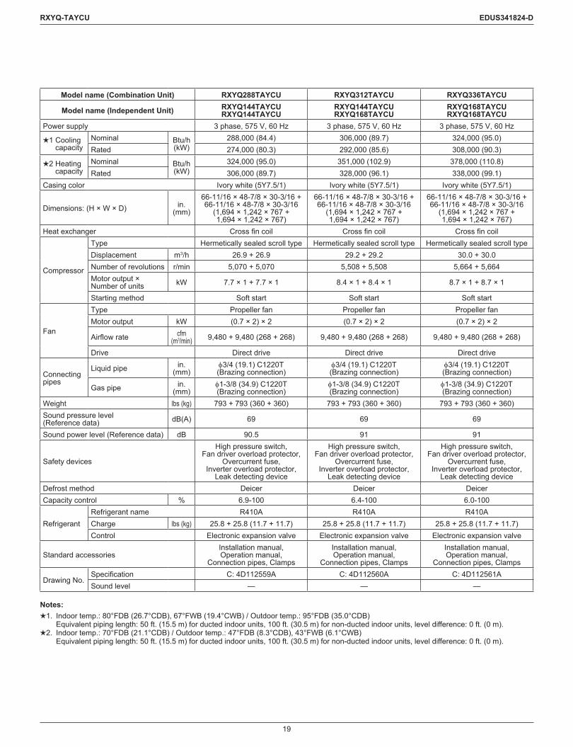
Model name (Combination Unit) RXYQ288TAYCU RXYQ312TAYCU RXYQ336TAYCU
Model name (Independent Unit) RXYQ144TAYCU RXYQ144TAYCU
RXYQ144TAYCU RXYQ168TAYCU
RXYQ168TAYCU RXYQ168TAYCU
Power supply 3 phase, 575 V, 60 Hz 3 phase, 575 V, 60 Hz 3 phase, 575 V, 60 Hz
1 Cooling capacity
Nominal Btu/h (kW)
288,000 (84.4) 306,000 (89.7) 324,000 (95.0)Rated 274,000 (80.3) 292,000 (85.6) 308,000 (90.3)
2 Heating capacity
Nominal Btu/h (kW)
324,000 (95.0) 351,000 (102.9) 378,000 (110.8)Rated 306,000 (89.7) 328,000 (96.1) 338,000 (99.1)
Casing color Ivory white (5Y7.5/1) Ivory white (5Y7.5/1) Ivory white (5Y7.5/1)
Dimensions: (H × W × D) in. (mm)
66-11/16 × 48-7/8 × 30-3/16 + 66-11/16 × 48-7/8 × 30-3/16
(1,694 × 1,242 × 767 + 1,694 × 1,242 × 767)
66-11/16 × 48-7/8 × 30-3/16 + 66-11/16 × 48-7/8 × 30-3/16
(1,694 × 1,242 × 767 + 1,694 × 1,242 × 767)
66-11/16 × 48-7/8 × 30-3/16 + 66-11/16 × 48-7/8 × 30-3/16
(1,694 × 1,242 × 767 + 1,694 × 1,242 × 767)
Heat exchanger Crossfincoil Crossfincoil Crossfincoil
Compressor
Type Hermetically sealed scroll type Hermetically sealed scroll type Hermetically sealed scroll typeDisplacement m3/h 26.9 + 26.9 29.2 + 29.2 30.0 + 30.0Number of revolutions r/min 5,070 + 5,070 5,508 + 5,508 5,664 + 5,664Motor output × Number of units kW 7.7 × 1 + 7.7 × 1 8.4 × 1 + 8.4 × 1 8.7 × 1 + 8.7 × 1
Starting method Soft start Soft start Soft start
Fan
Type Propeller fan Propeller fan Propeller fanMotor output kW (0.7 × 2) × 2 (0.7 × 2) × 2 (0.7 × 2) × 2
Airflowrate cfm (m3/min) 9,480 + 9,480 (268 + 268) 9,480 + 9,480 (268 + 268) 9,480 + 9,480 (268 + 268)
Drive Direct drive Direct drive Direct drive
Connecting pipes
Liquid pipe in. (mm)
f3/4 (19.1) C1220T(Brazing connection)
f3/4 (19.1) C1220T (Brazing connection)
f3/4 (19.1) C1220T (Brazing connection)
Gas pipe in. (mm)
f1-3/8 (34.9) C1220T (Brazing connection)
f1-3/8 (34.9) C1220T (Brazing connection)
f1-3/8 (34.9) C1220T (Brazing connection)
Weight lbs (kg) 793 + 793 (360 + 360) 793 + 793 (360 + 360) 793 + 793 (360 + 360)Sound pressure level (Reference data) dB(A) 69 69 69
Sound power level (Reference data) dB 90.5 91 91
Safety devices
High pressure switch, Fan driver overload protector,
Overcurrent fuse, Inverter overload protector,
Leak detecting device
High pressure switch, Fan driver overload protector,
Overcurrent fuse, Inverter overload protector,
Leak detecting device
High pressure switch, Fan driver overload protector,
Overcurrent fuse, Inverter overload protector,
Leak detecting deviceDefrost method Deicer Deicer DeicerCapacity control % 6.9-100 6.4-100 6.0-100
RefrigerantRefrigerant name R410A R410A R410ACharge lbs (kg) 25.8 + 25.8 (11.7 + 11.7) 25.8 + 25.8 (11.7 + 11.7) 25.8 + 25.8 (11.7 + 11.7)Control Electronic expansion valve Electronic expansion valve Electronic expansion valve
Standard accessoriesInstallation manual, Operation manual,
Connection pipes, Clamps
Installation manual, Operation manual,
Connection pipes, Clamps
Installation manual, Operation manual,
Connection pipes, Clamps
Drawing No.Specification C: 4D112559A C: 4D112560A C: 4D112561ASound level — — —
Notes:1. Indoor temp.: 80°FDB (26.7°CDB), 67°FWB (19.4°CWB) / Outdoor temp.: 95°FDB (35.0°CDB)
Equivalentpipinglength:50ft.(15.5m)forductedindoorunits,100ft.(30.5m)fornon-ductedindoorunits,leveldifference:0ft.(0m).2. Indoor temp.: 70°FDB (21.1°CDB) / Outdoor temp.: 47°FDB (8.3°CDB), 43°FWB (6.1°CWB)
Equivalentpipinglength:50ft.(15.5m)forductedindoorunits,100ft.(30.5m)fornon-ductedindoorunits,leveldifference:0ft.(0m).
20
RXYQ-TAYCU EDUS341824-D
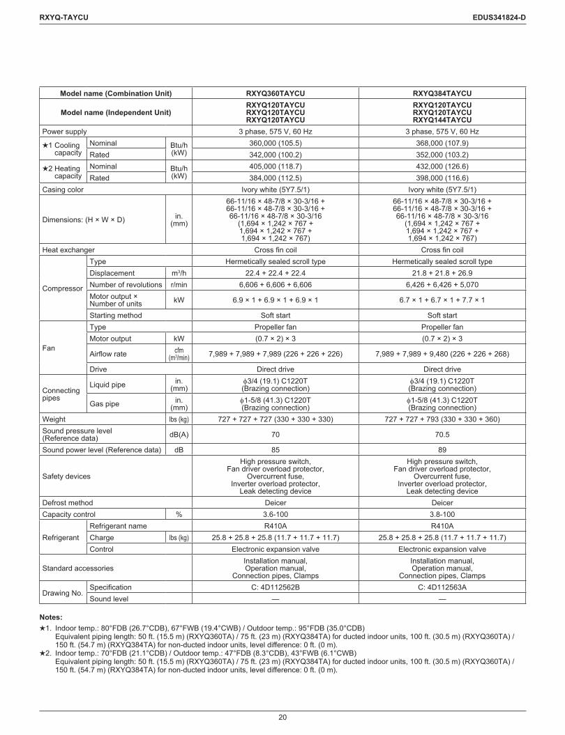
Model name (Combination Unit) RXYQ360TAYCU RXYQ384TAYCU
Model name (Independent Unit)RXYQ120TAYCURXYQ120TAYCURXYQ120TAYCU
RXYQ120TAYCURXYQ120TAYCURXYQ144TAYCU
Power supply 3 phase, 575 V, 60 Hz 3 phase, 575 V, 60 Hz
1 Cooling capacity
Nominal Btu/h (kW)
360,000 (105.5) 368,000 (107.9)Rated 342,000 (100.2) 352,000 (103.2)
2 Heating capacity
Nominal Btu/h (kW)
405,000 (118.7) 432,000 (126.6)Rated 384,000 (112.5) 398,000 (116.6)
Casing color Ivory white (5Y7.5/1) Ivory white (5Y7.5/1)
Dimensions: (H × W × D) in. (mm)
66-11/16 × 48-7/8 × 30-3/16 +66-11/16 × 48-7/8 × 30-3/16 +66-11/16 × 48-7/8 × 30-3/16
(1,694 × 1,242 × 767 +1,694 × 1,242 × 767 +1,694 × 1,242 × 767)
66-11/16 × 48-7/8 × 30-3/16 +66-11/16 × 48-7/8 × 30-3/16 +66-11/16 × 48-7/8 × 30-3/16
(1,694 × 1,242 × 767 +1,694 × 1,242 × 767 +1,694 × 1,242 × 767)
Heat exchanger Crossfincoil Crossfincoil
Compressor
Type Hermetically sealed scroll type Hermetically sealed scroll typeDisplacement m3/h 22.4 + 22.4 + 22.4 21.8 + 21.8 + 26.9Number of revolutions r/min 6,606 + 6,606 + 6,606 6,426 + 6,426 + 5,070Motor output × Number of units kW 6.9 × 1 + 6.9 × 1 + 6.9 × 1 6.7 × 1 + 6.7 × 1 + 7.7 × 1
Starting method Soft start Soft start
Fan
Type Propeller fan Propeller fanMotor output kW (0.7 × 2) × 3 (0.7 × 2) × 3
Airflowrate cfm (m3/min) 7,989 + 7,989 + 7,989 (226 + 226 + 226) 7,989 + 7,989 + 9,480 (226 + 226 + 268)
Drive Direct drive Direct drive
Connecting pipes
Liquid pipe in. (mm)
f3/4 (19.1) C1220T (Brazing connection)
f3/4 (19.1) C1220T (Brazing connection)
Gas pipe in. (mm)
f1-5/8 (41.3) C1220T (Brazing connection)
f1-5/8 (41.3) C1220T (Brazing connection)
Weight lbs (kg) 727 + 727 + 727 (330 + 330 + 330) 727 + 727 + 793 (330 + 330 + 360)Sound pressure level (Reference data) dB(A) 70 70.5
Sound power level (Reference data) dB 85 89
Safety devices
High pressure switch, Fan driver overload protector,
Overcurrent fuse, Inverter overload protector,
Leak detecting device
High pressure switch, Fan driver overload protector,
Overcurrent fuse, Inverter overload protector,
Leak detecting deviceDefrost method Deicer DeicerCapacity control % 3.6-100 3.8-100
RefrigerantRefrigerant name R410A R410ACharge lbs (kg) 25.8 + 25.8 + 25.8 (11.7 + 11.7 + 11.7) 25.8 + 25.8 + 25.8 (11.7 + 11.7 + 11.7)Control Electronic expansion valve Electronic expansion valve
Standard accessoriesInstallation manual, Operation manual,
Connection pipes, Clamps
Installation manual, Operation manual,
Connection pipes, Clamps
Drawing No.Specification C: 4D112562B C: 4D112563ASound level — —
Notes:1. Indoor temp.: 80°FDB (26.7°CDB), 67°FWB (19.4°CWB) / Outdoor temp.: 95°FDB (35.0°CDB)
Equivalent piping length: 50 ft. (15.5 m) (RXYQ360TA) / 75 ft. (23 m) (RXYQ384TA) for ducted indoor units, 100 ft. (30.5 m) (RXYQ360TA) / 150ft.(54.7m)(RXYQ384TA)fornon-ductedindoorunits,leveldifference:0ft.(0m).
2. Indoor temp.: 70°FDB (21.1°CDB) / Outdoor temp.: 47°FDB (8.3°CDB), 43°FWB (6.1°CWB) Equivalent piping length: 50 ft. (15.5 m) (RXYQ360TA) / 75 ft. (23 m) (RXYQ384TA) for ducted indoor units, 100 ft. (30.5 m) (RXYQ360TA) / 150ft.(54.7m)(RXYQ384TA)fornon-ductedindoorunits,leveldifference:0ft.(0m).

21
RXYQ-TAYCU EDUS341824-D
8. Dimensions
RXYQ72 - 120TAYCU
C: 3
D11
2576
Uni
t : in
. (m
m)
Li
quid
pip
e
Ø1/
2 Br
azin
g co
nnec
tion
Ø1
Braz
ing
conn
ectio
nØ
1-1/
8 Br
azin
g co
nnec
tion
Not
es)
1. F
or p
ipin
g co
nnec
tion
met
hod
(fron
t and
bot
tom
si
des)
, see
the
inst
alla
tion
man
ual.
2. G
as p
ipe
RXL
Q72
TAYC
U,T
ATJU
,TAY
DU
RXY
Q72
,96,
120T
AYC
U
Pipe
rout
ing
hole
(bot
tom
)9 8 7 6 5 4 3 2 1
Pipe
rout
ing
hole
(fro
nt)
Pow
er c
ord
rout
ing
hole
Pow
er c
ord
rout
ing
hole
Pow
er c
ord
rout
ing
hole
Tran
smis
sion
wire
rout
ing
hole
Gro
undi
ng te
rmin
alIn
side
of c
ontro
l bo
x (M
8)
Gas
pip
e co
nnec
tion
port
Liqu
id p
ipe
conn
ectio
n po
rtN
o.Pa
rts n
ame
Ø7/
8 (2
2.2)
Rem
arks
See
note
1.
See
note
1.
Ø1-
3/8
(35)
Ø1-
1/8
(28.
6)Ø
7/8
(22.
2)
See
note
2.
See
note
2.
RXL
Q96
,120
TAYC
U,T
ATJU
,TAY
DU
RXY
Q14
4,16
8TAY
CU
22
RXYQ-TAYCU EDUS341824-D
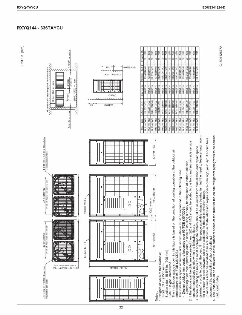
RXYQ144 - 336TAYCU
C: 3
D11
2577
A
Uni
t : in
. (m
m)
Not
es :
1. H
eigh
ts o
f wal
ls o
f thi
s ex
ampl
e;Fr
ont :
59
in. (
1500
mm
)Su
ctio
n si
de :
19-5
/8 in
. (50
0 m
m)
Side
: H
eigh
t unr
estri
cted
The
inst
alla
tion
spac
e sh
own
in th
is fi
gure
is b
ased
on
the
cond
ition
of c
oolin
g op
erat
ion
at th
e ou
tdoo
r air
tem
pera
ture
of 9
5°FD
B (3
5°C
DB)
.Th
e in
stal
latio
n sp
ace
of s
uctio
n si
de s
how
n ab
ove
mus
t be
expa
nded
in th
e fo
llow
ing
case
.∙
Des
ign
outd
oor t
empe
ratu
re b
ecom
es o
ver 9
5°FD
B (3
5°C
DB)
.∙
Ope
ratin
g ov
er m
ax. o
pera
ting
load
(In
case
of c
ausi
ng a
hea
vy h
eatin
g lo
ad a
t ind
oor u
nit s
ide)
2. If
the
abov
e w
all h
eigh
ts a
re e
xcee
ded
then
h2/
2 an
d h1
/2 s
houl
d be
add
ed to
the
front
and
suc
tion
side
ser
vice
sp
aces
resp
ectiv
ely
as s
how
n in
the
follo
win
g fig
ure.
3.
Whe
n in
stal
ling
the
units
the
mos
t app
ropr
iate
pat
tern
sho
uld
be s
elec
ted
from
"Ins
talla
tion
and
repa
ir sp
ace
draw
ing"
in o
rder
to o
btai
n th
e be
st fi
t in
the
spac
e av
aila
ble
alw
ays
bear
ing
in m
ind
the
need
to le
ave
enou
gh ro
om
for a
per
son
to p
ass
betw
een
units
and
wal
l and
for t
he a
ir to
circ
ulat
e fre
ely.
(If m
ore
units
are
to b
e in
stal
led
than
are
sho
wn
in "I
nsta
llatio
n an
d re
pair
spac
e dr
awin
g", y
our l
ayou
t sho
uld
take
ac
coun
t of t
he p
ossi
bilit
y of
sho
rt ci
rcui
ting.
)4.
The
uni
ts s
houl
d be
inst
alle
d to
leav
e su
ffici
ent s
pace
at t
he fr
ont f
or th
e on
site
refri
gera
nt p
ipin
g w
ork
to b
e ca
rried
ou
t com
forta
bly.
23
RXYQ-TAYCU EDUS341824-D
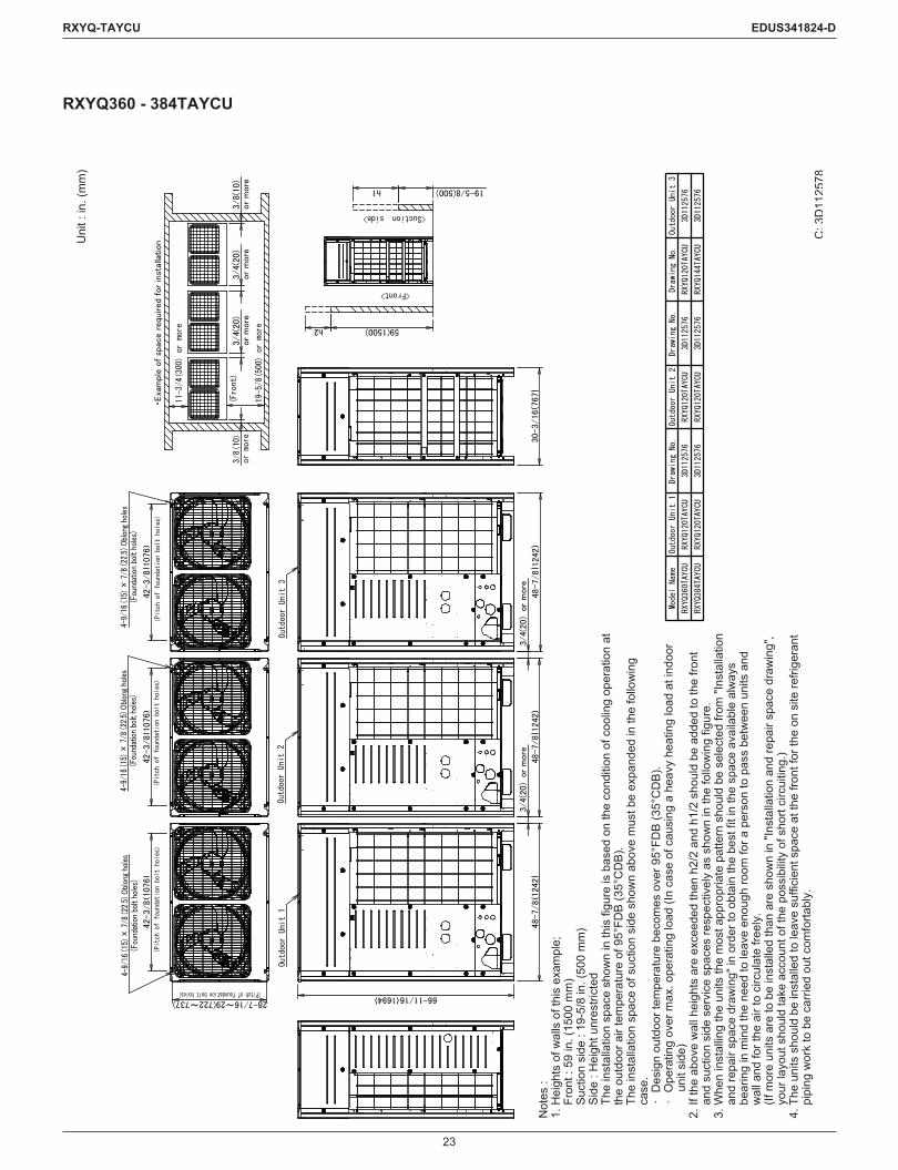
RXYQ360 - 384TAYCU
C: 3
D11
2578
Uni
t : in
. (m
m)
Not
es :
1. H
eigh
ts o
f wal
ls o
f thi
s ex
ampl
e;Fr
ont :
59
in. (
1500
mm
)Su
ctio
n si
de :
19-5
/8 in
. (50
0 m
m)
Side
: H
eigh
t unr
estri
cted
The
inst
alla
tion
spac
e sh
own
in th
is fi
gure
is b
ased
on
the
cond
ition
of c
oolin
g op
erat
ion
at
the
outd
oor a
ir te
mpe
ratu
re o
f 95°
FDB
(35°
CD
B).
The
inst
alla
tion
spac
e of
suc
tion
side
sho
wn
abov
e m
ust b
e ex
pand
ed in
the
follo
win
g ca
se.
∙ D
esig
n ou
tdoo
r tem
pera
ture
bec
omes
ove
r 95°
FDB
(35°
CD
B).
∙ O
pera
ting
over
max
. ope
ratin
g lo
ad (I
n ca
se o
f cau
sing
a h
eavy
hea
ting
load
at i
ndoo
r un
it si
de)
2. If
the
abov
e w
all h
eigh
ts a
re e
xcee
ded
then
h2/
2 an
d h1
/2 s
houl
d be
add
ed to
the
front
an
d su
ctio
n si
de s
ervi
ce s
pace
s re
spec
tivel
y as
sho
wn
in th
e fo
llow
ing
figur
e.
3. W
hen
inst
allin
g th
e un
its th
e m
ost a
ppro
pria
te p
atte
rn s
houl
d be
sel
ecte
d fro
m "I
nsta
llatio
n an
d re
pair
spac
e dr
awin
g" in
ord
er to
obt
ain
the
best
fit i
n th
e sp
ace
avai
labl
e al
way
s be
arin
g in
min
d th
e ne
ed to
leav
e en
ough
room
for a
per
son
to p
ass
betw
een
units
and
w
all a
nd fo
r the
air
to c
ircul
ate
freel
y.(If
mor
e un
its a
re to
be
inst
alle
d th
an a
re s
how
n in
"Ins
talla
tion
and
repa
ir sp
ace
draw
ing"
, yo
ur la
yout
sho
uld
take
acc
ount
of t
he p
ossi
bilit
y of
sho
rt ci
rcui
ting.
)4.
The
uni
ts s
houl
d be
inst
alle
d to
leav
e su
ffici
ent s
pace
at t
he fr
ont f
or th
e on
site
refri
gera
nt
pipi
ng w
ork
to b
e ca
rried
out
com
forta
bly.
24
RXYQ-TAYCU EDUS341824-D
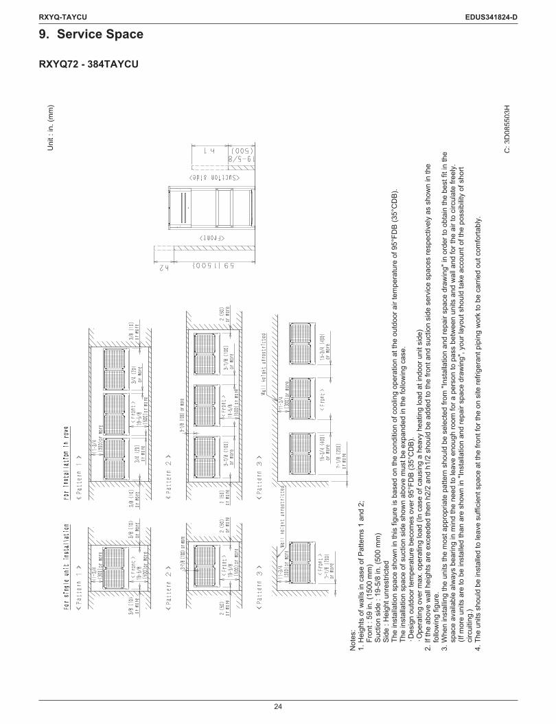
9. Service Space
RXYQ72 - 384TAYCU
C: 3
D08
5503
H
Uni
t : in
. (m
m)
Not
es:
1. H
eigh
ts o
f wal
ls in
cas
e of
Pat
tern
s 1
and
2;Fr
ont :
59
in. (
1500
mm
)Su
ctio
n si
de :
19-5
/8 in
. (50
0 m
m)
Side
: H
eigh
t unr
estri
cted
The
inst
alla
tion
spac
e sh
own
in th
is fi
gure
is b
ased
on
the
cond
ition
of c
oolin
g op
erat
ion
at th
e ou
tdoo
r air
tem
pera
ture
of 9
5°FD
B (3
5°C
DB)
. Th
e in
stal
latio
n sp
ace
of s
uctio
n si
de s
how
n ab
ove
mus
t be
expa
nded
in th
e fo
llow
ing
case
.∙D
esig
n ou
tdoo
r tem
pera
ture
bec
omes
ove
r 95°
FDB
(35°
CD
B).
∙ Ope
ratin
g ov
er m
ax. o
pera
ting
load
(In
case
of c
ausi
ng a
hea
vy h
eatin
g lo
ad a
t ind
oor u
nit s
ide)
2. If
the
abov
e w
all h
eigh
ts a
re e
xcee
ded
then
h2/
2 an
d h1
/2 s
houl
d be
add
ed to
the
front
and
suc
tion
side
ser
vice
spa
ces
resp
ectiv
ely
as s
how
n in
the
follo
win
g fig
ure.
3. W
hen
inst
allin
g th
e un
its th
e m
ost a
ppro
pria
te p
atte
rn s
houl
d be
sel
ecte
d fro
m "I
nsta
llatio
n an
d re
pair
spac
e dr
awin
g" in
ord
er to
obt
ain
the
best
fit i
n th
e sp
ace
avai
labl
e al
way
s be
arin
g in
min
d th
e ne
ed to
leav
e en
ough
room
for a
per
son
to p
ass
betw
een
units
and
wal
l and
for t
he a
ir to
circ
ulat
e fre
ely.
(If m
ore
units
are
to b
e in
stal
led
than
are
sho
wn
in "I
nsta
llatio
n an
d re
pair
spac
e dr
awin
g", y
our l
ayou
t sho
uld
take
acc
ount
of t
he p
ossi
bilit
y of
sho
rt ci
rcui
ting.
)4.
The
uni
ts s
houl
d be
inst
alle
d to
leav
e su
ffici
ent s
pace
at t
he fr
ont f
or th
e on
site
refri
gera
nt p
ipin
g w
ork
to b
e ca
rried
out
com
forta
bly.

25
RXYQ-TAYCU EDUS341824-D
RXYQ72 - 384TAYCU
Not
es:
1. H
eigh
ts o
f wal
ls in
cas
e of
Pat
tern
s 1
and
2;Fr
ont :
59
in. (
1500
mm
)Su
ctio
n si
de :
19-5
/8 in
. (50
0 m
m)
Side
: H
eigh
t unr
estri
cted
The
inst
alla
tion
spac
e sh
own
in th
is fi
gure
is b
ased
on
the
cond
ition
of c
oolin
g op
erat
ion
at th
e ou
tdoo
r air
tem
pera
ture
of 9
5°FD
B (3
5°C
DB)
. Th
e in
stal
latio
n sp
ace
of s
uctio
n si
de s
how
n ab
ove
mus
t be
expa
nded
in th
e fo
llow
ing
case
.∙D
esig
n ou
tdoo
r tem
pera
ture
bec
omes
ove
r 95°
FDB
(35°
CD
B).
∙Ope
ratin
g ov
er m
ax. o
pera
ting
load
(In
case
of c
ausi
ng a
hea
vy h
eatin
g lo
ad a
t ind
oor u
nit s
ide)
2. If
the
abov
e w
all h
eigh
ts a
re e
xcee
ded
then
h2/
2 an
d h1
/2 s
houl
d be
add
ed to
the
front
and
suc
tion
side
ser
vice
spa
ces
resp
ectiv
ely
as s
how
n in
the
follo
win
g fig
ure.
3. W
hen
inst
allin
g th
e un
its th
e m
ost a
ppro
pria
te p
atte
rn s
houl
d be
sel
ecte
d fro
m "I
nsta
llatio
n an
d re
pair
spac
e dr
awin
g" in
ord
er to
obt
ain
the
best
fit i
n th
e sp
ace
avai
labl
e al
way
s be
arin
g in
min
d th
e ne
ed to
leav
e en
ough
room
for a
per
son
to p
ass
betw
een
units
and
wal
l and
for t
he a
ir to
circ
ulat
e fre
ely.
(If m
ore
units
are
to b
e in
stal
led
than
are
sho
wn
in "I
nsta
llatio
n an
d re
pair
spac
e dr
awin
g", y
our l
ayou
t sho
uld
take
acc
ount
of t
he p
ossi
bilit
y of
sho
rt ci
rcui
ting.
)4.
The
uni
ts s
houl
d be
inst
alle
d to
leav
e su
ffici
ent s
pace
at t
he fr
ont f
or th
e on
site
refri
gera
nt p
ipin
g w
ork
to b
e ca
rried
out
com
forta
bly.
C: 3
D08
5503
H
Uni
t : in
. (m
m)
26
RXYQ-TAYCU EDUS341824-D
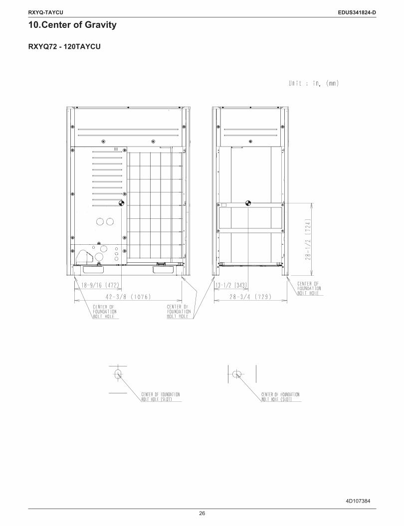
10. Center of Gravity
RXYQ72 - 120TAYCU
4D107384

27
RXYQ-TAYCU EDUS341824-D
RXYQ144 - 168TAYCU
4D107385
28
RXYQ-TAYCU EDUS341824-D
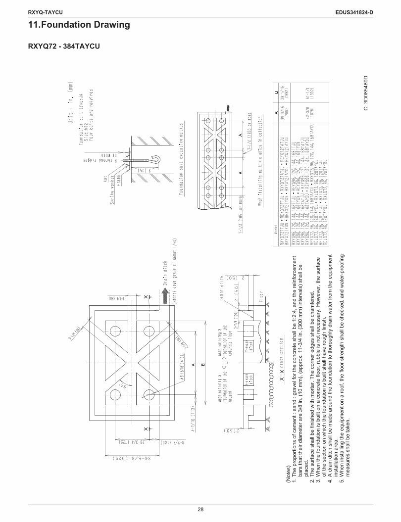
11. Foundation Drawing
RXYQ72 - 384TAYCU
C: 3
D08
5480
D
(Not
es)
1. T
he p
ropo
rtion
s of
cem
ent :
san
d : g
rave
l for
the
conc
rete
sha
ll be
1:2
:4, a
nd th
e re
info
rcem
ent
bars
that
thei
r dia
met
er a
re 3
/8 in
. (10
mm
), (a
ppro
x. 1
1-3/
4 in
. (30
0 m
m) i
nter
vals
) sha
ll be
pl
aced
.2.
The
sur
face
sha
ll be
fini
shed
with
mor
tar.
The
corn
er e
dges
sha
ll be
cha
mfe
red.
3. W
hen
the
foun
datio
n is
bui
lt on
a c
oncr
ete
floor
, rub
ble
is n
ot n
eces
sary
. How
ever
, the
sur
face
of
the
sect
ion
on w
hich
the
foun
datio
n is
bui
lt sh
all h
ave
roug
h fin
ish.
4. A
dra
in d
itch
shal
l be
mad
e ar
ound
the
foun
datio
n to
thor
ough
ly d
rain
wat
er fr
om th
e eq
uipm
ent
inst
alla
tion
area
.5.
Whe
n in
stal
ling
the
equi
pmen
t on
a ro
of, t
he fl
oor s
treng
th s
hall
be c
heck
ed, a
nd w
ater
-pro
ofin
g m
easu
res
shal
l be
take
n.

29
RXYQ-TAYCU EDUS341824-D
12. Piping Diagrams
RXYQ72 - 120TAYCU
C: 3
D11
2615
Liquid
pipe
Stop
valve
(With
serv
ice Ø
5/16
in. (
7.9
mm
) flar
e co
nnec
tion)
Filte
rCh
eck v
alve
Chec
k valv
e
Chec
k valv
e
Chec
k valv
e
Elec
tronic
expa
nsion
valve
Capil
lary
tube
Chec
kva
lveCh
eck
valve
Elec
tronic
expa
nsion
valve
Solen
oid va
lve
Pres
sure
regu
lating
valve
Filte
r
Filte
r
Filte
r
Elec
tronic
exp
ansio
n va
lve Capil
lary
tube
Chec
k valv
e
Elec
tronic
expa
nsion
valve
Plat
e he
atex
chan
ger
Fan
Filte
r
Filte
r
Gas
pipe
Four
way
valve
Doub
le tu
behe
at e
xcha
nger
Fusib
le plu
g
Accu
mula
tor
Filte
r
Solen
oidva
lve
Four
way
valve
Four
way
valve
Filte
rEl
ectro
nic e
xpan
sion
valve
Elec
tronic
exp
ansio
nva
lve
Heat
sink
Fusib
leplu
g
Rece
iver
Elec
tronic
expa
nsion
valve
Oil s
epar
ator
Char
ge p
ort
Heat
exc
hang
er
Capil
lary t
ube
Chec
k valv
e
Filte
r
Solen
oid va
lve
High
pre
ssur
esw
itch
Muf
fler
Com
pres
sor
Capil
lary t
ube
Capil
lary t
ube
Solen
oidva
lve
Filte
r
Filte
r
High
pre
ssur
ese
nsor
INV
SVSV
SV
SV
SENP
H
HPS
Fan M
M
Low
pres
sure
sens
orSE
NPL

30
RXYQ-TAYCU EDUS341824-D
RXYQ144 - 168TAYCU
C: 3
D11
2616
Liquid
pipe
Stop
valve
(With
serv
ice Ø
5/16
in.(7
.9 m
m) f
lare
conn
ectio
n)
Filte
rCh
eck v
alve
Chec
k valv
e
Chec
k valv
e
Chec
k valv
e
Elec
tronic
expa
nsion
valve
Capil
lary
tube
Chec
kva
lveCh
eck
valve
Elec
tronic
expa
nsion
valve
Solen
oid va
lve
Pres
sure
regu
lating
valve
Filte
r
Filte
r
Filte
r
Elec
tronic
exp
ansio
n va
lve Capil
lary
tube
Chec
k valv
e
Elec
tronic
expa
nsion
valve
Plat
e he
atex
chan
ger
Fan
Filte
r
Filte
r
Gas
pipe
Four
way
valve
Low
pres
sure
sens
or
Doub
le tu
behe
at e
xcha
nger
Fusib
le plu
g
Accu
mula
tor
Filte
r
Solen
oidva
lve
Four
way
valve
Four
way
valve
Filte
rEl
ectro
nic e
xpan
sion
valve
Elec
tronic
exp
ansio
nva
lve
Heat
sink
Fusib
leplu
g
Rece
iver
Elec
tronic
expa
nsion
valve
Oil s
epar
ator
Char
ge p
ort
Heat
exc
hang
er
Capil
lary t
ube
Chec
k valv
e
Filte
rSolen
oid va
lve
High
pre
ssur
esw
itch
Muf
fler
Com
pres
sor
Capil
lary t
ube
Capil
lary t
ube
Solen
oidva
lve
Filte
r
Filte
r
High
pre
ssur
ese
nsor
INV
SVSV
SV
SV
SENP
H
HPS
Fan
MM
SENP
L

31
RXYQ-TAYCU EDUS341824-D
13. Wiring Diagrams
RXYQ72 - 168TAYCU
C: 2
D11
2579
A
1. T
HIS
WIR
ING
DIA
GR
AM A
PPLI
ES O
NLY
TO
TH
E O
UTD
OO
R U
NIT
. 2
.
: FIE
LD W
IRIN
G,
:
TER
MIN
AL B
LOC
K,
: CO
NN
ECTO
R,
: T
ERM
INAL
,
: PR
OTE
CTI
VE E
ARTH
(SC
REW
),
: N
OIS
ELES
S EA
RTH
. 3
. WH
EN U
SIN
G T
HE
OPT
ION
AL A
DAP
TOR
, REF
ER T
O T
HE
INST
ALLA
TIO
N M
ANU
AL O
F TH
E O
PTIO
NAL
AD
APTO
R.
4. F
OR
CO
NN
ECTI
ON
WIR
ING
TO
IND
OO
R-O
UTD
OO
R T
RAN
SMIS
SIO
N F
1 ∙F2
, OU
TDO
OR
-OU
TDO
OR
TR
ANSM
ISSI
ON
F1∙
F2
OU
TDO
OR
-MU
LTI T
RAN
SMIS
SIO
N Q
1∙Q
2, R
EFER
TO
TH
E IN
STAL
LATI
ON
MAN
UAL
. 5
. HO
W T
O U
SE B
S1~3
SW
ITC
H, R
EFER
TO
“SER
VIC
E PR
ECAU
TIO
N L
ABEL
ON
C
ON
TRO
L BO
X C
OVE
R.
6. W
HEN
OPE
RAT
ING
, DO
N'T
SH
OR
TCIR
CU
IT T
HE
PRO
TEC
TIO
N D
EVIC
E(S1
PH).
7. C
OLO
RS
BLK
: BLA
CK
; RED
: R
ED ;
BLU
: BL
UE
; WH
T : W
HIT
E ; G
RN
: G
REE
N ;
GR
Y : G
RAY
; YL
W :
YELL
OW
. 8
. CLA
SS 2
WIR
E
NO
TES)

32
RXYQ-TAYCU EDUS341824-D
RXYQ72 - 168TAYCU
A1P PRINTED CIRCUIT BOARD (MAIN) R13T THERMISTOR (RECEIVER GAS PURGE)A2P, A3P PRINTED CIRCUIT BOARD (NOISE FILTER) R14T THERMISTOR (M1C BODY)A4P PRINTED CIRCUIT BOARD (INV) R15T THERMISTOR (LEAK DETECTION)A5P, A6P PRINTED CIRCUIT BOARD (FAN) R16T THERMISTOR (EVT)A7P PRINTED CIRCUIT BOARD (SUB) R21T THERMISTOR (M1C DISCHARGE)A8P PRINTED CIRCUIT BOARD (ABC I/P) S1NPH PRESSURE SENSOR (HIGH)
BS1~BS3 PUSH BUTTON SWITCH (A1P)(MODE, SET, RETURN)
S1NPL PRESSURE SENSOR (LOW)S1PH PRESSURE SWITCH (HIGH)
C1 CAPACITOR (A4P) SEG1~SEG3 7-SEGMENT DISPLAY (A1P)DS1, DS2 DIP SWITCH (A1P) T1A CURRENT SENSORE1HC, E2HC CRANKCASE HEATER T1R TRANSFORMER (575 V/220 V)F1U FUSE (A1P, A4P, A7P) V1D DIODE (A4P)F2U FUSE (A1P) V1R POWER MODULE (A4P)F101U FUSE (A2P, A5P, A6P) V1R POWER MODULE (A5P, A6P)F100U, F104U, F105U FUSE (A2P) V1T TRANSISTOR (A4P)
F1UT THERMAL FUSE (A4P) X1A, X2A CONNECTOR (M1F, M2F)
HAP PILOTLAMP (A1P, A4P~A7P)(SERVICE MONITOR-GREEN) X5A CONNECTOR
(CHECK THE RESIDUAL CHARGE)K1M MAGNETIC CONTACTOR (A4P) X3A, X4A CONNECTOR (T1R)K3R MAGNETIC RELAY (Y1S) (A1P) X13A, X14A CONNECTOR (E1HC, E2HC)K4R MAGNETIC RELAY (Y2S) (A1P) X1M TERMINAL BLOCK (POWER SUPPLY)K6R MAGNETIC RELAY (OPTION) (A1P) X1M TERMINAL BLOCK (CONTROL) (A1P)K7R MAGNETIC RELAY (E1HC, E2HC) (A1P) X1M TERMINAL BLOCK (ABC I/P) (A8P)K8R MAGNETIC RELAY (Y7S) (A1P) Y1E ELECTRIC EXPANSION VALVE (HEAT EXC.UPPER)K9R MAGNETIC RELAY (Y4S) (A1P)
Y2E ELECTRIC EXPANSION VALVE(SUBCOOL HEAT EXC.)K11R MAGNETIC RELAY (Y3S) (A1P)
K12R MAGNETIC RELAY (Y5S) (A1P) Y3E ELECTRIC EXPANSION VALVE (HEAT EXC.LOWER)K13R MAGNETIC RELAY (Y6S) (A1P) Y4E ELECTRIC EXPANSION VALVE (INJECTION)L1R REACTOR Y5E ELECTRIC EXPANSION VALVE (REFRIGERAT COOLING)M1C MOTOR (COMPRESSOR) Y6E ELECTRIC EXPANSION VALVE (LEAK DETECTION)M1F, M2F MOTOR (FAN) Y7E ELECTRIC EXPANSION VALVE (RECEIVER GAS PURGE)PS SWITCHING POWER SUPPLY (A1P, A4P, A7P) Y1S SOLENOID VALVE (OS OIL RETURN 1)Q1LD LEAKAGE DETECTION CIRCUIT (A1P) Y2S SOLENOID VALVE (HOT GAS BYPASS)R1 RESISTOR (CURRENT LIMITING) (A4P) Y3S SOLENOID VALVE (LIQUID SHUT OFF)R2 RESISTOR (CURRENT SENSOR) (A4P, A5P, A6P) Y4S 4WAY VALVE (HP/LP GAS)R1T THERMISTOR (AIR) Y5S 4WAY VALVE (HEAT EXC.LOWER)R3T THERMISTOR (RECEIVER INLET) Y6S 4WAY VALVE (HEAT EXC.UPPER)R4T THERMISTOR (HEAT EXC.LIQUID UPPER) Y7S SOLENOID VALVE (ACCUMU OIL RETURN)R5T THERMISTOR (HEAT EXC.LIQUID LOWER) Z1C~Z3C NOISE FILTER (FERRITE CORE)R6T THERMISTOR (SUBCOOL GAS)
ZF NOISE FILTER (A2P, A3P)(WITH SURGE ABSORBER)R7T THERMISTOR (SUBCOOL LIQUID)
R8T THERMISTOR (HEAT EXC.GAS UPPER) CONNECTOR FOR OPTIONAL ACCESSORIESR9T THERMISTOR (HEAT EXC.GAS LOWER) X37A CONNECTOR (POWER ADAPTER) (A1P)R10T THERMISTOR (SUCTION) COOL/HEAT SELECTORR11T THERMISTOR (DEICER) S1S SELECTOR SWITCH (FAN/COOL · HEAT)R12T THERMISTOR (COMPSUCTION) S2S SELECTOR SWITCH (COOL/HEAT)
C: 2D112579A
33
RXYQ-TAYCU EDUS341824-D
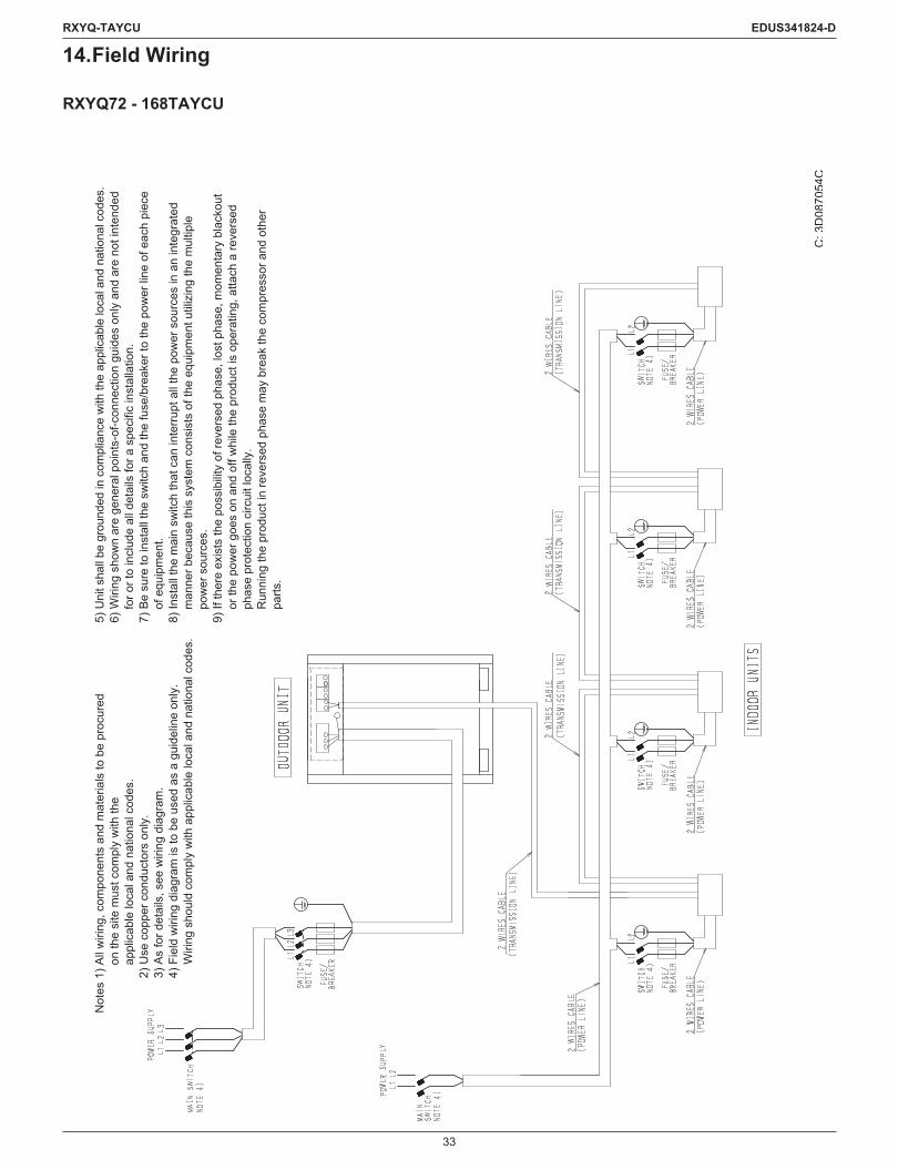
14. Field Wiring
RXYQ72 - 168TAYCU
C: 3
D08
7054
C
Not
es 1
) All
wiri
ng, c
ompo
nent
s an
d m
ater
ials
to b
e pr
ocur
edon
the
site
mus
t com
ply
with
the
appl
icab
le lo
cal a
nd n
atio
nal c
odes
.2)
Use
cop
per c
ondu
ctor
s on
ly.
3) A
s fo
r det
ails
, see
wiri
ng d
iagr
am.
4) F
ield
wiri
ng d
iagr
am is
to b
e us
ed a
s a
guid
elin
e on
ly.
Wiri
ng s
houl
d co
mpl
y w
ith a
pplic
able
loca
l and
nat
iona
l cod
es.
5) U
nit s
hall
be g
roun
ded
in c
ompl
ianc
e w
ith th
e ap
plic
able
loca
l and
nat
iona
l cod
es.
6) W
iring
sho
wn
are
gene
ral p
oint
s-of
-con
nect
ion
guid
es o
nly
and
are
not i
nten
ded
for o
r to
incl
ude
all d
etai
ls fo
r a s
peci
fic in
stal
latio
n.7)
Be
sure
to in
stal
l the
sw
itch
and
the
fuse
/bre
aker
to th
e po
wer
line
of e
ach
piec
e of
equ
ipm
ent.
8) In
stal
l the
mai
n sw
itch
that
can
inte
rrupt
all
the
pow
er s
ourc
es in
an
inte
grat
ed
man
ner b
ecau
se th
is s
yste
m c
onsi
sts
of th
e eq
uipm
ent u
tiliz
ing
the
mul
tiple
po
wer
sou
rces
.9)
If th
ere
exis
ts th
e po
ssib
ility
of re
vers
ed p
hase
, los
t pha
se, m
omen
tary
bla
ckou
t or
the
pow
er g
oes
on a
nd o
ff w
hile
the
prod
uct i
s op
erat
ing,
atta
ch a
reve
rsed
ph
ase
prot
ectio
n ci
rcui
t loc
ally
.R
unni
ng th
e pr
oduc
t in
reve
rsed
pha
se m
ay b
reak
the
com
pres
sor a
nd o
ther
pa
rts.

34
RXYQ-TAYCU EDUS341824-D
RXYQ192 - 336TAYCU
C: 3
D08
7055
C
Not
es 1
) All
wiri
ng, c
ompo
nent
s an
d m
ater
ials
to b
e pr
ocur
edon
the
site
mus
t com
ply
with
the
appl
icab
le lo
cal a
nd n
atio
nal c
odes
.2)
Use
cop
per c
ondu
ctor
s on
ly.
3) A
s fo
r det
ails
, see
wiri
ng d
iagr
am.
4) F
ield
wiri
ng d
iagr
am is
to b
e us
ed a
s a
guid
elin
e on
ly.
Wiri
ng s
houl
d co
mpl
y w
ith a
pplic
able
loca
l and
nat
iona
l cod
es.
5) U
nit s
hall
be g
roun
ded
in c
ompl
ianc
e w
ith th
e ap
plic
able
loca
l and
nat
iona
l cod
es.
6) W
iring
sho
wn
are
gene
ral p
oint
s-of
-con
nect
ion
guid
es o
nly
and
are
not i
nten
ded
for o
rto
incl
ude
all d
etai
ls fo
r a s
peci
fic in
stal
latio
n.7)
Be
sure
to in
stal
l the
sw
itch
and
the
fuse
/bre
aker
to th
e po
wer
line
of e
ach
piec
e of
equi
pmen
t.8)
Inst
all t
he m
ain
switc
h th
at c
an in
terru
pt a
ll th
e po
wer
sou
rces
in a
n in
tegr
ated
man
ner
beca
use
this
sys
tem
con
sist
s of
the
equi
pmen
t util
izin
g th
e m
ultip
le p
ower
sou
rces
.9)
If th
ere
exis
ts th
e po
ssib
ility
of re
vers
ed p
hase
, los
t pha
se, m
omen
tary
bla
ckou
t or t
hepo
wer
goe
s on
and
off
whi
le th
e pr
oduc
t is
oper
atin
g, a
ttach
a re
vers
ed p
hase
pro
tect
ion
circ
uit l
ocal
ly.
Run
ning
the
prod
uct i
n re
vers
ed p
hase
may
bre
ak th
e co
mpr
esso
r and
oth
er p
arts
.

35
RXYQ-TAYCU EDUS341824-D
RXYQ360 - 384TAYCU
C: 3
D08
7056
D
Not
es 1
) All
wiri
ng, c
ompo
nent
s an
d m
ater
ials
to b
e pr
ocur
edon
the
site
mus
t com
ply
with
the
appl
icab
le lo
cal a
nd n
atio
nal c
odes
.2)
Use
cop
per c
ondu
ctor
s on
ly.
3) A
s fo
r det
ails
, see
wiri
ng d
iagr
am.
4) F
ield
wiri
ng d
iagr
am is
to b
e us
ed a
s a
guid
elin
e on
ly.
Wiri
ng s
houl
d co
mpl
y w
ith a
pplic
able
loca
l and
nat
iona
l cod
es.
5) U
nit s
hall
be g
roun
ded
in c
ompl
ianc
e w
ith th
e ap
plic
able
loca
l and
nat
iona
l cod
es.
6) W
iring
sho
wn
are
gene
ral p
oint
s-of
-con
nect
ion
guid
es o
nly
and
are
not i
nten
ded
for o
rto
incl
ude
all d
etai
ls fo
r a s
peci
fic in
stal
latio
n.7)
Be
sure
to in
stal
l the
sw
itch
and
the
fuse
/bre
aker
to th
e po
wer
line
of e
ach
piec
e of
equi
pmen
t.8)
Inst
all t
he m
ain
switc
h th
at c
an in
terru
pt a
ll th
e po
wer
sou
rces
in a
n in
tegr
ated
man
ner
beca
use
this
sys
tem
con
sist
s of
the
equi
pmen
t util
izin
g th
e m
ultip
le p
ower
sou
rces
.9)
If th
ere
exis
ts th
e po
ssib
ility
of re
vers
ed p
hase
, los
t pha
se, m
omen
tary
bla
ckou
t or t
hepo
wer
goe
s on
and
off
whi
le th
e pr
oduc
t is
oper
atin
g, a
ttach
a re
vers
ed p
hase
pro
tect
ion
circ
uit l
ocal
ly.
Run
ning
the
prod
uct i
n re
vers
ed p
hase
may
bre
ak th
e co
mpr
esso
r and
oth
er p
arts
.

36
RXYQ-TAYCU EDUS341824-D
15. Electrical Characteristics
RXYQ72 - 384TAYCU
Model nameUnits Power supply Comp. OFM
Hz Volts Min. Max. MCA MOP RLA kW FLARXYQ72TAYCU 60 575 518 632 15.1 20 8.3 0.7 × 2 1.0 × 2RXYQ96TAYCU 60 575 518 632 16.8 20 10.2 0.7 × 2 1.0 × 2
RXYQ120TAYCU 60 575 518 632 18.2 25 11.9 0.7 × 2 1.0 × 2RXYQ144TAYCU 60 575 518 632 22.3 30 16.0 0.7 × 2 1.0 × 2RXYQ168TAYCU 60 575 518 632 24.9 30 16.8 0.7 × 2 1.0 × 2
RXYQ192TAYCURXYQ96TAYCU
60 575 518 632 16.8 + 16.8 20 + 20 10.0 + 10.0 (0.7 × 2) × 2 (1.0 × 2) × 2RXYQ96TAYCU
RXYQ216TAYCURXYQ96TAYCU
60 575 518 632 16.8 + 18.2 20 + 25 11.0 + 11.0 (0.7 × 2) × 2 (1.0 × 2) × 2RXYQ120TAYCU
RXYQ240TAYCURXYQ120TAYCU
60 575 518 632 18.2 + 18.2 25 + 25 12.2 + 12.2 (0.7 × 2) × 2 (1.0 × 2) × 2RXYQ120TAYCU
RXYQ264TAYCURXYQ120TAYCU
60 575 518 632 18.2 + 22.3 25 + 30 13.2 + 16.3 (0.7 × 2) × 2 (1.0 × 2) × 2RXYQ144TAYCU
RXYQ288TAYCURXYQ144TAYCU
60 575 518 632 22.3 + 22.3 30 + 30 16.4 + 16.4 (0.7 × 2) × 2 (1.0 × 2) × 2RXYQ144TAYCU
RXYQ312TAYCURXYQ144TAYCU
60 575 518 632 22.3 + 24.9 30 + 30 17.1 + 17.1 (0.7 × 2) × 2 (1.0 × 2) × 2RXYQ168TAYCU
RXYQ336TAYCURXYQ168TAYCU
60 575 518 632 24.9 + 24.9 30 + 30 18.2 + 18.2 (0.7 × 2) × 2 (1.0 × 2) × 2RXYQ168TAYCU
RXYQ360TAYCURXYQ120TAYCU
60 575 518 632 18.2 + 18.2 + 18.2 25 + 25 + 25 12.8 + 12.8 +
12.8 (0.7 × 2) × 3 (1.0 × 2) × 3RXYQ120TAYCURXYQ120TAYCU
RXYQ384TAYCURXYQ120TAYCU
60 575 518 632 18.2 + 18.2 + 22.3 25 + 25 + 30 12.7 + 12.7 +
16.1 (0.7 × 2) × 3 (1.0 × 2) × 3RXYQ120TAYCURXYQ144TAYCU
Symbols:MCA: Min. Circuit Amps. (A)MOP: Max. Overcurrent Protector (A)RLA: Rated Load Amps. (A)OFM: Outdoor Fan MotorkW: Rated Motor Output (kW)FLA: Full Load Amps. (A)
Notes:1. RLA is based on the following conditions.
Indoor temp. 80°FDB (26.7°CDB) / 67°FWB (19.4°CWB) Outdoor temp. 95°FDB (35.0°CDB)
2. Voltage range Units are designed to operate only at the rated voltage provided in the table above.
3. The maximum percent unbalance of phase voltage shall be 2%.4. Select wire size based on the value of MCA.5. MOP is used to select the circuit breaker.
C: 4D112610A, 4D112611A, 4D112612A
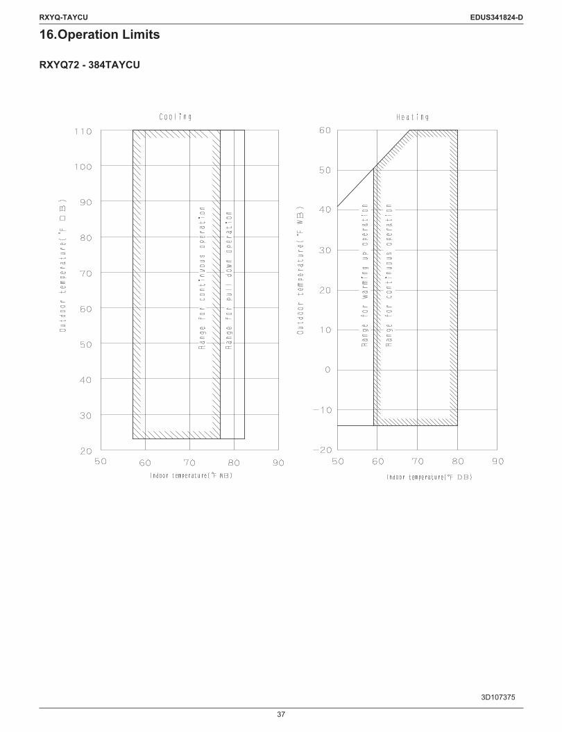
37
RXYQ-TAYCU EDUS341824-D
16. Operation Limits
RXYQ72 - 384TAYCU
3D107375

38
RXYQ-TAYCU EDUS341824-D
17. Sound Levels (Reference Data)
RXYQ72TAYCU
C: 4D107379A

39
RXYQ-TAYCU EDUS341824-D
RXYQ96TAYCU
C: 4D107380

40
RXYQ-TAYCU EDUS341824-D
RXYQ120TAYCU
C: 4D107381
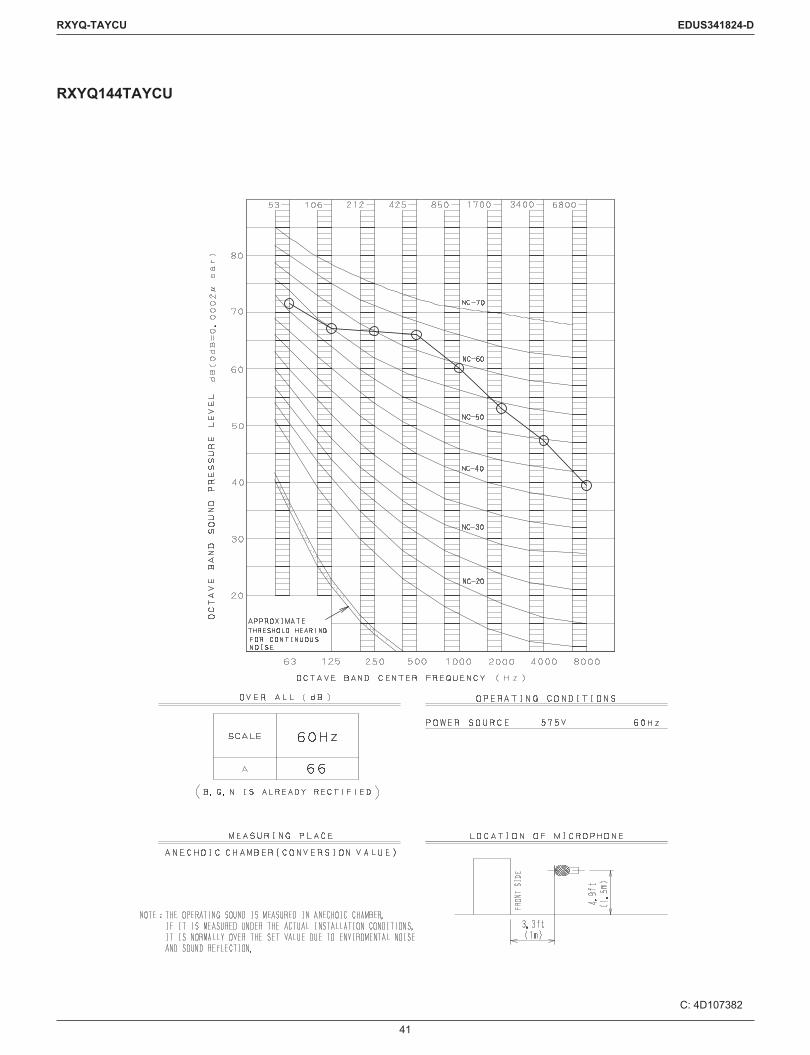
41
RXYQ-TAYCU EDUS341824-D
RXYQ144TAYCU
C: 4D107382

42
RXYQ-TAYCU EDUS341824-D
RXYQ168TAYCU
C: 4D107383
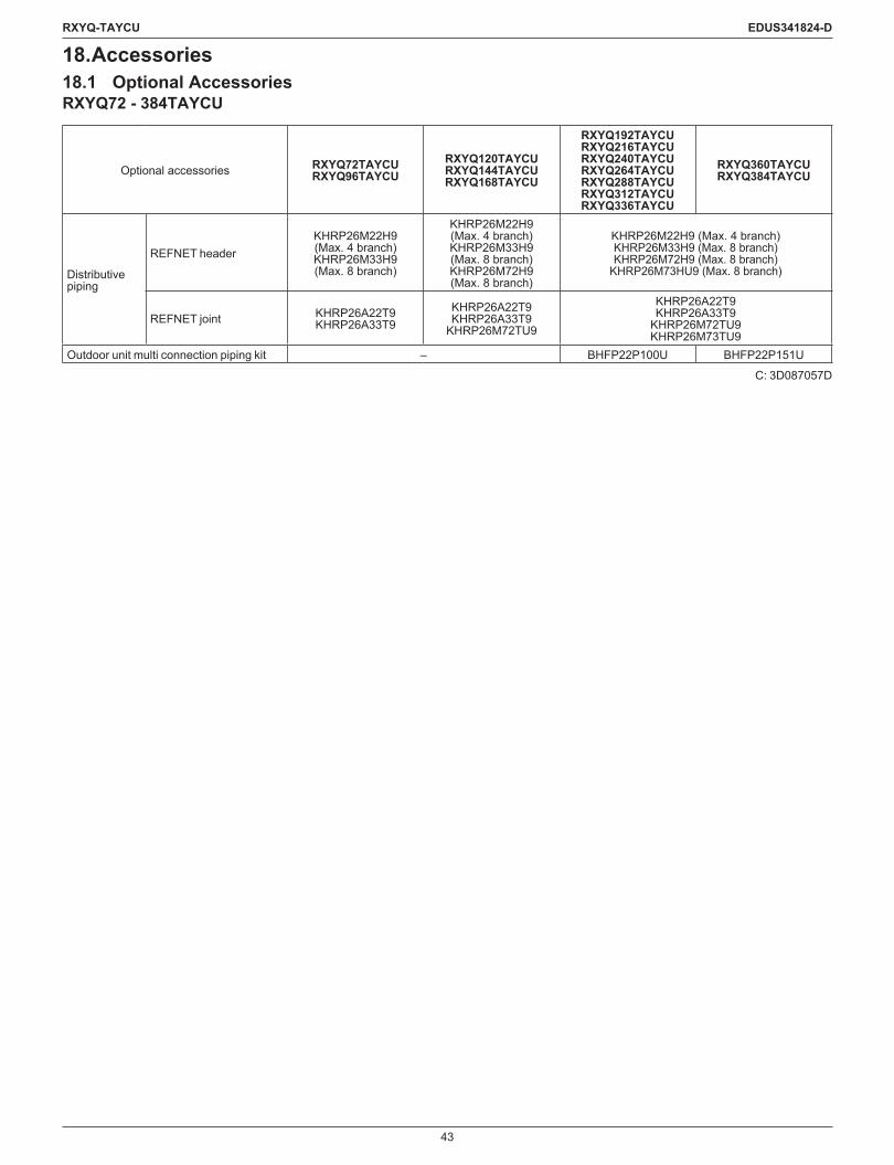
43
RXYQ-TAYCU EDUS341824-D
18. Accessories18.1 Optional AccessoriesRXYQ72 - 384TAYCU
Optional accessories RXYQ72TAYCURXYQ96TAYCU
RXYQ120TAYCURXYQ144TAYCURXYQ168TAYCU
RXYQ192TAYCURXYQ216TAYCURXYQ240TAYCURXYQ264TAYCURXYQ288TAYCURXYQ312TAYCURXYQ336TAYCU
RXYQ360TAYCURXYQ384TAYCU
Distributive piping
REFNET headerKHRP26M22H9 (Max. 4 branch)KHRP26M33H9 (Max. 8 branch)
KHRP26M22H9 (Max. 4 branch)KHRP26M33H9 (Max. 8 branch)KHRP26M72H9 (Max. 8 branch)
KHRP26M22H9 (Max. 4 branch)KHRP26M33H9 (Max. 8 branch)KHRP26M72H9 (Max. 8 branch)
KHRP26M73HU9 (Max. 8 branch)
REFNET joint KHRP26A22T9KHRP26A33T9
KHRP26A22T9KHRP26A33T9
KHRP26M72TU9
KHRP26A22T9KHRP26A33T9
KHRP26M72TU9KHRP26M73TU9
Outdoor unit multi connection piping kit – BHFP22P100U BHFP22P151U
C: 3D087057D

44
RXYQ-TAYCU EDUS341824-D
19. Selection Procedure19.1 Selection Procedure19.1.1 Flowchart
Provisionally select outdoor unit type and size based on limitation of connection ratio
Correct for cooling & heating capacity of the outdoor unit by the following items
VRV system selection is complete.
Confirm that the number of indoor units connected to the outdoor unit is within limitation.
Corrected capacity of the outdoor unit ≥ Required total heat load to the outdoor unit
2) Use the system peak load1) Use the sum of the peak load of each room
Define required total heat load to outdoor unit
Indoor unit capacity corrected for indoor air temperature (WB) ≥ Required heat load × Safety factor for the indoor units
Yes
No
-Piping length, level difference-Piping heat loss-Safety factor for the outdoor unit-Defrost (only for heating capacity)
-Outdoor air temperature-Indoor air temperature-Connection ratio
Given Conditions:· Design temperature and humidity (indoor & outdoor)· Required heat load of each room· System peak load (if necessary)· Piping length, level difference· Specifications of indoor units (type and number)
Define safety factor for the indoor units and outdoor unit
[1] Given conditions
[2] Selection of indoor units
[3] Selection of outdoor unit

45
RXYQ-TAYCU EDUS341824-D
19.1.2 Selection ExampleThe following is a selection example based on total heat load for cooling.
Room ARoom H Room G
Room F
Room B Room ERoom C Room D
Floor plan
[1] Given conditions-Design conditionsIndoor air temperature: 67°FWB / 80°FDB, Outdoor air temperature: 93°FDB
-Determine peak load of each room (and system peak load if necessary)
-Required heat load of each roomTime Room A Room B Room C Room D Room E Room F Room G Room H Total9:00 16.4 16.5 10.4 10.4 30.9 30.8 10.0 10.0 135.4
12:00 22.4 24.4 17.3 17.3 25.1 23.2 13.7 13.7 157.114:00 30.7 32.2 16.8 16.8 24.9 23.4 14.1 14.1 173.016:00 36.1 36.4 13.3 13.3 21.5 21.2 13.0 13.0 167.8
Total heat load (MBH)
From the above heat load calculation, the maximum heat load for the system (system peak load) is 173.0 MBH.
Level difference120 ft.
Select VRV indoor units FXMQ-PB series for each room.
Equivalent pipe length 200 ft.
-Safety factorIn this example, safety factor is not used. (i. e., safety factor = 1.0)
[2] Selection of indoor unitsCalculate total heat capacity of indoor units corrected for indoor air temperature.In case design temperature of the indoor air falls between temperatures listed in the table, calculate the capacity by interpolation.The corrected total heat capacity of indoor units shall satisfy the maximum heat load of each room.

46
RXYQ-TAYCU EDUS341824-D
Capacity table of indoor unitCooling Capacity
Model Capacity indication
Indoor air temp.°FWB (Te: 43°F (6°C))61 64 67 70 72 75
TC SHC TC SHC TC SHC TC SHC TC SHC TC SHCMBH MBH MBH MBH MBH MBH MBH MBH MBH MBH MBH MBH
FXMQ07PBVJU 07 5.7 5.5 6.4 5.9 7.2 6.1 7.3 6.5 7.4 5.8 7.6 5.8 FXMQ09PBVJU 09 7.5 6.9 8.5 7.3 9.5 7.8 9.7 8.1 9.8 7.1 10.0 7.2FXMQ12PBVJU 12 9.5 8.5 10.7 9.1 12.0 9.7 12.2 10.0 12.4 9.2 12.6 9.2FXMQ15PBVJU 15 11.2 10.2 12.7 10.7 14.2 11.4 14.5 11.6 14.7 11.5 14.9 9.6 FXMQ18PBVJU 18 14.2 13.9 16.1 14.7 18.0 15.6 18.4 16.1 18.6 14.6 18.9 12.1FXMQ24PBVJU 24 19.0 16.5 21.5 17.7 24.0 18.8 24.5 19.2 24.8 17.9 25.3 20.1FXMQ30PBVJU 30 23.7 20.8 26.8 22.3 30.0 23.8 30.6 24.4 31.0 22.5 31.6 22.5FXMQ36PBVJU 36 28.4 25.0 32.2 26.9 36.0 28.8 36.7 30.0 37.2 27.7 37.9 27.7FXMQ48PBVJU 48 37.9 31.3 43.0 33.6 48.0 35.8 49.0 36.9 49.6 34.7 50.5 33.2FXMQ54PBVJU 54 42.6 35.2 48.3 37.8 54.0 40.3 55.1 41.5 55.8 39.0 56.8 37.4
TC : Total capacity: MBHSHC : Sensible heat capacity: MBH
Selection results of indoor units
Room A Room B Room C Room D Room E Room F Room G Room HMax. heat load (MBH) 36.1 36.4 17.3 17.3 30.9 30.8 14.1 14.1
Selected IDU FXMQ48PBVJU FXMQ48PBVJU FXMQ18PBVJU FXMQ18PBVJU FXMQ36PBVJU FXMQ36PBVJU FXMQ15PBVJU FXMQ15PBVJUCorrected TC (MBH) 48.0 48.0 18.0 18.0 36.0 36.0 14.2 14.2
∗In case of selection based on Total Heat Load and Sensible Heat Load, select indoor units which satisfy not only the Total Heat Load but also the Sensible Heat Load of each room. The sensible heat capacity of indoor units is to be corrected for indoor air temperature. If the design temperature of indoor air falls between temperatures listed in table, calculate sensible heat capacity by using the bypass factor calculated by interpolation for each indoor air temperature.
[3] Selection of outdoor unit[3] –1 Define the required total heat load from the indoor units to the outdoor unitDefinetherequiredtotalheatload(A)basedon(1)thesumofthepeakloadofeachroomor(2)thesystempeakload.In this example, select an outdoor unit by (2).Therefore, (A) = 173.0 MBH

47
RXYQ-TAYCU EDUS341824-D
[3] –2 Provisionally select outdoor unit(1) Calculate CI (Capacity Index) of the selected indoor units.
CI of VRV indoor unitsCI of FXMQ15PBVJU = 15CI of FXMQ18PBVJU = 18CI of FXMQ36PBVJU = 36CI of FXMQ48PBVJU = 48
Calculate the total CI of the indoor units.Total CI = 15 × 2 + 18 × 2 + 36 × 2 + 48 × 2 = 234
The connection ratio of RXYQ-TA shall be between 50% (70%: RXYQ72TA type) and 130%.As the total CI of the indoor units is 234, outdoor units from 16 ton to 32 ton are connectable. Start from 16 ton which is the smallest outdoor unit.
(3) Confirm that the number of the connected indoor units is within the limitation.The number of the connected indoor units = 8The max. number of connectable indoor units of 16 ton outdoor unit = 33
(2) Provisionally select an outdoor unit based on the total CI of the indoor units
Capacity Range 0.5 ton 0.6 ton 0.8 ton 1 ton 1.25 ton 1.5 ton 2 ton 2.5 ton 3 ton 3.5 ton 4 ton 4.5 ton 5 ton 6 ton 8 ton Power Supply, StandardCapacity Index 5.8 7.5 9.5 12 15 18 20 24 30 36 42 48 54 60 72 96
Ceiling Mounted Duct Type (Middle and High Static Pressure)
FXMQ — 07PB 09PB 12PB 15PB 18PB — 24PB 30PB 36PB — 48PB 54PB — — — VJU
Type Ton Capacity index Model name CombinationOutdoor unit multi
connection piping kit *1
Total capacity index of connectable indoor units
*2Maximum number of
connectable indoor units
Single outdoor units
6 72 RXYQ72TA RXYQ72TA
—
51 to 93 (144) 12
8 96 RXYQ96TA RXYQ96TA 48 to 124 (192) 16
10 120 RXYQ120TA RXYQ120TA 60 to 156 (240) 20
12 144 RXYQ144TA RXYQ144TA 72 to 187 (288) 25
14 168 RXYQ168TA RXYQ168TA 84 to 218 (336) 29
Double outdoor units
16 192 RXYQ192TA RXYQ96TA+ RXYQ96TA
BHFP22P100U
96 to 249 (307) 33
18 216 RXYQ216TA RXYQ96TA+ RXYQ120TA 108 to 280 (345) 37
20 240 RXYQ240TA RXYQ120TA+ RXYQ120TA 120 to 312 (384) 41
22 264 RXYQ264TA RXYQ120TA+ RXYQ144TA 132 to 343 (422) 45
24 288 RXYQ288TA RXYQ144TA+ RXYQ144TA 144 to 374 (460) 49
26 312 RXYQ312TA RXYQ144TA+ RXYQ168TA 156 to 405 (499) 54
28 336 RXYQ336TA RXYQ168TA+ RXYQ168TA 168 to 436 (537) 58
Triple outdoor units
30 360 RXYQ360TARXYQ120TA+ RXYQ120TA+ RXYQ120TA
BHFP26P151U
180 to 468 (468) 62
32 384 RXYQ384TARXYQ120TA+ RXYQ120TA+ RXYQ144TA
192 to 499 (499) 64
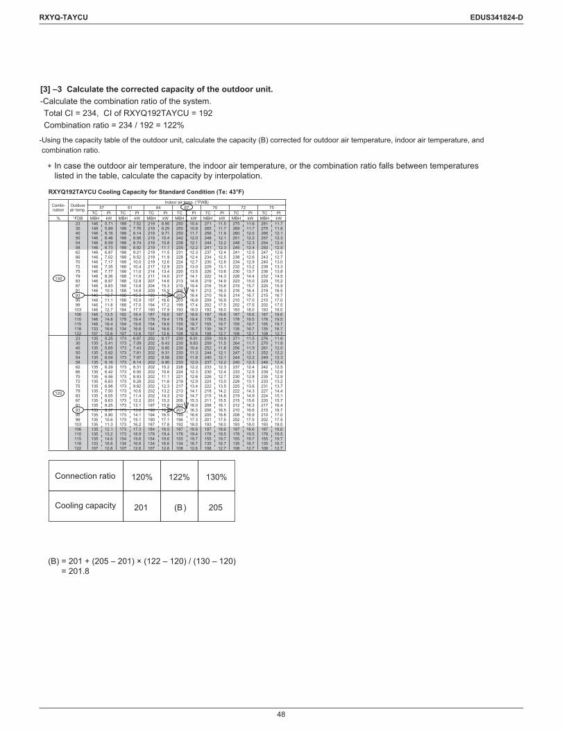
48
RXYQ-TAYCU EDUS341824-D
[3] –3 Calculate the corrected capacity of the outdoor unit.-Calculate the combination ratio of the system.Total CI = 234, CI of RXYQ192TAYCU = 192Combination ratio = 234 / 192 = 122%
- Using the capacity table of the outdoor unit, calculate the capacity (B) corrected for outdoor air temperature, indoor air temperature, and combination ratio.
120% 122% 130%
201 (B) 205
∗ In case the outdoor air temperature, the indoor air temperature, or the combination ratio falls between temperatures listed in the table, calculate the capacity by interpolation.
Connection ratio
Cooling capacity
(B) = 201 + (205 – 201) × (122 – 120) / (130 – 120) = 201.8
RXYQ192TAYCU Cooling Capacity for Standard Condition (Te: 43°F)
Combi-nation
Outdoorair temp.
Indoor air temp. (°FWB)57 61 64 67 70 72 75
TC PI TC PI TC PI TC PI TC PI TC PI TC PI% °FDB MBH kW MBH kW MBH kW MBH kW MBH kW MBH kW MBH kW
130
23 146 5.71 188 7.52 219 8.95 250 10.4 271 11.5 275 11.6 281 11.730 146 5.89 188 7.76 219 9.25 250 10.8 265 11.7 269 11.7 275 11.840 146 6.16 188 8.14 219 9.71 250 11.7 256 11.9 260 12.0 266 12.150 146 6.46 188 8.56 219 10.4 242 12.0 248 12.1 251 12.2 257 12.354 146 6.59 188 8.74 219 10.8 238 12.1 244 12.2 248 12.3 254 12.458 146 6.73 188 8.92 219 11.1 235 12.2 241 12.3 245 12.4 250 12.562 146 6.87 188 9.21 219 11.5 231 12.3 237 12.4 241 12.5 247 12.666 146 7.02 188 9.52 219 11.9 228 12.4 234 12.5 238 12.6 243 12.770 146 7.17 188 10.0 219 12.6 224 12.7 230 12.8 234 12.9 240 13.072 146 7.35 188 10.4 217 12.9 223 13.0 229 13.1 232 13.2 238 13.375 146 7.77 188 11.0 214 13.4 220 13.5 226 13.6 230 13.7 236 13.879 146 8.36 188 11.9 211 14.0 217 14.1 222 14.3 226 14.4 232 14.583 146 8.97 188 12.8 207 14.6 213 14.8 219 14.9 223 15.0 229 15.287 146 9.63 188 13.8 204 15.3 210 15.4 216 15.6 219 15.7 225 15.991 146 10.3 188 14.8 200 15.9 206 16.1 212 16.3 216 16.4 219 16.593 146 10.7 188 15.3 199 16.3 205 16.4 210 16.6 214 16.7 215 16.795 146 11.1 188 15.9 197 16.6 203 16.8 209 16.9 210 17.0 210 17.099 146 11.8 188 17.0 194 17.2 199 17.4 202 17.5 202 17.5 202 17.5
103 146 12.7 184 17.7 190 17.9 193 18.0 193 18.0 193 18.0 193 18.0106 146 13.5 182 18.4 187 18.6 187 18.6 187 18.6 187 18.6 187 18.6110 146 14.8 178 19.4 178 19.4 178 19.4 178 19.5 178 19.5 178 19.5115 146 16.4 154 19.6 154 19.6 155 19.7 155 19.7 155 19.7 155 19.7118 133 16.6 134 16.6 134 16.6 134 16.7 135 16.7 135 16.7 135 16.7122 107 12.6 107 12.6 107 12.6 108 12.6 108 12.7 108 12.7 108 12.7
120
23 135 5.25 173 6.87 202 8.17 230 9.51 259 10.9 271 11.5 276 11.630 135 5.41 173 7.09 202 8.43 230 9.83 259 11.5 264 11.7 270 11.840 135 5.65 173 7.43 202 8.85 230 10.4 252 11.8 256 11.9 261 12.050 135 5.92 173 7.81 202 9.31 230 11.3 244 12.1 247 12.1 252 12.254 135 6.04 173 7.97 202 9.58 230 11.6 240 12.1 244 12.2 249 12.358 135 6.16 173 8.14 202 9.90 230 12.0 237 12.2 240 12.3 246 12.462 135 6.29 173 8.31 202 10.2 228 12.2 233 12.3 237 12.4 242 12.566 135 6.42 173 8.50 202 10.6 224 12.3 230 12.4 233 12.5 239 12.670 135 6.56 173 8.93 202 11.1 221 12.6 226 12.7 230 12.8 235 12.972 135 6.63 173 9.28 202 11.6 219 12.9 224 13.0 228 13.1 233 13.275 135 6.98 173 9.82 202 12.3 217 13.4 222 13.5 225 13.6 231 13.779 135 7.50 173 10.6 202 13.2 213 14.1 218 14.2 222 14.3 227 14.483 135 8.05 173 11.4 202 14.3 210 14.7 215 14.8 219 14.9 224 15.187 135 8.63 173 12.2 201 15.2 206 15.3 211 15.5 215 15.6 220 15.791 135 9.25 173 13.1 197 15.8 203 16.0 208 16.1 212 16.3 217 16.493 135 9.57 173 13.6 196 16.2 201 16.3 206 16.5 210 16.6 215 16.795 135 9.90 173 14.1 194 16.5 199 16.6 205 16.8 208 16.9 210 17.099 135 10.6 173 15.1 190 17.1 196 17.3 201 17.5 202 17.5 202 17.5
103 135 11.3 173 16.2 187 17.8 192 18.0 193 18.0 193 18.0 193 18.0106 135 12.1 173 17.3 184 18.5 187 18.6 187 18.6 187 18.6 187 18.6110 135 13.2 173 18.9 178 19.4 178 19.4 178 19.5 178 19.5 178 19.5115 135 14.6 154 19.6 154 19.6 155 19.7 155 19.7 155 19.7 155 19.7118 133 16.6 134 16.6 134 16.6 134 16.7 135 16.7 135 16.7 135 16.7122 107 12.6 107 12.6 107 12.6 108 12.6 108 12.7 108 12.7 108 12.7

49
RXYQ-TAYCU EDUS341824-D
-Confirm capacity correction factor by piping length and level difference (K1)
-Calculate capacity correction factor by piping heat loss (K2)(K2) = 1 + (heat loss factor per feet of piping × (equivalent piping length – 25 ft.)) / 100
In cooling mode, heat loss factor per feet at 93°F is calculated as below.(R) Heat loss factor per feet = 0.072*2 + (0.098*1 – 0.072*2) × (93*3 – 86*4) / (95*5 – 86*4) = 0.0922
Using “Equivalent piping length = 200 ft.” and “Heat loss factor per feet = 0.0922”,(K2) = 1 + (0.0922 × (200 – 25)) / 100 = 1.161
-Calculate the corrected capacity of RXYQ192TAYCU(C) by using (K1) and (K2).Corrected capacity of RXYQ192TAYCU (C) = (B) × (K1) / (K2) (add defrost correction factor for heating capacity) Therefore (C) = 201.8 × 0.924 / 1.161 = 160.6 MBH
If the corrected capacity (C) is the same or greater than the required total heat load (A), selection is complete.If (C) < (A), return to Procedure [3]–2 and provisionally select a larger outdoor unit.In this example, 160.6 MBH (C) < 173.0 MBH (A), so need to select a larger outdoor unit.
The capacity of RXYQ216TAYCU at the same condition is 177.9 MBH, which is more than the heat load (A): 173.0 MBH. So the selection is complete.
Cooling Ambient temperature
Heat loss factor per feet of piping (%)
Heating Ambient temperature
Heat loss factor per feet of piping (%)
5°F 14°F 23°F 32°F 41°F 50°F 59°F 68°F0.328 0.305 0.282 0.256 0.233 0.210 0.187 0.161
(K1) = 0.924
0.924
41°F
0.000
50°F
0.000
59°F
0.013
68°F
0.030
77°F
0.046
86°F*4
0.072*2
93°F*3
(R)
95°F*5
0.098*1
104°F
0.125

50
RXYQ-TAYCU EDUS341824-D
20. Caution Label20.1 RXYQ72 - 120TAYCU
3P487082-1
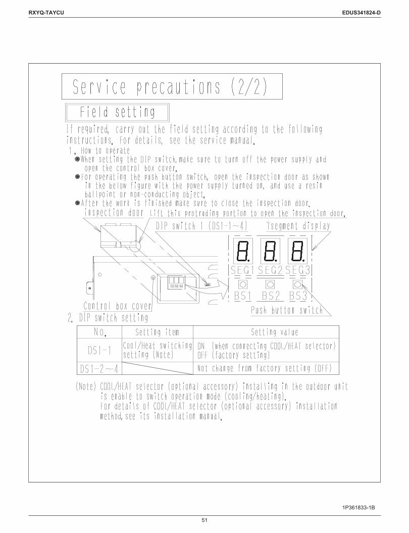
51
RXYQ-TAYCU EDUS341824-D
1P361833-1B
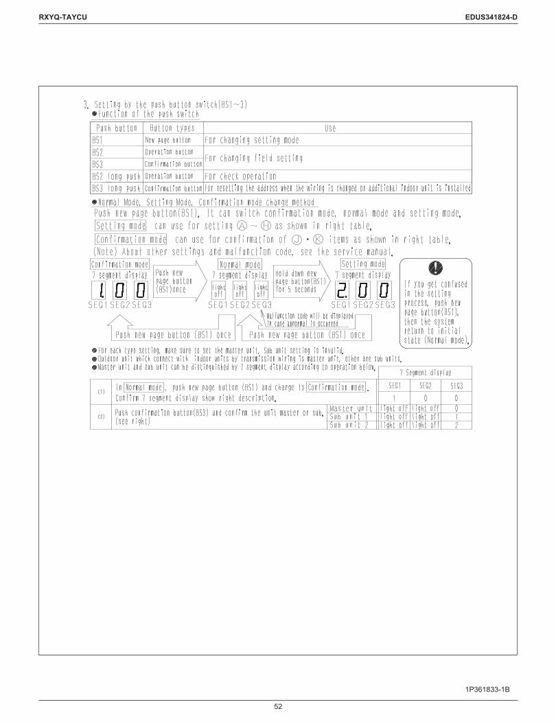
52
RXYQ-TAYCU EDUS341824-D
1P361833-1B

53
RXYQ-TAYCU EDUS341824-D
1P361833-1B

54
RXYQ-TAYCU EDUS341824-D
1P361833-1B

55
RXYQ-TAYCU EDUS341824-D
1P361833-1B

56
RXYQ-TAYCU EDUS341824-D
1P361833-1B

57
RXYQ-TAYCU EDUS341824-D
3P510840-1

58
RXYQ-TAYCU EDUS341824-D
3P510840-1

59
RXYQ-TAYCU EDUS341824-D
21. Caution for Refrigerant Leaks21.1 Introduction
Points to note in connection with refrigerant leaks
The installer and system specialist shall secure safety against leakage according to local regulations or standards. The following standards may be applicable if local regulations are not available.
The VRV System, like other air conditioning systems, uses R410A as refrigerant. R410A itself is an entirely safe non-toxic, non-combustible refrigerant.Neverthelesscaremustbetakentoensurethatairconditioningfacilitiesareinstalledinaroomwhichissufficientlylarge.Thisassuresthat the maximum concentration level of refrigerant gas is not exceeded, in the unlikely event of major leak in the system and this in accordance to the local applicable regulations and standards.
Maximum concentration levelThe maximum charge of refrigerant and the calculation of the maximum concentration of refrigerant is directly related to the humanly occupied space in to which it could leak.The unit of measurement of the concentration is lb./1000 ft.3 (the weight in Ibs. of the refrigerant gas in 1 ft.3 volume of the occupied space).Compliance to the local applicable regulations and standards for the maximum allowable concentration level is required.
Direction of therefrigerant flow
Room where refrigerant leak has occurred(outflow of all the refrigerant from the system)
Pay special attention to places, such as basements, etc. where refrigerant can stay, since refrigerant is heavier than air.
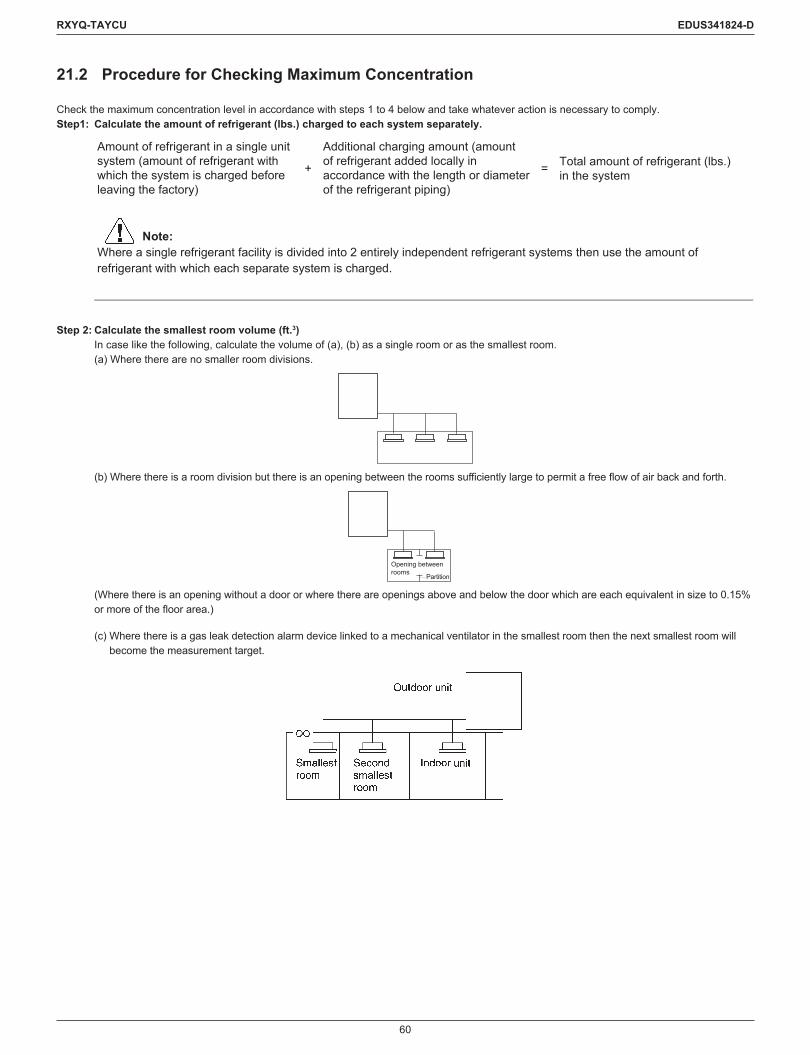
60
RXYQ-TAYCU EDUS341824-D
21.2 Procedure for Checking Maximum Concentration
Check the maximum concentration level in accordance with steps 1 to 4 below and take whatever action is necessary to comply.Step1: Calculate the amount of refrigerant (lbs.) charged to each system separately.
Amount of refrigerant in a single unitsystem (amount of refrigerant withwhich the system is charged beforeleaving the factory)
+
Additional charging amount (amountof refrigerant added locally inaccordance with the length or diameterof the refrigerant piping)
= Total amount of refrigerant (lbs.)in the system
Note:Where a single refrigerant facility is divided into 2 entirely independent refrigerant systems then use the amount of refrigerant with which each separate system is charged.
Step 2: Calculate the smallest room volume (ft.3) In case like the following, calculate the volume of (a), (b) as a single room or as the smallest room. (a) Where there are no smaller room divisions.
(b)Wherethereisaroomdivisionbutthereisanopeningbetweentheroomssufficientlylargetopermitafreeflowofairbackandforth.
Opening betweenrooms
Partition
(Where there is an opening without a door or where there are openings above and below the door which are each equivalent in size to 0.15% ormoreofthefloorarea.)
(c) Where there is a gas leak detection alarm device linked to a mechanical ventilator in the smallest room then the next smallest room will become the measurement target.

61
RXYQ-TAYCU EDUS341824-D
Step 3: Calculating the refrigerant density using the results of the calculations in steps 1 and 2 above.
Total volume of refrigerant in therefrigerant system
≤ Maximum concentration level (lbs./ft.3)Size (ft.3) of the smallest room in whichthere is an indoor unit installed
If the result of the above calculation exceeds the maximum concentration level then make similar calculations for the second then third smallest room and so until the result falls short of the maximum concentration.
Step 4: Dealing with the situations where the result exceeds the maximum concentration level. Where the installation of a facility results in a concentration in excess of the maximum concentration level then it will be necessary to revise
the system. Please consult your Daikin supplier.

62
RXYQ-TAYCU EDUS341824-D
22. Safety Devices Setting22.1 FXFQ-T
Model FXFQ07TVJU FXFQ09TVJU FXFQ12TVJU FXFQ15TVJU FXFQ18TVJUPrinted circuit board fuse 250 V, 3.15 A 250 V, 3.15 A 250 V, 3.15 A 250 V, 3.15 A 250 V, 3.15 AFan motor thermal fuse °F (°C) – – – – –Fan motor thermal protector °F (°C) – – – – –
Model FXFQ24TVJU FXFQ30TVJU FXFQ36TVJU FXFQ48TVJUPrinted circuit board fuse 250 V, 3.15 A 250 V, 3.15 A 250 V, 3.15 A 250 V, 3.15 AFan motor thermal fuse °F (°C) – – – –Fan motor thermal protector °F (°C) – – – –
C: 3D086932A
22.2 FXZQ-TA
Model FXZQ05TAVJU FXZQ07TAVJU FXZQ09TAVJU FXZQ12TAVJU FXZQ15TAVJU FXZQ18TAVJUPrinted circuit board fuse 250 V, 3.15 A 250 V, 3.15 A 250 V, 3.15 A 250 V, 3.15 A 250 V, 3.15 A 250 V, 3.15 AFan motor thermal fuse °F (°C) – – – – – –Fan motor thermal protector °F (°C) – – – – – –Drain pump fuse °F (°C) – – – – – –
C: 4D110603
22.3 FXUQ-P
Model FXUQ18PVJU FXUQ24PVJU FXUQ30PVJU FXUQ36PVJUPrinted circuit board fuse 250 V, 3.15 A 250 V, 3.15 A 250 V, 3.15 A 250 V, 3.15 ADrain pump thermal fuse °F (°C) – – – –Fan motor thermal protector °F (°C) – – – –Fan motor thermal fuse °F (°C) – – – –
C: 3D090213
22.4 FXEQ-P
Model FXEQ07PVJU FXEQ09PVJU FXEQ12PVJU FXEQ15PVJU FXEQ18PVJU FXEQ24PVJUPrinted circuit board fuse A1P 250 V, 3.15 A 250 V, 3.15 A 250 V, 3.15 A 250 V, 3.15 A 250 V, 3.15 A 250 V, 3.15 A
Fan motor thermal protector °F (°C)OFF: 223±9
(106±5)ON: 205±27
(96±15)
OFF: 223±9(106±5)
ON: 205±27(96±15)
OFF: 223±9(106±5)
ON: 205±27(96±15)
OFF: 223±9(106±5)
ON: 205±27(96±15)
OFF: 223±9 (106±5)
ON: 205±27(96±15)
OFF: 223±9(106±5)
ON: 205±27(96±15)
C: 4D098709

63
RXYQ-TAYCU EDUS341824-D
22.5 FXDQ-M
Model FXDQ07MVJU FXDQ09MVJU FXDQ12MVJU FXDQ18MVJU FXDQ24MVJUPrinted circuit board fuse A1P 250 V, 5 A 250 V, 5 A 250 V, 5 A 250 V, 5 A 250 V, 5 A
Fan motor thermal protector °F OFF: 266±9ON: 181±27
OFF: 266±9ON: 181±27
OFF: 266±9ON: 181±27
OFF: 266±9ON: 181±27
OFF: 266±9ON: 181±27
C: 3D051758
22.6 FXSQ-TA
Model FXSQ05TAVJU FXSQ07TAVJU FXSQ09TAVJU FXSQ12TAVJU FXSQ15TAVJUPrinted circuit board fuse 250 V, 3.15 A 250 V, 3.15 A 250 V, 3.15 A 250 V, 3.15 A 250 V, 3.15 APrinted circuit board fuse (Fan driver) 250 V, 6.3 A 250 V, 6.3 A 250 V, 6.3 A 250 V, 6.3 A 250 V, 6.3 ADrain pump thermal fuse °F (°C) — — — — —
Model FXSQ18TAVJU FXSQ24TAVJU FXSQ30TAVJU FXSQ36TAVJU FXSQ48TAVJU FXSQ54TAVJUPrinted circuit board fuse 250 V, 3.15 A 250 V, 3.15 A 250 V, 3.15 A 250 V, 3.15 A 250 V, 3.15 A 250 V, 3.15 APrinted circuit board fuse (Fan driver) 250 V, 6.3 A 250 V, 6.3 A 250 V, 6.3 A 250 V, 6.3 A 250 V, 6.3 A 250 V, 6.3 ADrain pump thermal fuse °F (°C) — — — — — —
C: 3D112398
22.7 FXMQ-PB
Model FXMQ07PBVJU FXMQ09PBVJU FXMQ12PBVJU FXMQ15PBVJU FXMQ18PBVJUPrinted circuit board fuse 250 V, 3.15 A 250 V, 3.15 A 250 V, 3.15 A 250 V, 3.15 A 250 V, 3.15 APrinted circuit board fuse (Fan driver) 250 V, 5 A 250 V, 5 A 250 V, 5 A 250 V, 6.3 A 250 V, 6.3 ADrain pump thermal fuse °F (°C) 293 (145) 293 (145) 293 (145) 293 (145) 293 (145)
Model FXMQ24PBVJU FXMQ30PBVJU FXMQ36PBVJU FXMQ48PBVJU FXMQ54PBVJUPrinted circuit board fuse 250 V, 3.15 A 250 V, 3.15 A 250 V, 3.15 A 250 V, 3.15 A 250 V, 3.15 APrinted circuit board fuse (Fan driver) 250 V, 6.3 A 250 V, 6.3 A 250 V, 6.3 A 250 V, 6.3 A 250 V, 6.3 ADrain pump thermal fuse °F (°C) 293 (145) 293 (145) 293 (145) 293 (145) 293 (145)
C: 3D086916B
22.8 FXMQ-M
Model FXMQ72MVJU FXMQ96MVJUPrinted circuit board fuse 250 V, 5 A 250 V, 5 AFan motor thermal fuse °F – –
Fan motor thermal protector °F OFF: 275±14(ON: 189±27)
OFF: 275±14(ON: 189±27)

64
RXYQ-TAYCU EDUS341824-D
22.9 FXHQ-M
Model FXHQ12MVJU FXHQ24MVJU FXHQ36MVJUPrinted circuit board fuse 250 V, 5 A 250 V, 5 A 250 V, 5 AFan motor thermal fuse °F – – –
Fan motor thermal protector °F OFF: 266±9ON: 176±36
OFF: 266±9ON: 176±36
OFF: 266±9ON: 176±36
C: 3D049334A
22.10 FXAQ-P
Model FXAQ07PVJU FXAQ09PVJU FXAQ12PVJU FXAQ18PVJU FXAQ24PVJUPrinted circuit board fuse 250 V, 3.15 A 250 V, 3.15 A 250 V, 3.15 A 250 V, 3.15 A 250 V, 3.15 AFan motor thermal fuse °F – – – – –Fan motor thermal protector °F – – – – –
C: 4D047085C
22.11 FXLQ-M, FXNQ-M
Model FXLQ07MVJUFXNQ07MVJU
FXLQ09MVJUFXNQ09MVJU
FXLQ12MVJUFXNQ12MVJU
FXLQ18MVJUFXNQ18MVJU
FXLQ24MVJUFXNQ24MVJU
Printed circuit board fuse 250 V, 5 A 250 V, 5 A 250 V, 5 A 250 V, 5 A 250 V, 5 A
Fan motor thermal protector °F (°C)OFF: 275±18
(135±18)ON: 248 (120)
or less
OFF: 275±18(135±18)
ON: 248 (120)or less
OFF: 275±18(135±18)
ON: 248 (120)or less
OFF: 275±18(135±18)
ON: 248 (120)or less
OFF: 275±18(135±18)
ON: 248 (120)or less
C: 3D045646B
22.12 FXTQ-TA
Model FXTQ09TAVJUA FXTQ12TAVJUA FXTQ18TAVJUA FXTQ24TAVJUA FXTQ30TAVJUAModel (with factory disconnect) FXTQ09TAVJUD FXTQ12TAVJUD FXTQ18TAVJUD FXTQ24TAVJUD FXTQ30TAVJUD
Printed circuit board fuse (F1U) 32 V, 3 A 32 V, 3 A 32 V, 3 A 32 V, 3 A 32 V, 3 APrinted circuit board fuse (F2U) 250 V, 3.15 A 250 V, 3.15 A 250 V, 3.15 A 250 V, 3.15 A 250 V, 3.15 AOthers Blower motor, Fan driver overload protector
Model FXTQ36TAVJUA FXTQ42TAVJUA FXTQ48TAVJUA FXTQ54TAVJUA FXTQ60TAVJUAModel (with factory disconnect) FXTQ36TAVJUD FXTQ42TAVJUD FXTQ48TAVJUD FXTQ54TAVJUD FXTQ60TAVJUD
Printed circuit board fuse (F1U) 32 V, 3 A 32 V, 3 A 32 V, 3 A 32 V, 3 A 32 V, 3 APrinted circuit board fuse (F2U) 250 V, 3.15 A 250 V, 3.15 A 250 V, 3.15 A 250 V, 3.15 A 250 V, 3.15 AOthers Blower motor, Fan driver overload protector

65
RXYQ-TAYCU EDUS341824-D
Appendix
1. Introduction ...............................................................................................661.1 ED Book List ...................................................................................661.2 Publication List of Engineering Data for VRV Products ..................67
2. GuideSpecifications .................................................................................692.1 GuideSpecifications .......................................................................69
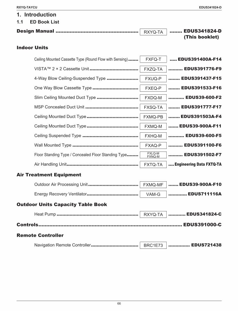
66
RXYQ-TAYCU EDUS341824-D
1. Introduction1.1 ED Book List
Design Manual ..................................................... RXYQ-TA ........ EDUS341824-D (This booklet)
Indoor Units
Ceiling Mounted Cassette Type (Round Flow with Sensing) ....... FXFQ-T ..... EDUS391400A-F14
VISTA™ 2 × 2 Cassette Unit .................................. FXZQ-TA .......... EDUS391776-F9
4-Way Blow Ceiling-Suspended Type ...................... FXUQ-P ........ EDUS391437-F15
One Way Blow Cassette Type ................................ FXEQ-P ........ EDUS391533-F16
Slim Ceiling Mounted Duct Type ............................. FXDQ-M ........... EDUS39-600-F2
MSP Concealed Duct Unit ..................................... FXSQ-TA ........ EDUS391777-F17
Ceiling Mounted Duct Type .................................... FXMQ-PB ........ EDUS391503A-F4
Ceiling Mounted Duct Type .................................... FXMQ-M ....... EDUS39-900A-F11
Ceiling Suspended Type ....................................... FXHQ-M ........... EDUS39-600-F5
Wall Mounted Type .............................................. FXAQ-P .......... EDUS391100-F6
Floor Standing Type / Concealed Floor Standing Type ........ FXLQ-MFXNQ-M .......... EDUS391502-F7
Air Handling Unit .................................................. FXTQ-TA ....Engineering Data FXTQ-TA
Air Treatment Equipment
Outdoor Air Processing Unit ................................... FXMQ-MF ....... EDUS39-900A-F10
Energy Recovery Ventilator .................................... VAM-G ............. EDUS711116A
Outdoor Units Capacity Table Book
Heat Pump ......................................................... RXYQ-TA ............ EDUS341824-C
Controls ............................................................................................ EDUS391000-C
Remote Controller
Navigation Remote Controller ................................. BRC1E73 ............... EDUS721438

67
RXYQ-TAYCU EDUS341824-D
1.2 Publication List of Engineering Data for VRV Products
Refrigerant Type Product Series Book No. Type Hz Volts Model name Area Note Published in
R410A
Air cooled
Inverter T, PC
EDUS371435-MH/RH/RH/RH/R
60 Hz60 Hz60 Hz60 Hz
460 V208/230 V460 V208/230 V
REYQ72-456TYDNREYQ72-456TTJUREYQ72-120PCYDREYQ72-144PCTJ
USA Generalinformation Aug. 2015
EDUS371435-NH/RH/RH/RH/R
60 Hz60 Hz60 Hz60 Hz
460 V208/230 V460 V208/230 V
REYQ72-456TYDNREYQ72-456TTJUREYQ72-120PCYDREYQ72-144PCTJ
USA Installation Jul. 2015
EDUS371435-R3 H/R 60 Hz 460 V REYQ72-120PCYD USA Specification Mar. 2015EDUS371435-R4 H/R 60 Hz 208/230 V REYQ72-144PCTJ USA Specification Mar. 2015
Inverter TA
EDUS341703-M H/PH/P
60 Hz60 Hz
460 V208/230 V
RXYQ72-408TAYDURXYQ72-408TATJU USA General
information Jun. 2017
EDUS341703-N H/PH/P
60 Hz60 Hz
460 V208/230 V
RXYQ72-408TAYDURXYQ72-408TATJU USA Installation Jul. 2017
EDUS341703-R1 H/P 60 Hz 460 V RXYQ72-408TAYDU USA Specification Apr. 2017EDUS341703-R2 H/P 60 Hz 208/230 V RXYQ72-408TATJU USA Specification Apr. 2017
EDUS371704-M H/RH/R
60 Hz60 Hz
460 V208/230 V
REYQ72-456TAYDUREYQ72-456TATJU USA General
information Jun. 2017
EDUS371704-N H/RH/R
60 Hz60 Hz
460 V208/230 V
REYQ72-456TAYDUREYQ72-456TATJU USA Installation Jul. 2017
EDUS371704-R1 H/R 60 Hz 460 V REYQ72-456TAYDU USA Specification May 2017EDUS371704-R2 H/R 60 Hz 208/230 V REYQ72-456TATJU USA Specification May 2017EDUS341824-D H/P 60 Hz 575 V RXYQ72-384TAYCU Canada Design manual Jun. 2018
EDUS341824-C H/P 60 Hz 575 V RXYQ72-384TAYCU Canada Capacity table book Jun. 2018
EDUS371706-M H/R 60 Hz 575 V REYQ72-384TAYCU Canada General Information Jun. 2017
EDUS371706-N H/R 60 Hz 575 V REYQ72-384TAYCU Canada Installation Jul. 2017EDUS371706-R H/R 60 Hz 575 V REYQ72-384TAYCU Canada Specification Jun. 2017
EDUS371705A-M H/R 60 Hz208/230 V460 V
RELQ72-240TATJURELQ72-240TAYDU
USACanada General
Information Oct. 2017575 V RELQ72-240TAYCU Canada
EDUS371705A-N H/R 60 Hz208/230 V460 V
RELQ72-240TATJURELQ72-240TAYDU
USACanada Installation Oct. 2017
575 V RELQ72-240TAYCU Canada
EDUS371705A-R H/R 60 Hz208/230 V460 V
RELQ72-240TATJURELQ72-240TAYDU
USACanada Specification Oct. 2017
575 V RELQ72-240TAYCU Canada
EDUS341819-D H/P 60 Hz208/230 V460 V
RXLQ72-240TATJURXLQ72-240TAYDU
USACanada Design manual Jun. 2018
575 V RXLQ72-240TAYCU Canada
EDUS341819-C H/P 60 Hz208/230 V460 V
RXLQ72-240TATJURXLQ72-240TAYDU
USACanada Capacity table
book Jun. 2018575 V RXLQ72-240TAYCU Canada
EDUS331608B-M H/P 60 Hz 208/230 V RXTQ36TAVJ9RXTQ48/60TAVJU USA General
information Feb. 2018
EDUS331608B-N H/P 60 Hz 208/230 V RXTQ36TAVJ9RXTQ48/60TAVJU USA Installation Jan. 2018
EDUS331608B-R H/P 60 Hz 208/230 V RXTQ36TAVJ9RXTQ48/60TAVJU USA Specification Jan. 2018
Water cooled
EDUS301716-MH/PH/RH/PH/R
60 Hz60 Hz60 Hz60 Hz
208/230 V208/230 V460 V460 V
RWEQ96-432TATJURWEQ96-432TAYDU USA General
information Mar. 2018
EDUS301716-NH/PH/RH/PH/R
60 Hz60 Hz60 Hz60 Hz
208/230 V208/230 V460 V460 V
RWEQ96-432TATJURWEQ96-432TAYDU USA Installation Mar. 2018
EDUS301716-RH/PH/RH/PH/R
60 Hz60 Hz60 Hz60 Hz
208/230 V208/230 V460 V460 V
RWEQ96-432TATJURWEQ96-432TAYDU USA Specification Mar. 2018

68
RXYQ-TAYCU EDUS341824-D
Refrigerant Type Product Series Book No. Type Hz Volts Model name Area Note Published in
R410A
VRV Indoor units
EDUS391400A-F14 – 60 Hz – FXFQ07-48TVJU USA
Ceiling Mounted Cassette (Round Flow with Sensing) Type
May 2018
EDUS391776-F9 – 60 Hz – FXZQ05-18TAVJU USA VISTA™ 2 x 2 Cassette Unit Mar. 2018
EDUS391437-F15 – 60 Hz – FXUQ18-36PVJU USA4-Way Blow Ceiling-Suspended Type
May 2015
EDUS391533-F16 – 60 Hz – FXEQ07-24PVJU USA One Way Blow Cassette Type Oct. 2015
EDUS39-600-F2 – 60 Hz – FXDQ07-24MVJU USASlim Ceiling Mounted Duct Type
Sep. 2006
EDUS391777-F17 – 60 Hz – FXSQ05-54TAVJU USAMSP Concealed Ducted Unit
Mar. 2018
EDUS391503A-F4 – 60 Hz – FXMQ07-54PBVJU USA
Ceiling Mounted Duct Type (Middle and High Static Pressure)
May 2018
EDUS39-900A-F11 – 60 Hz – FXMQ72/96MVJU USACeiling Mounted Duct Type
May 2010
EDUS39-600-F5 – 60 Hz – FXHQ12-36MVJU USACeiling Suspended Type
Sep. 2006
EDUS391100-F6 – 60 Hz – FXAQ07-24PVJU USA Wall Mounted Type Jan. 2012
EDUS391502-F7 – 60 Hz – FXLQ07-24MVJUFXNQ07-24MVJU USA
Floor Standing TypeConcealed Floor Standing Type
Jul. 2015
Engineering Data FXTQ-TA – 60 Hz – FXTQ09-60TAVJUA
FXTQ09-60TAVJUD USA Air Handling Unit Sep. 2016
EDUS39-900A-F10 – 60 Hz – FXMQ48-96MFVJU USAOutdoor Air Processing Unit
May 2010
EDUS391434-B – 60 Hz – BSQ36-96TVJ USA Single Branch Selector Unit Aug. 2015
EDUS391434-B – 60 Hz – BS4-12Q54TVJ USA Multi Branch Selector Unit Aug. 2015
Controls and networks
EDUS391000-C – – –
BRC1E71, BRC4C/7C/7E, BRC2A71DCS302C71, DCS301C71,DST301BA61, DCS601C71KRP1C74/75
USA
Remote controllerControl devices
Adaptor
Aug. 2010
EDUS721438 – – – BRC1E73 USANavigation remote controller
Apr. 2015
EDUS721212 – – – DCM601A71DCM601A72 USA
intelligent Touch Manager
Oct. 2012
EDUS72-608 – – – DCS601C71 USAintelligent Touch Controller
Dec. 2006
EDUS72-749 – – – DMS502B71 USAInterface for use in BACnet®
Oct. 2007
Option for all type OHUS07-1 – – – For indoor and outdoor units USA Option
handbook Nov. 2007
Energy Recovery Ventilator (VAM) EDUS711116A – 60 Hz – VAM300-1200GVJU USAEnergy Recovery Ventilator
Jun. 2017
EDUS341824-D, C as shown by .C/O : Cooling onlyH/P : Heat pumpH/R : Heat recovery

69
RXYQ-TAYCU EDUS341824-D
2. Guide Specifications2.1 Guide Specifications
GeneralUnit shall be air cooled, split type multi-system air conditioner consisting of one outdoor unit and plural indoor units, each having capability to cool or heat independently for the requirements of the rooms.Upto13differenttypeindoorunitscanbeconnectedtoonerefrigerantcircuitandcontrolledindividually.Compressor shall be equipped with inverter controller, and capable of changing the rotating speed to follow variations in cooling and heating load.Outdoor unit shall be suitable for mix-match connection of following models.
�� Ceiling Mounted Cassette Type (Round Flow with Sensing)�� VISTA™ 2 × 2 Cassette Unit�� 4-Way Blow Ceiling-Suspended Type�� One Way Blow Cassette Type�� Slim Ceiling Mounted Duct Type�� MSP Concealed Ducted Unit�� Ceiling Mounted Duct Type (Middle and High Static Pressure)�� Ceiling Mounted Duct Type�� Ceiling Suspended Type�� Wall Mounted Type�� Floor Standing Type�� Concealed Floor Standing Type�� Air Handling Unit
�� Refrigerant: R410A
2.1.1 TA Series Outdoor UnitThe actual refrigerant piping length shall be extended up to 540 ft. (165 m) with 164 ft. (50 m) (1)leveldifferencewithoutanyoiltraps.�� Air conditioner shall operate continuously at the ambient temperature of 23°F (-5°C) in cooling -13°F (-25°C) in heating.
Both indoor unit and outdoor unit are assembled, tested, and charged with refrigerant at the factory. 1: The value is based on the case where the outdoor unit is located above indoor unit. Where the outdoor unit is located under the indoor unit, the leveldifferenceisamaximumof130ft.(40m).
Outdoor UnitThe outdoor unit shall be a factory assembled unit housed in a sturdy weatherproof casing constructed form rust-proofed mild steel panels coated withabakedenamelfinish.�� The outdoor unit shall be modular in design and should be allowed for side by side installation.
CompressorThecompressorshallbeofhighlyefficienthermeticscrolltypeandequippedwithinvertercontrolcapableofchangingthespeedinaccordancetothe cooling or heating load requirement.�� Theoutdoorunitshallhavethemulti-stepofcapacitycontroltomeetloadfluctuationandindoorunitindividualcontrol.
Heat ExchangerTheheatexchangershallbeconstructedwithcoppertubesmechanicallybondedtoaluminumfinstoformacrossfincoil.�� Thealuminumfinsshallbecoveredbyanti-corrosionresinfilm.
Refrigerant CircuitTherefrigerantcircuitshallincludeliquidandgasshutoffvalvesandsolenoidvalves.All necessary safety devices shall be provided to ensure the safety operation of the system.
70
RXYQ-TAYCU EDUS341824-D
Safety DevicesThe following safety devices shall be part of the outdoor unit.High pressure switch, Fan driver overload protector, Overcurrent fuse, Inverter overload protector, Leak detecting device.
Oil Recovery SystemUnit shall be equipped with an oil recovery system to ensure stable operation with long refrigerant piping.
2.1.2 Indoor UnitsEach indoor unit shall be of the Ceiling Mounted Cassette Type (Round Flow with Sensing), VISTA™ 2 × 2 Cassette Unit, 4-Way Blow Ceiling-Suspended Type, One Way Blow Cassette Type, Slim Ceiling Mounted Duct Type, MSP Concealed Ducted Unit, Ceiling Mounted Duct Type (Middle and High Static Pressure), Ceiling Mounted Duct Type, Ceiling Suspended Type, Wall Mounted Type, Floor Standing Type, Concealed FloorStandingType,orAirHandlingUnit.Itshallhaveelectroniccontrolvalvewhichcontrolsrefrigerantflowrateinrespondtoloadvariationsofthe room. The fan shall be of the multi blade type and statically and dynamically balanced to ensure low noise and vibration free operation.�� The address of the indoor unit shall be set automatically in case of individual and group control.�� In case of centralized control, it shall be set by remote controller.
ControlComputerized PID control shall be used to maintain a correct room temperature.Unit shall be equipped with a self-diagnosis for easy and quick maintenance and service.The Navigation remote controller shall memorize the latest malfunction code for easy maintenance.�� Itshallbeabletocontrolupto16indoorunitsandchangefanspeedandangleofswingflapindividuallyinthegroup.
Central Remote Controller (Option)A multi-functional centralized control equipment (central remote controller) shall be supplied as optional accessory.�� It shall be able to control up to 64 Zones of 64 indoor unit groups (each group consists of max. 16 indoor units) or 128 indoor units with the following
functions.a) Temperature setting for each Zone, or group, or indoor unit.b) ON/OFF as a Zone or individual unit.c) Indication of operating condition.d) Select one of 10 operation modes for each Zone.�� The controller shall have wide screen LCD and can be wired by a non-polar 2-wire transmission cable to a distance of 3280 ft. (1000 m) away from
the indoor unit.
Unified ON / OFF Controller (Option)UnifiedON/OFFcontrollershallbesuppliedasoptionalaccessory.It shall be able to control up to 16 indoor unit groups (each group consists of max. 16 indoor units) or 128 indoor units with the following functions.a) ON/OFF as a zone or individual unit.b) Indication of operation condition of each group.c) Select one of 4 operation modes.
It shall be wired by a non-polar 2-wire transmission cable to a distance of 3280 ft. (1000 m) away from indoor unit.
Schedule Timer (Option)A schedule timer shall be supplied as optional accessory.�� It shall be able to set operation schedule of up to 128 indoor units.
The operation schedule shall include twice ON/OFF a day and holiday.�� It shall be able to set 8 patterns of schedule combined with centralized controller.
intelligent Touch Controller (Option)Air-conditioning management system that can be controlled by a compact all-in-one unit.
intelligent Touch Manager (Option)Air-conditioning management system that can be controlled by a compact all-in-one unit.


1. Air conditioners should not be installed in areas where corrosive gases, such as acid gas or alkaline gas, are produced.2. If the outdoor unit is to be installed close to the sea shore, direct exposure to the sea breeze should be avoided. If you need to install the outdoor unit close to the sea shore, contact your local distributor.
Cautions on product corrosion
Warning Ask a qualified installer or contractor to install this product. Do not try to install the product yourself. Improper installation can result in water or refrigerant leakage, electrical shock, fire or explosion.
Use only those parts and accessories supplied or specified by Daikin. Ask a qualified installer or contractor to install those parts and accessories. Use of unauthorised parts and accessories or improper installation of parts and accessories can result in water or refrigerant leakage, electrical shock, fire or explosion.
Read the user’s manual carefully before using this product. The user’s manual provides important safety instructions and warnings. Be sure to follow these instructions and warnings.
If you have any enquiries, please contact your local importer, distributor and/or retailer.
©All rights reserved 06/18 FS
●Specifications, designs and other content appearing in this brochure are current as of June 2018 but subject to change without notice.
VRV Air Conditioning System is the world’s first individual air conditioning system with variable refrigerant flow control and was commercialised by Daikin in 1982.VRV is the trade mark of Daikin Industries, Ltd., which is derived from the technology we call “variable refrigerant volume.”
VRV is a trade mark of Daikin Industries, Ltd.