Resolute Boiler® - Energy Kinetics
41
Resolute Gas Heat –Seventh Edition – December, 2020 ASME certified by EKI. Certificate plate is under the jacket on the steel vessel. MH27877 ANSI Z21.13b-2012 Low-Press Boiler Resolute Boiler ® INSTALLATION & SERVICE MANUAL GAS HEAT EDITION MANUFACTURED BY: ENERGY KINETICS, INC. 51 Molasses Hill Road Lebanon, NJ 08833 (908) 735-2066 www.energykinetics.com or www.system2000.com INSTALLER: PLEASE HANG THIS INSTRUCTION MANUAL AND ACCESSORY INSTRUCTIONS VISIBLY NEXT TO THE BOILER USING THE SUPPLIED POUCH. CONSUMER: PLEASE RETAIN THIS INSTRUCTION MANUAL AND ACCESSORY INSTRUCTIONS FOR FUTURE REFERENCE. This product meets the Energy Star ® guidelines for efficiency. National Board Listed
-
Upload
khangminh22 -
Category
Documents
-
view
1 -
download
0
Transcript of Resolute Boiler® - Energy Kinetics

Resolute Gas Heat –Seventh Edition – December, 2020
ASME certified by EKI. Certificate plate is under the jacket on the steel vessel.
MH27877
ANSI Z21.13b-2012 Low-Press Boiler
Resolute Boiler®
INSTALLATION & SERVICE MANUAL
GAS HEAT EDITION
MANUFACTURED BY:
ENERGY KINETICS, INC. 51 Molasses Hill Road
Lebanon, NJ 08833 (908) 735-2066
www.energykinetics.com or www.system2000.com
INSTALLER: PLEASE HANG THIS INSTRUCTION MANUAL AND ACCESSORY INSTRUCTIONS VISIBLY NEXT TO THE BOILER USING THE SUPPLIED POUCH.
CONSUMER: PLEASE RETAIN THIS INSTRUCTION MANUAL AND ACCESSORY INSTRUCTIONS FOR FUTURE REFERENCE.
This product meets the Energy Star® guidelines
for efficiency.
National Board
Listed


Resolute Gas Heat – Seventh Edition – December 2020 1
Please Read This First Special Attention Flags Please pay particular attention to the following flags when you see them throughout this manual.
DANGER: Notifies you of hazards that WILL cause severe personal injury, death or substantial property damage. WARNING: Notifies you of hazards that CAN cause severe personal injury, death or substantial property damage. CAUTION: Notifies you of hazards that WILL or CAN cause minor personal injury or property damage. NOTICE: Notifies you of special instructions on installation, operation, or maintenance that are important, but not
normally related to injury or property damage hazards.
WARNING: If the information in this manual is not followed exactly, a fire or explosion may result, causing property damage, personal injury or loss of life.
WARNING: Do not store or use gasoline or other flammable vapors and liquids in the vicinity of this or any other gas appliance.
Provide unobstructed combustion air openings sized and located per boiler manual and applicable codes.
WHAT TO DO IF YOU SMELL GAS • Do not try to light any appliance. • Do not touch any electrical switch; do not use any phone in your building. • Immediately call your gas supplier from an outside phone. • Follow the gas supplier’s instructions. • If you cannot reach your gas supplier, call the fire department.
WARNING: Installation and service must be performed by a qualified installer, service agency or the gas supplier.
Retain this manual for use by your qualified service technician only. Should you observe unusual or abnormal operation of the burner or
boiler, contact your qualified service technician immediately. Do not attempt to service or repair this product yourself.

Resolute Gas Heat – Seventh Edition – December 2020 2
WARNING: Have the burner/boiler started up and serviced at least once annually by a
qualified service technician. Professional care is necessary to properly service your equipment and verify it is operating reliably. Failure to properly maintain the equipment could result in severe personal injury, death or substantial property damage.
WARNING: You must keep the area around the burner/boiler free from the following.
• Do not store or use gasoline or other flammable vapors or liquids near or in the same room as the burner.
• Do not use or store laundry products, paint, varnish, thinner or other such chemicals near or in the same room as the burner/boiler. These chemicals cause creation of acids in the burner, heat exchanger and vent system that can cause severe damage.
• Do not store combustible materials near or in the same room as the burner/boiler.
• Failure to comply could result in severe personal injury, death or substantial property damage due to potential fire, explosion or equipment damage from corrosive flue products.
General care and maintenance �� Please read through the information provided for you in this manual. Ask your qualified
service technician to explain normal operation of your equipment.
�� Daily inspect the space around the burner/boiler to verify the area is clean and free of the materials listed above.
�� Periodically watch the operation of your burner/boiler through an operating cycle to verify normal operation. If you notice unusual conditions or equipment behavior, contact your qualified service technician. Follow the instructions on the next page to shut down the burner/boiler while waiting for the technician.
WARNING: Improper installation, adjustment, alteration, service or maintenance can cause property damage, personal injury (exposure to hazardous materials) or loss of life. Refer to the user’s information manual provided with this boiler. Installation and service must be performed by a qualified installer, service agency or the gas supplier (who must read and follow the supplied instructions before installing, servicing, or removing this boiler. This boiler contains materials that have been identified as carcinogenic, or possibly carcinogenic, to humans).

Resolute Gas Heat – Seventh Edition – December 2020 3
FOR YOUR SAFETY READ BEFORE OPERATING
A. This burner does not have a pilot. It is equipped with an ignition device which automatically lights the burner. Do not try to light the burner by hand.
C. Use only your hand to turn the gas control knob. Never use tools. If the knob will not turn by hand, don’t try to repair it, call a qualified service technician. Force or attempted repair may result in a fire or explosion.
B. Before OPERATING, smell all around the boiler area for gas. Be sure to smell next to the floor because some gas is heavier than air and will settle on the floor. See below.
WHAT TO DO IF YOU SMELL GAS
• Do not try to light any appliance. • Do not touch any electric switch; do not
use any phone in your building • Immediately call your gas supplier from a
neighbor’s phone. Follow the gas supplier’s instructions.
• If you cannot reach your gas supplier, call the fire department.
D. Do not use this boiler if any part has been under water. Immediately call a qualified service technician to inspect the boiler and to replace any part of the control system and any gas control, which has been under water.
OPERATING INSTRUCTIONS 1. STOP! Read the safety information above. 2. Set the thermostat(s) to their lowest setting. 3. Turn off all electrical power to the burner/boiler. 4. This burner is equipped with an ignition device which automatically lights the burner. 5. Do not try to light the burner by hand. 6. Turn Gas control knob clockwise to OFF. 7. Wait five (5) minutes to clear out any gas. Then smell for gas, including near the floor. If you
smell gas, STOP! Follow the safety information above. If you don’t smell gas, go to the next step.
8. Turn Gas control knob counterclockwise to ON. 9. Set thermostat(s) to desired setting. 10. Turn on all electric power to the burner and boiler. 11. If the burner/boiler will not operate, follow the instructions “TO TURN OFF GAS TO THE
BURNER” below and call your service technician or gas supplier.
TO TURN OFF GAS TO THE BURNER 1. Set thermostat(s) to their lowest setting. 2. Turn off all electric power to the burner and boiler if service is to be performed. 3. Turn Gas control knob clockwise to OFF. Do not force.
WARNING: If you do not follow these instructions exactly, a fire or explosion may result causing property damage, personal injury or loss of life.

Resolute Gas Heat – Seventh Edition – December 2020 4
RECORD OF INSTALLATION
INSTALLER NAME:
INSTALLER ADDRESS:
INSTALLER CITY, STATE:
DATE INSTALLED:
NOTES:
All installations must be made in accordance with all State and Local Codes, which may differ from this manual and in accordance with the following Codes, as applicable: National Fuel Gas Code, ANSI Z223.1/NFPA 54: Installation Codes, CAN/CGA B149 National Electrical Code, ANSI/NFPA 70 Canadian Electrical Code Part I, CSA 22.1, Electrical Code Chimneys, Fireplaces, Vents and Solid Fuel Burning Appliances, ANSI/NFPA 211 Where required by the authority having jurisdiction, the installation must conform to the Standard for: ANSI/ASME CSD-1 Controls and Safety Devices for Automatically Fired Boilers These codes are available from: National Fire Protection Association 1 Batterymarch Park Quincy, MA 02269-9101. A boiler should be installed in such a manner that, if the pressure vessel or any connection thereto should leak, the resulting flow of water will not cause damage to the area in which it is installed. A boiler’s pressure relief valve, backflow preventer, and all other devices must be piped to the nearest drain to avoid damage in the event the valve is actuated.

Resolute Gas Heat – Seventh Edition – December 2020 5
TABLE OF CONTENTS
Page Topic Page Topic
1 Please Read This First 17 Five-Zone Display Manager 4 Record of Installation 18 Dip Switch Settings 5 Table of Contents 18 Display Manager Option Menu Descriptions
6 SYSTEM 2000 Boiler - Principle of Operation 18 Expanded Energy Manager
6 Digital Manager - Principle of Operation 19 15-Zone Manager Installation Instructions 7 Receiving and Unpacking 20 Hydronic Control Settings 7 Location and Clearance 20 Prepare for Start Up
7 Boiler Weight, Water Content, Inlet and Outlet Sizes 20 Start Up Procedure
8 Clearance for Cleaning and Service 21 Air Free Method of Measuring CO 9 Combustion Air 22 Gas Burner Operation 9 Smart Vent System 23 Installation Check Off Procedure 9 Gas Burner Mounting 24 Energy Manager Operation
10 Gas Burner Settings 25 Energy Manager Check 10 Gas Piping Systems 26 2 Minute Digital Energy Manager Diagnostic 11 General Assembly 27 Additional Manager Tests 11 Boiler Mounting 28 Digital Manager Sensor Testing 11 Piping 28 Line Voltage Relays 13 Zone Control 28 Surge Suppression 13 Filling with Water, Venting, and Purging 29 Troubleshooting with Digital Manager 14 Boiler Water Treatment 30 Operation without the Digital Manager
14 Anti-Freeze 30 Emergency Heat without Manager or Relay Board
14 Winterizing 31 Annual Tune Up & Inspection 14 Wiring and Controls 33 Amulet Replacement 14 Electrical Connection - Line Voltage 33 Combustion Chamber Replacement 15 Line Voltage Wiring Diagram 33 Replacement Parts – Boiler 16 Low Voltage Wiring and Diagram 34 Exploded View of Boiler 16 Install Energy Manager 35 Commonwealth of Massachusetts
Inside Back Cover
Limited Lifetime Warranty Back Cover Warranty Transfer Agreement

Resolute Gas Heat – Seventh Edition – December 2020 6
SYSTEM 2000® RESOLUTE BOILER
IMPORTANT MESSAGE TO HOMEOWNER: These instructions should be carefully read and kept for future reference to gain the best performance from your System 2000 Resolute boiler.
CONGRATULATIONS ON YOUR PURCHASE OF THE SYSTEM 2000 BOILER with its highly efficient low mass hydronic heat exchanger, the Energy Converter. It is the product of years of engineering and advanced design, which brings together in a single system all elements needed to provide efficient home heat. This operation and maintenance information has been prepared so that you may better understand and use your Energy Kinetics Resolute Boiler and Heating System.
SYSTEM 2000 BOILER - PRINCIPLE of OPERATION
SYSTEM 2000 comprises a heat source, the energy converter, circulating water and five (or more) zones controlled by an electronic control, the Energy Manager.
The Boiler sits cold until a thermostat calls for heat. The Energy Manager receives the call for heat and turns on the main circulator and burner. Water circulates within the boiler as it warms up to operating temperature. When ready, the zone valves open and deliver heat to the zones calling for heat. When the thermostats are satisfied, the Energy Manager turns off the burner and enters the energy recovery stage. The circulator and zone valve stay energized to deliver the heat remaining in the boiler to your home.
When energy recovery is complete and the Boiler has been cooled off, the Energy Manager turns off the system and waits for another heat zone thermostat or hot water tank thermostat to call for heat. SYSTEM 2000 runs the burner only when you need heat and delivers that heat only where you need heat.
The System 2000 Energy Converter is the product of advanced thermal engineering. It is designed with two separate passageways, about 15 feet long on the flue gas side, coiled around each other. Water travels along one passageway from your home toward the center of the unit and heated gases travel from the unit center toward the exhaust. This is a “forced circulation counter-flow” design and it provides very efficient transfer of heat from the burning fuel to the circulating water. The superior insulation of the boiler minimizes heat losses to the surroundings, resulting in directing heat to your home in an efficient and quiet manner.
SYSTEM 2000 has an extremely high annual efficiency (over 99% of steady state) because it runs only when your home needs heat. Energy recovery is completed at the end of each heat call, virtually eliminating off cycle losses.
Your System 2000 holds a minimal quantity of water so it begins to supply heat in about 90 seconds. This rapid response means that your rooms can be heated quickly to temperature. The System 2000 EK-1 Resolute can heat water up to 100,000 BTU’s per hour.
A modern power burner fires into the center of System 2000 where a high temperature, light weight ceramic chamber provides ideal conditions for “near perfect” efficient, pollution-free combustion. Your System 2000 is tightly sealed so all products of combustion pass only to the outdoors.
The RESOLUTE Boiler is designed with a hinged front cover that allows access to the inside of the boiler for inspection and cleaning. All access for service is from the front, so the RESOLUTE Boiler can be placed directly against a wall or into a closet.
ENERGY MANAGER - PRINCIPLE of OPERATION The left side of the Manager is the input side, which provides 24-volt power supply and connections for thermostats.
The right side is the output side, which starts the burner, circulator and zone valves or zone circulators. See photo of the Manager on the cover. Because the Resolute Gas boiler is gas fired and sidewall vented, the Manager option switches one and two must be turned on, activating the 130 o F/150 o F return water setting and activating the inducer output.
Lights on the Digital Manager indicate what is calling for heat (left side) and (right side) lights indicate active zone(s), burner operation and circulator operation. These function lights are an aid in servicing. The following is a typical cycle.
1. SYSTEM WAITING FOR A CALL: The boiler is turned off and sits cold, waiting until a call for heat. The red power light on the Manager is glowing.
2. CALL FOR HEAT: A room thermostat call starts the cycle. The thermostat light on the left side will turn on for that zone.
3. PRE-HEAT: Output lights for the main circulator and burner turn on, the circulator starts, and the burner begins firing. The boiler water circulates through the energy converter via the bypass line, heating up the water.
4. HEAT: Once the boiler water has heated up to 150o F (about 90 seconds), the Manager will turn on the zone output light on the right side. The zone valve will open and hot water will flow to the zone needing heat. The burner runs as long as there is a thermostat calling and as long as heat is being delivered to the zone. The burner may shut off if the return temperature exceeds 170o F/190o F (RED burner light turns off) or if the high limit temperature is exceeded (RED burner light stays on, but the high limit aquastat shuts the burner off).
5. ANOTHER CALL FOR HEAT: If another zone calls for heat while the burner is already running and the return temperature is above 150o F, the zone output will turn on, immediately supplying heat to the zone.

Resolute Gas Heat – Seventh Edition – December 2020 7
6. MONITOR RETURN TEMPERATURE: The Manager continually senses the return temperature and will turn off the zone outputs if the return temperature drops below 130o F. With the zone outputs closed, the boiler water will quickly reheat and once the return temperature reaches 150o F, then the Manager will reopen the zone valves.
7. THERMOSTAT SATISFIED: The thermostat light on the left side will go out. The burner light and the burner will then turn off.
8. ENERGY RECOVERY: The circulator and zone valve remain energized. The circulating water will remove the energy from the converter, sending the heat to the last zone that called. The energy recovery stage continues until the return temperature has dropped sufficiently or until maximum timing has been reached. The boiler is now sitting cold, waiting for the next call for heat. Maximum timing for heat recovery stage is usually set at twenty minutes for space heating zones and is fixed at five minutes for Zone HW. (See Digital Manager Option Menu Descriptions).
.
RECEIVING and UNPACKING Inspect shipment upon receipt for external damage. When unpacking and uncrating, inspect each item for internal
damage. Any damage found should immediately be reported to the freight carrier before installation. The receiver is responsible for following the claims procedure of the freight carrier. The freight carrier is responsible for taking prompt action on all claims. If freight cannot be inspected at the time of delivery, sign the bill of lading “Subject to Inspection” and inspect the shipment as soon as possible after receipt. Replacements for parts damaged in shipment are available upon receipt of a signed copy of a claim report (concealed damage claims should be filed immediately against the freight carrier by the consignee).
After unpacking, check each item against the packing list. Inspect it thoroughly for loose parts, instruction sheets and packing lists. Immediately report any missing items. It is wise to complete the installation before discarding packing material. Store all parts where they will not be damaged or lost during installation.
LOCATION and CLEARANCE DANGER: Provide clearance to combustible surfaces in accordance with all local and national codes. Follow National Fire Protection Association Bulletin NFPA Installation of Gas Burning Equipment and all applicable codes.
*Minimum recommended clearance to allow the door to fully open.
CENTROTHERM Flue Connection/Pipe Clearance to Combustibles
Flue Gas Temp Clearance Enclosed Clearance Unenclosed Horizontal Vertical Horizontal Vertical
248ºF Max 0 0 0 0 For more information, see Centrotherm Installation Instructions
Boiler Weight and Water Content Model EK1 Resolute Weight 270 lbs Water Content 2-1/2 gallons Air Inlet Pipe Size 2" Boiler Flue Outlet 4"
Installation Clearances from Boiler Surfaces, Inches
Clearance to Combustibles
Clearance for Service
Front of boiler 15 1/2 20 Left side of boiler body 0 0 Right side of boiler body 0 0 Back of boiler body 4 4 Top of boiler body 16 16 Bottom of boiler legs to floor 0 9*
Z-Flex Z-Vent III Flue Connection Clearance to Combustibles
Flue Gas Temp Clearance Enclosed Clearance Unenclosed Horizontal Vertical Horizontal Vertical
300ºF 8” 4” 1” 1” 480ºF 8” 4” 1” 1”
For more information, see Z-Vent Model SVE Series III Installation and Maintenance Instruction

Resolute Gas Heat – Seventh Edition – December 2020 8
Figure 1B – Boiler Clearance for Cleaning and Service
3" PVC(Air Inlet)
5414"
7"
1914"
3734"
4834"
112"
22"25"
4114"
6334"
234"
3" Z-Vent III(Vent)
CLEARANCE for CLEANING and SERVICE The Resolute Gas boiler comes with a boiler stand to provide a solid, level, and smooth foundation for the boiler.
NOTICE: Do not install on carpeting. Place the unit as near to the vent as possible allowing clearance for front cleaning and service as shown in Figure 1B. If not using an Energy Kinetics supplied stand, provide a solid, level, smooth, foundation with clearance for door opening and service. NOTICE: The stand must be level to allow for proper venting of air from the boiler. The Resolute is manufactured with the BACK of the boiler higher than the front to assist in air removal.
The front door of the Resolute boiler swings down and allows full access to the flue passageways for cleaning. Do not run any gas piping or water piping in front of the front door that would prevent the front door from fully opening.
134"
214"
1"3"
1" ClearanceUnenclosed
4" ClearanceVertical Enclosed8" ClearanceHorizontal Enclosed
434"
4"
Figure 1A - Top View of Boiler, Flue Connection Clearance to Combustibles

Resolute Gas Heat – Seventh Edition – December 2020 9
COMBUSTION AIR
The System 2000 Boiler must be installed in an area where adequate fresh air is available to support combustion. The Resolute is provided with a sealed Air Box that must be piped to air outside the building. Piping of outside air directly to the boiler is required because it completely isolates the boiler from the home environment, as well as greatly reducing operating noise from the boiler.
WARNING: For the Resolute boiler with sidewall venting, combustion air piping from outside the building is required. The Energy Kinetics sidewall vent kit contains specific instructions for installation that must be followed. Combustion air may be supplied through PVC pipe. For EK-1 use, 3" pipe up to 20 feet in length with up to (5) 90-degree elbows. A total equivalent length of 45 feet is allowed. Each 90-degree elbow is the equivalent of 5 feet of straight pipe. For example, if three 90-degree elbows are used, then the length of pipe run may increase to 35 feet. An unglued or Tek-screw joint allows the door to swing down when the air inlet pipe is disconnected.
WARNING: If the boiler is installed in a confined space, the space shall be provided with two permanent openings, one near the top of the enclosure and one near the bottom. Each opening shall have a free area of not less than one square inch per 1,000 BTU per hour of the total input rating of all appliances in the enclosure, freely communicating with interior areas having adequate infiltration from the outside.
SMART VENT SYSTEM The Smart Vent with Dilution Air System is a complete vent system that has been specifically designed for use with
Energy Kinetics’ Resolute boiler. It uses a standard EK1 forced draft inducer fan and requires outside air for combustion air. Each part of this system works together and must be installed properly to work correctly.
Starting with combustion air, outside air must be piped directly to the factory supplied PVC air inlet tee. The air inlet tee is connected to the stainless steel dilution tee rated for positive pressure. The branch on the inlet tee is connected to the sealed air box and provides combustion air using PVC pipe and elbows supplied.
The EK1 forced draft inducer fan is factory mounted directly to the dilution tee, which is mounted directly on the boiler breech. The boiler pressure vessel is maintained at negative pressure by the forced draft fan. A fan proving safety switch is wired in series with the burner motor. Power to the burner motor is interrupted if operation of the forced draft fan is not proven. The system requires no draft adjustment when installed as recommended and is designed for use without any draft damper.
Combustion air is piped from the branch of the dilution air tee to the PVC male adapter on the sealed air box frame. Piping of outside air directly to the boiler is required to ensure that adequate fresh air is available for combustion and proper dilution of flue gasses. It completely isolates the boiler from the home environment, as well as greatly reducing operating noise from the boiler. A blocked air intake safety switch is wired in series with the standard System 2000 blocked vent switch. Burner operation will be prevented if the air inlet is blocked or if the boiler flue passage is blocked.
The Resolute boiler Smart Vent with dilution air system includes chimney and sidewall vent systems designed for positive pressure venting. The Smart Vent system for the Resolute boiler must be installed according to the Smart Vent with Dilution Air installation manual. WARNING: Smart Venting and combustion air piping from outside the building is required. The Energy Kinetics Smart Vent kits contains specific instructions for installation that must be followed, refer to the Smart Vent with Dilution Air installation manual. Combustion air may be supplied through PVC pipe. An unglued or Tek-screw joint allows the door to swing down when the air inlet pipe is disconnected.
When connecting the Gas Heat version of the Energy Kinetics Resolute boiler with sidewall venting, all vent installations shall be in accordance with Part 7, Venting of Equipment, of the National Fuel Gas Code, ANSI Z223.1/NFPA 54, or Section 7, Venting Systems and Air Supply for Appliances, of the CAN/CGA B149, Installation Codes, or applicable provisions of the local Building Codes. Vent connectors serving appliances vented by natural draft shall not be connected into any portion of mechanical draft systems operating under positive pressure. GAS BURNER MOUNTING
SYSTEM 2000 Boilers are shipped from the factory with the gas burner mounted. The burner flanges are designed to insert the burner head 2-3/8” into the boiler. Energy Kinetics installs a ceramic sleeve, (the amulet), to protect the burner head from the heat of combustion, and then seals the air tube flange joint with a high-grade retort cement.
NOTICE: Gas burners for field installation or for field replacement should be installed according to burner manufacturer instructions, according to installation instructions below, and with consultation from Energy Kinetics for any special considerations or adjustments.
Follow these instructions for field installation or replacement of Energy Kinetics supplied burners. Start by checking electrode and flame sense rod position per manufacturer’s specifications prior to assembly to unit. Test fit the amulet by inserting the amulet into the boiler opening. If the amulet doesn't easily slide into the boiler, then gently sand the outside diameter of the amulet until it will fit into the boiler opening. Test fit the amulet onto the burner head. The amulet for the

Resolute Gas Heat – Seventh Edition – December 2020 10
Carlin burners has a smooth interior. If the amulet is a tight fit on the burner head, then slightly moisten inside the amulet with water.
Place a 3/8" bead of retort cement onto the burner head at the flange to air tube joint, and slide the (moistened) amulet over the burner head and against the flange. Ensure proper seating of the amulet by pressing the amulet onto the burner with a flat object. Leave the excess retort cement at the amulet to flange joint and the cement will provide an airtight seal of the air tube flange to the boiler face.
The Carlin amulet does not have an edge and when fully seated the amulet will be flush with the front of the Carlin burner head. If needed, trim the front edge of the amulet to be flush with the front of the burner head.
Once the amulet has been seated and trimmed, then install the burner into the boiler by carefully inserting the air tube with amulet into the boiler opening while aligning the burner flange holes with the boiler studs. Install flat washers and nuts onto the boiler studs and tighten all nuts evenly.
GAS BURNER SETTINGS
EK-1 Resolute Gas Boilers are shipped from the factory preset for 100,000 Btu/Hr firing rate. The following table lists approximate settings for Carlin EZ-Gas burners based on extensive testing.
CAUTION: Final settings for a particular installation must be determined by using combustion test equipment and following the instructions given under "Start Up Procedure".
Gas Burner Settings
Mod
el Input
Btu/Hr
Chi
mne
y
Side
wal
l Ve
nt
Burner Orifice Drill size
Approximate air band setting
UTL - air tube insertion length
Diff
user
Natural Gas LPG 1 Slot 2 Slot inches
EK1
80,000 N Y #8 (0.199) #25 (0.149) 25 N/A 2-3/8” B
100,000 N Y #1 (0.228) #16 (0.177) 35 N/A 2-3/8” B
120,000* N Y C (0.242) #13 (0.189) 45 N/A 2-3/8” B
150,000 N Y J (0.228) 7/32 (0.219) 60 N/A 2-3/8” B
* Default Factory Setting
GAS PIPING SYSTEMS
The boiler and its individual shutoff valve must be disconnected from the gas supply piping system during any pressure testing of the gas supply piping system at test pressures in excess of 1/2 psi (3.5 kPa, 14 in wc).
The boiler must be isolated from the gas supply piping system by closing its individual manual shutoff valve during any pressure testing of the gas piping system at test pressures equal to or less than 1/2 psi (3.5 kPa, 14 in wc).
A manual shut off valve and a sediment trap must be provided in the gas piping upstream of the electric combination gas valve at the boiler. The boiler and its gas connection must be tested for gas leakage before placing the boiler in operation.
Gas piping must be properly sized in accordance with the National Fuel Gas Code, ANSI Z223.1/NFPA 54, or according to state and local codes as applicable. Gas piping must be sized to provide the maximum firing rate gas flow for all appliances in the building. For Natural Gas installations, be sure to verify that the gas meter is properly sized for all appliances. Do not use any service 90o elbows. Use only full port shutoff valves. If in doubt, oversize the piping.
BEST PRACTICE: Always size piping based on natural gas pipe size guidelines.

Resolute Gas Heat – Seventh Edition – December 2020 11
The following tables provide suggested sizing for Black Iron Pipe. Be sure to add the appropriate equivalent length for
every fitting and elbow used. For other types of pipe or tubing, consult NFPA 54 or the manufacturer of the pipe or tubing or your gas supplier for pipe sizing information.
For LPG, drawing up to 150,000 Btu/Hr (60 Cubic Feet per Hour) For Natural Gas, drawing up to 150,000 Btu/Hr (140 Cubic Feet per Hour)
Natural Gas LPG Gas Iron Pipe Size Maximum
Equivalent Length Iron Pipe Size Maximum
Equivalent Length 1/2 inches 20 feet 3/4 inches 30 feet 3/4 inches 90 feet 1 inch 100 feet 1 inch 200 feet 1-1/4 inches 200 feet 1-1/4 inches 200 feet
GENERAL ASSEMBLY Assembly of various packaged units is illustrated throughout this manual. The use of non-Energy Kinetics supplied
pump, controls and accessories should follow good practices. The diagrams and locations presented in the manual are recommended.
WARNING: Boiler shall be installed such that the gas ignition system components are protected from water (dripping, spraying, rain, etc.) during appliance operation and service (circulator replacement, control replacement, etc.). BOILER MOUNTING
The boiler comes on a factory mounted base. Place the boiler with the base on the floor. If desired, place patio blocks on the floor first, then place the boiler on the patio blocks.
BOILER PITCH: The Resolute pressure vessel is manufactured level with the base. The top cover of the boiler is pitched with the back higher. The base has adjustable feet, allowing the base to be leveled.
PIPING
All piping and accessory connections should follow good practice using approved joint sealants. Figure 2A indicates a general system piping arrangement and options. Piping of individual systems may vary from Figures. Supply and return connections are 1”NPT on the EK1. Contact Energy Kinetics for additional piping schematics. WARNING: A low water cut-off must be field installed if the boiler is installed above radiation level or if required by the authority having jurisdiction. A low water cut-off is available from Energy Kinetics as an option.
PIPING SO THE DOOR CAN OPEN: to avoid conflicts with the door opening, do not run piping in front of the boiler. The door opens and drops down to the front of the boiler. The burner and air box also need clearance when the door opens. Do not locate any piping in front of the boiler unless clearance from the door is verified. This also applies to the combustion air piping.
NOTICE: Disconnect the air inlet pipe before opening the front door.

Resolute Gas Heat – Seventh Edition – December 2020 12
Figure 2A – Piping
FeedwaterConnection
Premier Option: ComboAuto Feed/BackflowPreventer
Expansion Tank tobe located in returnpiping or at the inletside of the pump.
SupplyZone ValvesReturn
3/4" Air VentRelief Valve
T&P Gauge
Flue Box Test Port
Combustion/Over FireTest Port
Blocked Vent (Puff)Safety Switch
CombustionAir Inlet
System Circ
Return Manifold
Return Ball & Purge
Figure 2B indicates a typical flow schematic for boiler water feeding multiple zones.
Use Energy Kinetics Smart Thread Sealant
P/N 10-0620
Figure 2B

Resolute Gas Heat – Seventh Edition – December 2020 13
Full Size Tee (added)
Nipple (added)
Bushing (moved)
Circulators w/Flow Checks(Supply Side Preferred*)*Circulator may be InstalledReturn Side
1. Remove bushing installed at factory from boiler supply.2. Install a nipple (not supplied) into the existing tee.3. Install a tee (not supplied) on to the new nipple.4. Reinstall the bushing into the new tee.
Resolute Boiler Supply PipingModified piping for Zone Circulators.
Looking from rear of boiler.
System Manager
TEMP. SEN
S.RSBA2A1
B2CIRC
B1
24VAC
IND
T3
T1T2
THW
T4
Z1Z2Z3
Z4ZHW
Gro
und
Neu
tral
Line120 VAC
Call Energy Kinetics to obtain piping and wiring instructions for alternate applications, such as hydronic heating, radiant heating, domestic hot water, swimming pool heating, multiple boilers, injection loops, etc. Figures 2A and 2B indicate general system piping arrangement and options. Piping of individual systems may vary from Figures.
ZONE CONTROL
ZONE CONTROL BY VALVE: The SYSTEM 2000 Boiler is designed to provide multi-zone control of the heating system. Energy Kinetics recommends and supplies two wire, full port, 24-volt zone valves for control of each heating zone. A system with a single heating zone still requires a zone valve to provide control for preheat of unit and to maintain minimum temperature during operation.
ZONE CONTROL BY CIRCULATOR: Zone control by circulators requires a flow valve, circulator and 24-volt coil relay for each zone. The main circulator, domestic heat exchanger and bypass line are still used in these cases.
NOTICE: An additional tee must be installed into the supply on the inlet side of the main circulator, as shown in the above drawing. This tee is the supply for circulators with returns for these zones into normal return location.
ZONE PURGING: Valves to isolate and purge individual zones should be installed according to good piping practices.
EXPANSION TANK SIZING: The type and size of expansion tank depends on the total system water volume. The EK-1 Resolute contains 2-1/2 gallons of water. NOTICE: Sizing must consider cold start and hot operation due to system concepts of energy recovery and rapid heat up.
FILLING WITH WATER, VENTING, and PURGING When piping is completed and all accessories installed the Converter and piping should be filled with water. The Converter purges itself of air when properly installed. NOTICE: AIR VENT CAP MUST REMAIN OPEN. Vent cap should be removed and kept in a safe location. Each zone should be purged until a steady stream of water without air passes out of purge hose. Vent all radiation. NOTICE: DO NOT START BURNER UNTIL CONVERTER AND SYSTEM ARE FULL OF WATER. Fill to normal cold system pressure, 10 to 12 psi on pressure gauge. Before placing system in operation, carefully check for leaks throughout system. Tighten pipe joints, circulator flanges, check gaskets, etc., as needed.

Resolute Gas Heat – Seventh Edition – December 2020 14
BOILER WATER TREATMENT Addition of boiler water treatment is recommended to reduce lime buildup inside the boiler. Energy Kinetics recommends addition of one quart of 8-Way Boiler Treatment per 30 gallons system water. 8-Way Boiler Treatment is recommended to treat water up to medium hardness. Call Energy Kinetics for more details about boiler water treatment and about hard water conditions.
ANTI-FREEZE Only non-toxic antifreeze (such as Propylene Glycol) should be used if adding anti-freeze to a System 2000 boiler.
Hard water should not be used in combination with generic antifreeze. Energy Kinetics supplies a quality inhibited Propylene Glycol anti-freeze with orange dye and an antifoam agent. 8-Way Boiler Treatment can be added to Energy Kinetics anti-freeze and is recommended in areas of medium water hardness. NOTICE: Thoroughly clean system prior to adding antifreeze. TSP is recommended for removing flux and other oil based compounds. Once system has been cleaned and flushed, then add antifreeze to obtain approximately a 30% by volume mixture of antifreeze in water. Call Energy Kinetics for assistance in calculating how much anti-freeze to add to system.
WINTERIZING NOTICE: If the SYSTEM 2000 Boiler may be exposed to freezing temperatures, such as a vacation home shut down
for the winter, then anti-freeze should be added to the boiler water. When a home is winterized by draining all domestic water piping, then the SYSTEM 2000 Boiler must be protected. It is not recommended to drain the SYSTEM 2000 Boiler, because introducing air into the boiler can cause rusting inside the boiler shell and also because the Energy Converter has a spiral water passage that cannot be completely drained of water. When draining the domestic water piping system, be sure to drain the domestic side of the plate heat exchanger. If the hydronic system will not be drained, then add enough anti-freeze to protect the entire hydronic system including the boiler, piping, radiation, circulators, etc. If the hydronic system will be drained, then add shut off valves to isolate the boiler and add anti-freeze to the boiler only, as follows. Drain water from the boiler and then add anti-freeze to the boiler. Refill boiler with water and run boiler circulator through the bypass to distribute antifreeze within boiler. Propylene Glycol in water will provide the following freeze protection: 30% down to +8o F, 40% to -8o F, 50% to -27o F. Energy Kinetics recommends using 30% anti-freeze to obtain the best boiler performance. Use over 30% anti-freeze only if lower temperature freeze protection is mandatory. WIRING and CONTROLS
The Resolute Heating System is furnished with controls and basic accessories as illustrated and described in this manual. Figure 3A shows the Digital Manager Control configuration. DANGER: All wiring must comply with the NEC and any local codes.
ELECTRICAL CONNECTION - LINE VOLTAGE
POWER SUPPLY: 120 VOLT 60 HZ, minimum of 7.5 Amperes
DANGER: Make All Connections with Power Off at Main Circuit Box Caution: Label all wires prior to disconnection when servicing controls. Wiring errors can cause improper and
dangerous operation.
System 2000 requires 120 VAC. The supply voltage must be within 102 VAC min / 132 VAC max for reliable operation of the boiler and the Manager. An easy way to check the supply voltage is to plug a voltmeter in at the service outlet located on the side of the system junction box.
Figures 3A and 3B: Connect power from a separate 15 AMP fused circuit. Pigtails are provided for the line voltage power connection. Connect black pigtail to hot, white pigtail to neutral, and the green pigtail to ground. The system switch is included so power can be shut off at the unit for servicing. The boiler must be electrically bonded to ground in accordance with the requirements of the authority having jurisdiction or, in the absence of such requirements, with the National Electrical Code, ANSI/NFPA 70 and/or the Canadian Electrical Code Part I, CSA C22.1, Electrical Code. WARNING: The junction box is wired at the factory with the service outlet always powered, even with the System Emergency Switch turned off. To have the service outlet controlled by the System Emergency Switch, move the service outlet black lead to top lug of system switch.

Resolute Gas Heat – Seventh Edition – December 2020 15
LINE VOLTAGE WIRING DIAGRAMS
All wiring installations in: The United States must comply with the NEC, and
any local codes. Canada must be done in accordance with the
Canadian Electric Code, Part I.
Figure 3B Resolute
WH
ITE
WH
ITE
BLACKWHITE
OUTLET
GREENGREEN
SWIT
CH
SYST
EM
#14 WHITE#14 GREEN
WHITE
BLACK
#14 BLACK
USE
CO
PPER
CO
ND
UC
TOR
S O
NLY
FIEL
D W
IRIN
G
HO
T
NEU
TRAL
GR
OU
ND
BLACK
RED
BLACK
POW
ER (H
OT)
TT
TO B
UR
NER
NEU
TRAL
(WH
ITE)
DO
OR
SW
ITC
H
BLAC
K
BLUE
BUR
NER
SWIT
CH
WHITE
RED
ORANGE
BLACK
GREEN
BLUE
120
VAC
PO
WER
IN
BLACK
BLACK
MAI
N C
IRC
DO
MES
TIC
HO
TW
ATER
CIR
C
L1L2
LWC
OLI
MIT
WH
ITE
RED
BLAC
K
BLU
E
WH
ITE
BLAC
K
DU
ALG
ARD
CO
NTR
OL
LWC
O/L
IMIT
RED
BLU
EG
REE
N
GR
OU
ND
(GR
EEN
)
POW
ER (R
ED/W
HIT
E)
RED
/WH
ITE
RED
/WH
ITE
RED/WHITE
Tran
sfor
mer
50 V
A
Line
Volta
ge
A124
VA2
L1 D
ualG
ard
L2
WR
/W
V
Bk
BlIg
nite
r
Bloc
ked
Air
Inle
t Sw
itch
Bloc
ked
Vent
Puff
Switc
h
Car
lin A
irPr
over
Gas
Valv
e
Tran
sfor
mer
24 V
Y WY
Or
ORANGE
ORANGE
FAN
PR
OVE
RC
OM
MO
N &
N/O
TER
MIN
ALS
TO M
OTO
R L
EAD
FRO
M M
OTO
R L
EAD
ON
PR
IMAR
Y
-24
V
-B2
-B1
-IND
-ZH
W
-CIR
C
(GR
N)
(BLU
)
(WH
T)
(RED
)
(OR
G)
DIG
ITAL
MAN
AGER
RIG
HT
SID
E
-B1
(BLK
)
STAC
K LI
MIT
GR
OU
ND
SCR
EW
IND
UC
ER F
AN
WHITE
BLACK TRAN
SFO
RM
ERPO
WER
LEA
DS
Blac
k(H
ot)
(Neu
tral)
Whi
te
Syst
emEm
erge
ncy
Switc
h
NO
. Rel
ayIn
d/Au
xIn
duce
r
Dom
estic
HW
Circ
NO
. Rel
ayH
W C
irc
NO
. Rel
ayBu
rner
&M
ain
Circ
Mai
n C
irc
Burn
er S
ervi
ceSw
itch
Burn
er D
oor
Switc
h
Gre
en(G
ND
)
Dua
l Lim
itA
quas
tat &
LWC
O(In
tegr
ated
inD
ualG
ard)
Burn
er R
elay
Burn
erM
otor
Fan
Prov
er
AUX
IND
HW24 VA
CCI
RC24
V
AUX
IND
HW CIRC
GND
1 2 0 V N E U T R A L

Resolute Gas Heat – Seventh Edition – December 2020 16
Figure 4A
LOW VOLTAGE WIRING ENERGY MANAGER OPERATES ONLY ON 24 VOLT 60 HZ POWER WARNING: Make All Connections with Power off at Main Circuit Box
A typical low voltage wiring diagram for the Energy Manager is shown in Figure 4A. Thermostats must be located on inside walls away from cold drafts, windows or heat from fireplaces, appliances or sunlight. Set thermostat heat anticipators to 0.1 amps (or "gas" if gas/electric option). Call Energy Kinetics to request alternate low voltage wiring diagrams to handle special situations such as air handler wiring, heat pump wiring, isolation relays for thermostats, and isolation relays for heat motors or circulators, etc. The single 24-volt/50VA transformer is suitable for the Energy Manager and five zone outputs (zone valves or relays). NOTICE: Additional load such as extra valves may require greater transformer capacity. To add transformers, wire in parallel as follows: wire terminal “A” on one transformer to “A” on the other. Repeat with other low voltage terminal “B”. Be sure to verify 24VAC output from all transformers. The Energy Manager is designed for up to five heating zones. Use Energy Kinetics supplied zone valves with two wire connections. For more than five heating zones, use Energy Kinetics expanded 15 zone Energy Manager, or call Energy Kinetics for alternatives.
LOW VOLTAGE WIRING DIAGRAM
INSTALL ENERGY MANAGER The Energy Manager is shipped in its own protective shipping box.
NOTICE: Make sure option switches ONE and TWO are set to “ON”. The option switches can be set very easily before the Manager is installed.
Locate the pre-wired quick connectors fastened to the front of the junction box by two cable ties. Cut the two cable ties and discard. Fasten the Energy Manager to the junction box with the four corner screws. Slide the two quick connectors onto the Energy Manager. Label each zone on the manager, using the adhesive labels supplied.
TEMP. SEN
S.RED
WHITE
RS
BLACK BA2A1
B2CIRC
B1
MAIN CIRC RELAY
24VAC
IND
ZONE 2
ZONE 1
HOT WATER TANK
ZONE 1
ZONE 2
ZONE 4
LOAD
AB
Thermistor orDigital Sensor
(Located in BoilerReturn Piping)
T3
T1T2
THW
T4
Z1Z2Z3
Z4ZHW HOT WATER CIRC RELAY
ZONE 3
or ADDITIONAL ZONE
ZONE 3
ZONE 4
Transformer24VAC 50VA
T2
T4
A2
S
TEMP. SEN
S.R
B
A1T3
THWT1Tx*
CR W
T2
T4
A2
S
TEMP. SEN
S.R
B
A1T3
THWT1Tx*
Resistor between A2 and Tx
POWER STEALING OR WIFI THERMOSTATS THATREQUIRE A COMMON
CONNECT THE COMMON OR C TERMINAL ON THETHERMOSTAT TO THE A2 TERMINAL ON THE
MANAGER
*Tx CAN BE T1, T2, T3, T4 OR EVEN THW IF USED AS AHEATING ZONE
POWER STEALING THERMOSTAT USING 2 WIRES
USING 15 WATT 200 OHM RESISTOR(OR ISOLATE FROM MANAGER WITH A RELAY)
*Tx CAN BE T1, T2, T3, T4 OR EVEN THW IFUSED AS A HEATING ZONE
R W
FIELD WIRINGFACTORY WIRING*Field Wiring terminated to input terminal A1 and to output terminal 24VAC are to be wired into the open lugs provided at those locations.
NOTE: ALL ENERGY DISPLAY MANAGERS (W/LCD DISPLAY} ARE DESIGNED TO WORK WITH NEST THERMOSTATS WIRED DIRECT USING ONLY 2 WIRES
Injection ZoneValve ZONE 3
Loop Circ RelayConnected to Z11
ZONE 4
NL1
WHEN SECONDARY ZONES ARE ENABLED(PRIMARY/SECONDARY PIPING)
ZONE 3 BECOME THE INJECTION ZONEZONE 4 BECOMES THE LOOP CIRC
STACK LIMIT
T
TTO BURNER
RELAY
NOTE: DISPLAY MANAGERS (ENERGY MANAGERS W/LCD DISPLAY) ARE COMPATIBLE
WITH NEST THERMOSTATS USING ONLY TWO WIRES ( R TO A1 & W TO Tx)

Resolute Gas Heat – Seventh Edition – December 2020 17
FIVE ZONE DISPLAY MANAGER
The Display Manager is an Energy Manager that is equipped with an LCD display, and four pushbutton keys. With the exception of the Fuel Type (oil/gas) and Venting (chimney/inducer) options, all setup options are selected through option screens via the display and keys. The Fuel Type and Venting options can be viewed, but not set, in the option screens. These two options can only be set using the physical dip switches on the bottom of the Manager board. • To access the option screens, you must first ensure the manager is powered; if the manager is powered, the blue “PWR”
LED will be on. If the blue LED is on, but the screen is not illuminated, press any key to wake the display. • Use the UP/DOWN keys to view additional menu screens. Use the ENTER/ESC keys to enter/exit submenus. The
ENTER key is also used to change options from the option screens.
How to Use Self-Guided On-Screen Prompts To Edit Options From the system status screen, press the DOWN key twice, or until the Option Setup (edit) menu screen is displayed. Press the ENTER key to enter into the option screens. From there, use the UP/DOWN keys to view each option. Use the ENTER key to change the selected option.
Setting features are self-guided through on-screen prompts
Restore Settings
System Info
Restore Settings
Runtime
Software Version
Additional Info
Confirm Reset? Reset Confirmed!
Fuel Type (view-only)
Venting (view-only)
SmartBoost
Smart Boost Delay
HW Zone
HW Priority
Multipurge
Zone Purge Times
Secondary Zones
Option Setup
System Status
Purge Time Zone 1
...
Purge Time Zone X
Zone turge Time
Secondary Zone 1
...
Secondary Zone X
Secondary Zones
Option Switches
Resolute Gas Heat – Seventh Edition – December 2020 18
Figure 4B
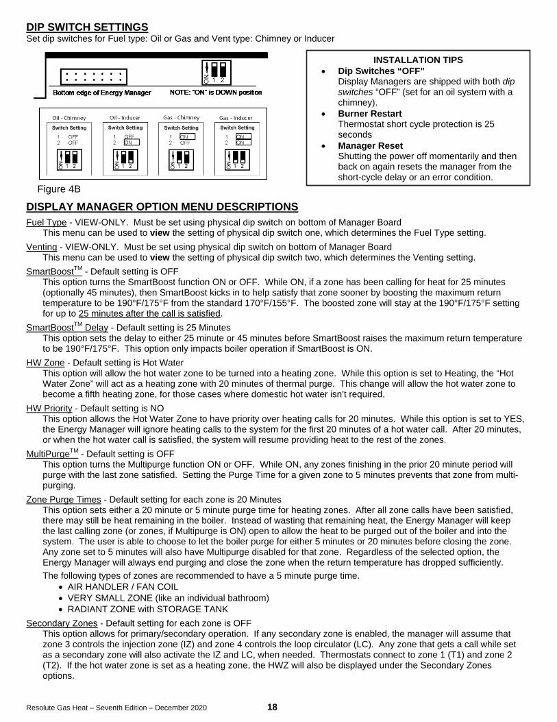
DIP SWITCH SETTINGS Set dip switches for Fuel type: Oil or Gas and Vent type: Chimney or Inducer DISPLAY MANAGER OPTION MENU DESCRIPTIONS
Fuel Type - VIEW-ONLY. Must be set using physical dip switch on bottom of Manager Board This menu can be used to view the setting of physical dip switch one, which determines the Fuel Type setting.
Venting - VIEW-ONLY. Must be set using physical dip switch on bottom of Manager Board This menu can be used to view the setting of physical dip switch two, which determines the Venting setting.
SmartBoostTM - Default setting is OFF This option turns the SmartBoost function ON or OFF. While ON, if a zone has been calling for heat for 25 minutes (optionally 45 minutes), then SmartBoost kicks in to help satisfy that zone sooner by boosting the maximum return temperature to be 190°F/175°F from the standard 170°F/155°F. The boosted zone will stay at the 190°F/175°F setting for up to 25 minutes after the call is satisfied.
SmartBoostTM Delay - Default setting is 25 Minutes This option sets the delay to either 25 minute or 45 minutes before SmartBoost raises the maximum return temperature to be 190°F/175°F. This option only impacts boiler operation if SmartBoost is ON.
HW Zone - Default setting is Hot Water This option will allow the hot water zone to be turned into a heating zone. While this option is set to Heating, the “Hot Water Zone” will act as a heating zone with 20 minutes of thermal purge. This change will allow the hot water zone to become a fifth heating zone, for those cases where domestic hot water isn’t required.
HW Priority - Default setting is NO This option allows the Hot Water Zone to have priority over heating calls for 20 minutes. While this option is set to YES, the Energy Manager will ignore heating calls to the system for the first 20 minutes of a hot water call. After 20 minutes, or when the hot water call is satisfied, the system will resume providing heat to the rest of the zones.
MultiPurgeTM - Default setting is OFF This option turns the Multipurge function ON or OFF. While ON, any zones finishing in the prior 20 minute period will purge with the last zone satisfied. Setting the Purge Time for a given zone to 5 minutes prevents that zone from multi-purging.
Zone Purge Times - Default setting for each zone is 20 Minutes This option sets either a 20 minute or 5 minute purge time for heating zones. After all zone calls have been satisfied, there may still be heat remaining in the boiler. Instead of wasting that remaining heat, the Energy Manager will keep the last calling zone (or zones, if Multipurge is ON) open to allow the heat to be purged out of the boiler and into the system. The user is able to choose to let the boiler purge for either 5 minutes or 20 minutes before closing the zone. Any zone set to 5 minutes will also have Multipurge disabled for that zone. Regardless of the selected option, the Energy Manager will always end purging and close the zone when the return temperature has dropped sufficiently. The following types of zones are recommended to have a 5 minute purge time.
• AIR HANDLER / FAN COIL • VERY SMALL ZONE (like an individual bathroom) • RADIANT ZONE with STORAGE TANK
Secondary Zones - Default setting for each zone is OFF This option allows for primary/secondary operation. If any secondary zone is enabled, the manager will assume that zone 3 controls the injection zone (IZ) and zone 4 controls the loop circulator (LC). Any zone that gets a call while set as a secondary zone will also activate the IZ and LC, when needed. Thermostats connect to zone 1 (T1) and zone 2 (T2). If the hot water zone is set as a heating zone, the HWZ will also be displayed under the Secondary Zones options.
INSTALLATION TIPS • Dip Switches “OFF”
Display Managers are shipped with both dip switches “OFF” (set for an oil system with a chimney).
• Burner Restart Thermostat short cycle protection is 25 seconds
• Manager Reset Shutting the power off momentarily and then back on again resets the manager from the short-cycle delay or an error condition.

Resolute Gas Heat – Seventh Edition – December 2020 19
EXPANDED ENERGY MANAGER
15 ZONE MANAGER INSTALLATION INSTRUCTIONS 1. Remove cover from junction box.
Use a free knockout on the top of the junction box to mount a second or third transformer, wire black lead to “XFMR” and white lead to “NEUTRAL” on relay board in box. (Use sections marked “120 VOLTS” only.) A second junction box is not needed for the expanded Energy Manager. Wire additional transformer(s) in parallel with first transformer. To wire in parallel, wire terminal “A” on one transformer to “A” on the other. Repeat with other low voltage terminal “B”. Verify 24VAC output from all transformers BEFORE reconnecting the Manager.
2. Mount long panel on top of box cover with long screws provided in lower 4 holes with spacers down. 3. Mount expanded Energy Manager to cover plate over 4 long screws and 2 wide bolts (top 2 holes). 4. Wire the bottom half of expanded manager as 5 zones Energy Manager. For top half, attach one thermostat lead to a
zone and the other to A1 on lower half of manager. Attach one lead from zone valve or relay to corresponding zone output and the other lead to 24VAC on lower half.
5. Option switches set fuel type (oil or gas) and venting (chimney or power vented). See Location of Switches: Figure. 4B.
6. NOTE: When using secondary zones with 15-zone manager, zone 13 controls injection zone, and zone 14 controls loop circulator.
NOTICE: When operating without an expanded manager, use a 5 zone service board for the lower half. If you do not
have a service board, refer to “Operation of Boilers without Energy Manager” in the Tech Manual.
15 Zone Manager Figure 4C
®
T9
TEMP. SEN
S.RED
SILVER
RS
BLACK BA2A1
T11T10
B2CIRC
B1T
MAIN CIRC RELAY
TTO BURNER RELAY
24VAC
IND
ZONE 2
Z11
ZONE 1
ZONE 4
ZONE 9
ZONE 11
ZONE 10
T8T7T6T5
THWT1T2T3
Z10Z9Z8Z7Z6Z5
Z4ZHWZ1Z2
ZONE 8
ZONE 7
ZONE 6
ZONE 5
ZONE 1
ZONE 2
ZONE 3
ZONE 11
ZONE 10
ZONE 9
ZONE 8
ZONE 7
ZONE 6
ZONE 5
HW CIRC RELAY
ZONE INPUTS(THERMOSTATS)
ZONE OUTPUTS24VAC
(ZONE VALVES ORZONE CIRC RELAYS)
LOAD
A B
LOAD
A B
TRANSFORMER 124VAC (50VA)
(FACTORY WIRED)Handles first five zones.
TRANSFORMER 224VAC (50VA)
(FIELD INSTALLED)Handles up to ten zones.
LOAD
A B
TRANSFORMER 324VAC (50VA)
(FIELD INSTALLED)Handles up to 15 zones
T4
Z3
T12T13T14
Z12Z13Z14
ZONE 4
HOT WATER TANK
ZONE 12
ZONE 13
ZONE 14
ZONE 3
ZONE 12
ZONE 13
ZONE 14

Resolute Gas Heat – Seventh Edition – December 2020 20
HYDRONIC CONTROL SETTINGS
Configuration Control Model No. Normal Setting
Resolute Boiler Auto Reset High Limit Auto Reset LWCO Manual Reset Lock Out Temp
DualGard Model: 2450-1 Energy Kinetics PN: 10-0596
215o F Auto Reset High Limit 10o F Differential (215o/205o F)* 250o F Manual Reset Fixed Max
Resolute Boiler w/Commercial Kit
Auto Reset High Limit Aquastat Manual Reset LWCO Manual Reset Lock Out Temp
DualGard Model: 2450-2 Energy Kinetics PN: 10-0596-M
215o F Auto Reset High Limit 10o F Differential (215o/205o F)* 250o F Manual Reset Fixed Max
Domestic Hot Water Tank
Tank Thermostat (On Tank) Energy Kinetics PN: 10-0414 ‘Hot’, pointer points to 6 pm.
(To suit individual installation) * Factory Setting
PREPARE FOR START UP DANGER: MAKE CERTAIN THE FOLLOWING REQUIREMENTS HAVE BEEN SATISFIED BEFORE START UP: 1. The boiler and piping are completely filled with water. 2. Re-check wiring to ensure that it is correct and in accordance with appropriate wiring diagrams and codes. 3. Verify that proper gas orifice size is used. 4. Verify electrode and flame sense rod settings. 5. Verify the burner settings for air band position and head position (see "Gas Burner Settings" Table). 6. Gas supply is connected to burner. Gas supply lines and shut-off valves are open. 7. Gas lines are purged. 8. Verify operating gas pressure at inlet of gas valve. 9. Adjust bypass valve on boiler side of heat exchanger to half open. See #4 under “Gas Burner Operation”. 10. Stainless flue pipe properly connected from breech to exhaust. All gasketed joints are secured and sealed. 11. Combustion air supply is available and sufficient. (See “Combustion Air”) 12. NOTICE: Do not punch a sampling hole in flue pipe. 13. Loosen both of the 1/8” plugs in front door of the boiler, one for use as the overfire sampling location and the other for
the breech sampling location.
START UP PROCEDURE Turn on system supply switch and burner supply switch. The Energy Manager lights should come on briefly, the
circulator relay should close briefly, and then the Energy Manager will show one blue light next to 'power' and yellow lights on the left side if any thermostats are calling.
1. If needed, adjust a thermostat to call for heat. Burner and main circulator should come on at the same time. If not, check primary control and reset it if necessary.
2. Check for burner light off. If gas piping is not well purged, then several starts may be required to clear air from gas piping.
3. On light off, water temperature and flue gas temperature will start to rise. A slight odor is common on initial light off as combustion chamber and converter surfaces warm for the first time.
4. NOTICE: Perform carbon monoxide test two minutes after light off. If the carbon monoxide exceeds 400 ppm air-free after two minutes of operation, shut off boiler immediately and repeat "Prepare for Start Up" checklist. (See “Air-free method of measuring CO”)
5. Once the boiler heats up and reaches temperature, Energy Manager “Heating” light will signal heat distribution to zone(s) calling for heat.
6. Allow system to run about 15 minutes before testing and recording burner operation. (See "Gas Burner Operation")

Resolute Gas Heat – Seventh Edition – December 2020 21
THE AIR-FREE METHOD OF MEASURING CO Air-free measurement of CO takes account of the amount of excess air by incorporating an adjustment to the as-
measured ppm value, thus simulating air-free (oxygen-free) conditions in the combustion gases. To do this, a reading of oxygen (O2) or carbon dioxide (CO2) percentage is taken from the combustion gases along with the as-measured CO reading. This can be done with a meter having the capability of measuring CO and O2 or CO2 percentage, or it can be done with two different meters, one measuring CO ppm and one measuring O2 or CO2 percentage.
If air-free CO is determined with a single meter, an integral electronic chip calculates the air-free level from as-measured CO ppm and O2 percentage.
If two meters are used, the equations below can be used to determine the air-free level of CO in a combustion gas sample.
For natural gas or LPG, using as-measured CO ppm and O2 percentage: CO AFppm = 20.9 x CO ppm
20.9-O2 For LPG, using measured CO ppm and CO2 percentage: . CO AFppm = 14 x CO ppm
CO2
For natural gas, using measured CO ppm and CO2 percentage:
CO Afppm = 12.2 x CO ppm CO2
Where: CO AFppm = Carbon monoxide, air-free ppm
CO ppm = As-measured combustion gas carbon monoxide ppm O2 = Percentage of oxygen in combustion gas, as a percentage CO2 = Percentage of carbon dioxide in combustion gas, as a percentage.

Resolute Gas Heat – Seventhth Edition – December, 2020 22
GAS BURNER OPERATION NOTICE: For reliable operation, set Air-Fuel mixture conservatively based on installation conditions. Carbon
dioxide, Oxygen, and Carbon Monoxide readings should be taken through 1/4" test port in front jacket opening just to right of burner (see FIG. 5A). Sample tube must extend at least six (6) inches into front cover to obtain accurate readings. A test port is provided for the flue box (see FIG. 5A) to measure draft loss.
NOTICE: For accurate efficiency calculations, measure flue gas temperature in flue pipe at flue outlet. Flue box and over fire temperatures may be higher than flue gas temperature measured in the flue pipe.
Note: CO2/O2 must be checked with air box cover in place.
AFTER 15 MINUTES RUNNING, CHECK AND RECORD: 1. DRAFT AT OVER FIRE TEST PORT…………………….. -0.05" to –0.25” w.c.
2. CO2 LP Gas………………………………………………………… 9.7 Min / 10.7 Max Natural Gas…………………………………………………… 8.6 Min / 9.2 Max
3. O2 LP Gas………………………………………………………… 4.5 Min / 6.0 Max Natural Gas…………………………………………………… 4.5 Min / 5.5 Max
4. STACK TEMPERATURE …………………………………… 190o to 290o F 5. CO TEST………………………………………………………… Must be less than 400 ppm air-free
1. DANGER: Verify proper operation of high limit aquastat.
a. Remove all heat and hot water calls (No input lights on left side of manager). b. Turn System switch off, then remove red return sensor lead from the left side quick connect. c. Restore power. The E100 error will flash on the manager’s temperature display, and the burner should start
shortly, in less than a minute. d. At approximately 205o F to 215o F, the high limit aquastat should shut off burner. e. Turn off power and reconnect the red sensor lead.
2. DANGER: Verify proper operation of boiler pressure relief valve by following instructions on pressure relief valve, which calls for a 'try lever test'. Make sure discharge pipe is properly placed to safely contain discharge and open relief valve using the try lever.
3. NOTICE: Check that each thermostat operates proper zone. 4. NOTICE: Bypass valve must be adjusted to raise return water temperature to approximately 130o F. on start up after
any zone valve opens. This prevents condensation from occurring in boiler passages. The digital manager provides condensing protection by closing the zone valves when the return drops below 130o F (Check option switches on the Digital Manager and verify that switch one (1) is set to “ON”). The following adjustments will help minimize zone cycling. a. On copper baseboard systems, valve normally should be ½ open. b. On large water volume systems or high heat load systems, where the return temperature from the system is
below 130o F, open bypass completely and throttle zone returns to increase bypass flow. 5. DANGER: Verify flame failure lockout of Carlin 60200FR burner control
a. Close the main manual gas valve and turn the combination gas valve knob to ON. b. Turn on power to System 2000 boiler and adjust a thermostat to call for heat. c. Burner motor will start. The burner control will run for 30 seconds (pre-purge), and then start the ignitor.
Approximately one second later, the combination gas valve will open. d. After the Trial For Ignition (TFI) period of 4 seconds, the burner control will lockout and turn on the red LED.
The ignitor will shut off and the gas valve will close. e. If lockout does not occur, replace the burner control. f. Turn on the main manual gas valve to restore operation.
6. WARNING: Blocked Vent or Inducer Malfunction Test: a. Remove power from the inducer. (Tip: turn off option switch 2 on the Digital Manager) b. Start burner. Safety lockout should occur in approximately 1 minute. c. Restore power to the inducer. (Tip: turn on option switch 2 on the Digital Manager)
7. WARNING: Blocked Air Intake Test: d. Block the air inlet piping to the burner air box. e. Start the burner. The blocked intake switch will open the gas valve circuit, the flame will go out, and the
primary control will detect the loss of flame. The primary control should lockout at the end of trial for ignition. f. Unblock the air inlet piping and verify that the burner operates normally.

Resolute Gas Heat – Seventhth Edition – December, 2020 23
Installation Check Off Procedure – Gas Fired 90+ Resolute Boiler Check Off: 1. GAS BURNER
Gas orifice nipple - Correct orifice size and properly tightened Spark Electrode Position – open the front door of boiler to inspect Flame Sense Rod Position – open the front door of boiler to inspect
2. CHECK HIGH LIMIT AQUASTAT (At rear of the boiler) Setting Differential 215°F 10°F 3. DRAFT INDUCER
A) Mounted securely on the dilution tee at the boiler B) All flue connections properly sealed (flue collar, damper pipe, inducer connection to vent piping, and all joints). C) Digital Energy Manager Option Switches 1 and 2 set to "ON" D) Take Flue Gas sample (Use 1/4" Metal Tube inserted at least 8" through the
Over Fire Test Port at the Puff Switch opening) E) Allow Burner to run 15 minutes before adjusting burner air settings F) Verify final draft over fire reading is between -0.05 to -0.25 inches H20
(steady state)
NOTE: Air Box Cover And Air Intake Piping MUST BE IN PLACE WHEN TAKING READINGS.
Min. Max. Min. Max. Record: LP CO2: 9.7% to 10.7% O2: 4.5% to 6.0%
[OR] NAT. CO2: 8.6% to 9.2% O2: 4.5% to 5.5%
4. RECORD TEMPERATURE and CO from BREECH: Min. Max. Record:
Draft Over Fire: -0.05” wc -0.25” wc Draft (steady state)______” wc Gross Stack (measured in flue box): 190°F 290°F Gross Stack Temp.______ °F Carbon Monoxide: less than 400 ppm CO air free CO ______ ppm
5. The inducer must be inspected annually to ensure safe and proper operation. Inspection points should include:
(a) MOTOR: The motor has sealed ball bearings and does not require lubrication. (b) FAN: Fan must be clear of soot, ash, or any other coating which affects balance,
rotation, or air flow. Remove all foreign material before operating.
Installed By:
Company: Date:
Installed For:
Address:

Resolute Gas Heat – Seventhth Edition – December, 2020 24
ENERGY MANAGER OPERATION WARNING: Do Not Jump! If you apply 24VAC to any Energy sensor lead with the sensor connected to the Manager, you will burn out both the sensor and the Manager in less than a second. NOTE: The Manager cannot lockout the primary control on the burner. The E140 error code will usually indicate that a burner lockout has occurred. Testing Manager Lights: To confirm operation of the Manager lights, turn power off briefly and power up the Manager. On startup, all output lights will turn on for a brief moment and LCD back light is turned on.
A) Thermostat Lights: Indicate a thermostat calling for heat. If all lights are OFF, the burner will not run because there is no call for heat. T4 is located on the bottom. SET HEAT ANTICIPATORS FOR 0.1 AMPS. There is a 25 second delay to prevent thermostat short cycling.
B) Return Temperature Thermistor: Senses return temperature and is required for manager to work properly. If the thermistor has failed, the E100 error code is displayed for the first ten minutes. After ten minutes, the manger switches to and displays E190 error code (Classic Mode). Disconnecting the RED lead will cause the manager to run in these modes also.
C) Option Switches: Set option switch 1 to ON for systems with a gas burner. Set option switch 2 to ON for sidewall vent systems.
D) LCD Display: Displays boiler RETURN temperature, not supply temperature.
• The Manager is the operating aquastat and will turn off the burner if return temperature reaches 170°F (operating limit).
• The zone outputs will open when the return temperature is above 140°F and close zone outputs when the return temperature drops below 120°F. If a new zone calls when the returns are below 140°F the new zone will not open until the temperature exceeds 140°F (even if other zones are open).
• The boiler will typically take about 2 minutes to reach 140°F from a cold start. When the Manager is working properly and has found a condition that needs service, the E100, E130, E140, E150 or E190 error codes will be displayed along with a description of what the error code means. See page 27.
E) Heating or Zone Lights: Indicate 24-volt power from 24VAC to ZX (ZHW, Z1, Z2, Z3, and Z4). This provides power to 24-volt zone valves or zone circulator relays. NEVER JUMPER THIS CONNECTION!
F) Inducer Light On: Indicates 24 volts from IND to 24VAC. This pulls in the 24-volt coil on the inducer relay, providing 120-volts to the power vent. This will only operate with option switch 2 ON.
G) Burner Light On: Indicates a closed contact between B1 to B2. This is wired to T-T on the burner primary control.
H) Circulator Light: On indicates 24 volts from manager CIRC to manager 24VAC. This pulls in the 24-volt coil on the Burner/Main circulator relay, providing 120-volt power to both the main circulator and the burner.
A
B
E
F G
H
D C

Resolute Gas Heat – Seventhth Edition – December, 2020 25
ENERGY MANAGER CHECK Troubleshooting
The burner will not run unless there is a call for heat (thermostat call) or a call for domestic hot water (tank aquastat).
Note: Do NOT Jumper Connections or Apply Voltage to Test the Manager.
Follow these simple steps: 1. Look at the Manager 2. See what it is telling you is supposed to be happening. 3. See if it is happening, and if it is not, find out why (see below). 4. If you do not find the problem, perform the 2 Minute Energy Manager Diagnostic to check all Manager
functions.
Remember: Most ‘no heat’ problems are not caused by the Manager.
and The Manager cannot cause a burner lockout.
These are zone output lights.
• If the light is ON, the zone valve should be open. For hot water, the bronze circulator should be running.
• If zone valve is not open with the light on, check the zone valve and zone valve wiring. For hot water, check the hot water relay, wiring, and the bronze circulator. These are the thermostat
input lights. These lights indicate when a thermostat is calling and only come on when there is an external connection.
• If the light is not ON, check the thermostat and thermostat wiring.
• If the light is ON, the thermostat is calling.
This is the LCD display.
• If no alerts are present, the display will show the operation mode and the return temperature.
• If an alert is detected, it will be displayed here, along with brief diagnostic or informational details.
This is the burner output. This light indicates T-T is made on the burner.
• If the light is ON, the burner should be running.
• If the light is on and the burner is not running, check the burner, limit aquastat, wiring, burner/main circulator relay, and burner service switch.
This is the power vent inducer output. This light should only operate if dip switch 2 is on.
• If the light is ON, the inducer should be running.
• If the light is on and the inducer is not running, check the inducer, wiring, and inducer relay and wiring.
This is the burner/main circulator output. This light indicates 24 volts is applied to the burner/main circulator relay coil.
• If the light is ON, the main circulator will be running, and the burner primary control should have line voltage.
• If the light is on and the circulator is not running, check the burner/main circulator relay, the circulator, and associated wiring.
INPUT SIDE (Thermostats)
OUTPUT SIDE (Heating Zones)

Resolute Gas Heat – Seventhth Edition – December, 2020 26
2-MINUTE ENERGY MANAGER DIAGNOSTICS
Most no-heat problems are not caused by the manager. Perform this test to prove proper manager function. Do NOT replace the manager if it functions properly in these tests.
Step 1:
Make sure you have no thermostat calls (turn thermostats down or disconnect after labeling zones).
Step 2: Turn Service Switch OFF for 5 seconds. Turn Service Switch ON while carefully observing the display. The display should briefly show “Startup Self test”, before changing to show the manager mode and return temperature. The BLUE power light will remain ON whenever the board is powered.* This proves the following:
• The display works • The board is able to detect the board type and mode • The processor is functioning properly
Step 3: Turn Service Switch OFF for 5 seconds. Turn Service Switch ON while carefully observing the output lights. The output lights should all turn on for about a second, and then turn OFF. The BLUE power light will remain ON whenever the board is powered.* This proves the following:
• All the output lights work • 24 VAC should be present • The processor is functioning properly (second verification)
*If you observe problems in step 2 or step 3, turn Burner Service Switch OFF, disconnect the right hand (output) quick-connector and repeat steps 1, 2, and 3. If problem persists, call technical support or replace manager. Note malfunction on warranty tag and return manager to Energy Kinetics. If problem goes away, there is a problem with the output wiring – check all wiring, re-connect quick-connector and repeat steps 1, 2 and 3 until problem is resolved.
You’re done. The manager is functioning properly. Remember to reset thermostats to original set point, to re-connect wiring connections, connect the quick-connector and to turn the Service Switch ON
The manager cannot cause a burner lockout.

Resolute Gas Heat – Seventhth Edition – December, 2020 27
ADDITIONAL MANAGER TESTS
Perform the following tests ONLY if you have any of the following: Case 1) Zones heating intermittently Case 2) E140 or E150 displayed WITHOUT a burner lockout Case 3) E100 or E190 displayed
If you have a burner lockout, troubleshoot as any conventional burner lockout. Case 1: Zones heating intermittently
Step 1: Have all connected thermostats including hot water aquastat call continuously for at least 10 minutes. Service Switch must be ON. Turn burner switch off to prevent zone overheating and to maintain thermostat calls continuously.
Step 2: Observe thermostat Lights. • If any thermostat input lights (left side) are not ON, check wiring and thermostats. • If thermostat input light (left side) is OFF within 10 minutes, and with thermostat call present, thermostat
input LED is bad. Solution: Move thermostat wire lead and zone valve wire lead to a different zone or replace manager.
Case 2: E140 or E150 alert without burner lockout Step 1: Turn service switch OFF and disconnect right hand (output) quick-connector. Step 2: Using a multi-meter, check the resistance from B1 to B2 on the manager solder strips. This will be an open
circuit (infinite resistance). Step 3: Turn service switch ON and start a thermostat call while observing the resistance from B1 to B2. Burner light
should come on. • If resistance is less than 3 ohms, manager is functioning properly. Look elsewhere for a problem. • If resistance is greater than 3 ohms after 3 seconds of operation, B1-B2 contact is bad. Solution: Replace
manager. Case 3: E100 or E190 alert without burner lockout
Step 1: Check the sensor wiring and quick-connectors to ensure proper contact. To improve contact, remove and squeeze the plastic quick connect at all terminals with flat pliers so the gap just closes.
Step 2: Replace sensor if no wiring or quick-connector issues are identified.

Resolute Gas Heat – Seventhth Edition – December, 2020 28
DISPLAY MANAGER RETURN SENSOR (THERMISTOR) TESTING
The temperature sensor in the return line allows better boiler control, and virtually eliminates condensation caused by cold returns.
The temperature sensor is a thermistor sealed with epoxy inside a stainless steel well. The thermistor communicates continuously with the Manager thousands of times a minute.
The Display Manager is the tester of the display manager thermistor. It verifies that it is connected and working properly, if not, will either say “Sensor Fault, Replace Soon”, indicating that one pair is bad or display the E100 or E190 error code.
The thermistor can be tested with an ohm meter, at room temp (approx. 77F) it should read ~10K Ohms between the black and red wires and between the white and red wires. As long as one pair is good, the manager will read the correct return temperature but display the “Sensor Fault, Replace Soon” message.
Never connect 24 volts to the black, white or red sensor terminals (labeled B, S, or R.) A caution: T4 thermostat input is adjacent to R, the red sensor terminal. When making thermostat connections,
never do so with power on. Once firm proper connections have been made, power up.
WARNING: Do Not Jump!
To test the functioning of each output zone, never apply a jumper to the Energy Manager output terminals. The easiest way to test each zone output is to remove the red sensor lead. The Manager should go into Service Board Mode (E100) for 10 minutes, followed by Classic Manager Mode (E190). Adjust each thermostat to call for heat and the corresponding zone should come on if working properly.
Rule #1: Never use a jumper to test the function of the Energy Manager. Rule #2: Never use a jumper to test the function of the Return Sensor. Rule #3: Never use a jumper to test the zones outputs. Rule #4: Only use a jumper from A1 to the thermostat inputs, if you can’t reach the thermostats. Rule #5: Always carry a Service Board with you.
LINE VOLTAGE RELAYS
Remember that behind the Manager is the junction box with the line voltage relays. The line voltage relays are controlled by the Manager.
The burner and circulator power is controlled by one line voltage relay. If both burner and circulator are without power, check the relay.
If the domestic hot water circulator does not have power, check the hot water relay. If equipped with an inducer and the inducer does not have power, check the inducer relay. Also check to be sure dip
switch #2 is turned “on”.
LINE VOLTAGE System 2000 requires 120 VAC. The supply voltage must be between a minimum of 102 VAC and a maximum of 132
VAC for reliable operation of the boiler and the Manager. An easy way to check the supply voltage is to plug a voltmeter in at the service outlet located on the system junction box.
SURGE SUPPRESSION
The Printed Circuit Relay Boards for Digital Managers (Rev 2 and above) are equipped with built-in surge suppression. Older systems can be retrofitted using plug-in surge suppressors. Tip: plugging a surge suppressing power strip such as used for computers into the service outlet will provide surge protection for the boiler.

Resolute Gas Heat – Seventhth Edition – December, 2020 29
TROUBLESHOOTING WITH THE ENERGY MANAGER
Display Manager Error Codes and Faults
An error code on the display indicates that Display Manager has detected a problem.
E100: Temperature sensor is not working properly. This indicates that the Manager is in service board mode. Circulator and inducer run constantly, burner runs off the high limit aquastat. All inputs turn on respective outputs. If the sensor is not detected within ten minutes, the Manager will change to E190 mode.
E190: After ten minutes in E100 mode the Display Manager switches to E190 mode. This indicates that the Manager is operating in Classic Manager Mode. The boiler will operate as cold start instead of maintaining temperature as when in service board mode. When a thermostat calls, the system will pre-heat for two minutes before opening the zone output and will post purge for whatever the zones max purge time is set.
Check Sensor wiring. Check sensor leads for loose connections or damage. If connections and wiring look good, replace the sensor.
If Manager is left in this mode, set Dual Guard high limit to “Service Mode”.
E130: Excessive temperature condition. Zones could not extract heat from boiler. Check zone valves, heat exchanger and boiler circulation. High limit aquastat may not be functioning.
E140: Boiler is in Freeze Protection Mode, Burner light off, Circulator light on, Heating zone outputs on. This means that the boiler return temperature did not increase enough to open zones within 27 minutes.
Does Primary Control need to be reset? YES: Troubleshoot as standard burner lockout.
NO: Did homeowner reset control? YES: Troubleshoot as standard burner lockout. NO: Reset Manager. Run through standard heat cycle.
Does boiler return heat up properly? NO: Check circulator. Possible closed or blocked bypass. Look for a zone valve not holding.
YES: Intermittent problem. Check low voltage wiring for tightness from Manager through relay board and cad cell relay to TT. Check line voltage at burner, in and out of cad cell relay. Check LWCO, Check limit aquastat for proper operation. See if burner/main circulator relay is properly plugged in and working properly.
E150: The return temperature did not reach 100°F after seven minutes. The manager will pulse the output of the calling zone for one minute on and one minute off. If the return increases within 20 minutes, the system will continue to run and supply heat while displaying the E150 code, indicating a boiler side blockage and that the manager is operating in Classic Manager Mode. When a thermostat calls, the system will pre-heat for two minutes before opening the zone output and will post purge for whatever the zone max purge time is set. If after 20 minutes the return does not heat up, the Manager will change to E140 mode.
Sensor Fault: On power-up, or display wake-up, the display will briefly show the message: “Sensor Fault; Replace Soon”. This indicates that one of the two dual thermistors is giving an invalid reading. Check to ensure that all thermistor leads are securely connected and tightened on the left-hand side quick-connect. If the connections are secure, and the message is still displayed on power-up or display wake-up, the thermistor should be replaced.
TO RESET MANAGER
The Manager can be reset to normal operation by turning the system switch off and back on.
WARNING: Do Not Jump! If you apply 24VAC to any temperature sensor lead with the sensor connected to the Manager, you will burn out both the sensor and the Manager in less than a second.

Resolute Gas Heat – Seventhth Edition – December, 2020 30
OPERATION WITHOUT THE ENERGY MANAGER
SERVICE BOARD MODE: The Display Manager can be placed into “E100 (SERVICE BOARD)/E150 (CLASSIC MANAGER MODE)” by
turning off the system switch and removing the RED temperature sensor lead from the left side input connector, and turning power back on. Removing the RED lead is similar to inserting the traditional green “Service Board”. The traditional service board may still be used if desired. E100 (SERVICE BOARD) allows the boiler to run like a conventional boiler for the first ten minutes. After which, it will switch to the E150 (CLASSIC MANAGER MODE). In CLASSIC MANAGER MODE, instead of maintaining temperature, the system will operate as the original “Classic” manager did. The burner will only run during a call for heat and will post purge to the last zone(s) calling based on time instead of temperature and time.
TEMPORARY OPERATION WITH JUMPERS (With partially functional Manager still in place and without service board)
If a particular function of the Manager fails, use appropriate jumper action below with Manager in place. BURNER: Jumper BB or TT on burner control. Burner will run on limit whenever Manager calls circulator. The boiler
may overheat slightly during energy recovery. Temporarily reset limit aquastat to 165o/180o F. MAIN CIRCULATOR: Remove blue CIRC lead from right side and connect to A2 on the left side, using an extension lead. The circulator will run constantly and the burner runs on Manager call. ZONE/HOT WATER CONTROL: Remove zone valve and thermostat leads for zone. Connect a thermostat lead to A1.
Connect a zone valve lead to A2. Wire the remaining thermostat and zone valve leads together. Zone valves will open whenever the Thermostat calls but it will not activate manager. If system is active, zone will receive heat when another calls or run system with high limit aquastat set to 165o/180o F and zone will get heat on call.
IF A PLUG-IN RELAY FAILS: Replace with spare relay. If spare is not available, temporarily install a relay with 24VAC coil and 120VAC contacts. Contact Energy Kinetics for connection details. EMERGENCY HEAT WITHOUT ENERGY MANAGER or RELAY BOARD
(Temporary Operation Only – 5 minute wiring change)
Method A (Heat and Hot Water): If the relay board is functioning properly, install a service board or follow the wiring instructions in the Owner and Installation Manual to run without a manager.
Method B (Heat Only) – Temporarily relocate (3) wires shown by arrows: 1) Move the black 120VAC wire from PWR to BURN (shown below). This will apply power continuously to the main circulator which will circulate water throughout all of the open heating zone valves. The stairway switch may be used to stop the circulator (and inducer if sidewall vented) if desired.
2) Select one thermostat that will control when the boiler runs to add heat to the house. Move that representative thermostat (T1, T2, T3, or T4) from the left side of the manager to B1. Move the other wire from that thermostat from A1 to B2. B1 and B2 connect internally to TT on the burner.
3) Turn down the high limit aquastat to 165°F/180°F and test and confirm proper and safe function. *When returning to service, reset high limit to 205°F/215°F.
4) Manually open all desired zone valves and close return valve a bit. There will not be any condensing protection without the manager; closing the return a bit will help limit condensing of flue
gases. NOTE for sidewall vent systems: Add a 120VAC jumper from BURN to IND. This will run the inducer continuously, so
caution should be used in systems without antifreeze.
Relay board
Emergency Heat
B1 B2
T1
A1

Resolute Gas Heat – Seventhth Edition – December, 2020 31
Step 2 Open Front Cover Turn off power to system and close main manual gas valve when servicing.
1. Loosen, but DO NOT REMOVE (2) lower nylock nuts on hinge bolts. 2. Remove (4) upper nuts and support cover while opening.
ANNUAL TUNE UP & INSPECTION
Flame Sense Rod Tip should extend in front of diffuser
by 1-1/4”.
Step 1 Initial Test (Draft Loss & CO2)
Air box cover must be in place before testing
1. Remove 1/8” brass plug from the “over fire” test port (2) next to the burner and the flue box (1) next to the puff switch. Check draft through the “over fire” test port (2) and at the flue box (1). Use a 12” long piece of ¼” O.D. steel or copper tubing and insert it approximately 8” into the boiler. Connect this tube to your test probe using a piece of hose.
Clean boiler flue passage if the draft difference between the flue box (1) and “over fire” test port (2) is greater than 0.04” w.c.
2. Check CO2 through the over fire test port (2). Insert the 12” long steel or copper tube approximately 8” in through the test port. Natural: CO2 : 8.6%-9.2%, O2 : 5.5%-4.5%
LPG: CO2 : 9.7%-10.7%, O2 : 6.0%-4.5%
Step 4 Clean Boiler
Do Not Touch, Vacuum or Remove Chamber! Note: If there is evidence of condensing in last pass: 1. Check for cold returns. 2. Open by-pass valve fully. 3. Verify Digital Manager Option Switch 1 to “ON”. 4. If condensing persists, increase firing rate.
Step 5 Remove Drawer Assembly (Refer to burner manual for detailed instructions on removal and for burners other than EZ-Gas)
1. Close the front cover and finger tighten a nut on the top center stud to hold the cover closed while working on the burner. Do not tighten the rest of the nuts at this time because you will need to open the cover up again to check the drawer assembly to the diffuser plate
2. Check porcelain condition. 3. Check and clean flame sense rod.
Step 6 Check Burner (Refer to burner manual for complete details and for burners other than EZ-Gas)
1. Check Fan/Air Inlet for dirt or lint. 2. Install drawer assembly carefully lining up the ignitor electrode and flame sense
rod. Open the front cover and check, neither should be any closer to the diffuser plate than 1/16”. Adjust if necessary.
3. Check amulet for cracking or other physical damage. Replace if necessary. (See amulet replacement section in installation manual). 4. Check burner diffuser plate. Some warping of plate is normal.
Note: All burners require “Amulet”
retention head protector.
1
2
Step 3 Inspect Flue Passage
If passage is clean, no scale, then proceed to step 5. Clean ONLY if dirty.
DO NOT remove or touch combustion chamber for inspection or when cleaning boiler!
Please refer to installation manual and burner manual for complete details and for burners other than EZ-Gas.
Electronic Analyzer
Drawer Assembly
Diffuser Plate
Ignitor Electrode Tip should be set back 1/16” from
the inside surface of diffuser.
1
2

Resolute Gas Heat – Seventhth Edition – December, 2020 32
ANNUAL TUNE UP & INSPECTION
Step 10 Start Burner & Check Safety Functions.
Check & Record: Air box cover must be in place before testing. Refer to burner manual for recommended settings. 1. Check manifold pressure by installing a hose barb fitting in the combination gas
valve outlet pressure tap and then starting the burner. Adjust valve regulator if necessary so the reading is 3.5”w.c. for either LPG or natural gas.
2. Draft Loss: A difference of 0.04”w.c. or less between flue box (1) and “over fire” test port (2). Sidewall Vent: Draft over fire of -0.10” to -0.12”w.c. after 15 minutes of continuous burner operation.
3. Check CO2/O2 at over fire test port (2) Natural: CO2 :8.6%-9.2%, O2 5.5%-4.5% LPG: CO2 :9.7%-10.7%, O2 6.0%-4.5% 4. Stack Temp: 190º-290° F (at stack or flue box port). 5. Check CO: 400 ppm Max Air-free (Refer to installation manual for Air-free method of measuring CO). 6. Set Safety High Limit to 215 oF with Differential set at 10oF. 7. Test Safety High Limit Aquastat:
a. Remove all heat and hot water calls (No input lights on left side of manager). b. Turn System switch off, then remove red sensor lead from the left side quick
connect. c. Restore power. The 100o light will flash on the manager’s temperature
display. The burner should start momentarily. d. At approximately 205oF to 215oF, the high limit aquastat should shut off
burner. 8. Verify flame failure lockout of Carlin 60200FR burner control.
a. Connect hose from manometer to hose barb fitting in the combination gas valve outlet pressure tap.
b. Close the main manual gas valve and turn ON the combination gas valve. c. Turn on power to System 2000 boiler and adjust a thermostat to call for heat. d. Burner motor will start. The burner control will run for 30 seconds (pre-purge)
and then start the ignitor. Approximately one second later, the combination gas valve will open. The manometer should show almost no pressure because the main manual gas valve is closed.
e. After 4 seconds, the burner control will lockout and turn on the red LED. The ignitor will shut off and the gas valve will close. Turn off power and adjust the thermostat to stop the call for heat. If lockout does not occur, replace the burner control.
9. Sidewall Vent: a. Remove power from the inducer by turning off option switch 2 on Digital
Manager. b. Start burner. Safety lock-out should occur in approximately 1 minute. c. Restore power to the inducer.
Step 8 Check Zone Valves
Open/Close zone valves several times to see that they move freely. Step 9 Backflush Plate Heat Exchanger
1. Close the valve underneath the domestic hot water circulator. 2. Open drain valve above the circulator to back flush the heat exchanger. 3. If domestic water supply is “hard” (lime), consider installing Scale Stopper (Item
no. 10-0650). 4. Set temperature feeding hot water tank (above heat exchanger) by adjusting the
ball valve below the bronze circulator. Adjust the ball valve with the burner running and a continuous flow of hot water from a fixture. You should just be able to hold your hand on the pipe.
Step 7 Close Front Cover, Tighten Rear Cover
1. Install (4) upper nuts and washers. 2. Tighten nuts (6) uniformly. 3. Check and tighten (6) rear cover nuts. 4. Check Flue Pipe.
1
2
Safety High Limit
Digital Manometer
1
3 4
5 6
2

Resolute Gas Heat – Seventhth Edition – December, 2020 33
AMULET REPLACEMENT It is recommended that a new ceramic sleeve “amulet” be installed each time the air tube is removed from unit. See
instructions that come with each amulet. The Resolute amulet is larger than the standard amulet, so be sure to order the proper part number shown in the Assembly Drawing. Using a standard amulet will allow excessive heat back to the front jacket and may damage burner tube. COMBUSTION CHAMBER REPLACEMENT
The combustion chamber is of high quality material and will normally not need to be replaced. A replacement chamber, if required, is available from Energy Kinetics. The proper part number for the Resolute chamber must be specified when ordering. For interim operation, the unit may be run without a combustion chamber if necessary. Ensure that the burner head is protected by the amulet, wet pack or a similar material.
To install the replacement:
1. Open boiler by removing the four nuts on the top center, middle left and right of the boiler. Note: Loosen, but do not remove, the two 3/8” nuts on the bottom of the front jacket, the door is hinged upon these bolts. While supporting the door, lower door slowly to the down position.
2. Spray chamber with a water mist to minimize disturbance and breakage of chamber material. 3. Remove chamber by tilting upward and rotating to loosen. 4. Locate and inspect the square dimple in the rear insulation board. The lower side of the chamber will insert into
this dimple. 5. Locate the 4”x2” support molded on the backside of the chamber and coat the 2” sides with refractory cement. 6. Insert chamber into the boiler with the exhaust opening in the 3 o’clock position. Chamber outlet must fit
behind or alongside the metal tab (supply nipple) in the top rear of the boiler. 7. With chamber fully inserted, slightly move the chamber until the chamber outlet is snug against the right side of
the boiler. The 4”x2” support on the back of the chamber should fit securely into the dimple on the rear insulation board.
8. Verify that the chamber is centered and ensure that the burner is centered with the chamber when closing the front door. Secure and tighten the four nuts. Also check the two 3/8” nuts on the lower hinge bolts and ensure that they are tight. Do not over tighten; tighten snugly enough to compress the door insulation.
9. Confirm proper setup and operation of burner (see "Gas Burner Operation").
WARNING: Ceramic fiber or fiberglass materials, may contain carcinogenic particles (cristobalite) after exposure to heat. Airborne particles from fiberglass or ceramic fiber components have been listed as having potential health effects. Take the following precautions when removing, replacing and handling these items. Precautionary procedures: Avoid breathing dust and avoid contact with skin or eyes. Wear long-sleeved, loose-fitting clothing, gloves and eye
protection. Use a properly fitted NIOSH certified respirator for dusty activities and where exposure levels are unknown.
Use hand tools whenever possible if cutting or trimming is required. Power tools generate significantly more airborne dust.
Use vacuums with HEPA-filters for clean up. If HEPA-filter vacuum are not feasible, lightly spray fiber materials and work area with a water mist before sweeping or bagging of debris.
Wash exposed skin with soap and water after handling. Do not use compressed air to clean work clothes or work area. Wash work clothes separately from other clothing. Rinse washer thoroughly afterwards. Avoid smoking, eating or drinking while dust is present in the work area.
REPLACEMENT PARTS
To order replacement parts, specify serial number stamped onto nameplate, part description and number shown under “Replacement Parts” in the next section. Replacement parts are available from any Energy Kinetics authorized Dealer. Contact Energy Kinetics at 800-323-2066 or [email protected] for names of Dealers in your area.

Resolute Gas Heat – Seventhth Edition – December, 2020 34
EXPLODED VIEW OF BOILER COMMON ITEMS AVAILABLE BUT NOT SHOWN
PART NO. DESCRIPTION PART NO. DESCRIPTION 10-0418D Digital Manager 10-0417F EK-1 Digital Temperature Sensor 10-0434 Air Vent 10-0516 Boiler Pressure Relief Valve 30 psi 10-0412A Plug-In Relay 10-0420 T&P Gauge 10-0681 Puff Switch, Gas 10-0150 ¾ Two Wire Zone Valve (Std.) 10-0682 Puff Switch, Blocked In-Let Air 10-0151 ¾” Four wire Zone Valve (w/End Switch) 10-0412B Relay Board inside Junction Box 10-0415 High Limit Aquastat 10-0717 Amulet ceramic sleeve 10-0416F Plate Heat Exchanger
A
C
F
G
S
H
J
R
D
LM
K
B
P
ITEM PART NO. DESCRIPTION A 10-0710 Combustion Chamber B 10-1077 Energy Converter, Resolute C 10-0712 Front Chamber Liner D 10-0713 Rear Chamber Liner (PacMan) F 10-0771 Front Insulation Board 2” G 10-0773 Front Cover w/Studs H 10-0774 Left Jacket J 10-0775 Right Jacket K 10-0776 Top Jacket L 10-0772 Rear Insulation Board 2” M 10-0777 Rear Cover P 10-0726 Door Hinge Assembly (ea.) R 10-0780 Base Kit S 10-0779 Front Insulation Board Clip (Set) --- 10-0537R Air Box Cover, Resolute

Resolute Gas Heat – Seventhth Edition – December, 2020 35
Commonwealth of Massachusetts
♦ Approval No. C1-0713-539. ♦ This Energy Kinetics gas fired hot water boiler has been approved by the
Massachusetts Board of Plumbers and Gas Fitters. ♦ When an Energy Kinetics gas fired hot water boiler is installed in the
Commonwealth of Massachusetts, the following requirements must be met. o The Commonwealth of Massachusetts requires that an Energy Kinetics gas
fired boiler must be installed by a licensed Plumber or a licensed Gas Fitter. o The Commonwealth of Massachusetts requires that the licensed Plumber or
a licensed Gas Fitter installing the boiler must comply with the following excerpt from “Rules and Regulations - 248 CMR”.
5.08: Modifications to NFPA-54, Chapter 10
(2) Revise 10.8.3 by adding the following additional requirements:
(a) For all side wall horizontally vented gas fueled equipment installed in every dwelling, building or structure used in whole or in part for residential purposes, including those owned or operated by the Commonwealth and where the side wall exhaust vent termination is less than seven (7) feet above finished grade in the area of the venting, including but not limited to decks and porches, the following requirements shall be satisfied:
1. INSTALLATION OF CARBON MONOXIDE DETECTORS. At the time of installation of the side wall horizontal vented gas fueled equipment, the installing plumber or gasfitter shall observe that a hard wired carbon monoxide detector with an alarm and battery back-up is installed on the floor level where the gas equipment is to be installed. In addition, the installing plumber or gasfitter shall observe that a battery operated or hard wired carbon monoxide detector with an alarm is installed on each additional level of the dwelling, building or structure served by the side wall horizontal vented gas fueled equipment. It shall be the responsibility of the property owner to secure the services of qualified licensed professionals for the installation of hard wired carbon monoxide detectors
a. In the event that the side wall horizontally vented gas fueled equipment is installed in a crawl space or an attic, the hard wired carbon monoxide detector with alarm and battery back-up may be installed on the next adjacent floor level.
b. In the event that the requirements of this subdivision can not be met at the time of completion of installation, the owner shall have a period of thirty (30) days to comply with the above requirements; provided, however, that during said thirty (30) day period, a battery operated carbon monoxide detector with an alarm shall be installed.
2. APPROVED CARBON MONOXIDE DETECTORS. Each carbon monoxide detector as required in accordance with the above provisions shall comply with NFPA 720 and be ANSI/UL 2034 listed and IAS certified.
3. SIGNAGE. A metal or plastic identification plate shall be permanently mounted to the exterior of the building at a minimum height of eight (8) feet above grade directly in line with the exhaust vent terminal for the horizontally vented gas fueled heating appliance or equipment. The sign shall read, in print size no less than one-half (1/2) inch in size, "GAS VENT DIRECTLY BELOW. KEEP CLEAR OF ALL OBSTRUCTIONS".

Resolute Gas Heat – Seventhth Edition – December, 2020 36
NOTES:

Resolute Gas Heat – Seventhth Edition – December, 2020 37
NOTES:

Page 38 of 2 August 2005
LIMITED LIFETIME WARRANTY For Residential Water Boilers
By this Warranty Statement, Energy Kinetics, Inc of Clinton Township, New Jersey, issues limited warranties subject to terms, conditions, exceptions and exclusions listed below.
These Warranties are issued only to the person or entity which owns the building in which the boiler is installed at the time of original installation and only for such portion of the warranty periods as such person or entity owns such building (hereinafter, the “End User”). I. THREE YEAR –LIMITED WARRANTY FOR RESIDENTIAL WATER BOILERS
Energy Kinetics warrants that its residential heating System 2000, with residential water boiler, Models EK-1 and EK-2, is free from defects in material and workmanship for three years from the date of installation. If any parts are found to be defective in manufacture, Energy Kinetics will repair or replace the defective parts. Exception: Honeywell Zone Valves
II. ADDITIONAL COMPONENT LIMITED WARRANTIES 1. Energy Kinetics warrants that its Digital Manager is free from defects in material and workmanship for a period of
five years from the date of installation. The warranty is extended to the End User for the lifetime of the unit by a manufacturer sponsored rebuild program offered at nominal cost.
2. Energy Kinetics hereby assigns to the End User limited warranties of the original manufacture of components supplied by Energy Kinetics to the extent or duration assignable.
3. If any such component is found defective, Energy Kinetics’ responsibility is solely to repair or replace the defective part at it’s or the original manufacturer’s option.
LIMITED LIFETIME WARRANTY FOR THE PRESSURE VESSEL During the lifetime of the original owner in the original place of installation, Energy Kinetics warrants that those parts, which comprise the pressure vessel of the residential hot water boiler, remain free of defects in material or workmanship under normal usage.
In the event that such pressure vessel is found to be defective in material or workmanship during the first ten years, Energy Kinetics will repair or replace the pressure vessel at its option and include a labor allowance per the published schedule. After 10 years, there will be a proportionate charge based upon the time the defective assembly was in service. The proportionate charge will be equal to the appropriate percentage of the trade list price of such pressure vessel at the time the warranty claim is made as determined in the following:
YEAR: 1st 11th 12th 13th 14th 15th 16th 17th
Percent of Trade list Price: 0% 5% 10% 15% 20% 25% 30% 35% YEAR: 18th 19th 20th 21st 22nd 23rd 24th 25th
Percent of Trade list Price: 40% 45% 50% 55% 60% 65% 70% 75% YEAR: 25TH and Above: 75% of Trade list Price
IMPLIED WARRANTIES OF FITNESS FOR A PARTICULAR PURPOSE AND MERCHANTABILITY SHALL BE LIMITED TO THE DURATION OF THE EXPRESS WARRANTY-ENERGY KINETICS EXPRESSLY DISCLAIMS AND EXCLUDES ANY LIABILITY FOR CONSEQUENTIAL OR INCIDENTAL DAMAGES FOR BREACH OF ANY EXPRESS OR IMPLIED WARRANTY.
This Warranty gives you specific legal rights and you may have, also, other rights which vary from state to state.
EXCEPTIONS AND EXCLUSIONS 1. The warranty is subject to the condition that the residential boiler must have been installed and serviced in
accordance with Energy Kinetics instructions, the basic BOCA Building Code, local statutes and ordinances and accepted good industry practice.
2. This warranty does not cover components that are part of the heating system but which were not furnished by Energy Kinetics.
3. This warranty does not cover the workmanship of any installer of Energy Kinetics residential water boiler. In addition, it does not assume any liability of any nature for unsatisfactory performance caused by improper installation.
4. This warranty does not cover improper burner adjustments, control settings, care or maintenance. 5. This warranty does not cover any labor for removal or reinstallation of the alleged defective part, transportation to
Energy Kinetics if necessary and other materials necessary to perform the exchange. 6. This warranty does not cover failure of the pressure vessel other than defects in material or workmanship and shall
specifically exclude any other reason including but not limited to a) lack of water b) freezing c) excessive pressure d) floods e) fire f) acts of God g) corrosion of internal or fireside surfaces h) improper water conditioning I) improper maintenance of external fireside surfaces j) operation with defective fuels or other additives which cause deposits to collect or corrosion to occur in or on the pressure vessel.

Page 39 of 2 August 2005
LIMITED WARRANTY (Continued from Previous Page)
7. Systems installed with chimneyless, through the wall venting option may have less than complete or poor
combustion which may cause sooty fumes, odors or gradual discoloration of the area near the vent (exhaust) outlet. Poor combustion is generally the result of a burner being out of adjustment for a number of reasons, including but not limited to fuel condition and combustion air supply. Energy Kinetics does not guarantee nor warranty that all times the exhaust contents will be without a trace of soot or odor for reasons described above. Periodic cleaning and repainting of the area around the vent hood may be required if the appearance is objectionable in the view of the end user. Such cleaning or repainting is not the responsibility of the service company, installer or manufacturer.
LIFETIME WARRANTY TRANSFER By completion of the Warranty Transfer Agreement, the original owner may transfer the warranty to a new owner
by payment of a $75 registration fee.
WARRANTY SERVICE For prompt warranty service, notify the installer who in turn will notify Energy Kinetics that the purchaser believes
there is a defect in material or workmanship covered by this warranty statement. If within 30 days of the discovery, this action does not produce a prompt response, notify Energy Kinetics, Inc. 51
Molasses Hill Road, Lebanon, NJ 08833, in writing with details to support the warranty claim. The End User is required to make available for inspection by Energy Kinetics or its representative, the parts
claimed to be defective and, if requested by Energy Kinetics, to ship said parts prepaid to Energy Kinetics at the above address for inspection or repair. In addition, the homeowner agrees to make all reasonable efforts to settle any disagreement arising in connection with this claim before resorting to legal remedies in courts. If you have any questions about the coverage of this warranty, contact Energy Kinetics at the above address.
Lifetime Warranty Transfer Agreement (I/We), the undersigned, as the original purchaser of the 90+ Resolute home heating system, submitted the Warranty Registration within three (3) months of installation of (my/our) 90+ Resolute to Energy Kinetics, Inc., and (I/we) hereby transfer our Lifetime Limited Warranty to the new owner(s) of the home located as noted below and understand a thirty (30) day waiting period applies. Warranty coverage begins on the date of original installation.
90+ Resolute Serial Number: Date of Original Installation: Name of original purchaser of 90+ Resolute: Print or Type full Name(s)
Located at this street address: City: State: Zip: TRANSFER TITLE of ENERGY KINETICS’ WARRANTY TO: Print or Type full Name(s) New Owner(s) of the 90+ Resolute located at the address noted above. Title to be effective, and continues uninterrupted coverage as is left on the original warranty. Enter Date of Title Transfer (Example: If the original owner has used 9 years, 3 months and 10 days of the warranty, the new homeowner warranty transfer begins at 9 years, 3 months and 11 days and continues to the end of the warranty as described on the back of this agreement or until the new homeowner sells the residence).
Enclosed is a check for $75.00 to register and maintain the warranty as described on the back of this Warranty Transfer Agreement to the new homeowner named above. Please make check payable to Energy Kinetics, Inc.
Agreed to by the Original Homeowner: Accepted: Original Homeowner Signature New Homeowner Signature
***************************************************** For Office Use Only ************************************************
Energy Kinetics, Inc. Received Transfer Information: $75.00 Received Check No. Date Received and Registered
Confirmation of Transfer mailed to New Homeowner: By: Date Office Personnel