Recovery boiler sootblowers: History and technological ...
10
JANUARY 2015 | VOL. 14 NO. 1 | TAPPI JOURNAL 51 T he accumulation of fireside deposits on heat transfer tube surfaces is a persistent problem in many kraft recovery boilers. The severity of the problem depends mainly on the amount and the melting behavior of fly ash particles (carryover and fume) entrained in the flue gas, and the efficacy of the deposit cleaning system that the individual boiler employs [1,2]. If left unattended, deposits may form a thick insulation coating on the tube surface, significantly reducing the boiler thermal performance and steam production capacity. In severe cases, deposits may completely plug the flue gas passes, leading to costly unscheduled boiler shutdowns for cleaning. They might also fall, and if large enough, damage screen tubes and floor tubes directly below [3]. Sootblowers are the principal means of cleaning depos- its in recovery boilers. During boiler operation, sootblow- ers blast deposits off tube surfaces with high pressure steam (Fig. 1), while during boiler outages, they use hot water instead of steam to remove the deposits and clean the boiler tubes. Maintaining a high deposit removal efficiency and availability of sootblowers is of vital impor- tance in recovery boiler operation [4,5]. Over the last three decades, much research and develop- ment has been done on deposit removal and sootblowing technology by researchers at the University of Toronto, and by researchers and engineers at recovery boiler and sootblow- er manufacturers. This includes jet hydrodynamics and nozzle design [6,7,8]; interactions between a jet and tubes and be- tween a jet and deposits [9,10,11]; the mechanisms of deposit breakup and removal by a jet [12,13]; and the effect of com- position, particularly chloride and potassium, on deposit re- movability [2,14,15]. The work was carried out through labo- ratory experiments, mathematical modeling, and computational fluid dynamic (CFD) modeling [16,17], as well as through mill trials [8,18,19]. The results provided signifi- cant insight into how a sootblower jet strikes and removes deposits from the tube surface, and factors influencing the removal efficiency. These research and development efforts resulted in two major innovations. One is the fully-expanded sootblower jet concept [6,7] that served as the basis for the Recovery boiler sootblowers: History and technological advances HONGHI TRAN AND DANNY TANDRA RECOVERY BOILER PEER-REVIEWED ABSTRACT: Sootblowing technology used in recovery boilers originated from that used in coal-fired boilers. It start- ed with manual cleaning with hand lancing and hand blowing, and evolved slowly into online sootblowing using retract- able sootblowers. Since 1991, intensive research and development has focused on sootblowing jet fundamentals and deposit removal in recovery boilers. The results have provided much insight into sootblower jet hydrodynamics, how a sootblower jet interacts with tubes and deposits, and factors influencing its deposit removal efficiency, and have led to two important innovations: fully-expanded sootblower nozzles that are used in virtually all recovery boilers today, and the low pressure sootblowing technology that has been implemented in several new recovery boilers. The availability of pow- erful computing systems, superfast microprocessors and data acquisition systems, and versatile computational fluid dynamics (CFD) modeling capability in the past two decades has also contributed greatly to the advancement of sootblow- ing technology. High quality infrared inspection cameras have enabled mills to inspect the deposit buildup conditions in the boiler during operation, and helped identify problems with sootblower lance swinging and superheater platens and boiler bank tube vibrations. As the recovery boiler firing capacity and steam parameters have increased markedly in re- cent years, sootblowers have become larger and longer, and this can present a challenge in terms of both sootblower design and operation. Application: This article helps readers to understand the history of recovery boiler sootblowers and several impor- tant technological advances that have been made in the past three decades. 1. Sootblower in action in a recovery boiler.
-
Upload
khangminh22 -
Category
Documents
-
view
1 -
download
0
Transcript of Recovery boiler sootblowers: History and technological ...

JANUARY 2015 | VOL. 14 NO. 1 | TAPPI JOURNAL 51
The accumulation of fireside deposits on heat transfer tube surfaces is a persistent problem in many kraft
recovery boilers. The severity of the problem depends mainly on the amount and the melting behavior of fly ash particles (carryover and fume) entrained in the flue gas, and the efficacy of the deposit cleaning system that the individual boiler employs [1,2]. If left unattended, deposits may form a thick insulation coating on the tube surface, significantly reducing the boiler thermal performance and steam production capacity. In severe cases, deposits may completely plug the flue gas passes, leading to costly unscheduled boiler shutdowns for cleaning. They might also fall, and if large enough, damage screen tubes and floor tubes directly below [3].
Sootblowers are the principal means of cleaning depos-its in recovery boilers. During boiler operation, sootblow-ers blast deposits off tube surfaces with high pressure steam (Fig. 1), while during boiler outages, they use hot water instead of steam to remove the deposits and clean the boiler tubes. Maintaining a high deposit removal efficiency and availability of sootblowers is of vital impor-tance in recovery boiler operation [4,5].
Over the last three decades, much research and develop-ment has been done on deposit removal and sootblowing technology by researchers at the University of Toronto, and by researchers and engineers at recovery boiler and sootblow-er manufacturers. This includes jet hydrodynamics and nozzle design [6,7,8]; interactions between a jet and tubes and be-
tween a jet and deposits [9,10,11]; the mechanisms of deposit breakup and removal by a jet [12,13]; and the effect of com-position, particularly chloride and potassium, on deposit re-movability [2,14,15]. The work was carried out through labo-ratory experiments, mathematical modeling, and computational fluid dynamic (CFD) modeling [16,17], as well as through mill trials [8,18,19]. The results provided signifi-cant insight into how a sootblower jet strikes and removes deposits from the tube surface, and factors influencing the removal efficiency. These research and development efforts resulted in two major innovations. One is the fully-expanded sootblower jet concept [6,7] that served as the basis for the
Recovery boiler sootblowers: History and technological advances
HONGHI TRAN and DANNY TANDRA
RECOVERY BOILERPEER-REVIEWED
ABSTRACT: Sootblowing technology used in recovery boilers originated from that used in coal-fired boilers. It start-ed with manual cleaning with hand lancing and hand blowing, and evolved slowly into online sootblowing using retract-able sootblowers. Since 1991, intensive research and development has focused on sootblowing jet fundamentals and deposit removal in recovery boilers. The results have provided much insight into sootblower jet hydrodynamics, how a sootblower jet interacts with tubes and deposits, and factors influencing its deposit removal efficiency, and have led to two important innovations: fully-expanded sootblower nozzles that are used in virtually all recovery boilers today, and the low pressure sootblowing technology that has been implemented in several new recovery boilers. The availability of pow-erful computing systems, superfast microprocessors and data acquisition systems, and versatile computational fluid dynamics (CFD) modeling capability in the past two decades has also contributed greatly to the advancement of sootblow-ing technology. High quality infrared inspection cameras have enabled mills to inspect the deposit buildup conditions in the boiler during operation, and helped identify problems with sootblower lance swinging and superheater platens and boiler bank tube vibrations. As the recovery boiler firing capacity and steam parameters have increased markedly in re-cent years, sootblowers have become larger and longer, and this can present a challenge in terms of both sootblower design and operation.
Application: This article helps readers to understand the history of recovery boiler sootblowers and several impor-tant technological advances that have been made in the past three decades.
1. Sootblower in action in a recovery boiler.
RECOVERY BOILER
52 TAPPI JOURNAL | VOL. 14 NO. 1 | JANUARY 2015
development of the new generation of high intensity soot-blower nozzles on the market today [20-23]. The other is low-pressure sootblowing technology [24,25] that has been tested [26,27] and implemented in several recovery boilers in the United States and Brazil [28].
The availability of high-computing power computers, su-perfast microprocessors and data acquisition systems, sophis-ticated process control logics, and versatile CFD modeling capabilities in the past two decades has also contributed great-ly to the advancement of sootblowing technology. Several deposit monitoring methods based on boiler and sootblower operating parameters were developed to estimate the state of fouling (or cleanliness) of the heat transfer surfaces in differ-ent regions of the boiler, and to incorporate the information to optimize the sootblowing operation [29-34].
There has been enormous change in recovery boiler tech-nology since the first Tomlinson recovery boiler was built in 1929 [35]. The black liquor firing capacity of the boiler has increased substantially from under 200 TDS/day (tons of black liquor dry solids per day) in the 1930s to slightly over 2000 TDS/day in the 1980s, over 3000 TDS/day in the 1990s, and to 5000 TDS/day in the 2000s [36]. Several recently built recov-ery boilers are in the 6000-7000 TDS/day range [37], and pres-ently the world’s largest recovery boiler is being built at a new pulp mill in Oki, Indonesia, with a staggering designed firing capacity of 11600 TDS/day. The superheated steam parameters have also increased, from a maximum temperature/pressure of 350°C/30 bar in the 1930s, to 480°C/60 bar in the 1990s and 2000s [36], with a few recovery boilers in Scandinavia and Japan operating at 515°C/110 bar to maximize the electricity generating efficiency [37-39]. As the firing capacity and steam quality increase, the boiler size and heat transfer surface area also increase. This inevitably requires not only a larger number of sootblowers per boiler, but also longer and larger sootblow-ers that can deliver stronger and better controlled jets.
This paper reviews the history of recovery boiler sootblow-ers, as well as several important technological advances that have been made in the past three decades.
SOOTBLOWER HISTORYThe word “soot” refers to black, carbonaceous fine particles that are formed during the combustion of coal, wood, oil, etc. Soot forms deposits on the walls of the combustors, chimneys, and pipes that convey the flue gas. In the context of recovery boilers, soot is synonymous with carryover/fume deposits. A sootblower is simply a device that is used for blowing and re-moving deposits from tube surfaces.
The first sootblower for online deposit cleaning was pat-ented and first used in coal-fired boilers by Diamond Power in 1903 [5]. The technology evolved slowly but eventually found its way to other applications, including recovery boilers.
In the early days, recovery boilers were designed with close tube spacings that were difficult to keep open. Hand lancing was carried out frequently to remove deposits but was only able to keep the boiler in operation for a short period of
time [4]. As the boiler became plugged, the operators stopped the liquor firing, opened the boiler mandoors to locate the deposits, and used a long steel rod (or lance) to manually knock them off the tubes. Hand lancing could only handle deposits that were close to the boiler wall. For deposits that were far from the boiler wall or were obscured by tubes/other deposits, hand lancing was difficult, as the steel rod needed to be extended deeper into the boiler. For deposits that were behind tubes, it was even more difficult since the steel rod needed to be bent in order to reach the deposits. Hand lanc-ing was dangerous to carry out during boiler operation due to the constant puffing of hot flue gas from the boiler, par-ticularly when the boiler became plugged.
Hand blowing became a preferred means of deposit re-moval. A hand blower was basically a long steel pipe with a
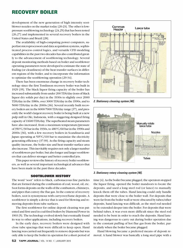
2. Stationary cleaning system [40].
3. Stationary rotary cleaning system [40].

RECOVERY BOILER
JANUARY 2015 | VOL. 14 NO. 1 | TAPPI JOURNAL 53
handle on one end and small nozzles on the other end. Com-pressed air was manually regulated through the pipe to pro-duce an air jet of various strengths. Depending on the nozzle design and position, operators could direct the air jet straight into the boiler or at an angle to clean deposits. Since the pass-ing air helped cool the pipe lance, hand blowing could be car-ried out during boiler operation.
Hand lancing and hand blowing were laborious and useful only for small boilers. As the boiler size increased, these man-ual cleaning devices became obsolete and were replaced by fixed-position (stationary) multi-nozzle cleaning systems, as shown in Fig. 2. In this system, several lance tubes were con-nected to a common steam header (steam is mostly used since it is readily available and less costly than compressed air). The nozzle at the end of each lance tube was designed so that the steam jet could be directed to a desired area. These stationary multi-nozzle cleaning systems were later replaced by station-ary rotary cleaning systems to increase the coverage area. This was achieved by mounting multiple nozzles along the length of the lance tube, which was manually rotated by pulling the chain around the lance tube (Fig. 3).
The large number of nozzles mounted on each lance tube reduces the steam flow rate per nozzle, and hence, reduces the cleaning power of the jet. Furthermore, the portion of the lance tube that stays inside the boiler has a short service life since the lance tube corrodes quickly if it is exposed un-cooled to the corrosive environment, particularly in the su-perheater region of the boiler. Even in the cooler and less corrosive regions of the boiler, the lance tube temperature is still high, close to the flue gas temperature. When the clean-ing is initiated, the cooler steam supplied to the lance tube causes the tube temperature to drop abruptly, resulting in
thermal cyclic stresses that can shorten the lance tube life. As a result of these drawbacks, stationary rotary sootblowers were soon replaced by retractable sootblowers.
Retractable sootblowersRetractable sootblowers were developed to address the short-comings of stationary rotary sootblowers. When the soot-blower is not in use, the lance tube is fully retracted and parked outside the boiler, and thus is not exposed to the hos-tile environment in the boiler. In order to maximize the jet cleaning power as well as to balance the lance tube, retract-able sootblowers are equipped with only two opposing noz-zles at the tip of the lance tube.
Retractable sootblowers were introduced to recovery boil-ers in the 1940s; this significant development made large re-covery boiler design practical [35].
Early retractable sootblowers had a chain drive system that moved and rotated the lance tube in and out of the boiler. The chain was driven by a stationary motor mounted on top of the sootblower canopy (Fig. 4). Safety and reliability were the main concerns for this version of retractable sootblowers.
4. Early retractable sootblower[40].
5. Clyde Bergemann’s sootblower [41].
6. Diamond Power’s IK-555 sootblower [43].

RECOVERY BOILER
54 TAPPI JOURNAL | VOL. 14 NO. 1 | JANUARY 2015
The chain system required constant maintenance. If it failed and broke during sootblower operation, the high pressure steam in the lance tube would cause the tube to torpedo forward and strike the boiler wall on the opposite side at a high speed. This could cause severe damage to the wall tubes and injuries to mill personnel who happened to be nearby.
Modern retractable sootblowers replaced the stationary motor and chain system in the early version with a traveling motor that had dual-rack and pinion drives. With such an ar-rangement, the motor travels together with the carriage as the lance tube is pushed in and retracted from the boiler. The dual-rack and pinion drives have greatly improved the reliabil-ity of the lance tube movement. This retractable sootblower design is currently used by the two major sootblower manu-facturers, Clyde Bergemann (Fig. 5) and Diamond Power (Fig. 6).
A schematic of multiple retractable sootblowers installed in a modern recovery boiler is shown in Fig. 7. The number of such sootblowers may range from 60 in a small unit to as many as 150 in a large unit.
Alternative cleaning systems There are several alternative cleaning systems that have been commonly used in coal-fired boilers and many other applica-tions, but not in recovery boilers. These include sonic soot-blowers, falling steel shot, and wall blowers.
Sonic sootblowers pass compressed air into a wave generator to produce a series of sound-induced pressure fluctuations that emit loud low-frequency noise. These air horns cause loosely bonded ash particles to de-bond from the heat transfer surface. They work relatively well on fluffy, unsintered deposits in the ductwork and the back of economizers, but not at all on dense, hard, and sintered deposits in the superheater and generation bank regions of recovery boilers. Falling shot is a cleaning method that drops small steel balls from the upper section of the boiler down onto deposits in the lower section and removes them from the tube surfaces. The dropped balls are subsequently
collected at the dust outlet and pneumatically returned to the upper section to be ready for the next shot. In recovery boiler operation, since the removed/collected dust are chemicals that need to be returned to the system for recovery, the possible inclusion of steel balls in the recycled dust and its impact on recovery equipment make the method impractical.
Wall blowers have also been widely used for removing de-posits and slags from wall panels in the lower furnace of util-ity boilers. In recovery boilers, however, since deposits on furnace walls at locations before the superheater entrance are thin, wall blowers are usually not needed.
TECHNOLOGICAL ADVANCESUp to the early 1990s, most improvements made on sootblow-ing technology were limited to the design and mechanical aspects of the equipment; little attention was given to optimiz-ing the sootblower cleaning power, the steam usage, and de-posit control strategies. The sootblowing technology used in recovery boilers was literally the same as that used in coal-fired boilers.
In 1991, with the support of 11 pulp and paper related companies and the Ontario University Research Incentive Fund, an industry-university collaborative research program on “Recovery Boiler Fireside Deposits” was initiated at the University of Toronto. The research program included, for the first time, projects on sootblower jet fundamentals and issues related to deposit removal in recovery boilers. The results of this research program, and of programs that followed over the subsequent two decades, and the work of recovery boiler and sootblower manufacturers, have significantly advanced the basic knowledge of sootblowing: how a sootblower jet behaves, how it interacts with tubes and deposits, and identification of the key parameters that influence the deposit removal efficiency. Two important innovations that resulted are fully-expanded nozzles and low pressure sootblowing technology.
8. Nozzle design comparison (HI-PIP=high performance peak impact pressure).
7. Schematic of retractable sootblower installation in a modern recovery boiler.
RECOVERY BOILER
JANUARY 2015 | VOL. 14 NO. 1 | TAPPI JOURNAL 55
Fully-expanded nozzlesThe design of sootblower nozzles used in industrial boilers until the mid-1990s ranged from two simple holes drilled into the lance tube to a more sophisticated venturi type, known conventionally as High Performance Peak Impact Pressure (Hi-PIP) nozzles (Fig. 8a). Hi-PIP nozzles were the most com-monly used nozzles in recovery boilers from the mid-1980s to the mid-1990s.
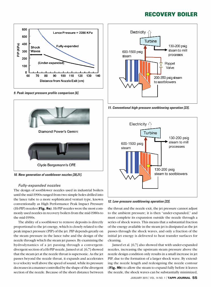
The ability of a sootblower to remove deposits is directly proportional to the jet energy, which is closely related to the peak impact pressure (PIP) of the jet. PIP depends greatly on the steam pressure in the lance tube and the design of the nozzle through which the steam jet passes. By examining the hydrodynamics of a jet passing through a convergent-divergent section of a Hi-PIP nozzle, Jameel et al. [6,7] showed that the steam jet at the nozzle throat is supersonic. As the jet passes beyond the nozzle throat, it expands and accelerates to a velocity well above the speed of sound, while its pressure decreases in a manner controlled by the shape of the divergent section of the nozzle. Because of the short distance between
the throat and the nozzle exit, the jet pressure cannot adjust to the ambient pressure; it is then “under-expanded,” and must complete its expansion outside the nozzle through a series of shock waves. This means that a substantial fraction of the energy available in the steam jet is dissipated as the jet passes through the shock waves, and only a fraction of the initial jet energy is delivered to heat transfer surfaces for cleaning.
Jameel et al. [6,7] also showed that with under-expanded nozzles, increasing the upstream steam pressure above the nozzle design condition only results in a small increase in jet PIP, due to the formation of a larger shock wave. By extend-ing the nozzle length and redesigning the nozzle contour (Fig. 8b) to allow the steam to expand fully before it leaves the nozzle, the shock waves can be substantially minimized,
9. Peak impact pressure profile comparison [6].
11. Conventional high-pressure sootblowing operation [23].
12. Low-pressure sootblowing operation [23].
10. New generation of sootblower nozzles [20,21].

RECOVERY BOILER
56 TAPPI JOURNAL | VOL. 14 NO. 1 | JANUARY 2015
and this can greatly improve the sootblower performance. As shown in Fig. 9, for the same steam consumption, fully ex-panded nozzles provide much greater cleaning power than under-expanded nozzles [7,8,9].
This discovery led to the development of a new generation of sootblower nozzles that allow the jet to achieve full (or close-to-full) expansion before it exits the nozzle. With the help of CFD modeling and efforts made by sootblower manu-facturers, the dimension, shape, and position of the nozzles around the tip of the lance were refined to make it easier for the stream to pass through the nozzles, thereby increasing the cleaning power of the steam jets even further. Fig. 10 shows the most advanced nozzles presently offered by the two major sootblower manufacturers: the Diamond Power Gemini noz-zles [20, 21] and the Clyde Bergemann CFE (Contoured Fully Expanded) nozzles [22,23].
Due to their superior performance compared to Hi-PIP nozzles, these fully expanded nozzles are now used in virtu-ally all new recovery boilers and utility boilers today.
Low pressure sootblowing technologyRecovery boilers operate at a superheated steam pressure ranging from 600 psig on older units to as high as 1500 psig (41 to 103 bar) on modern units [36]. The high pressure steam from the final superheater outlet is passed through a steam turbine to generate electricity. The exhaust steam from the turbine, typically at 130 to 250 psi (9 to 17 bar), is subsequent-ly used in various processes in the pulp mill (Fig. 11).
The concept of low pressure sootblowing was first introduced to us by a mill representative during our annual research review meeting at the University of Toronto in 2001. Instead of high-pressure steam, the exhaust steam from the steam turbine is used directly for sootblowing, as shown in Figure 12. Theoretical analysis, laboratory studies, and mill trials [22-26] were subsequently performed to evaluate the feasibility of the concept. The results clearly indicated that low pressure sootblowing is technically and practically feasible. However, in order for low pressure sootblowers to provide a deposit cleaning power that is comparable to that of high pressure sootblowers, they require a larger jet (a higher steam flow rate) to compensate for the adverse effect of reduced pressure. This can be accomplished by using larger fully-expanded nozzles with a modified design to achieve optimum performance at the lower pressure.
The economic benefits of implementing low-pressure sootblowing technology depend greatly on the amount of additional low pressure steam required to make up for the low pressure, in order to attain the same deposit cleaning power as high pressure sootblowers, and the differential cost between high pressure steam and low pressure steam [23]. Furthermore, the technology is difficult to implement on existing recovery boilers due to the need for re-piping the sootblowing steam lines to accommodate the higher steam flow rate. For new recovery boilers, this is not an issue, as sootblowing steam lines can be properly designed and
installed from scratch. Presently there are three recovery boilers in the United States and two in Brazil using low pressure sootblowers. A few other new recovery boilers are expected to follow suit.
Sootblower jet strengthIn 2007, a collaborative project was initiated by Andritz Inc., in collaboration with the University of Toronto, Diamond Power, and Clyde Bergemann, to systematically examine the strength of sootblower jets in-situ, using a jet force measurement system [18,19]. Four trials were conducted under various sootblowing conditions in recovery boilers at two different kraft pulp mills. The main conclusions were that the jet force increases linearly with an increase in lance pressure (Fig. 13).
At a given lance pressure, the jet force diminishes mark-edly with an increase in distance from the nozzle. At a distance farther than 1 m (3 ft) from the nozzle, the jet exerts only 10% of its original force on the same target (Fig. 14). At greater
14. Average jet force vs. distance at lance pressure of 9-11 bars [18,19].
13. Jet force vs. lance pressure at different distances [19].

RECOVERY BOILER
JANUARY 2015 | VOL. 14 NO. 1 | TAPPI JOURNAL 57
distances, the jet strikes the target not only with a weaker force but also for a shorter period of time.
The angle at which the jet hits the target also has an impact on jet force [19]. For a given projected area of the target, the larger the impact angle (closer to the normal direction), the greater is the jet force, i.e., Fθ = F90 × θ/90, where Fθ is the jet force exerted on the target at θ angle and F90 is the jet force at 90° (head-on).
Sootblower dimensionsPresently, there are only a few old and small recovery boilers in operation that have sootblowers mounted on one sidewall, with lance tubes that extend across the boiler width, 24 to 30 ft (8 to 10m), to the other side wall, in order to achieve full coverage. In most recovery boilers, sootblowers are mounted on both sidewalls so that they need to reach only half of the boiler width. Since the lance tube rests at about 6 in. (0.15 m) outside the boiler when it is fully retracted, the travel length (or distance) is slightly greater than 1/2 of the boiler width.
Prior to 1990, recovery boilers were relatively small, with a firing capacity under 2500 TDS/day. Sootblowers were equipped with a 3.5 in. (8.9 cm) outside diameter (OD) lance tube and had a travel distance of 15.7 ft (5 m). As boilers be-came larger and larger in recent years, larger 4 in. (10.2 cm) OD lance tubes have been used to support their longer length, >20 ft (6 m), as well as to better accommodate longer fully-expanded nozzles. They typically travel at a linear speed of 100 in./min (2.5 m/min) and take about 5 min to move in and out of the boiler. Longer sootblowers require a longer time to complete a blow cycle. In most modern installations, how-ever, the sootblower system is equipped with variable fre-quency drive (VFD) that can operate at a travel speed as high as 150 in./min (3.8 m/min), significantly shortening the time requirement for each blow.
For sootblowers with a travel length greater than 25 ft (7.5m), a center support is needed to balance the lance tube while it is in the rest position and the feed tube while the lance
tube is inserted deeply into the boiler. Without such support, the tubes may excessively deflect and bend.
Figure 15 shows the sootblower travel length (L) versus boiler firing capacity (F) for a few selected recovery boilers (actual data points). Since most boilers are designed such that the total heat input to the boiler per unit furnace floor area is constant, slightly under 1 MM Btu/ft2-h (or 3.3 MW/m2), L is proportional to the square root of F (broken curve). The world’s largest recovery boiler to be built at the pulp mill in Oki, Indonesia, will be equipped with 5 in. (12.7 cm) OD and 39.5 ft (11.6 m) long sootblowers. While they will be the larg-est and longest sootblowers ever installed in recovery boilers, sootblowers of this size are rather common in utility boilers.
Sootblowing efficiencyFlue gas pressure drop (draft loss) across individual heat trans-fer banks, steam production rate, attemperator valve opening, boiler bank exit gas temperature, economizer exit gas tem-perature, ID fan speed, etc., have traditionally been used to indicate the state of cleanliness (or fouling) of recovery boil-ers, and to decide when to operate the sootblowers more in-tensively in the heavy buildup area [1]. While these operating variables provide some indications of boiler fouling, they are not accurate, and are often influenced by other boiler operat-ing variables. Furthermore, when a change in flue gas pres-sure drop is noticed, the boiler has already been plugged to a point where a waterwash is usually needed. The lack of reli-able means for monitoring deposit buildup makes it difficult for pulp mills to automate their sootblowing operation.
In the early days, sootblowers were operated manually by pushing a button beside each sootblower or in the recovery boiler control room. Based on the experience and logic devel-oped at the mill over the years, the blowing sequence and frequency were programmed into the mill programmable logic controller (PLC) and distributed control system (DCS), which automatically operate the sootblowers “blindly” with-out any feedback on the state of fouling or boiler cleanliness. In recent years, thanks to the availability of high speed micro-processors and data acquisition systems, several intelligent/smart sootblowing systems have been developed. These sys-tems use more reliable fouling indicators to advise boiler op-erators when and where to activate the sootblowers, and to optimize sootblowing operation. These include:
• Heat balance: This involves the use of a fouling index based on the steam side heat balance performed on each individual superheater section (i.e., primary, secondary, and tertiary superheaters), boiler bank and economizer, and the gas side temperatures [29,30]. The fouling index is essentially a measure of the efficiency of a tube bank to transfer heat from the flue gas to the steam flowing inside the tubes. Thus, it can also serve as a key indicator of the sootblowing effectiveness.
• Strain gauge system: This system was patented by In-ternational Paper (IP) [32] and has been installed exclu-sively in recovery boilers at IP mills. It uses strange gaug-
15. Sootblower travel lengths of selected recovery boilers.

RECOVERY BOILER
58 TAPPI JOURNAL | VOL. 14 NO. 1 | JANUARY 2015
es installed on the hanger rods that support superheater platens to measure the elongation of the rods, which is directly proportional to the weight of the deposit buildup on the platen.
• Local deposition rate: This system analyzes the instan-taneous fluctuations of flue gas temperatures at the boil-er bank exit during single strokes of all sootblowers in the boiler, and converts them into a time series of raw data that indicates fouling of the tube surfaces [33]. This, in turn, can be used to indicate the short-term carryover deposition rate and the efficiency of deposit removal by the sootblowers. This approach yields a 3-D map of the local fouling rate in the vicinity of each sootblower that is useful in establishing the sootblowing sequence for minimum steam use or for plugging prevention.
• Principle component analysis (PCA): This system uses a multivariate statistical program to monitor the gradual and sudden shifts in boiler thermal efficiency for individual runs, allowing day-to-day analysis of changes in boiler fouling conditions [34].
Inspection Cameras The availability of compact, high quality, and inexpensive in-frared inspection cameras in recent years has enabled mills to inspect the state of deposit buildup at different locations in the boiler during operation, as well as to assess the deposit removal efficiency of sootblowers. Fig. 16 shows images of a piece of deposit being knocked off by a sootblower blowing from behind the tube, while Fig. 17 shows little evidence of deposit removal by a sootblower in a different recovery boiler as the sootblower moves in and out of the boiler.
Inspection cameras have also helped identify the following: 1) the swinging of sootblower lances caused by the imbalance of jet forces exiting the two opposing nozzles at the tip of the lance tube; 2) locations where massive deposits build up in the boiler; 3) the cleanliness of the tube
surface after thermal shedding events; and 4) the swinging of superheater platens and the vibration of boiler bank tubes caused by sootblowing.
FUTURE OUTLOOKSootblowing is a fairly mature technology, particularly with respect to hardware. With the trend toward operating recov-ery boilers with fewer and fewer operators in years ahead, it will be a challenge for sootblower manufacturers to provide equipment that is easy to operate and to maintain, such as gear boxes and other moving parts that can be quickly greased; poppet valves and lance tubes that can be easily re-placed; etc.
Sootblowing efficiency depends on two factors: 1) the force exerted by the jet on the deposit, and 2) the strength/tenacity of the deposit on the tube. The peak impact pressure of the sootblower jet and the resulting force can now be predicted accurately based on the nozzle design, stream conditions inside the lance tube, and the distance between the nozzle and the deposits. The deposit strength, however, is not as straightforward since it varies widely with location in the boiler, depending on gas temperature, deposit composition, and tube surface condition. These, in turn, are a strong function of black liquor composition and boiler operating conditions. Without the knowledge of deposit strength, it would be difficult to optimize the deposit removal process, unless reliable fouling indicators can be developed to advise boiler operators when and where to activate the sootblowers and to optimize sootblowing operation.
Fully-expanded nozzles will remain the preferred choice. Since the present nozzle designs have been optimized for best performance, these nozzles will be used for years to come. New recovery boilers will likely adopt the low pressure soot-blowing technology due to its economic advantage.
We will probably see more research and development work on CFD modeling of jet-tube and jet-deposit interactions
16. Images recorded by an infrared inspection camera showing a deposit being removed by a sootblower from behind.
17. Images recorded by an infrared inspection camera showing the ineffectiveness of a sootblower in removing massive superheater deposits during a blowing cycle (time=mm:ss).

RECOVERY BOILER
JANUARY 2015 | VOL. 14 NO. 1 | TAPPI JOURNAL 59
in the near future. Application of CFD results will help im-prove understanding of sootblowing jet behaviors. TJ
ACKNOWLEDGEMENTSThis work was conducted as part of the research program on “Increasing Energy and Chemical Recovery Efficiency in the Kraft Process,” jointly supported by the Natural Sciences and Engineering Research Council of Canada (NSERC) and a consortium of the following companies: Andritz, AV Nackawic, Babcock & Wilcox, Boise, Carter Holt Harvey, Cellulose Nipo-Brasileira, Clyde-Bergemann, DMI Peace River Pulp, Eldorado, ERCO Worldwide, Fibria, FP Innovations, International Paper, Irving Pulp and Paper, Kiln Flame Systems, Klabin, MeadWestvaco, StoraEnso Research, Suzano, Tembec, Tolko Industries, and Valmet. The authors also wish to acknowledge Diamond Power International for its past support of the sootblowing research program at the University of Toronto.
LITERATURE CITED1. Tran, H.N., in Kraft Recovery Boilers (T.N. Adams, et al., Eds.), TAPPI
PRESS, Atlanta, GA, USA, 1997, Chap. 9, pp. 247-282.
2. Tran, H.N., “Fouling of tube surfaces in kraft recovery boilers,” Int. Recovery Boiler Conf., 40th, Finnish Recovery Boiler Committee, Vantaa, Finland, 2004, p. 91.
3. Villarroel, R., Gonçalves, C., and Tran, H.N., Pulp Pap. Can. 106(12): T273(2005).
4. Chapel, R.E., “A basic understanding of sootblowing for recovery boiler cleaning,” Kraft Recovery Short Course, TAPPI PRESS, Atlanta, 1987, p. 159.
5. Barsin, J., “Recovery boiler sootblowers,” Kraft Recovery Short Course, TAPPI PRESS, Atlanta, 1992, p. 219.
6. Jameel, M.I., Cormack, D.E., Tran, H.N., et al., Tappi J. 77(5): 135(1994).
7. Jameel, M.I., Cormack, D.E., and Tran, H.N., U.S. pat. 5,375,771 (1996).
8. Moskal, T.E., Burton, M.A., and Jordan, C.A., “Results of laboratory testing and field trials of improved sootblower nozzles,” TAPPI Eng. Conf., TAPPI PRESS, Atlanta, 1993, p. 963.
9. Kaliazine, A., Piroozmand, F., Cormack, D.E., et al., TAPPI J. 80(11): 201(1997).
10. Kaliazine, A., Cormack, D.E., Ebrahimi-Sabet, A., et al., J. Pulp Pap. Sci. 25(12): 418(1999).
11. Tandra, D., Kaliazine, A., Cormack, D.E., et al., Pulp Pap. Can. 108(5): 43(2007).
12. Pophali, A., Eslamian, M., Bussmann, M., et al., TAPPI J. 8(9): 4(2009).
13. Pophali, A., Emami, B., Bussmann, M., et al., Fuel Process. Technol. 105: 69(2013).
14. Mao, X., Tran, H.N., and Cormack, D.E., TAPPI J. 84(6): 68(2001).
15. Mao, X., Lee, S., and Tran, H.N., J. Pulp Pap. Sci. 35(2): 41(2009).
16. Emami, B., Bussmann, M., Tran, H.N., et al., “Advanced CFD simulations of sootblower jets,” Int. Chem. Recovery Conf., TAPPI PRESS, Atlanta, 2010.
17. Emami, B., Bussmann, M., and Tran, H.N., SIAM J. Appl. Math. 72(1): 85(2012)
18. Saviharju, K., Kaliazine, A., Tran, H.N., et al., TAPPI J. 10(2): 27(2011).
19. Tran, H.N., Pophali, A., Emami, B., et al., TAPPI J. 11(9): 31(2012).
20. Habib, T.F., Keller, D.L., and Fortner, S.R., U.S. pat. 7028926 B2 (2006).
21. Diamond Power International Inc., “Gemini nozzle for improved recovery boiler cleaning,” Brochure, DPII-9644-1206-00, 2007.
22. Jameel, M.I, U.S. pat. 5,505,163 (April 9, 1996).
23. Clyde Bergemann, “Contoured Fully Expanded (CFE) III nozzle,” Brochure, 2012.
24. Kaliazine, A., Cormack, D.E., and Tran, H.N., Pulp Pap. Can. 107(4): T80(2006).
25. Tran, H.N., Tandra, D., and Jones, A.K., Pulp Pap. Can. 109(12): T129(2008).
26. Tandra, D., Kaliazine, A., Cormack, D.E., et al., “Mill trial on low pressure sootblower performance in a recovery boiler,” TAPPI Eng. Conf., TAPPI PRESS, Atlanta, 2005.
ABOUT THE AUTHORSWe chose this topic to research because it was the keynote topic that the Finnish Recovery Boiler Committee requested us to address at its 50th Anniversary Celebration Event in conjunction with the 2014 International Chemical Recovery Conference. The work here is a historic review, and as such, it is complementary to all the previous work by our re-search group and others.
The most difficult aspect of this work was to uncover the relevant historical information, which is not readily available. We addressed this by conduct-ing an intensive library search of articles related to sootblow-ers, as well as making requests of people who might have had this information. The most sur-prising aspect of this research was to discover that our group at the University of Toronto is part of sootblower history as the only group in the world pursuing recovery boiler soot-blowing research!
Mills may include this historical information in training programs for their new engineers.
Tran is Frank Dottori Professor of Pulp & Paper Engineering, Department of Chemical Engineering & Applied Chemistry, and Tandra is adjunct professor, Department of Mechanical & Industrial Engineering, at the University of Toronto, Toronto, ON, Canada. Email Tran at [email protected].
Tandra
Tran

RECOVERY BOILER
60 TAPPI JOURNAL | VOL. 14 NO. 1 | JANUARY 2015
27. Tavares, A. and Youssef, S., “Retrofitting existing sootblower sys-tem to use a lower pressure steam source,” TAPPI Eng. Conf., TAPPI PRESS, Atlanta, 2006.
28. Tandra, D.S., Hinman, J., Olson, M., et al., “Energy efficiency and cost reduction through the implementation of low pressure soot-blowing system,” TAPPI PEERS Conf., TAPPI PRESS, Atlanta, 2008.
29. Uloth, V.C., Markovic, C.M., Wearing, J.T., et al., Pulp Pap. Can. 97(7): T223(1996).
30. Tandra, D.S., Manay, A., and Edenfield, J.A., “The use of energy balance around recovery boiler heat exchangers to intelligently manage sootblower operations: A case study,” TAPPI PEERS Conf., TAPPI PRESS, Atlanta, 2010.
31. Thabot, A., Tandra, D.S., and Oehrig, B., “The use of intelligent sootblowing system to deal with various operational issues related to heavy backpass fouling,” Power-Gen Int. Conf., PenWell Publishing, Tulsa, OK, USA, 2010.
32. Jones, A.K, U.S. pat. 6,323,442 B1 (November 27, 2001).
33. Adams, T.N., “Sootblowing control based on measured local foul-ing rate,” TAPPI PEERS Conf., TAPPI PRESS, Atlanta, 2010
34. Versteeg, P. and Tran, H.N., TAPPI J. 8(11) 22(2009).
35. Kitto, J.B. and Stutz. S.C., Eds., Steam: Its Generation and Use, 41st edn., Babcock & Wilcox Company, Charlotte, NC, USA, ISBN 0-9634570-1-2, 2005.
36. Vakkilainen, E., “Boundaries of recovery boiler development,” Int. Recovery Boiler Conf., 45th, Finnish Recovery Boiler Committee, Vantaa, Finland, 2009, p. 7.
37. Haaga, K., “Development path of recovery boilers from small ones to big ones and how we made it happen?” Int. Colloq. Black Liquor and Biomass to Bioenergy and Biofuel, 8th, Federal University of Minas Gerais, Belo Horizonte, Brazil, 2013.
38. Tran, H.N. and Arakawa, Y., “Recovery boiler technology in Japan,” TAPPI Eng. Conf., TAPPI PRESS, Atlanta, 2011.
39. Arakawa, Y., Ukeguchi, Y., Maeda, T., et al., “Maximizing the elec-tricity generation capacity of recovery boilers and superheater tube materials in Japanese pulp and paper mills,” Int. Chem. Recovery Conf., TAPPI PRESS, Atlanta, 2014.
40. Vulcan Soot Blower Company, Vulcan Soot Cleaner Handbook, DuBois, PA, USA, 1921.
41. Cycle Bergemann, Archive photos.
42. Clyde Bergemann, “Model RS & RSI Recovery Service Sootblowers,” Brochure. Available [Online] http://www.boilercleaning.org/Literature/brochure/SBD/RS%20Recovery%20Service%20Sootblower.pdf <24Dec2014>.
43. Diamond Power International Inc., “IK-555 long travel retractable sootblower,” Brochure, 2011. Available [Online] http://www.diamondpower.com/Resources/IK555_Brochure.pdf <24Dec2014>.
PAPERCON 2015AT TAPPI’S CENTENNIAL CELEBRATION
Georgia World Congress Center - Atlanta, Georgia
2015 TAPPI Centennial Celebration:Honoring Our Past,
Inspiring Our Future
Featuring comprehensive peer-reviewed programs: ● Papermaking: Past Present and Future ● Papermaking Additives ● Process Control & Fluid Fundamentals ● Coating & Graphic Arts ● PIMA Management ● RPTA P-T Seminar ● Tissue360° Forum
PaperCon.org