
VISVESVARAYA TECHNOLOGICAL UNIVERSITY ...
62
VISVESVARAYA TECHNOLOGICAL UNIVERSITY Belgaum-590014, Karnataka PROJECT REPORT ON UNDERGROUND CABLE FAULT DISTANCE LOCATOR Submitted in the partial fulfillment for the award of the degree of Bachelor of Engineering in Electronics and Communication Engineering By Saranya Suresh (1NH12EC094) Ranjitha.N (1NH12EC745) Shilpa.V (1NH12EC755) UNDER THE GUIDANCE OF Ms.Simi Ranjith Asst. Professor, ECE Dept, NHCE Bangalore Department of Electronics & Communication Engineering, New Horizon College of Engineering, Bengaluru -560103, Karnataka. 2015-16
-
Upload
khangminh22 -
Category
Documents
-
view
0 -
download
0
Transcript of VISVESVARAYA TECHNOLOGICAL UNIVERSITY ...

VISVESVARAYA TECHNOLOGICAL UNIVERSITY Belgaum-590014, Karnataka
PROJECT REPORT
ON
UNDERGROUND CABLE FAULT DISTANCE
LOCATOR Submitted in the partial fulfillment for the award of the degree of
Bachelor of Engineering
in
Electronics and Communication Engineering By
Saranya Suresh (1NH12EC094)
Ranjitha.N (1NH12EC745)
Shilpa.V (1NH12EC755)
UNDER THE GUIDANCE OF Ms.Simi Ranjith
Asst. Professor,
ECE Dept, NHCE
Bangalore
Department of Electronics & Communication Engineering,
New Horizon College of Engineering, Bengaluru -560103, Karnataka.
2015-16


(i)
ACKNOWLEDGEMENT
The satisfaction that accompanies the successful completion of any task would be incomplete
without due reverence given to those who made it possible, whose constant guidance and
encouragement crowned our efforts with success.
Firstly we would like to express thanks to our college which has given us this opportunity to
work on this project.
We convey our sincere gratitude to Dr Manjunatha, Principal, NHCE, Bangalore for
facilities provided in college and for the support in numerous ways.
We remain indebted to Dr Sanjay Jain, HOD, Department of E&C, NHCE for providing us
permission to take up the project work.
We would like to express our profound gratitude to our internal guide Ms Simi Ranjith
Assistant Professor, Department of E&C, NHCE.
We would like to express our deepest sense of gratitude to our parents and friends who have
been a great source of moral support, courage, for giving us a helping hand and making us go
smiles with their lovable presence during our tough times and relieving us from stress
throughout our project endeavour.
We also thank our teaching and non-teaching staff members of Department of E&C, NHCE.

ABSTRACT
The aim of this project is to determine the distance of underground cable fault from base station
in kilometers. A constant current source feeds a known current into the wire under test (WUT).
The voltage drop across the WUT is measured using the ADC. A short circuit is detected based
on this difference voltage across the WUT. In case of a short circuit the length from the base
station is calculated and displayed locally as well as informed to the user/admin through a SMS
using a GSM modem. The length and the voltage across the WUT is also simultaneously
uploaded to a ThingSpeak channel and if necessary further analysis can be done using MATLAB
and can also be displayed using a user friendly UI.

TABLE OF CONTENTS
ACKNOWLEDGEMENT
ABSTRACT
CHAPTER 1: INTRODUCTION 1
1.1 Brief description 1
1.2 Types of faults 2
1.3 Advantages 2
1.4 Disadvantages 2
CHAPTER 2: LITERATURE SURVEY 3
CHAPTER 3: HARDWARE DESIGN 5
3.1 Block diagram 5
3.2 Introduction of Arduino 6
3.2.1 Advantages of arduino 7
3.2.2 Features of ATMEGA328 8
3.2.3 Pin configuration 9
3.2.4 Pin details 9
3.3 Power supply 10
3.4 Voltage regulator 10
3.5 Constant current source 11
3.6 Short circuit sensing element 13
3.7 LCD 15
3.7.1 Interfacing of LCD 17
3.8 GSM 17
3.8.1 General commands of GSM 18
3.8.2 HTTP commands 21

CHAPTER 4 : SOFTWARE IMPLEMENTATION 25
4.1 Initialization steps 25
4.1.1 Steps to download the program 26
4.2 Steps to post the data 28
CHAPTER 5 : HARDWARE IMPLEMENTATION 29
CHAPTER 6: RESULTS 30
6.1 Snapshot 30
6.2 Flowchart 31
CHAPTER 7: CONCLUSION & FUTURE SCOPE 36
APPENDIX 37
U N D E R G R O U N D C A B L E F A U L T D I S T A N C E L O C A T O R P a g e 1
Dept. of E&C ,NHCE 2015-16
CHAPTER 1
INTRODUCTION
1.1Brief description
More than 3 million miles of electrical cables are strung overhead across the
country. Add to that at least 180 million telephone and cable TV lines, and it’s no wonder
hurricanes, tornadoes, fires and ice storms are wreaking havoc on the electrical systems each
year, causing utility outages that last days, weeks and longer. Power outages over extended
periods present major health and safety concerns and economic losses. Concerns about the
reliability of overhead lines, increases in their maintenance and operating costs, and issues of
public safety and quality-of-life are leading more and more utilities and municipalities to the
realization that converting overhead distribution lines to underground is the best way to provide
high-quality service to their customers. For utility companies, undergrounding provides potential
benefits through reduced operations and maintenance (O&M) costs, reduced tree trimming costs,
less storm damage and reduced loss of day-to-day electricity sales when customers lose power
after storms. Creative funding options are often available to make the goal of undergrounding a
reality. The underground cable system is very important for distribution especially in
metropolitan cities, airports and defense service. Now the world is become digitalized so the
project is intended to detect the location of fault in digital way. The underground cable system is
more common practice followed in many urban areas. While fault occurs for some reason, at that
time the repairing process related to that particular cable is difficult due to not knowing the exact
location of cable fault.
Fault in cable is represented as:
• Any defect,
• Inconsistency,
• Weakness or non-homogeneity that affect performance of cable .
• Current is diverted from the intended path .
• Caused by breaking of conductor& failure of insulation
1.2TYPES OF FAULT IN UNDERGROUND CABLES
The most common types of fault that occur in underground cables are,

U N D E R G R O U N D C A B L E F A U L T D I S T A N C E L O C A T O R P a g e 2
Dept. of E&C ,NHCE 2015-16
1. Short circuit fault.
2. Open circuit fault.
3. Earth fault.
1.2.1. Short-circuit fault
When two conductors of a multi core cable come in electrical contact with each other due
to insulation failure, it is so called as short-circuit fault.
1.2.2. Open circuit fault
When there is a break in the conductor of a cable, it is called open-circuit fault. The open-circuit
fault can check by a megger.
1.2.3. Earth fault When the conductor of a cable comes in contact with earth, it is called earth fault or ground fault.
1.3ADVANTAGES
Easy to detect the Cable fault location instruments
Systems are applicable to all types of cables ranging from 1 kV to 500 kV
Less maintenance
Less faults
Higher efficiency
1.4 DISADVANTAGES
• Cost, must consider life time costs not just initial
• Cost differential decreasing with time
• Cost of losses (30-60% less than OH), maintenance and repair
• Fault location instantaneous, can have longer repair time
• Undergrounding all of the lines would increase the cost of electricity by 16%

U N D E R G R O U N D C A B L E F A U L T D I S T A N C E L O C A T O R P a g e 3
Dept. of E&C ,NHCE 2015-16
CHAPTER 2
LITERATURE SURVEY
Finding the location of an underground cable fault doesn’t have to be like finding a needle in a
haystack. The common methods of locating faults are
2.1 Sectionalizing: This procedure risks reducing cable reliability, because it depends on
physically cutting and splicing the cable. Dividing the cable into successively smaller sections
and measuring both ways with an ohmmeter or high-voltage insulation resistance (IR) tester
enable to narrow down search for a fault. This laborious procedure normally involves repeated
cable excavation.
2. 2 Time domain reflectometry (TDR):The TDR sends a low-energy signal through the
cable, causing no insulation degradation. A theoretically perfect cable returns that signal in a
known time and in a known profile. Impedance variations in a “real-world” cable alter both the
time and profile, which the TDR screen or printout graphically represents. One weakness of TDR
is that it does not pinpoint faults
2.3 Murray loop test: It is a bridge circuit used for locating faults in underground or
underwater cables. It uses the principle used in potentiometer experiment. One end of the
faulted cable is connected through a pair of resistors to the voltage source. Also a null detector
is connected. The other end of the cable is shorted. The bridge is brought to balance by
changing the value of RB.
In above figure, Rc is proportional to (l+ (l-x)) and RD is proportional to l.
Therefore

U N D E R G R O U N D C A B L E F A U L T D I S T A N C E L O C A T O R P a g e 4
Dept. of E&C ,NHCE 2015-16
RA/RB=r=RC/RD = (2l-x)/x (1)
And hence
x= 2l/(r-1) (2)
Where l is the length on each segment of wire, r is the ratio RA/RB and x is the length of faulty
segment.
The main disadvantage of this method assumes that only a single fault exists, a low resistance
when compared with UG cable resistance and cable conductors have uniform resistance per unit
length
2.4 Varley loop test: If the fault resistance is high , the sensitivity in Murray bridge is
reduced and Varely oop may be more suitable but only a single fault exists. Except that here the
ratio arms are fixed and a variable resistance is connected to the test end of the faulty cable.
The drawbacks of the above methods can be overcome to certain extent by this method in which
the concept of OHM’s law is applied.
U N D E R G R O U N D C A B L E F A U L T D I S T A N C E L O C A T O R P a g e 5
Dept. of E&C ,NHCE 2015-16
CHAPTER 3
HARDWARE DESIGN
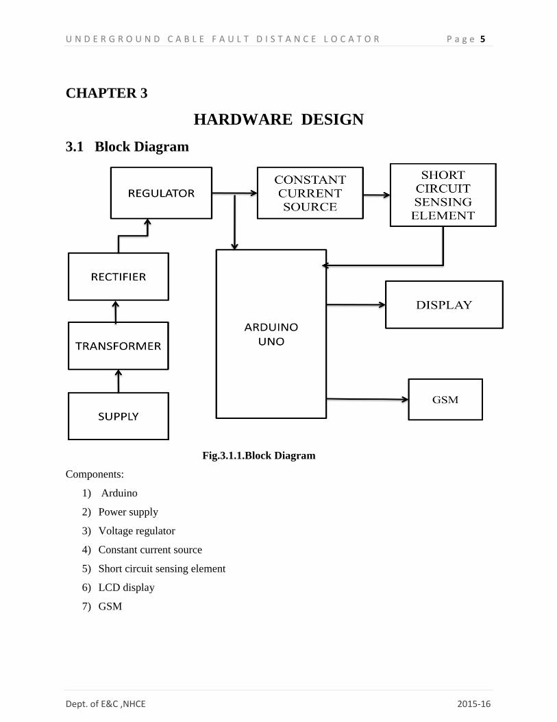
3.1 Block Diagram
Fig.3.1.1.Block Diagram
Components:
1) Arduino
2) Power supply
3) Voltage regulator
4) Constant current source
5) Short circuit sensing element
6) LCD display
7) GSM

U N D E R G R O U N D C A B L E F A U L T D I S T A N C E L O C A T O R P a g e 6
Dept. of E&C ,NHCE 2015-16
3.2 ARDUINO
The Arduino Uno is a microcontroller board based on the ATmega328 .It has 14 digital
input/output pins (of which 6 can be used as PWM outputs), 6 analog inputs, a 16 MHz ceramic
resonator, a USB connection, a power jack, an ICSP header, and a reset button. It contains
everything needed to support the microcontroller; simply connect it to a computer with a USB
cable or power it with a AC-to-DC adapter or battery to get started.
The Uno differs from all preceding boards in that it does not use the FTDI USB-to-serial driver
chip. Instead, it features the Atmega328P programmed as a USB-to-serial converter.
Fig3.1.2 Arduino Atmega328P
Summary
Microcontroller
ATmega328
Operating Voltage 5V
Input Voltage 7-12V
(recommended)
Input Voltage 6-20V (limits)
U N D E R G R O U N D C A B L E F A U L T D I S T A N C E L O C A T O R P a g e 7
Dept. of E&C ,NHCE 2015-16
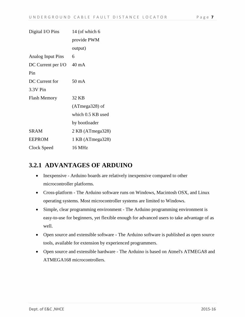
Digital I/O Pins 14 (of which 6
provide PWM
output)
Analog Input Pins 6
DC Current per I/O
Pin
40 mA
DC Current for
3.3V Pin
50 mA
Flash Memory 32 KB
(ATmega328) of
which 0.5 KB used
by bootloader
SRAM 2 KB (ATmega328)
EEPROM 1 KB (ATmega328)
Clock Speed 16 MHz
3.2.1 ADVANTAGES OF ARDUINO
Inexpensive - Arduino boards are relatively inexpensive compared to other
microcontroller platforms.
Cross-platform - The Arduino software runs on Windows, Macintosh OSX, and Linux
operating systems. Most microcontroller systems are limited to Windows.
Simple, clear programming environment - The Arduino programming environment is
easy-to-use for beginners, yet flexible enough for advanced users to take advantage of as
well.
Open source and extensible software - The Arduino software is published as open source
tools, available for extension by experienced programmers.
Open source and extensible hardware - The Arduino is based on Atmel's ATMEGA8 and
ATMEGA168 microcontrollers.

U N D E R G R O U N D C A B L E F A U L T D I S T A N C E L O C A T O R P a g e 8
Dept. of E&C ,NHCE 2015-16
3.2.2 ATMEGA328 FEATURES
The Atmega328 is a very popular microcontroller chip produced by Atmel. It is an 8-bit
microcontroller that has 32K of flash memory, 1K of EEPROM, and 2K of internal SRAM.
The Atmega328 is one of the microcontroller chips that are used with the popular Arduino
Duemilanove boards. The Arduino Duemilanove board comes with either 1 of 2 microcontroller
chips, the Atmega168 or the Atmega328. Unlike the Atmega168 which has 16K of flash program
memory and 512 bytes of internal SRAM, the Atmega328 has 32K of flash program memory and
2K of Internal SRAM. The Atmega328 is a low-power chip, so it only needs between 1.8-5.5V
of power to operate.
3.2.2 PIN CONFIGURATION
Fig.3.2.2.1 Pin mapping of ATMEGA328

U N D E R G R O U N D C A B L E F A U L T D I S T A N C E L O C A T O R P a g e 9
Dept. of E&C ,NHCE 2015-16
3.2.3 PIN DETAILS
The Atmega328 has 28 pins.
It has 14 digital I/O pins, of which 6 can be used as PWM outputs and 6 analog input
pins.
2 of the pins are for the crystal oscillator. The chip needs power so 2 of the pins, Vcc and
GND, provide it power so that it can operate.
The Atmega328 chip has an analog-to-digital converter (ADC) inside of it.
The ADC has 3 pins set aside for it to function- AVCC, AREF, and GND.
AVCC is the power supply, positive voltage, that for the ADC.
GND is the power supply ground.
AREF is the reference voltage that the ADC uses to convert an analog signal to its
corresponding digital value.Since the ADC for the Atmega328 is a 10-bit ADC, meaning
it produces a 10-bit digital value, value.
The last pin is the RESET pin. This allows a program to be rerun and start over.
Serial: 0 (RX) and 1 (TX). Used to receive (RX) and transmit (TX) TTL serial data.
External Interrupts: 2 and 3 are configured to trigger an interrupt on a low value, a rising
or falling edge, or a change in value.
PWM: 3, 5, 6, 9, 10, and 11. Provide 8-bit PWM output with the analogWrite() function.

U N D E R G R O U N D C A B L E F A U L T D I S T A N C E L O C A T O R P a g e 10
Dept. of E&C ,NHCE 2015-16
3.3 POWER SUPPLY
Fig.3.3.1.Power Supply
An AC voltage of 230v is step down to 5v using a step down transformer. Ac voltage is
converted into dc voltage using a bridge rectifier. Capacitors are used to remove the ripple in the
output.
A voltage regulator is used to maintain the constant output voltage 5v.
3.4 VOLTAGE REGULATOR
IC 7805 is a 5V Voltage Regulator that restricts the voltage output to 5V and draws
5V regulated power supply. It comes with provision to add heatsink .The maximum value for
input to the voltage regulator is 35V. It can provide a constant steady voltage flow of 5V for
higher voltage input till the threshold limit of 35V. If the voltage is near to 7.5V then it does not
produce any heat and hence no need for heatsink. If the voltage input is more, then excess
electricity is liberated as heat from 7805 .It regulates a steady output of 5V if the input voltage is
in rage of 7.2V to 35V. Hence to avoid power loss try to maintain the input to 7.2V. In some
circuitry voltage fluctuation is fatal for such situation to ensure constant voltage IC 7805
Voltage Regulator is used.

U N D E R G R O U N D C A B L E F A U L T D I S T A N C E L O C A T O R P a g e 11
Dept. of E&C ,NHCE 2015-16
Fig3.4.1Lm7805voltageregulator
Fig 3.4.2 characteristics of LM7805
3.5 CONSTANT CURRENT SOURCE
A current source is an electronic circuit that delivers or absorbs an electric current which is
independent of the voltage across it.A current source is the dual of a voltage source.
Transistor active constant current source basics
The simple use of a transistor enables a far more effective current source to be made.

U N D E R G R O U N D C A B L E F A U L T D I S T A N C E L O C A T O R P a g e 12
Dept. of E&C ,NHCE 2015-16
The current source operates because of the fact that the collector current in a transistor circuit is
Β times the base current. This is independent of the collector voltage, provided that there is
sufficient voltage to drive the current through the load device in the collector.
Fig.3.5.1Basic transistor constant current circuit
In this circuit, the collector current is Β times the base current. Normally Β is large and therefore
it can be assumed that the emitter current which is (Β + 1) times the base current and the
collector current which is Β times the base current are the same.
In view of this it is a simple matter to design the circuit for a given current.
By setting the resistors R1 and R2 it is possible to set the base voltage. The emitter voltage will
be 0.6 volts less, assuming a silicon transistor. By knowing the emitter voltage, it is possible to
calculate the emitter current from a simple knowledge of Ohms law.

U N D E R G R O U N D C A B L E F A U L T D I S T A N C E L O C A T O R P a g e 13
Dept. of E&C ,NHCE 2015-16
Simple stabilised active current source circuit
In order to remove any fluctuations in current arising from changes in supply voltage it is a
simple matter to add some regulation to the basic circuit. This is achieved by replacing R2 with a
Zener or voltage reference diode.
Fig3.5.2Simple regulated transistor active constant current circuit
The same equations apply as before, but the only difference is that the base voltage is held at a
more constant level as a result of the presence of the Zener, voltage reference diode.
3.6 SHORT CIRCUIT SENSING ELEMENT
Nichrome is used as a cable which carries the current.
Nichrome (NiCr, nickel-chrome, chrome-nickel, etc.) generally refers to
any alloy of nickel, chromium, and often iron and/or other elements or substances. Nichrome
alloys are typically used in resistance wire. They are also used in some dental
restorations (fillings) and in other applications.
The properties of nichrome vary depending on its alloy. Figures given are representative of
typical material and are accurate to expressed significant figures. Any variations are due to
different percentages of nickel or chromium.

U N D E R G R O U N D C A B L E F A U L T D I S T A N C E L O C A T O R P a g e 14
Dept. of E&C ,NHCE 2015-16
Material property Value Unit
Modulus of elasticity 2.2 × 10¹¹ Pa
Density 8400 kg·m−3
Melting point 1400 °C
Electrical resistivity at room temperature (1.0—1.5) × 10−6 Ω·m
Specific heat 450 J·kg−1·K−1
Thermal conductivity 11.3 W·m−1·K−1
Thermal expansion 14 × 10−6 K−1
Standard ambient temperature and pressure
Fig 3.6.1 characteristic of Nichrome

U N D E R G R O U N D C A B L E F A U L T D I S T A N C E L O C A T O R P a g e 15
Dept. of E&C ,NHCE 2015-16
3.7 LCD
The figure below shows LCD which is a liquid crystal display is a low cost device
capable of displaying text and images. LCD are, extremely common in embedded
system since such system often do not have video monitor like those that come
standard with desktop system. LCD can be found in numerous common devices
like watches fax and copy machines and calculators .The basic principle of one type
of LCD, a reflective LCD works as follows:
First incoming light passes through a polarizing plate
Polarized light encounters liquid crystal material if we excite a region of the
material
We cause the material‘s molecules to align, which in turns causes the polarized
light to pass through hits a mirror and reflects back, so the excited region appears to
light up.
Another type of LCD, an absorption LCD, works similarly, but uses a black
surface instead of a mirror. The surface below the exited region absorbs light, thus
appearing darker than the other regions.
An LCD driver converts these inputs to the electrical signals necessary to
excite the appropriate LCD segments. A dot matrix LCD consists of the matrix of
dots that can display alphanumerical characters (letters and digits) as well as other
symbol. A common dot matrix LCD has five columns and eight rows of dots for
one character .An LCD driver converts input data into the appropriate electrical
signal necessary to excite the appropriate LCD dots.
Each type of LCD may be able to display multiple characters. In addition, each
character may be displayed in normal or inverted display fashion. The LCD may
permit a character to be blinking indicating the current character. Such functionality
is difficult to implement for us to implement through software, thus we use an LCD
controllers to provide us with a simple interface to an LCD, perhaps eight inputs
and pulse the enable. This byte may be control word, which instructs the LCD

U N D E R G R O U N D C A B L E F A U L T D I S T A N C E L O C A T O R P a g e 16
Dept. of E&C ,NHCE 2015-16
controller to initialize the LCD, clear display; select the position of the cursor
brighten the display, and so on. Alternatively, this byte may be a data word, such as
an ASCII character, instructing the LCD to display the character at the currently–
selected display position.
A 16x2 LCD means it can display 16 characters per line and there are 2 such lines.
In this LCD each character is displayed in 5x7 pixel matrix. This LCD has two
registers, namely, Command and Data.The command register stores the command
instructions given to the LCD. A command is an instruction given to LCD to do a
predefined task like initializing it, clearing its screen setting the cursor position,
controlling display etc. The data register stores the data to be displayed on the LCD.
The data is the ASCII value of the character to be displayed on the LCD.
Fig 3.7.1 16x2 LCD

U N D E R G R O U N D C A B L E F A U L T D I S T A N C E L O C A T O R P a g e 17
Dept. of E&C ,NHCE 2015-16
3.7.1 Interfacing LCD
Fig 3.7.1 16x2 LCD Interfacing
The LCD LM018L has 16 pin connections as shown in the above figure. Pin1, Pin3 and
Pin16 are all grounded. Pin2 and Pin15 are given to +5V. We can use a potentiometer or
variable resistor between Pin1 and Pin3 for getting different contrast. Pin15 and Pin16 are
used for back light. Pin7 to 14 are used as data lines. Pin4 is rs, to data input we make rs=1
and to instruction code input we make rs=0. Pin5 is made 0 (gnd) to data write and made 1
(+5V) data read. Pin6 is enable, it is made high to enable the LCD.
3.8 GSM (GLOBAL SYSTEM FOR MOBILE
COMMUNICATION)
The SIM900 is a complete Quad-band GSM/GPRS solution in a SMT
module which can be embedded in the customer applications.
General features
Quad-Band 850/ 900/ 1800/ 1900 MHz ”
GPRS multi-slot class 10/8
GPRS mobile station class B

U N D E R G R O U N D C A B L E F A U L T D I S T A N C E L O C A T O R P a g e 18
Dept. of E&C ,NHCE 2015-16
Compliant to GSM phase 2/2+
– Class 4 (2 W @850/ 900 MHz)
– Class 1 (1 W @ 1800/1900MHz)
Control via AT commands (GSM 07.07 ,07.05 and SIMCOM
enhanced AT Commands)
SIM application toolkit
Supply voltage range 3.4 ... 4.5 V
Low power consumption
Operation temperature: -30 °C to +80 °C
The "AT" or "at" prefix must be set at the beginning of each command
line. To terminate a command line enter <CR>. Commands are usually
followed by a response that
includes.”<CR><LF><response><CR><LF>”. Throughout this
document, only the responses are presented, <CR><LF> are omitted
intentionally.
Global system for mobile communication (GSM) is a globally accepted standard
for digital cellular communication. GSM is the name of a standardization group
established in 1982 to create a common European mobile telephone standard that
would formulate specifications for a pan-European mobile cellular radio system
operating at 900 MHz. It is estimated that many countries outside of Europe will
join the GSM partnership.
3.8.1 General commands for GSM
1. Manufacturer identification +CGMI
Description:
This command gives the manufacturer identification.
Syntax:
Command syntax: AT+CGMI

U N D E R G R O U N D C A B L E F A U L T D I S T A N C E L O C A T O R P a g e 19
Dept. of E&C ,NHCE 2015-16
2. New message indication +CNMI
Description:
This command selects the procedure for message reception from the network.
Syntax :
Command syntax : AT+CNMI=<mode>,<mt>,<bm>,<ds>,<bfr>
3. Send message +CMGS
Description :

U N D E R G R O U N D C A B L E F A U L T D I S T A N C E L O C A T O R P a g e 20
Dept. of E&C ,NHCE 2015-16
The <address> field is the address of the terminal to which the message is sent. To send the
message, simply type, <ctrl-Z> character (ASCII 26). The text can contain all existing
characters except <ctrl-Z> and <ESC> (ASCII 27). This command can be aborted using
the <ESC> character when entering text. In PDU mode, only hexadecimal characters are
used (‘0’…’9’,’A’…’F’).
Syntax :
Command syntax in PDU mode :
AT+CMGS= <length><CR>
PDU is entered <ctrl-Z / ESC >
FLOW CHART
GSM_Send_SMS
Fig 3.8.1: Flow chart of GSM send SMS
AT+CMGS= command transmitted
serially to GSM module through UART0
0x22(ASCII value of “)
Mobile number
0x22(ASCII value of “)
Message
0x0D(ASCII value of carriage return)
0x1A(ASCII value of cntrl+z to send
message)

U N D E R G R O U N D C A B L E F A U L T D I S T A N C E L O C A T O R P a g e 21
Dept. of E&C ,NHCE 2015-16
3.8.2 HTTP COMMANDS
In computing, POST is one of many request methods supported by the HTTP protocol used by
the World Wide Web. By design, the POST request method requests that a web server accepts
and stores the data enclosed in the body of the request message.[1] It is often used when
uploading a file or submitting a completed web form.
In contrast, the HTTP GET request method is designed to retrieve information from the server.
As part of a GET request, some data can be passed within the URL's query string.
AT COMMANDS WITH RESPONSE
1. AT+SAPBR
2. AT+HTTPINIT
3. AT+HTTPTERM

U N D E R G R O U N D C A B L E F A U L T D I S T A N C E L O C A T O R P a g e 22
Dept. of E&C ,NHCE 2015-16
4. AT+HTTPDATA
5. AT+HTTPACTION

U N D E R G R O U N D C A B L E F A U L T D I S T A N C E L O C A T O R P a g e 23
Dept. of E&C ,NHCE 2015-16
6. AT+HTTPREAD
AT COMMANDS WITH RESPONSE
AT+SAPBR=3,1,"Contype","GPRS"
OK
AT+SAPBR=3,1,"APN","WWW"
OK
AT+SAPBR=1,1
OK
AT+SAPBR=2,1
+SAPBR: 1,1
AT+HTTPINIT
OK
AT+HTTPPARA="CID",1
OK
AT+HTTPPARA="URL","http://api.thingspeak.com/update"
OK
AT+HTTPDATA=33,10000

U N D E R G R O U N D C A B L E F A U L T D I S T A N C E L O C A T O R P a g e 24
Dept. of E&C ,NHCE 2015-16
DOWNLOAD
key=D9R6K3Y1NNMNZPCD&field1=3300
OK
AT+HTTPACTION=1
OK
+HTTPACTION:1,200,<no_of_bytes>
AT+HTTPTERM

U N D E R G R O U N D C A B L E F A U L T D I S T A N C E L O C A T O R P a g e 25
Dept. of E&C ,NHCE 2015-16
CHAPTER 4
SOFTWARE IMPLEMENTATION
STEP 1:Download and install arduino

U N D E R G R O U N D C A B L E F A U L T D I S T A N C E L O C A T O R P a g e 26
Dept. of E&C ,NHCE 2015-16
STEP 2: Select the arduino uno board from tools
STEP 3: Select COM port

U N D E R G R O U N D C A B L E F A U L T D I S T A N C E L O C A T O R P a g e 27
Dept. of E&C ,NHCE 2015-16
STEP 4: Compile the code and upload to aurduino

U N D E R G R O U N D C A B L E F A U L T D I S T A N C E L O C A T O R P a g e 28
Dept. of E&C ,NHCE 2015-16
4.2 TO POST THE DATA TO THINGSPEAK CHANNEL
STEP1: Create a channel in ThingSpeak website
STEP 2: Choose the fields(distance and voltage)

U N D E R G R O U N D C A B L E F A U L T D I S T A N C E L O C A T O R P a g e 29
Dept. of E&C ,NHCE 2015-16
CHAPTER 5
HARDWARE IMPLEMENTATION
Fig 5.1.1 underground cable fault detector
The 12v supply is step down to 5v and constant voltage is obtained using a voltage
regulator LM7805.
A Constant current source is used to produce a 100mA constant current which
drives the WUT.
A change in the voltage is read by the ADC(A0 and A1 pins of ARDUINO)
Necessary calculations are performed by ARDUINO
The distance at which the short circuit occurs is displayed on the LCD.
The SMS is sent to the assigned number and the same is posted onto the thingspeak
channel.
U N D E R G R O U N D C A B L E F A U L T D I S T A N C E L O C A T O R P a g e 30
Dept. of E&C ,NHCE 2015-16
CHAPTER 6
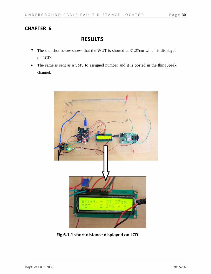
RESULTS
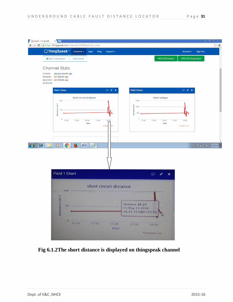
• The snapshot below shows that the WUT is shorted at 31.27cm which is displayed
on LCD.
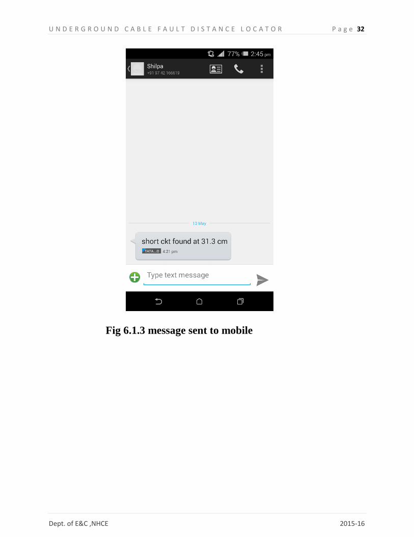
The same is sent as a SMS to assigned number and it is posted in the thingSpeak
channel.
Fig 6.1.1 short distance displayed on LCD
U N D E R G R O U N D C A B L E F A U L T D I S T A N C E L O C A T O R P a g e 31
Dept. of E&C ,NHCE 2015-16
Fig 6.1.2The short distance is displayed on thingspeak channel
U N D E R G R O U N D C A B L E F A U L T D I S T A N C E L O C A T O R P a g e 32
Dept. of E&C ,NHCE 2015-16
Fig 6.1.3 message sent to mobile

U N D E R G R O U N D C A B L E F A U L T D I S T A N C E L O C A T O R P a g e 33
Dept. of E&C ,NHCE 2015-16
6.2 FLOWCHART

U N D E R G R O U N D C A B L E F A U L T D I S T A N C E L O C A T O R P a g e 34
Dept. of E&C ,NHCE 2015-16

U N D E R G R O U N D C A B L E F A U L T D I S T A N C E L O C A T O R P a g e 35
Dept. of E&C ,NHCE 2015-16
U N D E R G R O U N D C A B L E F A U L T D I S T A N C E L O C A T O R P a g e 36
Dept. of E&C ,NHCE 2015-16
CHAPTER 7
CONCLUSION Underground distribution systems are characterized with their unique features that usually raise
their own complexities regarding protection functions. For fault location computation, in
particular, the considerable charging currents play a basic role affecting most of the known
single-end computational fault location schemes. The proposed algorithm shows a high
performance for locating faults in underground distribution feeders. Its basic core depends on
calculating the corresponding fault location with the apparent voltage approach. All test results
show a remarkable performance for locating faults in cable segments even with
high values of fault resistances.
FUTURE SCOPE
In this project we detect only the location of short circuit fault in underground cable line, but we
also detect the location of open circuit fault, to detect the open circuit fault capacitor is used in ac
circuit which measure the change in impedance & calculate the distance of fault.

U N D E R G R O U N D C A B L E F A U L T D I S T A N C E L O C A T O R P a g e 37
Dept. of E&C ,NHCE 2015-16
REFERENCES
1) DEVELOPMENT OF PROTOTYPE UNDERGROUND CABLE FAULT
DETECTOR- Department of Electronics and Communication Engineering.
2) UNDERGROUND CABLE FAULT DISTANCE LOCATOR -
INTERNATIONAL JOURNAL OF INNOVATIONS IN ENGINEERING
RESEARCH AND TECHNOLOGY [IJIERT] ISSN: 2394-3696,VOLUME 2,
ISSUE 4APR.-2015
3) AN ACCURATE FAULT LOCATOR FOR UNDERGROUND
4) DISTRIBUTION NETWORKS USING MODIFIED APPARENT-IMPEDANCE
CALCULATION- Electrical Engineering Dept., Faculty of Engineering,
Menoufiya University, Shebin El-Kom,Egypt
5) Tarlochan S. Sidhu, Zhihan Xu, “Detection of Incipient Faults in Distribution
Underground Cables”, IEEE Transactions on Power Delivery, Vol. 25, NO. 3,
JULY 2010.
6) Md. Fakhrul Islam, Amanullah M T Oo, Salahuddin. A. Azad1 , “Locating
Underground Cable Faults: A Review and Guideline for New Development” ,
2013 IEEE
7) http://www.scribd.com
8) http://ecmweb.com/content/locating-underground-cable

U N D E R G R O U N D C A B L E F A U L T D I S T A N C E L O C A T O R P a g e 38
Dept. of E&C ,NHCE 2015-16
APPENDIX
* LCD RS pin to digital pin 12
* LCD R/W pin to ground
* LCD Enable pin to digital pin 11
* LCD D4 pin to digital pin 5
* LCD D5 pin to digital pin 4
* LCD D6 pin to digital pin 3
* LCD D7 pin to digital pin 2
* LCD VSS pin to ground
* LCD VCC pin to 5V
* Serial port for GSM modem
* GSM modem RxD - pin 9
* GSM modem TxD - pin 8
#define Vcc 4970.0
#define Isupp 100.0 //supply current to sensor in mA
#define HTTP_DOWNLOAD_LATENCY 5000
#define HTTPDATA_LEN 60
#define WRITEAPIKEY "5LE4M38C1R5KC169"
#define Diag Serial
#define PHONE_NUMBER "\"+917411850476\""
#define ADC_SD_DEVIATION 5
#define ADC_SAMP_SIZE 10
float V1, V2, NoShrtVtg, RT ;

U N D E R G R O U N D C A B L E F A U L T D I S T A N C E L O C A T O R P a g e 39
Dept. of E&C ,NHCE 2015-16
#include <SoftwareSerial.h>
#include <LiquidCrystal.h>
char* floatToString(char * outstr, float value, int places, int minwidth, bool rightjustify);
//create a SW serial object for comm. with GSM modem
SoftwareSerial GSM_PORT(8, 9); // RX, TX
// initialize the library with the numbers of the interface pins
LiquidCrystal LCD(12, 11, 5, 4, 3, 2);
// the setup routine runs once when you press reset:
int IsModemAlive( void )
{
if( SendCommand("AT", "OK", 200) )
return 1 ;
return 0 ;
}
int IsSIMRegstrd( void )
{
int count = 5 ;
do
{
if( SendCommand("AT+CPIN?", "+CPIN: READY", 200) )
if( SendCommand("AT+CREG?", "+CREG: 0,1", 200) )
return 1 ;
else
count-- ;
else

U N D E R G R O U N D C A B L E F A U L T D I S T A N C E L O C A T O R P a g e 40
Dept. of E&C ,NHCE 2015-16
count-- ;
}while( count>0 ) ;
return 0 ;
}
int SendCommand(char *Cmd, char *PosResp, int timeout_ms )
{
char RxBuf[50], c ;
int len ;
long int startTime ;
int stCpy ;
//send the command
GSM_PORT.println(Cmd);
Diag.print(Cmd) ;
GSM_PORT.flush();
delay(200);
startTime = millis() ;
len = 0 ;
stCpy = 0 ;
do
{
while( GSM_PORT.available()>0 )
{
c = GSM_PORT.read() ;
if( !stCpy && c==PosResp[0] )
stCpy = 1 ;

U N D E R G R O U N D C A B L E F A U L T D I S T A N C E L O C A T O R P a g e 41
Dept. of E&C ,NHCE 2015-16
if( stCpy == 1 )
{
RxBuf[len%(sizeof(RxBuf)/sizeof(RxBuf[0]))] = c ;
len=len+1 ;
}
}
}while( !strstr( RxBuf, PosResp) && !strstr( RxBuf, "ERROR") && ((millis()-
startTime)<timeout_ms) ) ;
if( strstr( RxBuf, PosResp) )
{
Diag.println(F(" ---- + resp"));
return 1;
}
else
{
Diag.println(F(" ---- - resp"));
return 0;
}
}
int SendSMS(char number[], float x)
{
char command[30]= "AT+CMGS=", msg[50]="short ckt found at ", x_str[10] ;
char ctrl_z[2]={26,'\0'} ;

U N D E R G R O U N D C A B L E F A U L T D I S T A N C E L O C A T O R P a g e 42
Dept. of E&C ,NHCE 2015-16
//create diagnostic message to be sent to user
ftoa(x_str, x, 1, 0, false);
strcat(msg,x_str);
strcat(msg," cm");
strcat(msg,(char*)ctrl_z);
strcat( command, number );
delay(500);
if( SendCommand("AT+CMGF=1","OK",200) )
if( SendCommand(command,">", 400) )
if( SendCommand(msg,"+CMGS", 15000) )
return 1;
return 0 ;
}
char* ftoa(char * outstr, float value, int places, int minwidth, bool rightjustify) {
//char * floatToString(char * outstr, float value, int places, int minwidth=0, bool
rightjustify=false) {
// this is used to write a float value to string, outstr. oustr is also the return value.
int digit;
float tens = 0.1;

U N D E R G R O U N D C A B L E F A U L T D I S T A N C E L O C A T O R P a g e 43
Dept. of E&C ,NHCE 2015-16
int tenscount = 0;
int i;
float tempfloat = value;
int c = 0;
int charcount = 1;
int extra = 0;
// make sure we round properly. this could use pow from <math.h>, but doesn't seem worth the
import
// if this rounding step isn't here, the value 54.321 prints as 54.3209
// calculate rounding term d: 0.5/pow(10,places)
float d = 0.5;
if (value < 0)
d *= -1.0;
// divide by ten for each decimal place
for (i = 0; i < places; i++)
d/= 10.0;
// this small addition, combined with truncation will round our values properly
tempfloat += d;
// first get value tens to be the large power of ten less than value
if (value < 0)
tempfloat *= -1.0;
while ((tens * 10.0) <= tempfloat) {
tens *= 10.0;

U N D E R G R O U N D C A B L E F A U L T D I S T A N C E L O C A T O R P a g e 44
Dept. of E&C ,NHCE 2015-16
tenscount += 1;
}
if (tenscount > 0)
charcount += tenscount;
else
charcount += 1;
if (value < 0)
charcount += 1;
charcount += 1 + places;
minwidth += 1; // both count the null final character
if (minwidth > charcount){
extra = minwidth - charcount;
charcount = minwidth;
}
if (extra > 0 and rightjustify) {
for (int i = 0; i< extra; i++) {
outstr[c++] = ' ';
}
}
// write out the negative if needed
U N D E R G R O U N D C A B L E F A U L T D I S T A N C E L O C A T O R P a g e 45
Dept. of E&C ,NHCE 2015-16
if (value < 0)
outstr[c++] = '-';
if (tenscount == 0)
outstr[c++] = '0';
for (i=0; i< tenscount; i++) {
digit = (int) (tempfloat/tens);
itoa(digit, &outstr[c++], 10);
tempfloat = tempfloat - ((float)digit * tens);
tens /= 10.0;
}
// if no places after decimal, stop now and return
// otherwise, write the point and continue on
if (places > 0)
outstr[c++] = '.';
// now write out each decimal place by shifting digits one by one into the ones place and
writing the truncated value
for (i = 0; i < places; i++) {
tempfloat *= 10.0;
digit = (int) tempfloat;

U N D E R G R O U N D C A B L E F A U L T D I S T A N C E L O C A T O R P a g e 46
Dept. of E&C ,NHCE 2015-16
itoa(digit, &outstr[c++], 10);
// once written, subtract off that digit
tempfloat = tempfloat - (float) digit;
}
if (extra > 0 and not rightjustify) {
for (int i = 0; i< extra; i++) {
outstr[c++] = ' ';
}
}
outstr[c++] = '\0';
return(outstr);
}
int updateTSField(char * key, float len, float voltage)
{
char httpdata[HTTPDATA_LEN]="key=", buf[5] ;
strcat(httpdata, key);
strcat(httpdata,"&field1");
strcat(httpdata,"=");
strcat(httpdata,ftoa(buf, len, 2, 0, false));
strcat(httpdata,"&field2");
strcat(httpdata,"=");

U N D E R G R O U N D C A B L E F A U L T D I S T A N C E L O C A T O R P a g e 47
Dept. of E&C ,NHCE 2015-16
strcat(httpdata,ftoa(buf, voltage, 2, 0, false));
if( httpPOST( httpdata ) )
return 1 ;
else
return 0 ;
}
int httpPOST( char *data )
{
char httpdata_cmd[30]="AT+HTTPDATA=" ;
char buf[10] ;
int state ;
//setup bearer settings for GPRS
if( !setupGPRS() )
return 0;
//construct the AT+HTTPDATA=<no_of_bytes_for_download>,<latency_time>
strcat(httpdata_cmd, itoa(strlen(data), buf, 10));
strcat(httpdata_cmd, ",");
strcat(httpdata_cmd, itoa(HTTP_DOWNLOAD_LATENCY, buf, 10));
state = 0 ;
//continue with HTTP POST
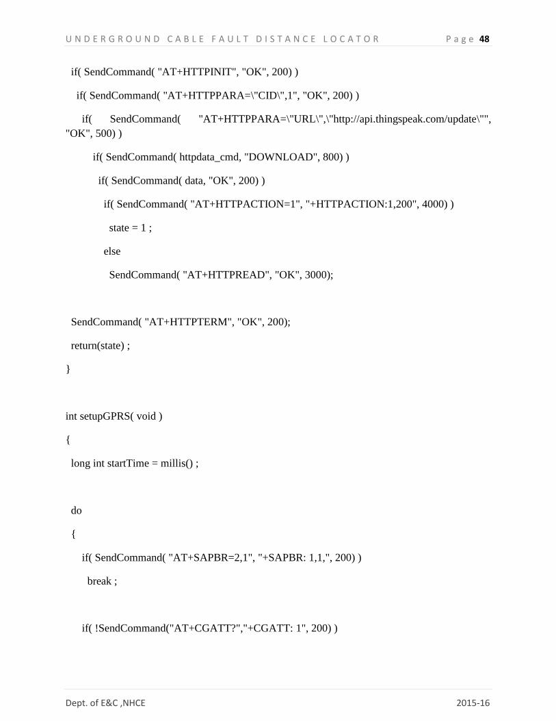
U N D E R G R O U N D C A B L E F A U L T D I S T A N C E L O C A T O R P a g e 48
Dept. of E&C ,NHCE 2015-16
if( SendCommand( "AT+HTTPINIT", "OK", 200) )
if( SendCommand( "AT+HTTPPARA=\"CID\",1", "OK", 200) )
if( SendCommand( "AT+HTTPPARA=\"URL\",\"http://api.thingspeak.com/update\"",
"OK", 500) )
if( SendCommand( httpdata_cmd, "DOWNLOAD", 800) )
if( SendCommand( data, "OK", 200) )
if( SendCommand( "AT+HTTPACTION=1", "+HTTPACTION:1,200", 4000) )
state = 1 ;
else
SendCommand( "AT+HTTPREAD", "OK", 3000);
SendCommand( "AT+HTTPTERM", "OK", 200);
return(state) ;
}
int setupGPRS( void )
{
long int startTime = millis() ;
do
{
if( SendCommand( "AT+SAPBR=2,1", "+SAPBR: 1,1,", 200) )
break ;
if( !SendCommand("AT+CGATT?","+CGATT: 1", 200) )

U N D E R G R O U N D C A B L E F A U L T D I S T A N C E L O C A T O R P a g e 49
Dept. of E&C ,NHCE 2015-16
SendCommand("AT+CGATT=1","OK",200);
if( SendCommand( "AT+SAPBR=3,1,\"Contype\",\"GPRS\"", "OK", 200) )
if( !SendCommand( "AT+SAPBR=1,1", "OK", 2000) )
if( SendCommand( "AT+SAPBR=2,1", "+SAPBR: 1,1", 200) )
break ;
}while( (millis()-startTime)<10000 ) ; //try to get a GPRS context for 10s
if( (millis()-startTime)<10000 )
return 1 ;
else
return 0 ;
}
void setup() {
// initialize serial communication at 115200 bits per second:
Diag.begin(115200);
//initialise a sw serial port to communicate with GSM modem
GSM_PORT.begin(9600);
// set up the LCD's number of columns and rows:
LCD.begin(16, 2);

U N D E R G R O U N D C A B L E F A U L T D I S T A N C E L O C A T O R P a g e 50
Dept. of E&C ,NHCE 2015-16
V1 = ((float)analogRead(A0) * (Vcc/1023)); //in mV
V2 = ((float)analogRead(A1) * (Vcc/1023)); //in mV
RT = (V1-V2)/Isupp ;
NoShrtVtg = V2 ;
String V1_str = "V1 = " + String(V1) + " mV" ;
String V2_str = "V2 = " + String(V2) + " mV" ;
String RT_str = "RT = " + String(RT) + " ohms" ;
Diag.println(V1_str);
Diag.println(V2_str);
Diag.println(RT_str);
LCD.clear();
LCD.print(V1_str);
LCD.setCursor(0,1);
LCD.print(V2_str);
delay(2000);
LCD.clear();
LCD.print(RT_str);
delay(2000);
LCD.clear();
LCD.print( "waiting 4 GSM" );

U N D E R G R O U N D C A B L E F A U L T D I S T A N C E L O C A T O R P a g e 51
Dept. of E&C ,NHCE 2015-16
do
{
Diag.println( "Waiting for GSM modem to initialise" ) ;
}while( !IsModemAlive() );
do
{
Diag.println( "Checking SIM" ) ;
}while( !IsSIMRegstrd() );
}
// the loop routine runs over and over again forever:
void loop()
{
float R ;
float len ;
String res ;
int i, stStab ;
long int startTime ;
float adcVtg[ADC_SAMP_SIZE], mean, sum , sd ;
String V1_str, V2_str, LCDMsg ;
while( 1 )
{
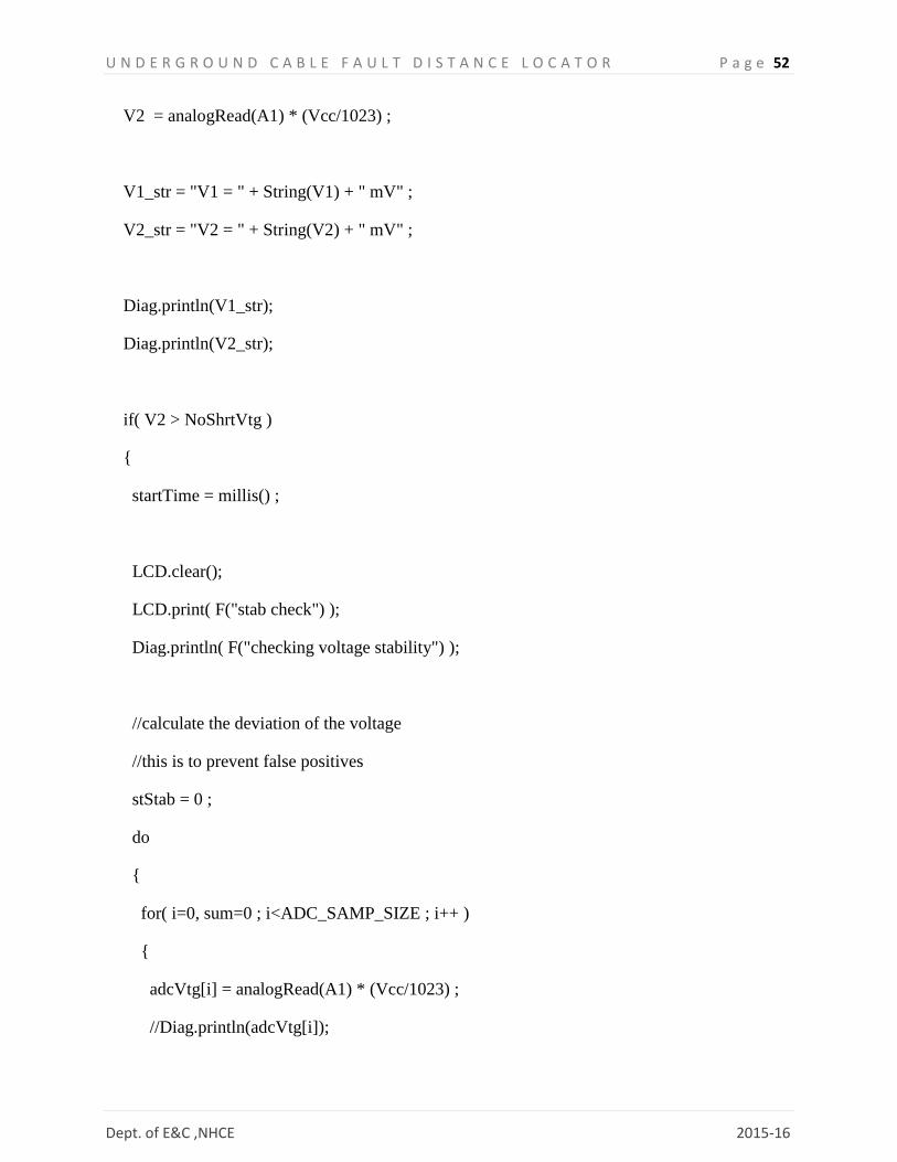
V1 = analogRead(A0) * (Vcc/1023) ;
U N D E R G R O U N D C A B L E F A U L T D I S T A N C E L O C A T O R P a g e 52
Dept. of E&C ,NHCE 2015-16
V2 = analogRead(A1) * (Vcc/1023) ;
V1_str = "V1 = " + String(V1) + " mV" ;
V2_str = "V2 = " + String(V2) + " mV" ;
Diag.println(V1_str);
Diag.println(V2_str);
if( V2 > NoShrtVtg )
{
startTime = millis() ;
LCD.clear();
LCD.print( F("stab check") );
Diag.println( F("checking voltage stability") );
//calculate the deviation of the voltage
//this is to prevent false positives
stStab = 0 ;
do
{
for( i=0, sum=0 ; i<ADC_SAMP_SIZE ; i++ )
{
adcVtg[i] = analogRead(A1) * (Vcc/1023) ;
//Diag.println(adcVtg[i]);
U N D E R G R O U N D C A B L E F A U L T D I S T A N C E L O C A T O R P a g e 53
Dept. of E&C ,NHCE 2015-16
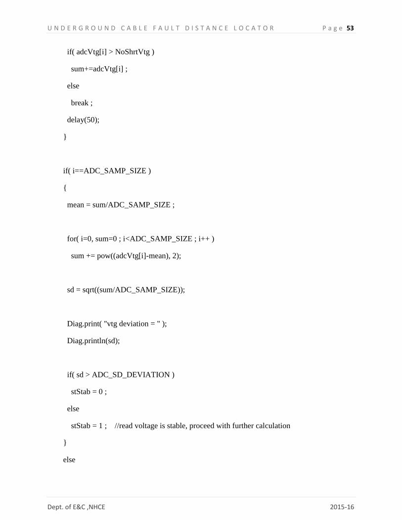
if( adcVtg[i] > NoShrtVtg )
sum+=adcVtg[i] ;
else
break ;
delay(50);
}
if( i==ADC_SAMP_SIZE )
{
mean = sum/ADC_SAMP_SIZE ;
for( i=0, sum=0 ; i<ADC_SAMP_SIZE ; i++ )
sum += pow((adcVtg[i]-mean), 2);
sd = sqrt((sum/ADC_SAMP_SIZE));
Diag.print( "vtg deviation = " );
Diag.println(sd);
if( sd > ADC_SD_DEVIATION )
stStab = 0 ;
else
stStab = 1 ; //read voltage is stable, proceed with further calculation
}
else

U N D E R G R O U N D C A B L E F A U L T D I S T A N C E L O C A T O R P a g e 54
Dept. of E&C ,NHCE 2015-16
break ;
}while( stStab!=1 && ((millis()-startTime)< 5000) );
if( stStab==1 )
{
R = (V1 - mean) / Isupp ;
len = (R * 100.0)/RT ;
res="R="+String(R)+" len = " + String(len) ;
Diag.println(res);
//create diagnostic message to be sent to user
LCDMsg = "short - " + String(len) + "cm";
//update to ThingSpeak channel
LCD.clear();
LCD.print(LCDMsg);
LCD.setCursor(0,1);
//update it to Thingspeak channel
if( !updateTSField( WRITEAPIKEY, len, (V1-V2) ) )
{
LCD.print( F("PST - F") );
Diag.println( F("POST - failed") );
}
else
U N D E R G R O U N D C A B L E F A U L T D I S T A N C E L O C A T O R P a g e 55
Dept. of E&C ,NHCE 2015-16
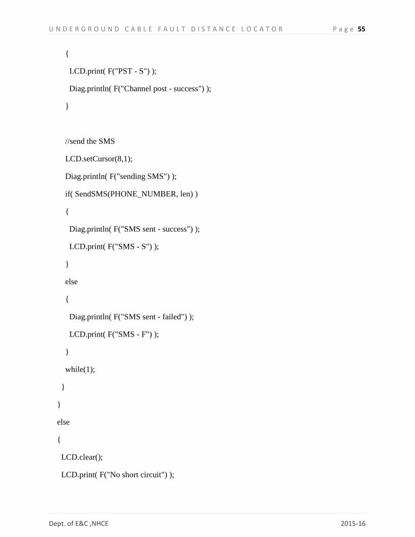
{
LCD.print( F("PST - S") );
Diag.println( F("Channel post - success") );
}
//send the SMS
LCD.setCursor(8,1);
Diag.println( F("sending SMS") );
if( SendSMS(PHONE_NUMBER, len) )
{
Diag.println( F("SMS sent - success") );
LCD.print( F("SMS - S") );
}
else
{
Diag.println( F("SMS sent - failed") );
LCD.print( F("SMS - F") );
}
while(1);
}
}
else
{
LCD.clear();
LCD.print( F("No short circuit") );

U N D E R G R O U N D C A B L E F A U L T D I S T A N C E L O C A T O R P a g e 56
Dept. of E&C ,NHCE 2015-16
}
delay(2000);
}
Diag.println( F("unreachable point") );
}