visvesvaraya technological univeristy
59
VISVESVARAYA TECHNOLOGICAL UNIVERISTY JNANASANGAMA, BELAGAVI-590018 A Project Report on “AUTOMATIC RAIN SENSING WIPER SYSTEM” Submitted in partial fulfillment for the award of degree of Bachelor of Engineering In MECHANICAL ENGINEERING Submitted by NITHIN PV 1NH12ME738 LOHITH A 1NH12ME731 GIRISH KUMAR DN 1NH13ME407 VENKATESH MN 1NH13ME431 Carried Out under the Guidance of Mr NAGENDRA J Asst. Professor DEPARTMENT OF MECHANICAL ENGG. NEW HORIZON COLLEGE OF ENGINEERING Kadubeesanahalli, Bellandur Post, Near Marathalli, Bengaluru, Karnataka -560103 2015-16
-
Upload
khangminh22 -
Category
Documents
-
view
6 -
download
0
Transcript of visvesvaraya technological univeristy

VISVESVARAYA TECHNOLOGICAL UNIVERISTY
JNANASANGAMA, BELAGAVI-590018
A Project Report
on
“AUTOMATIC RAIN SENSING WIPER SYSTEM”
Submitted in partial fulfillment for the award of degree of
Bachelor of Engineering
In
MECHANICAL ENGINEERING
Submitted by
NITHIN PV 1NH12ME738
LOHITH A 1NH12ME731
GIRISH KUMAR DN 1NH13ME407
VENKATESH MN 1NH13ME431
Carried Out under the Guidance
of
Mr NAGENDRA J
Asst. Professor
DEPARTMENT OF MECHANICAL ENGG.
NEW HORIZON COLLEGE OF ENGINEERING
Kadubeesanahalli, Bellandur Post, Near Marathalli, Bengaluru, Karnataka -560103
2015-16

DEPARTMENT OF MECHANICAL ENGINEERING
NEW HORIZON COLLEGE OF ENGINEERING
(Accredited by NAAC with „A‟ Grade, Permanently afflicted to VTU)
Kadubeesanahalli, Bellandur Post, Near Marathalli, Bengaluru, Karnataka -560103
CERTIFICATE
This is to certify that the Project entitled “AUTOMATIC RAIN SENSING WIPER
SYSTEM” is a bonafide work carried out by NITHIN PV, bearing USN: 1NH12ME738, LOHITH A
bearing USN:1NH12ME731, GIRISH KUMAR DN bearing USN:1NH13ME406, VENKATESHA
MN bearing USN:1NH13ME431 in partial fulfillment for the award of the degree of Bachelor of
Engineering in MECHANICAL ENGINEERING affiliated to Visvesvaraya Technological
University, Belagavi during the academic year 2015-2016. It is certified that all corrections/suggestions
indicated for project have been incorporated in the report deposited in the department library. The project
report has been approved as it satisfies the academic requirements with respect to project work prescribed
for the Bachelor of Engineering.
………………… ..………………….. ...…………………
NAME Dr. MS GANESH PRASAD Dr. MANJUNATH
Internal guide HOD Principal

ACKNOWLEDGEMENT
The successful completion of any project depends on help and co-ordination of many
people other than those who directly execute the work.
It is difficult to express in words our profound sense of gratitude to those who helped us but we
make a sense of gratitude to do so.
We wish to express our deep gratitude and indebtedness to our institution NEW HORIZON
COLLEGE OF ENGINEERING, which has provided us with the opportunity in fulfilling our
desire of becoming Mechanical Engineers.
We are grateful to Dr. V MANJUNATH, Principal NHCE & Dr. MS GANESH PRASAD,
HOD of Mechanical Engineering Dept. for their moral and academic guidance along with their
support through our period of study and completion of this project.
We sincerely acknowledge the full support and guidance to us, and we express our deep sense of
gratitude for our guide Mr NAGENDRA J, Assistant Professor, Dept. of Mechanical for his
timely suggestions along with constant evaluations of our progress helped us to speed up the
work and make it highly knowledge oriented. Our special thanks to him.
Our own lab staff have lent their helping hand whenever necessary. Our special thanks to all of
them.
Various peoples assisted us either directly or indirectly during execution of our project. We take
this opportunity to thank all of them who have helped us in successful completion of this project.
DEPARTMENT OF MECHANICAL ENGINEERING
NEW HORIZON COLLEGE OF ENGINEERING
(Accredited by NAAC with „A‟ Grade, Permanently afflicted to VTU)
Kadubeesanahalli, Bellandur Post, Near Marathalli, Bengaluru, Karnataka -560103
DECLARATION
I hereby declare that the entire work embodied in this project report titled, “AUTOMATIC
RAIN SENSING WIPER SYSTEM” submitted to Visvesvaraya Technological University,
Belagavi is carried out by me at Department of Mechanical Engineering ,New Horizon College
of Engineering Bengaluru, under the guidance of Mr Nagendra J, Asst. Professor. This thesis
has not been submitted in part or full for the award of any diploma or degree of this or any other
University.
SIGNATURES
NITHIN PV
LOHITH A
GIRISH KUMAR DN
VENKATESH MN

I
ABSTRACT
The world today is moving ahead at a very fast pace. Some of the very common
examples of fast moving objects are aeroplanes, high speed cars and many more. In our
everyday life we come across many fast moving vehicles and so it is very important to
measure the speed of these vehicles.
This is an era of automation where it is broadly defined as replacement of manual effort by
mechanical power in all degrees of automation. The operation remains an essential part of the
system although with changing demands on physical input as the degree of mechanization is
increased.
Rain operated motor is consists of conduction sensor (Tough sensor) circuit, Control Unit,
wiper motor and glass frame. The sensor is used to detect the rain or water flow. There is any
rain on the class, the sensor senses the rain or flow water and giving the control signal to the
wiper motor.

CONTENTS
1. INTRODUCTION
1.1 HISTORY……………………………………………………………….1
1.2 LITERATURE SURVEY……………………………………………… 5
2 AUTOMATION
2.1 INTRODUCTION………………………………………………….12
2.2 NEED FOR AUTOMATION………………………………………12
2.3 ADVANTAGES……………………………………………………...13
2.4 DISADVANTAGES…………………………………………………14
2.5 AUTOMATION TOOLS…………………………………………….14
3. WINDSCREEN WIPER
3.1 HISTORY …………………………………………………………18
3.2 INTERMITTENT WIPERS……………………………………….. 20
3.3 POWER…………………………………………………………….21
3.4 GEOMETRY……………………………………………………….24

4. SYSTEM OVERVIEW
4.1 PURPOSE OF DEVELOPMENT……………………………………25
4.2 SYSTEM CONFIGURATION………………………………………26
5. WORKING OF CIRCUIT
5.1 PROJECT SPECIALITIES ……………………………………… 28
5.2 TECHNICAL DESCRIPTION AND WORKING…………………29
6. PART LIST
6.1 FOR AUTOMATIC WIPER SPEED MOTOR CONTROLLER……31
7. CIRCUIT
7.1 AUTOMATIC WIPER CONTROL SYSTEM………………………32
8. ELECTRONIC COMPONENT
8.1 RESISTANCE………………………………………………………33
8.2 CAPACITOR………………………………………………………..35
8.3 SPEAKER/EAR PHONE……………………………………………36
8.4 KEY SWITCH………………………………………………………37
8.5 TRANSISTOR……………………………………………………….38
8.6 TRANSFORMER…………………………………………………….39
8.7 LIGHT DEPENDENT RESISTANCE………………………………40
8.8 COIL …………………………………………………………………41

8.9 IC 555………………………………………………………………43
8.10 PRESET…………………………………………………………….44
9. ADVANTAGES
9.1 HOW DO THEY INCREASE DRIVER SAFETY ……………….46
10. APPLICATIONS…………………………………………………… 48
Cost Estimation………………………………………………………49
Conclusion........................................................................................50

LIST OF FIGURES
1. Fig.3.1 Windscreen Wiper……………………………………..18
2. Fig.3.2 Pneumatic motor drive in train……………………….19
3. Fig.3.3-3.12 Wiper geometry…………………………………..24
4. Fig. 4.1 System configuration ……………………………….26
5. Fig 5.1 Block diagram of wiper system………………………29
6. Fig.7.1 Automatic Wiper Control System Circuit…………. 32
7. Fig.8.1 Resistor…………………………………………......... 34
8. Fig.8.2 Capicitor……………………………………………….35
9. Fig.8.3 Operation of Capacitor……………………………....36
10. Fig.8.4 Key Switch…………………………………………… 37
11. Fig.8.8 IC 555………………………………………………… 42
12. Fig.8.5 Transistor.......................................................................38
13. Fig.8.6 Coil …………………………………………………….41
14. Fig.8.7 Relay with Transformer...............................................41
15. Fig.8.9 Rain Sensor…………………………………………....44

AUTOMATIC RAIN SENSING WIPER 2015-16
NHCE-MECHANICAL DEPARTMENT
1
CHAPTER 1
INTRODUCTION
1.1 HISTORY
At least three inventors patented windscreen cleaning devices at around the same time
in 1903; Mary Anderson, Robert Douglass, and John Apjohn.
Anderson's 1903 window cleaner design
American inventor Mary Anderson is popularly credited with devising the first
operational windshield wiper in 1903. In Anderson's patent, she called her invention a
"window cleaning device" for electric cars and other vehicles. Operated via a lever from
inside a vehicle, her version of windshield wipers closely resembles the windshield wiper
found on many early car models. Anderson had a model of her design manufactured, then
filed a patent (US 743,801) on June 18, 1903 that was issued to her by the US Patent Office
on November 10, 1903.
Douglass's 1903 locomotive cab window cleaner
A similar device is recorded 3 months prior to Anderson's patent, with Robert A
Douglass filing a patent for a "locomotive-cab-window cleaner" on 12 March 1903.[5]
Apjohn's 1903 window cleaning apparatus design
Irish born inventor James Henry Apjohn (1845–1914) patented an "Apparatus for
Cleaning Carriage, Motor Car and other Windows" which was stated to use either brushes or
wipers and could be either motor driven or hand driven. The brushes or wipers were intended
to clean either both up and down or in just one direction on a vertical window. Apjohn's
invention had a priority date in the UK of 9 October 1903.[6]
In April 1911, a patent for windscreen wipers was registered by Sloan & Lloyd
Barnes, patent agents of Liverpool, England, for Gladstone Adams of Whitley Bay. The first
designs for the windscreen wiper are also credited to Polish concert pianist Józef Hofmann,
and Mills Munitions, Birmingham who also claimed to have been the first to patent

AUTOMATIC RAIN SENSING WIPER 2015-16
NHCE-MECHANICAL DEPARTMENT
2
windscreen wipers in England.
John R. Oishei (1886-1968) formed the Tri-Continental Corporation in 1917. This
company introduced the first windshield wiper, Rain Rubber, for the slotted, two-piece
windshields found on many of the automobiles of the time. Today Trico Products is one of
the world's leading manufacturers of windshield wiping systems, windshield wiper blades
and refills, with wiper plants on five continents.[citation needed] Bosch has the world's
biggest windscreen wiper factory in Tienen, Belgium, which produces 350,000 wiper blades
every day.
Inventor William M. Folberth applied for a patent for an automatic windscreen wiper
apparatus in 1919, which was granted in 1922. It was the first automatic
mechanism.[clarification needed] Trico later settled a patent dispute with Folberth and
purchased Folberth's Cleveland company, the Folberth Auto Specialty Co. The new vacuum-
powered system quickly became standard equipment on automobiles, and the vacuum
principle was in use until about 1960. In the late 1950s, a feature common on modern
vehicles first appeared, operating the wipers automatically for two or three passes when the
windshield washer button was pressed, making it unnecessary to manually turn the wipers on
as well. Today, an electronic timer is used, but originally a small vacuum cylinder
mechanically linked to a switch provided the delay as the vacuum leaked off.
1.1.1 INTERMITTENT WIPERS
The inventor of intermittent wipers might have been Raymond Anderson who, in
1923, proposed an electro-mechanical design. (US Patent 1,588,399). In 1958, Oishei et al.
filed a patent application describing electro-mechanical, thermal and hydraulic designs. (US
Patent 2,987,747). Then in 1961 John Amos, an engineer for the UK automotive engineering
company Lucas Industries, filed in the UK the first patent application for a solid-state
electronic design. (See US patent 3,262,042).
In 1963, another form of intermittent wiper was invented by Robert Kearns, an

AUTOMATIC RAIN SENSING WIPER 2015-16
NHCE-MECHANICAL DEPARTMENT
3
engineering professor at Wayne State University in Detroit, Michigan.The road to his
intermittent wipers began earlier, on his wedding night in 1953, when an errant champagne
cork shot into Kearn's left eye, which eventually went almost completely blind. Nearly a
decade later, Kearns was driving his Ford Galaxie through a light rain, and the constant
movement of the wiper blades irritated his already troubled vision. He got to thinking about
the human eye, which has its own kind of wiper, the eyelid, that automatically closes and
opens every few seconds. Finally in 1963, Kearns put his idea into action, building his first
intermittent wiper system using off-the-shelf electronic components. Kearns showed it to the
Ford Motor Company, and proposed manufacturing the design.
In the Kearns design, the interval between wipes was determined by the rate of
current flow into a capacitor. When the charge in the capacitor reached a certain voltage, the
capacitor was discharged, activating the wiper motor for one cycle. After extensive testing,
Ford executives decided to offer a design similar to Kearns’ intermittent wipers as an option
on the company's Mercury line, beginning with the 1969 models. Kearns and Ford became
involved in a multi-year patent dispute that eventually had to be resolved in court. A
fictionalized version of the Kearns invention and patent lawsuit was used for the 2009 film
Flash of Genius, which is billed as "based on the true story", but does not claim to be
historically accurate in all respects.In March 1970, Citroën introduced rain-sensitive
intermittent windscreen wipers on their SM model. When the intermittent function was
selected, the wiper would make one swipe. If the windscreen was relatively dry, the wiper
motor drew high current, which set the control circuit timer to delay the next wipe longest. If
the motor drew little current, it indicated that the glass was wet, setting the timer to minimize
the delay.
1.1.2 AUTOMATED RAIN SENSING WIPERS
We have pleasure in introducing our new project ―AUTOMATIC RAIN
OPERATED WIPER‖, which is fully equipped by sensors circuit and wiper motor. It is a
genuine project which is fully equipped and designed for Automobile vehicles.

AUTOMATIC RAIN SENSING WIPER 2015-16
NHCE-MECHANICAL DEPARTMENT
4
The Automatic rain operated wiper system is a fully automation project.
This is an era of automation where it is broadly defined as replacement of manual effort by
mechanical power in all degrees of automation. The operation remains an essential part of the
system although with changing demands on physical input as the degree of mechanization is
increased.
Degrees of automation are of two types, viz.
• Full automation.
• Semi automation.
In semi automation a combination of manual effort and mechanical power is required
whereas in full automation human participation is very negligible.
Windshield wipers, which have been standard equipment on most vehicles since 1916, were
developed to improve visibility during inclement weather. For nearly 100 years, drivers
operated the wipers with manual controls mounted on the dashboard. Today, technology has
made possible motorized windshield wipers that automatically recognize a developing
visibility problem and clear the glass before the driver can react to the problem.
The term ―rain-sensing wipers‖ is commonly used for a system designed to clear the
windshield of rain, snow, and debris without driver intervention. The system is programmed
to automatically activate and alter the speed and rate of the wiper blades to keep outward
visibility unobstructed at all times. A rain-sensing wiper system does not clean the windshield
any better than a manual system; it simply monitors outward visibility and automatically
activates the wipers.
Rain-sensing wipers are offered as standard equipment or as an inexpensive factory option on
many new cars, light trucks and SUVs. There are also many systems offered by aftermarket
suppliers. The wipers are easy to install; with just a single optical component, the technology
can easily be adapted to any vehicle with electric wipers. Because they increase driving
safety while reducing driver distraction and workload, rain-sensing wipers are a worthwhile
improvement to any vehicle.

AUTOMATIC RAIN SENSING WIPER 2015-16
NHCE-MECHANICAL DEPARTMENT
5
1.2 LITERATURE SURVEY
Automatic wipers with mist control
Ashik K.P1, A.N.Basavaraju2 1Research scholar, Dept. of Mechanical Engg., R.V College
of Engineering, Bangalore -560059, 2Head , Dept. of Automobile Engg ., Malnad College of
Engineering, Hassan-573202
ABSTRACT
This paper illustrates Automatic wipers with mist control. In modern days, the accidents are
most common in commercial vehicles. One of the reasons for these accidents is formation of
the mist inside the vehicle due to heavy rain. In rainy seasons for commercial vehicles, the
wiper on the windshield has to be controlled by the driver himself, which distracts his
concentration on driving. Also when the rain lasts for more time (say for about 15 minutes)
the formation of mist on the wind shield is also hinders the visibility of the driver and makes
driving difficult. The main aim of the project is to prevent the distractions to the driver of a
truck or bus. The rain intensity is measured by the set of sensors placed in the beaker at the
predetermined levels. The level of the water in the beaker decides the rain intensity and the
same will be sensed by each set of sensors and passes the signals corresponding to the level
of water in a beaker to microcontroller. Depending on the rain intensity microcontroller
controls the speed of the wiper motor. The principle of conductance is used for the working
of external and the internal sensors. The programmed microcontroller is used to actuate
external and internal wiper motors.
CONCLUSION
The concept of Automatic Wipers with Mist Control has been implemented successfully.
After the experimental setup the wiper motor was tested for all the following conditions
drizzling, heavy rain, medium rain. The test have been conducted under mist on the wind
shield. The mist has been removed successfully from the wind shield. By the uses of
automatic wipers one can drive the commercial vehicles without any distractions to operate
the wipe. Use of internal wipers ensures good visibility to the driver, prevents accidents.

AUTOMATIC RAIN SENSING WIPER 2015-16
NHCE-MECHANICAL DEPARTMENT
6
Smart Wiper Control System
N. M. Z. Hashim1, S. H. Husin2, A. S. Ja’afar3, N. A. A. Hamid4
1,2,3,4 Faculty of Electronics & Computer Engineering, Universiti Teknikal Malaysia
Melaka, Hang Tuah Jaya, 76100 Durian Tunggal, Melaka Malaysia
ABSTRACT
Wiper is an essential component that used to wipe raindrops or any water from the
vehicle’s windscreen. The previous system used to activate the wiper manually and the
process of pulling up the wiper is difficult to be handled. Thus, this system is proposed to
solve these problems. The objectives of this project are to upgrade the older cars system by
providing automatic wiping system, to improve the system by using sensor with actuator and
to design a basic program that will fully operate with the system. The concept of this
proposed wiper system is similar with other existing conventional wiper. In spite of removing
water from windscreen, this system also will be upgraded to an automatic control system by
using a Peripheral Interface Controller (PIC) 16F877A controller and water sensor. As the
conclusion for the project, the results shows all the aim objectives are successfully achieved.
The wiper system was well functionally according the water condition from the outside of a
car. This project showed a contribution on the design of the automatic wiper system for the
future research in this same field. It is recommended that the system to have a study on the
wiper material that been used to make a wiper because the driver at hot and climate country
are facing the problems regards to the wiper material
CONCLUSION
As the conclusion for the project, the results shows all the aim objectives are successfully
achieved. The wiper system was well functionally according the water condition from the
outside of a car. This project showed a contribution on the design of the automatic wiper
system for the future research in this field. For the future improvement, it is recommended
the system to have literature review on the material been used as the wiper, because the
material used is still has a problem in the procure issues especially for the hot and climate
country. Other suggestion for designing automatic push up wiper for future research and
improvement is about the design stand for the wiper.
AUTOMATIC RAIN SENSING WIPER 2015-16
NHCE-MECHANICAL DEPARTMENT
7
Automatic Wiper System
Shantanu Dharmadhikari1, Naeem Tamboli2, Nilesh Gawali3, Prof. N. N. Lokhande4
1,2,3,4Department of Instrumentation and Control Engg, Pravara Rural Engineering College,
Loni
ABSTRACT
In this paper, we present the automatic wiper system used to detect rainfall and activate
automobile windshield wipers without driver interaction. The system was developed to
reduce driving distractions and allow drivers to focus on main task of driving. The distraction
eliminated with the development of this system is the manual adjustment of wipers when
driving in precipitation. The few seconds that a driver takes their attention off the road to
adjust a knob while driving in poor weather conditions could potentially lead to car accidents.
The system uses a combination of impedance and piezo-electric sensors to detect rain and its
intensity. The system contains a microcontroller that takes in the input signals from the
sensors and controls the operation of the windshield wipers based on those input signals.
CONCLUSION
In conclusion, the automated windshield wiper system was designed, developed, and
demonstrated to detect rain and actuate the automobile windshield wipers based on the
intensity of that rain. The demonstration is able to simulate the operation of the system as if
installed in an automobile. The team was able to successfully complete the project and
satisfactorily meet the proposal goal of automating the driver’s response to rain within the
specified amount of time of 500 milliseconds. Though the system functioned as desired, in
retrospect then I would have selected different design approaches. After noticing that more
accuracy was required from the IR sensor to adequately detect the intensity of rain the team
would have selected a more applicable IR sensor.

AUTOMATIC RAIN SENSING WIPER 2015-16
NHCE-MECHANICAL DEPARTMENT
8
An Efficient Low Cost Wiper System for Autonomous Vehicle
N.Prabhakaran#1, Purushothaman Surendran*2 #Research Associate, School of
Electronics Engineering VIT University, Vellore, Tamil Nadu, India
ABSTRACT
The traditional wiper system requires driver’s attention to switch on the wiper system during
precipitation. Whereas in traffic condition, driver should not be diverted by manual
adjustment of switching the wiper system which may leads to accident. Probably 80% of
accidents are mainly due to distraction of driver. In this scenario we need to obtain an
automatic wiping on the wind screen during rain so as to avoid distraction of driver. The
existing automatic wiper system has false wiping just after the rainfall stops which can be
overcome by using proposed wiper system. Always just after the rainfall a few droplets on
the existing water sensor will be sustained until it is cleaned or inherently evaporated. These
water drops make a connection between two grid lines to occur false wiping. The advantage
of proposed automatic wiper system is compared with the water sensor of existing automatic
wiper system after rainfall. The proposed system in this paper is more accurate and
economically cheap which can be implemented in all low and middle level cars. In order to
avoid critical situation this automatic wiper system provides variable wiping speed based on
precipitation level. This automatic wiper system has low cost plate based water sensor,
ATMEGA8 microcontroller, MOSFET driver and wiper motor.
CONCLUSION
In the paper, plated based water sensor is evaluated on both rainfall and after rainfall
condition to obtain accurate result without false wiping under different scenarios. This system
is developed with low cost high performance electronic components to fit in all low cost
vehicles. The cost to implement is approximately 7$, which is less the any other wiping
system in the vehicles. A vertical/horizontal placement of plates give better result compare to
any another arrange of plates. The copper/aluminum plates can be fixed on to plastic board
and affix on the vehicles instead of placing directly on the windshield

AUTOMATIC RAIN SENSING WIPER 2015-16
NHCE-MECHANICAL DEPARTMENT
9
Semi-Automatic Rain Wiper System
Tapan S Kulkarni1, Harsh S Holalad2 1Dept of Automobile Engg, B V Bhoomaraddi College
of Engg & Tech Hubli 2 Dept of Electrical and Electronics Engg, B V Bhoomaraddi College
of Engg & Tech Hubli
ABSTRACT
The paper deals with a simple design of a Semi- Automatic Rain Wiper System. The system
is semi automatic because it has to be actuated for the first time. The system is developed
using 8051 microcontroller. The principle revolves around the rate of flow of water in a cup.
Corresponding to the rate of flow of water and the volume of the water, three levels of wiper
speeds have been achieved.
CONCLUSION
The tabletop model of semi-automatic rain wiper system has worked successfully at three
different stages of rain intensities. Also the cost of semi-automatic rain wiper system is INR
1080 only which can be easily implemented in all the present economic class vehicles. The
cup sensor is placed under the hood and thus does not affect the aesthetic of the vehicle.

AUTOMATIC RAIN SENSING WIPER 2015-16
NHCE-MECHANICAL DEPARTMENT
10
Intelligent Rain Sensing using Automatic Wiper System
Sonali B. Madankar, Dr. Milind M. Khanapurkar, Dept of CSE, Professor, Dept of ECE,
G.H. Raisoni College of Eng Nagpur-440016, India
ABSTRACT
Over the past two decades, the automotive industry has aggressively researched ways to
exploit modern computing and electronic advances in the development of safety, reliability,
and entertainment technologies for vehicles. With drivers exposed to an ever increasing
number of distractions, automatic rain-sensing wiper systems become an even more
appealing feature, as they work to minimize the time the driver must take his/her hands off
the wheel. Most traditional systems offer intermittent as well as variable speed operation. The
traditional wiper system however requires driver constant attention in adjusting the wiper
speed .Traditional windshield wiper speed constantly varies according to time and vehicle’s
speed. Because the manual adjustment of the wiper distracts driver's attention, which may be
a direct cause accidents. This is review paper for automatic wier in various method and also
explain the basic skeleton for adjust speed of wiper automatically cording to the amount of
water on the windshield and in addition with also in advance removal of moisture inside the
car while raining. The system activates the wiper to operate in full automatic mode and detect
moister using CAN technology.
CONCLUSION
We have to developed an automatic wiper control system which is improved version of
intermittent wiper system. This wiper system reduce cumbersome wiper operation and
improve driver’s level comfort.It will give a new dimension of comfort and aid to the drivers
who work at night and traffic prone areas where they already have to concentrate on brakes
and clutch. The removal of controlling the wipers during rain will provide them much ease
and help them concentrate on the basic ABC (accelerator, brake and clutch) of driving. Our
system features high accuracy, high sensitivity, and noncontact measurement. The system are
used as component in home automation system because it can detect a sudden rain and notify
people in the house.

AUTOMATIC RAIN SENSING WIPER 2015-16
NHCE-MECHANICAL DEPARTMENT
11
Design & Fabrication of Rain Operated Wiper Mechanism using
Conductive Sensor Circuit
K. V. Viswanadh Ch. Siva Sankara Babu J. Leela Krishna A. Lala Bahadur
Assistant Professor, Department of Mechanical Engineering Lakireddy Bali Reddy
College of Engineering Mylavaram, Andhra Pradesh, India
ABSTRACT
This is an era of automation where it is broadly defined as replacement of manual effort
by mechanical power in all degrees of automation. Now a day’s almost all the automobile
vehicles are being atomized in order to reduce human efforts. The AUTOMATIC RAIN
OPERATED WIPER system is a fully automation project. This is a genuine project
which is designed for automobile vehicles and is fully equipped by sensor circuit and
wiper motor. This project work includes design and development of a control system
based on electronically controlled automotive rain operated motor called AUTOMATIC
RAIN OPERATED WIPER.
CONCLUSION
And finally we conclude that, the wind screen wiper which we had fabricated with the
main theme of maintaining automation by using conductive sensor to the required extent
is a modification to the existing wind screen wiper which were been using in the four
wheelers. And therefore, implementation of this modified wind screen wiper helps
in reducing human effort, free from wear adjustment and operating principle is very easy
which were the problems being faced with the existing wind screen wiper. Presently the
mode of power source used in our project is a battery which is a replaceable power
source. Here we have used the battery which is a non-conventional source of power,
keeping the scope of resources in mind this can be easily replaced by the conventional
power sources like solar panels.

AUTOMATIC RAIN SENSING WIPER 2015-16
NHCE-MECHANICAL DEPARTMENT
12
CHAPTER 2
AUTOMATION
2.1 INTRODUCTION
It is the use of control systems and information technologies to reduce the need for
human work in the production of goods and services. In the scope of industrialization,
automation is a step beyond mechanization. Whereas mechanization provided human
operators with machinery to assist them with the muscular requirements of work, automation
greatly decreases the need for human sensory and mental requirements as well. Automation
plays an increasingly important role in the world economy and in daily experience.
Automation has had a notable impact in a wide range of industries beyond manufacturing
(where it began). Once-ubiquitous telephone operators have been replaced largely by
automated telephone switchboards and answering machines. Medical processes such as
primary screening in electrocardiography or radiography and laboratory analysis of human
genes, sera, cells, and tissues are carried out at much greater speed and accuracy by
automated systems. Automated teller machines have reduced the need for bank visits to
obtain cash and carry out transactions. In general, automation has been responsible for the
shift in the world economy from industrial jobs to service jobs in the 20th and 21st centuries.
2.2 NEED FOR AUTOMATION
Automation can be achieved through computers, hydraulics, pneumatics, robotics, etc., of
these sources, pneumatics form an attractive medium for low cost automation. Automation
plays an important role in automobile.
Nowadays almost all the automobile vehicle is being atomized in order to product the human
being. The automobile vehicle is being atomized for the following reasons.
• To achieve high safety

AUTOMATIC RAIN SENSING WIPER 2015-16
NHCE-MECHANICAL DEPARTMENT
13
• To reduce man power
• To increase the efficiency of the vehicle
• To reduce the work load
• To reduce veihcle accident
• To reduce the fatigue of drivers
• To high responsibility
• Less maintainence cost
2.3 ADVANTAGES
The main advantages of automation are:
• Replacing human operators in tasks that involve hard physical or monotonous work.
• Replacing humans in tasks done in dangerous environments (i.e. fire, space,
volcanoes, nuclear facilities, underwater, etc.)
• Performing tasks that are beyond human capabilities of size, weight, speed,
endurance, etc.
• Economy improvement: Automation may improve in economy of enterprises, society
or most of humanity. For example, when an enterprise invests in automation, technology
recovers its investment; or when a state or country increases its income due to automation
like Germany or Japan in the 20th Century.
• Reduces operation time and work handling time significantly.

AUTOMATIC RAIN SENSING WIPER 2015-16
NHCE-MECHANICAL DEPARTMENT
14
2.4 DISADVANTAGES
The main disadvantages of automation are:
• Unemployment rate increases due to machines replacing humans and putting those
humans out of their jobs.
• Technical Limitation: Current technology is unable to automate all the desired tasks.
• Security Threats/Vulnerability: An automated system may have limited level of
intelligence, hence it is most likely susceptible to commit error.
• Unpredictable development costs: The research and development cost of automating a
process may exceed the cost saved by the automation itself.
• High initial cost: The automation of a new product or plant requires a huge initial
investment in comparison with the unit cost of the product, although the cost of automation is
spread in many product batches of things
2.5 AUTOMATION TOOLS
Engineers now can have numerical control over automated devices. The result has
been a rapidly expanding range of applications and human activities. Computer-aided
technologies (or CAx) now serve the basis for mathematical and organizational tools used to
create complex systems. Notable examples of CAx include Computer-aided design (CAD
software) and Computer-aided manufacturing (CAM software). The improved design,
analysis, and manufacture of products enabled by CAx has been beneficial for industry.
Information technology, together with industrial machinery and processes, can assist in the
design, implementation, and monitoring of control systems. One example of an industrial
control system is a programmable logic controller (PLC). PLCs are specialized hardened
computers which are frequently used to synchronize the flow of inputs from (physical)

AUTOMATIC RAIN SENSING WIPER 2015-16
NHCE-MECHANICAL DEPARTMENT
15
sensors and events with the flow of outputs to actuators and events.
2.6 TYPES OF AUTOMATION
Discrete control (on/off)
One of the simplest types of control is on-off control. An example is the thermostats used on
household appliances. Electromechanical thermostats used in HVAC may only have
provision for on/off control of heating or cooling systems. Electronic controllers may add
multiple stages of heating and variable fan speed control.
Sequence control, in which a programmed sequence of discrete operations is performed,
often based on system logic that involves system states. An elevator control system is an
example of sequence control.
Continuous control
The advanced type of automation that revolutionized manufacturing, aircraft,
communications and other industries, is feedback control, which is usually continuous and
involves taking measurements using a sensor and making calculated adjustments to keep the
measured variable within a set range. Moreover, it can be understood as the relation of two
variables, one for the "x" axis and a second for the "y" axis. If the value of "y" increases, then
the value on the "x" axis will also increase, and vice versa,
Open and closed loop
All the elements constituting the measurement and control of a single variable are called a
control loop. Control that uses a measured signal, feeds the signal back and compares it to a
set point, calculates and sends a return signal to make a correction, is called closed loop
control. If the controller does not incorporate feedback to make a correction then it is open
loop.Loop control is normally accomplished with controller. The theoretical basis of open
and closed loop automation is control theory.

AUTOMATIC RAIN SENSING WIPER 2015-16
NHCE-MECHANICAL DEPARTMENT
16
Sequential control and logical sequence or system state control
Sequential control may be either to a fixed sequence or to a logical one that will
perform different actions depending on various system states. An example of an adjustable
but otherwise fixed sequence is a timer on a lawn sprinkler.
States refer to the various conditions that can occur in a use or sequence scenario of the
system. An example is an elevator, which uses logic based on the system state to perform
certain actions in response to its state and operator input. For example, if the operator presses
the floor n button, the system will respond depending on whether the elevator is stopped or
moving, going up or down, or if the door is open or closed, and other conditions. An early
development of sequential control was relay logic, by which electrical relays engage
electrical contacts which either start or interrupt power to a device. Relays were first used in
telegraph networks before being developed for controlling other devices, such as when
starting and stopping industrial-sized electric motors or opening and closing solenoid valves.
Using relays for control purposes allowed event-driven control, where actions could be
triggered out of sequence, in response to external events. These were more flexible in their
Figure No 2.1 State Abstraction
This state diagram shows how UML can be used for designing a door system that can only be
opened and closed

AUTOMATIC RAIN SENSING WIPER 2015-16
NHCE-MECHANICAL DEPARTMENT
17
response than the rigid single-sequence cam timers. More complicated examples involved
maintaining safe sequences for devices such as swing bridge controls, where a lock bolt
needed to be disengaged before the bridge could be moved, and the lock bolt could not be
released until the safety gates had already been closed.
The total number of relays, cam timers and drum sequencers can number into the hundreds or
even thousands in some factories. Early programming techniques and languages were needed
to make such systems manageable, one of the first being ladder logic, where diagrams of the
interconnected relays resembled the rungs of a ladder. Special computers called
programmable logic controllers were later designed to replace these collections of hardware
with a single, more easily re-programmed unit.
In a typical hard wired motor start and stop circuit (called a control circuit) a motor is started
by pushing a "Start" or "Run" button that activates a pair of electrical relays. The "lock-in"
relay locks in contacts that keep the control circuit energized when the push button is
released. (The start button is a normally open contact and the stop button is normally closed
contact.) Another relay energizes a switch that powers the device that throws the motor
starter switch (three sets of contacts for three phase industrial power) in the main power
circuit. Large motors use high voltage and experience high in-rush current, making speed
important in making and breaking contact. This can be dangerous for personnel and property
with manual switches. The "lock in" contacts in the start circuit and the main power contacts
for the motor are held engaged by their respective electromagnets until a "stop" or "off"
button is pressed, which de-energizes the lock in relay.
Commonly are added to a control circuit. Suppose that the motor in the example is powering
machinery that has a critical need for lubrication. In this case an interlock could be added to
insure that the oil pump is running before the motor starts. Timers, limit switches and electric
eyes are other common elements in control circuits. Solenoid valves are widely used on
compressed air or hydraulic fluid for powering actuators on mechanical components. While
motors are used to supply continuous rotary motion, actuators are typically a better choice for
intermittently creating a limited range of movement for a mechanical component, such as
moving various mechanical arms, opening or closing valves, raising heavy press rolls,
applying pressure to presses.
AUTOMATIC RAIN SENSING WIPER 2015-16
NHCE-MECHANICAL DEPARTMENT
18
CHAPTER 3
WINDSCREEN WIPER
A Windscreen wiper or Windshield wiper is a device used to remove rain and debris
from a windscreen or windshield. Almost all motor vehicles, including trains, aircraft and
watercraft, are equipped with such wipers, which are usually a legal requirement.
A wiper generally consists of an arm, pivoting at one end and with a long rubber blade
attached to the other. The blade is swung back and forth over the glass, pushing water from
its surface. The speed is normally adjustable, with several continuous speeds and often one or
more "intermittent" settings. Most automobiles use two synchronized radial type arms, while
many commercial vehicles use one or more pantograph arms.
3.1 HISTORY
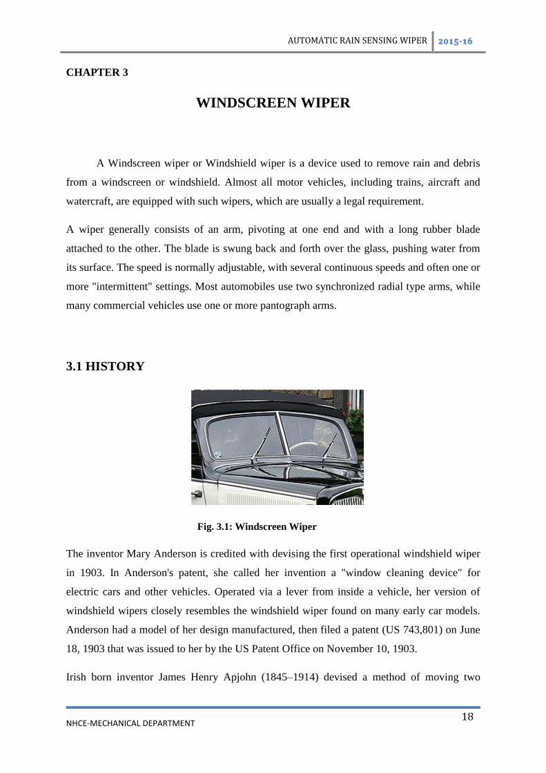
Fig. 3.1: Windscreen Wiper
The inventor Mary Anderson is credited with devising the first operational windshield wiper
in 1903. In Anderson's patent, she called her invention a "window cleaning device" for
electric cars and other vehicles. Operated via a lever from inside a vehicle, her version of
windshield wipers closely resembles the windshield wiper found on many early car models.
Anderson had a model of her design manufactured, then filed a patent (US 743,801) on June
18, 1903 that was issued to her by the US Patent Office on November 10, 1903.
Irish born inventor James Henry Apjohn (1845–1914) devised a method of moving two

AUTOMATIC RAIN SENSING WIPER 2015-16
NHCE-MECHANICAL DEPARTMENT
19
brushes up and down on a vertical plate glass windscreen in 1903. This was patented in the
UK.
In April 1911, a patent for windscreen wipers was registered by Sloan & Lloyd Barnes,
patent agents of Liverpool, England, for Gladstone Adams of Whitley Bay. The first designs
for the windscreen wiper are also credited to concert pianist Józef Hofmann, and Mills
Munitions, Birmingham who also claimed to have been the first to patent windscreen wipers
in England.
The company Oishei formed, the Tri-Continental Corporation, introduced the first windshield
wiper, Rain Rubber, for the slotted, two-piece windshields found on many of the automobiles
of the time. Today Trico Products is one of the world's leading manufacturers of windshield
wiping systems, windshield wiper blades and refills, with wiper plants on five continents
Bosch has the world's biggest windscreen wiper factory in Tienen, Belgium, which produces
350,000 wiper blades every day.
Inventor William M. Folberth applied for a patent for an automatic windscreen wiper
apparatus in 1919, which was granted in 1922. It was the first automatic mechanism. Trico
later settled a patent dispute with Folberth and purchased Folberth's Cleveland company, the
Folberth Auto Specialty Co. The new vacuum-powered system quickly became standard
equipment on automobiles, and the vacuum principle was in use until about 1960. In the late
1950s, a feature common on modern vehicles first appeared, operating the wipers
automatically for two or three passes when the windshield washer button was pressed,
making it unnecessary to manually turn the wipers on as well. Today, an electronic timer is
used, but originally a small vacuum cylinder mechanically linked to a switch provided the
delay as the vacuum leaked off.

AUTOMATIC RAIN SENSING WIPER 2015-16
NHCE-MECHANICAL DEPARTMENT
20
3.2 INTERMITTENT WIPERS
In 1963, the first modern intermittent wipers were invented by Robert Kearns, an
engineering professor at Wayne State University in Detroit, Michigan. The road to
intermittent wipers began earlier, on his wedding night in 1953, when an errant champagne
cork shot into Kearn's left eye, which eventually went almost completely blind. Nearly a
decade later, Kearns was driving his Ford Galaxie through a light rain, and the constant
movement of the wiper blades irritated his already troubled vision. He got to thinking about
the human eye, which has its own kind of wiper, the eyelid, that automatically closes and
opens every few seconds. Finally in 1963, Kearns put his idea into action, building the first
intermittent wiper system using off-the-shelf electronic components. Kearns showed it to the
Ford Motor Company, and proposed manufacturing the design.
In the Kearns design, the interval between wipes was determined by the rate of current flow
into a capacitor. When the charge in the capacitor reached a certain voltage, the capacitor was
discharged, activating the wiper motor for one cycle. After extensive testing, Ford executives
decided to offer a design similar to Kearns’ intermittent wipers as an option on the company's
Mercury line, beginning with the 1969 models. Kearns and Ford became involved in a multi-
year patent dispute that eventually had to be resolved in court.
Kearns may not, in fact, have been the original inventor of the intermittent wiper concept.
John Amos, an engineer for the UK automative engineering company Lucas Industries, was
the first to file a patent for an intermittent wiper (US Patent #3,262,042, issued 1966), two
years before Kearns applied (US Patent #3,351,836, issued 1967). One notable difference is
that the Amos patent describes an electromechanical device, whereas Kearns proposed a
solid-state electronic circuit.
In March 1970, Citroën introduced rain-sensitive intermittent windscreen wipers on their SM
model. When the intermittent function was selected, the wiper would make one swipe. If the
windscreen was relatively dry, the wiper motor drew high current, which set the control
circuit timer to delay the next wipe longest. If the motor drew little current, it indicated that
the glass was wet, setting the timer to minimize the delay.

AUTOMATIC RAIN SENSING WIPER 2015-16
NHCE-MECHANICAL DEPARTMENT
21
3.3 POWER
Fig. 3.2: Pneumatic Motor Drive in Train
Wipers may be powered by a variety of means, although most in use today are
powered by an electric motor through a series of mechanical components, typically two 4-bar
linkages in series or parallel.
Vehicles with air operated brakes sometimes use pneumatic wipers, powered by tapping a
small amount of pressurized air from the brake system to a small air operated motor mounted
on or just above the windscreen. These wipers are activated by opening a valve which allows
pressurized air to enter the motor.
Early wipers were often driven by a vacuum motor powered by manifold vacuum. This had
the drawback that manifold vacuum varies depending on throttle position, and is almost non-
existent under wide-open throttle, when the wipers would slow down or even stop. This
problem was overcome somewhat by using a combined fuel/vacuum booster pump.
Some cars, mostly from the 1960s and 1970s, had hydraulically driven wipers.
On the earlier Citroën 2CV, the windscreen wipers were powered by a purely mechanical
system, a cable connected to the transmission; to reduce cost, this cable also powered the
speedometer. The wipers' speed was therefore variable with car speed. When the car was
waiting at an intersection, the wipers were not powered, but a handle under the speedometer
allowed the driver to power them by hand.
AUTOMATIC RAIN SENSING WIPER 2015-16
NHCE-MECHANICAL DEPARTMENT
22
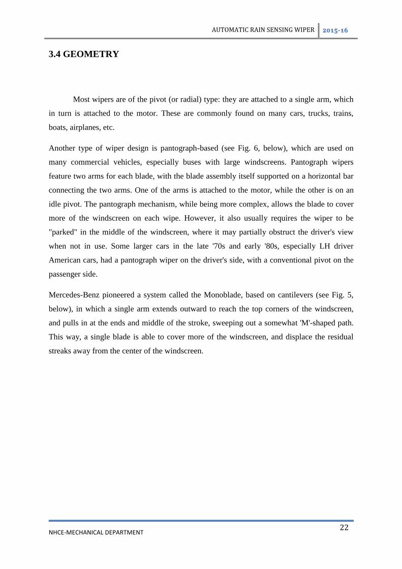
3.4 GEOMETRY
Most wipers are of the pivot (or radial) type: they are attached to a single arm, which
in turn is attached to the motor. These are commonly found on many cars, trucks, trains,
boats, airplanes, etc.
Another type of wiper design is pantograph-based (see Fig. 6, below), which are used on
many commercial vehicles, especially buses with large windscreens. Pantograph wipers
feature two arms for each blade, with the blade assembly itself supported on a horizontal bar
connecting the two arms. One of the arms is attached to the motor, while the other is on an
idle pivot. The pantograph mechanism, while being more complex, allows the blade to cover
more of the windscreen on each wipe. However, it also usually requires the wiper to be
"parked" in the middle of the windscreen, where it may partially obstruct the driver's view
when not in use. Some larger cars in the late '70s and early '80s, especially LH driver
American cars, had a pantograph wiper on the driver's side, with a conventional pivot on the
passenger side.
Mercedes-Benz pioneered a system called the Monoblade, based on cantilevers (see Fig. 5,
below), in which a single arm extends outward to reach the top corners of the windscreen,
and pulls in at the ends and middle of the stroke, sweeping out a somewhat 'M'-shaped path.
This way, a single blade is able to cover more of the windscreen, and displace the residual
streaks away from the center of the windscreen.

AUTOMATIC RAIN SENSING WIPER 2015-16
NHCE-MECHANICAL DEPARTMENT
23
•
Figure. 3.3: Most common geometry found on vast majority of vehicles
Figure 3.4: Mercedes-Benz W114, W168, W169; VW Sharan, Honda Civic, some
minivans, some school buses, Peugeot 307
Figure. 3.5: SEAT Altea, SEAT León Mk2, SEAT Toledo Mk3
Figure. 3.6: VAZ-1111 Oka, Fiat Uno 1983–1995, 1990's Citroën Citroen AX
Figure. 3.7: Subaru XT, Mercedes-Benz W124, W201, W202, W210
Figure. 3.8: Buses, some school buses, Mercedes-Benz O305

AUTOMATIC RAIN SENSING WIPER 2015-16
NHCE-MECHANICAL DEPARTMENT
24
Figure. 3.9: MAN, Toyota FJ Cruiser, Jaguar E-type, MGB, MG Midget, Austin Healey
Sprite
Figure. 3.10: obsolete, found on some older firetrucks
Figure. 3.11: U.S. military wheeled vehicles, jeepneys, some school buses
Figure. 3.12: Like Fig. 3.3 but mirrored, Mercedes-Benz W140

AUTOMATIC RAIN SENSING WIPER 2015-16
NHCE-MECHANICAL DEPARTMENT
25
CHAPTER 4
SYSTEM OVERVIEW
4.1 PURPOSE OF DEVELOPMENT
In developing the automobile we intended to fulfill the following purpose:
1. Convenience- To dispense with troublesome wiper operation needed when rainfall
condition change or when driving condition change including the car speed and entry to or
exit from tunnels.
2. Comfort- To operate the wiper with respose to change in rainfall and driving
condition. Thus keeping the windshield clear.
3. Installation- System is easy to install.

AUTOMATIC RAIN SENSING WIPER 2015-16
NHCE-MECHANICAL DEPARTMENT
26
4.2 SYSTEM CONFIGURATION
Fig 4.1: System configuration
The above figure shows the system configuration. The automatic wiper system consist of a
optical rain sensor installed on hood and a controller mounted inside. The controller is
connected to the existing wiper switch and motor. Since the automatic wiper is an extension
to the existing wiper system, it is easy for driver to control. The function of the sensor are
outlined below:
1. Rain Sensor- (Rain drop detection function) The rain sensor detect the rain drop by
sensing the change in light intensity when rain drops cross near infrared sensing between the
light emitting and light sensitive element.
2. Controller- The controller have following three conditions
• Semi Automatic- when the wiper switch is set to intermittent close position, the

AUTOMATIC RAIN SENSING WIPER 2015-16
NHCE-MECHANICAL DEPARTMENT
27
wipers move once and then moves at intervals automatically controlled. The interval can
range from low (continuous) operation to high (continuous) operation according to rain fall.
When the wiper switch is set to low or high the wiper works as a conventional wiper.
• Washer Interlock Function- when washer switch is turned on, the wiper moves. When
it is turned off, the wiper will stop after two wiping cycles.
• Fail Safe Function- it is assured that the wiper operates at 6 seconds intervals when
the rain drop detection is disabled because the sensing beam iscompletely blocked by dust,
snow or other matter struck to the sensor.

AUTOMATIC RAIN SENSING WIPER 2015-16
NHCE-MECHANICAL DEPARTMENT
28
CHAPTER 5
WORKING OF THE CIRCUIT
5.1 PROJECT SPECIALITIES
This project is very useful for every car. When we drive car, we do not know, whether
rain water reached up to the level that we could see any more. Such a project automatic turn
the wiper . Thus it saves the motor from burning as well as prevents current leakage and
increase the battery life.
5.1.1 PRINCIPLE OF WORKING
Rain will be detected through the circuit provided in the driver PCB when drops of
water fall on the sensor PCB located in front of the windshield provided in the vehicles. The
sensor PCB should be connected with the driver PCB.
When drops of rain water falls on the sensor PCB the base of T1 is getting connected to the
positive supply line. As the result T1 & T2 are switched on so that the relay R on the wiper
motor with the help of 9V battery. The motor is driven by the 12V battery and drives the link
rod through linkage and the shaft rotates. On this shaft the blade is mounted and locked by a
nut.
According to amount of rain pours on the sensing element, the circuit makes the motor to
rotate at reasonable speed. When the amount of rain drop is more the speed of the motor must
be in high to wash out the rain completely from the windshield. If the amount of rain is low,
less speed is sufficient for the clear vision of driver on the road.

AUTOMATIC RAIN SENSING WIPER 2015-16
NHCE-MECHANICAL DEPARTMENT
29
Figure 5.1 Block diagram of wiper system
5.2 TECHNICAL DESCRIPTION AND WORKING:-
Generally we use manual switch to control wiper motor to start wiper to swipe water on
the windshield. While swipe water, it is difficult to know whether the rain water level has
reached the danger mark or not. We are giving here a project which gives a automatic signal
to wiper motor when the water level reaches danger mark and the swipe motor goes on
running as long as the rain water level is above the danger mark. The motor stops only when
the rain water level comes below the danger mark. The circuit employs one integrated circuit
IC 555. Whenever the metal plate [metal rain water sensor] comes in contact with water, pin
no. 2 of the IC is triggered. As a result the output of IC, which available through pin no.3 is
fed to the motor to start wiping the water on the wind screen. The circuit is an example of a
stable operation which charges and discharges through C2 [.1 mfd] R1 10K or variable
resistance VR2 47K. The duty cycle of IC can be varied through the preset VR2 22K. This
preset connected to pin no. 4 of C also performs the function of OFF/ON. The circuit operates
on a 9 V DC.
VEHICLE MIRROR
SENSOR
CONTROL
UNIT
RELAY
WIPER
MOTOR
BATTERY

AUTOMATIC RAIN SENSING WIPER 2015-16
NHCE-MECHANICAL DEPARTMENT
30
5.2 Figure Number : Layout of wiper system

AUTOMATIC RAIN SENSING WIPER 2015-16
NHCE-MECHANICAL DEPARTMENT
31
CHAPTER 6
PARTS LIST
6.1 FOR AUTOMATIC WIPER SPEED MOTER CONTROLLER
1. IC 555 1
2. IC BASE 1
3. SPEAKER 8 OHM 1
4 CAPACITOR 100MFD/16V [C1,C2,C3] 1
RESISTERS
R1 10K 1
VR1 47K 1
VR2 22K 1
METAL PLATES 2

AUTOMATIC RAIN SENSING WIPER 2015-16
NHCE-MECHANICAL DEPARTMENT
32
CHAPTER 7
CIRCUIT
7.1 AUTOMATIC WIPER CONTROL SYSTEM
Fig.: 7.1 Automatic Wiper Control System Circuit

AUTOMATIC RAIN SENSING WIPER 2015-16
NHCE-MECHANICAL DEPARTMENT
33
CHAPTER 8
ELECTRONIC COMPONENT
8.1 RESISTANCE
It is a property of material to oppose the current flow in any conductor. It is measured
in Ohms. No conductor is 100% efficient to control the flow of current. Almost all type of
conductor material represent a certain amount of resistance. For this purpose we use lumped
resistance to control the flow of current. These resistance are of two type.
1. Fixed Resistance
2. Variable Resistance.
In fixed resistance the value is fixed and it can’t be change. Variable resistance can be
adjusted to any required value by a adjustable knob. Variable resistance are further divided
into three type
1. Carbon composition
2. Wire-wound
3. Special type
The most common type of resistance used in our project are carbon type. It value is normally
indicated by color band on its body. Each resistance has four color rings. One of the ring on
either side will be Gold or Silver. This is the fourth ring on the resistance and indicate the
tolerance. Other three ring will give the value of the resistance. The first ring gives the 1st
Digit. The second Ring gives the second digit. The third ring give the numbers of zero to be
placed after the digit. For example if the resistance has the following bands on it say Red,
Violet, Orange, and Gold. Reading the value of resistance with the help of colour code, its
value comes to be 27,000 Ohms or 27 K Ohms with tolerance 5%. Size of the resistance
indicates its power rating. Bigger the size more power rating. The table given below gives us
the colour code for the value of Resistance in Ohms.

AUTOMATIC RAIN SENSING WIPER 2015-16
NHCE-MECHANICAL DEPARTMENT
34
STANDARD COLOUR CODE SYSTEM COLOUR DIGIT
Black----------------------------------------------------------------------0
Brown --------------------------------------------------------------------1
Red -----------------------------------------------------------------------2
Orange -------------------------------------------------------------------3
Yellow -------------------------------------------------------------------4
Green --------------------------------------------------------------------5
Blue ----------------------------------------------------------------------6
Violet --------------------------------------------------------------------7
Grey ----------------------------------------------------------------------8
White --------------------------------------------------------------------9
Silver -----------------------------------------------------------------+-10%
Golden ---------------------------------------------------------------+-5%
Figure Number 8.1 : Resister

AUTOMATIC RAIN SENSING WIPER 2015-16
NHCE-MECHANICAL DEPARTMENT
35
8.2 CAPACITORS
It is a electronic component whose job is to store charge and after some interval to reales
it. It consists of two plate placed near to each other without touching. If a battery is connected
to these plate , positive of battery to one plate and -ve of battery to the another plate, then
electron from the battery will be attached from the plate to the positive of the battery. In this
position if battery is disconnected than one plate will be left with excess of electron while
other plate will be having the shortage of electrons. Thus there is a difference of potential
between these two plates and these plates act as capacitor. Capacitors are of two type:-
1. Fixed type [like ceramic, polyester, electrolyte.]
2. Variable type [like gang condenses trimmers etc.]
Fig.: 8.2 Capacitor
In a fix ed type capacitor there are two leads and its value is written on its body. In variable
type condenser there are three leads. Electrotype capacitor is polarity type and its terminals
are marked as positive and negative. Make sure that they are connected in circuit in proper
polarity. The value of the capacitor is measured in fared and denoted by the symbol F. Small
value of capacitor are measured in the Pico fared and denoted by PF.
Charge separation in a parallel-plate capacitor causes an internal electric field. A
dielectric (orange) reduces the field and increases the capacitance

AUTOMATIC RAIN SENSING WIPER 2015-16
NHCE-MECHANICAL DEPARTMENT
36
A simple demonstration of a parallel-plate capacitor .A capacitor consists of two conductors
separated by a non-conductive region. The non-conductive region is called the. In simpler
terms, the dielectric is just an electrical insulator.
8.2.1 THEORY OF OPERATION
Figure No:8.3 Operation of capacitor.
Examples of dielectric media are glass, air, paper, vacuum, and even a semiconductor
depletion region chemically identical to the conductors. A capacitor is assumed to be self-
contained and isolated, with no net electric charge and no influence from any external electric
field. The conductors thus hold equal and opposite charges on their facing surfaces, and the
dielectric develops an electric field. In SI units, a capacitance of one farad means that one
coulomb of charge on each conductor causes a voltage of one volt across the device. An ideal
capacitor is wholly characterized by a constant capacitance C, defined as the ratio of charge
±Q on each conductor to the voltage V between them:
Because the conductors (or plates) are close together, the opposite charges on the conductors
attract one another due to their electric fields, allowing the capacitor to store more charge for
a given voltage than if the conductors were separated, giving the capacitor a large
capacitance.Sometimes charge build-up affects the capacitor mechanically.

AUTOMATIC RAIN SENSING WIPER 2015-16
NHCE-MECHANICAL DEPARTMENT
37
8.3 KEY SWITCH
Switches are used to supply the power to a circuit. When it is pressed it makes the
current to flow through it. When the switch is released the current stops flowing. Thus a
switch is a mechanical part which controls the flow of current in a circuit. A switch is rated
according to
1. The maximum current it can carry.
2. Its working voltage
Figure : 8.4 Key Switch
Switches are of the following types.
1.Push Button Switches
2. Rocker Switches [Toggle]
3. Key Switches
4. Rotary Switches
5. Sliding Type Generally a switch consists of a fixed and moving contact but there are
switches which have several contacts in one unit.

AUTOMATIC RAIN SENSING WIPER 2015-16
NHCE-MECHANICAL DEPARTMENT
38
8.4 TRANSISTOR
It is a solid state semi-conductor device. It is used in electronics for amplification or
switching. A transistor has three terminals.
1. Collector 2. Base 3. Emitter
Electrons are emitted from the emitter and collected on the collector of the transistor. Third
terminal is called base and it acts as a control element. The function of these entire three
terminals depends upon the supply voltage applied to these terminals. Each transistor has a
number marked on its body. This number has its own specification. There are two types of
transistors.
1. NPN 2. PNP
Figure.: 8.5 Transistor
NPN TRANSISTOR
In this type of transistor when positive voltage is given to the base current starts flowing
through the collector to the emitter circuit. The current flowing through the base circuit
casuses a much more current to pass through the emitter/collector circuit. There is current
gain and this gain is measured in beta.
PNP TRANSISTOR
It functions in similar way that of NPN transistor accept that it has a negative voltage on its
collector and positive voltage on its emitter. In other words its supply voltage and biasing are
quite opposite to the NPN transistor.

AUTOMATIC RAIN SENSING WIPER 2015-16
NHCE-MECHANICAL DEPARTMENT
39
8.5 TRANSFORMER
There are different types of transformers depending upon the application just as step-
up, step-down, sound output, frequency matching and amplifier driver etc. Transformer
consists of two coils wound over a core in a such a way that both coils are magnetically
coupled. These coils are called primary and secondary winding. The core of the transformer
consists of a number of thin plates leminated from each other. These plates are made of
hardened silicon steel. The coil of the transformer are wound over a plastic bobbin or a
former made of hard paper. The winding of the transformer consist of number of turns of
enamelled copper wires. To prevent the short circuit between these windings a strip of
insulation paper is placed between each layer of the winding.
In a transformer the coupling between the coils makes a path for the magnetic flux to link
both the coils. Because of high permeability of the core iron. the flux path is only in the iron
and thus it links both the windings. When coupling is not good there is some leakage of flux
and it does not link both the coils. Ferrite core is used in high frequency transformer.
8.6.1 IDEAL TRANSFORMER
For simplification or approximation purposes, it is very common to analyze the
transformer as an ideal transformer model as presented in the two images. An ideal
transformer is a theoretical, linear transformer that is lossless and perfectly coupled; that is,
there are no energy losses and flux is completely confined within the magnetic core. Perfect
coupling implies infinitely high core magnetic permeability and winding inductances and
zero net magnetomotive force.
Ideal transformer connected with source VP on primary and load impedance ZL on
secondary, where 0 < ZL < ∞.
A varying current in the transformer's primary winding creates a varying magnetic flux in the
core and a varying magnetic field impinging on the secondary winding. This varying
magnetic field at the secondary induces a varying electromotive force (EMF) or voltage in the
secondary winding. The primary and secondary windings are wrapped around a core of

AUTOMATIC RAIN SENSING WIPER 2015-16
NHCE-MECHANICAL DEPARTMENT
40
infinitely high magnetic permeability so that all of the magnetic flux passes through both the
primary and secondary windings. With a voltage source connected to the primary winding
and load impedance connected to the secondary winding, the transformer currents flow in the
indicated directions. (See also Polarity.)
Ideal transformer and induction law
According to Faraday's Law, since the same magnetic flux passes through both the primary
and secondary windings in an ideal transformer,a voltage is induced in each winding,
according to eq. (1) in the secondary winding case, according to eq. (2) in the primary
`winding case. The primary EMF is sometimes termed counter EMF. This is in accordance
with Lenz's law, which states that induction of EMF always opposes development of any
such change in magnetic field.
The transformer winding voltage ratio is thus shown to be directly proportional to the
winding turns ratio according to eq. (3).
According to the law of Conservation of Energy, any load impedance connected to the ideal
transformer's secondary winding results in conservation of apparent, real and reactive power
consistent with eq. (4).
Instrument transformer, with polarity dot and X1 markings on LV side terminal
The ideal transformer identity shown in eq. (5) is a reasonable approximation for the typical
commercial transformer, with voltage ratio and winding turns ratio both being inversely
proportional to the corresponding current ratio.
By Ohm's Law and the ideal transformer identity:
the secondary circuit load impedance can be expressed as eq. (6)
the apparent load impedance referred to the primary circuit is derived in eq. (7) to be equal to
the turns ratio squared times the secondary circuit load impedance.

AUTOMATIC RAIN SENSING WIPER 2015-16
NHCE-MECHANICAL DEPARTMENT
41
8.6 COIL
Figure: 8.6 Coil
If a high resistance wire is wrapped over an insulator then it is called a wire wound
resistance. If in its place a wire with very negligible resistance is used then it is called coil. It
is measured in henry [H]. One thousand part of henry is called mili henry. In addition to the
resistance of the coil there is one more property called the inductance of the coil which play
very important part in its use. Some times due to this property coil is also called inductor.
Some time the coil is named according to the circuit where the coil has been used. Thus these
are called antenna coil [MW], oscillator coil and choke coil etc.
M 1. It offers some resistance in the path of AC.
M 2. It does not put any hindrance in the path of DC. At high frequency the coil offers more
hindrance to the current.
`
Figure Number 8.7 : Relay with transformer

AUTOMATIC RAIN SENSING WIPER 2015-16
NHCE-MECHANICAL DEPARTMENT
42
8.9 IC 555
The 555 timer IC is an amazingly simple yet versatile device.It has been around now
for many years and has been reworked into a number of different technologies.The two
primary versions today are the original bipolar design and the more recent CMOS
equivalent.These differences primarily affect the amount of power they require and their
maximum frequency of operation they are pincompatible and functionally interchangeable.
The IC is available in either an 8-pin round TO3-style can or an 8-pin mini-DIP package.In
either case the pin connections are as follows:
Figure: 8.8 IC 555

AUTOMATIC RAIN SENSING WIPER 2015-16
NHCE-MECHANICAL DEPARTMENT
43
1.Ground
2.Trigger input
3.Output
4.Reset input
5.Control voltage
6.Threshhold input
7.Discharge
8.15 to -15 volts in normal use.
The operations of 555 timer revolves around the three resistors that form a voltage divider
across the power supply.and two comparators connected to this voltage divider.The IC is
quiescent so as long the trigger input(pin2) remains at +Vcc and the threshhold input (pin6) is
at ground.Assume the rest input (pin4) is also at +Vcc and therefore inactive and the control
voltage input(pin5)is unconnected.Under these conditions the output(pin3)is at ground and
the discharge transistor(pin7)is turned on.Thus grounding whatever is connected to this pin.
The three resistors in the voltage divider all have the same value(5K in the bipolar version of
this IC)so the comparator reference voltages are 1/3 and 2/3 of the supply voltage,whatever
that may be.The control voltage input at pin 5 can directly affect this relationship.although
most of the time this pin is unused. The internal flip-flop changes state when the trigger input
at pin 2 is pulled down below +Vcc/3.When this occurs the output(pin3) changes state to
+Vcc and the discharge transistor (pin7)isturned off.The trigger input can now return to
+Vcc,it will not affect the state of the IC.
However,if the threshhold input(pin6)is now raised above(2/3)+Vcc.the output will return to
ground and the discharge transistor will be turned on again.When the threshhold input returns
to ground,the IC will remain in original state when we started this analysis. The easiest way
to allow the threshhold voltage(pin6)to gradually rise to(2/3)+Vcc is to connect it to a
capacitor is being allowed to charge through a resistor.In this way we can adjust the R and C
values for almost anytime interval we might want. The 555 can operate in either monostable
or astable mode,depending on the connections to and the arrangement of the external
AUTOMATIC RAIN SENSING WIPER 2015-16
NHCE-MECHANICAL DEPARTMENT
44
components.Thus,it can either produce a single pulse when triggered.or it can produce a
continuous pulse train as long as it remains powered.
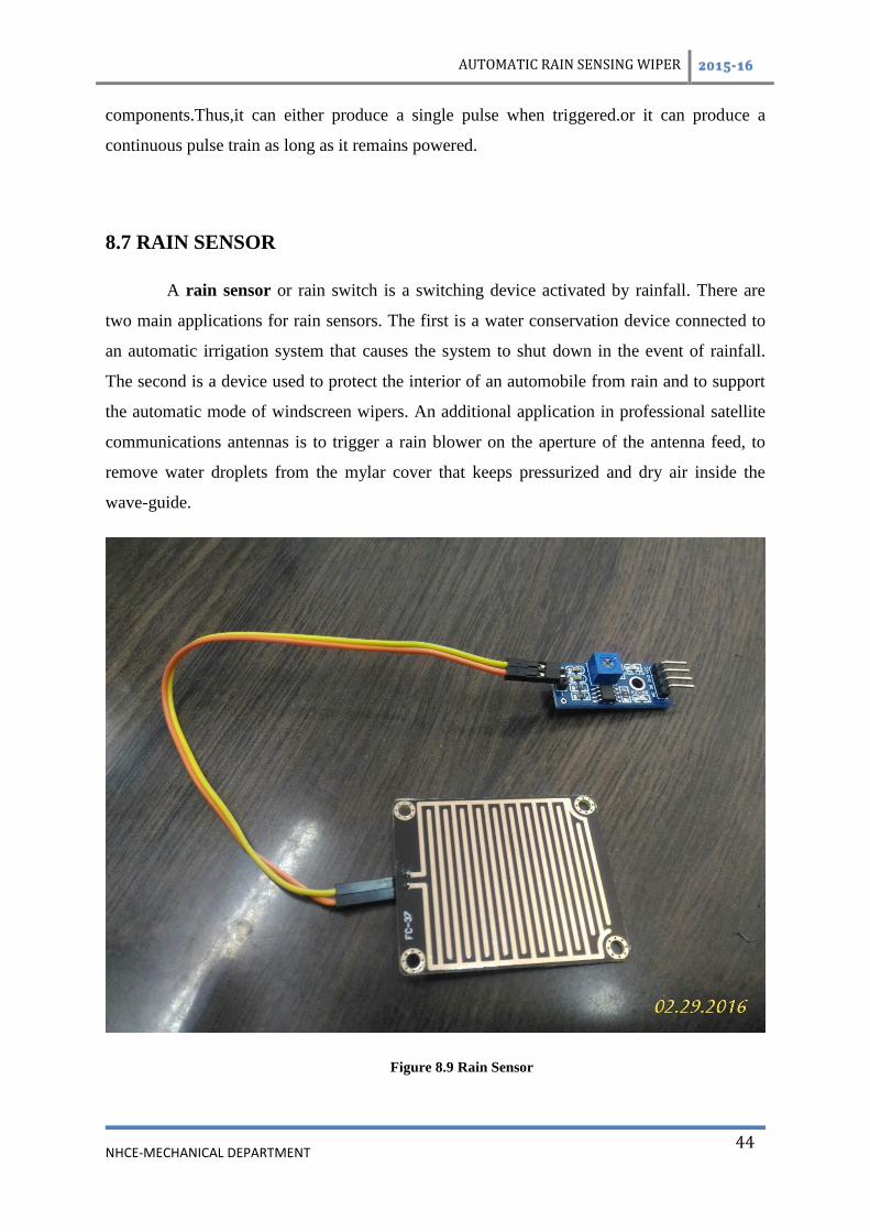
8.7 RAIN SENSOR
A rain sensor or rain switch is a switching device activated by rainfall. There are
two main applications for rain sensors. The first is a water conservation device connected to
an automatic irrigation system that causes the system to shut down in the event of rainfall.
The second is a device used to protect the interior of an automobile from rain and to support
the automatic mode of windscreen wipers. An additional application in professional satellite
communications antennas is to trigger a rain blower on the aperture of the antenna feed, to
remove water droplets from the mylar cover that keeps pressurized and dry air inside the
wave-guide.
Figure 8.9 Rain Sensor

AUTOMATIC RAIN SENSING WIPER 2015-16
NHCE-MECHANICAL DEPARTMENT
45
8.5.2 AUTOMATIVE SENSORS
Figure no 8.10 operation of an optical rain sensor
In 1958, the Cadillac Motor ar Division of General Motors experimented with a
water-sensitive switch that triggered various electric motors to close the convertible top and
raise the open windows of a specially-built Eldorado Biarritz model, in case of rain. The first
such device appears to have been used for that same purpose in a concept vehicle designated
Le Sabre and built around 1950–51. For Model Year 1996, Cadillac once again equipped cars
with an automatic rain sensor; this time to automatically trigger the windshield wipers and
adjust their speed to conditions as necessary].The most common modern rain sensors are
based on the principle of total internal reflection: an infrared light is beamed at a 45-degree
angle into the windshield from the interior — if the glass is wet, less light makes it back to
the sensor, and the wipers turn on. Most vehicles with this feature have an "AUTO" position
on the stalk

AUTOMATIC RAIN SENSING WIPER 2015-16
NHCE-MECHANICAL DEPARTMENT
46
CHAPTER 9
ADVANTAGES
The benefits of a rain-sensing wiper system are most obvious during inconsistent rain
or snow, when a standard wiper system requires constant attention by the driver to keep the
windshield clear. Under such conditions, the rain-sensing system adapts to periods of heavy
rain or snow and increases the speed of the wipers. During dry periods, when the windshield
is clear, the wipers completely stop. If other vehicles splash or spray water or debris on the
windshield, the rain-sensing system automatically intervenes by starting the wipers to keep
visibility unobstructed.
Rain sensing wipers allow the driver to simply activate the wipers once. The driver never has
to adjust the settings or speed of the wipers or turn them on and off with inconsistent
precipitation. It is especially beneficial while driving through varying degrees of traffic,
because the driver does not have to continually change the speed of the wipers.
Other advantages are as follows:-
• Low cost automation project.
• Free from wear adjustment.
• Less power consumption
• Operating Principle is very easy.
• Installation is simplified very much.
• To avoid other burnable interactions viz.… (Diaphragm) is not used.
• It is possible to operate Manually/automatically by proving On/Off switch.
• Sensor cost is very low due to conductive sensor
AUTOMATIC RAIN SENSING WIPER 2015-16
NHCE-MECHANICAL DEPARTMENT
47
9.1 HOW DO THEY INCREASE DRIVER SAFETY
Many collisions are caused by driver distractions. Rain-sensing wiper technology
allows the driver to activate the windshield wipers once, and then forget about them. The
windshield wipers must be re-activated, however, if the vehicle has been turned off and re-
started.

AUTOMATIC RAIN SENSING WIPER 2015-16
NHCE-MECHANICAL DEPARTMENT
48
CHAPTER 10
APPLICATIONS
1. Four wheeler application
2. Trucks
3. Buses
4. Trains
5. Airplanes
6. Ships

AUTOMATIC RAIN SENSING WIPER 2015-16
NHCE-MECHANICAL DEPARTMENT
49
COST ESTIMATION
• Glass Rs. 350.00
• Wiper Motor with linkages Rs. 1100.00
• Wiper blade Rs. 350.00
• Rain Sensor with accessories Rs. 1000.00
TOTAL Rs. 2800.00

AUTOMATIC RAIN SENSING WIPER 2015-16
NHCE-MECHANICAL DEPARTMENT
50
CONCLUSION
We have developed an optical automatic windshield wiper control which is an improved
version of the intermittent wiper systems. This wiper system reduces cumbersome wiper
operations and improves the driver’s level of comfort.
The rain sensor developed for the automatic wiper uses optics technology. The rain sensor
has been marked as a device suitable for use in harsh environments. Our optical system
features high accuracy, high sensitivity, and non contact measurement.
The rain sensor can also be used as a component in home automation systems because it can
detect a sudden rain and notify people in the house. Other possible applications are as smoke
sensors and high performance photoelectric switches.
ARE RAIN SENSORS NECESSARY?
In reality, the rain sensor is partly a safety product and in the automotive industry, safety
sells. I must admit that there are occasions when passing semi-trucks on the road in the right
weather conditions that a rain sensor would be a benefit.
Traditionally the rain sensor was available only on the high-priced luxury vehicles, but the
popularity is growing and it is becoming more mainstream and is appearing on several
average-priced cars. The list of manufacturers that are using a rain sensor on 2002 models
includes BMW, Ford, General Motors, Jaguar, Lexus, Mercedes Benz, Peugeot and
Volkswagen. Each is designed on the same basic principles.