
Visvesvaraya Technological University Belagavi, Karnataka ...
Upload
khangminh22Category
view
0download
0
Visvesvaraya Technological UniversityBelaga
“Design of PLC Program Using DG Synchronising PanelSubmitted on partial fulfillment of the requirement
Bachelor of Engineering Electrical
ADARSH M BNAGARAJU SSHARATH D NSUMALATHA B
Under the g
Department of Electrical and ElectronicsATME
13 KM Stone
araya Technological Universitygavi, Karnataka-590 018
A Project Report on
Design of PLC Program Using DG Synchronising Panelfulfillment of the requirement for the award of the degree
of Bachelor of Engineering
in ical and Electronics Engineering
Submitted by:
ADARSH M B 4AD12EE001 NAGARAJU S 4AD13EE412 SHARATH D N 4AD13EE415 SUMALATHA B 4AD12EE043
Under the guidance of: Mr. Sathish K R, M.E
Assistant Professor
of Electrical and Electronics Engineering
ATME College of Engineering tone, Mysuru-Kanakapura-Bengaluru Road,
Mysuru-570028 2015-16
araya Technological University
Design of PLC Program Using DG Synchronising Panel” award of the degree
Engineering

ATME College of Engineering, Mysuru-570028 Department of Electrical and Electronics Engineering
CERTIFICATE
This is to certify that the project report titled “Design Of PLC Program Using DG Synchronising Panel” is a bonafide work carried out by ADARSH M B: 4AD12EE001, NAGARAJU S: 4AD13EE412, SHARATH D N: 4AD13EE415 and SUMALATHA B: 4AD12EE043, in partial fulfillment for the award of Bachelor of Engineering in Electrical and Electronics Engineering, under Visvesvaraya Technological University, Belagavi -590 018 during the year 2015-2016. It is certified that all corrections/suggestions indicated during the Internal Assessment have been incorporated in the report and is deposited in the departmental library. The project report has been approved as it satisfies the academic requirements in respect of work prescribed for the said degree.
External Examiners
Name of the Examiner Signature with Date
1.
2.
Mr. Sathish K R Guide
Dr. Parthasarathy L Head of the Department
Dr. L Basavaraj Principal
DECLARATION
We, ADARSH M B: 4AD12EE001, NAGARAJU S: 4AD13EE412, SHARATH D N: 4AD13EE415 and SUMALATHA B: 4AD12EE043 students of VIII semester, Department of Electrical and Electronics Engineering, ATME College of Engineering, Mysuru-570028 declare that the project work titled “Design Of PLC Program Using DG Synchronising Panel” has been successfully completed. This work is submitted to Visvesvaraya Technological University, Belagavi-590 018, in partial fulfillment of the requirements for the award of Degree of Bachelor of Engineering in Electrical and Electronics Engineering during the academic year 2015-2016. Further the matter embodied in the project report has not been submitted previously by anybody for the award of any degree to any university.
Name USN Signature with Date ADARSH M B 4AD12EE001
NAGARAJU S 4AD13EE412
SHARATH D N 4AD13EE415
SUMALATHA B 4AD12EE043

Department of Electrical and Electronics Engineering, ATMECE, Mysuru i
ABSTRACT
PLC systems have been developed to reduce costs by optimizing plant operations.
They allow wide diesel generator monitoring and remote control from a central location. This system provides monitoring, data analysis, and control of equipment. In this work, we present the technologies for data collection, data storage, and reporting in this System. We also show how these systems manage time by giving an overview of this system architecture and the functions it performs. The goal of the work is to increase safety and reliability of the industry by means of supervision and fault detection and by assisting the operators and engineers in faster and better reaction to events and in better evaluation and design.
PLC is a commonly used industry term for computer-based systems allowing system
operators to obtain real-time data related to the status of an electric power system and to monitor and control elements of an electric power system over a wide geographic area. Our project is a prototype design of PLC program of diesel generators which are used in industries. The operation of generators in industries is operated manually when there is absence of power supply depending on the load condition. This manual operation of generators results in inaccuracy, lack of reliability and also increases the chances of damage of electrical equipments on the load side. Therefore generators should be operated in suitable combination with reference to load. This can be done by using PLC automation technique. This project improves the efficiency, durability & reliability of the power system. It also reduces the man power, labour cost and enables power system to operate accurately.
Department of Electrical and Electronics Engineering, ATMECE, Mysuru ii
ACKNOWLEDGEMENT
We sincerely owe our gratitude to all the person who helped us and guided us in completing this project.
We are thankful to Prof. Dr. L Basavaraj, Principal, ATME College of
Engineering, Mysuru, for having supported us in our academic endeavors. We are extremely thankful to Prof. Dr. Parthasarathy L, Head, Department of
Electrical and Electronics, ATME College of Engineering, Mysuru for permitting us to undertake this work. His valuable support and timely suggestions have enabled us to successfully complete this task in the various stages.
We take this opportunity to express our profound gratitude and deep regards to our Project guide Mr.Sathish K R, Assistant Professor, for his exemplary guidance, monitoring, continuous encouragement and inspiration throughout the progress of this project work.
We extend our gratitude to Project co-ordinator Ms.Lakshmi.K,, Assistant Professor for providing us an opportunity to present the project.
We are obliged to all teaching and Technical staff members of Department of Electrical and Electronics Engineering, ATME College of Engineering, Mysuru for the valuable information provided by them in their respective fields. We are grateful for their co-operation during the period of our assignment.
Lastly we thank almighty, our parents and friends for their constant encouragement without which this assignment would not be possible.
ADARSH M B 4AD12EE001 NAGARAJU S 4AD13EE412 SHARATH D N 4AD13EE415 SUMALATHA B 4AD12EE043
Design of PLC Program for DG Synchronising Panel 2015-16
Department of Electrical and Electronics Engineering, ATMECE, Mysuru iii
Table of Contents Abstract i
Acknowledgement ii
Table of Contents iii
List of Figures v
List of Tables vi
Chapter-1 Introduction
1.1 General Introduction 2 1.2 Motivation of The Project 3 1.3 Problem Definition 4 1.4 Project Objectives 5 1.5 Block Diagram 5 1.6 Chapter Outline 6
Chapter-2 Literature Review 2.1 Automation 8
2.2 History of Automation 9 2.3 General Introduction 13 2.4 Fundamentals of PLC 14 2.5 Programmable Logic Relay 15 2.6 Synchronizing Panel 16 2.7 Work Done
16
Design of PLC Program for DG Synchronising Panel 2015-16
Department of Electrical and Electronics Engineering, ATMECE, Mysuru iv
Chapter-3 Designs of Hardware And Software 3.1 Hardware Component Details 18
3.2 Software Details 25 3.3 Program Execution Process 31
Chapter-4 Circuit Diagram And Operation 4.1 Circuit Diagram of PLC Housing 33
4.2 Operation 35 4.3 Advantages of The Project 36 4.4 Limitations 36 4.5 Applications 37
Chapter-5 Result And Discussion 5.1 Synchronising Panel Circuit
Development 42
5.2 Single Line Diagram Circuit 42 5.3 PLC and Relay Section Housing Circuit 43
Chapter-6 Project conclusion And Future Scope Of Improvement 6.1 Conclusion 45
6.2 Suggestions for Future Improvements 46 References 47
Design of PLC Program for DG Synchronising Panel 2015-16
Department of Electrical and Electronics Engineering, ATMECE, Mysuru v
List of Figures Sl.No Title Page No
1.1 PLC Interface 3 1.2 Block Diagram 5 2.1 History of Automation 9 2.2 Manual Control Operation 10 2.3 Hardwired Circuit 11 2.4 Manual Control Operation 12 3.1 PLC Over View 19 3.2 Pin Diagram of PLC 22 3.3 Power Supply 22 3.4 24V Relay 23 3.5 Terminal Block 24 3.6 Screen Shots of Programming Of PLC 25 3.7 Program Execution 30 4.1 Circuit Diagram 32 4.2 PLC Automation In Process Industries 37 4.3 PLC Automation Used In Transmission and
Distribution Systems 37
4.4 PLC Automation Used In Control Room of Generating Stations
38
4.5 PLC Automation Used In Waste Water Treatment 38 4.6 PLC Integrated Robot 39 5.1 Single Line Diagram Circuit 41 5.2 PLC and Relay Section Housing Circuit 42
Design of PLC Program for DG Synchronising Panel 2015-16
Department of Electrical and Electronics Engineering, ATMECE, Mysuru vi
List of Tables
Sl.No Title Page No 3.1 Hardware Components 18 3.2 Addressing of Micrologix 1400 PLC 21
Design of PLC Program for DG Synchronising Panel 2015-16
Department of Electrical and Electronics Engineering, ATMECE, Mysuru Page 1
CHAPTER 1 INTRODUCTION
Design of PLC Program for DG Synchronising Panel 2015-16
Department of Electrical and Electronics Engineering, ATMECE, Mysuru Page 2
1.1 General Introduction PLC is a system for remote monitoring and control that operates with coded signals
over communication channels (using typically one communication channel per remote station). The control system may be combined with a data acquisition system by adding the use of coded signals over communication channels to acquire information about the status of the remote equipment for display or for recording functions. [1] It is a type of industrial control system (ICS). Industrial control systems are computer-based systems that monitor and control industrial processes that exist in the physical world. PLC systems historically distinguish themselves from other ICS systems by being large-scale processes that can include multiple sites, and large distances. [2] These processes include industrial, infrastructure, and facility-based processes, as described below: Industrial processes include those of manufacturing, production, power
generation, fabrication, and refining, and may run in continuous, batch, repetitive, or discrete modes.
Infrastructure processes may be public or private, and include water treatment and distribution, wastewater collection and treatment, oil and gas pipelines, electrical power transmission and distribution, wind farms, civil defence siren systems, and large communication systems.
Facility processes occur both in public facilities and private ones, including buildings, airports, ships, and space stations. They monitor and control heating, ventilation, and air conditioning systems , access, and energy consumption.

Design of PLC Program for DG Synchronising Panel 2015-16
Department of Electrical and Electronics Engineering, ATMECE, Mysuru Page 3
1.2 Motivation of The Project The purpose of this project is to ensure accurate operation of generators in industries
in the absence of power supply and to ensure correct combination in the operation of generators depending on the loading condition. Our aim is to design an affordable controlling and monitoring system which can easily carried by a person or can be installed in many large scale industries. This project implementation results in improving the efficiency, reliability and durability of the system. This system also reduces man power, labour cost and provides accurate distribution of power to all the units in an industry. Although there is automation implemented in some industries which are used only to detect faults and not used for the operation of generators.
Fig 1.1: PLC Interface
Design of PLC Program for DG Synchronising Panel 2015-16
Department of Electrical and Electronics Engineering, ATMECE, Mysuru Page 4
1.3 Problem Definition Case 1:
At present the operation of generators are manually operated in industries which requires skilled labours and also increases the labour cost. The protective devices such as ear plugs, apron are used by the labours and it the operation is manual is results in time delay in the operation of generators. Case 2: The correct combination in the operation generators and also the switching of generators are done manually. This results in increasing the damaging chances of the system, overloading of the generators and also improper synchronization Case 1 Solution: In order to overcome this problem PLC automation is introduced. The generators are automatically operated and also reduces man power and labour cost. Due to this accurate operation of generators are achieved and also time delay problem is eliminated Case 2 Solution: The loading condition is determined by the PLC kit and depending on the present loading condition the generators are operated automatically based on the PLC program. The correct combination of generators is fed to the program depending on the loading condition and each generator are operated automatically based on the time delay given in the program.

Design of PLC Program for DG Synchronising Panel 2015-16
Department of Electrical and Electronics Engineering, ATMECE, Mysuru Page 5
1.4 Project Objectives 1) Controlling valves in process industries 2) Automatic opening and closing of valves by using sensors 3) Monitoring the process by using PLC 4) To maintain accuracy in process industries and to reduce manual operation
1.5 Block Diagram
Fig 1.2: Block Diagram The above block diagram shows the outline of process of our project circuit and also process of our circuit work. In this project our PC is connected to PLC and download the program to the PLC and executed finally desired output is obtained.
Power failure detection circuit
Remote terminal All data of diesel generator are logged here
Power resumption detection circuit
Programmable logic controller
Start/Stop module of diesel
generator Diesel generator
Design of PLC Program for DG Synchronising Panel 2015-16
Department of Electrical and Electronics Engineering, ATMECE, Mysuru Page 6
1.6 Chapter Outline The problem definition, project objective, hardware description of the project has
been compiled into several chapters as discussed here under. Chapter 1 is an introduction chapter with general introduction, problem
definition, objectives of work carried out during the project. Chapter 2 involves the Literature survey of the project for the practical
implementation. Chapter 3 involves the description of the hardware design and the
software’s used .The chapter comprises of general operation and the use of components in the circuit.
Chapter 4 involves the circuit diagram and working principle of the project, applications, pros and cons of the project.
Chapter 5 involves the Results and discussion of the project. Chapter 6 concludes the report with suggestions for future improvements.
The list of references are provided in the report

Design of PLC Program for DG Synchronising Panel 2015-16
Department of Electrical and Electronics Engineering, ATMECE, Mysuru Page 7
CHAPTER 2 LITERATURE
REVIEW
Design of PLC Program for DG Synchronising Panel 2015-16
Department of Electrical and Electronics Engineering, ATMECE, Mysuru Page 8
2.1 Automation Automation is the use of control systems such as computers to control industrial machinery and processes, replacing human operators. In the scope of industrialization, it is a step beyond mechanization. Whereas mechanization provided human operators with machinery to assist them with the physical requirements of work, automation greatly reduces the need for human sensory and mental requirements as well. Automation is basically an allocation of Human control sequence to a technical equipment aimed towards achieving
Higher Productivity Superior quality of end products Efficient usage of Energy and Raw materials Improved safety in working conditions
Automation Tools
PLC ( Programmable Logic Controller ) SCADA ( Supervisory Control And Data Acquisition ) HMI ( Human Machine Interface) DCS ( Distributed Control Systems )
Types of Automation
1. Building automation Examples : Lift, Smoke detectors 2. Office Automation Examples : CCtv cameras 3. Scientific Automation Examples : Rocket Launching 4. Lighting Automation Examples : Street Solar Lighting 5. Industrial Automation Examples : Automated bottle filling stations, Steel
Factories, etc
Design of PLC Program for DG Synchronising Panel 2015-16
Department of Electrical and Electronics Engineering, ATMECE, Mysuru Page 9
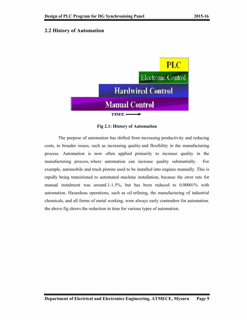
2.2 History of Automation
Fig 2.1: History of Automation
The purpose of automation has shifted from increasing productivity and reducing costs, to broader issues, such as increasing quality and flexibility in the manufacturing process. Automation is now often applied primarily to increase quality in the manufacturing process, where automation can increase quality substantially. For example, automobile and truck pistons used to be installed into engines manually. This is rapidly being transitioned to automated machine installation, because the error rate for manual instalment was around 1-1.5%, but has been reduced to 0.00001% with automation. Hazardous operations, such as oil refining, the manufacturing of industrial chemicals, and all forms of metal working, were always early contenders for automation. the above fig shows the reduction in time for various types of automation.

Design of PLC Program for DG Synchronising Panel 2015-16
Department of Electrical and Electronics Engineering, ATMECE, Mysuru Page 10
Manual Control The below fig 2.2 shows the typical process carried out in an industry. in this diagram all the valve or the solenoid operation are controlled manually depending on the sensor indication. the motoring action is also controlled manually and hence all these process operation are not automated depending on the sensor operation.
Fig 2.2: Manual Control Operation
Drawbacks: Less Accuracy High Manpower Less Safety Less Productivity Less Efficiency Less Reliable

Design of PLC Program for DG Synchronising Panel 2015-16
Department of Electrical and Electronics Engineering, ATMECE, Mysuru Page 11
Hardwired Control Prior to PLCs, many of these control tasks were solved with contactor or relay
controls. This is often referred to as hard-wired control. Circuit diagrams had to be designed, electrical components specified and installed, and wiring lists created. Electricians would then wire the components necessary to perform a specific task. If an error was made the wires had to be reconnected correctly. A change in function or system expansion required extensive component changes and rewiring. In this type of system the construction of the circuit requires more time and it is difficult to detect faults in the circuit.
Fig 2.3: Hardwired Circuit
Drawbacks: Bulky and complex wiring Difficult to change the logic Unreliable. Troubleshooting is difficult
Design of PLC Program for DG Synchronising Panel 2015-16
Department of Electrical and Electronics Engineering, ATMECE, Mysuru Page 12
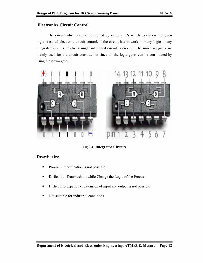
Electronics Circuit Control The circuit which can be controlled by various IC's which works on the given logic is called electronic circuit control. If the circuit has to work in many logics many integrated circuits or else a single integrated circuit is enough. The universal gates are mainly used for the circuit construction since all the logic gates can be constructed by using these two gates.
Fig 2.4: Integrated Circuits
Drawbacks: Program modification is not possible Difficult to Troubleshoot while Change the Logic of the Process Difficult to expand i.e. extension of input and output is not possible Not suitable for industrial conditions

Design of PLC Program for DG Synchronising Panel 2015-16
Department of Electrical and Electronics Engineering, ATMECE, Mysuru Page 13
2.3 General Introduction Industrial control system technology has evolved over the decades. DCS (distributed control systems) generally refer to the particular functional distributed control system design that exist in industrial process plants (e.g., oil and gas, refining, chemical, pharmaceutical, some food and beverage, water and wastewater, pulp and paper, utility power, mining, metals). The DCS concept came about from a need to gather data and control the systems on a large campus in real time on high-bandwidth, low-latency data networks. It is common for loop controls to extend all the way to the top level controllers in a DCS, as everything works in real time. These systems evolved from a need to extend pneumatic control systems beyond just a small cell area of a refinery.
PLC (programmable logic controller) evolved out of a need to replace racks of relays in ladder form. The latter were not particularly reliable, were difficult to rewire, and were difficult to diagnose. PLC control tends to be used in very regular, high-speed binary controls, such as controlling a high-speed printing press. Originally, PLC equipment did not have remote I/O racks, and many could not perform more than rudimentary analog controls.
SCADA's history is rooted in distribution applications, such as power, natural gas, and water pipelines, where there is a need to gather remote data through potentially unreliable or intermittent low-bandwidth/high-latency links. SCADA systems use open-loop control with sites that are widely separated geographically. A SCADA system uses RTUs (remote terminal units, also referred to as remote telemetry units) to send supervisory data back to a control centre. Most RTU systems always did have some limited capacity to handle local controls while the master station is not available. However, over the years RTU systems have grown more and more capable of handling local controls.
The boundaries between these system definitions are blurring as time goes on.[4] The technical limits that drove the designs of these various systems are no longer as much of an issue. Many PLC platforms can now perform quite well as a small DCS, using remote I/O and are sufficiently reliable that some SCADA systems actually manage closed loop control over long distances. With the increasing speed of today's processors, many DCS products have a full line of PLC-like subsystems that weren't offered when they were initially developed.

Design of PLC Program for DG Synchronising Panel 2015-16
Department of Electrical and Electronics Engineering, ATMECE, Mysuru Page 14
This led to the concept of a PAC (programmable automation controller) or process automation controller), that is an amalgamation of these three concepts. Time and the market will determine whether this can simplify some of the terminology and confusion that surrounds these concepts today. 2.4 Fundamentals of PLC (Programmable Logic Control)
Early PLCs were designed to replace relay logic systems. These PLCs were programmed in "ladder logic", which strongly resembles a schematic diagram of relay logic. This program notation was chosen to reduce training demands for the existing technicians. Other early PLCs used a form of instruction list programming, based on a stack-based logic solver.
Early PLCs, up to the mid-1990s, were programmed using proprietary programming panels or special-purpose programming terminals, which often had dedicated function keys representing the various logical elements of PLC programs. Some proprietary programming terminals displayed the elements of PLC programs as graphic symbols, but plain ASCII character representations of contacts, coils, and wires were common. Programs were stored on cassette tape cartridges. Facilities for printing and documentation were minimal due to lack of memory capacity. The oldest PLCs used non-volatile magnetic core memory. More recently, PLCs are programmed using application software on personal computers, which now represent the logic in graphic form instead of character symbols. The computer is connected to the PLC through Ethernet, RS-232, RS-485, or RS-422 cabling. The programming software allows entry and editing of the ladder-style logic. Generally the software provides functions for debugging and troubleshooting the PLC software, for example, by highlighting portions of the logic to show current status during operation or via simulation. The software will upload and download the PLC program, for backup and restoration purposes. In some models of programmable controller, the program is transferred from a personal computer to the PLC through a programming board which writes the program into a removable chip such as an EPROM

Design of PLC Program for DG Synchronising Panel 2015-16
Department of Electrical and Electronics Engineering, ATMECE, Mysuru Page 15
2.5 Programmable Logic Relay In more recent years, small products called PLRs (programmable logic relays),
and also by similar names, have become more common and accepted. These are much like PLCs, and are used in light industry where only a few points of I/O (i.e. a few signals coming in from the real world and a few going out) are needed, and low cost is desired. These small devices are typically made in a common physical size and shape by several manufacturers, and branded by the makers of larger PLCs to fill out their low end product range. Popular names include PICO Controller, NANO PLC, and other names implying very small controllers. Most of these have 8 to 12 discrete inputs, 4 to 8 discrete outputs, and up to 2 analog inputs. Size is usually about 4" wide, 3" high, and 3" deep. Most such devices include a tiny postage-stamp-sized LCD screen for viewing simplified ladder logic (only a very small portion of the program being visible at a given time) and status of I/O points, and typically these screens are accompanied by a 4-way rocker push-button plus four more separate push-buttons, similar to the key buttons on a VCR remote control, and used to navigate and edit the logic. Most have a small plug for connecting via RS-232 or RS-485 to a personal computer so that programmers can use simple Windows applications for programming instead of being forced to use the tiny LCD and push-button set for this purpose. Unlike regular PLCs that are usually modular and greatly expandable, the PLRs are usually not modular or expandable, but their price can be two orders of magnitude less than a PLC, and they still offer robust design and deterministic execution of the logics.

Design of PLC Program for DG Synchronising Panel 2015-16
Department of Electrical and Electronics Engineering, ATMECE, Mysuru Page 16
2.6 Synchronising Panel In accordance with the actual situations and the needs of the user, AKSA Intelligent Digital Automatic Parallel Connection System is selected which comes with DSE7510& DSE8610 Parallel Operation Controller made by Deep Sea Electronics plc (DSE). It matches with frame-based stationary ACB Switch and the entire system can function as single machine, double standby and artificial or automatic parallel operation. AKSA Intelligent Digital Automatic Parallel Connection Equipment is specially designed and manufactured for the parallel operation of the diesel power generating sets. This equipment can run in parallel operation of two or more than two diesel power generating sets with electronic speed control device or electronic-controlled fuel injection device. The core components and parts of this equipment consist of deep-sea DSE7510 & DSE8610 control module and auxiliary relay imported from UK, domestic high-quality electric components and the intelligent breakers of domestic or foreign brands. All of them are elaborately designed and meticulously made by professional senior engineers. DSE7510 & DSE8610 Parallel Connection Equipment is characterized by its versatile functions, simple handlings, reliable operation and ease of maintenance. 2.7 Proposed Work We have mounted PLC, relay, terminal block, cable trough & din rail to the wooden board and another board consist of single line diagram and control switches with some terminal block. The PLC used is Allen Bradley and language used for this PLC is ladder diagram. Using ladder diagram the program is written in rock well software and then interface with PLC. After the download process is finish to the PLC then check the status of the to and fro of the program and start execute as per program and output of program is verified both PC and SLD diagram which is interface with PLC.
Design of PLC Program for DG Synchronising Panel 2015-16
Department of Electrical and Electronics Engineering, ATMECE, Mysuru Page 17
CHAPTER 3 DESIGN OF HARDWARE AND
SOFTWARE
Design of PLC Program for DG Synchronising Panel 2015-16
Department of Electrical and Electronics Engineering, ATMECE, Mysuru Page 18
3. Design of Hardware And Software Our objective is to supply electricity to the industry without any interruption and
reduce the fuel consumption and to decreases the cost of overall industry. Also decrease the man power this can be achieve by the involving PLC Automation so that there will be no accident occur in the plant because there is not require of any man power it can work automatically and it is able to take overall control of industry for example electricity, diesel generator operation and others so it can be obtain by the DG synchronising panel 3.1 Hardware Component Details
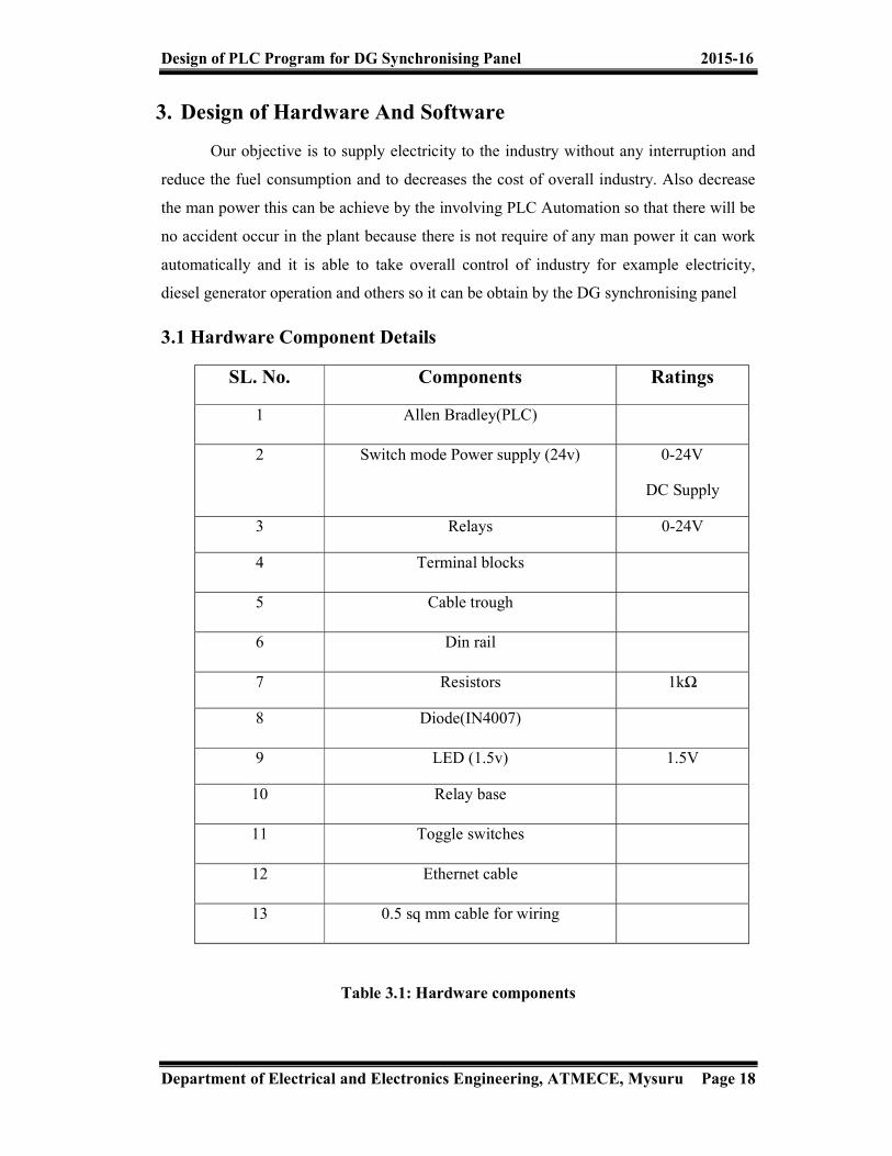
Table 3.1: Hardware components
SL. No. Components Ratings 1 Allen Bradley(PLC) 2 Switch mode Power supply (24v) 0-24V
DC Supply 3 Relays 0-24V 4 Terminal blocks 5 Cable trough 6 Din rail 7 Resistors 1kΩ 8 Diode(IN4007) 9 LED (1.5v) 1.5V
10 Relay base 11 Toggle switches 12 Ethernet cable 13 0.5 sq mm cable for wiring

Design of PLC Program for DG Synchronising Panel 2015-16
Department of Electrical and Electronics Engineering, ATMECE, Mysuru Page 19
3.1.1 Allen Bradley (PLC) PLC is solid state device whose output depends based on the status of inputs and the user program as shown in fig 3.1.
Fig 3.1: PLC Overview
Allen Bradley PLC: Pico soft Micrologix SLC (Smart Logic Controller) Control Logics Compact Logics Here we are going to discuss About Micrologix family Micrologix Model: Here we are using the PLC model Micrologix 1400 Programming Software: RS Logics 5 - PLC 5 RS Logics 500 - Micrologix, SLC RS Logics 5000 - Compact Logics, Control Logics, Soft Logics Here we are working with RS Logics 500 software
Design of PLC Program for DG Synchronising Panel 2015-16
Department of Electrical and Electronics Engineering, ATMECE, Mysuru Page 20
Programming Languages: Instruction List Structured Text Sequential Flow Chart Functional Block Diagram Ladder Logic Diagram Here we are working with Ladder Logic Diagram Specification
Total no of I/O’s: 32 No of inputs: 20 No of outputs: 12 No of expansion modules: 7 Communication cable: RS 232(PMO2),RS232(CP3),Ethernet cable Communication port: 8 pin mini din, D type 9 pin, Ethernet Online editing: Possible

Design of PLC Program for DG Synchronising Panel 2015-16
Department of Electrical and Electronics Engineering, ATMECE, Mysuru Page 21
Hardware configuration: SL.NO. Logics Addressing
1 Input I: 0/0………………..I:0/19 2 Output O: 0/0………………O:0/11 3
Memory B3:0/0 …………….B3:0/15 B3:255/0……..…B3:255/15
4 Timer T4:0……………..….T4:255 5 Counter C5:0…………….…C5:255 6 Control Register R6:0…………………R6:255 7 Integer N7:0……………..…N7:25 8 Float F8:0…………...........F8:255 9 Jump Q2:0…………............Q2:99
10 Subroutine U:3…………………….U:255
Table 3.2: Addressing of Micrologix 1400 PLC

Design of PLC Program for DG
Department of Electrical and Electronics Engineering, ATMECE, Mysuru
3.1.2 Pin Diagram of PLC
3.1.3 Power Supply Provides the voltage needed to run the primary PLC components This can be built
into the PLC or be an external unit. Common voltage levels required by the PLC (with and without the power supply) are 24Vdc, 120Vac, 220Vac.
rogram for DG Synchronising Panel
Department of Electrical and Electronics Engineering, ATMECE, Mysuru
PLC
Fig 3.2: Pin Diagram of PLC
Provides the voltage needed to run the primary PLC components This can be built into the PLC or be an external unit. Common voltage levels required by the PLC (with and without the power supply) are 24Vdc, 120Vac, 220Vac.
Fig 3.3: Power Supply
2015-16
Department of Electrical and Electronics Engineering, ATMECE, Mysuru Page 22
Provides the voltage needed to run the primary PLC components This can be built into the PLC or be an external unit. Common voltage levels required by the PLC (with

Design of PLC Program for DG Synchronising Panel 2015-16
Department of Electrical and Electronics Engineering, ATMECE, Mysuru Page 23
3.1.4 Relay In more recent years, small products called PLRs (programmable logic relays),
and also by similar names, have become more common and accepted. These are much like PLCs, and are used in light industry where only a few points of I/O (i.e. a few signals coming in from the real world and a few going out) are needed, and low cost is desired. These small devices are typically made in a common physical size and shape by several manufacturers, and branded by the makers of larger PLCs to fill out their low end product range. Popular names include PICO Controller, NANO PLC, and other names implying very small controllers.
Fig 3.4: 24V Relay

Design of PLC Program for DG Synchronising Panel 2015-16
Department of Electrical and Electronics Engineering, ATMECE, Mysuru Page 24
3.1.5 Terminal Block This is the contacts which are used for the connection of wire so that it reduces the complexity. This terminal blocks holds the end side of wires both from field and to the field. Field refers to SLD board here.
Fig 3.5: Terminal Block

Design of PLC Program for DG Synchronising Panel 2015-16
Department of Electrical and Electronics Engineering, ATMECE, Mysuru Page 25
3.2 Software Details PLC-Rockwell Software
RS logic 500 RS linx RS logics 500 emulator
Modes of Operation: Run mode:
No download Upload is possible Processor LED green light
Program mode : Download, Upload, Editing is possible program LED is in offline
Remote : Run, Test, Download, Upload, Editing is possible but machine is stopped
Remote Run : Online editing is possible

Design of PLC Program for DG Synchronising Panel 2015-16
Department of Electrical and Electronics Engineering, ATMECE, Mysuru Page 26
3.2.1 Procedure Followed.
Fig 3.6: First Step to Open PLC
Select the Processor Type
Fig 3.6.1: Selecting the PLC
Design of PLC Program for DG Synchronising Panel 2015-16
Department of Electrical and Electronics Engineering, ATMECE, Mysuru Page 27
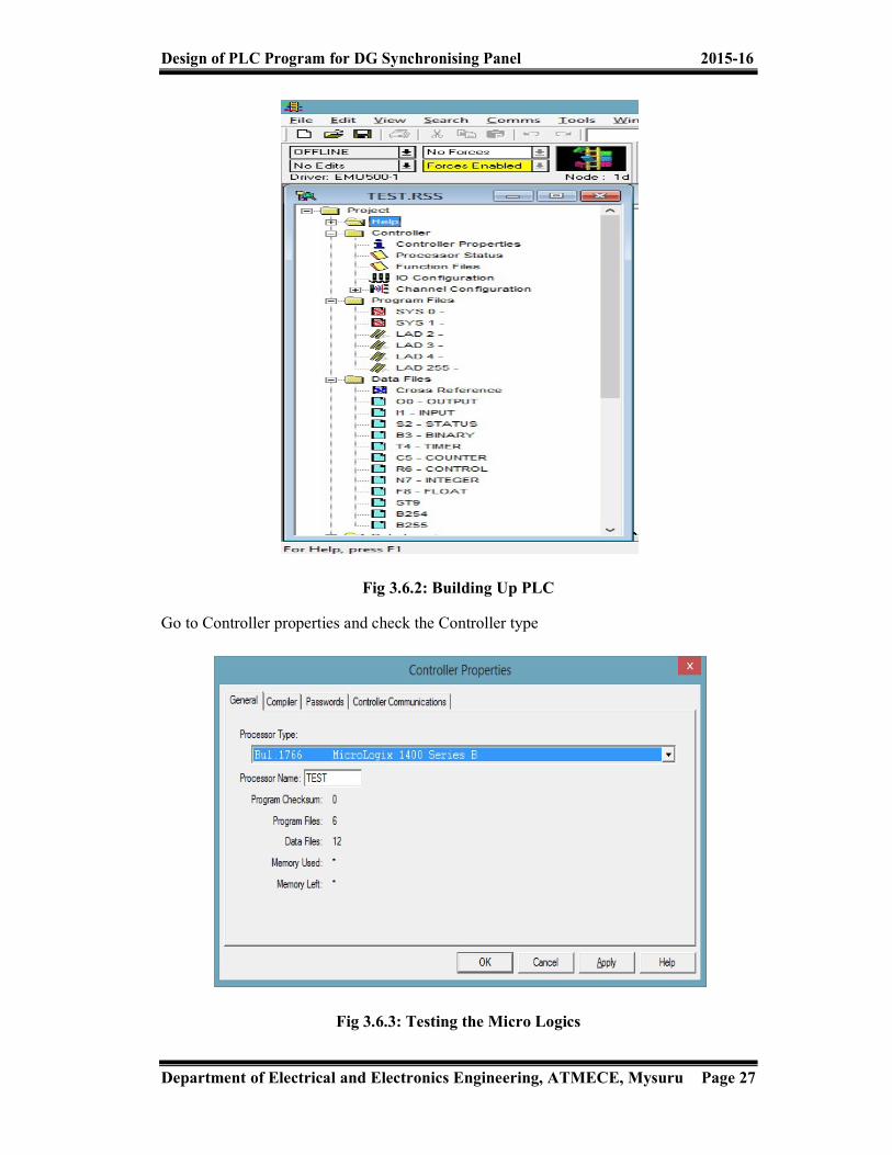
Fig 3.6.2: Building Up PLC
Go to Controller properties and check the Controller type
Fig 3.6.3: Testing the Micro Logics

Design of PLC Program for DG Synchronising Panel 2015-16
Department of Electrical and Electronics Engineering, ATMECE, Mysuru Page 28
Go to I/O configuration and check whether I/O modules added are displaying as shown in figure On the right side various types of Analog and Digital I/O modules are shown with their part number
Fig 3.6.4: Input and Output Configuration
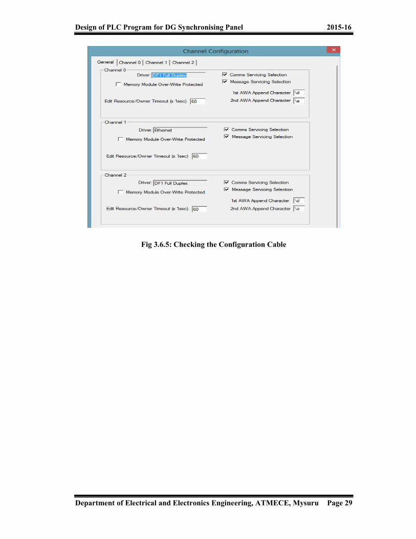
Go to Channel Configuration and Select the type of communication By default Channel 0 and Channel 2 will be DF1 Full Duplex Channel 1 will be Ethernet
Design of PLC Program for DG Synchronising Panel 2015-16
Department of Electrical and Electronics Engineering, ATMECE, Mysuru Page 29
Fig 3.6.5: Checking the Configuration Cable

Design of PLC Program for DG Synchronising Panel 2015-16
Department of Electrical and Electronics Engineering, ATMECE, Mysuru Page 30
Programming Instructions: User:
1) NO Contact (Normally Open) NO contact is an input contact. It is also known as XIO contact
i.e. Examine If Open contact 2) NC Contact (Normally Close )
NC contact is an input contact. It is also known as XIC contact i.e. Examine If Close contact
3) Load It is an Output Coil. It is also known as OTE i.e. Output Enable
4) Latch coil It is an Output Coil. It is also known as OTL i.e. Output Latch
5) Un latch coil It is an Output Coil. It is also as known as OTU i.e. Output Unlatch
Fig 3.6.6: Ladder Diagram Building

Design of PLC Program for DG Synchronising Panel 2015-16
Department of Electrical and Electronics Engineering, ATMECE, Mysuru Page 31
3.3 Program Execution Process Check Input Status First the PLC takes a look at each I/O to determine if it is on or off Execute Program
Next the PLC execute the program one instruction at a time Update Output Status
Finally PLC updates the status of the outputs. It updates the outputs based on which inputs were on during the first step
Fig 3.7: Program Execution

Design of PLC Program for DG Synchronising Panel 2015-16
Department of Electrical and Electronics Engineering, ATMECE, Mysuru Page 32
CHAPTER 4 CIRCUIT DIAGRAM
AND OPERATION
Design of PLC Program for DG
Department of Electrical and Electronics Engineering, ATMECE, Mysuru
4 Circuit Diagram and Operation4.1 Circuit Diagram of Plc Housing
As we are already mentioned the equipments we are using in our project, the procedure we follow here: we are From the mains we get around 230volts, this power supply provides the needed 24vold DC for the PLC in the main circuit board. From power supply we are also taking 0Volts to all the shorted common pointsthe input side of PLC.
Allen Bradley Micrologix consist of 32 I/O(input/output) pins, in which 20 are used for input purpose and 12 are used for output. But for our present project we are only needed of 15 number of input pins from the PLC.
rogram for DG Synchronising Panel
Department of Electrical and Electronics Engineering, ATMECE, Mysuru
nd Operation f Plc Housing
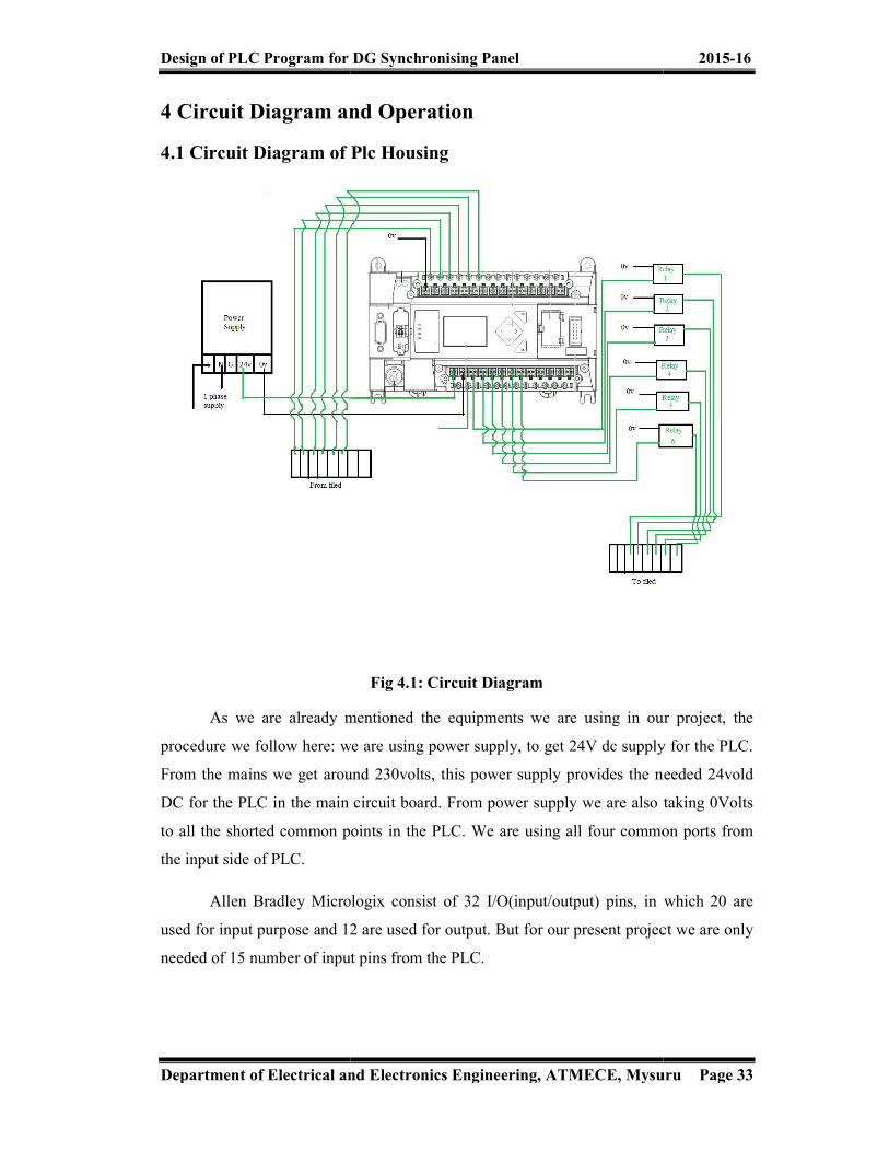
Fig 4.1: Circuit Diagram As we are already mentioned the equipments we are using in our project, the
procedure we follow here: we are using power supply, to get 24V dc supply for the PLC. From the mains we get around 230volts, this power supply provides the needed 24vold DC for the PLC in the main circuit board. From power supply we are also taking 0Volts to all the shorted common points in the PLC. We are using all four common ports from
Allen Bradley Micrologix consist of 32 I/O(input/output) pins, in which 20 are used for input purpose and 12 are used for output. But for our present project we are only
15 number of input pins from the PLC.
2015-16
Department of Electrical and Electronics Engineering, ATMECE, Mysuru Page 33
As we are already mentioned the equipments we are using in our project, the using power supply, to get 24V dc supply for the PLC.
From the mains we get around 230volts, this power supply provides the needed 24vold DC for the PLC in the main circuit board. From power supply we are also taking 0Volts
in the PLC. We are using all four common ports from
Allen Bradley Micrologix consist of 32 I/O(input/output) pins, in which 20 are used for input purpose and 12 are used for output. But for our present project we are only
Design of PLC Program for DG Synchronising Panel 2015-16
Department of Electrical and Electronics Engineering, ATMECE, Mysuru Page 34
In these 15 number of pins, we are taking inputs for conditioned such as, running feedback, auto mode, breaker close feedback for all three diesel generators. also electrical supply healthy condition. And for faults conditions such as alternator common fault and engine common fault for all three diesel generators.
Similarly for the output side of the PLC are taken number of 6 pins, in which we use three pins these for the purpose like start/stop of three diesel generators. Rest three for breaker close command for all three generators.
Ground pin is also used from output side, along with common port. For the communication with the computer, we use RS-232 and also Ethernet cable. These are many pins and ports we needed for PLC connections.
Terminal blocks are used to reduce the clumsiness in the circuit connection. We are using two separate boards in our project; one is main board which holds power supply, PLC, terminal blocks and relays. Other is Single line diagram board consisting of LED's, toggle switches and some resistors.
Relays are used in this circuit to get contact with the circuit which means instead of sensors we are using relay as the sensing element to latch and unlatch so that the circuit can get on to online or offline and the relay work on basis of program to be executed so there will less error in circuit to be operated.
The output connection from terminals blocks are taken to the single line diagram board. Here also some terminal blocks are provided. We take the output from the PLC to this SLD (single line diagram) board. The main board also consist of din rail which holds the equipments to the main board strongly. ferrules for numbering purpose.

Design of PLC Program for DG Synchronising Panel 2015-16
Department of Electrical and Electronics Engineering, ATMECE, Mysuru Page 35
4.2 Operation First we switch on the power supply. RS Linx Classic is a software tool from
Rockwell Automation Networks and Devices. It is a comprehensive factory communication solution, providing Allen Bradley PLC access to a wide variety of Rockwell Software and Allen Bradley applications, ranging from device programming and configuration applications such as RS Logix., the program we have to download it to PLC from the computer. We are already mentioned we are using ladder logic diagram language for writing program for PLC. Now after running the program. We operate the toggle switches provide on the single line diagram board. EB healthy switch will be in off state when power is not supplied to the grid. This makes all diesel generators to on and it takes like few minutes. Then when DG1 is on state breaker 1 is in on state, thus load is continuously supplied. Similarly when load is required in large quantity, other DG's also work in order to satisfy the load. In our project we have writer program providing priority for diesel generator 2. These priorities are based on number of working hours.
Also if any fault occurs in the generators, there is cut down of the faulted part from healthy part without interrupting the load. As we are connected LED's across the load side, we can see the on and off states of LED's on the single line diagram board. This helps for better understanding of the operation of working. Such a control system can be very useful for industrial automation, in research laboratories and big industries. The graphical interface makes it easy for the operator to operate switching and controlling operations. The PLC provides a very rugged solution to control relays and RS232 devices.

Design of PLC Program for DG Synchronising Panel 2015-16
Department of Electrical and Electronics Engineering, ATMECE, Mysuru Page 36
4.3 Advantages of the Project Very fast Easy to change logic i.e. flexibility Reliable due to absence of moving parts Low power consumption Easy maintenance due to modular assembly Facilities in fault finding and diagnostic Capable of handling of very complicated logic operations Good documentation facilities Easy to couple with the process computers Analog signal handling and close loop control programming Counter, timer and comparator can be programmed Ease operator interface due to colourographic and advisory system introduction To reduce complex circuitry of the entire system To get maximum efficiency from the machine & control them with human logic To eliminate the high costs associated with inflexible relay controlled systems
4.4 Limitations
This technique cannot be implemented to all type of systems where the output and input status will be continuously changing
The program does not remain same when any of the component of the system is in unhealthy condition
Design of PLC Program for DG Synchronising Panel 2015-16
Department of Electrical and Electronics Engineering, ATMECE, Mysuru Page 37
4.5 Applications Automotive assembly and painting Machining and metal processing Plastics injection moulding Forest processing Robotics Material testing Industrial process control Motion simulation Animation Medical equipment Detection of faults in generating stations and substations Recording of electrical parameters in generating stations and substations Level detectors Waste water treatment Smoke house control Radio frequency remote control Diesel generator control Residential elevators Residential irrigation control Airport runway light control Lubrication equipment Vacuum pump system Aviation testing equipment Ventilation control equipment Condensation control

Design of PLC Program for DG Synchronising Panel 2015-16
Department of Electrical and Electronics Engineering, ATMECE, Mysuru Page 38
Fig 4.2: PLC Automation in Process Industries
The above fig shows the automation implemented in process industries. The implementation of PLC automation in process industries results in the production of quality products. This reduces man power and accuracy in many process involved in manufacturing the products.
Fig 4.3: PLC Automation Used In Transmission and Distribution Systems
The above fig shows the automation used in transmission and distribution systems. The implementation of PLC automation in transmission and distribution helps in correct recording of the values of voltage levels and to detect faults in the network system.

Design of PLC Program for DG Synchronising Panel 2015-16
Department of Electrical and Electronics Engineering, ATMECE, Mysuru Page 39
Fig 4.4: PLC Automation Used In Control Room of Generating Stations
The above fig shows the automation used control room of generating stations . The implementation of PLC automation in generating stations helps in correct recording of the values of various electrical parameters and to detect faults in the network system.
Fig 4.5: PLC Automation Used In Waste Water Treatment
The above fig shows the PLC automation used in waste water treatment PLC is configured using the set of languages so that it’s instantly familiar to the new generation of control engineers. In wastewater applications, a PLC can be installed on treatment units and networked with a supervisory computer.

Design of PLC Program for DG Synchronising Panel 2015-16
Department of Electrical and Electronics Engineering, ATMECE, Mysuru Page 40
Fig 4.6: PLC Integrated Robot
The above fig shows the PLC integrated robot. Traditionally, Programmable Logic Controllers (PLC) is used as supervisory controls for approximately 90 percent of manufacturing systems. These PLCs control conveyors, filling systems, sealing and forming systems and most of the equipment in the plant. Even in a typical robotics system, the PLC controls the entire operation of the cell. However, robot operations and path planning are done on a different controls platform that is proprietary to the robot manufacturer. As with any proprietary system, robots require specially trained professionals to program, control and interface them with the PLC for major operational commands. Manufacturers and industrial and process engineers sought a way for robots to be programmed and controlled entirely through a PLC.

Design of PLC Program for DG Synchronising Panel 2015-16
Department of Electrical and Electronics Engineering, ATMECE, Mysuru Page 41
CHAPTER 5 RESULTS AND DISCUSSION
Design of PLC Program for DG Synchronising Panel 2015-16
Department of Electrical and Electronics Engineering, ATMECE, Mysuru Page 42
5.1 Synchronising Panel Circuit Development As the project proceeded, the module went through various changes and
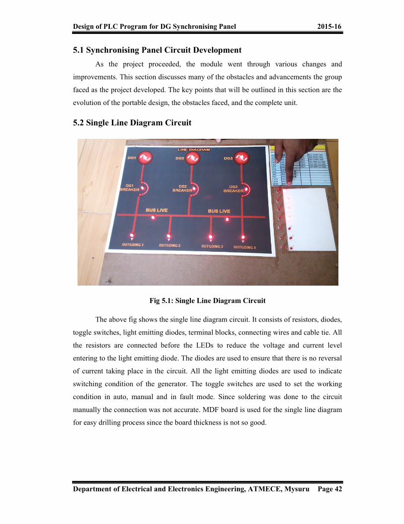
improvements. This section discusses many of the obstacles and advancements the group faced as the project developed. The key points that will be outlined in this section are the evolution of the portable design, the obstacles faced, and the complete unit. 5.2 Single Line Diagram Circuit
Fig 5.1: Single Line Diagram Circuit
The above fig shows the single line diagram circuit. It consists of resistors, diodes, toggle switches, light emitting diodes, terminal blocks, connecting wires and cable tie. All the resistors are connected before the LEDs to reduce the voltage and current level entering to the light emitting diode. The diodes are used to ensure that there is no reversal of current taking place in the circuit. All the light emitting diodes are used to indicate switching condition of the generator. The toggle switches are used to set the working condition in auto, manual and in fault mode. Since soldering was done to the circuit manually the connection was not accurate. MDF board is used for the single line diagram for easy drilling process since the board thickness is not so good.

Design of PLC Program for DG Synchronising Panel 2015-16
Department of Electrical and Electronics Engineering, ATMECE, Mysuru Page 43
5.3 PLC & Relay Section Housing Circuit
Fig 5.2: PLC & Relay Section Housing Circuit
The PLC housing circuit consists of the PLC kit, cable troughs, din rail, connecting wires, relay section, terminal blocks and 24 volts dc power supply. The components are mounted on a ply wood sheet and base of the sheet are provided with bushes. The PLC is used to record the program created by the software and the program is downloaded to the PLC kit. The output of the PLC is fed to the single line diagram circuit. The mounting of the components on the plywood sheet was really difficult since the sheet was very thick.
Design of PLC Program for DG Synchronising Panel 2015-16
Department of Electrical and Electronics Engineering, ATMECE, Mysuru Page 44
CHAPTER 6 CONCLUSION AND FUTURE SCOPE
Design of PLC Program for DG Synchronising Panel 2015-16
Department of Electrical and Electronics Engineering, ATMECE, Mysuru Page 45
6.1 Conclusion The PLC automation experienced an unprecedented growth as universal element in industrial automation It can be used in applications ranging from simple control like replacing a small number of relays to complex automation problems Today programmable logic controllers are used for control and automation in a single machine and increases full automation of manufacturing/ testing process in a factory The PLC automation is used for diesel generation control and can be implemented in industrial sector for controlling the power flow and also for easy and automatic operation of generators depending on the loading condition. The advancement in the PLC automation results in the replacement of electronic logic circuits, manual control operation and also hard wired control operation.
Design of PLC Program for DG Synchronising Panel 2015-16
Department of Electrical and Electronics Engineering, ATMECE, Mysuru Page 46
6.2 Suggestions for Future Improvements The programming of the PLC could be made more flexible so that the system can be used for complex applications The system could be improved by installing multi data meter so that the system can be implemented to all types of real time applications easily. The programming of the PLC could be improved by implementing various programming techniques so that we can run the PLC in different programming languages. The system could be also used to measure all the electrical parameters such as voltage, current and power if the multi data meter is installed in the system. The system can also be improved by introducing buzzers where the signals can be indicated through sounds The system could be improved by developing the program for more number of inputs and outputs so that the system will be very helpful for multiple input multiple output system based applications which can be used in encoders and decoders. The programming for more inputs and outputs would be more helpful in implementing automation technique in many complex circuits.

Design of PLC Program for DG Synchronising Panel 2015-16
Department of Electrical and Electronics Engineering, ATMECE, Mysuru Page 47
References: [1] E. A. Parr, Industrial Control Handbook, Industrial Press Inc., 1999 ISBN 0-
8311-3085-7 [2] M. A. Laughton, D. J. Warne, Electrical Engineer's Reference book, 16th edition,
Newnes, 2003 Chapter 16 Programmable Controller [3] "The father of invention: Dick Morley looks back on the 40th anniversary of the
PLC". Manufacturing Automation. 12 September 2008. [4] Harms, Toni M. & Kinner, Russell H. P.E., Enhancing PLC Performance with
Vision Systems. 18th Annual ESD/HMI International Programmable Controllers Conference Proceedings, 1989,
[5] Maher, Michael J. Real-Time Control and Communications. 18th Annual ESD/SMI International Programmable Controllers Conference Proceedings, 1989
[6] Kinner, Russell H., P.E. Designing Programmable Controller Application Programs Using More than One Designer. 14th Annual International Programmable Controllers Conference Proceedings, 1985,
[7] W. Bolton, Programmable Logic Controllers, Fifth Edition, Newnes, 2009 ISBN 978-1-85617-751-1
[8] Keller, William L Jr. Grafcet, A Functional Chart for Sequential Processes, 14th Annual International Programmable Controllers Conference Proceedings, 1984,
[9] Gregory K. McMillan, Douglas M. Considine (ed), Process/Industrial Instruments and Controls Handbook Fifth Edition, McGraw-Hill, 1999 ISBN 0-07-012582-1 Section 3 Controllers

Design of PLC Program for DG Synchronising Panel 2015-16
Department of Electrical and Electronics Engineering, ATMECE, Mysuru Page 48
Copyright © 2022 FDOKUMEN