VISVESVARAYA TECHNOLOGICAL UNIVERSITY, BELGAUM
57
VISVESVARAYA TECHNOLOGICAL UNIVERSITY, BELGAUM A PROJECT REPORT on “DESIGN & FABRICATION OF BLUETOOTH BASED PIPE INSPECTION ROBOT” Submitted in partial fulfillment of the requirements as a part of the curriculum, Bachelor of Engineering in Mechanical Engineering Submitted By Anand Murali -1CR15ME012 Faizan -1CR16ME027 Giridhar . J -1CR16ME031 Syed Abdulla -1CR16ME080 Under the guidance of: MR. SHREYAS P Assistant Professor Department of Mechanical Engineering, Department of Mechanical Engineering CMR Institute of Technology, Bengaluru - 560 037 2019 - 2020
-
Upload
khangminh22 -
Category
Documents
-
view
2 -
download
0
Transcript of VISVESVARAYA TECHNOLOGICAL UNIVERSITY, BELGAUM
VISVESVARAYA TECHNOLOGICAL UNIVERSITY,
BELGAUM
A PROJECT REPORT
on
“DESIGN & FABRICATION OF BLUETOOTH BASED PIPE
INSPECTION ROBOT”
Submitted in partial fulfillment of the requirements as a part of the curriculum,
Bachelor of Engineering in Mechanical Engineering
Submitted By
Anand Murali -1CR15ME012
Faizan -1CR16ME027
Giridhar . J -1CR16ME031
Syed Abdulla -1CR16ME080
Under the guidance of:
MR. SHREYAS P
Assistant Professor Department of Mechanical Engineering,
Department of Mechanical Engineering
CMR Institute of Technology, Bengaluru - 560 037
2019 - 2020

CMR INSTITUTE OF TECHNOLOGY
132, AECS Layout, Kundanahalli Colony, ITPL Main Rd, Bengaluru – 560037
Department of Mechanical Engineering
CERTIFICATE
This is to certify that the project work entitled “DESIGN & FABRICATION OF
BLUETOOTH BASED PIPE INSPECTION ROBOT” submitted to the CMR Institute
of Technology, Bangalore by Mr. Anand Murali, Mr. Faizan, Mr. Giridhar.J, Mr. Syed
Abdulla in partial fulfillment of the requirements as part of the curriculum, VIII Semester,
Bachelor of Engineering in Mechanical of the Visvesvaraya Technological University,
Belgaum during the year 2019 - 20. It is certified that all corrections/suggestions indicated
for internal assessment have been incorporated in the report deposited in the departmental
library. The Project report has been approved as it satisfies the academic requirements in
respect of Project report prescribed for the Bachelor of Engineering degree.
------------------------------ ------------------------------ -------------------------------
(Shreyas . P) (Dr. Vijayanand Kaup) (Dr. Sanjay Jain)
Signature of the Guide
Signature of the HOD Signature of the Principal
Examiners
Name of the examiners Signature with date
1.
2.
CMR INSTITUTE OF TECHNOLOGY
132, AECS Layout, Kundanahalli Colony, ITPL Main Rd, Bengaluru – 560037
Department of Mechanical Engineering
DECLARATION
I, ANAND MURALI, FAIZAN, GIRIDHAR . J SYED ABDULLA are bonafide students
of CMR Institute of Technology, Bangalore, hereby declare that the project report entitled,
“DESIGN & FABRICATION OF BLUETOOTH BASED PIPE INSPECTION
ROBOT” has been carried out at CMR Institute of Technology, Bangalore, in partial
fulfillment of the requirements for the award of BACHELOR OF
ENGINEERING in MECHANICAL ENGINEERING, of the VISVESVARAYA
TECHNOLOGICAL UNIVERSITY, Belgaum, during the year 2019 – 20. The work
done in this project report is original and has not been submitted for any other degree in any
university.
ANAND MURALI (1CR15ME012)
FAIZAN (1CR16ME027)
GIRIDHAR.J (1CR16ME031)
SYED ABDULLA (1CR16ME080)
ACKNOWLEDGEMENT
The satisfaction and euphoria that accompany the successful completion of our work would
be incomplete without the mention of the people who made it possible and whose constant
guidance and encouragement crowned the efforts with success.
I would like to express my sincere gratitude to the Principal Dr. SANJAY JAIN, CMR
Institute of Technology for providing facilities.
I wish place on record my grateful thanks to Dr. VIJAYANAND KAUP, Head of the
Department, Mechanical Engineering, CMR Institute of Technology for providing
encouragement and guidance.
I would like to thank our guide Prof. SHREYAS.P, Assistant Professor, Department of
Mechanical Engineering, CMR Institute of Technology on his periodic inspection, time to time
evaluation and management on his help to bring the seminar to the present from through proper
guidelines.
Last, but not the least, we would hereby acknowledge and thank our PARENTS who have
been a source of inspiration and also instrumental in the successful completion of the Project
Report work.
ANAND MURALI (1CR15ME012)
FAIZAN (1CR16ME027)
GIRIDHAR.J (1CR16ME031)
SYED ABDULLA (1CR16ME080)

ABSTRACT
A pipe inspection robot is a device or an instrument use to inspect and clean the pipe either an
industrial or nonindustrial. This is an innovation that took place in recent year to eliminate the
human factor from the work of inspecting and cleaning the pipe which is a risky task. Pipe
inspection robots are used in many fields of industry and also in other work such ask cleaning
and maintaining the city pipe line. The work of industrial pipe inspection robot is to monitor
the inside view of the pipes, to keep the notice on the various changes and recognizing the
irrelevant changes, which may cause problem and to take preventive action to prevent the
problem. If the problem has been recorded then take initiative action to solve the problem.
Though the industrial pipe inspection robot is monitoring the inside view of pipes still it can
find out the outer surface problem of pipe such as crack formation and this can be done with
the help of camera, which will be a part of our project. The pipe inspection robot can be use
for the cleaning purpose by adding and attachment to it, such as scrapper which will scrap out
the unwanted dross from the pipes project aims to create an autonomous robot used for in-pipe
inspection and removing the rust. The mechanism used involves a central rod upon which a
translational element is fitted which in turn is connected to three frames of links and wheels.
DC motors are attached to the wheels to achieve the drive required. The mechanism allows for
small accommodation in pipe diameters. The camera is mounted on the top of the assembly;
motor is attached with the buffering wheel to remove the rust. The robot allows for detection
of cracks, buckle, corrosions, pitting and many others.
Design & Fabrication of Bluetooth Based Pipe Inspection Robot 2019 - 20
Dept of ME, CMRIT Page 1
CONTENTS
1. INTRODUCTION 2
2. REVIEW OF RELATED LITERATURE 3-6
3. METHODOLOGY 7
4. DESIGN CONSEDRATION 8-17
5. CAED MODELS 18-19
6. MECHANICAL FABRICATION 20-25
7. HARDWARE DESCRIPTION 26-34
8. SOFTWARE DESCRIPTION 35-44
9. RESULT 45
10. FIELD OF APPLICATION 46
11. FUTURE SCOPE AND ADVANTAGES 47
12. CONCLUSION 48
13. LIST OF PARTS 49
14. COST ESTIMATION 50-51
15. REFERENCES 52
Design & Fabrication of Bluetooth Based Pipe Inspection Robot 2019 - 20
Dept of ME, CMRIT Page 2
CHAPTER – I
INTRODUCTION
Pipelines are proven to be the safest way to transport and distribute gases and liquids.
Periodic inspection is required to maintain that status. Pipeline systems deteriorate
progressively over time through various means. Robotics is one of the fastest growing
engineering fields of today. Robots are designed to remove the human factor from labour
intensive or dangerous work environments and also to act in inaccessible environment. The use
of robots is more common today than ever and it is no longer exclusively used by the heavy
production industrial plants. The specific operations such as inspection, maintenance, cleaning
etc. are expensive. Thus, the application of the robots appears to be an attractive solution. The
project aims to create a robotic inspection technology. It is beneficial to have a robot with
adaptable structure to the pipe diameter, which possesses enhanced dexterity, maneuverability
and capability to operate under hostile conditions. Wheeled robots are simple, energy efficient
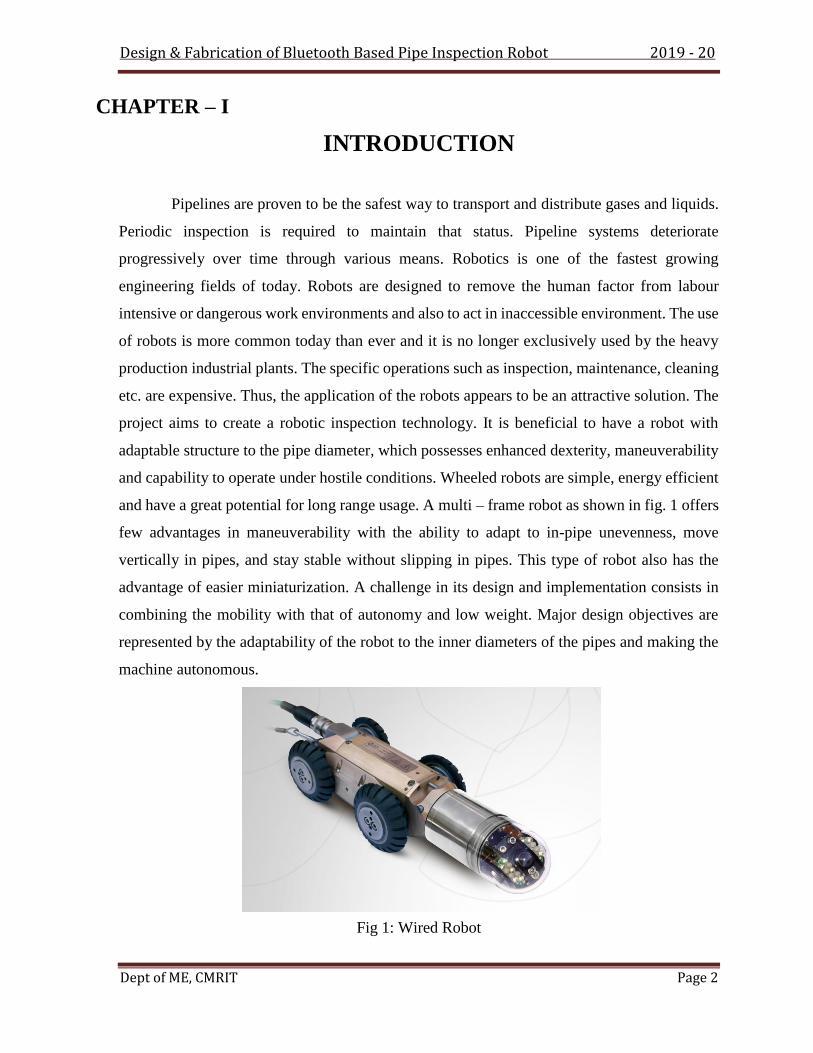
and have a great potential for long range usage. A multi – frame robot as shown in fig. 1 offers
few advantages in maneuverability with the ability to adapt to in-pipe unevenness, move
vertically in pipes, and stay stable without slipping in pipes. This type of robot also has the
advantage of easier miniaturization. A challenge in its design and implementation consists in
combining the mobility with that of autonomy and low weight. Major design objectives are
represented by the adaptability of the robot to the inner diameters of the pipes and making the
machine autonomous.
Fig 1: Wired Robot
Design & Fabrication of Bluetooth Based Pipe Inspection Robot 2019 - 20
Dept of ME, CMRIT Page 3
CHAPTER –II
REVIEW OF RELATED LITERATURE
2.1 LITERATURE REVIEW
Amr Bekhit discussed that the robot capable of operating in active pipelines would be of
great commercial and industrial benefit. This paper describes the requirements for such a
robot and considers the benefits and limitations of existing systems. A new design for an
inchworm robot is presented based on the Gough-Stewart parallel platform. The control
system made relatively simple due to use of inchworm locomotion, while the use of the
Gough-Stewart platform allows the robot to benefit from the accuracy, rigidity and speed
of parallel robots and provides a flexible base. The design aims to provide minimal
resistance to fluid flow by providing a low front area.
E Navin Prasad designed a robot for inspection of pipes in industrial plants. The
inspection of pipes may be related for improving security and efficiency in industrial
plants. The operations like inspection, maintenance, cleaning etc. are expensive, thus the
application of the robots appears to be one of the most attractive solutions. Pipelines
which are tools for transporting oils, gases and other fluids such as chemicals, have be
should have high magnetic susceptibility and should be good conductor of electricity. The
materials are copper, etc. But aluminum is selected as the materials for the linkages and
central body because of its much-desired properties employed as major utilities in a
number of countries for long time. Aluminum is light in weight and strength; it can be
used in many applications. Aluminum alloys with a wide range of properties are used in
engineering structures. The strength and durability of aluminum alloys vary widely
because of the components of the specific alloy as well as heat treatments and
manufacturing processes.
Edwin Dertien has discussed the design of a mechanical structure of a miniature pipe
inspection robot capable of moving through very small pipes. The main objective was to
negotiate bends, T-joints and steep inclinations pose another set of strict design

Design & Fabrication of Bluetooth Based Pipe Inspection Robot 2019 - 20
Dept of ME, CMRIT Page 4
constraints. The proposed robot consisted of a modular design (7 modules) with a
relatively low number of active degrees of freedom. The system used a novel clamping
mechanism with a series-elastic drive. The design of this mechanism resulted in a high
spreading factor allowing the system to operate in a wide diameter range). The
Mechanical design requirements and control system in the robot were also discussed and
Preliminary test results concluded that the robot was found quite effective than the
conventional inspection.
Atul Gargade explained that the robots are used to remove human being from laborious
and dangerous work. This project describes an in pipe inspection robot. This robot
consists of four leg system- a rear leg system and a body. The four leg systems are
constructed by using three worm gear systems that are arranged at an angle of 120 degree
with respect to each other to operate inside a pipe of different diameters. The springs are
attached to each leg to the robot body to operate in pipes of 140mm to 200mm diameter
range. Modeling and assembly of robot components is done in Solid works.
2.2 PROBLEM STATEMENT
As we have observed that in industry, home, power plant etc. there are several problems occurs
inside the pipe like corrosion, Cracking, Dent Mark, Metal Losses etc. so, we are inspecting the
pipe with the help of “PIPE INSPECTION ROBOT”.
GEOMETRICAL DEFECTS
Buckle: regular buckle and sharp buckle
Ovality
Wrinkle
Knob
Rolling imperfection or angularity
Tube expansion
Joint imperfection: edge displacement & angle error
2.2.1OVALITY
Definition: nearly symmetric deviation of the pipe cross-section from the circular
Shape resulting in ellipse cross-section without sharp breakpoints.
Measures: –minimum outside diameter, dk min [mm]; –maximum outside
Diameter, dk max [mm].
Possible cause of origin: –pipe manufacturing; –external mechanical impact.
Design & Fabrication of Bluetooth Based Pipe Inspection Robot 2019 - 20
Dept of ME, CMRIT Page 5
2.2.2KNOB
Definition: residual deformation of the pipe wall outside the pipe without sharp edge
Extending over an area.
Measures: maximum height, d [mm]; overall dimensions (axial length ×circumferential length), l
×k [mm ×mm].
Possible cause of origin: change in internal pressure interacting with another
Defect.
Remark: the knob can be interpreted as the opposite of the regular buckle.
2.2.3 RUCK
Definition: the pipe wall is rippled along its circumference partly or entirely
And the centre line of the pipe remains straight
Measures: – maximum depth of the ripple, db [mm]; –maximum height of the
Ripple, dk [mm]; angle subtended by the ruck along the circumference of the
Pipe, j [°].
Possible cause of origin: – pipe manufacturing; –soil movement.
2.2.4 ROLLING IMPERFECTION OR ANGULARITY
Definition: during the pipe manufacturing in the vicinity of the plate edge to be
Joined by welding (seam) the shape of the pipe deviates from cylindrical
Forming a sharp edge.
Measures: – height of the bevel edge, Y [mm]; –chord of the bevel edge, 2A
[Mm].
Possible cause of origin: pipe manufacturing.
2.2.5 TUBE EXPANSION
Definition: elimination of diameter difference between the two pipe ends to be
Joined with welding (girth weld).
Measures: – outside diameter of the pipe to be expanded, D1 [mm]; –wall
Thickness of the pipe to be expanded, t1 [mm]; – expansion length, L [mm].
Possible cause of origin: – pipe installation (laying); –repair.
2.2.6 EDGE DISPLACEMENT

Design & Fabrication of Bluetooth Based Pipe Inspection Robot 2019 - 20
Dept of ME, CMRIT Page 6
Definition: radial displacement of parallel centre lines of pipe sections joined with
Welding (girth weld).
Measures: eccentricity, e [mm].
Possible cause of origin:–pipe installation (laying); – repair; –pipe
Manufacturing.
2.1.7 ANGLE ERROR
Definition: deviation of centre lines of pipe sections joined with welding (girth
Weld).
Measures: angle between the centre action systems
2.3 OBJECTIVE
• To develop a machine that helps in easy and quick cleaning To provide the
alternative method for pipe cleaning.
• To reduce human efforts.
• To save the time.
• To reduce the cost anyone can use and easy to operate.
• To remove rust for inner surface
• To make the environment sanitary.
2.4 SCOPE OF THE PRESENT WORK
• Memory can be used to store the appliance status during power failure.
• Appliance scheduler/timer can be implemented using RTC (Real Time Clock)
Can be changes to an IoT device using WiFi connectivity.

Design & Fabrication of Bluetooth Based Pipe Inspection Robot 2019 - 20
Dept of ME, CMRIT Page 7
CHAPTER – III
METHODOLOGY
Fig 2: Project Generation Flow
I. Literature study makes review on other model and focusing on how to make it simple
and relevance to the project title.
II. Conceptual design sketching several type of design based on concept that being
choose. State the dimension for all part.
III. Materials Selection selected the true material based on model design and criteria.
Light, easy to joining and easy to manufacture. Assemble all the part to the design.
IV. Fabrication model refinement. Fabricate according to the main frame and design.
Refinement at several part of joining and sharp edge. V.
Performance testing.
VI. Documentation preparing a report for the project.

Design & Fabrication of Bluetooth Based Pipe Inspection Robot 2019 - 20
Dept of ME, CMRIT Page 8
CHAPTER – IV
DESIGN CONSIDERATION
4.1 FACTORS DETERMINING THE CHOICE OF MATERIALS
The various factors which determine the choice of material are discussed below.
Properties: The material selected must possess the necessary properties for the proposed
application. The various requirements to be satisfied can be weight, surface finish, rigidity,
ability to withstand environmental attack from chemicals, service life, reliability etc. The
following four types of principle properties of materials decisively affect their selection
1. Physical
2. Mechanical
3. From manufacturing point of view
4. Chemical
The various physical properties concerned are melting point, Thermal Conductivity,
Specific heat, coefficient of thermal expansion, specific gravity, electrical Conductivity,
Magnetic purposes etc.
The various Mechanical properties Concerned are strength in tensile, compressive shear,
bending, torsion and buckling load, fatigue resistance, impact resistance, elastic limit,
endurance limit, and modulus of elasticity, hardness, wears resistance and sliding properties.
The various properties concerned from the manufacturing point of view are
1. Cast ability
2. Weld ability
3. Brazability
4. Forge ability
5. Merchantability
6. Surface properties

Design & Fabrication of Bluetooth Based Pipe Inspection Robot 2019 - 20
Dept of ME, CMRIT Page 9
7. Shrinkage
8. Deep drawing etc.
MANUFACTURING COST:
Sometimes the demand for lowest possible manufacturing cost or surface qualities
obtainable by the application of suitable coating substances may demand the use of special
materials.
QUALITY REQUIRED:
This generally affects the manufacturing process and ultimately the material. For
example, it would never be desirable to go for casting of a less number of components which
can be fabricated much more economically by welding or hand forging the steel.
AVAILABILITY OF MATERIAL:
Some materials may be scarce or in short supply. It then becomes obligatory for the
designer to use some other material which though may not be a perfect substitute for the
material designed. The delivery of materials and the delivery date of product should also be
kept in mind.
SPACE CONSIDERATION:
Sometimes high strength materials have to be selected because the forces involved are
high and the space limitations are there.
COST:
As in any other problem, in selection of material the cost of material plays an important
part and should not be ignored. Sometimes factors like scrap utilization, appearance, and non-
maintenance of the designed part are involved in the selection of proper materials.

Design & Fabrication of Bluetooth Based Pipe Inspection Robot 2019 - 20
Dept of ME, CMRIT Page 10
4.2 DESIGN CALCULATION

Design & Fabrication of Bluetooth Based Pipe Inspection Robot 2019 - 20
Dept of ME, CMRIT Page 11

Design & Fabrication of Bluetooth Based Pipe Inspection Robot 2019 - 20
Dept of ME, CMRIT Page 12
4.3 BLOCK DIAGRAM
Fig 3: Block Diagram of Bluetooth Application
4.4 WORKING OF THE PIPE INSPECTION ROBOT
• As Pipe Inspection Robot is designed mainly for circular bore pipes, it have ability to
move inside any bore diameter pipes ranging from 8 inch to 10 inch( 203mm to
254mm ). Suitable mechanisms are provided so that it gains ability to move inside
pipes. This made possible by mounting the surveillance camera and LEDs on head.
• The perfect fitness between the pipe and robot is first conformed after inserting the
robot in the pipe. Then the supply of DC 12Vdc current from is on for working of
robot and the camera is also started. With the help robot control having three buttons,
working of robot can be easily control the motions which are forward and reverse by
one button, using the friction between wheels and pipe, the motion of wheels become
possible. At the rear end of the robot motor is fixed with buffering tool which can

Design & Fabrication of Bluetooth Based Pipe Inspection Robot 2019 - 20
Dept of ME, CMRIT Page 13
rotate up to 1000 rpm enough to scrub the rust metal to be polished. this vehicle is
operated through on and off switches
4.5 DESIGN PARAMETERS
The parameter for design of the robot is the diameter of pipe. We have chosen 8’’ and
10’’ (approx. 200 mm and 260 mm) pipes as the lower and upper limits respectively for our
robot. Selection of the wheel: The wheels of the robot should be chosen such that they should
be capable of moving without slipping in the vertical direction by exerting the required traction
force. They should also not wear out easily with use. These factors are determined by the co-
efficient of friction between the wheel and the pipe. Rubber wheels are a natural choice for this
environment as they meet the above demands. The co-efficient of friction between rubber and
two commonly used pipe materials (concrete and PVC) are considered. Coefficient of friction
between rubber and concrete is in the range of 0.6 – 0.85. Coefficient of friction between rubber
and PVC is in the range of 0.5 – 0.7. The power requirements are calculated using a coefficient
of friction of 0.8. The range of diameter of pipes considered in the present work is 200 to 260
mm. To accommodate the mechanism with rubber wheels and considering market availability
of standard wheels, the diameter was chosen to be 80 mm.
4.6 MECHANISM SYNTHESIS:
The robot mechanism is to be designed in such a way as to expand and contract between
the chosen limits. This necessitates the use of a mechanism where the input link causes the
other links to move in a uniform fashion without any crossovers. A parallelogram linkage offers
the required type of uniform motion.
FIG 4.6.1 Simple Parallelogram Linkage

Design & Fabrication of Bluetooth Based Pipe Inspection Robot 2019 - 20
Dept of ME, CMRIT Page 14
Simple Parallelogram Mechanism But, the required way of motion is not achieved from this
design. The joint F is made into a screw pair. The orientation of link 5 is changed so that when
the input, link 2 moves in the clockwise direction, link 5 moves in the opposite direction
pushing the screw pair forward and vice versa. This combination of linkages makes the
mechanism contract in the clockwise direction and expands in counter clockwise direction.
FIG 4.6.2 Simulation Position 1
FIG 4.6.3 Simulation Position 2
FIG 4.6.4 Simulation Position 3
The figures 5, 6 and 7 show the motion of the mechanism. The simulation showed that
the chosen dimensions for the links was capable of executing the desired motion. Material
Selection: The materials used for this machine are to be rigid. Different materials can be used
for different parts of the robot. For optimum use of power the materials used should be light
and strong. Wood is light but it is subjected to wear if used for this machine. Metals are the
ideal materials for the robot as most of the plastics cannot be as strong. Material chosen should
be ductile, less brittle, malleable, and have high magnetic susceptibility. Among the
metals/metal alloys, aluminum is a good choice. But, mild steel 1018 were chosen as the
material for links and a translational element as it is sufficiently rigid and less brittle.

Design & Fabrication of Bluetooth Based Pipe Inspection Robot 2019 - 20
Dept of ME, CMRIT Page 15
It balances ductility and strength and has good wear resistance; used for large parts,
forging and automotive components. However, mild steel is denser compared to aluminum and
makes the robot heavier. C45 steel is chosen as the material for screw rod as it is a medium
carbon steel, which is used when greater strength and hardness is desired than in the "as rolled"
condition. Extreme size accuracy, straightness and concentricity combine to minimize wear in
high speed applications. It is generally used for screws, forgings, wheel tyres, shafts, axes,
knives, wood working drills and hammers. Design calculations: The material chosen is C45
steel. The diameter of a shaft with bending moment and torsion moment is given by the relation
below.
Fig 8: Assembly Isometric View
4.7 FABRICATION AND WORKING
The fabrication phase of the project involves production of the parts designed. It also
entails the selection of appropriate electronic circuitry which can be effectively used to achieve
and control the robot motion. The various processes used in fabrication of the components are
Cutting Drilling Welding Turning.
Electronic circuit and components: The assembled robot needs to start or stop
instantaneously. Also, its direction of motion ought to be easily switched over. This can be
achieved by using a relay circuit and a remote control. Double Pole Double Throw (DPDT)
relay is an electromagnetic device used to separate two circuits electrically and connect them

Design & Fabrication of Bluetooth Based Pipe Inspection Robot 2019 - 20
Dept of ME, CMRIT Page 16
magnetically. They are often used to interface an electronic circuit, which works at a low
voltage to an electrical circuit which works at a voltage. At the end of fabrication, the electronic
circuitry is implemented onto the robot. The DC motors are fitted for the wheels, screw rod
and camera plate rod. The 4 channel relay is integrated with all the DC motors.
Appropriate wiring is done and a 12 V battery is connected to all electronic components
An important part of the Mechatronics course at Polytechnic University was designing
and realizing a robot. It had to been controlled by a Basic Stamp (BS2) and includes sensors
and actuators. It should be easily monitored and controlled by humans and safe. We decided to
build an in-pipe inspection robot, and we called it Gennaro.
4.8 CONSTRAINTS ON THE ROBOT
Design of the inspection robot depends on two main critical factors: size and shape of the
pipeline. It will weigh strongly on the maneuverability of robot and its dimensions. An ideal
robot should:
1. Drive through a pipe that can change its diameter along his pattern;
2. Cope with elbows and branches, reducer, valves with unexpected mechanical damages
that could change its mechanical configuration;
3. Have sufficient traction to move and to carry out tasks as measurements or clogging
detection in a slippery and not plane surface as a pipe
4. Be robust and reliable several constrains were taking into account in the first phase of
the mechanical design. They were:
• Minimal and maximal dimensions
• Weight
• Moving ability
• Power request
• cost issues
Any of the above influenced the others and was sometimes in contradiction. We wanted a light
robot, with high power and torque to move easily and firmly, and it must work in the small
space given by the 6 inch tube pipe. These were the main features for the robot we had in mind,
Design & Fabrication of Bluetooth Based Pipe Inspection Robot 2019 - 20
Dept of ME, CMRIT Page 17
but being realistic we knew from the beginning that we will have to arrive to a compromise
between them to be successful.
4.8.1 MINIMAL AND MAXIMAL DIMENSIONS
The maximal dimension was given by the nominal pipe diameter we wanted to expect, of six
inch. In addition, the robot was build to inspect pipes clogged by limestone, so we decided that
it should be able to move in pipes of up to 5 inch of inner diameter. One fundamental and
critical aspect was corners. As shown in the picture below, the width (w) and high (h) of the
robot influences each other, and the following formula1 has been used to design the robot: The
minimal acceptable dimension instead was given by the room necessary to equip the robot with
a Basic Stamp, all the circuitry, the data acquisition devices, the sensors and motors and the
power supplies needed.
4.8.2 MOVING ABILITY
The moving ability was probably the greatest problem to deal with. The smooth surface of the
pipes was something difficult to cope with and the round surface adds further difficulties. The
robot was intended to move not only in horizontal but also in vertical pipes, so it has to hold
onto the surfaces and have the necessary grip and power to climb them. All this requirements
had to face with the reality of the chosen traction engine, the DC motors, and with our limited
budget. We decided to use four rubber tyres of 1 inch of diameter, because they showed good
grip, were light, cheap and compatible with the robot dimension. As will be better explained
later we decided to have a robot made up of two different autonomous parts. In order to link
them, four strips of rubber with approximate dimensions of 5 cm length 1 cm width and 1 cm
height rubber were made, and fixed to the frame. The rubber was reinforced with a linear spring
to obtain the desired flexibility and rigidity when approaching an elbow.
4.8.3 WEIGHT
Weight was another critical parameter. A light robot was desired in order to need less power to
move, to be agile and to run in vertical pipes. However, this factor was influenced by the motor’s
choice and the batteries needed. Approximately 50% of the total weight was caused by the batteries
and motor. However any other kind of propulsion or power supply we thought was discarded, and
this seems to be the only possible way to have a compact and self-propelled vehicle.

Design & Fabrication of Bluetooth Based Pipe Inspection Robot 2019 - 20
Dept of ME, CMRIT Page 18
CHAPTER- V
CAED MODELS
FIG 5.1 Frame Stand Model
FIG 5.2 Different View of Frame Stand

Design & Fabrication of Bluetooth Based Pipe Inspection Robot 2019 - 20
Dept of ME, CMRIT Page 19
FIG5.3 Completed Assembly of Pipe Inspection Robot

Design & Fabrication of Bluetooth Based Pipe Inspection Robot 2019 - 20
Dept of ME, CMRIT Page 20
CHAPTER –VI
MECHANICAL FABRICATION
6.1 MILD STEEL
FIG 6.1 MS Flat Steel 1-inch breadth & 3mm thickness
Mild steel is a carbon steel typically with a maximum of 0.25% Carbon and 0.4%-0.7%
manganese, 0.1%-0.5% Silicon and some + traces of other elements such as phosphorous, it
may also contain lead (free cutting mild steel) or sulphur (again free cutting steel called
resulphurised mild steel) The stuff is used everywhere, looking out of my office window I can
see diesel pump injector parts, loudspeaker pole pieces, Automated packing machinery parts
and I haven't even got my glasses on. How it’s made and more info, depending upon the age
of your son it's probably an idea he spends a Saturday morning at the local library researching
his homework. Whilst the internet's good you still can't beat browsing through books at the
library for homework.
6.2 NUT AND BOLT

Design & Fabrication of Bluetooth Based Pipe Inspection Robot 2019 - 20
Dept of ME, CMRIT Page 21
FIG 6.2 M6 Nut & Bolts
A nut is a type of fastener with a threaded hole. Nuts are almost always used in
conjunction with a mating bolt to fasten two or more parts together. The two partners are kept
together by a combination of their threads' friction (with slight elastic deformation), a slight
stretching of the bolt, and compression of the parts to be held together. In applications where
vibration or rotation may work a nut loose, various locking mechanisms may be employed:
lock washers, jam nuts, specialist adhesive thread-locking fluid such as Loctite, safety pins
(split pins) or lockwire in conjunction with castellated nuts, nylon inserts (Nyloc nut), or
slightly oval-shaped threads. The most common shape is hexagonal, for similar reasons as the
bolt head - 6 sides give a good granularity of angles for a tool to approach from (good in tight
spots), but more (and smaller) corners would be vulnerable to being rounded off. It takes only
1/6th of a rotation to obtain the next side of the hexagon and grip is optimal. However polygons
with more than 6 sides do not give the requisite grip and polygons with fewer than 6 sides take
more time to be given a complete rotation. Other specialized shapes exist for certain needs,
such as wing nuts for finger adjustment and captive nuts (e.g. cage nuts) for inaccessible areas.

Design & Fabrication of Bluetooth Based Pipe Inspection Robot 2019 - 20
Dept of ME, CMRIT Page 22
6.3 ARC WELD
FIG 6.3 Arc Welding
Arc welding is a process that is used to join metal to metal by using electricity to create
enough heat to melt metal, and the melted metals when cool result in a binding of the metals.
It is a type of welding that uses a welding power supply to create an electric arc between an
electrode and the base material to melt the metals at the welding point. They can use either
direct (DC) or alternating (AC) current, and consumable or non-consumable electrodes. The
welding region is usually protected by some type of shielding gas, vapor, or slag. Arc welding
processes may be manual, semi-automatic, or fully automated. First developed in the late part
of the 19th century, arc welding became commercially important in shipbuilding during the
Second World War. Today it remains an important process for the fabrication of steel structures
and vehicles.

Design & Fabrication of Bluetooth Based Pipe Inspection Robot 2019 - 20
Dept of ME, CMRIT Page 23
6.4 ARC WELD EQUIPMENTS
FIG 6.4 Arc Welding Equipments
Welding is the joining of metals through coalescence by the use of either heat or
pressure or both. Coalescence is a term that means the joining of two materials to become as
one piece. The basic arc welder components consist of the machine that generates the power,
the electrode holder or wire feed gun, a means of shielding the weld as it forms, and protective
equipment for the user. The process begins in all types when the wire or rod makes contact
with the piece to be welded. This completes an electric circuit and creates an arc through which
the transfer of the metal from the wire or rod to the piece is facilitated. Spatter occurs during
transfer; some of the molten drops of metal become airborne and cover the piece and
surrounding area with small globules that solidify on cooling. Spatter may be minimized
depending on the skill of the operator and the welding method being used.

Design & Fabrication of Bluetooth Based Pipe Inspection Robot 2019 - 20
Dept of ME, CMRIT Page 24
6.5 RUST CLEANING
Oxidation creates a scale formation on the surface of the material. Scale formation gives rough
structure of surface of iron oxide. This iron oxide formation penetrates into the surface and
makes the metal weak and reduces the life of the components. Different grades of emery sheets
are used to remove the rust formed on the surface of the steel and cleaned properly.
FIG 6.5 Links
FIG 6.6 Lead Srew attached with screw & bolt

Design & Fabrication of Bluetooth Based Pipe Inspection Robot 2019 - 20
Dept of ME, CMRIT Page 25
FIG 6.7 Completed Mechanical Fabrication

Design & Fabrication of Bluetooth Based Pipe Inspection Robot 2019 - 20
Dept of ME, CMRIT Page 26
CHAPTER-VII
HADWARE DESCRIPTION
1. Arduino UNO
2. Bluetooth Module - HC-05
3. 12V Relay
4. Relay driver - ULN2003
5. Power Supply
7.1 Arduino UNO The Arduino Uno is a microcontroller board based on the ATmega328P.
It has 14 digital input/output pins (of which 6 can be used as PWM outputs), 6 analog inputs,a
16 MHz quartz crystal, a USB connection, a
Power jack, an ICSP header and a reset button.
Simply connect it to a computer with a USB cable or power it with a AC-to-DC adapter or
battery to get started.
FIG 7.1 Arduino Uno Board

Design & Fabrication of Bluetooth Based Pipe Inspection Robot 2019 - 20
Dept of ME, CMRIT Page 27
7.1.1 How to use Arduino Board
The 14 digital input/output pins can be used as input or output pins by using pinMode(), digitalRead()
and digitalWrite() functions in arduino programming. Each pin operate at 5V and can provide or
receive a maximum of 40mA current, and has an internal pull-up resistor of 20-50 KOhms which are
disconnected by default. Out of these 14 pins, some pins have specific functions as listed below:
● Serial Pins 0 (Rx) and 1 (Tx): Rx and Tx pins are used to receive and transmit TTL serial data.
They are connected with the corresponding ATmega328P USB to TTL serial chip.
● External Interrupt Pins 2 and 3: These pins can be configured to trigger an interrupt on a low
value, a rising or falling edge, or a change in value.
● PWM Pins 3, 5, 6, 9 and 11: These pins provide an 8-bit PWM output by using analogWrite()
function.
● SPI Pins 10 (SS), 11 (MOSI), 12 (MISO) and 13 (SCK): These pins are used for SPI
communication.
● In-built LED Pin 13: This pin is connected with an built-in LED, when pin 13 is HIGH – LED
is on and when pin 13 is LOW, its off.
Along with 14 Digital pins, there are 6 analog input pins, each of which provide 10 bits of resolution,
i.e. 1024 different values. They measure from 0 to 5 volts but this limit can be increased by using
AREF pin with analog Reference () function.
● Analog pin 4 (SDA) and pin 5 (SCA) also used for TWI communication using Wire library.

Design & Fabrication of Bluetooth Based Pipe Inspection Robot 2019 - 20
Dept of ME, CMRIT Page 28
Arduino Uno has a couple of other pins as explained below:
● AREF: Used to provide reference voltage for analog inputs with analogReference() function.
● Reset Pin: Making this pin LOW, resets the microcontroller.
FIG6.1.1 ATmega328P Board
7.1.2 Communication
Arduino can be used to communicate with a computer, another Arduino board or other
microcontrollers. The ATmega328P microcontroller provides UART TTL (5V) serial
communication which can be done using digital pin 0 (Rx) and digital pin 1 (Tx). An ATmega16U2
on the board channels this serial communication over USB and appears as a virtual com port to
software on the computer. The ATmega16U2 firmware uses the standard USB COM drivers, and no
external driver is needed. However, on Windows, a .inf file is required. The Arduino software
includes a serial monitor which allows simple textual data to be sent to and from the Arduino board.
There are two RX and TX LEDs on the Arduino board which will flash
Design & Fabrication of Bluetooth Based Pipe Inspection Robot 2019 - 20
Dept of ME, CMRIT Page 29
When data is being transmitted via the USB-to-serial chip and USB connection to the computer (not
for
Serial communication on pins 0 and 1). A Software Serial library allows for serial communication
on any of the Uno's digital pins. The ATmega328P also supports I2C (TWI) and SPI communication.
The Arduino software includes a Wire library to simplify use of the I2C bus.
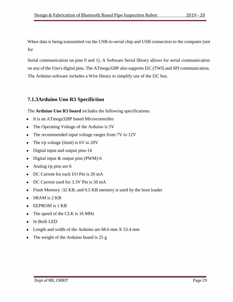
7.1.3Arduino Uno R3 Specifiction
The Arduino Uno R3 board includes the following specifications.
● It is an ATmega328P based Microcontroller
● The Operating Voltage of the Arduino is 5V
● The recommended input voltage ranges from 7V to 12V
● The i/p voltage (limit) is 6V to 20V
● Digital input and output pins-14
● Digital input & output pins (PWM)-6
● Analog i/p pins are 6
● DC Current for each I/O Pin is 20 mA
● DC Current used for 3.3V Pin is 50 mA
● Flash Memory -32 KB, and 0.5 KB memory is used by the boot loader
● SRAM is 2 KB
● EEPROM is 1 KB
● The speed of the CLK is 16 MHz
● In Built LED
● Length and width of the Arduino are 68.6 mm X 53.4 mm
● The weight of the Arduino board is 25 g

Design & Fabrication of Bluetooth Based Pipe Inspection Robot 2019 - 20
Dept of ME, CMRIT Page 30
7.2 BLUETOOTH MODULE (HC05)
HC-05 module is an easy to use Bluetooth SPP (Serial Port Protocol) module, designed for
transparent wireless serial connection setup. Serial port Bluetooth module is fully qualified Bluetooth
V2.0+EDR (Enhanced Data Rate) 3Mbps Modulation with complete 2.4GHz radio transceiver and
baseband. It uses CSR Blue core 04-External single chip Bluetooth system with CMOS technology
and with AFH (Adaptive Frequency Hopping Feature). It has the footprint as small as
12.7mmx27mm. Hope it will simplify your overall design/development cycle.
7.2.1HC05 MODULE TECHNICAL SPECIFICATION
Bluetooth protocol: Bluetooth Specification v2.0+EDR
Frequency: 2.4GHz ISM band
Modulation: GFSK(Gaussian Frequency Shift Keying)
Emission power: ≤4dBm, Class 2
Sensitivity: ≤-84dBm at 0.1% BER
Speed: Asynchronous: 2.1Mbps(Max) / 160 kbps, Synchronous: 1Mbps/1Mbps
Security: Authentication and encryption
Profiles: Bluetooth serial port
Power supply: +3.3VDC 50mA
Working temperature: -20 ~ +75Centigrade
Dimension: 26.9mm x 13mm x 2.2 mm
FIG7.2.1 Bluetooth Module HC05

Design & Fabrication of Bluetooth Based Pipe Inspection Robot 2019 - 20
Dept of ME, CMRIT Page 31
7.3 RELAY
A relay is basically a switch which is operated by an electromagnet. The electromagnet requires a
small voltage to get activated which we will give from the Arduino and once it is activated, it will
pull the contact to make the high voltage circuit.
FIG 7.3 Relay
A relay is basically a switch which is operated by an electromagnet. The electromagnet requires a
small voltage to get activated which we will give from the Arduino and once it is activated, it will
pull the contact to make the high voltage circuit.
The relay module we are going to use is the5v relay. It runs on 5V/12V and we can control it with
any micro-controller but we are going to use Arduino.
The Arduino relay module has total of six pins: three on one side and three on other side.On the
bottom side, there are three pins which are signal,5V /12Vand ground. We will connect these pins
with the Arduino. While on the other side, there are NC (Normally close), C (Common) and the NO
(normally open) which are the output pins of the 5V/12V relay. There, we will connect the output
device.

Design & Fabrication of Bluetooth Based Pipe Inspection Robot 2019 - 20
Dept of ME, CMRIT Page 32
Normally open state (NO) VS Normally closed state (NC)
The Arduino relay module can be used in two states which are
1. Normally open state (NO)
2. Normally closed state (NC)
Normally open (NO)
In the normally open state, the initial output of the relay will be low when it will be powered. In this
state, the common and the normally open pins are used.
Normally closed state (NC)
In the normally closed state, the initial output of the relay will be high when it will be powered. In
this state, the common and the normally close pins are used.
7.4 LEAD ACID BATTERY
The storage battery or secondary battery is such a battery where electrical energy can be
Stored as chemical energy and this chemical energy is then converted to electrical energy
As and when required. The conversion of electrical energy into chemical energy by
Applying external electrical source is known as charging of battery. Whereas conversion
Of chemical energy into electrical energy for supplying the external load is known as
Discharging of secondary battery.
During charging of battery, current is passed through it which causes some chemical
Changes inside the battery. This chemical changes absorb energy during their formation.
When the battery is connected to the external load, the chemical changes take place in
Reverse direction, during which the absorbed energy is released as electrical energy and
Supplied to the load. These batteries come with a light-weight (1 kg each) secure
Connector.
A universal charger with the following specifications is available off the shelf.
• AC input: 240 V
• Charger output: 30 V at 2 A

Design & Fabrication of Bluetooth Based Pipe Inspection Robot 2019 - 20
Dept of ME, CMRIT Page 33
FIG7.4 Battery
7.5 SERVO MOTOR
A servo motor is an electrical device which can push or rotate an object with great precision. If you
want to rotate and object at some specific angles or distance, then you use servo motor. It is just made
up of simple motor which run through servo mechanism. If motor is used is DC powered then it is
called DC servo motor, and if it is AC powered motor then it is called AC servo motor. We can get
a very high torque servo motor in a small and light weight packages. Doe to these features they are
being used in many applications like toy car, RC helicopters and planes, Robotics, Machine etc.
Servo motors are rated in kg/cm (kilogram per centimetre) most hobby servo motors are rated at
3kg/cm or 6kg/cm or 12kg/cm. This kg/cm tells you how much weight your servo motor can lift at a
particular distance. For example: A 6kg/cm Servo motor should be able to lift 6kg if the load is
suspended 1cm away from the motors shaft, the greater the distance the lesser the weight carrying
capacity.
The position of a servo motor is decided by electrical pulse and its circuitry is placed beside the
motor.

Design & Fabrication of Bluetooth Based Pipe Inspection Robot 2019 - 20
Dept of ME, CMRIT Page 34
FIG7.5 Servo motor

Design & Fabrication of Bluetooth Based Pipe Inspection Robot 2019 - 20
Dept of ME, CMRIT Page 35
CHAPTER-VIII
SOFTWARE DESCRIPTION
Software Used
• Arduino IDE
• Eclipse Android SDK (Software Development Kit)
Programming Languages Used
• Embedded C/C++
• Java & XML
8.1 PROGRAMMING THE ARDUINO
Step 1 − First you must have your Arduino board (you can choose your favourite board) and a USB
cable. In case you use Arduino UNO, Arduino Duemilanove, Nano, Arduino Mega 2560, or
Diecimila, you will need a standard USB cable (A plug to B plug), the kind you would connect to a
USB printer as shown in the following image
FIG 8.1 Usb Cable
Step 2 − Download Arduino IDE Software.
You can get different versions of Arduino IDE from the Download page on the Arduino Official
website. You must select your software, which is compatible with your operating system (Windows,
IOS, or Linux). After your file download is complete, unzip the file.
Design & Fabrication of Bluetooth Based Pipe Inspection Robot 2019 - 20
Dept of ME, CMRIT Page 36
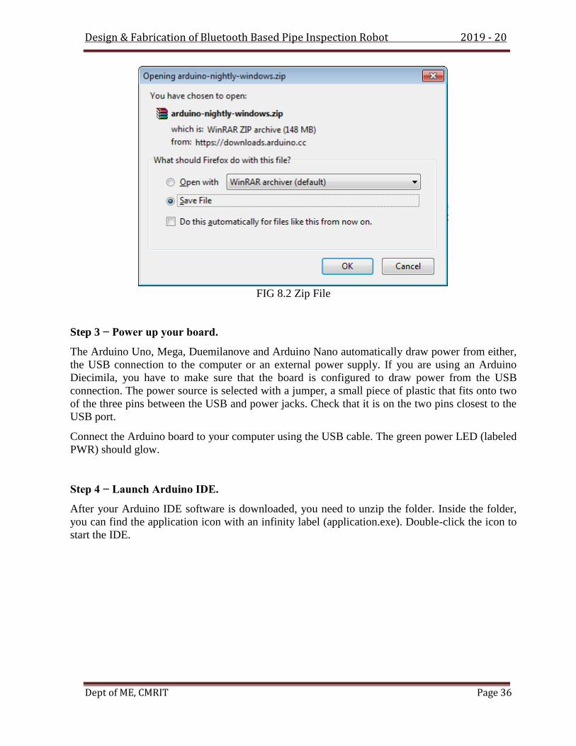
FIG 8.2 Zip File
Step 3 − Power up your board.
The Arduino Uno, Mega, Duemilanove and Arduino Nano automatically draw power from either,
the USB connection to the computer or an external power supply. If you are using an Arduino
Diecimila, you have to make sure that the board is configured to draw power from the USB
connection. The power source is selected with a jumper, a small piece of plastic that fits onto two
of the three pins between the USB and power jacks. Check that it is on the two pins closest to the
USB port.
Connect the Arduino board to your computer using the USB cable. The green power LED (labeled
PWR) should glow.
Step 4 − Launch Arduino IDE.
After your Arduino IDE software is downloaded, you need to unzip the folder. Inside the folder,
you can find the application icon with an infinity label (application.exe). Double-click the icon to
start the IDE.

Design & Fabrication of Bluetooth Based Pipe Inspection Robot 2019 - 20
Dept of ME, CMRIT Page 37
FIG 8.3 Arduino IDE File
Step 5 − Open your first project.
Once the software starts, you have two options −
Create a new project.
Open an existing project example.
To create a new project, select File → New.
FIG 8.4 Arduino IDE Environment

Design & Fabrication of Bluetooth Based Pipe Inspection Robot 2019 - 20
Dept of ME, CMRIT Page 38
To open an existing project example, select File → Example → Basics → Blink.
FIG 8.5 Arduino Setup
Here, we are selecting just one of the examples with the name Blink. It turns the LED on and off
with some time delay. You can select any other example from the list.
Step 6 − Select your Arduino board.
To avoid any error while uploading your program to the board, you must select the correct Arduino
board name, which matches with the board connected to your computer.
Go to Tools → Board and select your board.

Design & Fabrication of Bluetooth Based Pipe Inspection Robot 2019 - 20
Dept of ME, CMRIT Page 39
Here, we have selected Arduino Uno board according to our tutorial, but you must select the name
matching the board that you are using.
Step 7 − Select your serial port.
Select the serial device of the Arduino board. Go to Tools → Serial Port menu. This is likely to be
COM3 or higher (COM1 and COM2 are usually reserved for hardware serial ports). To find out,
you can disconnect your Arduino board and re-open the menu, the entry that disappears should be
of the Arduino board. Reconnect the board and select that serial port.
Design & Fabrication of Bluetooth Based Pipe Inspection Robot 2019 - 20
Dept of ME, CMRIT Page 40
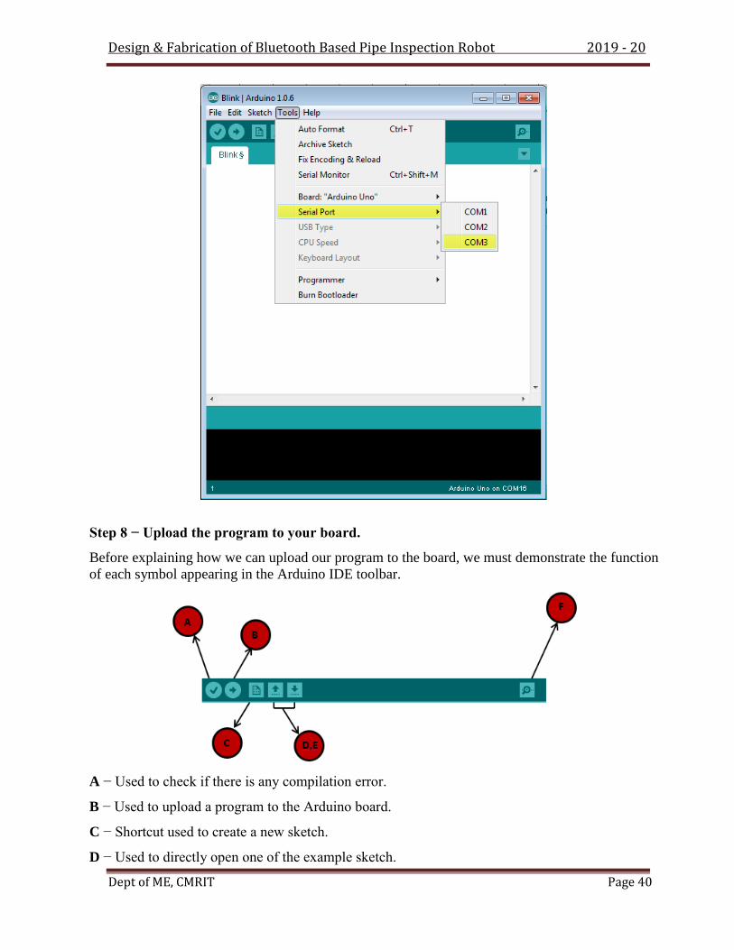
Step 8 − Upload the program to your board.
Before explaining how we can upload our program to the board, we must demonstrate the function
of each symbol appearing in the Arduino IDE toolbar.
A − Used to check if there is any compilation error.
B − Used to upload a program to the Arduino board.
C − Shortcut used to create a new sketch.
D − Used to directly open one of the example sketch.

Design & Fabrication of Bluetooth Based Pipe Inspection Robot 2019 - 20
Dept of ME, CMRIT Page 41
E − Used to save your sketch.
F − Serial monitor used to receive serial data from the board and send the serial data to the board.
Now, simply click the "Upload" button in the environment. Wait a few seconds; you will see the
RX and TX LEDs on the board, flashing. If the upload is successful, the message "Done uploading"
will appear in the status bar.
8.6 HOW TO USE BLUETOOTH MODULE HC-05
The HC-05 has two operating modes, one is the Data mode in which it can send and receive data
from other Bluetooth devices and the other is the AT Command mode where the default device
settings can be changed. We can operate the device in either of these two modes by using the key
pin as explained in the pin description.
It is very easy to pair the HC-05 module with microcontrollers because it operates using the Serial
Port Protocol (SPP). Simply power the module with +5V and connect the Rx pin of the module to
the Tx of MCU and Tx pin of module to Rx of MCU as shown in the figure below
FIG8.6 HC-05 Bluetooth Module
During power up the key pin can be grounded to enter into Command mode, if left free it will
by default, enter into the data mode. As soon as the module is powered you should be able to discover
the Bluetooth device as “HC-05” then connect with it using the default password 1234 and start

Design & Fabrication of Bluetooth Based Pipe Inspection Robot 2019 - 20
Dept of ME, CMRIT Page 42
communicating with it. The name password and other default parameters can be changed by entering
into the app.
For this tutorial I made two examples, controlling the Arduino using a smartphone and controlling
the Arduino using a laptop or a PC. In order not to overload this tutorial, in my next tutorial we will
learn how we can configure the HC-05 Bluetooth module and make a Bluetooth communication
between two separate Arduino Boards as master and slave devices.
8.7 CONNECTING THE SMARTPHONE TO THE HC-05 BLUETOOTH
MODULE AND THE ARDUINO
Now we are ready to connect the smartphone to the Bluetooth module and the Arduino. What we
need to do here is to activate the Bluetooth and the smartphone will find the HC-05 Bluetooth
module.
FIG8.7 Connection between Bluetooth Module and Arduino microcontroller
Then we need to pair the devices and the default password of the HC-05 module is 1234. After we
have paired the devices, we need an application for controlling the Arduino. There are many
applications in the Play Store for this purpose which will work with the Arduino code that we wrote.

Design & Fabrication of Bluetooth Based Pipe Inspection Robot 2019 - 20
Dept of ME, CMRIT Page 43
FIG 8.8 Mobile Controller
By using this app, we control devises using HC-05 Bluetooth module.
8.8 MASTER CODE
#define SM_Motor_pin1 6
#define SM_Motor_pin2 7
#define SM_Motor_pin3 8
char command;
void setup() {
// put your setup code here, to run once:
Serial.begin(9600);
pinMode(SM_Motor_pin1 , OUTPUT);
pinMode(SM_Motor_pin2 , OUTPUT);
pinMode( SM_Motor_pin3 , OUTPUT);
// initialised system in stop condition
digitalWrite(SM_Motor_pin1 ,HIGH);

Design & Fabrication of Bluetooth Based Pipe Inspection Robot 2019 - 20
Dept of ME, CMRIT Page 44
digitalWrite(SM_Motor_pin2 , HIGH);
digitalWrite( SM_Motor_pin3 ,HIGH);
}
void loop() {
// put your main code here, to run repeatedly:
while(Serial.available())
{
command = Serial.read();
Serial.print(command);
switch(command)
{
case 'A':
case 'D':
Motoroff();
break;
case 'E':
SM_Motor_stop();
break;
}
}
}

Design & Fabrication of Bluetooth Based Pipe Inspection Robot 2019 - 20
Dept of ME, CMRIT Page 45
CHAPTER -IX
RESULT
The mechanism used involves a central rod upon which a translational element is fitted which in
turn is connected to three frames of links and wheels. DC motors are attached to the wheels to
achieve the drive required. The mechanism allows autonomous robot used for in-pipe for small
accommodation in pipe diameters. An electronic circuit consisting of three relay switches is used
to control the entire circuitry of DC motors, camera and translational element. The camera is
mounted on the top of the assembly, Pipeline systems are prone to degradation and corrosion
resulting in a number of defects. Identification of defects is an important problem in chemical
plants, sewage pipes and other industries. This project aimed to create an autonomous robot for
in-pipe inspection capable of horizontal motion. The following results were obtained from the
completion of the project. The robot was capable of adapting to pipe diameters in the range of
200 mm to 260 mm. The robot was tested for motion in a 250 mm PVC pipe. It was found to
move horizontal direction
Robots can be effectively used as tools to carry out work in labor intensive, hazardous and
unreachable work environments. Pipeline systems are one such environment. Robots will be
successfully implemented in pipe line inspections and remove the rust from the inner surface.

Design & Fabrication of Bluetooth Based Pipe Inspection Robot 2019 - 20
Dept of ME, CMRIT Page 46
CHAPTER – X
FIELD OF APPLICATIONS OF PIPE
INSPECTION
• Conventional power plants
• Refineries
• Chemical and petrochemical plant
• Offshore
• Long distance city heating pipelines
• Food and drinks industries
• Communal waste water pipe systems
• Gas pipelines
• Video Inspection
• Visual Inspection
• Ultrasonic inspection

Design & Fabrication of Bluetooth Based Pipe Inspection Robot 2019 - 20
Dept of ME, CMRIT Page 47
CHAPTER – XI
FUTURE SCOPE
The project is limited in several ways and can be worked upon to broaden its features and
applications. A few of the improvements that can be implemented are mentioned below. Use
of tilted and guide wheels for traversing curves and bends in pipes. Use of lighter material for
the links to reduce the weight. Infrared/Ultrasonic inspection for better detection of defects.
Implementation of long range sensors. Implementation as a bore well rescue robot. Alternate
design without links to facilitate better motion.
ADVANTAGES
• The complete work process by reducing the human factor in dangerous work
Improving the efficiency and performance of the industry.
• It can be used to replace the work place of human to increase the speed the process by
increasing overall efficiency of process.
• Robot which is use to take care of pipes in terms of maintenance, cleaning and problem
solving and preventing.
• This robot fit with different size of pipe by adjustment
• Camera is placed for proper view of the pipe condition

Design & Fabrication of Bluetooth Based Pipe Inspection Robot 2019 - 20
Dept of ME, CMRIT Page 48
CHAPTER – XII
CONCLUSION
There are some many design configuration has been used for pipe inspection robot as showed in
paper, some may have same mechanism or driven action or communication network but they are
identically different from each other. As there application focused on only one purpose of inspecting
and cleaning with no or less involvement of human. That’s the reason we are working on designing
the robot which adapt according to size of pipe considering circular pipe. Hence we have chosen the
four bar linkage for our robot which is implemented on the frame of robot. Furthermore we have
used many sensors and night vision camera for the purpose of inspection with scrapper for cleaning.
So we believe with our project we will be able to inspect and clean the pipe effectively and
efficiently.

Design & Fabrication of Bluetooth Based Pipe Inspection Robot 2019 - 20
Dept of ME, CMRIT Page 49
LIST OF PARTS
Sl. No. PARTS Qty. MATERIAL
i. wheels 6 rubber
ii. frame Stand 1 Mild Steel
iii. Battery (12V D.C) 1 Lead-Acid
iv. Bolts & Nuts 6 Mild Steel
v. Permanent magnet D.C motor 3 Cu
vi. Connecting Wire - Cu
vii Lead screw 4 M.S
viii camera 1
ix Controller unit 1

Design & Fabrication of Bluetooth Based Pipe Inspection Robot 2019 - 20
Dept of ME, CMRIT Page 50
COSTING
Sl. No. PARTS Qty. MATERIAL AMOUNT (Rs)
i. wheels 1 ms 480/-
ii. frame Stand 1 Mild Steel 300/-
iii. Battery (12V D.C) 1 Lead-Acid 550/-
iv. Bolts & Nuts - Mild Steel 150/-
v. Permanent Magnet D.C
Motor
3 Cu 1200/-
vi. Connecting Wire - Cu 200/-
vii Controller unit 1 4000/-
viii Camera 1600/-
ix Lead screw 1 M.S 150/-
TOTAL= 8630 Rs
2. LABOUR COST
DRILLING, WELDING, POWER HACKSAW, GAS CUTTING, AND PCB DESIGNING:
Cost = 2000 Rs

Design & Fabrication of Bluetooth Based Pipe Inspection Robot 2019 - 20
Dept of ME, CMRIT Page 51
3. OVERHEAD CHARGES
The overhead charges are arrived by “Manufacturing cost”
Manufacturing Cost = Material Cost + Labour cost
= 8360 +2000
= 10360 Rs
TOTAL COST
Total cost = Material Cost + Labour cost + Overhead Charges
= 10360 Rs

Design & Fabrication of Bluetooth Based Pipe Inspection Robot 2019 - 20
Dept of ME, CMRIT Page 52
CHAPTER – XIII
REFERENCES
[1] AA Hashem, M Eng - eng.cu.edu.eg; Oil and gas pipeline design, maintenance and repair,
Cairo University, Department of Mining, petroleum and metallurgical Engineering, Egypt. [2]
AH Heidari, H Najjaran, M Mehrandezh, R Paranjape - 2010 - cdn.intechopen.com, Design,
development, dynamic analysis, andcontrol of a pipe crawling robot.
[3] I Doroftei, M Horodinca, E Mignon - 2000 - irisa.fr,A conceptual wheeled robot for inpipe
inspection. [4] M Horodinca, I Doroftei, E Mignon… - Proc. Int. Colloq. Mobile …, 2002 -
researchgate.net, A simple architecture for in pipe inspection robots.
[5] SS Rattan, Theory of machines, McGraw Hill, 3 Edition, 2009.
[6] K.Mahadevan, K. Balaveera Reddy, Design data hand book, CBS, 3 Edition, 1987.