
Advanced Keyboard Manuals
47
Document Version: v1.0R0 Date: 1/7/2009 1 Advanced Keyboard Manuals This Document System was last updated on 7 January 2009 Update history can be found here Contents Advanced Keyboard Manuals ................................................................................................................................. 1 Hardware Manuals ......................................................................................................................................... 4 Comparison Chart for Keyboards ........................................................................................................... 4 KB200 ...................................................................................................................................................... 5 KB200 Connectors and Controls ..................................................................................................... 5 Status LEDs.............................................................................................................................. 5 Key Buttons ............................................................................................................................. 5 USB Interface Connector ........................................................................................................ 6 Specifications and KB200 Modifications ........................................................................................ 6 KB220 ...................................................................................................................................................... 7 KB220 Connectors and Controls ..................................................................................................... 7 Status LEDs.............................................................................................................................. 7 Key Buttons ............................................................................................................................. 7 USB Interface Connector ........................................................................................................ 8 Specifications and KB220 Modifications ........................................................................................ 8 KB240 ...................................................................................................................................................... 9 KB240 Connectors and Controls ..................................................................................................... 9 Status LEDs.............................................................................................................................. 9 Key Buttons ........................................................................................................................... 10 MSR....................................................................................................................................... 10 Key Lock ................................................................................................................................ 10 USB Interface Connector ...................................................................................................... 10 Specifications and KB240 Modifications ...................................................................................... 10 KB270 .................................................................................................................................................... 12 KB270 Connectors and Controls ................................................................................................... 12 Status LEDs............................................................................................................................ 12 Key Buttons ........................................................................................................................... 13 MSR....................................................................................................................................... 13 USB Interface Connector ...................................................................................................... 13 Specifications and KB270 Modifications....................................................................................... 13 KB280 .................................................................................................................................................... 15 KB280 Connectors and Controls ................................................................................................... 15 Status LEDs............................................................................................................................ 15 Key Buttons ........................................................................................................................... 16 MSR....................................................................................................................................... 16
-
Upload
khangminh22 -
Category
Documents
-
view
1 -
download
0
Transcript of Advanced Keyboard Manuals
Document Version: v1.0R0 Date: 1/7/2009 1
Advanced Keyboard Manuals
This Document System was last updated on 7 January 2009
Update history can be found here
Contents
Advanced Keyboard Manuals ................................................................................................................................. 1
Hardware Manuals ......................................................................................................................................... 4
Comparison Chart for Keyboards ........................................................................................................... 4
KB200 ...................................................................................................................................................... 5
KB200 Connectors and Controls ..................................................................................................... 5
Status LEDs.............................................................................................................................. 5
Key Buttons ............................................................................................................................. 5
USB Interface Connector ........................................................................................................ 6
Specifications and KB200 Modifications ........................................................................................ 6
KB220 ...................................................................................................................................................... 7
KB220 Connectors and Controls ..................................................................................................... 7
Status LEDs.............................................................................................................................. 7
Key Buttons ............................................................................................................................. 7
USB Interface Connector ........................................................................................................ 8
Specifications and KB220 Modifications ........................................................................................ 8
KB240 ...................................................................................................................................................... 9
KB240 Connectors and Controls ..................................................................................................... 9
Status LEDs.............................................................................................................................. 9
Key Buttons ........................................................................................................................... 10
MSR ....................................................................................................................................... 10
Key Lock ................................................................................................................................ 10
USB Interface Connector ...................................................................................................... 10
Specifications and KB240 Modifications ...................................................................................... 10
KB270 .................................................................................................................................................... 12
KB270 Connectors and Controls ................................................................................................... 12
Status LEDs............................................................................................................................ 12
Key Buttons ........................................................................................................................... 13
MSR ....................................................................................................................................... 13
USB Interface Connector ...................................................................................................... 13
Specifications and KB270 Modifications ....................................................................................... 13
KB280 .................................................................................................................................................... 15
KB280 Connectors and Controls ................................................................................................... 15
Status LEDs............................................................................................................................ 15
Key Buttons ........................................................................................................................... 16
MSR ....................................................................................................................................... 16
Document Version: v1.0R0 Date: 1/7/2009 2
Key Lock ................................................................................................................................ 16
USB Interface Connector ...................................................................................................... 16
Specifications and KB280 Modifications ...................................................................................... 17
KB800 .................................................................................................................................................... 18
KB800 Connectors and Controls ................................................................................................... 18
Status LEDs............................................................................................................................ 18
Key Buttons ........................................................................................................................... 19
MSR ....................................................................................................................................... 19
Display .................................................................................................................................. 20
USB Hub (Port 2 ~ Port 4) ..................................................................................................... 20
External Power Port (DC Jack 5V) ......................................................................................... 20
USB Interface Connector (to Host PC) .................................................................................. 20
Specifications and KB800 Modifications ...................................................................................... 21
Appendix –Characters Table ......................................................................................................... 22
Firmware Manuals ........................................................................................................................................ 24
Vender ID and Product ID ..................................................................................................................... 24
Programming ........................................................................................................................................ 24
Commands ............................................................................................................................................ 24
Setting Macro Key definition of Layer #1 ..................................................................................... 25
Setting Macro Key definition of Layer #2 ..................................................................................... 26
Setting Macro Key definition of Layer #1 ..................................................................................... 27
Getting Macro Key definition of Layer #2 ..................................................................................... 27
Setting Language Key Map ........................................................................................................... 28
Getting Language Key Map ........................................................................................................... 29
Setting MSR Prefix/Suffix .............................................................................................................. 29
Getting MSR Prefix/Suffix ............................................................................................................. 30
Setting MSR Output Mode ........................................................................................................... 31
Getting MSR Output Mode ........................................................................................................... 33
Display Instructions ...................................................................................................................... 33
Appendix A: Keyboard layout with the key index number ................................................................... 35
KB200 ............................................................................................................................................ 35
Appendix B: Keyword list ...................................................................................................................... 36
Keyboard/Keypad ......................................................................................................................... 36
Special Keys .................................................................................................................................. 37
Software Manuals ......................................................................................................................................... 39
Advanced Keyboard Utility ................................................................................................................... 39
Introduction .................................................................................................................................. 39
Installing and Launching the Program .......................................................................................... 39
First Launching .............................................................................................................................. 39
Creating and Opening the Settings File ........................................................................................ 40
Configuring the Keyboard ............................................................................................................. 40
Configuration Mode tabs ...................................................................................................... 41
Keyboard tab................................................................................................................. 41

Document Version: v1.0R0 Date: 1/7/2009 3
Language Setting .................................................................................................. 42
Keyboard Layout ................................................................................................... 42
Key Button Appearance ................................................................................ 43
Macro Key Definition ............................................................................................ 43
Layer Lock ..................................................................................................... 45
Special Keys .................................................................................................. 45
List View of Key Definition ............................................................................ 47
MSR tab ........................................................................................................................ 47
Prefix/Suffix .......................................................................................................... 49
ISO ......................................................................................................................... 49
Decode Mode ....................................................................................................... 49
Track Data Filtering ....................................................................................... 49
Switch Output Order .................................................................................... 50
Miscellaneous tab ......................................................................................................... 50
Key Lock ................................................................................................................ 50
Display .................................................................................................................. 51
Saving the Settings to a File .......................................................................................................... 52
Updating the Settings to Keyboard .............................................................................................. 52
Testing the Keyboard .................................................................................................................... 53
OPOS Driver .......................................................................................................................................... 54
Line Display Class - KB800 Display ................................................................................................ 54
Driver Installation ................................................................................................................. 54
Supported Properties and Methods ..................................................................................... 55
Registry Information ............................................................................................................. 56
Sample OPOS Program ......................................................................................................................... 57
Line Display Class – KB800 Display ............................................................................................... 57
Installing and Launching Program ........................................................................................ 57
Testing the KB800 Display ..................................................................................................... 57
Source Code .......................................................................................................................... 58
Copies of CE and FCC Certificates ................................................................................................................. 59
KB800 .................................................................................................................................................... 59
Update History .............................................................................................................................................. 60

Document Version: v1.0R0 Date: 1/7/2009 4
Hardware Manuals
This part of documentation describes all the hardware of KB2xx/KB800 keyboards supplied by.
Comparison Chart for Keyboards
The following table compares main characteristics of KB2xx/KB800 keyboards.
Item KB200 KB220 KB240 KB270 KB280 KB800
Programmable
Keys 20 58 84 119 128 84
Magnetic Card
Reader NO Optional
Key Lock NO Optional
Display NO YES
Interface USB
Power
Consumption 5V DC/Max.60mA, Min.30mA
Mechanical
dimensions,
mm
(L x W x H)
177 x 108 x
37
230 x 200 x
42
190 x 260 x
43
235 x 350 x
50
235 x 350 x
50
260 x 215 x
58

Document Version: v1.0R0 Date: 1/7/2009 18
KB800
KB800 84-Keys programmable keyboard is specially designed for most dedicated applications, such as banking
system, POS system etc, and it is also built in one USB hub which is able to provide additional 3 attached USB
peripherals or devices to their USB ready PC. For the key buttons, each key can be programmable up to 127
characters and can be defined through PC by the user. The integrated magnetic stripe reader can read
authorization cards, credit card or bank card etc. The Display is able to show up to 40 characters (20 columns x
2 lines). Also KB800 with built in Cherry mechanical key switch to assure of the long life data entry usage.
KB800 Connectors and Controls
The back connectors:
Click on the area on the picture above to learn more about the KB800:
Status LEDs
There are four status LEDs which are able to light 3 colors: Green, Red and orange. The four LEDs are:
Display
Key Buttons
Status LEDs
MSR
Port 4 Port 3 Port 2 To host PC DC Jack 5V *Required if attached high- powered USB device

Document Version: v1.0R0 Date: 1/7/2009 19
Layer Status LED is used to indicate current used layer (number). If is green light, it is indicating the used
layer number is 1 (base layer). If is red light, it is indicating the used layer number is 2.
Num Lock / Caps Lock LED the possible lights are listed below:
Off: The Num Lock and the Caps Lock are all off.
Green: The Num Lock is on and the Caps Lock is off.
Red: The Num Lock is off and the Caps Lock is on.
Orange: The Num Lock and Caps Lock are both on.
State Port 2 LED the possible lights are listed below:
Green: Not attached any USB device.
Orange: Attached USB device.
Blinking in Green: Keyboard error.
Port 3 / Port 4 State LED the possible lights are listed below:
Off: The Port 3 and the Port 4 are not attached any USB peripherals or devices.
Green: The Port 3 is attached USB peripheral or device, but Port 4 is not attached any USB
peripheral or device.
Red: The Port 4 is attached USB peripheral or device, but Port 3 is not.
Orange: The Port 3 and Port 4 are both attached USB peripherals and devices.
Key Buttons
KB800 has 84 user programmable keys (7 x 12 keyboard matrix). Each key can be programmed up to 127
bytes characters.
MSR
The Magnetic Stripe Reader is able to read ISO 7116 standard Track 1, Track 2 and Track 3. If the swipe card
process is OK, there will be a beep sound from the internal buzzer. If failed, there will be a three short beep
sound.
State Port 2 LED
Num Lock/Caps Lock LED
Port 3 / Port 4 State LED
Layer Status LED

Document Version: v1.0R0 Date: 1/7/2009 20
Display
The display that KB800 uses is featuring 20x2 characters displayed, STN, Positive, Reflective, Yellow green text
LCD with backlight. The displayed message can be performed by the KB800 OPOS driver (customer display
class).
Refer to Appendix for the used pattern of all characters.
USB Hub (Port 2 ~ Port 4)
The KB800 provides 3-port Universal Serial Bus USB hub that allows a user to connect up to three USB
peripherals or devices to their USB ready PC, and is compatible with USB1.1 to 2.0.
External Power Port (DC Jack 5V)
Power for the KB800 can be provided directly from the USB bus for connection up to three low-powered USB
devices. When using the included 5V DC adapter in self-powered mode, the KB800 can support up to three
high-powered USB devices. The time to attach the adapter is when the power consumption of attached USB
device(s) is over than 250 mA.
USB Interface Connector (to Host PC)
The cable that KB800 uses is USB interface, which is compatible with USB1.1 to 2.0. The USB cable also
provides the power for KB800.
Document Version: v1.0R0 Date: 1/7/2009 21
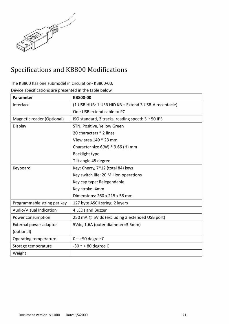
Specifications and KB800 Modifications
The KB800 has one submodel in circulation- KB800-00.
Device specifications are presented in the table below.
Parameter KB800-00
Interface (1 USB HUB: 1 USB HID KB + Extend 3 USB-A receptacle)
One USB extend cable to PC
Magnetic reader (Optional) ISO standard, 3 tracks, reading speed: 3 ~ 50 IPS.
Display STN, Positive, Yellow Green
20 characters * 2 lines
View area 149 * 23 mm
Character size 6(W) * 9.66 (H) mm
Backlight type
Tilt angle 45 degree
Keyboard Key: Cherry, 7*12 (total 84) keys
Key switch life: 20 Million operations
Key cap type: Relegendable
Key stroke: 4mm
Dimensions: 260 x 215 x 58 mm
Programmable string per key 127 byte ASCII string, 2 layers
Audio/Visual Indication 4 LEDs and Buzzer
Power consumption 250 mA @ 5V dc (excluding 3 extended USB port)
External power adaptor
(optional)
5Vdc, 1.6A (outer diameter=3.5mm)
Operating temperature 0 ~ +50 degree C
Storage temperature -30 ~ + 80 degree C
Weight

Document Version: v1.0R0 Date: 1/7/2009 22
Appendix –Characters Table

Document Version: v1.0R0 Date: 1/7/2009 23

Document Version: v1.0R0 Date: 1/7/2009 24
Firmware Manuals
This part of the documentation describes the communication protocol of firmware related to KB2xx/KB800
keyboards.
Vender ID and Product ID
Before starting the communication, it needs to get the control handle for the later data transferring. The
KB2xx/KB8xx using the same vender ID, the value is 5735 (0x1667 in hex format). The product IDs are listed as
below:
Model Product ID (decimal)
KB200 10
KB220 11
KB240 12
KB270 13
KB280 14
KB800 8
Programming
Using feature report function to tranfer the HID USB command and data. The HidD_SetFeature1 function is
used to send out the data. The HidD_GetFeature2 function is used to retrieve the incoming data. The
command data size is 131 bytes. Below is the command and data format:
1st byte 2nd byte 3rd ~ 131st
Report ID Command Code Data
The value of Report ID is always to be 0x00.
Note:
1. The HidD_SetFeature routine sends a feature report to HID control. For more details, please refer to
Microsoft MSDN website.
2. The HidD_GetFeature routine returns a feature report from HID control. For more details, please refer to
Microsoft MSDN website.
Commands
The commands are used to control the keyboard device and can be issued through the USB port. Below table
list all available commands:
Command Code Description
0x10 Set Macro Key definition of Layer #1
0x20 Set Macro Key definition of Layer #2
0x30 Set Language Key Map
0x40 Set MSR Prefix/Suffix
0x50 Set MSR Output Mode

Document Version: v1.0R0 Date: 1/7/2009 25
0x60 Get Macro Key definition of Layer #1
0x70 Get Macro Key definition of Layer #2
0x80 Get Language Key Map
0x90 Get MSR Prefix/Suffix
0xA0 Get MSR Output Mode
0xB0 Display Instructions
Setting Macro Key definition of Layer #1
Function: Defines the macro key of layer #1
Data format: KLdd…d, where K is the binary value that indicates the index number of key button, L is
the binary value that indicates the length of macro key string, dd…d is the content of
macro key string
Details:
The index number of key button for each keyboard can refer to the Appendix A. The macro key string may
contain the letters, numbers, function keys, control keys or special keys.
For the macro key string, the letters and numbers are presented as their own ASCII code. For the others
(function/control/special keys), will use the keyword to present. Please refer Appendix B for details.
Example: here is a sample to show how to define a macro key with the key combination – Alt+F+O, most of
the programs implement this key combination to open a file.
The report ID is 0x00. The command code is 0x10 (for layer #1), and the key index number to be programmed
is 3 (key location is in the upper-right corner of keyboard layout). The macro key string will be: <Alt>FO
The length of macro key string is 7. Then the command data will be as follow:
Visual Basic 6 Sample Code:
Redim bCmdData(131 - 1) as Byte
bCmdData(0)=&H0 „Report ID
bCmdData(1)=&H10 „Command Code for layer #1
bCmdData(2)=&H03 „Key Index
bCmdData(3)=&H7 „The string length of “<Alt>FO”
bCmdData(4)=&H3C „ASCII code of ”<”
bCmdData(5)=&H41 „ASCII code of ”A”
bCmdData(6)=&H41 „ASCII code of ”l”
bCmdData(7)=&H6C „ASCII code of “t”
bCmdData(8)=&H74 „ASCII code of “>”
bCmdData(9)=&H3E „ASCII code of “F”
bCmdData(10)=&H4F „ASCII code of “O”
. Rpt ID Cmd Key Idx Length Macro Key Definition
No. 1st 2nd 3rd 4th 5th 6th 7th 8th 9th 10th 11th 12 th-131th
Value 0x00 0x10 0x03 0x07 0x3c 0x41 0x6c 0x74 0x3e 0x46 0x4f 0x00
Char. < A l t > F O

Document Version: v1.0R0 Date: 1/7/2009 26
HidD_SetFeature(HidDevice, bCmdData(0), 131)
HidDevice is the handle to the device path of specified vendor ID and product ID of HID USB keyboard.
Setting Macro Key definition of Layer #2
Function: Defines the macro key of layer #2
Data format: KLdd…d, where K is the binary value that indicates the index number of key button, L is
the binary value that indicates the length of macro key string, dd…d is the content of
macro key string
Details:
The index number of key button for each keyboard can refer to the Appendix A. The macro key string may
contain the letters, numbers, function keys, control keys or special keys.
For the macro key string, the letters and numbers are presented as their own ASCII code. For the others
(function/control/special keys), will use the keyword to present. Please refer Appendix B for details.
Example: here is a sample to show how to the define a macro key with the key combination – Alt+F+O, most
of the programs implement this key combination to open a file.
The report ID is 0x00. The command code is 0x20 (for layer #2), and the key index number to be programmed
is 3 (key location is in the upper-right corner of keyboard layout). The macro key string will be: <Alt>FO
The length of macro key string is 7. Then the command data will be as follow:
Visual Basic 6 Sample Code:
Redim bCmdData(131 - 1) as Byte
bCmdData(0)=&H0 „Report ID
bCmdData(1)=&H20 „Command Code for layer #2
bCmdData(2)=&H03 „Key Index
bCmdData(3)=&H7 „The string length of “<Alt>FO”
bCmdData(4)=&H3C „ASCII code of ”<”
bCmdData(5)=&H41 „ASCII code of ”A”
bCmdData(6)=&H41 „ASCII code of ”l”
bCmdData(7)=&H6C „ASCII code of “t”
bCmdData(8)=&H74 „ASCII code of “>”
bCmdData(9)=&H3E „ASCII code of “F”
bCmdData(10)=&H4F „ASCII code of “O”
HidD_SetFeature(HidDevice, bCmdData(0), 131)
HidDevice is the handle to the device path of specified vendor ID and product ID of HID USB keyboard.
. Rpt ID Cmd Key Idx Length Macro Key Definition
No. 1st 2nd 3rd 4th 5th 6th 7th 8th 9th 10th 11th 12 th-131th
Value 0x00 0x20 0x03 0x07 0x3c 0x41 0x6c 0x74 0x3e 0x46 0x4f 0x00
Char. < A l t > F O

Document Version: v1.0R0 Date: 1/7/2009 27
Setting Macro Key definition of Layer #1
Function: Retrieves the macro key definition of layer #1
Data format: K, where K is the binary value that indicates the index number of key button
Details:
The index number of key button for each keyboard can refer to the Appendix A.
Example: here is a sample to show how to the retrieve a macro key definition.
The report ID is 0x00. The command code is 0x60 (for layer #1), and the key index number to be programmed
is 3 (key location is in the upper-right corner of keyboard layout). Then the command data will be as follow:
Visual Basic 6 Sample Code:
Redim bCmdData(131 - 1) as Byte
bCmdData(0)=&H0 „Report ID
bCmdData(1)=&H60 „Command Code for layer #2
bCmdData(2)=&H03 „Key Index
HidD_GetFeature(HidDevice, bCmdData(0), 131)
HidDevice is the handle to the device path of specified vendor ID and product ID of HID USB keyboard.
If succeeded, the macro key string will store in the bCmdData buffer, which the 3rd byte is the length of macro
key string, after 4th byte (including 4th byte) data is the macro key string.
Getting Macro Key definition of Layer #2
Function: Gets the macro key definition of layer #1
Data format: K, where K is the binary value that indicates the index number of key button
Details:
The index number of key button for each keyboard can refer to the Appendix A.
Example: here is a sample to show how to the retrieve a macro key definition.
The report ID is 0x00. The command code is 0x70 (for layer #2), and the key index number to be programmed
is 3 (key location is in the upper-right corner of keyboard layout). Then the command data will be as follow:
Visual Basic 6 Sample Code:
Redim bCmdData(131 - 1) as Byte
. Rpt ID Cmd Key Idx Remains
No. 1st 2nd 3rd 4th -131th
Value 0x00 0x60 0x03 0x00
. Rpt ID Cmd Key Idx Remains
No. 1st 2nd 3rd 4th -131th
Value 0x00 0x70 0x03 0x00

Document Version: v1.0R0 Date: 1/7/2009 28
bCmdData(0)=&H0 „Report ID
bCmdData(1)=&H60 „Command Code for layer #2
bCmdData(2)=&H03 „Key Index
HidD_GetFeature(HidDevice, bCmdData(0), 131)
HidDevice is the handle to the device path of specified vendor ID and product ID of HID USB keyboard.
If succeeded, the macro key string will store in the bCmdData buffer, which the 3rd byte is the length of macro
key string, after 4th byte (including 4th byte) data is the macro key string.
Setting Language Key Map
Function: Defines the control value and HID Usage ID of ASCII code
Data format: RCiIiCi+1Ii+1…, where R is the report index, Ci is the binary value that indicates the used
control value of following key Usage ID, Ii is the binary value that indicates the key Usage
ID. The index value i is the ASCII code that related the control value Ci and the Usage ID
Ii.
Details:
Because the data size of the key map can be up to 512 bytes, so it needs to send 4 reports to keyboard for
the updating, so the value of report index R is from 0 to 3.
Each ASCII code is related with the control value and the Usage ID, and different language keyboard may use
different control value and Usage ID for a certain ASCII code. For example, for the English keyboard, the
Usage ID of letter “x” is 0x1C, but for Germany keyboard, the “x” Usage ID is 0x1D.
1st report:
. Rpt ID Cmd Rpt Idx Key Map
No. 1st 2nd 3rd 4th 5th 6th 7th … 130 th 131th
Value 0x00 0x30 0x00 C0 I0 C1 I1 … C63 I63
2nd report:
. Rpt ID Cmd Rpt Idx Key Map
No. 1st 2nd 3rd 4th 5th 6th 7th … 130 th 131th
Value 0x00 0x30 0x01 C64 I64 C65 I65 … C127 I127
3rd report:
. Rpt ID Cmd Rpt Idx Key Map
No. 1st 2nd 3rd 4th 5th 6th 7th … 130 th 131th
Value 0x00 0x30 0x02 C129 I129 C130 I130 … C191 I191
4th report:
. Rpt ID Cmd Rpt Idx Key Map
No. 1st 2nd 3rd 4th 5th 6th 7th … 130 th 131th
Value 0x00 0x30 0x03 C192 I192 C193 I193 … C255 I255
Control value tells keyboard how to hit the control keys (Shift/Alt/Ctrl) or the way of hitting the key while
sending out the Usage ID. For example, the lower case letter “a”, the control value is 0. For the upper case
letter “A”, the control value is 1. Below shows all the control values:
0: No control key hit, direct to send out the Usage ID.

Document Version: v1.0R0 Date: 1/7/2009 29
1: Press Shift key, and then send out the Usage ID.
6: Press right Alt key, and then send out the Usage ID.
16: Double hit the key button.
17: Press Shift key and double hit the key button.
Not all the ASCII code needs to be defined by the control value and Usage ID. For example, before ASCII code
32, only the value 13 (for Enter key) is needed to be defined. For the undefined ASCII code, just leave 0 value
in the buffer.
Getting Language Key Map
Function: Gets the control value and HID Usage ID of ASCII code
Data format: R, where R is the report index
Details:
The index number of key button for each keyboard can refer to the Appendix A.
Example: here is a sample to show how to the retrieve language key map with specified report index.
The report ID is 0x00. The command code is 0x80, and the report index number is 3. Then the command data
will be as follow:
Visual Basic 6 Sample Code:
Redim bCmdData(131 - 1) as Byte
bCmdData(0)=&H0 „Report ID
bCmdData(1)=&H80 „Command Code for retrieve key map
bCmdData(2)=&H03 „Report Index
HidD_GetFeature(HidDevice, bCmdData(0), 131)
HidDevice is the handle to the device path of specified vendor ID and product ID of HID USB keyboard. The
retrieved data will put in the later 4th byte of bCmdData buffer. The retrieved data format is same to the data
format of updating language key map command.
Setting MSR Prefix/Suffix
Function: Defines the prefix or suffix of MSR output data
Data format: KLdd…d, where K is the binary value that indicates which type of prefix or suffix to be
updated., L is the binary value that indicates the length of macro key string, dd…d is the
content of updated prefix or suffix string
. Rpt ID Cmd Rpt Idx Remains
No. 1st 2nd 3rd 4th -131th
Value 0x00 0x80 0x03 0x00

Document Version: v1.0R0 Date: 1/7/2009 30
Details:
The prefix and suffix string may contain the letters, numbers, function keys, control keys or special keys.
There are four kinds of prefix and suffix, which are package, Track 1, Track 2 and Track 3.
Below is the list of type value for prefix and suffix:
0 (Prefix for package) The prefix string will append in the start of whole track data.
1 (Suffix for package) The suffix string will append in the end of whole track data.
2 (Prefix for Track 1) The prefix string will append in the start of track 1 data.
3 (Suffix for Track 1) The suffix string will append in the end of track 1 data.
4 (Prefix for Track 2) The prefix string will append in the start of track 2 data.
5 (Suffix for Track 2) The suffix string will append in the end of track 2 data.
6 (Prefix for Track 3) The prefix string will append in the start of track 3 data.
7 (Suffix for Track 3) The suffix string will append in the end of track 3 data.
Example: here is a sample to show how to define the prefix of Track 1.
The report ID is 0x00. The command code is 0x40, and the type value to be programmed is 2. The prefix string
will be “<TK1>=”.
The length of macro key string is 6. Then the command data will be as follow:
Visual Basic 6 Sample Code:
Redim bCmdData(131 - 1) as Byte
bCmdData(0)=&H0 „Report ID
bCmdData(1)=&H40 „Command Code
bCmdData(2)=&H02 „Type value for the Prefix of Track 1
bCmdData(3)=&H6 „The string length of “<TK1=>”
bCmdData(4)=&H3C „ASCII code of ”<”
bCmdData(5)=&H54 „ASCII code of ”T”
bCmdData(6)=&H4B „ASCII code of ”K”
bCmdData(7)=&H31 „ASCII code of “1”
bCmdData(8)=&H3D „ASCII code of “=”
bCmdData(9)=&H3E „ASCII code of “>”
HidD_SetFeature(HidDevice, bCmdData(0), 131)
HidDevice is the handle to the device path of specified vendor ID and product ID of HID USB keyboard.
Getting MSR Prefix/Suffix
Function: Gets the prefix or suffix of MSR output data
Data format: K, where K is the binary value that indicates which type of prefix or suffix to be updated.
. Rpt ID Cmd Typ Val Length Macro Key Definition
No. 1st 2nd 3rd 4th 5th 6th 7th 8th 9th 10th 11th-131th
Value 0x00 0x40 0x02 0x06 0x3c 0x54 0x4B 0x31 0x3D 0x3E 0x00
Char. < T K 1 = >

Document Version: v1.0R0 Date: 1/7/2009 31
Details:
The prefix and suffix string may contain the letters, numbers, function keys, control keys or special keys.
There are four kinds of prefix and suffix, which are package, Track 1, Track 2 and Track 3.
Below is the list of type value for prefix and suffix:
0 (Prefix for package) The prefix string will append in the start of whole track data.
1 (Suffix for package) The suffix string will append in the end of whole track data.
2 (Prefix for Track 1) The prefix string will append in the start of track 1 data.
3 (Suffix for Track 1) The suffix string will append in the end of track 1 data.
4 (Prefix for Track 2) The prefix string will append in the start of track 2 data.
5 (Suffix for Track 2) The suffix string will append in the end of track 2 data.
6 (Prefix for Track 3) The prefix string will append in the start of track 3 data.
7 (Suffix for Track 3) The suffix string will append in the end of track 3 data.
Example: here is a sample to show how to retrieve the prefix of Track 1.
The report ID is 0x00. The command code is 0x90, and the type value to be retrieved is 2.
The length of macro key string is 6. Then the command data will be as follow:
. Rpt ID Cmd Typ Val Remains
No. 1st 2nd 3rd 4th-131th
Value 0x00 0x90 0x02 0x00
Visual Basic 6 Sample Code:
Redim bCmdData(131 - 1) as Byte
bCmdData(0)=&H0 „Report ID
bCmdData(1)=&H90 „Command Code
bCmdData(2)=&H02 „Type value for the Prefix of Track 1
HidD_GetFeature(HidDevice, bCmdData(0), 131)
HidDevice is the handle to the device path of specified vendor ID and product ID of HID USB keyboard. The
retrieved data will put in the later 4th byte of bCmdData buffer. The retrieved data format is same to the data
format of updating MSR prefix/suffix command.
Setting MSR Output Mode
Function: Defines the tracks output sequence, required tracks to be output and the Start
Sentinel/End Sentinel for each track
Data format: BD1D2D3S1E1S2E2S3E3O, where B is the fixed binary value and the value is always to be 0,
D1, D2 and D3 is the binary value of decode mode for Track1, Track2 and Track3
separately. S1E1 is the ASCII of Start Sentinel and End Sentinel for Track1. S2E2 is the ASCII
of Start Sentinel and End Sentinel for Track2. S3E3 is the ASCII of Start Sentinel and End
Sentinel for Track3. O is the binary value that indicates the output order.

Document Version: v1.0R0 Date: 1/7/2009 32
Details:
Decode mode is used to limit which track needs to be or not to be output. The decode mode value has
below three values:
0 (Disabled) The specified track will not be output, regardless of the specified track is decoded or
not.
1 (Required) The specified track needs to be decoded. If the specified track is not decoded, the MSR
will not output any data even other tracks are decoded.
2 (Enabled) The specified track can be output. If the specified track data is not decoded, the track
filed will leave blank.
The output order defines the sequence of track1-3 to be output, which can be six kinds of orders. The values
are:
0 The track order is Track1-Track2-Track3.
1 The track order is Track1-Track3-Track2.
2 The track order is Track2-Track1-Track3.
3 The track order is Track2-Track3-Track1.
4 The track order is Track3-Track1-Track2.
5 The track order is Track3-Track2-Track1.
Example: here is a sample to show how to define the MSR output mode.
The report ID is 0x00. The command code is 0x50, and the B value fixed to be 0. The Track1, Track2 and Track3
decode modes are enabled, required and disabled separately. The Track1 SS (Start Sentinels) is “%”, the
Track2 SS is “;” and the Track3 SS is “;”. The ES (End Sentinel) is “?” for all tracks. The output order value is 5
(Track3-2-1). Then the command data will be as follow:
Visual Basic 6 Sample Code:
Redim bCmdData(131 - 1) as Byte
bCmdData(0)=&H0 „Report ID
bCmdData(1)=&H40 „Command Code
bCmdData(2)=&H00 „Fixed to 0
bCmdData(3)=&H2 „Track1 decode mode - enabled
bCmdData(4)=&H1 „Track2 decode mode - required
bCmdData(5)=&H0 „Track3 decode mode - disabled
bCmdData(6)=&H25 „Track 1 SS - %
bCmdData(7)=&H3F „Track 1 ES - ?
bCmdData(8)=&H3B „Track 2 SS - ;
bCmdData(9)=&H3F „Track 2 ES - ?
bCmdData(8)=&H3B „Track 3 SS - ;
bCmdData(9)=&H3F „Track 3 ES - ?
. Rpt ID Cmd B D1 D2 D3 S1 E1 S2 E2 S3 E3 O Remains
No. 1st 2nd 3rd 4th 5th 6th 7th 8th 9th 10th 11th 12th 13th 14th-131th
Value 0x00 0x50 0x00 0x02 0x01 0x00 0x25 0x3F 0x3B 0x3F 0x3B 0x3F 0x05 0x00
Char. % ? ; ? ; ?

Document Version: v1.0R0 Date: 1/7/2009 33
bCmdData(8)=&H5 „Output order – Track3-2-1
HidD_SetFeature(HidDevice, bCmdData(0), 131)
HidDevice is the handle to the device path of specified vendor ID and product ID of HID USB keyboard.
Getting MSR Output Mode
Function: Gets the tracks output sequence, required tracks to be output and the Start Sentinel/End
Sentinel for each track
Data format: B, where B is the fixed binary value and the value is always to be 0
Details:
The retrieving data content can refer to Updating MSR Output Mode.
Example: here is a sample to show how to retrieve the MSR output mode settings.
The report ID is 0x00. The command code is 0x50.
. Rpt ID Cmd B Val Remains
No. 1st 2nd 3rd 4th-131th
Value 0x00 0x50 0x00 0x00
Visual Basic 6 Sample Code:
Redim bCmdData(131 - 1) as Byte
bCmdData(0)=&H0 „Report ID
bCmdData(1)=&H50 „Command Code
bCmdData(2)=&H00 „Always fixed to 0
HidD_GetFeature(HidDevice, bCmdData(0), 131)
HidDevice is the handle to the device path of specified vendor ID and product ID of HID USB keyboard. The
retrieved data will put in the later 4th byte of bCmdData buffer. The retrieved data format is same to the data
format of updating MSR output mode command.
Display Instructions
Function: Makes display to perform certain action (Only for KB800 keyboard)
Data format: Dxx…x, where D is the binary value that indicates the action that display will perform.,
xx…x is the parameters of action may use, and the parameter format is related to the
action

Document Version: v1.0R0 Date: 1/7/2009 34
Details:
The binary values of action and the related parameters are listed as below:
Action Value (D) Description Parameters (xx…x)
0 Clear display -
1 Set cursor position rc, where r is the row (0~1), c is the column (0~19)
2 Display message mm…m, where mm…m is the string that be displayed in the
LCD, the string length is 1 ~ 40 long.
3 Read cursor position -
4 Read message -
5 Control backlight c, where c: 0 (turn off), 1 (turn on)

Document Version: v1.0R0 Date: 1/7/2009 35
Appendix A: Keyboard layout with the key index number
The index number is presented in the key button in red.
KB200
0 1 2 3
4 5 6 7
8 9 10 11
12 13 14 15
16 17 18 19

Document Version: v1.0R0 Date: 1/7/2009 36
Appendix B: Keyword list
Keyboard/Keypad
Usage Name Keyword
Keyboard ESCAPE <Esc>
Keyboard F1 <F1>
Keyboard F2 <F2>
Keyboard F3 <F3>
Keyboard F4 <F4>
Keyboard F5 <F5>
Keyboard F6 <F6>
Keyboard F7 <F7>
Keyboard F8 <F8>
Keyboard F9 <F9>
Keyboard F10 <F10>
Keyboard F11 <F11>
Keyboard F12 <F12>
Keyboard BackSpace <BackSpace>
Keyboard Tab <Tab>
Keyboard Caps Lock <CapsLock>
Keyboard Enter <Enter>
Keyboard Left Shift <LShift>
Keyboard Right Shift <RShift>
Keyboard Left Ctrl <LCtrl>
Keyboard Left WinKey <LGU>
Keyboard Space <SpaceBar>
Keyboard Right Alt <RAlt>
Keyboard Right WinKey <RGUI>
Keyboard Right Ctrl <RCtrl>
Keyboard Print Screen/SysRq <PrintScreenSysRq>
Keyboard Scroll Lock <ScrollLock>
Keyboard Pause/Break <PauseBreak>
Keyboard Insert <Insert>
Keyboard Home <Home>
Keyboard Page Up < PageUp >
Keyboard Delete <Delete>
Keyboard End < End >
Keyboard Page Down <PageDown>
Keyboard Up Arrow <UpArrow>

Document Version: v1.0R0 Date: 1/7/2009 37
Keyboard Insert <Insert>
Keyboard Left Arrow <LeftArrow>
Keyboard Down Arrow <DownArrow>
Keyboard Right Arrow <RightArrow>
Keypad Num Lock <NumLock>
Keypad / <Pad/>
Keypad * <Pad*>
Keypad - <Pad ->
Keypad 7 <Pad7>
Keypad 8 <Pad8>
Keypad 9 <Pad9>
Keypad + <Pad+>
Keypad 4 < Pad4>
Keypad 5 <Pad5>
Keypad 6 <Pad6>
Keypad 1 <Pad1>
Keypad 2 <Pad2>
Keypad 3 <Pad3>
Keypad Enter <PadEnter>
Keypad 0 <Pad0>
Keypad . <Pad.>
Layer Lock <LayerLock>
Special Keys
Usage Name Keyword
Power <Power>
Sleep <Sleep>
Wake Up <WakeUp>
Scan Next Track <ScanNextTrack>
Scan Previous Track <ScanPreTrack>
Stop <Stop>
Play/Pause <Play/Pause>
Mute <Mute>
Bass Boost <BassBoost>
Loudness <Loudness>
Volume Up <VolumeUp>
Volume Down <VolumeDown>
Bass Up <BassUp>
Bass Down <BassDown>
Treble Up <TrebleUp>
Treble Down <TrebleDown>

Document Version: v1.0R0 Date: 1/7/2009 38
Media Select <MediaSelect>
Mail <Mail>
Calculator <Calculator>
My Computer <MyComputor>
Web Search <WWWSearch>
Home Page <WWWHome>
Web Page Back <WWWBack>
Web Page Forward <WWWForward>
Web Page Stop <WWWStop>
Refresh Web Page <WWWRefresh>
Favorites Web Page <WWWFavorites>
Keyboard F13 <F13>
Keyboard F14 <F14>
Keyboard F15 <F15>
Keyboard F16 <F16>
Keyboard F17 <F17>
Keyboard F18 <F18>
Keyboard F19 <F19>
Keyboard F20 <F20>
Keyboard F21 <F21>
Keyboard F22 <F22>
Keyboard F23 <F23>
Keyboard F24 <F24>
Delay 100 mini-second <Delay100ms>
Delay 1 second <Delay1s>
Reset Shift/Ctrl/Alt key states <->

Document Version: v1.0R0 Date: 1/7/2009 39
Software Manuals
This part of the documentation describes the PC software related to KB2xx/KB800 keyboards.
Advanced Keyboard Utility
Introduction
Thank you for purchasing KB2xx/KB800 keyboards. Advanced Keyboard Utility (AKU) program has been
designed to work in conjunction with the keyboards equipped with keys, MSR reader, Key Lock and
display (depending on the model). The AKU provides an easy way to utilize the functions.
Installing and Launching the Program
If your system has ever installed the old version program, please remove it before installing.
Insert the AKU Setup CD into the CD-ROM drive of your PC. The setup program begins automatically.
There is no need to choose your CD-ROM drive from your on-screen settings, or to use the <RUN>
prompt.
A html page will pop up. Click [Install Advanced Keyboard Utility program]. The setup wizard will now
guide you during the setup procedure. You will be prompted to accept a default path for the AKU
program, which is "C:\Program Files\”.
When the setup procedure is completed, remove the software CD-ROM disk from your CD-ROM
drive and accept the prompt to restart your PC.
From the [Start] menu, select the [Programs]/ (default folder), click [Advanced Keyboard
Utility].
First Launching
For the first launching, AKU will ask you to select the keyboard model which is connected to PC. Select the
connected one and click OK button to open the main window.

Document Version: v1.0R0 Date: 1/7/2009 40
Before loading the main window, AKU will try to establish the connection between keyboard and PC. No
matter the result of connection is successful or failed, the main window will pop up and show the
connection result. The connection process will take about 3 seconds.
If the connection is OK, a light icon on the top-right corner of main window will turn to green. If failed, the
light icon will turn to red.
The successful connection.
The failed connection.
For the reason of failed connection, it could be caused by the cable disconnected or wrong keyboard model
selected.
Creating and Opening the Setting File
The setting file is a file that stores all the settings related to the keyboard, such as keys definition (macro key),
keyboard layout, language used, MSR output format... etc. Each keyboard has its own default setting file
(located in the [Default] folder of AKU installed path). AKU allows you to modify the setting file, specify the file
name and save the file to your wanted path. The saved file can be restored for future uses.
Before doing any update or change to the connected keyboard, the setting file needs to be loaded first. The file
tells AKU what the content of settings updated to the keyboard are.
To create a new setting file, from [File] menu, click [New]. Then a [Select Device Model] window will pop up.
Select the connected keyboard model and then click OK button to open the default setting file.
To open a pre-saved setting file, from [File], click [Open].
Configuring the Keyboard
After opening the setting file, all the settings in the file will be displayed in the Settings Area of the main
window.
The screenshot of the AKU's main window is shown as below.

Document Version: v1.0R0 Date: 1/7/2009 41
The main window has the following areas and controls:
Configuration Mode tabs provides a selection of three different configuration modes (Keyboard, MSR,
and Miscellaneous). Configuration modes define how the AKU setts up the keyboard settings.
Settings Area. The settings shown in the settings area depends on the selected configuration mode tab.
Function Buttons. Actions of the following function buttons apply to current selected keyboard.
Update button allow you to update the modified settings.
Connect button will try to re-establish the connection between device and PC.
Open button opens a dialog that inquires you to select the keyboard setting file.
Save button opens a dialog that inquires you to save all settings in to a specified file.
Exit button. Allows you to end the ACU program.
Status Area displays the update action result.
Configuration Mode tabs
The AKU categorizes the settings into three tabs. These tabs are:
Keyboard tab. In this tab, the keys will display in the settings area. It allows you to define a selected
macro key, the language used and the keyboard layout.
MSR tab. In this tab, it allows you to specify the output format of magnetic stripe data. This tab may be
disabled if the keyboard doesn’t feature MSR reader.
Miscellaneous tab. This tab contains two kinds of settings – Key Lock and Display, depending on the
keyboard model. This tab may be disabled if the keyboard doesn’t feature the Key Lock or Display.
Keyboard tab
In this tab, AKU displays the settings of language used, keyboard layout and macro key definition.
Configuration Mode tabs
Settings Area
Function Buttons
Status Area

Document Version: v1.0R0 Date: 1/7/2009 42
Language Setting
The language defines the code positions of the keyboard. Each language should use its own settings. Wrong
language selected will cause the wrong character displayed.
Keyboard Layout
The keyboard layout function provides a flexible way to compose the nearby keys into one key. AKU supports
two kinds of composed keys – double key (1x2 or 2x1) and quad key (2x2).
If you want some keys presented on the keyboard to be double/quad keys in order to provide special entries
(00, 000, Enter... etc.), please follow the procedure as below:
Move the mouse cursor on the double/quad key button (the double key marked with “1x2 " or "2x1”,
the quad key marked with “2x2”).
Click the Double/Quad key button and drag it onto any key you want to change the key layout.
Release the push button on the mouse and you will find that the key has been changed into "1x2” or
"2x1" double key or the “2x2” quad key.
Appeared as a double key.

Document Version: v1.0R0 Date: 1/7/2009 43
To return the double/quad key to the single key, please move mouse cursor on the single key button (1x1),
click and drag it on to the key that you want to change back to single.
Key Button Appearance
The appearance provides several properties for each key button that makes users easy to understand what the
key is used for. By using the appearance, it allows you to fill out your wanted color or caption on the specified
key button. The screen shot as below gives an example of the appearance properties that are set.
To setup the appearance, please follow steps as below:
Double click the key button, or right click the key button, select Appearance.
In the Properties window, double click the property item, and then enter or select your wanted setting.
Click Apply to apply and save the settings.
Macro Key Definition
In default, each key doesn’t have any key code definition. This means all keys are blank. So before using the
keyboard, the keys need to be defined first.

Document Version: v1.0R0 Date: 1/7/2009 44
The macro key means each key can contains more than one key code. Each key can contain up to 127 bytes.
For each one alpha-numeric and symbol character, one occupies one byte. For the control keys, it depends on
the length of presented key string it uses. For example, the function key F1, the presented key string is “<F1>”,
it occupies 4 bytes. For print screen key, the presented key string is “<PrintScreenSysRq>”, it occupies 18 bytes.
There are two layers for each key. Layer #1 is the base layer. If two layers are both used, it needs to define a
Layer Lock key to switch the layer.
To define a macro key, please follow below steps:
Select the layer number that you want to define.
In the keyboard layout of settings area, move mouse cursor and click a key you want to define.
After clicking the key, the focus will be automatically located in the data entry box.
Entering the data for the specified key.
For the control keys, function keys and number keypad keys, such as Page Up, Alt or Num Lock,
recommend loading the Key Definition window (“software keyboard”) to do the entry. To do this, please
click the button appearing with keyboard icon, which the location is on the right size of data entry box.
To enter the control or function key, clicking the key button of the Key Definition window.
When finish, click OK button to return to main window.

Document Version: v1.0R0 Date: 1/7/2009 45
To update the selected key, click Update button, in the drop down menu, click Update Selected Key.
Layer Lock
The Layer Lock is a layer switch key. This key is used to switch the layer number that all the keys use. The Layer
Lock can be assigned to any key or key lock you select. To define a key to be Layer Lock key, please follow steps:
In the keyboard layout of main window, select a key.
To load Key Definition window, clicking the button with keyboard icon (in the right side of key data
input box).
Click Layer Lock button (in red color).
Click OK button to complete the definition.
Once the Layer Lock is programmable to the specified key. To perform to switch the layer, the key must be
kept pressing about 2 second, then the layer will be switched. For KB2xx keyboards, the light of layer
status LED will be changed (keep lighting is layer #1, blinking is layer #2). For KB800, please refer to Layer
Status LED for light behavior of layer switched.
Special Keys
Besides the Keyboard/Keypad usage page of HID that AKU supports, the some usage IDs of Generic Desktop
usage page are supported too, such as the controls for Power, Web Bower or Audio/Video media application.
The special keys are allowed to be assigned with the Generic Desktop usage IDs to the specified key button. To
do this, please follow below steps:
In the keyboard layout of main window, select a key.
To load Key Definition window, clicking the button with keyboard icon (in the right side of key data input
box).
Regarding the needs, select Special Keys #1 or Special Keys #2 tab.

Document Version: v1.0R0 Date: 1/7/2009 46
Click the wanted key definition button.
Click OK to save the setting.
Below lists the special keys supported:
Power special keys:
Power key: Power down the system.
Sleep key: Turn to low power mode.
WakeUp key: Turn to full power state.
Web Brower special keys:
Home key: Load web home page.
Back key: Load previous web page.
Forward key: Load next web page.
Stop key: Stop loading web page.
Refresh key: Reload current view web page.
Favorites key: List favorite web pages.
Search key: Load search window.
Audio/Video special keys:
Play/Pause key: If media is playing, stop playing. If is paused, resume playing.
Stop key: Halts scanning, playing or recording media.
ScanNextTrack key: Move to next track.
ScanPreTrack key: Move to previous track.
VolumeUp key: Increase the volume value of media.
VolumeDown key: Decrease the volume value of media.
Mute key: Audio mute control.
Loudness key: Apply boost to audio base and treble.
BassUp key: Increase the audio base value.
BassDown key: Decrease the audio base value.
TrebleUp key: Increase the audio treble value.
TrebleDown key: Decrease the audio treble value.
MediaSelect key: Load media player.
BassBoost key: Enable audio bass boost.
Shortcut specialkeys:
Mail key: Load email program.
Calculator key: Load calculator program.
Document Version: v1.0R0 Date: 1/7/2009 47
MyComputer key: Open MyComputer folder.
Miscellaneous special keys:
Delay100ms key: Delay 100 mini-second between each key.
Delay1s key: Delay 1 second between each key.
- key: Release control key (such as shift, ctrl and alt keys) before sending out next key.
Function special keys:
F13 ~ F24 keys: Keyboard F13 to F24 function keys.
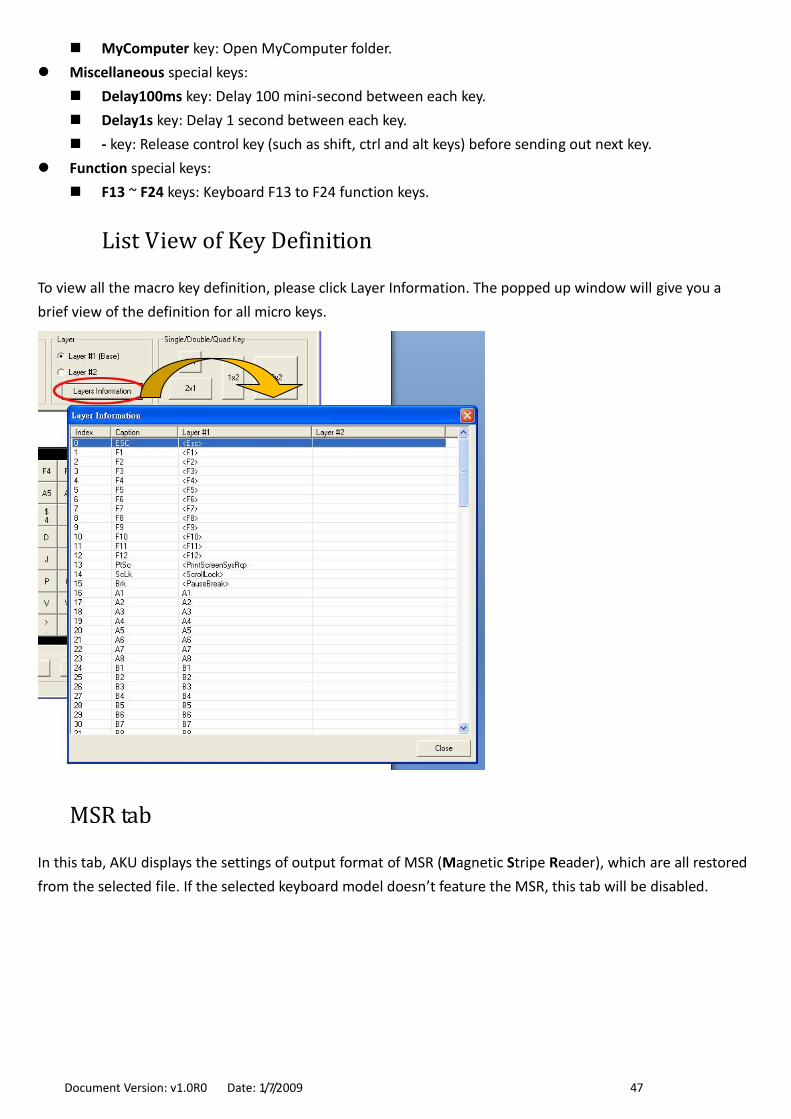
List View of Key Definition
To view all the macro key definition, please click Layer Information. The popped up window will give you a
brief view of the definition for all micro keys.
MSR tab
In this tab, AKU displays the settings of output format of MSR (Magnetic Stripe Reader), which are all restored
from the selected file. If the selected keyboard model doesn’t feature the MSR, this tab will be disabled.

Document Version: v1.0R0 Date: 1/7/2009 48
MSR tab divided the settings into 3 groups, which are:
Prefix/Suffix: Define the data string which you would like to append in front or end of the MSR data
string.
ISO: Define start and end sentinel character.
Decode Mode: Determine the way of outputting the three tracks data.
Shown below is the data structure of the output string for MSR.
PP PR1 SS1 TK1 ES1 SU1 PR2 SS2 TK2 ES2 SU2 PR3 SS3 TK3 ES3 SU3 SU
PP: Prefix for package.
PR1: Prefix for track 1.
SS1: Start sentinel for track 1.
TK1: Data for track 1.
ES1: End sentinel for track 1.
SU1: Suffix for track 1.
PR2: Prefix for track 2.
SS2: Start sentinel for track 2.
TK2: Data for track 2.
ES2: End sentinel for track 2.
SU2: Suffix for track 2.
PR3: Prefix for track 3.
SS3: Start sentinel for track 3.
TK3: Data for track 3.
ES3: End sentinel for track 3.
SU3: Suffix for track 3.
SU: Suffix for package.
Document Version: v1.0R0 Date: 1/7/2009 49
Prefix/Suffix
In default, the prefix and suffix settings are all keep blank. There are 4 kinds of prefix and suffix to be defined,
which are:
Package: For the prefix string, it is appended in the front of the whole MSR data. For the suffix, it is
appended in the end of the whole MSR data. In most case, the suffix for package is always to be the
“Enter” or “Tab” character. The max data length of the prefix and suffix for the package can be up to 127.
TK1: For the prefix string, it is appended in the front of the start sentinel of track 2. For the suffix, it is
appended in the end of the end sentinel of track 2. The max data length of the prefix and suffix for the
TK1 can be up to 127.
TK2: For the prefix string, it is appended in the front of the start sentinel of track 2. For the suffix, it is
appended in the end of the end sentinel of track 2. The max data length of the prefix and suffix for the
TK1 can be up to 127.
TK3: For the prefix string, it is appended in the front of the start sentinel of track 3. For the suffix, it is
appended in the end of the end sentinel of track 3. The max data length of the prefix and suffix for the
TK1 can be up to 127.
ISO
This group defines the start and end sentinel for each track. The sentinel is always used to extract the track
data from the whole MSR data string. The data length for each sentinel is fixed to one character. Because there
is ISO standard that defining the start and end sentinel for the three tracks. For the compatible reason, please
do not modify the default value if possible.
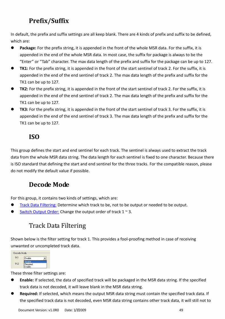
Decode Mode
For this group, it contains two kinds of settings, which are:
Track Data Filtering: Determine which track to be, not to be output or needed to be output.
Switch Output Order: Change the output order of track 1 ~ 3.
Track Data Filtering
Shown below is the filter setting for track 1. This provides a fool-proofing method in case of receiving
unwanted or uncompleted track data.
These three filter settings are:
Enable: If selected, the data of specified track will be packaged in the MSR data string. If the specified
track data is not decoded, it will leave blank in the MSR data string.
Required: If selected, which means the output MSR data string must contain the specified track data. If
the specified track data is not decoded, even MSR data string contains other track data, it will still not to

Document Version: v1.0R0 Date: 1/7/2009 50
be output.
Disable: If selected, the data of specified track will not be packaged in the MSR data string. No matter it is
decoded or not.
Switch Output Order
Show below is the selection of the three track data output order (sequence). The default order is Track 1–Track
2–Track 3.
There 6 orders allow to be selected. Please select one to fit your application needs.
Miscellaneous tab
There are two kinds of settings for this tab – Key Lock and Display. As so far, for KB2xx keyboard, it shows the
Key Lock settings if featured. For KB800 keyboard, it shows the Display settings.
This tab will be disabled if the selected keyboard model doesn’t feature the Key Lock and Display.
Key Lock
The Key Lock, with 8 positions, is most used to switch for layer selection, or for supervisory use.
The definition process is same to macro key. Below steps is to define the MA2 position to send out the
function “F1” if the key is switched to.
Use mouse click the MA2 button.
Click the button with keyboard icon to load the Key Definition window.

Document Version: v1.0R0 Date: 1/7/2009 51
Click F1 button to entry the key string.
Click OK button to return to main window.
Display
As so far, only KB800 features the display. Below instructions are used to make the display perform a certain
action, such as showing specified message, turning on the backlight... etc. These instructions are all used
under on-line, which means the changes will not save into the flash memory and take immediate effect.
There are four kinds of instructions for the display, which are:
Cursor Position Instructions are used to move or get the current cursor position. To specify the cursor
position, adjust the value of row and column, and then click Set button to update. To retrieve the cursor
position, click Get button, then the position value will be displayed in the Row and Column text box.
Message Instructions are used to show, get and clear the message. To show wanted message, enter the

Document Version: v1.0R0 Date: 1/7/2009 52
message in the text box (in the Message frame), then click Set button to show the message. The message
will start to be located in the pre-specified cursor position. To retrieve the entire message in the display,
click Get button, the message in display will be shown in the message text box. To clear the message in
display, click Clear Screen button.
Backlight Instructions are used to turn on or off backlight function of display. To turn on the backlight,
click Turn On button. To turn off the backlight, click Turn Off button.
Start up Message instructions is used to specified the message displayed after powering on the KB800.
Saving the Settings to a File
The AKU also lets you save current values of keyboard settings into a file (click Save button) and load setting
values from file (click Open button). Settings files have the .tbl extension.
Whenever completing the settings, keep a good habit to save in a file right away.
Updating the Settings to Keyboard
Before updating the opening or editing settings to keyboard, make sure the connection is established between
PC and keyboard. If the connection is disconnected, click Connect button to establish the connection.
To update the settings, click Update button (in the left-down corner of main window), in the drop down menu,
click Update All Settings.
For flexible and time saving reason, AKU provides 6 ways to do the update, which are:
Update All Settings: All the settings will be updated to keyboard. This will take most of the time, which
could be up to 18 seconds.
Update Selected Key: Only update the selected key definition. This may just take one second.
Update All Keys: All keys will be updated. The time took is depending on how many keys the keyboard
has.
Update MSR Settings: Only update the MSR settings to keyboard. This may just take 2 seconds.
Update Language: Only update the Language settings(related to the key code and keyboard position).
Document Version: v1.0R0 Date: 1/7/2009 53
This may just take 2 seconds.
Update Key Lock: Only update the Key Lock settings. This may just take 2 seconds.
Note: About time took of updating is tested under Windows XP SP2.
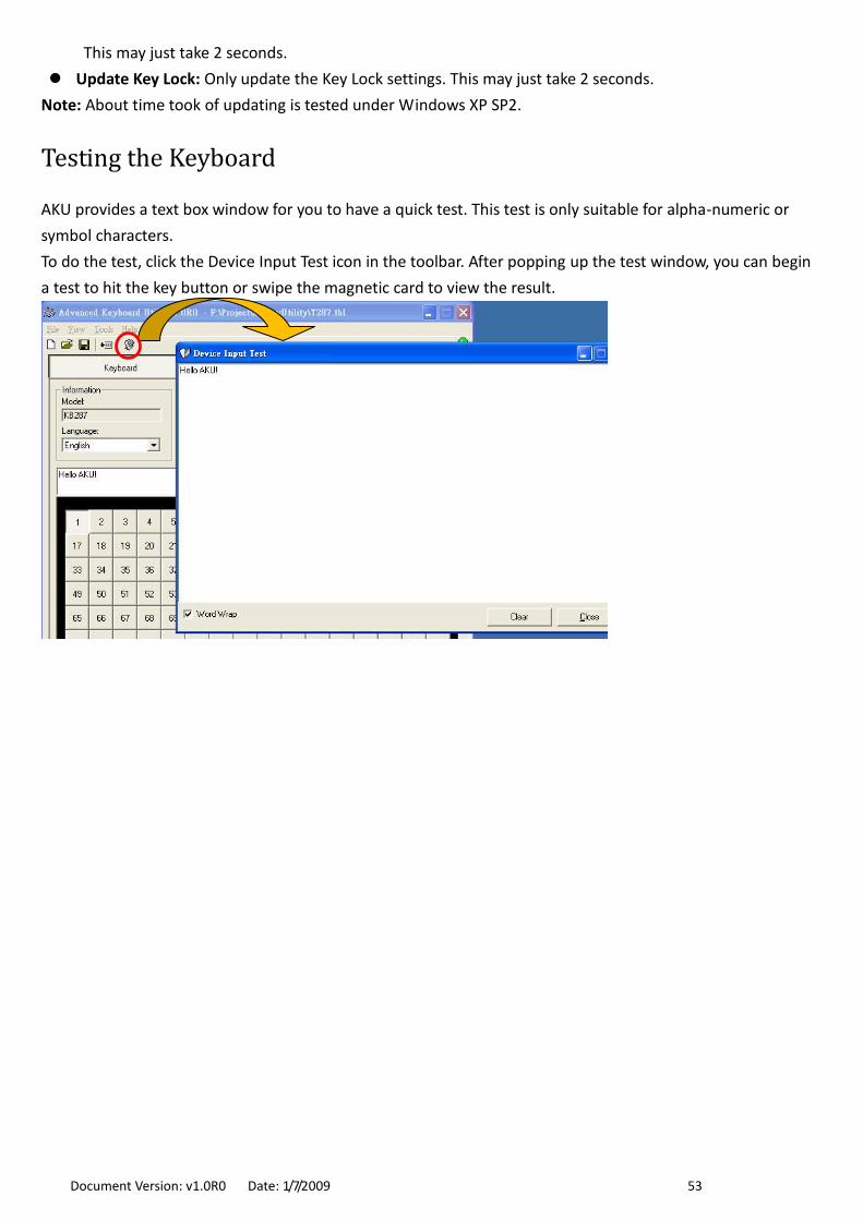
Testing the Keyboard
AKU provides a text box window for you to have a quick test. This test is only suitable for alpha-numeric or
symbol characters.
To do the test, click the Device Input Test icon in the toolbar. After popping up the test window, you can begin
a test to hit the key button or swipe the magnetic card to view the result.
Document Version: v1.0R0 Date: 1/7/2009 54
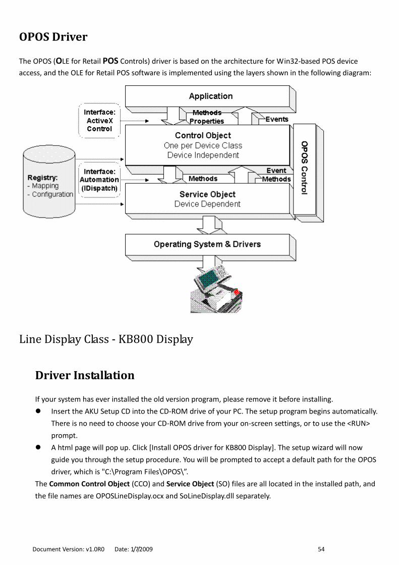
OPOS Driver
The OPOS (OLE for Retail POS Controls) driver is based on the architecture for Win32-based POS device
access, and the OLE for Retail POS software is implemented using the layers shown in the following diagram:
Line Display Class - KB800 Display
Driver Installation
If your system has ever installed the old version program, please remove it before installing.
Insert the AKU Setup CD into the CD-ROM drive of your PC. The setup program begins automatically.
There is no need to choose your CD-ROM drive from your on-screen settings, or to use the <RUN>
prompt.
A html page will pop up. Click [Install OPOS driver for KB800 Display]. The setup wizard will now
guide you through the setup procedure. You will be prompted to accept a default path for the OPOS
driver, which is "C:\Program Files\OPOS\”.
The Common Control Object (CCO) and Service Object (SO) files are all located in the installed path, and
the file names are OPOSLineDisplay.ocx and SoLineDisplay.dll separately.
Document Version: v1.0R0 Date: 1/7/2009 55
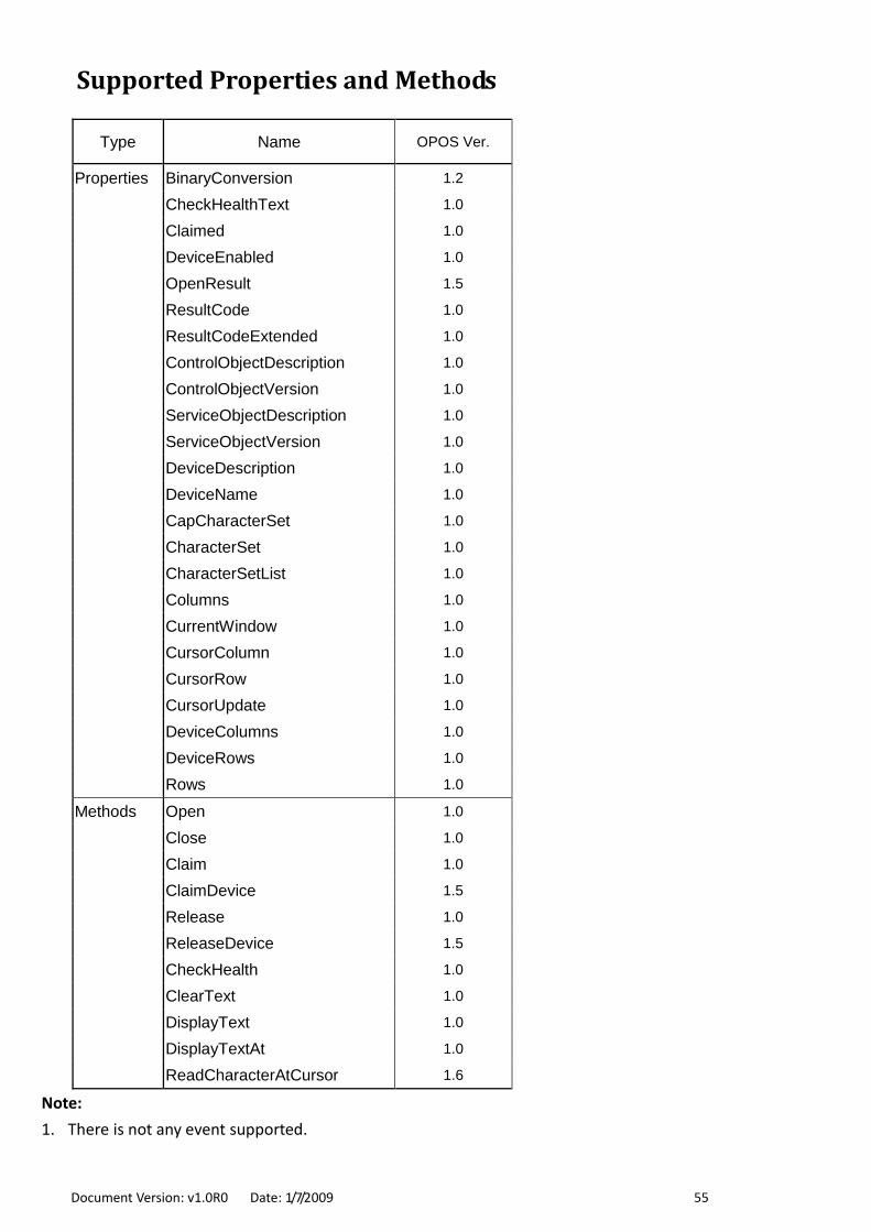
Supported Properties and Methods
Type Name OPOS Ver.
Properties BinaryConversion 1.2
CheckHealthText 1.0
Claimed 1.0
DeviceEnabled 1.0
OpenResult 1.5
ResultCode 1.0
ResultCodeExtended 1.0
ControlObjectDescription 1.0
ControlObjectVersion 1.0
ServiceObjectDescription 1.0
ServiceObjectVersion 1.0
DeviceDescription 1.0
DeviceName 1.0
CapCharacterSet 1.0
CharacterSet 1.0
CharacterSetList 1.0
Columns 1.0
CurrentWindow 1.0
CursorColumn 1.0
CursorRow 1.0
CursorUpdate 1.0
DeviceColumns 1.0
DeviceRows 1.0
Rows 1.0
Methods Open 1.0
Close 1.0
Claim 1.0
ClaimDevice 1.5
Release 1.0
ReleaseDevice 1.5
CheckHealth 1.0
ClearText 1.0
DisplayText 1.0
DisplayTextAt 1.0
ReadCharacterAtCursor 1.6
Note:
1. There is not any event supported.

Document Version: v1.0R0 Date: 1/7/2009 56
Registry Information
The default device name is “KB800”. Below is the registry information for the KB800 display.
[HKEY_LOCAL_MACHINE\SOFTWARE\OLEforRetail\ServiceOPOS\LineDisplay\KB800]
"Port"="COM1"
"Baudrate"="19200"
"Command"="1"
@="GIGATMS.OPOSPOSLineDisplay.Service"
"Parity"="NONE"
"Protocol"="Hardware"
"DeviceDescription"="GIGA-TMS KB800 POS LineDisplay"
"DefaultCharacterSet"="437"
"CharacterSetList"="437"
"DeviceRows"="2"
"DeviceColumns"="20"
"Debug"="1"
"FileName"=""
"Interface"="USB"
"ProductID"=dword:00000008

Document Version: v1.0R0 Date: 1/7/2009 57
Sample OPOS Program
Sample OPOS Program implements the Common Control Object (CCO) that shows an easy way to utilize the
OPOS powered device. Before running the Sample OPOS Program, make sure the OPOS driver has already
installed. Below lists the Sample OPOS Program:
Line Display Class: The program name is “OPOS LineDisplay Test”.
So far only Line Display class is supported.
Line Display Class – KB800 Display
Installing and Launching Program
If your system has ever installed the old version program, please remove it before installing.
Insert the AKU Setup CD into the CD-ROM drive of your PC. The setup program begins automatically.
There is no need to choose your CD-ROM drive from your on-screen settings, or to use the <RUN>
prompt.
A html page will pop up. Click [Install Sample OPOS Program]. The setup wizard will now guide you
through the setup procedure. You will be prompted to accept a default path for the Sample OPOS
program, which is "C:\Program Files\GIGA-TMS\OPOS Sample\LineDisplay”.
When the setup procedure is complete, remove the software CD-ROM disk from your CD-ROM drive
and accept the prompt to restart your PC.
From the [Start]/[Programs], select the [GIGA-TMS]\[Sample OPOS] (default folder), click [OPOS
LineDisplay Test].
Testing the KB800 Display
The OPOS LineDisplay Test program will list all the Line Display class devices. Please select the “KB800” and
then click Open to load the SO driver.
Shown below is the OPOS LineDisplay Test program’s main window.

Document Version: v1.0R0 Date: 1/7/2009 58
The main window has the follows buttons and entries:
Open: Load the SO driver with selected device name.
Claim: Set exclusive access permission to the device.
DeviceEnable (True): Enable the device.
Display Text: Display the specified message (in Text box) on the device screen.
Display Text At: Display the specified message (in Text box) on the device screen at specified location (in
Row and Col text box).
Clear Text: Clear the screen.
DeviceEnable (False): Disble the device.
Release: Disable the exclusive access permission.
Close: Unload the SO driver.
Exit: End the program.
Source Code
The source code is coded by Visual Basic 6 language and zipped in a file: OPOSLineDisplayTest_PSC00000.zip
which is located in the SourceCode folder of setup CD.

Document Version: v1.0R0 Date: 1/7/2009 59
Copies of CE, FCC and RoHS Certificates
KB800

Document Version: v1.0R0 Date: 1/7/2009 60
Update History
7-Jan-09 ("base") release