double smart module - FIBARO Manuals
30
SMART MODULE (FGS-214) DOUBLE SMART MODULE (FGS-224) OPERATING MANUAL EN v1.0
-
Upload
khangminh22 -
Category
Documents
-
view
1 -
download
0
Transcript of double smart module - FIBARO Manuals

SMART MODULE (FGS-214)
DOUBLE SMART MODULE (FGS-224)
OPERATINGMANUAL
EN
v1.0

3
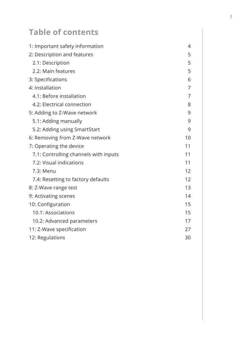
Table of contents1: Important safety information 4
2: Description and features 5
2.1: Description 5
2.2: Main features 5
3: Specifications 6
4: Installation 7
4.1: Before installation 7
4.2: Electrical connection 8
5: Adding to Z-Wave network 9
5.1: Adding manually 9
5.2: Adding using SmartStart 9
6: Removing from Z-Wave network 10
7: Operating the device 11
7.1: Controlling channels with inputs 11
7.2: Visual indications 11
7.3: Menu 12
7.4: Resetting to factory defaults 12
8: Z-Wave range test 13
9: Activating scenes 14
10: Configuration 15
10.1: Associations 15
10.2: Advanced parameters 17
11: Z-Wave specification 27
12: Regulations 30

4
Important safety InformatIon
1: Important safety informationRead this manual before attempting to install the device!
! Failure to observe recommendations included in this manual may be dangerous or cause a violation of the law. The manu-
facturer, Fibar Group S.A. will not be held responsible for any loss or damage resulting from not following the instructions of operating manual.
DANGER OF ELECTROCUTION!The device is designed to control other electrical devices and operate in their housings. Faulty connection or use may result
in fire or electric shock.
All works on the device may be performed only by a qualified and licensed electrician. Observe national regulations.
Even when the device is turned off, voltage may be present at its terminals. Any maintenance introducing changes into the
configuration of connections or the load must be always performed with disabled fuse or power supply.
To avoid risk of electrical shock, do not operate the device with wet or moist hands.
Do not modify!
! Do not modify this device in any way not included in this manual.
Other devices
! The manufacturer, Fibar Group S.A. will not be held responsi-ble for any damage or loss of warranty privileges for other con-
nected devices if the connection is not compliant with their manuals.
This product is intended for indoor use only in dry locations.
! Do not use in damp or wet locations, near a bathtub, sink, shower, swimming pool, or anywhere else where water or
moisture are present.
Not a toy!
! This product is not a toy. Keep away from children and animals!

5
DescrIptIon anD features
2: Description and features
2.1: Description
The remotely operated FIBARO Smart Module and Double Smart Module are designed to turn electrical devices or circuits on and off.
Smart Module allows to control one device or circuit and the Double Smart Module allows to control two devices or circuits.
The compact size of the device allows for the product to be installed in the housings of other devices. The devices can be controlled either via the Z-Wave™ network or with buttons connected directly to them.
2.2: Main features
• Works with various types of switches and buttons.
• Supports Z-Wave network Security Modes: S0 with AES-128 en-cryption and S2 Authenticated with PRNG-based encryption.
• Works as a Z-Wave signal repeater (all non-battery operated de-vices within the network will act as repeaters to increase reliabili-ty of the network).
• May be used with all devices certified with the Z-Wave Plus™ cer-tificate and should be compatible with such devices produced by other manufacturers.
The device is a Security Enabled Z-Wave Plus product and a Security Enabled Z-Wave Controller must be
used in order to fully utilize the product.
i

6
specIfIcatIons
3: Specifications
Power supply 100-240V~ 50/60Hz or 24-30VRated load current Smart Module (FGS-214):
6.5A
Double Smart Module (FGS-224):6A per one channel 9.5A total
Compatible load types resistive or incandescent onlyActive element micro-gap relay μMaximum length of wires 3 metersRecommended wire cross-section area
0.2–2.0mm2 (24–14 AWG) (depending on load current)
Operating temperature 0–35°CAmbient humidity 0–95% RH without condensationRadio protocol Z-Wave (500 series chip)Radio frequency band 868.0–868.6MHz; 869.7–870.0MHzMax. transmitting power +5dBmRange up to 50m outdoors
up to 40m indoors (depending on terrain and building structure)
Dimensions (Height x Width x Depth)
42.5 x 38.25 x 20.3 mm
Classification of installa-tion and use
Automatic electrical control for use in equipment for household or similar use
Mode of operation Type 1.B Action Pollution degree 2Software class Class ACompliance with EU directives
2011/65/EU 2015/863 2014/53/EU
Radio frequency of individual device must be same as your Z-Wave controller. Check information on the box
or consult your dealer if you are not sure.
i

7
InstallatIon
4: Installation
4.1: Before installation
! Connecting the device in a manner inconsistent with this manual may cause risk to health, life or material damage.
• Do not power the device before fully assembling it in the protect-ed environment,
• Check the operating/maintenance manual of the device you want to control to make sure the connection is safe and allowed,
• Connect only in accordance with the diagram,
• Always use the same power source for L and IN terminals,
• Do not connect devices which are not compliant with the specifi-cation or relevant safety standards,
• Do not install the device in metal boxes or on metal surfaces for best radio performance.
Notes for diagrams:S1 – terminal for 1st button
S2 – terminal for 2nd button
Q/Q1 – output terminal of the 1st channel
Q2 – output terminal of the 2nd channel
IN – input terminal for both channels
L – terminal for live wire
N – terminal for neutral wire
B – maintenance button
1 – device/system housing
2 – electrical device

8
InstallatIon
4.2: Electrical connection
1. Switch off the mains voltage (disable the fuse) or disable the power supply.
2. Connect with one of the diagrams below:
B IN
L
24-30V DC100-240V AC
NS1 S2
Q
SMART MODULEFGS-214
12
Diagram 1: Example connection of Smart Module
B INQ1
L
24-30V DC
NS1 S2
Q2
DOUBLESMART MODULE
FGS-224
100-240V AC
12
Diagram 2: Example connection of Double Smart Module
3. Verify correctness of connection.
4. Tighten the terminal screws using PH1 screwdriver.
5. If the device fully assembled, switch on the mains voltage or enable the power supply.
6. The LED light means the device is powered.
7. Add the device to the Z-Wave network (see the next chapter).

9
aDDIng to Z-Wave netWork
5: Adding to Z-Wave networkAdding (Inclusion) – Z-Wave device learning mode, allowing to add the device to existing Z-Wave network.
5.1: Adding manually
To add the device to the Z-Wave network manually:
1. Power the device.
2. Set the main controller in (Security/non-Security Mode) add mode (see the controller’s manual).
3. Quickly, three times click button connected to S1/S2 or the maintenance button.
4. LED will start blinking yellow, wait for the adding process to end.
5. If you are adding in Security S2 Authenticated, input the underlined part of the DSK (label on the bottom of the box).
6. Adding result will be confirmed by the Z-Wave controller’s message and the LED:
• Green – successful (non-secure, S0, S2 non-authenticated),
• Magenta – successful (Security S2 Authenticated),
• Red – not successful.
5.2: Adding using SmartStart
SmartStart enabled products can be added into a Z-Wave network by scanning the Z-Wave QR Code present on the product with a controller providing SmartStart inclusion. SmartStart product will be added automatically within 10 minutes of being switched on in the network range.
To add the device to the Z-Wave network using SmartStart:
1. To use SmartStart your controller needs to support Security S2 (see the controller’s manual).
2. Enter the full DSK string code to your controller. If your controller is capable of QR scanning, scan the QR code placed on the box or the device label.
3. Power the device.
4. Wait for the adding process to start (up to few minutes), which is signalled with yellow LED blinking.

10
removIng from Z-Wave netWork
5. Adding result will be confirmed by the Z-Wave controller’s message and the LED:
• Green – successful (non-secure, S0, S2 non-authenticated),
• Magenta – successful (Security S2 Authenticated),
• Red – not successful.
i In case of problems with adding the device, please re-set the device and repeat the adding procedure.
6: Removing from Z-Wave networkRemoving (Exclusion) – Z-Wave device learning mode, allowing to remove the device from existing Z-Wave network. Removing also re-sults in resetting the device to factory defaults.
! Make sure that restoring the parameters to factory defaults will not result in damaging the connected
device, we recommend disconnecting it first.
To remove the device from the Z-Wave network:
1. Power the device.
2. Set the main controller into remove mode (see the controller’s manual).
3. Quickly, three times click the maintenance button.
4. LED will start blinking yellow, wait for the removing process to end.
5. Successful removing will be confirmed by the Z-Wave controller’s message and red LED colour.

11
operatIng the DevIce
7: Operating the device
7.1: Controlling channels with inputs
Momentary switch (parameter 20 set to 0): 1x click – change the state of the channel to the opposite one
Toggle switch without memory (parameter 20 set to 1): 1x switch – change the state of the channel to the state of the switch (OFF if contacts opened, ON if contacts closed)
Toggle switch with memory (parameter 20 set to 2): 1x switch – change the state of the channel to the opposite one
i By default S1 input controls 1st channel and S2 input controls 2nd channel if present. It can be changed us-
ing parameters 24 and 25.
i By default outputs are set as NO (normally open). It means the contacts will be opened when turned off
and closed when turned on. It can be switched to NC (nor-mally closed), which means the contacts will be closed when turned off and opened when turned on using param-eters 162/163.
7.2: Visual indications
The built-in LED light shows current device status.
After powering the device:• Green – device added to a Z-Wave network (non-secure, S0, S2
non-authenticated),
• Magenta – device added to a Z-Wave network (Security S2 Authenticated),
• Red – device not added to a Z-Wave network.
Update:• Blinking cyan – update in progress,
• Green – update successful,
• Red – update not successful.
Menu:• Blinking green – entering the menu (added as non-secure, S0, S2
non-authenticated),
12
operatIng the DevIce
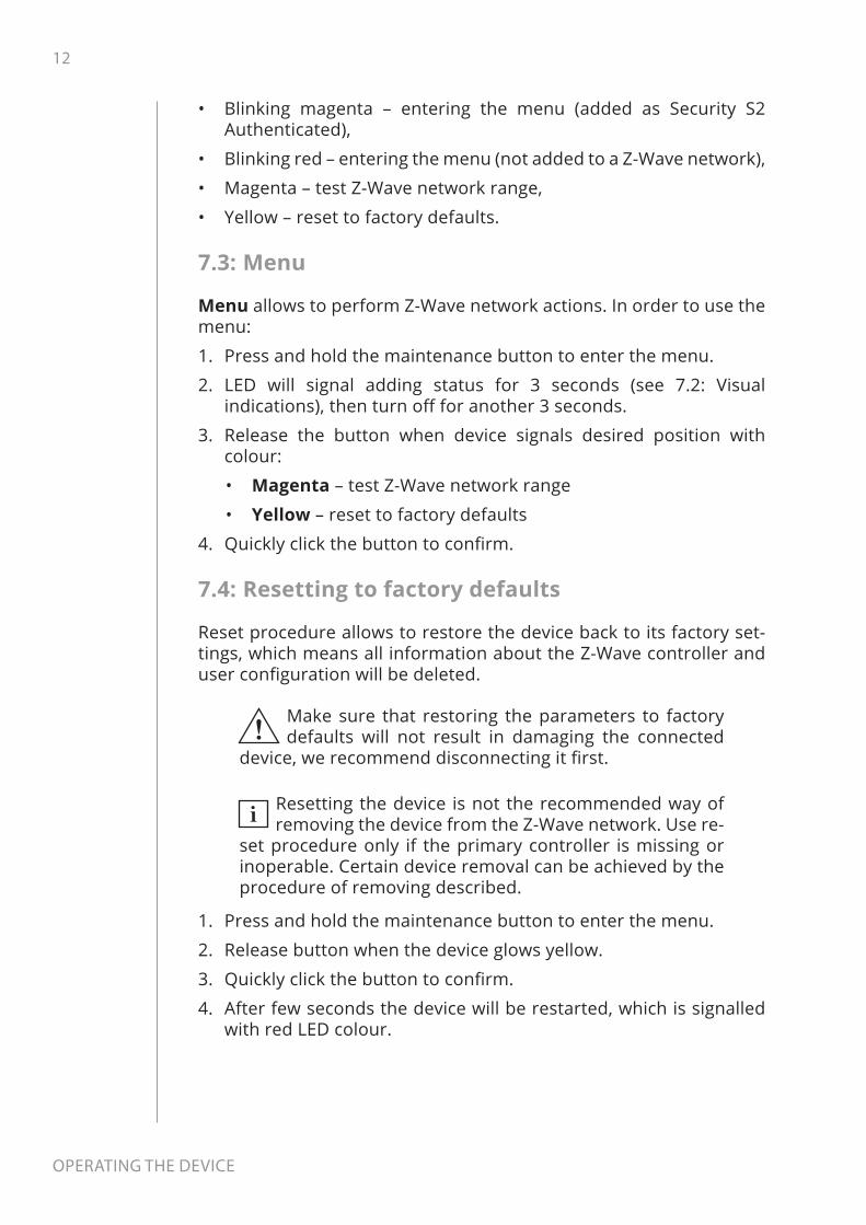
• Blinking magenta – entering the menu (added as Security S2 Authenticated),
• Blinking red – entering the menu (not added to a Z-Wave network),
• Magenta – test Z-Wave network range,
• Yellow – reset to factory defaults.
7.3: Menu
Menu allows to perform Z-Wave network actions. In order to use the menu:
1. Press and hold the maintenance button to enter the menu.
2. LED will signal adding status for 3 seconds (see 7.2: Visual indications), then turn off for another 3 seconds.
3. Release the button when device signals desired position with colour:
• Magenta – test Z-Wave network range
• Yellow – reset to factory defaults
4. Quickly click the button to confirm.
7.4: Resetting to factory defaults
Reset procedure allows to restore the device back to its factory set-tings, which means all information about the Z-Wave controller and user configuration will be deleted.
! Make sure that restoring the parameters to factory defaults will not result in damaging the connected
device, we recommend disconnecting it first.
i Resetting the device is not the recommended way of removing the device from the Z-Wave network. Use re-
set procedure only if the primary controller is missing or inoperable. Certain device removal can be achieved by the procedure of removing described.
1. Press and hold the maintenance button to enter the menu.
2. Release button when the device glows yellow.
3. Quickly click the button to confirm.
4. After few seconds the device will be restarted, which is signalled with red LED colour.

13
Z-Wave range test
8: Z-Wave range testThe device has a built in Z-Wave network main controller’s range tester.
i To make Z-Wave range test possible, the device must be added to the Z-Wave controller. Testing may stress
the network, so it is recommended to perform the test only in special cases.
To test the main controller’s range: 1. Press and hold the maintenance button to enter the menu.
2. Release button when the device glows magenta.
3. Quickly click the button to confirm.
4. Visual indicator will indicate the Z-Wave network’s range (range signaling modes described below).
5. To exit Z-Wave range test, press the button briefly.
Z-Wave range tester signalling modes:• Visual indicator pulsing green - the device attempts to establish
a direct communication with the main controller. If a direct com-munication attempt fails, the device will try to establish a routed communication, through other modules, which will be signalled by visual indicator pulsing yellow.
• Visual indicator glowing green - the device communicates with the main controller directly.
• Visual indicator pulsing yellow - the device tries to establish a routed communication with the main controller through other modules (repeaters).
• Visual indicator glowing yellow - the device communicates with the main controller through the other modules. After 2 seconds the device will retry to establish a direct communication with the main controller, which will be signalled with visual indicator puls-ing green.
• Visual indicator pulsing violet - the device does communicate at the maximum distance of the Z-Wave network. If connection proves successful it will be confirmed with a yellow glow. It’s not recommended to use the device at the range limit.
• Visual indicator glowing red - the device is not able to connect to the main controller directly or through another Z-Wave net-work device (repeater).
i Communication mode of the device may switch be-tween direct and one using routing, especially if
the device is on the limit of the direct range.

14
actIvatIng scenes
9: Activating scenesThe device can activate scenes in the Z-Wave controller by sending scene ID and attribute of a specific action using Central Scene Com-mand Class.
By default all action are activated, change settings of parameters 40 and 41 to disable scene activation for selected actions.
Switch Action Scene ID AttributeSw
itch
conn
ecte
d to
S1
term
inal
Switch clicked once 1 Key Pressed 1 time
Switch clicked twice 1 Key Pressed 2 times
Switch clicked thrice* 1 Key Pressed 3 times
Switch held** 1 Key Held DownSwitch released** 1 Key Released
Switc
h co
nnec
ted
to
S2 te
rmin
al
Switch clicked once 2 Key Pressed 1 time
Switch clicked twice 2 Key Pressed 2 times
Switch clicked thrice* 2 Key Pressed 3 times
Switch held** 2 Key Held DownSwitch released** 2 Key Released
* Activating triple clicks will disallow removing using this input.
** Not available for toggle switches.

15
confIguratIon
10: Configuration
10.1: Associations
Association (linking devices) – direct control of other devices with-in the Z-Wave system network.
Associations allow:
• reporting the device status to the Z-Wave controller (using Lifeline group),
• creating simple automations by controlling other devices without participation of the main controller (using groups assigned to ac-tions on the device).
i Commands send to association groups reflect input operation according to device configuration, e.g. turn-
ing the first channel on using button will send frame re-sponsible for the same action.
Smart Module provides the association of 2 groups:1st association group – “Lifeline” reports the device status and al-lows for assigning single device only (main controller by default).
2nd association group – “On/Off (1)” is used to turn the associated devices on/off reflecting input operation (uses Basic command class).
Double Smart Module provides the association of 3 groups:1st association group – “Lifeline” reports the device status and al-lows for assigning single device only (main controller by default).
2nd association group – “On/Off (1)” is used to turn the associated devices on/off reflecting input operation for 1st channel (uses Basic command class).
3rd association group – “On/Off (2)” is used to turn the associated devices on/off reflecting input operation for 2nd channel (uses Basic command class).
The device allows to control 5 regular or multichannel devices per an association group, with the exception of “LifeLine” that is reserved solely for the controller and hence only 1 node can be assigned.

16
confIguratIon
Values sent to association groups depending on settingsValues are sent using Basic Command Class. Values below are de-fault but can be adjusted using parameters 156-161.
Parameter 150/151
Parameter 152/153 Click Double
ClickMomentary or toggle switches with memory
(parameter 20/21 set to 0 or 2)
0, 1 or 3 – 255 (ON) if turned OFF 0 (OFF) if turned ON 99 (max)
20 or 1 255 (ON) if turned OFF
0 (OFF) during countdown 99 (max)
2 255 (ON) 99 (max)Toggle switches without memory
(parameter 20/21 set to 1)
– – 255 (ON) if turned OFF 0 (OFF) if turned ON 99 (max)

17
confIguratIon
10.2: Advanced parameters
The device allows to customize its operation to user’s needs using configurable parameters.
The settings can be adjusted via Z-Wave controller to which the de-vice is added. The way of adjusting them might differ depending on the controller.
In the FIBARO interface parameters are presented as simple options in Advanced Settings of the device.
Available parameters:
1. Remember relays state
Description
This parameter determines the state of relays after power supply failure (e.g. power outage).
For auto OFF and flashing modes the parameter is not relevant and the relay will always remain switched off.
Parameter size 1B
Default value 1 (restore the state)
Available values
0 – relays remain switched off after restoring power
1 – restore remembered state of relays after restoring power
2 – restore remembered state of relays after restoring power, but for toggle switches (param-eter 20/21 set to 1) set the same state as the current state of the switches
20. S1 input – switch type
DescriptionThis parameter defines as what type the device should treat the switch connected to the S1 terminal.
Parameter size 1B
Default value 0 (momentary switch)
Available values
0 – momentary switch
1 – toggle switch synchronized (contact closed - ON, contact opened - OFF)
2 – toggle switch with memory (device changes status when switch changes status)

18
confIguratIon
21. S2 input – switch type
DescriptionThis parameter defines as what type the device should treat the switch connected to the S2 terminal.
Parameter size 1B
Default value 0 (momentary switch)
Available values
0 – momentary switch
1 – toggle switch synchronized (contact closed - ON, contact opened - OFF)
2 – toggle switch with memory (device changes status when switch changes status)
24. Inputs orientation
This parameter allows reversing operation of S1 and S2 inputs without changing the wiring. Use in case of incorrect wiring.
Parameter size 1B
Default value 0 (default)
Available values
0 – default (S1 - 1st channel, S2 - 2nd channel)
1 – reversed (S1 - 2nd channel, S2 - 1st channel)
25. Outputs orientation
Only in Double Smart Module
This parameter allows reversing operation of Q1 and Q2 outputs without changing the wiring. Use in case of incorrect wiring.
Parameter size 1B
Default value 0 (default)
Available values
0 – default (Q1 - 1st channel, Q2 - 2nd channel)
1 – reversed (Q1 - 2nd channel, Q2 - 1st channel)

19
confIguratIon
30. Alarm configuration - 1st slot
Description
This parameter determines to which alarm frames and how the device should react. The parameters consist of 4 bytes, three most sig-nificant bytes are set according to the official Z-Wave protocol specification.
Parameter size 4B
Default value [0x00, 0x00, 0x00, 0x00] (disabled)
Available values
1B [MSB] – Notification Type
2B – Notification Status
3B – Event/State Parameters
4B [LSB] – action:
0x00 – no action, 0x01 – turn ON, 0x02 – turn OFF, 0x03 – turn ON/OFF continuously
31. Alarm configuration - 2nd slot
Description
This parameter determines to which alarm frames and how the device should react. The parameters consist of 4 bytes, three most sig-nificant bytes are set according to the official Z-Wave protocol specification.
Parameter size 4B
Default value[0x05, 0xFF, 0x00, 0x00]
(Water Alarm, any notification, no action)
Available values
1B [MSB] – Notification Type
2B – Notification Status
3B – Event/State Parameters
4B [LSB] – action:
0x00 – no action, 0x01 – turn ON, 0x02 – turn OFF, 0x03 – turn ON/OFF continuously

20
confIguratIon
32. Alarm configuration - 3rd slot
Description
This parameter determines to which alarm frames and how the device should react. The parameters consist of 4 bytes, three most sig-nificant bytes are set according to the official Z-Wave protocol specification.
Parameter size 4B
Default value[0x01, 0xFF, 0x00, 0x00]
(Smoke Alarm, any notification, no action)
Available values
1B [MSB] – Notification Type
2B – Notification Status
3B – Event/State Parameters
4B [LSB] – action:
0x00 – no action, 0x01 – turn ON, 0x02 – turn OFF, 0x03 – turn ON/OFF continuously
33. Alarm configuration - 4th slot
Description
This parameter determines to which alarm frames and how the device should react. The parameters consist of 4 bytes, three most sig-nificant bytes are set according to the official Z-Wave protocol specification.
Parameter size 4B
Default value[0x02, 0xFF, 0x00, 0x00]
(CO Alarm, any notification, no action)
Available values
1B [MSB] – Notification Type
2B – Notification Status
3B – Event/State Parameters
4B [LSB] – action:
0x00 – no action, 0x01 – turn ON, 0x02 – turn OFF, 0x03 – turn ON/OFF continuously

21
confIguratIon
34. Alarm configuration - 5th slot
Description
This parameter determines to which alarm frames and how the device should react. The parameters consist of 4 bytes, three most sig-nificant bytes are set according to the official Z-Wave protocol specification.
Parameter size 4B
Default value[0x04, 0xFF, 0x00, 0x00]
(Heat Alarm, any notification, no action)
Available values
1B [MSB] – Notification Type
2B – Notification Status
3B – Event/State Parameters
4B [LSB] – action:
0x00 – no action, 0x01 – turn ON, 0x02 – turn OFF, 0x03 – turn ON/OFF continuously
35. Alarm configuration – duration
Description
This parameter defines duration of alarm se-quence. When time set in this parameter elaps-es, alarm is cancelled and relays restore normal operation, but do not recover state from before the alarm.
Parameter size 2B
Default value 600 (10min)
Available values
0 – infinite
1-32400 (1s-9h, 1s step) – duration
40. S1 input – scenes sent
Description
This parameter determines which actions result in sending scene IDs assigned to them. Values can be combined (e.g. 1+2=3 means that scenes for single and double click are sent).
Enabling scenes for triple click disables entering the device in learning mode by triple clicking.
Parameter size 1B
Default value 15 (all active)
Available values
0 – no scenes sent
1 – Key pressed 1 time
2 – Key pressed 2 times
4 – Key pressed 3 times
8 – Key hold down and key released

22
confIguratIon
41. S2 input – scenes sent
Description
This parameter determines which actions result in sending scene IDs assigned to them. Values can be combined (e.g. 1+2=3 means that scenes for single and double click are sent).
Enabling scenes for triple click disables entering the device in learning mode by triple clicking.
Parameter size 1B
Default value 15 (all active)
Available values
0 – no scenes sent
1 – Key pressed 1 time
2 – Key pressed 2 times
4 – Key pressed 3 times
8 – Key hold down and key released
150. First channel – operating mode
Description
This parameter allows to choose operating mode for channel controlled with Q/Q1 output. For timed modes (value 1, 2 or 3), time is set with parameter 154 and reaction to input change is set with parameter 152.
Parameter size 1B
Default value 0 (standard operation)
Available values
0 – standard operation
1 – delayed OFF
2 – auto OFF
3 – flashing
151. Second channel – operating mode
Only in Double Smart Module
Description
This parameter allows to choose operating mode for channel controlled with Q2 output. For timed modes (value 1, 2 or 3), time is set with parameter 155 and reaction to input change is set with parameter 153.
Parameter size 1B
Default value 0 (standard operation)
Available values
0 – standard operation
1 – delayed OFF
2 – auto OFF
3 – flashing

23
confIguratIon
152. First channel – reaction to input change in delayed/auto OFF modes
DescriptionThis parameter determines how the device reacts when changing state of S1 input in timed modes for first channel.
Parameter size 1B
Default value 0 (cancel mode)
Available values
0 – cancel mode and set default state
1 – no reaction, mode runs until it ends
2 – reset timer, start counting time from the beginning
153. Second channel – reaction to input change in delayed/auto OFF modes
Only in Double Smart Module
DescriptionThis parameter determines how the device reacts when changing state of S2 input in timed modes for second channel.
Parameter size 1B
Default value 0 (cancel mode)
Available values
0 – cancel mode and set default state
1 – no reaction, mode runs until it ends
2 – reset timer, start counting time from the beginning
154. First channel – time parameter for delayed/auto OFF and flashing modes
Description
This parameter allows to set time parameter used in timed modes for first channel. For de-layed/auto OFF modes it determines duration, for flashing mode it determines cycle period.
Parameter size 2B
Default value 5 (0.5s)
Available values
0 – 0.1 seconds
1-32000 – 0.1-3200 seconds, 0.1s step

24
confIguratIon
155. Second channel – time parameter for delayed/auto OFF and flashing modes
Only in Double Smart Module
Description
This parameter allows to set time parameter used in timed modes for second channel. For delayed/auto OFF modes it determines duration, for flashing mode it determines cycle period.
Parameter size 2B
Default value 5 (0.5s)
Available values
0 – 0.1 seconds
1-32000 – 0.1-3200 seconds, 0.1s step
156. S1 input – Switch ON value sent to 2nd association group
DescriptionThis parameter defines value sent with Switch ON command to devices in 2nd association group when using S1 input.
Parameter size 2B
Default value 255
Available values
0 – turn off 1-99 – turn on and set level 255 – turn on with last level
157. S1 input – Switch OFF value sent to 2nd association group
DescriptionThis parameter defines value sent with Switch OFF command to devices in 2nd association group when using S1 input.
Parameter size 2B
Default value 0
Available values
0 – turn off 1-99 – turn on and set level 255 – turn on with last level
158. S1 input – Double Click value sent to 2nd association group
DescriptionThis parameter defines value sent with Double Click command to devices in 2nd association group when using S1 input.
Parameter size 2B
Default value 99
Available values
0 – turn off 1-99 – turn on and set level 255 – turn on with last level

25
confIguratIon
159. S2 input – Switch ON value sent to 3rd association group
Only in Double Smart Module
DescriptionThis parameter defines value sent with Switch ON command to devices in 3rd association group when using S2 input.
Parameter size 2B
Default value 255
Available values
0 – turn off 1-99 – turn on and set level 255 – turn on with last level
160. S2 input – Switch OFF value sent to 3rd association group
Only in Double Smart Module
DescriptionThis parameter defines value sent with Switch OFF command to devices in 3rd association group when using S2 input.
Parameter size 2B
Default value 0
Available values
0 – turn off 1-99 – turn on and set level 255 – turn on with last level
161. S2 input – Double Click value sent to 3rd association group
Only in Double Smart Module
DescriptionThis parameter defines value sent with Double Click command to devices in 3rd association group when using S2 input.
Parameter size 2B
Default value 99
Available values
0 – turn off 1-99 – turn on and set level 255 – turn on with last level

26
confIguratIon
162. Q/Q1 output type
Description This parameter determines type of Q/Q1 output.
Parameter size 1B
Default value 0 (Normally Open)
Available values
0 – Normally Open (relay contacts opened turned off, closed when turned on)
1 – Normally Closed (relay contacts closed turned off, opened when turned on)
163. Q2 output type
Only in Double Smart Module
Description This parameter determines type of Q2 output.
Parameter size 1B
Default value 0 (Normally Open)
Available values
0 – Normally Open (relay contacts opened turned off, closed when turned on)
1 – Normally Closed (relay contacts closed turned off, opened when turned on)
164. Lock simultaneous switching of Q1 and Q2 outputs
Only in Double Smart Module
Description When the lock is enabled, both outputs cannot be turned on at the same time.
Parameter size 1B
Default value 0 (lock disabled)
Available values
0 – lock disabled
1 – lock enabled

27
Z-Wave specIfIcatIon
11: Z-Wave specificationGeneric Device Class: GENERIC_TYPE_SWITCH_BINARY
Specific Device Class: SPECIFIC_TYPE_POWER_SWITCH_BINARY
Supported Command Classes
Command Class Version SecureCOMMAND_CLASS_ZWAVEPLUS_INFO [0x5E] V2
COMMAND_CLASS_SWITCH_BINARY [0x25] V1 YES
COMMAND_CLASS_ASSOCIATION [0x85] V2 YESCOMMAND_CLASS_MULTI_CHANNEL_ASSOCIA-TION [0x8E] V3 YES
COMMAND_CLASS_ASSOCIATION_GRP_INFO [0x59] V2 YES
COMMAND_CLASS_TRANSPORT_SERVICE [0x55] V2
COMMAND_CLASS_VERSION [0x86] V2 YESCOMMAND_CLASS_MANUFACTURER_SPECIFIC [0x72] V2 YES
COMMAND_CLASS_DEVICE_RESET_LOCALLY [0x5A] V1 YES
COMMAND_CLASS_POWERLEVEL [0x73] V1 YES
COMMAND_CLASS_SECURITY [0x98] V1
COMMAND_CLASS_SECURITY_2 [0x9F] V1
COMMAND_CLASS_CONFIGURATION [0x70] V1 YES
COMMAND_CLASS_CRC_16_ENCAP [0x56] V1
COMMAND_CLASS_NOTIFICATION [0x71] V8 YES
COMMAND_CLASS_PROTECTION [0x75] V2 YES
COMMAND_CLASS_CENTRAL_SCENE [0x5B] V3 YESCOMMAND_CLASS_FIRMWARE_UPDATE_MD [0x7A] V4 YES
COMMAND_CLASS_APPLICATION_STATUS [0x22] V1
COMMAND_CLASS_SUPERVISION [0x6C] V1 YESCOMMAND_CLASS_MULTI_CHANNEL [0x60] (only in FGS-224) V4 YES
COMMAND_CLASS_BASIC [0x20] V1 YES

28
Z-Wave specIfIcatIon
Multichannel Command Class (only in FGS-224)
Endpoint 1Generic Device Class: GENERIC_TYPE_SWITCH_BINARYSpecific Device Class: SPECIFIC_TYPE_POWER_SWITCH_BINARYDescription: 1st channelCommand Classes:COMMAND_CLASS_ZWAVEPLUS_INFO [0x5E]
COMMAND_CLASS_SWITCH_BINARY [0x25]
COMMAND_CLASS_ASSOCIATION [0x85]
COMMAND_CLASS_MULTI_CHANNEL_ASSOCIATION [0x8E]
COMMAND_CLASS_ASSOCIATION_GRP_INFO [0x59]
COMMAND_CLASS_SECURITY [0x98]
COMMAND_CLASS_SECURITY_2 [0x9F]
COMMAND_CLASS_SUPERVISION [0x6C]
COMMAND_CLASS_PROTECTION [0x75]
COMMAND_CLASS_NOTIFICATION [0x71]
COMMAND_CLASS_APPLICATION_STATUS [0x22]
Endpoint 2Generic Device Class: GENERIC_TYPE_SWITCH_BINARYSpecific Device Class: SPECIFIC_TYPE_POWER_SWITCH_BINARYDescription: 2nd channelCommand Classes:COMMAND_CLASS_ZWAVEPLUS_INFO [0x5E]
COMMAND_CLASS_SWITCH_BINARY [0x25]
COMMAND_CLASS_ASSOCIATION [0x85]
COMMAND_CLASS_MULTI_CHANNEL_ASSOCIATION [0x8E]
COMMAND_CLASS_ASSOCIATION_GRP_INFO [0x59]
COMMAND_CLASS_SECURITY [0x98]
COMMAND_CLASS_SECURITY_2 [0x9F]
COMMAND_CLASS_SUPERVISION [0x6C]
COMMAND_CLASS_PROTECTION [0x75]
COMMAND_CLASS_APPLICATION_STATUS [0x22]

29
Z-Wave specIfIcatIon
Notification Command ClassThe device uses Notification Command Class to report different events to the controller using “Lifeline” group (only in Root / Endpoint 1).
Notification Type Event Parameter Status
System [0x09] Heartbeat (Notifica-tion CC V5) [0x05] – 0xFF – enable
(non-changeable)
Protection CCProtection Command Class allows to prevent local or remote control of the outputs.
Type State Description Hint
Local 0Unprotected - The device is not
protected, and may be operated normally via the user interface.
Inputs connected with outputs.
Local 2
No operation possible – button can not change relay state, any other
functionality is available (menu and Central Scenes Notification).
Inputs disconnect-ed from outputs.
RF 0 Unprotected - The device accept and respond to all RF Commands.
Outputs can be controlled via
Z-Wave.
RF 1
No RF control – command class ba-sic and switch binary are rejected, every other command class will be
handled.
Outputs cannot be controlled via
Z-Wave.
Assocation groups mapping
Root Endpoint Association group in endpoint
Association Group 2 Endpoint 1 Association Group 2
Association Group 3 Endpoint 2 Association Group 2

30
regulatIons
12: RegulationsLegal NoticesAll information, including, but not limited to, information regarding the features, functionality, and/or other product specification are subject to change without notice. Fibaro reserves all rights to revise or update its products, software, or documentation without any obli-gation to notify any individual or entity.
FIBARO and Fibar Group logo are trademarks of Fibar Group S.A. All other brands and product names referred to herein are trademarks of their respective holders.
Declaration of conformityHereby, Fibar Group S.A. declares that the device is in com-pliance with the essential requirements and other relevant provisions of Directive 2014/53/EU, 2011/65/EU and
2015/863. The full text of the EU declaration of conformity is availa-ble at the following internet address: www.manuals.fibaro.com
WEEE Directive ComplianceDevice labelled with this symbol should not be disposed with other household wastes. It shall be handed over to the applica-ble collection point for the recycling of waste electrical and
electronic equipment.