Pro Spring Brake Chambers SD-02-4525 - NET
12
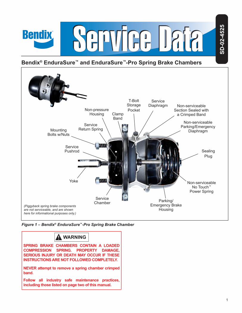
1 ® SPRING BRAKE CHAMBERS CONTAIN A LOADED COMPRESSION SPRING. PROPERTY DAMAGE, SERIOUS INJURY OR DEATH MAY OCCUR IF THESE INSTRUCTIONS ARE NOT FOLLOWED COMPLETELY. NEVER attempt to remove a spring chamber crimped band. Follow all industry safe maintenance practices, including those listed on page two of this manual. Figure 1 – Bendix ® EnduraSure ™ -Pro Spring Brake Chamber Bendix ® EnduraSure ™ and EnduraSure ™ -Pro Spring Brake Chambers SD-02-4525 Parking/ Emergency Brake Housing Non-serviceable No Touch ™ Power Spring Service Pushrod Service Return Spring Service Chamber Sealing Plug T-Bolt Storage Pocket Non-pressure Housing Yoke Service Diaphragm Clamp Band Non-serviceable Parking/Emergency Diaphragm Non-serviceable Section Sealed with a Crimped Band (Piggyback spring brake components are not serviceable, and are shown here for informational purposes only.) Mounting Bolts w/Nuts
-
Upload
khangminh22 -
Category
Documents
-
view
4 -
download
0
Transcript of Pro Spring Brake Chambers SD-02-4525 - NET
1
®
SPRING BRAKE CHAMBERS CONTAIN A LOADED COMPRESSION SPRING. PROPERTY DAMAGE, SERIOUS INJURY OR DEATH MAY OCCUR IF THESE INSTRUCTIONS ARE NOT FOLLOWED COMPLETELY.
NEVER attempt to remove a spring chamber crimped band.
Follow all industry safe maintenance practices, including those listed on page two of this manual.
Figure 1 – Bendix® EnduraSure™-Pro Spring Brake Chamber
Bendix® EnduraSure™ and EnduraSure™-Pro Spring Brake Chambers
SD-0
2-45
25
Parking/ Emergency Brake
Housing
Non-serviceable No Touch™
Power Spring
Service Pushrod
Service Return Spring
Service Chamber
Sealing Plug
T-Bolt Storage PocketNon-pressure
Housing
Yoke
Service Diaphragm
Clamp Band
Non-serviceable Parking/Emergency
Diaphragm
Non-serviceable Section Sealed with
a Crimped Band
(Piggyback spring brake components are not serviceable, and are shown here for informational purposes only.)
Mounting Bolts w/Nuts
2
GENERAL SAFETY GUIDELINESWARNING! PLEASE READ AND FOLLOW THESE INSTRUCTIONS
TO AVOID PERSONAL INJURY OR DEATH:When working on or around a vehicle, the following guidelines should be observed AT ALL TIMES:
▲ Park the vehicle on a level surface, apply the parking brakes and always block the wheels. Always wear personal protection equipment.
▲ Stop the engine and remove the ignition key when working under or around the vehicle. When working in the engine compartment, the engine should be shut off and the ignition key should be removed. Where circumstances require that the engine be in operation, EXTREME CAUTION should be used to prevent personal injury resulting from contact with moving, rotating, leaking, heated or electrically-charged components.
▲ Do not attempt to install, remove, disassemble or assemble a component until you have read, and thoroughly understand, the recommended procedures. Use only the proper tools and observe all precautions pertaining to use of those tools.
▲ If the work is being performed on the vehicle’s air brake system, or any auxiliary pressurized air systems, make certain to drain the air pressure from all reservoirs before beginning ANY work on the vehicle. If the vehicle is equipped with a Bendix® AD-IS® air dryer system, a Bendix® DRM™ dryer reservoir module, or a Bendix® AD-9si® air dryer, be sure to drain the purge reservoir.
▲ Fo l lowing the vehic le manufac turer ’s recommended procedures, deactivate the electrical system in a manner that safely removes all electrical power from the vehicle.
▲ Never exceed manufacturer’s recommended pressures.
▲ Never connect or disconnect a hose or line containing pressure; it may whip and/or cause hazardous airborne dust and dirt particles. Wear eye protection. Slowly open connections with care, and verify that no pressure is present. Never remove a component or plug unless you are certain all system pressure has been depleted.
▲ Use only genuine Bendix® brand replacement parts, components and kits. Replacement hardware, tubing, hose, fi ttings, wiring, etc. must be of equivalent size, type and strength as original equipment and be designed specifi cally for such applications and systems.
▲ Components with stripped threads or damaged parts should be replaced rather than repaired. Do not attempt repairs requiring machining or welding unless specifi cally stated and approved by the vehicle and component manufacturer.
▲ Prior to returning the vehicle to service, make certain all components and systems are restored to their proper operating condition.
▲ For vehicles with Automatic Traction Control (ATC), the ATC function must be disabled (ATC indicator lamp should be ON) prior to performing any vehicle maintenance where one or more wheels on a drive axle are lifted off the ground and moving.
▲ The power MUST be temporarily disconnected from the radar sensor whenever any tests USING A DYNAMOMETER are conducted on a vehicle equipped with a Bendix® Wingman® system.
▲ You should consult the vehicle manufacturer's operating and service manuals, and any related literature, in conjunction with the Guidelines above.
WARNING: Not all wheels and valve stems are compatible with Bendix Air Disc Brakes. Use only wheels and valve stems approved by the vehicle manufacturer to avoid the risk of valve stem shear and other compatibility issues.
WARNING: AVOID CREATING DUST. POSSIBLE CANCER AND LUNG DISEASE HAZARD.While Bendix Spicer Foundation Brake LLC does not offer asbestos brake linings, the long-term affects of some non-asbestos fi bers have not been determined. Current Occupational Safety and Health Administration (OSHA) Regulations cover exposure levels to some components of non-asbestos linings, but not all. The following precautions must be used when handling these materials. Avoid creating dust. Compressed air or dry brushing must never be used for cleaning brake assemblies or the work area.
▲ Bendix recommends that workers doing brake work must take steps to minimize exposure to airborne
brake lining particles. Proper procedures to reduce exposure include working in a well-ventilated area, segregation of areas where brake work is done, use of local fi ltered ventilation systems or use of enclosed cells with fi ltered vacuums. Respirators approved by the Mine Safety and Health Administration (MSHA) or National Institute for Occupational Safety and Health (NIOSH) should be worn at all times during brake servicing.
▲ Workers must wash before eating, drinking or smoking; shower after working, and should not wear work clothes home. Work clothes should be vacuumed and laundered separately without shaking.
▲ OSHA Regulations regarding testing, disposal of waste and methods of reducing exposure for asbestos are set forth in 29 Code of Federal Regulations §1910.001. These Regulations provide valuable information which can be utilized to reduce exposure to airborne particles.
▲ Material Safety Data Sheets on this product, as required by OSHA, are available from Bendix. Call 1-800-247-2725 and speak to the Tech Team or e-mail [email protected].
3
IndexSection PageDescription . . . . . . . . . . . . . . . . . . . . . . . . . . . . . . . . . . . . . . . . . . . . . . . . . 4
Safe Maintenance Practices . . . . . . . . . . . . . . . . . . . . . . . . . . . . . . . . . . . . . . . . 2
Spring Brake Chamber Models . . . . . . . . . . . . . . . . . . . . . . . . . . . . . . . . . . . . . . 3
Preventive Maintenance . . . . . . . . . . . . . . . . . . . . . . . . . . . . . . . . . . . . . . . . . . 4
Operation and Leakage Tests . . . . . . . . . . . . . . . . . . . . . . . . . . . . . . . . . . . . . . . 5
Operation: General . . . . . . . . . . . . . . . . . . . . . . . . . . . . . . . . . . . . . . . . . . . . . 5
Bendix® EnduraSure™-Pro Sealed Chamber. . . . . . . . . . . . . . . . . . . . . . . . . . . . . . . . 6
Mechanical Release (Caging) of the Bendix® EnduraSure™ Spring Brake. . . . . . . . . . . . . . . . . 7
Clocking (Rotating) the Bendix Service Replacement Spring Brake Chamber . . . . . . . . . . . . . . 7
Mechanical Release (Caging) and Removal of the Piggyback Spring Brake Chamber to be Replaced. . 8
Installing the Piggyback Spring Brake Chamber (EnduraSure chamber only) . . . . . . . . . . . . . . . 8
Un-caging the Bendix EverSure Spring Brake Chamber (Apply Park Brake) . . . . . . . . . . . . . . . 9
Removal and Installation of the Combination Spring Brake . . . . . . . . . . . . . . . . . . . . . . . . 9
Replacing the Service Diaphragm . . . . . . . . . . . . . . . . . . . . . . . . . . . . . . . . . . . . . 10
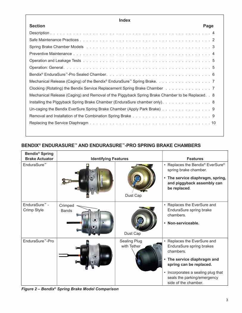
BENDIX® ENDURASURE™ AND ENDURASURE™-PRO SPRING BRAKE CHAMBERSBendix® Spring Brake Actuator Identifying Features Features
EnduraSure™
Dust Cap
• Replaces the Bendix® EverSure® spring brake chamber.
• The service diaphragm, spring, and piggyback assembly can be replaced.
EnduraSure™ - Crimp Style
Crimped Bands
Dust Cap
• Replaces the EverSure and EnduraSure spring brake chambers.
• Non-serviceable.
EnduraSure™-Pro Sealing Plug with Tether
• Replaces the EverSure and EnduraSure spring brakes chambers.
• The service diaphragm and spring can be replaced.
• Incorporates a sealing plug that seals the parking/emergency side of the chamber.
Figure 2 – Bendix® Spring Brake Model Comparison
4
DESCRIPTIONThe Bendix® EnduraSure™ and EnduraSure™-Pro spring brake chambers are made up of a conventional brake chamber and an emergency, or parking, spring mechanism for use on vehicles equipped with cam-type foundation brakes. The spring brake actuator provides: (1) service braking, (2) parking, and (3) emergency braking. The actuator can be piped with various system arrangements to be automatically, or manually, applied under emergency braking conditions.
The spring brake chamber is a diaphragm-type actuator which converts the energy of air pressure into mechanical force. The diaphragm is held between the adapter base and non-pressure plate by a two-piece clamp ring. The standard diaphragm material is a compound of natural rubber with a fabric interior of nylon.
Different size brake chambers are identified by numbers, which specify the effective area of a diaphragm. For example, a Type 30/30 spring brake chamber has 30 square inches of effective area on each diaphragm.
This Service Data sheet covers three different models of spring brake chambers: the Bendix® EnduraSure™; Bendix®
EnduraSure™ crimp-style; and Bendix® EnduraSure™-Pro. Be sure to verify the model being serviced before performing any service or maintenance. Refer to the chamber information on page three for the serviceability of each model. Important: Review the warranty policy before performing any maintenance procedures.
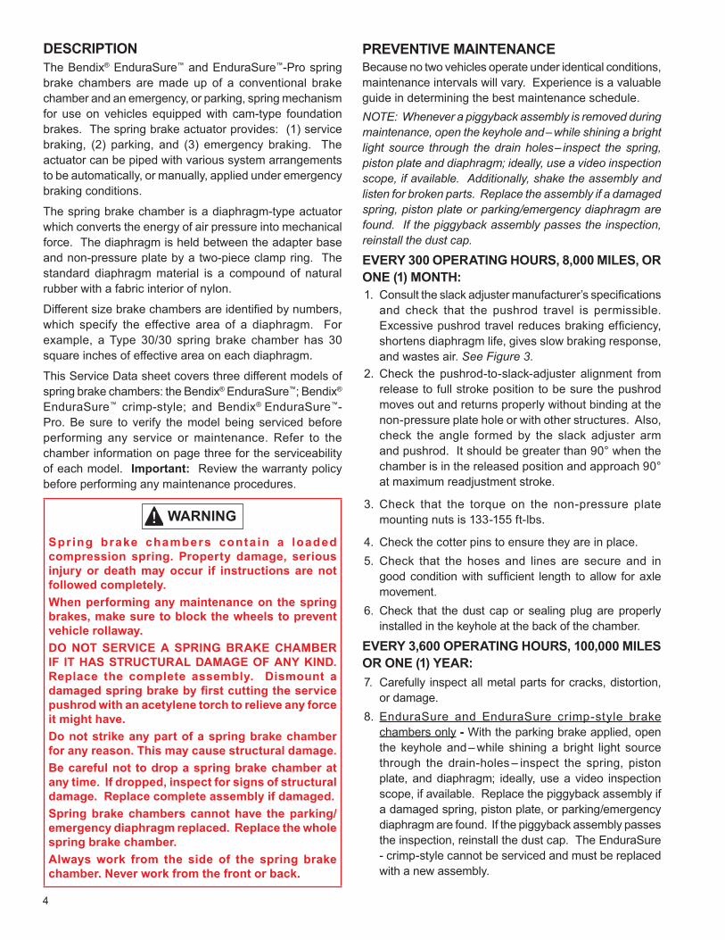
Spring brake chambers contain a loaded compression spring. Property damage, serious injury or death may occur if instructions are not followed completely.When performing any maintenance on the spring brakes, make sure to block the wheels to prevent vehicle rollaway.DO NOT SERVICE A SPRING BRAKE CHAMBER IF IT HAS STRUCTURAL DAMAGE OF ANY KIND. Replace the complete assembly. Dismount a damaged spring brake by first cutting the service pushrod with an acetylene torch to relieve any force it might have.Do not strike any part of a spring brake chamber for any reason. This may cause structural damage.Be careful not to drop a spring brake chamber at any time. If dropped, inspect for signs of structural damage. Replace complete assembly if damaged.Spring brake chambers cannot have the parking/emergency diaphragm replaced. Replace the whole spring brake chamber.Always work from the side of the spring brake chamber. Never work from the front or back.
PREVENTIVE MAINTENANCEBecause no two vehicles operate under identical conditions, maintenance intervals will vary. Experience is a valuable guide in determining the best maintenance schedule. NOTE: Whenever a piggyback assembly is removed during maintenance, open the keyhole and – while shining a bright light source through the drain holes – inspect the spring, piston plate and diaphragm; ideally, use a video inspection scope, if available. Additionally, shake the assembly and listen for broken parts. Replace the assembly if a damaged spring, piston plate or parking/emergency diaphragm are found. If the piggyback assembly passes the inspection, reinstall the dust cap.
EVERY 300 OPERATING HOURS, 8,000 MILES, OR ONE (1) MONTH: 1. Consult the slack adjuster manufacturer’s specifications
and check that the pushrod travel is permissible. Excessive pushrod travel reduces braking efficiency, shortens diaphragm life, gives slow braking response, and wastes air. See Figure 3.
2. Check the pushrod-to-slack-adjuster alignment from release to full stroke position to be sure the pushrod moves out and returns properly without binding at the non-pressure plate hole or with other structures. Also, check the angle formed by the slack adjuster arm and pushrod. It should be greater than 90° when the chamber is in the released position and approach 90° at maximum readjustment stroke.
3. Check that the torque on the non-pressure plate mounting nuts is 133-155 ft-lbs.
4. Check the cotter pins to ensure they are in place.5. Check that the hoses and lines are secure and in
good condition with sufficient length to allow for axle movement.
6. Check that the dust cap or sealing plug are properly installed in the keyhole at the back of the chamber.
EVERY 3,600 OPERATING HOURS, 100,000 MILES OR ONE (1) YEAR:7. Carefully inspect all metal parts for cracks, distortion,
or damage. 8. EnduraSure and EnduraSure crimp-style brake
chambers only - With the parking brake applied, open the keyhole and – while shining a bright light source through the drain-holes – inspect the spring, piston plate, and diaphragm; ideally, use a video inspection scope, if available. Replace the piggyback assembly if a damaged spring, piston plate, or parking/emergency diaphragm are found. If the piggyback assembly passes the inspection, reinstall the dust cap. The EnduraSure - crimp-style cannot be serviced and must be replaced with a new assembly.
5
9. Perform the Leakage Test (outlined in this document). As necessary –and if available – install a new service side diaphragm or any other parts if they are worn or deteriorated. All diaphragm sealing surfaces should be smooth and clean. Perform the steps outlined in the Replacing the Service Diaphragm section. When the service diaphragm, service return spring, or the spring brake chamber are replaced, they should be replaced as an axle set.
END OF PRODUCT-LIFE TESTAll spring brakes eventually deteriorate with age. Typical end of product-life signs are corrosion, and the presence of rattling sounds caused by broken power springs – perform the visual inspection in Step 2 of the Preventive Maintenance section.
For advice on the carefully de-powering and disposal of spring brakes, see BW7450 – available on the document library at bendix.com.
OPERATION & LEAKAGE TESTS
OPERATION TEST1. Apply the brakes and observe that all the pushrods
move out promptly, and without binding.
2. Release the brakes and observe that all the pushrods return to the released position promptly, and without binding.
3. Check the pushrod travel. The pushrod travel should be as short as possible without the brakes dragging. Adjust the travel of the pushrod at the slack adjuster if necessary.
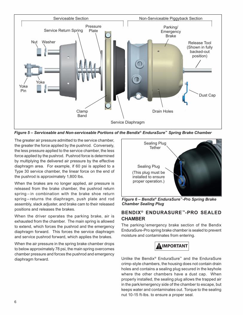
4. If the orange stroke indication mark on the pushrod is visible, consult the slack adjuster service instructions and verify the proper slack adjuster function. See Figure 3.
LEAKAGE TEST
1. Make and hold a full brake application.2. Using a soap solution, coat the clamping band. If
leakage is detected, tighten the clamping band only enough to stop the leakage. DO NOT OVERTIGHTEN as this can distort the sealing surface or clamping band. Note that the Bendix® EnduraSure™ crimp-style spring brake clamp band cannot be tightened and the spring brake must be replaced if leakage is detected.
3. Coat the area around the pushrod hole (loosen the boot, if applicable). Minimal leakage is permitted (100 SCCM). If abnormal leakage is detected, the diaphragm must be replaced, if serviceable.
4. Using a soap solution, check the hose fitting for leakage. A one-inch bubble in one minute is acceptable.
OPERATION: GENERALThe spring brake chambers are made up of the service chamber and the piggyback spring brake chamber. They provide service braking, parking, and emergency braking.
The spring brake can be mounted with the mounting bolts in either a vertical or horizontal plane on standard mounting stud centers. Two air hoses are used: the service air hose (the connector is marked “11”); and the parking/emergency air hose (the connector is marked “12”).
When the vehicle brakes are applied, controlled air pressure enters the service chamber through the inlet port and acts upon the diaphragm, moving the push plate and rod assembly forward.
When the service chamber is used to actuate the cam-type brake foundation assemblies, the yoke (which is welded to, or threaded on, the pushrod) is connected to a slack adjuster, which in turn is connected to the brake cam shaft. This forward motion of the pushrod rotates the slack adjuster, cam shaft and cam – applying the vehicle brakes.
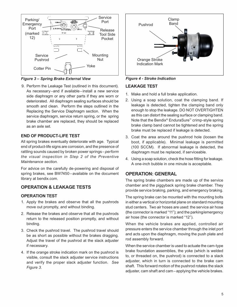
Release Tool Side Pocket
Parking/Emergency
Port(marked
12)
Service Port
Mounting Nut
Cotter Pin Yoke
Service Pushrod
Figure 3 – Spring Brake External View Figure 4 - Stroke Indication
Pushrod
Orange Stroke Indication Mark
Clamp Band
6
Figure 5 – Serviceable and Non-serviceable Portions of the Bendix® EnduraSure™ Spring Brake Chamber
Serviceable Section
Service Return Spring
Non-Serviceable Piggyback Section
Yoke Pin
Nut
Parking/ Emergency
Brake
Service Diaphragm
Release Tool (Shown in fully
backed-out position)
Dust Cap
Pressure Plate
Clamp Band
The greater air pressure admitted to the service chamber, the greater the force applied by the pushrod. Conversely, the less pressure applied to the service chamber, the less force applied by the pushrod. Pushrod force is determined by multiplying the delivered air pressure by the effective diaphragm area. For example, if 60 psi is applied to a Type 30 service chamber, the linear force on the end of the pushrod is approximately 1,800 lbs.
When the brakes are no longer applied, air pressure is released from the brake chamber, the pushrod return spring – in combination with the brake shoe return spring – returns the diaphragm, push plate and rod assembly, slack adjuster, and brake cam to their released positions and releases the brakes.
When the driver operates the parking brake, air is exhausted from the chamber. The main spring is allowed to extend, which forces the pushrod and the emergency diaphragm forward. This forces the service diaphragm and service pushrod forward, which applies the brakes.
When the air pressure in the spring brake chamber drops to below approximately 78 psi, the main spring overcomes chamber pressure and forces the pushrod and emergency diaphragm forward.
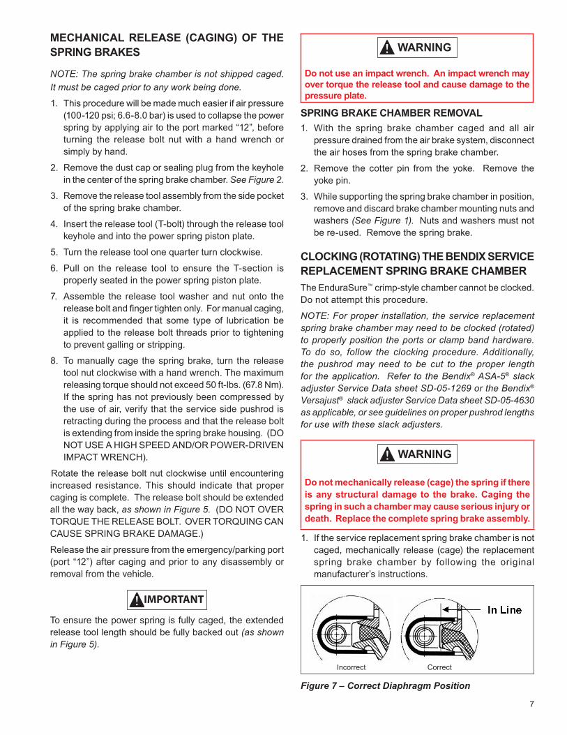
BENDIX® ENDURASURE™-PRO SEALED CHAMBERThe parking / emergency brake section of the Bendix EnduraSure-Pro spring brake chamber is sealed to prevent moisture and contaminates from entering.
IMPORTANT
Unlike the Bendix® EnduraSure™ and the EnduraSure crimp-style chambers, the housing does not contain drain holes and contains a sealing plug secured in the keyhole where the other chambers have a dust cap. When properly installed, the sealing plug allows the trapped air in the park/emergency side of the chamber to escape, but keeps water and contaminates out. Torque to the sealing nut 10-15 ft-lbs. to ensure a proper seal.
Yoke
Washer
Sealing Plug(This plug must be installed to ensure proper operation.)
Sealing Plug Tether
Figure 6 – Bendix® EnduraSure™-Pro Spring Brake Chamber Sealing Plug
Drain Holes
7
MECHANICAL RELEASE (CAGING) OF THE SPRING BRAKES
NOTE: The spring brake chamber is not shipped caged. It must be caged prior to any work being done.
1. This procedure will be made much easier if air pressure (100-120 psi; 6.6-8.0 bar) is used to collapse the power spring by applying air to the port marked “12”, before turning the release bolt nut with a hand wrench or simply by hand.
2. Remove the dust cap or sealing plug from the keyhole in the center of the spring brake chamber. See Figure 2.
3. Remove the release tool assembly from the side pocket of the spring brake chamber.
4. Insert the release tool (T-bolt) through the release tool keyhole and into the power spring piston plate.
5. Turn the release tool one quarter turn clockwise.
6. Pull on the release tool to ensure the T-section is properly seated in the power spring piston plate.
7. Assemble the release tool washer and nut onto the release bolt and finger tighten only. For manual caging, it is recommended that some type of lubrication be applied to the release bolt threads prior to tightening to prevent galling or stripping.
8. To manually cage the spring brake, turn the release tool nut clockwise with a hand wrench. The maximum releasing torque should not exceed 50 ft-lbs. (67.8 Nm). If the spring has not previously been compressed by the use of air, verify that the service side pushrod is retracting during the process and that the release bolt is extending from inside the spring brake housing. (DO NOT USE A HIGH SPEED AND/OR POWER-DRIVEN IMPACT WRENCH).
Rotate the release bolt nut clockwise until encountering increased resistance. This should indicate that proper caging is complete. The release bolt should be extended all the way back, as shown in Figure 5. (DO NOT OVER TORQUE THE RELEASE BOLT. OVER TORQUING CAN CAUSE SPRING BRAKE DAMAGE.)
Release the air pressure from the emergency/parking port (port “12”) after caging and prior to any disassembly or removal from the vehicle.
IMPORTANT
To ensure the power spring is fully caged, the extended release tool length should be fully backed out (as shown in Figure 5).
Do not use an impact wrench. An impact wrench may over torque the release tool and cause damage to the pressure plate.
SPRING BRAKE CHAMBER REMOVAL1. With the spring brake chamber caged and all air
pressure drained from the air brake system, disconnect the air hoses from the spring brake chamber.
2. Remove the cotter pin from the yoke. Remove the yoke pin.
3. While supporting the spring brake chamber in position, remove and discard brake chamber mounting nuts and washers (See Figure 1). Nuts and washers must not be re-used. Remove the spring brake.
CLOCKING (ROTATING) THE BENDIX SERVICE REPLACEMENT SPRING BRAKE CHAMBER The EnduraSure™ crimp-style chamber cannot be clocked. Do not attempt this procedure.
NOTE: For proper installation, the service replacement spring brake chamber may need to be clocked (rotated) to properly position the ports or clamp band hardware. To do so, follow the clocking procedure. Additionally, the pushrod may need to be cut to the proper length for the application. Refer to the Bendix® ASA-5® slack adjuster Service Data sheet SD-05-1269 or the Bendix® Versajust® slack adjuster Service Data sheet SD-05-4630 as applicable, or see guidelines on proper pushrod lengths for use with these slack adjusters.
Do not mechanically release (cage) the spring if there is any structural damage to the brake. Caging the spring in such a chamber may cause serious injury or death. Replace the complete spring brake assembly.
1. If the service replacement spring brake chamber is not caged, mechanically release (cage) the replacement spring brake chamber by following the original manufacturer’s instructions.
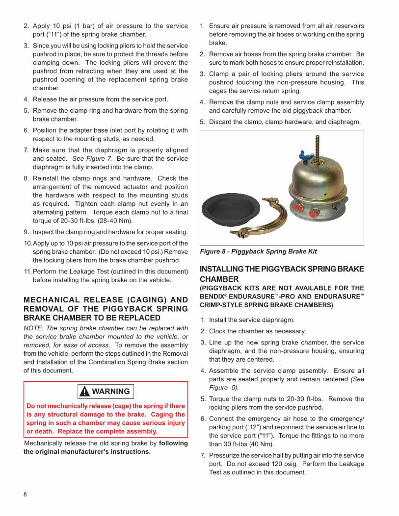
Incorrect Correct
Figure 7 – Correct Diaphragm Position
8
2. Apply 10 psi (1 bar) of air pressure to the service port (“11”) of the spring brake chamber.
3. Since you will be using locking pliers to hold the service pushrod in place, be sure to protect the threads before clamping down. The locking pliers will prevent the pushrod from retracting when they are used at the pushrod opening of the replacement spring brake chamber.
4. Release the air pressure from the service port.
5. Remove the clamp ring and hardware from the spring brake chamber.
6. Position the adapter base inlet port by rotating it with respect to the mounting studs, as needed.
7. Make sure that the diaphragm is properly aligned and seated. See Figure 7. Be sure that the service diaphragm is fully inserted into the clamp.
8. Reinstall the clamp rings and hardware. Check the arrangement of the removed actuator and position the hardware with respect to the mounting studs as required. Tighten each clamp nut evenly in an alternating pattern. Torque each clamp nut to a final torque of 20-30 ft-lbs. (28-40 Nm).
9. Inspect the clamp ring and hardware for proper seating.
10. Apply up to 10 psi air pressure to the service port of the spring brake chamber. (Do not exceed 10 psi.) Remove the locking pliers from the brake chamber pushrod.
11. Perform the Leakage Test (outlined in this document) before installing the spring brake on the vehicle.
MECHANICAL RELEASE (CAGING) AND REMOVAL OF THE PIGGYBACK SPRING BRAKE CHAMBER TO BE REPLACEDNOTE: The spring brake chamber can be replaced with the service brake chamber mounted to the vehicle, or removed, for ease of access. To remove the assembly from the vehicle, perform the steps outlined in the Removal and Installation of the Combination Spring Brake section of this document.
Do not mechanically release (cage) the spring if there is any structural damage to the brake. Caging the spring in such a chamber may cause serious injury or death. Replace the complete assembly.
Mechanically release the old spring brake by following the original manufacturer’s instructions.
1. Ensure air pressure is removed from all air reservoirs before removing the air hoses or working on the spring brake.
2. Remove air hoses from the spring brake chamber. Be sure to mark both hoses to ensure proper reinstallation.
3. Clamp a pair of locking pliers around the service pushrod touching the non-pressure housing. This cages the service return spring.
4. Remove the clamp nuts and service clamp assembly and carefully remove the old piggyback chamber.
5. Discard the clamp, clamp hardware, and diaphragm.
INSTALLING THE PIGGYBACK SPRING BRAKE CHAMBER (PIGGYBACK KITS ARE NOT AVAILABLE FOR THE BENDIX® ENDURASURE™-PRO AND ENDURASURE™
CRIMP-STYLE SPRING BRAKE CHAMBERS)
1. Install the service diaphragm.
2. Clock the chamber as necessary.
3. Line up the new spring brake chamber, the service diaphragm, and the non-pressure housing, ensuring that they are centered.
4. Assemble the service clamp assembly. Ensure all parts are seated properly and remain centered (See Figure 5).
5. Torque the clamp nuts to 20-30 ft-lbs. Remove the locking pliers from the service pushrod.
6. Connect the emergency air hose to the emergency/parking port (“12”) and reconnect the service air line to the service port (“11”). Torque the fittings to no more than 30 ft-lbs (40 Nm).
7. Pressurize the service half by putting air into the service port. Do not exceed 120 psig. Perform the Leakage Test as outlined in this document.
Figure 8 - Piggyback Spring Brake Kit
9
UN-CAGING THE SPRING BRAKE CHAMBER (APPLY PARK BRAKE) 1. Verify that the spring brake has been properly installed
on the spring brake bracket and properly attached to the slack adjuster.
2. Apply air pressure (100-120 psi; 6.6-8.0 bar) to restrain by air force the power spring.
3. Turn the release bolt nut counterclockwise with a hand wrench. (DO NOT USE A HIGH SPEED OR POWER-DRIVEN IMPACT WRENCH).Connect a regulated air line to the emergency/parking brake port (marked “12”) of the chamber (if not connected previously).
4. Continue to turn the release bolt nut until the caging tool is loose. Remove the caging bolt nut and washer.
5. Push the release bolt tool in, turn the release bolt a quarter-turn counterclockwise and remove it from the pressure plate keyhole.
6. With hands clear of moving parts, slowly release the air pressure to the emergency/parking brake port (“12”). Be sure to exercise caution to prevent pinching of fingers.
7. Place the caging bolt in the spring brake tool holder with the T-head down and seated in the slot. Install the washer and nut up on the exposed threads (this allows the washer to protect the holder cavity and caging bolt from corrosive elements), and torque the caging bolt nut to 10-15 ft-lbs (14-20 Nm).
8. Mount the dust cap / sealing plug in the keyhole located at the rear center of the spring brake chamber. Ensure that the o-ring seal is present and not torn or damaged. Torque the sealing plug to 10-15 ft-lbs (14-20 Nm). Check around the edge of the dust cap / sealing plug to be sure it is firmly seated. Refer to Figure 2.
IMPORTANT
Always reinstall the tethered dust cap / sealing plug in the spring brake caging tool keyhole. Failure to do so will result in corrosion and foreign material ingestion through the keyhole which may void the warranty. Do not use excessive force when installing the dust plug/sealing plug. Extreme force may cause damage and make it non-usable. Replacement dust caps and sealing plugs can be purchased from any authorized Bendix parts outlet.
Check for proper service and emergency operation after servicing any part of the brake chamber(s). Check the brake adjustment if the combination spring brake was removed/installed. (Follow the vehicle manufacturer’s instructions to adjust the brakes).
REMOVAL AND INSTALLATION OF THE COMBINATION SPRING BRAKE
SERVICE BRAKE CHAMBER REPLACEMENT AND CLOCKING
Replace the brake chamber with the same type and size as originally installed on the vehicle. Replacement with alternate equipment (without written authorization from Bendix and the vehicle manufacturer) could compromise brake performance. Brake chambers (with the exception of the Bendix® EnduraSure™ crimp-style chamber) can be clocked to ensure the proper alignment of mounting studs, drain holes, and ports.
Do not mechanically release (cage) the spring if there is any structural damage to the spring brake chamber. Caging the spring in such a chamber may cause serious injury or death. Replace the complete assembly.
REPLACING THE COMBINATION SPRING BRAKE1. Mechanically release (cage) the old spring brake
chamber by following the original manufacturer’s instructions (or use the instructions included in this document for Bendix® brand spring brakes).
2. Drain system pressure and then disconnect the air hoses from the service brake chamber. Be sure to mark both hoses to ensure proper reinstallation.
3. Remove the cotter and yoke pins, disconnect the yoke from the slack adjuster, remove the mounting nuts, washer, and lock washers and remove the combination spring brake. While removing, use care to prevent the combination spring brake from falling.
4. Remove the brake chamber mounting hardware from the mounting studs.
5. Remove the service brake chamber from its mounting bracket.
10
INSTALLATION: CLOCKING (ROTATING) THE REPLACEMENT BRAKE CHAMBER Brake chambers (with the exception of the Bendix® EnduraSure™ crimp-style chamber) can be clocked to ensure the proper alignment of mounting studs, drain holes and ports.1. Clock the chamber per the clocking instructions in this
document. 2. Clean and inspect the mounting bracket. Mount the
service brake chamber to the mounting bracket.
3. If the service replacement is a type that provides an extra-long threaded pushrod, thread a nut onto the rod past the point that it will need to be cut. Taking all necessary safety precautions, cut the rod to the required length and remove burrs. Remove the nut installed earlier to ensure that the threads are clear.
4. Install the combination spring brake using the furnished hardware. Torque the mounting nuts to 133-155 ft-lbs. (80-210 Nm). Connect the yoke to the slack adjuster and install the yoke pin and the cotter pin.
5. Connect the air hoses to the brake chamber. Torque the fitting to 30 ft-lbs. (40 + 5 Nm). Check to be sure the air hoses are properly supported and clamped, if necessary, to provide proper clearance, including checking for proper length when under full steer conditions.
6. Pressurize the service chamber by putting air into the service port. Do not exceed 120 psig.
7. Perform the leakage test included in this document. Minimal leakage is permitted (100 SCCM).
8. Un-cage the main spring and return the release tool into the release tool side pocket.
9. Adjust the slack adjuster per manufacturer ’s recommendations.
10. Check the function and stroke per the operating test.
11. Mount the dust cap / sealing plug in the keyhole located at the rear center of the spring brake chamber. Ensure that the o-ring seal is present and not torn or damaged. Torque the sealing plug to 10-15 ft-lbs. (14-20 Nm). Check around the edge of the dust cap /sealing plug to be sure it is firmly seated. Refer to Figure 2.
Check for proper service and emergency operation after servicing any part of the brake chamber(s). Check the brake adjustment if the combination spring brake was removed/installed. (Follow the vehicle manufacturer’s instructions to adjust the brakes).
REPLACING THE SERVICE DIAPHRAGMBendix EnduraSure crimp-style chamber cannot be serviced. If the service diaphragm leaks, the chamber must be replaced.
To ensure the proper alignment of mounting studs, drain holes and ports, see Figure 5. To replace the service diaphragm, it is not necessary to remove the complete combination spring brake from the vehicle (however, it can be removed for ease of access). To remove the combination spring brake, perform the steps outlined in the Removal and Installation of the Combination Spring Brake section.
When either the diaphragm, spring, or both, are replaced, they should be replaced in the corresponding chamber on the same axle. Use only genuine Bendix® brand replacement parts.
A spring brake chamber cannot have the emergency diaphragm replaced. Replace the whole spring brake chamber.
1. Protect the service pushrod with tape, and lock the locking pliers on the pushrod close to the non-pressure plate. (This will hold the rod in the applied position).
2. Ensure that the spring brake chamber is caged. To cage the spring brake chamber, perform the steps outlined in either the Mechanical Release (Caging) of the Bendix
EnduraSure Spring Brake section or the Mechanical Release (Caging) and Removal of the Piggyback Spring Brake Chamber to be Replaced section.
3. Mark the service clamp ring and non-pressure plate to ensure proper alignment of parts during reassembly.
4. Remove the service clamp ring assembly and the chamber. The service clamp ring is closest to the non-pressure plate and slack adjuster. See the provided illustrations if in doubt.
5. Install a new diaphragm.
6. Line up the spring brake chamber, the service diaphragm, and the non-pressure housing, ensuring that they are centered (See Figure 5).
7. Reassemble the service clamp assembly. Ensure all parts are seated properly and remain centered.
11
8. Torque the clamp nuts to 20-30 ft-lbs. Remove the locking pliers from the service pushrod.
9. Reconnect the emergency air hose to the emergency port (marked “12”) and reconnect the service air line to the service port (marked “11”).
10. Pressurize the service half by putting air into the service port. Perform the Operation and Leakage Test in this document.
11. Un-cage the main spring and return the release tool into the release tool side pocket.
12. Mount the dust cap / sealing plug in the keyhole located at the rear center of the spring brake chamber. Ensure that the o-ring seal is present and not torn or damaged. Torque the dust seal to 10-15 ft-lbs (14-20 Nm). Check around the edge of the dust cap /sealing plug to be sure it is firmly seated. Refer to Figure 2.
Check for proper service and emergency operation after servicing any part of the brake chamber(s). Check the brake adjustment if the combination spring brake was removed/installed. (Follow the vehicle manufacturer’s instructions to adjust the brakes).
12
Log-on and Learn from the BestOn-line training that's available when you are 24/7/365.
Visit www.brake-school.com.
SD-02-4525 Rev. 003 © 2017 Bendix Spicer Foundation Brake LLC. All Rights Reserved. 10/17