5412 SERIES ENCLOSED BRAKE - Kobelt
25
KOBELT MANUFACTURING CO. LTD MNL-5412-A.docx (rev B) 1 5412 SERIES ENCLOSED BRAKE AIR APPLIED VERSION Owner’s Operation, Installation & Maintenance Manual
-
Upload
khangminh22 -
Category
Documents
-
view
5 -
download
0
Transcript of 5412 SERIES ENCLOSED BRAKE - Kobelt

KOBELT MANUFACTURING CO. LTD MNL-5412-A.docx (rev B) 1
5412 SERIES ENCLOSED
BRAKE AIR APPLIED VERSION
Owner’s Operation, Installation &
Maintenance Manual

KOBELT MANUFACTURING CO. LTD MNL-5412-A.docx (rev B) 2
Table of Contents 1 Introduction ..................................................................................................................4
1.1 Contact Information ...................................................................................................... 4
1.2 Safety Information ........................................................................................................ 4
1.2.1 Safety Instructions .................................................................................................... 4
1.2.2 Hazards ..................................................................................................................... 5
1.3 Product Description....................................................................................................... 6
1.4 Technical Data ............................................................................................................... 7
1.5 Model Code Key ............................................................................................................ 8
2 Installation ....................................................................................................................9
2.1 Preparation ................................................................................................................... 9
2.2 Brake Hub ...................................................................................................................... 9
2.3 Caliper brakes ................................................................................................................ 9
2.3.1 Mechanical ................................................................................................................ 9
2.3.2 Piping ...................................................................................................................... 10
3 Commissioning ............................................................................................................ 11
3.1 Function Test ............................................................................................................... 11
3.2 Burnishing ................................................................................................................... 11
3.3 Torque Test ................................................................................................................. 12
4 Operation .................................................................................................................... 13
4.1 Functional Requirements ............................................................................................ 13
4.1.1 Pressure Supply ....................................................................................................... 13
4.2 Service Limits .............................................................................................................. 13
4.2.1 Disc Temperature .................................................................................................... 13
4.2.2 Ambient Temperature ............................................................................................ 13
4.2.3 Pressure .................................................................................................................. 13
4.2.4 Disc speed ............................................................................................................... 13
5 Maintenance ............................................................................................................... 14
5.1 Preventative Maintenance .......................................................................................... 14
5.2 Inspection .................................................................................................................... 14
5.2.1 Pad Wear ................................................................................................................ 14
5.2.2 Seals ........................................................................................................................ 14
5.2.3 Brake Disc ............................................................................................................... 14
5.3 Service ......................................................................................................................... 15
5.3.1 Tool List ................................................................................................................... 15
5.3.2 Brake Linings ........................................................................................................... 15
5.3.3 Actuators ................................................................................................................ 16
5.4 Recommended Spares................................................................................................. 18
6 Warranty ..................................................................................................................... 19
KOBELT MANUFACTURING CO. LTD MNL-5412-A.docx (rev B) 3
7 Appendix A: Technical Drawings ................................................................................... 20
8 Appendix B: Parts List Drawings ................................................................................... 21

KOBELT MANUFACTURING CO. LTD MNL-5412-A.docx (rev B) 4
1 INTRODUCTION
1.1 CONTACT INFORMATION Kobelt Manufacturing Co LTD.
8238 129TH Street
Surrey, British Columbia
Canada, V3W 0A6
Sales Tel: 604-572-3935
Fax: 604-590-8313
Email: [email protected]
Website: www.kobelt.com
For further instructions, please contact our distributors or visit our website.
1.2 SAFETY INFORMATION
1.2.1 Safety Instructions
Notice to Installer:
Disregarding the following safety measures can result in an accident causing severe injury to personnel and damage to material assets:
• Only use the product as directed in this manual.
• Never put the product into service if there is evidence of visible damage.
• Never put the product into service before fully completing installation and commissioning.
• Do not carry out any modifications to the product.
• Only use authentic Kobelt spare parts.
• Observe all local regulations, directives and laws during the installation of this product.
• All installation, commissioning and maintenance work must only be conducted by qualified personnel. (For the purpose of this manual, qualified personnel are persons who are familiar with the assembly, installation, commissioning, and operation of the product and who have the qualifications necessary for their occupation.)
• Observe all specifications in this manual. If these guidelines are not followed and damage occurs, the warranty will be voided.

KOBELT MANUFACTURING CO. LTD MNL-5412-A.docx (rev B) 5
1.2.2 Hazards
Throughout this publication, Warnings and Cautions accompanied by the International Hazard
Symbol is used to alert the user to special instructions concerning a particular service or
operation that may be hazardous if performed incorrectly or carelessly.
Equipment Starts Automatically:
Brake systems frequently are controlled remotely and may activate
suddenly causing bodily harm. Ensure all power sources are locked out
prior to performing work.
Pinch Points:
Brakes contain numerous pinch points which can cause serious injury.
Ensure all power sources are locked out prior to performing work.
High Pressure Fluids:
Kobelt brakes use compressed air. Ensure all pressure is exhausted and
the pressure source locked out prior to performing work.
Hot Surfaces:
Disc brakes are capable of making the surfaces of the brake disc
dangerously hot when burnishing or during braking events. Ensure the disc
is adequately guarded to prevent inadvertent contact with the disc.
Airborne Dust:
Brake linings contain fibers that may become airborne during cutting or
sanding operations. Over exposure to these dusts should be considered
hazardous. Use NIOSH approved respirators when working with brake
linings. Request a MSDS for further information.

KOBELT MANUFACTURING CO. LTD MNL-5412-A.docx (rev B) 6
1.3 PRODUCT DESCRIPTION The diagram below shows a typical Kobelt caliper brake with all the major components
identified. All of the Kobelt caliper brakes can be fitted with either air applied, hydraulic
applied, spring applied with air released or spring applied with hydraulic released actuators
depending on the required service.
Figure 1: Tension Brake Nomenclature

KOBELT MANUFACTURING CO. LTD MNL-5412-A.docx (rev B) 7
1.4 TECHNICAL DATA
For technical data and specifications refer to the relevant data sheets from www.kobelt.com or the
technical drawings in Appendix A if provided.
Model no.: 5412-A 5412-A-D 1. Maximum Torque: 200 ft-lbs [272 Nm] 300 ft-lbs [408 Nm]
Torque Range: 2.5% - 100% 2. Pad Life: 8000 hp-hr [5978 kw-hr] 3. Maximum Speed: 2140 rpm 4. Thermal Performance:
4.1. Cooling: See chart 4.2. Heat Sinking: 3.1 hp-sec/F [4.2 KJ/C]
5. Maximum pressure: 100 psi [6.9 bar] 6. Volume:
6.1. Normal: 6 in3 [101 cc] 6.2. Maximum: 22 in3 [362 cc]
7. Weight: 87 lbs [40 kg] 8. Rotating Inertia: 3.2 lbs-ft2 [.1 kgm2]
0.0
0.5
1.0
1.5
2.0
2.5
3.0
3.5
4.0
4.5
5.0
0 200 400 600 800 1000 1200 1400 1600 1800 2000 2200
Hea
t D
issi
pat
ion
(h
p)
Disc Speed (rpm)
5412 Series Tension BrakeHeat Dissipation vs. Disc Speed
FAN COOLED
NORMALCOOLING

KOBELT MANUFACTURING CO. LTD MNL-5412-A.docx (rev B) 8
1.5 MODEL CODE KEY
0
50
100
150
200
250
300
0 10 20 30 40 50 60 70 80 90 100
Bra
kin
g To
rqu
e (f
t-lb
s)
Supply Pressure (psi)
5412 Series Tension BrakeTorque Output
5412-A-D5412-A

KOBELT MANUFACTURING CO. LTD MNL-5412-A.docx (rev B) 9
2 INSTALLATION
2.1 PREPARATION The mounting bracket to support the brake must be designed to withstand the maximum
braking forces generated by the brake. The bracket must meet the following requirements:
Flatness: .004 in [.1 mm](1)
Pilot fit: 10.995/10.990 in [279.3/279.1 mm]2
(1) Allowable deviation from flatness is proportional to the pilot diameter with an IT8
tolerance grade. See Appendix A for key installation dimensions.
(2) The locating pilot on the mounting plate should provide the brake with an LC7 fit
(H10/e9).
The rotating element should have bearings suitably rated to carry the weight of the disc and
hub. The run-out of the shaft must not exceed .012 in [.30 mm] TIR.
Actuator ports are plugged to prevent contamination of the seals. Remove the plugs prior to
connection to the piping.
For cases where a guard or some protective cover is required ensure that the guard does not
compromise the performance. An improperly designed cover or shield may cause air
recirculation through the disc or radiant heat reflection, which could result in the disc
overheating. The cooling air pumped through the disc must be exhausted away from the outer
diameter of the disc to allow fresh, cool air to enter the inner vent opening of the disc.
2.2 BRAKE HUB The brake hub must be installed onto the rotating element before installing the caliper. Insert
the shaft key and tighten the two set screws to 64 in-lbs [7.2 Nm] using a 1/8 inch hexagon key.
2.3 CALIPER BRAKES
2.3.1 Mechanical
Perform the following steps to properly install a caliper brake:
1. Ensure that both mounting faces of the brake and the mating surfaces on the bracket are
clean.
2. Align the splines on the disc with those on the hub and insert the brake over the hub.
3. Install of SAE grade 5 mounting bolts. It is recommended to use a thread locking product
such as Loctite® to ensure a vibration resistant and secure joint.
4. Tighten the mounting bolts to 37 ft-lbs [50 Nm].

KOBELT MANUFACTURING CO. LTD MNL-5412-A.docx (rev B) 10
2.3.2 Piping
The piping to the brakes must be adequately sized to ensure appropriate response times. The
piping must be selected to safely withstand the pressures required to operate the brakes.
Secure the piping every 3 ft [0.9 m] against vibration with pipe clamp.
All piping must be cleaned prior to connection to the brake. Welded carbon steel piping must
be pickled to remove the scale produced by welding.
The brake is equipped with a 3/8 NPT pressure port. The connections to the brake actuators
must be made by hoses of a suitable rating to accommodate deflection of the brake.
Do not over tighten the fitting in the actuator port as damage to the
actuator may occur.
For operation in sub-zero temperatures down to a minimum of 0oF [-20oC] the air must be dried to a dew point of -50oF [-44oF]
Failure to adequately dry the compressed air supply may result in the brake
valve freezing and rendering the brakes inoperable in sub-zero weather
conditions.

KOBELT MANUFACTURING CO. LTD MNL-5412-A.docx (rev B) 11
3 COMMISSIONING
3.1 FUNCTION TEST Before burnishing the brakes perform a quick inspection and function test of the brakes:
(1) Ensure that all mounting bolts are properly installed.
(2) Ensure the brake disc surface is clean. Remove all contamination from the disc with
cleaning solvent.
(5) Check that the pressure source is within the specified pressure range.
(6) Check that all bolts are tight.
(7) Cycle the brakes and ensure that the brakes are operational
3.2 BURNISHING Burnishing is required in order to achieve rated brake torque. The process of burnishing
removes minor contaminants from the rubbing surfaces and improves the degree of contact
between the brake pad and disc.
If present, safety interlocks of the drive mechanism should be temporarily defeated to allow the
disc to be driven with the brake partially applied.
Extreme care must be taken not to overheat the disc during the process.
Disc temperature must not exceed 700°F (371°C) or permanent degradation
of the lining may occur.
Burnishing is best achieved by applying the maximum torque and minimum speed that the drive
can tolerate. Depending on the configuration of the brake system it may be necessary to reduce
the burnishing torque by;
a) Partially applying the brake with fluid pressure to a level that the drive can tolerate, or
b) In systems with more than one brake, isolate all but one brake and burnish one brake at
a time.
Three important points to consider when burnishing is;
i. The temperature of the disc must be closely monitored. Excessive heat will damage the
friction linings.
ii. The duration of burnishing varies with each application.
iii. Burnishing is not complete until the brake is producing rated torque. This will be
indicated by the motor current while burnishing.

KOBELT MANUFACTURING CO. LTD MNL-5412-A.docx (rev B) 12
Failure to properly burnish will not allow the brake to produce adequate
torque for the intended duty.
3.3 TORQUE TEST Before putting equipment into service, confirm that full rated braking torque has been achieved
through load testing or a torque test against the drive motors. If full brake torque has not been
achieved, continue burnishing.

KOBELT MANUFACTURING CO. LTD MNL-5412-A.docx (rev B) 13
4 OPERATION
4.1 FUNCTIONAL REQUIREMENTS
4.1.1 Pressure Supply
It is necessary to size air compressors and storage tanks to provide sufficient air for the intended
duty of the brakes.
The main supply line to the brake system should be equipped with a filter, and regulator. The
filter’s function is to remove moisture and dirt in the system and the regulator will provide a
constant air pressure to the control system. If the brake system is operating in sub-zero
temperatures, it is recommended to have an air dryer in the system to remove all moisture.
Alternatively, a lubricator can be filled with methyl hydrate (wood alcohol) to prevent freezing
of the air system.
4.2 SERVICE LIMITS
4.2.1 Disc Temperature
The Kobelt brake lining achieves maximum friction at 300oF. Over 300oF the brake begins to
fade or experience diminishing friction. The maximum operating temperature of the brake
linings is 700 0F [3710 C]. Temperatures in excess of this limit will permanently damage the
linings and require replacement.
4.2.2 Ambient Temperature
The maximum operating temperature of the brake is -35°C [-31°F] to 50°C [122°F]
4.2.3 Pressure
Do not allow the supply pressure to exceed 100 psi. If the available supply pressure exceeds the
maximum allowable working pressure, then some form of a pressure regulator is required. The
pressure supply system must be equipped with a safety relief valve.
4.2.4 Disc speed
The potential imbalance in the ventilated disc could be detrimental to rotating equipment at
high speeds. For running speeds greater than the values listed in the technical data section the
discs must be balanced. Under no circumstances must the running speed exceed this value.

KOBELT MANUFACTURING CO. LTD MNL-5412-A.docx (rev B) 14
5 MAINTENANCE
5.1 PREVENTATIVE MAINTENANCE Maintenance Schedule
Maintenance Item Daily Monthly Annually 5 years
Inspect for leaks ✓
Determine pad life ✓
Inspect brake disc ✓
Service Actuators ✓
5.2 INSPECTION
5.2.1 Pad Wear
The maximum allowable pad life has been reached when the brake pad has worn down to 1/16”
[1.5 mm] thick. The lining must be replaced before the backing plate makes contact with the
brake disc.
5.2.2 Seals
The actuator seals should be inspected on a periodic basis. Apply air pressure to the actuators
and listen for any hissing sound that would indicate a torn or ruptured diaphragm.
5.2.3 Brake Disc
The brake disc must be inspected periodically to monitor the condition of the braking surface.
When the condition of the braking surface has deteriorated to the point that the quality
requirements below are no longer met the disc must be removed and resurfaced or replaced.
Axial Run out: .012 in [.30 mm] TIR
Flatness: .004 in [.1 mm]
Surface Finish: 63 micro inches [1.6 micrometers] RMS
Follow the minimum thickness allowances in the table below as a guideline for when a disc must
be replaced.
Table 1: Brake Disc Minimum Thickness Allowances
Brake Disc Minimum Thickness
Disc Series Original Thickness in [mm]
Minimum Thickness in [mm]
1.25-2.5-XX 1.25 [31.8] 1.18 [30.0]
When re-machining the disc surface, equal amounts must be taken off of each face.

KOBELT MANUFACTURING CO. LTD MNL-5412-A.docx (rev B) 15
5.3 SERVICE
5.3.1 Tool List
The following tools are required for servicing the 5412-A tension brake:
1. ¾ inch socket or wrench actuator removal / installation
2. Pliers brake pad removal / installation
3. 7/32 inch hex bit actuator disassembly / assembly
4. 5/32 inch hex bit brake valve removal / installation
5. 1/8 inch hex bit brake valve disassembly / assembly
Diaphragm removal / installation
6. Philip’s screw driver fan kit removal / installation
7. Torque wrench, 50 ft-lbs brake assembly
5.3.2 Brake Linings
The linings must be replaced before the backing plate makes contact with the disc. When
replacing the brake pads follow these steps;
1. Remove the guards by removing the
thumb screws.
2. Starting with the mounting flange side
pads first, push the pad retainer out of
engagement with the backing plate. It
may be necessary to use a brake spring
plier or a screw driver.

KOBELT MANUFACTURING CO. LTD MNL-5412-A.docx (rev B) 16
3. While holding the return spring
compressed, slide the shoe radially
outward. Repeat with the other retainer
and lift the pad away.
4. Remove all six pads on the mounting
flange side.
5. Slide the disc towards the mounting face
of the brake.
6. Repeat steps 2 & 3 with the actuator side
pads.
7. Install the new brake pads by starting with
the actuator side first. Ensure that all pad
retainers are engaged with the backing
plate.
5.3.3 Actuators
To replace the actuator diaphragms and gasket the actuator sub-assembly must be removed
from the brake assembly. Follow the steps below:
1. Elevate the diaphragm magazine
on blocks.
2. Secure the diaphragms to the
pistons with the fender washers
and button head screws. Use
Loctite 243. Insert into the
magazine as shown.
Note:
The first generation of 5412 brakes
had six individual actuator covers
versus one single piece. For these
models apply a 1/8 in [3 mm] bead of
sealant around each cover before
positioning gasket and shims.

KOBELT MANUFACTURING CO. LTD MNL-5412-A.docx (rev B) 17
3. Position the actuator cover onto
the magazine and align the holes.
Ensure that the sealing faces are
dust and oil free. Position the
gasket onto the cover by carefully
aligning the holes.
4. Place the poppet and tapered
spring over top of the four small
holes in the cover.
5. Prepare the manifold plate for
assembly by applying a 1/8 in [3
mm] bead of Loctite SI 5900
instant gasket (or equivalent) in
three rings as shown. Flatten the
beads with a spatula to .04 in [1
mm] height.
6. Carefully lower the manifold plate
over top of the magazine
assembly ensuring that the
poppet aligns correctly with the
poppet seat. Ensure all the screw
holes are aligned. Install the
twelve flat head screws finger
tight and allow the assembly to
set for one hour.

KOBELT MANUFACTURING CO. LTD MNL-5412-A.docx (rev B) 18
7. Tighten the twelve flat head
screws using a 7/32 inch hex bit;
a. Follow the pattern noted
at right.
b. Progress to the final
torque value in two steps
starting with 10 ft-lbs [14
Nm].
c. Final torque value for the
assembly screws is 20 ft-
lbs [27 Nm].
8. Install the actuator onto the
brake and tighten the six nuts to
45 ft-lbs [61 Nm].
9. Allow the sealant to cure for 24
hours before placing into service.
5.4 RECOMMENDED SPARES The spare parts kept on hand will depend on the severity of the service. As a minimum Kobelt
recommends keeping the following parts for each brake in service:
1. One Lined set of brake shoes
a. See below
2. One complete set of diaphragms and gasket
a. 5412-RK see note (1)
b. 3340-RK
3. One sequence valve
a. 3340-30
Refer to the parts list drawings in Appendix B for a complete list of parts.
The table below itemizes which kit/spare part numbers change with the various brake
configuration options. Please reference this table to ensure you receive the correct parts.
Table 2: Configuration Kit Numbers
Configuration Kit Numbers
Friction Code Lined Shoe Friction Material
(blank) 5412-LSC low COF (.12-.15)
-D 5412-LSD low COF (.17-.20)
-E 5412-LSE mid COF (.25-.28)
Note 1: First generation units (serial no’s 0001 …0012) require shim set no. 5412-0404

KOBELT MANUFACTURING CO. LTD MNL-5412-A.docx (rev B) 19
6 WARRANTY
Kobelt Manufacturing Co. Ltd. (“Kobelt”) warrants the Products and Parts manufactured by Kobelt
to be free from defects in workmanship or material and that said products are designed
mechanically and functionally to perform to specifications.
This warranty is effective providing:
• The equipment is used within the intended operating conditions and in accordance with
Kobelt recommendations
• The equipment is installed according to equipment diagrams, specifications and
recommendations which Kobelt has provided
This warranty becomes invalid if the factory supplied serial number has been removed or altered
on the product. This warranty does not cover cosmetic damage or damage caused by an act of
God, accident, misuse, abuse, negligence or modification of any part of the product. This warranty
does not cover damage due to improper operation or maintenance, connection to inappropriate
equipment or attempted repair by anyone other than an authorized Kobelt representative.
Upon identification of a potential issue or defect with a Kobelt Product or Part, the Warranty
Applicant (“Applicant”) must immediately contact Kobelt and describe the issue in writing, by
letter, fax, email or other electronic conveyance. Kobelt will then assess the cause of the defect,
and determine warranty applicability and appropriate remediation.
If any part is found to be defective, Kobelt will replace said part FOB the Kobelt factory provided
that any such defective part is returned by the Buyer with freight and applicable forwarding
charges prepaid by the Buyer. Kobelt’s sole obligation to the Applicant will be to repair or replace
the defective part with same or similar product, to a maximum value of the list price of the product
or part. The Kobelt warranty does not cover labour charges, travel or any other associated
expenses.
All Products and Parts manufactured by Kobelt, with the exception of brake discs and pads, are
subject to a warranty against manufacturer’s defects in materials or workmanship for a period of
two (2) years from the date of purchase. Brake discs are subject to a one (1) year warranty period,
and brake pads and linings are not covered by warranty.
Kobelt will be responsible for all Products or Parts sold by Kobelt but manufactured by 3rd party
manufacturing companies. However, these products and parts are subject to applicable 3rd party
warranties, and may not be the same as the Kobelt warranty.

KOBELT MANUFACTURING CO. LTD MNL-5412-A.docx (rev B) 20
7 APPENDIX A: TECHNICAL DRAWINGS
KOBELT MANUFACTURING CO. LTD MNL-5412-A.docx (rev B) 21
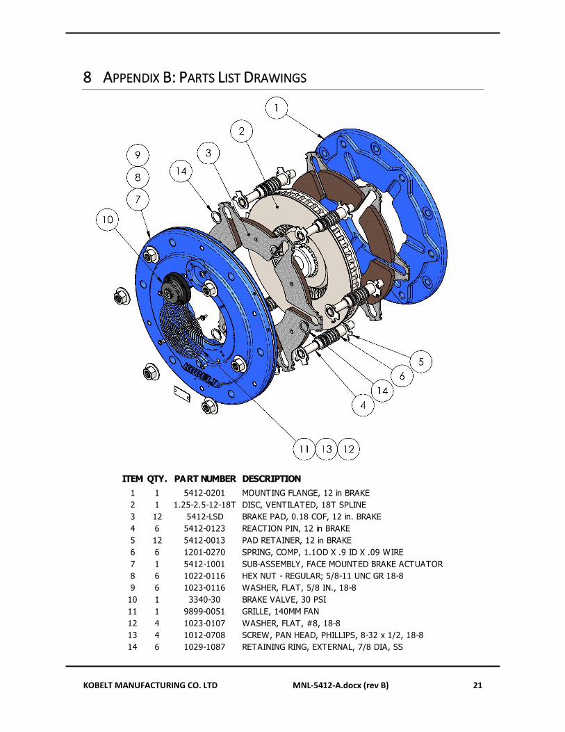
8 APPENDIX B: PARTS LIST DRAWINGS
ITEM QTY. PART NUMBER DESCRIPTION
1 1 5412-0201 MOUNTING FLANGE, 12 in BRAKE
2 1 1.25-2.5-12-18T DISC, VENTILATED, 18T SPLINE
3 12 5412-LSD BRAKE PAD, 0.18 COF, 12 in. BRAKE
4 6 5412-0123 REACTION PIN, 12 in BRAKE
5 12 5412-0013 PAD RETAINER, 12 in BRAKE
6 6 1201-0270 SPRING, COMP, 1.1OD X .9 ID X .09 WIRE
7 1 5412-1001 SUB-ASSEMBLY, FACE MOUNTED BRAKE ACTUATOR
8 6 1022-0116 HEX NUT - REGULAR; 5/8-11 UNC GR 18-8
9 6 1023-0116 WASHER, FLAT, 5/8 IN., 18-8
10 1 3340-30 BRAKE VALVE, 30 PSI
11 1 9899-0051 GRILLE, 140MM FAN
12 4 1023-0107 WASHER, FLAT, #8, 18-8
13 4 1012-0708 SCREW, PAN HEAD, PHILLIPS, 8-32 x 1/2, 18-8
14 6 1029-1087 RETAINING RING, EXTERNAL, 7/8 DIA, SS

KOBELT MANUFACTURING CO. LTD MNL-5412-A.docx (rev B) 22
5412-1001
ITEM QTY.PART
NUMBERDESCRIPTION
1 1 5412-0206 DIAPHRAGM MAGAZINE, 12 in BRAKE, GEN 2
2 6 5412-0012 PISTON, 12 in BRAKE
3 6 1023-0708 WASHER, FENDER, #10 X 1 OD, 18-8
4 6 1014-0806 SCREW, BTN HD CAP, 10-24 X 3/8, 18-8 SS, ASTM F879
5 1 5412-0304 ACTUATOR COVER, 12 IN BRAKE
6 1 5412-0102 MANIFOLD, 12 in BRAKE
7 12 1015-1216 CAP SCREW - BH SKT; 3/8 UNC X 1, 18-8
8 1 5412-RK REPAIR KIT, ENCLOSED BRAKE, AIR APPLIED

KOBELT MANUFACTURING CO. LTD MNL-5412-A.docx (rev B) 23
3340-30 BRAKE VALVE
ITEM QTY PART NUMBER DESCRIPTION
1 1 3340-0003 VALVE COVER
2 1 7039-3054 EXPANSION PLUG, CV173-218S
3 4 1002-0808 SCREW, SKT HEAD, 10-24 X 1/2, 18-8 SS, ASTM F837
4 1 3340-0004 PISTON, BRAKE VALVE
5 1 3340-0007 WASHER, PRECISION, 5MM ID X 19MM OD X 2MM THK, AISI 304
6 1 3340-0006 VALVE STEM, BRAKE VALVE
7 1 1201-0279 SPRING, COMPRESSION, .6IN OD X .085WIRE X 1.0IN FL, MUSIC WIRE
8 1 3340-0008 BELLOWS COLLAR, BRAKE VALVE
9 1 7039-3060 ORIFICE; INSERT, 2.5MM OD, 3000 LOHM
10 1 3340-RK REPAIR KIT; BRAKE VALVE
KOBELT MANUFACTURING CO. LTD MNL-5412-A.docx (rev B) 24
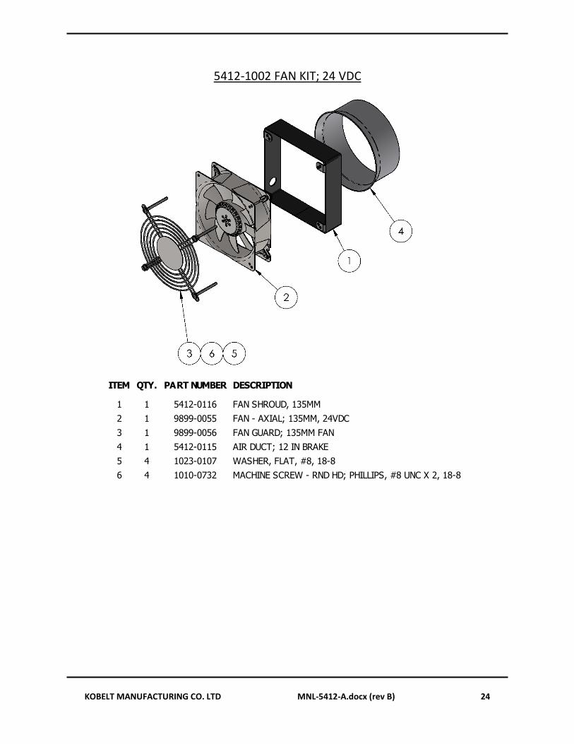
5412-1002 FAN KIT; 24 VDC
ITEM QTY. PART NUMBER DESCRIPTION
1 1 5412-0116 FAN SHROUD, 135MM
2 1 9899-0055 FAN - AXIAL; 135MM, 24VDC
3 1 9899-0056 FAN GUARD; 135MM FAN
4 1 5412-0115 AIR DUCT; 12 IN BRAKE
5 4 1023-0107 WASHER, FLAT, #8, 18-8
6 4 1010-0732 MACHINE SCREW - RND HD; PHILLIPS, #8 UNC X 2, 18-8
KOBELT MANUFACTURING CO. LTD MNL-5412-A.docx (rev B) 25
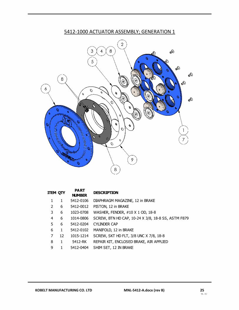
5412-1000 ACTUATOR ASSEMBLY; GENERATION 1
ITEM QTYPART
NUMBERDESCRIPTION
1 1 5412-0106 DIAPHRAGM MAGAZINE, 12 in BRAKE
2 6 5412-0012 PISTON, 12 in BRAKE
3 6 1023-0708 WASHER, FENDER, #10 X 1 OD, 18-8
4 6 1014-0806 SCREW, BTN HD CAP, 10-24 X 3/8, 18-8 SS, ASTM F879
5 6 5412-0204 CYLINDER CAP
6 1 5412-0102 MANIFOLD, 12 in BRAKE
7 12 1015-1214 SCREW, SKT HD FLT, 3/8 UNC X 7/8, 18-8
8 1 5412-RK REPAIR KIT, ENCLOSED BRAKE, AIR APPLIED
9 1 5412-0404 SHIM SET, 12 IN BRAKE