
Nokia 7705 SAR Routing Protocols Guide R20.4.R1
900
Nokia — Proprietary and confidential. Use pursuant to applicable agreements. 7705 SERVICE AGGREGATION ROUTER | RELEASE 20.4.R1 Routing Protocols Guide 3HE 16307 AAAA TQZZA Edition: 01 April 2020 Routing Protocols Guide
-
Upload
khangminh22 -
Category
Documents
-
view
0 -
download
0
Transcript of Nokia 7705 SAR Routing Protocols Guide R20.4.R1

Nokia — Proprietary and confidential.Use pursuant to applicable agreements.
7705 SERVICE AGGREGATION ROUTER | RELEASE 20.4.R1
Routing Protocols Guide
3HE 16307 AAAA TQZZA
Edition: 01
April 2020
Routing Protocols Guide

2
Routing Protocols Guide
3HE 16307 AAAA TQZZA Edition: 01
Nokia is a registered trademark of Nokia Corporation. Other products and company names mentioned herein may be trademarks or tradenames of their respective owners.
The information presented is subject to change without notice. No responsibility is assumed for inaccuracies contained herein.
© 2020 Nokia.
Contains proprietary/trade secret information which is the property of Nokia and must not be made available to, or copied or used by anyone outside Nokia without its written authorization. Not to be used or disclosed except in accordance with applicable agreements.

Routing Protocols Guide
Edition: 01 3HE 16307 AAAA TQZZA 3
Table of Contents1 Preface...........................................................................................191.1 About This Guide.......................................................................................191.1.1 Audience....................................................................................................191.1.2 Technical Support......................................................................................20
2 7705 SAR Routing Configuration Process .................................21
3 IP Multicast....................................................................................233.1 Overview of IP Multicast ............................................................................243.1.1 Multicast in IP-VPN Networks....................................................................253.1.2 Mobile Backhaul IP Multicast Example......................................................253.1.3 Multicast Models (ASM and SSM).............................................................263.1.3.1 Any-Source Multicast (ASM) .....................................................................263.1.3.2 Source-Specific Multicast (SSM) ...............................................................263.1.4 IGMP Snooping and MLD Snooping For VPLS and Routed VPLS...........273.1.5 Multicast Over Layer 3 Spoke SDP...........................................................283.2 IGMP .........................................................................................................293.2.1 IGMP Overview .........................................................................................293.2.2 IGMP Versions and Interoperability Requirements ...................................303.2.3 IGMP Version Transition ...........................................................................303.2.4 Query Messages .......................................................................................313.2.5 Source-Specific Multicast Groups (IPv4)...................................................313.3 MLD...........................................................................................................323.3.1 MLD Overview...........................................................................................323.3.2 MLDv1 .......................................................................................................323.3.3 MLDv2 .......................................................................................................333.4 PIM ............................................................................................................343.4.1 PIM-SM Overview......................................................................................353.4.2 PIM-SM Functions .....................................................................................363.4.2.1 Phase One.................................................................................................363.4.2.2 Phase Two.................................................................................................373.4.2.3 Phase Three .............................................................................................383.4.3 Encapsulating Data Packets in the Register Tunnel .................................383.4.4 PIM Bootstrap Router Mechanism.............................................................393.4.5 PIM-SM Routing Policies...........................................................................393.4.6 Reverse Path Forwarding Checks.............................................................403.4.7 Anycast RP for PIM-SM.............................................................................413.4.7.1 Implementation ..........................................................................................413.4.8 Multicast-only Fast Reroute (MoFRR) .......................................................443.4.9 Automatic Discovery of Group-to-RP Mappings (Auto-RP).......................453.5 IPv6 PIM Models .......................................................................................473.5.1 PIM-SSM ...................................................................................................473.5.2 PIM-ASM ...................................................................................................473.6 IP Multicast Debugging Tools....................................................................483.6.1 Mtrace........................................................................................................48

4
Routing Protocols Guide
3HE 16307 AAAA TQZZA Edition: 01
3.6.1.1 Finding the Last-hop Router ......................................................................493.6.1.2 Directing the Response .............................................................................503.6.2 Mstat..........................................................................................................513.6.3 Mrinfo.........................................................................................................513.7 MSDP ........................................................................................................523.7.1 MSDP and Anycast RP ............................................................................533.7.2 MSDP Procedure.......................................................................................533.7.2.1 MSDP Peering Scenarios..........................................................................543.7.3 MSDP Peer Groups...................................................................................553.7.4 MSDP Mesh Groups..................................................................................553.7.5 MSDP Routing Policies .............................................................................553.7.6 Auto-RP (Discovery Mode Only) in Multicast VPN....................................563.8 IP Multicast Configuration Process Overview............................................573.9 Configuration Notes...................................................................................583.9.1 General......................................................................................................583.9.2 Reference Sources....................................................................................583.10 Configuring IP Multicast Parameters with CLI ...........................................593.11 IP Multicast Configuration Overview..........................................................603.11.1 IGMP and MLD..........................................................................................603.11.1.1 Static Groups.............................................................................................603.11.1.2 SSM Translation ........................................................................................613.11.2 PIM ............................................................................................................613.11.3 Hardware Support .....................................................................................623.12 Basic IP Multicast Configuration................................................................633.13 Common Configuration Tasks ...................................................................683.13.1 Configuring IGMP and MLD Parameters...................................................683.13.1.1 Enabling IGMP or MLD..............................................................................683.13.1.2 Configuring IGMP and MLD ......................................................................693.13.1.3 Configuring IGMP and MLD Interfaces......................................................703.13.1.4 Configuring IGMP and MLD Interface Static Multicast ..............................713.13.1.5 Configuring IGMP and MLD SSM Translation...........................................723.13.2 Configuring PIM Parameters .....................................................................743.13.2.1 Enabling PIM .............................................................................................743.13.2.2 Configuring PIM Interface Parameters ......................................................763.13.2.3 Configuring a Rendezvous Point (RP).......................................................773.13.2.4 Importing PIM Join or Register Policies.....................................................783.13.2.5 Configuring Multicast Source Discovery Protocol (MSDP)
Parameters ................................................................................................793.14 Service Management Tasks ......................................................................803.14.1 Disabling IGMP, MLD, PIM, and MSDP ....................................................803.15 IP Multicast Command Reference.............................................................833.15.1 Command Hierarchies...............................................................................833.15.1.1 Configuration Commands..........................................................................843.15.1.2 Show Commands ......................................................................................893.15.1.3 Clear Commands.......................................................................................903.15.1.4 Debug Commands.....................................................................................913.15.1.5 Monitor Commands ...................................................................................923.15.2 Command Descriptions .............................................................................933.15.2.1 Configuration Commands..........................................................................94

Routing Protocols Guide
Edition: 01 3HE 16307 AAAA TQZZA 5
3.15.2.2 Show Commands ....................................................................................1403.15.2.3 Clear Commands.....................................................................................1943.15.2.4 Debug Commands...................................................................................1993.15.2.5 Monitor Commands .................................................................................214
4 OSPF ............................................................................................2154.1 Overview of OSPF...................................................................................2164.1.1 OSPF Areas ............................................................................................2174.1.1.1 Backbone Area ........................................................................................2184.1.1.2 Area Border Router .................................................................................2194.1.1.3 Stub Area.................................................................................................2204.1.1.4 Not-So-Stubby Area ................................................................................2204.1.2 Virtual Links .............................................................................................2204.1.3 Neighbors and Adjacencies.....................................................................2214.1.3.1 Designated Routers and Backup Designated Routers ............................2214.1.4 Link-State Advertisements.......................................................................2224.1.5 Metrics .....................................................................................................2244.1.6 Authentication..........................................................................................2244.1.6.1 Authentication Key...................................................................................2254.1.6.2 Authentication Keychains ........................................................................2264.1.7 Route Redistribution and Summarization ................................................2274.1.8 OSPF-TE Extensions ..............................................................................2274.1.9 Unnumbered Interfaces ...........................................................................2274.1.10 IP Subnets ...............................................................................................2284.1.11 OSPF Instances ......................................................................................2284.1.12 Multi-area Adjacencies ............................................................................2284.2 Bidirectional Forwarding Detection (BFD) for OSPF ...............................2304.3 Graceful Restart Helper...........................................................................2314.4 LFA Protection Using Segment Routing Backup Node SID ....................2324.4.1 Configuring LFA Using Backup Node SID...............................................2344.4.2 Detailed Operation of LFA Protection Using Backup Node SID ..............2344.4.3 Duplicate SID Handling ...........................................................................2374.4.4 OSPF Control Plane Extensions .............................................................2384.4.5 Topology-Independent LFA for OSPF.....................................................2404.5 LDP and IP Fast Reroute (FRR) for OSPF Prefixes................................2414.5.1 LFA Calculations .....................................................................................2424.5.1.1 Selection Algorithm..................................................................................2444.5.1.2 LFA Configuration....................................................................................2454.5.2 IGP Shortcuts (RSVP-TE Tunnels) .........................................................2464.5.2.1 Selection Algorithm..................................................................................2474.5.2.2 Forwarding Adjacency .............................................................................2484.5.2.3 IGP Shortcut Configuration......................................................................2484.5.3 LFA SPF Policies.....................................................................................2494.5.3.1 LFA SPF Policy Configuration .................................................................2494.6 Preconfiguration Requirements ...............................................................2514.7 OSPF Configuration Process Overview ..................................................2524.8 Configuration Notes.................................................................................2534.8.1 General....................................................................................................2534.8.2 Reference Sources..................................................................................253

6
Routing Protocols Guide
3HE 16307 AAAA TQZZA Edition: 01
4.9 Configuring OSPF with CLI .....................................................................2554.10 OSPF Configuration Guidelines ..............................................................2564.11 Basic OSPF Configuration.......................................................................2574.11.1 Configuring the Router ID........................................................................2574.11.2 Configuring an OSPF Area......................................................................2584.11.3 Configuring an Interface ..........................................................................2594.12 Configuring Other OSPF Components ....................................................2614.12.1 Configuring a Stub Area ..........................................................................2614.12.2 Configuring a Not-So-Stubby Area ..........................................................2624.12.3 Configuring a Virtual Link ........................................................................2634.12.4 Configuring Authentication ......................................................................2644.12.5 Assigning a Designated Router ...............................................................2664.12.6 Configuring Route Summaries ................................................................2674.12.7 Configuring Route Preferences ...............................................................2684.13 OSPF Configuration Management Tasks................................................2704.13.1 Modifying a Router ID .............................................................................2704.13.2 Deleting a Router ID ................................................................................2714.13.3 Modifying OSPF Parameters ..................................................................2714.14 OSPF Command Reference....................................................................2734.14.1 Command Hierarchies.............................................................................2734.14.1.1 Configuration Commands........................................................................2744.14.1.2 Show Commands ....................................................................................2794.14.1.3 Clear Commands.....................................................................................2804.14.1.4 Debug Commands...................................................................................2804.14.2 Command Descriptions ...........................................................................2824.14.2.1 Configuration Commands........................................................................2834.14.2.2 Show Commands ....................................................................................3324.14.2.3 Clear Commands.....................................................................................3844.14.2.4 Debug Commands...................................................................................386
5 IS-IS..............................................................................................3915.1 Overview of IS-IS.....................................................................................3925.1.1 IS-IS Areas (Two-level Hierarchy) ...........................................................3935.1.2 ISO Network Addressing .........................................................................3965.1.3 Neighbors and Adjacencies.....................................................................3975.1.3.1 Designated Routers.................................................................................3985.1.3.2 IS-IS Packet Types..................................................................................4005.1.4 Metrics .....................................................................................................4015.1.5 Authentication..........................................................................................4015.1.5.1 Authentication Key...................................................................................4025.1.5.2 Authentication Keychains ........................................................................4025.1.6 Route Redistribution and Summarization ................................................4035.1.6.1 Route Redistribution ................................................................................4035.1.6.2 Route Summarization ..............................................................................4045.1.7 IS-IS-TE Extensions ................................................................................4045.1.8 Unnumbered Interfaces ...........................................................................4055.1.9 Segment Routing in Shortest Path Forwarding .......................................4055.1.9.1 Configuring Segment Routing in Shortest Path.......................................4065.1.9.2 Segment Routing Operational Procedures..............................................410

Routing Protocols Guide
Edition: 01 3HE 16307 AAAA TQZZA 7
5.1.9.3 Segment Routing Tunnel Management...................................................4195.1.9.4 Remote LFA with Segment Routing ........................................................4215.1.9.5 Topology-Independent LFA ....................................................................4255.1.9.6 IPv6 Segment Routing using MPLS Encapsulation.................................4335.1.9.7 Data Path Support ...................................................................................4355.1.9.8 Control Protocol Changes .......................................................................4375.1.9.9 BGP Label Route Resolution Using Segment Routing Tunnel................4425.1.9.10 Service Packet Forwarding with Segment Routing .................................4435.1.9.11 Segment Routing Mapping Server for IPv4 /32 Prefixes (IS-IS)..............4445.1.9.12 Mirror Services ........................................................................................4455.1.10 Multi-Instance IS-IS (MI-IS-IS).................................................................4465.1.11 IPv6 Support............................................................................................4475.2 Bidirectional Forwarding Detection (BFD) for IS-IS .................................4485.3 LDP and IP Fast Reroute (FRR) for IS-IS Prefixes .................................4495.3.1 LFA Calculations .....................................................................................4505.3.1.1 Selection Algorithm..................................................................................4525.3.1.2 LFA Configuration....................................................................................4535.3.2 IGP Shortcuts (RSVP-TE Tunnels) .........................................................4535.3.2.1 Selection Algorithm..................................................................................4545.3.2.2 Forwarding Adjacency .............................................................................4555.3.2.3 IGP Shortcut Configuration......................................................................4565.3.3 LFA SPF Policies.....................................................................................4575.3.3.1 LFA SPF Policy Configuration .................................................................4575.4 IS-IS Configuration Process Overview ....................................................4595.5 Configuration Notes.................................................................................4605.5.1 General....................................................................................................4605.5.2 Reference Sources..................................................................................4605.6 Configuring IS-IS with CLI .......................................................................4615.7 IS-IS Configuration Overview ..................................................................4625.8 Basic IS-IS Configuration ........................................................................4635.9 Configuring IS-IS Components................................................................4655.9.1 Enabling IS-IS..........................................................................................4655.9.2 Configuring an IS-IS Instance Level ........................................................4655.9.3 Configuring ISO Area Addresses ............................................................4665.9.4 Configuring Global IS-IS Parameters ......................................................4675.9.5 Configuring Interface Parameters............................................................4685.9.5.1 Example 1: Configuring a Level 1 Area ...................................................4695.9.5.2 Example 2: Modifying Router Level Capability ........................................4715.9.5.3 Interface Level Capability ........................................................................4725.9.6 Configuring Authentication ......................................................................4725.9.7 Configuring Leaking.................................................................................4745.9.8 Redistributing External IS-IS Routes .......................................................4765.9.9 Configuring IS-IS Support for LDP-to-SR Stitching .................................4775.9.10 Configuring an SR Mapping Server for IPv4 /32 Prefixes .......................4775.10 IS-IS Configuration Management Tasks..................................................4795.10.1 Disabling IS-IS.........................................................................................4795.10.2 Removing IS-IS .......................................................................................4795.10.3 Modifying Global IS-IS Parameters ........................................................4805.10.4 Modifying IS-IS Interface Parameters......................................................481

8
Routing Protocols Guide
3HE 16307 AAAA TQZZA Edition: 01
5.11 IS-IS Command Reference .....................................................................4835.11.1 Command Hierarchies.............................................................................4835.11.1.1 Configuration Commands........................................................................4845.11.1.2 Show Commands ....................................................................................4875.11.1.3 Clear Commands.....................................................................................4875.11.1.4 Debug Commands...................................................................................4875.11.1.5 Monitor Commands .................................................................................4885.11.2 Command Descriptions ...........................................................................4895.11.2.1 Configuration Commands........................................................................4905.11.2.2 Show Commands ....................................................................................5365.11.2.3 Clear Commands.....................................................................................5725.11.2.4 Debug Commands...................................................................................5745.11.2.5 Monitor Commands .................................................................................578
6 BGP ..............................................................................................5816.1 BGP Overview.........................................................................................5826.1.1 BGP Communication ...............................................................................5826.1.1.1 Static and Dynamic Neighbors ................................................................5836.1.2 Message Types .......................................................................................5856.1.3 BGP Path Attributes ................................................................................5866.1.3.1 Origin Attribute.........................................................................................5876.1.3.2 AS Path Attribute .....................................................................................5876.1.3.3 Next-hop Attribute....................................................................................5886.1.3.4 MED Attribute ..........................................................................................5886.1.3.5 Local Preference Attribute .......................................................................5886.1.3.6 Route Aggregation Path Attributes ..........................................................5886.1.3.7 Communities Attribute .............................................................................5896.1.3.8 Route Reflection Attributes......................................................................5906.1.3.9 Multiprotocol BGP Extensions Attributes.................................................5906.1.3.10 4-Octet AS Attributes...............................................................................5906.1.3.11 AIGP Metric Attribute...............................................................................5916.1.4 Multi-Protocol BGP Attributes..................................................................5926.1.5 BGPv6 .....................................................................................................5936.1.6 BGP Add-Paths .......................................................................................5946.1.6.1 Path Selection Mode and Parameters for Multiple Paths to Add-
path Peers ...............................................................................................5956.1.6.2 Routing Policy for Multiple Paths.............................................................5966.1.6.3 BGP Route Advertisement Rules for Multiple Paths ...............................5966.1.6.4 BGP Split Horizon....................................................................................5966.1.7 Outbound Route Filtering (ORF) .............................................................5976.1.8 BGP Route Target Constrained Route Distribution .................................5986.2 Group Configuration and Peers...............................................................6006.2.1 Hierarchical Levels ..................................................................................6016.2.2 Route Reflection ......................................................................................6016.2.3 BGP Peer Groups with Dynamic Neighbors............................................6046.2.4 Fast External Failover..............................................................................6046.2.5 BGP Fast Reroute With Prefix-Independent Convergence .....................6056.2.5.1 BGP FRR Failure Detection and Switchover...........................................6076.2.6 Calculating Backup Paths........................................................................607
Routing Protocols Guide
Edition: 01 3HE 16307 AAAA TQZZA 9
6.2.7 Sending of BGP Communities.................................................................6086.2.8 BGP Decision Process ............................................................................6086.3 BGP Route Tunnels.................................................................................6106.3.1 Route Reflector Next-Hop-Self for VPN IPv4 Routes over IPv4
Labeled Routes ......................................................................................6116.3.2 Layer 2 Services and BGP Route Tunnel................................................6126.3.3 BGP Route Tunnel SDP Binding .............................................................6136.3.4 BGP Route Tunnel With Multihop EBGP Resolution...............................6136.3.5 Next-hop Resolution of BGP Labeled Routes to Tunnels .......................6136.3.6 BGP Next-Hop Resolution and Peer Tracking ........................................6156.3.7 BGP Route Installation in the Route Table..............................................6156.3.8 BGP Link State ........................................................................................6176.3.8.1 Supported BGP-LS Components ............................................................6186.4 Command Interactions and Dependencies .............................................6206.4.1 Changing the Autonomous System Number ...........................................6206.4.2 Changing the Local AS Number ..............................................................6216.4.3 Changing the Router ID at the Configuration Level.................................6216.4.4 Hold Time and Keepalive Timer Dependencies ......................................6216.4.5 Import and Export Route Policies ............................................................6226.4.6 AS Override .............................................................................................6226.4.7 TCP MD5 Authentication .........................................................................6236.4.8 TTL Security ............................................................................................6246.4.9 Advertise-Inactive ....................................................................................6246.4.10 Advertise-Inactive, Add-Paths, and Export Policy Interaction .................6256.5 BGP Configuration Process Overview.....................................................6266.6 Configuration Notes.................................................................................6276.6.1 General....................................................................................................6276.6.2 BGP Defaults...........................................................................................6276.6.3 BGP MIB Notes .......................................................................................6286.7 Configuring BGP with CLI........................................................................6316.8 BGP Configuration Overview...................................................................6326.8.1 Preconfiguration Requirements ...............................................................6326.8.2 BGP Hierarchy.........................................................................................6326.8.3 Internal and External BGP Configurations...............................................6336.8.4 BGP Route Reflectors .............................................................................6336.9 Basic BGP Configuration.........................................................................6366.10 Common Configuration Tasks .................................................................6386.10.1 Creating an Autonomous System............................................................6396.10.2 Configuring a Router ID...........................................................................6396.11 BGP Components....................................................................................6416.11.1 Configuring BGP......................................................................................6416.11.2 Configuring Group Attributes ...................................................................6426.11.3 Configuring Neighbor Attributes ..............................................................6436.11.4 Configuring BGP Address Families .........................................................6446.11.5 Configuring Route Reflection...................................................................6456.11.6 Configuring a BGP Peer Group with Dynamic Neighbors .......................6476.12 BGP Configuration Management Tasks ..................................................6496.12.1 Modifying an AS Number ........................................................................6496.12.2 Modifying the BGP Router ID ..................................................................650

10
Routing Protocols Guide
3HE 16307 AAAA TQZZA Edition: 01
6.12.3 Modifying the Router-Level Router ID .....................................................6516.12.4 Deleting a Neighbor.................................................................................6526.12.5 Deleting Groups.......................................................................................6536.12.6 Editing BGP Parameters ........................................................................6546.13 BGP Command Reference......................................................................6556.13.1 Command Hierarchies.............................................................................6556.13.1.1 Configuration Commands........................................................................6566.13.1.2 Show Commands ....................................................................................6626.13.1.3 Clear Commands.....................................................................................6646.13.1.4 Debug Commands...................................................................................6646.13.2 Command Descriptions ...........................................................................6666.13.2.1 Configuration Commands........................................................................6676.13.2.2 Show Commands ....................................................................................7156.13.2.3 Clear Commands.....................................................................................7856.13.2.4 Debug Commands...................................................................................787
7 RIP................................................................................................7917.1 RIP Overview...........................................................................................7927.1.1 RIP Versions............................................................................................7937.1.2 RIPv2 Authentication ...............................................................................7937.1.3 Metrics .....................................................................................................7937.1.4 Timers......................................................................................................7947.1.5 Import and Export Policies.......................................................................7947.1.6 RIP Packet Format ..................................................................................7947.1.7 RIP Hierarchical Levels ...........................................................................7967.2 RIP Configuration Process Overview ......................................................7977.3 Configuration Notes.................................................................................7987.4 Configuring RIP with CLI .........................................................................7997.5 RIP Configuration Overview ....................................................................8007.5.1 Preconfiguration Requirements ...............................................................8007.6 Basic RIP Configuration ..........................................................................8017.7 Common Configuration Tasks .................................................................8027.7.1 Configuring Interfaces .............................................................................8027.7.2 Configuring a Route Policy ......................................................................8047.8 Configuring RIP Parameters....................................................................8067.8.1 Configuring Global-Level Parameters .....................................................8077.8.2 Configuring Group-Level Parameters......................................................8087.8.3 Configuring Neighbor-Level Parameters .................................................8087.9 RIP Configuration Management Tasks....................................................8107.9.1 Modifying RIP Parameters.......................................................................8107.9.2 Deleting a RIP Group ..............................................................................8117.9.3 Deleting a RIP Neighbor..........................................................................8117.10 RIP Command Reference .......................................................................8137.10.1 Command Hierarchies.............................................................................8137.10.1.1 Configuration Commands........................................................................8147.10.1.2 Show Commands ....................................................................................8167.10.1.3 Clear Commands.....................................................................................8167.10.1.4 Debug Commands...................................................................................8177.10.2 Command Descriptions ...........................................................................818

Routing Protocols Guide
Edition: 01 3HE 16307 AAAA TQZZA 11
7.10.2.1 Configuration Commands........................................................................8197.10.2.2 Show Commands ....................................................................................8337.10.2.3 Clear Commands.....................................................................................8447.10.2.4 Debug Commands...................................................................................845
9 Standards and Protocol Support ..............................................875

12
Routing Protocols Guide
3HE 16307 AAAA TQZZA Edition: 01

Routing Protocols Guide
Edition: 01 3HE 16307 AAAA TQZZA 13
List of Tables2 7705 SAR Routing Configuration Process .................................21Table 1 Configuration Process .............................................................................21
3 IP Multicast....................................................................................23Table 2 Join Filter Policy Match Conditions ..........................................................40Table 3 Register Filter Policy Match Conditions ...................................................40Table 4 IGMP Group Field Descriptions ..............................................................141Table 5 IGMP Interface Field Descriptions ..........................................................144Table 6 IGMP SSM-Translate Field Descriptions ................................................146Table 7 Static IGMP Field Descriptions ...............................................................147Table 8 IGMP Statistics Field Descriptions .........................................................148Table 9 IGMP Status Field Descriptions ..............................................................150Table 10 MLD Group Field Descriptions ...............................................................152Table 11 MLD Interface Field Descriptions ...........................................................155Table 12 MLD SSM-Translate Field Descriptions .................................................158Table 13 MLD Static Group Field Descriptions .....................................................159Table 14 MLD Statistics Field Descriptions ...........................................................160Table 15 MLD Status Field Descriptions ...............................................................162Table 16 PIM Group Field Descriptions .................................................................164Table 17 PIM Interface Field Descriptions .............................................................169Table 18 PIM Neighbor Field Descriptions ............................................................173Table 19 RP Field Descriptions .............................................................................174Table 20 RP Hash Field Descriptions ....................................................................175Table 21 S-PMSI Field Descriptions ......................................................................177Table 22 PIM Statistics Field Descriptions ............................................................179Table 23 PIM Status Field Descriptions ................................................................182Table 24 MSDP Group Field Descriptions .............................................................185Table 25 MSDP Peer Field Descriptions ...............................................................186Table 26 MSDP Source Field Descriptions ...........................................................187Table 27 MSDP SA Field Descriptions ..................................................................189Table 28 MSDP Source-Active Field Descriptions ................................................190Table 29 MSDP Statistics Field Descriptions ........................................................191Table 30 MSDP Status Field Descriptions ............................................................193
4 OSPF ............................................................................................215Table 31 LSA Types ..............................................................................................223Table 32 Handling of Duplicate SIDs ....................................................................237Table 33 OSPF Control Plane Extension Fields ...................................................238Table 34 OSPF Control Plane Extension Flags ...................................................239Table 35 Route Preference Defaults by Route Type .............................................268Table 36 Route Preference Defaults by Route Type ............................................292Table 37 Area Field Descriptions .........................................................................334Table 38 Area LFA Field Descriptions ..................................................................336Table 39 Router Capabilities Field Descriptions ...................................................337Table 40 Database Field Descriptions ..................................................................340

14
Routing Protocols Guide
3HE 16307 AAAA TQZZA Edition: 01
Table 41 Interface Field Descriptions ...................................................................343Table 42 Detailed Interface Field Descriptions .....................................................344Table 43 LFA Coverage Field Descriptions ..........................................................350Table 44 Neighbor Field Descriptions ..................................................................352Table 45 Neighbor (Detail) Field Descriptions ......................................................353Table 46 Neighbor (Overview) Field Descriptions ................................................356Table 47 OSPF Opaque Database Field Descriptions .........................................360Table 48 Prefix SIDs Field Descriptions ...............................................................362Table 49 Area Range Field Descriptions ..............................................................363Table 50 SPF Field Descriptions ..........................................................................368Table 51 OSPF Statistics Field Descriptions ........................................................370Table 52 OSPF Status Field Descriptions ............................................................374Table 53 Virtual Link Field Descriptions ...............................................................378Table 54 Virtual Neighbor Field Descriptions .......................................................382
5 IS-IS..............................................................................................391Table 55 IS-IS Intermediate Systems ....................................................................395Table 56 IS-IS Packet Types .................................................................................400Table 57 Data Path Support .................................................................................435Table 58 Potential Adjacency Capabilities ............................................................472Table 59 Route Preference Defaults by Route Type .............................................503Table 60 Potential Adjacency Capabilities ............................................................505Table 61 Adjacency Field Descriptions .................................................................537Table 62 IS-IS Capabilities Field Descriptions ......................................................540Table 63 Database Summary Field Descriptions ..................................................541Table 64 Database Detailed Field Descriptions ...................................................543Table 65 Hostname Database Field Descriptions .................................................545Table 66 Interface Field Descriptions ...................................................................546Table 67 Interface Detailed Field Descriptions .....................................................547Table 68 LFA Coverage Field Descriptions ..........................................................549Table 69 Prefix SIDs Field Descriptions ...............................................................552Table 70 Routing Table Field Descriptions ...........................................................555Table 71 SPF Log Field Descriptions ...................................................................556Table 72 IS-IS Statistics Field Descriptions ..........................................................558Table 73 IS-IS Status Field Descriptions ..............................................................562Table 74 Summary Address Field Descriptions ...................................................568Table 75 IS-IS Topology Field Descriptions .........................................................571
6 BGP ..............................................................................................581Table 76 Multi-Protocol BGP Support on 7705 SAR .............................................592Table 77 BGP FRR Scenarios ..............................................................................606Table 78 7705 SAR and IETF MIB Variations .......................................................628Table 79 MIB Variable with SNMP ........................................................................628Table 80 BGP Auth-keychain Field Descriptions ..................................................716Table 81 BGP Damping Field Descriptions ..........................................................721Table 82 BGP Group Field Descriptions ..............................................................724Table 83 Inter-AS Service Label Field Descriptions ..............................................728Table 84 BGP Neighbor (Standard, Detailed, and Dynamic) Field
Descriptions ...........................................................................................734

Routing Protocols Guide
Edition: 01 3HE 16307 AAAA TQZZA 15
Table 85 BGP Neighbor (Advertised-Routes and Received-Routes) Field Descriptions ............................................................................................745
Table 86 BGP Neighbor (Graceful Restart) Field Descriptions .............................746Table 87 BGP Next-Hop Field Descriptions ..........................................................750Table 88 BGP Path Field Descriptions .................................................................752Table 89 BGP Route Field Descriptions ................................................................776Table 90 BGP Summary Field Descriptions .........................................................782
7 RIP................................................................................................791Table 91 RIP Database Field Descriptions ............................................................834Table 92 RIP Group Field Descriptions ................................................................835Table 93 RIP Neighbor Field Descriptions ...........................................................837Table 94 RIP Neighbor (Detailed) Field Descriptions ............................................838Table 95 RIP Peer Field Descriptions ...................................................................840Table 96 RIP Statistics Field Descriptions .............................................................841
8 List of Acronyms ........................................................................847Table 97 Acronyms ...............................................................................................847
9 Standards and Protocol Support ..............................................875Table 98 EMC Industrial Standards Compliance ...................................................876Table 99 EMC Regulatory and Customer Standards Compliance ........................877Table 100 Environmental Standards Compliance ...................................................879Table 101 Safety Standards Compliance ................................................................881Table 102 Telecom Interface Compliance ...............................................................882Table 103 Directives, Regional Approvals and Certifications Compliance ..............883

16
Routing Protocols Guide
3HE 16307 AAAA TQZZA Edition: 01

Routing Protocols Guide
Edition: 01 3HE 16307 AAAA TQZZA 17
List of Figures3 IP Multicast....................................................................................23Figure 1 IP Multicast for MBMS...............................................................................25Figure 2 Anycast RP for PIM-SM Implementation ...................................................42Figure 3 MoFRR in Steady State with No Failure....................................................44Figure 4 MoFRR in Failure State .............................................................................45Figure 5 IP Multicast Configuration Process............................................................57
4 OSPF ............................................................................................215Figure 6 Backbone Area ........................................................................................219Figure 7 Multi-area Adjacency ...............................................................................229Figure 8 Label Stack for Remote LFA in Ring Topology .......................................233Figure 9 Backup ABR Node SID............................................................................235Figure 10 Backup Routes Resulting in Micro-loops.................................................243Figure 11 LFA Backup Route ..................................................................................243Figure 12 OSPF Configuration Process ..................................................................252
5 IS-IS..............................................................................................391Figure 13 IS-IS Topology.........................................................................................394Figure 14 Using Area Addresses to Form Adjacencies ...........................................398Figure 15 Packet Label Encapsulation using Segment Routing Tunnel..................407Figure 16 Programming Multiple Tunnels to the Same Destination ........................414Figure 17 Handling of Same Prefix and SID in Different IS-IS Instances ................417Figure 18 Remote LFA Algorithm ............................................................................422Figure 19 Remote LFA Next Hop in Segment Routing............................................424Figure 20 Selecting Link-Protect TI-LFA Backup Path ............................................428Figure 21 TI-LFA Backup Path via a Pseudonode .................................................431Figure 22 Parallel Adjacencies between P and Q Nodes........................................432Figure 23 Transport Label Stack in Shortest Path Forwarding with Segment
Routing ....................................................................................................436Figure 24 Backup Routes Resulting in Micro-loops.................................................451Figure 25 LFA Backup Route ..................................................................................451Figure 26 IS-IS Configuration Process ....................................................................459Figure 27 Configuring a Level 1 Area ......................................................................469Figure 28 Configuring a Level 1/2 Area ...................................................................471
6 BGP ..............................................................................................581Figure 29 BGP Configuration...................................................................................583Figure 30 BGPv6 .....................................................................................................593Figure 31 BGP Update Message with Path Identifier for IPv4 NLRI........................594Figure 32 Fully Meshed BGP Configuration ............................................................602Figure 33 BGP Configuration with Route Reflectors ...............................................603Figure 34 Route Reflector Next-Hop-Self for VPN IPv4 Routes over IPv4
Labeled Routes .......................................................................................612Figure 35 Example of a BGP-LS Network ...............................................................617Figure 36 BGP Configuration and Implementation Flow .........................................626
18
Routing Protocols Guide
3HE 16307 AAAA TQZZA Edition: 01
Figure 37 Route Reflection Network Diagram Example ..........................................634
7 RIP................................................................................................791Figure 38 RIP Packet Format ..................................................................................795Figure 39 RIPv1 Packet Format ..............................................................................795Figure 40 RIPv2 Packet Format ..............................................................................795Figure 41 RIP Configuration and Implementation Flow ...........................................797

Routing Protocols Guide Preface
Edition: 01 3HE 16307 AAAA TQZZA 19
1 Preface
1.1 About This Guide
This guide describes routing protocols supported by the 7705 SAR and provides configuration and implementation examples.
This guide is organized into functional chapters and provides concepts and descriptions of the implementation flow, as well as Command Line Interface (CLI) syntax and command usage.
1.1.1 Audience
This guide is intended for network administrators who are responsible for configuring the 7705 SAR routers. It is assumed that the network administrators have an understanding of networking principles and configurations. Concepts described in this guide include the following:
• CLI concepts• Interior Gateway Protocols (IGP)• Open Shortest Path First (OSPF) routing protocol
Note: This manual generically covers Release 20.x content and may contain some content that will be released in later maintenance loads. Please refer to the 7705 SAR 20.x.Rx Software Release Notes, part number 3HE16192000xTQZZA, for information on features supported in each load of the Release 20.x software.
Note:
As of Release 7.0, support for the following hardware has been deprecated:
• CSMv1• 7705 SAR-F• 8-port Ethernet Adapter card, version 1• 16-port T1/E1 ASAP Adapter card, version 1
These components are no longer recognized in the release.

Preface
20
Routing Protocols Guide
3HE 16307 AAAA TQZZA Edition: 01
• Intermediate system to Intermediate system (IS-IS) routing protocol• traffic engineering extensions to IGP• Constrained Shortest Path First (CSPF)• Border Gateway Protocols (BGP)• Routing Information Protocol (RIP)
1.1.2 Technical Support
If you purchased a service agreement for your 7705 SAR router and related products from a distributor or authorized reseller, contact the technical support staff for that distributor or reseller for assistance. If you purchased a Nokia service agreement, follow this link to contact a Nokia support representative and to access product manuals and documentation updates:
Product Support Portal

Routing Protocols Guide 7705 SAR Routing Configuration Process
Edition: 01 3HE 16307 AAAA TQZZA 21
2 7705 SAR Routing Configuration Process
The 7705 SAR router can function as an LSR (label switch router), allowing it to be used in more complex networks; for example:
• tier-2 aggregation (aggregator of aggregator sites) – traffic is aggregated from other tier-3 7705 SAR nodes (aggregated small cell sites), and this traffic, along with local traffic, is switched to tier-1 7750 SR nodes
• ring-based configurations – multiple tier-3/tier-2 7705 SAR nodes are linked via a ring and a 7750 SR tier-2/tier-1 node, which acts as a gateway from the ring to a higher level or directly to the MTSO
To switch traffic from one router to another in the network, the 7705 SAR must support IP forwarding. To support these larger and more complex topologies, dynamic routing protocols are provided. The 7705 SAR supports OSPF, IS-IS, BGP, and RIP as dynamic routing protocols.
Table 1 lists the tasks that are required to configure multicast, OSPF, IS-IS, BGP, and RIP.
This guide is presented in an overall logical configuration flow. Each section describes a software area and provides CLI syntax and command usage to configure parameters for a functional area.
Note: For information on the 7705 SAR as an LSR, refer to the 7705 SAR MPLS Guide.
Table 1 Configuration Process
Area Task/Description Chapter
Protocol configuration
Configure multicast IP Multicast
Configure OSPF OSPF
Configure IS-IS IS-IS
Configure BGP BGP
Configure RIP RIP
Reference List of IEEE, IETF, and other proprietary entities
Standards and Protocol Support

7705 SAR Routing Configuration Process
22
Routing Protocols Guide
3HE 16307 AAAA TQZZA Edition: 01

Routing Protocols Guide IP Multicast
Edition: 01 3HE 16307 AAAA TQZZA 23
3 IP MulticastThis chapter provides information on multicast for IPv4 and IPv6, including Internet Group Management Protocol (IGMP), Multicast Listener Discovery (MLD), Protocol Independent Multicast Source-Specific Multicast (PIM-SSM), Protocol Independent Multicast Source-Sparse Mode (PIM-SM), and Multicast Source Discovery Protocol (MSDP).
Topics in this chapter include:
• Overview of IP Multicast• IGMP• MLD• PIM• IPv6 PIM Models• IP Multicast Debugging Tools• MSDP• IP Multicast Configuration Process Overview• Configuration Notes• Configuring IP Multicast Parameters with CLI• IP Multicast Command Reference

IP Multicast
24
Routing Protocols Guide
3HE 16307 AAAA TQZZA Edition: 01
3.1 Overview of IP Multicast
IP multicast is a method of sending a single stream of traffic (or a single copy of data) to multiple recipients. IP multicast provides an effective method of one-to-many and many-to-many communication.
In the case of unicast delivery, IP packets are sent from a single source to a single host receiver. The source inserts the address of the target receiver in the IP header destination field of an IP datagram, and intermediate routers (if present) forward the datagram towards the target in accordance with their respective routing tables.
However, some applications, such as audio or video streaming broadcasts, require the delivery of individual IP packets to multiple destinations. In such applications, IP multicast is used to distribute datagrams from one or more source hosts to a set of receivers that may be distributed over different (sub) networks.
Multicast sources can send a single copy of data using a single address for the entire group of recipients. The routers between the source and recipients route the data using the group address route. Multicast packets are delivered to a multicast group. A multicast group specifies a set of recipients who are interested in a particular data stream and is represented by an IP address from a specified range. Data addressed to the IP address is forwarded to the members of the group. A source host sends data to a multicast group by specifying the multicast group address in the datagram’s destination IP address. A source does not have to register to a Rendezvous Point (RP) in order to send data to a group nor do they need to be a member of the group.
Routers and Layer 3 switches use the Internet Group Management Protocol (IGMP) to manage group membership for IPv4 multicast, and Multicast Listener Discovery (MLD) to manage group membership for IPv6 multicast. When a host receiver wants to receive one or more multicast sessions, it signals its local router by sending a join message to each multicast group it wants to join. When a host wants to leave a multicast group, it sends a Leave message. The local router forwards its group membership information to the core routers to inform the core routers about which multicast flows are needed.
To extend multicast from the receivers’ local router to the Internet, the 7705 SAR uses Protocol Independent Multicast (PIM), which employs both unicast and multicast routing tables to keep track of route information. As more routers in the Internet become multicast-capable, using both unicast and multicast routing tables becomes more and more important.
The 7705 SAR also uses the Multicast Source Discovery Protocol (MSDP) as a mechanism to connect multiple IPv4 PIM-SM domains together. Each PIM-SM domain uses its own independent Rendezvous Point (RP) and does not have to depend on RPs in other domains.

Routing Protocols Guide IP Multicast
Edition: 01 3HE 16307 AAAA TQZZA 25
To summarize, host receivers connect to a local router (7705 SAR) via IGMP or MLD access or network interfaces. The 7705 SAR connects to the network—and eventually to the multicast source device at the far end—via PIM network interfaces. At the multicast source end, the 7705 SAR connects to the source via a PIM access or network interface.
3.1.1 Multicast in IP-VPN Networks
Multicast can be deployed as part of IP-VPN networks using VPRN. For details, refer to the “Multicast VPN (MVPN)” section in the 7705 SAR Services Guide.
3.1.2 Mobile Backhaul IP Multicast Example
A typical mobile backhaul infrastructure designed for Multimedia Broadcast Multicast Service (MBMS) is shown in Figure 1.
Figure 1 IP Multicast for MBMS
The 7705 SAR listens for IGMP and MLD receiver requests from the eNB and relays the requested group information back to the requester in one of two ways:
• via local replication, if the stream for the given group is already available (that is, one or more receivers have already joined the group), or
• via first relaying the request to the upstream router and then replicating the stream to the new receiver once the stream is available
Figure 1 illustrates this as follows.
• The 7705 SAR listens to IGMPv3 on an eNB IPv4 interface, or to MLDv2 on an eNB IPv6 interface.
eNB 7705 SAR
7750 SR23159
IGMPv3/MLDv2
PIM SSMfor IPv4/v6
PIM SSMfor IPv4/v6
MetroEthernetTransport

IP Multicast
26
Routing Protocols Guide
3HE 16307 AAAA TQZZA Edition: 01
• The 7705 SAR uses PIM-SSM to send multicast traffic upstream and communicate with the 7750 SR at the MTSO. Similarly, the 7750 SR runs PIM-SSM towards the 7705 SAR.
• The 7750 SR can then run a wide variety of different multicast protocols (such as point-to-multipoint LSPs, and multicast IP-VPN) towards the network core where the source (video head end) is located.
3.1.3 Multicast Models (ASM and SSM)
ASM provides network layer support for many-to-many delivery. SSM supports one-to-many delivery.
This section provides information on the following topics:
• Any-Source Multicast (ASM)• Source-Specific Multicast (SSM)
3.1.3.1 Any-Source Multicast (ASM)
ASM is the IP multicast service model defined in RFC 1112, Host extensions for IP Multicasting. An IP datagram is transmitted to a host group, which is a set of zero or more end-hosts identified by a single IP destination address (224.0.0.0 through 239.255.255.255 for IPv4). End-hosts can join and leave the group at any time and there is no restriction on their location or number. This model supports multicast groups with an arbitrary number of senders. Any end-host can transmit to a host group even if it is not a member of that group.
The ASM service model identifies a group by a (*, G) pair, where “*” (star) represents one or more sources.
3.1.3.2 Source-Specific Multicast (SSM)
The SSM service model defines a channel identified by an (S,G) pair, where S is a source address and G is an SSM destination address. In contrast to the ASM model, SSM only provides network-layer support for one-to-many delivery.

Routing Protocols Guide IP Multicast
Edition: 01 3HE 16307 AAAA TQZZA 27
The SSM service model attempts to alleviate the following deployment problems that ASM has presented:
• address allocation — SSM defines channels on a per-source basis. For example, the channel (S1,G) is distinct from the channel (S2,G), where S1 and S2 are source addresses. This avoids the problem of global allocation of SSM destination addresses and makes each source independently responsible for resolving address collisions for the various channels it creates.
• access control — SSM provides an efficient solution to the access control problem. When a receiver subscribes to an (S,G) channel, it receives data sent only by the source, S. In contrast, any host can transmit to an ASM host group. At the same time, when a sender picks a channel (S,G) to transmit on, it is automatically ensured that no other sender will be transmitting on the same channel (except in the case of malicious acts such as address spoofing). This makes it harder to spam an SSM channel than it is to spam an ASM multicast group.
• handling of well-known sources — SSM requires only source-based forwarding trees. This eliminates the need for a shared tree infrastructure. Thus the complexity of the multicast routing infrastructure for SSM is low, making it viable for immediate deployment.
3.1.4 IGMP Snooping and MLD Snooping For VPLS and Routed VPLS
The 7705 SAR supports IGMP snooping and MLD snooping for VPLS and routed VPLS (r-VPLS) services. IGMP and MLD snooping is enabled or disabled at the VPLS and r-VPLS service level. Further configurations are available at that level, as well as at the SAP and SDP (spoke and mesh) level of the service.
For details on IGMP and MLD snooping, refer to the “Multicast for VPLS and Routed VPLS (IGMP and MLD Snooping)” section in the 7705 SAR Services Guide.

IP Multicast
28
Routing Protocols Guide
3HE 16307 AAAA TQZZA Edition: 01
3.1.5 Multicast Over Layer 3 Spoke SDP
The 7705 SAR supports PIM on Layer 3 spoke SDP interfaces. PIM-SM and PIM-SSM are supported for IPv4 in VPRN and IES. PIM-SSM is supported for IPv6 in IES.
A Layer 3 spoke SDP interface can be configured in the same way existing interfaces to be part of PIM IPv4 or PIM IPv6, which allows the interface to be used for multicast signaling and to transport multicast PDUs. GRE, MPLS, LDP, and SR transport tunnels are supported.
When signaling, PIM is tunneled through the Layer 3 spoke SDP interface multihop. Multicast PDUs are tunneled in the reverse direction through the Layer 3 spoke SDP interface. In both cases, packets are encapsulated with the Layer 3 spoke SDP header.
For more information on PIM functionality, see PIM.

Routing Protocols Guide IP Multicast
Edition: 01 3HE 16307 AAAA TQZZA 29
3.2 IGMP
Internet Group Management Protocol (IGMP) enables multicast applications over native IPv4 networks. This section contains information on the following topics:
• IGMP Overview • IGMP Versions and Interoperability Requirements• IGMP Version Transition• Query Messages• Source-Specific Multicast Groups (IPv4)
3.2.1 IGMP Overview
Internet Group Management Protocol (IGMP) is used by IPv4 hosts and routers to report their IP multicast group memberships to neighboring multicast routers. A multicast router keeps a list of multicast group memberships for each attached network, and a timer for each membership.
Multicast group memberships include at least one member of a multicast group on an attached network. In each of its attached networks, a multicast router can assume one of two roles, querier or non-querier. There is normally only one querier per physical network. The querier is the router elected as the router that issues queries for all routers on a LAN segment. Non-queriers listen for reports.
The querier issues two types of queries, a general query and a group-specific query. General queries are issued to solicit membership information with regard to any multicast group. Group-specific queries are issued when a router receives a Leave message from the node it perceives as being the last remaining group member on that network segment. See Query Messages for additional information.
SSM translation allows an IGMPv1 or IGMPv2 device to join an SSM multicast network through the router that provides such a translation capability. SSM translation can done at the node (IGMP protocol) level, and at the interface level, which offers the ability to have the same (*,G) mapped to two different (S,G)s on two different interfaces to provide flexibility. Since PIM-SSM does not support (*,G), SSM translation is required to support IGMPv1 and IGMPv2.
Hosts wanting to receive a multicast session issue a multicast group membership report. These reports must be sent to all multicast-enabled routers.

IP Multicast
30
Routing Protocols Guide
3HE 16307 AAAA TQZZA Edition: 01
3.2.2 IGMP Versions and Interoperability Requirements
If routers run different versions of IGMP, they will negotiate to run the lowest common version of IGMP that is supported on their subnet and operate in that version. The 7705 SAR supports three versions of IGMP:
• version 1 — specified in RFC 1112, Host extensions for IP Multicasting, IGMPv1 was the first widely deployed version and the first version to become an Internet standard
• version 2 — specified in RFC 2236, Internet Group Management Protocol, IGMPv2 added support for “low leave latency”; that is, a reduction in the time it takes for a multicast router to learn that there are no longer any members of a particular group present on an attached network
• version 3 — specified in RFC 3376, Internet Group Management Protocol, IGMPv3 added support for source filtering; that is, the ability for a system to report interest in receiving packets only from specific source addresses, as required to support Source-Specific Multicast or from all but specific source addresses, sent to a particular multicast address (see Multicast Models (ASM and SSM))
IGMPv3 must keep track of each group’s state for each attached network. The group state consists of a filter-mode, a list of sources, and various timers. For each attached network running IGMP, a multicast router records the desired reception state for that network.
3.2.3 IGMP Version Transition
Nokia 7705 SAR routers are capable of interoperating with routers and hosts running IGMPv1, IGMPv2, and/or IGMPv3. RFC 5186, Internet Group Management Protocol version 3 (IGMPv3)/Multicast Listener Discovery version 2 (MLDv2) and Multicast Routing Protocol Interaction explores some of the interoperability issues and how they affect the various routing protocols.
IGMPv3 specifies that, if at any time a router receives an older IGMP version query message on an interface, it must immediately switch to a mode that is compatible with that earlier version. Since the previous versions of IGMP are source-aware, should this occur and the interface switch to version 1 or version 2 compatibility mode, any previously learned group memberships with specific sources (learned via the IGMPv3 specific INCLUDE or EXCLUDE mechanisms) must be converted to non-source-specific group memberships. The routing protocol will then treat this as if there is no EXCLUDE definition present.

Routing Protocols Guide IP Multicast
Edition: 01 3HE 16307 AAAA TQZZA 31
3.2.4 Query Messages
The IGMP query source address is configurable at two hierarchal levels. It can be configured globally at each router instance IGMP level and can be configured individually at the group interface level. The group interface level overrides the source IP address configured at the router instance level.
By default, subscribers with IGMP policies send IGMP queries with an all-zero source IP address (0.0.0.0). However, some systems only accept and process IGMP query messages with non-zero source IP addresses. The query messages feature allows the Broadband Network Gateway (BNG) to interoperate with such systems.
3.2.5 Source-Specific Multicast Groups (IPv4)
IGMPv3 allows a receiver to join a group and specify that it only wants to receive traffic for a multicast group if that traffic comes from a particular source. If a receiver does this, and no other receiver on the LAN requires all the traffic for the group, the designated router (DR) can omit performing a (*,G) join to set up the shared tree, and instead issue a source-specific (S,G) join only.
The range of multicast addresses from 232.0.0.0 to 232.255.255.255 is currently set aside for source-specific multicast in IPv4. For groups in this range, receivers should only issue source-specific IGMPv3 joins. If a PIM router receives a non-source-specific join message for a group in this range, it should ignore it.
A 7705 SAR PIM router must silently ignore a received (*,G) PIM join message when “G” is a multicast group address from the multicast address group range that has been explicitly configured for SSM. This occurrence should generate an event. If configured, the IGMPv2 request can be translated into IGMPv3. The 7705 SAR allows for the conversion of an IGMPv2 (*,G) request into a IGMPv3 (S,G) request based on manual entries. A maximum of 32 SSM ranges is supported.
IGMPv3 also permits a receiver to join a group and specify that it only wants to receive traffic for a group if that traffic does not come from a specific source or sources. In this case, the designated router (DR) will perform a (*,G) join as normal, but can combine this with a prune for each of the sources the receiver does not wish to receive.

IP Multicast
32
Routing Protocols Guide
3HE 16307 AAAA TQZZA Edition: 01
3.3 MLD
Multicast Listener Discovery (MLD) enables multicast applications over native IPv6 networks. This section contains information on the following topics:
• MLD Overview• MLDv1 • MLDv2
3.3.1 MLD Overview
MLD is the IPv6 version of IGMP. The purpose of MLD is to allow each IPv6 router to discover the presence of multicast listeners on its directly attached links, and to discover specifically which multicast groups are of interest to those neighboring nodes.
MLD is a sub-protocol of ICMPv6. MLD message types are a subset of the set of ICMPv6 messages, and MLD messages are identified in IPv6 packets by a preceding Next Header value of 58. All MLD messages are sent with a link-local IPv6 source address, a Hop Limit of 1, and an IPv6 Router Alert option in the Hop-by-Hop Options header.
3.3.2 MLDv1
Similar to IGMPv2, MLDv1 reports include only the multicast group addresses that listeners are interested in, and do not include the source addresses. In order to work with the PIM-SSM model, an SSM translation function similar to that used for IGMPv1 and IGMPv2 is required when MLDv1 is used.
SSM translation allows an MLDv1 device to join an SSM multicast network through the router that provides such a translation capability. SSM translation can done at the node (MLD protocol) level, and at the interface level, which offers the ability to have the same (*,G) mapped to two different (S,G)s on two different interfaces to provide flexibility. Since PIM-SSM does not support (*,G), SSM translation is required to support MLDv1.

Routing Protocols Guide IP Multicast
Edition: 01 3HE 16307 AAAA TQZZA 33
3.3.3 MLDv2
MLDv2 is backwards-compatible with MLDv1 and adds the ability for a node to report interest in listening to packets with a particular multicast group only from specific source addresses or from all sources except for specific source addresses.

IP Multicast
34
Routing Protocols Guide
3HE 16307 AAAA TQZZA Edition: 01
3.4 PIM
The 7705 SAR supports PIM-SM according to RFC 4601, Protocol Independent Multicast - Sparse Mode (PIM-SM): Protocol Specification (Revised), and PIM-SSM according to RFC 4607, Source-Specific Multicast for IP, as described in this section.
For information on PIM-SSM support for IPv4 and IPv6, refer to Source-Specific Multicast Groups (IPv4) and IPv6 PIM Models.
This section contains information on the following topics:
• PIM-SM Overview• PIM-SM Functions• Encapsulating Data Packets in the Register Tunnel• PIM Bootstrap Router Mechanism• PIM-SM Routing Policies• Reverse Path Forwarding Checks• Anycast RP for PIM-SM• Multicast-only Fast Reroute (MoFRR)• Automatic Discovery of Group-to-RP Mappings (Auto-RP)

Routing Protocols Guide IP Multicast
Edition: 01 3HE 16307 AAAA TQZZA 35
3.4.1 PIM-SM Overview
PIM-SM leverages the unicast routing protocols that are used to create the unicast routing table: OSPF, IS-IS, BGP, and static routes. Because PIM uses this unicast routing information to perform the multicast forwarding function, it is effectively IP protocol-independent. Unlike the distance vector multicast routing protocol (DVMRP), PIM does not send multicast routing table updates to its neighbors.
PIM-SM uses the unicast routing table to perform the Reverse Path Forwarding (RPF) check function instead of building up a completely independent multicast routing table.
PIM-SM only forwards data to network segments with active receivers that have explicitly requested the multicast group. Initially, PIM-SM in the ASM model uses a shared tree to distribute information about active sources. Depending on the configuration options, the traffic can remain on the shared tree or switch over to an optimized source distribution tree. As multicast traffic starts to flow down the shared tree, routers along the path determine if there is a better path to the source. If a more direct path exists, the router closest to the receiver sends a join message toward the source and reroutes the traffic along this path.
PIM-SM relies on an underlying topology-gathering protocol to populate a routing table with routes. This routing table is called the multicast routing information base (MRIB). The routes in this table can be taken directly from the unicast routing table or they can be different and provided by a separate routing protocol such as multicast BGP (MBGP). The primary role of the MRIB in the PIM-SM protocol is to provide the next-hop router along a multicast-capable path to each destination subnet. The MRIB is used to determine the next-hop neighbor to whom any PIM join/prune message is sent. Data flows along the reverse path of the join messages. Therefore, in contrast to the unicast RIB that specifies the next hop that a data packet would take to get to a subnet, the MRIB gives reverse-path information and indicates the path that a multicast data packet would take from its origin subnet to the router that has the MRIB.
Note:
• For proper functioning of the PIM protocol, multicast data packets must be received by the CSM CPU. Therefore, CSM filters and management access filters must be configured to allow forwarding of multicast data packets. For details on CSM filters and management access filters, refer to the “Security” chapter in the 7705 SAR System Management Guide.
• Although the Control and Switching module on the 7705 SAR is called a CSM, the CSM filters are referred to as CPM filters in the CLI in order to maintain consistency with other SR routers.

IP Multicast
36
Routing Protocols Guide
3HE 16307 AAAA TQZZA Edition: 01
3.4.2 PIM-SM Functions
PIM-SM functions in three phases:
• Phase One• Phase Two• Phase Three
3.4.2.1 Phase One
In this phase, a multicast receiver expresses its interest in receiving traffic destined for a multicast group. Typically it does this using IGMP or MLD, but other mechanisms might also serve this purpose. One of the receiver’s local routers is elected as the designated router (DR) for that subnet. When the expression of interest is received, the DR sends a PIM join message towards the RP for that multicast group. This join message is known as a (*,G) join because it joins group G for all sources to that group. The (*,G) join travels hop-by-hop towards the RP for the group, and in each router it passes through, the multicast tree state for group G is instantiated. Eventually, the (*,G) join either reaches the RP or reaches a router that already has the (*,G) join state for that group. When many receivers join the group, their join messages converge on the RP and form a distribution tree for group G that is rooted at the RP. The distribution tree is called the RP tree or the shared tree (because it is shared by all sources sending to that group). Join messages are re-sent periodically as long as the receiver remains in the group. When all receivers on a leaf network leave the group, the DR will send a PIM (*,G) prune message towards the RP for that multicast group. However, if the prune message is not sent for any reason, the state will eventually time out.
A multicast data sender starts sending data destined for a multicast group. The sender’s local router (the DR) takes these data packets, unicast-encapsulates them, and sends them directly to the RP. The RP receives these encapsulated data packets, removes the encapsulation, and forwards them to the shared tree. The packets then follow the (*,G) multicast tree state in the routers on the RP tree, are replicated wherever the RP tree branches, and eventually reach all the receivers for that multicast group. The process of encapsulating data packets to the RP is called registering, and the encapsulation packets are known as PIM register packets.
At the end of phase one, multicast traffic is flowing encapsulated to the RP, and then natively over the RP tree to the multicast receivers.
Routing Protocols Guide IP Multicast
Edition: 01 3HE 16307 AAAA TQZZA 37
3.4.2.2 Phase Two
In this phase, register-encapsulation of data packets is performed. However, register-encapsulation of data packets is inefficient for the following reasons.
• Encapsulation and de-encapsulation can be resource-intensive operations for a router to perform depending on whether the router has appropriate hardware for the tasks.
• Traveling to the RP and then back down the shared tree can cause the packets to travel a relatively long distance to reach receivers that are close to the sender. For some applications, increased latency is unwanted.
Although register-encapsulation can continue indefinitely, for the reasons above, the RP will normally switch to native forwarding. To do this, when the RP receives a register-encapsulated data packet from source S on group G, it will normally initiate an (S,G) source-specific join towards S. This join message travels hop-by-hop towards S, instantiating an (S,G) multicast tree state in the routers along the path. The (S,G) multicast tree state is used only to forward packets for group G if those packets come from source S. Eventually, the join message reaches S’s subnet or a router that already has the (S,G) multicast tree state, and packets from S the start to flow following the (S,G) tree state towards the RP. These data packets can also reach routers with a (*,G) state along the path towards the RP, and if this occurs, they take a shortcut to the RP tree at this point.
While the RP is in the process of joining the source-specific tree for S, the data packets continue being encapsulated to the RP. When packets from S also start to arrive natively at the RP, the RP receives two copies of each of these packets. At this point, the RP starts to discard the encapsulated copy of these packets and sends a register-stop message back to S’s DR to prevent the DR from unnecessarily encapsulating the packets. At the end of phase two, traffic is flowing natively from S along a source-specific tree to the RP and from there along the shared tree to the receivers. Where the two trees intersect, traffic can transfer from the shared RP tree to the shorter source tree.
Note: A sender can start sending before or after a receiver joins the group, and thus phase two may occur before the shared tree to the receiver is built.

IP Multicast
38
Routing Protocols Guide
3HE 16307 AAAA TQZZA Edition: 01
3.4.2.3 Phase Three
In this phase, the RP joins back towards the source using the shortest path tree (SPT). Although having the RP join back towards the source removes the encapsulation overhead, it does not completely optimize the forwarding paths. For many receivers, the route via the RP can involve a significant detour when compared with the shortest path from the source to the receiver.
To obtain lower latencies, a router on the receiver’s LAN, typically the DR, may optionally initiate a transfer from the shared tree to a source-specific SPT. To do this, it issues an (S,G) join towards S. This instantiates the (S,G) state in the routers along the path to S. Eventually, this join either reaches S’s subnet or reaches a router that already has the (S,G) state. When this happens, data packets from S start to flow following the (S,G) state until they reach the receiver.
At this point, the receiver (or a router upstream of the receiver) is receiving two copies of the data—one from the SPT and one from the RP tree. When the first traffic starts to arrive from the SPT, the DR or upstream router starts to drop the packets for G from S that arrive via the RP tree. In addition, it sends an (S,G) prune message towards the RP. The prune message travels hop-by-hop, instantiating an (S,G) state along the path towards the RP indicating that traffic from S for G should not be forwarded in this direction. The prune message is propagated until it reaches the RP or a router that still needs the traffic from S for other receivers.
By now, the receiver is receiving traffic from S along the SPT between the receiver and S. In addition, the RP is receiving the traffic from S, but this traffic is no longer reaching the receiver along the RP tree. As far as the receiver is concerned, this is the final distribution tree.
3.4.3 Encapsulating Data Packets in the Register Tunnel
Conceptually, the register tunnel is an interface with a smaller MTU than the underlying IP interface towards the RP. IP fragmentation on packets forwarded on the register tunnel is performed based on this smaller MTU. The encapsulating DR can perform path-MTU discovery to the RP to determine the effective MTU of the tunnel. This smaller MTU takes both the outer IP header and the PIM register header overhead into consideration.

Routing Protocols Guide IP Multicast
Edition: 01 3HE 16307 AAAA TQZZA 39
3.4.4 PIM Bootstrap Router Mechanism
For proper operation, every PIM-SM router within a PIM domain must be able to map a particular global-scope multicast group address to the same RP. If this is not possible, black holes can appear (this is where some receivers in the domain cannot receive some groups). A domain in this context is a contiguous set of routers that all implement PIM and are configured to operate within a common boundary.
The Bootstrap Router (BSR) mechanism provides a way in which viable group-to-RP mappings can be created and distributed to all the PIM-SM routers in a domain. Each candidate BSR originates bootstrap messages (BSMs). Every BSM contains a BSR priority field. Routers within the domain flood the BSMs throughout the domain. A candidate BSR that hears about a higher-priority candidate BSR suppresses sending more BSMs for a period of time. The single remaining candidate BSR becomes the elected BSR and its BSMs inform the other routers in the domain that it is the elected BSR.
The PIM bootstrap routing mechanism is adaptive, meaning that if an RP becomes unreachable, the event will be detected and the mapping tables will be modified so that the unreachable RP is no longer used and the new tables are rapidly distributed throughout the domain.
3.4.5 PIM-SM Routing Policies
Multicast traffic can be restricted from certain source addresses by creating routing policies. Join messages can be filtered using import filters. PIM join policies can be used to reduce denial of service attacks and subsequent PIM state explosion in the router and to remove unwanted multicast streams at the edge of the network before they are carried across the core. Route policies are created in the config>router>policy-options context. Join and register route policy match criteria for PIM-SM can specify the following:
• router interfaces specified by name or IP address • neighbor address (the source address in the IP header of the join and prune
message) • multicast group address embedded in the join and prune message • multicast source address embedded in the join and prune message
Join policies can be used to filter PIM join messages so that no (*,G) or (S,G) state is created on the router. Table 2 describes the match conditions.

IP Multicast
40
Routing Protocols Guide
3HE 16307 AAAA TQZZA Edition: 01
PIM register messages are sent by the first-hop designated router that has a direct connection to the source. This serves a dual purpose:
• notifies the RP that a source has active data for the group• delivers the multicast stream in register encapsulation to the RP and its potential
receivers. If no routers have joined the group at the RP, the RP ignores the register requests.
In an environment where the sources to particular multicast groups are always known, register filters can be applied at the RP to prevent any unwanted sources from transmitting a multicast stream. These filters can also be applied at the edge so that register data does not travel unnecessarily over the network towards the RP. Table 3 describes the match conditions.
3.4.6 Reverse Path Forwarding Checks
Multicast implements a reverse path forwarding (RPF) check. RPF checks the path that multicast packets take between their sources and the destinations to prevent loops. Multicast requires that an incoming interface be the outgoing interface used by unicast routing to reach the source of the multicast packet. RPF forwards a multicast packet only if it is received on an interface that is used by the router to route to the source.
Table 2 Join Filter Policy Match Conditions
Match Condition Matches:
Interface The router interface by name
Neighbor The neighbor’s source address in the IP header
Group address The multicast group address in the join/prune message
Source address The source address in the join/prune message
Table 3 Register Filter Policy Match Conditions
Match Condition Matches:
Interface The router interface by name
Group address The multicast group address in the join/prune message
Source address The source address in the join/prune message

Routing Protocols Guide IP Multicast
Edition: 01 3HE 16307 AAAA TQZZA 41
If the forwarding paths are modified due to routing topology changes, any dynamic filters that may have been applied must be re-evaluated. If filters are removed, the associated alarms are also cleared.
3.4.7 Anycast RP for PIM-SM
The implementation of anycast Rendezvous Point (RP) for PIM-SM environments enables fast convergence if a PIM RP router fails by allowing receivers and sources to rendezvous at the closest RP. It allows an arbitrary number of RPs per group in a single shared tree PIM-SM domain. This is particularly important for triple play configurations that choose to distribute multicast traffic using PIM-SM, not SSM. In this case, RP convergence must be fast enough to avoid the loss of multicast streams that could cause loss-of-TV delivery to the end customer.
Anycast RP for PIM-SM environments is supported in the base routing PIM-SM instance of the service router. This feature is also supported in Layer 3 VPRN instances that are configured with PIM.
3.4.7.1 Implementation
The anycast RP for PIM-SM implementation is defined in RFC 4610, Anycast-RP Using Protocol Independent Multicast (PIM), and is similar to that described in RFC 3446, Anycast Rendevous Point (RP) mechanism using Protocol Independent Multicast (PIM) and Multicast Source Discovery Protocol (MSDP). The implementation extends the register mechanism in PIM so that anycast RP functionality can be retained without using MSDP. For details, refer to the “Multicast VPN (MVPN)” section in the 7705 SAR Services Guide.
The mechanism works as follows.
• An IP address is chosen as the RP address. This address is statically configured or distributed using a dynamic protocol to all PIM routers throughout the domain.
• A set of routers in the domain are chosen to act as RPs for this RP address. These routers are called the anycast-RP set.
• Each router in the anycast-RP set is configured with a loopback interface using the RP address.
• Each router in the anycast-RP set also needs a separate IP address to be used for communication between the RPs.
• The RP address, or a prefix that covers the RP address, is injected into the unicast routing system inside the domain.

IP Multicast
42
Routing Protocols Guide
3HE 16307 AAAA TQZZA Edition: 01
• Each router in the anycast-RP set is configured with the addresses of all other routers in the anycast-RP set. This must be consistently configured for all RPs in the set.
Figure 2 Anycast RP for PIM-SM Implementation
Figure 2 shows a scenario where all routers connected, and where R1A, R1B, and R2 are receivers for a group, and S1 and S2 send to that group. In the example, RP1, RP2, and RP3 are all assigned the same IP address that is used as the anycast-RP address (RPA).
The following procedure is used when S1 starts sourcing traffic:
1. S1 sends a multicast packet.2. The DR directly attached to S1 forms a PIM register message to send to the
RPA. The unicast routing system delivers the PIM register message to the nearest RP, in this case RP1.
3. RP1 receives the PIM register message, de-encapsulates it, and sends the packet down the shared tree to receivers R1A and R1B.
4. RP1 is configured with the IP addresses of RP2 and RP3. Because the register message did not come from one of the RPs in the anycast-RP set, RP1 assumes the packet came from a DR. If the register message is not addressed to the RPA, an error has occurred and it should be rate-limited logged.
5. RP1 sends a copy of the register message from S1’s DR to both RP2 and RP3. RP1 uses its own IP address as the source address for the PIM register message.
6. RP1 may join back to the source tree by triggering an (S1,G) join message toward S1; however, RP1 must create an (S1,G) state.
S1 RP1 RP3 S2
R1A R1B
RP2
R2
26795
Note: The address used for the RP address in the domain (the RPA address) must be different from the addresses used by the anycast-RP routers to communicate with each other.

Routing Protocols Guide IP Multicast
Edition: 01 3HE 16307 AAAA TQZZA 43
7. RP2 receives the register message from RP1, de-encapsulates it, and also sends the packet down the shared tree to receiver R2.
8. RP2 sends a register-stop message back to RP1. RP2 may wait to send the register-stop message if it decides to join the source tree. RP2 should wait until it has received data from the source on the source tree before sending the register-stop message. If RP2 decides to wait, the register-stop message will be sent when the next register is received. If RP2 decides not to wait, the register-stop message is sent immediately.
9. RP2 may join back to the source tree by triggering an (S1,G) join message toward S1; however, RP2 must create an (S1,G) state.
10. RP3 receives the register message from RP1 and de-encapsulates it, but since there are no receivers joined for the group, it discards the packet.
11. RP3 sends a register-stop message back to RP1.12. RP3 creates an (S1,G) state so when a receiver joins after S1 starts sending,
RP3 can join quickly to the source tree for S1.13. RP1 processes the register-stop messages from RP2 and RP3. RP1 may
cache–on a per-RP/per-(S,G) basis—the receipt of register-stop messages from the RPs in the anycast-RP set. This option is performed to increase the reliability of register message delivery to each RP. When this option is used, subsequent register messages received by RP1 are sent only to the RPs in the anycast-RP set that have not previously sent register-stop messages for the (S,G) entry.
14. RP1 sends a register-stop message back to the DR the next time a register message is received from the DR and, when the option in step 13 is in use, if all RPs in the anycast-RP set have returned register-stop messages for a particular (S,G) route.
The procedure for S2 sending follows the same steps as above, but it is RP3 that sends a copy of the register originated by S2’s DR to RP1 and RP2. Therefore, this example shows how sources anywhere in the domain, associated with different RPs, can reach all receivers, also associated with different RPs, in the same domain.

IP Multicast
44
Routing Protocols Guide
3HE 16307 AAAA TQZZA Edition: 01
3.4.8 Multicast-only Fast Reroute (MoFRR)
The 7705 SAR supports multicast-only fast reroute (MoFRR) in the context of GRT for mLDP, where the multicast traffic is duplicated on a primary mLDP multicast tree and on a secondary mLDP multicast tree. These are two separate mLDP LSPs, and therefore they are set up separately. The root node transmits multicast PDUs on both active and inactive LSPs. The PDUs are duplicated using the multicast tree and sent through the network to the leaf node on both the active and the inactive LSPs. The leaf listens only to the active LSP and drops PDUs from the secondary, inactive LSP.
The MoFRR functionality relies on detecting failures on the primary path and switching to forwarding the traffic to the standby path. The traffic failure can happen with or without physical links or nodes going down. Various mechanisms for link or node failure detections are supported. However, for best performance and resilience, enable MoFRR on every node in the network and use hop-by-hop BFD for detection of fast link failure or data plane failure on each upstream link. If BFD is not used, PIM adjacency loss or a route change can be used to detect traffic failure.
Figure 3 and Figure 4 illustrate MoFRR with no failure and with a failure. MoFRR is enabled on P1, P2, P3, P4, PE2, and PE3. Primary streams (solid gray lines) are active; one stream is from PE1 to PE2 and another is from PE1 to PE3. Secondary streams (gray-black lines) are blocked (circles with “X” inside). In Figure 4, PE3 detects a link failure between P4 and PE3, and switches to the standby (secondary) stream from P2.
Figure 3 MoFRR in Steady State with No Failure
25935
PE2
PE3
PE1
P1
P3
Primary streamsSecondary streamsBlocked stream
Legend:
X
X
X X
X
X
X
P2
P4

Routing Protocols Guide IP Multicast
Edition: 01 3HE 16307 AAAA TQZZA 45
Figure 4 MoFRR in Failure State
3.4.9 Automatic Discovery of Group-to-RP Mappings (Auto-RP)
Auto-RP is a proprietary group discovery and mapping mechanism for IPv4 PIM that is described in cisco-ipmulticast/pim-autorp-spec, Auto-RP: Automatic discovery of Group-to-RP mappings for IP multicast. The functionality is similar to the IETF standard BSR mechanism that is described in RFC 5059, Bootstrap Router (BSR) Mechanism for Protocol Independent Multicast (PIM), to dynamically learn about the availability of RPs in a network.
When a router is configured as an RP mapping agent with the pim>rp>auto-rp-discovery command, it listens to the CISCO-RP-ANNOUNCE (224.0.1.39) group and caches the announced mappings. The RP mapping agent then periodically sends out RP mapping packets to the CISCO-RP-DISCOVERY (224.0.1.40) group. PIM dense mode (PIM-DM) as described in RFC 3973, Protocol Independent Multicast - Dense Mode (PIM-DM): Protocol Specification (Revised), is used for the auto-RP groups to support multihoming and redundancy. The RP mapping agent supports announcing, mapping, and discovery functions; candidate RP functionality is not supported.
25936
PE2
PE3
PE1
P1
P3
Primary streamsSecondary streamsBlocked stream
Legend:
X
X
X X
X X
P4
X
Primary IIF failure,unblock standby IIF
P2

IP Multicast
46
Routing Protocols Guide
3HE 16307 AAAA TQZZA Edition: 01
Auto-RP is supported for IPv4 in multicast VPNs and in the global routing instance. Either BSR or auto-RP for IPv4 can be configured; the two mechanisms cannot be enabled together. In a multicast VPN, auto-RP cannot be enabled together with sender-only or receiver-only multicast distribution trees (MDTs), or wildcard S-PMSI configurations that could block flooding.

Routing Protocols Guide IP Multicast
Edition: 01 3HE 16307 AAAA TQZZA 47
3.5 IPv6 PIM Models
IPv6 multicast enables multicast applications over native IPv6 networks. There are two service models: Any Source Multicast (ASM) and Source Specific Multicast (SSM) which includes PIM-SSM and MLD. SSM does not require source discovery and only supports a single source for a specific multicast stream. As a result, SSM is easier to operate in a large-scale deployment that uses the one-to-many service model.
3.5.1 PIM-SSM
The IPv6 address family for the SSM model is supported. OSPFv3 and static routing have extensions to support submission of routes into the IPv6 multicast RTM.
3.5.2 PIM-ASM
IPv4 PIM-ASM is supported. All PIM-ASM related functions—such as bootstrap router and RP—support the IPv4 address family.

IP Multicast
48
Routing Protocols Guide
3HE 16307 AAAA TQZZA Edition: 01
3.6 IP Multicast Debugging Tools
This section describes multicast debugging tools for the 7705 SAR. The debugging tools for multicast consist of three elements, which are accessed from the CLI <global> level:
• Mtrace • Mstat • Mrinfo
3.6.1 Mtrace
Assessing problems in the distribution of IP multicast traffic can be difficult. The multicast traceroute (mtrace) feature uses a tracing feature implemented in multicast routers that is accessed via an extension to the IGMP protocol. The mtrace feature is used to print the path from the source to a receiver; it does this by passing a trace query hop-by-hop along the reverse path from the receiver to the source. At each hop, information such as the hop address, routing error conditions, and packet statistics are gathered and returned to the requester.
Data added by each hop includes:
• query arrival time• incoming interface• outgoing interface• previous hop router address• input packet count• output packet count• total packets for this source/group• routing protocol• TTL threshold• forwarding/error code
The information enables the network administrator to determine:
• the flow of the multicast stream• where multicast flows stop

Routing Protocols Guide IP Multicast
Edition: 01 3HE 16307 AAAA TQZZA 49
When the trace response packet reaches the first-hop router (the router that is directly connected to the source’s network interface), that router sends the completed response to the response destination (receiver) address specified in the trace query.
If a multicast router along the path does not implement the mtrace feature or if there is an outage, then no response is returned. To solve this problem, the trace query includes a maximum hop count field to limit the number of hops traced before the response is returned. This allows a partial path to be traced.
The reports inserted by each router contain not only the address of the hop, but also the TTL required to forward the packets and flags to indicate routing errors, plus counts of the total number of packets on the incoming and outgoing interfaces and those forwarded for the specified group. Examining the differences in these counts for two separate traces and comparing the output packet counts from one hop with the input packet counts of the next hop allows the calculation of packet rate and packet loss statistics for each hop to isolate congestion problems.
3.6.1.1 Finding the Last-hop Router
The trace query must be sent to the multicast router that is the last hop on the path from the source to the receiver. If the receiver is on the local subnet (as determined by the subnet mask), then the default method is to send the trace query to all-routers.mcast.net (224.0.0.2) with a TTL of 1. Otherwise, the trace query is sent to the group address since the last-hop router will be a member of that group if the receiver is. Therefore, it is necessary to specify a group that the intended receiver has joined. This multicast query is sent with a default TTL of 64, which may not be sufficient for all cases.
When tracing from a multihomed host or router, the default receiver address may not be the desired interface for the path from the source. In that case, the desired interface should be specified explicitly as the receiver.

IP Multicast
50
Routing Protocols Guide
3HE 16307 AAAA TQZZA Edition: 01
3.6.1.2 Directing the Response
By default, mtrace first attempts to trace the full reverse path, unless the number of hops to trace is explicitly set with the hop option. If there is no response within a 3-s timeout interval, a “*” is displayed and the probing switches to hop-by-hop mode. Trace queries are issued starting with a maximum hop count of one and increasing by one until the full path is traced or no response is received. At each hop, multiple probes are sent. The first attempt is made with the unicast address of the host running mtrace as the destination for the response. Since the unicast route may be blocked, the remainder of attempts request that the response be sent to mtrace.mcast.net (224.0.1.32) with the TTL set to 32 more than what is needed to pass the thresholds seen so far along the path to the receiver. For the last attempts, the TTL is increased by another 32.
Alternatively, the TTL may be set explicitly with the TTL option.
For each attempt, if no response is received within the timeout, a “*” is displayed. After the specified number of attempts have failed, mtrace will try to query the next-hop router with a DVMRP_ASK_NEIGHBORS2 request (as used by the mrinfo feature) to determine the router type.
The output of mtrace is a short listing of the hops in the order they are queried, that is, in the reverse of the order from the source to the receiver. For each hop, a line is displayed showing:
• the hop number (counted negatively to indicate that this is the reverse path) • the multicast routing protocol • the threshold required to forward data (to the previous hop in the listing as
indicated by the up-arrow character) • the cumulative delay for the query to reach that hop (valid only if the clocks are
synchronized)
The response ends with a line showing the round-trip time which measures the interval from when the query is issued until the response is received, both derived from the local system clock.
Mtrace/mstat packets use special IGMP packets with IGMP type codes of 0x1E and 0x1F.

Routing Protocols Guide IP Multicast
Edition: 01 3HE 16307 AAAA TQZZA 51
3.6.2 Mstat
The mstat feature adds the capability to show the multicast path in a limited graphic display and indicates drops, duplicates, TTLs, and delays at each node. This information is useful to the network operator because it identifies nodes with high drop and duplicate counts. Duplicate counts are shown as negative drops.
The output of mstat provides a limited pictorial view of the path in the forward direction with data flow indicated by arrows pointing downward and the query path indicated by arrows pointing upward. For each hop, both the entry and exit addresses of the router are shown if different, along with the initial TTL required on the packet in order to be forwarded at this hop and the propagation delay across the hop assuming that the routers at both ends have synchronized clocks. The output consists of two columns, one for the overall multicast packet rate that does not contain lost/sent packets and the other for the (S,G)-specific case. The (S,G) statistics also do not contain lost/sent packets.
3.6.3 Mrinfo
The mrinfo feature is a simple mechanism to display the configuration information from the target multicast router. The type of information displayed includes the multicast capabilities of the router, code version, metrics, TTL thresholds, protocols, and status. This information can be used by network operators, for example, to verify if bidirectional adjacencies exist. Once the specified multicast router responds, the configuration is displayed.

IP Multicast
52
Routing Protocols Guide
3HE 16307 AAAA TQZZA Edition: 01
3.7 MSDP
Multicast Source Discovery Protocol (MSDP) is a mechanism that allows rendezvous points (RPs) to share information about active sources. When RPs in remote domains hear about the active sources, they can pass on that information to the local receivers and multicast data can be forwarded between the domains. MSDP allows each domain to maintain an independent RP that does not rely on other domains, but it also enables RPs to forward traffic between domains. PIM-SM is used to forward the traffic between the multicast domains.
Using PIM-SM, multicast sources and receivers register with their local RP via the closest multicast router. The RP maintains information about the sources and receivers for any particular group. RPs in other domains do not have any knowledge about sources located in other domains.
MSDP-speaking routers in a PIM-SM domain have an MSDP peering relationship with MSDP peers in another PIM-SM domain. The peering relationship is made up of a TCP connection in which control information is exchanged. Each domain has one or more connections to this virtual topology.
When a PIM-SM RP learns about a new multicast source within its own domain from a standard PIM register mechanism, it encapsulates the first data packet in an MSDP source-active (SA) message and sends it to all MSDP peers.
After an RPF check, the SA message is flooded by each peer to its MSDP peers until the SA message reaches every MSDP router in the interconnected networks. If the receiving MSDP peer is an RP, and the RP has a (*,G) entry (receiver) for the group, the RP creates a (*,G) state for the source and joins the shortest path tree for the source. The encapsulated data is de-encapsulated and forwarded down the shared tree of that RP. When the packet is received by the last-hop router of the receiver, the last-hop router can also join the shortest path tree to the source.
The MSDP speaker periodically sends SA messages that include all sources.
This section contains information on the following topics:
• MSDP and Anycast RP• MSDP Procedure• MSDP Peer Groups• MSDP Mesh Groups• MSDP Routing Policies• Auto-RP (Discovery Mode Only) in Multicast VPN
Routing Protocols Guide IP Multicast
Edition: 01 3HE 16307 AAAA TQZZA 53
The 7705 SAR supports MSDP in the base router context and on MVPNs in the VPRN service context. For information about MSDP on MVPNs, refer to “Multicast Source Discovery Protocol” in the Multicast VPN (MVPN) section of the 7705 SAR Services Guide.
3.7.1 MSDP and Anycast RP
MSDP is required to provide inter-domain multicast services using Any Source Multicast (ASM). Anycast RP for MSDP enables fast convergence when an MSDP PIM RP router fails by allowing receivers and sources to rendezvous at the closest RP.
3.7.2 MSDP Procedure
When an RP in a PIM-SM domain first learns of a new sender—for example, by PIM register messages—it constructs an SA message and sends it to its MSDP peers. The SA message contains the following fields:
• source address of the data source• group address the data source sends to• IP address of the RP
Each MSDP peer receives and then forwards the SA message away from the RP address in a peer-RPF flooding fashion. The RPF multicast routing information base (MRIB) is examined to determine which peer towards the originating RP of the SA message is selected. This peer is called an RPF peer. The MSDP peer performs peer-RPF forwarding by comparing the RP address carried in the SA message against the MSDP peer from which the message was received.
If the MSDP peer receives the SA from a non-RPF peer towards the originating RP, it will drop the message. Otherwise, it forwards the message to all its MSDP peers (except the one from which it received the SA message).
Note: An RP that is not a designated router on a shared network does not originate SAs for directly connected sources on that shared network. An RP only originates SAs in response to receiving register messages from the designated router.

IP Multicast
54
Routing Protocols Guide
3HE 16307 AAAA TQZZA Edition: 01
When an MSDP peer that is also an RP for its own domain receives a new SA message, it determines if there are any group members within the domain interested in any group described by an (S,G) entry within the SA message. That is, the RP checks for a (*,G) entry with a non-empty outgoing interface list. This implies that some router in the domain is interested in the group. In this case, the RP triggers an (S,G) join event toward the data source as if a join/prune message was received addressed to the RP. This sets up a branch of the source tree to this domain. Subsequent data packets arrive at the RP by this tree branch and are forwarded down the shared tree inside the domain. If leaf routers choose to join the source tree, they have the option to do so according to existing PIM-SM conventions. If an RP in a domain receives a PIM join message for a new group G, the RP must trigger an (S,G) join event for each active (S,G) for that group in its cache.
This procedure is called flood-and-join because if any RP is not interested in the group, the SA message can be ignored; otherwise, the RPs join a distribution tree.
3.7.2.1 MSDP Peering Scenarios
The 7705 SAR conforms to draft-ietf-mboned-msdp-deploy-nn.txt, Multicast Source Discovery Protocol (MSDP) Deployment Scenarios, which describes how PIM-SM and MP-BGP work together to provide intra- and inter-domain ASM service.
The 7705 SAR supports the following intra-domain MSDP peering deployment options:
• peering between routers configured for both MSDP and MBGP• MSDP peer is not a BGP peer (or no BGP peer)
The 7705 SAR supports the following inter-domain MSDP peering deployment options:
• peering between PIM border routers (single-hop peering)• peering between non-border routers (multi-hop peering)• MSDP peering without BGP• MSDP peering between mesh groups• MSDP peering at a multicast exchange

Routing Protocols Guide IP Multicast
Edition: 01 3HE 16307 AAAA TQZZA 55
3.7.3 MSDP Peer Groups
MSDP peer groups are typically created when multiple peers have a set of common operational parameters. Group parameters that are not specifically configured are inherited from the global level.
3.7.4 MSDP Mesh Groups
MSDP mesh groups are used to reduce SA flooding primarily in intra-domain configurations. When multiple speakers in an MSDP domain are fully meshed, they can be configured as a mesh group. The originator of the SA message forwards the message to all members of the mesh group; therefore, forwarding the SA message between non-originating members of the mesh group is not necessary.
3.7.5 MSDP Routing Policies
MSDP routing policies allow for filtering of inbound and outbound SA messages. Policies can be configured at different levels:
• global level — applies to all peers• group level — applies to all peers in a peer group• neighbor level — applies only to a specified peer
The most specific level is used. If multiple policy names are specified, the policies are evaluated in the order they are specified. The first policy that matches is applied. If no policy is applied, SA messages are passed.
Match conditions include:
• neighbor — the policy matches on a neighbor address that is the source address in the IP header of the SA message
• route filter — the policy matches on a multicast group address embedded in the SA message
• source address filter — the policy matches on a multicast source address embedded in the SA message
IP Multicast
56
Routing Protocols Guide
3HE 16307 AAAA TQZZA Edition: 01
3.7.6 Auto-RP (Discovery Mode Only) in Multicast VPN
Auto-RP is a vendor proprietary protocol used to dynamically learn about the availability of RPs in a network. The Auto-RP protocol consists of announcing, mapping, and discovery functions. The 7705 SAR supports the discovery mode of Auto-RP, which includes mapping and forwarding of RP-mapping messages and RP-candidate messages. Discovery mode also includes receiving RP-mapping messages locally in order to learn and maintain the RP-candidate database.
The Auto-RP protocol is supported for multicast VPN and in the global routing instance. Either BSR or Auto-RP can be configured per routing instance. Both mechanisms cannot be enabled together.

Routing Protocols Guide IP Multicast
Edition: 01 3HE 16307 AAAA TQZZA 57
3.8 IP Multicast Configuration Process Overview
Figure 5 shows the process to configure multicast parameters.
Figure 5 IP Multicast Configuration Process
Start
ENABLE
CONFIGURE IGMP OR MLD PARAMETERS
CONFIGURE PIM PARAMETERS
CONFIGURE ROUTE POLICIES
APPLY ROUTE POLICIES
23119

IP Multicast
58
Routing Protocols Guide
3HE 16307 AAAA TQZZA Edition: 01
3.9 Configuration Notes
3.9.1 General
This section describes multicast configuration guidelines and caveats:
• a multicast stream is required by one or more multicast clients• a multicast stream is offered by one or more multicast servers• unlike 7750 SR nodes, when the maximum number of groups per node limit is
exceeded, the additional groups are not stored at the CSM layer and an alarm is raised immediately
3.9.2 Reference Sources
For information on supported IETF drafts and standards, as well as standard and proprietary MIBs, refer to Standards and Protocol Support.

Routing Protocols Guide IP Multicast
Edition: 01 3HE 16307 AAAA TQZZA 59
3.10 Configuring IP Multicast Parameters with CLI
This section provides information to configure IP multicast, IGMP, MLD, and PIM.
Topics in this section include:
• IP Multicast Configuration Overview• Basic IP Multicast Configuration• Common Configuration Tasks• Service Management Tasks

IP Multicast
60
Routing Protocols Guide
3HE 16307 AAAA TQZZA Edition: 01
3.11 IP Multicast Configuration Overview
Nokia 7705 SAR routers use IGMP and MLD to manage membership of host receivers for a given multicast session. The routers use PIM-SSM or PIM-SM to connect to the multicast source and to the network.
Traffic can only flow away from the router to an IGMP or MLD interface; it can flow both to and from a PIM interface. A router directly connected to a source of multicast traffic must have PIM enabled on the interface to that source. The traffic travels through a network from PIM interface to PIM interface, and arrives on an IGMP- or MLD-enabled interface.
3.11.1 IGMP and MLD
The IGMP and MLD CLI contexts are created when the config>router>igmp and >mld commands are run. They are not operational until at least one interface is specified in the context, at which time the interface is enabled for IGMP or MLD and is called an IGMP or MLD interface. When enabled, the interface can be configured with IGMP or MLD parameters, which are in addition to the standard parameters for the interface when it is created.
You can filter traffic on an IGMP or MLD interface by defining and importing a routing policy. You can also define the maximum number of groups to which the interface can belong.
3.11.1.1 Static Groups
Static IGMP and MLD group memberships can be configured so that multicast forwarding can be set up without any host receivers in the group. When static IGMP or MLD group membership is enabled, data is forwarded to an interface even though membership reports from one or more host members have not been received.
Note: Before an IP interface can be specified in an IGMP or MLD context, it must be created on the 7705 SAR (config>router>interface or config>service>ies>interface).

Routing Protocols Guide IP Multicast
Edition: 01 3HE 16307 AAAA TQZZA 61
When static IGMP or MLD group entries on point-to-point links that connect routers to a rendezvous point (RP) are configured, the static IGMP or MLD group entries do not generate join messages toward the RP. When a host wants to receive multicast sessions, it sends a join message to each multicast group it wants to join. When a host wants to leave a multicast session, it sends a Leave message to each multicast group it wants to leave.
A multicast router keeps a list of multicast group memberships for each attached network and an interval timer for each membership. Host receivers issue a Multicast Group Membership Report when they want to receive a multicast session. In MLDv2, Leaves and Joins are both sub-messages of Report messages. These reports are sent to all multicast routers.
3.11.1.2 SSM Translation
The 7705 SAR supports SSM translation at both the protocol level and the interface level for both IGMP and MLD. When configured at the protocol level, the specified group and source addresses apply to all newly created IGMP and MLD interfaces. Configuring ssm-translation at the interface level overrides any protocol-level values for the specified interface.
3.11.2 PIM
Use the config>router>pim command to enable the PIM CLI context. The PIM protocol is not operational until at least one interface is specified for it, at which time the interface is enabled for PIM and is called a PIM interface. Once enabled, a PIM interface can be configured with PIM parameters, which are in addition to the standard parameters for the interface when it is created. When PIM is operational, data is forwarded to network segments with active host receivers that have explicitly requested the multicast group.
Note:
• Before an IP interface can be specified in the PIM context, it must be created on the 7705 SAR (config>router>interface or config>service>ies>interface).
• PIM interfaces can be automatically created once an IP or IES interface has been created by using the apply-to command.

IP Multicast
62
Routing Protocols Guide
3HE 16307 AAAA TQZZA Edition: 01
3.11.3 Hardware Support
IGMP and MLD are supported on the following:
• all Ethernet adapter cards except for the 8-port Ethernet Adapter card, version 1• GPON module, DSL module, 6-port SAR-M Ethernet module, or 2-port 10GigE
(Ethernet) module when the module is installed in the 7705 SAR-M • 4-port SAR-H Fast Ethernet module when the module is installed in the
7705 SAR-H• all datapath Ethernet ports on all fixed 7705 SAR platforms
PIM-SSM and PIM-SM are supported on the following:
• all Ethernet adapter cards except for the 8-port Ethernet Adapter card, version 1• GPON module, DSL module, 6-port SAR-M Ethernet module, or 2-port 10GigE
(Ethernet) module when the module is installed in the 7705 SAR-M • 4-port SAR-H Fast Ethernet module when the module is installed in the
7705 SAR-H• all T1/E1 adapter cards• all OC3/STM1 adapter cards • the 4-port DS3/E3 Adapter card • all datapath Ethernet ports on all fixed 7705 SAR platforms

Routing Protocols Guide IP Multicast
Edition: 01 3HE 16307 AAAA TQZZA 63
3.12 Basic IP Multicast Configuration
Perform the following basic multicast configuration tasks:
For IGMP:
• enable IGMP (required)• configure IGMP interfaces (required)• specify IGMP version on the interface (optional)• configure static (S,G) or (*,G) (optional)• configure SSM translation (optional)
For MLD:
• enable MLD (required)• configure MLD interfaces (required)• specify MLD version on the interface (optional)• configure static (S,G) or (*,G) (optional)• configure SSM translation (optional for (S,G), required for (*,G))
For PIM:
• enable PIM (required)• add interfaces so the protocol establishes adjacencies with the neighboring
routers (required)• configure a group-to-RP mapping (required) by either:
- configuring static group-to-RP mapping- enabling candidate RP or bootstrap mechanism on some routers
• enable unicast routing protocols to learn routes towards the RP (for (*,G)) and source (for (S,G)) for reverse path forwarding (required)
• add SSM ranges (optional)• enable candidate BSR (optional)• enable candidate RP (optional)• change hello interval (optional)
Note: Interfaces are created using the config>router>interface or config>service>ies>interface command (IES only), and then enabled and configured for IGMP, MLD, or PIM using the config>router>igmp>interface or mld>interface or pim>interface command.

IP Multicast
64
Routing Protocols Guide
3HE 16307 AAAA TQZZA Edition: 01
• configure route policies (bootstrap-export, bootstrap-import, and import join and register) (optional)
For MSDP:
• enable MSDP (required)• configure a peer• configure the local address
The following examples show information displays for IGMP, MLD, PIM, and MSDP. For IGMP, MLD, and PIM, each protocol shows the following output:
• without an interface specified (detailed information) • with an interface specified (detailed information)
IGMP
*A:7705custDoc:Sar18>config>router>igmp# info detail#--------------------------------------------------
query-interval 125query-last-member-interval 1query-response-interval 10robust-count 2no shutdown
#--------------------------------------------------
*A:7705custDoc:Sar18>config>router>igmp# info detail----------------------------------------------
interface "igmp_interface"no importversion 3subnet-checkno max-groupsno max-grp-sourcesno disable-router-alert-checkno shutdown
exitquery-interval 125query-last-member-interval 1query-response-interval 10robust-count 2no shutdown
----------------------------------------------*A:7705custDoc:Sar18>config>router>igmp#

Routing Protocols Guide IP Multicast
Edition: 01 3HE 16307 AAAA TQZZA 65
MLD
*A:7705custDoc:Sar18>config>router>mld$ info detail----------------------------------------------
query-interval 125query-last-listener-interval 1query-response-interval 10robust-count 2no shutdown
----------------------------------------------*A:7705custDoc:Sar18>config>router>mld$
*A:7705custDoc:Sar18>config>router>mld# info detail----------------------------------------------
interface "mld_interface"no importversion 2no max-groupsno disable-router-alert-checkno query-intervalno query-response-intervalno query-last-listener-intervalno shutdown
exitquery-interval 125query-last-listener-interval 1query-response-interval 10robust-count 2no shutdown
----------------------------------------------*A:7705custDoc:Sar18>config>router>mld#
PIM
*A:7705custDoc:Sar18>config>router>pim# info detail----------------------------------------------
rpf-table rtable-urpf6-table rtable6-uno import join-policyno import register-policyapply-to nonerp
no bootstrap-importno bootstrap-exportstaticexitbsr-candidate
shutdownpriority 0hash-mask-len 30no address
exitrp-candidate
shutdownno addressholdtime 150priority 192

IP Multicast
66
Routing Protocols Guide
3HE 16307 AAAA TQZZA Edition: 01
exitexitno non-dr-attract-trafficno ssm-default-range-disable ipv4no ssm-default-range-disable ipv6no shutdownno ipv4-multicast-disableipv6-multicast-disable
----------------------------------------------*A:7705custDoc:Sar18>config>router>pim#
*A:7705custDoc:Sar18>config>router>pim# info detail----------------------------------------------
rpf-table rtable-urpf6-table rtable6-uno import join-policyinterface "pim_interface"
hello-interval 30hello-multiplier 35no tracking-supportno improved-assertno bfd-enableno bfd-enable ipv6no three-way-hellopriority 1multicast-senders autono bsm-check-rtr-alertno sticky-drno max-groupsno assert-periodno instant-prune-echono shutdownno ipv4-multicast-disableno ipv6-multicast-disable
exitapply-to nonerp
no bootstrap-importno bootstrap-exportstaticexitbsr-candidate
shutdownpriority 0hash-mask-len 30no address
exitrp-candidate
shutdownno addressholdtime 150priority 192
exitexitno non-dr-attract-trafficno ssm-default-range-disable ipv4no ssm-default-range-disable ipv6no shutdownno ipv4-multicast-disable

Routing Protocols Guide IP Multicast
Edition: 01 3HE 16307 AAAA TQZZA 67
ipv6-multicast-disable----------------------------------------------*A:7705custDoc:Sar18>config>router>pim#
MSDP
*A:7705custDoc:Sar18>config>router>msdp# info detail----------------------------------------------
peer 10.20.1.1local-address 10.20.1.6
exit----------------------------------------------*A:7705custDoc:Sar18>config>router>pim#

IP Multicast
68
Routing Protocols Guide
3HE 16307 AAAA TQZZA Edition: 01
3.13 Common Configuration Tasks
The following sections show the CLI syntax and examples for:
• Configuring IGMP and MLD Parameters• Configuring PIM Parameters
3.13.1 Configuring IGMP and MLD Parameters
This section contains the following subsections:
• Enabling IGMP or MLD• Configuring IGMP and MLD• Configuring IGMP and MLD Interfaces• Configuring IGMP and MLD Interface Static Multicast• Configuring IGMP and MLD SSM Translation
3.13.1.1 Enabling IGMP or MLD
Use the following CLI syntax to enable IGMP or MLD.
CLI Syntax: config>router# igmp
CLI Syntax: config>router# mld
The following displays an enabled IGMP example. An MLD display would look similar.
*A:7705custDoc:Sar18>config>router# info detail...#------------------------------------------echo "IGMP Configuration"#------------------------------------------
igmpquery-interval 125query-last-member-interval 1query-response-interval 10robust-count 2no shutdown
exit#------------------------------------------*A:7705custDoc:Sar18>config>system#

Routing Protocols Guide IP Multicast
Edition: 01 3HE 16307 AAAA TQZZA 69
3.13.1.2 Configuring IGMP and MLD
Use the following CLI syntax to configure IGMP and MLD:
CLI Syntax: config>router# igmpquery-interval secondsquery-last-member-interval secondsquery-response-interval secondsrobust-count robust-count [no] shutdown
CLI Syntax: config>router# mldquery-interval secondsquery-last-member-interval secondsquery-response-interval secondsrobust-count robust-count [no] shutdown
The following displays an IGMP configuration example. An MLD example would look similar.
Example: config>router# igmpconfig>router>igmp# query-interval 150 config>router>igmp>if# query-last-member-interval 3config>router>igmp>if# query-response-interval 15config>router>igmp>if# robust count 3config>router>igmp>if# exit
*A:7705custDoc:Sar18>config>router>igmp# info detail----------------------------------------------
query-interval 150query-last-member-interval 3query-response-interval 15robust-count 3no shutdown
----------------------------------------------*A:7705custDoc:Sar18>config>router>igmp#

IP Multicast
70
Routing Protocols Guide
3HE 16307 AAAA TQZZA Edition: 01
3.13.1.3 Configuring IGMP and MLD Interfaces
IGMP and MLD are supported on both access and network interfaces.
Use the following CLI syntax to configure an IGMP or MLD interface:
CLI Syntax: config>router# igmpinterface ip-int-name
[no] disable-router-alert-check [no] import policy-name[no] max-groups value[no] max-grp-sources value[no] subnet-check [no] version version[no] shutdown
CLI Syntax: config>router# mldinterface ip-int-name
[no] disable-router-alert-check [no] import policy-name[no] max-groups value[no] query-interval seconds[no] query-last-member-interval seconds[no] query-response-interval seconds[no] version version[no] shutdown
The following example displays IGMP interface configuration command usage. An MLD interface example would look similar.
Example: config>router#config>router>igmp# interface "igmp_interface"config>router>igmp>if# max-groups 3config>router>igmp>if# max-grp-sources 2config>router>igmp>if# import igmp_policy1config>router>igmp>if# exit
Note: MLD “query” parameters can be configured at both the MLD protocol and interface levels. When configured at the protocol level, settings apply to all new interfaces added to the context. Configuring the “query” parameters at the interface level overrides the protocol-level configuration for the specified interface.
See Configuring IGMP and MLD for an example of query parameter configuration.

Routing Protocols Guide IP Multicast
Edition: 01 3HE 16307 AAAA TQZZA 71
The following example displays the IGMP interface configuration:
*A:7705custDoc:Sar18>config>router>igmp>interface# info detail----------------------------------------------
interface "igmp_interface"import igmp_policy1version 3subnet-checkmax-groups 3max-grp-sources 2no disable-router-alert-checkno shutdown
exit----------------------------------------------*A:7705custDoc:Sar18>config>router>igmp#
3.13.1.4 Configuring IGMP and MLD Interface Static Multicast
The maximum number of static groups and sources that can be configured on a group interface is controlled by the max-groups and max-grp-sources commands. A static (*,G) cannot be added to a group if an (S,G) exists. Similarly, a static (S,G) cannot be added to a group if a (*,G) exists.
A static group is not created until a source has been specified.
Use the following syntax to configure an IGMP or MLD static multicast group and source for a multicast interface:
CLI Syntax: config>router# igmpinterface ip-int-name
staticgroup grp-ip-address
source ip-addressstarg
CLI Syntax: config>router# mldinterface ip-int-name
staticgroup grp-ipv6-address
source ipv6-addressstarg
The following example displays an IGMP interface configuration for static multicast. An MLD interface example would look similar except that it would use IPv6 group and source addresses.

IP Multicast
72
Routing Protocols Guide
3HE 16307 AAAA TQZZA Edition: 01
Example: config>router>igmp# interface igmp_interfaceconfig>router>igmp>if# staticconfig>router>igmp>if>static# group 239.255.1.3config>router>igmp>if>static>group# source 10.0.2.8config>router>igmp>if>static>group# source 10.0.2.9config>router>igmp>if>static# group 239.255.0.3config>router>igmp>if>static>group# exitconfig>router>igmp>if>static>group# source 10.0.184.197config>router>igmp>if>static>group# source 10.0.184.198config>router>igmp>if>static>group# exitconfig>router>igmp>if>static# exitconfig>router>igmp>if# exit
The following example displays the configuration for IGMP. An MLD example would look similar except that it would use IPv6 group and source addresses.
A:7705custDoc:Sar18>config>router>igmp# info----------------------------------------------
interface "igmp_interface"static
group 239.255.1.3source 10.0.2.8source 10.0.2.9
exitgroup 239.255.0.3
source 10.0.184.197source 10.0.184.198
exitexit
exit----------------------------------------------A:7705custDoc:Sar18>config>router>igmp#
3.13.1.5 Configuring IGMP and MLD SSM Translation
SSM translation can be configured for IGMP and MLD at the protocol and the interface levels. When configured at the protocol level, settings apply to all new interfaces added to the context. Configuring SSM translation at the interface level overrides the protocol-level configuration for the specified interface.
The group range is not created until a source has been specified.
Use the following syntax to configure IGMP and MLD SSM translation parameters at the protocol and interface levels:
CLI Syntax: config>router# igmpssm-translate
grp-range start endsource ip-address

Routing Protocols Guide IP Multicast
Edition: 01 3HE 16307 AAAA TQZZA 73
CLI Syntax: config>router# igmpinterface ip-int-name
ssm-translategrp-range start end
source ip-address
CLI Syntax: config>router# mldssm-translate
grp-range start endsource ipv6-address
CLI Syntax: config>router# mldinterface ip-int-name
ssm-translategrp-range start end
source ipv6-address
The following example displays the command usage to configure IGMP SSM translation at the protocol and interface levels. Examples for MLD protocol and MLD interfaces would look similar. MLD would use IPv6 group and source addresses.
Example: config>router# igmpconfig>router>igmp# ssm-translateconfig>router>igmp>ssm# grp-range 192.0.2.0 192.0.2.10config>router>igmp>ssm>grp-range# source 10.10.10.100config>router>igmp>ssm>grp-range# exitconfig>router>igmp# interface igmp_ifconfig>router>igmp>interface>ssm# grp-range 192.0.2.20 192.0.2.30
config>router>igmp>interface>ssm>grp-range# source 10.10.10.110
config>router>igmp>interface>ssm>grp-range# source 10.10.10.111
The following example displays the SSM translation configuration at the IGMP protocol and interface levels:
A:7705custDoc:Sar18>config>router>igmp# info----------------------------------------------
ssm-translategrp-range 192.0.2.0 192.0.2.10
source 10.10.10.100exit
interface "igmp_if"max-groups 2max-grp-sources 3ssm-translate
grp-range 192.0.2.20 192.0.2.30source 10.10.10.110source 10.10.10.111
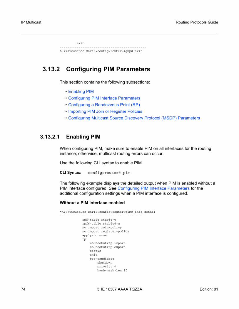
IP Multicast
74
Routing Protocols Guide
3HE 16307 AAAA TQZZA Edition: 01
exit----------------------------------------------A:7705custDoc:Sar18>config>router>igmp# exit
3.13.2 Configuring PIM Parameters
This section contains the following subsections:
• Enabling PIM• Configuring PIM Interface Parameters• Configuring a Rendezvous Point (RP)• Importing PIM Join or Register Policies• Configuring Multicast Source Discovery Protocol (MSDP) Parameters
3.13.2.1 Enabling PIM
When configuring PIM, make sure to enable PIM on all interfaces for the routing instance; otherwise, multicast routing errors can occur.
Use the following CLI syntax to enable PIM.
CLI Syntax: config>router# pim
The following example displays the detailed output when PIM is enabled without a PIM interface configured. See Configuring PIM Interface Parameters for the additional configuration settings when a PIM interface is configured.
Without a PIM interface enabled
*A:7705custDoc:Sar18>config>router>pim# info detail----------------------------------------------
rpf-table rtable-urpf6-table rtable6-uno import join-policyno import register-policyapply-to nonerp
no bootstrap-importno bootstrap-exportstaticexitbsr-candidate
shutdownpriority 0hash-mask-len 30
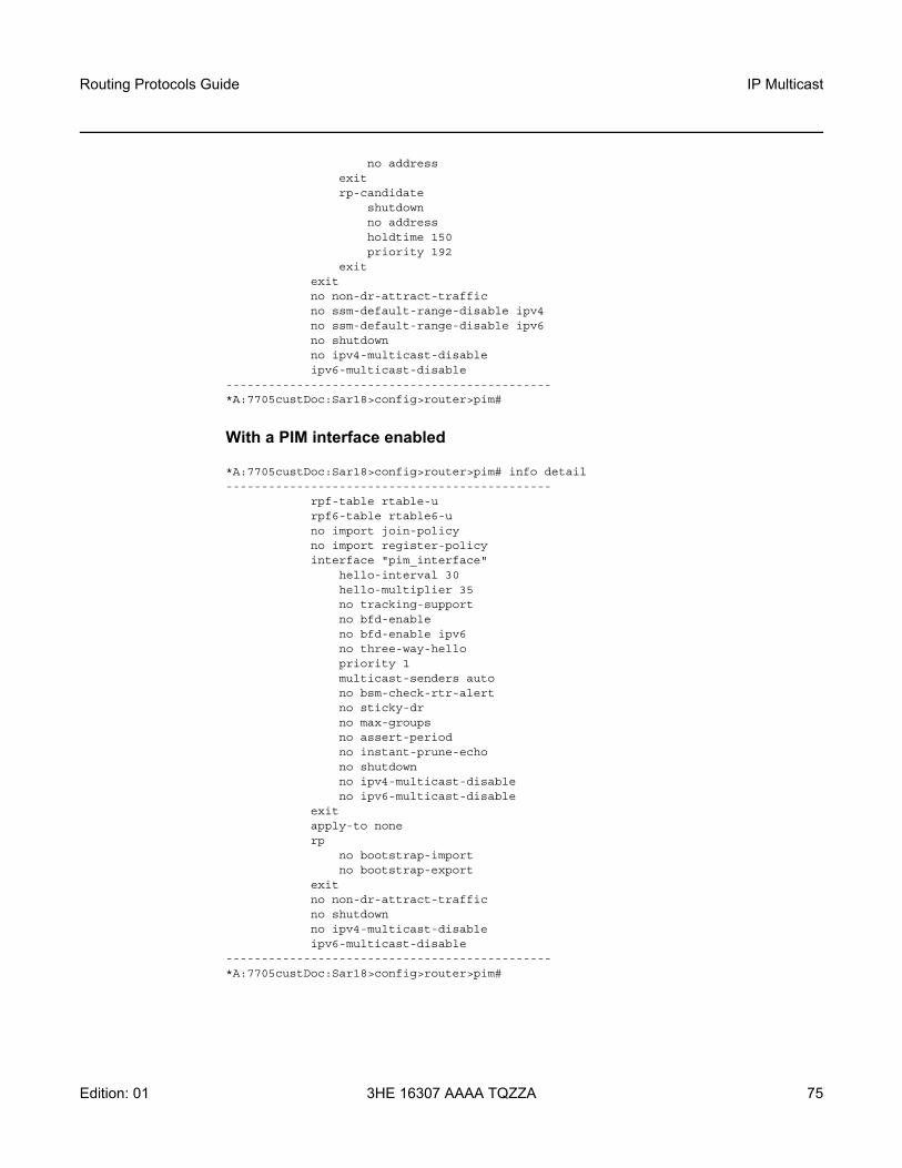
Routing Protocols Guide IP Multicast
Edition: 01 3HE 16307 AAAA TQZZA 75
no addressexitrp-candidate
shutdownno addressholdtime 150priority 192
exitexitno non-dr-attract-trafficno ssm-default-range-disable ipv4no ssm-default-range-disable ipv6no shutdownno ipv4-multicast-disableipv6-multicast-disable
----------------------------------------------*A:7705custDoc:Sar18>config>router>pim#
With a PIM interface enabled
*A:7705custDoc:Sar18>config>router>pim# info detail----------------------------------------------
rpf-table rtable-urpf6-table rtable6-uno import join-policyno import register-policyinterface "pim_interface"
hello-interval 30hello-multiplier 35no tracking-supportno bfd-enableno bfd-enable ipv6no three-way-hellopriority 1multicast-senders autono bsm-check-rtr-alertno sticky-drno max-groupsno assert-periodno instant-prune-echono shutdownno ipv4-multicast-disableno ipv6-multicast-disable
exitapply-to nonerp
no bootstrap-importno bootstrap-export
exitno non-dr-attract-trafficno shutdownno ipv4-multicast-disableipv6-multicast-disable
----------------------------------------------*A:7705custDoc:Sar18>config>router>pim#

IP Multicast
76
Routing Protocols Guide
3HE 16307 AAAA TQZZA Edition: 01
3.13.2.2 Configuring PIM Interface Parameters
To create a PIM interface, first create an IP interface using the config>router> interface or the config>service>ies>interface command (IES only). Then use the config>router>pim>interface command to configure PIM interface parameters.
The following example displays the command usage to configure PIM interface parameters:
Example: config>router# pim config>router>pim# interface "pim_interface"config>router>pim>if# assert-period assert-period config>router>pim>if# [no] bfd-enable [ipv4 | ipv6]config>router>pim>if# [no] bsm-check-rtr-alert config>router>pim>if# hello-interval hello-interval config>router>pim>if# hello-multiplier deci-units config>router>pim>if# instant-prune-echo config>router>pim>if# [no] ipv4-multicast-disable config>router>pim>if# [no] ipv6-multicast-disable config>router>pim>if# max-groups value config>router>pim>if# multicast-senders auto config>router>pim>if# priority dr-priority config>router>pim>if# [no] shutdown config>router>pim>if# sticky-dr [priority dr-priority] config>router>pim>if# [no] three-way-hello config>router>pim>if# [no] tracking-support config>router>pim>if# exit
The following example displays the detailed PIM interface configuration:
*A:7705custDoc:Sar18>config>router>pim# info detail----------------------------------------------...
interface "pim_interface"hello-interval 30hello-multiplier 35no tracking-supportno bfd-enableno bfd-enable ipv6no three-way-hellomulticast-senders autono bsm-check-rtr-alertpriority 1no sticky-drno max-groupsno assert-periodno instant-prune-echono shutdownno ipv4-multicast-disableno ipv6-multicast-disable
exit...

Routing Protocols Guide IP Multicast
Edition: 01 3HE 16307 AAAA TQZZA 77
----------------------------------------------*A:7705custDoc:Sar18>config>router>pim#
3.13.2.3 Configuring a Rendezvous Point (RP)
When configuring a Rendezvous Point (RP), you can configure parameters for an RP candidate, a BSR candidate, or a static RP.
The following example displays the command usage to configure an RP:
Example: config>router# pim config>router>pim# rp config>router>pim>rp# anycast rp-ip-addressconfig>router>pim>rp>anycast# rp-set-peer ip-address config>router>pim>rp# auto-rp-discovery config>router>pim>rp# bootstrap-export policy-name config>router>pim>rp# bootstrap-import policy-name config>router>pim>rp# bsr-candidate config>router>pim>rp>bsr-candidate# address ip-address config>router>pim>rp# rp-candidate config>router>pim>rp>rp-candidate# address ip-address config>router>pim>rp>rp-candidate# group-range {grp-ip-address/mask | grp-ip-address netmask}
config>router>pim>rp# static config>router>pim>rp>static# address ip-address config>router>pim>rp>static# group-prefix {grp-ip-address/mask | grp-ip-address netmask}
config>router>pim>rp>static# override
The following example displays the detailed RP configuration:
*A:7705custDoc:Sar18 Dut-B>config>router>pim>rp# info detail----------------------------------------------
no bootstrap-importno bootstrap-exportstaticexitbsr-candidate
shutdownpriority 0hash-mask-len 30no address
exitrp-candidate
shutdownno addressgroup-range 224.0.0.0/4group-range 224.0.0.0/8group-range 224.0.0.0/12holdtime 150

IP Multicast
78
Routing Protocols Guide
3HE 16307 AAAA TQZZA Edition: 01
priority 192exitanycast 10.10.10.12
rp-set-peer 10.10.10.13exit
----------------------------------------------*A:7705custDoc:Sar18 Dut-B>config>router>pim>rp#
3.13.2.4 Importing PIM Join or Register Policies
The import command provides a mechanism to control the (*,G) or (S,G) state that gets created on a router. Import policies are defined in the config>router>policy-options context.
Up to five join policies can be included in a single join-policy command and up to five register policies can be included in a single register-policy command. Each use of the join-policy or register-policy command overrides the previous use and resets the list of import policies.
Use the following commands to import PIM join policies:
CLI Syntax: config>router# pimimport {join-policy | register-policy} [policy-name [...up to 5 max]]
The following example displays the commands used to import a join policy statement named “pim_join”. The example also displays the commands used to import three register policies. For information on configuring a join or register policy, see the “Configuring PIM Join or Register Policies” section in the 7705 SAR Router Configuration Guide.
Example: config>router# pimconfig>router>pim# import join-policy “pim_join”config>router>pim# import register-policy “register_join” “register_join2” “register_join3”
config>router>pim# no shutdown
The following example displays the PIM configuration:
A:7705custDoc:Sar18>config>router>pim# info----------------------------------------------
Note: In the import policy, if a policy action is not specified in the entry, the default-action takes precedence. Similarly, if there are no entry matches, the default-action takes precedence. If no default-action is specified, the default default-action is executed.

Routing Protocols Guide IP Multicast
Edition: 01 3HE 16307 AAAA TQZZA 79
...import join-policy "pim_join"import register-policy "register_join" "register_join2" "register_join3"interface "pim_interface"exit
...----------------------------------------------A:7705custDoc:Sar18>config>router>pim#
3.13.2.5 Configuring Multicast Source Discovery Protocol (MSDP) Parameters
Use the following CLI syntax to configure MSDP parameters:
CLI Syntax: config>router# msdppeer peer-address
active-source-limit numberauthentication-key [authentication-key|hash-key][hash|hash2]default-peerexport policy-name [policy-name...(up to 5 max)]import policy-name [policy-name...(up to 5 max)]local-address addressreceive-msdp-msg-rate number interval seconds
[threshold number]no shutdown
no shutdown
The following example displays the command usage to configure basic MSDP parameters.
Example: config>router>msdp# peer 10.20.1.1config>router>msdp>peer# local-address 10.20.1.6config>router>msdp>peer# no shutdownconfig>router>msdp>peer# exitconfig>router>msdp# no shutdownconfig>router>msdp#
The following example displays the basic MSDP for configuration.
ALA-48>config>router>msdp# info-------------------------------------------
peer 10.20.1.1local-address 10.20.1.6
exit-------------------------------------------ALA-48>config>router>msdp#

IP Multicast
80
Routing Protocols Guide
3HE 16307 AAAA TQZZA Edition: 01
3.14 Service Management Tasks
This section discusses the following multicast configuration management tasks:
• Disabling IGMP, MLD, PIM, and MSDP
3.14.1 Disabling IGMP, MLD, PIM, and MSDP
To disable IP multicast, disable PIM and disable IGMP or MLD (or both).
Use the following CLI syntax to disable IGMP, MLD, PIM, and MSDP:
CLI Syntax: config>router#igmpshutdownmldshutdownpimshutdownmsdpshutdown
The following example displays the command usage to disable multicast:
Example: config>router# igmpconfig>router>igmp# shutdownconfig>router>igmp# exitconfig>router# mldconfig>router>mld# shutdownconfig>router>mld# exitconfig>router# pimconfig>router>pim# shutdownconfig>router>pim# exitconfig>router# msdpconfig>router>msdp# shutdownconfig>router>msdp# exit
The following example displays the configuration outputs:
*A:7705custDoc:Sar18>config>router>igmp# info detail----------------------------------------------
shutdowninterface "igmp_interface"
no importversion 3subnet-check

Routing Protocols Guide IP Multicast
Edition: 01 3HE 16307 AAAA TQZZA 81
no max-groupsno disable-router-alert-checkssm-translate
grp-range 239.255.0.0 239.255.20.20source 10.10.10.10
exitgrp-range 239.255.50.50 239.255.70.70
source 10.10.10.11exit
exitno shutdown
exitquery-interval 125query-last-member-interval 1query-response-interval 10robust-count 2
----------------------------------------------*A:7705custDoc:Sar18>config>router>igmp#
*A:7705custDoc:Sar18>config>router>mld# info detail----------------------------------------------
shutdowninterface "mld_interface"
no importversion 2no max-groupsno disable-router-alert-checkno query-intervalno query-response-intervalno query-last-listener-intervalno shutdown
exitquery-interval 125query-last-listener-interval 1query-response-interval 10robust-count 2
----------------------------------------------*A:7705custDoc:Sar18>config>router>mld#
*A:7705custDoc:Sar18>config>router>pim# info detail----------------------------------------------
shutdownrpf-table rtable-urpf6-table rtable6-uno import join-policyinterface "pim_interface"
hello-interval 30hello-multiplier 35no tracking-supportno bfd-enableno bfd-enable ipv6no three-way-hellopriority 1no sticky-drno max-groupsno assert-periodinstant-prune-echono shutdown

IP Multicast
82
Routing Protocols Guide
3HE 16307 AAAA TQZZA Edition: 01
no ipv4-multicast-disableno ipv6-multicast-disable
exitapply-to allrp
no bootstrap-importno bootstrap-export
exitno non-dr-attract-trafficno ipv4-multicast-disableipv6-multicast-disable
----------------------------------------------*A:7705custDoc:Sar18>config>router>pim#
#--------------------------------------------------echo "MSDP Configuration"#--------------------------------------------------
msdpshutdown
peer 10.20.1.1local-address 10.20.1.6
exitgroup "test"
active-source-limit 50000receive-msdp-msg-rate 100 interval 300 threshold 5000export "LDP-export"import "LDP-import"local-address 10.10.10.103mode mesh-grouppeer 10.10.10.104exit
exitexit
#--------------------------------------------------

Routing Protocols Guide IP Multicast
Edition: 01 3HE 16307 AAAA TQZZA 83
3.15 IP Multicast Command Reference
3.15.1 Command Hierarchies
• Configuration Commands- IGMP Commands- MLD Commands- PIM Commands- MSDP Commands
• Show Commands• Clear Commands• Debug Commands• Monitor Commands• Tools Commands (refer to the Tools chapter in the 7705 SAR OAM and
Diagnostics Guide)

IP Multicast
84
Routing Protocols Guide
3HE 16307 AAAA TQZZA Edition: 01
3.15.1.1 Configuration Commands
3.15.1.1.1 IGMP Commands
configure— router
— [no] igmp — [no] interface ip-int-name
— [no] disable-router-alert-check — import policy-name— no import — max-groups value— no max-groups — max-grp-sources value— no max-grp-sources — [no] shutdown — ssm-translate
— [no] grp-range start end— [no] source ip-address
— static — [no] group grp-ip-address
— [no] source ip-address— [no] subnet-check — version version— no version
— query-interval seconds— no query-interval — query-last-member-interval seconds— no query-last-member-interval — query-response-interval seconds— no query-response-interval — robust-count robust-count— no robust-count — [no] shutdown — ssm-translate
— [no] grp-range start end— [no] source ip-address

Routing Protocols Guide IP Multicast
Edition: 01 3HE 16307 AAAA TQZZA 85
3.15.1.1.2 MLD Commands
configure— router
— [no] mld — [no] interface ip-int-name
— [no] disable-router-alert-check — import policy-name — no import — max-groups value — no max-groups — query-interval seconds — no query-interval — query-last-listener-interval seconds — no query-last-listener-interval — query-response-interval seconds — no query-response-interval — [no] shutdown — no ssm-translate
— [no] grp-range start end — [no] source ipv6-address
— static — [no] group grp-ipv6-address
— [no] source src-ipv6-address — version version — no version
— query-interval seconds — no query-interval — query-last-listener-interval seconds — no query-last-listener-interval — query-response-interval seconds — no query-response-interval — robust-count seconds — no robust-count — [no] shutdown — no ssm-translate
— [no] grp-range start end — [no] source src-ipv6-address

IP Multicast
86
Routing Protocols Guide
3HE 16307 AAAA TQZZA Edition: 01
3.15.1.1.3 PIM Commands
configure— router
— [no] pim — apply-to {ies | non-ies | all | none} — import {join-policy | register-policy} policy-name[.. policy-name (up to 5
max)] — no import {join-policy | register-policy}— [no] interface ip-int-name
— assert-period assert-period — no assert-period — [no] bfd-enable [ipv4 | ipv6] — [no] bsm-check-rtr-alert— hello-interval hello-interval — no hello-interval — hello-multiplier deci-units — no hello-multiplier — [no] instant-prune-echo — [no] ipv4-multicast-disable — [no] ipv6-multicast-disable — max-groups value — no max-groups — multicast-senders {auto | always | never}— no multicast-senders— priority dr-priority — no priority — [no] shutdown — sticky-dr [priority dr-priority]— no sticky-dr — [no] three-way-hello — [no] tracking-support
— [no] ipv4-multicast-disable — [no] ipv6-multicast-disable — [no] non-dr-attract-traffic — rp
— [no] anycast rp-ip-address— [no] rp-set-peer ip-address
— [no] auto-rp-discovery— bootstrap-export policy-name[...policy-name (up to 5 max)] — no bootstrap-export — bootstrap-import policy-name[...policy-name (up to 5 max)] — no bootstrap-import — bsr-candidate
— address ipv4-address— no address— hash-mask-len hash-mask-length— no hash-mask-len— priority bootstrap-priority— no priority— [no] shutdown
— rp-candidate— address ip-address

Routing Protocols Guide IP Multicast
Edition: 01 3HE 16307 AAAA TQZZA 87
— no address— [no] group-range {grp-ip-address/mask | grp-ip-address
netmask}— holdtime holdtime— no holdtime— priority priority— no priority— [no] shutdown
— static— [no] address ip-address
— [no] group-prefix {grp-ip-address/mask | grp-ip-address netmask}
— [no] override— rpf-table {rtable-m | rtable-u | both} — no rpf-table — rpf6-table {rtable6-m | rtable6-u | both} — no rpf6-table — [no] shutdown — spt-switchover-threshold {grp-ipv4-prefix/ipv4-prefix-length | grp-ipv4-prefix
netmask | grp-ipv6-prefix/ipv6-prefix-length} spt-threshold— no spt-switchover-threshold {grp-ipv4-prefix/ipv4-prefix-length | grp-ipv4-
prefix netmask | grp-ipv6-prefix/ipv6-prefix-length}— [no] ssm-default-range-disable ipv4 — [no] ssm-default-range-disable ipv6— [no] ssm-groups
— [no] group-range {ip-prefix/mask | ip-prefix netmask}
3.15.1.1.4 MSDP Commands
config— router
— [no] msdp— [no] active-source-limit number — [no] data-encapsulation — export policy-name [policy-name...(up to 5 max)]— no export— [no] group group-name
— active-source-limit number — no active-source-limit— export policy-name [policy-name...(up to 5 max)]— no export— import policy-name [policy-name...(up to 5 max)]— no import— local-address address— no local-address— mode {mesh-group | standard}— [no] peer peer-address
— active-source-limit number — no active-source-limit— authentication-key [authentication-key | hash-key] [hash |
hash2]

IP Multicast
88
Routing Protocols Guide
3HE 16307 AAAA TQZZA Edition: 01
— no authentication-key— [no] default-peer— export policy-name [policy-name...(up to 5 max)]— no export— import policy-name [policy-name...(up to 5 max)]— no import— local-address address— no local-address— receive-msdp-msg-rate number interval seconds [threshold
number] — no receive-msdp-msg-rate— [no] shutdown
— receive-msdp-msg-rate number interval seconds [threshold number] — no receive-msdp-msg-rate— [no] shutdown
— import policy-name [policy-name...(up to 5 max)]— no import— local-address address— no local-address— [no] peer peer-address
— active-source-limit number — no active-source-limit— authentication-key [authentication-key | hash-key] [hash | hash2]— no authentication-key— [no] default-peer— export policy-name [policy-name...(up to 5 max)]— no export— import policy-name [policy-name...(up to 5 max)]— no import— local-address address— no local-address— receive-msdp-msg-rate number interval seconds [threshold number] — no receive-msdp-msg-rate— [no] shutdown
— receive-msdp-msg-rate number interval seconds [threshold number] — no receive-msdp-msg-rate— rpf-table {rtable-m | rtable-u | both}— no rpf-table— sa-timeout seconds— no sa-timeout— [no] shutdown— [no] source ip-prefix/mask
— active-source-limit number — no active-source-limit

Routing Protocols Guide IP Multicast
Edition: 01 3HE 16307 AAAA TQZZA 89
3.15.1.2 Show Commands
show— router
— igmp — group [grp-ip-address] — group summary— interface [ip-int-name | ip-address] [group] [grp-ip-address] [detail] — ssm-translate [interface-name] — static [ip-int-name | ip-address] — statistics [ip-int-name | ip-address] — status
show— router
— mld — group [grp-ipv6-address] — interface [ip-int-name | ip-address] [group] [grp-ipv6-address] [detail] — ssm-translate [ip-int-name] — static [ip-int-name | ip-address] — statistics [ip-int-name | ipv6-address] — status
show— router
— pim — group [grp-ip-address] [source ip-address] [detail] [family] — interface [ip-int-name | ip-address] [group grp-ip-address] [source ip-address]
[detail] [family]— neighbor [ip-int-name | ip-address [address neighbor-ip-address]] [detail]
[family]— rp [family | ip-address] — rp-hash [family | ip-address] — s-pmsi [family | ip-address] — statistics [ip-int-name | ip-address] [family]— status [detail] [family]
show— router
— msdp— group [group-name] [detail]— peer [ip-address] [group group-name] [detail]— source [ip-address/mask] [type {configured | dynamic | both}] [detail]— source-active [{group ip-address | local | originator ip-address | peer ip-
address | source ip-address | group ip-address source ip-address}] [detail]
— source-active-rejected [peer-group name] [group ip-address] [source ip-address] [originator ip-address] [peer ip-address]
— statistics [peer ip-address]— status

IP Multicast
90
Routing Protocols Guide
3HE 16307 AAAA TQZZA Edition: 01
3.15.1.3 Clear Commands
clear— router
— igmp — database [interface ip-int-name | ip-address] [group grp-ip-address [source
src-ip-address]] — statistics [ip-int-name | ip-address] — version [ip-int-name | ip-address]
clear— router
— mld — database [interface ip-int-name | ipv6-address] [group grp-ipv6-address
[source src-ipv6-address]] — statistics [ip-int-name | ipv6-address] — version [ip-int-name | ip-address]
clear— router
— pim — database [interface ip-int-name | ip-address] [group grp-ip-address [source
ip-address]] [family] — neighbor [ip-int-name] [family] — statistics [family] — statistics interface ip-int-name | ip-address [family] — statistics group grp-ip-address [source ip-address] [family]
clear— router
— msdp— cache [peer ip-address] [group ip-address] [source ip-address] [originrp ip-
address]— statistics [peer ip-address]

Routing Protocols Guide IP Multicast
Edition: 01 3HE 16307 AAAA TQZZA 91
3.15.1.4 Debug Commands
debug— router
— [no] igmp — [no] interface [ip-int-name | ip-address]— [no] misc— packet [query | v1-report | v2-report | v3-report | v2-leave] [ip-int-name | ip-
address] — no packet
debug— router
— [no] mld — [no] interface [ip-int-name | ipv6-address]— [no] misc— packet [query | v1-report | v2-report | v1-done] [ip-int-name | ipv6-address] — no packet
debug— router
— [no] msdp— packet [pkt-type] [peer ip-address]— no packet— pim [grp-address]— no pim— rtm [rp-address]— no rtm— sa-db [group grpAddr] [source srcAddr] [rp rpAddr]— no sa-db
debug— router
— [no] mtrace — [no] misc — [no] packet [query | request | response]
debug— router
— [no] pim — [no] adjacency— all [group grp-ip-address] [source ip-address] [detail] — no all— assert [group grp-ip-address] [source ip-address] [detail] — no assert— auto-rp [detail] — no auto-rp — bgp [group grp-ip-address] [source ip-address] [peer peer-ip-address] [detail] — no bgp— bsr [detail] — no bsr

IP Multicast
92
Routing Protocols Guide
3HE 16307 AAAA TQZZA Edition: 01
— data [group grp-ip-address] [source ip-address] [detail] — no data — db [group grp-ip-address] [source ip-address] [detail] — no db — interface [ip-int-name | ip-address] [detail] — no interface — jp [group grp-ip-address] [source ip-address] [detail] — no jp — mrib [group grp-ip-address] [source ip-address] [detail] — no mrib — msg [detail]— no msg — packet [hello | register | register-stop | jp | bsr | assert | crp] [ip-int-name |
ip-address] — no packet — [no] red [detail]— register [group grp-ip-address] [source ip-address] [detail] — no register — rtm [detail] — no rtm
3.15.1.5 Monitor Commands
monitor— router
— pim— group grp-ip-address [source ip-address] [interval interval] [repeat repeat]
[absolute | rate]

Routing Protocols Guide IP Multicast
Edition: 01 3HE 16307 AAAA TQZZA 93
3.15.2 Command Descriptions
• Configuration Commands• Show Commands• Clear Commands• Debug Commands• Monitor Commands

IP Multicast
94
Routing Protocols Guide
3HE 16307 AAAA TQZZA Edition: 01
3.15.2.1 Configuration Commands
• Generic Commands• IGMP Commands• MLD Commands• PIM Commands• MSDP Commands

Routing Protocols Guide IP Multicast
Edition: 01 3HE 16307 AAAA TQZZA 95
3.15.2.1.1 Generic Commands
shutdown
Syntax [no] shutdown
Context config>router>igmpconfig>router>igmp>interfaceconfig>router>mldconfig>router>mld>interfaceconfig>router>msdpconfig>router>msdp>groupconfig>router>msdp>group>peerconfig>router>msdp>peerconfig>router>pimconfig>router>pim>interfaceconfig>router>pim>rp>bsr-candidateconfig>router>pim>rp>rp-candidate
Description This command administratively disables the entity. When disabled, an entity does not change, reset, or remove any configuration settings or statistics. Many entities must be explicitly enabled using the no shutdown command.
The operational state of the entity is disabled as well as the operational state of any entities contained within. Many objects must be shut down before they can be deleted.
Unlike other commands and parameters where the default state is not indicated in the configuration file, shutdown and no shutdown are always indicated in system-generated configuration files.
The no form of the command puts an entity into the administratively enabled state.
Default no shutdown

IP Multicast
96
Routing Protocols Guide
3HE 16307 AAAA TQZZA Edition: 01
3.15.2.1.2 IGMP Commands
igmp
Syntax [no] igmp
Context config>router
Description This command enables the Internet Group Management Protocol (IGMP) context. When the context is created, the IGMP protocol is enabled.
The Internet Group Management Protocol (IGMP) is used by IPv4 systems (hosts and routers) to report their IP multicast group memberships to neighboring multicast routers. An IP multicast router can be a member of one or more multicast groups, in which case it performs both the “multicast router” part of the protocol, which collects the membership information needed by its multicast routing protocol, and the “group member” part of the protocol, which informs itself and other neighboring multicast routers of its memberships.
The no form of the command disables the IGMP instance. To start or suspend execution of IGMP without affecting the configuration, use the no shutdown command.
Default n/a
interface
Syntax [no] interface ip-int-name
Context config>router>igmp
Description This command enables the context to configure an IGMP interface. The interface is a local identifier of the network interface on which reception of the specified multicast address is to be enabled or disabled.
The no form of the command deletes the IGMP interface. The shutdown command in the config>router>igmp>interface context can be used to disable an interface without removing the configuration for the interface.
Default no interface (no interfaces are defined)
Parameters ip-int-name — the IP interface name. Interface names must be unique within the group of defined IP interfaces for config>router>igmp>interface and config>service>ies>interface commands. An interface name cannot be in the form of an IP address. Interface names can be any string up to 32 characters long composed of printable, 7-bit ASCII characters. If the string contains special characters (#, $, spaces, etc.), the entire string must be enclosed within double quotes.
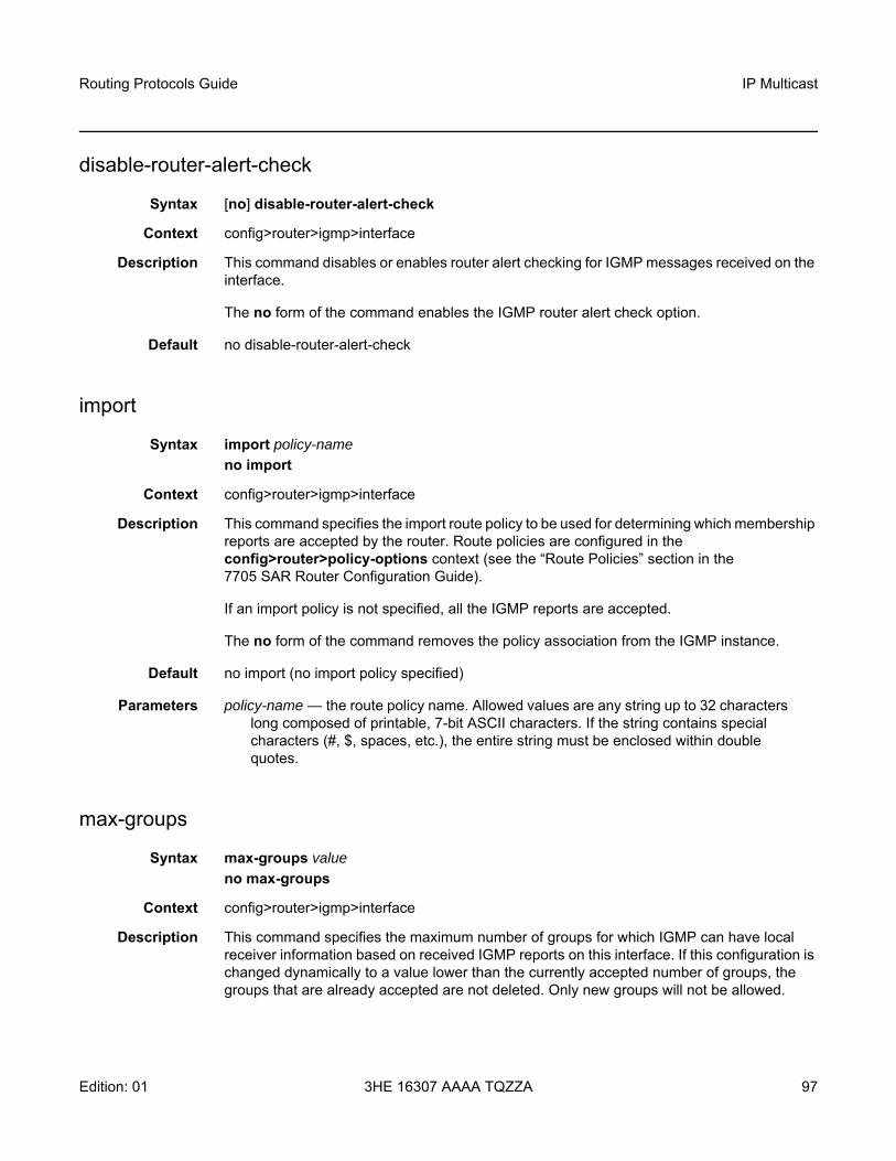
Routing Protocols Guide IP Multicast
Edition: 01 3HE 16307 AAAA TQZZA 97
disable-router-alert-check
Syntax [no] disable-router-alert-check
Context config>router>igmp>interface
Description This command disables or enables router alert checking for IGMP messages received on the interface.
The no form of the command enables the IGMP router alert check option.
Default no disable-router-alert-check
import
Syntax import policy-name no import
Context config>router>igmp>interface
Description This command specifies the import route policy to be used for determining which membership reports are accepted by the router. Route policies are configured in the config>router>policy-options context (see the “Route Policies” section in the 7705 SAR Router Configuration Guide).
If an import policy is not specified, all the IGMP reports are accepted.
The no form of the command removes the policy association from the IGMP instance.
Default no import (no import policy specified)
Parameters policy-name — the route policy name. Allowed values are any string up to 32 characters long composed of printable, 7-bit ASCII characters. If the string contains special characters (#, $, spaces, etc.), the entire string must be enclosed within double quotes.
max-groups
Syntax max-groups valueno max-groups
Context config>router>igmp>interface
Description This command specifies the maximum number of groups for which IGMP can have local receiver information based on received IGMP reports on this interface. If this configuration is changed dynamically to a value lower than the currently accepted number of groups, the groups that are already accepted are not deleted. Only new groups will not be allowed.

IP Multicast
98
Routing Protocols Guide
3HE 16307 AAAA TQZZA Edition: 01
The no version of the command removes the configured value and the maximum number of groups is not defined.
Default no max-groups
Parameters value — the maximum number of groups for the interface
Values 1 to 256
max-grp-sources
Syntax max-grp-sources valueno max-grp-sources
Context config>router>igmp>interface
Description This command specifies the maximum number of group sources for which IGMP can have local receiver information based on received IGMP reports on this interface. If this configuration is changed dynamically to a value lower than the currently accepted number of group sources, the group sources that are already accepted are not deleted. Only new group sources will not be allowed.
The no version of the command removes the configured value and the maximum number of group sources is not defined.
Default no max-grp-sources
Parameters value — the maximum number of group sources for the group interface
Values 1 to 256
ssm-translate
Syntax ssm-translate
Context config>router>igmpconfig>router>igmp>interface
Description This command enables the context to configure group ranges that are translated to SSM (S,G) entries. If the static entry needs to be created, it has to be translated from an IGMPv1 or IGMPv2 request to a Source-Specific Multicast (SSM) join message.
Routing Protocols Guide IP Multicast
Edition: 01 3HE 16307 AAAA TQZZA 99
grp-range
Syntax [no] grp-range start end
Context config>router>igmp>ssm-translateconfig>router>igmp>if>ssm-translate
Description This command adds or removes SSM translate group range entries. The group range is not created until the grp-range>source command is used to configure the source address.
Default n/a
Parameters start — an IP address that specifies the start of the group range
Values a.b.c.d
end — an IP address that specifies the end of the group range. This value should always be greater than or equal to the start value.
Values a.b.c.d
source
Syntax [no] source ip-address
Context config>router>igmp>ssm-translate>grp-rangeconfig>router>igmp>if>ssm-translate>grp-range
Description This command specifies the source IP address for the group range. Whenever a (*,G) report is received in the range specified by the grp-range start and end parameters, it is translated to an (S,G) report with the value of this object as the source address.
Default n/a
Parameters ip-address — the unicast IP source address
Values a.b.c.d
static
Syntax static
Context config>router>igmp>interface
Description This command allows multicast forwarding out an interface without having received a dynamic join report on that interface. The specific multicast traffic to be forwarded is configured using the static>group and static>group>source commands.
Default n/a

IP Multicast
100
Routing Protocols Guide
3HE 16307 AAAA TQZZA Edition: 01
group
Syntax [no] group grp-ip-address
Context config>router>igmp>if>static
Description This command adds a static multicast (S,G) group membership to an IPv4 interface. When IGMP static groups are enabled, data is forwarded to an interface without receiving membership reports from host members. A possible use for IGMP static groups is to test multicast forwarding in the absence of an IGMP host receiver.
The group command, in combination with the source command, is used to create a specific (S,G) static group entry.
Default n/a
Parameters grp-ip-address — specifies an IGMP multicast group address that receives data on an interface. The IP address must be unique for each static group.
Values a.b.c.d
source
Syntax [no] source ip-address
Context config>router>igmp>if>static>group
Description This command specifies the source IPv4 address (S) for the static IGMP group being configured. Multicast traffic to the group (G) will be forwarded out the interface on which this static group is configured if the source address in the IPv4 header of the multicast packets matches S.
The source command, in combination with the group command, is used to create a specific (S,G) static group entry.
The no form of the command removes the source from the configuration.
Default n/a
Parameters ip-address — the IPv4 unicast address
Values a.b.c.d

Routing Protocols Guide IP Multicast
Edition: 01 3HE 16307 AAAA TQZZA 101
subnet-check
Syntax [no] subnet-check
Context config>router>igmp>interface
Description This command enables subnet checking for IGMP messages received on this interface. All IGMP packets with a source address that is not in the local subnet are dropped.
Default enabled
version
Syntax version versionno version
Context config>router>igmp>interface
Description This command specifies the IGMP version. If routers run different versions of IGMP, they will negotiate the lowest common version of IGMP that is supported by hosts on their subnet and operate in that version. For IGMP to function correctly, all routers on a LAN must be configured to run the same version of IGMP on that LAN.
For IGMPv3, a multicast router that is also a group member performs both parts of IGMPv3, receiving and responding to its own IGMP message transmissions as well as those of its neighbors.
Default 3
Parameters version — the IGMP version number
Values 1, 2, or 3
query-interval
Syntax query-interval secondsno query-interval
Context config>router>igmp
Description This command specifies the frequency at which the querying router transmits general host-query messages. Host-query messages solicit group membership information and are sent to the all-systems multicast group address, 224.0.0.1.
Default 125

IP Multicast
102
Routing Protocols Guide
3HE 16307 AAAA TQZZA Edition: 01
Parameters seconds — the frequency, in seconds, at which the router transmits general host-query messages
Values 2 to 1024
query-last-member-interval
Syntax query-last-member-interval secondsno query-last-member-interval
Context config>router>igmp
Description This command configures the frequency at which the querying router sends group-specific query messages, including messages sent in response to leave-group messages. The shorter the interval, the faster the detection of the loss of the last member of a group.
Default 1
Parameters seconds — the frequency, in seconds, at which query messages are sent
Values 1 to 1023
query-response-interval
Syntax query-response-interval secondsno query-response-interval
Context config>router>igmp
Description This command specifies how long the querying router waits to receive a response to a host-query message from a host.
Default 10
Parameters seconds — the length of time to wait to receive a response to the host-query message from the host
Values 1 to 1023

Routing Protocols Guide IP Multicast
Edition: 01 3HE 16307 AAAA TQZZA 103
robust-count
Syntax robust-count robust-countno robust-count
Context config>router>igmp
Description This command configures the robust count, which is the number of times the router will retry a query. The robust-count variable allows tuning for the expected packet loss on a subnet. If a subnet anticipates losses, the robust-count variable can be increased.
Default 2
Parameters robust-count — the robust count value
Values 2 to 10

IP Multicast
104
Routing Protocols Guide
3HE 16307 AAAA TQZZA Edition: 01
3.15.2.1.3 MLD Commands
mld
Syntax [no] mld
Context config>router
Description This command enables the context to configure Multicast Listener Discovery (MLD) parameters.
The no form of the command disables MLD.
Default no mld
interface
Syntax [no] interface ip-int-name
Context config>router>mld
Description This command enables the context to configure an MLD interface. The interface is a local identifier of the network interface on which reception of the specified multicast address is to be enabled or disabled.
The no form of the command deletes the MLD interface. The shutdown command in the config>router>mld>interface context can be used to disable an interface without removing the configuration for the interface.
Default no interface (no interfaces are defined)
Parameters ip-int-name — the IP interface name. Interface names must be unique within the group of defined IP interfaces for config>router>interface and config>service>ies>interface commands. An interface name cannot be in the form of an IP address. Interface names can be any string up to 32 characters long composed of printable, 7-bit ASCII characters. If the string contains special characters (#, $, spaces, etc.), the entire string must be enclosed within double quotes.

Routing Protocols Guide IP Multicast
Edition: 01 3HE 16307 AAAA TQZZA 105
disable-router-alert-check
Syntax [no] disable-router-alert-check
Context config>router>mld>interface
Description This command enables or disables the router alert checking for MLD messages received on this interface.
The no form of the command enables the MLD router alert check option.
Default no disable-router-alert-check (enabled)
import
Syntax import policy-name no import
Context config>router>mld>interface
Description This command specifies the import route policy to be used for determining which membership reports are accepted by the router. Route policies are configured in the config>router>policy-options context.
If an import policy is not specified, all the MLD reports are accepted.
The no form of the command removes the policy association from the MLD instance.
Default no import (no import policy specified)
Parameters policy-name — the route policy name. Allowed values are any string up to 32 characters long composed of printable, 7-bit ASCII characters. If the string contains special characters (#, $, spaces, etc.), the entire string must be enclosed within double quotes.
max-groups
Syntax max-groups valueno max-groups
Context config>router>mld>interface
Description This command specifies the maximum number of groups for which MLD can have local receiver information based on received MLD reports on this interface. If this configuration is changed dynamically to a value lower than the currently accepted number of groups, the groups that are already accepted are not deleted. Only new groups will not be allowed.

IP Multicast
106
Routing Protocols Guide
3HE 16307 AAAA TQZZA Edition: 01
The no version of the command removes the configured value and the maximum number of groups is not defined.
Default no max-groups
Parameters value — the maximum number of groups for this interface
Values 1 to 256
query-interval
Syntax query-interval secondsno query-interval
Context config>router>mldconfig>router>mld>interface
Description This command specifies the frequency at which the querying router transmits general host-query messages. Host-query messages solicit group membership information and are sent to the all-systems multicast group address, 224.0.0.1.
Default 125
Parameters seconds — the frequency, in seconds, at which the router transmits general host-query messages
Values 2 to 1024
query-last-listener-interval
Syntax query-last-listener-interval secondsno query-last-listener-interval
Context config>router>mldconfig>router>mld>interface
Description This command configures the frequency at which the querying router sends group-specific query messages, including messages sent in response to leave-group messages. The shorter the interval, the faster the detection of the loss of the last member of a group.
Default 1
Parameters seconds — the frequency, in seconds, at which query messages are sent
Values 1 to 1023
Routing Protocols Guide IP Multicast
Edition: 01 3HE 16307 AAAA TQZZA 107
query-response-interval
Syntax query-response-interval secondsno query-response-interval
Context config>router>mldconfig>router>mld>interface
Description This command specifies how long the querying router waits to receive a response to a host-query message from a host.
Default 10
Parameters seconds — the length of time to wait to receive a response to the host-query message from the host
Values 1 to 1023
robust-count
Syntax robust-count robust-countno robust-count
Context config>router>mld
Description This command configures the robust count. The robust-count variable allows tuning for the expected packet loss on a subnet. If a subnet anticipates losses, the robust-count variable can be increased.
Default 2
Parameters robust-count — the robust count value
Values 2 to 10
ssm-translate
Syntax ssm-translate
Context config>router>mldconfig>router>mld>interface
Description This command enables the context to configure group ranges that are translated to SSM (S,G) entries. If the static entry needs to be created, it has to be translated from an MLDv1 request to a Source-Specific Multicast (SSM) join message.

IP Multicast
108
Routing Protocols Guide
3HE 16307 AAAA TQZZA Edition: 01
grp-range
Syntax [no] grp-range start end
Context config>router>mld>ssm-translateconfig>router>mld>if>ssm-translate
Description This command is used to configure group ranges that are translated to SSM (S,G) entries.
Default n/a
Parameters start — specifies a valid multicast group IPv6 address that identifies the start of the group range
Values ipv6-address: x:x:x:x:x:x:x:x (eight 16-bit pieces)x:x:x:x:x:x:d.d.d.dx: [0..FFFF]Hd: [0..255]D
end — an IP address that specifies the end of the group range. This value should always be greater than or equal to the start value.
Values ipv6-address: x:x:x:x:x:x:x:x (eight 16-bit pieces)x:x:x:x:x:x:d.d.d.dx: [0..FFFF]Hd: [0..255]D
source
Syntax [no] source src-ipv6-address
Context config>router>mld>ssm-translate>grp-rangeconfig>router>mld>if>ssm-translate>grp-range
Description This command specifies the source IPv6 address for the group range. Whenever a (*,G) report is received in the range specified by grp-range start and end parameters, it is translated to an (S,G) report with the value of this object as the source address.
Default n/a
Parameters src-ipv6-address — the IPv6 address that will be sending data
Values src-ipv6-address: x:x:x:x:x:x:x:x (eight 16-bit pieces)x:x:x:x:x:x:d.d.d.dx: [0..FFFF]Hd: [0..255]D

Routing Protocols Guide IP Multicast
Edition: 01 3HE 16307 AAAA TQZZA 109
static
Syntax static
Context config>router>mld>interface
Description This command allows multicast forwarding out an interface without having received a dynamic join report on that interface. The specific multicast traffic to be forwarded is configured using the static>group and static>group>source commands.
Default n/a
group
Syntax [no] group grp-ipv6-address
Context config>router>mld>if>static
Description This command adds a static multicast (S,G) group membership to an IPv6 interface. When MLD static groups are enabled, data is forwarded to an interface without receiving membership reports from host members. A possible use for MLD static groups is to test multicast forwarding in the absence of an MLD host receiver.
The no form of the command removes the IPv6 address from the configuration.
Default n/a
Parameters grp-ipv6-address — specifies an MLD multicast group address that receives data on an interface. The IP address must be unique for each static group
Values grp-ipv6-address: x:x:x:x:x:x:x:x (eight 16-bit pieces)x:x:x:x:x:x:d.d.d.dx: [0..FFFF]Hd: [0..255]D
source
Syntax [no] source src-ipv6-address
Context config>router>mld>if>static>group
Description This command specifies the source IPv6 address (S) for the static MLD group being configured. Multicast traffic to the group (G) will be forwarded out the interface on which this static group is configured if the source address in the IPv6 header of the multicast packets matches S.
The source command, in combination with the group command, is used to create a specific (S,G) static group entry.

IP Multicast
110
Routing Protocols Guide
3HE 16307 AAAA TQZZA Edition: 01
The no form of the command removes the source from the configuration.
Default n/a
Parameters src-ipv6-address — the IPv6 unicast address
Values src-ipv6-address: x:x:x:x:x:x:x:x (eight 16-bit pieces)x:x:x:x:x:x:d.d.d.dx: [0..FFFF]Hd: [0..255]D
version
Syntax version versionno version
Context config>router>mld>interface
Description This command specifies the MLD version. If routers run different versions of MLD, they will negotiate the lowest common version of MLD that is supported by hosts on their subnet and operate in that version. For MLD to function correctly, all routers on a LAN must be configured to run the same version of MLD on that LAN.
Default 2
Parameters version — the MLD version number
Values 1 or 2

Routing Protocols Guide IP Multicast
Edition: 01 3HE 16307 AAAA TQZZA 111
3.15.2.1.4 PIM Commands
pim
Syntax [no] pim
Context config>router
Description This command configures a Protocol Independent Multicast (PIM) instance.
PIM is used for multicast routing within the network. Devices in the network can receive the multicast feed requested and non-participating routers can be pruned. The 7705 SAR supports PIM Source-Specific Multicast (SSM) and PIM Sparse-Mode (SM).
The no form of the command deletes the PIM instance and removes all configuration parameters.
Default no pim
apply-to
Syntax apply-to {ies | non-ies | all | none}
Context config>router>pim
Description This command automatically creates or removes PIM interfaces. The ies, non-ies, and all options create a PIM interface with default PIM parameters when a new IP or IES interface is created manually. The none option removes any automatically created PIM interfaces that have not been modified manually in the PIM context. Existing manually created or modified PIM interfaces are not affected.
The default option for the apply-to command is none, so to activate its automatic behavior it must first be saved in the PIM configuration structure. Then, all subsequent commands either create new structures (in the case of IP or IES interface commands) or modify the default values created by the apply-to command (in the case of PIM interface commands).
For example, assume that the apply-to setting is none and that two manually created PIM interfaces already exist. If the apply-to setting is changed to ies, then the two manually created PIM interfaces remain unchanged but any newly created or modified IES interfaces will automatically create a corresponding PIM interface with default PIM values. Subsequently, if the apply-to command is changed back to none, then all PIM interfaces that were not manually created or modified are removed.
If a manually created or modified PIM interface is deleted, the interface will be recreated when (re)processing the apply-to command. If PIM is not required on a specific interface, then a config>router>pim>if>shutdown command should be executed.
Default none (keyword)

IP Multicast
112
Routing Protocols Guide
3HE 16307 AAAA TQZZA Edition: 01
Parameters ies — automatically creates a PIM interface for all IES interfaces in PIM
non-ies — creates non-IES interfaces in PIM
all — creates all IES and non-IES interfaces in PIM
none — removes all PIM interfaces that have not been manually created or modified in the PIM context
import
Syntax import {join-policy | register-policy} [policy-name [.. policy-name (up to 5 max)]no import {join-policy | register-policy}
Context config>router>pim
Description This command specifies the import route policy to be used by PIM. Route policies are configured in the config>router>policy-options context. Up to five import policy names can be specified.
If an import policy is not specified, IGP routes are accepted by default.
The no form of the command removes the policy association from the instance.
Default no import join-policy
no import register-policy
Parameters join-policy — this keyword filters PIM join messages, which prevents unwanted multicast streams from traversing the network
register-policy — this keyword filters PIM register messages. PIM register filters prevent register messages from being processed by the RP. This filter can only be defined on an RP. When a match is found, the RP immediately sends back a register-stop message.
policy-name — the route policy name
interface
Syntax [no] interface ip-int-name
Context config>router>pim
Description This command creates a logical IP routing interface.
The no form of the command removes the IP interface and all the associated configurations.
Default no interfaces or names are defined within PIM

Routing Protocols Guide IP Multicast
Edition: 01 3HE 16307 AAAA TQZZA 113
Parameters ip-int-name — the name of the IP interface. If the string contains special characters (#, $, spaces, etc.), the entire string must be enclosed within double quotes.If the ip-int-name already exists, the context is changed to maintain that IP interface. If ip-int-name does not exist, the interface is created and the context is changed to that interface for further command processing.
Values 1 to 32 alphanumeric characters
assert-period
Syntax assert-period assert-periodno assert-period
Context config>router>pim>interface
Description This command configures the period for refreshes of PIM Assert messages on an interface.
The no form of the command removes the assert period from the configuration.
Default no assert-period
Parameters assert-period — the period for refreshes of PIM Assert messages on an interface
Values 1 to 300 seconds
bfd-enable
Syntax [no] bfd-enable [ipv4 | ipv6]
Context config>router>pim>interface
Description This command enables the use of IPv4 or IPv6 Bidirectional Forwarding Detection (BFD) to control the state of the associated protocol interface. By enabling BFD on a given protocol interface, the state of the protocol interface is tied to the state of the BFD session between the local node and the remote node. The parameters used for BFD are set via the BFD command under the IP interface.
The no form of this command removes BFD from the associated IGP protocol adjacency.
Default no bfd-enable

IP Multicast
114
Routing Protocols Guide
3HE 16307 AAAA TQZZA Edition: 01
bsm-check-rtr-alert
Syntax [no] bsm-check-rtr-alert
Context config>router>pim>interface
Description This command enables the checking of the router alert option in the bootstrap messages received on this interface.
Default no bsm-check-rtr-alert
hello-interval
Syntax hello-interval hello-intervalno hello-interval
Context config>router>pim>interface
Description This command configures the time interval between PIM Hello messages transmitted on this interface.
The no form of this command reverts to the default value of the hello-interval.
Default 30
Parameters hello-interval — the hello interval in seconds. A 0 (zero) value disables the sending of Hello messages (the PIM neighbor will never time out the adjacency)
Values 0 to 255 seconds
hello-multiplier
Syntax hello-multiplier deci-unitsno hello-multiplier
Context config>router>pim>interface
Description This command configures the multiplier used to determine the hold time for a PIM neighbor on this interface.
The hello-multiplier in conjunction with the hello-interval determines the hold time for a PIM neighbor.
The multiplier value is expressed in deci-units, so that (for example) 10 deci-units represents a multiplier of 1 and 35 deci-units represents a multiplier of 3.5.

Routing Protocols Guide IP Multicast
Edition: 01 3HE 16307 AAAA TQZZA 115
For example, if the hello-interval is 1 s and the hello-multiplier is 35 deci-units, then the calculated hold time (in seconds) is:
hold time = (hello-interval * hello-multiplier) / 10= (1 s * 35 deci-units) / 10= 3.5 s
Parameters deci-units — the value, specified in multiples of 0.1, for the formula (above) used to calculate the hold time based on the hello-multiplierThis allows the PIM default timeout of 3.5 seconds to be supported.
Values 20 to 100
Default 35
instant-prune-echo
Syntax [no] instant-prune-echo
Context config>router>pim>interface
Description This command enables or disables instant PruneEcho for a PIM interface.
Default no instant-prune-echo
ipv4-multicast-disable
Syntax [no] ipv4-multicast-disable
Context config>router>pimconfig>router>pim>interface
Description This command administratively disables or enables PIM operation for IPv4.
Default no ipv4-multicast-disable
ipv6-multicast-disable
Syntax [no] ipv6-multicast-disable
Context config>router>pimconfig>router>pim>interface
Description This command administratively disables or enables PIM operation for IPv6.
Default no ipv6-multicast-disable

IP Multicast
116
Routing Protocols Guide
3HE 16307 AAAA TQZZA Edition: 01
max-groups
Syntax max-groups valueno max-groups
Context config>router>pim>interface
Description This command specifies the maximum number of groups for which PIM can have local receiver information based on received PIM reports on this interface. If this configuration is changed dynamically to a value lower than the currently accepted number of groups, the groups that are already accepted are not deleted. Only new groups will not be allowed. This command is applicable for IPv4 and IPv6.
The no version of the command removes the configured value and the maximum number of groups is not defined.
Default no max-groups
Parameters value — the maximum number of groups for this interface
Values 1 to 256
multicast-senders
Syntax multicast-senders {auto | always | never}no multicast-senders
Context config>router>pim>interface
Description This command configures how traffic from directly attached multicast sources should be treated on broadcast interfaces. It can also be used to treat all traffic received on an interface as traffic coming from a directly attached multicast source. This is particularly useful if a multicast source is connected to a point-to-point or unnumbered interface.
Default auto
Parameters auto — specifies that, on broadcast interfaces, the forwarding plane performs a subnet-match check on multicast packets received on the interface to determine if the packet is from a directly attached source. On unnumbered or point-to-point interfaces, all traffic is implicitly treated as coming from a remote source.
always — treats all traffic received on the interface as coming from a directly attached multicast source
never — specifies that, on broadcast interfaces, traffic from directly attached multicast sources will not be forwarded; however, traffic from a remote source will still be forwarded if there is a multicast state for it. On unnumbered or point-to-point interfaces, it means that all traffic received on that interface must not be forwarded.

Routing Protocols Guide IP Multicast
Edition: 01 3HE 16307 AAAA TQZZA 117
priority
Syntax priority dr-priorityno priority
Context config>router>pim>interface
Description This command sets the priority value that is used to elect the designated router (DR). The DR election priority is a 32-bit unsigned number and the router with numerically largest dr-priority value is always the preferred DR.
The no form of the command restores the default values.
Default 1
Parameters dr-priority — the priority value that is used to elect the DR. The higher the value, the higher the priority.
Values 1 to 4294967295
sticky-dr
Syntax sticky-dr [priority dr-priority]no sticky-dr
Context config>router>pim>interface
Description This command enables sticky-dr operation on this interface. When enabled, the priority in PIM Hello messages sent on this interface when elected as the designated router (DR) will be modified to the value configured in dr-priority. This is done to avoid the delays in forwarding caused by DR recovery, when switching back to the old DR on a LAN when it comes back up.
By enabling sticky-dr on this interface, it will continue to act as the DR for the LAN even after the old DR comes back up.
The no form of the command disables sticky-dr operation on this interface.
Default no sticky-dr (disabled)
Parameters priority dr-priority — sets the DR priority to be sent in PIM Hello messages following the election of that interface as the DR, when sticky-dr operation is enabled
Values 1 to 4294967295

IP Multicast
118
Routing Protocols Guide
3HE 16307 AAAA TQZZA Edition: 01
three-way-hello
Syntax [no] three-way-hello
Context config>router>pim>interface
Description This command enables three-way hello. By default, three-way hello is disabled on all interfaces and the standard two-way hello is supported.
Default no three-way-hello
tracking-support
Syntax [no] tracking-support
Context config>router>pim>interface
Description This command sets the T-bit in the LAN Prune Delay option of the Hello Message. This indicates the router’s capability to enable join message suppression. This capability allows for upstream routers to explicitly track Join memberships.
Default no tracking-support
non-dr-attract-traffic
Syntax [no] non-dr-attract-traffic
Context config>router>pim
Description This command specifies whether the router should ignore the designated router state and attract traffic even when it is not the designated router.
An operator can configure an interface (router or IES) to IGMP for PIM. The interface IGMP state will be synchronized to the backup node if it is associated with the redundant peer port. The interface can be configured to use PIM, which will cause multicast streams to be sent to the elected DR only. The DR will also be the router sending traffic to the DSLAM. Since it may be required to attract traffic to both routers, a non-dr-attract-traffic flag can be used in the PIM context to have the router ignore the DR state and attract traffic if it is not the DR. While using this flag, the router may not send the stream down to the DSLAM while it is not the DR.
When enabled, the designated router state is ignored. When disabled, the designated router value is honored.
Default no non-dr-attract-traffic

Routing Protocols Guide IP Multicast
Edition: 01 3HE 16307 AAAA TQZZA 119
rp
Syntax rp
Context config>router>pim
Description This command provides access to the bootstrap import and export policy commands.
The 7705 SAR cannot become a Rendezvous Point (RP); however, it may be present in a network that has one or more RPs. The 7705 SAR handles Register messages by allowing the configuration of policies that will drop incoming Register messages silently, or send register-stop messages if the policy action is set to “accept” or if no policy action is assigned.
anycast
Syntax [no] anycast rp-ip-address
Context config>router>pim>rp
Description This command configures a PIM anycast protocol instance for the RP being configured. Anycast enables fast convergence when a PIM RP router fails by allowing receivers and sources to rendezvous at the closest RP.
The no form of the command removes the anycast instance from the configuration.
Default n/a
Parameters rp-ip-address — specifies the loopback IP address shared by all routes that form the RP set for this anycast instance. Only a single address can be configured. If another anycast command is entered with an address, the old address is replaced with the new address. If no IP address is entered, the command is used to enter the anycast CLI level.
Values any valid loopback address configured on the node
rp-set-peer
Syntax [no] rp-set-peer ip-address
Context config>router>pim>rp>anycast
Description This command configures a peer in the anycast-RP set. The ip-address identifies the address used by the other node as the RP candidate address for the same multicast group address range as configured on this node.

IP Multicast
120
Routing Protocols Guide
3HE 16307 AAAA TQZZA Edition: 01
Although there is no set maximum number of addresses that can be configured in an RP set, a maximum of 15 IP addresses is recommended.
The no form of the command removes an entry from the list.
Default n/a
Parameters ip-address — specifies a peer in the anycast-RP set
Values any valid ip-address within the scope outlined above
auto-rp-discovery
Syntax [no] auto-rp-discovery
Context config>router>pim>rp
Description This command enables auto-RP protocol in discovery mode. In discovery mode, RP-mapping and RP-candidate messages are received and forwarded to downstream nodes. RP-mapping messages are received locally to learn about the availability of RP nodes present in the network.
Either bsr-candidate for IPv4 or auto-rp-discovery can be configured; the two mechanisms cannot be enabled together.
The no form of the command disables auto-RP discovery.
Default no auto-rp-discovery
bootstrap-export
Syntax bootstrap-export policy-name [..policy-name (up to 5 max)]no bootstrap-export
Context config>router>pim>rp
Description This command applies export policies to the PIM configuration. The policies control the flow of bootstrap messages from the RP. Up to five policy names can be specified.
Caution: This is a manual procedure. Caution should be taken to produce a consistent configuration of an RP set for a multicast group address range. The priority should be identical on each node and be a higher value than any other configured RP candidate that is not a member of this RP set.

Routing Protocols Guide IP Multicast
Edition: 01 3HE 16307 AAAA TQZZA 121
Bootstrap export policies are created using the config>router>policy-options>policy-statement command. For more information on configuring bootstrap policies, refer to the “Configuring Bootstrap Message Import and Export Policies” section of the 7705 SAR Router Configuration Guide.
Default no bootstrap-export
Parameters policy-name — the export policy name up
bootstrap-import
Syntax bootstrap-import policy-name [..policy-name (up to 5 max)]no bootstrap-import
Context config>router>pim>rp
Description This command applies import policies to the PIM configuration. The policies control the flow of bootstrap messages to the RP. Up to five policy names can be specified.
Bootstrap import policies are created using the config>router>policy-options>policy-statement command. For more information on configuring bootstrap policies, refer to the “Configuring Bootstrap Message Import and Export Policies” section of the 7705 SAR Router Configuration Guide.
Default no bootstrap-import
Parameters policy-name — the import policy name
bsr-candidate
Syntax bsr-candidate
Context config>router>pim>rp
Description This command enables the context to configure candidate bootstrap router (BSR) parameters.
Either bsr-candidate for IPv4 or auto-rp-discovery can be configured; the two mechanisms cannot be enabled together.
Default bsr-candidate shutdown

IP Multicast
122
Routing Protocols Guide
3HE 16307 AAAA TQZZA Edition: 01
address
Syntax address ip-address
Context config>router>pim>rp>bsr-candidate
Description This command is used to configure the candidate BSR IP address. This address is for bootstrap router election.
Default none
Parameters ip-address — specifies the IP host address that will be used by the IP interface within the subnet. This address must be a unique unicast address within the subnet and specified in dotted decimal notation (1.0.0.0 to 223.255.255.255).
Values a.b.c.d
hash-mask-len
Syntax hash-mask-len hash-mask-lengthno hash-mask-len
Context config>router>pim>rp>bsr-candidate
Description This command is used to configure the length of the mask that is combined with the group address before the hash function is called. All groups with the same hash result will map to the same RP. For example, if the hash-mask-length value is 24, only the first 24 bits of the group addresses matter. This mechanism is used to map one group or multiple groups to an RP.
Parameters hash-mask-length — specifies the hash mask length
Values 0 to 32
priority
Syntax priority bootstrap-priorityno priority
Context config>router>pim>rp>bsr-candidate
Description This command configures the bootstrap priority of the router. The RP is sometimes called the bootstrap router. The priority determines if the router is eligible to be a bootstrap router. In the case of a tie, the router with the highest IP address is elected to be the bootstrap router.
Default 0

Routing Protocols Guide IP Multicast
Edition: 01 3HE 16307 AAAA TQZZA 123
Parameters bootstrap-priority — specifies the priority to become the bootstrap router. The higher the value, the higher the priority. A value of 0 means the router is not eligible to be the bootstrap router. A value of 1 means router is the least likely to become the designated router.
Values 0 to 255
rp-candidate
Syntax rp-candidate
Context config>router>pim>rp
Description This command enables the context to configure the candidate rendezvous point (RP) parameters.
Routers use a set of available rendezvous points distributed in bootstrap messages to get the proper group-to-RP mapping. A set of routers within a domain are also configured as candidate RPs; typically, these will be the same routers that are configured as candidate BSRs.
Every multicast group has a shared tree through which receivers learn about new multicast sources and new receivers learn about all multicast sources. The RP is the root of this shared tree.
Default shutdown
address
Syntax address ip-addressno address
Context config>router>pim>rp>rp-candidate
Description This command configures the local RP address. This address is sent in the RP candidate advertisements to the bootstrap router.
Default none
Parameters ip-address — specifies the ip-address of the RP
Values 1.0.0.0 to 223.255.255.255

IP Multicast
124
Routing Protocols Guide
3HE 16307 AAAA TQZZA Edition: 01
group-range
Syntax [no] group-range {grp-ip-address/mask | grp-ip-address netmask}
Context config>router>pim>rp>rp-candidate
Description This command configures a range of addresses for the RP candidate group.
Default none
Parameters grp-ip-address — specifies the multicast group IP address expressed in dotted decimal notation (224.0.0.0 to 239.255.255.255)
Values a.b.c.d (multicast group address)
mask — specifies the mask associated with the IP prefix expressed as a mask length or in dotted decimal notation; for example /16 for a sixteen-bit mask. The mask can also be entered in dotted decimal notation (255.255.0.0).
Values 4 to 32
netmask — specifies the subnet mask in dotted decimal notation (0.0.0.0 to 255.255.255.255)
Values a.b.c.d (network bits all 1 and host bits all 0)
holdtime
Syntax holdtime holdtimeno holdtime
Context config>router>pim>rp>rp-candidate
Description This command configures the length of time, in seconds, that neighbors should consider the sending router to be operationally up. A local RP cannot be configured on a logical router.
Parameters holdtime — specifies the hold time, in seconds
Default 150
Values 5 to 255
priority
Syntax priority priorityno priority
Context config>router>pim>rp>rp-candidate
Description This command configures the candidate RP priority for becoming a rendezvous point (RP). This value is used to elect the RP for a group range.

Routing Protocols Guide IP Multicast
Edition: 01 3HE 16307 AAAA TQZZA 125
Default 192
Parameters priority — specifies the priority to become a rendezvous point (RP). A value of 0 is considered as the highest priority.
Default 192
Values 0 to 255
static
Syntax static
Context config>router>pim>rp
Description This command enables the context to configure static rendezvous point (RP) addresses for a multicast group range.
Entries can be created or destroyed. If no IP addresses are configured in the config>router>pim>rp>static>address context, then the multicast group-to-RP mapping is derived from the RP-set messages received from the bootstrap router.
address
Syntax address ip-addressno address
Context config>router>pim>rp>static
Description This command indicates the rendezvous point (RP) address that is used by the router for the range of multicast groups configured by the range command.
Default none
Parameters ip-address — specifies the IP host address that will be used by the IP interface within the subnet. This address must be a unique unicast address within the subnet and specified in dotted decimal notation (1.0.0.0 to 223.255.255.255).
Values a.b.c.d
group-prefix
Syntax [no] group-prefix {grp-ip-address/mask | grp-ip-address netmask}
Context config>router>pim>rp>static>address
Description The command defines a range of multicast IP addresses for which an RP is applicable.

IP Multicast
126
Routing Protocols Guide
3HE 16307 AAAA TQZZA Edition: 01
The no form of the command removes the address range.
Default n/a
Parameters grp-ip-address — specifies the multicast IP address
Values a.b.c.d (multicast group address)
mask — specifies the mask of the multicast IP address
Values 4 to 32
netmask — specifies the subnet mask in dotted decimal notation
Values a.b.c.d (network bits all 1 and host bits all 0)
override
Syntax [no] override
Context config>router>pim>rp>static>address
Description This command changes the precedence of static RP over dynamically learned RP.
When enabled, the static group-to-RP mappings take precedence over the dynamically learned mappings.
Default no override
rpf-table
Syntax rpf-table {rtable-m | rtable-u | both}no rpf-table
Context config>router>pim
Description This command configures the sequence of route tables used to find a Reverse Path Forwarding (RPF) interface for a particular multicast route.
By default, only the unicast route table is looked up to calculate the RPF interface towards the source/rendezvous point. However the operator can specify the following:
• use unicast route table only• use multicast route table only• use both route tables
Default rtable-u
Parameters rtable-m — specifies that only the multicast route table will be used by the multicast protocol (PIM) for IPv4 RPF checks. This route table will contain routes submitted by static routes, IS-IS and OSPF.

Routing Protocols Guide IP Multicast
Edition: 01 3HE 16307 AAAA TQZZA 127
rtable-u — specifies that only the unicast route table will be used by the multicast protocol (PIM) for IPv4 RPF checks. This route table will contain routes submitted by all the unicast routing protocols.
both — specifies that PIM will always use the multicast route table first, and if there is a route, it will use it. If PIM does not find a route in the first lookup, it will try to find it in the unicast route table.
rpf6-table
Syntax rpf6-table {rtable6-m | rtable6-u | both}no rpf6-table
Context config>router>pim
Description This command configures the sequence of route tables used to find a Reverse Path Forwarding (RPF) interface for a particular multicast route.
By default, only the unicast route table is looked up to calculate the RPF interface towards the source/rendezvous point. However the operator can specify the following:
• use unicast route table only• use multicast route table only• use both route tables
Default rtable6-u
Parameters rtable6-m — specifies that only the multicast route table will be used by the multicast protocol (PIM) for IPv6 RPF checks. This route table will contain routes submitted by static routes and OSPF.
rtable6-u — specifies that only the unicast route table will be used by the multicast protocol (PIM) for IPv6 RPF checks. This route table will contain routes submitted by all the unicast routing protocols.
both — specifies that PIM will always use the multicast route table first, and if there is a route, it will use it. If PIM does not find a route in the first lookup, it will try to find it in the unicast route table.
spt-switchover-threshold
Syntax spt-switchover-threshold {grp-ipv4-prefix/ipv4-prefix-length | grp-ipv4-prefix netmask | grp-ipv6-prefix/ipv6-prefix-length} spt-threshold
no spt-switchover-threshold {grp-ipv4-prefix/ipv4-prefix-length | grp-ipv4-prefix netmask | grp-ipv6-prefix/ipv6-prefix-length}
Context config>router>pim

IP Multicast
128
Routing Protocols Guide
3HE 16307 AAAA TQZZA Edition: 01
Description This command configures the shortest path tree (SPT) switchover thresholds for group prefixes.
PIM-SM routers with directly connected routers receive multicast traffic initially on a shared tree rooted at the RP. When the traffic arrives on the shared tree and the source of the traffic is known, a switchover to the SPT rooted at the source is attempted.
For a group that falls in the range of a prefix configured in the table, the corresponding threshold value determines when the router should switch over from the shared tree to the source-specific tree. The switchover is attempted only if the traffic rate on the shared tree for the group exceeds the configured threshold.
If there is no matching prefix in the table, the default behavior is to switch over when the first packet is seen. If there are multiple prefixes matching a group, the most specific entry is used.
Default n/a
Parameters grp-ipv4-prefix — specifies the group IPv4 multicast address in dotted decimal notation
Values a.b.c.d (multicast ip address)
ipv4-prefix-length — specifies the length of the IPv4 prefix
Values 4 to 32
netmask — specifies the netmask associated with the IPv4 prefix, expressed in dotted decimal notation. Network bits must be 1, and host bits must be 0.
Values a.b.c.d (network bits all 1 and host bits all 0)
grp-ipv6-prefix — specifies the group IPv6 multicast address in hexadecimal notation
Values ffxx:xxxx:xxxx:xxxx:xxxx:xxxx:xxxx:xxxx (eight 16-bit pieces)x:x:x:x:x:x:d.d.d.d
xx: [0 to FF]H d: [0 to 255]D
ipv6-prefix-length — the length of the IPv6 prefix
Values 8 to 128
spt-threshold — specifies the configured threshold in kilobits per second (kbps) for a group prefix. A switchover is attempted only if the traffic rate on the shared tree for the group exceeds this configured threshold. When the infinity keyword is specified, no switchover will occur at any time, regardless of the traffic level detected.
Values 1 to 4294967294 | infinity (threshold in kbps)
ssm-default-range-disable
Syntax [no] ssm-default-range-disable ipv4[no] ssm-default-range-disable ipv6

Routing Protocols Guide IP Multicast
Edition: 01 3HE 16307 AAAA TQZZA 129
Context config>router>pim
Description This command enables and disables the IPv4 and IPv6 SSM default ranges.
Default no ssm-default-range-disable ipv4no ssm-default-range-disable ipv6
Parameters ipv4 — specifies IPv4 as the SSM default range
ipv6 — specifies IPv6 as the SSM default range
ssm-groups
Syntax [no] ssm-groups
Context config>router>pim
Description This command enables the context to configure an SSM group range.
group-range
Syntax [no] group-range {ip-prefix/mask | ip-prefix netmask}
Context config>router>pim>ssm-groups
Description This command configures the address ranges of the multicast groups for this router. When there are parameters present, the command configures the SSM group ranges for IPv6 addresses and netmasks.
Default none
Parameters ip-prefix/mask — specifies the IP prefix for the range used by the ABR to advertise that summarizes the area into another area
Values ipv4-prefix: a.b.c.dipv4-prefix-length: 0 to 30ipv6-prefix: x:x:x:x:x:x:x:x (eight 16-bit pieces)
x:x:x:x:x:x:d.d.d.dx: [0..FFFF]Hd: [0..255]D
ipv6-prefix-length: 0 to 126
netmask — specifies subnet mask in dotted decimal notation
Values a.b.c.d (network bits all 1 and host bits all 0)

IP Multicast
130
Routing Protocols Guide
3HE 16307 AAAA TQZZA Edition: 01
3.15.2.1.5 MSDP Commands
msdp
Syntax [no] msdp
Context config>router
Description This command enables a Multicast Source Discovery Protocol (MSDP) instance. When an MSDP instance is created, the protocol is enabled. To start or suspend execution of the MSDP protocol without affecting the configuration, use the [no] shutdown command.
For MSDP to function, at least one peer must be configured.
When MSDP is configured and started, an event message is generated.
Before the no form of the command is executed, all sessions are terminated and an event message is generated.
When all peering sessions are terminated, event messages are not generated for each peer.
The no form of the command deletes the MSDP instance, removing all associated configuration parameters.
Default no msdp
active-source-limit
Syntax active-source-limit numberno active-source-limit
Context config>router>msdpconfig>router>msdp>groupconfig>router>msdp>group>peerconfig>router>msdp>peer config>router>msdp>source
Description This command controls the maximum number of source-active (SA) messages that will be accepted by MSDP, which controls the number of active sources that can be stored on the system.
The no form of this command resets the SA message limit to its default operation.
Default no active-source-limit
Parameters number — defines how many active sources can be maintained by MSDP
Values 0 to 1000000

Routing Protocols Guide IP Multicast
Edition: 01 3HE 16307 AAAA TQZZA 131
data-encapsulation
Syntax [no] data-encapsulation
Context config>router>msdp
Description This command configures a rendezvous point (RP) that uses MSDP to encapsulate multicast data received in MSDP register messages inside forwarded MSDP SA messages.
Default data-encapsulation
export
Syntax export policy-name [policy-name...(up to 5 max)]no export
Context config>router>msdpconfig>router>msdp>peerconfig>router>msdp>groupconfig>router>msdp>group>peer
Description This command specifies the policies to export the SA state from the SA list into MSDP.
If multiple policy names are specified, the policies are evaluated in the order they are specified. A maximum of five policy names can be specified. The first policy that matches is applied. If multiple export commands are issued, the last command entered will override the previous command.
If you configure an export policy at the global level, each individual peer inherits the global policy. If you configure an export policy at the group level, each individual peer in a group inherits the group’s policy. If you configure an export policy at the peer level, the policy only applies to the peer where it is configured.
The no form of the command removes all policies from the configuration and all SA entries are allowed.
Default no export
Parameters policy-name — specifies the export policy name. Up to five policy names can be specified.

IP Multicast
132
Routing Protocols Guide
3HE 16307 AAAA TQZZA Edition: 01
group
Syntax [no] group group-name
Context config>router>msdp
Description This command enables access to the context to create or modify an MSDP group. To configure multiple MSDP groups, multiple group statements must be included in the configuration.
By default, the group’s parameter settings are inherited from the global MSDP parameter settings. To override the global settings, group-specific settings within the group can be configured.
If the specified group name is already configured, this command enables the context to configure or modify group-specific parameters.
If the specified group name is not already configured, this command creates the group and enables the context to configure the group-specific parameters.
For a group to be functional, at least one peer must be configured.
Default no group
Parameters group-name — specifies a unique name for the MSDP group
import
Syntax import policy-name [policy-name...(up to 5 max)]no import
Context config>router>msdpconfig>router>msdp>peerconfig>router>msdp>groupconfig>router>msdp>group>peer
Description This command specifies the policies to import the SA state from MSDP into the SA list.
If multiple policy names are specified, the policies are evaluated in the order they are specified. A maximum of five policy names can be specified. The first policy that matches is applied. If multiple import commands are issued, the last command entered will override the previous command.
If you configure an import policy at the global level, each individual peer inherits the global policy.
If you configure an import policy at the group level, each individual peer in a group inherits the group’s policy.
Routing Protocols Guide IP Multicast
Edition: 01 3HE 16307 AAAA TQZZA 133
If you configure an import policy at the peer level, the policy only applies to the peer where it is configured.
The no form of the command removes all policies from the configuration and all SA messages are allowed.
Default no import
Parameters policy-name — specifies the import policy name. Up to five policy names can be specified.
local-address
Syntax local-address address no local-address
Context config>router>msdpconfig>router>msdp>peerconfig>router>msdp>groupconfig>router>msdp>group>peer
Description This command configures the local end of an MSDP session. For MSDP to function, at least one peer must be configured. When configuring a peer, you must include this local-address command. This address must be present on the node and is used to validate incoming connections to the peer and to establish connections to the remote peer.
When the address is configured, it is validated and will be used as the local address for MSDP peers from that point. If a subsequent local-address command is entered, it will replace the existing configuration and existing sessions will be terminated.
Similarly, when the no form of this command is entered, the existing local-address will be removed from the configuration and the existing sessions will be terminated.
Whenever a session is terminated, all information pertaining to and learned from that peer will be removed.
Whenever a new peering session is created or a peering session is lost, an event message is generated.
The no form of this command removes the local-address from the configuration.
Default no local-address
Parameters address — specifies an existing address on the node
IP Multicast
134
Routing Protocols Guide
3HE 16307 AAAA TQZZA Edition: 01
mode
Syntax mode {mesh-group | standard}
Context config>router>msdp>group
Description This command configures groups of peers either in non-meshed mode or in a full mesh topology to limit excessive flooding of SA messages to neighboring peers. When the mode is specified as mesh-group, SA messages received from a mesh group member are always accepted but are not flooded to other members of the same mesh group. These SA messages are only flooded to non-mesh-group peers or members of other mesh groups
In a meshed configuration, all members of the group must have a peer connection with every other mesh group member. If this rule is not adhered to, unpredictable results may occur.
Default standard
Parameters mesh-group — specifies that all members of the group have full mesh MSDP connectivity with each other
standard — specifies a non-meshed mode
peer
Syntax [no] peer peer-address
Context config>router>msdpconfig>router>msdp>group
Description This command configures an MSDP peer or MDSP group peer. MSDP must have at least one peer configured. A peer is defined by configuring a local-address that is used by the local node to set up a peering session and by configuring the address of a remote MSDP router. It is the address of this remote peer that is configured with this command.
After peer relationships are established, the MSDP peers exchange messages to advertise active multicast sources. If multiple peering sessions are required, multiple peer statements should be included in the configuration.
By default, the parameters applied to a peer are inherited from the global or group level. To override these inherited settings, the parameters must be configured at the peer level.
If the specified peer address is already a configured peer, this command enables the context to configure or modify the peer-specific parameters.
If the specified peer address is not already a configured peer, this command creates the peer instance and enables the context to configure the peer-specific parameters
The peer address is validated and, if valid, will be used as the remote address for an MSDP peering session.

Routing Protocols Guide IP Multicast
Edition: 01 3HE 16307 AAAA TQZZA 135
When the no form of this command is entered, the existing peering address is removed from the configuration and the existing session is terminated. Whenever a session is terminated, all SA information pertaining to and learned from that peer is removed. Whenever a new peering session is created or a peering session is lost, an event message is generated.
Default n/a
Parameters peer-address — specifies the peer address that identifies the remote MSDP router with which the peering session will be established
authentication-key
Syntax authentication-key [authentication-key | hash-key] [hash | hash2]no authentication-key
Context config>router>msdp>group>peerconfig>router>msdp>peer
Description This command configures a Message Digest 5 (MD5) authentication key to be used with a specific MSDP peering session. The authentication key must be configured per peer; therefore, no global or group configuration is possible.
Using the no form of the command accepts all MSDP messages and disables the MD5 signature option authentication key.
Default no authentication-key
Parameters authentication-key — specifies the authentication key. Allowed values are any string up to 256 characters long composed of printable, 7-bit ASCII characters. If the string contains special characters (#, $, spaces, etc.), the entire string must be enclosed in quotation marks (“ ”).
hash-key — specifies the hash key. The key can be any combination of ASCII characters up to 451 characters in length (encrypted). If spaces are used in the string, the entire string must be enclosed in quotation marks (“ ”).This parameter is useful when a user must configure the parameter, but for security purposes, the actual unencrypted key value is not provided.
hash — specifies that the key is entered in an encrypted form. If the hash or hash2 parameter is not used, the key is assumed to be in an unencrypted, clear text form. For security, all keys are stored in encrypted form in the configuration file with the hash or hash2 parameter specified.
hash2 — specifies that the key is entered in a more complex encrypted form that involves more variables than the key value alone, meaning that the hash2 encrypted variable cannot be copied and pasted. If the hash or hash2 parameter is not used, the key is assumed to be in an unencrypted, clear text form. For security, all keys are stored in encrypted form in the configuration file with the hash or hash2 parameter specified.

IP Multicast
136
Routing Protocols Guide
3HE 16307 AAAA TQZZA Edition: 01
default-peer
Syntax [no] default-peer
Context config>router>msdp>peerconfig>router>msdp>group>peer
Description This command enables the default peer mechanism, where a peer can be selected as the default MSDP peer. As a result, all SA messages from the peer will be accepted without the usual peer reverse path forwarding (RPF) check.
The MSDP peer-RPF check is different from the normal multicast RPF checks. The peer-RPF check is used to stop SA messages from looping. A router validates SA messages originated from other routers in a deterministic fashion.
A set of rules is applied to validate received SA messages, and the first rule that applies determines the peer-RPF neighbor. All SA messages from other routers are rejected. The following rules are applied to SA messages originating at router_S and received at router_R from router_N.
• If router_N and router_S are the same, the message is originated by a direct peer-RPF neighbor and is accepted.
• If router_N is a configured peer or a member of the router_R mesh group, its SA messages are accepted.
• If router_N is the BGP next hop of the active multicast RPF route toward router_S,then router_N is the peer-RPF neighbor and its SA messages are accepted.
• If router_N is an external BGP peer of router_R and the last autonomous system (AS) number in the BGP AS-path to router_S is the same as router_N’s AS number, then router_N is the peer-RPF neighbor and its SA messages are accepted.
• If router_N uses the same next hop as the next hop to router_S, then router_N is the peer-RPF neighbor and its SA messages are accepted.
• If router_N fits none of the above rules, then router_N is not a peer-RPF neighbor and its SA messages are rejected.
When the no form the command is issued, no default peer is established and all SA messages are RPF checked.
Default no default-peer
receive-msdp-msg-rate
Syntax receive-msdp-msg-rate number interval seconds [threshold number]no receive-msdp-msg-rate
Context config>router>msdpconfig>router>msdp>groupconfig>router>msdp>group>peerconfig>router>msdp>peer

Routing Protocols Guide IP Multicast
Edition: 01 3HE 16307 AAAA TQZZA 137
Description This command limits the number of MSDP messages that are read from the TCP session to prevent an MSDP RP router from receiving a large number of MSDP message packets in an SA message.
After the number of MSDP packets (including SA messages) defined by the threshold number have been processed, all other MSDP packets are rate-limited. Messages from the TCP session are no longer accepted until the configured interval seconds has elapsed. Setting the threshold is useful during at system startup and initialization. No limit is placed on the number of MSDP and SA messages that will be accepted
The no form of this command resets the message limit to its default operation.
Default n/a
Parameters receive-msdp-msg-rate number — specifies the number of MSDP messages (including SA messages) that are read from the TCP session per interval seconds
Values 10 to 10000
Default 0
seconds — specifies the interval of time in which the number of MSDP messages set by the receive-msdp-msg-rate number parameter are read from the TCP session
Values 1 to 600
Default 0
threshold number — specifies the number of MSDP messages that can be processed before the MSDP message rate-limiting function is activated
Values 1 to 1000000
Default 0
rpf-table
Syntax rpf-table {rtable-m | rtable-u | both}no rpf-table
Context config>router>msdp
Description This command configures the sequence of route tables used to find an RPF interface for a particular multicast route.
By default, only the unicast route table is looked up to calculate an RPF interface towards the source/rendezvous point. However, the operator can specify one of the following options:
• use the unicast route table only• use the multicast route table only• use both route tables
Default rtable-u

IP Multicast
138
Routing Protocols Guide
3HE 16307 AAAA TQZZA Edition: 01
Parameters rtable-m — specifies that only the multicast route table is used by the multicast protocol (PIM) for IPv4 RPF checks. This route table contains routes submitted by static routes, ISIS, and OSPF.
rtable-u — specifies that only the unicast route table is used by the multicast protocol (PIM) for IPv4 RPF checks. This route table contains routes submitted by all unicast routing protocols.
both — specifies that the first lookup is always in the multicast route table, and if there is a route, it will use it. If PIM does not find a route in the first lookup, it tries to find it in the unicast route table.
sa-timeout
Syntax sa-timeout secondsno sa-timeout
Context config>router>msdp
Description This command configures the timeout value for the SA entries in the cache. If these entries are not refreshed within the timeout value, they are removed from the cache. Normally, the entries are refreshed at least once a minute. However, under high load with many MSDP peers, the refresh cycle could be incomplete. A higher timeout value (more than 90 seconds) could be useful to prevent instabilities in the MSDP cache.
Default 90
Parameters seconds — specifies the time, in seconds, to wait for a response from the peer before declaring the peer unavailable
Values 90 to 600
source
Syntax [no] source ip-prefix/mask
Context config>router>msdp
Description This command configures an MSDP source.
If the specified prefix and mask is already configured, this command enables the context to configure or modify the source-specific parameters.
If the specified prefix and mask is not already configured, this command creates the source node instance and enables the context to configure the source-specific parameters.
The SA msdp messages are not rate-limited based on the source address range.
The no form of this command removes the sources in the address range.

Routing Protocols Guide IP Multicast
Edition: 01 3HE 16307 AAAA TQZZA 139
Default n/a
Parameters ip-prefix — specifies the IP prefix, in dotted-decimal notation, for the MSDP source
Values a.b.c.d (host bits must be 0)
mask — specifies the subnet mask for the range, expressed as a decimal integer mask length or in dotted-decimal notation
Values 0 to 32 (mask length) 0.0.0.0 to 255.255.255.255 (dotted-decimal)

IP Multicast
140
Routing Protocols Guide
3HE 16307 AAAA TQZZA Edition: 01
3.15.2.2 Show Commands
igmp
Syntax igmp
Context show>router
Description This command enables the context to display IGMP information.
group
Syntax group [grp-ip-address]group summary
Context show>router>igmp
Description This command displays the multicast group and (S,G) addresses. If no grp-ip-address parameters are specified, then all IGMP group, (*,G) and (S,G) addresses are displayed.
Parameters grp-ip-address — displays specific multicast group addresses
Output The following output is an example of IGMP group information, and Table 4 describes the fields.
Output Example
*B:Dut-C# show router igmp group===============================================================================IGMP Interface Groups==============================================================================================================================================================IGMP Host Groups===============================================================================(*,239.255.0.1)
Fwd List : 239.255.1.2 Up Time : 0d 00:00:21(10.11.0.1,239.255.0.1)
Fwd List : 239.255.1.1 Up Time : 0d 00:00:30Blk List : 239.255.1.20 Up Time : 0d 00:00:21
(10.11.0.2,239.255.0.100)Fwd List : 239.255.1.30 Up Time : 0d 00:00:30
(*,239.255.0.200)Fwd List : 239.255.1.40 Up Time : 0d 00:00:21
(10.11.0.3,239.255.0.210)Blk List : 239.255.1.50 Up Time : 0d 00:00:21
Note: The following command outputs are examples only; actual displays may differ depending on supported functionality and user configuration.

Routing Protocols Guide IP Multicast
Edition: 01 3HE 16307 AAAA TQZZA 141
-------------------------------------------------------------------------------(*,G)/(S,G) Entries : 5===============================================================================*B:Dut-C#
*B:Dut-C# show router igmp group summary===============================================================================IGMP Interface Groups==============================================================================================================================================================IGMP Host Groups Summary Nbr Fwd Hosts Nbr Blk Hosts===============================================================================(*,239.255.0.1) 1 0(10.11.0.1,239.255.0.1) 1 1(10.11.0.2,239.255.0.100) 1 0(*,239.255.0.2) 1 0(10.11.0.3,239.0.0.200) 0 1-------------------------------------------------------------------------------(*,G)/(S,G) Entries : 5===============================================================================*B:Dut-C#
interface
Syntax interface [ip-int-name | ip-address] [group] [grp-ip-address] [detail]
Context show>router>igmp
Description This command displays IGMP interface information.
Parameters ip-int-name — displays only the information associated with the specified IP interface name
ip-address — displays only the information associated with the specified IP address
grp-ip-address — displays only the IP multicast group address for which this entry contains information
detail — displays detailed IP interface information along with the source group information learned on that interface
Table 4 IGMP Group Field Descriptions
Label Description
IGMP Host Groups Summary
The IP multicast sources corresponding to the IP multicast groups that are statically configured
Nbr Fwd Hosts The number of forwarding hosts
Nbr Blk Hosts The number of blocking hosts

IP Multicast
142
Routing Protocols Guide
3HE 16307 AAAA TQZZA Edition: 01
Output The following output is an example of IGMP interface information, and Table 5 describes the fields.
Output Example
*A:ALU-BA# show router 100 interface===============================================================================Interface Table (Service: 100)===============================================================================Interface-Name Adm Opr(v4/v6) Mode Port/SapId
IP-Address PfxState-------------------------------------------------------------------------------IGMP_to_CE Up Up VPRN 1/1/7
10.1.1.1/24 n/asystem Up Up VPRN loopback
10.20.1.2/32 n/a-------------------------------------------------------------------------------Interfaces : 2===============================================================================*A:ALU-BA#
*A:ALU-BA# show router 100 interface IGMP_to_CE===============================================================================Interface Table (Service: 100)===============================================================================Interface-Name Adm Opr(v4/v6) Mode Port/SapId
IP-Address PfxState-------------------------------------------------------------------------------IGMP_to_CE Up Up VPRN 1/1/7
10.1.1.1/24 n/a-------------------------------------------------------------------------------Interfaces : 1===============================================================================*A:ALU-BA#
*A:ALU-BA# show router 100 igmp interface===============================================================================IGMP Interfaces===============================================================================Interface Adm Oper Querier Cfg/Opr Num Policy
Version Groups-------------------------------------------------------------------------------IGMP_to_CE Up Up 10.1.1.1 1/1 3 igmppol-------------------------------------------------------------------------------Interfaces : 1===============================================================================*A:ALU-BA#
*A:ALU-BA# show router 100 igmp interface IGMP_to_CE===============================================================================IGMP Interface IGMP_to_CE===============================================================================Interface Adm Oper Querier Cfg/Opr Num Policy
Version Groups-------------------------------------------------------------------------------IGMP_to_CE Up Up 10.1.1.1 1/1 3 igmppol

Routing Protocols Guide IP Multicast
Edition: 01 3HE 16307 AAAA TQZZA 143
-------------------------------------------------------------------------------Interfaces : 1===============================================================================*A:ALU-BA#
*A:ALU-BA# show router 100 igmp interface 10.1.1.1===============================================================================IGMP Interface 10.1.1.1===============================================================================Interface Adm Oper Querier Cfg/Opr Num Policy
Version Groups-------------------------------------------------------------------------------IGMP_to_CE Up Up 10.1.1.1 1/1 3 igmppol-------------------------------------------------------------------------------Interfaces : 1===============================================================================*A:ALU-BA#
*A:ALU-BA# show router 100 igmp interface IGMP_to_CE group 239.255.1.1===============================================================================IGMP Interface IGMP_to_CE===============================================================================Interface Adm Oper Querier Cfg/Opr Num Policy
Version Groups-------------------------------------------------------------------------------IGMP_to_CE Up Up 10.1.1.1 1/1 3 igmppol-------------------------------------------------------------------------------IGMP Group-------------------------------------------------------------------------------Group Address : 239.255.1.1 Up Time : 0d 00:03:52Interface : IGMP_to_CE Expires : neverLast Reporter : 0.0.0.0 Mode : excludeV1 Host Timer : Not running Type : staticV2 Host Timer : Not running Compat Mode : IGMP Version 3-------------------------------------------------------------------------------Interfaces : 1===============================================================================*A:ALU-BA#
*A:ALU-BA# show router 100 igmp interface IGMP_to_CE group 239.255.1.1 detail===============================================================================IGMP Interface IGMP_to_CE===============================================================================Interface : IGMP_to_CEAdmin Status : Up Oper Status : UpQuerier : 10.1.1.1 Querier Up Time : 0d 00:04:01Querier Expiry Time : N/A Time for next query : 0d 00:13:42Admin/Oper version : 1/1 Num Groups : 3Policy : igmppol Subnet Check : DisabledMax Groups Allowed : 16000 Max Groups Till Now : 3MCAC Policy Name : MCAC Const Adm St : EnableMCAC Max Unconst BW : no limit MCAC Max Mand BW : no limitMCAC In use Mand BW : 0 MCAC Avail Mand BW : unlimitedMCAC In use Opnl BW : 0 MCAC Avail Opnl BW : unlimited-------------------------------------------------------------------------------IGMP Group-------------------------------------------------------------------------------Group Address : 239.255.1.1 Up Time : 0d 00:04:02

IP Multicast
144
Routing Protocols Guide
3HE 16307 AAAA TQZZA Edition: 01
Interface : IGMP_to_CE Expires : neverLast Reporter : 0.0.0.0 Mode : excludeV1 Host Timer : Not running Type : staticV2 Host Timer : Not running Compat Mode : IGMP Version 3-------------------------------------------------------------------------------
Table 5 IGMP Interface Field Descriptions
Label Description
Interface The interface that participates in the IGMP protocol
Adm Admin Status
The administrative state for the IGMP protocol on this interface
Querier The address of the IGMP querier on the IP subnet to which the interface is attached
Oper Oper Status
The current operational state of the IGMP protocol on the interface
Querier Up Time The time since the querier was last elected as querier
Querier Expiry Time The time remaining before the querier ages out. If the querier is the local interface address, the value will be zero.
Cfg/Opr Version Admin/Oper version
Cfg — the configured version of IGMP running on this interface. For IGMP to function correctly, all routers on a LAN must be configured to run the same version of IGMP on that LAN.Opr — the operational version of IGMP running on this interface. If the cfg value is 3 but all of the routers in the local subnet of this interface use IGMPv1 or IGMPv2, the operational version will be v1 or v2 (as appropriate).
Num Groups The number of multicast groups that have been learned by the router on the interface
Policy The policy that is to be applied on the interface
Group Address The IP multicast group address for which this entry contains information
Up Time The time since this source group entry got created
Last Reporter The IP address of the source of the last membership report received for this IP multicast group address on this interface. If no membership report has been received, this object has the value 0.0.0.0.

Routing Protocols Guide IP Multicast
Edition: 01 3HE 16307 AAAA TQZZA 145
Mode The mode is based on the type of membership reports received on the interface for the group Include — reception of packets sent to the specified multicast address is requested only from those IP source addresses listed in the source-list parameter of the IGMP membership report Exclude — reception of packets sent to the given multicast address is requested from all IP source addresses except those listed in the source-list parameter
V1 Host Timer The time remaining until the local router assumes that there are no longer any IGMPv1 members on the IP subnet attached to this interface. Upon hearing any IGMPv1 membership report, this value is reset to the group membership timer. While this time remaining is non-zero, the local router ignores any IGMPv2 Leave messages for this group that it receives on this interface.
V2 Host Timer The time remaining until the local router assumes that there are no longer any IGMPv2 members on the IP subnet attached to this interface. Upon hearing any IGMPv2 membership report, this value is reset to the group membership timer. While this time remaining is non-zero, the local router ignores any IGMPv3 Leave messages for this group that it receives on this interface.
Type Indicates how this group entry was learned. If this group entry was learned by IGMP, it will be set to “dynamic”. For statically configured groups, the value will be set to “static”.
Compat Mode Used in order for routers to be compatible with older version routers. IGMPv3 hosts must operate in version 1 and version 2 compatibility modes. IGMPv3 hosts must keep track of the state per local interface regarding the compatibility mode of each attached network. A host’s compatibility mode is determined from the Host Compatibility Mode variable, which can be in one of three states: IGMPv1, IGMPv2 or IGMPv3. This variable is kept per interface and is dependent on the version of General Queries heard on that interface as well as the Older Version Querier Present timers for the interface.
Table 5 IGMP Interface Field Descriptions (Continued)
Label Description

IP Multicast
146
Routing Protocols Guide
3HE 16307 AAAA TQZZA Edition: 01
ssm-translate
Syntax ssm-translate [interface-name]
Context show>router>igmp
Description This command displays IGMP SSM translate configuration information.
Parameters interface-name — displays the information associated with the specified IP interface name (the interface name can have up to 32 characters and must start with a letter)
Output The following output is an example of IGMP ssm-translate configuration information, and Table 6 describes the fields.
Output Example
*A:7705custDoc:Sar18>show>router>igmp# ssm-translate===============================================================================IGMP SSM Translate Entries===============================================================================Group Range Source Interface-------------------------------------------------------------------------------<239.255.10.0 - 239.255.10.10> 10.10.10.10 igmp_interface-------------------------------------------------------------------------------SSM Translate Entries : 1===============================================================================*A:7705custDoc:Sar18>show>router>igmp#
static
Syntax static [ip-int-name | ip-address]
Context show>router>igmp
Description This command displays static IGMP, (*,G), and (S,G) information.
Parameters ip-int-name — displays the information associated with the specified IP interface name
Table 6 IGMP SSM-Translate Field Descriptions
Label Description
Group Range The address ranges of the multicast groups to which this router can belong
Source The unicast address that sends data on an interface
Interface The name of the interface
SSM Translate Entries
The total number of SSM translate entries

Routing Protocols Guide IP Multicast
Edition: 01 3HE 16307 AAAA TQZZA 147
ip-address — displays the information associated with the specified IP address in the format a.b.c.d
Output The following output is an example of static IGMP information, and Table 7 describes the fields.
Output Example
*A:7705custDoc:Sar18>show>router>igmp# static==================================================================IGMP Static Group Source==================================================================Source Group Interface------------------------------------------------------------------10.11.11.11 239.255.22.3 IGMP_to_CE------------------------------------------------------------------Static (*,G)/(S,G) Entries : 1==================================================================
statistics
Syntax statistics [ip-int-name | ip-address]
Context show>router>igmp
Description This command displays IGMP statistics information.
Parameters ip-int-name — displays the information associated with the specified IP interface name
ip-address — displays the information associated with the specified IP address
Output The following output is an example of IGMP statistic information, and Table 8 describes the fields.
Table 7 Static IGMP Field Descriptions
Label Description
Source The entries that represent a source address from which receivers are interested or not interested in receiving multicast traffic
Group The IP multicast group address for which this entry contains information
Interface The interface name

IP Multicast
148
Routing Protocols Guide
3HE 16307 AAAA TQZZA Edition: 01
Output Example
*A:ALU-BA# show router igmp statistics=================================================IGMP Interface Statistics=================================================Message Type Received Transmitted--------------------------------------------------Queries 0 5Report V1 0 0Report V2 0 0Report V3 10 0Leaves 0 0-------------------------------------------------General Interface Statistics-------------------------------------------------Bad Length : 0Bad Checksum : 0Unknown Type : 0Bad Receive If : 0Rx Non Local : 0Rx Wrong Version : 0Policy Drops : 0No Router Alert : 0Rx Bad Encodings : 0Local Scope Pkts : 0Resvd Scope Pkts : 0-------------------------------------------------Source Group Statistics-------------------------------------------------(S,G) : 2(*,G) : 1=================================================*A:ALU-BA#
Table 8 IGMP Statistics Field Descriptions
Label Description
IGMP Interface Statistics
Message Type Queries — The number of IGMP general queries transmitted or received on this interface
Report — The total number of IGMPv1, IGMPv2, or IGMPv3 reports transmitted or received on this interface
Leaves — The total number of IGMP leaves transmitted on this interface
Received The total number of IGMP packets received on this interface
Transmitted The total number of IGMP packets transmitted from this interface

Routing Protocols Guide IP Multicast
Edition: 01 3HE 16307 AAAA TQZZA 149
General Interface Statistics
Bad Length The total number of IGMP packets with bad length received on this interface
Bad Checksum The total number of IGMP packets with bad checksum received on this interface
Unknown Type The total number of IGMP packets with unknown type received on this interface
Bad Receive If The total number of IGMP packets incorrectly received on this interface
Rx Non Local The total number of IGMP packets received from a non-local sender
Rx Wrong Version The total number of IGMP packets with wrong versions received on this interface
Policy Drops The total number of times that the IGMP protocol instance matched the host IP address or group/source addresses specified in the import policy
No Router Alert The total number of IGMPv3 packets received on this interface that did not have the router alert flag set
Rx Bad Encodings The total number of IGMP packets with bad encoding received on this interface
Local Scope Pkts The total number of IGMP packets received with scope field of node-local on this interface
Resvd Scope Pkts The total number of IGMP packets with reserved scope on this interface
Source Group Statistics
(S,G) The total number of (S,G)s for IGMP
(*,G) The total number of (*,G)s for IGMP
Table 8 IGMP Statistics Field Descriptions (Continued)
Label Description

IP Multicast
150
Routing Protocols Guide
3HE 16307 AAAA TQZZA Edition: 01
status
Syntax status
Context show>router>igmp
Description This command displays IGMP status information. If IGMP is not enabled, the following message appears:
A:NYC# show router igmp statusMINOR: CLI IGMP is not configured.A:NYC#
Output The following output is an example of IGMP status information, and Table 9 describes the fields.
Output Example
*A:ALU-BA# show router 100 igmp status===============================================================================IGMP Status===============================================================================Admin State : UpOper State : UpQuery Interval : 1024Last Member Query Interval : 1024Query Response Interval : 1023Robust Count : 10===============================================================================*A:ALU-BA#
Table 9 IGMP Status Field Descriptions
Label Description
Admin State The administrative status of IGMP
Oper State The current operating state of this IGMP protocol instance on this router
Query Interval The frequency at which IGMP query packets are transmitted
Last Member Query Interval
The maximum response time inserted into group-specific queries sent in response to leave group messagesAlso, the amount of time between group-specific query messages
Query Response Interval
The maximum query response time advertised in IGMPv2 queries
Robust Count The number of times the router will retry a query

Routing Protocols Guide IP Multicast
Edition: 01 3HE 16307 AAAA TQZZA 151
mld
Syntax mld
Context show>router
Description This command enables the context to display MLD information.
group
Syntax group [grp-ipv6-address]
Context show>router>mld
Description This command displays MLD group information.
Parameters grp-ipv6-address — the IPv6 group address
Values grp-ipv6-address: x:x:x:x:x:x:x:x (eight 16-bit pieces) x:x:x:x:x:x:d.d.d.d
x: [0..FFFF]Hd: [0..255]D
Output The following output is an example of MLD group information, and Table 10 describes the fields.
Output Example
*A:ALU# show router mld group===============================================================================MLD Groups===============================================================================(3FFE:100::2:100,FF05::1:1)
Up Time : 0d 00:00:31Fwd List : Host1
(3FFE:100::2:100,FF05::1:2)Up Time : 0d 00:00:31Fwd List : Host1
(3FFE:100::2:100,FF05::1:3)Up Time : 0d 00:00:31Fwd List : Host1
(3FFE:100::2:100,FF05::1:4)Up Time : 0d 00:00:31Fwd List : Host1
(3FFE:100::2:100,FF05::1:5)===============================================================================*A:ALU#

IP Multicast
152
Routing Protocols Guide
3HE 16307 AAAA TQZZA Edition: 01
*A:ALU# show router mld group ff05::1:1===============================================================================MLD Groups===============================================================================(3FFE:100::2:100,FF05::1:1)
Up Time : 0d 00:00:40Fwd List : Host1
-------------------------------------------------------------------------------(*,G)/(S,G) Entries : 1===============================================================================*A:ALU#
interface
Syntax interface [ip-int-name | ip-address] [group] [grp-ipv6-address] [detail]
Context show>router>mld
Description This command displays MLD interface information.
Parameters ip-int-name — the IP interface name
ip-address — the IPv6 interface address (x:x:x:x:x:x:x:x)
grp-ipv6-address — the IPv6 multicast group address
Values grp-ipv6-address: x:x:x:x:x:x:x:x (eight 16-bit pieces) x:x:x:x:x:x:d.d.d.d
x: [0..FFFF]Hd: [0..255]D
detail — displays detailed information
Output The following output is an example of MLD interface information, and Table 11 describes the fields.
Output Example
*A:7705custDoc:Sar18>show>router>mld# interface mld_interface===============================================================================MLD Interface mld_interface===============================================================================Interface Adm Oper Cfg/Opr Num Policy
Table 10 MLD Group Field Descriptions
Label Description
Up Time The length of time that the interface has been part of the MLD group
Fwd List The forwarding list associated with the MLD group

Routing Protocols Guide IP Multicast
Edition: 01 3HE 16307 AAAA TQZZA 153
Querier Version Groups-------------------------------------------------------------------------------mld_interface Up Down 2/2 0 none
::-------------------------------------------------------------------------------Interfaces : 1===============================================================================*A:7705custDoc:Sar18>config>router>mld>if#
*A:7705custDoc:Sar18>show>router>mld# interface mld_interface detail===============================================================================MLD Interface mld_interface===============================================================================Interface : mld_interfaceAdmin Status : Up Oper Status : DownQuerier : ::Querier Up Time : 0d 00:00:00Querier Expiry Time : N/AAdmin/Oper version : 2/2 Num Groups : 0Policy : noneMax Groups Allowed : No Limit Max Groups Till Now: 0Query Interval : 0 Query Resp Interval: 0Last List Qry Interval : 0 Router Alert Check : Enabled-------------------------------------------------------------------------------Interfaces : 1===============================================================================
*A:ALU# show router mld interface===============================================================================MLD Interfaces===============================================================================Interface Adm Oper Cfg/Opr Num Policy
Querier Version Groups-------------------------------------------------------------------------------Host4_Srce1_IPv6 Up Up 2/2 0 none
FE80::216:4DFF:FED4:4D5BHost1 Up Up 2/2 0 none
FE80::216:4DFF:FED4:4D5BHost2 Up Up 2/2 0 none
FE80::216:4DFF:FE51:3728Host3_vlan1 Up Up 2/2 0 none
FE80::216:4DFF:FE51:3729Host3_vlan2 Up Up 2/2 0 none
FE80::216:4DFF:FE51:3729Host3_vlan3 Up Up 2/2 0 none
FE80::216:4DFF:FE51:3729Host3_vlan4 Up Up 2/2 0 none
FE80::216:4DFF:FE51:3729Host3_vlan5 Up Up 2/2 0 none*A:ALU
*A:ALU# show router mld interface Host1 detail===============================================================================MLD Interface Host1===============================================================================Interface : Host1Admin Status : Up Oper Status : UpQuerier : FE80::216:4DFF:FED4:4D5B

IP Multicast
154
Routing Protocols Guide
3HE 16307 AAAA TQZZA Edition: 01
Querier Up Time : 0d 00:02:18Querier Expiry Time : N/A Time for next query: 0d 00:15:25Admin/Oper version : 2/2 Num Groups : 6000Policy : noneMax Groups Allowed : No Limit Max Groups Till Now: 6000Query Interval : 0 Query Resp Interval: 0Last List Qry Interval : 0 Router Alert Check : Enabled-------------------------------------------------------------------------------MLD Group-------------------------------------------------------------------------------Group Address : FF05::1:1Last Reporter : FE80::1Interface : Host1 Expires : N/AUp Time : 0d 00:00:10 Mode : includeV1 Host Timer : Not running Type : dynamicCompat Mode : MLD Version 2-------------------------------------------------------------------------------SourceExpires Type Fwd/Blk-------------------------------------------------------------------------------3FFE:100::2:1000d 00:34:07 dynamic Fwd-------------------------------------------------------------------------------MLD Group-------------------------------------------------------------------------------Group Address : FF05::1:2Last Reporter : FE80::1Interface : Host1 Expires : N/AUp Time : 0d 00:00:11 Mode : includeV1 Host Timer : Not running Type : dynamicCompat Mode : MLD Version 2-------------------------------------------------------------------------------SourceExpires Type Fwd/Blk-------------------------------------------------------------------------------3FFE:100::2:1000d 00:34:07 dynamic Fwd-------------------------------------------------------------------------------MLD Group-------------------------------------------------------------------------------Group Address : FF05::1:3Last Reporter : FE80::1Interface : Host1 Expires : N/AUp Time : 0d 00:00:11 Mode : includeV1 Host Timer : Not running Type : dynamicCompat Mode : MLD Version 2-------------------------------------------------------------------------------SourceExpires Type Fwd/Blk-------------------------------------------------------------------------------3FFE:100::2:1000d 00:34:07 dynamic Fwd-------------------------------------------------------------------------------MLD Group-------------------------------------------------------------------------------Group Address : FF05::1:4Last Reporter : FE80::1Interface : Host1 Expires : N/AUp Time : 0d 00:00:12 Mode : include

Routing Protocols Guide IP Multicast
Edition: 01 3HE 16307 AAAA TQZZA 155
V1 Host Timer : Not running Type : dynamicCompat Mode : MLD Version 2-------------------------------------------------------------------------------SourceExpires Type Fwd/Blk-------------------------------------------------------------------------------3FFE:100::2:1000d 00:34:06 dynamic Fwd-------------------------------------------------------------------------------MLD Group-------------------------------------------------------------------------------Group Address : FF05::1:5Last Reporter : FE80::1Interface : Host1 Expires : N/AUp Time : 0d 00:00:12 Mode : includeV1 Host Timer : Not running Type : dynamicCompat Mode : MLD Version 2-------------------------------------------------------------------------------SourceExpires Type Fwd/Blk-------------------------------------------------------------------------------3FFE:100::2:1000d 00:34:06 dynamic Fwd-------------------------------------------------------------------------------*A:ALU# show router mld interface Host1 detail
Table 11 MLD Interface Field Descriptions
Label Description
MLD Interface
Interface The interface that participates in the MLD protocol
Admin Status The administrative state for the MLD protocol on this interface
Oper Status The current operational state of the MLD protocol on the interface
Querier The address of the MLD querier on the IP subnet to which the interface is attached
Querier Up Time The time since the querier was last elected as querier
Querier Expiry Time The time remaining before the querier ages out. If the querier is the local interface address, the value will be zero.
Time for next query The time until the next query is sent
Admin/Oper version The operational version of MLD running on this interface. If the cfg value is 2 but all of the routers in the local subnet of this interface use MLDv1, the operational version will be v1.
Num Groups The number of multicast groups that have been learned by the router on the interface
Policy The policy that is to be applied on the interface

IP Multicast
156
Routing Protocols Guide
3HE 16307 AAAA TQZZA Edition: 01
Max Groups Allowed The maximum number of groups allowed for this interface
Max Groups Till Now The maximum number of groups joined for this interface up until the present time
Query Interval The frequency at which MLD query packets are transmitted
Query Resp Interval The length of time that the interface will wait for a query response
Last List Qry Interval The maximum response time inserted into group-specific queries sent in response to leave group messagesAlso, the amount of time between group-specific query messages
Router Alert Check The status of the MLD message router alert check: enabled or disabled. When enabled (default), messages without the hop-by-hop router alert extension header in the IPv6 header will be rejected.
MLD Group
Group Address The IPv6 multicast group address for which this entry contains information
Last Reporter The IPv6 address of the source of the last membership report received for this IP multicast group address on this interface. If no membership report has been received, this object has the value 0.0.0.0.
Interface The interface that participates in the MLD protocol
Expires The length of time until the interface leaves the MLD group
Up Time The time since this source group entry got created
Mode The mode is based on the type of membership reports received on the interface for the group. Include — reception of packets sent to the specified multicast address is requested only from those IP source addresses listed in the source-list parameter of the IGMP membership reportExclude — reception of packets sent to the given multicast address is requested from all IP source addresses except those listed in the source-list parameter
V1 Host Timer The time remaining until the local router assumes that there are no longer any MLDv1 members on the IP subnet attached to this interface. Upon hearing any MLDv1 membership report, this value is reset to the group membership timer. While this time remaining is non-zero, the local router ignores any MLDv2 Leave messages for this group that it receives on this interface.
Table 11 MLD Interface Field Descriptions (Continued)
Label Description

Routing Protocols Guide IP Multicast
Edition: 01 3HE 16307 AAAA TQZZA 157
ssm-translate
Syntax ssm-translate [interface-name]
Context show>router>mld
Description This command displays the MLD SSM translate configuration.
Parameters interface-name — displays the information associated with the specified IP interface name (the interface name can have up to 32 characters and must start with a letter)
Output The following output is an example of MLD ssm-translate information, and Table 12 describes the fields.
Output Example
*A:7705custDoc:Sar18>show>router>mld# ssm-translate mld_interface===============================================================================MLD SSM Translate Entries===============================================================================Group Range Source Interface-------------------------------------------------------------------------------
Type Indicates how this group entry was learned. If this group entry was learned by MLD, it will be set to “dynamic”. For statically configured groups, the value will be set to “static”.
Compat Mode Used in order for routers to be compatible with older version routers. MLDv2 hosts must operate in version 1 compatibility mode. MLDv2 hosts must keep track of the state per local interface regarding the compatibility mode of each attached network. A host’s compatibility mode is determined from the Host Compatibility Mode variable, which can be in one of two states: MLDv1 or MLDv2. This variable is kept per interface and is dependent on the version of General Queries heard on that interface as well as the Older Version Querier Present timers for the interface.
Source
Expires The length of time until the source leaves the MLD group
Type The type of message that was used to join the source: dynamic or static
Fwd/Blk The state of the source: forwarding or blocking
Table 11 MLD Interface Field Descriptions (Continued)
Label Description

IP Multicast
158
Routing Protocols Guide
3HE 16307 AAAA TQZZA Edition: 01
<239.255.10.0 - 239.255.10.10> 10.10.10.10 mld_interface-------------------------------------------------------------------------------SSM Translate Entries : 1===============================================================================*A:7705custDoc:Sar18>show>router>mld#
static
Syntax static [ip-int-name | ip-address]
Context show>router>mld
Description This command displays MLD static group and source configuration.
Parameters ip-int-name — the IP interface name
ip-address — the IPv6 interface address in the format x:x:x:x:x:x:x:x
Output The following output is an example of MLD static group and source configuration information, and Table 13 describes the fields.
Output Example
*A:7705custDoc:Sar18# show router mld static===============================================================================MLD Static Group Source===============================================================================Source Group
Interface-------------------------------------------------------------------------------No Matching Entries===============================================================================*A:7705custDoc:Sar18#
Table 12 MLD SSM-Translate Field Descriptions
Label Description
Group Range The address range of the multicast group for this interface
Source The unicast address that sends data on an interface
Interface The name of the interface
SSM Translate Entries
The total number of SSM translate entries

Routing Protocols Guide IP Multicast
Edition: 01 3HE 16307 AAAA TQZZA 159
statistics
Syntax statistics [ip-int-name | ipv6-address]
Context show>router>mld
Description This command displays MLD statistics.
Parameters ip-int-name — displays the information associated with the specified IP interface name
ipv6-address — displays the information associated with the specified IPv6 address in the format x:x:x:x:x:x:x:x
Values ipv6-address: x:x:x:x:x:x:x:x (eight 16-bit pieces) x:x:x:x:x:x:d.d.d.d
x: [0..FFFF]Hd: [0..255]D
Output The following output is an example of MLD statistics information, and Table 14 describes the fields.
Output Example
*A:7705custDoc:Sar18>show>router>mld# statistics=================================================MLD Interface Statistics=================================================Message Type Received Transmitted-------------------------------------------------Queries 0 0Report V1 0 0Report V2 0 0Dones 0 0-------------------------------------------------------------------------------General Interface Statistics-------------------------------------------------------------------------------Bad Length : 0Bad Checksum : 0Unknown Type : 0Bad Receive If : 0
Table 13 MLD Static Group Field Descriptions
Label Description
Source The entries that represent a source address from which receivers are interested or not interested in receiving multicast traffic
Group The IP multicast group address for which this entry contains information
Interface The IPv6 interface name

IP Multicast
160
Routing Protocols Guide
3HE 16307 AAAA TQZZA Edition: 01
Rx Non Local : 0Rx Wrong Version : 0Policy Drops : 0No Router Alert : 0Rx Bad Encodings : 0Rx Pkt Drops : 0Local Scope Pkts : 0Resvd Scope Pkts : 0-------------------------------------------------------------------------------Source Group Statistics-------------------------------------------------------------------------------(S,G) : 0(*,G) : 0=================================================*A:7705custDoc:Sar18>show>router>mld#
Table 14 MLD Statistics Field Descriptions
Label Description
MLD Interface Statistics
Message Type Queries — the number of MLD general queries transmitted or received on this interface
Reports — the total number of MLDv1 or MLDv2 reports transmitted or received on this interface
Dones — the total number of MLD dones transmitted on this interface
Received The total number of MLD packets received on this interface
Transmitted The total number of MLD packets transmitted from this interface
General Interface Statistics
Bad Length The total number of MLD packets with bad length received on this interface
Bad Checksum The total number of MLD packets with bad checksum received on this interface
Unknown Type The total number of MLD packets with unknown type received on this interface
Bad Receive If The total number of MLD packets incorrectly received on this interface
Rx Non Local The total number of MLD packets received from a non-local sender
Rx Wrong Version The total number of MLD packets with wrong versions received on this interface

Routing Protocols Guide IP Multicast
Edition: 01 3HE 16307 AAAA TQZZA 161
status
Syntax status
Context show>router>mld
Description This command displays the MLD status.
Output The following output is an example of MLD status information, and Table 15 describes the fields.
Output Example
*A:7705Sar18>show>router>mld# status===============================================================================MLD Status===============================================================================Admin State : UpOper State : UpQuery Interval : 125Last Listener Query Interval : 1Query Response Interval : 10Robust Count : 2===============================================================================*A:7705Sar18>show>router>mld#
Policy Drops The total number of times that the MLD protocol instance matched the host IP address or group/source addresses specified in the import policy
No Router Alert The total number of MLDv2 packets received on this interface that did not have the router alert flag set
Rx Bad Encodings The total number of MLD packets with bad encoding received on this interface
Rx Pkt Drops The number of receive packets dropped by this interface
Local Scope Pkts The total number of MLD packets received with scope field of node-local on this interface
Resvd Scope Pkts The total number of MLD packets with reserved scope on this interface
Source Group Statistics
(S,G) The total number of (S,G)s for MLD
(*,G) The total number of (*,G)s for MLD
Table 14 MLD Statistics Field Descriptions (Continued)
Label Description

IP Multicast
162
Routing Protocols Guide
3HE 16307 AAAA TQZZA Edition: 01
pim
Syntax pim
Context show>router
Description This command enables the context to display PIM information.
group
Syntax group [grp-ip-address] [source ip-address] [detail] [family]
Context show>router>pim
Description This command displays PIM source group database information.
Parameters grp-ip-address — the IP multicast group address for which this entry contains information
ip-address — the source address for which this entry contains information
detail — displays detailed group information
family — displays either IPv4 or IPv6 information
Values ipv4 or ipv6
Output The following output is an example of PIM group information, and Table 16 describes the fields.
Table 15 MLD Status Field Descriptions
Label Description
Admin State The administrative status of MLD
Oper State The current operating state of this MLD protocol instance on this router
Query Interval The frequency at which MLD query packets are transmitted
Last Listener Query Interval
The maximum response time inserted into group-specific queries sent in response to leave group messagesAlso, the amount of time between group-specific query messages
Query Response Interval
The maximum query response time advertised in MLDv2 queries
Robust Count The number of times the router will retry a query

Routing Protocols Guide IP Multicast
Edition: 01 3HE 16307 AAAA TQZZA 163
Output Example
*A:7CSA:Dut-C# show router pim group===============================================================================PIM Groups ipv4===============================================================================Group Address Type Spt Bit Inc Intf No.Oifs
Source Address RP-------------------------------------------------------------------------------239.255.0.0 (S,G) ip-10.1.7.7 16
10.111.1.2239.255.0.1 (S,G) ip-10.1.7.7 16
10.111.1.2239.255.0.2 (S,G) ip-10.1.7.7 16
10.111.1.2239.255.0.3 (S,G) ip-10.1.7.7 16
10.111.1.2239.255.0.4 (S,G) ip-10.1.7.7 16
10.111.1.2-------------------------------------------------------------------------------Groups : 5===============================================================================
*A:7CSA:Dut-C# show router pim group 239.255.0.0===============================================================================PIM Groups ipv4===============================================================================Group Address Type Spt Bit Inc Intf No.Oifs
Source Address RP-------------------------------------------------------------------------------239.255.0.0 (S,G) ip-10.1.7.7 16
10.11.1.2-------------------------------------------------------------------------------Groups : 1===============================================================================
*A:7CSA:Dut-C# show router pim group 239.255.0.0 detail===============================================================================PIM Source Group ipv4===============================================================================Group Address : 239.255.0.0Source Address : 10.111.1.2RP Address : 0Flags : Type : (S,G)MRIB Next Hop : 10.1.7.1MRIB Src Flags : remote Keepalive Timer : Not RunningUp Time : 0d 00:27:25 Resolved By : rtable-uUp JP State : Joined Up JP Expiry : 0d 00:00:35Up JP Rpt : Not Joined StarG Up JP Rpt Override : 0d 00:00:00Register State : No InfoReg From Anycast RP: No
Rpf Neighbor : 10.1.7.1Incoming Intf : ip-10.1.7.7Outgoing Intf List : ip-10.112.1.1, ip-10.112.2.1, ip-10.112.3.1
ip-10.112.4.1, ip-10.112.5.1, ip-10.112.6.1ip-10.112.7.1, ip-10.112.8.1, ip-10.112.9.1ip-10.112.10.1, ip-10.112.11.1, ip-10.112.12.1

IP Multicast
164
Routing Protocols Guide
3HE 16307 AAAA TQZZA Edition: 01
ip-10.112.13.1, ip-10.112.14.1, ip-10.112.15.1ip-10.112.16.1
Curr Fwding Rate : 0.0 kbpsForwarded Packets : 0 Discarded Packets : 0Forwarded Octets : 0 RPF Mismatches : 0-------------------------------------------------------------------------------Groups : 1===============================================================================
Table 16 PIM Group Field Descriptions
Label Description
Group Address The IP multicast group address for which this entry contains information
Source Address The source address of the multicast sender
RP Address Always set to 0 (zero)
Flags The lists to which this interface belongs
Type The type of entry: (*,*, rp)/(*,G) or (S,G) The 7705 SAR only supports and will only indicate (S,G)
Spt Bit Specifies whether to forward on (*,*, rp)/(*,G) or on (S,G) state. It is updated when the (S,G) data comes on the RPF interface towards the source.The 7705 SAR only supports and will only indicate (S,G)
Inc Intf The incoming interface on which the traffic arrives (that is, the RPF interface to the source)
No. Oifs The number of interfaces in the inherited outgoing interface list, where an inherited list inherits the state from other types
MRIB Next Hop The next-hop address towards the source
MRIB Src Flags The MRIB information about the source
Keepalive Timer The keepalive timer is applicable only for (S,G) entriesThe (S,G) keepalive timer is updated by data being forwarded using this (S,G) Forwarding state. It is used to keep the (S,G) state alive in the absence of explicit (S,G) joins.
Up Time The length of time since this source group entry was created
Resolved By The route table used for the RPF check
Up JP State The upstream Join Prune state for this entry on the interface. PIM Join Prune messages are sent by the downstream routers towards the RPF neighbor.

Routing Protocols Guide IP Multicast
Edition: 01 3HE 16307 AAAA TQZZA 165
Up JP Expiry The minimum amount of time remaining before this entry will be aged out
Up JP Rpt The Join Prune Rpt state for this entry on the interface. PIM Join Prune messages are sent by the downstream routers towards the RPF neighbor. The (S,G, rpt) state is a result of receiving an (S,G, rpt) JP message from the downstream router on the source tree.
Up JP Rpt Override The value used to delay triggered Join (S,G, rpt) messages to prevent implosions of triggered messagesIf this has a non-zero value, it means that the router was in a “notPruned”state and it saw a prune (S,G, rpt) message being sent to the RPF (S,G, rpt). If the router sees a join (S,G, rpt) override message being sent by some other router on the LAN while the timer is still non-zero, it simply cancels the override timer. If it does not see a join (S,G, rpt) message, then on expiry of the override timer, it sends its own join (S,G, rpt) message to the RPF (S,G, rpt).
Register State The register state: always displays “No info”
Register Stop Exp The time remaining before the register state might transition to a different state
Reg from Anycast RP The receive status of the Register packet for that group from one of the RPs from the anycast-RP set: always displays “No”
RPF Neighbor The address of the Reverse Path Forwarding (RPF) neighbor
Outgoing Intf List A list of interfaces on which data is forwarded
Curr Fwding Rate The current forwarding rate of the multicast data for this group and source
Forwarded Packets The number of multicast packets that were forwarded to the interfaces in the outgoing interface list
Discarded Packets The number of multicast packets that matched this source group entry but were discarded For (S,G) entries, if the traffic is getting forwarded on the SPT (Shortest Path Tree), the packets arriving from the RPT will be discarded
Forwarded Octets The number of octets forwarded
RPF Mismatches The number of multicast packets that matched this source group entry but they did not arrive on the interface
Table 16 PIM Group Field Descriptions (Continued)
Label Description

IP Multicast
166
Routing Protocols Guide
3HE 16307 AAAA TQZZA Edition: 01
interface
Syntax interface [ip-int-name | mt-int-name | int-ip-address] [group grp-ip-address] [source ip-address] [detail] [family]
Context show>router>pim
Description This command displays PIM interface information and the (S,G) state of the interface.
Parameters ip-int-name — displays the interface information associated with the specified IP interface name
mt-int-name — displays information on the multicast tunnel (MT) interface for a VPRN
Values vprn-id-mt-grp-ip-address
ip-address — displays the interface information associated with the specified IP address
grp-ip-address — the IP multicast group address for which this entry contains information
source ip-address — specifies the source address for which this entry contains information
detail — displays detailed interface information
family — displays IPv4 or IPv6 information for the interface
Values ipv4 or ipv6
Output The following output is an example of PIM interface information, and Table 17 describes the fields.
Output Example
*A:7705:Dut-A# show router pim interface==================================================================PIM Interfaces ipv4==================================================================Interface Adm Opr DR Prty Hello Intvl
DR------------------------------------------------------------------ip-10.1.7.1 Up Up 1 30
10.1.7.7ip-10.111.1.1 Up Up 1 30
10.111.1.1------------------------------------------------------------------Interfaces : 2==================================================================
Spt threshold The value of the SPT threshold configured for that group: 0 kbps means that the switch to the SP tree will happen immediately
Table 16 PIM Group Field Descriptions (Continued)
Label Description

Routing Protocols Guide IP Multicast
Edition: 01 3HE 16307 AAAA TQZZA 167
*A:7705:Dut-A# show router pim interface detail===============================================================================PIM Interface ipv4 ip-10.1.7.1===============================================================================Admin Status : Up Oper Status : UpIPv4 Admin Status : Up IPv4 Oper Status : UpDR : 10.1.7.7Oper DR Priority : 1BSM RA Check : Disabled Cfg DR Priority : 1Hello Interval : 30 Time for next hello: 0d 00:00:16Hello Multiplier : 35J/P Tracking Admin : Disabled J/P Tracking Oper : DisabledAuto-created : No Improved Assert : EnabledSticky-DR : Disabled Sticky-DR Priority : N/AMax Groups Allowed : 0 Max Groups Till Now: 5Num Groups : 5 Bfd enabled : NoThree-way Hello : Disabled Assert-Period : 60Instant Prune Echo : Disabled-------------------------------------------------------------------------------PIM Group Source-------------------------------------------------------------------------------Group Address : 239.255.0.0Source Address : 10.111.1.2Interface : ip-10.1.7.1 Type : (S,G)RP Address : 10.0.0.0Up Time : 0d 00:01:09
Join Prune State : Join Expires : 0d 00:03:21Prune Pend Expires : N/A
Assert State : No Info-------------------------------------------------------------------------------PIM Group Source-------------------------------------------------------------------------------Group Address : 239.255.0.1Source Address : 10.111.1.2Interface : ip-10.1.7.1 Type : (S,G)RP Address : 10.0.0.0Up Time : 0d 00:01:10
Join Prune State : Join Expires : 0d 00:03:20Prune Pend Expires : N/A
Assert State : No Info-------------------------------------------------------------------------------PIM Group Source-------------------------------------------------------------------------------Group Address : 239.255.0.2Source Address : 10.111.1.2Interface : ip-10.1.7.1 Type : (S,G)RP Address : 10.0.0.0Up Time : 0d 00:01:11
Join Prune State : Join Expires : 0d 00:03:19Prune Pend Expires : N/A
Assert State : No Info-------------------------------------------------------------------------------PIM Group Source

IP Multicast
168
Routing Protocols Guide
3HE 16307 AAAA TQZZA Edition: 01
-------------------------------------------------------------------------------Group Address : 239.255.0.3Source Address : 10.111.1.2Interface : ip-10.1.7.1 Type : (S,G)RP Address : 10.0.0.0Up Time : 0d 00:01:11
Join Prune State : Join Expires : 0d 00:03:19Prune Pend Expires : N/A
Assert State : No Info-------------------------------------------------------------------------------PIM Group Source-------------------------------------------------------------------------------Group Address : 239.255.0.4Source Address : 10.111.1.2Interface : ip-10.1.7.1 Type : (S,G)RP Address : 10.0.0.0Up Time : 0d 00:01:11
Join Prune State : Join Expires : 0d 00:03:18Prune Pend Expires : N/A
Assert State : No Info===============================================================================PIM Interface ipv4 ip-10.111.1.1===============================================================================Admin Status : Up Oper Status : UpIPv4 Admin Status : Up IPv4 Oper Status : UpDR : 10.111.1.1Oper DR Priority : 1BSM RA Check : Disabled Cfg DR Priority : 1Hello Interval : 30 Time for next hello: 0d 00:00:29Hello Multiplier : 35J/P Tracking Admin : Disabled J/P Tracking Oper : DisabledAuto-created : No Improved Assert : EnabledSticky-DR : Disabled Sticky-DR Priority : N/AMax Groups Allowed : 0 Max Groups Till Now: 0Num Groups : 0 Bfd enabled : NoThree-way Hello : Disabled Assert-Period : 60Instant Prune Echo : Disabled-------------------------------------------------------------------------------Interfaces : 2===============================================================================
*A:7705:Dut-A# show router pim interface group==================================================================PIM Interface ipv4 ip-10.1.7.1==================================================================Interface Adm Opr DR Prty Hello Intvl
DR------------------------------------------------------------------ip-10.1.7.1 Up Up 1 30
10.1.7.7-------------------------------------------------------------------------------Group Address Type JP Assert
Source AddressRP Address
-------------------------------------------------------------------------------

Routing Protocols Guide IP Multicast
Edition: 01 3HE 16307 AAAA TQZZA 169
239.255.0.0 (S,G) Join No Info10.111.1.2
239.255.0.1 (S,G) Join No Info10.111.1.2
239.255.0.2 (S,G) Join No Info10.111.1.2
239.255.0.3 (S,G) Join No Info10.111.1.2
239.255.0.4 (S,G) Join No Info10.111.1.2
------------------------------------------------------------------Interfaces : 1==================================================================
*A:7705:Dut-A# show router pim interface group 239.255.0.0 detail==================================================================PIM Interface ipv4 ip-10.1.7.1==================================================================Interface Adm Opr DR Prty Hello Intvl
DR------------------------------------------------------------------ip-10.1.7.1 Up Up 1 30
10.1.7.7-------------------------------------------------------------------------------PIM Group Source-------------------------------------------------------------------------------Group Address : 239.255.0.0Source Address : 10.111.1.2Interface : ip-10.1.7.1 Type : (S,G)RP Address : 10.0.0.0Up Time : 0d 00:11:09
Join Prune State : Join Expires : 0d 00:03:21Prune Pend Expires : N/A
Assert State : No Info------------------------------------------------------------------Interfaces : 1==================================================================
Table 17 PIM Interface Field Descriptions
Label Description
PIM Interface
Admin Status The administrative state for the PIM protocol on this interface
Oper Status The current operational state of the PIM protocol on this interface
IPv4 Admin Status The administrative state for the PIM protocol on this interface
IPv4 Oper Status The current operational state of the PIM protocol on this interface

IP Multicast
170
Routing Protocols Guide
3HE 16307 AAAA TQZZA Edition: 01
DR The designated router on this PIM interface
Oper DR Priority The priority of the operational designated router
BSM RA Check Not applicable
Cfg DR Priority The priority value sent in PIM Hello messages that is used by routers to elect the designated router (DR)
Hello Interval The time interval at which PIM Hello messages are transmitted on this interface
Time for next hello The time when the next PIM Hello message will be transmitted
Hello Multiplier The value of the hello multiplier
J/P Tracking Admin The administrative state for Join Prune message tracking: Enabled or Disabled
J/P Tracking Oper The operational state for Join Prune message tracking: Enabled or Disabled
Auto-created Specifies whether the PIM interface was auto-created: Yes or No
Improved Assert Specifies whether the improved assert processing on this interface is Enabled or Disabled. The 7705 SAR supports only Enabled (that is, the PIM assert process is done entirely on the control plane with no interaction between the control and forwarding planes).
Sticky-DR The configured state of sticky-DR: Enabled or Disabled
Sticky-DR Priority Not applicable
Max Groups Allowed The maximum number of groups allowed for this interface
Max Groups Till Now The maximum number of groups joined for this interface up until the present time
Num Groups The current number of groups joined for this interface
Bfd enabled Specifies whether BFD is enabled: Yes or No
Three-way Hello The state of the three-way hello parameter: Enabled or Disabled
Assert-Period The period for refreshes of PIM Assert messages on an interface
Instant Prune Echo The state of the instant prune echo: Enabled or Disabled
PIM Group Source
Group Address The group IP address for this PIM group
Table 17 PIM Interface Field Descriptions (Continued)
Label Description

Routing Protocols Guide IP Multicast
Edition: 01 3HE 16307 AAAA TQZZA 171
neighbor
Syntax neighbor [ip-int-name | ip-address [address neighbor-ip-address]] [detail] [family]
Context show>router>pim
Description This command displays PIM neighbor information.
This information can be important if an interface has more than one adjacency. For example, assume a LAN interface configuration has three routers connected and all the routers are running PIM on their LAN interfaces. These routers have two adjacencies on their LAN interface, each with different neighbors. If the address neighbor-ip-address parameter is not defined in this example, then the show command output would display two adjacencies instead of only the one adjacency of the neighbor whose IP address is specified.
Parameters ip-int-name — displays the interface information associated with the specified IP interface name
ip-address — displays the interface information associated with the specified IP address (IPv4 or IPv6)
neighbor-ip-address — the IP address of the PIM neighbor on the other side of the interface (IPv4 or IPv6)
detail — displays detailed interface information
family — displays IPv4 or IPv6 information for the interface
Values ipv4 or ipv6
Source Address The unicast source IP address for this PIM group
Interface The PIM IP address for this PIM interface
Type The type of multicast group
RP Address The IP address of the Rendezvous Point for this PIM interface
Up Time The time since this PIM interface joined the multicast group
Join Prune State The Join Prune state for this PIM interface and multicast group
Expires The length of time until this PIM interface leaves the multicast group
Prune Pend Expires Not applicable
Assert State The PIM assert message state
Table 17 PIM Interface Field Descriptions (Continued)
Label Description

IP Multicast
172
Routing Protocols Guide
3HE 16307 AAAA TQZZA Edition: 01
Output The following output is an example of PIM neighbor information, and Table 18 describes the fields.
Output Example
*A:7705custDoc:Sar18>show>router>pim# neighbor===============================================================================PIM Neighbor ipv4===============================================================================Interface Nbr DR Prty Up Time Expiry Time Hold Time
Nbr Address-------------------------------------------------------------------------------ip-10.1.7.7 1 0d 00:29:49 0d 00:01:28 105
10.1.7.1ip-10.112.1.1 0 0d 00:28:44 0d 00:00:05 5
10.112.1.2ip-10.112.2.1 0 0d 00:28:44 0d 00:00:05 5
10.112.2.2ip-10.112.3.1 0 0d 00:28:43 0d 00:00:04 5
10.112.3.2ip-10.112.4.1 0 0d 00:28:43 0d 00:00:03 5
10.112.4.2-------------------------------------------------------------------------------Neighbors : 5===============================================================================*A:7705custDoc:Sar18>show>router>pim# neighbor
*A:7CSA:Dut-C# show router pim neighbor ip-10.1.7.7===============================================================================PIM Neighbor ipv4===============================================================================Interface Nbr DR Prty Up Time Expiry Time Hold Time
Nbr Address-------------------------------------------------------------------------------ip-10.1.7.7 1 0d 00:58:15 0d 00:01:31 105
10.1.7.1-------------------------------------------------------------------------------Neighbors : 1===============================================================================
*A:7CSA:Dut-C# show router pim neighbor ip-10.1.7.7 detail===============================================================================PIM Neighbor ipv4===============================================================================Interface : ip-10.1.7.7Neighbor Addr : 10.1.7.1DR Priority : 1Tracking Support : No LAN Delay(ms) : 500Gen Id : 60143787 Override Intvl(ms) : 2500Up Time : 0d 01:00:13 Expiry Time : 0d 00:01:34Hold Time(sec) : 105
-------------------------------------------------------------------------------Secondary Neighbor Addresses--------------------------------------------------------------------------------------------------------------------------------------------------------------Neighbors : 1

Routing Protocols Guide IP Multicast
Edition: 01 3HE 16307 AAAA TQZZA 173
rp
Syntax rp [family | ip-address]
Context show>router>pim
Description This command displays RP information that is learned through PIM bootstrap or configured statically.
Table 18 PIM Neighbor Field Descriptions
Label Description
Interface The interface name of the neighbor
Nbr DR Priority The value of the DR priority of the neighbor, which is received in the Hello message
Nbr Address The IP address of the neighbor
Up Time The time since this PIM neighbor (last) became a neighbor of the local router
Expiry Time The minimum time remaining before this PIM neighbor will be aged outA value of 0 (zero) means that this neighbor will never be aged out, which occurs when the PIM neighbor sends a Hello message with hold time set to 0xffff
Hold Time The value of the hold time present in the Hello message
DR Priority The value of the DR priority of the neighbor, which is received in the Hello message
Tracking Support Indicates the presence of the T-bit in the LAN prune delay option in the Hello message: Yes or No, which indicates the neighbor's capability to disable join message suppression
LAN Delay (ms) The value of the LAN delay field present in the Hello message received from the neighbor
Gen Id A randomly generated 32-bit value that is regenerated each time PIM forwarding is started or restarted on the interface, including when the router itself restarts. When a Hello message with a new GenID is received from a neighbor, any old Hello information about that neighbor is discarded and superseded by the information from the new Hello message.
Override Intvl (ms) The value of the override interval present in the Hello message

IP Multicast
174
Routing Protocols Guide
3HE 16307 AAAA TQZZA Edition: 01
Parameters family — displays either IPv4 or IPv6 information
Values ipv4 or ipv6
Default ipv4
ip-address — displays RP information associated with the specified IP address
Output The following output is an example of RP output information, and Table 19 describes the fields.
Output Example
*A:Sar18 Dut-B>show>router>pim# rp===============================================================================PIM RP Set ipv4===============================================================================Group Address Hold Expiry
RP Address Type Prio Time Time-------------------------------------------------------------------------------224.0.0.0/4
10.200.200.4 Dynamic 192 150 N/A10.1.7.1 Static 1 N/A N/A
===============================================================================
rp-hash
Syntax rp-hash ip-address
Context show>router>pim
Description This command hashes the RP for the multicast group address associated with the specified IPv4 address.
Table 19 RP Field Descriptions
Label Description
Group Address The multicast group address of the entry
RP Address The IP address of the RP
Type Indicates whether the entry was learned through the bootstrap mechanism or was statically configured
Prio The priority for the specified group address. The higher the value, the higher the priority
Hold Time The value of the hold time present in the BSM message
Expiry Time The length of time until the entry expires

Routing Protocols Guide IP Multicast
Edition: 01 3HE 16307 AAAA TQZZA 175
Parameters ip-address — displays RP information for the multicast group associated with the specified IPv4 address
Output The following output is an example of RP hash output information, and Table 20 describes the fields.
Output Example
*A:Sar18 Dut-B# show router pim rp-hash 239.255.0.0==============================================PIM Group-To-RP mapping==============================================Group Address RP Address Type----------------------------------------------239.255.0.0 239.255.200.4 Bootstrap==============================================*A:Sar18 Dut-B#
s-pmsi
Syntax s-pmsi [detail] s-pmsi [mdSrcAddr [mdGrpAddr]] [detail] s-pmsi ext-tunnel-id ext-tunnel-id [tunnel-id tunnel-id] [detail]s-pmsi root-addr root-addr [lsp-id lsp-id] [detail]
Context show>router>pim
Description This command displays PIM S-PMSIs that are currently active.
Parameters detail — displays detailed information
mdSrcAddr — displays PIM S-PMSI information associated with the specified source address of the multicast sender
mdGrpAddr — displays PIM S-PMSI information associated with the specified group address of the multicast sender
ext-tunnel-id — displays PIM S-PMSI information associated with the specified external tunnel ID
Table 20 RP Hash Field Descriptions
Label Description
Group Address The multicast group address for the specified IP address
RP Address The IP address of the RP
Type Indicates whether the entry was learned through the bootstrap mechanism or was statically configured

IP Multicast
176
Routing Protocols Guide
3HE 16307 AAAA TQZZA Edition: 01
tunnel-id — displays PIM S-PMSI information associated with the specified tunnel ID
root-addr — displays PIM S-PMSI information associated with the specified root address
Output The following output is an example of S-PMSI output information, and Table 21 describes the fields.
Output Example
*B:node-6# show router 100 pim s-pmsi===============================================================================PIM Selective provider tunnels===============================================================================MD Src Address MD Grp Address MT Index Num VPN SGs-------------------------------------------------------------------------------239.255.0.1 239.255.89.72 24603 1239.255.0.2 239.255.89.73 24604 1239.255.0.3 239.255.89.74 24605 1239.255.0.4 239.255.89.75 24606 1239.255.0.5 239.255.89.76 24607 1239.255.0.6 239.255.89.77 24608 1239.255.0.7 239.255.89.78 24609 1239.255.0.8 239.255.89.79 24610 1239.255.0.9 239.255.89.80 24611 1239.255.0.10 239.255.89.81 24612 1239.255.0.11 239.255.89.82 24613 1239.255.0.12 239.255.89.83 24614 1239.255.0.13 239.255.89.84 24615 1239.255.0.14 239.255.89.85 24616 1239.255.0.15 239.255.89.86 24617 1239.255.0.16 239.255.89.87 24618 1...===============================================================================*B:node-6#
*B:node-6# show router 100 pim s-pmsi detail===============================================================================PIM Selective provider tunnels===============================================================================Md Source Address : 239.255.0.1 Md Group Address : 239.255.89.72Number of VPN SGs : 1 Uptime : 0d 00:00:18MT IfIndex : 24603 Egress Fwding Rate : 163.2 kbps
VPN Group Address : 239.255.0.0 VPN Source Address : 10.2.102.1State : RX JoinedExpiry Timer : 0d 00:02:41===============================================================================PIM Selective provider tunnels===============================================================================Md Source Address : 239.255.0.2 Md Group Address : 239.255.89.73Number of VPN SGs : 1 Uptime : 0d 00:00:18MT IfIndex : 24604 Egress Fwding Rate : 163.2 kbps
VPN Group Address : 239.255.0.1 VPN Source Address : 10.2.102.1State : RX JoinedExpiry Timer : 0d 00:02:41

Routing Protocols Guide IP Multicast
Edition: 01 3HE 16307 AAAA TQZZA 177
===============================================================================PIM Selective provider tunnels===============================================================================Md Source Address : 239.255.0.4 Md Group Address : 239.255.89.74Number of VPN SGs : 1 Uptime : 0d 00:00:20MT IfIndex : 24605 Egress Fwding Rate : 165.7 kbps
VPN Group Address : 239.255.0.2 VPN Source Address : 10.2.102.1State : RX JoinedExpiry Timer : 0d 00:02:39===============================================================================PIM Selective provider tunnels===============================================================================Md Source Address : 239.255.0.5 Md Group Address : 239.255.89.75Number of VPN SGs : 1 Uptime : 0d 00:00:20MT IfIndex : 24606 Egress Fwding Rate : 165.7 kbps
VPN Group Address : 239.255.0.3 VPN Source Address : 10.2.102.1State : RX JoinedExpiry Timer : 0d 00:02:39===============================================================================*B:node-6#
Table 21 S-PMSI Field Descriptions
Label Description
MD Grp Address The IP multicast group address for which this entry contains information
MD Src Address The source address of the multicast sender A value of 0 (zero) indicates that the type is configured as starg.
MT IndexMT IfIndex
Displays the index number
Num VP SGs Displays the number of VPN (S,G)s
Uptime The length of time that the S-PMSI has been up
Egress Fwding Rate he egress forwarding rate for the S-PMSI
VPN Group Address The VPN group address for the S-PMSI
VPN Source Address The VPN source address for the S-PMSI
Expiry Timer The minimum time remaining before this S_PMSI will be aged out A value of 0 (zero) means that this S-PMSI will never be aged out, which occurs when the PIM neighbor sends a Hello message with hold time set to 0xffff
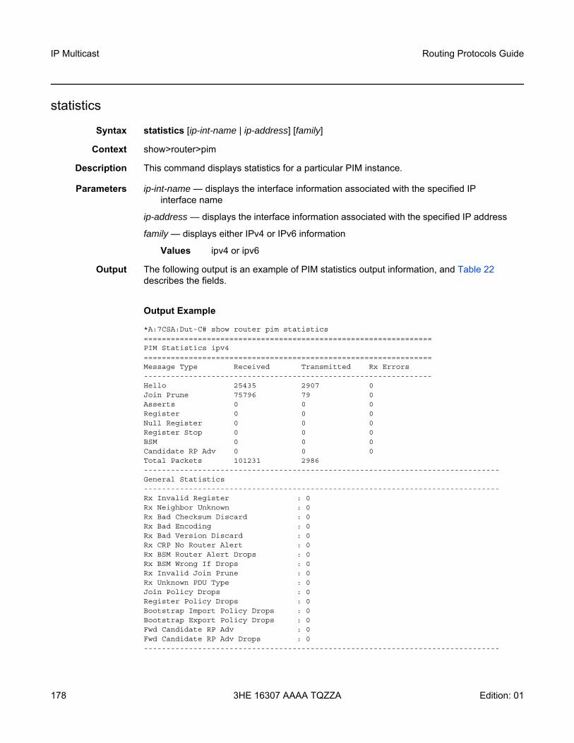
IP Multicast
178
Routing Protocols Guide
3HE 16307 AAAA TQZZA Edition: 01
statistics
Syntax statistics [ip-int-name | ip-address] [family]
Context show>router>pim
Description This command displays statistics for a particular PIM instance.
Parameters ip-int-name — displays the interface information associated with the specified IP interface name
ip-address — displays the interface information associated with the specified IP address
family — displays either IPv4 or IPv6 information
Values ipv4 or ipv6
Output The following output is an example of PIM statistics output information, and Table 22 describes the fields.
Output Example
*A:7CSA:Dut-C# show router pim statistics================================================================PIM Statistics ipv4================================================================Message Type Received Transmitted Rx Errors----------------------------------------------------------------Hello 25435 2907 0Join Prune 75796 79 0Asserts 0 0 0Register 0 0 0Null Register 0 0 0Register Stop 0 0 0BSM 0 0 0Candidate RP Adv 0 0 0Total Packets 101231 2986-------------------------------------------------------------------------------General Statistics-------------------------------------------------------------------------------Rx Invalid Register : 0Rx Neighbor Unknown : 0Rx Bad Checksum Discard : 0Rx Bad Encoding : 0Rx Bad Version Discard : 0Rx CRP No Router Alert : 0Rx BSM Router Alert Drops : 0Rx BSM Wrong If Drops : 0Rx Invalid Join Prune : 0Rx Unknown PDU Type : 0Join Policy Drops : 0Register Policy Drops : 0Bootstrap Import Policy Drops : 0Bootstrap Export Policy Drops : 0Fwd Candidate RP Adv : 0Fwd Candidate RP Adv Drops : 0-------------------------------------------------------------------------------

Routing Protocols Guide IP Multicast
Edition: 01 3HE 16307 AAAA TQZZA 179
Source Group Statistics-------------------------------------------------------------------------------(S,G) : 64(*,G) : 0(*,*,RP) : 0================================================================
Table 22 PIM Statistics Field Descriptions
Label Description
PIM Statistics
Message Type Hello — the number of PIM Hello messages received or transmitted on this interfaceJoin Prune — the number of PIM Join Prune messages received or transmitted on this interfaceAsserts — the number of PIM Assert messages received or transmitted on this interfaceRegister — the number of Register messages received or transmitted on this interfaceNull Register — the number of PIM Null Register messages received or transmitted on this interfaceRegister Stop — the number of PIM Register Stop messages received or transmitted on this interfaceBSM — the number of PIM Bootstrap messages (BSM) received or transmitted on this interfaceCandidate RP Adv — the number of candidate RP advertisementsTotal Packets — the total number of packets transmitted and received on this interface
Received The number of messages received on this interface
Transmitted The number of multicast data packets transmitted on this interface
Rx Errors The total number of receive errors
General Statistics
Rx Invalid Register The number of invalid PIM Register messages received on this interface
Rx Neighbor Unknown
The number of PIM messages (other than Hello messages) that were received on this interface and were rejected because the adjacency with the neighbor router was not already established
Rx Bad Checksum Discard
The number of PIM messages received on this interface that were discarded because of a bad checksum

IP Multicast
180
Routing Protocols Guide
3HE 16307 AAAA TQZZA Edition: 01
Rx Bad Encoding The number of PIM messages with bad encodings received on this interface
Rx Bad Version Discard
The number of PIM messages with bad versions received on this interface
Rx CRP No Router Alert
The number of candidate-rp advertisements (C-RP-Adv) received on this interface that had no router alert option set
Rx BSM Router Alert Drops
The number of router alert bootstrap message alerts that have been dropped on this interface
Rx BSM Wrong If Drops
The number of bootstrap messages not meant to be received on this interface
Rx Invalid Join Prune The number of invalid PIM Join Prune messages received on this interface
Rx Unknown PDU Type
The number of packets received with an unsupported PIM type
Join Policy Drops The number of times the join policy match resulted in dropping a PIM Join Prune message or one of the source groups contained in the message
Register Policy Drops The number of times the register policy match resulted in dropping a PIM Register message
Bootstrap Import Policy Drops
The number of Bootstrap messages received on this interface that were dropped because of Bootstrap import policy
Bootstrap Export Policy Drops
The number of Bootstrap messages that were not transmitted on this interface because of Bootstrap export policy
Fwd Candidate RP Adv
The number of candidate RP advertisements that were forwarded by the router
Fwd Candidate RP Adv Drops
The number of candidate RP advertisements that were dropped by the router
Source Group Statistics
(S,G) The number of entries in which the type is (S,G)
(*,G) The number of entries in which the type is (*,G)
(*,*,RP) The number of entries in which the type is (*, *, rp)
Table 22 PIM Statistics Field Descriptions (Continued)
Label Description

Routing Protocols Guide IP Multicast
Edition: 01 3HE 16307 AAAA TQZZA 181
status
Syntax status [detail] [family]
Context show>router>pim
Description This command displays the PIM status. The Oper Status indicates the combined operational status of IPv4/IPv6 PIM protocol status. If both are down, then Oper Status will be shown as down. If IPv4 or IPv6 is up, the Oper Status will indicate up.
If PIM is not enabled, the following message appears:
A:NYC# show router pim statusMINOR: CLI PIM is not configured.A:NYC#
Parameters family — displays either IPv4 or IPv6 information
Values ipv4 or ipv6
detail — displays detailed status information
Output The following output is an example of PIM status information, and Table 23 describes the fields.
Output Example
*A:7705:Dut-A# show router pim status detail ipv4===============================================================================PIM Status ipv4===============================================================================Admin State : UpOper State : Up
IPv4 Admin State : UpIPv4 Oper State : Up
BSR State : Accept Any
Elected BSRAddress : NoneExpiry Time : N/APriority : N/AHash Mask Length : 30Up Time : N/ARPF Intf towards E-BSR : N/A
Policy : None
RPF Table : rtable-u
Non-DR-Attract-Traffic : Disabled===============================================================================

IP Multicast
182
Routing Protocols Guide
3HE 16307 AAAA TQZZA Edition: 01
*A:7705:Dut-A# show router pim status detail ipv6===============================================================================PIM Status ipv6===============================================================================Admin State : UpOper State : Up
IPv6 Admin State : DownIPv6 Oper State : Down
BSR State : Accept Any
Elected BSRAddress : NoneExpiry Time : N/APriority : N/AHash Mask Length : 126Up Time : N/ARPF Intf towards E-BSR : N/A
Policy : None
RPF Table : rtable6-u
Non-DR-Attract-Traffic : Disabled===============================================================================
Table 23 PIM Status Field Descriptions
Label Description
Admin State The administrative status of PIM
Oper State The current operating state of this PIM protocol instance
IPv4 Admin StateIPv6 Admin State
The administrative status of PIM
IPv4 Oper StateIPv6 Oper State
The current operating state of this PIM protocol instance
BSR State The state of the router with respect to the Bootstrap mechanism

Routing Protocols Guide IP Multicast
Edition: 01 3HE 16307 AAAA TQZZA 183
msdp
Syntax msdp
Context show>router
Description This command enables the context to display MSDP information.
group
Syntax group [group-name] [detail]
Context show>router>msdp
Description This command displays information about MSDP groups.
Parameters group-name — displays information about the specified group. If no group-name is specified, information about all groups is displayed.
detail — displays detailed MSDP group information
Output The following output is an example of MSDP group information, and Table 24 describes the fields.
Elected BSR Address — the address of the elected Bootstrap router Expiry Time — the time remaining before the router sends the next Bootstrap message Priority — the priority of the elected Bootstrap router. The higher the value, the higher the priority.Hash Mask Length — the hash mask length of the Bootstrap router Up Time — the time since the current E-BSR became the Bootstrap router RPF Intf towards E-BSR — the RPF interface towards the elected BSR. The value is zero if there is no elected BSR in the network.
Policy The PIM policies for a particular PIM instance
RPF Table The route table used for the RPF check
Non-DR-Attract-Traffic
Indicates whether the router ignores the designated router state and attracts traffic even when it is not the designated router
Table 23 PIM Status Field Descriptions (Continued)
Label Description

IP Multicast
184
Routing Protocols Guide
3HE 16307 AAAA TQZZA Edition: 01
Output Example
*A:ALA-48>show>router>msdp# group===============================================================================MSDP Groups===============================================================================Group Name Mode Act Srcs Local Address-------------------------------------------------------------------------------main Mesh-group None Noneloop1 Mesh-group None Noneloop2 Mesh-group None Noneloop3 Mesh-group None Noneloop4 Mesh-group None Noneloop5 Mesh-group None None-------------------------------------------------------------------------------Groups : 6=======================*A:ALA-48>show>router>msdp#
*A:ALA-48>show>router>msdp# group test===============================================================================MSDP Groups===============================================================================Group Name Mode Act Srcs Local Address-------------------------------------------------------------------------------test Mesh-group 50000 10.10.10.103-------------------------------------------------------------------------------Groups : 1===============================================================================*A:ALA-48>show>router>msdp#
*A:ALA-48>show>router>msdp# group test detail===============================================================================MSDP Groups===============================================================================Group Name : test-------------------------------------------------------------------------------Local Address : 10.10.10.103Admin State : Up Receive Msg Rate : NoneReceive Msg Time : None Receive Msg Thd : NoneMode : Mesh-group SA Limit : 50000Export Policy : None Specified / InheritedImport Policy : None Specified / Inherited
-------------------------------------------------------------------------------Groups : 1===============================================================================*A:ALA-48>show>router>msdp#

Routing Protocols Guide IP Multicast
Edition: 01 3HE 16307 AAAA TQZZA 185
peer
Syntax peer [ip-address] [group group-name] [detail]
Context show>router>msdp
Description This command displays information about an MSDP peer.
Parameters ip-address — displays information about the peer with the specified IP address. If no IP address is specified, information about all MSDP peers is displayed.
group-name — displays information about peers in the specified group. If no group-name is specified, information about all MSDP peers display is displayed.
detail — displays detailed MSDP peer information
Output The following output is an example of MSDP peer information, and Table 25 describes the fields.
Table 24 MSDP Group Field Descriptions
Label Description
Group Name Displays the MSDP group name
Mode Displays the mode of peers in the group, either Mesh-group or Standard
Act Srcs Displays the configured maximum number of SA messages that will be accepted by MSDP
Local Address Displays the local end of an MSDP session
Admin State Displays the administrative state
Receive Msg Rate Displays the rate that the messages are read from the TCP session
Receive Msg Time Displays the time interval in which the number of MSDP messages set by the receive-msdp-msg-rate number parameter are read from the TCP session
Receive Msg Thd Displays the configured threshold for the number of MSDP messages that can be processed before the MSDP message rate-limiting function is activated
SA Limit Displays the SA message limit
Export Policy Displays whether an export policy is configured or inherited
Import Policy Displays whether an import policy is configured or inherited

IP Multicast
186
Routing Protocols Guide
3HE 16307 AAAA TQZZA Edition: 01
Output Example
A:ALA-48# show router msdp peer=============================================================================MSDP Peers=============================================================================Peer Local Address State Last State Change SA Learnt-----------------------------------------------------------------------------10.20.1.1 10.20.1.6 Established 08/30/2002 03:22:13 1008-----------------------------------------------------------------------------Peers : 1=============================================================================A:ALA-48#
A:ALA-48# show router msdp peer detail===============================================================================MSDP Peers-------------------------------------------------------------------------------Peer Address : 10.20.1.1-------------------------------------------------------------------------------Group Name : NoneLocal Address : 10.20.1.6Last State Change : 08/30/2002 03:22:13 Last Act Src Limit : N/APeer Admin State : Up Default Peer : NoPeer Connect Retry : 0 State : EstablishedSA accepted : 1008 SA received : 709State timer expires: 18 Peer time out : 62Active Source Limit: None Receive Msg Rate : 0Receive Msg Time : 0 Receive Msg Thd : 0Auth Status : Disabled Auth Key : NoneExport Policy : None Specified / InheritedImport Policy : None Specified / Inherited-------------------------------------------------------------------------------Peers : 1===============================================================================A:ALA-48#
Table 25 MSDP Peer Field Descriptions
Label Description
Peer Displays the IP address of the peer
Local Address Displays the local IP address
State Displays the current state of the peer
Last State Change Displays the date and time of the peer’s last state change
SA Learnt Displays the number of SAs learned through a peer

Routing Protocols Guide IP Multicast
Edition: 01 3HE 16307 AAAA TQZZA 187
source
Syntax source [ip-address/mask] [type {configured | dynamic | both}] [detail]
Context show>router>msdp
Description This command displays the discovery method for the specified multicast source. By default, all user-created sources are displayed.
Parameters ip-address/mask — specifies the IP address and mask for a multicast source
Values ip-address is in the format a.b.c.dmask range is from 1 to 32
configured — displays user-created sources
dynamic — displays dynamically created sources
both — displays both user-configured and dynamically created sources
detail — displays detailed MSDP source information
Output The following output is an example of MSDP source information and Table 26 describes the fields.
Output Example
*A:7705:Dut-C# show router msdp source===============================================================================MSDP Sources===============================================================================Source Type SA Limit Num Excd Last Exceeded-------------------------------------------------------------------------------10.3.3.3/32 Configured None 0 N/A-------------------------------------------------------------------------------Sources : 1===============================================================================*A:7705:Dut-C#
Table 26 MSDP Source Field Descriptions
Label Description
Source Displays the IP address of the MSDP peer
Type Displays the type of peer
SA Limit Displays the local IP address
Num Excd Displays the number of times the global active source limit has been exceeded
Last Exceeded Displays the date and time of the last state change of the peer

IP Multicast
188
Routing Protocols Guide
3HE 16307 AAAA TQZZA Edition: 01
source-active
Syntax source-active [{group ip-address | local | originator ip-address | peer ip-address | source ip-address | group ip-address source ip-address}] [detail]
Context show>router>msdp
Description This command displays source-active (SA) messages accepted by MSDP.
Parameters group ip-address — displays information about the specified group IP address
local — displays information about local SA messages
originator ip-address — displays information about the specified originator IP address
peer ip-address — displays information about the specified peer IP address
source ip-address — displays information about the specified source IP address
detail — displays detailed MSDP SA information
Output The following output is an example of accepted MSDP SA messages information, and Table 27 describes the fields.
Output Example
A:ALA-48# show router msdp source-active===============================================================================MSDP Source Active Info===============================================================================Grp Address Src Address Origin RP Peer Address State Timer-------------------------------------------------------------------------------239.255.0.0 239.255.1.2 10.20.1.1 10.20.1.1 69239.255.0.1 239.255.1.2 10.20.1.1 10.20.1.1 69239.255.0.2 239.255.1.2 10.20.1.1 10.20.1.1 69239.255.0.3 239.255.1.2 10.20.1.1 10.20.1.1 69239.255.0.4 239.255.1.2 10.20.1.1 10.20.1.1 69239.255.0.5 239.255.1.2 10.20.1.1 10.20.1.1 69239.255.0.6 239.255.1.2 10.20.1.1 10.20.1.1 69239.255.0.7 239.255.1.2 10.20.1.1 10.20.1.1 69239.255.0.8 239.255.1.2 10.20.1.1 10.20.1.1 69239.255.0.9 239.255.1.2 10.20.1.1 10.20.1.1 69-------------------------------------------------------------------------------MSDP Source Active : 10===============================================================================A:ALA-48#
A:ALA-48# show router msdp source-active detail===============================================================================MSDP Source Active===============================================================================Group Address : 239.255.0.0 Source Address : 10.112.1.2Origin RP : 10.20.1.1 Peer Address : 10.20.1.1State Timer : 64 Up Time : 3d 01:44:25Group Address : 239.255.0.1 Source Address : 10.112.1.2Origin RP : 10.20.1.1 Peer Address : 10.20.1.1State Timer : 64 Up Time : 48d 18:22:29

Routing Protocols Guide IP Multicast
Edition: 01 3HE 16307 AAAA TQZZA 189
Group Address : 239.255.0.2 Source Address : 10.112.1.2Origin RP : 10.20.1.1 Peer Address : 10.20.1.1State Timer : 64 Up Time : 48d 18:22:29Group Address : 239.255.0.3 Source Address : 10.112.1.2Origin RP : 10.20.1.1 Peer Address : 10.20.1.1State Timer : 64 Up Time : 48d 18:22:29Group Address : 239.255.0.4 Source Address : 10.112.1.2Origin RP : 10.20.1.1 Peer Address : 10.20.1.1State Timer : 64 Up Time : 48d 18:22:29Group Address : 239.255.0.5 Source Address : 10.112.1.2Origin RP : 10.20.1.1 Peer Address : 10.20.1.1State Timer : 64 Up Time : 48d 18:22:29Group Address : 239.255.0.6 Source Address : 10.112.1.2Origin RP : 10.20.1.1 Peer Address : 10.20.1.1State Timer : 64 Up Time : 48d 18:22:29Group Address : 239.255.0.7 Source Address : 10.112.1.2Origin RP : 10.20.1.1 Peer Address : 10.20.1.1State Timer : 64 Up Time : 48d 18:22:29Group Address : 239.255.0.8 Source Address : 10.112.1.2Origin RP : 10.20.1.1 Peer Address : 10.20.1.1State Timer : 64 Up Time : 48d 18:22:29Group Address : 239.255.0.9 Source Address : 10.112.1.2Origin RP : 10.20.1.1 Peer Address : 10.20.1.1State Timer : 64 Up Time : 48d 18:22:29-------------------------------------------------------------------------------MSDP Source Active : 10===============================================================================A:ALA-48#
source-active-rejected
Syntax source-active-rejected [peer-group name] [group ip-address] [source ip-address] [originator ip-address] [peer ip-address]
Context show>router>msdp
Description This command displays SA messages rejected by MSDP.
Parameters name — displays information about rejected SA messages for the specified peer group
Table 27 MSDP SA Field Descriptions
Label Description
Grp Address Displays the IP address of the group
Src Address Displays the IP address of the source
Origin RP Displays the originating rendezvous point (RP) address
Peer Address Displays the IP address of the peer
State Timer Displays the state timeout value. If the value reaches 0, the SA entry is removed.

IP Multicast
190
Routing Protocols Guide
3HE 16307 AAAA TQZZA Edition: 01
group ip-address — displays information about the specified group IP address
source ip-address — displays information about the source address of the source-active entry that is rejected
originator ip-address — displays information about the specified originator IP address
peer ip-address — displays information about the peer from which this rejected source-active entry was last received
Output The following output is an example of rejected MSDP SA messages information, and Table 28 describes the fields.
Output Example
*A:ALA-48# show router msdp source-active-rejected===============================================================================MSDP Source Active Rejected Info===============================================================================Grp Address Src Address Origin RP Peer Address Reject Reason-------------------------------------------------------------------------------239.255.0.1 10.0.0.1 10.20.0.1 10.10.0.1 Import Policy239.255.0.2 10.0.0.2 10.20.0.2 10.10.0.2 Export Policy239.255.0.3 10.0.0.3 10.20.0.3 10.10.0.3 RPF Failure239.255.0.4 10.0.0.4 10.20.0.4 10.10.0.4 Limit Exceeded239.255.0.5 10.0.0.5 10.20.0.5 10.10.0.5 Limit Exceeded239.255.0.6 10.0.0.6 10.20.0.6 10.10.0.6 Limit Exceeded239.255.0.7 10.0.0.7 10.20.0.7 10.10.0.7 Limit Exceeded-------------------------------------------------------------------------------SA Rejected Entries : 7===============================================================================*A:ALA-48#
Table 28 MSDP Source-Active Field Descriptions
Label Description
Grp Address Displays the IP address of the group
Src Address Displays the IP address of the source
Origin RP Displays the originating rendezvous point (RP) address
Peer Address Displays the address of the peer
Reject Reason Displays the reason why this SA entry is rejected

Routing Protocols Guide IP Multicast
Edition: 01 3HE 16307 AAAA TQZZA 191
statistics
Syntax statistics [peer ip-address]
Context show>router>msdp
Description This command displays statistics information related to an MSDP peer.
Parameters ip-address — displays statistics for the peer with the specified IP address
Output The following output is an example of MSDP statistics information, and Table 29 describes the fields.
Output Example
A:ALA-48# show router msdp statistics===============================================================================MSDP Statistics===============================================================================Glo ActSrc Lim Excd: 0-------------------------------------------------------------------------------Peer Address : 10.20.1.1-------------------------------------------------------------------------------Last State Change : 0d 11:33:16 Last message Peer : 0d 00:00:17RPF Failures : 0 Remote Closes : 0SA Msgs Sent : 0 SA Msgs Recvd : 709SA req. Msgs Sent : 0 SA req. Msgs Recvd : 0SA res. Msgs Sent : 0 SA res. Msgs Recvd : 0KeepAlive Msgs Sent: 694 KeepAlive Msgs Recd: 694Unknown Msgs Sent : 0 Error Msgs Recvd : 0-------------------------------------------------------------------------------Peers : 1===============================================================================A:ALA-48#
Table 29 MSDP Statistics Field Descriptions
Label Description
Glo ActSrc Lim Excd Displays the number of global active source messages that exceed the configured limit
Peer Address Displays the address of the MSDP peer
Last State Change Displays the date and time the peer state changed
Last message Peer Displays the time the last message was received from the peer
RPF Failures Displays the number of reverse path forwarding (RPF) failures
Remote Closes Displays the number of times the remote peer closed
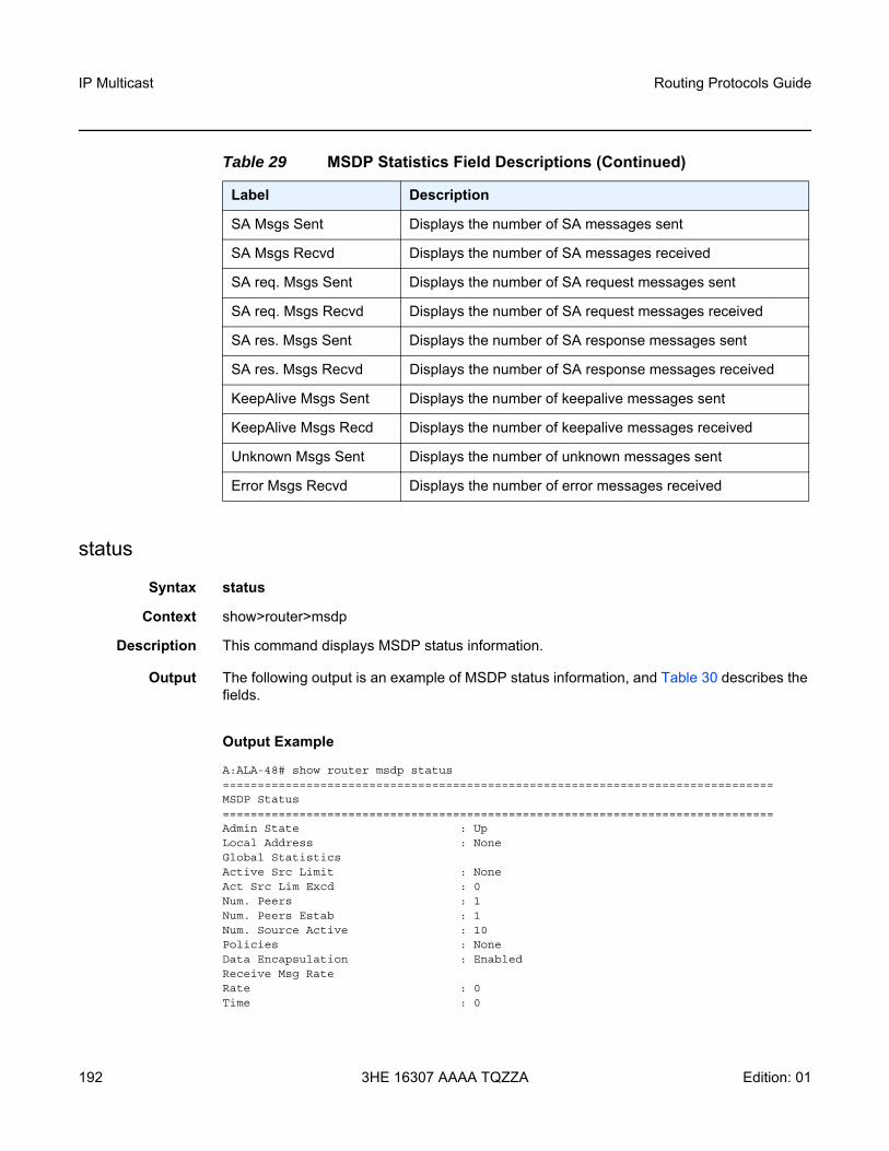
IP Multicast
192
Routing Protocols Guide
3HE 16307 AAAA TQZZA Edition: 01
status
Syntax status
Context show>router>msdp
Description This command displays MSDP status information.
Output The following output is an example of MSDP status information, and Table 30 describes the fields.
Output Example
A:ALA-48# show router msdp status===============================================================================MSDP Status===============================================================================Admin State : UpLocal Address : NoneGlobal StatisticsActive Src Limit : NoneAct Src Lim Excd : 0Num. Peers : 1Num. Peers Estab : 1Num. Source Active : 10Policies : NoneData Encapsulation : EnabledReceive Msg RateRate : 0Time : 0
SA Msgs Sent Displays the number of SA messages sent
SA Msgs Recvd Displays the number of SA messages received
SA req. Msgs Sent Displays the number of SA request messages sent
SA req. Msgs Recvd Displays the number of SA request messages received
SA res. Msgs Sent Displays the number of SA response messages sent
SA res. Msgs Recvd Displays the number of SA response messages received
KeepAlive Msgs Sent Displays the number of keepalive messages sent
KeepAlive Msgs Recd Displays the number of keepalive messages received
Unknown Msgs Sent Displays the number of unknown messages sent
Error Msgs Recvd Displays the number of error messages received
Table 29 MSDP Statistics Field Descriptions (Continued)
Label Description

Routing Protocols Guide IP Multicast
Edition: 01 3HE 16307 AAAA TQZZA 193
Threshold : 0Last Msdp Enabled : 08/30/2002 03:21:43===============================================================================A:ALA-48#
Table 30 MSDP Status Field Descriptions
Label Description
Admin State Displays the administrative state
Local Address Displays the local IP address
Global Statistics Displays global MSDP statistics
Active Src Limit Displays the active source limit
Act Src Lim Excd Displays the number of times that the active source limit was exceeded
Num. Peers Displays the number of peers
Num. Peers Estab Displays the number of peers established
Num. Source Active Displays the number of active sources
Policies Specifies the policy used to export the SA state from the SA list into MSDP
Data Encapsulation Specifies whether the rendezvous point (RP) encapsulates multicast data received in MSDP register messages inside forwarded MSDP SA messages
Rate The receive message rate
Time The receive message interval
Threshold The number of MSDP messages that can be processed before the MSDP message rate-limiting function is activated
Last Msdp Enabled The time the last MSDP was triggered
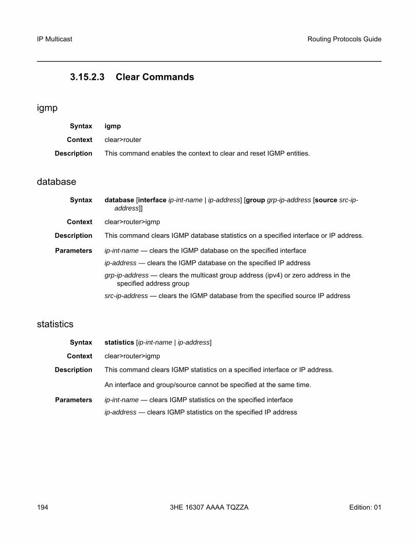
IP Multicast
194
Routing Protocols Guide
3HE 16307 AAAA TQZZA Edition: 01
3.15.2.3 Clear Commands
igmp
Syntax igmp
Context clear>router
Description This command enables the context to clear and reset IGMP entities.
database
Syntax database [interface ip-int-name | ip-address] [group grp-ip-address [source src-ip-address]]
Context clear>router>igmp
Description This command clears IGMP database statistics on a specified interface or IP address.
Parameters ip-int-name — clears the IGMP database on the specified interface
ip-address — clears the IGMP database on the specified IP address
grp-ip-address — clears the multicast group address (ipv4) or zero address in the specified address group
src-ip-address — clears the IGMP database from the specified source IP address
statistics
Syntax statistics [ip-int-name | ip-address]
Context clear>router>igmp
Description This command clears IGMP statistics on a specified interface or IP address.
An interface and group/source cannot be specified at the same time.
Parameters ip-int-name — clears IGMP statistics on the specified interface
ip-address — clears IGMP statistics on the specified IP address

Routing Protocols Guide IP Multicast
Edition: 01 3HE 16307 AAAA TQZZA 195
version
Syntax version [ip-int-name | ip-address]
Context clear>router>igmp
Description This command clears IGMP version parameters.
Parameters ip-int-name — clears version information for the specified IGMP interface name
ip-address — clears version information for the specified IGMP IP address
mld
Syntax mld
Context clear>router
Description This command enables the context to clear and reset MLD entities.
database
Syntax database [interface ip-int-name | ipv6-address] [group grp-ipv6-address [source src-ipv6-address]]
Context clear>router>mld
Description This command clears MLD database parameters.
Parameters ip-int-name — clears database information for the specified MLD interface name
ipv6-address — clears database information for the specified MLD interface IPv6 address
grp-ipv6-address — clears database information for the specified MLD group IPv6 address
src-ipv6-address — clears database information for the specified MLD source IP address
statistics
Syntax statistics [ip-int-name | ipv6-address]
Context clear>router>mld
Description This command clears MLD statistics parameters.
Parameters ip-int-name — clears statistics for the specified MLD interface name
ipv6-address — clears statistics for the specified MLD IPv6 address

IP Multicast
196
Routing Protocols Guide
3HE 16307 AAAA TQZZA Edition: 01
version
Syntax version [ip-int-name | ip-address]
Context clear>router>mld
Description This command clears MLD version parameters.
Parameters ip-int-name — clears version information for the specified MLD interface name
ip-address — clears version information for the specified MLD IP address
pim
Syntax pim
Context clear>router
Description This command enables the context to clear and reset PIM entities.
database
Syntax database [interface ip-int-name | ip-address] [group grp-ip-address [source src-ip-address]] [family]
Context clear>router>pim
Description This command clears PIM database statistics on a specified interface or IP address.
Parameters ip-int-name — clears the PIM database on the specified interface
ip-address — clears the PIM database on the specified IP address
grp-ip-address — clears the multicast group address (ipv4/ipv6) or zero address in the specified address group
src-ip-address — clears the PIM database from the specified source IP address
family — clears either IPv4 or IPv6 information
Values ipv4 or ipv6

Routing Protocols Guide IP Multicast
Edition: 01 3HE 16307 AAAA TQZZA 197
neighbor
Syntax neighbor [ip-int-name] [family]
Context clear>router>pim
Description This command clears PIM neighbor data on a specified interface or IP address.
Parameters ip-int-name — clears PIM neighbor data on the specified interface
family — clears either IPv4 or IPv6 information. If family is not specified, both IPv4 and IPv6 data are cleared.
Values ipv4 or ipv6
statistics
Syntax statistics [family] statistics interface ip-int-name | ip-address [family] statistics group grp-ip-address [source ip-address] [family]
Context clear>router>pim
Description This command clears PIM statistics.
Parameters ip-int-name — clears PIM statistics on the specified interface
interface ip-address — clears PIM statistics on the specified IP address
grp-ip-address — specifies a multicast group address (IPv4 or IPv6 or zero address). When the group address is specified along with the source address, then the (S,G) statistics are reset to zero.
source ip-address — specifies a source or RP address (IPv4 or IPv6). When the source address is specified along with the group address, then the (S,G) statistics are reset to zero.
family — clears either IPv4 or IPv6 information. If family is not specified, both IPv4 and IPv6 data are cleared.
Values ipv4 or ipv6
msdp
Syntax msdp
Context clear>router
Description This command enables the context to clear and reset Multicast Source Discovery Protocol (MSDP) entities and statistics.

IP Multicast
198
Routing Protocols Guide
3HE 16307 AAAA TQZZA Edition: 01
cache
Syntax cache [peer ip-address] [group ip-address] [source ip-address] [originrp ip-address]
Context clear>router>msdp
Description This command clears IP addresses from the MSDP cache.
Parameters peer ip-address — clears the specified peer address
group ip-address — clears the specified group address
source ip-address — clears the specified source address
originrp ip-address — clears the specified originating rendezvous point (RP) address
statistics
Syntax statistics [peer ip-address]
Context clear>router>msdp
Description This command clears IP address statistics for the peer to which MSDP SA requests for groups matching this entry's group range were sent.
Parameters ip-address — clears the MSDP statistics for the specified IP address

Routing Protocols Guide IP Multicast
Edition: 01 3HE 16307 AAAA TQZZA 199
3.15.2.4 Debug Commands
• Debug IGMP Commands• Debug MLD Commands• Debug PIM Commands• Debug Mtrace Commands

IP Multicast
200
Routing Protocols Guide
3HE 16307 AAAA TQZZA Edition: 01
3.15.2.4.1 Debug IGMP Commands
igmp
Syntax igmp
Context debug>router
Description This command enables access to the IGMP debug commands.
interface
Syntax [no] interface [ip-int-name | ip-address]
Context debug>router>igmp
Description This command enables debugging for IGMP interfaces.
The no form of the command disables the IGMP interface debugging for the specified interface name or IP address.
Parameters ip-int-name — displays the information associated with the specified IP interface name
ip-address — displays the information associated with the specified IP address
misc
Syntax [no] misc
Context debug>router>igmp
Description This command enables debugging for IGMP miscellaneous information.
The no form of the command disables the debugging.
packet
Syntax [no] packet [query | v1-report | v2-report | v3-report | v2-leave] [ip-int-name | ip-address]
Context debug>router>igmp
Description This command enables debugging for IGMP packets.
The no form of the command disables the debugging.
Routing Protocols Guide IP Multicast
Edition: 01 3HE 16307 AAAA TQZZA 201
Parameters query — specifies to log the IGMP group- and source-specific queries transmitted and received on this interface
v1-report — specifies to log IGMPv1 reports transmitted and received on this interface
v2-report — specifies to log IGMPv2 reports transmitted and received on this interface
v3-report — specifies to log IGMPv3 reports transmitted and received on this interface
v2-leave — specifies to log the IGMP Leaves transmitted and received on this interface
ip-int-name — displays the information associated with the specified IP interface name
ip-address — displays the information associated with the specified IP address

IP Multicast
202
Routing Protocols Guide
3HE 16307 AAAA TQZZA Edition: 01
3.15.2.4.2 Debug MLD Commands
mld
Syntax mld
Context debug>router
Description This command enables access to the MLD debug commands.
interface
Syntax [no] interface [ip-int-name | ipv6-address]
Context debug>router>mld
Description This command enables debugging for MLD interfaces.
The no form of the command disables the MLD interface debugging for the specified interface name or IP address.
Parameters ip-int-name — displays the information associated with the specified IP interface name
ipv6-address — displays the information associated with the specified IP address
misc
Syntax [no] misc
Context debug>router>mld
Description This command enables debugging for MLD miscellaneous information.
The no form of the command disables the debugging.
packet
Syntax [no] packet [query | v1-report | v2-report | v1-done] [ip-int-name | ipv6-address]
Context debug>router>mld
Description This command enables debugging for MLD packets.
The no form of the command disables the debugging.

Routing Protocols Guide IP Multicast
Edition: 01 3HE 16307 AAAA TQZZA 203
Parameters query — specifies to log the MLD group- and source-specific queries transmitted and received on this interface
v1-report — specifies to log MLDv1 reports transmitted and received on this interface
v2-report — specifies to log MLDv2 reports transmitted and received on this interface
v1-done — specifies to log the MLDv1 Done transmitted and received on this interface
ip-int-name — displays the information associated with the specified IP interface name
ipv6-address — displays the information associated with the specified IPv6 address
Values ipv6-address: x:x:x:x:x:x:x:x (eight 16-bit pieces) x:x:x:x:x:x:d.d.d.d
x: [0..FFFF]Hd: [0..255]D

IP Multicast
204
Routing Protocols Guide
3HE 16307 AAAA TQZZA Edition: 01
3.15.2.4.3 Debug PIM Commands
pim
Syntax pim
Context debug>router
Description This command enables access to the PIM debug commands.
adjacency
Syntax [no] adjacency
Context debug>router>pim
Description This command enables debugging for PIM adjacencies.
The no form of the command disables debugging.
all
Syntax all [group grp-ip-address] [source ip-address] [detail] no all
Context debug>router>pim
Description This command enables debugging for all the PIM groups.
The no form of the command disables debugging.
Parameters grp-ip-address — debugs information associated with all PIM groups for the specified multicast group address
Values IPv4 or IPv6 address
ip-address — debugs information associated with all PIM groups for the specified source address
Values IPv4 or IPv6 address
detail — debugs detailed information on all PIM groups

Routing Protocols Guide IP Multicast
Edition: 01 3HE 16307 AAAA TQZZA 205
assert
Syntax assert [group grp-ip-address] [source ip-address] [detail]no assert
Context debug>router>pim
Description This command enables debugging for the PIM assert mechanism.
The no form of the command disables debugging.
Parameters grp-ip-address — debugs information associated with the PIM assert mechanism for the specified multicast group address
Values IPv4 or IPv6 address
ip-address — debugs information associated with the PIM assert mechanism for the specified source address
Values IPv4 or IPv6 address
detail — debugs detailed information on the PIM assert mechanism
auto-rp
Syntax auto-rp [detail]no auto-rp
Context debug>router>pim
Description This command enables debugging for PIM auto-RP.
The no form of the command disables debugging.
Parameters detail — debugs detailed information on the PIM auto-RP mechanism
bgp
Syntax bgp [source src-ip-address] [group grp-ip-address] [peer peer-ip-address] no bgp
Context debug>router>pim
Description This command enables debugging for the PIM BGP mechanism.
The no form of the command disables debugging.
Parameters grp-ip-address — debugs PIM BGP information associated with the specified group IP address
Values IPv4 or IPv6 address

IP Multicast
206
Routing Protocols Guide
3HE 16307 AAAA TQZZA Edition: 01
peer-ip-address — debugs PIM BGP information associated with the specified peer IP address
Values IPv4 or IPv6 address
src-ip-address — debugs PIM BGP information associated with the specified source IP address
Values IPv4 or IPv6 address
detail — debugs detailed PIM BGP information
bsr
Syntax bsr [detail] no bsr
Context debug>router>pim
Description This command enables debugging for the PIM Bootstrap mechanism.
The no form of the command disables debugging.
Parameters detail — debugs detailed information on the PIM Bootstrap mechanism
data
Syntax data [group grp-ip-address] [source ip-address] [detail] no data
Context debug>router>pim
Description This command enables debugging for the PIM data exception.
The no form of the command disables debugging.
Parameters grp-ip-address — debugs information associated with the PIM data exception for the specified multicast group address
Values IPv4 or IPv6 address
ip-address — debugs information associated with the PIM data exception for the specified source address
Values IPv4 or IPv6 address
detail — debugs detailed information on the PIM data exception

Routing Protocols Guide IP Multicast
Edition: 01 3HE 16307 AAAA TQZZA 207
db
Syntax db [group grp-ip-address] [source ip-address] [detail] no db
Context debug>router>pim
Description This command enables debugging for the PIM database.
The no form of the command disables debugging.
Parameters grp-ip-address — debugs information associated with the PIM database for the specified multicast group address
Values IPv4 or IPv6 address or zero address
ip-address — debugs information associated with the PIM database for the specified source address
Values IPv4 or IPv6 address
detail — debugs detailed information on the PIM database
interface
Syntax interface [ip-int-name | int-ip-address] [detail] no interface
Context debug>router>pim
Description This command enables debugging for the PIM interface.
The no form of the command disables debugging.
Parameters ip-int-name — debugs information associated with the specified IP interface name
Values IPv4 or IPv6 address
int-ip-address — debugs information associated with the specified IP address
Values IPv4 or IPv6 address
detail — debugs detailed information on the IP interface
jp
Syntax jp [group grp-ip-address] [source ip-address] [detail] no jp
Context debug>router>pim
Description This command enables debugging for the PIM Join-Prune mechanism.

IP Multicast
208
Routing Protocols Guide
3HE 16307 AAAA TQZZA Edition: 01
The no form of the command disables debugging.
Parameters grp-ip-address — debugs information associated with the specified PIM Join-Prune mechanism
Values IPv4 or IPv6 address or zero address
ip-address — debugs information associated with the specified PIM Join-Prune mechanism
Values IPv4 or IPv6 address
detail — debugs detailed information on the PIM Join-Prune mechanism
mrib
Syntax mrib [group grp-ip-address] [source ip-address] [detail] no mrib
Context debug>router>pim
Description This command enables debugging for the PIM MRIB.
The no form of the command disables debugging.
Parameters grp-ip-address — debugs information associated with the specified PIM MRIB
Values IPv4 or IPv6 address
ip-address — debugs information associated with the specified PIM MRIB
Values IPv4 or IPv6 address
detail — debugs detailed information on PIM MRIBs
msg
Syntax msg [detail] no msg
Context debug>router>pim
Description This command enables debugging for PIM messaging.
The no form of the command disables debugging.
Parameters detail — debugs detailed information on PIM messaging

Routing Protocols Guide IP Multicast
Edition: 01 3HE 16307 AAAA TQZZA 209
packet
Syntax packet [hello | register | register-stop | jp | bsr | assert | crp] [ip-int-name | int-ip-address]no packet
Context debug>router>pim
Description This command enables debugging for PIM packets.
The no form of the command disables debugging.
Parameters ip-int-name — debugs information associated with the specified IP interface name
Values IPv4 or IPv6 interface name
int-ip-address — debugs information associated with the specified IP address of a particular packet type
red
Syntax [no] red [detail]
Context debug>router>pim
Description This command enables debugging for the PIM redundancy mechanism.
The no form of the command disables debugging.
Parameters detail — debugs detailed information on the PIM redundancy mechanism
register
Syntax register [group grp-ip-address] [source ip-address] [detail] no register
Context debug>router>pim
Description This command enables debugging for the PIM register mechanism.
The no form of the command disables debugging.
Parameters grp-ip-address — debugs information associated with the specified PIM register
Values IPv4 or IPv6 address
ip-address — debugs information associated with the specified PIM register
Values IPv4 or IPv6 address
detail — debugs detailed information on the PIM register mechanism

IP Multicast
210
Routing Protocols Guide
3HE 16307 AAAA TQZZA Edition: 01
rtm
Syntax rtm [detail] no rtm
Context debug>router>pim
Description This command enables debugging for the PIM RTM.
The no form of the command disables debugging.
Parameters detail — debugs detailed information on the PIM RTM

Routing Protocols Guide IP Multicast
Edition: 01 3HE 16307 AAAA TQZZA 211
3.15.2.4.4 Debug MSDP Commands
msdp
Syntax [no] msdp
Context debug>router
Description This command enables debugging for Multicast Source Discovery Protocol (MSDP).
The no form of the command disables MSDP debugging.
packet
Syntax packet [pkt-type] [peer ip-address]
Context debug>router>msdp
Description This command enables debugging for MSDP packets.
The no form of the command disables MSDP packet debugging.
Parameters pkt-type — debugs information associated with the specified packet type
Values keep-alive, source-active, sa-request, sa-response
ip-address — debugs information associated with the specified peer IP address
pim
Syntax pim [grp-address] no pim
Context debug>router>msdp
Description This command enables debugging for MSDP PIM.
The no form of the command disables MSDP PIM debugging.
Parameters grp-address — debugs the IP multicast group address for which this entry contains information

IP Multicast
212
Routing Protocols Guide
3HE 16307 AAAA TQZZA Edition: 01
rtm
Syntax rtm [rp-address] no rtm
Context debug>router>msdp
Description This command enables debugging for MSDP route table manager (RTM).
The no form of the command disables MSDP RTM debugging.
Parameters rp-address — debugs the IP multicast address for which this entry contains information
sa-db
Syntax sa-db [group grpAddr] [source srcAddr] [rp rpAddr] no sadb
Context debug>router>msdp
Description This command enables debugging for MSDP source-active (SA) requests.
The no form of the command disables the MSDP SA database debugging.
Parameters grpAddr — debugs the IP address of the group
srcAddr — debugs the source IP address
rpAddr — debugs the specified rendezvous point RP address

Routing Protocols Guide IP Multicast
Edition: 01 3HE 16307 AAAA TQZZA 213
3.15.2.4.5 Debug Mtrace Commands
mtrace
Syntax [no] mtrace
Context debug>router
Description This command enables access to the mtrace debug commands.
The no form of the command disables the debugging.
misc
Syntax [no] misc
Context debug>router>mtrace
Description This command enables debugging for mtrace miscellaneous events.
The no form of the command disables the debugging.
packet
Syntax [no] packet [query | request | response]
Context debug>router>mtrace
Description This command enables debugging for mtrace packets.
The no form of the command disables the debugging.
Parameters query — specifies to log the mtrace queries transmitted and received
request — specifies to log the mtrace requests transmitted and received
response — specifies to log the mtrace responses transmitted and received

IP Multicast
214
Routing Protocols Guide
3HE 16307 AAAA TQZZA Edition: 01
3.15.2.5 Monitor Commands
group
Syntax group grp-ip-address [source ip-address] [interval interval] [repeat repeat] [absolute | rate]
Context monitor>router>pim
Description This command monitors statistics for a PIM source group.
Parameters grp-ip-address — specifies the IP address of a multicast group that identifies a set of recipients that are interested in a particular data stream
Values IPv4 or IPv6 address
ip-address — specifies the source IP address to use in the ping requests
Values IPv4 or IPv6 address
Default 0.0.0.0 to 255.255.255.255
interval — specifies the interval for each display, in seconds
Values 10 | 20 | 30 | 40 | 50 | 60
Default 10
repeat — specifies the number of times the command is repeated
Values 1 to 999
Default 10
absolute — displays raw statistics, without processing. No calculations are performed on the delta or rate statistics.
rate — displays the rate per second for each statistic, instead of the delta
Routing Protocols Guide OSPF
Edition: 01 3HE 16307 AAAA TQZZA 215
4 OSPFThis chapter provides information about configuring the Open Shortest Path First (OSPF) protocol.
Topics in this chapter include:
• Overview of OSPF• Bidirectional Forwarding Detection (BFD) for OSPF• Graceful Restart Helper• LFA Protection Using Segment Routing Backup Node SID• LDP and IP Fast Reroute (FRR) for OSPF Prefixes• Preconfiguration Requirements• OSPF Configuration Process Overview• Configuration Notes• Configuring OSPF with CLI• OSPF Command Reference

OSPF
216
Routing Protocols Guide
3HE 16307 AAAA TQZZA Edition: 01
4.1 Overview of OSPF
OSPF (Open Shortest Path First) is an interior gateway protocol (IGP) that is used within large autonomous systems (ASs). An autonomous system is a group of networks and network equipment under a common administration. OSPF is a link-state protocol; each router maintains an identical database (called the link-state database, topological database, or routing information database [RIB]) of the AS, including information about the local state of each router (for example, its usable interfaces and reachable neighbors).
OSPF-TE (OSPF with traffic engineering extensions) is used to advertise reachability information and traffic engineering information such as bandwidth. OSPF routers exchange status, cost, and other relevant interface information with neighboring routers. The information exchange enables all participating routers to establish their link-state database.
OSPF uses a cost metric that represents the status of the link and the bandwidth of the interface in an algorithm to determine the best route to a destination. The algorithm used is called the SPF (shortest path first) or Dijkstra algorithm. Path selection is based on lowest cost, which might not necessarily be the shortest route but is the best route in regards to bandwidth. Each router applies the algorithm to calculate the shortest path to each destination in the network.
When the best route to a particular destination is determined, the route information is sent to the routing table manager (RTM). The RTM may contain more than one best route to a destination from multiple protocols. Because metrics from different protocols are not comparable, the RTM uses preference to select the best route. The route with the lowest preference value is selected. For more information, see Configuring Route Preferences.
The best routes from the RTM are then added to the forwarding table (also known as the forwarding database [or FIB]). All forwarding decisions are based on the information in the forwarding database.
The forwarding (or dropping) of packets is controlled by filters applied to the interface and route policies applied to the OSPF protocol. Refer to the 7705 SAR Router Configuration Guide for information on filters and route policies.
The 7705 SAR implementation of OSPF conforms to OSPF Version 2 specifications presented in RFC 2328, OSPF Version 2 and OSPF Version 3 specifications presented in RFC 2740, OSPF for IPv6. Routers running OSPF can be enabled with minimal configuration. All default and command parameters can be modified.

Routing Protocols Guide OSPF
Edition: 01 3HE 16307 AAAA TQZZA 217
Changes between OSPF for IPv4 and OSPFv3 for IPv6 include the following.
• Addressing semantics have been removed from OSPF packets and the basic link-state advertisements (LSAs). New LSAs have been created to carry IPv6 addresses and prefixes.
• OSPFv3 runs on a per-link basis, instead of on a per-IP-subnet basis.• Flooding scope for LSAs has been generalized.• Unlike OSPFv2, OSPFv3 authentication relies on IPV6's authentication header
and encapsulating security payload.• Most packets in OSPF for IPv6 are almost as compact as those in OSPF for
IPv4, even with the larger IPv6 addresses.• Most field and packet-size limitations present in OSPF for IPv4 have been
relaxed.• Option handling has been made more flexible.
The following major OSPF features are supported:
• areas – backbone, stub, and not-so-stubby areas (NSSAs)• virtual links• neighbors and adjacencies• link-state advertisements (LSAs)• metrics• authentication (OSPFv2 only)• route redistribution and summarization• OSPF traffic engineering (TE) extensions (to track and advertise available
bandwidth (OSPFv2 only)– used by MPLS traffic engineering; that is, RSVP-TE)
4.1.1 OSPF Areas
An autonomous system can be divided into areas, with each area containing a group of networks. An area’s topology is concealed from the rest of the AS, which significantly reduces OSPF protocol traffic (LSA updates), simplifies the network topology, and simplifies the routing table by populating it with summarized routes rather than exact routes on each router. This decrease in LSA updates, link-state database size, and CPU time, all required for OSPF route calculations, results in a decrease in route calculation time.
All routers in an area have identical link-state databases for that area.

OSPF
218
Routing Protocols Guide
3HE 16307 AAAA TQZZA Edition: 01
Areas within the same AS are linked to each other via area border routers (ABRs). An ABR is a router that belongs to, and passes reachability information between, more than one OSPF area. An ABR maintains a separate topological database for each area it is connected to.
Routing in the AS takes place on two levels, depending on whether the source and destination of a packet reside in the same area (intra-area routing) or different areas (inter-area routing). In intra-area routing, the packet is routed solely on information obtained within the area; that is, routing updates are only passed within the area. In inter-area routing, routing updates are passed between areas.
External routes refer to routing updates passed from another routing protocol into the OSPF domain.
Routers that pass information between an OSPF routing domain and a non-OSPF network are called autonomous system boundary routers (ASBRs).
4.1.1.1 Backbone Area
Every OSPF system requires a backbone area. The OSPF backbone area is uniquely identified as area 0 and uses the area ID 0.0.0.0. All other areas must be connected to the backbone area, either physically or logically. The backbone distributes routing information between areas. If it is not practical or possible to connect an area to the backbone (see area 0.0.0.5 in Figure 6), the ABRs (routers Y and Z in the figure) must be connected via a virtual link. The two ABRs form a point-to-point-like adjacency across the transit area (area 0.0.0.4).

Routing Protocols Guide OSPF
Edition: 01 3HE 16307 AAAA TQZZA 219
Figure 6 Backbone Area
4.1.1.2 Area Border Router
Areas within the same AS are linked to each other via ABRs. An ABR is a router that belongs to, and passes reachability information between, more than one area. An ABR maintains a separate topological database for each area it is connected to.
A base router OSPF instance assumes an ABR role if it is actively attached to two or more different areas with at least one operationally up interface, and one of the attached areas is area 0.
If an ABR has an area 0 adjacency, it always calculates inter-area routes using only backbone summary LSAs. A router connected to multiple areas without an area 0 adjacency calculates inter-area routes using summary LSAs from all actively attached areas. This functionality helps to avoid packet loss in some inter-area scenarios.
Area 0.0.0.1
Area 0.0.0.3
Another AS
Area 0.0.0.2
Area 0.0.0.4
Area 0.0.0.5
Area 0.0.0.0
OSPF domain
Z
Y
20105

OSPF
220
Routing Protocols Guide
3HE 16307 AAAA TQZZA Edition: 01
4.1.1.3 Stub Area
A stub area is a designated area that does not allow external route advertisements and cannot contain ASBRs. Virtual links cannot pass through stub areas.
To route to external destinations, the ABR of the stub area advertises a single default route into the stub area (0.0.0.0). A default route is the network route used by a router when no other known route exists for a given IP packet’s destination address. All packets for destinations not known by the router’s routing table are sent to the default route and thus out to the network.
This feature reduces the size of the router’s database and reduces OSPF protocol traffic, memory usage, and CPU route calculation time.
In Figure 6, areas 0.0.0.1, 0.0.0.2 and 0.0.0.5 could be configured as stub areas.
4.1.1.4 Not-So-Stubby Area
Another OSPF area type is called a not-so-stubby area (NSSA). NSSAs are similar to stub areas except that limited importing of external routes is allowed. Only routes within the AS are advertised. External routes learned by OSPF routers in the NSSA area are advertised as type 7 LSAs (external route advertisements only within the NSSA area) and are translated by ABRs into type 5 external route advertisements for distribution into other areas of the OSPF domain.
For information on LSA types, see Link-State Advertisements.
An NSSA area cannot be designated as the transit area of a virtual link.
In Figure 6, area 0.0.0.3 could be configured as an NSSA area.
4.1.2 Virtual Links
The backbone area in an OSPF AS must be contiguous and all other areas must be directly connected to the backbone area via an ABR. If it is not practical or possible to physically connect an area to the backbone, virtual links can be used to connect to the backbone through a non-backbone area.
Routing Protocols Guide OSPF
Edition: 01 3HE 16307 AAAA TQZZA 221
A virtual link functions as a point-to-point link that passes through a transit area. Figure 6 depicts routers Y and Z as the start and end points of the virtual link while area 0.0.0.4 is the transit area. In order to configure virtual links, the router must be an ABR. Virtual links are identified by the router ID of the other endpoint, which is another ABR.
These two endpoint routers must be attached to a common area, called the transit area. The area through which the virtual link passes must have full routing information.
Transit areas pass traffic from an area adjacent to the backbone or to another area. The traffic does not originate or terminate in the transit area. The transit area cannot be a stub area or an NSSA area.
Virtual links are part of the backbone and behave as if they were unnumbered point-to-point networks between the two routers. A virtual link uses the intra-area routing of its transit area to forward packets. Virtual links are brought up and down through the building of the shortest-path trees for the transit area.
4.1.3 Neighbors and Adjacencies
A router uses the OSPF Hello protocol to discover neighbors. Neighbors are routers that interface to a common network. In a broadcast-supported topology, one router sends Hello packets to a multicast address and receives Hello packets in return. Unicast Hello packets are used in non-broadcast topologies.
The neighbors then attempt to form adjacencies by exchanging link-state information with the goal of having identical link-state databases. When the link-state databases of two neighbors are synchronized, they are considered to be adjacent.
4.1.3.1 Designated Routers and Backup Designated Routers
In multi-access broadcast networks, such as Ethernet networks, with at least two attached routers, a designated router and a backup designated router can be elected. The concept of a designated router was developed in order to avoid the formation of adjacencies between all attached routers. Without a designated router, the area would be flooded with LSAs – a router would send LSAs to all its adjacent neighbors, and each in turn would send LSAs to all their neighbors, and so on. This would create multiple copies of the same LSA on the same link.

OSPF
222
Routing Protocols Guide
3HE 16307 AAAA TQZZA Edition: 01
The designated router reduces the number of adjacencies required because each router forms an adjacency only with the designated router and backup designated router. Only the designated router sends LSAs in multicast format to the rest of the network, reducing the amount of routing protocol traffic and the size of the link-state database. If the designated router fails, the backup designated router becomes active.
The designated router is automatically elected based on priority – the router with the highest priority becomes the designated router and the router with the second-highest priority becomes the backup. If two routers have the same priority, the one with the highest router ID wins.
A router with a priority set to 0 can never become a designated router.
After a designated router is elected, it begins sending Hello packets to all other attached routers in order to form adjacencies.
4.1.4 Link-State Advertisements
Link-state advertisements (LSAs) describe the state of a router or network, including router interfaces and adjacency states. Each LSA is flooded throughout an area. The collection of LSAs from all routers and networks form the protocol’s link-state (or topological) database.
The distribution of topology database updates takes place along adjacencies. A router sends LSAs to advertise its state according to the configured interval and when the router’s state changes. These packets include information about the router's adjacencies, which allows detection of non-operational routes.
Note:
• In point-to-point networks, where a single pair of routers are connected, no designated or backup designated router is elected. An adjacency must be formed with the neighbor router.
• To significantly improve adjacency forming and network convergence, a network should be configured as point-to-point if only two routers are connected, even if the network is a broadcast media such as Ethernet.

Routing Protocols Guide OSPF
Edition: 01 3HE 16307 AAAA TQZZA 223
When a router discovers a routing table change or detects a change in the network, link-state information is advertised to other routers to maintain identical routing tables. Router adjacencies are reflected in the contents of its link-state advertisements. The relationship between adjacencies and the link states allow the protocol to detect non-operating routers. Link-state advertisements flood the area. The flooding mechanism ensures that all routers in an area have the same topological database. The database consists of the collection of LSAs received from each router belonging to the area.
OSPF sends only the changed information, not the whole topology information or whole link-state database, when a change takes place. From the topological database, each router constructs a tree of shortest paths with itself as root (that is, runs the Dijkstra algorithm). OSPF distributes routing information between routers belonging to a single AS.
Table 31 lists the types of LSAs generated by routers.
Table 31 LSA Types
LSA Definition
Type 1 - Router Router link advertisements generated by each internal router for each area it belongs toLSAs are flooded only in the area in which they were originatedRouter LSAs list all the router’s links and the state and cost of the links
Type 2 - Network Network link advertisements generated by designated routers describing the set of routers attached to a particular networkLSAs are flooded only in the area of the router that originated themNetwork LSAs list all attached routers, including the designated router
Type 3 - Network Summary
Summary link advertisements generated by ABRs describing inter-area routes (areas within the AS but outside the area they are sent into) LSAs let internal routers know which destinations can be reached by the ABRLSAs are sent in both directions – into a non-zero area and into the backbone area
Type 4 - ASBR Summary
Summary link advertisements generated by ABRs indicating the location of ASBRsAn ABR generates a type 4 LSA after receiving a type 5 LSA from an ASBR
Type 5 - AS External
Generated by an ASBR and describes destinations external to the AS or a default route external to the ASLSAs are flooded to all areas except stub areas

OSPF
224
Routing Protocols Guide
3HE 16307 AAAA TQZZA Edition: 01
4.1.5 Metrics
In OSPF, all interfaces have a cost value or routing metric used in the OSPF link-state calculation. A metric value is configured based on hop count, bandwidth, or other parameters, to compare different paths through an AS. OSPF uses cost values to determine the best path to a particular destination – the lower the cost value, the more likely the interface will be used to forward data traffic.
Costs are also associated with externally derived routing data, such as those routes learned from an Exterior Gateway Protocol (EGP), for example, BGP, and are passed transparently throughout the AS. This data is kept separate from the OSPF protocol’s link-state data. Each external route can be tagged by the advertising router, enabling the passing of additional information between routers on the boundaries of the AS.
4.1.6 Authentication
Protocol authentication protects against malicious attacks on the communications between routing protocol neighbors. These attacks could either disrupt communications or inject incorrect routing information into the system’s routing table. The use of authentication keys can help to protect routing protocols from these types of attacks.
All OSPF protocol exchanges can be authenticated. This guarantees that only trusted routers can participate in autonomous system routing.
Type 6 - Group membership
Group membership link entry generated by multicast OSPF routersNot applicable in this release
Type 7 - NSSA External
NSSA external routes generated by an ASBR and used by the NSSA to import external routes into a stub areaLSAs are flooded only to the NSSAThe ABR converts type 7 LSAs into type 5 LSAs before flooding them into the backbone, where they are then flooded to all areas except stub areas
Table 31 LSA Types (Continued)
LSA Definition

Routing Protocols Guide OSPF
Edition: 01 3HE 16307 AAAA TQZZA 225
Authentication must be explicitly configured and can be done using two separate mechanisms:
• configuration of an explicit authentication key and algorithm using the authentication-key and authentication-type commands
• configuration of an authentication keychain using the auth-keychain command
Either the authentication-key command or the auth-keychain command can be used by OSPF, but both cannot be supported at the same time. If both commands are configured, the auth-keychain configuration will be applied and the authentication-key command will be ignored.
By default, authentication is not enabled on an interface.
4.1.6.1 Authentication Key
For explicit authentication keys, OSPF supports plain text (simple password) and Message Digest 5 (MD5) authentication.
When authentication is enabled on a link, a text string password must be configured. Neighbor OSPF routers must supply the password in all OSPF packets they send to an interface.
Plain text authentication includes the password in each OSPF packet sent on a link.
MD5 authentication is more secure than plain text authentication. MD5 authentication uses the password as an encryption key. Routers in the same routing domain must be configured with the same key. When the MD5 hashing algorithm is used for authentication, MD5 is used to verify data integrity by creating a 128-bit message digest from the data input that is included in each packet. The packet is transmitted to the router neighbor and can only be decrypted if the neighbor has the correct password.
The following authentication commands can be configured at the interface level and the virtual link level:
• authentication-key – configures the password used by the OSPF interface or virtual link to verify OSPF protocol packets
• authentication-type – enables authentication and specifies the type of authentication to be used on the interface or virtual link, either password or message digest
• message-digest-key – used when the message-digest keyword is selected in the authentication-type command.

OSPF
226
Routing Protocols Guide
3HE 16307 AAAA TQZZA Edition: 01
4.1.6.2 Authentication Keychains
The keychain mechanism allows for the creation of keys used to authenticate OSPF communications. Each keychain entry defines the authentication attributes to be used in authenticating OSPF messages from remote peers or neighbors; the entry must include at least one key entry to be valid. The keychain mechanism also allows authentication keys to be changed without affecting the state of the OSPF adjacencies and supports stronger authentication algorithms than plain text and MD5.
Keychains are configured in the config>system>security>keychain context. For more information about configuring keychains, refer to the 7705 SAR System Management Guide, “TCP Enhanced Authentication and Keychain Authentication”.
The keychain is then associated with an OSPF interface or virtual link with the auth-keychain command.
For a key entry to be valid, it must include a valid key, the current system clock value must be within the begin and end time of the key entry, and the algorithm specified must be supported by OSPF.
OSPF supports the following authentication algorithms:
• clear text password• MD5• HMAC-SHA-1-96• HMAC-SHA-1• HMAC-SHA-256
Keychain errors are handled as follows.
• If a keychain exists but there are no active key entries with an authentication type that matches the type supported by OSPF, inbound OSPF packets will not be authenticated and will be discarded and no outbound OSPF packets will be sent.
• If a keychain exists but the last key entry has expired, a log entry will be raised indicating that all keychain entries have expired.OSPF requires that the protocol continue to authenticate inbound and outbound traffic using the last valid authentication key.

Routing Protocols Guide OSPF
Edition: 01 3HE 16307 AAAA TQZZA 227
4.1.7 Route Redistribution and Summarization
Route redistribution is the taking of routes from one protocol and sending them to another protocol. The 7705 SAR supports the redistribution of static routes into OSPF. These routes are advertised as type 5 or type 7 LSAs (external routes) and are included in each router’s link-state database.
Route redistribution involves the use of routing policies. For information on routing policies, refer to the 7705 SAR Router Configuration Guide, “Route Policies”.
Route summarization allows an ABR or ASBR to summarize routes with the same prefix into a single route and distribute it to other areas. Routes redistributed into OSPF from static routes can also be summarized.
Route summarization reduces the amount of routing information across areas and the size of routing tables on the routers, thus improving the calculation speed of the routers.
4.1.8 OSPF-TE Extensions
OSPF traffic engineering (TE) extensions enable the 7705 SAR to include traffic engineering information in the algorithm in order to calculate the best route to a destination. The traffic information includes:
• maximum reservable bandwidth• unreserved bandwidth• available bandwidth
4.1.9 Unnumbered Interfaces
OSPF supports unnumbered point-to-point interfaces with both Ethernet and PPP encapsulations.
Unnumbered interfaces borrow the address from other interfaces such as system, loopback, or another numbered interface, and use it as the source IP address for packets originated from the interface.
This feature supports both dynamic and static ARP for unnumbered interfaces to allow interworking with unnumbered interfaces that may not support dynamic ARP.
OSPF
228
Routing Protocols Guide
3HE 16307 AAAA TQZZA Edition: 01
An unnumbered interface has IPv4 capability and is used only in cases where IPv4 is active (IPv4-only and mixed IPv4/IPv6 environments). When configuring an unnumbered interface, the interface specified for the unnumbered interface (system or other) must have an IPv4 address. As well, the interface type for the unnumbered interface will automatically be point-to-point.
The unnumbered option can be used in IES and VPRN access interfaces, as well as in a network interface with MPLS support.
4.1.10 IP Subnets
OSPF enables the flexible configuration of IP subnets. Each distributed OSPF route has a destination and mask. A network mask is a 32-bit number that indicates the range of IP addresses residing on a single IP network/subnet. This specification displays network masks as hexadecimal numbers; for example, the network mask for a class C IP network is displayed as 0xffffff00. This mask is often displayed as 255.255.255.0.
Two different subnets with the same IP network number might have different masks, called variable-length subnets. A packet is routed to the longest or most specific match. Host routes are considered to be subnets whose masks are all ones (0xffffffff).
For example, for a packet destined for IP address 10.1.1.1, 10.1.1.0/24 is a longer (better) match than 10.1.1.0/16. If both entries are in the routing table, the route designated by 10.1.1.0/24 will be used.
4.1.11 OSPF Instances
A routing instance is a routing entity for a router. The 7705 SAR supports the default routing instance only; it does not support multiple instances. The default routing instance is associated with the global routing table.
4.1.12 Multi-area Adjacencies
By default, an IP interface can belong to one OSPF area only. However, there may be situations in which the user wants to configure an interface to belong to more than one area. This configuration allows the corresponding link to be considered an intra-area link in multiple areas and to be preferred over other higher-cost intra-area links.

Routing Protocols Guide OSPF
Edition: 01 3HE 16307 AAAA TQZZA 229
For example, as shown in Figure 7, a high-speed backbone link (in area 0) is established between two ABRs (R1 and R2). The user wants traffic between R1 and R2 in area 1 to use that high-speed link as well. Because intra-area paths are preferred over inter-area paths, by default, R1 will always use the lower-speed links in area 1 to route the traffic. To enable area 1 to use the high-speed link, the user can configure the high-speed interface to belong to both area 0 and area 1.
Figure 7 Multi-area Adjacency
The 7705 SAR supports the use of a single IP interface in multiple areas as defined in RFC 5185, OSPF Multi-Area Adjacency. With multi-area adjacency, OSPF routers establish multiple adjacencies for different areas over a single logical interface. Each multi-area adjacency is announced as an unnumbered point-to-point link in the configured area by the routers connected to the link. For each area, one logical interface is treated as the primary interface and the other interfaces configured for the area are designated as secondary interfaces.
A logical interface can be configured as the primary interface for one area only. For any other area for which that interface is configured, the interface must be specified as secondary with the command config>router>ospf (ospf3)>area>interface ip-int-name secondary. It is recommended that area 0 (backbone area) be used for the primary interface association.
Multi-area adjacency is supported for OSPF and OSPFv3. It is also supported under the VPRN context.
R1
10 GigE
High-speed interfaceis configured in bothArea 0 and Area 1
OC12
1 GigE 1 GigE
R2Area 0
Area 1
R3 R4
28912

OSPF
230
Routing Protocols Guide
3HE 16307 AAAA TQZZA Edition: 01
4.2 Bidirectional Forwarding Detection (BFD) for OSPF
BFD is a simple protocol for detecting failures in a network. BFD uses a “hello” mechanism that sends control messages periodically to the far end and receives periodic control messages from the far end. BFD can detect device, link, and protocol failures.
BFD can be enabled using OSPFv2 (for IPv4) or OSPFv3 (for IPv6). Additionally, a network can be configured to use both OSPFv2 and OSPFv3.
When BFD is enabled on an OSPF interface, the state of the interface is tied to the state of the BFD session between the local node and remote (far-end) node. BFD is implemented in asynchronous mode only, meaning that neither end responds to control messages; rather, the messages are sent in the time period configured at each end.
If the configured number of consecutive BFD missed messages is reached, the link is declared down and OSPF takes the appropriate action (for example, generates an LSA update against the failed link or reroutes around the failed link).
Due to the lightweight nature of BFD, it can detect failures faster than other detection protocols, making it ideal for use in applications such as mobile transport.

Routing Protocols Guide OSPF
Edition: 01 3HE 16307 AAAA TQZZA 231
4.3 Graceful Restart Helper
Graceful Restart and non-stop routing (NSR) both provide mechanisms that allow neighbor routers to handle a service interruption due to a CSM switchover. Data packets continue to be forwarded along known routes while the OSPF information is being restored or refreshed following the switchover.
With Graceful Restart, a router undergoing a switchover informs its adjacent neighbors and requests a grace period whereby traffic is still forwarded based on the last known good FIB while the router restarts. The neighbor must cooperate with the requesting router in order for the traffic to be forwarded. After the switchover, the neighbor relationships must be re-established.
With NSR (or high-availability service), routing neighbors are unaware of any event on the router performing a switchover. All activity switches to the inactive CSM, which maintains up-to-date routing information, so that routing topology and reachability are not affected. NSR is a more reliable and robust way of handling service interruptions than Graceful Restart.
The 7705 SAR supports NSR; therefore, Graceful Restart is not implemented on the router. However, to support neighbor routers that do not have high-availability service, the 7705 SAR supports Graceful Restart Helper. In Graceful Restart Helper mode, the 7705 SAR never requests graceful restart support. However, if a grace LSA is received from an OSPF neighbor, the 7705 SAR keeps the link toward that neighbor up and operational until the specified grace period in the grace LSA expires or the graceful restart is successful, whichever comes first.

OSPF
232
Routing Protocols Guide
3HE 16307 AAAA TQZZA Edition: 01
4.4 LFA Protection Using Segment Routing Backup Node SID
One of the challenges in MPLS deployments across multiple IGP areas or domains, such as in seamless MPLS design, is the provisioning of FRR local protection in access and metro domains that make use of a ring, a square, or a partial mesh topology. In order to implement IP, LDP, or SR FRR in these topologies, the remote LFA feature must be implemented. Remote LFA provides a Segment Routing (SR) tunneled LFA next hop for an IP prefix, an LDP tunnel, or an SR tunnel. For prefixes outside of the area or domain, the access or aggregation router must push four labels: service label, BGP label for the destination PE, LDP/RSVP/SR label to reach the exit ABR/ASBR, and one label for the remote LFA next hop. Small routers deployed in these parts of the network have limited MPLS label stack size support.
Figure 8 illustrates the label stack required for the primary next-hop and the remote LFA next hop computed by aggregation node AGN2 for the inter-area prefix of a remote PE. For an inter-area BGP label unicast route prefix for which ABR1 is the primary exit ABR, AGN2 resolves the prefix to the transport tunnel of ABR1 and therefore, uses the remote LFA next hop of ABR1 for protection. The primary next hop uses two transport labels plus a s service label. The remote LFA next hop for ABR1 uses PQ node AGN5 and pushes three transport labels plus a service label.
Seamless MPLS with Fast Restoration requires up to four labels to be pushed by AGN2, as shown in Figure 8.

Routing Protocols Guide OSPF
Edition: 01 3HE 16307 AAAA TQZZA 233
Figure 8 Label Stack for Remote LFA in Ring Topology
The objective of the LFA protection with a backup node segment ID (SID) feature is to reduce the label stack pushed by AGN2 for BGP label unicast inter-area prefixes. When link AGN2-AGN1 fails, packets are direct away from the failure and forwarded toward ABR2, which acts as the backup for ABR1 (and vice-versa when ABR2 is the primary exit ABR for the BGP label unicast inter-area prefix). This requires that ABR2 advertise a special label for the loopback of ABR1 that will attract packets normally destined for ABR1. These packets will be forwarded by ABR2 to ABR1 via the inter-ABR link.
As a result, AGN2 will push the label advertised by ABR2 to back up ABR1 on top of the BGP label for the remote PE and the service label. This keeps the label stack the same size for the LFA next hop to be the same size as that of the primary next-hop. It is also the same size as the remote LFA next hop for the local prefix within the ring.
ABR1
ABR2
AGN1
AGN5
AGN2
AGN3
AGN4
27865
Label LocationPath Label Name Assigned By Protocol UseLabel 1 (Bottom) Service (PW, VC) Label Remote PE MP-BGP, T-LDP Identifies Service on Remote PE
Label 2 Inter-Area Label ABR1 BGP-LU Identifies Path to Remote PE
Label 3 Intra-Area AGN1 LDP, RSVP, SR Identifies Path to ABR1Label 4 (Top) R-LFA Label AGN3 LDP, RSVP, SR Identifies Path to AGN5
Transit pointEndpoint
Legend:

OSPF
234
Routing Protocols Guide
3HE 16307 AAAA TQZZA Edition: 01
4.4.1 Configuring LFA Using Backup Node SID
LFA using a backup node SID is enabled by configuring a backup node SID at an ABR/ASBR that acts as a backup to the primary exit ABR/ASBR of inter-area/inter-as routes learned as BGP labeled routes.
CLI Syntax: config>router>ospf>segment-routing$backup-node-sid ip-prefix/prefix-length index
0..4294967295backup-node-sid ip-prefix/prefix-length label
1..4294967295
The user can enter either a label or an index for the backup node SID.
4.4.2 Detailed Operation of LFA Protection Using Backup Node SID
As shown in Figure 9, LFA for seamless MPLS supports environments where the boundary routers are either:
• ABR nodes that connect with IBGP multiple domains, each using a different area of the same IGP instance
• ASBR nodes that connect domains running different IGP instances and use IBGP within a domain and EBGP to the other domains
Note: This feature only allows the configuration of a single backup node SID per IGP instance and per ABR/ASBR. In other words, only a pair of ABR/ASBR nodes can back up each other in an IGP domain. Each time the user invokes the above command within the same IGP instance, it overrides any previous configuration of the backup node SID. The same ABR/ASBR can, however, participate in multiple IGP instances and provide backup support within each instance.

Routing Protocols Guide OSPF
Edition: 01 3HE 16307 AAAA TQZZA 235
Figure 9 Backup ABR Node SID
The following steps describe the configuration and behavior of LFA Protection using backup node SID:
1. The user configures node SID 100 in ABR1 for its loopback prefix 1.1.1.1/32. This is the regular node SID. ABR1 advertises the prefix SID sub-TLV for this node SID in the IGP and installs the ILM using a unique label.
2. Each router receiving the prefix sub-TLV for node SID 100 resolves it as described in Segment Routing in Shortest Path Forwarding. Changes to the programming of the backup NHLFE of node SID 100 based on receiving the backup node SID for prefix 1.1.1.1/32 are defined in Duplicate SID Handling.
3. The user configures a backup node SID 200 in ABR2 for the loopback 1.1.1.1/32 of ABR1. The SID value must be different from that assigned by ABR1 for the same prefix. ABR2 installs the ILM, which performs a swap operation from the label of SID 200 to that of SID 100. The ILM must point to a direct link and next hop to reach 1.1.1.1/32 of ABR1 as its primary next hop. The IGP examines all adjacencies established in the same area as that of prefix 1.1.1.1/32 and determines which ones have ABR1 as a direct neighbor and with the best cost. If more than one adjacency has the best cost, the IGP selects the one with the lowest interface index. If there is no adjacency to reach ABR2, the prefix SID for the backup node is flushed and is not resolved. This is to prevent any other non-direct path being used to reach ABR1. As a result, any received traffic on the ILM of SID 200 traffic will be blackholed.
4. If resolved, ABR2 advertises the prefix SID sub-TLV for this backup node SID 200 and indicates in the SR Algorithm field that a modified SPF algorithm, referred to as “Backup-constrained-SPF”, is required to resolve this node SID.
27866
ABR1
ABR2
AGN1
AGN5
AGN2
AGN4
SID for Prefix 1.1.1.1Global Index 100
Flags: Node, nPHP, Primary
SID for Prefix 1.1.1.1Global Index 200Flags: Node, nPHP, Backup
AGN3
Loopback1.1.1.1/32

OSPF
236
Routing Protocols Guide
3HE 16307 AAAA TQZZA Edition: 01
5. Each router receiving the prefix sub-TLV for the backup node SID 200 performs the following steps.The following resolution steps do not require a CLI command to be enabled.
i. The router determines which router is being backed up. This is achieved by checking the router ID owner of the prefix sub-TLV that was advertised with the same prefix but without the backup flag and which is used as the best route for the prefix. In this case, it should be ABR1. Then the router runs a modified SPF by removing node ABR1 from the topology to resolve the backup node SID 200. The primary next hop should point to the path to ABR2 in the counter clockwise direction of the ring.The router will not compute an LFA or a remote LFA for node SID 200 because the main SPF used a modified topology.
ii. The router installs the ILM and primary NHLFE for the backup node SID. Only a swap label operation is configured by all routers for the backup node SID. There is no push operation, and no tunnel for the backup node SID is added into the TTM.
iii. The router programs the backup node SID as the LFA backup for the SR tunnel to node SID of 1.1.1.1/32 of ABR1. In other words, each router overrides the remote LFA backup for prefix 1.1.1.1/32, which is normally PQ node AGN5.
iv. If the router is adjacent to ABR1, for example AGN1, it also programs the backup node SID as the LFA backup for the protection of any adjacency SID to ABR1.
6. When node AGN2 resolves a BGP label route for an inter-area prefix for which the primary ABR exit router is ABR1, it will use the backup node SID of ABR1 as the remote LFA backup instead of the SID to the PQ node (AGN5 in this example) to save on the pushed label stack.AGN2 continues to resolve the prefix SID for any remote PE prefix that is summarized into the local area of AGN2 as usual. AGN2 programs a primary next hop and a remote LFA next hop. Remote LFA will use AGN5 as the PQ node and will push two labels, as it would for an intra-area prefix SID. There is no need to use the backup node SID for this prefix SID and force its backup path to go to ABR1. The backup path may exit from ABR2 if the cost from ABR2 to the destination prefix is shorter.
7. If the user excludes a link from LFA in the IGP instance (config>router>ospf>area>interface>loopfree-alternate-exclude or config>router>isis>interface>loopfree-alternate-exclude), a backup node SID that resolves to that interface will not be used as a remote LFA backup in the same way as regular LFA or PQ remote LFA next-hop behavior.

Routing Protocols Guide OSPF
Edition: 01 3HE 16307 AAAA TQZZA 237
8. If the OSPF neighbor of a router is put into overload or if the metric of an OSPF interface to that neighbor is set to LSInfinity (0xFFFF), a backup node SID that resolves to that neighbor will not be used as a remote LFA backup in the same way as regular LFA or PQ remote LFA next hop behavior.
9. If the IS-IS neighbor of a router is put into overload or if the metric of an IS-IS interface to that neighbor is set to overload max-metric (0xfffffe), a backup node SID that resolves to that neighbor will be used as a remote LFA backup in the same way as regular LFA or PQ remote LFA next hop behavior.
10. If the IS-IS interface to a neighbor is set to maximum link metric (0xffffff), a backup node SID that resolves to that neighbor will not be used as a remote LFA backup in the same way as regular LFA or PQ remote LFA next hop behavior.
11. LFA policy is supported for IP next hops only. It is not supported with tunnel next hops such as IGP shortcuts or remote LFA tunnels. A backup node SID is also a tunnel next hop and therefore a user-configured LFA policy will not be applied to check constraints such as admin-groups and SRLG against the outgoing interface of the selected backup node SID.
4.4.3 Duplicate SID Handling
When the IGP issues or receives an LSA/LSP containing a prefix SID sub-TLV for a node SID or a backup node SID with a SID value that is a duplicate of an existing SID or backup node SID, the resolution in Table 32 is followed.
Note: Other routers in the network will not forward transit traffic to the router in overload.
Table 32 Handling of Duplicate SIDs
Old LSA/LSP New LSA/LSP
Backup Node SID
Local Backup Node SID
Node SID Local Node SID
Backup Node SID Old New New New
Local Backup Node SID Old Equal New New
Node SID Old Old Equal/Old 1 Equal/New 2
Local Node SID Old Old Equal/Old 1 Equal/Old 1

OSPF
238
Routing Protocols Guide
3HE 16307 AAAA TQZZA Edition: 01
Notes:1. Equal/Old means the following.
- If the prefix is duplicate, it is equal and no change is needed. Keep the old LSA/LSP.- If the prefix is not duplicate, still keep the old LSA/LSP.
2. Equal/New means the following.- If the prefix is duplicate, it is equal and no change is needed. Keep the old LSA/LSP.- If the prefix is not duplicate, pick a new prefix and use the new LSA/LSP.
4.4.4 OSPF Control Plane Extensions
All routers supporting OSPF control plane extensions must advertise support of the new algorithm “Backup-constrained-SPF” of value 2 in the SR-Algorithm TLV, which is advertised in the Router Information Opaque LSA. This is in addition to the default supported algorithm “IGP-metric-based-SPF” of value 0. The following shows the encoding of the prefix SID sub-TLV to indicate a node SID of type backup and to indicate the modified SPF algorithm in the SR Algorithm field. The values used in the Flags field and in the Algorithm field are SR OS proprietary.
The new Algorithm (0x2) field and values are used by this feature.
0 1 2 30 1 2 3 4 5 6 7 8 9 0 1 2 3 4 5 6 7 8 9 0 1 2 3 4 5 6 7 8 9 0 1
+-+-+-+-+-+-+-+-+-+-+-+-+-+-+-+-+-+-+-+-+-+-+-+-+-+-+-+-+-+-+-+-+| Type | Length |+-+-+-+-+-+-+-+-+-+-+-+-+-+-+-+-+-+-+-+-+-+-+-+-+-+-+-+-+-+-+-+-+| Flags | Reserved | MT-ID |Algorithm (0x2)|+-+-+-+-+-+-+-+-+-+-+-+-+-+-+-+-+-+-+-+-+-+-+-+-+-+-+-+-+-+-+-+-+| SID/Index/Label (variable) |+-+-+-+-+-+-+-+-+-+-+-+-+-+-+-+-+-+-+-+-+-+-+-+-+-+-+-+-+-+-+-+-+
Table 33 lists OSPF control plane extension field values.
Table 33 OSPF Control Plane Extension Fields
Field Value
Type 2
Length variable
Flags 1 octet field

Routing Protocols Guide OSPF
Edition: 01 3HE 16307 AAAA TQZZA 239
The following flags are defined; the “B” flag is new:
0 1 2 3 4 5 6 7+--+--+--+--+--+--+--+--+| |NP|M |E |V |L | B| |+--+--+--+--+--+--+--+--+
Table 34 lists OSPF control plane extension flag values.
Table 34 OSPF Control Plane Extension Flags
Flag Description
NP-Flag No-PHP flagIf set, the penultimate hop must not pop the prefix SID before delivering the packet to the node that advertised the prefix SID
M-Flag Mapping Server FlagIf set, the SID is advertised from the Segment Routing Mapping Server functionality as described in I-D.filsfils-spring-segment-routing-ldp-interop
E-Flag Explicit-Null FlagIf set, any upstream neighbor of the prefix SID originator must replace the prefix SID with a prefix SID having an Explicit-NULL value (0 for IPv4) before forwarding the packet.
V-Flag Value/Index FlagIf set, the prefix SID carries an absolute value. If not set, the prefix SID carries an index.
L-Flag Local/Global FlagIf set, the value/index carried by the prefix SID has local significance. If not set, then the value/index carried by this sub-TLV has global significance.
B-Flag This flag is used by the Protection using backup node SID feature. If set, the SID is a backup SID for the prefix. This value is SR OS proprietary.
Other bits ReservedThese must be zero when sent and are ignored when received.
MT-ID Multi-Topology ID, as defined in RFC 4915
Algorithm One octet identifying the algorithm the prefix SID is associated with. A value of (0x2) indicates the modified SPF algorithm, which removes from the topology the node that is backed up by the backup node SID. This value is SR OS proprietary.

OSPF
240
Routing Protocols Guide
3HE 16307 AAAA TQZZA Edition: 01
4.4.5 Topology-Independent LFA for OSPF
OSPFv2 supports topology-independent LFA (TI-LFA), which improves the protection coverage of a network topology by computing and automatically instantiating a repair tunnel to a Q node that is not in the shortest path from the computing node. See Topology-Independent LFA for more information. The information in this section refers to IS-IS but also applies to OSPF.
SID/Index/Label
Based on the V and L flags, it contains either:• a 32-bit index defining the offset in the SID/Label space advertised
by this router• a 24-bit label where the 20 rightmost bits are used for encoding the
label value
Table 34 OSPF Control Plane Extension Flags (Continued)
Flag Description

Routing Protocols Guide OSPF
Edition: 01 3HE 16307 AAAA TQZZA 241
4.5 LDP and IP Fast Reroute (FRR) for OSPF Prefixes
LDP Fast Reroute (FRR) provides local protection for an LDP FEC by precalculating and downloading a primary and a backup NHLFE for the FEC to the LDP FIB. The primary NHLFE corresponds to the label of the FEC received from the primary next hop as per the standard LDP resolution of the FEC prefix in the RTM. The backup NHLFE corresponds to the label received for the same FEC from a Loop-Free Alternate (LFA) next hop.
LDP FRR improves convergence in case of a local link or node failure in the network, by using the label-FEC binding received from the LFA next hop to forward traffic for a given prefix as soon as the primary next hop is not available. This means that a router resumes forwarding LDP packets to a destination prefix using the backup path without waiting for the routing convergence.
IP Fast Reroute (FRR) protects against link or node failures in an IP network by precalculating a backup route to use when the primary next hop is not available. Both routes are populated in the RTM. IP FRR uses an LFA backup next hop to forward in-transit IP packets as soon as the primary next hop failure is detected and the backup is invoked. This means that a node resumes forwarding IP packets to a destination prefix without waiting for the routing convergence.
Refer to RFC 5286, Basic Specification for IP Fast Reroute: Loop-Free Alternates, for more information on LFAs.
Refer to the 7705 SAR MPLS Guide “LDP Fast Reroute (FRR)” for more information on LDP FRR and to the 7705 SAR Router Configuration Guide, “IP Fast Reroute (FRR)” for more information on IP FRR.
LFAs are supported on IPv4 and IPv6 OSPF prefixes, VPN IPv4 OSPF prefixes, and on inter-area OSPF prefixes. LFAs are also supported on IPv4 IS-IS prefixes and on inter-level IS-IS prefixes. For information on LFA support for IS-IS prefixes, see LDP and IP Fast Reroute (FRR) for IS-IS Prefixes.
IP FRR also provides an LFA backup next hop for the destination prefix of a GRE tunnel used in an SDP or in VPRN auto-bind.

OSPF
242
Routing Protocols Guide
3HE 16307 AAAA TQZZA Edition: 01
4.5.1 LFA Calculations
In addition to performing the Shortest Path First (SPF) calculation of the primary next hop, OSPF must calculate a backup next hop for all prefixes used by LDP to resolve FECs and for all prefixes used by IP to forward packets. The backup next hops are calculated to provide single link or node protection and to guarantee that when a failure occurs, forwarding traffic through the backup next hop will not result in a loop. These backup next hops are called Loop-Free Alternates (LFAs).
In general, in order to calculate LFAs for a specific destination (D), a router must know the following information:
• the shortest-path distance from the calculating router (source) to the destination (SP(S,D))
• the shortest-path distance from the router’s OSPF neighbors to the destination (SP(N,D))
• the shortest-path distance from the router’s OSPF neighbors to itself (SP(N,S))
A neighbor (N) can provide an LFA only if:
SP(N,D) < SP(N,S) + SP(S,D)
This is known as loop-free criterion.
Figure 10 shows an example of a backup route resulting in a micro-loop. In the example, PE-1 uses PE-2 as its next hop to reach PE-3. The total cost to reach PE-3 via PE-2 is 9. If the link between PE-1 and PE-2 fails, PE-1 can try to use PE-4 as its next hop to reach PE-3. However, the metric between PE-4 and PE-3 is 30. From the perspective of PE-4, forwarding traffic via the PE-1 and PE-2 path to PE-3 is more viable, as the cost is 17 (8 + 5 + 4) versus the direct link cost of 30. Therefore, if PE-1 forwards the traffic to PE-4 in order to reach PE-3, PE-4 forwards it back to PE-1, creating a micro-loop, until the routing protocols converge and declare the link between PE-1 and PE-2 to be down. PE-4 would then be forced to take the direct PE-3 link to reach PE-3 as there is no other alternative. Because PE-4 does not meet the loop-free criterion, it cannot be used as a valid LFA.

Routing Protocols Guide OSPF
Edition: 01 3HE 16307 AAAA TQZZA 243
Figure 10 Backup Routes Resulting in Micro-loops
Figure 11 shows an example of an LFA backup route. In this example, PE-1 again uses PE-2 as its next hop to reach PE-3. The total cost to reach PE-3 via PE-2 is 9. If the link between PE-1 and PE-2 fails, PE-1 can use PE-4 to reach PE-3. From the perspective of PE-4, the direct route to PE-3 is a viable route, as the cost is 3 versus the cost of forwarding traffic via PE-1 (17). Using the direct route does not cause micro-loops and meets the loop-free criterion; therefore, PE-4 can be used as a valid LFA.
Figure 11 LFA Backup Route
PE-2
5
4
8
30
PE-3
PE-1 PE-4
PE-2
5
4
8
30
PE-3
PE-1
25313
PE-4
X
SPF calculationprimary route
backup route next hop
Legend:
PE-2
5
4
8
3
PE-3
25314
PE-4PE-1
PE-2
4
8
3
PE-3
PE-4PE-1
5X
primary routeLFA SPF calculation
Legend:

OSPF
244
Routing Protocols Guide
3HE 16307 AAAA TQZZA Edition: 01
4.5.1.1 Selection Algorithm
For a point-to-point interface, if SPF finds multiple LFA next hops for a given primary next hop, the selection algorithm is as follows:
1. SPF will pick the node-protect type over the link-protect type.2. If there is more than one LFA next hop within the selected type, it will pick one
based on the least cost.3. If there is more than one LFA next hop with the same cost, SPF will select the
first one. This is not a deterministic selection and will vary for each SPF calculation.
For a broadcast interface, a node-protect LFA is not necessarily a link-protect LFA if the path to the LFA next hop goes over the same pseudonode as the primary next hop. Similarly, a link-protect LFA may not guarantee link protection if it goes over the same pseudonode as the primary next hop.
When SPF finds multiple LFA next hops for a given primary next hop, the selection algorithm is as follows:
1. The algorithm splits the LFA next hops into two sets:- the first set consists of LFA next hops that do not go over the pseudonode
used by the primary next hop- the second set consists of LFA next hops that do go over the pseudonode
used by the primary next hop2. If there is more than one LFA next hop in the first set, it will pick the node-protect
type over the link-protect type.3. If there is more than one LFA next hop within the selected type, it will pick one
based on the least cost.4. If there is more than one LFA next hop with the same cost, SPF will select the
first one from the remaining set. This is not a deterministic selection and will vary for each SPF calculation.
5. If no LFA next hop results from step 4, SPF will rerun steps 2 to 4 using the second set.
Both the calculated primary next hop and LFA next hop for a given prefix are programmed into the RTM.
Note: A node-protect LFA that does not guarantee link protection can still be selected as a last resort; as well, a link-protect LFA that does not guarantee node protection can still be selected as a last resort.

Routing Protocols Guide OSPF
Edition: 01 3HE 16307 AAAA TQZZA 245
4.5.1.2 LFA Configuration
To enable LFA for OSPF prefixes, enter the following command at the OSPF instance level:
config>router>ospf>loopfree-alternate or config>router>ospf3>loopfree-alternate
Next, enable FRR for LDP and/or IP by entering the following commands:
config>router>ldp>fast-reroute
config>router>ip-fast-reroute
These commands instruct the OSPF SPF algorithm to precalculate a primary next hop and LFA next hop for every learned prefix, in order to provide FRR to LDP FEC packets and/or IP packets.
To exclude all interfaces within a specific OSPF area or to exclude a specific IP interface from being included in the LFA SPF calculation, enter the following commands:
config>router>ospf>area>loopfree-alternate-excludeor
config>router>ospf3>area>loopfree-alternate-exclude
config>router>ospf>area>interface>loopfree-alternate-excludeor
config>router>ospf3>area>interface>loopfree-alternate-exclude
If IGP shortcuts are also enabled, any LSPs with a destination address in that OSPF area are not included in the LFA SPF calculation.
If an interface is excluded from the LFA SPF, it is excluded in all areas. However, the loopfree-alternate-exclude command can only be executed under the area in which the specified interface is primary. When the command is executed, the interface is excluded in that area and in all other areas where the interface is secondary. If the user attempts to execute the command under an area where the interface is secondary, the command will fail.
Note: The loopfree-alternate and loopfree-alternate-exclude commands are also supported for OSPF and OSPFv3 within a VPRN service.

OSPF
246
Routing Protocols Guide
3HE 16307 AAAA TQZZA Edition: 01
4.5.2 IGP Shortcuts (RSVP-TE Tunnels)
Micro-loops, especially in ring topologies, are typically unavoidable. As the number of nodes in a ring increases, the chance of micro-loops occurring also increases. In cases where a valid directly connected next hop cannot be ensured, remote LFAs can be used. Remote LFAs are non-directly connected LFA next hops that are reached via IGP shortcuts.
IGP shortcuts are an MPLS functionality where LSPs are treated like physical links within IGPs; that is, LSPs can be used for next hop reachability. If an RSVP-TE LSP is used as a shortcut by OSPF or IS-IS, it is included in the SPF calculation as a point-to-point link for both primary and LFA next hops. It can also be advertised to neighbors so that the neighboring nodes can also use the links to reach a destination via the advertised next hop.
IGP shortcuts can be used to simplify remote LFA support and simplify the number of LSPs required in a ring topology.
IGP shortcut functionality provides two options:
• LFA-protect option This option allows an LSP to be included in both the main SPF and the Loop-Free Alternate (LFA) SPF algorithm. For a given prefix, the LSP can be used either as a primary next hop or as an LFA next hop, but not both. If the main SPF calculation selects a tunneled primary next hop for a prefix, the LFA SPF calculation will not select an LFA next hop for this prefix and the protection of this prefix will rely on the RSVP LSP FRR protection. If the main SPF calculation selects a direct primary next hop, the LFA SPF calculation will select an LFA next hop for this prefix but will prefer a direct LFA next hop over a tunneled LFA next hop.
• LFA-only option This option allows an LSP to be included in the LFA SPF algorithm only, which means that the introduction of IGP shortcuts does not affect the main SPF decision. For a given prefix, the main SPF calculation always selects a direct primary next hop. The LFA SPF calculation will select an LFA next hop for this prefix but will prefer a direct LFA next hop over a tunneled LFA next hop.

Routing Protocols Guide OSPF
Edition: 01 3HE 16307 AAAA TQZZA 247
4.5.2.1 Selection Algorithm
If there are multiple LFA next hops for a primary next hop, the selection algorithm is as follows:
1. The algorithm splits the LFA next hops into two sets:- the first set consists of direct LFA next hops- the second set consists of tunneled LFA next hops after excluding the LSPs
that use the same outgoing interface as the primary next hop2. The algorithm continues with the first set if it is not empty; otherwise, it continues
with the second set.3. If the second set is used, the algorithm selects the tunneled LFA next hop whose
endpoint corresponds to the node advertising the prefix:- if more than one tunneled next hop exists, it selects the one with the lowest
LSP metric- if more than one tunneled next hop still exists, it selects the one with the
lowest tunnel ID- if none is available, it continues with rest of the tunneled LFAs in the second
set4. Within the selected set, the algorithm splits the LFA next hops into two sets:
- the first set consists of LFA next hops that do not go over the pseudonode used by the primary next hop
- the second set consists of LFA next hops that go over the pseudonode used by the primary next hop
5. If there is more than one LFA next hop in the selected set, it will pick the node-protect type over the link-protect type.
6. If there is more than one LFA next hop within the selected type, it will pick one based on the least total cost for the prefix. For a tunneled next hop, that means the LSP metric plus the cost of the LSP endpoint to the destination of the prefix.
7. If there is more than one LFA next hop within the selected type in the first set (ECMP is configured), it will select the first direct next hop from the remaining set. This is not a deterministic selection and will vary for each SPF calculation.
8. If there is more than one LFA next hop within the selected type in the second set (ECMP is configured), it will pick the tunneled next hop with the lowest cost from the endpoint of the LSP to the destination prefix. If there remains more than one next hop, it will pick the tunneled next hop with the lowest tunnel ID.

OSPF
248
Routing Protocols Guide
3HE 16307 AAAA TQZZA Edition: 01
4.5.2.2 Forwarding Adjacency
The forwarding adjacency feature allows OSPF to advertise an RSVP-TE LSP as a link so that other routers in the network can include it in the SPF calculations. The RSVP-TE is advertised as an unnumbered point-to-point link and the link-state advertisement (LSA) has no traffic engineering opaque sub-TLVs as per RFC 3906, Calculating Interior Gateway Protocol (IGP) Routes Over Traffic Engineering Tunnels.
The forwarding adjacency feature can be enabled independently from the IGP shortcut feature. If both features are enabled for a given OSPF instance, forwarding adjacency takes precedence.
When forwarding adjacency is enabled, each node advertises a point-to-point unnumbered link for each best-metric tunnel to the router ID of any endpoint node. The node does not include the tunnels as IGP shortcuts in the SPF calculation directly. Instead, when the LSA advertising the corresponding point-to-point unnumbered link is installed in the local routing database, the node performs an SPF calculation using the link like any other link LSA. The link bidirectional check requires that a regular link or tunnel link exist in the reverse direction for the tunnel to be used in SPF calculations.
4.5.2.3 IGP Shortcut Configuration
To enable the use of IGP shortcuts by OSPF, enter the following command at the OSPF instance level:
config>router>ospf>rsvp-shortcut
To enable forwarding adjacency, enter the following command at the OSPF instance level:
config>router>ospf>advertise-tunnel-link
To enable the use of an RSVP-TE LSP by OSPF as a shortcut or as a forwarding adjacency for resolving IGP routes, enter the following command:
config>router>mpls>lsp>igp-shortcut

Routing Protocols Guide OSPF
Edition: 01 3HE 16307 AAAA TQZZA 249
When the rsvp-shortcut or advertise-tunnel-link option is enabled at the OSPF instance level, all RSVP-TE LSPs originating on this node are eligible by default as long as the destination address of the LSP, as configured with the config>router> mpls>lsp>to command, corresponds to a router ID of a remote node. A specific LSP can be excluded from being used as a shortcut or forwarding adjacency with the no form of the igp-shortcut command.
4.5.3 LFA SPF Policies
An LFA SPF policy allows the user to apply specific criteria to the selection of a LFA backup next hop for a subset of prefixes that resolve to a specific primary next hop. The 7705 SAR supports the following LFA SPF policy constraints:
• admin group• shared risk link group (SRLG)• protection type• next hop type
A route next hop policy template must first be created under the global router context. The template contains criteria for the policies in the preceding list.
The template is then applied to prefixes protected by LFA. Each instance of OSPF can apply the same policy template to one or more prefixes and interfaces. If a template is modified, OSPF re-evaluates it for any changes and, if necessary, schedules a new LFA SPF to recalculate the LFA next hop for any prefixes associated with the template.
As a related feature, prefixes that match a prefix entry in a prefix policy can be excluded from the LFA SPF calculation. If a prefix is excluded, it is not included in the LFA SPF calculation, regardless of its priority. Prefix policies are created with the config>router>policy-options>prefix-list command (for information on prefix lists, refer to the 7705 SAR Router Configuration Guide, “Route Policies”.
4.5.3.1 LFA SPF Policy Configuration
To create a route next hop policy template, enter the following command:
config>router>route-next-hop-policy template
Configure the template with policy constraints for the items in the preceding list.
OSPF
250
Routing Protocols Guide
3HE 16307 AAAA TQZZA Edition: 01
Next, apply the template to OSPF interfaces by entering the following command:
config>router>ospf>area>interface>lfa-policy-map>route-nh-templateor
config>router>ospf3>area>interface>lfa-policy-map>route-nh-template
The template is applied to all prefixes using the specified interface name.
When a route next hop policy template is applied to an interface, it is applied in all areas. However, the route-nh-template command can only be executed under the area in which the specified interface is primary. When the command is executed, the template is applied in that area and in all other areas where the interface is secondary. If the user attempts to execute the command under an area where the interface is secondary, the command will fail.
Optionally, exclude prefixes in a prefix policy from the LFA SPF calculation by entering the following command:
config>router>ospf>loopfree-alternate-exclude prefix-policyor
config>router>ospf3>loopfree-alternate-exclude prefix-policy
Note: To configure constraints for admin groups and SRLG groups, these groups must already be created in the config>router>if-attribute>admin-group and config>router>if-attribute>srlg-group contexts.
Note: The lfa-policy-map and loopfree-alternate-exclude commands are also supported for OSPF within a VPRN service.

Routing Protocols Guide OSPF
Edition: 01 3HE 16307 AAAA TQZZA 251
4.6 Preconfiguration Requirements
The router ID must be available before OSPF can be configured. The router ID is a 32-bit IP address assigned to each router running OSPF. This number uniquely identifies the router within an AS. OSPF routers use the router IDs of the neighbor routers to establish adjacencies. Neighbor IDs are learned when Hello packets are received from the neighbor.
Before configuring OSPF parameters, ensure that the router ID is derived by one of the following methods:
• define the value using the config>router>router-id ip-address command• define the system interface using the config>router>interface ip-int-name
command (used if the router ID is not specified with the config>router>router-id ip-address command)A system interface must have an IP address with a 32-bit subnet mask. The system interface is assigned during the primary router configuration process when the interface is created in the logical IP interface context.
• if you do not specify a router ID, the last 4 bytes of the MAC address are used

OSPF
252
Routing Protocols Guide
3HE 16307 AAAA TQZZA Edition: 01
4.7 OSPF Configuration Process Overview
Figure 12 displays the process to provision basic OSPF parameters.
Figure 12 OSPF Configuration Process
END
CONFIGURE THE ROUTER ID
DEFINE ONE OR MORE AREAS
DEFINE INTERFACES
DEFINE STUB AREA
DEFINE NSSA
TURN UP
CONFIGURE VIRTUAL LINKS
START
21825
OPTIONAL

Routing Protocols Guide OSPF
Edition: 01 3HE 16307 AAAA TQZZA 253
4.8 Configuration Notes
4.8.1 General
• Before OSPF can be configured, the router ID must be configured.• The basic OSPF configuration includes at least one area and an associated
interface.• All default and command parameters can be modified. • By default, a router has no configured areas.• The base OSPF instance is created in the administratively enabled state.
4.8.2 Reference Sources
For information on supported IETF drafts and standards, as well as standard and proprietary MIBs, refer to Standards and Protocol Support.

OSPF
254
Routing Protocols Guide
3HE 16307 AAAA TQZZA Edition: 01
Routing Protocols Guide OSPF
Edition: 01 3HE 16307 AAAA TQZZA 255
4.9 Configuring OSPF with CLI
This section provides information to configure the Open Shortest Path First (OSPF) protocol using the command line interface.
Topics in this section include:
• OSPF Configuration Guidelines• Basic OSPF Configuration• Configuring Other OSPF Components• OSPF Configuration Management Tasks

OSPF
256
Routing Protocols Guide
3HE 16307 AAAA TQZZA Edition: 01
4.10 OSPF Configuration Guidelines
Configuration planning is essential to organize routers, backbone, non-backbone, stub, NSSA areas, and transit links. OSPF provides essential defaults for basic protocol operability. You can configure or modify most commands and parameters.
The minimal OSPF parameters that are necessary to deploy OSPF are:
• router IDEach router running OSPF must be configured with a unique router ID. The router ID is used by the OSPF routing protocol to establish adjacencies.If a new router ID is defined, the OSPF protocol is not automatically restarted with the new ID. The router must be shut down and restarted in order to initialize the new router ID.
• area At least one OSPF area must be created. An interface must be assigned to each OSPF area.
• interfacesAn interface is the connection between a router and one of its attached networks. An interface has state information associated with it, which is obtained from the underlying lower-level protocols and the routing protocol. An interface to a network has associated with it a single IP address and mask (unless the network is an unnumbered point-to-point network). An interface is sometimes also referred to as a link.
All configuration applies to both OSPF and OSPFv3 unless specifically noted in the OSPF Command Reference.

Routing Protocols Guide OSPF
Edition: 01 3HE 16307 AAAA TQZZA 257
4.11 Basic OSPF Configuration
This section provides information to configure OSPF as well as configuration examples of common configuration tasks.
The minimal OSPF parameters that need to be configured are:
• a router ID• one or more areas• interfaces (interface “system”)
The following is an example of a basic OSPF configuration:
ALU-A>config>router>ospf# info----------------------------------------------
area 0.0.0.0interface "system"exit
exitarea 0.0.0.20
nssaexitinterface "to-104"
priority 10exit
exitarea 0.0.1.1exit
----------------------------------------------ALU-A>config>router>ospf#
4.11.1 Configuring the Router ID
The router ID uniquely identifies the router within an AS. In OSPF, routing information is exchanged between autonomous systems, which are groups of networks that share routing information. The router ID can be set to be the same as the system interface address (loopback address). This is the default setting.
The router ID is derived by one of the following methods:
• defining the value using the config>router>router-id ip-address command• defining the system interface using the config>router>interface ip-int-name
command (used if the router ID is not specified with the config>router>router-id ip-address command)
• inheriting the last 4 bytes of the MAC address

OSPF
258
Routing Protocols Guide
3HE 16307 AAAA TQZZA Edition: 01
When configuring a new router ID, protocols are not automatically restarted with the new router ID. The next time a protocol is initialized, the new router ID is used. To force the new router ID, issue the shutdown and no shutdown commands for OSPF or restart the entire router.
Use the following CLI syntax to configure a router ID (in the config>router context):
CLI Syntax: router-id ip-address
The following displays a router ID configuration example:
A:ALU-B>config>router# info#------------------------------------------# IP Configuration#------------------------------------------
interface "system"address 10.10.10.104/8
exitinterface "to-103"
address 10.0.0.104/8port 1/1/1
exitrouter-id 10.10.10.104
...#------------------------------------------A:ALU-B>config>router#
4.11.2 Configuring an OSPF Area
An OSPF area consists of routers configured with the same area ID. To include a router in a specific area, the common area ID must be assigned and an interface identified.
If your network consists of multiple areas, you must also configure a backbone area (0.0.0.0) on at least one router. The backbone contains the area border routers and other routers not included in other areas. The backbone distributes routing information between areas. To maintain backbone connectivity, there must be at least one interface in the backbone area or a virtual link must be configured to another router in the backbone area.
The minimal configuration must include an area ID and an interface. Modifying other command parameters is optional.

Routing Protocols Guide OSPF
Edition: 01 3HE 16307 AAAA TQZZA 259
Use the following CLI syntax to configure an OSPF area (in the config>router context):
CLI Syntax: ospfarea area-id
area-range ip-prefix/mask [advertise | not-advertise]
blackhole-aggregate
The following displays an OSPF area configuration example:
A:ALU-A>config>router>ospf# info----------------------------------------------
area 0.0.0.0exitarea 0.0.0.20exit
----------------------------------------------ALU-A>config>router>ospf#
4.11.3 Configuring an Interface
In OSPF, an interface can be configured to act as a connection between a router and one of its attached networks. An interface includes state information that was obtained from underlying lower-level protocols and from the routing protocol itself. An interface to a network is associated with a single IP address and mask (unless the network is an unnumbered point-to-point network). If the address is removed from an interface, all OSPF data for the interface is also removed. If the address is merely changed, the OSPF configuration is preserved.
The passive command enables the passive property to and from the OSPF interface where passive interfaces are advertised as OSPF interfaces but do not run the OSPF protocol. By default, only interface addresses that are configured for OSPF are advertised as OSPF interfaces. The passive parameter allows an interface to be advertised as an OSPF interface without running the OSPF protocol. When enabled, the interface will ignore ingress OSPF protocol packets and not transmit any OSPF protocol packets.
An interface can be associated with more than one area, as specified in RFC 5185. To enable an interface to be associated with multiple areas, include the secondary keyword when creating the interface.
Use the following CLI syntax to configure an OSPF interface in the config>router context:

OSPF
260
Routing Protocols Guide
3HE 16307 AAAA TQZZA Edition: 01
CLI Syntax: ospf area area-id
interface ip-int-name [secondary]advertise-subnetauth-keychain nameauthentication-key {authentication-
key|hash-key} [hash|hash2]authentication-type [password | message-
digest]bfd-enable [remain-down-on-failure]dead-interval secondshello-interval secondsinterface-type {broadcast|point-to-point}message-digest-key key-id md5 [key|
hash-key] [hash|hash2]metric metricmtu bytespassivepriority numberretransmit-interval secondsno shutdowntransit-delay seconds
The following displays an interface configuration example:
A:ALU-49>config>router>ospf# info----------------------------------------------
asbroverloadoverload-on-boot timeout 60traffic-engineeringexport "OSPF-Export"exitarea 0.0.0.0
virtual-link 10.2.3.4 transit-area 1.2.3.4hello-interval 9dead-interval 40
exitinterface "system"exit
exitarea 0.0.0.20
interface "to-103" secondaryexit
exitarea 0.0.0.25
nssaexit
exitarea 1.2.3.4exit
----------------------------------------------A:ALU-49>config>router>ospf#

Routing Protocols Guide OSPF
Edition: 01 3HE 16307 AAAA TQZZA 261
4.12 Configuring Other OSPF Components
The following sections show the CLI syntax for:
• Configuring a Stub Area• Configuring a Not-So-Stubby Area• Configuring a Virtual Link• Configuring Authentication• Assigning a Designated Router• Configuring Route Summaries• Configuring Route Preferences
4.12.1 Configuring a Stub Area
Configure stub areas to control external advertisement flooding and to minimize the size of the topological databases on an area’s routers. A stub area cannot also be configured as an NSSA. The area ID cannot be 0.0.0.0 – this address is reserved for the backbone area.
By default, summary route advertisements (type 3 LSAs) are sent into stub areas. The no form of the summary command disables sending summary route advertisements, and only the default route is advertised by the ABR.
Stub areas cannot be used as transit areas. If the area was originally configured as a transit area for a virtual link, existing virtual links are removed when its designation is changed to NSSA or stub.
Use the following CLI syntax to configure a stub area:
CLI Syntax: ospfarea area-id
stubdefault-metric metricsummaries

OSPF
262
Routing Protocols Guide
3HE 16307 AAAA TQZZA Edition: 01
The following displays a stub configuration example:
ALU-A>config>router>ospf>area># info----------------------------------------------...
area 0.0.0.0exitarea 0.0.0.20
stubexit
exit
4.12.2 Configuring a Not-So-Stubby Area
NSSAs are similar to stub areas in that no external routes are imported into the area from other OSPF areas. The major difference between a stub area and an NSSA is that an NSSA can flood external routes that it learns throughout its area and from an area border router to the entire OSPF domain. An area cannot be both a stub area and an NSSA. The area ID cannot be 0.0.0.0 – this address is reserved for the backbone area.
NSSAs cannot be used as transit areas. If the area was originally configured as a transit area for a virtual link, existing virtual links are removed when its designation is changed to NSSA or stub.
Use the following CLI syntax to configure NSSAs:
CLI Syntax: ospf area area-id
nssaarea-range ip-prefix/mask [advertise|
not-advertise]originate-default-route [type-7][no-
adjacency-check]redistribute-externalsummaries
The following displays an NSSA configuration example:
A:ALU-49>config>router>ospf# info----------------------------------------------...
area 0.0.0.25nssaexit
exit----------------------------------------------A:ALU-49>config>router>ospf#

Routing Protocols Guide OSPF
Edition: 01 3HE 16307 AAAA TQZZA 263
4.12.3 Configuring a Virtual Link
The backbone area (area 0.0.0.0) must be contiguous and all other areas must be connected to the backbone area. If it is not possible or practical to connect an area to the backbone, the area border routers must be connected via a virtual link. Two area border routers will form a point-to-point-like adjacency across the transit area. A virtual link can only be configured while in the context of area 0.0.0.0. The transit area cannot be a stub area or an NSSA.
The router-id parameter specified in the virtual-link command must be associated with the virtual neighbor; that is, the router ID of the far-end router must be specified, not the local router ID.
Use the following CLI syntax to configure a virtual link:
CLI Syntax: ospfarea area-id
virtual-link router-id transit-area area-idauth-keychain nameauthentication-key {authentication-key |
hash-key} [hash | hash2] authentication-type [password | message-
digest]dead-interval secondshello-interval secondsmessage-digest-key key-id md5 [key | hash-
key] [hash | hash2]retransmit-interval secondstransit-delayno shutdown
The following displays a virtual link configuration example:
A:ALU-49>config>router>ospf# info----------------------------------------------...
area 0.0.0.0virtual-link 10.2.3.4 transit-area 1.2.3.4
hello-interval 9dead-interval 40
exitexitarea 0.0.0.20
stubexit
exitarea 0.0.0.25
nssaexit
exit

OSPF
264
Routing Protocols Guide
3HE 16307 AAAA TQZZA Edition: 01
area 1.2.3.4exit
4.12.4 Configuring Authentication
Authentication must be explicitly configured and can be done using two separate mechanisms:
• configuration of an explicit authentication key and algorithm using the authentication-key and authentication-type commands at the interface level or the virtual link level
• configuration of an authentication keychain using the auth-keychain command in the config>system>security>keychain context and associating the keychain with the interface or virtual link
Either the authentication-key command or the auth-keychain command can be used by OSPF, but both cannot be supported at the same time. If both commands are configured, the auth-keychain configuration will be applied and the authentication-key command will be ignored.
Use the following CLI syntax to configure authentication:
CLI Syntax: ospf area area-id
interface ip-int-nameauthentication-key {authentication-key |
hash-key} [hash | hash2]authentication-type [password | message-
digest]message-digest-key key-id md5 [key | hash-
key] [hash | hash2]virtual-link router-id transit-area
area-idauthentication-key {authentication-key |
hash-key} [hash|hash2]authentication-type [password | message-
digest]message-digest-key key-id md5 [key |
hash-key] [hash | hash2]

Routing Protocols Guide OSPF
Edition: 01 3HE 16307 AAAA TQZZA 265
The following displays authentication configuration examples:
A:ALU-49>config>router>ospf# info----------------------------------------------...
area 0.0.0.40interface "test1"
authentication-type passwordauthentication-key "3WErEDozxyQ" hash
exitexitarea 1.2.3.4exit
----------------------------------------------A:ALU-49>config>router>ospf#
A:ALU-49>config>router>ospf# info----------------------------------------------...
area 0.0.0.0virtual-link 10.0.0.1 transit-area 0.0.0.1
authentication-type message-digestmessage-digest-key 2 md5 "Mi6BQAFi3MI" hash
exitvirtual-link 10.2.3.4 transit-area 1.2.3.4
hello-interval 9dead-interval 40
exitinterface "system"exit
exit----------------------------------------------A:ALU-49>config>router>ospf#
Use the following CLI syntax to associate an interface or virtual link with an authentication keychain. The keychain must already be defined in the system>security>keychain context.
CLI Syntax: ospf area area-id
interface ip-int-nameauth-keychain name
virtual-link router-id transit-areaarea-id
auth-keychain name

OSPF
266
Routing Protocols Guide
3HE 16307 AAAA TQZZA Edition: 01
4.12.5 Assigning a Designated Router
The designated router is responsible for flooding network link advertisements on a broadcast network to describe the routers attached to the network. A router uses Hello packets to advertise its priority. The router with the highest-priority interface becomes the designated router. If routers have the same priority, the designated router is elected based on the highest router ID. A router with priority 0 is not eligible to be a designated router or a backup designated router. At least one router on each logical IP network or subnet must be eligible to be the designated router. By default, routers have a priority value of 1.
When a router starts up, it checks for a current designated router. If a designated router is present, the router accepts that designated router, regardless of its own priority designation. If the designated and backup designated routers fail, new designated and backup routers are elected according to their priority numbers or router IDs (in case of a priority tie).
Designated routers are used only in multi-access (broadcast) networks.
Use the following CLI syntax to configure the designated router:
CLI Syntax: ospf area area-id
interface ip-int-namepriority number
The following displays a priority designation example:
A:ALU-49>config>router>ospf# info----------------------------------------------...
area 0.0.0.25nssaexitinterface "if2"
priority 100exit
exit----------------------------------------------A:ALU-49>config>router>ospf#

Routing Protocols Guide OSPF
Edition: 01 3HE 16307 AAAA TQZZA 267
4.12.6 Configuring Route Summaries
ABRs send summary advertisements (type 3 LSAs) into a stub area or NSSA to describe the routes to other areas. This command is particularly useful in order to reduce the size of the link-state database within the stub or NSSA.
By default, summary route advertisements are sent into the stub area or NSSA. The no form of the summaries command disables sending summary route advertisements and, in stub areas, the default route is advertised by the area border router.
Use the following CLI syntax to configure a route summary:
CLI Syntax: ospfarea area-id
stubsummaries
nssasummaries
The following displays a stub route summary configuration example:
A:ALU-49>config>router>ospf# info----------------------------------------------...
area 0.0.0.20stub
summariesexitinterface "to-103"exit
exit----------------------------------------------A:ALU-49>config>router>ospf#

OSPF
268
Routing Protocols Guide
3HE 16307 AAAA TQZZA Edition: 01
4.12.7 Configuring Route Preferences
A router can learn routes from different protocols and distribute them into OSPF, in which case, the costs are not comparable. When this occurs, the preference value is used to decide which route is installed in the forwarding table and used as the path to the destination. The route with the lowest preference value is selected.
The 7705 SAR supports the redistribution of static routes and routes from directly attached and aggregated networks into OSPF.
Different protocols should not be configured with the same preference. If this occurs, the tiebreaker is based on the default preferences as defined in Table 35.
If multiple routes are learned with an identical preference using the same protocol, the lowest-cost route is used. If multiple routes are learned with an identical preference using the same protocol and the costs (metrics) are equal, the decision of what route to use is determined by the configuration of ECMP in the config>router context. Refer to the 7705 SAR Router Configuration Guide for information on ECMP.
Table 35 Route Preference Defaults by Route Type
Route Type Preference Configurable
Direct attached 0 No
Static routes 5 Yes
OSPF internal 10 Yes
IS-IS level 1 internal 15 Yes
IS-IS level 2 internal 18 Yes
OSPF external 150 Yes
IS-IS level 1 external 160 Yes
IS-IS level 2 external 165 Yes
Note: To configure a preference for static routes, use the config>router>static-route-entry context. Refer to the 7705 SAR Router Configuration Guide, “IP Router Command Reference”, for information.

Routing Protocols Guide OSPF
Edition: 01 3HE 16307 AAAA TQZZA 269
Use the following CLI syntax to configure a route preference for OSPF internal and external routes:
CLI Syntax: ospfpreference preferenceexternal-preference preference
The following displays a route preference configuration example:
A:ALU-49>config>router>ospf# info----------------------------------------------
asbroverloadoverload-on-boot timeout 60traffic-engineeringpreference 9external-preference 140exit
----------------------------------------------A:ALU-49>config>router>ospf#
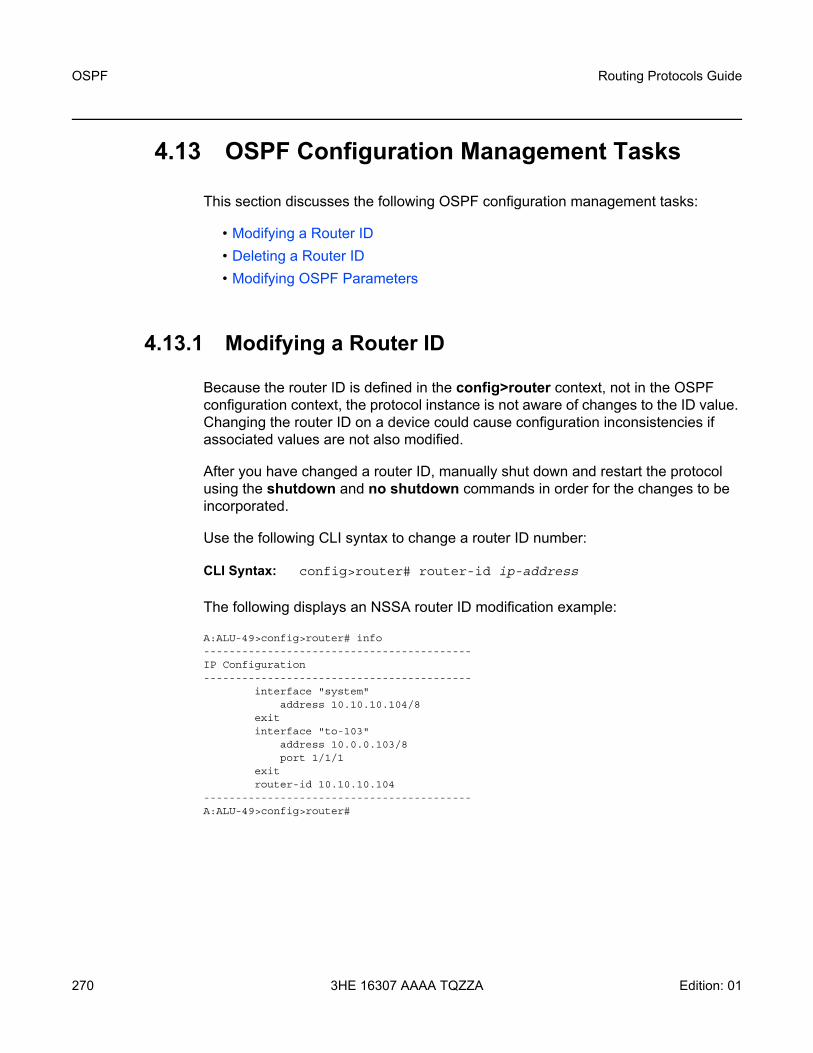
OSPF
270
Routing Protocols Guide
3HE 16307 AAAA TQZZA Edition: 01
4.13 OSPF Configuration Management Tasks
This section discusses the following OSPF configuration management tasks:
• Modifying a Router ID• Deleting a Router ID• Modifying OSPF Parameters
4.13.1 Modifying a Router ID
Because the router ID is defined in the config>router context, not in the OSPF configuration context, the protocol instance is not aware of changes to the ID value. Changing the router ID on a device could cause configuration inconsistencies if associated values are not also modified.
After you have changed a router ID, manually shut down and restart the protocol using the shutdown and no shutdown commands in order for the changes to be incorporated.
Use the following CLI syntax to change a router ID number:
CLI Syntax: config>router# router-id ip-address
The following displays an NSSA router ID modification example:
A:ALU-49>config>router# info------------------------------------------IP Configuration------------------------------------------
interface "system"address 10.10.10.104/8
exitinterface "to-103"
address 10.0.0.103/8port 1/1/1
exitrouter-id 10.10.10.104
------------------------------------------A:ALU-49>config>router#

Routing Protocols Guide OSPF
Edition: 01 3HE 16307 AAAA TQZZA 271
4.13.2 Deleting a Router ID
You can modify a router ID, but you cannot delete the parameter. If the no router router-id command is issued, the router ID reverts to the default value, the system interface address (which is also the loopback address). If a system interface address is not configured, the last 4 bytes of the chassis MAC address are used as the router ID.
4.13.3 Modifying OSPF Parameters
You can change or remove existing OSPF parameters in the CLI. The changes are applied immediately.
The following example displays an OSPF modification in which an interface is removed and another interface added.
Example: config>router# ospf config>router>ospf# area 0.0.0.20config>router>ospf>area# no interface "to-103"config>router>ospf>area# interface "to-HQ"config>router>ospf>area>if$ priority 50config>router>ospf>area>if# exitconfig>router>ospf>area# exit
The following example displays the OSPF configuration with the modifications entered in the previous example:
A:ALU-49>config>router>ospf# info----------------------------------------------
asbrexternal-preference 140export "OSPF-Export"overloadoverload-on-boot timeout 60preference 9traffic-engineeringexitarea 0.0.0.0
virtual-link 10.0.0.1 transit-area 0.0.0.1authentication-type message-digestmessage-digest-key 2 md5 "Mi6BQAFi3MI" hash
exitvirtual-link 10.2.3.4 transit-area 1.2.3.4
hello-interval 9dead-interval 40
exitinterface "system"exit

OSPF
272
Routing Protocols Guide
3HE 16307 AAAA TQZZA Edition: 01
exitarea 0.0.0.1exitarea 0.0.0.20
stubexitinterface "to-HQ"
priority 50exit
exit----------------------------------------------A:ALU-49>config>router>ospf#
Routing Protocols Guide OSPF
Edition: 01 3HE 16307 AAAA TQZZA 273
4.14 OSPF Command Reference
4.14.1 Command Hierarchies
• Configuration Commands• Show Commands• Clear Commands• Debug Commands• Tools Commands (refer to the Tools chapter in the 7705 SAR OAM and
Diagnostics Guide)

OSPF
274
Routing Protocols Guide
3HE 16307 AAAA TQZZA Edition: 01
4.14.1.1 Configuration Commands
config— router
— [no] ospf — advertise-router-capability {link | area | as}— no advertise-router-capability— [no] advertise-tunnel-link— [no] area area-id
— [no] advertise-router-capability— area-range ip-prefix/mask [advertise | not-advertise]— no area-range ip-prefix/mask— [no] blackhole-aggregate— interface ip-int-name [secondary]— no interface ip-int-name
— [no] advertise-router-capability— [no] advertise-subnet— auth-keychain name— no auth-keychain— authentication-key {authentication-key | hash-key} [hash |
hash2]— no authentication-key— authentication-type {password | message-digest}— no authentication-type— bfd-enable [remain-down-on-failure]— no bfd-enable— dead-interval seconds— no dead-interval— hello-interval seconds— no hello-interval— interface-type {broadcast | point-to-point}— no interface-type— lfa-policy-map route-nh-template template-name— no lfa-policy-map— [no] loopfree-alternate-exclude— message-digest-key key-id md5 {key | hash-key} [hash |
hash2]— no message-digest-key key-id— metric metric— no metric— mtu bytes— no mtu— node-sid index index-value — node-sid label label-value — no node-sid— [no] passive— priority number— no priority— retransmit-interval seconds— no retransmit-interval— [no] shutdown— [no] sid-protection— transit-delay seconds

Routing Protocols Guide OSPF
Edition: 01 3HE 16307 AAAA TQZZA 275
— no transit-delay— [no] loopfree-alternate-exclude— [no] nssa
— area-range ip-prefix/mask [advertise | not-advertise]— no area-range ip-prefix/mask— originate-default-route [type-7] [no-adjacency-check]— no originate-default-route — [no] redistribute-external— [no] summaries
— [no] stub— default-metric metric— no default-metric— [no] summaries
— [no] virtual-link router-id transit-area area-id— auth-keychain name— no auth-keychain— authentication-key {authentication-key | hash-key} [hash |
hash2]— no authentication-key— authentication-type {password | message-digest}— no authentication-type— dead-interval seconds— no dead-interval— hello-interval seconds— no hello-interval— message-digest-key key-id md5 {key | hash-key} [hash |
hash2]— no message-digest-key key-id— retransmit-interval seconds— no retransmit-interval— [no] shutdown— transit-delay seconds— no transit-delay
— [no] asbr [trace-path domain-id]— database-export [identifier id] [bgp-ls-identifier bgp-ls-id]— no database-export— [no] disable-ldp-sync— entropy-label
— [no] override-tunnel-elc— export policy-name [policy-name...(up to 5 max)] — no export— external-db-overflow limit seconds — no external-db-overflow— external-preference preference— no external-preference— [no] graceful-restart
— [no] helper-disable— loopfree-alternate— loopfree-alternate remote-lfa [max-pq-cost value]— loopfree-alternate remote-lfa [max-pq-cost value] ti-lfa [max-sr-frr-labels
value]— loopfree-alternate ti-lfa [max-sr-frr-labels value]— [no] loopfree-alternate — loopfree-alternate-exclude prefix-policy prefix-policy [prefix-policy]

OSPF
276
Routing Protocols Guide
3HE 16307 AAAA TQZZA Edition: 01
— no loopfree-alternate-exclude — [no] multicast-import — overload [timeout seconds]— no overload— [no] overload-include-stub— overload-on-boot [timeout seconds]— no overload-on-boot— preference preference— no preference— reference-bandwidth bandwidth-in-kbps— reference-bandwidth [tbps Tera-bps] [gbps Giga-bps] [mbps Mega-bps]
[kbps Kilo-bps]— no reference-bandwidth— router-id ip-address— no router-id— [no] rsvp-shortcut— [no] segment-routing
— adj-sid-hold seconds— no adj-sid-hold— backup-node-sid ip-prefix/prefix-length index [0..4294967295]— backup-node-sid ip-prefix/prefix-length label [1..4294967295]— no backup-node-sid — entropy-label {force-disable | enable}— no entropy-label — prefix-sid-range global — prefix-sid-range start-label label-value max-index index-value — no prefix-sid-range— [no] shutdown— tunnel-mtu bytes— no tunnel-mtu— tunnel-table-pref preference — no tunnel-table-pref
— [no] shutdown— timers
— lsa-arrival lsa-arrival-time— no lsa-arrival— lsa-generate max-lsa-wait [lsa-initial-wait [lsa-second-wait]]— no lsa-generate— spf-wait max-spf-wait [spf-initial-wait spf-initial-wait] [spf-second-
wait spf-second-wait]— no spf-wait
— [no] traffic-engineering— [no] unicast-import-disable
config— router
— [no] ospf3— advertise-router-capability {link | area | as}— no advertise-router-capability— [no] area area-id
— [no] advertise-router-capability— area-range ipv6-prefix/prefix-length [advertise | not-advertise]— no area-range ipv6-prefix/prefix-length— [no] blackhole-aggregate

Routing Protocols Guide OSPF
Edition: 01 3HE 16307 AAAA TQZZA 277
— interface ip-int-name [secondary]— no interface ip-int-name
— [no] advertise-router-capability— authentication bidirectional sa-name— authentication inbound sa-name outbound sa-name— no authentication — bfd-enable [remain-down-on-failure]— no bfd-enable— dead-interval seconds— no dead-interval— hello-interval seconds— no hello-interval— interface-type {broadcast | point-to-point}— no interface-type— lfa-policy-map route-nh-template template-name— no lfa-policy-map— [no] loopfree-alternate-exclude— metric metric— no metric— mtu bytes— no mtu— [no] passive— priority number— no priority— retransmit-interval seconds— no retransmit-interval— [no] shutdown— transit-delay seconds— no transit-delay
— key-rollover-interval seconds— no key-rollover-interval — [no] loopfree-alternate-exclude— [no] nssa
— area-range ipv6-prefix/prefix-length [advertise | not-advertise]— no area-range ipv6-prefix/prefix-length— originate-default-route [type-nssa] [no-adjacency-check]— no originate-default-route — [no] redistribute-external— [no] summaries
— [no] stub— default-metric metric— no default-metric— [no] summaries
— [no] virtual-link router-id transit-area area-id— authentication bidirectional sa-name— authentication inbound sa-name outbound sa-name— no authentication — dead-interval seconds— no dead-interval— hello-interval seconds— no hello-interval— retransmit-interval seconds— no retransmit-interval— [no] shutdown

OSPF
278
Routing Protocols Guide
3HE 16307 AAAA TQZZA Edition: 01
— transit-delay seconds— no transit-delay
— [no] asbr — export policy-name [policy-name...(up to 5 max)]— no export— external-db-overflow limit seconds — no external-db-overflow— external-preference preference— no external-preference— [no] loopfree-alternate— loopfree-alternate-exclude prefix-policy prefix-policy [prefix-policy...(up to 5
max)]— no loopfree-alternate-exclude— [no] multicast-import— overload [timeout seconds]— no overload— [no] overload-include-stub— overload-on-boot [timeout seconds]— no overload-on-boot— preference preference— no preference— reference-bandwidth bandwidth-in-kbps— reference-bandwidth [tbps Tera-bps] [gbps Giga-bps] [mbps Mega-bps]
[kbps Kilo-bps]— no reference-bandwidth— router-id ip-address— no router-id— [no] shutdown— timers
— lsa-arrival lsa-arrival-time— no lsa-arrival— lsa-generate max-lsa-wait [lsa-initial-wait [lsa-second-wait]]— no lsa-generate— spf-wait max-spf-wait [spf-initial-wait spf-initial-wait] [spf-second-
wait spf-second-wait] — no spf-wait
— [no] unicast-import-disable

Routing Protocols Guide OSPF
Edition: 01 3HE 16307 AAAA TQZZA 279
4.14.1.2 Show Commands
show— router [router-instance]— router service-name [service-name]
— ospf [all]— area [area-id] [detail] [lfa]— capabilities [router-id] — database [type {router | network | summary | asbr-summary | external |
nssa | all} [area area-id] [adv-router router-id] [link-state-id] [detail] [filtered]
— interface [area area-id] [detail]— interface [ip-int-name | ip-address] [detail]— interface [ip-int-name | ip-address] database [detail]— lfa-coverage— neighbor [ip-int-name | ip-address] [detail]— neighbor overview— neighbor [remote ip-address] [detail]— opaque-database [area area-id | as] [adv-router router-id] [ls-id] [detail]— prefix-sids [ip-prefix[/prefix-length]] [sid sid] [adv-router router-id]— range [area-id]— routes [ip-prefix[/prefix-length]] [type] [detail] [alternative] [summary]
[exclude-shortcut]— spf [lfa]— statistics— status— virtual-link database [detail]— virtual-link [detail]— virtual-neighbor [remote ip-address] [detail]
— ospf3 [all]— area [area-id] [detail] [lfa]— capabilities [router-id] — database [type database-type] [area area-id] [adv-router router-id] [link-state-
id] [detail] [filtered] — interface [area area-id] [detail]— interface [ip-int-name | ip-address | ipv6-address] [detail]— interface [ip-int-name | ip-address | ipv6-address] database [detail]— lfa-coverage— neighbor [ip-int-name] [router-id] [detail]— neighbor overview— range [area-id]— routes [ip-prefix[/pfx-len]] [type] [detail] [alternative] [summary] — spf [lfa]— statistics— status— virtual-link [detail]— virtual-neighbor [remote ipv6-address] [detail]
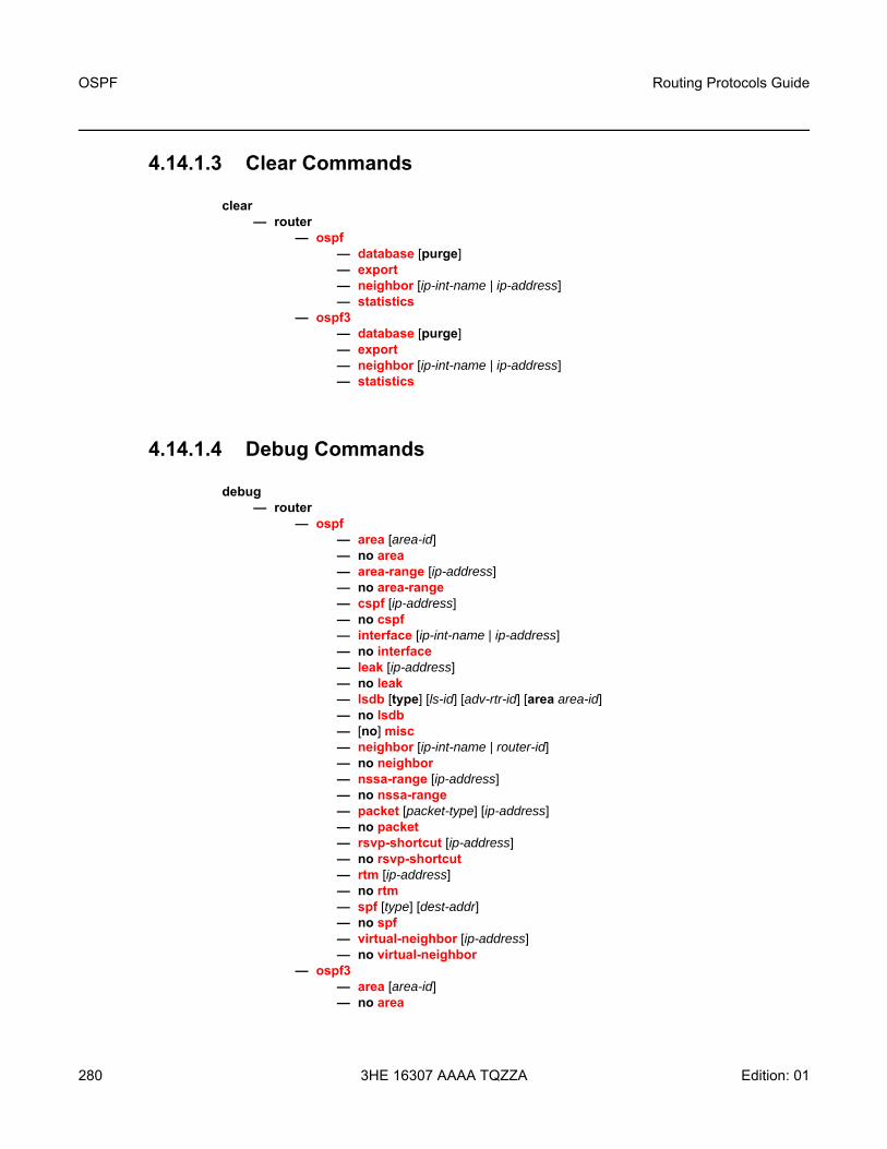
OSPF
280
Routing Protocols Guide
3HE 16307 AAAA TQZZA Edition: 01
4.14.1.3 Clear Commands
clear— router
— ospf — database [purge]— export— neighbor [ip-int-name | ip-address]— statistics
— ospf3 — database [purge]— export— neighbor [ip-int-name | ip-address]— statistics
4.14.1.4 Debug Commands
debug— router
— ospf— area [area-id]— no area— area-range [ip-address]— no area-range— cspf [ip-address]— no cspf— interface [ip-int-name | ip-address]— no interface— leak [ip-address]— no leak— lsdb [type] [ls-id] [adv-rtr-id] [area area-id]— no lsdb— [no] misc— neighbor [ip-int-name | router-id]— no neighbor— nssa-range [ip-address]— no nssa-range— packet [packet-type] [ip-address]— no packet— rsvp-shortcut [ip-address]— no rsvp-shortcut— rtm [ip-address]— no rtm— spf [type] [dest-addr]— no spf— virtual-neighbor [ip-address]— no virtual-neighbor
— ospf3— area [area-id]— no area

Routing Protocols Guide OSPF
Edition: 01 3HE 16307 AAAA TQZZA 281
— area-range [ip-address]— no area-range— interface [ip-int-name | ip-address]— no interface— leak [ip-address]— no leak— lsdb [type] [ls-id] [adv-rtr-id] [area area-id]— no lsdb— [no] misc— neighbor [ip-int-name | router-id]— no neighbor— nssa-range [ip-address]— no nssa-range— packet [packet-type] [ip-address]— no packet— rsvp-shortcut [ip-address]— no rsvp-shortcut— spf [type] [dest-addr]— no spf— virtual-neighbor [ip-address]— no virtual-neighbor

OSPF
282
Routing Protocols Guide
3HE 16307 AAAA TQZZA Edition: 01
4.14.2 Command Descriptions
• Configuration Commands• Show Commands• Clear Commands• Debug Commands

Routing Protocols Guide OSPF
Edition: 01 3HE 16307 AAAA TQZZA 283
4.14.2.1 Configuration Commands
• Generic Commands• Global Commands• Area Commands• Interface/Virtual Link Commands

OSPF
284
Routing Protocols Guide
3HE 16307 AAAA TQZZA Edition: 01
4.14.2.1.1 Generic Commands
shutdown
Syntax [no] shutdown
Context config>router>ospfconfig>router>ospf>area>interface config>router>ospf>area>segment-routingconfig>router>ospf>area>virtual-linkconfig>router>ospf3config>router>ospf3>area>interface config>router>ospf3>area>virtual-link
Description This command administratively disables the entity. When disabled, an entity does not change, reset, or remove any configuration settings or statistics. Many entities must be explicitly enabled using the no shutdown command.
The operational state of the entity is disabled as well as the operational state of any entities contained within. Many objects must be shut down before they can be deleted.
Unlike other commands and parameters where the default state is not indicated in the configuration file, shutdown and no shutdown are always indicated in system-generated configuration files.
The no form of the command puts an entity into the administratively enabled state.
Default OSPF Protocol — the Open Shortest Path First (OSPF) protocol is created in the no shutdown state
OSPF Interface — when an IP interface is configured as an OSPF interface, OSPF on the interface is in the no shutdown state by default

Routing Protocols Guide OSPF
Edition: 01 3HE 16307 AAAA TQZZA 285
4.14.2.1.2 Global Commands
ospf
Syntax [no] ospf
Context config>router
Description This command activates OSPF on the router and enables access to the context to define OSPF parameters.
Before OSPF can be activated on the router, the router ID must be configured.
The router ID uniquely identifies the router within an AS. In OSPF, routing information is exchanged between autonomous systems, which are groups of networks that share routing information. The router ID can be set to be the same as the system interface address (loopback address).
The router ID is derived by one of the following methods:
• defining the value using the config>router>router-id ip-address command• defining the system interface using the config>router>interface ip-int-name command
(used if the router ID is not specified with the config>router>router-id ip-address command)
• inheriting the last 4 bytes of the MAC address
When configuring a new router ID, protocols are not automatically restarted with the new router ID. The next time a protocol is initialized, the new router ID is used. To force the new router ID, issue the shutdown and no shutdown commands for OSPF or restart the entire router.
The no form of the command reverts to the default value.
Default no ospf
ospf3
Syntax [no] ospf3
Context config>router
Description This command activates OSPFv3 on the router and enables access to the context to define OSPFv3 parameters.
Before OSPFv3 can be activated on the router, the router ID must be configured.

OSPF
286
Routing Protocols Guide
3HE 16307 AAAA TQZZA Edition: 01
The router ID uniquely identifies the router within an AS. In OSPFv3, routing information is exchanged between autonomous systems, which are groups of networks that share routing information. The router ID can be set to be the same as the system interface address (loopback address).
The router ID is derived by one of the following methods:
• defining the value using the config>router>router-id ip-address command• defining the system interface using the config>router>interface ip-int-name command
(used if the router ID is not specified with the config>router>router-id ip-address command)
• inheriting the last 4 bytes of the MAC address
When configuring a new router ID, protocols are not automatically restarted with the new router ID. The next time a protocol is initialized, the new router ID is used. To force the new router ID, issue the shutdown and no shutdown commands for OSPFv3 or restart the entire router.
The no form of the command reverts to the default value.
Default no ospf3
advertise-router-capability
Syntax advertise-router-capability {link | area | as} no advertise-router-capability
Context config>router>ospf config>router>ospf3
Description This command enables advertisement of a router's capabilities to its neighbors for informational and troubleshooting purposes. A Router Information (RI) LSA as defined in RFC 4970 advertises the following capabilities:
• OSPF graceful restart capable: no • OSPF graceful restart helper: yes, when enabled • OSPF stub router support: yes • OSPF traffic engineering support: yes, when enabled • OSPF point-to-point over LAN: yes • OSPF experimental TE: no
The parameters (link, area and as) control the scope of the capability advertisements.
The no form of this command disables this capability.
Default no advertise-router-capability
Parameters link — capabilities are only advertised over local links and not flooded beyond

Routing Protocols Guide OSPF
Edition: 01 3HE 16307 AAAA TQZZA 287
area — capabilities are only advertised within the area of origin
as — capabilities are advertised throughout the entire autonomous system
advertise-tunnel-link
Syntax [no] advertise-tunnel-link
Context config>router>ospf
Description This command enables the forwarding adjacency feature. With this feature, OSPF advertises an RSVP-TE LSP as a link so that other routers in the network can include it in their SPF calculations. The RSVP-TE LSP is advertised as an unnumbered point-to-point link and the link-state advertisement (LSA) has no traffic engineering opaque sub-TLVs as per RFC 3906.
The forwarding adjacency feature can be enabled independently from the IGP shortcut feature (rsvp-shortcut). If both features are enabled for a given OSPF instance, the forwarding adjacency feature takes precedence.
When this feature is enabled, each node advertises a point-to-point unnumbered link for each best-metric tunnel to the router ID of any endpoint node. The node does not include the tunnels as IGP shortcuts in the SPF calculation directly. Instead, when the LSA advertising the corresponding point-to-point unnumbered link is installed in the local routing database, the node performs an SPF calculation using the link like any other link LSA.
The link bidirectional check requires that a regular link or tunnel link exists in the reverse direction for the tunnel to be used in the SPF calculation.
An RSVP-TE LSP can be excluded from being used as a forwarding adjacency with the config>router>mpls>lsp>no igp-shortcut command.
The no form of this command disables forwarding adjacency and therefore disables the advertisement of RSVP-TE LSPs into OSPF.
Default no advertise-tunnel-link
asbr
Syntax [no] asbr [trace-path domain-id]
Context config>router>ospfconfig>router>ospf3
Description This command configures the router as an Autonomous System Boundary Router (ASBR) if the router is to be used to distribute external routes into the OSPF domain. When a router is configured as an ASBR, the export policies into the OSPF domain take effect. If no policies are configured, no external routes are redistributed into the OSPF domain.

OSPF
288
Routing Protocols Guide
3HE 16307 AAAA TQZZA Edition: 01
The no form of the command removes the ASBR status and withdraws the routes redistributed from the routing table into OSPF from the link-state database.
Only the base OSPF instance is supported; therefore, the domain ID may not need to be configured. However, in order to prevent routing loops (where routes learned from one domain are redistributed back into the domain), the domain ID can be used to tag external LSAs – indicating which domain or network they have learned the route from.
Default no asbr — the router is not an ASBR
Parameters domain-id — specifies the domain ID
Values 1 to 31
Default 0x0
database-export
Syntax database-export [identifier id] [bgp-ls-identifier bgp-ls-id]no database-export
Context config>router>ospf
Description This command enables the population of the extended TE database (TE-DB) with the link-state information from a given OSPF instance.
The extended TE-DB is used as a central point for importing all link-state, link, node, and prefix information from IGP instances on the router and exporting the information to BGP-LS on the router. This information includes the IGP, TE, SID sub-TLV, and adjacency SID sub-TLV.
The no form of this command disables database exportation.
Default no database-export
Parameters identifier — uniquely identifies the IGP instance in the BGP-LS NLRI when a router has interfaces participating in multiple IGP instances. This parameter defaults to the IGP instance ID assigned by the 7705 SAR. However, because the concept of instance ID defined in IS-IS (RFC 6822) is unique within a routing domain while the one specified for OSPF is significant for the local subnet only (RFC 6549), the user can remove any overlap by configuring the new identifier value to be unique within a particular IGP domain when this router sends the IGP link-state information using BGP-LS.
id — specifies an entry ID to export
Values 0 to 18446744073709551615
bgp-ls-identifier — used with the Autonomous System Number (ASN) to correlate the BGP-LS NLRI advertisements of multiple BGP-LS speakers in the same IGP domain. If an NRC-P network domain has multiple IGP domains, BGP-LS speakers in each IGP domain must be configured with the same unique tuple {bgp-ls-identifier, asn}.

Routing Protocols Guide OSPF
Edition: 01 3HE 16307 AAAA TQZZA 289
The BGP-LS identifier is optional and is only sent in a BGP-LS NLRI if configured in the IGP instance of an IGP domain.If this IGP instance participates in traffic engineering with RSVP-TE or SR-TE, the traffic-engineering option is not strictly required because enabling the extended TE-DB populates this information automatically. However, it is recommended that the enable traffic engineering to make the configuration consistent with other routers in the network that do not require enabling of the extended TE-DB.
bgp-ls-id — specifies a BGP LS ID to export
Values 0 to 4294967295
disable-ldp-sync
Syntax [no] disable-ldp-sync
Context config>router>ospf
Description This command disables the IGP-LDP synchronization feature on all interfaces participating in the OSPF or IS-IS routing protocol. When this command is executed, IGP immediately advertises the actual value of the link cost for all interfaces that have the IGP-LDP synchronization enabled if the currently advertised cost is different. IGP-LDP synchronization will then be disabled for all interfaces. This command does not delete the interface configuration.
The no form of this command restores the default settings and re-enables IGP-LDP synchronization on all interfaces participating in the OSPF or IS-IS routing protocol and for which the ldp-sync-timer is configured (refer to the 7705 SAR Router Configuration Guide for information on configuring the ldp-sync-timer).
Default no disable-ldp-sync
entropy-label
Syntax entropy-label
Context config>router>ospf
Description This command enables the context for the configuration of entropy label capabilities for the routing protocol.

OSPF
290
Routing Protocols Guide
3HE 16307 AAAA TQZZA Edition: 01
override-tunnel-elc
Syntax [no] override-tunnel-elc
Context config>router>ospf>entropy-label
Description This command configures the ability to override any received entropy label capability advertisements. When enabled, the system assumes that all nodes for an IGP domain are capable of receiving and processing the entropy label on segment routed tunnels. This command can only be configured if entropy-label is enabled via the config>router>ospf>segment-routing>entropy-label command.
The no version of this command disables the override. The system assumes entropy label capability for other nodes in the IGP instance if capability advertisements are received.
Default no override-tunnel-elc
export
Syntax export policy-name [policy-name…(up to 5 max)]no export
Context config>router>ospfconfig>router>ospf3
Description This command specifies export route policies to determine which routes are exported from the routing table manager to OSPF. Export policies are only in effect if OSPF is configured as an ASBR.
If no export policy is specified, non-OSPF routes are not exported from the routing table manager to OSPF.
If multiple policy names are specified, the policies are evaluated in the order they are specified. The first policy that matches is applied. If multiple export commands are issued, the last command entered will override the previous command. A maximum of five policy names can be specified.
The no form of the command removes all policies from the configuration.
Refer to the 7705 SAR Router Configuration Guide for information on defining route policies.
Default no export — no export route policies specified
Parameters policy-name — the export route policy name. Allowed values are any string up to 32 characters long composed of printable, 7-bit ASCII characters. If the string contains special characters (#, $, spaces, etc.), the entire string must be enclosed within double quotes.The specified names must already be defined.

Routing Protocols Guide OSPF
Edition: 01 3HE 16307 AAAA TQZZA 291
external-db-overflow
Syntax external-db-overflow limit secondsno external-db-overflow
Context config>router>ospfconfig>router>ospf3
Description This command enables limits on the number of non-default, AS-external LSA entries that can be stored in the link-state database (LSDB) and specifies a wait timer before processing these entries after the limit is exceeded.
The limit value specifies the maximum number of entries that can be stored in the LSDB. Placing a limit on these LSAs in the LSDB protects the router from receiving an excessive number of external routes that consume excessive memory or CPU resources. If the number of routes reaches or exceeds the limit, the table is in an overflow state. When in an overflow state, the router will not originate any new AS-external LSAs and will withdraw all the self-originated non-default external LSAs.
The seconds value specifies the time to wait after an overflow state before regenerating and processing non-default, AS-external LSAs. The waiting period acts like a dampening period, preventing the router from continuously running shortest path first (SPF) calculations caused by the excessive number of non-default, AS-external LSAs.
The external-db-overflow must be set identically on all routers attached to any regular OSPF area. OSPF stub areas and not-so-stubby areas (NSSAs) are excluded.
The no form of the command disables limiting the number of non-default, AS-external LSA entries.
Default no external-db-overflow
Parameters limit — the maximum number of non-default, AS-external LSA entries that can be stored in the LSDB before going into an overflow state, expressed as a decimal integer
Values 0 to 2147483674
seconds — the number of seconds after entering an overflow state before attempting to process non-default, AS-external LSAs, expressed as a decimal integer
Values 0 to 2147483674
external-preference
Syntax external-preference preferenceno external-preference
Context config>router>ospfconfig>router>ospf3

OSPF
292
Routing Protocols Guide
3HE 16307 AAAA TQZZA Edition: 01
Description This command configures the preference for OSPF external routes. The preference for internal routes is set with the preference command.
A route can be learned by the router from different protocols, in which case, the costs are not comparable. When this occurs, the preference is used to decide which route will be used.
Different protocols should not be configured with the same preference. If this occurs, the tiebreaker is based on the default preferences as defined in Table 36.
If multiple routes are learned with the same preference using the same protocol, the lowest-cost route is used. If multiple routes are learned with the same preference using the same protocol and the costs (metrics) are equal, the decision of which route to use is determined by the configuration of ECMP in the config>router context. Refer to the 7705 SAR Router Configuration Guide for information on ECMP.
The no form of the command reverts to the default value.
Default external-preference 150 — OSPF external routes have a default preference of 150
Parameters preference — the preference for external routes, expressed as a decimal integer
Values 1 to 255
Table 36 Route Preference Defaults by Route Type
Route Type Preference Configurable
Direct attached 0 No
Static routes 5 Yes
OSPF internal 10 Yes
IS-IS level 1 internal 15 Yes
IS-IS level 2 internal 18 Yes
OSPF external 150 Yes
IS-IS level 1 external 160 Yes
IS-IS level 2 external 165 Yes
Note: To configure a preference for static routes, use the config>router>static-route-entry context. Refer to the 7705 SAR Router Configuration Guide for information.

Routing Protocols Guide OSPF
Edition: 01 3HE 16307 AAAA TQZZA 293
graceful-restart
Syntax [no] graceful-restart
Context config>router>ospf
Description This command enables or disables Graceful Restart for OSPF. Graceful Restart is not fully implemented on the 7705 SAR, meaning that the router will never request graceful restart support from its neighbors. However, Graceful Restart must be enabled before the 7705 SAR can be configured for Graceful Restart Helper mode.
The no form of the command disables Graceful Restart and removes all Graceful Restart configurations in the OSPF instance.
Default no graceful-restart
helper-disable
Syntax [no] helper-disable
Context config>router>ospf>graceful-restart
Description This command enables or disables Graceful Restart Helper mode for OSPF. In helper mode, if a grace LSA is received from an OSPF neighbor, the 7705 SAR keeps the link toward that neighbor up and operational until the specified grace period in the grace LSA expires or the graceful restart is successful, whichever comes first.
The no form of the command enables Graceful Restart Helper mode and is the default when graceful-restart is enabled.
Default no helper-disable
loopfree-alternate
Syntax loopfree-alternateloopfree-alternate remote-lfa [max-pq-cost value]loopfree-alternate remote-lfa [max-pq-cost value] ti-lfa [max-sr-frr-labels value]loopfree-alternate ti-lfa [max-sr-frr-labels value]no loopfree-alternate
Context config>router>ospf
Description This command enables loop-free alternate (LFA) computation by SPF under the OSPFv2 routing protocol instance.
When this command is enabled, it instructs the IGP SPF to attempt to precalculate both a primary next hop and an LFA backup next hop for every learned prefix. When found, the LFA next hop is populated into the routing table along with the primary next hop for the prefix.

OSPF
294
Routing Protocols Guide
3HE 16307 AAAA TQZZA Edition: 01
The user enables the remote LFA next hop calculation by the IGP LFA SPF by using the remote-lfa option. When this option is enabled in an IGP instance, SPF performs the additional remote LFA computation that follows the regular LFA next hop calculation when the latter calculation results in no protection for one or more prefixes that are resolved to a particular interface.
Remote LFA extends the protection coverage of LFA-FRR to any topology by automatically computing and establishing or tearing down shortcut tunnels, also referred to as repair tunnels, to a remote LFA node that puts the packets back into the shortest path without looping them back to the node that forwarded them over the repair tunnel. The remote LFA node is referred to as a PQ node. A repair tunnel can, in theory, be an RSVP-TE LSP, an LDP-in-LDP tunnel, or a segment routing (SR) tunnel. In this command, remote-lfa is restricted to using an SR repair tunnel to the remote LFA node.
The remote LFA algorithm is a per-link LFA SPF calculation and not a per-prefix calculation like the regular LFA algorithm. The remote LFA algorithm provides protection for all destination prefixes that share the protected link by using the neighbor on the other side of the protected link as a proxy for all the destinations.
The Topology-independent LFA (TI-LFA) further improves the protection coverage of a network topology by computing and automatically instantiating a repair tunnel to a Q node that is not in the shortest path from the computing node. The repair tunnel uses the shortest path to the P node and a source-routed path from the P node to the Q node.
The TI-LFA repair tunnel can have a maximum of three labels pushed in addition to the label of the destination node or prefix. The user can set a lower maximum value for the additional FRR labels by configuring the max-sr-frr-labels option. The default value is 2.
The no form of this command disables the LFA computation by the IGP SPF.
Default no loopfree-alternate
Parameters remote-lfa — specifies the use of the remote LFA algorithm in the LFA SPF calculation in this OSPF instance
max-pq-cost value — specifies the integer used to limit the search of candidate P and Q nodes in the remote LFA algorithm by setting the maximum IGP cost from the router performing the remote LFA calculation to the candidate P or Q node
Values 0 to 4294967295
Default 65535
ti-lfa — enables the use of the topology-independent LFA algorithm in the LFA SPFcalculation
max-sr-frr-labels value — specifies the maximum number of labels that the TI-LFA backup next hop can use. The TI-LFA algorithm uses this value to limit the search for the Q node from the P node on the post-convergence path.
Values 0 to 3
Default 2

Routing Protocols Guide OSPF
Edition: 01 3HE 16307 AAAA TQZZA 295
loopfree-alternate
Syntax [no] loopfree-alternate
Context config>router>ospf3
Description This command enables loop-free alternate (LFA) computation by SPF under the OSPFv3 routing protocol instance.
When this command is enabled, it instructs the IGP SPF to attempt to precalculate both a primary next hop and an LFA next hop for every learned prefix. When found, the LFA next hop is populated into the routing table along with the primary next hop for the prefix.
The no form of this command disables the LFA computation by the IGP SPF.
Default no loopfree-alternate
loopfree-alternate-exclude
Syntax loopfree-alternate-exclude prefix-policy prefix-policy [prefix-policy...(up to 5 max)]no loopfree-alternate-exclude
Context config>router>ospfconfig>router>ospf3
Description This command excludes from the LFA SPF calculation those prefixes that match a prefix entry or a tag entry in a prefix policy. If a prefix is excluded from LFA, it is not included in LFA calculations regardless of its priority. The prefix tag will, however, be used in the main SPF.
The implementation also allows the user to exclude a specific interface in IS-IS or OSPF, or all interfaces in an OSPF area or IS-IS level from the LFA SPF.
The default action of the loopfree-alternate-exclude command, when not explicitly specified by the user in the prefix policy, is “reject”. Therefore, regardless of whether the user explicitly added the statement “default-action reject” to the prefix policy, a prefix that does not match any entry in the policy will be accepted into LFA SPF.
The no form deletes the exclude prefix policy.
Default no loopfree-alternate-exclude
Note: Prefix tags are defined for the IS-IS protocol but not for the OSPF protocol.

OSPF
296
Routing Protocols Guide
3HE 16307 AAAA TQZZA Edition: 01
Parameters prefix-policy — specifies the name of the prefix policy, up to a maximum of five policies. The specified policy name must already be defined. Prefix policies are created with the command config>router>policy-options>prefix-list (for information on prefix lists, refer to the 7705 SAR Router Configuration Guide, “Route Policies”).
multicast-import
Syntax [no] multicast-import
Context config>router>ospfconfig>router>ospf3
Description This command administratively enables the submission of routes into the multicast RTM by OSPF.
The no form of the command disables the submission of routes into the multicast RTM.
Default no multicast-import
overload
Syntax overload [timeout seconds]no overload
Context config>router>ospfconfig>router>ospf3
Description This command changes the overload state of the local router so that it appears to be overloaded. When overload is enabled, the router can participate in OSPF routing, but is not used for transit traffic. Traffic destined for directly attached interfaces continues to reach the router.
To put the IGP in an overload state, enter a timeout value. The IGP will enter the overload state until the timeout timer expires or a no overload command is executed.
If no timeout is specified, the overload state is maintained indefinitely.
If the overload command is encountered during the execution of an overload-on-boot command, the overload command takes precedence. This situation could occur as a result of a saved configuration file where both parameters are saved. When the file is saved by the system, the overload-on-boot command is saved after the overload command.
Use the no form of this command to return to the default. When the no overload command is executed, the overload state is terminated regardless of the reason the protocol entered the overload state.
Default no overload

Routing Protocols Guide OSPF
Edition: 01 3HE 16307 AAAA TQZZA 297
Parameters seconds — the number of seconds to reset overloading
Values 1 to 1800
overload-include-stub
Syntax [no] overload-include-stub
Context config>router>ospfconfig>router>ospf3
Description This command is used to determine if the OSPF stub networks should be advertised with a maximum metric value when the system goes into an overload state for any reason. When enabled, the system uses the maximum metric value. When this command is enabled and the router is in overload, all stub interfaces, including loopback and system interfaces, will be advertised at the maximum metric.
Default no overload-include-stub
overload-on-boot
Syntax overload-on-boot [timeout seconds]no overload-on-boot
Context config>router>ospfconfig>router>ospf3
Description When the router is in an overload state, the router is used only if there is no other router to reach the destination. This command configures OSPF upon boot-up in the overload state until one of the following events occurs:
• the timeout timer expires (if a timeout has been specified)• a manual override of the current overload state is entered with the no overload
command
If no timeout is specified, the overload state is maintained indefinitely.
The no overload command does not affect the overload-on-boot function.
The no form of the command removes the overload-on-boot functionality from the configuration.
Default no overload-on-boot
Parameters seconds — the number of seconds to reset overloading
Values 1 to 1800

OSPF
298
Routing Protocols Guide
3HE 16307 AAAA TQZZA Edition: 01
preference
Syntax preference preference no preference
Context config>router>ospfconfig>router>ospf3
Description This command configures the preference for OSPF internal routes.
A route can be learned by the router from different protocols, in which case, the costs are not comparable. When this occurs, the preference is used to decide which route will be used.
Different protocols should not be configured with the same preference. If this occurs, the tiebreaker is based on the default preferences as defined in Table 36. If multiple routes are learned with the same preference using the same protocol and the costs (metrics) are equal, the decision of which route to use is determined by the configuration of ECMP in the config>router context. Refer to the 7705 SAR Router Configuration Guide for information on ECMP.
The no form of the command reverts to the default value.
Default preference 10 — OSPF internal routes have a preference of 10
Parameters preference — the preference for internal routes, expressed as a decimal integer
Values 1 to 255
reference-bandwidth
Syntax reference-bandwidth bandwidth-in-kbpsreference-bandwidth [tbps Tera-bps] [gbps Giga-bps] [mbps Mega-bps] [kbps Kilo-bps]no reference-bandwidth
Context config>router>ospfconfig>router>ospf3
Description This command configures the reference bandwidth used to calculate the default costs of interfaces based on their underlying link speed.
The default interface cost is calculated as follows:
cost = reference bandwidth/bandwidth

Routing Protocols Guide OSPF
Edition: 01 3HE 16307 AAAA TQZZA 299
The default reference bandwidth is 100 000 000 kb/s or 100 Gb/s; therefore, the default auto-cost metrics for various link speeds are as follows:
• 10 Mb/s link: default cost of 10000• 100 Mb/s link: default cost of 1000• 1 Gb/s link: default cost of 100• 10 Gb/s link: default cost of 10
The reference-bandwidth command assigns a default cost to the interface based on the interface speed. To override this default cost on a particular interface, use the metric metric command in the config>router>ospf>area>interface ip-int-name or config>router> ospf3>area>interface ip-int-name context.
The no form of the command resets the reference bandwidth to the default value.
Default reference-bandwidth 100000000
Parameters bandwidth-in-kbps — the reference bandwidth in kilobits per second, expressed as a decimal integer
Values 1 to 4000000000
Tera-bps — the reference bandwidth in terabits per second, expressed as a decimal integer
Values 1 to 4
Giga-bps — the reference bandwidth in gigabits per second, expressed as a decimal integer
Values 1 to 999
Mega-bps — the reference bandwidth in megabits per second, expressed as a decimal integer
Values 1 to 999
Kilo-bps — the reference bandwidth in kilobits per second, expressed as a decimal integer
Values 1 to 999
router-id
Syntax router-id ip-addressno router-id
Context config>router>ospfconfig>router>ospf3
Description This command configures the router ID to be used under the global routing table context (GRT). The 7705 SAR supports a single OSPF instance in the GRT context; therefore, changing the router ID has a global implication.

OSPF
300
Routing Protocols Guide
3HE 16307 AAAA TQZZA Edition: 01
When configuring the router ID in the base instance of OSPF, the value overrides the router ID configured in the config>router context.
The default value for the base instance is inherited from the configuration in the config>router context. If the router ID in the config>router context is not configured, the following applies:
• the system uses the system interface address (which is also the loopback address)• if a system interface address is not configured, the last 4 bytes of the chassis MAC
address are used
When configuring a new router ID, the instance is not automatically restarted with the new router ID. The next time the instance is initialized, the new router ID is used.
To force the new router ID to be used, issue the shutdown and no shutdown commands for the instance, or reboot the entire router.
The no form of the command to reverts to the default value.
Default 0.0.0.0 (base OSPF)
Parameters ip-address — a 32-bit, unsigned integer uniquely identifying the router in the Autonomous System
rsvp-shortcut
Syntax [no] rsvp-shortcut
Context config>router>ospf
Description This command enables the use of an RSVP-TE shortcut for resolving OSPF routes. When the command is enabled, OSPF includes RSVP-TE LSPs originating on this node and terminating on the router ID of a remote node as direct links with a metric equal to the operational metric provided by MPLS.
The SPF algorithm will always use the IGP metric to build the SPF tree, and the LSP metric value does not update the SPF tree calculation. During the IP reach to determine the reachability of nodes and prefixes, LSPs are overlaid and the LSP metric is used to determine the subset of paths that are of an equal lowest cost to reach a node or a prefix. If the relative-metric option for this LSP is enabled (in the config>router>mpls>lsp>igp-shortcut context), OSPF will apply the shortest cost between the endpoints of the LSP plus the value of the offset, instead of the LSP operational metric, when calculating the cost of a prefix that is resolved to the LSP.
When a prefix is resolved to a tunnel next hop, the packet is sent labeled with the label stack corresponding to the NHLFE of the RSVP-TE LSP. Any network event that causes an RSVP-TE LSP to go down will trigger a full SPF calculation, which may result in a new route being installed over another RSVP-TE LSP shortcut as a tunnel next hop or over a regular IP next hop.

Routing Protocols Guide OSPF
Edition: 01 3HE 16307 AAAA TQZZA 301
When the rsvp-shortcut command is enabled, all RSVP-TE LSPs originating on this node are eligible by default as long as the destination address of the LSP, as configured with the config>router>mpls> lsp>to command, corresponds to a router ID of a remote node. A specific LSP can be excluded from being used as a shortcut with the config>router>mpls>lsp>no igp-shortcut command.
If ECMP is enabled on the system and multiple equal-cost paths exist for the route over a set of tunnel next hops (based on the hashing routine supported for IPv4 packets), there are two possibilities:
• if the destination is the tunnel endpoint, the system selects the tunnel with the lowest tunnel ID (the IP next hop is never used)
• if the destination is different from the tunnel endpoint, the system:- selects tunnel endpoints where the LSP metric is lower than the IGP cost- prefers tunnel endpoints over IP next hops
ECMP is not performed across both the IP and tunnel next hops.
OSPF can populate the multicast RTM with the prefix IP next hop when both rsvp-shortcut and multicast-import are enabled. The unicast RTM can still use the tunnel next hop for the same prefix.
The forwarding adjacency feature (advertise-tunnel-link) can be enabled independently from the shortcuts feature. If both features are enabled for a given OSPF instance, the forwarding adjacency feature takes precedence.
The no form of this command disables the resolution of IGP routes using RSVP shortcuts.
Default no rsvp-shortcut
segment-routing
Syntax [no] segment-routing
Context config>router>ospf
Description This command enables the context to configure segment routing parameters within an IGP instance.
Segment routing adds to IS-IS and OSPF routing protocols the ability to perform shortest path routing and source routing using the concept of abstract segment. An abstract segment can represent a local prefix of a node, a specific adjacency of the node (interface or next hop), a service context, or a specific explicit path over the network. For each segment, the IGP advertises an identifier referred to as a segment ID (SID).
When segment routing is used together with the MPLS data plane, the SID is a standard MPLS label. A router forwarding a packet using segment routing will push one or more MPLS labels.

OSPF
302
Routing Protocols Guide
3HE 16307 AAAA TQZZA Edition: 01
Segment routing using MPLS labels can be used in both shortest path routing applications and traffic engineering applications. On the 7705 SAR, segment routing implements the shortest path forwarding application.
After segment routing is successfully enabled in the IS-IS or OSPF instance, the router will perform the following operations:
• Advertise the Segment Routing Capability sub-TLV to routers in all areas or levels of the IGP instance. However, only neighbors with which the IGP instance established an adjacency will interpret the SID and label range information and use it for calculating the label to swap to or push for a particular resolved prefix SID.
• Advertise the assigned index for each configured node SID in the new prefix SID sub-TLV with the N-flag (node SID flag) set. The segment routing module then programs the incoming label map (ILM) with a pop operation for each local node SID in the data path.
• Automatically assign and advertise an adjacency SID label for each formed adjacency over a network IP interface in the new adjacency SID sub-TLV. The segment routing module programs the incoming label map (ILM) with a pop operation, in effect with a swap to an implicit null label operation, for each advertised adjacency SID.
• Resolve received prefixes, and if a prefix SID sub-TLV exists, the segment routing module programs the ILM with a swap operation and programs an LSP ID to NHLFE (LTN) with a push operation, both pointing to the primary/LFA NHLFE. An SR tunnel is also added to the TTM.
When the user enables segment routing in an IGP instance, the main SPF and LFA SPF are computed normally and the primary next hop and LFA backup next hop for a received prefix are added to the RTM without the label information advertised in the prefix SID sub-TLV.
adj-sid-hold
Syntax adj-sid-hold secondsno adj-sid-hold
Context config>router>ospf>segment-routing
Description This command configures a timer to hold the ILM or LTN of an adjacency SID following a failure of the adjacency.
When an adjacency to a neighbor fails, the IGP will withdraw the advertisement of the link TLV information as well as its adjacency SID sub-TLV. However, the LTN or ILM record of the adjacency SID must be kept in the data path to maintain forwarding using the LFA or remote LFA backup for sufficient length of time to allow the ingress LER and other routers that use this adjacency SID to activate a new path after the IGP converges.
If the adjacency is restored before the timer expires, the timer is aborted as soon as the new ILM or LTN records are updated with the new primary and backup NHLFE information.
The no form of the command removes the adjacency SID hold time.
Routing Protocols Guide OSPF
Edition: 01 3HE 16307 AAAA TQZZA 303
Default adj-sid-hold 15
Parameters seconds — the adjacency SID hold time, in seconds
Values 1 to 300
backup-node-sid
Syntax backup-node-sid ip-prefix/prefix-length index [0..4294967295]backup-node-sid ip-prefix/prefix-length label [1..4294967295] no backup-node-sid
Context config>router>ospf>segment-routing
Description This command enables LFA protection using a segment routing backup node SID.
The objective of this feature is to reduce the label stack pushed in an LFA tunnel next hop of inter-area and inter-domain prefixes. This is applicable in MPLS deployments across multiple IGP areas or domains such as in seamless MPLS design.
The user enables the feature by configuring a backup node SID at an ABR/ASBR that is acting as a backup to the primary exit ABR/ASBR of inter-area or inter-as routes learned as BGP labeled routes. The user can enter either a label or an index for the backup node SID.
When a node in an IGP domain resolves a BGP label route for an inter-area or inter-domain prefix via the primary ABR exit router, the node will use the backup node SID of the primary ABR exit router, which is advertised by the backup ABR/ASBR, as the LFA backup—instead of the SID to the remote LFA PQ node—to save on the pushed label stack.
This feature only allows the configuration of a single backup node SID per IGP instance and per ABR/ASBR. In other words, only a pair of ABR/ASBR nodes can back up each other in an IGP domain. Each time the user invokes the backup-node-sid command within the same IGP instance, it overrides any previous configuration of the backup node SID. The same ABR/ASBR can, however, participate in multiple IGP instances and provide backup support within each instance.
Default no backup-node-sid
Parameters ip-prefix/prefix-length — The IP prefix in dotted decimal notation for the range used by the ABR to advertise that summarizes the area into another area.
Values ip-prefix/mask: • ip-prefix a.b.c.d (host bits must be 0)
ipv6-prefix:• x:x:x:x:x:x:x:x (eight 16-bit pieces)• x:x:x:x:x:x:d.d.d.d• x: [0 to FFFF]H• d: [0 to 255]D

OSPF
304
Routing Protocols Guide
3HE 16307 AAAA TQZZA Edition: 01
prefix-length: 0 to 128
index — specifies the index for this backup node SID
Values 0 to 4294967295
label — specifies the SID value for this backup node SID
Values 1 to 4294967295
entropy-label
Syntax entropy-label {force-disable | enable}no entropy-label
Context config>router>ospf>segment-routing
Description This command, when used with the force-disable keyword, instructs the system to ignore any received IGP advertisements of entropy label capability relating to remote nodes in the network. The command also prevents a user from configuring override-tunnel-elc for the IGP instance.
The no version of this command enables the processing of any received IGP advertisements of entropy label capability. Using the enable keyword has the same effect.
Default entropy-label enable
Parameters force-disable — forces the system to ignore any received advertisements of entropy label capability signaled in the IGP
enable — enables the system to process any received advertisements of entropy label capability signaled in the IGP
prefix-sid-range
Syntax prefix-sid-range globalprefix-sid-range start-label label-value max-index index-value no prefix-sid-range
Context config>router>ospf>segment-routing
Description This command configures the prefix SID index range and offset label value for an IGP instance.

Routing Protocols Guide OSPF
Edition: 01 3HE 16307 AAAA TQZZA 305
The key parameter is the configuration of the prefix SID index range and the offset label value that this IGP instance will use. Because each prefix SID represents a network global IP address, the SID index for a prefix must be unique network-wide. Therefore, all routers in the network are expected to configure and advertise the same prefix SID index range for an IGP instance. However, the label value used by each router to represent this prefix, that is, the label programmed in the ILM, can be local to that router by the use of an offset label, referred to as a start label:
Local Label (Prefix SID) = start-label + {SID index}
The label operation in the network is very similar to LDP when operating in independent label distribution mode (RFC 5036, LDP Specification), with the difference being that the label value used to forward a packet to each downstream router is computed by the upstream router based on the advertised prefix SID index using the above formula.
There are two mutually exclusive modes of operation for the prefix SID range on the router: global mode and per-instance mode.
In global mode, the user configures the global keyword and the IGP instance assumes that the start label value is the lowest label value in the SRGB and the prefix SID index range size is equal to the range size of the SRGB. When one IGP instance selects the global option for the prefix SID range, all IGP instances on the system must do the same. The user must shut down the segment routing context and disable the prefix-sid-range command in all IGP instances in order to change the SRGB. When the SRGB is changed, the user must re-enable the prefix-sid-range command. The SRGB range change will fail if an already allocated SID index/label goes out of range.
In per-instance mode, the user partitions the SRGB into non-overlapping sub-ranges among the IGP instances. The user configures a subset of the SRGB by specifying the start label value and the prefix SID index range size. All resulting net label values (start-label + index) must be within the SRGB or the configuration will fail. The 7705 SAR checks for overlaps of the resulting net label value range across IGP instances and will strictly enforce no overlapping of these ranges. The user must shut down the segment routing context of an IGP instance in order to change the SID index/label range of that IGP instance using the prefix-sid-range command. A range change will fail if an already allocated SID index/label goes out of range. The user can change the SRGB without shutting down the segment routing context as long as it does not reduce the current per-IGP instance SID index/label range defined with the prefix-sid-range command. Otherwise, shut down the segment routing context of the IGP instance, and disable and re-enable the prefix-sid-range command.
Default no prefix-sid-range
Parameters label-value — specifies the label offset for the SR label range of this IGP instance
Values 0 to 524287
index-value — specifies the maximum value of the prefix SID index range for this IGP instance
Values 1 to 524287

OSPF
306
Routing Protocols Guide
3HE 16307 AAAA TQZZA Edition: 01
tunnel-mtu
Syntax tunnel-mtu bytesno tunnel-mtu
Context config>router>ospf>segment-routing
Description This command configures the MTU of all SR tunnels within each IGP instance.
The MTU of an SR tunnel populated into the TTM is determined in the same way as the MTU of an IGP tunnel (for example, for an LDP LSP), based on the outgoing interface MTU minus the label stack size. Remote LFA can add, at most, one more label to the tunnel for a total of two labels. There is no default value for this command. If the user does not configure an SR tunnel MTU, the MTU, in bytes, is determined by IGP as explained below.
SR_Tunnel_MTU = MIN {Cfg_SR_MTU, IGP_Tunnel_MTU- (1 + frr-overhead)*4}
where:
• Cfg_SR_MTU is the MTU configured by the user for all SR tunnels within an IGP instance using the above CLI. If no value was configured by the user, the SR tunnel MTU will be fully determined by the IGP interface calculation explained next.
• IGP_Tunnel_MTU is the minimum of the IS-IS or OSPF interface MTU among all the ECMP paths or among the primary and LFA backup paths of this SR tunnel.
• frr-overhead is set to 1 if segment-routing and remote-lfa options are enabled in the IGMP instance. Otherwise, it is set to 0.
The SR tunnel MTU is dynamically updated anytime any of the above parameters used in its calculation changes. This includes when the set of the tunnel next hops changes or the user changes the configured SR MTU or interface MTU value.
Default no tunnel-mtu
Parameters bytes — specifies the size of the MTU in bytes
Values 512 to 9198
Default none
tunnel-table-pref
Syntax tunnel-table-pref preference no tunnel-table-pref
Context config>router>ospf>segment-routing

Routing Protocols Guide OSPF
Edition: 01 3HE 16307 AAAA TQZZA 307
Description This command configures the TTM preference of shortest path SR tunnels created by the IGP instance. This is used for BGP shortcuts, VPRN auto-bind, or BGP transport tunnel when the tunnel binding commands are configured to the any value, which parses the TTM for tunnels in the protocol preference order. The user can choose to either accept the global TTM preference or explicitly list the tunnel types they want to use. If the user lists the tunnel types explicitly, the TTM preference is still used to select one type over the other. In both cases, a fallback to the next preferred tunnel type is performed if the selected type fails. A reversion to a more preferred tunnel type is performed as soon as one is available.
The segment routing module adds to the TTM an SR tunnel entry for each resolved remote node SID prefix and programs the data path having the corresponding LTN with the push operation pointing to the primary and LFA backup NHLFEs.
The default preference for shortest path SR tunnels in the TTM is set lower than LDP tunnels but higher than BGP tunnels to allow controlled migration of customers without disrupting their current deployment when they enable segment routing. The following is the value of the default preference for the various tunnel types. This includes the preference of SR tunnels based on shortest path (referred to as SR-ISIS and SR-OSPF).
The global default TTM preference for the tunnel types is as follows:
• ROUTE_PREF_RSVP 7• ROUTE_PREF_SR_TE 8• ROUTE_PREF_LDP 9• ROUTE_PREF_OSPF_TTM 10• ROUTE_PREF_ISIS_TTM 11• ROUTE_PREF_BGP_TTM 12• ROUTE_PREF_GRE 255
The default value for SR-ISIS or SR-OSPF is the same regardless of whether one or more IS-IS or OSPF instances programmed a tunnel for the same prefix. The selection of an SR tunnel in this case is based on the lowest IGP instance ID.
Default tunnel-table-pref 10
Parameters preference — specifies the integer value to represent the preference of OSPF SR tunnels in the TTM
Values 1 to 255
Note: The preference of SR-TE LSP is not configurable and is the second most preferred tunnel type after RSVP-TE. This is independent if the SR-TE LSP was resolved in IS-IS or OSPF.

OSPF
308
Routing Protocols Guide
3HE 16307 AAAA TQZZA Edition: 01
timers
Syntax timers
Context config>router>ospfconfig>router>ospf3
Description This command enables the context that allows for the configuration of OSPF timers. Timers control the delay between receipt of a link-state advertisement (LSA) requiring an SPF calculation and the minimum time between successive SPF calculations.
Changing the timers affects CPU usage and network reconvergence times. Lower values reduce reconvergence time but increase CPU usage. Higher values reduce CPU usage but increase reconvergence time.
Default n/a
lsa-arrival
Syntax lsa-arrival lsa-arrival-timeno lsa-arrival
Context config>router>ospf>timersconfig>router>ospf3>timers
Description This command defines the minimum delay that must pass between receipt of the same link-state advertisements (LSAs) arriving from neighbors.
It is recommended that the configured lsa-generate lsa-second-wait interval for the neighbors be equal to or greater than the lsa-arrival-time.
Use the no form of this command to return to the default.
Default no lsa-arrival
Parameters lsa-arrival-time — the timer in milliseconds. Values entered that do not match this requirement will be rejected.
Values 0 to 600000
Note: The OSPF timer granularity is 10 ms if the value is less than 500 ms, and 100 ms if the value is equal to 500 ms. Timer values are rounded down to the nearest granularity; for example, a configured value of 550 ms is internally rounded down to 500 ms.

Routing Protocols Guide OSPF
Edition: 01 3HE 16307 AAAA TQZZA 309
lsa-generate
Syntax lsa-generate max-lsa-wait [lsa-initial-wait [lsa-second-wait]]no lsa-generate
Context config>router>ospf>timersconfig>router>ospf3>timers
Description This command customizes the throttling of OSPF LSA generation. Timers that determine when to generate the first, second, and subsequent LSAs can be controlled with this command. Subsequent LSAs are generated at increasing intervals of the lsa-second-wait timer until a maximum value is reached.
It is recommended that the lsa-arrival-time be equal to or less than the lsa-second-wait interval.
Use the no form of this command to return to the default.
Default no lsa-generate
Parameters max-lsa-wait — the maximum interval, in milliseconds, between two consecutive occurrences of an LSA being generated
Values 10 to 600000
Default 5000
lsa-initial-wait — the first waiting period between LSAs generated, in milliseconds. When the LSA exceeds the lsa-initial-wait timer value and the topology changes, there is no wait period and the LSA is immediately generated. When an LSA is generated, the initial wait period commences. If, within the specified lsa-initial-wait period, another topology change occurs, the lsa-initial-wait timer applies.
Values 10 to 600000
Default 5000
lsa-second-wait — the hold time, in milliseconds, between the first and second LSA generation. The next topology change is subject to this second wait period. With each subsequent topology change, the wait time doubles (that is, two times the previous wait time). This assumes that each failure occurs within the relevant wait period.
Values 10 to 600000
Default 5000
Note: The OSPF timer granularity is 10 ms if the value is less than 500 ms, and 100 ms if the value is equal to 500 ms. Timer values are rounded down to the nearest granularity; for example, a configured value of 550 ms is internally rounded down to 500 ms.

OSPF
310
Routing Protocols Guide
3HE 16307 AAAA TQZZA Edition: 01
spf-wait
Syntax spf-wait max-spf-wait [spf-initial-wait spf-initial-wait] [spf-second-wait spf-second-wait]no spf-wait
Context config>router>ospf>timersconfig>router>ospf3>timers
Description This command defines the maximum interval between two consecutive SPF calculations in milliseconds. Timers that determine when to initiate the first, second, and subsequent SPF calculations after a topology change occurs can be controlled with this command. Subsequent SPF runs (if required) will occur at exponentially increasing intervals of the spf-second-wait interval. For example, if the spf-second-wait interval is 1000, the next SPF will run after 2000 ms, and the next SPF will run after 4000 ms, and so on, until it reaches the spf-wait value. The SPF interval will stay at the spf-wait value until there are no more SPF runs scheduled in that interval. After a full interval without any SPF runs, the SPF interval will drop back to spf-initial-wait.
Use the no form of this command to return to the default.
Default no spf-wait
Parameters max-spf-wait — the maximum interval, in milliseconds, between two consecutive SPF calculations
Values 10 to 120000
Default 1000
spf-initial-wait — the initial SPF calculation delay, in milliseconds, after a topology change
Values 10 to 100000
Default 1000
spf-second-wait — the hold time, in milliseconds, between the first and second SPF calculation
Values 10 to 100000
Default 1000
Note: The OSPF timer granularity is 10 ms if the value is less than 500 ms, and 100 ms if the value is equal to 500 ms. Timer values are rounded down to the nearest granularity; for example, a configured value of 550 ms is internally rounded down to 500 ms.

Routing Protocols Guide OSPF
Edition: 01 3HE 16307 AAAA TQZZA 311
traffic-engineering
Syntax [no] traffic-engineering
Context config>router>ospf
Description This command enables traffic engineering route calculations constrained by nodes or links.
Traffic engineering enables the router to perform route calculations constrained by nodes or links. The traffic engineering capabilities of this router are limited to calculations based on link and nodal constraints.
The no form of the command disables traffic engineered route calculations.
Default no traffic-engineering
unicast-import-disable
Syntax [no] unicast-import-disable
Context config>router>ospfconfig>router>ospf3
Description This command allows one IGP to import its routes into the multicast RTM (also known as the RPF RTM [Reverse Path Forwarding - Route Table Manager]) while another IGP imports routes only into the unicast RTM. Import policies can redistribute routes from an IGP protocol into the RPF RTM. By default, the IGP routes will not be imported into the RPF RTM, since such an import policy must be explicitly configured.
The no form of the command enables importing IGP routes into the RPF RTM.
Default disabled (unicast-import-disable)

OSPF
312
Routing Protocols Guide
3HE 16307 AAAA TQZZA Edition: 01
4.14.2.1.3 Area Commands
area
Syntax [no] area area-id
Context config>router>ospfconfig>router>ospf3
Description This command enables the context to configure an OSPF area. An area is a collection of network segments within an AS that have been administratively grouped together. The area ID can be specified in dotted-decimal notation or as a 32-bit decimal integer.
The no form of the command deletes the specified area from the configuration. Deleting the area also removes the OSPF configuration of all the interfaces, virtual links, address ranges, and so on, that are currently assigned to this area.
The 7705 SAR supports a maximum of four areas.
Default no area — no OSPF areas are defined
Parameters area-id — the OSPF area ID expressed in dotted-decimal notation or as a 32-bit decimal integer
Values 0.0.0.0 to 255.255.255.255 (dotted-decimal) 0 to 4294967295 (decimal integer)
advertise-router-capability
Syntax [no] advertise-router-capability
Context config>router>ospf>areaconfig>router>ospf>area>interfaceconfig>router>ospf3>areaconfig>router>ospf3>area>interface
Description This command enables advertisement of a router’s capabilities to its neighbors for informational and troubleshooting purposes. A Router Information (RI) LSA as defined in RFC 4970 advertises the following capabilities:
• OSPF graceful restart capable: no • OSPF graceful restart helper: yes, when enabled • OSPF stub router support: yes • OSPF traffic engineering support: yes, when enabled • OSPF point-to-point over LAN: yes • OSPF experimental TE: no

Routing Protocols Guide OSPF
Edition: 01 3HE 16307 AAAA TQZZA 313
The no form of this command disables this capability.
Default advertise-router-capability
area-range
Syntax area-range ip-prefix/mask [advertise | not-advertise]no area-range ip-prefix/maskarea-range ipv6-prefix/prefix-length [advertise | not-advertise]no area-range ipv6-prefix/prefix-length
Context config>router>ospf>area config>router>ospf>area>nssaconfig>router>ospf3>area config>router>ospf3>area>nssa
Description This command creates ranges of addresses on an Area Border Router (ABR) for the purpose of route summarization or suppression. When a range is created, the range is configured to be advertised or not advertised to other areas. Multiple range commands can be used to summarize or hide different ranges. In the case of overlapping ranges, the most specific range command applies.
ABRs send summary link advertisements to describe routes to other areas. To minimize the number of advertisements that are flooded, you can summarize a range of IP addresses and send reachability information about these addresses in an LSA.
The ip-prefix/mask parameter applies in the ospf context. The ipv6-prefix/prefix-length parameter applies in the ospf3 context.
The no form of the command deletes the range advertisement or non-advertisement.
Default no area-range — no range of addresses is defined
Special Cases NSSA context — in the NSSA context, the option specifies that the range applies to external routes (via type 7 LSAs) learned within the NSSA when the routes are advertised to other areas as type 5 LSAs
Area context — if this command is not entered under the NSSA context, the range applies to summary LSAs even if the area is an NSSA
Parameters ip-prefix/mask — the IP prefix for the range in dotted-decimal notation and the subnet mask for the range, expressed as a decimal integer
Values ip-prefix a.b.c.d (host bits must be 0)mask 0 to 32

OSPF
314
Routing Protocols Guide
3HE 16307 AAAA TQZZA Edition: 01
ipv6-prefix/prefix-length — the IPv6 prefix for the range in hexadecimal notation
Values ipv6-prefix x:x:x:x:x:x:x:x (eight 16-bit pieces)
x:x:x:x:x:x:d.d.d.dx: [0 to FFFF]Hd: [0 to 255]D
prefix-length 0 to 128
advertise | not-advertise — specifies whether to advertise the summarized range of addresses to other areas
Default advertise
blackhole-aggregate
Syntax [no] blackhole-aggregate
Context config>router>ospf>areaconfig>router>ospf3>area
Description This command installs a low-priority blackhole route for the entire aggregate. Existing routes that make up the aggregate will have a higher priority and only the components of the range for which no route exists will be blackholed.
When performing area aggregation, addresses may be included in the range for which no actual route exists. This can cause routing loops. To avoid this problem, configure the blackhole aggregate option.
The no form of this command removes this option.
Default blackhole-aggregate
key-rollover-interval
Syntax key-rollover-interval secondsno key-rollover-interval
Context config>router>ospf3>area
Description This command configures the key rollover interval.
The no form of the command resets the configured interval to the default setting.
Default 10
Parameters key-rollover-interval — specifies the time, in seconds, after which a key rollover will start
Values 10 to 300

Routing Protocols Guide OSPF
Edition: 01 3HE 16307 AAAA TQZZA 315
loopfree-alternate-exclude
Syntax [no] loopfree-alternate-exclude
Context config>router>ospf>area config>router>ospf3>areaconfig>router>ospf>area>interfaceconfig>router>ospf3>area>interface
Description This command instructs OSPF to exclude a specific interface or all interfaces participating in a specific OSPF area from the LFA SPF calculation. The LFA SPF calculation can therefore be run only where it is needed.
If an interface is excluded from the LFA SPF calculation, it is excluded in all areas. However, this command can only be executed under the area in which the specified interface is primary. When the command is executed, the interface is excluded in that area and in all other areas where the interface is secondary. If the user attempts to execute the command under an area where the interface is secondary, the command will fail.
Default no loopfree-alternate-exclude
nssa
Syntax [no] nssa
Context config>router>ospf>areaconfig>router>ospf3>area
Description This command enables the context to configure an OSPF Not So Stubby Area (NSSA) and adds or removes the NSSA designation from the area.
NSSAs are similar to stub areas in that no external routes are imported into the area from other OSPF areas. The major difference between a stub area and an NSSA is that an NSSA has the capability to flood external routes that it learns throughout its area and via an ABR to the entire OSPF domain.
Existing virtual links of a non-stub area or NSSA are removed when the designation is changed to NSSA or stub.
An area can be designated as stub or NSSA but never both at the same time.
By default, an area is not configured as an NSSA area.
The no form of the command removes the NSSA designation and configuration context from the area.
Default no nssa

OSPF
316
Routing Protocols Guide
3HE 16307 AAAA TQZZA Edition: 01
originate-default-route
Syntax originate-default-route [type-7] [no-adjacency-check]originate-default-route [type-nssa] [no-adjacency-check]no originate-default-route
Context config>router>ospf>area>nssaconfig>router>ospf3>area>nssa
Description This command enables the generation of a default route and its LSA type into an NSSA by an NSSA ABR or ASBR.
The functionality of the type-7 parameter and the type-nssa parameter is the same. The type-7 parameter is available in the ospf context; the type-nssa parameter is available in the ospf3 context. Include the type-7 or type-nssa parameter to inject a type 7 LSA default route instead of the type 3 LSA into the NSSA configured with no summaries.
To revert to a type 3 LSA, enter the originate-default-route command without the type-7 or type-nssa parameter.
When configuring an NSSA with no summaries, the ABR will inject a type 3 LSA default route into the NSSA area. Some older implementations expect a type 7 LSA default route.
The no form of the command disables origination of a default route.
Default no originate-default-route
Parameters type-7 | type-nssa — specifies that a type 7 LSA should be used for the default route
no-adjacency-check — specifies whether adjacency checks are performed before originating a default route. If this parameter is configured, no area 0 adjacency is required for the ABR to advertise the default route.
redistribute-external
Syntax [no] redistribute-external
Context config>router>ospf>area>nssaconfig>router>ospf3>area>nssa
Description This command enables the redistribution of external routes into the Not So Stubby Area (NSSA) on an NSSA area border router (ABR) that is exporting the routes into non-NSSA areas.
NSSAs are similar to stub areas in that no external routes are imported into the area from other OSPF areas. The major difference between a stub area and an NSSA is that the NSSA has the capability to flood external routes that it learns (providing it is an ASBR) throughout its area and via an ABR to the entire OSPF domain.

Routing Protocols Guide OSPF
Edition: 01 3HE 16307 AAAA TQZZA 317
The no form of the command disables the default behavior to automatically redistribute external routes into the NSSA area from the NSSA ABR.
Default redistribute-external
summaries
Syntax [no] summaries
Context config>router>ospf>area>nssaconfig>router>ospf>area>stubconfig>router>ospf3>area>nssaconfig>router>ospf3>area>stub
Description This command enables sending summary (type 3) advertisements into a stub area or NSSA on an ABR.
This parameter is particularly useful to reduce the size of the routing and link-state database (LSDB) tables within the stub or NSSA area.
By default, summary route advertisements are sent into the stub area or NSSA.
The no form of the command disables sending summary route advertisements and, for stub areas, only the default route is advertised by the ABR.
Default summaries
stub
Syntax [no] stub
Context config>router>ospf>areaconfig>router>ospf3>area
Description This command enables access to the context to configure an OSPF stub area and adds or removes the stub designation from the area.
External routing information is not flooded into stub areas. All routers in the stub area must be configured with the stub command.
Existing virtual links of a non-stub area or NSSA are removed when its designation is changed to NSSA or stub.
An OSPF area cannot be both an NSSA and a stub area at the same time.
By default, an area is not a stub area.
The no form of the command removes the stub designation and configuration context from the area.

OSPF
318
Routing Protocols Guide
3HE 16307 AAAA TQZZA Edition: 01
Default no stub
default-metric
Syntax default-metric metricno default-metric
Context config>router>ospf>area>stubconfig>router>ospf3>area>stub
Description This command configures the metric used by the ABR for the default route into a stub area.
The default metric should only be configured on an ABR of a stub area.
An ABR generates a default route if the area is a stub area.
The no form of the command reverts to the default value.
Default default-metric 1
Parameters metric — the metric, expressed as a decimal integer, for the default route cost to be advertised into the stub area
Values 1 to 65535

Routing Protocols Guide OSPF
Edition: 01 3HE 16307 AAAA TQZZA 319
4.14.2.1.4 Interface/Virtual Link Commands
interface
Syntax interface ip-int-name [secondary]no interface ip-int-name
Context config>router>ospf>areaconfig>router>ospf3>area
Description This command creates a context to configure an OSPF interface.
By default, interfaces are not activated in any interior gateway protocol, such as OSPF, unless explicitly configured.
The no form of the command deletes the OSPF interface configuration for this interface. The shutdown command in the config>router>ospf>area>interface context can be used to disable an interface without removing the configuration for the interface.
Default no interface
Parameters ip-int-name — the IP interface name. Interface names must be unique within the group of defined IP interfaces for the config>router>interface command. An interface name cannot be in the form of an IP address. Interface names can be any string up to 32 characters long composed of printable, 7-bit ASCII characters. If the string contains special characters (#, $, spaces, etc.), the entire string must be enclosed within double quotes.If the IP interface exists in a different area, the configuration will be rejected with an error message unless the keyword secondary is specified.
secondary — enables multiple secondary adjacencies to be established over this IP interface
advertise-subnet
Syntax [no] advertise-subnet
Context config>router>ospf>area>interface
Description This command enables advertising point-to-point interfaces as subnet routes (network number and mask). When disabled, point-to-point interfaces are advertised as host routes.
The no form of the command disables advertising point-to-point interfaces as subnet routes, meaning they are advertised as host routes.
Default advertise-subnet

OSPF
320
Routing Protocols Guide
3HE 16307 AAAA TQZZA Edition: 01
auth-keychain
Syntax auth-keychain nameno auth-keychain
Context config>router>ospf>area>interfaceconfig>router>ospf>area>virtual-link
Description This command associates an authentication key chain with the OSPF interface or virtual link. The keychain is a collection of keys used to authenticate OSPF messages from remote peers. The key chain allows the rollover of authentication keys during the lifetime of a session and also supports stronger authentication algorithms than clear text and MD5.
The key chain must already be defined in the config>system>security>keychain context.
Either the authentication-key command or the auth-keychain command can be used by OSPF, but both cannot be supported at the same time. If both commands are configured, the auth-keychain configuration will be applied and the authentication-key command will be ignored.
By default, authentication is not enabled.
Default no auth-keychain
Parameters name — the name of an existing key chain, up to 32 characters
authentication
Syntax authentication bidirectional sa-nameauthentication inbound sa-name outbound sa-nameno authentication
Context config>router>ospf3>area>interfaceconfig>router>ospf3>area>virtual-link
Description This command configures an interface with a static security association (SA) used to authenticate OSPFv3 packets.
The no form of the command removes the SA name from the configuration.
Parameters bidirectional sa-name — specifies the IPSec SA name used for transmitting and receiving OSPFv3 packets
inbound sa-name — specifies the IPSec SA name used for receiving OSPFv3 packets
outbound sa-name — specifies the IPSec SA name used for transmitting OSPFv3 packets

Routing Protocols Guide OSPF
Edition: 01 3HE 16307 AAAA TQZZA 321
authentication-key
Syntax authentication-key {authentication-key | hash-key} [hash | hash2]no authentication-key
Context config>router>ospf>area>interfaceconfig>router>ospf>area>virtual-link
Description This command configures the password used by the OSPF interface or virtual link to send and receive OSPF protocol packets on the interface when simple password authentication is configured.
All neighboring routers must use the same type of authentication and password for correct protocol communication. If the authentication-type is configured as password, the authentication key must be configured.
Either the authentication-key command or the auth-keychain command can be used by OSPF, but both cannot be supported at the same time. If both commands are configured, the auth-keychain configuration will be applied and the authentication-key command will be ignored.
By default, no authentication key is configured.
The no form of the command removes the authentication key.
Default no authentication-key
Parameters authentication-key — the authentication key can be any combination of ASCII characters up to 8 characters in length (unencrypted). If spaces are used in the string, enclose the entire string in quotation marks (“ ”).
hash-key — the hash key can be any combination of ASCII characters up to 22 characters in length (encrypted) or 121 characters in length (if the hash2 parameter is used). If spaces are used in the string, enclose the entire string in quotation marks (“ ”). This is useful when a user must configure the parameter, but, for security purposes, the actual unencrypted key value is not provided.
hash — specifies that the key is entered in an encrypted form. If the hash parameter is not used, the key is assumed to be in a non-encrypted, clear text form. For security, all keys are stored in encrypted form in the configuration file with the hash parameter specified.
hash2 — specifies that the key is entered in a more complex encrypted form. If the hash2 parameter is not used, the less encrypted hash form is assumed.

OSPF
322
Routing Protocols Guide
3HE 16307 AAAA TQZZA Edition: 01
authentication-type
Syntax authentication-type {password | message-digest}no authentication-type
Context config>router>ospf>area>interfaceconfig>router>ospf>area>virtual-link
Description This command enables authentication and specifies the type of authentication to be used on the OSPF interface.
Both simple password and message-digest authentication are supported.
By default, authentication is not enabled on an interface.
The no form of the command disables authentication on the interface.
Default no authentication-type
Parameters password — enables simple password (plain text) authentication. If authentication is enabled and no authentication type is specified in the command, simple password authentication is enabled.
message-digest — enables message digest MD5 authentication in accordance with RFC 1321. If this option is configured, at least one message-digest-key must be configured.
bfd-enable
Syntax bfd-enable [remain-down-on-failure]no bfd-enable
Context config>router>ospf>area>interfaceconfig>router>ospf3>area>interface
Description This command enables the use of bidirectional forwarding (BFD) to control the state of the associated OSPF interface. By enabling BFD on an OSPF interface, the state of the interface is tied to the state of the BFD session between the local node and the remote node. The parameters used for BFD are set via the BFD command under the IP interface.
The optional remain-down-on-failure parameter can be specified on OSPF interfaces that are enabled for BFD, to keep OSPF from reaching the Full state if the BFD session to that neighbor cannot be established. This option is disabled by default and should be used only if there is a chance that unicast packets might be discarded while multicast packets are forwarded.
The no form of this command removes BFD from the associated OSPF adjacency.
Default no bfd-enable

Routing Protocols Guide OSPF
Edition: 01 3HE 16307 AAAA TQZZA 323
Parameters remain-down-on-failure — forces adjacency down on BFD failure
dead-interval
Syntax dead-interval secondsno dead-interval
Context config>router>ospf>area>interfaceconfig>router>ospf>area>virtual-linkconfig>router>ospf3>area>interfaceconfig>router>ospf3>area>virtual-link
Description This command configures the time, in seconds, that OSPF waits before declaring a neighbor router down. If no Hello packets are received from a neighbor for the duration of the dead interval, the router is assumed to be down. The minimum interval must be two times the hello interval.
The no form of the command reverts to the default value.
Default 40
Special Cases OSPF Interface — if the dead-interval configured applies to an interface, all nodes on the subnet must have the same dead interval
Virtual Link — if the dead-interval configured applies to a virtual link, the interval on both termination points of the virtual link must have the same dead interval
Parameters seconds — the dead interval in seconds, expressed as a decimal integer
Values 1 to 65535
hello-interval
Syntax hello-interval secondsno hello-interval
Context config>router>ospf>area>interfaceconfig>router>ospf>area>virtual-link config>router>ospf3>area>interfaceconfig>router>ospf3>area>virtual-link
Description This command configures the interval between OSPF hellos issued on the interface or virtual link.
The hello interval, in combination with the dead interval, is used to establish and maintain the adjacency. Use this parameter to edit the frequency that Hello packets are sent.

OSPF
324
Routing Protocols Guide
3HE 16307 AAAA TQZZA Edition: 01
Reducing the interval, in combination with an appropriate reduction in the associated dead-interval, allows for faster detection of link and/or router failures but results in higher processing costs.
The no form of this command reverts to the default value.
Default 10
Special Cases OSPF Interface — if the hello-interval configured applies to an interface, all nodes on the subnet must have the same hello interval
Virtual Link — if the hello-interval configured applies to a virtual link, the interval on both termination points of the virtual link must have the same hello interval
Parameters seconds — the hello interval in seconds, expressed as a decimal integer
Values 1 to 65535
interface-type
Syntax interface-type {broadcast | point-to-point}no interface-type
Context config>router>ospf>area>interface config>router>ospf3>area>interface
Description This command configures the interface type to be either broadcast or point-to-point.
Use this command to set the interface type of an Ethernet link to point-to-point to avoid having to carry the broadcast adjacency maintenance overhead of the link, provided that the link is used as a point-to-point link.
If the interface type is not known when the interface is added to OSPF, and the IP interface is subsequently bound (or moved) to a different interface type, this command must be entered manually.
The no form of the command reverts to the default value.
Default broadcast – if the physical interface is Ethernet or unknown
point-to-point – if the physical interface is T1, E1, or SONET/SDH
Special Cases Virtual Link — a virtual link is always regarded as a point-to-point interface and is not configurable
Parameters broadcast — configures the interface to maintain this link as a broadcast network. To significantly improve adjacency forming and network convergence, a network should be configured as point-to-point if only two routers are connected, even if the network is a broadcast media such as Ethernet.
point-to-point — configures the interface to maintain this link as a point-to-point link
Routing Protocols Guide OSPF
Edition: 01 3HE 16307 AAAA TQZZA 325
lfa-policy-map
Syntax lfa-policy-map route-nh-template template-nameno lfa-policy-map
Context config>router>ospf>area>interface config>router>ospf3>area>interface
Description This command applies a route next hop policy template to an OSPF interface.
When a route next hop policy template is applied to an interface, it is applied in all areas. However, this command can only be executed under the area in which the specified interface is primary. When the command is executed, the template is applied in that area and in all other areas where the interface is secondary. If the user attempts to execute the command under an area where the interface is secondary, the command will fail.
If the interface has been excluded from LFA with the loopfree-alternate-exclude command, the LFA policy has no effect on the interface.
If the route next hop policy template is applied to a loopback interface or to the system interface, the command will not be rejected, but the policy will have no effect on the interface.
The no form of the command deletes the mapping of a route next hop policy template to an OSPF interface.
Default no lfa-policy-map
Parameters template-name — the name of an existing template
message-digest-key
Syntax message-digest-key key-id md5 {key | hash-key} [hash | hash2]no message-digest-key key-id
Context config>router>ospf>area>interfaceconfig>router>ospf>area>virtual-link
Description This command configures a message digest key when MD5 authentication is enabled on the interface. Multiple message digest keys can be configured.
The no form of the command removes the message digest key identified by the key-id.
Default no message-digest-key
Parameters key-id — the key-id is expressed as a decimal integer
Values 1 to 255
key — the MD5 key, any alphanumeric string up to 16 characters in length

OSPF
326
Routing Protocols Guide
3HE 16307 AAAA TQZZA Edition: 01
hash-key — the MD5 hash key, any combination of ASCII characters up to 33 characters in length (encrypted) or 132 characters in length (if the hash2 parameter is used). If spaces are used in the string, enclose the entire string in quotation marks (“ ”). This is useful when a user must configure the parameter, but, for security purposes, the actual unencrypted key value is not provided.
hash — specifies that the key is entered in an encrypted form. If the hash parameter is not used, the key is assumed to be in a unencrypted, clear text form. For security, all keys are stored in encrypted form in the configuration file with the hash parameter specified.
hash2 — specifies that the key is entered in a more complex encrypted form. If the hash2 parameter is not used, the less encrypted hash form is assumed.
metric
Syntax metric metricno metric
Context config>router>ospf>area>interfaceconfig>router>ospf3>area>interface
Description This command configures an explicit route cost metric for the OSPF interface that overrides the metrics calculated based on the speed of the underlying link.
The no form of the command deletes the manually configured interface metric, so the interface uses the computed metric based on the reference-bandwidth command setting and the speed of the underlying link.
Default no metric
Parameters metric — the metric to be applied to the interface, expressed as a decimal integer
Values 1 to 65535
mtu
Syntax mtu bytesno mtu
Context config>router>ospf>area>interfaceconfig>router>ospf3>area>interface
Description This command configures the OSPF or OSPFv3 interface MTU value used when negotiating an OSPF or OSPFv3 adjacency.
The operational OSPF MTU value is calculated as follows.

Routing Protocols Guide OSPF
Edition: 01 3HE 16307 AAAA TQZZA 327
If this command is not configured:
• the OSPF or OSPFv3 interface operational MTU derives the MTU value from the IP interface MTU (which is derived from the port MTU); for example, port MTU minus 14 bytes for a null-encapsulated Ethernet port- for OSPF (not OSPFv3), if the derived MTU value is less than 576 bytes, the OSPF
interface operational MTU is set to 576 bytes. If a lower interface MTU is required, you must explicitly configure it using this command.
If this command is configured:
• for OSPF (not OSPFv3):- if the OSPF interface MTU is less than 576 bytes, it becomes the operational OSPF
MTU, regardless of the port MTU value- if the OSPF interface MTU is equal to or greater than 576 bytes, and the derived
interface MTU is less than 576 bytes, the operational OSPF MTU is set to 576 bytes- if the OSPF interface MTU is equal to or greater than 576 bytes, and the derived
interface MTU is greater than 576 bytes, the operational OSPF MTU is set to the lesser of the values configured with this command and the derived MTU
The port MTU must be set to 512 bytes or higher, since OSPF cannot support port MTU values lower than 512 bytes.
• for OSPFv3:- the operational OSPF MTU is set to the lesser of the values configured with this
command and the derived MTU- this applies only when the port MTU is set to 1280 bytes or higher, since OSPFv3
cannot support port MTU values less than 1280 bytes
To determine the actual packet size, add 14 bytes for an Ethernet packet and 18 bytes for a tagged Ethernet packet to the size of the OSPF (IP) packet MTU configured with this command.
If the OSPF mtu command is configured to a value less than the interface or port MTU value, then the OSPF MTU value will be used to transmit OSPF packets.
Use the no form of this command to revert to the default.
Default no mtu — uses the value derived from the port MTU
Parameters bytes — the MTU to be used by OSPF or OSPFv3 for this logical interface in bytes
Values OSPF: 512 to 9710 (9724 – 14) (depends on the physical media)OSPFv3: 1280 to 9710 (9724 – 14) (depends on the physical media)

OSPF
328
Routing Protocols Guide
3HE 16307 AAAA TQZZA Edition: 01
node-sid
Syntax node-sid index index-value node-sid label label-value no node-sid
Context config>router>ospf>area>interface
Description This command assigns a node SID index or label value to the prefix representing the primary address of an IPv4 network interface of type loopback. Only a single node SID can be assigned to an interface. The secondary address of an IPv4 interface cannot be assigned a node SID index and does not inherit the SID of the primary IPv4 address.
This command fails if the network interface is not of type loopback or if the interface is defined in an IES or a VPRN context.
Assigning the same SID index or label value to the same interface in two different IGP instances is not allowed within the same node.
The value of the label or index SID is taken from the range configured for this IGP instance. When using the global mode of operation, the segment routing module checks that the same index or label value cannot be assigned to more than one loopback interface address. When using the per-instance mode of operation, this check is not required because the index, and therefore the label ranges, of IGP instances are not allowed to overlap.
Parameters index-value — specifies the node SID index value
Values 0 to 4294967295
label-value — specifies the node SID label value
Values 0 to 4294967295
passive
Syntax [no] passive
Context config>router>ospf>area>interfaceconfig>router>ospf3>area>interface
Description This command adds the passive property to the OSPF interface where passive interfaces are advertised as OSPF interfaces but do not run the OSPF protocol.
By default, only interface addresses that are configured for OSPF will be advertised as OSPF interfaces. The passive parameter allows an interface to be advertised as an OSPF interface without running the OSPF protocol.
While in passive mode, the interface will ignore ingress OSPF protocol packets and not transmit any OSPF protocol packets.
The no form of the command removes the passive property from the OSPF interface.

Routing Protocols Guide OSPF
Edition: 01 3HE 16307 AAAA TQZZA 329
Default no passive
priority
Syntax priority numberno priority
Context config>router>ospf>area>interfaceconfig>router>ospf3>area>interface
Description This command configures the priority of the OSPF interface that is used in an election of the designated router on the subnet.
This parameter is only used if the interface is of type broadcast. The router with the highest-priority interface becomes the designated router. A router with priority 0 is not eligible to be a designated router or backup designated router.
The no form of the command resets the interface priority to the default value.
Default 1
Parameters number — the interface priority expressed as a decimal integer
Values 0 to 255
retransmit-interval
Syntax retransmit-interval secondsno retransmit-interval
Context config>router>ospf>area>interfaceconfig>router>ospf>area>virtual-linkconfig>router>ospf3>area>interface
Description This command specifies the length of time, in seconds, that OSPF will wait before retransmitting an unacknowledged link-state advertisement (LSA) to an OSPF neighbor.
The value should be longer than the expected round-trip delay between any two routers on the attached network. If the retransmit interval expires and no acknowledgment has been received, the LSA will be retransmitted.
The no form of this command reverts to the default interval.
Default 5
Parameters seconds — the retransmit interval in seconds, expressed as a decimal integer
Values 1 to 1800

OSPF
330
Routing Protocols Guide
3HE 16307 AAAA TQZZA Edition: 01
sid-protection
Syntax [no] sid-protection
Context config>router>ospf>area>interface
Description This command enables or disables adjacency SID protection by LFA and remote LFA.
LFA and remote LFA Fast-Reroute (FRR) protection is enabled for all node SIDs and local adjacency SIDs when the user enables the loopfree-alternate option in IS-IS or OSPF at the LER and LSR. However, may be applications where the user never wants traffic to divert from the strict hop computed by CSPF for an SR-TE LSP. In this case, the user can disable protection for all adjacency SIDs formed over a particular network IP interface using this command.
The protection state of an adjacency SID is advertised in the B-flag of the IS-IS or OSPF Adjacency SID sub-TLV.
Default sid-protection
transit-delay
Syntax transit-delay secondsno transit-delay
Context config>router>ospf>area>interfaceconfig>router>ospf>area>virtual-link
config>router>ospf3>area>interfaceconfig>router>ospf3>area>virtual-link
Description This command configures the estimated time, in seconds, that it takes to transmit a link-state advertisement (LSA) on the interface or virtual link.
The no form of this command reverts to the default delay time.
Default 1
Parameters seconds — the transit delay in seconds, expressed as a decimal integer
Values 1 to 1800

Routing Protocols Guide OSPF
Edition: 01 3HE 16307 AAAA TQZZA 331
virtual-link
Syntax [no] virtual-link router-id transit-area area-id
Context config>router>ospf>areaconfig>router>ospf3>area
Description This command configures a virtual link to connect ABRs to the backbone.
The backbone area (area 0.0.0.0) must be contiguous and all other areas must be connected to the backbone area. If it is not practical or possible to connect an area to the backbone, the ABRs must be connected via a virtual link. The two ABRs form a point-to-point-like adjacency across the transit area. A virtual link can only be configured while in the area 0.0.0.0 context.
The router-id specified in this command must be associated with the virtual neighbor. The transit area cannot be a stub area or an NSSA.
The no form of the command deletes the virtual link.
Default no virtual-link
Parameters router-id — the router ID of the virtual neighbor in IP address dotted-decimal notation
area-id — the area ID specified identifies the transit area that links the backbone area to the area that has no physical connection with the backbone, expressed in dotted-decimal notation or as a 32-bit decimal integer
Values 0.0.0.0 to 255.255.255.255 (dotted-decimal) 0 to 4294967295 (decimal integer)

OSPF
332
Routing Protocols Guide
3HE 16307 AAAA TQZZA Edition: 01
4.14.2.2 Show Commands
router
Syntax router [router-instance]router service-name service-name
Context show
Description The command displays router instance information.
Parameters router-instance — specifies either the router name or service ID
Values router-name: Base, managementservice-id: 1 to 2147483647
Default Base
service-name — specifies the service name, 64 characters maximum
ospf
Syntax ospf [all]
Context show>router
Description This command enables the context to display OSPF information.
Parameters all — shows all configured OSPF instances
ospf3
Syntax ospf3 [all]
Context show>router
Description This command enables the context to display OSPFv3 information.
Note: The following command outputs are examples only; actual displays may differ depending on supported functionality and user configuration.
Note: Using a service-id or a service-name for this command applies only to VPRN service.

Routing Protocols Guide OSPF
Edition: 01 3HE 16307 AAAA TQZZA 333
Parameters all — shows all configured OSPF3 instances
area
Syntax area [area-id] [detail] [lfa]
Context show>router>ospfshow>router>ospf3
Description This command displays configuration information about all areas or the specified area. When detail is specified, operational and statistical information will be displayed.
Parameters area-id — the OSPF area ID expressed in dotted-decimal notation or as a 32-bit decimal integer
detail — displays detailed information on the area
lfa — displays LFA next hop information
Output The following outputs are examples of OSPF area information:
• OSPF detailed area information (Output Example, Table 37)• OSPF detailed LFA information (Output Example, Table 38)
Output Example
*A:Sar18 Dut-B>show>router>ospf# area detail===============================================================================Rtr Base OSPFv2 Instance 0 Areas (detail)===============================================================================-------------------------------------------------------------------------------Area Id: 0.0.0.1-------------------------------------------------------------------------------Area Id : 0.0.0.1 Type : StandardLFA : IncludeVirtual Links : 0 Total Nbrs : 0Active IFs : 0 Total IFs : 2Area Bdr Rtrs : 0 AS Bdr Rtrs : 0SPF Runs : 0 Last SPF Run : NeverRouter LSAs : 0 Network LSAs : 0Summary LSAs : 0 Asbr-summ LSAs : 0Nssa ext LSAs : 0 Area opaque LSAs : 0Total LSAs : 0 LSA Cksum Sum : 0x0Blackhole Range : True Unknown LSAs : 0Export database : FalseExport Policies : NoneExport Fltrd LSAs: 0Import Policies : NoneImport Fltrd LSAs: 0===============================================================================*A:Sar18 Dut-B>show>router>ospf#

OSPF
334
Routing Protocols Guide
3HE 16307 AAAA TQZZA Edition: 01
Table 37 Area Field Descriptions
Label Description
Area Id A 32-bit integer uniquely identifying an area
Type NSSA: this area is configured as an NSSA area
Standard: this area is configured as a standard area (not NSSA or stub)
Stub: this area is configured as a stub area
LFA Indicates whether interfaces in this area are included in the LFA SPF calculation
Virtual Links The number of virtual links configured through this transit area
Total Nbrs The total number of neighbors in this area
Active IFs The active number of interfaces configured in this area
Total IFs The total number of interfaces configured in this area
Area Bdr Rtrs The total number of ABRs reachable within this area
AS Bdr Rtrs The total number of ASBRs reachable within this area
SPF Runs The number of times that the intra-area route table has been calculated using this area’s link-state database
Last SPF Run The time that the last intra-area SPF was run on this area
Router LSAs The total number of router LSAs in this area
Network LSAs The total number of network LSAs in this area
Summary LSAs The summary of LSAs in this area
Asbr-summ LSAs The summary of ASBR LSAs in this area
Nssa-ext LSAs The total number of NSSA-EXT LSAs in this area
Area opaque LSAs The total number of opaque LSAs in this area
Total LSAs The sum of LSAs in this area excluding autonomous system external LSAs
LSA Cksum Sum The 32-bit unsigned sum of the link-state database advertisements LS checksums contained in this area’s link-state database. This checksum excludes AS External LSAs (type 5).
LSA Count The total number of link-state advertisements in this area’s link-state database, excluding AS External LSAs
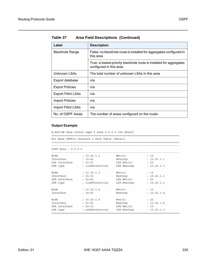
Routing Protocols Guide OSPF
Edition: 01 3HE 16307 AAAA TQZZA 335
Output Example
A:ALU-A# show router ospf 0 area 0.0.0.0 lfa detail===============================================================================Rtr Base OSPFv2 Instance 0 Path Table (detail)===============================================================================-------------------------------------------------------------------------------OSPF Area : 0.0.0.0-------------------------------------------------------------------------------Node : 10.20.1.1 Metric : 10Interface : In-A1 Nexthop : 10.20.1.1LFA Interface : In-C1 LFA Metric : 20LFA type : linkProtection LFA Nexthop : 10.20.1.3
Node : 10.20.1.3 Metric : 10Interface : In-C1 Nexthop : 10.20.1.3LFA Interface : In-A1 LFA Metric : 20LFA type : linkProtection LFA Nexthop : 10.20.1.1
Node : 10.20.1.4 Metric : 10Interface : In-D1 Nexthop : 10.20.1.4
Node : 10.20.1.6 Metric : 20Interface : In-D1 Nexthop : 10.20.1.4LFA Interface : In-C1 LFA Metric : 30LFA type : nodeProtection LFA Nexthop : 10.20.1.3===============================================================================
Blackhole Range False: no blackhole route is installed for aggregates configured in this area
True: a lowest-priority blackhole route is installed for aggregates configured in this area
Unknown LSAs The total number of unknown LSAs in this area
Export database n/a
Export Policies n/a
Export Flitrd LSAs n/a
Import Policies n/a
Import Flitrd LSAs n/a
No. of OSPF Areas The number of areas configured on the router
Table 37 Area Field Descriptions (Continued)
Label Description

OSPF
336
Routing Protocols Guide
3HE 16307 AAAA TQZZA Edition: 01
capabilities
Syntax capabilities [router-id]
Context show>router>ospfshow>router>ospf3
Description This command displays the entries in the Router Information (RI) LSAs.
Parameters router-id — lists only the LSAs related to that router ID. If no router-id is specified, all database entries are listed.
Output The following output is an example of OSPF capabilities information, and Table 39 describes the fields.
Output Example
*A:7705:Dut-A# show router ospf capabilities===============================================================================Rtr Base OSPFv2 Instance 0 Capabilities===============================================================================scope Router Id Capabilities-------------------------------------------------------------------------------Area 10.20.1.1 0x38000000: Stub TE P2P-VLAN
SR Algorithm:Backup-constrained-SPFIGP-metric-based-SPF
SR Label Range: start label 20000 range 10001Area 10.20.1.3 0x38000000: Stub TE P2P-VLAN
SR Algorithm:Backup-constrained-SPFIGP-metric-based-SPF
SR Label Range: start label 20000 range 10001
Table 38 Area LFA Field Descriptions
Label Description
Node The IP address of the source node
Metric The cost to the primary route next hop
Interface The interface name of the primary next hop
Nexthop The IP address of the primary next hop
LFA Interface The interface name of the LFA backup next hop
LFA Metric The cost to the LFA backup next hop
LFA type The LFA protection type: link protection or node protection
LFA Nexthop The IP address of the LFA backup next hop

Routing Protocols Guide OSPF
Edition: 01 3HE 16307 AAAA TQZZA 337
Area 10.20.1.4 0x38000000: Stub TE P2P-VLANSR Algorithm:
Backup-constrained-SPFIGP-metric-based-SPF
SR Label Range: start label 20000 range 10001Area 10.20.1.5 0x38000000: Stub TE P2P-VLAN
SR Algorithm:Backup-constrained-SPFIGP-metric-based-SPF
SR Label Range: start label 20000 range 10001Area 10.20.1.6 0x38000000: Stub TE P2P-VLAN
SR Algorithm:Backup-constrained-SPFIGP-metric-based-SPF
SR Label Range: start label 20000 range 10001Area 10.20.1.22 0x38000000: Stub TE P2P-VLAN
SR Algorithm:Backup-constrained-SPFIGP-metric-based-SPF
SR Label Range: start label 20000 range 10001-------------------------------------------------------------------------------No. of LSAs: 6===============================================================================*A:7705:Dut-A#
database
Syntax database [type {router | network | summary | asbr-summary | external | nssa | all}] [area area-id] [adv-router router-id] [link-state-id] [detail] [filtered]
database [type {router | network | inter-area-pfx | inter-area-rtr | external | nssa | intra-area-pfx | rtr-info | all}] [area area-id] [adv-router router-id] [link-state-id] [detail] [filtered]
Context show>router>ospfshow>router>ospf3
Description This command displays information about the OSPF link-state database.
Table 39 Router Capabilities Field Descriptions
Label Description
Scope The LSA type
Router ID The OSPF area identifier
Capabilities The link-state ID is an LSA type-specific field containing either a number to distinguish several LSAs from the same router, an interface ID, or a router ID; it identifies the piece of the routing domain being described by the advertisement

OSPF
338
Routing Protocols Guide
3HE 16307 AAAA TQZZA Edition: 01
When no command line options are specified, the command displays a summary output for all database entries.
Parameters type — specifies to filter the OSPF LSDB information based on the specified database type
router — displays only router (Type 1) LSAs in the LSDB
network — displays only network (Type 2) LSAs in the LSDB
summary — displays only summary (Type 3) LSAs in the LSDB
asbr-summary — displays only ASBR summary (Type 4) LSAs in the LSDB
external — displays only AS external (Type 5) LSAs in the LSDB. External LSAs are maintained globally and not per area. If the display of external links is requested, the area parameter, if present, is ignored.
nssa — displays only NSSA area-specific AS external (Type 7) LSAs in the LSDB
inter-area-pfx — displays inter-area prefix LSAs
inter-area-rtr — displays inter-area router LSAs
intra-area-pfx — displays intra-area prefix LSAs
rtr-info — displays router info LSAs
all — displays all LSAs in the LSDB. The all keyword is intended to be used with either the area area-id or the adv-router router-id [link-state-id] parameters.
area area-id — displays LSDB information associated with the specified OSPF area-id
Values ip-address — a.b.c.darea — 0 to 4294967295
adv-router router-id [link-state-id] — displays LSDB information associated with the specified advertising router. To further narrow the number of items displayed, the link-state-id can optionally be specified.
detail — displays detailed information on the LSDB entries
filtered — displays LSDB entries that were filtered by an area import or export policy
Output The following output is an example of OSPF database information, and Table 40 describes the fields.
Output Example
A:ALU-A# show router ospf database===============================================================================Rtr Base OSPFv2 Instance 0 Link State Database (type : All)===============================================================================Type Area ID Link State Id Adv Rtr Id Age Sequence Cksum-------------------------------------------------------------------------------Router 0.0.0.0 10.0.0.2 10.0.0.2 1800 0x800000b6 0xf54Router 0.0.0.0 10.0.0.5 10.0.0.5 1902 0x8000009d 0xcb7cRouter 0.0.0.0 10.0.0.8 10.0.0.8 1815 0x8000009a 0x529bRouter 0.0.0.0 10.0.0.9 10.0.0.9 1156 0x80000085 0xd00f

Routing Protocols Guide OSPF
Edition: 01 3HE 16307 AAAA TQZZA 339
Router 0.0.0.0 10.0.0.10 10.0.0.10 533 0x8000009d 0x3f1fRouter 0.0.0.0 10.0.0.11 10.0.0.11 137 0x80000086 0xc58fRouter 0.0.0.0 10.0.0.12 10.0.0.12 918 0x8000009d 0x4cf3Router 0.0.0.0 10.0.0.13 10.0.0.13 1401 0x800000a2 0x879cNetwork 0.0.0.0 10.0.53.28 10.0.0.28 149 0x80000083 0xe5cdNetwork 0.0.0.0 10.0.54.28 10.0.0.28 1259 0x80000083 0xdad7Summary 0.0.0.0 10.0.0.15 10.0.0.10 378 0x80000084 0xeba1Summary 0.0.0.0 10.0.0.15 10.0.0.12 73 0x80000084 0xdfabSummary 0.0.0.0 10.0.0.18 10.0.0.10 1177 0x80000083 0xcfbbSummary 0.0.0.1 10.100.25.4 10.0.0.12 208 0x80000091 0x3049AS Summ 0.0.0.1 10.0.0.8 10.0.0.10 824 0x80000084 0x3d07AS Summ 0.0.0.1 10.0.0.8 10.0.0.12 1183 0x80000095 0x4bdfAS Summ 0.0.0.1 10.0.0.9 10.0.0.10 244 0x80000082 0x73cbAS Ext n/a 10.1.0.0 10.0.0.23 1312 0x80000083 0x45e7AS Ext n/a 10.2.0.0 10.0.0.23 997 0x80000082 0x45e6AS Ext n/a 10.20.0.0 10.0.0.23 238 0x80000081 0x2d81...-------------------------------------------------------------------------------No. of LSAs: 339===============================================================================
A:ALU-A# show router ospf database detail===============================================================================Rtr Base OSPFv2 Instance 0 Link State Database (type : All) (detail)-------------------------------------------------------------------------------Router LSA for Area 0.0.0.0-------------------------------------------------------------------------------Area Id : 0.0.0.0 Adv Router Id : 10.0.0.2Link State Id : 10.0.0.2 LSA Type : RouterSequence No : 0x800000b7 Checksum : 0xd55Age : 155 Length : 192Options : EFlags : None Link Count : 14Link Type (1) : Point To PointNbr Rtr Id (1) : 10.0.0.13 I/F Address (1) : 10.0.22.2No of TOS (1) : 0 Metric-0 (1) : 25Link Type (2) : Stub NetworkNetwork (2) : 10.0.22.0 Mask (2) : 255.255.255.0No of TOS (2) : 0 Metric-0 (2) : 25Link Type (3) : Point To PointNbr Rtr Id (3) : 10.0.0.12 I/F Address (3) : 10.0.5.2No of TOS (3) : 0 Metric-0 (3) : 25Link Type (4) : Stub NetworkNetwork (4) : 10.0.5.0 Mask (4) : 255.255.255.0No of TOS (4) : 0 Metric-0 (4) : 25Link Type (5) : Point To PointNbr Rtr Id (5) : 10.0.0.8 I/F Address (5) : 10.0.13.2No of TOS (5) : 0 Metric-0 (5) : 6Link Type (6) : Stub NetworkNetwork (6) : 10.0.13.0 Mask (6) : 255.255.255.0No of TOS (6) : 0 Metric-0 (6) : 6Link Type (7) : Point To PointNbr Rtr Id (7) : 10.0.0.5 I/F Address (7) : 10.0.14.2No of TOS (7) : 0 Metric-0 (7) : 6Link Type (8) : Stub NetworkNetwork (8) : 10.0.14.0 Mask (8) : 255.255.255.0No of TOS (8) : 0 Metric-0 (8) : 6Link Type (9) : Point To PointNbr Rtr Id (9) : 10.0.0.11 I/F Address (9) : 10.0.17.2

OSPF
340
Routing Protocols Guide
3HE 16307 AAAA TQZZA Edition: 01
No of TOS (9) : 0 Metric-0 (9) : 25Link Type (10) : Stub NetworkNetwork (10) : 10.0.17.0 Mask (10) : 255.255.255.0No of TOS (10) : 0 Metric-0 (10) : 25Link Type (11) : Stub NetworkNetwork (11) : 10.0.0.2 Mask (11) : 255.255.255.255No of TOS (11) : 0 Metric-0 (11) : 1Link Type (12) : Stub NetworkNetwork (12) : 10.0.18.0 Mask (12) : 255.255.255.0No of TOS (12) : 0 Metric-0 (12) : 24Link Type (13) : Point To PointNbr Rtr Id (13) : 10.0.0.10 I/F Address (13) : 10.0.3.2No of TOS (13) : 0 Metric-0 (13) : 25Link Type (14) : Stub NetworkNetwork (14) : 10.0.3.0 Mask (14) : 255.255.255.0No of TOS (14) : 0 Metric-0 (14) : 25-------------------------------------------------------------------------------
AS Ext LSA for Network 10.0.0.14-------------------------------------------------------------------------------Area Id : N/A Adv Router Id : 10.0.0.10Link State Id : 10.0.0.14 LSA Type : AS ExtSequence No : 0x80000083 Checksum : 0xa659Age : 2033 Length : 36Options : ENetwork Mask : 255.255.255.255 Fwding Address : 10.1.6.15Metric Type : Type 2 Metric-0 : 4Ext Route Tag : 0
Table 40 Database Field Descriptions
Label Description
Type/ LSA Type The LSA type
Area ID The OSPF area identifier
Link State ID The link-state ID is an LSA type-specific field containing either a number to distinguish several LSAs from the same router, an interface ID, or a router ID; it identifies the piece of the routing domain being described by the advertisement
Adv Rtr Id/ Adv Router Id
The router identifier of the router advertising the LSA
Age The age of the link-state advertisement in seconds
Sequence/ Sequence No
The signed 32-bit integer sequence number
Cksum/ Checksum The 32-bit unsigned sum of the link-state advertisements' LS checksums
No. of LSAs The number of LSAs displayed

Routing Protocols Guide OSPF
Edition: 01 3HE 16307 AAAA TQZZA 341
Options EA: external attribute LSA support
DC: demand circuit support
R: if clear, a node can participate in OSPF topology distribution without being used to forward transit traffic
N: type 7 LSA support
MC: multicast support (not applicable)
E: external routes support
V6: not applicable
Prefix Options P: propagate NSSA LSA
MC: multicast support (not applicable)
LA: local address capability; if set, the prefix is an IPv6 interface address of the advertising router (not applicable)
NU: no unicast capability; if set, the prefix is excluded from IPv6 unicast calculations (not applicable)
Flags None: no flags set
V: the router is an endpoint for one or more fully adjacent virtual links having the described area as the transit area
E: the router is an AS Boundary Router
B: the router is an Area Border Router
Link Count The number of links advertised in the LSA
Link Type (n) The link type of the nth link in the LSA
Network (n) The network address of the nth link in the LSA
Metric-0 (n) The cost metric of the nth link in the LSA
Table 40 Database Field Descriptions (Continued)
Label Description

OSPF
342
Routing Protocols Guide
3HE 16307 AAAA TQZZA Edition: 01
interface
Syntax interface [area area-id] [detail]interface [ip-int-name | ip-address] [detail]interface [ip-int-name | ip-address] database [detail]interface [ip-int-name | ip-address | ipv6-address] [detail]interface [ip-int-name | ip-address | ipv6-address] database [detail]
Context show>router>ospfshow>router>ospf3
Description This command displays the details of the OSPF interface, which can be identified by IP address or IP interface name. If neither is specified, all in-service interfaces are displayed. The ipv6-address applies only in the ospf3 context.
The area option displays all interfaces configured in the specified area.
The detail option produces a great amount of data. It is recommended that this option be used only when requesting a specific interface.
Parameters area-id — displays all interfaces configured in this area
ip-int-name — displays only the interface identified by this interface name
ip-address — displays only the interface identified by this IP address
ipv6-address — displays only the interface identified by this IPv6 address
database — displays detailed information on the database for this interface
detail — displays detailed information on the interface
Output The following outputs are examples of OSPF interface information:
• OSPF standard interface information (Output Example, Table 41)• OSPF detailed interface information (Output Example, Table 42)
Output Example
A:ALU-A# show router ospf interface===============================================================================Rtr Base OSPFv2 Instance 0 Interface===============================================================================If Name Area Id Designated Rtr Bkup Desig Rtr Adm Oper-------------------------------------------------------------------------------system 0.0.0.1 10.10.10.104 0.0.0.0 Up DRto-103 0.0.0.20 0.0.0.0 0.0.0.0 Up Down-------------------------------------------------------------------------------No. of OSPF Interfaces: 2===============================================================================

Routing Protocols Guide OSPF
Edition: 01 3HE 16307 AAAA TQZZA 343
Table 41 Interface Field Descriptions
Label Description
If Name The interface name
Area Id A 32-bit integer uniquely identifying the area to which this interface is connected. Area ID 0.0.0.0 is used for the OSPF backbone.
Designated rtr The IP interface address of the router identified as the designated router for the network in which this interface is configuredSet to 0.0.0.0 if there is no designated router
Bkup Desig Rtr The IP interface address of the router identified as the backup designated router for the network in which this interface is configuredSet to 0.0.0.0 if there is no backup designated router
Adm Dn: OSPF on this interface is administratively shut down
Up: OSPF on this interface is administratively enabled
Oper Down: the initial interface state. In this state, the lower-level protocols have indicated that the interface is unusable.
Wait: the router is trying to determine the identity of the (backup) designated router for the network
PToP: the interface is operational, and connects either to a physical point-to-point network or to a virtual link
DR: this router is the designated router for this network
BDR: this router is the backup designated router for this network
ODR: the interface is operational and part of a broadcast or NBMA network on which another router has been selected to be the designated router
No. of OSPF Interfaces
The number of interfaces listed

OSPF
344
Routing Protocols Guide
3HE 16307 AAAA TQZZA Edition: 01
Output Example
A:ALU-A# show router ospf interface “system” detail===============================================================================Rtr Base OSPFv2 Instance 0 Interface "system" (detail)===============================================================================-------------------------------------------------------------------------------Configuration-------------------------------------------------------------------------------IP Address : 10.10.10.104Area Id : 0.0.0.1 Priority : 1Hello Intrvl : 10 sec Rtr Dead Intrvl : 40 secRetrans Intrvl : 5 sec Poll Intrvl : 120 secCfg Metric : 0 Advert Subnet : TrueTransit Delay : 1 Cfg IF Type : NonePassive : False Cfg MTU : 0LSA-filter-out : None Adv Rtr Capab : YesLFA : Include LFA NH Template : template1Auth Type : None-------------------------------------------------------------------------------State-------------------------------------------------------------------------------Admin Status : Enabled Oper State : Designated RtrDesignated Rtr : 10.10.10.104 Backup Desig Rtr : 0.0.0.0IF Type : Broadcast Network Type : TransitOper MTU : 1500 Last Enabled : 01/26/2015 23:28:25Oper Metric : 0 Bfd Enabled : NoTe Metric : 0 Te State : DownAdmin Groups : NoneLdp Sync : outOfService Ldp Sync Wait : DisabledLdp Timer State : Disabled Ldp Tm Left : 0-------------------------------------------------------------------------------Statistics-------------------------------------------------------------------------------Nbr Count : 0 If Events : 2Tot Rx Packets : 0 Tot Tx Packets : 0Rx Hellos : 0 Tx Hellos : 0Rx DBDs : 0 Tx DBDs : 0Rx LSRs : 0 Tx LSRs : 0Rx LSUs : 0 Tx LSUs : 0Rx LS Acks : 0 Tx LS Acks : 0Retransmits : 0 Discards : 0Bad Networks : 0 Bad Virt Links : 0Bad Areas : 0 Bad Dest Addrs : 0Bad Auth Types : 0 Auth Failures : 0Bad Neighbors : 0 Bad Pkt Types : 0Bad Lengths : 0 Bad Hello Int. : 0Bad Dead Int. : 0 Bad Options : 0Bad Versions : 0 Bad Checksums : 0LSA Count : 0 LSA Checksum : 0x0-------------------------------------------------------------------------------
Table 42 Detailed Interface Field Descriptions
Label Description
Interface The IP address of this OSPF interface

Routing Protocols Guide OSPF
Edition: 01 3HE 16307 AAAA TQZZA 345
IP Address The IP address and mask of this OSPF interface
Interface Name The interface name
Area Id A 32-bit integer uniquely identifying the area to which this interface is connected. Area ID 0.0.0.0 is used for the OSPF backbone.
Priority The priority of this interface. Used in multi-access networks, this field is used in the designated router election algorithm.
Hello Intrvl The length of time, in seconds, between the Hello packets that the router sends on the interface. This value must be the same for all routers attached to a common network.
Rtr Dead Intrvl The number of seconds that a router's Hello packets have not been seen before its neighbors declare the router down. This should be some multiple of the Hello interval. This value must be the same for all routers attached to a common network.
Retrans Intrvl The number of seconds between link-state advertisement retransmissions, for adjacencies belonging to this interface. This value is also used when retransmitting database description and link-state request packets.
Poll Intrvl The larger time interval, in seconds, between the Hello packets sent to an inactive non-broadcast multi-access neighbor
Cfg Metric The metric to be advertised for this interface
Advert Subnet False: when a point-to-point interface is configured as false, then the subnet is not advertised and the endpoints are advertised as host routes
True: when a point-to-point interface is configured as true, then the subnet is advertised
Transit Delay The estimated number of seconds it takes to transmit a link-state update packet over this interface
Cfg IF Type The configured interface type
Passive False: this interfaces operates as a normal OSPF interface with regard to adjacency forming and network and link behavior
True: no OSPF Hellos will be sent out on this interface and the router advertises this interface as a stub network or link in its router LSAs
Table 42 Detailed Interface Field Descriptions (Continued)
Label Description

OSPF
346
Routing Protocols Guide
3HE 16307 AAAA TQZZA Edition: 01
Cfg MTU The desired size of the largest packet that can be sent or received on this OSPF interface, specified in octets. This size does include the underlying IP header length, but not the underlying layer headers and trailers.
LFA Indicates whether the interface is included in the LFA SPF calculation
LFA NH Template Indicates whether an LFA next hop policy template is applied to this interface
Auth Type Identifies the authentication procedure to be used for the packet
None: routing exchanges over the network/subnet are not authenticated
Simple: a 64-bit field is configured on a per-network basis. All packets sent on a particular network must have this configured value in their OSPF header 64-bit authentication field. This essentially serves as a “clear” 64-bit password.
MD5: a shared secret key is configured on all routers attached to a common network or subnet. For each OSPF protocol packet, the key is used to generate and verify a “message digest” that is appended to the end of the OSPF packet.
Admin Status Disabled: OSPF on this interface is administratively shut down
Enabled: OSPF on this interface is administratively enabled
Oper State Down: the initial interface state. In this state, the lower-level protocols have indicated that the interface is unusable.
Waiting: the router is trying to determine the identity of the (backup) designated router for the network
Point To Point: the interface is operational and connects either to a physical point-to-point network or to a virtual link
Designated Rtr: this router is the designated router for this network
Other Desig Rtr: the interface is operational and part of a broadcast or NBMA network on which another router has been selected to be the designated router
Backup Desig Rtr: this router is the backup designated router for this network
Table 42 Detailed Interface Field Descriptions (Continued)
Label Description

Routing Protocols Guide OSPF
Edition: 01 3HE 16307 AAAA TQZZA 347
Designated Rtr The IP interface address of the router identified as the designated router for the network in which this interface is configuredSet to 0.0.0.0 if there is no designated router
Backup Desig Rtr The IP interface address of the router identified as the backup designated router for the network in which this interface is configuredSet to 0.0.0.0 if there is no backup designated router
IF Type Broadcast: LANs, such as Ethernet
NBMA: X.25, Frame Relay and similar technologies
Point-To-Point: links that are definitively point-to-point
Network Type Stub: OPSF has not established a neighbor relationship with any other OSPF router on this network; therefore, only traffic sourced or destined for this network will be routed to this network
Transit: OPSF has established at least one neighbor relationship with another OSPF router on this network; therefore, traffic en route to other networks may be routed via this network
Oper MTU The operational size of the largest packet that can be sent or received on this OSPF interface, specified in octets. This size includes the underlying IP header length, but not the underlying layer headers and trailers.
Last Enabled The time that this interface was last enabled to run OSPF on this interface
Te Metric The TE metric configured for this interface. This metric is flooded out in the TE metric sub-TLV in the OSPF TE LSAs. Depending on the configuration, either the TE metric value or the native OSPF metric value is used in CSPF computations.
Te State The MPLS interface TE status from OSPF standpoint
Admin Groups The bit-map inherited from the MPLS interface that identifies the admin groups to which this interface belongs
Ldp Sync Specifies whether the IGP-LDP synchronization feature is enabled or disabled on all interfaces participating in the OSPF routing protocol
Ldp Sync Wait The time to wait for the LDP adjacency to come up
Ldp Timer State The state of the LDP sync time left on the OSPF interface
Table 42 Detailed Interface Field Descriptions (Continued)
Label Description

OSPF
348
Routing Protocols Guide
3HE 16307 AAAA TQZZA Edition: 01
Ldp Tm Left The time left before OSPF reverts back to advertising normal metrics for this interface
Nbr Count The number of OSPF neighbors on the network for this interface
If Events The number of times this OSPF interface has changed its state, or an error has occurred since this interface was last enabled
Tot Rx Packets The total number of OSPF packets received on this interface since this interface was last enabled
Tot Tx Packets The total number of OSPF packets transmitted on this interface since this interface was last enabled
Rx Hellos The total number of OSPF Hello packets received on this interface since this interface was last enabled
Tx Hellos The total number of OSPF Hello packets transmitted on this interface since this interface was last enabled
Rx DBDs The total number of OSPF database description packets received on this interface since this interface was last enabled
Tx DBDs The total number of OSPF database description packets transmitted on this interface since this interface was last enabled
Rx LSRs The total number of Link-State Requests (LSRs) received on this interface since this interface was last enabled
Tx LSRs The total number of Link-State Requests (LSRs) transmitted on this interface since this interface was last enabled
Rx LSUs The total number of Link-State Updates (LSUs) received on this interface since this interface was last enabled
Tx LSUs The total number of Link-State Updates (LSUs) transmitted on this interface since this interface was last enabled
Rx LS Acks The total number of Link-State Acknowledgments received on this interface since this interface was last enabled
Tx LS Acks The total number of Link-State Acknowledgments transmitted on this interface since this interface was last enabled
Retransmits The total number of OSPF retransmits sent on this interface since this interface was last enabled
Discards The total number of OSPF packets discarded on this interface since this interface was last enabled
Table 42 Detailed Interface Field Descriptions (Continued)
Label Description

Routing Protocols Guide OSPF
Edition: 01 3HE 16307 AAAA TQZZA 349
Bad Networks The total number of OSPF packets received with invalid network or mask since this interface was last enabled
Bad Virt Links The total number of OSPF packets received on this interface that are destined for a virtual link that does not exist since this interface was last enabled
Bad Areas The total number of OSPF packets received with an area mismatch since this interface was last enabled
Bad Dest Addrs The total number of OSPF packets received with the incorrect IP destination address since this interface was last enabled
Bad Auth Types The total number of OSPF packets received with an invalid authorization type since this interface was last enabled
Auth Failures The total number of OSPF packets received with an invalid authorization key since this interface was last enabled
Bad Neighbors The total number of OSPF packets received where the neighbor information does not match the information this router has for the neighbor since this interface was last enabled
Bad Pkt Types The total number of OSPF packets received with an invalid OSPF packet type since this interface was last enabled
Bad Lengths The total number of OSPF packets received on this interface with a total length not equal to the length given in the packet itself since this interface was last enabled
Bad Hello Int. The total number of OSPF packets received where the hello interval given in the packet was not equal to that configured on this interface since this interface was last enabled
Bad Dead Int. The total number of OSPF packets received where the dead interval given in the packet was not equal to that configured on this interface since this interface was last enabled
Bad Options The total number of OSPF packets received with an option that does not match those configured for this interface or area since this interface was last enabled
Bad Versions The total number of OSPF packets received with bad OSPF version numbers since this interface was last enabled
Bad Checksums The total number of OSPF packets received with bad checksums since this interface was last enabled
LSA Count The total number of link-state advertisements in this area’s link-state database, excluding AS External LSAs
Table 42 Detailed Interface Field Descriptions (Continued)
Label Description

OSPF
350
Routing Protocols Guide
3HE 16307 AAAA TQZZA Edition: 01
lfa-coverage
Syntax lfa-coverage
Context show>router>ospfshow>router>ospf3
Description This command displays OSPF LFA coverage information.
Output The following output is an example of LFA coverage information, and Table 43 describes the fields.
Output Example
A:ALU-A# show router ospf lfa-coverage===============================================================================Rtr Base OSPFv2 Instance 0 LFA Coverage===============================================================================Area Node Prefix---------------------------------------------------------------------------0.0.0.0 4/4(100%) 8/8(100%)===============================================================================A:ALU-A#
LSA Checksum The 32-bit unsigned sum of the link-state database advertisements’ LS checksums contained in this area’s link-state database. This checksum excludes AS External LSAs (type 5).
Table 42 Detailed Interface Field Descriptions (Continued)
Label Description
Table 43 LFA Coverage Field Descriptions
Label Description
Area The OSPF area in which LFA is enabled
Node The number of nodes in the area on which LFA is enabled
Prefix The number of interfaces on the nodes on which LFA is enabled

Routing Protocols Guide OSPF
Edition: 01 3HE 16307 AAAA TQZZA 351
neighbor
Syntax neighbor [ip-int-name | ip-address] [detail]neighbor overview neighbor [remote ip-address] [detail]neighbor [ip-int-name] [router-id] [detail]
Context show>router>ospfshow>router>ospf3
Description This command displays all neighbor information or all information on neighbors of a router identified by interface name or router ID.
The detail option produces a large amount of data. It is recommended that this option be used only when requesting a specific neighbor.
Parameters ip-int-name — displays neighbor information only for neighbors of the interface identified by the interface name
ip-address — displays neighbor information for the neighbor identified by the specified IPv4 address
detail — displays detailed information on the interface
overview — displays overview information on the interface
remote ip-address — displays information for a far-end neighbor, identified by the IP address. This parameter applies only in the ospf context.
router-id — Displays information for the neighbor identified by the router ID.This parameter only applies in the ospf3 context.
Output The following outputs are examples of OSPF neighbor information:
• OSPF standard neighbor information (Output Example, Table 44)• OSPF neighbor (detail) information (Output Example, Table 45)• OSPF neighbor (overview) information (Output Example, Table 46)
Output Example
A:ALU-A# show router ospf neighbor===============================================================================Rtr Base OSPFv2 Instance 0 Neighbors===============================================================================Interface-Name Rtr Id State Pri RetxQ TTL-------------------------------------------------------------------------------pc157-2/1 10.13.8.158 Full 1 0 37pc157-2/2 10.13.7.165 Full 100 0 33pc157-2/3 10.13.6.188 Full 1 0 38-------------------------------------------------------------------------------No. of Neighbors: 3

OSPF
352
Routing Protocols Guide
3HE 16307 AAAA TQZZA Edition: 01
Table 44 Neighbor Field Descriptions
Label Description
Interface-Name The interface name or IP address this neighbor is using in its IP source address. On links with no address, this will not be 0.0.0.0, but the address of another of the neighbor's interfaces.
Rtr Id A 32-bit integer uniquely identifying the neighboring router in the Autonomous System
State Down: the initial state of a neighbor conversation. It indicates that there has been no recent information received from the neighbor.
Attempt: this state is only valid for neighbors attached to NBMA networks. It indicates that no recent information has been received from the neighbor, but that a more concerted effort should be made to contact the neighbor.
Init: in this state, a Hello packet has recently been seen from the neighbor. However, bidirectional communication has not yet been established with the neighbor (that is, the router itself did not appear in the neighbor's Hello packet).
Two Way: in this state, communication between the two routers is bidirectional
ExchStart: the first step in creating an adjacency between the two neighboring routers. The goal of this step is to decide which router is the master, and to decide upon the initial database descriptor sequence number.
Exchange: in this state, the router is describing its entire link-state database by sending database description packets to the neighbor
Loading: in this state, Link-State Request packets are sent to the neighbor asking for the more recent LSAs that have been discovered (but not yet received) in the Exchange state
Full: in this state, the neighboring routers are fully adjacent. These adjacencies will now appear in router-LSAs and network-LSAs.
Pri The priority of this neighbor in the designated router election algorithm. The value 0 signifies that the neighbor is not eligible to become the designated router on this particular network.
RetxQ The current length of the retransmission queue
TTL The time until this neighbor is declared down; this timer is set to the dead router interval when a valid Hello packet is received from the neighbor
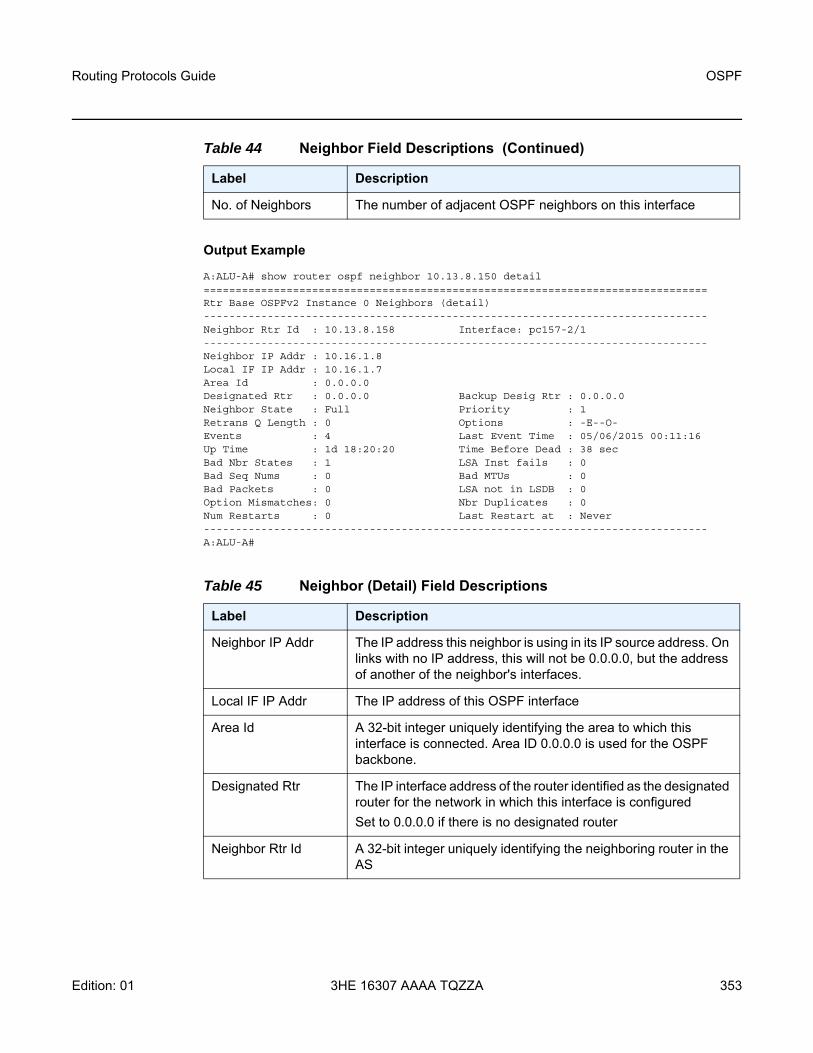
Routing Protocols Guide OSPF
Edition: 01 3HE 16307 AAAA TQZZA 353
Output Example
A:ALU-A# show router ospf neighbor 10.13.8.150 detail===============================================================================Rtr Base OSPFv2 Instance 0 Neighbors (detail)-------------------------------------------------------------------------------Neighbor Rtr Id : 10.13.8.158 Interface: pc157-2/1-------------------------------------------------------------------------------Neighbor IP Addr : 10.16.1.8Local IF IP Addr : 10.16.1.7Area Id : 0.0.0.0Designated Rtr : 0.0.0.0 Backup Desig Rtr : 0.0.0.0Neighbor State : Full Priority : 1Retrans Q Length : 0 Options : -E--O-Events : 4 Last Event Time : 05/06/2015 00:11:16Up Time : 1d 18:20:20 Time Before Dead : 38 secBad Nbr States : 1 LSA Inst fails : 0Bad Seq Nums : 0 Bad MTUs : 0Bad Packets : 0 LSA not in LSDB : 0Option Mismatches: 0 Nbr Duplicates : 0Num Restarts : 0 Last Restart at : Never-------------------------------------------------------------------------------A:ALU-A#
No. of Neighbors The number of adjacent OSPF neighbors on this interface
Table 45 Neighbor (Detail) Field Descriptions
Label Description
Neighbor IP Addr The IP address this neighbor is using in its IP source address. On links with no IP address, this will not be 0.0.0.0, but the address of another of the neighbor's interfaces.
Local IF IP Addr The IP address of this OSPF interface
Area Id A 32-bit integer uniquely identifying the area to which this interface is connected. Area ID 0.0.0.0 is used for the OSPF backbone.
Designated Rtr The IP interface address of the router identified as the designated router for the network in which this interface is configuredSet to 0.0.0.0 if there is no designated router
Neighbor Rtr Id A 32-bit integer uniquely identifying the neighboring router in the AS
Table 44 Neighbor Field Descriptions (Continued)
Label Description

OSPF
354
Routing Protocols Guide
3HE 16307 AAAA TQZZA Edition: 01
Neighbor State Down: the initial state of a neighbor conversation. It indicates that there has been no recent information received from the neighbor.
Attempt: this state is only valid for neighbors attached to NBMA networks. It indicates that no recent information has been received from the neighbor, but that a more concerted effort should be made to contact the neighbor.
Init: in this state, a Hello packet has recently been seen from the neighbor. However, bidirectional communication has not yet been established with the neighbor (that is, the router itself did not appear in the neighbor's Hello packet).
Two Way: in this state, communication between the two routers is bidirectional
Exchange start: the first step in creating an adjacency between the two neighboring routers. The goal of this step is to decide which router is the master, and to decide upon the initial database descriptor sequence number.
Exchange: in this state, the router is describing its entire link-state database by sending database description packets to the neighbor
Loading: in this state, Link-State Request packets are sent to the neighbor asking for the more recent LSAs that have been discovered (but not yet received) in the Exchange state
Full: in this state, the neighboring routers are fully adjacent. These adjacencies will now appear in router-LSAs and network-LSAs.
Priority The priority of this neighbor in the designated router election algorithm. The value 0 signifies that the neighbor is not eligible to become the designated router on this particular network.
Retrans Q Length The current length of the retransmission queue
Options E: external routes support
MC: multicast support (not applicable)
N/P: type 7 LSA support
EA: external attribute LSA support
DC: demand circuit support
O: opaque LSA support
Table 45 Neighbor (Detail) Field Descriptions (Continued)
Label Description

Routing Protocols Guide OSPF
Edition: 01 3HE 16307 AAAA TQZZA 355
Backup Desig Rtr The IP interface address of the router identified as the backup designated router for the network in which this interface is configuredSet to 0.0.0.0 if there is no backup designated router
Events The number of times this neighbor relationship has changed state, or an error has occurred
Last Event Time The time that the last event occurred that affected the adjacency to the neighbor
Up Time The uninterrupted time, in hundredths of seconds, that the adjacency to this neighbor has been up. To evaluate when the last state change occurred, see last event time.
Time Before Dead The time until this neighbor is declared down; this timer is set to the dead router interval when a valid Hello packet is received from the neighbor
Bad Nbr States The total number of OSPF packets received when the neighbor state was not expecting to receive this packet type since this interface was last enabled
LSA Inst fails The total number of times that an LSA could not be installed into the link-state database due to a resource allocation issue since this interface was last enabled
Bad Seq Nums The total number of times that a database description packet was received with a sequence number mismatch since this interface was last enabled
Bad MTUs The total number of times that the MTU in a received database description packet was larger than the MTU of the receiving interface since this interface was last enabled
Bad Packets The total number of times that an LS update was received with an illegal LS type or an option mismatch since this interface was last enabled
LSA not in LSDB The total number of times that an LS request was received for an LSA not installed in the LSDB of this router since this interface was last enabled
Option Mismatches The total number of times that an LS update was received with an option mismatch since this interface was last enabled
Nbr Duplicates The total number of times that a duplicate database description packet was received during the exchange state since this interface was last enabled
Table 45 Neighbor (Detail) Field Descriptions (Continued)
Label Description

OSPF
356
Routing Protocols Guide
3HE 16307 AAAA TQZZA Edition: 01
Output Example
*A:7705:Dut-A# show router ospf neighbor overview===============================================================================Rtr Base OSPFv2 Instance 0 Neighbor (overview)===============================================================================Neighbor-state Neighbors-------------------------------------------------------------------------------DOWN 0ATTEMPT 0INIT 02WAY 0EXSTART 0EXCHANGE 0LOADING 0FULL 0-------------------------------------------------------------------------------Total neighbors 0===============================================================================*A:7705:Dut-A# show router ospf#
Table 46 Neighbor (Overview) Field Descriptions
Label Description
Neighbor State
Down: the initial state of a neighbor conversation. It indicates that there has been no recent information received from the neighbor.
Attempt: this state is only valid for neighbors attached to NBMA networks. It indicates that no recent information has been received from the neighbor, but that a more concerted effort should be made to contact the neighbor.
Init: in this state, a Hello packet has recently been seen from the neighbor. However, bidirectional communication has not yet been established with the neighbor (that is, the router itself did not appear in the neighbor's Hello packet).
Two Way: in this state, communication between the two routers is bidirectional
Exchange start: the first step in creating an adjacency between the two neighboring routers. The goal of this step is to decide which router is the master, and to decide upon the initial database descriptor sequence number.
Exchange: in this state, the router is describing its entire link-state database by sending database description packets to the neighbor
Loading: in this state, Link-State Request packets are sent to the neighbor asking for the more recent LSAs that have been discovered (but not yet received) in the Exchange state
Full: in this state, the neighboring routers are fully adjacent. These adjacencies will now appear in router-LSAs and network-LSAs.

Routing Protocols Guide OSPF
Edition: 01 3HE 16307 AAAA TQZZA 357
opaque-database
Syntax opaque-database [area area-id | as] [adv-router router-id] [ls-id] [detail]
Context show>router>ospf
Description This command displays OSPF opaque database information.
Parameters area area-id — displays all opaque databases configured in this area
Values ip-address — a.b.c.darea — 0 to 4294967295
as — displays opaque databases configured in the autonomous system (AS)
adv-router router-id [ls-id] — displays opaque database information associated with the specified advertising router. To further narrow the number of items displayed, the ls-id parameter can optionally be specified.
Output The following output is an example of OSPF opaque database information, and Table 47 describes the fields.
Output Example
*A:7705:Dut-A# show router ospf opaque-database===============================================================================Rtr Base OSPFv2 Instance 0 Opaque Link State Database (type: All)===============================================================================Type Id Link State Id Adv Rtr Id Age Sequence Cksum-------------------------------------------------------------------------------Area 0.0.0.0 10.0.0.1 10.20.1.1 45 0x80000002 0xfd10Area 0.0.0.0 10.0.0.3 10.20.1.1 648 0x80000002 0x2585Area 0.0.0.0 10.0.0.4 10.20.1.1 603 0x80000002 0xd181Area 0.0.0.0 10.0.0.0 10.20.1.1 242 0x80000003 0xb15dArea 0.0.0.0 10.0.0.2 10.20.1.1 2118 0x80000002 0xb39aArea 0.0.0.0 10.0.0.3 10.20.1.1 283 0x80000003 0x5e01Area 0.0.0.0 10.0.0.4 10.20.1.1 579 0x80000003 0x4717Area 0.0.0.0 10.0.0.1 10.20.1.3 2135 0x80000001 0x803Area 0.0.0.0 10.0.0.3 10.20.1.3 425 0x80000002 0x5551Area 0.0.0.0 10.0.0.4 10.20.1.3 449 0x80000002 0xbf7dArea 0.0.0.0 10.0.0.0 10.20.1.3 2128 0x80000002 0xa766Area 0.0.0.0 10.0.0.2 10.20.1.3 444 0x80000003 0xf551
Neighbors The number of neighbors in the corresponding neighbor state
Total neighbors
The total number of neighbors
Table 46 Neighbor (Overview) Field Descriptions (Continued)
Label Description

OSPF
358
Routing Protocols Guide
3HE 16307 AAAA TQZZA Edition: 01
Area 0.0.0.0 10.0.0.3 10.20.1.3 264 0x80000003 0x83aaArea 0.0.0.0 10.0.0.4 10.20.1.3 246 0x80000003 0x6cdbArea 0.0.0.0 10.0.0.5 10.20.1.3 561 0x80000003 0x1e3dArea 0.0.0.0 10.0.0.1 10.20.1.4 354 0x80000002 0xafdArea 0.0.0.0 10.0.0.3 10.20.1.4 602 0x80000003 0xdf5bArea 0.0.0.0 10.0.0.4 10.20.1.4 580 0x80000003 0x45faArea 0.0.0.0 10.0.0.0 10.20.1.4 343 0x80000003 0x9f6cArea 0.0.0.0 10.0.0.2 10.20.1.4 6 0x80000006 0x122fArea 0.0.0.0 10.0.0.3 10.20.1.4 64 0x80000003 0xc750Area 0.0.0.0 10.0.0.4 10.20.1.4 493 0x80000003 0x3d0eArea 0.0.0.0 10.0.0.1 10.20.1.5 2106 0x80000001 0x10f6Area 0.0.0.0 10.0.0.3 10.20.1.5 2088 0x80000001 0xe461Area 0.0.0.0 10.0.0.4 10.20.1.5 2088 0x80000001 0x880fArea 0.0.0.0 10.0.0.0 10.20.1.5 2100 0x80000002 0x9b70Area 0.0.0.0 10.0.0.2 10.20.1.5 2089 0x80000002 0x3c06Area 0.0.0.0 10.0.0.3 10.20.1.5 2085 0x80000002 0x4dd3Area 0.0.0.0 10.0.0.4 10.20.1.5 2088 0x80000002 0x2923Area 0.0.0.0 10.0.0.1 10.20.1.6 2106 0x80000001 0x14f0Area 0.0.0.0 10.0.0.3 10.20.1.6 2089 0x80000001 0xaaebArea 0.0.0.0 10.0.0.0 10.20.1.6 2100 0x80000002 0x9575Area 0.0.0.0 10.0.0.2 10.20.1.6 2089 0x80000002 0x5ee0Area 0.0.0.0 10.0.0.3 10.20.1.6 2089 0x80000002 0xc455Area 0.0.0.0 10.0.0.1 10.20.1.22 264 0x80000002 0x5291Area 0.0.0.0 10.0.0.3 10.20.1.22 400 0x80000002 0xa889Area 0.0.0.0 10.0.0.4 10.20.1.22 2116 0x80000001 0x73caArea 0.0.0.0 10.0.0.0 10.20.1.22 239 0x80000003 0x33c6Area 0.0.0.0 10.0.0.2 10.20.1.22 362 0x80000003 0x74adArea 0.0.0.0 10.0.0.3 10.20.1.22 415 0x80000003 0x1eedArea 0.0.0.0 10.0.0.4 10.20.1.22 390 0x80000003 0xe337Area 0.0.0.0 10.0.0.5 10.20.1.22 2087 0x80000002 0x908a-------------------------------------------------------------------------------No. of Opaque LSAs: 42===============================================================================
*A:7705:Dut-A# show router ospf opaque-database adv-router 10.20.1.6===============================================================================Rtr Base OSPFv2 Instance 0 Opaque Link State Database (type: All)===============================================================================Type Id Link State Id Adv Rtr Id Age Sequence Cksum-------------------------------------------------------------------------------Area 0.0.0.0 10.0.0.1 10.20.1.6 2222 0x80000001 0x14f0Area 0.0.0.0 10.0.0.3 10.20.1.6 2204 0x80000001 0xaaebArea 0.0.0.0 10.0.0.0 10.20.1.6 2216 0x80000002 0x9575Area 0.0.0.0 10.0.0.2 10.20.1.6 2204 0x80000002 0x5ee0Area 0.0.0.0 10.0.0.3 10.20.1.6 2203 0x80000002 0xc455-------------------------------------------------------------------------------No. of Opaque LSAs: 5===============================================================================

Routing Protocols Guide OSPF
Edition: 01 3HE 16307 AAAA TQZZA 359
*A:7705:Dut-A# show router ospf opaque-database adv-router 10.20.1.6 detail===============================================================================Rtr Base OSPFv2 Instance 0 Opaque Link State Database (type: All) (detail)===============================================================================-------------------------------------------------------------------------------Opaque LSA-------------------------------------------------------------------------------Area Id : 0.0.0.0 Adv Router Id : 10.20.1.6Link State Id : 10.0.0.1 LSA Type : Area OpaqueSequence No : 0x80000001 Checksum : 0x14f0Age : 2243 Length : 28Options : EAdvertisement : Traffic Engineering
ROUTER-ID TLV (0001) Len 4 : 10.20.1.6-------------------------------------------------------------------------------Opaque LSA-------------------------------------------------------------------------------Area Id : 0.0.0.0 Adv Router Id : 10.20.1.6Link State Id : 10.0.0.3 LSA Type : Area OpaqueSequence No : 0x80000001 Checksum : 0xaaebAge : 2226 Length : 124Options : EAdvertisement : Traffic Engineering
LINK INFO TLV (0002) Len 100 :Sub-TLV: 1 Len: 1 LINK_TYPE : 2Sub-TLV: 2 Len: 4 LINK_ID : 10.10.6.6Sub-TLV: 3 Len: 4 LOC_IP_ADDR : 10.10.6.6Sub-TLV: 4 Len: 4 REM_IP_ADDR : 10.10.10.0Sub-TLV: 5 Len: 4 TE_METRIC : 100Sub-TLV: 6 Len: 4 MAX_BDWTH : 10000000 KbpsSub-TLV: 7 Len: 4 RSRVBL_BDWTH : 10000000 KbpsSub-TLV: 8 Len: 32 UNRSRVD_CLS0 :
P0: 10000000 Kbps P1: 10000000 Kbps P2: 10000000 Kbps P3: 10000000 KbpsP4: 10000000 Kbps P5: 10000000 Kbps P6: 10000000 Kbps P7: 10000000 Kbps
Sub-TLV: 9 Len: 4 ADMIN_GROUP : 0 None-------------------------------------------------------------------------------Opaque LSA-------------------------------------------------------------------------------Area Id : 0.0.0.0 Adv Router Id : 10.20.1.6Link State Id : 10.0.0.0 LSA Type : Area OpaqueSequence No : 0x80000002 Checksum : 0x9575Age : 2237 Length : 52Options : EAdvertisement : Router Info
Capabilities (1) Len 4 :0x38000000
SR algorithm (8) Len 2 :0x2 0x0
SR label range (9) Len 12 :Range-size=10001Sub-TLV SID/label(1) len 3 :
label=20000-------------------------------------------------------------------------------Opaque LSA-------------------------------------------------------------------------------Area Id : 0.0.0.0 Adv Router Id : 10.20.1.6Link State Id : 10.0.0.2 LSA Type : Area OpaqueSequence No : 0x80000002 Checksum : 0x5ee0Age : 2227 Length : 44

OSPF
360
Routing Protocols Guide
3HE 16307 AAAA TQZZA Edition: 01
Options : EAdvertisement : Extended Prefix
TLV Extended prefix (1) Len 20 :rtType=1 pfxLen=32 AF=0 pfx=10.20.1.6
Flags=Node (0x40)Sub-TLV Prefix SID (2) len 8 :
Flags=noPHP (0x40)MT-ID=0 Algorithm=0 SID/Index/Label=1006
-------------------------------------------------------------------------------Opaque LSA-------------------------------------------------------------------------------Area Id : 0.0.0.0 Adv Router Id : 10.20.1.6Link State Id : 10.0.0.3 LSA Type : Area OpaqueSequence No : 0x80000002 Checksum : 0xc455Age : 2226 Length : 52Options : EAdvertisement : Extended Link
TLV Extended link (1) Len 28 :link Type=Transit (2) Id=10.10.6.6 Data=10.10.6.6Sub-TLV LAN-Adj-SID (3) len 11 :
Flags=Value Local (0x60)MT-ID=0 Weight=0 Neighbor-ID=10.20.1.5SID/Index/Label=131071
===============================================================================*A:7705:Dut-A#
Table 47 OSPF Opaque Database Field Descriptions
Label Description
Area Id A 32-bit integer uniquely identifying an area. Area ID 0.0.0.0 is used for the OSPF backbone.
Type NSSAThis area is configured as an NSSA area.
AreaThis area is configured as a standard area (not NSSA or stub).
StubThis area is configured as an NSSA area.
Link State Id The link state ID is an LSA type specific field containing either a Router-Id or an IP Address; it identifies the piece of the routing domain being described by the advertisement.
Adv Rtr Id The router identifier of the router advertising the LSA.
Age The age of the link state advertisement in seconds.
Sequence The signed 32-bit integer sequence number.
Cksum The 32-bit unsigned sum of the link-state advertisements' LS checksums.

Routing Protocols Guide OSPF
Edition: 01 3HE 16307 AAAA TQZZA 361
prefix-sids
Syntax prefix-sids [ip-prefix[/prefix-length] [sid sid] [adv-router router-id]
Context show>router>ospf
Description This command displays OSPF prefix SIDs information.
Parameters ip-prefix[/prefix-length] — displays information about the specified IP prefix and length, up to 64 characters
sid — displays information for the specific segment identifier
Values 0 to 524287
router-id — displays information for the specific advertising router identified by its router ID
Output The following output is an example of OSPF prefix SIDs information, and Table 48 describes the fields.
Output Example
*A:7705:Dut-A# show router ospf prefix-sids========================================================================Rtr Base OSPFv2 Instance 0 Prefix-Sids========================================================================Prefix Area RtType SID
Adv-Rtr Flags------------------------------------------------------------------------10.20.1.1/32 0.0.0.0 INTRA-AREA 1001
10.20.1.1 NnP10.20.1.3/32 0.0.0.0 INTRA-AREA 1003
10.20.1.3 NnP10.20.1.4/32 0.0.0.0 INTRA-AREA 1004
10.20.1.4 NnP10.20.1.5/32 0.0.0.0 INTRA-AREA 1005
10.20.1.5 NnP10.20.1.6/32 0.0.0.0 INTRA-AREA 1006
10.20.1.6 NnP10.20.1.22/32 0.0.0.0 INTRA-AREA 1002
10.20.1.22 NnP------------------------------------------------------------------------No. of Prefix/SIDs: 6SID Flags : N = Node-SID
nP = no penultimate hop POPM = Mapping serverE = Explicit-NullV = Prefix-SID carries a valueL = value/index has local significanceI = Inter Area flagA = Attached flagB = Backup flag
========================================================================

OSPF
362
Routing Protocols Guide
3HE 16307 AAAA TQZZA Edition: 01
*A:7705:Dut-A# show router ospf prefix-sids sid 1002========================================================================Rtr Base OSPFv2 Instance 0 Prefix-Sids========================================================================Prefix Area RtType SID
Adv-Rtr Flags------------------------------------------------------------------------10.20.1.22/32 0.0.0.0 INTRA-AREA 1002
10.20.1.22 NnP------------------------------------------------------------------------No. of Prefix/SIDs: 1SID Flags : N = Node-SID
nP = no penultimate hop POPM = Mapping serverE = Explicit-NullV = Prefix-SID carries a valueL = value/index has local significanceI = Inter Area flagA = Attached flagB = Backup flag
========================================================================
Table 48 Prefix SIDs Field Descriptions
Label Description
Prefix The IP prefix for the SID
Area The OSPF area
Adv-Rtr The advertised router IP address
RtType The type of route
Active The status of the route: active (Y) or inactive (N)
SID The segment routing identifier (SID)
Flags The flags related to the advertised router: R = Re-advertisementN = Node SIDnP = No penultimate hop POPE = Explicit nullV = Prefix-SID carries a valueL = Value/index has local significance

Routing Protocols Guide OSPF
Edition: 01 3HE 16307 AAAA TQZZA 363
range
Syntax range [area-id]
Context show>router>ospfshow>router>ospf3
Description This command displays ranges of addresses on an ABR for the purpose of route summarization or suppression.
Parameters area-id — displays the configured ranges for the specified area
Output The following output is an example of OSPF range information, and Table 49 describes the fields.
Output Example
A:ALU-A# show router ospf range==========================================================Rtr Base OSPFv2 Instance 0 Ranges==========================================================Area Id Prefix Advertise LSDB-Type----------------------------------------------------------No. of Ranges: 0==========================================================A:ALU-A#
Table 49 Area Range Field Descriptions
Label Description
Area Id A 32-bit integer uniquely identifying an area. Area ID 0.0.0.0 is used for the OSPF backbone.
Prefix The mask for the range expressed as a decimal integer mask length or in dotted-decimal notation
Advertise False: the specified address/mask is not advertised outside the area
True: the specified address/mask is advertised outside the area
LSDB-Type NSSA: this range was specified in the NSSA context, and specifies that the range applies to external routes (via type 7 LSAs) learned within the NSSA when the routes are advertised to other areas as type 5 LSAs
Summary: this range was not specified in the NSSA context; the range applies to summary LSAs even if the area is an NSSA

OSPF
364
Routing Protocols Guide
3HE 16307 AAAA TQZZA Edition: 01
routes
Syntax routes [ip-prefix[/prefix-length]] [type] [detail] [alternative] [summary] [exclude-shortcut]routes [ip-prefix[/pfx-len]] [type] [detail] [alternative] [summary]
Context show>router>ospfshow>router>ospf3
Description This command displays information on OSPF routes.
Parameters ip-prefix/prefix-length — displays information about the specified IP address and prefix length
ip-prefix/pfx-len — displays information about the specified IP address and prefix length. This parameter applies only in the ospf3 context.
type — displays information about the specified route type
Values intra-area, inter-area, external-1, external-2, nssa-1, nssa-2
detail — displays detailed information about the routes
alternative — displays the level of protection per prefix
summary — displays summary information about the routes
exclude-shortcut — displays routes without shortcuts
Output The following outputs are examples of OSPF route information.
Output Example
A:ALU-A# show router ospf routes===============================================================================Rtr Base OSPFv2 Instance 0 Route Table===============================================================================Destination Type(Dest) Stat SID SIDflgs
NHIP NHIF Cost[E2]-------------------------------------------------------------------------------10.1.1.1/32 IA (HOST) N (R)
10.1.3.1 3 100010.1.2.0/24 IA (NET) N (R)
10.1.3.1 3 200010.2.3.2 4 2000
10.1.3.0/24 IA (NET) D (F)DIRECT 3 1000
10.2.3.0/24 IA (NET) D (F)DIRECT 4 1000
10.2.4.0/24 IA (NET) N (R)10.2.3.2 5 2000
10.3.5.0/24 IA (NET) D (F)DIRECT 6 1000
10.4.5.0/24 IA (NET) N (R)10.3.5.5 6 2000
10.4.6.0/24 IE (NET) N (R)10.2.3.2 5 300010.3.5.5 6 3000

Routing Protocols Guide OSPF
Edition: 01 3HE 16307 AAAA TQZZA 365
10.5.6.0/24 IE (NET) N (R)10.3.5.5 6 2000
10.2.2.2/32 IA (HOST) N (R)10.2.3.2 5 1000
10.2.3.0/24 IA (NET) D (F)DIRECT 5 1000
10.3.3.3/32 IA (HOST) D (F)DIRECT 2 0
10.4.4.4/32 IA (HOST) N (R)10.2.3.2 5 200010.3.5.5 6 2000
10.5.5.5/32 IA (HOST) N (R)1.3.5.5 6 1000
10.6.6.6/32 IE (HOST) N (R)10.3.5.5 6 2000
10.20.1.1/32 IA (HOST) N (R) 11 NnP10.1.3.1 3 1000
10.20.1.2/32 IA (HOST) N (R) 22 NnP10.2.3.2 5 1000
10.20.1.3/32 IA (HOST) D (F) 33 NnPDIRECT 1 0
10.20.1.4/32 IA (HOST) N (R) 44 NnP10.2.3.2 5 200010.3.5.5 6 2000
10.20.1.5/32 IA (HOST) N (R) 55 NnP10.3.5.5 6 1000
10.20.1.6/32 IE (HOST) N (R) 66 NnP10.3.5.5 6 2000
10.20.1.1/0 IA (RTR) N (N)10.1.3.1 3 1000
10.20.1.2/0 IA (AB-AS) N (N)10.2.3.2 5 1000
10.20.1.2/0 IA (AB-AS) N (N)10.2.3.2 4 1000
10.20.1.4/0 IA (AB-AS) N (N)10.2.3.2 5 200010.3.5.5 6 2000
10.20.1.5/0 IA (AB-AS) N (N)10.3.5.5 6 1000
-------------------------------------------------------------------------------No. of routes found: 26 (31 paths)Stat: D = direct N = not direct(RTM stat):(R) = added (F) = add failed
(N) = not added (D) = policy discardedSID Flags : N = Node-SID
nP = no penultimate hop POPM = Mapping serverE = Explicit-NullV = Prefix-SID carries a valueL = value/index has local significanceI = Inter Area flagA = Attached flag
===============================================================================A:ALU-A#

OSPF
366
Routing Protocols Guide
3HE 16307 AAAA TQZZA Edition: 01
A:ALU-A# show router ospf routes alternative detail=======================================================================Rtr Base OSPFv2 Instance 0 Routing Table (alternative) (detail)=======================================================================Destination Type(Dest) Stat
NHIP NHIF Cost[E2] Area Tunnel-InformationA-NHIP(L) A-NHIF A-Cost[E2] A-Type PGID
-----------------------------------------------------------------------10.1.2.0/24 IA (NET) D (F)
DIRECT 2 10 0.0.0.010.1.3.0/24 IA (NET) D (F)
DIRECT 3 10 0.0.0.010.2.3.0/24 IA (NET) N (R)
10.1.2.2 2 20 0.0.0.010.1.3.3 3 20 0.0.0.0
10.2.4.0/24 IA (NET) N (R)10.1.2.2 2 20 0.0.0.010.1.3.3(L) 3 30 LINK 0x130015
10.3.5.0/24 IA (NET) N (R)10.1.3.3 3 20 0.0.0.010.1.2.2(L) 2 30 LINK 0x130016
10.4.5.0/24 IA (NET) N (R)10.1.2.2 2 30 0.0.0.010.1.3.3 3 30 0.0.0.0
10.4.6.0/24 IA (NET) N (R)10.1.2.2 2 30 0.0.0.010.1.3.3(L) 3 40 LINK 0x130015
10.5.6.0/24 IA (NET) N (R)10.1.3.3 3 30 0.0.0.010.1.2.2(L) 2 40 LINK 0x130016
10.20.1.1/32 IA (HOST) D (F)DIRECT 1 0 0.0.0.0
10.20.1.2/32 IA (HOST) N (R)10.1.2.2 2 10 0.0.0.010.1.3.3(L) 3 20 LINK 0x130015
10.20.1.3/32 IA (HOST) N (R)10.1.3.3 3 10 0.0.0.010.1.2.2(L) 2 20 LINK 0x130016
10.20.1.4/32 IA (HOST) N (R)10.1.2.2 2 20 0.0.0.010.1.3.3(L) 3 30 LINK 0x130015
10.20.1.5/32 IA (HOST) N (R)1.1.3.3 3 20 0.0.0.01.1.2.2(L) 2 30 LINK 0x130016
10.20.1.6/32 IA (HOST) N (R)10.1.3.3 3 30 0.0.0.010.1.2.2 2 30 0.0.0.0
10.20.1.2/0 IA (RTR) N (N)10.1.2.2 2 10 0.0.0.0
10.20.1.3/0 IA (RTR) N (N)10.1.3.3 3 10 0.0.0.0
10.20.1.4/0 IA (RTR) N (N)10.1.2.2 2 20 0.0.0.0
10.20.1.5/0 IA (RTR) N (N)10.1.3.3 3 20 0.0.0.0
10.20.1.6/0 IA (RTR) N (N)10.1.3.3 3 30 0.0.0.010.1.2.2 2 30 0.0.0.0
-----------------------------------------------------------------------
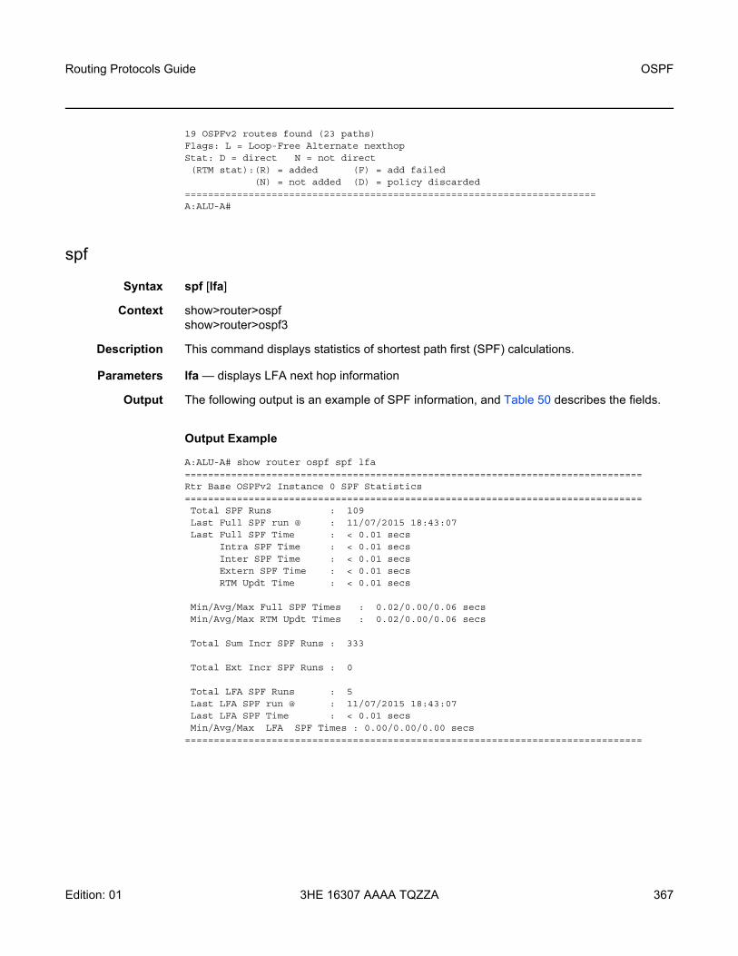
Routing Protocols Guide OSPF
Edition: 01 3HE 16307 AAAA TQZZA 367
19 OSPFv2 routes found (23 paths)Flags: L = Loop-Free Alternate nexthopStat: D = direct N = not direct(RTM stat):(R) = added (F) = add failed
(N) = not added (D) = policy discarded=======================================================================A:ALU-A#
spf
Syntax spf [lfa]
Context show>router>ospfshow>router>ospf3
Description This command displays statistics of shortest path first (SPF) calculations.
Parameters lfa — displays LFA next hop information
Output The following output is an example of SPF information, and Table 50 describes the fields.
Output Example
A:ALU-A# show router ospf spf lfa===============================================================================Rtr Base OSPFv2 Instance 0 SPF Statistics===============================================================================Total SPF Runs : 109Last Full SPF run @ : 11/07/2015 18:43:07Last Full SPF Time : < 0.01 secs
Intra SPF Time : < 0.01 secsInter SPF Time : < 0.01 secsExtern SPF Time : < 0.01 secsRTM Updt Time : < 0.01 secs
Min/Avg/Max Full SPF Times : 0.02/0.00/0.06 secsMin/Avg/Max RTM Updt Times : 0.02/0.00/0.06 secs
Total Sum Incr SPF Runs : 333
Total Ext Incr SPF Runs : 0
Total LFA SPF Runs : 5Last LFA SPF run @ : 11/07/2015 18:43:07Last LFA SPF Time : < 0.01 secsMin/Avg/Max LFA SPF Times : 0.00/0.00/0.00 secs
===============================================================================

OSPF
368
Routing Protocols Guide
3HE 16307 AAAA TQZZA Edition: 01
Table 50 SPF Field Descriptions
Label Description
Total SPF Runs The total number of incremental SPF runs triggered by new or updated LSAs
Last Full SPF run @ The date and time that the external OSPF SPF was last run
Last Full SPF Time The length of time, in seconds, when the last full SPF was run
Intra SPF Time The time that intra-area SPF was last run on this area
Inter SPF Time The total number of incremental SPF runs triggered by new or updated type 3 and type 4 summary LSAs
Extern SPF Time The total number of incremental SPF runs triggered by new or updated type 5 external LSAs
RTM Updt Time The time, in hundredths of seconds, used to perform a total SPF calculation
Min/Avg/Max Full SPF Times
Min: the minimum time, in hundredths of seconds, used to perform a total SPF calculation
Avg: the average time, in hundredths of seconds, of all the SPF calculations performed by this OSPF router
Max: the maximum time, in hundredths of seconds, used to perform a total SPF calculation
Min/Avg/Max RTM Updt Times
Min: the minimum time, in hundredths of seconds, used to perform an RTM updateNote: the RTM update is performed after the SPF calculation. The update is used to inform the routing table manager of any route or cost changes from the latest SPF calculation.
Avg: the average time, in hundredths of seconds, of all the RTM updates performed by this OSPF router
Max: the maximum time, in hundredths of seconds, used to perform an RTM update
Total Sum Incr SPF Runs
The total number of incremental SPF runs triggered by new or updated type 3 and type 4 summary LSAs
Total Ext Incr SPF Runs
The total number of incremental SPF runs triggered by new or updated type 5 external LSAs
Total LFA SPF Runs The total number of incremental LFA SPF runs triggered by new or updated LSAs
Last LFA SPF run @ The date and time that the external OSPF LFA SPF was last run

Routing Protocols Guide OSPF
Edition: 01 3HE 16307 AAAA TQZZA 369
statistics
Syntax statistics
Context show>router>ospfshow>router>ospf3
Description This command displays the global OSPF statistics.
Output The following output is an example of OSPF statistical information, and Table 51 describes the fields.
Output Example
A:ALU-A# show router ospf statistics===============================================================================Rtr Base OSPFv2 Instance 0 Statistics===============================================================================Rx Packets : 308462 Tx Packets : 246800Rx Hellos : 173796 Tx Hellos : 149062Rx DBDs : 67 Tx DBDs : 48Rx LSRs : 21 Tx LSRs : 19Rx LSUs : 105672 Tx LSUs : 65530Rx LS Acks : 28906 Tx LS Acks : 32141New LSAs Recvd : 38113 New LSAs Orig : 21067Ext LSAs Count : 17 No of Areas : 3No of Interfaces : 327 No of Neighbors : 0Retransmits : 46 Discards : 0Bad Networks : 0 Bad Virt Links : 0Bad Areas : 0 Bad Dest Addrs : 0Bad Auth Types : 0 Auth Failures : 0Bad Neighbors : 0 Bad Pkt Types : 0Bad Lengths : 0 Bad Hello Int. : 0Bad Dead Int. : 0 Bad Options : 0Bad Versions : 0 Bad Checksums : 0SID SRGB errors : 0 SID dupl errors : 0Failed SPF Attempts: 0 Bad MTUs : 0CSPF Requests : 0 CSPF Request Drops : 0
Last LFA SPF Time The length of time, in seconds, when the last LFA SPF was run
Min/Avg/Max LFA SPF Times
Min: the minimum time, in hundredths of seconds, used to perform an LFA SPF calculation
Avg: the average time, in hundredths of seconds, of all the LFA SPF calculations performed by this OSPF router
Max: the maximum time, in hundredths of seconds, used to perform an LFA SPF calculation
Table 50 SPF Field Descriptions (Continued)
Label Description

OSPF
370
Routing Protocols Guide
3HE 16307 AAAA TQZZA Edition: 01
CSPF Path Found : 0 CSPF Path Not Found: 0Total SPF Runs : 1 Total LFA SPF Runs : 1Total RLFA SPF Runs: 0===============================================================================
Table 51 OSPF Statistics Field Descriptions
Label Description
Rx Packets The total number of OSPF packets received on all OSPF enabled interfaces
Tx Packets The total number of OSPF packets transmitted on all OSPF enabled interfaces
Rx Hellos The total number of OSPF Hello packets received on all OSPF enabled interfaces
Tx Hellos The total number of OSPF Hello packets transmitted on all OSPF enabled interfaces
Rx DBDs The total number of OSPF database description packets received on all OSPF enabled interfaces
Tx DBDs The total number of OSPF database description packets transmitted on all OSPF enabled interfaces
Rx LSRs The total number of OSPF Link-State Requests (LSRs) received on all OSPF enabled interfaces
Tx LSRs The total number of OSPF Link-State Requests (LSRs) transmitted on all OSPF enabled interfaces
Rx LSUs The total number of OSPF Link-State Updates (LSUs) received on all OSPF enabled interfaces
Tx LSUs The total number of OSPF Link-State Updates (LSUs) transmitted on all OSPF enabled interfaces
Rx LS Acks The total number of OSPF Link-State Acknowledgments received on all OSPF enabled interfaces
New LSAs Recvd The total number of new OSPF Link-State Advertisements received on all OSPF enabled interfaces
New LSAs Orig The total number of new OSPF Link-State Advertisements originated on all OSPF enabled interfaces
Ext LSAs Count The total number of OSPF External Link-State Advertisements
No of Areas The number of areas configured for OSPF (maximum 4)
No of Interfaces The number of interfaces configured for OSPF on the router

Routing Protocols Guide OSPF
Edition: 01 3HE 16307 AAAA TQZZA 371
No of Neighbors The number of adjacent OSPF neighbors on this interface
Retransmits The total number of OSPF Retransmits transmitted on all OSPF enabled interfaces
Discards The total number of OSPF packets discarded on all OSPF enabled interfaces
Bad Networks The total number of OSPF packets received on all OSPF enabled interfaces with invalid network or mask
Bad Virt Links The total number of OSPF packets received on all OSPF enabled interfaces that are destined for a virtual link that does not exist
Bad Areas The total number of OSPF packets received on all OSPF enabled interfaces with an area mismatch
Bad Dest Addrs The total number of OSPF packets received on all OSPF enabled interfaces with the incorrect IP destination address
Bad Auth Types The total number of OSPF packets received on all OSPF enabled interfaces with an invalid authorization type
Auth Failures The total number of OSPF packets received on all OSPF enabled interfaces with an invalid authorization key
Bad Neighbors The total number of OSPF packets received on all OSPF enabled interfaces where the neighbor information does not match the information this router has for the neighbor
Bad Pkt Types The total number of OSPF packets received on all OSPF enabled interfaces with an invalid OSPF packet type
Bad Lengths The total number of OSPF packets received on all OSPF enabled interfaces with a total length not equal to the length given in the packet itself
Bad Hello Int. The total number of OSPF packets received on all OSPF enabled interfaces where the hello interval given in the packet was not equal to that configured for the respective interface
Bad Dead Int. The total number of OSPF packets received on all OSPF enabled interfaces where the dead interval given in the packet was not equal to that configured for the respective interface
Bad Options The total number of OSPF packets received on all OSPF enabled interfaces with an option that does not match those configured for the respective interface or area
Table 51 OSPF Statistics Field Descriptions (Continued)
Label Description

OSPF
372
Routing Protocols Guide
3HE 16307 AAAA TQZZA Edition: 01
status
Syntax status
Context show>router>ospfshow>router>ospf3
Description This command displays the general status of OSPF.
Output The following output is an example of OSPF status information, and Table 52 describes the fields.
Output Example
A:ALU-A# show router ospf status===============================================================================Rtr Base OSPFv2 Instance 0 Status===============================================================================OSPF Cfg Router Id : 10.0.0.0
Bad Versions The total number of OSPF packets received on all OSPF enabled interfaces with bad OSPF version numbers
Bad Checksums The total number of OSPF packets received with bad checksums since this interface was last enabled
SID SRGB errors The total number of SID SRGB errors
SID dupl errors The total number of SID duplication errors
Failed SPF Attempts The total number of failed SPF calculation attempts
Bad MTUs The total number of MTU mismatch
CSPF Requests The total number of constraint-based SPF requests
CSPF Request Drops The total number of constraint-based SPF requests dropped
CSPF Path Found A path that fulfills the set of constraints defined in MPLS traffic engineering
CSPF Path Not Found
A path that does not fulfill the set of constraints defined in MPLS traffic engineering
Total SPF Runs The total number of incremental SPF runs triggered by new or updated LSAs
Total LFA SPF Runs The total number of incremental LFA SPF runs triggered by new or updated LSAs
Table 51 OSPF Statistics Field Descriptions (Continued)
Label Description

Routing Protocols Guide OSPF
Edition: 01 3HE 16307 AAAA TQZZA 373
OSPF Oper Router Id : 10.10.10.104OSPF Version : 2OSPF Admin Status : EnabledOSPF Oper Status : EnabledGR Helper Mode : EnabledPreference : 10External Preference : 150Backbone Router : TrueArea Border Router : FalseAS Border Router : FalseOpaque LSA Support : TrueTraffic Engineering Support : FalseRFC 1583 Compatible : TrueDemand Exts Support : FalseIn Overload State : FalseIn External Overflow State : FalseExit Overflow Interval : 0Last Overflow Entered : NeverLast Overflow Exit : NeverExternal LSA Limit : -1Reference Bandwidth : 100,000,000 KbpsInit SPF Delay : 1000 msecSec SPF Delay : 1000 msecMax SPF Delay : 10000 msecMin LS Arrival Interval : 1000 msecInit LSA Gen Delay : 5000 msecSec LSA Gen Delay : 5000 msecMax LSA Gen Delay : 5000 msecLast Ext SPF Run : NeverExt LSA Cksum Sum : 0x0OSPF Last Enabled : 01/12/2015 15:32:11Unicast Import : TrueExport Policies : NoneImport Policies : NoneLfa Policies : pol1
: pol2: pol3: pol4: pol5
OSPF Ldp Sync Admin Status : EnabledLDP-over-RSVP : DisabledRSVP-Shortcut : EnabledAdvertise-Tunnel-Link : DisabledLFA : EnabledRemote-LFA : EnabledMax PQ Cost : 65535TI-LFA : DisabledMax SR FRR Labels : 2Export Limit : 0Export Limit Log Percent : 0Total Exp Routes : 0Segment Routing : DisabledDatabase export : DisabledASN : n/aEntropy Label : EnabledOverride ELC : Disabled===============================================================================A:ALU-A#

OSPF
374
Routing Protocols Guide
3HE 16307 AAAA TQZZA Edition: 01
Table 52 OSPF Status Field Descriptions
Label Description
OSPF Cfg Router Id The router ID configured for the router
OSPF Oper Router ID The operational router ID. The 7705 SAR defaults to the system IP address or, if not configured, the last 4 bytes of the system MAC address.
OSPF Version The current version number of the OSPF protocol: 2
OSPF Admin Status Disabled: the OSPF process is disabled on all interfaces
Enabled: the OSPF process is active on at least one interface
OSPF Oper Status Disabled: the OSPF process is not operational on all interfaces
Enabled: the OSPF process is operational on at least one interface
GR Helper Mode Disabled: Graceful Restart Helper is disabled
Enabled: Graceful Restart Helper is enabled
Preference The route preference for OSPF internal routes
External Preference The route preference for OSPF external routes
Backbone Router False: this router is not configured as an OSPF backbone router
True: this router is configured as an OSPF backbone router
Area Border Router False: this router is not configured as an area border router
True: this router is configured as an area border router
AS Border Router False: this router is not configured as an Autonomous System border (boundary) router
True: this router is configured as an Autonomous System border (boundary) router
Opaque LSA Support False: this router does not support opaque LSAs
True: this router supports opaque LSAs
Traffic Engineering Support
False: this router does not support traffic engineering
True: this router supports traffic engineering
RFC 1583 Compatible
False: this router is not RFC 1583 compatible
True: this router is RFC 1583 compatible
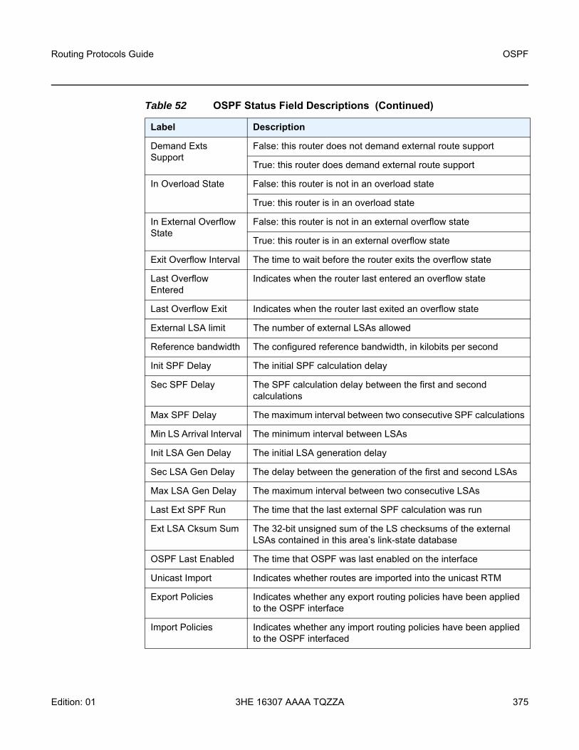
Routing Protocols Guide OSPF
Edition: 01 3HE 16307 AAAA TQZZA 375
Demand Exts Support
False: this router does not demand external route support
True: this router does demand external route support
In Overload State False: this router is not in an overload state
True: this router is in an overload state
In External Overflow State
False: this router is not in an external overflow state
True: this router is in an external overflow state
Exit Overflow Interval The time to wait before the router exits the overflow state
Last Overflow Entered
Indicates when the router last entered an overflow state
Last Overflow Exit Indicates when the router last exited an overflow state
External LSA limit The number of external LSAs allowed
Reference bandwidth The configured reference bandwidth, in kilobits per second
Init SPF Delay The initial SPF calculation delay
Sec SPF Delay The SPF calculation delay between the first and second calculations
Max SPF Delay The maximum interval between two consecutive SPF calculations
Min LS Arrival Interval The minimum interval between LSAs
Init LSA Gen Delay The initial LSA generation delay
Sec LSA Gen Delay The delay between the generation of the first and second LSAs
Max LSA Gen Delay The maximum interval between two consecutive LSAs
Last Ext SPF Run The time that the last external SPF calculation was run
Ext LSA Cksum Sum The 32-bit unsigned sum of the LS checksums of the external LSAs contained in this area’s link-state database
OSPF Last Enabled The time that OSPF was last enabled on the interface
Unicast Import Indicates whether routes are imported into the unicast RTM
Export Policies Indicates whether any export routing policies have been applied to the OSPF interface
Import Policies Indicates whether any import routing policies have been applied to the OSPF interfaced
Table 52 OSPF Status Field Descriptions (Continued)
Label Description

OSPF
376
Routing Protocols Guide
3HE 16307 AAAA TQZZA Edition: 01
Lfa Policies Lists the defined LFA policies
OSPF Ldp Sync Admin Status
Indicates whether the IGP-LDP synchronization feature is enabled or disabled on all interfaces participating in the OSPF routing protocol
RSVP-Shortcut Indicates whether RSVP-TE shortcuts (IGP shortcuts) are enabled
Advertise-Tunnel-Link
Indicates whether forwarding adjacencies are enabled
LFA Indicates whether LFA is enabled
Remote-LFA Indicates whether LFA is enabled on the remote device
Max PQ Cost Indicates the configured maximum PQ cost under the loopfree-alternate command
TI-LFA Indicates if TI-LFA is enabled or disabled under the loopfree-alternate command
Max SR FRR Labels The maximum number of segment routing FRR labels
Export Limit n/a
Export Limit Log Percent
n/a
Total Exp Routes Indicates the total number of export routes
Segment Routing Indicates whether segment routing is enabled
Database export Indicates whether database export is enabled
ASN n/a
Entropy Label Indicates whether entropy label is enabled
Override ELC Indicates whether entropy label capability is enabled for BGP tunnels
Table 52 OSPF Status Field Descriptions (Continued)
Label Description

Routing Protocols Guide OSPF
Edition: 01 3HE 16307 AAAA TQZZA 377
virtual-link
Syntax virtual-link database [detail]virtual-link [detail]
Context show>router>ospfshow>router>ospf3
Description This command displays information for OSPF virtual links.
Parameters database — displays the virtual link database.This parameter applies only in the ospf context.
detail — provides operational and statistical information about virtual links associated with this router
Output The following output is an example of OSPF virtual link information, and Table 53 describes the fields.
Output Example
A:ALU-A# show router ospf virtual-link=================================================================Rtr Base OSPFv2 Instance 0 Virtual Links=================================================================Nbr Rtr Id Area Id Local Interface Metric State-----------------------------------------------------------------10.0.0.10 0.0.0.1 10.1.7.12 300 PToP10.0.0.10 0.0.0.2 10.2.7.12 300 PToP-----------------------------------------------------------------No. of OSPF Virtual Links: 2=================================================================A:ALU-A#
A:ALU-A# show router ospf virtual-link detail===============================================================================Rtr Base OSPFv2 Instance 0 Virtual Links (detail)===============================================================================Neighbor Router Id : 10.0.0.10-------------------------------------------------------------------------------Nbr Router Id : 10.0.0.10 Area Id : 0.0.0.1Local Interface: 10.1.7.12 Metric : 300State : Point To Point Admin State : UpHello Intrvl : 10 sec Rtr Dead Intrvl: 60 secTot Rx Packets : 43022 Tot Tx Packets : 42964Rx Hellos : 24834 Tx Hellos : 24853Rx DBDs : 3 Tx DBDs : 2Rx LSRs : 0 Tx LSRs : 0Rx LSUs : 15966 Tx LSUs : 16352Rx LS Acks : 2219 Tx LS Acks : 1757Retransmits : 0 Discards : 0Bad Networks : 0 Bad Versions : 0Bad Areas : 0 Bad Dest Addrs : 0Bad Auth Types : 0 Auth Failures : 0Bad Neighbors : 0 Bad Pkt Types : 0

OSPF
378
Routing Protocols Guide
3HE 16307 AAAA TQZZA Edition: 01
Bad Lengths : 0 Bad Hello Int. : 0Bad Dead Int. : 0 Bad Options : 0Retrans Intrvl : 5 sec Transit Delay : 1 secLast Event : 11/07/2015 17:11:56 Authentication : None-------------------------------------------------------------------------------Neighbor Router Id : 10.0.0.10-------------------------------------------------------------------------------Nbr Router Id : 10.0.0.10 Area Id : 0.0.0.2Local Interface: 10.2.7.12 Metric : 300State : Point To Point Admin State : UpHello Intrvl : 10 sec Rtr Dead Intrvl: 60 secTot Rx Packets : 43073 Tot Tx Packets : 43034Rx Hellos : 24851 Tx Hellos : 24844Rx DBDs : 3 Tx DBDs : 2Rx LSRs : 1 Tx LSRs : 1Rx LSUs : 18071 Tx LSUs : 17853Rx LS Acks : 147 Tx LS Acks : 334Retransmits : 0 Discards : 0Bad Networks : 0 Bad Versions : 0Bad Areas : 0 Bad Dest Addrs : 0Bad Auth Types : 0 Auth Failures : 0Bad Neighbors : 0 Bad Pkt Types : 0Bad Lengths : 0 Bad Hello Int. : 0Bad Dead Int. : 0 Bad Options : 0Retrans Intrvl : 5 sec Transit Delay : 1 secLast Event : 11/07/2015 17:12:00 Authentication : None===============================================================================A:ALU-A#
Table 53 Virtual Link Field Descriptions
Label Description
Nbr Rtr ID The router IDs of neighboring routers
Area Id A 32-bit integer that identifies an area
Local Interface The IP address of the local egress interface used to maintain the adjacency to reach this virtual neighbor
Metric The metric value associated with the route. This value is used when importing this static route into other protocols. When the metric is configured as 0, then the metric configured in OSPF, default-metric, applies. This value is also used to determine which static route to install in the forwarding table.
State The operational state of the virtual link to the neighboring router
Authentication Specifies whether authentication is enabled for the interface or virtual link
Hello Intrvl The length of time, in seconds, between the Hello packets that the router sends on the interface

Routing Protocols Guide OSPF
Edition: 01 3HE 16307 AAAA TQZZA 379
Rtr Dead Intrvl The total number of OSPF packets received where the dead interval given in the packet was not equal to that configured on this interface since the OSPF admin status was enabled
Tot Rx Packets The total number of OSPF packets received on this interface since the OSPF admin status was enabled
Rx Hellos The total number of OSPF Hello packets received on this interface since the OSPF admin status was enabled
Rx DBDs The total number of OSPF database description packets received on this interface since the OSPF admin status was enabled
Rx LSRs The total number of Link-State Requests (LSRs) received on this interface since the OSPF admin status was enabled
Rx LSUs The total number of Link-State Updates (LSUs) received on this interface since the OSPF admin status was enabled
Rx LS Acks The total number of Link-State Acknowledgments received on this interface since the OSPF admin status was enabled
Tot Tx Packets The total number of OSPF packets transmitted on this interface since the OSPF admin status was enabled
Tx Hellos The total number of OSPF Hello packets transmitted on this interface since the OSPF admin status was enabled
Tx DBDs The total number of OSPF database description packets transmitted on this interface since the OSPF admin status was enabled
Tx LSRs The total number of OSPF Link-State Requests (LSRs) transmitted on this interface since the OSPF admin status was enabled
Tx LSUs The total number of OSPF Hello packets transmitted on this interface since the OSPF admin status was enabled
Tx LS Acks The total number of OSPF Link-State Acknowledgments transmitted on this interface since the OSPF admin status was enabled
Retransmits The total number of OSPF retransmits sent on this interface since the OSPF admin status was last enabled
Discards The total number of OSPF packets discarded on this interface since the OSPF admin status was last enabled
Table 53 Virtual Link Field Descriptions (Continued)
Label Description

OSPF
380
Routing Protocols Guide
3HE 16307 AAAA TQZZA Edition: 01
Bad Networks The total number of OSPF packets received with invalid network or mask since the OSPF admin status was last enabled
Bad Versions The total number of OSPF packets received with bad OSPF version numbers since the OSPF admin status was last enabled
Bad Areas The total number of OSPF packets received with an area mismatch since the OSPF admin status was last enabled
Bad Dest Addrs The total number of OSPF packets received with the incorrect IP destination address since the OSPF admin status was last enabled
Bad Auth Types The total number of OSPF packets received with an invalid authorization type since the OSPF admin status was last enabled
Auth Failures The total number of OSPF packets received with an invalid authorization key since the OSPF admin status was last enabled
Bad Neighbors The total number of OSPF packets received where the neighbor information does not match the information this router has for the neighbor since the OSPF admin status was last enabled
Bad Pkt Types The total number of OSPF packets received with an invalid OSPF packet type since the OSPF admin status was last enabled
Bad Lengths The total number of OSPF packets received on this interface with a total length not equal to the length given in the packet itself since the OSPF admin status was last enabled
Bad Hello Int. The total number of OSPF packets received where the hello interval given in the packet was not equal to that configured on this interface since the OSPF admin status was last enabled
Bad Dead Int. The total number of OSPF packets received where the dead interval given in the packet was not equal to that configured on this interface since the OSPF admin status was last enabled
Bad Options The total number of OSPF packets received with an option that does not match those configured for this interface or area since the OSPF admin status was last enabled
Retrans Intrvl The length of time, in seconds, that OSPF waits before retransmitting an unacknowledged link-state advertisement (LSA) to an OSPF neighbor
Transit Delay The time, in seconds, that it takes to transmit a link-state advertisement (LSA) on the interface or virtual link
Table 53 Virtual Link Field Descriptions (Continued)
Label Description

Routing Protocols Guide OSPF
Edition: 01 3HE 16307 AAAA TQZZA 381
virtual-neighbor
Syntax virtual-neighbor [remote ip-address] [detail]virtual-neighbor [remote ipv6-address] [detail]
Context show>router>ospfshow>router>ospf3
Description This command displays virtual neighbor information.
The detail option produces a large amount of data. It is recommended that this option be used only when requesting information on a specific neighbor.
Parameters ip-address — specifies the IPv4 address of a remote virtual neighbor. This parameter applies in the ospf context and reduces the amount of output displayed.
ipv6-address — specifies the IPv6 address of a remote virtual neighbor. This parameter applies in the ospf3 context and reduces the amount of output displayed.
detail — displays detailed information on the virtual neighbor
Output The following output is an example of OSPF virtual neighbor information, and Table 54 describes the fields.
Output Example
A:ALU-A# show router ospf virtual-neighbor===============================================================================Rtr Base OSPFv2 Instance 0 Virtual Neighbors===============================================================================Nbr IP Addr Nbr Rtr Id Nbr State Transit Area RetxQ Len Dead Time-------------------------------------------------------------------------------10.1.6.10 10.0.0.10 Full 0.0.0.1 0 5810.2.9.10 10.0.0.10 Full 0.0.0.2 0 52-------------------------------------------------------------------------------No. of Neighbors: 2===============================================================================A:ALU-A#
A:ALU-A# show router ospf virtual-neighbor detail===============================================================================Rtr Base OSPFv2 Instance 0 Virtual Neighbors (detail)===============================================================================Virtual Neighbor Router Id : 10.0.0.10-------------------------------------------------------------------------------Neighbor IP Addr : 10.1.6.10 Neighbor Rtr Id : 10.0.0.10
Last Event The date and time that an event was last associated with this OSPF interface
Table 53 Virtual Link Field Descriptions (Continued)
Label Description
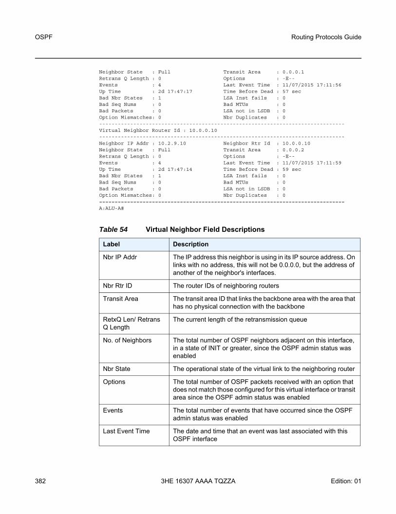
OSPF
382
Routing Protocols Guide
3HE 16307 AAAA TQZZA Edition: 01
Neighbor State : Full Transit Area : 0.0.0.1Retrans Q Length : 0 Options : -E--Events : 4 Last Event Time : 11/07/2015 17:11:56Up Time : 2d 17:47:17 Time Before Dead : 57 secBad Nbr States : 1 LSA Inst fails : 0Bad Seq Nums : 0 Bad MTUs : 0Bad Packets : 0 LSA not in LSDB : 0Option Mismatches: 0 Nbr Duplicates : 0-------------------------------------------------------------------------------Virtual Neighbor Router Id : 10.0.0.10-------------------------------------------------------------------------------Neighbor IP Addr : 10.2.9.10 Neighbor Rtr Id : 10.0.0.10Neighbor State : Full Transit Area : 0.0.0.2Retrans Q Length : 0 Options : -E--Events : 4 Last Event Time : 11/07/2015 17:11:59Up Time : 2d 17:47:14 Time Before Dead : 59 secBad Nbr States : 1 LSA Inst fails : 0Bad Seq Nums : 0 Bad MTUs : 0Bad Packets : 0 LSA not in LSDB : 0Option Mismatches: 0 Nbr Duplicates : 0===============================================================================A:ALU-A#
Table 54 Virtual Neighbor Field Descriptions
Label Description
Nbr IP Addr The IP address this neighbor is using in its IP source address. On links with no address, this will not be 0.0.0.0, but the address of another of the neighbor's interfaces.
Nbr Rtr ID The router IDs of neighboring routers
Transit Area The transit area ID that links the backbone area with the area that has no physical connection with the backbone
RetxQ Len/ Retrans Q Length
The current length of the retransmission queue
No. of Neighbors The total number of OSPF neighbors adjacent on this interface, in a state of INIT or greater, since the OSPF admin status was enabled
Nbr State The operational state of the virtual link to the neighboring router
Options The total number of OSPF packets received with an option that does not match those configured for this virtual interface or transit area since the OSPF admin status was enabled
Events The total number of events that have occurred since the OSPF admin status was enabled
Last Event Time The date and time that an event was last associated with this OSPF interface

Routing Protocols Guide OSPF
Edition: 01 3HE 16307 AAAA TQZZA 383
Up Time The uninterrupted time, in hundredths of seconds, that the adjacency to this neighbor has been up
Dead Time/Time Before Dead
The amount of time, in seconds, until the dead router interval expires
Bad Nbr States The total number of OSPF packets received where the neighbor information does not match the information this router has for the neighbor since the OSPF admin status was last enabled
LSA Inst fails The total number of times an LSA could not be installed into the LSDB due to a resource allocation issue since the OSPF admin status was last enabled
Bad Seq Nums The total number of times that a database description packet was received with a sequence number mismatch since the OSPF admin status was last enabled
Bad MTUs The total number of times that the MTU in a received database description packet was larger than the MTU of the receiving interface since the OSPF admin status was enabled
Bad Packets The total number of times that an LS update was received with an illegal LS type or an option mismatch since the OSPF admin status was enabled
LSA not in LSDB The total number of times that an LS request was received for an LSA not installed in the LSDB of this router since the OSPF admin status was enabled
Option Mismatches The total number of times that an LS update was received with an option mismatch since the OSPF admin status was enabled
Nbr Duplicates The total number of times that a duplicate database description packet was received during the Exchange state since the OSPF admin status was enabled
Table 54 Virtual Neighbor Field Descriptions (Continued)
Label Description

OSPF
384
Routing Protocols Guide
3HE 16307 AAAA TQZZA Edition: 01
4.14.2.3 Clear Commands
ospf
Syntax ospf
Context clear>router
Description This command clears and resets OSPF protocol entities.
ospf3
Syntax ospf3
Context clear>router
Description This command clears and resets OSPFv3 protocol entities.
database
Syntax database [purge]
Context clear>router>ospfclear>router>ospf3
Description This command clears all LSAs received from other nodes and refreshes all self-originated LSAs.
Parameters purge — clears all self-originated LSAs and reoriginates all self-originated LSAs
export
Syntax export
Context clear>router>ospfclear>router>ospf3
Description This command re-evaluates all effective export route policies.

Routing Protocols Guide OSPF
Edition: 01 3HE 16307 AAAA TQZZA 385
neighbor
Syntax neighbor [ip-int-name | ip-address]
Context clear>router>ospfclear>router>ospf3
Description This command marks the neighbor as dead and reinitiates the affected adjacencies.
Parameters ip-int-name — clears all neighbors for the interface specified by this interface name
ip-address — clears all neighbors for the interface specified by this IP address
statistics
Syntax statistics
Context clear>router>ospfclear>router>ospf3
Description This command clears all neighbor, router, interface, SPF, and global statistics for OSPF.

OSPF
386
Routing Protocols Guide
3HE 16307 AAAA TQZZA Edition: 01
4.14.2.4 Debug Commands
ospf
Syntax ospf
Context debug>router
Description This command enables the context for OSPF debugging purposes.
ospf3
Syntax ospf3
Context debug>router
Description This command enables the context for OSPFv3 debugging purposes.
area
Syntax area [area-id]no area
Context debug>router>ospfdebug>router>ospf3
Description This command enables or disables debugging for an OSPF area.
Parameters area-id — the OSPF area ID expressed in dotted-decimal notation or as a 32-bit decimal integer
area-range
Syntax area-range [ip-address]no area-range
Context debug>router>ospfdebug>router>ospf3
Description This command enables or disables debugging for an OSPF area range.
Parameters ip-address — the IP address for the range used by the ABR to advertise into another area

Routing Protocols Guide OSPF
Edition: 01 3HE 16307 AAAA TQZZA 387
cspf
Syntax cspf [ip-address]no cspf
Context debug>router>ospf
Description This command enables or disables debugging for an OSPF constraint-based shortest path first (CSPF).
Parameters ip-address — the IP address for the range used for CSPF
interface
Syntax interface [ip-int-name | ip-address]no interface
Context debug>router>ospfdebug>router>ospf3
Description This command enables or disables debugging for an OSPF interface.
Parameters ip-int-name — the IP interface name. An interface name cannot be in the form of an IP address. Interface names can be any string up to 32 characters long composed of printable, 7-bit ASCII characters. If the string contains special characters (#, $, spaces, etc.), the entire string must be enclosed within double quotes.
ip-address — the interface’s IP address
leak
Syntax leak [ip-address]no leak
Context debug>router>ospfdebug>router>ospf3
Description This command enables or disables debugging for OSPF leaks.
Parameters ip-address — the IP address to debug OSPF leaks

OSPF
388
Routing Protocols Guide
3HE 16307 AAAA TQZZA Edition: 01
lsdb
Syntax lsdb [type] [ls-id] [adv-rtr-id] [area area-id]no lsdb
Context debug>router>ospfdebug>router>ospf3
Description This command enables or disables debugging for an OSPF link-state database.
Parameters type — the OSPF link-state database type
Values router, network, summary, asbr, extern, nssa
ls-id — an LSA type-specific field containing either a router ID or an IP address. It identifies the piece of the routing domain being described by the advertisement.
adv-rtr-id — the router identifier of the router advertising the LSA
area-id — the OSPF area ID expressed in dotted-decimal notation or as a 32-bit decimal integer
misc
Syntax [no] misc
Context debug>router>ospfdebug>router>ospf3
Description This command enables or disables debugging for miscellaneous OSPF events.
neighbor
Syntax neighbor [ip-int-name | router-id]no neighbor
Context debug>router>ospfdebug>router>ospf3
Description This command enables or disables debugging for an OSPF neighbor.
Parameters ip-int-name — the neighbor interface name
router-id — neighbor information for the neighbor identified by the specified router ID

Routing Protocols Guide OSPF
Edition: 01 3HE 16307 AAAA TQZZA 389
nssa-range
Syntax nssa-range [ip-address]no nssa-range
Context debug>router>ospfdebug>router>ospf3
Description This command enables or disables debugging for an NSSA range.
Parameters ip-address — the IP address range to debug
packet
Syntax packet [packet-type] [ip-address]no packet
Context debug>router>ospfdebug>router>ospf3
Description This command enables or disables debugging for OSPF packets.
Parameters packet-type — the OSPF packet type to debug
Values hello, dbdescr, lsrequest, lsupdate, lsack
ip-address — the IP address to debug
rsvp-shortcut
Syntax rsvp-shortcut [ip-address]no rsvp-shortcut
Context debug>router>ospf
Description This command enables or disables debugging for RSVP-TE LSPs that are used as shortcuts.
Parameters ip-address — the IP address to debug

OSPF
390
Routing Protocols Guide
3HE 16307 AAAA TQZZA Edition: 01
rtm
Syntax rtm [ip-address]no rtm
Context debug>router>ospfdebug>router>ospf3
Description This command enables or disables debugging for the OSPF routing table manager.
Parameters ip-address — the IP address to debug
spf
Syntax spf [type] [dest-addr]no spf
Context debug>router>ospfdebug>router>ospf3
Description This command enables or disables debugging for OSPF SPF. Information regarding overall SPF start and stop times are shown. To see detailed information regarding the SPF calculation of a given route, the route must be specified as an optional argument.
Parameters type — the area to debug
Values intra-area, inter-area, external
dest-addr — the destination IP address to debug
virtual-neighbor
Syntax virtual-neighbor [ip-address]no virtual-neighbor
Context debug>router>ospfdebug>router>ospf3
Description This command enables or disables debugging for an OSPF virtual neighbor.
Parameters ip-address — the IP address of the virtual neighbor

Routing Protocols Guide IS-IS
Edition: 01 3HE 16307 AAAA TQZZA 391
5 IS-ISThis chapter provides information about configuring the Intermediate System-to-Intermediate System (IS-IS) protocol.
Topics in this chapter include:
• Overview of IS-IS• Bidirectional Forwarding Detection (BFD) for IS-IS• LDP and IP Fast Reroute (FRR) for IS-IS Prefixes• IS-IS Configuration Process Overview• Configuration Notes• Configuring IS-IS with CLI• IS-IS Command Reference

IS-IS
392
Routing Protocols Guide
3HE 16307 AAAA TQZZA Edition: 01
5.1 Overview of IS-IS
IS-IS is an interior gateway protocol (IGP), similar to OSPF, that is used within large autonomous systems (ASs). IS-IS is a link-state protocol. Each IS-IS router maintains an identical database (called the link-state database, topological database, or routing information database (RIB)) of the AS, including information about the local state of each router (for example, its usable interfaces and reachable neighbors).
IS-IS-TE (IS-IS with traffic engineering extensions) is used to advertise reachability information and traffic engineering information such as available bandwidth.
The 7705 SAR also supports multiple instances of IS-IS (MI-IS-IS).
Entities within IS-IS include networks, intermediate systems, and end systems. In IS-IS, a network is an autonomous system (AS), or routing domain, with intermediate systems and end systems. A router, such as the 7705 SAR, is an intermediate system. Intermediate systems send, receive, and forward protocol data units (PDUs). End systems are network devices (or hosts) that send and receive PDUs but do not forward them.
Intermediate system and end system protocols allow routers and nodes to identify each other. IS-IS sends out link-state updates (called link-state PDUs, or LSPs) periodically throughout the network so that each router can maintain current network topology information.
IS-IS uses a cost metric that represents the status of a link, and (optionally) the bandwidth of the interface, in an algorithm that determines the best route to a destination. This algorithm is called the Shortest Path First (SPF), or Dijkstra, algorithm. Routing decisions are made using the link-state information. IS-IS evaluates topology changes and, if necessary, performs SPF recalculations.
When the best route to a particular destination is determined, the route information is sent to the routing table manager (RTM). The RTM may contain more than one best route to a destination from multiple protocols. Because metrics from different protocols are not comparable, the RTM uses the concept of preference to select the best route. The route with the lowest preference value is selected.
The best routes from the RTM are then added to the forwarding table (also known as the forwarding information base (FIB)). All forwarding decisions are based on the information in the forwarding database.
The forwarding (or dropping) of packets is controlled by filters applied to the interface and route policies applied to the IS-IS protocol. Refer to the 7705 SAR Router Configuration Guide for information on filters and route policies.

Routing Protocols Guide IS-IS
Edition: 01 3HE 16307 AAAA TQZZA 393
The following major IS-IS features are supported:
• IS-IS Areas (Two-level Hierarchy) • ISO Network Addressing • Neighbors and Adjacencies • Metrics • Authentication • Route Redistribution and Summarization • IS-IS-TE Extensions • Unnumbered Interfaces• Segment Routing in Shortest Path Forwarding• Multi-Instance IS-IS (MI-IS-IS) • IPv6 Support
5.1.1 IS-IS Areas (Two-level Hierarchy)
IS-IS can subdivide an autonomous system into areas to simplify the calculation of routes and minimize the size of IP routing tables. When an AS is divided into areas, each IS-IS router in an area must maintain an identical link-state database of the area topology, but routes from other areas can be summarized. Sometimes one “default” route can be used to represent many different routes. The topology is hidden from routing devices in other areas, which minimizes the size of the link-state database and reduces IS-IS link-state PDUs (LSPs). See Route Redistribution and Summarization.
IS-IS uses a two-level hierarchy when dividing an AS into smaller areas. A system logically belongs to one area. Level 1 routing is performed within an area. Level 2 routing is performed between areas. The 7705 SAR can be configured as a level 1 router, level 2 router, or level 1/2 router. By default, the 7705 SAR is a level 1/2 router, which enables the router to operate as a level 1 and/or a level 2 router with the associated databases. The router runs separate shortest path first (SPF) calculations for the level 1 area routing and for the level 2 multi-area routing to create the IS-IS routing table for the IS-IS instance.
Figure 13 shows an example of an IS-IS topology.

IS-IS
394
Routing Protocols Guide
3HE 16307 AAAA TQZZA Edition: 01
Figure 13 IS-IS Topology
Level 1 routers know the topology in their area, including all routers and end systems, but do not know the identity of routers or destinations outside of their area. To reach a destination outside of the level 1 area, level 1 routers forward the packets to a level 1/2 router in their area as the next hop.
In order for level 1 routers to forward traffic to a level 1/2 router, the level 1/2 router sets the Attached (ATT) bit in its level 1 LSP, which indicates that it is attached to another area, and floods it to all the level 1 neighbors. The level 1 router installs the default route to the level 1/2 router in its routing table. If there is more than one level 1/2 router connected to the level 1 area, the level 1 router only installs the default route of the closest level 1/2 router. The level 1 router then forwards all traffic with a destination outside of its area to this level 1/2 router.
In some cases, users may want to control whether a level 1 router forwards traffic to a specific level 1/2 router; for example, it may be desirable to route around a particular level 1/2 router for traffic engineering reasons. This can be done by configuring a level 1 router to ignore the ATT bit on received level 1 LSPs (using the config>router>isis>ignore-attached-bit command) or configuring a level 1/2 router to suppress the ATT bit on originating level 1 LSPs (using the config>router>isis>suppress-attached-bit command). In the first case, when the level 1 router ignores the ATT bit, it will not install the default route to the level 1/2 router. In the second case, when the level 1/2 router suppresses the ATT bit, all level 1 routers in the area are prevented from installing the default route.
Area 49.0001
Area 49.0002
Area 49.0003
L1
L1
L2
L1/L2
L1/L2
L1/L2 L1
Level 1 linkBackbone (level 2) link
Level 1/level 2
Level 1Level 2
L1/L2
L1L2
Legend:
20355

Routing Protocols Guide IS-IS
Edition: 01 3HE 16307 AAAA TQZZA 395
Sometimes the shortest path to an outside destination is not through the closest level 1/2 router, or the only level 1/2 router to forward packets out of an area is not operational. To reduce suboptimal routing, route leaking provides a mechanism to leak (or redistribute) level 2 information into level 1 areas to provide routing information regarding inter-area routes. By distributing more detailed information into the level 1 area, a level 1 router is able to make a better decision as to which level 1/2 router should forward the packet.
The 7705 SAR implementation of IS-IS route leaking is in compliance with RFC 2966, Domain-wide Prefix Distribution with Two-Level IS-IS.
Level 2 routers know the level 2 topology and know which addresses are reachable by each level 2 router. Level 2 routers do not need to know the topology within any level 1 area, except if the level 2 router is also a level 1 router within a single area. By default, only level 2 routers can exchange PDUs or routing information directly with external routers located outside the routing domain.
Table 55 describes the router types (or intermediate systems) within IS-IS.
Table 55 IS-IS Intermediate Systems
Intermediate System
Description
Level 1 Maintains a link-state database of other routers that reside in the same area (local area)Exchanges topology information for the local areaRouting is performed within the area, based on the area ID portion of the ISO address (see ISO Network Addressing)If the destination address is in the area (area ID is equal), routers forward the packets to the level 1 router that is advertising the destination address, based on the system IDIf the destination address is not in the area (area ID is not equal), routers forward the packet to the nearest level 1/2 router in the local area
Level 2 Resides within an area but connects to other level 2 routers in multiple areas in a backbone meshMaintains a link-state database of other level 2 routers and of the level 1/2 routers in each local areaExchanges topology information between areasRouting is performed between areas based on the area address

IS-IS
396
Routing Protocols Guide
3HE 16307 AAAA TQZZA Edition: 01
5.1.2 ISO Network Addressing
IS-IS uses ISO network addresses. There are two types of network addresses:
• Network Service Access Point (NSAP)NSAP addresses identify a point of connection to the network, such as a router interface. Each NSAP represents a service that is available at that node. An end system can have multiple NSAP addresses; the addresses differ only by the last byte (called the n-selector). In addition to having multiple services, a single node can belong to multiple areas.
• Network Entity Title (NET)NET addresses identify network layer entities or processes instead of services. Structurally, an NET is identical to an NSAP address but has an n-selector of 00. Most end systems have one NET. Intermediate systems (routers) can have up to three NETs, differentiated by the area ID.
NSAP addresses are divided into three parts. Only the area ID portion is configurable:
• area ID – a variable-length field between 1 and 13 bytes that identifies the area to which the router belongs. This field includes the Authority and Format Identifier (AFI) as the first (most significant byte) and the area identifier.
• system ID – A 6-byte system identifier. This value is not configurable. The system ID is derived from the system or router ID and uniquely identifies the router.
Level 1/2 Acts as an area border router with links to the level 2 backbone as well as to the level 1 routers within its areaMaintains two link-state databases – a level 1 link-state database of the routers in the local area and a level 2 link-state database of the backbone and any level 1/2 routers Exchanges topology information within the local area and between areasRouting is performed within and between areasIf the destination address is in the area (area ID is equal), routers use the level 1 database to forward the packets to the level 1 router that is advertising the destination address, based on the system IDIf the destination address is not in the area (area ID is not equal), routers use the level 2 database to forward the packet based on the area ID
Table 55 IS-IS Intermediate Systems (Continued)
Intermediate System
Description

Routing Protocols Guide IS-IS
Edition: 01 3HE 16307 AAAA TQZZA 397
• selector ID – A 1-byte selector identifier that is always 00 for an NET. This value is not configurable.
The area ID portion of the NET can be manually configured with 1 to 13 bytes. If fewer than 13 bytes are entered, the rest of the field is padded with zeros.
5.1.3 Neighbors and Adjacencies
IS-IS routers discover their neighbors by exchanging Hello PDUs. Neighbors are routers that have an interface to a common network/area. In a broadcast-supported topology, one router sends Hello packets to a multicast address and receives Hello packets in return. In non-broadcast topologies, unicast Hello packets are used.
Because all routing devices on a common network must agree on certain parameters, these parameters are included in Hello packets. Differences in these parameters can prevent neighbor relationships from forming.
A level 1 router will not become a neighbor with a node that does not have a common area address. However, if a level 1 router has area addresses A, B, and C, and a neighbor has area addresses B and D, the level 1 router will accept the other node as a neighbor because address B is common to both routers.
When Hello packets have been successfully exchanged, the neighbors are considered to be adjacent.
Within an area, level 1 routers exchange link-state PDUs (LSPs) that identify the IP addresses reachable by each router. Each router has one LSP that contains information about that router; included in each LSP can be zero or more IP addresses, subnet masks, and metric combinations. Each level 1 router is manually configured with the IP address, subnet mask, and metric combinations that are reachable on each interface.
Level 2 routers exchange LSPs that include a complete list of IP addresses, subnet masks, and metrics specifying all the IP addresses that are reachable in their area. Level 2 routers can also report external reachability information, corresponding to addresses reachable by routers in other routing domains or autonomous systems.
Routers with common area addresses form level 1 adjacencies. Routers with no common NET addresses form level 2 adjacencies, if they are capable. See Figure 14.
Level 2 adjacencies are formed with other level 2 nodes whose area addresses do not overlap. If the area addresses do not overlap, the link is considered by both routers to be level 2 and only level 2 LSPs flow on the link.

IS-IS
398
Routing Protocols Guide
3HE 16307 AAAA TQZZA Edition: 01
Figure 14 Using Area Addresses to Form Adjacencies
5.1.3.1 Designated Routers
In multi-access broadcast networks, such as Ethernet networks, with at least two attached routers, a designated router can be elected. The IS-IS protocol refers to the designated router as the designated intermediate system (DIS).
The concept of a designated router was developed in order to avoid the formation of adjacencies between all attached routers. Without a designated router, the area would be flooded with link-state PDUs (LSPs)—a router would send LSPs to all its adjacent neighbors, and each in turn would send LSPs to all their neighbors, and so on. This would create multiple copies of the same LSP on the same link.
The designated router reduces the number of adjacencies required because each router forms an adjacency only with the designated router. Only the designated router sends LSPs in multicast format to the rest of the network, reducing the amount of routing protocol traffic.
In IS-IS, a broadcast subnetwork with multiple connected routers is considered to be a pseudonode. The pseudonode has links to each of the routers and each of the routers has a single link to the pseudonode (rather than links to each of the other routers). LSPs are generated on behalf of the pseudonode by the DIS.
20108
L 1/2area 49.0001area 87.0001area 86.0001
L 1/2area 49.0001area 80.0001area 51.0001
L 1/2area 80.0001area 79.0001area 78.0001
L 1/2area 47.0001area 48.0001area 49.0001
L 1/2area 47.0001area 32.0001area 34.0001
L 1area 29.0001area 50.0001area 51.0001
L 1area 29.0001area 50.0001area 51.0001
L 1/2area 45.0001area 46.0001area 90.0001
L 1area 45.0001area 28.0001area 29.0001
L 1/2area 30.0001area 31.0001area 32.0001

Routing Protocols Guide IS-IS
Edition: 01 3HE 16307 AAAA TQZZA 399
The DIS has two tasks:
• create and update the pseudonode LSP• flood the LSP over the LAN
The DIS is automatically elected based on the interface priority of the router and/or if it has the highest MAC address of all routers in the LAN. If all interface priorities are the same, the router with the highest subnetwork point of attachment (SNPA) is selected. The SNPA is the MAC address on a LAN.
Every IS-IS router interface is assigned both a level 1 priority and a level 2 priority. If a new router starts up in the LAN and has a higher interface priority, the new router preempts the original DIS and becomes the new DIS. The new DIS purges the old pseudonode LSP and floods a new set of LSPs.
Because different priorities can be set according to level 1 or level 2 routing, there can be two different routers in an Ethernet LAN that are DIS-designated. One DIS supports all level 1 routers, and the other DIS supports all level 2 routers on that segment.
The DIS generates the pseudonode LSP. The DIS reports all LAN neighbors (including itself) in the pseudonode link-state PDU (LSP). All LAN routers communicate with the pseudonode via their LSPs. The pseudonode reduces the number of adjacencies by having all physical devices exchange information only with the pseudonode. Each router listens for updates to the pseudonode and updates its individual topology according to those updates.
Note:
• In point-to-point networks, where a single pair of routers is connected, no designated router is elected. An adjacency must be formed with the neighbor router.
• To significantly improve adjacency forming and network convergence, a network should be configured as point-to-point if only two routers are connected, even if the network is a broadcast media such as Ethernet.

IS-IS
400
Routing Protocols Guide
3HE 16307 AAAA TQZZA Edition: 01
5.1.3.2 IS-IS Packet Types
Table 56 describes the packet types used by IS-IS to exchange protocol information.
When a change takes place, IS-IS sends only the changed information, not the whole topology information or whole link-state database. From the topological database, each router constructs a tree of shortest paths with itself as root (that is, runs the Dijkstra algorithm). IS-IS distributes routing information between routers belonging to a single AS.
To summarize:
• Hello PDUs are sent over the IS-IS-enabled interfaces to discover neighbors and establish adjacencies.
• IS-IS neighbor relationships are formed if the Hello PDUs contain information that meets the criteria for forming an adjacency.
• Routers can build a link-state PDU based upon their local interfaces that are configured for IS-IS and prefixes learned from other adjacent routers.
• Routers flood LSPs to the adjacent neighbors except the neighbor from which they received the same LSP. The link-state database is constructed from these LSPs.
• A Shortest Path Tree (SPT) is calculated by each router, and from this SPT the routing table is built.
Table 56 IS-IS Packet Types
Packet Type Description
Hello PDUs Routers with IS-IS enabled send Hello PDUs to IS-IS-enabled interfaces to discover neighbors and establish adjacencies.
Link-state PDUs (LSPs)
LSPs contain information about the state of adjacencies to neighboring IS-IS systems and are used to build the link-state database. LSPs are flooded periodically throughout an area.Level 1 and level 2 LSPs are supported.
Complete sequence number PDUs (CSNPs)
In order for all routers to maintain the same information (synchronize), CSNPs inform other routers that some LSPs might be outdated or missing from their database. CSNPs contain a complete list of all LSPs in the current IS-IS database.Level 1 and level 2 CSNPs are supported.
Partial sequence number PDUs (PSNPs)
PSNPs are used to request missing LSPs and acknowledge that an LSP was received.Level 1 and level 2 PSNPs are supported.

Routing Protocols Guide IS-IS
Edition: 01 3HE 16307 AAAA TQZZA 401
5.1.4 Metrics
IS-IS uses a cost metric that represents the status of a link in an algorithm to determine the best route to a destination. This algorithm is called the Shortest Path First (SPF), or Dijkstra, algorithm. Routing decisions are made using the link-state information. IS-IS evaluates topology changes and, if necessary, performs SPF recalculations.
To calculate the lowest cost to reach a destination, each configured level on each interface must have a cost. The costs for each level on an interface may be different.
In IS-IS, if the metric is not configured, the default cost 10 is used, regardless of the actual capacity of the link. By default, IS-IS does not use reference bandwidth in the calculation, unlike OSPF.
5.1.5 Authentication
Protocol authentication protects against malicious attacks on the communications between routing protocol neighbors. These attacks could either disrupt communications or inject incorrect routing information into the system’s routing table. The use of authentication keys can help to protect routing protocols from these types of attacks.
All IS-IS protocol exchanges can be authenticated. This guarantees that only trusted routers can participate in autonomous system routing.
Authentication must be explicitly configured and can be done using two separate mechanisms:
• configuration of an explicit authentication key and algorithm using the authentication-key and authentication-type commands
• configuration of an authentication keychain using the auth-keychain command
Either the authentication-key command or the auth-keychain command can be used by IS-IS, but both cannot be supported at the same time. If both commands are configured, the auth-keychain configuration will be applied and the authentication-key command will be ignored.
By default, authentication is not enabled on an interface.

IS-IS
402
Routing Protocols Guide
3HE 16307 AAAA TQZZA Edition: 01
5.1.5.1 Authentication Key
For explicit authentication keys, IS-IS supports plain text (simple password) and Message Digest 5 (MD5) authentication.
When authentication is enabled on a link, a text string password must be configured. Neighbor IS-IS routers must supply the password in all IS-IS packets they send to an interface.
Plain text authentication includes the password in each IS-IS packet sent on a link.
MD5 authentication is more secure than plain text authentication. MD5 authentication uses the password as an encryption key. Routers in the same routing domain must be configured with the same key. When the MD5 hashing algorithm is used for authentication, MD5 is used to verify data integrity by creating a 128-bit message digest from the data input that is included in each packet. The packet is transmitted to the router neighbor and can only be decrypted if the neighbor has the correct password.
The following authentication commands can be configured in the IS-IS global and IS-IS level contexts:
• authentication-key – configures the authentication password used to verify IS-IS protocol packets
• authentication-type – enables authentication and specifies the type of authentication to be used, either password or message digest
The following Hello PDU authentication commands can be configured in the IS-IS interface and IS-IS interface level contexts:
• hello-authentication-key – configures the authentication password for Hello PDUs
• hello-authentication-type – enables Hello authentication and specifies the type of authentication to be used, either password or message digest
5.1.5.2 Authentication Keychains
The keychain mechanism allows for the creation of keys used to authenticate IS-IS communications. Each keychain entry defines the authentication attributes to be used in authenticating IS-IS messages from remote peers or neighbors; the entry must include at least one key entry to be valid. The keychain mechanism also allows authentication keys to be changed without affecting the state of the IS-IS adjacencies and supports stronger authentication algorithms than plain text and MD5.

Routing Protocols Guide IS-IS
Edition: 01 3HE 16307 AAAA TQZZA 403
Keychains are configured in the config>system>security>keychain context. For more information about configuring keychains, refer to the 7705 SAR System Management Guide, “TCP Enhanced Authentication and Keychain Authentication”.
The authentication keychain is then associated with IS-IS in the global or level contexts with the auth-keychain command. The Hello authentication keychain is associated with IS-IS in the global, interface, or interface level contexts with the hello-auth-keychain command.
For a key entry to be valid, it must include a valid key, the current system clock value must be within the begin and end time of the key entry, and the algorithm specified must be supported by IS-IS.
IS-IS supports the following authentication algorithms:
• clear text password• HMAC-MD5• HMAC-SHA-1• HMAC-SHA-256
Keychain errors are handled as follows.
• If a keychain exists but there are no active key entries with an authentication type that matches the type supported by IS-IS, inbound IS-IS packets will not be authenticated and will be discarded and no outbound IS-IS packets will be sent.
• If a keychain exists but the last key entry has expired, a log entry will be raised indicating that all keychain entries have expired.IS-IS protocol requires that the protocol not revert to an unauthenticated state and requires that the old key not be used; therefore, when the last key has expired, all traffic will be discarded.
5.1.6 Route Redistribution and Summarization
5.1.6.1 Route Redistribution
Route redistribution is the taking of routes from one protocol and sending them to another protocol. The 7705 SAR supports the redistribution of static routes into OSPF and IS-IS and the redistribution of routes between IS-IS levels. The routes can be redistributed as level 1, level 2, or level 1/2 routes, depending on the level capability of the IS-IS router.

IS-IS
404
Routing Protocols Guide
3HE 16307 AAAA TQZZA Edition: 01
Multi-instance IS-IS (MI-IS-IS) supports route redistribution:
• to and from any other routing protocol• to and from any other IS-IS instance
Route redistribution involves the use of routing policies. For information on routing policies, refer to the 7705 SAR Router Configuration Guide, “Route Policies”. To configure route redistribution, see Redistributing External IS-IS Routes.
5.1.6.2 Route Summarization
IS-IS IPv4 route summarization allows users to create aggregate IPv4 addresses that include multiple groups of IPv4 addresses for a given IS-IS level. Routes redistributed from other routing protocols can also be summarized.
IS-IS route summarization helps to reduce the size of the link-state database and the routing table. It also helps to reduce the chance of route flapping, which may occur when a router alternately advertises a destination network via one route then another route in quick sequence (or advertises a route as unavailable then available again).
5.1.6.2.1 Partial SPF Calculation
IS-IS supports partial SPF calculation, also referred to as partial route calculation. When an event does not change the topology of the network, IS-IS does not perform full SPF but instead performs an IP reachability calculation for impacted routes. Partial SPF is performed at the receipt of IS-IS LSPs with changes to IP reachability TLVs and, in general, for any IS-IS LSP TLV and sub-TLV change that does not impact the network topology.
5.1.7 IS-IS-TE Extensions
IS-IS traffic engineering (TE) extensions enable the 7705 SAR to include traffic engineering information in the algorithm in order to calculate the best route to a destination. IS-IS-TE extensions are used by MPLS traffic engineering; that is, RSVP-TE. The traffic information includes:
• maximum reservable bandwidth• unreserved bandwidth• available bandwidth

Routing Protocols Guide IS-IS
Edition: 01 3HE 16307 AAAA TQZZA 405
• link administration groups (or link colors)• SRLGs• TE metrics
5.1.8 Unnumbered Interfaces
IS-IS supports unnumbered point-to-point interfaces with both Ethernet and PPP encapsulations.
Unnumbered interfaces borrow the address from other interfaces such as system, loopback, or another numbered interface, and use it as the source IP address for packets originated from the interface.
This feature supports both dynamic and static ARP for unnumbered interfaces to allow interworking with unnumbered interfaces that may not support dynamic ARP.
An unnumbered interface has IPv4 capability and is used only in cases where IPv4 is active (IPv4-only and mixed IPv4/IPv6 environments). When configuring an unnumbered interface, the interface specified for the unnumbered interface (system or other) must have an IPv4 address. As well, the interface type for the unnumbered interface will automatically be point-to-point.
The unnumbered option can be used in IES and VPRN access interfaces, as well as in a network interface with MPLS support.
5.1.9 Segment Routing in Shortest Path Forwarding
Segment routing adds to IS-IS and OSPF routing protocols the ability to perform shortest path routing and source routing using the concept of abstract segment. A segment can represent a local prefix of a node, a specific adjacency of the node (interface or next hop), a service context, or a specific explicit path over the network. For each segment, the IGP advertises an identifier referred to as a segment ID (SID).
When segment routing is used together with the MPLS data plane, the SID is a standard MPLS label. A router forwarding a packet using segment routing will push one or more MPLS labels.
Segment routing using MPLS labels can be used in both shortest path routing applications and traffic engineering applications. On the 7705 SAR, segment routing implements the shortest path forwarding application.

IS-IS
406
Routing Protocols Guide
3HE 16307 AAAA TQZZA Edition: 01
When a received IPv4 or IPv6 prefix SID is resolved, the segment routing module programs the ILM with a swap operation and programs the LTN with a push operation both pointing to the primary/LFA NHLFE. An IPv4 or IPv6 SR tunnel to the prefix destination is also added to the TTM and is available for use by shortcut applications and Layer 2 or Layer 3 services.
Segment routing introduces the remote LFA feature, which expands the coverage of LFA by computing and automatically programming SR tunnels that are used as backup next hops. The SR shortcut tunnels terminate on a remote alternate node, which provides loop-free forwarding for packets of the resolved prefixes. When the loopfree-alternate option is enabled in an IS-IS or OSPF instance, SR tunnels are protected with an LFA backup next hop. If the prefix of an SR tunnel is not protected by the base LFA, remote LFA automatically computes a backup next hop using an SR tunnel if the remote-lfa option is also enabled in the IGP instance.
Segment routing can also be used with Layer 3 spoke SDP interfaces to support multicast (PIM only). See Multicast Over Layer 3 Spoke SDP for more information.
5.1.9.1 Configuring Segment Routing in Shortest Path
Segment routing is enabled in an IGP routing instance using the following sequence of commands.
First, the user configures the global label block, referred to as the Segment Routing Global Block (SRGB), which is reserved for assigning labels to segment routing prefix SIDs originated by this router. This range is within the system dynamic label range and by default is not instantiated:
config>router>mpls-labels>sr-labels start start-value end end-value
Next, the user enables the context to configure segment routing parameters within an IGP instance:
config>router>isis>segment-routing
config>router>ospf>segment-routing
The key parameter is the configuration of the prefix SID index range and the offset label value that this IGP instance uses. Because each prefix SID represents a network global IP address, the SID index for a prefix must be unique network-wide. All routers in the network are expected to configure and advertise the same prefix SID index range for an IGP instance. However, the label value used by each router to represent this prefix, that is, the label programmed in the ILM, can be local to that router by the use of an offset label, referred to as a start label:

Routing Protocols Guide IS-IS
Edition: 01 3HE 16307 AAAA TQZZA 407
Local Label (Prefix SID) = start-label + {SID index}
The label operation in the network is very similar to LDP when operating in independent label distribution mode (RFC 5036), with the difference being that the label value used to forward a packet to each downstream router is computed by the upstream router based on the advertised prefix SID index using the above formula.
Figure 15 is an example of a router advertising its loopback address and the resulting packet label encapsulation throughout the network.
Figure 15 Packet Label Encapsulation using Segment Routing Tunnel
Router N-6 advertises loopback 10.10.10.1/32 with a prefix index of 5. Routers N-1 to N-6 are configured with the same SID index range of [1,100] and an offset label of 100 to 600 respectively. The following are the actual label values programmed by each router for the prefix of PE2.
• N-6 has a start label value of 600 and programs an ILM with label 605.• N-3 has a start label value of 300 and swaps incoming label 305 to label 605.• N-2 has a start label value of 200 and swaps incoming label 205 to label 305.
Similar operations are performed by N-4 and N-5 for the bottom path.
N-1 has an SR tunnel to N-6 with two ECMP paths. It pushes label 205 when forwarding an IP or service packet to N-6 via downstream next hop N-2 and pushes label 405 when forwarding via downstream next hop N-4.
data 305data 205
data 605data 505
data 405
data 605
N-1
A-2
A-1 A-3
A-2
A-2
A-3
A-2
A-2
A-3 A-1
A-2A-1 A-1
A-3A-1
A-1
N-2 N-3
N-4 N-5
N-6
27868

IS-IS
408
Routing Protocols Guide
3HE 16307 AAAA TQZZA Edition: 01
The CLI commands for configuring the prefix SID index range and offset label value for an IGP instance are as follows:
config>router>isis>segment-routing>prefix-sid-range {global | start-label label-value max-index index-value}
config>router>ospf>segment-routing>prefix-sid-range {global | start-label label-value max-index index-value}
There are two mutually exclusive modes of operation for the prefix SID range on the router: global mode and per-instance mode.
In the global mode of operation, the user configures the global value and the IGP instance assumes that the start label value is the lowest label value in the SRGB and the prefix SID index range size is equal to the range size of the SRGB. When one IGP instance selects the global option for the prefix SID range, all IGP instances on the system must do the same.
The user must shut down the segment routing context and disable the prefix-sid-range command in all IGP instances in order to change the SRGB. When the SRGB is changed, the user must re-enable the prefix-sid-range command. The SRGB range change fails if an already allocated SID index/label goes out of range.
In the per-instance mode of operation, the user partitions the SRGB into non-overlapping sub-ranges among the IGP instances. The user configures a subset of the SRGB by specifying the start label value and the prefix SID index range size. All resulting net label values (start-label + index) must be within the SRGB or the configuration fails. The 7705 SAR checks for overlaps of the resulting net label value range across IGP instances and strictly enforces no overlapping of the ranges.
The user must shut down the segment routing context of an IGP instance in order to change the SID index/label range of that IGP instance using the prefix-sid-range command. A range change fails if an already allocated SID index/label goes out of range.
The user can, however, change the SRGB without shutting down the segment routing context as long as it does not reduce the current per-IGP instance SID index/label range defined with the prefix-sid-range command. Otherwise, the user must shut down the segment routing context of the IGP instance and disable and re-enable the prefix-sid-range command.
Finally, the user brings up segment routing on the IGP instance by using the no shutdown command:
config>router>isis>segment-routing>no shutdown
config>router>ospf>segment-routing>no shutdown

Routing Protocols Guide IS-IS
Edition: 01 3HE 16307 AAAA TQZZA 409
This command fails if the user has not previously enabled the advertise-router-capability option in the IGP instance. Segment routing capability must be advertised to all routers in a particular domain so that routers that support the capability only program the node SID in the data path toward neighbors that also support it.
config>router>isis>advertise-router-capability {area | as}
config>router>ospf>advertise-router-capability {link | area | as}
The IGP segment routing extensions are area-scoped. The user must therefore configure the flooding scope to area in OSPF and to area or as in IS-IS; otherwise, performing a no shutdown of the segment-routing node will fail.
The segment-routing command and the igp-shortcut and advertise-tunnel-link are mutually exclusive under IGP, because an SR tunnel cannot resolve to an RSVP tunnel next hop.
IS-IS supports node SID indexes or labels on IPv4 and IPv6 interfaces, and OSPF supports node SID indexes or labels on IPv4 addresses only, because OSPFv3 does not support segment routing.
The user assigns a node SID index or label to the prefix representing the primary address of an IPv4 or IPv6 network interface of type loopback using one of the following commands:
config>router>isis>interface>ipv4-node-sid index value
config>router>ospf>area>interface>node-sid index value
config>router>isis>interface>ipv4-node-sid label value
config>router>ospf>area>interface>node-sid label value
config>router>isis>interface>ipv6-node-sid index value
config>router>isis>interface>ipv6-node-sid label value
Only a single node SID can be assigned to an interface. The secondary address of an IPv4 interface cannot be assigned a node SID index and does not inherit the SID of the primary IPv4 address. The same applies to the non-primary IPv6 addresses of an interface.
The above commands will fail if the network interface is not of type loopback or if the interface is defined in an IES or a VPRN context. Assigning the same SID index/label value to the same interface in two different IGP instances is not allowed within the same node.

IS-IS
410
Routing Protocols Guide
3HE 16307 AAAA TQZZA Edition: 01
The value of the label or index SID is taken from the range configured for the IGP instance. When using the global mode of operation, a new segment routing module checks that the same index or label value is not assigned to more than one loopback interface address. When using the per-instance mode of operation, this check is not required because the index, and therefore the label ranges, of IGP instances are not allowed to overlap.
5.1.9.2 Segment Routing Operational Procedures
5.1.9.2.1 Prefix SID Resolution for a Segment Routing Mapping Server
An SR-capable router, including a mapping server and its clients, attempts to resolve each received prefix SID to either an SR tunnel endpoint or an LDP tunnel endpoint as described below.
IP Prefix Resolution1. SPF calculates the next hops, up to the maximum value defined by the
config>router>ecmp>max-ecmp-routes command, to reach a destination node (refer to the 7705 SAR Router Configuration Guide, “IP Router Command Reference”, “Router Commands” for more information on this command).
2. A prefix advertised by multiple nodes that are all reachable with the same cost inherits the next hops, up to the max-ecmp-routes defined value, from the advertising nodes.
3. The next-hop selection is based on:- the lowest next-hop router ID- the lowest interface index (for parallel links to same router ID)
Each next hop keeps a reference to the destination node from which it was inherited.
Prefix SID Resolution1. For a specified prefix, the IGP selects the SID value among multiple advertised
values according to the following preference order:i. the local intra-area SID owned by this routerii. the prefix SID sub-TLV advertised within an IP reachability TLV

Routing Protocols Guide IS-IS
Edition: 01 3HE 16307 AAAA TQZZA 411
If multiple SIDs exist, the IGP selects the SID corresponding to the destination router or the ABR with the lowest system ID that is reachable using the first next hop of the prefix.
iii. the IS-IS SID and Label Binding TLV from the mapping serverIf multiple SIDs exist, the IGP selects the SID advertised by the mapping server with the lowest system ID.
2. the selected SID is used with all ECMP next hops from step 1 of IP Prefix Resolution toward all destination nodes or ABR nodes that advertised the prefix.
If duplicate prefix SIDs exist after the above steps are completed, the first SID that is processed is programmed according to its corresponding prefix. Subsequent SIDs cause a duplicate SID trap and are not programmed. The corresponding prefixes are resolved and programmed normally using IP next hops.
SR Tunnel Programming1. If the prefix SID is resolved from a prefix SID sub-TLV advertised within an IP
reachability TLV, the SR ILM performs a swapping operation to an SR NHLFE as with regular SR tunnel resolution.
2. If the prefix SID is resolved from a mapping server advertisement, stitching to an LDP FEC is preferred over a swapping operation to an SR next hop.The LDP FEC can be resolved via a static route or a route within an IS-IS instance. The IS-IS instance does not have to be the same as the IGP instance that advertised the mapping server prefix SID sub-TLV.The SR next hop is only possible if a route is exported from another IGP instance into the local IGP instance without propagating the prefix SID sub-TLV with the route. Otherwise, when the prefix SID is propagated with the route, the resolution follows step 1 above.
5.1.9.2.2 Prefix Advertisement and Resolution
When segment routing is successfully enabled in the IS-IS or OSPF instance, the router performs the following operations. See Control Protocol Changes for details of all TLVs and sub-TLVs for both IS-IS and OSPF protocols.
Note: If a level 1/2 router acts as a mapping server and also readvertises the mapping server prefix SID from other mapping servers, the redistributed mapping server prefix SID is preferred by other routers resolving the prefix; this may result in the mapping server with the lowest system ID not being selected.

IS-IS
412
Routing Protocols Guide
3HE 16307 AAAA TQZZA Edition: 01
• Advertises the Segment Routing Capability sub-TLV to routers in all areas or levels of this IGP instance. However, only neighbors with which the IGP instance established an adjacency will interpret the SID and label range information and use it for calculating the label to swap to or push for a particular resolved prefix SID.
• Advertises the assigned index for each configured node SID in the new prefix SID sub-TLV with the N-flag (node SID flag) set. The segment routing module then programs the incoming label map (ILM) with a pop operation for each local node SID in the data path.
• Automatically assigns and advertises an adjacency SID label for each formed adjacency over a network IP interface in the new Adjacency SID sub-TLV. The following points should be considered.- An adjacency SID is advertised for both numbered and unnumbered
network IP interfaces.- An adjacency SID is not supported for parallel adjacencies between two
IGP neighbors.- An adjacency SID is not advertised for an IES interface because access
interfaces do not support MPLS.- The adjacency SID must be unique per instance and per adjacency.
Furthermore, IS-IS multi-topology 0 (MT=0, IPv4 unicast) can establish an adjacency for both IPv4 and IPv6 address families over the same link, and in that case, a different adjacency SID is assigned to each next hop. However, the existing IS-IS implementation assigns a single Protect-Group ID (PG-ID) to the adjacency; therefore, when the state machine of a BFD session tracking the IPv4 or IPv6 next hop times out, an action is triggered for the prefixes of both address families over that adjacency.
The segment routing module programs the incoming label map (ILM) with a swap to an implicit null label operation for each advertised adjacency SID.
• Resolves received prefixes, and if a prefix SID sub-TLV exists, the segment routing module programs the ILM with a swap operation and an LTN with a push operation, both pointing to the primary/LFA NHLFE. An SR tunnel is also added to the TTM. If a node SID resolves over an IES interface, the data path is not programmed and a trap is raised. Therefore, only next hops of an ECMP set corresponding to network IP interfaces are programmed in the data path; next hops corresponding to IES interfaces are not programmed. If the user configures the interface as network on one side and IES on the other side, MPLS packets for the SR tunnel received on the access side are dropped.
Note: An IS-IS multi-topology (MT) is a set of independent IP topologies run within a single IS-IS domain. The 7705 SAR supports only MT=0 (see RFC 4971).

Routing Protocols Guide IS-IS
Edition: 01 3HE 16307 AAAA TQZZA 413
• LSA filtering, causing SIDs not to be sent in one direction which means some node SIDs are resolved in parts of the network upstream of the advertisement suppression.
When the user enables segment routing in an IGP instance, the main SPF and LFA SPF are computed normally and the primary next hop and LFA backup next hop for a received prefix are added to the RTM without the label information advertised in the prefix SID sub-TLV. In all cases, the SR tunnel is not added into the RTM.
5.1.9.2.3 Error and Resource Exhaustion Handling
When the prefix corresponding to a node SID is being resolved, the following procedures are followed.
Procedure 1: Providing support of multiple topologies for the same destination prefix
The 7705 SAR supports assigning different prefix SID indexes and labels to the same prefix in different IGP instances. While other routers that receive these prefix SIDs program a single route into the RTM, based on the winning instance ID as per the RTM route type preference, the 7705 SAR adds two tunnels to this destination prefix in the TTM. This provides for the support of multiple topologies for the same destination prefix.
Example:
In two different instances (level 2, IS-IS instance 1 and level1, IS-IS instance 2—see Figure 16), Router D has the same prefix destination with different SIDs (SIDx and SIDy).

IS-IS
414
Routing Protocols Guide
3HE 16307 AAAA TQZZA Edition: 01
Figure 16 Programming Multiple Tunnels to the Same Destination
Assume that the following route type preference in the RTM and tunnel type preference in the TTM are configured:
• ROUTE_PREF_ISIS_L1_INTER (RTM) 15• ROUTE_PREF_ISIS_L2_INTER (RTM) 18• ROUTE_PREF_ISIS_TTM 10
1. Router A performs the following resolution within the single IS-IS instance 1, level 2. All metrics are the same, and ECMP = 2.- For prefix N, the RTM entry is:
• prefix N• nhop1 = B• nhop2 = C• preference 18
- For prefix N, the SR tunnel TTM entry is: • tunnel-id 1: prefix N-SIDx• nhop1 = B• nhop2 = C• tunl-pref 10
Step 1
Level 2,IS-IS Instance 1
Router B
Level 2,IS-IS Instance 1
Router A
Level 2,IS-IS Instance 1
Router Dprefix N, SIDx
Level 2,IS-IS Instance 1
Router C
Step 2
Level 1,IS-IS Instance 2
Router B
Level 1,IS-IS Instance 2
Router A
Level 1,IS-IS Instance 2
Router Dprefix N, SIDy
27871
Note: The TTM tunnel type preference is not used by the SR module. It is put in the TTM and is used by other applications such as VPRN auto-bind and BGP shortcuts to select a TTM tunnel.

Routing Protocols Guide IS-IS
Edition: 01 3HE 16307 AAAA TQZZA 415
2. Add IS-IS instance 2 (level 1) in the same setup, but in routers A, B, and C only. Router A performs the resolution. - For prefix N, the RTM entry is:
• prefix N• nhop1 = B• preference 15
The RTM prefers level 1 route over level 2 route.- For prefix N, there are two SR tunnel entries in the TTM:
SR entry for level 2:• tunnel-id 1: prefix N-SIDx• nhop1 = B• nhop2= C• tunl-pref 10
SR entry for level 1:• tunnel-id 2: prefix N-SIDy
Procedure 2: Resolving received SID indexes or labels to different routes of the same prefix within the same IGP instance
Two variations of this procedure can occur.
a. If the 7705 SAR does not allow assigning the same SID index or label to different routes of the same prefix within the same IGP instance, it resolves only one SID index or label if it is received from another SR implementation and based on the RTM active route selection.
b. If the 7705 SAR does not allow assigning different SID indexes or labels to different routes of the same prefix within the same IGP instance, it resolves only one SID index or label if received from another SR implementation and based on the RTM active route selection.The selected SID will be used for ECMP resolution to all neighbors. If the route is inter-area and the conflicting SIDs are advertised by different ABRs, ECMP toward all ABRs uses the selected SID.

IS-IS
416
Routing Protocols Guide
3HE 16307 AAAA TQZZA Edition: 01
Procedure 3: Checking for SID errors prior to programming ILM and NHLFE
If any of the following conditions are true, the router logs a trap and generates a syslog error message and will not program the ILM and NHLFE for the prefix SID:
• the received prefix SID index falls outside the locally configured SID range• one or more resolved ECMP next hops for a received prefix SID did not advertise
SR Capability sub-TLV• the received prefix SID index falls outside the advertised SID range of one or
more resolved ECMP next hops
Procedure 4: Programming ILM/NHLFE for duplicate prefix SID indexes/labels for different prefixes
Two variations of this procedure can occur.
a. For received duplicate prefix SID indexes or labels for different prefixes within the same IGP instance, the router: - programs ILM/NHLFE for the first prefix SID- logs a trap and a syslog error message- does not program the subsequent prefix SID in the data path
b. For received duplicate prefix SID indexes for different prefixes across IGP instances, there are two options.- In the global SID index range mode of operation, the resulting ILM label
values are the same across the IGP instances. The router:• programs ILM/NHLFE for the prefix of the winning IGP instance based
on the RTM route type preference• logs a trap and a syslog error message• does not program the subsequent prefix SIDs in the data path
- In the per-instance SID index range mode of operation, the resulting ILM label will have different values across the IGP instances. The router programs ILM/NHLFE for each prefix as expected.

Routing Protocols Guide IS-IS
Edition: 01 3HE 16307 AAAA TQZZA 417
Procedure 5: Programming ILM/NHLFE for the same prefix across IGP instances
The behavior in the case of a global SID index range is illustrated by the IS-IS example in Figure 17.
In the global SID index range mode of operation, the resulting ILM label values are the same across the IGP instances. The router programs ILM/NHLFE for the prefix of the winning IGP instance based on the RTM route type preference. The router logs a trap and a syslog error message, and does not program the other prefix SIDs in the data path.
In the per-instance SID index range mode of operation, the resulting ILM label has different values across the IGP instances. The router programs ILM/NHLFE for each prefix as expected.
Figure 17 Handling of Same Prefix and SID in Different IS-IS Instances
Assume that the following route type preference in the RTM and tunnel type preference in the TTM are configured:
• ROUTE_PREF_ISIS_L1_INTER (RTM) 15• ROUTE_PREF_ISIS_L2_INTER (RTM) 18• ROUTE_PREF_ISIS_TTM 10
Step 1
Level 2,IS-IS Instance 1
Router B
Level 2,IS-IS Instance 1
Router A
Level 2,IS-IS Instance 1
Router Dprefix N, SIDx
Level 2,IS-IS Instance 1
Router C
Step 2
Level 1,IS-IS Instance 2
Router B
Level 1,IS-IS Instance 2
Router A
Level 1,IS-IS Instance 2
Router Eprefix N, SIDx
27872
Note: The TTM tunnel type preference is not used by the SR module. It is put in the TTM and is used by other applications such as VPRN auto-bind and BGP shortcuts to select a TTM tunnel.

IS-IS
418
Routing Protocols Guide
3HE 16307 AAAA TQZZA Edition: 01
1. Router A performs the following resolution within the single IS-IS instance 1, level 2. All metrics are the same, and ECMP = 2.- For prefix N, the RTM entry is:
• prefix N• nhop1 = B• nhop2 = C• preference 18
- For prefix N, the SR tunnel TTM entry is: • tunnel-id 1: prefix N-SIDx• nhop1 = B• nhop2 = C• tunl-pref 10
2. Add IS-IS instance 2 (level 1) in the same setup, but in routers A, B, and E only. Router A performs the resolution. - For prefix N, the RTM entry is:
• prefix N• nhop1 = B• preference 15
The RTM prefers level 1 route over level 2 route.- For prefix N, there is one SR tunnel entry for level 2 in the TTM:
• tunnel-id 1: prefix N-SIDx• nhop1 = B• nhop2 = C• tunl-pref 10
Procedure 6: Handling ILM resource exhaustion while assigning a SID index/label
If the system exhausted an ILM resource while assigning a SID index/label to a local loopback interface, index allocation fails and an error is returned in the CLI. In addition, the router logs a trap and generates a syslog error message.

Routing Protocols Guide IS-IS
Edition: 01 3HE 16307 AAAA TQZZA 419
Procedure 7: Handling ILM, NHLFE, or other IOM or CSM resource exhaustion while resolving or programming a SID index/label
If the system exhausted an ILM, NHLFE, or any other IOM or CSM resource while resolving and programming a received prefix SID or programming a local adjacency SID, the following occurs.
• The IGP instance goes into overload and a trap and syslog error message are generated.
• The segment routing module deletes the tunnel.
The user must manually clear the IGP overload condition after freeing resources. After the IGP is brought back up, it attempts to program at the next SPF all tunnels that previously failed the programming operation.
5.1.9.3 Segment Routing Tunnel Management
The segment routing module adds to the TTM a shortest path SR tunnel entry for each resolved remote node SID prefix and programs the data path with the corresponding LTN with the push operation pointing to the primary and LFA backup NHLFEs. The LFA backup next hop for a prefix that was advertised with a node SID will only be computed if the loopfree-alternate option is enabled in the IS-IS or OSPF instance. The resulting SR tunnel that is populated in the TTM is automatically protected with FRR when an LFA backup next hop exists for the prefix of the node SID.
With ECMP, a maximum of 8 primary next hops (NHLFEs) are programmed for the same tunnel destination per IGP instance. ECMP and LFA next hops are mutually exclusive.
The default preference for shortest path SR tunnels in the TTM is set lower than LDP tunnels but higher than BGP tunnels to allow controlled migration of customers without disrupting their current deployment when they enable segment routing. The following is the setting of the default preferences for the various tunnel types. This includes the preference of both SR tunnels based on shortest path (referred to as SR-ISIS and SR-OSPF).
The global default TTM preference for the tunnel types is as follows:
• ROUTE_PREF_RSVP 7 • ROUTE_PREF_SR_TE 8• ROUTE_PREF_LDP 9 • ROUTE_PREF_OSPF_TTM 10

IS-IS
420
Routing Protocols Guide
3HE 16307 AAAA TQZZA Edition: 01
• ROUTE_PREF_ISIS_TTM 11• ROUTE_PREF_BGP_TTM 12 • ROUTE_PREF_GRE 255
The default value for SR-ISIS or SR-OSPF is the same regardless of whether one or more IS-IS or OSPF instances programmed a tunnel for the same prefix. The selection of an SR tunnel in this case is based on the lowest IGP instance ID.
The TTM preference is used for BGP shortcuts, VPRN auto-bind, or BGP transport tunnel when the tunnel binding commands are configured to the any value, which parses the TTM for tunnels in the protocol preference order. The user can choose to either accept the global TTM preference or explicitly list the tunnel types to be used. When the tunnel types are listed explicitly, the TTM preference is still used to select one type over the other. In both cases, a fallback to the next preferred tunnel type is performed if the selected one fails. A reversion to a more preferred tunnel type is performed as soon as one is available. See BGP Label Route Resolution Using Segment Routing Tunnel, and Service Packet Forwarding with Segment Routing for the detailed service and shortcut binding CLI commands.
For SR-ISIS and SR-OSPF, the user can configure the preference of each specific IGP instance away from the above default values.
CLI Syntax: config>router>isis>segment-routing>tunnel-table-pref preference
config>router>ospf>segment-routing>tunnel-table-pref preference
5.1.9.3.1 Tunnel MTU Determination
The MTU of an SR tunnel populated into the TTM is determined as in the same way as the MTU of an IGP tunnel (for example, LDP LSP), based on the outgoing interface MTU minus the label stack size. Segment routing, however, supports remote LFA, which programs an LFA backup next hop, adding another label to the tunnel for a total of two labels.
The following commands are used to configure the MTU of all SR tunnels within each IGP instance:
CLI Syntax: config>router>isis (ospf)>segment-routing>tunnel-mtu bytes
Note: The preference of the SR-TE LSP is not configurable and is the second most preferred tunnel type after RSVP-TE. The preference is the same whether the SR-TE LSP was resolved in IS-IS or OSPF.

Routing Protocols Guide IS-IS
Edition: 01 3HE 16307 AAAA TQZZA 421
There is no default value for this command. If the user does not configure an SR tunnel MTU, the MTU, in bytes, is fully determined by IGP as follows:
SR_Tunnel_MTU = MIN {Cfg_SR_MTU, IGP_Tunnel_MTU– (1+ frr-overhead)×4}
where
• Cfg_SR_MTU is the MTU configured by the user for all SR tunnels within an IGP instance using the tunnel-mtu command. If no value is configured by the user, the SR tunnel MTU is fully determined by the IGP interface calculation explained in the following bullet point
• IGP_Tunnel_MTU is the minimum of the IS-IS or OSPF interface MTU among all the ECMP paths or among the primary and LFA backup paths of this SR tunnel
• frr-overhead is set to 1 if the segment-routing and remote-lfa options are enabled in the IGP instance. Otherwise, it is set to 0.
The SR tunnel MTU is dynamically updated whenever any of the above parameters used in its calculation changes. This includes if the set of the tunnel next hops changes or the user changes the configured SR MTU or interface MTU value.
5.1.9.4 Remote LFA with Segment Routing
The remote LFA next-hop calculation by the IGP LFA SPF is enabled by appending the following option to the loopfree-alternate command:
CLI Syntax: config>router>isis>loopfree-alternate remote-lfaconfig>router>ospf>loopfree-alternate remote-lfa
SPF performs the remote LFA additional computation following the regular LFA next-hop calculation when both of the following conditions are met:
• the remote-lfa option is enabled in an IGP instance• the LFA next-hop calculation did not result in protection for one or more prefixes
resolved to an interface
Note: If fragmentation is used for IP packets forwarded in the GRT or in a VPRN over an SR shortest path tunnel, the IOM always deducts the worst-case MTU (5 labels, or 6 labels if the hash label feature is enabled) from the outgoing interface MTU when deciding whether to fragment the packet. In this case, the above formula is not used.

IS-IS
422
Routing Protocols Guide
3HE 16307 AAAA TQZZA Edition: 01
Remote LFA extends the protection coverage of LFA-FRR to any topology by automatically computing and establishing or tearing down shortcut tunnels, also referred to as repair tunnels, to a remote LFA node that puts the packets back into the shortest path without looping them back to the node that forwarded them over the repair tunnel. A repair tunnel can, in theory, be an RSVP-TE LSP, an LDP-in-LDP tunnel, or an SR tunnel. On the 7705 SAR, this feature is restricted to using an SR repair tunnel to the remote LFA node.
The remote LFA algorithm for link protection is described in RFC 7490, Remote Loop-Free Alternate (LFA) Fast Reroute (FRR). Unlike the regular LFA calculation, which is calculated per prefix, the LFA algorithm for link protection is a per-link LFA SPF calculation. The algorithm provides protection for all destination prefixes which share the protected link by using the neighbor on the other side of the protected link as a proxy for all the destinations. An example is shown in Figure 18.
Figure 18 Remote LFA Algorithm
When the LFA SPF in node C computes the per-prefix LFA next hop, prefixes that use link C-B as the primary next hop have no LFA next hop due to the ring topology. If node C used node link C-D as a backup next hop, node D would loop a packet back to node C. Remote LFA then runs the following algorithm, referred to as the “PQ Algorithm” in RFC 7490:
1. The algorithm computes the extended P space of node C with respect to link C-B: the set of nodes reachable from node C without any path transiting the protected link (link C-B). This yields nodes D, E, and F.
100
100
100
Shortcut tunnel
100
100
100
B
E
XQ-space
P-space
ExtendedP-space
A
F
D
C
27869
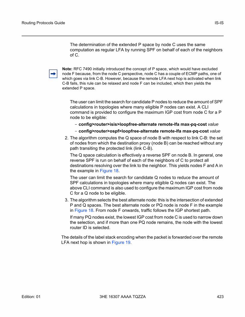
Routing Protocols Guide IS-IS
Edition: 01 3HE 16307 AAAA TQZZA 423
The determination of the extended P space by node C uses the same computation as regular LFA by running SPF on behalf of each of the neighbors of C.
The user can limit the search for candidate P nodes to reduce the amount of SPF calculations in topologies where many eligible P nodes can exist. A CLI command is provided to configure the maximum IGP cost from node C for a P node to be eligible:- config>router>isis>loopfree-alternate remote-lfa max-pq-cost value- config>router>ospf>loopfree-alternate remote-lfa max-pq-cost value
2. The algorithm computes the Q space of node B with respect to link C-B: the set of nodes from which the destination proxy (node B) can be reached without any path transiting the protected link (link C-B). The Q space calculation is effectively a reverse SPF on node B. In general, one reverse SPF is run on behalf of each of the neighbors of C to protect all destinations resolving over the link to the neighbor. This yields nodes F and A in the example in Figure 18. The user can limit the search for candidate Q nodes to reduce the amount of SPF calculations in topologies where many eligible Q nodes can exist. The above CLI command is also used to configure the maximum IGP cost from node C for a Q node to be eligible.
3. The algorithm selects the best alternate node: this is the intersection of extended P and Q spaces. The best alternate node or PQ node is node F in the example in Figure 18. From node F onwards, traffic follows the IGP shortest path. If many PQ nodes exist, the lowest IGP cost from node C is used to narrow down the selection, and if more than one PQ node remains, the node with the lowest router ID is selected.
The details of the label stack encoding when the packet is forwarded over the remote LFA next hop is shown in Figure 19.
Note: RFC 7490 initially introduced the concept of P space, which would have excluded node F because, from the node C perspective, node C has a couple of ECMP paths, one of which goes via link C-B. However, because the remote LFA next hop is activated when link C-B fails, this rule can be relaxed and node F can be included, which then yields the extended P space.

IS-IS
424
Routing Protocols Guide
3HE 16307 AAAA TQZZA Edition: 01
Figure 19 Remote LFA Next Hop in Segment Routing
The label corresponding to the node SID of the PQ node is pushed on top of the original label of the SID of the resolved destination prefix. If node C has resolved multiple node SIDs corresponding to different prefixes of the selected PQ node, it pushes the lowest node SID label on the packet when forwarding the packets over the remote LFA backup next hop.
If the PQ node is also the advertising router for the resolved prefix, the label stack is compressed in some cases, depending on the IGP.
• In IS-IS, the label stack is always reduced to a single label, which is the label of the resolved prefix owned by the PQ node.
• In OSPF, the label stack is reduced to the single label of the resolved prefix when the PQ node advertised a single node SID in the OSPF instance. If the PQ node advertised a node SID for multiple loopback interfaces within this same OSPF instance, the label stack is reduced to a single label only if the SID of the resolved prefix is the lowest SID value.
27870
ZNode-SID:65
CNode-SID:72
DNode-SID:80
Metric 10
Metric 10
Metric 10
Metric 10 Metric 10
Metric 10
BNode-SID:55
NNode-SID:60Adj-SID:9101
X (Optional)
Pkt
X (Optional)
PktX (Optional)
Pkt
X (Optional)
60
Pkt
X (Optional)
60
Pkt
X (Optional)
60
Pkt
ANode-SID:50
Pkt
X

Routing Protocols Guide IS-IS
Edition: 01 3HE 16307 AAAA TQZZA 425
The following rules and limitations apply to the remote LFA implementation.
• LFA policy is currently supported for IP next hops only. It is not supported for tunnel next hops when IGP shortcuts are used for LFA backup. Remote LFA is also a tunnel next hop, and therefore, a user-configured LFA policy is not applied in the selection of a remote LFA backup next hop when multiple candidates are available.
• As a result, if an LFA policy is applied and does not find an LFA IP next hop for a set of prefixes, the remote LFA SPF runs a search for a remote LFA next hop for the same prefixes. The selected remote LFA next hops, if found, may not satisfy the LFA policy constraints.
• If the user excludes a network IP interface from being used as an LFA next hop using the CLI command loopfree-alternate-exclude under the interface IS-IS or OSPF context, the interface is also excluded from being used as the outgoing interface for a remote LFA tunnel next hop.
• As with the regular LFA algorithm, the remote LFA algorithm computes a backup next hop to the ABR advertising an inter-area prefix and not to the destination prefix.
5.1.9.5 Topology-Independent LFA
The Topology-Independent LFA (TI-LFA) feature improves the protection coverage of a network topology by computing and automatically instantiating a repair tunnel to a Q node that is not in the shortest path from the computing node. The repair tunnel uses the shortest path to the P node and a source-routed path from the P node to the Q node.
In addition, the TI-LFA algorithm selects the backup path that matches the post-convergence path. This helps capacity planning in the network because traffic always flows on the same path when transitioning to the FRR next hop and then to the new primary next hop.
At a high level, the TI-LFA link-protection algorithm searches for the closest Q node to the computing node and then selects the closest P node to this Q node, up to a maximum number of labels. This is performed on each of the post-convergence paths to each destination node or prefix.
When the TI-LFA feature is enabled in IS-IS, it provides a TI-LFA link-protect backup path in IS-IS MT=0 for an SR-ISIS IPV4/IPv6 tunnel (node SID and adjacency SID), and for an IPv4 SR-TE LSP. See more details of the applicability of the various LFA options in LFA Protection Option Applicability.

IS-IS
426
Routing Protocols Guide
3HE 16307 AAAA TQZZA Edition: 01
5.1.9.5.1 TI-LFA Configuration
TI-LFA can be enabled in an IS-IS instance using the following command:
config>router>isis>loopfree-alternate [remote-lfa [max-pq-cost value]] [ti-lfa [max-sr-frr-labels value]]
When the ti-lfa option is enabled in IS-IS, it provides a TI-LFA link-protect backup path in IS-IS multi-topology 0 (MT=0) for an SR-ISIS IPV4 and IPv6 tunnel (node SID and adjacency SID), and for an IPv4 SR-TE LSP.
The max-sr-frr-labels parameter limits the search for the LFA backup next hop:
• 0 — the IGP LFA SPF restricts the search to a TI-LFA backup next hop that does not require a repair tunnel, meaning that the P node and Q node are the same and match a neighbor. This is also the case when both P and Q nodes match the advertising router for a prefix.
• 1 to 3 — the IGP LFA SPF widens the search to include a repair tunnel to a P node that is connected to the Q nodes with zero to two hops for a total of three labels maximum: one node SID to the P node and two adjacency SIDs from the P node to the Q node. If the P node is a neighbor of the computing node, its node SID is compressed, meaning that up to three adjacency SIDs can separate the P and Q nodes.
• 2 (default) — corresponds to a repair tunnel to a non-adjacent P node that is adjacent to the Q node. If the P node is a neighbor of the computing node, the node SID of the P node is compressed and the default value of two labels corresponds to two adjacency SIDs between the P and Q nodes.
If the user attempts to change the max-sr-frr-labels parameter to a value that results in a change to the computed FRR overhead, the IGP checks that all SR-TE LSPs can properly account for the overhead based on the configuration of the LSP max-sr-labels and additional-frr-labels parameter values; otherwise, the change is rejected.
The FRR overhead is computed by the IGP and its value is set as follows:
• 0 if segment-routing is disabled in the IGP instance• 0 if segment-routing is enabled but remote-lfa is disabled and ti-lfa is disabled• 1 if segment routing is enabled and remote-lfa is enabled but ti-lfa is disabled,
or if segment-routing is enabled and remote-lfa is enabled and ti-lfa is enabled but ti-lfa max-sr-frr-labels labels is set to 0
• to the value of ti-lfa max-sr-frr-labels labels, if segment-routing is enabled and ti-lfa is enabled, regardless of whether remote-lfa is enabled or disabled
Routing Protocols Guide IS-IS
Edition: 01 3HE 16307 AAAA TQZZA 427
The LFA commands enable the base LFA feature with the loopfree-alternate command, and optionally add remote LFA with the remote-lfa option and TI-LFA with the ti-lfa option. The behavior when one or more of these options is enabled is explained in TI-LFA Link-Protect Operation.
5.1.9.5.2 TI-LFA Link-Protect Operation
LFA Protection Option Applicability
Depending on the configured options of the loopfree-alternate command, the LFA SPF in an IGP instance runs the algorithms in the following order.
1. The algorithm first computes a regular LFA for each node and prefix. In this step, a computed backup next hop satisfies any applied LFA policy. This backup next hop protects the specific prefix or node in the context of IP FRR, SR FRR, or SR-TE FRR.
2. Next, the algorithm always follows with the TI-LFA if the ti-lfa option is enabled for all prefixes and nodes regardless of the outcome of the first step. With SR FRR and SR-TE FRR, the TI-LFA next hop protects the node SID of that prefix and protects any adjacency SID terminating on the node SID of that prefix.
3. Finally, the algorithm runs remote LFA only for the next hop of prefixes and nodes that remain unprotected after the first and second steps if the remote-lfa option is enabled.
When protecting an adjacency SID, a parallel ECMP adjacency takes precedence over any other type of LFA backup path. Applying the above algorithm applicability rules results in the following selection:
• adjacency SID of an alternate ECMP next hop• TI-LFA backup next hop• LFA backup next hop• remote LFA backup next hop
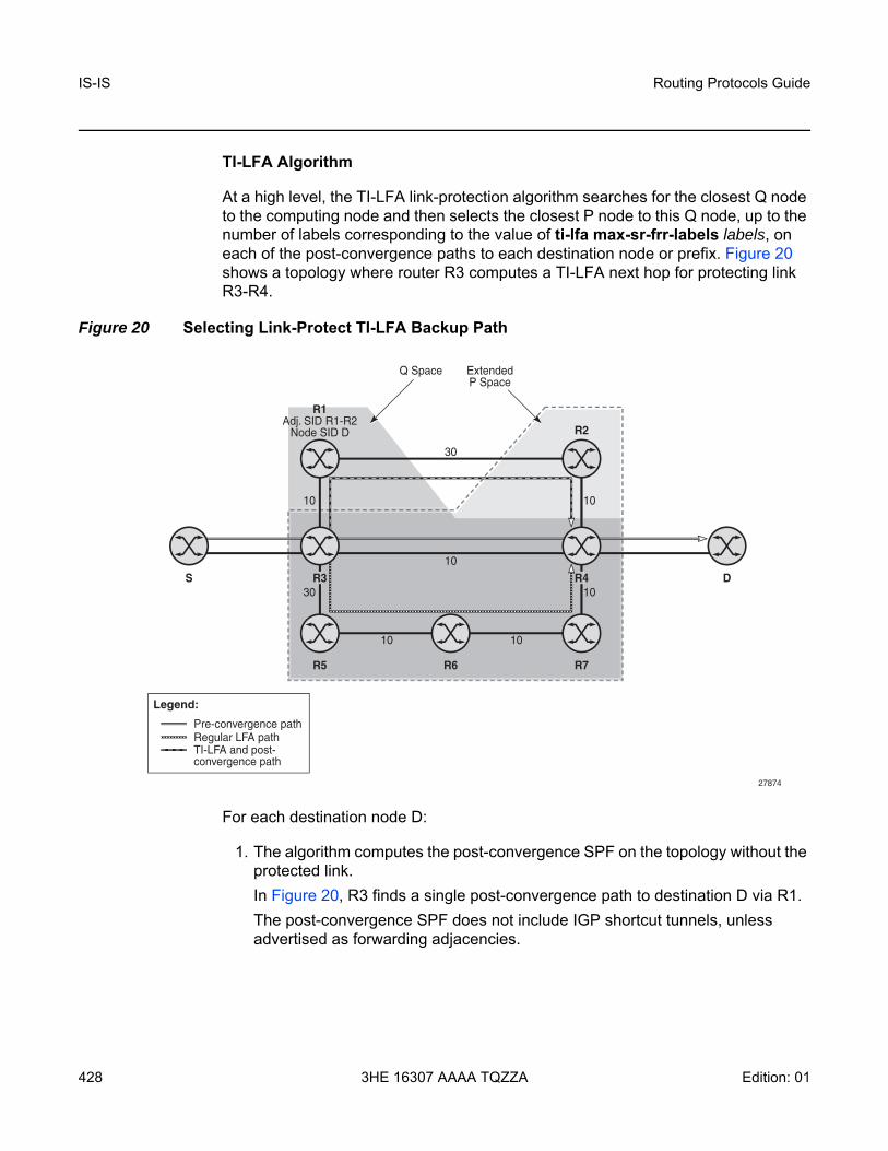
IS-IS
428
Routing Protocols Guide
3HE 16307 AAAA TQZZA Edition: 01
TI-LFA Algorithm
At a high level, the TI-LFA link-protection algorithm searches for the closest Q node to the computing node and then selects the closest P node to this Q node, up to the number of labels corresponding to the value of ti-lfa max-sr-frr-labels labels, on each of the post-convergence paths to each destination node or prefix. Figure 20 shows a topology where router R3 computes a TI-LFA next hop for protecting link R3-R4.
Figure 20 Selecting Link-Protect TI-LFA Backup Path
For each destination node D:
1. The algorithm computes the post-convergence SPF on the topology without the protected link. In Figure 20, R3 finds a single post-convergence path to destination D via R1. The post-convergence SPF does not include IGP shortcut tunnels, unless advertised as forwarding adjacencies.
R1Adj. SID R1-R2
Node SID D R2
S D
R5 R6 R7
30
30
10
10
10
27874
10
10
10
R4R3
ExtendedP Space
Q Space
Regular LFA pathPre-convergence path
TI-LFA and post-convergence path
Legend:

Routing Protocols Guide IS-IS
Edition: 01 3HE 16307 AAAA TQZZA 429
2. The algorithm computes the extended P space of R3 with respect to protected link R3-R4 on the post-convergence paths. This is the set of nodes Yi in the post-convergence paths that are reachable from R3 neighbors without any path transiting the protected link R3-R4. R3 computes an LFA SPF rooted at each of its neighbors within the post-convergence paths, that is, R1, using the following equation:Distance_opt(R1, Yi) < Distance_opt(R1, R3) + Distance_opt(R3, Yi)where “Distance_opt(A, B)” is the shortest distance between two nodes, A and B. The extended P space calculation yields only node R1.
3. The algorithm computes the Q space of R3 with respect to protected link R3-R4 in the post-convergence paths. This is the set of nodes Zi in the post-convergence paths from which the neighbor node R4 of the protected link, acting as a proxy for all destinations D, can be reached without any path transiting the protected link R3-R4. Distance_opt(Zi, R4) < Distance_opt(Zi, R3) + Distance_opt(R3, R4)The Q-space calculation yields nodes R2 and R4.This is the same computation of the Q-space performed by the remote LFA algorithm, except that the TI-LFA Q-space computation is performed only on the post-convergence.
4. For each post-convergence path, the algorithm searches for the closest Q node and selects the closest P node to this Q node, up to the number of labels corresponding to the value of ti-lfa max-sr-frr-labels labels. In the topology in Figure 20, there is a single post-convergence path, and a single P node (R1), and the closest of the two found Q nodes to the P node is R2.R3 installs the repair tunnel to the P-Q set and includes the node SID of R1 and the adjacency SID of the adjacency over link R1-R2 in the label stack. Because the P node R1 is a neighbor of the computing node R3, the node SID of R1 is not needed and the label stack of the repair tunnel is compressed to the adjacency SID over link R1-R2 as shown in Figure 20.When a P-Q set is found on multiple ECMP post-convergence paths, the following selection rules are applied, in ascending order, to select a set from a single path:
1. the lowest number of labels2. the lowest next-hop router ID3. the lowest interface index if the same next-hop router ID is the same
If multiple links with adjacency SIDs exist between the selected P node and the selected Q node, the following rules are used to select one link:
1. the adjacency SID with the lowest metric2. the adjacency SID with the lowest SID value if the lowest metric is the same

IS-IS
430
Routing Protocols Guide
3HE 16307 AAAA TQZZA Edition: 01
TI-LFA Feature Interaction and Limitations
The following are feature interactions and limitations of TI-LFA link protection.
• Enabling the ti-lfa option in overrides the user configuration of the loopfree-alternate-exclude command under the interface context in the IGP instance. In other words, the TI-LFA SPF uses that interface as a backup next hop if it matches the post-convergence next hop.
• Any prefix excluded from LFA protection using the loopfree-alternate-exclude prefix-policy prefix-policy command under the IGP instance context is also excluded from TI-LFA.
• Because the post-convergence SPF does not use paths transiting on a node in IS-IS overload, the TI-LFA backup path automatically will not transit on such a node.
• As with remote LFA, a user-configured LFA policy is not applied in the selection of a TI-LFA backup next hop when multiple candidates are available.
• IES interfaces are skipped in TI-LFA computations because they do not support segment routing with MPLS encapsulation. If the only found TI-LFA backup next hop matches an IES interface, the IGP will treat this as if there were no TI-LFA backup paths and will fall back to using either a remote LFA or regular LFA backup path as per the selection rules in LFA Protection Option Applicability.
• The TI-LFA feature provides link protection only. If the protected link is a broadcast interface, the TI-LFA algorithm only guarantees protection of that link and not of the pseudonode corresponding to that shared subnet. In other words, if the pseudonode is in the post-convergence path, the TI-LFA backup path may still traverse the pseudonode. For example, node E in Figure 21 computes a TI-LFA backup path to destination D via E-C-PN-D because it is the post-convergence path when excluding link E-PN from the topology. This TI-LFA backup does not protect against the failure of the pseudonode (PN).

Routing Protocols Guide IS-IS
Edition: 01 3HE 16307 AAAA TQZZA 431
Figure 21 TI-LFA Backup Path via a Pseudonode
• When the computing router selects an adjacency SID among a set of parallel adjacencies between the P and Q nodes, the selection rules in step 4 of TI-LFA Algorithm are used. However, these rules may not yield the same interface that the P node would have selected in its post-convergence SPF because the latter is based on the lowest value of the locally managed interface index. For example, node A in Figure 22 computes the link-protect TI-LFA backup path for destination node E as path A-C-E, where C is the P node and E is the Q node and destination. C has a pair of adjacency SIDs with the same metric to E. Node A selects the adjacency over the point-to-point link C-E because it has the lowest SID value, but node C may select the interface C-PN in its post-convergence path calculation if that interface has a lower interface index than point-to-point link C-E.
27875
100100
99100
100
100
AREA_0/level_1
Start_labelSID loopback/system_ltfSID loopback/ipv6_native(*)
B30000/20000(*)
5/1117/23(*)
E60000/20000(*)
2/814/20(*)
C40000/20000(*)
0/612/18(*)
D50000/20000(*)
1/713/19(*)
F70000/20000(*)
3/915/21(*)

IS-IS
432
Routing Protocols Guide
3HE 16307 AAAA TQZZA Edition: 01
Figure 22 Parallel Adjacencies between P and Q Nodes
• When a node SID is advertised by multiple routers (anycast SID), the TI-LFA algorithm on a router that resolves the prefix of this SID computes the backup next hop toward a single node owner of the prefix based on the rules for prefix and SID ECMP next-hop selection.
5.1.9.5.3 Data Path Support
The TI-LFA repair tunnel can have a maximum of three additional labels pushed in addition to the label of the destination node or prefix. The user can set a lower maximum value for the additional FRR labels by configuring the ti-lfa max-sr-frr-labels labels option. The default value is 2.
The data path models the backup path like an SR-TE LSP and therefore uses a super-NHLFE pointing to the NHLFE of the first hop in the repair tunnel. That first hop corresponds to either an adjacency SID or a node SID of the P node.
27876
1000100
100100
100
100
1000
Start_labelSID loopback/system_ltfSID loopback/ipv6_native
B30000/20000
5/1117/23
A20000/20000
4/1016/22
E60000/20000
2/814/20
C40000/20000
0/612/18
D50000/20000
1/713/19
F70000/20000
3/915/21
router_Id of E < router_Id of D
AREA_0/level_1

Routing Protocols Guide IS-IS
Edition: 01 3HE 16307 AAAA TQZZA 433
There is a special case where the P node is adjacent to the node computing the TI-LFA backup, and the Q node is the same as the P node or adjacent to the P node. In this case, the data path at the computing router pushes either zero labels or one label for the adjacency SID between the P and Q nodes. The backup path uses a regular NHLFE in this case as in base LFA or remote LFA. Figure 20 shows an example of a single label in the backup NHLFE.
5.1.9.6 IPv6 Segment Routing using MPLS Encapsulation
This feature implements support for SR IPv6 tunnels in IS-IS MT=0. The user can configure a node SID for the primary IPv6 global address of a loopback interface, which then gets advertised in IS-IS. IS-IS automatically assigns and advertises an adjacency SID for each adjacency with an IPv6 neighbor. After the node SID is resolved, it is used to install an IPv6 SR-ISIS tunnel in the TTM for use by the services.
5.1.9.6.1 IS-IS MT=0 Extensions
The IS-IS MT=0 extensions consist of supporting the advertising and resolution of the prefix SID sub-TLV within the IP reachability TLV-236 (IPv6), which is defined in RFC 5308.
The adjacency SID is still advertised as a sub-TLV of the Extended IS Reachability TLV 22, as defined in RFC 5305, IS-IS Extensions for Traffic Engineering, as in the case of an IPv4 adjacency. The router sets the V-Flag and I-Flag in the SR-Capabilities sub-TLV to indicate that it is capable of processing SR MPLS-encapsulated IPv4 and IPv6 packets on its network interfaces.
5.1.9.6.2 Supported Service and Forwarding Contexts
The service and forwarding contexts supported with SR-ISIS IPv6 tunnels are:
• SDP of type sr-isis with far-end option using IPv6 address• VLL, VPLS, IES/VPRN spoke-SDP interfaces, R-VPLS• PW redundancy within Epipe/Ipipe VLLs, Epipe spoke-SDP termination on
VPLS and R-VPLS, and Epipe/Ipipe spoke-SDP termination on IES/VPRN• remote mirroring
IS-IS
434
Routing Protocols Guide
3HE 16307 AAAA TQZZA Edition: 01
5.1.9.6.3 Services Using SDP with an SR IPv6 Tunnel
The MPLS SDP of type sr-isis with a far-end option using an IPv6 address is supported. The SDP must have the same IPv6 far-end address, used by the control plane for the T-LDP session, as the prefix of the node SID of the SR IPv6 tunnel.
Example: configureservice
[no] sdp sdp-id mpls[no] far-end ipv6-addresssr-isisno sr-isis
The bgp-tunnel, lsp, sr-te lsp, sr-ospf, and mixed-lsp-mode commands are blocked within the SDP configuration context when the far-end address is an IPv6 address.
SDP admin groups are not supported with an SDP using an SR IPv6 tunnel, or with SR-OSPF for IPv6 tunnels, and their assignment is blocked in the CLI.
Services that use an LDP control plane such as T-LDP VPLS and R-VPLS, VLL, and IES/VPRN spoke-SDP interfaces have the spoke SDP (PW) signaled with an IPv6 T-LDP session because the far-end option is configured to an IPv6 address. The spoke SDP for these services binds to an SDP that uses an SR IPv6 tunnel where the prefix matches the far-end address. The 7705 SAR also supports the following:
• the IPv6 PW control word with both data plane packets and VCCV OAM packets
The PW switching feature is not supported with LDP IPv6 control planes. As a result, the CLI does not allow the user to enable the vc-switching option whenever one or both spoke SDPs uses an SDP that has the far-end configured as an IPv6 address.
Layer 2 services that use the BGP control plane, such as dynamic MS-PW, cannot bind to an SR IPv6 tunnel because a BGP session to a BGP IPv6 peer does not support advertising an IPv6 next hop for the Layer 2 NLRI. As a result, these services will not auto-generate SDPs using an SR IPv6 tunnel,
The Shortest Path Bridging (SPB) feature works with spoke SDPs bound to an SDP that uses an SR IPv6 tunnel.

Routing Protocols Guide IS-IS
Edition: 01 3HE 16307 AAAA TQZZA 435
5.1.9.7 Data Path Support
A packet received with a label matching either a node SID or an adjacency SID is forwarded according to the ILM type and operation, as described in Table 57.
A router forwarding an IP or a service packet over an SR tunnel pushes a maximum of two transport labels with a remote LFA next hop. This is illustrated in Figure 23.
Table 57 Data Path Support
Label type Operation
Top label is a local node SID
Label is popped and the packet is further processedIf the popped node SID label is the bottom of stack label, the IP packet is looked up and forwarded in the appropriate FIB
Top or next label is a remote node SID
Label is swapped to the calculated label value for the next hop and forwarded according to the primary or backup NHLFEWith ECMP, a maximum of 8 primary next hops (NHLFEs+) are programmed for the same destination prefix and for each IGP instance. ECMP and LFA next hops are mutually exclusive
Top or next label is an adjacency SID
Label is popped and the packet is forwarded out on the interface to the next hop associated with this adjacency SID labelIn effect, the data path operation is modeled like a swap to an implicit-null label instead of a pop
Next label is a BGP 3107 label
The packet is further processed according to the ILM operation in the current implementation:
• the BGP label may be popped and the packet looked up in the appropriate FIB
• the BGP label may be swapped to another BGP label
Next label is a service label
The packet is looked up and forwarded in the Layer 2 or VPRN FIB

IS-IS
436
Routing Protocols Guide
3HE 16307 AAAA TQZZA Edition: 01
Figure 23 Transport Label Stack in Shortest Path Forwarding with Segment Routing
In Figure 23, a VPRN service in node B forwards a packet received on a SAP to a destination VPN-IPv4 prefix X advertised by a remote PE2 via ASBR/ABR node A. Router B is in a segment routing domain while PE2 is in an LDP domain. BGP label routes are used to distribute the PE /32 loopbacks between the two domains.
When node B forwards a packet over the primary next hop for prefix X, it pushes the node SID of the ASBR followed by the BGP 3107 label for PE2, followed by the service label for prefix X. When the remote LFA next hop is activated, node B pushes one or more segment routing labels: the node SID for the remote LFA backup node (node N).
When node N receives the packet while the remote LFA next hop is activated, it pops the top segment routing label, which corresponds to a local node SID. Th packet is then forwarded to the ASBR node over the shortest path (link N-Z).
When the ABR/ASBR node receives the packet from either node B or node Z, it pops the segment routing label that corresponds to a local node SID, then swaps the BGP label and pushes the LDP label of PE2, which is the next hop of the BGP label route.
27870
ZNode-SID:65
CNode-SID:72
DNode-SID:80
Metric 10
Metric 10
Metric 10
Metric 10 Metric 10
Metric 10
BNode-SID:55
NNode-SID:60Adj-SID:9101
X (Optional)
Pkt
X (Optional)
PktX (Optional)
Pkt
X (Optional)
60
Pkt
X (Optional)
60
Pkt
X (Optional)
60
Pkt
ANode-SID:50
Pkt
X
Routing Protocols Guide IS-IS
Edition: 01 3HE 16307 AAAA TQZZA 437
5.1.9.8 Control Protocol Changes
This section describes both IS-IS Control Protocol Changes and OSPF Control Protocol Changes.
5.1.9.8.1 IS-IS Control Protocol Changes
New TLV/sub-TLVs are defined in draft-ietf-isis-segment-routing-extensions and are supported in the implementation of segment routing in IS-IS:
• the prefix SID sub-TLV• the adjacency SID sub-TLV• the SID/Label Binding TLV• SR-Capabilities sub-TLV• SR-Algorithm sub-TLV
This section describes the behaviors and limitations of IS-IS support of segment routing TLV and sub-TLVs.
The 7705 SAR supports advertising the IS router capability TLV (RFC 4971) only for topology MT=0. As a result, the segment routing capability sub-TLV can only be advertised in MT=0, which restricts the segment routing feature to MT=0.
Similarly, if prefix SID sub-TLVs for the same prefix are received in different MT numbers of the same IS-IS instance, only the one in MT=0 is resolved. If the prefix SID index is also duplicated, an error is logged and a trap is generated, as explained in Error and Resource Exhaustion Handling.
The I and V flags are both set to 1 when originating the SR capability sub-TLV to indicate support for processing both SR MPLS-encapsulated IPv4 and IPv6 packets on its network interfaces. These flags are not checked when the sub-TLV is received. Only the SRGB range is processed.
Both IPv4 and IPv6 prefix and adjacency SID sub-TLVs originate within MT=0.
The 7705 SAR originates a single prefix SID sub-TLV per IS-IS IP reachability TLV and processes the first prefix SID sub-TLV only if multiple SID sub-TLVs are received within the same IS-IS IP reachability TLV.
The 7705 SAR encodes the 32-bit index in the prefix SID sub-TLV. The 24-bit label is not supported.
The 7705 SAR originates a prefix SID sub-TLV with the following encoding of the flags and the following processing rules.

IS-IS
438
Routing Protocols Guide
3HE 16307 AAAA TQZZA Edition: 01
• The R-flag is set if the prefix SID sub-TLV, along with its corresponding IP reachability TLV, is propagated between levels. See below for more details about prefix propagation.
• The N-flag is always set because the 7705 SAR supports prefix SID of type node SID only.
• The P-flag (no-PHP flag) is always set, meaning that the label for the prefix SID is pushed by the PHP router when forwarding to this router. The 7705 SAR PHP router properly processes a received prefix SID with the P-flag set to zero and uses implicit-null for the outgoing label toward the router that advertised it as long as the P-flag is also set to 1.
• The E-flag (Explicit-Null flag) is always set to 0. A 7705 SAR PHP router, however, properly processes a received prefix SID with the E-flag set to 1, and when the P-flag is also set to 1, it pushes explicit-null for the outgoing label toward the router that advertised it.
• The V-flag is always set to 0 to indicate an index value for the SID.• The L-flag is always set to 0 to indicate that the SID index value is not locally
significant.• A router that receives the TLV advertisement leaks it between IS-IS levels 1 and
2. If leaked from level 2 to level 1, the D-flag must be set; this prevents the TLV from being leaked back into level 2.
• The A-flag is used to indicate that a prefix for which the mapping server prefix SID is advertised is directly attached.
• The M-flag is used to advertise a SID for a mirroring context to provide protection against the failure of a service node.
• The algorithm field is set to 0 to indicate that the Shortest Path First (SPF) algorithm based on link is used when originating the SR-Algorithm capability sub-TLV but is not checked when the sub-TLV is received.
• The 7705 SAR still resolves a prefix SID sub-TLV received without the N-flag set but with the prefix length equal to 32. However, a trap is raised by IS-IS.
• The 7705 SAR will not resolve a prefix SID sub-TLV received with the N-flag set and a prefix length not equal to 32. A trap is raised by IS-IS.
• The 7705 SAR resolves a prefix SID received within a IP reachability TLV based on the following route preference:- a SID received via level 1 in a prefix SID sub-TLV part of IP reachability TLV- a SID received via level 2 in a prefix SID sub-TLV part of IP reachability TLV
• A prefix received in an IP reachability TLV is propagated, along with the prefix SID sub-TLV, by default from level 1 to level 2 by a level 1/2 router. A router in level 2 sets up an SR tunnel to the level 1 router via the level 1/2 router, which acts as an LSR.

Routing Protocols Guide IS-IS
Edition: 01 3HE 16307 AAAA TQZZA 439
• A prefix received in an IP reachability TLV is not propagated, along with the prefix SID sub-TLV, by default from level 2 to level 1 by a level 1/2 router. If the user adds a policy to propagate the received prefix, a router in L1 sets up an SR tunnel to the level 2 router via the level1/2 router, which acts as an LSR.
• If a prefix is summarized by an ABR, the prefix SID sub-TLV is not propagated with the summarized route between levels. To propagate the node SID for a /32 prefix, route summarization must be disabled.
• The 7705 SAR propagates the prefix SID sub-TLV when exporting the prefix to another IS-IS instance; however, it does not propagate it if the prefix is exported from a different protocol. Therefore, when the corresponding prefix is redistributed from another protocol such as OSPF, the prefix SID is removed.
The 7705 SAR originates an adjacency SID sub-TLV with the following encoding of the flags:
• the F-flag is set to 0 to indicate the IPv4 family and is set to 1 to indicate an IPv6 family for the adjacency encapsulation
• the B-flag is set to 0 and is not processed on receipt• the V-flag is always set to 1• the L-flag is always set to 1• the S-flag is set to 0 because assigning an adjacency SID to parallel links
between neighbors is not supported. A received adjacency SID with the S-flag set is not processed.
• the weight octet is not supported and is set to all 0s.
The 7705 SAR can originate the SID/Label Binding TLV as part of the mapping server feature functionality (see Segment Routing Mapping Server for IPv4 /32 Prefixes (IS-IS) for more information) and can also process the TLV if received. The following behavior applies.
• Only the mapping server prefix SID sub-TLV within the TLV is processed. The ILMs are installed if the prefixes in the provided range are resolved.
• If the same prefix is advertised with both a prefix SID sub-TLV and a mapping server Prefix SID sub-TLV, the resolution follows the following route preference:- a SID received via level 1 in a prefix SID sub-TLV that is part of an IP
reachability TLV- a SID received via level 2 in a prefix SID sub-TLV that is part of an IP
reachability TLV- a SID received via level 1 in a mapping server prefix SID sub-TLV- a SID received via level 2 in a mapping server prefix SID sub-TLV

IS-IS
440
Routing Protocols Guide
3HE 16307 AAAA TQZZA Edition: 01
• The range and FEC prefix fields are processed. Each FEC prefix is resolved in the same way as the prefix SID sub-TLV; that is, there must be an IP reachability TLV received for the exact matching prefix in order for it to be resolved.
• The entire TLV can be propagated between levels based on the settings of the S-flag. The TLV cannot be propagated between IS-IS instances (see Segment Routing Mapping Server for IPv4 /32 Prefixes (IS-IS) for more information). A level 1/2 router is not propagated with the prefix SID sub-TLV from the SID/Label Binding TLV, which is received from a mapping server, into the IP reachability TLV if the SID/Label Binding TLV is propagated between levels.
• The mapping server that advertises the SID/Label Binding TLV does not need to be in the shortest path for the FEC prefix.
• If the same FEC prefix is advertised in multiple binding TLVs by different routers, the SID in the binding TLV of the first reachable router is used. If that router becomes unreachable, the next reachable one is used.
• No check is performed to determine whether the contents of the binding TLVs from different mapping servers are consistent.
• Any other sub-TLV, such as the ERO metric or unnumbered interface ID ERO SID/Label sub-TLV, is ignored. However, a user can get an output of the octets of the received but unsupported sub-TLVs by using the IGP show command.
5.1.9.8.2 OSPF Control Protocol Changes
New TLV/sub-TLVs are defined in draft-ietf-ospf-segment-routing-extensions-04 and are required for the implementation of segment routing in OSPF:
• the prefix SID sub-TLV part of the OSPFv2 Extended Prefix TLV• the prefix SID sub-TLV part of the OSPFv2 Extended Prefix Range TLV• the adjacency SID sub-TLV part of the OSPFv2 Extended Link TLV• SID/Label Range Capability TLV• SR-Algorithm Capability TLV
This section describes the behaviors and limitations of OSPF support of segment routing TLV and sub-TLVs.
The 7705 SAR originates a single prefix SID sub-TLV per OSPFv2 Extended Prefix TLV and processes the first one only if multiple prefix SID sub-TLVs are received within the same OSPFv2 Extended Prefix TLV.
The 7705 SAR encodes the 32-bit index in the prefix SID sub-TLV. The 24-bit label or variable IPv6 SID is not supported.

Routing Protocols Guide IS-IS
Edition: 01 3HE 16307 AAAA TQZZA 441
The 7705 SAR originates a prefix SID sub-TLV with the following encoding of the flags.
• The NP-flag is always set, meaning that the label for the prefix SID is pushed by the PHP router when forwarding to this router. The 7705 SAR PHP router properly processes a received prefix SID with the NP-flag set to 0 and uses implicit-null for the outgoing label toward the router that advertised it.
• The M-flag is never set because the 7705 SAR does not support originating a mapping server prefix SID sub-TLV.
• The E-flag is always set to 0. The 7705 SAR PHP router properly processes a received prefix SID with the E-flag set to 1, and when the NP-flag is also set to 1, it pushes explicit-null for the outgoing label toward the router that advertised it.
• The V-flag is always set to 0 to indicate an index value for the SID.• The L-flag is always set to 0 to indicate that the SID index value is not locally
significant.• The algorithm field is always set to 0 to indicate that the Shortest Path First
(SPF) algorithm based on link metric is used and is not checked on a received prefix SID sub-TLV.
The 7705 SAR resolves a prefix SID received within an Extended Prefix TLV based on the following route preference:
• SID received via an intra-area route in a prefix SID sub-TLV part of Extended Prefix TLV
• SID received via an inter-area route in a prefix SID sub-TLV part of Extended Prefix TLV
The 7705 SAR originates an adjacency SID sub-TLV with the following encoding of the flags.
• The F-flag is not set to indicate that the Adjacency SID refers to an adjacency with outgoing IPv4 encapsulation.
• The B-flag is set to 0 and is not processed on receipt.• The V-flag is always set.• The L-flag is always set.• The S-flag is not supported.• The weight octet is not supported and is set to all 0s.
The 7705 SAR does not originate the OSPFv2 Extended Prefix Range TLV but can process it properly if received. The following rules and limitations should be considered.

IS-IS
442
Routing Protocols Guide
3HE 16307 AAAA TQZZA Edition: 01
• Only the prefix SID sub-TLV within the TLV is processed and the ILMs installed if the prefixes are resolved.
• The range and address prefix fields are processed. Each prefix is resolved separately.
• Any other sub-TLV, for example, the ERO metric and unnumbered interface ID ERO, is ignored, but the user can get a list of the octets of the received but not supported sub-TLVs using the existing IGP show command.
The 7705 SAR supports propagation on the ABR of external prefix LSAs into other areas with the route type set to 3 as per draft-ietf-ospf-segment-routing-extensions-04.
The 7705 SAR supports propagation on the ABR of external prefix LSAs with route type 7 from an NSSA area into other areas with route type set to 5 as per draft-ietf-ospf-segment-routing-extensions-04. The 7705 SAR does not support propagation of the prefix SID sub-TLV between OSPF instances.
When the user configures an OSPF import policy, the outcome of the policy applies to prefixes resolved in the RTM and the corresponding tunnels in the TTM. A prefix removed by the policy will not appear as both a route in the RTM and as an SR tunnel in the TTM.
5.1.9.9 BGP Label Route Resolution Using Segment Routing Tunnel
The resolution of RFC 3107 BGP label route prefixes using SR tunnels to BGP next hops in the TTM is enabled with the following command:
CLI Syntax: configure>router>bgp>next-hop-resolutionlabel-routes-transport-tunnel
[no] family {vpn | label-ipv4}resolution {any | filter | disabled}resolution-filter
[no] ldp [no] rsvp [no] sr-isis[no] sr-ospf[no] sr-te
exitexit
exit

Routing Protocols Guide IS-IS
Edition: 01 3HE 16307 AAAA TQZZA 443
If the resolution option is explicitly set to disabled, the default binding to LDP tunnels resumes. If resolution is set to any, any supported tunnel type in the BGP label route context is selected following the TTM preference. If resolution is set to filter, the resolution-filter option is used.
The following tunnel types are supported in a BGP label route context and in order of preference: RSVP, SR-TE, LDP, SR-OSPF, and SR-ISIS.
If the sr-isis or sr-ospf option is specified using the resolution-filter option, a tunnel to the BGP next hop is selected in the TTM from the lowest-numbered IS-IS or OSPF instance.
See the BGP chapter for more details.
5.1.9.10 Service Packet Forwarding with Segment Routing
SDP subtypes of the MPLS type are available to allow service binding to an SR tunnel programmed in the TTM by OSPF or IS-IS:
CLI Syntax: configure>service>sdp sdp-id mpls create sr-ospfsr-isis
The SDP of type sr-isis or sr-ospf can be used with the far-end option. When the sr-isis or sr-ospf option is enabled, a tunnel to the far-end address is selected in the TTM from the lowest-preference IS-IS or OSPF instance. If multiple instances have the same lowest preference, the lowest-numbered IS-IS or OSPF instance is selected. The SR-ISIS or SR-OSPF tunnel is selected at the time of the binding, following the tunnel selection rules. If a more preferred tunnel is subsequently added to the TTM, the SDP will not automatically switch to the new tunnel until the next time the SDP is being resolved.
The signaling protocol for the service labels for an SDP using an SR tunnel can be configured to static (off) or T-LDP (tldp), or BGP (bgp).
SR tunnels can be used in VPRN services and BGP EVPN with the auto-bind-tunnel command. See Next-hop Resolution of BGP Labeled Routes to Tunnelsfor more information.
Both VPN-IPv4 and VPN-IPv6 (6VPE) are supported in a VPRN service or BGP EVPN using segment routing transport tunnels with the auto-bind-tunnel command.
For more information about the VPRN auto-bind-tunnel command, see BGP. Additionally, refer to the “VPRN Auto-binding Tunnels” section in the 7705 SAR Services Guide.

IS-IS
444
Routing Protocols Guide
3HE 16307 AAAA TQZZA Edition: 01
The following are the service contexts that are supported with SR tunnels:
• VLL, LDP VPLS, IES/VPRN spoke-SDP interfaces, and R-VPLS• Intra-AS BGP VPRN for VPN-IPv4 and VPN-IPv6 prefixes with both auto-bind
and explicit SDP
The following service contexts are not supported:
• Inter-AS VPRN• Dynamic MS-PW, PW-switching
5.1.9.11 Segment Routing Mapping Server for IPv4 /32 Prefixes (IS-IS)
The mapping server feature allows the configuration and advertisement via IS-IS of the node SID index for prefixes of routers which are in the LDP domain. This functionality is performed in the router acting as a mapping server and using a prefix SID sub-TLV within the SID/Label Binding TLV in IS-IS.
For more information on prefix SID sub-TLVs and SID/Label Binding TLVs, as well as information on the setting of the various types of flags associated with IS-IS support of SR TLV and sub-TLVs, see to IS-IS Control Protocol Changes. For more information on LDP-to-SR stitching, refer to the 7705 SAR MPLS Guide, “LDP-to-Segment Routing Stitching for IPv4 /32 Prefixes (IS-IS)”.
An SR mapping server is configured using the following CLI commands:
CLI Syntax: configurerouter
isissegment-routing
mapping-serversid-map node-sid {index value
[range value]} prefix {ip-address/mask | ip-address netmask} [set-flags {s}] [level {1|2|1/2}]
A user can enter the node-sid index for one prefix or a range of prefixes by specifying the index value or a value range. Only the first prefix in a consecutive range of prefixes must be entered. If the user enters the first prefix with a mask lower than 32, the SID/Label Binding TLV is advertised but the router does not resolve the prefix SIDs; a trap is originated instead.

Routing Protocols Guide IS-IS
Edition: 01 3HE 16307 AAAA TQZZA 445
The user can configure the S-flag using the set-flags option to indicate to the IS-IS network routers that the flooding of the SID/Label Binding TLV applies to the entire domain. A router that receives the TLV advertisement leaks it between IS-IS levels 1 and 2. If leaked from level 2 to level 1, the D-flag must be set; this prevents the TLV from being leaked back into level 2. The S-flag is not defined by default; if it is not configured, the TLV is not leaked by routers receiving the mapping server advertisement.
The user can specify the mapping server’s flooding scope for the generated SID/Label Binding TLV using the level option. The default flooding scope of the mapping server is level 1/2.
Each time a prefix or a range of prefixes is configured in the SR mapping database in any routing instance, the router issues a prefix SID sub-TLV within an IS-IS SID/Label Binding TLV for the prefix or range of prefixes.. The flooding scope of the TLV from the mapping server is determined as explained above. No further check of the reachability of that prefix in the mapping server route table is performed, and no check is done to determine if the SID index is a duplicate of an existing prefix in the local IGP instance database or if the SID index is out of range with the local SRGB.
An SR-capable router, including the mapping server and its clients, attempts to resolve each received prefix SID to either an SR tunnel endpoint or an LDP tunnel endpoint. See Prefix SID Resolution for a Segment Routing Mapping Server.
5.1.9.12 Mirror Services
A spoke SDP can be bound to an SR tunnel to forward mirrored packets from a mirror source to a remote mirror destination. In the configuration of the mirror destination service at the destination node, the remote-source command must use a spoke SDP with a VC-ID that matches the one configured in the mirror destination service at the mirror source node. The far-end option is not supported with an SR tunnel.
Configuration at mirror source node:
CLI Syntax: config mirror mirror-dest 10no spoke-sdp sdp-id:vc-id spoke-sdp sdp-id:vc-id [create]
egressvc-label egress-vc-label
Note: The 7705 SAR does not leak the SID/Label Binding TLV between IS-IS instances.

IS-IS
446
Routing Protocols Guide
3HE 16307 AAAA TQZZA Edition: 01
Configuration at mirror destination node:
CLI Syntax: configure mirror mirror-dest 10 remote-sourcespoke-sdp sdp-id:vc-id create <--- vc-id matching
that of spoke-sdp configured in mirror destination context at mirror source node
ingressvc-label ingress-vc-label
exitno shutdown
exitexit
Mirroring is also supported with the PW redundancy feature when the endpoint spoke SDP, including the ICB, is using an SR tunnel.
5.1.10 Multi-Instance IS-IS (MI-IS-IS)
The 7705 SAR routers support multiple IS-IS instances. There is one default (base) instance. The remaining (non-default) instances must be specified with an isis-instance value.
The default (base) and non-default MI-IS-IS instances use the following MAC addresses:
• default instance, as per the ISO 10589 standard: - 01-80-C2-00-00-14 for all level 1 routers (AllL1IS)
Note:
• The sdp-id matches an SDP that uses an SR tunnel.• For vc-label, both static and T-LDP egress VC labels are supported.
Note:
• The far-end command is not supported with an SR tunnel at the mirror destination node; the user must reference a spoke SDP using a segment routing SDP coming from the mirror source node:- far-end ip-address [vc-id vc-id] [ing-svc-label ingress-vc-label | tldp] [icb]- no far-end ip-address
• For vc-label, both static and T-LDP ingress VC labels are supported.

Routing Protocols Guide IS-IS
Edition: 01 3HE 16307 AAAA TQZZA 447
- 01-80-C2-00-00-15 for all level 2 routers (AllL2IS)• non-default instances, as per the RFC 6822 standard:
- 01-00-5E-90-00-02 for all level 1 routers (AllL1MI-ISs) - 01-00-5E-90-00-03 for all level 2 routers (AllL2MI-ISs)
All IS-IS instances on a 7705 SAR populate the same router information base (RIB).
To use the same router interface in more than one IS-IS instance, use the iid-tlv-enable command. When the iid-tlv-enable command is issued, the instance ID (IID) is included in all IS-IS PDUs so that the far-end router knows which instance will receive the packet.
5.1.11 IPv6 Support
IS-IS for IPv6 routing supports two modes: single topology (native) and multi-topology. The 7705 SAR supports native mode only. In native mode, IPv6 routing information is exchanged within IS-IS using the following TLVs contained in the LSP:
• IPv6 reachability TLV• IPv6 interface address TLV
For detailed information, see RFC 5308, Routing IPv6 with IS-IS.
IPv4 and IPv6 routing can be run at the same time in an area. However, because one SPF calculation is performed per level to compute the routes, the IPv4 and IPv6 topologies must be the same. That is, both IPv4 and IPv6 addresses must be configured on all router interfaces in an area; otherwise, traffic may be blackholed. For example, if the SPF calculation includes a link that is not configured with an IPv6 address, IPv6 traffic will be blackholed over that link.
Note: On the 7705 SAR, all non-default instances use the same MAC address for routers at the same level, which is different multicast MAC address from the base instance. The non-default MAC address is not user-configurable and is permanently set.

IS-IS
448
Routing Protocols Guide
3HE 16307 AAAA TQZZA Edition: 01
5.2 Bidirectional Forwarding Detection (BFD) for IS-IS
BFD is a simple protocol for detecting failures in a network. BFD uses a “hello” mechanism that sends control messages periodically to the far end and receives periodic control messages from the far end. BFD can detect device, link, and protocol failures.
When BFD is enabled on an IS-IS interface, the state of the interface is tied to the state of the BFD session between the local node and remote (far-end) node. BFD is implemented in asynchronous mode only (similar to a heartbeat message), meaning that neither end responds to control messages; rather, the messages are sent in the interval configured at each end.
If the configured number of consecutive BFD missed messages is reached, the link is declared down and IS-IS takes the appropriate action (for example, generates a link-state PDU (LSP) against the failed link or reroutes around the failed link).
Due to the lightweight nature of BFD, the frequency of BFD packets can be relatively high (up to 10 per second); therefore, it can detect failures faster than other detection protocols, making it ideal for use in applications such as mobile transport.

Routing Protocols Guide IS-IS
Edition: 01 3HE 16307 AAAA TQZZA 449
5.3 LDP and IP Fast Reroute (FRR) for IS-IS Prefixes
LDP Fast Reroute (FRR) provides local protection for an LDP FEC by precalculating and downloading a primary and a backup NHLFE for the FEC to the LDP FIB. The primary NHLFE corresponds to the label of the FEC received from the primary next hop as per the standard LDP resolution of the FEC prefix in the RTM. The backup NHLFE corresponds to the label received for the same FEC from a Loop-Free Alternate (LFA) next hop.
LDP FRR improves convergence in case of a local link or node failure in the network, by using the label-FEC binding received from the LFA next hop to forward traffic for a given prefix as soon as the primary next hop is not available. This means that a router resumes forwarding LDP packets to a destination prefix using the backup path without waiting for the routing convergence.
IP Fast Reroute (FRR) protects against link or node failures in an IP network by precalculating a backup route to use when the primary next hop is not available. Both routes are populated in the RTM. IP FRR uses an LFA backup next hop to forward in-transit and CSM-generated IP packets as soon as the primary next-hop failure is detected and the backup is invoked. This means that a node resumes forwarding IP packets to a destination prefix without waiting for the routing convergence.
Refer to RFC 5286, Basic Specification for IP Fast Reroute: Loop-Free Alternates, for more information on LFAs.
Refer to the 7705 SAR MPLS Guide “LDP Fast Reroute (FRR)” for more information on LDP FRR and to the 7705 SAR Router Configuration Guide, “IP Fast Reroute (FRR)” for more information on IP FRR.
LFAs are supported on IPv4 IS-IS prefixes and on inter-level IS-IS prefixes. LFAs are also supported on IPv4 and IPv6 OSPF prefixes, VPN IPv4 OSPF prefixes, and on inter-area OSPF prefixes. For information on LFA support for OSPF prefixes, see LDP and IP Fast Reroute (FRR) for OSPF Prefixes.
IP FRR also provides an LFA backup next hop for the destination prefix of a GRE tunnel used in an SDP or in VPRN auto-bind.

IS-IS
450
Routing Protocols Guide
3HE 16307 AAAA TQZZA Edition: 01
5.3.1 LFA Calculations
In addition to performing the Shortest Path First (SPF) calculation of the primary next hop, IS-IS must calculate a backup next hop for all prefixes used by LDP to resolve FECs and for all prefixes used by IP to forward packets. The backup next hops are calculated to provide single link or node protection and to guarantee that when a failure occurs, forwarding traffic through the backup next hop will not result in a loop. These backup next hops are called Loop-Free Alternates (LFAs).
In general, in order to calculate LFAs for a specific destination (D), a router must know the following information:
• the shortest-path distance from the calculating router (source) to the destination (SP(S,D))
• the shortest-path distance from the router’s IS-IS neighbors to the destination (SP(N,D))
• the shortest-path distance from the router’s IS-IS neighbors to itself (SP(N,S))
A neighbor (N) can provide an LFA only if:
SP(N,D) < SP(N,S) + SP(S,D)
This is known as loop-free criterion.
Figure 24 shows an example of a backup route resulting in a micro-loop. In the example, PE-1 uses PE-2 as its next hop to reach PE-3. The total cost to reach PE-3 via PE-2 is 9. If the link between PE-1 and PE-2 fails, PE-1 can try to use PE-4 as its next hop to reach PE-3. However, the metric between PE-4 and PE-3 is 30. From the perspective of PE-4, forwarding traffic via the PE-1 and PE-2 path to PE-3 is more viable, as the cost is 17 (8 + 5 + 4) versus the direct link cost of 30. Therefore, if PE-1 forwards the traffic to PE-4 in order to reach PE-3, PE-4 forwards it back to PE-1, creating a micro-loop, until the routing protocols converge and declare the link between PE-1 and PE-2 to be down. PE-4 would then be forced to take the direct PE-3 link to reach PE-3 as there is no other alternative. Because PE-4 does not meet the loop-free criterion, it cannot be used as a valid LFA.

Routing Protocols Guide IS-IS
Edition: 01 3HE 16307 AAAA TQZZA 451
Figure 24 Backup Routes Resulting in Micro-loops
Figure 25 shows an example of an LFA backup route. In this example, PE-1 again uses PE-2 as its next hop to reach PE-3. The total cost to reach PE-3 via PE-2 is 9. If the link between PE-1 and PE-2 fails, PE-1 can use PE-4 to reach PE-3. From the perspective of PE-4, the direct route to PE-3 is a viable route, as the cost is 3 versus the cost of forwarding traffic via PE-1 (17). Using the direct route does not cause micro-loops and meets the loop-free criterion; therefore, PE-4 can be used as a valid LFA.
Figure 25 LFA Backup Route
PE-2
5
4
8
30
PE-3
PE-1 PE-4
PE-2
5
4
8
30
PE-3
PE-1
25313
PE-4
X
SPF calculationprimary route
backup route next hop
Legend:
PE-2
5
4
8
3
PE-3
25314
PE-4PE-1
PE-2
4
8
3
PE-3
PE-4PE-1
5X
primary routeLFA SPF calculation
Legend:

IS-IS
452
Routing Protocols Guide
3HE 16307 AAAA TQZZA Edition: 01
5.3.1.1 Selection Algorithm
For a point-to-point interface, if SPF finds multiple LFA next hops for a given primary next hop, the selection algorithm is as follows:
1. SPF will pick the node-protect type over the link-protect type.2. If there is more than one LFA next hop within the selected type, it will pick one
based on the least cost.3. If there is more than one LFA next hop with the same cost, SPF will select the
first one. This is not a deterministic selection and will vary for each SPF calculation.
For a broadcast interface, a node-protect LFA is not necessarily a link-protect LFA if the path to the LFA next hop goes over the same pseudonode as the primary next hop. Similarly, a link-protect LFA may not guarantee link protection if it goes over the same pseudonode as the primary next hop.
When SPF finds multiple LFA next hops for a given primary next hop, the selection algorithm is as follows:
1. The algorithm splits the LFA next hops into two sets:- the first set consists of LFA next hops that do not go over the pseudonode
used by the primary next hop- the second set consists of LFA next hops that do go over the pseudonode
used by the primary next hop2. If there is more than one LFA next hop in the first set, it will pick the node-protect
type over the link-protect type.3. If there is more than one LFA next hop within the selected type, it will pick one
based on the least cost.4. If there is more than one LFA next hop with the same cost, SPF will select the
first one from the remaining set. This is not a deterministic selection and will vary for each SPF calculation.
5. If no LFA next hop results from step 4, SPF will rerun steps 2 to 4 using the second set.
Both the calculated primary next hop and LFA next hop for a given prefix are programmed into the RTM.
Note: A node-protect LFA that does not guarantee link protection can still be selected as a last resort; as well, a link-protect LFA that does not guarantee node protection can still be selected as a last resort.

Routing Protocols Guide IS-IS
Edition: 01 3HE 16307 AAAA TQZZA 453
5.3.1.2 LFA Configuration
To enable LFA for IS-IS prefixes, enter the following command at the IS-IS instance level:
config>router>isis>loopfree-alternate
Next, enable FRR for LDP and/or IP by entering the following commands:
config>router>ldp>fast-reroute
config>router>ip-fast-reroute
These commands instruct the IS-IS SPF algorithm to precalculate a primary next hop and LFA next hop for every learned prefix, in order to provide FRR to LDP FEC packets and/or IP packets.
To exclude all interfaces within a specific IS-IS level or to exclude a specific IP interface from being included in the LFA SPF calculation, enter the following commands:
config>router>isis>level>loopfree-alternate-exclude
config>router>isis>interface>loopfree-alternate-exclude
If IGP shortcuts are also enabled, any LSPs with a destination address in that IS-IS level are not included in the LFA SPF calculation.
If an interface is excluded from the LFA SPF in IS-IS, it is excluded in both level 1 and level 2.
5.3.2 IGP Shortcuts (RSVP-TE Tunnels)
Micro-loops, especially in ring topologies, are typically unavoidable. As the number of nodes in a ring increases, the chance of micro-loops occurring also increases. In cases where a valid directly connected next hop cannot be ensured, remote LFAs can be used. Remote LFAs are non-directly connected LFA next hops that are reached via IGP shortcuts.

IS-IS
454
Routing Protocols Guide
3HE 16307 AAAA TQZZA Edition: 01
IGP shortcuts are an MPLS functionality where LSPs are treated like physical links within IGPs; that is, LSPs can be used for next-hop reachability. If an RSVP-TE LSP is used as a shortcut by OSPF or IS-IS, it is included in the SPF calculation as a point-to-point link for both primary and LFA next hops. It can also be advertised to neighbors so that the neighboring nodes can also use the links to reach a destination via the advertised next hop.
IGP shortcuts can be used to simplify remote LFA support and simplify the number of LSPs required in a ring topology.
IGP shortcut functionality provides two options:
• LFA-protect option This option allows an LSP to be included in both the main SPF and the Loop-Free Alternate (LFA) SPF algorithm. For a given prefix, the LSP can be used either as a primary next hop or as an LFA next hop, but not both. If the main SPF calculation selects a tunneled primary next hop for a prefix, the LFA SPF calculation will not select an LFA next hop for this prefix and the protection of this prefix will rely on the RSVP LSP FRR protection. If the main SPF calculation selects a direct primary next hop, the LFA SPF calculation will select an LFA next hop for this prefix but will prefer a direct LFA next hop over a tunneled LFA next hop.
• LFA-only option This option allows an LSP to be included in the LFA SPF algorithm only, which means that the introduction of IGP shortcuts does not affect the main SPF decision. For a given prefix, the main SPF calculation always selects a direct primary next hop. The LFA SPF calculation will select an LFA next hop for this prefix but will prefer a direct LFA next hop over a tunneled LFA next hop.
5.3.2.1 Selection Algorithm
If there are multiple LFA next hops for a primary next hop, the selection algorithm is as follows:
1. The algorithm splits the LFA next hops into two sets:- the first set consists of direct LFA next hops- the second set consists of tunneled LFA next hops after excluding the LSPs
that use the same outgoing interface as the primary next hop2. The algorithm continues with the first set if it is not empty; otherwise, it continues
with the second set.

Routing Protocols Guide IS-IS
Edition: 01 3HE 16307 AAAA TQZZA 455
3. If the second set is used, the algorithm selects the tunneled LFA next hop whose endpoint corresponds to the node advertising the prefix:- if more than one tunneled next hop exists, it selects the one with the lowest
LSP metric- if more than one tunneled next hop still exists, it selects the one with the
lowest tunnel ID- if none is available, it continues with rest of the tunneled LFAs in the second
set4. Within the selected set, the algorithm splits the LFA next hops into two sets:
- the first set consists of LFA next hops that do not go over the pseudonode used by the primary next hop
- the second set consists of LFA next hops that go over the pseudonode used by the primary next hop
5. If there is more than one LFA next hop in the selected set, it will pick the node-protect type over the link-protect type.
6. If there is more than one LFA next hop within the selected type, it will pick one based on the least total cost for the prefix. For a tunneled next hop, that means the LSP metric plus the cost of the LSP endpoint to the destination of the prefix.
7. If there is more than one LFA next hop within the selected type in the first set (ECMP is configured), it will select the first direct next hop from the remaining set. This is not a deterministic selection and will vary for each SPF calculation.
8. If there is more than one LFA next hop within the selected type in the second set (ECMP is configured), it will pick the tunneled next hop with the lowest cost from the endpoint of the LSP to the destination prefix. If there remains more than one next hop, it will pick the tunneled next hop with the lowest tunnel ID.
5.3.2.2 Forwarding Adjacency
The forwarding adjacency feature allows IS-IS to advertise an RSVP-TE LSP as a link so that other routers in the network can include it in the SPF calculations. The RSVP-TE is advertised as an unnumbered point-to-point link and the link-state PDU (LSP) has no traffic engineering opaque sub-TLVs as per RFC 3906, Calculating Interior Gateway Protocol (IGP) Routes Over Traffic Engineering Tunnels.
The forwarding adjacency feature can be enabled independently from the IGP shortcut feature. If both features are enabled for a given IS-IS instance, forwarding adjacency takes precedence.
IS-IS
456
Routing Protocols Guide
3HE 16307 AAAA TQZZA Edition: 01
When forwarding adjacency is enabled, each node advertises a point-to-point unnumbered link for each best-metric tunnel to the router ID of any endpoint node. The node does not include the tunnels as IGP shortcuts in the SPF calculation directly. Instead, when the LSP advertising the corresponding point-to-point unnumbered link is installed in the local routing database, the node performs an SPF calculation using the link like any other link LSP. The link bidirectional check requires that a regular link or tunnel link exist in the reverse direction for the tunnel to be used in SPF calculations.
5.3.2.3 IGP Shortcut Configuration
To enable the use of IGP shortcuts by IS-IS, enter the following command at the IS-IS instance level:
config>router>isis>rsvp-shortcut
To enable forwarding adjacency, enter the following command at the IS-IS instance level:
config>router>isis>advertise-tunnel-link
To enable the use of an RSVP-TE LSP by IS-IS as a shortcut or as a forwarding adjacency for resolving IGP routes, enter the following command:
config>router>mpls>lsp>igp-shortcut
When the rsvp-shortcut or advertise-tunnel-link option is enabled at the IS-IS instance level, all RSVP-TE LSPs originating on this node are eligible by default as long as the destination address of the LSP, as configured with the config>router> mpls>lsp>to command, corresponds to a router ID of a remote node. A specific LSP can be excluded from being used as a shortcut or forwarding adjacency with the no form of the igp-shortcut command.

Routing Protocols Guide IS-IS
Edition: 01 3HE 16307 AAAA TQZZA 457
5.3.3 LFA SPF Policies
An LFA SPF policy allows the user to apply specific criteria to the selection of an LFA backup next hop for a subset of prefixes that resolve to a specific primary next hop. The 7705 SAR supports the following LFA SPF policy constraints:
• admin group• shared risk link group (SRLG)• protection type• next-hop type
A route next-hop policy template must first be created under the global router context. The template contains criteria for the policies in the preceding list.
The template is then applied to prefixes protected by LFA. Each instance of IS-IS can apply the same policy template to one or more prefixes and interfaces. If a template is modified, IS-IS re-evaluates it for any changes and, if necessary, schedules a new LFA SPF to recalculate the LFA next hop for any prefixes associated with the template.
As a related feature, prefixes that match a prefix entry in a prefix policy can be excluded from the LFA SPF calculation. If a prefix is excluded, it is not included in the LFA SPF calculation, regardless of its priority. Prefix policies are created with the config>router>policy-options>prefix-list command (for information on prefix lists, refer to the 7705 SAR Router Configuration Guide, “Route Policies”.
5.3.3.1 LFA SPF Policy Configuration
To create a route next-hop policy template, enter the following command:
config>router>route-next-hop-policy template
Configure the template with policy constraints for the items in the preceding list.
Next, apply the template to IS-IS interfaces by entering the following command:
config>router>isis>interface>lfa-policy-map>route-nh-template
Note: To configure constraints for admin groups and SRLG groups, these groups must already be created in the config>router>if-attribute>admin-group and config>router>if-attribute>srlg-group contexts.

IS-IS
458
Routing Protocols Guide
3HE 16307 AAAA TQZZA Edition: 01
The template is applied to all prefixes using the specified interface name.
Optionally, exclude prefixes in a prefix policy from the LFA SPF calculation by entering the following command:
config>router>isis>loopfree-alternate-exclude prefix-policy

Routing Protocols Guide IS-IS
Edition: 01 3HE 16307 AAAA TQZZA 459
5.4 IS-IS Configuration Process Overview
Figure 26 shows the process to provision basic IS-IS parameters.
Figure 26 IS-IS Configuration Process
ENABLE IS-IS
CONFIGURE GLOBAL PARAMETERS MODIFY LEVEL CAPABILITY (OPTIONAL)
CONFIGURE AREA ADDRESSES
CONFIGURE INTERFACE PARAMETERS
TURN UP
START
21826

IS-IS
460
Routing Protocols Guide
3HE 16307 AAAA TQZZA Edition: 01
5.5 Configuration Notes
5.5.1 General
• IS-IS must be enabled on each participating 7705 SAR.• There are no default NETs.• There are no default interfaces.• By default, 7705 SAR routers are assigned a level 1/2 capability.
5.5.2 Reference Sources
For information on supported IETF drafts and standards, as well as standard and proprietary MIBs, refer to Standards and Protocol Support.

Routing Protocols Guide IS-IS
Edition: 01 3HE 16307 AAAA TQZZA 461
5.6 Configuring IS-IS with CLI
This section provides information to configure the Intermediate System-to-Intermediate System (IS-IS) protocol using the command line interface.
Topics in this section include:
• IS-IS Configuration Overview• Basic IS-IS Configuration• Configuring IS-IS Components• IS-IS Configuration Management Tasks

IS-IS
462
Routing Protocols Guide
3HE 16307 AAAA TQZZA Edition: 01
5.7 IS-IS Configuration Overview
The 7705 SAR supports multi-instance IS-IS (MI-IS-IS). For IS-IS to operate on 7705 SAR routers, IS-IS must be explicitly enabled for each instance, and at least one area address and interface must be configured for the instance. If IS-IS is enabled but no area address or interface is configured, no routes are exchanged. When at least one area address and interface are configured, adjacencies can be formed and routes exchanged.

Routing Protocols Guide IS-IS
Edition: 01 3HE 16307 AAAA TQZZA 463
5.8 Basic IS-IS Configuration
The basic IS-IS configuration tasks that must be performed are:
• enable IS-IS• modify the level capability on the global level from the default level 1/2 (if
required)• define area addresses• configure IS-IS interfaces
The following output displays IS-IS default values:
Dut-B>config>router>isis# info detail----------------------------------------------
no router-idlevel-capability level-1/2no auth-keychainno authentication-keyno authentication-typeauthentication-checkcsnp-authenticationno ignore-lsp-errorslsp-lifetime 1200lsp-mtu-size 1492no database-exportno overloadno overload-on-bootno exporthello-authenticationpsnp-authenticationno traffic-engineeringno reference-bandwidthno disable-ldp-syncno advertise-router-capabilityno rsvp-shortcutno advertise-tunnel-linkno ignore-attached-bitno suppress-attached-bitno iid-tlv-enableno poi-tlv-enableloopfree-alternateno loopfree-alternate-excludeipv4-routingno ipv6-routingno unicast-import-disable ipv4no multicast-import ipv4no strict-adjacency-checkentropy-label
override-tunnel-elcexittimers
lsp-wait 5000 lsp-initial-wait 10 lsp-second-wait 1000spf-wait 10000 spf-initial-wait 1000 spf-second-wait 1000
exit

IS-IS
464
Routing Protocols Guide
3HE 16307 AAAA TQZZA Edition: 01
level 1advertise-router-capabilityno auth-keychainno authentication-keyno authentication-typecsnp-authenticationno database-export-excludeexternal-preference 160hello-authenticationno loopfree-alternate-excludepreference 15psnp-authenticationno wide-metrics-only
exitlevel 2
advertise-router-capabilityno auth-keychainno authentication-keyno authentication-typecsnp-authenticationno database-export-excludeexternal-preference 165hello-authenticationno loopfree-alternate-excludepreference 18psnp-authenticationno wide-metrics-only
exitsegment-routing
shutdownadj-sid-hold 15entropy-label enableexport-tunnel-table ldpno prefix-sid-rangetunnel-table-pref 11no tunnel-mtumapping-server
shutdownexit
exitno shutdown
----------------------------------------------Dut-B>config>router>isis#
Routing Protocols Guide IS-IS
Edition: 01 3HE 16307 AAAA TQZZA 465
5.9 Configuring IS-IS Components
The following sections show the CLI syntax for:
• Enabling IS-IS• Configuring an IS-IS Instance Level• Configuring ISO Area Addresses• Configuring Global IS-IS Parameters• Configuring Interface Parameters• Configuring Authentication• Configuring Leaking• Redistributing External IS-IS Routes• Configuring IS-IS Support for LDP-to-SR Stitching• Configuring an SR Mapping Server for IPv4 /32 Prefixes
5.9.1 Enabling IS-IS
An IS-IS instance must be enabled in order for the protocol to be active. If the isis command is used without an isis-instance specified, the default (“base”) instance is used.
To configure an IS-IS instance on a router, enter the following command:
CLI Syntax: configrouter router-name
isis [isis-instance]
5.9.2 Configuring an IS-IS Instance Level
When an IS-IS instance is enabled, the global default level capability is level 1/2. This means that the instance operates with both level 1 and level 2 routing capabilities. To change the default value in order for the instance to operate as a level 1 router or a level 2 router only, you must explicitly modify the level-capability value.
Note: Careful planning is essential when implementing commands that can affect the behavior of global and interface levels.

IS-IS
466
Routing Protocols Guide
3HE 16307 AAAA TQZZA Edition: 01
Select level-1 to route traffic only within an area. Select level-2 to route traffic to destinations outside an area, toward other eligible level 2 routers.
If the level-capability is modified, the protocol restarts, which will likely affect adjacencies and routes.
The level-capability value can be configured at the global level and on a per-interface level. The level-capability value determines which level values can be assigned on the router instance level or on an interface level.
The level command lets you configure parameters for level 1 or level 2 instances (or both).
To configure the router instance level, enter the following command:
CLI Syntax: config>router# isis [isis-instance] level-capability {level-1 | level-2 | level-1/2}level (1 | 2)
The following example displays a level configuration:
A:ALU-A>config>router>isis# info----------------------------------------------
level-capability level-1/2level 1
no hello-authenticationpreference 150
level 2preference 200
----------------------------------------------A:ALU-A>config>router>isis#
If the default value is not modified on any routers in the area, the routers try to form both level 1 and level 2 adjacencies on all IS-IS interfaces. If the default values are modified to level 1 or level 2, the number of adjacencies formed are limited to that level only. See Interface Level Capability for information on the types of adjacencies that can be established depending on the global and interface level values.
5.9.3 Configuring ISO Area Addresses
The area-id command specifies the area address portion of the NET, which is used to define the IS-IS area to which the router will belong. At least one area ID must be configured per instance for each router participating in IS-IS; a maximum of three area IDs are supported. Use the following syntax to configure an ISO area address.
For more information on area addresses, see ISO Network Addressing.

Routing Protocols Guide IS-IS
Edition: 01 3HE 16307 AAAA TQZZA 467
CLI Syntax: config>router# isis [isis-instance]area-id area-address
The following example shows the commands to configure the area ID.
Example: config>router>isis#config>router>isis# area-id 49.0180.0001config>router>isis# area-id 49.0180.0002config>router>isis# area-id 49.0180.0003
The following example displays an area ID configuration:
A:ALU-A>config>router>isis# info----------------------------------------------
area-id 49.0180.0001area-id 49.0180.0002area-id 49.0180.0003
----------------------------------------------A:ALU-A>config>router>isis#
5.9.4 Configuring Global IS-IS Parameters
Commands and parameters configured on the global level are inherited by the interface levels. Parameters specified in the interface configuration override the global configuration for that interface.
Use the following syntax to configure global IS-IS parameters:
CLI Syntax: config>router# isis [isis-instance]level-capability {level-1 | level-2 | level-1/2}[no] authentication-checkauthentication-key {authentication-key | hash-key}
[hash | hash2]authentication-type {password | message-digest}overload [timeout seconds]traffic-engineering
The following example displays a global level configuration:
A:ALU-A>config>router>isis# info----------------------------------------------
level-capability level-2area-id 49.0180.0001area-id 49.0180.0002area-id 49.0180.0003authentication-key "H5vv6WrAAQU" hashauthentication-type passwordoverload timeout 90

IS-IS
468
Routing Protocols Guide
3HE 16307 AAAA TQZZA Edition: 01
traffic-engineering----------------------------------------------A:ALU-A>config>router>isis#
5.9.5 Configuring Interface Parameters
By default, there are no interfaces associated with IS-IS. You must configure at least one IS-IS interface in order for IS-IS to work. An interface belongs to all areas configured on a router. Interfaces cannot belong to separate areas.
To enable IS-IS on an interface, first configure an IP interface in the config>router>interface context. Then, apply the interface in the config>router>isis>interface context.
The level-capability value can be configured on an interface. The default value is level 1/2. You can configure both level 1 parameters and level 2 parameters on an interface. The level-capability value determines which level values are used.
Use the following syntax to configure interface parameters:
CLI Syntax: config>router# isis [isis-instance]level {1 | 2}
[no] wide-metrics-onlyinterface ip-int-name
level-capability {level-1 | level-2 | level-1/2}
mesh-group [value | blocked]interface-type {broadcast | point-to-point}
The following example displays a global level and interface configuration:
----------------------------------------------A:ALU-A>config>router>isis# info
level-capability level-2area-id 49.0180.0001area-id 49.0180.0002area-id 49.0180.0003authentication-key "H5vv6WrAAQU" hashauthentication-type passwordtraffic-engineeringlevel 1
wide-metrics-onlyexit
Note: For point-to-point interfaces, only the values configured under level 1 are used, regardless of the operational level of the interface.

Routing Protocols Guide IS-IS
Edition: 01 3HE 16307 AAAA TQZZA 469
level 2wide-metrics-only
exitinterface "system"exitinterface "ALU-1-2"
level-capability level-2mesh-group 85
exitinterface "ALU-1-3"
level-capability level-1interface-type point-to-pointmesh-group 101
exitinterface "ALU-1-5"
level-capability level-1interface-type point-to-pointmesh-group 85
exitinterface "to-103"
mesh-group 101exit
----------------------------------------------A:ALU-A>config>router>isis#
5.9.5.1 Example 1: Configuring a Level 1 Area
Interfaces are configured in the config>router>interface context. Figure 27 shows a level 1 area configuration.
Figure 27 Configuring a Level 1 Area
The following example shows the commands to configure a level 1 area:
Example: A:ALU-A>config>router# isis..>isis# area-id 49.0180.0001 ..>isis# level-capability level-1..>isis# interface system..>isis>if# exit
24297
Area-ID 49.0180.0001L1
Area A (ALU-A)
Area-ID 49.0180.0001L1
Area B (ALU-B)
Area-ID 49.0180.0001L1
Area C (ALU-C)
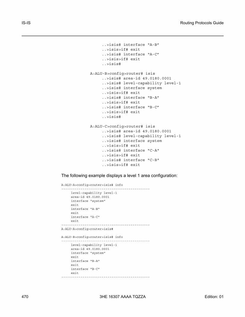
IS-IS
470
Routing Protocols Guide
3HE 16307 AAAA TQZZA Edition: 01
..>isis# interface “A-B”
..>isis>if# exit
..>isis# interface “A-C”
..>isis>if# exit
..>isis#
A:ALU-B>config>router# isis..>isis# area-id 49.0180.0001 ..>isis# level-capability level-1..>isis# interface system..>isis>if# exit..>isis# interface “B-A”..>isis>if# exit..>isis# interface “B-C”..>isis>if# exit..>isis#
A:ALU-C>config>router# isis..>isis# area-id 49.0180.0001 ..>isis# level-capability level-1..>isis# interface system..>isis>if# exit..>isis# interface "C-A"..>isis>if# exit..>isis# interface "C-B"..>isis>if# exit
The following example displays a level 1 area configuration:
A:ALU-A>config>router>isis# info----------------------------------------------
level-capability level-1area-id 49.0180.0001interface "system"exitinterface "A-B"exitinterface "A-C"exit
----------------------------------------------A:ALU-A>config>router>isis#
A:ALU-B>config>router>isis# info----------------------------------------------
level-capability level-1area-id 49.0180.0001interface "system"exitinterface "B-A"exitinterface "B-C"exit
----------------------------------------------

Routing Protocols Guide IS-IS
Edition: 01 3HE 16307 AAAA TQZZA 471
A:ALU-B>config>router>isis#
A:ALU-C>config>router>isis# info#------------------------------------------echo "ISIS"----------------------------------------------
level-capability level-1area-id 49.0180.0001interface "system"exitinterface "C-A"exitinterface "C-B"exit
----------------------------------------------A:ALU-C>config>router>isis#
5.9.5.2 Example 2: Modifying Router Level Capability
In the previous example, ALU-A, ALU-B, and ALU-C are configured as level 1 systems. Level 1 systems communicate with other level 1 systems in the same area. In this example, ALU-A is modified to set the level capability to level 1/2. Now the level 1 systems in the area with NET 49.0180.0001 forward PDUs to ALU-A for destinations that are not in the local area, as shown in Figure 28.
Figure 28 Configuring a Level 1/2 Area
The following example shows the commands to configure a level 1/2 area for ALU-A:
Example: A:ALU-A>config>router# isis..>isis# level-capability level-1/2
L1/2
24298
Area-ID 49.0180.0001L1/L2
Area A (ALU-A)
L2Area-ID 49.0180.0001
L1
Area B (ALU-B)
Area-ID 49.0180.0001L1
Area C (ALU-C)

IS-IS
472
Routing Protocols Guide
3HE 16307 AAAA TQZZA Edition: 01
5.9.5.3 Interface Level Capability
The level capability value configured on the interface level is compared to the level capability value configured on the global level to determine the type of adjacencies that can be established. The default value for 7705 SAR routers and interfaces is level 1/2. Table 58 lists capability combinations and the potential adjacencies that can be formed.
5.9.6 Configuring Authentication
Authentication must be explicitly configured and can be done using two separate mechanisms:
• configuration of an explicit authentication key and algorithm using the authentication-key and authentication-type commands in the IS-IS global or IS-IS level contexts; configuration of a Hello PDU authentication key using the hello-authentication-key and hello-authentication-type commands in the IS-IS interface and IS-IS interface level contexts
• configuration of an authentication keychain using the auth-keychain command in the config>system>security>keychain context and associating the keychain in the applicable IS-IS contexts
Table 58 Potential Adjacency Capabilities
Global Level Interface Level Potential Adjacency
Level 1/2 Level 1/2 Level 1 and/or level 2
Level 1/2 Level 1 Level 1 only
Level 1/2 Level 2 Level 2 only
Level 2 Level 1/2 Level 2 only
Level 2 Level 2 Level 2 only
Level 2 Level 1 None
Level 1 Level 1/2 Level 1 only
Level 1 Level 2 None
Level 1 Level 1 Level 1 only

Routing Protocols Guide IS-IS
Edition: 01 3HE 16307 AAAA TQZZA 473
Either the authentication-key command or the auth-keychain command can be used by IS-IS, but both cannot be supported at the same time. If both commands are configured, the auth-keychain configuration will be applied and the authentication-key command will be ignored.
Use the following CLI syntax to configure authentication:
CLI Syntax: config>router# isis [isis-instance][no] authentication-checkauthentication-key {authentication-key | hash-key}
[hash | hash2]authentication-type {password | message-digest}[no] hello-authenticationlevel {1 | 2}
authentication-key {authentication-key | hash-key} [hash | hash2]
authentication-type {password | message-digest}
CLI Syntax: config>router# isis [isis-instance]interface ip-int-name
[no] hello-authenticationhello-authentication-key {authentication-key |
hash-key} [hash | hash2]hello-authentication-type {password | message-
digest}level {1 | 2}
hello-authentication-key {authentication-key | hash-key} [hash | hash2]
hello-authentication-type {password | message-digest}
Use the following CLI syntax to associate IS-IS at the global level or IS-IS level with an authentication keychain and to associate an IS-IS interface or interface level with a Hello authentication keychain. The keychain must already be defined in the system>security>keychain context.
CLI Syntax: config>router# isis [isis-instance]auth-keychain namelevel {1 | 2}
auth-keychain name
CLI Syntax: config>router# isis [isis-instance]interface ip-int-name
hello-auth-keychain namelevel {1 | 2}
hello-auth-keychain name

IS-IS
474
Routing Protocols Guide
3HE 16307 AAAA TQZZA Edition: 01
5.9.7 Configuring Leaking
IS-IS allows a two-level hierarchy to route PDUs. Level 1 areas can be interconnected by a contiguous level 2 backbone.
The level 1 link-state database contains information only about that area. The level 2 link-state database contains information about the level 2 system and each of the level 1 systems in the area. A level 1/2 router contains information about both level 1 and level 2 databases. A level 1/2 router advertises information about its level 1 area toward the other level 1/2 or level 2 routers.
Packets with destinations outside the level 1 area are forwarded toward the closest level 1/2 router which, in turn, forwards the packets to the destination area.
Sometimes the shortest path to an outside destination is not through the closest level 1/2 router, or the only level 1/2 router to forward packets out of an area is not operational. Route leaking provides a mechanism to leak level 2 information to level 1 routers to provide routing information regarding inter-area routes. Route leaking therefore gives a level 1 router more options to forward packets.
Configure a route policy to leak routes from level 2 into level 1 areas in the config> router>policy-options>policy-statement context. For more information on creating route policies, refer to the 7705 SAR Router Configuration Guide.
The following example shows the commands to configure prefix list (“loops”) and policy statement (“leak”) parameters in the config>router context.
Example: config>router>policy-options# prefix-list loops..>policy-options>prefix-list# prefix 10.1.1.0/8 longer..>policy-options>prefix-list# exit..>policy-options# policy-statement leak..>policy-options>policy-statement# entry 10..>policy-options>policy-statement>entry# from..>policy-options>policy-statement>entry>from# prefix-
list loops..>policy-options>policy-statement>entry>from# level 2..>policy-options>policy-statement>entry>from# exit..>policy-options>policy-statement>entry# to..>policy-options>policy-statement>entry>to# level 1..>policy-options>policy-statement>entry>to# exit..>policy-options>policy-statement>entry# action accept..>policy-options>policy-statement>entry>action# exit..>policy-options>policy-statement>entry# exit..>policy-options>policy-statement# exit..>policy-options# commit..>policy-options#

Routing Protocols Guide IS-IS
Edition: 01 3HE 16307 AAAA TQZZA 475
The following example displays a prefix list and policy statement configuration:
A:ALU-A>config>router>policy-options# info----------------------------------------------
prefix-list "loops"prefix 10.1.1.0/8 longer
exitpolicy-statement "leak"
entry 10from
prefix-list "loop"level 2
exitto
level 1exitaction acceptexit
exitexit
----------------------------------------------A:ALU-A>config>router>policy-options#
Next, apply the policy in order to leak routes from level 2 into level 1 routers on ALU-A:
CLI Syntax: config>router# isis [isis-instance]export leak
A:ALU-A>config>router>isis# info----------------------------------------------
area-id 49.0180.0001area-id 49.0180.0002area-id 49.0180.0003authentication-key "//oZrvL4FPn06nyRIJ5E" hashauthentication-type passwordno authentication-checkexport "leak"
...----------------------------------------------A:ALU-A>config>router>isis#
Then, after the policy is applied, create a policy statement (“isis-ext”) to redistribute external IS-IS routes from level 1 routers into the level 2 backbone (see Redistributing External IS-IS Routes). In the config>router context, configure the following policy statement parameters:
Example: config>router>policy-options# begin..>policy-options# policy-statement "isis-ext"..>policy-options>policy-statement# entry 10..>policy-options>policy-statement>entry$ from..>policy-options>policy-statement>entry>from$ external..>policy-options>policy-statement>entry>from# exit

IS-IS
476
Routing Protocols Guide
3HE 16307 AAAA TQZZA Edition: 01
..>policy-options>policy-statement>entry# to
..>policy-options>policy-statement>entry>to$ level 2
..>policy-options>policy-statement>entry>to# exit
..>policy-options>policy-statement>entry# action accept
..>policy-options>policy-statement>entry>action# exit
..>policy-options>policy-statement>entry# exit
..>policy-options>policy-statement# exit
..>policy-options# commit
5.9.8 Redistributing External IS-IS Routes
By default, IS-IS does not redistribute level 1 external routes into level 2. The policy to redistribute external IS-IS routes must be explicitly applied. Policies are created in the config>router>policy-options context. Refer to the 7705 SAR Router Configuration Guide for information on creating policies.
The following example displays the policy statement configuration:
A:ALU-A>config>router>policy-options# info----------------------------------------------
prefix-list "loops"prefix 10.1.1.0/8 longer
exitpolicy-statement "leak"
entry 10from
prefix-list "loop"level 2
exitto
level 1exitaction acceptexit
exitexitpolicy-statement "isis-ext"
entry 10from
externalexitto
level 2exitaction acceptexit
exitexit
----------------------------------------------A:ALU-A>config>router>policy-options#
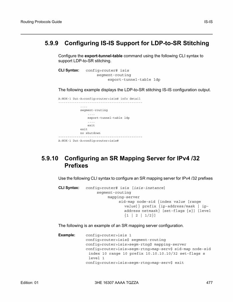
Routing Protocols Guide IS-IS
Edition: 01 3HE 16307 AAAA TQZZA 477
5.9.9 Configuring IS-IS Support for LDP-to-SR Stitching
Configure the export-tunnel-table command using the following CLI syntax to support LDP-to-SR stitching.
CLI Syntax: config>router# isissegment-routing
export-tunnel-table ldp
The following example displays the LDP-to-SR stitching IS-IS configuration output.
A:NOK-1 Dut-A>config>router>isis# info detail----------------------------------------------
....segment-routing
....export-tunnel-table ldp....exit
exitno shutdown
----------------------------------------------A:NOK-1 Dut-A>config>router>isis#
5.9.10 Configuring an SR Mapping Server for IPv4 /32 Prefixes
Use the following CLI syntax to configure an SR mapping server for IPv4 /32 prefixes
CLI Syntax: config>router# isis [isis-instance]segment-routing
mapping-serversid-map node-sid {index value [range
value]} prefix {ip-address/mask | ip-address netmask} [set-flags {s}] [level {1 | 2 | 1/2}]
The following is an example of an SR mapping server configuration.
Example: config>router>isis 1config>router>isis$ segment-routingconfig>router>isis>segm-rtng$ mapping-serverconfig>router>isis>segm-rtng>map-serv$ sid-map node-sid index 10 range 10 prefix 10.10.10.10/32 set-flags s level 1
config>router>isis>segm-rtng>map-serv$ exit

IS-IS
478
Routing Protocols Guide
3HE 16307 AAAA TQZZA Edition: 01
config>router>isis>segm-rtng$ exitconfig>router>isis$ exit
The following example displays the SR mapping server configuration.
A:NOK-1 Dut-A>config>router>isis# info detail----------------------------------------------
...segment-routing
mapping-servershutdownsid-map node-sid index 10 range 10 prefix 10.10.10.10/32 set-flags s level 1
exitexitno shutdown
----------------------------------------------A:NOK-1 Dut-A>config>router>isis#

Routing Protocols Guide IS-IS
Edition: 01 3HE 16307 AAAA TQZZA 479
5.10 IS-IS Configuration Management Tasks
This section discusses the following IS-IS configuration management tasks:
• Disabling IS-IS• Removing IS-IS• Modifying Global IS-IS Parameters• Modifying IS-IS Interface Parameters
5.10.1 Disabling IS-IS
The shutdown command disables an IS-IS instance on the router. The configuration settings are not changed, reset, or removed.
Use the following CLI syntax to disable an IS-IS instance on a router:
CLI Syntax: config>router# isis [isis-instance]shutdown
5.10.2 Removing IS-IS
The no isis command deletes an IS-IS instance and reverts its configuration to default values for its next use.
Use the following CLI syntax to remove an IS-IS instance:
CLI Syntax: config>router#no isis [isis-instance]

IS-IS
480
Routing Protocols Guide
3HE 16307 AAAA TQZZA Edition: 01
5.10.3 Modifying Global IS-IS Parameters
You can modify, disable, or remove global IS-IS parameters without shutting down entities. The changes are applied immediately. Modifying the level capability on the global level causes the IS-IS instance to restart.
The following example displays an IS-IS global parameter modification.
Example: config>router>isis# overload timeout 500config>router>isis# level-capability level-1/2config>router>isis# no authentication-checkconfig>router>isis# authentication-key raider123
The following example displays the IS-IS configuration with the modifications entered in the previous example:
A:ALU-A>config>router>isis# info----------------------------------------------
area-id 49.0180.0001area-id 49.0180.0002area-id 49.0180.0003authentication-key "//oZrvtvFPn06nyRIJ5E" hashauthentication-type passwordno authentication-checkoverload timeout 500level 1
wide-metrics-onlyexitlevel 2
wide-metrics-onlyexitinterface "system"exitinterface "ALU-1-2"
level-capability level-2mesh-group 85
exitinterface "ALU-1-3"
level-capability level-1interface-type point-to-pointmesh-group 101
exitinterface "ALU-1-5"
level-capability level-1interface-type point-to-pointmesh-group 85
exitinterface "to-103"
mesh-group 101exitinterface "A-B"exitinterface "A-C"exit

Routing Protocols Guide IS-IS
Edition: 01 3HE 16307 AAAA TQZZA 481
5.10.4 Modifying IS-IS Interface Parameters
You can modify, disable, or remove interface level IS-IS parameters without shutting down entities. Changes take effect immediately. Modifying the level capability on the interface causes the IS-IS instance on the interface to restart.
To remove an interface, use the no interface ip-int-name command.
To disable an interface, use the shutdown command in the interface context.
The following example displays an IS-IS interface parameter modification.
Example: config>router# isisconfig>router>isis# interface ALU-1-3config>router>isis>if# mesh-group 85config>router>isis>if# passiveconfig>router>isis>if# lsp-pacing-interval 5000config>router>isis>if# exitconfig>router>isis# interface to-103config>router>isis>if# hello-authentication-type message-digest
config>router>isis>if# hello-authentication-key 49ersrule
config>router>isis>if# exit
The following example displays the IS-IS configuration with the modifications entered in the previous example:
A:ALU-A>config>router>isis# info----------------------------------------------
area-id 49.0180.0001area-id 49.0180.0002area-id 49.0180.0003authentication-key "//oZrvtvFPn06nyRIJ5E" hashauthentication-type passwordno authentication-checkoverload timeout 500level 1
wide-metrics-onlyexitlevel 2
wide-metrics-onlyexitinterface "system"exitinterface "ALU-1-2"
level-capability level-2mesh-group 85
exitinterface "ALU-1-3"
level-capability level-1interface-type point-to-point

IS-IS
482
Routing Protocols Guide
3HE 16307 AAAA TQZZA Edition: 01
lsp-pacing-interval 5000mesh-group 85passive
exitinterface "ALU-1-5"
level-capability level-1interface-type point-to-pointmesh-group 85
exitinterface "to-103"
hello-authentication-key "DvR5l2xxB6XMTvbAZ1mE" hashhello-authentication-type message-digestmesh-group 101
exitinterface "A-B"exit
----------------------------------------------A:ALU-A>config>router>isis#

Routing Protocols Guide IS-IS
Edition: 01 3HE 16307 AAAA TQZZA 483
5.11 IS-IS Command Reference
5.11.1 Command Hierarchies
• Configuration Commands• Show Commands• Clear Commands• Debug Commands• Monitor Commands• Tools Commands (refer to the Tools chapter in the 7705 SAR OAM and
Diagnostics Guide)

IS-IS
484
Routing Protocols Guide
3HE 16307 AAAA TQZZA Edition: 01
5.11.1.1 Configuration Commands
config— router
— [no] isis [isis-instance]— advertise-router-capability {area | as} — no advertise-router-capability — [no] advertise-tunnel-link— [no] area-id area-address— auth-keychain name— no auth-keychain— [no] authentication-check— authentication-key {authentication-key | hash-key} [hash | hash2]— no authentication-key— authentication-type {password | message-digest}— no authentication-type— [no] csnp-authentication— database-export [identifier id] [bgp-ls-identifier bgp-ls-id]— no database-export— [no] disable-ldp-sync— entropy-label
— [no] override-tunnel-elc— export policy-name [policy-name...(up to 5 max)]— no export— [no] hello-authentication— [no] ignore-attached-bit— [no] ignore-lsp-errors— [no] iid-tlv-enable— [no] interface ip-int-name
— [no] bfd-enable ipv4— csnp-interval seconds— no csnp-interval— hello-auth-keychain name— no hello-auth-keychain — [no] hello-authentication— hello-authentication-key {authentication-key | hash-key} [hash |
hash2]— no hello-authentication-key— hello-authentication-type {password | message-digest}— no hello-authentication-type— interface-type {broadcast | point-to-point}— no interface-type— ipv4-node-sid index index_value — ipv4-node-sid label label_value — no ipv4-node-sid — ipv6-node-sid index index_value — ipv6-node-sid label label_value — no ipv6-node-sid— level {1 | 2}
— hello-auth-keychain name— no hello-auth-keychain — hello-authentication-key {authentication-key | hash-key} [hash
| hash2]

Routing Protocols Guide IS-IS
Edition: 01 3HE 16307 AAAA TQZZA 485
— no hello-authentication-key— hello-authentication-type {password | message-digest}— no hello-authentication-type— hello-interval seconds— no hello-interval— hello-multiplier multiplier— no hello-multiplier— metric metric— no metric— [no] passive— priority number— no priority
— level-capability {level-1 | level-2 | level-1/2}— no level-capability— lfa-policy-map route-nh-template template-name— no lfa-policy-map— [no] loopfree-alternate-exclude— lsp-pacing-interval milliseconds— no lsp-pacing-interval— mesh-group [value | blocked]— no mesh-group— [no] passive— retransmit-interval seconds— no retransmit-interval— [no] sid-protection — [no] shutdown
— [no] ipv4-routing— ipv6-routing native— no ipv6-routing— level {1 | 2}
— auth-keychain name— no auth-keychain— authentication-key {authentication-key | hash-key} [hash | hash2]— no authentication-key— authentication-type {password | message-digest}— no authentication-type— [no] csnp-authentication— external-preference external-preference— no external-preference— [no] hello-authentication— [no] loopfree-alternate-exclude— preference preference— no preference— [no] psnp-authentication— [no] wide-metrics-only
— level-capability {level-1 | level-2 | level-1/2}— no level-capability— loopfree-alternate— loopfree-alternate remote-lfa [max-pq-cost value]— loopfree-alternate remote-lfa [max-pq-cost value] ti-lfa [max-sr-frr-labels
value]— loopfree-alternate ti-lfa [max-sr-frr-labels value]— no loopfree-alternate

IS-IS
486
Routing Protocols Guide
3HE 16307 AAAA TQZZA Edition: 01
— loopfree-alternate-exclude prefix-policy prefix-policy [prefix-policy...(up to 5 max)]
— no loopfree-alternate-exclude— lsp-lifetime seconds— no lsp-lifetime— lsp-mtu-size size— no lsp-mtu-size — [no] multicast-import [ipv4]— overload [timeout seconds]— no overload— overload-on-boot [timeout seconds]— no overload-on-boot— [no] poi-tlv-enable— [no] psnp-authentication— reference-bandwidth bandwidth-in-kbps— reference-bandwidth [tbps Tera-bps] [gbps Giga-bps] [mbps Mega-bps]
[kbps Kilo-bps]— no reference-bandwidth— [no] rsvp-shortcut— [no] segment-routing
— adj-sid-hold seconds— no adj-sid-hold— entropy-label {force-disable | enable}— no entropy-label — export-tunnel-table ldp— no export-tunnel-table— [no] mapping-server
— [no] shutdown— sid-map node-sid {index value [range value]} prefix {ip
address/mask} | ip-address netmask} [set-flags {s}] [level {1 | 2 | 1/2}]
— prefix-sid-range global — prefix-sid-range start-label label-value max-index index-value — no prefix-sid-range— [no] shutdown— tunnel-mtu bytes— no tunnel-mtu— tunnel-table-pref preference — no tunnel-table-pref
— [no] shutdown— [no] strict-adjacency-check— summary-address {ip-prefix/prefix-length | ip-prefix [netmask]} level— no summary-address {ip-prefix/prefix-length | ip-prefix [netmask]}— [no] suppress-attached-bit— [no] timers
— lsp-wait lsp-wait [lsp-initial-wait initial-wait] [lsp-second-wait second-wait]
— no lsp-wait— spf-wait spf-wait [spf-initial-wait initial-wait] [spf-second-wait second-
wait]— no spf-wait
— [no] traffic-engineering— [no] unicast-import-disable [ipv4]

Routing Protocols Guide IS-IS
Edition: 01 3HE 16307 AAAA TQZZA 487
5.11.1.2 Show Commands
show— router
— isis all — isis [isis-instance]
— adjacency [ip-int-name | ip-address | nbr-system-id] [detail]— capabilities [system-id | lsp-id] [level level]] — database [system-id | lsp-id] [detail] [level level]— hostname — interface [ip-int-name | ip-address] [detail]— lfa-coverage— mapping-server [prefix ip-address [/mask]] [index index] [level level] [flag {s}]— prefix-sids [ipv4-unicast | ipv6-unicast | mt mt-id-number] [ip-prefix[/prefix-
length]] [sid sid] [adv-router {system-id | hostname}] [srms | no-srms] — routes [ipv4-unicast | ipv6-unicast | mt mt-id-number] [ip-prefix[/prefix-
length]] [alternative] [exclude-shortcut] [detail] — spf-log [detail]— statistics— status— summary-address [ip-prefix[/prefix-length]]— topology [detail] [lfa]
5.11.1.3 Clear Commands
clear— router
— isis [isis-instance]— adjacency [system-id]— database [system-id]— export— spf-log— statistics
5.11.1.4 Debug Commands
debug— router
— isis [isis-instance]— [no] adjacency [ip-int-name | ip-address | nbr-system-id]— [no] cspf— interface [ip-int-name | ip-address]— no interface— leak [ip-address]— no leak— [no] lsdb [level-number] [system-id | lsp-id]— [no] misc

IS-IS
488
Routing Protocols Guide
3HE 16307 AAAA TQZZA Edition: 01
— packet [packet-type] [ip-int-name | ip-address | ipv6-address] [detail]— no packet— rtm [ip-address]— no rtm— [no] spf [level-number] [system-id]
5.11.1.5 Monitor Commands
monitor— router
— isis [isis-instance]— statistics [interval seconds] [repeat repeat] [absolute | rate]

Routing Protocols Guide IS-IS
Edition: 01 3HE 16307 AAAA TQZZA 489
5.11.2 Command Descriptions
• Configuration Commands• Show Commands• Clear Commands• Debug Commands• Monitor Commands

IS-IS
490
Routing Protocols Guide
3HE 16307 AAAA TQZZA Edition: 01
5.11.2.1 Configuration Commands
• Generic Commands• Global Commands• Interface Commands

Routing Protocols Guide IS-IS
Edition: 01 3HE 16307 AAAA TQZZA 491
5.11.2.1.1 Generic Commands
shutdown
Syntax [no] shutdown
Context config>router>isisconfig>router>isis>segment-routing config>router>isis>interface
Description This command administratively disables the entity. When disabled, an entity does not change, reset, or remove any configuration settings or statistics. Many entities must be explicitly enabled using the no shutdown command.
The operational state of the entity is disabled as well as the operational state of any entities contained within. Many objects must be shut down before they can be deleted.
Unlike other commands and parameters where the default state is not indicated in the configuration file, shutdown and no shutdown are always indicated in system-generated configuration files.
The no form of the command puts an entity into the administratively enabled state.
Default IS-IS Global - the IS-IS protocol is created in the no shutdown state
IS-IS Interface - when an IP interface is configured as an IS-IS interface, IS-IS on the interface is in the no shutdown state by default

IS-IS
492
Routing Protocols Guide
3HE 16307 AAAA TQZZA Edition: 01
5.11.2.1.2 Global Commands
isis
Syntax [no] isis [isis-instance]
Context config>router
Description This command activates an IS-IS instance on the router and enables access to the context to define IS-IS parameters.
Instance 0, the base instance, is enabled when the isis command is run without specifying an isis-instance. Multiple IS-IS instances are enabled by including an isis-instance value.
The no form of the command deletes the IS-IS instance and removes all configuration parameters.
Default no isis
Parameters isis-instance — the IS-IS instance ID. If no isis-instance is specified, instance 0 is used.
Values 1 to 31
advertise-router-capability
Syntax advertise-router-capability {area | as} no advertise-router-capability
Context config>router>isis
Description This command enables advertisement of a router’s capabilities to its neighbors for informational and troubleshooting purposes. A TLV as defined in RFC 4971 advertises the TE Node Capability Descriptor capability.
The parameters (area and as) control the scope of the capability advertisements.
The no form of this command disables this capability.
Default no advertise-router-capability
Parameters area — capabilities are only advertised within the area of origin
as — capabilities are advertised throughout the entire autonomous system

Routing Protocols Guide IS-IS
Edition: 01 3HE 16307 AAAA TQZZA 493
advertise-tunnel-link
Syntax [no] advertise-tunnel-link
Context config>router>isis
Description This command enables the forwarding adjacency feature. With this feature, IS-IS advertises an RSVP-TE LSP as a link so that other routers in the network can include it in their SPF calculations. The RSVP-TE LSP is advertised as an unnumbered point-to-point link and the link-state PDU (LSP) has no traffic engineering opaque sub-TLVs as per RFC 3906.
The forwarding adjacency feature can be enabled independently from the IGP shortcut feature (rsvp-shortcut). If both features are enabled for a given IS-IS instance, the forwarding adjacency feature takes precedence.
When this feature is enabled, each node advertises a point-to-point unnumbered link for each best-metric tunnel to the router ID of any endpoint node. The node does not include the tunnels as IGP shortcuts in the SPF calculation directly. Instead, when the LSP advertising the corresponding point-to-point unnumbered link is installed in the local routing database, the node performs an SPF calculation using the link like any other link LSP.
The link bidirectional check requires that a regular link or tunnel link exists in the reverse direction for the tunnel to be used in the SPF calculation.
An RSVP-TE LSP can be excluded from being used as a forwarding adjacency with the config>router>mpls>lsp>no igp-shortcut command.
The no form of this command disables forwarding adjacency and therefore disables the advertisement of RSVP-TE LSPs into IS-IS.
Default no advertise-tunnel-link
area-id
Syntax [no] area-id area-address
Context config>router>isis
Description This command configures the area ID portion of the Network Service Access Point (NSAP) address, which identifies a point of connection to the network, such as a router interface.
Addresses in the IS-IS protocol are based on the ISO NSAP addresses and Network Entity Titles (NETs), not IP addresses. NET addresses are constructed similarly to NSAPs with the exception that the selector ID is always 00. NET addresses are exchanged in Hello and LSP PDUs. All NET addresses configured on the node are advertised to its neighbors.
Up to three area addresses can be configured.

IS-IS
494
Routing Protocols Guide
3HE 16307 AAAA TQZZA Edition: 01
NSAP addresses are divided into three parts. Only the area ID portion is configurable:
• area ID – a variable-length field between 1 and 13 bytes that identifies the area to which the router belongs. This field includes the Authority and Format Identifier (AFI) as the first (most significant) byte and the area identifier.
• system ID – A 6-byte system identifier. This value is not configurable. The system ID is derived from the system or router ID and uniquely identifies the router.
• selector ID – A 1-byte selector identifier that is always 00 for an NET. This value is not configurable.
For level 1 interfaces, neighbors can have different area IDs, but they must have at least one area ID (AFI + area) in common. Sharing a common area ID, they become neighbors and area merging between the potentially different areas can occur.
For level 2 interfaces, neighbors can have different area IDs. However, if they have no area IDs in common, they become only level 2 neighbors and only level 2 LSPs are exchanged.
For level 1/2 interfaces, neighbors can have different area IDs. If they have at least one area ID (AFI + area) in common, they become neighbors. In addition to exchanging level 2 LSPs, area merging between potentially different areas can occur.
If multiple area-id commands are entered, the system ID of all subsequent entries must match the system ID of the first area address.
The no form of the command removes the area address.
Default n/a — no area address is assigned
Parameters area-address — the area ID, from 1 to 13 bytes (if fewer than 13 bytes are entered, the rest of the field is padded with zeros)
auth-keychain
Syntax auth-keychain nameno auth-keychain
Context config>router>isisconfig>router>isis>level
Description This command associates an authentication keychain with the IS-IS instance or level. The keychain is a collection of keys used to authenticate IS-IS messages from remote peers. The keychain allows the rollover of authentication keys during the lifetime of a session and also supports stronger authentication algorithms than clear text and MD5.
The keychain must already be defined in the config>system>security>keychain context.

Routing Protocols Guide IS-IS
Edition: 01 3HE 16307 AAAA TQZZA 495
Either the authentication-key command or the auth-keychain command can be used by IS-IS, but both cannot be supported at the same time. If both commands are configured, the auth-keychain configuration will be applied and the authentication-key command will be ignored.
By default, authentication is not enabled.
Default no auth-keychain
Parameters name — the name of an existing keychain, up to 32 characters
authentication-check
Syntax [no] authentication-check
Context config>router>isis
Description This command sets an authentication check to reject PDUs that do not match the type or key requirements.
The default behavior when authentication is configured is to reject all IS-IS protocol PDUs that have a mismatch in either the authentication type or authentication key.
When no authentication-check is configured, authentication PDUs are generated and IS-IS PDUs are authenticated on receipt. However, although mismatches cause an event to be generated, the mismatches will not be rejected.
Default authentication-check
authentication-key
Syntax authentication-key {authentication-key | hash-key} [hash | hash2]no authentication-key
Context config>router>isisconfig>router>isis>level
Description This command sets the authentication key used to verify PDUs sent by neighboring routers on the interface. Neighboring routers use passwords to authenticate PDUs sent from an interface. For authentication to work, both the authentication key and the authentication type on a segment must match. The authentication-type command must also be entered.
To configure authentication on the global level, configure this command in the config>router>isis context. When this parameter is configured on the global level, all PDUs are authenticated, including the Hello PDU.

IS-IS
496
Routing Protocols Guide
3HE 16307 AAAA TQZZA Edition: 01
To override the global setting for a specific level, configure the authentication-key command in the config>router>isis>level context. When configured within the specific level, Hello PDUs are not authenticated.
By default, no authentication key is configured.
Either the authentication-key command or the auth-keychain command can be used by IS-IS, but both cannot be supported at the same time. If both commands are configured, the auth-keychain configuration will be applied and the authentication-key command will be ignored.
The no form of the command removes the authentication key.
Default no authentication-key
Parameters authentication-key — the authentication key can be any combination of ASCII characters up to 254 characters in length (unencrypted). If spaces are used in the string, the entire string must be enclosed in double quotes (“ ”).
hash-key — the hash key can be any combination of ASCII characters up to 352 characters in length (encrypted) or 407 characters in length (if the hash2 parameter is used). If spaces are used in the string, the entire string must be enclosed in double quotes (“ ”). This is useful when a user must configure the parameter, but for security purposes, the actual unencrypted key value is not provided.
hash — specifies that the key is entered in an encrypted form. If the hash parameter is not used, the key is assumed to be in a non-encrypted, clear text form. For security, all keys are stored in encrypted form in the configuration file with the hash parameter specified.
hash2 — specifies that the key is entered in a more complex encrypted form. If the hash2 parameter is not used, the less encrypted hash form is assumed.
authentication-type
Syntax authentication-type {password | message-digest}no authentication-type
Context config>router>isisconfig>router>isis>level
Description This command enables either simple password or message-digest authentication in the global IS-IS or IS-IS level context. Both the authentication key and the authentication type on a segment must match. The authentication-key command must also be entered.
Configure the authentication type at the global level in the config>router>isis context. Configure or override the global setting by configuring the authentication type in the config>router>isis>level context.

Routing Protocols Guide IS-IS
Edition: 01 3HE 16307 AAAA TQZZA 497
The no form of the command disables authentication.
Default no authentication-type
Parameters password — enables simple password (plain text) authentication. If authentication is enabled and no authentication type is specified in the command, simple password authentication is enabled.
message-digest — enables message-digest MD5 authentication in accordance with RFC 1321. If this option is configured, at least one message-digest-key must be configured.
csnp-authentication
Syntax [no] csnp-authentication
Context config>router>isisconfig>router>isis>level
Description This command enables authentication of individual IS-IS packets of complete sequence number PDUs (CSNPs).
The no form of the command suppresses authentication of CSNP packets.
Default csnp-authentication
database-export
Syntax database-export [identifier id] [bgp-ls-identifier bgp-ls-id]no database-export
Context config>router>isis
Description This command enables the population of the extended TE database (TE-DB) with the link-state information from the IS-IS instance.
The extended TE-DB is used as a central point for importing all link-state, link, node, and prefix information from IGP instances on the router and exporting the information to BGP-LS on the router. This information includes the IGP, TE, SID sub-TLV, and adjacency SID sub-TLV.
The no form of this command disables database exportation.
Default no database-export

IS-IS
498
Routing Protocols Guide
3HE 16307 AAAA TQZZA Edition: 01
Parameters identifier — uniquely identifies the IGP instance in the BGP-LS NLRI when a router has interfaces participating in multiple IGP instances. This parameter defaults to the IGP instance ID assigned by the 7705 SAR. However, because the concept of instance ID defined in IS-IS (RFC 6822) is unique within a routing domain while the one specified for OSPF is significant for the local subnet only (RFC 6549), the user can remove any overlap by configuring the new identifier value to be unique within a particular IGP domain when this router sends the IGP link-state information using BGP-LS.
id — specifies an entry ID to export
Values 0 to 18446744073709551615
bgp-ls-identifier — used with the Autonomous System Number (ASN) to correlate the BGP-LS NLRI advertisements of multiple BGP-LS speakers in the same IGP domain. If an NRC-P network domain has multiple IGP domains, BGP-LS speakers in each IGP domain must be configured with the same unique tuple {bgp-ls-identifier, asn}.The BGP-LS identifier is optional and is only sent in a BGP-LS NLRI if configured in the IGP instance of an IGP domain.If this IGP instance participates in traffic engineering with RSVP-TE or SR-TE, the traffic-engineering option is not strictly required because enabling the extended TE-DB populates this information automatically. However, it is recommended that the user enable traffic engineering to make the configuration consistent with other routers in the network that do not require enabling of the extended TE-DB.
bgp-ls-id — specifies a BGP LS ID to export
Values 0 to 4294967295
disable-ldp-sync
Syntax [no] disable-ldp-sync
Context config>router>isis
Description This command disables the IGP-LDP synchronization feature on all interfaces participating in the OSPF or IS-IS routing protocol. When this command is executed, the IGP immediately advertises the actual value of the link cost for all interfaces that have the IGP-LDP synchronization enabled if the currently advertised cost is different. IGP-LDP synchronization will then be disabled for all interfaces. This command does not delete the interface configuration.
The no form of this command restores the default settings and re-enables IGP-LDP synchronization on all interfaces participating in the OSPF or IS-IS routing protocol and for which the ldp-sync-timer is configured (refer to the 7705 SAR Router Configuration Guide for information on configuring the ldp-sync-timer).
Default no disable-ldp-sync

Routing Protocols Guide IS-IS
Edition: 01 3HE 16307 AAAA TQZZA 499
entropy-label
Syntax entropy-label
Context config>router>isis
Description This command enables the context for the configuration of entropy label capabilities (ELC) for the routing protocol.
override-tunnel-elc
Syntax [no] override-tunnel-elc
Context config>router>isis>entropy-label
Description This command configures the ability to override any received entropy label capability advertisements. When enabled, the system assumes that all nodes for an IGP domain are capable of receiving and processing the entropy label on segment routed tunnels. This command can only be configured if entropy-label is enabled via the config>router>isis>segment-routing>entropy-label command.
The no version of this command disables the override. The system assumes entropy label capability for other nodes in the IGP instance if capability advertisements are received.
Default no override-tunnel-elc
export
Syntax export policy-name [policy-name…(up to 5 max)]no export
Context config>router>isis
Description This command associates export route policies to determine which routes are exported from the route table to IS-IS.
If no export policy is specified, non-IS-IS routes are not exported from the routing table manager to IS-IS.
If multiple policy names are specified, the policies are evaluated in the order they are specified. The first policy that matches is applied. If multiple export commands are issued, the last command entered will override the previous command. A maximum of five policy names can be specified.
The no form of the command removes all policies from the configuration.
Refer to the 7705 SAR Router Configuration Guide for information on defining route policies.
Default n/a — no export route policies specified

IS-IS
500
Routing Protocols Guide
3HE 16307 AAAA TQZZA Edition: 01
Parameters policy-name — the export route policy name. Allowed values are any string up to 32 characters long composed of printable, 7-bit ASCII characters. If the string contains special characters (#, $, spaces, etc.), the entire string must be enclosed within double quotes.The specified names must already be defined.
hello-authentication
Syntax [no] hello-authentication
Context config>router>isisconfig>router>isis>interface
Description This command enables authentication of individual IS-IS Hello PDUs.
The no form of the command suppresses authentication of Hello PDUs.
Default hello-authentication
ignore-attached-bit
Syntax [no] ignore-attached-bit
Context config>router>isis
Description This command specifies that this level 1 router will ignore the attached (ATT) bit in received level 1 link-state PDUs (LSPs) and therefore will not install the default route to the level 1/2 router that set the ATT bit.
The no form of the command specifies that the router will install the default route to the closest level 1/2 router.
Default no ignore-attached-bit
ignore-lsp-errors
Syntax [no] ignore-lsp-errors
Context config>router>isis
Description This command specifies that the router will ignore LSPs with internal checksum errors rather than purging the LSPs.
The no form of the command specifies that LSPs with internal checksum errors will be purged, which will cause the originator to resend the LSPs.
Default no ignore-lsp-errors

Routing Protocols Guide IS-IS
Edition: 01 3HE 16307 AAAA TQZZA 501
iid-tlv-enable
Syntax [no] iid-tlv-enable
Context config>router>isis
Description This command specifies whether the Instance Identifier (IID) TLV is enabled or disabled for this IS-IS instance so an interface can be used in multiple IS-IS instances.
When enabled, each IS-IS instance marks its packets with the IID TLV containing its unique 16-bit IID for the routing domain. You must use a shutdown/no shutdown command sequence on the IS-IS instance to make the change operational.
The no form of the command disables the IID TLV marking of packets.
Default no iid-tlv-enable
ipv4-routing
Syntax [no] ipv4-routing
Context config>router>isis
Description This command enables or disables IPv4 routing on the IS-IS instance.
Default ipv4-routing
ipv6-routing
Syntax ipv6-routing nativeno ipv6-routing
Context config>router>isis
Description This command enables or disables single topology (native) IPv6 routing on the IS-IS instance. In native mode, IPv6 routing information is exchanged within IS-IS using IS-IS IPv6 TLVs.
Default no ipv6-routing
Parameters native — specifies to use IS-IS IPv6 TLVs for IPv6 routing

IS-IS
502
Routing Protocols Guide
3HE 16307 AAAA TQZZA Edition: 01
level
Syntax level {1 | 2}
Context config>router>isisconfig>router>isis>interface
Description This command enables the context to configure IS-IS level 1 or level 2 area attributes.
To reset global and/or interface level parameters to the default, the following commands must be entered independently:
— level> no hello-authentication-key— level> no hello-authentication-type— level> no hello-interval— level> no hello-multiplier— level> no metric— level> no passive— level> no priority
Default level 1 or level 2
Special Cases Global IS-IS Level — the config>router>isis context configures default global parameters for both level 1 and level 2 interfaces
IS-IS Interface Level — the config>router>isis>interface context configures IS-IS operational characteristics of the interfaces at level 1 and/or level 2. A logical interface can be configured on one level 1 and one level 2 interface. In this case, each level can be configured independently and parameters must be removed independently.
Parameters 1 — specifies that the router or interface is a level 1 router or interface
2 — specifies that the router or interface is a level 2 router or interface
external-preference
Syntax external-preference external-preferenceno external-preference
Context config>router>isis>level
Description This command configures the preference for IS-IS external routes for the IS-IS level. The preference for internal routes is set with the preference command.
The command configures the preference level for either level 1 or level 2 external routes. The default preferences are listed in Table 59.
A route can be learned by the router from different protocols, in which case, the costs are not comparable. When this occurs, the preference is used to decide which route will be used.

Routing Protocols Guide IS-IS
Edition: 01 3HE 16307 AAAA TQZZA 503
Different protocols should not be configured with the same preference. If this occurs, the tiebreaker is based on the default preferences as listed in Table 59.
If multiple routes are learned with an identical preference using the same protocol, the lowest-cost route is used. If multiple routes are learned with an identical preference using the same protocol and the costs (metrics) are equal, the decision of which route to use is determined by the configuration of ECMP in the config>router context. Refer to the 7705 SAR Router Configuration Guide for information on ECMP.
The no form of the command reverts to the default value.
Default external-preference 160 — for IS-IS level 1 external routes
external-preference 165 — for IS-IS level 2 external routes
Parameters external-preference — the preference for external routes at this level, expressed as a decimal integer
Values 1 to 255
Table 59 Route Preference Defaults by Route Type
Route Type Preference Configurable
Direct attached 0 No
Static routes 5 Yes
OSPF internal 10 Yes
IS-IS level 1 internal 15 Yes
IS-IS level 2 internal 18 Yes
OSPF external 150 Yes
IS-IS level 1 external 160 Yes
IS-IS level 2 external 165 Yes
Note: To configure a preference for static routes, use the config>router>static-route-entry context. Refer to the 7705 SAR Router Configuration Guide for information.

IS-IS
504
Routing Protocols Guide
3HE 16307 AAAA TQZZA Edition: 01
loopfree-alternate-exclude
Syntax [no] loopfree-alternate-exclude
Context config>router>isis>level config>router>isis>interface
Description This command instructs IS-IS to exclude a specific interface or all interfaces participating in a specific IS-IS level from the LFA SPF calculation. The LFA SPF calculation can therefore be run only where it is needed.
If an interface is excluded from the LFA SPF in IS-IS, it is excluded in both level 1 and level 2.
Default no loopfree-alternate-exclude
preference
Syntax preference preference no preference
Context config>router>isis>level
Description This command configures the preference for IS-IS level 1 or level 2 internal routes.
A route can be learned by the router from different protocols, in which case, the costs are not comparable. When this occurs, the preference is used to decide which route will be used.
Different protocols should not be configured with the same preference. If this occurs, the tiebreaker is based on the default preferences as listed in Table 59. If multiple routes are learned with an identical preference using the same protocol and the costs (metrics) are equal, the decision of which route to use is determined by the configuration of ECMP in the config>router context. Refer to the 7705 SAR Router Configuration Guide for information on ECMP.
The no form of the command reverts to the default value.
Default preference 15 — for IS-IS level 1 internal routes
preference 18 — for IS-IS level 2 internal routes
Parameters preference — the preference for internal routes expressed as a decimal integer
Values 1 to 255
wide-metrics-only
Syntax [no] wide-metrics-only
Context config>router>isis>level

Routing Protocols Guide IS-IS
Edition: 01 3HE 16307 AAAA TQZZA 505
Description This command enables the exclusive use of wide metrics in the LSPs for the level number. Narrow metrics can have values between 1 and 63. IS-IS can generate two TLVs, one for the adjacency and one for the IP prefix. In order to support traffic engineering, wider metrics are required. When wide metrics are used, a second pair of TLVs are added for the adjacency and the IP prefix.
By default, both sets of TLVs are generated. When wide-metrics-only is configured, IS-IS only generates the pair of TLVs with wide metrics for that level.
The no form of the command reverts to the default value.
Default no wide-metrics-only
level-capability
Syntax level-capability {level-1 | level-2 | level-1/2}no level-capability
Context config>router>isisconfig>router>isis>interface
Description This command configures the routing level for the IS-IS instance.
An IS-IS router and IS-IS interface can operate at level 1, level 2, or both level 1 and level 2.
A level 1 adjacency can be established if there is at least one area address shared by this router and a neighbor. A level 2 adjacency cannot be established over this interface.
A level 1/2 adjacency is created if the neighbor is also configured as a level 1/2 router and has at least one area address in common. A level 2 adjacency is established if there are no common area IDs.
A level 2 adjacency is established if another router is configured as a level 2 or level 1/2 router with interfaces configured as level 1/2 or level 2. Level 1 adjacencies will not established over this interface.
Table 60 lists capability combinations and the potential adjacencies that can be formed.
Table 60 Potential Adjacency Capabilities
Global Level Interface Level Potential Adjacency
Level 1/2 Level 1/2 Level 1 and/or level 2
Level 1/2 Level 1 Level 1 only
Level 1/2 Level 2 Level 2 only
Level 2 Level 1/2 Level 2 only

IS-IS
506
Routing Protocols Guide
3HE 16307 AAAA TQZZA Edition: 01
The no form of the command removes the level capability from the configuration.
Default level-1/2
Special Cases IS-IS Router — in the config>router>isis context, changing the level capability performs a restart on the IS-IS protocol instance
IS-IS Interface — in the config>router>isis>interface context, changing the level capability performs a restart of IS-IS on the interface
Parameters level-1 — specifies that the router or interface can operate at level 1 only
level-2 — specifies that the router or interface can operate at level 2 only
level-1/2 — specifies that the router or interface can operate at both level 1 and level 2
loopfree-alternate
Syntax loopfree-alternateloopfree-alternate remote-lfa [max-pq-cost value]loopfree-alternate remote-lfa [max-pq-cost value] ti-lfa [max-sr-frr-labels value]loopfree-alternate ti-lfa [max-sr-frr-labels value]no loopfree-alternate
Context config>router>isis
Description This command enables Loop-Free Alternate (LFA) computation by SPF for the IS-IS routing protocol.
When this command is enabled, it instructs the IGP SPF to attempt to precompute both a primary next hop and an LFA backup next hop for every learned prefix. When found, the LFA next hop is populated into the routing table along with the primary next hop for the prefix.
Level 2 Level 2 Level 2 only
Level 2 Level 1 None
Level 1 Level 1/2 Level 1 only
Level 1 Level 2 None
Level 1 Level 1 Level 1 only
Table 60 Potential Adjacency Capabilities (Continued)
Global Level Interface Level Potential Adjacency

Routing Protocols Guide IS-IS
Edition: 01 3HE 16307 AAAA TQZZA 507
The user enables the remote LFA next-hop calculation by the IGP LFA SPF by using the remote-lfa option. When this option is enabled in an IGP instance, SPF performs the additional remote LFA computation that follows the regular LFA next-hop calculation when the latter calculation results in no protection for one or more prefixes that resolve to a particular interface.
Remote LFA extends the protection coverage of LFA-FRR to any topology by automatically computing and establishing or tearing-down shortcut tunnels, also referred to as repair tunnels, to a remote LFA node that puts the packets back into the shortest path without looping them back to the node that forwarded them over the repair tunnel. The remote LFA node is referred to as a PQ node. A repair tunnel can, in theory, be an RSVP-TE LSP, an LDP-in-LDP tunnel, or a segment routing (SR) tunnel. In this command, remote-lfa is restricted to using an SR repair tunnel to the remote LFA node.
The remote LFA algorithm is a per-link LFA SPF calculation and not a per-prefix calculation like the regular LFA algorithm. The remote LFA algorithm provides protection for all destination prefixes that share the protected link by using the neighbor on the other side of the protected link as a proxy for all the destinations.
The Topology-independent LFA (TI-LFA) further improves the protection coverage of a network topology by computing and automatically instantiating a repair tunnel to a Q node that is not in the shortest path from the computing node. The repair tunnel uses the shortest path to the P node and a source-routed path from the P node to the Q node.
The TI-LFA repair tunnel can have a maximum of three labels pushed in addition to the label of the destination node or prefix. The user can set a lower maximum value for the additional FRR labels by configuring the max-sr-frr-labels option. The default value is 2.
The no form of this command disables the LFA computation by the IGP SPF.
Default no loopfree-alternate
Parameters remote-lfa — enables the remote LFA next-hop calculation by the IGP LFA SPF
max-pq-cost value — specifies the integer used to limit the search of candidate P and Q nodes in remote LFA algorithm by setting the maximum IGP cost from the router performing the remote LFA calculation to the candidate P or Q node
Values 0 to 4294967295
Default 4261412864
ti-lfa — enables the use of the topology-independent LFA algorithm in the LFA SPFcalculation
max-sr-frr-labels value — specifies the maximum number of labels that the TI-LFA backup next hop can use. The TI-LFA algorithm uses this value to limit the search for the Q node from the P node on the post-convergence path.
Values 0 to 3
Default 2

IS-IS
508
Routing Protocols Guide
3HE 16307 AAAA TQZZA Edition: 01
loopfree-alternate-exclude
Syntax loopfree-alternate-exclude prefix-policy prefix-policy [prefix-policy...(up to 5 max)]no loopfree-alternate-exclude
Context config>router>isis
Description This command excludes from the LFA SPF calculation any prefixes that match a prefix entry in a prefix policy. If a prefix is excluded, it is not included in the LFA SPF calculation, regardless of its priority. Prefix policies are created with the command config>router> policy-options>prefix-list (for information on prefix lists, refer to the 7705 SAR Router Configuration Guide, “Route Policies”).
The default action of the loopfree-alternate-exclude command, when not explicitly specified in the prefix policy, is to “reject”. Therefore, even if the default-action reject statement was not explicitly stated for the prefix policy, a prefix that does not match any entry in the policy will be used in the LFA SPF calculation.
The no form of the command deletes the excluded prefix policy.
Default no loopfree-alternate-exclude
Parameters prefix-policy — the name of an existing prefix policy
lsp-lifetime
Syntax lsp-lifetime secondsno lsp-lifetime
Context config>router>isis
Description This command sets the time interval for LSPs originated by the router to be considered valid by other routers in the domain.
Each LSP received is maintained in an LSP database until the LSP lifetime expires, unless the originating router refreshes the LSP. Each router refreshes its LSPs at the half-life of the lsp-lifetime value (by default, every 10 min (600 s)), so that other routers will not age out the LSP.
The no form of the command reverts to the default value.
Default 1200
Parameters seconds — the interval for LSPs originated by the route to be considered valid by other routers in the domain
Values 350 to 65335

Routing Protocols Guide IS-IS
Edition: 01 3HE 16307 AAAA TQZZA 509
lsp-mtu-size
Syntax lsp-mtu-size sizeno lsp-mtu
Context config>router>isis
Description This command configures the LSP MTU size. If the MTU size is changed from the default value using the CLI or SNMP, IS-IS must be restarted in order for the change to take effect. This can be done by performing a shutdown command and then a no shutdown command in the config>router>isis context.
The no form of the command reverts to the default value.
Default 1492
Parameters size — the LSP MTU size
Values 490 to 9702
multicast-import
Syntax [no] multicast-import [ipv4]
Context config>router>isis
Description This command enables the submission of routes into the multicast Route Table Manager (RTM) by IS-IS.
The no form of the command disables the submission of routes into the multicast RTM.
Default no multicast-import ipv4
overload
Syntax overload [timeout seconds]no overload
Context config>router>isis
Description This command administratively sets the IS-IS router to operate in the overload state for a specific time period, in seconds, or indefinitely.
Note: If the MTU size is changed from the default value by using the exec command to execute a configuration file with the changed value, IS-IS will automatically bounce before the change takes effect.

IS-IS
510
Routing Protocols Guide
3HE 16307 AAAA TQZZA Edition: 01
During normal operation, the router may be forced to enter an overload state due to a lack of resources. When in the overload state, the router is only used if the destination is reachable by the router and will not be used for other transit traffic.
If a time period is specified, the overload state persists for the configured length of time. If no time is specified, the overload state operation is maintained indefinitely.
The overload command can be useful in circumstances where the router is overloaded or used prior to executing a shutdown command to divert traffic around the router.
The no form of the command causes the router to exit the overload state.
Default no overload
Parameters seconds — the number of seconds that the router remains in the overload state
Values 60 to 1800
Default infinity (overload state maintained indefinitely)
overload-on-boot
Syntax overload-on-boot [timeout seconds]no overload-on-boot
Context config>router>isis
Description This command configures IS-IS in the overload state upon boot-up until one of the following events occurs:
• the timeout timer expires• the current overload state is manually overridden with the no overload command
When the router is in an overload state, the router is used only if there is no other router to reach the destination.
The no overload command does not affect the overload-on-boot function. If the overload state is cleared with the no overload command, the router will still re-enter the overload state after rebooting.
If no timeout is specified, IS-IS will go into the overload state indefinitely after a reboot. After the reboot, the IS-IS status will display a permanent overload state:
• L1 LSDB Overload : Manual on boot (Indefinitely in overload)• L2 LSDB Overload : Manual on boot (Indefinitely in overload)
This state can be cleared with the no overload command.
If a timeout value is specified, IS-IS will go into the overload state for the configured timeout after a reboot. After the reboot, the IS-IS status will display the remaining time that the system stays in overload:

Routing Protocols Guide IS-IS
Edition: 01 3HE 16307 AAAA TQZZA 511
• L1 LSDB Overload : Manual on boot (Overload Time Left : 17)• L2 LSDB Overload : Manual on boot (Overload Time Left : 17)
The overload state can be cleared before the timeout expires with the no overload command.
The no form of the command removes the overload-on-boot functionality from the configuration.
Default no overload-on-boot
Parameters seconds — the number of seconds that the router remains in the overload state after rebooting
Values 60 to 1800
Default 60
poi-tlv-enable
Syntax [no] poi-tlv-enable
Context config>router>isis
Description This command enables the use of the Purge Originator Identification (POI) TLV for this IS-IS instance. The POI is added to purges and contains the system ID of the router that generated the purge, which simplifies troubleshooting and determining what caused the purge.
The no form of this command removes the POI functionality from the configuration.
Default no poi-tlv-enable
psnp-authentication
Syntax [no] psnp-authentication
Context config>router>isisconfig>router>isis>level
Description This command enables authentication of individual IS-IS packets of partial sequence number PDUs (PSNPs).
The no form of the command suppresses authentication of PSNP packets.
Default psnp-authentication

IS-IS
512
Routing Protocols Guide
3HE 16307 AAAA TQZZA Edition: 01
reference-bandwidth
Syntax reference-bandwidth bandwidth-in-kbpsreference-bandwidth [tbps Tera-bps] [gbps Giga-bps] [mbps Mega-bps] [kbps Kilo-bps]no reference-bandwidth
Context config>router>isis
Description This command configures the reference bandwidth used to calculate the default costs of interfaces based on their underlying link speed.
The default interface cost is calculated as follows:
cost = reference bandwidth/bandwidth
If the reference bandwidth is configured as 10 Gbytes (10 000 000 000), a 100 Mb/s interface has a default metric of 100. In order for metrics in excess of 63 to be configured, wide metrics must be deployed (see the wide-metrics-only command).
If the reference bandwidth is not configured, all interfaces have a default metric of 10.
The no form of the command resets the reference bandwidth to the default value.
Default no reference-bandwidth (all interfaces have a metric of 10)
Parameters bandwidth-in-kbps — the reference bandwidth in kilobits per second, expressed as a decimal integer
Values 1 to 400000000
Tera-bps — the reference bandwidth in terabits per second, expressed as a decimal integer
Values 1 to 4
Giga-bps — the reference bandwidth in gigabits per second, expressed as a decimal integer
Values 1 to 999
Mega-bps — the reference bandwidth in megabits per second, expressed as a decimal integer
Values 1 to 999
Kilo-bps — the reference bandwidth in kilobits per second, expressed as a decimal integer
Values 1 to 999

Routing Protocols Guide IS-IS
Edition: 01 3HE 16307 AAAA TQZZA 513
rsvp-shortcut
Syntax rsvp-shortcutno rsvp-shortcut
Context config>router>isis
Description This command enables the use of an RSVP-TE shortcut for resolving IS-IS routes. When the command is enabled, IS-IS includes RSVP-TE LSPs originating on this node and terminating on the router ID of a remote node as direct links with a metric equal to the operational metric provided by MPLS.
The SPF algorithm will always use the IGP metric to build the SPF tree, and the LSP metric value does not update the SPF tree calculation. During the IP reach to determine the reachability of nodes and prefixes, LSPs are overlaid and the LSP metric is used to determine the subset of paths that are of an equal lowest cost to reach a node or a prefix. If the relative-metric option for this LSP is enabled (in the config>router>mpls>lsp>igp-shortcut context), IS-IS will apply the shortest cost between the endpoints of the LSP plus the value of the offset, instead of the LSP operational metric, when calculating the cost of a prefix that is resolved to the LSP.
When a prefix is resolved to a tunnel next hop, the packet is sent labeled with the label stack corresponding to the NHLFE of the RSVP-TE LSP. Any network event that causes an RSVP-TE LSP to go down will trigger a full SPF calculation, which may result in a new route being installed over another RSVP-TE LSP shortcut as a tunnel next hop or over a regular IP next hop.
When the rsvp-shortcut command is enabled, all RSVP-TE LSPs originating on this node are eligible by default as long as the destination address of the LSP, as configured with the config>router>mpls> lsp>to command, corresponds to a router ID of a remote node. A specific LSP can be excluded from being used as a shortcut with the config>router>mpls>lsp>no igp-shortcut command.
If ECMP is enabled on the system and multiple equal-cost paths exist for the route over a set of tunnel next hops (based on the hashing routine supported for IPv4 packets), there are two possibilities:
• if the destination is the tunnel endpoint, the system selects the tunnel with the lowest tunnel ID (the IP next hop is never used)
• if the destination is different from the tunnel endpoint, the system:- selects tunnel endpoints where the LSP metric is lower than the IGP cost- prefers tunnel endpoints over IP next hops
ECMP is not performed across both the IP and tunnel next hops.
IS-IS can populate the multicast RTM with the prefix IP next hop when both rsvp-shortcut and multicast-import are enabled. The unicast RTM can still use the tunnel next hop for the same prefix.

IS-IS
514
Routing Protocols Guide
3HE 16307 AAAA TQZZA Edition: 01
The forwarding adjacency feature (advertise-tunnel-link) can be enabled independently from the shortcuts feature. If both features are enabled for a given IS-IS instance, the forwarding adjacency feature takes precedence.
The no form of this command disables the resolution of IGP routes using RSVP shortcuts.
Default no rsvp-shortcut
segment-routing
Syntax [no] segment-routing
Context config>router>isis
Description This command enables the context to configure segment routing parameters within an IGP instance.
Segment routing adds to IS-IS and OSPF routing protocols the ability to perform shortest path routing and source routing using the concept of abstract segment. An abstract segment can represent a local prefix of a node, a specific adjacency of the node (interface or next-hop), a service context, or a specific explicit path over the network. For each segment, the IGP advertises an identifier referred to as the segment ID (SID).
When segment routing is used together with the MPLS data plane, the SID is a standard MPLS label. A router forwarding a packet using segment routing will push one or more MPLS labels.
Segment routing using MPLS labels can be used in both shortest path routing applications and traffic engineering applications. On the 7705 SAR, segment routing implements the shortest path forwarding application.
After segment routing is successfully enabled in the IS-IS or OSPF instance, the router will perform the following operations:
• Advertise the Segment Routing Capability sub-TLV to routers in all areas or levels of this IGP instance. However, only neighbors with which the IGP instance established an adjacency will interpret the SID and label range information and use it for calculating the label to swap to or push for a particular resolved prefix SID.
• Advertise the assigned index for each configured node SID in the new prefix SID sub-TLV with the N-flag (node SID flag) set. The segment routing module then programs the incoming label map (ILM) with a pop operation for each local node SID in the data path.
• Automatically assign and advertise an adjacency SID label for each formed adjacency over a network IP interface in the new Adjacency SID sub-TLV. The segment routing module programs the incoming label map (ILM) with a pop operation, in effect with a swap to an implicit null label operation, for each advertised adjacency SID.
• Resolve received prefixes, and if a prefix SID sub-TLV exists, the segment routing module programs the ILM with a swap operation and programs an LSP ID to NHLFE (LTN) with a push operation, both pointing to the primary/LFA NHLFE. An SR tunnel is also added to the TTM.

Routing Protocols Guide IS-IS
Edition: 01 3HE 16307 AAAA TQZZA 515
When the user enables segment routing in an IGP instance, the main SPF and LFA SPF are computed normally and the primary next hop and LFA backup next hop for a received prefix are added to the RTM without the label information advertised in the prefix SID sub-TLV.
adj-sid-hold
Syntax adj-sid-hold secondsno adj-sid-hold
Context config>router>isis>segment-routing
Description This command configures a timer to hold the ILM or LTN of an adjacency SID following a failure of the adjacency.
When an adjacency to a neighbor fails, the IGP will withdraw the advertisement of the link TLV information as well as its adjacency SID sub-TLV. However, the ILM or LTN record of the adjacency SID must be kept in the data path to maintain forwarding using the LFA or remote LFA backup for a sufficient length of time to allow the ingress LER and other routers that use this adjacency SID to activate a new path after the IGP converges.
If the adjacency is restored before the timer expires, the timer is aborted as soon as the new ILM or LTN records are updated with the new primary and backup NHLFE information.
The no form of the command removes the adjacency SID hold time.
Default 15
Parameters seconds — the adjacency SID hold time, in seconds
Values 1 to 300
entropy-label
Syntax entropy-label {force-disable | enable}no entropy-label
Context config>router>isis>segment-routing
Description This command, when used with the force-disable keyword, instructs the system to ignore any received IGP advertisements of entropy label capability relating to remote nodes in the network. The command also prevents a user from configuring override-tunnel-elc for the IGP instance.
The no version of this command enables the processing of any received IGP advertisements of entropy label capability. Using the enable keyword has the same effect.
Default entropy-label enable

IS-IS
516
Routing Protocols Guide
3HE 16307 AAAA TQZZA Edition: 01
Parameters force-disable — forces the system to ignore any received advertisements of entropy label capability signaled in the IGP
enable — enables the system to process any received advertisements of entropy label capability signaled in the IGP
export-tunnel-table
Syntax export-tunnel-table ldp no export-tunnel-table
Context config>router>isis>segment-routing
Description This command enables the exporting of LDP tunnels from the TTM to an IGP instance for the purpose of stitching an SR tunnel to an LDP FEC for the same destination IPv4 /32 prefix.
When this command is enabled, the IGP monitors the LDP tunnel entries in the TTM. Whenever an LDP tunnel destination matches a prefix for which IGP received a prefix SID sub-TLV from the mapping server, the IGP instructs the SR module to program the SR ILM and to stitch it to the LDP tunnel endpoint.
The no form of this command disables the exporting of LDP tunnels to the IGP instance.
Default no export-tunnel-table
Parameters ldp — exports LDP tunnels from the TTM to an IGP instance
mapping-server
Syntax [no] mapping-server
Context config>router>isis>segment-routing
Description This command enables the context to enable the SR mapping server feature for an IS-IS instance.
The mapping server feature allows the configuration and advertisement via IS-IS of the node SID index for IS-IS prefixes of routers that are in the LDP domain. The router that is acting as a mapping server uses a prefix SID sub-TLV within the SID/Label Binding TLV in IS-IS to advertise a node SID index.
The no form of this command deletes the mapping server.

Routing Protocols Guide IS-IS
Edition: 01 3HE 16307 AAAA TQZZA 517
sid-map
Syntax sid-map node-sid {index value [range value]} prefix {ip-address/mask | ip-address netmask} [set-flags {s}] [level {1 | 2 | 1/2}]
no sid-map node-sid index value
Context config>router>isis>segm-rtng>mapping-server
Description This command configures the SR mapping server database for an IS-IS instance.
The node-sid index can be configured for one prefix or a range of prefixes by specifying the index value or a value range.
Only the first prefix in a consecutive range of prefixes must be entered. If the first prefix has a mask lower than 32, the SID/Label Binding TLV is advertised but the router does not resolve the prefix SIDs; a trap is originated instead.
The set-flags s option indicates to the IS-IS network routers that the flooding of the SID/Label Binding TLV applies to the entire domain. A router that receives the TLV advertisement leaks it between IS-IS levels 1 and 2. If leaked from level 2 to level 1, the D-flag must be set; this prevents the TLV from being leaked back into level 2. The S-flag is not defined by default; if it is not configured, the TLV is not leaked by routers receiving the mapping server advertisement.
The level option specifies the mapping server’s flooding scope for the generated SID/Label Binding TLV using t. The default flooding scope of the mapping server is level 1/2.
The no form of this command deletes the range of node SIDs beginning with the specified index value.
Parameters index value — specifies the node SID index for the IS-IS prefix that will be advertised in a SID/Label Binding TLV
Values 0 to 4294967295
range value — specifies the node SID range for the IS-IS prefixes that will be advertised in a SID/Label Binding TLV
Values 0 to 65535
ip-address — specifies the IP address
Values a.b.c.d. (host bits must be 0)
mask — specifies te subnet mask
Values 0 to 32
netmask — specifies the subnet mask in dotted-decimal notation
Values 0.0.0.0 to 255.255.255.255
set-flags s — specifies that the flooding of the SID/Label Binding TLV applies to the entire domain

IS-IS
518
Routing Protocols Guide
3HE 16307 AAAA TQZZA Edition: 01
level {1 | 2 | 1/2} — specifies the mapping server flooding scope for the generated SID/Label Binding TLV
Default 1/2
prefix-sid-range
Syntax prefix-sid-range global prefix-sid-range start-label label-value max-index index-value no prefix-sid-range
Context config>router>isis>segment-routing
Description This command configures the prefix SID index range and offset label value for an IGP instance.
The key parameter is the configuration of the prefix SID index range and the offset label value that this IGP instance will use. Because each prefix SID represents a network global IP address, the SID index for a prefix must be unique network-wide. Therefore, all routers in the network are expected to configure and advertise the same prefix SID index range for an IGP instance. However, the label value used by each router to represent this prefix, that is, the label programmed in the ILM, can be local to that router by the use of an offset label, referred to as a start label:
Local Label (Prefix SID) = start-label + {SID index}
The label operation in the network is very similar to LDP when operating in the independent label distribution mode (RFC 5036, LDP Specification), with the difference that the label value used to forward a packet to each downstream router is computed by the upstream router based on the advertised prefix SID index using the above formula.
There are two mutually exclusive modes of operation for the prefix SID range on the router: global mode and per-instance mode.
In global mode, the user configures the global value and the IGP instance assumes that the start label value is the lowest label value in the Segment Routing Global Block (SRGB) and the prefix SID index range size is equal to the range size of the SRGB. When one IGP instance selects the global option for the prefix SID range, all IGP instances on the system must do the same. The user must shut down the segment routing context and disable the prefix-sid-range command in all IGP instances in order to change the SRGB. When the SRGB is changed, the user must re-enable the prefix-sid-range command. The SRGB range change will fail if an already allocated SID index/label goes out of range.
In per-instance mode, the user partitions the SRGB into non-overlapping sub-ranges among the IGP instances. The user configures a subset of the SRGB by specifying the start label value and the prefix SID index range size. All resulting net label values (start-label + index) must be within the SRGB or the configuration will fail. The 7705 SAR checks for overlaps of the resulting net label value range across IGP instances and will strictly enforce no overlapping of these ranges. The user must shut down the segment routing context of an IGP

Routing Protocols Guide IS-IS
Edition: 01 3HE 16307 AAAA TQZZA 519
instance in order to change the SID index/label range of that IGP instance using the prefix-sid-range command. A range change will fail if an already allocated SID index/label goes out of range. The user can change the SRGB without shutting down the segment routing context as long as it does not reduce the current per-IGP instance SID index/label range defined with the prefix-sid-range command. Otherwise, the user must shut down the segment routing context of the IGP instance, and disable and re-enable the prefix-sid-range command.
Default no prefix-sid-range
Parameters label-value — specifies the label offset for the SR label range of this IGP instance
Values 0 to 524287
index-value — specifies the maximum value of the prefix SID index range for this IGP instance
Values 1 to 524287
tunnel-mtu
Syntax tunnel-mtu bytesno tunnel-mtu
Context config>router>isis>segment-routing
Description This command configures the MTU of all SR tunnels within each IGP instance.
The MTU of an SR tunnel populated into the TTM is determined in the same way as the MTU of an IGP tunnel (for example, an LDP LSP) based on the outgoing interface MTU minus the label stack size. Remote LFA can add, at most, one more label to the tunnel for a total of two labels. There is no default value for this command. If the user does not configure an SR tunnel MTU, the MTU, in bytes, is determined by IGP as follows:
SR_Tunnel_MTU = MIN {Cfg_SR_MTU, IGP_Tunnel_MTU – (1 + frr-overhead)× 4}
where:
• Cfg_SR_MTU is the MTU configured by the user for all SR tunnels within an IGP instance using the tunnel-mtu command. If no value is configured by the user, the SR tunnel MTU is determined by the IGP interface calculation explained in the following bullet point
• IGP_Tunnel_MTU is the minimum of the IS-IS or OSPF interface MTU among all the ECMP paths or among the primary and LFA backup paths of this SR tunnel
• frr-overhead is set to 1 if the segment-routing and remote-lfa options are enabled in the IGMP instance. Otherwise, it is set to 0.
The SR tunnel MTU is dynamically updated whenever any of the above parameters used in its calculation changes. This includes if the set of the tunnel next hops changes or the user changes the configured SR MTU or interface MTU value.

IS-IS
520
Routing Protocols Guide
3HE 16307 AAAA TQZZA Edition: 01
Default no tunnel-mtu
Parameters bytes — specifies the size of the MTU in bytes
Values 512 to 9198
tunnel-table-pref
Syntax tunnel-table-pref preference no tunnel-table-pref
Context config>router>isis>segment-routing
Description This command configures the TTM preference of shortest path SR tunnels created by the IGP instance. This is used for BGP shortcuts, VPRN auto-bind, or BGP transport tunnel when the tunnel binding commands are configured to the any value, which parses the TTM for tunnels in the protocol preference order. The user can choose either the global TTM preference or explicitly list the tunnel types they want to use. If the user lists the tunnel types explicitly, the TTM preference is still used to select one type over the other. In both cases, a fallback to the next preferred tunnel type is performed if the selected type fails. A reversion to a more preferred tunnel type is performed as soon as one is available.
The segment routing module adds to the TTM an SR tunnel entry for each resolved remote node SID prefix and programs the data path having the corresponding LTN with the push operation pointing to the primary and LFA backup NHLFEs.
The default preference for shortest path SR tunnels in the TTM is set lower than LDP tunnels but higher than BGP tunnels to allow controlled migration of customers without disrupting their current deployment when they enable segment routing. The following list shows the value of the default preference for the various tunnel types. This includes the preference of SR tunnels based on shortest path (referred to as SR-ISIS and SR-OSPF).
The global default TTM preference for the tunnel types is as follows:
• ROUTE_PREF_RSVP 7• ROUTE_PREF_SR_TE 8• ROUTE_PREF_LDP 9• ROUTE_PREF_OSPF_TTM 10• ROUTE_PREF_ISIS_TTM 11• ROUTE_PREF_BGP_TTM 12• ROUTE_PREF_GRE 255
Note: The preference of the SR-TE LSP is not configurable and is the second most preferred tunnel type after RSVP-TE. The preference is the same whether the SR-TE LSP was resolved in IS-IS or OSPF.

Routing Protocols Guide IS-IS
Edition: 01 3HE 16307 AAAA TQZZA 521
The default value for SR-ISIS or SR-OSPF is the same regardless of whether one or more IS-IS or OSPF instances programmed a tunnel for the same prefix. The selection of an SR tunnel in this case is based on the lowest IGP instance ID.
Default 11
Parameters preference — specifies the integer value to represent the preference of IS-IS SR tunnels in the TTM
Values 1 to 255
strict-adjacency-check
Syntax [no] strict-adjacency-check
Context config>router>isis
Description This command enables strict checking of address families (IPv4 and IPv6) for IS-IS adjacencies. When enabled, adjacencies will not come up unless both routers have exactly the same address families configured. If there is an existing adjacency with unmatched address families, it will be torn down. By ensuring that adjacencies are only established if both routers have the same address families, this command prevents the blackholing of traffic that may occur when IPv4 and IPv6 topologies are different.
When the command is disabled, both routers only need to have one common address family to establish the adjacency. A BFD session failure for either IPv4 or IPv6 will cause the routes for the other address family to be removed as well.
Default no strict-adjacency-check
summary-address
Syntax summary-address {ip-prefix/prefix-length | ip-prefix [netmask]} levelno summary-address {ip-prefix/prefix-length | ip-prefix [netmask]}
Context config>router>isis
Description This command creates summary addresses.
Default no summary-address
Parameters ip-prefix/prefix-length — IP prefix and mask length
Values ipv4-prefix a.b.c.d (host bits must be 0)ipv4-prefix-length 0 to 32ipv6-prefix x:x:x:x:x:x:x:x (eight 16-bit pieces)
x:x:x:x:x:x:d.d.d.d x: [0..FFFF]H

IS-IS
522
Routing Protocols Guide
3HE 16307 AAAA TQZZA Edition: 01
d: [0..255]Dipv6-prefix-length 0 to 128
netmask — the subnet mask in dotted-decimal notation
Values a.b.c.d (0.0.0.0 to 255.255.255.255) (network bits all 1 and host bits all 0)
level — the IS-IS level
Values level-1, level-2, level-1/2
suppress-attached-bit
Syntax [no] suppress-attached-bit
Context config>router>isis
Description This command suppresses the setting of the attached (ATT) bit in level 1 LSPs originated by this level 1/2 router to prevent all level 1 routers in the area from installing a default route to this router.
The no form of the command enables the setting of the ATT bit.
Default no suppress-attached-bit
timers
Syntax [no] timers
Context config>router>isis
Description This command configures the IS-IS timer values.
lsp-wait
Syntax lsp-wait lsp-wait [lsp-initial-wait initial-wait] [lsp-second-wait second-wait]no lsp-wait
Context config>router>isis>timers
Description This command is used to customize LSP generation throttling. Timers that determine when to generate the first, second, and subsequent LSPs can be controlled with this command. Subsequent LSPs are generated at increasing intervals of the second lsp-wait timer until a maximum value is reached.

Routing Protocols Guide IS-IS
Edition: 01 3HE 16307 AAAA TQZZA 523
Default lsp-wait 5000
Parameters lsp-wait — the maximum interval, in milliseconds, between two consecutive occurrences of an LSP being generated
Values 10 to 120000
Default 5000
initial-wait — the initial LSP generation delay, in milliseconds. Values less than 100 ms are internally rounded down to 0, so that there is no added initial LSP generation delay.
Values 10 to 100000
Default 10
second-wait — the hold time, in milliseconds, between the first and second LSP generation
Values 10 to 100000
Default 1000
spf-wait
Syntax spf-wait spf-wait [spf-initial-wait initial-wait] [spf-second-wait second-wait]no spf-wait
Context config>router>isis>timers
Description This command defines the maximum interval, in milliseconds, between two consecutive SPF calculations. Timers that determine when to initiate the first, second, and subsequent SPF calculations after a topology change occurs can be controlled with this command.
Subsequent SPF runs (if required) will occur at exponentially increasing intervals of the spf-second-wait interval. For example, if the spf-second-wait interval is 1000, the next SPF will run after 2000 ms, the SPF after that will run after 4000 ms, and so on, until it reaches the spf-wait value. The SPF interval will stay at the spf-wait value until there are no more SPF runs scheduled in that interval. After a full interval without any SPF runs, the SPF interval will drop back to the spf-initial-wait value.
Note: The IS-IS timer granularity is 100 ms. Timer values are rounded down to the nearest supported value; for example, a configured value of 550 ms is internally rounded down to 500 ms.
Note: The IS-IS timer granularity is 100 ms. Timer values are rounded down to the nearest supported value; for example, a configured value of 550 ms is internally rounded down to 500 ms.

IS-IS
524
Routing Protocols Guide
3HE 16307 AAAA TQZZA Edition: 01
Default spf-wait 10000
Parameters spf-wait — the maximum interval, in milliseconds, between two consecutive SPF calculations
Values 10 to 120000
Default 10000
initial-wait — the initial SPF calculation delay, in milliseconds, after a topology change
Values 10 to 100000
Default 1000
second-wait — the hold time, in milliseconds, between the first and second SPF calculation
Values 10 to 100000
Default 1000
traffic-engineering
Syntax [no] traffic-engineering
Context config>router>isis
Description This command enables traffic engineering and determines if IGP shortcuts are required.
The no form of the command disables traffic-engineered route calculations.
Default no traffic-engineering
unicast-import-disable
Syntax [no] unicast-import-disable [ipv4]
Context config>router>isis
Description This command allows one IGP to import its routes into the multicast RTM (also known as the RPF RTM [Reverse Path Forwarding - Route Table Manager]) while another IGP imports routes only into the unicast RTM. Import policies can redistribute routes from an IGP protocol into the RPF RTM. By default, the IGP routes will not be imported into the RPF RTM, since such an import policy must be explicitly configured.
The no form of the command enables importing IGP routes into the RPF RTM.
Default no unicast-import-disable ipv4

Routing Protocols Guide IS-IS
Edition: 01 3HE 16307 AAAA TQZZA 525
5.11.2.1.3 Interface Commands
interface
Syntax [no] interface ip-int-name
Context config>router>isis
Description This command enables the context to configure an IS-IS interface.
When an area is defined, the interfaces belong to that area. Interfaces cannot belong to other areas.
If the interface is a POS channel, the OSI Network Layer Control Protocol (OSINLCP) is enabled when the interface is created and removed when the interface is deleted.
The no form of the command deletes the IS-IS interface configuration for this interface. The shutdown command in the config>router>isis>interface context can be used to disable an interface without removing the configuration for the interface.
Default no interface
Parameters ip-int-name — the IP interface name. Interface names must be unique within the group of defined IP interfaces for the config>router>interface command. An interface name cannot be in the form of an IP address. Interface names can be any string up to 32 characters long composed of printable, 7-bit ASCII characters. If the string contains special characters (#, $, spaces, etc.), the entire string must be enclosed within double quotes.
bfd-enable
Syntax [no] bfd-enable ipv4
Context config>router>isis>interface
Description This command enables the use of bidirectional forwarding (BFD) to control IPv4 adjacencies. By enabling BFD on a given IS-IS interface, the state of the interface is tied to the state of the BFD session between the local node and the remote node. The parameters used for BFD are set via the BFD command under the IP interface.
The no form of this command removes BFD from the associated IPv4 adjacency.
Default no bfd-enable ipv4

IS-IS
526
Routing Protocols Guide
3HE 16307 AAAA TQZZA Edition: 01
csnp-interval
Syntax csnp-interval secondsno csnp-interval
Context config>router>isis>interface
Description This command configures the interval, in seconds, to send complete sequence number PDUs (CSNPs) from the interface. IS-IS must send CSNPs periodically.
The no form of the command reverts to the default value.
Default csnp-interval 10 – CSN PDUs are sent every 10 s for LAN interfaces
csnp-interval 5 – CSN PDUs are sent every 5 s for point-to-point interfaces
Parameters seconds — the CSNP interval expressed in seconds
Values 1 to 65535
hello-auth-keychain
Syntax hello-auth-keychain nameno hello-auth-keychain
Context config>router>isis>interfaceconfig>router>isis>interface>level
Description This command associates a Hello authentication keychain with the IS-IS interface or interface level. The keychain is a collection of keys used to authenticate IS-IS messages from remote peers. The keychain allows the rollover of authentication keys during the lifetime of a session and also supports stronger authentication algorithms than clear text and MD5.
The keychain must already be defined in the config>system>security>keychain context.
Either the hello-authentication-key command or the hello-auth-keychain command can be used by IS-IS, but both cannot be supported at the same time. If both commands are configured, the hello-auth-keychain configuration will be applied and the hello-authentication-key command will be ignored.
Default no hello-auth-keychain
Parameters name — the name of the keychain, up to 32 characters

Routing Protocols Guide IS-IS
Edition: 01 3HE 16307 AAAA TQZZA 527
hello-authentication-key
Syntax hello-authentication-key {authentication-key | hash-key} [hash | hash2]no hello-authentication-key
Context config>router>isis>interfaceconfig>router>isis>interface>level
Description This command configures the authentication key (password) for Hello PDUs. Neighboring routers use the password to verify the authenticity of Hello PDUs sent from this interface. Both the Hello authentication key and the Hello authentication type on a segment must match. The hello-authentication-type command must also be entered.
To configure the Hello authentication key for all levels configured for the interface, use the hello-authentication-key command in the config>router>isis>interface context.
To configure or override the Hello authentication key for a specific level, use the hello-authentication-key command in the config>router>isis>interface>level context.
If both IS-IS authentication and Hello authentication are configured, Hello messages are validated using Hello authentication. If only IS-IS authentication is configured, it will be used to authenticate all IS-IS protocol PDUs, including Hello PDUs.
Either the hello-authentication-key command or the hello-auth-keychain command can be used by IS-IS, but both cannot be supported at the same time. If both commands are configured, the hello-auth-keychain configuration will be applied and the hello-authentication-key command will be ignored.
The no form of the command removes the hello authentication key from the configuration.
Default no hello-authentication-key
Parameters authentication-key — the authentication key can be any combination of ASCII characters up to 254 characters in length (unencrypted). If spaces are used in the string, the entire string must be enclosed within double quotes (“ ”).
hash-key — the hash key can be any combination of ASCII characters up to 352 characters in length (encrypted) or 451 characters in length (if the hash2 parameter is used). If spaces are used in the string, the entire string must be enclosed within double quotes (“ ”). This is useful when a user must configure the parameter, but for security purposes, the actual unencrypted key value is not provided.
hash — specifies that the key is entered in an encrypted form. If the hash parameter is not used, the key is assumed to be in a non-encrypted, clear text form. For security, all keys are stored in encrypted form in the configuration file with the hash parameter specified.
hash2 — specifies that the key is entered in a more complex encrypted form. If the hash2 parameter is not used, the less encrypted hash form is assumed.

IS-IS
528
Routing Protocols Guide
3HE 16307 AAAA TQZZA Edition: 01
hello-authentication-type
Syntax hello-authentication-type {password | message-digest}no hello-authentication-type
Context config>router>isis>interfaceconfig>router>isis>interface>level
Description This command enables Hello authentication at either the interface or level context. Both the hello authentication key and the hello authentication type on a segment must match. The hello-auth-keychain command must also be entered.
To configure the hello authentication type for all levels configured for the interface, use the hello-authentication-type command in the config>router>isis>interface context.
To configure or override the hello authentication type for a specific level, use the hello-authentication-type command in the config>router>isis>interface>level context.
The no form of the command disables Hello PDU authentication.
Default no hello-authentication-type
Parameters password — enables simple password (plain text) authentication. If authentication is enabled and no authentication type is specified in the command, simple password authentication is enabled.
message-digest — enables message-digest MD5 authentication in accordance with RFC 1321. If this option is configured, at least one message-digest-key must be configured.
hello-interval
Syntax hello-interval secondsno hello-interval
Context config>router>isis>interface>level
Description This command configures the interval between IS-IS Hello PDUs issued on the interface at this level. The hello-interval, along with the hello-multiplier, is used to calculate a hold time, which is communicated to a neighbor in a Hello PDU.
The no form of this command reverts to the default value.
Note: The neighbor hold time is (hello multiplier × hello interval) on non-designated intermediate system broadcast interfaces and point-to-point interfaces and is (hello multiplier × hello interval / 3) on designated intermediate system broadcast interfaces. Hello values can be adjusted for faster convergence, but the hold time should always be > 3 to reduce routing instability.
Routing Protocols Guide IS-IS
Edition: 01 3HE 16307 AAAA TQZZA 529
Default 3 – for designated intermediate system interfaces
9 – for non-designated intermediate system interfaces and point-to-point interfaces
Parameters seconds — the hello interval, in seconds, expressed as a decimal integer
Values 1 to 20000
hello-multiplier
Syntax hello-multiplier multiplierno hello-multiplier
Context config>router>isis>interface>level
Description This command configures a hello multiplier. The hello-multiplier, along with the hello-interval, is used to calculate a hold time, which is communicated to a neighbor in a Hello PDU.
The hold time is the time in which the neighbor expects to receive the next Hello PDU. If the neighbor receives a Hello within this time, the hold time is reset. If the neighbor does not receive a Hello within the hold time, it brings the adjacency down.
The no form of this command reverts to the default value.
Default 3
Parameters multiplier — the multiplier for the hello interval, in seconds, expressed as a decimal integer
Values 2 to 100
interface-type
Syntax interface-type {broadcast | point-to-point}no interface-type
Context config>router>isis>interface
Description This command configures the interface type to be either broadcast or point-to-point.
Note: The neighbor hold time is (hello multiplier × hello interval) on non-designated intermediate system broadcast interfaces and point-to-point interfaces and is (hello multiplier × hello interval / 3) on designated intermediate system broadcast interfaces. Hello values can be adjusted for faster convergence, but the hold time should always be > 3 to reduce routing instability.

IS-IS
530
Routing Protocols Guide
3HE 16307 AAAA TQZZA Edition: 01
Use this command to set the interface type of an Ethernet link to point-to-point to avoid having to carry the broadcast adjacency maintenance overhead of the Ethernet link, provided the link is used as a point-to-point link.
If the interface type is not known when the interface is added to IS-IS, and the IP interface is subsequently bound (or moved) to a different interface type, this command must be entered manually.
The no form of the command reverts to the default value.
Default broadcast – if the physical interface is Ethernet or unknown
point-to-point – if the physical interface is T1, E1, or SONET/SDH
Parameters broadcast — configures the interface to maintain this link as a broadcast network. To significantly improve adjacency forming and network convergence, a network should be configured as point-to-point if only two routers are connected, even if the network is a broadcast media such as Ethernet.
point-to-point — configures the interface to maintain this link as a point-to-point link
ipv4-node-sid
Syntax ipv4-node-sid index index-value ipv4-node-sid label label-value no ipv4-node-sid
Context config>router>isis>interface
Description This command assigns a node SID index or label value to the prefix representing the primary address of an IPv4 network interface of type loopback. Only a single node SID can be assigned to an interface. The secondary address of an IPv4 interface cannot be assigned a node SID index and does not inherit the SID of the primary IPv4 address.
This command fails if the network interface is not of type loopback or if the interface is defined in an IES or a VPRN context.
Assigning the same SID index or label value to the same interface in two different IGP instances is not allowed within the same node.
The value of the label or index SID is taken from the range configured for this IGP instance. When using the global mode of operation, the segment routing module checks that the same index or label value is not assigned to more than one loopback interface address. When using the per-instance mode of operation, this check is not required because the index, and therefore the label ranges, of IGP instances are not allowed to overlap.
Default no ipv4-node-sid
Parameters index-value — specifies the index value
Values 0 to 4294967295

Routing Protocols Guide IS-IS
Edition: 01 3HE 16307 AAAA TQZZA 531
label-value — specifies the label value
Values 0 to 4294967295
ipv6-node-sid
Syntax ipv6-node-sid index index-value ipv6-node-sid label label-value no ipv6-node-sid
Context config>router>isis>interface
Description This command assigns a node SID index or label value to the prefix representing the primary address of an IPv6 network interface of type loopback. Only a single node SID can be assigned to an IPv6 interface. When an IPv6 interface has multiple global addresses, the primary address is always the first one in the list, as displayed by the interface info command.
This command fails if the network interface is not of type loopback or if the interface is defined in an IES or a VPRN context.
Assigning the same SID index or label value to the same interface in two different IGP instances is not allowed within the same node.
The value of the label or index SID is taken from the range configured for this IGP instance. When using the global mode of operation, the segment routing module checks that the same index or label value is not assigned to more than one loopback interface address. When using the per-instance mode of operation, this check is not required because the index, and therefore the label ranges, of IGP instances are not allowed to overlap.
Default no ipv6-node-sid
Parameters index-value — specifies the index value
Values 0 to 4294967295
label-value — specifies the label value
Values 0 to 4294967295
lfa-policy-map
Syntax lfa-policy-map route-nh-template template-nameno lfa-policy-map
Context config>router>isis>interface
Description This command applies a route next-hop policy template to an IS-IS interface. When a route next-hop policy template is applied to an interface in IS-IS, it is applied in both level 1 and level 2.

IS-IS
532
Routing Protocols Guide
3HE 16307 AAAA TQZZA Edition: 01
If the interface has been excluded from LFA with the loopfree-alternate-exclude command, the LFA policy has no effect on the interface.
If the route next-hop policy template is applied to a loopback interface or to the system interface, the command will not be rejected, but the policy will have no effect on the interface.
The no form of the command deletes the mapping of a route next-hop policy template to an IS-IS interface.
Default no lfa-policy-map
Parameters template-name — the name of an existing template
lsp-pacing-interval
Syntax lsp-pacing-interval millisecondsno lsp-pacing-interval
Context config>router>isis>interface
Description This command configures the interval between link-state PDUs (LSPs) sent from this interface. Controlling the time between LSPs ensures that adjacent neighbors are not being bombarded with excessive data.
A value of 0 means that no LSPs are sent from the interface.
The no form of the command reverts to the default value.
Default 100
Parameters milliseconds — the interval that LSPs can be sent from the interface, expressed as a decimal integer
Values 0 to 65335
mesh-group
Syntax mesh-group [value | blocked]no mesh-group
Context config>router>isis>interface
Description This command assigns an interface to a mesh group. Mesh groups limit the amount of flooding that occurs when a new or changed LSP is advertised throughout an area.
All routers in a mesh group should be fully meshed. When LSPs need to be flooded, only a single copy is received rather than one copy per neighbor.

Routing Protocols Guide IS-IS
Edition: 01 3HE 16307 AAAA TQZZA 533
To create a mesh group, configure the same mesh group value for each interface that is part of the mesh group. All routers must have the same mesh group value configured for all interfaces that are part of the mesh group.
To prevent an interface from flooding LSPs, the optional blocked parameter can be specified.
The no form of the command removes the interface from the mesh group.
Default no mesh-group
Parameters value — the unique decimal integer that distinguishes this mesh group from other mesh groups on this router or on other routers
Values 1 to 2000000000
blocked — prevents an interface from flooding LSPs
metric
Syntax metric metricno metric
Context config>router>isis>interface>level
Description This command configures the metric used for the level on this IS-IS interface.
To calculate the lowest cost to reach a given destination, each configured level on each interface must have a cost. The costs for each level on an interface may be different.
If the metric is not configured, the default value of 10 is used unless the reference-bandwidth is configured.
The no form of the command reverts to the default value.
Default no metric (10)
Parameters metric — the metric assigned to this level on this interface, expressed as a decimal integer
Values 1 to 16777215
Caution: Configure mesh groups carefully. It is easy to create isolated islands that will not receive updates if other links fail.
IS-IS
534
Routing Protocols Guide
3HE 16307 AAAA TQZZA Edition: 01
passive
Syntax [no] passive
Context config>router>isis>interfaceconfig>router>isis>interface>level
Description This command adds the passive attribute to the IS-IS interface, which causes the interface to be advertised as an IS-IS interface without running the IS-IS protocol. Normally, only interface addresses that are configured for IS-IS are advertised as IS-IS interfaces at the level that they are configured.
If the passive mode is enabled, the interface or the interface at the specified level ignores ingress IS-IS protocol PDUs and will not transmit IS-IS protocol PDUs.
The no form of the command removes the passive attribute.
Default no passive
priority
Syntax priority numberno priority
Context config>router>isis>interface>level
Description This command configures the priority of the IS-IS interface that is used in an election of the designated router (DIS) on a multi-access network.
This parameter is only used if the interface is a broadcast type.
The priority is included in Hello PDUs transmitted by the interface on a multi-access network. The router with the highest priority becomes the designated router. The designated router is responsible for sending LSPs about the network and the routers attached to it.
The no form of the command reverts to the default value.
Default 64
Parameters number — the priority for this interface at this level, expressed as a decimal integer
Values 0 to 127

Routing Protocols Guide IS-IS
Edition: 01 3HE 16307 AAAA TQZZA 535
retransmit-interval
Syntax retransmit-interval secondsno retransmit-interval
Context config>router>isis>interface
Description This command specifies the interval, in seconds, that IS-IS will wait before retransmitting an unacknowledged LSP to an IS-IS neighbor.
If the retransmit interval expires and no acknowledgment has been received, the LSP will be retransmitted.
The no form of this command reverts to the default interval.
Default 5
Parameters seconds — the retransmit interval, in seconds, expressed as a decimal integer
Values 1 to 65335
sid-protection
Syntax [no] sid-protection
Context config>router>isis>interface
Description This command enables or disables adjacency SID protection by LFA and remote LFA.
LFA and remote LFA Fast Reroute (FRR) protection is enabled for all node SIDs and local adjacency SIDs when the user enables the loopfree-alternate option in IS-IS or OSPF at the LER and LSR. However, there may be applications where the user never wants traffic to divert from the strict hop computed by CSPF for an SR-TE LSP. In this case, the user can disable protection for all adjacency SIDs formed over a particular network IP interface using this command.
The protection state of an adjacency SID is advertised in the B flag of the IS-IS or OSPF Adjacency SID sub-TLV.
Default sid-protection

IS-IS
536
Routing Protocols Guide
3HE 16307 AAAA TQZZA Edition: 01
5.11.2.2 Show Commands
isis
Syntax isis all isis [isis-instance]
Context show>router
Description This command enables the context to display IS-IS information.
Parameters all — enables the context to display all IS-IS instances
isis-instance — enables the context to display the specified IS-IS instance ID. If no isis-instance is specified, instance 0 is used.
Values 0 to 31
adjacency
Syntax adjacency [ip-int-name | ip-address | nbr-system-id] [detail]
Context show>router>isis
Description This command displays information about IS-IS neighbors. If no parameters are specified, adjacencies for the specified IS-IS instance are displayed. If detail is specified, operational and statistical information is displayed.
To display adjacency information for all IS-IS instances, use the show router isis all context.
Parameters ip-int-name — displays only adjacencies with the specified interface
ip-address — displays only adjacencies with the specified IP address
Values ipv4-address: a.b.c.d ipv6-address: x:x:x:x:x:x:x:x (eight 16-bit pieces)
x:x:x:x:x:x:d.d.d.dx: [0..FFFF]Hd: [0..255]D
nbr-system-id — displays only the adjacency with the specified system ID
Values 6-octet system identifier (xxxx.xxxx.xxxx)
detail — displays detailed information about the adjacency
Note: The following command outputs are examples only; actual displays may differ depending on supported functionality and user configuration.

Routing Protocols Guide IS-IS
Edition: 01 3HE 16307 AAAA TQZZA 537
Output The following output is an example of IS-IS adjacency information, and Table 61 describes the fields for both summary and detailed outputs.
Output Example
A:ALU-A# show router isis adjacency===============================================================================Rtr Base ISIS Instance 0 Adjacency===============================================================================System ID Usage State Hold Interface MT-ID-------------------------------------------------------------------------------ALU-B L1 Up 2 ip-to1 0ALU-B L2 Up 2 ip-to2 0ALU-F L1L2 Up 5 ip-303 0-------------------------------------------------------------------------------Adjacencies : 3===============================================================================A:ALU-A#
*A:Sar18 Dut-B>show>router# isis all adjacency===============================================================================Rtr Base ISIS Instance 0 Adjacency===============================================================================System ID Usage State Hold Interface MT-ID-------------------------------------------------------------------------------ALU-B L1 Up 2 ip-to1 0ALU-B L2 Up 2 ip-to2 0ALU-F L1L2 Up 5 ip-303 0==============================================================================================================================================================Rtr Base ISIS Instance 1 Adjacency===============================================================================System ID Usage State Hold Interface MT-ID-------------------------------------------------------------------------------No Matching Entries==============================================================================================================================================================Rtr Base ISIS Instance 2 Adjacency===============================================================================System ID Usage State Hold Interface MT-ID-------------------------------------------------------------------------------No Matching Entries===============================================================================
Table 61 Adjacency Field Descriptions
Label Description
System ID System ID of the neighbor
Usage/L. Circ Typ Level on the interface: L1, L2, or L1/2
State State of the adjacency: up, down, new, one-way, initializing, or rejected

IS-IS
538
Routing Protocols Guide
3HE 16307 AAAA TQZZA Edition: 01
capabilities
Syntax capabilities [system-id | lsp-id] [level level ]
Context show>router>isis
Description This command displays information about the capabilities for the specified IS-IS instance. If no parameters are specified, capabilities for the specified IS-IS instance are displayed. If level is specified, only information about the configured level is displayed.
To display capabilities information for all IS-IS instances, use the show router isis all context.
Parameters system-id — displays only the LSPs related to the specified system ID
lsp-id — displays only the specified LSP (hostname)
level — displays information only for the specified level (1 or 2)
Output The following output is an example of IS-IS capabilities information, and Table 62 describes the fields.
Output Example
*A:7705:Dut-A# show router isis capabilities===============================================================================Rtr Base ISIS Instance 0 Capabilities===============================================================================Displaying Level 1 capabilities-------------------------------------------------------------------------------LSP ID : 7705:Dut-A.00-00
Router Cap : 10.20.1.1, D:0, S:0TE Node Cap : B E MSR Cap: IPv4 MPLS-IPv6
SRGB Base:20000, Range:10001SR Alg: metric based SPF
LSP ID : 7705:Dut-A.01-00LSP ID : 7705:Dut-A.02-00LSP ID : 7705:Dut-C.00-00
Router Cap : 10.20.1.3, D:0, S:0TE Node Cap : B E MSR Cap: IPv4 MPLS-IPv6
SRGB Base:20000, Range:10001SR Alg: metric based SPF
Hold/Hold Time Hold time remaining for the adjacency
Interface Interface name associated with the neighbor
MT-ID Not applicable. The value 0 is always displayed.
Table 61 Adjacency Field Descriptions (Continued)
Label Description

Routing Protocols Guide IS-IS
Edition: 01 3HE 16307 AAAA TQZZA 539
LSP ID : 7705:Dut-C.02-00LSP ID : 7705:Dut-C.03-00LSP ID : 7705:Dut-D.00-00
Router Cap : 10.20.1.4, D:0, S:0TE Node Cap : B E MSR Cap: IPv4 MPLS-IPv6
SRGB Base:20000, Range:10001SR Alg: metric based SPF
LSP ID : 7705:Dut-B.00-00Router Cap : 10.20.1.22, D:0, S:0
TE Node Cap : B E MSR Cap: IPv4 MPLS-IPv6
SRGB Base:20000, Range:10001SR Alg: metric based SPF
LSP ID : 7705:Dut-B.01-00Level (1) Capability Count : 9
Displaying Level 2 capabilities-------------------------------------------------------------------------------LSP ID : 7705:Dut-A.00-00
Router Cap : 10.20.1.1, D:0, S:0TE Node Cap : B E MSR Cap: IPv4 MPLS-IPv6
SRGB Base:20000, Range:10001SR Alg: metric based SPF
LSP ID : 7705:Dut-A.01-00LSP ID : 7705:Dut-A.02-00LSP ID : 7705:Dut-C.00-00
Router Cap : 10.20.1.3, D:0, S:0TE Node Cap : B E MSR Cap: IPv4 MPLS-IPv6
SRGB Base:20000, Range:10001SR Alg: metric based SPF
LSP ID : 7705:Dut-C.02-00LSP ID : 7705:Dut-C.03-00LSP ID : 7705:Dut-D.00-00
Router Cap : 10.20.1.4, D:0, S:0TE Node Cap : B E MSR Cap: IPv4 MPLS-IPv6
SRGB Base:20000, Range:10001SR Alg: metric based SPF
LSP ID : 7705:Dut-B.00-00Router Cap : 10.20.1.22, D:0, S:0
TE Node Cap : B E MSR Cap: IPv4 MPLS-IPv6
SRGB Base:20000, Range:10001SR Alg: metric based SPF
LSP ID : 7705:Dut-B.01-00Level (2) Capability Count : 9===============================================================================

IS-IS
540
Routing Protocols Guide
3HE 16307 AAAA TQZZA Edition: 01
database
Syntax database [system-id | lsp-id] [detail] [level level]
Context show>router>isis
Description This command displays information about the IS-IS link-state database. If the system ID and LSP ID are not specified, database entries for the specified IS-IS instance are listed.
To display database information for all IS-IS instances, use the show router isis all context.
Parameters system-id — displays only the LSPs related to the specified system ID
lsp-id — displays only the specified LSP (hostname)
detail — displays detailed information on the link-state database entries
level — displays information only for the specified level (1 or 2)
Output The following outputs are examples of IS-IS database information:
• IS-IS summary database information (Output Example, Table 63)• IS-IS detailed database information (Output Example, Table 64)
Table 62 IS-IS Capabilities Field Descriptions
Label Description
LSP ID The LSP ID of the specified system ID or hostname
Router Cap The router IP address and capability
TE Node Cap The TE node capability
SR Cap The segment routing capability
SRGB Base The Segment Routing Global Block (SRGB) base index value and range
SR Alg The type of SR algorithm used for the specified LSP ID
Level (n) Capability Count
The capability count for the specified level

Routing Protocols Guide IS-IS
Edition: 01 3HE 16307 AAAA TQZZA 541
Output Example
A:ALU-A# show router isis database==============================================================================Rtr Base ISIS Instance 0 Database==============================================================================LSP ID Sequence Checksum Lifetime Attributes------------------------------------------------------------------------------
Displaying Level 1 database------------------------------------------------------------------------------ALU-A.00-00 0x7 0x51b4 1177 L1L2Level (1) LSP Count : 1
Displaying Level 2 database------------------------------------------------------------------------------ALU-A.00-00 0x7 0x51b4 1014 L1L2Level (2) LSP Count : 1==============================================================================A:ALU-A#
Table 63 Database Summary Field Descriptions
Label Description
LSP ID LSP IDs are auto-assigned by the originating IS-IS node. The LSP ID consists of three sections: the first 6 bytes are the system ID for that node, followed by a single byte value for the pseudonode generated by that router, followed by a fragment byte that starts at 0. For example, if a router’s system ID is 1800.0000.0029, the first LSP ID is 1800.0000.0029.00-00. If there are too many routes, LSP ID 1800.0000.0029.00-01 is created to contain the excess routes. If the router is the designated router (or designated intermediate system ([DIS]) on a broadcast network, a pseudonode LSP is created. Usually the internal circuit ID is used to determine the ID assigned to the pseudonode. For instance, for circuit 4, an LSP pseudonode with ID 1800.0000.0029.04-00 is created.Note: The 7705 SAR learns hostnames and uses the hostname in place of the system ID.
Sequence The sequence number of the LSP that allows other systems to determine if they have received the latest information from the source
Checksum The checksum of the entire LSP packet
Lifetime Length of time, in seconds, that the LSP remains valid

IS-IS
542
Routing Protocols Guide
3HE 16307 AAAA TQZZA Edition: 01
Output Example
*A:ALU-A# show router isis database detail==============================================================================Rtr Base ISIS Instance 0 Database (detail)==============================================================================
Displaying Level 1 database------------------------------------------------------------------------------LSP ID : ALU-A.00-00 Level : L1Sequence : 0x7 Checksum : 0x51b4 Lifetime : 1079Version : 1 Pkt Type : 18 Pkt Ver : 1Attributes: L1L2 Max Area : 3 Alloc Len : 1492SYS ID : 0100.1001.0001 SysID Len : 6 Used Len : 50
TLVs :Supp Protocols:
Protocols : IPv4IS-Hostname : ALU-ARouter ID :
Router ID : 10.0.0.0
Level (1) LSP Count : 1
Displaying Level 2 database------------------------------------------------------------------------------LSP ID : ALU-A.00-00 Level : L2Sequence : 0x7 Checksum : 0x51b4 Lifetime : 900Version : 1 Pkt Type : 20 Pkt Ver : 1Attributes: L1L2 Max Area : 3 Alloc Len : 1492SYS ID : 0100.1001.0001 SysID Len : 6 Used Len : 50
TLVs :Supp Protocols:
Protocols : IPv4IS-Hostname : ALU-ARouter ID :
Router ID : 10.0.0.0
Level (2) LSP Count : 1
Attributes OV: the overload bit is set
L1: specifies a level 1 router
L2: specifies a level 2 router
L1L2: specifies a level 1/2 router
ATT: the attachment bit is set; when set, the router can act as a level 2 router and can reach other areas
Table 63 Database Summary Field Descriptions (Continued)
Label Description

Routing Protocols Guide IS-IS
Edition: 01 3HE 16307 AAAA TQZZA 543
Table 64 Database Detailed Field Descriptions
Label Description
LSP ID LSP IDs are auto-assigned by the originating IS-IS node. The LSP ID consists of three sections: the first 6 bytes are the system ID for that node, followed by a single byte value for the pseudonode generated by that router, followed by a fragment byte that starts at 0.For example, if a router’s system ID is 1800.0000.0029, the first LSP ID is 1800.0000.0029.00-00. If there are too many routes, LSP ID 1800.0000.0029.00-01 is created to contain the excess routes. If the router is the designated router (or designated intermediate system ([DIS]) on a broadcast network, a pseudonode LSP is created. Usually the internal circuit ID is used to determine the ID assigned to the pseudonode. For instance, for circuit 4, an LSP pseudonode with ID 1800.0000.0029.04-00 is created.The 7705 SAR learns hostnames and uses the hostname in place of the system ID.
Sequence The sequence number of the LSP that allows other systems to determine if they have received the latest information from the source
Checksum The checksum of the entire LSP packet
Lifetime Length of time, in seconds, that the LSP remains valid
Attributes OV: the overload bit is set
L1: specifies a level 1 router
L2: specifies a level 2 router
L1L2: specifies a level 1/2 router
ATT: the attachment bit is set; when set, the router can act as a level 2 router and can reach other areas
LSP Count A sum of all the configured level 1 and level 2 LSPs
LSP ID A unique identifier for each LSP, consisting of the system ID, pseudonode ID, and LSP name
Version The version protocol ID extension – always set to 1
Pkt Type The PDU type number
PkT Ver The version protocol ID extension – always set to 1
Max Area The maximum number of area addresses supported

IS-IS
544
Routing Protocols Guide
3HE 16307 AAAA TQZZA Edition: 01
hostname
Syntax hostname
Context show>router>isis
Description This command displays the hostname database for the specified IS-IS instance.
To display hostname information for all IS-IS instances, use the show router isis all context.
Output The following output is an example of hostname database information, and Table 65 describes the fields.
Alloc Len The amount of memory space allocated for the LSP
SYS ID The system ID
SysID Len The length of the system ID field (0 or 6)
Used Len The actual length of the PDU
Area Address The area addresses to which the router is connected
Supp Protocols The supported data protocols
IS-Hostname The name of the router from which the LSP originated
Virtual Flag 0: level 1 routers report this octet as 0 to all neighbors
1: indicates that the path to a neighbor is a level 2 virtual path used to repair an area partition
Neighbor The routers running interfaces to which the router is connected
Internal Reach A 32-bit metricA bit is added for the up/down transitions resulting from level 2 to level 1 route leaking
IP Prefix The IP addresses that the router knows about by externally originated interfaces
Metrics The routing metric used in the IS-IS link-state calculations
Table 64 Database Detailed Field Descriptions (Continued)
Label Description

Routing Protocols Guide IS-IS
Edition: 01 3HE 16307 AAAA TQZZA 545
Output Example
*A:ALU-A show router isis hostname===============================================================================Rtr Base ISIS Instance 0 Hostnames===============================================================================System Id Hostname-------------------------------------------------------------------------------2550.0000.0000 7705_custDoc-------------------------------------------------------------------------------Hostnames : 1===============================================================================
interface
Syntax interface [ip-int-name | ip-address] [detail]
Context show>router>isis
Description This command displays the details of the IS-IS interface, which can be identified by IP address or IP interface name. If neither is specified, in-service interfaces for the specified IS-IS instance are displayed.
To display interface information for all IS-IS instances, use the show router isis all context.
Parameters ip-int-name — displays only the interface identified by this interface name
ip-address — displays only the interface identified by this IP address
Values ipv4-address: a.b.c.d ipv6-address: x:x:x:x:x:x:x:x (eight 16-bit pieces)
x:x:x:x:x:x:d.d.d.dx: [0..FFFF]Hd: [0..255]D
detail — displays detailed information on the interface
Output The following outputs are examples of IS-IS interface information:
• IS-IS summary interface information (Output Example, Table 66)• IS-IS detailed interface information (Output Example, Table 67)
Table 65 Hostname Database Field Descriptions
Label Description
System ID The system ID mapped to the hostname
Hostname The hostname for the specified system ID

IS-IS
546
Routing Protocols Guide
3HE 16307 AAAA TQZZA Edition: 01
Output Example
A:ALU-A# show router isis interface==============================================================================Rtr Base ISIS Instance 0 Interfaces==============================================================================Interface Level CircID Oper State L1/L2 Metric------------------------------------------------------------------------------system L1L2 1 Up 0/0isis_interface L1L2 30 Down 10/10------------------------------------------------------------------------------Interfaces : 2==============================================================================A:ALU-A#
Output Example
A:ALU-A# show router isis interface isis_interface detail==============================================================================Rtr Base ISIS Instance 0 Interfaces==============================================================================------------------------------------------------------------------------------Interface : isis_interface Level Capability: L1L2Oper State : Down Admin State : UpAuth Type : NoneCircuit Id : 30 Retransmit Int. : 5Type : Broadcast LSP Pacing Int. : 100Mesh Group : Inactive CSNP Int. : 10LFA NH Template: None Bfd Enabled : NoTopology : IPv4-Unicast, IPv6-UnicastTe Metric : 0 Te State : DownAdmin Groups : NoneLdp Sync : outOfService Ldp Sync Wait : DisabledLdp Timer State: Disabled Ldp Tm Left : 0Route Tag : None LFA : Included
Level : 1 Adjacencies : 0Auth Type : None Metric : 0Hello Timer : 9 IPv6-Ucast-Met : 0Priority : 64
Table 66 Interface Field Descriptions
Label Description
Interface The interface name
Level The interface level: L1, L2, or L1L2
CircID The circuit identifier
Oper State Up: the interface is operationally up
Down: the interface is operationally down
L1/L2 Metric Interface metric for level 1 and level 2, if none are set to 0

Routing Protocols Guide IS-IS
Edition: 01 3HE 16307 AAAA TQZZA 547
Passive : NoSD-Offset : 0 SF-Offset : 0Hello Mult. : 3
Level : 2 Adjacencies : 0Auth Type : None Metric : 0Hello Timer : 9 IPv6-Ucast-Met : 0Priority : 64Passive : NoSD-Offset : 0 SF-Offset : 0Hello Mult. : 3
==============================================================================A:ALU-A#
Table 67 Interface Detailed Field Descriptions
Label Description
Interface The interface name
Level Capability The routing level for the IS-IS routing process
Oper State Up: the interface is operationally up
Down: the interface is operationally down
Admin State Up: the interface is administratively up
Down: the interface is administratively down
Auth Type The authentication type for the interface
Circuit Id The circuit identifier
Retransmit Int. The length of time, in seconds, that IS-IS will wait before retransmitting an unacknowledged LSP to an IS-IS neighbor
Type The interface type: point-to-point or broadcast
LSP Pacing Int. The interval between LSPs sent from this interface
Mesh Group Indicates whether a mesh group has been configured
CSNP Int. The time, in seconds, that complete sequence number PDUs (CSNPs) are sent from the interface
LFA NH Template Indicates whether an LFA next-hop policy template is applied to this interface
BFD Enabled Indicates whether BFD is enabled or disabled
Topology The network topology (unicast)

IS-IS
548
Routing Protocols Guide
3HE 16307 AAAA TQZZA Edition: 01
TE Metric The TE metric configured for this interface. This metric is flooded out in the TE metric sub-TLV in the IS-IS-TE LSPs. Depending on the configuration, either the TE metric value or the native IS-IS metric value is used in CSPF computations.
TE State The MPLS interface TE status from the IS-IS standpoint
Admin Groups The bitmap inherited from the MPLS interface that identifies the admin groups to which this interface belongs
Ldp Sync Specifies whether the IGP-LDP synchronization feature is enabled or disabled on all interfaces participating in the IS-IS routing protocol
Ldp Sync Wait The time to wait for the LDP adjacency to come up
Ldp Timer State The state of the LDP sync time left on the IS-IS interface
LDP TM Left The time left before IS-IS reverts back to advertising normal metrics for this interface
Route Tag The route tag for this interface
LFA Indicates whether the interface is included in the LFA SPF calculation
Level The interface level
Adjacencies The number of adjacencies for this interface
Auth Type The authentication type for the interface level
Metric Indicates whether a metric has been configured for the interface level
Hello Timer The interval between IS-IS Hello PDUs issued on the interface at this level
IPv6-Ucast-Met Not applicable
Priority The priority of the IS-IS interface that is used in an election of the designated router on a multi-access network
Passive Indicates if passive mode is enabled or disabled; if enabled, the interface is advertised as an IS-IS interface without running the IS-IS protocol
SD-offset Not applicable
SF-offset Not applicable
Hello Mult. Not applicable
Table 67 Interface Detailed Field Descriptions (Continued)
Label Description

Routing Protocols Guide IS-IS
Edition: 01 3HE 16307 AAAA TQZZA 549
lfa-coverage
Syntax lfa-coverage
Context show>router>isis
Description This command displays IS-IS LFA coverage information for the specified IS-IS instance.
To display LFA coverage information for all IS-IS instances, use the show router isis all context.
Output The following output is an example of LFA coverage information, and Table 68 describes the fields.
Output Example
A:ALU-A# show router isis lfa-coverage===============================================================================Rtr Base ISIS Instance 0 LFA Coverage===============================================================================Topology Level Node IPv4 IPv6-------------------------------------------------------------------------------IPV4 Unicast L1 0/0(0%) 0/0(0%) 0/0(0%)IPV6 Unicast L1 0/0(0%) 0/0(0%) 0/0(0%)IPV4 Multicast L1 0/0(0%) 0/0(0%) 0/0(0%)IPV6 Multicast L1 0/0(0%) 0/0(0%) 0/0(0%)IPV4 Unicast L2 0/0(0%) 0/0(0%) 0/0(0%)IPV6 Unicast L2 0/0(0%) 0/0(0%) 0/0(0%)IPV4 Multicast L2 0/0(0%) 0/0(0%) 0/0(0%)IPV6 Multicast L2 0/0(0%) 0/0(0%) 0/0(0%)===============================================================================A:ALU-A#
Table 68 LFA Coverage Field Descriptions
Label Description
Topology The type of network
Level The IS-IS level in which LFA is enabled
Node The number of nodes in the level on which LFA is enabled
IPv4 The number of IPv4 interfaces on the nodes on which LFA is enabled
IPv6 The number of IPv6 interfaces on the nodes on which LFA is enabled

IS-IS
550
Routing Protocols Guide
3HE 16307 AAAA TQZZA Edition: 01
mapping-server
Syntax mapping-server [prefix ip-address [/mask]] [index index] [level level] [flag {s}]
Context show>router>isis
Description This command displays IS-IS mapping server information.
Parameters ip-address [/mask] — specifies the IP address and subnet mask of a prefix that has received a node-sid in a SID/Label Binding TLV
Values ip-address: a.b.c.d. (host bits must be 0)mask: 0 to 32
index — specifies the node SID index value for the generated SID/Label Binding TLV
Values 0 to 4294967295
level — specifies a match on the mapping server’s flooding scope for the generated SID/Label Binding TLV
Values 1, 2, 1/2
flag s — specifies a match on the flooding scope of the generated SID/Label Binding TLV that applies to the entire domain
Output The following output is an example of mapping server information.
Output Example
*A:Dut-C# show router isis mapping-server===============================================================================Rtr Base ISIS Instance 0 Mapping Server===============================================================================Index Prefix Range Flags Level-------------------------------------------------------------------------------1000 10.20.1.4/32 1 - L1L21001 10.20.1.5/32 1 - L1L21002 10.20.1.6/32 1 - L1L2-------------------------------------------------------------------------------No. of Mapping Server Sid-Maps : 3===============================================================================

Routing Protocols Guide IS-IS
Edition: 01 3HE 16307 AAAA TQZZA 551
prefix-sids
Syntax prefix-sids [ipv4-unicast | ipv6-unicast | mt mt-id-number] [ip-prefix[/prefix-length]] [sid sid] [adv-router {system-id | hostname}] [srms | no-srms]
Context show>router>isis
Description This command displays IS-IS prefix SID information for the specified IS-IS instance.
To display prefix SID information for all IS-IS instances, use the show router isis all context.
Parameters ipv4-unicast — displays information on the IPv4 unicast prefix SIDs
ipv6-unicast — displays information on the IPv6 unicast prefix SIDs
mt-id-number — displays information on the multicast tunnel (MT) ID number for a VPRN. The value is always 0.
ip-prefix/prefix-length — IP prefix and mask length
Values ipv4-prefix a.b.c.d (host bits must be 0)ipv4-prefix-length 0 to 32ipv6-prefix x:x:x:x:x:x:x:x (eight 16-bit pieces)
x:x:x:x:x:x:d.d.d.d x: [0..FFFF]H
d: [0..255]Dipv6-prefix-length 0 to 128
sid — displays information related to the specified segment routing ID
Values 0 to 524287
system-id — displays only the prefix SIDs related to the specified system ID
hostname — displays only the prefix SIDs related to the specified host
srms | no-srms — displays information on the IPv4 unicast prefix SIDs segment routing mapping service (SRMS)
Output The following output is an example of prefix SIDs information, and Table 69 describes the fields.
Output Example
*A:7705:Dut-A# show router isis prefix-sids===============================================================================Rtr Base ISIS Instance 0 Prefix/SID Table===============================================================================Prefix SID Lvl/Typ SRMS AdvRtr
MT Flags-------------------------------------------------------------------------------10.20.1.1/32 2001 1/Int. N 7705:Dut-A
0 NnP10.20.1.1/32 2001 2/Int. N 7705:Dut-A
0 NnP

IS-IS
552
Routing Protocols Guide
3HE 16307 AAAA TQZZA Edition: 01
10.20.1.3/32 2003 1/Int. N 7705:Dut-C0 NnP
10.20.1.3/32 2003 2/Int. N 7705:Dut-C0 NnP
10.20.1.4/32 2004 1/Int. N 7705:Dut-D0 NnP
10.20.1.4/32 2004 2/Int. N 7705:Dut-D0 NnP
10.20.1.22/32 2002 1/Int. N 7705:Dut-B0 NnP
10.20.1.22/32 2002 2/Int. N 7705:Dut-B0 NnP
-------------------------------------------------------------------------------No. of Prefix/SIDs: 8 (4 unique)-------------------------------------------------------------------------------SRMS : Y/N = prefix SID advertised by SR Mapping Server (Y) or not (N)
S = SRMS prefix SID is selected to be programmedFlags: R = Re-advertisement
N = Node-SIDnP = no penultimate hop POPE = Explicit-NullV = Prefix-SID carries a valueL = value/index has local significance
===============================================================================*A:7705:Dut-A#
Table 69 Prefix SIDs Field Descriptions
Label Description
Prefix The IP prefix for the SID
SID The segment routing identifier (SID)
Lvl/Typ The level and type of SR
SRMS Indicates whether the prefix SID is advertised by the SR mapping service: Y (yes) or N (no)
MT Not applicable. The value 0 is always displayed.
AdvRtr The advertised router name
Flags The flags related to the advertised router: R = Re-advertisementN = Node-SIDnP = No penultimate hop POPE = Explicit-NullV = Prefix-SID carries a valueL = value/index has local significance

Routing Protocols Guide IS-IS
Edition: 01 3HE 16307 AAAA TQZZA 553
routes
Syntax routes [ipv4-unicast | ipv6-unicast | mt mt-id-number] [ip-prefix[/prefix-length]] [alternative] [exclude-shortcut] [detail]
Context show>router>isis
Description This command displays the routes in the IS-IS routing table for the specified IS-IS instance.
To display route information for all IS-IS instances, use the show router isis all context.
Parameters ipv4-unicast — displays IPv4 unicast parameters
ipv6-unicast — displays IPv6 unicast parameters
mt-id-number — displays information on the multicast tunnel (MT) ID number for a VPRN. The value is always 0.
ip-prefix/prefix-length — IP prefix and mask length
Values ipv4-prefix a.b.c.d (host bits must be 0)ipv4-prefix-length 0 to 32ipv6-prefix x:x:x:x:x:x:x:x (eight 16-bit pieces)
x:x:x:x:x:x:d.d.d.d x: [0..FFFF]H
d: [0..255]Dipv6-prefix-length 0 to 128
alternative — displays the level of protection per prefix
exclude-shortcut — displays routes without shortcuts
detail — displays detailed information on the route
Output The following outputs are examples of IS-IS route information, and Table 70 describes the fields.
Output Example
A:ALU-A# show router isis routes============================================================================Rtr Base ISIS Instance 0 Route Table============================================================================Prefix [Flags] Metric Lvl/Typ Ver. SysID/Hostname
NextHop MT AdminTag/SID[F]----------------------------------------------------------------------------10.20.1.2/32 0 1/Int. 3 ALU-B
10.0.0.0 0 010.20.1.3/32 [L] 10 2/Int. 2 ALU-C
10.20.3.3 0 010.20.1.4/32 10 2/Int. 3 ALU-D
10.20.4.4 0 010.20.1.5/32 20 2/Int. 3 ALU-C
10.20.3.3 0 010.20.1.6/32 20 2/Int. 3 ALU-D

IS-IS
554
Routing Protocols Guide
3HE 16307 AAAA TQZZA Edition: 01
10.20.4.4 0 010.20.3.0/24 10 1/Int. 3 ALU-B
10.0.0.0 0 010.20.4.0/24 10 1/Int. 3 ALU-B
10.0.0.0 0 010.20.5.0/24 20 2/Int. 2 ALU-C
10.20.3.3 0 010.20.6.0/24 20 2/Int. 4 ALU-D
10.20.4.4 0 010.20.9.0/24 20 2/Int. 3 ALU-D
10.20.4.4 0 010.20.10.0/24 30 2/Int. 3 ALU-C
10.20.3.3 0 0----------------------------------------------------------------------------No. of Routes : 11Flags : L = Loop-Free Alternate nexthopAlt-Type : LP = linkProtection, NP = nodeProtectionSID[F] : R = Re-advertisement
N = Node-SIDnP = no penultimate hop POPE = Explicit-NullV = Prefix-SID carries a valueL = value/index has local significance
============================================================================A:ALU-A#
A:ALU-A# show router isis routes alternative============================================================================Rtr Base ISIS Instance 0 Route Table (alternative)============================================================================Prefix [Flags] Metric Lvl/Typ Ver. SysID/Hostname
NextHop MT AdminTag/SID[F]Alt-Nexthop Alt- Alt-Type
Metric----------------------------------------------------------------------------10.10.1.0/24 10 1/Int. 3 ALU-A
10.0.0.0 0 010.10.2.0/24 10 1/Int. 4 ALU-A
10.0.0.0 0 010.10.4.0/24 20 1/Int. 5 ALU-B
10.10.1.2 0 010.10.5.0/24 20 1/Int. 5 ALU-C
10.10.2.3 0 010.10.9.0/24 30 1/Int. 6 ALU-B
10.10.1.2 0 010.20.1.5 (LFA)(LSP:RSVP:3) 50 nodeProtection
10.10.10.0/24 30 1/Int. 11 ALU-E10.20.1.5 (LSP:RSVP:3) 0 0
10.20.1.1/32 0 1/Int. 1 ALU-A10.0.0.0 0 0
10.20.1.2/32 10 1/Int. 4 ALU-B10.10.1.2 0 0
10.20.1.3/32 10 1/Int. 5 ALU-C10.10.2.3 0 0
10.20.1.4/32 20 1/Int. 5 ALU-B10.10.1.2 0 010.20.1.5 (LFA)(LSP:RSVP:3) 40 nodeProtection
10.20.1.5/32 20 1/Int. 11 Dut-E10.20.1.5 (LSP:RSVP:3) 0 0

Routing Protocols Guide IS-IS
Edition: 01 3HE 16307 AAAA TQZZA 555
10.20.1.6/32 30 1/Int. 6 Dut-B_Sparrow10.10.1.2 0 010.10.2.3 (LFA) 30 nodeProtection
----------------------------------------------------------------------------No. of Routes: 12Flags : L = Loop-Free Alternate nexthopAlt-Type : LP = linkProtection, NP = nodeProtectionSID[F] : R = Re-advertisement
N = Node-SIDnP = no penultimate hop POPE = Explicit-NullV = Prefix-SID carries a valueL = value/index has local significance
============================================================================A:ALU-A#
Table 70 Routing Table Field Descriptions
Label Description
Prefix (Flags) The route prefix and mask, and the L/LFA flag (if applicable)
Metric The metric of the route
Lvl/Typ The level (1 or 2) and the route type (internal or external)
Ver. The SPF version that generated the route
SysID/Hostname The hostname for the specific system ID
MT Not applicable. The value 0 is always displayed.
NextHop The system ID of the next hop (or the hostname, if possible)
AdminTag/SID[F] The flags related to the SID: R = Re-advertisementN = Node SIDnP = No penultimate hop POPE = Explicit nullV = Prefix-SID carries a valueL = Value/index has local significance
Alt-Nexthop The backup next hop
Alt-Metric The metric of the backup route
Alt-Type The type of backup routeLP = Link protectionNP = Node protection

IS-IS
556
Routing Protocols Guide
3HE 16307 AAAA TQZZA Edition: 01
spf-log
Syntax spf-log [detail]
Context show>router>isis
Description This command displays the last 20 SPF events for the specified IS-IS instance.
To display SPF log information for all IS-IS instances, use the show router isis all context.
Parameters detail — displays detailed information about the SPF events
Output The following output is an example of SPF events, and Table 71 describes the fields.
Output Example
A:ALU-A# show router isis spf-log===============================================================================Rtr Base ISIS Instance 0 SPF Log===============================================================================When Duration L1 Nodes L2 Nodes Event Count Type-------------------------------------------------------------------------------05/23/2018 18:41:06 <0.01s 1 1 1 Reg05/23/2018 18:41:06 <0.01s - - - Lfa-------------------------------------------------------------------------------Log Entries: 2===============================================================================
*A:Sar18 Dut-B>show>router# isis spf-log detail===============================================================================Rtr Base ISIS Instance 0 SPF Log===============================================================================When : 05/23/2018 18:41:06 Duration : <0.01sL1 Nodes : 1 L2 Nodes : 1Trigger LSP: None Event Count : 1SPF Type : RegReason : LFACHANGEDWhen : 05/23/2018 18:41:06 Duration : <0.01sL1 Nodes : - L2 Nodes : -Trigger LSP: None Event Count : -SPF Type : LfaReason : LFACHANGED===============================================================================
Table 71 SPF Log Field Descriptions
Label Description
When The timestamp when the SPF run started on the system
Duration The time (in hundredths of seconds) required to complete the SPF run
L1 Nodes The number of level 1 nodes involved in the SPF run

Routing Protocols Guide IS-IS
Edition: 01 3HE 16307 AAAA TQZZA 557
statistics
Syntax statistics
Context show>router>isis
Description This command displays information about IS-IS traffic statistics for the specified IS-IS instance.
To display statistics information for all IS-IS instances, use the show router isis all context.
L2 Nodes The number of level 2 nodes involved in the SPF run
Trigger LSP The LSP that triggered the SPF run
Event Count The number of SPF events that triggered the SPF calculation
TypeSPF Type
The SPF type: Reg (regular) or Lfa (Loopfree-Alternate)
Reason The reason(s) for the SPF run: ADMINTAGCHANGED: An administrative tag changed DBCHANGED: The LSP database was cleared by an
administrator ECMPCHANGED: An ECMP path changed LFACHANGED: The LFS changed LSPCONTENT: The content of an LSP changed LSPEXPIRED: An LSP expired MANUALREQ: An SPF calculation was requested by an
administrator NEWADJ: An adjacency changed NEWAREA: An area changed NEWLSP: A new LSP was received NEWMETRIC: A prefix metric changed NEWNLPID: The routed protocols (IPv4 or IPv6) changed NEWPREF: The external route preference changed NEWREACH: A prefix changed RESTART: The graceful restart exited TUNNELCHANGED: An MPLS tunnel changed
Log Entries The total number of log entries
Table 71 SPF Log Field Descriptions (Continued)
Label Description

IS-IS
558
Routing Protocols Guide
3HE 16307 AAAA TQZZA Edition: 01
Output The following output is an example of IS-IS statistical information, and Table 72 describes the fields.
Output Example
A:ALU-A# show router isis statistics===============================================================================Rtr Base ISIS Instance 0 Statistics===============================================================================ISIS Instance : 0Purge Initiated : 0 LSP Regens. : 39SID SRGB errors : 0 SID dupl errors: 0
CSPF StatisticsRequests : 0 Request Drops : 0Paths Found : 0 Paths Not Found: 0
SPF StatisticsSPF Runs : 1Last scheduled : 05/23/2018 18:41:05
Partial SPF Runs : 3Last scheduled : 05/23/2018 18:41:03
LFA StatisticsLFA Runs : 1Last scheduled : 05/23/2018 18:41:06
Partial LFA Runs : 0
RLFA StatisticsRLFA Runs : 0
TI-LFA StatisticsTI-LFA Runs : 0
-------------------------------------------------------------------------------PDU Type Received Processed Dropped Sent Retransmitted-------------------------------------------------------------------------------LSP 0 0 0 0 0IIH 0 0 0 0 0CSNP 0 0 0 0 0PSNP 0 0 0 0 0Unknown 0 0 0 0 0===============================================================================A:ALU-A#
Table 72 IS-IS Statistics Field Descriptions
Label Description
ISIS Instance The IS-IS instance
Purge Initiated The number of times that purges have been initiated
LSP Regens The number of LSP regenerations

Routing Protocols Guide IS-IS
Edition: 01 3HE 16307 AAAA TQZZA 559
SID SRGB errors The number of SIDs received that are outside of the Segment Routing Global Block (SRGB) label range
SID dupl errors The number of duplicate SIDs received from IS-IS nodes in the network
CSPF Statistics
Requests The number of CSPF requests made to the protocol
Request Drops The number of CSPF requests dropped
Paths Found The number of responses to CSPF requests for which paths satisfying the constraints were found
Paths Not Found The number of responses to CSPF requests for which paths not satisfying the constraints were found
SPF Statistics
SPF Runs The number of times that SPF calculations have been made
Last scheduled The timestamp of the last SPF run
Partial SPF Runs The total number of partial SPF runs
Last scheduled The timestamp of the last partial SPF run
LFA Statistics
LFA Runs The total number of incremental LFA SPF runs triggered by new or updated LSPs
Last scheduled The timestamp of the last SPF run
Partial LFA Runs The total number of partial LFA SPF runs triggered by new or updated LSPs
RLFA Statistics
RLFA Runs The total number of incremental remote LFA SPF runs triggered by new or updated LSPs
TI-LFA Statistics
TI-LFA Runs The total number of incremental topology-independent LFA SPF runs triggered by new or updated LSPs
Other Statistics
PDU Type The PDU (packet) type
Received The number of LSPs received by this instance of the protocol
Table 72 IS-IS Statistics Field Descriptions (Continued)
Label Description

IS-IS
560
Routing Protocols Guide
3HE 16307 AAAA TQZZA Edition: 01
status
Syntax status
Context show>router>isis
Description This command displays the general status of IS-IS for the specified IS-IS instance.
To display statistics information for all IS-IS instances, use the show router isis all context.
Output The following output is an example of IS-IS status information, and Table 73 describes the fields.
Output Example
*A:Sar18 Dut-B>show>router# isis status===============================================================================Rtr Base ISIS Instance 0 Status===============================================================================ISIS Oper System Id : 0100.1001.0001ISIS Cfg Router Id : 0.0.0.0ISIS Oper Router Id : 10.0.0.0ASN : 0Admin State : UpOper State : UpIpv4 Routing : EnabledIpv6 Routing : DisabledLast Enabled : 05/23/2018 18:41:05Level Capability : L1L2Authentication Check : TrueAuth Keychain : DisabledAuthentication Type : NoneCSNP-Authentication : EnabledHELLO-Authentication : EnabledPSNP-Authentication : EnabledTraffic Engineering : DisabledOverload-On-Boot Tim*: 0LSP Lifetime : 1200LSP Wait : 5000 ms (Max) 10 ms (Initial) 1000 ms (Second)LSP MTU Size : 1492 (Config)L1 LSP MTU Size : 1492 (Config) 1492 (Oper)
Processed The number of LSPs processed by this instance of the protocol
Dropped The number of LSPs dropped by this instance of the protocol
Sent The number of LSPs sent out by this instance of the protocol
Retransmitted The number of LSPs that had to be retransmitted by this instance of the protocol
Table 72 IS-IS Statistics Field Descriptions (Continued)
Label Description

Routing Protocols Guide IS-IS
Edition: 01 3HE 16307 AAAA TQZZA 561
L2 LSP MTU Size : 1492 (Config) 1492 (Oper)Adjacency Check : looseL1 Auth Keychain : DisabledL1 Auth Type : noneL1 CSNP-Authenticati*: EnabledL1 HELLO-Authenticat*: EnabledL1 PSNP-Authenticati*: EnabledL1 Preference : 15L1 Ext. Preference : 160L1 Wide Metrics : DisabledL1 LSDB Overload : DisabledL1 LSPs : 1L1 Default Metric : 10L1 IPv6 Def Metric : 10L1 Mcast IPv4 Def Me*: 10L1 Mcast IPv6 Def Me*: 10L1 Adv Router Cap : EnabledLast SPF : 05/23/2018 18:41:06SPF Wait : 10000 ms (Max) 1000 ms (Initial) 1000 ms (Second)Area Addresses : NoneTotal Exp Routes(L1) : 0IID TLV : DisabledAll-L1-MacAddr (Cfg) : 01:80:c2:00:00:14L2 Auth Keychain : DisabledL2 Auth Type : noneL2 CSNP-Authenticati*: EnabledL2 HELLO-Authenticat*: EnabledL2 PSNP-Authenticati*: EnabledL2 Preference : 18L2 Ext. Preference : 165L2 Wide Metrics : DisabledL2 LSDB Overload : DisabledL2 LSPs : 1L2 Default Metric : 10L2 IPv6 Def Metric : 10L2 Mcast IPv4 Def Me*: 10L2 Mcast IPv6 Def Me*: 10L2 Adv Router Cap : EnabledExport Policies : NoneLFA Policies : NoneIgnore Attached Bit : DisabledSuppress Attached Bit: DisabledDefault Route Tag : NoneRib Prio List High : NoneRib Prio Tag High : NoneLdp Sync Admin State : UpLDP-over-RSVP : DisabledRSVP-Shortcut : DisabledAdvertise-Tunnel-Link: DisabledExport Limit : 0Exp Lmt Log Percent : 0Total Exp Routes(L2) : 0All-L2-MacAddr (Cfg) : 01:80:c2:00:00:15Loopfree-Alternate : EnabledRemote-LFA : DisabledMax PQ Cost : 4261412864TI-LFA : DisabledMax SR FRR Labels : 2L1 LFA : Included

IS-IS
562
Routing Protocols Guide
3HE 16307 AAAA TQZZA Edition: 01
L2 LFA : IncludedAdvertise Router Cap : DisabledHello Padding : DisabledL1 Hello Padding : DisabledL2 Hello Padding : DisabledIgnore Lsp Errors : DisabledReference Bandwidth : 0Ucast Import Disable : NoneSegment Routing : DisabledMapping Server : DisabledPurge Originator Id : DisabledEntropy Label : EnabledOverride ELC : Enabled===============================================================================* indicates that the corresponding row element may have been truncated.
Table 73 IS-IS Status Field Descriptions
Label Description
ISIS Oper System Id The operational system ID mapped to the hostname
ISIS Cfg Router Id The router ID configured for the router
ISIS Oper Router Id The operational router ID
ASN The autonomous system (AS) number
Admin State Up: IS-IS is administratively upDown: IS-IS is administratively down
Oper State Up: IS-IS is operationally upDown: IS-IS is operationally down
IPv4 Routing Enabled: IPv4 routing is enabledDisabled: IPv4 routing is disabled
IPv6 Routing Enabled: IPv6 routing is enabledDisabled: IPv6 routing is disabled
Last Enabled The date and time that IS-IS was last enabled on the router
Level Capability The routing level for the IS-IS routing process
Authentication Check True: all IS-IS mismatched packets are rejectedFalse: authentication is performed on received IS-IS protocol packets but mismatched packets are not rejected
Auth Keychain Enabled: an authentication keychain is enabledDisabled: an authentication keychain is disabled
Authentication Type The method of authentication used to verify the authenticity of packets sent by neighboring routers on an IS-IS interface

Routing Protocols Guide IS-IS
Edition: 01 3HE 16307 AAAA TQZZA 563
CSNP-Authentication Indicates whether authentication of CSNP packets is enabled
HELLO-Authentication
Indicates whether authentication of Hello packets is enabled
PSNP Authentication Indicates whether authentication of PSNP packets is enabled
Traffic Engineering Enabled: TE is enabled for the routerDisabled: TE is disabled; TE metrics are not generated and are ignored when received by this node
Overload-on-Boot Tim
The length of time that IS-IS is in the overload state upon boot-up
LSP Lifetime The length of time that the LSPs originated by the router are to be considered valid by other routers in the domain
LSP Wait The length of time that the router will generate the first, second, and subsequent LSPs
LSP MTU Size The MTU size for LSPs (configured and operational)
L1 LSP MTU Size The MTU size for level 1 LSPs (derived from the LSP MTU size)
L2 LSP MTU Size The MTU size for level 2 LSPs (derived from the LSP MTU size)
Adjacency Check Type of adjacency check – always “loose”
L1 Auth Keychain Enabled: an authentication keychain is enabled on the level 1 routerDisabled: an authentication keychain is disabled on the level 1 router
L1 Auth Type The method of authentication used to verify the authenticity of packets sent by neighboring routers to an IS-IS level 1 router
L1 CSNP-Authentication
Indicates whether authentication of CSNP packets is enabled on the level 1 router
L1 HELLO-Authentication
Indicates whether authentication of Hello packets is enabled on the level 1 router
L1 PSNP Authentication
Indicates whether authentication of PSNP packets is enabled on the level 1 router
L1 Preference The preference level for level 1 internal routes
L1 Ext. Preference The preference level for level 1 external routes
L1 Wide Metrics Indicates whether wide metrics are enabled or disabled for level 1 routers
Table 73 IS-IS Status Field Descriptions (Continued)
Label Description

IS-IS
564
Routing Protocols Guide
3HE 16307 AAAA TQZZA Edition: 01
L1 LSDB Overload Indicates whether link-state database overload is enabled or disabled for level 1 routers
L1 LSPs Number of LSPs sent on the level 1 router interface
L1 Default Metric The default metric for the level 1 router interface
L1 IPv6 Def Metric The default metric for the level 1 router IPv6 interface
L1 Mcast IPv4 Def Metric
The default metric for the level 1 multicast IPv4 interface
L1 Mcast IPv6 Def Metric
The default metric for the level 1 multicast IPv6 interface
L1 Adv Router Cap The level 1 advertised router capacity
Last SPF Date and time that the last SPF calculation was performed
SPF Wait Length of time that the first, second, and subsequent SPF calculations are initiated after a topology change occurs
Area Addresses The number of area addresses (area IDs) configured for the router
Total Exp Routes(L1) Total number of routes exported from the routing table to a level 1 router
IID TLV Indicates whether the IID TLV is enabled or disabled for this IS-IS instance
All-L1-MacAddr Indicates the MAC address used by this level 1 router interface. For the default (base) IS-IS instance, the MAC address is 01:80:c2:00:00:14. For all other IS-IS instances, the MAC address is 01:00:5e:90:00:02.
L2 Auth Keychain Enabled: an authentication keychain is enabled on the level 2 routerDisabled: an authentication keychain is disabled on the level 2 router
L2 Auth Type The method of authentication used to verify the authenticity of packets sent by neighboring routers to an IS-IS level 2 router
L2 CSNP-Authentication
Indicates whether authentication of CSNP packets is enabled on the level 2 router
L2 HELLO-Authentication
Indicates whether authentication of Hello packets is enabled on the level 2 router
L2 PSNP Authentication
Indicates whether authentication of PSNP packets is enabled on the level 2 router
Table 73 IS-IS Status Field Descriptions (Continued)
Label Description

Routing Protocols Guide IS-IS
Edition: 01 3HE 16307 AAAA TQZZA 565
L2 Preference The preference level for level 2 internal routes
L2 Ext. Preference The preference level for level 2 external routes
L2 Wide Metrics Indicates whether wide metrics are enabled or disabled for level 2 routers
L2 LSDB Overload Indicates whether link-state database overload is enabled or disabled for level 2 routers
L2 LSPs Number of LSPs sent on the level 2 router interface
L2 Default Metric The default metric for the level 2 router interface
L2 IPv6 Def Metric The default metric for the level 2 router IPv6 interface
L2 Mcast IPv4 Def Metric
The default metric for the level 2 multicast IPv4 interface
L2 Mcast IPv6 Def Metric
The default metric for the level 2 multicast IPv6 interface
L2 Adv Router Cap The level 2 advertised router capacity
Export Policies Indicates if export policies are applied to the router
LFA Policies Lists the defined LFA policies
Ignore Attached Bit Indicates whether the ATT bit is ignored on received level 1 LSPs and therefore the level 1 router does not install default routes
Suppress Attached Bit
Indicates whether the ATT bit is suppressed on originating level 1 LSPs to prevent level 1 routers from installing default routes
Default Route Tag n/a
Rib Prio List High n/a
Rib Prio Tag High n/a
LDP Sync Admin State
Indicates whether the IGP-LDP synchronization feature is enabled or disabled on all interfaces participating in the IS-IS routing protocol
LDP-over-RSVP Indicates whether LDP over RSVP processing is enabled in IS-IS
RSVP-Shortcut Indicates whether RSVP-TE shortcuts (IGP shortcuts) are enabled
Advertise-Tunnel-Link
Indicates whether forwarding adjacencies are enabled
Table 73 IS-IS Status Field Descriptions (Continued)
Label Description

IS-IS
566
Routing Protocols Guide
3HE 16307 AAAA TQZZA Edition: 01
Export Limit The maximum number of routes that can be exported into IS-IS from the route table
Exp Lmt Log Percent The percentage of the maximum number of routes at which a warning message and SNMP notification is sent
Total Exp Routes(L2) Total number of routes exported from the routing table to a level 2 router
All-L2-MacAddr Indicates the MAC address used by this level 2 router interface. For the default (base) IS-IS instance, the MAC address is 01:80:c2:00:00:15. For all other IS-IS instances, the MAC address is 01:00:5e:90:00:03.
Loopfree-Alternate Indicates whether LFA is enabled
Remote-LFA Indicates if remote LFA is enabled or disabled under the loopfree-alternate command
Max PQ Cost Indicates the configured maximum PQ cost under the loopfree-alternate command
TI-LFA Indicates if TI-LFA is enabled or disabled under the loopfree-alternate command
Max SR FRR Labels The maximum number of segment routing FRR labels
L1 LFA Indicates whether interfaces in this level are included in the LFA SPF calculation
L2 LFA Indicates whether interfaces in this level are included in the LFA SPF calculation
Advertise Router Cap Indicates whether router capabilities are enabled
Hello Padding Indicates whether hello padding is enabled
L1 Hello Padding Indicates whether level 1 hello padding is enabled
L2 Hello Padding Indicates whether level 2 hello padding is enabled
Ignore Lsp Errors Indicates whether ignoring LSP errors is enabled
Reference Bandwidth Indicates configured reference bandwidth for calculating interface metrics
Ucast Import Disable Indicates whether ISIS is configured to import its routes into RPF RTM (the multicast routing table)
Segment Routing Indicates whether segment routing is enabled
Mapping Server Indicates whether server mapping is enabled
Table 73 IS-IS Status Field Descriptions (Continued)
Label Description

Routing Protocols Guide IS-IS
Edition: 01 3HE 16307 AAAA TQZZA 567
summary-address
Syntax summary-address [ip-prefix[/prefix-length]]
Context show>router>isis
Description This command displays IS-IS summary addresses for the specified IS-IS instance.
To display statistics information for all IS-IS instances, use the show router isis all context.
Parameters ip-prefix/prefix-length — IP prefix and mask length
Values ipv4-prefix a.b.c.d (host bits must be 0)ipv4-prefix-length 0 to 32ipv6-prefix x:x:x:x:x:x:x:x (eight 16-bit pieces)
x:x:x:x:x:x:d.d.d.d x: [0..FFFF]H
d: [0..255]Dipv6-prefix-length 0 to 128
Output The following output is an example of IS-IS summary address information, and Table 74 describes the fields.
Output Example
A:ALU-A# show router isis summary-address===============================================================================Rtr Base ISIS Instance 0 Summary Address===============================================================================Address Level Tag10.0.0.0/8 L1 None10.3.3.3/32 L2 None-------------------------------------------------------------------------------A:ALU-A#
Purge Originator Id Indicates whether the Purge Originator Identification (POI) TLV is enabled
Entropy Label Indicates whether entropy label is enabled
Override ELC Indicates whether entropy label capability is enabled for BGP tunnels
Table 73 IS-IS Status Field Descriptions (Continued)
Label Description

IS-IS
568
Routing Protocols Guide
3HE 16307 AAAA TQZZA Edition: 01
topology
Syntax topology [detail] [lfa]
Context show>router>isis
Description This command displays IS-IS topology information for the specified IS-IS instance.
To display statistics information for all IS-IS instances, use the show router isis all context.
Parameters detail — displays detailed topology information
lfa — displays LFA information
Output The following outputs are examples of IS-IS topology information, and Table 75 describes the fields.
Output Example
A:ALU-A# show router isis topology===============================================================================Rtr Base ISIS Instance 0 Topology Table===============================================================================Node Interface Nexthop--------------------------------------------------------------------------------------------------------------------------------------------------------------IS-IS IP paths (MT-ID 0), Level 1-------------------------------------------------------------------------------7705:ALU-A.00 ip-10.20.1.2 7705:ALU-A7705:ALU-A.00 ip-10.20.3.2 7705:ALU-A-------------------------------------------------------------------------------IS-IS IP paths (MT-ID 0), Level 2-------------------------------------------------------------------------------7705:ALU-C.00 ip-10.20.4.1 7705:ALU-C7705:ALU-C.00 ip-10.20.6.1 7705:ALU-C7705:ALU-D.00 ip-10.20.4.1 7705:ALU-C7705:ALU-D.00 ip-10.20.6.1 7705:ALU-C7705:ALU-D.01 ip-10.20.4.1 7705:ALU-C7705:ALU-D.01 ip-10.20.6.1 7705:ALU-C7705:ALU-F.00 ip-10.20.13.1 7705:ALU-F===============================================================================
A:ALU-A# show router isis topology detail
Table 74 Summary Address Field Descriptions
Label Description
Address The IP address
Level The IS-IS level from which the prefix should be summarized
Tag The IS-IS tag (if any) assigned to this summary address

Routing Protocols Guide IS-IS
Edition: 01 3HE 16307 AAAA TQZZA 569
===============================================================================Rtr Base ISIS Instance 0 Topology Table===============================================================================-------------------------------------------------------------------------------IS-IS IP paths (MT-ID 0), Level 1-------------------------------------------------------------------------------Node : 7705:ALU-A.00 Metric : 10Interface : ip-10.20.1.2 SNPA : noneNexthop : 7705:ALU-A
Node : 7705:ALU-A.00 Metric : 10Interface : ip-10.20.3.2 SNPA : noneNexthop : 7705:ALU-A
-------------------------------------------------------------------------------IS-IS IP paths (MT-ID 0), Level 2-------------------------------------------------------------------------------Node : 7705:ALU-C.00 Metric : 10Interface : ip-10.20.4.1 SNPA : noneNexthop : 7705:ALU-C
Node : 7705:ALU-C.00 Metric : 10Interface : ip-10.20.6.1 SNPA : noneNexthop : 7705:ALU-C
Node : 7705:ALU-D.00 Metric : 20Interface : ip-10.20.4.1 SNPA : noneNexthop : 7705:ALU-C
Node : 7705:ALU-D.00 Metric : 20Interface : ip-10.20.6.1 SNPA : noneNexthop : 7705:ALU-C
Node : 7705:ALU-D.01 Metric : 20Interface : ip-10.20.4.1 SNPA : noneNexthop : 7705:ALU-C
Node : 7705:ALU-D.01 Metric : 20Interface : ip-10.20.6.1 SNPA : noneNexthop : 7705:ALU-C
Node : 7705:ALU-F.00 Metric : 10Interface : ip-10.20.13.1 SNPA : noneNexthop : 7705:ALU-F
===============================================================================A:ALU-A#
*A:Sar18 Dut-B>show>router# isis topology lfa===============================================================================Rtr Base ISIS Instance 0 Topology Table===============================================================================Node Interface Nexthop
LFA Interface LFA Nexthop-------------------------------------------------------------------------------No Matching Entries===============================================================================*A:Sar18 Dut-B>show>router#
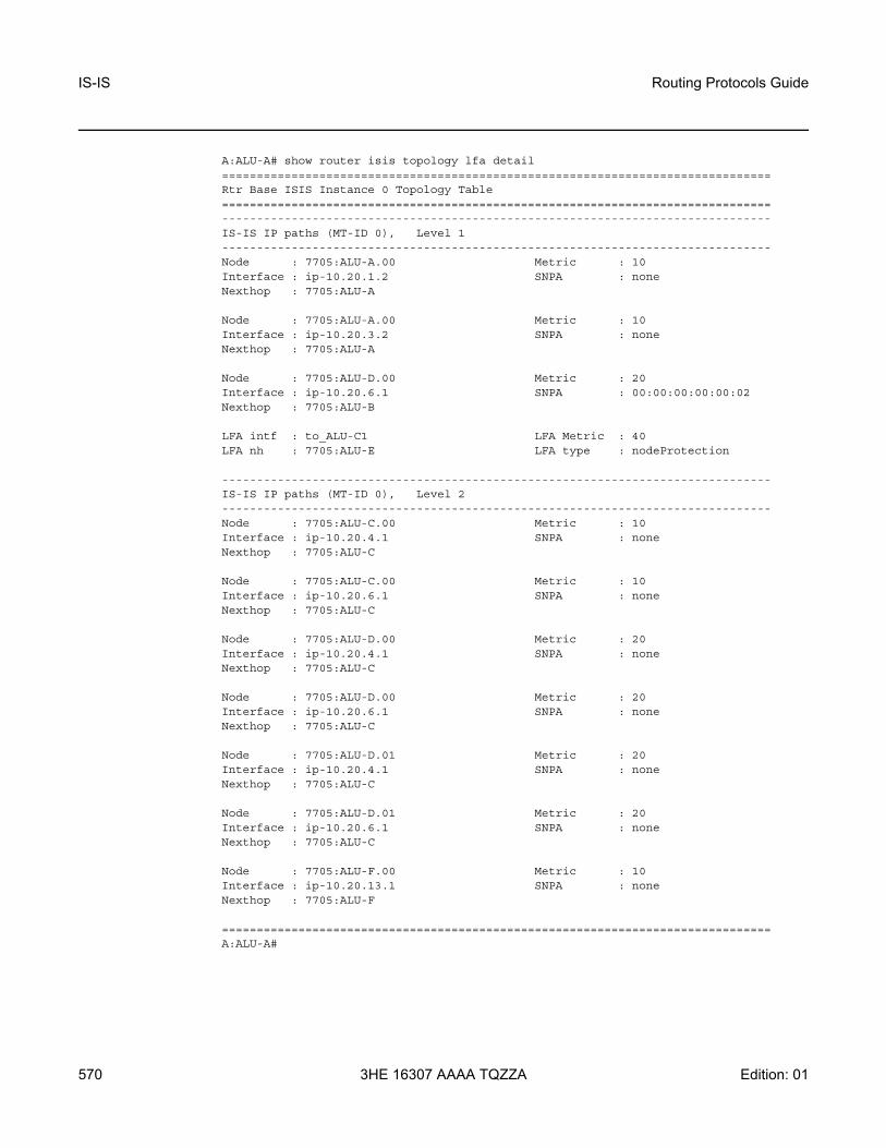
IS-IS
570
Routing Protocols Guide
3HE 16307 AAAA TQZZA Edition: 01
A:ALU-A# show router isis topology lfa detail===============================================================================Rtr Base ISIS Instance 0 Topology Table===============================================================================-------------------------------------------------------------------------------IS-IS IP paths (MT-ID 0), Level 1-------------------------------------------------------------------------------Node : 7705:ALU-A.00 Metric : 10Interface : ip-10.20.1.2 SNPA : noneNexthop : 7705:ALU-A
Node : 7705:ALU-A.00 Metric : 10Interface : ip-10.20.3.2 SNPA : noneNexthop : 7705:ALU-A
Node : 7705:ALU-D.00 Metric : 20Interface : ip-10.20.6.1 SNPA : 00:00:00:00:00:02Nexthop : 7705:ALU-B
LFA intf : to_ALU-C1 LFA Metric : 40LFA nh : 7705:ALU-E LFA type : nodeProtection
-------------------------------------------------------------------------------IS-IS IP paths (MT-ID 0), Level 2-------------------------------------------------------------------------------Node : 7705:ALU-C.00 Metric : 10Interface : ip-10.20.4.1 SNPA : noneNexthop : 7705:ALU-C
Node : 7705:ALU-C.00 Metric : 10Interface : ip-10.20.6.1 SNPA : noneNexthop : 7705:ALU-C
Node : 7705:ALU-D.00 Metric : 20Interface : ip-10.20.4.1 SNPA : noneNexthop : 7705:ALU-C
Node : 7705:ALU-D.00 Metric : 20Interface : ip-10.20.6.1 SNPA : noneNexthop : 7705:ALU-C
Node : 7705:ALU-D.01 Metric : 20Interface : ip-10.20.4.1 SNPA : noneNexthop : 7705:ALU-C
Node : 7705:ALU-D.01 Metric : 20Interface : ip-10.20.6.1 SNPA : noneNexthop : 7705:ALU-C
Node : 7705:ALU-F.00 Metric : 10Interface : ip-10.20.13.1 SNPA : noneNexthop : 7705:ALU-F
===============================================================================A:ALU-A#

Routing Protocols Guide IS-IS
Edition: 01 3HE 16307 AAAA TQZZA 571
Table 75 IS-IS Topology Field Descriptions
Label Description
Node The IP address
Interface The interface name
Nexthop The next-hop IP address
Metric The route metric for the route
SNPA The subnetwork points of attachment (SNPA) where a router is physically attached to a subnetwork
LFA intfLFA interface
The LFA interface name
LFA Metric The route metric for the LFA backup route
LFA nhLFA nexthop
The LFA next hop
LFA type The LFA protection type: link protection or node protection

IS-IS
572
Routing Protocols Guide
3HE 16307 AAAA TQZZA Edition: 01
5.11.2.3 Clear Commands
isis
Syntax isis [isis-instance]
Context clear>router
Description This command enables the context to clear IS-IS information.
Parameters isis-instance — the IS-IS instance ID. If no isis-instance is specified, instance 0 is used.
Values 0 to 31
adjacency
Syntax adjacency [system-id]
Context clear>router>isis
Description This command clears and resets the entries from the IS-IS adjacency database.
Parameters system-id — 6-octet system identifier in the form xxxx.xxxx.xxxx
database
Syntax database [system-id]
Context clear>router>isis
Description This command removes the entries from the IS-IS link-state database that contains information about PDUs.
Parameters system-id — 6-octet system identifier in the form xxxx.xxxx.xxxx
export
Syntax export
Context clear>router>isis
Description This command re-evaluates the route policies for IS-IS.

Routing Protocols Guide IS-IS
Edition: 01 3HE 16307 AAAA TQZZA 573
spf-log
Syntax spf-log
Context clear>router>isis
Description This command clears the SPF log.
statistics
Syntax statistics
Context clear>router>isis
Description This command clears and resets all IS-IS statistics.

IS-IS
574
Routing Protocols Guide
3HE 16307 AAAA TQZZA Edition: 01
5.11.2.4 Debug Commands
isis
Syntax isis [isis-instance]
Context debug>router
Description This command enables the context to debug IS-IS information.
Parameters isis-instance — the IS-IS instance ID. If no isis-instance is specified, instance 0 is used.
Values 0 to 31
adjacency
Syntax [no] adjacency [ip-int-name | ip-address | nbr-system-id]
Context debug>router>isis
Description This command enables or disables debugging for IS-IS adjacency.
Parameters ip-int-name — debugs only adjacencies with the specified interface
ip-address — debugs only adjacencies with the specified IP address
Values ipv4-address: a.b.c.d ipv6-address: x:x:x:x:x:x:x:x (eight 16-bit pieces)
x:x:x:x:x:x:d.d.d.dx: [0..FFFF]Hd: [0..255]D
nbr-system-id — debugs only the adjacency with the specified system ID
cspf
Syntax [no] cspf
Context debug>router>isis
Description This command enables or disables debugging for an IS-IS constraint-based shortest path first (CSPF).

Routing Protocols Guide IS-IS
Edition: 01 3HE 16307 AAAA TQZZA 575
interface
Syntax interface [ip-int-name | ip-address]no interface
Context debug>router>isis
Description This command enables or disables debugging for an IS-IS interface.
Parameters ip-int-name — the IP interface name. An interface name cannot be in the form of an IP address. Interface names can be any string up to 32 characters long composed of printable, 7-bit ASCII characters. If the string contains special characters (#, $, spaces, etc.), the entire string must be enclosed within double quotes.
ip-address — the interface IP address
Values ipv4-address: a.b.c.d ipv6-address: x:x:x:x:x:x:x:x (eight 16-bit pieces)
x:x:x:x:x:x:d.d.d.dx: [0..FFFF]Hd: [0..255]D
leak
Syntax leak [ip-address]no leak
Context debug>router>isis
Description This command enables or disables debugging for IS-IS leaks.
Parameters ip-address — the IP address to debug for IS-IS leaks
Values ipv4-address: a.b.c.d ipv6-address: x:x:x:x:x:x:x:x (eight 16-bit pieces)
x:x:x:x:x:x:d.d.d.dx: [0..FFFF]Hd: [0..255]D
lsdb
Syntax [no] lsdb [level-number] [system-id | lsp-id]
Context debug>router>isis
Description This command enables or disables debugging for the IS-IS link-state database.
Parameters level-number — 1 or 2
IS-IS
576
Routing Protocols Guide
3HE 16307 AAAA TQZZA Edition: 01
system-id — 6-octet system identifier in the form xxxx.xxxx.xxxx
lsp-id — the hostname (38 characters maximum)
misc
Syntax [no] misc
Context debug>router>isis
Description This command enables or disables debugging for miscellaneous IS-IS events.
packet
Syntax [no] packet [packet-type] [ip-int-name | ip-address | ipv6-address] [detail]
Context debug>router>isis
Description This command enables or disables debugging for IS-IS packets.
Parameters packet-type — the IS-IS packet type to debug
Values ptop-hello | l1-hello | l2-hello | l1-psnp | l2-psnp | l1-csnp | l2- csnp | l1-lsp | l2-lsp
ip-int-name — the IP interface name. An interface name cannot be in the form of an IP address. Interface names can be any string up to 32 characters long composed of printable, 7-bit ASCII characters. If the string contains special characters (#, $, spaces, etc.), the entire string must be enclosed within double quotes.
ip-address — the IPv4 address to debug
Values a.b.c.d
ipv6-address — the IPv6 address to debug
Values x:x:x:x:x:x:x:x (eight 16-bit pieces)x:x:x:x:x:x:d.d.d.dx: [0 to FFFF]Hd: [0 to 255]D
detail — provides detailed debugging information
rtm
Syntax rtm [ip-address]no rtm
Context debug>router>isis

Routing Protocols Guide IS-IS
Edition: 01 3HE 16307 AAAA TQZZA 577
Description This command enables or disables debugging for the IS-IS routing table manager.
Parameters ip-address — the IP address to debug
Values ipv4-address: a.b.c.d ipv6-address: x:x:x:x:x:x:x:x (eight 16-bit pieces)
x:x:x:x:x:x:d.d.d.dx: [0..FFFF]Hd: [0..255]D
spf
Syntax [no] spf [level-number] [system-id]
Context debug>router>isis
Description This command enables or disables debugging for IS-IS SPF calculations.
Parameters level-number — 1 or 2
system-id — 6-octet system identifier in the form xxxx.xxxx.xxxx

IS-IS
578
Routing Protocols Guide
3HE 16307 AAAA TQZZA Edition: 01
5.11.2.5 Monitor Commands
isis
Syntax isis [isis-instance]
Context monitor>router
Description This command enables the context to monitor IS-IS information.
Parameters isis-instance — the IS-IS instance ID. If no isis-instance is specified, instance 0 is used.
Values 0 to 31
statistics
Syntax statistics [interval seconds] [repeat repeat] [absolute | rate]
Context monitor>router>isis
Description This command enables monitoring statistics for IS-IS instances.
Parameters seconds — specifies the interval for each display in seconds
Values 3 to 60
Default 10
repeat — specifies the number of times the command is repeated
Values 1 to 999
Default 10
absolute — specifies that raw statistics are displayed, without processing. No calculations are performed on the delta or rate statistics.
rate — specifies the rate per second for each statistic instead of the delta
Output The following output is an example of statistics information for a router IS-IS instance.

Routing Protocols Guide IS-IS
Edition: 01 3HE 16307 AAAA TQZZA 579
Output Example
A:7705custDoc:Sar18>monitor>router>isis# statistics===============================================================================ISIS Statistics===============================================================================-------------------------------------------------------------------------------At time t = 0 sec (Base Statistics)-------------------------------------------------------------------------------ISIS Instance : 0 SPF Runs : 0Purge Initiated : 0 LSP Regens. : 73CSPF StatisticsRequests : 0 Request Drops : 0Paths Found : 0 Paths Not Found: 0-------------------------------------------------------------------------------PDU Type Received Processed Dropped Sent Retransmitted-------------------------------------------------------------------------------LSP 0 0 0 0 0IIH 0 0 0 0 0CSNP 0 0 0 0 0PSNP 0 0 0 0 0Unknown 0 0 0 0 0-------------------------------------------------------------------------------At time t = 10 sec (Mode: Delta)-------------------------------------------------------------------------------ISIS Instance : 0 SPF Runs : 0Purge Initiated : 0 LSP Regens. : 0CSPF StatisticsRequests : 0 Request Drops : 0Paths Found : 0 Paths Not Found: 0-------------------------------------------------------------------------------PDU Type Received Processed Dropped Sent Retransmitted-------------------------------------------------------------------------------LSP 0 0 0 0 0IIH 0 0 0 0 0CSNP 0 0 0 0 0PSNP 0 0 0 0 0Unknown 0 0 0 0 0-------------------------------------------------------------------------------At time t = 20 sec (Mode: Delta)-------------------------------------------------------------------------------ISIS Instance : 0 SPF Runs : 0Purge Initiated : 0 LSP Regens. : 0CSPF StatisticsRequests : 0 Request Drops : 0Paths Found : 0 Paths Not Found: 0-------------------------------------------------------------------------------PDU Type Received Processed Dropped Sent Retransmitted-------------------------------------------------------------------------------LSP 0 0 0 0 0IIH 0 0 0 0 0CSNP 0 0 0 0 0PSNP 0 0 0 0 0Unknown 0 0 0 0 0-------------------------------------------------------------------------------

IS-IS
580
Routing Protocols Guide
3HE 16307 AAAA TQZZA Edition: 01

Routing Protocols Guide BGP
Edition: 01 3HE 16307 AAAA TQZZA 581
6 BGPThis chapter provides information on configuring BGP.
Topics in this chapter include:
• BGP Overview • Group Configuration and Peers • BGP Route Tunnels • Command Interactions and Dependencies • BGP Configuration Process Overview• Configuration Notes • Configuring BGP with CLI• BGP Command Reference

BGP
582
Routing Protocols Guide
3HE 16307 AAAA TQZZA Edition: 01
6.1 BGP Overview
Border Gateway Protocol (BGP) is an inter-autonomous system routing protocol. An autonomous system (AS) is a network or a group of routers logically organized and controlled by a common network administration. BGP enables routers to exchange network reachability information, including information about other ASs that traffic must traverse to reach other routers in other ASs. In order to implement BGP, the AS number must be specified in the config>router context. A 7705 SAR BGP configuration must contain at least one group (a collection of related BGP peers) and include information about at least one neighbor (peer).
AS paths are the routes to each destination. Other attributes, such as the path’s origin, the system’s route preference, aggregation, route reflection, and communities included in the AS path are called path attributes. When BGP interprets routing and topology information, loops can be detected and eliminated. Route preference for routes learned from the configured peers can be enabled among groups of routes to enforce administrative preferences and routing policy decisions.
This section contains information on the following topics:
• BGP Communication• Message Types• BGP Path Attributes• Multi-Protocol BGP Attributes• BGPv6• BGP Add-Paths• Outbound Route Filtering (ORF)• BGP Route Target Constrained Route Distribution
6.1.1 BGP Communication
There are two types of BGP peers: internal BGP (IBGP) peers and external BGP (EBGP) peers (see Figure 29).
• Within an AS, IBGP is used to communicate with peers.• Between ASs, EBGP is used to communicate with peers. Routes received from
a router in a different AS can be advertised to both EBGP and IBGP peers.In an external group, the next hop depends upon the interface shared between the external peer and the specific neighbor. The multihop command must be specified if an EBGP peer is more than one hop away from the local router.
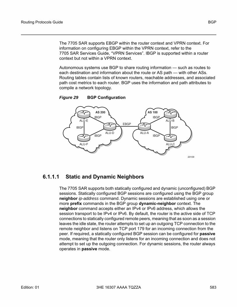
Routing Protocols Guide BGP
Edition: 01 3HE 16307 AAAA TQZZA 583
The 7705 SAR supports EBGP within the router context and VPRN context. For information on configuring EBGP within the VPRN context, refer to the 7705 SAR Services Guide, “VPRN Services”. IBGP is supported within a router context but not within a VPRN context.
Autonomous systems use BGP to share routing information — such as routes to each destination and information about the route or AS path — with other ASs. Routing tables contain lists of known routers, reachable addresses, and associated path cost metrics to each router. BGP uses the information and path attributes to compile a network topology.
Figure 29 BGP Configuration
6.1.1.1 Static and Dynamic Neighbors
The 7705 SAR supports both statically configured and dynamic (unconfigured) BGP sessions. Statically configured BGP sessions are configured using the BGP group neighbor ip-address command. Dynamic sessions are established using one or more prefix commands in the BGP group dynamic-neighbor context. The neighbor command accepts either an IPv4 or IPv6 address, which allows the session transport to be IPv4 or IPv6. By default, the router is the active side of TCP connections to statically configured remote peers, meaning that as soon as a session leaves the idle state, the router attempts to set up an outgoing TCP connection to the remote neighbor and listens on TCP port 179 for an incoming connection from the peer. If required, a statically configured BGP session can be configured for passive mode, meaning that the router only listens for an incoming connection and does not attempt to set up the outgoing connection. For dynamic sessions, the router always operates in passive mode.
20109
ALU-F ALU-C
AS 200 AS 100
ALU-D ALU-A
IBGP
IBGP
IBGP
EBGPIBGP
IBGP
IBGPALU-BALU-E

BGP
584
Routing Protocols Guide
3HE 16307 AAAA TQZZA Edition: 01
The source IP address used to set up the TCP connection to the static or dynamic peer can be configured explicitly using the local-address command. If a local-address is not configured, the source IP address is determined as follows:
• if the neighbor’s IP address belongs to a local subnet, the source IP address is the local router’s interface IP address on that subnet
• if the neighbor’s IP address does not belong to a local subnet, the source IP address is the local router’s system IP address
Configuring the router interface as the local address can be done in the config>router>bgp>group context and the config>router>bgp>group>neighbor context.
When the router interface is configured as the local address, BGP inherits the IP address from the interface as follows:
• BGP-4 sessions — the primary IPv4 address configured on the interface is used as the local address
• BGPv6 sessions — the primary IPv6 address configured on the interface is used as the local address
If the corresponding IPv4 or IPv6 address is not configured on the router interface, the BGP sessions that have this interface set as the local address are kept in the down state until an interface address is configured on the router interface.
If the primary IPv4 or IPv6 address is changed on the router interface and that interface is being used as the local address for BGP, BGP will bounce the link. Bouncing the link causes all routes advertised using the previous address to be removed and readvertised using the newly configured IP address.

Routing Protocols Guide BGP
Edition: 01 3HE 16307 AAAA TQZZA 585
6.1.2 Message Types
Four message types are used by BGP to negotiate parameters, exchange routing information and indicate errors. They are:
• Open message — after a transport protocol connection is established, the first message sent by each side is an Open message. If the Open message is acceptable, a Keepalive message confirming the Open message is sent back. Once the Open message is confirmed, Update, Keepalive, and Notification messages can be exchanged. Open messages consist of the BGP header and the following fields:- version — the current BGP version number is 4- local AS number — the autonomous system number is configured in the
config>router context- hold time — the maximum time BGP will wait between successive
messages (either Keepalive or Update) from its peer, before closing the connection. Configure the local hold time within the config>router>bgp context.
- BGP identifier — IP address of the BGP domain or the router ID. The router ID must be a valid host address.
• Update message — Update messages are used to transfer routing information between BGP peers. The information contained in the packet can be used to construct a graph describing the relationships of the various autonomous systems. By applying rules, routing information loops and some other anomalies can be detected and removed from the inter-AS routing.The Update messages consist of a BGP header and the following optional fields:- unfeasible routes length — the length of the field that lists the routes being
withdrawn from service because they are considered unreachable- withdrawn routes — the associated IP address prefixes for the routes
withdrawn from service- total path attribute length — the total length of the path field that provides
the attributes for a possible route to a destination- path attributes — the path attributes presented in variable-length TLV
format- network layer reachability information (NLRI) — IP address prefixes of
reachability information• Keepalive message — Keepalive messages, consisting of only a 19-octet
message header, are exchanged between peers frequently so hold timers do not expire. The Keepalive messages determine if a link is unavailable.

BGP
586
Routing Protocols Guide
3HE 16307 AAAA TQZZA Edition: 01
• Notification message — A Notification message is sent when an error condition is detected. The peering session is terminated and the BGP connection (TCP connection) is closed immediately after sending it.
6.1.3 BGP Path Attributes
Path attributes are fundamental to BGP. A BGP route for a particular NLRI is distinguished from other BGP routes for the same NLRI by the set of path attributes for the route. Each path attribute describes some property of the path and is encoded as a TLV in the Path Attributes field of the Update message. The Type field of the TLV identifies the path attribute and the Value field carries data specific to the attribute type. There are four categories of path attributes:
• well-known mandatoryThese attributes must be recognized by all BGP routers and must be present in every Update message that advertises reachable NLRI toward a specific type of neighbor (EBGP or IBGP).
• well-known discretionaryThese attributes must be recognized by all BGP routers but are not required in every Update message.
• optional transitiveThese attributes do not need to be recognized by all BGP routers. If a BGP router does not recognize one of these attributes, it accepts it and passes it on to other BGP peers.
• optional non-transitiveThese attributes do not need to be recognized by all BGP routers. If a BGP router does not recognize one of these attributes, it is quietly ignored and not passed on to other BGP peers.
The 7705 SAR supports the following path attributes:
• ORIGIN (well-known mandatory)• AS_PATH (well-known mandatory)• NEXT_HOP (well-known, mandatory only in Update messages with IPv4
prefixes in the NLRI field)• MED (optional non-transitive)• LOCAL_PREF (well-known, mandatory only in Update messages sent to IBGP
peers)• ATOMIC_AGGREGATE (well-known discretionary)• AGGREGATOR (optional transitive)

Routing Protocols Guide BGP
Edition: 01 3HE 16307 AAAA TQZZA 587
• COMMUNITIES (optional transitive)• ORIGINATOR_ID (optional non-transitive)• CLUSTER_LIST (optional non-transitive)• MP_REACH_NLRI (optional non-transitive)• MP_UNREACH_NLRI (optional non-transitive)• EXT_COMMUNITY (optional transitive)• AS4_PATH (optional transitive)• AS4_AGGREGATOR (optional transitive)• CONNECTOR (optional transitive)• PMSI_TUNNEL (optional transitive)• TUNNEL_ENCAPSULATION (optional transitive)• AIGP (optional non-transitive)• BGP-LS (optional non-transitive)
6.1.3.1 Origin Attribute
The ORIGIN attribute indicates the origin of the path information. There are three supported values:
• IGP (0) – the prefix was originated from information learned from an interior gateway protocol
• EGP (1) – the prefix originated from an exterior gateway protocol (BGP)• Incomplete (2) – the prefix originated from an unknown source
6.1.3.2 AS Path Attribute
The AS_PATH attribute contains the list of ASs through which the routing information has passed.
The AS numbers in the AS_PATH attribute are all 2-byte values or all 4-byte values (if the 4-octet ASN capability was announced by both peers).
BGP
588
Routing Protocols Guide
3HE 16307 AAAA TQZZA Edition: 01
6.1.3.3 Next-hop Attribute
The NEXT_HOP attribute indicates the IPv4 address of the BGP router that is the next hop to reach the IPv4 prefixes in the NLRI field. If the Update message is advertising routes other than IPv4 unicast routes, the next hop of these routes is encoded in the MP_REACH_NLRI attribute; see Multiprotocol BGP Extensions Attributes for more details.
6.1.3.4 MED Attribute
The Multi-Exit Discriminator (MED) attribute is an optional attribute that can be added to routes advertised to an EBGP peer to influence the flow of inbound traffic to the AS. The MED attribute carries a 32-bit metric value. A lower metric is better than a higher metric when MED attributes are compared during the BGP decision process. Unless the always-compare-med command is configured, MED attributes are compared only if the routes come from the same neighbor AS. By default, if a route is received without a MED attribute, it is evaluated by the BGP decision process as though it had a MED containing the value 0. This can be changed so that a missing MED attribute is handled in the same way as a MED with the maximum value. The 7705 SAR always removes the received MED attribute when advertising the route to an EBGP peer.
6.1.3.5 Local Preference Attribute
The LOCAL_PREF attribute is a well-known attribute that should be included in every route advertised to an IBGP peer. It is used to influence the flow of outbound traffic from the AS. The local preference is a 32-bit value, and higher values are more preferred by the BGP decision process. The LOCAL_PREF attribute is not included in routes advertised to EBGP peers. If the attribute is received from an EBGP peer, it is ignored.
6.1.3.6 Route Aggregation Path Attributes
An aggregate route is a group of routes with a common prefix that are combined into a single entry in the forwarding table (for more information, refer to the aggregate command in the 7705 SAR Router Configuration Guide, “Router Global Commands”).

Routing Protocols Guide BGP
Edition: 01 3HE 16307 AAAA TQZZA 589
An active aggregate route can be advertised to a BGP peer by exporting it into BGP. This reduces the number of routes that need to be advertised to the peer and reduces the number of routes in the peer AS. When a router advertises an aggregate route to a BGP peer, the aggregation attributes in the route are set as follows.
• The ATOMIC_AGGREGATE attribute is included in the route if at least one contributing route has the ATOMIC_AGGREGATE attribute, or the aggregate route was formed without the as-set option in the config>router>aggregate context and at least one contributing route has a non-empty AS_PATH. The ATOMIC_AGGREGATE attribute indicates that some of the AS numbers present in the AS paths of the contributing routes are missing from the advertised AS_PATH.
• The AGGREGATOR attribute is added to the route. This attribute encodes, by default, the global AS number and router ID (BGP identifier) of the router that formed the aggregate, but these values can be changed on a per-aggregate route basis using the aggregator command option in the config>router> aggregate context. The AS number in the AGGREGATOR attribute is either 2 bytes or 4 bytes (if the 4-octet ASN capability was announced by both peers). The router ID in the aggregate routes advertised to a particular set of peers can be set to 0.0.0.0 using the aggregator-id-zero command in the config>router> bgp context.
6.1.3.7 Communities Attribute
A BGP route can be associated with one or more communities. There are two kinds of BGP communities supported by the 7705 SAR:
• standard communities (each 4 bytes in length, all packed into a path attribute with type code 8)
• extended communities (each 8 bytes in length, with potentially many possible subtypes, all packed into a path attribute with type code 16)
For information on communities, refer to the 7705 SAR Router Configuration Guide, “Route Policies”.
The COMMUNITIES attribute is an optional transitive attribute of variable length. The attribute consists of a set of four octet values, each of which specifies a community. All routes with this attribute belong to the communities listed in the attribute.
The following communities are well-known standard communities that should be recognized by all BGP routers:
• NO_EXPORT – a route that carries this community must not be advertised outside the local AS

BGP
590
Routing Protocols Guide
3HE 16307 AAAA TQZZA Edition: 01
• NO_ADVERTISE – a route that carries this community must not be advertised to any other BGP peer
• NO_EXPORT_SUBCONFED – a route that carries this community must not be advertised outside a member AS boundary to external BGP peers
6.1.3.8 Route Reflection Attributes
The ORIGINATOR_ID and CLUSTER_LIST attributes are optional non-transitive attributes that are used in route reflection; see Route Reflection.
6.1.3.9 Multiprotocol BGP Extensions Attributes
Multiprotocol extensions for BGP (MP-BGP) allow BGP peers to exchange routes for NLRI other than IPv4 prefixes; for example, IPv6 prefixes or Layer 3 VPN routes. A BGP router that supports MP-BGP indicates the types of routes it wants to exchange with a peer by including the corresponding AFI (Address Family Identifier) and SAFI (Subsequent Address Family Identifier) values in the MP-BGP capability fields of its Open message.
To advertise reachable routes of a particular AFI/SAFI, a BGP router includes a single MP_REACH_NLRI attribute in the Update message. The MP_REACH_NLRI attribute encodes the AFI, the SAFI, the BGP next hop, and all the reachable NLRI.
To withdraw routes of a particular AFI/SAFI, a BGP router includes a single MP_UNREACH_NLRI attribute in the Update message. The MP_UNREACH_NLRI attribute encodes the AFI, the SAFI, and all the withdrawn NLRI.
6.1.3.10 4-Octet AS Attributes
The AS4_PATH and AS4_AGGREGATOR attributes are optional transitive attributes that support the gradual migration of routers that can understand and parse 4-octet ASN numbers.

Routing Protocols Guide BGP
Edition: 01 3HE 16307 AAAA TQZZA 591
6.1.3.11 AIGP Metric Attribute
The accumulated IGP (AIGP) metric attribute is an optional non-transitive attribute that can be attached to selected routes (using route policies) in order to influence the BGP decision process to prefer BGP paths with a lower end-to-end IGP cost, even when the compared paths span more than one AS or IGP instance. AIGP is different from MED in several important ways.
• AIGP is not intended to be transitive between completely distinct ASs (only across internal AS boundaries).
• AIGP is always compared in paths that have the attribute, regardless of whether they come from different neighbor ASs.
• AIGP is more important than MED in the BGP decision process.• AIGP is automatically incremented every time there is a BGP next-hop change,
so that it can track the end-to-end IGP cost. All arithmetic operations on MED attributes must be done manually (for example, using route policies).
The 7705 SAR supports AIGP for the following address families in the GRT context:
• IPv4• label-IPv4• IPv6
The AIGP attribute is only sent to peers that are configured with the aigp command. If the attribute is received from a peer that is not configured for aigp, or if the attribute is received in an unsupported route type, the attribute is discarded and is not propagated to other peers. However, it is still displayed in BGP show commands.
When a 7705 SAR receives a route with an AIGP attribute and readvertises the route to an AIGP-enabled peer without any change to the BGP next hop, the AIGP metric value is unchanged by the advertisement (RIB-OUT) process. However, if the route is readvertised with a new BGP next hop, the AIGP metric value is automatically incremented by the route table cost (or tunnel table cost) to reach the received BGP next hop and/or is incremented by a statically configured value (using route policies).

BGP
592
Routing Protocols Guide
3HE 16307 AAAA TQZZA Edition: 01
6.1.4 Multi-Protocol BGP Attributes
Multi-Protocol BGP Attributes (MP-BGP) allows BGP peers to exchange routes for NLRI other than IPv4 prefixes; for example IPv6 prefixes, Layer 3 VPN routes, Layer 2 VPN routes, and flow-spec rules. A BGP router that supports MP-BGP indicates the types of routes it wants to exchange with a peer by including the corresponding AFI (Address Family Identifier) and SAFI (Subsequent Address Family Identifier) values in the MP-BGP capability of its OPEN message. The two peers forming a session do not need indicate support for the same address families; as long as there is one AFI/SAFI in common the session will establish and routes associated with all the common AFI/SAFI can be exchanged between the peers.
The list of AFI/SAFI advertised in the MP-BGP capability is controlled entirely by the family commands. The AFI/SAFI supported by the 7705 SAR and the method of configuring the AFI/SAFI support is summarized in Table 76.
To advertise reachable routes of a particular AFI/SAFI a BGP router includes a single MP_REACH_NLRI attribute in the UPDATE message. The MP_REACH_NLRI attribute encodes the AFI, the SAFI, the BGP next-hop and all the reachable NLRI. To withdraw routes of a particular AFI/SAFI a BGP router includes a single MP_UNREACH_NLRI attribute in the UPDATE message. The MP_UNREACH_NLRI attribute encodes the AFI, the SAFI and all the withdrawn NLRI. While it is valid to advertise and withdraw IPv4 unicast routes using the MP_REACH_NLRI and MP_UNREACH_NLRI attributes, SR OS always uses the IPv4 fields of the UPDATE message to convey reachable and unreachable IPv4 unicast routes.
Table 76 Multi-Protocol BGP Support on 7705 SAR
Name AFI SAFI Configuration Commands
IPv4 unicast 1 1 family ipv4
IPv4 labeled unicast 1 4 family label-ipv4
NG-MVPN IPv4 1 5 family mvpn-ipv4
VPN-IPv4 1 128 family vpn-ipv4
RT constrain 1 132 family route-target
IPv6 unicast 2 1 family ipv6
VPN-IPv6 2 128 family vpn-ipv6
BGP-LS 16388 (base)16388 (VPN)
71 (base)128 (VPN)
family bgp-ls

Routing Protocols Guide BGP
Edition: 01 3HE 16307 AAAA TQZZA 593
6.1.5 BGPv6
The 7705 SAR supports BGPv6 in the GRT (for network and IES interfaces) to provide increased IPv6 connectivity in a PE-CE environment.
Figure 30 shows an example of a network with 7705 SAR nodes on the CE utilizing BGPv6. The 7705 SAR can also be used on the PE.
Figure 30 BGPv6
CEs are connected via EBGP or, in some cases, IBGP to edge routers, which then connect the CEs across a core BGP network. A privately owned customer network uses IBGP by default. For backup, a third-party network that uses EBGP for connectivity between edge routers and the backup network is used.
Any failures occurring between PEs and CEs are detected with BFD and BGP PIC and resolved with BGP fast reroute.
7705 SAR CEs 7705 SAR CEs
CoreAS1 Primary
Owned
CoreAS2 Back upThird party
7750 SR PE
7750 SR PE
7750 SR PE
IBGP
IBGP
IBGPEBGP
Legend:
26598
7750 SR PE

BGP
594
Routing Protocols Guide
3HE 16307 AAAA TQZZA Edition: 01
6.1.6 BGP Add-Paths
Add-paths allows a BGP router to advertise multiple distinct paths for the same prefix/NLRI. BGP add-paths provides a number of potential benefits, including reduced routing churn, faster convergence, and better load sharing. Refer to draft-ietf-idr-add-paths-04.txt, Advertisement of Multiple Paths in BGP for details of the add-paths capabilities advertisement.
This section also contains information on the following topics:
• Path Selection Mode and Parameters for Multiple Paths to Add-path Peers• Routing Policy for Multiple Paths• BGP Route Advertisement Rules for Multiple Paths• BGP Split Horizon
In order for router A to receive multiple paths per NLRI from peer B for a particular address family, they must advertise their BGP capabilities during session setup. Peer router B advertises that it wants to send multiple paths for an address family and router A indicates that it is able to receive multiple paths for the address family.
When the add-paths receive capability for an address family has been negotiated with a peer router, all advertisements and withdrawals of NLRI within that address family by that peer will include a path identifier. Path identifiers have no significance to the receiving peer. If the combination of NLRI and path identifier in an advertisement from a peer is unique and does not match an existing route in the RIB-IN from that peer, then the route is added to the RIB-IN. If the combination of NLRI and path identifier in a received advertisement is the same as an existing route in the RIB-IN from the peer, then the new route replaces the existing one. If the combination of NLRI and path identifier in a received withdrawal matches an existing route in the RIB-IN from the peer, then that route is removed from the RIB-IN. An UPDATE message carrying an IPv4 NLRI with a path identifier is shown in Figure 31.
Figure 31 BGP Update Message with Path Identifier for IPv4 NLRI
Withdrawn Routes Length (2 octets)Withdrawn Routes (variable)
Total Path Attribute Length (2 octets)Path Attributes (variable)Path Identifier (4 octets)
Length (1 octets)Prefix (variable)
Path identifier (4 octets)Length (1 octets)
Route 1
Route 2Prefix (variable)
Path Identifier (4 octets)Length (1 octets)Prefix (variable)
Path identifier (4 octets)Length (1 octets)
Route 3
Route 4Prefix (variable)
24075

Routing Protocols Guide BGP
Edition: 01 3HE 16307 AAAA TQZZA 595
Add-paths are only supported on the base router BGP instance and the EBGP and IBGP sessions it forms with other add-path-capable peers. The ability to send and receive multiple paths per prefix to and from an add-paths peer is configurable per family. The following families support BGP add-path:
• IPv4• label-IPv4• VPN-IPv4• IPv6• VPN-IPv6
6.1.6.1 Path Selection Mode and Parameters for Multiple Paths to Add-path Peers
The RIB-IN may have multiple paths for a prefix (for example, prefix D). The path selection mode refers to the algorithm used to decide which of these paths to advertise to an add-paths peer. In the current implementation, the 7705 SAR supports only one path selection algorithm, the Add-N algorithm described in draft-ietf-idr-add-paths-guidelines-00.txt, Best Practices for Advertisement of Multiple Paths in BGP. The Add-N algorithm selects the N best overall paths for each prefix, regardless of path type (internal vs. external), degree of difference between the paths or use in forwarding. If this set of N best overall paths includes multiple paths with the same BGP NEXT_HOP, only the best route with a particular NEXT_HOP is advertised and the others are suppressed.
In the 7705 SAR implementation, N is configurable, per address-family, at the BGP global, group, and neighbor levels; N has a minimum value of 1 and a maximum value of 16. For a peer belonging to a group, the path selection parameters are first based on the neighbor configuration for the peer, then the group configuration, then the BGP global configuration.
When add-path is enabled for the VPN-IPv4 or VPN-IPv6 address family in the base router BGP context, only VPN-IP routes in the base router BGP RIB-IN are considered for advertisement to add-path peers. If a VPRN best route to a destination is a BGP-VPN route imported from the base router and its next-best route is a CE-learned BGP route that would be accepted by the VPRN VRF export policy, this next-best route is not advertised, regardless of the base router’s add-path configuration.

BGP
596
Routing Protocols Guide
3HE 16307 AAAA TQZZA Edition: 01
6.1.6.2 Routing Policy for Multiple Paths
BGP and VRF export policies are applied after path selection is performed. If add-paths is configured to send up to N paths to a peer and an export policy prevents some number (X) of the N best paths for prefix D from being advertised to the peer, then only the remaining (N minus X) best paths are sent.
6.1.6.3 BGP Route Advertisement Rules for Multiple Paths
Add-paths allows non-best paths to be advertised to a peer, but it still complies with basic BGP advertisement rules such as the IBGP split horizon rule: a route learned from an IBGP neighbor cannot be readvertised to another IBGP neighbor unless the router is configured as a route reflector.
If add-paths is configured to send up to N paths to a peer and some number (X) of the N best paths for D cannot be advertised to the peer due to route advertisement rules, then only the remaining (N minus X) routes are advertised.
6.1.6.4 BGP Split Horizon
Split horizon refers to the action taken by a router to avoid advertising a route back to the peer from which it was received or to another non-client peer for IBGP. By default, the 7705 SAR applies split-horizon behavior only to routes received from IBGP non-client peers. This split-horizon functionality, which cannot be disabled, prevents routing loops by disabling the advertisement of routes learned from a non-client IBGP peer back to the sending peer or any other non-client peer.
To apply split-horizon behavior to routes learned from RR clients, peers or EBGP peers, the split-horizon command must be configured in the appropriate contexts; it is supported at the global BGP, group, and neighbor levels. When split horizon is enabled on these types of sessions, it only prevents the advertisement of a route back to its originating peer; for example, the 7705 SAR does not prevent the advertisement of a route learned from one EBGP peer back to a different EBGP peer in the same neighbor AS.

Routing Protocols Guide BGP
Edition: 01 3HE 16307 AAAA TQZZA 597
6.1.7 Outbound Route Filtering (ORF)
ORF is a mechanism that allows one router, the ORF-sending router, to signal to a peer, the ORF-receiving router, a set of route filtering rules (ORF entries) that the ORF-receiving router should apply to its route advertisements towards the ORF-sending router. The ORF entries are encoded in Route Refresh messages.
The use of ORF for a session must be negotiated — both routers must advertise the ORF capability in their Open messages. The ORF capability describes the address families that support ORF, and for each address family, the ORF types that are supported and the ability to send/receive each type. The 7705 SAR supports ORF type 3, ORF based on extended communities, for the following address families:
• VPN-IPv4• VPN-IPv6• MVPN-IPv4
The send and receive capability for ORF is configurable with the send-orf and accept-orf commands, and the setting applies to all supported address families.
ORF type 3 allows a PE router that imports VPN routes with a particular set of route target extended communities to indicate to a peer (for example a route reflector) that it only wants to receive VPN routes that contain one or more of these extended communities. To inform a peer to add or remove a route target extended community, the PE router sends a Route Refresh message to the peer containing an ORF type 3 entry that instructs the peer to either add or remove a permit entry for the 8-byte extended community value.
The type 3 ORF entries that are sent to a peer can be generated dynamically (if no route target extended communities are specified with the send-orf command) or specified statically. Dynamically generated ORF entries are based on the route targets that are imported by all locally configured VPRNs.
A router that has installed ORF entries received from a peer can still apply BGP export policies to the session. BGP export policies overrule ORF entries. If the evaluation of a BGP export policy results in a reject action for a VPN route that matches a permit ORF entry, the route is not advertised.
ORF filtering is efficient; a large number of VPN routes can be filtered faster than using a conventional BGP export policy. In addition to ORF, users can also use BGP Route Target Constrained Route Distribution for dynamic filtering based on route target extended communities. RTC, as discussed below, offers some advantages over ORF.

BGP
598
Routing Protocols Guide
3HE 16307 AAAA TQZZA Edition: 01
6.1.8 BGP Route Target Constrained Route Distribution
BGP route target constrained route distribution allows a router to advertise a route target constraint (RTC) route to its peers. A peer receiving an RTC route does not advertise VPN routes back to the router unless they contain a route target extended community that matches one of the received RTC routes. For detailed information on RTC, refer to the 7705 SAR Services Guide, “Route Target Constraint”.
RTC routes are carried using MP-BGP with an AFI value of 1 and SAFI value of 132. The NLRI of an RTC route encodes an Origin AS and a route target extended community using prefix-type encoding with the host bits after the prefix length set to zero.
In order for two routers to exchange route target membership NLRI, they must advertise the corresponding AFI and SAFI to each other during capability negotiation. The use of MP-BGP means route target membership NLRI are propagated, loop-free, within an autonomous system and between autonomous systems, using well-known BGP route selection and advertisement rules.
If there are multiple RTC routes for the same NLRI, the BGP decision process selects one as the best path. The propagation of the best path installs RIB-Out filter rules as it travels from one router to the next, which creates an optimal VPN route distribution tree rooted at the source of the RTC route.
Route target constrained route distribution and outbound route filtering (ORF) both allow routers to advertise which route target extended communities they want to receive in VPN routes from peers. RTC, however, is more widely supported, is simpler to configure, and its distribution scope is not limited to a direct peer.
ORF and RTC are mutually exclusive for a particular BGP session. The CLI does not attempt to block the configuration of both ORF and RTC, but if both capabilities are enabled for a session, the ORF capability will not be included in the Open message sent to the peer.
The capability to exchange RTC routes is advertised when the route-target keyword is added to the family command. RTC is supported for EBGP and IBGP sessions on the base router instance.
When RTC has been negotiated with one or more peers, the 7705 SAR automatically originates and advertises to these peers one RTC route with a prefix length of 96 (the origin AS and route target extended community are fully specified) for every route target imported by a locally configured VPRN or BGP-based Layer 2 VPN, including MVPN-specific route targets.
Routing Protocols Guide BGP
Edition: 01 3HE 16307 AAAA TQZZA 599
A router may be configured to send the default RTC route to a group or neighbor with the default-route-target CLI command. This causes the router to generate and send a special RTC route with a prefix length of 0:0:0/0. Sending the default RTC route to a peer conveys a request to receive all VPN routes from that peer. The default RTC route is typically advertised by a route reflector to PE clients. Advertising the default RTC route to a peer does not suppress other more specific RTC routes from being sent to that peer. A received default RTC route is never propagated to other routers.
The advertisement of RTC routes by a route reflector follows special rules as described in RFC 4684. These rules are needed to ensure that RTC routes for the same NLRI that are originated by different PE routers in the same AS are properly distributed within the AS.
When a BGP session comes up and RTC is enabled for the session (both peers advertised the MP-BGP capability), routers delay sending any VPN-IPv4 and VPN-IPv6 routes until either the session has been up for 60 s or the end-of-RIB marker is received for the RTC address family. When the VPN-IPv4 and VPN-IPv6 routes are sent, they are filtered to include only those with a route target extended community that matches an RTC route from the peer.
VPN-IP routes matching an RTC route originated in the local AS are advertised to any IBGP peer that advertises a valid path for the RTC NLRI. Route distribution is not limited only to the IBGP peer advertising the best path. VPN-IP routes matching an RTC route that originated outside the local AS are only advertised to the EBGP or IBGP peer that advertises the best path.
The 7705 SAR does not support an equivalent of BGP Multipath for RTC routes. There is no way to distribute VPN routes across more than one set of inter-AS paths that are nearly equal.
Received RTC routes have no effect on the advertisement on MVPN-IPv4 routes.

BGP
600
Routing Protocols Guide
3HE 16307 AAAA TQZZA Edition: 01
6.2 Group Configuration and Peers
To enable BGP routing, participating routers must have BGP enabled and be assigned to an autonomous system, and the neighbor (peer) relationships must be specified. A router can belong to only one AS. TCP connections must be established in order for neighbors to exchange routing information and updates. Neighbors exchange BGP Open messages that include information such as AS numbers, BGP versions, router IDs, and hold-time values. Keepalive messages determine if a connection is established and operational. The hold-time value specifies the maximum time BGP will wait between successive messages (either Keepalive or Update) from its peer, before closing the connection.
In BGP, peers are arranged into groups. A group must contain at least one neighbor. A neighbor must belong to a group. Groups allow multiple peers to share similar configuration attributes.
Although neighbors do not have to belong to the same AS, they must be able to communicate with each other. If TCP connections are not established between two neighbors, the BGP peering session will not be established and updates will not be exchanged.
Peer relationships are defined by configuring the IP address of the routers that are peers of the local BGP domain. When neighbor and peer relationships are configured, the BGP peers exchange Update messages to advertise network reachability information.
The 7705 SAR supports BGP peering sessions to both static and dynamic neighbors.
This section contains information on the following topics:
• Hierarchical Levels• Route Reflection• BGP Peer Groups with Dynamic Neighbors• Fast External Failover• BGP Fast Reroute With Prefix-Independent Convergence• Calculating Backup Paths• Sending of BGP Communities• BGP Decision Process

Routing Protocols Guide BGP
Edition: 01 3HE 16307 AAAA TQZZA 601
6.2.1 Hierarchical Levels
BGP parameters are initially applied at the global level. These parameters are inherited by the group and neighbor (peer) levels. Parameters can be modified and overridden on a level-specific basis. BGP command hierarchy consists of three levels:
• global level• group level • neighbor level
Many of the hierarchical BGP commands can be modified at different levels. The most specific value is used. That is, a BGP group-specific command takes precedence over a global BGP command. A neighbor-specific command takes precedence over a global BGP and group-specific command; for example, if you modify a BGP neighbor-level command default, the new value takes precedence over group- and global-level settings.
6.2.2 Route Reflection
In a standard BGP configuration, all BGP speakers within an AS must have full BGP mesh to ensure that all externally learned routes are redistributed through the entire AS. IBGP speakers do not readvertise routes learned from one IBGP peer to another IBGP peer. If a network grows, scaling issues could emerge because of the full mesh configuration requirement. Instead of peering with all other IBGP routers in the network, each IBGP router only peers with a router configured as a route reflector.
Route reflection circumvents the full mesh requirement but maintains the full distribution of external routing information within an AS. Route reflection is effective in large networks because it is manageable, scalable, and easy to implement. Route reflection is implemented in autonomous systems with a large internal BGP mesh in order to reduce the number of IBGP sessions required within an AS.
Caution: Take care how you use command settings at a lower level that can disable features at a higher level. For example, if the damping command is used to enable damping at the global level and you want it disabled only for a specified neighbor, use the no damping command at the neighbor level only; do not use it the global level also, since this will disable damping for all neighbors within the BGP global instance.

BGP
602
Routing Protocols Guide
3HE 16307 AAAA TQZZA Edition: 01
A large AS can be subdivided into smaller ASs, called clusters. Each cluster contains at least one route reflector, which is responsible for redistributing route updates to all clients. Route reflector clients do not need to maintain a full peering mesh between each other. They only require a peering to the route reflectors in their cluster. The route reflectors must maintain a full peering mesh between all non-clients within the AS.
Each route reflector must be assigned a cluster ID and specify which neighbors are clients and which are non-clients to determine which neighbors should receive reflected routes and which should be treated as a standard IBGP peer. Additional configuration is not required for the route reflector, aside from the typical BGP neighbor parameters.
BGP speakers within the AS that are not peers with the route reflector are called non-clients. Non-clients are peers to a route reflector but do not understand the route reflector attributes. Several BGP-speaking routers can peer with a route reflector. A route reflector forms peer connections to other route reflectors.
Figure 32 displays a simple configuration with several IBGP 7705 SAR nodes.
When SR-A receives a route from SR-1 (an external neighbor), it must advertise route information to SAR-01, SAR-02, SAR-03, SAR-04, and SAR-05. To prevent loops, IBGP learned routes are not readvertised to other IBGP peers.
Figure 32 Fully Meshed BGP Configuration
When route reflectors are configured, the routers within a cluster do not need to be fully meshed. Figure 32 depicts a fully meshed network and Figure 33 depicts the same network but with route reflectors configured to minimize the IBGP mesh between SR-A, SAR-01, SAR-02, and SAR-03. SR-A, configured as the route reflector, is responsible for redistributing route updates to clients SAR-01, SAR-02, and SAR-03. IBGP peering between SAR-01, SAR-02 and SAR-03 is not necessary because even IBGP learned routes are reflected to the route reflector’s clients.
20953
EBGP Peering
SR-1 SR-A SAR-05
SAR-04SAR-01
SAR-03SAR-02

Routing Protocols Guide BGP
Edition: 01 3HE 16307 AAAA TQZZA 603
In Figure 33, SAR-04 and SAR-05 are shown as non-clients of the route reflector. As a result, a full mesh of IBGP peerings must be maintained between SR-A, SAR-04, and SAR-05.
Figure 33 BGP Configuration with Route Reflectors
BGP speakers within an AS that are not configured as reflectors are considered to be client peers. Non-client peers are other routers in the AS. A route reflector enables communication between the clients and non-client peers. Route reflector-to-client peer configurations do not need to be fully meshed, but non-client peers need to be fully meshed within an AS.
A grouping, called a cluster, is composed of a route reflector and its client peers. A cluster ID identifies the grouping unless specific BGP peerings are configured. A cluster’s clients do not share information messages with other peers outside the cluster. Multiple route reflectors can be configured within a cluster for redundancy. A router assumes the role as a route reflector by configuring the cluster cluster-id command. No other command is required unless the operator wants to disable reflection to specific clients.
When a route reflector receives an advertised route, depending on the sender and neighbors (peers), it selects the best path. Routes received from an EBGP peer are advertised unmodified (to retain next-hop information) to all clients and non-client peers in the AS. Routes received from a non-client peer are advertised to all clients in the AS. Routes received from a client are advertised to all clients and non-client peers.
20954
EBGP Peering
Routereflector
Route reflectorcluster 0.0.0.1
SR-1 SR-A SAR-05(Non-client)
SAR-04(Non-client)
SAR-01(Client)
SAR-03(Client)
SAR-02(Client)

BGP
604
Routing Protocols Guide
3HE 16307 AAAA TQZZA Edition: 01
6.2.3 BGP Peer Groups with Dynamic Neighbors
The 7705 SAR supports TCP connections to statically configured and dynamic (unconfigured) BGP peers. A static TCP connection with a remote peer requires the peer to be locally configured as a neighbor using the neighbor ip-address command. Dynamic TCP connections, which are optional and in addition to static connections, use the dynamic-neighbor prefix command to establish a prefix range of potential neighbors from which dynamic connections are allowed, as per RFC 4271 for a BGP speaker.
Enabling the dynamic neighbor functionality makes a BGP speaker more vulnerable to certain security threats and configuration errors; however, on an internal node such as a route reflector these risks may be tolerable, especially if many manual BGP neighbor configurations can be avoided.
The implementation of BGP peer groups with dynamic neighbors is as follows:
• a configured BGP group supports both static and dynamic peers • multiple IPv4 and/or IPv6 prefix ranges can be associated with a peer group to
specify allowed sources for incoming TCP connections The association of a dynamic peer with a group is based on the source IP address of the TCP connection. If there are multiple overlapping IP prefixes that match the remote IP address, the IP prefix with the longest prefix length is used.
• outgoing TCP connections are never initiated toward discovered dynamic peers• all dynamic peers in a group must use the same session parameters; the
parameter values come from the group configuration (such as hold time, keepalive, peer AS, and advertised address families)
• the maximum number of dynamic peers is configurable per group as well as for the entire BGP instance using the dynamic-neighbor-limit command
• dynamic peers are supported by the base router and VPRN BGP instances
6.2.4 Fast External Failover
Fast external failover on a group and neighbor basis is supported. For EBGP neighbors, fast external failover controls whether the router drops an EBGP session immediately upon an interface-down event, or whether the BGP session is kept up until the hold-time expires.

Routing Protocols Guide BGP
Edition: 01 3HE 16307 AAAA TQZZA 605
When fast external failover is disabled, the EBGP session stays up until the hold-time expires or the interface comes back up again. If the BGP routes become unreachable as a result of the interface going down, they are immediately withdrawn from other peers.
6.2.5 BGP Fast Reroute With Prefix-Independent Convergence
BGP Fast Reroute (FRR) creates an alternate path to support fast rerouting of BGP traffic around failed or unreachable next hops. When BGP FRR is enabled, the system switches to a precalculated alternate path as soon as a failure is detected.
BGP Prefix-Independent Convergence (PIC) is supported on the 7705 SAR and is automatically enabled when a BGP backup path is enabled. With BGP FRR and PIC, alternate paths are precalculated and the FIB is updated with all alternate next hops. When a prefix has a backup path, and its primary paths fail, the affected traffic is rapidly diverted to the backup path without waiting for control plane reconvergence to occur. When many prefixes share the same primary paths, and in some cases also share the same backup path, the time to switch traffic to the backup path can be very fast and is independent of the number of prefixes.
BGP FRR can be enabled in the BGP context or in the VPRN context on either IPv4 or IPv6 prefixes. For information about BGP FRR for VPRNs, refer to the 7705 SAR Services Guide, “BGP Fast Reroute with Prefix-Independent Convergence in a VPRN”.
When BGP FRR is enabled, the control plane attempts to find an eligible backup path for every received IPv4 or IPv6 prefix. In most cases, the backup path is the single best path remaining after the 7705 SAR removes the primary ECMP paths and any paths with the same BGP next hops.

BGP
606
Routing Protocols Guide
3HE 16307 AAAA TQZZA Edition: 01
The following scenarios affect backup path selection.
• A backup path is not calculated for a prefix if the best path is a label-IPv4 route that has been programmed with multiple ECMP next hops through different BGP next hops.
• For label-IPv4 or prefixes that are readvertised with a new BGP next hop, the programmed backup path is the same for all prefixes that have the same best path and received label, even if the calculated backup path is different for some of the prefixes.
Table 77 lists the supported BGP FRR scenarios.
Table 77 BGP FRR Scenarios
Ingress Packet Primary Route Backup Route PIC
IPv4 (ingress PE) IPv4 route with next hop A resolved by an IPv4 route
IPv4 route with next hop B resolved by an IPv4 route
Yes
IPv4 (ingress PE) VPN-IPv4 route with next hop A resolved by a GRE, LDP, RSVP, or BGP tunnel
VPN-IPv4 route with next hop B resolved by a GRE, LDP, RSVP or BGP tunnel
Yes
IPv6 (ingress PE) VPN-IPv6 route with next hop A resolved by a GRE, LDP, RSVP, or BGP tunnel
VPN-IPv6 route with next hop B resolved by a GRE, LDP, RSVP, or BGP tunnel
Yes
IPv6 (ingress PE) IPv6 route with next hop A resolved by an IPv6 route
IPv6 route with next hop B resolved by an IPv6 route
Yes
MPLS (egress PE) IPv4 route with next hop A resolved by an IPv4 route
IPv4 route with next hop B resolved by an IPv4 route
Yes
MPLS (egress PE) IPv4 route with next hop A resolved by an IPv4 route
VPN-IPv4 route with next hop B resolved by a GRE, LDP, RSVP or BGP tunnel
Yes
MPLS (egress PE) IPv6 route with next hop A resolved by an IPv6 route
VPN-IPv6 route with next hop B resolved by a GRE, LDP, RSVP or BGP tunnel
Yes

Routing Protocols Guide BGP
Edition: 01 3HE 16307 AAAA TQZZA 607
6.2.5.1 BGP FRR Failure Detection and Switchover
When BGP FRR is enabled, the 7705 SAR reroutes traffic onto a backup path based on input from BGP. When a primary path is no longer usable, BGP notifies the IOM and affected traffic is immediately switched to the backup path.
BGP FRR is triggered when:
• peer tracking is enabled and a peer IP address is unreachable• a BFD session associated with the BGP peer goes down• a BGP session with a peer is terminated• there is no longer any route allowed by the next-hop resolution policy, if
configured, that can resolve the BGP next-hop address• the LDP tunnel that resolves the next-hop is down. This can occur if there is no
longer any IP route that can resolve the FEC, if the LDP session goes down, or if the LDP peer withdraws its label mapping.
• the RSVP tunnel that resolves the next hop is down. This can occur if a ResvTear message is received, the RESV state times out, or if the outgoing interface fails and is not protected by FRR or a secondary path.
• the BGP tunnel that resolves the next hop is down. This can occur if the BGP label-IPv4 route is withdrawn by the peer or if it becomes invalid due to an unresolved next hop.
6.2.6 Calculating Backup Paths
Fast reroute is enabled using the BGP backup-path command.
The backup-path command in the base router context is used to control fast reroute on a per-RIB basis (IPv4, label-IPv4, and IPv6). When the command specifies a particular family, BGP attempts to find a backup path for every prefix learned by the associated BGP RIB.
In general, a prefix supports ECMP paths or a backup path, but not both. The backup path is the best path after the primary path and any paths with the same BGP next hop as the primary path have been removed.

BGP
608
Routing Protocols Guide
3HE 16307 AAAA TQZZA Edition: 01
6.2.7 Sending of BGP Communities
The capability to explicitly enable or disable the sending of the BGP community attribute to BGP neighbors, other than through the use of policy statements, is supported.
This feature allows an administrator to enable or disable the sending of BGP communities to an associated peer. This feature overrides communities that are already associated with a given route or that may have been added via an export route policy. In other words, even if the export policies leave BGP communities attached to a given route, when the disable-communities feature is enabled, no BGP communities are advertised to the associated BGP peers.
6.2.8 BGP Decision Process
When a BGP router has multiple routes in its RIB-IN, the BGP decision process is responsible for deciding which route is the best. The best path can be used by the local router and advertised to other BGP peers.
Whenever a new route is received, the BGP decision process compares this route to the current best path for the same prefix by making a series of comparisons. The process is used to determine whether the new route should become the new best path.
On the 7705 SAR, the BGP decision process prioritizes received routes based on the following sequence of comparisons. If there is a tie between routes at any step, BGP proceeds to the next step.
1. Select a valid route over an invalid route.2. Select the route with the numerically lowest route-table preference.3. Select the route with the highest local preference (LOCAL_PREF).4. Select the route with an AIGP metric. If both routes have an AIGP metric, select
the route with the lowest sum of:a. the AIGP metric value stored with the RIB-IN copy of the routeb. the route table or tunnel table cost between the calculating router and the
BGP next hop in the received route5. Select the route with the shortest AS path. This step is skipped if as-path-ignore
is configured for the address family.6. Select the route with the lowest ORIGIN (IGP < EGP < Incomplete).

Routing Protocols Guide BGP
Edition: 01 3HE 16307 AAAA TQZZA 609
7. Select the route with the lowest MED. Routes with no MED attribute (default MED value of 0) are exempted from this step unless always-compare-med is configured.
8. Select the route learned from an EBGP peer over a route learned from an IBGP peer.
9. Select the route with the lowest IGP cost to the next hop.10. Select the route with the lowest BGP identifier.11. Select the route with the shortest CLUSTER_LIST length.12. Select the route with the lowest next-hop IP address.

BGP
610
Routing Protocols Guide
3HE 16307 AAAA TQZZA Edition: 01
6.3 BGP Route Tunnels
BGP route tunnels can be used to distribute MPLS label mapping information for a particular route, as defined in RFC 3107. When BGP is used to distribute a route, it can also distribute the MPLS label for the same route by piggybacking the label onto the BGP update message.
In a network scenario where two adjacent LSRs are also BGP peers, label distribution can be handled entirely by the BGP update message—no other distribution protocol is required.
In a network scenario where the exterior LSRs are BGP speakers, the LSRs can send MPLS labels to each other along with each route they distribute. The MPLS label is piggybacked onto the BGP update message by using the BGP-4 Multiprotocol Extensions Attribute. The label is encoded in the NLRI field and the SAFI (Subsequent Address Family Identifier) field is used to indicate that the NLRI field contains a label. A labeled route update is only exchanged between BGP speakers supporting AFI/SAFI for MPLS Label Capability.
The 7705 SAR supports the following BGP address families:
• IPv4• VPN-IPv4• IPv6• VPN-IPv6• MVPN-IPv4• route-target• EVPN• label-IPv4• BGP-LS
The types of routes that are advertised are indicated by the AFI/SAFI advertised.
BGP speakers that are not adjacent to each other may choose LDP or RSVP-TE tunnels to reach the BGP-labeled route next hop. Client applications using BGP tunnels must push two labels (BGP label and LDP/RSVP-TE label) on top of the existing label stack (which will typically include one or more service-specific labels) in order to reach the BGP next hop. The next-hop BGP node can either resolve its own local LDP or RSVP-TE LSPs to reach its next hop.

Routing Protocols Guide BGP
Edition: 01 3HE 16307 AAAA TQZZA 611
If BGP speaker nodes are adjacent to each other (for example, ASBRs running an EBGP session) and have exchanged labeled routes, then only the BGP route label is used to forward traffic toward the next hop. If the BGP route tunnel transits through multiple autonomous systems, then each AS segment would have two labels. For the last BGP segment, ASBR may select to have either one (LDP/RSVP-TE) or two (BGP + LDP/RSVP-TE) labels to reach the far end.
This section contains information on the following topics:
• Route Reflector Next-Hop-Self for VPN IPv4 Routes over IPv4 Labeled Routes• Layer 2 Services and BGP Route Tunnel• BGP Route Tunnel SDP Binding• BGP Route Tunnel With Multihop EBGP Resolution• Next-hop Resolution of BGP Labeled Routes to Tunnels• BGP Next-Hop Resolution and Peer Tracking• BGP Route Installation in the Route Table• BGP Link State
6.3.1 Route Reflector Next-Hop-Self for VPN IPv4 Routes over IPv4 Labeled Routes
As an enhancement to the preceding route distribution scenario, inter-AS option B model-like behavior (as per RFC 4364, BGP/MPLS IP Virtual Private Networks (VPNs)) can be enabled for route reflectors that exchange PE reachability information using IPv4 address family labeled routes. A route reflector acting as an ASBR that receives VPN IPv4 or VPN IPv6 routes from a client over a BGP-labeled tunnel can use next-hop-self to redistribute the VPN routes to another ASBR by means of an IBGP session for the VPN IPv4 or VPN IPv6 address family.
For example (see Figure 34):
• a route reflector (RR1), acting as an ASBR in AS 65001, receives VPN IPv4 routes from PE1 over a BGP-labeled tunnel
• a route reflector (RR2), acting as an ASBR in AS 65002, receives VPN IPv4 routes from PE2 over a BGP-labeled tunnel
• the enable-rr-vpn-forwarding command is enabled on RR1, which allows it to distribute VPN IPv4 routes
• the next-hop-self command is enabled on both RR1 and RR2• RR1 has an IBGP session established with RR2. To establish the IBGP session,
RR1 must have a local-AS value configured as AS 65002.

BGP
612
Routing Protocols Guide
3HE 16307 AAAA TQZZA Edition: 01
When PE2 advertises a VPN IPv4 route to RR2, the route reflector resolves the route to an MPLS tunnel, changes the next hop to itself, advertises the route to RR1, and performs a label swap between the advertised and received labels. RR1 resolves the route via the IPv4 tunnel to RR2. RR1 then changes the next hop to itself, performs a label swap, prepends the local-AS 65002, and readvertises the VPN IPv4 route to PE1.
Figure 34 Route Reflector Next-Hop-Self for VPN IPv4 Routes over IPv4 Labeled Routes
6.3.2 Layer 2 Services and BGP Route Tunnel
An MPLS transport tunnel per VPLS/VLL instance is enabled by an explicit MPLS-SDP configuration for each far-end PE.
24661
Core-A7750 SR
Core-C7750 SR
Region-1AS 65001
Region-2AS 65002
ASBR,RR1, NHS
SAR-8
ANSAR-8/SAR-M
VPN
ASBR,RR2 NHS
SAR-8
ANSAR-8/SAR-M
VPN
IBGP VPN IPv4
IBGP Label
MPLS
VPN IPv4
Label RouteExchange
TransportSignaling
IBGP VPN IPv4
IBGP Label
MPLS
IBGP VPN IPv4, local AS=65002
Multihop EBGP Label-IPv4
MPLS=RSVP/LDP
NHS
NHS
NHS
NHS
Payload PayloadPayloadIP-VPN1
L1T1
PayloadIP-VPN1
T3
PayloadIP-VPN1
L2T2
AN=IP-VPN PE
E2E IP-VPN model with NHS ("next-hop-self") for maximum scalabilityMulti-AS modelNHS on RR/ASBR for VPN IPv4 address family (option B model via "enable-rr-vpn-forwarding")NHS on RR/ASBR for IPv4 label-route address family (option B model)Seamless scaling for both VPN IPv4 and lPv4 label-route address families
Scalability

Routing Protocols Guide BGP
Edition: 01 3HE 16307 AAAA TQZZA 613
6.3.3 BGP Route Tunnel SDP Binding
BGP route tunnel-based SDP binding is allowed for VPLS and VLL services. Any service using BGP SDP must presume a two-label stack to compute the SDP MTU. For more information about SDPs for BGP route tunnels, refer to the 7705 SAR Services Guide, “Service Destination Points (SDPs)”.
6.3.4 BGP Route Tunnel With Multihop EBGP Resolution
Either an RSVP-TE or LDP LSP can be used to resolve the next hop between two ASBR nodes. The transport-tunnel CLI command can be used to select the specific transport LSP method. The mpls option under transport-tunnel enables the option to select either an RSVP-TE LSP or LDP LSP. If the mpls option is selected, an RSVP-TE LSP is considered the higher-priority LSP and its availability is checked first. If an RSVP-TE LSP is not available, then an LDP LSP is selected.
6.3.5 Next-hop Resolution of BGP Labeled Routes to Tunnels
The 7705 SAR always attempts to resolve the next hop of a label-IPv4 route. The resolution is attempted as follows. If the first condition does not apply, the 7705 SAR moves to the next, and so on:
• if the BGP next hop is part of a local subnet, the next hop is resolved by the interface route
• if there is a static-route entry with a blackhole next hop that matches the BGP next hop, this static route resolves the label-IPv4 route
• if there is a tunnel in the tunnel-table with a destination that matches the BGP next-hop address and the tunnel type is allowed by the label-route-transport-tunnel-label-ipv4 command and is the tunnel with the numerically lowest TTM preference to the destination, this tunnel resolves the label-IPv4 route
• if none of the above conditions apply, the label-IPv4 is unresolved and invalid
Use the following CLI syntax to configure next-hop resolution of BGP labeled routes.
CLI Syntax: config>router>bgp>next-hop-reslabel-route-transport-tunnel
family {vpn |label-ipv4}resolution {any | filter | disabled}

BGP
614
Routing Protocols Guide
3HE 16307 AAAA TQZZA Edition: 01
resolution-filter[no] ldp[no] rsvp[no] sr-isis[no] sr-ospf[no] sr-te
The label-route-transport-tunnel context provides separate control for the different types of BGP label routes: label-IPv4 and VPN routes (which includes both VPN-IPv4 and VPN-IPv6 routes). By default, all labeled routes resolve to LDP (even if the preceding CLI commands are not configured in the system).
If the resolution option is set to disabled, the default binding to LDP tunnels resumes. If resolution is set to any, the supported tunnel type selection is based on TTM preference. The order of preference of TTM tunnels is: RSVP, SR-TE, LDP, SR-OSPF, and SR-ISIS.
The rsvp option instructs BGP to search for the best metric RSVP-TE LSP to the address of the BGP next hop. The address can correspond to the system interface or to another loopback used by the BGP instance on the remote node. The LSP metric is provided by MPLS in the tunnel table. If there are multiple RSVP-TE LSPs with the same lowest metric, BGP selects the LSP with the lowest tunnel ID.
The ldp option instructs BGP to search for an LDP LSP with a FEC prefix corresponding to the address of the BGP next hop.
When the sr-isis or sr-ospf option is enabled, an SR tunnel to the BGP next hop is selected in the TTM from the lowest preference IS-IS or OSPF instance. If multiple instances have the same lowest preference, the lowest-numbered IS-IS or OSPF instance is selected.
The sr-te option instructs BGP to search for the best metric SR-TE LSP to the address of the BGP next hop. The LSP metric is provided by MPLS in the tunnel table. If there are multiple SR-TE LSPs with the same lowest metric, BGP selects the LSP with the lowest tunnel ID.
If one or more explicit tunnel types are specified using the resolution-filter option, only these tunnel types are selected again following the TTM preference. The resolution command must be set to filter to activate the list of tunnel types configured with the resolution-filter command.

Routing Protocols Guide BGP
Edition: 01 3HE 16307 AAAA TQZZA 615
6.3.6 BGP Next-Hop Resolution and Peer Tracking
The 7705 SAR can attach a route policy to the BGP next-hop resolution process and can allow a route policy to be associated with the optional BGP peer-tracking function. These two features are also supported for VPRN BGP service.
BGP next-hop resolution determines the best matching route (or tunnel) for the BGP next-hop address and uses information about this resolving route when running the best-path selection algorithm and programming the forwarding table. Attaching a policy to BGP next-hop resolution provides additional control over which IP routes in the routing table can become resolving routes. Similar flexibility and control is available for BGP peer tracking, which is an optional feature that allows a session with a BGP neighbor to be taken down if there is no IP route to the neighbor address or if the best matching IP route is rejected by the policy.
Use the following CLI syntax to configure next-hop resolution and peer-tracking policies:
CLI Syntax: config>router>bgpnext-hop-resolution
policy policy-nameno policy
peer-tracking-policy policy-nameno peer-tracking-policy
For details, refer to the “Route Policies for BGP Next-Hop Resolution and Peer Tracking” section in the 7705 SAR Router Configuration Guide.
6.3.7 BGP Route Installation in the Route Table
Each BGP RIB that is holding routes (unlabeled IPv4, labeled-unicast IPv4, unlabeled IPv6) submits its best path for each prefix to the common IP route table. It is up to the route table to choose the single best of these paths for forwarding to each IP prefix destination. The route table chooses the route by using the BGP decision process. The default preference for BGP routes submitted by the label-IPv4 RIBs (which appear in the route table and FIB as having a BGP-LABEL protocol type) can be modified using the label-preference command. The default preference for BGP routes submitted by the unlabeled IPv4 and IPv6 RIBs can be modified by using the preference command.

BGP
616
Routing Protocols Guide
3HE 16307 AAAA TQZZA Edition: 01
If a BGP RIB has multiple BGP paths (LOC-RIB routes) for the same IPv4 or IPv6 prefix that qualify as the best path up to a certain point in the comparison process, a certain number of these paths can be submitted to the common IP route table. This functionality is called BGP Multipath and it must be explicitly enabled using the multipath command. The multipath command specifies the maximum number of BGP paths, including the overall best path, that each BGP RIB can submit to the route table for any particular IPv4 or IPv6 prefix. If ECMP, with a limit of n, is enabled in the base router instance, then up to n paths are selected for installation in the IP FIB. In the datapath, traffic matching the IP route is load-shared across the ECMP next-hops based on a per-packet hash calculation.
By default, the hashing is not sticky, meaning that when one or more of the equal-cost BGP next-hops fail, all traffic flows matching the route are potentially moved to new BGP next hops.
In the route table, a BGP path to an IPv4 or IPv6 prefix is a candidate for installation as an ECMP next hop (subject to the path limits of the multipath and ecmp commands) only if it meets all of the following criteria:
1. it is the overall best BGP path or it is tied with the overall best path up to and including step 12 of the decision process summarized in BGP Decision Process.
2. compared with other paths with the same BGP NEXT_HOP, it is the best path, based on evaluation of all steps of the BGP decision process
3. it is the same type of route as the best path and all other paths installed with the multipath command, that is, it came from the same BGP RIB (labeled unicast or unlabeled)
The 7705 SAR also supports a feature called IBGP Multipath. In some topologies, a BGP next hop is resolved by an IP route (for example a static, OSPF, or IS-IS route) that has multiple ECMP next hops. If ibgp-multipath is not configured, only one of these ECMP next hops is programmed as a next hop of the BGP route in the IOM. If ibgp-multipath is configured, the IOM attempts to use all of the ECMP next-hops of the resolving route for forwarding.
Although the name of the ibgp-multipath command implies that it is specific to IBGP-learned routes, it applies to routes learned from any multi-hop BGP session, including routes learned from multi-hop EBGP peers.
Note: BGP Multipath and IBGP Multipath are not mutually exclusive and work together. BGP Multipath enables ECMP load-sharing across different BGP next hops (corresponding to different LOC-RIB routes) and IBGP Multipath enables ECMP load-sharing across different IP next hops of IP routes that resolve the BGP next hops.
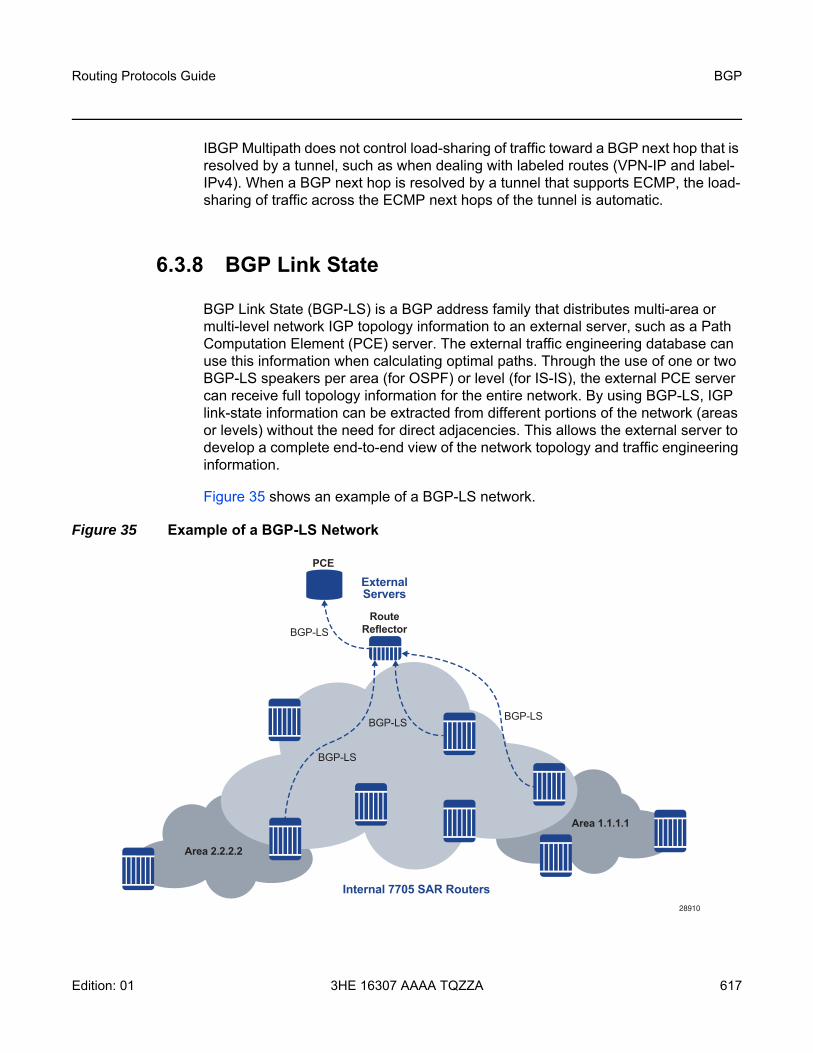
Routing Protocols Guide BGP
Edition: 01 3HE 16307 AAAA TQZZA 617
IBGP Multipath does not control load-sharing of traffic toward a BGP next hop that is resolved by a tunnel, such as when dealing with labeled routes (VPN-IP and label-IPv4). When a BGP next hop is resolved by a tunnel that supports ECMP, the load-sharing of traffic across the ECMP next hops of the tunnel is automatic.
6.3.8 BGP Link State
BGP Link State (BGP-LS) is a BGP address family that distributes multi-area or multi-level network IGP topology information to an external server, such as a Path Computation Element (PCE) server. The external traffic engineering database can use this information when calculating optimal paths. Through the use of one or two BGP-LS speakers per area (for OSPF) or level (for IS-IS), the external PCE server can receive full topology information for the entire network. By using BGP-LS, IGP link-state information can be extracted from different portions of the network (areas or levels) without the need for direct adjacencies. This allows the external server to develop a complete end-to-end view of the network topology and traffic engineering information.
Figure 35 shows an example of a BGP-LS network.
Figure 35 Example of a BGP-LS Network
28910
BGP-LS
Area 2.2.2.2
Area 1.1.1.1
PCE
ExternalServers
Internal 7705 SAR Routers
RouteReflector
BGP-LS
BGP-LS
BGP-LS

BGP
618
Routing Protocols Guide
3HE 16307 AAAA TQZZA Edition: 01
6.3.8.1 Supported BGP-LS Components
The following BGP-LS components are supported.
Protocol-ID:
• IS-IS Level 1• IS-IS Level 2• OSPFv2
NLRI types:
• Node• Link• IPv4 Prefix
Node Descriptor TLVs:
• 512 — Autonomous System • 513 — BGP-LS Identifier• 514 — OSPF Area-ID• 515 — IGP Router-ID
Node Attribute TLVs:
• 1024 — Node Flag Bits (O and B bits supported)• 1028 — IPv4 Router-ID of Local Node (IS-IS only)• Segment Routing:
- 1034 — SR Capabilities (IS-IS only)- 1035 — SR Algorithm (IS-IS only)
Link Descriptor TLVs:
• 258 — Link Local/Remote Identifiers• 259 — IPv4 interface address• 260 — IPv4 neighbor address
Link Attribute TLVs:
• 1028 — IPv4 Router-ID of Local Node (IS-IS only)• 1088 — Administrative group (color) • 1089 — Maximum link bandwidth

Routing Protocols Guide BGP
Edition: 01 3HE 16307 AAAA TQZZA 619
• 1090 — Maximum reservable link bandwidth• 1091 — Unreserved bandwidth• 1092 — TE Default Metric• 1095 — IGP Metric• 1096 — Shared Risk Link Group• Segment Routing:
- 1099 — Adjacency Segment Identifier- 1100 — LAN Adjacency Segment Identifier
Prefix Descriptor TLVs:
• 264 — OSPF Route Type (Intra-Area and Inter-Area only)• 265 — IP Reachability Information
Prefix Attribute TLVs:
• 1152 — IGP Flags (D flag only)• 1155 — Prefix Metric • Segment Routing:
- 1158 — Prefix SID- 1159 — Range (prefix-SID and sub-TLV only)- 1170 — Prefix Attribute Flags (OSPF only)

BGP
620
Routing Protocols Guide
3HE 16307 AAAA TQZZA Edition: 01
6.4 Command Interactions and Dependencies
This section highlights the BGP command interactions and dependencies that are important for configuration or operational maintenance of 7705 SAR routers. Topics covered in this section are:
• Changing the Autonomous System Number • Changing the Local AS Number • Changing the Router ID at the Configuration Level • Hold Time and Keepalive Timer Dependencies • Import and Export Route Policies • AS Override • TCP MD5 Authentication• TTL Security• Advertise-Inactive• Advertise-Inactive, Add-Paths, and Export Policy Interaction
This information can be found in the BGP Command Reference, which provides detailed descriptions of the configuration commands.
6.4.1 Changing the Autonomous System Number
If the AS number is changed on a router with an active BGP instance, the new AS number will not be used until the BGP instance is restarted either by administratively disabling or enabling the BGP instance or by rebooting the system with the new configuration.
Note: The 7705 SAR supports 4-byte AS numbers, as defined in RFC 4893, BGP Support for Four-octet AS Number Space. This allows up to 4 294 967 295 unique AS numbers.
Routing Protocols Guide BGP
Edition: 01 3HE 16307 AAAA TQZZA 621
6.4.2 Changing the Local AS Number
Changing the local AS of an active BGP instance:
• at the global level — causes the BGP instance to restart with the new local AS number
• at the group level — causes BGP to re-establish the peer relationships with all peers in the group with the new local AS number
• at the neighbor level — causes BGP to re-establish the peer relationship with the new local AS number
6.4.3 Changing the Router ID at the Configuration Level
If you configure a new router ID in the config>router-id context, protocols are not automatically restarted with the new router ID. The next time a protocol is initialized or reinitialized, the new router ID is used. An interim period of time can occur when different protocols use different router IDs.
6.4.4 Hold Time and Keepalive Timer Dependencies
The BGP hold time specifies the maximum time BGP will wait between successive messages (either Keepalive or Update) from its peer, before closing the connection. This configuration parameter can be set at three levels. The most specific value is used:
• global level — applies to all peers• group level — applies to all peers in the group• neighbor level — only applies to the specified peer
Although the keepalive time can be user-specified, the configured keepalive timer is overridden by the value of hold time under the following circumstances.
• If the hold time specified is less than the configured keepalive time, then the operational keepalive time is set to one third of the specified hold time; the configured keepalive time is unchanged.
• If the hold time is set to zero, then the operational value of the keepalive time is set to zero; the configured keepalive time is unchanged. This means that the connection with the peer will be up permanently and no keepalive packets are sent to the peer.

BGP
622
Routing Protocols Guide
3HE 16307 AAAA TQZZA Edition: 01
If the hold time or keepalive values are changed, the changed timer values take effect when the new peering relationship is established. Changing the values causes the peerings to restart. The changed timer values are used when renegotiating the peer relationship.
6.4.5 Import and Export Route Policies
Import and export route policy statements are specified for BGP at the global, group, and neighbor level. Up to five unique policy statement names can be specified in the command line per level. The most specific command is applied to the peer. Defining the policy statement name is not required before being applied. Policy statements are evaluated in the order in which they are specified within the command context until the first matching policy statement is found.
The import and export policies configured at different levels are not cumulative. The most specific value is used. An import or export policy command specified at the neighbor level takes precedence over the same command specified at the group or global level. An import or export policy command specified at the group level takes precedence over the same command specified at the global level.
6.4.6 AS Override
BGP-4 Explicit AS Override simplifies the use of the same AS number (ASN) across multiple RFC 2547 VPRN sites.
The Explicit AS Override feature can be used in VPRN scenarios where a customer is running BGP as the PE-CE protocol and some or all of the CE locations are in the same Autonomous System (AS). Without this feature, two sites in the same AS would not be able to reach each other directly since there is an apparent loop in the AS path.
With AS Override enabled on an EBGP session on a PE node, the service provider network can rewrite the AS path — overriding the customer ASN with its own ASN — as routes are advertised to other sites within the same VPRN.

Routing Protocols Guide BGP
Edition: 01 3HE 16307 AAAA TQZZA 623
6.4.7 TCP MD5 Authentication
The operation of a network can be compromised if an unauthorized system is able to form or hijack a BGP session and inject control packets by falsely representing itself as a valid neighbor. This risk can be mitigated by enabling TCP MD5 authentication on one or more of the sessions. When TCP MD5 authentication is enabled on a session, every TCP segment exchanged with the peer includes a TCP option (19) containing a 16-byte MD5 digest of the segment (more specifically the TCP/IP pseudo-header, TCP header, and TCP data). The MD5 digest is generated and validated using an authentication key that must be known to both sides. If the received digest value is different from the locally computed one, the TCP segment is dropped, thereby protecting the router from a spoofed TCP segment.
The TCP Enhanced Authentication Option, as specified in draft-bonica-tcpauth-05.txt, Authentication for TCP-based Routing and Management Protocols, is a TCP extension that enhances security for BGP, LDP, and other TCP-based protocols. It extends the MD5 authentication option to include the ability to change keys in a BGP or LDP session seamlessly without tearing down the session, and allows for stronger authentication algorithms to be used. It is intended for applications where secure administrative access to both endpoints of the TCP connection is normally available.
TCP peers can use this extension to authenticate messages passed between one another. This strategy improves upon the practice described in RFC 2385, Protection of BGP Sessions via the TCP MD5 Signature Option. Using this new strategy, TCP peers can update authentication keys during the lifetime of a TCP connection. TCP peers can also use stronger authentication algorithms to authenticate routing messages.
TCP enhanced authentication uses keychains that are associated with every protected TCP connection.
Keychains are configured in the config>system>security>keychain context. For more information about configuring keychains, refer to the 7705 SAR System Management Guide, “TCP Enhanced Authentication and Keychain Authentication”.

BGP
624
Routing Protocols Guide
3HE 16307 AAAA TQZZA Edition: 01
6.4.8 TTL Security
TTL security provides protection for EBGP peering sessions against CPU utilization-based attacks such as denial of service (DoS) attacks. This feature is supported for directly connected peering sessions and for multihop EBGP peering sessions. The BGP session can be over router interfaces, over spoke-SDP terminated VPRN interfaces, SAP interfaces, and loopback interfaces, and over IPSec interface tunnels.
TTL security is most important for EBGP PE-CE sessions because CE devices can be multiple hops away, which adds a higher level of risk. TTL security provides a mechanism to better ensure the validity of BGP sessions from the CE device.
TTL security is configured at the group or neighbor level. The ttl-security command sets the minimum TTL that will be accepted in a BGP peering session and checks the TTL of the packets received. For multihop peering sessions, the multihop command sets the TTL in the IP header of egress BGP packets sent to a terminating peer that is several hops away.
When TTL security is configured, the network processor must inspect BGP packets. The value in the TTL field of received IP packets is compared with the TTL security value that is configured locally for each EBGP peering session. If the value in the TTL field of the incoming IP packet is greater than or equal to the configured minimum TTL value, the IP packet is accepted and processed normally. If the TTL value is less than the configured value, the packet is discarded.
6.4.9 Advertise-Inactive
BGP does not allow a route to be advertised unless it is the best path in the RIB and an export policy allows the advertisement.
In some cases, it may be useful to advertise the best BGP path to peers despite the fact that it is inactive; for example, if there are one or more lower-preference non-BGP routes to the same destination and one of these other routes is the active route. This flexibility is supported using the advertise-inactive and add-path commands.
As a global BGP configuration option, the advertise-inactive command applies to all IPv4, IPv6, and label-IPv4 routes and all sessions that advertise these routes. If the command is configured and the best BGP path is inactive, it is automatically advertised to every peer unless rejected by a BGP export policy.

Routing Protocols Guide BGP
Edition: 01 3HE 16307 AAAA TQZZA 625
6.4.10 Advertise-Inactive, Add-Paths, and Export Policy Interaction
This section describes the interaction between the BGP advertise-inactive, add-paths, and export policy commands. The 7705 SAR allows the policy-based export of an active and installed route to a peer when the local router has BGP advertise-inactive enabled in its configuration.
Prior to Release 7.0 of the 7705 SAR, when there are multiple routes to a prefix and a non-BGP route is in the routing table, there could be many inactive BGP routes selected by BGP as the best routes as part of the route selection criteria. For example, assume route A is an active non-BGP route and there are a number (n) of BGP routes (routes B1, B2, B3, ..., up to Bn), where the order of preference is determined by the BGP best-path selection algorithm (see BGP Decision Process). Then the following cases arise.
• When advertise-inactive is enabled, add-paths is disabled, and there is a BGP export policy that accepts route A, then the route advertised to the peer is always B1 and route A is not advertised.
• When advertise-inactive is enabled, add-paths is enabled, and there is a BGP export policy that accepts route A, then the routes advertised to the peer are always B1, B2, B3, ... , up to the add-paths send-limit, and route A is not advertised.
In Release 7.0 and later, the following behavior for advertise-inactive occurs when an active, non-BGP route (route A) exists in the routing table and is accepted by the configured BGP export policy.
• If the add-paths send-limit is set to n paths, then BGP advertises n paths that are accepted by the export policy and have diverse next hops, whether advertise-inactive is enabled or disabled.For example, if n=3, then routes A, B1, and B2 are advertised (route A is counted as one of the paths), as long as route A is accepted by the export policy. Otherwise, routes B1, B2 and B3 are advertised.
• If add-paths is disabled and advertise-inactive is enabled, then BGP advertises one active non-BGP route if the route is accepted by the export policy. Otherwise, BGP advertises the best BGP route that is accepted by the policy.For example, BGP advertises either route A or route B1, depending on the export policy.

BGP
626
Routing Protocols Guide
3HE 16307 AAAA TQZZA Edition: 01
6.5 BGP Configuration Process Overview
Figure 36 displays the process to provision basic BGP parameters.
Figure 36 BGP Configuration and Implementation Flow
CONFIGURE GLOBAL ROUTER PARAMETERS
CONFIGURE BGP GROUP PARAMETERS - CONFIGURE ROUTER ID- ASSIGN AUTONOMOUS SYSTEM NUMBER
CONFIGURE BGP NEIGHBOR PARAMETERS
ENABLE
START
21827

Routing Protocols Guide BGP
Edition: 01 3HE 16307 AAAA TQZZA 627
6.6 Configuration Notes
This section describes BGP configuration guidelines and caveats.
6.6.1 General
• Before BGP can be configured, the router ID (a valid host address, not the MAC address default) and autonomous system global parameters must be configured.
• BGP instances must be explicitly created on each BGP peer. There are no default BGP instances on a 7705 SAR.
6.6.2 BGP Defaults
The following list summarizes the BGP configuration defaults.
• By default, the 7705 SAR is not assigned to an AS.• A BGP instance is created in the administratively enabled state.• A BGP group is created in the administratively enabled state.• A BGP neighbor is created in the administratively enabled state.• No BGP router ID is specified. If no BGP router ID is specified, BGP uses the
router system interface address.• The 7705 SAR BGP timer defaults are the values recommended in IETF drafts
and RFCs (see BGP MIB Notes).• If no import route policy statements are specified, then all BGP routes are
accepted.• If no export route policy statements specified, then all BGP routes are advertised
and non-BGP routes are not advertised.

BGP
628
Routing Protocols Guide
3HE 16307 AAAA TQZZA Edition: 01
6.6.3 BGP MIB Notes
The 7705 SAR implementation of the RFC 1657 MIB variables listed in Table 78 differs from the IETF MIB specification.
If SNMP is used to set a value of X to the MIB variable in Table 79, there are three possible results:
When the value set using SNMP is within the IETF allowed values and outside the 7705 SAR values as specified in Table 78 and Table 79, a log message is generated. The log messages that display are similar to the following log messages.
Table 78 7705 SAR and IETF MIB Variations
MIB Variable Description RFC 1657 Allowed Values
7705 SAR Allowed Values
bgpPeerMinASOrig-intionInterval
Time interval in seconds for the MinASOriginationInterval timer. The suggested value for this timer is 15 s.
1 to 65535 2 to 255
bgpPeerMinRouteAd-vertisementInterval
Time interval in seconds for the MinRouteAdvertisementInterval timer. The suggested value for this timer is 30 s.
1 to 65535 2 to 255
Table 79 MIB Variable with SNMP
Condition Result
X is within IETF MIB values andX is within 7705 SAR values
SNMP set operation does not return an error MIB variable set to X
X is within IETF MIB values andX is outside 7705 SAR values
SNMP set operation does not return an error MIB variable set to “nearest” 7705 SAR supported value (for example, 7705 SAR range is 2 to 255 and X = 65535, MIB variable will be set to 255)Log message generated
X is outside IETF MIB valuesandX is outside 7705 SAR values
SNMP set operation returns an error

Routing Protocols Guide BGP
Edition: 01 3HE 16307 AAAA TQZZA 629
Log Message for setting bgpPeerMinASOriginationInterval to 65535
576 2006/11/12 19:45:48 [Snmpd] BGP-4-bgpVariableRangeViolation: Trying to set bgpPeerMinASOrigInt to 65535 - valid range is [2-255] - setting to 255:
Log Message for setting bgpPeerMinASOriginationInterval to 1
594 2006/11/12 19:48:05 [Snmpd] BGP-4-bgpVariableRangeViolation: Trying to set bgpPeerMinASOrigInt to 1 - valid range is [2-255] - setting to 2:
Log Message for setting bgpPeerMinRouteAdvertisementInterval to 256
535 2006/11/12 19:40:53 [Snmpd] BGP-4-bgpVariableRangeViolation: Trying to set bgpPeerMinRouteAdvInt to 256 - valid range is [2-255] - setting to 255:
Log Message for setting bgpPeerMinRouteAdvertisementInterval to 1
566 2006/11/12 19:44:41 [Snmpd] BGP-4-bgpVariableRangeViolation: Trying to set bgpPeerMinRouteAdvInt to 1 - valid range is [2-255] - setting to 2

BGP
630
Routing Protocols Guide
3HE 16307 AAAA TQZZA Edition: 01
Routing Protocols Guide BGP
Edition: 01 3HE 16307 AAAA TQZZA 631
6.7 Configuring BGP with CLI
This section provides information to configure BGP using the command line interface.
Topics in this section include:
• BGP Configuration Overview• Basic BGP Configuration• Common Configuration Tasks• BGP Components• BGP Configuration Management Tasks

BGP
632
Routing Protocols Guide
3HE 16307 AAAA TQZZA Edition: 01
6.8 BGP Configuration Overview
6.8.1 Preconfiguration Requirements
Before BGP can be implemented, the following entities must be configured:
• the autonomous system (AS) number for the routerAn AS number is a globally unique value that associates a router with a specific autonomous system. This number is used to exchange exterior routing information with neighboring ASs and as an identifier of the AS itself. Each router participating in BGP must have an AS number specified.In order to implement BGP, the AS number must be specified in the config>router context.
• the router IDThe router ID is the IP address of the local router. The router ID identifies a packet’s origin. The router ID must be a valid host address.
6.8.2 BGP Hierarchy
BGP is configured in the config>router>bgp context. Three hierarchical levels are included in BGP configurations:
• global level• group level• neighbor level
Commands and parameters configured at the global level are inherited by the group and neighbor levels, although parameters configured at the group and neighbor levels take precedence over global configurations.

Routing Protocols Guide BGP
Edition: 01 3HE 16307 AAAA TQZZA 633
6.8.3 Internal and External BGP Configurations
A BGP domain is composed of ASs that share network reachability information. Network reachability information is shared throughout the BGP domain by BGP speakers. BGP speakers can belong to the same or different AS. BGP supports two types of routing information exchanges.
• Internal BGP (IBGP) is used within an AS. An IBGP speaker peers to the same AS and typically does not share a subnet. Neighbors (peers) do not have to be directly connected to each other. Since IBGP neighbors are not required to be directly connected, IBGP uses the IGP path (the IP next hop learned from the IGP) to reach an IBGP neighbor for its peering connection.The 7705 SAR supports IBGP — for MP-BGP purposes — only within the router context.
• External BGP (EBGP) is used between ASs. EBGP speakers peer to different ASs and typically share a subnet. In an external group, the next hop is dependent upon the interface shared between the external peer and the local one. The multihop command must be specified if an EBGP peer is more than one hop away from the local router. The next hop to the peer must be configured so that the two EBGP speakers can establish a BGP session.The 7705 SAR supports EBGP within the router context and VPRN context. For information on configuring EBGP within the VPRN context, refer to the 7705 SAR Services Guide, “VPRN Services”.
6.8.4 BGP Route Reflectors
In a standard BGP configuration, all BGP speakers within an AS must have a full BGP mesh to ensure that all externally learned routes are redistributed through the entire AS. IBGP speakers do not readvertise routes learned from one IBGP peer to another IBGP peer. If a network grows, scaling issues could emerge because of the full mesh configuration requirement. Route reflection circumvents the full mesh requirement but still maintains the full distribution of external routing information within an AS.
Autonomous systems using route reflection arrange BGP routers into groups called clusters. Each cluster contains at least one route reflector that is responsible for redistributing route updates to all clients. Route reflector clients do not need to maintain a full peering mesh between each other. They only require a peering to the route reflectors in their cluster. The route reflectors must maintain a full peering mesh between all non-clients within the AS.

BGP
634
Routing Protocols Guide
3HE 16307 AAAA TQZZA Edition: 01
Each route reflector must be assigned a cluster ID and specify which neighbors are clients and which are non-clients to determine which neighbors should receive reflected routes and which should be treated as a standard IBGP peer. Additional configuration is not required for the route reflector except for the typical BGP neighbor parameters.
Figure 37 illustrates an autonomous system with clusters.
Figure 37 Route Reflection Network Diagram Example
The following configuration example shows the minimum BGP configuration for routers in Cluster 1.1.1.1, shown in Figure 37.
ALU-Aconfig router bgp
group cluster1peer-as 100cluster 1.1.1.1neighbor 10.2.2.2exitneighbor 10.3.3.3exitneighbor 10.4.4.4exit
exitgroup RRs
peer-as 100neighbor 10.5.5.5exitneighbor 10.9.9.9exit
exit
20956
Cluster 2.2.2.2
AS100
Cluster 1.1.1.1
Router 110.9.9.9
Router A10.1.1.1
Router B10.2.2.2
Router C10.3.3.3
Router C10.4.4.4
Router E10.5.5.5
Router F10.6.6.6
Router G10.7.7.7
Router H10.8.8.8

Routing Protocols Guide BGP
Edition: 01 3HE 16307 AAAA TQZZA 635
exitALU-B
config router bgpgroup cluster1
peer-as 100neighbor 10.1.1.1exit
exitexit
ALU-Cconfig router bgp
group cluster1peer-as 100neighbor 10.1.1.1exit
exitexit
ALU-Dconfig router bgp
group cluster1peer-as 100neighbor 10.1.1.1exit
exitexit

BGP
636
Routing Protocols Guide
3HE 16307 AAAA TQZZA Edition: 01
6.9 Basic BGP Configuration
This section provides information to configure BGP and configuration examples of common configuration tasks. The minimum BGP parameters that must be configured are:
• an autonomous system number for the router• a router ID• a BGP peer group• a BGP neighbor with which to peer• a BGP peer-AS that is associated with the above peer
The BGP configuration commands have three primary configuration levels:
• global configuration (config>router>bgp)• BGP group configuration (config>router>bgp>group)• BGP neighbor configuration (config>router>bgp>group>neighbor)
Within the three levels, many of the configuration commands are repeated. For the repeated commands, the command that is most specific to the neighboring router is in effect; that is, neighbor settings have precedence over group settings, which have precedence over BGP global settings.
The following is an example of a configuration that includes the parameters in the list above. The other parameters shown below are optional:
info#--------------------------------------------------echo "IP Configuration"#--------------------------------------------------...
autonomous-system 200router-id 10.10.10.103
#--------------------------------------------------...#--------------------------------------------------echo "BGP Configuration"#--------------------------------------------------
bgpgraceful-restartexitcluster 0.0.0.100
Note: If a new or different router ID value is entered in the BGP context, the new value takes precedence and overwrites the router-level router ID.

Routing Protocols Guide BGP
Edition: 01 3HE 16307 AAAA TQZZA 637
dampingexport "direct2bgp"router-id 10.0.0.12group "Group1"
connect-retry 20dampinghold-time 90keepalive 30local-preference 100multihop 3remove-privatepeer-as 200ttl-security 10neighbor 10.0.0.8
connect-retry 20dampinghold-time 90keepalive 30local-address 10.0.0.12multihop 3passivepreference 99peer-as 200ttl-security 10
exitexitgroup "Group2"
connect-retry 20dampinghold-time 90keepalive 30local-preference 100remove-privatepeer-as 200neighbor 10.0.3.10
description "To_Router C - IBGP Peer"connect-retry 20dampinghold-time 90keepalive 30peer-as 200
exitexitgroup "Group3"
connect-retry 20dampinghold-time 30keepalive 30local-preference 100peer-as 200neighbor 10.0.0.15
description "To_Router E - IBGP Peer"connect-retry 20dampinghold-time 90keepalive 30local-address 10.0.0.12peer-as 200
exit

BGP
638
Routing Protocols Guide
3HE 16307 AAAA TQZZA Edition: 01
6.10 Common Configuration Tasks
This section provides a brief overview of the tasks that must be performed to configure BGP and provides the CLI commands. In order to enable BGP, one AS must be configured and at least one group must be configured that includes neighbor (system or IP address) and peering information (AS number).
BGP is configured hierarchically; the global level applies to all peers, the group level applies to all peers in a group, and the neighbor level only applies to a specified peer. By default, group members inherit the group’s configuration parameters, although a parameter can be modified on a per-member basis without affecting the group-level parameters.
Many of the hierarchical BGP commands can be used at different levels. The most specific value is used. That is, a BGP group-specific command takes precedence over a global BGP command. A neighbor-specific command takes precedence over a global BGP or group-specific command.
All BGP instances must be explicitly created on each 7705 SAR. Once created, BGP is administratively enabled.
Configuration planning is essential to organize ASs and the 7705 SARs within the ASs, and to determine the internal and external BGP peering. To configure a basic autonomous system, perform the following tasks.
1. Prepare a plan detailing the autonomous systems, the 7705 SAR belonging to each group, group names, and peering connections.
2. Associate each 7705 SAR with an autonomous system number.3. Configure each 7705 SAR with a router ID.4. Associate each 7705 SAR with a peer group name.5. Specify the local IP address that will be used by the group or neighbor when
communicating with BGP peers.6. Specify neighbors.7. Specify the autonomous system number associated with each neighbor.

Routing Protocols Guide BGP
Edition: 01 3HE 16307 AAAA TQZZA 639
6.10.1 Creating an Autonomous System
Before BGP can be configured, the autonomous system must be configured. In BGP, routing reachability information is exchanged between autonomous systems (ASs). An AS is a group of networks that share routing information. The autonomous-system command associates an autonomous system number with the 7705 SAR being configured. A 7705 SAR can only belong to one AS. The autonomous-system command is configured in the config>router context.
Use the following CLI syntax to associate a 7705 SAR with an autonomous system:
CLI Syntax: config>router# autonomous-system as-number
The following example displays autonomous system configuration command usage:
Example: config>router# autonomous-system 100
The following example displays the autonomous system configuration:
ALU-B>config>router# info#------------------------------------------# IP Configuration#------------------------------------------
interface "system"address 10.10.10.104/8
exitinterface "to-103"
address 10.0.0.104/8port 1/1/1
exitautonomous-system 100
#------------------------------------------ALU-B>config>router#
6.10.2 Configuring a Router ID
In BGP, routing information is exchanged between autonomous systems. The BGP router ID, expressed as an IP address, uniquely identifies the router. It can be set to be the same as the loopback address.
Note: The 7705 SAR supports 4-byte AS numbers, as defined in RFC 4893, BGP Support for Four-octet AS Number Space. This allows up to 4 294 967 295 unique AS numbers.

BGP
640
Routing Protocols Guide
3HE 16307 AAAA TQZZA Edition: 01
If a new or different router ID value is entered in the BGP context, the new router ID value is used instead of the router ID configured on the router level, system interface level, or inherited from the MAC address. The router-level router ID value remains intact.
A router ID can be derived by:
• defining the value in the config>router context, using the router-id command• defining the system interface in the config>router>interface ip-int-name
context• inheriting the last four bytes of the MAC address• defining the value within the BGP protocol level. The router ID can be defined in
the config>router>bgp context, using the router-id command, and is only used within BGP.
When configuring a new router ID, protocols are not automatically restarted with the new router ID. The next time a protocol is initialized or reinitialized, the new router ID is used. An interim period of time can occur when different protocols use different router IDs. To force the new router ID, issue the shutdown and no shutdown commands for each protocol that uses the router ID or restart the entire router.
Use the following CLI syntax to configure the router ID:
CLI Syntax: config>router# router-id ip-address
The following example displays router ID configuration command usage:
Example: config>router# router-id 10.10.10.104
The following example displays the router ID configuration:
ALU-B>config>router# info----------------------------------------------# IP Configuration#------------------------------------------
interface "system"address 10.10.10.104/8
exitinterface "to-103"
address 10.0.0.104/8port 1/1/1
exitautonomous-system 100router-id 10.10.10.104
#------------------------------------------ALU-B>config>router#

Routing Protocols Guide BGP
Edition: 01 3HE 16307 AAAA TQZZA 641
6.11 BGP Components
This section describes how to configure the following BGP attributes:
• Configuring BGP• Configuring Group Attributes • Configuring Neighbor Attributes • Configuring BGP Address Families • Configuring Route Reflection • Configuring a BGP Peer Group with Dynamic Neighbors
6.11.1 Configuring BGP
Once the BGP protocol instance is created, the no shutdown command is not required since BGP is administratively enabled upon creation. Minimally, to enable BGP on a router, you must associate an autonomous system number for the router, have a preconfigured router ID or system interface, create a peer group, neighbor, and associate a peer AS number. There are no default groups or neighbors. Each group and neighbor must be explicitly configured.
All parameters configured for BGP are applied to the group and are inherited by each peer, but a group parameter can be overridden on a specific basis. BGP command hierarchy consists of three levels:
• the global level • the group level • the neighbor level
For example:
CLI Syntax: config>router# bgp (global level)group (group level)
neighbor (neighbor level)
Note: Careful planning is essential to implement commands that can affect the behavior of global, group, and neighbor levels. Because the BGP commands are hierarchical, analyze the values that can disable features on a particular level.

BGP
642
Routing Protocols Guide
3HE 16307 AAAA TQZZA Edition: 01
The following example displays the basic BGP configuration:
ALU-B>config>router# info#------------------------------------------# BGP Configuration#------------------------------------------# BGP#------------------------------------------
bgpexit
#------------------------------------------ALU-B>config>router#
6.11.2 Configuring Group Attributes
A group is a collection of related BGP peers. The group name should be a descriptive name for the group. Follow your group naming and ID naming conventions for consistency and to help when troubleshooting faults. All parameters configured for a peer group are applied to the group and are inherited by each peer (neighbor), but a group parameter can be overridden on a specific neighbor-level basis. To configure BGP dynamic peers, see Configuring a BGP Peer Group with Dynamic Neighbors.
The following example displays group configuration command usage:
Example: config>router# bgpconfig>router>bgp# group headquarters1config>router>bgp>group# description “HQ execs”config>router>bgp>group# multihop 3config>router>bgp>group# med-out 100config>router>bgp>group# ttl-security 10config>router>bgp>group# local-address 10.0.0.104config>router>bgp>group# disable-communities standardconfig>router>bgp>group# exit
The following example displays the BGP group configuration:
ALU-B>config>router>bgp# info----------------------------------------------...
group "headquarters1"description "HQ execs"multihop 3med-out 100local-address 10.0.0.104disable-communities standardttl-security 10exit
exit...----------------------------------------------

Routing Protocols Guide BGP
Edition: 01 3HE 16307 AAAA TQZZA 643
6.11.3 Configuring Neighbor Attributes
After you create a group name and assign options, add neighbors within the same autonomous system to create IBGP connections. All parameters configured for the peer group level are applied to each neighbor, but a group parameter can be overridden on a specific neighbor basis.
The following example displays neighbor configuration command usage:
Example: config>router# bgpconfig>router>bgp# group headquarters1config>router>bgp>group# neighbor 10.0.0.5config>router>bgp>group# multihop 3config>router>bgp>group# peer-as 100 config>router>bgp>group# passiveconfig>router>bgp>group# ttl-security 10config>router>bgp>group# exitconfig>router>bgp>group# neighbor 10.10.10.6config>router>bgp>group# multihop 255config>router>bgp>group# med-out 100config>router>bgp>group# peer-as 100 config>router>bgp>group# exitconfig>router>bgp>group# neighbor 10.10.10.7config>router>bgp>group>neighbor$ hold-time 90config>router>bgp>group>neighbor$ keepalive 30config>router>bgp>group>neighbor$ local-preference 170config>router>bgp>group# multihop 255config>router>bgp>group# med-out 100config>router>bgp>group>neighbor$ peer-as 100 config>router>bgp>group>neighbor$ exitconfig>router>bgp>group# neighbor 10.10.10.8config>router>bgp>group>neighbor$ hold-time 90config>router>bgp>group>neighbor$ keepalive 30config>router>bgp>group>neighbor$ local-preference 100config>router>bgp>group>neighbor$ min-route-advertisement 30
config>router>bgp>group>neighbor$ preference 170config>router>bgp>group# multihop 255config>router>bgp>group# med-out 100config>router>bgp>group>neighbor$ peer-as 100 config>router>bgp>group>neighbor$ exitconfig>router>bgp>group# exit

BGP
644
Routing Protocols Guide
3HE 16307 AAAA TQZZA Edition: 01
The following example displays neighbors configured in group “headquarters1”.
ALU-B>config>router>bgp# info----------------------------------------------...
group "headquarters1"description "HQ execs"local-address 10.0.0.104disable-communities standard extendedneighbor 10.0.0.5
multihop 3med-out 100peer-as 100passivettl-security 10
exitneighbor 10.0.0.106
peer-as 100exitneighbor 10.0.0.107
hold-time 90keepalive 30local-preference 170multihop 255med-out 100peer-as 100
exitneighbor 10.0.0.220
hold-time 90keepalive 30min-as-origination 15local-preference 100preference 170multihop 255med-out 100peer-as 100
exitexit
...----------------------------------------------ALU-B>config>router>bgp#
6.11.4 Configuring BGP Address Families
Routers advertise their BGP capabilities during session setup. The 7705 SAR supports several address families. One or more address families can be specified in a single command. To add an address family to the currently configured families, re-issue the command by including the current families in addition to any new family.

Routing Protocols Guide BGP
Edition: 01 3HE 16307 AAAA TQZZA 645
Use the following CLI syntax to configure BGP IPv6 parameters:
CLI Syntax: config>router router-namebgp
family [ipv4] [vpn-ipv4] [vpn-ipv6] [mvpn-ipv4] [route-target]
group namefamily [ipv4] [vpn-ipv4] [vpn-ipv6] [mvpn-
ipv4] [route-target] neighbor ip-address
family [ipv4] [vpn-ipv4] [vpn-ipv6] [mvpn-ipv4] [route-target]
In the display example below, the mvpn-ipv4 address family is added to the BGP group to communicate auto-discovery routes and C-multicast signaling.
#--------------------------------------------------echo "BGP Configuration"#--------------------------------------------------
bgpgroup "MVPN-BGP"
family ipv4 vpn-ipv4 mvpn-ipv4peer-as 65000neighbor 10.10.10.125exitneighbor 10.10.10.127exit
exitno shutdown
exit#--------------------------------------------------
6.11.5 Configuring Route Reflection
Route reflection can be implemented in autonomous systems with a large internal BGP mesh to reduce the number of IBGP sessions required. One or more routers can be selected to act as focal points for internal BGP sessions. Several BGP speaking routers can peer with a route reflector. A route reflector forms peer connections to other route reflectors. A router assumes the role as a route reflector by configuring the cluster cluster-id command. No other command is required unless you want to disable reflection to specific peers.
If you configure the cluster command at the global level, then all subordinate groups and neighbors are members of the cluster. The route reflector cluster ID is expressed in dotted- decimal notation. The ID should be a significant topology-specific value. No other command is required unless you want to disable reflection to specific peers.

BGP
646
Routing Protocols Guide
3HE 16307 AAAA TQZZA Edition: 01
If a route reflector client is fully meshed, the disable-client-reflect command can be enabled to stop the route reflector from reflecting redundant route updates to a client.
The following example displays route reflection configuration command usage:
Example: config>router# bgpconfig>router>bgp# cluster 0.0.0.100config>router>bgp# group “Santa Clara”config>router>bgp>group$ local-address 10.0.0.103config>router>bgp>group# neighbor 10.0.0.91config>router>bgp>group>neighbor$ peer-as 100config>router>bgp>group>neighbor# exitconfig>router>bgp>group# neighbor 10.0.0.92config>router>bgp>group>neighbor$ peer-as 100config>router>bgp>group>neighbor# exitconfig>router>bgp>group# neighbor 10.0.0.93config>router>bgp>group>neighbor$ disable-client-reflconfig>router>bgp>group>neighbor# peer-as 100config>router>bgp>group>neighbor# exit
The following example displays a route reflection configuration:
ALU-B>config>router>bgp# info---------------------------------------------
cluster 0.0.0.100group "Santa Clara"
local-address 10.0.0.103neighbor 10.0.0.91
peer-as 100exitneighbor 10.0.0.92
peer-as 100exitneighbor 10.0.0.93
disable-client-reflectpeer-as 100
exitexit
---------------------------------------------ALU-B>config>router>bgp#

Routing Protocols Guide BGP
Edition: 01 3HE 16307 AAAA TQZZA 647
6.11.6 Configuring a BGP Peer Group with Dynamic Neighbors
The dynamic-neighbor command allows any router within the configured IP prefix range to establish BGP peering sessions with other routers in the prefix range without any manual intervention.
A BGP neighbor session is considered dynamic if its setup is triggered by an incoming TCP connection that does not match the IP address of any static (configured) neighbor. A dynamic BGP session is always associated with one BGP group, as is the case for statically configured peers.
For a base router BGP group to have dynamic sessions, one or more prefix command entries must be added under the config>router>bgp>group>dynamic-neighbor context. There is no limit on the number of prefix entries per group or overall.
The CLI blocks completely overlapping prefix entries in the same routing instance (that is, entries with the same address and same prefix length). Partially overlapping entries are allowed; for example, 10.0.0.0/8 and 10.10.0.0/16.
For a dynamic session to come up, its source IP address must match at least one prefix entry. The dynamic session is associated with the entry—and consequently, the group—having the longest prefix match for the IP address. When a dynamic session has been set up, changes to the neighbor may occur and are handled as follows:
• when a prefix already exists in a group and a new longer prefix entry is added to the same group, and if the session that already exists still matches on the newly prefix match, the session remains established and is not taken down
• when a prefix already exists in a group and a new longer prefix entry is added to a different group, and if the session that already exists now matches on the newly added prefix in the different group, the session is taken down in order to apply the new group parameters to the new session when it gets established
• when a new static neighbor is configured using the neighbor command in any group and the neighbor IP address matches the source IP address of the existing dynamic neighbor, the dynamic neighbor session is taken down and a new session is established using the configured parameters of the static neighbor
Static sessions always take precedence regardless of any longest-prefix match with a dynamic neighbor prefix entry.

BGP
648
Routing Protocols Guide
3HE 16307 AAAA TQZZA Edition: 01
The number of dynamic BGP peers can be limited at the BGP global and BGP group levels using the dynamic-neighbor-limit command, which limits the number of dynamic sessions allowed by the router and the group, respectively. If an incoming connection for a new dynamic session exceeds the BGP global or BGP group limit, the connection attempt is rejected and a notification message is issued.
The following example displays the dynamic-neighbor command usage:
Example: config>router# bgpconfig>router>bgp# group “dynamic”config>router>bgp>group# peer-as 100config>router>bgp>group# dynamic-neighbor config>router>bgp>group>dynamic-neighbor$ prefix 10.100.0.0/16
config>router>bgp>group>dynamic-neighbor# exitconfig>router>bgp>group# dynamic-neighbor-limit 75 config>router>bgp>group# exit
The following example displays a dynamic neighbor configuration:
ALU-B>config>router>bgp# info---------------------------------------------
...snip...
group "dynamic"peer-as 100dynamic-neighbor
prefix 10.100.0.0/16exitdynamic-neighbor-limit 75
exit
...snip...---------------------------------------------ALU-B>config>router>bgp#

Routing Protocols Guide BGP
Edition: 01 3HE 16307 AAAA TQZZA 649
6.12 BGP Configuration Management Tasks
This section discusses the following BGP configuration management tasks:
• Modifying an AS Number• Modifying the BGP Router ID• Modifying the Router-Level Router ID• Deleting a Neighbor• Deleting Groups• Editing BGP Parameters
6.12.1 Modifying an AS Number
You can modify an AS number on a 7705 SAR but the new AS number will not be used until the BGP instance is restarted either by administratively disabling or enabling the BGP instance, or by rebooting the system with the new configuration.
Since the AS number is defined in the config>router context, not in the BGP configuration context, the BGP instance is not aware of the change. Re-examine the plan detailing the autonomous systems, the 7705 SARs belonging to each group, group names, and peering connections.
Use the following CLI syntax to change an autonomous system number:
CLI Syntax: config>router# autonomous-system as-number
CLI Syntax: config>router# bgpgroup name
neighbor ip-addrpeer-as as-number
Note: Changing an AS number on a 7705 SAR could cause configuration inconsistencies if associated peer-as values are not also modified as required. At the group and neighbor levels, BGP will re-establish the peer relationships with all peers in the group with the new AS number.

BGP
650
Routing Protocols Guide
3HE 16307 AAAA TQZZA Edition: 01
Example: config>router# autonomous-system 400config>router# bgpconfig>router>bgp# group headquarters1config>router>bgp>group# neighbor 10.10.10.103config>router>bgp>group# peer-as 400config>router>bgp>group# exit
6.12.2 Modifying the BGP Router ID
Changing the router ID number in the BGP context causes the new value to overwrite the router ID configured on the router level, system interface level, or the value inherited from the MAC address.
When configuring a new router ID, protocols are not automatically restarted with the new router ID. The next time a protocol is initialized or reinitialized, the new router ID is used.
To force the new router ID for BGP, issue the shutdown and no shutdown commands or restart the router.
Example: config>router>bgp# router-id 10.0.0.104config>router>bgp# shutdownconfig>router>bgp# router-id 10.0.0.123config>router>bgp# no shutdown
This example displays the BGP configuration with the BGP router ID specified:
ALU-B>config>router>bgp# info detail----------------------------------------------
no shutdownno descriptionno always-compare-medibgp-multipath load-balance
. . .router-id 10.0.0.123
----------------------------------------------ALU-B>config>router>bgp#
Note: Changing the router ID on a router could cause configuration inconsistencies if associated values are not also modified.

Routing Protocols Guide BGP
Edition: 01 3HE 16307 AAAA TQZZA 651
6.12.3 Modifying the Router-Level Router ID
Changing the router ID number in the config>router context causes the new value to overwrite the router ID configured on the protocol level, system interface level, or the value inherited from the MAC address.
When configuring a new router ID, protocols are not automatically restarted with the new router ID. The next time a protocol is initialized or reinitialized, the new router ID is used. An interim period of time can occur when different protocols use different router IDs. To force the new router ID, issue the shutdown and no shutdown commands for each protocol that uses the router ID or restart the entire router.
Use the following CLI syntax to change a router ID:
CLI Syntax: config>router# router-id ip-address
Example: config>router# router-id 10.10.10.104config>router# no shutdownconfig>router>bgp# shutdownconfig>router>bgp# no shutdown
The following example displays the router ID configuration:
ALU-A>config>router# info#------------------------------------------# IP Configuration#------------------------------------------
interface "system"address 10.10.10.104/8
exitinterface "to-103"
address 10.0.0.104/8port 1/1/1
exitautonomous-system 100router-id 10.10.10.104
#------------------------------------------ALU-B>config>router#
Note: Changing the router ID on a router could cause configuration inconsistencies if associated values are not also modified.

BGP
652
Routing Protocols Guide
3HE 16307 AAAA TQZZA Edition: 01
6.12.4 Deleting a Neighbor
In order to delete a neighbor, you must shut down the neighbor before issuing the no neighbor ip-addr command.
Use the following CLI syntax to delete a neighbor:
CLI Syntax: config>router# bgpgroup name
neighbor ip-addressshutdownexit
no neighbor ip-address
Example: config>router# bgpconfig>router>bgp# group headquarters1config>router>bgp>group# neighbor 10.0.0.103config>router>bgp>group>neighbor# shutdownconfig>router>bgp>group>neighbor# exitconfig>router>bgp>group# no neighbor 10.0.0.103
The following example displays the “headquarters1” configuration with the neighbor 10.0.0.103 removed.
ALU-B>config>router>bgp# info----------------------------------------------
group "headquarters1"description “HQ execs”
local-address 10.0.0.104neighbor 10.0.0.5
passivepeer-as 300
exitexit
----------------------------------------------ALU-B>config>router>bgp#

Routing Protocols Guide BGP
Edition: 01 3HE 16307 AAAA TQZZA 653
6.12.5 Deleting Groups
In order to delete a group, the neighbor configurations must be shut down first. After each neighbor is shut down, you must shut down the group before issuing the no group name command.
Use the following CLI syntax to shut down a peer and neighbor and then delete a group:
CLI Syntax: config>router# bgpgroup name
neighbor ip-addressshutdownexit
neighbor ip-addressshutdownexit
shutdownexit
no group name
Example: config>router# bgpconfig>router>bgp# group headquarters1config>router>bgp>group# neighbor 10.0.0.105config>router>bgp>group>neighbor# shutdownconfig>router>bgp>group>neighbor# exitconfig>router>bgp>group# neighbor 10.0.0.103config>router>bgp>group>neighbor# shutdownconfig>router>bgp>group>neighbor# exitconfig>router>bgp>group# shutdownconfig>router>bgp>group# exitconfig>router>bgp# no group headquarters1
If you try to delete the group without shutting it down first, the following message appears:
ALU-B>config>router>bgp# no group headquarters1
MINOR: CLI BGP Peer Group should be shutdown before deleted. BGP Peer Group not deleted.

BGP
654
Routing Protocols Guide
3HE 16307 AAAA TQZZA Edition: 01
6.12.6 Editing BGP Parameters
You can change existing BGP parameters in the CLI. The changes are applied immediately.
CLI Syntax: config>router# bgpgroup name. . .
neighbor ip-address. . .
Example: config>router# bgp
Refer to BGP Components for a complete list of BGP parameters.

Routing Protocols Guide BGP
Edition: 01 3HE 16307 AAAA TQZZA 655
6.13 BGP Command Reference
6.13.1 Command Hierarchies
• Configuration Commands- Global BGP Commands - Group BGP Commands- Neighbor BGP Commands - Other BGP-Related Commands
• Show Commands • Clear Commands • Debug Commands

BGP
656
Routing Protocols Guide
3HE 16307 AAAA TQZZA Edition: 01
6.13.1.1 Configuration Commands
6.13.1.1.1 Global BGP Commands
config — router [router-name]
— [no] bgp— [no] add-paths
— ipv4 send send-limit receive [none]— ipv4 send send-limit— no ipv4— ipv6 send send-limit receive [none]— ipv6 send send-limit — no ipv6— label-ipv4 send send-limit receive [none]— label-ipv4 send send-limit — no label-ipv4— vpn-ipv4 send send-limit receive [none]— vpn-ipv4 send send-limit— no vpn-ipv4— vpn-ipv6 send send-limit receive [none]— vpn-ipv6 send send-limit— no vpn-ipv6
— [no] advertise-inactive — [no] aggregator-id-zero— auth-keychain name— no auth-keychain — authentication-key {authentication-key | hash-key} [hash | hash2]— no authentication-key — [no] backup-path [ipv4] [label-ipv4] [ipv6]— best-path-selection
— always-compare-med [zero | infinity]— always-compare-med strict-as [zero | infinity]— no always-compare-med— as-path-ignore [ipv4] [label-ipv4] [vpn-ipv4] [ipv6] [vpn-ipv6]
[mvpn-ipv4] — no as-path-ignore
— [no] bfd-enable— cluster cluster-id— no cluster— connect-retry seconds— no connect-retry — [no] damping — def-recv-evpn-encap encap-type — no def-recv-evpn-encap — description description-string— no description— [no] disable-client-reflect— disable-communities [standard] [extended]— [no] disable-communities— [no] disable-fast-external-failover

Routing Protocols Guide BGP
Edition: 01 3HE 16307 AAAA TQZZA 657
— dynamic-neighbor-limit peers— no dynamic-neighbor-limit— [no] enable-peer-tracking — [no] enable-rr-vpn-forwarding — export policy-name [policy-name…(up to 5 max)]— no export [policy-name] — family [ipv4] [vpn-ipv4] [ipv6] [vpn-ipv6] [mvpn-ipv4] [route-target] [evpn]
[label-ipv4] [bgp-ls] — no family— [no] graceful-restart
— stale-routes-time time— no stale-routes-time
— [no] group name— [no] add-paths
— hold-time seconds [min seconds2] — no hold-time— [no] ibgp-multipath— import policy-name [policy-name…(up to 5 max)]— no import [policy-name]— keepalive seconds— no keepalive— label-preference value— no label-preference— [no] link-state-export-enable — local-as as-number [private]— no local-as— local-preference local-preference— no local-preference— loop-detect {drop-peer | discard-route | ignore-loop | off}— no loop-detect— med-out {number | igp-cost}— no med-out — min-route-advertisement seconds— no min-route-advertisement— multihop ttl-value — no multihop— multipath integer — no multipath— [no] mvpn-vrf-import-subtype-new — next-hop-resolution
— label-route-transport-tunnel— family family
— resolution {any | filter | disabled}— resolution-filter
— [no] ldp— [no] rsvp— [no] sr-isis— [no] sr-ospf— [no] sr-te
— policy policy-name— no policy
— [no] outbound-route-filtering— [no] extended-community
— [no] accept-orf

BGP
658
Routing Protocols Guide
3HE 16307 AAAA TQZZA Edition: 01
— send-orf [comm-id...(up to 32 max)]— no send-orf comm-id
— peer-tracking-policy policy-name— no peer-tracking-policy— preference preference— no preference— rapid-update [mvpn-ipv4] [evpn] — no rapid-update— [no] rapid-withdrawal— [no] remove-private [limited] — rib-management
— ipv4— route-table-import policy-name— no route-table-import
— ipv6— route-table-import policy-name— no route-table-import
— label-ipv4— route-table-import policy-name— no route-table-import
— route-target-list comm-id [comm-id...(up to 15 max)]— no route-target-list [comm-id]— router-id ip-address— no router-id — [no] shutdown — [no] split-horizon— [no] vpn-apply-export— [no] vpn-apply-import
6.13.1.1.2 Group BGP Commands
config— router [router-name]
— [no] bgp— [no] group name
— [no] add-paths — ipv4 send send-limit receive [none]— ipv4 send send-limit— no ipv4— ipv6 send send-limit receive [none]— ipv6 send send-limit — no ipv6— label-ipv4 send send-limit receive [none]— label-ipv4 send send-limit — no label-ipv4— vpn-ipv4 send send-limit receive [none]— vpn-ipv4 send send-limit— no vpn-ipv4— vpn-ipv6 send send-limit receive [none]— vpn-ipv6 send send-limit— no vpn-ipv6

Routing Protocols Guide BGP
Edition: 01 3HE 16307 AAAA TQZZA 659
— [no] advertise-inactive — [no] aggregator-id-zero— [no] aigp— auth-keychain name— no auth-keychain — authentication-key {authentication-key | hash-key} [hash | hash2]— no authentication-key — [no] bfd-enable— cluster cluster-id— no cluster— connect-retry seconds— no connect-retry— [no] damping — def-recv-evpn-encap encap-type — no def-recv-evpn-encap — [no] default-route-target — description description-string— no description— [no] disable-client-reflect— disable-communities [standard] [extended]— no disable-communities— [no] disable-fast-external-failover— dynamic-neighbor
— [no] prefix ip-prefix/ip-prefix-length— dynamic-neighbor-limit peers— no dynamic-neighbor-limit— [no] enable-peer-tracking — export policy-name [policy-name…(up to 5 max)]— no export [policy-name] — family [ipv4] [vpn-ipv4] [ipv6] [vpn-ipv6] [mvpn-ipv4] [route-target]
[evpn] [label-ipv4] [bgp-ls]— no family— [no] graceful-restart
— stale-routes-time time— no stale-routes-time
— hold-time seconds [min seconds2] — no hold-time— import policy-name [policy-name…(up to 5 max)]— no import [policy-name]— keepalive seconds— no keepalive— label-preference value— no label-preference— local-address ip-address— no local-address— local-as as-number [private]— no local-as— local-preference local-preference— no local-preference— loop-detect {drop-peer | discard-route | ignore-loop | off}— no loop-detect— med-out {number | igp-cost}— no med-out — min-route-advertisement seconds
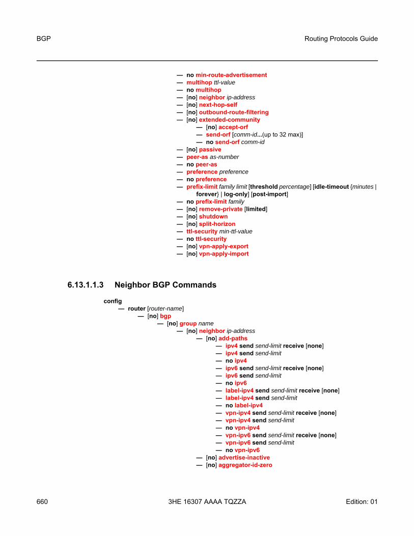
BGP
660
Routing Protocols Guide
3HE 16307 AAAA TQZZA Edition: 01
— no min-route-advertisement— multihop ttl-value — no multihop— [no] neighbor ip-address — [no] next-hop-self— [no] outbound-route-filtering— [no] extended-community
— [no] accept-orf— send-orf [comm-id...(up to 32 max)]— no send-orf comm-id
— [no] passive— peer-as as-number— no peer-as— preference preference— no preference— prefix-limit family limit [threshold percentage] [idle-timeout {minutes |
forever} | log-only] [post-import]— no prefix-limit family— [no] remove-private [limited]— [no] shutdown— [no] split-horizon— ttl-security min-ttl-value— no ttl-security— [no] vpn-apply-export— [no] vpn-apply-import
6.13.1.1.3 Neighbor BGP Commands
config — router [router-name]
— [no] bgp— [no] group name
— [no] neighbor ip-address— [no] add-paths
— ipv4 send send-limit receive [none]— ipv4 send send-limit— no ipv4— ipv6 send send-limit receive [none]— ipv6 send send-limit — no ipv6— label-ipv4 send send-limit receive [none]— label-ipv4 send send-limit — no label-ipv4— vpn-ipv4 send send-limit receive [none]— vpn-ipv4 send send-limit— no vpn-ipv4— vpn-ipv6 send send-limit receive [none]— vpn-ipv6 send send-limit— no vpn-ipv6
— [no] advertise-inactive — [no] aggregator-id-zero

Routing Protocols Guide BGP
Edition: 01 3HE 16307 AAAA TQZZA 661
— [no] aigp— auth-keychain name— no auth-keychain — authentication-key {authentication-key | hash-key} [hash |
hash2]— no authentication-key — [no] bfd-enable— cluster cluster-id— no cluster— connect-retry seconds— no connect-retry— [no] damping — def-recv-evpn-encap encap-type — no def-recv-evpn-encap — [no] default-route-target — description description-string— no description— [no] disable-client-reflect— disable-communities [standard] [extended]— no disable-communities— [no] disable-fast-external-failover— [no] enable-peer-tracking — export policy-name [policy-name…(up to 5 max)]— no export [policy-name] — family [ipv4] [vpn-ipv4] [ipv6] [vpn-ipv6] [mvpn-ipv4]
[route-target] [evpn] [label-ipv4] [bgp-ls]— no family— [no] graceful-restart
— stale-routes-time time— no stale-routes-time
— hold-time seconds [min seconds2] — no hold-time— import policy-name [policy-name…(up to 5 max)]— no import [policy-name] — keepalive seconds— no keepalive— label-preference value— no label-preference— local-address ip-address— no local-address— local-as as-number [private]— no local-as— local-preference local-preference— no local-preference— loop-detect {drop-peer | discard-route | ignore-loop | off}— no loop-detect— med-out {number | igp-cost}— no med-out — min-route-advertisement seconds— no min-route-advertisement— multihop ttl-value — no multihop— [no] next-hop-self— [no] outbound-route-filtering

BGP
662
Routing Protocols Guide
3HE 16307 AAAA TQZZA Edition: 01
— [no] extended-community— [no] accept-orf— send-orf [comm-id...(up to 32 max)]— no send-orf comm-id
— [no] passive— peer-as as-number— no peer-as— preference preference— no preference— prefix-limit family limit [threshold percentage] [idle-timeout
{minutes | forever} | log-only] [post-import]— no prefix-limit family— [no] remove-private [limited]— [no] shutdown— [no] split-horizon— ttl-security min-ttl-value— no ttl-security— [no] vpn-apply-export— [no] vpn-apply-import
6.13.1.1.4 Other BGP-Related Commands
config — router [router-name]
— aggregate ip-prefix/ip-prefix-length [summary-only] — no aggregate ip-prefix/ip-prefix-length — autonomous-system as-number— no autonomous-system— router-id ip-address— no router-id
6.13.1.2 Show Commands
show— router [router-instance]— router service-name service-name
— bgp— auth-keychain [keychain]— damping [ip-prefix[/ip-prefix-length]] [damp-type] [detail] [ipv4]— damping [ip-prefix[/ip-prefix-length]] [damp-type] [detail] ipv6— damping [ip-prefix[/ip-prefix-length]] [damp-type] [detail] label-ipv4— damping [ip-prefix[/ip-prefix-length]] [damp-type] [detail] vpn-ipv4— damping [ip-prefix[/ip-prefix-length]] [damp-type] [detail] vpn-ipv6— damping [ip-prefix[/ip-prefix-length]] [damp-type] [detail] mvpn-ipv4— group [name] [detail]— inter-as-label— neighbor [ip-address [detail]]— neighbor [as-number [detail]]

Routing Protocols Guide BGP
Edition: 01 3HE 16307 AAAA TQZZA 663
— neighbor [ip-address [family [type mvpn-type]] filter1 [brief]]]— neighbor [ip-address [[family] filter2]]— neighbor [as-number [[family] filter2]]— neighbor ip-address orf [filter3]— neighbor ip-address graceful-restart— neighbor [dynamic]— next-hop [family] [ip-address] [detail]— paths — routes [ip-prefix/mask | ip-address]— routes aspath-regex reg-exp {detail | longer}— routes aspath-regex reg-exp — routes aspath-regex reg-exp hunt— routes bgp-ls [hunt] [node | link | ipv4-prefix [ipv4-prefix/mask-len]]— routes brief— routes community comm-id {detail |longer}— routes community comm-id— routes community comm-id hunt— routes detail— routes hunt [brief]— routes ipv4 [aspath-regex reg-exp] [community comm-id] [brief] [all]— routes ipv4 [aspath-regex reg-exp] hunt [community comm-id] brief] [all]— routes ipv4 [detail |longer] [aspath-regex reg-exp] [community comm-id]
[all]— routes ipv6 [aspath-regex reg-exp] [community comm-id] [brief] [all]— routes ipv6 [aspath-regex reg-exp] hunt [community comm-id] [brief] [all]— routes ipv6 [detail |longer] [aspath-regex reg-exp] [community comm-id]
[all]— routes label-ipv4 [aspath-regex reg-exp] [community comm-id] [brief] [all]— routes label-ipv4 [aspath-regex reg-exp] hunt [community comm-id] [brief]
[all]— routes label-ipv4 [detail | longer] [aspath-regex reg-exp] [community
comm-id] [all]— routes longer— routes mvpn-ipv4 [aspath-regex reg-exp] [community comm-id] [rd rd]
[brief] [type mvpn-type] [originator-ip ip-address] [source-ip ipv4 address |pv6 address] [group-ip ipv4 address | ipv6 address] [source-as as-number]
— routes mvpn-ipv4 [aspath-regex reg-exp] hunt [community comm-id] [rd rd] [brief] [type mvpn-type] [originator-ip ip-address] [source-ip ipv4 address |ipv6 address] [group-ip ipv4 address | ipv6 address] [source-as as-number]
— routes mvpn-ipv4 [detail |longer] [aspath-regex reg-exp] [community comm-id] [rd rd] [type mvpn-type] [originator-ip ip-address] [source-ip ipv4 address |ipv6 address] [group-ip ipv4 address | ipv6 address] [source-as as-number]
— routes route-target [source-as as-number] [brief] [aspath-regex reg-exp] [community comm-id]
— routes route-target [rtc-prefix rtc-prefix] [hunt] [brief] [aspath-regex reg-exp] [community comm-id]
— routes route-target [rtc-prefix rtc-prefix [aspath-regex reg-exp] [community comm-id]
— routes route-target [rtc-prefix rtc-prefix] [detail | longer] [aspath-regex reg-exp] [community comm-id]
— routes vpn-ipv4 [aspath-regex reg-exp] [community comm-id] [rd rd] [brief]

BGP
664
Routing Protocols Guide
3HE 16307 AAAA TQZZA Edition: 01
— routes vpn-ipv4 [aspath-regex reg-exp] hunt [community comm-id] [rd rd] [brief]
— routes vpn-ipv4 [detail |longer] [aspath-regex reg-exp] [community comm-id] [rd rd]
— routes vpn-ipv6 [aspath-regex reg-exp] [community comm-id] [rd rd] [brief]— routes vpn-ipv6 [aspath-regex reg-exp] hunt [community comm-id] [rd rd]
[brief]— routes vpn-ipv6 [detail |longer] [aspath-regex reg-exp] [community
comm-id] [rd rd]— summary [all]— summary [family family] [neighbor ip-address]
6.13.1.3 Clear Commands
clear— router
— bgp— flap-statistics [{ip-prefix/mask [neighbor ip-address] | group group-name |
regex reg-exp | policy policy-name}]— neighbor {ip-address | as as-number | external | all} [soft | soft-inbound]— neighbor {ip-address | as as-number | external | all} statistics— neighbor ip-address end-of-rib— protocol
6.13.1.4 Debug Commands
debug— router
— bgp— events [neighbor ip-address | group name]— no events — graceful-restart [neighbor ip-address | group name]— no graceful-restart — keepalive [neighbor ip-address | group name]— no keepalive — notification [neighbor ip-address | group name]— no notification — open [neighbor ip-address | group name]— no open — [no] outbound-route-filtering — packets [neighbor ip-address | group name]— no packets — route-refresh [neighbor ip-address | group name]— no route-refresh — rtm [neighbor ip-address | group name]— no rtm — socket [neighbor ip-address | group name]— no socket

Routing Protocols Guide BGP
Edition: 01 3HE 16307 AAAA TQZZA 665
— timers [neighbor ip-address | group name]— no timers — update [neighbor ip-address | group name]— no update

BGP
666
Routing Protocols Guide
3HE 16307 AAAA TQZZA Edition: 01
6.13.2 Command Descriptions
• Configuration Commands• Show Commands• Clear Commands• Debug Commands

Routing Protocols Guide BGP
Edition: 01 3HE 16307 AAAA TQZZA 667
6.13.2.1 Configuration Commands
• Configuration Commands• Other BGP-Related Commands

BGP
668
Routing Protocols Guide
3HE 16307 AAAA TQZZA Edition: 01
6.13.2.1.1 Configuration Commands
bgp
Syntax [no] bgp
Context config>router
Description This command creates the BGP protocol instance and BGP configuration context. BGP is administratively enabled upon creation.
The no form of the command deletes the BGP protocol instance and removes all configuration parameters for the BGP instance. BGP must be shut down before deleting the BGP instance. An error occurs if BGP is not shut down first.
Default no bgp
add-paths
Syntax [no] add-paths
Context config>router>bgpconfig>router>bgp>groupconfig>router>bgp>group>neighbor
Description This command creates the add-paths configuration context and enables add-paths to be configured for one or more families on a BGP instance, BGP group, or BGP neighbor. The BGP add-paths capability allows the router to send and/or receive multiple paths per prefix to/from a peer. The add-paths command without additional parameters is equivalent to removing add-paths support for all address families, which causes sessions that previously negotiated the add-paths capability for one or more address families to go down and come back up without the add-paths capability.
The no form of the command removes add-paths from the configuration of BGP, BGP group, or BGP neighbor, causing sessions established using add-paths to go down and come back up without the add-paths capability.
Default no add-paths

Routing Protocols Guide BGP
Edition: 01 3HE 16307 AAAA TQZZA 669
ipv4
Syntax ipv4 send send-limit receive [none]ipv4 send send-limitno ipv4
Context config>router>bgp>add-pathsconfig>router>bgp>group>add-pathsconfig>router>bgp>group>neighbor>add-paths
Description This command is used to configure the add-paths capability for IPv4 routes (including labeled IPv4 routes on BGP route tunnels). By default, add-paths is not enabled for IPv4 routes.
The maximum number of paths to send per IPv4 prefix is the configured send limit, which is a mandatory parameter. The capability to receive multiple paths per prefix from a peer is configurable using the receive keyword, which is optional. If the receive keyword is not included in the command, the receive capability is enabled by default. Entering the command without optional parameters enables the ability to both send and receive multiple paths per IPv4 prefix with each peer, and configures the router to send the two best paths per prefix to each peer using the default Add-N, N=2 path selection algorithm.
The BGP advertise-inactive, add-paths, and export policy commands can be configured such that active, non-BGP routes are advertised. For more information, see Advertise-Inactive, Add-Paths, and Export Policy Interaction.
The no form of the command removes add-path support for IPv4 routes, causing sessions established using add-paths for IPv4 to go down and come back up without the add-paths capability.
Default no ipv4
Parameters send-limit — the maximum number of paths per IPv4 prefix that are allowed to be advertised to add-path peers. The actual number of advertised routes may be less depending on the next-hop diversity requirement, other configuration options, route policies, and/or route advertisement rules. If the value is none, the router does not negotiate the send capability with respect to IPv4 AFI/SAFI.
Values 1 to 16, or none
receive — configures the router to negotiate the add-paths receive capability for IPv4 routes with its peers
none — the router does not negotiate the add-paths receive capability for IPv4 routes with its peers

BGP
670
Routing Protocols Guide
3HE 16307 AAAA TQZZA Edition: 01
ipv6
Syntax ipv6 send send-limit receive [none]ipv6 send send-limitno ipv6
Context config>router>bgp>add-pathsconfig>router>bgp>group>add-pathsconfig>router>bgp>group>neighbor>add-paths
Description This command is used to configure the add-paths capability for unlabeled IPv6 unicast routes. By default, add-paths is not enabled for unlabeled IPv6 unicast routes.
The maximum number of unlabeled unicast paths to send per IPv6 prefix is the configured send limit, which is a mandatory parameter. The capability to receive multiple unlabeled IPv6 unicast paths per prefix from a peer is configurable using the receive keyword, which is optional. If the receive keyword is not included in the command, the receive capability is enabled by default.
The no form of the command removes add-path support for unlabeled IPv6 unicast routes, causing sessions established using add-paths for unlabeled IPv6 unicast to go down and come back up without the add-paths capability.
Default no ipv6
Parameters send-limit — the maximum number of paths per unlabeled IPv6 unicast prefix that are allowed to be advertised to add-path peers. (The actual number of advertised routes may be less.) If the value is none, the router does not negotiate the send capability with respect to IPv6 AFI/SAFI.
Values 1 to 16, or none
receive — the router negotiates to receive multiple unlabeled unicast routes per IPv6 prefix
none — the router does not negotiate to receive multiple unlabeled unicast routes per IPv6 prefix
label-ipv4
Syntax label-ipv4 send send-limit receive [none]label-ipv4 send send-limitno label-ipv4
Context config>router>bgp>add-pathsconfig>router>bgp>group>add-pathsconfig>router>bgp>group>neighbor>add-paths
Description This command is used to configure the add-paths capability for labeled-unicast IPv4 routes. By default, add-paths is not enabled for labeled-unicast IPv4 routes.

Routing Protocols Guide BGP
Edition: 01 3HE 16307 AAAA TQZZA 671
The maximum number of labeled-unicast paths per IPv4 prefix to send is the configured send-limit, which is a mandatory parameter. The capability to receive multiple labeled-unicast paths per prefix from a peer is configurable using the receive keyword, which is optional. If the receive keyword is not included in the command, receive capability is enabled by default.
The no form of the command disables add-paths support for labeled-unicast IPv4 routes, causing sessions established using add-paths for labeled-unicast IPv4 to go down and come back up without the add-paths capability.
Default no label-ipv4
Parameters send-limit — the maximum number of paths per labeled-unicast IPv4 prefix that are allowed to be advertised to add-paths peers. The actual number of advertised routes may be less. If the value is none, the router does not negotiate the send capability with respect to label-IPv4 AFI/SAFI.
Values 1 to 16, none
receive — configures the router to negotiate to receive multiple labeled-unicast routes per IPv4 prefix
none — the router does not negotiate to receive multiple labeled-unicast routes per IPv4 prefix
vpn-ipv4
Syntax vpn-ipv4 send send-limit receive [none]vpn-ipv4 send send-limitno vpn-ipv4
Context config>router>bgp>add-pathsconfig>router>bgp>group>add-pathsconfig>router>bgp>group>neighbor>add-paths
Description This command is used to configure the add-paths capability for VPN-IPv4 routes. By default, add-paths is not enabled for VPN-IPv4 routes.
The maximum number of paths to send per VPN-IPv4 prefix is the configured send limit, which is a mandatory parameter. The capability to receive multiple paths per prefix from a peer is configurable using the receive keyword, which is optional. If the receive keyword is not included in the command, the receive capability is enabled by default.
The BGP advertise-inactive, add-paths, and export policy commands can be configured such that active, non-BGP routes are advertised. For more information, see Advertise-Inactive, Add-Paths, and Export Policy Interaction.
The no form of the command removes add-path support for VPN-IPv4 routes, causing sessions established using add-paths for VPN-IPv4 to go down and come back up without the add-paths capability.
Default no vpn-ipv4

BGP
672
Routing Protocols Guide
3HE 16307 AAAA TQZZA Edition: 01
Parameters send-limit — the maximum number of paths per VPN-IPv4 prefix that are allowed to be advertised to add-path peers. The actual number of advertised routes may be less depending on the next-hop diversity requirement, other configuration options, route policies, and/or route advertisement rules. If the value is none, the router does not negotiate the send capability with respect to VPN-IPv4 AFI/SAFI.
Values 1 to 16, or none
receive — configures the router to negotiate the add-paths receive capability for VPN-IPv4 routes with its peers
none — the router does not negotiate the add-paths receive capability for VPN-IPv4 routes with its peers
vpn-ipv6
Syntax vpn-ipv6 send send-limit receive [none]vpn-ipv6 send send-limitno vpn-ipv6
Context config>router>bgp>add-pathsconfig>router>bgp>group>add-pathsconfig>router>bgp>group>neighbor>add-paths
Description This command is used to configure the add-paths capability for VPN-IPv6 routes. By default, add-paths is not enabled for VPN-IPv6 routes.
The maximum number of paths to send per VPN-IPv6 prefix is the configured send limit, which is a mandatory parameter. The capability to receive multiple paths per prefix from a peer is configurable using the receive keyword, which is optional. If the receive keyword is not included in the command, the receive capability is enabled by default.
The BGP advertise-inactive, add-paths, and export policy commands can be configured such that active, non-BGP routes are advertised. For more information, see Advertise-Inactive, Add-Paths, and Export Policy Interaction.
The no form of the command removes add-path support for VPN-IPv6 routes, causing sessions established using add-paths for VPN-IPv6 to go down and come back up without the add-paths capability.
Default no vpn-ipv6
Parameters send-limit — the maximum number of paths per VPN-IPv6 prefix that are allowed to be advertised to add-path peers. The actual number of advertised routes may be less depending on the next-hop diversity requirement, other configuration options, route policies, and/or route advertisement rules. If the value is none, the router does not negotiate the send capability with respect to VPN-IPv6 AFI/SAFI.
Values 1 to 16, or none

Routing Protocols Guide BGP
Edition: 01 3HE 16307 AAAA TQZZA 673
receive — configures the router to negotiate the add-paths receive capability for VPN-IPv6 routes with its peers
none — the router does not negotiate the add-paths receive capability for VPN-IPv6 routes with its peers
advertise-inactive
Syntax [no] advertise-inactive
Context config>router>bgp config>router>bgp>group config>router>bgp>group>neighbor
Description This command enables the advertising of inactive BGP routes to other BGP peers. By default, BGP only advertises BGP routes to other BGP peers if a given BGP route is chosen by the route table manager as the most preferred route within the system and is active in the forwarding plane. This command allows system administrators to advertise a BGP route even though it is not the most preferred route within the system for a given destination.
The BGP advertise-inactive, add-paths, and export policy commands can be configured such that active, non-BGP routes are advertised. For more information, see Advertise-Inactive, Add-Paths, and Export Policy Interaction.
The no form of the command disables the advertising of inactive BGP routers to other BGP peers.
Default no advertise-inactive
aggregator-id-zero
Syntax [no] aggregator-id-zero
Context config>router>bgp config>router>bgp>group config>router>bgp>group>neighbor
Description This command is used to set the router ID in the BGP aggregator path attribute to 0 when BGP aggregates routes. This prevents different routers within an AS from creating aggregate routes that contain different AS paths.
When BGP is aggregating routes, it adds the aggregator path attribute to the BGP Update messages. By default, BGP adds the AS number and router ID to the aggregator path attribute.
When this command is enabled, BGP adds only the router ID (set to 0) to the aggregator path attribute. This command is used at the group level to revert to the value defined under the global level, and this command is used at the neighbor level to revert to the value defined under the group level.

BGP
674
Routing Protocols Guide
3HE 16307 AAAA TQZZA Edition: 01
The no form of the command used at the global level reverts to the default, where BGP adds the AS number and router ID to the aggregator path attribute.
The no form of the command used at the group level reverts to the value defined at the global level.
The no form of the command used at the neighbor level reverts to the value defined at the group level.
Default no aggregator-id-zero
aigp
Syntax [no] aigp
Context config>router>bgp>groupconfig>router>bgp>group>neighbor
Description This command enables or disables accumulated IGP (AIGP) metric path attribute support with one or more BGP peers. BGP path selection among routes with an associated AIGP metric is based on the end-to-end IGP metrics of the different BGP paths, even when these BGP paths span more than one AS and IGP instance.
If AIGP is disabled, the AIGP attribute is removed from advertised routes, if present, and is ignored in received routes.
Default no aigp
auth-keychain
Syntax auth-keychain nameno auth-keychain
Context config>router>bgpconfig>router>bgp>groupconfig>router>bgp>group>neighbor
Description This command associates an authentication keychain with the BGP protocol. The keychain is a collection of keys used to authenticate BGP messages from remote neighbors. The keychain allows the rollover of authentication keys during the lifetime of a session and also supports stronger authentication algorithms than clear text and MD5.
The keychain must already be defined in the config>system>security>keychain context.
Either the authentication-key command or the auth-keychain command can be used by BGP, but both cannot be supported at the same time. If both commands are configured, the auth-keychain configuration will be applied and the authentication-key command will be ignored.

Routing Protocols Guide BGP
Edition: 01 3HE 16307 AAAA TQZZA 675
By default, authentication is not enabled.
Default no auth-keychain
Parameters name — the name of an existing keychain, up to 32 characters
authentication-key
Syntax authentication-key {authentication-key | hash-key} [hash | hash2] no authentication-key
Context config>router>bgp config>router>bgp>group config>router>bgp>group>neighbor
Description This command configures the BGP authentication key.
Authentication is performed between neighboring routers before setting up the BGP session by verifying the password. Authentication is performed using the MD5 message-based digest.
The authentication key can be any combination of ASCII characters up to 255 characters long.
The TCP MD5 key information used to securely communicate with a BGP peer is retained even after the connection has closed, allowing connectionless RST packets to be sent with the proper authentication data.
Either the authentication-key command or the auth-keychain command can be used by BGP, but both cannot be supported at the same time. If both commands are configured, the auth-keychain configuration will be applied and the authentication-key command will be ignored.
The no form of the command reverts to the default value.
Default MD5 authentication is disabled by default
Parameters authentication-key — the authentication key. The key can be any combination of ASCII characters up to 255 characters in length (unencrypted). If spaces are used in the string, the entire string must be enclosed in quotation marks (“ ”).
hash-key — the hash key. The key can be any combination of ASCII characters up to 342 characters in length (encrypted). If spaces are used in the string, the entire string must be enclosed in quotation marks (“ ”). This is useful when a user must configure the parameter, but for security purposes, the actual unencrypted key value is not provided.
hash — specifies that the key is entered in an encrypted form. If the hash parameter is not used, the key is assumed to be in a non-encrypted, clear text form. For security, all keys are stored in encrypted form in the configuration file with the hash parameter specified.

BGP
676
Routing Protocols Guide
3HE 16307 AAAA TQZZA Edition: 01
hash2 — specifies that the key is entered in a more complex encrypted form. If the hash2 parameter is not used, the less encrypted hash form is assumed.
backup-path
Syntax [no] backup-path [ipv4] [label-ipv4] [ipv6]
Context config>router>bgp
Description This command enables BGP Fast Reroute (FRR) with Prefix-Independent Convergence (PIC), allowing for the creation of a backup path for IPv4, label IPv4, or IPv6 learned prefixes belonging to the router. Multiple paths must be received for a prefix in order to take advantage of this feature.
When a prefix has a backup path, and its primary paths fail, the affected traffic is rapidly diverted to the backup path without waiting for control plane reconvergence to occur. The time to reroute the traffic is independent of the number of prefixes sharing the primary or backup paths.
The no form of the command disables BGP FRR with PIC.
Default no backup-path
Parameters ipv4 — enables a backup path for IPv4 BGP learned prefixes
label-ipv4 — enables a backup path for labeled IPv4 BGP learned prefixes
ipv6 — enables a backup path for IPv6 BGP learned prefixes
best-path-selection
Syntax best-path-selection
Context config>router>bgp
Description This command enables path selection configuration.
always-compare-med
Syntax always-compare-med [zero | infinity]always-compare-med strict-as [zero | infinity]no always-compare-med
Context config>router>bgp>path-selection
Description This command specifies how the Multi-Exit Discriminator (MED) path attribute is used in the BGP route selection process.

Routing Protocols Guide BGP
Edition: 01 3HE 16307 AAAA TQZZA 677
If this command is used without the strict-as option, the MEDs of two paths are always compared even if the paths have a different neighbor AS.
If the strict-as option is used, the MEDs of two paths are compared only if they come from the same neighboring AS.
The zero and infinity options specify how to treat paths that do not have a MED attribute; for example, always-compare-med zero means that if one path is missing a MED attribute, it is treated as though it had a MED attribute with the value of 0. If neither option is specified, the zero option is implied.
The no form of the command means that only the MEDs of paths that have the same neighbor AS are compared.
Default no always-compare-med
Parameters zero — specifies that for routes learned without a MED attribute, a zero (0) value is used in the MED comparison. The routes with the lowest metric are the most preferred.
infinity — specifies that for routes learned without a MED attribute, a value of infinity (4294967295) is used in the MED comparison. This, in effect, makes these routes the least desirable.
strict-as — specifies that the MEDs of two paths are compared only if they come from the same neighboring AS
as-path-ignore
Syntax as-path-ignore [ipv4] [label-ipv4] [ipv6] [vpn-ipv4] [vpn-ipv6] [mvpn-ipv4] no as-path-ignore
Context config>router>bgp>path-selection
Description This command specifies whether the AS path is used to determine the best BGP route.
If this command is enabled, the AS paths of incoming routes are not used in the route selection process.
When as-path-ignore is used without specifying any keywords, all keywords are configured.
The no form of the command means that the AS paths of incoming routes are used to determine the best BGP route.
Default no as-path-ignore
Parameters ipv4 — specifies that the AS path length will be ignored for all IPv4 routes
label-ipv4 — specifies that the AS path length will be ignored for all labeled IPv4 routes
ipv6 — specifies that the AS path length will be ignored for all IPv6 routes
vpn-ipv4 — specifies that the AS path length will be ignored for all VPN-IPv4 routes

BGP
678
Routing Protocols Guide
3HE 16307 AAAA TQZZA Edition: 01
vpn-ipv6 — specifies that the AS path length will be ignored for all VPN-IPv6 routes
mvpn-ipv4 — specifies that the AS path length will be ignored for all MVPN-IPv4 routes
bfd-enable
Syntax [no] bfd-enable
Context config>router>bgp config>router>bgp>group config>router>bgp>group>neighbor
Description This command enables the use of bidirectional forwarding (BFD) to control the state of the associated protocol interface. By enabling BFD on a given protocol interface, the state of the protocol interface is tied to the state of the BFD session between the local node and the remote node. The parameters used for BFD are set via the BFD command under the IP interface.
The no form of this command removes BFD from the associated IGP/BGP protocol adjacency.
Default no bfd-enable
cluster
Syntax cluster cluster-id no cluster
Context config>router>bgp config>router>bgp>group config>router>bgp>group>neighbor
Description This command configures the cluster ID for a route reflector server.
Route reflectors are used to reduce the number of IBGP sessions required within an AS. Normally, all BGP speakers within an AS must have a BGP peering with every other BGP speaker in the AS. A route reflector and its clients form a cluster. Peers that are not part of the cluster are considered to be non-clients.
When a route reflector receives a route, it must first select the best path from all the paths received. If the route was received from a non-client peer, then the route reflector sends the route to all clients in the cluster. If the route came from a client peer, the route reflector sends the route to all non-client peers and to all client peers except the originator.
For redundancy, a cluster can have multiple route reflectors.
The no form of the command deletes the cluster ID and effectively disables route reflection for the given group.

Routing Protocols Guide BGP
Edition: 01 3HE 16307 AAAA TQZZA 679
Default no cluster
Parameters cluster-id — the route reflector cluster ID, expressed in dotted-decimal notation
Values any 32-bit number in dotted-decimal notation (0.0.0.1 to 255.255.255.255)
connect-retry
Syntax connect-retry seconds no connect-retry
Context config>router>bgp config>router>bgp>group config>router>bgp>group>neighbor
Description This command configures the BGP connect retry timer value in seconds. When this timer expires, BGP tries to reconnect to the configured peer. This configuration parameter can be set at three levels: global level (applies to all peers), group level (applies to all peers in group) or neighbor level (only applies to specified peer). The most specific value is used.
The no form of the command used at the global level reverts to the default value.
The no form of the command used at the group level reverts to the value defined at the global level.
The no form of the command used at the neighbor level reverts to the value defined at the group level.
Default 120 s
Parameters seconds — the BGP connect retry timer value, in seconds, expressed as a decimal integer
Values 1 to 65535
damping
Syntax [no] damping
Context config>router>bgp config>router>bgp>group config>router>bgp>group>neighbor
Description This command enables BGP route damping for learned routes that are defined within the route policy. Use damping to reduce the number of update messages sent between BGP peers and reduce the load on peers without affecting the route convergence time for stable routes. Damping parameters are set at the route policy level. See 7705 SAR Router Configuration Guide, “Route Policy Command Reference”.

BGP
680
Routing Protocols Guide
3HE 16307 AAAA TQZZA Edition: 01
The no form of the command disables learned route damping.
The no form of the command used at the group level reverts to the value defined at the global level.
The no form of the command used at the neighbor level reverts to the value defined at the group level.
Default no damping
def-recv-evpn-encap
Syntax def-recv-evpn-encap encap-type no def-recv-evpn-encap
Context config>router>bgpconfig>router>bgp>groupconfig>router>bgp>group>neighbor
Description This command defines how BGP treats a received EVPN route without RFC 5512 BGP encapsulation extended community. If no encapsulation is received, BGP validates the route as MPLS.
Default no def-recv-evpn-encap
Parameters encap-type — specifies the default encapsulation value in the case where no RFC 5512 extended community is received in the incoming BGP-EVPN route
Values mpls
default-route-target
Syntax [no] default-route-target
Context config>router>bgp>group config>router>bgp>group>neighbor
Description This command advertises the default RTC route towards the selected peers.
The default RTC route is a special route that has a prefix length of zero. Sending the default RTC route to a peer conveys a request to receive all VPN routes from that peer, whether or not they match the route target extended community. Advertising the default RTC route to a peer does not suppress other more specific RTC routes from being sent to that peer.
The no form of the command blocks the router from advertising the default RTC route.
Default no default-route-target

Routing Protocols Guide BGP
Edition: 01 3HE 16307 AAAA TQZZA 681
description
Syntax description description-string no description
Context config>router>bgp config>router>bgp>group config>router>bgp>group>neighbor
Description This command creates a text description stored in the configuration file for a configuration context.
The no form of the command removes the description string from the context.
Default No description is associated with the configuration context
Parameters string — the description character string. Allowed values are any string up to 80 characters long composed of printable, 7-bit ASCII characters. If the string contains special characters (#, $, spaces, etc.), the entire string must be enclosed within double quotes.
disable-client-reflect
Syntax [no] disable-client-reflect
Context config>router>bgp config>router>bgp>group config>router>bgp>group>neighbor
Description This command disables the reflection of routes by the route reflector to the clients in a specific group or neighbor.
This command only disables the reflection of routes from other client peers. Routes learned from non-client peers are still reflected to all clients.
The no form re-enables client reflection of routes.
Default no disable-client-reflect
disable-communities
Syntax disable-communities [standard] [extended] no disable-communities
Context config>router>bgp config>router>bgp>group config>router>bgp>group>neighbor
BGP
682
Routing Protocols Guide
3HE 16307 AAAA TQZZA Edition: 01
Description This command configures BGP to disable sending communities.
Default no disable-communities
Parameters standard — specifies standard communities that existed before VPRNs or RFC 2547
extended — specifies BGP communities that were expanded after the concept of RFC 2547 was introduced, to include handling the route target from the VRF
disable-fast-external-failover
Syntax [no] disable-fast-external-failover
Context config>router>bgp config>router>bgp>group config>router>bgp>group>neighbor
Description This command configures BGP fast external failover.
For EBGP neighbors, this feature controls whether the router should drop an EBGP session immediately upon an interface-down event, or whether the BGP session should be kept up until the hold-time expires.
When fast external failover is disabled, the EBGP session stays up until the hold-time expires or the interface comes back up. If the BGP routes become unreachable as a result of the down IP interface, BGP withdraws the unavailable route immediately from other peers.
Default no disable-communities
dynamic-neighbor
Syntax dynamic-neighbor
Context config>router>bgp>group
Description This command enables the context to configure dynamic BGP sessions for a peer group.
prefix
Syntax [no] prefix ip-prefix/ip-prefix-length
Context config>router>bgp>group>dynamic-neighbor

Routing Protocols Guide BGP
Edition: 01 3HE 16307 AAAA TQZZA 683
Description This command configures a prefix to accept dynamic BGP sessions, which are sessions from source IP addresses that do not match any configured (static) neighbor addresses. A dynamic session is associated with the group having the longest-match prefix entry for the source IP address of the peer. There is no limit on the number of prefixes that can be configured. The group association determines local parameters that apply to the session, including the local AS, local IP address, MP-BGP families, and import and export policies.
The no form of this command removes a prefix entry.
Default n/a
Parameters ip-prefix/ip-prefix-length — specifies a prefix from which to accept dynamic BGP sessions
Values ipv4-prefix — a.b.c.d (host bits must be 0)ipv4-prefix-length — 0 to 32ipv6-prefix — x:x:x:x:x:x:x:x (eight 16-bit pieces)
x:x:x:x:x:x:d.d.d.dx — [0 to FFFF]Hd — [0 to 255]D
ipv6-prefix-length — 0 to 128
dynamic-neighbor-limit
Syntax dynamic-neighbor-limit peersno dynamic-neighbor-limit
Context config>router>bgpconfig>router>bgp>group
Description This command configures the maximum number of dynamic BGP sessions that will be accepted from remote peers associated with the global BGP instance or a specific peer group. If accepting a new dynamic session would cause either the group limit or the global limit to be exceeded, the new session attempt is rejected and a notification message is sent back to the remote peer.
The no form of this command removes the limit on the number of dynamic sessions.
Default no dynamic-neighbor-limit
Parameters peers — specifies the maximum number of dynamic BGP sessions
Values 1 to 320: 7705 SAR-18, 7705 SAR-8 1 to 128: 7705 SAR-X 1 to 64: 7705 SAR-A, 7705 SAR-Ax, 7705 SAR-H, 7705 SAR-Hc, 7705 SAR-M, 7705 SAR-W, 7705 SAR-Wx

BGP
684
Routing Protocols Guide
3HE 16307 AAAA TQZZA Edition: 01
enable-peer-tracking
Syntax [no] enable-peer-tracking
Context config>router>bgp config>router>bgp>group config>router>bgp>group>neighbor
Description This command enables BGP peer tracking. BGP peer tracking allows a BGP peer to be dropped immediately if the route used to resolve the BGP peer address is removed from the IP routing table and there is no alternative available. The BGP peer will not wait for the hold timer to expire; therefore, the BGP reconvergence process is accelerated.
The no form of the command disables peer tracking.
Default no enable-peer-tracking
enable-rr-vpn-forwarding
Syntax [no] enable-rr-vpn-forwarding
Context config>router>bgp
Description This command enables a route reflector of VPN-IP routes to be deployed in the data path between two BGP peers (a peer X and a peer Y) in a next-hop resolution.
All received VPN-IP routes are imported into a table that is used to resolve the BGP next hops. The next hop of a VPN-IP route that is imported from peer X and selected as having the best path by the table is advertised to peer Y (the next-hop-self command must be set for peer Y or a next-hop action must be used in an export policy that is applied to peer Y in order for the next-hop to be advertised to peer Y).
A new VPN service label value is then allocated for the VPN-IP route. This new label is advertised to peer Y and a label swap operation is then performed by the IOM.
The no form of the command disables the advertising of a new VPN service label from one BGP peer to another.
Default no enable-rr-vpn-forwarding
export
Syntax export policy-name [policy-name…(up to 5 max)] no export [policy-name]
Context config>router>bgp config>router>bgp>group config>router>bgp>group>neighbor
Routing Protocols Guide BGP
Edition: 01 3HE 16307 AAAA TQZZA 685
Description This command specifies the export route policy used to determine which routes are advertised to peers. Route policies are configured in the config>router>policy-options context. Refer to the section on “Route Policy” in the 7705 SAR Router Configuration Guide.
This configuration parameter can be set at three levels: global level (applies to all peers), group level (applies to all peers in group) or neighbor level (only applies to specified peer). The most specific level is used.
When multiple policy names are specified, the policies are evaluated in the order in which they are specified. A maximum of five (5) policy names can be configured. The first policy that matches is applied.
When multiple export commands are issued, the last command entered overrides the previous command.
When no export policies are specified, BGP routes are advertised and non-BGP routes are not advertised (by default).
The BGP advertise-inactive, add-paths, and export policy commands can be configured such that active, non-BGP routes are advertised. For more information, see Advertise-Inactive, Add-Paths, and Export Policy Interaction.
The no form of the command removes the policy association with the BGP instance. To remove association of all policies, use the no export command without arguments.
Default no export
Parameters policy-name — the route policy name. Allowed values are any string up to 32 characters long composed of printable, 7-bit ASCII characters. If the string contains special characters (#, $, spaces, etc.), the entire string must be enclosed within double quotes.
family
Syntax family [ipv4] [vpn-ipv4] [ipv6] [vpn-ipv6] [mvpn-ipv4] [route-target] [evpn] [label-ipv4] [bgp-ls]
no family
Context config>router>bgp config>router>bgp>group config>router>bgp>group>neighbor
Description This command specifies the address family or families to be supported over BGP peerings in the base router. One or more address families can be specified in a single command. To add an address family to the currently configured families, reissue the command and include the current families in addition to any new family.
The no form of the command removes the specified address family from the associated BGP peerings. If an address family is not specified, the supported address family is reset to the default.

BGP
686
Routing Protocols Guide
3HE 16307 AAAA TQZZA Edition: 01
Default ipv4
Parameters ipv4 — supports IPv4 routing information
vpn-ipv4 — exchanges VPN-IPv4 routing information
ipv6 — supports IPv6 routing information
vpn-ipv6 — exchanges VPN-IPv6 routing information
mvpn-ipv4 — exchanges MVPN-IPv4 routing information
route-target — exchanges RTC routing information
evpn — exchanges EVPN routing information
label-ipv4 — supports labeled IPv4 routing information
bgp-ls — supports BGP-LS routing information
graceful-restart
Syntax [no] graceful-restart
Context config>router>bgp config>router>bgp>group config>router>bgp>group>neighbor
Description The command enables procedures for BGP graceful restart (GR) helper—the receiving router role, as defined in the RFC 4724 standard—for all received IPv4 and VPN-IPv4 routes. In order for helper mode to be available for a particular address family, both peers must signal GR support for the address family during capability negotiation.
When a neighbor covered by GR helper mode restarts its control plane, the forwarding of traffic can continue uninterrupted while the session is being re-established and routes are relearned.
The no form of the command disables graceful restart and removes all graceful restart configurations in the BGP instance.
Default no graceful-restart
stale-routes-time
Syntax stale-routes-time time no stale-routes-time
Context config>router>bgp>graceful-restart config>router>bgp>group>graceful-restart config>router>bgp>group>neighbor>graceful-restart

Routing Protocols Guide BGP
Edition: 01 3HE 16307 AAAA TQZZA 687
Description This command configures the maximum amount of time in seconds that stale routes should be maintained after a graceful restart is initiated.
The no form of the command resets the stale routes time back to the default value.
Default 360 s
Parameters time — the amount of time that stale routes should be maintained after a graceful restart is initiated
Values 1 to 3600 s
group
Syntax [no] group name
Context config>router>bgp
Description This command creates a context to configure a BGP peer group.
The no form of the command deletes the specified peer group and all configurations associated with the peer group. The group must be shut down before it can be deleted.
Default no group
Parameters name — the peer group name. Allowed values are any string up to 32 characters long composed of printable, 7-bit ASCII characters. If the string contains special characters (#, $, spaces, etc.), the entire string must be enclosed within double quotes.
hold-time
Syntax hold-time seconds [min seconds2]no hold-time
Context config>router>bgp config>router>bgp>group config>router>bgp>group>neighbor
Description This command configures the BGP hold time, expressed in seconds.
The BGP hold time specifies the maximum time BGP waits between successive messages (either Keepalive or Update) from its peer, before closing the connection. This configuration parameter can be set at three levels: global level (applies to all peers), group level (applies to all peers in group) or neighbor level (only applies to specified peer). The most specific value is used.

BGP
688
Routing Protocols Guide
3HE 16307 AAAA TQZZA Edition: 01
The min option ensures a minimum hold time for a BGP session that is independent of the hold time advertised in a received Open message. The min option replaces the strict keyword used prior to Release 7.0. If a pre-Release 7.0 configuration database file is loaded that contains the strict keyword, the default value for min is set to the same value as the hold time (that is, seconds2 is equal to seconds).
Even though the 7705 SAR implementation allows setting the keepalive time separately, the configured keepalive timer is overridden by the hold-time value under the following circumstances.
• If the specified hold-time is less than the configured keepalive time, then the operational keepalive time is set to a third of the hold-time; the configured keepalive time is not changed.
• If the hold-time is set to 0, then the operational value of the keepalive time is set to 0; the configured keepalive time is not changed. This means that the connection with the peer is up permanently and no keepalive packets are sent to the peer.
The no form of the command used at the global level reverts to the default value.
The no form of the command used at the group level reverts to the value defined at the global level.
The no form of the command used at the neighbor level reverts to the value defined at the group level.
Default 90 s
Parameters seconds — the hold time, in seconds, expressed as a decimal integer. A value of 0 indicates that the connection to the peer is permanently up.
Values 0, 3 to 65535
seconds2 — the minimum hold time, in seconds, that will be accepted for the session. If the peer proposes a hold time lower than this value, the session attempt will be rejected.
Values 0, 3 to 65535
ibgp-multipath
Syntax [no] ibgp-multipath
Context config>router>bgp
Description This command enables IBGP multipath load balancing when adding BGP routes to the route table if the route resolving the BGP next-hop offers multiple next-hops.
The no form of the command disables the IBGP multipath load balancing feature.
Default no ibgp-multipath

Routing Protocols Guide BGP
Edition: 01 3HE 16307 AAAA TQZZA 689
import
Syntax import policy-name [policy-name…(up to 5 max)] no import [policy-name]
Context config>router>bgp config>router>bgp>group config>router>bgp>group>neighbor
Description This command specifies the import route policy to be used to determine which routes are accepted from peers. Route policies are configured in the config>router>policy-options context. Refer to the section on “Route Policy” in the 7705 SAR Router Configuration Guide.
This configuration parameter can be set at three levels: global level (applies to all peers), group level (applies to all peers in group) or neighbor level (only applies to specified peer). The most specific level is used.
When multiple policy names are specified, the policies are evaluated in the order in which they are specified. A maximum of five (5) policy names can be specified. The first policy that matches is applied.
When multiple import commands are issued, the last command entered will override the previous command.
When an import policy is not specified, BGP routes are accepted by default.
The no form of the command removes the policy association with the BGP instance. To remove association of all policies, use no import without arguments.
Default no import
Parameters policy-name — the route policy name. Allowed values are any string up to 32 characters long composed of printable, 7-bit ASCII characters. If the string contains special characters (#, $, spaces, etc.), the entire string must be enclosed within double quotes.
keepalive
Syntax keepalive seconds no keepalive
Context config>router>bgp config>router>bgp>group config>router>bgp>group>neighbor
Description This command configures the BGP keepalive timer. A Keepalive message is sent every time this timer expires.

BGP
690
Routing Protocols Guide
3HE 16307 AAAA TQZZA Edition: 01
The keepalive parameter can be set at three levels: global level (applies to all peers), group level (applies to all peers in group) or neighbor level (only applies to specified peer). The most specific value is used. The keepalive value is generally one-third of the hold-time interval. Even though the 7705 SAR implementation allows the keepalive value and the hold-time interval to be independently set, under the following circumstances, the configured keepalive value is overridden by the hold-time value.
• If the specified keepalive value is greater than the configured hold-time, then the specified value is ignored, and the keepalive value is set to one third of the current hold-time value.
• If the specified hold-time interval is less than the configured keepalive value, then the keepalive value is reset to one third of the specified hold-time interval.
• If the hold-time interval is set to 0, then the configured value of the keepalive value is ignored. This means that the connection with the peer is up permanently and no keepalive packets are sent to the peer.
The no form of the command used at the global level reverts to the default value.
The no form of the command used at the group level reverts to the value defined at the global level.
The no form of the command used at the neighbor level reverts to the value defined at the group level.
Default 30 s
Parameters seconds — the keepalive timer, in seconds, expressed as a decimal integer
Values 0 to 21845
label-preference
Syntax label-preference valueno label-preference
Context config>router>bgpconfig>router>bgp>groupconfig>router>bgp>group>neighbor
Description This command configures the route preference for routes learned from labeled-unicast peers.
This command can be configured at three levels:
• global level — applies to all peers• group level — applies to all peers in the peer group• neighbor level — applies only to the specified peer
The most specific value is used.

Routing Protocols Guide BGP
Edition: 01 3HE 16307 AAAA TQZZA 691
The lower the preference value, the higher the chance of the route being the active route.
The no form of the command used at the global level reverts to the default value of 170.
The no form of the command used at the group level reverts to the value defined at the global level.
The no form of the command used at the neighbor level reverts to the value defined at the group level.
Default no label-preference
Parameters value — specifies the route preference value
Values 1 to 255
Default 170 (global level)
link-state-export-enable
Syntax [no] link-state-export-enable
Context config>router>bgp
Description This command enables the export of link-state information into the BGP-LS address family.
The no form of this command disables the export of link-state information into the BGP-LS address family.
Default no link-state-export-enable
local-address
Syntax local-address ip-address no local-address
Context config>router>bgp>group config>router>bgp>group>neighbor
Description This command configures the local IP address used by the group or neighbor when communicating with BGP peers.
Outgoing connections use the local-address as the source of the TCP connection when initiating connections with a peer.
When a local address is not specified at the group level, the 7705 SAR uses the system IP address when communicating with IBGP peers and uses the interface address for directly connected EBGP peers. When a local address is not specified at the neighbor level, the neighbor uses the value defined at the group level.

BGP
692
Routing Protocols Guide
3HE 16307 AAAA TQZZA Edition: 01
The no form of the command removes the configured local address for BGP.
Default no local-address
Parameters ip-address — the local address. The allowed value is a valid routable IP address on the router, either an interface or system IP address.
Values ipv4-address: a.b.c.d (host bits must be 0)ipv6-address: x:x:x:x:x:x:x:x (eight 16-bit pieces)
x:x:x:x:x:x:d.d.d.dx: [0 to FFFF]Hd: [0 to 255]D
local-as
Syntax local-as as-number [private] no local-as
Context config>router>bgp config>router>bgp>group config>router>bgp>group>neighbor
Description This command configures a BGP virtual autonomous system (AS) number.
In addition to the AS number configured for BGP in the config>router>autonomous-system context, a virtual (local) AS number is configured. The virtual AS number is added to the as-path attribute before the router’s AS number makes the virtual AS the second AS in the AS path.
This configuration parameter can be set at three levels: global level (applies to all peers), group level (applies to all peers in group) or neighbor level (only applies to specified peer). By specifying this parameter at each neighbor level, it is possible to have a separate AS number per EBGP session.
When a command is entered multiple times for the same AS, the last command entered is used in the configuration. The private attribute can be added or removed dynamically by reissuing the command.
Changing the local AS at the global level in an active BGP instance causes the BGP instance to restart with the new local AS number.
Changing the local AS at the group level in an active BGP instance causes BGP to re-establish the peer relationships with all peers in the group with the new local AS number.
Changing the local AS at the neighbor level in an active BGP instance causes BGP to re-establish the peer relationship with the new local AS number.
This is an optional command and can be used in the following situation.

Routing Protocols Guide BGP
Edition: 01 3HE 16307 AAAA TQZZA 693
Example: Provider router P is moved from AS1 to AS2. The customer router that is connected to P, however, is configured to belong to AS1. To avoid reconfiguring the customer router, the local-as value on router P can be set to AS1. Thus, router P adds AS1 to the as-path message for routes it advertises to the customer router.
The no form of the command used at the global level will remove any virtual AS number configured.
The no form of the command used at the group level reverts to the value defined at the global level.
The no form of the command used at the neighbor level reverts to the value defined at the group level.
Default no local-as
Parameters as-number — the virtual autonomous system number expressed as a decimal integer
Values 1 to 4294967295
private — specifies that the local AS is hidden in paths learned from the peering
local-preference
Syntax local-preference local-preference no local-preference
Context config>router>bgp config>router>bgp>group config>router>bgp>group>neighbor
Description This command configures the default value of the BGP local preference attribute if it is not already specified in incoming routes.
This value is used if the BGP route arrives from a BGP peer without the local-preference integer set.
The specified value can be overridden by any value set via a route policy. This configuration parameter can be set at three levels: global level (applies to all peers), group level (applies to all peers in group) or neighbor level (only applies to specified peer). The most specific value is used.
The no form of the command at the global level specifies that incoming routes with local preference set are not overridden and routes arriving without local preference set are interpreted as if the route had a local preference value of 100.
The no form of the command used at the group level reverts to the value defined at the global level.
The no form of the command used at the neighbor level reverts to the value defined at the group level.

BGP
694
Routing Protocols Guide
3HE 16307 AAAA TQZZA Edition: 01
Default no local-preference
Parameters local-preference — the local preference value to be used as the override value, expressed as a decimal integer
Values 0 to 4294967295
loop-detect
Syntax loop-detect {drop-peer | discard-route | ignore-loop | off} no loop-detect
Context config>router>bgp config>router>bgp>group config>router>bgp>group>neighbor
Description This command configures how the BGP peer session handles loop detection in the AS path.
This configuration parameter can be set at three levels: global level (applies to all peers), group level (applies to all peers in group) or neighbor level (only applies to specified peer). The most specific value is used.
When applied to an ongoing BGP peer session, this command does not take effect until the BGP peer session is re-established.
The no form of the command used at the global level reverts to the default (ignore- loop).
The no form of the command used at the group level reverts to the value defined at the global level.
The no form of the command used at the neighbor level reverts to the value defined at the group level.
Default ignore-loop
Parameters drop-peer — sends a notification to the remote peer and drops the session
discard-route — discards routes received from a peer with the same AS number as the router itself. This option prevents routes looped back to the router from being added to the routing information base and consuming memory. When this option is changed, the change will not be active for an established peer until the connection is re-established for the peer.
ignore-loop — ignores routes with loops in the AS path, but maintains peering
off — disables loop detection

Routing Protocols Guide BGP
Edition: 01 3HE 16307 AAAA TQZZA 695
med-out
Syntax med-out {number | igp-cost}no med-out
Context config>router>bgp config>router>bgp>group config>router>bgp>group>neighbor
Description This command is used to advertise the Multi-Exit Discriminator (MED) to BGP peers and assign the path value if the MED is not already set via a route policy (the specified value can be overridden by a MED value that is set via a route policy using the metric command. See the 7705 SAR Router Configuration Guide, “Route Policy Configuration Commands”).
The no form of the command used at the global level reverts to the default where the MED is not advertised.
The no form of the command used at the group level reverts to the value defined at the global level.
The no form of the command used at the neighbor level reverts to the value defined at the group level.
Default no med-out (the MED is not advertised)
Parameters number — the MED path value
Values 0 to 4294967295
igp-cost — the MED is set to the IGP cost of the IP prefix that is defined via a route policy
min-route-advertisement
Syntax min-route-advertisement seconds no min-route-advertisement
Context config>router>bgp config>router>bgp>group config>router>bgp>group>neighbor
Description This command configures the minimum interval, in seconds, at which a prefix can be advertised to a peer.
This configuration parameter can be set at three levels: global level (applies to all peers), group level (applies to all peers in group) or neighbor level (only applies to specified peer). The most specific value is used.
The no form of the command used at the global level reverts to the default.
The no form of the command used at the group level reverts to the value defined at the global level.

BGP
696
Routing Protocols Guide
3HE 16307 AAAA TQZZA Edition: 01
The no form of the command used at the neighbor level reverts to the value defined at the group level.
Default 30 s
Parameters seconds — the minimum route advertising interval, in seconds, expressed as a decimal integer
Values 2 to 255
multihop
Syntax multihop ttl-value no multihop
Context config>router>bgp config>router>bgp>group config>router>bgp>group>neighbor
Description This command configures the time to live (TTL) value at an originating BGP peer. The TTL value is entered in the IP header of packets that are sent to a terminating BGP peer that is multiple hops away.
The no form of the command used at the global level reverts to the default value.
The no form of the command used at the group level reverts to the value defined at the global level.
The no form of the command used at the neighbor level reverts to the value defined at the group level.
Default 1 — EBGP peers are directly connected
64 — IBGP peer
Parameters ttl-value — the TTL value that will be entered in the IP header of packets that are sent to a terminating BGP peer that is multiple hops away
Values 1 to 255
multipath
Syntax multipath integer no multipath
Context config>router>bgp
Description This command enables BGP multipath.

Routing Protocols Guide BGP
Edition: 01 3HE 16307 AAAA TQZZA 697
When multipath is enabled, BGP load-shares traffic across multiple links. Multipath can be configured to load-share traffic across a maximum of 16 routes. If the equal-cost routes available are more than the configured value, then routes with the lowest next-hop IP address value are chosen.
This configuration parameter is set at the global level (applies to all peers).
Multipath is disabled if the value is set to 1. When multipath is disabled and multiple equal-cost routes are available, the route with the lowest next-hop IP address will be used.
The no form of the command reverts to the default where multipath is disabled.
Default no multipath
Parameters integer — the number of equal-cost routes to use for multipath routing. If more equal-cost routes exist than the configured value, routes with the lowest next-hop value are chosen. Setting this value to 1 disables multipath.
Values 1 to 16
mvpn-vrf-import-subtype-new
Syntax [no] mvpn-vrf-import-subtype-new
Context config>router>bgp
Description This command enables the type/subtype in advertised routes to be encoded as 0x010b (extended community type: transitive IPv4-address-specific VRF route import).
The no form of the command encodes the type/subtype as 0x010a (extended community type: transitive IPv4-address-specific L2VPN identifier), in order to preserve backwards compatibility.
Default no mvpn-vrf-import-subtype-new
next-hop-resolution
Syntax next-hop-resolution
Context config>router>bgp
Description This command enables the context to configure next-hop resolution parameters.

BGP
698
Routing Protocols Guide
3HE 16307 AAAA TQZZA Edition: 01
label-route-transport-tunnel
Syntax label-route-transport-tunnel
Context config>router>bgp>next-hop-res
Description This command enables the context to configure options for the next-hop resolution of BGP labeled routes (VPN-IP and labeled-unicast) using tunnels in the Tunnel Table Manager (TTM). The context allows the selection of different tunnel resolution options for different types of BGP labeled routes: label-unicast IPv4 and VPN-IP routes (both VPN-IPv4 and VPN-IPv6).
By default (if this context and the resolution options are not configured), these routes resolve only to LDP tunnels.
family
Syntax family family
Context config>router>bgp>next-hop-res>lbl-rt-tunn
Description This command configures the address family context for configuring next-hop resolution of BGP label routes.
Parameters family — specifies and enters the context for configuring next-hop-resolution options
Values vpn or label-ipv4 vpn: enter the context for VPN-IPv4 and VPN-IPv6 routes when they are not imported into any VPRN servicelabel-ipv4: enter the context for labeled-unicast IPv4 routes
resolution
Syntax resolution {any | filter | disabled}
Context config>router>bgp>next-hop-res>lbl-rt-tunn>family
Description This command configures the resolution mode in the resolution of BGP label routes using tunnels to BGP peers.
If the resolution option is explicitly set to disabled, the default binding to LDP tunnels resumes. If resolution is set to any, any supported tunnel type is allowed and the selection is based on the lowest numerical TTM preference value. The resolution must be set to filter to activate the list of tunnel types configured under the resolution-filter command.
Parameters any — enables the binding to any supported tunnel type in the BGP label route context following TTM preference

Routing Protocols Guide BGP
Edition: 01 3HE 16307 AAAA TQZZA 699
filter — enables the binding to the subset of tunnel types configured under resolution-filter
disabled — disables the resolution of BGP label routes using tunnels to BGP peers
resolution-filter
Syntax resolution-filter
Context config>router>bgp>next-hop-res>lbl-rt-tunn>family
Description This command enables the context to configure the subset of tunnel types that can be used in the resolution of BGP label routes.
The following tunnel types are supported in a BGP label route context (in order of preference from most to least preferred): RSVP, SR-TE, LDP, SR-OSPF, and SR-ISIS.
Only the tunnel types specified using the resolution-filter command are selected, following the TTM preference.
The resolution must be set to filter to activate the list of tunnel types configured under resolution-filter.
ldp
Syntax [no] ldp
Context config>router>bgp>next-hop-res>lbl-rt-tunn>family>res-filter
Description This command selects LDP tunneling for next-hop resolution.
The ldp command instructs BGP to search for an LDP LSP with a FEC prefix corresponding to the address of the BGP next hop.
rsvp
Syntax [no] rsvp
Context config>router>bgp>next-hop-res>lbl-rt-tunn>family>res-filter
Description This command selects RSVP tunneling for next-hop resolution.
The rsvp command instructs BGP to search for the best metric RSVP-TE LSP to the BGP next-hop address. The address can correspond to the system interface or to another loopback interface used by the BGP instance on the remote node. The LSP metric is provided by MPLS in the tunnel table. If there are multiple RSVP-TE LSPs with the same lowest metric, BGP selects the LSP with the lowest tunnel ID.

BGP
700
Routing Protocols Guide
3HE 16307 AAAA TQZZA Edition: 01
sr-isis
Syntax [no] sr-isis
Context config>router>bgp>next-hop-res>lbl-rt-tunn>family>res-filter
Description This command selects the Segment Routing (SR) tunnel type programmed by an IS-IS instance in the TTM for next-hop resolution.
When the sr-isis command is enabled, a tunnel to the BGP next hop is selected in the TTM from the lowest-numbered IS-IS instance.
sr-ospf
Syntax [no] sr-ospf
Context config>router>bgp>next-hop-res>lbl-rt-tunn>family>res-filter
Description This command selects the Segment Routing (SR) tunnel type programmed by an OSPF instance in the TTM for next-hop resolution.
When the sr-ospf command is enabled, a tunnel to the BGP next hop is selected in the TTM from the lowest-numbered OSPF instance.
sr-te
Syntax [no] sr-te
Context config>router>bgp>next-hop-res>lbl-rt-tunn>family>res-filter
Description This command selects the Segment Routing (SR) tunnel type programmed by a traffic engineered (TE) instance in the TTM for next-hop resolution.
The sr-te command initiates a search for the best metric SR-TE LSP to the BGP next-hop address. The LSP metric is provided by MPLS in the tunnel table. If there are multiple SR-TE LSPs with the same lowest metric, BGP selects the LSP with the lowest tunnel ID.
policy
Syntax policy policy-nameno policy
Context config>router>bgp>next-hop-resolution

Routing Protocols Guide BGP
Edition: 01 3HE 16307 AAAA TQZZA 701
Description This command specifies the name of a policy statement to use with the BGP next-hop resolution process. The policy controls which IP routes in the RTM are eligible to resolve the BGP next-hop addresses of IPv4 and IPv6 routes. The policy has no effect on the resolution of BGP next hops to MPLS tunnels. If a BGP next hop of an IPv4 or IPv6 route is resolved in the RTM and the longest matching route for the next-hop address is an IP route that is rejected by the policy, the route is unresolved; if the route is accepted by the policy, it becomes the resolving route.
If the no form of the command is used, the default next-hop-resolution policy is to use the longest matching active route in the RTM that is not a BGP route or an aggregate route.
Default no policy
Parameters policy-name — specifies an existing route policy name. Route policies are configured in the config>router>policy-options context.
neighbor
Syntax [no] neighbor ip-address
Context config>router>bgp>group
Description This command creates a BGP peer/neighbor instance within the context of the BGP group.
This command can be issued repeatedly to create multiple peers and their associated configurations.
The no form of the command is used to remove the specified neighbor and the entire configuration associated with the neighbor. The neighbor must be administratively shut down before it can be deleted. If the neighbor is not shut down, the command will not result in any action except a warning message on the CLI indicating that the neighbor is still administratively up.
Default no neighbor — no neighbors are defined
Parameters ip-address — the IP address of the BGP neighbor
Values ipv4-address: a.b.c.d
split-horizon
Syntax [no] split-horizon
Context config>router>bgpconfig>router>bgp>groupconfig>router>bgp>group>neighbor

BGP
702
Routing Protocols Guide
3HE 16307 AAAA TQZZA Edition: 01
Description This command enables the use of split horizon. Split horizon prevents routes from being reflected back to a peer that sends the best route. It applies to routes of all address families and to any type of sending peer: EBGP and IBGP.
By default, split horizon is not enabled, meaning that no effort is taken to prevent a best route from being reflected back to the sending peer.
Default no split-horizon
next-hop-self
Syntax [no] next-hop-self
Context config>router>bgp>group config>router>bgp>group>neighbor
Description This command configures the group or neighbor to always set the next-hop path attribute to its own physical interface when advertising to a peer.
This command is primarily used to avoid third-party route advertisements when connected to a multi-access network.
The no form of the command used at the group level allows third-party route advertisements in a multi-access network.
The no form of the command used at the neighbor level reverts to the value defined at the group level.
Default no next-hop-self
outbound-route-filtering
Syntax [no] outbound-route-filtering
Context config>router>bgp config>router>bgp>group config>router>bgp>group>neighbor
Description This command opens the configuration tree for sending or accepting BGP filter lists from peers (outbound route filtering (ORF)).
Default no outbound-route-filtering
Note: Enabling split horizon may have a detrimental impact on peer and route scaling; therefore, operators are encouraged to use it only when absolutely needed.

Routing Protocols Guide BGP
Edition: 01 3HE 16307 AAAA TQZZA 703
extended-community
Syntax [no] extended-community
Context config>router>bgp>outbound-route-filtering config>router>bgp>group>outbound-route-filtering config>router>bgp>group>neighbor>outbound-route-filtering
Description This command opens the configuration tree for sending or accepting extended-community-based BGP filters. In order for the no version of the command to work, all sub-commands (send-orf, accept-orf) must be removed first.
Default no extended-community
accept-orf
Syntax [no] accept-orf
Context config>router>bgp>outbound-route-filtering>extended-communityconfig>router>bgp>group>outbound-route-filtering>extended-communityconfig>router>bgp>group>neighbor>outbound-route-filtering>extended-community
Description This command instructs the router to negotiate the receive capability in the BGP outbound route filtering (ORF) negotiation with a peer, and to accept filters that the peer wishes to send.
The no form of the command causes the router to remove the accept capability in the BGP ORF negotiation with a peer, and to clear any existing ORF filters that are currently in place.
Default no accept-orf
send-orf
Syntax send-orf [comm-id...(up to 32 max)] no send-orf [comm-id]
Context config>router>bgp>outbound-route-filtering>extended-community config>router>bgp>group>outbound-route-filtering>extended-community config>router>bgp>group>neighbor>outbound-route-filtering>extended-community
Description This command instructs the router to negotiate the send capability in the BGP outbound route filtering (ORF) negotiation with a peer.
This command also causes the router to send a community filter, prefix filter, or AS path filter configured as an inbound filter on the BGP session to its peer as an ORF Action ADD.
The no form of this command causes the router to remove the send capability in the BGP ORF negotiation with a peer.

BGP
704
Routing Protocols Guide
3HE 16307 AAAA TQZZA Edition: 01
The no form also causes the router to send an ORF remove action for a community filter, prefix filter, or AS path filter configured as an inbound filter on the BGP session to its peer.
If the comm-id parameters are not exclusively route target communities, the router will extract appropriate route targets and use those. If, for some reason, the comm-id parameters specified contain no route targets, the router will not send an ORF.
Default no send-orf
Parameters comm-id — any community policy that consists exclusively of route target extended communities. If the policy is not specified, then the ORF policy is automatically generated from configured route target lists, accepted client route target ORFs, and locally configured route targets.
Values comm-id: target: {ip-addr:comm-val | as-number:ext- comm-val}ip-addr: a.b.c.dcomm-val: 0 to 65535as-number: 0 to 65535ext-comm-val: 0 to 4294967295
passive
Syntax [no] passive
Context config>router>bgp>group config>router>bgp>group>neighbor
Description This command enables and disables passive mode for the BGP group or neighbor. When in passive mode, BGP will not attempt to actively connect to the configured BGP peers but responds only when it receives a connect open request from the peer.
The no form of the command used at the group level disables passive mode, and BGP actively attempts to connect to its peers.
The no form of the command used at the neighbor level reverts to the value defined at the group level.
Default no passive
peer-as
Syntax peer-as as-number no peer-as
Context config>router>bgp>group config>router>bgp>group>neighbor

Routing Protocols Guide BGP
Edition: 01 3HE 16307 AAAA TQZZA 705
Description This command configures the autonomous system number for the remote peer. The peer AS number must be configured for each configured peer.
For IBGP peers, the peer AS number must be the same as the autonomous system number of this router configured under the global level.
This command may be configured under the group level for all neighbors in a particular group.
Default no AS numbers are defined
Parameters as-number — the autonomous system number, expressed as a decimal integer
Values 1 to 4294967295
peer-tracking-policy
Syntax peer-tracking-policy policy-name no peer-tracking-policy
Context config>router>bgp
Description This command specifies the name of a policy statement to use with the BGP peer-tracking function on the BGP sessions where the peer-tracking-policy command is enabled. The policy controls which IP routes in the RTM are eligible to indicate reachability of IPv4 and IPv6 BGP neighbor addresses. If the longest matching route in the RTM for a BGP neighbor address is an IP route that is rejected by the policy or a BGP route accepted by the policy, or if there is no matching route, the neighbor is considered unreachable and BGP tears down the peering session and keeps it in the idle state until a valid route is available again and accepted by the policy.
The no form of the command defaults to using the longest matching active route in the RTM that is not an aggregate route.
Default no peer-tracking-policy
Parameters policy-name — specifies an existing route policy name. Route policies are configured in the config>router>policy-options context.
preference
Syntax preference preference no preference
Context config>router>bgp config>router>bgp>group config>router>bgp>group>neighbor
Description This command configures the route preference for routes learned from the configured peers.

BGP
706
Routing Protocols Guide
3HE 16307 AAAA TQZZA Edition: 01
This configuration parameter can be set at three levels: global level (applies to all peers), group level (applies to all peers in group) or neighbor level (only applies to specified peer). The most specific value is used.
The lower the preference, the higher the chance of the route being the active route. The 7705 SAR assigns the highest default preference to BGP routes as compared to routes that are direct, static, or learned via MPLS or OSPF.
The no form of the command used at the global level reverts to the default value.
The no form of the command used at the group level reverts to the value defined at the global level.
The no form of the command used at the neighbor level reverts to the value defined at the group level.
Default 170
Parameters preference — the route preference, expressed as a decimal integer
Values 1 to 255
prefix-limit
Syntax prefix-limit family limit [threshold percentage] [idle-timeout {minutes | forever} | log-only] [post-import]
no prefix-limit family
Context config>router>bgp>groupconfig>router>bgp>group>neighbor
Description This command configures the maximum number of BGP routes that can be received from a peer before administrative action is taken. The administrative action can be the generation of a log event or the taking down of the session. If a session is taken down, it can be brought back up automatically after an idle-timeout period or it can be configured to stay down (forever) until the operator performs a reset.
The prefix-limit command allows each address family to have its own limit; a set of address family limits can be applied to one neighbor or to all neighbors in a group.
The no form of the command removes the prefix-limit.
Default No prefix limits for any address family
Parameters family — specifies the address family to which the limit applies
Values ipv4, vpn-ipv4, ipv6, vpn-ipv6, mvpn-ipv4, route-target, label-ipv4, bgp-ls

Routing Protocols Guide BGP
Edition: 01 3HE 16307 AAAA TQZZA 707
limit — specifies the number of routes that can be learned from a peer, expressed as a decimal integer
Values 1 to 4294967295
percentage — specifies the threshold value, as a percentage, that triggers a warning message to be sent
Values 1 to 100
minutes — specifies the length of time, in minutes, before automatically re-establishing a session
Values 1 to 1024
forever — specifies that the session is re-established only after the clear router bgp command is executed
log-only — enables a warning message to be sent at the specified threshold percentage and also when the limit is reached. However, the BGP session is not taken down.
post-import — specifies that the limit should be applied only to the number of routes that are accepted by import policies
rapid-update
Syntax rapid-update [mvpn-ipv4] [evpn] no rapid-update
Context config>router>bgp
Description This command enables BGP rapid update for specified address families.
The no form of the command disables BGP rapid update.
Default no rapid-update
Parameters mvpn-ipv4 — specifies BGP rapid update for the MVPN-IPv4 family
evpn — specifies BGP rapid update for the EVPN family
rapid-withdrawal
Syntax [no] rapid-withdrawal
Context config>router>bgp
Description This command disables the delay on issuing BGP withdrawals.

BGP
708
Routing Protocols Guide
3HE 16307 AAAA TQZZA Edition: 01
By default, BGP withdrawals (messages containing the routes that are no longer valid) are delayed up to the min-route-advertisement to allow for efficient packing of BGP Update messages. However, when the rapid-withdrawal command is enabled, the delay on sending BGP withdrawals is disabled.
The no form of the command returns BGP withdrawal processing to its default behavior.
Default no rapid-withdrawal
remove-private
Syntax [no] remove-private [limited]
Context config>router>bgp config>router>bgp>group config>router>bgp>group>neighbor
Description This command allows all private AS numbers to be removed from the AS path before advertising them to BGP peers. The no form of the command includes private AS numbers in the AS path attribute.
If the limited keyword is included, only the leading private ASNs up to the first public ASN are removed.
When the remove-private parameter is set at the global level, it applies to all peers regardless of group or neighbor configuration. When the parameter is set at the group level, it applies to all peers in the group regardless of the neighbor configuration.
The 7705 SAR recognizes the set of AS numbers that are defined by IANA as private. These are AS numbers in the range 64512 through 65535, inclusive.
The no form of the command used at the global level reverts to the default value.
The no form of the command used at the group level reverts to the value defined at the global level.
The no form of the command used at the neighbor level reverts to the value defined at the group level.
Default no remove-private
rib-management
Syntax rib-management
Context config>router>bgp
Description This command enables the context to configure RIB management parameters. Under the RIB management context are options for ipv4, ipv6, and label-ipv4

Routing Protocols Guide BGP
Edition: 01 3HE 16307 AAAA TQZZA 709
route-table-import
Syntax route-table-import policy-nameno route-table-import
Context config>router>bgp>rib-management>ipv4config>router>bgp>rib-management>ipv6config>router>bgp>rib-management>label-ipv4
Description This command specifies the name of a route policy to control the importation of active routes from the IP route table into one of the BGP RIBs.
If the route-table-import command is not configured, or if the command refers to an empty policy, all non-BGP routes from the IP route table are imported into the applicable RIB.
If the route-table-import command is configured, routes that are dropped or rejected by the configured policy are not installed in the associated RIB. Rejected routes cannot be advertised to BGP peers associated with the RIB, but they can still be used to resolve BGP next hops of routes in that RIB. If the active route for a prefix is rejected by the route-table-import policy, the best BGP route for that prefix in the BGP RIB can be advertised to peers as though it is used.
Aggregate routes are always imported into the applicable RIB, independent of the route-table-import policy.
Route modifications specified in the actions of a route-table-import policy are ignored and have no effect on the imported routes.
Default no route-table-import
Parameters policy-name — specifies the name of a policy statement; the policy statement must already have been created
route-target-list
Syntax route-target-list comm-id [comm-id ..(up to 15 max)] no route-target-list [comm-id]
Context config>router>bgp
Description This command specifies the route targets to be accepted from and advertised to peers. If the route-target-list is a non-null list, only routes with one or more of the specified route targets are accepted from or advertised to peers.
This command is only applicable if the router is a route-reflector server.
The route-target-list is assigned at the global level and applies to all peers connected to the system.

BGP
710
Routing Protocols Guide
3HE 16307 AAAA TQZZA Edition: 01
The no form of the command with a specified route target community removes the community from the route-target-list.
The no form of the command entered without a route target community removes all communities from the list.
Default no route-target-list
Parameters comm-id — the route target community
Values target:{ip-addr:comm-val | 2byte-asnumber:ext-comm-val | 4-byte-asnumber:comm-val}
router-id
Syntax router-id ip-address no router-id
Context config>router>bgp
Description This command specifies the router ID to be used with this BGP instance. If no router ID is specified, the system interface IP address is used.
Changing the BGP router ID on an active BGP instance causes the BGP instance to restart with the new router ID. The router ID must be set to a valid host address.
Default no router-id
Parameters ip-address — the router ID, expressed in dotted-decimal notation. The allowed value is a valid routable IP address on the router, either an interface or system IP address. It is highly recommended that this address be the system IP address.
Values a.b.c.d
shutdown
Syntax [no] shutdown
Context config>router>bgp config>router>bgp>group config>router>bgp>group>neighbor
where:ip-addr a.b.c.dcomm-val 0 to 655352-byte-asnumber 0 to 65535ext-comm-val 0 to 42949672954-byte-asnumber 0 to 4294967295

Routing Protocols Guide BGP
Edition: 01 3HE 16307 AAAA TQZZA 711
Description This command administratively disables an entity. When disabled, an entity does not change, reset, or remove any configuration settings or statistics.
The operational state of the entity is disabled as well as the operational state of any entities contained within. Many objects must be shut down before they may be deleted.
The no form of this command administratively enables an entity.
Unlike other commands and parameters where the default state is not indicated in the configuration file, the shutdown and no shutdown states are always indicated in system-generated configuration files.
Default administrative states for services and service entities are described in Special Cases.
The no form of the command places an entity in an administratively enabled state.
Special Cases BGP Global — the BGP protocol is created in the no shutdown state
BGP Group — BGP groups are created in the no shutdown state
BGP Neighbor — BGP neighbors/peers are created in the no shutdown state
ttl-security
Syntax ttl-security min-ttl-valueno ttl-security
Context config>router>bgp>group config>router>bgp>group>neighbor
Description This command configures TTL security parameters for incoming packets. When the feature is enabled, BGP accepts incoming IP packets from a peer only if the TTL value in the packet is greater than or equal to the minimum TTL value configured for that peer.
The no form of the command disables TTL security.
Default no ttl-security
Parameters min-ttl-value — the minimum TTL value for an incoming packet
Values 1 to 255
Default 1

BGP
712
Routing Protocols Guide
3HE 16307 AAAA TQZZA Edition: 01
vpn-apply-export
Syntax [no] vpn-apply-export
Context config>router>bgp config>router>bgp>group config>router>bgp>group>neighbor
Description This command causes the base instance BGP export route policies to be applied to VPN-IPv4 routes.
The no form of the command disables the application of the base instance BGP export route policies to VPN-IPv4 routes.
Default no vpn-apply-export
vpn-apply-import
Syntax [no] vpn-apply-import
Context config>router>bgp config>router>bgp>group config>router>bgp>group>neighbor
Description This command causes the base instance BGP import route policies to be applied to VPN-IPv4 routes.
The no form of the command disables the application of the base instance BGP import route policies to VPN-IPv4 routes.
Default no vpn-apply-import

Routing Protocols Guide BGP
Edition: 01 3HE 16307 AAAA TQZZA 713
6.13.2.1.2 Other BGP-Related Commands
aggregate
Syntax aggregate ip-prefix/ip-prefix-length [summary-only] no aggregate ip-prefix/ip-prefix-length
Context config>router
Description This command creates an aggregate route.
Use this command to group a number of routes with common prefixes into a single entry in the routing table. This reduces the number of routes that need to be advertised by this router and reduces the number of routes in the routing tables of downstream routers.
Both the original components and the aggregated route (source protocol aggregate) are offered to the Routing Table Manager (RTM). Subsequent policies can be configured to assign protocol-specific characteristics, such as the OSPF tag, to aggregate routes.
Multiple entries with the same prefix but a different mask can be configured; routes are aggregated to the longest mask. If one aggregate is configured as 10.0/16 and another as 10.0.0/24, then route 10.0.128/17 would be aggregated into 10.0/16 and route 10.0.0.128/25 would be aggregated into 10.0.0/24. If multiple entries are made with the same prefix and the same mask, the previous entry is overwritten.
The no form of the command removes the aggregate.
Default no aggregate
Parameters ip-prefix/ip-prefix-length — the destination address of the aggregate route in dotted-decimal notation
Values ip-prefix: a.b.c.d (host bits must be 0)ip-prefix-length: 0 to 32
summary-only — suppresses advertisement of more specific component routes for the aggregate. To remove the summary-only option, enter the same aggregate command without the summary-only parameter.

BGP
714
Routing Protocols Guide
3HE 16307 AAAA TQZZA Edition: 01
autonomous-system
Syntax autonomous-system as-number no autonomous-system
Context config>router
Description This command configures the autonomous system (AS) number for the router. A router can only belong to one AS. An AS number is a globally unique number within an AS. This number is used to exchange exterior routing information with neighboring ASs and as an identifier of the AS itself.
If the AS number is changed on a router with an active BGP instance, the new AS number is not used until the BGP instance is restarted either by administratively disabling/enabling (shutdown/no shutdown) the BGP instance or rebooting the system with the new configuration.
Default no autonomous-system
Parameters as-number — the autonomous system number expressed as a decimal integer
Values 1 to 4294967295
router-id
Syntax router-id ip-address [no] router-id
Context config>router
Description This command configures the router ID for the router instance.
The router ID is used by both OSPF and BGP routing protocols in this instance of the routing table manager. IS-IS uses the router ID value as its system ID.
When configuring a new router ID, protocols are not automatically restarted with the new router ID. The next time a protocol is initialized, the new router ID is used. This can result in an interim period of time when different protocols use different router IDs.
To force the new router ID to be used, issue the shutdown and no shutdown commands for each protocol that uses the router ID, or restart the entire router.
The no form of the command reverts to the default value.
Default The system uses the system interface address (which is also the loopback address). If a system interface address is not configured, use the last 32 bits of the chassis MAC address.
Parameters ip-address — 32-bit router ID, expressed in dotted-decimal notation or as a decimal value

Routing Protocols Guide BGP
Edition: 01 3HE 16307 AAAA TQZZA 715
6.13.2.2 Show Commands
router
Syntax router [router-instance]router service-name service-name
Context show
Description The command displays router instance information.
Parameters router-instance — specifies either the router name or service ID
Values router-name: Base, managementservice-id: 1 to 2147483647
Default Base
service-name — specifies the service name, 64 characters maximum
bgp
Syntax bgp
Context show>router
Description This command enables the context to display BGP-related information.
auth-keychain
Syntax auth-keychain [keychain]
Context show>router>bgp
Description This command displays BGP sessions using a particular authentication keychain.
Parameters keychain — specifies an existing keychain name
Output The following output is an example of BGP sessions using an authentication keychain, and Table 80 describes the fields.
Note: The following command outputs are examples only; actual displays may differ depending on supported functionality and user configuration.

BGP
716
Routing Protocols Guide
3HE 16307 AAAA TQZZA Edition: 01
Output Example
*A:ALU-48# show router bgp auth-keychain===============================================================================Sessions using key chains===============================================================================Peer address Group Keychain name-------------------------------------------------------------------------------10.20.1.3 1 eta_keychain1-------------------------------------------------------------------------------No. of Peers: 1===============================================================================*A:ALU-48#
damping
Syntax damping [ip-prefix[/ip-prefix-length]] [damp-type] [detail] [ipv4]damping [ip-prefix[/ip-prefix-length]] [damp-type] [detail] ipv6damping [ip-prefix[/ip-prefix-length]] [damp-type] [detail] label-ipv4damping [ip-prefix[/ip-prefix-length]] [damp-type] [detail] vpn-ipv4damping [ip-prefix[/ip-prefix-length]] [damp-type] [detail] vpn-ipv6damping [ip-prefix[/ip-prefix-length]] [damp-type] [detail] mvpn-ipv4
Context show>router>bgp
Description This command displays BGP routes that have been dampened due to route flapping. This command can be entered with or without a route parameter. If no parameters are included, all dampened routes are listed.
If the keyword detail is included, more detailed information is displayed.
If a damp-type is specified, only those types of dampened routes (decayed, history, or suppressed) are displayed. Routes that have a state of decayed have gained penalties for flapping but have not yet reached the suppression limit. Routes that have a state of history have had a route flap and have been withdrawn. Routes that have a state of suppressed have reached the suppression limit and are not considered in BGP path selection.
Table 80 BGP Auth-keychain Field Descriptions
Label Description
Peer address The IP address of the peer
Group The BGP group name
Keychain name Indicates the authentication keychain associated with the session, if applicable

Routing Protocols Guide BGP
Edition: 01 3HE 16307 AAAA TQZZA 717
Parameters ip-prefix/ip-prefix-length — displays damping information for the specified IP address
Values ipv4-prefix a.b.c.d (host bits must be 0)ipv4-prefix-length 0 to 30ipv6-prefix x:x:x:x:x:x:x:x (eight 16-bit
pieces)x:x:x:x:x:x:d.d.d.dx: [0 to FFFF]H
d: [0 to 255]Dipv6-prefix-length 0 to 128
damp-type — displays damping information for routes with the specified damp type
Values decayed, history, suppressed
detail — displays detailed information
ipv4 — displays dampened routes for the IPv4 address family
ipv6 — displays dampened routes for the IPv6 address family
label-ipv4 — displays dampened routes for the labeled IPv4 address family
vpn-ipv4 — displays dampened routes for the VPN-IPv4 address family
vpn-ipv6 — displays dampened routes for the VPN-IPv6 address family
mvpn-ipv4 — displays dampened routes for the MVPN-IPv4 address family
Output The following output is an example of BGP damping information, and Table 81 describes the fields.
Output Example
*A: ALU-12>show>router>bgp# damping===============================================================================BGP Router ID:10.0.0.14 AS:65206 Local AS:65206
===============================================================================Legend -Status codes : u - used, s - suppressed, h - history, d - decayed, * - validOrigin codes : i - IGP, e - EGP, ? - incomplete, > - best, b - backup
===============================================================================BGP Damped Routes===============================================================================Flag Network From Reuse AS-Path------------------------------------------------------------------------------ud*i 10.149.7.0/24 10.0.28.1 00h00m00s 60203 65001 19855 3356
1239 22406si 10.155.6.0/23 10.0.28.1 00h43m41s 60203 65001 19855 3356
2914 7459si 10.155.8.0/22 10.0.28.1 00h38m31s 60203 65001 19855 3356
2914 7459si 10.155.12.0/22 10.0.28.1 00h35m41s 60203 65001 19855 3356
2914 7459si 10.155.22.0/23 10.0.28.1 00h35m41s 60203 65001 19855 3356
2914 7459si 10.155.24.0/22 10.0.28.1 00h35m41s 60203 65001 19855 3356

BGP
718
Routing Protocols Guide
3HE 16307 AAAA TQZZA Edition: 01
2914 7459si 10.155.28.0/22 10.0.28.1 00h34m31s 60203 65001 19855 3356
2914 7459si 10.155.40.0/21 10.0.28.1 00h28m24s 60203 65001 19855 3356
7911 7459si 10.155.48.0/20 10.0.28.1 00h28m24s 60203 65001 19855 3356
7911 7459ud*i 10.8.140.0/24 10.0.28.1 00h00m00s 60203 65001 19855 3356
4637 17447ud*i 10.8.141.0/24 10.0.28.1 00h00m00s 60203 65001 19855 3356
4637 17447ud*i 10.9.0.0/18 10.0.28.1 00h00m00s 60203 65001 19855 3356
3561 9658 6163. . .ud*i 10.213.184.0/23 10.0.28.1 00h00m00s 60203 65001 19855 3356
6774 6774 9154------------------------------------------------------------------------------*A:7705_ALU-2>show>router>bgp#
*A:7705_ALU-2>show>router>bgp# damping detail==============================================================================
BGP Router ID : 10.0.0.0 AS : 65206 Local AS : 65206==============================================================================
Legend -Status codes : u - used, s - suppressed, h - history, d - decayed, * -
validOrigin codes : i - IGP, e - EGP, ? - incomplete, - best
==============================================================================BGP Damped Routes==============================================================================------------------------------------------------------------------------------Network : 10.149.7.0/24------------------------------------------------------------------------------Network : 10.149.7.0/24 Peer : 10.0.28.1NextHop : 10.0.28.1 Reuse time : 00h00m00sPeer AS : 60203 Peer Router-Id : 10.10.10.203Local Pref : noneAge : 00h22m09s Last update : 02d00h58mFOM Present : 738 FOM Last upd. : 2039Number of Flaps : 2 Flags : ud*iPath : 60203 65001 19855 3356 1239 22406Applied Policy : default-damping-profile------------------------------------------------------------------------------Network : 10.142.48.0/20------------------------------------------------------------------------------Network : 10.142.48.0/20 Peer : 10.0.28.1NextHop : 10.0.28.1 Reuse time : 00h00m00sPeer AS : 60203 Peer Router-Id : 10.10.10.203Local Pref : noneAge : 00h00m38s Last update : 02d01h20mFOM Present : 2011 FOM Last upd. : 2023Number of Flaps : 2 Flags : ud*iPath : 60203 65001 19855 3356 3561 5551 1889Applied Policy : default-damping-profile------------------------------------------------------------------------------Network : 10.200.128.0/19------------------------------------------------------------------------------Network : 10.200.128.0/19 Peer : 10.0.28.1NextHop : 10.0.28.1 Reuse time : 00h00m00s

Routing Protocols Guide BGP
Edition: 01 3HE 16307 AAAA TQZZA 719
Peer AS : 60203 Peer Router-Id : 10.10.10.203Local Pref : noneAge : 00h00m38s Last update : 02d01h20mFOM Present : 2011 FOM Last upd. : 2023Number of Flaps : 2 Flags : ud*iPath : 60203 65001 19855 1299 702 1889Applied Policy : default-damping-profile------------------------------------------------------------------------------Network : 10.203.192.0/18-------------------------------------------------------------------------------Network : 10.203.192.0/18 Peer : 10.0.28.1NextHop : 10.0.28.1 Reuse time : 00h00m00sPeer AS : 60203 Peer Router-Id : 10.10.10.203Local Pref : noneAge : 00h00m07s Last update : 02d01h20mFOM Present : 1018 FOM Last upd. : 1024Number of Flaps : 1 Flags : ud*iPath : 60203 65001 19855 1299 702 1889Applied Policy : default-damping-profile------------------------------------------------------------------------------*A:7705_ALU-2>show>router>bgp#
*A:7705_ALU-2>show>rouetr>bgp# damping 10.203.192.0/18 detail==============================================================================
BGP Router ID : 10.0.0.14 AS : 65206 Local AS : 65206==============================================================================
Legend -Status codes : u - used, s - suppressed, h - history, d - decayed, * - validOrigin codes : i - IGP, e - EGP, ? - incomplete, - best
==============================================================================BGP Damped Routes 10.203.192.0/18==============================================================================Network : 10.203.192.0/18------------------------------------------------------------------------------Network : 10.203.192.0/18 Peer : 10.0.28.1NextHop : 10.0.28.1 Reuse time : 00h00m00sPeer AS : 60203 Peer Router-Id : 10.10.10.203Local Pref : noneAge : 00h00m42s Last update : 02d01h20mFOM Present : 2003 FOM Last upd. : 2025Number of Flaps : 2 Flags : ud*iPath : 60203 65001 19855 3356 702 1889Applied Policy : default-damping-profile------------------------------------------------------------------------------Paths : 1==============================================================================*A:7705_ALU-2>show>router>bgp#
*A:7705_ALU-2>show>router>bgp# damping suppressed detail==============================================================================
BGP Router ID : 10.0.0.14 AS : 65206 Local AS : 65206==============================================================================
Legend -Status codes : u - used, s - suppressed, h - history, d - decayed, * - validOrigin codes : i - IGP, e - EGP, ? - incomplete, - best
==============================================================================BGP Damped Routes (Suppressed)==============================================================================

BGP
720
Routing Protocols Guide
3HE 16307 AAAA TQZZA Edition: 01
Network : 10.142.48.0/20------------------------------------------------------------------------------Network : 10.142.48.0/20 Peer : 10.0.28.1NextHop : 10.0.28.1 Reuse time : 00h29m22sPeer AS : 60203 Peer Router-Id : 10.10.10.203Local Pref : noneAge : 00h01m28s Last update : 02d01h20mFOM Present : 2936 FOM Last upd. : 3001Number of Flaps : 3 Flags : siPath : 60203 65001 19855 3356 702 1889Applied Policy : default-damping-profile------------------------------------------------------------------------------Network : 10.200.128.0/19------------------------------------------------------------------------------Network : 10.200.128.0/19 Peer : 10.0.28.1NextHop : 10.0.28.1 Reuse time : 00h29m22sPeer AS : 60203 Peer Router-Id : 10.10.10.203Local Pref : noneAge : 00h01m28s Last update : 02d01h20mFOM Present : 2936 FOM Last upd. : 3001Number of Flaps : 3 Flags : siPath : 60203 65001 19855 3356 702 1889Applied Policy : default-damping-profile------------------------------------------------------------------------------Network : 10.203.240.0/20------------------------------------------------------------------------------Network : 10.203.240.0/20 Peer : 10.0.28.1NextHop : 10.0.28.1 Reuse time : 00h29m22sPeer AS : 60203 Peer Router-Id : 10.10.10.203Local Pref : noneAge : 00h01m28s Last update : 02d01h20mFOM Present : 2936 FOM Last upd. : 3001Number of Flaps : 3 Flags : siPath : 60203 65001 19855 3356 702 1889Applied Policy : default-damping-profile------------------------------------------------------------------------------Network : 10.206.0.0/17------------------------------------------------------------------------------Network : 10.206.0.0/17 Peer : 10.0.28.1NextHop : 10.0.28.1 Reuse time : 00h29m22sPeer AS : 60203 Peer Router-Id : 10.10.10.203Local Pref : noneAge : 00h01m28s Last update : 02d01h20mFOM Present : 2936 FOM Last upd. : 3001Number of Flaps : 3 Flags : siPath : 60203 65001 19855 3356 702 1889Applied Policy : default-damping-profile------------------------------------------------------------------------------*A:7705_ALU-2>show>router>bgp#

Routing Protocols Guide BGP
Edition: 01 3HE 16307 AAAA TQZZA 721
Table 81 BGP Damping Field Descriptions
Label Description
BGP Router ID The local BGP router ID
AS The configured autonomous system number
Local AS The configured or inherited local AS for the specified peer group; if not configured, it is the same value as the AS
Network The IP prefix and mask length for the route
Flag/Flags Legend:Status codes: u-used, s-suppressed, h-history, d-decayed, *-valid (if an * is not present, the status is invalid)Origin codes: i-IGP, e-EGP, ?-incomplete, >-best
From The originator ID path attribute value
Reuse/Reuse time The time when a suppressed route can be used again
AS-Path The BGP AS path for the route
Peer The router ID of the advertising router
NextHop The BGP next hop for the route
Peer AS The autonomous system number of the advertising router
Peer Router-Id The router ID of the advertising router
Local Pref The BGP local preference path attribute for the route
Age The time elapsed since the service was enabled
Last update The time that BGP was last updated
FOM Present The current Figure of Merit (FOM) value
FOM Last upd. The last updated FOM value
Number of Flaps The number of flaps in the neighbor connection
Reuse time The time when the route can be reused
Path The BGP AS path for the route
Applied Policy The applied route policy name

BGP
722
Routing Protocols Guide
3HE 16307 AAAA TQZZA Edition: 01
group
Syntax group [name] [detail]
Context show>router>bgp
Description This command displays group information for a BGP peer group. This command can be entered with or without parameters.
When this command is entered without a group name, information about all peer groups displays.
When the command is issued with a specific group name, information only pertaining to that specific peer group displays.
The “State” field displays the BGP group’s operational state. Valid states are:
• Up — BGP global process is configured and running• Down — BGP global process is administratively shut down and not running• Disabled — BGP global process is operationally disabled. The process must be
restarted by the operator.
Parameters name — displays information for the specified BGP group
detail — displays detailed information
Output The following output is an example of BGP group information, and Table 82 describes the fields.
Output Example
*A:7705_ALU-2>show>router>bgp# group===============================================================================BGP Group===============================================================================-------------------------------------------------------------------------------Group : bgp_group-------------------------------------------------------------------------------Group Type : No Type State : UpPeer AS : n/a Local AS : 1Local Address : n/a Loop Detect : IgnoreImport Policy : None Specified / InheritedExport Policy : None Specified / InheritedHold Time : 90 Keep Alive : 30Min Hold Time : 10Cluster Id : None Client Reflect : EnabledNLRI : Unicast Preference : 170TTL Security : Enabled Min TTL Value : 10Graceful Restart : Enabled Stale Routes Time: 360Auth key chain : n/aBfd Enabled : DisabledCreation Origin : manual
Split Horizon : Disabled

Routing Protocols Guide BGP
Edition: 01 3HE 16307 AAAA TQZZA 723
List of Static Peers- 10.44.44.44 :
List of Dynamic Peers- 10.100.1.3- 3ffe::a14:103
Total Peers : 3 Established : 2-------------------------------------------------------------------------------Peer Groups : 1
*A:7705_ALU-2>show>router>bgp# group detail===============================================================================BGP Group (detail)===============================================================================-------------------------------------------------------------------------------Group : bgp_group-------------------------------------------------------------------------------Group Type : No Type State : UpPeer AS : n/a Local AS : 1Local Address : n/a Loop Detect : IgnoreConnect Retry : 120 Authentication : NoneLocal Pref : 100 MED Out : 0Multihop : 0 (Default) AS Override : DisabledMin Route Advt. : 30 Min AS Originate : 15Prefix_Limit : No LimitPassive : DisabledNext Hop Self : Disabled Aggregator ID 0 : DisabledRemove Private : Disabled Damping : EnabledImport Policy : None Specified / InheritedExport Policy : None Specified / InheritedHold Time : 90 Keep Alive : 30Min Hold Time : 10Cluster Id : None Client Reflect : EnabledNLRI : Unicast Preference : 170TTL Security : Enabled Min TTL Value : 10Graceful Restart : Enabled Stale Routes Time: 360Auth key chain : n/aBfd Enabled : DisabledCreation Origin : manualSplit Horizon : Disabled
List of Static Peers- 10.44.44.44 :
List of Dynamic Peers- 10.100.1.3- 3ffe::a14:103
Total Peers : 3 Established : 2
===============================================================================Prefix Limits Per Address Family===============================================================================Family Limit Idle Timeout Threshold Log Only Post Import-------------------------------------------------------------------------------No prefix-limit entries configured===============================================================================-------------------------------------------------------------------------------

BGP
724
Routing Protocols Guide
3HE 16307 AAAA TQZZA Edition: 01
Peer Groups : 1===============================================================================*A:7705_ALU-2>show>router>bgp#
Table 82 BGP Group Field Descriptions
Label Description
Group The BGP group name
Group Type No Type: peer type not configuredExternal: peer type configured as external BGP peersInternal: peer type configured as internal BGP peers
State Disabled: the BGP peer group has been operationally disabledDown: the BGP peer group is operationally inactiveUp: the BGP peer group is operationally active
Peer AS The configured or inherited peer AS for the specified peer group
Local AS The configured or inherited local AS for the specified peer group
Local Address The configured or inherited local address for originating peering for the specified peer group
Loop Detect The configured or inherited loop detect setting for the specified peer group
Connect Retry The configured or inherited connect retry timer value
Authentication None: no authentication is configuredMD5: MD5 authentication is configured
Local Pref The configured or inherited local preference value
MED Out The configured or inherited MED value that is assigned to advertised routes
Multihop The maximum number of router hops a BGP connection can traverse
AS Override The setting of the AS override
Min Route Advt. The minimum amount of time that must pass between route updates for the same IP prefix
Min AS Originate The minimum amount of time that must pass between updates for a route originated by the local router

Routing Protocols Guide BGP
Edition: 01 3HE 16307 AAAA TQZZA 725
Prefix Limit No Limit: no route limit assigned to the BGP peer group
1 — 4294967295: the maximum number of routes BGP can learn from a peer
Passive Disabled: BGP attempts to establish a BGP connection with a neighbor in the specified peer groupEnabled: BGP will not actively attempt to establish a BGP connection with a neighbor in the specified peer group
Next Hop Self Disabled: BGP is not configured to send only its own IP address as the BGP next hop in route updates to neighbors in the peer groupEnabled: BGP sends only its own IP address as the BGP next hop in route updates to neighbors in the specified peer group
Aggregator ID 0 Disabled: BGP is not configured to set the aggregator ID to 0.0.0.0 in all originated route aggregates sent to the neighbor in the peer groupEnabled: BGP is configured to set the aggregator ID to 0.0.0.0 in all originated route aggregates sent to the neighbor in the peer group
Remove Private Disabled: BGP will not remove all private AS numbers from the AS path attribute in updates sent to the neighbor in the peer groupEnabled: BGP removes all private AS numbers from the AS path attribute in updates sent to the neighbor in the peer group
Damping Disabled: the peer group is configured not to dampen route flapsEnabled: the peer group is configured to dampen route flaps
Import Policy The configured import policies for the peer group
Export Policy The configured export policies for the peer group
Hold Time The configured hold-time setting
Keep Alive The configured keepalive setting
Min Hold Time The configured minimum hold-time setting
Cluster Id The configured route reflector cluster IDNone: No cluster ID has been configured
Table 82 BGP Group Field Descriptions (Continued)
Label Description

BGP
726
Routing Protocols Guide
3HE 16307 AAAA TQZZA Edition: 01
Client Reflect Disabled: the BGP route reflector will not reflect routes to this neighborEnabled: the BGP route reflector is configured to reflect routes to this neighbor
NLRI The type of network layer reachability information that the specified peer group can acceptUnicast: IPv4 unicast routing information can be carried
Preference The configured route preference value for the peer group
TTL Security Enabled: TTL security is enabledDisabled: TTL security is disabled
Min TTL Value The minimum TTL value configured for the peer
Graceful Restart The state of graceful restart
Stale Routes Time The length of time that stale routes are kept in the route table
Auth key chain The value for the authentication key chain
Bfd Enabled Enabled: BFD is enabledDisabled: BFD is disabled
Creation Origin The creation method of the peer group
Split Horizon The configured split-horizon setting
List of Static Peers The list of BGP static peers configured under the peer group
List of Dynamic Peers The list of BGP dynamic peers learned under the peer group
Total Peers The total number of peers configured or learned under the peer group
Established The total number of peers that are in an established state
Prefix Limits Per Address Family
Family The IP family
Limit The maximum number of routes BGP can learn from the address family. “No Limit” means that a limit has not been assigned.
Idle Timeout The duration, in minutes, before automatically re-establishing a session if it was taken down when the prefix limit was reached
Table 82 BGP Group Field Descriptions (Continued)
Label Description

Routing Protocols Guide BGP
Edition: 01 3HE 16307 AAAA TQZZA 727
inter-as-label
Syntax inter-as-label
Context show>router>bgp
Description This command displays a summary of BGP inter-autonomous system (inter-AS) service label information pertaining to a next-hop resolution when enable-rr-vpn-forwarding is enabled.
Output The following output is an example of inter-AS service label information, and Table 83 describes the fields.
Output Example
*A:7705_ALU-2>show>router>bgp# inter-as-labels
===============================================================================BGP Inter-AS labels===============================================================================NextHop Received Advertised Label
Label Label Origin-------------------------------------------------------------------------------10.20.1.1 131069 131057 Internal10.20.1.1 131070 131055 Internal10.20.1.1 131071 131056 Internal10.20.1.2 131068 131050 Internal10.20.1.2 131070 131053 Internal10.20.1.6 131066 131049 Internal10.20.1.6 131067 131052 Internal10.20.1.6 131070 131051 Internal-------------------------------------------------------------------------------Total Labels allocated: 9===============================================================================
Threshold Log Only Indicates that a warning message is sent at the specified threshold percentage and also when the prefix limit is reached. The BGP session is not taken down.
Post Import Indicates that the prefix limit is applied only to the routes that are accepted by import policies
Peer Groups The number of peer groups
Table 82 BGP Group Field Descriptions (Continued)
Label Description

BGP
728
Routing Protocols Guide
3HE 16307 AAAA TQZZA Edition: 01
neighbor
Syntax neighbor [ip-address [detail]] neighbor [as-number [detail]] neighbor ip-address [family [type mvpn-type]] filter1 [brief]neighbor ip-address [family] filter2neighbor as-number [family] filter2neighbor ip-address orf [filter3]neighbor ip-address graceful-restartneighbor [dynamic]
Context show>router>bgp
Description This command displays BGP neighbor information. This command can be entered with or without any parameters.
When this command is issued without any parameters, information about all BGP peers displays.
When the command is issued with a specific IP address or ASN, information regarding only that specific peer or peers with the same AS displays.
Parameters ip-address — the specified IP address for which to display information
Values ipv4-address: a.b.c.d ipv6-address: x:x:x:x:x:x:x:x[-interface] x:x:x:x:x:x:d.d.d.d[-interface]
Table 83 Inter-AS Service Label Field Descriptions
Label Description
NextHop The BGP next hop ID
Received Label The service label ID that is received by the Multiprotocol Border Gateway Protocol (MP-BGP)
Advertised Label The service label ID that is advertised by the MP-BGP
Label Origin The origin of the received label (either external or internal)
Total Labels allocated The total number of service labels that are allocated as a result of the next-hop resolution
Note: This information is not available when using SNMP.

Routing Protocols Guide BGP
Edition: 01 3HE 16307 AAAA TQZZA 729
x: [0 to FFFF]H d: [0 to 255]D
interface: 32 characters maximum, mandatory for link local addresses
detail — displays detailed information
as-number — the specified AS number for which to display information
Values 1 to 4294967295
family — the type of routing information to be distributed by this peer group
Values ipv4 — displays only those BGP peers that have the IPv4 family enabled and not those capable of exchanging VPN-IPv4 routeslabel-ipv4 — displays only those BGP peers that have the label-IPv4 family enabled vpn-ipv4 — displays only those BGP peers that have the VPN-IPv4 family enabled mvpn-ipv4 — displays only those BGP peers that have the MVPN-IPv4 family enabled
type — displays information for the MVPN type
mvpn-type — the specified MVPN type for which to display information
Values intra-ad | inter-ad | spmsi-ad | leaf-ad | source-ad | shared-join | source-join
filter1 — displays information for the specified IP address
Values received-routes — displays the number of routes received from this peeradvertised-routes — displays the number of routes advertised by this peer
filter2 — displays information for the specified AS number
Values history — displays statistics for dampened routessuppressed — displays the number of paths from this peer that have been suppressed by damping
brief — displays information in a brief format. This parameter is only supported with received-routes and advertised-routes.
Note: When either received-routes or advertised-routes is specified, the routes that are received from or sent to the specified peer are listed. When either history or suppressed is specified, the routes that are learned from those peers that either have a history or are suppressed are listed.

BGP
730
Routing Protocols Guide
3HE 16307 AAAA TQZZA Edition: 01
orf — displays outbound route filtering for the BGP instance. ORF (Outbound Route Filtering) is used to inform a neighbor of targets (using target-list) that it is willing to receive. This mechanism helps lessen the update exchanges between neighbors and saves CPU cycles to process routes that could have been received from the neighbor only to be dropped/ignored.
filter3 — displays path information for the specified IP address
Values send — displays the number of paths sent to this peerreceive — displays the number of paths received from this peer
graceful-restart — displays neighbors configured for graceful restart
dynamic — displays information for dynamic BGP neighbors
Output The following outputs are examples of BGP neighbor information:
• BGP neighbor (standard, detailed, and dynamic) (Output Example - BGP Neighbor (standard, detailed, and dynamic), Table 84)
• BGP neighbor (advertised and received) (Output Example - BGP Neighbor (advertised-routes and received-routes), Table 85)
• BGP neighbor (graceful restart) (Output Example - BGP Neighbor (graceful restart), Table 86)
Output Example - BGP Neighbor (standard, detailed, and dynamic)
*A:7705_ALU-2>show>router>bgp# neighbor===============================================================================BGP Neighbor===============================================================================-------------------------------------------------------------------------------Peer : 10.10.10.12Group : ibgp_group-------------------------------------------------------------------------------Peer AS : 65000 Peer Port : 49550Peer Address : 10.10.10.12Local AS : 65000 Local Port : 179Local Address : 10.10.10.1Peer Type : Internal Dynamic Peer : NoState : Established Last State : EstablishedLast Event : recvKeepAliveLast Error : CeaseLocal Family : IPv4 VPN-IPv4Remote Family : IPv4 VPN-IPv4Hold Time : 90 Keep Alive : 30Min Hold Time : 10Active Hold Time : 90 Active Keep Alive : 30Cluster Id : NonePreference : 170 Num of Flaps : 0Recd. Paths : 19IPv4 Recd. Prefixes : 600 IPv4 Active Prefixes : 563IPv4 Suppressed Pfxs : 0 VPN-IPv4 Suppr. Pfxs : 0VPN-IPv4 Recd. Pfxs : 8656 VPN-IPv4 Active Pfxs : 8656IPv6 Recd. Prefixes : 0 IPv6 Active Prefixes : 0VPN-IPv6 Recd. Pfxs : 0 VPN-IPv6 Active Pfxs : 0VPN-IPv6 Suppr. Pfxs : 0

Routing Protocols Guide BGP
Edition: 01 3HE 16307 AAAA TQZZA 731
Backup IPv4 Pfxs : 0 Backup IPv6 Pfxs : 0
Backup Vpn IPv4 Pfxs : 0 Backup Vpn IPv6 Pfxs : 0Input Queue : 0 Output Queue : 0i/p Messages : 1141 o/p Messages : 1041i/p Octets : 449029 o/p Octets : 163814i/p Updates : 151 o/p Updates : 50TTL Security : Enabled Min TTL Value : 10Graceful Restart : Disabled Stale Routes Time : n/aAdvertise Inactive : Disabled Peer Tracking : DisabledAdvertise Label : NoneAuth key chain : n/aDisable Cap Nego : Disabled Bfd Enabled : DisabledLocal Capability : RouteRefresh MP-BGPRemote Capability : RouteRefresh MP-BGPLocal AddPath Capabi*: DisabledRemote AddPath Capab*: Send - None
: Receive - NoneImport Policy : None Specified / InheritedExport Policy : stmt1-------------------------------------------------------------------------------Neighbors : 1===============================================================================*A:7705_ALU-2>show>router>bgp#
*A:7705_ALU-2>show>router>bgp# neighbor 10.10.10.12 detail===============================================================================BGP Neighbor===============================================================================-------------------------------------------------------------------------------Peer : 10.10.10.12Group : iBGP-------------------------------------------------------------------------------Peer AS : 65000 Peer Port : 49550Peer Address : 10.10.10.12Local AS : 65000 Local Port : 179Local Address : 10.10.10.1Peer Type : Internal Dynamic Peer : NoState : Established Last State : EstablishedLast Event : recvKeepAliveLast Error : CeaseLocal Family : IPv4 VPN-IPv4Remote Family : IPv4 VPN-IPv4Connect Retry : 120 Local Pref. : 70Min Route Advt. : 30 Min AS Orig. : 15Multihop : 0 (Default) AS Override : DisabledDamping : Disabled Loop Detect : IgnoreMED Out : No MED Out Authentication : NoneNext Hop Self : Disabled AggregatorID Zero : DisabledRemove Private : Disabled Passive : DisabledPeer Identifier : 10.10.10.12 Fsm Est. Trans : 1Fsm Est. Time : 22h42m46s InUpd Elap. Time : 22h54m31sPrefix Limit : No Limit Pref Limit Idle Time*: foreverHold Time : 90 Keep Alive : 30Min Hold Time : 10Active Hold Time : 90 Active Keep Alive : 30Cluster Id : None Client Reflect : DisabledPreference : 170 Num of Flaps : 0

BGP
732
Routing Protocols Guide
3HE 16307 AAAA TQZZA Edition: 01
Recd. Paths : 19IPv4 Recd. Prefixes : 600 IPv4 Active Prefixes : 563IPv4 Suppressed Pfxs : 0 VPN-IPv4 Suppr. Pfxs : 0VPN-IPv4 Recd. Pfxs : 8656 VPN-IPv4 Active Pfxs : 8656
IPv6 Suppressed Pfxs : 0IPv6 Recd. Prefixes : 0 IPv6 Active Prefixes : 0VPN-IPv6 Recd. Pfxs : 0 VPN-IPv6 Active Pfxs : 0VPN-IPv6 Suppr. Pfxs : 0Backup IPv4 Pfxs : 0 Backup IPv6 Pfxs : 0Backup Vpn IPv4 Pfxs : 0 Backup Vpn IPv6 Pfxs : 0Input Queue : 0 Output Queue : 0i/p Messages : 2881 o/p Messages : 2777i/p Octets : 482089 o/p Octets : 196798i/p Updates : 151 o/p Updates : 50TTL Security : Enabled Min TTL Value : 10Graceful Restart : Disabled Stale Routes Time : n/aAdvertise Inactive : Disabled Peer Tracking : DisabledAdvertise Label : NoneAuth key chain : n/aBfd Enabled : EnabledDisable Cap Nego : Disabled Bfd Enabled : DisabledLocal Capability : RtRefresh MPBGP 4byte ASNRemote Capability :Local AddPath Capabi*: DisabledRemote AddPath Capab*: Send - None
: Receive - NoneImport Policy : None Specified / InheritedExport Policy : stmt1-------------------------------------------------------------------------------Neighbors : 1===============================================================================*A:7705_ALU-2>show>router>bgp#
*A:7705_ALU-2>show>router>bgp# neighbor 10.0.0.11 orf===============================================================================BGP Neighbor 10.0.0.11 ORF===============================================================================Send List (Automatic)-------------------------------------------------------------------------------target:65535:10target:65535:20===============================================================================*A:7705_ALU-2>show>router>bgp#
*A:7705_ALU-2>show>router>bgp# neighbor 10.0.0.1 orf===============================================================================BGP Neighbor 10.0.0.1 ORF===============================================================================Receive List-------------------------------------------------------------------------------target:65535:10target:65535:20===============================================================================*A:7705_ALU-2>show>router>bgp#

Routing Protocols Guide BGP
Edition: 01 3HE 16307 AAAA TQZZA 733
*A:7705_ALU-2>show>router>bgp# neighbor dynamic===============================================================================BGP Neighbor===============================================================================-------------------------------------------------------------------------------Peer : 10.100.1.3Description : (Not Specified)Group : dynamic-------------------------------------------------------------------------------Peer AS : 65000 Peer Port : 51374Peer Address : 10.100.1.3Local AS : 65000 Local Port : 179Local Address : 10.100.1.2Peer Type : Internal Dynamic Peer : YesState : Established Last State : EstablishedLast Event : recvKeepAliveLast Error : Cease (Connection Collision Resolution)Local Family : IPv4 VPN-IPv4 IPv6 VPN-IPv6Remote Family : IPv4 VPN-IPv4 IPv6 VPN-IPv6Hold Time : 90 Keep Alive : 30Min Hold Time : 0Active Hold Time : 90 Active Keep Alive : 30Cluster Id : NonePreference : 170 Num of Update Flaps : 0Recd. Paths : 6IPv4 Recd. Prefixes : 5 IPv4 Active Prefixes : 0IPv4 Suppressed Pfxs : 0 VPN-IPv4 Suppr. Pfxs : 0VPN-IPv4 Recd. Pfxs : 0 VPN-IPv4 Active Pfxs : 0IPv6 Suppressed Pfxs : 0IPv6 Recd. Prefixes : 2 IPv6 Active Prefixes : 0VPN-IPv6 Recd. Pfxs : 0 VPN-IPv6 Active Pfxs : 0VPN-IPv6 Suppr. Pfxs : 0MVPN-IPv4 Suppr. Pfxs: 0 MVPN-IPv4 Recd. Pfxs : 0MVPN-IPv4 Active Pfxs: 0Flow-IPv4 Suppr. Pfxs: N/A Flow-IPv4 Recd. Pfxs : N/AFlow-IPv4 Active Pfxs: N/A Rte-Tgt Suppr. Pfxs : 0Rte-Tgt Recd. Pfxs : 0 Rte-Tgt Active Pfxs : 0Backup IPv4 Pfxs : 0 Backup IPv6 Pfxs : 0Mc Vpn Ipv4 Suppr. P*: N/ABackup Vpn IPv4 Pfxs : 0 Backup Vpn IPv6 Pfxs : 0Input Queue : 0 Output Queue : 0i/p Messages : 11 o/p Messages : 9i/p Octets : 951 o/p Octets : 445i/p Updates : 6 o/p Updates : 4Evpn Suppr. Pfxs : 0 Evpn Recd. Pfxs : 0Evpn Active Pfxs : 0MS-PW Suppr. Pfxs : N/A MS-PW Recd. Pfxs : N/AMS-PW Active Pfxs : N/ATTL Security : Disabled Min TTL Value : n/aGraceful Restart : Disabled Stale Routes Time : n/aAdvertise Inactive : Disabled Peer Tracking : DisabledAuth key chain : n/aDisable Cap Nego : N/A Bfd Enabled : DisabledFlowspec Validate : N/A Default Route Tgt : DisabledAigp Metric : Disabled Split Horizon : EnabledLocal Capability : RtRefresh MPBGP 4byte ASNRemote Capability : RtRefresh MPBGP 4byte ASNLocal AddPath Capabi*: DisabledRemote AddPath Capab*: Send - None

BGP
734
Routing Protocols Guide
3HE 16307 AAAA TQZZA Edition: 01
: Receive - NoneImport Policy : None Specified / InheritedExport Policy : expPolOrigin Validation : N/AEBGP Link Bandwidth : n/aIPv4 Rej. Pfxs : 0 IPv6 Rej. Pfxs : 0VPN-IPv4 Rej. Pfxs : 0 VPN-IPv6 Rej. Pfxs : 0Mc IPv4 Rej. Pfxs : 0 Mc IPv6 Rej. Pfxs : 0MVPN-IPv4 Rej. Pfxs : 0 MVPN-IPv6 Rej. Pfxs : 0Flow-IPv4 Rej. Pfxs : 0 Flow-IPv6 Rej. Pfxs : 0L2-VPN Rej. Pfxs : 0 MDT-SAFI Rej. Pfxs : 0Rte-Tgt Rej. Pfxs : 0 MS-PW Rej. Pfxs : 0Mc Vpn Ipv4 Rej. Pfxs: 0 Evpn Rej. Pfxs : 0Label-v4 Suppr. Pfxs : 0 Label-v4 Recd. Pfxs : 0Label-v4 Active Pfxs : 0 Label-v4 Rej. Pfxs : 0Label-v6 Suppr. Pfxs : 0 Label-v6 Recd. Pfxs : 0Label-v6 Active Pfxs : 0 Label-v6 Rej. Pfxs : 0Bgp-Ls Suppr. Pfxs : 0 Bgp-Ls Recd. Pfxs : 0Bgp-Ls Active Pfxs : 0 Bgp-Ls Rej. Pfxs : 0-------------------------------------------------------------------------------
Table 84 BGP Neighbor (Standard, Detailed, and Dynamic) Field Descriptions
Label Description
Peer The IP address of the configured BGP peer
Group The BGP peer group to which this peer is assigned
Peer AS The configured or inherited peer AS for the peer group
Peer Address The configured address for the BGP peer
Peer Port The TCP port number used on the far-end system
Local AS The configured or inherited local AS for the peer group
Local Address The configured or inherited local address for originating peering for the peer group
Local Port The TCP port number used on the local system
Peer Type External: peer type configured as external BGP peers
Internal: peer type configured as internal BGP peers
Dynamic Peer Yes: the session is dynamic (that is, unconfigured)
No: the session is statically configured

Routing Protocols Guide BGP
Edition: 01 3HE 16307 AAAA TQZZA 735
State Idle: The BGP peer is not accepting connections. (Shutdown) is also displayed if the peer is administratively disabled.
Active: BGP is listening for and accepting TCP connections from this peer
Connect: BGP is attempting to establish a TCP connection with this peer
Open Sent: BGP has sent an OPEN message to the peer and is waiting for an OPEN message from the peer
Open Confirm: BGP has received a valid OPEN message from the peer and is awaiting a KEEPALIVE or NOTIFICATION
Established: BGP has successfully established a peering session and is exchanging routing information
Last State Idle: The BGP peer is not accepting connections
Active: BGP is listening for and accepting TCP connections from this peer
Connect: BGP is attempting to establish a TCP connections with this peer
Open Sent: BGP has sent an OPEN message to the peer and is waiting for an OPEN message from the peer
Open Confirm: BGP has received a valid OPEN message from the peer and is awaiting a KEEPALIVE or NOTIFICATION
Table 84 BGP Neighbor (Standard, Detailed, and Dynamic) Field Descriptions (Continued)
Label Description

BGP
736
Routing Protocols Guide
3HE 16307 AAAA TQZZA Edition: 01
Last Event start: BGP has initialized the BGP neighbor
stop: BGP has disabled the BGP neighbor
open: BGP transport connection is opened
close: BGP transport connection is closed
openFail: BGP transport connection failed to open
error: BGP transport connection error
connectRetry: the connect retry timer expired
holdTime: the hold time timer expired
keepAlive: the keepalive timer expired
recvOpen: BGP has received an OPEN message
revKeepalive: BGP has received a KEEPALIVE message
recvUpdate: BGP has received an UPDATE message
recvNotify: BGP has received a NOTIFICATION message
None: no events have occurred
Last Error The last BGP error and subcode to occur on the BGP neighbor
Local Family The configured local family value
Remote Family The configured remote family value
Connect Retry The configured or inherited connect retry timer value
Local Pref. The configured or inherited local preference value
Min Route Advt. The minimum amount of time that must pass between route updates for the same IP prefix
Min AS Originate The minimum amount of time that must pass between updates for a route originated by the local router
Multihop The maximum number of router hops a BGP connection can traverse
Table 84 BGP Neighbor (Standard, Detailed, and Dynamic) Field Descriptions (Continued)
Label Description

Routing Protocols Guide BGP
Edition: 01 3HE 16307 AAAA TQZZA 737
Damping Disabled: the BGP neighbor is configured not to dampen route flaps
Enabled: the BGP neighbor is configured to dampen route flaps
Loop Detect Ignore: The BGP neighbor is configured to ignore routes with an AS loop
Drop: The BGP neighbor is configured to drop the BGP peering if an AS loop is detected
Off: AS loop detection is disabled for the neighbor
MED Out The configured or inherited MED value that is assigned to advertised routes
Authentication None: no authentication is configured
MD5: MD5 authentication is configured
Next Hop Self Disabled: BGP is not configured to send only its own IP address as the BGP next hop in route updates to the specified neighbor
Enabled: BGP will send only its own IP address as the BGP next hop in route updates to the neighbor
AggregatorID Zero Disabled: the BGP neighbor is not configured to set the aggregator ID to 0.0.0.0 in all originated route aggregates
Enabled: the BGP neighbor is configured to set the aggregator ID to 0.0.0.0 in all originated route aggregates
Remove Private Disabled: BGP will not remove all private AS numbers from the AS path attribute in updates sent to the specified neighbor
Enabled: BGP will remove all private AS numbers from the AS path attribute in updates sent to the specified neighbor
Passive Disabled: BGP will actively attempt to establish a BGP connection with the specified neighbor
Enabled: BGP will not actively attempt to establish a BGP connection with the specified neighbor
Peer Identifier The IP identifier for the peer router
Table 84 BGP Neighbor (Standard, Detailed, and Dynamic) Field Descriptions (Continued)
Label Description

BGP
738
Routing Protocols Guide
3HE 16307 AAAA TQZZA Edition: 01
Prefix Limit No Limit: no route limit assigned to the BGP peer group
1 — 4294967295: the maximum number of routes BGP can learn from a peer
Pref Limit Idle Time* The length of time that the session is held in the idle state after it is taken down as a result of reaching the prefix limit
Hold Time The configured hold-time setting
Keep Alive The configured keepalive setting
Min Hold Time The configured minimum hold-time setting
Active Hold Time The negotiated hold time, if the BGP neighbor is in an established state
Active Keep Alive The negotiated keepalive time, if the BGP neighbor is in an established state
Cluster Id The configured route reflector cluster ID
None: no cluster ID has been configured
Client Reflect Disabled: The BGP route reflector is configured not to reflect routes to this neighbor
Enabled: The BGP route reflector is configured to reflect routes to this neighbor
Preference The configured route preference value for the peer group
Num of Flaps The number of route flaps in the neighbor connection
Recd. Paths The number of unique sets of path attributes received from the BGP neighbor
IPv4 Recd. Prefixes The number of unique sets of IPv4 path attributes received from the BGP neighbor
IPv4 Active Prefixes The number of IPv4 routes received from the BGP neighbor and active in the forwarding table
IPv4 Suppressed Pfxs The number of unique sets of IPv4 path attributes received from the BGP neighbor and suppressed due to route damping
VPN-IPv4 Suppr. Pfxs The number of unique sets of VPN-IPv4 path attributes received from the BGP neighbor and suppressed due to route damping
Table 84 BGP Neighbor (Standard, Detailed, and Dynamic) Field Descriptions (Continued)
Label Description

Routing Protocols Guide BGP
Edition: 01 3HE 16307 AAAA TQZZA 739
VPN-IPv4 Recd. Pfxs The number of unique sets of VPN-IPv4 path attributes received from the BGP neighbor
VPN-IPv4 Active Pfxs The number of VPN-IPv4 routes received from the BGP neighbor and active in the forwarding table
IPv6 Suppressed. Pfxs The number of unique sets of IPv6 path attributes received from the BGP neighbor and suppressed due to route damping
IPv6 Recd. Prefixes The number of unique sets of IPv6 path attributes received from the BGP neighbor
IPv6 Active Prefixes The number of IPv6 routes received from the BGP neighbor and active in the forwarding table
VPN-IPv6 Recd. Pfxs The number of unique sets of VPN-IPv6 path attributes received from the BGP neighbor
VPN-IPv6 Active Pfxs The number of VPN-IPv6 routes received from the BGP neighbor and active in the forwarding table
VPN-IPv6 Suppr. Pfxs The number of unique sets of VPN-IPv6 path attributes received from the BGP neighbor and suppressed due to route damping
MVPN-IPv4 Suppr. Pfxs The number of unique sets of MVPN-IPv4 path attributes received from the BGP neighbor and suppressed due to route damping
MVPN-IPv4 Recd. Pfxs The number of unique sets of MVPN-IPv4 path attributes received from the BGP neighbor
MVPN-IPv4 Active Pfxs The number of MVPN-IPv4 routes received from the BGP neighbor and active in the forwarding table
Flow-IPv4 Suppr. Pfxs N/A
Flow-IPv4 Recd. Pfxs N/A
Flow-IPv4 Active Pfxs N/A
Rte-Tgt Suppr. Pfxs The number of unique sets of route target path attributes received from the BGP neighbor and suppressed due to route damping
Rte-Tgt Recd. Pfxs The number of unique sets of route target path attributes received from the BGP neighbor
Rte-Tgt Active. Pfxs The number of route target routes received from the BGP neighbor and active in the forwarding table
Table 84 BGP Neighbor (Standard, Detailed, and Dynamic) Field Descriptions (Continued)
Label Description

BGP
740
Routing Protocols Guide
3HE 16307 AAAA TQZZA Edition: 01
Backup IPv4 Pfxs The number of BGP Fast Reroute backup path IPv4 prefixes
Backup IPv6 Pfxs The number of BGP Fast Reroute backup path IPv6 prefixes
Mc Vpn Ipv4 Suppr. P* N/A
Backup Vpn IPv4 Pfxs The number of BGP Fast Reroute backup path VPN IPv4 prefixes
Backup Vpn IPv6 Pfxs The number of BGP Fast Reroute backup path VPN IPv6 prefixes
Input Queue The number of BGP messages to be processed
Output Queue The number of BGP messages to be transmitted
i/p Messages The total number of packets received from the BGP neighbor
o/p Messages The total number of packets sent to the BGP neighbor
i/p Octets The total number of octets received from the BGP neighbor
o/p Octets The total number of octets sent to the BGP neighbor
i/p Updates The total number of updates received from the BGP neighbor
o/p Updates The total number of updates sent to the BGP neighbor
Evpn Suppr. Pfxs The number of unique sets of EVPN-IPv4 path attributes received from the BGP neighbor and suppressed due to route damping
Evpn Recd. Pfxs The number of unique sets of EVPN-IPv4 path attributes received from the BGP neighbor
Evpn Active Pfxs The number of EVPN-IPv4 routes received from the BGP neighbor and active in the forwarding table
MS-PW Suppr. Pfxs N/A
MS-PW Recd. Pfxs N/A
MS-PW Active Pfxs N/A
TTL Security Enabled: TTL security is enabledDisabled: TTL security is disabled
Min TTL Value The minimum TTL value configured for the peer
Graceful Restart The state of graceful restart
Table 84 BGP Neighbor (Standard, Detailed, and Dynamic) Field Descriptions (Continued)
Label Description

Routing Protocols Guide BGP
Edition: 01 3HE 16307 AAAA TQZZA 741
Stale Routes Time The length of time that stale routes are kept in the route table
Advertise Inactive The state of advertising inactive BGP routes to other BGP peers (enabled or disabled)
Peer Tracking The state of tracking a neighbor IP address in the routing table for a BGP session
Advertise Label Indicates the enabled address family for supporting RFC 3107 BGP label capability
Auth key chain The value for the authentication key chain
Disable Cap Nego N/A
Bfd Enabled Enabled: BFD is enabledDisabled: BFD is disabled
Flowspec Validate N/A
Default Route Tgt Indicates that the default RTC route (zero prefix length) is originated towards the selected peers
Aigp Metric Indicates whether accumulated IGP (AIGP) path attribute support with one or more BGP peers is enabled or disabled
Split Horizon Indicates whether split horizon is enabled or disabled, When enabled, split horizon prevents routes from being reflected back to a peer that sends the best route.
Local Capability The capability of the local BGP speaker; for example, route refresh, MP-BGP, ORF
Remote Capability The capability of the remote BGP peer; for example, route refresh, MP-BGP, ORF
Local AddPath Capabi* The state of the local BGP add-paths capabilities. The add-paths capability allows the router to send and receive multiple paths per prefix to or from a peer.
Remote AddPath Capab* The state of the remote BGP add-paths capabilities
Import Policy The configured import policies for the peer group
Export Policy The configured export policies for the peer group
Origin Validation N/A
EBGP Link Bandwidth N/A
Table 84 BGP Neighbor (Standard, Detailed, and Dynamic) Field Descriptions (Continued)
Label Description

BGP
742
Routing Protocols Guide
3HE 16307 AAAA TQZZA Edition: 01
IPv4 Rej. Pfxs The number of unique sets of IPv4 path attributes received from the BGP neighbor and rejected by the router
IPv6 Rej. Pfxs The number of unique sets of IPv6 path attributes received from the BGP neighbor and rejected by the router
VPN-IPv4 Rej. Pfxs The number of unique sets of VPN-IPv4 path attributes received from the BGP neighbor and rejected by the router
VPN-IPv6 Rej. Pfxs The number of unique sets of VPN-IPv6 path attributes received from the BGP neighbor and rejected by the router
Mc IPv4 Rej. Pfxs The number of unique sets of MC IPv4 path attributes received from the BGP neighbor and rejected by the router
Mc IPv6 Rej. Pfxs The number of unique sets of MC IPv6 path attributes received from the BGP neighbor and rejected by the router
MVPN-IPv4 Rej. Pfxs The number of unique sets of MVPN-IPv4 path attributes received from the BGP neighbor and rejected by the router
MVPN-IPv6 Rej. Pfxs The number of unique sets of MVPN-IPv6 path attributes received from the BGP neighbor and rejected by the router
Flow-IPv4 Rej. Pfxs The number of unique sets of Flow-IPv4 path attributes received from the BGP neighbor and rejected by the router
Flow-IPv6 Rej. Pfxs The number of unique sets of Flow-IPv6 path attributes received from the BGP neighbor and rejected by the router
L2-VPN Rej. Pfxs The number of unique sets of L2-VPN path attributes received from the BGP neighbor and rejected by the router
MDT-SAFI Rej. Pfxs The number of unique sets of MDT-SAFI path attributes received from the BGP neighbor and rejected by the router
Rte-Tgt Rej. Pfxs The number of unique sets of route target path attributes received from the BGP neighbor and rejected by the router
MS-PW Rej. Pfxs The number of unique sets of MS-PW path attributes received from the BGP neighbor and rejected by the router
Mc Vpn Ipv4 Rej. Pfxs The number of unique sets of MC VPN IPv4 path attributes received from the BGP neighbor and rejected by the router
Evpn Rej. Pfxs The number of unique sets of EVPN path attributes received from the BGP neighbor and rejected by the router
Table 84 BGP Neighbor (Standard, Detailed, and Dynamic) Field Descriptions (Continued)
Label Description
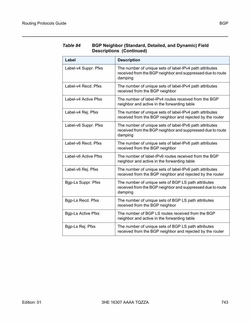
Routing Protocols Guide BGP
Edition: 01 3HE 16307 AAAA TQZZA 743
Label-v4 Suppr. Pfxs The number of unique sets of label-IPv4 path attributes received from the BGP neighbor and suppressed due to route damping
Label-v4 Recd. Pfxs The number of unique sets of label-IPv4 path attributes received from the BGP neighbor
Label-v4 Active Pfxs The number of label-IPv4 routes received from the BGP neighbor and active in the forwarding table
Label-v4 Rej. Pfxs The number of unique sets of label-IPv4 path attributes received from the BGP neighbor and rejected by the router
Label-v6 Suppr. Pfxs The number of unique sets of label-IPv6 path attributes received from the BGP neighbor and suppressed due to route damping
Label-v6 Recd. Pfxs The number of unique sets of label-IPv6 path attributes received from the BGP neighbor
Label-v6 Active Pfxs The number of label-IPv6 routes received from the BGP neighbor and active in the forwarding table
Label-v6 Rej. Pfxs The number of unique sets of label-IPv6 path attributes received from the BGP neighbor and rejected by the router
Bgp-Ls Suppr. Pfxs The number of unique sets of BGP LS path attributes received from the BGP neighbor and suppressed due to route damping
Bgp-Ls Recd. Pfxs The number of unique sets of BGP LS path attributes received from the BGP neighbor
Bgp-Ls Active Pfxs The number of BGP LS routes received from the BGP neighbor and active in the forwarding table
Bgp-Ls Rej. Pfxs The number of unique sets of BGP LS path attributes received from the BGP neighbor and rejected by the router
Table 84 BGP Neighbor (Standard, Detailed, and Dynamic) Field Descriptions (Continued)
Label Description

BGP
744
Routing Protocols Guide
3HE 16307 AAAA TQZZA Edition: 01
Output Example - BGP Neighbor (advertised-routes and received-routes)
*A:7705_ALU-2>show>router>bgp# neighbor 10.44.44.44 advertised-routes===============================================================================BGP Router ID : 10.55.55.55 AS : 1 Local AS : 1
===============================================================================Legend -Status codes : u - used, s - suppressed, h - history, d - decayed, * - validOrigin codes : i - IGP, e - EGP, ? - incomplete, > - best
===============================================================================BGP IPv4 Routes===============================================================================Flag Network LocalPref MED
Nexthop Path-Id LabelAs-Path
-------------------------------------------------------------------------------? 10.0.0.02/32 100 none
10.0.0.16 -No As-Path
? 10.0.6.04/24 100 none10.0.0.16 -No As-Path
-------------------------------------------------------------------------------Routes : 2===============================================================================*A:7705_ALU-2>show>router>bgp#
*A:PE1>show>router>bgp# neighbor 10.10.10.12 advertised-routes brief===============================================================================BGP Router ID : 10.10.10.1 AS : 65000 Local AS : 65000
===============================================================================Legend -Status codes : u - used, s - suppressed, h - history, d - decayed, * - validOrigin codes : i - IGP, e - EGP, ? - incomplete, > - best
===============================================================================BGP IPv4 Routes===============================================================================Flag Network-------------------------------------------------------------------------------? 10.10.10.1/32? 10.10.10.0/24? 10.10.10.1/24? 10.10.10.2/24? 10.10.10.3/24-------------------------------------------------------------------------------Routes : 5===============================================================================*A:7705_ALU-2>show>router>bgp#
*A:7705_ALU-2>show>router>bgp# neighbor 10.44.44.44 received-routes===============================================================================BGP Router ID : 10.55.55.55 AS : 1 Local AS : 1
===============================================================================Legend -Status codes : u - used, s - suppressed, h - history, d - decayed, * - validOrigin codes : i - IGP, e - EGP, ? - incomplete, > - best
===============================================================================BGP IPv4 Routes

Routing Protocols Guide BGP
Edition: 01 3HE 16307 AAAA TQZZA 745
===============================================================================Flag Network LocalPref MED
Nexthop Path-Id LabelAs-Path
-------------------------------------------------------------------------------? 10.0.0.16/32 100 none
10.0.0.16 -No As-Path
? 10.0.6.0/24 100 none10.0.0.16 -No As-Path
? 10.0.8.0/24 100 none10.0.0.16 -No As-Path
? 10.0.12.0/24 100 none10.0.0.16 -No As-Path
-------------------------------------------------------------------------------Routes : 4===============================================================================*A:7705_ALU-2>show>router>bgp#
Table 85 BGP Neighbor (Advertised-Routes and Received-Routes) Field Descriptions
Label Description
BGP Router ID The local BGP router ID
AS The configured autonomous system number
Local AS The configured local AS setting. If not configured, then it is the same value as the AS.
Flag/Flags Legend:Status codes:u - useds - suppressedh - historyd - decayed* - validIf an * is not present, then the status is invalidOrigin codes: i - IGPe - EGP? - incomplete> - best
Network The route IP prefix and mask length for the route
Next Hop The BGP next hop for the route

BGP
746
Routing Protocols Guide
3HE 16307 AAAA TQZZA Edition: 01
Output Example - BGP Neighbor (graceful restart)
*A:7705_ALU-2>show>router>bgp# neighbor 10.10.120.44 graceful-restart===============================================================================BGP Neighbor 10.10.120.44 Graceful Restart===============================================================================Graceful Restart locally configured for peer : EnabledPeer's Graceful Restart feature : EnabledNLRI(s) that peer supports restart for : IPv4-Unicast IPv4-MPLS IPv4-VPNNLRI(s) that peer saved forwarding for : IPv4-Unicast IPv4-MPLS IPv4-VPNNLRI(s) that restart is negotiated for : NoneNLRI(s) of received end-of-rib markers : IPv4-UnicastNLRI(s) of all end-of-rib markers sent : IPv4-UnicastRestart time locally configured for peer : 120 secondsRestart time requested by the peer : 390 secondsTime stale routes from peer are kept for : 360 secondsGraceful restart status on the peer : Not currently being helpedNumber of Restarts : 328Last Restart at : 08/20/2006 12:22:06===============================================================================*A:7705_ALU-2>show>router>bgp#
LocalPref The BGP local preference path attribute for the route
MED The BGP Multi-Exit Discriminator (MED) path attribute for the route
Path-Id The path ID that is received as part of the add-path capability
Label The BGP label associated with the route
AS-Path The BGP AS path for the route
Table 86 BGP Neighbor (Graceful Restart) Field Descriptions
Label Description
BGP Neighbor The IP address of the BGP neighbor
Graceful Restart locally configured for peer The configured state of graceful restart for the local router
Peer's Graceful Restart feature The configured state of graceful restart for the peer router
NLRI(s) that peer supports restart for The families supported by the peer router for graceful restart
Table 85 BGP Neighbor (Advertised-Routes and Received-Routes) Field Descriptions (Continued)
Label Description

Routing Protocols Guide BGP
Edition: 01 3HE 16307 AAAA TQZZA 747
NLRI(s) that peer saved forwarding for The families for which the peer router continued to forward packets after graceful restart
NLRI(s) that restart is negotiated for The families that negotiate restart during graceful restart
NLRI(s) of received end-of-rib markers The families for which end-of-RIB markers have been received
NLRI(s) of all end-of-rib markers sent The families for which end-of-RIB markers have been sent
Restart time locally configured for peer The length of time configured on the local router for the peer router’s graceful restart
Restart time requested by the peer The length of time requested by the peer router for graceful restart
Time stale routes from peer are kept for The length of time that the local router continues to support stale routes
Graceful restart status on the peer The status of graceful restart on the peer router
Number of Restarts The number of restarts since graceful restart is enabled between peers
Last Restart at The local time of the last graceful restart
Table 86 BGP Neighbor (Graceful Restart) Field Descriptions (Continued)
Label Description

BGP
748
Routing Protocols Guide
3HE 16307 AAAA TQZZA Edition: 01
next-hop
Syntax next-hop [family [service-id service-id]] [ip-address [detail]]
Context show>router>bgp
Description This command displays BGP next-hop information.
Parameters family — the type of routing information to be distributed by this peer group
Values ipv4 — displays only those BGP peers that have the IPv4 family enabled and not those capable of exchanging VPN-IPv4 routesipv6 — displays only those BGP peers that have the IPv6 family enabled and not those capable of exchanging VPN-IPv6 routeslabel-ipv4 — displays only those BGP peers that support the labeled IPv4 IPv4 unicast address familyvpn-ipv4 — displays only those BGP peers that have the VPN-IPv4 family enabled vpn-ipv6 — displays only those BGP peers that have the VPN-IPv6 family enabled mvpn-ipv4 — displays only those BGP peers that have the MVPN-IPv4 family enabled evpn — displays only those BGP peers that have the EVPN family enabled
service-id — specifies the service ID
Values 1 to 2147483647
ip-address — displays the next hop-information for the specified IP address
Values ipv4-address: a.b.c.d ipv6-address: x:x:x:x:x:x:x:x[-interface] x:x:x:x:x:x:d.d.d.d[-interface] x: [0 to FFFF]H d: [0 to 255]D
interface: 32 characters maximum, mandatory for link local addresses
detail — displays the more detailed version of the output
Output The following output is an example of BGP next-hop information, and Table 87 describes the fields.
Output Example
A:7705_ALU-2>show>router>bgp# next-hop===============================================================================BGP Router ID : 10.10.10.1 AS : 65000 Local AS : 65000
==============================================================================================================================================================

Routing Protocols Guide BGP
Edition: 01 3HE 16307 AAAA TQZZA 749
BGP Next Hop===============================================================================Next Hop Pref Owner
Resolving Prefix MetricResolved Next Hop Ref. Count
-------------------------------------------------------------------------------10.10.10.12 7 ISIS
10.20.1.1/32 1010.10.2.1 592
10.10.10.12 7 ISIS10.20.1.2/32 1010.10.3.2 592
10.20.1.4 7 ISIS10.20.0.0/32 2010.10.11.4 8
-------------------------------------------------------------------------------Next Hops : 3===============================================================================A:7705_ALU-2>show>router>bgp#
A:7705_ALU-2>show>router>bgp# next-hop 10.0.0.1===============================================================================BGP Router ID : 10.10.10.1 AS : 65000 Local AS : 65000
==============================================================================================================================================================BGP Next Hop===============================================================================Next Hop Pref Owner
Resolving Prefix MetricResolved Next Hop Ref. Count
-------------------------------------------------------------------------------10.0.0.1 15 ISIS
10.0.0.0/24 2010.88.1.2 8
10.0.0.1 15 ISIS10.0.0.0/24 2010.88.2.2 8
-------------------------------------------------------------------------------Next Hops : 1===============================================================================A:7705_ALU-2>show>router>bgp#
A:7705_ALU-2>show>router>bgp# next-hop 10.0.0.1 detail===============================================================================BGP Router ID : 10.10.10.1 AS : 65000 Local AS : 65000
==============================================================================================================================================================BGP Next Hop===============================================================================Next Hop: 10.0.0.1-------------------------------------------------------------------------------Resolving Prefix : 10.0.0.0/24Preference : 15 Metric : 20Reference Count : 8 Owner : ISISResolved Next Hop: 10.88.1.2Egress Label : N/AResolved Next Hop: 10.88.2.2Egress Label : N/A

BGP
750
Routing Protocols Guide
3HE 16307 AAAA TQZZA Edition: 01
Resolved Next Hop: 10.88.3.2Egress Label : N/A-------------------------------------------------------------------------------Next Hops : 1===============================================================================A:7705_ALU-2>show>router>bgp#
The following output displays an example of when the next hop is unresolved by a next-hop-resolution policy.A:7705_ALU-2>show router bgp next-hop===============================================================================BGP Router ID:10.20.1.3 AS:100 Local AS:100
==============================================================================================================================================================BGP Next Hop===============================================================================Next Hop Pref Owner
Resolving Prefix FibProg MetricResolved Next Hop Ref. Count
-------------------------------------------------------------------------------10.20.1.2 10 OSPF
10.20.1.2/32 Y 100010.10.3.2 2
10.20.1.4 10 OSPF10.20.1.4/32 Y 100010.10.11.4 1
10.20.1.5 - -Unresolved --- -
-------------------------------------------------------------------------------Next Hops : 3===============================================================================
Table 87 BGP Next-Hop Field Descriptions
Label Description
BGP Router ID The local BGP router ID
AS The configured autonomous system number
Local AS The configured local AS setting. If not configured, then the value is the same as the AS.
Next Hop The next-hop address
Resolving Prefix The prefix of the best next hop
Pref: Preference The BGP preference attribute for the routes
FibProg Indicates whether a resolved BGP next hop is programmed in the FIB
Metric The metric derived from the IGP for a particular next hop

Routing Protocols Guide BGP
Edition: 01 3HE 16307 AAAA TQZZA 751
paths
Syntax paths
Context show>router>bgp
Description This command displays a summary of BGP path attributes.
Output The following output is an example of BGP path information, and Table 88 describes the fields.
Output Example
*A:7705_ALU-2>show>router>bgp# paths===============================================================================BGP Router ID : 10.55.55.55 AS : 65000 Local AS : 65000==============================================================================================================================================================BGP Paths===============================================================================Path: No As-Path-------------------------------------------------------------------------------Next Hop : 10.44.10.12Origin : Incomplete Segments : 0MED : None Local Preference : 4294967295Refs : 1080 ASes : 0Flags : IBGP-learned-------------------------------------------------------------------------------Path: No As-Path-------------------------------------------------------------------------------Next Hop : 10.88.1.2Origin : IGP Segments : 0MED : 10 Local Preference : NoneRefs : 4 ASes : 0Flags : Imported-------------------------------------------------------------------------------Path: No As-Path-------------------------------------------------------------------------------Next Hop : 10.44.10.21Origin : IGP Segments : 0
Reference Count The number of routes using the resolving prefix
Owner The routing protocol used to derive the best next hop
Resolved Next Hop The IP address of the next hop
Egress Label The VPN label used for VPN-IPv4 data
Next Hops The number of next hops
Table 87 BGP Next-Hop Field Descriptions (Continued)
Label Description

BGP
752
Routing Protocols Guide
3HE 16307 AAAA TQZZA Edition: 01
MED : None Local Preference : 100Refs : 1082 ASes : 0Flags : IBGP-learnedCluster : 10.10.10.12Originator Id : 10.10.10.21-------------------------------------------------------------------------------Paths : 3===============================================================================*A:7705_ALU-2>show>router>bgp#
Table 88 BGP Path Field Descriptions
Label Description
BGP Router ID The local BGP router ID
AS The configured autonomous system number
Local AS The configured local AS setting. If not configured, then the value is the same as the AS.
Path The AS path attribute
Next Hop The advertised BGP next hop
Origin EGP: the NLRI is learned by an EGP protocol
IGP: the NLRI is interior to the originating AS
Incomplete: NLRI was learned another way
Segments The number of segments in the AS path attribute
MED The Multi-Exit Discriminator value
Local Preference The local preference value. This value is used if the BGP route arrives from a BGP peer without the Local Pref attribute set. It is overridden by any value set via a route policy.
Refs The number of routes using a specified set of path attributes
ASes The number of autonomous system numbers in the AS path attribute
Flags IBGP-learned: path attributes learned by an IBGP peering
Community The BGP community attribute list
Cluster List The route reflector cluster list
Originator ID The originator ID path attribute value

Routing Protocols Guide BGP
Edition: 01 3HE 16307 AAAA TQZZA 753
routes
Syntax routes [ip-prefix/mask | ip-address]routes aspath-regex reg-exp {detail |longer}routes aspath-regex reg-exp routes aspath-regex reg-exp huntroutes bgp-ls [hunt] [node | link | ipv4-prefix [ipv4-prefix/mask-len]]routes briefroutes community comm-id {detail |longer}routes community comm-idroutes community comm-id huntroutes detail routes hunt [brief]routes ipv4 [aspath-regex reg-exp] [community comm-id] [brief] [all]routes ipv4 [aspath-regex reg-exp] hunt [community comm-id [brief] [all]routes ipv4 [detail |longer] [aspath-regex reg-exp] [community comm-id] [all]routes ipv6 [aspath-regex reg-exp] [community comm-id] [brief] [all]routes ipv6 [aspath-regex reg-exp] hunt [community comm-id] [brief] [all]routes ipv6 [detail |longer] [aspath-regex reg-exp] [community comm-id] [all]routes label-ipv4 [aspath-regex reg-exp] [community comm-id] [brief] [all]routes label-ipv4 [aspath-regex reg-exp] hunt [community comm-id] [brief] [all]routes label-ipv4 [detail | longer] [aspath-regex reg-exp] [community comm-id] [all]routes longerroutes mvpn-ipv4 [aspath-regex reg-exp] [community comm-id] [rd rd] [brief] [type
mvpn-type] [originator-ip ip-address] [source-ip ipv4 address | ipv6 address] [group-ip ipv4 address | ipv6 address] [source-as as-number]
routes mvpn-ipv4 [aspath-regex reg-exp] hunt [community comm-id] [rd rd] [brief] [type mvpn-type] [originator-ip ip-address] [source-ip ipv4 address | ipv6 address] [group-ip ipv4 address | ipv6 address] [source-as as-number]
routes mvpn-ipv4 [detail |longer] [aspath-regex reg-exp] [community comm-id] [rd rd] [type mvpn-type] [originator-ip ip-address] [source-ip ipv4 address | ipv6 address] [group-ip ipv4 address | ipv6 address] [source-as as-number]
routes route-target [source-as as-number] [brief] [aspath-regex reg-exp] [community comm-id]
routes route-target [rtc-prefix rtc-prefix] [hunt] [brief] [aspath-regex reg-exp] [community comm-id]
routes route-target rtc-prefix rtc-prefix [aspath-regex reg-exp] [community comm-id]routes route-target [rtc-prefix rtc-prefix] [detail | longer] [aspath-regex reg-exp]
[community comm-id]routes vpn-ipv4 [aspath-regex reg-exp] [community comm-id] [rd rd] [brief]routes vpn-ipv4 [aspath-regex reg-exp] hunt [community comm-id] [rd rd] [brief]routes vpn-ipv4 [detail |longer] [aspath-regex reg-exp] [community comm-id] [rd rd] routes vpn-ipv6 [aspath-regex reg-exp] [community comm-id] [rd rd] [brief]routes vpn-ipv6 [aspath-regex reg-exp] hunt [community comm-id] [rd rd] [brief]

BGP
754
Routing Protocols Guide
3HE 16307 AAAA TQZZA Edition: 01
routes vpn-ipv6 [detail |longer] [aspath-regex reg-exp] [community comm-id] [rd rd]
Context show>router>bgp
Description This command displays BGP route information.
When this command is issued without any parameters, the entire BGP routing table displays.
When this command is issued with an IP prefix/mask or IP address, the best match for the parameter displays.
Parameters ip-prefix/mask | ip-address — displays parameters that match the specified IPv4 prefix and mask length or IPv6 address (256 characters maximum)
Values ip-prefix: a.b.c.d (host bits must be 0) mask: 0 to 32 ip-address: x:x:x:x:x:x:x:x[-interface]
x:x:x:x:x:x:d.d.d.d[-interface]interface - 32 chars max,
mandatory for link local addresses x: [0 to FFFF]Hd: [0 to 255]D
aspath-regex reg-exp — displays all routes with an AS path matching the specifiedregular expression (80 characters maximum)
bgp-ls — displays BGP Link State routes
ipv4-prefix — displays BGP LS NLRI of type IPv4 Prefix
link — displays BGP Link State NLRI of type Link
node — displays BGP Link State NLRI of type Node
brief — provides a summarized display of the set of peers to which a BGP route is advertised; this option is only supported when no IP prefix/mask or IP address is specified
community — displays all routes with the specified BGP community; community matching is based only on RIB-In communities, not RIB-Out communities
comm-id — specifies community IDs, in the format as-number1:comm-val1 | ext-comm | well-known-comm
Values
Note: To apply a family filter to the route output of the command, the family name must be specified before all other filtering parameters except for the IP prefix/mask or IP address, which, if present, must be placed before the family name in the command.
as-number1 0 to 65535comm-val1 0 to 65535

Routing Protocols Guide BGP
Edition: 01 3HE 16307 AAAA TQZZA 755
group-ip ipv4 address | ipv6 address — displays the group IPv4 or IPv6 address
originator-ip ip-address — displays the originating IPv4 or IPv6 address
source-ip ipv4 address | ipv6 address — displays the source IPv4 or IPv6 address
detail — displays a more detailed version of the output
source-as as-number — displays the source AS number
hunt — displays entries for the specified route in the RIB-In, RIB-Out, and RTM
ipv4 — displays only those BGP peers that have the IPv4 family enabled
ipv6 — displays only those BGP peers that have the IPv6 family enabled
label-ipv4 — displays only those BGP peers for the labeled IPv4 IPv4 unicast address family
longer — displays the specified route and subsets of the route
mvpn-ipv4 — displays the BGP peers that are MVPN-IPv4 capable
mvpn-type — the specified MVPN type for which to display information
Values intra-ad | inter-ad | spmsi-ad | leaf-ad | source-ad | shared-join | source-join
route-target — displays a summary of route target constrained routes for this BGP peer
ext-comm type:{ip-address:comm-val1 | as-number1:comm-val2 |as-number2:comm-val1 | as-number1:val-in-mbps} ext:xxyy:ovstatewheretype: target | origin | bandwidth (keywords)ip-address:ipv4-address: a.b.c.dipv6-address: x:x:x:x:x:x:x:x[-interface]
x:x:x:x:x:x:d.d.d.d[-interface]interface - 32 chars max, mandatory for link local addresses x: [0 to FFFF]Hd: [0 to 255]D
ext:xxyy:ovstate xx: 43yy: 0ovstate: 0, 1, 2 (0 for valid, 1 for not-found, 2 for invalid)
well-known-comm null | no-export | no-export-subconfed | no-advertise (keywords)

BGP
756
Routing Protocols Guide
3HE 16307 AAAA TQZZA Edition: 01
rtc-prefix rtc-prefix — displays route target constraint prefix information, in the format source-as:{ip-addr:comm-val | 2byte-asnumber:ext-comm-val | 4byte-asnumber:comm-val}/prefix-length
Values ip-addr:ipv4-address: a.b.c.dipv6-address: x:x:x:x:x:x:x:x[-interface]
x:x:x:x:x:x:d.d.d.d[-interface]interface - 32 chars max, mandatory for link local addresses
x: [0 to FFFF]Hd: [0 to 255]D
comm-val: 0 to 655352byte-asnumber: 0 to 65535ext-comm-val: 0 to 42949672954byte-asnumber: 0 to 4294967295prefix-length: 0 to 96
rd rd — displays the route distinguisher value, in the format ip-addr:comm-val | 2byte-asnumber:ext-comm-val | 4-byte-asnumber:comm-val
Values ip-addr:ipv4-address: a.b.c.dipv6-address: x:x:x:x:x:x:x:x[-interface]
x:x:x:x:x:x:d.d.d.d[-interface]interface - 32 chars max, mandatory for link local addresses
x: [0 to FFFF]Hd: [0 to 255]D
comm-val: 0 to 655352byte-asnumber: 0 to 65535ext-comm-val: 0 to 42949672954byte-asnumber: 0 to 4294967295
vpn-ipv4 — displays the BGP VPN IPv4 routes
vpn-ipv6 — displays the BGP VPN IPv6 routes
originator-ip ip-address — filters BGP MVPN routes by the originating router IP address that is found in the intra-AD (auto-discovery) MVPN routes
source-ip ip-address — filters BGP MVPN routes by the source IP address that is found in the source-join, source-AD, or S-PMSI-AD MVPN routes
group-ip ip-address — filters BGP MVPN routes by the multicast group IP address that is found in the source-join, source-AD, or S-PMSI-AD MVPN routes
source-as as-number — filters BGP MVPN routes by source-AS (autonomous system) extended community attribute

Routing Protocols Guide BGP
Edition: 01 3HE 16307 AAAA TQZZA 757
Output The following output is an example of BGP route information, and Table 89 describes the fields.
Output Example
*A:Sar18 Dut-B# show router bgp routes 10.10.10.5===============================================================================BGP Router ID:10.20.1.3 AS:100 Local AS:100
===============================================================================Legend -Status codes : u - used, s - suppressed, h - history, d - decayed, * - valid
l - leaked, x - stale, > - best, b - backup, p - purgeOrigin codes : i - IGP, e - EGP, ? - incomplete
===============================================================================BGP IPv4 Routes===============================================================================Flag Network LocalPref MED
Nexthop (Router) Path-Id LabelAs-Path
-------------------------------------------------------------------------------u*>? 10.10.10.0/24 None None
10.20.1.4 None -200 300
-------------------------------------------------------------------------------Routes : 1===============================================================================*A:Sar18 Dut-B##
*A:Sar18 Dut-B# show>router>bgp# routes vpn-ipv4 10.10.10.6/32 rd 10.20.1.4:1 hunt===============================================================================BGP Router ID:10.20.1.3 AS:None Local AS:100
===============================================================================Legend -Status codes : u - used, s - suppressed, h - history, d - decayed, * - valid
l - leaked, x - stale, > - best, b - backup, p - purgeOrigin codes : i - IGP, e - EGP, ? - incomplete, > - best, b - backup
===============================================================================BGP VPN-IPv4 Routes===============================================================================-------------------------------------------------------------------------------RIB In Entries-------------------------------------------------------------------------------Network : 10.10.10.6/32Nexthop : 10.20.1.4Route Dist. : 10.20.1.4:1 VPN Label : 131070Path Id : NoneFrom : 10.20.1.4Res. Nexthop : n/aLocal Pref. : 100 Interface Name : int_to_DAggregator AS : None Aggregator : NoneAtomic Aggr. : Not Atomic MED : NoneAIGP Metric : NoneConnector : NoneCommunity : target:100:100Cluster : No Cluster MembersOriginator Id : None Peer Router Id : 10.20.1.4Fwd Class : None Priority : None

BGP
758
Routing Protocols Guide
3HE 16307 AAAA TQZZA Edition: 01
Flags : Used Valid Best IncompleteRoute Source : InternalAS-Path : 106VPRN Imported : 1-------------------------------------------------------------------------------RIB Out Entries--------------------------------------------------------------------------------------------------------------------------------------------------------------Routes : 1===============================================================================*A:Sar18 Dut-B#
*A:Sar18 Dut-B# show>router>bgp# routes 3FFE::606:609/128 vpn-ipv6 hunt===============================================================================BGP Router ID:10.20.1.3 AS:None Local AS:100
===============================================================================Legend -Status codes : u - used, s - suppressed, h - history, d - decayed, * - valid
l - leaked, x - stale, > - best, b - backup, p - purgeOrigin codes : i - IGP, e - EGP, ? - incomplete, > - best, b - backup
===============================================================================BGP VPN-IPv6 Routes===============================================================================-------------------------------------------------------------------------------RIB In Entries-------------------------------------------------------------------------------Network : 3FFE::606:609/128Nexthop : ::FFFF:A14:104Route Dist. : 10.20.1.4:1 VPN Label : 131070Path Id : NoneFrom : 10.20.1.4Res. Nexthop : n/aLocal Pref. : 100 Interface Name : int_to_DAggregator AS : None Aggregator : NoneAtomic Aggr. : Not Atomic MED : NoneAIGP Metric : NoneConnector : NoneCommunity : target:100:100Cluster : No Cluster MembersOriginator Id : None Peer Router Id : 10.20.1.4Fwd Class : None Priority : NoneFlags : Used Valid Best IncompleteRoute Source : InternalAS-Path : 106VPRN Imported : 1-------------------------------------------------------------------------------RIB Out Entries--------------------------------------------------------------------------------------------------------------------------------------------------------------Routes : 1===============================================================================*A:Sar18 Dut-B#
*A:Sar18 Dut-B# show>router>bgp# routes vpn-ipv6 3FFE::606:607 128 rd 10.20.1.4:1hunt===============================================================================BGP Router ID:10.20.1.3 AS:None Local AS:100

Routing Protocols Guide BGP
Edition: 01 3HE 16307 AAAA TQZZA 759
===============================================================================Legend -Status codes : u - used, s - suppressed, h - history, d - decayed, * - valid
l - leaked, x - stale, > - best, b - backup, p - purgeOrigin codes : i - IGP, e - EGP, ? - incomplete, > - best, b - backup
===============================================================================BGP VPN-IPv6 Routes===============================================================================-------------------------------------------------------------------------------RIB In Entries-------------------------------------------------------------------------------Network : 3FFE::606:607/128Nexthop : ::FFFF:A14:104Route Dist. : 10.20.1.4:1 VPN Label : 131070Path Id : NoneFrom : 10.20.1.4Res. Nexthop : n/aLocal Pref. : 100 Interface Name : int_to_DAggregator AS : None Aggregator : NoneAtomic Aggr. : Not Atomic MED : NoneAIGP Metric : NoneConnector : NoneCommunity : target:100:100Cluster : No Cluster MembersOriginator Id : None Peer Router Id : 10.20.1.4Fwd Class : None Priority : NoneFlags : Used Valid Best IncompleteRoute Source : InternalAS-Path : 106VPRN Imported : 1-------------------------------------------------------------------------------RIB Out Entries--------------------------------------------------------------------------------------------------------------------------------------------------------------Routes : 1===============================================================================*A:Sar18 Dut-B#
*A:Sar18 Dut-B# show>router>bgp# routes vpn-ipv6 3FFE::606:607/128 rd 10.20.1.4:2hunt===============================================================================BGP Router ID:10.20.1.3 AS:None Local AS:100
===============================================================================Legend -Status codes : u - used, s - suppressed, h - history, d - decayed, * - valid
l - leaked, x - stale, > - best, b - backup, p - purgeOrigin codes : i - IGP, e - EGP, ? - incomplete, > - best, b - backup
===============================================================================BGP VPN-IPv6 Routes===============================================================================No Matching Entries Found===============================================================================*A:Sar18 Dut-B#
*A:Sar18 Dut-B# show router bgp routes hunt 10.10.10.1/32===============================================================================BGP Router ID:10.20.1.3 AS:5000 Local AS:5000

BGP
760
Routing Protocols Guide
3HE 16307 AAAA TQZZA Edition: 01
===============================================================================Legend -Status codes : u - used, s - suppressed, h - history, d - decayed, * - valid
l - leaked, x - stale, > - best, b - backup, p - purgeOrigin codes : i - IGP, e - EGP, ? - incomplete, > - best===============================================================================BGP IPv4 Routes===============================================================================-------------------------------------------------------------------------------RIB In Entries-------------------------------------------------------------------------------Network : 10.10.10.1/32Nexthop : 10.20.1.1From : 10.20.1.1Res. Nexthop : 10.20.1.1 (RSVP LSP: 1)Local Pref. : 100 Interface Name : ip-10.10.2.3Aggregator AS : None Aggregator : NoneAtomic Aggr. : Not Atomic MED : NoneCommunity : No Community MembersCluster : No Cluster MembersOriginator Id : None Peer Router Id : 10.20.1.1Flags : Used Valid Best IncompleteAS-Path : No As-Path-------------------------------------------------------------------------------RIB Out Entries--------------------------------------------------------------------------------------------------------------------------------------------------------------Routes : 1===============================================================================*A:Sar18 Dut-B#
*A:Sar18 Dut-B# show router bgp routes family ipv4===============================================================================BGP Router ID : 10.10.10.103 AS : 200 Local AS : 200
===============================================================================Legend -Status codes : u - used, s - suppressed, h - history, d - decayed, * - valid
l - leaked, x - stale, > - best, b - backup, p - purgeOrigin codes : i - IGP, e - EGP, ? - incomplete, > - best
===============================================================================BGP Routes===============================================================================Flag Network Nexthop LocalPref MED
VPN Label As-Path-------------------------------------------------------------------------------No Matching Entries Found===============================================================================*A:Sar18 Dut-B#
*A:Sar18 Dut-B# show router bgp routes 10.10.10.0/24 detail===============================================================================BGP Router ID : 10.128.0.161 AS : 65535 Local AS : 65535===============================================================================Legend -Status codes : u - used, s - suppressed, h - history, d - decayed, * - valid
l - leaked, x - stale, > - best, b - backup, p - purgeOrigin codes : i - IGP, e - EGP, ? - incomplete, > - best

Routing Protocols Guide BGP
Edition: 01 3HE 16307 AAAA TQZZA 761
===============================================================================BGP Routes===============================================================================Original AttributesNetwork : 10.10.10.0/24 Nexthop : 10.20.1.20Route Dist. : 10070:100 VPN Label : 152784From : 10.20.1.20 Res. Nexthop : 10.130.0.2Local Pref. : 100Aggregator AS : none Aggregator : noneAtomic Aggr. : Not Atomic MED : noneCommunity : target:10070:1Cluster : No Cluster MembersOriginator Id : None Peer Router Id : 10.20.1.20Flags : Used Valid Best IGPAS-Path : 10070 {14730}Modified Attributes
Network :10.10.10.0/24 Nexthop :10.20.1.20Route Dist.: 10001:100 VPN Label :152560From :10.20.1.20 Res. Nexthop :10.130.0.2Local Pref.:100Aggregator AS: none Aggregator:noneAtomic Aggr.:Not Atomic MED :noneCommunity :target:10001:1Cluster :No Cluster MembersOriginator Id:None Peer Router Id:10.20.1.20Flags :Used Valid Best IGPAS-Path :No As-Path-------------------------------------------------------------------------------*A:Sar18 Dut-B#
*A:Sar18 Dut-B# show router bgp routes 10.10.10.0/24 hunt===============================================================================BGP Router ID : 10.20.1.1 AS : 100Local AS : 100
===============================================================================Legend -Status codes : u - used, s - suppressed, h - history, d - decayed, * - valid
l - leaked, x - stale, > - best, b - backup, p - purgeOrigin codes : i - IGP, e - EGP, ? - incomplete, > - best
===============================================================================BGP Routes===============================================================================RIB In Entries-------------------------------------------------------------------------------Network : 10.10.10.0/24Nexthop : 10.20.1.2Route Dist. : 10.20.1.2:1VPN Label: 131070From : 10.20.1.2Res. Nexthop : 10.10.1.2Local Pref. : 100Interface Name: to-sr7Aggregator AS : noneAggregator: noneAtomic Aggr. : Not AtomicMED: noneCommunity : target:10.20.1.2:1Cluster : No Cluster MembersOriginator Id : NonePeer Router Id: 10.20.1.2Flags : Used Valid Best IGPAS-Path : No As-PathVPRN Imported : 1 2 10 12
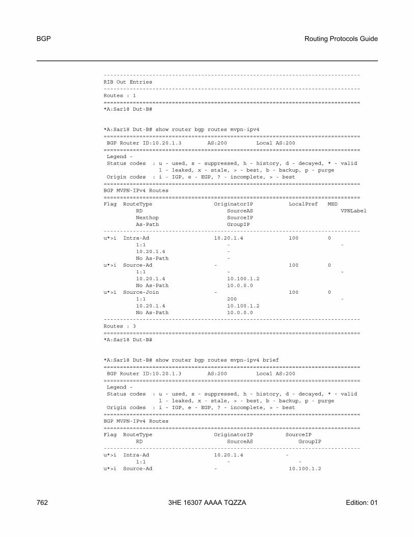
BGP
762
Routing Protocols Guide
3HE 16307 AAAA TQZZA Edition: 01
-------------------------------------------------------------------------------RIB Out Entries-------------------------------------------------------------------------------Routes : 1===============================================================================*A:Sar18 Dut-B#
*A:Sar18 Dut-B# show router bgp routes mvpn-ipv4===============================================================================BGP Router ID:10.20.1.3 AS:200 Local AS:200
===============================================================================Legend -Status codes : u - used, s - suppressed, h - history, d - decayed, * - valid
l - leaked, x - stale, > - best, b - backup, p - purgeOrigin codes : i - IGP, e - EGP, ? - incomplete, > - best
===============================================================================BGP MVPN-IPv4 Routes===============================================================================Flag RouteType OriginatorIP LocalPref MED
RD SourceAS VPNLabelNexthop SourceIPAs-Path GroupIP
-------------------------------------------------------------------------------u*>i Intra-Ad 10.20.1.4 100 0
1:1 - -10.20.1.4 -No As-Path -
u*>i Source-Ad - 100 01:1 - -10.20.1.4 10.100.1.2No As-Path 10.0.0.0
u*>i Source-Join - 100 01:1 200 -10.20.1.4 10.100.1.2No As-Path 10.0.0.0
-------------------------------------------------------------------------------Routes : 3===============================================================================*A:Sar18 Dut-B#
*A:Sar18 Dut-B# show router bgp routes mvpn-ipv4 brief===============================================================================BGP Router ID:10.20.1.3 AS:200 Local AS:200
===============================================================================Legend -Status codes : u - used, s - suppressed, h - history, d - decayed, * - valid
l - leaked, x - stale, > - best, b - backup, p - purgeOrigin codes : i - IGP, e - EGP, ? - incomplete, > - best
===============================================================================BGP MVPN-IPv4 Routes===============================================================================Flag RouteType OriginatorIP SourceIP
RD SourceAS GroupIP-------------------------------------------------------------------------------u*>i Intra-Ad 10.20.1.4 -
1:1 - -u*>i Source-Ad - 10.100.1.2
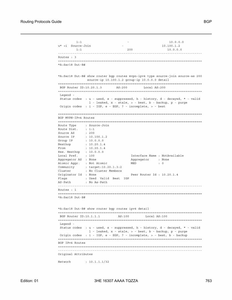
Routing Protocols Guide BGP
Edition: 01 3HE 16307 AAAA TQZZA 763
1:1 - 10.0.0.0u* >i Source-Join - 10.100.1.2
1:1 200 10.0.0.0-------------------------------------------------------------------------------Routes : 3===============================================================================*A:Sar18 Dut-B#
*A:Sar18 Dut-B# show router bgp routes mvpn-ipv4 type source-join source-as 200source-ip 10.100.1.2 group-ip 10.0.0.0 detail
===============================================================================BGP Router ID:10.20.1.3 AS:200 Local AS:200
===============================================================================Legend -Status codes : u - used, s - suppressed, h - history, d - decayed, * - valid
l - leaked, x - stale, > - best, b - backup, p - purgeOrigin codes : i - IGP, e - EGP, ? - incomplete, > - best
===============================================================================BGP MVPN-IPv4 Routes===============================================================================Route Type : Source-JoinRoute Dist. : 1:1Source AS : 200Source IP : 10.100.1.2Group IP : 10.0.0.0Nexthop : 10.20.1.4From : 10.20.1.4Res. Nexthop : 10.0.0.0Local Pref. : 100 Interface Name : NotAvailableAggregator AS : None Aggregator : NoneAtomic Aggr. : Not Atomic MED : 0Community : target:10.20.1.3:2Cluster : No Cluster MembersOriginator Id : None Peer Router Id : 10.20.1.4Flags : Used Valid Best IGPAS-Path : No As-Path-------------------------------------------------------------------------------Routes : 1===============================================================================*A:Sar18 Dut-B#
*A:Sar18 Dut-B# show router bgp routes ipv4 detail===============================================================================BGP Router ID:10.1.1.1 AS:100 Local AS:100
===============================================================================Legend -Status codes : u - used, s - suppressed, h - history, d - decayed, * - valid
l - leaked, x - stale, > - best, b - backup, p - purgeOrigin codes : i - IGP, e - EGP, ? - incomplete, > - best, b - backup
===============================================================================BGP IPv4 Routes===============================================================================-------------------------------------------------------------------------------Original Attributes
Network : 10.1.1.1/32

BGP
764
Routing Protocols Guide
3HE 16307 AAAA TQZZA Edition: 01
Nexthop : 192.168.1.1Path Id : NoneFrom : 192.168.1.1Res. Nexthop : 192.168.1.1Local Pref. : n/a Interface Name : netAggregator AS : None Aggregator : NoneAtomic Aggr. : Not Atomic MED : 5000AIGP Metric : 100Community : NoneCluster : No Cluster MembersOriginator Id : None Peer Router Id : 2.2.2.2Fwd Class : None Priority : NoneFlags : Used Valid Best IncompleteRoute Source : ExternalAS-Path : 200 400 500
Modified Attributes
Network : 10.1.1.1/32Nexthop : 192.168.1.1Path Id : NoneFrom : 192.168.1.1Res. Nexthop : 192.168.1.1Local Pref. : None Interface Name : netAggregator AS : None Aggregator : NoneAtomic Aggr. : Not Atomic MED : 5000AIGP Metric : 110Community : NoneCluster : No Cluster MembersOriginator Id : None Peer Router Id : 2.2.2.2Fwd Class : None Priority : NoneFlags : Used Valid Best IncompleteRoute Source : ExternalAS-Path : 200 400 500--------------------------------------------------------------------------------------------------------------------------------------------------------------Routes : 1===============================================================================*A:Sar18 Dut-B#
*A:Sar18 Dut-B# show router bgp routes 10.1.1.1/32 hunt===============================================================================BGP Router ID:1.1.1.1 AS:100 Local AS:100
===============================================================================Legend -Status codes : u - used, s - suppressed, h - history, d - decayed, * - valid
l - leaked, x - stale, > - best, b - backup, p - purgeOrigin codes : i - IGP, e - EGP, ? - incomplete, > - best, b - backup
===============================================================================BGP IPv4 Routes===============================================================================-------------------------------------------------------------------------------RIB In Entries-------------------------------------------------------------------------------Network : 10.1.1.1/32Nexthop : 192.168.1.1Path Id : NoneFrom : 192.168.1.1

Routing Protocols Guide BGP
Edition: 01 3HE 16307 AAAA TQZZA 765
Res. Nexthop : 192.168.1.1Local Pref. : None Interface Name : netAggregator AS : None Aggregator : NoneAtomic Aggr. : Not Atomic MED : 5000AIGP Metric : 110Community : NoneCluster : No Cluster MembersOriginator Id : None Peer Router Id : 2.2.2.2Fwd Class : None Priority : NoneFlags : Used Valid Best IncompleteRoute Source : ExternalAS-Path : 200 400 500-------------------------------------------------------------------------------RIB Out Entries-------------------------------------------------------------------------------Network : 10.1.1.1/32Nexthop : 10.1.1.1Path Id : NoneTo : 10.3.3.3Res. Nexthop : n/aLocal Pref. : 100 Interface Name : NotAvailableAggregator AS : None Aggregator : NoneAtomic Aggr. : Not Atomic MED : 5000AIGP Metric : 150Community : NoneCluster : No Cluster MembersOriginator Id : None Peer Router Id : 10.3.3.3Origin : IncompleteAS-Path : 200 400 500-------------------------------------------------------------------------------Routes : 2===============================================================================*A:Sar18 Dut-B#
*A:Sar18 Dut-B# show router bgp routes===============================================================================BGP Router ID:10.20.1.1 AS:1 Local AS:1
===============================================================================Legend -Status codes : u - used, s - suppressed, h - history, d - decayed, * - valid
l - leaked, x - stale, > - best, b - backup, p - purgeOrigin codes : i - IGP, e - EGP, ? - incomplete, > - best, b - backup
===============================================================================BGP IPv4 Routes===============================================================================Flag Network LocalPref MED
Nexthop Path-Id LabelAs-Path
-------------------------------------------------------------------------------u*>i 10.0.0.1/32 100 2010
10.20.1.2 None 1310572
ub*i 10.0.0.1/32 100 201010.20.1.3 None 1310672
-------------------------------------------------------------------------------Routes : 2===============================================================================

BGP
766
Routing Protocols Guide
3HE 16307 AAAA TQZZA Edition: 01
*A:Sar18 Dut-B#
*A:Sar18# show router bgp routes vpn-ipv4 community target:100.100.100.100:2 hunt===============================================================================BGP Router ID:10.20.1.6 AS:62000 Local AS:62000===============================================================================Legend -Status codes : u - used, s - suppressed, h - history, d - decayed, * - valid
l - leaked, x - stale, > - best, b - backup, p - purgel - leaked, x - stale, > - best, b - backup, p - purge
Origin codes : i - IGP, e - EGP, ? - incomplete===============================================================================BGP VPN-IPv4 Routes===============================================================================-------------------------------------------------------------------------------RIB In Entries-------------------------------------------------------------------------------Network : 10.1.1.1/32Nexthop : 10.20.1.6Route Dist. : 100.100.100.100:2 VPN Label : 131068Path Id : NoneFrom : 10.20.1.5Res. Nexthop : n/aLocal Pref. : 100 Interface Name : systemAggregator AS : None Aggregator : NoneAtomic Aggr. : Not Atomic MED : 100AIGP Metric : NoneConnector : NoneCommunity : target:100.100.100.100:2Cluster : 5.5.5.5Originator Id : 10.20.1.6 Peer Router Id : 10.20.1.5Flags : Invalid IGPRoute Source : InternalAS-Path : No As-PathRoute Tag : 0Neighbor-AS : N/AAdd Paths Send : DefaultLast Modified : 00h00m06sVPRN Imported : None-------------------------------------------------------------------------------RIB Out Entries-------------------------------------------------------------------------------Network : 10.1.1.1/32Nexthop : 10.20.1.6Route Dist. : 100.100.100.100:2 VPN Label : 131068Path Id : NoneTo : 10.20.1.5Res. Nexthop : n/aLocal Pref. : 100 Interface Name : NotAvailableAggregator AS : None Aggregator : NoneAtomic Aggr. : Not Atomic MED : NoneAIGP Metric : NoneConnector : NoneCommunity : target:100.100.100.100:2Cluster : No Cluster MembersOriginator Id : None Peer Router Id : 10.20.1.5Origin : IGPAS-Path : No As-PathRoute Tag : 0

Routing Protocols Guide BGP
Edition: 01 3HE 16307 AAAA TQZZA 767
Neighbor-AS : N/A-------------------------------------------------------------------------------Routes : 2===============================================================================*A:Sar18#
*A:Sar18# show router bgp routes vpn-ipv6 community target:100.100.100.100:2 hunt===============================================================================BGP Router ID:10.20.1.3 AS:61000 Local AS:61000
===============================================================================Legend -Status codes : u - used, s - suppressed, h - history, d - decayed, * - valid
l - leaked, x - stale, > - best, b - backup, p - purgeOrigin codes : i - IGP, e - EGP, ? - incomplete
===============================================================================BGP VPN-IPv6 Routes===============================================================================-------------------------------------------------------------------------------RIB In Entries-------------------------------------------------------------------------------Network : 3ffe::100:0/109Nexthop : ::ffff:10.20.1.1Route Dist. : 1:1234 VPN Label : 131067Path Id : NoneFrom : 10.20.1.2Res. Nexthop : n/aLocal Pref. : 100 Interface Name : toAAggregator AS : None Aggregator : NoneAtomic Aggr. : Not Atomic MED : 100AIGP Metric : NoneConnector : NoneCommunity : 0:0 target:100.100.100.100:2 target:1:123456
origin:100.100.100.100:2Cluster : 2.2.2.2Originator Id : 10.20.1.1 Peer Router Id : 10.20.1.2Flags : Used Valid Best IGPRoute Source : InternalAS-Path : No As-PathRoute Tag : 0Neighbor-AS : N/AAdd Paths Send : DefaultLast Modified : 00h03m41sVPRN Imported : 3 1
Network : 3ffe::101:100/120Nexthop : ::ffff:10.20.1.1Route Dist. : 1:1234 VPN Label : 131067Path Id : NoneFrom : 10.20.1.2Res. Nexthop : n/aLocal Pref. : 100 Interface Name : toAAggregator AS : None Aggregator : NoneAtomic Aggr. : Not Atomic MED : 100AIGP Metric : NoneConnector : NoneCommunity : 0:0 target:100.100.100.100:2 target:1:123456
origin:100.100.100.100:2Cluster : 2.2.2.2Originator Id : 10.20.1.1 Peer Router Id : 10.20.1.2

BGP
768
Routing Protocols Guide
3HE 16307 AAAA TQZZA Edition: 01
Flags : Used Valid Best IGPRoute Source : InternalAS-Path : No As-PathRoute Tag : 0Neighbor-AS : N/AAdd Paths Send : DefaultLast Modified : 00h03m41sVPRN Imported : 3 1
Network : 3ffe::101:100/123Nexthop : ::ffff:10.20.1.1Route Dist. : 1:1234 VPN Label : 131067Path Id : NoneFrom : 10.20.1.2Res. Nexthop : n/aLocal Pref. : 100 Interface Name : toAAggregator AS : None Aggregator : NoneAtomic Aggr. : Not Atomic MED : 100AIGP Metric : NoneConnector : NoneCommunity : 0:0 target:100.100.100.100:2 target:1:123456
origin:100.100.100.100:2Cluster : 2.2.2.2Originator Id : 10.20.1.1 Peer Router Id : 10.20.1.2Flags : Used Valid Best IGPRoute Source : InternalAS-Path : No As-PathRoute Tag : 0Neighbor-AS : N/AAdd Paths Send : DefaultLast Modified : 00h03m41sVPRN Imported : 3 1
Network : 3ffe::300:0/104Nexthop : ::ffff:10.20.1.1Route Dist. : 1:1234 VPN Label : 131067Path Id : NoneFrom : 10.20.1.2Res. Nexthop : n/aLocal Pref. : 100 Interface Name : toAAggregator AS : None Aggregator : NoneAtomic Aggr. : Not Atomic MED : 100AIGP Metric : NoneConnector : NoneCommunity : 0:0 target:100.100.100.100:2 target:1:123456
origin:123456:2Cluster : 2.2.2.2Originator Id : 10.20.1.1 Peer Router Id : 10.20.1.2Flags : Used Valid Best IGPRoute Source : InternalAS-Path : No As-PathRoute Tag : 0Neighbor-AS : N/AAdd Paths Send : DefaultLast Modified : 00h03m41sVPRN Imported : 3 1
Network : 3ffe::303:300/120Nexthop : ::ffff:10.20.1.1

Routing Protocols Guide BGP
Edition: 01 3HE 16307 AAAA TQZZA 769
Route Dist. : 1:1234 VPN Label : 131067Path Id : NoneFrom : 10.20.1.2Res. Nexthop : n/aLocal Pref. : 100 Interface Name : toAAggregator AS : None Aggregator : NoneAtomic Aggr. : Not Atomic MED : 100AIGP Metric : NoneConnector : NoneCommunity : 0:0 target:100.100.100.100:2 target:1:123456
origin:123456:2Cluster : 2.2.2.2Originator Id : 10.20.1.1 Peer Router Id : 10.20.1.2Flags : Used Valid Best IGPRoute Source : InternalAS-Path : No As-PathRoute Tag : 0Neighbor-AS : N/AAdd Paths Send : DefaultLast Modified : 00h03m41sVPRN Imported : 3 1
Network : ::/0Nexthop : ::ffff:10.20.1.1Route Dist. : 100.100.100.100:2 VPN Label : 131069Path Id : NoneFrom : 10.20.1.2Res. Nexthop : n/aLocal Pref. : 100 Interface Name : toAAggregator AS : None Aggregator : NoneAtomic Aggr. : Not Atomic MED : 100AIGP Metric : NoneConnector : NoneCommunity : target:100.100.100.100:2 origin:100.100.100.100:2
origin:1:123456Cluster : 2.2.2.2Originator Id : 10.20.1.1 Peer Router Id : 10.20.1.2Flags : Used Valid Best IGPRoute Source : InternalAS-Path : No As-PathRoute Tag : 0Neighbor-AS : N/AAdd Paths Send : DefaultLast Modified : 00h03m42sVPRN Imported : 1
Network : 3ffe::100:0/104Nexthop : ::ffff:10.20.1.1Route Dist. : 100.100.100.100:2 VPN Label : 131069Path Id : NoneFrom : 10.20.1.2Res. Nexthop : n/aLocal Pref. : 100 Interface Name : toAAggregator AS : None Aggregator : NoneAtomic Aggr. : Not Atomic MED : 100AIGP Metric : NoneConnector : NoneCommunity : 100:100 2:3 target:100.100.100.100:2
origin:1:123456 origin:1:2

BGP
770
Routing Protocols Guide
3HE 16307 AAAA TQZZA Edition: 01
Cluster : 2.2.2.2Originator Id : 10.20.1.1 Peer Router Id : 10.20.1.2Flags : Used Valid Best IGPRoute Source : InternalAS-Path : No As-PathRoute Tag : 0Neighbor-AS : N/AAdd Paths Send : DefaultLast Modified : 00h03m42sVPRN Imported : 1
Network : 3ffe::101:0/112Nexthop : ::ffff:10.20.1.1Route Dist. : 100.100.100.100:2 VPN Label : 131069Path Id : NoneFrom : 10.20.1.2Res. Nexthop : n/aLocal Pref. : 100 Interface Name : toAAggregator AS : None Aggregator : NoneAtomic Aggr. : Not Atomic MED : 100AIGP Metric : NoneConnector : NoneCommunity : 100:100 2:3 target:100.100.100.100:2
origin:100.100.100.100:2 origin:1:123456 origin:1:2Cluster : 2.2.2.2Originator Id : 10.20.1.1 Peer Router Id : 10.20.1.2Flags : Used Valid Best IGPRoute Source : InternalAS-Path : No As-PathRoute Tag : 0Neighbor-AS : N/AAdd Paths Send : DefaultLast Modified : 00h03m41sVPRN Imported : 1
Network : 3ffe::202:202/128Nexthop : ::ffff:10.20.1.1Route Dist. : 100.100.100.100:2 VPN Label : 131069Path Id : NoneFrom : 10.20.1.2Res. Nexthop : n/aLocal Pref. : 100 Interface Name : toAAggregator AS : None Aggregator : NoneAtomic Aggr. : Not Atomic MED : 100AIGP Metric : NoneConnector : NoneCommunity : 0:0 target:100.100.100.100:2
origin:100.100.100.100:2 origin:1:123456Cluster : 2.2.2.2Originator Id : 10.20.1.1 Peer Router Id : 10.20.1.2Flags : Used Valid Best IGPRoute Source : InternalAS-Path : No As-PathRoute Tag : 0Neighbor-AS : N/AAdd Paths Send : DefaultLast Modified : 00h03m41sVPRN Imported : 1

Routing Protocols Guide BGP
Edition: 01 3HE 16307 AAAA TQZZA 771
Network : ::/0Nexthop : ::ffff:10.20.1.1Route Dist. : 123456:2 VPN Label : 131068Path Id : NoneFrom : 10.20.1.2Res. Nexthop : n/aLocal Pref. : 100 Interface Name : toAAggregator AS : None Aggregator : NoneAtomic Aggr. : Not Atomic MED : 100AIGP Metric : NoneConnector : NoneCommunity : target:100.100.100.100:2 origin:100.100.100.100:2
origin:1:123456Cluster : 2.2.2.2Originator Id : 10.20.1.1 Peer Router Id : 10.20.1.2Flags : Used Valid Best IGPRoute Source : InternalAS-Path : No As-PathRoute Tag : 0Neighbor-AS : N/AAdd Paths Send : DefaultLast Modified : 00h03m41sVPRN Imported : 1
Network : 3ffe::100:0/104Nexthop : ::ffff:10.20.1.1Route Dist. : 123456:2 VPN Label : 131068Path Id : NoneFrom : 10.20.1.2Res. Nexthop : n/aLocal Pref. : 100 Interface Name : toAAggregator AS : None Aggregator : NoneAtomic Aggr. : Not Atomic MED : 100AIGP Metric : NoneConnector : NoneCommunity : 100:100 2:3 target:100.100.100.100:2
origin:1:123456 origin:1:2Cluster : 2.2.2.2Originator Id : 10.20.1.1 Peer Router Id : 10.20.1.2Flags : Used Valid Best IGPRoute Source : InternalAS-Path : No As-PathRoute Tag : 0Neighbor-AS : N/AAdd Paths Send : DefaultLast Modified : 00h03m41sVPRN Imported : 1
Network : 3ffe::101:0/112Nexthop : ::ffff:10.20.1.1Route Dist. : 123456:2 VPN Label : 131068Path Id : NoneFrom : 10.20.1.2Res. Nexthop : n/aLocal Pref. : 100 Interface Name : toAAggregator AS : None Aggregator : NoneAtomic Aggr. : Not Atomic MED : 100AIGP Metric : NoneConnector : None

BGP
772
Routing Protocols Guide
3HE 16307 AAAA TQZZA Edition: 01
Community : 100:100 2:3 target:100.100.100.100:2origin:100.100.100.100:2 origin:1:123456 origin:1:2
Cluster : 2.2.2.2Originator Id : 10.20.1.1 Peer Router Id : 10.20.1.2Flags : Used Valid Best IGPRoute Source : InternalAS-Path : No As-PathRoute Tag : 0Neighbor-AS : N/AAdd Paths Send : DefaultLast Modified : 00h03m41sVPRN Imported : 1
Network : 3ffe::202:202/128Nexthop : ::ffff:10.20.1.1Route Dist. : 123456:2 VPN Label : 131068Path Id : NoneFrom : 10.20.1.2Res. Nexthop : n/aLocal Pref. : 100 Interface Name : toAAggregator AS : None Aggregator : NoneAtomic Aggr. : Not Atomic MED : 100AIGP Metric : NoneConnector : NoneCommunity : 0:0 target:100.100.100.100:2
origin:100.100.100.100:2 origin:1:123456Cluster : 2.2.2.2Originator Id : 10.20.1.1 Peer Router Id : 10.20.1.2Flags : Used Valid Best IGPRoute Source : InternalAS-Path : No As-PathRoute Tag : 0Neighbor-AS : N/AAdd Paths Send : DefaultLast Modified : 00h03m41sVPRN Imported : 1
-------------------------------------------------------------------------------RIB Out Entries--------------------------------------------------------------------------------------------------------------------------------------------------------------Routes : 13===============================================================================*A:Sar18#
*A:7705:Dut-A>config>router# show router bgp routes bgp-ls===============================================================================BGP Router ID:10.0.0.1 AS:1001 Local AS:1001
===============================================================================Legend -Status codes : u - used, s - suppressed, h - history, d - decayed, * - valid
l - leaked, x - stale, > - best, b - backup, p - purgeOrigin codes : i - IGP, e - EGP, ? - incomplete
===============================================================================BGP-LS Node NLRIs===============================================================================Flag Prot/Id Nexthop LocalPref MED
Local Node:AS/LsID/OSPF Ar IdIGP Rt Id

Routing Protocols Guide BGP
Edition: 01 3HE 16307 AAAA TQZZA 773
-------------------------------------------------------------------------------*>i OSPFv2/0 1.13.0.3 n/a None
0.0.7.208/-/0.0.0.010.0.0.4
*>i OSPFv2/0 1.13.0.3 n/a None0.0.7.208/-/0.0.0.010.0.0.6
-------------------------------------------------------------------------------Routes : 2===============================================================================BGP-LS Link NLRIs===============================================================================Flag Prot/Id Nexthop LocalPref MED
Local Node:AS/LsID/OSPF Ar IdIGP Rt Id
Remote Node:AS/LsID/OSPF Ar IdIGP Rt Id
Link: Local Id/Remote IdIPv4 Inf/NeighborIPv6 Inf/Neighbor
-------------------------------------------------------------------------------*>i OSPFv2/0 1.13.0.3 n/a None
0.0.7.208/-/0.0.0.010.0.0.6
0.0.7.208/-/0.0.0.010.0.0.4
--/-1.46.0.6/-
*>i OSPFv2/0 1.13.0.3 n/a None0.0.7.208/-/0.0.0.010.0.0.4
0.0.7.208/-/0.0.0.010.0.0.6
--/-1.46.0.4/-
-------------------------------------------------------------------------------Routes : 2===============================================================================BGP-LS Ipv4 NLRIs===============================================================================Flag Prot/Id Nexthop LocalPref MED
Local Node:AS/LsID/OSPF Ar IdIGP Rt Id
Prefix Desc:MT ID/OSPF Rt TypeIP Reachability Addr/Prefix Len
-------------------------------------------------------------------------------*>i OSPFv2/0 1.13.0.3 n/a None
0.0.7.208/-/0.0.0.010.0.0.6
-/Intra1.46.0.0/24
*>i OSPFv2/0 1.13.0.3 n/a None0.0.7.208/-/0.0.0.010.0.0.4
-/Intra10.0.0.4/32
*>i OSPFv2/0 1.13.0.3 n/a None0.0.7.208/-/0.0.0.010.0.0.6

BGP
774
Routing Protocols Guide
3HE 16307 AAAA TQZZA Edition: 01
-/Intra10.0.0.6/32
*>i OSPFv2/0 1.13.0.3 n/a None0.0.7.208/-/0.0.0.010.0.0.4
-/Intra1.46.0.0/24
-------------------------------------------------------------------------------Routes : 4-------------------------------------------------------------------------------Total Routes : 8===============================================================================*A:7705:Dut-A>config>router#
*A:7705:Dut-A>config>router# show router bgp routes bgp-ls node===============================================================================BGP Router ID:10.0.0.1 AS:1001 Local AS:1001
===============================================================================Legend -Status codes : u - used, s - suppressed, h - history, d - decayed, * - valid
l - leaked, x - stale, > - best, b - backup, p - purgeOrigin codes : i - IGP, e - EGP, ? - incomplete
===============================================================================BGP-LS Node NLRIs===============================================================================Flag Prot/Id Nexthop LocalPref MED
Local Node:AS/LsID/OSPF Ar IdIGP Rt Id
-------------------------------------------------------------------------------*>i OSPFv2/0 1.13.0.3 n/a None
0.0.7.208/-/0.0.0.010.0.0.4
*>i OSPFv2/0 1.13.0.3 n/a None0.0.7.208/-/0.0.0.010.0.0.6
-------------------------------------------------------------------------------Routes : 2===============================================================================*A:7705:Dut-A>config>router#
*A:7705:Dut-A>config>router# show router bgp routes bgp-ls link===============================================================================BGP Router ID:10.0.0.1 AS:1001 Local AS:1001
===============================================================================Legend -Status codes : u - used, s - suppressed, h - history, d - decayed, * - valid
l - leaked, x - stale, > - best, b - backup, p - purgeOrigin codes : i - IGP, e - EGP, ? - incomplete
===============================================================================BGP-LS Link NLRIs===============================================================================Flag Prot/Id Nexthop LocalPref MED
Local Node:AS/LsID/OSPF Ar IdIGP Rt Id
Remote Node:AS/LsID/OSPF Ar IdIGP Rt Id
Link: Local Id/Remote IdIPv4 Inf/Neighbor

Routing Protocols Guide BGP
Edition: 01 3HE 16307 AAAA TQZZA 775
IPv6 Inf/Neighbor-------------------------------------------------------------------------------*>i OSPFv2/0 1.13.0.3 n/a None
0.0.7.208/-/0.0.0.010.0.0.6
0.0.7.208/-/0.0.0.010.0.0.4
--/-1.46.0.6/-
*>i OSPFv2/0 1.13.0.3 n/a None0.0.7.208/-/0.0.0.010.0.0.4
0.0.7.208/-/0.0.0.010.0.0.6
--/-1.46.0.4/-
-------------------------------------------------------------------------------Routes : 2===============================================================================*A:7705:Dut-A>config>router#
*A:7705:Dut-A>config>router# show router bgp routes bgp-ls ipv4-prefix===============================================================================BGP Router ID:10.0.0.1 AS:1001 Local AS:1001
===============================================================================Legend -Status codes : u - used, s - suppressed, h - history, d - decayed, * - valid
l - leaked, x - stale, > - best, b - backup, p - purgeOrigin codes : i - IGP, e - EGP, ? - incomplete
===============================================================================BGP-LS Ipv4 NLRIs===============================================================================Flag Prot/Id Nexthop LocalPref MED
Local Node:AS/LsID/OSPF Ar IdIGP Rt Id
Prefix Desc:MT ID/OSPF Rt TypeIP Reachability Addr/Prefix Len
-------------------------------------------------------------------------------*>i OSPFv2/0 1.13.0.3 n/a None
0.0.7.208/-/0.0.0.010.0.0.6
-/Intra1.46.0.0/24
*>i OSPFv2/0 1.13.0.3 n/a None0.0.7.208/-/0.0.0.010.0.0.4
-/Intra10.0.0.4/32
*>i OSPFv2/0 1.13.0.3 n/a None0.0.7.208/-/0.0.0.010.0.0.6
-/Intra10.0.0.6/32
*>i OSPFv2/0 1.13.0.3 n/a None0.0.7.208/-/0.0.0.010.0.0.4
-/Intra1.46.0.0/24
-------------------------------------------------------------------------------

BGP
776
Routing Protocols Guide
3HE 16307 AAAA TQZZA Edition: 01
Routes : 4===============================================================================*A:7705:Dut-A>config>router#
Table 89 BGP Route Field Descriptions
Label Description
BGP Router ID The local BGP router ID
AS The configured autonomous system number
Local AS The configured local AS setting. If not configured, the value is the same as the AS.
Flag/Flags Legend:Status codes:u - useds - suppressedh - historyd - decayed* - valid
If an * is not present, the status is invalidl - leaked x - stale > - best b - backup p - purge
Origin codes: i - IGPe - EGP? - incomplete> - best
Network The IP prefix and mask length
Nexthop The BGP next hop
AS-Path The BGP AS path attribute
Local Pref. The local preference value. This value is used if the BGP route arrives from a BGP peer without the Local Pref attribute set. It is overridden by any value set via a route policy.
MED The MED metric value
none: MED metrics are not present

Routing Protocols Guide BGP
Edition: 01 3HE 16307 AAAA TQZZA 777
VPN Label The label generated by the PE label manager
Original Attributes The received BGP attributes of a route from a peer without any modification from any policy
Modified Attributes The final BGP attributes of a route after the policies evaluation
Route Dist. The route distinguisher identifier attached to routes that distinguishes the VPN it belongs to
From The advertising BGP neighbor IP address
Res. Nexthop The resolved next hop
Aggregator AS The aggregator AS value
none: aggregator AS attributes are not present
Aggregator The aggregator attribute value
none: aggregator attributes are not present
Atomic Aggr. Atomic: the atomic aggregator flag is set
Not Atomic: the atomic aggregator flag is not set
Community The BGP community attribute list
Cluster The route reflector cluster list
Originator Id The originator ID path attribute value
none: the originator ID attribute is not present
Peer Router Id The router ID of the advertising router
Table 89 BGP Route Field Descriptions (Continued)
Label Description

BGP
778
Routing Protocols Guide
3HE 16307 AAAA TQZZA Edition: 01
summary
Syntax summary [all]summary [family family] [neighbor ip-address]
Context show>router>bgp
Description This command displays a summary of BGP neighbor information.
If confederations are not configured, that portion of the output will not display.
TieBreakReason The step in the BGP decision process where a BGP route lost the tiebreaker with the next BGP route for the same prefixLocalPref — this route is not the best because the next better route has a higher LOCAL_PREFAIGP — this route is not the best because the next better route has a lower derived AIGP metric valueASPathLen — this route is not the best because the next better route has a shorter AS PATH lengthOrigin — this route is not the best because the next better route has a lower origin valueMED — this route is not the best because the next better route has a lower MED, and MED comparison of the routes was allowedIBGP — this IBGP route is not the best because the next better route is an EBGP routeNHCost — this route is not the best because the next better route has a lower metric value to reach the BGP NEXT HOPBGPID — this route is not the best because the next better route has a lower originator ID or BGP identifierClusterLen — this route is not the best because the next better route has a shorter cluster list lengthPeerIP — this route is not the best because the next better route has a lower neighbor IP address
VPRN Imported The VPRNs where a particular BGP-VPN received route has been imported and installed
BGP-LS Node NLRIs BGP-LS NLRI of type Node
BGP-LS Link NLRIs BGP-LS NLRI of type Link
BGP-LS Ipv4 NLRIs BGP-LS NLRI of type IPv4 Prefix
Table 89 BGP Route Field Descriptions (Continued)
Label Description

Routing Protocols Guide BGP
Edition: 01 3HE 16307 AAAA TQZZA 779
The “State” field displays the global BGP operational state. The valid values are:
• Up — BGP global process is configured and running• Down — BGP global process is administratively shut down and not running• Disabled — BGP global process is operationally disabled. The process must be
restarted by the operator.
For example, if a BGP peer is operationally disabled, then the state in the summary table shows the state ‘Disabled’.
Parameters all — displays BGP peers in all instances
family — the type of routing information to be distributed by the BGP instance
Values ipv4, vpn-ipv4, ipv6, vpn-ipv6, mvpn-ipv4, label-ipv4ipv4, ipv6 — displays only those BGP peers that have the IPv4 or IPv6 family enabledvpn-ipv4, vpn-ipv6 — displays the BGP peers that are IPv4-VPN capable or IPv6-VPN capable mvpn-ipv4 — displays the BGP peers that are MVPN-IPv4 capable label-ipv4 — displays only those BGP peers that have the labeled IPv4 unicast family enabled
ip-address — clears damping information for entries received from the BGP neighbor
Values ipv4-address: a.b.c.d ipv6-address: x:x:x:x:x:x:x:x[-interface]
x:x:x:x:x:x:d.d.d.d[-interface]interface - 32 chars max, mandatory for link local addresses
x: [0 to FFFF]Hd: [0 to 255]D
Output The following output is an example of BGP summary information, and Table 90 describes the fields.
Output Example
*A:7705_ALU-2>show>router>bgp# summary===============================================================================BGP Router ID : 10.55.55.1 AS : 65000 Local AS : 65000
===============================================================================BGP Admin State : Up BGP Oper State : UpTotal Peer Groups : 1 Total Peers : 1Total BGP Paths : 74 Total Path Memory : 9128Total IPv4 Remote Rts : 600 Total IPv4 Rem. Active Rts : 563
Total Supressed Rts : 0 Total Hist. Rts : 0Total Decay Rts : 0
Total VPN Peer Groups : 0 Total VPN Peers : 0Total VPN Local Rts : 8672
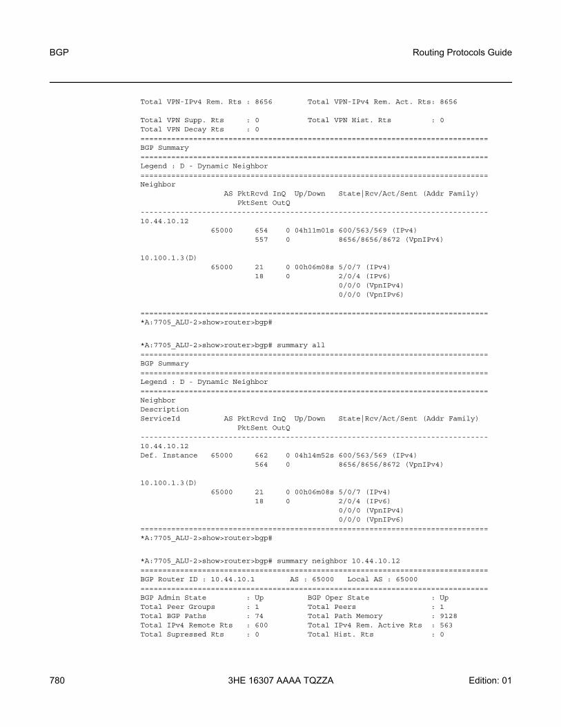
BGP
780
Routing Protocols Guide
3HE 16307 AAAA TQZZA Edition: 01
Total VPN-IPv4 Rem. Rts : 8656 Total VPN-IPv4 Rem. Act. Rts: 8656
Total VPN Supp. Rts : 0 Total VPN Hist. Rts : 0Total VPN Decay Rts : 0===============================================================================BGP Summary===============================================================================Legend : D - Dynamic Neighbor===============================================================================Neighbor
AS PktRcvd InQ Up/Down State|Rcv/Act/Sent (Addr Family)PktSent OutQ
-------------------------------------------------------------------------------10.44.10.12
65000 654 0 04h11m01s 600/563/569 (IPv4)557 0 8656/8656/8672 (VpnIPv4)
10.100.1.3(D)65000 21 0 00h06m08s 5/0/7 (IPv4)
18 0 2/0/4 (IPv6)0/0/0 (VpnIPv4)0/0/0 (VpnIPv6)
===============================================================================*A:7705_ALU-2>show>router>bgp#
*A:7705_ALU-2>show>router>bgp# summary all===============================================================================BGP Summary===============================================================================Legend : D - Dynamic Neighbor===============================================================================NeighborDescriptionServiceId AS PktRcvd InQ Up/Down State|Rcv/Act/Sent (Addr Family)
PktSent OutQ-------------------------------------------------------------------------------10.44.10.12Def. Instance 65000 662 0 04h14m52s 600/563/569 (IPv4)
564 0 8656/8656/8672 (VpnIPv4)
10.100.1.3(D)65000 21 0 00h06m08s 5/0/7 (IPv4)
18 0 2/0/4 (IPv6)0/0/0 (VpnIPv4)0/0/0 (VpnIPv6)
===============================================================================*A:7705_ALU-2>show>router>bgp#
*A:7705_ALU-2>show>router>bgp# summary neighbor 10.44.10.12===============================================================================BGP Router ID : 10.44.10.1 AS : 65000 Local AS : 65000===============================================================================BGP Admin State : Up BGP Oper State : UpTotal Peer Groups : 1 Total Peers : 1Total BGP Paths : 74 Total Path Memory : 9128Total IPv4 Remote Rts : 600 Total IPv4 Rem. Active Rts : 563Total Supressed Rts : 0 Total Hist. Rts : 0

Routing Protocols Guide BGP
Edition: 01 3HE 16307 AAAA TQZZA 781
Total Decay Rts : 0
Total VPN Peer Groups : 0 Total VPN Peers : 0Total VPN Local Rts : 8672Total VPN-IPv4 Rem. Rts : 8656 Total VPN-IPv4 Rem. Act. Rts: 8656Total VPN Supp. Rts : 0 Total VPN Hist. Rts : 0Total VPN Decay Rts : 0
===============================================================================BGP Summary===============================================================================Legend : D - Dynamic Neighbor===============================================================================Neighbor
AS PktRcvd InQ Up/Down State|Rcv/Act/Sent (Addr Family)PktSent OutQ
-------------------------------------------------------------------------------10.44.10.12
65000 673 0 04h20m24s 600/563/569 (IPv4)575 0 8656/8656/8672 (VpnIPv4)
10.100.1.3(D)65000 21 0 00h06m08s 5/0/7 (IPv4)
18 0 2/0/4 (IPv6)0/0/0 (VpnIPv4)0/0/0 (VpnIPv6)
===============================================================================*A:7705_ALU-2>show>router>bgp#
*A:7705_ALU-2>show>router>bgp# summary family ipv4===============================================================================BGP Router ID : 10.44.10.1 AS : 65000 Local AS : 65000===============================================================================BGP Admin State : Up BGP Oper State : UpTotal Peer Groups : 1 Total Peers : 1Total BGP Paths : 74 Total Path Memory : 9128Total IPv4 Remote Rts : 600 Total IPv4 Rem. Active Rts : 563
Total Supressed Rts : 0 Total Hist. Rts : 0Total Decay Rts : 0
Total VPN Peer Groups : 0 Total VPN Peers : 0Total VPN Local Rts : 8672Total VPN-IPv4 Rem. Rts : 8656 Total VPN-IPv4 Rem. Act. Rts: 8656
Total VPN Supp. Rts : 0 Total VPN Hist. Rts : 0Total VPN Decay Rts : 0===============================================================================BGP IPv4 Summary===============================================================================Legend : D - Dynamic Neighbor===============================================================================Neighbor
AS PktRcvd PktSent InQ OutQ Up/Down State|Recv/Actv/Sent-------------------------------------------------------------------------------10.44.10.12
65000 679 581 0 0 04h23m36s 600/563/569===============================================================================*A:7705_ALU-2>show>router>bgp#

BGP
782
Routing Protocols Guide
3HE 16307 AAAA TQZZA Edition: 01
*A:7705:Dut-A# show router bgp summary neighbor 10.0.0.3 family ipv6===============================================================================BGP Router ID:10.0.0.1 AS:1001 Local AS:1001===============================================================================BGP Admin State : Up BGP Oper State : UpTotal IPv4 Remote Rts : 0 Total IPv4 Rem. Active Rts : 0Total McIPv4 Remote Rts : 0 Total McIPv4 Rem. Active Rts: 0Total IPv6 Remote Rts : 0 Total IPv6 Rem. Active Rts : 0Total IPv4 Backup Rts : 0 Total IPv6 Backup Rts : 0
Total VPN-IPv4 Rem. Rts : 0 Total VPN-IPv4 Rem. Act. Rts: 0Total VPN-IPv6 Rem. Rts : 0 Total VPN-IPv6 Rem. Act. Rts: 0Total VPN-IPv4 Bkup Rts : 0 Total VPN-IPv6 Bkup Rts : 0
Total MVPN-IPv4 Rem Rts : 0 Total MVPN-IPv4 Rem Act Rts : 0Total RouteTgt Rem Rts : 0 Total RouteTgt Rem Act Rts : 0Total EVPN Rem Rts : 0 Total EVPN Rem Act Rts : 0Total LblIpv4 Rem Rts : 0 Total LblIpv4 Rem. Act Rts : 0Total LblIpv6 Rem Rts : 0 Total LblIpv6 Rem. Act Rts : 0Total LblIpv4 Bkp Rts : 0 Total LblIpv6 Bkp Rts : 0Total Link State Rem Rts: 8 Total Link State Rem. Act Rts:0Bgp-Ls Suppr. Pfxs : 0 Bgp-Ls Recd. Pfxs :0Bgp-Ls Active Pfxs : 0 Bgp-Ls Rej. Pfxs :0
===============================================================================BGP IPv6 Summary===============================================================================Legend : D - Dynamic Neighbor===============================================================================Neighbor
AS PktRcvd PktSent InQ OutQ Up/Down State|Recv/Actv/Sent-------------------------------------------------------------------------------10.0.0.3
1000 23 25 0 0 00h03m09s 0/0/0-------------------------------------------------------------------------------*A:7705:Dut-A#
Table 90 BGP Summary Field Descriptions
Label Description
BGP Router ID The local BGP router ID
AS The configured autonomous system number
Local AS The configured local AS setting. If not configured, then the value is the same as the AS.
BGP Admin State Down: BGP is administratively disabled
Up: BGP is administratively enabled
BGP Oper State Down: BGP is operationally disabled
Up: BGP is operationally enabled

Routing Protocols Guide BGP
Edition: 01 3HE 16307 AAAA TQZZA 783
Total Peer Groups The total number of configured BGP peer groups
Total Peers The total number of configured BGP peers
Total BGP Paths The total number of unique sets of BGP path attributes learned from BGP peers
Total Path Memory The total amount of memory used to store the path attributes
Total IPv4 Remote Rts The total number of IPv4 routes learned from BGP peers
Total IPv4 Remote Act. Rts The total number of IPv4 routes used in the forwarding table
Total Supressed Rts The total number of suppressed routes due to route damping
Total Hist. Rts The total number of routes with history due to route damping
Total Decay Rts The total number of decayed routes due to route damping
Total VPN Peer Groups The total number of configured VPN peer groups
Total VPN Peers The total number of configured VPN peers
Total VPN Local Rts The total number of configured local VPN routes
Total VPN-IPv4 Rem. Rts The total number of configured remote VPN-IPv4 routes
Total VPN-IPv4 Rem. Act. Rts The total number of active remote VPN-IPv4 routes used in the forwarding table
Total VPN Supp. Rts The total number of suppressed VPN routes due to route damping
Total VPN Hist. Rts The total number of VPN routes with history due to route damping
Total VPN Decay Rts The total number of decayed routes due to route damping
Total Link State Rem Rts The total number of link-state routes
Total Link State Rem. Act Rts The total number of active link-state routes
Bgp-Ls Suppr. Pfxs The total number of BGP-LS suppressed prefixes
Bgp-Ls Recd. Pfxs The total number of BGP-LS received prefixes
Bgp-Ls Active Pfxs The total number of BGP-LS active prefixes
Bgp-Ls Rej. Pfxs The total number of BGP-LS rejected prefixes
Table 90 BGP Summary Field Descriptions (Continued)
Label Description

BGP
784
Routing Protocols Guide
3HE 16307 AAAA TQZZA Edition: 01
Neighbor The BGP neighbor address
AS (Neighbor) The BGP neighbor autonomous system number
PktRcvd The total number of packets received from the BGP neighbor
PktSent The total number of packets sent to the BGP neighbor
InQ The number of BGP messages to be processed
OutQ The number of BGP messages to be transmitted
Up/Down The amount of time that the BGP neighbor has either been established or not established depending on its current state
State|Recv/Actv/Sent (Addr Family)
The BGP neighbor’s current state (if not established) or the number of received routes, active routes and sent routes (if established), along with the address family
Table 90 BGP Summary Field Descriptions (Continued)
Label Description

Routing Protocols Guide BGP
Edition: 01 3HE 16307 AAAA TQZZA 785
6.13.2.3 Clear Commands
flap-statistics
Syntax flap-statistics [{ip-prefix/mask [neighbor ip-address] | group group-name | regex reg-exp | policy policy-name}]
Context clear>router>bgp
Description This command clears route flap statistics.
Parameters ip-prefix/mask — clears route flap statistics for entries that match the specified IP prefix and mask length
Values ip-prefix a.b.c.d (host bits must be 0)mask: 0 to 32
ip-address — clears route flap statistics for entries received from the specified BGP neighbor
Values ipv4-address: a.b.c.d
group-name — clears route flap statistics for entries received from any BGP neighbors in the specified peer group
reg-exp — clears route flap statistics for all entries that have the regular expression and the AS path that matches the regular expression
policy-name — clears route flap statistics for entries that match the specified route policy
neighbor
Syntax neighbor {ip-address | as as-number | external | all} [soft | soft-inbound]neighbor {ip-address | as as-number | external | all} statisticsneighbor ip-address end-of-rib
Context clear>router>bgp
Description This command resets the specified BGP peer or peers. This can cause existing BGP connections to be shut down and restarted.
Parameters ip-address — resets the BGP neighbor with the specified IP address
Values ipv4-address: a.b.c.d
as-number — resets all BGP neighbors with the specified peer AS
Values 1 to 4294967295
external — resets all EBGP neighbors
all — resets all BGP neighbors

BGP
786
Routing Protocols Guide
3HE 16307 AAAA TQZZA Edition: 01
soft — the specified BGP neighbors re-evaluate all routes in the Local-RIB against the configured export policies
soft-inbound — the specified BGP neighbors re-evaluate all routes in the RIB-In against the configured import policies
statistics — the BGP neighbor statistics
end-of-rib — clears the routing information base (RIB)
protocol
Syntax protocol
Context clear>router>bgp
Description This command resets the entire BGP protocol.

Routing Protocols Guide BGP
Edition: 01 3HE 16307 AAAA TQZZA 787
6.13.2.4 Debug Commands
events
Syntax events [neighbor ip-address | group name]no events
Context debug>router>bgp
Description This command logs all events changing the state of a BGP peer.
Parameters ip-address — debugs only events affecting the specified BGP neighbor
Values ipv4-address: a.b.c.d (host bits must be 0)
name — debugs only events affecting the specified peer group and associated neighbors
graceful-restart
Syntax graceful-restart [neighbor ip-address | group name]no graceful-restart
Context debug>router>bgp
Description This command enables debugging for BGP graceful restart.
The no form of the command disables the debugging.
Parameters ip-address — debugs only events affecting the specified BGP neighbor
Values ipv4-address: a.b.c.d (host bits must be 0)
name — debugs only events affecting the specified peer group and associated neighbors
keepalive
Syntax keepalive [neighbor ip-address | group name]no keepalive
Context debug>router>bgp
Description This command decodes and logs all sent and received Keepalive messages in the debug log.
Parameters ip-address — debugs only events affecting the specified BGP neighbor
Values ipv4-address: a.b.c.d (host bits must be 0)
name — debugs only events affecting the specified peer group and associated neighbors

BGP
788
Routing Protocols Guide
3HE 16307 AAAA TQZZA Edition: 01
notification
Syntax notification [neighbor ip-address | group name]no notification
Context debug>router>bgp
Description This command decodes and logs all sent and received Notification messages in the debug log.
Parameters ip-address — debugs only events affecting the specified BGP neighbor
Values ipv4-address: a.b.c.d (host bits must be 0)
name — debugs only events affecting the specified peer group and associated neighbors
open
Syntax open [neighbor ip-address | group name]no open
Context debug>router>bgp
Description This command decodes and logs all sent and received Open messages in the debug log.
Parameters ip-address — debugs only events affecting the specified BGP neighbor
name — debugs only events affecting the specified peer group and associated neighbors
outbound-route-filtering
Syntax [no] outbound-route-filtering
Context debug>router>bgp
Description This command enables debugging for all BGP outbound route filtering (ORF) packets. ORF is used to inform a neighbor of targets (using target-list) that it is willing to receive.
packets
Syntax packets [neighbor ip-address | group name]packets
Context debug>router>bgp
Description This command decodes and logs all sent and received BGP packets in the debug log.

Routing Protocols Guide BGP
Edition: 01 3HE 16307 AAAA TQZZA 789
Parameters ip-address — debugs only events affecting the specified BGP neighbor
Values ipv4-address: a.b.c.d (host bits must be 0)
name — debugs only events affecting the specified peer group and associated neighbors
route-refresh
Syntax route-refresh [neighbor ip-address | group name]no route-refresh
Context debug>router>bgp
Description This command enables and disables debugging for BGP route refresh.
Parameters ip-address — debugs only events affecting the specified BGP neighbor
Values ipv4-address: a.b.c.d (host bits must be 0)
name — debugs only events affecting the specified peer group and associated neighbors
rtm
Syntax rtm [neighbor ip-address | group name]no rtm
Context debug>router>bgp
Description This command logs RTM changes in the debug log.
Parameters ip-address — debugs only events affecting the specified BGP neighbor
Values ipv4-address: a.b.c.d (host bits must be 0)
name — debugs only events affecting the specified peer group and associated neighbors
socket
Syntax socket [neighbor ip-address | group name]no socket
Context debug>router>bgp
Description This command logs all TCP socket events to the debug log.
Parameters ip-address — debugs only events affecting the specified BGP neighbor
Values ipv4-address: a.b.c.d (host bits must be 0)
name — debugs only events affecting the specified peer group and associated neighbors

BGP
790
Routing Protocols Guide
3HE 16307 AAAA TQZZA Edition: 01
timers
Syntax timers [neighbor ip-address | group name]no timers
Context debug>router>bgp
Description This command logs all BGP timer events to the debug log.
Parameters ip-address — debugs only events affecting the specified BGP neighbor
Values ipv4-address: a.b.c.d (host bits must be 0)
name — debugs only events affecting the specified peer group and associated neighbors
update
Syntax update [neighbor ip-address | group name]no update
Context debug>router>bgp
Description This command decodes and logs all sent and received Update messages in the debug log.
Parameters ip-address — debugs only events affecting the specified BGP neighbor
Values ipv4-address: a.b.c.d (host bits must be 0)
name — debugs only events affecting the specified peer group and associated neighbors

Routing Protocols Guide RIP
Edition: 01 3HE 16307 AAAA TQZZA 791
7 RIPThis chapter provides information on configuring RIP on the 7705 SAR.
Topics in this chapter include:
• RIP Overview • RIP Configuration Process Overview• Configuration Notes • Configuring RIP with CLI• RIP Command Reference

RIP
792
Routing Protocols Guide
3HE 16307 AAAA TQZZA Edition: 01
7.1 RIP Overview
Routing Information Protocol (RIP) is an interior gateway protocol (IGP) that uses a Bellman-Ford distance-vector algorithm to determine the best route to a destination, using hop count as the metric. In order for the protocol to provide complete information on routing, every router in the domain must participate in the protocol.
The 7705 SAR supports RIPv1 and RIPv2 on all IP network interfaces and on IES and VPRN access interfaces.
RIPv1, specified in RFC 1058, was written and implemented prior to the introduction of CIDR. The RIPv1 protocol does not send subnet mask information during routing updates; instead, it assumes the subnet mask information for non-local routes based on the class the route belongs to:
• Class A – 8-bit mask• Class B – 16-bit mask• Class C – 24-bit mask
RIPv2, as defined in RFC 2453, was written after CIDR was developed and transmits subnet mask information with every route. Because of the support for CIDR routes and other enhancements in RIPv2 such as triggered updates, multicast advertisements, and authentication, most production networks use RIPv2. However, some older hosts and routers only support RIPv1, especially when RIP is used simply to advertise default routing information.
RIP, which is carried over the UDP protocol, updates its neighbors, and the neighbors update their neighbors, and so on. Each host that uses RIP has a routing process that sends and receives datagrams on UDP port number 520. Although the RIP mechanism is fairly simple, it requires a lot of convergence time in large networks and is prone to routing loops unless additional measures are taken.
Each RIP router advertises all RIP routes periodically via RIP updates. By default, each update can contain a maximum of 25 route advertisements. This limit is imposed by RIP specifications. RIP can be configured to send as many as 255 routes per update. RIPv1 and RIPv2 updates are formatted slightly differently. RIPv1 updates are sent to a broadcast address (255.255.255.255); RIPv2 updates can be sent either to a broadcast or multicast address (224.0.0.9).
A network address of 0.0.0.0 is considered a default route. A default route is used when it is not convenient to list every possible network in the RIP updates and when one or more closely connected gateways in the system are prepared to handle traffic to the networks that are not listed explicitly. These gateways create RIP entries for the address 0.0.0.0 as if it were a network to which they are connected.

Routing Protocols Guide RIP
Edition: 01 3HE 16307 AAAA TQZZA 793
7.1.1 RIP Versions
You can specify the RIP version that will be sent to RIP neighbors and the version of RIP updates that will be accepted and processed. The 7705 SAR allows the following combinations:
• send only RIPv1 or RIPv2 messages to either the broadcast or multicast address, or send no messagesIf the sending router’s RIP interface is configured to send to the broadcast address, the receiving router interface must be configured to allow directed broadcasts in the config>router>interface context (for network interfaces), in the config>service>ies>interface context (for IES interfaces), or in the config>service>vprn>interface context (for VPRN interfaces). The 7705 SAR sends RIPv2 formatted messages to the broadcast address by default.
• receive only RIPv1 updates, receive only RIPv2 updates, receive both RIPv1 and RIPv2 updates, or receive no updatesThe 7705 SAR receives both RIPv1 and RIPv2 updates by default.
7.1.2 RIPv2 Authentication
RIPv2 messages carry more information than RIPv1 messages, which permits the use of a simple authentication mechanism to secure table updates. The 7705 SAR RIPv2 implementation enables the use of a plain text (simple) password or message digest (MD5) authentication.
7.1.3 Metrics
By default, RIP advertises all RIP routes to each peer every 30 s. RIP uses a hop count metric to determine the distance between the packet’s source and destination. The metric/cost value for a valid route is 1 through 15.
Each router along the path increments the hop count value by 1. When a router receives a routing update with new or different destination information, the metric increments by 1.
The maximum number of hops in a path is 15. The router treats any number over 15 as infinitely large. If a router receives a routing update with a metric of 15 that contains a new or modified entry, the route metric value increments to 16 and the destination is considered unreachable.

RIP
794
Routing Protocols Guide
3HE 16307 AAAA TQZZA Edition: 01
The 7705 SAR uses split horizon and split horizon with poison reverse to avoid looping routes propagating through the network. When split horizon is enabled, the local router does not readvertise routes learned from a neighbor back to the same neighbor. When split horizon with poison is enabled and the router receives an update over an interface, the router sets the route metric to 16 (infinity) and advertises the route back to the network where it is now considered unreachable.
7.1.4 Timers
RIP uses three timers to determine how often RIP updates are sent and how long routes are maintained:
• update — times the interval between periodic routing updates• timeout — initialized when a route is established and any time an update
message is received for the route. When this timer expires, the route is no longer valid. It is retained in the table for a short time so that neighbors can be notified that the route has been dropped.
• flush — when the flush timer expires, the route is removed from the tables
7.1.5 Import and Export Policies
Routing policies control the content of the routing tables, the routes that are advertised, and the best route to take to reach a destination. Import route policies determine which routes are accepted from RIP neighbors. Export route policies determine which routes are exported from the route table to RIP.
There are no default import or export routing policies. Policies must be explicitly created and applied with RIP import or export commands.
7.1.6 RIP Packet Format
There can be 1 to 25 route entries. The RIP packet header format is displayed in Figure 38. Figure 39 and Figure 40 display the RIPv1 and RIPv2 packet formats.

Routing Protocols Guide RIP
Edition: 01 3HE 16307 AAAA TQZZA 795
Figure 38 RIP Packet Format
Figure 39 RIPv1 Packet Format
Figure 40 RIPv2 Packet Format
1 1 1 1 1 1 1 1 1 1 2 2 2 2 2 2 2 2 2 2 3 30 1 2 3 4 5 6 7 8 9 0 1 2 3 4 5 6 7 8 9 0 1 2 3 4 5 6 7 8 9 0 1
Command Version Must be zero
RIP Entry (20)
23174
1 1 1 1 1 1 1 1 1 1 2 2 2 2 2 2 2 2 2 2 3 30 1 2 3 4 5 6 7 8 9 0 1 2 3 4 5 6 7 8 9 0 1 2 3 4 5 6 7 8 9 0 1
Address Family Identifier (2) Must be zero (2)
IP Address (4)
Must be zero (4)
Must be zero (4)
Metric (4)
23175
1 1 1 1 1 1 1 1 1 1 2 2 2 2 2 2 2 2 2 2 3 30 1 2 3 4 5 6 7 8 9 0 1 2 3 4 5 6 7 8 9 0 1 2 3 4 5 6 7 8 9 0 1
Address Family Identifier (2) Route Tag (2)
IP Address (4)
Subnet Mask (4)
Nexthop (4)
Metric (4)
23176

RIP
796
Routing Protocols Guide
3HE 16307 AAAA TQZZA Edition: 01
RIP packets contain the following fields:
• Command — indicates whether the packet is a request or a response message. A request message asks the responding system to send all or part of its routing table. The response message may be sent in response to a request, or it may be an unsolicited routing update generated by the sender.
• Version — specifies the RIP version used and can be used to signal different, and potentially incompatible, versions
• Must be zero — provides backward compatibility with pre-standard varieties of RIP. RIP messages with non-zero values in this field are rejected unless the check-zero command is disabled.
• Address family identifier (AFI) — the type of address. RIP can carry routing information for several different protocols. Each entry in this field has an AFI to indicate the type of address being specified. The IP AFI is 2.
• IP Address — the IP address for the packet• Metric — specifies the number of hops to the destination• Next hop — the IP address of the next router along the path to the destination.
This field appears only in RIPv2 packets.• Subnet mask — the subnet mask for the entry. If this field is 0, no subnet mask
has been specified for the entry. This field appears only in RIPv2 packets.
7.1.7 RIP Hierarchical Levels
The minimum RIP configuration must define one group and one neighbor. The parameters configured at the RIP global level are inherited by the group and neighbor levels. Parameters can be modified and overridden on a level-specific basis. The RIP command hierarchy consists of three levels:
• global• group• neighbor
Hierarchical RIP commands can be modified on different levels. The most specific value is used. A RIP group-specific command takes precedence over a global RIP command. A neighbor-specific command takes precedence over a global RIP or group-specific RIP command.

Routing Protocols Guide RIP
Edition: 01 3HE 16307 AAAA TQZZA 797
7.2 RIP Configuration Process Overview
Figure 41 displays the process to configure RIP parameters.
Figure 41 RIP Configuration and Implementation Flow
Start
TURN UP
CONFIGURE ROUTER INTERFACES
CONFIGURE POLICY STATEMENTS
CONFIGURE GLOBAL RIP PARAMETERS
CONFIGURE NEIGHBOR PARAMETERS
CONFIGURE RIP GROUP PARAMETERS
23177

RIP
798
Routing Protocols Guide
3HE 16307 AAAA TQZZA Edition: 01
7.3 Configuration Notes
The following guidelines and caveats apply to RIP configuration.
• Before RIP neighbor parameters can be configured, router interfaces must be configured.
• RIP must be explicitly created for each router interface. There are no default RIP instances on a 7705 SAR router.
Routing Protocols Guide RIP
Edition: 01 3HE 16307 AAAA TQZZA 799
7.4 Configuring RIP with CLI
This section provides information on configuring RIP using the command line interface.
Topics in this section include:
• RIP Configuration Overview• Basic RIP Configuration• Common Configuration Tasks• Configuring RIP Parameters• RIP Configuration Management Tasks

RIP
800
Routing Protocols Guide
3HE 16307 AAAA TQZZA Edition: 01
7.5 RIP Configuration Overview
7.5.1 Preconfiguration Requirements
Before RIP can be implemented, the following entities must be configured:
• policy statements must be defined in the config>router>policy-options context

Routing Protocols Guide RIP
Edition: 01 3HE 16307 AAAA TQZZA 801
7.6 Basic RIP Configuration
RIP is configured in the config>router>rip context for network interfaces and IES access interfaces. RIP is configured in the config>service>vprn>rip context for VPRN interfaces when RIP is used as a PE-to-CE routing protocol for VPRN service. For information on configuring RIP under VPRN, refer to the 7705 SAR Services Guide, “Configuring RIP for VPRN”.
RIP configuration commands have three primary configuration levels: rip for global configurations, group group-name for RIP groups, and neighbor ip-int-name for RIP neighbor configurations. Within the different levels, the configuration commands are identical.
Commands and parameters configured at the global level are inherited by the group and neighbor level; however, the command that is most specific to the neighboring router takes precedence. Parameters configured at the neighbor level have precedence over group and global configurations and parameters configured at the group level have precedence over global configurations.
The minimum RIP parameters that must be configured in the config>router>rip context are:
• group• neighbor
For a router to accept RIP updates, at least one group and one neighbor must be defined. A 7705 SAR router ignores RIP updates received from routers on interfaces not configured for RIP. Configuring other RIP commands and parameters is optional.
By default, the local router imports all routes from its neighbor and does not advertise routes. The router receives both RIPv1 and RIPv2 update messages with 25 to 255 route entries per message.
The following is an example of a basic RIP configuration.
ALU-A>config>router>rip# info----------------------------------------------
group "RIP-ALU-A"neighbor "to-ALU-4"exit
exit----------------------------------------------ALU-A>config>router>rip#

RIP
802
Routing Protocols Guide
3HE 16307 AAAA TQZZA Edition: 01
7.7 Common Configuration Tasks
This section provides a brief overview of the tasks that must be performed to configure RIP and provides the CLI commands.
RIP is configured hierarchically; the global level applies to all peers, the group level applies to all peers in the group, and the neighbor level only applies to a specified peer. By default, group members inherit the group’s configuration parameters, although a parameter can be modified on a per-member basis without affecting the group-level parameters.
All RIP instances must be explicitly created on each 7705 SAR. Once created, RIP is administratively enabled.
To configure RIP, perform the following tasks in order:
• configure interfaces• configure policy statements (optional)• enable RIP• configure group parameters• configure neighbor parameters
7.7.1 Configuring Interfaces
The following command sequences create a logical IP interface. The logical interface can associate attributes such as an IP address, port, Link Aggregation Group (LAG), or the system. For more information about configuring interfaces, refer to the 7705 SAR Router Configuration Guide.
To configure a network interface:
CLI Syntax: config>routerinterface ip-int-name
address {ip-addr/mask-length | ip-addr/netmask}
allow-directed-broadcastsport port-name
Example: config>router# interface “to-ALU-4”config>router>if# address 10.10.12.1/8config>router>if# port 1/1/1config>router>if# exit

Routing Protocols Guide RIP
Edition: 01 3HE 16307 AAAA TQZZA 803
The following example displays the configuration output:
ALU-3>config>router# info----------------------------------------------#echo “IP Configuration”#------------------------------------------
interface "system"address 192.0.2.0/24
exitinterface "to-ALU-4"
address 10.10.12.1/8port 1/1/1
exit#------------------------------------------ALU-3>config>router#
The following command sequences create an IES (access) interface that will be added to RIP in the config>router>rip context. For more information about IES interfaces, refer to the 7705 SAR Services Guide, “Internet Enhanced Service”.
To configure an IES interface:
CLI Syntax: config>serviceies service-id [customer customer-id] [create] [vpn
vpn-id]interface ip-int-name [create]
address {ip-addr/mask | ip-addr/netmask}allow-directed-broadcastssap sap-id [create]
Example: config>service# ies 4 customer 1 createconfig>service>ies# interface “rip_interface” createconfig>service>ies>if$ address 172.16.1.1/12config>service>ies>if$ allow-directed-broadcastsconfig>service>ies>if$ sap 1/1/4 create
The following example displays the configuration output:
*A:Sar18 Dut-B>config>service>ies# info----------------------------------------------
interface "rip_interface" createaddress 172.16.1.1/12allow-directed-broadcastssap 1/1/4 createexit
exitno shutdown
----------------------------------------------*A:Sar18 Dut-B>config>service>ies#

RIP
804
Routing Protocols Guide
3HE 16307 AAAA TQZZA Edition: 01
7.7.2 Configuring a Route Policy
The import route policy command allows you to filter routes being imported by the local router from its neighbors. If no match is found, the local router does not import any routes.
The export route policy command allows you to determine which routes are exported from the route table to RIP. By default, RIP does not export routes it has learned to its neighbors. If no export policy is specified, non-RIP routes will not be exported from the routing table manager to RIP.
If multiple policy names are specified, the policies are evaluated in the order they are specified. The first policy that matches is applied. If multiple export commands are issued, the last command entered will override the previous command. A maximum of five policy names can be specified.
To enter the mode to create or edit route policies, you must enter the begin keyword at the config>router>policy-options prompt. Other editing commands include:
• the commit command, saves and enables changes made to route policies during a session
• the abort command, discards changes that have been made to route policies during a session
Use the following CLI syntax to configure a policy to use for RIP global, group, and neighbor import and export commands. This section provides brief instructions to configure route policies. For more details and the complete list of policy options commands, refer to the 7705 SAR Router Configuration Guide, “Configuring Route Policies With CLI”.
CLI Syntax: config>router>policy-optionsbegincommitabortpolicy-statement name
description textdefault-action {accept | next-entry |
next-policy | reject}entry entry-id
description textaction {accept | next-entry | next-policy
| reject}from
protocol {bgp | direct | ospf | ospf3 | rip | isis | static | aggregate | bgp-vpn | igmp | mld | pim | ldp}

Routing Protocols Guide RIP
Edition: 01 3HE 16307 AAAA TQZZA 805
toprotocol {bgp | direct | ospf | ospf3
| rip | isis | static | aggregate | bgp-vpn | igmp | mld | pim | ldp}
The following example displays commands to configure a policy statement. Use the commit command to save the changes.
Example: config>router>policy-options# beginpolicy-options# policy-statement“RIP-policy”policy-options>policy-statement$ description "this is atest RIP policy”policy-options>policy-statement>default# entry 1policy-options>policy-statement>entry$ action acceptpolicy-options>policy-statement>entry# exitpolicy-options>policy-statement# default-action rejectpolicy-options>policy-statement# exitpolicy-options# commit
ALU-A>config>router>policy-options# info----------------------------------------------
policy-statement "RIP-policy"description "this is a test RIP policy"entry 1action acceptexitexitdefault-action rejectexit
----------------------------------------------ALU-A>config>router>policy-options>policy-statement#

RIP
806
Routing Protocols Guide
3HE 16307 AAAA TQZZA Edition: 01
7.8 Configuring RIP Parameters
Use the CLI syntax below to configure global-level, group-level, and neighbor-level parameters:
CLI Syntax: config>routerrip
authentication-key {authentication-key | hash-key} [hash | hash2]
authentication-type {none | password | message-digest | message-digest-20}
check-zero {enable | disable}description description-stringexport policy-name [policy-name ...up to 5 max]import policy-name [policy-name ...up to 5 max]message-size max-num-of-routesmetric-in metricmetric-out metricneighbor ip-int-name
authentication-key {authentication-key | hash-key} [hash|hash2]
authentication-type {none | password | message-digest | message-digest-20}
check-zero {enable | disable}description description-stringexport policy-name [policy-name ...up to 5
max]]import policy-name [policy-name ...up to 5
max]]message-size max-num-of-routesmetric-in metricmetric-out metricpreference preferencereceive receive-typesend send-typesplit-horizon {enable | disable}timers update timeout flushno shutdown
preference preferencereceive receive-typesend send-typeno shutdownsplit-horizon {enable|disable}timers update timeout flushgroup group-name
authentication-key {authentication-key | hash-key} [hash | hash2]

Routing Protocols Guide RIP
Edition: 01 3HE 16307 AAAA TQZZA 807
authentication-type {none | password | message-digest | message-digest-20}
check-zero {enable | disable}description description-stringexport policy-name [policy-name ...up to 5
max]]import policy-name [policy-name ...up to 5
max]]message-size max-num-of-routesmetric-in metricmetric-out metricpreference preferencereceive receive-typesend send-typeno shutdownsplit-horizon {enable | disable}timers update timeout flush
7.8.1 Configuring Global-Level Parameters
Once the RIP protocol instance is created, it is administratively enabled automatically; the no shutdown command is not required. To enable RIP on a router, at least one group and one neighbor must be configured. There are no default groups or neighbors. Each group and neighbor must be explicitly configured.
The following example displays a global RIP configuration:
Example: config>router# ripconfig>router>rip# authentication-type passwordconfig>router>rip# authentication-key test123config>router>rip# receive bothconfig>router>rip# split-horizon enableconfig>router>rip# timers 300 600 600config>router>rip>group# exit
ALU-A>config>router>rip# info----------------------------------------------
authentication-type simpleauthentication-key "ac1865lvz1d" hashtimers 300 600 600
----------------------------------------------
Note: Careful planning is essential to implement commands that can affect the behavior of global, group, and neighbor levels. Because the RIP commands are hierarchical, analyze the values that can disable features on a particular level.

RIP
808
Routing Protocols Guide
3HE 16307 AAAA TQZZA Edition: 01
7.8.2 Configuring Group-Level Parameters
A group is a collection of related RIP peers (neighbors). The group name should be a descriptive name for the group. Follow your group, name, and ID naming conventions for consistency and to help when troubleshooting faults.
All parameters configured for a peer group are applied to the group and are inherited by each peer (neighbor), but a group parameter can be overridden on a specific neighbor-level basis.
The following example displays a group configuration:
Example: config>router# ripconfig>router>rip# group headquartersconfig>router>rip>group$ description "Base HQ"config>router>rip>group# no shutdown
ALA-A>config>router>rip# info----------------------------------------------
authentication-type simpleauthentication-key "ac1865lvz1d" hashtimers 300 600 600group "headquarters"
description "Base HQ"exit
----------------------------------------------ALA-A>config>router>rip#
7.8.3 Configuring Neighbor-Level Parameters
After you create a group name and assign options, add neighbor interfaces within the same group. All parameters configured for the peer group level are applied to each neighbor, but a group parameter can be overridden on a specific neighbor basis.
The following example displays a neighbor configuration:
Example: config>router# ripconfig>router>rip# group headquartersconfig>router>rip>group# neighbor ferguson-274config>router>rip>group>neighbor$ preference 255config>router>rip>group>neighbor# send bothconfig>router>rip>group>neighbor# split-horizon enableconfig>router>rip>group>neighbor# message-size 255

Routing Protocols Guide RIP
Edition: 01 3HE 16307 AAAA TQZZA 809
ALU-A>config>router>rip>group>neighbor# info----------------------------------------------
message-size 255preference 255split-horizon enableno timers
----------------------------------------------ALU-A>config>router>rip>group>neighbor#

RIP
810
Routing Protocols Guide
3HE 16307 AAAA TQZZA Edition: 01
7.9 RIP Configuration Management Tasks
Examples are provided for the following RIP configuration management tasks:
• Modifying RIP Parameters• Deleting a RIP Group• Deleting a RIP Neighbor
7.9.1 Modifying RIP Parameters
When RIP parameters are modified, added, or removed, the changes are applied immediately. For the complete list of CLI commands, refer to Configuring RIP Parameters.
CLI Syntax: config>router# ripgroup group-name. . .neighbor ip-int-name. . .
Example: config>router>rip# group "headquarters"config>router>rip>group# neighbor "ferguson-274"config>router>rip>group>neighbor# import RIPpolicyconfig>router>rip>group>neighbor# message-size 150
The following example displays the updated parameters:
ALU-A>config>router>rip# info----------------------------------------------authentication-type simpleauthentication-key "ac1865lvz1d" hashtimers 300 600 600group "headquarters"description "Mt. View"neighbor "ferguson-274"import "RIPpolicy"message-size 150preference 255split-horizon enableno timersexitexit----------------------------------------------ALU-A>config>router>rip#

Routing Protocols Guide RIP
Edition: 01 3HE 16307 AAAA TQZZA 811
7.9.2 Deleting a RIP Group
A RIP group must be shut down first in order to delete it.
Use the following CLI syntax to shut down and then delete a RIP group.
CLI Syntax: config>router# ripgroup group-nameshutdownno group group-name
Example: config>router> ripconfig>router>rip# group “RIP-ALU-3”config>router>rip>group# shutdownconfig>router>rip>group# exitconfig>router>rip# no group “RIP-ALU-3”
If you try to delete the group without shutting it down first, the following message appears:
INFO: RIP #1204 group should be administratively down -virtual router index 1,groupRIP-ALA-4
7.9.3 Deleting a RIP Neighbor
A RIP neighbor must be shut down first in order to delete it.
Use the following CLI syntax to shut down and then delete a RIP neighbor.
CLI Syntax: config>router# ripgroup group-name
neighbor ip-int-nameshutdownexitno neighbor ip-int-name
Example: config>router# ripconfig>router>rip# group “RIP-ALU-4”config>router>rip>group# neighbor “to-ALU-3”config>router>rip>group>neighbor# shutdownconfig>router>rip>group>neighbor# exitconfig>router>rip>group# no neighbor “to-ALU-3”

RIP
812
Routing Protocols Guide
3HE 16307 AAAA TQZZA Edition: 01
If you try to delete the neighbor before it is shut down, the following message appears:
INFO: RIP #1101 neighbor should be administratively down - virtual router index

Routing Protocols Guide RIP
Edition: 01 3HE 16307 AAAA TQZZA 813
7.10 RIP Command Reference
7.10.1 Command Hierarchies
• Configuration Commands- Global RIP Commands- Group RIP Commands- Neighbor RIP Commands
• Show Commands • Clear Commands • Debug Commands

RIP
814
Routing Protocols Guide
3HE 16307 AAAA TQZZA Edition: 01
7.10.1.1 Configuration Commands
7.10.1.1.1 Global RIP Commands
config— router [router-name]
— [no] rip— authentication-key {authentication-key | hash-key} [hash | hash2]— no authentication-key — authentication-type {none | password | message-digest | message-digest-
20}— no authentication-type— check-zero {enable | disable}— no check-zero— description string— no description— export policy-name [policy-name…(up to 5 max)]— no export— export-limit number [log percentage]— no export-limit— [no] group group-name— import policy-name [policy-name…(up to 5 max)]— no import— message-size max-num-of-routes— no message-size— metric-in metric— no metric-in— metric-out metric— no metric-out— preference preference— no preference— receive receive-type— no receive— send send-type— no send— [no] shutdown— split-horizon {enable | disable}— no split-horizon— timers update timeout flush— no timers

Routing Protocols Guide RIP
Edition: 01 3HE 16307 AAAA TQZZA 815
7.10.1.1.2 Group RIP Commands
config— router [router-name]
— [no] rip— [no] group group-name
— authentication-key {authentication-key | hash-key} [hash | hash2]
— no authentication-key — authentication-type {none | password | message-digest |
message-digest-20}— no authentication-type— check-zero {enable | disable}— no check-zero— description string— no description— export policy-name [policy-name…(up to 5 max)]— no export— import policy-name [policy-name…(up to 5 max)]— no import— message-size max-num-of-routes— no message-size— metric-in metric— no metric-in— metric-out metric— no metric-out— [no] neighbor ip-int-name — preference preference— no preference— receive receive-type— no receive— send send-type— no send— [no] shutdown— split-horizon {enable | disable}— no split-horizon— timers update timeout flush— no timers
7.10.1.1.3 Neighbor RIP Commands
config — router [router-name]
— [no] rip— [no] group group-name
— [no] neighbor ip-int-name— authentication-key {authentication-key | hash-key} [hash |
hash2]— no authentication-key — authentication-type {none | password | message-digest |
message-digest-20}

RIP
816
Routing Protocols Guide
3HE 16307 AAAA TQZZA Edition: 01
— no authentication-type— check-zero {enable | disable}— no check-zero— description string— no description— export policy-name [policy-name…(up to 5 max)]— no export— import policy-name [policy-name…(up to 5 max)]— no import— message-size max-num-of-routes— no message-size— metric-in metric— no metric-in— metric-out metric— no metric-out— preference preference— no preference— receive receive-type— no receive— send send-type— no send— [no] shutdown— split-horizon {enable | disable}— no split-horizon— timers update timeout flush— no timers
7.10.1.2 Show Commands
show— router [router-instance]
— rip— database [ip-prefix [/mask] [longer] [peer ip-address] [detail]— group [name] [detail]— neighbor [ip-int-name | ip-address] [detail] [advertised-routes]— peer [interface-name]— statistics [ip-int-name | ip-address]
7.10.1.3 Clear Commands
clear— router
— rip— database — statistics [neighbor ip-int-name | ip-address]

Routing Protocols Guide RIP
Edition: 01 3HE 16307 AAAA TQZZA 817
7.10.1.4 Debug Commands
debug— router
— rip— [no] auth [neighbor ip-int-name | ip-address]— [no] error [neighbor ip-int-name | ip-address]— [no] events [neighbor ip-int-name | ip-address]— [no] holddown [neighbor ip-int-name | ip-address]— [no] packets [neighbor ip-int-name | ip-address]— [no] request [neighbor ip-int-name | ip-address]— [no] trigger [neighbor ip-int-name | ip-address]— [no] updates [neighbor ip-int-name | ip-address]
Note: Unless specified otherwise, all hierarchical RIP commands can be modified on different levels. The most specific value is used. A RIP group-specific command takes precedence over a global RIP command. A neighbor-specific command takes precedence over a global RIP or group-specific RIP command.

RIP
818
Routing Protocols Guide
3HE 16307 AAAA TQZZA Edition: 01
7.10.2 Command Descriptions
• Configuration Commands• Show Commands• Clear Commands• Debug Commands

Routing Protocols Guide RIP
Edition: 01 3HE 16307 AAAA TQZZA 819
7.10.2.1 Configuration Commands
• Generic Commands• RIP Commands

RIP
820
Routing Protocols Guide
3HE 16307 AAAA TQZZA Edition: 01
7.10.2.1.1 Generic Commands
description
Syntax description description-string no description
Context config>router>rip config>router>rip>group config>router>rip>group>neighbor
Description This command creates a text description stored in the configuration file for a configuration context.
The no form of the command removes the description string from the context.
Default no description is associated with the configuration context
Parameters description-string — the description character string. Allowed values are any string up to 80 characters long composed of printable, 7-bit ASCII characters. If the string contains special characters (#, $, spaces, etc.), the entire string must be enclosed within double quotes.
shutdown
Syntax [no] shutdown
Context config>router>rip config>router>rip>group config>router>rip>group>neighbor
Description This command administratively disables an entity. When disabled, an entity does not change, reset, or remove any configuration settings or statistics.
The operational state of the entity is disabled as well as the operational state of any entities contained within. Many objects must be shut down before they may be deleted.
The no form of this command administratively enables an entity.
Unlike other commands and parameters where the default state is not indicated in the configuration file, the shutdown and no shutdown states are always indicated in system-generated configuration files.

Routing Protocols Guide RIP
Edition: 01 3HE 16307 AAAA TQZZA 821
Default administrative states for services and service entities are described in Special Cases.
Special Cases RIP Global — the RIP protocol is created in the no shutdown state
RIP Group — RIP groups are created in the no shutdown state
RIP Neighbor — RIP neighbors/peers are created in the no shutdown state

RIP
822
Routing Protocols Guide
3HE 16307 AAAA TQZZA Edition: 01
7.10.2.1.2 RIP Commands
rip
Syntax [no] rip
Context config>router
Description This command creates the RIP protocol instance and RIP configuration context. RIP is administratively enabled upon creation. To start or suspend execution of the RIP protocol without affecting the configuration, use the [no] shutdown command.
The no form of the command deletes the RIP protocol instance and removes all configuration parameters for the RIP instance.
Default no rip
authentication-key
Syntax authentication-key {authentication-key | hash-key} [hash | hash2] no authentication-key
Context config>router>rip config>router>rip>groupconfig>router>rip>group>neighbor
Description This command configures the RIPv2 authentication key.
Authentication is performed between neighboring routers before setting up the RIP session by verifying the password. Authentication is performed using the MD5 message-based digest.
The authentication key can be any combination of ASCII characters up to 255 characters long. The hash-key can be any combination of ASCII characters up to 342 characters long.
The no form of the command removes the authentication password from the configuration and disables authentication.
Default no authentication-key
Parameters authentication-key — the authentication key. The key can be any combination of ASCII characters up to 255 characters in length (unencrypted). If spaces are used in the string, the entire string must be enclosed in quotation marks (“ ”).
hash-key — the hash key. The key can be any combination of ASCII characters up to 342 characters in length (encrypted). If spaces are used in the string, the entire string must be enclosed in quotation marks (“ “). This is useful when a user must configure the parameter, but for security purposes, the actual unencrypted key value is not provided.

Routing Protocols Guide RIP
Edition: 01 3HE 16307 AAAA TQZZA 823
hash — specifies that the key is entered in an encrypted form. If the hash parameter is not used, the key is assumed to be in a non-encrypted, clear text form. For security, all keys are stored in encrypted form in the configuration file with the hash parameter specified.
hash2 — specifies that the key is entered in a more complex encrypted form. If the hash2 parameter is not used, the less-encrypted hash form is assumed.
authentication-type
Syntax authentication-type {none | password | message-digest | message-digest-20}no authentication-type
Context config>router>rip config>router>rip>group config>router>rip>group>neighbor
Description This command sets the type of authentication to be used between RIP neighbors. Authentication type can be specified regardless of the configured send and receive parameters, but will only apply to RIPv2 packets.
The type and password must match exactly for the RIP message to be considered authentic and processed.
The no form of the command removes the authentication type from the configuration and disables authentication.
Default no authentication-type
Parameters none — explicitly disables authentication at a given level (global, group, neighbor). If the command does not exist in the configuration, the parameter is inherited from a higher level.
password — enables simple password (plain text) authentication. If authentication is enabled and no authentication type is specified in the command, simple password authentication is enabled.
message-digest — configures 16-byte message digest for MD5 authentication. If this option is configured, then at least one message-digest key must be configured.
message-digest-20 — configures 20-byte message digest for MD5 authentication in accordance with RFC 2082, RIP-2 MD5 Authentication. If this option is configured, then at least one message-digest key must be configured.

RIP
824
Routing Protocols Guide
3HE 16307 AAAA TQZZA Edition: 01
check-zero
Syntax check-zero {enable | disable}no check-zero
Context config>router>rip config>router>rip>group config>router>rip>group>neighbor
Description This command enables checking for zero values in fields specified to be zero by the RIPv1 and RIPv2 specifications.
The check-zero enable command enables checking of the mandatory zero fields in the RIPv1 and RIPv2 specifications and rejecting of non-compliant RIP messages.
The check-zero disable command disables this check and allows the receipt of RIP messages even if the mandatory zero fields are non-zero.
The check-zero command can be enabled at all three RIP levels. The most specific value is used. If no check-zero value is set (no check-zero), the setting from the less-specific level is inherited by the lower level.
The no form of the command disables check-zero on the configuration.
Default disabled at the RIP global level
Parameters enable — configures the router to reject RIP messages that do not have zero in the mandatory fields
disable — configures the router to accept RIP messages that do not have zero in the mandatory fields
export
Syntax export policy-name [policy-name…(up to 5 max)] no export
Context config>router>rip config>router>rip>group config>router>rip>group>neighbor
Description This command specifies the export route policy used to determine which routes are advertised to peers. Route policies are configured in the config>router>policy-options context. Refer to the section on “Route Policy” in the 7705 SAR Router Configuration Guide.
When multiple policy names are specified, the policies are evaluated in the order in which they are specified. A maximum of five (5) policy names can be configured. The first policy that matches is applied.

Routing Protocols Guide RIP
Edition: 01 3HE 16307 AAAA TQZZA 825
When multiple export commands are issued, the last command entered overrides the previous command.
By default, when no export policies are specified, RIP routes are advertised and non-RIP routes are not advertised.
The no form of the command removes the policy association with the RIP instance. To remove association of all policies, use the no export command without arguments.
Default no export
Parameters policy-name — the route policy name. Allowed values are any string up to 32 characters long composed of printable, 7-bit ASCII characters. If the string contains special characters (#, $, spaces, etc.), the entire string must be enclosed within double quotes.
export-limit
Syntax export-limit number [log percentage]no export-limit
Context config>router>rip
Description This command configures the maximum number of routes (prefixes) that can be exported into RIP from the route table. Export-limit can be configured only on the global level.
The no form of the command removes the parameters from the configuration.
Default no export-limit
Parameters number — specifies the maximum number of routes (prefixes) that can be exported into RIP from the route table
Values 1 to 4294967295
percentage — specifies the percentage of the export-limit at which a warning log message and SNMP notification would be sent
Values 1 to 100
group
Syntax [no] group group-name
Context config>router>rip
Description This command enables the context for configuring a RIP group of neighbor interfaces.
RIP groups logically associate RIP neighbor interfaces to facilitate a common configuration for RIP interfaces.

RIP
826
Routing Protocols Guide
3HE 16307 AAAA TQZZA Edition: 01
The no form of the command deletes the RIP neighbor interface group. Deleting the group also removes the RIP configuration from all of the neighbor interfaces currently assigned to the group.
Parameters group-name — the RIP group name. Allowed values are any string up to 32 characters long composed of printable, 7-bit ASCII characters. If the string contains special characters (#, $, spaces, etc.), the entire string must be enclosed within double quotes.
import
Syntax import policy-name [policy-name…(up to 5 max)] no import
Context config>router>rip config>router>rip>group config>router>rip>group>neighbor
Description This command specifies the import route policy to be used to determine which routes are accepted from peers. Route policies are configured in the config>router>policy-options context. Refer to the section on “Route Policy” in the 7705 SAR Router Configuration Guide.
When multiple policy names are specified, the policies are evaluated in the order in which they are specified. A maximum of five (5) policy names can be specified. The first policy that matches is applied.
When multiple import commands are issued, the last command entered will override the previous command.
When an import policy is not specified, RIP routes are accepted by default.
The no form of the command removes the policy association with the RIP instance. To remove association of all policies, use no import without arguments.
Default no import
Parameters policy-name — the route policy name. Allowed values are any string up to 32 characters long composed of printable, 7-bit ASCII characters. If the string contains special characters (#, $, spaces, etc.), the entire string must be enclosed within double quotes.

Routing Protocols Guide RIP
Edition: 01 3HE 16307 AAAA TQZZA 827
message-size
Syntax message-size max-num-of-routesno message-size
Context config>router>rip config>router>rip>group config>router>rip>group>neighbor
Description This command configures the maximum number of routes per RIP update message.
By default, each update can contain a maximum of 25 route advertisements. This limit is imposed by RIP specifications. RIP can be configured to send as many as 255 routes per update.
The no form of the command reverts to the default value.
Default 25
Parameters max-num-of-routes — the maximum number of RIP routes per RIP update message, expressed as a decimal integer
Values 25 to 255
metric-in
Syntax metric-in metricno metric-in
Context config>router>rip config>router>rip>group config>router>rip>group>neighbor
Description This command configures the metric added to routes received from a RIP neighbor. The specified metric value is added to the hop count and shortens the maximum distance of the route.
When applying an export policy to a RIP configuration, the policy overrides the metric values determined through calculations involving the metric-in and metric-out values.
The no form of the command reverts to the default value.
Default 1
Parameters metric — the value added to the metric of routes received from a RIP neighbor, expressed as a decimal integer
Values 1 to 16

RIP
828
Routing Protocols Guide
3HE 16307 AAAA TQZZA Edition: 01
metric-out
Syntax metric-out metricno metric-out
Context config>router>rip config>router>rip>group config>router>rip>group>neighbor
Description This command configures the metric assigned to routes exported into RIP and advertised to RIP neighbors. The specified metric value is added to the hop count and shortens the maximum distance of the route.
When applying an export policy to a RIP configuration, the policy overrides the metric values determined through calculations involving the metric-in and metric-out values.
The no form of the command reverts to the default value.
Default 1
Parameters metric — the value added to the metric for routes exported into RIP and advertised to RIP neighbors, expressed as a decimal integer
Values 1 to 16
neighbor
Syntax [no] neighbor ip-int-name
Context config>router>rip>group
Description This command enables the context for configuring a RIP neighbor interface.
By default, interfaces are not activated unless explicitly configured.
The no form of the command deletes the RIP interface configuration for this interface. The shutdown command in the config>router>rip>group group-name>neighbor context can be used to disable an interface without removing the configuration for the interface.
Default No RIP interfaces are defined by default.
Parameters ip-int-name — the IP interface name. Interface names must already be defined under the config>router>interface or config>service>ies>interface context.

Routing Protocols Guide RIP
Edition: 01 3HE 16307 AAAA TQZZA 829
preference
Syntax preference preference no preference
Context config>router>rip config>router>rip>group config>router>rip>group>neighbor
Description This command configures the route preference for routes learned from the configured peers.
The lower the preference, the higher the chance of the route being the active route. The 7705 SAR assigns the highest default preference to RIP routes as compared to routes that are direct, static, or learned via MPLS or OSPF.
Default 170
Parameters preference — the route preference, expressed as a decimal integer
Values 1 to 255
receive
Syntax receive receive-typeno receive
Context config>router>rip config>router>rip>group config>router>rip>group>neighbor
Description This command configures the type of RIP updates that will be accepted and processed.
If you specify version-2 or both, the RIP instance listens for and accepts packets sent to the broadcast (255.255.255.255) and multicast (224.0.0.9) addresses.
If version-1 is specified, the router only listens for and accepts packets sent to the broadcast address.
The default behavior is to accept and process both RIPv1 and RIPv2 messages.
The no form of the command reverts to the default value.
Default both
Parameters receive-type — configures the type of RIP updates that will be accepted and processed
Values receiver-type values are both, none, version-1, and version-2, where:
both specifies that RIP updates in either version 1 or version 2 format will be accepted

RIP
830
Routing Protocols Guide
3HE 16307 AAAA TQZZA Edition: 01
send
Syntax send send-typeno send
Context config>router>rip config>router>rip>group config>router>rip>group>neighbor
Description This command specifies the type of RIP messages sent to RIP neighbors.
If broadcast or version-1 is specified, the router only listens for and accepts packets sent to the broadcast address.
The no form of the command reverts to the default value.
Default broadcast
Parameters send-type — configures the type of RIP messages that will be sent to RIP neighbors
Values send-type values are broadcast, multicast, none, and version-1, where:
split-horizon
Syntax split-horizon {enable | disable}no split-horizon
Context config>router>rip config>router>rip>group config>router>rip>group>neighbor
none specifies that RIP updates will not be acceptedversion-1 specifies that RIP updates in version 1 format
only will be acceptedversion-2 specifies that RIP updates in version 2 format
only will be accepted
broadcast sends RIPv2 formatted messages to the broadcast address
multicast sends RIPv2 formatted messages to the multicast address
none does not to send any RIP messages (silent listener)
version-1 sends RIPv1 formatted messages to the broadcast address

Routing Protocols Guide RIP
Edition: 01 3HE 16307 AAAA TQZZA 831
Description This command enables the use of split-horizon.
RIP uses split-horizon with poison-reverse to avoid looping routes propagating through the network. Split-horizon with poison reverse means that routes learned from a neighbor through a given interface are advertised in updates out of the same interface but with a metric of 16 (infinity).
The split-horizon disable command enables split horizon without poison reverse. With split horizon enabled, the local router does not readvertise routes learned from a neighbor back to the neighbor.
This configuration parameter can be set at three levels: global level (applies to all groups and neighbor interfaces), group level (applies to all neighbor interfaces in the group) or neighbor level (only applies to the specified neighbor interface). The most specific value is used. In particular if no value is set (no split-horizon), the setting from the less specific level is inherited by the lower level.
The no form of the command disables split horizon.
Default enable
Parameters enable — enables split horizon and poison reverse
disable — disables poison reverse but leaves split horizon enabled
timers
Syntax timers update timeout flushno timers
Context config>router>rip config>router>rip>group config>router>rip>group>neighbor
Description This command configures values for the update, timeout, and flush RIP timers.
The RIP update timer determines how often RIP updates are sent.
If the route is not updated by the time the RIP timeout timer expires, the route is declared invalid but is maintained in the RIP database.
The RIP flush timer determines how long a route is maintained in the RIP database after it has been declared invalid. Once the flush timer expires, the route is removed from the RIP database.
The no form of the command reverts to the default values.

RIP
832
Routing Protocols Guide
3HE 16307 AAAA TQZZA Edition: 01
Parameters update — the RIP update timer value, in seconds, expressed as a decimal integer
Values 1 to 600
Default 30
timeout — the RIP timeout value, in seconds, expressed as a decimal integer
Values 1 to 1200
Default 180
flush — the RIP flush timer value, in seconds, expressed as a decimal integer
Values 1 to 1200
Default 120

Routing Protocols Guide RIP
Edition: 01 3HE 16307 AAAA TQZZA 833
7.10.2.2 Show Commands
database
Syntax database [ip-prefix [/mask] [longer]] [peer ip-address] [detail]
Context show>router>rip
Description This command displays the routes in the RIP database.
Parameters ip-prefix — the IP prefix for the IP match criterion, in dotted-decimal notation
/mask — the subnet mask length, expressed as a decimal integer
longer — displays routes matching the ip-prefix/mask and routes with longer masks
ip-address — specifies a targeted RIP peer
detail — displays detailed information on the RIP database entries
Output The following output is an example of RIP database information, and Table 91 describes the fields.
Output Example
A:ALU-A# show router rip database===============================================================================RIP Route Database===============================================================================Destination Peer NextHop Metric Tag TL Valid-------------------------------------------------------------------------------10.0.0.10/32 10.1.7.15 10.0.0.0 2 0 163 No10.0.0.10/32 10.1.8.14 10.0.0.0 2 0 179 No10.0.0.14/32 10.1.8.14 10.0.0.0 1 0 179 Yes10.0.6.0/24 10.1.7.15 10.0.0.0 11 8194 163 No10.0.6.0/24 10.1.8.14 10.0.0.0 11 8194 179 No10.0.7.0/24 10.1.7.15 10.0.0.0 11 8194 163 No10.1.5.0/24 10.1.7.15 10.0.0.0 2 0 151 Yes10.1.5.0/24 10.1.8.14 10.0.0.0 1 0 167 No10.100.17.16/30 10.1.7.15 10.0.0.0 2 0 151 No10.100.17.16/30 10.1.8.14 10.0.0.0 2 0 167 No-------------------------------------------------------------------------------No. of Routes: 10===============================================================================A:ALU-A#
Note: The following command outputs are examples only; actual displays may differ depending on supported functionality and user configuration.

RIP
834
Routing Protocols Guide
3HE 16307 AAAA TQZZA Edition: 01
group
Syntax group [name] [detail]
Context show>router>rip
Description This command displays group information for a RIP peer group. This command can be entered with or without parameters.
When this command is entered without a group name, only information about all peer groups is displayed.
When the command is issued with a specific group name, information only pertaining to that specific peer group is displayed.
The Admin and Oper state fields display the RIP group’s operational state. Valid states are:
• Up — RIP global process is configured and running• Down — RIP global process is administratively shut down and not running• Disabled — RIP global process is operationally disabled. The process must be restarted
by the operator.
Parameters name — displays information for the RIP group specified
detail — displays detailed information
Output The following output is an example of RIP group and detailed RIP group information, and Table 92 describes the fields.
Table 91 RIP Database Field Descriptions
Label Description
Destination The RIP destination for the route
Peer The router ID of the peer router
NextHop The IP address of the next hop
Metric The hop count to rate the value of different hops
Tag The value to distinguish between internal routes (learned by RIP) and external routes (learned from other protocols)
TL Displays how many seconds the specific route will remain in the routing table. When an entry reaches 0, it is removed from the routing table.
Valid Yes — the route is validNo — the route is not valid
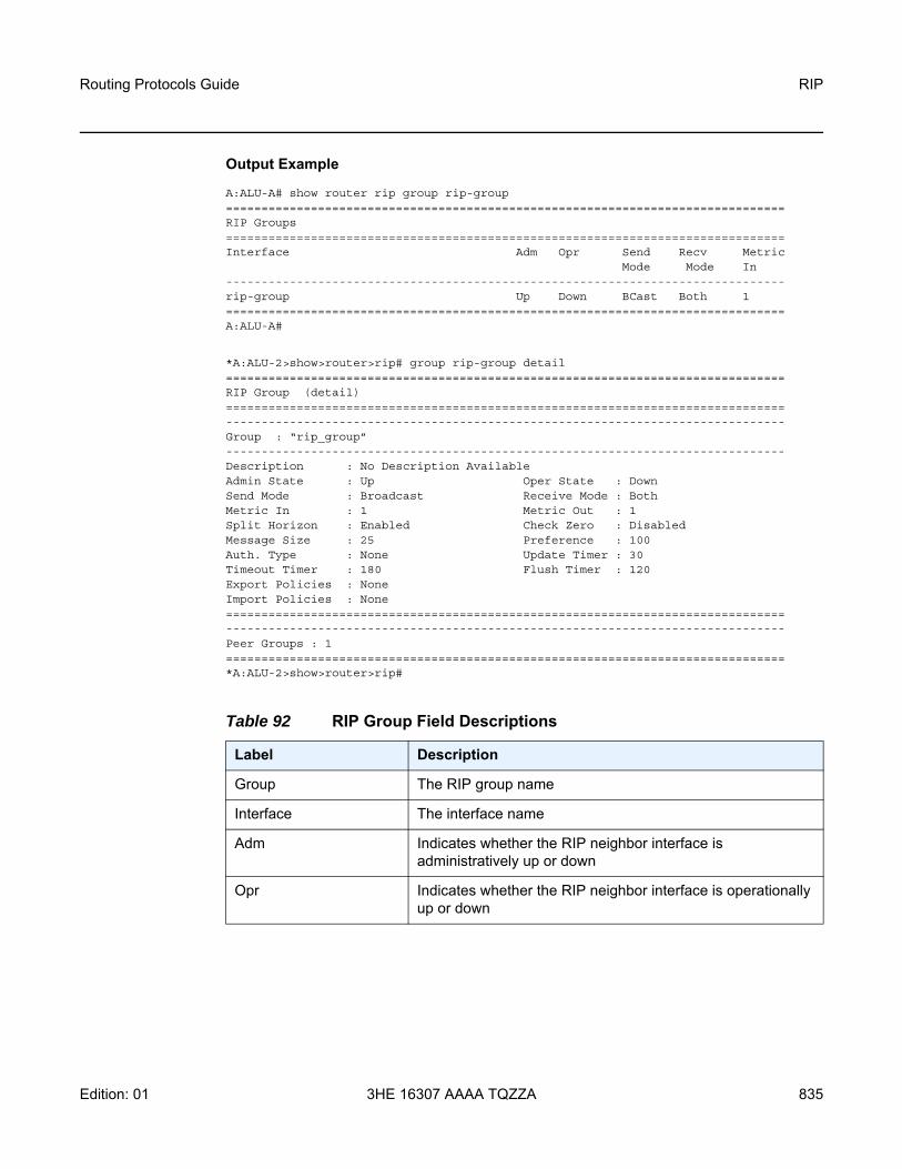
Routing Protocols Guide RIP
Edition: 01 3HE 16307 AAAA TQZZA 835
Output Example
A:ALU-A# show router rip group rip-group===============================================================================RIP Groups===============================================================================Interface Adm Opr Send Recv Metric
Mode Mode In-------------------------------------------------------------------------------rip-group Up Down BCast Both 1===============================================================================A:ALU-A#
*A:ALU-2>show>router>rip# group rip-group detail===============================================================================RIP Group (detail)===============================================================================-------------------------------------------------------------------------------Group : “rip_group”-------------------------------------------------------------------------------Description : No Description AvailableAdmin State : Up Oper State : DownSend Mode : Broadcast Receive Mode : BothMetric In : 1 Metric Out : 1Split Horizon : Enabled Check Zero : DisabledMessage Size : 25 Preference : 100Auth. Type : None Update Timer : 30Timeout Timer : 180 Flush Timer : 120Export Policies : NoneImport Policies : None===============================================================================-------------------------------------------------------------------------------Peer Groups : 1===============================================================================*A:ALU-2>show>router>rip#
Table 92 RIP Group Field Descriptions
Label Description
Group The RIP group name
Interface The interface name
Adm Indicates whether the RIP neighbor interface is administratively up or down
Opr Indicates whether the RIP neighbor interface is operationally up or down

RIP
836
Routing Protocols Guide
3HE 16307 AAAA TQZZA Edition: 01
neighbor
Syntax neighbor [ip-int-name | ip-address] [detail] [advertised-routes]
Context show>router>rip
Description This command displays RIP neighbor information. This command can be entered with or without any parameters.
When this command is issued without any parameters, information about all RIP neighbors displays.
Parameters ip-int-name | ip-address — displays information for the specified IP interface
Values ipv4-address: a.b.c.d (host bits must be 0)
detail — displays detailed RIP neighbor information
advertised-routes — displays the routes advertised to RIP neighbors. If no neighbors are specified, then all routes advertised to all neighbors are displayed. If a neighbor is specified, then only routes advertised to that neighbor are displayed.
Output The following outputs are examples of RIP neighbor information:
• RIP neighbor (standard and advertised-routes) (Output Example - RIP Neighbor (Standard and Advertised Routes), Table 93)
• RIP neighbor (detailed) (Output Example - RIP Neighbor (Detailed), Table 94)
Send Mode Bcast — specifies that RIPv2 formatted messages are sent to the broadcast addressMcast — specifies that RIPv2 formatted messages are sent to the multicast addressNone — specifies that no RIP messages are sent (silent listener)RIPv1 — specifies that RIPv1 formatted messages are sent to the broadcast address
Recv Mode Both — specifies that RIP updates in either version 1 or version 2 format will be acceptedNone — specifies that RIP updates will not be acceptedRIPv1 — specifies that RIP updates in version 1 format only are acceptedRIPv2 — specifies that RIP updates in version 2 format only are accepted
Metric In The metric added to routes received from a RIP neighbor
Table 92 RIP Group Field Descriptions (Continued)
Label Description

Routing Protocols Guide RIP
Edition: 01 3HE 16307 AAAA TQZZA 837
Output Example - RIP Neighbor (Standard and Advertised Routes)
A:ALU-A# show router rip neighbor===============================================================================RIP Neighbors===============================================================================Interface Adm Opr Primary IP Send Recv Metric
Mode Mode In-------------------------------------------------------------------------------router-2/1 Up Up 10.0.3.12 None Both 1router-2/2 Up Up 10.0.5.12 BCast Both 1router-2/3 Up Up 10.0.6.12 BCast Both 1router-2/5 Up Up 10.0.9.12 BCast Both 1router-2/6 Up Up 10.0.17.12 None Both 1router-2/7 Up Up 10.0.16.12 None Both 1===============================================================================A:ALU-A#
Table 93 RIP Neighbor Field Descriptions
Label Description
Interface The RIP neighbor name or IP address
Adm Indicates whether the RIP neighbor interface is administratively up or down
Opr Indicates whether the RIP neighbor interface is operationally up or down
Primary IP The primary IP address of the RIP neighbor interface
Send Mode Bcast — specifies that RIPv2 formatted messages are sent to the broadcast addressMcast — specifies that RIPv2 formatted messages are sent to the multicast addressNone — specifies that no RIP messages are sent (silent listener)RIPv1 — specifies that RIPv1 formatted messages are sent to the broadcast address
Recv Mode Both — specifies that RIP updates in either version 1 or version 2 format will be acceptedNone — specifies that RIP updates will not be acceptedRIPv1 — specifies that RIP updates in version 1 format only are acceptedRIPv2 — specifies that RIP updates in version 2 format only are accepted
Metric In The metric added to routes received from a RIP neighbor

RIP
838
Routing Protocols Guide
3HE 16307 AAAA TQZZA Edition: 01
Output Example - RIP Neighbor (Detailed)
A:ALU-A# show router rip neighbor detail===============================================================================RIP Neighbors (Detail)===============================================================================-------------------------------------------------------------------------------Neighbor "router-2/7"-------------------------------------------------------------------------------Description : No Description AvailablePrimary IP : 10.0.16.12 Group : sevenAdmin State : Up Oper State : UpSend Mode : None Receive Mode : BothMetric In : 1 Metric Out : 1Split Horizon : Enabled Check Zero : DisabledMessage Size : 25 Preference : 100Auth. Type : None Update Timer : 3Timeout Timer : 6 Flush Timer : 6Export Policies:
Rip2Ripdirect2Ripbgp2Rip
Import Policies:None
===============================================================================A:ALU-A#
Table 94 RIP Neighbor (Detailed) Field Descriptions
Label Description
Neighbor The RIP neighbor name or IP address
Description The RIP neighbor description. No Description Available indicates no description is configured.
Primary IP The RIP neighbor interface primary IP address
Group The RIP group name of the neighbor interface
Admin State Indicates whether the RIP neighbor interface is administratively up or down
Oper State Indicates whether the RIP neighbor interface is operationally up or down
Send Mode Bcast — specifies that RIPv2 formatted messages are sent to the broadcast addressMcast — specifies that RIPv2 formatted messages are sent to the multicast addressNone — specifies that no RIP messages are sent (silent listener)RIPv1 — specifies that RIPv1 formatted messages are sent to the broadcast address

Routing Protocols Guide RIP
Edition: 01 3HE 16307 AAAA TQZZA 839
Receive Mode Both — specifies that RIP updates in either version 1 or version 2 format will be accepted\None — specifies that RIP updates will not be acceptedRIPv1 — specifies that RIP updates in version 1 format only are acceptedRIPv2 — specifies that RIP updates in version 2 format only are accepted
Metric In The metric value added to routes received from a RIP neighbor
Metric Out The value added to routes exported into RIP and advertised to RIP neighbors
Split Horizon Indicates whether split horizon and poison reverse is Enabled or Disabled for the RIP neighbor
Check Zero Disabled — the mandatory zero fields in RIP packets are not checked, allowing receipt of RIP messages even if mandatory zero fields are non-zero for the neighborEnabled — mandatory zero fields in RIP packets are checked and non-compliant RIP messages are rejected
Message Size The maximum number of routes per RIP update message
Preference The preference of RIP routes from the neighbor
Auth. Type Specifies the authentication type
Update Timer The current setting of the RIP update timer value expressed in seconds
Timeout Timer The current RIP timeout timer value expressed in seconds
Flush Timer The number of seconds after a route has been declared invalid that it is flushed from the route database
Export Policies The export route policy that is used to determine routes advertised to all peers
Import Policies The import route policy that is used to determine which routes are accepted from RIP neighbors
Table 94 RIP Neighbor (Detailed) Field Descriptions (Continued)
Label Description

RIP
840
Routing Protocols Guide
3HE 16307 AAAA TQZZA Edition: 01
peer
Syntax peer [interface-name]
Context show>router>rip
Description This command displays RIP peer information.
Parameters interface-name — displays peer information for peers on the specified IP interface
Output The following output is an example of RIP peer information, and Table 95 describes the fields.
Output Example
A:ALU-A# show router rip peers===============================================================================RIP Peers===============================================================================Peer IP Addr Interface Name Version Last Update-------------------------------------------------------------------------------10.0.5.13 router-2/2 RIPv2 010.0.6.16 router-2/3 RIPv2 210.0.9.14 router-2/5 RIPv2 810.0.10.15 router-2/4 RIPv2 0-------------------------------------------------------------------------------No. of Peers: 4===============================================================================A:ALU-A#
statistics
Syntax statistics [ip-int-name | ip-addr]
Context show>router>rip
Description This command displays interface level statistics for the RIP protocol.
Table 95 RIP Peer Field Descriptions
Label Description
Peer IP Addr The IP address of the peer router
Interface Name The peer interface name
Version The version of RIP running on the peer
Last Update The number of days since the last update
No. of Peers The number of RIP peers

Routing Protocols Guide RIP
Edition: 01 3HE 16307 AAAA TQZZA 841
If no IP address or interface name is specified, then all configured RIP interfaces are displayed.
If an IP address or interface name is specified, then only data about the specified RIP interface is displayed.
Parameters ip-addr | ip-int-name — displays statistics for the specified IP interface
Output The following output is an example of RIP statistics information, and Table 96 describes the fields.
Output Example
A:ALU-A# show router rip statistics===============================================================================RIP Statistics===============================================================================Learned Routes : 0 Timed Out Routes : 0Current Memory : 120624 Maximum Memory : 262144-------------------------------------------------------------------------------Interface "to-web"-------------------------------------------------------------------------------Primary IP : 10.1.1.3 Update Timer : 30Timeout Timer : 180 Flush Timer : 120Counter Total Last 5 Min Last 1 Min-------------------------------------------------------------------------------Updates Sent 0 0 0Triggered Updates 0 0 0Bad Packets Received 0 0 0RIPv1 Updates Received 0 0 0RIPv1 Updates Ignored 0 0 0RIPv1 Bad Routes 0 0 0RIPv1 Requests Received 0 0 0RIPv1 Requests Ignored 0 0 0RIPv2 Updates Received 0 0 0RIPv2 Updates Ignored 0 0 0RIPv2 Bad Routes 0 0 0RIPv2 Requests Received 0 0 0RIPv2 Requests Ignored 0 0 0Authentication Errors 0 0 0===============================================================================A:ALU-A#
Table 96 RIP Statistics Field Descriptions
Label Description
Learned Routes The number of RIP learned routes that were exported to RIP neighbors
Timed Out Routes The number of routes that have timed out
Current Memory The amount of memory used by the RIP router instance

RIP
842
Routing Protocols Guide
3HE 16307 AAAA TQZZA Edition: 01
Maximum Memory The amount of memory allocated for the RIP router instance
Interface Displays the name of each interface configured in RIP and its associated RIP statistics
Primary IP The interface IP address
Update Timer The current setting of the RIP update timer value expressed in seconds
Timeout Timer The current RIP timeout timer value expressed in seconds
Flush Timer The number of seconds before a route that has been declared invalid is removed from the route database
Total The total number of each corresponding RIP statistic collected
Last 5 Min The number of each corresponding RIP statistic collected in the last 5 minutes
Last 1 Min The number of each corresponding RIP statistic that was collected in the last minute
Updates Sent The total number of RIP updates that have been sent
Triggered Updates The number of triggered updates that have been sent. Triggered updates are sent before the RIP routing table is sent.
Bad Packets Received The number of RIP updates received on this interface that were discarded as invalid
RIPv1 Updates Received The number of RIPv1 updates received
RIPv1 Updates Ignored The number of RIPv1 updates ignored
RIPv1 Bad Routes The number of bad RIPv1 routes received from the peer
RIPv1 Requests Received The number of RIPv1 requests received from other routers
RIPv1 Requests Ignored The number of times the router ignored a RIPv1 route request from other routers
RIPv2 Updates Received The number of RIPv2 updates received
Table 96 RIP Statistics Field Descriptions (Continued)
Label Description

Routing Protocols Guide RIP
Edition: 01 3HE 16307 AAAA TQZZA 843
RIPv2 Updates Ignored The number of RIPv2 updates ignored
RIPv2 Bad Routes The number of bad RIPv2 routes received from the peer
RIPv2 Requests Received The number of RIPv2 requests received from other routers
RIPv2 Requests Ignored The number of times the router ignored a RIPv2 route request from other routers
Authentication Errors The number of authentication errors that occurred while attempting to secure table updates
Table 96 RIP Statistics Field Descriptions (Continued)
Label Description

RIP
844
Routing Protocols Guide
3HE 16307 AAAA TQZZA Edition: 01
7.10.2.3 Clear Commands
database
Syntax database
Context clear>router>rip
Description This command deletes all routes in the RIP database.
statistics
Syntax statistics [neighbor ip-int-name | ip-address]
Context clear>router>rip
Description This command clears RIP neighbor statistics. You can clear statistics for a specific RIP interface or for all RIP interfaces.
Default none
Parameters ip-int-name | ip-address — clears the statistics for the specified RIP interface

Routing Protocols Guide RIP
Edition: 01 3HE 16307 AAAA TQZZA 845
7.10.2.4 Debug Commands
auth
Syntax [no] auth [neighbor ip-int-name | ip-address]
Context debug>router>rip
Description This command enables debugging for RIP authentication at either the global level or neighbor level.
Parameters ip-int-name | ip-address — the interface name or IP address of the neighbor
error
Syntax [no] error [neighbor ip-int-name | ip-address]
Context debug>router>rip
Description This command enables debugging for RIP errors at either the global level or neighbor level.
Parameters ip-int-name | ip-address — the interface name or IP address of the neighbor
events
Syntax [no] events [neighbor ip-int-name | ip-address]
Context debug>router>rip
Description This command enables debugging for RIP events at either the global level or neighbor level.
Parameters ip-int-name | ip-address — the interface name or IP address of the neighbor
holddown
Syntax [no] holddown [neighbor ip-int-name | ip-address]
Context debug>router>rip
Description This command enables debugging for RIP hold-downs at either the global level or neighbor level.
Parameters ip-int-name | ip-address — the interface name or IP address of the neighbor

RIP
846
Routing Protocols Guide
3HE 16307 AAAA TQZZA Edition: 01
packets
Syntax [no] packets [neighbor ip-int-name | ip-address]
Context debug>router>rip
Description This command enables debugging for RIP packets at either the global level or neighbor level.
Parameters ip-int-name | ip-address — the interface name or IP address of the neighbor
request
Syntax [no] request [neighbor ip-int-name | ip-address]
Context debug>router>rip
Description This command enables debugging for RIP requests at either the global level or neighbor level.
Parameters ip-int-name | ip-address — the interface name or IP address of the neighbor
trigger
Syntax [no] trigger [neighbor ip-int-name | ip-address]
Context debug>router>rip
Description This command enables debugging for RIP triggers at either the global level or neighbor level.
Parameters ip-int-name | ip-address — the interface name or IP address of the neighbor
updates
Syntax [no] updates [neighbor ip-int-name | ip-address]
Context debug>router>rip
Description This command enables debugging for RIP updates at either the global level or neighbor level.
Parameters ip-int-name | ip-address — the interface name or IP address of the neighbor

Routing Protocols Guide List of Acronyms
Edition: 01 3HE 16307 AAAA TQZZA 847
8 List of Acronyms
Table 97 Acronyms
Acronym Expansion
2G second generation wireless telephone technology
3DES triple DES (data encryption standard)
3G third generation mobile telephone technology
6VPE IPv6 on Virtual Private Edge Router
7705 SAR 7705 Service Aggregation Router
7750 SR 7750 Service Router
8 PSK eight phase shift keying
16 QAM 16-state quadrature amplitude modulation
32 QAM 32-state quadrature amplitude modulation
64 QAM 64-state quadrature amplitude modulation
128 QAM 128-state quadrature amplitude modulation
256 QAM 256-state quadrature amplitude modulation
ABR area border routeravailable bit rate
AC alternating currentattachment circuit
ACK acknowledge
ACL access control list
ACR adaptive clock recovery
AD auto-discovery
ADM add/drop multiplexer
ADP automatic discovery protocol
AES advanced encryption standard
AFI authority and format identifier
AIGP accumulated IGP
AIS alarm indication signal

List of Acronyms
848
Routing Protocols Guide
3HE 16307 AAAA TQZZA Edition: 01
ALG application level gateway
ANSI American National Standards Institute
Apipe ATM VLL
APS automatic protection switching
ARP address resolution protocol
A/S active/standby
AS autonomous system
ASAP any service, any port
ASBR autonomous system boundary router
ASM any-source multicastautonomous system message
ASN autonomous system number
ATM asynchronous transfer mode
ATM PVC ATM permanent virtual circuit
AU administrative unit
AUG administrative unit group
B3ZS bipolar with three-zero substitution
Batt A battery A
B-bit beginning bit (first packet of a fragment)
BBE background block errors
Bc committed burst size
Be excess burst size
BECN backward explicit congestion notification
Bellcore Bell Communications Research
BFD bidirectional forwarding detection
BGP border gateway protocol
BGP-LS border gateway protocol link state
BGP-LU border gateway protocol labeled unicast
Table 97 Acronyms (Continued)
Acronym Expansion

Routing Protocols Guide List of Acronyms
Edition: 01 3HE 16307 AAAA TQZZA 849
BITS building integrated timing supply
BMCA best master clock algorithm
BMU broadcast, multicast, and unknown trafficTraffic that is not unicast. Any nature of multipoint traffic:
• broadcast (that is, all 1s as the destination IP to represent all destinations within the subnet)
• multicast (that is, traffic typically identified by the destination address, uses special destination address); for IP, the destination must be 224.0.0.0 to 239.255.255.255
• unknown (that is, the destination is typically a valid unicast address but the destination port/interface is not yet known; therefore, traffic needs to be forwarded to all destinations; unknown traffic is treated as broadcast)
BNM bandwidth notification message
BOF boot options file
BoS bottom of stack
BPDU bridge protocol data unit
BRAS Broadband Remote Access Server
BSC Base Station Controller
BSM bootstrap message
BSR bootstrap router
BSTA Broadband Service Termination Architecture
BTS base transceiver station
CA certificate authority
CAS channel associated signaling
CBN common bonding networks
CBS committed buffer space
CC continuity checkcontrol channel
CCM continuity check message
CCTV closed-circuit television
Table 97 Acronyms (Continued)
Acronym Expansion

List of Acronyms
850
Routing Protocols Guide
3HE 16307 AAAA TQZZA Edition: 01
CE circuit emulationcustomer edge
CEM circuit emulation
CES circuit emulation services
CESoPSN circuit emulation services over packet switched network
CFM connectivity fault management
cHDLC Cisco high-level data link control protocol
CIDR classless inter-domain routing
CIR committed information rate
CLI command line interface
CLP cell loss priority
CMP certificate management protocol
C-multicast customer multicast
CoS class of service
CPE customer premises equipment
Cpipe circuit emulation (or TDM) VLL
CPM Control and Processing Module (CPM is used instead of CSM when referring to CSM filtering to align with CLI syntax used with other SR products). CSM management ports are referred to as CPM management ports in the CLI.
CPROTO C prototype
CPU central processing unit
C/R command/response
CRC cyclic redundancy check
CRC-32 32-bit cyclic redundancy check
CRL certificate revocation list
CRON a time-based scheduling service (from chronos = time)
CRP candidate RP
CSM Control and Switching Module
Table 97 Acronyms (Continued)
Acronym Expansion

Routing Protocols Guide List of Acronyms
Edition: 01 3HE 16307 AAAA TQZZA 851
CSNP complete sequence number PDU
CSPF constrained shortest path first
C-TAG customer VLAN tag
CV connection verificationcustomer VLAN (tag)
CW control word
CWDM coarse wavelength-division multiplexing
DA/FAN distribution automation and field area network
DC direct current
DC-C DC return - common
DCE data communications equipment
DC-I DC return - isolated
DCO digitally controlled oscillator
DCR differential clock recovery
DDoS distributed DoS
DE discard eligibility
DER distinguished encoding rules
DES data encryption standard
DF do not fragmentdesignated forwarder
DH Diffie-Hellman
DHB decimal, hexadecimal, or binary
DHCP dynamic host configuration protocol
DHCPv6 dynamic host configuration protocol for IPv6
DIS designated intermediate system
DLCI data link connection identifier
DLCMI data link connection management interface
DM delay measurement
Table 97 Acronyms (Continued)
Acronym Expansion

List of Acronyms
852
Routing Protocols Guide
3HE 16307 AAAA TQZZA Edition: 01
DNS domain name server
DNU do not use
DoS denial of service
dot1p IEEE 802.1p bits, in Ethernet or VLAN ingress packet headers, used to map traffic to up to eight forwarding classes
dot1q IEEE 802.1q encapsulation for Ethernet interfaces
DPD dead peer detection
DPI deep packet inspection
DPLL digital phase locked loop
DR designated router
DSA digital signal algorithm
DSCP differentiated services code point
DSL digital subscriber line
DSLAM digital subscriber line access multiplexer
DTE data termination equipment
DU downstream unsolicited
DUID DHCP unique identifier
DUS do not use for synchronization
DV delay variation
DVMRP distance vector multicast routing protocol
e911 enhanced 911 service
EAP Extensible Authentication Protocol
EAPOL EAP over LAN
E-bit ending bit (last packet of a fragment)
E-BSR elected BSR
ECMP equal cost multipath
EE end entity
EFM Ethernet in the first mile
Table 97 Acronyms (Continued)
Acronym Expansion

Routing Protocols Guide List of Acronyms
Edition: 01 3HE 16307 AAAA TQZZA 853
EGP exterior gateway protocol
EIA/TIA-232 Electronic Industries Alliance/Telecommunications Industry Association Standard 232 (also known as RS-232)
EIR excess information rate
EJBCA Enterprise Java Bean Certificate Authority
E-LAN Ethernet local area network
E-Line Ethernet virtual private line
EL entropy label
eLER egress label edge router
ELI entropy label indicator
E&M ear and mouthearth and magnetoexchange and multiplexer
eMBMS evolved MBMS
EOP end of packet
EPC evolved packet core
EPD early packet discard
Epipe Ethernet VLL
EPL Ethernet private line
EPON Ethernet Passive Optical Network
EPS equipment protection switching
ERO explicit route object
ES Ethernet segmenterrored seconds
ESD electrostatic discharge
ESI Ethernet segment identifier
ESMC Ethernet synchronization message channel
ESN extended sequence number
ESP encapsulating security payload
Table 97 Acronyms (Continued)
Acronym Expansion

List of Acronyms
854
Routing Protocols Guide
3HE 16307 AAAA TQZZA Edition: 01
ESPI encapsulating security payload identifier
ETE end-to-end
ETH-BN Ethernet bandwidth notification
ETH-CFM Ethernet connectivity fault management (IEEE 802.1ag)
EVC Ethernet virtual connection
EVDO evolution - data optimized
EVI EVPN instance
EVPL Ethernet virtual private link
EVPN Ethernet virtual private network
EXP bits experimental bits (currently known as TC)
FC forwarding class
FCS frame check sequence
FD frequency diversity
FDB forwarding database
FDL facilities data link
FEAC far-end alarm and control
FEC forwarding equivalence class
FECN forward explicit congestion notification
FeGW far-end gateway
FEP front-end processor
FF fixed filter
FFD fast fault detection
FIB forwarding information base
FIFO first in, first out
FIPS-140-2 Federal Information Processing Standard publication 140-2
FNG fault notification generator
FOM figure of merit
Table 97 Acronyms (Continued)
Acronym Expansion

Routing Protocols Guide List of Acronyms
Edition: 01 3HE 16307 AAAA TQZZA 855
Fpipe frame relay VLL
FQDN fully qualified domain name
FR frame relay
FRG bit fragmentation bit
FRR fast reroute
FTN FEC-to-NHLFE
FTP file transfer protocol
FXO foreign exchange office
FXS foreign exchange subscriber
GFP generic framing procedure
GigE Gigabit Ethernet
GLONASS Global Navigation Satellite System (Russia)
GNSS global navigation satellite system (generic)
GPON Gigabit Passive Optical Network
GPRS general packet radio service
GPS Global Positioning System
GRE generic routing encapsulation
GRT global routing table
GSM Global System for Mobile Communications (2G)
GTP-U GPRS tunneling protocol user plane
GW gateway
HA high availability
HCM high capacity multiplexing
HDB3 high density bipolar of order 3
HDLC high-level data link control protocol
HEC header error control
HMAC hash message authentication code
Table 97 Acronyms (Continued)
Acronym Expansion

List of Acronyms
856
Routing Protocols Guide
3HE 16307 AAAA TQZZA Edition: 01
Hpipe HDLC VLL
H-QoS hierarchical quality of service
HSB hot standby
HSDPA high-speed downlink packet access
HSPA high-speed packet access
H-VPLS hierarchical virtual private line service
IANA internet assigned numbers authority
IBN isolated bonding networks
ICB inter-chassis backup
ICMP Internet control message protocol
ICMPv6 Internet control message protocol for IPv6
ICP IMA control protocol cells
IDS intrusion detection system
IDU indoor unit
IED intelligent end device
IEEE Institute of Electrical and Electronics Engineers
IEEE 1588v2 Institute of Electrical and Electronics Engineers standard 1588-2008
IES Internet Enhanced Service
IETF Internet Engineering Task Force
IGMP Internet group management protocol
IGP interior gateway protocol
IID instance ID
IKE Internet key exchange
iLER ingress label edge router
ILM incoming label map
IMA inverse multiplexing over ATM
IMET-IR inclusive multicast Ethernet tag—ingress replication
Table 97 Acronyms (Continued)
Acronym Expansion

Routing Protocols Guide List of Acronyms
Edition: 01 3HE 16307 AAAA TQZZA 857
INVARP inverse address resolution protocol
IOM input/output module
IP Internet Protocol
IPCP Internet Protocol Control Protocol
IPIP IP in IP
Ipipe IP interworking VLL
I-PMSI inclusive PMSI
IPoATM IP over ATM
IPS intrusion prevention system
IPSec Internet Protocol security
IR ingress replication
IRB integrated routing and bridging
ISA integrated services adapter
ISAKMP Internet security association and key management protocol
IS-IS Intermediate System-to-Intermediate System
IS-IS-TE IS-IS-traffic engineering (extensions)
ISO International Organization for Standardization
IW interworking
JP join prune
KG key group
LB loopback
lbf-in pound force inch
LBM loopback message
LBO line buildout
LBR loopback reply
LCP link control protocol
LDP label distribution protocol
Table 97 Acronyms (Continued)
Acronym Expansion

List of Acronyms
858
Routing Protocols Guide
3HE 16307 AAAA TQZZA Edition: 01
LER label edge router
LFA loop-free alternate
LFIB label forwarding information base
LIB label information base
LLDP link layer discovery protocol
LLDPDU link layer discovery protocol data unit
LLF link loss forwarding
LLID loopback location ID
LM loss measurement
LMI local management interface
LOS line-of-sightloss of signal
LSA link-state advertisement
LSDB link-state database
LSP label switched pathlink-state PDU (for IS-IS)
LSPA LSP attributes
LSR label switch routerlink-state request
LSU link-state update
LT linktrace
LTE long term evolutionline termination equipment
LTM linktrace message
LTN LSP ID to NHLFE
LTR link trace reply
MA maintenance association
MAC media access control
MA-ID maintenance association identifier
Table 97 Acronyms (Continued)
Acronym Expansion

Routing Protocols Guide List of Acronyms
Edition: 01 3HE 16307 AAAA TQZZA 859
MBB make-before-break
MBGP multicast BGPmultiprotocol BGPmultiprotocol extensions for BGP
MBMS multimedia broadcast multicast service
MBS maximum buffer spacemaximum burst sizemedia buffer space
MBSP mobile backhaul service provider
MCAC multicast connection admission control
MC-APS multi-chassis automatic protection switching
MC-MLPPP multi-class multilink point-to-point protocol
MCS multicast servermulti-chassis synchronization
MCT MPT craft terminal
MD maintenance domain
MD5 message digest version 5 (algorithm)
MDA media dependent adapter
MDDB multidrop data bridge
MDL maintenance data link
MDT multicast distribution tree
ME maintenance entity
MED multi-exit discriminator
MEF Metro Ethernet Forum
MEG maintenance entity group
MEG-ID maintenance entity group identifier
MEN Metro Ethernet network
MEP maintenance association end point
MFC multi-field classification
Table 97 Acronyms (Continued)
Acronym Expansion

List of Acronyms
860
Routing Protocols Guide
3HE 16307 AAAA TQZZA Edition: 01
MHD multi-homed device
MHF MIP half function
MHN multi-homed network
MIB management information base
MI-IS-IS multi-instance IS-IS
MIR minimum information rate
MLD multicast listener discovery
mLDP multicast LDP
MLPPP multilink point-to-point protocol
mLSP multicast LSP
MoFRR multicast-only fast reroute
MP merge pointmultilink protocolmultipoint
MP-BGP multiprotocol border gateway protocol
MPLS multiprotocol label switching
MPLSCP multiprotocol label switching control protocol
MPP MPT protection protocol
MPR see Wavence
MPR-e Microwave Packet Radio (standalone mode)
MPT-HC V2/9558HC Microwave Packet Transport, High Capacity version 2
MPT-HLC Microwave Packet Transport, High-Capacity Long-Haul Cubic (ANSI)
MPT-HQAM Microwave Packet Transport, High Capacity (MPT-HC-QAM) or Extended Power (MPT-XP-QAM) with 512/1024 QAM
MPT-MC Microwave Packet Transport, Medium Capacity
MPT-XP Microwave Packet Transport, High Capacity (very high power version of MPT-HC V2/9558HC)
MRAI minimum route advertisement interval
Table 97 Acronyms (Continued)
Acronym Expansion

Routing Protocols Guide List of Acronyms
Edition: 01 3HE 16307 AAAA TQZZA 861
MRRU maximum received reconstructed unit
MRU maximum receive unit
MSDP Multicast Source Discovery Protocol
MSDU MAC Service Data Unit
MSO multi-system operator
MS-PW multi-segment pseudowire
MSS maximum segment sizeMicrowave Service Switch
MTIE maximum time interval error
MTSO mobile trunk switching office
MTU maximum transmission unitmulti-tenant unit
M-VPLS management virtual private line service
MVPN multicast VPN
MVR multicast VPLS registration
MW microwave
MWA microwave awareness
N.m newton meter
NAT network address translation
NAT-T network address translation traversal
NBMA non-broadcast multiple access (network)
ND neighbor discovery
NE network element
NET network entity title
NFM-P Network Functions Manager - Packet (formerly 5620 SAM)
NGE network group encryption
NG-MVPN next generation MVPN
NH next hop
Table 97 Acronyms (Continued)
Acronym Expansion

List of Acronyms
862
Routing Protocols Guide
3HE 16307 AAAA TQZZA Edition: 01
NHLFE next hop label forwarding entry
NHOP next-hop
NLOS non-line-of-sight
NLPID network level protocol identifier
NLRI network layer reachability information
NNHOP next next-hop
NNI network-to-network interface
Node B similar to BTS but used in 3G networks — term is used in UMTS (3G systems) while BTS is used in GSM (2G systems)
NPAT network port address translation
NRC-F Network Resource Controller - Flow
NRC-P Network Resource Controller - Packet
NRC-T Network Resource Controller - Transport
NRC-X Network Resource Controller - Cross Domain
NSAP network service access point
NSD Network Services Director
NSP native service processingNetwork Services Platform
NSSA not-so-stubby area
NTP network time protocol
NTR network timing reference
OADM optical add/drop multiplexer
OAM operations, administration, and maintenance
OAMPDU OAM protocol data units
OC3 optical carrier level 3
OCSP online certificate status protocol
ODU outdoor unit
OIF outgoing interface
Table 97 Acronyms (Continued)
Acronym Expansion
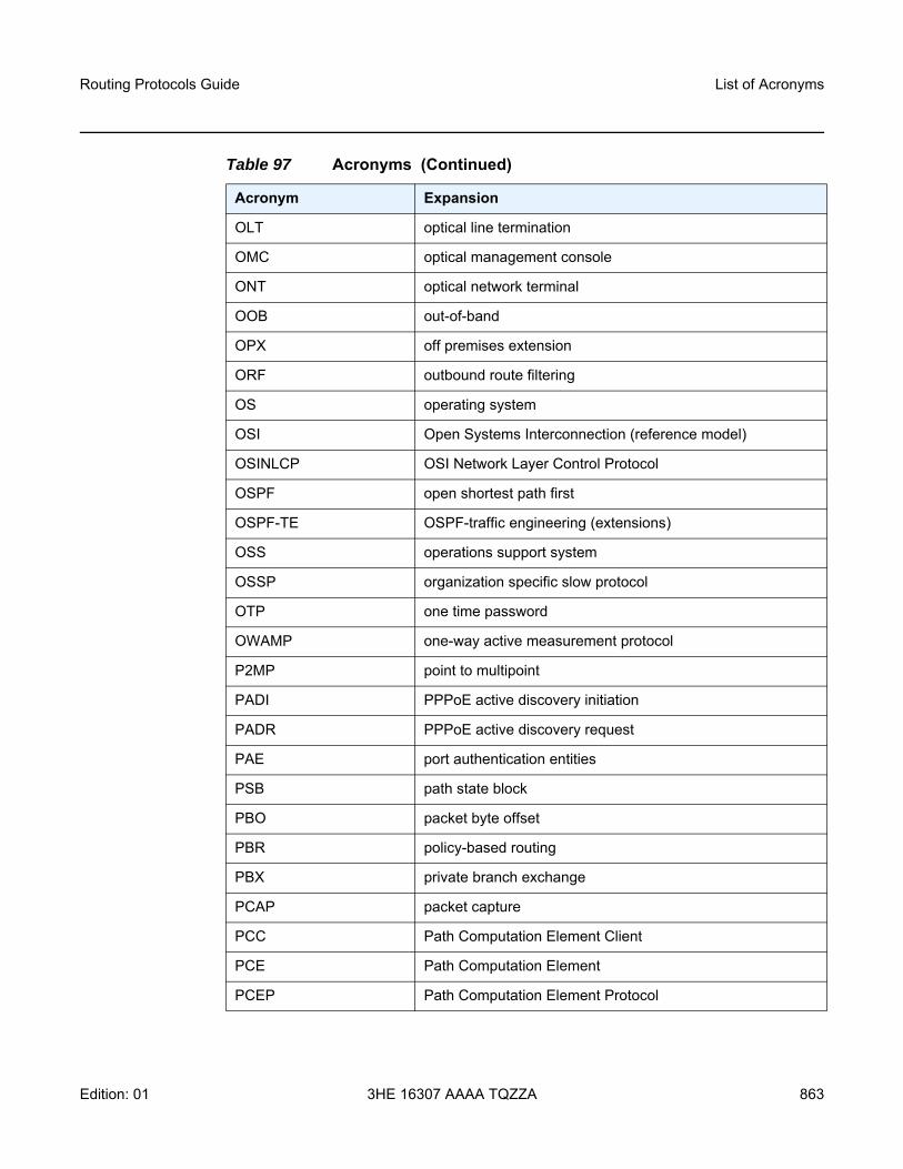
Routing Protocols Guide List of Acronyms
Edition: 01 3HE 16307 AAAA TQZZA 863
OLT optical line termination
OMC optical management console
ONT optical network terminal
OOB out-of-band
OPX off premises extension
ORF outbound route filtering
OS operating system
OSI Open Systems Interconnection (reference model)
OSINLCP OSI Network Layer Control Protocol
OSPF open shortest path first
OSPF-TE OSPF-traffic engineering (extensions)
OSS operations support system
OSSP organization specific slow protocol
OTP one time password
OWAMP one-way active measurement protocol
P2MP point to multipoint
PADI PPPoE active discovery initiation
PADR PPPoE active discovery request
PAE port authentication entities
PSB path state block
PBO packet byte offset
PBR policy-based routing
PBX private branch exchange
PCAP packet capture
PCC Path Computation Element Client
PCE Path Computation Element
PCEP Path Computation Element Protocol
Table 97 Acronyms (Continued)
Acronym Expansion

List of Acronyms
864
Routing Protocols Guide
3HE 16307 AAAA TQZZA Edition: 01
PCM pulse code modulation
PCP priority code point
PCR proprietary clock recovery
PDU power distribution unitprotocol data units
PDV packet delay variation
PDVT packet delay variation tolerance
PE provider edge router
PEAPv0 protected extensible authentication protocol version 0
PEM privacy enhanced mail
PFoE power feed over Ethernet
PFS perfect forward secrecy
PHB per-hop behavior
PHP penultimate hop popping
PHY physical layer
PIC prefix independent convergence
PID protocol ID
PIM SSM protocol independent multicast—source-specific multicast
PIR peak information rate
PKCS public key cryptography standards
PKI public key infrastructure
PLAR private line automatic ringdown
PLCP Physical Layer Convergence Protocol
PLR point of local repair
PLSP path LSP
PMSI P-multicast service interface
P-multicast provider multicast
PoE power over Ethernet
Table 97 Acronyms (Continued)
Acronym Expansion

Routing Protocols Guide List of Acronyms
Edition: 01 3HE 16307 AAAA TQZZA 865
PoE+ power over Ethernet plus
POH path overhead
POI purge originator identification
PoP point of presence
POS packet over SONET
PPP point-to-point protocol
PPPoE point-to-point protocol over Ethernet
PPS pulses per second
PRC primary reference clock
PRS primary reference source
PRTC primary reference time clock
PSE power sourcing equipment
PSK pre-shared key
PSN packet switched network
PSNP partial sequence number PDU
PTA PMSI tunnel attribute
PTM packet transfer mode
PTP performance transparency protocolprecision time protocol
PuTTY an open-source terminal emulator, serial console, and network file transfer application
PVC permanent virtual circuit
PVCC permanent virtual channel connection
PW pseudowire
PWE pseudowire emulation
PWE3 pseudowire emulation edge-to-edge
Q.922 ITU-T Q-series Specification 922
QL quality level
Table 97 Acronyms (Continued)
Acronym Expansion

List of Acronyms
866
Routing Protocols Guide
3HE 16307 AAAA TQZZA Edition: 01
QoS quality of service
QPSK quadrature phase shift keying
RADIUS Remote Authentication Dial In User Service
RAN Radio Access Network
RBS robbed bit signaling
RD route distinguisher
RDI remote defect indication
RED random early discard
RESV reservation
RIB routing information base
RIP routing information protocol
RJ-45 registered jack 45
RMON remote network monitoring
RNC Radio Network Controller
RP rendezvous point
RPF RTM reverse path forwarding RTM
RPS radio protection switching
RPT rendezvous-point tree
RR route reflector
RRO record route object
RS-232 Recommended Standard 232 (also known as EIA/TIA-232)
RSA Rivest, Shamir, and Adleman (authors of the RSA encryption algorithm)
RSHG residential split horizon group
RSTP rapid spanning tree protocol
RSVP-TE resource reservation protocol - traffic engineering
RT receive/transmit
RTC route target constraint
Table 97 Acronyms (Continued)
Acronym Expansion

Routing Protocols Guide List of Acronyms
Edition: 01 3HE 16307 AAAA TQZZA 867
RTM routing table manager
RTN battery return
RTP real-time protocol
R&TTE Radio and Telecommunications Terminal Equipment
RTU remote terminal unit
RU rack unit
r-VPLS routed virtual private LAN service
SA security associationsource-active
SAA service assurance agent
SAFI subsequent address family identifier
SAP service access point
SAR-8 7705 Service Aggregation Router – 8-slot chassis
SAR-18 7705 Service Aggregation Router – 18-slot chassis
SAR-A 7705 Service Aggregation Router – two variants:• passively cooled chassis with 12 Ethernet ports and 8
T1/E1 ports• passively cooled chassis with 12 Ethernet ports and no
T1/E1 ports
SAR-Ax 7705 Service Aggregation Router:• passively cooled• DC-powered with a dual-feed DC input that can be
connected to a +24/-48/-60 VDC power source• equipped with 12 Ethernet ports (ports 1 to 4 are XOR
ports and 5 to 12 are 100/1000 Ethernet SFP ports)• equipped with a factory-installed GPS receiver and
GNSS RF faceplate connector
SAR-H 7705 Service Aggregation Router – temperature- and EMC-hardened to the following specifications: IEEE 1613 and IEC 61850-3
SAR-Hc 7705 Service Aggregation Router – compact version of 7705 SAR-H
Table 97 Acronyms (Continued)
Acronym Expansion

List of Acronyms
868
Routing Protocols Guide
3HE 16307 AAAA TQZZA Edition: 01
SAR-M 7705 Service Aggregation Router – four variants:• actively cooled chassis with 16 T1/E1 ports, 7 Ethernet
ports, and 1 hot-insertable module slot• actively cooled chassis with 0 T1/E1 ports, 7 Ethernet
ports, and 1 hot-insertable module slot• passively cooled chassis with 16 T1/E1 ports, 7 Ethernet
ports, and 0 module slots• passively cooled chassis with 0 T1/E1 ports, 7 Ethernet
ports, and 0 module slots
SAR-O 7705 Service Aggregation Router passive CWDM device – three variants:
• 2-wavelength CWDM dual-fiber• 4-wavelength CWDM dual-fiber• 8-wavelength CWDM single-fiber
Each variant has different models that are used to add and drop different wavelengths
SAR-W 7705 Service Aggregation Router – passively cooled, universal AC and DC powered unit, equipped with five Gigabit Ethernet ports (three SFP ports and two RJ-45 Power over Ethernet (PoE) ports)
Table 97 Acronyms (Continued)
Acronym Expansion

Routing Protocols Guide List of Acronyms
Edition: 01 3HE 16307 AAAA TQZZA 869
SAR-Wx 7705 Service Aggregation Router – passively cooled, universal AC powered unit; there are six variants:
• a unit that is equipped with an AC power input connector, five Gigabit Ethernet data ports (three SFP ports and two RJ-45 Ethernet ports), and an RJ-45 alarm input connector
• a unit that is equipped with an AC power input connector, five Gigabit Ethernet data ports (three SFP ports and two RJ-45 Ethernet ports), a GPS receiver, and an RJ-45 alarm input connector
• a unit that is equipped with an AC power input connector, five Gigabit Ethernet data ports (three SFP ports, one RJ-45 Ethernet port, and one RJ-45 PoE+ port), and an RJ-45 alarm input connector
• a unit that is equipped with an AC power input connector, five Gigabit Ethernet data ports (three SFP ports, one RJ-45 Ethernet port, and one RJ-45 PoE+ port), a GPS receiver, and an RJ-45 alarm input connector
• a unit that is equipped with an AC power input connector, four Gigabit Ethernet data ports (three SFP ports and one RJ-45 port), one RJ-45 4-pair xDSL port, and an RJ-45 alarm input connector
• a unit that is equipped with an AC power input connector, four Gigabit Ethernet data ports (three SFP ports and one RJ-45 port), one RJ-45 4-pair xDSL port, a GPS receiver, and an RJ-45 alarm input connector
SAR-X 7705 Service Aggregation Router – fan-cooled, rack-mountable, IP20 design, available in two variants:
• AC-powered variant with a single-feed AC input that can be connected to a 100 to 240 VAC, 50/60 Hz power source
• DC-powered variant with a dual-feed DC input that can be connected to a +24/-48/-60 VDC power source
SAToP structure-agnostic TDM over packet
SCADA surveillance, control and data acquisition
SC-APS single-chassis automatic protection switching
SCP secure copy
SCTP Stream Control Transmission Protocol
Table 97 Acronyms (Continued)
Acronym Expansion

List of Acronyms
870
Routing Protocols Guide
3HE 16307 AAAA TQZZA Edition: 01
SD signal degradespace diversity
SDH synchronous digital hierarchy
SDI serial data interface
SDN software defined network
SDP service destination point
SE shared explicit
SeGW secure gateway
SES severely errored seconds
SETS synchronous equipment timing source
SF signal fail
SFP small form-factor pluggable (transceiver)
SFTP SSH file transfer protocol
(S,G) (source, group)
SGT self-generated traffic
SHA-1 secure hash algorithm
SHG split horizon group
SIR sustained information rate
SLA Service Level Agreement
SLARP serial line address resolution protocol
SLID subscriber location identifier of a GPON module
SLM synthetic loss measurement
SNMP Simple Network Management Protocol
SNPA subnetwork point of attachment
SNR signal to noise ratio
SNTP simple network time protocol
SONET synchronous optical networking
S-PE switching provider edge router
Table 97 Acronyms (Continued)
Acronym Expansion

Routing Protocols Guide List of Acronyms
Edition: 01 3HE 16307 AAAA TQZZA 871
SPF shortest path first
SPI security parameter index
S-PMSI selective PMSI
SPT shortest path tree
SR service router (7750 SR)segment routing
SRLG shared risk link group
SRP stateful request parameter
SRRP subscriber routed redundancy protocol
SR-ISIS segment routing IS-IS
SR-OSPF segment routing OSPF
SR-TE segment routing traffic engineering
SSH secure shell
SSM source-specific multicastsynchronization status messaging
SSU system synchronization unit
S-TAG service VLAN tag
STM synchronous transport module
STM1 synchronous transport module, level 1
STP spanning tree protocol
STS synchronous transport signal
SVC switched virtual circuit
SVEC synchronization vector
SYN synchronize
TACACS+ Terminal Access Controller Access-Control System Plus
TC traffic class (formerly known as EXP bits)
TCP transmission control protocol
TDA transmit diversity antenna
Table 97 Acronyms (Continued)
Acronym Expansion

List of Acronyms
872
Routing Protocols Guide
3HE 16307 AAAA TQZZA Edition: 01
TDEV time deviation
TDM time division multiplexing
TE traffic engineering
TEDB traffic engineering database
TEID tunnel endpoint identifier
TEP tunnel endpoint
TFTP trivial file transfer protocol
T-LDP targeted LDP
TLS transport layer security
TLV type length value
TM traffic management
ToD time of day
ToS type of service
T-PE terminating provider edge router
TPID tag protocol identifier
TPIF IEEE C37.94 teleprotection interface
TPMR two-port MAC relay
TPS transmission protection switching
TSoP Transparent SDH/SONET over Packet
TTL time to live
TTLS tunneled transport layer security
TTM tunnel table manager
TU tributary unit
TUG tributary unit group
TWAMP two-way active measurement protocol
U-APS unidirectional automatic protection switching
UAS unavailable seconds
Table 97 Acronyms (Continued)
Acronym Expansion

Routing Protocols Guide List of Acronyms
Edition: 01 3HE 16307 AAAA TQZZA 873
UBR unspecified bit rate
UDP user datagram protocol
UFD unidirectional forwarding detection
UMH upstream multicast hop
UMTS Universal Mobile Telecommunications System (3G)
UNI user-to-network interface
uRPF unicast reverse path forwarding
V.11 ITU-T V-series Recommendation 11
V.24 ITU-T V-series Recommendation 24
V.35 ITU-T V-series Recommendation 35
VC virtual circuit
VCB voice conference bridge
VCC virtual channel connection
VCCV virtual circuit connectivity verification
VCI virtual circuit identifier
VID VLAN ID
VLAN virtual LAN
VLL virtual leased line
VM virtual machine
VoIP voice over IP
Vp peak voltage
VP virtual path
VPC virtual path connection
VPI virtual path identifier
VPLS virtual private LAN service
VPN virtual private network
VPRN virtual private routed network
Table 97 Acronyms (Continued)
Acronym Expansion

List of Acronyms
874
Routing Protocols Guide
3HE 16307 AAAA TQZZA Edition: 01
VRF virtual routing and forwarding table
VRRP virtual router redundancy protocol
VSE vendor-specific extension
VSI virtual switch instance
VSO vendor-specific option
VT virtual trunkvirtual tributary
VTG virtual tributary group
Wavence formerly 9500 MPR (Microwave Packet Radio)
WCDMA wideband code division multiple access (transmission protocol used in UMTS networks)
WRED weighted random early discard
WTR wait to restore
X.21 ITU-T X-series Recommendation 21
XOR exclusive-OR
XRO exclude route object
Table 97 Acronyms (Continued)
Acronym Expansion

Routing Protocols Guide Standards and Protocol Support
Edition: 01 3HE 16307 AAAA TQZZA 875
9 Standards and Protocol SupportThis chapter lists the 7705 SAR compliance with EMC, environmental, and safety standards, telecom standards, and supported protocols:
• EMC Industrial Standards Compliance• EMC Regulatory and Customer Standards Compliance• Environmental Standards Compliance• Safety Standards Compliance• Telecom Interface Compliance• Directives, Regional Approvals and Certifications Compliance• Security Standards• Telecom Standards• Protocol Support• Proprietary MIBs

Standards and Protocol Support
876
Routing Protocols Guide
3HE 16307 AAAA TQZZA Edition: 01
Table 98 EMC Industrial Standards Compliance
Standard Title Platform
SAR
-X
SAR
-A
SAR
-Ax
SAR
-M
SAR
-8
SAR
-18
SAR
-H
SAR
-Hc
SAR
-W
SAR
-Wx
IEEE 1613:2009 + A1:2011
IEEE Standard Environmental and Testing Requirements for Communications Networking Devices Installed in Electric Power Substations
✓ 1 ✓ 1 ✓ 2 ✓ 1 ✓ 3 ✓ 3
IEEE 1613.1-2013 IEEE Standard Environmental and Testing Requirements for Communications Networking Devices Installed in Transmission and Distribution Facilities
✓ 4 ✓ 4 ✓ 5 ✓ 6 ✓ 7 ✓ 7
IEEE Std C37.90 IEEE Standard for relays and relay systems associated with Electric Power Apparatus
✓ ✓ ✓ ✓ ✓ ✓
IEEE Std C37.90.1 Surge Withstand Capability (SWC) Tests ✓ ✓ ✓ ✓ ✓ ✓
IEEE Std C37.90.2 Withstand Capability of Relay Systems to Radiated Electromagnetic Interference from Transceivers
✓ ✓ ✓ ✓ ✓ ✓
IEEE Std C37.90.3 IEEE Standard Electrostatic Discharge Tests for Protective Relays
✓ ✓ ✓ ✓ ✓ ✓
EN 50121-4 Electromagnetic Compatibility – Part 4: Emission and Immunity of the Signalling and Telecommunications Apparatus
✓ ✓ ✓ ✓ ✓ ✓ ✓ ✓ ✓ ✓
IEC 62236-4 Electromagnetic Compatibility – Part 4: Emission and Immunity of the Signalling and Telecommunications Apparatus
✓ ✓ ✓ ✓ ✓ ✓ ✓ ✓ ✓ ✓
IEC 61000-6-2 Generic standards – Immunity for industrial environments
✓ ✓ ✓ ✓ ✓ ✓ ✓ ✓ ✓ ✓
IEC 61000-6-4 Generic standards – Emissions standard for industrial environments
✓ ✓ ✓ ✓ ✓ ✓ ✓ ✓ ✓ ✓
IEC 61000-6-5 Generic standards – immunity for equipment used in power station and substation environment
✓ ✓ ✓ ✓ ✓ ✓
IEC 61850-3 Communication networks and systems for power utility automation - Part 3: General requirements
✓ ✓ ✓ ✓ 8 ✓ ✓
IEC/AS 60870.2.1 Telecontrol equipment and systems. Operating conditions. Power supply and electromagnetic compatibility
✓ ✓ ✓ ✓ ✓ ✓

Routing Protocols Guide Standards and Protocol Support
Edition: 01 3HE 16307 AAAA TQZZA 877
Notes:1. Performance Class 12. Performance Class 1 (Class 2 with Optics interfaces only)3. Performance Class 24. Zone A; Performance Class 15. Zone A; Performance Class 1 (Class 2 with Optics interfaces only)6. Zone B; Performance Class 17. Zone A; Performance Class 28. With the exception of DC surges
Table 99 EMC Regulatory and Customer Standards Compliance
Standard Title Platform
SAR
-X
SAR
-A
SAR
-Ax
SAR
-M
SAR
-8
SAR
-18
SAR
-H
SAR
-Hc
SAR
-W
SAR
-Wx
IEC 61000-4-2 Electrostatic discharge immunity test ✓ ✓ ✓ ✓ ✓ ✓ ✓ ✓ ✓ ✓
IEC 61000-4-3 Radiated electromagnetic field immunity test
✓ ✓ ✓ ✓ ✓ ✓ ✓ ✓ ✓ ✓
IEC 61000-4-4 Electrical fast transient/burst immunity test
✓ ✓ ✓ ✓ ✓ ✓ ✓ ✓ ✓ ✓
IEC 61000-4-5 Surge immunity test ✓ ✓ ✓ ✓ ✓ ✓ ✓ ✓ ✓ ✓
IEC 61000-4-6 Immunity to conducted disturbances ✓ ✓ ✓ ✓ ✓ ✓ ✓ ✓ ✓ ✓
IEC 61000-4-8 Power frequency magnetic field immunity test
✓ ✓ ✓ ✓ ✓ ✓
IEC 61000-4-9 Pulse Magnetic field immunity test ✓ ✓ ✓ ✓ ✓ ✓
IEC 61000-4-10 Damped Oscillatory Magnetic Field ✓ ✓ ✓ ✓ ✓ ✓
IEC 61000-4-11 Voltage dips, short interruptions and voltage variations immunity tests
✓ ✓ 1 ✓ 1 ✓ 1 ✓ 1 ✓ 1 ✓ ✓ 1 ✓ ✓
IEC 61000-4-12 Oscillatory wave immunity test ✓ ✓ ✓ ✓ ✓ ✓
IEC 61000-4-16 Conducted immunity 0 Hz - 150 kHz ✓ ✓ ✓ ✓ ✓ ✓
IEC 61000-4-17 Ripple on d.c. input power port immunity test
✓ ✓ ✓ ✓ ✓ ✓
IEC 61000-4-18 Damped oscillatory wave immunity test ✓ ✓ ✓ ✓ ✓ ✓
IEC 61000-4-29 Voltage dips, short interruptions and voltage variations on d.c. input power port immunity tests
✓ ✓ ✓ ✓ ✓ ✓
IEC 61000-3-2 Limits for harmonic current emissions (equipment input current <16A per phase)
✓ ✓ 1 ✓ 1 ✓ 1 ✓ 1 ✓ 1 ✓ ✓ 1 ✓ ✓

Standards and Protocol Support
878
Routing Protocols Guide
3HE 16307 AAAA TQZZA Edition: 01
IEC 61000-3-3 Limits for voltage fluctuations and flicker in low-voltage supply systems for equipment with rated current <16A
✓ ✓ 1 ✓ 1 ✓ 1 ✓ 1 ✓ 1 ✓ ✓ 1 ✓ ✓
ITU-T K.20 (DC Ports) Resistibility of telecommunication equipment installed in a telecommunications centre to overvoltages and overcurrents
✓ ✓ ✓ ✓ ✓ ✓ ✓ ✓
ITU-T K.44 Resistibility tests for telecommunication equipment exposed to overvoltages and overcurrents - Basic Recommendation
✓ ✓
ETSI 300 132-2 Power supply interface at the input to telecommunications and datacom (ICT) equipment; Part 2: Operated by -48 V direct current (dc)
✓ ✓ ✓ ✓ ✓ ✓ ✓ ✓ ✓
ETSI 300 132-3 Power supply interface at the input to telecommunications equipment; Part 3: Operated by rectified current source, alternating current source or direct current source up to 400V
✓ ✓ 1 ✓ 1 ✓ 1 ✓ ✓ 1 ✓ ✓
EN 300 386 Telecommunication network equipment; ElectroMagnetic Compatibility (EMC)
✓ ✓ ✓ ✓ ✓ ✓ ✓ ✓ ✓ ✓
ES 201 468 Electromagnetic compatibility and Radio spectrum Matters (ERM); Additional ElectroMagnetic Compatibility (EMC) requirements and resistibility requirements for telecommunications equipment for enhanced availability of service in specific applications
✓ ✓ ✓ ✓ ✓ ✓
EN 55024 Information technology equipment -Immunity characteristics - Limits and methods of measurements
✓ ✓ ✓ ✓ ✓ ✓ ✓ ✓ ✓ ✓
Telcordia GR-1089-CORE
EMC and Electrical Safety - Generic Criteria for Network Telecommunications Equipment
✓ ✓ ✓ ✓ ✓ ✓ ✓ ✓
AS/NZS CISPR 32 Information technology equipment - Radio disturbance characteristics - Limits and methods of measurement
✓ 2 ✓ 2 ✓ 2 ✓ 2 ✓ 2 ✓ 2 ✓ 2 ✓ 2 ✓ 3 ✓ 3
FCC Part 15, Subpart B
Radio Frequency devices- Unintentional Radiators (Radiated & Conducted Emissions)
✓ 2 ✓ 2 ✓ 2 ✓ 2 ✓ 2 ✓ 2 ✓ 2 ✓ 2 ✓ 3 ✓ 3
Table 99 EMC Regulatory and Customer Standards Compliance (Continued)
Standard Title Platform
SAR
-X
SAR
-A
SAR
-Ax
SAR
-M
SAR
-8
SAR
-18
SAR
-H
SAR
-Hc
SAR
-W
SAR
-Wx

Routing Protocols Guide Standards and Protocol Support
Edition: 01 3HE 16307 AAAA TQZZA 879
Notes:1. With external AC/DC power supply2. Class A3. Class B
ICES-003 Information Technology Equipment (ITE) — Limits and methods of measurement
✓ 2 ✓ 2 ✓ 2 ✓ 2 ✓ 2 ✓ 2 ✓ 2 ✓ 2 ✓ 3 ✓ 3
EN 55032 Electromagnetic compatibility of multimedia equipment – Emission requirements
✓ 2 ✓ 2 ✓ 2 ✓ 2 ✓ 2 ✓ 2 ✓ 2 ✓ 2 ✓ 2 ✓ 2
CISPR 32 Electromagnetic compatibility of multimedia equipment – Emission requirements
✓ 2 ✓ 2 ✓ 2 ✓ 2 ✓ 2 ✓ 2 ✓ 2 ✓ 2 ✓ 2 ✓ 2
GS7 EMC Electromagnetic Standard Compatibility (BT standard)
✓ ✓ ✓ ✓ ✓ ✓ ✓
KC Notice Emission (KN32) and Immunity (KN35) (South Korea)
EMS standard: NRRA notice ✓ ✓ ✓ ✓ ✓ ✓ ✓ ✓
Table 99 EMC Regulatory and Customer Standards Compliance (Continued)
Standard Title Platform
SAR
-X
SAR
-A
SAR
-Ax
SAR
-M
SAR
-8
SAR
-18
SAR
-H
SAR
-Hc
SAR
-W
SAR
-Wx
Table 100 Environmental Standards Compliance
Standard Title Platform
SAR
-X
SAR
-A
SAR
-Ax
SAR
-M
SAR
-8
SAR
-18
SAR
-H
SAR
-Hc
SAR
-W
SAR
-Wx
IEEE 1613:2009 + A1:2011
Environmental and Testing Requirements for Communications Networking Devices
✓ 1 ✓ ✓ 1 ✓ 1 ✓ ✓
IEC 61850-3 Communication networks and systems for power utility automation - Part 3: General requirements
✓ 2 ✓ 2 ✓ 2 ✓ 2 ✓ 2 ✓ 2
IEC 60068-2-1 Environmental testing – Part 2-1: Tests – Test A: Cold
✓ ✓ ✓ ✓ ✓ ✓ ✓ ✓ ✓ ✓
IEC 60068-2-2 Environmental testing - Part 2-2: Tests - Test B: Dry heat
✓ ✓ ✓ ✓ ✓ ✓ ✓ ✓ ✓ ✓
IEC 60068-2-30 Environmental testing - Part 2: Tests. Test Db and guidance: Damp heat, cyclic (12 + 12-hour cycle)
✓ ✓ ✓ ✓ ✓ ✓ ✓ ✓ ✓ ✓

Standards and Protocol Support
880
Routing Protocols Guide
3HE 16307 AAAA TQZZA Edition: 01
Notes:1. Forced air system; uses fans2. Normal environmental conditions as per IEC 61850-3 ed.23. Class 24. Class 45. Conformal coating is available as an orderable option
IEC 60255-21-2 Electrical relays - Part 21: Vibration, shock, bump and seismic tests on measuring relays and protection equipment - Section Two: Shock and bump tests
✓ ✓ ✓ ✓ ✓ ✓
ETSI 300 753 Class 3.2 Acoustic noise emitted by telecommunications equipment
✓ ✓ ✓ ✓ ✓ ✓ ✓ ✓ ✓ ✓
Telcordia GR-63-CORE NEBS Requirements: Physical Protection
✓ ✓ ✓ ✓ ✓ ✓ ✓ ✓ ✓ ✓
ETSI EN 300 019-2-1 Class 1.2
Specification of environmental tests; Storage
✓ ✓ ✓ ✓ ✓ ✓ ✓ ✓ ✓ ✓
ETSI EN 300 019-2-2 Class 2.3
Specification of environmental tests; Transportation
✓ ✓ ✓ ✓ ✓ ✓ ✓ ✓ ✓ ✓
ETSI EN 300 019-2-3 Class 3.2
Specification of environmental tests; Stationary use at weatherprotected locations
✓ ✓ ✓ ✓ ✓ ✓ ✓ ✓
ETSI EN 300 019-2-4 Class T4.1
Specification of environmental tests; Stationary use at non-weatherprotected locations
✓ ✓
Telcordia GR-3108-CORE
Generic Requirements for Network Equipment in the Outside Plant (OSP)
✓ 3 ✓ 3 ✓ 3 ✓ 3 ✓ 3 ✓ 3 ✓ 3 ✓ 4 ✓ 4
Telcordia GR-950-CORE Generic Requirements for ONU Closures and ONU Systems
✓ ✓
“GR-3108 Class 3 Section 6.2IEC 60068-2-52 - Severity 3MIL-STD-810G Method 509.5EN 60721-3-3 Class 3C4EN 60068-2-11: Salt MistEN 50155 Class ST4”
Conformal Coating 5 ✓ ✓ ✓ ✓ ✓
Table 100 Environmental Standards Compliance (Continued)
Standard Title Platform
SAR
-X
SAR
-A
SAR
-Ax
SAR
-M
SAR
-8
SAR
-18
SAR
-H
SAR
-Hc
SAR
-W
SAR
-Wx

Routing Protocols Guide Standards and Protocol Support
Edition: 01 3HE 16307 AAAA TQZZA 881
Notes:1. IP202. IP403. IP65
Table 101 Safety Standards Compliance
Standard Title Platform
SAR
-X
SAR
-A
SAR
-Ax
SAR
-M
SAR
-8
SAR
-18
SAR
-H
SAR
-Hc
SAR
-W
SAR
-Wx
UL/CSA 60950-1 Information technology equipment - Safety - Part 1: General requirements
✓ ✓ ✓ ✓ ✓ ✓ ✓ ✓ ✓ ✓
IEC/EN 60950-1 Information technology equipment - Safety - Part 1: General requirements
✓ ✓ ✓ ✓ ✓ ✓ ✓ ✓ ✓ ✓
UL/CSA 62368-1 Audio/video, information and communication technology equipment - Part 1: Safety requirements
✓ ✓ ✓
IEC/EN 62368-1 Audio/video, information and communication technology equipment - Part 1: Safety requirements
✓ ✓ ✓
AS/NZS 60950-1 Information technology equipment - Safety - Part 1: General requirements
✓ ✓ ✓ ✓ ✓ ✓ ✓ ✓ ✓ ✓
IEC/EN 60825-1 and 2
Safety of laser products - Part 1: Equipment classification and requirements Part 2: Safety of optical fibre communication systems (OFCS)
✓ ✓ ✓ ✓ ✓ ✓ ✓ ✓ ✓ ✓
UL/CSA 60950-22 Information Technology Equipment - Safety - Part 22: Equipment to be Installed Outdoors
✓ ✓
CSA–C22.2 No.94 Special Purpose Enclosures ✓ ✓
UL50 Enclosures for Electrical Equipment, Non-Environmental Consideration
✓ ✓
IEC/EN 60950-22 Information technology equipment. Equipment to be installed Outdoors.
✓ ✓
IEC 60529 Degrees of Protection Provided by Enclosures (IP Code)
✓ 1 ✓ 2 ✓ 2 ✓ 1 ✓ 1 ✓ 1 ✓ 2 ✓ 2 ✓ 3 ✓ 3

Standards and Protocol Support
882
Routing Protocols Guide
3HE 16307 AAAA TQZZA Edition: 01
Table 102 Telecom Interface Compliance
Standard Title Platform
SAR
-X
SAR
-A
SAR
-Ax
SAR
-M
SAR
-8
SAR
-18
SAR
-H
SAR
-Hc
SAR
-W
SAR
-Wx
IC CS-03 Issue 9 Compliance Specification for Terminal Equipment, Terminal Systems, Network Protection Devices, Connection Arrangements and Hearing Aids Compatibility
✓ ✓ ✓ ✓ ✓ ✓
ACTA TIA-968-B Telecommunications - Telephone Terminal Equipment - Technical Requirements for Connection of Terminal Equipment to the Telephone Network
✓ ✓ ✓ ✓ ✓ ✓
AS/ACIF S016 (Australia)
Requirements for Customer Equipment for connection to hierarchical digital interfaces
✓ ✓ ✓ ✓ ✓ ✓
ATIS-06000403 Network and Customer Installation Interfaces- DS1 Electrical Interfaces
✓ ✓ ✓ ✓ ✓ ✓
ANSI/TIA/EIA-422-B (RS422)
Electrical Characteristics for balanced voltage digital interfaces circuits
✓ ✓
ITU-T G.825 The control of jitter and wander within digital networks which are based on the synchronous digital hierarchy (SDH)
✓ ✓
ITU-T G.703 Physical/electrical characteristics of hierarchical digital interfaces
✓ ✓ ✓ ✓ ✓ ✓
ITU-T G.712 (E&M) Transmission performance characteristics of pulse code modulation channels
✓ ✓
ITU-T G.957 Optical interfaces for equipments and systems relating to the synchronous digital hierarchy
✓ ✓
ITU-T V.24 (RS232) List of definitions for interchange circuits between data terminal equipment (DTE) and data circuit-terminating equipment (DCE)
✓ ✓ ✓ ✓
ITU-T V.28 (V35) Electrical characteristics for unbalanced double-current interchange circuits
✓ ✓
ITU-T V.36 (V35) Modems for synchronous data transmission using 60-108 kHz group band circuits
✓ ✓

Routing Protocols Guide Standards and Protocol Support
Edition: 01 3HE 16307 AAAA TQZZA 883
ITU-T V.11 / X.27 (RS-422)
Electrical characteristics for balanced double current interchange circuits operating at data signalling rates up to 10 Mbit/s
✓ ✓
ITU-T X.21 (RS-422) Interface between Data Terminal Equipment and Data Circuit-terminating Equipment for synchronous operation on public data networks
✓ ✓
IEEE 802.3at (POE) Data Terminal Equipment Power via the Media Dependent Interfaces Enhancements
✓ ✓ ✓ ✓ ✓
Table 102 Telecom Interface Compliance (Continued)
Standard Title Platform
SAR
-X
SAR
-A
SAR
-Ax
SAR
-M
SAR
-8
SAR
-18
SAR
-H
SAR
-Hc
SAR
-W
SAR
-Wx
Table 103 Directives, Regional Approvals and Certifications Compliance
Standard Title Platform
SAR
-X
SAR
-A
SAR
-Ax
SAR
-M
SAR
-8
SAR
-18
SAR
-H
SAR
-Hc
SAR
-W
SAR
-Wx
EU Directive 2014/30/EU (EMC)
Electromagnetic Compatibility (EMC) ✓ ✓ ✓ ✓ ✓ ✓ ✓ ✓ ✓ ✓
EU Directive 2014/35/EU (LVD)
Low Voltage Directive (LVD) ✓ ✓ ✓ ✓ ✓ ✓ ✓ ✓ ✓ ✓
EU Directive 2012/19/EU (WEEE)
Waste Electrical and Electronic Equipment (WEEE)
✓ ✓ ✓ ✓ ✓ ✓ ✓ ✓ ✓ ✓
EU Directive 2011/65/EU (RoHS2)
Restriction of the use of certain Hazardous Substances in Electrical and Electronic Equipment (Recast)
✓ ✓ ✓ ✓ ✓ ✓ ✓ ✓ ✓ ✓
CE Mark ✓ ✓ ✓ ✓ ✓ ✓ ✓ ✓ ✓ ✓
CRoHS Logo; Ministry of Information Industry order No.39
✓ ✓ ✓ ✓ ✓ ✓ ✓ ✓ ✓ ✓
China (MII NAL) Network Access License
✓ ✓ ✓ ✓ ✓ ✓
South Korea (KC Mark)
✓ ✓ ✓ ✓ ✓ ✓ ✓ ✓
Australia (RCM Mark) ✓ ✓ ✓ ✓ ✓ ✓ ✓ ✓ ✓ ✓

Standards and Protocol Support
884
Routing Protocols Guide
3HE 16307 AAAA TQZZA Edition: 01
Japan (VCCI Mark) ✓ ✓ ✓ ✓ ✓ ✓ ✓
NEBS Level 3 ✓ ✓ ✓ ✓ ✓ ✓ ✓ ✓ ✓ ✓
TL9000 certified ✓ ✓ ✓ ✓ ✓ ✓ ✓ ✓ ✓ ✓
ISO 14001 certified ✓ ✓ ✓ ✓ ✓ ✓ ✓ ✓ ✓ ✓
ISO 9001:2008 certified
✓ ✓ ✓ ✓ ✓ ✓ ✓ ✓ ✓ ✓
Table 103 Directives, Regional Approvals and Certifications Compliance (Continued)
Standard Title Platform
SAR
-X
SAR
-A
SAR
-Ax
SAR
-M
SAR
-8
SAR
-18
SAR
-H
SAR
-Hc
SAR
-W
SAR
-Wx

Routing Protocols Guide Standards and Protocol Support
Edition: 01 3HE 16307 AAAA TQZZA 885
Security StandardsFIPS 140-2—Federal Information Processing Standard publication 140-2, Security
Requirements for Cryptographic Modules
Telecom StandardsANSI/TIA/EIA-232-C—Interface Between Data Terminal Equipment and Data
Circuit-Terminating Equipment Employing Serial Binary Data InterchangeIEEE 802.1ad—IEEE Standard for Local and Metropolitan Area Networks---Virtual
Bridged Local Area NetworksIEEE 802.1ag—Service Layer OAMIEEE 802.1p/q—VLAN TaggingIEEE 802.3—10BaseTIEEE 802.3ab—1000BaseTIEEE 802.3ah—Ethernet OAMIEEE 802.3u—100BaseTXIEEE 802.3x —Flow ControlIEEE 802.3z—1000BaseSX/LXIEEE 802.3-2008—Revised base standardIEEE 802.1AX-2008—Link Aggregation Task Force (transferred from IEEE 802.3ad)IEEE C37.94-2017—N Times 64 Kilobit Per Second Optical Fiber Interfaces
Between Teleprotection and Multiplexer EquipmentITU-T G.704—Synchronous frame structures used at 1544, 6312, 2048, 8448 and
44 736 kbit/s hierarchical levelsITU-T G.707—Network node interface for the Synchronous Digital Hierarchy (SDH)ITU-T G.826—End-to-end error performance parameters and objectives for
international, constant bit-rate digital paths and connectionsITU-T G.8032 — Ethernet Ring Protection SwitchingITU-T G.984.1—Gigabit-capable passive optical networks (GPON): general
characteristicsITU-T Y.1564—Ethernet service activation test methodologyITU-T Y.1731—OAM functions and mechanisms for Ethernet-based networks

Standards and Protocol Support
886
Routing Protocols Guide
3HE 16307 AAAA TQZZA Edition: 01
Protocol Support
ATMAF-PHY-0086.001—Inverse Multiplexing for ATM (IMA)af-tm-0121.000—Traffic Management Specification Version 4.1, March 1999GR-1113-CORE—Bellcore, Asynchronous Transfer Mode (ATM) and ATM
Adaptation Layer (AAL) Protocols Generic Requirements, Issue 1, July 1994GR-1248-CORE—Generic Requirements for Operations of ATM Network Elements
(NEs). Issue 3 June 1996ITU-T Recommendation I.432.1—B-ISDN user-network interface - Physical layer
specification: General characteristicsITU-T Recommendation I.610—B-ISDN Operation and Maintenance Principles and
Functions version 11/95RFC 2514—Definitions of Textual Conventions and OBJECT_IDENTITIES for ATM
Management, February 1999RFC 2515—Definition of Managed Objects for ATM Management, February 1999RFC 2684—Multiprotocol Encapsulation over ATM Adaptation Layer 5
BFDdraft-ietf-bfd-mib-00.txt—Bidirectional Forwarding Detection Management
Information Basedraft-ietf-bfd-base-o5.txt—Bidirectional Forwarding Detectiondraft-ietf-bfd-v4v6-1hop-06.txt—BFD IPv4 and IPv6 (Single Hop)draft-ietf-bfd-multihop-06.txt—BFD for Multi-hop Paths
BGPRFC 1397—BGP Default Route AdvertisementRFC 1997—BGP Communities AttributeRFC 2385—Protection of BGP Sessions via the TCP MD5 Signature OptionRFC 2439—BGP Route Flap DampeningRFC 2545—Use of BGP-4 Multiprotocol Extensions for IPv6 Inter-Domain RoutingRFC 2918—Route Refresh Capability for BGP-4RFC 3107—Carrying Label Information in BGP-4RFC 3392—Capabilities Advertisement with BGP-4RFC 4271—BGP-4 (previously RFC 1771)RFC 4360—BGP Extended Communities AttributeRFC 4364—BGP/MPLS IP Virtual Private Networks (VPNs) (previously RFC
2574bis BGP/MPLS VPNs)RFC 4456—BGP Route Reflection: Alternative to Full-mesh IBGP (previously RFC
1966 and RFC 2796)

Routing Protocols Guide Standards and Protocol Support
Edition: 01 3HE 16307 AAAA TQZZA 887
RFC 4486—Subcodes for BGP Cease Notification MessageRFC 4684—Constrained Route Distribution for Border Gateway Protocol/
MultiProtocol Label Switching (BGP/MPLS) Internet Protocol (IP) Virtual Private Networks (VPNs)
RFC 4724—Graceful Restart Mechanism for BGP - GR HelperRFC 4760—Multi-protocol Extensions for BGP (previously RFC 2858)RFC 4893—BGP Support for Four-octet AS Number SpaceRFC 6513—Multicast in MPLS/BGP IP VPNsRFC 6514—BGP Encodings and Procedures for Multicast in MPLS/BGP IP VPNsdraft-ietf-idr-add-paths-04.txt—Advertisement of Multiple Paths in BGPdraft-ietf-idr-add-paths-guidelines-00.txt—Best Practices for Advertisement of
Multiple Paths in BGP
DHCP/DHCPv6RFC 1534—Interoperation between DHCP and BOOTPRFC 2131—Dynamic Host Configuration Protocol (REV)RFC 2132—DHCP Options and BOOTP Vendor ExtensionsRFC 3046—DHCP Relay Agent Information Option (Option 82)RFC 3315—Dynamic Host Configuration Protocol for IPv6RFC 3736—Stateless Dynamic Host Configuration Protocol (DHCP) Service for IPv6
Differentiated ServicesRFC 2474—Definition of the DS Field in the IPv4 and IPv6 HeadersRFC 2597—Assured Forwarding PHB GroupRFC 2598—An Expedited Forwarding PHBRFC 3140—Per-Hop Behavior Identification Codes
Digital Data Network ManagementV.35RS-232 (also known as EIA/TIA-232)X.21
DSL ModulesIEEE 802.2 LLC/SNAP bridged encapsulation while operating in ATM bonded modeITU-T G.991.2 Annex A, B, F and ITU-T G.991.2 Amendment 2 Annex G—SHDSL
standards complianceITU-T G.991.2 Appendix F and G—Support for up to 5696 Kb/s per pair ITU-T G.992.1 (ADSL)ITU-T G.992.3 (G.dmt.bis), Annex A, B, J, M ITU-T G.992.3 Annex K.2 (ADSL2)

Standards and Protocol Support
888
Routing Protocols Guide
3HE 16307 AAAA TQZZA Edition: 01
ITU-T G.992.5, Annex A, B, J, MITU-T G.992.5 Annex K (ADSL2+)ITU-T G.993.2 Amendment 1—Seamless Rate Adaptation ITU-T G.993.2 Annex A and Annex B—xDSL Standards Compliance (ADSL2/2+ and
VDSL2)ITU-T G.993.2 Annex K.3—Supported Transport Protocol Specific Transmission
Convergence functionsITU G.994.1 (2/07) Amendment 1 and 2—G.hs Handshake ITU-T G.998.2—SHDSL 4-pair EFM bondingITU-T G.998.4 G.inp—Physical layer retransmissionITU-T Y.1564 Ethernet service activation test methodologyTR-060—SHDSL rate and reach TR112 (U-R2 Deutsche Telekom AG) Version 7.0 and report of Self-Test-Result
(ATU-T Register#3)
ECMPRFC 2992—Analysis of an Equal-Cost Multi-Path Algorithm
Ethernet VPN (EVPN)RFC 7432—BGP MPLS-Based Ethernet VPNdraft-ietf-bess-evpn-vpls-seamless-integ—(PBB-)EVPN Seamless Integration with
(PBB-)VPLSdraft-ietf-bess-evpn-vpws—Virtual Private Wire Service support in Ethernet VPN
Frame RelayANSI T1.617 Annex D—Signalling Specification For Frame Relay Bearer ServiceITU-T Q.922 Annex A—Digital Subscriber Signalling System No. 1 (DSS1) data link
layer - ISDN data link layer specification for frame mode bearer servicesFRF.1.2—PVC User-to-Network Interface (UNI) Implementation AgreementFRF.12—Frame Relay Fragmentation Implementation AgreementRFC 2427—Multiprotocol Interconnect over Frame Relay
GRERFC 2784—Generic Routing Encapsulation (GRE)
IPSecITU-T X.690 (2002)—ASN.1 encoding rules: Specification of Basic Encoding Rules
(BER), Canonical Encoding Rules (CER) and Distinguished Encoding Rules (DER)
PKCS #12 Personal Information Exchange Syntax StandardRFC 2315—PKCS #7: Cryptographic Message Syntax

Routing Protocols Guide Standards and Protocol Support
Edition: 01 3HE 16307 AAAA TQZZA 889
RFC 2401—Security Architecture for the Internet Protocol RFC 2409—The Internet Key Exchange (IKE)RFC 2986—PKCS #10: Certification Request Syntax SpecificationRFC 3706—A Traffic-Based Method of Detecting Dead Internet Key Exchange (IKE)
PeersRFC 3947—Negotiation of NAT-Traversal in the IKERFC 3948—UDP Encapsulation of IPsec ESP Packets RFC 4303—IP Encapsulating Security Payload (ESP)RFC 4210—Internet X.509 Public Key Infrastructure Certificate Management
Protocol (CMP)RFC 4211—Internet X.509 Public Key Infrastructure Certificate Request Message
Format (CRMF)RFC 4945—The Internet IP Security PKI Profile of IKEv1/ISAKMP, IKEv2, and PKIXRFC 5280—Internet X.509 Public Key Infrastructure Certificate and Certificate
Revocation List (CRL) ProfileRFC 5996—Internet Key Exchange Protocol Version 2 (IKEv2)RFC 7383—Internet Key Exchange Protocol Version 2 (IKEv2) Message
Fragmentation
IPv6RFC 2460—Internet Protocol, Version 6 (IPv6) SpecificationRFC 2462—IPv6 Stateless Address AutoconfigurationRFC 2464—Transmission of IPv6 Packets over Ethernet NetworksRFC 3587—IPv6 Global Unicast Address FormatRFC 3595—Textual Conventions for IPv6 Flow LabelRFC 4007—IPv6 Scoped Address ArchitectureRFC 4193—Unique Local IPv6 Unicast AddressesRFC 4291—IPv6 Addressing ArchitectureRFC 4443—Internet Control Message Protocol (ICMPv6) for the Internet Protocol
Version 6 SpecificationRFC 4649—DHCPv6 Relay Agent Remote-ID OptionRFC 4861—Neighbor Discovery for IP version 6 (IPv6)RFC 5095—Deprecation of Type 0 Routing Headers in IPv6RFC 5952—A Recommendation for IPv6 Address Text Representation
IS-ISRFC 1142—OSI IS-IS Intra-domain Routing Protocol (ISO 10589)RFC 1195—Use of OSI IS-IS for routing in TCP/IP & dual environmentsRFC 2763—Dynamic Hostname Exchange for IS-IS

Standards and Protocol Support
890
Routing Protocols Guide
3HE 16307 AAAA TQZZA Edition: 01
RFC 2966—Domain-wide Prefix Distribution with Two-Level IS-ISRFC 2973—IS-IS Mesh GroupsRFC 3373—Three-Way Handshake for Intermediate System to Intermediate System
(IS-IS) Point-to-Point AdjacenciesRFC 3567—Intermediate System to Intermediate System (IS-IS) Cryptographic
AuthenticationRFC 3719—Recommendations for Interoperable Networks using IS-ISRFC 3784—Intermediate System to Intermediate System (IS-IS) Extensions for
Traffic Engineering (TE)RFC 3787—Recommendations for Interoperable IP NetworksRFC 4205 for Shared Risk Link Group (SRLG) TLVRFC 4971—Intermediate System to Intermediate System (IS-IS) Extensions for
Advertising Router Information RFC 5304—IS-IS Cryptographic AuthenticationRFC 5305—IS-IS Extensions for Traffic Engineering RFC 5308—Routing IPv6 with IS-ISRFC 5309—Point-to-Point Operation over LAN in Link State Routing ProtocolsRFC 5310—IS-IS Generic Cryptographic AuthenticationRFC 6232—Purge Originator Identification TLV for IS-IS
LDPRFC 5036—LDP SpecificationRFC 5283—LDP Extension for Inter-Area Label Switched PathsRFC 5350—-IANA Considerations for the IPv4 and IPv6 Router Alert OptionsRFC 5443—LDP IGP SynchronizationRFC 5561—LDP CapabilitiesRFC 6388—Label Distribution Protocol Extensions for Point-to-Multipoint and
Multipoint-to-Multipoint Label Switched Paths RFC 6512—Using Multipoint LDP When the Backbone Has No Route to the Root RFC 6829—Label Switched Path (LSP) Ping for Pseudowire Forwarding
Equivalence Classes (FECs) Advertised over IPv6RFC 7552—Updates to LDP for IPv6 draft-ietf-mpls-ldp-ip-pw-capability—Controlling State Advertisements Of Non-
negotiated LDP Applicationsdraft-ietf-mpls-oam-ipv6-rao—IPv6 Router Alert Option for MPLS OAMdraft-pdutta-mpls-ldp-adj-capability-00—LDP Adjacency Capabilities draft-pdutta-mpls-ldp-v2-00—LDP Version 2draft-pdutta-mpls-mldp-up-redundancy-00.txt—Upstream LSR Redundancy for
Multi-point LDP Tunnels

Routing Protocols Guide Standards and Protocol Support
Edition: 01 3HE 16307 AAAA TQZZA 891
LDP and IP FRRRFC 5286—Basic Specification for IP Fast Reroute: Loop-Free AlternatesRFC 7490—Remote Loop-Free Alternate (LFA) Fast Reroute (FRR)
MPLSRFC 3031—MPLS ArchitectureRFC 3032—MPLS Label Stack EncodingRFC 3815—Definitions of Managed Objects for the Multiprotocol Label Switching
(MPLS), Label Distribution Protocol (LDP)RFC 6790—The Use of Entropy Labels in MPLS Forwarding
MPLS – OAMRFC 4379—Detecting Multi-Protocol Label Switched (MPLS) Data Plane FailuresRFC 6424— Mechanism for Performing Label Switched Path Ping (LSP Ping) over
MPLS Tunnels
MulticastRFC 3956—Embedding the Rendezvous Point (RP) Address in an IPv6 Multicast
AddressRFC 3973—Protocol Independent Multicast - Dense Mode (PIM-DM): Protocol
Specification (Revised)RFC 4610—Anycast-RP Using Protocol Independent Multicast (PIM), which is
similar to RFC 3446—Anycast Rendevous Point (RP) mechanism using Protocol Independent Multicast (PIM) and Multicast Source Discovery Protocol (MSDP)
RFC 6514—BGP Encodings and Procedures for Multicast in MPLS/IP VPNscisco-ipmulticast/pim-autorp-spec—Auto-RP: Automatic discovery of Group-to-RP
mappings for IP multicast, which is similar to RFC 5059—Bootstrap Router (BSR) Mechanism for Protocol Independent Multicast (PIM)
draft-ietf-l2vpn-vpls-pim-snooping-07—Protocol Independent Multicast (PIM) over Virtual Private LAN Service (VPLS)
draft-ietf-mboned-msdp-deploy-nn.txt—Multicast Source Discovery Protocol (MSDP) Deployment Scenarios
Network ManagementIANA-IFType-MIBITU-T X.721—Information technology- OSI-Structure of Management InformationITU-T X.734—Information technology- OSI-Systems Management: Event Report
Management FunctionM.3100/3120—Equipment and Connection ModelsRFC 1157—SNMPv1

Standards and Protocol Support
892
Routing Protocols Guide
3HE 16307 AAAA TQZZA Edition: 01
RFC 1850—OSPF-MIBRFC 1907—SNMPv2-MIBRFC 2011—IP-MIBRFC 2012—TCP-MIBRFC 2013—UDP-MIBRFC 2030—Simple Network Time Protocol (SNTP) Version 4 for IPv4, IPv6 and OSIRFC 2096—IP-FORWARD-MIBRFC 2138—RADIUSRFC 2206—RSVP-MIBRFC 2571—SNMP-FRAMEWORKMIBRFC 2572—SNMP-MPD-MIBRFC 2573—SNMP-TARGET-&-NOTIFICATION-MIBRFC 2574—SNMP-USER-BASED-SMMIBRFC 2575—SNMP-VIEW-BASED ACM-MIBRFC 2576—SNMP-COMMUNITY-MIBRFC 2588—SONET-MIBRFC 2665—EtherLike-MIBRFC 2819—RMON-MIBRFC 2863—IF-MIBRFC 2864—INVERTED-STACK-MIBRFC 3014—NOTIFICATION-LOG MIBRFC 3164—The BSD Syslog ProtocolRFC 3273—HCRMON-MIBRFC 3411—An Architecture for Describing Simple Network Management Protocol
(SNMP) Management FrameworksRFC 3412—Message Processing and Dispatching for the Simple Network
Management Protocol (SNMP)RFC 3413—Simple Network Management Protocol (SNMP) ApplicationsRFC 3414—User-based Security Model (USM) for version 3 of the Simple Network
Management Protocol (SNMPv3)RFC 3418—SNMP MIBRFC 3954—Cisco Systems NetFlow Services Export Version 9RFC 5101—Specification of the IP Flow Information Export (IPFIX) Protocol for the Exchange of IP Traffic Flow InformationRFC 5102—Information Model for IP Flow Information Exportdraft-ietf-disman-alarm-mib-04.txtdraft-ietf-mpls-ldp-mib-07.txtdraft-ietf-ospf-mib-update-04.txt

Routing Protocols Guide Standards and Protocol Support
Edition: 01 3HE 16307 AAAA TQZZA 893
draft-ietf-mpls-lsr-mib-06.txtdraft-ietf-mpls-te-mib-04.txtTMF 509/613—Network Connectivity Model
OSPFRFC 1765—OSPF Database OverflowRFC 2328—OSPF Version 2RFC 2370—Opaque LSA SupportRFC 2740—OSPF for IPv6RFC 3101—OSPF NSSA OptionRFC 3137—OSPF Stub Router AdvertisementRFC 3509—Alternative Implementations of OSPF Area Border RoutersRFC 3623—Graceful OSPF Restart (support for Helper mode)RFC 3630—Traffic Engineering (TE) Extensions to OSPFRFC 4203 for Shared Risk Link Group (SRLG) sub-TLVRFC 4577—OSPF as the Provider/Customer Edge Protocol for BGP/MPLS IP
Virtual Private Networks (VPNs) (support for basic OSPF at PE-CE links)RFC 4915—Multi-Topology (MT) Routing in OSPF RFC 4970—Extensions to OSPF for Advertising Optional Router Capabilities RFC 5185—OSPF Multi-Area Adjacency
OSPFv3RFC 4552—Authentication/Confidentiality for OSPFv3
PPPRFC 1332—PPP Internet Protocol Control Protocol (IPCP)RFC 1570—PPP LCP Extensions RFC 1619—PPP over SONET/SDHRFC 1661—The Point-to-Point Protocol (PPP)RFC 1662—PPP in HDLC-like FramingRFC 1989—PPP Link Quality MonitoringRFC 1990—The PPP Multilink Protocol (MP)RFC 2686—The Multi-Class Extension to Multi-Link PPP
PseudowiresMetro Ethernet Forum—Implementation Agreement for the Emulation of PDH
Circuits over Metro Ethernet NetworksRFC 3550—RTP: A Transport Protocol for Real-Time Applications RFC 3985—Pseudo Wire Emulation Edge-to-Edge (PWE3) Architecture

Standards and Protocol Support
894
Routing Protocols Guide
3HE 16307 AAAA TQZZA Edition: 01
RFC 4385—Pseudowire Emulation Edge-to-Edge (PWE3) Control Word for Use over an MPLS PSN
RFC 4446—IANA Allocation for PWE3RFC 4447—Pseudowire Setup and Maintenance Using the Label Distribution
Protocol (LDP)RFC 4448—Encapsulation Methods for Transport of Ethernet over MPLS NetworksRFC 4553—Structure-Agnostic Time Division Multiplexing (TDM) over Packet
(SAToP)RFC 4717—Encapsulation Methods for Transport of Asynchronous Transfer Mode
(ATM) over MPLS NetworksRFC 4618—Encapsulation Methods for Transport of PPP/High-Level Data Link
Control (HDLC) over MPLS NetworksRFC 4619—Encapsulation Methods for Transport of Frame Relay over Multiprotocol
Label Switching (MPLS) NetworksRFC 4816—Pseudowire Emulation Edge-to-Edge (PWE3) Asynchronous Transfer
Mode (ATM) Transparent Cell Transport ServiceRFC 5085—Pseudowire Virtual Circuit Connectivity Verification (VCCV): A Control
Channel for PseudowiresRFC 5086—Structure-Aware Time Division Multiplexed (TDM) Circuit Emulation
Service over Packet Switched Network (CESoPSN) draft-ietf-pwe3-redundancy-02.txt—Pseudowire (PW) Redundancy
RIPRFC 1058—Routing Information ProtocolRFC 2453—RIP Version 2
RADIUSRFC 2865—Remote Authentication Dial In User ServiceRFC 2866—RADIUS Accounting
RSVP-TE and FRRRFC 2430—A Provider Architecture for DiffServ & TERFC 2702—Requirements for Traffic Engineering over MPLSRFC 2747—RSVP Cryptographic AuthenticationRFC 2961—RSVP Refresh Overhead Reduction ExtensionsRFC 3097—RSVP Cryptographic Authentication - Updated Message Type ValueRFC 3209—Extensions to RSVP for LSP TunnelsRFC 3210—Applicability Statement for Extensions to RSVP for LSP TunnelsRFC 3477—Signalling Unnumbered Links in Resource ReSerVation Protocol -
Traffic Engineering (RSVP-TE)

Routing Protocols Guide Standards and Protocol Support
Edition: 01 3HE 16307 AAAA TQZZA 895
RFC 4090—Fast Reroute Extensions to RSVP-TE for LSP TunnelsRFC 5440—Path Computation Element (PCE) Communication Protocol (PCEP)draft-ietf-pce-stateful-pce—PCEP Extensions for Stateful PCEdraft-ietf-pce-segment-routing—PCEP Extensions for Segment Routingdraft-alvarez-pce-path-profiles—PCE Path Profiles
Segment Routing (SR)draft-francois-rtgwg-segment-routing-ti-lfa-04—Topology Independent Fast Reroute
using Segment Routingdraft-gredler-idr-bgp-ls-segment-routing-ext-03—BGP Link-State extensions for
Segment Routingdraft-ietf-isis-segment-routing-extensions-04—IS-IS Extensions for Segment
Routingdraft-ietf-mpls-spring-lsp-ping-02—Label Switched Path (LSP) Ping/Trace for
Segment Routing Networks Using MPLS Dataplanedraft-ietf-ospf-segment-routing-extensions-04—OSPF Extensions for Segment
Routing
SONET/SDHGR-253-CORE—SONET Transport Systems: Common Generic Criteria. Issue 3,
September 2000ITU-T Recommendation G.841—Telecommunication Standardization Section of
ITU, Types and Characteristics of SDH Networks Protection Architecture, issued in October 1998 and as augmented by Corrigendum1 issued in July 2002
SSHdraft-ietf-secsh-architecture.txt—SSH Protocol Architecturedraft-ietf-secsh-userauth.txt—SSH Authentication Protocoldraft-ietf-secsh-transport.txt—SSH Transport Layer Protocoldraft-ietf-secsh-connection.txt—SSH Connection Protocoldraft-ietf-secsh- newmodes.txt—SSH Transport Layer Encryption Modesdraft-ietf-secsh-filexfer-13.txt—SSH File Transfer Protocol
SynchronizationG.781—Synchronization layer functions, 2001/09/17G.803—Architecture of transport networks based on the synchronous digital
hierarchy (SDH)G.813—Timing characteristics of SDH equipment slave clocks (SEC)G.823—The control of jitter and wander within digital networks which are based on
the 2048 kbit/s hierarchy, 2003/03/16

Standards and Protocol Support
896
Routing Protocols Guide
3HE 16307 AAAA TQZZA Edition: 01
G.824—The control of jitter and wander within digital networks which are based on the 1544 kbit/s hierarchy, 2003/03/16
G.8261—Timing and synchronization aspects in packet networksG.8262—Timing characteristics of synchronous Ethernet equipment slave clockGR 1244 CORE—Clocks for the Synchronized Network: Common Generic CriteriaIEEE Std 1588-2008—IEEE Standard for a Precision Clock Synchronization
Protocol for Networked Measurement and Control SystemsIEEE Std 1588-2008—IEEE Standard for a Precision Clock Synchronization
Protocol for Networked Measurement and Control Systems, Annex E – Transport of PTP over User Datagram Protocol over Internet Protocol Version 6
ITU-T G.8264—Telecommunication Standardization Section of ITU, Distribution of timing information through packet networks, issued 10/2008
ITU-T G.8265.1—Telecommunication Standardization Section of ITU, Precision time protocol telecom profile for frequency synchronization, issued 10/2010
ITU-T G.8275.1—Telecommunication Standardization Section of ITU, Precision time protocol telecom profile for phase/time synchronization with full timing support from the network, issued 07/2014
ITU-T G.8275.2—Telecommunication Standardization Section of ITU, Precision time protocol telecom profile for time/phase synchronization with partial timing support from the network, issued 06/2016
RFC 5905—Network Time Protocol Version 4: Protocol and Algorithms Specification
TACACS+IETF draft-grant-tacacs-02.txt—The TACACS+ Protocol
TCP/IPRFC 768—User Datagram ProtocolRFC 791—Internet ProtocolRFC 792—Internet Control Message ProtocolRFC 793—Transmission Control Protocol RFC 826—Ethernet Address Resolution ProtocolRFC 854—Telnet Protocol SpecificationRFC 1350—The TFTP Protocol (Rev. 2)RFC 1812—Requirements for IPv4 Routers
TWAMPRFC 5357—A Two-Way Active Measurement Protocol (TWAMP)
VPLSRFC 4762—Virtual Private LAN Services Using LDP
Routing Protocols Guide Standards and Protocol Support
Edition: 01 3HE 16307 AAAA TQZZA 897
VRRPRFC 2787—Definitions of Managed Objects for the Virtual Router Redundancy
ProtocolRFC 3768 Virtual Router Redundancy ProtocolRFC 5798 Virtual Router Redundancy Protocol Version 3 for IPv4 and IPv6
Proprietary MIBsTIMETRA-ATM-MIB.mibTIMETRA-CAPABILITY-7705-V1.mibTIMETRA-CHASSIS-MIB.mibTIMETRA-CLEAR-MIB.mibTIMETRA-FILTER-MIB.mibTIMETRA-GLOBAL-MIB.mibTIMETRA-LAG-MIB.mibTIMETRA-LDP-MIB.mibTIMETRA-LOG-MIB.mibTIMETRA-MPLS-MIB.mibTIMETRA-OAM-TEST-MIB.mibTIMETRA-PORT-MIB.mibTIMETRA-PPP-MIB.mibTIMETRA-QOS-MIB.mibTIMETRA-ROUTE-POLICY-MIB.mibTIMETRA-RSVP-MIB.mibTIMETRA-SAP-MIB.mibTIMETRA-SDP-MIB.mibTIMETRA-SECURITY-MIB.mibTIMETRA-SERV-MIB.mibTIMETRA-SYSTEM-MIB.mibTIMETRA-TC-MIB.mibTIMETRA-VRRP-MIB.mib

Standards and Protocol Support
898
Routing Protocols Guide
3HE 16307 AAAA TQZZA Edition: 01

Customer Document and Product Support
Customer DocumentationCustomer Documentation Welcome Page
Technical SupportProduct Support Portal
Documentation FeedbackCustomer Documentation Feedback

© 2020 Nokia.3HE 16307 AAAA TQZZA