HM the King and Abu Dhabi Crown Prince boost bilateral ties ...
Upload
khangminh22Category
view
2download
0
Nokia — Proprietary and confidential.Use pursuant to applicable agreements.
7705 SAR-Hm7705 SAR-Hmc | Release 20.10.R1
Interface Configuration Guide
3HE 16178 AAAD TQZZA
Edition: 01
October 2020
Interface Configuration Guide
2
Interface Configuration Guide
3HE 16178 AAAD TQZZA Edition: 01
Nokia is committed to diversity and inclusion. We are continuously reviewing our customer documentation and consulting with standards bodies to ensure that terminology is inclusive and aligned with the industry. Our future customer documentation will be updated accordingly.
Nokia is a registered trademark of Nokia Corporation. Other products and company names mentioned herein may be trademarks or tradenames of their respective owners.
The information presented is subject to change without notice. No responsibility is assumed for inaccuracies contained herein.
© 2020 Nokia.
Contains proprietary/trade secret information which is the property of Nokia and must not be made available to, or copied or used by anyone outside Nokia without its written authorization. Not to be used or disclosed except in accordance with applicable agreements.
Interface Configuration Guide
Edition: 01 3HE 16178 AAAD TQZZA 3
Table of Contents1 Preface...........................................................................................111.1 How to Use This Guide..............................................................................111.1.1 Software Documents in this Documentation Suite ....................................121.1.2 Technical Support......................................................................................14
2 Interfaces.......................................................................................152.1 Configuration Overview .............................................................................162.1.1 Chassis IOM and MDAs ............................................................................162.2 Ports ..........................................................................................................202.2.1 Port Types ................................................................................................202.2.2 Port Features.............................................................................................212.3 MTU Configuration Guidelines ..................................................................222.3.1 Default and Maximum MTU Values...........................................................222.3.2 MTU Considerations Over a Cellular Port .................................................222.3.3 MTU Considerations Over the WLAN Interface.........................................242.4 Serial Transport Over Raw Sockets .........................................................262.4.1 Raw Socket Configuration ........................................................................272.4.2 Raw Socket Packet Processing.................................................................282.4.2.1 Raw Socket Processing for UDP Sessions ...............................................292.4.2.2 Raw Socket Processing for TCP Sessions................................................292.4.3 Raw Socket Squelch Functionality ............................................................29
3 Cellular MDA and Ports................................................................313.1 In This Chapter ..........................................................................................313.2 Overview....................................................................................................323.3 Prerequisites and Required Configurations...............................................323.4 Cellular MDA Management .......................................................................333.4.1 SIM Installation and Configuration ............................................................343.4.1.1 SIM Security and Security Commands .....................................................343.4.2 Down-Recovery Timer and Criteria ...........................................................373.4.3 Dual SIM Deployment................................................................................383.4.3.1 Enabling Dual SIM Operation ....................................................................393.4.3.2 Active SIM Selection..................................................................................393.4.3.3 Criteria for Automatic Failover ...................................................................413.5 Cellular Port Management.........................................................................433.5.1 Cellular Port and its PDN ..........................................................................433.5.1.1 PDN Profile................................................................................................443.6 Firmware Update ......................................................................................46
4 GNSS Receiver..............................................................................474.1 In This Chapter ..........................................................................................474.2 Overview ...................................................................................................484.3 GNSS Configuration ..................................................................................484.3.1 Enabling or Disabling GNSS .....................................................................484.3.2 Configuring the GNSS Satellite Constellation ...........................................49
4
Interface Configuration Guide
3HE 16178 AAAD TQZZA Edition: 01
4.3.3 Configuring NMEA Parameters .................................................................494.3.4 Displaying GNSS Location and Satellite Information ................................50
5 Wireless LAN Interface.................................................................515.1 In This Chapter ..........................................................................................515.2 Overview....................................................................................................525.3 WLAN Radio MDA Configuration ..............................................................535.4 WLAN Port Configuration ..........................................................................545.4.1 Network SSID............................................................................................545.4.2 AP-Specific Parameters ............................................................................545.5 WLAN Security ..........................................................................................555.6 WLAN Interface Status ..............................................................................575.7 WLAN Statistics.........................................................................................585.7.1 WLAN Port Statistics .................................................................................585.7.2 WLAN AP Statistics and Information .........................................................58
6 Configuring Physical Ports .........................................................596.1 Configuring Ethernet Port Parameters .....................................................596.2 Configuring Cellular Port Parameters........................................................596.3 Configuring Serial Port Parameters...........................................................606.4 Configuring RS-232 Raw Socket Serial Port Parameters .........................63
7 Interface Command Reference....................................................657.1 Configuration Commands..........................................................................657.1.1 Configuration Command Hierarchies ........................................................657.1.1.1 Ethernet Commands..................................................................................667.1.1.2 Ethernet Access and Network Commands................................................677.1.1.3 Cellular MDA and Cellular Port Configuration Commands .......................677.1.1.4 Cellular PDN Profile Configuration Commands ........................................687.1.1.5 GNSS Receiver Configuration Commands ...............................................687.1.1.6 Serial Interface Configuration Commands.................................................697.1.1.7 Serial Raw Socket Interface Configuration Commands ...........................707.1.1.8 WLAN MDA Radio Configuration Commands ..........................................707.1.1.9 WLAN Port Configuration Commands ......................................................717.1.2 Configuration Command Descriptions.......................................................727.1.2.1 Common Configuration Commands .........................................................737.1.2.2 Cellular MDA and Cellular Port Configuration Commands .......................747.1.2.3 Cellular PDN Profile Configuration Commands ........................................827.1.2.4 Ethernet Configuration Commands ...........................................................857.1.2.5 GNSS Receiver Configuration Commands ...............................................867.1.2.6 Serial Interface Configuration Commands.................................................897.1.2.7 Raw Socket Configuration Commands......................................................967.1.2.8 WLAN MDA Radio Configuration Commands .........................................1007.1.2.9 WLAN Port Configuration Commands.....................................................1037.2 Show, Clear, and Tools Commands .......................................................1107.2.1 Command Hierarchies.............................................................................1107.2.1.1 Show Commands ....................................................................................1107.2.1.2 Clear Commands.....................................................................................1117.2.1.3 Tools Commands ....................................................................................112
Interface Configuration Guide
Edition: 01 3HE 16178 AAAD TQZZA 5
7.2.2 Command Descriptions ...........................................................................1137.2.2.1 Show Commands ...................................................................................1137.2.2.2 Clear Commands ....................................................................................1227.2.2.3 Tools Commands ...................................................................................124
8 Appendix .....................................................................................131
9 Standards and Protocol Support ..............................................135

6
Interface Configuration Guide
3HE 16178 AAAD TQZZA Edition: 01
Interface Configuration Guide
Edition: 01 3HE 16178 AAAD TQZZA 7
List of Tables1 Preface...........................................................................................11Table 1 7450 ESS, 7750 SR, 7950 XRS, and VSR Software Guides ...................12
2 Interfaces.......................................................................................15Table 2 CLI Port Identifiers ....................................................................................16Table 3 MTU Default and Maximum Values ..........................................................22
3 Cellular MDA and Ports................................................................31Table 4 Default PDN Profile Values ......................................................................45
5 Wireless LAN Interface.................................................................51Table 5 WLAN Client Authentication Types ..........................................................56Table 6 WLAN Interface Status ...........................................................................57
8 Appendix .....................................................................................131Table 7 Channel Identifier and Size per Country .................................................131

8
Interface Configuration Guide
3HE 16178 AAAD TQZZA Edition: 01
Interface Configuration Guide
Edition: 01 3HE 16178 AAAD TQZZA 9
List of Figures2 Interfaces.......................................................................................15Figure 1 Serial Transport Over Raw Socket Application .........................................27Figure 2 Raw Socket Packet Processing.................................................................28
3 Cellular MDA and Ports................................................................31Figure 3 Dual SIM Operation ...................................................................................38

10
Interface Configuration Guide
3HE 16178 AAAD TQZZA Edition: 01

Interface Configuration Guide Preface
Edition: 01 3HE 16178 AAAD TQZZA 11
1 Preface
1.1 How to Use This Guide
The 7705 SAR-Hm series of routers is made up of the 7705 SAR-Hm and the 7705 SAR-Hmc. Unless specified otherwise, references in this guide to the router, the node, or the system apply to both chassis.
This guide is organized into functional chapters that describe the operation of the routers. It provides conceptual information as well as Command Line Interface (CLI) syntax and command descriptions for provisioning ports, interfaces, and functionality that is specifically related to the 7705 SAR-Hm series.
The 7705 SAR-Hm series shares functionality with the SR OS and the Virtualized Service Router (VSR). This guide is intended to be used in conjunction with guides from the SR software documentation set. Chapters in this guide map to the SR software guides. Shared functionality between the SR OS and the 7705 SAR-Hm series is referenced in each chapter of this guide but described in the relevant SR software guide; users are directed to the appropriate location in the SR guide for information. For ease of use, all references are mapped to section headings in the SR guides. When a high-level section heading from an SR guide is referenced without references to lower-level sections, this indicates that all the functionality described in that section is supported on the 7705 SAR-Hm series. When lower-level section headings are specified, this indicates that only the functionality described in those sections is supported. Lower-level section headings are omitted if those areas of functionality are not supported on the 7705 SAR-Hm series.
Note: This manual generically covers supported Release 20.x.Rx content and may contain some content that will be released in later maintenance loads. Please refer to the 7705 SAR-Hm and SAR-Hmc 20.x.Rx Software Release Notes, part number 3HE1626400xxTQZZA, for information on features supported in each load of the Release 20.x.Rx software.
Preface
12
Interface Configuration Guide
3HE 16178 AAAD TQZZA Edition: 01
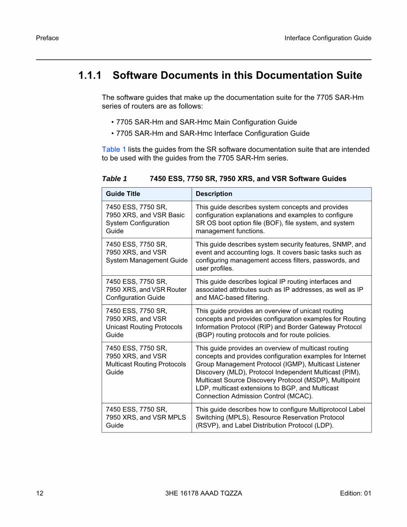
1.1.1 Software Documents in this Documentation Suite
The software guides that make up the documentation suite for the 7705 SAR-Hm series of routers are as follows:
• 7705 SAR-Hm and SAR-Hmc Main Configuration Guide• 7705 SAR-Hm and SAR-Hmc Interface Configuration Guide
Table 1 lists the guides from the SR software documentation suite that are intended to be used with the guides from the 7705 SAR-Hm series.
Table 1 7450 ESS, 7750 SR, 7950 XRS, and VSR Software Guides
Guide Title Description
7450 ESS, 7750 SR, 7950 XRS, and VSR Basic System Configuration Guide
This guide describes system concepts and provides configuration explanations and examples to configure SR OS boot option file (BOF), file system, and system management functions.
7450 ESS, 7750 SR, 7950 XRS, and VSR System Management Guide
This guide describes system security features, SNMP, and event and accounting logs. It covers basic tasks such as configuring management access filters, passwords, and user profiles.
7450 ESS, 7750 SR, 7950 XRS, and VSR Router Configuration Guide
This guide describes logical IP routing interfaces and associated attributes such as IP addresses, as well as IP and MAC-based filtering.
7450 ESS, 7750 SR, 7950 XRS, and VSR Unicast Routing Protocols Guide
This guide provides an overview of unicast routing concepts and provides configuration examples for Routing Information Protocol (RIP) and Border Gateway Protocol (BGP) routing protocols and for route policies.
7450 ESS, 7750 SR, 7950 XRS, and VSR Multicast Routing Protocols Guide
This guide provides an overview of multicast routing concepts and provides configuration examples for Internet Group Management Protocol (IGMP), Multicast Listener Discovery (MLD), Protocol Independent Multicast (PIM), Multicast Source Discovery Protocol (MSDP), Multipoint LDP, multicast extensions to BGP, and Multicast Connection Admission Control (MCAC).
7450 ESS, 7750 SR, 7950 XRS, and VSR MPLS Guide
This guide describes how to configure Multiprotocol Label Switching (MPLS), Resource Reservation Protocol (RSVP), and Label Distribution Protocol (LDP).
Interface Configuration Guide Preface
Edition: 01 3HE 16178 AAAD TQZZA 13
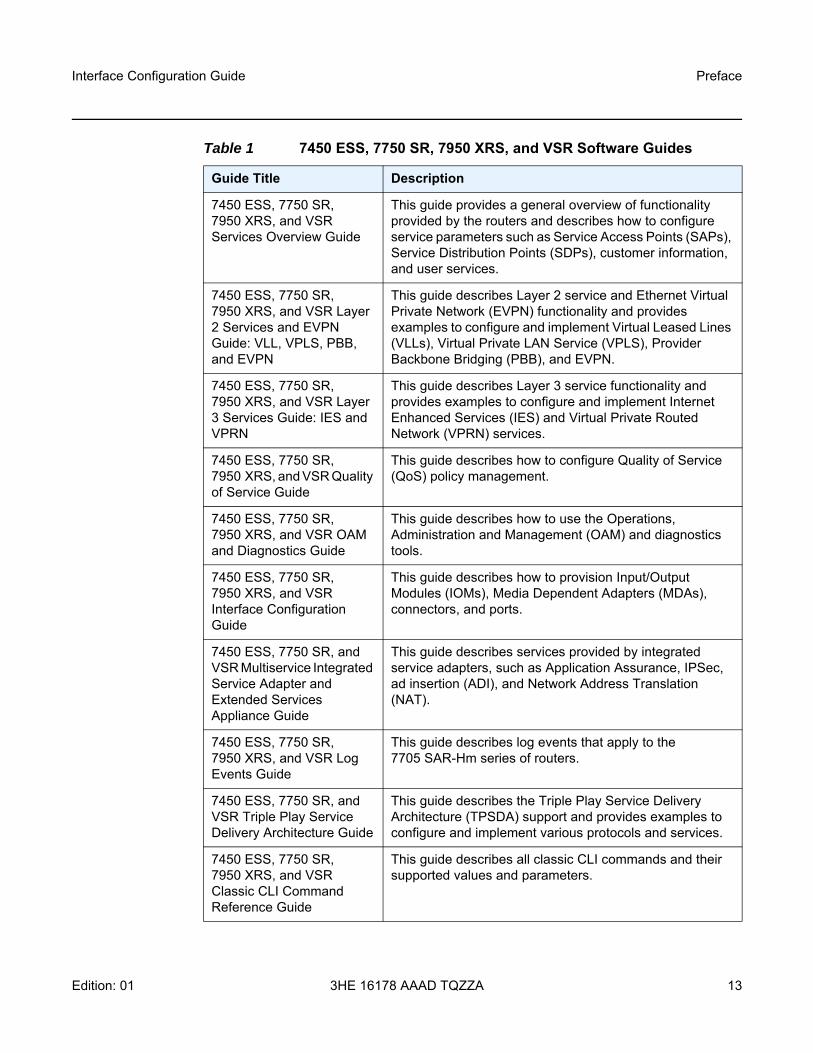
7450 ESS, 7750 SR, 7950 XRS, and VSR Services Overview Guide
This guide provides a general overview of functionality provided by the routers and describes how to configure service parameters such as Service Access Points (SAPs), Service Distribution Points (SDPs), customer information, and user services.
7450 ESS, 7750 SR, 7950 XRS, and VSR Layer 2 Services and EVPN Guide: VLL, VPLS, PBB, and EVPN
This guide describes Layer 2 service and Ethernet Virtual Private Network (EVPN) functionality and provides examples to configure and implement Virtual Leased Lines (VLLs), Virtual Private LAN Service (VPLS), Provider Backbone Bridging (PBB), and EVPN.
7450 ESS, 7750 SR, 7950 XRS, and VSR Layer 3 Services Guide: IES and VPRN
This guide describes Layer 3 service functionality and provides examples to configure and implement Internet Enhanced Services (IES) and Virtual Private Routed Network (VPRN) services.
7450 ESS, 7750 SR, 7950 XRS, and VSR Quality of Service Guide
This guide describes how to configure Quality of Service (QoS) policy management.
7450 ESS, 7750 SR, 7950 XRS, and VSR OAM and Diagnostics Guide
This guide describes how to use the Operations, Administration and Management (OAM) and diagnostics tools.
7450 ESS, 7750 SR, 7950 XRS, and VSR Interface Configuration Guide
This guide describes how to provision Input/Output Modules (IOMs), Media Dependent Adapters (MDAs), connectors, and ports.
7450 ESS, 7750 SR, and VSR Multiservice Integrated Service Adapter and Extended Services Appliance Guide
This guide describes services provided by integrated service adapters, such as Application Assurance, IPSec, ad insertion (ADI), and Network Address Translation (NAT).
7450 ESS, 7750 SR, 7950 XRS, and VSR Log Events Guide
This guide describes log events that apply to the 7705 SAR-Hm series of routers.
7450 ESS, 7750 SR, and VSR Triple Play Service Delivery Architecture Guide
This guide describes the Triple Play Service Delivery Architecture (TPSDA) support and provides examples to configure and implement various protocols and services.
7450 ESS, 7750 SR, 7950 XRS, and VSR Classic CLI Command Reference Guide
This guide describes all classic CLI commands and their supported values and parameters.
Table 1 7450 ESS, 7750 SR, 7950 XRS, and VSR Software Guides
Guide Title Description

Preface
14
Interface Configuration Guide
3HE 16178 AAAD TQZZA Edition: 01
1.1.2 Technical Support
If you purchased a service agreement for your 7705 SAR-Hm series router and related products from a distributor or authorized reseller, contact the technical support staff for that distributor or reseller for assistance. If you purchased a Nokia service agreement, follow this link to contact a Nokia support representative and to access product manuals and documentation updates:
Product Support Portal
7450 ESS, 7750 SR, 7950 XRS, and VSR Clear, Show, and Tools Command Reference Guide
This guide describes all clear, show, and tools commands for both classic and MD-CLI and their supported values and parameters.
Table 1 7450 ESS, 7750 SR, 7950 XRS, and VSR Software Guides
Guide Title Description

Interface Configuration Guide Interfaces
Edition: 01 3HE 16178 AAAD TQZZA 15
2 InterfacesThis chapter provides overview information about the types of interfaces supported on 7705 SAR-Hm series routers.
Topics in this chapter include:
• Configuration Overview- Chassis IOM and MDAs
• Ports- Port Types- Port Features
• Port State and Operational State• Port Cross-Connect (PXC)
- PXC Terminology- Physical Port in Cross Connect (Loopback) Mode- PXC Sub-Ports- Port Statistics- Basic PXC Provisioning - Health Monitoring on the PXC Sub-Ports- Configuration Example
• MTU Configuration Guidelines- Default and Maximum MTU Values- MTU Considerations Over a Cellular Port- MTU Considerations Over the WLAN Interface
• Serial Transport Over Raw Sockets- Raw Socket Configuration- Raw Socket Packet Processing- Raw Socket Squelch Functionality
• Configuration Process Overview• Configuration Notes
Note: For specific information about the topics that are not explicitly described in this guide (in black text in the list below), refer to the corresponding sections in the 7450 ESS, 7750 SR, 7950 XRS, and VSR Interface Configuration Guide.
Interfaces
16
Interface Configuration Guide
3HE 16178 AAAD TQZZA Edition: 01
2.1 Configuration Overview
This guide uses the term preprovisioning in the context of preparing or preconfiguring ports and interfaces prior to enabling them. When the entity is in a no shutdown state (administratively enabled), the entity is considered provisioned.
2.1.1 Chassis IOM and MDAs
The 7705 SAR-Hm series routers have a fixed physical configuration that uses an integrated control and switching functional block. The Input/Output module (IOM) and Media Dependent Adapters (MDAs) are also integrated into the chassis.
On the CLI, a port is identified using the format slot/mda/port. The slot ID identifies the IOM and is always 1. The MDA identifiers are:
• 1/1 for the cellular MDA and for the GNSS receiver• 1/2 for the Ethernet MDA• 1/3 for the serial port MDA• 1/4 for the WLAN port MDA • 1/5 for the virtualized integrated ISA MDA, for IPSec and IP tunnel functionality• 1/6 for the virtualized integrated BB ISA MDA, for Network Address Translation
(NAT) functionality
On the 7705 SAR-Hm, MDAs 1/1 through 1/5 are automatically provisioned and cannot be deprovisioned. MDA 1/6 is not automatically provisioned, but can be provisioned and deprovisioned.
On the 7705 SAR-Hmc, MDAs 1/1, 1/2, and 1/3 are automatically provisioned. MDAs 1/5 and 1/6 are not automatically provisioned, but can be provisioned and deprovisioned.
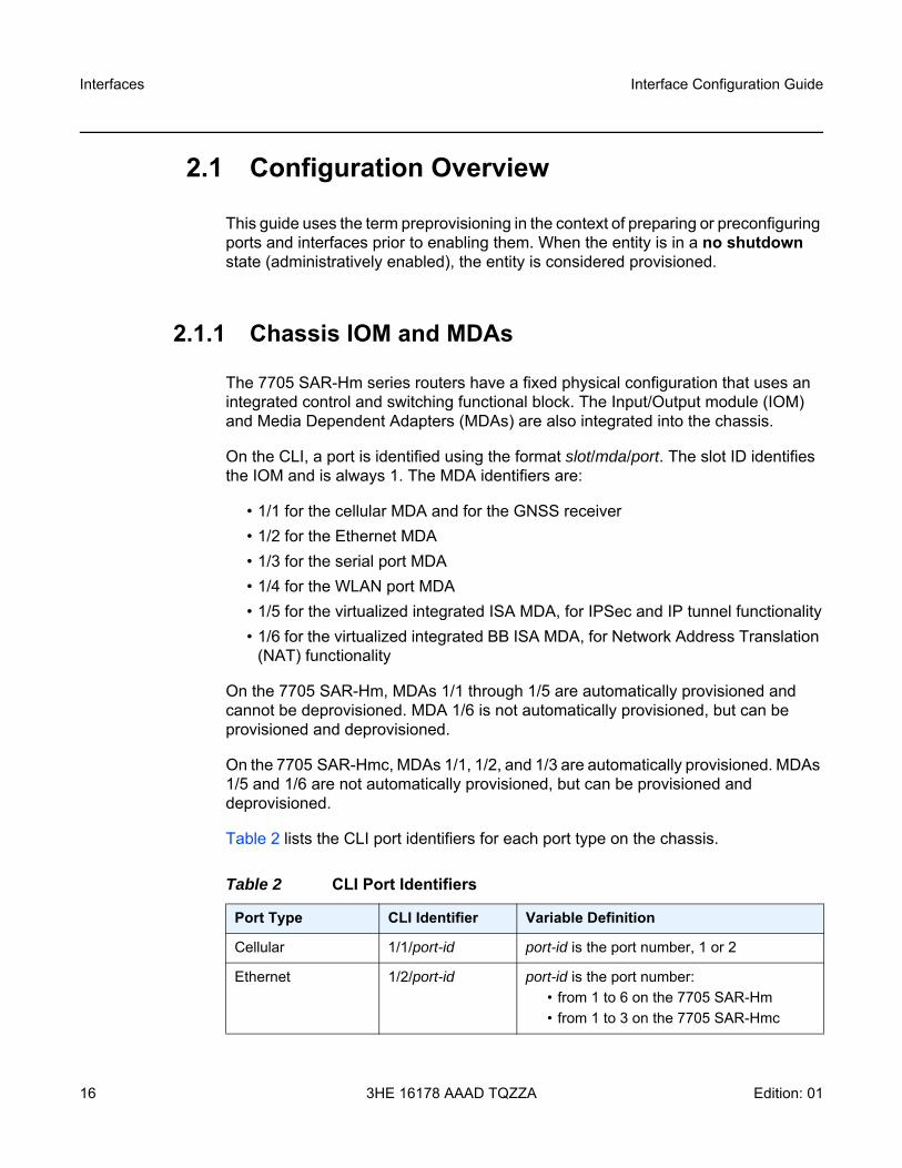
Table 2 lists the CLI port identifiers for each port type on the chassis.
Table 2 CLI Port Identifiers
Port Type CLI Identifier Variable Definition
Cellular 1/1/port-id port-id is the port number, 1 or 2
Ethernet 1/2/port-id port-id is the port number: • from 1 to 6 on the 7705 SAR-Hm• from 1 to 3 on the 7705 SAR-Hmc
Interface Configuration Guide Interfaces
Edition: 01 3HE 16178 AAAD TQZZA 17
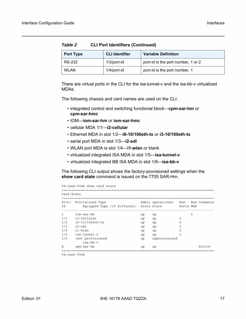
There are virtual ports in the CLI for the isa-tunnel-v and the isa-bb-v virtualized MDAs.
The following chassis and card names are used on the CLI:
• integrated control and switching functional block—cpm-sar-hm or cpm-sar-hmc
• IOM—iom-sar-hm or iom-sar-hmc• cellular MDA 1/1—i2-cellular• Ethernet MDA in slot 1/2—i6-10/100eth-tx or i3-10/100eth-tx• serial port MDA in slot 1/3—i2-sdi• WLAN port MDA is slot 1/4—i1-wlan or blank• virtualized integrated ISA MDA in slot 1/5—isa-tunnel-v• virtualized integrated BB ISA MDA in slot 1/6—isa-bb-v
The following CLI output shows the factory-provisioned settings when the show card state command is issued on the 7705 SAR-Hm.
*A:cses-V34# show card state===============================================================================Card State===============================================================================Slot/ Provisioned Type Admin Operational Num Num CommentsId Equipped Type (if different) State State Ports MDA-------------------------------------------------------------------------------1 iom-sar-hm up up 61/1 i2-cellular up up 21/2 i6-10/100eth-tx up up 61/3 i2-sdi up up 21/4 i1-wlan up up 21/5 isa-tunnel-v up up 21/6 (not provisioned) up unprovisioned
isa-bb-vA cpm-sar-hm up up Active===============================================================================*A:cses-V34#
RS-232 1/3/port-id port-id is the port number, 1 or 2
WLAN 1/4/port-id port-id is the port number, 1
Table 2 CLI Port Identifiers (Continued)
Port Type CLI Identifier Variable Definition
Interfaces
18
Interface Configuration Guide
3HE 16178 AAAD TQZZA Edition: 01
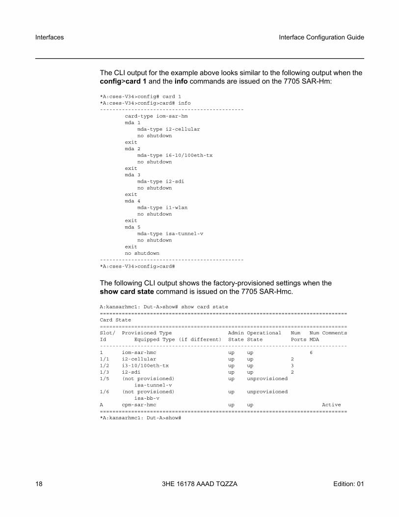
The CLI output for the example above looks similar to the following output when the config>card 1 and the info commands are issued on the 7705 SAR-Hm:
*A:cses-V34>config# card 1*A:cses-V34>config>card# info----------------------------------------------
card-type iom-sar-hmmda 1
mda-type i2-cellularno shutdown
exitmda 2
mda-type i6-10/100eth-txno shutdown
exitmda 3
mda-type i2-sdino shutdown
exitmda 4
mda-type i1-wlanno shutdown
exitmda 5
mda-type isa-tunnel-vno shutdown
exitno shutdown
----------------------------------------------*A:cses-V34>config>card#
The following CLI output shows the factory-provisioned settings when the show card state command is issued on the 7705 SAR-Hmc.
A:kansarhmc1: Dut-A>show# show card state===============================================================================Card State===============================================================================Slot/ Provisioned Type Admin Operational Num Num CommentsId Equipped Type (if different) State State Ports MDA-------------------------------------------------------------------------------1 iom-sar-hmc up up 61/1 i2-cellular up up 21/2 i3-10/100eth-tx up up 31/3 i2-sdi up up 21/5 (not provisioned) up unprovisioned
isa-tunnel-v1/6 (not provisioned) up unprovisioned
isa-bb-vA cpm-sar-hmc up up Active===============================================================================*A:kansarhmc1: Dut-A>show#
Interface Configuration Guide Interfaces
Edition: 01 3HE 16178 AAAD TQZZA 19
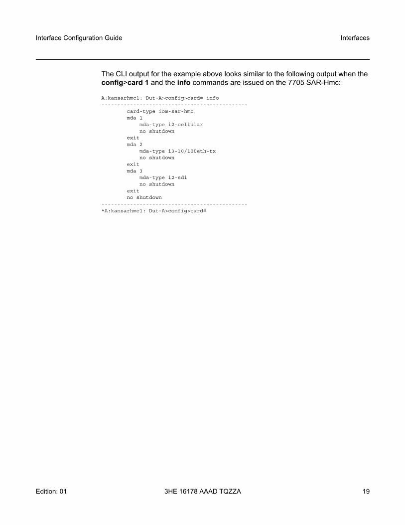
The CLI output for the example above looks similar to the following output when the config>card 1 and the info commands are issued on the 7705 SAR-Hmc:
A:kansarhmc1: Dut-A>config>card# info----------------------------------------------
card-type iom-sar-hmcmda 1
mda-type i2-cellularno shutdown
exitmda 2
mda-type i3-10/100eth-txno shutdown
exitmda 3
mda-type i2-sdino shutdown
exitno shutdown
----------------------------------------------*A:kansarhmc1: Dut-A>config>card#
Interfaces
20
Interface Configuration Guide
3HE 16178 AAAD TQZZA Edition: 01
2.2 Ports
This section provides information about the types of ports supported on the system.
2.2.1 Port Types
The system supports the port types listed below.
• Cellular The cellular interface supports dual SIM operation using major carrier frequency bands in North America, EMEA, and APAC. For more information on cellular ports, see Cellular MDA and Ports.
• EthernetThe system supports Fast Ethernet (10/100Base-T) ports. The Ethernet ports are typically connected to field devices, such as Intelligent Electronic Devices (IEDs), AMI collectors, supervisory modules, weather monitoring devices, cameras, and other hosts.In some cases, an Ethernet port may be connected to a 7705 SAR-18, 7705 SAR-8, 7705 SAR-H, or 7705 SAR-Hc node, which will use the system’s cellular port as a backup link.For more information on Fast Ethernet ports, refer to the 7450 ESS, 7750 SR, 7950 XRS, and VSR Interface Configuration Guide, “Port Types”.
• SerialRS-232 asynchronous ports are typically used for connecting to remote SCADA equipment. The ports support full-duplex communication and interface speeds of 600 b/s, 1200 b/s, 2400 b/s, 4800 b/s, 9600 b/s, 19 200 b/s, 38 400 b/s, 57 600 b/s, and 115 200 b/s. The serial ports can be configured to support raw socket transport; see Serial Transport Over Raw Sockets for more information.
• Alarm For information about the alarm port and the number of supported alarm inputs and outputs, refer to the SAR-Hm and SAR-Hmc Chassis Installation Guide. For information about configuring alarm inputs, refer to the 7450 ESS, 7750 SR, 7950 XRS, and VSR Basic System Configuration Guide.
Interface Configuration Guide Interfaces
Edition: 01 3HE 16178 AAAD TQZZA 21
Alarm inputs are configured using the config>system>alarm-contact-input CLI command and sub-commands. For information, refer to the 7450 ESS, 7750 SR, 7950 XRS, and VSR Classic CLI Command Reference Guide. To display the status of the alarm inputs, use the show>system>alarm-contact-input all CLI command; refer to the 7450 ESS, 7750 SR, 7950 XRS, and VSR Clear, Show, and Tools Command Reference Guidefor information.
• WLAN The WLAN interface supports the IEEE 802.11 b/g/n WLAN standard. The interface is enabled as a WLAN access point (AP) that remote WLAN stations can connect to. For more information, see Wireless LAN Interface. WLAN traffic that is received from WLAN stations connected to the WLAN AP is transported over a Layer 2 service using an Epipe. Refer to the 7705 SAR-Hm and SAR-Hmc Main Configuration Guide for details about configuring services for the WLAN AP.
2.2.2 Port Features
For general information about port features, refer to the “Port State and Operational State” section in the 7450 ESS, 7750 SR, 7950 XRS, and VSR Interface Configuration Guide.
Interfaces
22
Interface Configuration Guide
3HE 16178 AAAD TQZZA Edition: 01
2.3 MTU Configuration Guidelines
Observe the general rules described in the 7450 ESS, 7750 SR, 7950 XRS, and VSR Interface Configuration Guide, “MTU Configuration Guidelines”, when planning service and physical MTU configurations.
2.3.1 Default and Maximum MTU Values
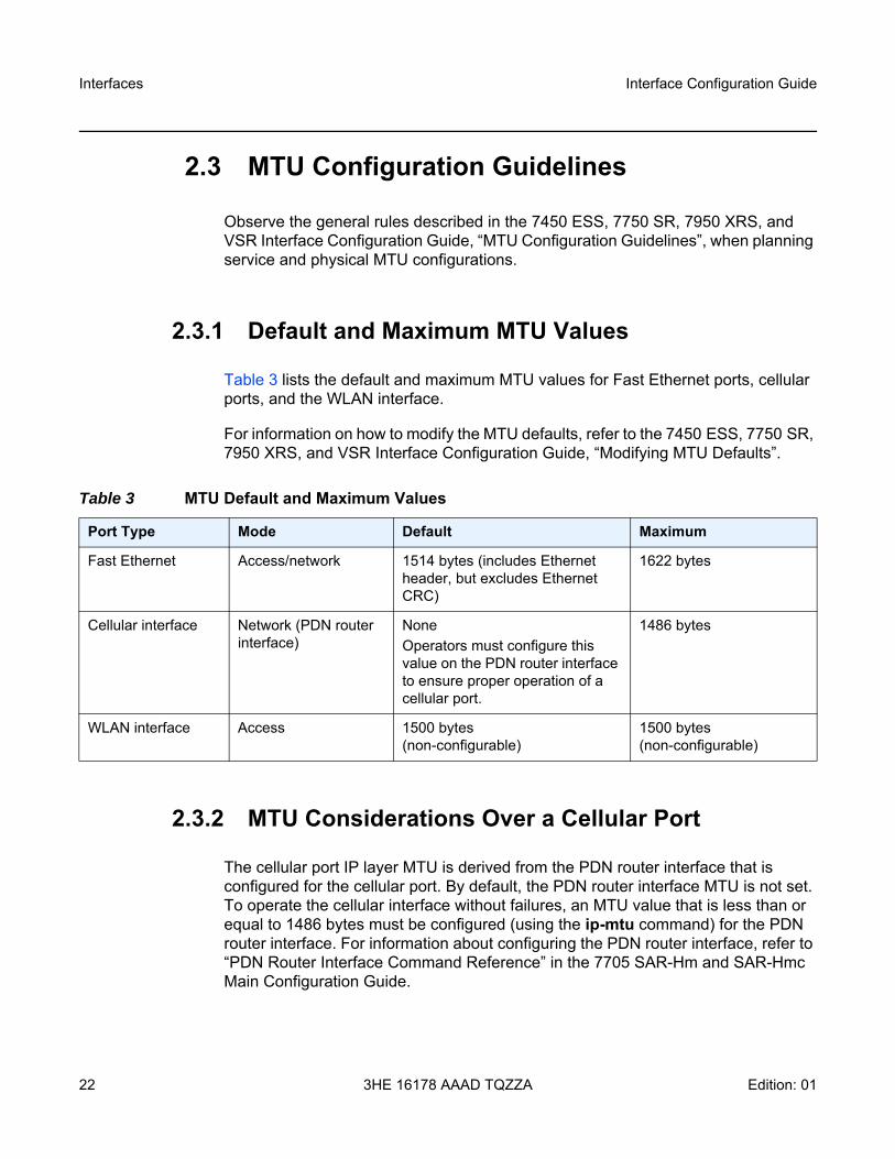
Table 3 lists the default and maximum MTU values for Fast Ethernet ports, cellular ports, and the WLAN interface.
For information on how to modify the MTU defaults, refer to the 7450 ESS, 7750 SR, 7950 XRS, and VSR Interface Configuration Guide, “Modifying MTU Defaults”.
2.3.2 MTU Considerations Over a Cellular Port
The cellular port IP layer MTU is derived from the PDN router interface that is configured for the cellular port. By default, the PDN router interface MTU is not set. To operate the cellular interface without failures, an MTU value that is less than or equal to 1486 bytes must be configured (using the ip-mtu command) for the PDN router interface. For information about configuring the PDN router interface, refer to “PDN Router Interface Command Reference” in the 7705 SAR-Hm and SAR-Hmc Main Configuration Guide.
Table 3 MTU Default and Maximum Values
Port Type Mode Default Maximum
Fast Ethernet Access/network 1514 bytes (includes Ethernet header, but excludes Ethernet CRC)
1622 bytes
Cellular interface Network (PDN router interface)
NoneOperators must configure this value on the PDN router interface to ensure proper operation of a cellular port.
1486 bytes
WLAN interface Access 1500 bytes (non-configurable)
1500 bytes (non-configurable)
Interface Configuration Guide Interfaces
Edition: 01 3HE 16178 AAAD TQZZA 23
Mobile networks often require a strict IP layer MTU for the LTE interface that is less than or equal to1486 bytes. Consult with the cellular service provider regarding the correct IP layer MTU value to set for the associated PDN router interface.
The SAP MTU settings must also correctly account for the PDN router interface IP layer MTU, as services that are transported over the cellular interface are impacted by this configuration.
For example, if a cellular provider allows an IP layer MTU of 1486 bytes, the following calculations and values must be considered when setting up services over a cellular port.
For BGP and T-LDP protocols, the MTU of protocol packets must be set to 1486 bytes or less. For information about BGP path MTU discovery and LDP path MTU discovery, refer to the path-mtu-discovery command in the 7450 ESS, 7750 SR, 7950 XRS, and VSR Classic CLI Command Reference Guide.
For Layer 3 services over a VPRN service using GRE transport, the SAP MTU must be set as follows:
• SAP MTU = {1486 bytes – (GRE packet overhead) – (VPRN service label)}• SAP MTU = {1486 bytes – (24 bytes) – (4 bytes)}• SAP MTU = 1458 bytes
For Layer 3 services over a VPRN service using GRE transport with NGE enabled, the SAP MTU must be set as follows:
• SAP MTU = {1486 bytes – (GRE packet overhead) – (VPRN service label) – (NGE overhead)}
• SAP MTU = {1486 bytes – (24 bytes) – (4 bytes) – (77 bytes)}• SAP MTU = 1381 bytes
For Layer 2 services over a VPLS service using GRE transport, the SAP (port) MTU must be set as follows:
• SAP MTU = {1486 bytes – (GRE packet overhead) – (VPLS service label)}• SAP MTU = {1486 bytes – (24 bytes) – (4 bytes)}• SAP MTU = 1458 bytes
Interfaces
24
Interface Configuration Guide
3HE 16178 AAAD TQZZA Edition: 01
For Layer 2 services over a VPLS service using GRE transport with NGE enabled, the SAP MTU must be set as follows:
• SAP MTU = {1486 bytes – (GRE packet overhead) – (VPLS service label) – (NGE overhead)}
• SAP MTU = {1486 bytes – (24 bytes) – (4 bytes) – (77 bytes)}• SAP MTU = 1381 bytes
For Layer 2 services using an Epipe VLL/VPWS service with a control word, an additional 4 bytes of overhead is required for the control word. Therefore, the following SAP (port) MTU must be set as follows:
• SAP MTU = {1486 bytes – (GRE packet overhead) – (VLL service label) – (CTL word)}
• SAP MTU = {1486 bytes – (24 bytes) – (4 bytes) – (4 bytes)}• SAP MTU = 1454 bytes
For Layer 2 services using an Epipe VLL/VPWS service with a control word and NGE enabled, an additional 4 bytes of overhead is required for the control word and 4 bytes of NGE overhead is added. Therefore, the following SAP (port) MTU must be set as follows:
• SAP MTU = {1486 bytes – (GRE packet overhead) – (VLL service label) – (CTL word) – (NGE overhead)}
• SAP MTU = {1486 bytes – (24 bytes) – (4 bytes) – (4 bytes) – (81 bytes)}• SAP MTU = 1373 bytes
The SAP MTU of Layer 2 services can be increased to accommodate larger packets that are closer to the Ethernet port maximum MTU value by using GRE SDP fragmentation and reassembly. Refer to “GRE SDP Tunnel Fragmentation and Reassembly” in the 7705 SAR-Hm and SAR-Hmc Main Configuration Guide.
2.3.3 MTU Considerations Over the WLAN Interface
The WLAN port MTU value is set to 1500 bytes and cannot be changed. Since cellular ports have a lower MTU with a maximum of 1486 bytes, and WLAN traffic from stations connected to the WLAN AP is carried over an IP/MPLS service that adds additional overhead to traffic traveling over cellular ports, the operator must understand the requirements of the MTU for their applications in order to successfully use the WLAN interface.
Interface Configuration Guide Interfaces
Edition: 01 3HE 16178 AAAD TQZZA 25
For example, when the WLAN interface AP is connected to the Nokia WLAN GW using an Epipe service, there is at most 1454 bytes available to carry a Layer 2 packet for the WLAN AP packet that includes a Layer 2 header of 14 bytes (see MTU Considerations Over a Cellular Port for information about the SAP MTU of an Epipe service over a cellular port). In order to successfully send these packets over a cellular port without further modification, the MTU of the IP payload in the WLAN AP Layer 2 packet must be restricted to 1440 bytes.
The MTU of the WLAN interface can be handled in one of two ways:
• by modifying the MTU value on clients that are connecting to the WLAN AP such that they send traffic that conforms to the service MTU of the IP/MPLS transport service, minus the 14 byte Layer 2 overhead
• by configuring GRE SDP fragmentation and reassembly on the node to allow packets that require an MTU greater than that available on the cellular interface to be fragmented and reassembled when carried over the cellular interface
Interfaces
26
Interface Configuration Guide
3HE 16178 AAAD TQZZA Edition: 01
2.4 Serial Transport Over Raw Sockets
Serial transport over raw sockets provides the capability of transporting serial data, in the form of characters, over an IP transport service within a Layer 3 IP/MPLS VPRN service. A raw socket allows direct sending and receiving of IP packets without any protocol-specific transport layer formatting. For information about raw socket IP transport services, refer to the 7705 SAR-Hm and SAR-Hmc Main Configuration Guide, Layer 2 and Layer 3 Services chapter, “Raw Socket IP Transport Service”.
The feature provides the functionality for a local host to listen to and open raw socket sessions from remote hosts, and for a remote host to initiate and open raw socket sessions to local hosts. The local and remote host functions support TCP or UDP sessions (but not both concurrently) over the IP transport service.
Raw sockets are supported for RS-232 ports on the node.
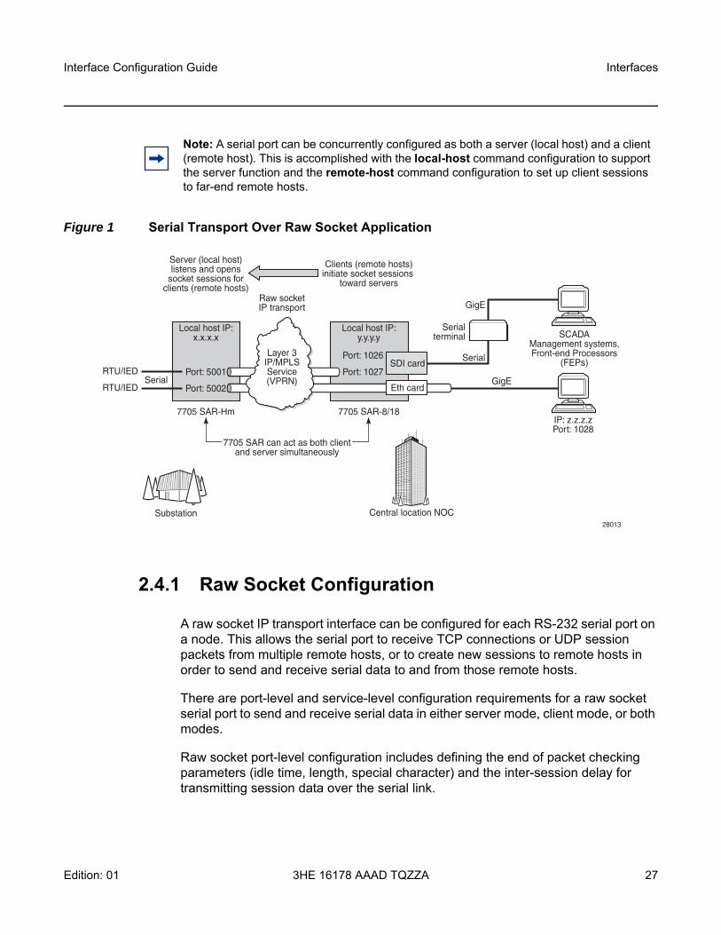
Figure 1 shows an example of a raw socket application, where serial data is transferred between RTUs and a utility’s SCADA management system using an IP transport service across a Layer 3 VPRN service that includes 7705 SAR-Hm and 7705 SAR-8/7705 SAR-18 nodes.
A raw socket local host (acting as a server) at the 7705 SAR-Hm substation listens to TCP sessions that originate at the 7705 SAR-8 or 7705 SAR-18 central location network operations center (NOC). The 7705 SAR-8 or 7705 SAR-18 at the NOC is connected to two front-end processors (FEPs), one via a serial port and another via an Ethernet port. The serial port on the 7705 SAR-8 or 7705 SAR-18 is configured as a remote host (acting as a client) that initiates TCP/UDP sessions towards the RTU at the 7705 SAR-Hm substation when traffic is received from the FEP over the serial port. These TCP/UDP sessions are transported over the IP/MPLS network using IP transport service over a VPRN service. The serial data transported over the TCP/UDP session and received at the 7705 SAR-Hm is then sent over the serial link towards the RTU. TCP/UDP sessions received from the FEP over the Ethernet port are transported over a VPRN service (that is, there is no need for serial port remote host configuration in this case).
Multiple FEPs can poll a single RTU. If multiple sessions attempt to transmit serial data on the serial port simultaneously, the 7705 SAR-Hm queues packets per session and ensures that all data for one session is sent out before processing another session’s data, ensuring that sessions do not overlap one another.
Interface Configuration Guide Interfaces
Edition: 01 3HE 16178 AAAD TQZZA 27
Figure 1 Serial Transport Over Raw Socket Application
2.4.1 Raw Socket Configuration
A raw socket IP transport interface can be configured for each RS-232 serial port on a node. This allows the serial port to receive TCP connections or UDP session packets from multiple remote hosts, or to create new sessions to remote hosts in order to send and receive serial data to and from those remote hosts.
There are port-level and service-level configuration requirements for a raw socket serial port to send and receive serial data in either server mode, client mode, or both modes.
Raw socket port-level configuration includes defining the end of packet checking parameters (idle time, length, special character) and the inter-session delay for transmitting session data over the serial link.
Note: A serial port can be concurrently configured as both a server (local host) and a client (remote host). This is accomplished with the local-host command configuration to support the server function and the remote-host command configuration to set up client sessions to far-end remote hosts.
Local host IP:x.x.x.x
Local host IP:y.y.y.y
RTU/IED
RTU/IED
7705 SAR-Hm
Port: 5002
Port: 5001
Layer 3IP/MPLSService(VPRN)Serial
7705 SAR-8/18
Port: 1026
Port: 1027
IP: z.z.z.zPort: 1028
SCADAManagement systems,Front-end Processors
(FEPs)SDI card
Eth card
Serialterminal
Serial
GigE
GigE
Raw socketIP transport
7705 SAR can act as both clientand server simultaneously
Server (local host)listens and opens
socket sessions forclients (remote hosts)
Clients (remote hosts)initiate socket sessions
toward servers
Substation28013
Central location NOC

Interfaces
28
Interface Configuration Guide
3HE 16178 AAAD TQZZA Edition: 01
At the service level, an IP transport subservice is created within a VPRN service to associate the serial port with the VPRN service. TCP/UDP encapsulated serial data is routed within the corresponding Layer 3 VPRN service. The required configuration includes IP transport subservice local host and remote host configuration, TCP timers, and session control.
See Serial Raw Socket Interface Configuration Commands for information about the required port-level configuration. For information on how the IP transport subservice operates within a VPRN service, as well as information on the required system-level configuration, refer to the 7705 SAR-Hm and SAR-Hmc Main Configuration Guide, Layer 2 and Layer 3 Services chapter, “Raw Socket IP Transport Service”.
2.4.2 Raw Socket Packet Processing
Figure 2 illustrates how raw socket packets are processed over a serial link.
Session data attempting to access the serial port is queued. One queue is maintained per session. The purpose of the session queue is to prevent two different flows of packets from interleaving out the serial port and creating unreadable messages. When data is being transmitted over the serial link for a session, any other session’s data is queued until the first session has emptied its queue. The next session’s data is transmitted over the serial link only after the inter-session-delay timer expires. Each session’s data is sent out in round-robin fashion.
Figure 2 Raw Socket Packet Processing
28011
RTU(1)
7705 SAR-Hm
Serialport
Substation Central location NOC
Configurable inter-sessiontime between each
queued data stream fromeach socket session
Packets are queued foreach group of socket sessionsuntil the serial line becomes
free to transmit
Round robin allsession queues(flush eachqueue beforeproceedingto next)
Src: Z, Dest: X, sPort: Bp, dPort: 5001
Src: Z, Dest: X, sPort: Ap, dPort: 5001
Src: C, Dest: X, sPort: Cp, dPort: 5001
Server (local host) sessions
Layer 3IP/MPLSservices
Ethport
Interface Configuration Guide Interfaces
Edition: 01 3HE 16178 AAAD TQZZA 29
2.4.2.1 Raw Socket Processing for UDP Sessions
When the local host receives a UDP packet from a remote host, it queues the packet and sends it over the serial link. The local host remembers the UDP session while there is still data to send from the serial link. If further packets are received for the same session, they are queued behind the already queued packet. After all the queued data has been sent over the serial link, the session is removed from the system. An associated UDP remote host for the serial link must be configured to have serial data sent back to the remote host from the serial port.
When a packet is received from the serial link based on end-of-packet (EOP) requirements, the data is copied and sent in a UDP packet to each configured remote host.
2.4.2.2 Raw Socket Processing for TCP Sessions
An open TCP session from a remote host to a raw socket’s local host is kept open until either the remote host terminates the session or the TCP inactivity timer expires. When a TCP session is open, all packets received from the remote host are queued for the raw socket serial link and sent over the serial link until no packets remain in the queue. If multiple sessions are open towards the local host, and each is receiving data, then each session’s data is queued and then sent over the serial link in round-robin fashion for each session until no packets remain. When a packet is received over the serial link, it is copied to each open TCP session and transmitted to the remote host.
2.4.3 Raw Socket Squelch Functionality
A condition may occur where the end device connected to the serial port continues to send out a continuous stream of data after the normal response period has expired. This can prevent the far-end remote host or master equipment from receiving data from other end devices in the network. To resolve this condition, the squelch command can be used on the raw socket at the port level (it is disabled by default). This stops the socket from receiving any more data from the problematic device.
Interfaces
30
Interface Configuration Guide
3HE 16178 AAAD TQZZA Edition: 01
If the command is enabled, the node will monitor the serial port for a constant character stream. A configurable squelch delay period, using the squelch-delay command, is used to determine how long to measure the constant character stream before initiating the squelch function. If the squelch function is initiated, the port is considered locked up and an alarm is raised indicating the lock-up and that the squelching function has been triggered.
The serial port can be forced out of squelch and put back to normal, either manually using the squelch-reset command or automatically using the unsquelch-delay command. The unsquelch-delay command defines the time to wait after squelch is initiated before it is removed.
Interface Configuration Guide Cellular MDA and Ports
Edition: 01 3HE 16178 AAAD TQZZA 31
3 Cellular MDA and Ports
3.1 In This Chapter
This chapter describes the cellular MDA and cellular ports. Topics include:
• Overview• Prerequisites and Required Configurations• Cellular MDA Management • Cellular Port Management • Firmware Update
For more information about using the cellular MDA and ports for establishing IP/MPLS service, refer to the following sections in the 7705 SAR-Hm and SAR-Hmc Main Configuration Guide:
• PDN Router Interfaces• Services over the Cellular PDN Interface• Dedicated Bearers
Cellular MDA and Ports
32
Interface Configuration Guide
3HE 16178 AAAD TQZZA Edition: 01
3.2 Overview
The cellular MDA supports 4G LTE and 3G connectivity, depending on the radio module installed in the node. Refer to the SAR-Hm and SAR-Hmc Chassis Installation Guide for the types of supported modules.
Each node supports a single cellular MDA. Each cellular MDA supports two cellular ports, one for each SIM that can be configured on the node. Each cellular port has its own PDN router interface. A PDN router interface is a network-facing interface that is used to route traffic to and from the node over a cellular network, providing WAN connectivity over the cellular port.
3.3 Prerequisites and Required Configurations
Before configuring the cellular MDA and cellular ports, the following prerequisites must be considered.
• Depending on the radio module selected, 4G LTE/3G network coverage is required where the node is to be physically installed.
• The operator must subscribe to a service plan with a wireless service provider. For private cellular networks, the operator must procure a SIM that allows the node to connect to the private cellular network being deployed. If dual SIM functionality is required, the operator must subscribe to a second service plan with another wireless provider and procure a second SIM.
• The radio firmware shipped with the node is a generic firmware version. Some service providers require a specific radio firmware version to run on the node, depending on the radio variant used on the node and the wireless service provider being connected to; in this case, the firmware on the node must be updated to the correct version. Refer to the 7705 SAR-Hm and SAR-Hmc Software Release Notes for details about updating the radio firmware to the correct version. If dual SIM functionality is enabled, the firmware associated with the second wireless service provider must be updated for the associated SIM.
• The SIM or SIMs must be physically installed before powering up the router and configuring the cellular MDA and cellular ports.
• For a typical GSM profile, and if required by the service plan, the following information must be obtained from the service provider: Access Point Name (APN), username, and password. For dual SIM deployments, obtain the GSM profile information for each SIM.
When the prerequisites have been met, the following configurations are required.
Interface Configuration Guide Cellular MDA and Ports
Edition: 01 3HE 16178 AAAD TQZZA 33
• A cellular port interface must be configured for each installed SIM.• The required SIMs must be configured under the cellular MDA.
The following CLI syntax shows an example of the required cellular MDA and cellular port parameters:
*A:Dut# configure card 1 mda 1 cellular sim 1*A:Dut>config>card>mda>cellular>sim# pinEnter PIN: xxxxRe-enter PIN: xxxx*A:Dut>config>>card>mda>cellular>sim# exit*A:Dut# configure port 1/1/1 cellular pdn*A:Dut>config>port>cellular>pdn# pdn-profile 1*A:Dut>config>port>cellular>pdn# exit*A:Dut#
• A cellular system PDN profile must be created and the corresponding APN, GSM parameters (such as username, password, and authentication), and protocol must be configured for each installed SIM. For an example of the CLI syntax required for the PDN profile configuration, see PDN Profile.
• A PDN router interface must be created for each cellular port to enable services over the cellular port; for information, refer to the 7705 SAR-Hm and SAR-Hmc Main Configuration Guide, “PDN Router Interfaces”.
3.4 Cellular MDA Management
Cellular MDA management activities include the following:
• setting SIM control parameters such as specifying the active SIM and the preferred SIM to use after a node reset
• specifying the SIM PIN value needed to operate each SIM if SIM security is enabled
• specifying failover criteria on each SIM to determine when to automatically switch to the backup SIM when the system is operating in dual SIM mode
• configuring optional recovery criteria for cellular ports or BGP sessions that are operationally down, and an associated interval when it is desirable to perform a node reset due to a potential cellular lockup as a result of a modem failure
• configuring the maximum transmit power on the 7705 SAR-Hmc for applications that require changes to maximum transmit power. Refer to the 7705 SAR-Hm and SAR-Hmc Software Release Notes for information about applications that require a change to the maximum transmit power.
Cellular MDA and Ports
34
Interface Configuration Guide
3HE 16178 AAAD TQZZA Edition: 01
3.4.1 SIM Installation and Configuration
Up to two valid SIMs must be procured before configuring the cellular MDA or cellular ports. The SIMs must be inserted into the proper SIM slots before the node is powered up. SIMs cannot be installed when the node is powered on. To run the Automatic Discovery Protocol (ADP-Hm) on the node, a SIM must be inserted into slot 1; otherwise, ADP-Hm will not function. For more information on ADP-Hm, refer to the 7705 SAR-Hm and SAR-Hmc Main Configuration Guide “Basic System Configuration”.
For information about dual SIM operation, see Dual SIM Deployment.
3.4.1.1 SIM Security and Security Commands
A SIM that is installed on the node can be secured using a personal identification number (PIN). The PIN is a 4- to 8-digit code that is used to control access to information stored on the SIM. The PIN is stored on the SIM and is used to lock the SIM, unlock the SIM, or change the PIN value.
To secure a node, the PIN needs to be set and the SIM must be locked using the PIN. When locked, the SIM cannot be used to access the cellular network unless the PIN is present in the configuration file of the node operating the SIM. If the locked SIM is inserted into another node that does not have the correct PIN configured for the SIM, the SIM will not allow access to the cellular network. If the number of attempts made to access the cellular network using an incorrect PIN exceeds the number of attempts allowed by the SIM, then the SIM will become blocked and will not allow any further attempts to gain access the cellular network.
When a SIM is procured from a carrier, the PIN is either not set or sometimes set to a default value such as 0000 or 1111. When a locked SIM is first installed in the node, the operator must enter the default PIN in the node system configuration twice. When stored in the system configuration, the PIN provides access to the locked SIM, both to read information from the SIM and to grant access to the cellular network.
The PIN can be stored in the system configuration in encrypted form to keep the PIN value secret.
Interface Configuration Guide Cellular MDA and Ports
Edition: 01 3HE 16178 AAAD TQZZA 35
The number of allowed attempts to access a SIM depends on the SIM. The “PIN retries left” field under the SIM Card heading in the show>port CLI output indicates the number of attempts left before the SIM is blocked and must be unblocked to establish cellular connections.
If the SIM becomes blocked, the operator must enter the personal unblocking key (PUK) in the CLI to unblock the SIM and reset the PIN. The PUK is stored on the SIM and must be acquired from the service provider or administrator.
Many carriers provide unlocked SIMs. If an unlocked SIM is installed in a node, the operator does not need to know the PIN or configure the PIN in order for a cellular port to become operational. For example, during the ADP-Hm process, setting the PIN before attempting to connect to the network is not required.
The default PIN can be changed on the SIM using the tools>perform>mda>cellular>sim>change-pin command. If the default PIN is changed on the SIM, the system configuration must be updated with the new PIN value using the config>card>mda>cellular>sim>pin command.
The commands described below are available for SIM security. All of the SIM security commands are in the tools>perform>mda>cellular>sim context.
• lock-sim—this command locks the SIM and enables the PIN verification function on the SIM. A locked SIM verifies the PIN stored in the system configuration for operation. To lock the SIM, the operator must enter the current PIN.
• unlock-sim—this command unlocks the SIM and disables the PIN verification function on the SIM. To unlock the SIM, the operator must enter the current PIN.
Caution:
• Avoid entering an invalid PIN in the system configuration. If an invalid PIN is saved to the system configuration file, the system will attempt to enter that PIN on the SIM each time the system reboots. This will eventually exhaust the number of available PIN retries for the SIM and make the SIM inoperative until it is unblocked with the personal unblocking key (PUK).
• In addition, if multiple attempts are made to either lock or unlock the SIM using an incorrect PIN, the SIM becomes blocked. In both cases, the SIM must be unblocked using the PUK.
Note: The SIM specified in the tools>perform>mda>cellular>sim commands must be the currently active SIM. If the SIM is not the currently active SIM, the commands fail.
Cellular MDA and Ports
36
Interface Configuration Guide
3HE 16178 AAAD TQZZA Edition: 01
• unblock-sim—this command unblocks a SIM that is currently blocked because too many attempts were made to access the SIM with an incorrect PIN. To unblock the SIM, the operator must enter the PUK for the SIM and then enter a new PIN twice. The lock/unlock state of the SIM does not change when it becomes unblocked.
• change-pin—this command allows the operator to change the PIN value on the SIM. The operator must enter the existing PIN and then enter the new PIN twice correctly to change the PIN. The command is shown in the output below.
A:Dut-A# tools perform mda 1/1 cellular sim 1 change-pinEnter current PIN:Enter new PIN:Re-enter new PIN:
Warning:
• When an operator successfully locks a SIM, unblocks a SIM, or changes a SIM PIN, the system updates the PIN value in the system configuration. However, the system does not automatically save the system configuration containing the new PIN. The operator must perform an admin>save command immediately after changing the PIN in order to save the new PIN in the system configuration file and avoid potential service interruptions such as the node becoming unreachable.
• If the SIM becomes blocked when setting the PIN remotely using in-band management over a cellular port, the node will be unreachable. Physical access to the node will be required to unblock the SIM.
Note: Changes can only be made to the currently active SIM. If changes to the backup SIM in a dual SIM deployment are required, then a SIM switchover must be performed in order to modify the backup. Before switching over to the backup SIM, the operator must ensure that it is operational and not locked. The operator should configure the down-recovery-interval command and ensure that one of the SIMs is operational in order to reduce the risk of the node becoming unreachable.

Interface Configuration Guide Cellular MDA and Ports
Edition: 01 3HE 16178 AAAD TQZZA 37
3.4.2 Down-Recovery Timer and Criteria
A down-recovery timer can be set so that if the cellular MDA fails to establish cellular service for any SIM within a specified duration, the node will reboot. The down-recovery-interval is configured at the cellular MDA level and is not specific to a particular SIM. It can be set when there is a single SIM or two SIMs installed in the node.
The operator can specify criteria that are monitored during the down- recovery-interval by configuring the down-recovery-criteria command. The down-recovery-criteria can be set to port or bgp. When set to port, all cellular ports configured on the system are monitored during the down-recovery interval. When set to bgp, all BGP sessions whose local-address is configured on a PDN interface are monitored during the down-recovery interval. Both criteria can be specified concurrently, and the node will use either the cellular port state or BGP session state to declare the SIM state as down.
When set, the down-recovery-interval specifies the length of time that the configured down-recovery criteria are monitored from the moment when either criterion is declared operationally down. If the interval is exceeded without any criteria going operationally up, the node resets so that the preferred SIM can try to connect to a cellular network again. As soon as one criterion is operationally up, the down-recovery timer stops.
In a dual SIM deployment, the down-recovery-interval guards against persistent cycling of automatic switchovers between SIMs when a node hardware reset may be required. The timer provides a mechanism to allow the node to start again from the preferred SIM after the node resets. In a single SIM deployment, the down-recovery-interval can help resolve hardware lockup conditions on the cellular port by resetting the node.
The down-recovery-interval is measured in minutes, with a range of 1 to 240 minutes. Sixty seconds before the timer expires, the node will issue a log event stating that the node will reboot in 60 seconds if the down-recovery condition (based on the configured criteria) is not resolved. This 60-second warning interval can be used for further debugging and diagnostics before the node resets.
Cellular MDA and Ports
38
Interface Configuration Guide
3HE 16178 AAAD TQZZA Edition: 01
3.4.3 Dual SIM Deployment
The node supports dual SIM deployment for users who require a redundancy option using two wireless carriers.
With dual SIM deployment, two SIMs are installed in the node, one from each carrier. Only one SIM is active at a time to establish a cellular service WAN connection. The operator choses which SIM is primary and which is secondary or manually selects which SIM to keep active.
Configurable criteria give the operator some control over when it is appropriate for the system to perform a SIM switchover. For example, the BGP operational state associated with the cellular port can be used as a criterion for determining when a SIM switchover should occur. If the BGP operational state is down for a specified interval, a SIM switchover occurs. See Criteria for Automatic Failover for more information.
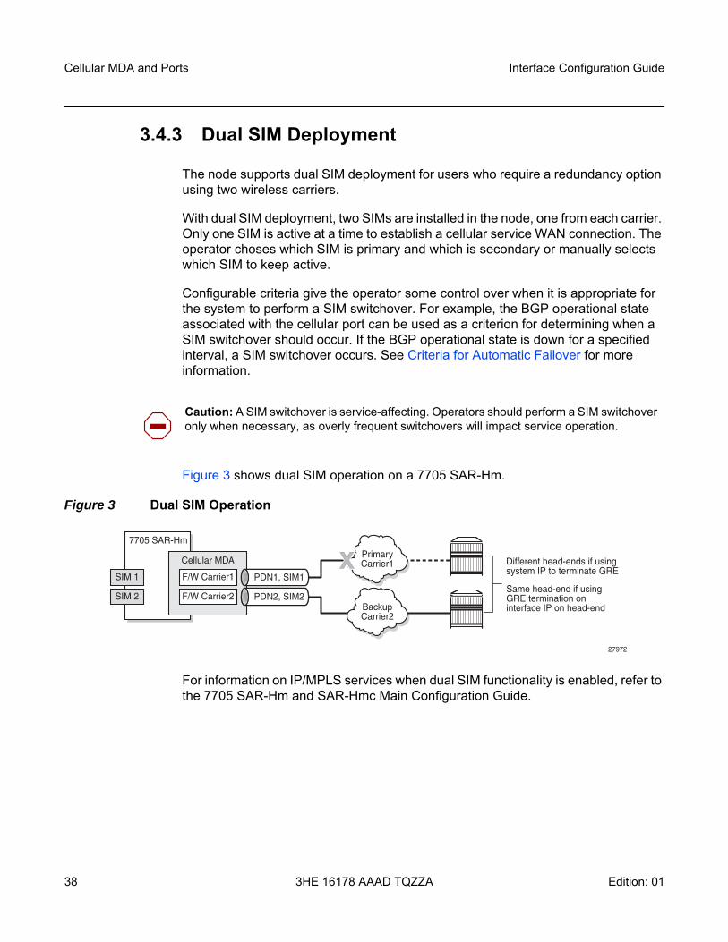
Figure 3 shows dual SIM operation on a 7705 SAR-Hm.
Figure 3 Dual SIM Operation
For information on IP/MPLS services when dual SIM functionality is enabled, refer to the 7705 SAR-Hm and SAR-Hmc Main Configuration Guide.
Caution: A SIM switchover is service-affecting. Operators should perform a SIM switchover only when necessary, as overly frequent switchovers will impact service operation.
7705 SAR-Hm
Different head-ends if usingsystem IP to terminate GRE
Same head-end if usingGRE termination oninterface IP on head-end
PrimaryCarrier1
PDN1, SIM1X
BackupCarrier2
PDN2, SIM2
Cellular MDA
F/W Carrier1
F/W Carrier2
SIM 1
SIM 2
27972
Interface Configuration Guide Cellular MDA and Ports
Edition: 01 3HE 16178 AAAD TQZZA 39
3.4.3.1 Enabling Dual SIM Operation
To enable dual SIM operation on the node, operators must perform the following tasks.
• procure two SIMs, each for a different cellular network• if ADP-Hm is required, insert the SIM needed to operate with ADP-Hm into SIM
slot 1. For more information on ADP-Hm, refer to the 7705 SAR-Hm and SAR-Hmc Main Configuration Guide, “Basic System Configuration”.
• ensure that each SIM is associated with a unique packet data network (PDN) by configuring a PDN profile and a PDN router interface that will be assigned a unique IP address during the PDN attach process. The PDN profiles and PDN router interfaces must be configured beforehand.
• choose whether the SIMs will be switched manually or use automatic failover. If automatic failover is chosen, the operator must determine the criteria for failover. See Criteria for Automatic Failover for information.
3.4.3.2 Active SIM Selection
When the two SIMs have been installed in the node, the operator chooses which SIM will be active by configuring the active-sim command under the cellular MDA. This command can be configured either with a specific SIM (1 or 2) or with the auto parameter. The default is 1. The configuration of this command determines whether the SIMs are switched manually or use automatic failover.
3.4.3.2.1 Manual Selection
The operator can manually select the active SIM by configuring a specific SIM as active, either 1 or 2. This configuration makes the selected SIM permanently active.
The active SIM can be manually switched by changing the active-sim setting from 1 to 2 or from 2 to 1.
Caution: Changing the active SIM from 1 to 2 or from 2 to 1 is service-affecting. The recovery time after making this change can range from a few seconds to up to a few minutes.
Cellular MDA and Ports
40
Interface Configuration Guide
3HE 16178 AAAD TQZZA Edition: 01
When the system powers up or reboots, it uses the active-sim setting to determine which SIM is the active SIM. If the operator configures the active-sim as 1 but there is no physical SIM in the associated SIM slot, the cellular port remains operationally down. The operator must either install the SIM in the appropriate slot or change the configuration in order to bring the service up.
3.4.3.2.2 Automatic Failover
An automatic failover occurs when activity switches from one SIM to the other.
Automatic failover is enabled in a dual SIM deployment when the active-sim command is set to auto. In this case, the operator must select the SIM to use as the primary SIM by setting the preferred-sim value. The node uses the preferred-sim setting to determine which SIM to use for a cellular port after a system reset.
If the operator changes the active-sim value from auto to 1 or from auto to 2 and the active SIM is the same as the new configuration, there is no change to service of the active SIM.
If the operator changes the active SIM from 1 to auto or from 2 to auto, there is no service outage. The system keeps the currently active SIM up and does not perform any switchover.
When active-sim is set to auto, the operator can use the tools>perform>mda> cellular>force-sim-switch command to manually force a SIM switch.
The auto parameter can be set if there is only one SIM installed in the system; however, the system keeps the currently active SIM up and does not perform any switchover.
Caution: Changing the active-sim setting so that the newly active SIM is different from the currently active SIM is service-affecting. The recovery time after making this change could range from a few seconds to up to a few minutes.
Interface Configuration Guide Cellular MDA and Ports
Edition: 01 3HE 16178 AAAD TQZZA 41
3.4.3.3 Criteria for Automatic Failover
When the active-sim command is set to auto, the operator can configure the parameters that will cause an automatic failover to occur. The parameters that serve as criteria for automatic failover are:
• the cellular port operational state • the BGP operational state
These parameters are configured per SIM and can be different for each SIM. As well, one or both parameters can be configured for each SIM.
An automatic failover occurs when the conditions are met for either of the configured criterion on the currently active SIM.
3.4.3.3.1 Cellular Port Operational State
The cellular port operational state can be specified as a failover criterion for the currently active SIM. The operational state of cellular port 1/1/1 is used as the failover criterion for SIM 1 and the operational state of cellular port 1/1/2 is used as the failover criterion for SIM 2.
When the cellular port operational state criterion is specified, the system monitors the operational state of the PDN. If the PDN is operationally down for a specified failure-duration, the system performs a SIM failover and attempts to establish cellular service using the other SIM. See Failure Duration for more information.
3.4.3.3.2 BGP Operational State
The operational state of BGP sessions associated with the currently active SIM can be specified as a failover criterion for the currently active SIM. The state of all the BGP sessions whose local-address is set to the PDN interface name that is configured under SIM 1 is used as the failover criterion for SIM 1. Similarly, the state of the BGP sessions whose local-address is set to the PDN interface name associated with SIM 2 is used as the failover criterion for SIM 2.
Note: Automatic failover between SIMs can continue indefinitely until either the recovery timer expires, which will reboot the entire system and bring up a cellular port based on the preferred SIM, or the operator manually intervenes to halt automatic failover by configuring a specific SIM as the active SIM.

Cellular MDA and Ports
42
Interface Configuration Guide
3HE 16178 AAAD TQZZA Edition: 01
When the BGP operational state criterion is specified, the system monitors the operational state of the BGP sessions. If all the BGP sessions are operationally down for a specified failure-duration, the system performs a SIM failover and attempts to establish cellular service using the other SIM. See Failure Duration for more information.
3.4.3.3.3 Failure Duration
When the active-sim command is set to auto and a least one failure criterion is configured, the system uses the length of time configured for the failure-duration to determine when to perform an automatic failover from one SIM to the other.
The failure-duration value is configured per SIM but it applies to both failure criteria. It is not possible to configure one failure duration value for the cellular port operational state and another value for the BGP session operational state.
The default value is 5 minutes. The valid range is from 1 minute to 60 minutes.
Note: It is recommended that the failure-duration be set to a high value so that the system does not perform frequent switches between SIMs.
Interface Configuration Guide Cellular MDA and Ports
Edition: 01 3HE 16178 AAAD TQZZA 43
3.5 Cellular Port Management
A cellular port enables a specific cellular service for an associated SIM. Each cellular port is managed separately per SIM and per PDN.
Cellular port 1/1/1 is associated with SIM 1 and cellular port 1/1/2 is associated with SIM 2.
A cellular port can be shut down by using the port>shutdown command. When a cellular port is shut down, the cellular service for that port is disabled. To enable cellular service for the port, use the port>no shutdown command. See Common Configuration Commands for more information on the shutdown command.
3.5.1 Cellular Port and its PDN
The node provides a single PDN connection for each cellular port. A cellular port must have an associated PDN router interface in order to allow routed traffic and services over the PDN connection and over the cellular network. For more information on the PDN router interface, refer to the 7705 SAR-Hm and SAR-Hmc Main Configuration Guide, “PDN Router Interfaces”.
The node supports the configuration of an access point name (APN) as part of a PDN profile in order to establish the PDN connection. In many cases, the default PDN profile is sufficient to establish a connection. For example, often the only configuration that is necessary to establish a connection is to enable the port using the config>port port-id no shutdown command. However, some carriers may require the user to configure a specific APN before allowing a connection to be established. In those cases, the user must configure a PDN profile and configure the cellular port to use that PDN profile. See PDN Profile for more information.
Warning: Use caution when executing the port>shutdown command on a cellular port. Shutting down a cellular port when it is the only means of communication to a remote node over a wireless network may cause permanent loss of connectivity to the node.
Cellular MDA and Ports
44
Interface Configuration Guide
3HE 16178 AAAD TQZZA Edition: 01
3.5.1.1 PDN Profile
The node uses PDN profiles to establish PDN connections over a cellular port. When the default PDN profile is not sufficient to establish connections, a PDN profile must be created. Manually created PDN profiles contain additional cellular network access configuration items that are not stored on the SIM but that are required in order to establish a PDN connection. PDN profiles can be created, modified, and deleted.
A PDN profile is referenced using a PDN profile ID. When a PDN profile is created at the system level and then configured on a cellular port, it cannot be modified or deleted until it is removed from the cellular port.
PDN profiles are necessary so that CLI or SNMP changes can be made to cellular ports without first having to shut down the ports. For example, when changing the APN information for a cellular port, another PDN profile can be configured with the changed information and assigned to the cellular port. This change will cause the cellular port to connect to the cellular network using the new PDN profile information immediately.
The following items can be configured as part of a PDN profile:
• APN—the Access Point Name provided by the service provider to use for the cellular service
• authentication—the type of authentication to use for establishing the connection, either Password Authentication Protocol (PAP) or Challenge Handshake Authentication Protocol (CHAP)
• description—a description for the PDN profile • password—a password for the PAP or CHAP authentication• protocol—the protocol for the associated PDN interface, either IPv4 or IPv6• username—a username for the PAP or CHAP authentication
The following CLI syntax shows an example of how to configure a PDN profile.
*A:Dut# config>system>cellular# pdn-profile 1*A:Dut>config>system>cellular>pdn-prof# apn apn1*A:Dut>config>system>cellular>pdn-prof# authentication pap*A:Dut>config>system>cellular>pdn-prof# description "PDNprofile1"*A:Dut>config>system>cellular>pdn-prof# no password*A:Dut>config>system>cellular>pdn-prof# protocol ipv6*A:Dut>config>system>cellular>pdn-prof# username waldowaldo*A:Dut>config>system>cellular>pdn-prof# exit*A:Dut>config>system>cellular# exit*A:Du>config>system# exit*A:Dut>config# exit*A:Dut#
For more information, see Cellular PDN Profile Configuration Commands.
Interface Configuration Guide Cellular MDA and Ports
Edition: 01 3HE 16178 AAAD TQZZA 45
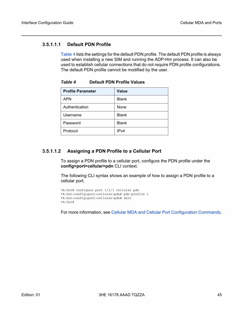
3.5.1.1.1 Default PDN Profile
Table 4 lists the settings for the default PDN profile. The default PDN profile is always used when installing a new SIM and running the ADP-Hm process. It can also be used to establish cellular connections that do not require PDN profile configurations. The default PDN profile cannot be modified by the user.
3.5.1.1.2 Assigning a PDN Profile to a Cellular Port
To assign a PDN profile to a cellular port, configure the PDN profile under the config>port>cellular>pdn CLI context.
The following CLI syntax shows an example of how to assign a PDN profile to a cellular port.
*A:Dut# configure port 1/1/1 cellular pdn*A:Dut>config>port>cellular>pdn# pdn-profile 1*A:Dut>config>port>cellular>pdn# exit*A:Dut#
For more information, see Cellular MDA and Cellular Port Configuration Commands.
Table 4 Default PDN Profile Values
Profile Parameter Value
APN Blank
Authentication None
Username Blank
Password Blank
Protocol IPv4
Cellular MDA and Ports
46
Interface Configuration Guide
3HE 16178 AAAD TQZZA Edition: 01
3.6 Firmware Update
The update-firmware command is available to update firmware on the node. The command is used to preload the correct firmware associated with each SIM's wireless service provider onto the cellular modem for those node variants that require firmware updates to operate in that service provider network.
For some node variants, the firmware is updated for each SIM. For other node variants, the firmware is updated for the radio and the SIMs use the same version. There are two forms of the update-firmware command to address both cases:
• tools>perform>mda 1/1>cellular>update-firmware firmware-file sim 1 | 2This form of the command is used for node variants that require the firmware to be updated for each SIM. In a dual SIM deployment, the command must be run twice, once for each SIM. For example, a node might have an ATT SIM installed in SIM slot 1 and a VZW SIM installed in SIM slot 2. The command is used to ensure that ATT-supported firmware is loaded for SIM 1 operation and that VZW-supported firmware is loaded for SIM 2 operation. Depending on which SIM is active based on the active-sim command, the corresponding radio firmware for that carrier SIM is used by the radio. If an automatic failover occurs, the associated firmware for the new SIM is used by the radio to establish service using the new SIM.
• tools>perform>mda 1/1>cellular update-firmware firmware-file This form of the command is used for node variants that do not support firmware updates per SIM. When executed, the command updates the firmware for the radio, and in a dual SIM deployment, both SIMs use the same version of the firmware.
For more information about using the command, see the update-firmware command description in the Interface Command Reference chapter.
By default, the firmware that is shipped with the node is used for both SIM 1 and SIM 2 when either SIM is active and no other firmware is specified for that SIM. Refer to the 7705 SAR-Hm and SAR-Hmc Software Release Notes for information about the node variants that require firmware updates to operate in a particular service provider network and for information about the firmware that must be used when operating on wireless carriers that require specific firmware.
Interface Configuration Guide GNSS Receiver
Edition: 01 3HE 16178 AAAD TQZZA 47
4 GNSS Receiver
4.1 In This Chapter
This chapter provides information about the GNSS receiver. Topics include:
• Overview• GNSS Configuration
GNSS Receiver
48
Interface Configuration Guide
3HE 16178 AAAD TQZZA Edition: 01
4.2 Overview
The GNSS receiver is used for streaming location information from the node (for example, for vehicle position information) or for querying GNSS information on the node.
4.3 GNSS Configuration
GNSS services are enabled in the CLI under the cellular MDA (mda 1/1). Use the CLI for the following:
• enabling or disabling GNSS• configuring the GNSS satellite constellation• configuring NMEA parameters• displaying GNSS location information and satellite information
4.3.1 Enabling or Disabling GNSS
GNSS services are enabled using the config>card>mda>gnss no shutdown command. When GNSS services are enabled, the GNSS receiver begins acquiring GPS and/or GLONASS satellite signals and determines the position of the system. The GPS LED on the chassis blinks green during this process. The GPS LED is lit solid green when the GNSS receiver has determined the position of the node. The GPS LED is unlit when the GNSS receiver is disabled.
When NMEA services are also enabled, NMEA sentences are streamed according to the parameters associated with that service. See Configuring NMEA Parameters for information.
GNSS services are disabled using the shutdown command. When GNSS services are disabled, the GNSS receiver is disabled and satellite information is reset. The GPS LED is unlit when the GNSS receiver is disabled.
GNSS services are disabled by default.
The GNSS receiver generates a logging event when it starts to acquire a position fix and when it has acquired a position fix.

Interface Configuration Guide GNSS Receiver
Edition: 01 3HE 16178 AAAD TQZZA 49
4.3.2 Configuring the GNSS Satellite Constellation
The constellation of the GNSS receiver can be set to either GPS (gps) or GPS and GLONASS (gps-glonass). The constellation can be modified only when the GNSS service is shut down. The default constellation setting is gps.
4.3.3 Configuring NMEA Parameters
The node can be configured to send position, velocity, and time information at regular intervals to servers that can process the data. When the data is formatted as an ASCII string according to National Marine Electronics Association (NMEA) standards, it is called an NMEA sentence. The node uses an IP transport service to send NMEA sentences to remote hosts. For information about enabling IP transport for NMEA sentences, refer to the 7705 SAR-Hm and SAR-Hmc Main Configuration Guide, “GNSS NMEA Data IP Transport Service”.
NMEA data streaming is enabled on the node when the IP transport ipt-id parameter is configured as gnss and the nmea no shutdown command is issued.
The following NMEA parameters must be configured on the node when streaming is enabled:
• sentence-type• sentence-interval
The NMEA defines a number of sentence types for streaming. The node supports the following sentence types:
• GGA — this sentence is for time, position, and fix-related data for a GNSS receiver
• RMC — this sentence is for time, date, position, course, and speed data provided by the GNSS receiver
• VTG — this sentence is for vector track and speed relative to the ground • GNS — this sentence is for time, position, and fix-related data for single or
combined constellations for a GNSS receiver.
For information about the sentence types, refer to NMEA 0183, Standard For Interfacing Marine Electronic Devices.
GNSS Receiver
50
Interface Configuration Guide
3HE 16178 AAAD TQZZA Edition: 01
The sentence interval specifies the frequency with which NMEA sentences are sent from the GNSS receiver. The interval can be set from 1 s to 3600 s. Different sentence types can be enabled concurrently so that multiple sentences can be streamed per sentence interval.
4.3.4 Displaying GNSS Location and Satellite Information
The following GNSS location information can be displayed on the CLI:
• latitude of the last position fix • longitude of the last position fix • time at which the last position fix was taken• altitude at which the last position fix was taken• heading and speed of the system
The following satellite information can be displayed on the CLI for up to 30 satellites:
• the satellite NMEA identifier—for GPS, the range is from 1 to 32; for GLONASS, the range is from 65 to 96
• the elevation of the satellite relative to the node, from 0 to 90° • the azimuth relative to the node position, from 0 to 360°• the signal-to-noise ratio (SNR), from 0 to 99 dB

Interface Configuration Guide Wireless LAN Interface
Edition: 01 3HE 16178 AAAD TQZZA 51
5 Wireless LAN Interface
5.1 In This Chapter
This chapter provides information about the wireless LAN (WLAN) interface. Topics include:
• Overview• WLAN Radio MDA Configuration• WLAN Port Configuration• WLAN Security• WLAN Interface Status• WLAN Statistics
Wireless LAN Interface
52
Interface Configuration Guide
3HE 16178 AAAD TQZZA Edition: 01
5.2 Overview
The node provides IEEE 802.11 b/g/n WLAN interface support.
The WLAN interface acts as an access point (AP) that clients can use to connect to the node. The interface can provide connectivity from the AP to the Nokia WLAN gateway (GW) for subscriber and WLAN access, and for WLAN mobility management. Refer to the 7705 SAR-Hm and SAR-Hmc Main Configuration Guide for details about configuring the WLAN interface with IP/MPLS services.
There are two areas of configuration for the WLAN interface:
• the MDA-level configuration, which includes parameters such as channel, frequency band, and country code
• the port-level configuration, which includes elements such as the network service set identifier (SSID), security parameters, dot1x parameters, and access point parameters
The WLAN MDA has a fixed port configuration that represents the access point. The WLAN port on the node shares the same WLAN MDA-level configuration and is independently configurable per network (SSID).
A WLAN network SSID is configured in the configure>port>wlan CLI context.
Interface Configuration Guide Wireless LAN Interface
Edition: 01 3HE 16178 AAAD TQZZA 53
5.3 WLAN Radio MDA Configuration
The following parameters must be configured for the WLAN MDA:
• country code• AP frequency band• AP channel• AP bandwidth• administrative status• beacon interval
The country-code is required to bring the radio up. The country code must be configured before any other MDA-level configuration can proceed and before the WLAN radio can be enabled with the no shutdown command. The country-code command is configured by entering one of the following country names in the CLI: Australia, Belgium, Bolivia, Brazil, Canada, Chile, Colombia, France, Germany, India, Iran, Italy, Japan, Malaysia, Mexico, New Zealand, Peru, Russia, Singapore, South Africa, United States, or Venezuela.
The access-point frequency-band can be configured as either 2.4 GHz or 5 GHz. The default is 2.4 GHz. If the configured country code changes, the frequency band resets to the default value.
The access-point channel can be configured either as auto or set to a specific channel identifier. The channel ID supported by the node depends on the configured country code. See the Appendix for channel ID and country code mappings. The default access-point channel setting is auto. If the configured country code changes, the channel resets to the default value.
The access-point bandwidth can be configured as either 20 MHz or 40 MHz, depending on the configured country code. See the Appendix for bandwidth and country code mapping. The default bandwidth is 20 MHz. If the configured country code changes, the bandwidth resets to the default value.
The AP broadcasts a beacon packet in order to synchronize the wireless network. It is possible to configure the frequency with which the packet is sent using the beacon-interval command.
The WLAN radio can be turned off using the shutdown command in the config>card>mda>wlan-radio context. When the WLAN radio is turned off, any configured WLAN ports become operationally down if they were not already shut down. When the no shutdown command is issued in this context, the radio is turned on and configured WLAN ports can begin operating; however, the no shutdown command cannot be issued until the country code is configured.
Wireless LAN Interface
54
Interface Configuration Guide
3HE 16178 AAAD TQZZA Edition: 01
The WLAN radio can be put into reset mode using the shutdown command in the config>card>mda context. Any configured WLAN ports become operationally down when the WLAN radio is in reset mode. When the no shutdown command is issued in this context, the radio comes out of reset and configured WLAN ports can begin operating.
5.4 WLAN Port Configuration
The WLAN port operates as an access point (AP) and can be configured with the following:
• the network service set identifier (SSID), including the security parameters for the WLAN network (see WLAN Security)
• AP-specific parameters, including dot1x parameters, DHCP relay, and access point control parameters
5.4.1 Network SSID
The network service set identifier (SSID) defines the name of the WLAN network. The WLAN AP port uses this name to allow WLAN clients to connect to the WLAN network. Operators can optionally configure security parameters for each configured network SSID.
The SSID can be changed only when the WLAN AP port has been shut down.
5.4.2 AP-Specific Parameters
Operators can configure the following on a WLAN AP port:
• security parameters (see WLAN Security)• dot1x parameters, depending on the type of security configured• enable or disable DHCP relay• broadcast of the SSID, using the broadcast-ssid command• the maximum number of clients that can connect to the AP, using the client-limit
command
Interface Configuration Guide Wireless LAN Interface
Edition: 01 3HE 16178 AAAD TQZZA 55
• the length of time the port waits before releasing and disconnecting a client when the client has not transmitted nor received any data, using the client-timeout command
The DHCP relay setting can be modified without shutting down the WLAN AP port. All other AP parameters can only be modified when the WLAN port is shut down.
5.5 WLAN Security
The WLAN ports support the following security options:
• open • WPA2-PSK • WPA2-Enterprise
When no WLAN security is required, a WLAN port is configured with no wlan-security and WLAN AP security is open.
When WLAN security is required, a WLAN port can be configured with WPA2-PSK or WPA2-Enterprise security. When configuring either of these security types, the encryption must be set to either TKIP or AES using the wpa-encryption command. AES is the default.
When a WLAN AP port is configured for WPA2-PSK security, operators must use the wpa-passphrase command to configure a pre-shared secret pass phrase that is used by clients to connect to the AP.
When a WLAN AP port is configured for WPA2-Enterprise security, operators must configure a RADIUS policy under the config>system>security>dot1x context in the CLI. For information about configuring a RADIUS policy in this context, refer to the 7450 ESS, 7750 SR, 7950 XRS, and VSR System Management Guide. The dot1x RADIUS policy ID used to configure the RADIUS policy is then configured on the WLAN AP port using the config>port>wlan>access-point> dot1x>radius-plcy command.
The retry and timeout commands in the config>system>security>dot1x context are ignored by the WLAN AP port. Instead, the retry count is set to 3 and the timeout value is set to 5 s so that the node will retry each server four times before moving on to the next server if multiple servers are configured.
A WLAN AP port configured for WPA2-Enterprise security requires connected clients to periodically re-authenticate themselves to the WLAN network. The interval is configured using the re-auth-period command.
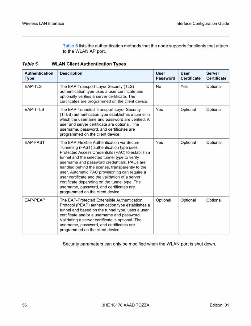
Wireless LAN Interface
56
Interface Configuration Guide
3HE 16178 AAAD TQZZA Edition: 01
Table 5 lists the authentication methods that the node supports for clients that attach to the WLAN AP port.
Security parameters can only be modified when the WLAN port is shut down.
Table 5 WLAN Client Authentication Types
Authentication Type
Description UserPassword
User Certificate
Server Certificate
EAP-TLS The EAP-Transport Layer Security (TLS) authentication type uses a user certificate and optionally verifies a server certificate. The certificates are programmed on the client device.
No Yes Optional
EAP-TTLS The EAP-Tunneled Transport Layer Security (TTLS) authentication type establishes a tunnel in which the username and password are verified. A user and server certificate are optional. The username, password, and certificates are programmed on the client device.
Yes Optional Optional
EAP-FAST The EAP-Flexible Authentication via Secure Tunneling (FAST) authentication type uses Protected Access Credentials (PAC) to establish a tunnel and the selected tunnel type to verify username and password credentials. PACs are handled behind the scenes, transparently to the user. Automatic PAC provisioning can require a user certificate and the validation of a server certificate depending on the tunnel type. The username, password, and certificates are programmed on the client device.
Yes Optional Optional
EAP-PEAP The EAP-Protected Extensible Authentication Protocol (PEAP) authentication type establishes a tunnel and based on the tunnel type, uses a user certificate and/or a username and password. Validating a server certificate is optional. The username, password, and certificates are programmed on the client device.
Optional Optional Optional
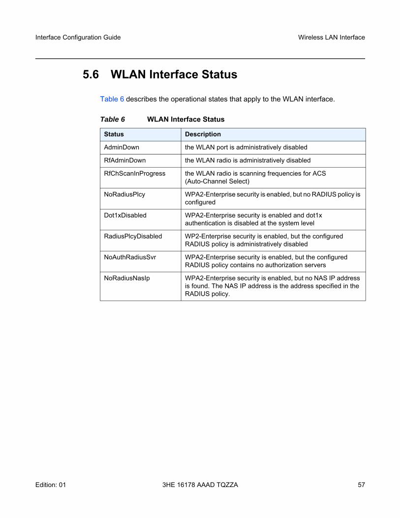
Interface Configuration Guide Wireless LAN Interface
Edition: 01 3HE 16178 AAAD TQZZA 57
5.6 WLAN Interface Status
Table 6 describes the operational states that apply to the WLAN interface.
Table 6 WLAN Interface Status
Status Description
AdminDown the WLAN port is administratively disabled
RfAdminDown the WLAN radio is administratively disabled
RfChScanInProgress the WLAN radio is scanning frequencies for ACS (Auto-Channel Select)
NoRadiusPlcy WPA2-Enterprise security is enabled, but no RADIUS policy is configured
Dot1xDisabled WPA2-Enterprise security is enabled and dot1x authentication is disabled at the system level
RadiusPlcyDisabled WP2-Enterprise security is enabled, but the configured RADIUS policy is administratively disabled
NoAuthRadiusSvr WPA2-Enterprise security is enabled, but the configured RADIUS policy contains no authorization servers
NoRadiusNasIp WPA2-Enterprise security is enabled, but no NAS IP address is found. The NAS IP address is the address specified in the RADIUS policy.
Wireless LAN Interface
58
Interface Configuration Guide
3HE 16178 AAAD TQZZA Edition: 01
5.7 WLAN Statistics
Statistics items can be displayed on the CLI for the WLAN port and for each WLAN instance. The node also collects access point and client-specific data transfer and operational statistics.
5.7.1 WLAN Port Statistics
On the WLAN port, the CLI displays a summary of the total port traffic in and out of the WLAN radio.
5.7.2 WLAN AP Statistics and Information
The node collects statistics and information that summarize the use of the WLAN AP, as listed below.
• port-level traffic statistics (packets and bytes)• RADIUS information• AP-level operational statistics:
- number of clients currently connected- total number of client attachments- total number of client detachments- total number of successful client authentications- total number of failed client authentications
Interface Configuration Guide Configuring Physical Ports
Edition: 01 3HE 16178 AAAD TQZZA 59
6 Configuring Physical Ports This chapter provides information about configuring physical ports with the CLI on the node.
Topics in this chapter include:
• Configuring Ethernet Port Parameters• Configuring Cellular Port Parameters• Configuring Serial Port Parameters• Configuring RS-232 Raw Socket Serial Port Parameters
6.1 Configuring Ethernet Port Parameters
Refer to the 7450 ESS, 7750 SR, 7950 XRS, and VSR Interface Configuration Guide, “Configuring Ethernet Port Parameters”.
6.2 Configuring Cellular Port Parameters
The pdn-profile parameter must be configured for the cellular port.
The PDN profile defines the specific APN that the node can connect to. Configure the pdn-profile under the appropriate cellular port. If a PDN profile is not specified, the default profile is used; this default PDN profile cannot be changed.
For more information, see Cellular PDN Profile Configuration Commands and Cellular MDA and Cellular Port Configuration Commands.
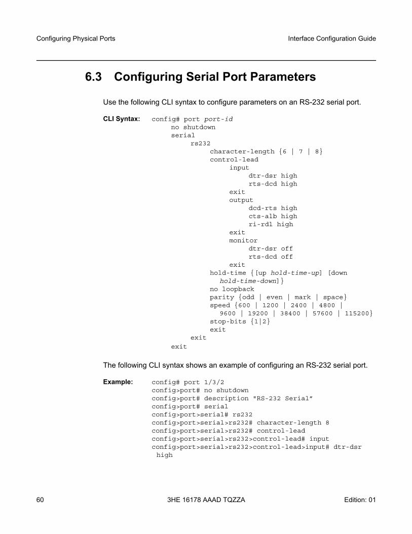
Configuring Physical Ports
60
Interface Configuration Guide
3HE 16178 AAAD TQZZA Edition: 01
6.3 Configuring Serial Port Parameters
Use the following CLI syntax to configure parameters on an RS-232 serial port.
CLI Syntax: config# port port-id no shutdownserial
rs232character-length {6 | 7 | 8}control-lead
inputdtr-dsr highrts-dcd high
exitoutput
dcd-rts highcts-alb highri-rdl high
exitmonitor
dtr-dsr offrts-dcd off
exithold-time {[up hold-time-up] [down
hold-time-down]}no loopbackparity {odd | even | mark | space}speed {600 | 1200 | 2400 | 4800 |
9600 | 19200 | 38400 | 57600 | 115200}stop-bits {1|2}exit
exit
exit
The following CLI syntax shows an example of configuring an RS-232 serial port.
Example: config# port 1/3/2config>port# no shutdownconfig>port# description "RS-232 Serial”config>port# serialconfig>port>serial# rs232config>port>serial>rs232# character-length 8config>port>serial>rs232# control-leadconfig>port>serial>rs232>control-lead# inputconfig>port>serial>rs232>control-lead>input# dtr-dsr high

Interface Configuration Guide Configuring Physical Ports
Edition: 01 3HE 16178 AAAD TQZZA 61
config>port>serial>rs232>control-lead>input# rts-dcd high
config>port>serial>rs232>control-lead>input# exitconfig>port>serial>rs232>control-lead# outputconfig>port>serial>rs232>control-lead>output# dcd-rts high
config>port>serial>rs232>control-lead>output# cts-alb high
config>port>serial>rs232>control-lead>output# ri-rdl high
config>port>serial>rs232>control-lead>output# exitconfig>port>serial>rs232>control-lead# monitorconfig>port>serial>rs232>control-lead>monitor# dtr-dsr off
config>port>serial>rs232>control-lead>monitor# rts-dcd off
config>port>serial>rs232>control-lead>monitor# exitconfig>port>serial>rs232>control-lead# exitconfig>port>serial>rs232# hold-time up 100config>port>serial>rs232# no loopbackconfig>port>serial>rs232# parity oddconfig>port>serial>rs232# speed 9600config>port>serial>rs232# stop-bits 1config>port>serial>rs232# exitconfig>port>serial# exitconfig>port# exit
Use the admin>display-config detail command to display the serial RS-232 port configuration information.
*A:Dut>admin# display-config detail#--------------------------------------------------echo "Port Configuration"#--------------------------------------------------
.....port 1/3/2
description "RS-232 Serial"serial
rs232speed 9600control-lead
inputdtr-dsr highrts-dcd high
exitoutput
dcd-rts highcts-alb highri-rdl high
exitmonitor
dtr-dsr offrts-dcd off
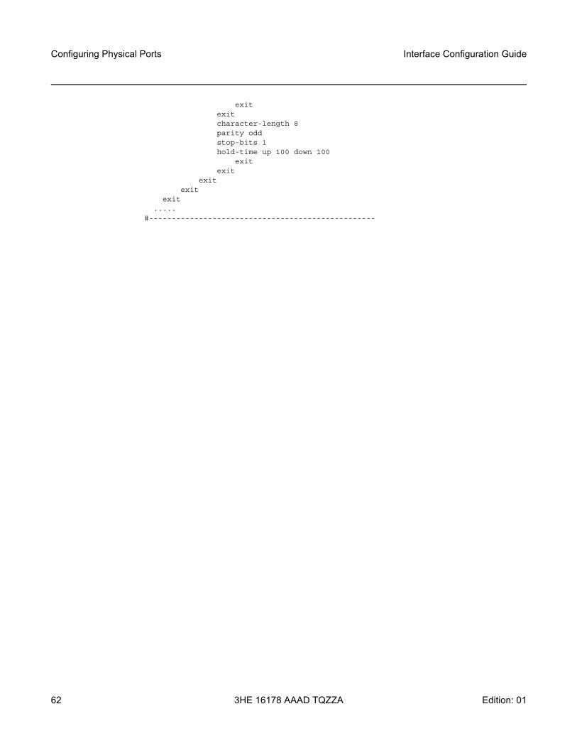
Configuring Physical Ports
62
Interface Configuration Guide
3HE 16178 AAAD TQZZA Edition: 01
exitexitcharacter-length 8parity oddstop-bits 1hold-time up 100 down 100
exitexit
exitexit
exit.....
#--------------------------------------------------

Interface Configuration Guide Configuring Physical Ports
Edition: 01 3HE 16178 AAAD TQZZA 63
6.4 Configuring RS-232 Raw Socket Serial Port Parameters
Use the following CLI syntax to configure an RS-232 raw socket serial port.
CLI Syntax: config# port port-id serial
rs232socket
description description-stringrx
eoplength bytesidle-timeout milliseconds[no] special-char valueexit
no squelch-delayno unsquelch-delayexit
txinter-session-delay msexit
exit
exit
The following CLI syntax shows an example of configuring an RS-232 raw socket serial port.
Example: config# port 1/3/2config>port# description "RS-232 Serial"config>port# serialconfig>port>serial# rs232config>port>serial>rs232# socketconfig>port>serial>rs232>socket# rxconfig>port>serial>rs232>socket>rx# eopconfig>port>serial>rs232>socket>rx>eop# idle-timeout 50config>port>serial>rs232>socket>rx>eop# length 1500config>port>serial>rs232>socket>rx>eop# no special-charconfig>port>serial>rs232>socket>rx>eop# exitconfig>port>serial>rs232>socket>rx# no squelch-delayconfig>port>serial>rs232>socket>rx# no unsquelch-delayconfig>port>serial>rs232>socket>rx# exitconfig>port>serial>rs232>socket# txconfig>port>serial>rs232>socket>tx# inter-session-delay 10
config>port>serial>rs232>socket>tx# exit
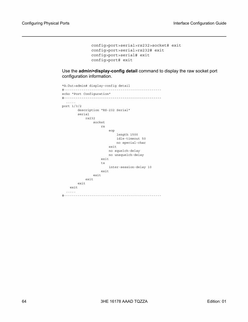
Configuring Physical Ports
64
Interface Configuration Guide
3HE 16178 AAAD TQZZA Edition: 01
config>port>serial>rs232>socket# exitconfig>port>serial>rs232# exitconfig>port>serial# exitconfig>port# exit
Use the admin>display-config detail command to display the raw socket port configuration information.
*A:Dut>admin# display-config detail#--------------------------------------------------echo "Port Configuration"#--------------------------------------------------
.....port 1/3/2
description "RS-232 Serial"serial
rs232socket
rxeop
length 1500idle-timeout 50no special-char
exitno squelch-delayno unsquelch-delay
exittx
inter-session-delay 10exit
exitexit
exitexit
.....#--------------------------------------------------
Interface Configuration Guide Interface Command Reference
Edition: 01 3HE 16178 AAAD TQZZA 65
7 Interface Command ReferenceThis chapter describes the following:
• Configuration Commands• Show, Clear, and Tools Commands
7.1 Configuration Commands
7.1.1 Configuration Command Hierarchies
• Ethernet Commands• Ethernet Access and Network Commands• Cellular MDA and Cellular Port Configuration Commands• Cellular PDN Profile Configuration Commands• GNSS Receiver Configuration Commands • Serial Interface Configuration Commands• Serial Raw Socket Interface Configuration Commands• WLAN MDA Radio Configuration Commands• WLAN Port Configuration Commands
Note: The commands described in this section apply specifically to the 7705 SAR-Hm series nodes. All other applicable commands supported on the nodes are described in the 7450 ESS, 7750 SR, 7950 XRS, and VSR Classic CLI Command Reference Guide and the 7450 ESS, 7750 SR, 7950 XRS, and VSR Clear, Show, and Tools Command Reference Guide.
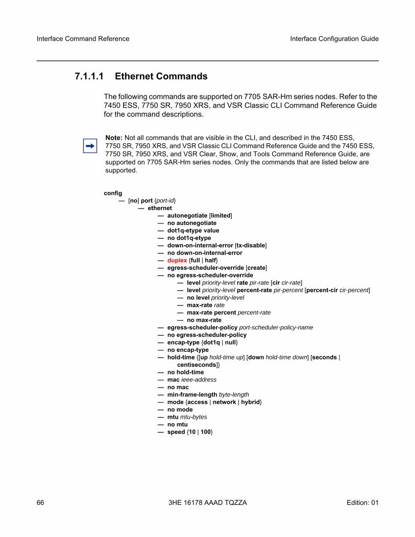
Interface Command Reference
66
Interface Configuration Guide
3HE 16178 AAAD TQZZA Edition: 01
7.1.1.1 Ethernet Commands
The following commands are supported on 7705 SAR-Hm series nodes. Refer to the 7450 ESS, 7750 SR, 7950 XRS, and VSR Classic CLI Command Reference Guide for the command descriptions.
config — [no] port {port-id}
— ethernet— autonegotiate [limited]— no autonegotiate— dot1q-etype value— no dot1q-etype— down-on-internal-error [tx-disable]— no down-on-internal-error— duplex {full | half}— egress-scheduler-override [create]— no egress-scheduler-override
— level priority-level rate pir-rate [cir cir-rate]— level priority-level percent-rate pir-percent [percent-cir cir-percent]— no level priority-level— max-rate rate— max-rate percent percent-rate— no max-rate
— egress-scheduler-policy port-scheduler-policy-name— no egress-scheduler-policy— encap-type {dot1q | null}— no encap-type— hold-time {[up hold-time up] [down hold-time down] [seconds |
centiseconds]}— no hold-time— mac ieee-address— no mac— min-frame-length byte-length— mode {access | network | hybrid} — no mode— mtu mtu-bytes— no mtu— speed {10 | 100}
Note: Not all commands that are visible in the CLI, and described in the 7450 ESS, 7750 SR, 7950 XRS, and VSR Classic CLI Command Reference Guide and the 7450 ESS, 7750 SR, 7950 XRS, and VSR Clear, Show, and Tools Command Reference Guide, are supported on 7705 SAR-Hm series nodes. Only the commands that are listed below are supported.
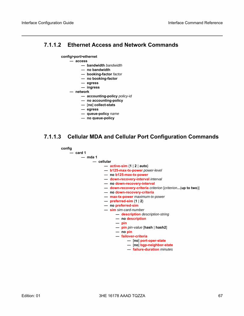
Interface Configuration Guide Interface Command Reference
Edition: 01 3HE 16178 AAAD TQZZA 67
7.1.1.2 Ethernet Access and Network Commands
config>port>ethernet— access
— bandwidth bandwidth— no bandwidth— booking-factor factor— no booking-factor— egress— ingress
— network— accounting-policy policy-id— no accounting-policy— [no] collect-stats— egress— queue-policy name— no queue-policy
7.1.1.3 Cellular MDA and Cellular Port Configuration Commands
config— card 1
— mda 1— cellular
— active-sim {1 | 2 | auto}— b125-max-tx-power power-level— no b125-max-tx-power — down-recovery-interval interval— no down-recovery-interval — down-recovery-criteria criterion [criterion...(up to two)]— no down-recovery-criteria — max-tx-power maximum-tx-power— preferred-sim {1 | 2}— no preferred-sim — sim sim-card-number
— description description-string— no description — pin — pin pin-value [hash | hash2]— no pin— failover-criteria
— [no] port-oper-state — [no] bgp-neighbor-state — failure-duration minutes
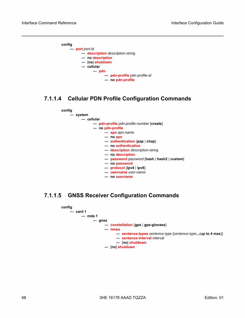
Interface Command Reference
68
Interface Configuration Guide
3HE 16178 AAAD TQZZA Edition: 01
config— port port-id
— description description-string— no description — [no] shutdown — cellular
— pdn— pdn-profile pdn-profile-id — no pdn-profile
7.1.1.4 Cellular PDN Profile Configuration Commands
config— system
— cellular— pdn-profile pdn-profile-number [create]— no pdn-profile
— apn apn-name— no apn — authentication {pap | chap}— no authentication — description description-string— no description — password password [hash | hash2 | custom]— no password — protocol {ipv4 | ipv6} — username user-name— no username
7.1.1.5 GNSS Receiver Configuration Commands
config— card 1
— mda 1— gnss
— constellation {gps | gps-glonass}— nmea
— sentence-types sentence-type [sentence-type...(up to 4 max)]— sentence-interval interval— [no] shutdown
— [no] shutdown
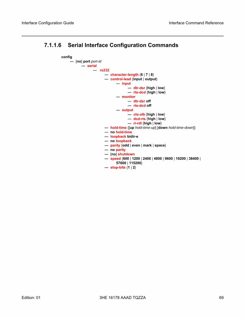
Interface Configuration Guide Interface Command Reference
Edition: 01 3HE 16178 AAAD TQZZA 69
7.1.1.6 Serial Interface Configuration Commands
config — [no] port port-id
— serial— rs232
— character-length {6 | 7 | 8}— control-lead {input | output}
— input— dtr-dsr {high | low}— rts-dcd {high | low}
— monitor— dtr-dsr off— rts-dcd off
— output— cts-alb {high | low}— dcd-rts {high | low}— ri-rdl {high | low}
— hold-time {[up hold-time-up] [down hold-time-down]}— no hold-time— loopback bidir-e— no loopback— parity {odd | even | mark | space}— no parity— [no] shutdown— speed {600 | 1200 | 2400 | 4800 | 9600 | 19200 | 38400 |
57600 | 115200}— stop-bits {1 | 2}
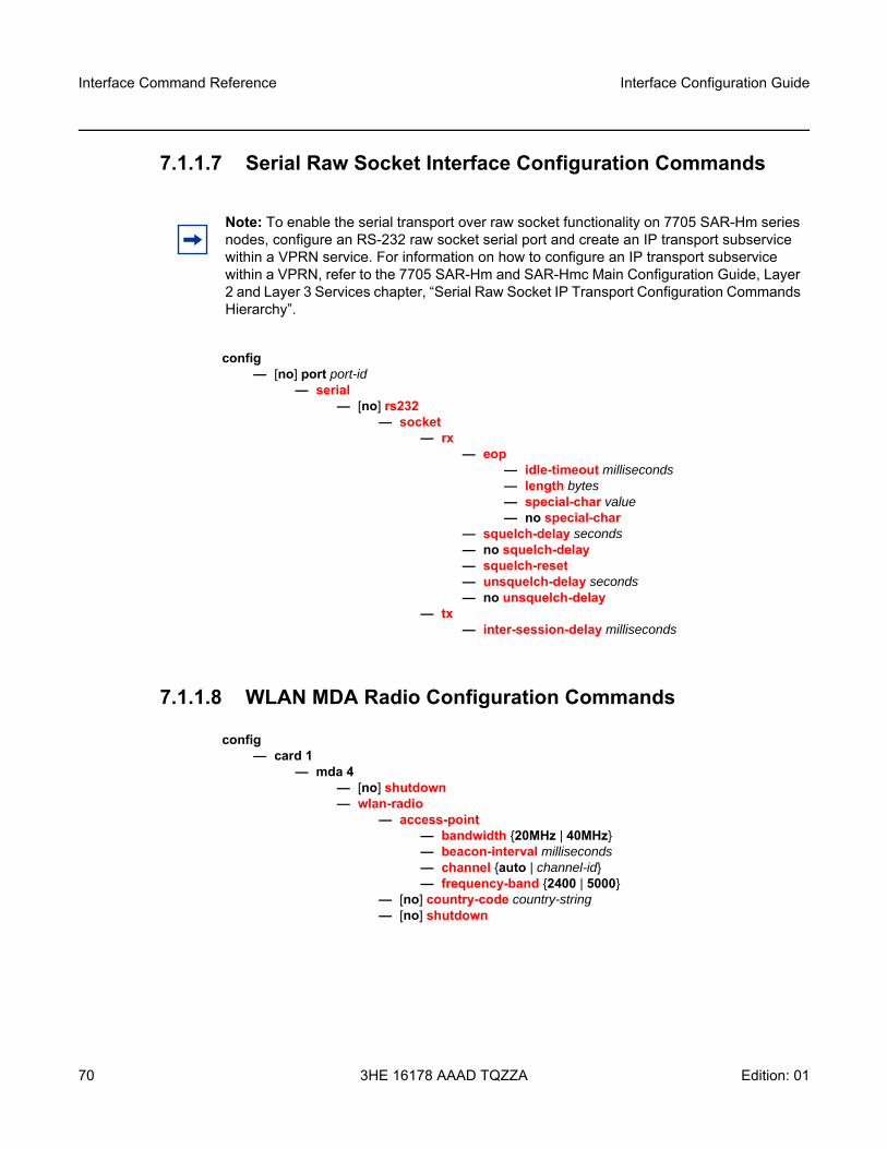
Interface Command Reference
70
Interface Configuration Guide
3HE 16178 AAAD TQZZA Edition: 01
7.1.1.7 Serial Raw Socket Interface Configuration Commands
config — [no] port port-id
— serial— [no] rs232
— socket — rx
— eop— idle-timeout milliseconds— length bytes— special-char value— no special-char
— squelch-delay seconds— no squelch-delay — squelch-reset— unsquelch-delay seconds— no unsquelch-delay
— tx— inter-session-delay milliseconds
7.1.1.8 WLAN MDA Radio Configuration Commands
config — card 1
— mda 4— [no] shutdown — wlan-radio
— access-point — bandwidth {20MHz | 40MHz}— beacon-interval milliseconds— channel {auto | channel-id}— frequency-band {2400 | 5000}
— [no] country-code country-string— [no] shutdown
Note: To enable the serial transport over raw socket functionality on 7705 SAR-Hm series nodes, configure an RS-232 raw socket serial port and create an IP transport subservice within a VPRN service. For information on how to configure an IP transport subservice within a VPRN, refer to the 7705 SAR-Hm and SAR-Hmc Main Configuration Guide, Layer 2 and Layer 3 Services chapter, “Serial Raw Socket IP Transport Configuration Commands Hierarchy”.
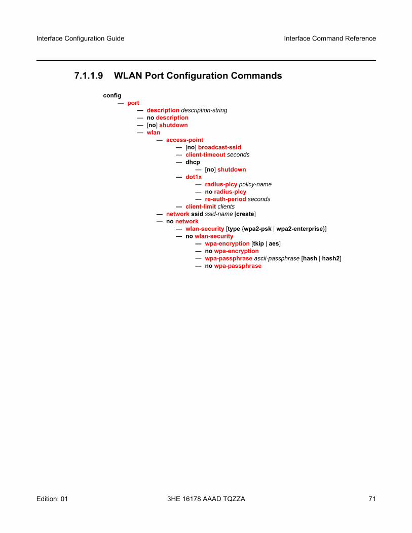
Interface Configuration Guide Interface Command Reference
Edition: 01 3HE 16178 AAAD TQZZA 71
7.1.1.9 WLAN Port Configuration Commands
config — port
— description description-string— no description — [no] shutdown — wlan
— access-point — [no] broadcast-ssid — client-timeout seconds— dhcp
— [no] shutdown — dot1x
— radius-plcy policy-name— no radius-plcy — re-auth-period seconds
— client-limit clients— network ssid ssid-name [create]— no network
— wlan-security [type {wpa2-psk | wpa2-enterprise}]— no wlan-security
— wpa-encryption [tkip | aes]— no wpa-encryption— wpa-passphrase ascii-passphrase [hash | hash2]— no wpa-passphrase

Interface Command Reference
72
Interface Configuration Guide
3HE 16178 AAAD TQZZA Edition: 01
7.1.2 Configuration Command Descriptions
The commands described in this section apply specifically to 7705 SAR-Hm series nodes. All other applicable commands supported on the nodes are described in the 7450 ESS, 7750 SR, 7950 XRS, and VSR Classic CLI Command Reference Guide and the 7450 ESS, 7750 SR, 7950 XRS, and VSR Clear, Show, and Tools Command Reference Guide.
• Common Configuration Commands• Cellular MDA and Cellular Port Configuration Commands• Cellular PDN Profile Configuration Commands• Ethernet Configuration Commands • GNSS Receiver Configuration Commands • Serial Interface Configuration Commands• Raw Socket Configuration Commands• WLAN MDA Radio Configuration Commands • WLAN Port Configuration Commands
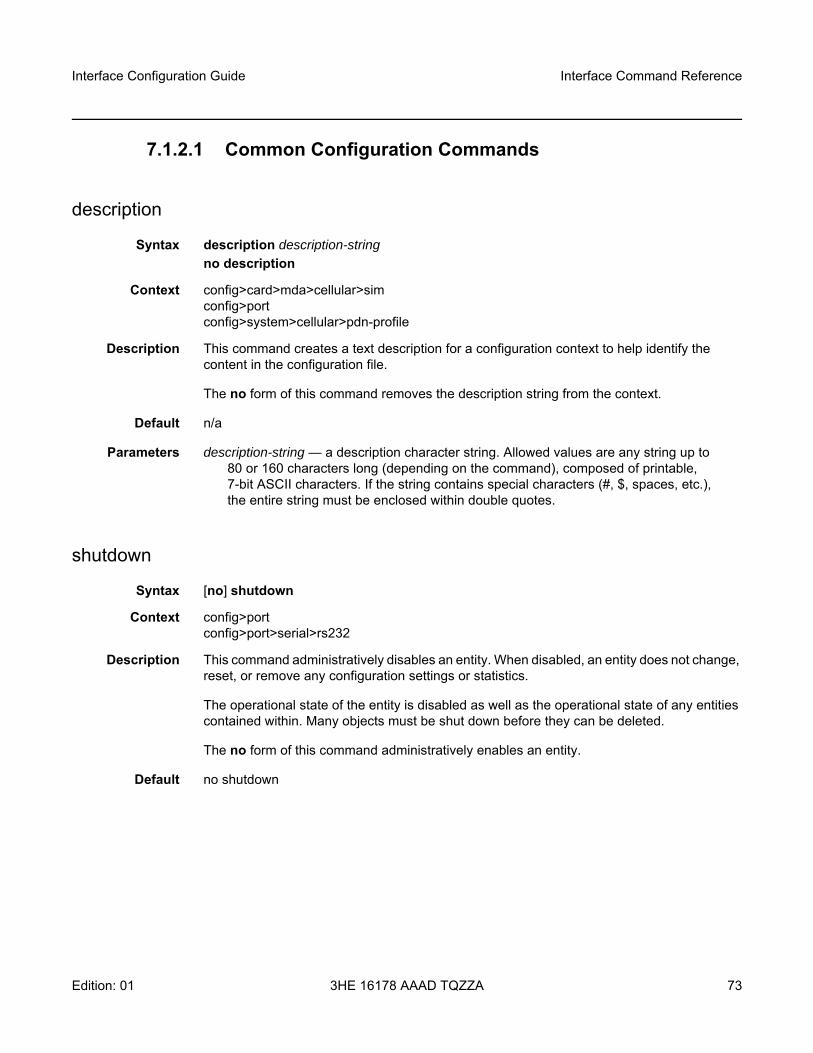
Interface Configuration Guide Interface Command Reference
Edition: 01 3HE 16178 AAAD TQZZA 73
7.1.2.1 Common Configuration Commands
description
Syntax description description-string no description
Context config>card>mda>cellular>simconfig>portconfig>system>cellular>pdn-profile
Description This command creates a text description for a configuration context to help identify the content in the configuration file.
The no form of this command removes the description string from the context.
Default n/a
Parameters description-string — a description character string. Allowed values are any string up to 80 or 160 characters long (depending on the command), composed of printable, 7-bit ASCII characters. If the string contains special characters (#, $, spaces, etc.), the entire string must be enclosed within double quotes.
shutdown
Syntax [no] shutdown
Context config>portconfig>port>serial>rs232
Description This command administratively disables an entity. When disabled, an entity does not change, reset, or remove any configuration settings or statistics.
The operational state of the entity is disabled as well as the operational state of any entities contained within. Many objects must be shut down before they can be deleted.
The no form of this command administratively enables an entity.
Default no shutdown
Interface Command Reference
74
Interface Configuration Guide
3HE 16178 AAAD TQZZA Edition: 01
7.1.2.2 Cellular MDA and Cellular Port Configuration Commands
port
Syntax port port-id
Context config
Description This command configures an identifier for a cellular port on the node. Up to two cellular ports can be configured and each cellular port is associated with a SIM. Cellular port 1/1/1 is associated with SIM 1 and cellular port 1/1/2 is associated with SIM 2. The relationship between the ports and the SIMs cannot be changed.
Default 1/1/1
Parameters port-id — the cellular port identifier
Values 1/1/1 or 1/1/2, in the format slot/mda/port
active-sim
Syntax active-sim {1 | 2 | auto}
Context config>card>mda>cellular
Description This command assigns a SIM to be the active SIM.
When the system powers up or reboots, it uses the active-sim setting to determine which SIM is the active SIM. Selecting 1 or 2 makes the selected SIM permanently active. The active SIM can be manually switched by changing the active-sim setting from 1 to 2 or from 2 to 1.
If a SIM is specified but is not physically installed in the associated SIM slot, the cellular port remains operationally down. The operator must either install the SIM in the appropriate slot or change the configuration in order to bring up the service.
Selecting auto enables automatic failover in a dual SIM deployment. An automatic failover occurs when activity switches from one SIM to the other. The settings configured for the failover-criteria command determine when an automatic failover will occur.
Caution: Changing the active SIM from 1 to 2 or vice versa is considered a manual switchover and is service-affecting. The recovery time after making the change can range from a few seconds to up to a few minutes. Ensure that there is service on the other SIM before changing the active SIM.

Interface Configuration Guide Interface Command Reference
Edition: 01 3HE 16178 AAAD TQZZA 75
When the auto parameter is set in a dual SIM deployment, the node must be configured with a preferred SIM. The preferred-sim command specifies whether SIM 1 or SIM 2 is used for a cellular port after a system reset.
If the active-sim value is changed from auto to 1 or from auto to 2 and the active SIM is the same as the new configuration, there is no change to service of the active SIM.
If the active-sim value is changed from 1 to auto or from 2 to auto, there is no service outage. The system keeps the currently active SIM up and does not perform any switchover.
When active-sim is set to auto, operators can use the tools>perform>mda> cellular>force-sim-switch command to manually force a SIM switch.
The auto parameter can be set even if there is only one SIM installed in the system. In this case, the system keeps the currently active SIM up and does not perform any switchover.
Default 1
Parameters 1 — sets the active SIM to SIM 1
2 — sets the active SIM to SIM 2
auto — enables automatic failover between the two SIMs in a dual SIM deployment
b125-max-tx-power
Syntax b125-max-tx-power power-levelno b125-max-tx-power
Context config>card>mda>cellular
Description This command configures the maximum transmit power level of the B125 radio module. The B125 power level depends on the installation height of the B125 variant antenna, and the value must be set based on the guidelines provided in the SAR-Hm and SAR-Hmc Chassis Installation Guide for B125 antenna locations.
For more information, refer to the SAR-Hm and SAR-Hmc Chassis Installation Guide.
Default 1
Parameters power-level — the B125 antenna power level
Values 1 to 20
Caution: Changing the active-sim setting so that the newly active SIM is different from the currently active SIM is service-affecting. The recovery time after making this change could range from a few seconds to up to a few minutes.
Interface Command Reference
76
Interface Configuration Guide
3HE 16178 AAAD TQZZA Edition: 01
down-recovery-interval
Syntax down-recovery-interval intervalno down-recovery-interval
Context config>card>mda>cellular
Description This command configures the length of time in which the cellular MDA must establish cellular service for a SIM before the node resets. It is used in conjunction with the down-recovery-criteria command.
When configured, this option provides a hardware reset to unblock any potential hardware lockup conditions related to the cellular radio modem or to guard against persistent cycling of automatic switchovers between SIMs in a dual SIM deployment. If the cellular MDA has not successfully achieved service based on the down-recovery-criteria value set for either SIM 1 or SIM 2 within the specified length of time, the node resets.
Prior to resetting, the node will issue a log event stating that the node will reset within 60 seconds. This interval can be used to collect information for further debugging and analysis.
The no form of the command disables the down-recovery-interval, and the state of the cellular MDA is not monitored other than for dual SIM operation and criteria configured for automatic failover (see failover-criteria for more information).
Default no down-recovery-interval
Parameters interval — the length of time, in minutes, before a down-recovery condition is declared
Values 1 to 240
down-recovery-criteria
Syntax down-recovery-criteria criterion [criterion...(up to two)]no down-recovery-criteria
Context config>card>mda>cellular
Description This command configures criteria used to detect a problem with the cellular radio modem. It is used in conjunction with the down-recovery-interval command. The criteria are port and bgp.
When the command is set to port, the node detects if any cellular port has connected to a wireless network and is operationally up within the configured down-recovery-interval. When a port connects successfully, the down-recovery timer stops. The down-recovery timer restarts when all PDN interfaces are operationally down.
Interface Configuration Guide Interface Command Reference
Edition: 01 3HE 16178 AAAD TQZZA 77
When the command is set to bgp, the node detects if any BGP session whose local-address is configured to a PDN interface name has come up within the configured down-recovery-interval. When a BGP session comes up, the down-recovery timer stops. The down-recovery timer restarts when all BGP sessions associated with PDN interfaces (associated with the configured local-address) are down.
Both port and bgp can be set concurrently as criteria.
Default port
Parameters criterion — specifies the criterion to use for detecting a problem with the cellular radio modem
Values port —all cellular ports are monitored bgp—all BGP sessions associated with PDNs are monitored
max-tx-power
Syntax max-tx-power maximum-tx-power
Context config>card>mda>cellular
Description This command configures the maximum transmit power used by the cellular interface on the MDA of the 7705 SAR-Hmc. For information about supported variants, refer to the 7705 SAR-Hm/Hmc Software Release Notes. This command is not supported on the 7705 SAR-Hm.
The command is used when higher gain antennas are deployed using spectrum where maximum power must be reduced to accommodate for the added gain.
The command adjusts the upper range of transmit power on the cellular interface. The transmit power range of the cellular interface on the MDA is -44 dBm to 23 dBm. The command can adjust this power range down by as much as 22 dB when the parameter is set within the supported range of 1 to 23 dBm.
Default 23 dBm
Parameters maximum-tx-power — the transmit power
Values 1 to 23 dBm (in 1 dBm increments)
preferred-sim
Syntax preferred-sim {1 | 2}no preferred-sim
Context config>card>mda>cellular
Interface Command Reference
78
Interface Configuration Guide
3HE 16178 AAAD TQZZA Edition: 01
Description This command configures which SIM to use when the node resets. The configuration is used in a dual SIM deployment when the active-sim command is set to auto. When the node resets, the system uses the preferred SIM to bring up the associated cellular port.
Default 1
Parameters 1 — sets the preferred SIM to SIM 1
2 — sets the preferred SIM to SIM 2
sim
Syntax sim sim-card-number
Context config>card>mda>cellular
Description This command enables the context to configure parameters for the specified SIM.
Parameters sim-card-number — identifies the SIM
Values 1 or 2
pin
Syntax pin pin pin-value [hash | hash2]no pin
Context config>card>mda>cellular>sim
Description This command stores the SIM PIN in the system configuration file. This command does not change the PIN on the SIM.
Use the pin command to enter the PIN in the system configuration file from an interactive CLI session. The system prompts you to enter the PIN twice. If the two entered PINs do not match, the system rejects the configuration.
Use the pin command with a specified PIN value and the hash or hash2 keyword to load the PIN in encrypted form in the configuration file.
The no form of this command removes the PIN from the system configuration.
Default n/a
Note: Before setting the preferred SIM, the operator must ensure that the corresponding SIM is installed and configured.
Interface Configuration Guide Interface Command Reference
Edition: 01 3HE 16178 AAAD TQZZA 79
Parameters pin-value — the 4-to-8 digit PIN code
hash — specifies that the PIN is entered in an encrypted form. If the hash or hash2 keyword is not used, the PIN is assumed to be in an unencrypted, clear text form. For security, all PINs are stored in encrypted form in the configuration file with the specified hash or hash2 parameter.
hash2 — specifies that the PIN is entered in a more complex, encrypted form that involves more variables than the PIN value alone, meaning that the hash2 encrypted variable cannot be copied and pasted. If the hash or hash2 keyword is not used, the PIN is assumed to be in an unencrypted, clear text form. For security, all PINs are stored in encrypted form in the configuration file with the specified hash or hash2 parameter.
failover-criteria
Syntax failover-criteria
Context config>card>mda>cellular>sim
Description This command enables the context to configure the criteria that will cause an automatic SIM switchover in a dual SIM deployment.
The failover-criteria parameters are used when the active-sim command is set to auto. The parameters are configured per SIM, so each SIM can have different failover criteria. The system uses the criteria configured on the currently active SIM to determine when a switchover should occur.
Default n/a
port-oper-state
Syntax [no] port-oper-state
Context config>card>mda>cellular>sim>failover-criteria
Description This command sets the operational status of the cellular port as a failover criterion for the specified SIM.
If the operational status of the cellular port remains down for the failure-duration interval, the SIM is considered to be in a failed state and the system performs an automatic switch from the currently active SIM to the other SIM.
The no form of the command disables the port-oper-state from being used as a failover criterion.
Default port-oper-state
Interface Command Reference
80
Interface Configuration Guide
3HE 16178 AAAD TQZZA Edition: 01
bgp-neighbor-state
Syntax [no] bgp-neighbor-state
Context config>card>mda>cellular>sim>failover-criteria
Description This command sets the operational status of BGP sessions as a failover criterion for the specified SIM.
The BGP sessions monitored by the system are those that are configured with the local-address set to the PDN interface name that uses the associated SIM cellular port-id.
If the operational status of BGP sessions remain down for the failure-duration interval, the SIM is considered to be in a failed state and the system performs an automatic switch from the currently active SIM to the other SIM.
The no form of the command disables the bgp-neighbor-state from being used as a failover criterion.
Default no bgp-neighbor-state
failure-duration
Syntax failure-duration minutes
Context config>card>mda>cellular>sim>failover-criteria
Description This command configures the length of time before the SIM is considered to be in a failed state based on the specified failover criteria. The value is used for both configured failover criteria.
When the node detects a down state for the failure-duration time, the SIM is considered to be in a failed state and the node performs an automatic switch from the currently active SIM to the other SIM.
Default 5
Parameters minutes — the length of time, in minutes, before the SIM is considered to be in a failed state
Values 1 to 60
Note: It is recommended that the failure-duration be set to a high value so that the system does not perform frequent switches between SIMs.
Interface Configuration Guide Interface Command Reference
Edition: 01 3HE 16178 AAAD TQZZA 81
pdn
Syntax pdn
Context config>port>cellular
Description This command enables the context to configure PDN parameters for the cellular port.
Default n/a
pdn-profile
Syntax pdn-profile pdn-profile-id no pdn-profile
Context config>port>cellular>pdn
Description This command assigns a PDN profile to the cellular port. The PDN profile must be configured at the system level before this command can be used; see Cellular PDN Profile Configuration Commands for information.
The no form of this command assigns the default PDN profile to the PDN.
Default no pdn-profile
Parameters pdn-profile-id — the PDN profile identifier
Values 1 to 15
Interface Command Reference
82
Interface Configuration Guide
3HE 16178 AAAD TQZZA Edition: 01
7.1.2.3 Cellular PDN Profile Configuration Commands
pdn-profile
Syntax pdn-profile pdn-profile-number [create]no pdn-profile
Context config>system>cellular
Description This command creates a PDN profile with an associated ID when used with the create keyword.
The system supports a default PDN profile and up to 15 user-created PDN profiles.
The default PDN profile is used during the ADP-Hm process and cannot be modified.
The no form of this command deletes the PDN profile if the profile is not in use. If the profile is in use, the no form of the command cannot be executed.
Default n/a
Parameters pdn-profile-number — the PDN profile identifier
Values 1 to 15
create — the keyword used to create the PDN profile
apn
Syntax apn apn-nameno apn
Context config>system>cellular>pdn-profile
Description This command configures the Access Point Name (APN) for the PDN profile.
The no form of this command removes the APN.
Default no apn
Parameters apn-name — a character string up to a maximum of 100 characters
Interface Configuration Guide Interface Command Reference
Edition: 01 3HE 16178 AAAD TQZZA 83
authentication
Syntax authentication {pap | chap}no authentication
Context config>system>cellular>pdn-profile
Description This command configures the authentication type used by the PDN profile.
The no form of this command removes authentication from the PDN profile.
Default n/a
Parameters pap — sets the authentication type to PAP
chap — sets the authentication type to CHAP
password
Syntax password password [hash | hash2 | custom]no password
Context config>system>cellular>pdn-profile
Description This command configures the password for PAP or CHAP authentication of the PDN profile. The password must be confirmed by entering it twice.
The no version of this command removes the authentication password from the PDN profile.
Default no password
Parameters password — a character string up to a maximum of 64 characters
hash — specifies that the key is entered in an encrypted form. If the hash parameter is not used, the key is assumed to be in a non-encrypted, clear text form For security, all keys are stored in encrypted form in the configuration file with the hash or hash2 parameter specified.
hash2 — specifies that the key is entered in a more complex encrypted form that involves more variables than the key value alone. This means that a hash2 encrypted variable cannot be copied and pasted. If the hash2 parameter is not used, the key is assumed to be in a non-encrypted, clear text form. For security, all keys are stored in encrypted form in the configuration file with the hash or hash2 parameter specified.
custom — specifies the custom encryption to management interface
Interface Command Reference
84
Interface Configuration Guide
3HE 16178 AAAD TQZZA Edition: 01
protocol
Syntax protocol {ipv4 | ipv6}
Context config>system>cellular>pdn-profile
Description This command configures the address type, either IPv4 or IPv6, that is learned by the PDN router interface during the PDN attachment process. When set to IPv4, the PDN router interface can operate in static cellular system mode, static cellular interface mode, or dynamic cellular interface mode. When set to IPv6, the PDN router interface can operate in either static cellular interface mode or dynamic cellular interface mode. For more information on the PDN router interface modes, refer to “PDN Router Interfaces” in the 7705 SAR-Hm and SAR-Hmc Main Configuration Guide.
Default ipv4
Parameters ipv4 — sets the IP address type for the PDN connection to IPv4
ipv6 — sets the IP address type for the PDN connection to IPv6
username
Syntax username user-nameno username
Context config>system>cellular>pdn-profile
Description This command configures the user name for PAP or CHAP authentication of the PDN profile.
The no form of this command removes the user name.
Default n/a
Parameters user-name — a character string up to a maximum of 255 characters
Interface Configuration Guide Interface Command Reference
Edition: 01 3HE 16178 AAAD TQZZA 85
7.1.2.4 Ethernet Configuration Commands
duplex
Syntax duplex (full | half}
Context config>port>ethernet
Description This command configures the duplex mode of a Fast Ethernet port when autonegotiation is disabled. If the port is configured to autonegotiate, this parameter is ignored.
The 7705 SAR-Hm only supports full-duplex mode.
Default full
Parameters full — sets the link to full-duplex mode
half — sets the link to half duplex mode
Interface Command Reference
86
Interface Configuration Guide
3HE 16178 AAAD TQZZA Edition: 01
7.1.2.5 GNSS Receiver Configuration Commands
constellation
Syntax constellation {gps | gps-glonass}
Context config>card>mda>gnss
Description This command configures which GNSS system or systems will be used by the GNSS receiver. The configuration can be modified only when the GNSS service is shut down.
Default gps
Parameters gps — configures the GNSS receiver to use the American GPS GNSS system
gps-glonass — configures the GNSS receiver to use both the American GPS GNSS system and the Russian GLONASS GNSS system
nmea
Syntax nmea
Context config>card>mda>gnss
Description This command enables the context for configuring NMEA parameters.
sentence-types
Syntax sentence-types sentence-type [sentence-type...(up to 4 max)]
Context config>card>mda>gnss>nmea
Description This command configures NMEA sentence types that are sent from the GNSS receiver over the associated IP transport service when the service is configured for NMEA streaming. The following sentence types are supported: GGA, RMC, VTG, and GNS. For information about the sentence types, refer to NMEA 0183, Standard For Interfacing Marine Electronic Devices.
At least one sentence type must be specified, up to a maximum of four. Different sentence types can be specified concurrently so that multiple sentences can be streamed per NMEA sentence interval.
Default gga
Interface Configuration Guide Interface Command Reference
Edition: 01 3HE 16178 AAAD TQZZA 87
Parameters sentence-type — an NMEA sentence type to be streamed
Values gga — this sentence is for time, position, and fix-related data for a GNSS receiver rmc — this sentence is for time, date, position, course, and speed data provided by the GNSS receiver vtg — this sentence is for vector track and speed relative to the ground gns — this sentence is for time, position, and fix-related data for single or combined constellations for a GNSS receiver.
sentence-interval
Syntax sentence-interval interval
Context config>card>mda>gnss>nmea
Description This command configures the intervals at which NMEA sentences are retrieved from the GNSS receiver and sent over the associated IP transport service configured for NMEA streaming.
Default 5 s
Parameters interval — time, in seconds, between the sending of NMEA sentences
Values 1 to 3600
shutdown
Syntax [no] shutdown
Context config>card>mda>gnss>nmea
Description This command enables or disables NMEA streaming from the GNSS receiver. The no form of the command enables NMEA streaming. Using the shutdown command disables NMEA streaming.
The node uses an IP transport service to send NMEA sentences from the GNSS receiver to remote hosts. For information about enabling IP transport for NMEA sentences, refer to the 7705 SAR-Hm and SAR-Hmc Main Configuration Guide, “GNSS NMEA Data IP Transport Service”.
Default shutdown
Interface Command Reference
88
Interface Configuration Guide
3HE 16178 AAAD TQZZA Edition: 01
shutdown
Syntax [no] shutdown
Context config>card>mda>gnss
Description This command enables or disables the GNSS service on the GNSS receiver. Enabling the GNSS receiver causes MDA 1/1 to reset under the following conditions:
• when the configuration of the constellation command changes• the first time the GNSS receiver is enabled after a firmware update of the cellular MDA
The no form of the command enables the GNSS service. Using the shutdown command disables the GNSS receiver and resets the position fix and associated information.
Default shutdown
Interface Configuration Guide Interface Command Reference
Edition: 01 3HE 16178 AAAD TQZZA 89
7.1.2.6 Serial Interface Configuration Commands
serial
Syntax serial
Context config>port
Description This command enables the context to configure parameters for an RS-232 serial port on the node.
Default n/a
rs232
Syntax rs232
Context config>port>serial
Description This command enables the context to configure RS-232 parameters for a serial port.
Default n/a
character-length
Syntax character-length {6 | 7 | 8}
Context config>port>serial>rs232
Description This command configures the number of data bits used to transmit a character. The value for this command cannot be 8 if the value for parity is anything other than no parity (that is, anything other than none) and the value for stop-bits is 2.
Default 8
Parameters 6 — specifies six bits in a character
7 — specifies seven bits in a character
8 — specifies eight bits in a character
Interface Command Reference
90
Interface Configuration Guide
3HE 16178 AAAD TQZZA Edition: 01
control-lead
Syntax control-lead {input | output}
Context config>port>serial>rs232
Description This command enables access to the context to configure the input and output leads that carry control signals. Control signals provide the handshaking for call setup, teardown, and synchronization.
Default n/a
input
Syntax input
Context config>port>serial>rs232>control-lead
Description This command enables access to the context to configure the input control leads.
Default n/a
dtr-dsr
Syntax dtr-dsr {high | low}
Context config>port>serial>rs232>control-lead>input
Description This command configures the Data Terminal Ready (DTR) or Data Set Ready (DSR) input control lead. For a DCE device, the input signal is DTR. For a DTE device, the input signal is DSR. This command is supported on the 7705 SAR-Hm only.
Default high
Parameters high — the input control lead is assumed to be on
low — the input control lead is assumed to be off
rts-dcd
Syntax rts-dcd {high | low}
Context config>port>serial>rs232>control-lead>input
Description This command configures the Request To Send (RTS) or Data Carrier Detect (DCD) input control lead. For a DCE device, the input signal is RTS. For a DTE device, the input signal is DCD. This command is supported on the 7705 SAR-Hm only.
Interface Configuration Guide Interface Command Reference
Edition: 01 3HE 16178 AAAD TQZZA 91
Default high
Parameters high — the input control lead is assumed to be on
monitor
Syntax monitor
Context config>port>serial>rs232>control-lead
Description This command enables access to the context to monitor the input control leads. When monitoring is enabled on a control lead, the node polls the status of the control lead every second. Any change in state of the control lead causes an alarm to be raised. This functionality provides an indication to the operator of a problem in the DTE-to-DCE path; for example, it can indicate that the far-end device is disconnected.
Monitoring is enabled on a per-lead basis.
Default n/a
dtr-dsr
Syntax dtr-dsr off
Context config>port>serial>rs232>control-lead>monitor
Description This command enables monitoring on the Data Terminal Ready (DTR) or Data Set Ready (DSR) input control lead. For a DCE device, the input control lead is DTR. For a DTE device, the input control lead is DSR. This command is supported on the 7705 SAR-Hm only.
Default off
Parameters off — monitoring is disabled on the lead
rts-dcd
Syntax rts-dcd off
Context config>port>serial>rs232>control-lead>monitor
Description This command enables monitoring on the Request To Send (RTS) or Data Carrier Detect (DCD) input control lead. For a DCE device, the input control lead is RTS. For a DTE device, the input control lead is DCD. This command is supported on the 7705 SAR-Hm only.
Default off
Parameters off — monitoring is disabled on the lead
Interface Command Reference
92
Interface Configuration Guide
3HE 16178 AAAD TQZZA Edition: 01
output
Syntax output
Context config>port>serial>rs232>control-lead
Description This command enables access to the context to configure the output control leads.
Default n/a
cts-alb
Syntax cts-alb {high | low}
Context config>port>serial>rs232>control-lead>output
Description This command configures the Clear To Send (CTS) or Analog Loopback (ALB) output control lead. For a DCE device, the output signal is CTS. For a DTE device, the output signal is ALB.
Default high
Parameters high — the output control lead is forced on
low — the output control lead is forced off
dcd-rts
Syntax dcd-rts {high | low}
Context config>port>serial>rs232>control-lead>output
Description This command configures the Data Carrier Detect (DCD) or Request To Send (RTS) output control lead. For a DCE device, the output signal is DCD. For a DTE device, the output signal is RTS. This command is supported on the 7705 SAR-Hm only.
Default high
Parameters high — the output control lead is forced on
low — the output control lead is forced off
ri-rdl
Syntax ri-rdl {high | low}
Context config>port>serial>rs232>control-lead>output
Interface Configuration Guide Interface Command Reference
Edition: 01 3HE 16178 AAAD TQZZA 93
Description This command configures the Ring Indicator (RI) or Remote Digital Loopback (RDL) output control lead. For a DCE device, the output signal is RI. For a DTE device, the output signal is RDL. This command is supported on the 7705 SAR-Hm only.
Default high
Parameters high — the output control lead is forced on
low — the output control lead is forced off
hold-time
Syntax hold-time {[up hold-time-up] [down hold-time-down]}no hold-time
Context config>port>serial>rs232
Description This command configures the serial link dampening timers in 100s of milliseconds, which guards against reporting excessive interface transitions. Once implemented, subsequent transitions of the interface from one state to another are not advertised to upper layer protocols until the configured timer has expired.
Default no hold-time
Parameters hold-time-up — the hold-timer for link-up event dampening. A value of zero (0) indicates that an up transition is reported immediately.
Values 0 to 100 (in 100s of milliseconds)
hold-time-down — the hold-timer for link-down event dampening. A value of zero (0) indicates that a down transition is reported immediately.
Values 0 to 100 (in 100s of milliseconds)
loopback
Syntax loopback bidir-eno loopback
Context config>port>serial>rs232
Description This command puts the specified interface into a loopback mode. The corresponding interface must be in a shutdown state in order for the loopback mode to be enabled.
In the serial context, it is possible to configure a a bidirectional loopback E. A bidirectional loopback is a circuit loopback that loops traffic from the line back to the line. Bidirectional loopback E takes place on the data device side of the adapter card, and is closer to the line.
This command is not saved in the system configuration between boots.
Interface Command Reference
94
Interface Configuration Guide
3HE 16178 AAAD TQZZA Edition: 01
The no form of this command disables the loopback on the interface.
Default no loopback
Parameters bidir-e — configures a bidirectional loopback E
parity
Syntax parity {odd | even | mark | space}no parity
Context config>port>serial>rs232
Description This command configures the parity bit in a character. Parity is an error detection method that adds an extra bit to each character, based on the number of 0s or 1s in the character.
The value for this command must be no parity (that is, none) if the character-length value is 8 and the stop-bits value is 2.
The no form of this command disables the parity bit in a character.
Default no parity
Parameters odd — the parity bit is set to 0 or 1 to make the total number of 1s in the set of bits odd
even — the parity bit is set to 0 or 1 to make the total number of 1s in the set of bits even
mark — the parity bit is present but not used and is always set to 1
space — the parity bit is present but not used and is always set to 0
speed
Syntax speed {600 | 1200 | 2400 | 4800 | 9600 | 19200 | 38400 | 57600 | 115200}
Context config>port>serial>rs232
Description This command configures the speed of the interface. The speed also determines the DS0 timeslots assigned to the channel group.
Default 9600
Parameters 600 — sets the link speed to 600 b/s
1200 — sets the link speed to 1200 b/s
2400 — sets the link speed to 2400 b/s
4800 — sets the link speed to 4800 b/s
9600 — sets the link speed to 9600 b/s
Interface Configuration Guide Interface Command Reference
Edition: 01 3HE 16178 AAAD TQZZA 95
19200 — sets the link speed to 19 200 b/s
38400 — sets the link speed to 38 400 b/s
57600 — sets the link speed to 57 600 b/s
115200 — sets the link speed to 115 200 b/s
stop-bits
Syntax stop-bits {1 | 2}
Context config>port>serial>rs232
Description This command configures the number of stop bits used to signify the end of a character.
This command cannot have a value of 2 if the character-length value is 8 and the parity value is anything other than no parity (that is, anything other than none).
Default 1
Parameters 1 — specifies one stop bit in a character
2 — specifies two stop bits in a character
Interface Command Reference
96
Interface Configuration Guide
3HE 16178 AAAD TQZZA Edition: 01
7.1.2.7 Raw Socket Configuration Commands
7.1.2.7.1 Raw Socket Port Configuration Commands
socket
Syntax socket
Context config>port>serial>rs232
Description This command creates a raw socket on an RS-232 port.
The no form of the command deletes the socket from the serial port.
Default n/a
rx
Syntax rx
Context config>port>serial>rs232>socket
Description This command enables the context to configure parameters for data packets received over a serial port’s raw socket.
Default n/a
eop
Syntax eop
Context config>port>serial>rs232>socket>rx
Description This command enables the context to configure end of packet (EOP) parameters for data packets received over the raw socket.
Note: The speed command must be set to a value that supports raw sockets; see Serial Interface Configuration Commands for the required information.
Note: An EOP will be declared by whichever EOP condition is encountered first.
Interface Configuration Guide Interface Command Reference
Edition: 01 3HE 16178 AAAD TQZZA 97
idle-timeout
Syntax idle-timeout milliseconds
Context config>port>serial>rs232>socket>rx>eop
Description This command specifies how long a serial port can remain idle before an EOP is declared and the packet is sent over the raw socket.
Default 50 ms
Parameters milliseconds — the length of time, in milliseconds, that a serial port can remain idle before an EOP is declared
Values 10 to 5000
length
Syntax length bytes
Context config>port>serial>rs232>socket>rx>eop
Description This command specifies the number of characters (converted to bytes) received on the serial port that triggers the node to encapsulate the characters in an IP transport packet and send it over a VPRN service.
Default 1500
Parameters bytes — the number of characters (in bytes) to trigger sending an IP transport packet
Values 1 to 1500
special-char
Syntax special-char valueno special-char
Context config>port>serial>rs232>socket>rx>eop
Description This command specifies a special character that, if received on the serial port, declares EOP and triggers the node to encapsulate previously received queued characters in an IP transport packet and send it over a VPRN service.
The no form of the command disables checking for a special character.
Note: Other than declaring the EOP, the special character is otherwise treated as regular data; that is, it is added to the packet.
Interface Command Reference
98
Interface Configuration Guide
3HE 16178 AAAD TQZZA Edition: 01
Default no special-char
Parameters value — specifies the special character, in a decimal or hexadecimal format, that triggers end of packet
Values 0 to 255, or 0x00 to 0xFF
squelch-delay
Syntax squelch-delay secondsno squelch-delay
Context config>port>serial>rs232>socket>rx
Description This command specifies how long a serial port can receive a continuous data stream before an alarm is raised indicating that the serial port has locked up and triggering the squelching function.
The no form of the command disables the squelching function on the serial port.
Default no squelch-delay
Parameters seconds — the number of seconds that a serial port can receive data before the squelching function is triggered
Values 1 to 120
squelch-reset
Syntax squelch-reset
Context config>port>serial>rs232>socket>rx
Description This command allows an operator to manually clear squelching on a serial port’s raw socket without having to configure a time limit on the squelching function.
Squelching can also be set to clear automatically after a time limit has been reached with the unsquelch-delay command.
Default n/a
unsquelch-delay
Syntax unsquelch-delay secondsno unsquelch-delay
Context config>port>serial>rs232>socket>rx
Interface Configuration Guide Interface Command Reference
Edition: 01 3HE 16178 AAAD TQZZA 99
Description This command clears squelching on a raw socket by setting a limit on the amount of time that squelching can remain active on the port. When the time limit is reached, the auto-clear function is enabled and the serial port’s raw socket is put back into a normal state.
Squelching can also be cleared manually with the squelch-reset command.
The no form of the command disables the auto-clear function on a serial port.
Default no unsquelch-delay
Parameters seconds — the number of seconds before the auto-clear function is activated
Values 1 to 120
tx
Syntax tx
Context config>port>serial>rs232>socket
Description This command enables the context to configure parameters for data packets transmitted over a serial port’s raw socket.
inter-session-delay
Syntax inter-session-delay milliseconds
Context config>port>serial>rs232>socket>tx
Description This command specifies a time delay that the node inserts between a session’s data that is being transmitted over a serial port and the next queued session’s data. The next session's data is not sent until the current session's data is sent and the inter-session-delay is reached.
Default 10 ms
Parameters milliseconds — the time delay, in milliseconds, between a session’s data that is being transmitted over a serial port and the next queued session’s data
Values 0 to 5000
Interface Command Reference
100
Interface Configuration Guide
3HE 16178 AAAD TQZZA Edition: 01
7.1.2.8 WLAN MDA Radio Configuration Commands
wlan-radio
Syntax wlan-radio
Context config>card>mda
Description This command enables the context to configure WLAN radio commands.
Default n/a
country-code
Syntax [no] country-code country-string
Context config>card>mda>wlan-radio
Description This command configures the country code for the WLAN radio. Because the values configured for the channel and bandwidth commands depend on the country-code configuration, the country code must be configured before any other MDA parameters. The country-code must be configured in order to enable the radio; otherwise, executing a no shutdown command returns an error.
The no form of the command removes the specified country code from the WLAN radio, and resets the MDA AP frequency-band, channel, and bandwidth commands to their default values. The no form can only be executed when the WLAN radio is shutdown.
Default none
Parameters country-string — the name of the country
Values australia, belgium, bolivia, brazil, canada, chile, colombia, france, germany, india, iran, italy, japan, malaysia, mexico, new-zealand, peru, russia, singapore, south-africa, usa, venezuela
access-point
Syntax access-point
Context config>card>mda>wlan-radio
Description This command enables the context to configure WLAN radio AP parameters.
Default n/a
Interface Configuration Guide Interface Command Reference
Edition: 01 3HE 16178 AAAD TQZZA 101
frequency-band
Syntax frequency-band {2400 | 5000}
Context config>card>mda>wlan-radio>access-point
Description This command sets the frequency band for the access point configured under the WLAN radio MDA.
Default 2400
Parameters 2400 — sets the frequency band to 2.4 GHz
5000 — sets the frequency band to 5.0 GHz
channel
Syntax channel {auto | channel-id}
Context config>card>mda>wlan-radio>access-point
Description This command sets the channel of the WLAN radio. The channel-id values that are available for this command depend on the configured country-code and frequency-band. See the Appendix for information about the available values.
When the WLAN radio channel is set to auto, the node scans the frequency bands supported by the configured county-code for the most appropriate channel.
Default auto
Parameters auto — specifies that the WLAN radio can select the most appropriate channel to use
channel-id — see the Appendix for information
bandwidth
Syntax bandwidth {20MHz | 40MHz}
Context config>card>mda>wlan-radio>access-point
Description This command sets the channel bandwidth of the WLAN radio.
Default 20MHz
Parameters 20MHz — sets the channel bandwidth to 20 MHz
40MHz — sets the channel bandwidth to 40 MHz
Interface Command Reference
102
Interface Configuration Guide
3HE 16178 AAAD TQZZA Edition: 01
beacon-interval
Syntax beacon-interval milliseconds
Context config>card>mda>wlan-radio>access-point
Description This command sets the beacon interval for WLAN radio access points. The interval is the frequency with which an AP broadcasts a packet in order to synchronize with the wireless network. This command is configured at the MDA level and is used by all APs for their associated beacon.
.
Default 200
Parameters milliseconds — the interval at which an AP broadcasts a packet that is used to synchronize with the wireless network
Values 75 to 999
shutdown
Syntax [no] shutdown
Context config>card>mdaconfig>card>mda>wlan-radio
Description In the config>card>mda>wlan-radio context, this command shuts down the WLAN radio. When the radio is turned off, a configured AP becomes operationally down. The no form of this command enables the WLAN radio, and any configured WLAN ports that are operationally down can begin operating.
In the config>card>mda context, this command shuts down the WLAN MDA and puts the WLAN radio into reset mode. Any WLAN ports configured under the MDA become operationally down. The no form of this command brings the WLAN radio out of reset
Default shutdown
Interface Configuration Guide Interface Command Reference
Edition: 01 3HE 16178 AAAD TQZZA 103
7.1.2.9 WLAN Port Configuration Commands
port
Syntax port port-id
Context config
Description This command configures a WLAN port. The WLAN port identifier for the WLAN MDA is fixed and represents an access point (AP).
Default n/a
Parameters port-id — specifies the physical port ID in the format slot/mda/port, where the slot ID is always 1, the MDA is always 4, and the port ID is from 1 to 3
shutdown
Syntax [no] shutdown
Context config>port
Description This command administratively disables the specified WLAN port. When disabled, the port does not change, reset, or remove any configuration settings or statistics. The operational state of the port is also disabled.
When the WLAN port on the node is shut down, the following occurs:
• All WLAN clients connected to the AP are released.• If the AP is configured as a SAP towards the WLAN gateway, the SAP and associated
service become operationally down.
The no form of this command administratively enables the specified port.
Default shutdown
description
Syntax description description-stringno description
Context config>port
Description This command creates a text description for a configuration context to help identify the content in the configuration file.
The no form of this command removes any description string from the context.
Interface Command Reference
104
Interface Configuration Guide
3HE 16178 AAAD TQZZA Edition: 01
Default n/a
Parameters description-string — description character string. Allowed values are any string up to 80 or 160 characters long (depending on the command) composed of printable, 7-bit ASCII characters. If the string contains special characters (#, $, spaces, etc.), the entire string must be enclosed within double quotes.
wlan
Syntax wlan
Context config>port
Description This command enables the context to configure WLAN port parameters.
Default n/a
network
Syntax network ssid ssid-name [create]no network
Context config>port>wlan
Description This command configures the network service set identifier (SSID). Only one network SSID can be configured on a port. The network SSID can be changed only when the WLAN AP port is shutdown.
The no form of this command removes the network and all the configurations within the network context.
Default none
Parameters ssid-name — a 32-character string that defines the SSID
create — keyword used create the network SSID
Interface Configuration Guide Interface Command Reference
Edition: 01 3HE 16178 AAAD TQZZA 105
wlan-security
Syntax wlan-security [type {wpa2-psk | wpa2-enterprise}]no wlan-security
Context config>port>wlan>network
Description This command configures the network security type for the specified WLAN interface.
When no security type is set, the WLAN interface is considered to be open. When the security type is set to wpa2-psk, the WPA2 PSK pass phrase must be configured. When the security type is set to wpa2-enterprise, the radius-plcy command under the access-point context must be configured in order to authenticate clients connecting to the WLAN access point.
The no form of the command disables security and the WLAN interface is considered to be open.
Default no wlan-security
Parameters type — keyword used to select the security type
wpa2-psk — the WLAN interface uses WPA2-PSK security
wpa2-enterprise — the WLAN interface uses WPA2-enterprise security
wpa-encryption
Syntax wpa-encryption [tkip | aes]no wpa-encryption
Context config>port>wlan>network>wlan-security
Description This command sets the WPA2 encryption type when network WLAN security is configured as either wpa2-psk or wpa2-enterprise.
When WLAN security is set to either wpa2-psk or wpa2-enterprise, the encryption type defaults to aes.
The no form of the command removes the configured encryption type.
Default aes
Parameters tkip — sets the encryption type to TKIP
aes — sets the encryption type to AES
Interface Command Reference
106
Interface Configuration Guide
3HE 16178 AAAD TQZZA Edition: 01
wpa-passphrase
Syntax wpa-passphrase ascii-passphrase [hash | hash2]no wpa-passphrase
Context config>port>wlan>network>wlan-security
Description This command configures the WPA2-PSK pass phrase when network WLAN security is configured as wpa2-psk. The pass phrase is a pre-shared secret pass phrase that is used to connect potential clients to the AP.
The no form of the command clears the pass phrase. The default setting is the string passphrase.
Default passphrase
Parameters ascii-passphrase — a 63-character alpha-numeric string that identifies the pass phrase to use for WPA2-PSK security
hash — specifies that the hash key is entered in an encrypted form. If the hash or hash2 parameter is not used, the key is assumed to be in an unencrypted, clear text form. For security, all keys are stored in encrypted form in the configuration file with the specified hash or hash2 parameter.
hash2 — specifies that the hash key is entered in a more complex, encrypted form that involves more variables than the key value alone, meaning that the hash2 encrypted variable cannot be copied and pasted. If the hash or hash2 parameter is not used, the key is assumed to be in an unencrypted, clear text form. For security, all keys are stored in encrypted form in the configuration file with the specified hash or hash2 parameter.
access-point
Syntax access-point
Context config>port>wlan
Description This command enables the context to configure WLAN port AP parameters.
dot1x
Syntax dot1x
Context config>port>wlan>access-point
Description This command enables the context to configure Dot1X parameters for the specified WLAN port AP.
Interface Configuration Guide Interface Command Reference
Edition: 01 3HE 16178 AAAD TQZZA 107
radius-plcy
Syntax radius-plcy policy-nameno radius-plcy
Context config>port>wlan>access-point>dot1x
Description This command configures a RADIUS policy for the specified WLAN access point to use when network WLAN security is set to wpa2-enterprise.
The RADIUS policy name must have already been configured under the config>system>security>dot1x context before executing this command. For information about configuring a RADIUS policy name in the config>system>security>dot1x context, refer to the 7450 ESS, 7750 SR, 7950 XRS, and VSR Classic CLI Command Reference Guide.
The no form of the command clears the radius policy name from the WLAN AP.
Default none
Parameters policy-name — the radius policy to use for a WLAN AP
re-auth-period
Syntax re-auth-period seconds
Context config>port>wlan>access-point>dot1x
Description This command configures the re-authentication period when network LAN security for a WLAN AP is set to wpa2-enterprise. Clients that are connected to the WLAN AP must re-authenticate after the re-authentication period expires.
Default 300 s
Parameters seconds — the length of time in seconds the WLAN access points wait before re-authenticating connected clients
Values 1 to 9000
Interface Command Reference
108
Interface Configuration Guide
3HE 16178 AAAD TQZZA Edition: 01
broadcast-ssid
Syntax [no] broadcast-ssid
Context config>port>wlan>access-point
Description This command enables WLAN access points to broadcast the network SSID.
The no form of the command disables the broadcast of the network SSID.
Default no broadcast-ssid
client-limit
Syntax client-limit clients
Context config>port>wlan>access-point
Description This command configures the maximum number of clients that can connect to the WLAN AP concurrently.
Default 24
Parameters clients — the number concurrent clients that can connect to the WLAN AP
Values 1 to 24
client-timeout
Syntax client-timeout seconds
Context config>port>wlan>access-point
Description This command configures the timeout period for inactive clients. If a client does not send or receive data over the WLAN connection within the specified period, then the client is disconnected from the WLAN AP.
Default 300 s
Parameters seconds — the length of time, in seconds, that the WLAN AP waits before disconnecting an inactive client
Values 60 (1 minute) to 86400 (24 hours)
Interface Configuration Guide Interface Command Reference
Edition: 01 3HE 16178 AAAD TQZZA 109
shutdown
Syntax [no] shutdown
Context config>port>wlan>access-point>dhcp
Description This command disables the DHCP relay function for the specified AP.
The no form of the command enables the DHCP relay function on the AP. When a DHCP request is received by a client trying to connect to the AP, the node inserts option-82 with specific information needed to connect to the WLAN gateway. If an option-82 sub-option is already present in the DHCP request, then it is replaced with the version expected by the WLAN gateway.
Default shutdown
Interface Command Reference
110
Interface Configuration Guide
3HE 16178 AAAD TQZZA Edition: 01
7.2 Show, Clear, and Tools Commands
7.2.1 Command Hierarchies
• Show Commands• Clear Commands• Tools Commands
7.2.1.1 Show Commands
7.2.1.1.1 Cellular MDA Commands
show— mda port-id [detail]
7.2.1.1.2 Cellular Port Commands
show— port port-id
7.2.1.1.3 GNSS Receiver Commands
show— mda 1/1
— gnss
Note: The commands described in this section apply specifically to 7705 SAR-Hm series nodes. All other applicable commands supported on the nodes are described in the 7450 ESS, 7750 SR, 7950 XRS, and VSR Classic CLI Command Reference Guide and the 7450 ESS, 7750 SR, 7950 XRS, and VSR Clear, Show, and Tools Command Reference Guide.
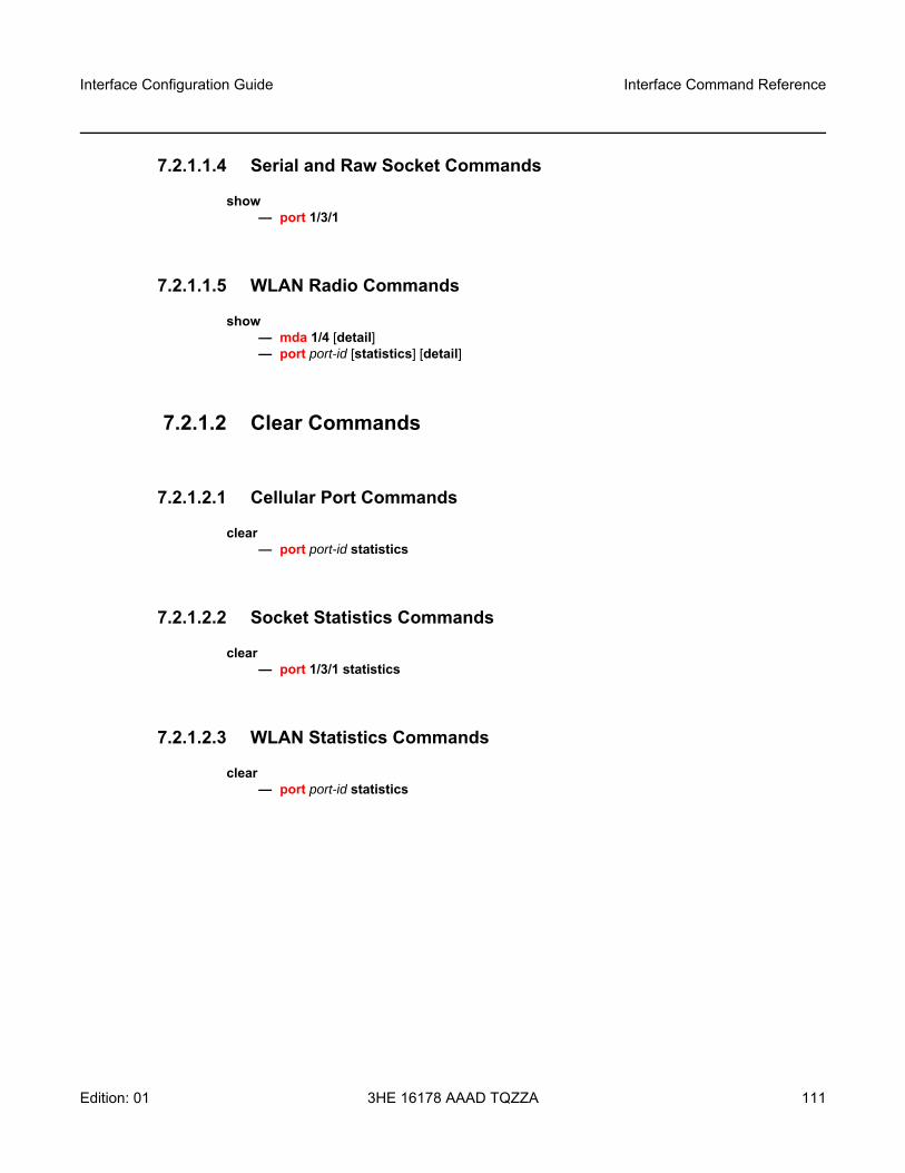
Interface Configuration Guide Interface Command Reference
Edition: 01 3HE 16178 AAAD TQZZA 111
7.2.1.1.4 Serial and Raw Socket Commands
show— port 1/3/1
7.2.1.1.5 WLAN Radio Commands
show— mda 1/4 [detail]— port port-id [statistics] [detail]
7.2.1.2 Clear Commands
7.2.1.2.1 Cellular Port Commands
clear— port port-id statistics
7.2.1.2.2 Socket Statistics Commands
clear— port 1/3/1 statistics
7.2.1.2.3 WLAN Statistics Commands
clear— port port-id statistics
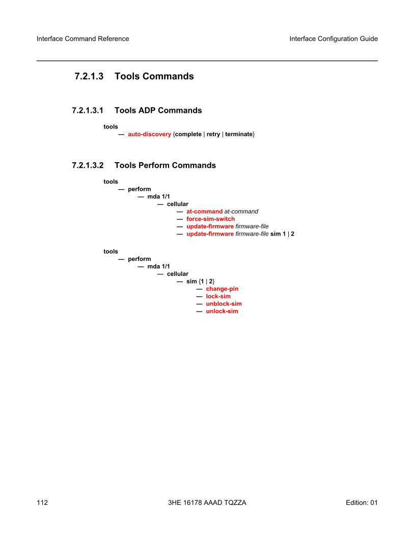
Interface Command Reference
112
Interface Configuration Guide
3HE 16178 AAAD TQZZA Edition: 01
7.2.1.3 Tools Commands
7.2.1.3.1 Tools ADP Commands
tools— auto-discovery {complete | retry | terminate}
7.2.1.3.2 Tools Perform Commands
tools— perform
— mda 1/1— cellular
— at-command at-command— force-sim-switch — update-firmware firmware-file— update-firmware firmware-file sim 1 | 2
tools— perform
— mda 1/1— cellular
— sim {1 | 2}— change-pin — lock-sim — unblock-sim — unlock-sim
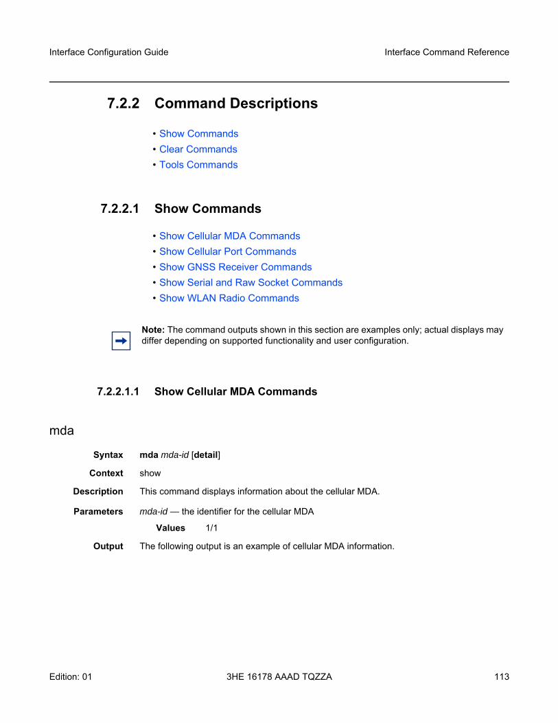
Interface Configuration Guide Interface Command Reference
Edition: 01 3HE 16178 AAAD TQZZA 113
7.2.2 Command Descriptions
• Show Commands• Clear Commands• Tools Commands
7.2.2.1 Show Commands
• Show Cellular MDA Commands• Show Cellular Port Commands• Show GNSS Receiver Commands• Show Serial and Raw Socket Commands• Show WLAN Radio Commands
7.2.2.1.1 Show Cellular MDA Commands
mda
Syntax mda mda-id [detail]
Context show
Description This command displays information about the cellular MDA.
Parameters mda-id — the identifier for the cellular MDA
Values 1/1
Output The following output is an example of cellular MDA information.
Note: The command outputs shown in this section are examples only; actual displays may differ depending on supported functionality and user configuration.

Interface Command Reference
114
Interface Configuration Guide
3HE 16178 AAAD TQZZA Edition: 01
Output Example
A:Dut-E# show mda 1/1 detail===============================================================================MDA 1/1 detail===============================================================================Slot Mda Provisioned Type Admin Operational
Equipped Type (if different) State State-------------------------------------------------------------------------------1 1 i2-cellular up upMDA Specific Data
Maximum port/connector count : 2Num ports/connectors equipped : 2Capabilities : Wireless, CellularFail On Error : Disabled
Hardware DataPlatform type : 7705Part number : 3HE12472AA010104CLEI code : INM7H00CRASerial number : NS190310019Manufacture date : 01242019Manufacturing deviations : (Not Specified)Manufacturing assembly number :Administrative state : upOperational state : upTemperature : 40CTemperature threshold : 89CSoftware boot (rom) version : (Not Specified)Software version : (Not Specified)Time of last boot : 2020/10/18 14:13:30Current alarm state : alarm clearedBase MAC address : 1c:ea:1b:db:27:f1Firmware version : CAT4_GS_BYPASS_0.3.3.9_ATT_V1.12
Cellular MDA InformationSpecified Firmware : CAT4_GS_BYPASS_0.3.3.9_ATT_V1.12Configured active SIM card : SIM 1Actual active SIM card : SIM 1Automatic SIM switch status : N/ANo service reset interval : disabledNo service reset status : N/AMaximum transmit power : 10 dBm
===============================================================================
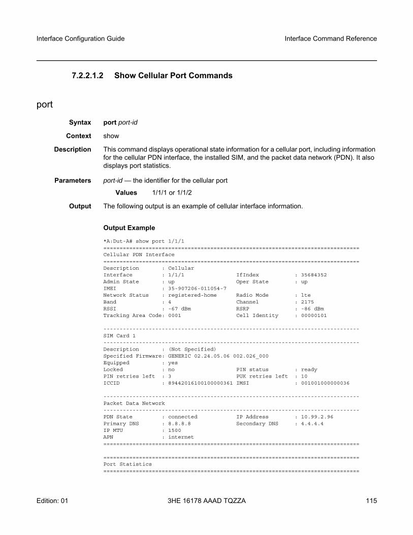
Interface Configuration Guide Interface Command Reference
Edition: 01 3HE 16178 AAAD TQZZA 115
7.2.2.1.2 Show Cellular Port Commands
port
Syntax port port-id
Context show
Description This command displays operational state information for a cellular port, including information for the cellular PDN interface, the installed SIM, and the packet data network (PDN). It also displays port statistics.
Parameters port-id — the identifier for the cellular port
Values 1/1/1 or 1/1/2
Output The following output is an example of cellular interface information.
Output Example
*A:Dut-A# show port 1/1/1===============================================================================Cellular PDN Interface===============================================================================Description : CellularInterface : 1/1/1 IfIndex : 35684352Admin State : up Oper State : upIMEI : 35-907206-011054-7Network Status : registered-home Radio Mode : lteBand : 4 Channel : 2175RSSI : -67 dBm RSRP : -86 dBmTracking Area Code: 0001 Cell Identity : 00000101
-------------------------------------------------------------------------------SIM Card 1-------------------------------------------------------------------------------Description : (Not Specified)Specified Firmware: GENERIC 02.24.05.06 002.026_000Equipped : yesLocked : no PIN status : readyPIN retries left : 3 PUK retries left : 10ICCID : 89442016100100000361 IMSI : 001001000000036
-------------------------------------------------------------------------------Packet Data Network-------------------------------------------------------------------------------PDN State : connected IP Address : 10.99.2.96Primary DNS : 8.8.8.8 Secondary DNS : 4.4.4.4IP MTU : 1500APN : internet===============================================================================
===============================================================================Port Statistics===============================================================================
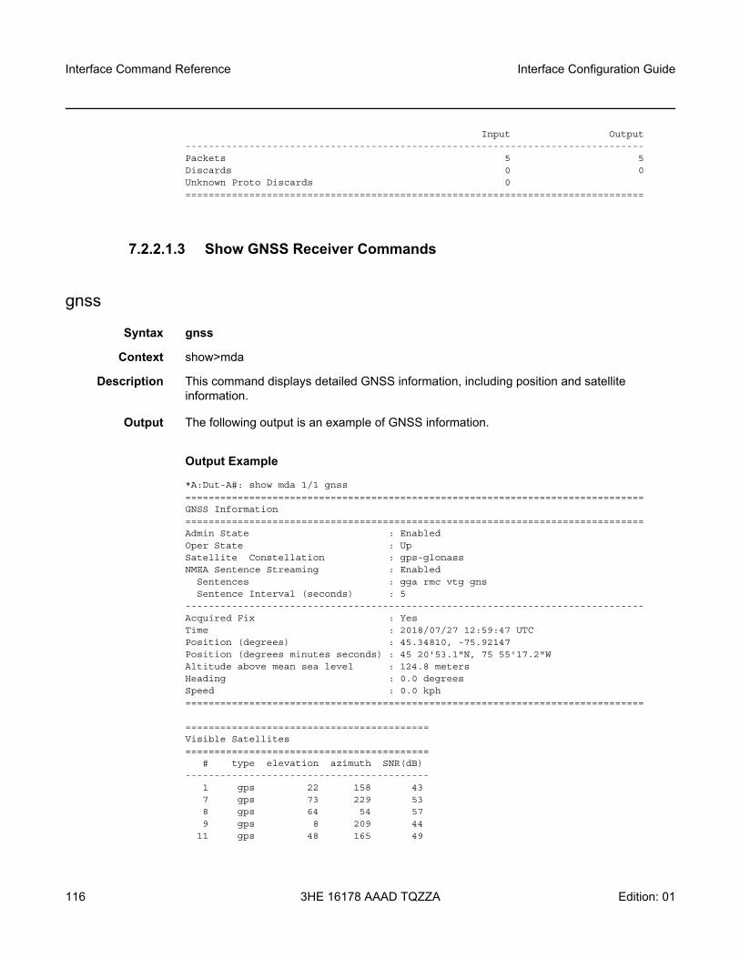
Interface Command Reference
116
Interface Configuration Guide
3HE 16178 AAAD TQZZA Edition: 01
Input Output-------------------------------------------------------------------------------Packets 5 5Discards 0 0Unknown Proto Discards 0===============================================================================
7.2.2.1.3 Show GNSS Receiver Commands
gnss
Syntax gnss
Context show>mda
Description This command displays detailed GNSS information, including position and satellite information.
Output The following output is an example of GNSS information.
Output Example
*A:Dut-A#: show mda 1/1 gnss===============================================================================GNSS Information===============================================================================Admin State : EnabledOper State : UpSatellite Constellation : gps-glonassNMEA Sentence Streaming : Enabled
Sentences : gga rmc vtg gnsSentence Interval (seconds) : 5
-------------------------------------------------------------------------------Acquired Fix : YesTime : 2018/07/27 12:59:47 UTCPosition (degrees) : 45.34810, -75.92147Position (degrees minutes seconds) : 45 20'53.1"N, 75 55'17.2"WAltitude above mean sea level : 124.8 metersHeading : 0.0 degreesSpeed : 0.0 kph===============================================================================
==========================================Visible Satellites==========================================
# type elevation azimuth SNR(dB)------------------------------------------
1 gps 22 158 437 gps 73 229 538 gps 64 54 579 gps 8 209 44
11 gps 48 165 49
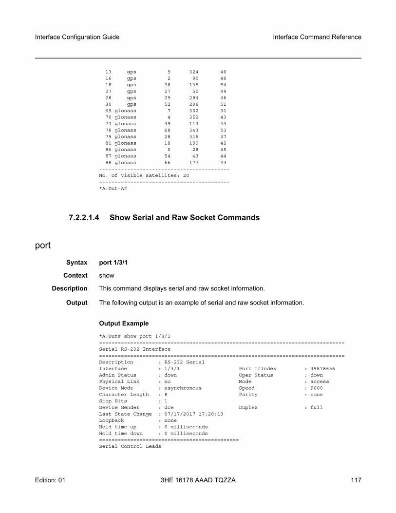
Interface Configuration Guide Interface Command Reference
Edition: 01 3HE 16178 AAAD TQZZA 117
13 gps 9 324 4016 gps 2 90 4018 gps 38 135 5427 gps 27 50 4928 gps 29 284 4630 gps 52 296 5169 glonass 7 302 3170 glonass 4 352 4377 glonass 49 113 4478 glonass 68 343 5379 glonass 28 316 4781 glonass 18 199 4286 glonass 0 28 4587 glonass 54 43 4488 glonass 66 177 43
------------------------------------------No. of visible satellites: 20==========================================*A:Dut-A#
7.2.2.1.4 Show Serial and Raw Socket Commands
port
Syntax port 1/3/1
Context show
Description This command displays serial and raw socket information.
Output The following output is an example of serial and raw socket information.
Output Example
*A:Dut# show port 1/3/1===============================================================================Serial RS-232 Interface===============================================================================Description : RS-232 SerialInterface : 1/3/1 Port IfIndex : 39878656Admin Status : down Oper Status : downPhysical Link : no Mode : accessDevice Mode : asynchronous Speed : 9600Character Length : 8 Parity : noneStop Bits : 1Device Gender : dce Duplex : fullLast State Change : 07/17/2017 17:20:13Loopback : noneHold time up : 0 millisecondsHold time down : 0 milliseconds=============================================Serial Control Leads
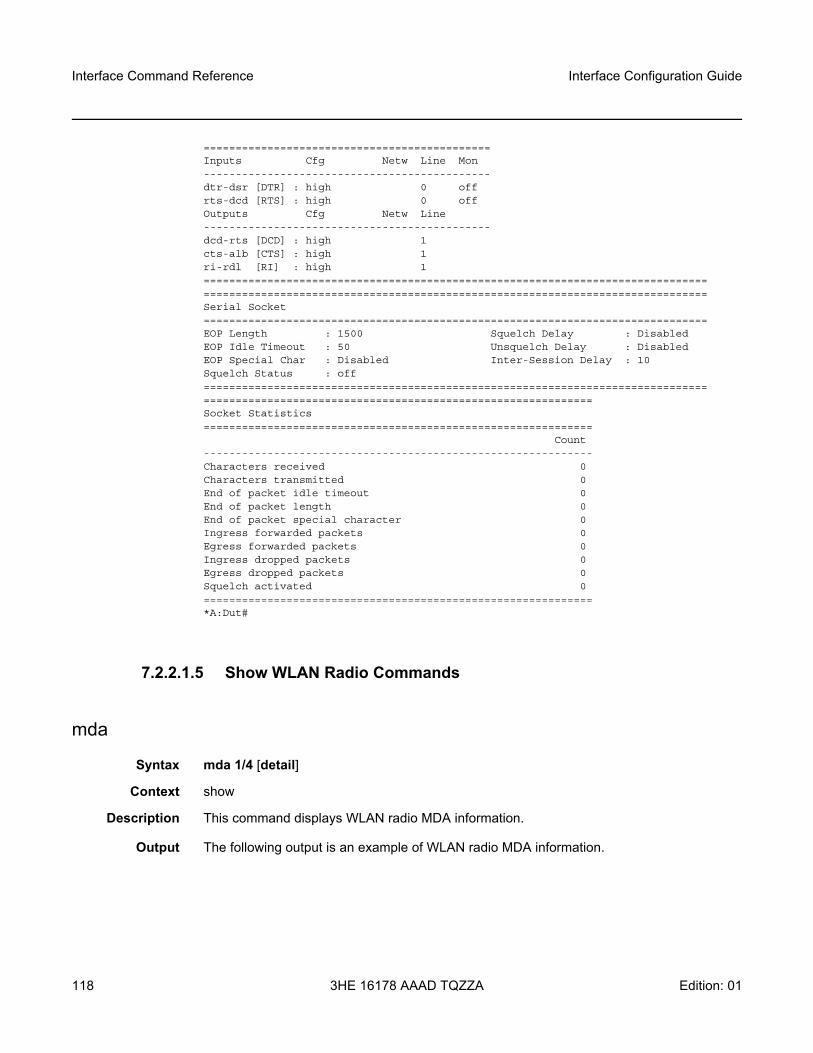
Interface Command Reference
118
Interface Configuration Guide
3HE 16178 AAAD TQZZA Edition: 01
=============================================Inputs Cfg Netw Line Mon---------------------------------------------dtr-dsr [DTR] : high 0 offrts-dcd [RTS] : high 0 offOutputs Cfg Netw Line---------------------------------------------dcd-rts [DCD] : high 1cts-alb [CTS] : high 1ri-rdl [RI] : high 1==============================================================================================================================================================Serial Socket===============================================================================EOP Length : 1500 Squelch Delay : DisabledEOP Idle Timeout : 50 Unsquelch Delay : DisabledEOP Special Char : Disabled Inter-Session Delay : 10Squelch Status : off============================================================================================================================================Socket Statistics=============================================================
Count-------------------------------------------------------------Characters received 0Characters transmitted 0End of packet idle timeout 0End of packet length 0End of packet special character 0Ingress forwarded packets 0Egress forwarded packets 0Ingress dropped packets 0Egress dropped packets 0Squelch activated 0=============================================================*A:Dut#
7.2.2.1.5 Show WLAN Radio Commands
mda
Syntax mda 1/4 [detail]
Context show
Description This command displays WLAN radio MDA information.
Output The following output is an example of WLAN radio MDA information.
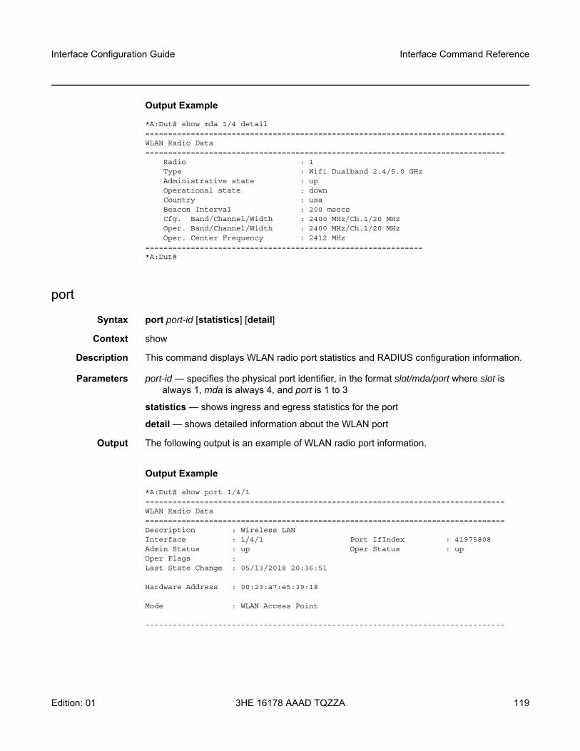
Interface Configuration Guide Interface Command Reference
Edition: 01 3HE 16178 AAAD TQZZA 119
Output Example
*A:Dut# show mda 1/4 detail===============================================================================WLAN Radio Data===============================================================================
Radio : 1Type : Wifi Dualband 2.4/5.0 GHzAdministrative state : upOperational state : downCountry : usaBeacon Interval : 200 msecsCfg. Band/Channel/Width : 2400 MHz/Ch.1/20 MHzOper. Band/Channel/Width : 2400 MHz/Ch.1/20 MHzOper. Center Frequency : 2412 MHz
=============================================================*A:Dut#
port
Syntax port port-id [statistics] [detail]
Context show
Description This command displays WLAN radio port statistics and RADIUS configuration information.
Parameters port-id — specifies the physical port identifier, in the format slot/mda/port where slot is always 1, mda is always 4, and port is 1 to 3
statistics — shows ingress and egress statistics for the port
detail — shows detailed information about the WLAN port
Output The following output is an example of WLAN radio port information.
Output Example
*A:Dut# show port 1/4/1===============================================================================WLAN Radio Data===============================================================================Description : Wireless LANInterface : 1/4/1 Port IfIndex : 41975808Admin Status : up Oper Status : upOper Flags :Last State Change : 05/13/2018 20:36:51
Hardware Address : 00:23:a7:e5:39:18
Mode : WLAN Access Point
-------------------------------------------------------------------------------
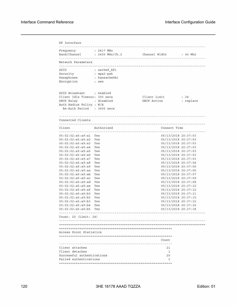
Interface Command Reference
120
Interface Configuration Guide
3HE 16178 AAAD TQZZA Edition: 01
RF Interface-------------------------------------------------------------------------------Frequency : 2417 MHzBand/Channel : 2400 MHz/Ch.2 Channel Width : 40 Mhz-------------------------------------------------------------------------------Network Parameters-------------------------------------------------------------------------------SSID : sarhm9_AP1Security : wpa2-pskPassphrase : kansarhm9A1Encryption : aes
SSID Broadcast : enabledClient Idle Timeout: 300 secs Client Limit : 24DHCP Relay : disabled DHCP Action : replaceAuth Radius Policy : N/A
Re-Auth Period : 3600 secs
-------------------------------------------------------------------------------Connected Clients-------------------------------------------------------------------------------Client Authorized Connect Time-------------------------------------------------------------------------------00:02:02:a5:a9:a1 Yes 05/13/2018 20:37:0300:02:02:a5:a9:a2 Yes 05/13/2018 20:37:0300:02:02:a5:a9:a3 Yes 05/13/2018 20:37:0300:02:02:a5:a9:a4 Yes 05/13/2018 20:37:0300:02:02:a5:a9:a5 Yes 05/13/2018 20:37:0300:02:02:a5:a9:a6 Yes 05/13/2018 20:37:0300:02:02:a5:a9:a7 Yes 05/13/2018 20:37:0300:02:02:a5:a9:a8 Yes 05/13/2018 20:37:0400:02:02:a5:a9:a9 Yes 05/13/2018 20:37:0600:02:02:a5:a9:aa Yes 05/13/2018 20:37:0500:02:02:a5:a9:ab Yes 05/13/2018 20:37:0700:02:02:a5:a9:ac Yes 05/13/2018 20:37:0900:02:02:a5:a9:ad Yes 05/13/2018 20:37:0800:02:02:a5:a9:ae Yes 05/13/2018 20:37:1000:02:02:a5:a9:af Yes 05/13/2018 20:37:1200:02:02:a5:a9:b0 Yes 05/13/2018 20:37:1100:02:02:a5:a9:b2 Yes 05/13/2018 20:37:1500:02:02:a5:a9:b3 Yes 05/13/2018 20:37:1500:02:02:a5:a9:b4 Yes 05/13/2018 20:37:1600:02:02:a5:a9:b5 Yes 05/13/2018 20:37:18-------------------------------------------------------------------------------Count: 20 (Limit: 24)-------------------------------------------------------------------------------============================================================================================================================================Access Point Statistics=============================================================
Count-------------------------------------------------------------Client attaches 21Client detaches 1Successful authentications 20Failed authentications 1=============================================================
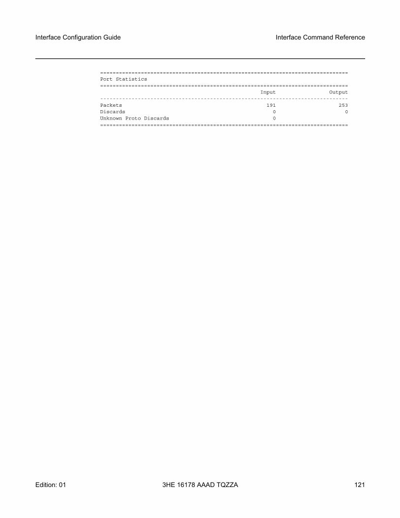
Interface Configuration Guide Interface Command Reference
Edition: 01 3HE 16178 AAAD TQZZA 121
===============================================================================Port Statistics===============================================================================
Input Output-------------------------------------------------------------------------------Packets 191 253Discards 0 0Unknown Proto Discards 0===============================================================================
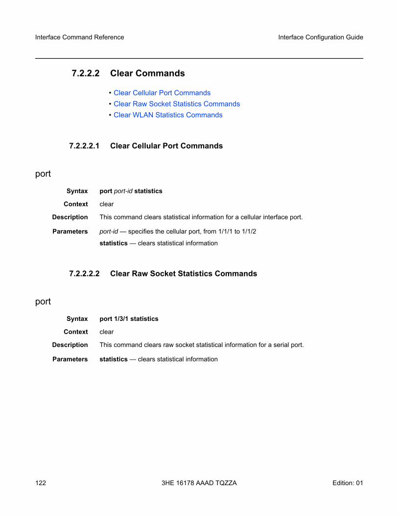
Interface Command Reference
122
Interface Configuration Guide
3HE 16178 AAAD TQZZA Edition: 01
7.2.2.2 Clear Commands
• Clear Cellular Port Commands• Clear Raw Socket Statistics Commands• Clear WLAN Statistics Commands
7.2.2.2.1 Clear Cellular Port Commands
port
Syntax port port-id statistics
Context clear
Description This command clears statistical information for a cellular interface port.
Parameters port-id — specifies the cellular port, from 1/1/1 to 1/1/2
statistics — clears statistical information
7.2.2.2.2 Clear Raw Socket Statistics Commands
port
Syntax port 1/3/1 statistics
Context clear
Description This command clears raw socket statistical information for a serial port.
Parameters statistics — clears statistical information
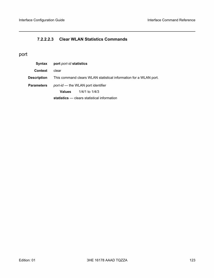
Interface Configuration Guide Interface Command Reference
Edition: 01 3HE 16178 AAAD TQZZA 123
7.2.2.2.3 Clear WLAN Statistics Commands
port
Syntax port port-id statistics
Context clear
Description This command clears WLAN statistical information for a WLAN port.
Parameters port-id — the WLAN port identifier
Values 1/4/1 to 1/4/3
statistics — clears statistical information
Interface Command Reference
124
Interface Configuration Guide
3HE 16178 AAAD TQZZA Edition: 01
7.2.2.3 Tools Commands
• Tools ADP Commands• Tools Perform Commands
7.2.2.3.1 Tools ADP Commands
auto-discovery
Syntax auto-discovery {complete | retry | terminate}
Context tools
Description This command is used to configure the status of the ADP-Hm process running on the node.
Parameters complete — specifies that the ADP-Hm process is complete
retry — specifies that the ADP-Hm process is being retried
terminate — specifies that the ADP-Hm process has been terminated
7.2.2.3.2 Tools Perform Commands
at-command
Syntax at-command at-command
Context tools>perform>mda>cellular
Description This command executes an ATtention (AT) command on the cellular port. AT commands are instruction commands that are used to control a modem. The commands are issued to the modem, and responses to the commands from the modem are displayed directly on the CLI console.
These commands can also be used to view operational information about the cellular port.
Warning: Risk of service outage. Do not change any at-command settings.
Interface Configuration Guide Interface Command Reference
Edition: 01 3HE 16178 AAAD TQZZA 125
Parameters at-command — a supported AT command
Values up to 256 characters; must be preceded by the string “at”
force-sim-switch
Syntax force-sim-switch
Context tools>perform>mda>cellular
Description This command manually forces a SIM activity switch. This command is used in a dual SIM deployment when the active-sim command is set to auto.
update-firmware
Syntax update-firmware firmware-fileupdate-firmware firmware-file sim 1 | 2
Context tools>perform>mda>cellular
Description This command preloads the correct firmware onto the cellular modem when specific firmware is needed to attach to a cellular network.
The 7705 SAR-Hm supports the update-firmware firmware-file sim 1 | 2 command. The command updates the firmware for the specified SIM. This form of command is supported only on the 7705 SAR-Hm, and specifying either sim 1 or sim 2 is mandatory. The firmware is updated only after the system reboots. When the command is executed, a prompt appears asking the operator whether to proceed with a reboot in order to update the firmware. Entering y at the prompt reboots the system immediately and the firmware is updated. Entering n at the prompt postpones the reboot and the firmware is updated the next time the system is rebooted.
For the 7705 SAR-Hm, in a dual SIM deployment, to update the firmware on both SIMs at the same time, the operator must execute the update-firmware command for the first SIM and enter n at the reboot prompt. The operator must then execute the update-firmware command for the second SIM and enter y at the reboot prompt in order to proceed with a system reboot. The firmware for both SIMs is updated when the reboot is complete. If the operator enters n at the second reboot prompt, the reboot is postponed and the firmware for both SIMs is updated the next time the system is rebooted.
The command can be executed on the SIMs in either order, SIM 1 first or SIM 2 first.
Note: .• The commands are reserved for use by Nokia personnel only.• Some commands may take up to several minutes to complete.
Interface Command Reference
126
Interface Configuration Guide
3HE 16178 AAAD TQZZA Edition: 01
The firmware for both SIMs can be updated individually, but this requires the system to be rebooted twice.
If the update-firmware command is executed multiple times for the same SIM but with different firmware files and no reboot occurs at the time the command is executed, when a system reboot does occur, the firmware is updated with the last firmware file specified in the command.
The 7705 SAR-Hmc supports the update-firmware firmware-file command.
The firmware that is bundled with SR OS is considered the default firmware for the radio module on the 7705 SAR-Hmc. If the update-firmware command is not used, the radio module uses the default firmware and system upgrades to a newer version of SR OS will automatically use the firmware version that is bundled in SR OS. If the update-firmware command is used, the radio module uses the version of firmware specified in the command and when the system upgrades to a newer version of SR OS, the radio module continues using the version of firmware specified in the command and ignores the bundled version of firmware in SR OS.
The update-firmware command is used to specify the version of firmware that will be used by the radio module on both SIMs (the firmware cannot be updated per SIM). The command overwrites the firmware currently used by the radio module, which can be the default firmware automatically loaded by SR OS or another specified version of firmware. When the system is rebooted, this updated firmware is used by the radio module.
To return to the default firmware, the operator must execute the update-firmware command using “default” as the specified firmware file. Using “default” informs the system that the current version of firmware must be discarded and replaced with the firmware version that is bundled with SR OS.
When this command is executed, a prompt appears asking the operator whether to proceed with a reboot in order to update the firmware. Entering y at the prompt reboots the system immediately and the firmware is updated. Entering n at the prompt postpones the reboot and the firmware is updated the next time the system is rebooted.
Parameters firmware-file — specifies a cellular radio firmware file located on the cf3: file system. If “default” is specified, the firmware is updated to use the bundled version of firmware in SR OS.
change-pin
Syntax change-pin
Context tools>perform>mda>cellular>sim
Description This command launches an interactive CLI session to change the PIN on the SIM.
Interface Configuration Guide Interface Command Reference
Edition: 01 3HE 16178 AAAD TQZZA 127
When a SIM is procured from a carrier, the SIM PIN is set to a default value. When this command is issued, the CLI prompts the user to enter the current PIN once and then correctly enter the new PIN twice in order to change it.
lock-sim
Syntax lock-sim
Context tools>perform>mda>cellular>sim
Description This command enables the PIN verification function on the SIM and locks the SIM. When locked, the SIM can only be accessed if the operator enters the PIN stored in the configuration file.
When this command is issued, the CLI prompts the user to enter the current PIN in order to lock the SIM.
Note: • Ensure that the specified SIM is the currently active SIM. • It is not possible to change the PIN on a SIM unless the SIM is locked. See the lock-
sim command.
Warning: • When an operator successfully locks a SIM, unblocks a SIM, or changes a SIM PIN,
the system updates the PIN value in the system configuration. However, the system does not automatically save the system configuration containing the new PIN. The operator must perform an admin>save command immediately after changing the PIN in order to save the new PIN in the system configuration file and avoid potential service interruptions such as the node becoming unreachable.
• If the SIM becomes blocked when setting the PIN remotely using in-band management over a cellular port, the node will be unreachable. Physical access to the node will be required to unblock the SIM.
Note: Ensure that the specified SIM is the currently active SIM.
Interface Command Reference
128
Interface Configuration Guide
3HE 16178 AAAD TQZZA Edition: 01
unblock-sim
Syntax unblock-sim
Context tools>perform>mda>cellular>sim
Description This command unblocks a SIM that is currently blocked as a result of too many attempts being made to access the SIM using an incorrect PIN.
When this command is issued, the CLI prompts the user to enter the personal unblocking key (PUK) for the SIM and then enter a new PIN value twice. The PUK is acquired from the service provider or administrator and is also stored on the SIM. The lock/unlock state of the SIM does not change when it becomes unblocked.
Warning: • When an operator successfully locks a SIM, unblocks a SIM, or changes a SIM PIN,
the system updates the PIN value in the system configuration. However, the system does not automatically save the system configuration containing the new PIN. The operator must perform an admin>save command immediately after changing the PIN in order to save the new PIN in the system configuration file and avoid potential service interruptions such as the node becoming unreachable.
• If the SIM becomes blocked when setting the PIN remotely using in-band management over a cellular port, the node will be unreachable. Physical access to the node will be required to unblock the SIM.
Note: Ensure that the specified SIM is the currently active SIM.
Warning: • When an operator successfully locks a SIM, unblocks a SIM, or changes a SIM PIN,
the system updates the PIN value in the system configuration. However, the system does not automatically save the system configuration containing the new PIN. The operator must perform an admin>save command immediately after changing the PIN in order to save the new PIN in the system configuration file and avoid potential service interruptions such as the node becoming unreachable.
• If the SIM becomes blocked when setting the PIN remotely using in-band management over a cellular port, the node will be unreachable. Physical access to the node will be required to unblock the SIM.
Interface Configuration Guide Interface Command Reference
Edition: 01 3HE 16178 AAAD TQZZA 129
unlock-sim
Syntax unlock-sim
Context tools>perform>mda>cellular>sim
Description This command disables the PIN verification function on the SIM and unlocks the SIM. When unlocked, the PIN is not required in order to access the SIM.
When this command is issued, the CLI prompts the user to enter the current PIN in order to unlock the SIM.
Note: Ensure that the specified SIM is the currently active SIM.

Interface Command Reference
130
Interface Configuration Guide
3HE 16178 AAAD TQZZA Edition: 01
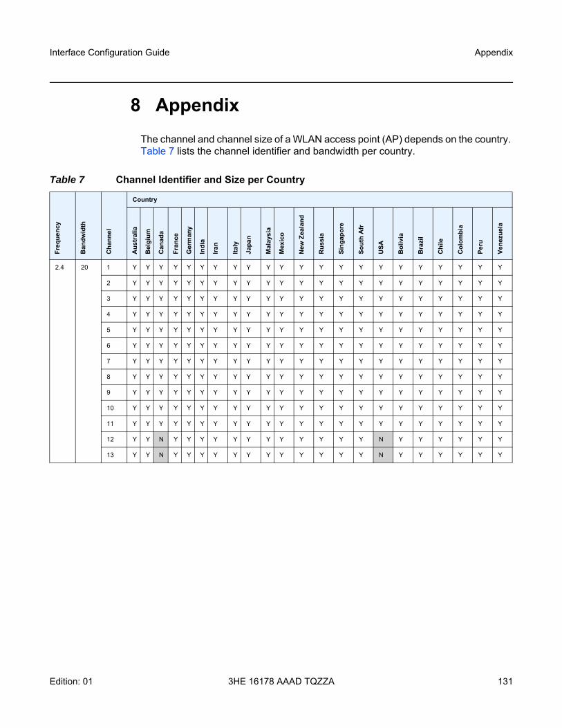
Interface Configuration Guide Appendix
Edition: 01 3HE 16178 AAAD TQZZA 131
8 AppendixThe channel and channel size of a WLAN access point (AP) depends on the country. Table 7 lists the channel identifier and bandwidth per country.
Table 7 Channel Identifier and Size per Country
Freq
uenc
y
Ban
dwid
th
Cha
nnel
Country
Aus
tral
ia
Bel
gium
Can
ada
Fran
ce
Ger
man
y
Indi
a
Iran
Italy
Japa
n
Mal
aysi
a
Mex
ico
New
Zea
land
Rus
sia
Sing
apor
e
Sout
h A
fr
USA
Bol
ivia
Bra
zil
Chi
le
Col
ombi
a
Peru
Vene
zuel
a
2.4 20 1 Y Y Y Y Y Y Y Y Y Y Y Y Y Y Y Y Y Y Y Y Y Y
2 Y Y Y Y Y Y Y Y Y Y Y Y Y Y Y Y Y Y Y Y Y Y
3 Y Y Y Y Y Y Y Y Y Y Y Y Y Y Y Y Y Y Y Y Y Y
4 Y Y Y Y Y Y Y Y Y Y Y Y Y Y Y Y Y Y Y Y Y Y
5 Y Y Y Y Y Y Y Y Y Y Y Y Y Y Y Y Y Y Y Y Y Y
6 Y Y Y Y Y Y Y Y Y Y Y Y Y Y Y Y Y Y Y Y Y Y
7 Y Y Y Y Y Y Y Y Y Y Y Y Y Y Y Y Y Y Y Y Y Y
8 Y Y Y Y Y Y Y Y Y Y Y Y Y Y Y Y Y Y Y Y Y Y
9 Y Y Y Y Y Y Y Y Y Y Y Y Y Y Y Y Y Y Y Y Y Y
10 Y Y Y Y Y Y Y Y Y Y Y Y Y Y Y Y Y Y Y Y Y Y
11 Y Y Y Y Y Y Y Y Y Y Y Y Y Y Y Y Y Y Y Y Y Y
12 Y Y N Y Y Y Y Y Y Y Y Y Y Y Y N Y Y Y Y Y Y
13 Y Y N Y Y Y Y Y Y Y Y Y Y Y Y N Y Y Y Y Y Y
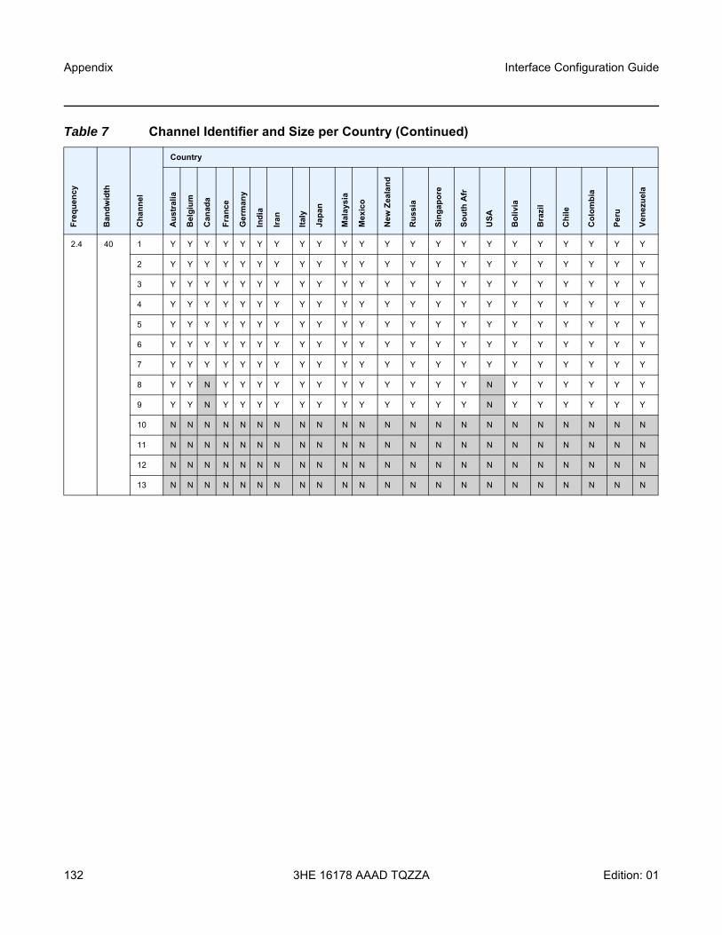
Appendix
132
Interface Configuration Guide
3HE 16178 AAAD TQZZA Edition: 01
2.4 40 1 Y Y Y Y Y Y Y Y Y Y Y Y Y Y Y Y Y Y Y Y Y Y
2 Y Y Y Y Y Y Y Y Y Y Y Y Y Y Y Y Y Y Y Y Y Y
3 Y Y Y Y Y Y Y Y Y Y Y Y Y Y Y Y Y Y Y Y Y Y
4 Y Y Y Y Y Y Y Y Y Y Y Y Y Y Y Y Y Y Y Y Y Y
5 Y Y Y Y Y Y Y Y Y Y Y Y Y Y Y Y Y Y Y Y Y Y
6 Y Y Y Y Y Y Y Y Y Y Y Y Y Y Y Y Y Y Y Y Y Y
7 Y Y Y Y Y Y Y Y Y Y Y Y Y Y Y Y Y Y Y Y Y Y
8 Y Y N Y Y Y Y Y Y Y Y Y Y Y Y N Y Y Y Y Y Y
9 Y Y N Y Y Y Y Y Y Y Y Y Y Y Y N Y Y Y Y Y Y
10 N N N N N N N N N N N N N N N N N N N N N N
11 N N N N N N N N N N N N N N N N N N N N N N
12 N N N N N N N N N N N N N N N N N N N N N N
13 N N N N N N N N N N N N N N N N N N N N N N
Table 7 Channel Identifier and Size per Country (Continued)
Freq
uenc
y
Ban
dwid
th
Cha
nnel
Country
Aus
tral
ia
Bel
gium
Can
ada
Fran
ce
Ger
man
y
Indi
a
Iran
Italy
Japa
n
Mal
aysi
a
Mex
ico
New
Zea
land
Rus
sia
Sing
apor
e
Sout
h A
fr
USA
Bol
ivia
Bra
zil
Chi
le
Col
ombi
a
Peru
Vene
zuel
a
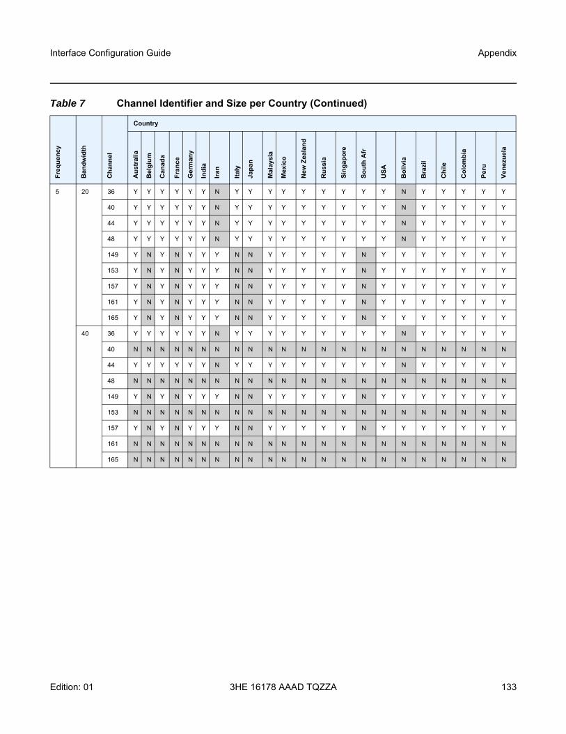
Interface Configuration Guide Appendix
Edition: 01 3HE 16178 AAAD TQZZA 133
5 20 36 Y Y Y Y Y Y N Y Y Y Y Y Y Y Y Y N Y Y Y Y Y
40 Y Y Y Y Y Y N Y Y Y Y Y Y Y Y Y N Y Y Y Y Y
44 Y Y Y Y Y Y N Y Y Y Y Y Y Y Y Y N Y Y Y Y Y
48 Y Y Y Y Y Y N Y Y Y Y Y Y Y Y Y N Y Y Y Y Y
149 Y N Y N Y Y Y N N Y Y Y Y Y N Y Y Y Y Y Y Y
153 Y N Y N Y Y Y N N Y Y Y Y Y N Y Y Y Y Y Y Y
157 Y N Y N Y Y Y N N Y Y Y Y Y N Y Y Y Y Y Y Y
161 Y N Y N Y Y Y N N Y Y Y Y Y N Y Y Y Y Y Y Y
165 Y N Y N Y Y Y N N Y Y Y Y Y N Y Y Y Y Y Y Y
40 36 Y Y Y Y Y Y N Y Y Y Y Y Y Y Y Y N Y Y Y Y Y
40 N N N N N N N N N N N N N N N N N N N N N N
44 Y Y Y Y Y Y N Y Y Y Y Y Y Y Y Y N Y Y Y Y Y
48 N N N N N N N N N N N N N N N N N N N N N N
149 Y N Y N Y Y Y N N Y Y Y Y Y N Y Y Y Y Y Y Y
153 N N N N N N N N N N N N N N N N N N N N N N
157 Y N Y N Y Y Y N N Y Y Y Y Y N Y Y Y Y Y Y Y
161 N N N N N N N N N N N N N N N N N N N N N N
165 N N N N N N N N N N N N N N N N N N N N N N
Table 7 Channel Identifier and Size per Country (Continued)
Freq
uenc
y
Ban
dwid
th
Cha
nnel
Country
Aus
tral
ia
Bel
gium
Can
ada
Fran
ce
Ger
man
y
Indi
a
Iran
Italy
Japa
n
Mal
aysi
a
Mex
ico
New
Zea
land
Rus
sia
Sing
apor
e
Sout
h A
fr
USA
Bol
ivia
Bra
zil
Chi
le
Col
ombi
a
Peru
Vene
zuel
a

Appendix
134
Interface Configuration Guide
3HE 16178 AAAD TQZZA Edition: 01

Interface Configuration Guide Standards and Protocol Support
Edition: 01 3HE 16178 AAAD TQZZA 135
9 Standards and Protocol SupportRefer to the software guides from the SR documentation suite for a list of standards and protocols supported by the SR OS. Use the features and descriptions outlined in this documentation set and in the relevant software release notes to identify the related standards and protocols that are supported by the 7705 SAR-Hm series.

Standards and Protocol Support
136
Interface Configuration Guide
3HE 16178 AAAD TQZZA Edition: 01
Customer Document and Product Support
Customer DocumentationCustomer Documentation Welcome Page
Technical SupportProduct Support Portal
Documentation FeedbackCustomer Documentation Feedback

© 2020 Nokia.3HE 16178 AAAD TQZZA
Copyright © 2022 FDOKUMEN


![Colombia - Loan 2611 - P006794 - Staff Appraisal Report [SAR]](https://static.fdokumen.com/doc/165x107/6328219a6d480576770d9dea/colombia-loan-2611-p006794-staff-appraisal-report-sar.jpg)