
AREVA Realistic Thermal-Mechanical Fuel Rod Methodology ...
165
A .AREVA Realistic Thermal-Mechanical Fuel Rod Methodology for Boiling Water Reactors Supplement 1: Qualification of RODEX4 for Recrystallized Zircaloy-2 Cladding April 2017 AREVA Inc. © 2017 AREVA Inc. BAW-10247PA Revision 0 Supplement 1NP-A Revision 0
-
Upload
khangminh22 -
Category
Documents
-
view
6 -
download
0
Transcript of AREVA Realistic Thermal-Mechanical Fuel Rod Methodology ...

A .AREVA
Realistic Thermal-Mechanical Fuel Rod Methodology for Boiling Water Reactors Supplement 1: Qualification of RODEX4 for Recrystallized Zircaloy-2 Cladding
April 2017
AREVA Inc.
© 2017 AREVA Inc.
BAW-10247PA Revision 0 Supplement 1 NP-A Revision 0

Copyright© 2017
AREVA Inc. All Rights Reserved
L
BAW-10247PA Revision 0 Supplement 1 NP-A Revision 0

UNITED STATES NUCl,..EAR REGULATORY COMMISSION
WASHINGTON, D.C. 20555-0001
fvJr. Gary Peters, Director .Lk:ensing and RegulatQcy Affairs ARE.VA ln.G: 3315 Old Forest Rqc:td .. Lynchburg, VA 245-01
May 17, 2017
NRC-IC-:-17-018 T4.12.l
Rec'd 5/23/17 HHE
SUB;JECT: PINAL SAFETY EVALUATION FOR AREVA INC, TOPICAL ~EPORT BAW~10241PA, REVISION O, SlJPPl,.EMENT 1P1 REVISION0, 11REA~ISTIC THERMAL-MECHANICAL FUEL ROD METHODOLOGY FOFfBQfLING WATER REACTORS SUPPLEMENT 1: QUALIFICATION OF R0DEX4 F:dR . RECRYSTALLIZED ZIRCALOY.;2 Cl:APOING'' (C.AC NO; MF5421)
D~Clr Mr. Peter~:
ByJetter a~t~d December 22, 2009 (Agencyw!de Oocuments Acces.S and Mariagem1~rtt ~yst~m (APAMS) A~ces~lqn Nq, ML09$580237), AREVA NP Inc. {AR!;VA) submitted TopJc;al R<?port (TR) sAw..:102:ii?PA, Revision o, Supplement ·1P, Revision o, ''RealisticThermal--Mechanical Fuel Rod Methodology for Boiiipg Water Reactors supplement t: Q.ualiflcatioh of Rodex4 for Recrystallized Zirc~doy..,~ Claqdirig, 11 :to the lJS·, Nuclear F{egul?tory C<;>nimission (NRC) $t'3ff for review and approval. ·sy letter' dafed February 8, 2017 (ADAMS Accession No, ML 16351A486)1
~n NRE :qraft s~fety "evalu.ation (SE) regarding our approval of TR 6AW-10247PA, Revision o, 'Suppleml7nt 1 P, Re~ision o, was ·provide(! foryour review anq comment. 13y letter'datect March t3, ?017 (ADAMS Acc;~s~ion No. ML 17015A32!))), AREVA provided comrnellts on .the draft SE. the NRG staff1s disposltiQn of the AREVA comments oh the c!raftSE "are discusse~ in th~ attE!chment (ADAMS Accesi;ion No. ML 17096A!522) to the final SE enclosedwilh this ·Jeft¢r.
The NRC. staff has found that TR BAW-10247PA, Revision o, Si,ipplemecit 1 R, .Revision o .. i$ acc~ptat:>le forrreferencing in ·llc~nsilig ~ppllcatkms fornJ,icl~ar power.J:>Jants to :th~extetnt · sgeclfi~<fand under the limitations <;leliileate¢1 inJhe TR andJo ~Jie·enclosed final SE. The final sg d$finesJhe1 ·ba$is fOr our acceptance of the TR.
0 .. ur .acce.ptance applies pnly to material:provide~ in thE! S,LIPjE!ct tR We dq nptint~nq to .r$pept our review of the acceptable material ·described in ·the TR.. ·Whentbe . .TR appears.:as a reference in ·ucensiJ1g action reque~ts, our re'iiew will ensure that th~ material presented applies to the ~pecifio plant ihvolved, Requests.for licensing .actions that deviate from this TR will be.
·.subject to·~ plant..,i:;p$clfiG review In ac;cor:dance· with appllcabl~ review standards.

G. Petet$
In ·accordance with the guicianc~ pr.(jvided on the NRG wel;>$it~, We rf;lqi,Jest that AREVA publish approved proprietary and non.,proprietary v$rsions of TR BAW-10247PA, Revision O, · Supplement 1 P, Revision 0, within 3 months of receipt of thh~ letter. The ~pproved versions shall incorporate this letter and the enclbsed fin.al SE. after.the title page. Also, 'they must contain historicc:il review information, lncluqing NRC requests for additional information and your respoqses; TheapproVed ver$16ns shall incJud~ an "-A" (gesigriating approved) following tn~ TR identification symbol. · · · ·
As an alternative to including the request for.ad.ditional in:formatkm (RAls) .and RAI responses behind the title page, ·ir changes to the TR .were provided to the NRG staff'to support the resql!iltiqn of RAI responses, and if the NRC staff reviewed :and ~pproveg those changes~s tlescrlbed in the ~Al r~sp6n$es, .there are :two ways that the accepted versJon c~n capture the RAls: ·
1, The RAls and RAI response$ can be included as an .App~ndiX: tp the aqcepted version. 2. The RAls and RAI respons~s can be captured .in the form of a fable (lm>erted after the final ·SE) wnich summarizes the ohanges as shown in the approved ver$ion ·of tfle TR The ta.ble shpLild. reference the sp!3cific RAls and 'RAI responses which resulted ln any·changes, as shown in the accepted version of the TR. ·
!f future phanges to the NRC's reguiatory requirements affect the acceptability of this TR, AREVAwiil be expected to revise.the TR apprcpri~tely ,or Justify its contiht,1ed appli·c~bility for subseq1,1ent refetemcing. Licensees referencing this TR would oe expected to justify its continued appllc:;ability .or ~vah,.1ate their plant usin·~ the revised TR. ·
Project No: 12a
Enc:;losure: Fin.al Safety Evalyation (Non-Proprietary)
·Sincerialy,
~ !U K "H .· h c· h" f. ~vin sue , . 1e
Licensing Process.es Branch Oivif;fon of Policy and Rulemaking GfficeprNuclear Reactqr Regulation

·1,:1 l'.J t:~ .'\} ~ ~ !<':.'.!<:~ ~l t ,'. __ Qt~~·\'.' ·'
FINALSAFETY EVALUATIONBYTHE OFFICE OF NUCLEAR REACTOR REGULATION
l"OPICAL RE~.ORT BAW-10247PA. REVISION O. SUPPLEMENT 1 P, REVISION 0,
'HEALISTICTHERMAL"'.MECHANICAL FUEL ROD METHODOLOGY FOR BOILING WATER
REACTORS SUPPLEMENT t: QUALIFICATION .QF RODEX4 FORHECRYSTALLIZED:
ZIRCALOY--2 CLADDING"
AREVA INC .
.(CAC NO. MF5421)
1.0 . INTRODUCTION AND BACKGROUND
By letter dated D13cernber 22, 2009, AREVA NP; Inc;., (AREVA) submitted for U.S. Nuclear Regulat()ry Commission (NHC) staff rev!ew Topical Report '(TR),. BAW-10247PA, Revision 0$ Sl)pplel11E;mt 1P, Revi$iOri o, 11He~listiqthermal".Mechanical Fuel R9d Methodology for Bolling Water Reactors .$upplement 1: Qualifipa:tion of RODEX4 for Recrystalliz~d Zircaloy"2 .ctatjcJing" in Reference 1. Supplemen~al information was received by the NRG staff in Reference 2. The NRC provided request fdr additional information (RAI) qu~stioris regarding thi$ TR in Reference 3. The responses to FiAt questions 2 through 12 were received by the NRC staff in Reference 4. The response to A.Al questfon 1 was submitted to the NRC in Reference ·s. The response to RAI question 13 and a correction to the response to AAI question 1 were rec~ived by the NRC in Reference 6.
By letter.dated Februa.ry 8, 2017 (AgencyWlde .Documents Access and Mana,gement System (ADAMS) Accession NQ. ML 16351 A486), fin NRG dr(lft safety evaluation (SE) .regarding our approv~I of TR BAW-10247PA, Revision O; Supplemet)t 1 P, Revision 01 was provided for your review and comment. By letter c:Jated March 13! 2017 (ADAMS Accession Nd. ML17075A325), AREVA provided comrttents·bn the draft SE The.NRG staft's·disposltion of the AREVA comments on thEl draft SE is dlscusseq in the attachment.
The sub.rttitteo TR .(Reference 1) i$ an extension to the NRC-approv~d TR BAW"' 10247PA., Revisior:i 0 (Reference 7)~
The TR only describes the qualification otthe RODEX4 computer cope for. licensing analyses using fUel rods wltn recrysta:liizetj (RX) Zircaloy--2 claqding &nd a r.iew hydrogen·pickup m'<Jdel to be applied to both cold-worked, stress-'relieved (CWSR), a:nd RX ZircaJoy-2 Cladding. The TR also covers:
• ThermaJ creep and recalibration for .RX Zircaloy-2 • lrr~dia~ion' creE}p and recaJibratiqntorRX ZirmiloY-'2 • lrradi9tion growth and tecalioration tor RX Zlrcaloy.;2
Enclo$ure

-2-
'• Model parameter uncertainty evaiuation tor RX Zirc9,loy,:2 thermal and JrradiC;ttion cresp mode.ls . · ·
• ·Calibration of the RX Zircak~Y"2 cla(:fdlng corrosion model and ·evaluation of its. associated h10del paramet1ar Uticertaii1ty
" Validation .bf theMecaJibration of the RX Zircal0y~2 rnechanical models by b'emchmarking the ·tree (vgid} Volume database· · · ·· ·.·
Paqific Northwest National Laboratory .(PNNL),.has acted.as· a consultantto tile NRC l$taff in thi~ review. As a: re·sult of the NRC stc;itt's and PNNl.'$ consultant revfow of the Tfl, the ·~L1pportirig theory :rn~nllal (Ref~r~nce 8)1. arid vaUdation report {Reference ·9), an RAl was cs~nt'by thel NRG to AREVA (Reference 3)~ AR_EVA pr<:?vided a respom:;e to the BAI que$tions (Rf:lfere·nc·es 4, 5; and t~): A·se.condrmm'd of RAI questions was sent to ARgvA (Reference 24) and AR~VA provid~d a response (Referenc~ .P). PNNL provided a teGhniCal evaluati'on report (R~ference 4S). . . .
This ~q.fety evafuaJion (SE) .~ddri:Js$es ~the following major areas bMhe .application qf th~ ROOEX4 c.ode io RX ZirGalOY"2 cla,ddin·g;
·" ·Material .property updates. tor RX Zircaloy·{~ (Section .3.1) •· Application of approved CWSR ·Zircaloy-2 properties to RX Zircaloy;2 (Section 3.2) • :F,l9d V<;>id v9lqfr,Je .as~esf;rtl,ellt: (S.ection 3;~1 · _ · · . · ,. The.impact: of usinS AX: cladding on approved licensing applicc1.ti6ns (Section ·3r4).
Modi;ils ft(>rn th.e· NRG ~udit code; FRAPCbN (Reference 10), have been used as an.aid i,n 'this review to a$ses$ the model& and cci.lculatkm result~ from R.ODEX4. This code ti as· recently b~en a$SElss.$d against a large volume of.lo\.Y ~md high burnup fl1el pertormanc~ cfa\ta (Re.ference H). ·
2.0 REGULATORY EVALUATION
The NRG$taffused the .guioance of Stanc;f:ard'Review,Plan (SJiP), NUAEG-0806, ·Section4;2· (Reference t6), j
1Fuel System ·Design'1 for the .review .of ,BAW-10247PA, Revision Q, -Supplement 1 P, Ri3vlslon o (References :1). SRP Sectien 4;2 acc:eptanc~ 'ctlteri?t $re pased ·cm meeting the req1:1ireriients ·of~errer~I Design Criteria (GOG) 1 o of Appendix A ofTitle 1 o of tlie Godif .of t=etJera!Regutatio,ns (to .CFF.l} Part ~o.
·GDC 10 $tates:
The ree1;otor :core a,nd as$oc,iiated c;>oolant, control, and prbtt;JctiQh system$. $hall be designed With the-a,ppropriatemargi,n tq assure that speciffect ~ccept~ble fuel .desi.gn limits are not exceeded .during any. cond[tipn of normal operation, Including the. effects cit aniicipi;ited :oper~tionat occurrences.
·GPC ·10 estab)ishes.s_pecified·a:ccept~ble fuel design limits (SAFC)i,;s) to en$l,lrethat the fuel is !•not dama~ed.n Th.at mean$ that fuel rods q~ not fail, fuel· ~ysti3m ·dimen~ions remain within opera.ti anal tolerancesi· ahd ftinc;tiohal capat>ilitle$. are riot -reduced below those assumeq in 'fhe sqf ety c.i.r.i~lysis. ·
·- ,3 -.
!n accotdarice w/th SAR Sectiqri 4.2, th.e objectives of tne-fuer ~ystem sl:!fety r€}vi¢w fJ.re to provide, ·~§surance th~t:
a. the· fuel $ysterri is not ·d~_rnageq as a result of nqrmal qperation and anticipated operatiorJal occµrrences (AbOs),
b. Fu$1 system <;:Jamage is never so severe as to prt;ivent contrql ro<;:J in$eriton Wheh it is r~quir~d. · ·
q. The number- of· fu~I rod failures is not .underestimated for postula,ted i:\Cbid,ent$, and
d .. Coolability is· always-maintained.
The NRC ~taft reviewed the iR to: (1) ens_ure that the· material properties and In-core beh~vioral chqracteristics of·fuel and cladding a$analyte_d using the supplement and $Upported by confirmatory <:;alcµlations using the FRAPCON audit code are cap~ble of aGcurately (or oohs$t\latli/ely) ehs\Jring the fuel system safety criteria, (2) lder\tify any !imitations on the behavioral characteristics bf the fuel, .and ($) ensure GotrmHance ot f ual design .criteria with li¢ensing l'equiremE;!lits of fuel de$igns and I~ c~pable ·<;>t ensuring Gonipliance with $RP Section ~4.2 :g1,1idance criteriEi · · ·
·3.0 -TECHNICAL EVALUATION
3.1 MATERIAL PRbPERTYUPDATES FOR RX GLADDING
The pu(pose of the TR ls to extend apj:ilicability of the apprpved RQDEX4 bdiling water reactor {B\IYR) rei'Jli$ti.c methodolqgy {Ref~fehce 7) t_o ~How analyses with RX. ;Zlrcal()y-2 cl~dd!ng. The BAW'-19247PA; Revisiqn 0, final SE restricts ·application to only CWSR Zircaloy-2 cladding (Condition c;), Thi~ restriction was imposed since the NAO.staff qetermlned that the experiment$! da,taset t<;>r irrtAdiation .growth.and cre~p of 'RX Zircaloy .. 2 ·cl<:\dd!i19 was insuffici1,311t .and more data wouli:I be needed in order to assure an adequ~te verification a.nd validatiorl. of -t_he m·e¢nafli9al .prop,erties ·of H~ Zircale)y~2 material~ In c»rder to .OV:.ercnme this res.tri~tion, AREVA has expanded the RX Zircaloy-2· database -based on 9perating experienc~ with th.e. RX Zircaioy:-2 cladding tYpft 'in Europe for many years. .- ·
The $xpanded RX ZJrc:aloy;.2,databMe Wa$ used to re¢alibrate several of the· cladding models, These models-are: · - ·
• Thermal· and irradiation creep • Free.:sfress irradia.tioh growth
•· Corrosion
The following $edtio11s wi.11 a.s$ess th~se· .rnodels ·~md the!Y"~s$oci~ted Lmcerta.,int!es rel?.tive t_o those rnodef~ for RX Z(rcaloy.:2:;n FRAPCON and relatiWHo the data proylded by AREVA.
'3~1.1- rherrnal and.Irradiation Creep
Th~ NRG staff qsked AREVA in RAl'-3 to pro\tid¢ more det~il~ r9.garding the type of measurements thatwi3re macje} that war~ .used' to validate the thermal and'irraciiation c;reep

models, AREVA proViped n~w:co:effici~nts for their. cla,dcling creep mode.I for-use with RX ZircaloY-2 cl~dding. RespondJrig to NRC staff'siAAl-q·, AREVA $tatE1d that the thermal cref:}p component "is partly based on me¢hanical tests," Which W~ie perforrneq in ~ hot cell on .samples taken from fuel rods pre•irradi~~ed in a commerdaJ reactor. Other model 1pq.ra.rneters of the.rnial ,creep derived from non-fueled tuties taken from as,.rnam.~factured alac:ldlhg, Irradiation cre~p niE}a,surements a.re obtained by profllometry mea.surements of fuel rods at poolsl~a.
AREVA provideq updated fitting parameters for the thermal ?tid irfC\djation creep model$, .which are the. same models ~s thoseapproved for CWSR, . .alihougli several par~meters ~re differeflt Certain parameters were not provided and some pµramet~rs were pr9Vided twice With ditteremt value ori e~ch ·instant~. The NRG staff asked AREVA to provide the parameters Hi!, Ha, ·and H4. The NRG staff also asked that AREVA clarify which values of Ha and H1 are used in RODEX4 (RAl-2).
.AR~VA re:sponded that the oreep co~fficiehts Hz, H~, anq H4 do not chan_ge (and thus were not provideq in thEi TR~, amlare ind$peiideht of metallurgical state, i,e., CWSfi orH)( (RAJ-2b). Ori the other h1;1,nd, H~ hcis be~n ¢hanged to [ ], and Hi: ([. ]) and H1 ([ . . .
]) were provided on Pa,ge 13· µs qpposed to intermedi.at~ valµes -on Page. 11 .of the TR. AREVA 15tates that th~. new fr!odel fits more modern data for HXA Zircalr:>y-2 whereas the old . :modl:il f1;;iq been used' to fit some·old~r Babcock & WilcqxCompany(B~W).fD(Adata. (RAl,:2c).
Th~ Hill's·paramet~rs R and P ·a,re ·diffEnentfor ·AXA cladd{ng than for CWSR, and AREVA provided updated Rand P parameters from those provided hi EM.F.;2994 (Reference B) antj EMF-3014 (Reterehce.9). The oldervc::\lues for Rand P Were determined based on AXA· .Zircaloy~4 cl~dding ,that was produqed by B&W. That clcidding is not represent~tiVe of AREVA AXA Zircaloy:.2 cladding. Furthermore, AREVA:has determined that Pis.a function of fas~ fluence .(Reference 12) and the function is de$cribed ·as decaying expcmential, which saturates :oy ~ fluence of 6 E21 n/cni2 {E greater thi:m (>.) 1 MeV). AREVA indicates that RX cla:dding pecqmes less anisotropic or more isotropic With irradiation, ·an observation which. is supported ih the literature (Reference 1:3). ·
With respect tq irradiation creep, AREVA clarified that parameters L2 and L4 do not change~ anp are .Provided in the. ROOEX4Theory M,anu~I. (EMF.;2994(P)). The vall:le L1 has ch·ang~d from [ ] (old) t9 [ ] .(rieW),. whi9h .provide$ be1ter agreement With measured irradiation creep (RAl-2q). ·
·The thermal Qreep rno.deJ pararnetendor dWSR and RX Zircaloy-"2, are compared in TCJ.ble 1, ·G\lld the irrat;iiatiQ.n. creep rriod·et parameters are comp~reo ;ih Table 2. 1he parameter P i.s Q.iveh by a deca:yin~ exppnential.
f- t\}1 1~Jt)~1 l ;,_""~~tJ~.w~~ r ··~~/\kt~~' ~
-5-
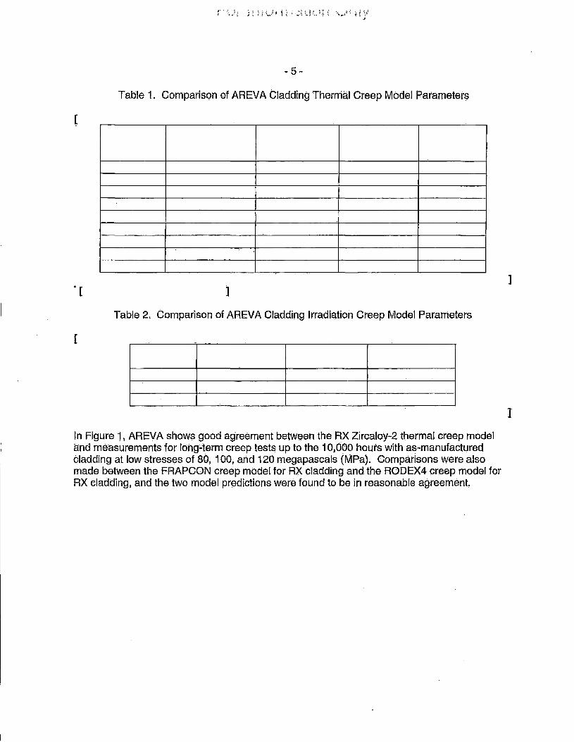
Table 1. Comparison of AREVA Cladding Thermal Creep Model Parameter$
[
]
Table 2. Comparison of AREVA Cladding Irradiation Creep Model Parameters
[
In Figure 1. AREVA shows good ag·reement between the RX Zircaloy-2 thermal creep model and measurements for long;.;term creep tests up to the 1 O,doo hours with as-manufactured cladding at low stresses of 80, 100, arid 120 megapascals (MPa). Comparisons were also made between the FRAPCON creep model for RX cladding and the RODEX4 creep model for RX cladding, and the two model predictions were found to be in reasonc:ible agreement.
]
l

~--------------------------------------------
[
Figure 1:
- 6 -
Comparison of pr~dicted to mea$ured cre~p hoop strains during long-term creep tests of as-manufactured RX Zicaloy-2 clac;lding .. (Taken from Reference I)
]
A.REVA provided plots of creep straJn for RX Zircaloy-2 similar to those provided for CWSR Zircaloy-2 in Section 7 of in RODEX4 Theory Manual (EMF-2994(P)) (RAl-2e). The plOts show that the creep rate of RX cladding is much greater than th.at of CWSR Zircaloy"72 .cif,ldding at high stresses. This is. corisist~nt with observations .reported by Limback and Anderson '(Reference 14).
The NRC staff requested that AREVA compare its updated RX Zircaloy-2 creep model to other known creep experiments in RAl-4. AREVA provided these comparisons that demonstrated that its moc;:Jel is in reasonable agreement wlth the measurements from these experiments.
AREVA used the same methodology as previously approved for RODEX4 to determine upper and lower bound uncertainties on the thermal ahd irradiation creep model parameters, L1 and i-h~ l,..1 is [ ] for the lower bound and [ ] for the upper bound. H1 is [ ] for the lower bound and [ ] for the upper bound. The NRC staff· asked AREVA to provide more justification forthese upper a.nd lower .bounds in RAl-5b. AREVA provided more discussion .on how this was don~ and ·provided plot to demonstrate that the upper and lower bound models provide a 95/95 upper and lower bound relative to those data.
The NRG staff finds the creep models and the l,lpper boun4 and lower bound uncertainties to be acceptable for modeling AXA Zircalby-2 cladding with HODEX4.

-7-
~-1 d.~ Free Stress Irradiation Growth
Th~ HOD'EX4 h~s :one q>.<ic:ll growth model that is a fuhc:tion qf cladding temp~ratur~ qnd fq~t floence with. giffereht sets of coeffi'cients. The.re are two sets of coe.fffclents approved for CWSR Zirtaloyo.z in BWR 9i<9 and 1 Oi<1 o fuel designs. This supplement pres.anted a ;third set for RX Zircaloy~2 clackJing;
The ro~ growth ti1qqels for RX ZircaJoy-2 cladding were compared El9cdnst the mod~! Jn FRAPCON for RX Zircaloy,.2. The FRAPCO.N model for RX :Zircaloy.:g cladding is pased on the I;PRI mod.el (Reference 1 SJ and i$. valii;lated U.P to a local burnup of 65 gigawatt days· per metric ton of ur~nium (GWQ/MTLJ). 'Th~ 0riginal cpmpaiison showec:f significant disag.reeriient between the FRAPGQN arid. ROOEX4 mpdE;Jls. The NRO i;;taij ~sk~d AREVA.ta verify that·Jti~ rnc;>qe! parameters provided are correct (:AAl•9a)·;
AREVA responoed With a new.growth model. for RXZircal0y.02 (RAl.,9). AREVA statas that they modified t.he s.tress,.free irrac:liatipn .growth mo(Jel anc:I aqdecj a model to reflEiGt the ,liner effect on the.axial pelleVcladding mechanical inJeraction (PCMI). The 'new model for R)CZircaloy".2 Is based on AXA channel material (BAW-10247Q3(P)}. PNNL compared the .resul~$ of the new model and the original mod~I to FRAPCON and thes.e are shown In Figure 2,
[
Figure 2: Fuel. rod axial 'growth in RODE:X4 arid FRAPCON tor BWR RX ZirG~loy-2.
The NRC staff noted ,that.is it difficult t.o as.se.ss the calculations of the RX Zirc~loy-2 model r~lativ~ to :the data pl'.ovided in Figur~ ~ of the TR, with. r13sp~qt to the s~parate.affects of

·-·a-·
stre$8-frE;le growth and· PCMI. AREVA provided a revh>ed figure showing ca:l<:l,llat~d ·an·c;t mef.',l.surnd .9rowth of RX olad:tu~I rOd$ (RAl;-9) •. whiqh s.hows gteat~t v~hies of growth :for . fluenc.es abi;>ve [ ], The NAO staff rE;Jqueisted that ARl;VA pr0,vide .a plot·of predicted minus tneasure·d axial strain as B,:function of fast flt,Jence. AREVA .responde-d With a plot :of P~M for growth (RAl-9q) sh9wn in Figur~ 3. Th$ pl9t shpws th.at the .tne>efJE31 tends :ttr under$$tiniate growth for tlu.e·nce ·b~loW [ ], anc:! QVerestlmro~ te.r flu~m~es ( · _ ]. The plot of P-M for ·growth is ~onsi$tent With the plot oft.he wcial growth data. in Fi9ur~ 4.
[
Fi~ure:a: Predictea.:Mea§ured .Axiai: Strain for AREVA BWR'fu~I a.s El function 6ffast flue nee.
l

•:9 ~
l
J
AREVA plot qt:foel.rod axial growth c;aJcuJated with R00EX4 and compareti to . ·me~~i,ii~d .graWth .d~ta. · · ·
Figure4;·
1he. NRC e;fa,i.ff ·Eisk~d AREVA ~tioµf th<!J tmp~pt ·pf spac~r ·spring: f!<>ad$J:tnd friction. on the g,rOWth of. fuel· rods, AREVA re$ponded :~hatth~ impactofgtid intera.9tlon Is minimal, and concluded· ·
·.that,. 1\th~ main effecton 'dlaCiding.:axial elongation i$i due fr-; th~· plenutn sfning and .not. to sp~c~rs'; .~RAHic>.~ · · · · ·· · · ·
The NRC $taff 9{;nc;;h:i9.es tf1~t th~ R'ODEX4 mod§! ·for RX Zirc:;J.loy-2 cl;.u:jding growth 'is .1;1ec;.ep.t~l:n~. · · · · ·
<ti ;3 eorr6si6t1 .
The unifo'rm q>{ida.tiOn. r~t$ ir.t HQPEXkfor a BWH'I~ ~ twp-s'tage .mope!!. that Is a fu'nctj©rt of both fin:l'e. (~xp,osure); ~· cprrosjon ~lihanC,emerit ·f~ctor (d~pen(is. on reactor .and chemistry) .~nd ternPer~lure.at the.r:n~tah9Xide: intei:face; and therefore~ ti.near heat.genaratkm ,ra,te ·(LHGR). It ;is rec·ognlze~ that ;both· nadulttr c6rrosi0,r1 and .diff1Jsion,.<;Qntr6lled uniform corrosk>n 'OGcur '1.; !BWR·cladding. Nodular-corrosion is tt$~tecl ~s ·?,herma;I; :~nt:f th~ cliff14siorH~ontroll.ed corroslbfl . i$.t~mperaturs~arh1en. RODEX4does, 1nof.'hav~ a nodular·~orr<>si.on :model. The .uniform. · :twi;i.-$t;;!.g~ corrosion moc:J~I inclu<;Je.$ ~ pr~~trar1$ltiqn mog€)1 1:1nd a pm~t ,t.rl!lllsi1ior'.] 111Qd§l With th~
1 tr~n~itioh:te,mp~tatur~ a'fUnpti611 .of the metaJ:.oxida intertace terriperatufe. AREVA 1$ta,ted thaJ . ~he·'RX. d~~t:tbase Oil cl~_dditig cotro.~{qhiis more .c;9hSc;Jl\it;ttiV~ tha,1t the cw~n=l dl)lti;t!:>ase J:?~Pal.,ls~ onlyrnaximum values:are·recotd~d for RX·~latlc)fing (ind.some·:af tl:le data come from pl€1rit$ that·
·exhibit nodular corrosion! ·

-, 10,.
In order to model the RX cladding, AREVA uses a [
] (Referenqe 1 }. The BWR.oxic:lation model in FRAPCGN~3, that is ba.sed on the. gpRl~ESCORE mod~!. C}tld in turn :is .based qn cqrrelati6ris of BWR data, was cmmpared to ;the oxidCltion model,s i.il. RODEX4 for CW SH and RX Zirc~Ioy .. 2. The results ·of this cornpari~on i:lre shown in Figure 5 for typical BWR 1bxt0 conditions ci.t~ constant p.ow~r of 7 kilowatt (kW) per ·foot It can b~ $~en in· this figure :that the RODEX4 RX Zi.rcaloy-2 model predicts abquJ the sarne.as FRAPCON .. Al$o shown in this figure are the 9519S upper bound predictions from AODEX4 (RX) and FRAPCON. !t cah be seen that the RODE)(4 upper pound is greater them the FRAPOON upper'boulid for high oxide predictions. This Will' lead to CJ,.similarternperature ·chan(Je across th¢ claddlt1g, and sim'ilar tempen;tture predictions r~lative to FRAPGON.
[
Figure5~ Oxide layer lhiGkness. predictions .in RbDEX4 GWSR and RX .Zircaloy;.2 and FRAPCON~~ for stand!:trd SWR tOx10 conditlqns with nocru~J buildup.
The NRG staff requested thcit AREVA provide. corrosioh data with the :corresponding temperature ~nd other r~levfl.nt oonditiqhs ip RAl;;1A AREVA pr9Videt19xid~ thickri~ss. m~a~yr~ment data and correspohding calcu.lated oxide thicknesses for [ I Juel :.rods. Fi9ure 6 plots the calculated values versus the r'neasureq values, and Figure 7 plots ClitlCulat~d rninu$ measured (O-M) versus the·mea,su,red val1,1e; There seems tq be~ slight bias towards underestimating the oxide thickness based cm the: uniform corrosioh model, and this. ts more
]

-11 -
apparent in Figure 7 in which the C·M decreases as the measured oxitje thickness incre.ases. AREVA has indicated that the measured valu~s will include sorne crud and nodular corrosion, so it is important to consider this. on a plant-specific basis.
[
CalculC\ted versus Measured o.xide Thickness
l

[
]
Figure 7: Calculated rriinus Measured OxideThickness versus Measured Oxide Th.ickness
AREVA also pres~nted LJPPer and lower bound values of the oxidation enhancement model p~rani~ter that can be used tq provki~ a 95/95 uppe,r or iower bound predictkms qt RX Zirc~IC>Y""2 ·corrosion. The NAO staff deterrnihecl tn~t the 1;1pper bound pc;i.rameter only bounded 'about [ ] of the datq. in t,he FtX corrosion dataset AREVA stated, 11Pl~.rit c;onditions create sotne variability in measurec;i liftoff dueto.diffetences In Water.·chemistry • .A1s·a; cruc;t deposition can lead to.app;;trent Cliffere.nces iri the AREVA littoff me.asureinertts because normal leveJs•of crud are noteasily sep~rable from the total liftoff~ Therefqre, the corrosion enhancement para/neter and ~$s.ociated "uncertainties :may ttee.d to b~ .µpdqted as more liftoff ·data are acquired for different plants or chal'.lg~d w~ter chemistry 'Conditions. AREVA wiH resubmit updated corrosJpn parameters in the event the values exhiblt.a,sigraificant general ch~nge (i.e., the !Jpper and rower bol,Jrids 'Chahge by more th$n one stancli;frd deviation): Otherwise; upda~ed corrosion parameters will be used as needed for plant-spec::ific applic::atiqn ih orderto provide the $atne or grei;iter level of¢onservatisrn in the methodology' (,Reference. 1);
The NHC staff accepts that sc>me of the v~riatlon ip liftoff Is likely. due to ~rud and nodular cprro,siqn,.
the NRG ~taff find~ the HOQEX4 :unltorm corrosion model ~nd tne upper .b:o.untl ·uncertainty to be. sati15factory for RX Zircaloy~2. AREVA should .a6counttor crud and nodular corro$ion on a plMt specific basis. ,

- ts -
3~2 .APPLICATION OF APPROVED OWSRMATERIAL PROPERTIES FOR.RX CLADDING - - '
3,g, 1 ben·sity
HODEX4 LJs.ewth!3 $ame de'nsity,cprrelatipl'J fqr cws·R arid RX _2iroaloy:.2. c;:la(:f(fiflg. This, is:ftie 9t;litie approach tl'.le,t is used in FAAPC()N, 'The NRC st$,ff does not expect.the <;JensiW oqhe Zircaloy,-2· to oh~in9i3 'b9.sed on the final heal treatrn~nt. - -
The NRG staff finds that the use of the approved CWSR Zircaloy-2 density corr~lation for RX Zircaloy72 is a.cceP.taple, -
3'.2.2 Thermal .Expansion
HbDI;X4 Lises the -se{me thermal exp~nsion for CWSR and HX Zircaloy-2 cladping. This is, the sam~ approach that is used in FRAPCON. The NRc· staff -doei:; not expect the thermal expansioh of the .Zrroaloy-2 to ohange based on the final ·heat trea;tment.
The NAO staff finds that the use of the approved CWSR Zirc~doy,.2 thermal expansion tcxr~l~tion for RX Zircalqy-2 is ~u;:ceptr;i.ole.
3,2.3 He~t Capacity
RQDEX4 uses the same heat c~padty correl~t_ibri ·tor CWS_R and RX Zircaloy-~ tladdilif:1. lhis is the same approi;ich that is used i(l FRAPCON,_ Th.e NRC staff d<;>(:}~ not ~xp~c;t ~he her;i.t Capp.city-of the Zircaloy,;2 to ohange· ba,sed on the final he~t treatment.
The· NRG ::;taff.findsthatthe u~e otthe approved CWSR Zircaloy-.2 heat capacity correlatioh for RX Zirqaloy .. ~ is acceptable, · - - --
3.2.4 Elastic Moduli
ARl;:VA uses the MATPRO equation for Young's Moduh,Js (E) and Shear Modulus (G}, _but does notinclude any term~ for fa~t flu~nq~ or OXYfJen concentration. the effect of fast tiµenqe· causes the· moduli to increase somewhat. The· NRG .staff previously determined that this correlation was acceptable for CWSR Zfrcaloy-2, and also finds that it is acceptable for RX Zii'¢aloy~2.
~.2.5 Thermal. Conductivity
RODEX4 .uses the same thermal conductivity correlation for 9WSR and RX .Zircaiqy.;2 ·cladding, This is)he same appmach that .i$ us~d.in FRAPCON. Th_e NRC staff do~~ not expect th~ -thermal conductivity of tile Zirca:loy.,2 to change. based on the .final .heat treatment.
The NRG staff find::> that :the· use Gf the approvt3d OWSR Zircaloy,;2 thermal conductiVity correlatlon tor RX ':Zircaloy~2.ls acceptable. - -

L
-14~
3.2.6 bxide Conductivity
RODEX4 qs~s. the same oxide themial conductivity <;mrref~tipn for cWSR ariq RX Zlrna:loy-2 cl~dding. This Is the same apprqach ~hat is UEied in FRAPCON. The NRC staff d9es ·hot expect th€} oxide thermal conductivity .of the Zir~aloy"'2 ,to change based pn th$Jini'.ll 'hei~t ·treatm~nt of the cla(:jding. · · ·
The NRG staff findf! .that the use 9f the ~pproVed eWSR ·Zircal9y-2 oxide the·rmf:ll qonductiv1ty c.orrelatio11 tor RX Zircalpy-2 is. accept~ble. ·
3.·2.7 Hydrogen Pickup
ROD.EX4 has previously used a constant hydrog$n pickup fr~ction :of[ ]for CWSA -and RX ~ircaloy-2 undE:r .BWR conditions; Recent data suggests that pickt,Jp frqction in BVVRs increases significantly with burnup ~nd c(ln exceed a 30 percent piqkup fraction at high burn ups (greater- than so GWd/MTU) (References Hi, 171 1~,.~nd 19). Ttw NRG staff notes.-that itis · knpWn thathyc;irogen cotiterit impagts tfle cladding ductility and. therefore, the threshold f9r failure c:furing· AOOs and cartain postµla:ted accidents, e.g., Aeactivity,.lnitiated Aggidents (RIA$). It was also noted th~t due to thef;e effects, in the future the NRC may impose •ii .JimH on · hydrogen uptake' to avoid brittle claddin·g failure :tor normal operation ctnd AOQs to maintain the 1 perc.ent tqtal (elastic.+ plastic) failure strain limit In addition, new limits on RIAs ant{ loss;pf:, cooli;int a,yyidehts (LOGA$) wi.11 require that.hydrogen effeots be accour1ted for on embriftlement criteria.
Duringlhe review of RODEX4 TR{Reference7),the NRC did not approve the use.of the hyqrogen pfokup modeL. AREVA su):>mitteo Supplement 1 without a9dressing flydrogen pickup,. therefore, the NRG staff a~ked AAEVA if a hydrogen pickup model wauld·be usec;l in AAl-1b.
ARE:VA re:::;pqnded with a n~w model thaf uses'a power dep$naent hytlrogen pick-up rate (RAl.:.1 b),• In the neW model, the hydrogen pickup fraction is determined to be a function of .[
]. AREVA ,presehts four fuel. r¢d evafuations c;9mp"ctrihg thE! calt;::ulated ·hydrogen ccmterit With measurea value$: .. This moqel is-.shown in Figure 8. . .
~ 15 -
[
l
Figure~: AREVA hydr.ogen pickl.IP model
AREVA has published examples 9f the new mo.del (References 12 and 20). Two case .studies . are provided; one with low.hydr¢gen content (149 parts per miilion (ppinH an.done.With high .hydrogen tontent (4~6 ppm). Both cases ~re taken from European BWR fuel operating for 6 annual cycles for 2018 and 2001 days of operation, respectiv~!y; .so they ~ncompass cin .equiv~lent operation ofthtee 24~month cycles in the US. AR~VA :P.rovjqes the IC:ict;tl Hnef.lr powe(forthe axial location from where the hydrogen m¢asurements were made. Th~ low . hydrogen location operaJed apove ~o kW per m~ter (kW/m) tor tour qycles, and moder~t$ iinear pow~r~ ln the range of 13 to 15.5 KW/m during ,the fifth and :sixth t:;ycles;. ·In contrast, the·higti' hydrogen case operated'for three cycles· With a local LHGR > 15 kW/m, butwith VfJry' lower pow(3r, P.PiDroxima:t~Iy 5 to 6 kW/m durinS last three cycles;
Jn the TR, AREVA prqvided additional evidence to support ,the power depend~nce ,of hydrogen pi¢kup in Zircalpy-2. In c:t9c:Jitionto the two previoualy published c.ases, AREVA;ptoyil;Jf!;id.tWo ad.ditidnal cases, :one:ot lowf1yarogen pickup, and on~ with high hydrogen pickup.
:Some :additional circunist~uitiai evidence s4gge~ting .a pqwE!r dependemce on ·hydrogen.pickup .is also fq1,111d 'in oth$r published Work (References·21 •. ;22, :ancf.23). A dramatic ihcreas.e in · hydrqgen :content is:observeo i'n 7 ahd 9 cycles :fat Asea Brown BoveffSWR with LK3 ·cladding. ·f:he foqal 1-HGRS: Wefe lh·the.range ot·s to.·9·kW/m for Cycle '7 and increased during cycles-a· (8"12 kW/rn) and 9 (8'-15 kW/m), depending on: axial location (R.eference.21), AdcUtional data are.r:teeded to cqnfir'ni a power qepend~ncy. Jf:ipane~e 9x~ 13WR fuel has b$en observed t~ have an ihcrea,s(;3 in hy<;irogen c6nt$r'Jt with liurnup, particUlarly dUJjhg the last cyClt?. '(References 22 ~nd 23). :Puring the first four cycles, the local LHGH was: typically .greater tha,n 17· kW/rn, while q~rihg the fifth and last cyclE:i, -~hf:! 'fQcal LHGRwas g~neral(y ·le.ss. than 1 & kWlm (Ref~renc~ 23). Nevertheless, the expe~ience of othe.r fuel $Uppliers tends to s(Jpport AAEVNs model.

---- ------------------------------------
-'16-
The NRG staff c;:onc.!ude$ th-at the .hyi:Jrogen pickup modejl in ROOEX4 is acc~pt~b.le .for CWSR' or RX Zircaloy,.2 c;laddirig_ an9 may be used for arialy$es where hydrogl3n content is r~quired.
a·.~ HOD VOID VOLUME ASSESSMENT
The rod ·growth modei has a significant imp~d on f!ie- i;:alculc;ition of -the r.od void volume. As noted Jn Section·~· '1.2 of this SE, a new rod growth model was presenteq for RX Zirc~Joy..:2; This section Will ~ssess the predictions of HOPEX4 voicfvolum~ fo.r RX cl~c:tding.
The void volume in RODE):(4 is .dep~ndent on several phenomena including th~ folloWing fuel models· tar densification, sw~lling, creep (dish fl.liing), thermal expansion, arid <;racking; S:nd th~ clad~ing models for creep .down, thermal expansion, axial :creep, and Irradiation growtn. The ROOEX4 coda has- been compa,i'e(;t to rn~e1sure~ void volume~ from t ] irr~qir;lteCi c:Qmnierci13,I rods witli HX Zircali:>Y'"2 c;:lad~ing. The; R0DEX4 code' appears to provkfo a best estim~te prediction of these commercial rods with little .scatter (plus .or minus- [ ] cubic centimeters (cm3))
between predfcted and measured ~alues. ·
AREVA was 13,sked in RAl,.10 to provide ·a.h updated plot and confirm if tnore than [ ] points e}(i~t, AREVA provid~d tjet~il~ from [ ] fuel r()ds (RAI., 1 ba) a:nd .explained that [ ·
·· ]. No addition<ll fuel rod voig volume data are available at the time ttiatthe TR Was submitted {RAl-1 Ob),
Th~ l ] fuel rods· lrielud~ [ ] full-Jength fµel_ ro.ds and [ _ ] part-length ftJel ro·ds, The initial filr gas pressure was ·essentially identical for all the rod~, a,nd AREVA provided the qetails of the .Initial void velum~. thi:l calctilat~d ~nd measurecd ppst~irradiation vqid volumes, and the .e~posures. The void -voltjtnes calculated by RODEX4 tend to be greater than meas.ured for l>urn1,1ps greate:r them 60 .GWd/MTU.

Figure 9:
-17 -
AREVA Calculatep 'anq Measured Veid Volume as ·a Fun·ctfon of Roel Average Bt!rnllp
Figure 9 shows a cqmparisoli of Cq.lculated (C} and Measured (M) Void volumes for the set of sixteen fuel rods provided by AREVA. For burn ups up to approximately 57 GWd/MTU rod averag~. the data indicate a tendency to u.nderestimate void volume, While there is a tendency· to slightly overestimate void vo.lume at roc:J average burnups of 65 GWd/MTU and greater. However, .the maximum of overestimation is less than [ ].
Figure 1 o provides a plot of the calculated versus measurec! void volume. The scatter above and below .the G equal M line is consistent With trends observed for CWSR ZircaJoy-2 and Zircaloy-4 cladding.
The NRC staff .concludes that results and trends obtained for void Volume predictions for RX Zircaloy-2 clacjding are comparable to those obtained for CWSR Zircaloy-2 Cladding. Therefore the void volume assessment provides adequate as~essment 1 of the RX Zircaloy~2 models in ROOEX4.
]
.., 18-
[
AREVA Calculated versl)s Me$s.urea Void Vol.umes
9.4 IMPACT ON.LICENSING APPLICATIONS
This sectic;m describes: the inipact ohhe use of RX Zircaloy~2 cladding on various· lic~nsing calculations.
1
AREVA prqvided exa.mple calculatl9ns of appllcatioh of the: HODEX4 .cod~ te ·df3Sign analy~e!=! to sp:tisfy SAFD~ identified in section .tt.2 oflhe ,SAP .and criteri~ in the Io CFR 90.46 wh·en tne code was originally reviewed. The c<)dE';- appliqa:tions to the$e ~nalyses include;
• .ftuel m~lting • Fuel rod internal pressure • Clad strain • Pellet column creep ·9ollaps$
The NRG'$taff us$cl the lates.tversion of PRAPCON (PRAPCON.,4.0) toa~sessth~ im·pact of u~irtg RKZircaloy~2 rel.ative to GWSR Zircaloy-2. ThE;J following Sections· (3.4.1 to ~.4.4.) will discuss the impact .qf this change .on these, c~iculations and mak$ 13.n a$ses~hl$ht r~garding. th.e acceptability of ROOEX4 to perform these·caicul.atlons with RX :Zircaloy-:2 cl~dding. 'The NRC staff also requested that AREVA provide (RAl-12.) Sf;ltnple calculations.of calculatlons.With · 1.mcert;3h1tii;is of maximum r.og .internal pr~ssure, f1..1el melting calculatibn, and maximum clatlding hoop strain increment AREVA provid~d these calculations~

The application of power histories, uncertci,inties and ·f?.tatistics to these calculations ar13 very ir)'lpprtant but .have not chC":.mg~d relative to what wa~ dtme for QWSR Zircaloy-'2 otner than the .t1ncert!lin.ty valL1es in the creep ~rid o}(ldation models; These. ~rt;)as are briefly .t;fiscussep hi · Sections 3.4.5 to 3A.7. · ·
Th.e steaay statE;l LHGR liniit.of'RODEX4:i.s reviewed with respect to the limit of the data used·in the ca.lipration and verification ·of ROD.EX4 Seetion 3A.8· and burnup .limits ~re disqussed in Section 3.4.9.
The NRC staff ~sked ·AREVA t() .qiscuss the Impact .pf the introdLJ¢tlon of RX Zircaloy.,2 on the ·ridging P?lfametGr .in RAl~.a .. AREVA responded thatth~· original cali~ration of this. parameter for ROD6X4 was performed using data .from CWSR and RX Zircaloy-21 so recalibration Was not n<?.c(;ls$g;ry. Additionally, ARSVA stated th~t the ridging stra.in is rio.t us.eq in any licensing analysts. · · · ·
Tile code Will .not be applied to calct:ilating fuel s~ored energy· or othe.r input for .initiating LOCA analy$e~. · ·
SA; 1 ~~el M~Itinq
The u~m.of RX Zircalqy::2 cicidding does 11Pt ~ignificantiY impact the. fuel .t~mp~ratur$, gnd hlis no impact ·on ihe fuef melting temperature. The use of RX.Zircaloy4 Wbt,ild affeotthe fuel-dla~ding gap early in life at low to moderate burn up, due to· the. lower ·cre~p rate of the · Cladc;ling. At power le\/~ls, which close the gap such as those that cause fuel melting, there would be· nd significant Ci~terence in the 'fuel temperature, · ·
AREVA provided .sampl13 calcuil:!.tions In the response to· RA1,.12 tor fuel rod melti119 fhat ~emonstr~te that.theire is little char:lge in the maxirnum temperature with CWSR :Zfrcal<W"'2 ([ ]) .and RX Zircaloy ([ ])·.
The NRC stc;i.ff conol'udes that RODEX4 is acceptable fr;>r c~dculatjng fuel meltin·g with RX Zifcaloy..,2.. ·
~A.2 Fu.el Hod·rnternal Pressure
AREVA previously has provided example oalculaticihs for ATRIVM 1 o (1 ox1 O) rocf design applications to different BWR plant designslcores (e.g., BWR4 and BWR6 ettliilibrium core and transition cores) With maximum rod internal pressure with CWSR Zircaloy-2. The NRC staff has modeled the BWR4 equilibrium cor~ rocJ in FRAPCON for RX and CWSH Zircaloy-.2. The resl..ilt13 for the rad internci.I press Ii res and fission 9~s relE!ase. {FGR) EJ.re shown i.n Fi,gure 11 and Figure t2,. ·respectively. Jt can be seen, that rRAPCON predicts vlrtuaUy no. difference in rod internal pressure or.fission gas release w.hen the cladding is change frornOWSR Zircaloy-2 to RX Zirca'.loy-2. !3iven the models that are .changed lnRdDEX4 for R)( Zircaloy,.2, there would be virtually no change .in the$e resuits tor ROD.EX4 eithQr. Aoditionally, it has b$en cc:mfirmed in Section 3.3 that ROPEX4 provides accepti;ible pretjidions of void volume tor RX: Zirc~lqy:.a.

[
Figure 11;
[
Figure· 1~:
Comparison of rod pressure history resulting iri maximum rod pressure from RODEX4 analysis for a BWR CWSR fuel rod (no uncertainties included) to that ca,lculated with FRAPGON for CWSR and RX Zircaloy-2
q:imparison ·of fission gas release history resultill~ in- maximum rod pressure from RODEX4 analysis for a BWR GWSR fuel rod (no uncertainties included) to that calculated With FRAPCON for CWSR and RX Zircaloy~2
]

- 21 ~
The NRC ·staff a,sked AREVA in RAH3 if the new RX Zircctloy~2 creep mode.I would irnpact the Us~ion gas release predictions .. AR.EVA, responded ~ha~ t.f1e RX Ziroaloy.,2 creep rn,odel i'C)u,ld . have minimal lrnpa9t on the, fis$ioh gas release predicfiphs·, which is In good agrj3ement with ·the FRAf3GbN Qalculations shown in Figure 12. AREVA also provided comparison$ tq new FGR dat~ .from high exposure rods with RX Zirc;aiqy~2 that show that RODEX4 ove.rprediptS'the · fi$sion gas release, Wh1ch is conservative. .
The NRG $taff a.sk(3d AREVA.hi HAl-1;1 tq prQvide and jt,istify1he rt>d internal pres~ure limit that .would b£:) 1;1sed for RX Zirc~loy-2. AREVA statec;f that the limit previously approved for CWSR Zircaloy•.2 :of [ l pounds per square inch (psi) over system pressure will l:>e used for RX Zircaloy~.2! AA EVA performed a gap .opening analysis With. the RX Zircaloy-2 ·creep m9del that showed more marg·in to the [ ] psT limit This is ~xpacted sine~ the RX Zircaloy-2 creep. rate Is less .Ulan tile CWSR creep rate and :a lower creep rate will leap to gap reqperiing at a higher pr~s$Ure. ·
AREVA pr.ovicled sampla calcUlations in the response to RAl-'t~ tot rod internal pressure (with uncert~inties that qemonstrat~ that there is little. change in th~ maximum 'pressure with CW$R Zlrcaloy':'~ ([ ]) anc;I R?< Zirpaloy ([ · ]), Bqth ca!culat!ons show rmirginfo the·[ I psi limit over system pressure,
The NRG staff c::onoludes that RODEX4 is aqqeptable tor calculatin_g rod internal pressure '}iith RX· Zircaloy~2: ·
-~.4;3 Clad Strain
AF{EVA h~s previously provided example calculations for a -rod With maximum permanent hoop .strain and incremental .strain (during a control rod Withdrawal error with CW$R qladding. The NAO staff has mo{J~l~d thi~ rod in 'FRAPGON: for HXan9 CWSR Zircalqy .. 2. 'The results f9r the permar:ieht hoop strain are $hown ih Figure 13. It can be seen that FRAPCON predfcts less creep down.for the RX case and noincr~ase in permanent hoop strain as the gap Gloses later in life. PNNL lias asses$ed the cladping creep mod.el ih HODEX4 and it is e)(pecte9 that ·RODEX4 would predict similar differe,nces b~tween CWSR and RX Zirc8,loy~2 fuel rods. AREVA.providetl samf)IE} calculations in the respon$e fo. RAl-1? for cl8:~ ,tr~nsient .strain that demonstrate less strain fdrthe RX case ([ }) than for the .CWSR ca.$e ([ J).
The NRG staff concludes that ROD'EX4 'is acceptable for calculating .cladding ·hoop strain increments with RX Zim~loy-2,
. I

[
] RODEX4 pr6.dictioh$ of permanent hoop str~iti for autjitc~lcu!ation.cqntaining an AObfora BWA CWSR fuel rod (no uncertainties included) to that calculated with FRAPCQN for GW$R and RX Zircaloy.:2. .
.3.4.4 Pellet .Column 'Greep Collapse Axial Gap
AREV A's methodology remains unqhanged. PNNL requested in RAl'-Sc that AREVA discuss the impact of the n~w RX Zircaloy-2 creep properties on .creep collapse; AREVA statep that there is g.pout a [ ] percent difference in irraqiation creep strain rate, bt,Jt did not shoW specifics of the ·impact on qreep collapse. The NRC staff askti'ld in HAl:-13 for AREVA to provide a sample c·aiculation to demonstrate the impact of this change, AREVA provided results for the five ovaOW benchmark ca,ses th~:t demonstrated that the n$W creep model increases the calculated 0vality by about [ · l percent,
The NRG s~aff cont:ludes ,that the HODEX4 methodology for prediction of axial ga,p formatioh is conservative and acceptable fbr RX Zircaloy~2. . . .
3:4.5 Power. Histories
Thi~ seCtion describes the treatment of power histories and :the ·application ·ot .uncertainties to the steapy ,~tate power h!st(>ri~s $ri<;l AOO ,slow powertransients.
Slnce:ARE:VA has: not changed· the tr~atment of power uneertai'htiE:is;,Th~ NAO stf:\ff. expects that the power unc;ertaihties rS:ril?iri ,the sam~. and. the 'Us~ of RX ·or CWSR would not affect the 'trealmeht of .uncertainties.
The NRG st~ff conCludes that the RQDEX4 .~pplication .¢f power histories for licensin·g analyses is acceptCl.ble for CW SR and RX Zirci:iloy~2.

3.4:6 Application of Uncertainties
With respectt.o irradiation creep uncertainty, AR.EVA mentioned tha.t;. "the determiriE\tiOh of cre:iep (i~radiatioh and th13rmal component~) uncertainty ·tallowed the same procedure as· inith:llly reported in BAW•10241PN {RAl .. Sp). While the methodologJy is tile same as previously. repqrte<:l. the uncertainty values are different! For e~ample,-the bestestimate rnoqel parameter, l.;1, C!id change, and therefore the uncertc\ir1ty pounQs are dlfferenHronnho,se of CWSR or previously reported values for AXA. PNN.L ha$ revi13wed the uncertainties proposed fort.he reyised models (creep and oxidation) and hf;ls found them to be acceptable.
The NRG staff concludes that the appliGatipn of unc~rtail1ties in the HODEX4meth6dologyfor licensing analyses is accept?ble for .CWSR and RX Zircaloy-2.
3.4.7 Statistical Approach
AREVA :uses thf) $8me statistic:al a11proach as previously df)scribetj In BAW .. t0247PA ~nd acc:epted ah.d approved by :the NRG. This approa<;:h hi;ts b.een previow~ly reviewed ?rid found to oe acceptable. PNNL has found no reason that this approach would not be applicable to RX .Zircl~qy"'?.
The NRC staff concludes that the .s\C\ti~tical approach approved for RODEX4 is acGeptable for ·perfor:rnin9. licen$ihg anaiys'e's for CWSR and RX. ·zircaloyo.2;
3.4.8 LHGR Limits
The scime LHGR limits applied to CWSR cl~dding al~o apply to RX Zircaloy.-2 BWR cladding. 'The, properties ~nd behavior (e.g., creep) of the cladding are deterrni11e.d by temperature, arid the temperature is a function of the heat flux; whic:h is governed by the LHGR and cladding diameter; and the heattransfer .coefficient, which is governed by the cooling channel geonietry and cool~nt properties. The. LHGRs ~re governed by lattice ;;ind c9re de~ign$ (nu<;:lear methods), which are iridepencient of c:;'ladding rnechanical properties. The CWSR and RX claddings tend to h'ave tne same radial geometry, and therefore the c.hoic:;e :of clagdih.9 is not? ·factor With respect to LHGR. · ,
The. NA9 staff ha,s previously reviewed thi.s limit a,long with the d~*1 presente~ by ARE:V A NP to support ;this ·Urnit. The NRG $faff has also :reviewed in ·section 5.5 the 1::1ppli'cation .qf this limit to their R00EX4 input power histories used for demonstrating that they meet .their SAFDls. Th·~ NHG·.staff cdm~lur,tes that the calibration and.verification data u.sed in the development of RQDEX4 support operation at orbeJow this LHGR limit. .It should be noteid that this limit applies only to stef!dy state L,HGR arid does not apply to .transient LHGR f?Ubh as for an AOQ. The peak LHGfi during an AOO may exceed this LHGlR limit for the short duration of the transient ·but must meet the LHGR versustirne duration Used for .a,nalyzlng A.00 .events·;
.3.'4.£) Exposure (Burnup) .Limits
AREVA· was asked for justifidq.tion for the E!Xpo~ure limit$ 9n the cladding cr~ep ~nd .corrp~ion models (RAI.,. 7). AREVA responde}d that "the fast fluence on the X-'aXi$ of Figure a, of Supplement 1 is the wd average fast fluence and the maximum Value of [ ] (E > 1

- 24 '-
MeV) correspondi;; to [ ] MWd/KgU. Ttie l,:Jurnl)p span of the· corrosion data in Figure 12 of Supplem~nt 1 is I ] MWd/KgU roq ~verage: burnup.'' ·
The range of fluences and burnups are greater than the reqi,Jesteo rod i;3Verage burn up of 62 GWd/f\llTU,. and thus the NRCst~ff conqludes.that theUim'it.oN32 GWd/MTlJ i~ ju~tified.
4.0 LIMITATIONS AND CON.DITIONS
The limit?tions ~nd 'conditi9ns stipula:t~d jn Section 4 of the SE tor the NRC:.approved TR HAW-1 P247PA (Reference 7) c6ntimie to ppply, with the exception qf the third limitC3.tion that was removed per Section 3.2.7 of this SE~ lh adtUtioti, a second paragraph is a,dded to Condition s tor RX Zircalciy-2 applications. The amended limitations ·and conditions are as: follows:·
1. Due to limit~t.ion~ Within the FGR model, the analytical fuel peillet graih siZEl sh.all not exceed ~o microns 3~D when the a..s~manufactured fuel pellet grain size could ~xceed 20 microns 3:.0. (Sectkin 3'.2·ofthe Reference 7 SE) .
2. RODEX4:shall not be tJSed to model. fuel above ,jncipient fuel melting ter:nperatures. (f3eotion $.7,, i of -the Referenc~ 7 SE)
3; Removed per $ection ~.2;?.
4. Due to the empirical nature of the RODEX4 c::tllbration ;ind validation proces$, the specific values of the equation constants and tuning f5ararnetets derived in BAW-10247(P), Revision.o (as updated byRAI responsei:;) becomeinherentlypartof the i;lpproved mod~ls: Thi,Js, th$s~ vah,ies may not be updated withot,it Jieces~iti;ttihg further NRC review. (Sectron 1.0 pf the Referenc:;e 7 SE) ,
5. RODEX4 ha$ no crud deposition mode.I, Due to the potential impact of .crud formation Ori heat transfer, foel temperature, and related calculations, RODEX4 calculations must account fo.r a design b~sls crud thic:l{ness, The lever of dfi?posited crud on the fu~r ro(:f surface should be based upon an upper bmihd of expected crud and may be bas~d on . ple,nt.,specific history. Specific analyses would be required If ah abnormal crud or corrosion layer (beyond the design basis) i.s observed at any given ,plant. For the purpose of this evaluation, an abnormal crud/corrosion layer is defined by a formation th£lt increasf;}~ the calc:µlatec;i fuel average temp<;m:ttljre by mc;m~ than 25 °c beyond the de9ign basis cq:loulation~ (S~qtioil 3.3. of the Reference 7 SE)
.As more· liftoff tlata is aequired for different plants or when water chemistry conditiomi cnang~ ?t planti;;, ihe corro$ipn enharicertrent par:ameters arid associatecfuncertairities. forHKZirc.aloY-2 .may need to be upc;latec;L AREVA ·shall re.submit the updated parameters iil the evenUhe values reported in t.his supplement to RODEX4 exhil)it significant general changes in the upper and 1.ower bounds by more than ofle standard deviation (Section 3.1.3). ·
-25-
~to C.ONCLUSION
Tne t~sult .of the rt;ivli;iW of the supplement to BA,W-l0247PA, Revision o (Ref(=)rence 1} is tl1at the RODEX4 code. and methods are aGCeptable fdr the inclusion of RX Zircaloy.:2 ana therefore, Conc.iition c; in Se1ction 5 of the Reference 7 .SE: is removeg~ All oth~r limlt~tions as ·dls~ussetj above in $eotion 4 continue to apply, Additionally, the·hydro.gen pickup moael·in the RODEX4 ·ood~ and methods has bef!n.found to be .acceptable for RX CJ:nd CWSR.Zlrcaloy .. 2 olac!ding for BWA ~P.plicatt9ns.
The NRG stl:lff c9nciludes that the RODEX4 code is ac«:ieptabJe to model BWR ftiel rods with ahg withot,it solid P!?llet (non-anm,ilar) U02 fUel and With GWSR an<;l RXZir<;:;il9y-'2 cladc;li11g .up .to~ peak rod average burnup of 62 GWd/MTU as re.quested by AREVA.NP. The code'is also acceptq.l;>le for mocleling mixed Urania, gadolihla fu~I rods With Up to 10 ,Vveight perc.enf 9c:tciolinla, up to a peak rod avei:age burnµp ot,62 GWd/MTU as requested by A.REVA NP·. ·
The i?tatistical mf::1thC!ddiogy and uncertaihtiey~ are approve9. With increas~<;f .uric;;~rtaJnties in f1,1el thermfll conductivity~ pladding creep, ·and fuel :solid swelling from the original ·submitt,;il ..
•'6,0 REFERENCES
1. l,..ett$r·NRG:.09:133 from Ronnie l.,, GifJ.rdner (AREVA, Inc,) .to US NAO, SAW~10247PA · H~vision O 'Suppl$m(;}nt 1 P Revision o, ~'Realistic Thermal-Mech~inicc:i:1 fqel Hod
Methodology tor Boiling Water Reactors su-pplement1: Qualification of H00EX4 tor Recrystalliz~d.Zircalby'-2 'Cladding.~; AREVA lhc.1 December 2009 (AgencyWide bc>cument Access .and Management System (ADAM~) Acces.~km No. ·ML09358024Q) .
. 2! Letter NRG: 10:093 ftom Ronnie L. Gardner (AREVA Inc.) to us NRG, 'Transmittal of ·Revised Information for Review of Topical.Report_BAW-.1Q241PA. Revision O, Supplement 1 P; Revision b," OctoQer 22, 201 o (ADAMS AccessiQh No. ML 102990067).
3. Emal!, Holly Cruz (NRG) to, Gayle F~ Eiliot (AREVA NP). "Draft RAls Re~ BAW10247, Sup 1 related to AXA Zr:-2 ir'i the RODEX4.Qode.'' September 19, 2011.
4. Letter NR0:13:016, Pedro.Salas (AREVA Inc.) to US NRC,, 1'Response/to a Draft R~quest for Additional Information Regarding Report BAW·10247RA, Revisiqn 0,
.. supplement 1 P, Revision o. 1Reaiistic Thermal .. Mechanic~I Fuel Rod Methodology for Bo!Hrtg Water Reactors Su'pplement: 1: Qua]jficat.ion of R00.EX4 for Re¢rystallized Zirc,eJ.foy-2 Cladcjing/' April 19, 2013 (ADAMS Accession No. ML 13119AOg9)·.
5. L..ettsr NRG:i 3:oa4 from Pedro Salas. (AREVA Inc.) to l)S NRG. "Response to a Draft Re:q,Qe$t fqt Aclditiorial lnformatioh R$gtlrdlng Repprt B.AW-10·247PA. Revi~iqn o, Supplement tP; Revision o, 'Heali~tic; Thermal-Mechanical Fµel Rod Methodology tor Boliing W~ter Reactors Supplement 1: Qu~lificatioJi of RbDEX4 for Recrystalli~eg ZimaJ6y-~ Ql~c;l¢tin·g," November 2,0, .2013 (ADAMS Ac;;ces$lon N<;>. ML 13329A4$3)',

- 26~
'6. 1-.ettl;lr NRC:16:013 trorn ~ary Peters (AREVA, ·the.,) to us NR·c., •iResponse to·8 Draft Requestfpr Additional Information Regarding Re.port BAW-10247PA; 8ev1$ion o, supplement lP., Revision o, "Realistit:lhermal~Mechanical Fuel Hod Methodolqgy. tor Boiling Water Reactors Stjp~lement 1: Qualification of RbDEX4 .for R<;icrystallizi;1d ?ircaloy-2 C:::laddlng/"i May 4016 (AOAMS Accession Np. ML 16137 A626).
7. BAW-10247PA Revi~Jon o, "Realistic Thermal-Mechanical Fuel Rod Methodology tor ·soiling Water Reactors/ AR!=VAi April ·Z0.08 (ADAMS Accessi.on N·o. ML081340220}.
8. EMF-2994(P), Revision o, ·~RODEX4: Thflrrnal-Me.chanical Fu~I Rod Performance Cod~ Theory ManUcd," AREVA, August 20:04 (ADAMS Acct;Jssioh· No. ML 11. 217A054),
9. EMF~'3Q14(P), Revision o, "ROOEX4: Thetrnal.,.Mecharijcal F'.uel Rod Petiormance b.ode Veriticatign and Validation Report;'' AREVA; August 2004.
10~ PNNL.:19418, Volume 1, Revi~ion 2, Geelhood K·.J., W.G~ Lusqher, P.A. R~ynaud, l.E·. porter, "'FRAPCON-4.0: A Computer Code for the Calculafioh of Steady-'Stat(7, Thermal~Mecflanic·a1 Behavior of Oxide Fuel Ro9s for High Bl.jrnup/' Pacific Northwest National Labor~tory, 2Ch5.
11. PNNb19418, Vol utile 2, R'eVisi.on 2, Geel hood K.J. -arid W .G. Lusoher, ''FRAPC.ON~4.0: Integral Assessment/r Pacific Northwest National Laboratory, 2015.
i2. Arimesc::u, l, W; Goll, P.~ 8. Hoffmann, "Recrystallized Zirci;iloy.:2 Mechanical Properties after lrradir:ttion and Associatetl H .Pickup1" Paper 8528, Top Fuel 2013 (Charlotte), September 15-19; 2013 (Pages 97.,104). ·
13. Nakatsuka; Mand M: Neigai, "Reduction of Plastic Anisotropy of Zircaloy Cladding by Neljtron Irradiation, (I),'; Journal of Nuclear Science and Technology, 2.4. [1 OJ, · Pages ;832-838,. October 19'87. ·
14~ Umb~ck, ·M. i;lnd Anderson, T., 11A Model for Analysis bf the Effect of Final Annealfrig;oh the In- and Out~ot-ReC\ctor Creep.B~hctvier of Zircaloy Cladping," Ziraqnium i/1 the Nuclear Industry: Elevr;Jnth lnternation13/ symposi1.fm, ASTM STP 1E!J5, E:. R, Bradley and, G. P. Sabol, Eds., American .$ociety for Testing and Materials, Pages 44&-'46a, · 1·996. . . .
16. Franklin, D. ~- 19a2. "Zir.caloy-4 CJacj~ing Deformation during Pow.er R~aqtor lrri:;i.diation, 11 Z(fconiuin in the N11¢.leaf lndt1$t,Y, ASTM :STP 754, Pages 235-267.
16. ltagaki, N., K Kakiuehi, Y. Mozunii, T., Furu}f;a, 2003, iioevelopmerit :of New tligb. Corro$iOn Resistance Zr .Allo,y "HiFi0 for High Burnup BWR Fuel/' Raper i 15-f1 Top fuel 2003, WQr~bur~, 2003; · ·
17. lshimoto, s., Y. Etoh, T. Matsumoto, D. Lutz, A. Takagi, 2006, ·"Improved Zr Alloys for High Burliup 1;3WR Fuel·;'' Tpp fuel 2006, Salamanca, 2Q.Q6, Pages.318;329.
18. Zhou, G., G. Wi.kmark, L. Hallstadius, J; Wright; M. Dahlb&ck·, L..13randf}~. S. Hqlcombe, u. Wettethotm,.A~ Lindquist, s. VaHz~deh, Y. l,ong, P. Blair; 2009, i·corrosion and

;-27-
r{ydrogen Uptake Behavtor ahd Modeling for Mod~rn BWR Cladding Materials a.t High Burnup," Paper2020, Pr9ceedhigs of Tbp Fuel 200$, Paris, Se·ptember $ .. to,_ 2009. ·
19. Garzarolli, F.;. 8; Cm<1 P. Rudlin91 201 o~ "Opt.imization of Zry-2 for High Burnup," JAl10~3955, Journal of ASTM lntern·atiqnal, J.uly 2010, Pa·ges 711-727.
20. Ni~sen, Y.,. K.L., V. {. Atimes¢u, W. Goll; G. Ledergerber; c. Hellwig, 2014, "Hydrog~n Uptake Qf BWR Fuel Rods: Power Hi§itory Effe·cts at L,ong, lrr~diation Times·," · P~per 1'00102, Proceeding$ ofWRFPM 2014, Sendai, September 1.4~17, 2014
21 .. Ledergerber, G,, $. Valizadeh, J. Wright, M, Liml;Jfiqk, L. Hallstac:liu~, D, -G~villet, s. Abolhassani; F. Nagase, T. Sugiyama, ·w. Wiesent:Jck, T. Tverberg., 2010, !'Fuel Perform~nce Beyond Design - Exploring the Limit~," Paper 0044, 'Proceeding$ of 201 o LWR Fu~r Performanc;effop Fuel/Water Reactpr Fuel Performance Meeting (WRFPM),. Orlando, September 26-29, .2010, Pages ·013 .. 524. ·
22. Hirahq, Y. 1 Y. Mpzumi, K. Kamimurai Y. Tsukuda, 2005, "lrradi~tioh Cha~acteristics of BWR High Burnup :9x9 'Lead. Use As$emblies," Paper 1101, Proce~d-lngs of WRFPM 2005, October 2·6, 20.05., Kyoto, Japan, P~gei? 403-420.
23. Yam;:Jlitofo, T., 2()09, "Gompllation of Measurements and Analysis Results of Isotopic l,nventories.ofSpent BWR Fuels/' Japan NLiolear Energy Saf$lY brg_anizaJion JJNES), JNES Rep()t'j, February 2°009. ·
24. Letter from Jon~than Rowley· (NRC) to Gary Peters (AREVA Inc.), "Request,for Additional lhformation RE:·AREVA NP, Inc. Topical Report BAW-10247PA, Revision 0, Supplement 1 P, Revision 0, 'Realistic Thermal-Mechanic~! Fl,J~I Rod Metho·dql9gy for Boliing Water Reactprs Supplement 1.: Qualification of ROOEX4 for Recrystallized ·z;ircaloy-2 Cla,dding'," March 25, 2016 (APAMs Acce$$ion No. ML 15365A244).
25. "Te'<;;liniqal·EValuatl9n Report of the Toplcai Report BAW,.10?47PA, -Supplement 1 P, K.J, Ge~lhood and D.J. $underland, Paeific N9rthwe~t Ncitiorigl Labon~tory, Augwst 2016.
Attachmeht: Resolution of Comments
Principal C9ntributors: PNNL Staff Matthew .P~nfo*er, NRR/QSS
Date: May 11; 2017
T4.12.2 Contract.No·. NA VVBS':NA
December 22, 2009 NRC:09:133
Document Control Desk U.S. Nuclear Regulatory Commission Washington, D.C. 20555-0001
E
Realistic Thermal-M~chanical Fuel Rod Methodology for Boiling Water Reactors Supplement 1: Qualification of RODEX4 for Recrystallized Zircaloy-2 Cladding ·
AREVA NP Inc. (AREVA NP) requests the NRC's review and approval for referencing in licensing action BAW-10247PA, Revision 0, Supplement 1 P, Revision 0, "Realistic ThermalMechanical Fuel Rod Methodology for Boiling Water Reactors Supplement 1: Qualification of RODEX4 for Recrystall.ized Zircaloy-2 Cladding." ' ·
Proprietary and nonproprietary versions of the topical report are enclosed. As required by 10 CFR 2.390(b), an affidavit is enclosed to support the withholding of the information from public disclosure.
AREVA requests that the NRC specify in the Safety Evaluation (SE) upon release that Supplement 1 be incorporated into the original document and then issued as Revision 1 of BAW-10247PA. .
If you have any questions related to this submittal, please contact Mr. Alan B. Meginnis, Product Licensing Manager at 509-375-8266 or by e-mail at [email protected].
Sincerely,
Ronnie L. Gardner, Manager Corporate Regulatory Affairs AREVA NP Inc.
Enclosures
cc: H. D. Cruz Project 728
AREVA NP INCa An AREVA and Siemens company
3315 Old Forest Road, P.O. Box 1 0935, Lynchburg, VA 24506-0935 Tel.: 434 832 3000 • Fax: 434 832 3840 - www.areva.com

October 22, 201 O NRC:10:093 .
Document Control Desk U.S, Nuclear RegL1lat6ry Commission Washington, D.C. 20555-00_01
EV·
Transmittal of Revised Information for Review of Topical Report aAW-.10247PA, Revision (),Supplement 1P, Revision o -Ref. 1: Letter, Ronnie~- Gardner (AREVA NP Inc.) to DCD (NRC), "RealisticThermal
Mechanical Fuel Rod Methodology for Boiling Water Reactors Supplement 1: Qualification of RODEX4 for Recrystaliized ZircaloY-2 Claddihg, 11 NRC:09:133, December 22, 2009.
AREVA NP Inc. (AREVA NP) requested the NRC's review ~nd appro.v~I of topical report. BAW·10247PA, Revision o, Supplement 1P; Revision O, "Realistic Thermal;.MechaliicalFuel Rod Methodology for Borling Water Reaptors Supplement 1: Qualification of RODEX4 for Recrystallized Zircalby-2 Cladding» in Reference 1. AREVA NP has ~elf-identified information in the submitted topical report that requires updating to be consistent with the. current RODEX4 ·code implementatiOn. The nC!ture ·of tne updated information is described in the Attachment A to this letter.
It is desired that the updated figures in Attachment A .replace the porresponding figures In the submittE3d topical report when the final approved version is issuec!. TherE?fore, it is requ~sted that the NRC recqgnize the need to replace these figures in the final :SE for th.e topical rE3Pe>rt:
Proprietary and non proprietary version of Attachment A are en Closed. As required by 1 O CfR 2.390{b), an affidavit is enclosed to support the withholding of the Information from p!Jblic disclosure, ·
If you have any questions related to this submittal, please contact Mr. Alan !3. Meginnis·, Product Licensing Marn;iger at 509-375-8266 or by e-mail at [email protected]. ·
Sincereiy, /7 '
:\ bX\,~" J~ .}fi?~&~ ~onnie L. ~ardner, Manager ·Corporate R~gi,llatory Affairs AR_EVA NP Irie.
Enc.losures
~c: H. Cruz. Project 728
A.REVA NP INC .. An AREVA and _Slnmcn's company
3315 Old Fc:;>rest Road. P.O. Bo?< 169~5. Lynchburg. VA 2450ffQ935 Tel.; 434 $3:? 3000 - www,!'lfeva.cofn

Document Cpntrol Desk OctOb!3r 22, 201 b
ATTACHM~Nt A
NRC:1D:093 ·PageA-1
UPDATE TO BAW•10241PA, ~EVISION Q, SUPPLEMENT 1P, REVISION 0
The RODEX4 RXA clad analyses of report BAW-10247PA, Revision 0, Supplement 1 P, Revision O used version µnovQ~L Since the submittal, RODEX4 version ·umay10 hc:is been issued to supersede unov09.
The unovO$ code ver$ion had been developed from the originally approved ujun07 code version put the internal coding had undergone substantial· restructuring in order to mod~rnize .the cod~ and adapt it for implementation on other computing platforms. AREVA has self Identified potential anomalous be!havior in this restructured code that the ujun07 co,de does not exhibit. It. has been .d.etermined tha~ extensjvewprk will .be required ·t9 identify an.d correct th~ anomalous behavior. ·
As a result, AREVA hasdeveioped a llew code version (umay10) based on the originally approved ujun07 code ver$ion that implements tfie recrystallized clad models and does not exhibit the potentially anomalous behavior observed in the unov09 .code.
While it is not believed that the recrystaHizeci clad analyses submitted to the NRC in BAW-10247PA, Revii;;ion o, :supplement 1 P1 Revi~i.on O wer13 impacted qy the potentially arlomalolis b~havior of the restructured code, it is necessary to verify the submitted results with the new code version. Due to the numerical nature of the· analyses pE!rformed by the RODEX4 code, it was expected that results from the new code .should be similar .put not :identical to the.submitted rf?s.ults. ·
the submitted .RXA clad Benchma*s were reanalyzed with the umay1 O RODE.X4 code version and the results compared to those preseritE:Jd in BAW-10247PA, Revision 0, SupplemenJ 1 P, Revisio"n O. As expectt;)d, results are $imilar but not identiqal. The reported best.:estimate .ar.id model uncertainty parameters remain unchanged Within rep.orted pre.cision but 1the results 9f individual benchm·ark cases are not identical. ·Asa result, the attached figµres.are being submitted to replace the figures which presented the individual benchmark results in the topical report.
AREVA has also identified that Figure 3 and Figure 6 in the aAW-1.0247PA Revision 0, Supplement 1 P, Revision O are reversed. The captions. are .apprqpriately ·numbered but the figures should be swapped.
All of the above noted changesshourd be updated in thetoplcal report whem the.approved version is issued.
Following are the updated 5 figures to be substltuteci in th~ topic"al rf?port:

Doc:;umerit Control Desk October 22, 201 O
NRC:10:093 Page A-2

Documi;mt Contrql Desk October 22, 2010
NRC:10:093 Page A~3
-- I

Document Control Desk October 22, 2010
NRC:10:093 pageA-4

From: Cruz, Holly [mailto:[email protected]] Sent: Monday, September 19, 20111:32 PM To: ELLIOTT Gayle (CORP/QP) Subject: Draft RAis re: BAW-10247, Sup. 1 related to RXA Zr-2 in the RODEX4 code
Gayle,
Please find the attached preliminary/draft RAls. Please note that these may undergo changes as I place them into a concurrence package, however I wanted to forward for your review of the technical content. Please let me know if you have any questions.
Thanks,
Holly
Holly Cruz, Project Manager Licensing Processes Branch (PLPB) Division of Policy and Rulemaking Office of Nuclear Reactor Regulation Phone: (301) 415-1053 Location: 012F12 M/S: 012E1 email: [email protected]
~~U.S.NRC l'un:.i:SCAU NWur ~.tluur Ca~
_,p,,,pt,..,.,/11,,F..,._,."';"
Request for Additional Information for BA W-10247P, Supplement lP
1. The following relates to cladding corrosion and hydriding.
a. Please provide the individual corrosion data along with cladding temperature (radial and axial location and fluence/time) and RXA Zr-2 model prediction and identify the fuel design the data was taken from. Also, include the maximum power level and burnup for each of the operating cycles for each rod. Do any of these data come from plants with power uprates? If so, please identify the data along with percentage uprate in power along with uprated core average power. This will help assess whether the data is applicable to today's fuel designs and operating envelopes.
b. No model was provided for hydrogen pickup ofRXA Zircaloy-2. NRC has developed cladding embrittlement criteria for loss-of- coolant accident (LOCA) and reactivity initiated accident (RIA) based on hydrogen content. Does AREVA intend to include a hydrogen pickup model for accident analyses? If so, does

AREVA intend to submit hydrogen pickup models for RXA Zircaloy-2 and CWSRA Zircaloy-2 as part of this review, also please provide supporting hydrogen concentration data for these models.
2. The following are related to understanding the thermal and irradiated creep model coefficients and verify the calculation of thermal and irradiated creep.
a. Possible Typos - i) Should there be parenthesis around each of the following terms, the axial creep rate term and the axial creep strain term in Equation 24 and 25. ii) The last line on page 10 refers to H6, should this be H5 instead? iii) The first sentence on page 11 suggests that the data were fine tuned rather than the model coefficients, please modify if this is not true. If the data were fine tuned please explain in detail how this was done.
b. Fitting parameters for thermal creep, H2, H3, and H4 are not provided. Please provide these values. Also provide some discussion of how the primary creep is initialized at time=O.
c. Fitting parameters, H6 and H7 are defined differently on pages 11 and 13. Please specify which values are used and why they are different on these pages.
d. Fitting parameters for irradiation creep, L2 and L4 could not be found in the submittal for the revised RXA Zr-2 model. Please provide these values.
e. Please provide equivalent figures to Figures 7.26 - 7.30 in EMF-2994(P) for the re-calibrated thermal and irradiation creep models for RXA Zr-2 material. Also provide the creep rate versus fluence on the same figure for thermal and irradiation creep at different stress levels up to 120 MPa that demonstrates the fluence level where irradiation creep dominates.
3. The following are related to understanding the creep data and how this data is used to develop the coefficients to the creep model.
a. Please confirm whether the creep data is from fuel rods or from non-fueled tubes (see band c below).
b. If data from fuel rods at what fluence level is hard contact established for the fuel designs from which the irradiated data were taken? Please provide references for the irradiated creep data at fluences below which fuel-cladding hard contact is not experienced if creep data is from fuel rods. If these data are not publicly available
please provide the data and model predictions identifying the maximum hoop stress/pressure, temperature and fluence (fuel rod data). How were the diameters of these fuel rods accurately measured axially and azimuthally prior to irradiation? An issue with fuel rod creep data is that it is difficult to separate

primary and secondary creep quantitatively due to the limited amount of data versus time/fluence.
c. If data is from non-fueled tubes supply plots of hoop strain vs fluence for a given temperature and stress (for pressurized tubes held at relatively constant temperature).
4. Several assumptions have been applied in developing this creep model including the following: 1) radial stress can be ignored in determining creep in the hoop direction (Halden data appears to suggest it cannot be ignored); 2) the yield strength decrease in anisotropy in hoop and axial direction also applies to the creep anisotropy; and 3) P can be used to quantitatively define how creep anisotropy changes with fluence. The creep data provided is very limited and appears to be only in the compressive stress direction that suggests it does not provide justification for the above assumptions. In order to demonstrate that these and other assumptions are valid please provide comparisons to the following RXA Zr-2 in-reactor creep data.
• In-reactor creep data for RXA Zr-2 cladding tubes from the following Halden experiments (Halden reports): IF A-5 85 (HWR-4 71, HWR-413 and HWR-677); IFA-663 (HWR-755); and cladding liftoff experiment IFA-610 (HWR-877, HWR-919).
• Also provide comparisons to the creep database for RXA Zr-2 cladding in Franklin, D.G., G.E. Lucas, A.L. Bement. 1983. "Creep of Zirconium Alloys
. in Nuclear Reactors", ASTM STP 815, American Society for Testing and Materials, West Conshohocken, PA.
• These comparisons of creep predictions and data should be for both tensile and compressive stress states when available and gap estimates for cladding liftoff. These data will help determine if the assumptions for the creep model are valid and if primary and secondary irradiation creep are modeled correctly in terms of fluence, temperature and stress.
5. The following are related to understanding the application of the RXA Zr-2 creep model for licensing analyses and whether proposed application is justified.
a. Is RODEX4 creep calculated at mid-wall and if so is irradiated data adjusted for mid-wall creep? If not please explain how cladding creep is calculated?
b. Provide justification for the use of the multiplier on sigma (Section 5.0) to obtain an upper bound model for irradiated creep given the limited amount of irradiated creep data. The multiplier does not appear to provide a 95/95 upper tolerance.

c. What impact does the new RXA Zr-2 creep properties have on creep collapse (ovality) for AREVA BWR fuel designs with RXA Zr-2 cladding? Provide data
that demonstrates the RXA Zr-2 creep model is acceptable for application to cladding creep collapse.
6. Does the new RXA Zr-2 creep model impact fission gas release analyses, e.g., does the code need to be recalibrated against release data? If not please provide justification for why recalibration is not necessary.
7. It is the intent to place limits on the application of the corrosion and creep models. What is the cladding temperature and burnup/fluence limitation for the corrosion and creep models. Provide justification based on the data that supports these limitations.
8. Does the ridging parameter Khg in Equation 6.86 in EMF-2994 impact licensing analyses? If so, please explain why this ridging parameter is not impacted with the introduction of RXA Zr-2 cladding.
9. The following relate to the axial growth model for RX Zircaloy-2.
a. PNNL is unable to replicate model predictions of axial strain shown in Figure 9. It appears that the value for the c coefficient may be in error, please confirm or provide a discussion of why the coefficients in the submittal are correct. Please verify that the correct model parameters are given in the submittal.
b. It appears that the slope of the growth model versus fluence should be lower because growth is underpredicted at low fluence and overpredicted on average at high fluence. At what burnup/fluence level is hard contact experienced for these fuel designs based on; 1) RODEX4 calculations, and 2) data analysis. To illustrate the adequacy of the growth model dependence on fluence and temperature please provide plots of predicted minus measured axial strain as a function of fast fluence and cladding temperature. If there are under or overpredictions on average please explain why this is acceptable for each of the licensing analyses of rod internal pressure, fuel temperature (melting and stored energy) and cladding strain. Identify the fuel design for each set of growth data. Have additional growth data become available since the submittal to better determine the accuracy of the growth model? If so, please provide this data.
c. Axial rod growth is also dependent on axial stresses on the fuel rods which is dependent on spacer spring loads (Section 4.0) and PCI. Please identify differences in spacer spring design and loads between those designs from which the data were taken and those from current fuel designs. Please identify any other axial loads on the fuel rods besides PCI. Based on the near linear dependence

with fluence it appears that there is little growth due to PCI. Please discuss this further. Were these data from fuel assemblies utilizing tie rods?
10. The following relate to the free volume predictions with RODEX4 for RXA Zircaloy-2.
a. Please provide the free volume data (Section 7.0) (also as-fabricated volume along with how this is determined) along with bumup and fuel design from which
data were taken. There appears to be a small overprediction [ ] of
void volume at bumup greater than [ ] (Figure 14). Is this related
to the overprediction of growth at high fluences? Please provide a discussion of why this acceptable.
b. In addition, the growth model appears to be based on only 19 data points. Have any additional data been collected since this submittal and if available provide these data?
11. Please provide the rod pressure limit for BWR fuel rods with RXA Zr-2 cladding. Also justify this limit based on the upper bound creep model for RXA Zr-2 and lower bound fuel swelling model.
12. Please provide sample calculations for the following safety analyses using the approved RODEX-4 methodology for RXA Zircaloy-2 cladding. For each sample calculation, provide discussion on how power histories are selected and how the uncertainties are perturbed, and plots of the selected power histories. The uncertainties (values and parameter perturbed) and how they are perturbed need to be identified such that similar analyses can be perfo1:med with the FRAPCON-3.4 code with statistical analysis sampling capabilities.
a. Maximum rod internal pressure
b. Fuel melting calculation
c. Maximum cladding hoop strain increment

April 19, 2013 NRC:13:016
U.S. Nuclear Regulatory Commission Document Control Desk 11555 Rockville Pike Rockville, MD 20852
·.·A···
Response to a Draft Request for Additional Information Regarding Report BAW-10247PA, Revision 0, Supplement lP, Revision 0, "Realistic Thermal-Mechanical Fuel Rod Methodology for Boiling Water Reactors Supplement 1: Qualification of RODEX4 for Recrystallized Zircaloy-2 Cladding"
Ref. 1: Letter, Ronnie L. Gardner (AREVA NP Inc.) to DCD (NRC}, "Realistic Thermal-Mechanical Fuel Rod Methodology for Boiling Water Reactors Supplement 1: Qualification of RODEX4 for Recrystallized Zircaloy-2 Cladding," NRC:09:133, December 22, 2009.
Ref. 2: Letter, Ronnie L. Gardner (AREVA NP Inc.) to DCD (NRC}, "Transmittal of Revised Information for Review of Topical Report BAW-10247PA, Revision 0, Supplement 1P, Revision 0,11 NRC:10:093, October 22, 2010.
Ref. 3: Email, Holly C. Cruz {NRC} to Gayle F. Elliott (AREVA NP Inc.) "Draft RAls re: BAW-10247, Sup. 1 related to RXA Zr-2 in the RODEX4 code," September 19, 2011.
AREVA NP Inc. (AREVA NP) requested the NRC's review and approval of the topical report BAW-10247PA, Revision 0, Supplement 1P, Revision 0, "Realistic Thermal-Mechanical Fuel Rod Methodology for Boiling Water Reactors Supplement 1: Qualification of RODEX4 for Recrystallized Zircaloy-2 Cladding" in Reference 1. Supplemental information for the submittal was transmitted to the NRC in Reference 2. The NRC provided a draft request for additional information (RAI) regarding this topical report in Reference 3. The response to questions 2 through 12 of this request are enclosed with this letter as an attachment. The response to question 1 will be submitted to the NRC at a later date. A DVD ROM containing the proprietary data requested in question 12 is also enclosed. A README file on the DVDROM provides a description of the DVDROM content.
AREVA NP considers some of the material contained in the enclosed to be proprietary. As required by 10 CFR 2.390{b), an affidavit is attached to support the withholding of the information from public disclosure. Proprietary and non-proprietary versions of the attached RAI responses are provided.
Al~EVA NP INC.
3315 Old Forest Road, P.O. Box 10935, L.¥nchburg, VA 24506-0935 Tel.: 434 832-3000 - www.areva.com

Document Control Desk
April 19, 2013 NRC:13:016
PageA-2
If you have any questions related to this submittal, please contact Mr. Alan B. Meginnis, Product Licensing Manager by telephone at 509-375-8266 or by e-mail at [email protected].
Sincerely,
edro Salas, Director Regulatory Affairs AREVA NP Inc.
Enclosures
1. A Proprietary copy of the topical report"BAW-10247PA, Revision 0, Supplement 1P, Revision 0, 'Realistic Thermal-Mechanical Fuel Rod Methodology for Boiling Water Reactors Supplement 1: Qualification of RODEX4 for Recrystallized Zircaloy-2 Cladding'. 11
2. A Non-Proprietary copy of the topical report "BAW-10247PA, Revision 0, Supplement 1P, Revision 0, 'Realistic Thermal-Mechanical Fuel Rod Methodology for Boiling Water Reactors Supplement 1: Qualification of RODEX4 for Recrystallized Zircaloy-2 Cladding'.11
3. DVDROM RXA Zr-2 Sample Case to support AREVA response to U.S. NRC RAI Question 12, related to BAW-10247PA, Revision 0, Supplement 1, Revision 0. April 2013.
cc: J. G. Rowley S. A. Whaley Project 728

AREVA NP Inc.
Realistic Thermal-Mechanical Fuel Rod Methodology for Boiling Water Reactors
Supplement 1: Qualification of RODEX4 for Recrystallized Zircaloy-2 Cladding
Responses to NRC Request for Additional Information
BAW-10247PA Revision 0
Supplement 1Q1 NP Revision O

Realistic Thermal-Mechanical Fuel Rod Methodology for Boiling Water Reactors Supplement 1: Qualification of RODEX4 for Recrystallized Zircaloy-2 Cladding Responses to NRC Request for Additional Information
Nature of Changes
Item Page Description and Justification
1. This is a new document.
AREVA NP Inc.
BAW-10247PA Revision 0
Supplement 1Q1NP Revision 0
Page i

Realistic Thermal-Mechanical Fuel Rod Methodology for Boiling Water Reactors Supplement 1: Qualification of RODEX4 for Recrystallized Zircaloy-2 Cladding Responses to NRC Request for Additional Information
Contents
BAW-10247PA Revision 0
Supplement 1 Q1 NP Revision 0
Page ii
Question 1 ................................................................................................................................... 1 Question 2 ................................................................................................................................... 1 Question 2a ................................................................................................................................. 1 Question 2b ................................................................................................................................. 2 Question 2c ................................................................................................................................. 2 Question 2d ................................................................................................................................. 3
· Question 2e ................................................................................................................................. 3 Question 3 ................................................................................................................................... 8 Question 3a ................................................................................................................................. 8 Question 3b ................................................................................................................................. 9 Question 3c ................................................................................................................................. 9· Question 4 ................................................................................................................................. 10 Question S ................................................................................................................................. 18 Question Sa ............................................................................................................................... 18 Question Sb ............................................................................................................................... 19 Question Sc ............................................................................................................................... 23 Question 6 ................................................................................................................................. 23 Question 7 ................................................................................................................................. 2S Question 8 ................................................................................................................................. 2S Question 9 ................................................................................................................................. 26 Question 9a ............................................................................................................................... 30 Question 9b ............................................................................................................................... 30 Question 9c ............................................................................................................................... 33 Question 1 O ............................................................................................................................... 34 Question 1 Oa ............................................................................................................................. 34 Question 1 Ob ............................................................................................................................. 37 Question 11 ................................................................................................................................ 37 Question 12 ............................................................................................................................... 38
AREVA NP Inc.

Realistic Thermal-Mechanical Fuel Rod Methodology for Boiling Water Reactors Supplement 1: Qualification of RODEX4 for Recrystallized Zircaloy-2 Cladding Responses to NRC · Request for Additional Information
Tables
BAW-10247PA Revision 0
Supplement 101 NP Revision 0
Page iii
Table 10-1 Free-volume database .......................................................................................... 35
Table 12-1 Sample calculations for a typical BWR Equilibrium Cycle of ATRIUM 10XM ........................................................................................................ 39
Figures
Figure 2-1 Thermal creep of non-irradiated RXA Zircaloy-2 vs. equivalent stress [similar to Figure 7.26 of EMF-2994(P)] ................................................................. 4
Figure 2-2 Thermal creep of non-irradiated RXA Zircaloy-2 vs. temperature [similar to Figure 7.27 of EMF-2994(P)] ................................................................. 4
Figure 2-3 RXA Zircaloy-2 thermal creep vs. fast fluence [similar to Figure 7.28 of EMF-2994(P)] ........................................................................................................... 5
Figure 2-4 RXA Zircaloy-2 irradiation creep vs. equivalent stress [similar to Figure 7.29 of EMF-2994(P)] ...................................................................... : ............. 5
Figure 2-5 RXA Zircaloy-2 irradiation creep vs. fast flux [similar to Figure 7.30 of EMF 2994(P)] ............................................................ · ............................................... 6
Figure 2-6 Thermal and irradiation creep for RXA Zircaloy-2 at -40 MPa ............................ 6
Figure 2-7 Thermal and irradiation creep for RXA Zircaloy-2 at -80 MPa .................... : ....... 7
Figure 2-8 Thermal and irradiation creep for RXA Zircaloy-2 at -120 MPa .......................... 7
Figure 2-9 Thermal and irradiation creep for RXA Zircaloy-2 at 200 MPa ............................ 8
Figure 4-2 Benchmarking RODEX4 RXA creep model for IFA-663, GE segments ............ 14
Figure 4-3 Benchmarking RODEX4 RXA creep model for IFA-663, GE upper segment - evolution of thermal and irradiation creep components during the test ....................................................................................................... 14
Figure 4-4 Benchmarking RODEX4 RXA creep model for IFA-663, GE lower segment - evolution of thermal and irradiation creep components during the test ........................................................................................................ 15
Figure 4-5 Calculated diameter change during IFA-610.1 O with RODEX4 creep model for RXA cladding ....................................................................................... 16
Figure 4-6 Calculated length change during IFA-610.10 with RODEX4 creep model for RXA cladding ..............................................................................•.................... 17
Figure 5-1 Best-estimate RXA creep model, (predicted-measurement) vs. fast fluence ................................................................................................................... 20
AREVA NP Inc.

Realistic Thermal-Mechanical Fuel Rod Methodology for Boiling Water Reactors Supplement 1: Qualification of RODEX4 for Recrystallized Zircaloy-2 Cladding Responses to NRG Request for Additional Information
BAW-10247PA Revision O
Supplement 1 Q1 NP Revision O
Page iv
Figure 5-2 Lower-bound RXA creep model and measurement uncertainty, (predicted-measurement) vs. fast fluence .......................................................... 21
Figure 5-3 Upper-bound RXA creep model and measurement uncertainty, (predicted-measurement) vs. fast fluence .......................................................... 21
Figure 5-4 Upper-bound RXA creep model, (predicted-measurement) vs. fast fluence ................................................................................................................... 22
Figure 5-5 Lower-bound RXA creep model, (predicted-measurement) vs. fast fluence ................................................................................................................... 22
Figure 6-1 Fission gas release benchmarking of fuel rods with RXA Zircaloy-2 cladding ................................................................................................................. 24
Figure 6-2 Fission gas release of fuel rods with RXA Zircaloy-2 cladding vs. exposure ................................................................................................................ 24
Figure 9-1 CWSR Zircaloy cladding axial elongation with and without liner vs. fast fluence ................................................................................................................... 28
Figure 9-2 Benchmarking CWSR Zircaloy cladding axial elongation with and without liner ........................................................................................................... 28
Figure 9-3 Update of the axial elongation benchmarking for fuel rods with RXA Zircaloy-2 cladding (equivalent of Figure 9 of Supplement 1) .......................... 29
Figure 9-4 (Predicted-measured) axial strain versus fast fluence ...................................... 31
Figure 10-1 Benchmarking of free volume for fuel rods with RXA Zircaloy-2 cladding ................................................................................................................. 36
Figure 10-2 Comparison of predicted and measured free volume vs. burnup .................... 36
Figure 11-1 Fuel-swelling/Cladding-creep ratio dependency to LHGR for RXA Zircaloy cladding .................................................................................................. 38
This document contains a total of 46 pages.
AREVA NP Inc.

Realistic Thermal-Mechanical Fuel Rod Methodology for Boiling Water Reactors Supplement 1: Qualification of RODEX4 for Recrystallized Zircaloy-2 Cladding Responses to NRC
BAW-10247PA Revision 0
Supplement 1 Q1 NP Revision 0
Page 1 Request for Additional Information
Response to NRC Request for Additional Information - BAW-10247PA Revision 0Supplement1P Revision 0
Question 1
1. The following relates to cladding corrosion and hydriding.
Response 1
a. Please provide the individual corrosion data along with cladding temperature (radial and axial location and fluenceltime) and RXA Zr-2 model prediction and identify the fuel design the data was taken from. Also, include the maximum power level and burnup for each of the operating cycles for each rod. Do any of these data come from plants with power uprates? If so, please identify the data along with percentage uprate in power along with uprated core average power. This will help assess whether the data is applicable to today's fuel designs and operating envelopes.
b. No model was provided for hydrogen pickup of RXA Zircaloy-2. NRG has developed cladding embrittlement criteria for loss-of coolant accident (LOCA) and reactivity initiated accident (RIA) based on hydrogen content. Does AREVA intend to include a hydrogen pickup model for accident analyses? If so, does AREVA intend to submit hydrogen pickup models for RXA Zircaloy-2 and CWSRA Zircaloy-2 as part of this review, also please provide supporting hydrogen concentration data for these models.
The response to Question 1 will be provided at a later time.
Question 2
The following are related to understanding the thermal and irradiated creep model coefficients and verify the calculation of thermal and irradiated creep.
Question 2a
Possible Typos - i) Should there be parenthesis around each of the following terms, the axial creep rate term and the axial creep strain term in Equation 24 and 25. ii) The last line on page 10 refers to H6, should this be H5 instead? iii) The first sentence on page 11 suggests that the data were fine tuned rather than the . model coefficients, please modify if this is not true. If the data were fine tuned please explain in detail how this was done.
AREVA NP Inc.

------------------------------------------------
Realistic Thermal-Mechanical Fuel Rod Methodology for Boiling Water Reactors Supplement 1: Qualification of RODEX4 for Recrystallized Zircaloy-2 Cladding Responses to NRC Request for Additional Information
Response 2a
BAW-10247PA Revision 0
Supplement 1 Q1 NP Revision 0
Page 2
i) All equations pertaining to the explicit formulation of the creep rate relationship have been enclosed in proprietary brackets. As such, Equation 24 has proprietary parenthesis, while Equation 25 was not bracketed, because it was considered that the main terms contained in Equation 25 have been enclosed in proprietary brackets in the preceding equations.
ii) Yes, there is a typo on the last line of page 10, where H6 will be replaced by H5 .
iii) The meaning of the first sentence on page 11 is indeed, that the model parameters H1
and Hs have been fine-tuned against the long-term creep data; the word "against" was omitted inadvertently from the first sentence on page 11. The sentence will be corrected to clarify by inserting the word, "against."
Question 2b
Fitting parameters for thermal creep, H2, H3, and H4 are not provided. Please provide these values. Also provide some discussion o( how the primary creep is initialized at time=O.
Response 2b
The parameters H2 , H3 and H4 have not been changed for the re-calibration of the RXA Zircaloy-2 material type. These model parameters are related to the temperature dependence of the creep rate of Zircaloy, which is not dependent on [
]. Their derivation is described in the Theory Manual, EMF-2994(P) Rev. 0 and succinctly repeated in Section 2.1 of Supplement 1.
With regards to creep initialization at time zero, the divergence of the strain rate equation (Equation 6 and other similar equations) when the strain in the denominator is zero is handled by using the integral of the strain rate in the implementation in the code. Therefore, the code calculates creep strain increments, which are not subject to divergence at time zero. This was described in Appendix C of the Theory Manual, EMF-2994(P) Rev. 0.
Question 2c
Fitting parameters, H6 and H7 are defined differently on pages 11 and 13. Please specify which values are used and why they are different on these pages.
AREVA NP Inc.

Realistic Thermal-Mechanical Fuel Rod Methodology for Boiling Water Reactors Supplement 1: Qualifieation of. RODEX4 for Recrystallized Zircaloy-2 Cladding Responses to NRC Request for Additional Information
Respon.se 2c
BAW-10247PA Revision o
Supplement 1Q1NP Reyision Q
.PaQe=3.
The values of He and H1 on page 13 ar:e the final values, which are used in the. code. The values on page 11 are intermediate values, which were derived in the first stage of irradiation hardening model development, [
]. This is explained in the second to last paragraph on Page 11 of BAW-10247PA Rev. O Supplement 1 Rev~ O · ·
Question 2d
Fitting param~ters for irracJ.iation creep, L2 and L4 could not be found in the submittal for the revised RXA Zr-2 model~ Please provide these values.
Response 2d
The parameters L2 and Li wer~ not changed during the re-calibration for RXA Zira;iloy-2 (similar situation as for the model parameters in Question 2b), Their values are, therefore, unchang~d from those presented in ~he Theory Manual EMF-2994(P) Rev. 0, namely: [ ··
].
Question 2e
.Please provide equivalent figures to Figures 7.26 - 7.30 in EMF-2994(P) for the re·calibrated thermal and irradiation creep models for RXA Zr-2 material. Also provide .the creep rate versus fluence on the same figure for thermal and irradiation creep at different stress levels up to 120 MPa that demonstrates the flt.ience level where irradi~tion creep dominates. ·
Response 2e
The figures similar to Figures 7.26 - 7.30 in EMF-2994(P) ar~ provided below, as Figures 2-1 -2-5, respectively. The response to the reque~t of plotting the thermal creep alongside the irradiation creep ~t different stress levels, up to 1 ~o MPa, vs. fast fluence is pr~sente<:I in Figures 2·6- 2-8. The creepdown loading cc:mditionwas used with the thiGk.:wan stress calculation; as in the response to Question 4. Three hoop stress l~vels have been stucjied, namely, -40 MPa, ~so MPa and -120 MPa. These figures clearly demonstrate that creepdown is dominated by irradiation creep ·after a fast fluence of about [ J. lri additipn, an outvvard creepitensile loading condition was calculated at a higher .hoop stress level of 200 MPa; Figure 2:-9 shows that the thermal creep overtakes the irradiation creep at this high stress level at the l:Jeginning of irradiatiQn and only after a fast fluence of about [ ], when the irradiation hardening process is complete (which slows down the thermal creep) does the irradiation creep become dominant. However, during short~term tens(le loadings, associated with power ramps, the thermal creep is dominant at all fast fluences. · · · ·
AREVA NP Inc.
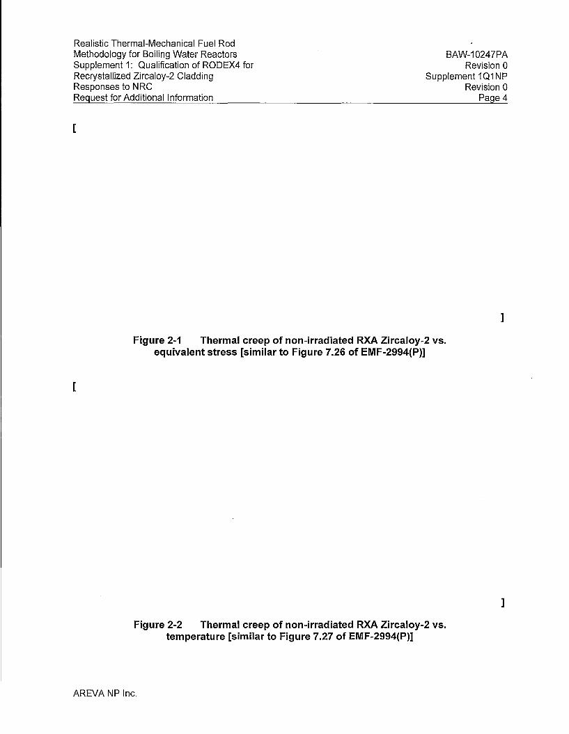
Realistic Thermal-Mechanical Fuel Rod Methodology for Boiling Water Reactors Supplement 1: Qualification of RODEX4 for Recrystallized Zircaloy-2 Cladding Responses to NRC Request for Additional Information
[
BAW-10247PA Revision O
Supplement 101 NP Revision 0
Page4
]
Figure 2-1 Thermal creep of non-irradiated RXA Zircaloy-2 vs. equivalent stress [similar to Figure 7.26 of EMF-2994(P)]
[
]
Figure 2-2 Thermal creep of non-irradiated RXA Zircaloy-2 vs. temperature [similar to Figure 7.27 of EMF-2994(P)]
AREVA NP Inc.

Realistic Thermal-Mechanical Fuel Rod Methodology for Boiling Water Reactors Supplement 1: Qualification of RODEX4 for Recrystallized Zircaloy-2 Cladding Responses to NRC Request for Additional Information
[
BAW-10247PA Revision 0
Supplement 1Q1NP Revision O
Page 5
l Figure 2-3 RXA Zircaloy-2 thermal creep vs. fast fluence [similar
to Figure 7.28 of EMF-2994(P)]
[
Figure 2-4
AREVA NP Inc.
RXA Zircaloy-2 irradiation creep vs. equivalent stress [similar to Figure 7.29 of EMF-2994(P)]
l

Realistic Thermal-Mechanical Fuel Rod Methodology for Boiling Water Reactors Supplement 1: Qualification of RODEX4 for Recrystallized Zircaloy-2 Cladding Responses to NRC Request for Additional Information
[
BAW-10247PA Revision 0
Supplement 101 NP Revision 0
Page 6
]
Figure 2-5 RXA Zircaloy-2 irradiation creep vs. fast flux [similar to Figure 7.30 of EMF 2994(P)]
[
]
Figure 2-6 Thermal and irradiation creep for RXA Zircaloy-2 at -40 MPa
AREVA NP Inc.

Realistic Thermal-Mechanical Fuel Rod Methodology for Boiling Water Reactors Supplement 1: Qualification of RODEX4 for Recrystallized Zircaloy-2 Cladding Responses to NRC Request for Additional Information
[
BAW-10247PA Revision 0
Supplement 1 Q1 NP Revision 0
Page 7
Figure 2-7 Thermal and irradiation creep for RXA Zircaloy-2 at -80 MPa
[
Figure 2-8
AREVA NP Inc.
Thermal and irradiation creep for RXA Zircaloy-2 at -120 MPa
1

Realistic Thermal-Mechanical Fuel Rod Methodology for Boiling Water Reactors Supplement 1: Qualification of RODEX4 for Recrystallized Zircaloy-2 Cladding Responses to NRC Request for Additional Information
BAW-10247PA Revision 0
Supplement 1 Q1 NP Revision 0
Page 8
[
Question 3
Figure 2-9 Thermal and irradiation creep for RXA Zircaloy-2 at 200 MPa
The following are related to understanding the creep data and how this data is used to develop the coefficients to the creep model.
Question 3a
Please confirm whether the creep data is from fuel rods or from non-fueled tubes (see b and c below).
Response 3a
A variety of data was used to construct the RODEX4 unified creep model, which predicts both thermal creep and irradiation creep. The irradiation creep parameters are derived from ·creepdown data obtained by profilometry of fuel rods at pool-side.
The thermal creep component is based partly on mechanical tests, used to define irradiation hardening, which are relevant for creep modeling because the RODEX4 model is applicable to both slower strain rate creep and to faster strain rate so-called plastic straining. The samples employed for these hot-cell tests were taken from fuel rods pre-irradiated in a commercial reactor.
AREVA NP Inc.
]

Realistic Thermal-Mechanical Fuel Rod Methodology for Boiling Water Reactors Supplement 1: Qualification of RODEX4 for Recrystallized Zircaloy-2 Cladding Responses to NRC Request for Additional Information
BAW-10247PA Revision 0
Supplement 101 NP Revision 0
Page 9
The other model parameters of the thermal creep were derived from non-fueled tubes cut from as-manufactured cladding.
Question 3b
If data from fuel rods at what fluence level is hard contact established for the fuel designs from which the irradiated data were taken? Please provide references for the irradiated creep data at fluences below which fuel-cladding hard contact is not experienced if creep data is from fuel rods. If these data are not publicly available please provide the data and model predictions identifying the maximum hoop stress/pressure, temperature and fluence (fuel rod data). How were the diameters of these fuel rods accurately measured axially and azimuthally prior to irradiation? An issue with fuel rod creep data is that it is difficult to separate primary and secondary creep quantitatively due to the limited amount of data versus time! fluence.
Response 3b
As in the original submittal, for both CWSR and RXA cladding the creepdown database was used, which consists of measured diameters of fuel rods after a number of power reactor cycles. This is stated on p. 14 of Supplement 1 at the beginning of Section 3.2. It is also mentioned that the creepdown database contains both "pure" creepdown data (before the onset of pelletcladding mechanical contact), as well as data from the "creepout" stage after hard pelletcladding mechanical contact was established. The transition between the two stages occurs between [ ] fast fluence as shown in Figure 8 of Supplement 1.
With regards to the measurement of the as-fabricated cladding, profilometry is the method employed to characterize dimensionally the fuel rods before being loaded in the power reactors. The as-fabricated tubes are scanned longitudinally by ultrasound techniques at several azimuthal angles so that the average cladding outer diameter, cladding thickness and ovality are determined.
The data are acquired for each tube lot and the statistics are used in the methodology applications as approved in BAW-10247PA. The detailed description of the uncertainty analysis of creepdown benchmarking, which includes the as-fabricated uncertainty component, is part of Response Sb.
Question 3c
If data is from non-fueled tubes supply plots of hoop strain vs. fluence for a given temperature and stress (for pressurized tubes held at relatively constant temperature).
AREVA NP Inc.

Realistic Thermal-Mechanical Fuel Rod Methodology for Boiling Water Reactors Supplement 1: Qualification of RODEX4 for Recrystallized Zircaloy-2 Cladding Responses to NRC Request for Additional Information
Response 3c
BAW-10247PA Revision 0
Supplement 1 Q1 NP Revision O
Page 10
As mentioned in response to Question 3a all data on creepdown were acquired from fueled rods. The burst mechanical tests used to define irradiation hardening were performed after irradiation on cladding samples cut from fuel rods after the fuel was removed. These data are described in Section 2.3.2 and Figures 3 and 6 of Supplement 1.
Question 4
Several assumptions have been applied in developing this creep model including the following: 1) radial stress can be ignored in determining creep in the hoop direction (Halden data appears to suggest it cannot be ignored); 2) the yield strength decrease in anisotropy in hoop and axial direction also applies to the creep anisotropy; and 3) P can be used to quantitatively define how creep anisotropy changes with fluence. The creep data provided is very limited and appears to be only in the compressive stress direction that suggests it does not provide justification for the above assumptions. In order to demonstrate that these and other assumptions are valid please provide comparisons to the following RXA Zr-2 in-reactor creep data.
• In-reactor creep data for RXA Zr-2 cladding tubes from the following Halden experiments (Halden reports): IFA-585 (HWR-471, HWR-413 and HWR-677); IFA-663 (HWR-755); and cladding liftoff experiment IFA-610 (HWR-877, HWR-919).
• Also provide comparisons to the creep database for RXA Zr-2 cladding in Franklin, D.G., G.E. Lucas, A.L. Bement. 1983. "Creep of Zirconium Alloys in Nuclear Reactors", ASTM STP 815, American Society for Testing and Materials, West Conshohocken, PA. ·
• These comparisons of creep predictions and data should be for both tensile and compressive stress states when available and gap estimates for cladding liftoff. These data will help determine if the assumptions for the creep model are valid and if primary and secondary irradiation creep are modeled correctly in terms of f/uence, temperature and stress.
Response 4
The calibration of the thermal creep model was performed by using long-term creep tests on unirradiated cladding, as described in Reference 4-1. The same thin-wall stress analysis was employed as used before for the initial and pre-submittal calibrations for both cold work stress relieved (CWSR) and RXA cladding types (see References 4-2 and 4-3). As mentioned in Section 2.1.3 of Supplement 1 (Reference 4-1 ), a detailed analysis was performed regarding the use of thick-wall stresses and it was concluded that using the thin-wall stresses has no impact on the calibration of the thermal creep model parameters (Section 2.2 of Reference 4-4)
AREVA NP Inc.

Realistic Thermal-Mechanical Fuel Rod Methodology for Boiling Water Reactors Supplement 1: Qualification of RODEX4 for Recrystallized Zircaloy-2 Cladding Responses to NRC Request for Additional Information
BAW-10247PA Revision 0
Supplement 1 Q1 NP Revision 0
Page 11
The justification of this assertion is as follows. The same relationship exists between the deviatoric stress components for the thick-wall analysis (when the radial stress is accounted for), as for the thin wall approximation, namely:
Therefore, Equation 13 of Reference 4-1, which links the generalized stress and the hoop stress remains of the same form when the hoop stress is replaced by the hoop stress minus the radial stress, while the link between the hoop strain and the generalized strain of Equation 14 of Reference 4-1 does not change.
The radial stress at the mean fiber for an internally pressurized tube is equal to minus half the internal pressure and thus the only difference between relations obtained by the thin wall approximation and the thick wall relations that account for radial stress, is the replacement of the hoop stress by the hoop stress minus half the internal pressure.
Therefore, the determination of the H1 and H5 model parameters from the linear relationship between the logarithm of the hoop strain and the hoop stress (Equation 25 of Reference 4-1) is not affected by the small difference between thin-wall and thick-wall stresses.
The simulation of the requested Halden tests is presented below. The IFA-585 test was already simulated in response to Q 12f of the RODEX4 RAls (BAW-1024701 P) and there is no impact of the new model parameters (i.e. the difference is within rounding-off range).
Simulation of the B&W creepdown experiment
The first requested verification is the creepdown experiment performed by B&W under a cooperative program with EPRI (References 4-5 and 4-6). The RXA Zircaloy-4, S2 material type was pre-pressurized to two levels, which created two levels of compressive hoop stresses. The test rods were guide tubes filled with SS mandrel pellets, to limit the creep-collapse in case it happened. The irradiation took place in the Oconee 2 reactor and profilometry of the test rods was carried out after each cycle. The measured data were taken from Reference 4-7 together with the fast flux and time values.
In order to calculate all three principal stresses with the thick-wall relationships, Equations 1 through 3 of Reference 4-1, the inner rod pressure and the outer coolant pressure must be known. References 4-5 through 4-7 provide the initial RT fill gas pressure and the clad average hoop stresses. Therefore, the inner gas pressure in hot conditions (based on the clad temperature provided in References 4-6 and 4-7, as test rods did not have any heat-generating pellets inside and the gamma-heating of the mandrel pellets is negligible), was calculated according to the gas law between room temperature and the operating temperature of around 305°C.
Next, the thin-wall hoop stress formula was used to determine the inside-outside pressure differential and the outer coolant pressure was estimated. Comparable values were obtained
AREVA NP Inc.

Realistic Thermal-Mechanical Fuel Rod Methodology for Boiling Water Reactors Supplement 1: Qualification of RODEX4 for Recrystallized Zircaloy-2 Cladding Responses to NRC Request for Additional Information
BAW-10247PA Revision 0
Supplement 1Q1NP Revision 0
Page 12
for all three hoop stress values, which are in agreement also with the typical PWR coolant pressure of around 15 MPa. Fine tuning of the coolant pressure was performed to match the given hoop stress with the thick-wall formulas.
The most recent AREVA model parameters for RXA Zircaloy-2 were used together with the varying P anisotropy coefficient. The calculations presented in Figure 4-1 below are comparable with measurements considering the uncertainty associated with the test conditions and measurements. It may be noted that the initial clad dimensions and the profilometry technique have expected uncertainties as previously described in the responses to RODEX4 RAI questions (Reference 4-3). The reported clad outer diameter variation for the S2 cladding (the smallest of all cladding types) is equivalent to a variation of [ ] hoop strain.
[
Figure 4-1 B&W creepdown simulation with RODEX4 RXA creep model and anisotropy coefficients
Simulation of the IFA-663 test
This experiment was dedicated to in-pile determination of creep behavior of pre-irradiated clad materials consisting of modern Zircaloy alloys. It was performed in an instrumented rig where two test rods (one consisting of three segments) were each connected to a separate external gas pressurization system for control of cladding stress.
AREVA NP Inc.
]
Realistic Thermal-Mechanical Fuel Rod Methodology for Boiling Water Reactors Supplement 1: Qualification of RODEX4 for Recrystallized Zircaloy-2 Cladding Responses to NRC Request for Additional Information
BAW-10247PA Revision 0
Supplement 1Q1NP Revision O
Page 13
Of interest to the current analysis is the lower rod, consisting of two Zry-2 (GE BWR cladding) segments, cut from fuel irradiated to 58 MWd/kgU in a commercial reactor.
The necessary cladding dimensional characterization and test conditions needed for creep calculation were taken from Reference 4-8. The Zry-2 rod was subject to three periods of different stress levels, the first one almost zero, the second one in compression and the final one in tension.
The calculations are displayed in Figure 4-2 below, which show diameter changes for the two segments. The difference in the test conditions between the lower and the upper segments is the fast flux, which is much lower for the lower segment (as being below the fast flux booster).
Therefore, the total deformation at the end of the test is lower for the lower segment. The negative deformation during the shorter and lower stress second compression period is smaller in absolute value compared to the longer and higher stress third tensile period.
As shown in Figure 4-2, the elastic component of the diameter change is the same for the two segments. In particular the change from the compressive to tensile is about [ ]. This is in good agreement with the measurements, which are only illustrated in Figures 7 and 8 in Reference 4-8.
With regards to the creep component of the diameter change during the tensile period, the calculated values are [ ] for the upper and lower segments, respectively. These calculations are in good agreement with the measurements as they can be inferred from the above mentioned figures of Reference 4-8.
It is remarked that the measurements are affected by uncertainty, as seen from Figure 7 of Reference 4-8, where the up and down profilometry runs gave different results. In addition, the measuring device scanned the segments along the same axial line. Because the rods are also subject to ovalization, the measured values are most likely different from the average diameter change that is calculated. Even if ovalization was accounted for in the calculation, it is still unknown which section of the ellipse is measured.
The relative evolution of the thermal and irradiation creep deformations is illustrated in Figures 4-3 and 4-4, for the upper and lowers segments, respectively. As mentioned, the lower segment was exposed to a much lower fast flux than the upper segment, which is reflected in the thermal creep being dominant for the lower segment, unlike the upper segment, for which the irradiation creep is dominant. This is consistent with the measured data presented in Figures 7 and 8 of Reference 4-8, where primary creep is noticed for the lower segment but not for the upper segment. As the calculation shows, the thermal primary creep is masked by the higher irradiation creep for the upper segment (see Figure 4-3); whereas the lower segment's dominant thermal creep provides a decreasing strain-rate, primary creep stage, when the stress value is changed from compressive to tensile.
AREVA NP Inc.

Realistic Thermal-Mechanical Fuel Rod Methodology for Boiling Water Reactors Supplement 1: Qualification of RODEX4 for Recrystallized Zircaloy-2 Cladding Responses to N RC Request for Additional Information
[
BAW-10247PA Revision 0
Supplement 101 NP Revision 0
Page 14
]
Figure 4-2 Benchmarking RODEX4 RXA creep model for IFA-663, GE segments
[
Figure 4-3 Benchmarking RODEX4 RXA creep model for IFA-663,
AREVA NP Inc.
GE upper segment - evolution of thermal and irradiation creep components during the test
]

Realistic Thermal-Mechanical Fuel Rod Methodology for Boiling Water Reactors Supplement 1: Qualification of RODEX4 for Recrystallized Zircaloy-2 Cladding Responses to NRC Request for Additional Information
BAW-10247PA Revision 0
Supplement 1 Q1 NP Revision O
Page 15
[
Figure 4-4 Benchmarking RODEX4 RXA creep model for IFA-663, GE lower segment - evolution of thermal and irradiation creep
components during the test
Simulation of the IFA-610.1 O test
The objective of the test was to study the lift-off propensity of a high burn-up BWR rod. To that end the rod was instrumented with a central thermocouple and an elongation sensor while it was connected to a gas pressurization and gas circulation system. The clad deformation was inferred by calculation from the changes in the measured pellet centerline temperature (Reference 4-9 and 4-10) and this is the useful output to be compared with calculated cladding creep. The clad deformation is directly proportional to cold gap values, but the cold gap was only measured at the end of the irradiation. Therefore, comparing the clad deformation, as predicted by the RODEX4 model, to the Halden inferred clad deformation is equivalent to comparing to the final cold gap measurement and thus adequate for the simulation exercise requested by Question 4.
l
The internal rod pressure was set to five levels of over pressurization as described in Table 2 of Reference 4-9. The times at different over pressures were taken from Figure 4 of the same reference. The dimensions were found in Reference 4-10.
AREVA NP Inc.

Realistic Thermal-Mechanical Fuel Rod Methodology for Boiling Water Reactors Supplement 1: Qualification of RODEX4 for Recrystallized Zircaloy-2 Cladding Responses to NRC Request for Additional Information
BAW-10247PA Revision 0
Supplement 1 Q1 NP Revision 0
Page 16
The measured (actually estimated from the cold gap measurements) creep strain at the end of the irradiation is a diameter change of [ ] (Figure 19 of Reference 4-9), while the calculated corresponding value is [ ] (Figure 4-5 below), which shows good agreement.
[
Figure 4-5 Calculated diameter change during IFA-610.10 with RODEX4 creep model for RXA cladding
The axial elongation was also measured and the calculated values agree well with measurements. Comparing the final calculated elongation, illustrated in Figure 4-6 below with the measurement displayed in Figure 1 O of Reference 4-9, an under-prediction can be noted. This under-prediction is due to the fact that the current modeling assumed an empty closed-end pressurized tube, while in the experiment pellet-to-cladding contact most likely occurred at pellet-pellet interfaces, which caused axial PCMI with the associated additional axial elongation.
The modeling of IFA-610.10 shows good agreement both in terms of evolution, as well as absolute values for both the hoop and axial deformations. This demonstrates the validity of the RODEX4 creep model for RXA Zircaloy-2 and especially its anisotropy model, which was able to reproduce the measured behavior, i.e., tensile hoop creep correlated with negative axial creep for the basically biaxial stress state (slightly different during periods of PCMI) with the 0.5 ratio between the axial stress and the hoop stress. It can be remarked that a CWSR material would have a positive axial creep under the same loading conditions.
AREVA NP Inc.
]

Realistic Thermal-Mechanical Fuel Rod Methodology for Boiling Water Reactors Supplement 1: Qualification of RODEX4 for Recrystallized Zircaloy-2 Cladding Responses to NRC Request for Additional Information
BAW-10247PA Revision 0
Supplement 1 Q1 NP Revision 0
Page 17
[
Figure 4-6 Calculated length change during IFA-610.10 with RODEX4 creep model for RXA cladding
References
4-1. "Realistic Thermal-Mechanical Fuel Rod Methodology for Boiling Water Reactors, Supplement 1: Qualification of RODEX4 for Recrystallized Zircaloy-2 Cladding," BAW-10247PA Revision 0 Supplement 1P Revision 0, AREVA NP Inc., Dec. 2009
4-2. "A Simple Zircaloy Viscoplastic Model and Its Validation against the Results of the ZODIAC Tests," EMF-2435, AREVA NP Inc., Feb. 2001
]
4-3. "Realistic Thermal-Mechanical Fuel Rod Methodology for Boiling Water Reactors," BAW-10247-PA, AREVA NP Inc., March 2008
4-4. "Qualification of the Thermal Creep Model for RXA Zry-2 of RODEX4 ThermalMechanical Fuel Rod Performance," 32-9117055-000, AREVA NP Inc., Nov. 2009
4-5. "EPRl/B&W Cooperative Program on PWR Fuel Rod Performance," EPRI NP-2848, March 1983
AREVA NP Inc.

Realistic Thermal-Mechanical Fuel Rod Methodology for Boiling Water Reactors Supplement 1: Qualification of RODEX4for Recrystallized Zircaloy-2 Cladding Responses to NRC Request for Additional Information
BAW-10247PA Revision O
Supplement 1 Q1 NP Revision O
Page 18
4-6. D. L. Batty, et al., "Deformation Characteristics of Cold-Worked and Recrystallized Zircaloy-2 Cladding," Sixth International Symposium on Zirconium in the Nuclear Industry, Vancouver, B.C., ASTM Code 04-824000-35, pp 306-339, 1982
4-7. D. G. Franklin, et al., "Creep of Zirconium Alloys in Nuclear Reactors," ASTM STP-815, Nov. 1983
4-8. H. Horn, "In-Reactor Creep of Various Fuel Claddings: Results from IFA-663," HWR-755, March 2004
4-9. S. Watanabe, "The lift-off Experiment IFA-610.10 with BWR Fuel Rod, In-Pile Data Evaluation," HWR-919, March 2010
4-10. M. Amaya, "The lift-off Experiment IFA-610.10 with a High Burn-up BWR U02 Fuel Rod: In-Pile Results During the First Irradiation Cycle," HWR-877, March 2008
\
Question 5
The following are related to understanding the application of the RXA Zr-2 creep model for licensing analyses and whether proposed application is justified.
Question 5a
Is RODEX4 creep calculated at mid-wall and if so is irradiated data adjusted for mid-wall creep? If not please explain how cladding creep is calculated?
Response 5a
The cladding model of RODEX4 consists of a [ ] radial mesh and thus, the radial displacements and stresses are calculated as average values over the [ ] radial intervals of the mesh and the strains are available at the [ ] nodal points. The axial strain is constant across the cladding thickness according to the axial symmetry assumption of the cladding model.
Therefore, the strains are available at inner, outer and mid-wall cladding locations. When RODEX4 is benchmarked against measured creepdown (resulting from profilometry of irradiated rods), of course, the cladding outer strain values are used since the profilometry measurements provide the outer diameter of the cladding. The cladding outer strain is also used in methodology applications in the context of the 1 % strain criterion. It is worth mentioning that the outer oxide layer is taken into account, by subtracting the metal consumed by oxidation from the thickness of the outermost radial interval.
AREVA NP Inc.
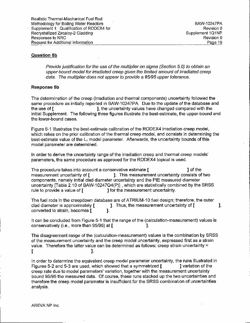
Realistic Thermal-Mechanical Fuel Rod Methodology for Boiling Water Reactors Supplement 1: Qualification of RODEX4 for Recrystallized Zircaloy-2 Cladding Responses to NRG Request for Additional Information
Question Sb
BAW-10247PA Revision 0
Supplement 1 Q1 NP Revision 0
Page 19
Provide justification for the use of the multiplier on sigma (Section 5.0) to obtain an upper bound model for irradiated creep given the limited amount of irradiated creep data. The multiplier does not appear to provide a 95195 upper tolerance.
Response Sb
The determination of the creep (irradiation and thermal components) uncertainty followed the same procedure as initially reported in BAW-10247PA. Due to the update of the database and the use of [ ], the uncertainty values have changed compared with the initial Supplement. The following three figures illustrate the best-estimate, the upper-bound and the lower-bound cases.
Figure 5-1 illustrates the best-estimate calibration of the RODEX4 irradiation creep model, which relies on the prior calibration of the thermal creep model, and consists in determining the best-estimate value of the L1 model parameter. Afterwards, the uncertainty bounds of this model parameter are determined.
In order to derive the uncertainty range of the irradiation creep and thermal creep models' parameters, the same procedure as approved for the RODEX4 topical is used.
The procedure takes into account a conservative estimate [ ] of the measurement uncertainty of [ ]. This measurement uncertainty consists of two components, namely initial clad diameter uncertainty and the PIE measured diameter uncertainty [Table 2.10 of BAW-10247Q4(P)] , which are statistically combined by the SRSS rule to provide a value of [ ] for the measurement uncertainty.
The fuel rods in the creepdown database are of ATRIUM-10 fuel design; therefore, the outer clad diameter is approximately [ ]. Thus, the measurement uncertainty of [ ], converted to strain, becomes [ ].
It can be concluded from Figure 5-1 that the range of the (calculation-measurement) values is conservatively (i.e., more than 95/95) at [ ].
The disagreement range of the (calculation-measurement) values is the combination by SRSS of the measurement uncertainty and the creep model uncertainty, expressed first as a strain value. Therefore the latter value can be determined as follows: creep strain uncertainty = [ ].
In order to determine the equivalent creep model parameter uncertainty, the runs illustrated in Figures 5-2 and 5-3 are used, which showed that a symmetrized [ ] variation of the creep rate due to model parameters' variation, together with the measurement uncertainty bound 95/95 the measured data. Of course, these runs stacked up the two uncertainties and therefore the creep model parameter is insufficient for the SRSS combination of uncertainties analysis.
AREVA NP Inc.

Realistic Thermal-Mechanical Fuel Rod Methodology for Boiling Water Reactors Supplement 1: Qualification of RODEX4 for Recrystallized Zircaloy-2 Cladding Responses to NRC Request for Additional Information
BAW-10247PA Revision O
Supplement 101 NP Revision O
Page 20
However, these runs can· be used to convert from creep strain uncertainty to creep model parameter uncertainty. The runs show that a [ ] variation of the creep modeling parameters lead to a shift of about [ ] strain on the average (so that the data points are shifted above or below the perfect agreement line on a 95/95 basis). The average creepdown strain of the database is [ ] and therefore, the above mentioned variation of [ ] is equivalent to a creep strain variation of [ ].
Taking into account the power/fast flux uncertainty of [ ], an additional [ ] uncertainty can be added and the total creep strain uncertainty due to creep model parameter becomes [ ]. This is insufficient to provide the [ ] SRSS combined value with the measurement uncertainty and therefore, an augmentation factor, a, is calculated, as follows:
[ ]
Therefore, the uncertainty bounds determined from the initial analysis that stacked up uncertainties, must be multiplied by 4.5, leading to the following range for the creep model parameter uncertainty:
[ ]
·The proper determination of the uncertainty bounds is demonstrated by the few data points (less the required number of points for the 95%/95% bounds for the specific sample size) below and above the best-estimate line in Figures 5-4 and 5-5, respectively.
[
Figure 5-1
AREVA NP Inc.
Best-estimate RXA creep model, (predictedmeasurement) vs. fast fluence
]
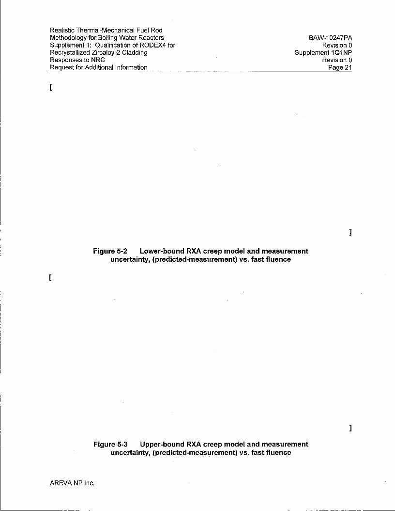
Realistic Thermal-Mechanical Fuel Rod Methodology for Boiling Water Reactors Supplement 1: Qualification of RODEX4 for Recrystallized Zircaloy-2 Cladding Responses to NRC Request for Additional Information
[
BAW-10247PA Revision O
Supplement 1Q1NP Revision 0
Page 21
]
Figure 5-2 Lower-bound RXA creep model and measurement uncertainty, (predicted-measurement) vs. fast fluence
[
]
Figure 5-3 Upper-bound RXA creep model and measurement uncertainty, (predicted-measurement) vs. fast fluence
AREVA NP Inc.

Realistic Thermal-Mechanical Fuel Rod Methodology for Boiling Water Reactors Supplement 1: Qualification of RODEX4 for Recrystallized Zircaloy-2 Cladding Responses to N RC Request for Additional Information
[
BAW-10247PA Revision O
Supplement 1Q1NP Revision 0
Page 22
]
Figure 5-4 Upper-bound RXA creep model, (predictedmeasurement) vs. fast fluence
[
AREVA NP Inc.
Figure 5-5 Lower-bound RXA creep model, (predictedmeasurement) vs. fast fluence
]

Realistic Thermal-Mechanical Fuel Rod Methodology for Boiling Water Reactors Supplement 1: Qualification of RODEX4 for Recrystallized Zircaloy-2 Cladding Responses to NRC Request for Additional Information
Question Sc
BAW-10247PA Revision 0
Supplement 1 Q1 NP Revision 0
Page 23
What impact does the new RXA Zr-2 creep properties have on creep collapse (ovality) for AREVA BWR fuel designs with RXA Zr-2 cladding? Provide data that demonstrates the RXA Zr-2 creep model is acceptable for application to cladding creep collapse.
Response Sc
There was one RXA cladding fuel rod benchmarked in the ovality database, which was calibrated with very good agreement with the measurement [rod 2/3 on PP 4-25 to 4-27 of BAW-10247(P) Rev. O]. As irradiation creep overshadows thermal creep during irradiation, and because the recalibrated L1 irradiation creep model parameter value of [ ] is very close to the initial value reported in the RODEX4 Theory Manual (EMF-2994(P) Rev. O], namely [
], the calibration of the ovality model remains valid. This is because the ovality rate depends on the irradiation creep rate, and the re-calibrated irradiation creep model parameter's value is very close to the value obtained .in the initial RODEX4 calibration for the RXA cladding type. · ,
Question 6
Does the new RXA Zr-2 creep triode/ impact fission gas release analyses, e.g., does the code need to be recalibrated against release data? If not please provide justification for why recalibration is not necessary.
Response 6
The relatively small change in creep model parameters has a negligible effect on the calculated pellet temperature, which is the major parameter affecting the fission gas release. In order to illustrate that no re-calibration is needed, some new FGR measurements on the commercial cases are used, which have been acquired after the initial RODEX4 submittal. The benchmarking of these recent additional cases shows that the code with the new RXA creep model parameters provides a conservative prediction of fission gas release, as illustrated in Figure 6-1 below. Figure 6-2 illustrates that the measured FGR data span the high and very high exposure range, which bounds the approved burnup in BAW-10247PA.
AREVA NP Inc.

Realistic Thermal-Mechanical Fuel Rod Methodology for Boiling Water Reactors Supplement 1: Qualification of RODEX4 for Recrystallized Zircaloy-2 Cladding Responses to NRG Request for Additional Information
[
Figure 6-1 Fission gas release benchmarking of fuel rods with RXA Zircaloy-2 cladding
[
Figure 6-2 Fission gas release of fuel rods with RXA Zircaloy-2 cladding vs. exposure
AREVA NP Inc.
BAW-10247PA Revision 0
Supplement 1Q1NP Revision O
Page 24
]
]

- ---- ---------------------------------------~
Realistic Thermal-Mechanical Fuel Rod Methodology for Boiling Water Reactors Supplement 1: Qualification of RODEX4 for Recrystallized Zircaloy-2 Cladding Responses to NRC Request for Additional Information
Question 7
BAW-10247PA Revision 0
Supplement 1Q1NP Revision O
Page 25
It is the intent to place limits on the application of the corrosion and creep models. What is the cladding temperature and bumup/fluence limitation for the corrosion and creep models. Provide justification based on the data that supports these limitations.
Response 7
The RXA Zircaloy-2 corrosion and creep models have been validated by RODEX4 benchmarks against the corresponding corrosion and creepdown databases, which bound the operating conditions related to cladding temperature and burnup/fast fluence, up to and beyond the approved burnup in BAW-10247PA.
The illustration of the above statement is contained in Figures 8 and 12 of Supplement 1 for the creep and corrosion models, respectively. The fast fluence on the x-axis of Figure 8 of Supplement 1 is the rod average fast fluence and the maximum value of [
] corresponds to [ ]. The burnup span of the corrosion data in Figure 12 of Supplement 1 is [ ].
Therefore, AREVA's justification that the existing rod burnup limit is applicable to the corrosion and creep models is that the benchmarks include data which bound the operating domain limits.
Question 8
Does the ridging parameter Khg in Equation 6. 86 in EMF-:2994 impact licensing analyses? If so, please explain why this ridging parameter is not impacted with the introduction of RXA Zr-2 cladding.
Response 8
The power ramp database, which was used to benchmark the strain increment during power transients, includes both CWSR and RXA cladding types. Therefore, the calibration of the ridging parameter is valid for both cladding types.
General theoretical considerations can also be invoked in order to justify the same ridging parameter for both cladding types. Cladding ridging occurs as an effect of the hourglassing deformation of the pellet during the power increase. The pellet imposes thus an additional cladding deformation at the pellet-pellet interface, which is initially fully elastic (at the typical power ramp rates in operation). Therefore, the amount of ridging depends almost solely on pellet properties and hence the same ridging parameter is valid for both metallurgical conditions of the cladding, namely RXA and CWSR.
The ridging strain is not directly taken into account in any licensing criterion. The ridge stresses that are calculated together with the ridge strains are used in the fatigue usage factor analysis. Any change to the ridging parameter has negligible impact on temperature, strain and internal
AREVA NP Inc.

Realistic Thermal-Mechanical Fuel Rod Methodology for Boiling Water Reactors Supplement 1: Qualification of RODEX4 for Recrystallized Zircaloy-2 Cladding Responses to NRC Request for Additional Information
BAW-10247PA Revision O
Supplement 1Q1NP Revision 0
Page 26
rod pressure (which includes fission gas release). This is because the ridging model is a separate calculation at pellet-pellet interface, which only impacts the onset of the axial PCMI, which in turn only affects the cladding axial elongation.
Question 9
The following relate to the axial growth model for RX Zircaloy-2.
Response 9
In order to respond to questions 9a, 9b and 9c, an introduction is. presented first, to describe the two changes made in relation to the axial growth model of RXA Zircaloy-2. The text and figures in Supplement 1 will be updated prior to the issuance of the report. The changes, noted as C1 and C2, are as follows: ·
C1
C2
[
[
]
]
The change C1 consisted of replacing the model used before in RODEX4 for RXA cladding material with the model developed for RXA material in the frame [
], which was approved by the NRC as part of BAW-10247PA.
The RXA free-stress irradiation growth model that existed in RODEX4 had the same relationship as for the CWSR model. This is in contradiction to the known different behavior of RXA material with respect to free-stress irradiation growth, which has a saturation plateau after the initial quasi-linear increase at the beginning of irradiation, followed by an enhancement at high fast fluence. The old model was amenable to calibration but was not consistent with known phenomenology and it was found that it does not work with newly introduced liner effect on axial PCMI.
Therefore, the RXA free-stress irradiation growth model was modified and the model developed for [ ] was implemented.
The RXA material shows a growth acceleration after [ ], with an asymptotic linear variation similar to that of CWSR material. Based on in-house data, the following non-linear model was developed for RX material:
[ ] (9-2)
with:
[
]
, AREVA NP Inc.

Realistic Thermal-Mechanical Fuel Rod Methodology for Boiling Water Reactors Supplement 1: Qualification of RODEX4 for Recrystallized Zircaloy-2 Cladding Responses to NRC Request for Additional Information
[
]
and
[ ]
where,
T : absolute temperature
Ez gr : axial free-stress growth
: fast fluence (> 1 MeV)
%
n/cm2
BAW-10247PA Revision 0
Supplement 101 NP Revision 0
Page 27
The change C2 refers to the addition of a model to reflect the [ ] for both CWSR and RXA metallurgical conditions. The verification and validation of change C2 is reported herein only for the RXA metallurgical condition.
[
].
[
].
AREVA NP Inc.

Realistic Thermal-Mechanical Fuel Rod Methodology for Boiling Water Reactors Supplement 1: Qualification of RODEX4 for Recrystallized Zircaloy-2 Cladding Responses to NRC Request for Additional Information
[
BAW-10247PA Revision 0
Supplement 101 NP Revision 0
Page 28
]
Figure 9-1 CWSR Zircaloy cladding axial elongation with and without liner vs. fast fluence
[
]
Figure 9-2 Benchmarking CWSR Zircaloy cladding axial elongation with and without liner
AREVA NP Inc.

Realistic Thermal-Mechanical Fuel Rod Methodology for Boiling Water Reactors Supplement 1: Qualification of RODEX4 for Recrystallized Zircaloy-2 Cladding Responses to NRC Request for Additional Information
[
[
\.
BAW-10247PA Revision 0
Supplement 101 NP Revision 0
Page 29
].
]
Figure 9-3 Update of the axial elongation benchmarking for fuel
AREVA NP Inc.
rods with RXA Zircaloy-2 cladding (equivalent of Figure 9 of Supplement 1)

Realistic Thermal-Mechanical Fuel Rod Methodology for Boiling Water Reactors Supplement 1: Qualification of RODEX4 for Recrystallized Zircaloy-2 Cladding Responses to NRC Request for Additional Information
Question 9a
BAW-10247PA Revision 0
Supplement 1 Q1 NP Revision 0
Page 30
PNNL is unable to replicate model predictions of axial strain shown in Figure 9. It appears that the value for the c coefficient may be in error, please confirm or provide a discussion of why the coefficients in the submittal are correct. Please verify that the correct model parameters are given in the submittal.
Response 9a
The axial strain displayed in Figure 9, "Net axial growth benchmarking of RX Zr-2 database," of Supplement 1 is the net axial strain of the cladding, which is the combined result of the stressfree irradiation growth and the axial deformation caused by the axial PCMI (Pellet-to-Cladding Mechanical Interaction).
Therefore, the stress-free irradiation growth is only one component of the net axial strain; it is the dominant component at the beginning of irradiation while the pellet-to-cladding gap is still open (see details in the response to Question 9b) and afterwards is overtaken by the axial PCMI permanent axial strain component at medium and at high burnup. The relative contributions of the two axial strain components are dependent on the particular power histories and a discrepancy calculation/measurement can be due to either or both strain components.
However, it was recognized that the initial stress-free irradiation growth model was not fully consistent with the known phenomenology of RXA stress-free irradiation growth, especially at medium and high fast fluences. Therefore, the change described above in the introductory part of the response to Question 9 was implemented in RODEX4.
Question 9b
It appears that the slope of the growth model versus f/uence should be lower because growth is underpredicted at low f/uence and overpredicted on average at high f/uence. At what burnup/fluence level is hard contact experienced for these fuel designs based on; 1) RODEX4 calculations, and 2) data analysis. To illustrate the adequacy of the growth model dependence on f/uence and temperature please provide plots of predicted minus measured axial strain as a function of fast fluence and cladding temperature. If there are under or overpredictions on average please explain why this is acceptable for each of the licensing analyses of rod internal pressure, fuel temperature (melting and stored energy) and cladding strain. Identify the fuel design for each set of growth data. Have additional growth data become available since the submittal to better determine the accuracy of the growth model? If so, please provide this data.
AREVA NP Inc.
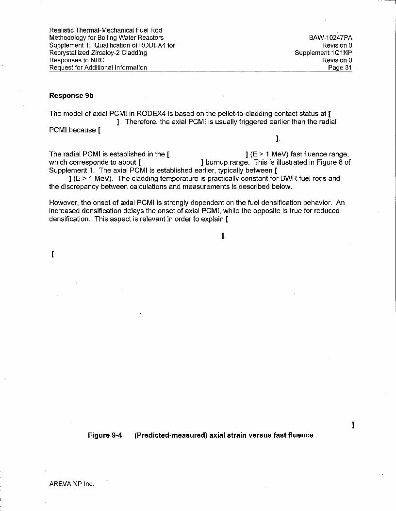
Realistic Thermal-Mechanical Fuel Rod Methodology for Boiling Water Reactors Supplement 1: Qualification of RODEX4 for Recrystallized Zircaloy-2 Cladding Responses to NRC Request for Additional Information
BAW-10247PA Revision 0
Supplement 1 Q1 NP Revision 0
Page 31
Response 9b
The model of axial PCMI in RODEX4 is based on the pellet-to-cladding contact status at [ ]. Therefore, the axial PCMI is usually triggered earlier than the radial
PCMI because [ ].
The radial PCMI is established in the [ ] (E > 1 MeV) fast fluence range, which corresponds to about [ ] burnup range. This is illustrated in Figure 8 of Supplement 1. The axial PCMI is established earlier, typically between [
] (E > 1 MeV). The cladding temperature is practically constant for BWR fuel rods and the discrepancy between calculations and measurements is described below.
However, the onset of axial PCMI is strongly dependent on the fuel densification behavior. An increased densification delays the onset of axial PCMI, while the opposite is true for reduced densification. This aspect is relevant in order to explain [
].
[
Figure 9-4 (Predicted-measured) axial strain versus fast fluence
AREVA NP Inc.
]

Realistic Thermal-Mechanical Fuel Rod Methodology for Boiling Water Reactors Supplement 1: Qualification of RODEX4 for Recrystallized Zircaloy-2 Cladding Responses to NRC Request for Additional Information
The majority of the data points in the low fast fluence range of [ (E > 1 MeV) came from measuring fuel rods [
].
BAW-10247PA Revision 0
Supplement 101 NP Revision 0
Page 32
]
In reality, there is an alternate axial PCMI component even when the radial gap at the pelletpellet interface is open, namely the axial elongation of the fuel pellet stack is partially transmitted to the cladding through the plenum spring. Initially the plenum spring is rigid and absorbs little of the axial expansion of the fuel pellet stack; as irradiation progresses, the plenum spring becomes softer because of annealing stress relaxation and less of the pellet stack axial elongation is transmitted to the cladding; in addition axial PCMI sets in and overtakes the interaction through the plenum spring.
The axial interaction between fuel pellet stack and cladding through the plenum spring [ ], but it is part of the calibration of the stress-free irradiation growth
model. [
].
The updated benchmarking of the Zircaloy-2 RXA axial elongation database is presented in Figure 9-3, where both the calculations and the measurements are plotted versus fast fluence. Therefore, the discrepancy between calculations and measurements is clearly illustrated and further discussion is given below. Note that the growth data included in Figures 9-1 through 9-3 is an updated version of the elongation data in the Supplement. The changes are minor as two points were removed due to legal restrictions and two new points were added. The overall change is not significant.
At the high end of the fast fluence domain, a slight over-prediction of the net axial strain is observed. While the magnitude of the discrepancy between predictions and measurements is again small enough to be considered as typical prediction uncertainty, a possible explanation for the over-prediction is as follows: the fuel creep is enhanced at high burnup and the axial clad elongation induced by the trapped bottom part of the fuel pellet stack is over-estimated by the code.
Therefore, the slight over-prediction at high fast fluences has minimal effect on the rod internal free volume, as most likely the fuel column and cladding are in PCMI state, except perhaps a small portion at the bottom of the rod. The fast fluence at the design burnup is not yet in the domain of full accelerated stress-free irradiation growth. As the low and mid-burn up net growth data are in good agreement, it is more likely that the PCMl-related axial elongation is the reason
AREVA NP Inc.

Realistic Thermal-Mechanical Fuel Rod Methodology for Boiling Water Reactors Supplement 1: Qualification of RODEX4 for Recrystallized Zircaloy-2 Cladding Responses to NRC Request for Additional Information
BAW-10247PA Revision 0
Supplement 1 Q1 NP Revision 0
Page 33
for over-prediction at high burnup; however, this does not affect the plenum volume as the cladding follows the pellet axial elongation when axial PCMI is active.
The above statement is further confirmed by the agreement of calculated free-volumes to measurements, as shown in the response to Q10.
As for the fuel temperature and cladding strain (in the circumferential direction) analyses, the slight under-prediction at low burnup and over-prediction at high burnup, respectively, have no effects because they only impact on the plenum volume. The free-stress irradiation growth does not affect cladding deformation in the transverse direction and, therefore, has no impact on the fuel-to-cladding gap. Therefore the cladding creepdown is not affected. In addition, the fuel-to-cladding heat transfer and fuel temperatures are also not affected,
Question 9c
Axial rod growth is also dependent on axial stresses on the fuel rods which is dependent on spacer spring loads (Section 4. 0) and PC/. Please identify differences in spacer spring design and loads between those designs from which the data were taken and those from current fuel designs. Please identify any other axial loads on the fuel rods besides PC/. Based on the near linear dependence with fluence it appears that there is little growth due to PC/. Please discuss this further. Were these data from fuel assemblies utilizing tie rods?
Response 9c
The new growth model in combination with the [ ] on axial PCMI, which was described above, leads to a good overall agreement with measurements. However, some under-prediction exists at low burnup and some over-prediction at high burnup. The investigation, described in the response to the previous Question 9b, concluded that the axial interaction transmitted through the plenum spring in combination with much lower densification of the Gad fuel sub-set is the cause of the under-prediction at low burnup.
Therefore, the main effect on cladding axial elongation is due to the plenum spring and not to spacers. The friction force induced by the spacers is one of the factors influencing rod bow; however, these forces are small for ATRIUM-10 and following BWR designs, and the impact on rod growth is not significant.
Some of the rods in the axial elongation database were part of assemblies with tie rods, but this has no impact on rod axial growth. The net cladding axial growth is the combination stress-free irradiation growth and axial permanent strain due to axial PCMI. Another component could be the radial PCMI, which occurs at high burnup and which decreases the cladding axial deformation by the Poisson effect. The apparent linear trend of the net cladding axial elongation is the effect of the three contributing mechanisms mentioned above.
· AREVA NP Inc.

Realistic Thermal-Mechanical Fuel Rod Methodology for Boiling Water Reactors Supplement 1: Qualification of RODEX4 for Recrystallized Zircaloy-2 Cladding Responses to NRC Request for Additional Information
Question 10
BAW-10247PA Revision O
Supplement 1Q1NP Revision 0
Page 34
The following relate to the free volume predictions with RODEX4 for RXA Zirca/oy-2.
Question 1 Oa
Please provide the free volume data (Section 7.0) (also as-fabricated volume along with how this is determined) along with burnup and fuel design from which data were taken. There appears to be a small overprediction [ ] of void volume at burnup greater than [ ] (Figure 14). Is this related to the overprediction of growth at high fluences? Please provide a discussion of why this acceptable.
Response 1 Oa
The free volume dataset is comprised of rods irradiated in three power reactors, which are of either 9x9 or ATRIUM-10 design; also while most of the rods are full-length fuel rods (FLFRs), some are part-length fuel rods (PLFRs). The rod fill gas pressure was practically identical in all rods, at a value of [ ]. The initial free volume is not directly measured, unlike the fill gas pressure. The value of the initial rod free volume is calculated based on the pellet and cladding dimensional data, which allow the determination of ·all components of the initial free volume: pellet-to-cladding gap, pellet dishing and plenum. Because of differences in design and FLFR or PLFR rod type, the initial free volume ranged from [
]. The details of the free-volume data requested by Q10a are provided in Table 10-1 below.
Figure 10-1 is an update of the predicted free volume comparison to measurements following the model updates reported in response to Q9. The burnups are indicated in Figure 14 of Supplement 1, which is repeated below as Figure 10-2.
The last part of the question refers to the group of data at high burnup, around [ ], for which a slight over-prediction exists. All these rods come from the same assembly and it is considered that the most likely reason for the consistent over-prediction of these 5 rods is the uncertainty of the pellet and cladding initial dimensions. The difference between calculations and measurements for these rods, as well as for the other rods of the free volume dataset, is consistent with the uncertainty of the pellet-to-cladding gap and pellet dish volumes and is therefore acceptable.
AREVA NP Inc.

[
Realistic Thermal-Mechanical Fuel Rod Methodology for Boiling Water Reactors Supplement 1: Qualification of RODEX4 for Recrystallized Zircaloy-2 Cladding Responses to NRC Request for Additional Information
Table 10-1
AREVA NP Inc.
Free-volume database
BAW-10247PA Revision 0
Supplement 1 Q1 NP Revision 0
Page 35
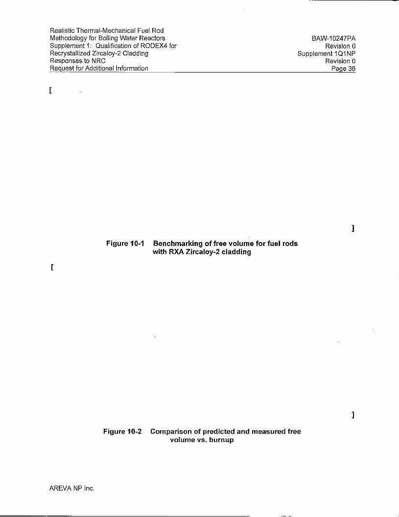
Realistic Thermal-Mechanical Fuel Rod Methodology for Boiling Water Reactors Supplement 1: Qualification of RODEX4 for Recrystallized Zircaloy-2 Cladding Responses to NRC Request for Additional Information
[
BAW-10247PA Revision O
Supplement 1 Q1 NP Revision 0
Page 36
]
Figure 10-1 Benchmarking of free volume for fuel rods with RXA Zircaloy-2 cladding
[
AREVA NP Inc.
Figure 10-2 Comparison of predicted and measured free volume vs. burnup
]

Realistic Thermal-Mechanical Fuel Rod Methodology for Boiling Water Reactors Supplement 1: Qualification of RODEX4 for Recrystallized Zircaloy-2 Cladding Responses to NRC Request for Additional Information
Question 1 Ob
BAW-10247PA Revision O
Supplement 1 Q1 NP Revision 0
Page 37
In addition, the free volume model appears to be based on only 19 data points. Have any additional data been collected since this submittal and if available provide these data?
Response 1 Ob
No additional free volume data have been acquired after the RXA Supplement submittal, but it is considered that the existing data cover the whole burnup range, design and fuel rod type, as described above in re·sponse to Question 1 Oa. Therefore, the existing free volume database is relevant and suffices for the verification purpose of this global code benchmarking exercise.
Question 11
Please provide the rod pressure limit for BWR fuel rods with RXA Zr-2 cladding. Also justify this limit based on the upper bound creep model for RXA Zr-2 and lower bound fuel swelling model.
Response 11
The approved RODEX4 methodology includes the rod pressure criterion of [ ] above the coolant pressure. This is based on demonstrating that the [ ] over pressure has significant margin to the internal rod over pressure that would cause lift-off, as characterized by pellet-to-clad opening.
1
A previous calculation was performed to determine the conservative value of the lift-off rod over pressure, which is based on the conservative assumptions formulated in the question, namely, upper bound creep model and lower bound fuel swelling model. This calculation was repeated for the RXA Zircaloy-2 creep model, as re-calibrated in the Supplement and updated as presented in response to Q9.
The results of the analysis, illustrated in Figure 11-1, show that the lift-off over pressure limit for RXA Zircaloy-2 is at least [ ]; this is well above the approved [ ] over pressure.
AREVA NP Inc.
l _____ ---
Realistic Thermal-Mechanical Fuel Rod Methodology for Boiling Water Reactors Supplement 1: Qualification of RODEX4 for Recrystallized Zircaloy-2 Cladding Responses to NRC Request for Additional Information
BAW-10247PA Revision 0
Supplement 101 NP Revision 0
Page 38
[
Figure 11-1 Fuel-swelling/Cladding-creep ratio dependency to LHGR for RXA Zircaloy cladding
Question 12
1. Please provide sample calculations for the following safety analyses using the approved RODEX-4 methodology for RXA Zircaloy-2 cladding. For each sample calculation, provide discussion on how power histories are selected and how the uncertainties are perturbed, and plots of the selected power histories. The uncertainties (values and parameter perturbed) and how they are perturbed need to be identified such that similar analyses can be performed with the FRAPCON-3. 4 code with statistical analysis sampling capabilities.
a. Maximum rod internal pressure
b. Fuel melting calculation
c. Maximum cladding hoop strain increment
Response 12
l
The sample calculations requested in Question 12 have been prepared by using the latest code version, which incorporates the final multi-node calibration, the stress-free irradiation growth model change and the new [ ] model (described in response to Question 9). A recent BWR equilibrium cycle using AREVA's current ATRIUM 10XM fuel design was selected
AREVA NP Inc.

Realistic Thermal-Mechanical Fuel Rod Methodology for Boiling Water Reactors Supplement 1: Qualification of RODEX4 for Recrystallized Zircaloy-2 Cladding Responses to NRC Request for Additional Information
BAW-10247PA Revision 0
Supplement 1 Q1 NP Revision 0
Page 39
for the sample cases. The calculations were performed by turning off and on the new [ ] model option flag. The results of the sample cases are presented in Table 12-1,
below, where the results of the CWSR Zircaloy runs are included for comparison.
The calculations for these sample cases have followed the methodology fully described in BAW-10247PA. For each of the three cases identified in Table 12-1, separate analyses of U02 and Gadolinia-bearing rods were performed for both normal operation runs with and without AOO transients (CRWE in this case). The results reported in Table 12-1 are the minimum margin values from all the analyses described above.
As agreed during a phone call, the full set of RODEX4 input files will be provided on a CD-ROM. These input files contain the power history adjusted for all power uncertainty factors included in the methodology. Also, all other input manufacturing and modeling parameters that are varied in the methodology, are identified in the input file and the nominal value for each parameter is provided. A "readme" file on the CD-ROM describes the structure of the folders and files for the sample cases provided in response to Question 12.
Table 12-1
AREVA NP Inc.
Sample calculations for a typical BWR Equilibrium Cycle of ATRIUM 10XM
November 20, 2013 NRC:13:084
U.S. Nuclear Regulatory Commission Document Control Desk 11555 Rockville Pike Rockville, MD 20852
A AREVA.
Response to a Draft Request for Additional Information Regarding Report BAW-10247PA, Revision 0, Supplement 1P, Revision O, "Realistic Thermal-Mechanical Fuel Rod Methodology for Boiling Water Reactors Supplement 1: Qualification of RODEX4 for Recrystallized Zircaloy-2 Cladding"
AREVA NP Inc. (AREVA NP) requested the NRC review and approval of topical report BAW-10247PA, Revision 0, Supplement 1P, Revision 0, "Realistic Thermal-Mechanical Fuel Rod Methodology for Boiling Water Reactors Supplement 1: Qualification of RODEX4 for Recrystallized Zircaloy-2 Cladding" in Reference 1. Supplemental information for the submittal was transmitted to the NRC in Reference 2. The NRC provided a draft request for additional information (RAI) regarding this topical report in Reference 3. The responses to Questions 2 through 12 of this request were submitted to the NRC in Reference 4. The Response to Question 1 of the RAI is enclosed with this letter as an attachment.
AREVA NP considers some of the material contained in the enclosed to be proprietary. As required by 10 CFR 2.390{b), an affidavit is attached to support the withholding of the information from public disclosure. Proprietary and non-proprietary versions of the attached RAI responses are provided.
If you have any questions related to this submittal, please contact Mr. Alan B. Meginnis, Product Licensing Manager by telephone at 509-375-8266 or by e-mail at [email protected].
AREVA NP INC.
3315 Old Forest Road, P.O. Box 10935, Lynchburg, VA 24506-0935 Tel.: 434 832-3000 - www.areva.com

Document Control Desk November 20, 2013
References
NRC:13:084 Page 2
Ref. 1: Letter, Ronnie L. Gardner (AREVA NP Inc.) to Document Control Desk (NRC), "Realistic ThermalMechanical Fuel Rod Methodology for Boiling Water Reactors Supplement 1: Qualification of RODEX4 for Recrystallized Zircaloy-2 Cladding," NRC:09:133, December 22, 2009.
Ref. 2: Letter, Ronnie L. Gardner (AREVA NP Inc.) to Document Control Desk (NRC), "Transmittal of Revised Information for Review of Topical Report BAW-10247PA, Revision 0, Supplement lP, Revision O," NRC:10:093, October 22, 2010.
Ref. 3: Email, Holly C. Cruz (NRC) to Gayle F. Elliott (AREVA NP Inc.) "Draft RAls re: BAW-10247, Sup. 1 related to RXA Zr-2 in the RODEX4 code," September 19, 2011.
Ref. 4: Letter, Pedro Salas (AREVA NP Inc.) to Document Control Desk (NRC), Response to a Draft Request for Additional Information Regarding Report BAW-10247PA, Revision 0, Supplement lP, Revision 0, "Realistic Thermal-Mechanical Fuel Rod Methodology for Boiling Water Reactors Supplement 1: Qualification of RODEX4 for Recrystallized Zircaloy-2 Cladding" NRC:13:016, April 19, 2013.
Enclosures
1. BAW-10247PA, Revision 0, Supplement 1Q2P, Revision 0, "Realistic Thermal-Mechanical Fuel Rod Methodology for Boiling Water Reactors Supplement 1: Qualification of RODEX4 for Recrystallized Zircaloy-2 Cladding Responses to NRC Request for Additional Information"
2. BAW-10247PA, Revision 0, Supplement 1Q2NP, Revision 0, "Realistic Thermal-Mechanical Fuel Rod Methodology for Boiling Water Reactors Supplement 1: Qualification of RODEX4 for Recrystallized Zircaloy-2 Cladding Responses to NRC Request for Additional Information"
3. Notarized Affidavit ,
cc: J. A. Golla J. L. Dean Project 728
BAW-10247NP-A, Revision 0, Supplement 1Q2NP, Revision 0
is replaced by
BAW-10247NP-A, Revision 0, Supplement 1Q2NP, Revision 1
in its entirety.
See BAW-10247NP-A, Revision 0, Supplement 1Q2NP, Revision 1; Enclosure to
Correspondence NRC:16:013.

Mr. Gary Peters, Director Licensing and Regulatory Affairs AREVA Inc. 3315 Old Forest Road Lynchburg, VA 24501
March 25, 2016
SUBJECT: REQUEST FOR ADDITIONAL INFORMATION RE: AREVA NP, INC. TOPICAL REPORT BAW-10247PA, REVISION 0, SUPPLEMENT 1 P, REVISION 0, "REALISTIC THERMAL-MECHANICAL FUEL ROD METHODOLOGY FOR BOILING WATER REACTORS SUPPLEMENT 1: QUALIFICATION OF RODEX4 FOR RECRYSTALLIZED ZIRCALOY-2 CLADDING" (TAC NO. MF5421)
Dear Mr. Peters:
By letter dated December 22, 2009 (Agencywide Documents Access and Management System Accession (ADAMS) Accession No. ML093580237), AREVA NP, INC. (AREVA) submitted for U.S. Nuclear Regulatory Commission (NRC) staff review Topical Report BAW-10247PA, Revision 0, Supplement 1 P, Revision 0, "Realistic Thermal-Mechanical Fuel Rod Methodology for Boiling Water Reactors Supplement 1: Qualification of RODEX4 for Recrystallized Zircoloy-2 Cladding."
In an email dated September 19, 2011, AREVA was supplied twelve draft requested for additional information (RAI) questions. By letters dated April 19 and November 20, 2013 (ADAMS Accession Nos. ML 13119A027 and ML 13329A454, respectively), AREVA responded to those draft RAI questions. Upon review of the information provided in those responses, the NRC staff has determined that additional information is needed to complete the review.
Enclosure 1 contains a new RAI question to which AREVA needs to respond. Enclosure 2 contains the first twelve RAI questions. Enclosure 2 represents the formal transmittal of those RAI questions. There were editorial changes to the draft RAI questions in order to finalize them. Those editorial changes do not impact the content or intent of the RAI questions. Therefore, no additional response is required from AREVA for the formal RAI questions in Enclosure 2.
On December 30, 2015, Alan Meginnis, AREVA Product Licensing Manager, and I agreed that the NRC staff will receive the response to the RAI question in Enclosure 1 within 45 days from the date of this letter.

- 2 -
If you have any questions regarding the enclosed RAI questions, please contact me at 301-415-4053.
Project No. 728
Enclosures: 1. RAI Number 13 2. RAI Numbers 1 - 12 (Nonproprietary Version)
Sincerely,
IRA/
Jonathan G. Rowley, Project Manager Licensing Processes Branch Division of Policy and Rulemaking Office of Nuclear Reactor Regulation

REQUEST FOR ADDITIONAL INFORMATION
RELATED TO AREVA NP. INC.
TOPICAL REPORT BAW-10247PA. REVISION 0. SUPPLEMENT 1 P. REVISION 0,
"REALISTIC THERMAL-MECHANICAL FUEL ROD METHODOLOGY FOR BOILING
WATER REACTORS SUPPLEMENT 1: QUALIFICATION OF RODEX4 FOR
RECRYSTALLIZED ZIRCALOY-2 CLADDING"
RAl-13
Related to RAI 5C, please provide sample calculations for cladding collapse using the original recrystallized annealed (RXA) correlations and the new RXA correlations. The RAI 5C responses mentioned 7 percent difference but did not state which one was higher or lower. This comparison will allow staff to assess the impact of using the original RXA correlations and the new RXA correlations in the cladding collapse calculation.
Enclosure 1

REQUEST FOR ADDITIONAL INFORMATION
RELATED TO AREVA NP, INC.
TOPICAL REPORT BAW-10247PA. REVISION 0, SUPPLEMENT 1P, REVISION 0,
"REALISTIC THERMAL-MECHANICAL FUEL ROD METHODOLOGY FOR BOILING
WATER REACTORS SUPPLEMENT 1: QUALIFICATION OF RODEX4 FOR
RECRYSTALLIZED ZIRCALOY-2 CLADDING"
The following relates to cladding corrosion and hydriding.
a. Please provide the individual corrosion data along with cladding temperature (radial and axial location and fluence/time) and recrystallized annealed (RXA) Zircaloy-2 (Zr-2) model prediction and identify the fuel design the data was taken from. Also, include the maximum power level and burn up for each of the operating cycles for each rod. Do any of these data come from plants with power uprates? If so, please identify the data along with percentage uprate in power along with uprated core average power. This will help assess whether the data is applicable to today's fuel designs and operating envelopes.
b. No model was provided for hydrogen pickup of RXA Zr-2. NRG has developed cladding embrittlement criteria for loss-of coolant accident and reactivity initiated accident based on hydrogen content. Does AREVA intend to include a hydrogen pickup model for accident analyses? If so, does AREVA intend to submit hydrogen pickup models for RXA Zr-2 and cold-worked, stress-relief annealed Zr-2 as part of this review, also please provide supporting hydrogen concentration data for these models.
The following are related to understanding the thermal and irradiated creep model coefficients and verify the calculation of thermal and irradiated creep.
a. Possible Typos - i) Should there be parenthesis around each of the following terms, the axial creep rate term and the axial creep strain term in Equation 24 and 25. ii) The last line on page 10 refers to HB, should this be Hs instead? iii) The first sentence on page 11 suggests that the data were fine tuned rather than the model coefficients, please modify if this is not true. If the data were fine tuned please explain in detail how this was done.
b. Fitting parameters for thermal creep, H2, Hs, and H4 are not provided. Please provide these values. Also provide some discussion of how the primary creep is initialized at time=O.
c. Fitting parameters, HB and H7 are defined differently on pages 11 and 13. Please specify which values are used and why they are different on these pages.
Enclosure 2

- 2 -
d. Fitting parameters for irradiation creep, L2 and L4 could not be found in the submittal for the revised RXA Zr-2 model. Please provide these values.
e. Please provide equivalent figures to Figures 7.26 - 7.30 in EMF-2994(P) for the recalibrated thermal and irradiation creep models for RXA Zr-2 material. Also provide the creep rate versus fluence on the same figure for thermal and irradiation creep at different stress levels up to 120 megapascal that demonstrates the fluence level where irradiation creep dominates.
The following are related to understanding the creep data and how this data is used to develop the coefficients to the creep model.
a. Please confirm whether the creep data is from fuel rods or from non-fueled tubes (see b and c below).
b. If data from fuel rods at what fluence level is hard contact established for the fuel designs from which the irradiated data were taken? Please provide references for the irradiated creep data at fluences below which fuel-cladding hard contact is not experienced if creep data is from fuel rods. If these data are not publicly available please provide the data and model predictions identifying the maximum hoop stress/pressure, temperature and fluence (fuel rod data). How were the diameters of these fuel rods accurately measured axially and azimuthally prior to irradiation? An issue with fuel rod creep data is that it is difficult to separate primary and secondary creep quantitatively due to the limited amount of data versus time/fluence.
c. If data is from non-fueled tubes supply plots of hoop strain vs fluence for a given temperature and stress (for pressurized"tubes held at relatively constant temperature).
Several assumptions have been. applied in developing this creep model including the following: 1) radial stress can be ignored in determining creep in the hoop direction (Halden data appears to suggest it cannot be ignored); 2) the yield strength decrease in anisotropy in hoop and axial direction also applies to the creep anisotropy; and 3) P can be used to quantitatively define how creep anisotropy changes with fluence. The creep data provided is very limited and appears to be only in the compressive stress direction that suggests it does not provide justification for the above assumptions. In order to demonstrate that these and other assumptions are valid please provide comparisons to the following RXA Zr-2 in-reactor creep data.
• In-reactor creep data for RXA Zr-2 cladding tubes from the following Halden experiments (Halden reports): IFA-585 (HWR-471, HWR-413 and HWR-677); IFA-663 (HWR-755); and cladding liftoff experiment IFA-610 (HWR-877, HWR-919).
• Also provide comparisons to the creep database for RXA Zr-2 cladding in Franklin, D.G., G.E. Lucas, AL. Bement. 1983. "Creep of Zirconium Alloys in Nuclear Reactors", ASTM STP 815, American Society for Testing and Materials, West Conshohocken, PA

- 3 -
• These comparisons of creep predictions and data should be for both tensile and compressive stress states when available and gap estimates for cladding liftoff. These data will help determine if the assumptions for the creep model are valid and if primary and secondary irradiation creep are modeled correctly in terms of fluence, temperature and stress.
The following are related to understanding the application of the RXA Zr-2 creep model for licensing analyses and whether proposed application is justified.
a. Is RODEX4 creep calculated at mid-wall and if so is irradiated data adjusted for mid-wall creep? If not please explain how cladding creep is calculated?
b. Provide justification for the use of the multiplier on sigma (Section 5.0) to obtain an upper bound model for irradiated creep given the limited amount of irradiated creep data. The multiplier does not appear to provide a 95/95 upper tolerance.
c. What impact does the new RXA Zr-2 creep properties have on creep collapse (ovality) for AREVA boiling water reactor (BWR) fuel designs with RXA Zr-2 cladding? Provide data that demonstrates the RXA Zr-2 creep model is acceptable for application to cladding creep collapse.
Does the new RXA Zr-2 creep model impact fission gas release analyses, e.g., does the code need to be recalibrated against release data? If not please provide justification for why recalibration is not necessary.
It is the intent to place limits on the application of the corrosion and creep models. What is the cladding temperature and burnup/fluence limitation for the corrosion and creep models? Provide justification based on the data that supports these limitations.
Does the ridging parameter Khg in Equation 6.86 in EMF-2994 impact licensing analyses? If so, please explain why this ridging parameter is not impacted with the introduction of RXA Zr-2 cladding.
The following relate to the axial growth model for RXA Zr-2.
a. Pacific Northwest National Laboratory is unable to replicate model predictions of axial strain shown in Figure 9. It appears that the value for the c coefficient may be in error, please confirm or provide a discussion of why the coefficients in the submittal are correct. Please verify that the correct model parameters are given in the submittal.

- 4 -
b. It appears that the slope of the growth model versus fluence should be lower because growth is underpredicted at low fluence and overpredicted on average at high fluence. At what burnup/fluence level is hard contact experienced for these fuel designs based on; 1) RODEX4 calculations, and 2) data analysis. To illustrate the adequacy of the growth model dependence on fluence and temperature please provide plots of predicted minus measured axial strain as a function of fast fluence and cladding temperature. If there are under or overpredictions on average please explain why this is acceptable for each of the licensing analyses of rod internal pressure, fuel temperature (melting and stored energy) and cladding strain. Identify the fuel design for each set of growth data. Have additional growth data become available since the submittal to better determine the accuracy of the growth model? If so, please provide this data.
c. Axial rod growth is also dependent on axial stresses on the fuel rods which is dependent on spacer spring loads (Section 4.0) and pellet/cladding interaction (PCI). Please identify differences in spacer spring design and loads between those designs from which the data were taken and those from current fuel designs. Please identify any other axial loads on the fuel rods besides PCI. Based on the near linear dependence with fluence it appears that there is little growth due to PCI. Please discuss this further. Were these data from fuel assemblies utilizing tie rods?
RAI 10
The following relate to the free volume predictions with RODEX4 for RXA Zr-2.
a. Please provide the free volume data (Section 7.0) (also as-fabricated volume along with how this is determined) along with burnup and fuel design from which data were taken. There appears to be a small overprediction [ ] of void volume at burnup greater than [ · ] (Figure 14). Is this related to the overprediction of growth at high fluences? Please provide a discussion of why this acceptable.
b. In addition, the growth model appears to be based on only 19 data points. Have any additional data been collected since this submittal and if available provide these data?
RAI 11
Please provide the rod pressure limit for BWR fuel rods with RXA Zr-2 cladding. Also justify this limit based on the upper bound creep model for RXA Zr-2 and lower bound fuel swelling model.
RAI 12
Please provide sample calculations for the following safety analyses using the approved RODEX-4 methodology for RXA Zr-2 cladding. For each sample calculation, provide discussion on how power histories are selected and how the uncertainties are perturbed, and plots of the selected power histories. The uncertainties (values and parameter perturbed) and how they are perturbed need to be identified such that similar analyses can be performed with the FRAPCON-3.4 code with statistical analysis sampling capabilities.

- 5 -
a. Maximum rod internal pressure b. Fuel melting calculation c. Maximum cladding hoop strain increment

'.f4.l2.~
May9, 2016 Nl{C:16:0i3
U.S. Nuclear Regulatory Commission Document Control Desk 11555 Rockville Pike Rockville, MD 20852
A AREVA
Response to a Draft Request for Additional Information Regarding Report BAW-10247PA, Revision 0, Supplement 1P, Revision 0, "Realistic Thermal-Mechanical Fuel Rod Methodology for Boiling Water Reactors Supplement 1: Qualification of RODEX4 for Recrystallized Zircaloy-2 Claddingn
AREVA Inc. (AREVA) requested the NRC review and approve Topical Report (TR) BAW-10247PA, Revision 0, Supplement 1P, Revision 0, "Realistic Thermal-Mechanical Fuel Rod Methodology for Boiling Water Reactors Supplement 1: Qualification of RODEX4 for Recrystallized Zircaloy-2 Cladding" in Reference 1. Supplemental information for the submittal was transmitted to the NRC in Reference 2. The NRC provided a Request for Additional Information (RAI) regarding this TR in Reference 3. The responses to Questions 2 through 12 of this request were submitted to the NRC in Reference 4. The Response to Question 1 of the RAI was submitted to the NRC in Reference 5. The Response to Question 13 and a correction to the Question 1 response are included in this letter as Enclosure 3.
The correction to Question 1 addresses a typographical error in the equation for HPUF oi1Page15 of BAW-10247PA, Revision O; Supplement 1Q2P, Revision 0, "Realistic Thermal-Mechanical Fuel Rod Methodology for Boiling Water Reactors Supplement 1: Qualification of RODEX4 for Recrystallized Zircaloy-2 Cladding Responses to NRC Request for Additional Information" as enclosed in Reference 5. The correction is made by revising this document and adding the response to Question 13 in the revision (BAW-10247PA, Revision 0, Supplement 1Q2P, Revision 1). To prevent erroneous information from appearing in the Approved TR, AREVA requests that the NRC acknowledge in the Safety Evaluation (SE) for this TR that only Revision 1 of the Supplement 1Q2P document will be included in the NRC Correspondence Section of the approved TR.
Additionally, a few other changes to correct minor errors and improve clarity, as listed in Enclosure 1, were identified during the NRC review of t~e RAI responses contained in BAW-10247PA, Revision 0, Supplement 1Q1P, Revision 0, as enclosed in Reference 4. AREVA believes it would be advantageous to revise BAW-10247PA, Supplement 1Q1P, Revision Oto Revision 1 to incorporate these changes and include only Revision 1 in the NRC Correspondence Section of the Approved TR. AREVA requests the SE for this TR acknowledge that only Revision 1 of the Supplement 1Q1P document, containing these changes, will be included in the NRC Correspondence Section of the approved TR.
Note that in Reference 2, AREVA identified information which should be replaced in the base Supplement, BAW-10247PA, Revision O, Supplement 1P, Revision 0, before the Approved TR is issued. The response to RAI Question 2a in ReferEmtif:.4 also makes a commitment to change additional items in the base Supplement before issuing thea_ppr;oved"fii. In order to incorporate the noted changes, AREVA
AREVA INC.
3315 Old Forest Road. Lynchburg, VA 24501 Tel.: 434 832 :3000 - www.areva.com

Document Control besk May9,201~
NRt:16:013
Page2
will revJs·e the base Supplement to '1BAW-10247P-A, Revision o,. Supplement lP, Revision 1" prior to including it in the Approved TR instead· of Revision o. Consequently, the approved TR Wil.I also. be Revision 1 (BAW-10247P.,A, Revision 0, Supplement 1P.,A, Revision 1). AREVA requests thatthe NRC acknowledge thJs in the SE for this TR.
AREVA considers some of the material contained in the enclos'ed to be proprietary. As required by lQ CFR 2.390(b), an affidavit is attached to support the withholding of the informatior'J from p.ubHc disclosure. Proprietary and non-propri.etary versions ofthe ~ttached RAI responses ~re provicted.
If you have any qu~stions rela.ted to this information, ·please-contact Mr. Al~n B. Meginnis by telephone at (509) 375-8266, or by e-mail at [email protected] .
. cc: J. G. Rowley Project728

Document.control Desk May 91_2oi(J
References:
NRC:1,6;013 Page3
Ref. 1; 'Letter, R.<;>nnie l, G~rdner (AREVA Jn~) to DCD (NRC:t ''ReaHstic ThermaH\ilec;nankC!l Fu~i Rod Meth.o.oology for Boiiing Water R~actors Suppietoent t Q1:1alification of RODEX4 for R.ecrysta,llized ZircaJoy-2 Cladgin~," .NRC:09:1.33, Dr;icenil,ler '.2:2, ·2.Q09 .•
~ef. 2: Letter, R9nnie L. Gardner (AREVA lnc.) to .DCD (NRG}, '1Tr~nsmittt.i! of Re~ised Information for Re~iew of To pica, I R.eport BAW::10247PA, R.eVisiori 0, Supplement JP, Revisior(O/ NRC:l.0:093, Qcto~er 22, ?0:1.0.
Ref. 3: ~etter, Jonathan ·Rowley (NRC) to Gary Pet~rs·(AREVA Inc . .),. 11 Request:forA~ditiona.l lnformation RE: ~R~VANP, Inc. Topical Report BAW'..i0247PA, ~evision a, supplement 1P, Re\iisiarro, 'R~~listi9 Thermat-Mechanical EU,el Rod MethodoJogy for Boiling WaJ¢r Rea,~tors Suppfernerit l: Qua:tific::tition o:f RODE)\4 for Recrystallizett lirc~loy-2 Cladding; (TAt fl,fo. MF54Z.1,);" March 25, 2016.
Ref. 4, Letter, Peclro Salas (AREVA.Inc) to oco (NRC), "R~sptjf!se to a .Oraft Requ~st for Acfditjonal lnformatiQn Regar(Jing Report !3AW-10247PA, Revisia~.o, Supptern.ent lP, Revisia·rrO, (Realistic Then'ne1i-Mechanicql Fuel Roel Methogol<;)gy for aoiling Water Reactor~ S~pplement :!.) .Qualification ofRonEX4 for Recrystallized Zircaloyq Ci.:idding',1' NRC:13:0:(6, Apr!l· 19, 20:1,~.
B~f. 5: Letter, Pedro Salcis (AREVA Inc.) to -OCO (NRC), ''Response, to a Draft R~quest forAdditiorral lnf9rmation Regcirding Report !3AW:.lo247PA Revision:Q~ syppJemen~ lP, Revision·O/Reaiistic: Th~rmal-Mettianical Fuel R.od Methm;Jology for Bollipg Water Reactors Supple·rnent '.I,: Qualification of RODEX4 for RetrystalHtedZlrcraloy~2 Cfaddjrig':/1 NRc;:13:084, November 2or201~.
1. Upp;;1te:s toB.AW-10247PA,,_Revjsiono~ supplement 1QlP, Revision o 2. Affidavit for.Witlih61d.ing a·f'Preprietary tnforrnati.on, 3', A Proprietary copy of the Topi¢9I R~port BAW-10247P-A, RevisionO,.S1Jpptement1Q2p,
R~vision i, ''Rea.Iistic Thermai..:Mecflanir;al Fuel Rod Metho.doh;igy for BbiUng Wat~r·Re~ctors Sl!pplement 1,: Qualifiq1tion qf RDDEX4 for Recrystallized Zirc;;ifoy.,2 CJa<;iding Resp.onse to. NRC R~qlJest ·tor Additional lnf6rmi!tion"~
4, A Non-Proprietary.copy Qf the Topical ReportBAW-10247NP.,A,. RevJsi(ln 0, Supplement 1Q2.NP., Revision l, 11Re·austic Thermal-Mechanical.fuel R.od Mettio.dblogy for Bo Hing W;;1t~r Re~ctors
·Supplement l: O.u~lif]cation of RODEX4- for Recrystailized Zircaloy~2 CJaoding Resp:on~e to NRC Request for Addltion<1l ·lnformi(tiori":

Docum.ent.Qontrol De~k }y1ay 9, 2P.16
Entlosure 1
l:J.pd~tes to BA,W~~0247PJ\, ~evisio11 o, St.lPPi~ment l,g1P., Revlsioh o
Update 1: Revise the captions forFigure.s 5..,2 and S.,3 as follows;
NRC:16;01~ Page4
Figure :s-2: (Pretfittf;!d"'m~<isurement) f:iooP:strain vs, fast ff uerke with the areep .model arid m:east,.1remerit uncertair'!tJe$ biased at their iower bouricis·
FigiJre 5'"$; (Rredicted-:rneasurernent) hoop strciin vs. fast flu.enc(;? with the.c'reep model ·an~ meas1,1rement unce·rt~ihtie.s bi;'lsep at thE!!ir upper bounds
Up9~te 2: Page 27., 8th line from the. top: insert;~>< 1,E+21/i before n./crn.2, 9s foliow.s:
1lJ : feist flue nee (i? .1 MeV} x 1.E+21 n/cm2

AREVA Inc. BAW-10247NP-A Revision 0 Supplement 1 Q2NP Revision 1
Realistic Thermal-Mechanical Fuel Rod Methodology For Boiling Water Reactors Supplement 1: Qualification of RODEX4 for Recrystallized Zircaloy-2 Cladding Responses to N RC Request for Additional Information Topical Report Page i
Item
1.
2.
3.
Section(s) or Page(s)
15
21-22
23
Nature of Changes
Description and Justification
Typo corrections in the equation for HPUF per discussion with the NRC staff
Response to new RAI Question 13
Corrected typographical error in Reference 1
AREVA Inc. BAW-10247NP-A Revision 0 Supplement 1 Q2NP Revision 1
Realistic Thermal-Mechanical Fuel Rod Methodology For Boiling Water Reactors Supplement 1: Qualification of RODEX4 for Recrystallized Zircaloy-2 Cladding Responses to N RC Request for Additional Information Topical Report Page ii
Contents
Page
Question 1 ....................................................................................................................... 1
Question 1 a ..................................................................................................................... 1
Question 1 b ................................................................................................................... 10
Question 13 ................................................................................................................... 21
References .................................................................................................................... 23
List of Tables
Table 1: RXA Zirc.aloy-2 Lift-off Oxidation Database Data ............................................. 2
List of Figures
Figure 1 : Outer Cladding Temperature Dependence on Rod Power .............................. 9
Figure 2: Calculated and Measured Hydrogen Uptake ................................................. 18
Figure 3: Calculated and Measured Uniform Oxide Thickness .................................... 18
Figure 4: Calculated and Measured Uniform Oxide Thickness vs. Time ...................... 19
Figure 5: Calculated and Measured HPU vs. Time ...................................................... 19
Figure 6: Two Typical High Power Histories and Associated Low Measured HPU ...... 20
Figure 7: Two Power Histories with Extended Final Low Power Period and Associated High Measured HPU ................................................................... 20
Figure 8: RXA Cladding Ovality Benchmarking with Current and Initial RODEX4 Versions ........................................................................................................ 22

AREVA Inc. BAW-10247NP-A Revision 0 Supplement 1 Q2NP Revision 1
Realistic Thermal-Mechanical Fuel Rod Methodology For Boiling Water Reactors Supplement 1: Qualification of RODEX4 for Recrystallized Zircaloy-2 Cladding Responses to N RC Request for Additional Information Topical Report Page 1
Response to NRC Request for Additional Information - BAW-10247PA Revision 0 Supplement 1P Revision 0
Question 1
The following relates to cladding corrosion and hydriding.
Question 1a
Please provide the individual corrosion data along with cladding temperature (radial and axial location and f/uenceltime) and RXA Zr-2 model prediction and identify the fuel design the data was taken from. Also, include the maximum power level and burnup for each of the operating cycles for each rod. Do any of these data come from plants with power uprates? If so, please identify the data along with percentage uprate in power along with uprated core average power. This will help assess whether the data is applicable to today's fuel designs and operating envelopes.
Response 1a
Table 1 provides the requested information of the oxide database, with exposure and fast fluence being the local values at the location where the maximum oxide thickness was measured (of course, irradiation time is a global parameter). The data come from AREVA fuel irradiated in European reactors with annual cycle fuel management by selecting for each fuel rod examined pool-side by EC (Eddy Current) probe technique, the maximum value of the several EC probe linear scans usually performed on each rod. The irradiation lifetime covers the two-year cycle fuel management that is used in US, with up to eight years of operation and
the exposures conservatively bound the [ ] limit approved for RODEX4.
Radial and axial cladding temperatures for each data point are not provided in Table 1. There is only minimal axial variation of coolant and cladding outer temperatures in a BWR coolant channel. This implies, as experimentally confirmed, that little axial variation exists with regard to oxide thickness, except the first 10% of the rod length at the bottom inlet region for which low
coolant temperature and power levels exist through irradiation lifetime. [
]
Cladding outside temperature has little variation along the fuel rod length because the coolant temperature does not vary significantly axially and the film heat transfer coefficient increases with elevation as nucleate boiling regime is established by the increasing coolant temperature.
Typically, coolant inlet temperature is approximately [
] Parametric studies for
- j

[
AREVA Inc. BAW-10247NP-A Revision 0 Supplement 1 Q2NP Revision 1
Realistic Thermal-Mechanical Fuel Rod Methodology For Boiling Water Reactors Supplement 1: Qualification of RODEX4 for Recrystallized Zircaloy-2 Cladding Responses to N RC Request for Additional Information Topical Report Page 2
ATRIUM-10 and ATRIUM 10XM fuel were performed that resulted in a non-linear correlation of cladding outer temperature with linear heat generation rate. Figure 1 below illustrates the variation of cladding outer temperature with LHGR as described by the above relationship. It can be concluded that cladding outer temperature varies very little with axial location and linear heat generation rate. Therefore, the cladding outer temperature can be considered the same for any power and burnup values in the BWR normal operational domain. This includes power levels up to and including extended power uprates in U.S. plants.
Table 1: RXA Zircaloy-2 Lift-off Oxidation Database Data
]

[
AREVA Inc. BAW-10247NP-A Revision 0 Supplement 1 Q2NP Revision 1
Realistic Thermal-Mechanical Fuel Rod Methodology For Boiling Water Reactors Supplement 1: Qualification of RODEX4 for Recrystallized Zircaloy-2 Cladding Responses to N RC Request for Additional Information Topical Report Page 3
Table 1: RXA Zircaloy-2 Lift-off Oxidation Database Data (continued)
]

[
AREVA Inc. BAW-10247NP-A Revision 0 Supplement 1 Q2NP Revision 1
Realistic Thermal-Mechanical Fuel Rod Methodology For Boiling Water Reactors Supplement 1: Qualification of RODEX4 for Recrystallized Zircaloy-2 Cladding Responses to N RC Request for Additional Information Topical Report Page 4
Table 1: RXA Zircaloy-2 Lift-off Oxidation Database Data (continued)
]

[
AREVA Inc. BAW-10247NP-A Revision 0 Supplement 1 Q2NP Revision 1
Realistic Thermal-Mechanical Fuel Rod Methodology For Boiling Water Reactors Supplement 1: Qualification of RODEX4 for Recrystallized Zircaloy-2 Cladding Responses to N RC Request for Additional Information Topical Report Page 5
Table 1: RXA Zircaloy-2 Lift-off Oxidation Database Data (continued)
]

[
AREVA Inc. BAW-10247NP-A Revision 0 Supplement 1 Q2NP Revision 1
Realistic Thermal-Mechanical Fuel Rod Methodology For Boiling Water Reactors Supplement 1: Qualification of RODEX4 for Recrystallized Zircaloy-2 Cladding Responses to N RC Request for Additional Information Topical Report Page 6
Table 1: RXA Zircaloy-2 Lift-off Oxidation Database Data (continued)
]

[
AREVA Inc. BAW-10247NP-A Revision 0 Supplement 1 Q2N P Revision 1
Realistic Thermal-Mechanical Fuel Rod Methodology For Boiling Water Reactors Supplement 1: Qualification of RODEX4 for Recrystallized Zircaloy-2 Cladding Responses to N RC · Request for Additional Information Topical Report Page 7
Table 1: RXA Zircaloy-2 Lift-off Oxidation Database Data (continued)
]

[
AREVA Inc. BAW-10247NP-A Revision 0 Supplement 1 Q2NP Revision 1
Realistic Thermal-Mechanical Fuel Rod Methodology For Boiling Water Reactors Supplement 1: Qualification of RODEX4 for Recrystallized Zircaloy-2 Cladding Responses to N RC Request for Additional Information Topical Report Page 8
Table 1: RXA Zircaloy-2 Lift-off Oxidation Database Data (continued)
]

AREVA Inc. BAW-10247NP-A Revision 0 Supplement 1 Q2NP Revision 1.
Realistic Thermal-Mechanical Fuel Rod Methodology For Boiling Water Reactors 1
Supplement 1: Qualification of RODEX4 for Recrystallized Zircaloy-2 Cladding Responses to N RC Request for Additional Information Topical Report Page 9
Table 1: RXA Zircaloy-2 Lift-off Oxidation Database Data (continued)
[
]
[
]
Figure 1: Outer Cladding Temperature Dependence on Rod Power

AREVA Inc. BAW-10247NP-A Revision 0 Supplement 1 Q2NP Revision 1
Realistic Thermal-Mechanical Fuel Rod Methodology For Boiling Water Reactors Supplement 1: Qualification of RODEX4 for Recrystallized Zircaloy-2 Cladding Responses to N RC Request for Additional Information Topical Report Page 1 O
Question 1b
No model was provided for hydrogen pickup of RXA Zircaloy-2. NRG has developed cladding embritt/ement criteria for loss-of coolant accident (LOCA) and reactivity initiated accident (RIA) based on hydrogen content. Does AREVA intend to include a hydrogen pickup model for accident analyses? If so, does AREVA intend to submit hydrogen pickup models for RXA Zircaloy-2 and CWSRA Zircaloy-2 as part of this review, also please provide supporting hydrogen concentration data for these models.
Response 1b
Background
AREVA has submitted a hydrogen pick-up (HPU) model as part of the RODEX4 Thermal Mechanical Code Licensing Technical Report (LTR) (Reference 1). The U.S. Nuclear Regulatory Commission (NRC) judged that the database was insufficient to allow approval of this model, and it was therefore excluded from the Safety Evaluation Report (SER). Subsequently, AREVA has established an enlarged hydrogen pick-up database from new hot cell examinations to determine hydrogen pick-up levels of liner cladding consisting of RXA Zircaloy-2 material, from fuel rods irradiated in European power reactors. In US, AREVA uses Zircaloy-2 in the CWSR condition. The equivalence of the two separate lift-off based oxidation databases for the RXA and CWSR metallurgical conditions support the assertion that corrosion of Zircaloy-2 is the same regardless of the metallurgical state. Because hydrogen uptake is intimately linked to oxidation, hydrogen uptake is also considered equivalent for the two metallurgical states of Zircaloy-2.
The currently available industry data are typically presented as a function of burnup (BU), which is roughly proportional to the correct independent variable, namely irradiation time. The hydrogen is created from the oxidation reaction between the zircaloy cladding and the coolant, with a certain percentage, the hydrogen pick-up factor (HPUF), being absorbed by the clad and leading to the final hydrogen wppm content in the clad. The oxidation rate is also believed to be enhanced at high burnup. This HPU evolution is typically illustrated as a plot of hydrogen content vs. BU, which exhibits an accelerating level of hydrogen content with burnup. Typical hydrogen values at end-of-life BU (at -62 GWdlMTU rod average BU) that were reported in the
past ranged up to [ ] and exhibited a great deal of scatter [
]

AREVA Inc. BAW-10247NP-A Revision 0 Supplement 1 Q2NP Revision 1
Realistic Thermal-Mechanical Fuel Rod Methodology For Boiling Water Reactors Supplement 1: Qualification of RODEX4 for Recrystallized Zircaloy-2 Cladding Responses to N RC Request for Additional Information Topical Report Page 11
[ ]
Outline of H uptake mechanisms
The oxidation of and H absorption by cladding is a very complex, thermo-mechanical, electrochemical and diffusion-reaction process. The outcome depends on:
• The radio-chemistry of the coolant condition; • The oxidative or reducing state of the coolant, which influences: • The adsorption reactions at the oxide surface; • The diffusion through the oxide of 0 ions and e-, as influenced by the 0 vacancies and the
effect of second-phase precipitates (SPPs); • The diffusion-reaction inside the metal which is influenced by temperature, concentration
and stress gradients; • The mechanical damage of the oxide, due to stresses created by the density mismatch
between the oxide and the metal substrate.
It is extremely challenging to model this complex process in all its details, not only because of the physical and mathematical complications, but because of incomplete knowledge of the mechanisms involved. Therefore, a simplified approach is proposed, which is also what has been adopted in the past on the basis of the experimental data and research into this matter.
The whole body of data accumulated in more than 50 years of investigations on zircaloy alloy corrosion and H pick-up, led to the general conclusion that there is a strong link between the oxide layer thickness and the H uptake, hence the use of HPUF was and still is widespread. How.ever, the exact value of HPUF is dependent on the environmental conditions, such as water chemistry and also on material properties and composition.
In spite of extensive research the exact mechanisms involved in H ingress into the cladding are
yet to be identified. A research program is currently underway in the NFIR program [
]
Role of [ ] and liner as H sink
Due to hydrogen's negative migration energy in zircaloy, H migrates down the temperature gradient (from highest to lowest temperature regions). In operation at typical high power levels, a radial temperature gradient of 20 to 35 K exists within the cladding with the cool end at the cladding outer surface. Therefore, in those conditions, the temperature gradient opposes but doesn't prevent H ingress into the cladding and a dynamic equilibrium is established between the concentration gradient (higher concentration at the cladding outer surface) and the temperature gradient. In addition, after the solubility limit is attained at the cladding outer surface, a hydride layer can develop there.

AREVA Inc. BAW-10247NP-A Revision 0 Supplement 1 Q2NP Revision 1
Realistic Thermal-Mechanical Fuel Rod Methodology For Boiling Water Reactors Supplement 1: Qualification of RODEX4 for Recrystallized Zircaloy-2 Cladding Responses to NRC Request for Additional Information Topical Report Page 12
During periods of time with low Linear Heat Generation Rate (LHGR) [
] the temperature gradient is very small and therefore the inward H diffusion is greatly
enhanced. This effect of the heat flux on H pick-up [
]
This specific feature of liner being a sink for the H taken up by the cladding is the result of the lower H solubility limit of the more pure zirconium liner, which creates a driving force for H migration to the zirconium liner at the cladding inner surface. Opposing this liner sink effect, there are two other forces, namely the concentration gradient and the temperature gradient.
[
]
This liner sink effect is well documented for both BWRs and pressurized water reactors (PWRs).
The PWR example is documented in Reference 3. For BWRs, recent studies in the frame [
] clearly showed that a significant [
] portion of the H intake is located in the liner (Reference 4).
Based on the theoretical arguments and experimental evidence for the liner sink effect presented above it is clear that the liner enhances hydrogen uptake and therefore, hydrogen uptake of liner cladding bounds the hydrogen uptake of non-liner cladding.
[
] Support for this correlation to the power history type can be found in the data published by
another fuel supplier [ ]
(Reference 5). Also, data reported by the Japanese Atomic Energy Research Institute (JAERI) in the context of Nuclear Safety Research Reactor (NSRR) Reactivity Initiated Accident (RIA)type studies showed the impact of low power at the end of the irradiation lifetime (Reference 6).
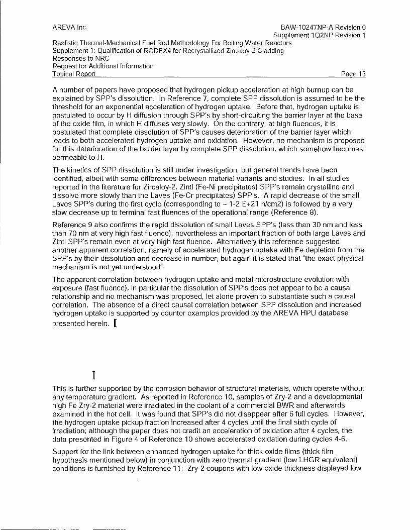
AREVA Inc. BAW-10247NP-A Revision 0 Supplement 1 Q2NP Revision 1
Realistic Thermal-Mechanical Fuel Rod Methodology For Boiling Water Reactors Supplement 1: Qualification of RODEX4 for Recrystallized Zircaloy-2 Cladding Responses to N RC Request for Additional Information Topical Report Page 13
A number of papers have proposed that hydrogen pickup acceleration at high burnup can be explained by SPP's dissolution. In Reference 7, complete SPP dissolution is assumed to be the threshold for an exponential acceleration of hydrogen uptake. Before that, hydrogen uptake is postulated to occur by H diffusion through SPP's by short-circuiting the barrier layer at the base of the oxide film, in which H diffuses very slowly. On the contrary, at high fluences, it is postulated that complete dissolution of SPP's causes deterioration of the barrier layer which leads to both accelerated hydrogen uptake and oxidation. However, no mechanism is proposed for this deterioration of the barrier layer by complete SPP dissolution, which somehow becomes permeable to H.
The kinetics of SPP dissolution is still under investigation, but general trends have been identified, albeit with some differences between material variants and studies. In all studies reported in the literature for Zircaloy-2, Zintl (Fe-Ni precipitates) SPP's remain crystalline and dissolve more slowly than the Laves (Fe-Cr precipitates) SPP's. A rapid decrease of the small Laves SP P's during the first cycle (corresponding to - 1-2 E +21 n/cm2) is followed by a very slow decrease up to terminal fast fluences of the operational range (Reference 8).
Reference 9 also confirms the rapid dissolution of small Laves SPP's (less than 30 nm and less than 70 nm at very high fast fluence), nevertheless an important fraction of both large Laves and Zintl SPP's remain even at very high fast fluence. Alternatively this reference suggested another apparent correlation, namely of accelerated hydrogen uptake with Fe depletion from the SPP's by their dissolution and decrease in number, but again it is stated that "the exact physical mechanism is not yet understood".
The apparent correlation between hydrogen uptake and metal microstructure evolution with exposure (fast fluence), in particular the dissolution of SPP's does not appear to be a causal relationship and no mechanism was proposed, let alone proven to substantiate such a causal correlation. The absence of a direct causal correlation between SPP dissolution and increased hydrogen uptake is supported by counter examples provided by the AREVA HPU database
presented herein. [
]
This is further supported by the corrosion behavior of structural materials, which operate without any temperature gradient. As reported in Reference 10, samples of Zry-2 and a developmental high Fe Zry-2 material were irradiated in the coolant of a commercial BWR and afterwards examined in the hot cell. It was found that SPP's did not disappear after 6 full cycles. However, the hydrogen uptake pickup fraction increased after 4 cycles until the final sixth cycle of irradiation; although the paper does not credit an acceleration of oxidation after 4 cycles, the data presented in Figure 4 of Reference 10 shows accelerated oxidation during cycles 4-6.
Support for the link between enhanced hydrogen uptake for thick oxide films (thick film hypothesis mentioned below) in conjunction with zero thermal gradient (low LHGR equivalent) conditions is furnished by Reference 11: Zry-2 coupons with low oxide thickness displayed low

[
AREVA Inc. BAW-10247NP-A Revision 0 Supplement 1 Q2NP Revision 1
Realistic Thermal-Mechanical Fuel Rod Methodology For Boiling Water Reactors Supplement 1: Qualification of RODEX4 for Recrystallized Zircaloy-2 Cladding Responses to N RC Request for Additional Information Topical Report Page 14
HPU, while large HPU was associated with thick oxide coupons. Although a speculative correlation to fast fluence is mentioned in Reference 11, it is clear that the data support the thick film threshold as a condition for enhanced HPU, concomitant with low heat flux.
H uptake model
Therefore, the model described herein relies on the following three main features, which act synergistically at long irradiation times and could result in enhanced HPU in those conditions:
The first and third items have been described in the previous section, while the second one is presented below.
Although no generally accepted model exists that could explain all aspects of Zry-2 corrosion and H pick-up, a widely accepted phenomenological feature of Zircaloy-2 corrosion is the socalled "thick film" hypothesis (Reference 12), which asserts that enhanced corrosion and hydrogen uptake occur in thicker oxide layers. It is remarkable that both oxidation and HPU are increased after the oxide thickness exceeds the thick film threshold. The explanation proposed for this seeming paradox is the mechanical damage and crack tunnel formation in the outer thicker oxide layer. In addition, the thick film hypothesis can be correlated with the Ni segregation on the grain boundaries as a result of SPP dissolution, which occurs after a certain irradiation time.
The thick film hypothesis was confirmed in a number of studies, such as References 10-12, where the accelerated oxidation and/or hydrogen uptake was noticed at about the same oxide thickness, namely 11-13 microns.
The inner 2-3 micron-thick layer which is tetragonal zirconia was found to be very opaque to H, i.e., H diffusion through it is extremely slow if anything (Reference 12). Temporary easier access routes though oxide pores and/or SPP crossing the oxide-metal boundary are the most likely explanations for the thick film behavior. In addition, at long irradiation time, the SPPs are
. dissolved and contribute to the decoration of oxide grain boundaries by alloying elements, which become shortcut pathways for H ingress.
[
1
]

AREVA Inc. BAW-10247NP-A Revision 0 Supplement 1 Q2NP Revision 1
Realistic Thermal-Mechanical Fuel Rod Methodology For Boiling Water Reactors Supplement 1: Qualification of RODEX4 for Recrystallized Zircaloy-2 Cladding Responses to N RC Request for Additional Information Topical Report Page 15
[
]
When LHGR decreases during the second part of the irradiation lifetime, the temperature gradient practically vanishes and the surface hydride layer dissolves leading to H transport into the metal. Further H ingress is then possible (assisted by the liner sink effect of the liner material). This leads to increased H uptake.
[
]

[
[
AREVA Inc. BAW-10247NP-A Revision 0 Supplement 1 Q2NP Revision 1
Realistic Thermal-Mechanical Fuel Rod Methodology For Boiling Water Reactors Supplement 1: Qualification of RODEX4 for Recrystallized Zircaloy-2 Cladding Responses to N RC Request for Additional Information Topical Report Page 16
In addition, the change to the higher HPUF values of F2 is conditioned by exceeding an incubation time threshold for low power operation that was set to:
] The power thresholds defined above are applicable to other fuel designs because the temperature drop across the cladding is similar for all fuel designs as the ratio of thickness to mean radius has been kept approximately the same for all fuel designs. Indeed, the temperature drop across the cladding thickness, t. can easily be calculated, using a constant zircaloy conductivity, k, and equating the heat flux at the cladding outer surface, R from Fourier's law with the expression derived from the definition of the linear power, P, to obtain:
The uniform oxidation model is a pre-requisite for calculating the hydrogen uptake by the above formulas. The hot-cell examinations that produced the HPU database also include metallographic determinations of the average uniform oxide at the neighboring location to the cut used to determine hydrogen uptake by a high-vacuum fusion and chromatographic measurement of hydrogen.
The model is based on the MATPRO (Reference 13) model with a variable adjusting factor that was used for calibration on the uniform oxide database. The oxide thickness is calculated with this variant of the MATPRO model, so that best-estimate agreement is obtained in the high
oxide end of the database, [ ] To that end a variable adjusting factor was implemented. The increase of oxidation rate above a certain oxide thickness is in accord with the thick oxide hypothesis adopted as a model assumption. The following values have been determined by calibration:
]

AREVA Inc. BAW-10247NP-A Revision 0 Supplement 1 Q2NP Revision 1
Realistic Thermal-Mechanical Fuel Rod Methodology For Boiling Water Reactors Supplement 1: Qualification of RODEX4 for Recrystallized Zircaloy-2 Cladding Responses to N RC Request for Additional Information Topical Report Page 17
H model calibration
The results of benchmarking on the AREVA HPU for Zry-2 are presented below.
The model was calibrated based on the current enlarged dataset, consisting of [
] by using the re-calibrated uniform corrosion model for Zry-2 as defined above. The results obtained are displayed in Figure 1. The calibration goal was to achieve a best-estimate model, especially in the high-end range; if necessary a moderately conservative, over predictive
model is acceptable in the low-end domain so that over [ ] H pick-up range a best-estimate model is obtained.
The results of the re-calibrated uniform oxidation model are presented in Figure 2 and show good centered prediction for the whole database domain. Figure 3 overlays uniform oxide calculations and measurements against irradiation time and shows the slight over prediction of the low end of the measured oxide range.
[
]

AREVA Inc. BAW-10247NP-A Revision 0 Supplement 1 Q2NP Revision 1
Realistic Thermal-Mechanical Fuel Rod Methodology For Boiling Water Reactors Supplement 1: Qualification of RODEX4 for Recrystallized Zircaloy-2 Cladding Responses to N RC Request for Additional Information Topical Report Page 18
[
] Figure 2: Calculated and Measured Hydrogen Uptake
[
] Figure 3: Calculated and Measured Uniform Oxide Thickness
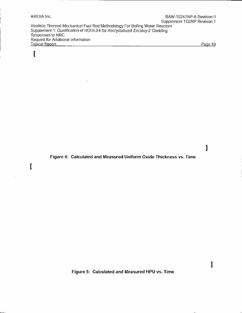
AREVA Inc. BAW-10247NP-A Revision 0 Supplement 1 Q2NP Revision 1
Realistic Thermal-Mechanical Fuel Rod Methodology For Boiling Water Reactors Supplement 1: Qualification of RODEX4 for Recrystallized Zircaloy-2 Cladding Responses to N RC Request for Additional Information Topical Report Page 19
[
] Figure 4: Calculated and Measured Uniform Oxide Thickness vs. Time
[
] Figure 5: Calculated and Measured HPU vs. Time
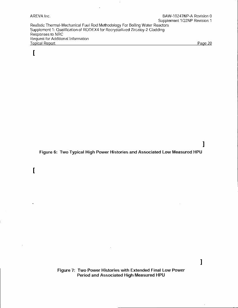
AREVA Inc. BAW-10247NP-A Revision 0 Supplement 1 Q2NP Revision 1
Realistic Thermal-Mechanical Fuel Rod Methodology For Boiling Water Reactors Supplement 1: Qualification of RODEX4 for Recrystallized Zircaloy-2 Cladding Responses to N RC Request for Additional Information Topical Report Page 20
[
[
Figure 6: Two Typical High Power Histories and Associated Low Measured HPU
Figure 7: Two Power Histories with Extended Final Low Power Period and Associated High Measured HPU
]
]

AREVA Inc. BAW-10247NP-A Revision 0 Supplement 1 Q2NP Revision 1
Realistic Thermal-Mechanical Fuel Rod Methodology For Boiling Water Reactors Supplement 1: Qualification of RODEX4 for Recrystallized Zircaloy-2 Cladding Responses to NRC Request for Additional Information Topical Report Page 21
Question 13
Related to RAI SC, please provide sample calculations for cladding collapse using the original recrystallized annealed (RXA) correlations and the new RXA correlations. The RAI SC responses mentioned 7% difference but did not state which one was higher or lower. This comparison will allow staff to assess the impact of using the original RXA correlations and the new RXA correlations in the cladding collapse calculation.
Response 13
The ovality benchmarking performed initially for the RODEX4 submitted topical (Reference 1) included five cases with recrystallized cladding in the HBRP program that had ovality measurements. All of them are rodlets with a similar power history, but with slightly different initial ovalites and consequently with different final ovalities measured after irradiation.
The results of the new RXA creep correlation in Supplement 1 to the RODEX4 topical for the five RXA cladding ovality cases are displayed in Figure 8, together with the results of the original RODEX4 topical RXA creep correlation. A systematic difference exists between the two
sets of results, which was calculated as approximately [ ] relative difference for each of the five cases.
This difference between the re-calibrated and original parameters of the creep model for RXA cladding is consistent with the expected behavior of the ovality evolution and its modeling as described in response to RAl-Sc. Moreover, the ovality calculated with the new RXA creep correlation is slightly larger than with the original RXA creep correlation, with the consequence that an earlier pellet-cladding contact is predicted, which in the context of the creep-collapse
criterion, leads to [
]
In conclusion, the impact on the creep-collapse criterion of the new RXA creep correlation is minor and in the direction of reducing the creep-collapse margin. The initial calibration of the ovality enhancement factor was demonstrated to remain valid for the new RXA creep correlation.
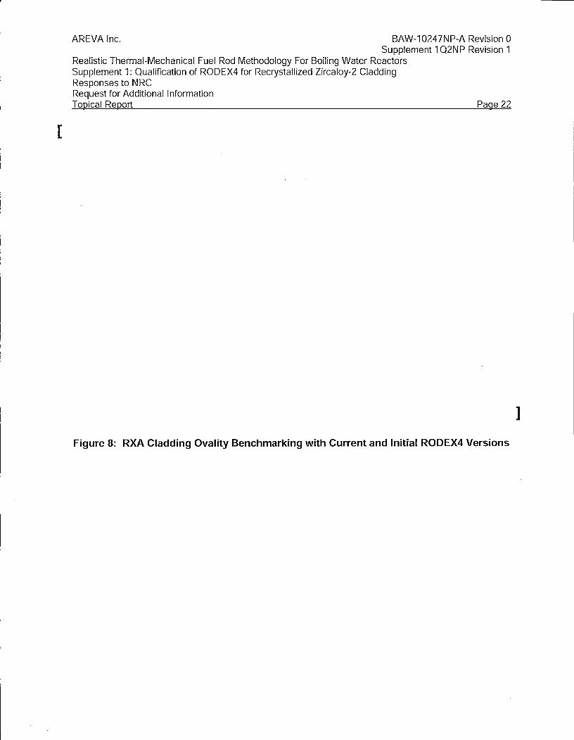
[
AREVA Inc. BAW-10247NP-A Revision 0 Supplement 1 Q2NP Revision 1
Realistic Thermal-Mechanical Fuel Rod Methodology For Boiling Water Reactors Supplement 1: Qualification of RODEX4 for Recrystallized Zircaloy-2 Cladding Responses to N RC Request for Additional Information T apical Report Page 22
Figure 8: RXA Cladding Ovality Benchmarking with Current and Initial RODEX4 Versions
]
AREVA Inc. BAW-10247NP-A Revision 0 Supplement 1 Q2NP Revision 1
Realistic Thermal-Mechanical Fuel Rod Methodology For Boiling Water Reactors Supplement 1: Qualification of RODEX4 for Recrystallized Zircaloy-2 Cladding Responses to N RC Request for Additional Information Topical Report Page 23
References
1. BAW-10247PA Revision 0, "Realistic Thermal-Mechanical Fuel Rod Methodology for Boiling Water Reactors," AREVA NP Inc., February 2008
2. [
]
3. G. A. Sofer, Leo van Swam, "Annular-Pellet Barrier-Clad Fuel Assemblies at the R. E. Ginna PWR: Hotcell Examinations," Research Report EP 80-17, Prepared by SPC, April 1997
4. [
]
5. G. Ledergerber et al, "Fuel Performance Beyond Design - Exploring the Limits," Proceedings of 2010 LWR Fuel Performance/Topfuel/WRFPM Orlando, Florida, USA, September 26-29, 201 O
6. T. Nakamura et al., "High-Burnup BWR Fuel Behavior under Simulated Reactivity-Initiated Accident Conditions," Nucl. Techn., Vol. 138, pp 246-259, June 2002
7. G. Zhou et al, "Corrosion and Hydrogen Uptake Behavior and Modeling for Modern BWR Cladding Materials at High Burnup," Proceedings of TopFuel 2009, Paris, France, September 6-10, 2009
8. 0. Takagawa et al, "The Correlation between Microstructure and in-BWR Corrosion Behavior of Highly Irradiated Zr-based Alloys," Jo. of ASTM Int., Jan 2004, Vol. 2, No. 1, Paper ID JAl12357
9. S. Valizadeh et al, "Effects of Secondary Phase Particle Dissolution on the In-Reactor Performance of BWR Cladding," Zirconium in the Nuclear Industry Symposium, Chengdu, China, 2010
10. K. Kakiuchi et al, "Irradiated Behavior at High Burn up for HiFi Alloy," Jo. Of Nucl. Sci. and Techn., Vol. 43, No. 9, p. 1031-1036
11. S. lshimoto et al, "Improved Zr Alloys for High Burnup BWR Fuel," Proceedings of TopFuel 2006, Salamanca, Spain, pp 318-329, October 22-26, 2006
12. "Waterside Corrosion of Zirconium Alloys in Nuclear Power Plants," IAEA-TECDOC-996, January 1998
13. SCDAP/RELAP5/MOD3.1 Code Manual. Volume IV: MATPRO - A Library of Materials Properties for Light-Water-Reactor Accident Analysis, NUREG/CR-6150, EGG-2720, Volume IV, November 1993.

BAW-10247PA Revision O Supplement 1 NP Revision O
Realistic Thermal-Mechanical Fuel Rod Methodology for Boiling Water Reactors
Supplement 1: Qualification of RODEX4 for Recrystallized Zircaloy-2 Cladding
December 2009
A AREVA

AREVA NP lriC;
BAW-10247PA Revision 0 Supplement 1 NP Revision o
Realistic Thermal-Mechanical Fuel Rod Methodology for Boiling Water Reactors
Supplement 1 : Qualification of RODEX4 for Recrystallized Zircaloy-2_ Cladding
Realistic Thermal-Mechanical Fuel Rod Methodology for Bolling Water Reactors Supplement 1: Qualification of RODEX4 for Recrystallized Zircaloy-2 Cladding
Nature of Changes
BAW-10247PA Revision 0 Supplement 1 NP Revision 0
Pagei
Item Page Description and Justification
1.. All This is a new document.
AREVA NP Inc.

Realistic Thermal-Mechanical Fuel Rod Methodology for Boiling Water Reactors Supplement 1: Qualification of RODEX4 for Recrystallized Zircaloy-2 Cladding
BAW.,.10247PA Revision 0 Supplement 1 NP Revision O
Page ii
Contents
1.0 Introduction·'···'······'·············--···: ...... , •................................................................................ 1
2.0 Thermal Creep Model Re-calibration for RX Zr-2 Cladding .............................................. 2 2.1 Formulation of the u_nified creep-plasticity constitutive equation ................................... 2
2.1.1 Generalized stress and anisotropy coefficients .......................................................... 2 2.1.2 The strain rate constitutive equation .......................................................................... 3 2.1 ;3 Internally pr~ssuriz~d closed tube tests ..................................................................... 5
2.2 Model parameter determination from creep tests at different stress levels ................... 7 2.2~ 1 Determination of H1 and H5 parameters ..................................................................... 7 2.2,2 Determination of the Ha parameter ............................................................................. 8 2.2.3 Determin(ition of the anisotropy coefficients ............................................................ 1 O
2~3 R.esults of tlie thermal creep calibration to RX Zr-2 material.. ..................................... 1 o 2.3.1 Evaluation of H1 and Hs parameters ........................................................................ 1 O 2~3.2 Evaluation of Ha parameter and the P anisotropy par'arneter .. , ... ,, .. ,, ...... , .. , ......•...... 11
3.0 3.1 3.2
4.0 4.1 4.2
5.0
6,0
7.0
8.0
Irradiation Creep Model Re-calibration for RX Zr-'2 Cladding ................. , .. , ... ,, ......... , .. ,~ .. 13 Model description •... , ..................................................................................................... 13 Re.:calibration results ... _, ....•......... , ..... , .......................................................................... 14
Irradiation Growth .Model Re'-calibration for RX Zr-2 Cladding ........................................ 15 Free stress irradiation growth model ........................................................................... 15 Calibration results ....•...... ~._ .... , ...................................................................................... 16
Model Parame'ter Unc:ertalnty Evaluation for the RX Zr-2 Thermal and Irradiation .Creep Mqdel .. , ..•... , ...... , ......•............. : •... , ......................................................................... 17
Calibration of the Corrosion Model for RX Zr-2 Cladding and Evaluation of Its Associated Model Parameter Uncertainty ....................................................................... 18
Validation of the RX Zr-2 Mechanical Models Re-calibration by Benchmarking the Free Volum~ Database·········•····"········'·································-~--: .................................... 18
References .•....•....•.•.•..•. -.•.•....••.•.•..•...•..•.......................................................................... 20
AREVA NP Inc.

Realistic Thermal~Mechanical Fuel Rod Methodology for Boiling Water Reactors Supplement 1: Qualification of RODEX4 for Recrystallized Zircaloy-2 Cladding .
BAW-10247PA Revision O Supplement 1 NP Revision 6
Page iii
Tables
There are no tables in ·this document.
Figures
Figure 1 Lin$ar fit to determine H1 and HS parameters .. , .... ,., ..•. , ....... ,.,.,, ...•..•.... ,.,, .•. , .• ,.,, .... ~ ... 21
Figure 2 Comparison of predicted to measured creep hoop strains during long• term creep tests of as-manufactured RX Zr-2 cladding ........ ; ................................... :21
Figure 3 Initial exponential fit of irrac:liation hardening with constant P···•''····'···'··'······'······-,, .. ,.,22
Fi~ure 4 Evolution o.f the hoop yield to axial yield ratio with fast fluence , ............ , .... , ....• , .... , ..... 22
Figure 5 Evolution of the P parameter with fast fluence ...•.. , ............. ~ •........... , .•.... , ..•. ,; ... , ..• , ...•. 23
Figure 6 Final calibration of irradiation hardening with rast fluence-dependent P ............. ; ....... ,23
Figure 7 Comparison of measured to calculated hoop yield values .................................... ; ..... 24
Figure .8 Creepdown benchmarking of RX Zr-2 database ...... ,.,, .. : .. , .... , ........... ,., ..................... ,24
Figure 9 Net axial growth benchmarking of RX zr.;2 database ........... , ...................................... 25
Figure 10 Deviation of prediction from me~surement for RX Zr-2.creepdown database ................. , .....••.... ;;; ..•..... ~"···'·· ... •'·····.•·.·'·········'''··"··'"·········'··················'··'··'·'··25
Figure 11 Deviation of prediction from measurement for CWSR Zr-2 ,. .• , .•....... ., .•....•..•.... , .. ,, .. ,. 26
Figure 12 Benchmarking of A-10 RXZr-2 corrosion·database .. , .. , ............................................ 26
Figure 13 Benchmarking offree volume for RX Zr-2 database ................................................ ~27
Figure 14 Free volume predictions and measurements as a function of burnup for RX .Zr-2 database ........................................................................................................ 27
This document contains a total pf 35 pages.
AREVA NP lr')c.

Realistic Thermal-Mechanical Fuel Rod Methodology for Boiling Water Reactors Supplement 1: Qualification of RODEX4 for Recrystallized Zircaloy-2 Cladding
Acronym Definition
AREVA NP Inc.
Nomenclature
BAW-10247PA Revision 0 Supplement 1 NP Revision O
Page iv
AREVA NP ASTM B&W
ASTM (American Society for Testing and Materials) Babcock & Wilcox
BWR CWSR Gd LTP MPa PCI RX SE U02 Zr-2 p R
AREVA NP Inc.
Boiling Water Reactor Cold Worked and Stress Relieved Gadolinia Low Temperature Process Mega Pascal Pellet-Cladding Interaction Recrystallized Safety Evaluation Uranium Dioxide Zircaloy-2 P anisotropy parameter R anisotropy parameter
J

Realistic Thermal-Mechanical Fuel Rod Methodology for Boiling Water Reactors Supplement 1: Qualification of RODEX4 for Recrystallized Zircaloy-2 Cladding
Abstract
BAW-10247PA Revision 0 Supplement 1 NP Revision 0
Pagev
This supplement to the approved BAW-10247PA, "Realistic Thermal-Mechanical Fuel Rod
Methodology for Boiling Water Reactors," presents benchmarking and re-calibration of the
cladding mechanical models in RODEX4 for an enlarged recrystallized (RX) Zircaloy-2 database.
The only change to the modeling in RODEX4 was the addition of a model ~hat describes the
change in anisotropy of RX Zircaloy-2 with irradiation. This model change was necessary
because the irradiation effect, while not significant for cold-worked stress-relieved (CWSR)
cladding, is pronounced for" RX cladding.
The objective of this supplement is to obtain NRC approval to extend condition c. of the Safety
Evaluation to allow modeling of BWR Fuel Rods with RX Zircaloy-2 cladding.
AREVA NP Inc.

Realisti.c Thermal-Mechanical Fuel Rod Methodology for.Boiling Water·Reactors Supplement· 1: Qualification of RODEX4 for Recrystallized Zircaloy-2 Cladding
1.0 INTRODUCTION . .
BAW-10247PA Revision O supplement 1 NP Revision 6 . . . . .
Page 1
The pµrpose of this supplement is to extend applicability of the approved RODEX4 boiling water
reactor (BWR) realistic methodology to allow analyses With recrystallized (RX) Zircaloy-2
cladding. Currently, co.ndition c. of the SE restricts application to only cold-worked and stress
relieved (CWSR) cladding.
During the u. S. Nuclear Regulatory Commission review, it was indicated that the experimental
dataset for irradiation growth and creep of RX Zr-2 claddjng was insufficient and more .data
would be needed in order to assure an adequate verification and validation of the mechanical
properties of RX Zr-2 material.
To tha~ ~nd, an enlarged RX Zr,.2 database was prepared based on ARE:VANP Inc. (AREVA
NP) operating experience with the RXZr-2 cladding type in Europe. AREVA NP has
manufactured RX Zr-2 cladding for a number of years and has ·considerable irradiation
experience in BWR rcaactors.
The specification and manufacturing process for RX Zr-2 cladding has evolved over the years to
improve both mechanical and corrosion properties. Cum~ntly, the Low Temperatur~ Process
(L TP) zr.,.2 is AREVA'S standard product, available in both the RX .aild CWSR rn<atallurgical
condition. It is optimized in terms of secondary precipitates to assure high performance for
uniform and nodular corrosion. In addition, the fabrication process assures a high radial texture
(the R anisotropy factor, described herein), which confers the best combination of high strength
ancl high duc~ility as well as favorabi~ peilet-cladding interaction (PCI) pertormance,.
The expanded RX database has been used to re-calibrate the following models:
• Thermal creep
· • Irradiation creep
• Free-stress irradiation g·rqwth
• Cprros.ion
Ttie following sections describe the models along With the methods used to re-calibrate the
m9dels and the rei:3ults.
AREVA NP Inc.
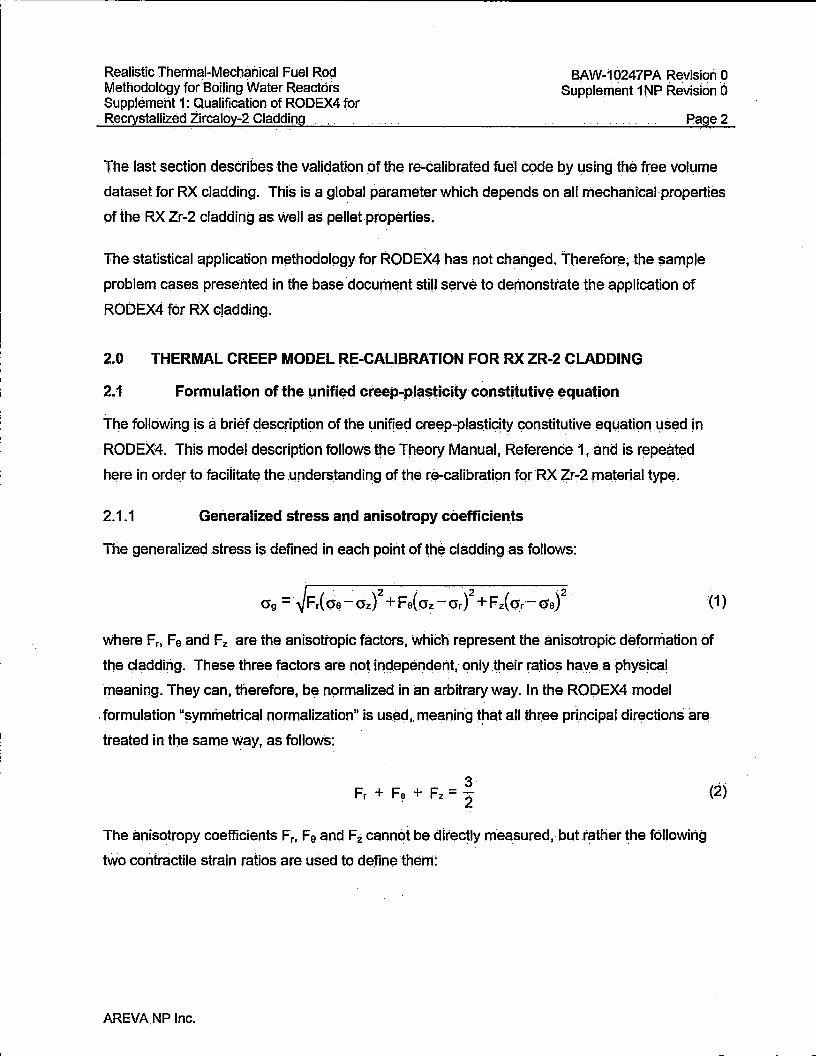
Realistic Thermal-:Mechanical Fuel Rod Methodology fo(Boiling Water Reactors Supplement 1: Qualification of RODEX4 for Recrystallized Zircaloy-2 Cladding
BAW-10247PA Revision 0 Supplement 1 NP Revision 6
Page2
The last section describes the validation pf the re-calibrated fuel code by using the free volume
dataset for RX cladding. This is a global parameter which depends on all niechanical·properties
of ihe RX Zr-2 cladding as Well as pellet properties.
The statistical application methodology for RODEX4 has not changed. Therefore; the $ample
problem cases presented in the base docum~nt still serve to demonstrate the application of
RODEX4 for RX cladding.
2 .. 0 THERMAL CREEP MODEL RE-CALIBRATION FOR RX ZR-2 CLADDING . . .
2 .. 1 Formule1tion of the µnified creep-plasticity constitutive ~quation . .
The following is a brief qescription of the unified creep-plasticity constitutive equation used in
RODEX4. This model description follows the Theory Manual, Reference 1, and is repeated
here in order to faciiitate the .understanding of the re-calibration for RX fr'."2 mciterial type.
2.1.1 Generalized stress and a.nisotropy coefficients
The generalized stress is defined in each point of the cladding as follows:
'(1)
Where Fr, Fe and Fz are the anisotropic factors, which represent the anisotrqpic deformation of
the cladding. These three factors are not independent; only .their ratios have a physical
meaning. They can .• therefore, be normalized in an arbitrary way. In the ROOEX4 model
. formulation "symmetrical normalization" is us~d •. meaning that all three principal directions are
treated in the same way, as follows:
3 Fr + Fe + Fz = i
The anisotropy coefficients Fr. Fe and Fz cannot be directly m·easured, ·but rather the following . . .
tWo contractile strain ratios are used to definefthem:
AREVA.NP Inc.
(2)
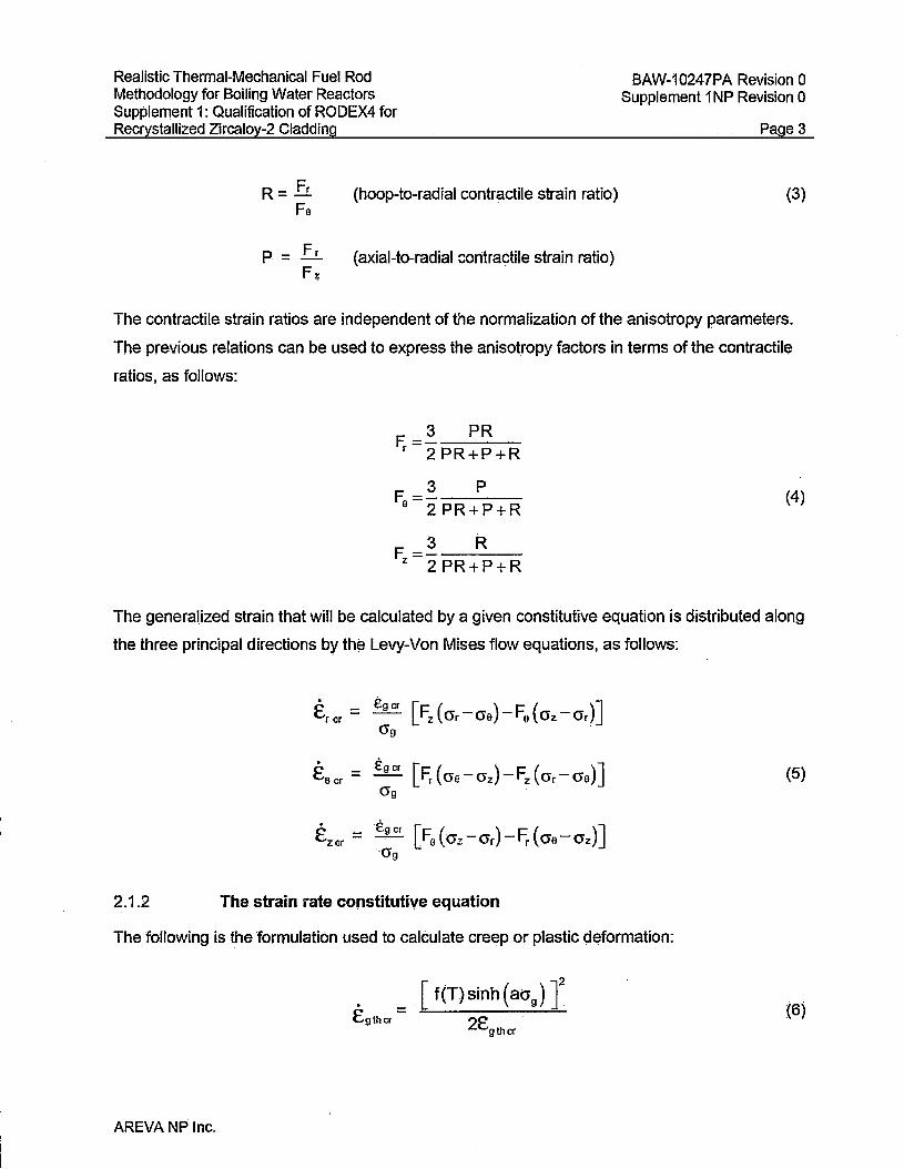
Realistic Thermal-Mechanical Fuel Rod Methodology for Boiling Water Reactors Supplement 1: Qualification of RODEX4 for Recrystallized Zircaloy-2 Cladding
R= Fr Fe
p = Fr Fz
(hoop-to-radial contractile strain ratio)
(axial-to-radial contractile strain ratio)
BAW-10247PA Revision O Supplement 1 NP Revision O
Page3
(3)
The contractile strain ratios are independent of the normalization of the anisotropy parameters.
The previous relations can be used to express the anisotmpy factors in terms of the contractile
ratios, as follows:
3 PR F.=-----
r 2PR+P+R
3 p F =-----a 2PR+P+R
3 R F ='----
z 2 PR+P+R
(4)
The generalized strain that will be calculated by a given constitutive equation is distributed along
the three principal directions by th~ Levy-Von Mises flow equations, as follows:
. f:ger [Fz (crr-cr0)-F0 ( crz-crr)] trer = (Jg
. fg er [Fr { cre -crz)-Fz { O"r - cra)] teer = (5)
(Jg
. fg er [Fa ( crz -crr )-Fr ( cra-crz)] Ezer =
O"g
2.1.2 The strain rate constitutive equation
The following is the formulation used to calculate creep or plastic d~formation:
[ f (T) sinh ( aa9 ) r 2tgthcr .
(6)
AREVA NP Inc.

Realistic Thermal-Mechanical Fuel Rocj Methodology for Boiling Water Reactors Suppleme"nt 1: Qualification of RODEX4 for Recrystallized Zircaloy-2 Cladding
where the temperature-dependent term is as follows:
f(T) = K exp(- Eth ). · kT
with
Eth = activation energy
k = Boltzmann constant
K = propqrtionality constant
T = absolu_te temperature
[
AREVA NP .Inc.
BAW-10247PA Revision 0 Supplement 1NP Revision 6
Page4
(7)
(8)·

Realistic Thermal-Mechanical Fuel Rod Methodology for Boiling Water Reactor~ _ Supplemeht 1: Qualification of RODEX4 for Recrystallized Zircaloy-2 Cladding
]
BAW.,.10247PA Revision 0 Supplement 1 NP Revlskm 6 . . - . .
Pages
(9)
Mechanical tests ori irradiated pieces of cladding reveal ari increase of the Zircaloy yield
strength with irradiation. This phenomenon is called "irradiation hardening." the results of the
mechanical tests show tnat this effect ca)l be simulated by decreasing the parameter a in
Equation 6 when the fast fluence increases, as follows:
a = a,+ (a1 -a0{1~exp(-:J] (10)
'I' 0 = 1 025 neutrons I m2
with
\jl = -fast neutron fluence > 1 MeV
ao ~ value of parameter a for non-irradiaied cladding
a1 = value of parameter a for cladding irradiated at high fast fluence
2.-1.3 Internally pressurized closed tube tests
In this analysis, as well a~ in all previc;>Lis analyses, the thin wall membrane. approximation was
used, which in its classical form neglects the radial stress as being less than .5% of the hoop
stress. A more detailed study has shown th~t this approximation is pr~ctically equivalent from
the point of view of model parameter estimation, with the calculation that accounts for the rciidial
stress as small but different from zero.
Therefore, the-stress state car1.be descril:>ed as:
= 0 (11 )'
= 0'9 2
(1·2)
AREVA NP Inc.

Realistic Thermal-Mechanical Fuel Rod Methodology for Boiling Water Reactors Supplement 1 : Qualification of RODEX4 for Recrystallized Zircaloy-2 Cladding
BAW-10247PA Revision 0 Supplement 1 NP Revision 0
Page6
Then the generalized stress of Equation 1 can be written as a function of the hoop stress, O'a ,
as follows:
while the hoop plastlc strain rate or strain is linked to the generalized strain by the following
relation:
where:
1
= -+-F 2 (3 3 )-8 4 z
1 3R(P+2) 8 0 4(PR+P+R)
With the above notations, the strain rate Equation 6 can be re-written as follows:
[
]
Moreover, after the following notations are made:
H1 = ln{A9 K1h)
H2 To
H3 = Q1
H4 Q2
Hs = Ba ao
Hs = Ba(ao -a1)
AREVA NP Inc.
(13)
{14)
(15)
(16)
(17)

Realistic Thermal-Mechanical Fuel Rod Methodology for Boiling Water Reactors Supplement 1: Qualification of RODEX4 for Recrystallized Zircaloy-2 Cladding
the strain rate Equation 17 becomes:
[
BAW~10247PA Revision 0 Supplement 1 NP Revision O
Page?
(18)
(19)
{20)
1
2.2 Model parameter determination from creep tests at different stre~s levels
With the notations of the Equations 18 through 20, the internally pressurized closed tube creep
test is described by the following equation:
[
(21)
]
The above formulation is based on the thin wall membrane approximation, which usually
neglects the radial stress (which i:; in this approximation less than 5% of the hoop stress). This
approximation is described by relations 11 and 12.
2.2.1 Determination of H1 and Hs parameters
The above description allows the relation for the evolution of the hoop strain during the creep
test of an internally pressurized closed tube to be obtained by integrating Equation 21, thus
AREVA NP .Inc.

Realistic Thermal-Mechanical Fuel Rod Methodology for ·Boiling Water Reactors Supplement 1: Qualification of RODEX4 for Recrystallized Zircaloy-2 Cladding
BAW .. 10247PA Revision 0 Supplement 1 NP Revision o
Page a
reverting to the assumed parabolic dependency between the hoop creep strain and time, which
was the starting basis of the model.
Then the hyperbolic sin function is approximated by neglecting the term with a negative
exponent, whicn is smal.1 at high stress, as is the case for the creep tests modeled here, as
follows:
and finally the logarithm is applied to both sld~s of the equation, to obtain:
[
]
(22)
(23)
The temperature term is based on previous studies which is ~enerally applicable to Zr alloy and
therefore has not been modified.
The parameters H1 and Hs are determined by plotting the above relationship between
[ ] and oe whlle Hs is determined from the irradiation hardening data. Long term cr¢ep
te~t data are available at three stress levels-80 MPa, 100 MPa and 120 MPa, respectively, all
performed at 350 °C to 10,000 .hrs. The average value of the left;.hand $ide of Equation 2S is
determined (as it'should be a constant) for the three stress. levels separately. Then, these three
values 9f the left hand side of Equation 23 are fitted to a line versus the stre~ antj the slop~ e>f
that line represents the Hs param.et~r. The y-iritercept of the line is tne tree term in Equation :23,
and thus H1 is obtained after subtracting the temperature term.
2,2.2 Determination of the Hs parameter
In order to determine the Hs parameter. the axial yield val.ues measured after irradiatiori are
used. In that case the uniaxial tensile test is characterized by only the axial stress being
different from zero. The axial yield stress, Y z, is estimated by using a strain rate of 0.5%. min-\
which is the ASTM re¢ommerided value that is typically used in tensile tests. The permanent
strain is set to 0.2%, which is the definition for the.yield stress. Then, by inverting the hyperbolic
sin function, a relation is obtained for the·axi(il yield stress ..
AREVA NP Inc.
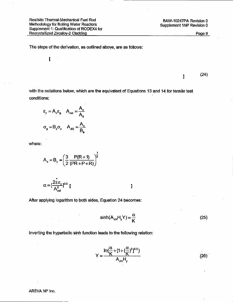
Realistic Thermal-Mechanical Fuel Rod Methodology for Boiling Water Reactors Supplement 1: Qualification of RODEX4 for Recrystallized Zircaloy-2 Cladding
The steps of the derivation. as outlined abo\fe, are as follows:
[
BAW .. 10247PA Revision 0 Suppiement 1NP Revision 6
Page.9
1 (24)
With the notations below, which are the equivalent of Equations 13 and 14 :for tensile test
cpnditions:
where:
A A - z
.zat ~A a
Azb. = Az . ·' B . a
1
A = B =(3 P(R+1) )2 z z 2(PR+P+R).
1
After ~pplying logarithm to both sides, Equation 24 becomes:
Inverting the hyperbolic 'si.n.h function leads to the followin~ relation:
AREVA NP Inc.
(25)
(29)

Realistic Thermal-Mechanical Fuel Roc:t . Methodology for Boiling Water Reactors Supplement 1: Qualification of RODEX4 for Recrystallized Zircaloy-2 Cladding
BAW-10247PA Revision O Supplement 1 NP .Revision o
Page 10.
With the other rriodel parameters fbced, the Ha p~rameter was varied until the best fit to the
measured axial yield stress values was achieved, as defined by the average su·m of squares.
2.2.3 Determination pf the anisotropy coefficients
Th~ derivation of the ratio of the hoop yield stress to the axial yield stress is given in
Reference 2 .and relies on the same approximation of the sihh function by the first exponential
term, as explained above for the creep.test interpretation. The following relation is obtained:
Y0 _ 1 Yz -:- [0.25+R/(PR +P)]°"5
The R anisotropy coefficient is determined by mechani~al tests after manufacturing, and a
median value of the m.ost recen~ measurements is R = [ ].
In addition the R value can be. deduced from the relationship between the R anisqtropy
coefficient and the Kearns texture factor being:
R= fr 1-f -f r z
With the measured Kearns parameter values, the R value calculated by using the above
(27)
equation is about ( ], which is close to the ( ] measured value and vef\/ different from
the previous R value of ( ]. It is worth mentioning that the R to fr relationship is qualitatively
torrect but it is subject to a !?ignificant scatter; .therefore, the small differenc;:e is not surprising.
' '
2.3· ·Results ofthe thermal creep calibration to RX Zr-2 fT!aterial
2.3.1 !:valuation of H1 and Hs parameters
The two parameters, H1 :and H5, WE!re determined as explaln·ed in Section 2.2.1, above, using
the long-term creep tests.
!=igure 1 ill.ust~ates the exqelleht linear fit obtained fer Equation 23, which allows the· evaluation
Of the H1 and H5 parameters as indicated by they-intercept and the slope, respectively.
AREVA NP Inc•

Realistic Thermal-Mechanical Fuel Rod Methodology f6r Boiling Water Reactors . . .
Supplement 1: Qualification of RODEX4 for Recrystallized Zircaloy-2 Cladding
BAW-10247PA Revision 0 Supplement 1 NP Revision o . .
Page 11
The final values of H1 and H9 were established by fine tuning against the long-term creep data in
order to minimize the overall difference between predictions and measurements and also ·to
agree with the axial yield stress values as mucti as possible. The values of H1 = [ ] and
H5 = { ] were found to provide the best fit, as illustrat13d in Figure 2, which shows the final
result.
2,3.2 Evaluation of H6 parameter and the P anisotropy parameter
The data reported in References 3 to 5 were used to determi.ne the Hs parameter, However, the
determination of Hs is linked to that qf the P anisotropy parameter. This Is because the basis for
H6 estimatiqn is the axial yield stress.of irradiateq material, and P affect~ the value of the-axial
yield stress.
In order to determine the P anisotropy coefficient for unirradiated material, Equation 27 is used
with the established value of the R parameter, The ratio Ya/Yz was calculated as approximately
[ ] by using Yz and Ye vaiues as specified l~ Reference 4 (bottom of page 3) for the yield
stress at 350 °C. The Ye va_lue is also mentioned in Reference 5 at the same temperature.
The values for unirradiated material are also confirmed by the AREVA NP qualification results of
RX Zr-2 cladding produced by AREVA NP, A similar high value of P was also determined in
Reference 6. Also, R13ference 7 indicates a ratio of Rfp· of 0.38. When correlated with 'the R
value qf [ ] as determined in Section 2.2,3, the result is P = [ ]. The final value inferred
from all sources was rounded off to P = [ ].
With the constant P = [ ] and H1 :and Hs as determined ih Section 2,3.1 above, an initial
calibr~tion of the irradiation hardening was performed, which provic:led H9 = [ ] and H1 = [ ]. This is illustrated in Figure 3.
lh~re are strong indications (such as in References 8 and 9) that irradiation caus~s a significant
change from the initial pronounced anisotropy of RX Zr-2 to a near isotropic behavior. This is
i::ohfirmed by the axial tensile arid burst data on irradiated RX material (References 4 ~nd 5).
. .
In ord~r to_ take into account a varying value of P, a fast fluenceMdependent correlation was
developed based on both axial tensile and burst yield values.
AREVA NP Inc.
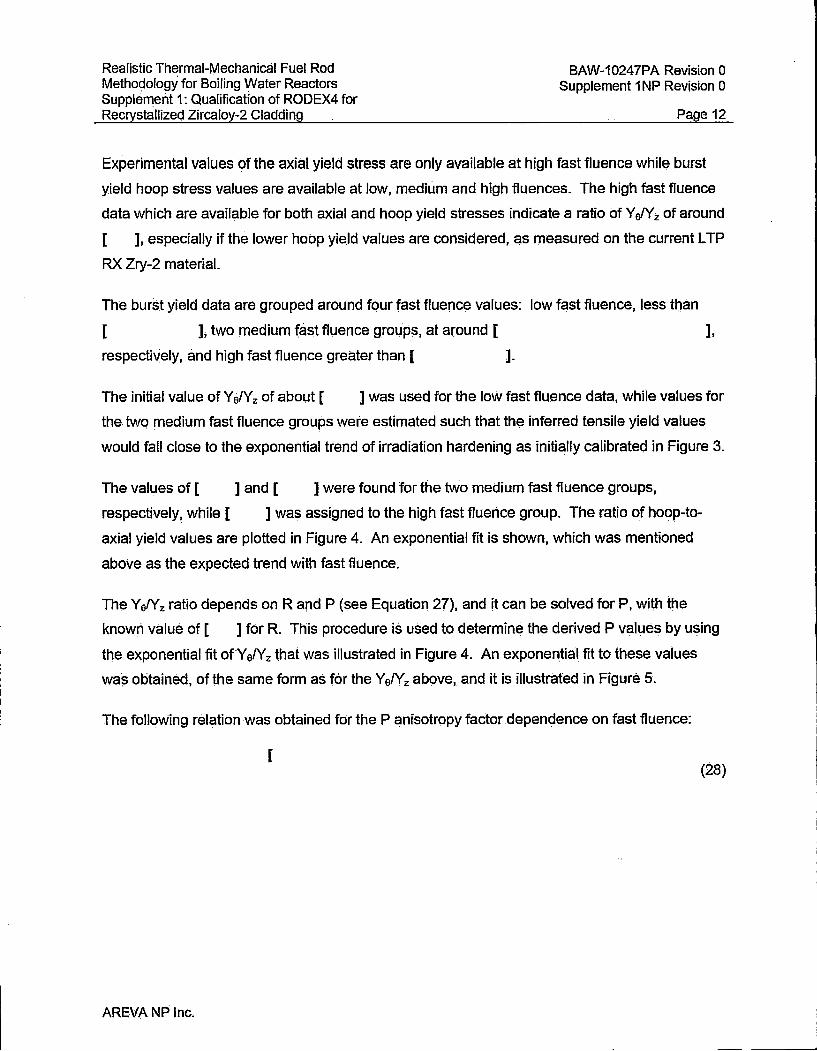
Realistic Thermal-Mechanical Fuel Rod Methodology for Boiling Water Reactors Supplement 1: Qualification of RODEX4 for Recrystallized Zircaloy-2 Cladding
BAW-10247PA Revision 0 Supplement 1 NP Revision O
Page 12
Experimental values of the axial yield stress are only available at high fast fluence while burst
yield hoop stress values are available at low, medium and high fluences. The high fast fluence
data which are available for both axial and hoop yield stresses indicate a ratio of Y elY z. of around
[ ], especially if the lower hoop yield values are considered, as measured on the current L TP
RX Zry-2 material.
The burst yield data are grouped around four fast fluence values: low fast fluence, less than
[ ], two medium fast fluence group~. at around [ ],
respectively, and high fast fluence greater than [ ].
The initial value of YefYz of about [ ] was used for the low fast fluence data, while values for
the twq medium fast fluence groups were estimated such that the inferred tensile yield values
would fall close to the exponential trend of irradiation hardening as initially calibrated in Figure 3.
] and [ ] were found for the two medium fast fluence groups, The values of [
respectively, while [ ] was assigned to the high fast fluerice .group. The ratio of hoop-to-
axial yield values are plotted in Figure 4. An exponential fit is shown, which was mentioned
above as the expected trend with fast fluence.
The Y e!Yz ratio depends on Rand P (see Equation 27), and it can be solved for P, with the
known value of [ ] for R. This procedure is used to determine the derived P values by using
tile exponential fit ofYefYz that was illustrated in Figure 4. An exponential fit to these values
was obtained, of the same form as f6r the YefYz above, and it is illustrated in Figure 5.
The following relation was obtained for the P anisotropy factor .dependence on fast fluence:
[
AREVA NP Inc.
(28)

Realistic Thermal-Mechanical Fuel Rod Methodology for Boiling Water Reactor~ Supplemeht 1: Qualification of RODEX4 for Recrystallized Zircaloy-2 Cladding
BAW-10247PA Revi~ion 0 Supplement 1 NP Revision o
Page 13
]
Using P that is depe·ndent on fast fluence; it was necessary to recalibrate the irradiation
hardening parameters H6 and H7• Figure 6 shows the resuit obtained with the values
He = [ ] and H1 = [ ]. The value of He minimizes the root-mean-square
deviation of predictions from measurements when AREVA NP data are considered only (the
older B~qcock & Wilcox data are slightly under-predicted, qut the B&W material is different from
current AREVA RX Zr-2 material).
Moreover, Figure 7 illustrates the fit With the hoop yield data, which validates the estimated
variable P as determined from Equation 28.
3.0 IRRADIATION CREEP MODEL RE~CALIBRATION FOR RX ZR-2 CLADDING
3.1 . Model description
The formulation ofthe irradiation creep model is as follows:
• - K n ,y.m Cgirrcr - irr O"g 'P (29)
In the case of a pressurized thin tube and in all cases when relations 11 and 12 are satisfied;
the previous relation can. be re-written as
(30)
' '
It comains the parameters As and 80 which are functions of the anisotropy factors Rand P. As
for thermal creep, it is possible to rewrite the equation so that the calculated hoop irradiation
creep will be insensitive .to the choice oOhe anisotropy factors as long as·the,state·of stresses is
close to the conditions expressed in Equations ~ 1 and 12. The following d~finitions are used:
(31')
AREVA NP Inc.
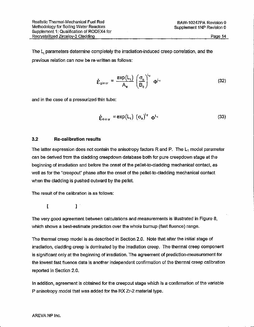
Realistic Thermal-Mechanical Fuel Rod Methodology for Boiling Water Reactors Supplement 1: Qualification of RODEX4 for Recrystallized Zircaloy-2 Cladding
BAW-10247PA Revision 0 Supplement 1 NP Revision O
Page 14
The L1 parameters determine completely the irradiation-induced creep correlation, and the
previous relation can now be re-written as follows:
and in the case of a pressurized thin tube:
3.2 Re-calibration results
(32)
(33)
The latter expression does not contain the anisotropy factors R and P. The L, model parameter
can be derived from the cladding creepdown database both for pure creepdown stage at the
beginning of irradiation and before the onset of the pellet-to-cladding mechanical contact, as
well as for the "creepout" phase after the onset of the pellet-to-cladding mechanical contact
when the cladding is pushed outward by the pellet.
The result of the calibration is as follows:
[ ]
The very good agreement between calculations and measurements is illustrated in Figure 8,
which shows a best-estimate prediction over the whole bumup (fast fluence) range.
The thermal creep model is as described in Section 2.0. Note that after the initial stage of
irradiation, cladding creep is dominated by the irradiation creep. The thermal creep component
is significant only at the beginning of irradiation. The agreement of prediction-measurement for
the lowest fast fluence data is another independent confirmation of the thermal creep calibration
reported in Section 2.0.
In addition, agreement is obtained for the creepout stage which is a confirmation of the variable
P anisotropy model that was added for the RX Zr-2 material type.
AREVA NP Inc.
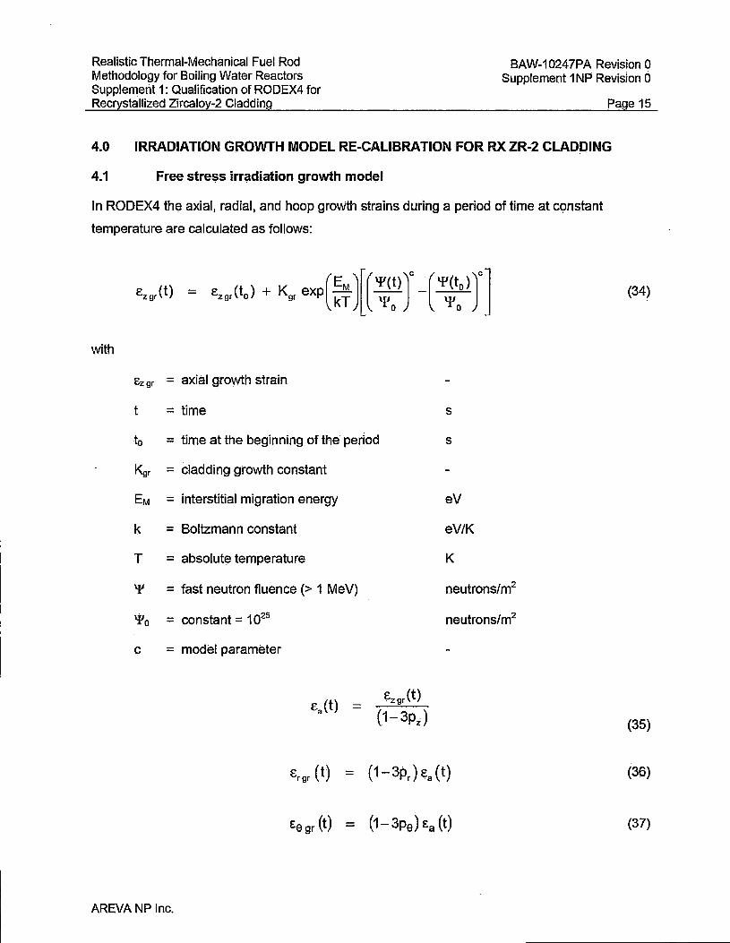
Realistic Thermal-Mechanical Fuel Rod Methodology for Boiling Water Reactors Supplement 1: Qualification of RODEX4 for Recrystallized Zircaloy-2 Cladding
BAW-10247PA Revision 0 Supplement 1 NP Revision O
Page 15
4.0 IRRADIATION GROWTH MODEL RE-CALIBRATION FOR RX ZR.;2 CLADDING
4.1 Free stress irradiation growth mod~I
In RODEX4 the axial, radial, and hoop growth strains during a period of time at constant
temperature are calculated as follows:
e,,,(t) ~ e,,, (t,) + K,, exp ( ~~ )[ ( ~:) J -[ "'~:) J] with
Ez gr = axial growth strain
t =time
to = time at the beginning of the period
l<gr = cladding growth constant
EM = interstitial migration energy
k = Boltzmann constant
T = absolute temperature
'{J = fast neutron fluence (> 1 MeV)
'Po = constant = 1025
c = model parameter
AREVA NP Inc.
ezgr(t)
(1-3pi)
s
s
eV
eV/K
K
neutrons/m2
neutrons/m2
(34)
(35)
(36)
(37)
Realistic Thermal-Mechanical Fuel Rod Methodology for Boiling Water Reactors Supplement 1: Qualification of RODEX4 for Rec'">;stallized Zircaloy..;2 Cladding
BAW.,.10247PA Revision 0 Supplement 1 NP Revision o . . . .
Page 16
with
Er gr = radial growth strain
Eo gr = tangential growth strain
Pr = radial Kearns texture factor
· Pz = axial Kef.jlrns texture factor
Pe = tangential Kearns texture factor
EM is the interstiti~I migration energy. It is used to define the temperatur~ dependence of
Zircaloy s;irowth~ The variable EM can therefore be derived from growth measurements. The
cladding elongation measurements are consistent with a value of EM/k = 240.8 K, which
corresponds to a valµe of EM equal t() 0.021 eV.
Then., the pre.,.exponential ·constant is written as:
K = C. 3.1x10⁻⁴ gr gr o.oooe
4.2 Calibration results
Consistent with previous calibration work, two parameters are subject to calibration, the c
exponent and the pre-exponential constant, C9r, The previous thermal and irradiation creep
model~ ~re fixed as determined previously.
The results of the re,..calibration for RX.Zr-2 material are as foilows:
- [ ]
C9r -[ ]
(38)
The agreement between calculations and measurements is illustrated in Figure 9. Very good
agreement is obtained for the majority of the data. The slight 1.mder,.prediction at low buniup is
· conservative and itis due to a sub-set of the growth database, which incl.udes mostly Gadoliriia
(Gd) fuel,
. AREVA NP Inc.

Realistic Thermal-Mechanical Fuel Rod Methodology for Boiling Water Reaetors Supplement 1: Qualification of RODEX4 for Recrystallized Zircaloy-2 Cladding .
BAW-10247PA Revision 0 Supplement 1 NP Revision o
Page 17
In this context, it is worthwhile recalling that the measured axial growth is the combination of
stress-free growth and axial creep due to pellet-cladding mechanical interaction. Another
loading source is the axial fOrce exerted by the pleriurn spring, [
]. Therefore, the axial creep due to plenum spring axial load is inherently part of
the stress-free growth. Because t~e spring stress relaxes in time, the impact of the plenum
spring axial force is manifested only at.low burliup. The higher than expected groWth of the
gadqlinia rods could be due to the l9wer fuel densificatjon relative to the· urania fuel. Less axial
column shrinkage would lead to a larger average plenum spring force and contribute to
increased axial creep elongation of the .cladding forgadolinia rods.
5.0 MODEL PARAMETER UNCERTAINTY EVALUATiON FOR THE RX ZR;.2 THERMAL AND IRRADIATION CREEP MODEL
The illustration of the model parameter uncertainty is shown in Figure 1 o In the form pf the
deviation of prediction from measurement. No significant systematic bias is observed for the
whole range of burnu'p (fast fluence >:
The slight over-prediction at high burnup is conservative and is due not only to mechanical
properties of the cladding but also to fuel pellet properties~
The deviation of predictic>n from mea.surement for RX cladding is nearly equivalent to that for
C\NSR cladding shown in Figure 11.
Therefore, the model parameter uncertainty wil! be similar on a relative basis. The uncertainty
analysis, using the same methodology as. in Response 2 of BAW-10247Q3P..,QOO, resulted in
the following model parameterrelative uncertainty, expressed as lower pound (-1.645 times . .
$igma),. nominal and upper bound (+1.645 times sigma):
[
]
AREVA NP Inc.

Realistic Thermal-Mechanical Fuel Rod Methodology f()r Boiling Water Readers Supplem~nt 1: Qualification of RODEX4 for Recrystallized Zircaloy-2 Cladding.
BAW .. 10247PA .Revision 0 Supplement 1 NP Revision o
6.0 CALIBRATION OF THE CORROSION MODEL FOR RX ZR-2 CLADDING AND EVALUATION OF ITS ASSOCIATED MODEL PARAMETER UNCERTAINTY
Page 18
The RX datc:tbase on cladding outer oxidation is more conservative than the CWSR database
because only [
].
Therefore, the oxidation enhancement mqdel p~rameter was ~stimated at [
]. The qneertainty range associated
with this corrosion model paralTI~ter was determined to be cis follows:
[
]
'Plant conditions create some variabiiitY in measured liftoff due to diffE!rences In water
chemistry. Also, crud deposition can lead to apparent differences in the AREVA liftoff
measurements because normal levels of crud are not easily separable from the
total liftoff. Therefore, the corrosion· enhancement parameter and associated uncertainties may
need to be upda~ed as niore liftoff data are acquire(J for different plants·orchanged water
chemistry conditions. AREVA will resubmit updated corro·sion parameters in the event
the values exhibit a s.i9hificant general change (i.e., the upper and lower bounds c:hange by
more than orie standard deviation}. Otherwise, updated corrosiqn parameters will be used as
needed for plant-specific application in order to provide the same or greater level of conservatism in the methodology. ·
7Jl VALIDATION OF THE RX ZR-2 MECHANICAL MODELS RE-GALtBRATION BY BENCHMARKING Tf1E FREE VOLUM~ DATABASE
The free v9lume measurements in the hot cell after irradiation in a commercial reactor repres~nt
a global validation of the claqding mechanical models re-calibration. Atthe same time, pellet
b~havior-lmpact;; the free volume after irradiation such that a code global validatic:m is obtainecl .
for the RX Zr-2.cladding iri combination with thc: pellet behavior.
Figure 13 illustrates·the best-estimate prediction of free volume. The same good prediction is
~lso shown in Figure 14 when? the dependency of free volume with bumup i~ illus.trate9. As
AREVANP Inc.

Realistic Thermal-Mechanical Fuel Rod Methodology for ·soiling Water Reactors Supplement 1: Qualification of RODEX4 for Recrystallized Zircaloy-2 Cladding.
BAW-10247PA Revision O supplement 1 NP Revision o
Page 19
expected, a decreasing trend of free volume with burnup is observed for both calculate.d and
measured values; in addition no trend or consistent bias is evident for the free volume
prediction. The lower free volume values at high bLirnlip are associated w.ith part..,length rods,
which show an equally good prediction compared to measurements.
AREVA NP Inc.

Realistic Thermal-Mechanical Fuel Rod Methodology for Boiling _Water Reactors Supplement 1: Qualification of RODEX4 for Recrystallized Zircaloy.,;2 Cladding_-
BAW .. 10247PA Revision 0 supplement 1 NP Revision o
Page 20
8.0 REFERENCES
1 ~ EMF-2994 Revision 2, RODE;X4: Thermal•Mec;hanical Fuel Rpd Perform<jmce Cocle
Theory Manual, August 2007.
2. N. E. Hoppe, Engineering Mode/for Zirca/oy Creep and Growth.ANS Topical LWR
Meeting, Avignon, 1991.
3. Baty, D. L. et al., "Deformation Characteristics <:>f Cold.:worked and Recrystallized
,Zircaloy-4 Cladding," Zirconium in the Nuclear lndti§try: &11 Int. Symposium,, ASTM ~TP
824, Vancouver, B.C., 1982, pp, 306-339.
4.
5,
W. Goll, Einfluss der Bestrahlung aufdie behngrenze Rpo.2 von Zr-Basislegieiungen,
A1C-1323481-0, 09.03.2006.
W. Goll and E. Witt, Influence of neutron fluence and hydrogen content on the - - -
mechanical properties of Zirca/oy at toom and elevated temperatures, A tC-1310645-b,
Sept. 2002.
6. S.M. Stoller Corporation, Evaluation and Modification of COMETHE Iii-OJ; EPRI NP;.
2911, March 1983.
7. -L. Murty and S. T. Mahmood, "Effects of recrys~allization and neutron irradiation on
creep anisotropy of Zircaloy cladding,;' in the Nuclear Industry: gth Int, Sym{J()sium,
ASTM STP 1132, Kobe Japan, 1990, pp. 1.98-216.
8. M. Nak~tsul<a and M. Nagai, !<Reduction of Plastic Anisotropy of Zircciloy Cladding by
Neutron Irradiation," J. of Nµc/, ,$ci. and Tech!J., 24[1()], Oct.1987, pp. 832..:838,
9. X. Wei, J. R. iheaker, and !\JI. Griffiths, "Deformation Ari isotropy of Annealed Zircaloy-2
as _a Function of Fast Neutron Fl1..1ence," Journal of ASTM lnterna_tional, Vol. 5, No. 1
Paper ID JA_l101135.
AREVA NP Inc.
Realistic Thermal-Mechanical Fuel Rod Methodology for Boiling Water Reactors Supplement 1: Qualification of RODEX4 for Recrystallized Zircaloy-2 Cladding
BAW-10247PA Revision 0 Supplement 1 NP Revision 0
[
[
1
Figure 1 Linear fit to determine H1 and HS parameters
1
Figure 2 Comparison of predicted to measured creep hoop strains during long-term creep tests of as-manufactured RX Zr-2 cladding
AREVA NP Inc.
Page 21
Realistic Thermal-Mechanical Fuel Rod Methodology for Boiling Water Reactors Supplement 1: Qualification of RODEX4 for Recrystallized Zircaloy-2 Cladding
[
BAW-10247PA Revision 0 Supplement 1 NP Revision D
Page 22
1
Figure 3 Initial exponential fit of irradiation hardening with constant P
[
1
Figure 4 Evolution of the hoop yield to axial yield ratio with fast fluence
AREVA NP Inc.

Realistic Thermal-Mechanical Fuel Rod Methodology for Boiling Water Reactors Supplement 1: Qualification of RODEX4 for Recrystallized Zircaloy-2 Cladding
BAW-10247PA Revision 0 Supplement 1 NP Revision O
[
[
AREVA NP Inc.
Figure 5 Evolution of the P parameter with fast fluence
Figure 6 Final calibration of irradiation hardening with fast fluence-dependent P
Page 23
]
]
Realistic Thermal-Mechanical Fuel Rod Methodology for Boiling Water Reactors Supplement 1: Qualification of RODEX4 for Recrystallized Zircaloy..:2 Cladding.
[
BAW-10247PA Revision O Supplement 1 NP Revision o . . - .
Page24
]
Figure 7 Comparison of m(!asured to calculated hoop yield values
[
]
Figure 8 Creepdown benchmarking of RX Zr-~ database
AREVA NP Inc~
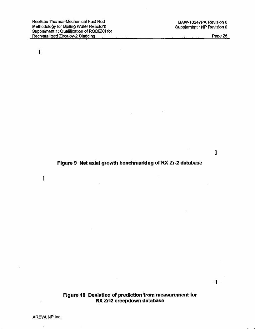
Realistic Thermal-Mechanical Fuel Rod Methodology for Boiling Water Reactors Supplement 1: Qualification of RODEX4 for Recrystallized Zircaloy-2 Cladding .
BAW-10247PA Revision 0 Supplem~nt 1 NP Revision O
[
[
Figure 9 Net axial growth benchmarldng of RX Zr-2 database
Figure 1 O Deviation of prediction from measurement for RX zr;.2 creepdown database
AREVA NP Ilic.
Page 25
j
]

Realistic Thermal-Mechanical Fuel Rod Methodqlogy for Boiling Water Reactors Supplemeht 1: Qualification of RODEX4 for Recrystallized Zircaloy-2 Cladding
[
BAW.,.10247PA Revision 0 Supplement 1 NP Revision o
Page26.
]
Figure 11 Deviation of prediction from measurement for CWSR.Zr-2
[
]
Figure 12 Benchmarking of A-1 O RX Zr-2 c()rro~iC>n database
AREVANP Inc.

Realistic Thermal-Mechanical Fuel Rod Methodology for Boiling Water Reactors Supplement 1: Qualification of RODEX4 for Recrystallized Zircaloy-2 Cladding
BAW-10247PA Revision 0 Supplement 1 NP Revision o
[
[
Figure 13 Benchn'uuking of free volume for RX Zr-2 database
Figure 14 Free volume predictions and measurements as a function of burnup for RX Zr-2 database
AREVA NP Inc.
Page 27
]
]

Record of Changes to Suppl. 1 to BAW-10247:
1. Typo on p. 10: H6 replaced by H5 in the last sentence on p. 10
2. Typo on p. 11: insert "against" in the first sentence on p. 11
BAW-10247PA Revision 0 Supplement 1NP-A Revision 0

Realistic Thermal-Mechanical Fuel Rod Methodology for Boiling Water Reactors Supplement 1: Qualification of RODEX4 for Recrystallized Zircaloy-2 Cladding
BAW-10247PA Revision 0 Supplement 1 NP Revision 0
Page 10
With the other model parameters fixed, the H6 parameter was varied until the best fit to the
measured axial yield stress values was achieved, as defined by the average sum of squares.
2.2.3 Determination of the anisotropy coefficients
The derivation of the ratio of the hoop yield stress to the axial yield stress is given in
Reference 2 and relies on the same approximation of the sinh function by the first exponential
term, as explained above for the creep test interpretation. The following relation is obtained:
Y9 _ 1
Yz [0.25 + R/(PR + P)]0·5
The R anisotropy coefficient is determined by mechanical tests after manufacturing, and a
median value of the most recent measurements is R = [ ].
In addition the R value can be deduced from the relationship between the R anisotropy
coefficient and the Kearns texture factor being:
R= fr 1-f -f r z
With the measured Kearns parameter values, the R value calculated by using the above
(27)
equation is about [ ], which is close to the [ ] measured value and very different from
the previous R value of [ ]. It is worth mentioning that the R to fr relationship is qualitatively
correct but it is subject to a significant scatter; therefore, the small difference is not surprising.
2.3 Results of the thermal creep calibration to RX Zr-2 material
2.3.1 Evaluation of H1 and H5 parameters
The two parameters, H1 and H5, were determined as explained in Section 2.2.1, above, using
the long-term creep tests.
Figure 1 illustrates the excellent linear fit obtained for Equation 23, which allows the evaluation
of the H1 and -1=1-6 H5 parameters as indicated by they-intercept and the slope, respectively.
AREVA NP Inc.

Realistic Thermal-Mechanical Fuel Rod Methodology for Boiling Water Reactors Supplement 1: Qualification of RODEX4 for Recrystallized Zircaloy-2 Cladding
BAW-10247PA Revision 0 Supplement 1 NP Revision 0
Page 11
The final values of H1 and H5 were established by fine tuning against the long-term creep data in
order to minimize the overall difference between predictions and measurements and also to
agree with the axial yield stress values as much as possible. The values of H1 = [ ] and
Hs = [
result.
] were found to provide the best fit, as illustrated in Figure 2, which shows the final
2.3.2 Evaluation of H6 parameter and the P anisotropy parameter
The data reported in References 3 to 5 were used to determine the H6 parameter. However, the
determination of H6 is linked to that of the P anisotropy parameter. This is because the basis for
H6 estimation is the axial yield stress of irradiated material, and P affects the value of the axial
yield stress.
In order to determine the P anisotropy coefficient for unirradiated material, Equation 27 is used
with the established value of the R parameter. The ratio Ye/Yz was calculated as approximately
[ ] by using Y z and Ye values as specified in Reference 4 (bottom of page 3) for the yield
stress at 350 °C. The Ye value is also mentioned in Reference 5 at the same temperature.
The values for unirradiated material are also confirmed by the AREVA NP qualification results of
RX Zr-2 cladding produced by AREVA NP. A similar high value of P was also determined in
Reference 6. Also, Reference 7 indicates a ratio of RIP of 0.38. When correlated with the R
value of [ ] as determined in Section 2.2.3, the result is P = [ ]. The final value inferred
from all sources was rounded off to P = [ ].
With the constant P = [ ] and H1 and H5 as determined in Section 2.3.1 above, an initial
calibration of the irradiation hardening was performed, which provided H6 = [
]. This is illustrated in Figure 3.
There are strong indications (such as in References 8 and 9) that irradiation causes a significant
change from the initial pronounced anisotropy of RX Zr-2 to a near isotropic behavior. This is
confirmed by the axial tensile and burst data on irradiated RX material (References 4 and 5).
In order to take into account a varying value of P, a fast fluence-dependent correlation was
developed based on both axial tensile and burst yield values.
AREVA NP Inc.