Novel small-size directional antenna for UWB WBAN/WPAN applications
13
3884 IEEE TRANSACTIONS ON ANTENNAS AND PROPAGATION, VOL. 53, NO. 12, DECEMBER 2005 Novel Small-Size Directional Antenna for UWB WBAN/WPAN Applications Maciej Klemm, Student Member, IEEE, István Z. Kov ´cs, Member, IEEE, Gert F. Pedersen, Member, IEEE, and Gerhard Tröster, Senior Member, IEEE Abstract—This paper presents a novel small-size directional an- tenna design for ultrawide-band wireless body area networks/wire- less personal area networks applications. The design is based on a typical slot antenna structure with an added reflector in order to achieve directionality. The effects of different antenna parameters and human body proximity on the radiation characteristics are an- alyzed. Antenna measurements with an optic RF setup were per- formed in order to characterize the small-size antenna far field ra- diation pattern. The different structural antenna parameters were optimized via extensive numerical simulations. Results show that for frequencies above 3.5 GHz, where the power front-to-back ratio of the directional antenna is greater than 10 dB, its impedance is nearly the same as in the free space. It is not the case neither for the omnidirectional slot antenna nor the monopole antenna next to the body. Between 3 and 6 GHz performance of the novel directional antenna, in terms of radiation efficiency and SAR values, is signif- icantly improved compared to omnidirectional antenna designs. Index Terms—Body-worn antennas, human body, pulsed an- tennas, specific absorption rate (SAR), ultrawide-band (UWB), wearable antennas, wireless communication. I. INTRODUCTION I N the past few years ultrawide-band (UWB) technology has received increasing attention in the wireless world. Its main envisioned advantages over conventional (narrowband) wireless communications systems are: low transmit power levels, high-data rates, and possibly simpler hardware configurations. Wireless personal area networks (WPAN) and wireless body area networks (WBAN) are seen as one of the major fields where such UWB characteristics can be potentially exploited [1]–[4]. Antennas play a critical role in the UWB communication systems, since they act as pulse-shaping filters [5]. In impulse radio based UWB systems (TH-UWB, DS-UWB) the antenna performance and characteristics influence the design of the pulse generator and also the complexity of the detection mechanism in the receiver [6]. For any UWB antenna, the flat frequency response requirement in a given band cannot be obtained for all spatial directions [7]. Generally, there can be only a limited area/direction in which the nondispersive conditions are well approximated [8], thus the impulse response of the antenna becomes an additional design parameter. The choice for a specific Manuscript received March 22, 2005; revised July 9, 2005. M. Klemm and G. Tröster are with the Electronics Laboratory of the De- partment of Information Technology and Electrical Engineering, Swiss Fed- eral Institute of Technology (ETH) Zürich, 8092 Zürich, Switzerland (e-mail: [email protected]). I. Z. Kov ´cs and G. F. Pedersen are with the Antennas and Propagation Lab- oratory of the Department of Communication Technology, AalborgUniversity, Niels Jernes Vej 12, Aalborg, Denmark (e-mail: {istvan, gfp}@kom.auc.dk). Digital Object Identifier 10.1109/TAP.2005.859906 UWB antenna design has to be based on the main implementation requirements. As we will show later in this paper, this aspect is especially important in the UWB WBAN/WPAN applications. They require that antennas must have small form factor (esp. in WBAN), good efficiency, easy integration with circuitry and good transient characteristics (short impulse response). There are several UWB antenna designs available, which meet some of the imposed requirements [9]–[11]. Additional requirements exist for UWB WBAN antennas, since the proximity of the human body can significantly modify their impedance bandwidth and radiation characteristics, thus modifying also the transient characteristics of the antenna [13]. These main observations have led us to the conclusion that for an efficient design the UWB antennas used in WBAN/WPAN devices have to be designed and tested in their normal operating scenarios. However, very few UWB antenna designs concerned with this issue were reported in open literature, both for WPAN [12] and WBAN [13], [15] applications. Most of the antenna designs presented so far for UWB WPAN/WBAN, present radiation patterns similar to the tradi- tional monopole/dipole antennas. However, a directional radi- ation pattern of an antenna would be desirable for body-worn devices (WBAN) in order to minimize the effects of the human body proximity and body exposure to EM radiation. To obtain this, the radiation toward the body needs either not to take place or to be minimized. Generally, directivity can be obtained if the antenna is large in the direction of interest, such as horn or Vivaldi antennas [16]. Other ways to achieve direc- tional antenna pattern include adding the cavity or shielding plane behind the antenna, or using the absorbing materials [17]. However these techniques lead to either serious increase in a size of an antenna, a more complicated manufacturing or a decreased efficiency. As it was shown in [18], [19], another way to reduce the backward radiation is incorporation of re- flecting element. However this method has been used [18], [19] only to improve the front-to-back ratio of antennas, which were already directional (with a front-to-back ratio 10 dB). Introduction of a reflecting element had therefore negligible effect on the input impedance of the antenna and the reflector could be safely incorporated into existing design. The size of the antenna was also not an issue for the investigations presented in [18], [19]. In this paper we propose a novel small-size directional antenna for UWB systems, with the main focus on the WBAN (body-worn) applications. It is based on the omnidirectional UWB slot antenna design (presented also in this paper) and utilizes the reflecting patch element to achieve front-to-back ratio 0018-926X/$20.00 © 2005 IEEE Authorized licensed use limited to: UNIVERSITY OF BRISTOL. Downloaded on November 20, 2009 at 10:10 from IEEE Xplore. Restrictions apply.
-
Upload
independent -
Category
Documents
-
view
1 -
download
0
Transcript of Novel small-size directional antenna for UWB WBAN/WPAN applications

3884 IEEE TRANSACTIONS ON ANTENNAS AND PROPAGATION, VOL. 53, NO. 12, DECEMBER 2005
Novel Small-Size Directional Antenna for UWBWBAN/WPAN Applications
Maciej Klemm, Student Member, IEEE, István Z. Kov́cs, Member, IEEE, Gert F. Pedersen, Member, IEEE, andGerhard Tröster, Senior Member, IEEE
Abstract—This paper presents a novel small-size directional an-tenna design for ultrawide-band wireless body area networks/wire-less personal area networks applications. The design is based on atypical slot antenna structure with an added reflector in order toachieve directionality. The effects of different antenna parametersand human body proximity on the radiation characteristics are an-alyzed. Antenna measurements with an optic RF setup were per-formed in order to characterize the small-size antenna far field ra-diation pattern. The different structural antenna parameters wereoptimized via extensive numerical simulations. Results show thatfor frequencies above 3.5 GHz, where the power front-to-back ratioof the directional antenna is greater than 10 dB, its impedance isnearly the same as in the free space. It is not the case neither for theomnidirectional slot antenna nor the monopole antenna next to thebody. Between 3 and 6 GHz performance of the novel directionalantenna, in terms of radiation efficiency and SAR values, is signif-icantly improved compared to omnidirectional antenna designs.
Index Terms—Body-worn antennas, human body, pulsed an-tennas, specific absorption rate (SAR), ultrawide-band (UWB),wearable antennas, wireless communication.
I. INTRODUCTION
I N the past few years ultrawide-band (UWB) technologyhas received increasing attention in the wireless world. Its
main envisioned advantages over conventional (narrowband)wireless communications systemsare: low transmitpower levels,high-data rates, and possibly simpler hardware configurations.Wireless personal area networks (WPAN) and wireless bodyarea networks (WBAN) are seen as one of the major fieldswhere such UWB characteristics can be potentially exploited[1]–[4]. Antennas play a critical role in the UWB communicationsystems, since they act as pulse-shaping filters [5]. In impulseradio based UWB systems (TH-UWB, DS-UWB) the antennaperformance and characteristics influence the design of the pulsegenerator and also the complexity of the detection mechanismin the receiver [6]. For any UWB antenna, the flat frequencyresponse requirement in a given band cannot be obtained forall spatial directions [7]. Generally, there can be only a limitedarea/direction in which the nondispersive conditions are wellapproximated [8], thus the impulse response of the antennabecomes an additional design parameter.The choice for a specific
Manuscript received March 22, 2005; revised July 9, 2005.M. Klemm and G. Tröster are with the Electronics Laboratory of the De-
partment of Information Technology and Electrical Engineering, Swiss Fed-eral Institute of Technology (ETH) Zürich, 8092 Zürich, Switzerland (e-mail:[email protected]).
I. Z. Kov́cs and G. F. Pedersen are with the Antennas and Propagation Lab-oratory of the Department of Communication Technology, Aalborg University,Niels Jernes Vej 12, Aalborg, Denmark (e-mail: {istvan, gfp}@kom.auc.dk).
Digital Object Identifier 10.1109/TAP.2005.859906
UWB antenna design has to be based on the main implementationrequirements. As we will show later in this paper, this aspect isespecially important in the UWB WBAN/WPAN applications.They require that antennas must have small form factor (esp.in WBAN), good efficiency, easy integration with circuitry andgood transient characteristics (short impulse response). Thereare several UWB antenna designs available, which meet someof the imposed requirements [9]–[11]. Additional requirementsexist for UWB WBAN antennas, since the proximity of thehuman body can significantly modify their impedancebandwidthand radiation characteristics, thus modifying also the transientcharacteristics of the antenna [13]. These main observationshave led us to the conclusion that for an efficient design the UWBantennas used in WBAN/WPAN devices have to be designedand tested in their normal operating scenarios. However, veryfew UWB antenna designs concerned with this issue werereported in open literature, both for WPAN [12] and WBAN[13], [15] applications.
Most of the antenna designs presented so far for UWBWPAN/WBAN, present radiation patterns similar to the tradi-tional monopole/dipole antennas. However, a directional radi-ation pattern of an antenna would be desirable for body-worndevices (WBAN) in order to minimize the effects of the humanbody proximity and body exposure to EM radiation. To obtainthis, the radiation toward the body needs either not to takeplace or to be minimized. Generally, directivity can be obtainedif the antenna is large in the direction of interest, such ashorn or Vivaldi antennas [16]. Other ways to achieve direc-tional antenna pattern include adding the cavity or shieldingplane behind the antenna, or using the absorbing materials[17]. However these techniques lead to either serious increasein a size of an antenna, a more complicated manufacturing ora decreased efficiency. As it was shown in [18], [19], anotherway to reduce the backward radiation is incorporation of re-flecting element. However this method has been used [18],[19] only to improve the front-to-back ratio of antennas, whichwere already directional (with a front-to-back ratio 10 dB).Introduction of a reflecting element had therefore negligibleeffect on the input impedance of the antenna and the reflectorcould be safely incorporated into existing design. The sizeof the antenna was also not an issue for the investigationspresented in [18], [19].
In this paper we propose a novel small-size directionalantenna for UWB systems, with the main focus on the WBAN(body-worn) applications. It is based on the omnidirectionalUWB slot antenna design (presented also in this paper) andutilizes the reflecting patch element to achieve front-to-back ratio
0018-926X/$20.00 © 2005 IEEE
Authorized licensed use limited to: UNIVERSITY OF BRISTOL. Downloaded on November 20, 2009 at 10:10 from IEEE Xplore. Restrictions apply.

KLEMM et al.: NOVEL SMALL-SIZE DIRECTIONAL ANTENNA FOR UWB 3885
better than 10 dB across a wide frequency range (in far field).By means of the full-wave electromagnetic (EM) numericalFIT method (using commercial CST Microwave Studio), asystematic parameter study of our new design was performedto investigate the influence of the reflector and other antennaparameters on transient characteristics of the new antenna.Further analysis incorporated the human body models in aWBAN operating scenario. Moreover, a true characterizationof UWB antenna is presented based on the antenna transferfunction.
The paper is organized as follows: In Section II, the param-eters used for UWB antenna characterization and source pulseare presented. In Section III we show the special cable-lessmeasurement set-up, suitable for electrically small antenna mea-surements. This section also introduces human body modelsused during numerical electromagnetic simulations. To providea reference for results obtained with the new antenna design acommonly known/used example of small UWB antenna, thedisc monopole antenna is presented in Section IV. Section Vpresents the design of an omnidirectional UWB slot antenna,supported by a very small ground plane size, as well as thedesign and characterization of a new directional UWB slotantenna. Spatial UWB characteristics (averaged transfer func-tions and pulse distortions) are analyzed in Section VI, fortwo different directional antennas and omnidirectional antennas,when operating in the free space. Finally, the influence of thehuman body on different designs (examining radiation effi-ciency, impedance and averaged transfer functions) is shownin Section VII.
II. PARAMETERS USED FOR UWB ANTENNAS
CHARACTERIZATION
A very wide operational bandwidth of UWB systems makesthe design and evaluation of antennas much more difficult. Forthe same reason traditional narrowband parameters character-izing antenna, such as return loss, radiation pattern, polariza-tion are relatively less useful for UWB radio systems. There-fore UWB antennas should be evaluated by means of differentparameters,such as the antenna transfer function (TF). Togetherwith the waveform driving the antenna TF allows distortions in-troduced by the UWB antenna to be calculated. In the followingsections we will base the antenna design and evaluation on thefollowing parameters.
A. ‘Narrowband’ Parameters
As it was mentioned, even if not directly useful, parame-ters known from the traditional (narrowband systems) antennatheory can be helpful. In our investigations we were looking atthe return loss parameter, as it is also the part in the antennatransfer function. In further investigation the impedance band-width is defined as 10 dB. We were also looking atthe radiation patterns on different frequencies, by which we can(only) roughly estimate the behavior of the transfer functionsin different propagation directions. The 3-D radiation patternswere used to calculate the antenna front-to-back (F2B) ratio, de-fined as a ratio of total power radiated in the two half-spaces inthe far field.
B. Source Pulse
As a source pulse we have used the Gaussian modulatedpulse, which has the following form:
(1)
where defines center frequency of the pulse, (natural pulsewidth) defines its bandwidth. Based on the amplitude charac-teristics of transfer functions of investigated antennas (see Sec-tion V), we have chosen 5 GHz and 160 ps. It givesthe 10 dB pulse bandwidth from approximately 3 to 7 GHz.
C. Frequency Domain Transfer Functions
During the design of the new antenna we have investigatedtransmit (Tx) transfer function defined as [20]
(2)
It relates the radiated electric field intensity and thepulse from the generator driving the antenna. This definitionis very convenient for practical cases, because it also includesthe impedance match between the antenna and the pulse gener-ator. In this form is easily computable from the time-do-main electromagnetic solvers, applying Fourier transformation.
D. Spatially Averaged Transfer Functions
We introduce a new parameter for UWB antenna characteri-zation—the spatially averaged transfer function, expressed as
(3)
where are the transfer functions in a given direction, nor-malized to the maximum value within the frequency band .
and are propagation directions for the and coordinate,respectively. The choice for the should be based on the spec-trum of the antenna input pulse. is a very useful parameterand can be calculated for different solid anglesof the radiation sphere, or for the entire sphere, depending onthe interest. Preferable directions of propagation with best per-formance in terms of transient characteristics could be foundfor a given antenna as well. Concept of parameter is sim-ilar to the mean effective gain (MEG) [21] or mean effectiveenergy gain [22], however it deals with the frequency-depen-dant transfer function (which is more appropriate to characterizeUWB antennas).
E. Pulse Distortion Parameters
Based on the transfer functions we are able to calculate pulsedistortions introduced by an antenna. For UWB systems, thecommonly used receivers are based on the pulse energy detec-tion or correlation with the template waveform. Therefore wewill examine the pulse distortions by calculating fidelity factorand time spread of radiated pulses (with respect to the antenna
Authorized licensed use limited to: UNIVERSITY OF BRISTOL. Downloaded on November 20, 2009 at 10:10 from IEEE Xplore. Restrictions apply.
3886 IEEE TRANSACTIONS ON ANTENNAS AND PROPAGATION, VOL. 53, NO. 12, DECEMBER 2005
Fig. 1. Small-size antenna measurement setup using RF on fiber optic: (a) photo of the antenna measurement setup (antenna, optical receiver and fiber link) and(b) block diagram of the RF on fiber optic setup.
input pulse). Fidelity between waveforms and is gen-erally defined as
(4)
The fidelity parameter , is the maximum of the cross-cor-relation function and compares only shapes of both waveforms,not amplitudes. Time spread is a ratio between the lengths of the99% energy window (E99) of the radiated pulse and the antennainput pulse (source pulse). It discloses how much the energy ofradiated pulse is spread compared to the input pulse.
III. MEASUREMENT AND SIMULATION SETUP
A. Antenna Measurement Setup
In traditional antenna measurements, the antenna is con-nected to the measurement equipment with a coaxial cable. Thisset-up is perfectly suited for electrically large antennas, but notfor electrically small antennas, as the radiation characteristicsare significantly influenced by the size of the ground planeor any conductive cables acting as additional ground planes[14], [15]. The influence of the connecting feed cables or anyother conductive cables connected to the device, which doesnot belong to the final application, ought to be minimized ifnot completely eliminated. In [14], [15] a practical set-up wasproposed to achieve this, namely the use of an RF on fiberoptic (FO) link (transmitter and receiver) instead of the usualconductive cable feed connections. Fig. 1 shows the RF on fiberoptic setup used in our antenna measurements.
The comparison between measured and simulated radiationpatterns are presented in Fig. 2, for the two principal planes, at3.5, 4.5, and 6 GHz. Good agreement is achieved, especially forthe co-polarization component. In the final application the trans-mitter (pulse generator) will be integrated on the antenna, so weexpect the radiation characteristics very close to simulated ofthe directional antenna (see Section VI), without any additionalcables or metallic elements.
B. Human Body Models for Numerical ElectromagneticSimulations
In the main applications (UWB WBAN) the antenna ismounted on the human body. It is known that the body has a
significant impact on the antenna characteristics (radiation pat-tern, efficiency and input impedance). Therefore, it is importantto include the human body in the EM simulations. We have in-cluded two different models of the human body. The first one isa three-tissue model, consisting of layers of skin (1-mm thick),fat (3-mm thick) and a muscle tissue (40-mm thick), and thesecond is a simple homogeneous model composed of muscletissue (44-mm thick). Overall dimensions of these models arethe same: 120 110 44 mm . The size of this truncatedbody model was found by comparing the simulation resultsin terms of antenna radiation characteristics when a larger (by50%) model was used. No significant differences were noticed.The human tissues are dispersive and their electrical propertiesare therefore changing over frequencies. The influence of thesechanges on the antenna characteristics was investigated byan EM code which could include frequency dispersion and itwas found to have a minor influence (e.g., radiation efficiencychanges 5%), thus in all further investigations the electricalparameters of the tissues were assumed to be nondispersive andthe values as at the centre frequency (4.5 GHz) were used [25]:skin- 38, 2.7 S/m ; fat- 5.1, 0.18 S/m ;muscle- 50.8, 3 S/m .
IV. REFERENCE ANTENNA DESIGN- UWB DISC MONOPOLE
Different kinds of monopole antennas are very often used inUWB applications and we have therefore included results for aUWB monopole antenna as reference. We designed the UWBdisc monopole, with the criteria of an impedance bandwidthfrom 3 to 6 GHz 10 dB and with the size com-parable to the of slot antenna. The antenna geometry is shownin Fig. 3(a). Its dimensions are: ground plane20 mm, disc diameter 16 mm. Gap between ground planeand disc is 0.75 mm. Overall planar dimension of antenna is36.75 20 mm. It was realized on a 0.5-mm thick FR4 sub-strate 4.4 and is fed from a 50 microstrip line.
It is relatively easy to design a UWB monopole antenna whenconsidering only the impedance bandwidth. But to achieve thesame radiation pattern bandwidth is difficult, due to the signif-icant changes in the antenna pattern at higher frequencies [26].Plots of the return loss and the function (in 0, 0direction) of the UWB disc monopole antenna are shown inFig. 3(b). As can be seen, the antenna is well matched in a much
Authorized licensed use limited to: UNIVERSITY OF BRISTOL. Downloaded on November 20, 2009 at 10:10 from IEEE Xplore. Restrictions apply.

KLEMM et al.: NOVEL SMALL-SIZE DIRECTIONAL ANTENNA FOR UWB 3887
Fig. 2. Comparison of measured and simulated radiation patterns of directional slot antenna [see Fig. 1(a)]. (a) XZ plane 3.5 GHz, (b) XZ plane 4.5 GHz, (c)XZ plane 6 GHz, (d) Y Z plane 3.5 GHz, and (e) Y Z plane 4.5 GHz, (f) Y Z plane 6 GHz.
Fig. 3. UWB disc monopole antenna: (a) geometry of the antenna and (b)return loss and Tx transfer function (in propagation direction � = 0, � = 0).
wider bandwidth than 3–6 GHz. is presented on the samescale as for different slot antennas from Fig. 5(b). It shows aweak integrative characteristic.
V. SMALL-SIZE DIRECTIONAL UWB SLOT ANTENNA DESIGN
The main objective of this work was to design an ultrawideband directional antenna, which is compact especiallyconcerning the thickness of the antenna. The geometry of theproposed antenna is shown in Fig. 4.
As a first step the slot antenna without the reflector and onthe small ground plane was designed. The antenna is a slot cutin the ground plane, fed by two symmetrically placed 100microstrip lines which are connected in parallel to the 50 feedline. This feeding topology provides very wideband matchingfor slot and stacked patch antennas [23], [24]. Since our finalapplication, a wearable UWB transmitter, will operate in thelower FCC UWB band (3–6 GHz), we achieved impedancebandwidth 10 dB of 67%. This is one of the widestbandwidths reported in the literature, for the medium widthslot antenna. Moreover, it is realized on a very small groundplane. The overall antenna dimensions are defined by theground plane size—32 29 mm (0.32 0.29 at the lowestoperating frequency 3 GHz). Due to the small ground planedimensions compared to the slot dimensions, the antenna hasa quasiomni directional radiation pattern in an plane.Moreover the antenna radiates almost the same amount ofthe power in the two half-spaces. Front-to-back ratio is 0.09,0.44, and 0.72 dB at 3.5, 4.5, and 6 GHz, respectively.
To improve the front-to-back ratio we have added anotherradiating (reflecting) element below the feed line.
As has been shown [18], [19], this is an efficient way toreduce the backward radiation. However authors of [18], [19]have used this method only to improve front-to-back ratio ofantennas, which were already directional (with a front-to-backratio 10 dB). Introduction of a reflecting element therefore
Authorized licensed use limited to: UNIVERSITY OF BRISTOL. Downloaded on November 20, 2009 at 10:10 from IEEE Xplore. Restrictions apply.

3888 IEEE TRANSACTIONS ON ANTENNAS AND PROPAGATION, VOL. 53, NO. 12, DECEMBER 2005
Fig. 4. Geometry of the novel small directional UWB antenna.
had negligible effect on the input impedance of the antennaand reflector could easily be incorporated into existing designs.This is certainly not our case, since we are dealing with the om-nidirectional slot antenna. Due to the application requirements(WBAN, WPAN) we are interested in a very small spacing( 10 mm) between the reflector and the antenna feed line, tokeep the antenna thickness as small as possible. Thus the inputimpedance of the antenna will be strongly influenced by thereflector. Further, the radiation properties of the new structurecan not be analyzed in the same way as in [18], [19], where thedesign process involves examining the relative magnitude andphase of the radiated far field due to the slot and reflector (withdesired solution of equal magnitudes and a 180 phase differ-ence). To understand the influence of different antenna (slotantenna plus reflector) parameters on its impedance bandwidthand radiation characteristics, a systematic parametric study wasperformed. Table I presents initial design parameter of the di-rectional UWB antenna, selected after several EM simulations,and dimensions of the omnidirectional UWB slot antenna. Itshould be noticed that since the reflector significantly affectsantenna characteristics, values from Table I are different fromthose optimized for a single slot antenna. In our study onedesign parameter at the time was varied, keeping the othersconstant. For different antenna parameters we have investigatedmatching bandwidth (defined as 10 dB), radiationpatterns at 3.5, 4.5, and 6 GHz and a transmit transfer function
0 0 .
A. Variation of the Spacing Between the Reflector and FeedLine (S)
Fig. 5(a) and (b) shows, the and , respectively,for different values (6, 8, 10 mm) and also without reflector(omnidirectional pattern). A very wide impedance bandwidthof 67% (3–6 GHz) for the slot antenna without reflector wasachieved. With the addition of a reflector the shift in theimpedance bandwidth is visible, especially at lower frequen-cies. Impedance bandwidth is 47% when the reflector is 6mm away from the feed line, from 4 to 6.5 GHz. Moving the
TABLE IINITIAL DESIGN PARAMETERS OF THE ANTENNA SHOWN IN FIG. 4
reflector further away keeps almost the same relative bandwidth(47% for 8 mm, 40% for 10 mm), but at the lower frequencies.
In Fig. 6 we can see the radiation patterns in two major planesat 3.5, 4.5, and 6 GHz, for different values and also for theantenna without the reflector. The slot antenna radiates equalpower in two hemispheres, with the gain increasing from 3.5dB at 3.5 GHz to 5.3 dB at 6 GHz. With the presence of thereflector the front-to-back (F2B) ratio greatly increases, beingabove 10 dB for all values (it varies slightly for differentvalues, but no more than 1 dB). As expected the gain of theantenna increases to around 7, 7.5 and 8.5 dB at 3.5, 4.5 and 6GHz, respectively. Gain variations are not higher than 0.4 dB fordifferent values. It is also worth to notice, that the new direc-tional antenna has a very stable radiation pattern across the fre-quency band of interest. In Fig. 5(b) we can see 0 0characteristics. As visible, the omnidirectional slot antenna hasvery flat amplitude of , with a 3 dB bandwidth from 2.85to 8 GHz (95%). For directional antennas the amplitude ofhas narrower bandpass characteristic, with a 3 dB bandwidthfrom around 3.5 to 7 GHz (67%). As expected the amplitude of
for the directional antenna is higher compared to the slotantenna, even at frequencies, where the matching is poor this
Authorized licensed use limited to: UNIVERSITY OF BRISTOL. Downloaded on November 20, 2009 at 10:10 from IEEE Xplore. Restrictions apply.

KLEMM et al.: NOVEL SMALL-SIZE DIRECTIONAL ANTENNA FOR UWB 3889
Fig. 5. (a) jS j for different S, (b) jH (!; 0; 0; )j transfer function for different S (curve named “no refl.” corresponds to the slot antenna without reflector),and (c) radiated waveforms from the directional antenna (as in Table I) and from the slot antenna.
Fig. 6. Radiation patterns of directional slot antenna for different S. (a) XZ plane 3.5 GHz, (b) XZ plane 4.5 GHz, (c) XZ plane 6 GHz, (d) Y Z plane 3.5GHz, (e) Y Z plane 4.5 GHz, and (f) Y Z plane 6 GHz. Pattern of the omnidirectional slot antenna (S =1) included for comparison.
is compensated by a higher antenna gain. Varying does nothave a large influence on the amplitude and the shape of .Looking only at and characteristics, one could saythat the new directional antenna has a 20–30% lower bandwidthcompared to the slot antenna. But the difference is not visiblewhen looking at the transient results, when using the sourcepulse described earlier in Section II-B. Fig. 5(c) presents ra-diated waveforms by the omnidirectional slot antenna and thedirectional antenna with parameters as in Table I. We can seethat the radiated pulses have almost the same shapes, but theelectric field intensity is higher for directional antenna. Furtherinvestigations of the transient characteristics of both antennasare presented in more details in Section VII.
B. Variation of the Reflector Width
The return loss and the of directional slot antenna,when varying values of the reflector width ( 8, 12, 16and 20 mm), were investigated. A decrease of impedancebandwidth, from 54% (3.7–6.4 GHz) for 8 mm, 47%(4–6.5 GHz) for 16 mm, to only 20% (5.3–6.5 GHz)when 20 mm was observed. Thus, considering onlythe impedance bandwidth, one would say that there is a sig-nificant difference when changing the reflector width. Whenconsidering , however, we observed that its amplitude andshape is almost the same for different values [similarly,as shown in Fig. 5(b)]. Based on the results from the previous
Authorized licensed use limited to: UNIVERSITY OF BRISTOL. Downloaded on November 20, 2009 at 10:10 from IEEE Xplore. Restrictions apply.

3890 IEEE TRANSACTIONS ON ANTENNAS AND PROPAGATION, VOL. 53, NO. 12, DECEMBER 2005
Fig. 7. (a) Return loss of the directional antenna for different ST values and (b) jH (!; 0; 0)j for different ST values.
paragraph (Section II-A) of radiated pulses by antennas withdifferent characteristics, we could expect very similarpulses radiated from directional antennas with various .
C. Variation of the Reflector Length
There is a certain threshold of the reflector length re-sulting in a directive radiation characteristic. This length deter-mines the lower frequency bound of antenna operation, in termsof directivity. To have F2B higher than 10 dB at 3.5 GHz thislength is 36 mm. Parametric studies of the influence of the re-flector length were done only for 36 mm (36, 40, 44, 48mm). Above this length does not affect significantly theand characteristics, indicating however a slight degrada-tion in performance at the lower frequencies when shorteningthe reflector.
D. Variation of the Distance Between Feed Lines ( )
Fig. 7 presents the influence of the spacing between parallel100 feed lines on characteristics of directional slot antenna.Results show that the distance between feed lines is one of themost critical parameters, for the impedance bandwidth andcharacteristics. Position of the feed lines affects the field distri-bution in the slot. Therefore for a certain slot length there is anoptimal value of , resulting in the widest impedance band-width, defining at the same time the characteristic of . Itshould also be pointed out that to achieve the optimum band-width for a given value, the length of the tuning stubs (and ) must be appropriately adapted. Note that for a dif-ferent value there is also an optimum and value.No separate studies of varying and have been con-ducted.
E. Physical Operation of a Directional UWB Slot Antenna
To further investigate the physical operation of the new di-rectional antenna, and the impact of the reflector on the antennaimpedance and radiation, we have examined the near-fields ofthe antenna. In Fig. 8, we present the electric field distributionin a slot, for the antenna without [Fig. 8(a)] and with the re-flector [Fig. 8(b)]. It can be seen that the reflector has a greatinfluence on the field distribution at lower frequencies (3.5 and4.5 GHz). At 6 GHz however, the field distribution is almost
Fig. 8. Distribution of the electric field in the slot: (a) omnidirectional antennaand (b) directional antenna. Size of arrows corresponds to the field strength.
Fig. 9. Comparison of radiation mechanism at 4.5 GHz: (a) directional UWBslot antenna and (b) omnidirectional UWB slot antenna. Presented cut takenalong the Y axis, at the center of the slot.
unchanged. This significant change in the field distribution es-pecially at low frequencies explains the serious change in thereturn loss (impedance) between 3 and 5 GHz [see Fig. 5(a)].
Fig. 9 show the radiation of near-fields for the directional andomnidirectional slot antennas. Shown is the field (co-polar-ization) component at 4.5 GHz, at a cut taken along the axis, at
Authorized licensed use limited to: UNIVERSITY OF BRISTOL. Downloaded on November 20, 2009 at 10:10 from IEEE Xplore. Restrictions apply.

KLEMM et al.: NOVEL SMALL-SIZE DIRECTIONAL ANTENNA FOR UWB 3891
Fig. 10. (a) Placement of the time-domain probes (E far-field component). Transfer functions recorded alongXZ plane for: (b) the omnidirectional slot antenna,and (c) the directional slot antenna with R = 16 mm.
the center of the slot (antenna symmetry axis). It is visible thatthe reflector function is a combination of radiation and reflec-tion. From our observations of simple near-fields, we concludedthat the reflector contributes more to the radiation process atthe lower frequencies, and acts more as a simple reflector at thehigher frequencies.
Additional prove of that comes when investigating the radi-ation phase center of antennas. We assume that the referencepoint ( 0 mm, 0 mm, 0 mm) is placed in the centerof the slot. Then, phase center of the omnidirectional antenna isat (0, 3.5, 2.8), (0, 3.5, 2.7) and (0, 3.5, 2.9) for 3.5, 4.5,and 6 GHz, respectively. So it practically does not move withfrequency, what is very important for good transient behavior.The same calculation for the directional slot antenna (reflectorat 6 mm) gives the phase centers located at (0, 0, 5.5),(0, 0, 3.4) and (0, 0, 2.8) for 3.5, 4.5, and 6 GHz, respec-tively. Therefore, we observe that with increasing frequency thephase center moves in the direction closer and closer to thatof the slot antenna without the reflector.
VI. COMPARISON OF ANTENNAS OPERATING IN FREE-SPACE
A. Spatially Averaged Transmit Transfer Functions
In the previously presented section we have studied the newdirectional antenna characteristics considering input matching,transmit transfer function, , in the direction ( 0 ,0 ) and the radiation patterns at 3.5, 4.5, and 6 GHz. In this sec-tion we will present extended analysis of the two versions ofdirectional UWB slot antennas, the omnidirectional UWB slotantenna and the monopole antenna (as a reference). As in thereal application (WBAN) antenna should be as thin as possible,we have chosen two directional antennas, the first one with allparameters as in Table I, the second one with 16 mm.Investigations are based on the transient co-polarized electric
far-field signals (cross-polarization level 20 dB lower)from different directions in the upper hemi-sphere. A limitedset of time-domain field values was chosen, along the and
cuts. Locations are shown in Fig. 10(a). The number ofpoints is higher for angles 60 90 , to account for thehigher pattern changes in these directions. For the calculationsof it gives 11 and 4 [see (3)]. From theseprobes we are able to characterize antennas in the time- andfrequency-domain. In Fig. 10(b) and (c) we can see examples
Fig. 11. Averaged transmit transfer functions for the slot antenna and thedirectional antennas with different reflector widths (8, 16 mm).
of transfer functions in plane, for omnidirectional and di-rectional 16 mm slot antennas. It should be noticed,that different slopes (positive, flat, negative) of transfer func-tions exist, depending on the angle of propagation. It means thatwithin the limited frequency bandwidth the antenna will intro-duce angle-dependant time operators (e.g., derivation or inte-gration) to the driving pulse.
Fig. 11 depicts the averaged transmit transfer functionsfor all antennas. Three different are calculated:
1. : averaged over and planes, forangles between 0 60 . This represents the ra-diation away from the human body, for body-mountedantenna.
2. : averaged over and planes, forangles 60 90 . This represents the radiationalong the human body.
3. : averaged over 0 90 .The directional slot antennas have a small difference in the
averaged transfer functions for frequencies between 3 and 4GHz. This difference is related to the input matching of these an-tennas. However the difference in the return loss characteristicsof the slot antenna and directional slot antennas is not reflectedin the characteristics. On the other hand, for frequenciesabove 6.5 GHz we observe very different characteristics ofof the omnidirectional and the directional slot antennas, even if
Authorized licensed use limited to: UNIVERSITY OF BRISTOL. Downloaded on November 20, 2009 at 10:10 from IEEE Xplore. Restrictions apply.

3892 IEEE TRANSACTIONS ON ANTENNAS AND PROPAGATION, VOL. 53, NO. 12, DECEMBER 2005
Fig. 12. Pulse distortion metrics for different antennas: (a) omnidirectional slot antenna, (b) directional slot antenna with R = 8 mm, (c) directional antennawith R = 16 mm, and (d) monopole antenna (as the reference).
their characteristics look alike in this frequency range. Itresults from the fact that the gain of the directional antenna in-creases faster than for the omnidirectional slot antenna, thus itshalf-power beam width also decreases faster (from 71 at 3.5GHz to 51 at 7 GHz, plane) than for the omnidirectionalslot antenna (from 80 at 3.5 GHz to 67 at 7 GHz, plane).Therefore by choosing the 120 width of the solid angle for the
, its amplitude drops above 6 GHz.
B. Pulse Distortion Parameters
Based on the transfer functions we have calculatedparameters showing quantitative angular characteristics ofantennas for UWB systems: 1) 99% energy window (E99), rel-ative to the input pulse; 2) 99% energy window, relative to thepulse radiated in the ( 0 , 0 ) direction; and 3) fidelityof radiated pulses (assuming the pulse radiated in ( 0 ,
0 ) direction as the reference waveform). It should benoted that all these parameters depend on the pulse driving theantenna. Although these angular-dependent characteristics arevery important from the point of view of UWB system design,they are very rarely presented in papers about antennas forUWB systems. Results are presented in Fig. 18. Driving pulseis the one presented in Section II-B. Results for the monopoleantenna are presented for the reference.
The omnidirectional slot antenna has a fidelity above 98% inthe plane. In the plane fidelity factors are above 95%for angles of between 70 and 65 , for the rest of considereddirections is lower, with a minimum of 84%. Very similarfidelity results are obtained for both directional slot antennas.There is a slight difference for the plane, where 95is for angles within 65 50 . Monopole antenna has thefidelity above 99% in the plane, but in the plane it ismuch worse. 95 is only between 50 and 20 , and at60 it reaches the minimum of 75%. Compared to all slot an-tennas, we can also notice asymmetry in the plane, whichresults from the changes of radiation pattern for different fre-quencies. Considering pulse distortions based on time windowswith 99% of the pulse energy (E99), we can see that direc-tional antennas introduce higher spatial variations of the E99time windows [Fig. 12(b) and (c)], compared to the slot an-tenna [Fig. 12(a)] and also to the monopole antenna [Fig. 12(d)].Taking as the reference input antenna pulse (its E99 window is0.392 ns), radiated pulses are 1.19–1.68 0.49 , 1.16–3.8
2.64 , 1.28–2.44 1.16 , 1.13–1.83 0.7times longer, for the slot antenna, directional slot antenna with
8 mm, directional slot antenna with 16 mm andmonopole antenna, respectively. Angular spread of E99 win-dows is important if one is interested in applications where anyrelative position between Tx and Rx antennas is possible. Aninteresting point to notice that even if E99 windows are shorter
Authorized licensed use limited to: UNIVERSITY OF BRISTOL. Downloaded on November 20, 2009 at 10:10 from IEEE Xplore. Restrictions apply.

KLEMM et al.: NOVEL SMALL-SIZE DIRECTIONAL ANTENNA FOR UWB 3893
TABLE IIRADIATION EFFICIENCY (RAD.EFF.) AND PEAK SAR VALUES FOR THE DIRECTIONAL SLOT ANTENNA. INPUT POWER P = 1 W
TABLE IIIRADIATION EFFICIENCY AND PEAK SAR VALUES FOR THE OMNI-DIRECTIONAL SLOT ANTENNA. INPUT POWER P = 1 W
between 45 and 75 of the plane for the monopole thandirectional slot 8 mm , its fidelity is lower at these di-rections. For the system considerations that would mean onewould prefer a different antenna (directional slot or monopole),depending on the type of receiver (e.g., energy detector or tem-plate-based).
VII. COMPARISON OF ANTENNAS OPERATING CLOSE TO THE
HUMAN BODY
To show the effect of the human body on the antenna char-acteristics we have simulated the same antennas as used inSection VII with the addition of the truncated human bodymodels. For the different separations between the antenna andthe body we have examined: antenna radiation efficiency, peakSAR values (10 g averaged), transmit transfer functions andinput matching.
A. Radiation Efficiency and SAR
The objective of these investigations was to show the differ-ence in the radiation efficiency and SAR values for differentantennas. The slot antenna has the omnidirectional pattern(front-to-back ratio close to 0 dB) and the 10 dB impedancebandwidth within 3–6 GHz. The first directional slot antenna(reflector width 8 mm) has 10 dB within3.7–6.4 GHz and power front-to-back ratio of 7.1, 7.4 and 11.7dB at 3.5, 4.5, and 6 GHz, respectively. The second directionalslot antenna (reflector width 16 mm) has the 10 dB returnloss bandwidth within 4–6.5 GHz and power front-to-back ratioof 10.4, 10.8 and 15.4 dB at 3.5, 4.5, and 6 GHz, respectivel
y. For comparison we assume the same body-to-feed line dis-tance, 7 and 10 mm. For directional slot antennas it means thatthe reflector is only 1 mm away from the body. Additional cal-culations were made for the omnidirectional slot antenna, when
it was placed only 2 mm away from the body. The radiation effi-ciency and SAR values are presented in Table II for directionalslot antennas and in Table III for the omnidirectional slot an-tenna. They show that:
— Radiation efficiency of all antennas increases with fre-quency. Only for the slot antenna in the position 2 mmaway from the body was a different behavior observed.
— Antenna performance in terms of the radiation effi-ciency and SAR has improved for directional slot an-tennas, compared to the omnidirectional slot antenna.
— Comparing only directional slot antennas, better per-formance (radiation efficiency and SAR) was obtainedfor the one with wider reflector (16 mm). Therefore,one would choose different values of for operationin free space than close to the human body.
— Comparing results obtained when using different bodymodels, higher (than 4–24%) radiation efficiencieswere calculated when homogeneous muscle-tissuebody model was used. Again, different behavior forslot antenna 2 mm away from the body is observed.As the electrical parameters of skin and muscle tissueare very similar (conductivity plays a much biggerrole than permittivity), the main difference betweenthese two models is an incorporation of the fat tissue.Fat is a low water content tissue, thus its conductivityis lower than for skin and muscle.
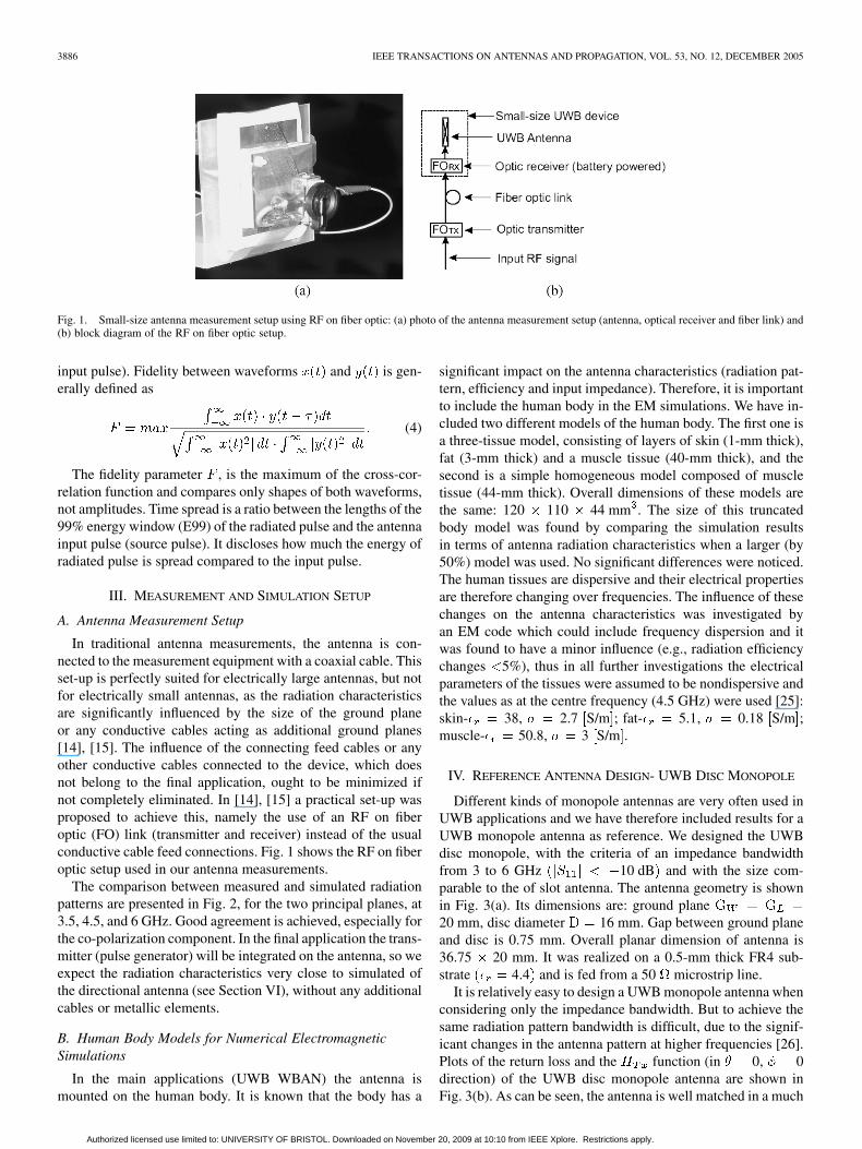
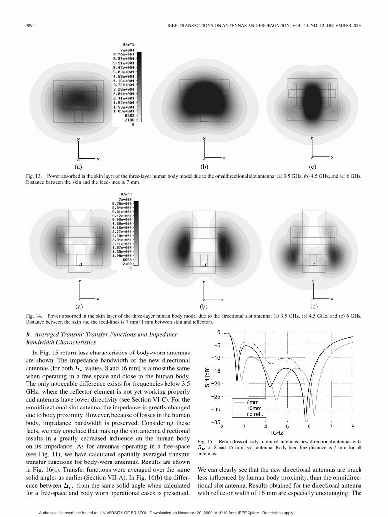
As an illustration to the results presented in Table II and IIIwe present the power absorbed in the skin layer (where themaximum absorption occurs) of the three-layer human bodymodel. Fig. 13 shows results for the omnidirectional slot an-tenna, Fig. 14 for the directional slot antenna, normalized tothe same absolute value. It is visible that with the use of re-flector, near-fields where scattered, resulting in the lower powerdeposited in the tissue.
Authorized licensed use limited to: UNIVERSITY OF BRISTOL. Downloaded on November 20, 2009 at 10:10 from IEEE Xplore. Restrictions apply.
3894 IEEE TRANSACTIONS ON ANTENNAS AND PROPAGATION, VOL. 53, NO. 12, DECEMBER 2005
Fig. 13. Power absorbed in the skin layer of the three-layer human body model due to the omnidirectional slot antenna: (a) 3.5 GHz, (b) 4.5 GHz, and (c) 6 GHz.Distance between the skin and the feed-lines is 7 mm.
Fig. 14. Power absorbed in the skin layer of the three-layer human body model due to the directional slot antenna: (a) 3.5 GHz, (b) 4.5 GHz, and (c) 6 GHz.Distance between the skin and the feed-lines is 7 mm (1 mm between skin and reflector).
B. Averaged Transmit Transfer Functions and ImpedanceBandwidth Characteristics
In Fig. 15 return loss characteristics of body-worn antennasare shown. The impedance bandwidth of the new directionalantennas (for both values, 8 and 16 mm) is almost the samewhen operating in a free space and close to the human body.The only noticeable difference exists for frequencies below 3.5GHz, where the reflector element is not yet working properlyand antennas have lower directivity (see Section VI-C). For theomnidirectional slot antenna, the impedance is greatly changeddue to body proximity. However, because of losses in the humanbody, impedance bandwidth is preserved. Considering thesefacts, we may conclude that making the slot antenna directionalresults in a greatly decreased influence on the human bodyon its impedance. As for antennas operating in a free-space(see Fig. 11), we have calculated spatially averaged transmittransfer functions for body-worn antennas. Results are shownin Fig. 16(a). Transfer functions were averaged over the samesolid angles as earlier (Section VII-A). In Fig. 16(b) the differ-ence between from the same solid angle when calculatedfor a free-space and body worn operational cases is presented.
Fig. 15. Return loss of body-mounted antennas: new directional antennas withR of 8 and 16 mm, slot antenna. Body-feed line distance is 7 mm for allantennas.
We can clearly see that the new directional antennas are muchless influenced by human body proximity, than the omnidirec-tional slot antenna. Results obtained for the directional antennawith reflector width of 16 mm are especially encouraging. The
Authorized licensed use limited to: UNIVERSITY OF BRISTOL. Downloaded on November 20, 2009 at 10:10 from IEEE Xplore. Restrictions apply.

KLEMM et al.: NOVEL SMALL-SIZE DIRECTIONAL ANTENNA FOR UWB 3895
Fig. 16. (a) Spatially averaged transmit transfer functions (H ) of body-mounted antennas: omnidirectional slot antenna and directional slot antennas withR = 8 and 16 mm: (b) Difference inH between free-space and body-mounted operations. Distance between feed line of antennas and the body is 7 mm.
transfer function (propagation from the body) within the3.4–8 GHz band is maximally 0.5 dB different from the onein free-space. For the same frequency band, variationsin the case of omnidirectional slot antenna are even up to 4dB. Comparing only directional antennas, we can see again (asfor the radiation efficiency and SAR), that the antenna with
16 mm performs slightly better, when one considers thedifference in transient characteristics between the freespace and on the body operations.
VIII. CONCLUSION
A novel small-size directional UWB antenna forWPAN/WBAN applications has been proposed in this work. Itutilizes the small reflecting/radiating patch element to achievea front-to-back ratio above 10 dB in a very large bandwidthfrom 3.5 to 7 GHz. Antenna measurements with an optic RFsetup were performed in order to characterize the small-sizeantenna far field radiation pattern. By means of numerical EMsimulations, systematic parametric study was performed tounderstand the influence of the reflecting element on transientcharacteristics of the new antenna. As will be the case in normalWPAN/WBAN operating scenarios, antenna performance wasexamined when in free space and close to the human body.Two truncated body models were used, three-tissue model(skin, fat and muscle tissues) and homogeneous muscle tissuemodel. Performance of the novel directional UWB antennawas compared with the omnidirectional UWB slot antenna andwith the UWB disc monopole antenna. As monopole antennasare very popular and commonly used in UWB systems, thelatter one serves as the reference design.
In free space, spatial UWB characteristics of antennas havebeen obtained based on the transmit transfer functions, timewindows with 99% energy and fidelity of radiated pulses. Re-sults show that the new directional antenna has slightly largervalues of 99% energy windows of radiated pulses compared tothe UWB disc monopole. However, when considering fidelityof radiated pulses, the directional antenna performs better thanthe monopole, due to the more stable radiation pattern acrossthe frequency band of interest. Therefore, our new design can
be an attractive alternative to the popular UWB monopole an-tennas, especially for WBAN/WPAN applications where direc-tional antenna could be of interest.
The advantage of using the proposed directional UWB an-tenna is even more pronounced if we consider its operationon the human body (UWB WBAN applications). Results showthat for frequencies above 3.5 GHz, where the power front-to-back ratio of the directional antenna is greater than 10 dB, itsimpedance bandwidth is nearly the same as in the free space. It isnot the case neither for the commonly used omnidirectional slotantenna nor monopole antennas. Furthermore, between 3 and6 GHz the performance of the novel directional slot antenna, interms of radiation efficiency and SAR, is significantly improvedcompared to omnidirectional antenna designs. Results of spa-tially averaged transfer functions also prove better performanceof the directional slot antenna. They show that the difference ofspatially averaged transfer functions between operation in thefree space and when close to the body is much lower ( 0.5 dBfor , within 3.5–8 GHz) than for the omnidirectional slotantenna. These main observations lead to the conclusion that ournew directional UWB antenna is indeed very suitable for UWBBAN applications, being a more efficient design with radiationcharacteristics less influenced by proximity of the human body.
REFERENCES
[1] “European IST FP5 Project, Power Aware Communications forWireless OptiMised Personal Area Networks (PACWOMAN),”http://www.imec.be/pacwoman, Oct. 2003.
[2] “European IST FP6 Project MAGNET,” http://www.ist-magnet.org, Jan.2004.
[3] “Human ++ Project,” www.imec.be.[4] T. Zasowski, F. Althaus, M. Staeger, A. Wittneben, and G. Troester,
“UWB for noninvasive wireless body area networks: channel measure-ments and results,” presented at the IEEE Conf. Ultra Wideband Systemsand Technologies, UWBST, Reston, VA, Nov. 2003.
[5] Z. N. Chen, X. H. Wu, H. F. Li, N. Yang, and M. Y. W. Chia, “Consid-erations for source pulses and antennas in UWB radio systems,” IEEETrans. Antennas Propag., vol. 52, no. 7, pp. 1739–1748, Jul. 2004.
[6] X. H. Wu and Z. N. Chen, “Design and optimization of UWB antennasby a powerful CAD tool: PULSE KIT,” presented at the IEEE Antennasand Propag. Society Symp., Jun. 20–25, 2004.
[7] J. S. McLean, H. Foltz, and R. Sutton, “The effect of frequency-depen-dent radiation pattern on UWB antenna performance,” presented at theProc. IEEE Antennas and Propagation Society Symp., Jun. 20–25, 2004.
Authorized licensed use limited to: UNIVERSITY OF BRISTOL. Downloaded on November 20, 2009 at 10:10 from IEEE Xplore. Restrictions apply.

3896 IEEE TRANSACTIONS ON ANTENNAS AND PROPAGATION, VOL. 53, NO. 12, DECEMBER 2005
[8] H. G. Schantz, “Dispersion and UWB antennas,” presented at the Proc.Joint Conf. Center For TeleInFrastruktur, Department of Communica-tion Technology Int. Workshop Ultra Wideband Systems with Ultraw-ideband Systems and Technologies Conf., Kyoto, Japan, May 18–21,2004.
[9] H. G. Schantz and L. Fullerton, “The diamond dipole: a Gaussian im-pulse antenna,” presented at the IEEE Antennas and Propagation Soc.Symp., Jul. 8–13, 2001.
[10] M. Klemm and G. Troester, “Characterization of an aperture-stackedpatch antenna for ultra-wideband wearable radio systems,” in Proc. 15thInt. Conf. Microwaves, Radar and Wireless Communications-MIKON,vol. 2, Warsaw, Poland, May 17–19, 2004, pp. 395–398.
[11] D. H. Kwon and Y. Kim, “A small ceramic chip antenna for ultra-wide-band systems,” presented at the Int. Workshop on Ultra WidebandSystems Joint With Conf. Ultra Wideband Systems and Technologies,Kyoto, Japan, May 18–21, 2004.
[12] D. Manteuffel, J. Kunish, W. Simon, and M. Geissler, “Characteriza-tion of UWB antennas by their spatio-temporal transfer function basedon FDTD simulations,” presented at the Proc. EUROEM Conf., Magde-burg, Germany, Jul. 12–16, 2004.
[13] M. Klemm and G. Troester, “Small patch antennas for ultra-widebandwireless body area netwroks,” presented at the EUROEM 2004 Conf.,Magdeburg, Germany, Jul. 12–16, 2004.
[14] W. A. T. Kotterman, G. F. Pedersen, K. Olesen, and P. Eggers,, “Cable-less measurement setup for wireless handheld terminals,” in Proc. Symp.Personal, Indoor and Mobile Radio Communications (PIMRC), vol. 1,Oct. 2001, pp. B112–B116.
[15] Future Adaptive communication environment (FACE), internal researchproject, Denmark: Center For PersonKommunikation Center for TeleIn-Frastruktur, Aalborg Univ., Mar. 2004.
[16] X. Qing and Z. N. Chen, “Antipodal vivaldi antenna for UWB applica-tions,” presented at the EUROEM 2004 Conf., Magdeburg, Germany,Jul. 12–16, 2004.
[17] A. G. Yarovoy, “Antenna development for UWB impulse radio,” pre-sented at the Eur. Microwave Week, Amsterdam, The Netherlands, Oct.2004.
[18] W. S. T. Rowe and R. B. Waterhouse, “Reduction of backward radiationfor CPW fed aperture stacked patch antennas on small ground planes,”IEEE Trans. Antennas Propag., vol. 51, no. 6, Jun. 2003.
[19] S. D. Targonski and D. M. Pozar, “Aperture-coupled microstrip an-tennas using reflector elements for wireless communications,” in Proc.IEEE-APS Conf. Antennas and Propagation for Wireless Communica-tions, Nov. 1998, pp. 163–166.
[20] D. Lamensdorf and L. Susman, “Baseband-pulse-antenna techniques,”IEEE Antennas Propag. Mag., vol. 36, no. 1, Feb. 1994.
[21] “Analysis for mean effective gain of mobile antennas in land mobileradio environments,” IEEE Trans. Veh. Technol., vol. 39, no. 2, May1990.
[22] J. McLean, H. D. Foltz, and R. Sutton, “Pattern descriptors for UWBantennas,” IEEE Trans. Antennas Propag., vol. 53, no. 1, pp. 553–559,Jan. 2005.
[23] S. D. Targonski, R. B. Waterhouse, and D. M. Pozar, “Design ofWide-band aperture-stacked patch microstrip antennas,” IEEE Trans.Antennas Propag., vol. 46, no. 9, Sep. 1998.
[24] X. Qing, M. Y. W. Chia, and X. Wu, “Wide-slot antenna for UWB appli-cations,” in Proc. IEEE Antennas and Propagation Soc. Int. Symp., vol.1, Jun. 22–27, 2003, pp. 834–837.
[25] C. Gabriel, “Compilation of the dielectric properties of body tissuesat RF and microwave frequencies,”, AL/OE-TR-1996-0037 Rep., Jun.1996.
[26] T.-Y. Shih, C.-L. Li, and C.-S. Lai, “Design of an UWB fully planarquasielliptic monopole antenna,” presented at the Proc. Int. Conf. Elec-tromagnetic Applications and Compatibility (ICEMAC 2004), Taipei,Taiwan, Oct. 14–16, 2004.
Maciej Klemm was born in 1978. He received theM.Sc. degree in microwave engineering from GdanskUniversity of Technology, Poland, in 2002.
In February 2003, he joined the Electronics Labo-ratory, Swiss Federal Institute of Technology (ETH)Zurich, Switzerland, where he is currently workingtoward the PhD. degree. In spring 2004, he was avisiting researcher at the Antennas and PropagationLaboratory, University of Aalborg, Denmark, wherehe was working on the new antennas for UWB radios.His current research interests include small UWB an-
tennas and UWB communications, antenna interactions with a human body,electromagnetic simulations, microwave MCM technologies and millimeter-wave integrated passives (European IST LIPS project).
Mr. Klemm received a Best Paper Award at the IEEE MIKON May 2004conference for a paper about antennas for UWB wearable radios.
István Z. Kov́cs received the B.Sc. degree from“Politehnica” Technical University of Timisoara,Romania, in 1989, the M.Sc.E.E. degree fromThe Franco-Polish School of New Informationand Communication Technologies/Ecole NationaleSupérieure des Télécommunications de Bretagne,Poland/France, in 1996, and the Ph.D.E.E. degree inwireless communications from Aalborg University,Aalborg, Denmark, in 2002.
Currently, he is holding the position of AssistantResearch Professor with the Center For TeleInFras-
truktur, Department of Communication Technology, Aalborg University, in theAntennas and Propagation Division. He is actively involved in the EuropeanIST PACWOMAN and IST MAGNET projects and participated in several in-dustrial projects with partners such as TeleDanmark, Motorola, IOSpan, andArrayComm. His research interests are in the field of radio channel propagationmeasurements and modeling, with major focus on short-range ultrawide-bandradio channel and ultrawide-band antenna investigations.
Gert F. Pedersen was born in 1965. He received theB.Sc.E.E. degree from the College of Technology,Dublin, Ireland, and the M.Sc.E.E. degree fromAalborg University, Aalborg, Denmark, in 1993.
Since 1993 he was employed by Aalborg Uni-versity, Department of Communication Technology,where he is currently working within the CenterFor TeleInFrastruktur as an Associate ResearchProfessor heading an antenna group. His researchhas focused on radio communication for mobileterminal, including antennas, diversity systems,
propagation and biological effects. He has also worked as a Consultant fordevelopments of antennas for mobile terminals including the first internalantenna for mobile phones in 1994 with very low SAR, first internal triple-bandantenna in 1998 with low SAR and high efficiency, smallest internal dual-bandantenna in 2000, and various antenna diversity systems rated as the mostefficient on the market. Recently, he has been involved in establishing a methodto measure the communication performance for mobile terminals that canbe used as a basis for a 3G standard where measurements also including theantenna will be needed. Further, he is involved in mobile terminals for 3Gincluding several antennas to enhance the data communication.
Gerhard Tröster (SM’93) received the M.S. degreefrom the Technical University of Karlsruhe, Karl-sruhe, Germany, in 1978 and the Ph.D degree fromthe Technical University of Darmstadt, Darmstadt,Germany, in 1984, both in electrical engineering.
He is a Professor and Head of the Electronics Lab-oratory, ETH Zürich, Zürich,Switzerland. During theeight years he spent at Telefunken Corporation, Ger-many, he was responsible for various national and in-ternational research projects focused on key compo-nents for ISDN and digital mobile phones. In 1997,
he cofounded the spinoff u-blox ag. He authored and coauthored more than 100articles and holds five patents. His field of research includes wearable com-puting, reconfigurable systems, signal processing, mechatronics, and electronicpackaging.
Authorized licensed use limited to: UNIVERSITY OF BRISTOL. Downloaded on November 20, 2009 at 10:10 from IEEE Xplore. Restrictions apply.