Document Image Enhancement Using Directional ... - CiteSeerX
20
Image Enhancement of Historical Documents using Directional Wavelet Qian Wang 1 , Tao Xia 2 , Chew Lim Tan 1 , Lida Li 1 1 School of Computing, National University of Singapore 3, Science Drive 2, Singapore 117543 [email protected], [email protected], [email protected] 2 Centre for Wavelets, Approximation and Information Processing Department of Mathematics, National University of Singapore 2, Science Drive 2, Singapore 117543 [email protected] Abstract - This paper proposes a novel algorithm to clean up a large collection of historical handwritten documents kept in the National Archives of Singapore. Due to the seepage of ink over long period of storage, the front page of each document has been severely marred by the reverse side writing. Earlier attempts have been made to match both sides of a page to identify the offending strokes originating from the back so as to eliminate them with the aid of a wavelet transform. Perfect matching, however, is difficult due to document skews, differing resolutions, inadvertently missing out reverse side and warped pages during image capture. A new approach is now proposed to do away with double side mapping by using a directional wavelet transform that is able to distinguish the foreground and reverse side strokes much better than the conventional wavelet transform. Experiments have shown that the method indeed enhances the readability of each document significantly after the directional wavelet operation without the need for mapping with its reverse side. Keywords – Document image analysis, directional wavelet transform, thresholding AMS Subject Classification – 65T60, 68U10
-
Upload
khangminh22 -
Category
Documents
-
view
0 -
download
0
Transcript of Document Image Enhancement Using Directional ... - CiteSeerX

Image Enhancement of Historical Documents using Directional Wavelet
Qian Wang1, Tao Xia2, Chew Lim Tan1, Lida Li1
1School of Computing, National University of Singapore 3, Science Drive 2, Singapore 117543
[email protected], [email protected], [email protected]
2Centre for Wavelets, Approximation and Information Processing Department of Mathematics, National University of Singapore
2, Science Drive 2, Singapore 117543 [email protected]
Abstract - This paper proposes a novel algorithm to clean up a large collection of
historical handwritten documents kept in the National Archives of Singapore. Due to the
seepage of ink over long period of storage, the front page of each document has
been severely marred by the reverse side writing. Earlier attempts have been made to
match both sides of a page to identify the offending strokes originating from the back so
as to eliminate them with the aid of a wavelet transform. Perfect matching, however, is
difficult due to document skews, differing resolutions, inadvertently missing out reverse
side and warped pages during image capture. A new approach is now proposed to do
away with double side mapping by using a directional wavelet transform that is able
to distinguish the foreground and reverse side strokes much better than the conventional
wavelet transform. Experiments have shown that the method indeed enhances the
readability of each document significantly after the directional wavelet operation without
the need for mapping with its reverse side.
Keywords – Document image analysis, directional wavelet transform, thresholding
AMS Subject Classification – 65T60, 68U10
2
1. Introduction
The National Archives of Singapore keeps a large collection of double-sided
handwritten historical documents. Due to seeping of ink over long periods of storage, the
front page of each document has been severely marred by the reverse side writing. As the
original copies of these historical documents are carefully preserved and not available for
public reading, photocopying of these documents for public access makes the documents
even more difficult to read (See Figure 1). There is thus a need to enhance these images
by removing the interfering strokes.
When we were first approached by the National Archives of Singapore, we tried to
look for existing methods to deal with this problem. In the process, we found Negishi�s
several automatic thresholding algorithms [1] in extracting character bodies from the
noisy background. The algorithms dealt with terribly dirty and considerably large images,
and cases where the gray levels of the character parts overlap with that of the
background. We later found Liang and Ahmadi�s [2] morphological approach to extract
text strings from regular periodic overlapping text/background images. Searching on
further saw two binarization algorithms by Chang et al. [3] and Jiang and Hong [4] using
histogram-based edge detection and thin line modeling, respectively. Finally, Don�s [5]
method utilized the noise attribute features based on a simple noise model to overcome
the difficulty that some objects do not form prominent peaks in the histogram.

(a) (b)
While appealing
problem, mainly be
the original foregro
foreground strokes a
presents such a cas
darker than the fore
entirely different ap
In our earlier wor
identify the offendi
from the front. It
stronger than its orig
In [6], a point p
between two sides
determines which p
The adopted algorit
Figure 1. Two sample historical document images.3
as they are, the above methods cannot be applied directly to our
cause the interfering strokes appear in varying intensities relative to
und strokes in different documents. In certain cases, the edges of the
re more prominent than the interfering strokes. Image (a) in Figure 1
e. On the other hand, the interfering strokes sometimes look even
ground strokes, as we can observe from image (b) in Figure 1. So an
proach has to be resorted for these historical documents.
k [6][7], we introduced methods for matching both sides of a page to
ng strokes originating from the back so as to eliminate such strokes
is based on the observation that the interfering strokes cannot be
inating stroke because not all ink seeped through the page.
attern matching algorithm is used to retrieve the correspondence
. Once the matching pixels are found, the intensity difference
ixel is originated from the reverse side and should then be removed.
hm is tolerant to varying transformation due to image distortion. On

4
the other hand, as the matching is processed pixel by pixel, the method is not efficient
enough to be used in real-time applications.
We further proposed a wavelet transform [7] to strengthen the foreground strokes and
weaken the interfering strokes. The method first manually matches both sides of a
document page. Then the foreground and interfering strokes are identified roughly, which
guide the revision of wavelet coefficients during the wavelet transform. The wavelet
transform is performed iteratively to improve the readability of the document image step
by step. Perfect mapping of strokes from both sides, however, is difficult due to reasons
such as (1) different document skews and resolutions during image capture of both sides,
(2) inadvertently missing out of a reverse page during scanning, and (3) warped surfaces
caused by the placement of the thick bound volume of the documents on the scanner�s
glass plate. It is with these considerations that another approach without the need for the
reverse page is proposed in this paper.
It is observed that the writing style of these documents is slanting from the lower-left
to upper-right. In contrast, by its mirror image effect, the interfering strokes originating
from the reverse side are slanting from the upper-left to lower-right. We therefore would
like to take advantage of this distinguishing feature to separate the foreground strokes and
the interfering strokes using techniques such as wavelet. However, the conventional
wavelet transform for image highlights and separates the horizontal and vertical edges
into different wavelet frequency domain [8]. Therefore it is not suitable for our
application. To exploit the directional property of the strokes in these documents, we
develop a directional wavelet transform for 2-D image which separates the foreground
strokes and the interference mainly in different wavelet frequency domains. A theoretical
5
analysis shows that it can be implemented by orientation filtering operation of
conventional filters.
In section 2, we will elaborate the directional wavelet based method. Section 3 will
present the experimental results of the proposed system, which is followed by the
conclusion in section 4.
2. Proposed Method
The writing style of the document determines the differences between the orientations
of the foreground and the interfering strokes. Basically the foreground and the interfering
strokes are slanting along the directions of 45° and 135° respectively. It is known that a
two-dimensional wavelet transform extracts the spatial information contained in the
image, more precisely, the horizontal, vertical and diagonal components. However, in our
application, we need to differentiate 45° and 135° components. One way is to rotate the
document image 45° clockwise. Thus the foreground strokes become horizontal and the
interfering strokes are parallel to the vertical axis. But this approach introduces additional
storage, computational cost and some distortion of image caused by the rotation
operation. A more straightforward method is to use a directional wavelet transform for
the image, in which the wavelet filters are convolved along the directions of 45° and 135°
instead of horizontally and vertically, so that the foreground strokes will be captured in
one component and on the other hand, the interfering strokes will contribute to the other
component.

6
2.1. Directional Wavelet Transform
Let ),( yxf denote the 2-D continuous signal. The directional wavelet transform for
),( yxf is as follows,
>Ψ<=
>Ψ<=
>Ψ<=
>Φ<=
∈
∈
∈
∈
2
2
2
2
),(3
,,3
),(2
,,2
),(1
,,1
),(,,
)),(),,((),)((
)),(),,((),)((
)),(),,((),)((
)),(),,((),)((
Znmnmjj
Znmnmjj
Znmnmjj
Znmnmjj
yxyxfnmfD
yxyxfnmfD
yxyxfnmfD
yxyxfnmfC
(1)
where j is the scale index, ),)(( nmfC j are the wavelet approximation coefficients of
),( yxf at scale j2 , while )3,2,1(),)(( =knmfD kj are the wavelet coefficients
accordingly. For simplicity, we use 321 ,,, jjjj DDDC to represent fDfDfDfC jjjj321 ,,, .
In the normal wavelet transform, 2-D scaling and wavelet functions are constructed by
a tensor product of 1-D scaling and wavelet functions of two separable variables [8]. The
proposed 2-D directional wavelet transform for image is constructed as follows,
)()(),(
)()(),(
)()(),(
)()(),(
1,1,3
,,
1,1,2
,,
1,1,1
,,
1,1,,,
yxyx
yxyx
yxyx
yxyx
njmjnmj
njmjnmj
njmjnmj
njmjnmj
ψψ
ψφ
φψ
φφ
=Ψ
=Ψ
=Ψ
=Φ
(2)
where ),2
(2
1)(, mxx jjmj −= φφ ),2
(21)(, mxx jjmj −= ψψ ψφ, are conventional 1-D
scaling and wavelet functions , and ,cossinsincos
,1
1
−
=
=
θθθθ
cAyx
Ayx
In this paper we
use parameters 4/,2c πθ == for document image analysis application.

7
It is well known that wavelet is translation variant. However translation invariance is
desired for some applications, such as signal denoising and our document image analysis.
Translation invariant wavelet transform is proposed for signal applications [9]. It is
equivalent to wavelet transform without downsampling in other words, frames in some
sense. The following theorem gives the translation invariant directional wavelet
transform.
Theorem: Using the orthogonal/biorthogonal 2-D directional wavelet defined in (1)
and (2), directional wavelet transform decomposition and reconstruction are computed as
in (3) and (4), where ),(0 nmC is the approximation coefficient of scale 0, and inserting
12 −j zeros between each sample of filter )(nk makes the dilated filter )(nk j , and
nn ngnh )}({,)}({ are the analysis filters associated with scaling and wavelet functions
respectively, nn ngnh )}(~{ ,)}(~{ are the synthesis filters associate with 1-D scaling and
wavelet functions, )()(~ ),()(~ ngngnhnh == hold for the orthogonal wavelets and do not
hold for biorthogonal wavelets. The proof is given in the appendix.
2),(,
)()(),(),(31
)()(),(),(21
)()(),(),(11
)()(),(),(1
ZnmZjl k
ljgkjglknlkmjCnmjD
l kljhkjglknlkmjCnmjD
l kljgkjhlknlkmjCnmjD
l kljhkjhlknlkmjCnmjC
∈∈
∑∑ ++−+=+
∑∑ ++−+=+
∑∑ ++−+=+
∑∑ ++−+=+
(3)
))(~)(~),(
)(~)(~),(
)(~)(~),(
)(~)(~),((41),(
31
21
11
1
∑∑∑∑∑∑∑∑
−−+−
+−−+−
+−−+−
+−−+−=
+
+
+
+
l kjjj
l kjjj
l kjjj
l kjjjj
lgkglknlkmD
lhkglknlkmD
lgkhlknlkmD
lhkhlknlkmCnmC
(4)

8
2),(, ZnmZj ∈∈
In the application, the original image is regards as 20 Z)n,m()}n,m(C{∈
. It is obvious that
(3) and (4) can be implemented by the convolution of conventional wavelet filters along
45° and 135°.
The three-level wavelet decomposition generates the wavelet coefficients and
approximation coefficients as below. The decomposition results for the first level
decomposition are shown in Figure 2.
}3,2,1;3,2,1),,(),,({),( 3 === kjnmDnmCnmWf kj (5)
(a1) (b1)
(a2) (b2)

(a3) (b3)
(a4) (b4)
As w
with the
,(2 nmD j
further
enhance
Figure 2. Directional wavelet decomposition results: (a1)(b1) ),(1 nmC ;
(a2)(b2) ),(1 nmD ; (a3)(b3) ),(2 nmD ; (a4)(b4) ),(3 nmD .
9
e can observe from the images above, the foreground and background strokes
diagonal orientation are distinct and highlighted in the images of ),(1 nmDj and
) respectively, therefore directional wavelet transform output is suitable for
image processing operations for the document image [7]. An alternative is to
),(1 nmDj and smear ),(2 nmD j as below,
Do { ),(),(~ nmDenmD kj
kj
kj =
} for ( j=1,2,3) (6)
1 1 1
where kje }3,2,1,01,1{ 21 =>>> jee jj are set empirically. The inverse directional wavelet
transform (4) is used for the reconstruction back from the processed wavelet coefficients
together with approximation coefficients },,j),n,m(D),n,m(D~),n,m(D~),n,m(C{ jjj 3213213 = .
Daubechies [10] has proved that there is no symmetric orthogonal wavelet except for
Haar wavelet, so in the image compression and image processing applications
biorthogonal wavelets are in popular use. In this paper we use biorthogonal wavelets with
(5,3) taps.
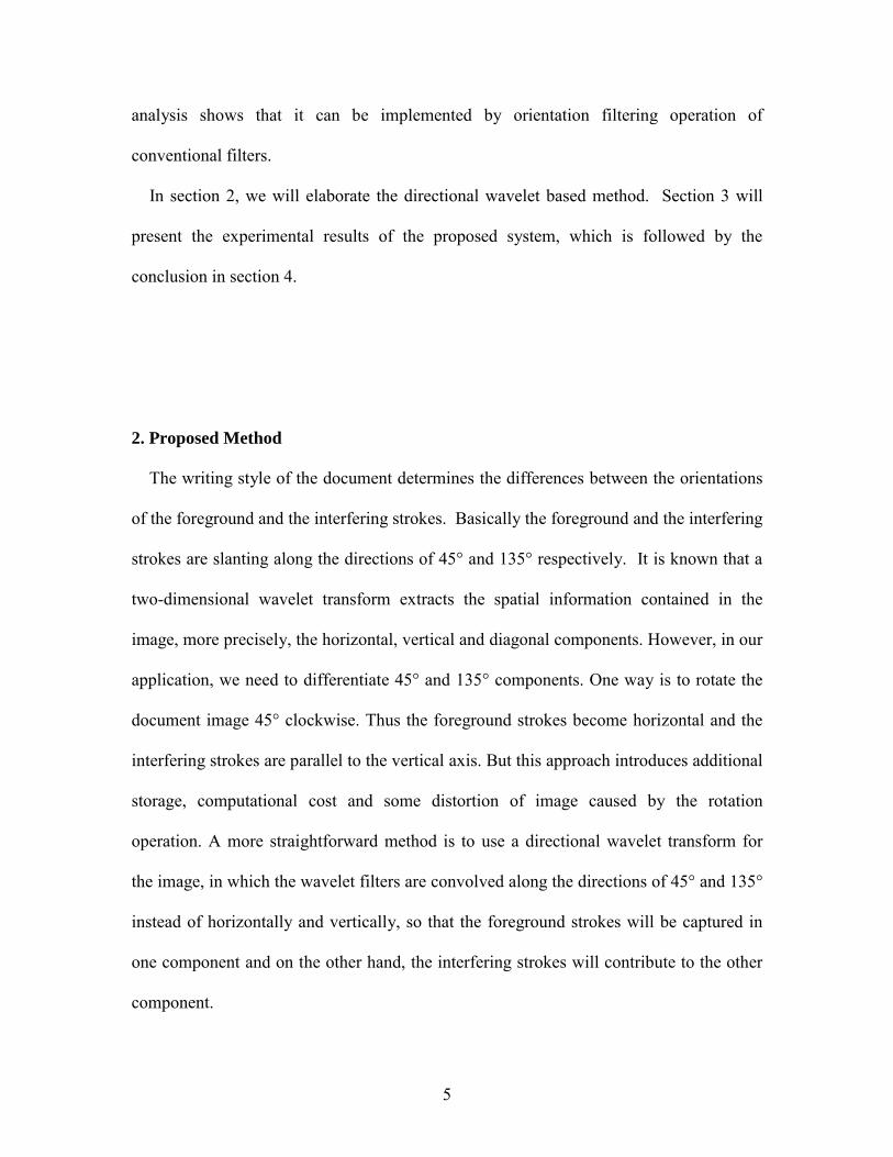
The directional wavelet transform can strengthen the foreground strokes and weaken
the interference in the reconstructed image, as we can see from Figure 3.
(a) (b)
It is noticed
interference imag
Figure 4).
.
Figure 3. Final results of directional wavelet reconstruction10
that the reconstructed foreground strokes is much darker than the
es. So unwanted noise can be easily removed after binarization (See

11
(a) (b)
2.2 Image Recovery
Directional wavelet transform produces a clean output; however some of the
foreground strokes become broken when interfering strokes that were intersecting with
these foreground strokes have been removed. And it is obvious that small pieces of
strokes may have extremely different orientations other than the majority and the system
will remove them together with the interference. To deal with this problem, the
reconstructed image from the above now serve as loci for us to recover streaks of gray
level images from the original document image, such that the neighboring pixels within a
7×7 window centered on each edge pixel are recovered. It may be perceived as that while
tracing along the edges, a small 7×7 window is opened up to view the original document
image (see Figure 5). The size of the window is based on the average width of the strokes
in the documents. This window is more reasonably defined for performing adaptive
thresholding. Through this recovery, isolated or broken foreground strokes are fully
restored. Figure 6 shows the restored images of foreground strokes. To improve the final
Figure 4. Reconstruction images after binarization.

12
appearance, the restored images are binarized using Niblack�s [11] method and the
resultant images are shown in Figure 7.
(a) (b)
(a) (b)
Figure 6. Restored foreground text images.
Figure 7. Final binarized output.
7
7
Edges
Figure 5. Recovery of the foreground strokes images from the original document image while tracing along edges.

13
3. Experiment Results And Discussion
The performance of our approach has been evaluated based on the scanned images of
historical handwritten documents from the National Archives of Singapore. About 200
images have been tested and found to produce readable outputs. For illustration purpose,
we choose 50 images that contain serious interference and manually count the following
numbers of words: words in the original documents, words that are fully restored, words
or parts of words from the interference, words that are impaired by the interference. The
two evaluation metrics: precision and recall [12] defined below are used to measure the
performance of the system.
detected wordsof no. Totaldetectedcorrectly wordsof No. Precision = (7)
document in the wordsof no. Totaldetectedcorrectly wordsof No. Recall = (8)
In equations (7) and (8), the total number of words detected refers to the words appearing
in the final output, some of which are the original words on the front side and some are
from the reverse side (interfering words). The total number of words in the document
refers to all the original words on the front side of a document image. If some words on
the front side are lost or not recovered properly in the resultant image, the whole word is
considered lost and not counted. If parts of a word from the reverse side appear, the total
number of words detected will be increased by 1. Precision shows how well the system
can remove the interfering strokes while recall is an indication of the performance of the
system in restoring the front page to its original state.
The evaluation of the 50 images is shown in table 1, and the first image with its final
binarized results are shown in Figure 8. Table 1 shows a high average precision and recall

14
of 87.5% & 92.4% respectively. By enhancing and smearing wavelet coefficients
sufficiently, almost all the original foreground strokes can be detected. However, in the
image recovery process, although the interfering strokes have already been removed, bits
and pieces of interfering strokes can still fall into the 7×7 window and remain as
interference in the foreground. On the other hand, a few strong interfering strokes are
erroneously regarded as the foreground strokes. These have thus prevented the system
from achieving a perfect recall and precision.
(a) (b)
Figure 8. Result of interference removal of the entire document page: (a) original image; (b) final binarized result.

15
Image 1 2 3 4 5 6 7 8 9 10 11 12 Total # words 188 204 162 166 247 146 186 187 194 172 113 124 Precision (%) 93.7 96.6 67.8 98.8 90.8 96 90 86.8 96.4 93.7 91.3 92.3
Recall (%) 94.1 97.1 72.2 100 91.9 98 92 88.2 96.9 95.3 92.9 96.8 Image 13 14 15 16 17 18 19 20 21 22 23 24
Total # words 180 173 157 150 99 113 120 115 109 124 127 139 Precision (%) 87.5 89.7 89.9 86.7 85 91.3 92 93.2 85.1 92.3 82 77.6
Recall (%) 93.3 96 96.1 91.3 91.9 92.9 95.8 94.8 89 96.8 89.8 87.1 Image 25 26 27 28 29 30 31 32 33 34 35 36
Total # words 173 180 211 175 95 150 157 159 91 78 98 48 Precision (%) 89.7 87.5 85.6 86.7 74.3 86.7 89.9 75 77.9 79.1 87 84
Recall (%) 96 93.3 92.9 93.1 82.1 91.3 96.2 84.9 81.3 87.1 96 87.5 Image 37 38 39 40 41 42 43 44 45 46 47 48
Total # words 147 109 113 199 130 135 124 149 127 40 66 117 Precision (%) 80.1 86.2 92.2 87.7 88.8 84.4 89.4 92.3 94.7 95.1 83.6 84.9
Recall (%) 87.8 97.2 94.7 89.9 97.9 88.1 95.2 96.6 97.6 97.5 92.4 91.5 Image 49 50 Average
Total # words 142 88 140 Precision (%) 77.5 89.5 87.5
Recall (%) 87.3 96.6 92.4
4. Conclusions And Future Work
In this paper we introduce a new method based on directional wavelet to remove
interference appearing in historical handwritten documents. This new algorithm improves
the appearances of the original documents significantly. Currently we are looking into the
development of a flexible method to work with strokes of arbitrary θ and more general
affine transform A other than constant multiply a unitary matrix in (2). This will then
allow other such historical documents with different stroke orientations to be applied with
the directional wavelet.
Table 1. Evaluation of image restoration results
16
Acknowledgement
This research is supported by a joint grant R-252-000-071-112/303 provided by the
Agency for Science, Technology and Research (A*STAR) and the Ministry of Education,
Singapore. We would like to thank the National Archives of Singapore, for the
permission to use their archival documents.
References
[1] H. Negishi, J. Kato, H. Hase and T. Watanabe, Character extraction from noisy
background for an automatic reference system, Proc. of 5th International
Conference on Document Analysis &Recognition, India, 1999, pp. 143-146.
[2] S.Liang, M. Ahmadi, A morphological approach to text string extraction from
regular periodic overlapping text/ background images, Graphical Models and
Image Processing. CVGIP, Vol. 56, No. 5, Sep.1994, pp. 402-413.
[3] M. S. Chang, S. M. Kang, W. S. Rho, H. G. Kim and D. J. Kim, Improved
binarization algorithm for document image by histogram and edge detection, Proc.
of 3rd International Conference on Document Analysis and Recognition, Canada,
1995, pp. 636-639.
[4] J. H. Jang and K. S. Hong, Binarization of noisy gray-scale character images by thin
line modeling, Pattern Recognition, 32, 1999, pp. 743-752.
[5] H. S. Don, A noise attribute thresholding method for document image binarization,
Proc. of 3rd International Conference on Document Analysis and Recognition,
Canada, 1995, pp. 231-234.

17
[6] Q. Wang, C. L. Tan, Matching of double-sided document images to remove
interference, IEEE Conference on Computer Vision and Pattern Recognition,
CVPR2001, Hawaii, USA, 8-14 Dec 2001.
[7] C. L. Tan, R. Cao, P. Shen, Restoration of archival documents using a wavelet
technique, IEEE Tansactions on Pattern Analysis and Machine Intelligence, Vol.24,
No. 10, October 2002, pp. 1399-1404.
[8] S Mallat, A wavelet tour of signal processing, Academic Press, 1998.
[9] R. R. Coifman and D. Donoho, Translation invariantde-noising, Technical Report,
475, Dept. of Statistics, Stanford University, May, 1995.
[10] I Daubechies, Ten lectures on wavelets, SIAM, Philadelphia, PA, 1992.
[11] W. Niblack, An introduction to digital image processing, Englewood Cliffs, N. J.,
Prentice Hall, pp. 115-116, 1986.
[12] M. Junker, R. Hoch and A. Dengel, On the evaluation of document analysis
components by recall, precision, and accuracy, Proc. of 5th International
Conference on Document Analysis and Recognition, India, 1999, pp. 713-716.

18
Appendix
Proof
We only prove the first equation of (3), all other equations in (3) and (4) can be proved in
same way.
We first prove the following equation,
∑∑ >−+−+−++−+<=+ l kjjj lhkhlknyxlkmyxyxfnmjC )()()))(()(
21())()(
21(
21),,(),(1 φφ (9)
According to the definition,
>−+−⋅−+⋅>=<=<+ )nyx()myx(),y,x(f)y()x(),y,x(f)n,m(jC jjjn,jm,j 221
221
21
1 11 φφφφ
We prove (9) holding for 2 cases according to the parity of nm + ,
1) If Znm ∈+2
, then Znm ∈−2
We do the coordinate transform for XY plain by affine
transform
−
=
=
1111
,''
:1 Ayx
Ayx
A , A is the matrix in (2) with
4/,2c πθ == , then,
)nm'y()nm'x()n)yx(()m)yx((
)'y,'x(g)y,x(f
jjj
Ajjj
A
22
22
2122
21
1
11
+−−−→−+−−+
→
−−−− φφφφ
thus,
>+−−−=<+−− )
2'2()
2'2(
21),','(),(1
nmynmxyxgnmjC jjj φφ
In new coordinate system, the conventional 2-D wavelet transform
for 3,2,1,),,)(~(),,)(~( =∈ kZjnmfDnmfC kjj can be defined as (1) with 2-D wavelets and
scaling function,

19
)()(),(
)()(),(
)()(),(
)()(),(
,,3
,,
,,2
,,
,,1
,,
,,,,
yxyx
yxyx
yxyx
yxyx
njmjnmj
njmjnmj
njmjnmj
njmjnmj
ψψ
ψφ
φψ
φφ
=Ψ
=Ψ
=Ψ
=Φ
. (2�)
A simple extension of Mallat�s work [8] to 2-D case leads to,
∑∑
∑∑∑∑
>++−+−−<=
><=
+++−=
+−=+
++
+−
+
l kjjj
l k knmjlnmj
l kj
j
lhkhknmylnmxyxg
lhkhyxyxg
lhkhknmlnmgC
nmnmgCnmjC
)()())2
(21())
2(
21(
21),,(
)()()()(),,(
)()()2
,2
)(~(
)2
,2
)(~(),(1
1
2,
2,1
1
11
φφ
φφ
We do the affine transform 11
−A
Then,
∑∑ >−+−+−++−+<=+l k
jjj )l(h)k(h)))lk(n()yx(())lkm()yx((),y,x(f)n,m(jC21
21
21
1 φφ
2) If Znm ∉+2
, then Znm ∈+±2
1
We do the coordinate transform for XY plain by affine
transform
−
=
+
=
1111
,01
''
:2 Ayx
Ayx
A , then,
)2
1'2()2
1'2(21))(2())(2(
21
)','(),(
2
22
++−+−−→−+−−+
→
−−−− nmynmxnyxmyx
yxgyxf
jjj
Ajjj
A
φφφφ
thus,
>++−+−−=<+−− )
21'2()
21'2(
21),','(),(1 2
nmynmxyxgnmjC jjj φφ

20
Similar to case 1), we apply the conventional 2-D wavelet transform defined in (1) and
(2�),
∑∑
∑∑∑∑
>+++−++−−<=
><=
+++++−=
+++−=+
+++
++−
+
l kjjj
l k knm,jlnm,j
l kj
j
)l(h)k(h))knm(y())lnm(x(),y,x(g
)l(h)k(h)y()x(),y,x(g
)l(h)k(h)knm,lnm)(gC~(
)nm,nm)(gC~()n,m(jC
21
21
21
21
21
21
21
21
21
1
2
21
212
2
21
φφ
φφ
We do the affine transform 12
−A
Then,
∑∑ >−+−+−++−+<=+l k
jjj )l(h)k(h)))lk(n()yx(())lkm()yx((),y,x(f)n,m(jC21
21
21
1 φφ
So in both cases, (9) holds, from (9) we have,
∑∑∑∑∑∑
−+++=
>Φ<=
>−+−++−<=+
−+++
l kj
l klkn,lkm,j
l kjjj
)l(h)k(h)lkn,lkm(C
)l(h)k(h),y,x(f
)l(h)k(h))lkn(y())lkm(x(),y,x(f)n,m(jC 11 21
21
21
1 φφ
That is the first equation of (3). That completes the proof.