DIRECTIONAL ANTENNA CHANNEL MODELING IN URBAN ...
8
DIRECTIONAL ANTENNA CHANNEL MODELING IN URBAN AREA USING RAY TRACING Zhuyin Li 1 , Sithamparanathan Kandeepan 1 , Andrea Giorgetti 2 , Akram Al-Hourani 1 , Kagiso Magowe 1 1 School of Engineering, RMIT University, Melbourne, Australia, 2 DEI, University of Bologna, Italy Abstract – Directional antennas are regarded as one of the key technologies to achieve higher signal quality and data rate. Evidence has shown that the directional antenna channel features can be very different from the omnidirectional ones. There- fore, it is essential to characterize the directional antenna channel model (DACM), since an accurate, easy-to-implement DACM plays a vital role in the wireless network design, optimization and utilization. In this paper, we cluster the incident rays based on the azimuth direction of arrival at the receiver and extract the features concerning the number of clusters, the distribution of the cluster center and the cluster power ratio. The proposed DACM is derived by the ray tracing method and is feasible for a typical urban scenario within a range of a few hundred meters. Moreover, our proposed model is veriϔied by both ray tracing and numerical simulations. In this paper, we present the model derivation methodology, recommend the model parameters and offer an implementation guideline. Keywords – Directional channel modeling, direction of arrival, multipath clustering, radio propagation, ray tracing 1. INTRODUCTION 5G networks are born with the tags of high capac- ity, high energy efϐiciency and high data rate. In the last decades, multiple-input-multiple-output (MIMO) has been regarded as one of the most promising techniques to enable some of the 5G vital features [1]. Directional an- tennas can improve propagation quality by focusing the beam within some desired direction. We can, therefore, achieve longer transmission distance with higher perfor- mance and lower interference by enhancing the signal strength in the speciϐic direction and suppressing the sig- nal in other directions [2]. For instance, higher frequency bands above 6 GHz e.g. millimeter-wave (mmWave), as part of the 5G spectrum offer huge bandwidth, but at the same time, bring problems like high path loss, high pen- etration loss, limited delay spread and reϐlection domi- nated propagation [3]. Therefore, directional antennas are deployed to overcome such challenges. On the other hand, the utility of directional antennas at both traditional and higher frequency bands can bring new challenges to the wireless network design, development and imple- mentation, with the increasing demand for the accuracy of the channel modeling [4]. Moreover, the angular infor- mation such as direction of arrival (DOA) and direction of departure (DOD), cannot be neglected in directional chan- nels, because they are not only important features for the propagation model, but also affect other parameters like path loss and delay [5]. As a result, the traditional omni- directional channel models cannot accurately estimate a directional antenna propagation. Channel models are essential for wireless network design and analysis, since they give insights into the character- istics of the radio channel without conducting ϐield mea- surements, which are usually time-consuming and costly. Among all the channel modeling methods, ray tracing, as a geometry-based technique, can provide an accurate esti- mation of the radio propagation with high computational speed [6]. In a ray tracing simulation (RTS), the software estimates possible paths between the transmitter and the receiver depending on the environment, and offers a list of outputs including path loss, DOA, DOD, delay etc. Fur- thermore, even though the RTS can offer a great number of multipath components (MPCs), it is not necessary to deal with MPCs individually. Many measurements have revealed that MPCs can be grouped into clusters with sim- ilar features such as DOA, DOD or delay. Such cluster- based channel models are more compact and intuitive since the intra-cluster, and inter-cluster statistics can be treated separately [7]. Considering the urge to have an accurate channel model in a directional propagation environment, we propose a directional antenna channel model (DACM) and also offer a generic methodology framework for channel modeling. In this paper, our main contributions can be summarized as follows: 1) We derive a clustering DACM using the ray tracing method. The model is feasible for a typical urban scenario in which the transmitter and the receiver are a few hundred meters apart, such as an urban microcell net- work. 2) We cluster the MPCs based on the azimuth DOA, and further extract the probability mass function (PMF) of the number of clusters, the probability density func- tion (PDF) of the azimuth cluster center and the cluster power ratio. 3) The derived PDF expressions are simple functions of only a few distance-independent parameters. The remainder of the paper is organized as follows. In sec- tion 2, a literature review on the existing directional chan- nel model is presented. We also present the system model in section 3 and the ray tracing simulation method in sec- tion 4. The proposed DACM is presented in section 5, fol- ITU Journal: ICT Discoveries, Vol. 2(1), 19 November 2019 © International Telecommunication Union, 2019 Some rights reserved. This work is available under the CC BY-NC-ND 3.0 IGO license: https://creativecommons.org/licenses/by-nc-nd/3.0/igo/. More information regarding the license and suggested citation, additional permissions and disclaimers is available at https://www.itu.int/en/journal/2019/001/Pages/default.aspx
-
Upload
khangminh22 -
Category
Documents
-
view
1 -
download
0
Transcript of DIRECTIONAL ANTENNA CHANNEL MODELING IN URBAN ...
DIRECTIONAL ANTENNA CHANNEL MODELING IN URBAN AREA USING RAY TRACING
Zhuyin Li1, Sithamparanathan Kandeepan1, Andrea Giorgetti2, Akram Al-Hourani1, Kagiso Magowe11School of Engineering, RMIT University, Melbourne, Australia, 2DEI, University of Bologna, Italy
Abstract – Directional antennas are regarded as one of the key technologies to achieve higher signal quality and data rate.Evidence has shown that the directional antenna channel features can be very different from the omnidirectional ones. There-fore, it is essential to characterize the directional antenna channelmodel (DACM), since an accurate, easy-to-implementDACMplays a vital role in the wireless network design, optimization and utilization. In this paper, we cluster the incident rays basedon the azimuth direction of arrival at the receiver and extract the features concerning the number of clusters, the distributionof the cluster center and the cluster power ratio. The proposed DACM is derived by the ray tracingmethod and is feasible for atypical urban scenario within a range of a few hundred meters. Moreover, our proposed model is veri ied by both ray tracingand numerical simulations. In this paper, we present the model derivation methodology, recommend the model parametersand offer an implementation guideline.
Keywords – Directional channel modeling, direction of arrival, multipath clustering, radio propagation, ray tracing
1. INTRODUCTION
5G networks are born with the tags of high capac-ity, high energy ef iciency and high data rate. In thelast decades, multiple-input-multiple-output (MIMO) hasbeen regarded as one of themost promising techniques toenable some of the 5G vital features [1]. Directional an-tennas can improve propagation quality by focusing thebeam within some desired direction. We can, therefore,achieve longer transmission distance with higher perfor-mance and lower interference by enhancing the signalstrength in the speci ic direction and suppressing the sig-nal in other directions [2]. For instance, higher frequencybands above 6 GHz e.g. millimeter-wave (mmWave), aspart of the 5G spectrum offer huge bandwidth, but at thesame time, bring problems like high path loss, high pen-etration loss, limited delay spread and re lection domi-nated propagation [3]. Therefore, directional antennasare deployed to overcome such challenges. On the otherhand, theutility of directional antennas at both traditionaland higher frequency bands can bring new challengesto the wireless network design, development and imple-mentation, with the increasing demand for the accuracyof the channel modeling [4]. Moreover, the angular infor-mation such as direction of arrival (DOA) and direction ofdeparture (DOD), cannot beneglected indirectional chan-nels, because they are not only important features for thepropagation model, but also affect other parameters likepath loss and delay [5]. As a result, the traditional omni-directional channel models cannot accurately estimate adirectional antenna propagation.
Channelmodels are essential forwireless network designand analysis, since they give insights into the character-istics of the radio channel without conducting ield mea-surements, which are usually time-consuming and costly.Among all the channelmodelingmethods, ray tracing, as a
geometry-based technique, can provide an accurate esti-mation of the radio propagation with high computationalspeed [6]. In a ray tracing simulation (RTS), the softwareestimates possible paths between the transmitter and thereceiver depending on the environment, and offers a listof outputs including path loss, DOA, DOD, delay etc. Fur-thermore, even though the RTS can offer a great numberof multipath components (MPCs), it is not necessary todeal with MPCs individually. Many measurements haverevealed thatMPCs can be grouped into clusterswith sim-ilar features such as DOA, DOD or delay. Such cluster-based channel models are more compact and intuitivesince the intra-cluster, and inter-cluster statistics can betreated separately [7].
Considering the urge to have an accurate channel modelin a directional propagation environment, we propose adirectional antenna channel model (DACM) and also offera generic methodology framework for channel modeling.In this paper, our main contributions can be summarizedas follows: 1) We derive a clustering DACM using the raytracing method. The model is feasible for a typical urbanscenario in which the transmitter and the receiver are afewhundredmeters apart, suchas anurbanmicrocell net-work. 2) We cluster the MPCs based on the azimuth DOA,and further extract the probability mass function (PMF)of the number of clusters, the probability density func-tion (PDF) of the azimuth cluster center and the clusterpower ratio. 3) The derived PDF expressions are simplefunctions of only a fewdistance-independent parameters.
The remainderof thepaper is organizedas follows. In sec-tion 2, a literature reviewon the existing directional chan-nelmodel is presented. We also present the systemmodelin section 3 and the ray tracing simulation method in sec-tion 4. The proposed DACM is presented in section 5, fol-
ITU Journal: ICT Discoveries, Vol. 2(1), 19 November 2019
© International Telecommunication Union, 2019Some rights reserved. This work is available under the CC BY-NC-ND 3.0 IGO license: https://creativecommons.org/licenses/by-nc-nd/3.0/igo/. More
information regarding the license and suggested citation, additional permissions and disclaimers is available at https://www.itu.int/en/journal/2019/001/Pages/default.aspx
lowed by the simulation results in section 6. In section 7and 8, we present a guideline for the model implementa-tion andmodel veri ication, andwe conclude the paper insection 9.
2. LITERATURE REVIEWIn the existing literature, standard models draw great at-tention since they are regulated and agreed on by organi-zations across theworld [8, 9, 10]. Among all the standardmodels, cooperation in science and technology (COST)models are widely accepted. The different COST channelmodels e.g. COST207, COST231, COST259, COST273andCOST 2100 were developed to address speci ic objectivesin various application ields [8, 9, 10, 11, 12].
COST 259 has a three-layered framework structure, spec-ifying 13 radio propagation environments considered inthe analysis of performance in wireless systems [8, 13]. Itclusters MPCs in the delay domain and models the chan-nel by distance-dependent path loss, shadowing fading,and power-delay-angular-pro ile. Adopting the hierarchyof modeling concepts similar to COST 259, the COST 273model provides two signi icant achievements: 1) Newscenarios for multiple-input multiple-output (MIMO) arede ined; and 2) the clusters are considered differently i.e.,apart from local clusters and single clusters, twin clustersare introduced to simulate multiple-bounce interactions[9]. Moreover, the COST 2100 model extended the COST273 model by the novel developments of the polarizationof the channel, dense multipath components and multi-link aspects [10].
Apart from the aforementioned standard models, someother directional models widely adopted by researchersinclude analytical models, stochasticmodels and ray trac-ing models [14]. Analytical models mathematically de-scribe the channel without considering the speci ic geog-raphy of the environment, such as the independent andidentically distributed (i.i.d.) model [15] and the Kro-necker model [16]. Stochastic models characterize theradio propagation between transmitters and receiversby using stochastic scatterings [3, 17]. Most of themare geometry-based models but are not limited to a spe-ci ic site. The COST models mentioned above are alsostochastic models. The last classi ication, ray tracingmodels, highly depend on the radio propagation environ-ment with a limited range of validity. However, ray trac-ing models can extract the propagation parameters (pathloss, DOD, DOA, and so forth) accurately [18, 19].
Although there are plenty of directional channel mod-els characterizing the propagation from various perspec-tives, some papers focused on the delay or delay-DOAdomain [3, 8, 9], while some papers considered a non-clustering DOA domain [20, 21]. However, the number ofpapers focusing on the azimuthDOA clusters and the clus-ter power pro ile are limited. By contrast, our paper cap-tures the features of the azimuth DOA in clusters. In our
proposedmodel, the clusteredDOA features are extractedindependently from the delay or other channel parame-ters. Therefore, our model is in a relatively compact formand focuses on the azimuth DOA domain.
3. SYSTEMMODELIn this section, we present the transmitter and the re-ceiver system model considering only one base station(BS), and multiple mobile stations (MS). Additionally, weillustrate the virtual city models used in the RTS.
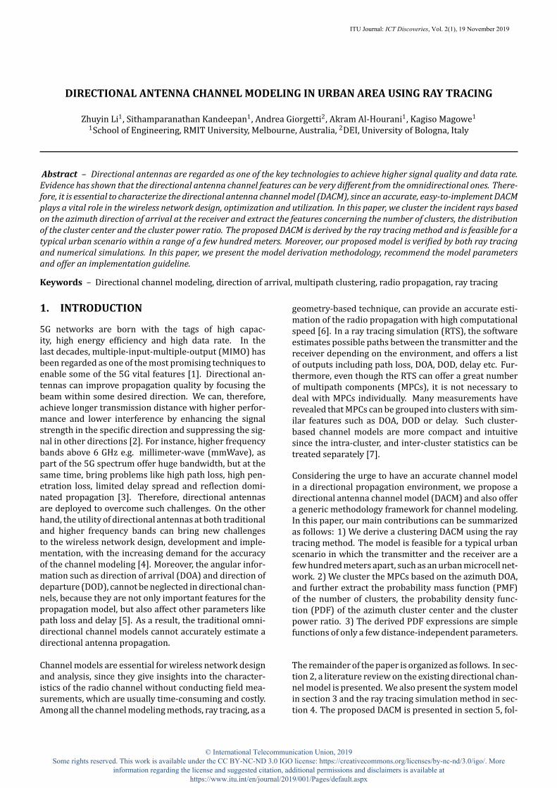
3.1 Transmitter and receiver systemmodelA basic system layout model is shown in Fig. 1. We con-sider an omnidirectional transmitter as the BS, located atLBS = [x𝑏, y𝑏] and 𝑁 MS randomly and uniformly placedwithin the area, located at ixed positions LMS = [x𝑛, y𝑛],𝑛 = 1, ..., 𝑁 . The height of the BS is ℎBS, and all the MShave an identical height of ℎMS. Such a system layout isable to capture the propagation features from360° at var-ious distances. We also propose a local coordinate systemfor each MS in section 4, and the electromagnetic proper-ties of the simulated BS and MS can be found in section6.
Fig. 1 – Systemmodel. The station at the center in red is the base station,and the devices in blue are the mobile stations.
3.2 Virtual urban scenarioDifferent types of environments have a signi icant impacton the channel model. For the typical urban scenario weare interested in, it has dense buildings with a relativelysmall number of large open areas like lakes and parks. Al-though there is some afforestation in the urban environ-ment, it is out of proportion with buildings. Apart fromthese aforementioned urban features associated with thebuilding layout, another key factor taken into considera-tion is the materials of the buildings. The reason is thatthe materials affect the electrical conductivity and resis-tivity, leading to a signi icant impact on the electromag-
ITU Journal: ICT Discoveries, Vol. 2(1), 19 November 2019

netic (EM) propagation. In our RTS, we set the build-ing material as one-layer concrete and the terrain as wetearth. For simplicity, we consider a lat terrain and ne-glect the afforestation,which is acceptable since it is a typ-ical urban environment. As for the building layout, we fol-low the Recommendation document proposed by the In-ternational Telecommunication Union (ITU) [22]. Threeparameters, 𝑈𝛼, 𝑈𝛽, and 𝑈𝛾 detailed in Table 1 are usedto generate a virtual random city model. The PDF of thebuilding height follows a Rayleigh distribution [22]
𝑓h(ℎ) =ℎ exp( −ℎ2
2𝑈2𝛾)
𝑈2𝛾(1)
where ℎ is the building height in meters.
Table 1 – Parameters for generating a virtual random city model
𝑈𝛼Ratio of land area covered by buildings to totalland area (dimensionless)
𝑈𝛽Mean number of buildings per unit area(buildings/km2)
𝑈𝛾
A variable scaling the building height PDF, de-ined by a Rayleigh distribution given by (1) (di-mensionless)
Fig. 2 shows a Manhattan grid layout for the software-generated city. Cubic buildings are uniformly distributedwithin a square area with side length 𝑆 m. All buildingsshare the same square cross-section, 𝐵 × 𝐵 m2, and ixedstreet width 𝑊 m. Both 𝐵 and 𝑊 can be obtained from𝑈𝛼 and 𝑈𝛽 as 𝐵 = 1000√ 𝑈𝛼
𝑈𝛽, and 𝑊 = 1000
√𝑈𝛽− 𝐵 [23].
0
500
400
300
20
500
X Axis [m]
400200
Y Axis [m]
300
Bui
ldin
g H
eigh
t [m
]
100 200
40
1000 0
60
0
5
10
15
20
25
30
35
40
45
50
Fig. 2 – A virtual random city generated based on ITU-R parameters.
In this paper, we consider not only software-generatedvirtual city models but also real urban footprints. TheRTS in a real urban environment can give us more prac-tical and reliable insights into the results. We export thefootprints and terrainmap of the central business district(CBD) area inMelbourne, Australia fromonline databases[24, 25]. TheMelbourne CBD scenario is used for the veri-ication of our proposed directional channelmodel in sec-tion 8.
4. RAY TRACING SIMULATIONS FOR DACM
A ray tracing simulator, Wireless InSite®, is used for theradio propagation modeling in this paper. It predictsradio frequency (RF) signal propagation, as well as EMield in a speci ic environment and offers a list of outputresults, including propagation paths between each pairof transmitter and receiver, received signal power, mag-nitude and phase of E- ield, DOA, DOD etc. The majorray propagation mechanisms are line-of-sight(LoS), re-lection and diffraction. Scattering is neglected due to thebuilding layout and transmission parameters in this case.Since radio propagation mainly interacts with buildingsand terrain in the urban environment, the transmissionthrough objects is also neglected for simplicity. It is rea-sonable becausewe are not interested in indoor propaga-tion, nor indoor-to-outdoor propagation. As a result, oursimulation involves amixture of LoS andnon-line-of-sight(NLoS) propagation. Fig. 3 shows a pair of BS and MS inMelbourne CBD from the ray tracing simulator as an ex-ample. Cubes shaded blue at various height represent thebuildings, and the dark green layer at the bottom is theterrain. The green and red cubes are the BS and theMS re-spectively. In this case, the MS is 600m away from the BS.The colorful lines are the propagation paths (rays) fromBS to MS. Such colors indicate the power level of each ray.Since ℎMS is identical for all the MS and the terrain is rel-atively lat in our environment, there is little variation inthe elevation angle. As a result, we focus more on the az-imuth angle𝜙. TheMS itself is the pole of the local angularcoordinate system. The LoS direction from the MS to theBS is de ined as the angular axis at 𝜙 = 0°, and 𝜙 increasescounterclockwise from -180° to 180°.
Fig. 3 – The local coordinate system in the ray tracing simulator (simu-lation environment: Melbourne CBD).
Theoutputdata fromRTS is furtherprocessedbyMatlab®.We quantify the parameters for the proposed channelmodel from curve itting. The inal veri ication is given bythe ray tracing results as well as the numerical results byMatlab® Monte-Carlo simulations. A brief process of themethodology of our DACM is shown in Fig. 4.
ITU Journal: ICT Discoveries, Vol. 2(1), 19 November 2019

Fig. 4 – The methodology of directional antenna channel modeling.
5. DIRECTIONAL ANTENNA CHANNELMODELING
In this section, we propose the directional antenna chan-nel model. Firstly, we will introduce the clusters of therays at the receiver. Then we will present the channelmodel with three key parameters: 1) the number of clus-ters and its PMF; 2) the cluster center (in degrees) in theazimuth domain and its PDF; 3) the cluster power ratio(in dBm) and its PDF.
5.1 Clusters of the incident raysThe received signal propagated in a directional antennachannel model can be characterized by the summation ofthe clusters, and each cluster can be further characterizedby the summation of all the rays within the cluster:
𝑟(𝜏i, m, 𝜙i, m, 𝛽i, m) =ℳ∑m=1
ℛm
∑i=1
𝑟i, m(𝜏i, m, 𝜙i, m, 𝛽i, m)⏟⏟⏟⏟⏟⏟⏟⏟⏟⏟⏟
𝑟m(𝜏i, m,𝜙i, m,𝛽i, m)
(2)
where 𝜏 , 𝜙 and 𝛽 are the delay, DOA and power ratio ofthe received signal respectively, the subscriptm and i rep-resent the corresponding parameters of the m-th clus-ter and the i-th ray. The terms 𝑟i, m(𝜏i, m, 𝜙i, m, 𝛽i, m) and𝑟m(𝜏i, m, 𝜙i, m, 𝛽i, m) represent the received signal of eachray and each cluster, respectively. We de ine that at onereceiver, the cluster number isℳ, and the number of rayswithin each cluster is ℛm.
Fig. 5 shows an example given by one MS located 600 maway from the BS in a virtual random city environment.In particular, Fig. 5(a), Fig. 5(b) and Fig. 5(c) illustratethe cluster classi ication considering clustered rays in theray tracing simulator, the delay domain and the azimuthDOA domain, respectively. As expected, the received raysare clustered in both delay domain and angular domain.The clusters in both domains have some similarities to acertain degree. However, the cluster division in two do-mains does not always share the exact consistency sincemultiple complex factors in the scenario are responsible
for the result of 𝜏 and 𝜙. It is common in the existing lit-erature that the authors start analyzing the channel fromthe delay domain, and the azimuth spread has some cor-relation with the delay [8, 9]. In this paper, we believethat it is worthy of focusing more on the features of thedirectionality of the wireless channel.
(a) Visualized clustered rays in the ray tracing simulator.
(b) Clustered rays in the delay domain.
(c) Clustered rays in the azimuth domain.
Fig. 5 – An example of the rays in clusters with respect to 𝜏 and 𝜙.
To further characterize the clusters of 𝜙, we de ine thecluster gap, 𝜔, as the shortest angular distance betweentwo clusters in degree. In other words, if the DOA of twoneighboring rays has a gap greater than 𝜔, these two raysfall into two clusters. Noting that in our system model insection 3, we consider MS located at random positions.However, the inal results show that the distance between
ITU Journal: ICT Discoveries, Vol. 2(1), 19 November 2019

MS and BS does not have a signi icant impact on our re-sults. The main reason is that we set the simulation areaas a square with a side length of 1.6 km, and farthest dis-tance from MS to BS is 600 m. The distance variation inour simulation is not very big, but it is enough to cover areasonable range. In other words, our model is distance-independent, valid for a range of a few hundred meters,such as an outdoor urban microcell scenario. In the fol-lowing parts of this section, the directional channelmodelis representedwith two carrier frequencies, 2 GHz and 28GHz, to cover both examples of microwave and mmWavespectrum.
5.2 Number of clustersOnce the cluster gap 𝜔 is set, all the rays at one receivercan be grouped into ℳ clusters in the azimuth domain.ℳ is characterized by its PMF, 𝑃 (ℳ = 𝑖), 𝑖=1,...,5, pre-sented in Table 2.
Table 2 – Probability mass function of ℳ
ℳ 1 2 3 4 52 GHz 0.2496 0.4389 0.2551 0.05419 0.00219328 GHz 0.3821 0.3836 0.2005 0.03124 0.002588
5.3 Cluster centerTo further outline the azimuth feature of the clusters, weintroduce cluster center, 𝜙m, as the average azimuth of allthe rays within the same cluster
𝜙m = ∑ℛm𝑖=1 𝜙𝑖ℛm
(3)
where ℛm is the total number of rays within the samecluster. 𝜙𝑖 is the DOA per ray within this cluster in de-gree. Then based on our RTS, we extract the PDF of 𝜙m asa piecewise exponential function,
𝑓𝜙(𝜙m) =
⎧{{⎨{{⎩
𝑎2exp(−𝑏2(𝜙m + 90)), −180 ≤ 𝜙m < −90𝑎1exp(𝑏1𝜙m), −90 ≤ 𝜙m < 0𝑎1exp(−𝑏1𝜙m), 0 ≤ 𝜙m < 90𝑎2exp(𝑏2(𝜙m − 90)), 90 ≤ 𝜙m < 180.
(4)To make (4) right continuous and symmetric on 𝜙m = 0,
𝑎2 = 𝑓𝜙(𝜙m = −90) = 𝑎1exp(−90𝑏1) (5)
Table 3 – Parameters of 𝑓𝜙(𝜙m)
𝑓𝑐 𝑎1 𝑏1 𝑏22 GHz 0.005658 0.01340 0.00766628 GHz 0.007494 0.02485 0.02121
Parameters obtained by curve itting are presented in Ta-ble 3. Noting that due to the curve itting, we end up withthe result for the model such that ∫180
−180 𝑓𝜙(𝜙m)𝑑𝜙m ≈ 1.
5.4 Cluster power ratioThepowerper cluster canbe solvedby two sub-problems,the total received power, Pr at the MS, and the power dis-tribution among ℳ clusters. In this paper, we are moreinterested in the latter problem. For the irst one, basedon the speci ic scenarios, the Pr calculation can be solvedby many widely accepted omnidirectional path loss mod-els in the existing literature, such as the log-normal shad-owing model, two-ray model, Okumura–Hata model etc.In this paper, we do not recommend any path loss expo-nent or shadowing parameters, because the main contri-bution from us is the directional features of the power atthe receiver end. To model the power per cluster, we de-ine a cluster power ratio as
𝛽m = PmPr
. (6)
Note that 0 < 𝛽m ≤ 1, and if ℳ = 1, 𝛽m = 1. Forother cases given ℳ > 1, we ind that no matter whatthe value of ℳ is, the PDF of 𝛽m follows a U-shape dis-tribution, which can be very well itted by Kumaraswamydistribution [26].
𝐾(𝛽m|ℳ) = {1, ℳ = 1𝑐𝑑𝛽𝑐−1
m (1 − 𝛽𝑐m)𝑑−1, ℳ > 1. (7)
A summary of 𝑐 and 𝑑 parameters conditioned by ℳ islisted in Table 4. Another important condition of thepower ratio is that the summation of all the 𝛽m at one MSis 1, ∑ℳ
m=1 𝛽m = 1.
Table 4 – Parameters of 𝛽m
𝑓𝑐ℳ = 2 ℳ = 3 ℳ = 4 ℳ = 5
𝑐 𝑑 𝑐 𝑑 𝑐 𝑑 𝑐 𝑑2 GHz 0.17 0.37 0.15 0.45 0.20 0.55 0.03 0.5028 GHz 0.17 0.37 0.12 0.55 0.05 0.50 0.01 0.55
6. SIMULATION RESULTSIn the RTS, we consider the system models presented insection 3 using the parameters in Table 5.
We generate ive realizations of the virtual city modelswith the same set of 𝑈𝛼, 𝑈𝛽 and 𝑈𝛾 , and launch RTS inive such environments to average the randomness. Ateach MS, we consider the maximum of 100 incident rays.However, the power of some rays can be low, so that theyhardly contribute to the total received signal. Therefore,we remove such rays with power below a threshold, Poff =-150 dBm. The RTS returns 𝜙i in the output iles and the
ITU Journal: ICT Discoveries, Vol. 2(1), 19 November 2019

Table 5 – Simulation parameters
ITU-R urban parameters𝑈𝛼 = 0.3𝑈𝛽 = 500 buildings/km2
𝑈𝛾 = 15Virtual city side length (𝑆) 1600 m
BS height (ℎBS) 30 mMS height (ℎMS) 1.5 m
Number of MS (𝑁) 3771BS transmit power (Pt) 20 dBmCarrier frequency (𝑓𝑐) 2 GHz, 28 GHzCut-off power (Poff) -150 dBm
Max rays per MS (ℛMAX) 100Cluster gap (𝜔) 50∘
data can be clustered by sophisticated algorithms such ashierarchical clustering once the shortest distance 𝜔 is setup. Then ℳ and 𝜙m can be determined consequently. Fi-nally when taking all MS into consideration, 𝑃 (ℳ) and𝑓𝜙(𝜙m) can be obtained by calculating their PMF and PDFrespectively. Fig. 6 shows the comparison of the direc-tional channel model and the RTS results regarding 𝜙m.Adjustments on the curve itting parameters have beenmade to have 𝑓𝜙(𝜙m) symmetric on 𝜙m = 0 and right con-tinuous. The inal step is to model the power per clus-ter. We use the E- ield strength per ray from RTS to solvethis problem. The total received power per MS is Pr =∑ℛ
𝑖=1 𝑃𝑖, and the power per cluster is Pm = ∑ℛm𝑖=1 𝑃𝑖 [27],
where 𝑃𝑖 is the time averaged received power in watts ofthe 𝑖-th ray, calculated by the E- ield components:
𝑃𝑖 = 𝜆2𝐹8𝜋𝜂0
∣𝐸𝜃,𝑖 + 𝐸𝜙,𝑖∣2
(8)
= 𝜆2𝐹8𝜋𝜂0
∣𝑀𝜃,𝑖𝑒𝑗𝜓𝜃,𝑖 + 𝑀𝜙,𝑖𝑒𝑗𝜓𝜙,𝑖 ∣2 . (9)
where𝐸𝜃,𝑖 and𝐸𝜙,𝑖 are the 𝜃 and 𝜙 components of E- ieldof the 𝑖-th ray, 𝑀 and 𝜓 are the magnitude and the phaseof the ray, 𝜆 is the wavelength, 𝜂0 is the impedance of freespace (377 Ω) and 𝐹 is the overlap of the frequency spec-trum of the transmitted waveform and the spectrum ofthe frequency selectivity of the receiver [27]. The powerratio in (6) can be rewritten as:
𝛽m = ∑ℛm𝑖=1 ∣𝑀𝜃,𝑖𝑒𝑗𝜓𝜃,𝑖 + 𝑀𝜙,𝑖𝑒𝑗𝜓𝜙,𝑖 ∣2
∑ℛ𝑖=1 ∣𝑀𝜃,𝑖𝑒𝑗𝜓𝜃,𝑖 + 𝑀𝜙,𝑖𝑒𝑗𝜓𝜙,𝑖 ∣2
. (10)
Two examples of the curve itting for𝐾(𝛽m) givenℳ = 2,𝑓𝑐 = 2 GHz and ℳ = 3, 𝑓𝑐 = 28 GHz are shown in Fig. 7.
7. DACM IMPLEMENTATION STEPS USINGSOFTWARE TOOLS
The proposed directional channel model in this paper en-ables readers to calculate the distributed azimuth andpower in clusters. Such information can be helpful whendirectional features play an important role in the de-sign and analysis of the wireless channel, for example,
−180 −135 −90 −45 0 45 90 135 1800
0.2
0.4
0.6
0.8
1 ⋅10−2
𝜙m (degree)
𝑓 𝜙(𝜙
m)
RTSDACM
(a) 𝑓𝑐 = 2 GHz
−180 −135 −90 −45 0 45 90 135 1800
0.2
0.4
0.6
0.8
1 ⋅10−2
𝜙m (degree)
𝑓 𝜙(𝜙
m)
RTSDACM
(b) 𝑓𝑐 = 28 GHz
Fig. 6 – The curve itting of 𝑓𝜙(𝜙m) at 2 GHz and 28 GHz.
some5Gdirection-based applications. We summarize themodel in two phases, the directionality of the clusters andthe power distribution. The guideline for the model im-plementation is in Algorithm 1.Algorithm 1 DACM implementation steps1: Get system set-up parameters, 𝑓𝑐, 𝑁2: for each Receiver 𝑛 do3: Get number of clustersℳ, following the PMF in Ta-
ble 24: for allm ∈ ℳ do5: Get 𝜙m following (4)6: Condition: MAX(𝜙m − 𝜙m-1) ≤ 𝜔, m = 2...ℳ7: Get 𝛽m following (7)8: Condition: ∑ℳ
m=1 𝛽m = 19: Pm ← 𝛽mPr
10: end for11: end for
8. DACM VERIFICATION
To verify our model, we propose two methods, ray trac-ing simulated veri ication byWireless Insite® and numer-ically simulated veri ication by Monte-Carlo simulations.For the formermethod, we consider both virtual city (VC)models generated by Matlab® and an actual MelbourneCBD footprint imported from online databases [24, 25].The system model for the veri ication follows the sameset-up as section 3. Then we choose 𝑁 = 500 receiversuniformly from RTS set-up to join the verifying calcula-
ITU Journal: ICT Discoveries, Vol. 2(1), 19 November 2019

0 0.2 0.4 0.6 0.8 10
5
10
15
20
𝛽m
𝐾(𝛽
m)
RTSDACM
(a) ℳ = 2, 𝑓𝑐 = 2 GHz
0 0.2 0.4 0.6 0.8 10
10
20
30
40
𝛽m
𝐾(𝛽
m)
RTSDACM
(b) ℳ = 3, 𝑓𝑐 = 28 GHz
Fig. 7 – Examples of the curve itting for 𝐾(𝛽m).
tion. For the latter method, we simulate the channel fol-lowing Algorithm 1. The receiver number is also 𝑁 andthe simulation follows the steps in section 7. A compari-son of these verifying cases, RTS (VC), RTS (Melb), simu-latedmodel and the channel model can be found in Fig. 8.In both of the sub- igures, the scattered dots are the veri-ication results, and the colors, red, yellow and green rep-resent the RTS in a virtual city, the RTS in Melbourne CBDand the numerical results respectively. The solid blue lineis the proposed directional channel model. The carrierfrequencies are 2 GHz for Fig. 8(a) and 28 GHz for Fig.8(b). The three veri ication cases match the model verywell in both igures. Actually, we have veri ied every case,including 𝜙m, 𝛽m conditioned by each ℳ at two frequen-cies. All the cases have shown a high level of matching.However, only two examples are depicted in this paper.
9. CONCLUSIONIn this paper, we presented a statistical clustering DACMfor a general urban scenario. It can bene it the directionalwireless network design, optimization and utilization insubstance since the channel features can be estimated bymerely a few distance-independent probability distribu-tion parameters. The model is proposed in three key as-pects, the number of clusters, the cluster center distribu-tion and the cluster power ratio distribution at two car-rier frequencies, 2 GHz and 28 GHz. We have concludedthat for both frequencies, these three parameters sharesimilar features but with notable differences. Comparedwith 2 GHz, 28 GHz tends to bring relatively equal prob-
−180 −135 −90 −45 0 45 90 135 1800
0.2
0.4
0.6
0.8
1 ⋅10−2
𝜙m (degree)
𝑓 𝜙(𝜙
m)
RTS (VC)RTS (Melb)
Simulated resultsDACM
(a) Veri ication on 𝜙m , 𝑓𝑐 = 2 GHz
0 0.2 0.4 0.6 0.8 10
5
10
15
20
𝛽m
𝐾(𝛽
m)
RTS (VC)RTS (Melb)
Simulated resultsDACM
(b) Veri ication on 𝛽m , ℳ = 3, 𝑓𝑐 = 28 GHz
Fig. 8 – Examples of the channel model veri ication on 𝜙m and 𝛽m .
ability of the cluster number if ℳ ≤ 3, but these clus-ters are more concentrated at the LoS direction, and thepower distribution is more uneven. Future works can beextended from the 2D model to a 3D air-to-ground chan-nelmodel, which bringsmore interest to the elevation an-gle. Also, the clustering algorithmand themodeling of therootmean square delaywill be studied tomake the DACMmore completed.
REFERENCES[1] NGMN Alliance, “NGMN 5G white paper,” accessed
2019-07-17. [Online]. Available: https://www.ngmn.org/work-programme/5g-white-paper.html
[2] Z. Li, K. Magowe, A. Giorgetti, and S. Kandeepan,“Blind localization of primary users with sectorialantennas,” in IEEE International Conference on Com-munications Workshops (ICC Workshops), KansasCity, MO, USA, May 2018, pp. 1–6.
[3] R. T. Rakesh, G. Das, and D. Sen, “An analytical modelformillimeterwave outdoor directional non-line-of-sight channels,” in IEEE International Conference onCommunications (ICC), Paris, France, May 2017, pp.1–6.
[4] M. Sha i, J. Zhang, H. Tataria, A. F. Molisch, S. Sun, T. S.Rappaport, F. Tufvesson, S. Wu, and K. Kitao, “Mi-crowave vs. millimeter-wave propagation channels:Key differences and impact on 5G cellular systems,”
ITU Journal: ICT Discoveries, Vol. 2(1), 19 November 2019
IEEE Communications Magazine, vol. 56, no. 12, pp.14–20, December 2018.
[5] E. Anderson, G. Yee, C. Phillips, D. Sicker, andD. Grunwald, “The impact of directional antennamodels on simulation accuracy,” in IEEE Interna-tional Symposium on Modeling and Optimization inMobile, Ad Hoc, andWireless Networks, Seoul, Korea,Jun 2009, pp. 1–7.
[6] Z. Yun and M. F. Iskander, “Ray tracing for radiopropagationmodeling: Principles and applications,”IEEE Access, vol. 3, pp. 1089–1100, 2015.
[7] R. He, B. Ai, A. F. Molisch, G. L. Stuber, Q. Li, Z. Zhong,and J. Yu, “Clustering enabledwireless channelmod-eling using big data algorithms,” IEEE Communica-tions Magazine, vol. 56, no. 5, pp. 177–183, May2018.
[8] A. F. Molisch, H. Asplund, R. Heddergott, M. Stein-bauer, and T. Zwick, “The COST 259 directionalchannel model-part I: Overview and methodol-ogy,” IEEE Transactions on Wireless Communica-tions, vol. 5, no. 12, 2006.
[9] A. F. Molisch, H. Hofstetter, and et al., “The COST 273channel model,” New York, NY, USA, 2006.
[10] L. Liu, C. Oestges, J. Poutanen, K. Haneda,P. Vainikainen, F. Quitin, F. Tufvesson, and P. D.Doncker, “The COST 2100 MIMO channel model,”IEEE Wireless Communications, vol. 19, pp. 92–99,December 2012.
[11] COST 207 Management Committee, COST 207: digi-tal landmobile radio communications. Commissionof the European Communities, 1989.
[12] E. Damosso et al., “Digital mobile radio: Cost 231view on the evolution towards 3rd generation sys-tems,” European Commission, 1998.
[13] H. Asplund, A. A. Glazunov, A. F. Molisch, K. I. Peder-sen, and M. Steinbauer, “The COST 259 directionalchannel model-part II: macrocells,” IEEE Transac-tions on Wireless Communications, vol. 5, no. 12,2006.
[14] P. Almers, E. Bonek, A. Burr, N. Czink, M. Debbah,V. Degli-Esposti, H. Hofstetter, P. Kyosti, D. Lau-renson, G. Matz et al., “Survey of channel and ra-dio propagationmodels forwirelessmimo systems,”EURASIP Journal on Wireless Communications andNetworking, vol. 2007, no. 1, p. 019070, 2007.
[15] E. Telatar, “Capacity of multi-antenna Gaussianchannels,” European transactions on telecommunica-tions, vol. 10, no. 6, pp. 585–595, 1999.
[16] H. Ozcelik, M. Herdin, W. Weichselberger, J. Wallace, and E. Bonek, “De iciencies of ’kronecker’ MIMO radio channel model,” Electronics Letters, vol. 39, no. 16, pp. 1209–1210, 2003.
[17] J. Chen, F. Bin, X. Ge, Q. Li, and C. X. Wang, “A dual-directional path-loss model in 5G wireless fractal small cell networks,” in IEEE International Confer-ence on Communications, 2017, pp. 1–6.
[18] N. Lertsirisopon, G. S. Ching, M. Ghoraishi, J. Takada,I. Ida, Y. Oishi et al., “Directional channel character-istics from microcell measurement and simulation,” in Proceedings of Asia-Paci ic Microwave Conference, Bangkok, Thailand, 2007, pp. 1–4.
[19] D. Green, Z. Yun, and M. F. Iskander, “Propa-gation characteristics in urban environments,” in IEEE/ACES International Conference on Wireless In-formation Technology and Systems and Applied Com-putational Electromagnetics,, Honolulu, HI, USA, 2016, pp. 1–2.
[20] H. Luo and Y. I. Wu, “A wireless channel model for the multipaths’ doa distribution, assuming direc-tional antennas at transmitter and receiver,” in IEEE International Conference on Consumer Electronics, Taiwan, Province of China, June 2015, pp. 414–415.
[21] A. Y. Olenko, K. T. Wong, and M. Abdulla, “An-alytically derived TOA-DOA distributions of up-link/downlink wireless-cellular multipaths arisen from scatterers with an inverted-parabolic spatial distribution around the mobile,” IEEE Signal Pro-cessing Letters, vol. 12, no. 7, pp. 516–519, July 2005.
[22] Radiocommunication Sector of ITU, “Recommenda-tion p.1410 : Propagation data and prediction meth-ods required for the design of terrestrial broadband radio access systems,” International Telecommuni-cation Union, Tech. Rep. Recommendation P.1410, 2003.
[23] A. Al-Hourani, S. Kandeepan, and A. Jamalipour, “Modeling air-to-ground path loss for low altitude platforms in urban environments,” in IEEE Global Communications Conference, Austin, TX, USA, Dec 2014, pp. 2898–2904.
[24] “ELVIS - Elevation - Foundation Spatial Data,” accessed 2019-06-17. [Online]. Available: http: //elevation.fsdf.org.au/
[25] “AURIN Portal,” accessed 2019-06-17. [Online]. Available: https://portal.aurin.org.au/
[26] P. Kumaraswamy, “A generalized probability density function for double-bounded random processes,” Journal of Hydrology, vol. 46, no. 1, pp. 79–88, 1980.
[27] Wireless InSite Reference Manual, Remcom, Novem-ber 2017.
ITU Journal: ICT Discoveries, Vol. 2(1), 19 November 2019


![Patch Antenna[1]](https://static.fdokumen.com/doc/165x107/63158e4cc32ab5e46f0d5c89/patch-antenna1.jpg)