Horizontal Directional Drilling (HDD) Feasibility Report
74
Appendix B.1: Horizontal Directional Drilling (HDD) Feasibility Report NorthConnect KS Phone +47 38 60 70 00 Serviceboks 603, Lundsiden Mail: [email protected] N-4606 Kristiansand Web: www.northconnect.no Norway
-
Upload
khangminh22 -
Category
Documents
-
view
0 -
download
0
Transcript of Horizontal Directional Drilling (HDD) Feasibility Report

Appendix B.1:
Horizontal Directional Drilling (HDD) Feasibility Report
NorthConnect KS Phone +47 38 60 70 00 Serviceboks 603, Lundsiden Mail: [email protected] N-4606 Kristiansand Web: www.northconnect.no
Norway

0 02 14.05.2018 IFU – Issued for Use RAL MIR ECB
NCT Revision
Contractor Revision
Issue Date Reason for Issue Author Reviewer Approver
HORIZONTAL DIRECTIONAL DRILLING (HDD) FEASIBILITY REPORT
Document Originator Project Name: NorthConnect
Total Pages
RIGGALL & ASSOCIATES LTD.
NCT Document Number Contractor Document Number
Contractor Logo NCFFS-NCT-Z-RS-0001 20160401RA-C-FR01
73
TAG Number
Northconnect Ks
VERIFIED COPY
HDD Feasibility Report, NorthConnect Cable Landfalls HDD, Peterhead, UK
20160401RA-C-FR01_Rev01 Page 1 of 66
Riggall& Associates
Riggall & Associates Ltd.
HORIZONTAL DIRECTIONAL DRILLING
(HDD)
FEASIBILITY REPORT
NorthConnect Cable Landfalls
Longhaven, Peterhead, U.K.
Client: Allen Gordon / NorthConnect
Date of Issue: 14th May 2018
Report Reference No.: 20160401RA-C-FR01
Report Issue: 02
Prepared by: Tim Riggall
Riggall & Associates Limited. Geotechnical and HDD Consultants.
7 Fairview Close, Watledge, Nailsworth, GL6-0AX, U.K.
Tel: +44 (0) 1453 833 913 http://www.riggallandassociates.co.uk

HDD Feasibility Report, NorthConnect Cable Landfalls HDD, Peterhead, UK
20160401RA-C-FR01_Rev01 Page 2 of 66
Riggall & Associates
TABLE OF CONTENTS
INTRODUCTION 4
1.1. OVERVIEW ......................................................................................................................................................... 4 1.2. SCOPE OF WORK ................................................................................................................................................ 5 1.3. REFERENCE DOCUMENTS ................................................................................................................................... 5 1.4. CABLING AND DUCTING OPTIONS ...................................................................................................................... 6 1.5. ELEVATION DATUM ........................................................................................................................................... 7
SITE VISITS 8
2.1. INITIAL SITE VISIT ............................................................................................................................................. 8 2.2. SECOND SITE VISIT .......................................................................................................................................... 13
2.2.1 Landfall location ........................................................................................................................................ 13 2.2.2 A90 and abandoned railway location ......................................................................................................... 13
GEOLOGY 16
3.1. SUPERFICIAL DEPOSITS - LAND ........................................................................................................................ 16 3.2. SUPERFICIAL DEPOSITS - MARINE .................................................................................................................... 16 3.3. GRANITE BEDROCK .......................................................................................................................................... 17 3.4. HYDROGEOLOGY ............................................................................................................................................. 18 3.5. SUITABILITY OF GEOLOGY AND GROUNDWATER FOR HDD ............................................................................. 18
CONCEPTUAL HDD DESIGN 20
4.1. DESIGN PROFILE .............................................................................................................................................. 20 4.2. SITE LAYOUT AND REQUIREMENTS .................................................................................................................. 21 4.3. DUCTS .............................................................................................................................................................. 21 4.4. MINIMUM RADIUS AND TOLERANCES .............................................................................................................. 21 4.5. EXISTING INFRASTRUCTURE AND UTILITIES .................................................................................................... 21
DRILLING METHODOLOGY 22
5.1. SITE SETUP ....................................................................................................................................................... 22 5.2. CASING ............................................................................................................................................................ 23 5.3. PILOT HOLE ..................................................................................................................................................... 23 5.4. DRILLING FLUIDS ............................................................................................................................................. 25 5.5. REAMING ......................................................................................................................................................... 26 5.6. DUCT INSTALLATION ....................................................................................................................................... 27
5.6.1 Pulled Installation ...................................................................................................................................... 28 5.6.2 Pushed Installation ..................................................................................................................................... 29 5.6.3 Post Installation Works .............................................................................................................................. 30
5.7. MARINE SUPPORT WORKS ............................................................................................................................... 30
HYDROFRACTUR E MODELLING 32
6.1. METHODOLOGY ............................................................................................................................................... 32 6.2. RESULTS .......................................................................................................................................................... 34 6.3. CONCLUSIONS .................................................................................................................................................. 35
DRILLING FORCES CALCULATIONS 36
PULLBACK CALCULATIONS 37
INDICATIVE PROGRAMME 38
HIGH LEVEL HDD RISK REGISTER 39
CONCLUSIONS AND RECOMMENDATIONS 44
11.1. GEOLOGY ......................................................................................................................................................... 44 11.2. FEASIBILITY OF THE PROPOSED HDD DESIGN .................................................................................................. 44 11.3. PRIMARY GEOTECHNICAL RISKS ...................................................................................................................... 45
11.3.1 Drilling Fluid Breakout ......................................................................................................................... 45 11.3.2 Ground Collapse .................................................................................................................................... 46

HDD Feasibility Report, NorthConnect Cable Landfalls HDD, Peterhead, UK
20160401RA-C-FR01_Rev01 Page 3 of 66
Riggall & Associates
11.4. HDD RIG AND DRILLING EQUIPMENT .............................................................................................................. 47 11.5. GUIDANCE........................................................................................................................................................ 47 11.6. DRILLING FLUID............................................................................................................................................... 47 11.7. NOISE AND LIGHTING ....................................................................................................................................... 48 11.8. DUCT INSTALLATION METHOD ........................................................................................................................ 48 11.9. INSTALLATION FORCES .................................................................................................................................... 49 11.10. TRENCHLESS CROSSING OF THE A90 AND ABANDONED RAILWAY ............................................................. 49
REFERENCES 51
APPENDIX A
OUTPUT GRAPHS FROM HYDRAULIC FRACTURE MODELLING 52
APPENDIX B
OUTPUT GRAPHS FROM MODELLING OF DRILLING FORCES 54
APPENDIX C
OUTPUT FROM CALCULATION OF DUCT PULLBACK FORCES 56
APPENDIX D 59
OUTLINE METHODOLOGY FOR A MIDI-HDD RIG CROSSING 59
APPENDIX E
CONCEPTUAL DESIGN DRAWINGS 66
HDD Feasibility Report, NorthConnect Cable Landfalls HDD, Peterhead, UK
20160401RA-C-FR01_Rev01 Page 4 of 66
Riggall & Associates
INTRODUCTION
1.1. Overview
Allen Gordon, acting as the UK Civil Lead for the proposed NorthConnect HVDC Interconnector
between Peterhead and Norway, has sought expert opinion on the feasibility of Horizontal
Directional Drilling (HDD) for proposed landfalls of offshore cables from the NorthConnect project.
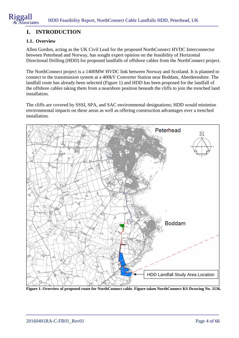
The NorthConnect project is a 1400MW HVDC link between Norway and Scotland. It is planned to
connect to the transmission system at a 400kV Converter Station near Boddam, Aberdeenshire. The
landfall route has already been selected (Figure 1) and HDD has been proposed for the landfall of
the offshore cables taking them from a nearshore position beneath the cliffs to join the trenched land
installation.
The cliffs are covered by SSSI, SPA, and SAC environmental designations; HDD would minimise
environmental impacts on these areas as well as offering construction advantages over a trenched
installation.
Figure 1. Overview of proposed route for NorthConnect cable. Figure taken NorthConnect KS Drawing No. 3136.
HDD Landfall Study Area Location

HDD Feasibility Report, NorthConnect Cable Landfalls HDD, Peterhead, UK
20160401RA-C-FR01_Rev01 Page 5 of 66
Riggall & Associates
1.2. Scope of Work
Riggall and Associates have been invited by Allen Gordon to undertake a site visit and examine
documents related to the project. The aim of this report is to apply our knowledge and expertise in
HDD and geotechnical engineering / geology to give an independent assessment of the viability and
design of HDD’s to effect cable landfalls near Longhaven.
This purpose of this document is to:
• Review the available geological information and make recommendations for any further
ground investigation work
• Provide a conceptual HDD design
• Provide an outline drilling methodology suitable to the conditions
• Assess the viability of the conceptual HDD design through hydrofracture modelling, drilling
forces modelling, and calculation of duct installation forces
• determine likely equipment requirements by modelling drilling forces and duct installation
forces for the HDD
• provide an indicative programme for the HDD works
• provide a high-level risk assessment of the HDD
• identify any additional risks, mitigations measures, or opportunities for the landfalls
The initial (Rev00) version of this report was completed prior to offshore and onshore
investigations. This version (Rev02) takes into account LOTA Offshore Investigations undertaken in
December 2016 and onshore ground investigations undertaken in late 2017 to early 2018.
1.3. Reference Documents
The documents supplied by Allen Gordon for review are outline in Table 1 below.
Table 1. Documents supplied by Allen Gordon for review.
Filename Title / Description Doc No. and Issue Author
2013.12.18_NorthCon
nect_TEC_HDD
Technip Landfall
Options Study
Report.pdf
NorthConnect Landfall Option
Study
High level appraisal of 3
potential landfall sites resulting
in Location 1 as preferred site.
Project No. : 1076
Document No. :
TOWL 1076 RT ENG 001
Revision No. : Rev1
Date: 18/12/2013
Technip
Offshore Wind
Ltd
2016.01.06_NORTH
CONNECT_PER_DR
A_HVDC_CABLE_S
EARCH_CORRIDO
R_3136_A.pdf
HVDC Cable Search Corridor
Drawing indicating HDVC cable
search corridor(land) and
indicative DC cable route.
Drawing No. : 3136
Rev No. : A
NorthConnect
KS
Technical data
NOVA-L 500 kV
1x1600 mm2 Cu.pdf
Technical data for Nexans’
NOVA-L 500 kV 1x1600 mm2
Cu cable.
None given Nexans
102273-NOC-MMT-
SUR-REP-
SURVEYLA.pdf
NorthConnect LOTA
Geophysical and Geotechnical
Route Survey – Survey Report
Document No. :
102273-NOC-MMT-SUR-
REP-SURVEYLA
Revision No. : Rev02
Date: January 2017
MMT Sweden
AB

HDD Feasibility Report, NorthConnect Cable Landfalls HDD, Peterhead, UK
20160401RA-C-FR01_Rev01 Page 6 of 66
Riggall& Associates
Filename Title / Description Doc No. and Issue Author
102273-NOC-MMT-
SUR-DWG-
ALNOC001.pdf
Geophysical, Benthic and
Geotechnical Route Survey,
NorthConnect, Alignment Chart,
KP 0.000 – KP 4.690
Drawing Filename: 102273-
NOC-MMT-SUR-DWG-
ALNOC001
Revision: 02
Date: 2017-01-24
MMT Sweden
AB
102273-NOC-MMT-
SUR-DWG-
NUHDD001.pdf
Geophysical, Benthic and
Geotechnical Route Survey,
NorthConnect, Alignment Chart,
North Up Chart
Drawing Filename: 102273-
NOC-MMT-SUR-DWG-
NUHDD001
Revision: 02
Date: 2017-02-09
MMT Sweden
AB
102272 Draft
CPT_MMT.pdf
Cone Penetration Test Records
for CPT_A 001, 001_A, 001_B,
002, 003, 004, and 004_A
CPT log status: Final MMT Sweden
AB
102272 Draft VC
MMT.pdf
Vibrocore records for
vibrocores A_001, A_002,
A_003, and A_004_A
Core log status: Preliminary MMT Sweden
AB
170929 Intertek
Metocean Report
P2152A_R4323
Rev1.pdf
NorthConnect Metocean Data
Study
Document No. :
P2152A_R4323
Revision No. : Rev1
Date: 29/09/2017
Intertek
Energy &
Water
Consulting
Services
RSK Peterhead-
R01(00) Geophysical
Report (1).pdf
Geophysical Report, Peterhead,
Scotland, NorthConnect KS
Interconnector
Convertor Station, Landing and
Cable Routes
Project No.: 193047-
Peterhead-R01(00)
Rev: Final
Date: 5th December 2017
RSK
BH201.pdf
BH202.pdf
BH301.pdf
BH302.pdf
Draft logs and photographs for
BH201,BH202, BH301, BH302
Draft Structural
Soils
18-022 - Cert 04 -
Peterhead.pdf
UCS and Point Load testing
results for BH201 and BH202
Date: 17/4/2018 MATtest
Limited
1.4. Cabling and Ducting Options
The DC cable specification supplied at the time of writing this report is a Nexans NOVA-L 500 kV
1x1600 mm2 Cu, with an outer O.D. of approximately 125mm, approximated weight of 52kg/m, and
a maximum permissible pulling tension of 315kN.
NorthConnect have requested that the size of the duct to be considered should be set at 560mm OD,
until cable specifications have been finalised. The assumed duct size is therefore 560mm OD,
436mm ID, SDR9.
Thinner wall (e.g. SDR11) duct of the same diameter might also be suitable but would need to be
assessed for installation and operational forces. Such forces could include negative internal pressure

HDD Feasibility Report, NorthConnect Cable Landfalls HDD, Peterhead, UK
20160401RA-C-FR01_Rev01 Page 7 of 66
Riggall & Associates
in the case that the installed, bentonite / water filled duct is sealed at the entry point but open at the
seaward end.
NorthConnect have indicated that the requirements are for two cables and a fibre optic cable. For
this report it is assumed that the cables will be installed in separate HDD’s in order to maximise the
thermal losses to surrounding ground. This report assumes that three separate HDD’s will be
required. The conceptual HDD designs indicate routes for three ducts but the final diameter of the
HDD’s has not been specified at this stage.
For HDD’s the final bore diameter is generally between 1.25 to 1.5 times the duct / duct bundle
diameter, with projects in stable ground tending to the lower values. Given the boreholes will be in
granite the multiple is expected to be at the lower values. This study will assume the final HDD
ream diameter will be 762mm (30”) giving 1.36 times the duct OD. If ground conditions are
favourable a 711mm (28”) ream equating to 1.27 times the duct OD might be preferred for
construction.
Table 2. Cable, Duct and Ream diameters assumed for this report
Item Specification Internal
Diameter
Outer
Diameter
Cable Nexans NOVA-L 500 kV 1x1600 mm2 Cu N/A 125mm
Cable Duct 560mm OD HDPE SDR9 436mm 560mm
Final HDD Reamed to 30 inch N/A 762mm
1.5. Elevation Datum
For this study the datum information at Peterhead provided on the Admiralty chart has been used for
conversion of bathymetric data to Ordnance Datum (Newlyn). The datum used are given in Table 3
below:
Table 3. Elevation datum conversions used in the Feasibility Report and Drawings
0.70 1 -1.50 2
0.80 1 -1.40 2
3.20 1 1.00 2
4.00 1 1.80 2
0.00 -2.20 1
Sources: 1. Admiralty Chart
2. Calculated from source 1.
Chart Datum
Datum used for information in Report & Drawings
Admiralty
(m above
Chart Datum)
Ordnance Survey
(m ODN)DATUM
MLWS
MLWN
MHWN
MHWS
HDD Feasibility Report, NorthConnect Cable Landfalls HDD, Peterhead, UK
20160401RA-C-FR01_Rev01 Page 8 of 66
Riggall & Associates
SITE VISITS
2.1. Initial Site Visit
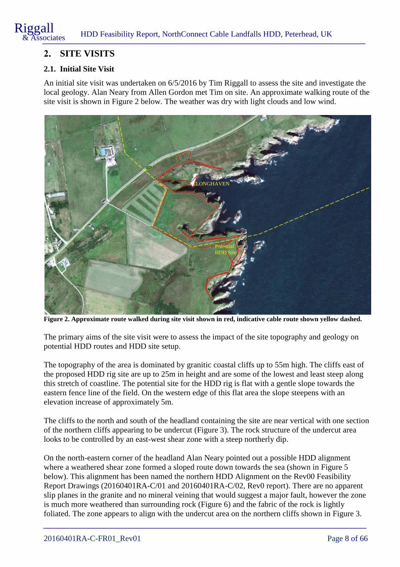
An initial site visit was undertaken on 6/5/2016 by Tim Riggall to assess the site and investigate the
local geology. Alan Neary from Allen Gordon met Tim on site. An approximate walking route of the
site visit is shown in Figure 2 below. The weather was dry with light clouds and low wind.
Figure 2. Approximate route walked during site visit shown in red, indicative cable route shown yellow dashed.
The primary aims of the site visit were to assess the impact of the site topography and geology on
potential HDD routes and HDD site setup.
The topography of the area is dominated by granitic coastal cliffs up to 55m high. The cliffs east of
the proposed HDD rig site are up to 25m in height and are some of the lowest and least steep along
this stretch of coastline. The potential site for the HDD rig is flat with a gentle slope towards the
eastern fence line of the field. On the western edge of this flat area the slope steepens with an
elevation increase of approximately 5m.
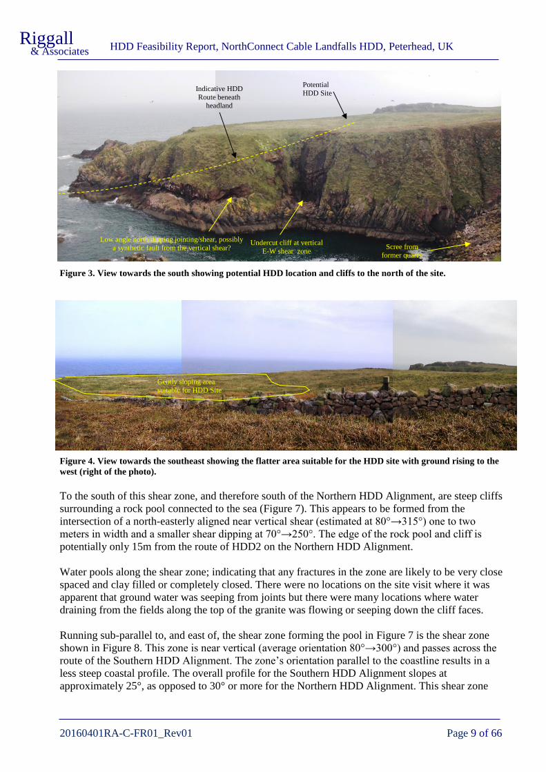
The cliffs to the north and south of the headland containing the site are near vertical with one section
of the northern cliffs appearing to be undercut (Figure 3). The rock structure of the undercut area
looks to be controlled by an east-west shear zone with a steep northerly dip.
On the north-eastern corner of the headland Alan Neary pointed out a possible HDD alignment
where a weathered shear zone formed a sloped route down towards the sea (shown in Figure 5
below). This alignment has been named the northern HDD Alignment on the Rev00 Feasibility
Report Drawings (20160401RA-C/01 and 20160401RA-C/02, Rev0 report). There are no apparent
slip planes in the granite and no mineral veining that would suggest a major fault, however the zone
is much more weathered than surrounding rock (Figure 6) and the fabric of the rock is lightly
foliated. The zone appears to align with the undercut area on the northern cliffs shown in Figure 3.
Potential
HDD Site
LONGHAVEN
HDD Feasibility Report, NorthConnect Cable Landfalls HDD, Peterhead, UK
20160401RA-C-FR01_Rev01 Page 9 of 66
Riggall & Associates
Figure 3. View towards the south showing potential HDD location and cliffs to the north of the site.
Figure 4. View towards the southeast showing the flatter area suitable for the HDD site with ground rising to the
west (right of the photo).
To the south of this shear zone, and therefore south of the Northern HDD Alignment, are steep cliffs
surrounding a rock pool connected to the sea (Figure 7). This appears to be formed from the
intersection of a north-easterly aligned near vertical shear (estimated at 80°→315°) one to two
meters in width and a smaller shear dipping at 70°→250°. The edge of the rock pool and cliff is
potentially only 15m from the route of HDD2 on the Northern HDD Alignment.
Water pools along the shear zone; indicating that any fractures in the zone are likely to be very close
spaced and clay filled or completely closed. There were no locations on the site visit where it was
apparent that ground water was seeping from joints but there were many locations where water
draining from the fields along the top of the granite was flowing or seeping down the cliff faces.
Running sub-parallel to, and east of, the shear zone forming the pool in Figure 7 is the shear zone
shown in Figure 8. This zone is near vertical (average orientation 80°→300°) and passes across the
route of the Southern HDD Alignment. The zone’s orientation parallel to the coastline results in a
less steep coastal profile. The overall profile for the Southern HDD Alignment slopes at
approximately 25°, as opposed to 30° or more for the Northern HDD Alignment. This shear zone
Potential
HDD Site Indicative HDD
Route beneath headland
Scree from
former quarry
Undercut cliff at vertical
E-W shear zone
Gently sloping area
suitable for HDD Site
Low angle north dipping jointing/shear, possibly
a synthetic fault from the vertical shear?

HDD Feasibility Report, NorthConnect Cable Landfalls HDD, Peterhead, UK
20160401RA-C-FR01_Rev01 Page 10 of 66
Riggall & Associates
can be seen continuing through Watery Haven on to the south of the site and into the cliffs on the
southern side of the Haven (Figure 9).
Figure 5. View towards the east along the Alignment of the Northern HDD route. The small gorge follows a
steeply north dipping (east-west trending) shear zone. While no slip planes are apparent in the shear zone the
granite is more weathered than the surrounding rock. This shear zone appears to be the eastern extension of the
shear in the undercut area of cliff shown in Figure 3.
Figure 6. View towards the west at the shear zone shown in Figure 5 showing the weathered nature of the foliated
granite. Because of its lower topography water draining from the fields flows through the zone, further increasing
the weathering and erosion. For scale, the document holder is A4 size.

HDD Feasibility Report, NorthConnect Cable Landfalls HDD, Peterhead, UK
20160401RA-C-FR01_Rev01 Page 11 of 66
Riggall & Associates
Figure 7. View northward towards the Northern HDD Alignment showing the steep cliffs down to a pool. The
closest HDD in the Northern Alignment would be approximately 15m north of the undercut section and at a level
of approximately the base of the pool.
Figure 8. The trace of a South-southwest trending,
near vertical shear zone forming a small valley
along the coastal slope. Viewed towards the south.
Figure 9. The continuation of the shear zone shown
in Figure 8 as viewed from 170m to the south.
View is looking northwards across Watery Haven.
Approximate line of southern HDD
Shear
Shear
Shear
Shear
HDD Site

HDD Feasibility Report, NorthConnect Cable Landfalls HDD, Peterhead, UK
20160401RA-C-FR01_Rev01 Page 12 of 66
Riggall & Associates
Between the coastal low water mark and the small rock outcrop named as Hare Craig lies the Gutter
of Nesh. This channel is likely to be formed along a north-south fault or shear zone. The depth of the
seafloor is not known and there is potential for bedrock being deeper than the seafloor and infilled
with sediments. Nearshore geophysics would be useful for identifying the bedrock position here if
the water depth permits it.
Figure 10. Soil profile from an exposure near the abandoned quarry 150m northwest of site. The pen at bottom
left indicates the scale.
The local soil profile is exposed at a number of places along the cliff edges and around the margins
of the former quarry workings to the northwest of the HDD site. The soils are generally clayey sand
with some angular gravels. They appear to be between 1m to 3m thick overlying the granite bedrock.
It is probable that in places there will be cobbles and boulders of weathered granite corestones
overlying the bedrock surface.
The morphology of the potential HDD site is gently sloping towards the east at approximately 1 in
15. The western edge of the potential site is formed by a steeper slope of approximately 1 in 3 with a
5m elevation increase before levelling out further west. The westernmost section of the potential site
is slightly less well drained but overall the site will be well drained once the topsoil has been
stripped for site preparation.
Access to the site is from the A90 through two fields. The fields are mostly well drained with
boggier areas around gates. They are likely to provide good access once topsoil has been stripped
and laid with geofabric and hardcore or gravel.

HDD Feasibility Report, NorthConnect Cable Landfalls HDD, Peterhead, UK
20160401RA-C-FR01_Rev01 Page 13 of 66
Riggall & Associates
2.2. Second Site Visit
2.2.1 Landfall location
A second site visit was undertaken on 4/10/2017 to review the landfall location following the
offshore survey and to review the location of planed ground investigations. Tim Riggall joined the
following personnel on site: Gary McCann, Eckhard Bruckschen, Mikael Rosendahl, Henning
Augestad, and Lucy Quinn.
The team indicated that the preferred HDD site is now on the higher ground to the NW of the area
originally proposed in the Rev00 report. The revised site is indicated in red in Figure 11, the
previously considered area is in yellow. The revised location is approximately 6m higher elevation
and would result in increased cable pull-in tensions, however the cable specialists on the team have
determined that these are within the acceptable range for the proposed cable.
Figure 11. View towards the southeast showing the revised location of the HDD site in red (right of the photo).
The revised HDD site is on ground gently sloping to the east. The area is grassed, probably grazing
land, and is easily accessed through the field gate, although the area around the gate itself is boggy.
There is a slightly raised (0.5-0.8m) stony lineament in the middle of the area estimated as being
between OS Coordinates 412080 E, 839990 N and 412105 E, 839990 N. The line might represent an
abandoned stone fence but there is nothing that correlates on any of the historical mapping.
The depth of soil and superficial deposits beneath the revised site is not known but bedrock is
expected to be relatively shallow, possibly at 3m depth. Exposures in the face of the quarry located
northwest of the site show that bedrock is at 1-3m below ground surface there with similar ground
conditions in the adjacent field.
The revised location is very suitable as a HDD site. The location changes the alignment of potential
HDD routes slightly and the different options available are explored in Section 4.
2.2.2 A90 and abandoned railway location
As a part of the second site visit on 4/10/2017, the potential location of HDD crossings beneath the
A90 and the former railway were examined. Located approximately 500m inland from the landfall
location the A90 and former railway could either be crossed as a single HDD or as separate HDD’s
or trenchless crossings.
The decision on whether to undertake the crossing as a single crossing or two separate crossings will
depend on the results of ground investigations and contractor’s preference. The option of two
Indicated HDD Site
from Rev00 report
Revised HDD Site

HDD Feasibility Report, NorthConnect Cable Landfalls HDD, Peterhead, UK
20160401RA-C-FR01_Rev01 Page 14 of 66
Riggall & Associates
separate HDD’s is only expected to be marginally less expensive than a single HDD, so the practical
options are likely to be a single HDD or separate crossings using other trenchless methods such as
auger bore or pipe ramming.
Figure 12. View to the northwest showing approximate cable route beneath the A90.
Figure 13. View to the west showing approximate cable route beneath the A90.
Approximate
line of cable
route
A90
Approximate line of cable
route
A90

HDD Feasibility Report, NorthConnect Cable Landfalls HDD, Peterhead, UK
20160401RA-C-FR01_Rev01 Page 15 of 66
Riggall & Associates
Figure 14. View to the north showing approximate cable route beneath the abandoned railway.
There was no direct evidence on the site walkover of the depth to bedrock. The railway is in a 1.5m
to 1.8m depth cutting so assuming 1.5m cable burial depth and drive or reception pit would be 3m to
4m depth.
The A90 has a 0.5m embankment on its western side and a 2m embankment on its eastern side at the
probable crossing location. The fields either side of the A90 slope moderately to the east but are not
expected to require earthworks to host a HDD site.
Approximate
line of cable
route Former Railway

HDD Feasibility Report, NorthConnect Cable Landfalls HDD, Peterhead, UK
20160401RA-C-FR01_Rev01 Page 16 of 66
Riggall & Associates
GEOLOGY
3.1. Superficial Deposits - Land
The site contains only a thin layer of superficial deposits. From the site visit the thickness is
expected to be 1-3m over solid bedrock and potentially up to 5m depth above weathered shear
zones.
In the field there is expected to be a thin (0.3 - 0.5m) humic layer overlying silty SAND with gravel.
With depth the gravel component is likely to increase in size and percentage. Towards the base of
the superficial deposits there are likely to be cobbles and boulders formed from weathered granite
corestone. An indicative soil profile is shown in Figure 10.
Results from BH201 indicate that the HDD locations will probably encounter soft sandy slightly
gravelly CLAY, with occasional boulders, in the top 2m of ground. Underlying this will be 4m of
cobbles and boulders of granite with some sand. The geophysical information from Resistivity Line
1 matches the results from BH201.
3.2. Superficial Deposits - Marine
The MMT 2016 LOTA marine geophysical and geotechnical survey identified a sequence of thin
loose surficial Holocene sediments (silt sand and gravel) overlying dense sand and Glacial Till in the
areas near potential HDD landfalls. At the probable HDD exit points the Holocene sediments are
identified as silt and fine sand, while in the centre of the survey area near the shoreline it is identified
as sand to gravel with ripples.
The summary table of interpreted geology from the offshore report is reproduced in Table 4 below.
An excerpt from the Geophysical, Benthic and Geotechnical Route Survey drawing is provided in
Figure 15 that indicates the expected superficial geology in the area of the HDD exit point. The
results from the marine geophysical survey have also been overlaid on Drawing No. 20160401RA-
C/10 in Appendix E of this report.
Table 4. Shallow geology units and expected lithology summary. Taken from Offshore survey report 102273-
NOC-MMT-SUR-REP-SURVEYLA .
INTERPRETED
STRATIGRAPHY
LITHOLOGY BGS
CORRELATION
Surficial Holocene
sediments
Silt, Sand and Gravel in different proportions, locally
containing shells pebbles or cobbles and boulders. Occasional
clay lenses may occur. Locally mobile sediments occur.
Primarily loose sands (lithology verified with geotechnical
sampling).
Recent and/or
Forth Formation
Late Weichselian to
Holocene
Dense SAND and SILT. Forth Formation
(Upper)
Late Weichselian Very soft to stiff sandy CLAY, partings and layers of sand. Forth Formation
(Lower)
Weichselian deposit Glacial deposit /till. Unsorted sediment, soft to stiff clay with
interbeds of sand and pebbly sand, and layers/lenses of coarse sand
and gravel.
Wee Bankie
Formation
Silurian Bedrock Peterhead Pluton
granite

HDD Feasibility Report, NorthConnect Cable Landfalls HDD, Peterhead, UK
20160401RA-C-FR01_Rev01 Page 17 of 66
Riggall & Associates
Figure 15. Excerpt from Drawing 102273-NOC-MMT-SUR-DWG-ALNOC001 of the 2016 Geophysical and
Geotechnical offshore survey. Profile shown is from the Starboard line.
3.3. Granite Bedrock
BGS mapping indicates that the HDD site is underlain by Granite of the Peterhead Pluton and is of
Silurian (416 – 444 Ma) age. The site visit found all of the exposed rock to be pink, coarse grained,
Peterhead granite. No evidence was found of carboniferous intrusive rocks that are present in east-
west orientations further north and south on the coastline.
The granite outcrops as massive with jointing usually spaced at 0.5 to 3m with closer spaced jointing
(0.1m to 0.5m) locally near fault/shear zones. Fault/shear zones appear to be near vertical with the
primary orientations being:
• trending north-south
• trending to north-north-east
• trending east-west
Locally there appear to be low angle synthetic faults branching from the main faults (Figure 3).
The fault/shear zones observed on the site visit were lacking in conspicuous fault planes or
slickenside surfaces, but the granite was usually foliated and always significantly more weathered
than surrounding rock (Figure 6). The observed zones were typically 0.5m to 3m in width.
The Unconfined Compressive Strength (UCS) of the fresh granite is potentially 200Mpa or higher.
Granite in the weathered fault zones might be as low as 40MPa depending on the degree of

HDD Feasibility Report, NorthConnect Cable Landfalls HDD, Peterhead, UK
20160401RA-C-FR01_Rev01 Page 18 of 66
Riggall & Associates
weathering. Edmond and Graham (1977) note that weathering in the Peterhead granite reaches a
depth of 56 m in a fault zone identified in the Peterhead Power Station water intake tunnel
construction. However, the majority of either HDD Alignment is expected to be within fresh rock
and even the weathered rock is of a strength that would be considered medium to hard rock for HDD
drilling.
At the time of this report, initial UCS and Point Load testing from boreholes BH201 and BH202 has
been received. One UCS test was taken from BH201 (33.9MPa) and two from BH202 (73.1MPa and
67.9MPa). These results are lower than expected. Looking at the core photographs the chosen
sections may have contained pre-existing axial / sub-axial fractures in the samples selected. Further
UCS tests from the core have been planned but no results received as yet.
In contrast, the Point Load tests from BH201 and BH202 give values that are closer to what might
be expected from the granite. The Is(50) readings are typically in the range of 4 to 8 MPa, and using
a factor of 24 they indicate UCS strengths of 96MPa to 192MPa.
Drawing number 20160401RA-C/07 (Appendix E) show a sectional view with the interpreted
geology based on the site visit, ground investigations (boreholes and geophysics), and interpretation
of structural lineaments from aerial photography.
Note that the continuation of the granite offshore is an assumption; there is no direct evidence of the
bedrock material beyond Hare Craig. However locally there are granite outcrops offshore (e.g.
Skerry Rock, 500m offshore from Boddam) and the BGS offshore index mapping shows the granite
bedrock extending to 1.75km from shore. Granite continuing to the possible HDD exit location
250m from the shoreline is therefore considered to be very probable.
3.4. Hydrogeology
The BGS Hydrogeology 1:625,000 scale mapping designates the Peterhead Pluton as a low
productivity aquifer with “small amounts of groundwater in near surface weathered zone and
secondary fractures; rare springs”. This description matches the site visit observations that
groundwater flowed from the base of the superficial deposits at the cliff lines. There were no
observed flows from joints or shear zones in the granite.
Boreholes BH201 and BH202 encountered no groundwater. Borehole BH201 was drilled with air
mist and water flush and did not have water returns during the drilling. BH202 was drilled
predominantly with water flush with returns generally 70-80%.
3.5. Suitability of Geology and Groundwater for HDD
The land superficial deposits, because of their limited thickness, will only be encountered in the
initial 20m of HDD drilling. Outcrops of the silty sand and gravel generally form near vertical faces
in cliff top exposures and should form a stable borehole, but their limited depth means they are only
likely to be exposed in the entry pit.
The underlying boulders and cobbles of weathered granite might need to be cased to ensure stability
and drilling fluid returns to the entry pit. A 20m casing length is a relatively short length for HDD.
And could be installed by a downhole casing hammer or by washing in casing after an initial pilot
and ream through the deposits.

HDD Feasibility Report, NorthConnect Cable Landfalls HDD, Peterhead, UK
20160401RA-C-FR01_Rev01 Page 19 of 66
Riggall & Associates
The granite is expected to form a stable borehole. There is a potential risk of localised collapse of
small blocks from the roof of the HDD in areas where it passes through closed spaced joint sets. The
site visit suggests such conditions only exist proximal to shear zones. Given the final ream diameter
of 762mm the size of blocks that might collapse can be expected to be relatively small (100mm to
300mm size). Additionally, the site investigation found no real infill on jointing and they were
generally closed (i.e. there was no visible gap between the sides of the joints), further reducing the
chance of a block collapsing from the roof. Nevertheless, the HDD drilling and reaming equipment
should be designed to allow any collapsed cobbles to be cleaned out of the borehole.
The fault zones and shear zones are only likely to be noticed as zones of faster drilling during the
HDD. There is no evidence that they will contain significant volumes or flows of groundwater.
The high strength of the granite will result in slow drilling rates and greater than normal wear on the
drilling equipment. These are factors that HDD contractors will need to price into their costs and
programme.
The entry elevation and jointing in the granite suggests that loss of drilling fluid is possible when the
vertical depth of cover is less than 10m based on projects in similar conditions. There is potential for
drilling fluid to migrate a greater distance horizontally and this needs to be taken into account for
designs running parallel to cliffs and steep slopes. A length of casing through these deposits would
assist in mitigating fluid loss risks in the zone.
A cable landfall for the Hywind project was successfully drilled through Peterhead granite for the
Hywind project in August 2016. The HDD drilling contractor was LMR drilling and by their account
the drilling and installation was relatively straightforward. Further details are given in Section 11.2.
The marine superficial deposits are expected to be suited to the HDD technique. Upon exiting the
granite the HDD is expected to encounter stiff Glacial Till followed by dense sand and finally a thin
veneer of loose silt and sand. Much of the thin silt and sand around the HDD exit might be eroded
due to the flow of drilling fluid from the borehole during the final reaming stages.
Where ducts are to be pulled into the HDD from sea, there is the potential for gravels and cobbles to
be dragged into the borehole and potentially result in the duct becoming stuck. There is no indication
of such problematic sediments from the 2017 marine geophysical and geotechnical survey and this
risk is viewed as very low. Gravels are identified in some of the Holocene sediments to the north of
the proposed HDD exit, however they are contained within a finer sand matrix. Indications from the
vibrocore photographs are that they pose a very low risk to duct installation from the sea.
An alternative method of pushed duct installation would eliminate the risk from sediments being
dragged into the borehole during duct installation.

HDD Feasibility Report, NorthConnect Cable Landfalls HDD, Peterhead, UK
20160401RA-C-FR01_Rev01 Page 20 of 66
Riggall & Associates
CONCEPTUAL HDD DESIGN
For the Revision 0 of the feasibility study two HDD Alignments were assessed, a Northern route
drilled towards bearing 070° (OS Grid) and a Southern Alignment drilled towards 120° (OS Grid).
For each Alignment two vertical designs were drawn, a shallow design and a deeper design.
Following the results of the Marine Geophysical and Geotechnical survey, an exit near the Southern
alignment was preferred. For Revision 1 of the report, a number of different options for exiting in
the southern area were considered, the designs being named Southern Designs 3, 4 and 5.
This Revision 2 of the report has been undertaken based on additional information from draft
onshore borehole and final onshore geophysical survey information. Southern Design 5 is the current
preferred alignment because it balances depth of cover beneath the intertidal / gutter of nesh area,
lateral distance from the cliffs south of the site, alignment for onward cabling toward the substation,
and more favourable conditions at the exit point.
In plan view the three HDD’s for Southern Design 5 are 10m apart for the length of the drill. It is
possible to reduce the proximity to 5m at entry if required and increase the separation at exit if
needed for offshore works.
Final designs might require a different geometry to account for any new information from ground
investigations, offshore requirements, or depth and cable separation requirements for thermal
conductivity.
4.1. Design Profile
The conceptual design profile is shown in Appendix E on drawing number 20160401RA-C/07
(Southern Design 5). The main parameters of the designs are given in Table 5 below.
Table 5. Main Parameters of the Conceptual Southern Design 5 HDD
Alignment Bearing (OS
Grid) 108°
Entry Elevation +38.38m ODN
Entry Angle -17°
Entry Tangent Length 220.07m
Vertical Curve Radius 400m
Vertical Curve Length 153.59m
Exit Tangent Length 63.71m
Exit Angle +5°
Exit Elevation -28.10m ODN
Total Horizontal Length 398.70m
Total Drilling Length 409.10m
Drawing number 20160401RA-C/10 (Appendix E) shows Southern Design 5 in plan view with the
key mapping results from the onshore boreholes, onshore geophysics and offshore surveys. It exits
in an area where the seafloor is described as SILT and fine SAND.
The entry point in the field is designed at 17 degrees; this angle is towards the steeper limits for
standard HDD rigs. It is intended to ensure depth is reached as quickly as possible, reducing the
overall length of the HDD and maintain an angle close to that of the coastline. The exit point is
chosen to keep the HDD length to a minimum as well as exit at a suitable angle for duct installation
and onward cabling.

HDD Feasibility Report, NorthConnect Cable Landfalls HDD, Peterhead, UK
20160401RA-C-FR01_Rev01 Page 21 of 66
Riggall & Associates
The vertical curve radius of 400m is within the limits of both the drilling equipment and the
expected ducts. There is potential to increase the radius to perhaps 600m; this would decrease the
drilling forces slightly when forward reaming to enlarge the HDD in the granite but will decrease the
level of cover and potentially increase the risk of breakout.
4.2. Site Layout and Requirements
The HDD entry site is likely to be approximately 50m x 65m in dimension as shown in Figure 16
below and Drawing No. 20160401RA-C/03 (Appendix E). The layout is indicative and contractors
will have their own preferred layout but there is sufficient room in the field to accommodate the
required equipment.
Figure 16. Detail of HDD site showing indicative positioning of equipment for Southern Design 5.
4.3. Ducts
As outlined in Section 1.4 the ducting is assumed to be 560mm OD HDPE SDR9, PE100. The
minimum recommended bending radius for SDR9 PE100 duct is 25 times the OD, so 14m.
Assuming a design factor of 3.0 this becomes a minimum design radius of 42m. The 400m design
radius of the HDD is well above the limits of the duct.
4.4. Minimum Radius and Tolerances
The 400m design radius is well above the limits of both the drilling equipment and the ducts. No
positional tolerances have been set at this stage of design.
4.5. Existing Infrastructure and Utilities
It is assumed that there are no buried utilities in the vicinity of the entry location because of its
position in open fields distant from any infrastructure; however a services search will be required
prior to construction.

HDD Feasibility Report, NorthConnect Cable Landfalls HDD, Peterhead, UK
20160401RA-C-FR01_Rev01 Page 22 of 66
Riggall & Associates
DRILLING METHODOLOGY
The conceptual design of the HDD is a relatively straightforward landfall drilling with the ground
expected to be predominantly unweathered granite with zones of weathered granite where fault or
shear zones are intersected. The following methodology outlines the most commonly used
techniques for this type of HDD however tenderers might suggest variations or alternative methods
for some aspects of the HDD.
5.1. Site Setup
Prior to the arrival of HDD equipment the vehicle access, drilling pad and working area at the entry
site shall be prepared. Any uneven ground should be made level and access should be suitable for
the haulage equipment. Topsoil should be removed and stockpiled for reinstatement after completion
of the works. If necessary, the access track will be upgraded with bog mats or geotextile and
hardstanding material.
Any drainage work required to make the site safe for working and to prevent environmental damage
from site runoff should be complete.
All services, below ground and above, should be located and protected from damage or isolated as
needed.
A water supply of suitable quality and flow rate will be used for mixing drilling fluid. It is
anticipated that a supply will be provided tapped in to the mains supply running beside the A90.
A traffic management plan and haulage route for heavy equipment should be implemented prior to
arrival of equipment. The site is accessed directly off the A90 and there are no overhead lines
between the A90 and site.
The entry point should be accurately surveyed and clearly marked, as should a number of alignment
pegs for positioning of the rig and points for any surface tracking cable, if it is to be used.
An anchor block will be required at the front position of the rig to ensure stability when drilling and
installing the duct. Anchor blocks are typically 4m x 2m x 2m depth poured concrete blocks with
steel I beams set in them to allow connection to the front foot plate of the HDD rig. The final
specification of the anchor block should be designed to accommodate the expected drilling and
installation forces imparted by the HDD rig.
Personnel on the drill site should wear standard PPE including safety boots and hard hats. Personnel
working on the rig will need gloves for manual handling and appropriate eye protection when
welding, grinding, etc. The mud man on the drilling fluid mixing unit will need to wear appropriate
hand and eye protection and dust masks when handling powdered bentonite and additives and
complete PPE with coveralls if caustic soda is used to adjust the fluid pH.
Prior to the commencement of drilling barrier mesh should be placed around any open holes and
measures taken to prevent public access to the site. High pressure hoses from the mud pumps should
have appropriate safety lanyards. Personnel should hold the relevant permits and licences for any
plant and equipment they are operating.
An indicative site layout for the HDD works is shown in Section 4.2.

HDD Feasibility Report, NorthConnect Cable Landfalls HDD, Peterhead, UK
20160401RA-C-FR01_Rev01 Page 23 of 66
Riggall & Associates
The nearest residence, Station House, is 500m to the west of the site beside the A90 road. The HDD
equipment will probably be visible from the residence but noise disturbance at the residence is
unlikely to be a problem. The HDD site equipment is only likely to be audible at night during
periods with easterly breezes.
Figure 17. Example HDD rig of the size likely to be used for the HDD’s.
Other residences with a line of sight to the HDD location are Glen Ugie, 750m NNE on the A90,
Longhaven Mains, 650m NW, and Station Farm, 620m West of site. Over these distances noise
should not be a disturbance, particularly when ambient noise levels from the A90 adjacent to the
residences is taken into account. The residences could have a clear view of the lighting towers on the
site; however the lights would not be directed at the residences. Lighting arrangements might also
need to be discussed with Peterhead Port Authority to ensure they do not affect shipping navigation.
5.2. Casing
The exposures of silty sand with gravel in the coastal cliffs indicate that surface casing is not
necessarily required (see Section 3.1) but contractors might install it to reduce the risk of hole
collapse and fluid losses in the superficial deposits. If casing is required it is only likely to be 20m
in length and will either be washed over the pilot drill or installed with a casing hammer. Ideally the
casing should be of larger diameter than the final reamed hole size. After duct installation the casing
can be removed, generally by being pulled out by the drilling rig.
5.3. Pilot Hole
Prior to drilling an entry pit is excavated; generally several metres square and 1.5m to 2.0m in depth.
The entry pit has the dual purpose of containing drilling fluid returns and ensuring any buried
services are exposed prior to drilling. A pump in the pit transfers fluid to the mud recycling unit.
The HDD drilling contractor will use a tri-cone drilling bit powered by a downhole motor (DHM)
(Figure 18) to drill the pilot hole in the granite.

HDD Feasibility Report, NorthConnect Cable Landfalls HDD, Peterhead, UK
20160401RA-C-FR01_Rev01 Page 24 of 66
Riggall & Associates
Figure 18. Schematic of Pilot Hole drilling assembly with downhole motor powering a tri-cone bit.
Behind the DHM will be the guidance probe followed by the drilling rods. Between the components
there may be various connection subs to provide connections between differing types and sizes of
threads. All connections are torqued to recommended values when they are added at the drilling rig.
On occasion the drilling assembly may need to be torqued using chain tongues. This operation
should only be performed by experienced personnel and all non-essential personnel should stand
well clear.
The downhole motor is powered by the hydraulic pressure of the drilling fluid allowing the bit to
turn without need to rotate the drilling rods. To deviate along a curve the string of drilling rods is
held at a fixed position (not rotated) and a bent sub behind the drilling bit allows the hole to be
deviated with the bit being rotated by the downhole motor alone. To drill a straight section of hole
the entire string of drilling rods is rotated.
Located behind the downhole motor, the guidance sensors allow tracking of the borehole position
during the pilot hole drilling. The sensors are connected to processing equipment at the surface by an
insulated cable running through the centre of the drill rods. The guidance system will either be a
Gyro system or a Magnetic Guidance System (MGS) with surface tracking. If an MGS is used
tracking cable will be placed at points along the surface alignment of the bore to give an independent
position of the HDD and calibrate the magnetic bearing of the HDD. On this project it is likely that
the tracking cable will be extended as near as possible to the top of the cliffs but will not be required
all the way to exit.
During drilling operations the drilling rods will be turning at around 60-90 rpm. All personnel
should stand clear of the rotating string. Loose clothing should be avoided for those working around
the rig; high visibility vests tend to be a risk in these conditions and should be replaced with high
visibility clothing or jackets.
When a drilling rod has been drilled down the rod is disconnected from the drive head. The drive
head is pulled back to the top of the mast and a new drill rod is added. A wireline cable inside the
drilling rods is extended and connected before the new drilling rod is torque ready for drilling down.
During the procedure of adding and removing drill rods there is potential for accidents involving
pinch points and rotating equipment. Only trained and experienced rig hands should be working on
the rig at these times.
Downhole positional surveys are taken at the end of each drilled rod. While a new drilling rod is
added the guidance engineer plots the position of the HDD and formulates instructions for drilling
the next rod so that the bore remains on course. The driller will adapt drilling forces as the rod
progresses to effect efficient and stable drilling. The driller keeps a log recording the drilling
parameters and any notes on ground conditions for each rod. The pilot drilling process continues
until exit is reached.

HDD Feasibility Report, NorthConnect Cable Landfalls HDD, Peterhead, UK
20160401RA-C-FR01_Rev01 Page 25 of 66
Riggall & Associates
On long crossings or in hard ground the drilling rig can be exerting 30 tonne or more force on the
drill rods. On rare occasions the drill rods can suddenly buckle, potentially deflecting sideways and
injuring bystanders. Personnel should stand well to the side of the drill string during operation.
Unacceptable deviation of the pilot hole is unlikely because the granite is massive with even the
weathered zones being of good rock strength and unlikely to deflect the drilling bit. However if the
pilot drill deviates too far off course at any point the bit can be pulled back (by removing drilling
rods) to a suitable point. A sidetrack off the old borehole can then be cut and the new section of hole
steered onto the correct course.
5.4. Drilling Fluids
The drilling fluid serves many purposes. Its primary role is to create a gel thick enough to suspend
soil and rock cuttings and carry them out of the hole. In addition the drilling fluid hydraulically
excavates soil in soft ground, powers the downhole motor in hard ground, cools the drilling
equipment, clears debris from the drilling bit and face, seals the perimeter of the borehole in porous
ground and lubricates the borehole to reduce friction on the drilling equipment.
The drilling fluid predominantly used in HDD is a mix of water and a naturally occurring swelling
clay, bentonite. On occasions the chemical properties of the drilled soil or rock reduce the
effectiveness of the drilling fluid. As a result additives such as natural xanthum gum and gypsum are
sometimes added to improve the properties of the fluid, however they are unlikely to be required for
this project.
Bentonite drilling fluid is non-toxic however if sufficient quantity enters a watercourse it can
potentially settle on the bottom, smothering benthic flora and affecting faunal feeding and breeding
sites. In saltwater environments the smothering affect is less problematic because seawater degrades
the bentonite fluid, causing it to flocculate and allowing faster dispersal. However as a matter of
course breakouts (loss of drilling fluid to the surface) are to be avoided and quickly remediated if
they occur.
Bentonite is supplied in powdered form in either 25kg bags or bulk bags. The bentonite is fed into a
hopper where it is mixed with water circulated through the mixing tank. From the mixing tank the
fluid is transferred to the active tank. High pressure pumps then pump the fluid downhole. The
operator of the fluid system (the “mud man”) will need to wear appropriate hand and eye protection
and dust masks when handling powdered bentonite and additives. If caustic soda is used to adjust the
fluid pH complete PPE with coveralls should be worn.
The bentonite drilling fluid is circulated down through the drill rods and back up the outside the rods
in the annulus of the borehole. Exiting into the entry pit, the fluid is then pumped to the mud
recycling unit (Figure 19) where hydro-cyclones and shaker screens remove cuttings. The cuttings
accumulate beneath the shakers and are usually disposed of at landfill sites. The cleaned drilling
fluid transfers to the active tank ready for circulation through the hole.
The mud man will keep records of drilling fluid parameters at regular intervals and monitor drilling
fluid volumes so that any losses to the formation are identified. The driller will monitor and record
downhole fluid pressures and returns to the entry pit to also ensure that any losses are recognised
quickly.

HDD Feasibility Report, NorthConnect Cable Landfalls HDD, Peterhead, UK
20160401RA-C-FR01_Rev01 Page 26 of 66
Riggall & Associates
Figure 19. A drilling fluid recycling unit with hydrocyclones and shaker screens on the upper level and active
mud tank underneath. The blue bins capturing cuttings as they are removed by the shaker screens. On the right
is a grey transfer pump for transferring cuttings from the entry pit (foreground) to the hydrocyclones and shaker
screens.
During pilot hole drilling in soft ground the use of a Pressure While Drilling (PWD) tool is
recommended to reduce the risk of breakout, formation damage, and equipment becoming stuck
because of inadequate hole cleaning. A PWD tool is located with the downhole surveying assembly
behind the downhole motor and measures the annular pressure in the borehole; the pressure of the
drilling fluid flowing between the outside of the drill rods and the borehole wall. It is a standard add-
on module for Gyro and MWD guidance systems. Because this HDD is in solid rock a PWD could
be useful in giving early warning of insufficient hole cleaning, however this can also be diagnosed
by monitoring of drilling cuttings returns and drilling forces.
5.5. Reaming
Once the pilot hole is completed the bit, downhole motor, and steering equipment is removed. For
landfall projects the pilot hole is usually stopped short of the exit point so that drilling fluid returns
are not lost to the sea. The pilot hole is then enlarged using forward reaming; the reamer / hole
opener being advanced from entry towards exit. The drilling fluid is pumped down through the
drilling rods onto the cutting face of the reamer and then carries the cuttings back up the hole to the
entry pit. From the entry pit the fluid is passed through the recycling unit to remove the cuttings
before being pumped downhole again.
The safety precautions for pilot hole drilling apply to reaming operations; keeping personnel clear of
the drill string during operations and only trained personnel on the rig. If chain tongues are used they
should only be operated by experienced personnel and all non-essential personnel should stand well
clear.

HDD Feasibility Report, NorthConnect Cable Landfalls HDD, Peterhead, UK
20160401RA-C-FR01_Rev01 Page 27 of 66
Riggall & Associates
The HDD will require several reaming passes with progressively larger diameter reamers until the
final hole size is reached. A final decision on the diameter and number of reaming stages is usually
made by the drilling contractor once ground conditions have been evaluated from drilling the pilot
hole. A possible configuration for the project would be a 12.25” (311mm) pilot hole with reaming
stages of 18” (457mm), 24” (610mm), and 762mm (30”).
To ensure the forward reaming follows the pilot hole, a short (1-3m) drill rod and a rounded “bull
nose” is usually placed in front of the hole opener. For the larger diameter reams a front centraliser
is often used to ensure that the reamer cuts evenly, and a rear centraliser is often used to ensure
evenly distributed force on the hole opener.
For this project a rock hole opener with Tungsten Carbide Inserts (TCI) for cutting will be used
(Figure 20) for the reaming. The HDD contractor will need to ensure that the reaming equipment is
withdrawn periodically to check wear, thus avoiding loss of equipment in the hole.
Figure 20. Typical forward reaming assembly for rock containing a TCI rock hole opener (right) with rear
centraliser (left).
Once all stages of the forward reaming are completed to the end of the pilot hole, the pilot hole is
then extended to the exit point. At this stage the hydrostatic head of drilling fluid will be lost into the
sea. The remainder of the pilot hole is then opened up to the final diameter using conventional (pull)
reaming. The hole opener is attached at the exit point and pulled towards the entry point. Drilling
fluids are pumped from the HDD rig through the drilling rods to the hole opener where they remove
the cuttings and flow into the sea.
5.6. Duct Installation
For HDD landfalls the traditional duct installation method is to pull the HDPE into the hole from
exit towards entry. Because the HDD will be through solid granite and the final borehole is expected
to be stable there is also the potential to install the duct by pushing it in from the entry point.

HDD Feasibility Report, NorthConnect Cable Landfalls HDD, Peterhead, UK
20160401RA-C-FR01_Rev01 Page 28 of 66
Riggall & Associates
5.6.1 Pulled Installation
For a pulled installation the ducts are floated into position at the exit point, flooded with water, and
then pulled into the reamed borehole for installation (commonly termed “pullback”). The ducting
can either be fabricated as a single piece (by Pipelife in Norway) and towed to a mooring position
nearby awaiting installation, or it can be fabricated at a nearby convenient location by butt fusion
welding 12m or 18m lengths to form the duct. This can then be towed to the exit position when
required. A typical setup for butt fusion welding of PE pipe is shown in Figure 21.
Prior to installation a cleaning run is preformed with a reamer of slightly smaller diameter than the
final hole size, in the case of a 22” reamed hole a 20” reamer would normally be pulled through.
The duct will be prepared for installation by attaching a pulling head (Figure 22) and the duct is
usually ballasted by filling with water to reduce its buoyancy. Because of the considerable length of
borehole above sea level on this project, rather than a sealed duct, ports to allow air or water to enter
at the pulling head might be considered. This would allow entry of air once the duct has been pulled
above sea level in the borehole, significantly reducing the pulling force.
The pulling assembly will consist of the drill rods connected to a reamer of slightly larger diameter
than the pipeline. Connected to the reamer is a swivel of adequate strength for the expected pullback
forces. When the pulling assembly is torqued to the drill rods the pulling head of the pipeline is
bolted to the swivel and pullback can begin.
Figure 21. Typical setup of PE butt fusion welder
Figure 22. Drilling rod, swivel, pulling head and
duct being pulled into the entry pit
Pullback proceeds by pulling back and removing a drilling rod then connecting onto the next drill
rod and repeating. During pullback the ducts will displace bentonite fluid from the borehole. In this
case the entry point is approximately 30m above sea level so most of the displaced fluid will flow
out into the sea at the exit point.
During pullback the driller will monitor pulling forces to ensure the maximum allowable pulling
force for the pipeline is not exceeded. When the pulling assembly reaches the drilling rig it will be
disconnected and removed. Because of the elevation difference between entry and exit the end of the
pipeline might need to be secured to ensure the pipeline does not slip down slope in the hole.

HDD Feasibility Report, NorthConnect Cable Landfalls HDD, Peterhead, UK
20160401RA-C-FR01_Rev01 Page 29 of 66
Riggall & Associates
5.6.2 Pushed Installation
Pushed installations are traditionally used for steel pipelines on landfalls drilled in rock but have also
been performed on a number of large (>300mm) diameter HDPE installations in rock. The potential
advantages of a pushed installation at this location are the reduction in offshore works with the
attendant risk of weather delays, and a reduction in duct installation tensions.
A pushed installation requires either a proprietary pipe pusher, modification to the HDD carriage to
allow pushing of the HDPE or, if the push forces are low, excavators or side booms with slings to
move the duct. For longer installations the push can be assisted by a cable and pulling head at the
exit point to guide the head of the HDPE along the borehole. In this case a workboat would probably
provide sufficient tension in the duct.
Figure 23. A pipe pusher (black unit at HDD entry point) installing 560mm HDPE on a 584m length HDD in
Ireland (AMS Drilling).
If the duct has a closed end it will need to be filled with water as it is pushed into the hole to reduce
the buoyancy of the duct in the section of hole below sea level. Alternatively the duct could be
pushed open ended and fluid would fill the duct through the open end when it reaches sea level. The
duct will then require pigging afterwards to remove drilling fluid from it.
If an additional PE line is required for grouting of the borehole after installation (see Section 5.6.3
below) the risks with a pushed installation increase significantly and additional pull from offshore
might be required. The additional, smaller, duct is at risk of buckling during installation causing the
main duct to become stuck. The risk can be reduced by fixing the smaller duct to a pushing cap on
the seaward end of the main duct and strapping the smaller duct to the main duct. The only instance
the author knows of using multiple ducts or pipelines for a pushed installation is the Billia Croo
HDD in Orkney drilled by Stockton Drilling, however the smaller pipeline appears to have been
steel.

HDD Feasibility Report, NorthConnect Cable Landfalls HDD, Peterhead, UK
20160401RA-C-FR01_Rev01 Page 30 of 66
Riggall & Associates
The use of a cable and pulling head towed by a vessel to ensure the ducts are in tension would
reduce risks during a multi-duct push. However, offshore assistance reduces one of the benefits of
the pushed installation method, the reduction in marine works and weather dependency.
5.6.3 Post Installation Works
Following duct installation, a messenger cable is pigged through the duct using compressed air or
water to propel the pig and the ends of the duct are sealed awaiting HV cable installation.
Based on discussions during the second site visit there might be a need to grout some or all of the
annulus between the duct and the HDD bore to enhance thermal dissipation from the cables. Because
of the entry elevation this would need to be undertaken as a staged operation. A section of borehole
below the level of the exit point would need to be grouted first and allowed to set to create a plug for
grouting of the sections above the exit level.
For grouting of the first plug section the most suitable method is probably to use a “tremmie” line. A
PE duct would be pulled into the HDD during installation of the main duct. The PE duct would be of
approximately 75mm to 100mm diameter and either the downhole end of the duct would be located
at the lowest point of the borehole, or the duct would be pulled completely through the borehole with
perforations in the duct positioned in the lowest section of the borehole.
Following installation of the PE duct (tremmie line), grout is pumped through the line to the lowest
point of the borehole where it displaces the bentonite fluid until the level of grout reaches the
seafloor exit of the HDD. When this section of grout has set, the section of borehole between the
HDD entry point and the set grout can be filled with either bentonite or grout by pumping into the
entry point of the HDD. If grout is used it should have a retardant added to ensure it has adequate
time to flow to the base of the column and displace any bentonite fluid upwards to the HDD entry
point.
5.7. Marine Support Works
Because the exit point is located below the low water mark the operations at exit side will entail
offshore works. The offshore equipment will be needed during the conventional reaming of the final
section of the HDD and the duct installation operations. The approach taken to the offshore works
varies between contractors and their preferred method of working will depend on their previous
experiences.
On previous landfalls exiting in this depth of water a range of methods have been used from large
barges to smaller scale legged or jack-up barges. At the small scale end are workboats with divers
used to retrieve and connect equipment, as was done at the Hywind Peterhead landfall (see Section
11.2). Because the exit point is expected to be at -25mODN or lower for this project divers are likely
to be used. As a minimum they will be required to locate and attach lifting equipment to the drilling
string. The drilling bit and assembly can then be pushed out and lifted onto a barge, platform or
workboat to allow disconnection and connection of reamers and pulling heads.
For a pulled duct installation, these marine operations will be required from the time that the pilot
hole exits to the seafloor until duct installation is completed. For a pushed duct installation the
marine operations are mainly required between pilot hole exit and completion of any pull reaming.

HDD Feasibility Report, NorthConnect Cable Landfalls HDD, Peterhead, UK
20160401RA-C-FR01_Rev01 Page 31 of 66
Riggall & Associates
Figure 24. Large barge with four point anchoring and workboat. On the right hand side of the barge the duct can
be seen being pulled into the HDD. The water depth is approximately 4m.

HDD Feasibility Report, NorthConnect Cable Landfalls HDD, Peterhead, UK
20160401RA-C-FR01_Rev01 Page 32 of 66
Riggall & Associates
HYDROFRACTUR E MODELLING
To better understand the risk of bentonite breakout on this project hydraulic fracture modelling was
undertaken for Rev00 of this report as outlined in the following sections. The modelling has not
been updated for Rev02 of the report because the Southern design 5 is of similar length and depth of
cover to the Southern alignment examined in Rev00.
Hydrofracture modelling is usually used in superficial deposits rather than rock. For this project the
modelling tests the scenario of drilling fluid utilising an open joint of significant width (>20mm) for
breakout with the joint being filled with soft clay, soft sandy clay, or firm clay. A highly weathered
shear zone would give similar results if it were encountered.
The use of hydrofracture modelling might be considered useful for determining the planned stopping
point of the pilot before forward reaming commences. This could be undertaken by the HDD
contractor when the final HDD design has been determined.
6.1. Methodology
Hydraulic fracture modelling examines the pressure required for drilling fluid to force its way
through the ground to the surface. The programme is based on equations that account for strength
characteristics of the ground. The equations were developed at the Technical University of Delft,
Netherlands, and were published in the USA by the Army Corps of Engineers.
The Delft equations are based on plastic cavity expansion theory and account for the pressure
required for plastic deformation and propagation of fractures from a cylindrical hole through a soil
mass. The modelling incorporates the soil shear modulus as well as undrained cohesion and angle of
internal friction to account for the behaviour of both cohesive (clays etc) and non-cohesive (silts,
sand, gravel etc) soils.
Field use of the programme in superficial deposits with back analysis of field data has shown a good
correlation between modelled and actual pressures inducing formation damage or breakouts. The
programme has only been used on projects with rock drilling on three occasions because of the low
susceptibility of rock to hydrofracture by drilling pressures. The modelling results for this project
will be very conservative because they assume the occurrence of some very specific conditions;
continuity of a fracture / joint to the surface, continuity of significant width in the fracture / joint for
the entire distance to surface, and the infill in the fracture / joint being of low strength.
The geotechnical parameters required for hydraulic fracture modelling are soil cohesion, internal
angle of friction, saturated density, and the shear modulus. The parameter values were chosen as
representative of the soft clay, soft sandy clay, and firm clay in the scenarios. The parameters are
given in Table 6 below.
Table 6. Geotechnical Parameters used in the hydraulic fracture modelling.
Internal Angle
of Friction, φ
Undrained
Cohesion, cu
Shear Modulus,
G
Saturated
Desity, ρb
(deg) (kPa) (N/mm2) (t/m3)
Fault / Shear zone Infill - Extremely Weathered soft CLAY 18 30 2.0 1.80
Fault / Shear zone Infill - Highly Weathered soft sandy CLAY 25 10 5.0 1.80
Fault / Shear zone Infill - Moderately Weathered firm CLAY 20 55 7.5 1.85
GEOTECHNICAL PARAMETERS
Lithology Description

HDD Feasibility Report, NorthConnect Cable Landfalls HDD, Peterhead, UK
20160401RA-C-FR01_Rev01 Page 33 of 66
Riggall & Associates
Figure 25. Example of parameters used for drilling fluid downhole pressure modelling.
To examine if the drilling fluid is likely to exceed the modelled soil strengths, the parameters from
the drilling assembly, drilling fluid, and flow rate are used to model the annular pressure at the bit
along numerous points of the drilling profile. The surface topography and drill profile is used to
calculate the depth of the HDD at each point.
The drilling fluid downhole pressure modelling is based on American Petroleum Institute
recommended practice API RP 13D 2003. The programme uses the Power Law rheological model
to calculate downhole pressures losses and velocities in each section of the drilling equipment, the
downhole assembly, and the annulus between downhole assembly and wall of the borehole. The
model accounts for turbulent and laminar flow regimes. An example of the parameters used in this
modelling is shown in Figure 25.
A number of scenarios were modelled to test the sensitivity of break out risk to:
• the size of the drilling bit
• fault / shear / joint infill material
NorthConnect - Northern Alignment - Deeper Design
Mud pump line to rig Length of mud line (m) 20.00 I.D. 3 inches
Surface Casing Length of casing (m) 10.00 I.D. 24 inches
I.D. 5.901 O.D. 6.625 inches
I.D. 4.5 O.D. 7.625 inches
Length of collars (m) 18.00 I.D. 2.813 O.D. 6.750 inchesinclude O/S & X/O I.D. 2.813 O.D. 6.000 inches
Length of motor (m) 8.00 (incl bit + ext) O.D. 6.75 inches
Pressure drop 1250.0 Bar O.D. 6.75 inches
nozzle 1 nozzle 2 nozzle 3 nozzle 4
18 18 18 0
1.227
Hole size (in) 9.625
10
0.2
Pressure UnitsDifferential Pressure on motor 15
HDD HYDRAULICS & HYDROFRACTURE LIMITS
Hydraulics programme calculates downhole pressures losses and velocities in each section based on Power Law rheology model from API RP 13D 2003
Hydrofracture programme calculates limits based on the Delft equations, US Army Corps of Engineers CPAR-GL-98-1
3"
6 5/8" 27.7 lb/ft
6 3/4" NMDC
Enter Nozzle sizes (1/32 inch)
Enter Total Flow Area (square inches)
6 3/4 " mud motor
User defined OD and ID (inches)
User defined OD and ID (inches)
Hole Data
Surface Configuration
Drilling Assembly Drill pipe
BHA Collars
Motor/Jet
Bit/Reamer
Enter Nozzle size (1/32 inch)
Enter Total Flow Area (square inches)
Bar
Weepersub/nozzle in string
Add weeper/nozzle to string
Pressure units
Joint M.D Away Elev Flow Mud Fann Fann Fann Fann Vertical Annulus HydrostaticTotal AnnulPressure at
Bore Rate Weight 600 300 100 3 Depth (m) Pressure Pressure Press Drop Guage
No. (m) (m) (m) (l/min) (kg/l) (m) bar bar bar bar
Entry 0.00 0 32.25 1200 1.03 60 40 25 15 0.00 0.2 0.0 0.2 #VALUE!
1 5.00 4.7815 30.7881 1200 1.03 60 40 25 15 1.46 0.4 0.1 0.2 #VALUE!
2 10.00 9.563 29.3263 1200 1.03 60 40 25 15 2.92 0.5 0.3 0.2 #VALUE!
3 15.00 14.3446 27.8644 1200 1.03 60 40 25 15 4.39 0.7 0.4 0.2 #VALUE!
4 20.00 19.1261 26.4026 1200 1.03 60 40 25 15 5.85 0.8 0.6 0.2 10.8
5 25.00 23.9076 24.9407 1200 1.03 60 40 25 15 7.31 1.0 0.7 0.2 10.8
6 30.00 28.6891 23.4788 1200 1.03 60 40 25 15 8.77 1.1 0.9 0.2 10.8

HDD Feasibility Report, NorthConnect Cable Landfalls HDD, Peterhead, UK
20160401RA-C-FR01_Rev01 Page 34 of 66
Riggall & Associates
6.2. Results
The output graphs from the modelling are shown in Appendix A. The graph from The Northern
Alignment Shallow Design is shown in Figure 26 below in order to explain the interpretation of the
graph.
Figure 26. Output graph of Hydrofracture modelling Run 1
The thick red and burgundy lines in Figure 26 above show the theoretically derived annular pressure
that would be required to cause hydrofracture to extend to the surface for each of the infill clay
types. This would result in a breakout of drilling fluid at the surface if these pressures were reached
and then maintained. The accuracy of these predicted maximum allowable pressures is dependent on
the geotechnical parameters being representative of the actual clay infill in the fracture or joint.
Additionally the width of the joint will affect the hydrofracture pressure, bentonite generally seals
any fracture less than 10mm width and fractures less than 20mm width tend to gradually seal with a
combination of fluid and rock cuttings.
The thick green, blue, and orange lines in Figure 26 represent the modelled annular pressure behind
the drilling bit. In this case four different sizes of drilling assembly have been modelled. It can be
seen on the graph that wherever the modelled annular pressure exceeds the maximum allowable
pressure are points where the HDD could cause a breakout of drilling fluid at the surface. In the
example above it can be seen that beyond 100m if the HDD encounters a fracture >20mm in width
extending to surface and filled with soft clay there is a risk of causing a breakout. If the fractures are
>20mm width and filled with soft sandy clay breakout might be expected from 260m Measured
Depth (MD). If the infill material is firm clay breakout might occur from 290m MD. (Measured
depth is the distance measured from the entry point to the drilling bit along the drilling route;
essentially the complete length of drilling equipment in the hole).
0
2
4
6
8
10
12
14
16
0 100 200 300 400
An
nu
lar
Pre
ssu
re
(Bar)
Measured Depth (m)
Modelled Annular Pressure & Hydrofracture Limits
Max Allowable Pressure for Soft Sandy Clay Infill
Max Allowable Pressure for Soft Clay Infill
Max Allowable Pressure for Firm Clay Infill
Modelled Annular Pressure, 9.625" Bit
Modelled Annular Pressure, 10.625" Bit
Modelled Annular Pressure, 12.25" Bit
Modelled Annular Pressure, 16" Bit
Overburden Pressure
Riggall& Associates NorthConnect - Northern Alignment - Shallow Design
Drill pipe: 6.625" OD, 5.901" ID
Parameters for 9.625" bit
Collars: 6.75" OD, 2.8125" ID
Motor: 6.75" OD, Bit: 9.625"
Flow Rate: 1200(l/min)
MW= 1.03
Drill pipe: 6.625" OD, 5.901" ID
Parameters for 10.625" bit
Collars: 6.75" OD, 2.8125" ID
Motor: 6.75" OD, Bit: 10.625"
Flow Rate: 1800(l/min)
MW= 1.03
Collars: 6.75" OD, 2.8125" ID
Drill pipe: 6.625" OD, 5.901" ID
Parameters for 12.25" bit
Motor: 5.75" OD, Bit: 12.25"
Flow Rate: 2200(l/min)
MW= 1.03
Collars: 6.75" OD, 2.8125" ID
Drill pipe: 6.625" OD, 5.901" IDParameters for 16" bit
Motor: 8" OD, Bit: 16"
Flow Rate: 2500(l/min)
MW= 1.03
HDD Feasibility Report, NorthConnect Cable Landfalls HDD, Peterhead, UK
20160401RA-C-FR01_Rev01 Page 35 of 66
Riggall & Associates
The overburden pressure shown on the graph is the vertical pressure imparted by the column of soil
and water overlying the HDD at any point. In simple terms it can be thought of as the mass of soil. It
indicates the pressure at which the weight of the soil alone is sufficient to resist the annular pressure
without requiring the additional strength in the soil provided by friction between grains, cohesion, or
cementation.
The graphs in Appendix A for all four designs show very similar results. The only marked difference
is that the Northern Alignment Shallow Design potentially breaks out 5-10m earlier for the firm clay
scenario. This is because the design has an exit angle of 3° compared to 5° for the other designs so
the depth of cover is lower as exit is approached.
The modelled annular pressures for the different bit diameters show a decrease in pressure with
increasing diameter, however the risk of breakout has a low sensitivity to bit diameter. The largest
bit diameter (16”) only defers the risk of breakout by approximately 20m over the smallest bit (9 5/8”) for the four different designs.
6.3. Conclusions
Based on observations from the site visit there is a low chance of the HDD encountering fractures of
greater width than 10mm filled with soft clay or soft sandy clay. There is a potential for fractures
filled with firm clay so potentially there is a risk of drilling fluid breakout to surface at a distance of
20 to 40m before exit. Breakout would require a vertical fracture (probably in a shear or fault zone)
of 10mm width or greater. No jointing surfaces observed on the site visit had an infill width
sufficient to give concerns of breakout risk.
A risk that is difficult to model and assess is that of drilling fluid escaping laterally to cliff faces
while the HDD is drilled above sea level. The nearest cliff is 30m to the south of the southern HDD
when it approaches sea level. The shear zone indicated in (Figure 9) is a potential pathway for
drilling fluid, however the HDD will be 10m below sea level when it intersects the shear zone and
breakout via this route is unlikely and should be able to be sealed if it occurs.
There is only a small benefit realised by using larger bit diameters in reducing the breakout risk. The
pilot hole diameter should therefore be chosen to suit drilling considerations rather than for
mitigation of bentonite breakout risk.

HDD Feasibility Report, NorthConnect Cable Landfalls HDD, Peterhead, UK
20160401RA-C-FR01_Rev01 Page 36 of 66
Riggall & Associates
DRILLING FORCES CALCULATIONS
To determine the required specifications of drilling equipment the likely ranges of drilling forces
were modelled for the longest of the Rev00 designs; the Deeper Design on the Northern Alignment
(438m drilled length). The graphs from the modelling are contained in Appendix B.
The longest of the Rev01 Southern Designs, design 3, is of a similar length and would therefore
have very similar forces to the modelled deeper design on the northern alignment.
The results of the modelling suggest the following maximum drilling forces:
• Maximum Push = 27 tonne force (assumes coefficient of friction = 0.6)
• Maximum Pull = 13 tonne force (assumes coefficient of friction = 0.6)
• Maximum Torque = 16 kN.m (assumes coefficient of friction = 0.6)
The actual coefficient of friction is expected to be 0.3 to 0.4 and can be significantly lowered by
ensuring drill cuttings are removed from the borehole and sand content in the drilling fluid is low.
A check of the reaming passes indicated that if three reaming passes are used the maximum torque
will be equal to the pilot hole torque for the final ream (24”-30”) with lower values for the preceding
reams. However the torque can vary with a number of factors including the size of the reaming
steps, the Weight On Bit (WOB) applied, and ground conditions (e.g. jointing and fracturing in the
rock).
Based on the maximum forces the critical force for determination of the HDD rig size will be torque.
During HDD drilling, and particularly during reaming, the torque can spike considerably above the
theoretical value when variable ground conditions are encountered. When drilling into or out of
fault/shear zones such torque spikes might occur on this HDD. It would be prudent to assume torque
spikes could be double the modelled value. Therefore a rig with 34 kN.m capability or more should
be considered. This equates to a rig with 70 tonne pull force or greater. Most HDD contractors prefer
to operate with additional capacity and would probably view a 100t machine as a minimum.
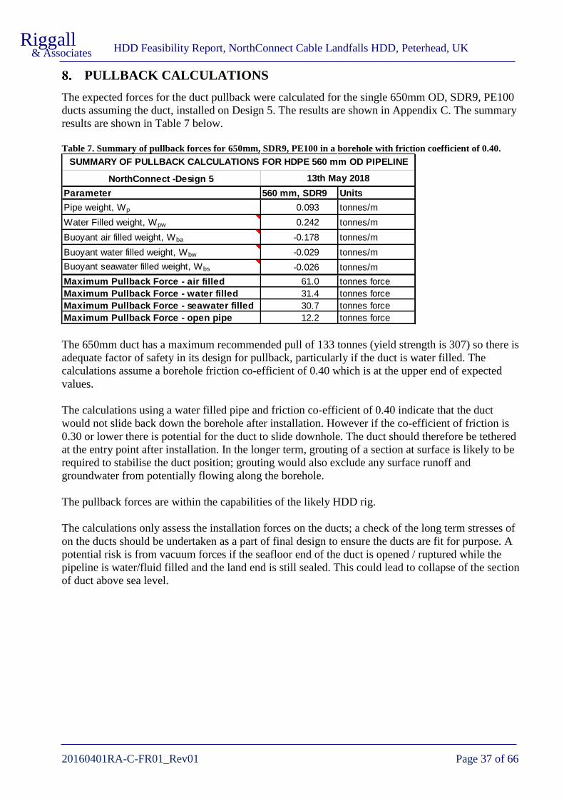
HDD Feasibility Report, NorthConnect Cable Landfalls HDD, Peterhead, UK
20160401RA-C-FR01_Rev01 Page 37 of 66
Riggall & Associates
PULLBACK CALCULATIONS
The expected forces for the duct pullback were calculated for the single 650mm OD, SDR9, PE100
ducts assuming the duct, installed on Design 5. The results are shown in Appendix C. The summary
results are shown in Table 7 below.
Table 7. Summary of pullback forces for 650mm, SDR9, PE100 in a borehole with friction coefficient of 0.40.
The 650mm duct has a maximum recommended pull of 133 tonnes (yield strength is 307) so there is
adequate factor of safety in its design for pullback, particularly if the duct is water filled. The
calculations assume a borehole friction co-efficient of 0.40 which is at the upper end of expected
values.
The calculations using a water filled pipe and friction co-efficient of 0.40 indicate that the duct
would not slide back down the borehole after installation. However if the co-efficient of friction is
0.30 or lower there is potential for the duct to slide downhole. The duct should therefore be tethered
at the entry point after installation. In the longer term, grouting of a section at surface is likely to be
required to stabilise the duct position; grouting would also exclude any surface runoff and
groundwater from potentially flowing along the borehole.
The pullback forces are within the capabilities of the likely HDD rig.
The calculations only assess the installation forces on the ducts; a check of the long term stresses of
on the ducts should be undertaken as a part of final design to ensure the ducts are fit for purpose. A
potential risk is from vacuum forces if the seafloor end of the duct is opened / ruptured while the
pipeline is water/fluid filled and the land end is still sealed. This could lead to collapse of the section
of duct above sea level.
NorthConnect -Design 5
Parameter 560 mm, SDR9 Units
Pipe weight, Wp 0.093 tonnes/m
Water Filled weight, Wpw 0.242 tonnes/m
Buoyant air filled weight, Wba -0.178 tonnes/m
Buoyant water filled weight, Wbw -0.029 tonnes/m
Buoyant seawater filled weight, Wbs -0.026 tonnes/m
Maximum Pullback Force - air filled 61.0 tonnes force
Maximum Pullback Force - water filled 31.4 tonnes force
Maximum Pullback Force - seawater filled 30.7 tonnes force
Maximum Pullback Force - open pipe 12.2 tonnes force
SUMMARY OF PULLBACK CALCULATIONS FOR HDPE 560 mm OD PIPELINE
13th May 2018

HDD Feasibility Report, NorthConnect Cable Landfalls HDD, Peterhead, UK
20160401RA-C-FR01_Rev01 Page 38 of 66
Riggall & Associates
INDICATIVE PROGRAMME
An indicative programme of works for three HDD landfalls is shown in Table 8 below. The
programme shows results for both 12 hour working per day and 24 hour working per day. For much
of the HDD works there is the potential to work 24 hours provided there are no restrictions for
environmental reasons.
Table 8. Indicative programme of works for Southern Design 5.
Length of HDD (m) 410 410
Length of Surface Casing (m) 20 20
60 60
Length of sediments at Exit (m) 40 40
Bull nose length (m) 5 5
35 35
30 30
120 120
80 80
500 500
800 800
12hr Shifts 24hr Shifts
10.0 10.0
10.0 10.0
Mobilise, unload, position 5.0 5.0
Rig & recycling setup 5.0 5.0
Casing Installation 30": 0 - 20m 4.0 4.0
Pilot hole drilling 12.25: 0 - 350m 10.0 5.0
Forward ream 18": 0 - 345m 11.5 5.8
Forward ream 24": 0 - 340m 11.3 5.7
Forward ream 30": 0 - 335m 11.2 5.6
Demobilisation to HDD #2 1.0 1.0
Setup Rig 2.0 2.0
Casing Installation 30": 0 - 20m 4.0 4.0
Pilot hole drilling 12.25: 0 - 350m 10.0 5.0
Forward ream 18": 0 - 345m 11.5 5.8
Forward ream 24": 0 - 340m 11.3 5.7
Forward ream 30": 0 - 335m 11.2 5.6
Demobilisation to HDD #3 1.0 1.0
Setup Rig 2.0 2.0
Casing Installation 30": 0 - 20m 4.0 4.0
Pilot hole drilling 12.25: 0 - 350m 10.0 5.0
Forward ream 18": 0 - 345m 11.5 5.8
Forward ream 24": 0 - 340m 11.3 5.7
Forward ream 30": 0 - 335m 11.2 5.6
Pilot hole drilling: 350 - 410m 1.6 1.6
Barge/diver exit confirmation 1.0 1.0
Back ream 18": 345 - 410m 1.8 0.9
Back ream 22": 340 - 410m 1.9 1.0
Cleaning pass 1.0 1.0
Demobilisation to HDD #2 1.0 1.0
Setup Pipe Pusher 1.0 1.0
Installation of duct 1.0 1.0
HDD Duct #1
Indicative Programme - NorthConnect HDD's
Southern Design 5 - 13/5/2018
Stopping distance before Exit (m)
Pilot ROP - Bedrock (m/12hr shift)
Forward Ream ROP - Bedrock (m/12hr shift)
Pilot ROP - Sediments (m/12hr shift)
Forward Ream ROP - Sediments (m/12hr shift)
Wireline tripping in ROP (m/12hr shift)
Rods tripping in ROP (m/12hr shift)
Activity
Access Road works
Site establishment works
HDD Duct #2
HDD Duct #3
12hr Shifts 24hr Shifts
Setup Rig 2.0 2.0
Pilot hole drilling: 350 - 410m 1.6 1.6
Barge/diver exit confirmation 1.0 1.0
Back ream 18": 345 - 410m 1.8 0.9
Back ream 24": 340 - 410m 1.9 1.0
Back ream 30": 335 - 410m 2.1 1.0
Cleaning pass 1.0 1.0
Demobilisation to HDD #3 1.0 1.0
Setup Pipe Pusher 1.0 1.0
Installation of duct 1.0 1.0
Setup Rig 2.0 2.0
Pilot hole drilling: 350 - 410m 1.6 1.6
Barge/diver exit confirmation 1.0 1.0
Back ream 18": 345 - 410m 1.8 0.9
Back ream 24": 340 - 410m 1.9 1.0
Back ream 30": 335 - 410m 2.1 1.0
Cleaning pass 1.0 1.0
Remove HDD Rig 1.0 1.0
Setup Pipe Pusher 1.0 1.0
Installation of duct 1.0 1.0
5.0 5.0
Grouting HDD Annulus 9.0 9.0
10.0 10.0
Weather Delay Days 4.0 4.0
Adverse Ground Delays 21.0 21.0
TOTAL 268.1 194.5
Notes: ROP's include allowance for slow drilling
Duct welding and stringing assumed to run concurrently
Casing installation for HDD's 2 and 3 could be potentially be
run concurrently
HDD Duct #2
HDD Duct #1
Rig Down & Demobilise HDD Equipment
Site reinstatement works
Adverse ground delays assume stop and grout of areas with
large fluid loss
Activity (continued)
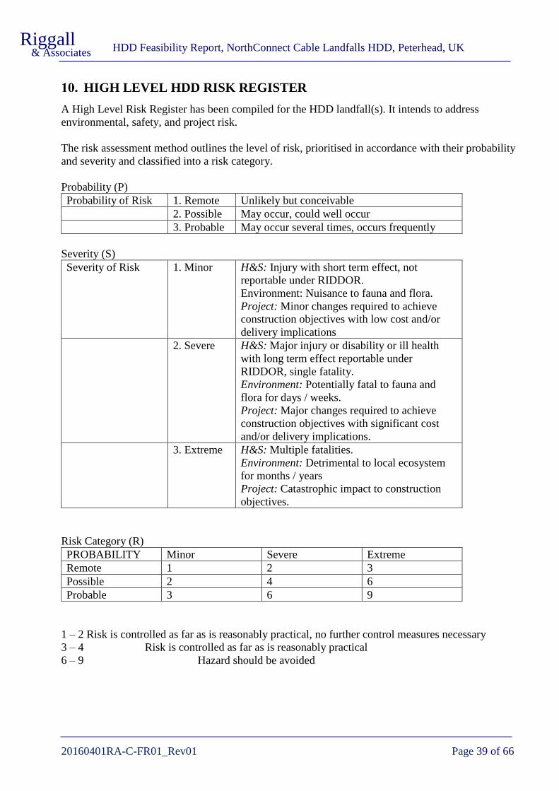
HDD Feasibility Report, NorthConnect Cable Landfalls HDD, Peterhead, UK
20160401RA-C-FR01_Rev01 Page 39 of 66
Riggall & Associates
HIGH LEVEL HDD RISK REGISTER
A High Level Risk Register has been compiled for the HDD landfall(s). It intends to address
environmental, safety, and project risk.
The risk assessment method outlines the level of risk, prioritised in accordance with their probability
and severity and classified into a risk category.
Probability (P)
Probability of Risk 1. Remote Unlikely but conceivable
2. Possible May occur, could well occur
3. Probable May occur several times, occurs frequently
Severity (S)
Severity of Risk 1. Minor H&S: Injury with short term effect, not
reportable under RIDDOR.
Environment: Nuisance to fauna and flora.
Project: Minor changes required to achieve
construction objectives with low cost and/or
delivery implications
2. Severe H&S: Major injury or disability or ill health
with long term effect reportable under
RIDDOR, single fatality.
Environment: Potentially fatal to fauna and
flora for days / weeks.
Project: Major changes required to achieve
construction objectives with significant cost
and/or delivery implications.
3. Extreme H&S: Multiple fatalities.
Environment: Detrimental to local ecosystem
for months / years
Project: Catastrophic impact to construction
objectives.
Risk Category (R)
PROBABILITY Minor Severe Extreme
Remote 1 2 3
Possible 2 4 6
Probable 3 6 9
1 – 2 Risk is controlled as far as is reasonably practical, no further control measures necessary
3 – 4 Risk is controlled as far as is reasonably practical
6 – 9 Hazard should be avoided

HDD Feasibility Report, NorthConnect Cable Landfalls HDD, Peterhead, UK
20160401RA-C-FR01_Rev01 Page 40 of 66
Riggall & Associates
Item Risk Risk
Classification
Mitigation Measures Reduced Risk
Classification
P S R P S R
1 Personnel and equipment falling over
cliffs
2 3 6 Fencing and barricades around site 1 3 3
Site boundary clearly marked 1 3 3
Site designed to be away from cliffs 1 3 3
Coastal public footpath diverted through the fields during
works
1 3 3
2 Release of drilling fluid to sea when
drilling out exit affects sea life
3 2 6 Drilling fluid pump rate reduced as ground becomes soft 3 2 6
Evaluate use of alternative drilling fluid or water
1 2 2
3 Toppling of vehicles on uneven /
sloping ground
2 3 6 Access roads designed to avoid traversing slopes 1 3 3
Speed limits appropriate to conditions 1 2 2
All plant and vehicle operators to be suitably qualified 1 3 3
HDD working site to be level or benched on steep ground 1 3 3
4 Downhole failure of drilling
equipment
2 2 4 Check of all drilling equipment before being run into hole 1 2 2
Trip out to check condition of equipment after set number of
hours recommended by manufacturer / supplier
1 2 2
Monitoring and recording of drilling forces to ensure they are
within the tolerances of the equipment
1 2 2
Ensure sand content of drilling fluid is minimised to reduce
abrasive wear
1 2 2
Fishing for equipment lost in hole 2 2 4
5 Accumulation of cuttings in borehole
leading to equipment stuck in hole
2
2
4
Monitoring the volume of cuttings removed from the HDD
against volume drilled
1 2 2
Trained mud engineer in charge of drilling fluids 1 2 2
Real time downhole Annular Pressure Monitoring to identify
restrictions in borehole annulus and trigger remedial action
1 2 2

HDD Feasibility Report, NorthConnect Cable Landfalls HDD, Peterhead, UK
20160401RA-C-FR01_Rev01 Page 41 of 66
Riggall & Associates
Item Risk Risk
Classification
Mitigation Measures Reduced Risk
Classification
6 HDPE duct stuck during pullback 2 2 4 Hole cleaning run(s) performed before pullback 1 2 2
Installation forces monitored 1 2 2
Safe pull limit adhered to 1 2 2
7 Breakout of drilling fluid to the
surface during pilot drilling
2 2 4 Design with sufficient depth below surface for expected
ground conditions
1 2 2
Monitoring of drilling fluid returns and volumes to warn of
inadequate hole cleaning
2 2 4
Drilling fluid to be of sufficient viscosity and properties for the
ground being drilled and cutting size generated
2 2 4
Topographical survey to identify risk of lateral fluid losses to
cliffs
1 2 2
Stopping point of pilot hole considers ground conditions found
during pilot drilling
2 2 4
Have Lost Circulation Materials available on site to seal any
breakout
2 2 4
Grouting if necessary 1 2 2
8 Collapse of granite blocks from roof
of borehole
2 2 4 Ensure drilling equipment has ability to clear out collapsed
blocks (hardfacing and gauge protection on rear)
2 2 4
Geophysics to identify faults / shears 2 2 4
HDD designed to drill in the most suitable ground conditions 2 2 4
Grout any areas of instability downhole
1 2 2
9 Unthreading from downhole
equipment during back reaming due to
insufficient make-up torque applied to
connections on barge / workboat /
platform
2 2 4 Competent personnel on barge / workboat making drillpipe /
assembly connections
1 2 2
Drilling technique to maintain consistent torque and avoid
over-spinning
2 2 2
Use of cradles to assist in aligning drill rods 1 2 2
Hydraulic breakout unit installed on barge / workboat
1 2 2

HDD Feasibility Report, NorthConnect Cable Landfalls HDD, Peterhead, UK
20160401RA-C-FR01_Rev01 Page 42 of 66
Riggall & Associates
Item Risk Risk
Classification
Mitigation Measures Reduced Risk
Classification
10 Breakout of drilling fluid to the
surface during forward reaming
2 2 4 Monitoring of drilling fluid returns and volumes to warn of
inadequate hole cleaning
2 2 4
Drilling fluid to be of sufficient viscosity and properties for the
ground being drilled and cutting size generated
2 2 4
Pilot hole stopped in competent ground before exit point and
only advanced to exit when reaming to that point is completed
1 2 2
Have Lost Circulation Materials available on site to seal any
breakout
2 2 4
Grouting if necessary 1 2 2
11 Forward reaming fails to follow pilot
hole
2 2 4 Use of sufficiently long lead rods in front of stabiliser 1 2 2
Use of a passive tool on lead rods (e.g. bull nose) 1 2 2
Monitoring of drilling forces during forward reaming and
comparison to pilot hole rate of penetration
1 2 2
Trip out and survey reamed hole if in doubt
1 2 2
12 HDPE duct is damaged during
pullback
2 2 4 Design to avoid unsuitable ground conditions if possible 1 2 2
Cleaning run satisfactorily completed before pullback 1 2 2
Monitoring of forces during pullback operations 1 2 2
Duct removed, borehole reconditioned, new or repaired duct
installed
1 2 2
13 Collapse of installed water filled
HDPE above MSL due to leak at exit
end (tail) of duct
2 2 4 Provide for admittance of air to head after pullback is
completed
1 2 2
Check of potential vacuum forces to determine risk of ring
collapse in duct
1 2 2
14 Duct sliding downhole after
installation
2 2 4 Temporarily secure duct to rig anchor block after installation 1 2 2
Grouting annulus between duct and borehole for length
installed above sea level
1 2 2

HDD Feasibility Report, NorthConnect Cable Landfalls HDD, Peterhead, UK
20160401RA-C-FR01_Rev01 Page 43 of 66
Riggall & Associates
Item Risk Risk
Classification
Mitigation Measures Reduced Risk
Classification
15 Loose gravels and cobbles at exit
point prevent or jam duct installation
2 2 4 Nearshore surveys to identify suitable exit points 1 2 2
High volume flush from hole during initial duct pullback to
prevent stones being dragged into borehole
1 2 2
Clearing of sediment from around exit point 1 2 2
Pushed duct installation 1 2 2
16 Drilling stopped due to nuisance noise
/ lighting to neighbouring residences
or shipping (lighting)
2 2 4 Placement of topsoil stockpiles, office cabins etc as shielding 1 1 1
Engines etc enclosed in silencing units 1 1 1
Consultation with shipping authorities 1 1 1
Pre construction baseline noise monitoring 1 1 1
Installation of dedicated sound& light barriers if required 1 1 1
17 Collapse of coastal cliffs extending to
work site
1 3 3 Position site and access sufficiently distant from cliff line 1 3 3
Monitoring of nearby cliff for fretting and movement
1 3 3
18 Collapse of soft ground in superficial
deposits at entry
2 1 2 Ensure drilling fluid characteristics are suitable for ground
conditions (e.g. viscosity, fluid loss / filter cake)
1 2 2
HDD designed to drill in the most suitable ground conditions 1 2 2
Casing any unstable areas near entry or exit 1 2 2
Excavate collapsed zones if sufficiently shallow
1 2 2
19 Parallel HDD boreholes accidentally
intersect each other
1 2 2 Ensure guidance system has sufficient accuracy to avoid
collision
1 1 1
Grout and re-drill
1 2 2
20 Unintentional sliding downhole of
unsecured drilling rods
1 2 2 Safety chain attached when tripping drilling rods in and out of
initial section of borehole
1 2 2
Rig personnel aware of risk and methodology 1 2 2
21 Construction affects local fauna –
especially nesting birds
2 2 4 Programme to avoid sensitive seasons for wildlife 1 1 1
Construction site sufficiently distant from wildlife sites
1 1 1
HDD Feasibility Report, NorthConnect Cable Landfalls HDD, Peterhead, UK
20160401RA-C-FR01_Rev01 Page 44 of 66
Riggall & Associates
CONCLUSIONS AND RECOMMENDATIONS
11.1. Geology
The bedrock geology appears to be entirely Peterhead granite with wide joint spacing (0.5m to 3m)
except in areas affected by fault / shear zones where the joint spacing parallel to the zone is
generally 0.1m – 0.5m. These zones are generally near vertical with strikes (alignments) trending
NNE-SSW, N-S or E-W. There is also a shallow north dipping synthetic fault exposed in the cliffs
bounding the north of the site.
Exposures of faults / shear zones at the eastern edge of the site show them to be foliated and more
weathered than surrounding rock. There were no apparent veining, slickensides, open fractures, or
clay infilled fractures. No water was noted flowing from the zones but they were a route for surface
water because they have weathered to form gullies. The indication is that they would not be a route
for bentonite breakout.
The Gutter of Nesh off the eastern end of the site appears to follow a fault / shear zone. The
weathering along this zone is potentially deeper and of higher grade than the observed zones
resulting in it eroding to form the bathymetric feature.
The granite is likely to be of very high strength, probably around 200MPa and will be slow to drill
but should form a stable borehole. Where the borehole passes through faults or shear zones there is
the potential for local collapse of blocks from the roof of the borehole if the orientation of close
spaced jointing is unfavourable. However the collapse volume should be limited by arching around
the 762mm diameter borehole.
The superficial deposits at the drill site appear to be composed of a thin (0.5m) layer of humus
overlying silty sand with gravels, 1-3m in thickness. The proportion of gravel appears to increase
with depth and near the base of the superficials there are likely to be cobbles, possibly boulders, of
granite corestone.
The seabed sediments at exit point are expected to be 1m to 3m of glacial till overlain by 4m to 5m
of dense sand and 1m to 1.5m of loose gravelly sand or loose silt and fine sand.
11.2. Feasibility of the proposed HDD design
Based on the available information the use of a landfall drilled by HDD from the site is feasible.
There are no indications of any ground conditions that would cause significant risk of non-
completion by HDD.
The initial Rev00 feasibility report examined designs along two separate alignments; a Northern
Alignment drilled towards bearing 070° (OS Grid) and a Southern Alignment drilled towards 120°
(OS Grid). The entry point for both Alignments was in a similar area on a gently sloping section of
the field approximately 100m back from the eastern edge of the field.
This update to the feasibility report, Rev01, discounted the northern alignment and produced three
conceptual designs exiting at a similar position to the southern alignment. Based on discussions
during the second site visit, the entry points for the HDD was moved to higher ground
approximately 90m SSW of the Rev00 HDD entry site. This area of higher ground offers simpler
access and a larger area in which to site the HDD’s, with more level ground.

HDD Feasibility Report, NorthConnect Cable Landfalls HDD, Peterhead, UK
20160401RA-C-FR01_Rev01 Page 45 of 66
Riggall & Associates
Following onshore ground investigations the preferred alignment of Southern Design 5 has been
examined in this Revision 2 of the feasibility report. The design is shown in plan and section view in
shown in Appendix E, drawing number 20160401RA-C/07.
The designs is 409.10m in length, with entry elevation approximately +38m ODN and exit elevation
-28m ODN (26m below LAT). The entry angle is 17° in order to maximise the depth beneath the
coastal land; it is at the upper end of normal HDD rig setup angles.
A cable landfall for the Hywind project was successfully drilled through Peterhead granite for the
Hywind project in August 2016. The HDD drilling contractor was LMR drilling and by their account
the drilling and installation was relatively straightforward. They noted variable strength in the
granite that suggests a number of weathered zones, similar to those described in the power station
tunnel construction (Edmond, 1977), were encountered. There were no indications that the
weathered zones created borehole instability.
Weathered zones on this project might be expected from MHWS onwards, and therefore over the
final 200m of the HDD. The angled ground investigation boreholes were positioned to test the
potential extension of a fractured or weathered zone that caused the “pond” area on the coastline just
to the north of the HDD alignments. In BH202 a weak zone was encountered at 36.1m to 37.6m
depth that aligns with this feature. While total core recovery was 100% in this zone, Solid core
recovery was 0% and Rock Quality Designation was 0% indicating very broken ground. Flush
returns, however, were 100% in this zone indicating that the fault is of low permeability and should
be sealed by the drilling fluid.
The HDD entry point for the Hywind project was located in Barclay Park, Peterhead, with the HDD
660m in length and 610mm diameter. The elevation of the entry point was approximately 15m AOD
and the exit was at -14m. The entry point for this project is considerably higher (approximately 38m
AOD). This results in a longer section of borehole that is unsupported by drilling fluid when the
HDD exits to the sea. Ground investigation boreholes will provide further information of the risk of
ground collapse in this length. Based on observations of the stability of the surrounding cliffs, even
in areas where jointing and faulting patterns intersect, ground collapse is expected to be a low risk to
successful completion of the HDD.
The marine operations for the Hywind landfall were planned to use a multi-cat vessel anchored at
the exit point and used as support vessel during the breakthrough and diving operations. This
suggests the HDD was forward reamed for most of the length. The duct installation was planned as a
floated duct using two tugs for the duct and a support vessel and divers for connection to the pulling
assembly.
11.3. Primary Geotechnical Risks
11.3.1 Drilling Fluid Breakout
Hydrofracture modelling indicates that the conceptual design has a low risk of (vertical) breakout
until the final 30m to 40m before exit. For breakout to occur within the granite it would require a
vertical fracture of 10mm or wider infilled with soft clay. Any fractures/ joint gaps seen on the site
visit were 2mm or less on the rock exposures.

HDD Feasibility Report, NorthConnect Cable Landfalls HDD, Peterhead, UK
20160401RA-C-FR01_Rev01 Page 46 of 66
Riggall & Associates
The greatest risk of breakout in the granite is from lateral or downward migration of fluid to adjacent
cliffs when the HDD is above sea level. The design is potentially only 30m from cliffs to the south
and loss of drilling fluid to them, although unlikely, is a possibility.
The next highest probability of inadvertent breakout will be within 40m of the exit. When the HDD
exits the granite, at approximately 43m before the seafloor exit point for Southern Design 5, the risk
of breakout to the seafloor significantly increases. The selection of the point at which to stop the
pilot hole drilling and commence forward reaming will need to assess this risk using information
from the nearshore surveys and monitoring of conditions during the drilling.
When forward reaming has been completed there is an unavoidable loss of drilling fluid as the pilot
hole exits to the sea. Any fluid above sea level at the entry side (approximately 110m of drilled
length) will flow into the sea. The volume of fluid will be approximately 38m3 per HDD for this
stage of losses.
Following the exit to the sea floor the HDD might need to be pull reamed to open up the last section
of borehole to 30” diameter. The volume of fluid required for this phase, and lost to the sea, will
depend on the length to be reamed and the nature of the rock. Indicative fluid volumes lost to the sea
are provided in Section 11.6.
The final unavoidable release of drilling fluid will occur during duct installation when the duct
displaces its volume of drilling fluid from the bore. For the Southern Design 5 HDD this will be
approximately 70m3 per HDD.
While bentonite is a naturally occurring clay and breaks down in saline water, consideration will
need to be given to the potential environmental and visual effects of this release. These unavoidable
releases occur on all HDD landfalls; early discussions with the relevant authorities (SEPA etc) are
always advisable.
11.3.2 Ground Collapse
There is a risk of ground collapse in the superficial near the entry point, particularly once the pilot
hole exits to the sea and the support of the drilling fluid is lost. However, this is not expected to be a
significant problem; at worst it would require temporary 34” steel casing for the likely 20m length
drilled in the silty sands, cobbles and boulders.
When the HDD passes through fault or shear zones there is the potential for local collapse of blocks
from the roof of the borehole. This would occur if the orientation of close spaced jointing is
unfavourable, however the collapse volume should be limited by arching around the 560mm
diameter borehole. To mitigate the risk the drilling contractor should be diligent in monitoring
drilling forces, proactive in hole cleaning, and their drilling tools should enable some degree of
protection against working back through collapsed blocks.
At the exit point the nearshore survey will need to assess the thickness and type of sediment to
mitigate the risk of gravels and cobbles being dragged into the borehole during duct installation.
This potentially could result in the duct becoming stuck.

HDD Feasibility Report, NorthConnect Cable Landfalls HDD, Peterhead, UK
20160401RA-C-FR01_Rev01 Page 47 of 66
Riggall & Associates
11.4. HDD Rig and Drilling Equipment
A HDD rig with 70 tonne pull force or greater is recommended; most contractors would elect to use
a 100t machine or larger to ensure sufficient power for the reaming stages. The critical parameter is
not likely to be the pull / push force but the torque capability of the machine; a rig with 34 kN.m or
more should be considered and this is likely to mean a rig of 70t pull force or greater.
11.5. Guidance
A wireline guidance system will be almost certainly used to allow monitoring and surveying of the
HDD from the driller’s cabin. The guidance tool is located a few metres behind the downhole motor
and sends real time information back to the drillers cabin through a cable inside the drilling rods.
The two main options for a wireline system are a Gyro system or a Magnetic Guidance System
(MGS). Either system is suitable for the project.
The MGS will have additional surface tracking capability to calibrate the magnetic bearing of the
HDD (proprietary names include Tensor and Paratrack). The surface tracking requires a thin (4mm
diameter) cable to be placed at surface along a section of the drilling route. In this case it would
likely extend to the edge of the grassed area above the bare coastal rocks.
11.6. Drilling Fluid
Drilling fluid tailored to the ground conditions is an important part of the HDD process for both
completing the HDD efficiently and minimising the risk of breakout. The HDD contractor should
use a reputable mud (drilling fluids) engineer and quality products to ensure the borehole is stable,
that all cuttings are carried from the borehole and the friction in the borehole is minimised.
On some landfall HDD’s a proprietary drilling fluid called Purebore is used for the exit and pull
reaming. Purebore is CEFAS registered and biodegradable but incurs additional costs and requires
an additional number of shifts to mix and displace the existing bentonite fluid in the borehole.
There will be unavoidable losses to the sea at three stages of the HDD:
1. When the pilot hole exits at the seafloor. At this point all the fluid in the length of HDD
above sea level will flow out until the fluid level in the HDD is at sea level.
2. During pull reaming of the final section of HDD. The last 50m to 70m of HDD might be pull
reamed – the reamer is pulled from exit toward entry with fluid flowing to the exit point. The
volume of fluid depends on the drilling time (related to how hard the ground is). The volume
of solids depends on the volume of hole to be reamed.
3. During duct installation the duct will displace drilling fluid from the hole.
Table 9 below provides indicative volumes for fluid loss on the Rev01 report HDD designs.

HDD Feasibility Report, NorthConnect Cable Landfalls HDD, Peterhead, UK
20160401RA-C-FR01_Rev01 Page 48 of 66
Riggall & Associates
Table 9. Estimated drilling fluid volumes lost to the sea for a single HDD on Southern Design 5.
11.7. Noise and Lighting
The nearest residences are 500m and 700m from the HDD site. Noise is unlikely to adversely affect
these neighbours except during night working in summer when a light breeze is blowing towards the
residences.
Site lighting for 24 hr working is unlikely to be an issue for residences but may require consultation
with Peterhead Port Authority to ensure it doesn’t affect shipping navigation.
11.8. Duct Installation Method
There are two options for installation of the duct, a pulled installation using a floated duct at the exit
point, and a pushed installation using a duct pushed into the HDD from the land. Pulled installations
are the conventional method of installation for landfalls.
ESTIMATED DRILLING FLUID LOSSESS FOR HDD DESIGN OPTIONS
FOR A SINGLE HDD
PROJECT: NorthConnect DATE: 13th May 2018
Duct Diameter 400 mm
Working hrs / shift 12 hrs
Av. Drilling Time per shift 6.0 hrs
Mud capacity 1.75% % solids
Bore Cut
(inches) (m3 / m) (m
3 / m)
Pilot 12.25 0.08 0.08
Ream 1 18 0.16 0.09
Ream 2 24 0.29 0.13
Ream 3 30 0.46 0.29
Southern HDD Design No. 5 Units
Total HDD length 415 m
Length of HDD above MSL 130 m
Pilot 65 m before exit
Ream 1 70 m before exit
Ream 2 75 m before exit
Ream 1 27 m of granite
Ream 2 32 m of granite
Ream 1 43 m of superficials
Ream 2 43 m of superficials
Loss 1 on pilot hole exit (fluid) 38 m3 (volume above MSL)
Loss 1 on pilot hole exit (solids) 0.7 m3
Loss 2 during reaming (fluid) 881 m3 total
Shifts Reaming 2.5 shifts
Loss 2 per shift (fluids) 346 m3/shift
Loss 2 per shift (solids) 4.9 m3/shift
Loss 3 on pullback (fluids) 70 m3
Loss 3 on pullback (solids) 0.2 m3
FLUIDS 989 m3
SOLIDS 5.8 m3
Diameter of stageVolumes
TOTAL LOSSES TO SEA
Granite drilled with losses
to sea
Superficial drilled with
losses to sea
REAMING VOLUMES
DRILLING FLUID LOSSES TO
SEA
HDD
Pilot & Fwd Ream
Stopping Points

HDD Feasibility Report, NorthConnect Cable Landfalls HDD, Peterhead, UK
20160401RA-C-FR01_Rev01 Page 49 of 66
Riggall & Associates
Pushed installations potentially offer the advantage of reduced offshore works. However, if
additional PE pipelines for grouting of the borehole are to be installed with the main duct some form
of marine support might be required to provide tension at the head of the duct.
Both pushed and pulled installation are potential options at the location and it is recommended that
the choice of methodology is given to the HDD contractor if possible. The pushed installation
requires a stringing area for the pipeline; this can be undertaken along the land cable route, provided
that this section of cable installation is not scheduled at the same time as HDD works.
11.9. Installation Forces
The modelled installation (pullback) forces for a conventional pulled installation are well within the
limits of a 650mm SDR9 PE100 duct provided the duct is water filled and well within the likely
capabilities of the HDD rig.
11.10. Trenchless Crossing of the A90 and Abandoned Railway
During the second site visit the potential location of trenchless crossing of the A90 and abandoned
railway was visited. The location is described in Section 2.2.2. The locations could be undertaken as
separate crossings or as a single crossing.
For a single crossing, the HDD method would be required, other trenchless techniques are unlikely
to be feasible or economic over this length. The crossing would be approximately 120m in length
and would probably require a midi sized HDD rig (capable of 15t to 40t pulling force).
The cable route is expected to cross the road and railway at an oblique angle of approximately 70
degrees; this is not expected to be a problem for permitting by Transport Scotland. The depth of any
HDD will need to be optimised to ensure that any surface settlement at the A90 is acceptable to
Transport Scotland. As a guide, a depth of 7m has been used on similar HDD crossings of the A90
in superficial deposits, but the depth will depend on ground conditions and Transport Scotland
requirements.
If undertaken as separate crossings, HDD or alternative trenchless methods such as auger bore and
pipe ramming could be used. The A90 crossing would be approximately 40m in length, the railway
crossing 20m. If completed as HDD’s a mini-HDD rig (less than 15t pull force) could be suitable,
however the depth of the design beneath the A90 would still need to satisfy Transport Scotland.
For the A90 crossings non-HDD methods would allow a shallower depth of cover because the
maximum amount of settlement from these methods in superficial deposits is lower. However, the
appropriate technique will depend on ground conditions and in the case of shallow bedrock, HDD is
likely to be preferred over other trenchless methods.
It is recommended that the working corridor between the A90 and railway is maintained at normal
widths (typically 30m) so that the contractor can choose the most suitable method for the crossings.
Parallel HDD’s can be drilled at 2m centres if required, 3m centres is more commonly used, subject
to suitability for thermal dissipation. Alternative trenchless methods can use similar spacings or
might consider using a larger pipe with two ducts installed within it, subject to suitability for thermal
dissipation.
Figure 27 below shows a typical layout for a midi sized HDD that would probably be used for the
crossing (about 120m length). The area shown on the pdf is 25m x 30m. It might be better to allow

HDD Feasibility Report, NorthConnect Cable Landfalls HDD, Peterhead, UK
20160401RA-C-FR01_Rev01 Page 50 of 66
Riggall & Associates
30m x 30m on the northern side of the A90, set back 15m from the road. On the southern side of the
A90 an area of 20m x 20m would be suitable for the exit area. Normally the crossing would be
drilled as two separate HDD’s, one with cable duct and fibre optic duct and a second with just a
cable duct. Separation distance between the HDD’s is typically 5m for this length HDD.
An outline methodology for completing a HDD crossing with a midi HDD rig is provided in
Appendix D of this report. Conceptual Designs for crossing both the A90 and abandoned railway
using maxi and mini rigs are provided in Appendix E, Drawing No’s 20160401RA-C/31 and
20160401RA-C/32.
Figure 27. Indicative layout for a midi sized HDD rig.

HDD Feasibility Report, NorthConnect Cable Landfalls HDD, Peterhead, UK
20160401RA-C-FR01_Rev01 Page 51 of 66
Riggall & Associates
REFERENCES
British Geological Survey Geoindex Offshore. Accessed from
http://mapapps2.bgs.ac.uk/geoindex_offshore/home.html
British Geological Survey Geology of Britain Viewer. Accessed from
http://mapapps.bgs.ac.uk/geologyofbritain/home.html
Edmond, J.M. and Graham, J.D.. 1977. “Peterhead power station cooling water intake tunnel:
an engineering case study”. Quarterly Journal of Engineering Geology 10, pp281–301.
Hall, A.M., “Hill of Longahven Quarry”. Geological Conservation Review, Volume 6: Quaternary
of Scotland, Chapter 8: North-east Scotland, Site: Hill of Longahven Quarry (GCR ID: 374).
Accessed from http://jncc.defra.gov.uk/pdf/gcrdb/GCRsiteaccount374.pdf on 12th May 2016.
Navionics SonarChart Mapping. Accessed at http://webapp.navionics.com/?lang=en
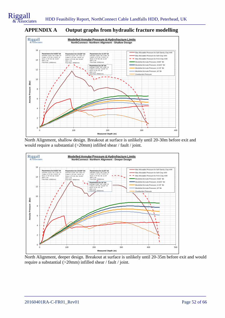
HDD Feasibility Report, NorthConnect Cable Landfalls HDD, Peterhead, UK
20160401RA-C-FR01_Rev01 Page 52 of 66
Riggall & Associates
APPENDIX A Output graphs from hydraulic fracture modelling
North Alignment, shallow design. Breakout at surface is unlikely until 20-30m before exit and
would require a substantial (>20mm) infilled shear / fault / joint.
North Alignment, deeper design. Breakout at surface is unlikely until 20-35m before exit and would
require a substantial (>20mm) infilled shear / fault / joint.
0
2
4
6
8
10
12
14
16
0 100 200 300 400
An
nu
lar
Pre
ssu
re
(Bar)
Measured Depth (m)
Modelled Annular Pressure & Hydrofracture Limits
Max Allowable Pressure for Soft Sandy Clay Infill
Max Allowable Pressure for Soft Clay Infill
Max Allowable Pressure for Firm Clay Infill
Modelled Annular Pressure, 9.625" Bit
Modelled Annular Pressure, 10.625" Bit
Modelled Annular Pressure, 12.25" Bit
Modelled Annular Pressure, 16" Bit
Overburden Pressure
Riggall& Associates NorthConnect - Northern Alignment - Shallow Design
Drill pipe: 6.625" OD, 5.901" ID
Parameters for 9.625" bit
Collars: 6.75" OD, 2.8125" ID
Motor: 6.75" OD, Bit: 9.625"
Flow Rate: 1200(l/min)
MW= 1.03
Drill pipe: 6.625" OD, 5.901" ID
Parameters for 10.625" bit
Collars: 6.75" OD, 2.8125" ID
Motor: 6.75" OD, Bit: 10.625"
Flow Rate: 1800(l/min)
MW= 1.03
Collars: 6.75" OD, 2.8125" ID
Drill pipe: 6.625" OD, 5.901" ID
Parameters for 12.25" bit
Motor: 5.75" OD, Bit: 12.25"
Flow Rate: 2200(l/min)
MW= 1.03
Collars: 6.75" OD, 2.8125" ID
Drill pipe: 6.625" OD, 5.901" IDParameters for 16" bit
Motor: 8" OD, Bit: 16"
Flow Rate: 2500(l/min)
MW= 1.03
0
2
4
6
8
10
12
14
16
0 100 200 300 400 500
An
nu
lar
Pre
ssu
re
(Bar)
Measured Depth (m)
Modelled Annular Pressure & Hydrofracture Limits
Max Allowable Pressure for Soft Sandy Clay Infill
Max Allowable Pressure for Soft Clay Infill
Max Allowable Pressure for Firm Clay Infill
Modelled Annular Pressure, 9.625" Bit
Modelled Annular Pressure, 10.625" Bit
Modelled Annular Pressure, 12.25" Bit
Modelled Annular Pressure, 16" Bit
Overburden Pressure
Riggall& Associates NorthConnect - Northern Alignment - Deeper Design
Drill pipe: 6.625" OD, 5.901" ID
Parameters for 9.625" bit
Collars: 6.75" OD, 2.8125" ID
Motor: 6.75" OD, Bit: 9.625"
Flow Rate: 1200(l/min)
MW= 1.03
Drill pipe: 6.625" OD, 5.901" ID
Parameters for 10.625" bit
Collars: 6.75" OD, 2.8125" ID
Motor: 6.75" OD, Bit: 10.625"
Flow Rate: 1800(l/min)
MW= 1.03
Collars: 6.75" OD, 2.8125" ID
Drill pipe: 6.625" OD, 5.901" ID
Parameters for 12.25" bit
Motor: 5.75" OD, Bit: 12.25"
Flow Rate: 2200(l/min)
MW= 1.03
Collars: 6.75" OD, 2.8125" ID
Drill pipe: 6.625" OD, 5.901" IDParameters for 16" bit
Motor: 8" OD, Bit: 16"
Flow Rate: 2500(l/min)
MW= 1.03

HDD Feasibility Report, NorthConnect Cable Landfalls HDD, Peterhead, UK
20160401RA-C-FR01_Rev01 Page 53 of 66
Riggall & Associates
South Alignment, shallow design. Breakout at surface is unlikely until 25-45m before exit and
would require a substantial (>20mm) infilled shear / fault / joint. The increased distance before exit
for this design is due to the shallower exit angle, +3° as opposed to +5° for the other three designs.
South Alignment, deeper design. Breakout at surface is unlikely until 20-40m before exit and would
require a substantial (>20mm) infilled shear / fault / joint.
0
2
4
6
8
10
12
14
16
0 100 200 300 400
An
nu
lar
Pre
ssu
re
(Bar)
Measured Depth (m)
Modelled Annular Pressure & Hydrofracture Limits
Max Allowable Pressure for Soft Sandy Clay Infill
Max Allowable Pressure for Soft Clay Infill
Max Allowable Pressure for Firm Clay Infill
Modelled Annular Pressure, 9.625" Bit
Modelled Annular Pressure, 10.625" Bit
Modelled Annular Pressure, 12.25" Bit
Modelled Annular Pressure, 16" Bit
Overburden Pressure
Riggall& Associates NorthConnect - Southern Alignment - Shallow Design
Drill pipe: 6.625" OD, 5.901" ID
Parameters for 9.625" bit
Collars: 6.75" OD, 2.8125" ID
Motor: 6.75" OD, Bit: 9.625"
Flow Rate: 1200(l/min)
MW= 1.03
Drill pipe: 6.625" OD, 5.901" ID
Parameters for 10.625" bit
Collars: 6.75" OD, 2.8125" ID
Motor: 6.75" OD, Bit: 10.625"
Flow Rate: 1800(l/min)
MW= 1.03
Collars: 6.75" OD, 2.8125" ID
Drill pipe: 6.625" OD, 5.901" ID
Parameters for 12.25" bit
Motor: 5.75" OD, Bit: 12.25"
Flow Rate: 2200(l/min)
MW= 1.03
Collars: 6.75" OD, 2.8125" ID
Drill pipe: 6.625" OD, 5.901" IDParameters for 16" bit
Motor: 8" OD, Bit: 16"
Flow Rate: 2500(l/min)
MW= 1.03
0
2
4
6
8
10
12
14
16
0 100 200 300 400 500
An
nu
lar
Pre
ssu
re
(Bar)
Measured Depth (m)
Modelled Annular Pressure & Hydrofracture Limits
Max Allowable Pressure for Soft Sandy Clay Infill
Max Allowable Pressure for Soft Clay Infill
Max Allowable Pressure for Firm Clay Infill
Modelled Annular Pressure, 9.625" Bit
Modelled Annular Pressure, 10.625" Bit
Modelled Annular Pressure, 12.25" Bit
Modelled Annular Pressure, 16" Bit
Overburden Pressure
Riggall& Associates NorthConnect - Southern Alignment - Deeper Design
Drill pipe: 6.625" OD, 5.901" ID
Parameters for 9.625" bit
Collars: 6.75" OD, 2.8125" ID
Motor: 6.75" OD, Bit: 9.625"
Flow Rate: 1200(l/min)
MW= 1.03
Drill pipe: 6.625" OD, 5.901" ID
Parameters for 10.625" bit
Collars: 6.75" OD, 2.8125" ID
Motor: 6.75" OD, Bit: 10.625"
Flow Rate: 1800(l/min)
MW= 1.03
Collars: 6.75" OD, 2.8125" ID
Drill pipe: 6.625" OD, 5.901" ID
Parameters for 12.25" bit
Motor: 5.75" OD, Bit: 12.25"
Flow Rate: 2200(l/min)
MW= 1.03
Collars: 6.75" OD, 2.8125" ID
Drill pipe: 6.625" OD, 5.901" IDParameters for 16" bit
Motor: 8" OD, Bit: 16"
Flow Rate: 2500(l/min)
MW= 1.03

HDD Feasibility Report, NorthConnect Cable Landfalls HDD, Peterhead, UK
20160401RA-C-FR01_Rev01 Page 54 of 66
Riggall & Associates
APPENDIX B Output graphs from modelling of Drilling Forces
0
5
10
15
20
25
30
0 50 100 150 200 250 300 350 400 450
Pu
sh
(to
nn
es)
Bit Depth (m)
Modelled Push Force
On Bottom Slide Push Modelled - Friction = 0.3
On Bottom Slide Push Modelled - Friction = 0.4
On Bottom Slide Push Modelled - Friction = 0.5
On Bottom Slide Push Modelled - Friction = 0.6
Riggall& Associates
BHA: 12.25" bit, 6 3/4 " mud motor, 6 3/4" NMDC
String 1: 6 5/8", 25.2 lb/ft, L = 500 m
String 2: 6 5/8", 25.2 lb/ft, L = 0 m
String 3: 6 5/8", 27.7 lb/ft, L = 0 m
NorthConnect - Southern Design 5 - 13/5/2018
0
2
4
6
8
10
12
14
0 50 100 150 200 250 300 350 400 450
Pu
ll (t
on
ne
s)
Bit Depth (m)
Modelled Pull Force
Off Bottom Slide Pull Modelled - Friction = 0.3
Off Bottom Slide Pull Modelled - Friction = 0.4
Off Bottom Slide Pull Modelled - Friction = 0.5
Off Bottom Slide Pull Modelled - Friction = 0.6
Riggall& Associates
BHA: 12.25" bit, 6 3/4 " mud motor, 6 3/4" NMDC
String 1: 6 5/8", 25.2 lb/ft, L = 500 m
String 2: 6 5/8", 25.2 lb/ft, L = 0 m
String 3: 6 5/8", 27.7 lb/ft, L = 0 m
NorthConnect - Southern Design 5 - 13/5/2018

HDD Feasibility Report, NorthConnect Cable Landfalls HDD, Peterhead, UK
20160401RA-C-FR01_Rev01 Page 55 of 66
Riggall & Associates
0
2
4
6
8
10
12
14
16
18
0 50 100 150 200 250 300 350 400 450
To
rqu
e
(kN
.m)
Bit Depth (m)
Modelled Torque
On Bottom Torque Modelled - Friction = 0.3
On Bottom Torque Modelled - Friction = 0.4
On Bottom Torque Modelled - Friction = 0.5
On Bottom Torque Modelled - Friction = 0.6
Riggall& Associates
BHA: 12.25" bit, 6 3/4 " mud motor, 6 3/4" NMDC
String 1: 6 5/8", 25.2 lb/ft, L = 500 m
String 2: 6 5/8", 25.2 lb/ft, L = 0 m
String 3: 6 5/8", 27.7 lb/ft, L = 0 m
NorthConnect - Southern Design 5 - 13/5/2018

HDD Feasibility Report, NorthConnect Cable Landfalls HDD, Peterhead, UK
20160401RA-C-FR01_Rev01 Page 56 of 66
Riggall & Associates
APPENDIX C Output from Calculation of Duct Pullback Forces
PIPE PULLBACK CALCULATIONS - HDPE OUTFALL, EMPTY PIPE
Simple outfall model for air filled pipe. Assumes water level in HDD is at MSL.
Assumes pipe is floating in sea and pulled in by HDD rig on land.
Base on method by Slavin as outlined by Plastic Pipes Institute
Includes Frictional Drag Forces, Capstan Forces, and Hydokinetic Forces
Project: NorthConnect - Design 5
Modelling Date: 13th May 2018
Pipe specifications and Borehole dimensions Minimum radius
Reamed hole diameter DH 30 762 mm Minimum Installed Radius 34 m
Pipe outer diameter OD 560 22.0 inches Minimum overbend radius 22 m
SDR 9 Note that SDR of HDPE pipe should be selected to pass long and short
Wall thickness t 62 mm 2.4 inches term ring deflection, tensile pressures etc
Pipe internal diameter ID 436 mm 17.1 inches
Reamed : Pipe ratio 1.36 (1.5 typical) Dead and buoyant pipe weights
Density HDPE 0.952 t/m3 0.034 lbf/in3 Pipe weight, Wp 0.093 tonnes/m 62 lb/ft
Cross sectional area 97304 sq mm 151 sq inches Buoyant empty weight, Wb -0.178 tonnes/m 120 lb/ft ^
Design minimum radius Rmin 400 m 1312 ft Buoyant filled weight, Wb -0.029 tonnes/m 20 lb/ft ^
Total pipe length 278 m
Friction and drilling fluid characteristics Total pipe weight 26 tonnes 56,752 lbs
Coefficient of sea floating friction mg 0.05 (suggest 0.05 for tow lines) Total pipe weight submerged -50 tonnes 109,235- lbs
Coefficient of borehole friction mb 0.4 (typically 0.25 - 0.50) Total pipe weight of submerged tail in sea -14 tonnes 29,852- lbs
Hydrokinetic pressure p 42 kPa (28-55 kPa normally)
Specific gravity of the mud slurry gb 1.1 (Bentonite typically 1.05 - 1.20) PULLBACK FORCES
Density of fresh water rw 1.0 t/m3 Combined Drag and Capstan Forces at:
Density of seawater rs 1.025 t/m4 Point 1 15 t 32,708 lbs
Point 2 35 t 78,045 lbs
HDD DESIGN Point 3 48 t 106,562 lbs
Section of borehole above Mean Sea Level (MSL) Point 4 52 t 114,928 lbs
Length from entry to MSL elevation L1 132.34 m Hydrokinetic Force 0.5 t 990 lbs
Angle AE 17 deg Max Force from submerged section 52.7 t 115,919 lbs
Section of borehole below Mean Sea Level (MSL)
As drilled exit angle (pipeside) Aa 5 deg 0.087 rad Gravitational pull component 3.6 t 7,902 lbs
Angle (rigside) at MSL Ab 17 deg 0.297 rad Frictional pull component 4.7 t 10,338 lbs
Drilled MSL tangent + curve length L2 179.40 m 588.6 ft Pipe unlikley to slide downhole if unsecured
Horizontal tangent length L3 0 m 0.0 ft Force from dry section (empty pipe) 8.3 t 18,240 lbs
Drilled exit curve length L4 35.39 m 116.1 ft
Exit tangent L5 63.69 m 209.0 ft Maximum force through submerged hole 52.7 t 116,162 lbs
Vertical depth (relative to MSL) H 35.19 m 115.5 ft Maximum force through dry hole 8.3 t 18,240 lbs
Length from exit to sea level (MSL) L6 81.5 m 267.4 ft Maximum Force 61.0 t 134,402 lbs
L3
2
4
3
1
Duct / Pipeline Entry
(HDD Exit / Pipeside)
Duct / Pipeline Exit
(HDD Entry / Rigside)
L1
L6
L5
L4
L2
Mean Sea LevelMSL
Aa
Ab
AE
5
H

HDD Feasibility Report, NorthConnect Cable Landfalls HDD, Peterhead, UK
20160401RA-C-FR01_Rev01 Page 57 of 66
Riggall & Associates
PIPE PULLBACK CALCULATIONS - HDPE OUTFALL, FRESH WATER FILLED PIPE
Simple outfall model for air filled pipe. Assumes water level in HDD is at MSL.
Assumes pipe is floating in sea and pulled in by HDD rig on land.
Base on method by Slavin as outlined by Plastic Pipes Institute
Includes Frictional Drag Forces, Capstan Forces, and Hydokinetic Forces
Project: NorthConnect - Design 5
Modelling Date: 13th May 2018
Pipe specifications and Borehole dimensions Minimum radius
Reamed hole diameter DH 30 inches 762 mm Minimum Installed Radius 34 m
Pipe outer diameter OD 560 mm 22.0 inches Minimum overbend radius 22 m
SDR 9 Note that SDR of HDPE pipe should be selected to pass long and short
Wall thickness t 62 mm 2.4 inches term ring deflection, tensile pressures etc
Pipe internal diameter ID 436 mm 17.1 inches
Reamed : Pipe ratio 1.36 (1.5 typical) Dead and buoyant pipe weights
Density HDPE 0.952 t/m3 0.034 lbf/in3 Pipe weight, Wp 0.093 tonnes/m 62 lb/ft
Cross sectional area 97304 sq mm 151 sq inches Pipe weight filled, Wpw 0.242 tonnes/m 162 lb/ft
Design minimum radius Rmin 400 m 1312 ft Buoyant empty weight, Wb -0.178 tonnes/m 120 lb/ft ^
Buoyant filled weight, Wb -0.029 tonnes/m 20 lb/ft ^
Friction and drilling fluid characteristics Total pipe length 278 m
Coefficient of sea floating friction mg 0.05 (suggest 0.05 for tow lines) Total pipe weight 26 tonnes 56,752 lbs
Coefficient of borehole friction mb 0.4 (typically 0.25 - 0.50) Total pipe weight submerged -8 tonnes 17,951- lbs
Hydrokinetic pressure p 42 kPa (28-55 kPa normally) Total pipe weight of submerged tail in sea -2 tonnes 4,906- lbs
Specific gravity of the mud slurry gb 1.1 (Bentonite typically 1.05 - 1.20)
Density of fresh water rw 1.0 t/m3 PULLBACK FORCES
Density of seawater rs 1.025 t/m4 Combined Drag and Capstan Forces at:
Point 1 3.5 t 7,762 lbs
HDD DESIGN Point 2 7.0 t 15,297 lbs
Section of borehole above Mean Sea Level (MSL) Point 3 8.9 t 19,669 lbs
Length from entry to MSL elevation L1 132.34 m Point 4 9.4 t 20,680 lbs
Angle AE 17 deg Point 5 31.4 t 69,294 lbs
Section of borehole below Mean Sea Level (MSL) Hydrokinetic Force 0.5 t 990 lbs
As drilled exit angle (pipeside) Aa 5 deg 0.087 rad Max Force from submerged section 9.8 t 21,670 lbs
Angle (rigside) at MSL Ab 17 deg 0.297 rad
Drilled MSL tangent + curve length L2 179.40 m 588.6 ft Gravitational pull component 9.3 t 20,612 lbs
Horizontal tangent length L3 0 m 0.0 ft Frictional pull component 12.2 t 26,967 lbs
Drilled exit curve length L4 35.39 m 116.1 ft Pipe unlikley to slide downhole if unsecured
Exit tangent L5 63.69 m 209.0 ft Force from dry section of hole (full) 21.6 t 47,579 lbs
Vertical depth (relative to MSL) H 35.19 m 115.5 ft
Length from exit to sea level (MSL) L6 81.5 m 267.4 ft Maximum Force 31.4 t 69,294 lbs
L3
2
4
3
1
Duct / Pipeline Entry
(HDD Exit / Pipeside)
Duct / Pipeline Exit
(HDD Entry / Rigside)
L1
L6
L5
L4
L2
Mean Sea LevelMSL
Aa
Ab
AE
5
H

HDD Feasibility Report, NorthConnect Cable Landfalls HDD, Peterhead, UK
20160401RA-C-FR01_Rev01 Page 58 of 66
Riggall & Associates
PIPE PULLBACK CALCULATIONS - HDPE OUTFALL, SEA WATER FILLED PIPE
Simple outfall model for air filled pipe. Assumes water level in HDD is at MSL.
Assumes pipe is floating in sea and pulled in by HDD rig on land.
Base on method by Slavin as outlined by Plastic Pipes Institute
Includes Frictional Drag Forces, Capstan Forces, and Hydokinetic Forces
Project: NorthConnect - Design 5
Modelling Date: 13th May 2018
Pipe specifications and Borehole dimensions Minimum radius
Reamed hole diameter DH 24 inches 762 mm Minimum Installed Radius 34 m
Pipe outer diameter OD 450 mm 22.0 inches Minimum overbend radius 22 m
SDR 9 Note that SDR of HDPE pipe should be selected to pass long and short
Wall thickness t 62 mm 2.4 inches term ring deflection, tensile pressures etc
Pipe internal diameter ID 436 mm 17.1 inches
Reamed : Pipe ratio 1.36 (1.5 typical) Dead and buoyant pipe weights
Density HDPE 0.952 t/m3 0.034 lbf/in3 Pipe weight, Wp 0.093 tonnes/m 62 lb/ft
Cross sectional area 97304 sq mm 151 sq inches Pipe weight filled, Wpw 0.245 tonnes/m 165 lb/ft
Design minimum radius Rmin 400 m 1312 ft Buoyant empty weight, Wb -0.178 tonnes/m 120 lb/ft ^
Buoyant filled weight, Ws -0.026 tonnes/m 17 lb/ft ^
Friction and drilling fluid characteristics Total pipe length 278 m
Coefficient of sea floating friction mg 0.05 (suggest 0.05 for tow lines) Total pipe weight 26 tonnes 56,752 lbs
Coefficient of borehole friction mb 0.4 (typically 0.25 - 0.50) Total pipe weight submerged -7 tonnes 15,669- lbs
Hydrokinetic pressure p 42 kPa (28-55 kPa normally) Total pipe weight of submerged tail in sea -2 tonnes 4,282- lbs
Specific gravity of the mud slurry gb 1.1 (Bentonite typically 1.05 - 1.20)
Density of fresh water rw 1.0 t/m3 PULLBACK FORCES
Density of seawater rs 1.025 t/m4 Combined Drag and Capstan Forces at:
Point 1 3.2 t 7,138 lbs
HDD DESIGN Point 2 6.2 t 13,728 lbs
Section of borehole above Mean Sea Level (MSL) Point 3 8.0 t 17,497 lbs
Length from entry to MSL elevation L1 132.34 m Point 4 8.3 t 18,323 lbs
Angle AE 17 deg Point 5 30.7 t 67,666 lbs
Section of borehole below Mean Sea Level (MSL) Hydrokinetic Force 0.5 t 990 lbs
As drilled exit angle (pipeside) Aa 5 deg 0.087 rad Max Force from submerged section 8.8 t 19,314 lbs
Angle (rigside) at MSL Ab 17 deg 0.297 rad
Drilled MSL tangent + curve length L2 179.4 m 588.6 ft Gravitational pull component 9.5 t 20,929 lbs
Horizontal tangent length L3 0 m 0.0 ft Frictional pull component 12.4 t 27,383 lbs
Drilled exit curve length L4 35.39 m 116.1 ft Pipe unlikley to slide downhole if unsecured
Exit tangent L5 63.69 m 209.0 ft Force from dry section of hole (full) 21.9 t 48,312 lbs
Vertical depth (relative to MSL) H 35.19 m 115.5 ft
Length from exit to sea level (MSL) L6 81.5 m 267.4 ft Maximum Force 30.7 t 67,666 lbs
L3
2
4
3
1
Duct / Pipeline Entry
(HDD Exit / Pipeside)
Duct / Pipeline Exit
(HDD Entry / Rigside)
L1
L6
L5
L4
L2
Mean Sea LevelMSL
Aa
Ab
AE
5
H

HDD Feasibility Report, NorthConnect Cable Landfalls HDD, Peterhead, UK
20160401RA-C-FR01_Rev01 Page 59 of 66
Riggall & Associates
APPENDIX D Outline Methodology for a Midi-HDD Rig Crossing
The following is an indicative methodology for a crossing using a Midi HDD rig (15t-40t pull
capability). A detailed methodology will need to be tailored to suit the circumstances of individual
crossings.
Site Setup
Prior to arrival of HDD equipment the vehicle access, drilling pad and working area at the entry site
will be prepared. Any uneven ground should be made level and access should be suitable for the
haulage equipment. Topsoil should be removed and stockpiled for reinstatement after completion of
the works.
Once the topsoil has been stripped bog mats or geotextile with hard standing material might be used
to ensure a suitable surface.
Overhead power lines will require transport planning to be negotiated safely, some of them might
require safety goalposts to be installed.
Any drainage work required to make the site safe for working and to prevent environmental damage
through contaminated runoff should be completed before mobilisation of HDD equipment.
All services, below ground and above, should be located and protected from damage or isolated as
needed.
A water supply of suitable quality and flow rate will be used for mixing drilling fluid. Because of the
length and relatively small diameter of the HDD’s, mains water could be tankered to site with a
tractor and bowser or obtained from the nearest mains water from a hydrant point.
A traffic management plan and haulage route for heavy equipment should be implemented prior to
arrival of equipment.
The entry point should be accurately surveyed and clearly marked, as should a number of alignment
pegs for positioning of the rig and points for any surface tracking cable, if used.
Usually the drilling rig will use its own auger screw anchors to stabilise the rig while drilling. In
some cases sheet piling might be require at the front of the rig to ensure stability when drilling and
installing the pipeline. Sheet piles are usually 4m or longer across a 3-4m width with I beams welded
or bolted to the top for connection to the HDD rig.
Personnel on the drill site should wear standard PPE including safety boots and hard hats. Personnel
working on the rig will need gloves for manual handling and appropriate eye protection when
welding, grinding, etc. The mud man on the drilling fluid mixing unit will need to wear appropriate
hand and eye protection, dust masks when handling powdered bentonite and additives, and complete
PPE with coveralls if caustic soda is used to adjust the fluid pH.
Prior to commencement of drilling barrier mesh should be placed around any open excavations and
measures taken to prevent public access to the site. High pressure hoses from the mud pumps should

HDD Feasibility Report, NorthConnect Cable Landfalls HDD, Peterhead, UK
20160401RA-C-FR01_Rev01 Page 60 of 66
Riggall & Associates
have appropriate safety lanyards. Personnel should hold the relevant permits and licences for any
plant and equipment they are operating.
Noise generated by the works is not usually a nuisance to nearby residents during the day. For mini
and midi rigs the noise is comparable to excavators and working is only likely to be during daylight
hours.
Pilot Hole
Prior to the drill commencing an entry pit is excavated; generally several metres square and 1.5m to
2.0m in depth. The entry pit has the dual purpose of containing drilling fluid returns and ensuring
any buried services are exposed prior to drilling. A pump in the pit transfers fluid to the mud
recycling unit.
Pilot hole drilling normally uses either a jetting assembly (Figure 18) on crossings without rock.
Where crossings are expected to drill into bedrock a tri-cone drilling bit powered by a downhole
motor (DHM) will be used.
A jetting assembly uses the high pressured jets omitted from the nozzles in the bit to hydraulically
excavate the ground ahead. To drill a straight section of hole the entire string of drilling rods is
rotated. To drill a curved section of hole the angled shoe or bent sub is oriented and then pushed
forwards to steer in the required direction. When using a tri-cone bit the function of the jetted fluid is
more to clear away the cuttings than to hydraulically excavate the ground ahead.
A DHM uses the hydraulic pressure of the drilling fluid to turn a progressing cavity motor located
behind the bit. Like a jetting assembly a DHM has a bend section to allow the hole to be steered. To
steer the bend is oriented in the required direction and the drilling rods are pushed in without
rotation. Only the drilling bit, powered by the DHM, is rotating to cut the rock and advance the bore.
For drilling straight sections of hole the entire drillstring is rotated.
Behind the jetting assembly or DHM will be the guidance probe followed by the drilling rods.
Between the components there may be various connection subs to provide connections between
differing types and sizes of threads. All connections are torqued to recommended values as they are
added at the drilling rig.
On occasion the drilling assembly may need to be torqued using chain tongues. This operation
should only be performed by experienced personnel and all non essential personnel should stand
well clear.
To ensure the HDD follows the designed route either a walkover system or a wireline system will be
used to track and steer the HDD. A walkover system uses a battery powered transmitter behind the
drilling bit. The signals are received at surface using a walkover detector that allows the position and
orientation of the drilling head to be determined. Walkover systems are typically effective to a depth
of 15m and possibly 20m below surface.

HDD Feasibility Report, NorthConnect Cable Landfalls HDD, Peterhead, UK
20160401RA-C-FR01_Rev01 Page 61 of 66
Riggall & Associates
Figure 28. Example a midi sized HDD rig. The rig is anchored with sheet piling in this case.
Figure 29. Example drilling assemblies; Jetting assembly with spade bit at top, jetting assembly with tri-cone bit
in centre, and downhole motor assembly with tri-cone bit at bottom.

HDD Feasibility Report, NorthConnect Cable Landfalls HDD, Peterhead, UK
20160401RA-C-FR01_Rev01 Page 62 of 66
Riggall & Associates
A wireline steering tool uses guidance sensors located behind the drilling bit or downhole motor that
send and receive data through a wireline running through the centre of the drill rods. Equipment at
the surface collects the data and gives real time information on position and orientation of the HDD.
There are two standard wireline systems, Magnetic Guidance System (MGS), often with additional
surface tracking, and the Gyro System.
If an MGS is used tracking cable will be placed at points along the surface alignment of the bore to
give an independent position of the HDD.
During drilling operations the drilling rods will be turning at around 60-90 rpm. All personnel
should stand clear of the rotating rods. Loose clothing should be avoided for those working around
the rig; high visibility vests tend to be a risk in these conditions and should be replaced with high
visibility clothing or jackets.
When a drilling rod has been drilled down the rod is disconnected from the drive head. The drive
head is pulled back to the top of the mast and a new drill rod is added. A wireline cable inside the
drilling rods is extended and connected before the new rod is torqued ready for drilling down.
During the procedure of adding and removing drill rods there is potential for accidents involving
pinch points and rotating equipment. Only trained and experienced rig hands should be working on
the rig at these times.
Downhole positional surveys are taken at the end of each drilled rod. While a new drilling rod is
added the guidance engineer plots the position of the HDD and formulates instructions for drilling
the next rod so that the bore remains on course. The driller will adapt drilling forces as the rod
progresses to effect efficient and stable drilling. The driller keeps a log recording the drilling
parameters and any notes on ground conditions for each rod. The pilot drilling process continues
until exit is reached.
On long crossings or in hard ground some drilling rigs can be exerting 25 tonne or more force on the
drill rods. On rare occasions the drill rods can suddenly buckle, potentially deflecting sideways and
injuring bystanders. Personnel should stand well to the side of the drill rods during operation.
If the pilot drill deviates too far off course at any point the bit can be pulled back (by removing
drilling rods) to a suitable point. A sidetrack off the old borehole can then be cut and the new section
of hole steered onto the correct course.
Drilling Fluids
The drilling fluid serves many purposes. Its primary role is to create a gel thick enough to suspend
soil and rock cuttings and carry them out of the hole. In addition the drilling fluid hydraulically
excavates soil in soft ground, powers the downhole motor in hard ground, cools the drilling
equipment, clears debris from the drilling bit and face, and lubricates the borehole to reduce friction
on the drilling equipment.
The drilling fluid predominantly used in HDD is a mix of water and a naturally occurring swelling
clay, bentonite. On occasions the chemical properties of the drilled soil or rock reduce the
effectiveness of the drilling fluid. As a result additives such as natural xanthum gum and gypsum are
sometimes added to improve the properties of the fluid.

HDD Feasibility Report, NorthConnect Cable Landfalls HDD, Peterhead, UK
20160401RA-C-FR01_Rev01 Page 63 of 66
Riggall & Associates
Bentonite drilling fluid is non-toxic however if sufficient quantity enters a freshwater watercourse it
can potentially settle on the bottom, smothering benthic flora and affecting faunal feeding and
breeding sites. Standard bentonite fluid breaks down quickly (flocculates) in seawater. Varieties of
bentonite are available that are stable in saline water, however their effectiveness is less than normal
freshwater mixes.
Bentonite is supplied in powdered form in either 25kg bags or bulk bags. The bentonite is fed into a
hopper where it is mixed with water circulated through the mixing tank. From the mixing tank the
fluid is transferred to the active tank. High pressure pumps then pump the fluid downhole. The
operator of the fluid system (the “mud man”) will need to wear appropriate hand and eye protection
and dust masks when handling powdered bentonite and additives. If caustic soda is used to adjust the
fluid pH complete PPE with coveralls should be worn.
Figure 30. Drilling Fluid (“Mud”) Recycling Unit for midi sized HD rig.
The bentonite drilling fluid is circulated down through the drill rods and back up the outside of the
rods in the annulus of the borehole. Exiting into the entry pit, the fluid is then pumped to the mud
recycling unit where hydro-cyclones and shaker screens remove cuttings. The cuttings accumulate
beneath the shakers and are usually disposed of at landfill sites. The cleaned drilling fluid transfers
to the active tank ready for circulation through the hole.
The mud man will keep records of drilling fluid parameters at regular intervals and monitor drilling
fluid volumes so that any losses to the formation are identified. The driller will monitor and record
downhole fluid pressures and returns to the entry pit to also ensure that any losses are recognised
quickly.
Reaming
When the pilot hole is completed the bit, jetting sub and steering equipment is removed at the exit
point. The pilot hole is then enlarged using conventional reaming; the reamer being pulled from exit

HDD Feasibility Report, NorthConnect Cable Landfalls HDD, Peterhead, UK
20160401RA-C-FR01_Rev01 Page 64 of 66
Riggall & Associates
towards entry. For larger diameter HDD’s a number of incrementally larger reaming passes are
required to open up the bore to final diameter.
During reaming the drilling fluid is pumped down through the drilling rods onto the cutting face of
the reamer and then carries cuttings through the reamed hole to the exit pit. The fluid is transferred
from the exit pit to the entry pit by either a HDPE returns line or by tractor and bowser. On this
project a tractor and bowser will probably be used. At the entry point the fluid is passed through the
recycling unit to remove the cuttings before being pumped downhole again.
The safety precautions for pilot hole drilling apply to reaming operations; keeping personnel clear of
the drill rods during operations, and only trained personnel on the rig. If chain tongues are used they
should only be operated by experienced personnel and all non-essential personnel should stand clear.
Once the reaming is completed to the entry point a cleaning run with a slightly smaller reamer is
performed by pulling the reamer through the hole to ensure it is suitable for installing the pipeline.
Figure 31. Typical fly-cutter hole opener (left) and Barrel Reamer (right).
Pipeline or Duct Installation
The pipeline or duct will have been welded and placed along the stringing alignment prior to
completion of the HDD reaming.
The pipeline or duct will be prepared for installation by attaching a pulling head (Figure 22) and if
required it is ballasted by filling the pipeline / duct (or a duct within the pipeline) with water to
reduce its buoyancy.
The pulling assembly will consist of the drill rods connected to a reamer of slightly larger diameter
than the pipeline / duct. Connected to the reamer is a swivel of adequate strength for the expected
pullback forces. When the pulling assembly is torqued to the drill rods the pulling head of the
pipeline / duct is bolted to the swivel and pullback can begin.
Pullback proceeds by pulling back and removing a drilling rod then connecting onto the next drill
rod and repeating. A typical installation rate for pullback is 100m per hour. During pullback the
driller will monitor pulling forces to ensure the maximum allowable pulling force for the pipeline /
duct is not exceeded.
During pullback the pipeline / duct will displace bentonite fluid from the borehole and at these
locations it is expected to flow to the exit pit. There should either be ample storage prepared for the
displaced fluid or sufficient bowsers / tankers to remove it from site without having to stop the
installation process.

HDD Feasibility Report, NorthConnect Cable Landfalls HDD, Peterhead, UK
20160401RA-C-FR01_Rev01 Page 65 of 66
Riggall & Associates
When the pulling assembly reaches the drilling rig it will be disconnected and removed. For PE
ducts the pipeline should be secured to the drilling rig overnight so that the duct does not withdraw
back into the borehole as elastic strain is recovered.
Figure 32. Drilling rod, swivel, pulling head and pipeline being pulled into the entry

HDD Feasibility Report, NorthConnect Cable Landfalls HDD, Peterhead, UK
20160401RA-C-FR01_Rev01 Page 66 of 66
Riggall & Associates
APPENDIX E Conceptual Design Drawings
20160401RA-C/03 – Conceptual HDD Site Layout for Southern Design 5
20160401RA-C/07 – Conceptual HDD Design - South Alignment H
20160401RA-C/10 – Plan View comparing Conceptual HDD Designs
20160401RA-C/31 – Conceptual Maxi Rig HDD Design A90 & Railway Crossing
20160401RA-C/32 – Conceptual Mini Rig HDD Design A90 & Railway Crossing

41
20
00
E
842000 N
841000 N
840000 N
839000 N
41
30
00
E
41
40
00
E
41
20
00
E
41
30
00
E
41
40
00
E
41
20
00
E
41
30
00
E
41
40
00
E
41
20
00
E
41
30
00
E
41
40
00
E
41
20
00
E
842000 N
841000 N
840000 N
839000 N
842000 N
841000 N
840000 N
839000 N
K
P
0.0
0
K
P
0.1
0
KP0.2
0
KP0.3
0
SURFICIAL GEOLOGY - Horizontal S
cale 1:2000
þ
ÿ
26
25
TP01
Longhaven Mains
Station House
A 90
A 90
H
'
H
E
X
IT
-
L
a
n
d
fa
ll H
D
D
E
N
T
R
Y
-
L
a
n
d
fa
ll H
D
D
H
''
BH201
BH301
BH302
TP304
E
X
IT
-
R
o
a
d
C
r
o
s
s
in
g
H
D
D
L
o
n
g
E
N
T
R
Y
-
R
o
a
d
C
r
o
s
s
in
g
H
D
D
L
o
n
g
1
0
.0
0
1
0
.0
0
BH202
HDD Borehole: 762mm Diameter
Duct: 560mm O.D. SDR 9 HDPE
Cable: 125mm O.D.
Elevation (m
O
D N
ew
lyn)
Elevation (m
O
D N
ew
lyn)
25.00
30.00
25.00
30.00
35.00
40.00
45.00
35.00
40.00
45.00
GROUND LEVELS (m) AOD
CHAINAGE FROM ENTRY (m)
DEEPER HDD OPTION
CENTRE OF HDD BORE (m) AOD
HDD DEPTH OF COVER (m) BGL
HD
D
CENTRE OF HDD BORE (m) AOD
HDD DEPTH OF COVER (m) BGL
GROUND LEVELS (m) AOD
CHAINAGE FROM ENTRY (m)
DEEPER HDD OPTION
55.00
50.00
60.00
65.00
70.00
75.00
80.00
85.00
55.00
50.00
60.00
65.00
70.00
75.00
80.00
85.00
A90
Dismantled
Railway
R400.00
R400.00
LONG HDD OPTION - 250.32m horizontal length, 252.39m drilled length
2.44
7.97
10.14
4.76
LONG HDD EXIT LONG HDD ENTRY
52.08
HD
D
7.0°
10.0°
7
9
.7
7
7
8
.3
2
7
7
.1
9
7
5
.6
1
7
3
.1
7
7
0
.6
4
6
7
.9
2
6
6
.
7
6
6
6
.
4
1
6
6
.
1
9
6
6
.
1
6
6
6
.8
0
6
6
.8
5
6
8
.2
8
7
0
.7
0
7
3
.3
5
7
5
.1
8
7
6
.4
5
77.38
77.31
78.5
1
79.7
5
80.7
3
B
T
6
6
.5
9
6
6
.
5
9
6
6
.
5
1
6
6
.
4
8
IC
6
5
.8
5
M
K
R
M
K
R
P
IP
E
6
6
.
1
0
6
6
.
0
9
6
6
.
1
3
6
6
.
1
4
6
6
.
1
3
G
6
6
.
2
5
6
6
.
2
8
6
5
.
7
4
6
5
.
8
7
6
5
.
5
3
6
5
.
9
2
6
6
.
1
5
6
6
.
3
0
B
O
L
6
6
.
4
1
6
6
.
3
7
6
6
.
3
4
6
4
.
2
1
6
4
.
4
1
6
3
.2
4
6
3
.6
7
6
5
.
0
4
6
4
.
3
4
6
3
.
9
6
6
3
.3
0
5
9
.
5
7
6
2
.
3
0
6
3
.
8
4
6
4
.
2
3
6
2
.
5
9
5
9
.
8
7
6
1
.9
0
6
0
.3
2
5
9
.6
9
5
9
.5
2
5
8
.
8
2
5
9
.0
8
6
0
.8
3
5
4
.
3
3
5
4
.
3
9
5
4
.
6
0
5
5
.
7
6
5
5
.
2
4
5
4
.
8
2
5
4
.
5
3
5
4
.
3
6
5
4
.
2
7
54.39
5
4
.
5
8
5
4
.
9
6
5
7
.5
9
5
7
.0
6
5
6
.1
4
5
5
.6
4
5
4
.9
7
5
5
.1
8
5
4
.9
9
5
5
.
1
7
5
4
.
6
9
5
3
.
9
8
5
3
.
8
2
5
3
.
9
5
5
4
.
1
5
5
4
.
2
6
5
4
.4
9
5
3
.
7
9
5
3
.
6
4
5
3
.
6
8
5
3
.
6
8
5
4
.
2
1
5
3
.
9
8
5
3
.
7
1
5
3
.
7
4
P
IP
E
IN
V
E
R
T
P
IP
E
IN
V
E
R
T
5
3
.2
3
5
3
.0
7
5
4
.4
8
5
3
.
8
5
5
4
.0
0
54.50
5
5
.0
0
54.5
0
55.00
5
5
.
5
0
5
6
.0
0
6
2
.
0
0
6
2
.
5
0
6
3
.
0
0
6
3
.
5
0
6
4
.
0
0
6
6
.0
0
6
6
.5
0
6
6
.
5
0
6
7
.
0
0
67.50
68.00
68.50
69.00
69.50
70.00
70.50
71.00
71.50
72.00
72.50
73.00
73.50
74.00
74.50
75.00
75.50
76.00
76.50
7
7
.0
0
7
7
.5
0
78.00
78.50
79.00
79.50
80.00
80.50
G
R
A
S
S
A
R
E
A
G
R
A
S
S
A
R
E
A
G
R
A
S
S
A
R
E
A
G
R
A
S
S
A
R
E
A
A
9
0
T
A
R
R
O
A
D
G
R
A
S
S
V
E
R
G
E
G
R
A
S
S
V
E
R
G
E
G
R
A
S
S
V
E
R
G
E
O
L
D
W
A
L
L
D
I
T
C
H
F
E
N
C
E
(
P
O
S
T
\
W
I
R
E
)
D
I
T
C
H
F
E
N
C
E
(
P
O
S
T
\
W
I
R
E
)
FE
NC
E(P
OS
T\W
IRE
)
B
H
3
0
1
B
H
3
0
2
T
P
3
0
4
EXIT - Road Crossing HDD Long
ENTRY - Road Crossing HDD Long
SCALE
0 10 20 30 40 50
metres
N
O
S
G
B
3
6
10.00
10.00
Exit Pit
HGV turning area
Drill Pipe Rack
Fluid tank &
Recycling
Cuttings
Mixin
g
Stores
Workshop
Gen
Tool
Laydown
Fuel
Bentonite
Stora
ge
Mixing tank
Drill Pipe Rack
Entry Pit
Drill Pipe Rack
HDD RIG FOOTPRINT
Entry Pit
Drill Pipe Rack
HDD RIG FOOTPRINT
Welfare
Site O
ffice
Lunch room
Power Pack
Driller's
Cabin
Entry Pit
Drill Pipe Rack
HDD RIG FOOTPRINT
Generator
Mud P
um
p
Mud P
um
p
HGV turning area
35.00
30.00
60.00
40.00
Exit Pit
Exit Pit
Riggall& Associates7 Fairview CloseWatledgeNailsworthGL6 0AXU.K.Telephone: +44 (0)1453 833913Email: [email protected]
A1
Approved by
Drawing Number
Designed by Checked by
Issue
Date approved
Date Drawn
Client
Scale Drawn by Sheet Size
20160401RA-C/31
16/10/2017
AS SHOWNTR
A
NORTHCONNECT
TR
DateRev Description By
06/02/2018A Draft for discussion TR
2.
NOTES
1. DO NOT SCALE
Project Title
Drawing Title
ALL DIMENSIONS, LEVELS AND CHAINAGES ARE IN METRES UNLESS OTHERWISE STATED.
PROPOSED BOREHOLES ARE INDICATED BY YELLOW MARKERS.
LAND ELEVATIONS ARE ESTIMATED BASED ON OS MASTERMAP1:25,000 MAPPING AND
TOPOGRAPHICAL SURVEY PROVIDED BY NORTHCONNECT
PLAN VIEW - SOUTHERN ALIGNMENT
SECTION VIEW - SOUTHERN ALIGNMENT
GENERAL LOCATION
DUCT DETAIL
NORTHCONNECT
HDD FEASIBILITY STUDY
3. BATHYMETRY DEPTHS RELATES TO ADMIRALTY CHART DATUM. CHART DATUM IS -2.20 ODN
MEASURED AT PETERHEAD.
4. GEOLOGY IS BASED ON HIGH LEVEL GEOLOGICAL MAPPING DURING THE RIGGALL &
ASSOCIATES SITE VISIT. FURTHER GROUND INVESTIGATIONS WILL BE REQUIRED TO BETTER
DETERMINE CONDITIONS AT SITE.
CONCEPTUAL LONG HDD DESIGN
A90 & RAILWAY CROSSING
11/03/2018B Removed North side Entry option TR
30/5/2018C Cosmetic changes for ITT TR
18/6/2018D Offshore survey boundary lines removed TR

41
20
00
E
842000 N
841000 N
840000 N
839000 N
41
30
00
E
41
40
00
E
41
20
00
E
41
30
00
E
41
40
00
E
41
20
00
E
41
30
00
E
41
40
00
E
41
20
00
E
41
30
00
E
41
40
00
E
41
20
00
E
842000 N
841000 N
840000 N
839000 N
842000 N
841000 N
840000 N
839000 N
K
P
0.0
0
K
P
0.1
0
KP0.2
0
KP0.3
0
SURFICIAL GEOLOGY - Horizontal S
cale 1:2000
þ
ÿ
26
25
TP01
Longhaven Mains
Station House
A 90
A 90
H
'
H
E
X
IT
-
L
a
n
d
fa
ll H
D
D
E
N
T
R
Y
-
L
a
n
d
fa
ll H
D
D
H
''
BH201
BH301
BH302
TP304
E
N
T
R
Y
-
R
o
a
d
C
r
o
s
s
in
g
H
D
D
S
h
o
r
t
E
X
IT
-
R
o
a
d
C
r
o
s
s
in
g
H
D
D
S
h
o
r
t
1
0
.0
0
1
0
.0
0
BH202
HDD Borehole: 762mm Diameter
Duct: 560mm O.D. SDR 9 HDPE
Cable: 125mm O.D.
Elevation (m
O
D N
ew
lyn)
Elevation (m
O
D N
ew
lyn)
25.00
30.00
25.00
30.00
35.00
40.00
45.00
35.00
40.00
45.00
GROUND LEVELS (m) AOD
CHAINAGE FROM ENTRY (m)
DEEPER HDD OPTION
CENTRE OF HDD BORE (m) AOD
HDD DEPTH OF COVER (m) BGL
HD
D
CENTRE OF HDD BORE (m) AOD
HDD DEPTH OF COVER (m) BGL
GROUND LEVELS (m) AOD
CHAINAGE FROM ENTRY (m)
DEEPER HDD OPTION
SHORT HDD ENTRY
55.00
50.00
60.00
65.00
70.00
75.00
80.00
85.00
55.00
50.00
60.00
65.00
70.00
75.00
80.00
85.00
A90
Dismantled
Railway
8.14
2.0°
22.69
2.86
SHORT HDD OPTION - 155.67m horizontal length, 157.85m drilled length
10.67
17.0°
10.0°
SHORT HDD EXIT
R200.00
HD
D
R200.00
7
9
.7
7
7
8
.3
2
7
7
.1
9
7
5
.6
1
7
3
.1
7
7
0
.6
4
6
7
.9
2
6
6
.
7
6
6
6
.
4
1
6
6
.
1
9
6
6
.
1
6
6
6
.8
0
6
6
.8
5
6
8
.2
8
7
0
.7
0
7
3
.3
5
7
5
.1
8
7
6
.4
5
77.38
77.31
78.5
1
79.7
5
80.7
3
B
T
6
6
.5
9
6
6
.
5
9
6
6
.
5
1
6
6
.
4
8
IC
6
5
.8
5
M
K
R
M
K
R
P
IP
E
6
6
.
1
0
6
6
.
0
9
6
6
.
1
3
6
6
.
1
4
6
6
.
1
3
G
6
6
.
2
5
6
6
.
2
8
6
5
.
7
4
6
5
.
8
7
6
5
.
5
3
6
5
.
9
2
6
6
.
1
5
6
6
.
3
0
B
O
L
6
6
.
4
1
6
6
.
3
7
6
6
.
3
4
6
4
.
2
1
6
4
.
4
1
6
3
.2
4
6
3
.6
7
6
5
.
0
4
6
4
.
3
4
6
3
.
9
6
6
3
.3
0
5
9
.
5
7
6
2
.
3
0
6
3
.
8
4
6
4
.
2
3
6
2
.
5
9
5
9
.
8
7
6
1
.9
0
6
0
.3
2
5
9
.6
9
5
9
.5
2
5
8
.
8
2
5
9
.0
8
6
0
.8
3
5
4
.
3
3
5
4
.
3
9
5
4
.
6
0
5
5
.
7
6
5
5
.
2
4
5
4
.
8
2
5
4
.
5
3
5
4
.
3
6
5
4
.
2
7
54.39
5
4
.
5
8
5
4
.
9
6
5
7
.5
9
5
7
.0
6
5
6
.1
4
5
5
.6
4
5
4
.9
7
5
5
.1
8
5
4
.9
9
5
5
.
1
7
5
4
.
6
9
5
3
.
9
8
5
3
.
8
2
5
3
.
9
5
5
4
.
1
5
5
4
.
2
6
5
4
.4
9
5
3
.
7
9
5
3
.
6
4
5
3
.
6
8
5
3
.
6
8
5
4
.
2
1
5
3
.
9
8
5
3
.
7
1
5
3
.
7
4
P
IP
E
IN
V
E
R
T
P
IP
E
IN
V
E
R
T
5
3
.2
3
5
3
.0
7
5
4
.4
8
5
3
.
8
5
5
4
.0
0
54.50
5
5
.0
0
54.5
0
55.00
5
5
.
5
0
5
6
.0
0
6
2
.
0
0
6
2
.
5
0
6
3
.
0
0
6
3
.
5
0
6
4
.
0
0
6
6
.0
0
6
6
.5
0
6
6
.
5
0
6
7
.
0
0
67.50
68.00
68.50
69.00
69.50
70.00
70.50
71.00
71.50
72.00
72.50
73.00
73.50
74.00
74.50
75.00
75.50
76.00
76.50
7
7
.0
0
7
7
.5
0
78.00
78.50
79.00
79.50
80.00
80.50
G
R
A
S
S
A
R
E
A
G
R
A
S
S
A
R
E
A
G
R
A
S
S
A
R
E
A
G
R
A
S
S
A
R
E
A
A
9
0
T
A
R
R
O
A
D
G
R
A
S
S
V
E
R
G
E
G
R
A
S
S
V
E
R
G
E
G
R
A
S
S
V
E
R
G
E
O
L
D
W
A
L
L
D
I
T
C
H
F
E
N
C
E
(
P
O
S
T
\
W
I
R
E
)
D
I
T
C
H
F
E
N
C
E
(
P
O
S
T
\
W
I
R
E
)
FE
NC
E(P
OS
T\W
IRE
)
B
H
3
0
1
B
H
3
0
2
T
P
3
0
4
ENTRY - Road Crossing HDD ShortEXIT - Road Crossing HDD Short
SCALE
0 10 20 30 40 50
metres
N
O
S
G
B
3
6
10.00
10.00
Midi Rig footprint
Entry
Pit
Spare Rods
Spare Rods
Spare Rods
Midi Rig footprint
Entry
Pit
Spare Rods
Spare Rods
Spare Rods
Midi Rig footprint
Entry
Pit
Spare Rods
Spare Rods
Spare Rods
Mud tank
Cuttings
Gen
Office
Workshop
Bentonite
Storage
Lunch room
& recycling
Fuel
Tooling
Laydow
n
Area
Excavator working area
50.00
35.00
30.00
35.00
Exit Pit
Exit Pit
Exit Pit
Riggall& Associates7 Fairview CloseWatledgeNailsworthGL6 0AXU.K.Telephone: +44 (0)1453 833913Email: [email protected]
A1
Approved by
Drawing Number
Designed by Checked by
Issue
Date approved
Date Drawn
Client
Scale Drawn by Sheet Size
20160401RA-C/32
16/10/2017
AS SHOWNTR
A
NORTHCONNECT
TR
DateRev Description By
06/02/2018A Draft for discussion TR
2.
NOTES
1. DO NOT SCALE
Project Title
Drawing Title
ALL DIMENSIONS, LEVELS AND CHAINAGES ARE IN METRES UNLESS OTHERWISE STATED.
PROPOSED BOREHOLES ARE INDICATED BY YELLOW MARKERS.
LAND ELEVATIONS ARE ESTIMATED BASED ON OS MASTERMAP1:25,000 MAPPING AND
TOPOGRAPHICAL SURVEY PROVIDED BY NORTHCONNECT
PLAN VIEW - SOUTHERN ALIGNMENT
SECTION VIEW - SOUTHERN ALIGNMENT
GENERAL LOCATION
DUCT DETAIL
NORTHCONNECT
HDD FEASIBILITY STUDY
3. BATHYMETRY DEPTHS RELATES TO ADMIRALTY CHART DATUM. CHART DATUM IS -2.20 ODN
MEASURED AT PETERHEAD.
4. GEOLOGY IS BASED ON HIGH LEVEL GEOLOGICAL MAPPING DURING THE RIGGALL &
ASSOCIATES SITE VISIT. FURTHER GROUND INVESTIGATIONS WILL BE REQUIRED TO BETTER
DETERMINE CONDITIONS AT SITE.
CONCEPTUAL SHORT HDD DESIGN
A90 & RAILWAY CROSSING
11/03/2018B Removed North side Entry option TR
30/5/2018C Cosmetic changes for ITT TR
18/6/2018D Offshore survey boundary lines removed TR

4
1
2
0
0
0
E
Drill P
ip
e R
ack
Fluid tank &
Recycling
Cuttings
Mixing
Sto
re
s
Wo
rksh
op
Ge
n
Tool
Laydown
Fuel
Bentonite
Storage
Mixing tank
Drill P
ip
e R
ack
Entry Pit
Drill Pipe Rack
HDD RIG FOOTPRINT
Water Storage Water Storage
SITE PARKING
Entry Pit
Drill Pipe Rack
HDD RIG FOOTPRINT
S
I
T
E
A
C
C
E
S
S
WelfareSite Office
Lunch room
3
4
.
5
0
3
5
.
0
0
3
5
.
5
0
3
6
.0
0
3
6
.5
0
3
7
.0
03
7
.5
0
3
8
.0
0
3
8
.5
0
4
2
.0
0
4
2
.
5
0
4
1
.
5
0
4
3
.0
0
4
1
.0
0
4
0
.5
0
4
0
.0
0
3
9
.5
0
39.00
38.00
37.00
36.00
35.00
38.50
37.50
36.50
35.50
34.00
3
3
.0
0
3
2
.
0
0
3
1
.
0
0
34.50
33.50
3
2
.
5
0
3
1
.
5
0
3
0
.
5
0
3
0
.0
0
2
9
.5
0
29.00
2
8
.
5
0
2
8
.
5
0
2
8
.
0
0
2
7
.
5
0
2
7
.
5
0
2
7
.
0
0
2
8
.
0
0
2
8
.
0
0
2
8
.
5
0
2
9
.
0
0
3
4
.0
0
3
3
.0
0
32.00
3
1
.
0
0
3
4
.
5
0
3
3
.
5
0
3
2
.
5
0
3
1
.
5
0
3
0
.
5
0
3
0
.
0
0
29.50
30.00
2
9
.5
0
K
P
0
.
0
0
K
P
0
.
1
0
S
C
A
L
E
0
1
0
2
0
3
0
4
0
5
0
m
e
t
r
e
s
N
O
S
G
B
3
6
2
5
T
P
0
1
F
A
U
L
T
?
B
e
d
o
c
k
d
e
e
p
e
r in
Is
o
p
a
c
h
s
4
3
.3
9
4
2
.
8
3
4
3
.
1
3
4
2
.
4
6
4
2
.
8
0
4
3
.1
7
P
IP
E
IN
V
E
R
T
P
I
P
E
I
N
V
E
R
T
4
2
.
6
2
4
2
.5
0
4
2
.9
2
3
4
.
2
2
3
5
.
1
1
3
4
.
7
4
3
4
.
5
0
3
3
.
8
8
3
1
.
8
0
3
0
.
7
7
30.78
30.62
29.80
29.61
2
8
.
8
1
2
8
.
2
6
2
8
.
4
5
2
8
.
9
0
2
8
.
5
6
2
8
.
3
3
2
7
.
9
2
2
8
.
8
5
2
9
.
7
3
3
0
.
5
9
3
1
.
2
2
3
2
.
3
9
3
5
.
8
5
3
9
.
3
8
4
0
.
7
3
4
1
.
6
8
4
1
.
8
3
4
2
.
6
0
4
3
.
1
4
42.68
42
.7
8
4
3
.
3
5
4
2
.
2
5
4
0
.
6
7
P
O
S
T
2
8
.
0
6
3
1
.
2
6
2
9
.
9
0
2
9
.
0
4
29
.3
3
2
9
.
6
2
2
9
.6
0
2
9
.2
8
2
8
.7
1
2
8
.
5
2
2
8
.1
0
2
7
.
4
2
2
6
.
7
6
2
6
.5
6
26
.7
6
2
7
.
2
7
2
7
.7
9
2
8
.
0
6
2
8
.
5
0
28.15
2
7
.
7
2
2
6
.
9
7
27.1
6
2
6
.
5
5
2
6
.3
5
3
1
.
8
6
3
3
.
8
2
30.56
30.56
3
0
.6
4
30.55
2
9
.6
72
9.5
0
2
8
.
8
2
2
8
.
2
0
2
8
.
3
9
2
8
.
7
9
2
8
.
4
4
2
7
.
9
4
2
7
.
3
9
2
8
.2
1
2
8
.
2
6
2
8
.
9
6
2
8
.
3
8
2
8
.
1
0
2
9
.6
7
2
8
.
6
8
2
9
.
3
5
3
0
.
0
6
3
1
.3
0
3
2
.
7
6
3
5
.
0
1
3
8
.9
5
4
0
.5
4
4
1
.4
6
4
1
.
8
9
3
8
.7
5
3
9
.
1
3
4
0
.3
9
4
0
.
9
2
4
1
.
8
7
4
2
.3
9
4
1
.8
4
4
1
.2
3
4
0
.
5
8
3
9
.
9
4
3
8
.7
2
3
8
.2
8
3
1
.
4
6
3
0
.
2
2
3
0
.2
1
3
0
.1
6
30.11
2
9
.2
52
9.1
2
2
8
.
3
2
2
7
.
6
9
2
7
.
9
7
2
8
.
3
3
2
7
.
7
2
2
7
.
3
4
4
2
.6
3
4
1
.9
7
4
1
.5
7
4
1
.
4
9
4
1
.
2
9
4
0
.
4
8
3
9
.2
5
3
8
.9
7
3
6
.
1
4
3
5
.
5
5
3
4
.
5
4
3
4
.
4
1
3
1
.8
3
3
2
.
4
4
3
4
.
0
1
3
3
.
9
7
3
4
.
7
0
3
5
.8
0
3
5
.6
2
3
6
.
4
8
3
6
.
1
0
3
8
.1
5
3
8
.
5
7
3
9
.
4
6
4
0
.3
2
4
0
.4
1
3
9
.
7
3
3
8
.
9
4
3
7
.
8
0
3
3
.
9
4
3
2
.
0
2
3
0
.8
4
2
9
.
8
0
2
9
.0
1
2
8
.
7
0
2
8
.
8
5
2
9
.
3
0
2
9
.
5
1
3
0
.
9
3
3
0
.
1
6
3
0
.
1
8
3
1
.
2
6
3
2
.
2
3
3
0
.
8
8
2
9
.
9
6
2
9
.
2
5
2
9
.4
8
3
0
.
5
2
3
3
.
6
3
3
3
.6
1
3
4
.
1
3
3
4
.
8
5
3
5
.
5
8
3
7
.
4
7
3
7
.
4
2
3
8
.
2
5
3
8
.8
9
3
9
.4
8
3
8
.
8
9
3
7
.
8
9
3
8
.
1
5
3
7
.
0
5
3
6
.
6
8
3
6
.
3
7
3
6
.
6
1
3
6
.
2
8
3
5
.
1
9
3
4
.4
5
3
5
.
8
1
3
6
.
3
2
3
6
.
5
6
3
5
.
9
0
3
7
.1
7
3
6
.
7
3
3
7
.6
6
3
8
.4
1
2
7
.5
0
2
8
.
0
0
2
8
.
5
0
2
8
.
5
0
29.00
2
9
.5
0
3
0
.
0
0
3
0
.
5
0
3
1
.
0
0
3
1
.
5
0
3
2
.
0
0
3
2
.
5
0
3
3
.0
0
3
3
.5
0
3
4
.0
0
3
4
.5
0
3
5
.0
0
35.50
36.00
3
6
.5
0
3
7
.0
0
37.50
38.00
38.50
3
9
.0
0
3
9
.
5
0
4
0
.
0
0
4
0
.5
0
4
1
.0
0
4
1
.5
0
4
2
.0
0
42.50
4
3
.
0
0
3
7
.
5
0
3
8
.
0
0
38
.5
0
3
6
.
5
0
3
7
.
0
0
3
5
.
5
0
3
6
.
0
0
3
4
.
5
0
3
5
.0
0
3
3
.0
0
3
3
.
5
0
3
4
.0
0
3
4
.
5
0
3
1
.
5
0
32.00
3
2
.
5
0
3
0
.
0
0
3
0
.
5
0
3
1
.
0
0
29.50
2
8
.5
0
2
9
.
0
0
2
7
.
0
0
2
7
.
5
02
8
.
0
0
2
8
.
0
0
2
9
.
5
0
30.00
B
U
IL
D
IN
G
F
E
N
C
E
(
P
O
S
T
\
W
I
R
E
)
D
I
T
C
H
T
O
P
O
F
C
L
I
F
F
/
E
M
B
A
N
K
M
E
N
T
T
O
P
O
F
C
L
I
F
F
/
E
M
B
A
N
K
M
E
N
T
F
E
N
C
E
(
P
O
S
T
\
W
I
R
E
)
G
R
A
S
S
A
R
E
A
G
R
A
S
S
A
R
E
A
G
R
A
S
S
A
R
E
A
H'
H
EXIT - Landfall HDD
ENTRY - Landfall HDD
Power Pack
Driller's
Cabin
Entry Pit
Drill Pipe Rack
HDD RIG FOOTPRINT
B
H
2
0
1
Ge
ne
ra
to
r
65.00
Mu
d P
um
p
Mu
d P
um
p
50.00
73
85
3.5m width buffer for soil bunding or noise mitigation measures
3.5m width buffer for soil bunding or noise mitigation measures
HGV turning area
Area for site runoff
control measures
10.00
10.07
80.00
3.5
m w
id
th
b
uffe
r fo
r so
il b
un
din
g o
r n
oise
m
itig
atio
n m
ea
su
re
s
B
H
2
0
2
41
20
00
E
842000 N
841000 N
840000 N
839000 N
41
30
00
E
41
40
00
E
41
20
00
E
41
30
00
E
41
40
00
E
41
20
00
E
41
30
00
E
41
40
00
E
41
20
00
E
41
30
00
E
41
40
00
E
41
20
00
E
842000 N
841000 N
840000 N
839000 N
842000 N
841000 N
840000 N
839000 N
34.50
35.00
35.50
36.00
36.50
37.00
37.50
38.00
38.50
42.00
42.50
41.50
44.50
44.00
43.50
43.00
41.00
40.50
40.00
39.50
3
9
.0
0
3
8
.0
0
3
7
.0
0
3
6
.0
0
3
5
.0
0
3
8
.5
0
3
7
.5
0
3
6
.5
0
3
5
.5
0 3
4
.0
0
33.0
0
3
2
.0
0
3
1
.0
0
3
4
.5
0
3
3
.5
0
3
2
.5
0 31.5
0 3
0
.5
0
30
.0
0
29
.5
0
2
9
.0
0
28.50
2
8
.5
0
2
8
.0
0
27.50
27
.50
27
.002
8.0
0
28
.00
28
.50
29.0
0
3
4
.0
0 33
.00
3
2
.0
0
3
1
.0
0
3
4
.5
0
3
3
.5
0
3
2
.5
0
3
1
.5
0
30.5
0
30.00
29.50
3
0
.0
0
29
.5
0
KP0.0
0
K
P
0.1
0
K
P
0
.2
0
K
P
0.3
0
SURFICIAL GEOLOGY - Horizontal S
cale 1:2000
þ
ÿ
26
25
TP01
A 90
A 90
H
'
H
E
X
IT
-
L
a
n
d
fa
ll H
D
D
E
N
T
R
Y
-
L
a
n
d
fa
ll H
D
D
H
''
BH201
BH301
BH302
TP304
E
N
T
R
Y
-
R
o
a
d
C
r
o
s
s
in
g
H
D
D
S
h
o
r
t
E
X
IT
-
R
o
a
d
C
r
o
s
s
in
g
H
D
D
L
o
n
g
E
N
T
R
Y
-
R
o
a
d
C
r
o
s
s
in
g
H
D
D
L
o
n
g
1
0
.0
0
1
0
.0
0
1
0
.0
0
1
0
.0
0
M
idi Rig footprint
Entry
Pit
Spare Rods
Spare Rods
Spare R
ods
M
idi Rig footprint
Entry
Pit
Spare Rods
Spare Rods
Spare Rods
M
idi Rig footprint
EntryPit
Spare R
ods
Spare Rods
Spare Rods
Mud tank
Cuttings
Gen
O
ffice
W
orkshop
BentoniteStorage
Lunch room
& recycling
Fuel
Tooling
LaydownArea
Excavator working area
5
0
.0
0
3
5
.0
0
3
0
.0
0
3
5
.0
0
E
xit P
it
E
xit P
it
E
xit P
it
BH202
HDD Borehole: 762mm Diameter
Duct: 560mm O.D. SDR 9 HDPE
Cable: 125mm O.D.
H'H
Elevation (m
O
D N
ew
lyn)
5.00
15.00
0.00
Elevation (m
O
D N
ew
lyn)
10.00
20.00
25.00
30.00
5.00
15.00
0.00
10.00
20.00
25.00
30.00
-5.00
-10.00
-5.00
-10.00
35.00
40.00
45.00
35.00
40.00
45.00
-15.00-15.00
-20.00-20.00
MHLS
MHWS
GRANITE
-25.00
-30.00
-25.00
-30.00
GROUND LEVELS (m) AOD
CHAINAGE FROM ENTRY (m)
DEEPER HDD OPTION
CENTRE OF HDD BORE (m) AOD
HDD DEPTH OF COVER (m) BGL
DE
EP
ER
H
DD
O
PT
IO
N
CENTRE OF HDD BORE (m) AOD
HDD DEPTH OF COVER (m) BGL
GROUND LEVELS (m) AOD
CHAINAGE FROM ENTRY (m)
DEEPER HDD OPTION
DE
EP
ER
H
DD
O
PT
IO
N
SILT & Fine SAND Seafloor
BEDROCK, ASSUMED GRANITE
Positions of bedrock, till and soft sand taken
from Offshore Investigation Isopach's
50mLAT
TILL
LOOSE GRAVELLY SAND
DENSE SAND
-35.00
-40.00
85m
BH201
BH202
Landfall HDD
10.17
7.15
22.13
25.33
398.70m horizontal length, 409.10m drilled length
42.59
17.0°
5.0°
NO DATA
BATHYMETRY ASSUMED
31.17
35m
45m
56m
Soft sandy slightly gravelly CLAY, occasional boulders
Boulders and cobbles of GRANITE and schist
Dense brown SAND and broken granite
Cobbles of GRANITE, schist, gabbro
Extremely weak to weak GRANITE
Very weak to medium strong GRANITE
Medium strong GRANITE
Strong occasionally
medium strong GRANITE
Strong GRANITE
Weak to medium strong GRANITE
Medium strong to strong GRANITE
Very strong to extremely strong RHYOLITE
49.90m end of core
Soft to firm sandy slightly gravelly CLAY
Strong to medium strong weathered GRANITE
Strong partially unweathered GRANITE
Weak to very weak destructed GRANITE
Medium strong to strong weathered GRANITE
Strong to medium strong weathered GRANITE
Very strong to extremely strong weathered GRANITE
Strong partially weathered GRANITE
Strong greenish grey partially weathered GRANITE
Strong to extremely strong partially weathered GRANITE
Strong greenish grey partially weathered GRANITE
Strong partially weathered GRANITE
Medium strong distinctly weathered GRANITE
Strong partially weathered GRANITE
R
Q
D
1
0
0
%
0
%
R
Q
D
1
0
0
%
0
%
R
Q
D
1
0
0
%
0
%
R
Q
D
1
0
0
%
0
%
SAND, GRAVEL, CLAY, BOULDERS
SAND, COBBLES, BOULDERS
Riggall& Associates7 Fairview CloseWatledgeNailsworthGL6 0AXU.K.Telephone: +44 (0)1453 833913Email: [email protected]
A1
Approved by
Drawing Number
Designed by Checked by
Issue
Date approved
Date Drawn
Client
Scale Drawn by Sheet Size
20160401RA-C/07
16/10/2017
AS SHOWNTR
A
NORTHCONNECT
TR
DateRev Description By
16/10/2017A Draft for discussion TR
2.
NOTES
1.
DO NOT SCALE
Project Title
Drawing Title
ALL DIMENSIONS, LEVELS AND CHAINAGES ARE IN METRES UNLESS OTHERWISE STATED.
PROPOSED BOREHOLES ARE INDICATED BY YELLOW MARKERS.
LAND ELEVATIONS ARE ESTIMATED BASED ON OS MASTERMAP1:25,000 MAPPING AND
TOPOGRAPHICAL SURVEY PROVIDED BY NORTHCONNECT
PLAN VIEW - SOUTHERN ALIGNMENT
SECTION VIEW - SOUTHERN ALIGNMENT
GENERAL LOCATION
DUCT DETAIL
NORTHCONNECT
HDD FEASIBILITY STUDY
3. BATHYMETRY DEPTHS RELATES TO ADMIRALTY CHART DATUM. CHART DATUM IS -2.20 ODN
MEASURED AT PETERHEAD.
4. GEOLOGY IS BASED ON HIGH LEVEL GEOLOGICAL MAPPING DURING THE RIGGALL &
ASSOCIATES SITE VISIT, OFFSHORE SURVEYS, ONSHORE GEOPHYSICAL SURVEYS, AND
ONSHORE BOREHOLES
CONCEPTUAL LANDFALL HDD DESIGN
9/11/2017B Rev01 of Feasibility Report TR
13/5/2018C Rev02 of Feasibility Report TR
30/5/2018D Cosmetic changes for ITT TR
18/6/2018E Offshore survey boundary lines removed TR

8
4
0
0
0
0
N
4
1
2
0
0
0
E
Drill P
ipe R
ack
Fluid tank &
Recycling
Cuttings
Mixing
Stores
Workshop
Gen
Tool
Laydown
Fuel
Bentonite
Storage
Mixing tank
Drill P
ipe R
ack
Entry Pit
Drill Pipe Rack
HDD RIG FOOTPRINT
Water Storage Water Storage
SITE PARKING
Entry Pit
Drill Pipe Rack
HDD RIG FOOTPRINT
S
I
T
E
A
C
C
E
S
S
WelfareSite Office
Lunch room
3
4
.
5
0
3
5
.
0
0
3
5
.
5
0
3
6
.
0
0
3
6
.
5
0
3
7
.
0
0
3
7
.
5
0
3
8
.0
0
3
8
.
5
0
4
2
.
0
0
4
2
.
5
0
4
1
.5
0
4
4
.
5
0
4
4
.
0
0
4
3
.
5
0
4
3
.
0
0
4
1
.0
0
4
0
.
5
0
4
0
.
0
0
3
9
.
5
0
39.00
38.00
37.00
36.00
35.00
38.50
37.50
36.50
35.50
34.00
3
3
.0
0
3
2
.
0
0
3
1
.
0
0
34.50
33.50
3
2
.
5
0
3
1
.
5
0
3
0
.
5
0
3
0
.0
0
2
9
.5
0
29.00
2
8
.
5
0
2
8
.
5
0
2
8
.
0
0
2
7
.
5
0
2
7
.
5
0
2
7
.
0
0
2
8
.
0
0
2
8
.
0
0
2
8
.
5
0
2
9
.
0
0
3
4
.0
0
3
3
.0
0
32.00
3
1
.
0
0
3
4
.
5
0
3
3
.
5
0
3
2
.
5
0
3
1
.
5
0
3
0
.
5
0
3
0
.
0
0
29.50
30.00
2
9
.5
0
T
P
0
1
4
6
.1
0
4
4
.4
9
4
3
.6
7
4
3
.3
9
4
2
.
8
3
4
3
.
1
3
4
6
.
3
7
4
4
.2
0
4
3
.
1
8
4
2
.
4
6
4
2
.
8
0
4
3
.1
7
P
I
P
E
I
N
V
E
R
T
P
I
P
E
I
N
V
E
R
T
4
2
.6
2
4
2
.5
0
4
2
.9
2
3
4
.
1
9
3
5
.2
2
34.66
3
4
.3
8
3
4
.
2
2
3
5
.
1
1
3
4
.
7
4
3
4
.
5
0
3
3
.
8
8
3
1
.
8
0
3
0
.
7
7
30.78
30.62
29.80
29.61
2
8
.
8
1
2
8
.
2
6
2
8
.
4
5
2
8
.
9
0
2
8
.
5
6
2
8
.
3
3
2
7
.
9
2
2
8
.
8
5
2
9
.
7
3
3
0
.
5
9
3
1
.
2
2
3
2
.
3
9
3
5
.
8
5
3
9
.
3
8
4
0
.
7
3
4
1
.
6
8
4
1
.
8
3
4
2
.
6
0
4
3
.
1
4
42.68
42.78
4
3
.
3
5
4
2
.
2
5
4
0
.6
7
2
8
.
0
6
3
1
.
2
6
2
9
.
9
0
2
9
.
0
4
29.33
2
9
.
6
2
2
9
.6
0
2
9
.2
8
2
8
.7
1
2
8
.
5
2
2
8
.1
0
2
7
.
4
2
2
6
.
7
6
2
6
.5
6
26.76
2
7
.
2
7
2
7
.7
9
2
8
.
0
6
2
8
.
5
0
28.15
2
7
.
7
2
2
6
.
9
7
27.16
2
6
.
5
5
3
1
.
8
6
3
3
.
8
2
30.56
30.56
3
0
.6
4
30.55
2
9
.6
729.50
2
8
.
8
2
2
8
.
2
0
2
8
.
3
9
2
8
.
7
9
2
8
.
4
4
2
7
.
9
4
2
7
.
3
9
2
8
.2
1
2
8
.
2
6
2
8
.
9
6
2
8
.
3
8
2
8
.
1
0
2
9
.6
7
2
8
.
6
8
2
9
.
3
5
3
0
.0
6
3
1
.
3
0
3
2
.
7
6
3
5
.0
1
3
8
.
9
5
4
0
.
5
4
4
1
.
4
6
4
1
.8
9
3
4
.
0
9
3
5
.
1
1
3
7
.9
8
3
8
.7
5
3
9
.1
3
4
0
.3
9
4
0
.
9
2
4
1
.
8
7
4
2
.3
9
4
1
.8
4
4
1
.2
3
4
0
.
5
8
3
9
.
9
4
3
8
.7
2
3
8
.2
8
3
7
.3
4
3
1
.
4
6
3
0
.
2
2
3
0
.2
1
3
0
.1
6
30.11
2
9
.2
529.12
2
8
.
3
2
2
7
.
6
9
2
7
.
9
7
2
8
.
3
3
2
7
.
7
2
2
7
.
3
4
4
2
.6
3
4
1
.9
7
4
1
.5
7
4
1
.
4
9
4
1
.
2
9
4
0
.
4
8
3
9
.2
5
3
8
.9
7
3
8
.1
3
3
6
.0
2
3
5
.
6
8
3
5
.
3
9
3
6
.
1
4
3
5
.
5
5
3
4
.
5
4
3
4
.
4
1
3
1
.
8
3
3
2
.
4
4
3
4
.0
1
3
3
.
9
7
3
4
.7
0
3
5
.8
0
3
5
.6
2
3
6
.4
8
3
6
.
1
0
3
6
.
5
2
3
7
.1
8
3
8
.1
5
3
8
.
5
7
3
9
.
4
6
4
0
.
3
2
4
0
.4
1
3
9
.
7
3
3
8
.9
4
3
7
.8
0
3
3
.9
4
3
2
.0
2
3
0
.
8
4
2
9
.
8
0
2
9
.
0
1
2
8
.
7
0
2
8
.
8
5
2
9
.
3
0
2
9
.
5
1
3
0
.9
3
3
0
.1
6
3
0
.
1
8
3
1
.2
6
3
2
.2
3
3
0
.8
8
2
9
.
9
6
2
9
.2
5
2
9
.
4
8
3
0
.5
2
3
3
.
6
3
3
3
.
6
1
3
4
.1
3
3
4
.8
5
3
5
.
5
8
3
7
.
4
7
3
7
.4
2
3
8
.
2
5
3
8
.
8
9
3
9
.
4
8
3
8
.
8
9
3
7
.
8
9
3
8
.1
5
3
7
.0
5
3
6
.6
8
3
6
.
3
7
3
6
.
6
1
3
6
.2
8
3
5
.
1
9
3
4
.
4
5
3
5
.8
1
3
6
.3
2
3
6
.
5
6
3
5
.
9
0
3
7
.
1
7
3
6
.
7
3
3
7
.6
6
3
8
.4
1
3
6
.
1
9
3
6
.
8
2
2
7
.5
0
2
8
.
0
0
2
8
.
5
0
2
8
.
5
0
29.00
2
9
.5
0
3
0
.
0
0
3
0
.
5
0
3
1
.
0
0
3
1
.
5
0
3
2
.
0
0
3
2
.
5
0
3
3
.0
0
3
3
.5
0
3
4
.0
0
3
4
.5
0
3
5
.0
0
35.50
36.00
36.50
3
7
.0
0
37.50
38.00
38.50
39.00
3
9
.
5
0
4
0
.
0
0
4
0
.5
0
4
1
.0
0
4
1
.5
0
4
2
.0
0
42.50
4
3
.
0
0
4
3
.
5
0
4
4
.
0
0
4
4
.
5
0
4
5
.
0
0
4
5
.5
0
46.00
46.50
4
7
.
0
0
3
7
.
5
0
3
8
.
0
0
38.50
3
6
.
5
0
3
7
.
0
0
3
5
.
5
0
3
6
.
0
0
3
4
.
5
0
3
5
.0
0
3
3
.0
0
3
3
.
5
0
3
4
.0
0
3
4
.
5
0
3
1
.
5
0
32.00
3
2
.
5
0
3
0
.
0
0
3
0
.
5
0
3
1
.
0
0
29.50
2
8
.5
0
2
9
.
0
0
2
7
.
0
0
2
7
.
5
02
8
.
0
0
2
8
.
0
0
2
9
.
5
0
30.00
B
U
I
L
D
I
N
G
F
E
N
C
E
(
P
O
S
T
\
W
I
R
E
)
D
I
T
C
H
T
O
P
O
F
C
L
I
F
F
/
E
M
B
A
N
K
M
E
N
T
T
O
P
O
F
C
L
I
F
F
/
E
M
B
A
N
K
M
E
N
T
F
E
N
C
E
(
P
O
S
T
\
W
I
R
E
)
G
R
A
S
S
A
R
E
A
G
R
A
S
S
A
R
E
A
G
R
A
S
S
A
R
E
A
G
R
A
S
S
A
R
E
A
H
ENTRY - Landfall HDD
Power Pack
Driller's
Cabin
Entry Pit
Drill Pipe Rack
HDD RIG FOOTPRINT
B
H
2
0
1
Generator
65.00
Mud P
um
p
Mud P
um
p
50.00
73
85
3.5m width buffer for soil bunding or noise mitigation measures
3.5m width buffer for soil bunding or noise mitigation measures
HGV turning area
Area for site runoff
control measures
10.00
10.07
80.00
3.5m
w
idth buffer for soil bunding or noise m
itigation m
easures
B
H
2
0
2
Riggall& Associates7 Fairview CloseWatledgeNailsworthGL6 0AXU.K.Telephone: +44 (0)1453 833913Email: [email protected]
A1
Approved by
Drawing Number
Designed by Checked by
Issue
Date approved
Date Drawn
Client
Scale Drawn by Sheet Size
20151001RA-C/03
20/05/2016
AS SHOWNTR
A
NORTHCONNECT
TR
DateRev Description By
20/05/2016A Draft for discussion TR
NOTES
DO NOT SCALE
Project Title
Drawing Title
PLAN VIEW
NORTHCONNECT
HDD FEASIBILITY STUDY
2.
1. ALL DIMENSIONS, LEVELS AND CHAINAGES ARE IN METRES UNLESS OTHERWISE STATED.
LAND ELEVATIONS ARE ESTIMATED BASED ON OS MASTERMAP1:25,000 MAPPING AND
TOPOGRAPHICAL SURVEY PROVIDED BY NORTHCONNECT
3. BATHYMETRY DEPTHS RELATES TO ADMIRALTY CHART DATUM. CHART DATUM IS -2.20 ODN
MEASURED AT PETERHEAD.
4. GEOLOGY IS BASED ON HIGH LEVEL GEOLOGICAL MAPPING DURING THE RIGGALL &
ASSOCIATES SITE VISIT, OFFSHORE SURVEYS, ONSHORE GEOPHYSICAL SURVEYS, AND
ONSHORE BOREHOLES
CONCEPTUAL LANDFALL HDD SITE LAYOUT
9/11/2017B Updated for Southern Design 5 TR
7/02/2018C Revised layout to minimise noise TR
13/5/2018D Revision 2 of Feasibility Report TR
30/5/2018E Cosmetic changes for ITT TR
18/6/2018F Offshore survey boundary lines removed TR

4
1
2
0
0
0
E
Drill P
ipe R
ack
Fluid tank &
Recycling
Cuttings
Mixing
Stores
Workshop
Gen
Tool
Laydown
Fuel
Bentonite
Storage
Mixing tank
Drill P
ipe R
ack
Entry Pit
Drill Pipe Rack
HDD RIG FOOTPRINT
Water Storage Water Storage
SITE PARKING
Entry Pit
Drill Pipe Rack
HDD RIG FOOTPRINT
S
I
T
E
A
C
C
E
S
S
WelfareSite Office
Lunch room
T
P
0
1
4
1
.
8
9
4
0
.3
9
4
0
.
9
2
3
9
.
9
4
4
0
.
4
8
3
9
.
4
6
4
0
.
3
2
4
0
.
4
1
3
9
.
7
3
3
7
.
4
2
3
8
.
2
5
3
8
.
8
9
3
9
.
4
8
3
8
.
8
9
3
7
.
8
9
3
7
.
1
7
3
6
.
7
3
3
7
.
6
6
3
8
.
4
1
Power Pack
Driller's
Cabin
Entry Pit
Drill Pipe Rack
HDD RIG FOOTPRINT
Generator
65.00
Mud P
um
p
Mud P
um
p
50.00
3.5m width buffer for soil bunding or noise mitigation measures
3.5m width buffer for soil bunding or noise mitigation measures
HGV turning area
Area for site runoff
control measures
10.00
10.07
80.00
3.5m
w
idth buffer for soil bunding or noise m
itigation m
easures
Riggall& Associates7 Fairview CloseWatledgeNailsworthGL6 0AXU.K.Telephone: +44 (0)1453 833913Email: [email protected]
A1
Approved by
Drawing Number
Designed by Checked by
Issue
Date approved
Date Drawn
Client
Scale Drawn by Sheet Size
20151001RA-C/04
7/02/2018
AS SHOWNTR
A
NORTHCONNECT
TR
DateRev Description By
7/02/2018A Draft for discussion TR
NOTES
DO NOT SCALE
Project Title
Drawing Title
PLAN VIEW
NORTHCONNECT
HDD FEASIBILITY STUDY
2.
1. ALL DIMENSIONS, LEVELS AND CHAINAGES ARE IN METRES UNLESS OTHERWISE STATED.
LAND ELEVATIONS ARE ESTIMATED BASED ON OS MASTERMAP1:25,000 MAPPING AND
TOPOGRAPHICAL SURVEY PROVIDED BY NORTHCONNECT
3. BATHYMETRY DEPTHS RELATES TO ADMIRALTY CHART DATUM. CHART DATUM IS -2.20 ODN
MEASURED AT PETERHEAD.
4. GEOLOGY IS BASED ON HIGH LEVEL GEOLOGICAL MAPPING DURING THE RIGGALL &
ASSOCIATES SITE VISIT. FURTHER GROUND INVESTIGATIONS WILL BE REQUIRED TO BETTER
DETERMINE CONDITIONS AT SITE.
DETAIL OF CONCEPTUAL HDD LANDFALL
SITE LAYOUT
13/05/2018B For Rev02 HDD Feasibility Report TR
30/05/2018C Cosmetic changes for ITT TR
18/06/2018D Offshore survey boundary lines removed TR
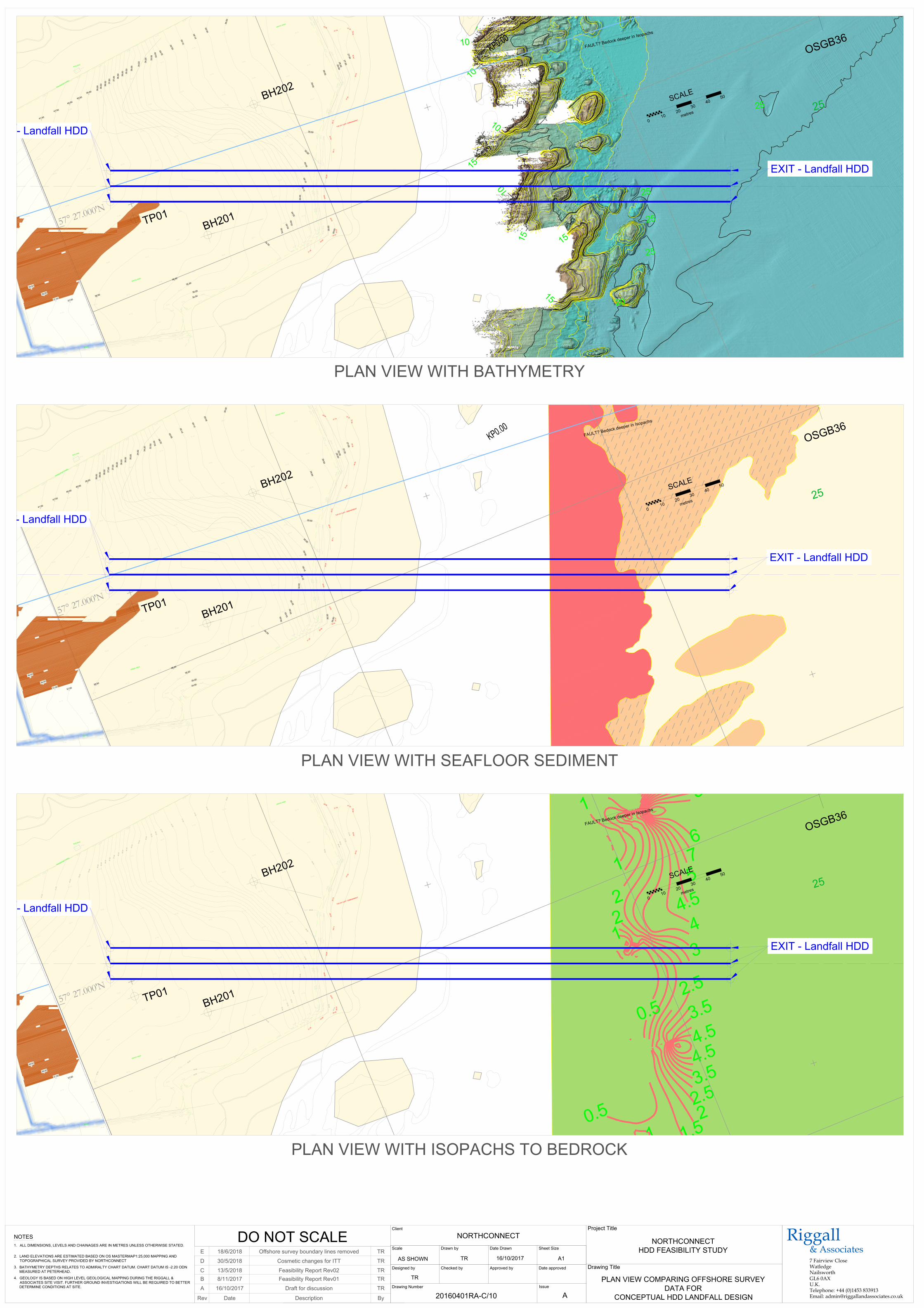
4
1
2
0
0
0
E
3
4
.
5
0
3
5
.0
0
3
5
.
5
0
3
6
.0
0
3
6
.
5
0
3
7
.0
0
3
7
.5
0
3
8
.
0
0
3
8
.5
0
4
1
.5
0
4
1
.0
0
4
0
.
5
0
4
0
.0
0
3
9
.5
0
39.00
38.00
37.00
36.00
35.00
38.50
37.50
36.50
35.50
34.00
3
3
.0
0
3
2
.
0
0
3
1
.
0
0
34.50
33.50
3
2
.
5
0
3
1
.
5
0
3
0
.
5
0
3
0
.0
0
2
7
.
5
0
2
7
.
0
0
2
8
.
0
0
2
8
.
0
0
2
8
.
5
0
2
9
.
0
0
3
4
.0
0
3
3
.0
0
32
.00
3
1
.
0
0
3
4
.
5
0
3
3
.
5
0
3
2
.
5
0
3
1
.
5
0
3
0
.
5
0
3
0
.
0
0
29.50
30.00
2
9
.5
0
K
P
0
.
0
0
S
C
A
L
E
0
1
0
2
0
3
0
4
0
5
0
m
e
t
r
e
s
O
S
G
B
3
6
2
5
T
P
0
1
F
A
U
L
T
?
B
e
d
o
c
k
d
e
e
p
e
r in
Is
o
p
a
c
h
s
3
4
.
5
7
3
4
.
0
1
3
3
.
3
8
3
4
.
1
9
3
5
.2
2
3
4
.6
6
3
4
.3
8
3
4
.
2
2
3
5
.
1
1
3
4
.
7
4
3
4
.
5
0
3
3
.
8
8
3
1
.
8
0
3
0
.
7
7
30.78
30.62
29.80
29.61
2
8
.
8
1
2
8
.
2
6
2
8
.
4
5
2
8
.
9
0
3
1
.
2
2
3
2
.
3
9
3
5
.
8
5
3
9
.
3
8
4
0
.
7
3
4
1
.
6
8
4
0
.
6
7
3
1
.
2
6
2
9
.
9
0
2
9
.
0
4
29
.3
3
2
9
.
6
2
2
9
.6
0
2
9
.2
8
2
8
.7
1
2
8
.
5
2
2
8
.1
0
2
7
.
4
2
2
6
.
7
6
2
6
.5
6
26
.7
6
2
7
.
2
7
2
7
.7
9
2
8
.
0
6
3
1
.
8
6
3
3
.
8
2
30.56
30.56
3
0
.6
4
30.55
2
9
.6
72
9.5
0
2
8
.
8
2
2
8
.
2
0
2
8
.
3
9
2
8
.
7
9
2
8
.
9
6
2
8
.
3
8
2
8
.
1
0
2
9
.6
7
2
9
.
3
5
3
0
.
0
6
3
1
.
3
0
3
2
.
7
6
3
5
.
0
1
3
8
.
9
5
4
0
.
5
4
4
1
.
4
6
3
4
.
0
9
3
5
.
1
1
35.2
3
3
6
.3
0
36.66
3
7
.4
9
37.2
2
3
7
.
8
8
3
7
.9
8
3
8
.7
5
3
8
.2
8
3
7
.
3
4
3
7
.0
6
3
6
.
7
7
36.6
0
35.50
35.05
3
4
.1
8
33.8
6 33.64
3
1
.
4
6
3
0
.
2
2
3
0
.2
1
3
0
.1
6
30.11
2
9
.2
52
9.1
2
2
8
.
3
2
2
7
.
6
9
2
7
.
9
7
2
8
.
3
3
3
8
.9
7
3
8
.1
3
3
7
.9
0
3
7
.
6
6
37.8
0
36.8
8
3
6
.1
6
34.91
34.7
5
34.0
5
3
7
.
9
1
3
6
.
0
2
3
5
.
6
8
3
5
.
3
9
3
6
.
1
4
3
5
.
5
5
3
4
.
5
4
3
4
.
4
1
3
1
.
8
3
3
2
.
4
4
3
4
.
0
1
3
3
.9
7
3
4
.
7
0
3
5
.8
0
3
5
.6
2
3
6
.
4
8
3
6
.
1
0
3
6
.
5
2
3
7
.
1
8
3
8
.
1
5
3
8
.
5
7
3
9
.
4
6
4
0
.
3
2
4
0
.4
1
3
9
.
7
3
3
8
.9
4
3
7
.
8
0
3
3
.
9
4
3
2
.
0
2
3
0
.
8
4
2
9
.
8
0
2
9
.0
1
2
8
.
7
0
2
8
.
8
5
2
9
.
3
0
2
9
.
5
1
3
0
.
9
3
3
0
.1
6
3
0
.
1
8
3
1
.2
6
3
2
.
2
3
3
0
.
8
8
2
9
.
9
6
2
9
.
2
5
2
9
.
4
8
3
0
.
5
2
3
3
.
6
3
3
3
.
6
1
3
4
.
1
3
3
4
.
8
5
3
5
.
5
8
3
7
.4
7
3
7
.4
2
3
8
.
2
5
3
8
.
8
9
3
9
.
4
8
3
8
.
8
9
3
7
.
8
9
3
8
.1
5
3
7
.
0
5
3
6
.
6
8
3
6
.
3
7
3
6
.
6
1
3
6
.2
8
3
5
.
1
9
3
4
.
4
5
3
5
.8
1
3
6
.3
2
3
6
.
5
6
3
5
.
9
0
3
7
.
1
7
3
6
.
7
3
3
7
.6
6
3
8
.4
1
3
6
.1
9
3
6
.8
2
3
0
.
0
0
3
0
.
5
0
3
1
.
0
0
3
1
.
5
0
3
2
.
0
0
3
2
.
5
0
3
3
.0
0
3
3
.5
0
3
4
.0
0
3
4
.5
0
3
5
.0
0
35.50
36.00
36.50
3
7
.0
0
37.50
38.00
38.50
3
9
.0
0
3
9
.
5
0
4
0
.
0
0
4
0
.5
0
4
1
.0
0
4
1
.5
0
3
7
.
5
0
3
8
.
0
0
38
.5
0
3
6
.
5
0
3
7
.
0
0
3
5
.
5
0
3
6
.
0
0
3
4
.
5
0
3
5
.0
0
3
3
.0
0
3
3
.
5
0
3
4
.0
0
3
4
.
5
0
3
1
.
5
0
32.00
3
2
.
5
0
3
0
.
0
0
3
0
.
5
0
3
1
.
0
0
29.50
2
8
.5
0
2
9
.
0
0
2
7
.
0
0
2
7
.
5
02
8
.
0
0
2
8
.
0
0
2
9
.
5
0
30.00
D
IT
C
H
B
U
IL
D
IN
G
F
E
N
C
E
(
P
O
S
T
\
W
I
R
E
)
T
O
P
O
F
C
L
I
F
F
/
E
M
B
A
N
K
M
E
N
T
G
R
A
S
S
A
R
E
A
G
R
A
S
S
A
R
E
A
G
R
A
S
S
A
R
E
A
EXIT - Landfall HDD
ENTRY - Landfall HDD
B
H
2
0
1
B
H
2
0
2
4
1
2
0
0
0
E
3
4
.5
0
3
5
.0
0
3
5
.5
0
3
6
.
0
0
3
6
.
5
0
3
7
.
0
0
3
7
.5
0
3
8
.
0
0
3
8
.
5
0
4
1
.5
0
4
1
.
0
0
4
0
.
5
0
4
0
.
0
0
3
9
.
5
0
39.00
38.00
37.00
36.00
35.00
38.50
37.50
36.50
35.50
34.00
3
3
.0
0
3
2
.
0
0
3
1
.
0
0
34.50
33.50
3
2
.
5
0
3
1
.
5
0
3
0
.
5
0
3
0
.0
0
2
7
.
5
0
2
7
.
0
0
2
8
.
0
0
2
8
.
0
0
2
8
.
5
0
2
9
.
0
0
3
4
.0
0
3
3
.0
0
32.00
3
1
.
0
0
3
4
.
5
0
3
3
.
5
0
3
2
.
5
0
3
1
.
5
0
3
0
.
5
0
3
0
.
0
0
29.50
30.00
2
9
.5
0
K
P
0
.
0
0
S
C
A
L
E
0
1
0
2
0
3
0
4
0
5
0
m
e
t
r
e
s
O
S
G
B
3
6
2
5
T
P
0
1
F
A
U
L
T
?
B
e
d
o
c
k
d
e
e
p
e
r in
Is
o
p
a
c
h
s
3
4
.
5
7
3
4
.
0
1
3
3
.
3
8
3
4
.
1
9
3
5
.2
2
3
4
.6
6
3
4
.3
8
3
4
.
2
2
3
5
.
1
1
3
4
.
7
4
3
4
.
5
0
3
3
.
8
8
3
1
.
8
0
3
0
.
7
7
30.78
30.62
29.80
29.61
2
8
.
8
1
2
8
.
2
6
2
8
.
4
5
2
8
.
9
0
3
1
.
2
2
3
2
.
3
9
3
5
.
8
5
3
9
.
3
8
4
0
.
7
3
4
1
.
6
8
4
0
.
6
7
3
1
.
2
6
2
9
.
9
0
2
9
.
0
4
29
.3
3
2
9
.
6
2
2
9
.6
0
2
9
.2
8
2
8
.7
1
2
8
.
5
2
2
8
.1
0
2
7
.
4
2
2
6
.
7
6
2
6
.5
6
26
.7
6
2
7
.
2
7
2
7
.7
9
2
8
.
0
6
3
1
.
8
6
3
3
.
8
2
30.56
30.56
3
0
.6
4
30.55
2
9
.6
72
9.5
0
2
8
.
8
2
2
8
.
2
0
2
8
.
3
9
2
8
.
7
9
2
8
.
9
6
2
8
.
3
8
2
8
.
1
0
2
9
.6
7
2
9
.
3
5
3
0
.
0
6
3
1
.
3
0
3
2
.7
6
3
5
.0
1
3
8
.
9
5
4
0
.
5
4
4
1
.4
6
3
4
.
0
9
3
5
.
1
1
35.2
3
3
6
.3
0
3
6
.6
6
37.49
37.2
2
3
7
.
8
8
3
7
.9
8
3
8
.7
5
3
8
.2
8
3
7
.
3
4
3
7
.0
6
3
6
.
7
7
36.6
0
35.50
35.05
3
4
.1
8
33.8
6 33.64
3
1
.
4
6
3
0
.
2
2
30.21
3
0
.1
6
30.11
2
9
.2
52
9.1
2
2
8
.
3
2
2
7
.
6
9
2
7
.
9
7
2
8
.
3
3
3
8
.1
3
3
7
.9
0
3
7
.
6
6
37.8
0
36.8
8
3
6
.1
6
34.91
34.7
5
34.0
5
3
7
.
9
1
3
6
.0
2
3
5
.
6
8
3
5
.
3
9
3
6
.
1
4
3
5
.
5
5
3
4
.
5
4
3
4
.
4
1
3
1
.
8
3
3
2
.4
4
3
4
.
0
1
3
3
.
9
7
3
4
.7
0
3
5
.
8
0
3
5
.
6
2
3
6
.4
8
3
6
.1
0
3
6
.
5
2
3
7
.
1
8
3
8
.
1
5
3
8
.
5
7
3
9
.
4
6
4
0
.
4
1
3
9
.7
3
3
8
.
9
4
3
7
.
8
0
3
3
.
9
4
3
2
.
0
2
3
0
.
8
4
2
9
.
8
0
2
9
.
0
1
2
8
.7
0
2
8
.8
5
2
9
.
3
0
2
9
.5
1
3
0
.
9
3
3
0
.
1
6
3
0
.1
8
3
1
.
2
6
3
2
.
2
3
3
0
.
8
8
2
9
.9
6
2
9
.
2
5
2
9
.
4
8
3
0
.
5
2
3
3
.
6
3
3
3
.
6
1
3
4
.
1
3
3
4
.
8
5
3
5
.
5
8
3
7
.4
7
3
7
.
4
2
3
8
.
2
5
3
8
.
8
9
3
9
.
4
8
3
8
.
8
9
3
7
.8
9
3
8
.
1
5
3
7
.
0
5
3
6
.6
8
3
6
.
3
7
3
6
.6
1
3
6
.
2
8
3
5
.1
9
3
4
.
4
5
3
5
.
8
1
3
6
.
3
2
3
6
.
5
6
3
5
.
9
0
3
7
.
1
7
3
6
.
7
3
3
7
.
6
6
3
8
.
4
1
3
6
.
1
9
3
6
.
8
2
3
0
.
0
0
3
0
.
5
0
3
1
.
0
0
3
1
.
5
0
3
2
.
0
0
3
2
.
5
0
3
3
.0
0
3
3
.5
0
3
4
.0
0
3
4
.5
0
3
5
.0
0
35.50
36.00
3
6
.5
0
3
7
.0
0
37.50
38.00
38.50
3
9
.0
0
3
9
.
5
0
4
0
.
0
0
4
0
.5
0
4
1
.0
0
4
1
.5
0
3
7
.
5
0
3
8
.
0
0
38
.5
0
3
6
.
5
0
3
7
.
0
0
3
5
.
5
0
3
6
.
0
0
3
4
.
5
0
3
5
.0
0
3
3
.0
0
3
3
.
5
0
3
4
.0
0
3
4
.
5
0
3
1
.
5
0
32.00
3
2
.
5
0
3
0
.
0
0
3
0
.
5
0
3
1
.
0
0
29.50
2
8
.5
0
2
9
.
0
0
2
7
.
0
0
2
7
.
5
0
2
8
.
0
0
2
8
.
0
0
2
9
.
5
0
30.00
D
IT
C
H
B
U
I
L
D
I
N
G
F
E
N
C
E
(
P
O
S
T
\
W
I
R
E
)
T
O
P
O
F
C
L
I
F
F
/
E
M
B
A
N
K
M
E
N
T
G
R
A
S
S
A
R
E
A
G
R
A
S
S
A
R
E
A
G
R
A
S
S
A
R
E
A
EXIT - Landfall HDD
ENTRY - Landfall HDD
B
H
2
0
1
B
H
2
0
2
4
1
2
0
0
0
E
3
4
.5
0
3
5
.
0
0
3
5
.5
0
3
6
.0
0
3
6
.5
0
3
7
.0
0
3
7
.5
0
3
8
.0
0
3
8
.5
0
4
1
.
5
0
4
1
.0
0
4
0
.5
0
4
0
.0
0
3
9
.5
0
39.00
38.00
37.00
36.00
35.00
38.50
37.50
36.50
35.50
34.00
3
3
.0
0
3
2
.
0
0
3
1
.
0
0
34.50
33.50
3
2
.
5
0
3
1
.
5
0
3
0
.
5
0
3
0
.0
0
2
7
.
5
0
2
7
.
0
0
2
8
.
0
0
2
8
.
0
0
2
8
.
5
0
2
9
.
0
0
3
4
.0
0
3
3
.0
0
32.00
3
1
.
0
0
3
4
.
5
0
3
3
.
5
0
3
2
.
5
0
3
1
.
5
0
3
0
.
5
0
3
0
.
0
0
29.50
30.00
2
9
.5
0
K
P
0
.
0
0
S
C
A
L
E
0
1
0
2
0
3
0
4
0
5
0
m
e
t
r
e
s
O
S
G
B
3
6
2
5
T
P
0
1
F
A
U
L
T
?
B
e
d
o
c
k
d
e
e
p
e
r in
Is
o
p
a
c
h
s
3
4
.
5
7
3
4
.
0
1
3
3
.
3
8
3
4
.
1
9
3
5
.2
2
3
4
.6
6
3
4
.3
8
3
4
.
2
2
3
5
.
1
1
3
4
.
7
4
3
4
.
5
0
3
3
.
8
8
3
1
.
8
0
3
0
.
7
7
30.78
30.62
29.80
29.61
2
8
.
8
1
2
8
.
2
6
2
8
.
4
5
2
8
.
9
0
3
1
.
2
2
3
2
.
3
9
3
5
.
8
5
3
9
.
3
8
4
0
.
7
3
4
1
.
6
8
4
0
.
6
7
3
1
.
2
6
2
9
.
9
0
2
9
.
0
4
29
.3
3
2
9
.
6
2
2
9
.6
0
2
9
.2
8
2
8
.7
1
2
8
.
5
2
2
8
.1
0
2
7
.
4
2
2
6
.
7
6
2
6
.5
6
26
.7
6
2
7
.
2
7
2
7
.7
9
2
8
.
0
6
3
1
.
8
6
3
3
.
8
2
30.56
30.56
3
0
.6
4
30.55
2
9
.6
72
9.5
0
2
8
.
8
2
2
8
.
2
0
2
8
.
3
9
2
8
.
7
9
2
8
.
9
6
2
8
.
3
8
2
8
.
1
0
2
9
.6
7
2
9
.
3
5
3
0
.0
6
3
1
.3
0
3
2
.
7
6
3
5
.
0
1
3
8
.9
5
4
0
.5
4
4
1
.
4
6
3
4
.
0
9
3
5
.
1
1
35.2
3
3
6
.3
0
3
6
.6
6
37.49
37.2
2
3
7
.
8
8
3
7
.
9
8
3
8
.7
5
3
8
.2
8
3
7
.3
4
3
7
.0
6
3
6
.
7
7
36.6
0
35.5
0
35.05
34.18
33.8
6 33.6
4
3
1
.
4
6
3
0
.
2
2
3
0
.2
1
3
0
.1
6
30.11
2
9
.2
529.12
2
8
.
3
2
2
7
.
6
9
2
7
.
9
7
2
8
.
3
3
3
8
.9
7
3
8
.1
3
3
7
.9
0
3
7
.
6
6
37.8
0
36.8
8
3
6
.1
6
34.91
34.7
5
34.0
5
3
7
.
9
1
3
6
.
0
2
3
5
.
6
8
3
5
.
3
9
3
6
.
1
4
3
5
.
5
5
3
4
.
5
4
3
4
.
4
1
3
1
.8
3
3
2
.
4
4
3
4
.
0
1
3
3
.
9
7
3
4
.
7
0
3
5
.
8
0
3
5
.
6
2
3
6
.
4
8
3
6
.
1
0
3
6
.
5
2
3
7
.1
8
3
8
.1
5
3
8
.
5
7
3
9
.
4
6
4
0
.3
2
4
0
.
4
1
3
9
.
7
3
3
8
.
9
4
3
7
.
8
0
3
3
.
9
4
3
2
.0
2
3
0
.8
4
2
9
.
8
0
2
9
.
0
1
2
8
.
7
0
2
8
.
8
5
2
9
.3
0
2
9
.
5
1
3
0
.
9
3
3
0
.
1
6
3
0
.
1
8
3
1
.
2
6
3
2
.
2
3
3
0
.
8
8
2
9
.
9
6
2
9
.
2
5
2
9
.4
8
3
0
.
5
2
3
3
.
6
3
3
3
.
6
1
3
4
.
1
3
3
4
.8
5
3
5
.5
8
3
7
.
4
7
3
7
.
4
2
3
8
.2
5
3
8
.8
9
3
9
.4
8
3
8
.
8
9
3
7
.
8
9
3
8
.
1
5
3
7
.
0
5
3
6
.
6
8
3
6
.
3
7
3
6
.
6
1
3
6
.
2
8
3
5
.
1
9
3
4
.4
5
3
5
.
8
1
3
6
.
3
2
3
6
.
5
6
3
5
.9
0
3
7
.1
7
3
6
.7
3
3
7
.
6
6
3
8
.
4
1
3
6
.
1
9
3
6
.
8
2
3
0
.
0
0
3
0
.
5
0
3
1
.
0
0
3
1
.
5
0
3
2
.
0
0
3
2
.
5
0
3
3
.0
0
3
3
.5
0
3
4
.0
0
3
4
.5
0
3
5
.0
0
35.50
36.00
36.50
3
7
.0
0
37.50
38.00
38.50
3
9
.0
0
3
9
.
5
0
4
0
.
0
0
4
0
.5
0
4
1
.0
0
4
1
.5
0
3
7
.
5
0
3
8
.
0
0
38
.5
0
3
6
.
5
0
3
7
.
0
0
3
5
.
5
0
3
6
.
0
0
3
4
.
5
0
3
5
.0
0
3
3
.0
0
3
3
.
5
0
3
4
.0
0
3
4
.
5
0
3
1
.
5
0
32.00
3
2
.
5
0
3
0
.
0
0
3
0
.
5
0
3
1
.
0
0
29.50
2
8
.5
0
2
9
.
0
0
2
7
.
0
0
2
7
.
5
02
8
.
0
0
2
8
.
0
0
2
9
.
5
0
30.00
D
IT
C
H
B
U
I
L
D
I
N
G
F
E
N
C
E
(
P
O
S
T
\
W
I
R
E
)
T
O
P
O
F
C
L
I
F
F
/
E
M
B
A
N
K
M
E
N
T
G
R
A
S
S
A
R
E
A
G
R
A
S
S
A
R
E
A
G
R
A
S
S
A
R
E
A
EXIT - Landfall HDD
ENTRY - Landfall HDD
B
H
2
0
1
B
H
2
0
2
Riggall& Associates7 Fairview CloseWatledgeNailsworthGL6 0AXU.K.Telephone: +44 (0)1453 833913Email: [email protected]
A1
Approved by
Drawing Number
Designed by Checked by
Issue
Date approved
Date Drawn
Client
Scale Drawn by Sheet Size
20160401RA-C/10
16/10/2017
AS SHOWNTR
A
NORTHCONNECT
TR
DateRev Description By
16/10/2017A Draft for discussion TR
2.
NOTES
1.
DO NOT SCALE
Project Title
Drawing Title
ALL DIMENSIONS, LEVELS AND CHAINAGES ARE IN METRES UNLESS OTHERWISE STATED.
LAND ELEVATIONS ARE ESTIMATED BASED ON OS MASTERMAP1:25,000 MAPPING AND
TOPOGRAPHICAL SURVEY PROVIDED BY NORTHCONNECT
PLAN VIEW WITH BATHYMETRY
NORTHCONNECT
HDD FEASIBILITY STUDY
3. BATHYMETRY DEPTHS RELATES TO ADMIRALTY CHART DATUM. CHART DATUM IS -2.20 ODN
MEASURED AT PETERHEAD.
4. GEOLOGY IS BASED ON HIGH LEVEL GEOLOGICAL MAPPING DURING THE RIGGALL &
ASSOCIATES SITE VISIT. FURTHER GROUND INVESTIGATIONS WILL BE REQUIRED TO BETTER
DETERMINE CONDITIONS AT SITE.
PLAN VIEW COMPARING OFFSHORE SURVEY
DATA FOR
CONCEPTUAL HDD LANDFALL DESIGN
PLAN VIEW WITH SEAFLOOR SEDIMENT
PLAN VIEW WITH ISOPACHS TO BEDROCK
8/11/2017B Feasibility Report Rev01 TR
13/5/2018C Feasibility Report Rev02 TR
30/5/2018D Cosmetic changes for ITT TR
18/6/2018E Offshore survey boundary lines removed TR